JP2021023200A - Noodle line cutting/transport device and noodle production method - Google Patents
Noodle line cutting/transport device and noodle production method Download PDFInfo
- Publication number
- JP2021023200A JP2021023200A JP2019143658A JP2019143658A JP2021023200A JP 2021023200 A JP2021023200 A JP 2021023200A JP 2019143658 A JP2019143658 A JP 2019143658A JP 2019143658 A JP2019143658 A JP 2019143658A JP 2021023200 A JP2021023200 A JP 2021023200A
- Authority
- JP
- Japan
- Prior art keywords
- noodle
- cutting
- noodles
- string
- cutting edge
- Prior art date
- Legal status (The legal status is an assumption and is not a legal conclusion. Google has not performed a legal analysis and makes no representation as to the accuracy of the status listed.)
- Pending
Links
Images


Abstract
Description
本発明は、積層された麺線束を作製する麺線切出し搬送装置及び該麺線切出し搬送装置を用いた麺類の製造方法に関する。 The present invention relates to a noodle string cutting and transporting device for producing a laminated noodle string bundle and a method for producing noodles using the noodle string cutting and transporting device.
従来、機械による麺線の切出し方法は、切刃と呼ばれる複数の環状刃と複数の環状溝部を有し、相互に対向し、噛み合うように並設され、回転する一対のロール(切刃ロール)の間に、圧延ロールにより所定の厚みとした麺帯を通すことにより、麺帯を切断し、麺線を作製する方法が一般的である。切刃には、切り出される麺線の形状や環状刃の形状によって、角刃、丸刃、包丁刃など複数の種類が存在する。 Conventionally, a method of cutting noodle strings by a machine has a plurality of annular blades called cutting blades and a plurality of annular grooves, and a pair of rolls (cutting blade rolls) that face each other, are arranged side by side so as to mesh with each other, and rotate. A general method is to cut the noodle strips to produce noodle strings by passing the noodle strips having a predetermined thickness through a rolling roll. There are multiple types of cutting blades, such as square blades, round blades, and kitchen knife blades, depending on the shape of the noodle wire to be cut out and the shape of the annular blade.
切刃により切断された麺線は、切断された直後、切刃ロールの環状溝部に押し込まれ、切刃ロールとともに回転するが、切刃ロールの環状溝部に挿入配置されたカスリの掻き出し歯に当たることで、環状溝部から掻き出されて、麺線として切り出される。 Immediately after the noodle string cut by the cutting edge is cut, it is pushed into the annular groove portion of the cutting edge roll and rotates together with the cutting edge roll, but it hits the scraped teeth of the scraps inserted and arranged in the annular groove portion of the cutting edge roll. Then, it is scraped out from the annular groove and cut out as a noodle string.
切刃により切り出された麺線は、即席麺や蒸麺などの麺類では、麺線をα化させるために蒸煮庫で蒸気により蒸煮される。この時、麺線同士の結着を防止し、α化のための蒸気を通しやすくするため、ウェーブボックスと呼ばれる切刃ロールの直下に備えた箱型の導管に切刃により切り出された麺線を通すことにより、麺線にウェーブ(波状のちぢれ)形状を付与することが一般的である。 The noodle strings cut out by the cutting blade are steamed in a steaming chamber in order to gelatinize the noodle strings in noodles such as instant noodles and steamed noodles. At this time, in order to prevent the noodle strings from binding to each other and to facilitate the passage of steam for pregelatinization, the noodle strings cut out by the cutting edge into a box-shaped conduit provided directly under the cutting edge roll called a wave box. It is common to give the noodle strings a wavy shape by passing them through.
しかしながら、近年、消費者のニーズの多様化により、ウェーブが少ない、略直線状のいわゆる「ストレート麺」と呼ばれる麺に対する需要も高まっており、ストレート麺を製造するための技術も多数開示されている(例えば、特許文献1〜5)。
However, in recent years, due to the diversification of consumer needs, there has been an increase in demand for so-called "straight noodles" that have few waves and are substantially straight, and many techniques for producing straight noodles have been disclosed. (For example,
特許文献1には、即席麺におけるストレート麺の作製技術として、麺生地から切り出された麺線が、麺線を搬送するコンベア上で、繰り返し輪を描きながら、輪はコンベアの搬送方向と逆方向に順次ずれながら配置され、麺線の描く軌道は、隣り合う麺線同士と同調せず、各麺線は、麺線中の輪の位置が隣り合う麺線の輪の位置とずれた状態で、相互に交差して重なりあった積層状態である束になった即席麺用生麺に関する技術が記載されている。
In
また、特許文献2〜5には、特許文献1に記載された束になった即席麺用生麺を作製するための切出し装置に関する技術が記載されている。何れの技術も同一の切刃ロールで切り出される隣同士の麺線の位置をずらすことにより、麺線同士の結着を防止する技術である。しかしながら、何れの技術も麺線が搬送されるコンベアは1つであるため、切り出された麺線は切り出される位置によって順次コンベア上に積層していく。そのため、麺線の切出される位置が搬送方向側となるほど麺線のコンベア上に描く軌道が不規則となりやすく、麺線の形状が過度に屈曲したり、麺線同士の結着が発生するなどの課題があった。
Further,
本発明は、蒸麺または即席麺などの麺類を製造するにおいて、過度の屈曲が少なく、麺線同士の結着の少ない略直線状の麺線切出し搬送装置を提供すること、及び過度の屈曲が少なく、麺線同士の結着の少ない略直線状の蒸麺または即席麺などの麺類の製造方法を提供することを目的とする。 The present invention provides a substantially linear noodle string cutting and transporting device that has less excessive bending and less binding between noodle strings in producing noodles such as steamed noodles or instant noodles, and has less excessive bending. An object of the present invention is to provide a method for producing noodles such as steamed noodles or instant noodles, which are substantially linear with little binding between noodle strings.
発明者は、前記課題に対して、従来法によるストレート麺の製法よりも麺線同士の結着が少なく、均質なストレート状とすべく、できるだけコンベアに積層される麺線の軌跡の状態が一定となるような麺線の切出し方法について鋭意研究した結果、本発明に至った。 In response to the above problem, the inventor has less binding between noodle strings than the conventional method for producing straight noodles, and the state of the trajectory of the noodle strings laminated on the conveyor is constant as much as possible in order to obtain a uniform straight shape. As a result of diligent research on a method for cutting out noodle strings, the present invention has been reached.
すなわち、複数の環状刃及び環状溝部を有し、相互に対向し、噛み合うように並設され、回転することにより、麺帯を麺線に切断するための一対の切刃ロールと、前記一対の切刃ロールにより切断された前記麺線が押し込まれた前記環状溝部から前記麺線を掻き出すためのカスリと、を含む麺線切出し装置と、前記麺線切出し装置によって切り出された前記麺線をコンベア上に乗せて搬送する麺線搬送装置と、を含む麺線切出し搬送装置であって、前記麺線切出し装置は、前記切刃ロール上の隣同士の前記環状溝部に嵌入される前記カスリの掻き出し歯の歯先の位置をずらすことにより、前記カスリにより掻き出される前記麺線の位置が、前記切刃ロール上の隣同士の前記環状溝部で異なるものであり、前記麺線搬送装置は、前記麺線切出し装置から切り出された前記麺線を工程の進行方向側に進む複数のコンベア上に乗せて搬送するものであることを特徴とする麺線切出し搬送装置である。 That is, a pair of cutting edge rolls having a plurality of annular blades and annular groove portions, facing each other, arranged side by side so as to mesh with each other, and rotating to cut the noodle band into noodle strings, and the pair of cutting edge rolls. A noodle wire cutting device including a scrap for scraping the noodle wire from the annular groove portion into which the noodle wire cut by the cutting blade roll is pushed, and a conveyor for the noodle wire cut out by the noodle wire cutting device. A noodle wire cutting and transporting device including a noodle string transporting device for carrying the noodles on the noodle wire, wherein the noodle string cutting device scrapes out the scraps to be fitted into the annular groove portions adjacent to each other on the cutting blade roll. By shifting the position of the tip of the tooth, the position of the noodle string scraped out by the scraping is different in the annular groove portions adjacent to each other on the cutting edge roll, and the noodle string transporting device is described in the noodle string transporting device. The noodle string cutting and transporting device is characterized in that the noodle strings cut out from the noodle string cutting and transporting device are placed on a plurality of conveyors traveling in the direction of progress of the process and transported.
また、本発明に係る麺線切出し装置は、同一の切刃ロール上の環状溝部に嵌入されるカスリを2つ備え、それぞれのカスリの掻き出し歯が同一の切刃ロール上の隣同士の環状溝部に交互に嵌入され、環状溝部に嵌入されるそれぞれのカスリの掻き出し歯の歯先の位置をずらすことにより、カスリにより掻き出される麺線の位置が、同一の切刃ロール上の隣同士の環状溝部で異なることが好ましい。 Further, the noodle string cutting device according to the present invention includes two scraps to be fitted into the annular groove portions on the same cutting edge roll, and the scraped teeth of each scraping tooth are adjacent to each other on the same cutting edge roll. By shifting the position of the tip of the scraped tooth of each scraped tooth that is alternately fitted into the annular groove portion, the position of the noodle string scraped by the scraping is the ring of adjacent to each other on the same cutting edge roll. It is preferable that the groove portion is different.
また、本発明に係る麺線搬送装置は、工程の進行方向側の切刃ロールから切り出された麺線を工程の進行方向に搬送するコンベアと、工程の進行方向と反対側の切刃ロールから切り出された麺線を工程の進行方向に搬送するコンベアの2つのコンベアを有することが好ましい。 Further, the noodle string conveying device according to the present invention is composed of a conveyor that conveys noodle strings cut out from a cutting edge roll on the process progress direction side in the process progress direction and a cutting edge roll on the side opposite to the process progress direction. It is preferable to have two conveyors, which are conveyors that convey the cut noodle strings in the direction of progress of the process.
また、本発明に係る麺線搬送装置は、麺線切出し装置によって切り出される麺線の位置ごとに工程の進行方向に麺線を搬送するコンベアを有することが好ましい。 Further, the noodle string conveying device according to the present invention preferably has a conveyor that conveys the noodle strings in the progress direction of the process at each position of the noodle strings cut out by the noodle string cutting device.
また、本発明に係る麺線搬送装置は、複数のコンベアで搬送された麺線を最終的に1つのコンベアに乗り移して積層された麺線束とするものであることが好ましい。 Further, the noodle string conveying device according to the present invention preferably transfers noodle strings conveyed by a plurality of conveyors to one conveyor to form a laminated noodle string bundle.
また、本発明に係る麺類の製造方法としては、麺原料粉から麺生地を作製する工程と、作製した麺生地から麺帯を作製する工程と、作製した麺帯から、複数の環状刃及び環状溝部を有し、相互に並設され、回転することにより、麺帯を麺線に切断するための一対の切刃ロールと、一対の切刃ロールにより切断された麺線が押し込まれた環状溝部から麺線を掻き出すためのカスリと、を含む麺線切出し装置により、切刃ロール上の隣同士の環状溝部に嵌入されるカスリの掻き出し歯の位置をずらすことで、切刃ロール上の隣同士の前記環状溝部から掻き出される麺線の位置が異なるように麺線を切り出す工程と、切出された麺線を工程の進行方向側に進む複数のコンベアに乗せて搬送した後、最終的に1つのコンベアに乗り移して麺線が積層した麺線束を作製し搬送する工程と、麺線束を蒸煮する工程と、蒸煮した前記麺線束を引き延ばし略直線状とする工程と、を含むことが好ましい。 Further, as a method for producing noodles according to the present invention, a step of producing noodle dough from noodle raw material powder, a step of producing a noodle band from the produced noodle dough, and a plurality of annular blades and rings from the produced noodle band. A pair of cutting edge rolls for cutting the noodle band into noodle strings and an annular groove portion into which the noodle strings cut by the pair of cutting edge rolls are pushed by having grooves, which are arranged side by side with each other and rotate. By shifting the positions of the scraped teeth of the scraps that are fitted into the annular grooves of the adjacent ones on the cutting blade roll by the noodle wire cutting device that includes the scraps for scraping the noodle strings from The process of cutting out the noodle strings so that the positions of the noodle strings scraped from the annular groove portion of the above are different, and the process of transporting the cut noodle strings on a plurality of conveyors advancing in the direction of progress of the process, and finally It is preferable to include a step of transferring to one conveyor to prepare and transport a bundle of noodle strings in which noodle strings are laminated, a step of steaming the bundle of noodle strings, and a step of stretching the steamed noodle bundle to make it substantially linear. ..
また、本発明に係る麺線切出し搬送装置を用いて製造する麺類としては、切り出された麺線を蒸煮する工程を有するものが好ましく、特に即席麺及び蒸麺の製造に適している。 Further, as the noodles produced by using the noodle string cutting and transporting device according to the present invention, those having a step of steaming the cut noodle strings are preferable, and they are particularly suitable for producing instant noodles and steamed noodles.
本発明により、蒸麺または即席麺などの麺類を製造するにおいて、過度の屈曲が少なく、結着の少ない略直線状の麺類を製造するための麺線の切出し搬送装置を提供すること、及び過度の屈曲が少なく、結着の少ない略直線状の蒸麺または即席麺などの麺類の製造方法を提供することができる。 INDUSTRIAL APPLICABILITY According to the present invention, in producing noodles such as steamed noodles or instant noodles, it is possible to provide a noodle string cutting and transporting device for producing substantially linear noodles with less excessive bending and less binding, and excessive It is possible to provide a method for producing noodles such as substantially linear steamed noodles or instant noodles with less bending and less binding.
以下、本発明について詳細に説明する。ただし、本発明は以下の記載に限定されるものではない。 Hereinafter, the present invention will be described in detail. However, the present invention is not limited to the following description.
本発明に係る麺の種類としては、特に限定はなく、うどん、そば、中華麺またはパスタなどの麺が挙げられる。また、本発明に係る麺類としては、特に限定はなく、生麺、茹で麺、蒸麺、乾麺、半乾麺、即席麺または冷凍麺が挙げられるが、特にストレート状の麺を作製するという点においては、蒸煮工程を有する蒸麺または即席麺が好ましい。 The type of noodles according to the present invention is not particularly limited, and examples thereof include noodles such as udon, buckwheat noodles, Chinese noodles, and pasta. The noodles according to the present invention are not particularly limited, and examples thereof include raw noodles, boiled noodles, steamed noodles, dried noodles, semi-dried noodles, instant noodles, and frozen noodles, but in particular, in terms of producing straight noodles. , Steamed noodles having a steaming step or instant noodles are preferable.
本発明に係る麺類の製造方法としては、まず、小麦粉(デュラム粉を含む)、そば粉、大麦粉及び米粉等の穀粉、並びに馬鈴薯澱粉、タピオカ澱粉及びコーンスターチ等の各種澱粉からなる麺原料粉と、食塩やアルカリ剤、リン酸塩類、各種増粘剤、麺質改良剤、食用油脂、pH調整剤、カロチン色素等の各種色素及び保存料等を溶解または懸濁した練り水とをバッチミキサー、フロージェットミキサー、真空ミキサー等で、均一に混ざるように混捏して麺生地(ドウ)を作製する。 As a method for producing noodles according to the present invention, first, a noodle raw material flour composed of wheat flour (including durum flour), buckwheat flour, barley flour, rice flour and other flours, and various starches such as horse bell flour, tapioca starch and corn starch. , Salt, alkaline agents, phosphates, various thickeners, noodle quality improvers, edible oils and fats, pH adjusters, various pigments such as carotene pigments, and kneading water in which preservatives are dissolved or suspended. Use a flow jet mixer, vacuum mixer, etc. to knead the noodles so that they are evenly mixed to make noodle dough.
次いで、作製したドウを麺帯化する。麺帯化の方法は、特に限定はなく、整形ロールにより粗麺帯とした後、複合等により麺帯を作製する方法や、エクストルーダーにより麺帯を作製する方法、さらに複数の麺帯を合わせて多層麺帯を作製する方法が挙げられる。作製した麺帯は、圧延ロールにより複数回圧延し、所定の麺帯厚とした後、下記に記載する本発明に係る麺線切出し搬送装置により麺帯を麺線に切出し、搬送する。 Next, the prepared dough is made into noodle strips. The method of forming the noodle band is not particularly limited, and a method of producing a coarse noodle band by a shaping roll and then producing a noodle band by a composite or the like, a method of producing a noodle band by an extruder, and a method of combining a plurality of noodle bands. There is a method of producing a multi-layer noodle band. The produced noodle band is rolled a plurality of times with a rolling roll to obtain a predetermined noodle band thickness, and then the noodle band is cut out into a noodle string by the noodle string cutting and transporting device according to the present invention described below and conveyed.
(麺線切出し搬送装置の実施形態について)
―麺線切出し搬送装置―
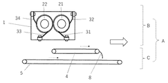
図1で示すように、本発明の実施形態である麺線切出し搬送装置Aは、麺線切出し装置B及び麺線搬送装置Cを含む。
(About the embodiment of the noodle string cutting and transporting device)
-Noodle line cutting and transporting device-
As shown in FIG. 1, the noodle string cutting and transporting device A according to the embodiment of the present invention includes the noodle string cutting and transporting device B and the noodle string transporting device C.
─麺線切出し装置─
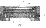
本発明の実施形態である麺線切出し搬送装置Aの麺線切出し装置Bは、図1〜4で示すように複数の環状刃(211及び221)及び環状溝部(212及び222)を有し、相互に対向し、噛み合うように並設され、回転することにより、麺帯から麺線を切り出すための一対の切刃ロール(21及び22)と、一対の切刃ロール(21及び22)により切り出された麺線が押し込まれた環状溝部(212及び222)から麺線を掻き出すためのカスリ(31〜34)を備える。
─ Noodle wire cutting device ─
As shown in FIGS. 1 to 4, the noodle string cutting device B of the noodle string cutting and transporting device A according to the embodiment of the present invention has a plurality of annular blades (211 and 221) and an annular groove portion (212 and 222). It is cut out by a pair of cutting edge rolls (21 and 22) and a pair of cutting edge rolls (21 and 22) for cutting out noodle strings from the noodle band by arranging them side by side so as to face each other and meshing with each other and rotating them. The noodles are provided with scraps (31 to 34) for scraping the noodles from the annular grooves (212 and 222) into which the noodles are pushed.
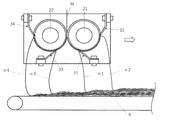
図4は、切刃ロール(21及び22)の一部を拡大した図であるが、図4で示すように、切刃ロール(21及び22)は、ロール上に複数の環状刃(211及び221)、環状溝部(212及び222)及び押し込み部(213及び223)を有する。図4で示すように一対の切刃ロール(21及び22)は、環状溝部(212または222)と押し込み部(223または213)が向かい合うように互いに対向し、互いの環状刃(211及び212)が噛み合うように並設されており、切刃ロール(21及び22)が回転し、作製した麺帯が麺線切出し装置Bの切刃ロール21及び切刃ロール22の間を通過することで切断され、麺線nとなる。この時、通常、麺線nは、押し込み部(213及び223)ではなく、環状溝部(212及び222)に押し込まれる。
FIG. 4 is an enlarged view of a part of the cutting edge rolls (21 and 22), but as shown in FIG. 4, the cutting edge rolls (21 and 22) have a plurality of annular blades (211 and 22) on the roll. 221), it has an annular groove portion (212 and 222) and a pushing portion (213 and 223). As shown in FIG. 4, the pair of cutting edge rolls (21 and 22) face each other so that the annular groove portion (212 or 222) and the pushing portion (223 or 213) face each other, and the annular blades (211 and 212) of each other. The cutting edge rolls (21 and 22) rotate, and the produced noodle strip passes between the cutting
図4は、丸刃と呼ばれる切刃ロールの構造であるが、図5で示すように切刃ロールは角刃と呼ばれる構造であってもよい。図5で示すように角刃の場合は、押し込み部(213及び223)はない。図4で示すように丸刃で切断した場合は、麺線nの長手方向に対して垂直に切断した断面は、略楕円状の形状になる。それに対し、図5で示すような角刃で切断した場合には、麺線nの長手方向に対して垂直に切断した断面は、略四角形となる。この他、図では示さないが切刃ロールは包丁刃などの構造であってもよい。 FIG. 4 shows a structure of a cutting edge roll called a round blade, but as shown in FIG. 5, the cutting edge roll may have a structure called a square blade. As shown in FIG. 5, in the case of a square blade, there are no pushing portions (213 and 223). When cut with a round blade as shown in FIG. 4, the cross section cut perpendicular to the longitudinal direction of the noodle wire n has a substantially elliptical shape. On the other hand, when cut with a square blade as shown in FIG. 5, the cross section cut perpendicular to the longitudinal direction of the noodle wire n becomes a substantially quadrangle. In addition, although not shown in the figure, the cutting edge roll may have a structure such as a kitchen knife blade.
本発明の実施形態である麺線切出し装置Bは、図1〜図3で示すように同一切刃ロールに対して2つの独立したカスリ(31〜34)を有する。カスリ(31〜34)は、切刃ロール(21及び22)で切り出され、環状溝部(212または222)に押し込まれた麺線nを環状溝部(212または222)から掻き出すためのものである。材質は特に限定はないが、切刃ロール(21及び22)よりも柔らかい金属、例えば、切刃ロール(21及び22)がステンレス製であれば、真鍮や銅などの金属などで作製することが好ましい。ステンレス製のカスリ(31〜34)を用いる場合は切刃ロール(21及び22)に直接接触しないような非接触カスリを使用することが好ましい。 The noodle string cutting device B according to the embodiment of the present invention has two independent scraps (31 to 34) for the same cutting edge roll as shown in FIGS. 1 to 3. The scraps (31 to 34) are for scraping the noodle strings n cut out by the cutting edge rolls (21 and 22) and pushed into the annular groove portion (212 or 222) from the annular groove portion (212 or 222). The material is not particularly limited, but it can be made of a metal softer than the cutting edge rolls (21 and 22), for example, if the cutting edge rolls (21 and 22) are made of stainless steel, it can be made of a metal such as brass or copper. preferable. When using stainless steel scraps (31 to 34), it is preferable to use non-contact scraps that do not come into direct contact with the cutting edge rolls (21 and 22).
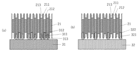
図6(a)は第1カスリ31を示した図であるが、第1切刃ロール21の環状溝部212に嵌入する掻き出し歯311と、押し込み部213に嵌入する補助歯313を有しており、図7(a)で示すように掻き出し歯311は、第1切刃ロール21上の環状溝部212に一つ飛びに嵌入するように配置されており、補助歯313は掻き出し歯311が嵌入する両隣の押し込み部213に嵌入するように配置されている。これにより、第1切刃ロール21によって切断され、環状溝部212に押し込まれた麺線nは、第1カスリ31によって一つ飛びに環状溝部212から掻き出される。なお、補助歯313は、ごくまれに第2切刃ロール22側の環状溝部222に押し込まれるはずの麺線nが第1切刃ロール21側の押し込み部213に押し込まれてしまった場合に、麺線nを押し込み部213から掻き出すためのものである。
FIG. 6A is a diagram showing the
図6(b)は、第2カスリ32を示した図であるが、第1切刃ロール21の環状溝部212に嵌入する掻き出し歯321を有しており、図7(b)で示すように掻き出し歯321は、環状溝部212の位置が1つ飛びで第1カスリ31の掻き出し歯311が嵌入しない環状溝部212に嵌入するように配置されている。これにより、第1切刃ロール21によって切断され、環状溝部212に押し込まれた麺線nで第1カスリ31によって掻き出されなかった麺線nが第2カスリ32によって環状溝部212から掻き出される。
FIG. 6B is a view showing the
なお、第2切刃ロール22側で第1カスリ31と対称の位置に配置される第3カスリ33については第一カスリ31と同じ構造であり、第2カスリ32と対称の位置に配置される第4カスリ34は同じ構造である。
The
図8で示すようにカスリ(31〜34)は、図9で示すように第1カスリ31の歯先312と第3カスリ33の歯先332の位置、及び第2カスリ32の歯先322と第4カスリ34の歯先342位置が、第1切刃ロール21と第2切刃ロール22との噛み合う位置Xから同じ角度(α1=α2=70.5°、β1=β2=180°)だけ、切刃ロール21または切刃ロール22が回転した位置となるように筐体1に固定されている。
As shown in FIG. 8, the scraps (31 to 34) are the positions of the
本発明の実施形態である麺線切出し装置Bは、角度α1とα2及び角度β1とβ2は同じ角度となっているが、本発明においては、同一の切刃ロール(21または22)上の隣同士の環状溝部(212または222)に嵌入されるカスリの歯先(312と322または332と342)の位置をずらす(α1とβ1またはα2とβ2の角度を変える)ことが必要であり、必ずしもα1とα2及びβ1とβ2は必ずしも同じ角度である必要はない。好ましいα1及びα2の角度としては、5〜90°、より好ましくは、30〜90°、好ましいβ1及びβ2の角度としては、120〜210°、より好ましくは150〜180°である。このよう同一の切刃ロール(21または22)上の隣同士の環状溝部(212または222)に嵌入されるカスリの歯先(312と322または332と342)の位置を大きくずらすことにより、図10で示すように同一の切刃ロール(21または22)上の隣同士の環状溝部(212または222)の掻き出される麺線(n1とn2またはn3とn4)の位置をずらすことができ、麺線(n1〜n4)同士が干渉しあうことなく、麺線(n1〜n4)をコンベアに落下させることができる。 In the noodle string cutting device B according to the embodiment of the present invention, the angles α1 and α2 and the angles β1 and β2 are the same angle, but in the present invention, they are next to each other on the same cutting edge roll (21 or 22). It is necessary to shift the position (change the angle of α1 and β1 or α2 and β2) of the tooth tips (312 and 322 or 332 and 342) of the scraps to be fitted into the annular grooves (212 or 222) of each other, and it is not always necessary. α1 and α2 and β1 and β2 do not necessarily have to be at the same angle. The preferred angles of α1 and α2 are 5 to 90 °, more preferably 30 to 90 °, and the preferred angles of β1 and β2 are 120 to 210 °, more preferably 150 to 180 °. By greatly shifting the positions of the tooth tips (312 and 322 or 332 and 342) of the scraps to be fitted into the adjacent annular grooves (212 or 222) on the same cutting edge roll (21 or 22), the figure is shown. As shown by 10, the positions of the scraped noodle strings (n1 and n2 or n3 and n4) of the adjacent annular grooves (212 or 222) on the same cutting edge roll (21 or 22) can be shifted. The noodle strings (n1 to n4) can be dropped onto the conveyor without interfering with each other.
なお、本明細書において麺線が切り出される位置と表現することがあるが、麺線(n1〜n4)がカスリ(31〜34)によって環状溝部(212または222)から掻き出される位置のことである。 In addition, although it may be expressed as a position where the noodle strings are cut out in the present specification, it is a position where the noodle strings (n1 to n4) are scraped out from the annular groove portion (212 or 222) by the scraping (31 to 34). is there.
また、図1や図10で示すように本発明の実施形態である麺線切出し装置Bは、地面に対して水平に設置されているが図11で示すように麺線切出し装置Bの水平面に対する設置角度γが±60°の範囲で傾いた状態で設置されてもよい。この場合、それぞれの麺線(n1〜n4)が落下される位置が近くなりすぎないように注意することが好ましい。 Further, as shown in FIGS. 1 and 10, the noodle string cutting device B according to the embodiment of the present invention is installed horizontally with respect to the ground, but as shown in FIG. 11, with respect to the horizontal plane of the noodle string cutting device B. It may be installed in a state where the installation angle γ is tilted within a range of ± 60 °. In this case, it is preferable to be careful not to make the positions where the noodle strings (n1 to n4) are dropped too close.
本発明の実施形態である麺線切出し装置Bは、特許文献4に記載された麺線切出し装置の一実施形態であるが、本発明に係る麺線切出し装置の他の実施形態として、図12や特許文献1または2に記載されているような、同一の切刃ロールに対してカスリが1つであり、隣同士の環状溝部に嵌入するカスリの歯の歯先の位置をずらすことにより、麺線が掻き出される位置をずらすものや、特許文献3〜5に記載されているように同一切刃ロールに対してカスリを2つ設けて隣同士の環状溝部に嵌入するカスリの歯の歯先の位置をずらすものを用いることができる。本発明に係る麺線切出し装置としては、同一の切刃ロールに対して独立したカスリを2つ設ける特許文献3〜5の麺線切出し装置を用いる方が隣同士の麺線間の距離を大きく離すことができるため好ましい。
The noodle line cutting device B according to the embodiment of the present invention is one embodiment of the noodle line cutting device described in
―麺線搬送装置―
本発明の実施形態である麺線切出し搬送装置Aの麺線搬送装置Cは、図1及び図13で示すように、工程の進行方向側の切刃ロールである第1切刃ロール21から切り出される麺線(n1、n2)を工程の進行方向側に搬送する順走コンベア4と、工程の進行側と反対側の第2切刃ロール22から切り出される麺線(n3、n4)を工程の進行方向に搬送するコンベア5と異なるコンベア間で麺線束を乗り移すときに麺線の軌跡や積層状態を保護するための積層保護部材8を含む。
-Noodle wire transport device-
As shown in FIGS. 1 and 13, the noodle wire transporting device C of the noodle string cutting and transporting device A according to the embodiment of the present invention is cut out from the first
切り出された麺線(n1〜n4)は、麺線を搬送するコンベア4またはコンベア5上に落下し、搬送される。このとき、麺線の切出し速度(切刃ロール(21、22)の回転速度)よりもコンベア4またはコンベア5の搬送速度を遅くすることで、図15(a)で示すように繰り返し輪を描く軌跡を描きながら、麺線がコンベア上に乗り搬送される。特に、麺線の切出し速度をコンベアの搬送速度の3〜20倍とすることにより、形状良く麺線が繰り返し輪を描きながら略螺旋状にコンベア上に配置される。このような軌跡を描くことで蒸煮工程を有する蒸麺や即席麺などの麺類を製造するにあたっては、過度の屈曲のない状態で蒸煮されるため、麺線を引き延ばした際には、屈曲した形状が残ることなく略直線状の麺線を得ることができる。
The cut noodle strings (n1 to n4) fall on the
図14で示すように、切り出された麺線の搬送において、通常通り工程の進行方向に搬送するコンベア4のみで行う場合には、麺線切出し装置Bにより切り出された麺線(n1〜n4)は工程の進行方向から遠い麺線n4、n3、n1、n2の順にコンベア上に落下し、順次積層していく。そのため、麺線の切出される位置が麺線の搬送方向から一番遠い麺線n4はコンベア上に麺線が落下するが、その他の麺線は、先に落下した麺線の上に落下し、積層していくこととなる。このとき、落下した麺線の軌跡は、落下する場所の状態に影響を受けやすく、積層する順番が遅いほど図15(b)〜(d)、図16(a)で示すように、円の大きさや向きが変わったり、麺線が急に曲がったりして麺線の軌跡が不規則となりやすく、蒸煮工程を有する麺類を製造する場合、麺線の形状が過度に屈曲したり、麺線同士が結着するなどの課題があった。
As shown in FIG. 14, when the cut-out noodle strings are conveyed only by the
それに対し、本発明の実施形態である麺線搬送装置Cは、図13で示すように工程の進行方向側の第一切刃ロール21から切り出された麺線(n1、n2)を乗せて工程の進行方向に搬送するコンベア4と、工程の進行方向と反対側の第2切刃ロール22から切り出された麺線(n3、n4)を乗せて工程の進行方向に搬送するコンベア5と2つに分けることで、図16(b)で示すように通常の麺線搬送装置状に積層される数が半減されるため、麺線の軌跡が不規則となりにくい。
On the other hand, in the noodle string conveying device C according to the embodiment of the present invention, as shown in FIG. 13, the noodle strings (n1, n2) cut out from the
また、図13で示すように、本件発明の実施形態である麺線搬送装置Cでは、コンベア4上に落下し、積層した麺線(n1及びn2)は、コンベア5に積層した麺線(n3及びn4)の上に乗り移って積層され、1つの麺線束として次の工程へ搬送される。この乗り移りは、すでに安定した形状の軌跡を描く麺線が積層されたものが乗り移るため、積層状態を崩さないように乗り移りすることが好ましく、コンベア4とコンベア5との距離を短くしたり、積層保護部材8を設けることが好ましい。そうすることで、1つの搬送コンベアのみを用いた場合と比較して麺線の軌跡が安定した状態で積層した麺線束を得ることができる。そのため、蒸煮工程を有する麺類を製造する場合、積層状態において麺線が過度の屈曲したり、隣同士の麺線が同調することがなく、より安定したストレート形状の麺線やほぐれの良い麺類が得られる。
Further, as shown in FIG. 13, in the noodle string conveying device C according to the embodiment of the present invention, the noodle strings (n1 and n2) that have fallen onto the
また、本発明においては、必ずしもコンベア4で搬送された麺線(n1及びn2)を、コンベア5に積層した麺線(n3及びn4)の上に乗り移す必要はなく、コンベア4及びコンベア5それぞれが蒸煮工程などの次の工程へと麺線を搬送することもできる。しかしながら、蒸煮工程などの次の工程の設備を2つ設ける必要があるため、本発明の実施形態である麺線切出し装置Cのようにコンベア4で搬送された麺線(n1及びn2)をコンベア5に積層した麺線(n3及びn4)の上に乗り移して積層した麺線束としてから搬送することが好ましい。
Further, in the present invention, it is not always necessary to transfer the noodle strings (n1 and n2) conveyed by the
図13で示すように本発明に係る麺線搬送装置Cのコンベアは、2つであるが、必ずしも2つである必要はなく、図17の本発明の麺線搬送装置の変形例である麺線搬送装置C’で示すように麺線の切出し位置ごとに複数のコンベア(4、5、6,7)を設けることができる。こうすることで、コンベア数は増えるが、すべての麺線が何もないコンベア上に落下するため、コンベア上に落下した麺線の軌跡は安定する。ただし、それぞれの麺線の落下距離が異なるため、距離が短くなるように傾けて麺線切出し装置Bを傾けて設置することが好ましい。 As shown in FIG. 13, there are two conveyors of the noodle wire transporting device C according to the present invention, but the number of conveyors does not necessarily have to be two, and the noodles which are a modification of the noodle wire conveying device of the present invention of FIG. As shown by the line transfer device C', a plurality of conveyors (4, 5, 6, 7) can be provided for each cutting position of the noodle wire. By doing so, the number of conveyors increases, but all the noodle strings fall on the empty conveyor, so that the trajectory of the noodle strings dropped on the conveyor is stable. However, since the falling distance of each noodle string is different, it is preferable to tilt the noodle string cutting device B so that the distance is short.
また、図17で示すようにコンベア(4、5、6、7)は、コンベアの高い位置から順番に麺線の積層状態を維持したまま、一つ下のコンベアに麺線を乗り移すことができ、最終的に1つのコンベアに乗り移すことで麺線の軌跡が安定した状態で積層した麺線束を得ることができる。 Further, as shown in FIG. 17, the conveyors (4, 5, 6, 7) can transfer the noodle strings to the next lower conveyor while maintaining the stacked state of the noodle strings in order from the highest position of the conveyor. Finally, by transferring to one conveyor, it is possible to obtain a bundle of noodle strings stacked in a state where the trajectory of the noodle strings is stable.
本発明に係る麺線切出し搬送装置によって積層され、搬送された麺線束は、蒸煮工程を有する麺類を製造する場合には、常法により蒸煮し、麺線をα化する。蒸煮条件は、麺の種類、麺の太さにより好ましい条件が異なるため、目的とする食感に合わせて、好ましい条件を適宜設定すればよい。蒸煮の方法としては、飽和水蒸気による加熱だけでなく、過熱水蒸気により加熱することもでき、シャワーや浸漬などの水分補給工程を組み合わせることもできる。また、調味液やほぐし液を付着することもできる。 When producing noodles having a steaming step, the noodle string bundles laminated and transported by the noodle string cutting and transporting apparatus according to the present invention are steamed by a conventional method to gelatinize the noodle strings. Since the steaming conditions differ depending on the type of noodles and the thickness of the noodles, the preferable conditions may be appropriately set according to the desired texture. As a method of steaming, not only heating with saturated steam but also heating with superheated steam can be performed, and a hydration step such as showering or immersion can be combined. In addition, a seasoning liquid or a loosening liquid can be attached.
蒸煮した麺線束は、蒸煮に用いたコンベアの速度よりも速いコンベアに乗り移らせながら引っ張ることにより、麺線をストレート状にし、切断する。このとき、引っ張りに使用するコンベアは複数あってもよく、最終的に切出し速度に近い速度で引っ張ることにより、麺線が直線化する。切断した麺線は、即席麺の場合には、常法により製造すればよく、例えば、1食毎ごとに計量し、乾燥用容器に入れ、120〜160℃の油で1〜3分間程度フライ乾燥したり、60〜160℃の熱風で3〜120分間程度熱風乾燥することにより、即席麺を製造すればよい。蒸麺の場合には、常法に従って製造すればよく、例えば、必要により油を付与した後、1食毎にポリエチレン袋等の袋に入れて60〜100℃の殺菌庫で10〜60分間程度殺菌して蒸麺を製造すればよい。 The steamed noodle string bundle is straightened and cut by pulling it while transferring it to a conveyor whose speed is faster than the conveyor used for steaming. At this time, there may be a plurality of conveyors used for pulling, and finally the noodle strings are straightened by pulling at a speed close to the cutting speed. In the case of instant noodles, the cut noodle strings may be produced by a conventional method. For example, each meal is weighed, placed in a drying container, and fried in oil at 120 to 160 ° C for about 1 to 3 minutes. Instant noodles may be produced by drying or drying with hot air at 60 to 160 ° C. for about 3 to 120 minutes. In the case of steamed noodles, it may be produced according to a conventional method. For example, after adding oil as necessary, each meal is placed in a bag such as a polyethylene bag and sterilized in a sterilizer at 60 to 100 ° C. for about 10 to 60 minutes. Then, steamed noodles may be produced.
本発明に係る麺線切出し搬送装置は、蒸煮工程を有し、蒸煮により麺線の形状が固定される即席麺や蒸麺などの麺類において、ストレート状の麺線を作製することを目的としているが、蒸煮工程のない即席麺や蒸麺以外の麺類を作製する場合にも、本発明に係る麺線切出し搬送装置を使用することができ、例えば、生麺、茹で麺、乾麺、半乾麺、または冷凍麺を製造する場合では、本発明に係る麺線切出し搬送装置により麺線束を作製する以降の工程は、それぞれの麺類の常法に従って麺類を作製すればよい。 The noodle string cutting and transporting device according to the present invention has a steaming step, and an object of the present invention is to produce straight noodle strings in noodles such as instant noodles and steamed noodles in which the shape of the noodle strings is fixed by steaming. The noodle line cutting and transporting device according to the present invention can also be used when producing instant noodles or noodles other than steamed noodles without a steaming step, for example, raw noodles, boiled noodles, dried noodles, semi-dried noodles, or frozen noodles. In the case of producing noodles, in the subsequent steps of producing the noodle string bundle by the noodle string cutting and transporting device according to the present invention, the noodles may be produced according to the conventional method for each noodle.
以上のように、一対の切刃ロールの内、同一の切刃ロール上の隣同士の環状溝部に嵌入されるカスリの掻き出し歯の位置をずらした切出し装置を用いて、同一の切刃ロール上の隣同士の環状溝部で麺線を異なる位置で切り出し、工程の進行方向側の切刃ロールから切り出された麺線は、複数の工程の進行方向に搬送するコンベアに乗せ、工程の進行方向へ搬送する麺線切出し装置を用いることにより、コンベアに積層される麺線の軌跡が安定し、蒸煮工程を有する即席麺や蒸麺などの麺類においては、従来法によるストレート麺よりも過度な屈曲が少なくより均質なストレート状で麺線同士の結着が少ないものを得ることができる。 As described above, among the pair of cutting edge rolls, on the same cutting edge roll, the cutting device in which the positions of the scraping teeth of the scraps fitted in the adjacent annular grooves on the same cutting edge roll are shifted is used. The noodle strings are cut out at different positions in the annular grooves next to each other, and the noodle strings cut out from the cutting edge roll on the progress direction side of the process are placed on a conveyor that is conveyed in the progress directions of multiple processes, and the noodle strings are placed in the progress direction of the process. By using the noodle wire cutting device to be transported, the trajectory of the noodle strings laminated on the conveyor is stabilized, and noodles such as instant noodles and steamed noodles having a steaming process have less excessive bending than straight noodles by the conventional method. It is possible to obtain a more uniform straight shape with less binding between noodle strings.
A 麺線切出し搬送装置
B 麺線切出し装置
C,C’,C’’ 麺線搬送装置
M 麺帯
n,n1〜n4 麺線
1 筐体
21 第1切刃ロール(工程の進行方向側)
211 環状刃
212 環状溝部
213 押し込み部
214 軸
22 第2切刃ロール(工程の進行方向と反対側)
221 環状刃
222 環状溝部
223 押し込み部
224 軸
31 第1カスリ
311 掻き出し歯
312 歯先
313 補助歯
314 留め具
32 第2カスリ
321 掻き出し歯
322 歯先
323 補助歯
324 留め具
33 第3カスリ
331 掻き出し歯
332 歯先
333 補助歯
334 留め具
34 第4カスリ
341 掻き出し歯
342 歯先
343 補助歯
344 留め具
4、5、6、7 コンベア
7
8 積層保護部材
X 第1切刃ロールと第2切刃ロールが噛み合う位置
α1 Xから第1カスリの歯先312が第1切刃ロール21に接している位置までの回転
角度
α2 Xから第2カスリの歯先322が第1切刃ロール21に接している位置までの回転
角度
α1 Xから第3カスリの歯先332が第2切刃ロール22に接している位置までの回転
角度
α2 Xから第4カスリの歯先342が第2切刃ロール22に接している位置までの回転
角度
γ 麺線切出し装置Bの水平面に対する設置角度
白直線矢印 工程の進行方向
点線直線矢印 コンベアの進行方向
白曲線矢印 回転方向
点線曲線矢印 回転角度
A Noodle wire cutting and transporting device B Noodle string cutting and transporting device C, C', C'' Noodle string transporting device M Noodle band n, n1 to
221
8 Laminated protective member X Rotation angle α2 X to the second from the position where the first cutting edge roll and the second cutting edge roll mesh with each other α1 X to the position where the
Claims (7)
前記麺線切出し装置によって切り出された前記麺線をコンベア上に乗せて搬送する麺線搬送装置と、
を含む麺線切出し搬送装置であって、
前記麺線切出し装置は、前記切刃ロール上の隣同士の前記環状溝部に嵌入される前記カスリの掻き出し歯の歯先の位置をずらすことにより、前記カスリにより掻き出される前記麺線の位置が、前記切刃ロール上の隣同士の前記環状溝部で異なるものであり、
前記麺線搬送装置は、前記麺線切出し装置から切り出された前記麺線を工程の進行方向側に進む複数のコンベア上に乗せて搬送するものであることを特徴とする麺線切出し搬送装置。 A pair of cutting edge rolls having a plurality of annular blades and annular groove portions, facing each other, arranged side by side so as to mesh with each other, and rotating to cut the noodle band into noodle strings, and the pair of cutting blades. A noodle string cutting device including a scrap for scraping the noodle string from the annular groove portion into which the noodle string cut by a roll is pushed.
A noodle string transporting device that transports the noodle strings cut out by the noodle string cutting device on a conveyor, and
It is a noodle line cutting and transporting device including
In the noodle string cutting device, the position of the noodle string scraped by the scraping is changed by shifting the position of the tooth tip of the scraping tooth of the scraping tooth fitted in the annular groove portion adjacent to each other on the cutting blade roll. , The annular groove portions adjacent to each other on the cutting edge roll are different.
The noodle string transporting device is a noodle string cutting and transporting device, characterized in that the noodle strings cut out from the noodle string cutting device are placed on a plurality of conveyors traveling in a traveling direction of a process and transported.
作製した前記麺生地から麺帯を作製する工程と、
作製した前記麺帯から、複数の環状刃及び環状溝部を有し、相互に並設され、回転することにより、前記麺帯を麺線に切断するための一対の切刃ロールと、前記一対の切刃ロールにより切断された前記麺線が押し込まれた前記環状溝部から前記麺線を掻き出すためのカスリと、を含む麺線切出し装置により、前記切刃ロール上の隣同士の前記環状溝部に嵌入される前記カスリの掻き出し歯の歯先の位置をずらすことで、前記切刃ロール上の隣同士の前記環状溝部から掻き出される前記麺線の位置が異なるように前記麺線を切り出す工程と、
切出された前記麺線を前記工程の進行方向側に進む複数のコンベアに乗せて搬送した後、最終的に1つのコンベアに乗り移して前記麺線が積層した麺線束を作製し搬送する工程と、
前記麺線束を蒸煮する工程と、
蒸煮した前記麺線束を引き延ばし略直線状とする工程と、
を含むことを特徴とする麺類の製造方法。 The process of making noodle dough from noodle raw material flour,
The process of making a noodle band from the prepared noodle dough and
From the produced noodle band, a pair of cutting edge rolls having a plurality of annular blades and annular groove portions, arranged side by side with each other, and rotated to cut the noodle band into noodle strings, and the pair of cutting edge rolls. By a noodle wire cutting device including a scrap for scraping the noodle wire from the annular groove portion into which the noodle wire cut by the cutting blade roll is pushed, the noodle string is fitted into the adjacent annular groove portions on the cutting blade roll. By shifting the position of the tip of the scraped tooth of the scraped noodles, the noodle strings are cut out so that the positions of the noodle strings scraped from the annular groove portions adjacent to each other on the cutting edge roll are different.
A step of transporting the cut out noodle strings on a plurality of conveyors traveling in the traveling direction of the process, and then finally transferring the cut noodle strings to one conveyor to prepare and transport a bundle of noodle strings in which the noodle strings are laminated. When,
The process of steaming the noodle bundle and
The process of stretching the steamed noodle bundle to make it substantially straight, and
A method for producing noodles, which comprises.
The method for producing noodles according to claim 6, wherein the noodles are steamed noodles or instant noodles.
Priority Applications (1)
| Application Number | Priority Date | Filing Date | Title |
|---|---|---|---|
| JP2019143658A JP2021023200A (en) | 2019-08-05 | 2019-08-05 | Noodle line cutting/transport device and noodle production method |
Applications Claiming Priority (1)
| Application Number | Priority Date | Filing Date | Title |
|---|---|---|---|
| JP2019143658A JP2021023200A (en) | 2019-08-05 | 2019-08-05 | Noodle line cutting/transport device and noodle production method |
Publications (1)
| Publication Number | Publication Date |
|---|---|
| JP2021023200A true JP2021023200A (en) | 2021-02-22 |
Family
ID=74661885
Family Applications (1)
| Application Number | Title | Priority Date | Filing Date |
|---|---|---|---|
| JP2019143658A Pending JP2021023200A (en) | 2019-08-05 | 2019-08-05 | Noodle line cutting/transport device and noodle production method |
Country Status (1)
| Country | Link |
|---|---|
| JP (1) | JP2021023200A (en) |
Cited By (1)
| Publication number | Priority date | Publication date | Assignee | Title |
|---|---|---|---|---|
| CN113575634A (en) * | 2021-07-19 | 2021-11-02 | 吴菊香 | Full-automatic noodle is used in food processing |
-
2019
- 2019-08-05 JP JP2019143658A patent/JP2021023200A/en active Pending
Cited By (2)
| Publication number | Priority date | Publication date | Assignee | Title |
|---|---|---|---|---|
| CN113575634A (en) * | 2021-07-19 | 2021-11-02 | 吴菊香 | Full-automatic noodle is used in food processing |
| CN113575634B (en) * | 2021-07-19 | 2022-06-14 | 湖北小食代科技有限公司 | Full-automatic noodle is used in food processing |
Similar Documents
| Publication | Publication Date | Title |
|---|---|---|
| EP2676552B1 (en) | Method for producing instant noodles | |
| US9468228B2 (en) | Process for making bunchy fresh noodles | |
| ES2549867T3 (en) | Apparatus and procedure for the production of a rolled-up food product | |
| JP4951012B2 (en) | Noodle making cutting device and method for producing noodles using the device | |
| JP2010110334A (en) | Noodle strip separating plate and noodle strip cutting device | |
| JP2021023200A (en) | Noodle line cutting/transport device and noodle production method | |
| JP2021023209A (en) | Noodle line cutting/transport device and noodle production method | |
| WO2021130825A1 (en) | Noodle string cutting device, noodle manufacturing device, and noodle and instant noodle manufacturing method | |
| JP7325265B2 (en) | Method for producing noodle strings having wavy cross section | |
| TW201340884A (en) | Method for producing instant noodle | |
| JP6865461B2 (en) | Noodle making method and noodle making equipment | |
| JP6137465B2 (en) | How to make noodles continuously | |
| JP2023147346A (en) | Method of producing noodles including noodle strings with different widths, and noodle string cutting and collecting device | |
| JP2022102097A (en) | Production method of noodles having wave shape | |
| WO2021130827A1 (en) | Noodle cutting device, noodle production device, noodle, and instant noodle production method | |
| JP7226967B2 (en) | Device for cutting out noodle strings, device for producing noodles, and method for producing noodles and instant noodles | |
| JP7280690B2 (en) | Method and apparatus for cutting and conveying noodle strings | |
| JP5344490B2 (en) | Instant noodle manufacturing method and noodle strip cutting device | |
| JP2023150408A (en) | Slitter for noodle making and method for producing noodle | |
| JP5041916B2 (en) | Noodle production equipment | |
| JP2020068662A (en) | Noodle strip cutting device, manufacturing device of noodles and manufacturing method of noodles and instant noodle | |
| JP6399768B2 (en) | Method for producing noodles | |
| JP5839946B2 (en) | Instant noodle manufacturing method | |
| JPS58179430A (en) | Apparatus for applying wave to noodle |