JP2021018874A - Luminaire - Google Patents

Luminaire Download PDF

Info

Publication number
JP2021018874A
JP2021018874A JP2019132601A JP2019132601A JP2021018874A JP 2021018874 A JP2021018874 A JP 2021018874A JP 2019132601 A JP2019132601 A JP 2019132601A JP 2019132601 A JP2019132601 A JP 2019132601A JP 2021018874 A JP2021018874 A JP 2021018874A
Authority
JP
Japan
Prior art keywords
fixture
cover
lighting
lighting device
lamp
Prior art date
Legal status (The legal status is an assumption and is not a legal conclusion. Google has not performed a legal analysis and makes no representation as to the accuracy of the status listed.)
Pending
Application number
JP2019132601A
Other languages
Japanese (ja)
Other versions
JP2021018874A5 (en
Inventor
岩瀬 恵悟
Keigo Iwase
恵悟 岩瀬
山内 豪
Takeshi Yamauchi
豪 山内
博文 池谷
Hirobumi Iketani
博文 池谷
Current Assignee (The listed assignees may be inaccurate. Google has not performed a legal analysis and makes no representation or warranty as to the accuracy of the list.)
Mitsubishi Electric Corp
Original Assignee
Mitsubishi Electric Corp
Priority date (The priority date is an assumption and is not a legal conclusion. Google has not performed a legal analysis and makes no representation as to the accuracy of the date listed.)
Filing date
Publication date
Application filed by Mitsubishi Electric Corp filed Critical Mitsubishi Electric Corp
Priority to JP2019132601A priority Critical patent/JP2021018874A/en
Publication of JP2021018874A publication Critical patent/JP2021018874A/en
Publication of JP2021018874A5 publication Critical patent/JP2021018874A5/ja
Pending legal-status Critical Current

Links

Images

Abstract

To provide a luminaire capable of preventing a cover from deteriorating.SOLUTION: The present invention relates to a luminaire comprising a lighting fixture having a cover for accommodating a light-emitting element as a light source, and a lighting instrument mounted with the lighting fixture. The lighting instrument has an instrument bottom part opposed to an opening surface where the lighting fixture is mounted, and a pair of instrument side face parts serving as walls raised from the instrument bottom part along a first direction and opposed to each other in a second direction crossing the first direction. When the lighting instrument mounted with the lighting fixture is viewed in a perpendicular direction, final end parts of opening surface-side end parts of the instrument side face parts are arranged across a gap with an outer peripheral part of the cover which is exposed to the outside.SELECTED DRAWING: Figure 6

Description

本発明は、照明装置に関するものである。特に、灯具におけるカバーの劣化防止に係るものである。 The present invention relates to a lighting device. In particular, it relates to the prevention of deterioration of the cover in the lamp.

照明装置において、壁等に取り付けるための照明器具と、カバーで覆われた光源を有し、照明器具に取り付けられる灯具とを備えるものがある。このような照明装置において、照明器具の側壁下端部に設けられた突片により、灯具と照明器具との間の隙間を少なくし、灯具と照明器具との境界部分における明るさの低下を抑えつつ、照明器具の小型化をはかるものがある。 Some luminaires include a luminaire for mounting on a wall or the like, and a luminaire having a light source covered with a cover and being attached to the luminaire. In such a luminaire, the protrusions provided at the lower end of the side wall of the luminaire reduce the gap between the luminaire and the luminaire, and suppress the decrease in brightness at the boundary between the luminaire and the luminaire. , There are things to reduce the size of lighting equipment.

特許第6481941号公報Japanese Patent No. 6481941

しかしながら、上述した照明装置は、照明器具本体において側壁に設けられた突片が、灯具におけるカバーの側壁と鉛直方向において、重なった構成になっている。このため、照明器具本体の側壁に流体が付着すると、流れ落ちた流体が、カバーの側壁等に滴下する。 However, the above-mentioned lighting device has a configuration in which protrusions provided on the side wall of the main body of the lighting fixture overlap with the side wall of the cover of the lamp in the vertical direction. Therefore, when the fluid adheres to the side wall of the main body of the luminaire, the fluid that has flowed down drops on the side wall of the cover or the like.

灯具が有するカバー等は、樹脂材料により形成される樹脂成型部品である。このため、照明装置が、油脂等を取り扱う環境に設置される場合では、カバー等に特殊な薬剤、油脂等が付着する可能性がある。そして、付着する薬剤等の種類(組成)によっては、カバー等に、クレージング等のダメージを与えてしまうおそれがある。 The cover or the like of the lamp is a resin molded part formed of a resin material. Therefore, when the lighting device is installed in an environment where oils and fats are handled, special chemicals, oils and fats and the like may adhere to the cover and the like. Then, depending on the type (composition) of the attached chemicals or the like, there is a risk of causing damage such as crazing to the cover or the like.

また、上述した照明装置では、突片の近くに位置するカバーの側壁は、下に向かって互いに離れるように外側に湾曲する形状である。したがって、ケースの外表面は、照明器具本体側に向く成分を有する傾斜面となっている。このため、突片から滴下する流体は、流下を妨げられる。このとき、滞留した異物等によって、灯具においては、側方への光の照射の妨げとなるおそれがある。また、流体内の薬剤等の濃度が高くなることによって、カバーへのクレージング等のダメージの進行を加速させるおそれがある。 Further, in the above-mentioned lighting device, the side walls of the cover located near the projecting pieces are curved outward so as to be separated from each other downward. Therefore, the outer surface of the case is an inclined surface having a component facing the main body of the luminaire. Therefore, the fluid dripping from the projecting piece is prevented from flowing down. At this time, the accumulated foreign matter or the like may hinder the irradiation of light to the side of the lamp. In addition, an increase in the concentration of the chemical or the like in the fluid may accelerate the progress of damage such as crazing on the cover.

本発明は、上記の課題に鑑み、灯具が有するカバーの劣化を防止することができる照明装置を提供することを目的とする。 In view of the above problems, an object of the present invention is to provide a lighting device capable of preventing deterioration of a cover of a lamp.

本発明に係る照明装置は、光源となる発光素子を収容するカバーを有する灯具と、灯具が装着される照明器具とを備える照明装置であって、照明器具は、灯具が装着される開口面と対向する器具底面部と、第1方向に沿って、器具底面部から立ち上がって設けられる壁となり、第1方向と交わる第2方向で互いに対向する対となる一組の器具側面部とを有し、鉛直方向に沿って灯具が装着された照明器具を見たときに、器具側面部の開口面側の端部の最端部分が、外部に露出するカバーの外周部との間に隙間を有して配置されるものである。 The luminaire according to the present invention is a luminaire including a lamp having a cover for accommodating a light emitting element serving as a light source and a luminaire on which the luminaire is mounted. The luminaire has an opening surface on which the luminaire is mounted. It has an opposing bottom surface of the fixture and a pair of side surfaces of the fixture that stand up from the bottom of the fixture along the first direction and are opposed to each other in the second direction intersecting the first direction. When looking at a luminaire with a lamp mounted along the vertical direction, the end of the side surface of the luminaire on the opening surface side has a gap between it and the outer periphery of the cover exposed to the outside. It is arranged as follows.

本発明によれば、鉛直方向から見て、照明器具の器具側面部における開口面側の最端部が、灯具のカバーにおける外周部と重ならず、隙間を有して配置される。このため、照明器具から流下した流体がカバーに滴下せず、カバーの劣化を防止することができる。 According to the present invention, when viewed from the vertical direction, the end of the side surface of the luminaire on the opening surface side does not overlap with the outer peripheral portion of the cover of the luminaire, and is arranged with a gap. Therefore, the fluid flowing down from the luminaire does not drip onto the cover, and deterioration of the cover can be prevented.

実施の形態1に係る照明装置1の斜視図である。It is a perspective view of the lighting apparatus 1 which concerns on Embodiment 1. FIG. 実施の形態1に係る照明装置1の照明器具2と灯具3とを分割した分割斜視図である。It is a divided perspective view which divided the lighting fixture 2 and the lighting fixture 3 of the lighting apparatus 1 which concerns on Embodiment 1. FIG. 実施の形態1に係る灯具3の斜視図である。It is a perspective view of the lamp 3 which concerns on Embodiment 1. FIG. 実施の形態1に係る灯具3の一方の端部3Aにおける分解斜視図である。It is an exploded perspective view at one end 3A of the lamp 3 which concerns on Embodiment 1. FIG. 実施の形態1に係る照明装置1について、図1におけるA部を拡大した部分拡大斜視図である。It is a partially enlarged perspective view which enlarged the part A in FIG. 1 about the lighting apparatus 1 which concerns on Embodiment 1. FIG. 実施の形態1に係る照明装置1の長手方向に直交する照明装置1の垂直断面を模式的に示した断面図である。It is sectional drawing which shows typically the vertical cross section of the illuminating device 1 orthogonal to the longitudinal direction of the illuminating device 1 which concerns on Embodiment 1. FIG. 実施の形態1に係る照明装置1について、図6におけるC部を部分拡大した断面図である。FIG. 5 is a partially enlarged cross-sectional view of a portion C in FIG. 6 of the lighting device 1 according to the first embodiment. 実施の形態2に係る照明装置1の長手方向に直交する照明装置1の垂直断面を模式的に示した断面図である。It is sectional drawing which shows typically the vertical cross section of the illuminating device 1 orthogonal to the longitudinal direction of the illuminating device 1 which concerns on Embodiment 2. FIG. 実施の形態3に係る照明装置1の長手方向に直交する照明装置1の垂直断面を模式的に示した断面図である。It is sectional drawing which shows typically the vertical cross section of the illuminating device 1 orthogonal to the longitudinal direction of the illuminating device 1 which concerns on Embodiment 3. FIG. 実施の形態4に係る照明装置1の長手方向に直交する照明装置1の垂直断面を模式的に示した断面図である。It is sectional drawing which shows typically the vertical cross section of the illuminating device 1 orthogonal to the longitudinal direction of the illuminating device 1 which concerns on Embodiment 4. FIG.

以下、実施の形態に係る照明装置について、図面を参照して説明する。各図において同じまたは対応する構成要素には、同じ符号を付すことで、説明の繰り返しを省略する場合がある。 Hereinafter, the lighting device according to the embodiment will be described with reference to the drawings. By assigning the same reference numerals to the same or corresponding components in each figure, the repetition of the description may be omitted.

ここで、以下に説明する実施の形態によって本発明が限定されるものではない。また、以下の図面では、各構成部材の大きさの関係が実際のものとは異なる場合がある。また、実施の形態の説明において、上、下、左、右、前、後、表または裏といった向きあるいは位置が示されている場合がある。これらの表記は、説明の便宜上の記載であり、装置、器具あるいは部品等の配置、方向および向きを限定するものではない。 Here, the present invention is not limited to the embodiments described below. Further, in the drawings below, the relationship between the sizes of the constituent members may differ from the actual one. Further, in the description of the embodiment, the orientation or position such as top, bottom, left, right, front, back, front or back may be indicated. These notations are for convenience of explanation and do not limit the arrangement, direction and orientation of devices, instruments, parts, or the like.

実施の形態1.
<照明装置1の構成>
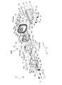
図1は、実施の形態1に係る照明装置1の斜視図である。また、図2は、実施の形態1に係る照明装置1の照明器具2と灯具3とを分割した分割斜視図である。さらに、図3は、実施の形態1に係る灯具3の斜視図である。また、図4は、実施の形態1に係る灯具3の一方の端部3Aにおける分解斜視図である。また、図5は、実施の形態1に係る照明装置1について、図1におけるA部を拡大した部分拡大斜視図である。また、図6は、実施の形態1に係る照明装置1の長手方向に直交する照明装置1の垂直断面を模式的に示した断面図である。図6は、図1のB部における断面図である。そして、図7は、実施の形態1に係る照明装置1について、図6におけるC部を部分拡大した断面図である。図1〜図7を参照して、実施の形態1に係る照明装置1の構成について説明を行う。
Embodiment 1.
<Configuration of lighting device 1>
FIG. 1 is a perspective view of the lighting device 1 according to the first embodiment. Further, FIG. 2 is a divided perspective view of the luminaire 2 and the lamp 3 of the luminaire 1 according to the first embodiment. Further, FIG. 3 is a perspective view of the lamp 3 according to the first embodiment. Further, FIG. 4 is an exploded perspective view of one end 3A of the lamp 3 according to the first embodiment. Further, FIG. 5 is a partially enlarged perspective view of the lighting device 1 according to the first embodiment, in which the portion A in FIG. 1 is enlarged. Further, FIG. 6 is a cross-sectional view schematically showing a vertical cross section of the illuminating device 1 orthogonal to the longitudinal direction of the illuminating device 1 according to the first embodiment. FIG. 6 is a cross-sectional view taken along the line B of FIG. FIG. 7 is a partially enlarged cross-sectional view of the portion C in FIG. 6 of the lighting device 1 according to the first embodiment. The configuration of the lighting device 1 according to the first embodiment will be described with reference to FIGS. 1 to 7.

ここで、以下の説明において、照明装置1の長手側に沿った方向を、第1方向となる長手方向Xとする。また、長手方向Xに直交し、長手方向Xに対する短手側に沿った方向を、第2方向となる短手方向Yとする。そして、長手方向Xおよび短手方向Yのいずれとも直交する方向を、第3方向となる上下方向Zとする。ここで、実施の形態1における上下方向Zは、鉛直方向であるものとする。また、長手方向Xにおいて、長手端部側への向きを、端向きX1とする。そして、端向きX1と反対側への向きであり、長手中央側への向きを、中向きX2とする。さらに、上下方向Zにおいて、照明装置1が取り付けられる造営部9の側(すなわち、天井または壁側)への向きを、上向きZ1とする。そして、上向きZ1と反対側への向きであり、照明装置1から光が照射される照射空間側への向きを、下向きZ2とする。ここで、上向きZ1は、灯具3が照明器具2に取り付けられる向きである。また、下向きZ2は、灯具3が照明器具2から取り外される向きである。 Here, in the following description, the direction along the longitudinal side of the lighting device 1 is referred to as the longitudinal direction X, which is the first direction. Further, the direction orthogonal to the longitudinal direction X and along the lateral side with respect to the longitudinal direction X is defined as the lateral direction Y which is the second direction. Then, the direction orthogonal to both the longitudinal direction X and the lateral direction Y is defined as the vertical direction Z which is the third direction. Here, it is assumed that the vertical direction Z in the first embodiment is the vertical direction. Further, in the longitudinal direction X, the direction toward the longitudinal end portion is defined as the end direction X1. Then, the direction is opposite to the end direction X1 and the direction toward the longitudinal center side is the middle direction X2. Further, in the vertical direction Z, the direction toward the side (that is, the ceiling or wall side) of the construction unit 9 to which the lighting device 1 is attached is defined as upward Z1. Then, the direction toward the side opposite to the upward Z1 and the direction toward the irradiation space side where the light is irradiated from the lighting device 1 is defined as the downward Z2. Here, the upward Z1 is the direction in which the lamp 3 is attached to the luminaire 2. Further, the downward Z2 is the direction in which the lamp 3 is removed from the luminaire 2.

実施の形態1における照明装置1は、天井または壁等の造営部9に取り付けられる照明器具2と照明器具2に装着される灯具3とを有する。実施の形態1では、いわゆるトラフタイプの照明器具2を例として示す。 The lighting device 1 in the first embodiment has a lighting fixture 2 attached to a construction portion 9 such as a ceiling or a wall, and a lighting fixture 3 attached to the lighting fixture 2. In the first embodiment, a so-called trough type luminaire 2 is shown as an example.

<照明器具2>
照明器具2は、灯具3が取り付けられる器具である。照明器具2は、器具本体20を有する。器具本体20は、実施の形態1では、金属製の板材を折り曲げて形成される。器具本体20は、照明器具2を天井等の造営部9に取り付けるための取付部である器具底面部21、2つで一組となる器具側面部22および2つで一組となる器具端部23を有する。器具底面部21は、長手方向Xに長尺、かつ、後述する開口面に対向して、長手方向Xおよび短手方向Yに延びる平板状に形成されている。器具底面部21は、短手方向Yにおける側縁部間の距離が最小幅となる。また、対となる2つで一組の器具側面部22は、器具底面部21の短手方向Yの両端に配置されている。また、2つで一組となる対の器具端部23は、器具底面部21の長手方向Xの両端に配置されている。また、図1、図2および図5に示すように、器具端部23には、ノックアウト24が形成され、後述する配線材85における電源線81等の各種電線を挿通する際に取り外される。
<Lighting fixture 2>
The lighting fixture 2 is a fixture to which the lighting fixture 3 is attached. The lighting fixture 2 has a fixture body 20. In the first embodiment, the instrument main body 20 is formed by bending a metal plate material. The fixture body 20 includes a fixture bottom portion 21, which is an attachment portion for attaching the lighting fixture 2 to a construction portion 9 such as a ceiling, a fixture side portion 22 which is a set of two, and a fixture end portion which is a set of two. 23. The instrument bottom surface portion 21 is formed in a flat plate shape that is long in the longitudinal direction X and extends in the longitudinal direction X and the lateral direction Y so as to face the opening surface described later. The minimum width of the instrument bottom surface portion 21 is the distance between the side edge portions in the lateral direction Y. Further, a pair of two pair of instrument side surface portions 22 are arranged at both ends of the instrument bottom surface portion 21 in the lateral direction Y. Further, a pair of instrument end portions 23, which are a set of two, are arranged at both ends of the instrument bottom surface portion 21 in the longitudinal direction X. Further, as shown in FIGS. 1, 2 and 5, a knockout 24 is formed at the end portion 23 of the appliance, and is removed when various electric wires such as a power line 81 in the wiring material 85 described later are inserted.

図2に示す装着部25は、装着された灯具3の一部を収容する収容部となる。装着部25は、器具本体20の器具底面部21、一組の器具側面部22および一組の器具端部23により、一面が開口した開口面を有する凹形状(箱形状)に形成される。このため、装着部25は、器具本体20の器具底面部21、一組の器具側面部22および一組の器具端部23で囲まれる空間を形成している。ここで、装着部25が収容する灯具3の一部は、照射側ではない非照射部となる。また、図6等に示すように、装着部25の空間のうち、灯具3が収容された状態で、灯具3に占有されていない部分は、後述する配線材85等が灯具3に接続される際に経由し、配置される配線領域となる。 The mounting portion 25 shown in FIG. 2 serves as a housing portion for accommodating a part of the mounted lamp 3. The mounting portion 25 is formed in a concave shape (box shape) having an opening surface with one open surface by the instrument bottom surface portion 21 of the instrument body 20, the instrument side surface portion 22 and the instrument end portion 23. Therefore, the mounting portion 25 forms a space surrounded by the instrument bottom surface portion 21, the instrument side surface portion 22, and the instrument end portion 23 of the instrument body 20. Here, a part of the lamp 3 accommodated by the mounting portion 25 is a non-irradiating portion that is not on the irradiation side. Further, as shown in FIG. 6 and the like, in the space of the mounting portion 25, in the portion where the lamp 3 is housed and not occupied by the lamp 3, the wiring material 85 or the like described later is connected to the lamp 3. It becomes a wiring area to be arranged via the case.

一組の器具側面部22は、長手方向Xにおける装着部25の周壁部であり、器具底面部21の長手方向Xに沿って並行するように、器具底面部21の側縁部を基端部として、対をなして立ち上がる側壁である。器具側面部22は、器具底面部21に対して垂直に立ち上がる第1側面部220と、第1側面部220の下端である屈曲部222から、短手方向Yにおける内側に向かって傾斜する第2側面部221とを有する。ここで、一組の器具側面部22において、第1側面部220間の距離は、短手方向Yにおける器具底面部21の最小幅となる側縁部間の距離と同じである。そして、第2側面部221間の距離は、短手方向Yにおける器具底面部21の側縁部間の距離よりも短くなる。このため、器具側面部22は、器具底面部21の幅の領域よりも内側に位置する。第2側面部221における下端の側は、短手方向Yにおける内側に巻かれて、カール状に曲げられたカール部223となっている。カール部223は、後述するように、一組の器具側面部22において、短手方向Yの間隔が最も狭い部分となる。カール部223の下端は、後述する開口端部26となり、上下方向Zにおいて、器具側面部22で最端となる部分となる。また、後述するようにカール部223の内側に巻かれた部分の端部と第2側面部221との間は隙間を有する。さらに、後述するように、カール部223の内側は、巻かれて形成されることで、捕捉溝224となる空間を有する。ここで、第2側面部221およびカール部223は、後述する灯具3の透光性カバー30に対向するように、端部カバー40が配置されない範囲に設けられる。 A set of instrument side surface portions 22 are peripheral wall portions of the mounting portion 25 in the longitudinal direction X, and the side edge portion of the instrument bottom surface portion 21 is a base end portion so as to be parallel to the instrument bottom surface portion 21 along the longitudinal direction X. It is a side wall that stands up in pairs. The instrument side surface portion 22 is a second inclined inward in the lateral direction Y from the first side surface portion 220 that rises perpendicularly to the instrument bottom surface portion 21 and the bent portion 222 that is the lower end of the first side surface portion 220. It has a side surface portion 221 and. Here, in the set of instrument side surface portions 22, the distance between the first side surface portions 220 is the same as the distance between the side edge portions which is the minimum width of the instrument bottom surface portion 21 in the lateral direction Y. Then, the distance between the second side surface portions 221 is shorter than the distance between the side edge portions of the instrument bottom surface portion 21 in the lateral direction Y. Therefore, the instrument side surface portion 22 is located inside the width region of the instrument bottom surface portion 21. The lower end side of the second side surface portion 221 is a curl portion 223 that is wound inward in the lateral direction Y and bent in a curl shape. As will be described later, the curl portion 223 is a portion of a set of instrument side surface portions 22 having the narrowest interval in the lateral direction Y. The lower end of the curl portion 223 becomes the opening end portion 26, which will be described later, and is the endmost portion of the instrument side surface portion 22 in the vertical direction Z. Further, as will be described later, there is a gap between the end portion of the portion wound inside the curl portion 223 and the second side surface portion 221. Further, as will be described later, the inside of the curl portion 223 has a space that becomes a catching groove 224 by being wound and formed. Here, the second side surface portion 221 and the curl portion 223 are provided in a range in which the end cover 40 is not arranged so as to face the translucent cover 30 of the lamp 3 described later.

器具本体20の下端に位置する開口端部26は、器具本体20において開口している部分の端部であり、器具側面部22の先端部となる。開口端部26は、照明器具2の装着部25に対して、灯具3の着脱を行う際の装着口となる。器具本体20の開口端部26において、長手方向Xの両端部には、連結部27が形成されている。連結部27には、灯具3が取り付けられる。灯具3が連結部27に取り付けられて支えられている。実施の形態1では、連結部27は、器具端部23と一体に形成されており、開口端部26から長手方向Xにおける中向きX2に向かって、折り曲げて形成されている。連結部27に形成されたネジ孔28は、灯具3に取り付けられた、後述する連結ネジ48がねじ止めされる孔である。灯具3は、連結ネジ48によって照明器具2にねじ止めされて固定される。 The open end portion 26 located at the lower end of the instrument main body 20 is the end portion of the portion of the instrument main body 20 that is open, and is the tip end portion of the instrument side surface portion 22. The opening end portion 26 serves as a mounting port for attaching / detaching the lamp 3 to / from the mounting portion 25 of the lighting fixture 2. In the open end portion 26 of the instrument main body 20, connecting portions 27 are formed at both ends in the longitudinal direction X. The lamp 3 is attached to the connecting portion 27. The lamp 3 is attached to and supported by the connecting portion 27. In the first embodiment, the connecting portion 27 is integrally formed with the instrument end portion 23, and is formed by bending from the opening end portion 26 toward the inward X2 in the longitudinal direction X. The screw hole 28 formed in the connecting portion 27 is a hole attached to the lamp 3 to which the connecting screw 48 described later is screwed. The lamp 3 is screwed to and fixed to the luminaire 2 by the connecting screw 48.

<灯具3>
次に、主として図3および図4を用いて灯具3について説明する。灯具3は、照明器具2に取り付けられることによって照明装置1を構成する。照明具および光源ユニットとなる灯具3は、長尺状に形成されており、照明器具2に装着されて使用される。実施の形態1では、灯具3は、照明器具2の長手方向Xにおける両端部において、後述する連結ネジ48によって照明器具2の連結部27に取り付けられる。実施の形態1の灯具3は、図2、図3および図6に示すように、主として、透光性カバー30、端部カバー40、発光部60等を有する。
<Lamp 3>
Next, the lamp 3 will be described mainly with reference to FIGS. 3 and 4. The lighting device 3 constitutes the lighting device 1 by being attached to the lighting device 2. The luminaire and the luminaire 3 serving as the light source unit are formed in a long shape and are used by being attached to the luminaire 2. In the first embodiment, the lamp 3 is attached to the connecting portion 27 of the lighting fixture 2 by the connecting screws 48 described later at both ends of the lighting fixture 2 in the longitudinal direction X. As shown in FIGS. 2, 3 and 6, the lamp 3 of the first embodiment mainly has a translucent cover 30, an end cover 40, a light emitting portion 60 and the like.

<透光性カバー30>
外郭となる透光性カバー30は、少なくとも可視光を透過する透光性の材料が用いられるカバーである。透光性カバー30は、後述する取付部材50、発光部60、制御部80等を内部の空間に収容して、保護する、筒形状となっている。透光性カバー30は、ガラス、ポリカーボネイト、アクリル等の樹脂材料を用いて形成することができる。また、透光性カバー30において、装着部25から外部に露出している部分は外観意匠部分にもなる。実施の形態1の透光性カバー30は、たとえば、押出成形によって筒形部材を形成し、製品の仕様等に応じて必要な長さに切断することで、製造することができる。
<Translucent cover 30>
The outer translucent cover 30 is a cover made of a translucent material that transmits at least visible light. The translucent cover 30 has a tubular shape that accommodates and protects the mounting member 50, the light emitting unit 60, the control unit 80, and the like, which will be described later, in the internal space. The translucent cover 30 can be formed by using a resin material such as glass, polycarbonate, or acrylic. Further, in the translucent cover 30, the portion exposed to the outside from the mounting portion 25 also serves as an exterior design portion. The translucent cover 30 of the first embodiment can be manufactured, for example, by forming a tubular member by extrusion molding and cutting it to a required length according to the specifications of the product or the like.

実施の形態1の灯具3では、図6に示すように、透光性カバー30のうち、装着部25から外部に露出している部分は、発光部60の照射側および取付部材50における台座51の表面を覆う外壁部となる外殻部になる。ここで、透光性カバー30において外部に露出した部分の外周部37については、外面部に対する法線の向きが、発光素子61の光軸に沿う向きから光軸に直交する向きまでの範囲内となっている。たとえば、照明装置1から下方に向けて光が照射されるように、灯具3が照明器具2に装着された場合において、透光性カバー30の装着部25から外部に露出している部分は、外面部が下方、斜め下方、あるいは側方(水平方向外側)に向いている。すなわち、透光性カバー30の装着部25から外部に露出している部分は、外面部が、上方、あるいは斜め上方に向いていない。また、透光性カバー30のうち、装着部25に収容され、外部に露出していない部分は、制御部80および台座51における取付面部52の制御部80が配置される側を覆う。そして、透光性カバー30のうち、装着部25に収容され、外部に露出していない部分の表面は、器具本体20の器具底面部21および一組の器具側面部22と対向する。ここで、透光性カバー30は、製品の仕様等に応じて、光拡散性、波長弁別性等を有するものであってもよい。また、透光性カバー30のうち、外部に露出していない部分については、反射性、遮光性等を有する材料を用いて形成してもよい。 In the lamp 3 of the first embodiment, as shown in FIG. 6, the portion of the translucent cover 30 exposed to the outside from the mounting portion 25 is the pedestal 51 on the irradiation side of the light emitting portion 60 and the mounting member 50. It becomes the outer shell part which becomes the outer wall part which covers the surface of. Here, with respect to the outer peripheral portion 37 of the portion of the translucent cover 30 exposed to the outside, the direction of the normal line with respect to the outer surface portion is within the range from the direction along the optical axis of the light emitting element 61 to the direction orthogonal to the optical axis. It has become. For example, when the lamp 3 is mounted on the luminaire 2 so that the light is emitted downward from the luminaire 1, the portion exposed to the outside from the mounting portion 25 of the translucent cover 30 is The outer surface faces downward, diagonally downward, or laterally (horizontally outward). That is, the outer surface portion of the portion of the translucent cover 30 exposed to the outside from the mounting portion 25 does not face upward or diagonally upward. Further, the portion of the translucent cover 30 housed in the mounting portion 25 and not exposed to the outside covers the side of the control unit 80 and the pedestal 51 on which the control unit 80 of the mounting surface portion 52 is arranged. The surface of the translucent cover 30 housed in the mounting portion 25 and not exposed to the outside faces the instrument bottom surface 21 of the instrument body 20 and the set of instrument side surfaces 22. Here, the translucent cover 30 may have light diffusivity, wavelength discrimination, and the like, depending on the specifications of the product and the like. Further, the portion of the translucent cover 30 that is not exposed to the outside may be formed by using a material having reflectivity, light shielding property, or the like.

実施の形態1に示す筒形の透光性カバー30は、図1から図6に示すように、内部に収容される機器を覆い、内部に収容される機器に対する位置によって、一組の並行部31、第1接続部32および第2接続部33に分かれている。一組の並行部31は、透光性カバー30において、一組の面が同じ距離で並行する面を形成している。透光性カバー30は、一組の並行部31の外側の面部分となる外面部および内側の面部分となる内面部が、それぞれ、ともに平面形状である。一組の外面部および一組の内面部は、透光性カバー30に収容される発光素子61の光軸に沿った平面である。実施の形態1では、この平面は、灯具3が照明器具2に装着された状態で、上下方向Zに沿っている。さらに、この平面は、一組の外面部および一組の内面部が、灯具3が照明器具2に装着された状態で、それぞれ対向する器具側面部22に沿った平面でもあり、それぞれ対向するカール部223に沿った平面でもある。そして、この平面は、灯具3が照明器具2に取り付けられる向きまたは照明器具2から取り外される向きに沿った平面にもなる。このため、透光性カバー30の並行部31は、短手方向Yにおいて、器具側面部22より外側にはならず、器具側面部22の内側に位置し、カール部223と対向する。並行部31のうち、灯具3が照明器具2に装着されたときに露出している部分は、灯具3の側方における照射部となる。また、実施の形態1の照明装置1において、一組の並行部31間の距離は、灯具における最も広い部分となる。 As shown in FIGS. 1 to 6, the tubular translucent cover 30 shown in the first embodiment covers a device housed inside, and a set of parallel portions depending on the position with respect to the device housed inside. It is divided into 31, a first connection portion 32 and a second connection portion 33. A set of parallel portions 31 forms surfaces in which a set of surfaces are parallel at the same distance in the translucent cover 30. In the translucent cover 30, both the outer surface portion which is the outer surface portion and the inner surface portion which is the inner surface portion of the set of parallel portions 31 have a planar shape. A set of outer surface portions and a set of inner surface portions are flat surfaces along the optical axis of the light emitting element 61 housed in the translucent cover 30. In the first embodiment, this plane is along the vertical direction Z with the lamp 3 attached to the luminaire 2. Further, this flat surface is also a flat surface along the side surface portions 22 of the fixtures in which the lamp 3 is attached to the lighting fixture 2 and the outer surface portion and the inner surface portion of the set are opposed to each other. It is also a plane along the portion 223. Then, this plane also becomes a plane along the direction in which the lamp 3 is attached to the luminaire 2 or the direction in which the lamp 3 is removed from the luminaire 2. Therefore, the parallel portion 31 of the translucent cover 30 is located inside the instrument side surface portion 22 and faces the curl portion 223, not outside the instrument side surface portion 22 in the lateral direction Y. The portion of the parallel portion 31 that is exposed when the lamp 3 is attached to the luminaire 2 becomes an irradiation portion on the side of the lamp 3. Further, in the lighting device 1 of the first embodiment, the distance between a set of parallel portions 31 is the widest portion in the lamp.

第1接続部32は、一組の並行部31における照射側の端部同士を繋いでいる部分であり、発光素子61の光軸と交わり、灯具3の主たる照射部となる。第1接続部32は、発光素子61からの光を下方に向けて照射する。第1接続部32の外面部および内面部は、1つまたは複数の面で構成されている。図6に示すように、実施の形態1では、透光性カバー30における第1接続部32の外面部および内面部が、1つの曲面で構成されている場合について説明する。ここで、第1接続部32の外面部および内面部が、複数の面で構成される場合は、複数の異なる曲率の複数の曲面、複数の異なる角度の複数の平面、これらの曲面と平面とを組み合わせて構成することができる。第2接続部33は、一組の並行部31における器具側の端部同士を繋いでいる部分であり、灯具3が照明器具2に装着された状態において、装着部25に収容される部分である。実施の形態1では、透光性カバー30における第2接続部33の外面部および内面部は、1つの曲面で構成されている場合について説明する。ここで、第2接続部33の外面部および内面部が、複数の面で構成される場合は、複数の異なる曲率の複数の曲面、複数の異なる角度の複数の平面、これらの曲面と平面とを組み合わせて構成することができる。 The first connection portion 32 is a portion of a set of parallel portions 31 that connects the ends on the irradiation side to each other, intersects the optical axis of the light emitting element 61, and serves as the main irradiation portion of the lamp 3. The first connection portion 32 irradiates the light from the light emitting element 61 downward. The outer surface portion and the inner surface portion of the first connecting portion 32 are composed of one or a plurality of surfaces. As shown in FIG. 6, in the first embodiment, a case where the outer surface portion and the inner surface portion of the first connection portion 32 of the translucent cover 30 are formed of one curved surface will be described. Here, when the outer surface portion and the inner surface portion of the first connecting portion 32 are composed of a plurality of surfaces, a plurality of curved surfaces having a plurality of different curvatures, a plurality of planes having a plurality of different angles, and these curved surfaces and planes. Can be combined and configured. The second connection portion 33 is a portion of a set of parallel portions 31 that connects the ends on the fixture side to each other, and is a portion that is accommodated in the mounting portion 25 when the lamp 3 is mounted on the lighting fixture 2. is there. In the first embodiment, a case where the outer surface portion and the inner surface portion of the second connecting portion 33 of the translucent cover 30 are formed of one curved surface will be described. Here, when the outer surface portion and the inner surface portion of the second connecting portion 33 are composed of a plurality of surfaces, a plurality of curved surfaces having a plurality of different curvatures, a plurality of planes having a plurality of different angles, and these curved surfaces and planes. Can be combined and configured.

配線材85は、外部から灯具3に接続される、電源線81、接地線82および制御線83等の各種配線を有する。また、これらの配線を接続する端子、配線保持具およびソケット等も配線材85とする。図6では、灯具3と接続される電源線81、接地線82および制御線83を、配線材85として示している。配線材85は、それぞれ絶縁材料で被包された各配線を被覆で一纏めにしたり、結束バンドで束ねたりした状態で、装着部25内の配線領域に配置されるようにしてもよい。また、各配線をバラバラに分離した状態で、装着部25内の配線領域に配置されるようにしてもよい。 The wiring material 85 has various wirings such as a power supply line 81, a grounding line 82, and a control line 83, which are connected to the lamp 3 from the outside. Further, the terminal, the wiring holder, the socket, and the like for connecting these wirings are also used as the wiring material 85. In FIG. 6, the power supply line 81, the ground line 82, and the control line 83 connected to the lamp 3 are shown as the wiring material 85. The wiring material 85 may be arranged in the wiring region in the mounting portion 25 in a state where each wiring wrapped with the insulating material is bundled with a coating or bundled with a binding band. Further, each wiring may be arranged in a wiring region in the mounting portion 25 in a state of being separated from each other.

実施の形態1においては、配線材85が、透光性カバー30に接触するものとして説明する。ただし、配線材85だけでなく、たとえば、施工場所に設けられる、灯具3外の送り配線および調光線等の電線材についても、配線領域内に配置されることで、被覆が接触する可能性がある。図示は省略するが、実施の形態1においては、透光性カバー30は、灯具3から照射される光を妨げない領域であって、配線材85の被覆が接触する可能性がある部分に可塑剤遮断部が設けられてもよい。 In the first embodiment, the wiring material 85 will be described as being in contact with the translucent cover 30. However, not only the wiring material 85, but also, for example, the electric wire material such as the feed wiring outside the lamp 3 and the light control light provided at the construction site may come into contact with the coating by being arranged in the wiring area. is there. Although not shown, in the first embodiment, the translucent cover 30 is a region that does not block the light emitted from the lamp 3, and is plasticized in a portion where the coating of the wiring material 85 may come into contact. An agent blocking portion may be provided.

図示は省略するが、透光性カバー30は、異なる材料を用いた複数の層からなる積層構造としてもよい。積層構造は、異種材料を用いた多色成形、塗布、或いは噴霧による基材表面に対する膜形成、基材表面に対する膜貼合等の方法によって形成することができる。この際、発光部60に近い層である内側層は、耐衝撃性、耐熱性、難燃性の面で優れた材料を用いて形成されることが好ましく、照射空間に近い層である外側層は、耐水性、耐薬品性、防汚性、帯電防止性、吸水率管理の面で優れた材料を用いて形成されることが好ましい。 Although not shown, the translucent cover 30 may have a laminated structure composed of a plurality of layers using different materials. The laminated structure can be formed by a method such as multicolor molding using different materials, coating, or spraying to form a film on the surface of the base material, or bonding the film to the surface of the base material. At this time, the inner layer, which is a layer close to the light emitting portion 60, is preferably formed by using a material having excellent impact resistance, heat resistance, and flame retardancy, and is an outer layer which is a layer close to the irradiation space. Is preferably formed using a material having excellent water resistance, chemical resistance, stain resistance, antistatic property, and water absorption rate control.

透光性カバー30は、たとえば、耐衝撃性に優れた材料を用いて内側層を形成した場合、発光部60を透光性カバー30の内部に収容する際に接触しても、損傷しにくくなる。また、たとえば、透光性カバー30は、難燃性に優れた材料を用いて内側層を形成した場合、発光部60由来の万が一の発火に際して、外部への類焼を防止することができる。 When the inner layer of the translucent cover 30 is formed of, for example, a material having excellent impact resistance, the translucent cover 30 is not easily damaged even if it comes into contact with the light emitting portion 60 when it is housed inside the translucent cover 30. Become. Further, for example, when the inner layer of the translucent cover 30 is formed by using a material having excellent flame retardancy, it is possible to prevent burning to the outside in the unlikely event of ignition from the light emitting portion 60.

透光性カバー30は、たとえば、加水分解が主鎖に及ばない材料を用いて外側層を形成した場合、或いは、吸水率が低い成分を用いて外側層を形成した場合、内側層には加水分解が進行しにくく、長期に渡って発光部60を保護する機能が保たれる。また、透光性カバー30は、吸水率が高い成分を用いて外側層を形成した場合、発光部60の動作熱の影響を受ける内側層の熱膨張量と吸水の影響を受ける外側層の吸水膨張量とをバランスさせることができるため、内側層と外側層とが剥離しにくくなる。 When the outer layer is formed by using a material whose main chain is not hydrolyzed, or when the outer layer is formed by using a component having a low water absorption rate, the translucent cover 30 has water added to the inner layer. Decomposition does not proceed easily, and the function of protecting the light emitting unit 60 is maintained for a long period of time. Further, when the outer layer of the translucent cover 30 is formed by using a component having a high water absorption rate, the amount of thermal expansion of the inner layer affected by the operating heat of the light emitting portion 60 and the water absorption of the outer layer affected by water absorption. Since the amount of expansion can be balanced, the inner layer and the outer layer are less likely to separate.

透光性カバー30は、たとえば、発光部60に近い層としてポリカーボネイト(PC)を主成分とする材料を用いて筒形部材を形成し、筒形部材における照射空間の側の表面にアクリル(PMMA)を主成分とする膜を形成した、異種材料積層構造とすることができる。 The translucent cover 30 forms, for example, a tubular member using a material containing polycarbonate (PC) as a main component as a layer close to the light emitting portion 60, and acrylic (PMMA) is formed on the surface of the tubular member on the irradiation space side. ) Can be formed into a film having a different material layered structure.

さらに、図示は省略するが、透光性カバー30の形状を安定させることまたは剛性を向上させること等を目的として、一組の並行部31において、それぞれ長手方向Xに渡るリブが設けられるようにしてもよい。この際、リブは、灯具3が照明器具2に装着された状態で、器具側面部22におけるカール部223付近と対向するような位置に形成される。ここで、透光性カバー30が、後述する端部カバー40と嵌合できるように、リブは、端部36の外面部には形成されない。 Further, although not shown, ribs extending in the longitudinal direction X are provided in each of the pair of parallel portions 31 for the purpose of stabilizing the shape of the translucent cover 30 or improving the rigidity. You may. At this time, the rib is formed at a position facing the vicinity of the curl portion 223 on the side surface portion 22 of the fixture with the lamp 3 attached to the lighting fixture 2. Here, the rib is not formed on the outer surface portion of the end portion 36 so that the translucent cover 30 can be fitted with the end cover 40 described later.

そして、図4に示すように、透光性カバー30は、取付部材50に配置された発光素子61の発光面を覆うと共に、取付部材50の長手方向に沿った長手方向Xとなる第1方向における端部36に、開口が形成されている。換言すれば、透光性カバー30は、少なくとも一方の端部36が開口する長尺形状の中空体であると共に、発光素子61が実装された基板62を内部に収容する。カバー端部35は、透光性カバー30の長手方向Xにおいて、透光性カバー30の両端部分である。透光性カバー30のカバー端部35には、端部36が設けられている。端部36は、カバー端部35において端部カバー40が嵌合される部分であり、端部蓋である端部カバー40に覆われる部分である。端部36は、透光性カバー30の伸縮に伴い、端部カバー40と共に長手方向Xである第1方向に沿って移動自在な自由端である。厳密には、透光性カバー30の端部36および端部カバー40は、「長手方向X」以外の方向にも伸縮するものであるが、実施の形態に係る灯具3においては、透光性カバー30は「長手方向X」の伸縮を許容する構造(構成)を有するものとする。図4および図6に示すように、透光性カバー30の外周部37は、一組の並行部31、第1接続部32および第2接続部33となる外殻部の外面側である。また、内周部38は、一組の並行部31、第1接続部32および第2接続部33となる外殻部の内面側である。 Then, as shown in FIG. 4, the translucent cover 30 covers the light emitting surface of the light emitting element 61 arranged on the mounting member 50, and is in the first direction X along the longitudinal direction of the mounting member 50. An opening is formed at the end portion 36 of the above. In other words, the translucent cover 30 is a long hollow body in which at least one end 36 is open, and houses a substrate 62 on which a light emitting element 61 is mounted. The cover end portions 35 are both end portions of the translucent cover 30 in the longitudinal direction X of the translucent cover 30. An end portion 36 is provided at the cover end portion 35 of the translucent cover 30. The end portion 36 is a portion where the end cover 40 is fitted in the cover end portion 35, and is a portion covered by the end cover 40 which is an end lid. The end portion 36 is a free end that can move along with the end cover 40 along the first direction, which is the longitudinal direction X, as the translucent cover 30 expands and contracts. Strictly speaking, the end portion 36 and the end portion cover 40 of the translucent cover 30 expand and contract in a direction other than the "longitudinal direction X", but in the lamp 3 according to the embodiment, the translucent property is used. The cover 30 shall have a structure (configuration) that allows expansion and contraction in the "longitudinal direction X". As shown in FIGS. 4 and 6, the outer peripheral portion 37 of the translucent cover 30 is the outer surface side of the outer shell portion serving as a set of parallel portions 31, the first connecting portion 32, and the second connecting portion 33. The inner peripheral portion 38 is the inner surface side of the outer shell portion that serves as a set of parallel portions 31, the first connecting portion 32, and the second connecting portion 33.

<端部カバー40の概要>
端部カバー40は、透光性カバー30の長手方向Xにおける両端部に取り付けられる。端部カバー40は、封止具43を挟んで嵌着または嵌合することによって、透光性カバー30を密閉構造とする。ここで、端部カバー40に取り付けられる取付部材50および透光性カバー30は、照明装置1の使用環境温度、灯具3の点灯時と消灯時とにおける温度の変化に対し、特に、長手方向Xにおける伸縮量が異なる。端部カバー40は、透光性カバー30の密閉を維持しながら、透光性カバー30および取付部材50の長手方向Xにおける端部同士が、相互に移動可能となるような構造となっている。
<Overview of end cover 40>
The end cover 40 is attached to both ends of the translucent cover 30 in the longitudinal direction X. The end cover 40 has a translucent cover 30 having a sealed structure by being fitted or fitted with the sealing tool 43 sandwiched between them. Here, the mounting member 50 and the translucent cover 30 attached to the end cover 40 are subjected to a change in the operating environment temperature of the lighting device 1 and the temperature when the lamp 3 is turned on and off, particularly in the longitudinal direction X. The amount of expansion and contraction is different. The end cover 40 has a structure in which the ends of the translucent cover 30 and the mounting member 50 in the longitudinal direction X can move to each other while maintaining the hermeticity of the translucent cover 30. ..

端部カバー40は、外カバーとなる第1端部カバー41と内カバーとなる第2端部カバー42とを有する。第1端部カバー41は、第1カバー貫通孔411、第1カバー連結孔412、連結ガイド413、カバー下面部414、カバー下面貫通孔415、カバー電線保持部416、カバー端面部417、カバー端面貫通孔418および端部カバー外周部419を有する。ここで、カバー下面貫通孔415は、図2に示すように、カバー蓋49によって覆われる。また、第2端部カバー42は、第2カバー主部420、端部カバー挿通部421、第2カバー係合片422、第2カバー係合爪423および端部カバー内周部425を有する。また、端部カバー挿通部421を形成する縁部に沿って、挿通壁421aが形成されている。ここで、実施の形態1の第1端部カバー41および第2端部カバー42は、樹脂材料を用いて形成されているものとして説明する。ただし、これに限定するものではない。樹脂材料以外の金属材料、セラミック材料等を用いて形成されてもよい。また、実施の形態1では、第1端部カバー41と第2端部カバー42とを別部材とし、嵌着または嵌合して一体化するようにしているが、あらかじめ一体化された1つの部材として成形するようにしてもよい。 The end cover 40 has a first end cover 41 as an outer cover and a second end cover 42 as an inner cover. The first end cover 41 includes a first cover through hole 411, a first cover connecting hole 412, a connecting guide 413, a cover lower surface portion 414, a cover lower surface through hole 415, a cover wire holding portion 416, a cover end surface portion 417, and a cover end surface. It has a through hole 418 and an end cover outer peripheral portion 419. Here, the cover lower surface through hole 415 is covered with the cover lid 49 as shown in FIG. Further, the second end cover 42 has a second cover main portion 420, an end cover insertion portion 421, a second cover engaging piece 422, a second cover engaging claw 423, and an end cover inner peripheral portion 425. Further, an insertion wall 421a is formed along the edge portion forming the end cover insertion portion 421. Here, the first end cover 41 and the second end cover 42 of the first embodiment will be described as being formed by using a resin material. However, it is not limited to this. It may be formed by using a metal material other than the resin material, a ceramic material, or the like. Further, in the first embodiment, the first end cover 41 and the second end cover 42 are made into separate members so as to be fitted or fitted to be integrated, but one that is integrated in advance. It may be molded as a member.

<封止具43>
封止具43は、透光性カバー30の長手方向Xにおける両端部と端部カバー40との間に挟まれた状態で、透光性カバー30の長手方向Xにおける両端部に配置される弾性部材である。弾性部材である封止具43は、透光性カバー30の端部36に取り付けられて端部36の開口を塞いでいる。封止具43は、樹脂材料を用いて製造されており、弾性変形するシール部材(ガスケット、パッキン等)である。そのため、封止具43は、透光性カバー30の長手方向Xにおける両端部と端部カバー40との間に挟まれた状態で、透光性カバー30の長手方向Xにおける両端部を密閉する。封止具43は、樹脂材料を用いて弾性変形するように形成されて、透光性カバー30および端部カバー40に密着する。
<Seal 43>
The sealant 43 is elastically arranged at both ends of the translucent cover 30 in the longitudinal direction X while being sandwiched between both ends of the translucent cover 30 in the longitudinal direction X and the end cover 40. It is a member. The sealant 43, which is an elastic member, is attached to the end portion 36 of the translucent cover 30 to close the opening of the end portion 36. The sealant 43 is a sealing member (gasket, packing, etc.) that is manufactured by using a resin material and is elastically deformed. Therefore, the sealant 43 seals both ends of the translucent cover 30 in the longitudinal direction X while being sandwiched between both ends of the translucent cover 30 in the longitudinal direction X and the end cover 40. .. The sealant 43 is formed by elastically deforming using a resin material, and is in close contact with the translucent cover 30 and the end cover 40.

封止具43は、封止具主部430、内周部435、外周部437および接続部436を有する。封止具43は、封止具主部430、内周部435、外周部437および接続部436が一体に形成されている。封止具主部430は、内周部435の内側を塞ぐように形成される。封止具主部430は、後述する固定具54の固定部56と第2端部カバー42の第2カバー主部420とに挟まれる。封止具主部430は、板状に形成されており、封止具43と端部カバー40とが係合した状態において、端部カバー40と対向する面側に、電線挿通部431と封止具筒状部433とが形成されている。封止具主部430は、封止具43と端部カバー40とが係合した状態において、第2端部カバー42の第2カバー主部420と当接する。電線挿通部431は、封止具43と端部カバー40とが係合した状態において、端部カバー40と対向する面側から突出しており、電源線81、接地線82および制御線83を通過させる電線挿通孔432を形成している。封止具筒状部433は、電線挿通部431を挟んで2つ設けられているが、封止具筒状部433の形成数は、固定具54の固定部56の数以上であれば、1つでもよく、3つ以上でもよい。封止具筒状部433は、封止具43と端部カバー40とが係合した状態において、端部カバー40と対向する面側から突出している。封止具筒状部433は、封止具43と固定具54とが係合した状態において、固定具54の固定部56から突出するボス部57が挿入される。封止具筒状部433は、円筒状に形成されている。封止具筒状部433の先端には、固定ネジ75をネジ止めするネジ挿通孔434が形成されている。 The sealing tool 43 has a sealing tool main portion 430, an inner peripheral portion 435, an outer peripheral portion 437, and a connecting portion 436. In the sealing tool 43, the sealing tool main portion 430, the inner peripheral portion 435, the outer peripheral portion 437, and the connecting portion 436 are integrally formed. The sealant main portion 430 is formed so as to close the inside of the inner peripheral portion 435. The sealant main portion 430 is sandwiched between the fixing portion 56 of the fixture 54, which will be described later, and the second cover main portion 420 of the second end cover 42. The sealant main portion 430 is formed in a plate shape, and when the sealant 43 and the end cover 40 are engaged with each other, the wire insertion portion 431 and the wire insertion portion 431 are sealed on the surface side facing the end cover 40. A stopper tubular portion 433 is formed. The sealant main portion 430 comes into contact with the second cover main portion 420 of the second end cover 42 in a state where the sealant 43 and the end cover 40 are engaged with each other. The electric wire insertion portion 431 projects from the surface side facing the end cover 40 in a state where the sealant 43 and the end cover 40 are engaged, and passes through the power supply line 81, the ground wire 82, and the control line 83. An electric wire insertion hole 432 is formed. Two sealant tubular portions 433 are provided with the electric wire insertion portion 431 interposed therebetween, but if the number of sealant tubular portions 433 formed is equal to or greater than the number of fixing portions 56 of the fixture 54, It may be one, or three or more. The sealing tool tubular portion 433 projects from the surface side facing the end cover 40 in a state where the sealing tool 43 and the end cover 40 are engaged with each other. A boss portion 57 protruding from the fixing portion 56 of the fixing tool 54 is inserted into the sealing tool tubular portion 433 in a state where the sealing tool 43 and the fixing tool 54 are engaged with each other. The sealing tool tubular portion 433 is formed in a cylindrical shape. A screw insertion hole 434 for screwing the fixing screw 75 is formed at the tip of the sealing tool tubular portion 433.

板状に形成された封止具主部430の周縁部には、内周部435が形成されている。内周部435は、弾性部材である封止具43が、第2端部カバー42および透光性カバー30と係合した状態において、第2端部カバー42の端部カバー内周部425と透光性カバー30の端部36の内周部38とに挟まれる部分である。 An inner peripheral portion 435 is formed on the peripheral portion of the sealing tool main portion 430 formed in a plate shape. The inner peripheral portion 435 is provided with the end cover inner peripheral portion 425 of the second end cover 42 in a state where the sealing tool 43, which is an elastic member, is engaged with the second end cover 42 and the translucent cover 30. It is a portion sandwiched between the inner peripheral portion 38 of the end portion 36 of the translucent cover 30.

封止具43の外周部437は、環状に形成されており、内周部38と対向するように内周部38の外側に配置される。この外周部437は、封止具43が、第1端部カバー41および透光性カバー30と係合した状態において、第1端部カバー41の外壁部410aと透光性カバー30の外周部37とに挟まれる部分である。 The outer peripheral portion 437 of the sealing tool 43 is formed in an annular shape, and is arranged outside the inner peripheral portion 38 so as to face the inner peripheral portion 38. The outer peripheral portion 437 is the outer peripheral portion of the outer wall portion 410a of the first end cover 41 and the translucent cover 30 in a state where the sealant 43 is engaged with the first end cover 41 and the translucent cover 30. It is a part sandwiched between 37 and 37.

封止具43の接続部436は、封止具主部430の内周部38と外周部437との間に位置する。接続部436は、封止具43が、第1端部カバー41および透光性カバー30と係合した状態において、第1端部カバー41の第1カバー主部410と透光性カバー30のカバー端部35とに挟まれる部分である。 The connecting portion 436 of the sealing tool 43 is located between the inner peripheral portion 38 and the outer peripheral portion 437 of the sealing tool main portion 430. The connection portion 436 is a state in which the sealant 43 is engaged with the first end cover 41 and the translucent cover 30, and the first cover main portion 410 and the translucent cover 30 of the first end cover 41 are engaged. It is a portion sandwiched between the cover end portion 35 and the cover end portion 35.

連結部材44は連結具であり、灯具3の長手方向Xの両端部に備えられており、灯具3を照明器具2に取り付けるための取付金具である。連結部材44は、固定部46の長手方向X(第1方向)における中央側(X2側)の面とボス部57の端面とが当接した状態で、2つの固定ネジ75を用いて固定具54に取り付けられて固定される。連結部材44は、端部カバー40に対して、ネジ等を用いた直接的な固定はされていない。連結部材44は、固定具54のボス部57に密着する封止具43を介して位置決めされて間接的に固定される。すなわち、連結部材44は、灯具3の長手方向Xである第1方向において、端部カバー40の外側に配置されると共に、一部が端部カバー40を貫通している取付部材50に固定されると共に、他の一部が照明器具2に固定される。実施の形態1では、連結部材44は、金属製の板材を折り曲げて形成されているものとする。ただし、連結部材44は、金属製の板材の折り曲げから形成されるものに限定されるものではなく、たとえば、樹脂、セラミック等、他の材料を用いて形成されてもよく、また、押出成形、積層造形等、他の方法で形成されてもよい。連結部材44は、連結部45と、固定部46と、係合部47とを有する。 The connecting member 44 is a connecting tool, and is provided at both ends of the lamp 3 in the longitudinal direction X, and is a mounting bracket for attaching the lamp 3 to the lighting device 2. The connecting member 44 is a fixture using two fixing screws 75 in a state where the central side (X2 side) surface of the fixing portion 46 in the longitudinal direction X (first direction) and the end surface of the boss portion 57 are in contact with each other. It is attached to 54 and fixed. The connecting member 44 is not directly fixed to the end cover 40 using screws or the like. The connecting member 44 is positioned and indirectly fixed via the sealing tool 43 that is in close contact with the boss portion 57 of the fixing tool 54. That is, the connecting member 44 is arranged outside the end cover 40 in the first direction, which is the longitudinal direction X of the lamp 3, and is partially fixed to the mounting member 50 penetrating the end cover 40. At the same time, the other part is fixed to the luminaire 2. In the first embodiment, it is assumed that the connecting member 44 is formed by bending a metal plate material. However, the connecting member 44 is not limited to that formed by bending a metal plate material, and may be formed by using other materials such as resin and ceramic, and may be extruded. It may be formed by another method such as laminated molding. The connecting member 44 has a connecting portion 45, a fixing portion 46, and an engaging portion 47.

連結部45は、固定部46において、下方側(Z2側)の端部から灯具3の端部側(X1側)に延設する板状の部材である。すなわち、連結部45は、固定部46の下縁部から突出する板状の部材である。連結部45は、端部カバー40と係合した状態において、端部カバー40側とは反対側に突出している。換言すれば、連結部45は、係合部47の突出方向とは反対側に突出している。連結部45は、灯具3が照明器具2に取り付けられている状態では、段差部450以外の上方の面が照明器具2の連結部27に当接する。 The connecting portion 45 is a plate-shaped member extending from the lower end (Z2 side) to the end side (X1 side) of the lamp 3 in the fixing portion 46. That is, the connecting portion 45 is a plate-shaped member protruding from the lower edge portion of the fixing portion 46. The connecting portion 45 projects to the side opposite to the end cover 40 side in a state of being engaged with the end cover 40. In other words, the connecting portion 45 projects in the direction opposite to the protruding direction of the engaging portion 47. In the state where the lamp 3 is attached to the luminaire 2, the upper surface of the connecting portion 45 other than the step portion 450 comes into contact with the connecting portion 27 of the luminaire 2.

連結部45には、面の高さが異なる段差部450が形成されており、段差部450には、連結ネジ48が挿入される連結ネジ挿通部451が形成されている。段差部450は、連結部45の短手方向Yの中央領域において一部下方(Z2側)に窪ませた部分である。連結部45の段差部450には、連結ネジ挿通部451を通過した連結ネジ48を固定する抜け止めワッシャ480が配置される。この抜け止めワッシャ480は、連結ネジ48から外れないように予め連結ネジ48に嵌着されている。段差部450の高さ(深さ、段差)寸法は、抜け止めワッシャ480の厚さ寸法と同じ寸法である。灯具3が照明器具2に取り付けられている状態では、抜け止めワッシャ480の上方(Z1側)の面が照明器具2の連結部27に当接し、抜け止めワッシャ480の下方(Z2側)の面は連結部材44の段差部450に当接する。段差部450の形状および面積は、抜け止めワッシャ480の形状および寸法を考慮して決定される。連結ネジ挿通部451は、段差部450の短手方向Yにおける略中央において、長手方向X(第1方向)における端部側(X1側)からスリット状に形成されている。連結ネジ挿通部451は、連結ネジ48のネジ本体部481より大きい幅寸法で形成されており、連結ネジ48のネジ本体部481が挿通する。連結ネジ挿通部451の形状はスリット状に限定されず、断面が楕円形を含む円形、多角形の貫通孔でもよい。 The connecting portion 45 is formed with stepped portions 450 having different surface heights, and the stepped portion 450 is formed with a connecting screw insertion portion 451 into which the connecting screw 48 is inserted. The step portion 450 is a portion of the connecting portion 45 that is partially recessed downward (Z2 side) in the central region in the lateral direction Y. A retaining washer 480 for fixing the connecting screw 48 that has passed through the connecting screw insertion portion 451 is arranged in the step portion 450 of the connecting portion 45. The retaining washer 480 is previously fitted to the connecting screw 48 so as not to come off from the connecting screw 48. The height (depth, step) dimension of the step portion 450 is the same as the thickness dimension of the retaining washer 480. In the state where the lamp 3 is attached to the luminaire 2, the upper surface (Z1 side) of the retaining washer 480 abuts on the connecting portion 27 of the luminaire 2, and the lower surface (Z2 side) of the retaining washer 480. Abuts on the stepped portion 450 of the connecting member 44. The shape and area of the step portion 450 are determined in consideration of the shape and dimensions of the retaining washer 480. The connecting screw insertion portion 451 is formed in a slit shape from the end side (X1 side) in the longitudinal direction X (first direction) at substantially the center of the step portion 450 in the lateral direction Y. The connecting screw insertion portion 451 is formed with a width dimension larger than that of the screw main body portion 481 of the connecting screw 48, and the screw main body portion 481 of the connecting screw 48 is inserted. The shape of the connecting screw insertion portion 451 is not limited to a slit shape, and may be a circular or polygonal through hole having an elliptical cross section.

固定部46は、連結部45において、長手方向X(第1方向)における中央側(X2側)の端部から上方に延びた部分である。固定部46は、板状の部材である。固定部46は、端部カバー40および封止具43を、取付部材50の固定具54と共に挟持する。固定部46には、固定ネジ75をネジ止めする固定ネジ挿通孔460が形成されている。固定ネジ挿通孔460は、ボス部57のネジ孔58にねじ込まれる固定ネジ75が挿通する貫通孔である。固定部46は、固定ネジ挿通孔460に挿入される固定ネジ75によってボス部57に取り付けられる。 The fixing portion 46 is a portion of the connecting portion 45 extending upward from the end portion on the central side (X2 side) in the longitudinal direction X (first direction). The fixing portion 46 is a plate-shaped member. The fixing portion 46 sandwiches the end cover 40 and the sealing tool 43 together with the fixing tool 54 of the mounting member 50. The fixing portion 46 is formed with a fixing screw insertion hole 460 for screwing the fixing screw 75. The fixing screw insertion hole 460 is a through hole through which the fixing screw 75 screwed into the screw hole 58 of the boss portion 57 is inserted. The fixing portion 46 is attached to the boss portion 57 by a fixing screw 75 inserted into the fixing screw insertion hole 460.

連結部材44には、電源線81、接地線82、制御線83等の電線を通過させる電線挿通孔470がスリット状に形成されている。電線挿通孔470は、上部スリット4710と、端部スリット4711とを有する。固定部46に形成されている電線挿通孔470を端部スリット4711と称する。端部スリット4711は、連結部材44の上下方向(Z軸方向)に形成されている。端部スリット4711は、係合部47に形成されている後述する上部スリット4710と繋がっている。 The connecting member 44 is formed with a slit-shaped electric wire insertion hole 470 through which electric wires such as a power supply line 81, a grounding wire 82, and a control line 83 pass. The wire insertion hole 470 has an upper slit 4710 and an end slit 4711. The electric wire insertion hole 470 formed in the fixed portion 46 is referred to as an end slit 4711. The end slit 4711 is formed in the vertical direction (Z-axis direction) of the connecting member 44. The end slit 4711 is connected to an upper slit 4710 formed in the engaging portion 47, which will be described later.

固定部46には、係合片挿通孔461が形成されてもよい。係合片挿通孔461は、第2端部カバー42の第2カバー係合片422および第2カバー係合爪423の断面形状に対応して、固定部46に設けられる貫通孔である。係合片挿通孔461は、透光性カバー30の伸長に伴い長手方向X(第1方向)に移動する第2端部カバー42の第2カバー係合片422および第2カバー係合爪423が、連結部材44の固定部46と干渉しないように、形成されている。係合片挿通孔461は、透光性カバー30の伸長の量、すなわち、第2カバー係合片422および第2カバー係合爪423の移動の量が小さい場合、あるいは、端部カバー40が一体形成されている場合等は不要であり、灯具3の必須の構成ではない。 The fixing portion 46 may be formed with an engaging piece insertion hole 461. The engaging piece insertion hole 461 is a through hole provided in the fixing portion 46 corresponding to the cross-sectional shape of the second cover engaging piece 422 and the second cover engaging claw 423 of the second end cover 42. The engaging piece insertion hole 461 is the second cover engaging piece 422 and the second cover engaging claw 423 of the second end cover 42 that move in the longitudinal direction X (first direction) as the translucent cover 30 extends. Is formed so as not to interfere with the fixing portion 46 of the connecting member 44. The engaging piece insertion hole 461 has a small amount of extension of the translucent cover 30, that is, a small amount of movement of the second cover engaging piece 422 and the second cover engaging claw 423, or the end cover 40 It is not necessary when it is integrally formed, and it is not an essential configuration of the lamp 3.

係合部47は、固定部46において、上方側(Z1側)の端部から長手方向X(第1方向)における中央側(X2側)に延びた部分である。すなわち、係合部47は、固定部46の上縁部から突出する板状の部材である。係合部47は、端部カバー40と係合した状態において、端部カバー40側に突出しており、灯具3において、灯具3の上方側(Z1側)に配置される。 The engaging portion 47 is a portion of the fixed portion 46 extending from the end portion on the upper side (Z1 side) to the central side (X2 side) in the longitudinal direction X (first direction). That is, the engaging portion 47 is a plate-shaped member protruding from the upper edge portion of the fixing portion 46. The engaging portion 47 projects toward the end cover 40 in a state of being engaged with the end cover 40, and is arranged on the upper side (Z1 side) of the lamp 3 in the lamp 3.

上述したように、連結部材44には、電源線81、接地線82、制御線83等の電線を通過させる電線挿通孔470がスリット状に形成されている。係合部47に形成されている電線挿通孔470を上部スリット4710と称する。上部スリット4710は、灯具3の長手方向Xに沿って形成されている。上部スリット4710は、固定部46に形成された端部スリット4711と繋がっている。上部スリット4710は、透光性カバー30の端部36および端部カバー40を、長手方向X(第1方向)の移動が規制されない自由端とするために、連結部材44の係合部47に形成されたスリットである。上部スリット4710には、後述する挿入孔472から挿入されるカバー電線保持部416が、短手方向Yおよび上下方向Zに移動が規制された状態で係合する。なお、挿入孔472に配置されるカバー電線保持部416は、長手方向X(第1方向)には移動が規制されない。上部スリット4710に、カバー電線保持部416が係合した状態では、連結部材44の端部カバー40に対する位置が決まるので、固定ネジ75を用いて連結部材44をボス部57に固定する際に固定ネジ75の位置合わせがしやすくなる。電源線81、接地線82、制御線83の全てまたは一部を編組チューブ等で束線した状態では、一般的に硬くなり曲がり難くなる。しかし、連結部材44は、上部スリット4710と繋がるように形成された端部スリット4711を有することにより、電源線81等が束線されて曲がり難くなっても、配線がし易くなる。 As described above, the connecting member 44 is formed with a slit-shaped electric wire insertion hole 470 through which the electric wires such as the power supply line 81, the grounding wire 82, and the control line 83 pass. The electric wire insertion hole 470 formed in the engaging portion 47 is referred to as an upper slit 4710. The upper slit 4710 is formed along the longitudinal direction X of the lamp 3. The upper slit 4710 is connected to the end slit 4711 formed in the fixing portion 46. The upper slit 4710 fits into the engaging portion 47 of the connecting member 44 so that the end 36 and the end cover 40 of the translucent cover 30 are free ends where movement in the longitudinal direction X (first direction) is not restricted. It is a formed slit. The cover wire holding portion 416 inserted from the insertion hole 472, which will be described later, engages with the upper slit 4710 in a state where movement is restricted in the lateral direction Y and the vertical direction Z. The movement of the cover electric wire holding portion 416 arranged in the insertion hole 472 is not restricted in the longitudinal direction X (first direction). When the cover electric wire holding portion 416 is engaged with the upper slit 4710, the position of the connecting member 44 with respect to the end cover 40 is determined. Therefore, the connecting member 44 is fixed to the boss portion 57 by using the fixing screw 75. It becomes easy to align the screw 75. When all or part of the power line 81, the ground line 82, and the control line 83 are bundled with a braided tube or the like, they are generally hard and difficult to bend. However, since the connecting member 44 has the end slit 4711 formed so as to be connected to the upper slit 4710, even if the power supply line 81 or the like is bundled and becomes difficult to bend, wiring becomes easy.

係合部47には、後述するカバー電線保持部416が挿入される挿入孔472が形成されている。挿入孔472は、上部スリット4710と連続して形成されている。挿入孔472は、固定部46に形成されている貫通孔であり、上部スリット4710の長手方向X(第1方向)における中央側(X2側)と繋がって形成されている。挿入孔472は、カバー電線保持部416が挿入可能な形状および寸法で形成されている。挿入孔472から挿入されたカバー電線保持部416は、透光性カバー30の伸長に応じて、上部スリット4710と係合した状態で、長手方向Xに沿って移動する。そのためカバー電線保持部416は、透光性カバー30の伸縮、および透光性カバー30の伸縮に伴う端部カバー40および封止具43の移動を妨げない。 The engaging portion 47 is formed with an insertion hole 472 into which the cover electric wire holding portion 416, which will be described later, is inserted. The insertion hole 472 is formed continuously with the upper slit 4710. The insertion hole 472 is a through hole formed in the fixing portion 46, and is formed by being connected to the central side (X2 side) in the longitudinal direction X (first direction) of the upper slit 4710. The insertion hole 472 is formed in a shape and size into which the cover electric wire holding portion 416 can be inserted. The cover wire holding portion 416 inserted from the insertion hole 472 moves along the longitudinal direction X in a state of being engaged with the upper slit 4710 in accordance with the extension of the translucent cover 30. Therefore, the cover wire holding portion 416 does not hinder the expansion and contraction of the translucent cover 30 and the movement of the end cover 40 and the sealant 43 due to the expansion and contraction of the translucent cover 30.

<取付部材50>
取付部材50は、図4および図6に示すように、発光部60および制御部80等を透光性カバー30内の空間に固定させる部材である。また、取付部材50は、透光性カバー30の両端部に取り付けられた端部カバー40および連結部材44に取付部材50を固定する部材である。取付部材50は、台座51と、固定具54と、を有する。取付部材50は、透光性カバー30に収容される。そして、取付部材50は、図4に示すように、固定ネジ75によって、端部カバー40および連結部材44に固定される。したがって、取付部材50は、透光性カバー30には直接固定されていないが、透光性カバー30の長手方向Xにおける両側のカバー端部35に嵌合または嵌着している端部カバー40を介して透光性カバー30と繋がっている。
<Mounting member 50>
As shown in FIGS. 4 and 6, the mounting member 50 is a member that fixes the light emitting unit 60, the control unit 80, and the like in the space inside the translucent cover 30. Further, the mounting member 50 is a member for fixing the mounting member 50 to the end cover 40 and the connecting member 44 attached to both ends of the translucent cover 30. The mounting member 50 has a pedestal 51 and a fixture 54. The mounting member 50 is housed in the translucent cover 30. Then, as shown in FIG. 4, the mounting member 50 is fixed to the end cover 40 and the connecting member 44 by the fixing screw 75. Therefore, although the mounting member 50 is not directly fixed to the translucent cover 30, the end cover 40 is fitted or fitted to the cover ends 35 on both sides of the translucent cover 30 in the longitudinal direction X. It is connected to the translucent cover 30 via.

台座51は、取付部材50の主たる部分であり、発光部60および制御部80等が取り付けられる。実施の形態1では、台座51は、金属製の板材を折り曲げて形成されているものとする。ただし、台座51は、金属製の板材を折り曲げて形成されたものに限定するものではなく、たとえば、樹脂、セラミック等、金属以外の材料を用いて形成されたものでもよく、また、押出成形、積層造形等、他の方法で形成されたものでもよい。また、図示は省略するが、放熱効率(熱放射率)、あるいは、光の利用効率(反射率)等を向上させるために、台座51に表面処理を施し、あるいは、台座51に機能部材を敷設してもよい。台座51は、取付面部52と、側部53とを有する。台座51の取付面部52は、長尺の平板状に形成されており、照射側の面である表面には、発光部60が取り付けられる。また、器具側の面である裏面には、電源装置等の制御部80が取り付けられる。 The pedestal 51 is a main portion of the mounting member 50, and a light emitting unit 60, a control unit 80, and the like are mounted. In the first embodiment, it is assumed that the pedestal 51 is formed by bending a metal plate material. However, the pedestal 51 is not limited to the one formed by bending a metal plate material, and may be formed by using a material other than metal such as resin and ceramic, and may be extruded. It may be formed by another method such as laminated molding. Although not shown, the pedestal 51 is surface-treated or a functional member is laid on the pedestal 51 in order to improve heat dissipation efficiency (heat emissivity) or light utilization efficiency (reflectivity). You may. The pedestal 51 has a mounting surface portion 52 and a side portion 53. The mounting surface portion 52 of the pedestal 51 is formed in a long flat plate shape, and the light emitting portion 60 is mounted on the surface which is the surface on the irradiation side. Further, a control unit 80 such as a power supply device is attached to the back surface, which is the surface on the instrument side.

図4に示すように、台座51の取付面部52には、ネジ孔520が形成されている。ネジ孔520は、取付面部52の長手方向Xの両端部に形成されている。このネジ孔520には、取付部材50を端部カバー40および連結部材44に固定するための固定ネジ75が挿入される。取付面部52には、給電線84等を通過させる切り欠き部521が形成されている。切り欠き521部は、取付面部52の長手方向Xの両端部において、取付面部52の縁部に形成されている。ここで、灯具3の他方の端部における、取付面部52には、切り欠き部521が形成されている代わりに、貫通孔である装着孔が形成されている。 As shown in FIG. 4, a screw hole 520 is formed in the mounting surface portion 52 of the pedestal 51. The screw holes 520 are formed at both ends of the mounting surface portion 52 in the longitudinal direction X. A fixing screw 75 for fixing the mounting member 50 to the end cover 40 and the connecting member 44 is inserted into the screw hole 520. The mounting surface portion 52 is formed with a notch portion 521 through which the feeding line 84 and the like are passed. The cutouts 521 are formed at the edges of the mounting surface 52 at both ends of the mounting surface 52 in the longitudinal direction X. Here, the mounting surface portion 52 at the other end of the lamp 3 is formed with a mounting hole, which is a through hole, instead of being formed with a notch portion 521.

台座51の側部53は、取付面部52の短手方向Yの両端部分から照射側に折り曲げられて立ち上がった部分である。側部53は、取付面部52の長手方向Xに沿って取付面部52の縁部から立設していることで、台座51の剛性を向上させる。実施の形態1では、側部53は、制御部80等が配置される器具側だけに立設させている。しかし、側部53は、発光部60が配置される照射側だけに立設させてもよく、あるいは、照射側および器具側の両方に立設させてもよい。また、実施の形態1では、側部53は、取付面部52の短手方向Yの両端部分に立設させているが、たとえば、取付面部52の短手方向Yにおける中央部分等、両端部分以外の位置に立ち上がるように設置させてもよい。 The side portion 53 of the pedestal 51 is a portion of the mounting surface portion 52 that is bent toward the irradiation side from both ends in the lateral direction Y and rises. The side portion 53 is erected from the edge portion of the mounting surface portion 52 along the longitudinal direction X of the mounting surface portion 52, thereby improving the rigidity of the pedestal 51. In the first embodiment, the side portion 53 is erected only on the instrument side on which the control unit 80 and the like are arranged. However, the side portion 53 may be erected only on the irradiation side where the light emitting portion 60 is arranged, or may be erected on both the irradiation side and the instrument side. Further, in the first embodiment, the side portions 53 are erected at both end portions of the mounting surface portion 52 in the lateral direction Y, but other than both end portions such as the central portion of the mounting surface portion 52 in the lateral direction Y. It may be installed so as to stand up at the position of.

固定具54は、台座51の長手方向Xの両端部分に配置されており、透光性カバー30の両端部に取り付けられた端部カバー40および連結部材44に取付部材50を固定する部材である。固定具54は、端部カバー40を貫通すると共に連結部材44が固定される。ここで、実施の形態1では、固定具54は台座51と別部材で構成されているが、固定具54の構成は、当該構成に限定するものではない。たとえば、台座51の両端部分を折り曲げる等して、台座51と固定具54とを一体に形成し、台座51が固定具54と同じ機能をもつ部分を有するようにしてもよい。固定具54は、取付ネジ(図示は省略)等の固定部材を用いて台座51に取り付けてもよい。 The fixture 54 is arranged at both ends of the pedestal 51 in the longitudinal direction X, and is a member for fixing the attachment member 50 to the end cover 40 and the connecting member 44 attached to both ends of the translucent cover 30. .. The fixture 54 penetrates the end cover 40 and the connecting member 44 is fixed. Here, in the first embodiment, the fixture 54 is composed of a member different from the pedestal 51, but the configuration of the fixture 54 is not limited to the configuration. For example, both ends of the pedestal 51 may be bent to integrally form the pedestal 51 and the fixture 54 so that the pedestal 51 has a portion having the same function as the fixture 54. The fixture 54 may be attached to the pedestal 51 by using a fixing member such as a mounting screw (not shown).

固定具54は、取付部55と、固定部56とを有しており、板金を折り曲げることによって製造している。ここで、固定具54は、金具であるが、金具に限定するものではなく、たとえば、樹脂またはセラミック等、他の材料を用いて形成されてもよく、また、押出成形または積層造形等、他の方法で形成されたものでもよい。 The fixture 54 has a mounting portion 55 and a fixing portion 56, and is manufactured by bending a sheet metal. Here, the fixture 54 is a metal fitting, but is not limited to the metal fitting, and may be formed by using another material such as resin or ceramic, and may be formed by extrusion molding, laminated molding, or the like. It may be formed by the method of.

固定具54の取付部55は、固定具54を台座51に取り付ける部分であり、固定ネジ75を用いて台座51の両端部分に固定される。取付部55は、たとえば、カシメ、溶着、溶接、嵌着または係着等の方法で、台座51と構造的に一体化されてもよい。 The attachment portion 55 of the fixture 54 is a portion for attaching the fixture 54 to the pedestal 51, and is fixed to both end portions of the pedestal 51 by using fixing screws 75. The mounting portion 55 may be structurally integrated with the pedestal 51 by, for example, caulking, welding, welding, fitting or engaging.

固定具54の固定部56は、連結部材44の固定部46と共に端部カバー40と封止具43とを挟持する。すなわち、透光性カバー30と、封止具43と、端部カバー40と、連結部材44とが組み合わされた状態において、固定部56と連結部材44の固定部46との間には、封止具43が配置されている。固定部56には、ボス部57が設けられている。 The fixing portion 56 of the fixing tool 54 sandwiches the end cover 40 and the sealing tool 43 together with the fixing portion 46 of the connecting member 44. That is, in a state where the translucent cover 30, the sealing tool 43, the end cover 40, and the connecting member 44 are combined, the fixing portion 56 and the fixing portion 46 of the connecting member 44 are sealed. The stopper 43 is arranged. The fixed portion 56 is provided with a boss portion 57.

ボス部57は、たとえば、カシメ、溶着(溶接)または嵌着(係着)等の方法によって固定部56に取り付けられている。ボス部57には、固定ネジ75がねじ込まれるネジ孔58が形成されている。ネジ孔58の内周側には、ネジ溝が形成されている。そして、連結部材44の外側から、連結部材44の固定ネジ挿通孔460、第2端部カバー42の端部カバー挿通部421、第1端部カバー41の第1カバー貫通孔411および封止具43のネジ挿通孔434に固定ネジ75が挿通される。そして固定ネジ75が、ボス部57のネジ孔58にねじ込まれて、連結部材44は取付部材50の固定具54に固定される。すなわち、連結部材44が固定されるのは、固定具54のボス部57である。 The boss portion 57 is attached to the fixing portion 56 by, for example, caulking, welding (welding), or fitting (engagement). The boss portion 57 is formed with a screw hole 58 into which the fixing screw 75 is screwed. A screw groove is formed on the inner peripheral side of the screw hole 58. Then, from the outside of the connecting member 44, the fixing screw insertion hole 460 of the connecting member 44, the end cover insertion portion 421 of the second end cover 42, the first cover through hole 411 of the first end cover 41, and the sealing tool. The fixing screw 75 is inserted into the screw insertion hole 434 of 43. Then, the fixing screw 75 is screwed into the screw hole 58 of the boss portion 57, and the connecting member 44 is fixed to the fixture 54 of the mounting member 50. That is, the connecting member 44 is fixed to the boss portion 57 of the fixture 54.

<発光部60>
発光部60は、図6に示すように、発光素子61、基板62等を有する。発光素子61は、電力供給により発光する。実施の形態1では、発光素子61として、発光ダイオード(Light Emitting Diode;以下、LEDと称す)素子を用いており、基板62の実装面に、長手方向Xに沿って、列状、千鳥状等に実装される。そして、実施の形態1の発光素子61は、波長が440〜480〔nm〕の青色光を出射するLEDチップ上に、青色光を黄色光に波長変換する蛍光体を配して、パッケージ化された面実装部品である疑似白色LED素子である。ここで、発光素子61が出射する光は、光束値が最大であり、発光面に垂直な光軸に対して、対称に照射角αだけ広がる。実施の形態1の照明装置1では、発光素子61の照射角αは、120度であるものとする。発光素子61は、固体レーザ(Solid State Laser)、半導体レーザ(Semiconductor Laser)、有機EL(Electro Luminescence)、無機EL等を用いてもよい。基板62は、ガラス−エポキシ基板(FR−4)、ガラス−コンポジット基板(CEM−3)、紙エポキシ基板(FR−3)、紙フェノール基板(XPC)、金属ベース基板等が用いられる。
<Light emitting unit 60>
As shown in FIG. 6, the light emitting unit 60 includes a light emitting element 61, a substrate 62, and the like. The light emitting element 61 emits light by supplying electric power. In the first embodiment, a light emitting diode (Light Emitting Diode; hereinafter referred to as an LED) element is used as the light emitting element 61, and the mounting surface of the substrate 62 is formed in a row shape, a staggered shape, or the like along the longitudinal direction X. Is implemented in. The light emitting element 61 of the first embodiment is packaged by arranging a phosphor that converts blue light into yellow light on an LED chip that emits blue light having a wavelength of 440 to 480 [nm]. It is a pseudo-white LED element that is a surface mount component. Here, the light emitted by the light emitting element 61 has the maximum luminous flux value, and spreads by the irradiation angle α symmetrically with respect to the optical axis perpendicular to the light emitting surface. In the lighting device 1 of the first embodiment, the irradiation angle α of the light emitting element 61 is assumed to be 120 degrees. As the light emitting element 61, a solid-state laser (Solid State Laser), a semiconductor laser (Semiconducor Laser), an organic EL (Electro Luminescence), an inorganic EL, or the like may be used. As the substrate 62, a glass-epoxy substrate (FR-4), a glass-composite substrate (CEM-3), a paper epoxy substrate (FR-3), a paper phenol substrate (XPC), a metal base substrate and the like are used.

制御部80は、電源装置であり、外部から供給される電力から発光素子61を点灯させる電力に変換して、発光素子61に供給する。実施の形態1の照明装置1では、制御部80は、前述したように、台座51の取付面部52の裏面に、ネジ(図示は省略)等の固定部材を用いて取り付けられた状態で、発光素子61等と共に筒状の透光性カバー30に収容されている。ただし、制御部80は、灯具3ではなく、照明器具2に取り付けられる構成であってもよい。この場合、電線は、制御部80から発光素子61に供給される電力の供給経路として機能する給電線となる。実施の形態1の照明装置1における電源線81、接地線82および制御線83等の電線は、一端は、制御部80に接続される。そして、電線の他端は、照明器具2に取り付けられている端子台(図示は省略)に接続される。 The control unit 80 is a power supply device, converts electric power supplied from the outside into electric power for lighting the light emitting element 61, and supplies the electric power to the light emitting element 61. In the lighting device 1 of the first embodiment, as described above, the control unit 80 emits light in a state of being attached to the back surface of the attachment surface portion 52 of the pedestal 51 by using a fixing member such as a screw (not shown). It is housed in a tubular translucent cover 30 together with the element 61 and the like. However, the control unit 80 may be attached to the luminaire 2 instead of the lamp 3. In this case, the electric wire becomes a feeder function as a supply path of electric power supplied from the control unit 80 to the light emitting element 61. One end of the electric wires such as the power supply line 81, the ground wire 82, and the control line 83 in the lighting device 1 of the first embodiment is connected to the control unit 80. The other end of the electric wire is connected to a terminal block (not shown) attached to the luminaire 2.

ここで、図6において、P1は、器具底面部21と器具側面部22との境界となる器具側面部22が折り曲がって立ち上がった部分における内側の部分である。距離W4は、一組の器具側面部22における2つのP1の間の距離であり、短手方向Yにおける器具底面部21の幅となる。そして、距離W5は、一組の器具側面部22におけるカール部223の内側に巻かれた部分の端部間の距離である。 Here, in FIG. 6, P1 is an inner portion in a portion where the instrument side surface portion 22 which is a boundary between the instrument bottom surface portion 21 and the instrument side surface portion 22 is bent and stands up. The distance W4 is the distance between two P1s on the side surface portion 22 of the instrument, and is the width of the bottom surface portion 21 of the instrument in the lateral direction Y. The distance W5 is the distance between the ends of the curl portion 223 of the set of instrument side surface portions 22 that are wound inside.

また、P2は、第2側面部221の折り曲げ部分である。距離W1は、一組の器具側面部22における2つのP2間の距離である。さらに、P3は、器具側面部22における下端部分となる。ここでは、P3は、開口端部26の位置となる。距離W2は、一組の器具側面部22における2つのP3間の距離である。また、P4は、カール部223において、短手方向Y(第2方向)の最も内側に位置する側面最狭部である。距離W3は、一組の器具側面部22における2つのP4間の距離である。ここで、距離W1、距離W2および距離W3は、W1>W2>W3の関係にある。そして、P6は、透光性カバー30の外周部37において、一組の器具側面部22における側面最狭部P4と対向し、透光性カバー30の短手方向Yにおける幅が最も広いカバー最広部である。ここでは、P6は、外周部37の並行部31の部分となる。距離W6は、2つのカバー最広部P6間の距離である。 Further, P2 is a bent portion of the second side surface portion 221. The distance W1 is the distance between two P2s on a set of instrument side surfaces 22. Further, P3 is a lower end portion of the instrument side surface portion 22. Here, P3 is the position of the opening end portion 26. The distance W2 is the distance between two P3s on a set of instrument side surfaces 22. Further, P4 is the narrowest side surface portion of the curl portion 223 located on the innermost side in the lateral direction Y (second direction). The distance W3 is the distance between the two P4s in the set of instrument side surfaces 22. Here, the distance W1, the distance W2, and the distance W3 have a relationship of W1> W2> W3. Then, P6 faces the narrowest side surface portion P4 of the set of instrument side surface portions 22 on the outer peripheral portion 37 of the translucent cover 30, and is the widest cover maximum in the lateral direction Y of the translucent cover 30. It is a wide area. Here, P6 is a portion of the parallel portion 31 of the outer peripheral portion 37. The distance W6 is the distance between the two widest covers P6.

図6および図7に示すように、灯具3が照明器具2の装着部25に装着された状態において、透光性カバー30の外周部37は、照明器具2と最も近接する部分となる。外周部37の並行部31におけるカバー最広部P6とカール部223の側面最狭部P4とは、寸法T2の隙間を有し、対向して配置される。ここで、寸法T2は、(距離W3−距離W6)/2となる。また、開口端部26となるP3は、短手方向Yにおいて側面最狭部P4よりも外側に位置する。 As shown in FIGS. 6 and 7, when the lamp 3 is mounted on the mounting portion 25 of the lighting fixture 2, the outer peripheral portion 37 of the translucent cover 30 is the portion closest to the lighting fixture 2. The widest cover portion P6 in the parallel portion 31 of the outer peripheral portion 37 and the narrowest side portion P4 of the curl portion 223 have a gap of dimension T2 and are arranged so as to face each other. Here, the dimension T2 is (distance W3-distance W6) / 2. Further, P3, which is the opening end portion 26, is located outside the narrowest side portion P4 in the lateral direction Y.

したがって、実施の形態1の照明装置1では、カバー最広部P6は、短手方向Yにおいて、開口端部26が位置するP3とも離れた位置にある。このため、カバー最広部を有する透光性カバー30の並行部31における外周部37と側面最狭部を有するカール部223(特に開口端部26)とは、上下方向Zから見たときに、重ならない位置関係にある。このため、図7の実線矢印で示すように、器具本体20における器具側面部22の外面に付着し、流下した流体は、器具側面部22において下端である開口端部26から下方に滴下する。透光性カバー30の外周部37と器具側面部22の開口端部26は、上下方向Zにおいて重なっていない位置関係にあるため、開口端部26から流下した流体は、外周部37には滴下しない。このため、流体が流下しても、灯具3を構成する外郭である透光性カバー30には付着しない。 Therefore, in the lighting device 1 of the first embodiment, the widest cover portion P6 is located at a position away from P3 where the opening end portion 26 is located in the lateral direction Y. Therefore, the outer peripheral portion 37 and the curl portion 223 (particularly the opening end portion 26) having the narrowest side surface portion of the parallel portion 31 of the translucent cover 30 having the widest portion of the cover are viewed from the vertical direction Z. , There is a positional relationship that does not overlap. Therefore, as shown by the solid arrow in FIG. 7, the fluid adhering to the outer surface of the instrument side surface portion 22 of the instrument body 20 and flowing down is dropped downward from the opening end portion 26 which is the lower end of the instrument side surface portion 22. Since the outer peripheral portion 37 of the translucent cover 30 and the open end portion 26 of the instrument side surface portion 22 are not overlapped in the vertical direction Z, the fluid flowing down from the open end portion 26 drops on the outer peripheral portion 37. do not do. Therefore, even if the fluid flows down, it does not adhere to the translucent cover 30 which is the outer shell constituting the lamp 3.

また、側面最狭部P4であるカール部223とカバー最広部P6である外周部37の並行部31とは、寸法T2の隙間を有し、対向して配置される。ここで、寸法T2は、(距離W3−距離W6)/2となる。このため、図7の破線矢印で示すように、透光性カバー30の外周部37において、装着部25に収容されている部分に付着し、流下した流体は、寸法T2の隙間を介して並行部31を流下する。したがって、流体が装着部25の内部に滞留することおよび装着部25に滞留した流体が乾燥固化することを抑制できる。ここで、照明装置1を下方から見上げたときに、照明器具2(カール部223)と灯具3(並行部31)との境界は、黒スジ状の線となって見えることになる。そこで、側面最狭部P4であるカール部223とカバー最広部P6である並行部31との隙間の寸法T2は、黒スジ状の線が目立たなくなるような寸法であることが好ましい。そこで、隙間の寸法T2が、たとえば、0.5mm以上1.0mm以下の寸法になるようにする。 Further, the curl portion 223, which is the narrowest side portion P4, and the parallel portion 31 of the outer peripheral portion 37, which is the widest cover portion P6, have a gap of dimension T2 and are arranged so as to face each other. Here, the dimension T2 is (distance W3-distance W6) / 2. Therefore, as shown by the broken line arrow in FIG. 7, the fluid adhering to the portion of the outer peripheral portion 37 of the translucent cover 30 accommodated in the mounting portion 25 and flowing down is parallel through the gap of dimension T2. The part 31 flows down. Therefore, it is possible to prevent the fluid from staying inside the mounting portion 25 and the fluid staying in the mounting portion 25 from drying and solidifying. Here, when the lighting device 1 is looked up from below, the boundary between the lighting fixture 2 (curl portion 223) and the lighting fixture 3 (parallel portion 31) appears as a black streak-like line. Therefore, it is preferable that the dimension T2 of the gap between the curl portion 223, which is the narrowest side portion P4, and the parallel portion 31, which is the widest cover portion P6, is such that the black streak-shaped lines are inconspicuous. Therefore, the gap dimension T2 is set to, for example, 0.5 mm or more and 1.0 mm or less.

また、カール部223は、前述したように、カール部223の端部と器具側面部22の内面側とが、侵入口225となる隙間を有する。侵入口225となる隙間の寸法T1は、(距離W4−距離W5)/2となる。図7の破線矢印で示すように、器具本体20の器具側面部22の内面に付着し、流下した流体は、侵入口225を介して、カール部223の捕捉溝224に捕捉される。したがって、流下した流体は、灯具3を構成する外郭である透光性カバー30に付着および滴下しない。 Further, as described above, the curl portion 223 has a gap between the end portion of the curl portion 223 and the inner surface side of the instrument side surface portion 22 as an entry port 225. The dimension T1 of the gap serving as the entrance 225 is (distance W4-distance W5) / 2. As shown by the broken line arrow in FIG. 7, the fluid adhering to the inner surface of the instrument side surface portion 22 of the instrument body 20 and flowing down is captured by the trapping groove 224 of the curl portion 223 via the entry port 225. Therefore, the flowing fluid does not adhere to and drip on the translucent cover 30, which is the outer shell constituting the lamp 3.

ここで、図示は省略するが、たとえば、カール部223の下端である開口端部26に貫通孔を設け、捕捉溝224に捕捉された流体を、貫通孔を介して、下方に排出させるようにしてもよい。カール部223の下端に貫通孔を設け、捕捉溝224内の流体を排出することで、捕捉溝224に捕捉された流体が、侵入口225となる寸法T1の隙間から溢れ出し、灯具3を構成する外郭である透光性カバー30に付着することを防止することができる。 Although not shown here, for example, a through hole is provided in the opening end portion 26 which is the lower end of the curl portion 223 so that the fluid captured in the capture groove 224 is discharged downward through the through hole. You may. By providing a through hole at the lower end of the curl portion 223 and discharging the fluid in the capture groove 224, the fluid captured in the capture groove 224 overflows from the gap of the dimension T1 which becomes the entry port 225, and constitutes the lamp tool 3. It is possible to prevent the cover 30 from adhering to the translucent cover 30 which is the outer shell.

以上のように、実施の形態1によれば、照明装置1が、灯具3の最広部となる透光性カバー30における外周部37と、最狭部となる照明器具2の器具側面部22において開口面側の端部となるカール部223(開口端部26)とは、鉛直方向である上下方向Zにおいて重ならない位置関係にある構成にする。このため、照明器具2から流下する流体が、灯具3が有する透光性カバー30に滴下しない。したがって、透光性カバー30への異物付着等を防止し、透光性カバー30の劣化を防止することができる。そして、一対の器具側面部22の距離が、短手方向Yにおける器具底面部21の最小幅以下であるため、さらに、透光性カバー30への流体の滴下を防止することができる。 As described above, according to the first embodiment, the lighting device 1 has an outer peripheral portion 37 of the translucent cover 30 which is the widest portion of the lamp 3 and a fixture side surface portion 22 of the lighting fixture 2 which is the narrowest portion. The curl portion 223 (opening end portion 26), which is the end portion on the opening surface side, is configured to have a positional relationship that does not overlap in the vertical direction Z in the vertical direction. Therefore, the fluid flowing down from the luminaire 2 does not drip onto the translucent cover 30 of the luminaire 3. Therefore, it is possible to prevent foreign matter from adhering to the translucent cover 30 and prevent deterioration of the translucent cover 30. Since the distance between the pair of instrument side surface portions 22 is equal to or less than the minimum width of the instrument bottom surface portion 21 in the lateral direction Y, it is possible to further prevent the fluid from dripping onto the translucent cover 30.

実施の形態2.
図8は、実施の形態2に係る照明装置1の長手方向に直交する照明装置1の垂直断面を模式的に示した断面図である。図8において、図6等と同じ符号を付している部品等については、実施の形態1で説明したことと同様の機能を果たす。ここで、図8では、制御部80および配線材85を省略する。
Embodiment 2.
FIG. 8 is a cross-sectional view schematically showing a vertical cross section of the illuminating device 1 orthogonal to the longitudinal direction of the illuminating device 1 according to the second embodiment. In FIG. 8, parts and the like having the same reference numerals as those in FIG. 6 and the like perform the same functions as those described in the first embodiment. Here, in FIG. 8, the control unit 80 and the wiring material 85 are omitted.

実施の形態1の器具側面部22は、第1側面部220と第1側面部220の下端である屈曲部222から傾斜した第2側面部221とを有する。実施の形態1の照明装置1では、器具側面部22の第1側面部220は、器具底面部21に対して垂直に立ち上がるように形成した。そして、実施の形態1では、屈曲部222において第2側面部221を傾斜させ、一組の器具側面部22における下端となる2つのP3間の距離W2および2つの側面最狭部P4間の距離W3を調整した。 The instrument side surface portion 22 of the first embodiment has a first side surface portion 220 and a second side surface portion 221 inclined from a bent portion 222 which is a lower end of the first side surface portion 220. In the lighting device 1 of the first embodiment, the first side surface portion 220 of the fixture side surface portion 22 is formed so as to stand up perpendicular to the fixture bottom surface portion 21. Then, in the first embodiment, the second side surface portion 221 is tilted at the bent portion 222, and the distance W2 between the two P3s which are the lower ends of the set of instrument side surface portions 22 and the distance between the two narrowest side surface portions P4. W3 was adjusted.

一方、実施の形態2の照明装置1は、照明器具2aを有する。照明器具2aは、一組の器具側面部22aが形成された器具本体20aを有する。実施の形態2の器具側面部22aは、器具底面部21に対して垂直ではなく、上下方向Zに対して、内側に向けて傾斜させて立ち上がることで、傾斜平面状となった壁である。このため、第1側面部220および第2側面部221の区別がなく、屈曲部222はない。 On the other hand, the lighting device 1 of the second embodiment has a lighting device 2a. The lighting fixture 2a has a fixture body 20a on which a set of fixture side surface portions 22a is formed. The instrument side surface portion 22a of the second embodiment is a wall that is not perpendicular to the instrument bottom surface portion 21 but is inclined inward in the vertical direction Z so as to stand up. Therefore, there is no distinction between the first side surface portion 220 and the second side surface portion 221 and there is no bent portion 222.

以上のように、実施の形態2の照明装置1においては、器具側面部22aが傾斜平面を有する形状であるため、折り曲げ部分を少なくし、意匠性を向上させることができる。また、実施の形態3では、折り曲げ部分を少なくすることで、照明器具2aの製造の際の加工を簡単にし、手順を軽減することができる。 As described above, in the lighting device 1 of the second embodiment, since the fixture side surface portion 22a has a shape having an inclined plane, it is possible to reduce the number of bent portions and improve the design. Further, in the third embodiment, by reducing the number of bent portions, it is possible to simplify the processing at the time of manufacturing the luminaire 2a and reduce the procedure.

実施の形態3.
図9は、実施の形態3に係る照明装置1の長手方向に直交する照明装置1の垂直断面を模式的に示した断面図である。図9において、図6等と同じ符号を付している部品等については、実施の形態1で説明したことと同様の機能を果たす。ここで、図9では、制御部80および配線材85を省略する。
Embodiment 3.
FIG. 9 is a cross-sectional view schematically showing a vertical cross section of the illuminating device 1 orthogonal to the longitudinal direction of the illuminating device 1 according to the third embodiment. In FIG. 9, the parts and the like having the same reference numerals as those in FIG. 6 and the like perform the same functions as those described in the first embodiment. Here, in FIG. 9, the control unit 80 and the wiring material 85 are omitted.

実施の形態3の照明装置1は、照明器具2bを有する。照明器具2bは、一組の器具側面部22bが形成された器具本体20bを有する。実施の形態3の照明装置1における器具側面部22bは、器具底面部21に対して垂直ではなく、上下方向Zに対して、内側に向けて傾斜した凹み部曲面状に立ち上がった傾斜曲面の湾曲部を有する壁である。このため、第1側面部220および第2側面部221の区別がなく、屈曲部222はない。 The illuminating device 1 of the third embodiment has a luminaire 2b. The luminaire 2b has a fixture body 20b in which a set of fixture side surfaces 22b is formed. The fixture side surface portion 22b in the lighting device 1 of the third embodiment is not perpendicular to the fixture bottom surface portion 21, but is curved in an inclined curved surface that rises in a concave portion curved surface that is inclined inward in the vertical direction Z. It is a wall with a part. Therefore, there is no distinction between the first side surface portion 220 and the second side surface portion 221 and there is no bent portion 222.

以上のように、実施の形態3の照明装置1においては、器具側面部22bが、内側に向けた傾斜曲面を有する形状であるため、折り曲げ部分を少なくし、意匠性を向上させることができる。また、実施の形態3では、折り曲げ部分を少なくすることで、照明器具2bの製造の際の加工を簡単にし、手順を軽減することができる。 As described above, in the lighting device 1 of the third embodiment, since the fixture side surface portion 22b has a shape having an inclined curved surface facing inward, it is possible to reduce the number of bent portions and improve the design. Further, in the third embodiment, by reducing the number of bent portions, it is possible to simplify the processing at the time of manufacturing the luminaire 2b and reduce the procedure.

実施の形態4.
図10は、実施の形態4に係る照明装置1の長手方向に直交する照明装置1の垂直断面を模式的に示した断面図である。図10において、図6等と同じ符号を付している部品等については、実施の形態1で説明したことと同様の機能を果たす。ここで、図10では、制御部80および配線材85を省略する。
Embodiment 4.
FIG. 10 is a cross-sectional view schematically showing a vertical cross section of the illuminating device 1 orthogonal to the longitudinal direction of the illuminating device 1 according to the fourth embodiment. In FIG. 10, parts and the like having the same reference numerals as those in FIG. 6 and the like perform the same functions as those described in the first embodiment. Here, in FIG. 10, the control unit 80 and the wiring material 85 are omitted.

実施の形態4の照明装置1は、照明器具2cを有する。照明器具2cは、一組の器具側面部22cが形成された器具本体20cを有する。実施の形態4の照明装置1における器具側面部22cは、器具底面部21に対して垂直ではなく、上下方向Zに対して、外側に向けて膨出して傾斜した凸部曲面状に立ち上がった傾斜曲面の湾曲部を有する壁である。このため、第1側面部220および第2側面部221の区別がなく、屈曲部222はない。 The lighting device 1 of the fourth embodiment has a lighting device 2c. The luminaire 2c has a fixture body 20c in which a set of fixture side surfaces 22c is formed. The fixture side surface portion 22c in the lighting device 1 of the fourth embodiment is not perpendicular to the fixture bottom surface portion 21, but is inclined to rise in a convex curved surface shape that bulges outward and is inclined in the vertical direction Z. It is a wall having a curved portion of a curved surface. Therefore, there is no distinction between the first side surface portion 220 and the second side surface portion 221 and there is no bent portion 222.

以上のように、実施の形態4の照明装置1においては、器具側面部22cが、外側に向けた傾斜曲面を有する形状であるため、折り曲げ部分を少なくし、意匠性を向上させることができる。また、実施の形態4では、折り曲げ部分を少なくすることで、照明器具2cの製造の際の加工を簡単にし、手順を軽減することができる。 As described above, in the lighting device 1 of the fourth embodiment, since the fixture side surface portion 22c has a shape having an inclined curved surface facing outward, it is possible to reduce the number of bent portions and improve the design. Further, in the fourth embodiment, by reducing the number of bent portions, it is possible to simplify the processing at the time of manufacturing the luminaire 2c and reduce the procedure.

実施の形態5.
実施の形態1〜実施の形態4の照明装置1は、側面最狭部P4間の距離W3より、カバー最広部P6間の距離W6の方が大きく、照明器具2のカール部223と灯具3の透光性カバー30における外周部37との間に、寸法T2の隙間を有する態様であるものとして説明した。しかしながら、これに限定するものではない。たとえば、側面最狭部P4間の距離W3とカバー最広部P6間の距離W6とが同じであり、照明器具2のカール部223と灯具3の透光性カバー30における外周部37とが当接する態様としてもよい。
Embodiment 5.
In the lighting device 1 of the first to fourth embodiments, the distance W6 between the widest covers P6 is larger than the distance W3 between the narrowest side surfaces P4, and the curl portion 223 and the lamp 3 of the lighting fixture 2 The present invention has been described as having a gap of dimension T2 between the translucent cover 30 and the outer peripheral portion 37 of the above. However, it is not limited to this. For example, the distance W3 between the narrowest side portion P4 and the distance W6 between the widest side portion P6 are the same, and the curl portion 223 of the lighting fixture 2 and the outer peripheral portion 37 of the translucent cover 30 of the lighting fixture 3 are in contact with each other. It may be in contact with each other.

実施の形態5の照明装置1のように、照明器具2のカール部223と灯具3の透光性カバー30における外周部37との間の隙間がない場合には、意匠性を向上させることができる。また、照明器具2のカール部223と透光性カバー30の外周部37との間に隙間がないことで、装着部25の内部への異物等の侵入を抑制することができる。 When there is no gap between the curl portion 223 of the lighting fixture 2 and the outer peripheral portion 37 of the translucent cover 30 of the lighting fixture 3, as in the lighting device 1 of the fifth embodiment, the design can be improved. it can. Further, since there is no gap between the curl portion 223 of the lighting fixture 2 and the outer peripheral portion 37 of the translucent cover 30, it is possible to suppress the intrusion of foreign matter or the like into the inside of the mounting portion 25.

実施の形態6.
実施の形態5の照明装置1では、照明器具2のカール部223と灯具3の透光性カバー30における外周部37とが当接する態様について説明した。このとき、当接部分において、カール部223が、透光性カバー30の並行部31を押圧するようにしてもよい。
Embodiment 6.
In the lighting device 1 of the fifth embodiment, a mode in which the curl portion 223 of the lighting fixture 2 and the outer peripheral portion 37 of the translucent cover 30 of the lamp 3 come into contact with each other has been described. At this time, the curl portion 223 may press the parallel portion 31 of the translucent cover 30 at the contact portion.

カール部223は、透光性カバー30の並行部31との当接部分において、透光性カバー30の変形を矯正するように作用する。このため、透光性カバー30に変形が残っていても、カール部223と透光性カバー30の並行部31との間に隙間が発生しない。このため、意匠性を向上させることができ、装着部25の内部への異物等の侵入を抑制することができる。そして、透光性カバー30単体で変形が許容されることによって、透光性カバー30の製造上の歩留まりを向上させることができる。また、透光性カバー30を薄肉化することができ、使用する材料の削減、透光性カバー30および灯具3の軽量化に繋がる効果を期待することができる。 The curl portion 223 acts to correct the deformation of the translucent cover 30 at the contact portion of the translucent cover 30 with the parallel portion 31. Therefore, even if the translucent cover 30 remains deformed, no gap is generated between the curl portion 223 and the parallel portion 31 of the translucent cover 30. Therefore, the design can be improved, and the invasion of foreign matter or the like into the mounting portion 25 can be suppressed. Then, since the translucent cover 30 alone is allowed to be deformed, the manufacturing yield of the translucent cover 30 can be improved. In addition, the translucent cover 30 can be made thinner, and the effect of reducing the materials used and reducing the weight of the translucent cover 30 and the lamp 3 can be expected.

以上、各実施の形態について説明したが、複数の実施の形態を組み合わせて照明装置1を構成しても構わない。また、これらの実施の形態のうち、1つを部分的に行っても構わない。さらに、これらの実施の形態と変形例とを部分的に組み合わせて行っても構わない。本発明は、これらの実施の形態、および変形例に限定されるものではなく、必要に応じて種々の変更が可能である。 Although each embodiment has been described above, the lighting device 1 may be configured by combining a plurality of embodiments. In addition, one of these embodiments may be partially performed. Further, these embodiments and modifications may be partially combined. The present invention is not limited to these embodiments and modifications, and various modifications can be made as needed.

1 照明装置、2,2a,2b,2c 照明器具、3 灯具、3A 端部、9 造営部、20,20a,20b,20c 器具本体、21 器具底面部、22,22a,22b,22c 器具側面部、23 器具端部、24 ノックアウト、25 装着部、26 開口端部、27 連結部、28 ネジ孔、30 透光性カバー、31 並行部、32 第1接続部、33 第2接続部、35 カバー端部、36 端部、37 外周部、38 内周部、40 端部カバー、41 第1端部カバー、42 第2端部カバー、43 封止具、44 連結部材、45 連結部、46 固定部、47 係合部、48 連結ネジ、49 カバー蓋、50 取付部材、51 台座、52 取付面部、53 側部、54 固定具、55 取付部、56 固定部、57 ボス部、58 ネジ孔、60 発光部、61 発光素子、62 基板、75 固定ネジ、80 制御部、81 電源線、82 接地線、83 制御線、84 給電線、85 配線材、220 第1側面部、221 第2側面部、222 屈曲部、223 カール部、224 捕捉溝、225 侵入口、410 第1カバー主部、410a 外壁部、411 第1カバー貫通孔、412 第1カバー連結孔、413 連結ガイド、414 カバー下面部、415 カバー下面貫通孔、416 カバー電線保持部、417 カバー端面部、418 カバー端面貫通孔、419 端部カバー外周部、420 第2カバー主部、421 端部カバー挿通部、421a 挿通壁、422 第2カバー係合片、423 第2カバー係合爪、425 端部カバー内周部、430 封止具主部、431 電線挿通部、432 電線挿通孔、433 封止具筒状部、434 ネジ挿通孔、435 内周部、436 接続部、437 外周部、450 段差部、451 連結ネジ挿通部、460 固定ネジ挿通孔、461 係合片挿通孔、470 電線挿通孔、472 挿入孔、480 抜け止めワッシャ、481 ネジ本体部、520 ネジ孔、521 切り欠き部、4710 上部スリット、4711 端部スリット。 1 Lighting device, 2,2a, 2b, 2c Lighting equipment, 3 Lighting equipment, 3A end, 9 Construction part, 20, 20a, 20b, 20c Equipment body, 21 Equipment bottom part, 22, 22a, 22b, 22c Equipment side part , 23 Instrument end, 24 Knockout, 25 Mounting part, 26 Opening end, 27 Connecting part, 28 Screw holes, 30 Translucent cover, 31 Parallel part, 32 First connecting part, 33 Second connecting part, 35 Cover End, 36 End, 37 Outer circumference, 38 Inner circumference, 40 End cover, 41 1st end cover, 42 2nd end cover, 43 Sealant, 44 Connecting member, 45 Connecting part, 46 Fixing Part, 47 engaging part, 48 connecting screw, 49 cover lid, 50 mounting member, 51 pedestal, 52 mounting surface part, 53 side part, 54 fixture, 55 mounting part, 56 fixing part, 57 boss part, 58 screw hole, 60 light emitting part, 61 light emitting element, 62 board, 75 fixing screw, 80 control part, 81 power supply line, 82 ground line, 83 control line, 84 power supply line, 85 wiring material, 220 1st side surface part, 221 2nd side surface part , 222 Bending part, 223 curling part, 224 catching groove, 225 entry port, 410 1st cover main part, 410a outer wall part, 411 1st cover through hole, 412 1st cover connecting hole, 413 connecting guide, 414 cover lower surface part 415 Cover bottom surface through hole, 416 Cover wire holding part, 417 Cover end face part, 418 Cover end face through hole, 419 End cover outer circumference, 420 Second cover main part, 421 End cover insertion part, 421a Insertion wall, 422 2nd cover engaging piece, 423 2nd cover engaging claw, 425 end cover inner peripheral part, 430 sealant main part, 431 wire insertion part, 432 wire insertion hole, 433 sealant tubular part, 434 screws Insertion hole, 435 inner peripheral part, 436 connection part, 437 outer peripheral part, 450 step part, 451 connection screw insertion part, 460 fixing screw insertion hole, 461 engagement piece insertion hole, 470 wire insertion hole, 472 insertion hole, 480 removal Stop washer, 481 screw body, 520 screw holes, 521 notches, 4710 top slit, 4711 end slit.

Claims (16)

光源となる発光素子を収容するカバーを有する灯具と、前記灯具が装着される照明器具とを備える照明装置であって、
前記照明器具は、前記灯具が装着される開口面と対向する器具底面部と、第1方向に沿って、前記器具底面部から立ち上がって設けられる壁となり、前記第1方向と交わる第2方向で互いに対向する対となる一組の器具側面部とを有し、
鉛直方向に沿って前記灯具が装着された前記照明器具を見たときに、前記器具側面部の前記開口面側の端部の最端部分が、外部に露出する前記カバーの外周部との間に隙間を有して配置される照明装置。
A lighting device including a lamp having a cover for accommodating a light emitting element serving as a light source and a lighting fixture to which the lamp is mounted.
The luminaire is a wall provided on the bottom surface of the fixture facing the opening surface on which the lamp is mounted and rising from the bottom surface of the fixture along the first direction, and in a second direction intersecting the first direction. It has a pair of side parts of the fixture facing each other,
When the lighting fixture to which the lighting fixture is mounted is viewed along the vertical direction, the end portion of the side surface portion of the fixture on the opening surface side is between the outer peripheral portion of the cover exposed to the outside. A lighting device that is placed with a gap in the space.
前記照明器具は、
一組の前記器具側面部間の距離が、前記器具底面部における最小幅以上となる請求項1に記載の照明装置。
The lighting equipment
The lighting device according to claim 1, wherein the distance between the side surface portions of the fixture is equal to or greater than the minimum width of the bottom surface portion of the fixture.
光源となる発光素子を収容するカバーを有する灯具と、前記灯具が装着される照明器具とを備える照明装置であって、
前記照明器具は、
造営部に取り付けられ、前記灯具が装着される開口面と対向する器具底面部、第1方向に沿って、前記器具底面部から立ち上がる壁となり、前記第1方向と交わる第2方向で互いに対向する一組の器具側面部、および、前記器具側面部において前記第2方向における前記器具側面部間の距離が最小となる最狭部を有し、
前記灯具は、
前記第2方向における前記カバーの距離が最大となり、前記器具底面部における最小幅以下となる最広部を有し、
鉛直方向に沿って前記灯具が装着された前記照明器具を見たときに、前記灯具の最広部が、前記器具側面部の前記最狭部との間に隙間を有して配置される照明装置。
A lighting device including a lamp having a cover for accommodating a light emitting element serving as a light source and a lighting fixture to which the lamp is mounted.
The lighting equipment
The bottom surface of the fixture, which is attached to the construction section and faces the opening surface on which the lamp is mounted, becomes a wall that rises from the bottom surface of the fixture along the first direction, and faces each other in the second direction intersecting the first direction. It has a set of instrument side surfaces and the narrowest portion of the instrument side surface that minimizes the distance between the instrument side surfaces in the second direction.
The lamp is
It has the widest part where the distance of the cover in the second direction is the maximum and is equal to or less than the minimum width on the bottom surface of the device.
When the lighting fixture to which the lighting fixture is mounted is viewed along the vertical direction, the widest portion of the lighting fixture is arranged with a gap between the side surface portion of the lighting fixture and the narrowest portion. apparatus.
前記照明器具は、
一組の前記器具側面部の前記最狭部間における距離が、前記器具底面部における最小幅以上となる請求項3に記載の照明装置。
The lighting equipment
The lighting device according to claim 3, wherein the distance between the narrowest portions of the side surface portion of the fixture is equal to or greater than the minimum width of the bottom surface portion of the fixture.
前記照明器具は、
一組の前記器具側面部の前記開口面側の端部間の距離が、前記器具底面部における最小幅以下である請求項1〜請求項4のいずれか一項に記載の照明装置。
The lighting equipment
The lighting device according to any one of claims 1 to 4, wherein the distance between the ends of the side surface portion of the fixture on the opening surface side is equal to or less than the minimum width of the bottom surface portion of the fixture.
前記第1方向は、前記鉛直方向と直交する方向である請求項1〜請求項5のいずれか一項に記載の照明装置。 The lighting device according to any one of claims 1 to 5, wherein the first direction is a direction orthogonal to the vertical direction. 前記第1方向と前記第2方向とは、相互に直交する方向である請求項1〜請求項6のいずれか一項に記載の照明装置。 The lighting device according to any one of claims 1 to 6, wherein the first direction and the second direction are directions orthogonal to each other. 前記器具側面部は、前記鉛直方向に対して、少なくとも一部が傾斜した傾斜平面を有する請求項1〜請求項7のいずれか一項に記載の照明装置。 The lighting device according to any one of claims 1 to 7, wherein the fixture side surface portion has an inclined plane at least partially inclined with respect to the vertical direction. 前記器具側面部は、少なくとも一部が平面状である請求項1〜請求項8のいずれか一項に記載の照明装置。 The lighting device according to any one of claims 1 to 8, wherein at least a part of the side surface portion of the fixture is flat. 前記器具側面部は、少なくとも一部が曲面状に形成されている請求項1〜請求項9のいずれか一項に記載の照明装置。 The lighting device according to any one of claims 1 to 9, wherein at least a part of the side surface portion of the fixture is formed in a curved surface shape. 前記器具側面部は、対向する前記器具側面部側に折り曲がった屈曲部を有する請求項1〜請求項10のいずれか一項に記載の照明装置。 The lighting device according to any one of claims 1 to 10, wherein the fixture side surface portion has a bent portion bent toward the fixture side surface portion side facing the fixture. 前記器具側面部は、
対向する前記器具側面部の側に向かって曲げられた、湾曲部が形成されている請求項1〜請求項11のいずれか一項に記載の照明装置。
The side surface of the device
The lighting device according to any one of claims 1 to 11, wherein a curved portion is formed, which is bent toward the side of the side surface portion of the appliance facing the device.
前記灯具が前記照明器具に装着された状態において、前記灯具の前記カバーの外面が、前記照明器具の前記器具側面部の内側に当接する請求項1〜請求項12のいずれか一項に記載の照明装置。 The invention according to any one of claims 1 to 12, wherein the outer surface of the cover of the luminaire comes into contact with the inside of the side surface of the luminaire when the luminaire is attached to the luminaire. Lighting device. 前記灯具が前記照明器具に取り付けられた状態において、前記灯具の前記カバーの外面が、前記照明器具の前記器具側面部に当接しない請求項1〜請求項13のいずれか一項に記載の照明装置。 The lighting according to any one of claims 1 to 13, wherein the outer surface of the cover of the lighting fixture does not abut on the side surface portion of the lighting fixture in a state where the lighting fixture is attached to the lighting fixture. apparatus. 前記カバーは、前記灯具が前記照明器具に取り付けられた状態において、前記鉛直方向に沿った面が形成された並行部を有する請求項1〜請求項14のいずれか一項に記載の照明装置。 The lighting device according to any one of claims 1 to 14, wherein the cover has a parallel portion in which a surface along the vertical direction is formed in a state where the lighting equipment is attached to the lighting equipment. 前記器具側面部の前記開口面側の端部は、内側にカール状に巻かれて曲げられたカール部を有する請求項1〜請求項15のいずれか一項に記載の照明装置。 The lighting device according to any one of claims 1 to 15, wherein the end portion of the side surface portion of the fixture on the opening surface side has a curled portion that is curled inward and bent.
JP2019132601A 2019-07-18 2019-07-18 Luminaire Pending JP2021018874A (en)

Priority Applications (1)

Application Number Priority Date Filing Date Title
JP2019132601A JP2021018874A (en) 2019-07-18 2019-07-18 Luminaire

Applications Claiming Priority (1)

Application Number Priority Date Filing Date Title
JP2019132601A JP2021018874A (en) 2019-07-18 2019-07-18 Luminaire

Publications (2)

Publication Number Publication Date
JP2021018874A true JP2021018874A (en) 2021-02-15
JP2021018874A5 JP2021018874A5 (en) 2022-04-05

Family

ID=74563707

Family Applications (1)

Application Number Title Priority Date Filing Date
JP2019132601A Pending JP2021018874A (en) 2019-07-18 2019-07-18 Luminaire

Country Status (1)

Country Link
JP (1) JP2021018874A (en)

Citations (5)

* Cited by examiner, † Cited by third party
Publication number Priority date Publication date Assignee Title
WO2016052486A1 (en) * 2014-09-30 2016-04-07 シャープ株式会社 Reflective plate unit and lighting device
JP2016219384A (en) * 2015-05-26 2016-12-22 パナソニックIpマネジメント株式会社 Lighting fixture
JP2018018839A (en) * 2017-11-06 2018-02-01 東芝ライテック株式会社 Lighting fixture
US20190078769A1 (en) * 2017-09-08 2019-03-14 Xiamen Pvtech Co., Ltd. Portable light
KR20190043904A (en) * 2017-10-19 2019-04-29 (주)하우스앤비욘드 Led lighting device

Patent Citations (5)

* Cited by examiner, † Cited by third party
Publication number Priority date Publication date Assignee Title
WO2016052486A1 (en) * 2014-09-30 2016-04-07 シャープ株式会社 Reflective plate unit and lighting device
JP2016219384A (en) * 2015-05-26 2016-12-22 パナソニックIpマネジメント株式会社 Lighting fixture
US20190078769A1 (en) * 2017-09-08 2019-03-14 Xiamen Pvtech Co., Ltd. Portable light
KR20190043904A (en) * 2017-10-19 2019-04-29 (주)하우스앤비욘드 Led lighting device
JP2018018839A (en) * 2017-11-06 2018-02-01 東芝ライテック株式会社 Lighting fixture

Similar Documents

Publication Publication Date Title
KR101871374B1 (en) A light emitting lamp
KR20150018493A (en) Vehicular lighting instrument semiconductor light source light source unit and vehicular lighting instrument
JP7067198B2 (en) Lamps and lighting equipment
CN106931319B (en) Lighting device
TW201525356A (en) Explosion-proof luminaire
JP2021018874A (en) Luminaire
KR101967736B1 (en) Illuminating device
KR101790211B1 (en) Illuminating device
JP6671046B2 (en) lighting equipment
JP7097789B2 (en) Lighting equipment and lighting equipment
JP7229123B2 (en) Telescopic structure for lighting fixture, lighting fixture, and lighting device
JP7233353B2 (en) translucent covers, lamps and lighting devices
JP7085927B2 (en) Lamps, lamp encapsulation structures, and lighting equipment
KR101977717B1 (en) Illuminating device
JP7462490B2 (en) Light-transmitting cover, lighting fixture and lighting device
JP7383097B2 (en) Light equipment
US20140022815A1 (en) Led lighting apparatus
JP2021136154A (en) Lighting attachment tool, illumination device, and correction tool
KR20190054041A (en) Illuminating device
JP7378205B2 (en) Lighting devices and couplings for lighting devices
JP7170467B2 (en) Light fixture, mounting structure of light fixture, and lighting device
KR101967737B1 (en) Illuminating device
KR101977721B1 (en) Illuminating device
JP2023096462A (en) Luminaire
JP2023002181A (en) Cover for lamp, lamp and lighting device

Legal Events

Date Code Title Description
A521 Request for written amendment filed

Free format text: JAPANESE INTERMEDIATE CODE: A523

Effective date: 20220328

A621 Written request for application examination

Free format text: JAPANESE INTERMEDIATE CODE: A621

Effective date: 20220328

A977 Report on retrieval

Free format text: JAPANESE INTERMEDIATE CODE: A971007

Effective date: 20230118

A131 Notification of reasons for refusal

Free format text: JAPANESE INTERMEDIATE CODE: A131

Effective date: 20230124

A521 Request for written amendment filed

Free format text: JAPANESE INTERMEDIATE CODE: A523

Effective date: 20230322

A131 Notification of reasons for refusal

Free format text: JAPANESE INTERMEDIATE CODE: A131

Effective date: 20230711

A521 Request for written amendment filed

Free format text: JAPANESE INTERMEDIATE CODE: A523

Effective date: 20230906

A02 Decision of refusal

Free format text: JAPANESE INTERMEDIATE CODE: A02

Effective date: 20231219