JP2021018564A - smoke detector - Google Patents
smoke detector Download PDFInfo
- Publication number
- JP2021018564A JP2021018564A JP2019133473A JP2019133473A JP2021018564A JP 2021018564 A JP2021018564 A JP 2021018564A JP 2019133473 A JP2019133473 A JP 2019133473A JP 2019133473 A JP2019133473 A JP 2019133473A JP 2021018564 A JP2021018564 A JP 2021018564A
- Authority
- JP
- Japan
- Prior art keywords
- smoke
- inflow
- light
- smoke detector
- unit
- Prior art date
- Legal status (The legal status is an assumption and is not a legal conclusion. Google has not performed a legal analysis and makes no representation as to the accuracy of the status listed.)
- Pending
Links
Images
Landscapes
- Investigating Or Analysing Materials By Optical Means (AREA)
- Fire-Detection Mechanisms (AREA)
- Fire Alarms (AREA)
Abstract
【課題】検煙部内に流入した流入物を判別し、その判別結果に応じた処理を行うと共に、その判別結果を容易に知ることのできる煙感知器を提供することを課題とする【解決手段】検煙部13内に向かって発光する2つの発光素子8A・8Bと、検煙部13に流入した流入物によって散乱した2つの発光素子8A・8Bの光を受光する受光素子9と、2つの発光素子8A・8Bと受光素子9によって流入物を検知したときに点灯する確認灯5と、を有する煙感知器において、流入物の種類を判別する判別部21と、流入物Aの種類の判別結果に基づいて確認灯5を異なる点灯パターンで点灯させる点灯部23を備える。【選択図】図3PROBLEM TO BE SOLVED: To provide a smoke detector capable of discriminating an influent flowing into a smoke detection unit, performing processing according to the discriminating result, and easily knowing the discriminating result. The two light emitting elements 8A and 8B that emit light toward the inside of the smoke detection unit 13, and the light receiving elements 9 and 2 that receive the light of the two light emitting elements 8A and 8B scattered by the inflow material that has flowed into the smoke detection unit 13. In a smoke detector having two light emitting elements 8A and 8B and a confirmation lamp 5 that lights up when an inflow material is detected by the light receiving element 9, a discriminating unit 21 for determining the type of the inflow material and a type of the inflow material A A lighting unit 23 for lighting the confirmation lamp 5 in a different lighting pattern based on the determination result is provided. [Selection diagram] Fig. 3
Description
本発明は、光学素子を用いて検煙部内に流入した流入物の種類を判別する煙感知器に関する。 The present invention relates to a smoke detector that uses an optical element to determine the type of inflow that has flowed into the smoke detector.
従来から、投光部から光を出射し、煙の粒子から発生する散乱光を受光部が受光することにより、煙を検知して火災を検出する光電式煙感知器が知られている。このような光電式煙感知器の中でも複数の投光部を有し、受光部で得られる受光強度によって、感煙領域に存在する煙が白煙であるのか黒煙であるのかを識別結果に応じた処理を行う煙感知器が提案されている。(特許文献1参照) Conventionally, there has been known a photoelectric smoke detector that detects smoke and detects a fire by emitting light from a light projecting unit and receiving scattered light generated from smoke particles by a light receiving unit. Among such photoelectric smoke detectors, it has a plurality of light emitting units, and the light receiving intensity obtained by the light receiving unit determines whether the smoke existing in the smoke sensitive region is white smoke or black smoke. Smoke detectors that perform the corresponding treatment have been proposed. (See Patent Document 1)
しかしこのような煙感知器では、検煙部内に流入した流入物の種類を判別しても、その判別結果に応じた処理を煙感知器内で行うため、実際に火災発報した際に、どの種類と判別して発報したか外部からはわからないという問題があった。 However, in such a smoke detector, even if the type of inflow that has flowed into the smoke detector is discriminated, processing is performed in the smoke detector according to the discriminant result. Therefore, when a fire is actually reported, the smoke detector performs processing. There was a problem that it was not possible to know from the outside which type was identified and the report was issued.
そこで本発明は、検煙部内に流入した流入物を判別し、その判別結果に応じた処理を行うと共に、その判別結果を容易に知ることのできる煙感知器を提供することを目的とする。 Therefore, an object of the present invention is to provide a smoke detector capable of discriminating an influent flowing into a smoke detection unit, performing processing according to the discriminating result, and easily knowing the discriminating result.
(1)上記の目的を達成するため本発明は、
検煙部内に向かって発光する発光素子と、検煙部に流入した流入物によって散乱した発光素子の光を受光する受光素子と、発光素子と受光素子によって流入物を検知したときに点灯する確認灯を有する煙感知器において、流入物の種類を判別する判別部と、流入物の種類の判別結果に基づいて確認灯を異なる点灯パターンで点灯させる点灯部を備えることを特徴とする煙感知器である。
(2)また、本発明において、
判別部は、受光素子の受光出力によって流入物を、湯気、白煙または黒煙のいずれかであるかを判別し、判別結果を出力することを特徴とする(1)記載の煙感知器である。
(3)また、本発明において、
判別部が流入物を湯気であると判別したとき、点灯部は、判別部が流入物を煙であると判別したときよりも、確認灯の点滅間隔を遅くするという点灯パターンで点灯させることを特徴とする(1)または(2)記載の煙感知器である。
(4)また、本発明において、
判別部が流入物を黒煙であると判別したとき、点灯部は、確認灯を点滅させ、流入物が白煙であると判別したときは、確認灯を常時点灯させるという点灯パターンで点灯させることを特徴とする(1)または(2)記載の煙感知器である。
(1) In order to achieve the above object, the present invention
A light emitting element that emits light toward the inside of the smoke detection unit, a light receiving element that receives the light of the light emitting element scattered by the inflow material that has flowed into the smoke detection unit, and a confirmation that the light emitting element and the light receiving element light up when the inflow material is detected. A smoke detector having a light is provided with a discriminating unit for discriminating the type of inflow and a lighting unit for lighting a confirmation light in a different lighting pattern based on the discriminating result of the type of inflow. Is.
(2) Further, in the present invention.
The smoke detector according to (1), wherein the discrimination unit discriminates whether the inflow is steam, white smoke, or black smoke by the light receiving output of the light receiving element, and outputs the discrimination result. is there.
(3) Further, in the present invention.
When the discriminating unit determines that the inflow is steam, the lighting unit lights in a lighting pattern in which the blinking interval of the confirmation lamp is slower than when the discriminating unit determines that the inflow is smoke. The smoke detector according to (1) or (2).
(4) Further, in the present invention.
When the discriminating unit determines that the inflow is black smoke, the lighting unit blinks the confirmation lamp, and when it determines that the inflow is white smoke, the lighting unit lights the confirmation lamp in a lighting pattern of constantly lighting. The smoke detector according to (1) or (2).
本発明は、それぞれ異なる確認灯の点灯パターンで光らせることによって、検煙部内に流入し火災と判断された流入物の種類を知らせる煙感知器であり、新たな構成を足すことなく、容易に流入物の種類を知ることができるという効果を奏する。 The present invention is a smoke detector that informs the type of inflow that has flowed into the smoke detection unit and is determined to be a fire by illuminating with different confirmation lamp lighting patterns, and easily flows in without adding a new configuration. It has the effect of being able to know the type of thing.
以下に、本願の発明を実施するための形態を記載する。なお前後方向については、煙感知器が、天井や壁などの設置面に設置された状態において、煙感知器方向を前方、設置面方向を後方とする。 Hereinafter, embodiments for carrying out the invention of the present application will be described. Regarding the front-rear direction, when the smoke detector is installed on an installation surface such as a ceiling or a wall, the smoke detector direction is the front and the installation surface direction is the rear.
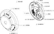
図1は、本発明の実施例における煙感知器1の分解斜視図である。煙感知器1を分解して斜め下方から見た状態を示す。煙感知器1は光電式スポット型の煙感知器であり、外形円筒形状をなし、後方から、感知器本体2、感知器カバー3からなる。
FIG. 1 is an exploded perspective view of the smoke detector 1 according to the embodiment of the present invention. The state where the smoke detector 1 is disassembled and viewed from diagonally below is shown. The smoke detector 1 is a photoelectric spot type smoke detector, which has a cylindrical outer shape, and is composed of a sensor
感知器本体2は、外形略円板形状をなし、設置面に、ベース部材(図示なし)を介して取り付けられる。感知器本体2を設置面に取り付けた状態において前方から見たとき、裏板4に光学台プレート6が取り付けられる。光学台プレート6の裏面すなわち後方に、回路基板(図示なし)が固定される。回路基板は制御部20や、火災を検知した時に光る確認灯5を有する。
The sensor
感知器カバー3は、感知器本体2より外周が大きく、略ドーム形状に形成される。感知器本体2を前方から覆うように被さり、感知器本体2の外周上に設けられた凸部と、感知器カバー3側に設けられた係止部(図示なし)を嵌合させることで係止する。また、環状に形成されるカバー表面部11には、透明な樹脂が嵌め込まれた確認灯窓12が設けられ、確認灯5の光が透光する。これにより煙感知器1設置時に前方から確認灯5の光を視認できる。
The sensor cover 3 has a larger outer circumference than the sensor
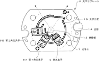
図2は、感知器本体2における光学台プレート6を、図1より拡大し90度右回転させ、正面から見た図であり、煙感知器1設置時においては前方から見た図である。感知器本体2に直接取り付けられる部品以外の煙感知器1の構成部品が、光学台プレート6に取り付けられ、間接的に感知器本体2に取り付けられる。光学台プレート6の外周には半円状の凹部14を有し、凹部14の空間には、回路基板に設けられた確認灯5が位置する。また、光学台プレート6は、光学台プレート6の略中央に設けられた光学台7と共に黒色樹脂により一体成形されている。光学台7は、光学台壁10によって高さの低い略円筒形状に形成される。光学台7の前方面には光学台カバー(図示なし)が取り付けられ、光学台7内に外光が入ることを遮断し、煙などの流入物を光学台7内へと導入する。
FIG. 2 is a view of the optical table plate 6 of the sensor
光学台壁10の周上には、第1発光素子8A、第2発光素子8B、受光素子9が設けられる。第1発光素子8Aおよび第2発光素子8B(以下、2つの発光素子8A・8Bと記載する)は、例えばLEDからなり、光学台7の内側に向かってそれぞれ異なるタイミング、例えば2秒おきのタイミングで交互に、発光する。受光素子9は、例えばフォトダイオードからなり、流入物によって発生した2つの発光素子8A・8Bの散乱光を受光する。散乱光は流入物が検煙部13に流入したときに発生する。検煙部13は、光学台7内に設けられ、2つの発光素子8A・8Bの光軸(図2では第1発光素子8Aの光軸のみ図示)と、受光素子9の光軸との交点を中心としたその周囲をいう。 A first light emitting element 8A, a second light emitting element 8B, and a light receiving element 9 are provided on the periphery of the optical base wall 10. The first light emitting element 8A and the second light emitting element 8B (hereinafter, referred to as two light emitting elements 8A and 8B) are composed of, for example, LEDs, and have different timings toward the inside of the optical table 7, for example, timings every 2 seconds. Lights up alternately with. The light receiving element 9 is composed of, for example, a photodiode, and receives the scattered light of the two light emitting elements 8A and 8B generated by the inflow. The scattered light is generated when the influent flows into the smoke detection unit 13. The smoke detection unit 13 is provided in the optical table 7, and is an intersection of the optical axes of the two light emitting elements 8A and 8B (only the optical axis of the first light emitting element 8A is shown in FIG. 2) and the optical axis of the light receiving element 9. It refers to the surrounding area centered on.
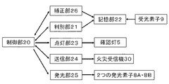
図3は、回路基板(図示なし)に設けられ、煙感知器1の制御機能の構成を示した模式図である。具体的には、煙感知器1を制御する機能として、制御部20を中心に、判別部21、記憶部22、点灯部23、送信部24、発光部25、補正部26を有する。判別部21は、煙感知器1内の流入物の種類を判別する機能を有し、記憶部22に繋がる。点灯部23は、確認灯5を点灯させる機能を有する。送信部24は、火災受信機30へ火災発報信号を出す。発光部25は、2つの発光素子8A・8Bを点灯させる機能を有する。補正部26は、計算された値を補正する機能を有する。制御部20は判別部21、送信部24、補正部26と相互に信号を送受信し、点灯部23、発光部25へ信号を送信する。 FIG. 3 is a schematic diagram provided on a circuit board (not shown) and showing the configuration of the control function of the smoke detector 1. Specifically, as a function of controlling the smoke detector 1, it has a discrimination unit 21, a storage unit 22, a lighting unit 23, a transmission unit 24, a light emitting unit 25, and a correction unit 26, centering on the control unit 20. The discrimination unit 21 has a function of discriminating the type of inflow in the smoke detector 1 and is connected to the storage unit 22. The lighting unit 23 has a function of lighting the confirmation lamp 5. The transmission unit 24 outputs a fire alarm signal to the fire receiver 30. The light emitting unit 25 has a function of lighting the two light emitting elements 8A and 8B. The correction unit 26 has a function of correcting the calculated value. The control unit 20 transmits and receives signals to and from the discrimination unit 21, the transmission unit 24, and the correction unit 26, and transmits the signals to the lighting unit 23 and the light emitting unit 25.
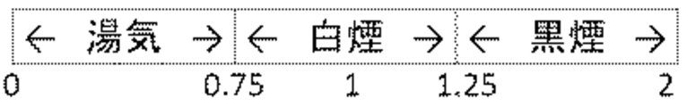
このような構成の煙感知器1における、煙感知器1内に流入した流入物の種類の判別方法について記載する。本発明でいう流入物とは、湯気、白煙または黒煙のいずれかとする。流入物が煙感知器1内に流入し検煙部13に到達すると、流入物に含まれる物質の粒子が、検煙部13を通る2つの発光素子8A・8Bの光を散乱させる。受光素子9は、発生した散乱光を受け、電圧として回路基板(図示なし)へ出力する。回路基板は、散乱光の電圧をデジタル信号に変換したのち数値化して記憶部22へ格納する。判別部21は、記憶部22に格納された情報を用いて流入物の種類を判断する。具体的には、判別部21は、第1発光素子8Aの散乱光の受光出力である第1信号S1と、第2発光素子8Bの散乱光の受光出力である第2信号S2を、比R(=第1信号S1/第2信号S2)を用いて計算する。比Rから計算された値を用いて、例えば図4のような表を基にして流入物の種類を判別する。この受光出力の比に基づいて流入物の種類を判別する方法は、従来から知られている方法である。また出力比は出力値をそのまま使用してもよいし、一方の出力値に補正係数を乗算してから比を求めたり、比の代わりに差分値を利用したりしてもよい。 A method for determining the type of inflow into the smoke detector 1 in the smoke detector 1 having such a configuration will be described. The influx referred to in the present invention is either steam, white smoke or black smoke. When the influent flows into the smoke detector 1 and reaches the smoke detection unit 13, the particles of the substance contained in the inflow material scatter the light of the two light emitting elements 8A and 8B passing through the smoke detection unit 13. The light receiving element 9 receives the generated scattered light and outputs it as a voltage to a circuit board (not shown). The circuit board converts the voltage of the scattered light into a digital signal, digitizes it, and stores it in the storage unit 22. The determination unit 21 determines the type of inflow using the information stored in the storage unit 22. Specifically, the discriminating unit 21 compares the first signal S1 which is the light receiving output of the scattered light of the first light emitting element 8A with the second signal S2 which is the light receiving output of the scattered light of the second light emitting element 8B. Calculation is performed using (= first signal S1 / second signal S2). Using the value calculated from the ratio R, for example, the type of inflow is determined based on a table as shown in FIG. A method of determining the type of inflow based on the ratio of the received light output is a conventionally known method. Further, as the output ratio, the output value may be used as it is, one output value may be multiplied by a correction coefficient and then the ratio may be obtained, or a difference value may be used instead of the ratio.
またこのような煙感知器1において、受光素子9が受ける、2つの発光素子8A・8Bの散乱光の受光量は、湯気>白煙>黒煙という関係にある。湯気の場合に最も受光量が多くなるのは、湯気に含まれる水の粒が光をより多く反射させる特徴があるためである。2つの発光素子8A・8Bの光がより多く散乱し、受光量が多くなる。一方、白煙や黒煙の場合、煙は光を吸収する特徴をもつことから、受光素子9に光が届きづらくなり受光量が少なくなる。とりわけ黒煙の場合は、煙の色によっても、より光を吸収しやすくなり、白煙よりも受光量は少なくなる。 Further, in such a smoke detector 1, the amount of light received by the two light emitting elements 8A and 8B received by the light receiving element 9 has a relationship of steam> white smoke> black smoke. In the case of steam, the amount of light received is the largest because the water particles contained in the steam have the characteristic of reflecting more light. The light of the two light emitting elements 8A and 8B is scattered more, and the amount of received light is increased. On the other hand, in the case of white smoke or black smoke, since the smoke has a characteristic of absorbing light, it becomes difficult for the light to reach the light receiving element 9, and the amount of received light is reduced. Especially in the case of black smoke, the color of the smoke also makes it easier to absorb light, and the amount of light received is smaller than that of white smoke.
この関係に基づき、本発明の煙感知器1では、流入物の判別基準を図4のように設定した。以下に図4を用いて流入物の種類の判断方法を詳しく説明する。上述のとおり、マイコン内で受光素子9の受光出力は数値に変換される。変換された数値を用いて判別部21が比Rの値を算出する。このとき例えば、煙感知器1内に流入した流入物を流入物Aとして、流入物Aの第1信号S1は100、第2信号S2も100だとする。判別部21は比Rを用いて「第1信号S1/第2信号S2=100/100=1」と計算する。そして比Rから計算された値を記憶部22に記憶される図4に示す表と照合し、流入物Aを白煙だと判別する。流入物Aが湯気または黒煙の場合も同様の手順で判別される。 Based on this relationship, in the smoke detector 1 of the present invention, the criteria for discriminating inflows are set as shown in FIG. The method of determining the type of influent will be described in detail below with reference to FIG. As described above, the light receiving output of the light receiving element 9 is converted into a numerical value in the microcomputer. The discriminating unit 21 calculates the value of the ratio R using the converted numerical value. At this time, for example, it is assumed that the inflow material that has flowed into the smoke detector 1 is the inflow material A, the first signal S1 of the inflow material A is 100, and the second signal S2 is also 100. The discrimination unit 21 calculates "first signal S1 / second signal S2 = 100/100 = 1" using the ratio R. Then, the value calculated from the ratio R is collated with the table shown in FIG. 4 stored in the storage unit 22, and the inflow material A is determined to be white smoke. When the influent A is steam or black smoke, it is determined by the same procedure.
流入物の種類が判別されると、次に火災判定がなされる。煙感知器1内で流入物の判別結果がでると、補正部26が第1信号S1を所定量増減幅する補正をする。具体的には、記憶部22に記憶される、流入物の種類別に定められた増減幅の数値に基づき補正をする。この補正は、流入物の種類によって受光出力に大きく差があり、火災判定にばらつきがでるために行われる。補正された第1信号S1を用いて、判別部21が所定の火災閾値と比較して火災判定をする。火災と判定されると、送信部24が火災受信機30へ火災信号を出力する。 Once the type of inflow is determined, a fire determination is made next. When the determination result of the inflow is obtained in the smoke detector 1, the correction unit 26 corrects the first signal S1 by a predetermined amount. Specifically, the correction is performed based on the numerical value of the increase / decrease width determined for each type of inflow, which is stored in the storage unit 22. This correction is performed because there is a large difference in the light receiving output depending on the type of inflow and the fire judgment varies. Using the corrected first signal S1, the discriminating unit 21 makes a fire determination by comparing with a predetermined fire threshold value. If it is determined that there is a fire, the transmission unit 24 outputs a fire signal to the fire receiver 30.
具体例を示して火災判定の手順を説明する。例えば、煙感知器1に流入した流入物を流入物Bとして、流入物Bの第1信号S1は40、第2信号S2は20だとする。判別部21は比Rを用いて「第1信号S1/第2信号S2=40/20=2」と計算し、図4の表と照合した結果、流入物Bを黒煙だと判別する。次に補正部26が、第1信号S1の補正を行う。補正部26は、流入物Bは黒煙なので第1信号S1を、本発明においては5倍増幅し、「40×5倍=200」と計算する。そして判別部21は、計算された数値を所定の火災閾値と比較して火災判定をする。本発明において火災閾値は200であり、計算された数値は火災閾値以上なので火災と判定する。火災と判定されると、送信部24は火災受信機30へ火災信号を出力し、火災受信機30は火災発報する。流入物Bが白煙または湯気である場合も、流入物の種類によって異なる値で補正がなされ、同様の手順で火災判定される。 A procedure for determining a fire will be described with reference to a specific example. For example, it is assumed that the inflow material that has flowed into the smoke detector 1 is the inflow material B, the first signal S1 of the inflow material B is 40, and the second signal S2 is 20. The discriminating unit 21 calculates “first signal S1 / second signal S2 = 40/20 = 2” using the ratio R, and as a result of collating with the table of FIG. 4, determines that the influent B is black smoke. Next, the correction unit 26 corrects the first signal S1. Since the inflow B is black smoke, the correction unit 26 amplifies the first signal S1 5 times in the present invention and calculates "40 x 5 times = 200". Then, the discrimination unit 21 compares the calculated numerical value with a predetermined fire threshold value to make a fire judgment. In the present invention, the fire threshold value is 200, and the calculated numerical value is equal to or higher than the fire threshold value, so that the fire is determined to be fire. When it is determined that there is a fire, the transmission unit 24 outputs a fire signal to the fire receiver 30, and the fire receiver 30 issues a fire alarm. Even when the influent B is white smoke or steam, it is corrected by a different value depending on the type of the inflow, and a fire is determined by the same procedure.
判別部21により火災と判定されると、点灯部23は確認灯5を点灯させる。このとき、点灯部23は判別された流入物の種類によって、確認灯5の点灯パターンを変える。例えば、湯気の場合は遅点滅、白煙の場合は常時点灯、黒煙の場合は速点滅、などそれぞれの違いが視認できる点灯パターンであればよい。煙感知器1を設置した状態において、確認灯5の光は、感知器カバー3に設けられた確認灯窓12を通じてその点灯パターンを視認することができる。 When the determination unit 21 determines that a fire has occurred, the lighting unit 23 turns on the confirmation lamp 5. At this time, the lighting unit 23 changes the lighting pattern of the confirmation lamp 5 according to the type of the discriminated inflow. For example, it may be a lighting pattern in which the differences can be visually recognized, such as slow blinking in the case of steam, constant lighting in the case of white smoke, and fast blinking in the case of black smoke. With the smoke detector 1 installed, the light of the confirmation light 5 can visually recognize the lighting pattern through the confirmation light window 12 provided on the sensor cover 3.
以上のように、確認灯5の点灯パターンを変えることで、火災発報の原因となった流入物の種類を知ることできる。例えば、ホテルの居室の浴室付近など湯気が多く発生する場所に設置される火災感知器においては、湯気によって火災感知器が作動することが容易に考えられる。このように流入物が湯気の場合、実際には火災ではないが、火災発報がなされる。しかし本発明の煙感知器1によれば、火災発報がなされても確認灯5の点灯パターンを確認するだけで湯気が原因であることを確認できるので、火元を探す手間が省けると共に確実に湯気による誤発報であることを知ることができる。さらに、煙感知器1の作動試験時に、試験者が煙感知器1に向かって常時点灯すべき試験煙を入れたにもかかわらず、確認灯5が常時点灯以外の点灯パターンを示したような場合、煙感知器1の不具合の可能性を知ることができる。
<その他>
本発明の実施例において、確認灯5を1つ設け、点灯パターンを常時点灯または点滅間隔を異ならせる点滅としたが、確認灯5を複数設ける構成としてもよいし、異なる色に光る確認灯5を設けて、流入物の種類によって別の色を点灯させて流入物の種類を示す構成としても本発明と同様の効果が得られる。
As described above, by changing the lighting pattern of the confirmation lamp 5, it is possible to know the type of inflow that caused the fire alarm. For example, in a fire detector installed in a place where a lot of steam is generated, such as near the bathroom of a hotel room, it is easily considered that the fire detector is activated by the steam. When the inflow is steam in this way, a fire is issued, although it is not actually a fire. However, according to the smoke detector 1 of the present invention, even if a fire is triggered, it can be confirmed that the cause is steam only by checking the lighting pattern of the confirmation lamp 5, so that the trouble of searching for the fire source can be saved and surely. It is possible to know that it is a false report due to steam. Further, during the operation test of the smoke detector 1, it seems that the confirmation lamp 5 shows a lighting pattern other than the constant lighting even though the tester puts test smoke that should be constantly lit toward the smoke detector 1. In this case, it is possible to know the possibility of malfunction of the smoke detector 1.
<Others>
In the embodiment of the present invention, one confirmation light 5 is provided and the lighting pattern is always lit or blinking at different blinking intervals. However, a plurality of confirmation lights 5 may be provided, or the confirmation light 5 shining in a different color may be provided. The same effect as that of the present invention can be obtained even if a configuration is provided in which a different color is lit depending on the type of inflow to indicate the type of inflow.
また、本発明の実施例では、発光素子を2つ、受光素子を1つ、有する煙感知器1としたが、発光素子と受光素子のどちらを1つとしてもよいし、どちらも複数個ずつ備える構成としても本発明と同様の効果が得られる。 Further, in the embodiment of the present invention, the smoke detector 1 has two light emitting elements and one light receiving element, but either the light emitting element or the light receiving element may be one, and a plurality of both may be used. The same effect as that of the present invention can be obtained as the configuration provided.
また、本発明の実施例では、発光素子と受光素子は光電センサのものを使用しているが、それぞれ、光電センサ、COセンサ、イオンセンサといった異なるセンサを用いる構成としても、本発明と同様の効果が得られる。 Further, in the embodiment of the present invention, the light emitting element and the light receiving element are those of a photoelectric sensor, but the configuration using different sensors such as a photoelectric sensor, a CO sensor, and an ion sensor is the same as that of the present invention. The effect is obtained.
1 煙感知器、2 感知器本体、3 感知器カバー、4 裏板、5 確認灯、
6 光学台プレート、7 光学台、8A 第1発光素子、 8B 第2発光素子、
9 受光素子、10 光学台壁、11 カバー表面部、12 確認灯窓、
13 検煙部、14 凹部、20 制御部、21 判別部、22 記憶部、23 点灯部、24 送信部、
25 発光部、26 補正部、30 火災受信機
1 Smoke detector, 2 Sensor body, 3 Sensor cover, 4 Back plate, 5 Confirmation light,
6 Optical stand plate, 7 Optical stand, 8A 1st light emitting element, 8B 2nd light emitting element,
9 light receiving element, 10 optical base wall, 11 cover surface, 12 confirmation light window,
13 Smoke detection unit, 14 recess, 20 control unit, 21 discrimination unit, 22 storage unit, 23 lighting unit, 24 transmitter unit,
25 light emitting part, 26 correction part, 30 fire receiver
Claims (4)
前記検煙部に流入した流入物によって散乱した前記発光素子の光を受光する受光素子と、
前記発光素子と前記受光素子によって前記流入物を検知したときに点灯する確認灯と、を有する煙感知器において、
前記流入物の種類を判別する判別部と、
前記流入物の種類の判別結果に基づいて前記確認灯を異なる点灯パターンで点灯させる点灯部と、を備えることを特徴とする煙感知器。 A light emitting element that emits light toward the inside of the smoke detector,
A light receiving element that receives the light of the light emitting element scattered by the inflow material that has flowed into the smoke detection unit, and
In a smoke detector having the light emitting element and the confirmation light that lights up when the inflow is detected by the light receiving element.
A discriminating unit that discriminates the type of inflow and
A smoke detector comprising a lighting unit that lights the confirmation lamp in a different lighting pattern based on a determination result of the type of inflow.
Priority Applications (1)
| Application Number | Priority Date | Filing Date | Title |
|---|---|---|---|
| JP2019133473A JP2021018564A (en) | 2019-07-19 | 2019-07-19 | smoke detector |
Applications Claiming Priority (1)
| Application Number | Priority Date | Filing Date | Title |
|---|---|---|---|
| JP2019133473A JP2021018564A (en) | 2019-07-19 | 2019-07-19 | smoke detector |
Publications (1)
| Publication Number | Publication Date |
|---|---|
| JP2021018564A true JP2021018564A (en) | 2021-02-15 |
Family
ID=74564324
Family Applications (1)
| Application Number | Title | Priority Date | Filing Date |
|---|---|---|---|
| JP2019133473A Pending JP2021018564A (en) | 2019-07-19 | 2019-07-19 | smoke detector |
Country Status (1)
| Country | Link |
|---|---|
| JP (1) | JP2021018564A (en) |
Citations (13)
| Publication number | Priority date | Publication date | Assignee | Title |
|---|---|---|---|---|
| JPS60221897A (en) * | 1983-09-17 | 1985-11-06 | 関 廣 | Alarming for state and position of fire |
| JPH05298573A (en) * | 1992-04-23 | 1993-11-12 | Matsushita Electric Works Ltd | Fire alarm system |
| JP2001216581A (en) * | 2000-01-31 | 2001-08-10 | Osaka Gas Co Ltd | Gas alarm and control method thereof |
| JP2002042268A (en) * | 2000-07-27 | 2002-02-08 | Hochiki Corp | Fire gas leak alarm |
| JP2004325211A (en) * | 2003-04-24 | 2004-11-18 | Hochiki Corp | Scattered light smoke detector |
| JP2005115970A (en) * | 1997-05-08 | 2005-04-28 | Nittan Co Ltd | Smoke sensor and monitor control system |
| JP2005165740A (en) * | 2003-12-03 | 2005-06-23 | Tokyo Gas Co Ltd | Alarm |
| JP2005267466A (en) * | 2004-03-19 | 2005-09-29 | Nohmi Bosai Ltd | Fire alarm |
| JP2007133584A (en) * | 2005-11-09 | 2007-05-31 | Osaka Gas Co Ltd | Alarm device |
| JP2009169869A (en) * | 2008-01-18 | 2009-07-30 | Fujitsu Ten Ltd | Vehicle information recording system |
| JP2013214330A (en) * | 2008-10-09 | 2013-10-17 | Hochiki Corp | Smoke detector |
| JP2016071581A (en) * | 2014-09-30 | 2016-05-09 | 能美防災株式会社 | Smoke detector |
| JP2019032594A (en) * | 2017-08-04 | 2019-02-28 | 能美防災株式会社 | smoke detector |
-
2019
- 2019-07-19 JP JP2019133473A patent/JP2021018564A/en active Pending
Patent Citations (13)
| Publication number | Priority date | Publication date | Assignee | Title |
|---|---|---|---|---|
| JPS60221897A (en) * | 1983-09-17 | 1985-11-06 | 関 廣 | Alarming for state and position of fire |
| JPH05298573A (en) * | 1992-04-23 | 1993-11-12 | Matsushita Electric Works Ltd | Fire alarm system |
| JP2005115970A (en) * | 1997-05-08 | 2005-04-28 | Nittan Co Ltd | Smoke sensor and monitor control system |
| JP2001216581A (en) * | 2000-01-31 | 2001-08-10 | Osaka Gas Co Ltd | Gas alarm and control method thereof |
| JP2002042268A (en) * | 2000-07-27 | 2002-02-08 | Hochiki Corp | Fire gas leak alarm |
| JP2004325211A (en) * | 2003-04-24 | 2004-11-18 | Hochiki Corp | Scattered light smoke detector |
| JP2005165740A (en) * | 2003-12-03 | 2005-06-23 | Tokyo Gas Co Ltd | Alarm |
| JP2005267466A (en) * | 2004-03-19 | 2005-09-29 | Nohmi Bosai Ltd | Fire alarm |
| JP2007133584A (en) * | 2005-11-09 | 2007-05-31 | Osaka Gas Co Ltd | Alarm device |
| JP2009169869A (en) * | 2008-01-18 | 2009-07-30 | Fujitsu Ten Ltd | Vehicle information recording system |
| JP2013214330A (en) * | 2008-10-09 | 2013-10-17 | Hochiki Corp | Smoke detector |
| JP2016071581A (en) * | 2014-09-30 | 2016-05-09 | 能美防災株式会社 | Smoke detector |
| JP2019032594A (en) * | 2017-08-04 | 2019-02-28 | 能美防災株式会社 | smoke detector |
Similar Documents
| Publication | Publication Date | Title |
|---|---|---|
| JP3086406B2 (en) | Passive infrared human body detector | |
| US8232884B2 (en) | Carbon monoxide and smoke detectors having distinct alarm indications and a test button that indicates improper operation | |
| CN114550405B (en) | Smoke detector | |
| US8872648B2 (en) | Fire detector with a man-machine interface and method for controlling the fire detector | |
| WO2008091528A2 (en) | Motion sensor with led alignment aid | |
| US5489892A (en) | Infrared human detector not barred by an intervening obstruction | |
| TW201329913A (en) | Photoelectric smoke detector | |
| JP2011203892A (en) | Smoke detector | |
| JP2013003760A (en) | Smoke sensor | |
| JP2021018564A (en) | smoke detector | |
| JPH11160238A (en) | Photoelectric smoke sensor | |
| JP2005121490A (en) | Flame detector equipped with automatic test function | |
| CN117037412A (en) | smoke detector | |
| KR100339255B1 (en) | infrared sensor and managing method thereof | |
| JPH11224387A5 (en) | ||
| JP5038112B2 (en) | Photoelectric smoke detector | |
| JP2008250851A (en) | Photoelectric smoke detector | |
| JP7538308B2 (en) | Flame detector | |
| JP7589033B2 (en) | Smoke detectors and smoke detection systems | |
| JP7365470B2 (en) | sensor | |
| US12270760B2 (en) | Masking to eliminate direct line of sight between light emitter and light receiver in a smoke detector | |
| EP4332936A1 (en) | Single-wave multi-angle smoke alarm algorithm | |
| JP2013003759A (en) | Smoke sensor | |
| JP2009110434A (en) | Photoelectric smoke detector | |
| EP1993083A2 (en) | Smoke detection device and method |
Legal Events
| Date | Code | Title | Description |
|---|---|---|---|
| A621 | Written request for application examination |
Free format text: JAPANESE INTERMEDIATE CODE: A621 Effective date: 20220713 |
|
| A977 | Report on retrieval |
Free format text: JAPANESE INTERMEDIATE CODE: A971007 Effective date: 20230821 |
|
| A131 | Notification of reasons for refusal |
Free format text: JAPANESE INTERMEDIATE CODE: A131 Effective date: 20230905 |
|
| A521 | Request for written amendment filed |
Free format text: JAPANESE INTERMEDIATE CODE: A523 Effective date: 20231102 |
|
| A02 | Decision of refusal |
Free format text: JAPANESE INTERMEDIATE CODE: A02 Effective date: 20240130 |