JP2021017993A - Cooling storage - Google Patents
Cooling storage Download PDFInfo
- Publication number
- JP2021017993A JP2021017993A JP2019131907A JP2019131907A JP2021017993A JP 2021017993 A JP2021017993 A JP 2021017993A JP 2019131907 A JP2019131907 A JP 2019131907A JP 2019131907 A JP2019131907 A JP 2019131907A JP 2021017993 A JP2021017993 A JP 2021017993A
- Authority
- JP
- Japan
- Prior art keywords
- energization
- storage
- energization rate
- discharge pipe
- temperature difference
- Prior art date
- Legal status (The legal status is an assumption and is not a legal conclusion. Google has not performed a legal analysis and makes no representation as to the accuracy of the status listed.)
- Pending
Links
Images


Landscapes
- Devices That Are Associated With Refrigeration Equipment (AREA)
- Removal Of Water From Condensation And Defrosting (AREA)
Abstract
【課題】消費電力の増加を抑制することが可能な冷却貯蔵庫を提供する。【解決手段】冷蔵庫(冷却貯蔵庫)10は、貯蔵物を収容することが可能な貯蔵庫本体12と、貯蔵庫本体12の内部を冷却する冷却装置18と、冷却装置18の作動により生じた霜を外部に排出する排出管48と、排出管48を加熱するパイプヒータ58と、貯蔵庫本体12の外部の温度を取得する外部温度センサ(外部温度取得部)64と、貯蔵庫本体12の内部の温度を取得する内部温度センサ(内部温度取得部)46と、パイプヒータ58を制御する制御部20と、を備え、制御部20は、外部温度センサ64によって取得された外部温度と、内部温度センサ46によって取得された内部温度との温度差ΔTを算出する温度差算出部(温度差算出手段)66と、算出された温度差ΔTに基づき、パイプヒータ58の発熱量を変化させる制御を行う発熱量制御部(発熱量制御手段)70と、を備える。【選択図】図4PROBLEM TO BE SOLVED: To provide a cooling storage capable of suppressing an increase in power consumption. SOLUTION: A refrigerator (cooling storage) 10 has a storage main body 12 capable of accommodating storage, a cooling device 18 for cooling the inside of the storage main body 12, and frost generated by the operation of the cooling device 18 to the outside. The discharge pipe 48 that discharges to, the pipe heater 58 that heats the discharge pipe 48, the external temperature sensor (external temperature acquisition unit) 64 that acquires the temperature outside the storage body 12, and the temperature inside the storage body 12 are acquired. An internal temperature sensor (internal temperature acquisition unit) 46 and a control unit 20 for controlling the pipe heater 58 are provided, and the control unit 20 acquires the external temperature acquired by the external temperature sensor 64 and the internal temperature sensor 46. A temperature difference calculation unit (temperature difference calculation means) 66 that calculates the temperature difference ΔT from the internal temperature, and a calorific value control unit that controls to change the calorific value of the pipe heater 58 based on the calculated temperature difference ΔT. (Chemical generation control means) 70. [Selection diagram] Fig. 4
Description
本開示は、冷却貯蔵庫に関する。 The present disclosure relates to a cooled storage.
従来の冷却貯蔵庫として、例えば、下記特許文献1に記載の冷凍・冷蔵庫が知られている。この冷凍・冷蔵庫は、2つの収納庫(冷蔵庫および冷凍庫)と、各庫内を冷却する2つの冷却器(冷蔵用冷却器および冷凍用冷却器)と、各冷却器からの除霜水が集められる2つのダクト(冷蔵用ダクトおよび冷凍用ダクト)と、各ダクトに接続され、各ダクトに集められた除霜水を外部にそれぞれ排出する2つの排水パイプ(第1の排水パイプおよび第2の排水パイプ)と、を備えて構成されている。冷凍用ダクトに接続される第2の排水パイプには、第2の排水パイプ内の凍結、および、第2の排水パイプの外周面の結露を抑制するパイプヒータが取り付けられている。 As a conventional cooling storage, for example, the freezer / refrigerator described in Patent Document 1 below is known. This freezer / refrigerator collects two storages (refrigerator and freezer), two coolers (refrigerator and freezer cooler) that cool the inside of each refrigerator, and defrost water from each cooler. Two ducts (refrigerator duct and refrigerating duct) and two drainage pipes (first drainage pipe and second drainage pipe) that are connected to each duct and discharge the defrosted water collected in each duct to the outside, respectively. Drainage pipe) and is configured. A pipe heater for suppressing freezing in the second drainage pipe and dew condensation on the outer peripheral surface of the second drainage pipe is attached to the second drainage pipe connected to the refrigeration duct.
上記構成において、パイプヒータは常時通電されており、消費電力が増加することとなる。また、パイプヒータへの常時通電によって、パイプヒータの温度は過度に高くなり、パイプヒータの熱が庫内に伝わり易くなる。これに伴い、庫内の温度を一定に保つため、冷凍・冷蔵庫の運転率が増加し、消費電力がさらに増加することとなる。また、庫内におけるパイプヒータ側の温度が高くなり、庫内に温度ムラが発生することとなる。また、パイプヒータを囲う外装部にユーザの手が接触すると、ユーザが熱いと感じて不快になるおそれがある。 In the above configuration, the pipe heater is always energized, which increases the power consumption. Further, by constantly energizing the pipe heater, the temperature of the pipe heater becomes excessively high, and the heat of the pipe heater is easily transferred to the inside of the refrigerator. Along with this, in order to keep the temperature inside the refrigerator constant, the operating rate of the refrigerator / refrigerator will increase, and the power consumption will further increase. In addition, the temperature on the pipe heater side in the refrigerator becomes high, and temperature unevenness occurs in the refrigerator. Further, when the user's hand comes into contact with the exterior portion surrounding the pipe heater, the user may feel hot and uncomfortable.
本開示は上記のような事情に基づいて完成されたものであって、消費電力の増加を抑制することが可能な冷却貯蔵庫を提供することを目的とする。 The present disclosure has been completed based on the above circumstances, and an object of the present disclosure is to provide a cooling storage capable of suppressing an increase in power consumption.
上記課題を解決するために、本開示の冷却貯蔵庫は、貯蔵物を収容することが可能な貯蔵庫本体と、前記貯蔵庫本体の内部を冷却する冷却装置と、前記冷却装置の作動により生じた霜を外部に排出する排出管と、前記排出管を加熱する排出管ヒータと、前記貯蔵庫本体の外部の温度を取得する外部温度取得部と、前記貯蔵庫本体の内部の温度を取得する内部温度取得部と、前記排出管ヒータを制御する制御部と、を備え、前記制御部は、前記外部温度取得部によって取得された外部温度と、前記内部温度取得部によって取得された内部温度との温度差を算出する温度差算出手段と、算出された前記温度差に基づき、前記排出管ヒータの発熱量を変化させる制御を行う発熱量制御手段と、を備える。 In order to solve the above problems, the cooling storage of the present disclosure includes a storage main body capable of accommodating storage, a cooling device for cooling the inside of the storage main body, and frost generated by the operation of the cooling device. A discharge pipe that discharges to the outside, a discharge pipe heater that heats the discharge pipe, an external temperature acquisition unit that acquires the temperature outside the storage body, and an internal temperature acquisition unit that acquires the temperature inside the storage body. The control unit includes a control unit that controls the discharge pipe heater, and the control unit calculates a temperature difference between the external temperature acquired by the external temperature acquisition unit and the internal temperature acquired by the internal temperature acquisition unit. It is provided with a temperature difference calculating means for calculating the temperature difference, and a calorific value controlling means for controlling to change the calorific value of the discharge pipe heater based on the calculated temperature difference.
一般的に、貯蔵庫本体の周囲の外部温度と、貯蔵庫本体の内部温度との温度差が大きいほど、排出管は凍結・結露し易くなる。そこで、貯蔵庫本体の外部温度と内部温度との温度差を算出し、算出された温度差に基づき、排出管ヒータの発熱量を変化させる制御を行うことで、従来のように排出管ヒータに常時通電させる構成と比較して、冷却貯蔵庫の消費電力量が増加することを抑制できる。すなわち、排出管ヒータの発熱量を、排出管の内面が凍結しない最適な温度、かつ、排出管の外面が結露しない最適な温度となるように排出管ヒータの発熱量を制御することにより、排出管ヒータが無駄に電力を消費することが抑制され、冷却貯蔵庫としての消費電力量を低下できる。また、排出管ヒータの温度が過度に高くなることが抑制されるため、排出管ヒータの熱が庫内に伝わることを抑制できる。このため、冷却貯蔵庫の冷却運転率を低下でき、消費電力量の増加をさらに抑制できる。また、庫内における排出管ヒータ側の温度の上昇が抑えられるため、庫内の温度ムラを低減できる。また、ユーザの手が、排出管を囲う外装部に接触しても、熱いと感じて不快になることはない。 Generally, the larger the temperature difference between the external temperature around the storage body and the internal temperature of the storage body, the easier it is for the discharge pipe to freeze and condense. Therefore, by calculating the temperature difference between the external temperature and the internal temperature of the storage body and controlling to change the calorific value of the discharge pipe heater based on the calculated temperature difference, the discharge pipe heater is always used as in the conventional case. It is possible to suppress an increase in the power consumption of the cooling storage as compared with the configuration in which the electricity is supplied. That is, the calorific value of the discharge pipe heater is discharged by controlling the calorific value of the discharge pipe heater so that the inner surface of the discharge pipe does not freeze and the outer surface of the discharge pipe does not condense. It is possible to suppress wasteful power consumption by the tube heater and reduce the power consumption as a cooling storage. Further, since the temperature of the discharge pipe heater is suppressed from becoming excessively high, it is possible to suppress the heat of the discharge pipe heater from being transferred to the inside of the refrigerator. Therefore, the cooling operation rate of the cooling storage can be lowered, and the increase in power consumption can be further suppressed. Further, since the temperature rise on the discharge pipe heater side in the refrigerator is suppressed, the temperature unevenness in the refrigerator can be reduced. Further, even if the user's hand comes into contact with the exterior portion surrounding the discharge pipe, it does not feel hot and uncomfortable.
また、前記発熱量制御手段は、算出された前記温度差に基づき、所定の周期時間内における、前記排出管ヒータへの通電がオンにされる時間であるオン時間と、前記排出管ヒータへの通電がオフにされる時間であるオフ時間との割合を表す通電率を決定する通電率決定手段と、決定された前記通電率に基づき、前記排出管ヒータへの通電をオン/オフさせる制御を行う通電制御手段と、を備える構成としても良い。 Further, the calorific value control means has an on-time, which is a time during which the energization of the discharge pipe heater is turned on, and an on-time to the discharge pipe heater within a predetermined cycle time based on the calculated temperature difference. The energization rate determining means for determining the energization rate, which represents the ratio to the off time, which is the time when the energization is turned off, and the control for turning on / off the energization of the discharge pipe heater based on the determined energization rate. It may be configured to include the energization control means to be performed.
算出された温度差から通電率を決定し、決定された通電率に基づき排出管ヒータへの通電をオン/オフさせる制御を行うことで、算出された温度差に基づき排出管ヒータの発熱量を変化させることができる。 By determining the energization rate from the calculated temperature difference and controlling the energization of the discharge pipe heater to be turned on / off based on the determined energization rate, the amount of heat generated by the discharge pipe heater is determined based on the calculated temperature difference. Can be changed.
また、前記貯蔵庫本体に設けられた開口部に開閉可能に取り付けられる扉と、前記扉を加熱する扉ヒータと、一方に電源が接続され、他方に前記排出管ヒータおよび前記扉ヒータが並列接続されるリレーと、を備え、前記通電制御手段は、前記通電率に基づいて前記リレーをオン/オフさせる制御を行うことにより、前記排出管ヒータおよび前記扉ヒータへの通電を同時にオン/オフさせる制御を行う構成としても良い。 Further, a door that can be opened and closed in an opening provided in the storage body, a door heater that heats the door, a power supply is connected to one, and the discharge pipe heater and the door heater are connected in parallel to the other. The relay is provided, and the energization control means controls to turn on / off the relay based on the energization rate, thereby simultaneously turning on / off the energization of the discharge pipe heater and the door heater. It may be configured to perform.
1つのリレーに対して、排出管ヒータおよび扉ヒータを並列接続し、1つのリレーをオン/オフさせる制御を行う構成とすることで、排出管ヒータおよび扉ヒータのそれぞれに異なるリレーを接続し、それぞれのリレーを同時にオン/オフさせる制御を行う構成と比較して、リレーの数を削減できる。 By connecting the discharge pipe heater and the door heater in parallel to one relay and controlling to turn on / off one relay, different relays can be connected to each of the discharge pipe heater and the door heater. The number of relays can be reduced as compared with a configuration in which each relay is controlled to be turned on / off at the same time.
また、前記温度差ごとに定められた前記通電率の集合データである通電率テーブルを記憶する通電率記憶部を備え、前記通電率決定手段は、記憶された前記通電率テーブルから、前記温度差算出手段により算出された前記温度差に対応する前記通電率を決定する構成としても良い。 Further, the energization rate storage unit for storing the energization rate table which is the aggregate data of the energization rates determined for each temperature difference is provided, and the energization rate determining means is the temperature difference from the stored energization rate table. The configuration may be such that the energization rate corresponding to the temperature difference calculated by the calculation means is determined.
温度差と通電率との対応テーブル(通電率テーブル)を用いることにより、算出された温度差に対応する通電率を決定できる。 By using the correspondence table between the temperature difference and the energization rate (energization rate table), the energization rate corresponding to the calculated temperature difference can be determined.
また、前記通電率テーブルは、前記通電率記憶部に複数記憶されており、複数の前記通電率テーブルのうち、いずれか一つの前記通電率テーブルを選択する通電率選択部を備え、前記通電率決定手段は、前記通電率選択部により選択された一つの前記通電率テーブルから、前記温度差算出手段により算出された前記温度差に対応する前記通電率を決定する構成としても良い。 Further, a plurality of the energization rate tables are stored in the energization rate storage unit, and the energization rate selection unit for selecting any one of the energization rate tables among the plurality of energization rate tables is provided. The determining means may be configured to determine the energizing rate corresponding to the temperature difference calculated by the temperature difference calculating means from one energizing rate table selected by the energizing rate selecting unit.
複数の通電率テーブルのうち、いずれか一つの通電率テーブルを選択する通電率選択部を設けることにより、冷却貯蔵庫の使用環境に応じて適切な通電率を選択できるようになる。例えば、通電率テーブル内の各通電率の平均値が高めに設定された第1の通電率テーブルと、平均値が低めに設定された第2の通電率テーブルとが、通電率記憶部に記憶されている場合において、ユーザが常に結露を防止したいと判断した場合は、第1の通電率テーブルを選択し、省エネを優先したいと判断した場合は第2の通電テーブルを選択することができる。 By providing the energization rate selection unit for selecting any one of the energization rate tables from the plurality of energization rate tables, it becomes possible to select an appropriate energization rate according to the usage environment of the cooling storage. For example, a first energization rate table in which the average value of each energization rate in the energization rate table is set higher and a second energization rate table in which the average value is set lower are stored in the energization rate storage unit. If it is determined that the user always wants to prevent dew condensation, the first energization rate table can be selected, and if it is determined that energy saving is prioritized, the second energization table can be selected.
本開示によれば、消費電力の増加を抑制することが可能な冷却貯蔵庫を提供できる。 According to the present disclosure, it is possible to provide a cooling storage capable of suppressing an increase in power consumption.
<実施形態>
本開示の実施形態を図1から図8によって説明する。本実施形態では、冷却貯蔵庫として、図1に示すように、4ドア式の冷蔵庫10を例示する。冷蔵庫10は、食材等の貯蔵物(図示せず)を冷蔵保存することが可能とされる。
<Embodiment>
The embodiments of the present disclosure will be described with reference to FIGS. 1 to 8. In the present embodiment, as a cooling storage, a 4-
[冷蔵庫10]
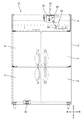
図1、図2に示すように、冷蔵庫10は、貯蔵庫本体12と、扉14と、機械室16と、冷却装置18と、を備えて構成されている。ここで、冷却装置18は、貯蔵庫本体12の内部を冷却する装置であって、圧縮機22と、凝縮器ファン24を有する凝縮器26と、冷却器28と、を備えて構成されている。
[Refrigerator 10]
As shown in FIGS. 1 and 2, the
[貯蔵庫本体12]
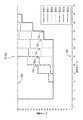
図2に示すように、貯蔵庫本体12は、前方に開口する開口部12Aを有する断熱箱体であって、外箱30と内箱32とを備えて構成されている。外箱30と内箱32との間には、図示しない断熱材が発泡充填されている。貯蔵庫本体12の内部(すなわち、内箱32の内部)には、貯蔵室34および冷却器室36が設けられている。貯蔵室34内には、貯蔵物が載置される複数の棚38が設けられている。冷却器室36には冷却器28が収容されている。貯蔵室34と冷却器室36とは、冷却ダクト40によって仕切られている。
[Storage body 12]
As shown in FIG. 2, the storage
冷却ダクト40は、後方に向けて下方に傾斜する傾斜部42を備えている。冷却ダクト40の傾斜部42には、吸込口42Aおよび吹出口42Bが設けられている。冷却器室36内における、吸込口42Aの上方には、循環ファン44が設けられている。さらに循環ファン44の上方には、内部温度センサ(内部温度取得部)46が設けられている。冷却器28は、循環ファン44の後方側に配されている。冷却器28の後方には、排出管48が設けられている。排出管48は、冷却器室36の後壁(すなわち、内箱32の後壁)から冷却器室36の外部に突き抜け、さらに下方に延びている。排出管48における下方に延びる部位は、外箱30と内箱32との間に位置しており、図示しない断熱材によって囲われている。
The cooling
[機械室16]
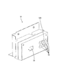
図1、図2に示すように、機械室16は、貯蔵庫本体12の上方に設けられている。図2に示すように、圧縮機22および凝縮器26は、機械室16に収容されている。また、図1に示すように、機械室16には電装箱50、および、オペレーションボックス52が収容されている。
[Machine room 16]
As shown in FIGS. 1 and 2, the
[オペレーションボックス52]
図1に示すように、機械室16の前面の一部には開口が設けられており、その開口から、オペレーションボックス52の前面が外部に露出している。図3に示すように、オペレーションボックス52の前面には、表示画面54および複数の操作ボタン56が設けられている。表示画面54には、貯蔵室34の内部温度等の情報が表示される。各操作ボタン56は、ユーザの操作により、冷蔵庫10の設定(例えば、貯蔵庫本体12の内部の温度設定)等を変更するためのボタンである。複数の操作ボタン56のうち、一つの操作ボタン(通電率選択部)56Aは、後述する通電率テーブルTBを選択するためのボタンである。
[Operation Box 52]
As shown in FIG. 1, an opening is provided in a part of the front surface of the
[冷却装置18]
冷却装置18を構成する各機器(圧縮機22、凝縮器26、および冷却器28)は、冷媒管によって循環接続されている。これによって、冷凍回路が構成されている。圧縮機22および凝縮器26によって圧縮および凝縮された冷媒は、冷却器28内を通過する。このとき、冷却器28内を通過する冷媒と、冷却器28の周囲の空気とが熱交換され、冷気が生成される。
[Cooling device 18]
Each device (
貯蔵室34の内気は、循環ファン44によって吸込口42Aから冷却器室36内に吸い込まれる。このとき、内部温度センサ46に循環ファン44によって吸い込まれた内気が当たることにより、貯蔵室34内の温度が検知される。循環ファン44によって吸い込まれた内気は、冷却器28によって冷却され、吹出口42Bから貯蔵室34内に排出される。これにより、貯蔵室34に収容された貯蔵物が冷却される。
The inside air of the
冷却装置18が作動すると、冷却器28の周囲の水蒸気が冷却器28によって冷却され、固体化されることにより、冷却器28の表面には霜が付着する。冷却器28に付着した霜は、冷蔵庫10が除霜運転を開始すると、融解される。除霜運転は、図示しないデフロストヒータにより冷却器28を加熱し、冷却器28に付着した霜を融解するヒータデフロスト方式、または冷却装置18を停止することにより冷却器28に付着した霜を融解するオフサイクルデフロスト方式により行われる。除霜運転により融解された霜は、冷却ダクト40の傾斜部42に落ち、排出管48から貯蔵庫本体12の外部に排出される。
When the
[パイプヒータ58]
図2に示すように、排出管48にはパイプヒータ(排出管ヒータ)58が取り付けられている。パイプヒータ58は、コードヒータであって、排出管48上に巻き付け固定されている。なお、パイプヒータ58は巻き付け固定ではなく、排出管48上にU字状に貼り付けて固定されていても良い。パイプヒータ58が作動すると、排出管48は加熱される。これにより、排出管48内を流れる除霜水が凍結すること、および、排出管48の外表面となる外箱30が結露することの双方を抑制できる。
[Pipe heater 58]
As shown in FIG. 2, a pipe heater (discharge pipe heater) 58 is attached to the
[扉14、扉ヒータ60]
扉14は、貯蔵庫本体12の開口部12Aに開閉可能に取り付けられており、図1に示すように、上下に2組設けられている。図2に示すように、扉14には、扉ヒータ60が取り付けられている。扉ヒータ60は、コードヒータであって、扉14の側縁に沿って扉14に固定されている。扉ヒータ60が作動すると、扉14は加熱される。これにより、扉14の後面部および開口部12Aの開口縁部が結露することを抑制できる。
[
The
[電装箱50、制御部20、リレー62、外部温度センサ64]
電装箱50内には、マイクロコンピュータを備える制御基板(図示せず)、および、リレー62が収容されている。また、オペレーションボックス52内には操作基板(図示せず)が収容されており、操作基板上には、貯蔵庫本体12の周囲の外部温度を取得する外部温度センサ(外部温度取得部)64が取り付けられている。
[
A control board (not shown) including a microcomputer and a
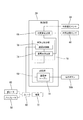
冷蔵庫10には、各種装置を電気的に制御する制御部20が設けられている。制御部20は、電装箱50内の制御基板、およびオペレーションボックス52内の操作基板により構成されており、電装箱50内の制御基板と、オペレーションボックス52内の操作基板とは、通信接続されている。図4における電気的構成図には、パイプヒータ58および扉ヒータ60の制御に関連する電気的構成が図示されている。なお、図示はしないものの、制御部20には凝縮器ファン24、デフロストヒータ等も電気的に接続されている。制御部20は、パイプヒータ58および扉ヒータ60の制御の他、冷却運転および除霜運転等の制御も行っている。以降の説明では、パイプヒータ58および扉ヒータ60の制御について説明する。
The
図4に示すように、制御部20は、温度差算出部(温度差算出手段)66と、記憶部(通電率記憶部)68と、発熱量制御部(発熱量制御手段)70と、を備えて構成されている。温度差算出部66は、外部温度センサ64によって検知された外部温度と、内部温度センサ46によって検知された内部温度との温度差ΔTを算出する処理を行う。発熱量制御部70は、算出された温度差ΔTに基づき、各ヒータ58、60の発熱量を変化させる制御を行っており、通電率決定部(通電率決定手段)74と、通電制御部(通電制御手段)76と、を備えて構成されている。また、制御部20には、内部温度センサ46、外部温度センサ64、リレー62、および操作ボタン56Aが電気的に接続されている。
As shown in FIG. 4, the
リレー62は、制御部20(具体的には、後述する通電制御部76)からのオン/オフの制御信号に基づいて、リレー62の両接続部間を導通/遮断させるスイッチである。リレー62の一方の接続部には電源72が接続されており、リレー62の他方の接続部には扉ヒータ60およびパイプヒータ58が並列接続されている。制御部20からリレー62に対してオン信号が送信されると、各ヒータ58、60に電源72から電力が供給され、各ヒータ58、60は同時に通電される。また、制御部20からリレー62に対してオフ信号が送信されると、各ヒータ58、60への通電が同時に遮断される。
The
[通電率E]
制御部20におけるリレー62へのオン/オフ信号の送信は、通電率Eに基づき行われる。ここで、通電率Eは、所定の周期時間(本実施形態においては、1サイクル60秒)における、リレー62をオンにさせる時間であるオン時間と、リレー62をオフにさせる時間であるオフ時間との割合を表しており、以下の式によって定義されている。
通電率E[%]=100×オン時間[秒]/(オン時間[秒]+オフ時間[秒])
例えば、通電率Eが75%である場合、1サイクル60秒におけるオン時間は45秒(60×0.75秒)となり、オフ時間は15秒(60×0.25秒)となる。通電率Eが高いほど(すなわち、通電率Eが100%に近づくほど)、1サイクル60秒におけるオン時間の占める割合は高くなり、各ヒータ58、60の発熱量は高くなる。すなわち、通電率Eを変えることにより、各ヒータ58、60の発熱量を変化させることができる。通電率Eは、後述する通電率テーブルTBにより決定される。通電率Eは、2サイクル120秒毎に更新され、温度差ΔTの変化にあわせて追随して変化するようになっている。
[Energization rate E]
The transmission of the on / off signal to the
Energization rate E [%] = 100 x on time [seconds] / (on time [seconds] + off time [seconds])
For example, when the energization rate E is 75%, the on time in one cycle of 60 seconds is 45 seconds (60 × 0.75 seconds), and the off time is 15 seconds (60 × 0.25 seconds). The higher the energization rate E (that is, the closer the energization rate E approaches 100%), the higher the proportion of the on-time in 60 seconds per cycle, and the higher the calorific value of the
[記憶部68、通電率テーブルTB]
記憶部68は、データを記憶することが可能なメモリであって、図5に示すように、記憶部68には、通電率テーブルTBが複数記憶されている。ここで、通電率テーブルTBは温度差ΔTごとに定められた通電率Eの集合データである。
[
The
通電率決定部74は、通電率テーブルTBを参照し、温度差算出部66により算出された温度差ΔTに対応する通電率Eを決定する処理を行う。通電制御部76は、決定された通電率Eに基づき、リレー62をオン/オフさせる制御を行うことにより、各ヒータ58、60への通電をオン/オフさせる制御を行う。これにより、温度差ΔTに基づき、各ヒータ58、60の発熱量を変化させる制御を行うことができる。
The energization
貯蔵庫本体12の周囲の外部温度と、貯蔵庫本体12の内部温度(具体的には、貯蔵室34の内部温度)との温度差ΔTが大きい場合、排出管48の外表面である外箱30の結露が発生しやすくなる。また、扉14の後面等の結露が発生しやすくなる。また、温度差ΔTが大きい場合、冷蔵庫10の温度設定が低く設定されていることから、排出管48の内部を流れる除霜水が凍結しやすくなる。そこで、通電率テーブルTBは、図5に示すように、温度差ΔTが大きいほど、通電率Eが高くなるように、通電率Eを定めている。
When the temperature difference ΔT between the external temperature around the storage
図5に示すように、通電率テーブルTBは、設定0から設定6の範囲で、7段階用意されている。初期設定では、平均的な冷蔵庫10の設置環境や使用条件を想定して、設定2となっている。設定の数値は、ユーザが操作ボタン56A(図3参照)を操作することにより変更できる。例えば、設定2の状態で、操作ボタン56Aが1回押されると、設定3となる。ユーザは使用状況等に応じて、いずれかの設定の通電率テーブルTB(T0からT06)を任意に選択できる。
As shown in FIG. 5, the energization rate table TB is prepared in seven stages in the range of setting 0 to setting 6. In the initial setting, setting 2 is set assuming the installation environment and usage conditions of the
設定0の通電率テーブルTB0は、通電率Eが温度差ΔTによらず常に0%となっている。すなわち、設定0は、リレー62を常にオフ状態にさせ、各ヒータ58、60を作動させない設定となっている。また、設定6の通電率テーブルTB6は、通電率Eが温度差ΔTによらず常に100%となっている。すなわち、設定6は、各ヒータ58、60に常時通電させる設定となっている。
In the energization rate table TB0 of setting 0, the energization rate E is always 0% regardless of the temperature difference ΔT. That is, setting 0 is a setting in which the
設定2から設定5の通電率テーブルTB2、TB3、TB4、TB5は、温度差ΔTに応じて通電率Eが変化するテーブルとなっており、温度差ΔTが大きいほど通電率Eは高くなっている。また、通電率テーブルTBの設定値(0から6の数値)が高いほど、温度差ΔTが同じであっても、通電率Eは高くなっている。すなわち、設定3の通電率テーブルTB3の通電率Eよりも、設定4の通電率テーブルTB4の通電率Eの方が、同じ温度差ΔTであっても高い通電率Eとなっている。これにより、例えば、設定2の通電率テーブルTB2が選択されている場合において、ユーザが常に結露を防止したいと考えた場合は、設定3の通電率テーブルTB3に変更し、省エネを優先させたいと考えた場合は、設定1の通電率テーブルTB1に変更することができる。このように、ユーザの使用状況に応じて、ユーザは任意の通電率テーブルTB(T0からT06)を選択できる。 The energization rate tables TB2, TB3, TB4, and TB5 of settings 2 to 5 are tables in which the energization rate E changes according to the temperature difference ΔT, and the larger the temperature difference ΔT, the higher the energization rate E. .. Further, the higher the set value (value from 0 to 6) of the energization rate table TB, the higher the energization rate E even if the temperature difference ΔT is the same. That is, the energization rate E of the energization rate table TB4 of the setting 4 is higher than the energization rate E of the energization rate table TB3 of the setting 3 even if the temperature difference is the same ΔT. As a result, for example, when the energization rate table TB2 of setting 2 is selected and the user always wants to prevent dew condensation, he / she wants to change to the energization rate table TB3 of setting 3 and give priority to energy saving. If you think about it, you can change to the energization rate table TB1 of setting 1. In this way, the user can select an arbitrary energization rate table TB (T0 to T06) according to the usage situation of the user.
発熱量制御部70を構成する通電率決定部74は、選択された通電率テーブルTBを参照し、温度差算出部66により算出された温度差ΔTに対応する通電率Eを決定する処理を行う。また、発熱量制御部70を構成する通電制御部76は、決定された通電率Eに基づき、リレー62をオン/オフさせる制御を行うことにより、各ヒータ58、60に通電させる通電制御を行う。これにより、温度差ΔTに基づき、各ヒータ58、60の発熱量を変化させる制御が行われる。
The energization
図7のフローチャートを参照しつつ、各ヒータ58、60を制御する制御部20の動作を説明する。ここでは、設定2の通電率テーブルTB2が選択されているものとする。
The operation of the
まず、温度差算出部66が、温度差ΔTを算出する(S101)。次に、通電率決定部74が、記憶部68に記憶されている通電率テーブルTB2を参照し、温度差ΔTに対応する通電率Eを決定する(S102)。ここでは、温度差ΔTが32Kであるものとする。この場合、図6に示すように、通電率Eは55%となる。次に、通電制御部76が、決定された通電率Eに基づき、リレー62をオン/オフさせ、各ヒータ58、60への通電をオン/オフさせる通電制御を行う(S103)。具体的には、1サイクル60秒のうち、リレー62をオンにさせるオン時間は33秒(60×0.55秒)となり、リレー62をオフにさせるオフ時間は27秒(60×0.45秒)となる。1サイクルの通電制御が完了後、さらにもう1サイクル、同様の通電制御を行う。2サイクルの通電制御が完了したら(S104)、最初の処理(S101)に戻る。以上の処理が繰り返されることにより、温度差ΔTが変化したとしても、追随して最適な通電率Eが決定される。
First, the temperature
次に本実施形態の効果について説明する。実施形態によれば、一般的に、貯蔵庫本体12の周囲の外部温度と、貯蔵庫本体12の内部温度との温度差ΔTが大きいほど、排出管48内の凍結や、外箱30の結露が発生し易くなる。そこで、貯蔵庫本体12の外部温度と内部温度との温度差ΔTを算出し、算出された温度差ΔTに基づき、パイプヒータ(排出管ヒータ)58の発熱量を変化させる制御を行うことで、従来のように排出管ヒータに常時通電させる構成と比較して、冷蔵庫(冷却貯蔵庫)10の消費電力量が増加することを抑制できる。すなわち、パイプヒータ58の発熱量を、排出管48の内面が凍結しない最適な温度、かつ、排出管48の外面が結露しない最適な温度となるようにパイプヒータ58の発熱量を制御することにより、パイプヒータ58が無駄に電力を消費することが抑制され、冷蔵庫10としての消費電力量を低下できる。また、パイプヒータ58の温度が過度に高くなることが抑制されるため、パイプヒータ58の熱が庫内に伝わることを抑制できる。このため、冷蔵庫10の冷却運転率を低下でき、消費電力量の増加をさらに抑制できる。また、庫内におけるパイプヒータ58側の温度の上昇が抑えられるため、庫内の温度ムラを低減できる。また、ユーザの手が、排出管48を囲う外装部(例えば、外箱30の後壁の表面部)に接触しても、熱いと感じて不快になることはない。
Next, the effect of this embodiment will be described. According to the embodiment, in general, the larger the temperature difference ΔT between the external temperature around the storage
また、算出された温度差ΔTから通電率Eを決定し、決定された通電率Eに基づきパイプヒータ58への通電をオン/オフさせる制御を行うことで、算出された温度差ΔTに基づきパイプヒータ58の発熱量を変化させることができる。
Further, the energization rate E is determined from the calculated temperature difference ΔT, and the
また、1つのリレー62に対して、パイプヒータ58および扉ヒータ60を並列接続し、1つのリレー62をオン/オフさせる制御を行う構成とすることで、排出管ヒータおよび扉ヒータのそれぞれに異なるリレーを接続し、それぞれのリレーを同時にオン/オフさせる制御を行う構成と比較して、リレー62の数を削減できる。
Further, the
また、温度差ΔTと通電率Eとの対応テーブル(通電率テーブルTB)を用いることにより、算出された温度差ΔTに対応する通電率Eを決定できる。 Further, by using the correspondence table between the temperature difference ΔT and the energization rate E (energization rate table TB), the energization rate E corresponding to the calculated temperature difference ΔT can be determined.
また、複数の通電率テーブルTB(T0からT06)のうち、いずれか一つの通電率テーブルTBを選択する操作ボタン(通電率選択部)56Aを設けることにより、冷蔵庫10の使用環境に応じて適切な通電率Eを選択できるようになる。例えば、通電率テーブルTB内の各通電率Eの平均値が高めに設定された第1の通電率テーブルTB3と、平均値が低めに設定された第2の通電率テーブルTB1とが、記憶部(通電率記憶部)68に記憶されている場合において、ユーザが常に結露を防止したいと判断した場合は、第1の通電率テーブルTB3を選択し、省エネを優先したいと判断した場合は第2の通電率テーブルTB1を選択することができる。
Further, by providing an operation button (energization rate selection unit) 56A for selecting any one of the energization rate tables TB (T0 to T06), it is appropriate according to the usage environment of the
<他の実施形態>
本開示は上記記述及び図面によって説明した実施形態に限定されるものではなく、例えば次のような実施形態も本開示の技術的範囲に含まれる。
<Other embodiments>
The present disclosure is not limited to the embodiments described by the above description and drawings, and for example, the following embodiments are also included in the technical scope of the present disclosure.
(1)実施形態においては、冷却貯蔵庫は冷蔵庫10である構成としたが、例えば、冷却貯蔵庫は冷凍庫である構成としても良い。この場合、図8に示すように、冷蔵庫10の通電率テーブルTBよりも通電率が高めに設定されている冷凍庫用の通電率テーブルTBAを用いても良い。
(1) In the embodiment, the cooling storage is configured to be a
(2)実施形態においては、温度差ΔTに基づき通電率Eを決定し、通電率Eに基づいて各ヒータ58、60に間欠通電させる制御を行うことで、各ヒータ58、60の発熱量を変化させる構成としたが、例えば、各ヒータには一定の直流電圧が印加されており、温度差に基づき直流電圧を変化させる制御を行うことで、各ヒータの発熱量を変化させる構成としても良い。
(2) In the embodiment, the energization rate E is determined based on the temperature difference ΔT, and the
(3)実施形態においては、通電率選択部は、オペレーションボックス52に備えられた操作ボタン56Aである構成としたが、例えば、通電率選択部は、冷却貯蔵庫とは異なる外部の端末に設けられる構成とし、外部の端末に備えられた通電率選択部から任意の通電率を選択する構成としても良い。
(3) In the embodiment, the energization rate selection unit is configured to be the
10: 冷蔵庫(冷却貯蔵庫)
12: 貯蔵庫本体
12A: 開口部
14: 扉
16: 機械室
18: 冷却装置
20: 制御部
22: 圧縮機
24: 凝縮器ファン
26: 凝縮器
28: 冷却器
30: 外箱
32: 内箱
34: 貯蔵室
36: 冷却器室
38: 棚
40: 冷却ダクト
42: 傾斜部
42A: 吸込口
42B: 吹出口
44: 循環ファン
46: 内部温度センサ(内部温度取得部)
48: 排出管
50: 電装箱
52: オペレーションボックス
54: 表示画面
56: 操作ボタン
56A: 操作ボタン(通電率選択部)
58: パイプヒータ(排出管ヒータ)
60: 扉ヒータ
62: リレー
64: 外部温度センサ(外部温度取得部)
66: 温度差算出部(温度差算出手段)
68: 記憶部(通電率記憶部)
70: 発熱量制御部(発熱量制御手段)
72: 電源
74: 通電率決定部(通電率決定手段)
76: 通電制御部(通電制御手段)
E: 通電率
ΔT: 温度差
TB: 通電率テーブル
10: Refrigerator (cooling storage)
12:
48: Discharge pipe 50: Electrical box 52: Operation box 54: Display screen 56:
58: Pipe heater (exhaust pipe heater)
60: Door heater 62: Relay 64: External temperature sensor (external temperature acquisition unit)
66: Temperature difference calculation unit (temperature difference calculation means)
68: Storage unit (energization rate storage unit)
70: Calorific value control unit (calorific value control means)
72: Power supply 74: Energization rate determination unit (energization rate determination means)
76: Energization control unit (energization control means)
E: Energization rate ΔT: Temperature difference TB: Energization rate table
Claims (5)
前記貯蔵庫本体の内部を冷却する冷却装置と、
前記冷却装置の作動により生じた霜を外部に排出する排出管と、
前記排出管を加熱する排出管ヒータと、
前記貯蔵庫本体の外部の温度を取得する外部温度取得部と、
前記貯蔵庫本体の内部の温度を取得する内部温度取得部と、
前記排出管ヒータを制御する制御部と、を備え、
前記制御部は、
前記外部温度取得部によって取得された外部温度と、前記内部温度取得部によって取得された内部温度との温度差を算出する温度差算出手段と、
算出された前記温度差に基づき、前記排出管ヒータの発熱量を変化させる制御を行う発熱量制御手段と、を備える冷却貯蔵庫。 The main body of the storage that can store the storage,
A cooling device that cools the inside of the storage body,
A discharge pipe that discharges frost generated by the operation of the cooling device to the outside,
A discharge pipe heater that heats the discharge pipe and
An external temperature acquisition unit that acquires the temperature outside the storage body,
An internal temperature acquisition unit that acquires the internal temperature of the storage body,
A control unit for controlling the discharge pipe heater is provided.
The control unit
A temperature difference calculation means for calculating the temperature difference between the external temperature acquired by the external temperature acquisition unit and the internal temperature acquired by the internal temperature acquisition unit.
A cooling storage including a calorific value control means for controlling to change the calorific value of the discharge pipe heater based on the calculated temperature difference.
算出された前記温度差に基づき、所定の周期時間内における、前記排出管ヒータへの通電がオンにされる時間であるオン時間と、前記排出管ヒータへの通電がオフにされる時間であるオフ時間との割合を表す通電率を決定する通電率決定手段と、
決定された前記通電率に基づき、前記排出管ヒータへの通電をオン/オフさせる制御を行う通電制御手段と、を備える請求項1に記載の冷却貯蔵庫。 The calorific value control means
Based on the calculated temperature difference, the on-time, which is the time during which the energization of the discharge pipe heater is turned on, and the time during which the energization of the discharge pipe heater is turned off, are within a predetermined cycle time. An energization rate determining means for determining the energizing rate representing the ratio with the off time, and
The cooling storage according to claim 1, further comprising an energization control means for controlling energization of the discharge pipe heater based on the determined energization rate.
前記扉を加熱する扉ヒータと、
一方に電源が接続され、他方に前記排出管ヒータおよび前記扉ヒータが並列接続されるリレーと、を備え、
前記通電制御手段は、前記通電率に基づいて前記リレーをオン/オフさせる制御を行うことにより、前記排出管ヒータおよび前記扉ヒータへの通電を同時にオン/オフさせる制御を行う請求項2に記載の冷却貯蔵庫。 A door that can be opened and closed in the opening provided in the storage body,
A door heater that heats the door and
A relay to which a power supply is connected to one side and the discharge pipe heater and the door heater are connected in parallel to the other side is provided.
The second aspect of the present invention, wherein the energization control means controls to turn on / off the relay on / off based on the energization rate, thereby simultaneously turning on / off the energization of the discharge pipe heater and the door heater. Cooling storage.
前記通電率決定手段は、記憶された前記通電率テーブルから、前記温度差算出手段により算出された前記温度差に対応する前記通電率を決定する請求項2または請求項3に記載の冷却貯蔵庫。 It is provided with an energization rate storage unit that stores an energization rate table that is a set data of the energization rates determined for each temperature difference.
The cooling storage according to claim 2 or 3, wherein the energization rate determining means determines the energizing rate corresponding to the temperature difference calculated by the temperature difference calculating means from the stored energizing rate table.
複数の前記通電率テーブルのうち、いずれか一つの前記通電率テーブルを選択する通電率選択部を備え、
前記通電率決定手段は、前記通電率選択部により選択された一つの前記通電率テーブルから、前記温度差算出手段により算出された前記温度差に対応する前記通電率を決定する請求項4に記載の冷却貯蔵庫。 A plurality of the energization rate tables are stored in the energization rate storage unit.
The energization rate selection unit for selecting any one of the energization rate tables among the plurality of energization rate tables is provided.
The fourth aspect of the present invention, wherein the energization rate determining means determines the energizing rate corresponding to the temperature difference calculated by the temperature difference calculating means from one energizing rate table selected by the energizing rate selecting unit. Cool storage.
Priority Applications (1)
| Application Number | Priority Date | Filing Date | Title |
|---|---|---|---|
| JP2019131907A JP2021017993A (en) | 2019-07-17 | 2019-07-17 | Cooling storage |
Applications Claiming Priority (1)
| Application Number | Priority Date | Filing Date | Title |
|---|---|---|---|
| JP2019131907A JP2021017993A (en) | 2019-07-17 | 2019-07-17 | Cooling storage |
Publications (1)
| Publication Number | Publication Date |
|---|---|
| JP2021017993A true JP2021017993A (en) | 2021-02-15 |
Family
ID=74563087
Family Applications (1)
| Application Number | Title | Priority Date | Filing Date |
|---|---|---|---|
| JP2019131907A Pending JP2021017993A (en) | 2019-07-17 | 2019-07-17 | Cooling storage |
Country Status (1)
| Country | Link |
|---|---|
| JP (1) | JP2021017993A (en) |
Citations (8)
| Publication number | Priority date | Publication date | Assignee | Title |
|---|---|---|---|---|
| JPS6365274A (en) * | 1986-09-05 | 1988-03-23 | 伊藤 進一 | Method of operating showcase for frozen refrigerated product |
| JPH02130381A (en) * | 1988-11-09 | 1990-05-18 | Sanyo Electric Co Ltd | Control device for refrigerator |
| JP2004309003A (en) * | 2003-04-04 | 2004-11-04 | Hoshizaki Electric Co Ltd | Refrigerating storage chamber |
| JP2006226587A (en) * | 2005-02-17 | 2006-08-31 | Sanden Corp | Showcase |
| JP2012154534A (en) * | 2011-01-25 | 2012-08-16 | Hoshizaki Electric Co Ltd | Cooling storage |
| US20160356539A1 (en) * | 2015-01-21 | 2016-12-08 | Lg Electronics Inc. | Refrigerator and method for controlling the same |
| WO2018173283A1 (en) * | 2017-03-24 | 2018-09-27 | 三菱電機株式会社 | Refrigerator |
| JP2018204834A (en) * | 2017-06-01 | 2018-12-27 | ホシザキ株式会社 | Cooling storage |
-
2019
- 2019-07-17 JP JP2019131907A patent/JP2021017993A/en active Pending
Patent Citations (8)
| Publication number | Priority date | Publication date | Assignee | Title |
|---|---|---|---|---|
| JPS6365274A (en) * | 1986-09-05 | 1988-03-23 | 伊藤 進一 | Method of operating showcase for frozen refrigerated product |
| JPH02130381A (en) * | 1988-11-09 | 1990-05-18 | Sanyo Electric Co Ltd | Control device for refrigerator |
| JP2004309003A (en) * | 2003-04-04 | 2004-11-04 | Hoshizaki Electric Co Ltd | Refrigerating storage chamber |
| JP2006226587A (en) * | 2005-02-17 | 2006-08-31 | Sanden Corp | Showcase |
| JP2012154534A (en) * | 2011-01-25 | 2012-08-16 | Hoshizaki Electric Co Ltd | Cooling storage |
| US20160356539A1 (en) * | 2015-01-21 | 2016-12-08 | Lg Electronics Inc. | Refrigerator and method for controlling the same |
| WO2018173283A1 (en) * | 2017-03-24 | 2018-09-27 | 三菱電機株式会社 | Refrigerator |
| JP2018204834A (en) * | 2017-06-01 | 2018-12-27 | ホシザキ株式会社 | Cooling storage |
Similar Documents
| Publication | Publication Date | Title |
|---|---|---|
| JP5756898B2 (en) | Cold storage | |
| EP2574868A2 (en) | Refrigerator | |
| AU2014303819B2 (en) | Refrigerator | |
| AU2018202121B2 (en) | Refrigerator and method for controlling the same | |
| EP3396280B1 (en) | Method for controlling a refrigerator | |
| CN106605112A (en) | refrigerator | |
| CN105849485A (en) | Refrigerator | |
| JP7521098B2 (en) | refrigerator | |
| CN107543351B (en) | Refrigerator and control method thereof | |
| JP7642457B2 (en) | Defroster | |
| US4061482A (en) | Cooling coil and air distribution system defrost means | |
| JP2008075964A (en) | Defrosting device of cooling device | |
| CN101995131A (en) | Refrigerator | |
| JP2018112398A (en) | refrigerator | |
| JP2021017993A (en) | Cooling storage | |
| JP6385638B2 (en) | refrigerator | |
| JP2011069540A (en) | Cooling device | |
| JP2022178367A (en) | cold storage | |
| JP2017020750A (en) | Cold and hot storage device | |
| JP2005003262A (en) | refrigerator | |
| US20230266047A1 (en) | Method for operating a domestic refrigerator, and domestic refrigerator | |
| JP3920653B2 (en) | refrigerator | |
| JP6325273B2 (en) | refrigerator | |
| JP2004116861A (en) | Refrigeration storage shed | |
| JP6837423B2 (en) | refrigerator |
Legal Events
| Date | Code | Title | Description |
|---|---|---|---|
| A621 | Written request for application examination |
Free format text: JAPANESE INTERMEDIATE CODE: A621 Effective date: 20220609 |
|
| A977 | Report on retrieval |
Free format text: JAPANESE INTERMEDIATE CODE: A971007 Effective date: 20230704 |
|
| A131 | Notification of reasons for refusal |
Free format text: JAPANESE INTERMEDIATE CODE: A131 Effective date: 20230713 |
|
| A521 | Request for written amendment filed |
Free format text: JAPANESE INTERMEDIATE CODE: A523 Effective date: 20230821 |
|
| A131 | Notification of reasons for refusal |
Free format text: JAPANESE INTERMEDIATE CODE: A131 Effective date: 20231017 |
|
| A02 | Decision of refusal |
Free format text: JAPANESE INTERMEDIATE CODE: A02 Effective date: 20240409 |