JP2021011256A - Gate device for platform - Google Patents
Gate device for platform Download PDFInfo
- Publication number
- JP2021011256A JP2021011256A JP2020108630A JP2020108630A JP2021011256A JP 2021011256 A JP2021011256 A JP 2021011256A JP 2020108630 A JP2020108630 A JP 2020108630A JP 2020108630 A JP2020108630 A JP 2020108630A JP 2021011256 A JP2021011256 A JP 2021011256A
- Authority
- JP
- Japan
- Prior art keywords
- door
- platform
- gate device
- vehicle
- passage
- Prior art date
- Legal status (The legal status is an assumption and is not a legal conclusion. Google has not performed a legal analysis and makes no representation as to the accuracy of the status listed.)
- Pending
Links
Images


Abstract
Description
本発明は、プラットホーム用ゲート装置に関する。 The present invention relates to a platform gate device.
従来、線路への転落防止など乗客の安全性を確保するためにプラットホーム上に設置される所謂ホームドアが知られている。特許文献1には、扉を収容すると共にプラットホーム上を走行可能な戸袋を備えるホームドアが開示されている。特許文献1のホームドアにおいては、鉄道車両の扉の数やその間隔が異なる鉄道車両がプラットホーム脇に停車した場合においても、適切な位置に開口(乗客が乗降する通路)を形成することができる。また、鉄道車両が目標位置に停車されなかった場合においても、鉄道車両の停車位置に応じて適切な位置に開口を形成することができる。
Conventionally, so-called platform doors installed on platforms for ensuring passenger safety such as prevention of falling onto railroad tracks have been known.
しかしながら、特許文献1のホームドアにおいては、戸袋内に、戸袋を走行させるための駆動部、2つの扉、及び扉を移動させるための駆動部が収容されることとなり、戸袋を駆動するための駆動部において大きな動力が必要となってしまう。そのため、駆動部が大型化し、その結果、ホームドアが全体として大型化してしまう。
However, in the platform door of
上記課題を鑑みて、本発明は、開口位置の自由度を向上すると共に、装置の大型化を抑制可能なプラットホーム用ゲート装置を提供することを目的とする。 In view of the above problems, it is an object of the present invention to provide a platform gate device capable of improving the degree of freedom of the opening position and suppressing the increase in size of the device.
上記課題を解決すべく本出願において開示される発明は種々の側面を有しており、それら側面の代表的なものの概要は以下のとおりである。 The invention disclosed in the present application in order to solve the above problems has various aspects, and the outline of typical ones of these aspects is as follows.
(1)プラットホームの縁に沿って延びる第1の扉通路上を移動する第1の扉と、前記第1の扉通路よりも前記プラットホームの縁側において前記プラットホームの縁に沿って延びる第2の扉通路上を、前記第1の扉とは独立して移動する第2の扉と、前記プラットホーム脇に停車する鉄道車両の車両扉の位置に応じた第1の目標位置に前記第1の扉を移動させる第1の駆動部と、前記プラットホーム脇に停車する鉄道車両の車両扉の位置に応じた第2の目標位置に前記第2の扉を移動させる第2の駆動部と、を有するプラットホーム用ゲート装置。 (1) A first door extending along the edge of the platform A first door moving on the passage and a second door extending along the edge of the platform on the edge side of the platform with respect to the first door passage. The first door is placed on the passage at a second target position corresponding to the position of the second door that moves independently of the first door and the vehicle door of the railroad vehicle that stops beside the platform. For a platform having a first drive unit to be moved and a second drive unit to move the second door to a second target position corresponding to the position of the vehicle door of a railroad vehicle stopped beside the platform. Gate device.
(2)(1)において、前記第1の扉は、少なくとも前記鉄道車両が前記プラットホーム脇に停車していない場合、前記プラットホーム上から線路への乗客の移動を規制する第1の基準位置に位置しており、前記第2の扉は、少なくとも前記鉄道車両が前記プラットホーム脇に停車していない場合、前記第1の基準位置に位置する前記第1の扉と共に前記プラットホーム上から線路への乗客の移動を規制する第2の基準位置に位置している、プラットホーム用ゲート装置。 (2) In (1), the first door is located at a first reference position that regulates the movement of passengers from the platform to the railroad track, at least when the railroad vehicle is not stopped beside the platform. The second door, together with the first door located at the first reference position, is used by passengers from the platform to the railroad track, at least when the railcar is not parked beside the platform. A platform gate device located in a second reference position that regulates movement.
(3)(2)において、前記第2の扉通路よりも前記プラットホームの縁側において前記プラットホームの縁に沿って延びる第3の扉通路上を、前記第1の扉及び前記第2の扉とは独立して移動する第3の扉と、前記プラットホーム脇に停車する鉄道車両の車両扉の位置に応じた第3の目標位置に前記第3の扉を移動させる第3の駆動部と、をさらに有し、前記第3の扉は、少なくとも前記鉄道車両が前記プラットホーム脇に停車していない場合、前記第2の基準位置に位置する前記第2の扉と共に前記プラットホーム上から線路への乗客の移動を規制する第3の基準位置に位置している、プラットホーム用ゲート装置。 (3) In (2), the first door and the second door are on the third door passage extending along the edge of the platform on the edge side of the platform with respect to the second door passage. Further, a third door that moves independently and a third drive unit that moves the third door to a third target position according to the position of the vehicle door of the railroad vehicle that stops beside the platform. The third door, together with the second door located at the second reference position, allows passengers to move from the platform to the track, at least when the railcar is not parked beside the platform. A platform gate device located in a third reference position that regulates.
(4)(3)において、前記第1の扉通路上を移動する第4の扉と、前記プラットホーム脇に停車する鉄道車両の車両扉の位置に応じた第4の目標位置に前記第4の扉を移動させる第4の駆動部と、をさらに有し、前記第4の扉は、少なくとも前記鉄道車両が前記プラットホーム脇に停車していない場合、前記第1の基準位置に位置する前記第1の扉と共に前記プラットホーム上から線路への乗客の移動を規制する第4の基準位置に位置している、プラットホーム用ゲート装置。 (4) In (3), the fourth door is located at a fourth target position according to the position of the fourth door moving on the first door passage and the vehicle door of the railroad vehicle stopped beside the platform. Further comprising a fourth drive unit for moving the door, the fourth door is located at the first reference position, at least if the railcar is not parked beside the platform. A platform gate device located at a fourth reference position that regulates the movement of passengers from the platform to the railroad track together with the door.
(5)(4)において、前記第3の扉通路上を移動する第5の扉と、前記プラットホーム脇に停車する鉄道車両の車両扉の位置に応じた第5の目標位置に前記第5の扉を移動させる第5の駆動部と、をさらに有し、前記第5の扉は、少なくとも前記鉄道車両が前記プラットホーム脇に停車していない場合、前記第3の基準位置に位置する前記第3の扉と共に前記プラットホーム上から線路への乗客の移動を規制する第5の基準位置に位置している、プラットホーム用ゲート装置。 (5) In (4), the fifth door is located at a fifth target position according to the positions of the fifth door moving on the third door passage and the vehicle door of the railroad vehicle stopped beside the platform. The third, further comprising a fifth drive unit for moving the door, the fifth door is located at the third reference position, at least if the railcar is not parked beside the platform. A platform gate device located at a fifth reference position that regulates the movement of passengers from the platform to the railroad track together with the door.
(6)(5)において、前記第2の扉通路上を移動する第6の扉と、前記プラットホーム脇に停車する鉄道車両の車両扉の位置に応じた第6の目標位置に前記第6の扉を移動させる第6の駆動部と、をさらに有し、前記第6の扉は、少なくとも前記鉄道車両が前記プラットホーム脇に停車していない場合、前記第5の基準位置に位置する前記第5の扉と共に前記プラットホーム上から線路への乗客の移動を規制する第6の基準位置に位置している、プラットホーム用ゲート装置。 (6) In (5), the sixth target position is set to the sixth target position according to the position of the sixth door moving on the second door passage and the vehicle door of the railroad vehicle stopped beside the platform. The fifth has a sixth drive unit for moving the door, and the sixth door is located at the fifth reference position at least when the railroad vehicle is not parked beside the platform. A platform gate device located at a sixth reference position that regulates the movement of passengers from the platform to the railroad track together with the door.
(7)(4)〜(6)のいずれかにおいて、前記第1の目標位置及び前記第4の目標位置は、前記第1の扉と前記第4の扉との間に、前記プラットホーム上から前記鉄道車両内への乗客の移動を許容する開口を形成する位置である、プラットホーム用ゲート装置。 (7) In any of (4) to (6), the first target position and the fourth target position are located between the first door and the fourth door from the platform. A platform gate device at a position that forms an opening that allows passengers to move into the railcar.
(8)(4)〜(7)のいずれかにおいて、前記第3の目標位置及び第5の目標位置は、前記第3の扉と前記第5の扉との間に、前記プラットホーム上から前記鉄道車両内への乗客の移動を許容する開口を形成する位置である、プラットホーム用ゲート装置。 (8) In any of (4) to (7), the third target position and the fifth target position are located between the third door and the fifth door from the platform. A platform gate device that forms an opening that allows passengers to move into a railroad vehicle.
(9)(4)〜(8)のいずれかにおいて、前記第1の扉通路は、前記第1の駆動部の少なくとも一部が配置される、前記プラットホーム上において上方に開口する第1の溝を含んでおり、前記第1の扉と前記第4の扉との間に掛けわたされており、前記第1の扉と前記第4の扉の少なくとも一方の移動に応じて、前記第1の扉と前記第4の扉との間の前記第1の溝を塞ぐベルトを含む、プラットホーム用ゲート装置。 (9) In any of (4) to (8), the first door passage is a first groove that opens upward on the platform on which at least a part of the first drive unit is arranged. Is hung between the first door and the fourth door, and the first door is moved according to the movement of at least one of the first door and the fourth door. A platform gate device comprising a belt that closes the first groove between the door and the fourth door.
(10)(9)において、前記第1の扉は、前記ベルトの一端を巻き取り及び巻き出し可能なリールと、前記第1の扉の移動に伴って前記プラットホーム上で回転する車輪と、を有し、前記第4の扉は、前記ベルトの他端が固定される固定部を有し、前記ベルトは、前記車輪の周面にガイドされている、プラットホーム用ゲート装置。 (10) In (9), the first door includes a reel capable of winding and unwinding one end of the belt, and a wheel that rotates on the platform as the first door moves. The fourth door has a fixing portion to which the other end of the belt is fixed, and the belt is a platform gate device guided by a peripheral surface of the wheel.
(11)(9)又は(10)において、前記第1の扉は、該第1の扉の外装を構成するハウジングに固定されると共に、前記溝に挿入されることにより前記第1の扉を支持する第1の支持板を有する、プラットホーム用ゲート装置。 (11) In (9) or (10), the first door is fixed to a housing constituting the exterior of the first door, and is inserted into the groove to open the first door. A platform gate device having a first support plate to support.
(12)(3)〜(11)のいずれかにおいて、少なくとも前記第3の扉のうち底面を含む下部の厚みは、前記第2の扉のうち底面を含む下部の厚みよりも厚い、プラットホーム用ゲート装置。 (12) In any of (3) to (11), at least the thickness of the lower part of the third door including the bottom surface is thicker than the thickness of the lower part of the second door including the bottom surface, for platforms. Gate device.
(13)(3)〜(12)のいずれかにおいて、前記第2の扉通路は、前記プラットホームの縁に沿って延びると共に前記プラットホーム上において上方に開口する第2の溝を含んでおり、前記第2の扉は、該第2の扉の外装を構成するハウジングに固定されると共に、前記第2の溝に挿入されることにより前記第2の扉を支持する第2の支持板を有し、前記第3の扉通路は、前記プラットホームの縁に沿って延びると共に前記プラットホーム上において上方に開口する第3の溝を含んでおり、前記第3の扉は、該第3の扉の外装を構成するハウジングに固定されると共に、前記第3の溝に挿入されることにより前記第3の扉を支持する第3の支持板を有し、前記第3の支持板のうち前記第3の溝に挿入される部分の長さは、前記第2の支持板のうち前記第2の溝に挿入される部分の長さよりも長い、プラットホーム用ゲート装置。 (13) In any of (3) to (12), the second door passage includes a second groove extending along the edge of the platform and opening upward on the platform. The second door has a second support plate that is fixed to the housing constituting the exterior of the second door and supports the second door by being inserted into the second groove. The third door passage includes a third groove that extends along the edge of the platform and opens upward on the platform, the third door covering the exterior of the third door. It has a third support plate that is fixed to the housing to be configured and supports the third door by being inserted into the third groove, and the third groove of the third support plate. A platform gate device in which the length of the portion inserted into the second support plate is longer than the length of the portion inserted into the second groove of the second support plate.
(14)(1)〜(13)のいずれかにおいて、前記第1の駆動部は、前記第1の扉の外装を構成するハウジング内に収容されるモータを含む、プラットホーム用ゲート装置。 (14) In any of (1) to (13), the first drive unit is a platform gate device including a motor housed in a housing constituting the exterior of the first door.
(15)(14)において、前記第1の駆動部は、前記モータの駆動力により回転する輪列を含み、前記第1の扉通路は、前記プラットホームの縁に沿って延びると共に、前記輪列と噛み合うラックギアを含み、前記輪列の回転に伴って、前記第1の扉は前記第1の扉通路上を移動する、プラットホーム用ゲート装置。 (15) In (14), the first driving unit includes a train wheel that is rotated by the driving force of the motor, and the first door passage extends along the edge of the platform and the wheel train. A platform gate device that includes a rack gear that meshes with the first door and moves on the first door passage as the train wheel rotates.
(16)(4)において、前記第1の駆動部は、前記第1の扉の外装を構成するハウジング内又は前記第4の扉の外装を構成するハウジング内に収容されるモータを含み、前記第1の扉と前記第4の扉とは、前記モータの駆動力に応じて張力が変化するベルトを介して連結されており、前記第1の扉は、前記ベルトの張力に応じて前記第1の扉通路上を移動する、プラットホーム用ゲート装置。 (16) In (4), the first drive unit includes a motor housed in a housing constituting the exterior of the first door or in a housing constituting the exterior of the fourth door. The first door and the fourth door are connected via a belt whose tension changes according to the driving force of the motor, and the first door is connected to the first door according to the tension of the belt. A platform gate device that moves on the door passage of 1.
(17)(14)〜(16)のいずかにおいて、前記モータは、その駆動軸が前記第1の扉の厚み方向に直交するように配置されている、プラットホーム用ゲート装置。 (17) In any of (14) to (16), the motor is a platform gate device in which a drive shaft thereof is arranged so as to be orthogonal to the thickness direction of the first door.
(18)(1)〜(17)のいずれかにおいて、少なくとも前記第1の扉は、当該第1の扉の移動の際にその旨を表示する表示装置を有している、プラットホーム用ゲート装置。 (18) In any of (1) to (17), at least the first door has a display device for displaying the fact when the first door is moved, a platform gate device. ..
(19)(18)において、前記表示装置は、前記第1の扉の移動方向を示す画像を表示する、プラットホーム用ゲート装置。 (19) In (18), the display device is a platform gate device that displays an image showing a moving direction of the first door.
上記(1)〜(19)の側面によれば、開口位置の自由度を向上すると共に、装置の大型化を抑制可能なプラットホーム用ゲート装置を提供することができる。 According to the aspects (1) to (19) above, it is possible to provide a platform gate device capable of improving the degree of freedom of the opening position and suppressing the increase in size of the device.
以下に、本発明の実施形態(以下、本実施形態ともいう)について、図面を参照しつつ説明する。なお、開示はあくまで一例にすぎず、当業者において、発明の主旨を保っての適宜変更について容易に想到し得るものについては、当然に本発明の範囲に含有されるものである。また、図面は説明をより明確にするため、実際の態様に比べ、各部の幅、厚さ、形状等について模式的に表される場合があるが、あくまで一例であって、本発明の解釈を限定するものではない。また、本明細書と各図において、既出の図に関して前述したものと同様の要素には、同一の符号を付して、詳細な説明を適宜省略することがある。 Hereinafter, embodiments of the present invention (hereinafter, also referred to as the present embodiment) will be described with reference to the drawings. It should be noted that the disclosure is merely an example, and those skilled in the art can easily conceive of appropriate changes while maintaining the gist of the invention are naturally included in the scope of the present invention. Further, in order to clarify the explanation, the drawings may schematically represent the width, thickness, shape, etc. of each part as compared with the actual embodiment, but this is just an example, and the interpretation of the present invention is used. It is not limited. Further, in the present specification and each figure, the same elements as those described above with respect to the above-mentioned figures may be designated by the same reference numerals, and detailed description thereof may be omitted as appropriate.
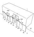
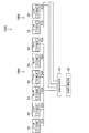
図1は、本実施形態に係るゲート装置を示す斜視図である。図2は、本実施形態に係るゲート装置を示す上面図である。なお、図1においては、プラットホームP脇に鉄道車両Tが停車している様子を示しており、図2においては、プラットホームP脇に鉄道車両Tが停車していない様子を示している。図3は、本実施形態に係るゲートシステムの概要を示すブロック図である。 FIG. 1 is a perspective view showing a gate device according to the present embodiment. FIG. 2 is a top view showing a gate device according to the present embodiment. Note that FIG. 1 shows a state in which the railroad vehicle T is stopped beside the platform P, and FIG. 2 shows a state in which the railroad car T is not stopped beside the platform P. FIG. 3 is a block diagram showing an outline of the gate system according to the present embodiment.
なお、本実施形態においては、車両扉Dの数、車両扉Dの間隔が異なる鉄道車両をそれぞれ鉄道車両T1〜T6と符号を付して表すが、特に区別して説明する必要がない場合は、単に鉄道車両Tとして表して説明する。また、本実施形態においては、図2中の左方向が鉄道車両Tの進行方向(前方)であり、図2中の右方向が鉄道車両Tの進行方向の逆方向(後方)であるとする。後述の図4〜図17においても同様とする。また、車両扉においては、鉄道車両Tの前方から順に、車両扉D1、車両扉D2、車両扉D3、車両扉D4と符号を付して表すが、特に区別して説明する必要がない場合は、単に車両扉Dとして表して説明する。 In the present embodiment, railroad vehicles having different numbers of vehicle doors D and different distances between vehicle doors D are designated as railroad vehicles T1 to T6, respectively, but when it is not necessary to distinguish them, they are represented. It will be described simply as a railroad vehicle T. Further, in the present embodiment, it is assumed that the left direction in FIG. 2 is the traveling direction (forward) of the railway vehicle T, and the right direction in FIG. 2 is the opposite direction (rear direction) of the traveling direction of the railway vehicle T. .. The same applies to FIGS. 4 to 17 described later. Further, in the rolling stock doors, the rolling stock doors D1, the rolling stock doors D2, the rolling stock doors D3, and the rolling stock doors D4 are designated in order from the front of the railcar T, but if it is not necessary to distinguish them, they are represented. It will be described simply as a vehicle door D.
プラットホーム用ゲートシステム1000(以下、単にゲートシステム1000という)は、複数のプラットホーム用ゲート装置100(以下、単にゲート装置100という)と、車両扉位置取得部20と、目標位置決定部30とを含む。
The platform gate system 1000 (hereinafter, simply referred to as a gate system 1000) includes a plurality of platform gate devices 100 (hereinafter, simply referred to as a gate device 100), a vehicle door
ゲートシステム1000は、プラットホームPから線路Rへの落下防止など乗客の安全性を確保するためのシステムである。なお、プラットホームPとは、線路R上を走行する電車や新幹線等の鉄道車両Tが停車する駅において乗客が鉄道車両Tに乗り降りするために設けられる乗降場所である。
The
図2に示すように、本実施形態において、プラットホームPには、プラットホームPの縁PEに沿うように延びる、第1の扉通路11、第2の扉通路12、第3の扉通路13が設けられている。第2の扉通路12は、第1の扉通路11よりもプラットホームPの縁PE側においてプラットホームPの縁PEに沿うように延びている。また、第3の扉通路13は、第2の扉通路12よりもプラットホームPの縁PE側においてプラットホームPの縁PEに沿うように延びている。
As shown in FIG. 2, in the present embodiment, the platform P is provided with a
ゲート装置100は、第1の扉1、第2の扉2、第3の扉3、第4の扉4、第5の扉5、第6の扉6を有している。
The
第1の扉1と第4の扉4は、第1の扉通路11上を移動する。第2の扉2と第6の扉6は、第2の扉通路12上を移動する。第3の扉3と第5の扉5は、第3の扉通路13上を移動する。第1の扉1〜第6の扉6は、プラットホームPの縁PEの長さに応じて、それぞれ複数設けられているとよい。なお、図1においては、プラットホームPの縁PEの長さに応じて設けられる複数のゲート装置100の一部のみを示している。
The
後述の図4〜図17においては、ゲート装置を前方から順に、ゲート装置100A、ゲート装置100B、ゲート装置100C、ゲート装置100Dと符号を付して表すが、特に区別して説明する必要がない場合は、単にゲート装置100として表して説明する。ゲート装置100が備える各構成についても同様とする。例えば、ゲート装置100Aの各扉を、第1の扉1A〜第6の扉6Aと符号を付して表し、特に区別して説明する必要がない場合は、単に第1の扉1〜第6の扉6として表して説明する。
In FIGS. 4 to 17, which will be described later, the gate devices are represented by reference numerals as
車両扉位置取得部20は、プラットホームP脇に停車する鉄道車両Tの車両扉Dの位置情報を取得する。車両扉位置取得部20は、次にプラットホームP脇に停車する鉄道車両Tの車両扉Dの位置を予め取得するものであってもよいし、実際にプラットホームP脇に停車した鉄道車両Tの車両扉Dの位置を、プラットホームP上又はゲート装置100に設けられるレーザセンサ等の位置センサを用いて検知することにより取得するものであってもよい。
The vehicle door
目標位置決定部30は、車両扉位置取得部20が取得した、プラットホームP脇に停車する鉄道車両Tの車両扉Dの位置に応じて、複数のゲート装置100の各扉の目標位置をそれぞれ決定する。
The target
また、図3に示すように、ゲート装置100の第1の扉1〜第6の扉6はそれぞれ、モータ等を含む駆動部51〜駆動部56を有している。第1の扉1〜第6の扉6はそれぞれ、駆動部51〜駆動部56により、他の扉と独立して移動される。なお、駆動部の構成の詳細については後述することとする。
Further, as shown in FIG. 3, each of the
以下の説明において、ゲート装置100の各扉が、乗客が乗降するための開口を形成しない位置を、基準位置という。ゲート装置100の各扉は、プラットホームP脇に鉄道車両Tが停止していない場合、又は、プラットホームP脇を鉄道車両Tが通過している場合に、基準位置に位置している。以下の説明において、第1の扉1〜第6の扉6の基準位置をそれぞれ、第1の基準位置〜第6の基準位置という。また、第1の基準位置〜第6の基準位置にある第1の扉1〜第6の扉6が、乗客が乗降するための開口を形成するために移動した後の位置をそれぞれ、第1の目標位置〜第6の目標位置という。
In the following description, a position where each door of the
図4は、鉄道車両がプラットホーム脇に停車しておらず、複数のゲート装置の各扉が基準位置にある様子を示す図である。図5は、図4に示す鉄道車両及びゲート装置を上方から見た様子を模式的に示す図である。なお、図4においては、プラットホームP上からゲート装置100を見た様子を示している。後述の図6、図8、図10、図12、図14、図16においても同様である。
FIG. 4 is a diagram showing a state in which a railroad vehicle is not stopped beside the platform and each door of a plurality of gate devices is in a reference position. FIG. 5 is a diagram schematically showing a state in which the railway vehicle and the gate device shown in FIG. 4 are viewed from above. Note that FIG. 4 shows a state in which the
図4、図5に示すように、第1の基準位置にある第1の扉1Bと、第4の基準位置にある第4の扉4Bとは、互いに隣接することにより、プラットホームP上から線路Rへの乗客の移動を規制している。また、第3の基準位置にある第3の扉3Bと、第5の基準位置にある第5の扉5Bとは、互いに隣接することにより、プラットホームP上から線路Rへの乗客の移動を規制している。
As shown in FIGS. 4 and 5, the
また、図5に示すように、第2の基準位置にある第2の扉2Bは、プラットホームPの縁PEが延びる方向において、第1の扉1B及び第3の扉3Bと一部が重なることにより、プラットホームPから線路Rへの乗客の移動を規制している。ただし、この配置は一例であり、少なくとも、第2の基準位置にある第2の扉2Bは、第1の扉1B及び第3の扉3Bと共に、プラットホームPから線路Rへの乗客の移動を規制するものであればよく、プラットホームPの縁PEが延びる方向において、それらの一部が重なっていなくても構わない。
Further, as shown in FIG. 5, the
また、第6の基準位置にある第6の扉6Bは、プラットホームPの縁が延びる方向において、第5の扉5B及び第4の扉4Aと一部が重なることにより、プラットホームPから線路Rへの乗客の移動を規制している。ただし、この配置は一例であり、少なくとも、第6の基準位置にある第6の扉6Bは、第5の扉5B及び第4の扉4Aと共に、プラットホームPから線路Rへの乗客の移動を規制するものであればよく、プラットホームPの縁PEが延びる方向において、それらの一部が重なっていなくても構わない。
Further, the
各ゲート装置100の各扉が上記のように基準位置に位置することにより、プラットホームPの縁PEが沿う方向の全域に亘って、プラットホームPから線路Rへの乗客の移動が規制されることとなる。
By locating each door of each
駆動部51は、第1の基準位置にある第1の扉1を、目標位置決定部30が決定した第1の目標位置に移動させる。駆動部52は、第2の基準位置にある第2の扉2を、目標位置決定部30が決定した第2の目標位置に移動させる。駆動部53は、第3の基準位置にある第3の扉3を、目標位置決定部30が決定した第3の目標位置に移動させる。駆動部54は、第4の基準位置にある第4の扉4を、目標位置決定部30が決定した第4の目標位置に移動させる。駆動部55は、第5の基準位置にある第5の扉5を、目標位置決定部30が決定した第5の目標位置に移動させる。駆動部56は、第6の基準位置にある第6の扉6を、目標位置決定部30が決定した第6の目標位置に移動させる。
The
また、プラットホームP脇に停車する鉄道車両Tにおいて、乗客の乗り降りが行われ、発車の準備が完了した後、駆動部51〜駆動部56はそれぞれ、第1の目標位置〜第6の目標位置にある第1の扉1〜第6の扉6を、第1の基準位置〜第6の基準位置に移動させるとよい。すなわち、図4、図5に示す位置に、第1の扉1〜第6の扉を移動させることにより、プラットホームPの縁PEが沿う方向の全域に亘って、プラットホームPから線路Rへの乗客の移動を規制する状態とするとよい。
Further, in the railcar T that stops beside the platform P, after passengers get on and off and preparations for departure are completed, the
[車両扉に応じた各扉の位置の例]
以下、図6〜図17を参照して、プラットホームP脇に停車する鉄道車両Tの車両扉Dに応じた、ゲート装置100の各扉の位置の例について具体的に説明する。図6〜図17においては、ゲート装置100A〜100Dの各扉が、プラットホームP脇に停車する鉄道車両Tの車両扉Dの数及びその間隔に応じて、目標位置にそれぞれ移動した後の様子を示している。
[Example of the position of each door according to the vehicle door]
Hereinafter, an example of the position of each door of the
まず、図6、図7を参照して、4つの車両扉D1〜D4を備える鉄道車両T1がプラットホームP脇に停車する第1の例について説明する。図6は、第1の例において、ゲート装置が備える各扉が目標位置にある様子を示す図である。図7は、図6に示す鉄道車両及びゲート装置を上方から見た図である。 First, a first example in which a railroad vehicle T1 having four vehicle doors D1 to D4 stops beside a platform P will be described with reference to FIGS. 6 and 7. FIG. 6 is a diagram showing how each door included in the gate device is at a target position in the first example. FIG. 7 is a view of the railroad vehicle and the gate device shown in FIG. 6 as viewed from above.
図6、図7に示すように、4つの車両扉D1〜D4を通じての鉄道車両T1への乗客の乗り降りが可能となるように、各扉が基準位置から目標位置へ移動される。車両扉位置取得部20が車両扉D1〜D4の位置情報を取得し、目標位置決定部30が各車両扉の位置情報に基づいて各扉の目標位置を決定する。そして、各駆動部が、それぞれ決定された各目標位置に各扉をそれぞれ移動させる。
As shown in FIGS. 6 and 7, each door is moved from the reference position to the target position so that passengers can get on and off the railway vehicle T1 through the four vehicle doors D1 to D4. The vehicle door
第1の例においては、第3の扉3Aと第5の扉5Aとが互いに離間する方向に移動することにより、車両扉D1を通じて乗客の乗り降りを可能とする開口が形成されている。この際、開口の幅を十分に確保するために、第2の扉2Aと第6の扉6Aも互いに離間する方向に移動している。一方、開口の幅に寄与しない第1の扉1Aと第4の扉4Aは、基準位置にある状態を維持している。
In the first example, the
第1の例においては、車両扉D1〜D4が等間隔に配置されているため、ゲート装置100B、100C、100Dの各扉も、ゲート装置100Aの各扉と同様の配置になっている。
In the first example, since the vehicle doors D1 to D4 are arranged at equal intervals, the doors of the
なお、図6、図7においては、車両扉Dの幅よりもゲート装置100の開口の幅が広くなるようにゲート装置100の各扉の目標位置が決定された場合の例について示すが、これに限られるものではなく、開口が、少なくとも乗客が通過できる程度の幅となるようにゲート装置100の各扉の目標位置が決定されるとよい。以下で説明する図8〜図17で示す例においても同様である。
Note that FIGS. 6 and 7 show an example in which the target position of each door of the
次に、図8、図9を参照して、4つの車両扉D1〜D4を備える先頭車両T2がプラットホームP脇に停車する第2の例について説明する。図8は、第2の例において、ゲート装置が備える各扉が目標位置にある様子を示す図である。図9は、図8に示す鉄道車両及びゲート装置を上方から見た図である。 Next, a second example in which the leading vehicle T2 having the four vehicle doors D1 to D4 stops beside the platform P will be described with reference to FIGS. 8 and 9. FIG. 8 is a diagram showing a state in which each door included in the gate device is at a target position in the second example. FIG. 9 is a view of the railroad vehicle and the gate device shown in FIG. 8 as viewed from above.
第2の例は、第1の例と同様に、4つの車両扉を備える鉄道車両がプラットホームP脇に停車している例である。本例では、プラットホームP脇に停車する鉄道車両が先頭車両T2である場合を例に挙げて説明する。 The second example is an example in which a railroad vehicle having four vehicle doors is stopped beside the platform P, as in the first example. In this example, the case where the railroad vehicle stopped beside the platform P is the leading vehicle T2 will be described as an example.
先頭車両T2においては、車両の前部に運転室があるため、車両扉D1〜D4が等間隔に配置されていない。具体的には、第1の例と比較して、車両扉D1が車両の後方に位置しており、車両扉D1と車両扉D2の間隔が、他の車両扉の間隔よりも狭くなっている。 In the leading vehicle T2, since the driver's cab is located at the front of the vehicle, the vehicle doors D1 to D4 are not arranged at equal intervals. Specifically, as compared with the first example, the vehicle door D1 is located behind the vehicle, and the distance between the vehicle door D1 and the vehicle door D2 is narrower than the distance between the other vehicle doors. ..
本実施形態に係るゲート装置100においては、車両扉D1〜D4が等間隔に配置されていない先頭車両T2がプラットホームP脇に停車した場合であっても、適切な位置に開口を形成することができる。具体的には、図8、図9に示すように、第1の扉1Aは第1の基準位置にある状態を維持し、第2の扉2A及び第3の扉3Aが、第1の扉1Aと重なり合う位置まで移動する。これにより、車両扉D1を通じて乗客が先頭車両T2に乗り降りするのに十分な幅の開口を形成することができる。なお、図8、図9に示すように、ゲート装置100B〜100Dの各扉は、第1の例と同様の目標位置に移動しているとよい。
In the
次に、図10、図11を参照して、3つの車両扉D1〜D3を備える鉄道車両T3がプラットホームP脇に停車する第3の例について説明する。図10は、第3の例において、ゲート装置が備える各扉が目標位置にある様子を示す図である。図11は、図10に示す鉄道車両及びゲート装置を上方から見た図である。 Next, with reference to FIGS. 10 and 11, a third example in which the railway vehicle T3 having the three vehicle doors D1 to D3 stops beside the platform P will be described. FIG. 10 is a diagram showing a state in which each door included in the gate device is at a target position in the third example. FIG. 11 is a view of the railroad vehicle and the gate device shown in FIG. 10 as viewed from above.
図10、図11に示すように、車両扉D1を通じて乗客の乗り降りを可能とする開口を形成するように、第3の扉3Aが第5の扉5Aから離間する方向に移動し、第2の扉2Aが第6の扉6Aから離間する方向に移動している。なお、第1の扉1Aは第1の基準位置にある状態を維持しており、第4の扉4Aは第4の基準位置にある状態を維持しており、第5の扉5Aは第5の基準位置にある状態を維持しており、第6の扉6Aは第6の基準位置にある状態を維持している。
As shown in FIGS. 10 and 11, the
また、車両扉D2を通じて乗客の乗り降りを可能とする開口を形成するように、第1の扉1Bと第4の扉4Bが互いに離間する方向に移動し、第2の扉2Bと第6の扉6Cが互いに離間する方向に移動している。なお、第3の扉3Bは第3の基準位置にある状態を維持しており、第5の扉5Bは第5の基準位置にある状態を維持しており、第6の扉6Bは第6の基準位置にある状態を維持している。
Further, the
また、車両扉D3を通じて乗客の乗り降りを可能とする開口を形成するように、第5の扉5Dが第3の扉3Dから離間する方向に移動し、第6の扉6Dが第2の扉2Dから離間する方向に移動している。なお、第1の扉1Dは第1の基準位置にある状態を維持しており、第2の扉2Dは第2の基準位置にある状態を維持しており、第3の扉3Dは第3の基準位置にある状態を維持しており、第4の扉4Dは第4の基準位置にある状態を維持している。
Further, the
次に、図12、図13を参照して、2つの車両扉D1、D2を備える鉄道車両T4がプラットホームP脇に停車する第4の例について説明する。図12は、第4の例において、ゲート装置が備える各扉が目標位置にある様子を示す図である。図13は、図12に示す鉄道車両及びゲート装置を上方から見た図である。 Next, a fourth example in which the railway vehicle T4 having the two vehicle doors D1 and D2 stops beside the platform P will be described with reference to FIGS. 12 and 13. FIG. 12 is a diagram showing how each door included in the gate device is at a target position in the fourth example. FIG. 13 is a view of the railroad vehicle and the gate device shown in FIG. 12 as viewed from above.
図12、図13に示すように、車両扉D1を通じて乗客の乗り降りを可能とする開口を形成するように、第1の扉1Aが第4の扉4Aから離間する方向に移動し、第2の扉2Aが第6の扉6Bから離間する方向に移動している。なお、第3の扉3Aは第3の基準位置にある状態を維持しており、第4の扉4Aは第4の基準位置にある状態を維持しており、第5の扉5Aは第5の基準位置にある状態を維持しており、第6の扉6Aは第6の基準位置にある状態を維持している。
As shown in FIGS. 12 and 13, the
また、ゲート装置100Bの第1の扉1B〜第6の扉6Bはいずれも基準位置にある状態を維持している。
Further, the
また、車両扉D2を通じて乗客の乗り降りを可能とする開口を形成するように、第4の扉4Cが第1の扉1Cから離間する方向に移動しており、第6の扉6Dが第2の扉2Cから離間する方向に移動している。なお、ゲート装置100Cの第4の扉4C以外の扉は、基準位置にある状態を維持している。また、ゲート装置100Dの第6の扉6D以外の扉は、基準位置にある状態を維持している。
Further, the
次に、図14、図15を参照して、1つの車両扉D1を備える鉄道車両T5がプラットホームP脇に停車する第5の例について説明する。図14は、第5の例において、ゲート装置が備える各扉が目標位置にある様子を示す図である。図15は、図14に示す鉄道車両及びゲート装置を上方から見た図である。 Next, a fifth example in which the railroad vehicle T5 having one vehicle door D1 stops beside the platform P will be described with reference to FIGS. 14 and 15. FIG. 14 is a diagram showing how each door included in the gate device is at a target position in the fifth example. FIG. 15 is a view of the railroad vehicle and the gate device shown in FIG. 14 as viewed from above.
図14、図15に示すように、車両扉D1を通じて乗客の乗り降りを可能とする開口を形成するように、第3の扉3Dと第5の扉5Dとが互いに離間する方向に移動している。この際、開口の幅を十分に確保するために、第2の扉2Dと第6の扉6Dも互いに離間する方向に移動している。なお、ゲート装置100A〜100Cが備える各扉は、基準位置にある状態を維持している。
As shown in FIGS. 14 and 15, the
次に、図16、図17を参照して、1つの車両扉D1を備える鉄道車両T6がプラットホームP脇に停車する第6の例について説明する。図16は、第6の例において、ゲート装置が備える各扉が目標位置にある様子を示す図である。図17は、図16に示す鉄道車両及びゲート装置を上方から見た図である。 Next, a sixth example in which the railroad vehicle T6 having one vehicle door D1 stops beside the platform P will be described with reference to FIGS. 16 and 17. FIG. 16 is a diagram showing how each door included in the gate device is at a target position in the sixth example. FIG. 17 is a view of the railroad vehicle and the gate device shown in FIG. 16 as viewed from above.
第6の例の鉄道車両T6は、第5の例の鉄道車両T5と同様に1つの車両扉D1を備えているが、車両扉D1が鉄道車両T5よりも後方に位置している。 The railway vehicle T6 of the sixth example has one vehicle door D1 like the railway vehicle T5 of the fifth example, but the vehicle door D1 is located behind the railway vehicle T5.
図16、図17に示すように、車両扉D1を通じて乗客の乗り降りを可能とする開口を形成するように、第1の扉1Dが第4の扉4Dから離間する方向に移動している。この際、開口の幅を十分に確保するために、第2の扉2Dも第1の扉1Dと同じ方向に移動している。なお、ゲート装置100A〜100Cが備える各扉は、基準位置にある状態を維持している。
As shown in FIGS. 16 and 17, the
以上、第1の例〜第6の例を用いて説明したように、本実施形態に係るゲート装置100においては、プラットホームP脇に停車する鉄道車両Tの車両扉Dの数、車両扉Dの間隔に応じて、乗客の乗り降りを可能とする開口を形成することができる。
As described above using the first to sixth examples, in the
なお、第1の例〜第6の例においては、第1の扉1と第4の扉4との間に開口が形成される例と、第3の扉3と第5の扉5との間に開口が形成される例について示したが、これに限られるものではない。例えば、第1の扉1Aと第2の扉2Aとの間、第2の扉2Aと第3の扉3Aとの間、第4の扉4Aと第6の扉6Bとの間、第5の扉5Aと第6の扉6Aとの間に開口が形成されるよう、各扉を移動可能としても構わない。このような構成とすることにより、より開口位置の自由度を向上することができる。
In the first to sixth examples, an example in which an opening is formed between the
また、各扉は、扉通路上であって、隣り合う扉に接触するまでの範囲であれば、制限なく移動可能としてもよい。例えば、図7に示す第3の扉3Aは、第3の扉通路13上において第5の扉5Bと接触する位置まで移動可能であってもよい。同様に、例えば、図7に示す第6の扉6Dは、第2の扉通路12上において第2の扉2Cと接触する位置まで移動可能であってもよい。このような構成とすることにより、第1の例〜第6の例で示した車両扉Dよりも幅の広い車両扉を備える鉄道車両Tや、複数の車両扉Dが近接して配置される鉄道車両TがプラットホームP脇に停車した場合であっても、当該車両扉の幅、その間隔に応じて、適切な幅の開口を形成することができる。
Further, each door may be movable without limitation as long as it is on the door passage and within a range until it comes into contact with adjacent doors. For example, the
[各扉の駆動方式]
図18〜図21を参照して、ゲート装置100の扉の駆動方式について具体的に説明する。ここでは、第1の扉1を例に挙げて説明するが、第2の扉2〜第6の扉6にも同様の駆動方式を適用するとよい。
[Drive system for each door]
The door drive system of the
図18は、第1の扉の内部構造、及びプラットホーム内の構造を示す図である。図19は、図18に示すXIX−XIX切断線で切り取った切断面を示す断面図である。図20は、図18に示すXX−XX切断線で切り取った切断面を示す断面図である。図21は、図18に示すXXI−XXI切断線で切り取った切断面を示す断面図である。 FIG. 18 is a diagram showing the internal structure of the first door and the structure inside the platform. FIG. 19 is a cross-sectional view showing a cut surface cut along the XIX-XIX cutting line shown in FIG. FIG. 20 is a cross-sectional view showing a cut surface cut along the XX-XX cutting line shown in FIG. FIG. 21 is a cross-sectional view showing a cut surface cut along the XXI-XXI cutting line shown in FIG.
なお、図18においては、第1の扉1の内部構造を示すため、第1の扉1の外装を構成するハウジング1hの紙面手前側(プラットホームPの内側)の面の図示を省略している。また、図18においては、プラットホームPの図示を省略している。また、図18においては、図4等と同様に、図中の左方向が前方であり、右方向が後方であるとする。また、図19〜図21においては、図面の簡略化のためハッチングを省略している。
In FIG. 18, in order to show the internal structure of the
第1の扉1は、駆動部51を有している。駆動部51は、モータ511と、モータ511の回転に伴い回転する輪列を含む。モータ511及び輪列の一部は、第1の扉1の外装を構成するハウジング1h内に収容されている。
The
輪列は、モータ511と同軸上で回転する歯車511aと、歯車511aと噛み合う歯車512と、駆動プーリ513と、駆動プーリ514とを含む。また、輪列は、歯車512と同軸上で歯車512と共に回転する歯車512aと、駆動プーリ513と、駆動プーリ514とに掛けわたされるタイミングベルト515を含む。また、輪列は、駆動プーリ513と同軸上で駆動プーリ513と共に回転する歯車513aと、駆動プーリ513と同軸上で駆動プーリ513と共に回転する歯車514aと、に掛けわたされるパワーベルト516を含む。パワーベルト516の内周面には、歯車513aと歯車514aとに噛み合う歯車が形成されている。また、パワーベルト516の外周面には、後述のラックギア60と噛み合う歯車が形成されている。
The train wheel includes a
また、プラットホームPに設けられる第1の扉通路11には、プラットホームPの縁PEに沿うように延びる溝gが形成されている。溝gは、深溝g1と、深溝g1に隣接する浅溝g2を含む。図19に示すように、浅溝g2内には、ラックギア60が設けられている。ラックギア60はプラットホームPに対して固定されている。また、ラックギア60は、パワーベルト516の外周面に形成される歯車と噛み合うように設けられている。また、図18、図20に示すように、溝g内には、上述の駆動プーリ513及び駆動プーリ514が配置されている。
Further, a groove g extending along the edge PE of the platform P is formed in the
モータ511からの駆動力は、上記輪列を介して、パワーベルト516に伝達される。それにより、パワーベルト516は、その外周面に形成される歯車がラックギア60と噛み合うと共に、歯車513aと歯車514aとに掛けわたされた状態で、図18中の時計回り又は反時計回りに回動する。
The driving force from the
パワーベルト516を図18中の時計回りに回動させた場合、ラックギア60と噛み合うパワーベルト516は、ラックギア60に対して相対的に図18中の左方向に移動することとなる。それにより、第1の扉1は、プラットホームPの第1の扉通路11上を、左方向(前方)に移動することとなる。
When the
一方、パワーベルト516を図18中の反時計回り回動させた場合、ラックギア60と噛み合うパワーベルト516は、ラックギア60に対して相対的に図18中の右方向に移動することとなる。それにより、第1の扉1は、プラットホームPの第1の扉通路11上を、右方向(後方)に移動することとなる。
On the other hand, when the
また、第1の扉1は、ハウジング1hに対して固定されており、下方に突出する支持板70を有しているとよい。図18においては、支持板70が2枚設けられる例について示すが、支持板70は1枚であってもよいし、3枚以上であってもよい。支持板70は、図19に示すように、プラットホームPに形成される深溝g1に挿入されているとよい。
Further, it is preferable that the
このように、支持板70が設けられることにより、第1の扉1は、プラットホームPに対して支持され、プラットホームP上において自立状態を維持することができる。また、乗客に押されたり、鉄道車両Tが通過する際に生じる風圧の影響を受けたりした場合であっても、自立状態を維持し、倒れることはない。
By providing the
上記特許文献1のように装置が全体として大型化してしまう構成においては、戸袋及び扉を自立させるために、下部の厚みを厚くする必要があるところ、本実施形態に係るゲート装置100においては、上部と下部の厚みを略同じにした場合であっても、扉を自立させることができる。このように、本実施形態に係るゲート装置100においては、支持構造を簡易にすると共に、小型化することが可能となる。
In the configuration in which the device becomes large as a whole as in
また、第1の扉1は、その下部に車輪81、82を有しているとよい。車輪81、82は、第1の扉1の移動に伴って、プラットホームPの第1の扉通路11上で回転する。このように、第1の扉1は、車輪81、82を有しているため、プラットホームPの第1の扉通路11上をスムーズに移動することができる。
Further, the
また、図19〜図21に示すように、プラットホームPには、後述の溝埋めベルト83が嵌る溝g3が形成されているとよい。また、溝g3の幅は、車輪81、82が嵌る程度の幅であるとよい。溝g3の側壁がガイドとなり、第1の扉1は、よりスムーズに直進移動することができる。また、車輪81、82は、溝g3よりも幅が広くてもよい。その場合、車輪81、82は、溝g3の上方においてプラットホームP上で回転することとなる。その場合、車輪81、82は、車輪81、82の径方向に突出しており、溝g3に嵌る程度の幅のフランジ部を有しているとよい。これにより、溝g3の側壁が当該フランジ部のガイドとなり、第1の扉1は、スムーズに直進移動することができる。
Further, as shown in FIGS. 19 to 21, it is preferable that the platform P is formed with a groove g3 into which the
さらに、第1の扉1は、図18に示すように、溝埋めベルト83と、溝埋めベルト83を巻き取り及び巻き出し可能なリール84を有しているとよい。溝埋めベルト83は、プラットホームPの第1の扉通路11に形成される溝の開口を塞ぐ機能を担うものである。
Further, as shown in FIG. 18, the
溝埋めベルト83の一端はリール84に巻き取られており、溝埋めベルト83の他端は、隣り合う扉に固定されているとよい。図18においては、第1の扉1と後方で隣り合う第4の扉4から延びる溝埋めベルト83の他端が、第1の扉1の下部に設けられる止めピン(固定部)85に固定されている様子を示している。また、図示は省略するが、同様に、第1の扉1から延びる溝埋めベルト83の他端は、第1の扉1と前方で隣り合う不図示の第4の扉の下部に設けられる止めピンに固定されているとよい。
It is preferable that one end of the
また、車輪81は、溝埋めベルト83のガイドローラとしての機能を備えているとよい。図18においては、リール84から巻き出された溝埋めベルト83が、車輪81の周面に掛けられている様子を示している。
Further, the
第1の扉1が後方に移動した場合、第1の扉1に収容されるリール84から溝埋めベルト83が巻き出される。巻き出された溝埋めベルト83は、図21に示すように、第1の扉通路11に形成される溝に嵌められる。
When the
第1の扉通路11に形成される溝の開口のうち、第1の扉1よりも前方の領域は、第1の扉1から延びる溝埋めベルト83により塞がれる。また、第1の扉通路11に形成される溝の開口のうち、第1の扉1よりも後方の領域は、第4の扉4から延びる溝埋めベルト83により塞がれる。このため、第1の扉通路11に形成される溝の開口がプラットホームP上に露出することがない。
Of the groove openings formed in the
第1の扉通路11に形成される溝の開口が塞がれることにより、乗客の靴が溝に嵌るなどの危険を防ぐことが可能となる。また、第1の扉通路11に形成される溝内に雨水や粉塵が入り込んでしまうことを抑制することができる。その結果、第1の扉1の駆動に不具合等が生じてしまうことを抑制することができる。
By closing the opening of the groove formed in the
なお、詳細な説明については省略するが、第2の扉通路12、第3の扉通路13に形成される溝の開口も同様に、第2の扉2、第3の扉3、第5の扉5、第6の扉6から延びる溝埋めベルト83により塞がれるとよい。
Although detailed description will be omitted, the openings of the grooves formed in the
また、3つの扉通路上をそれぞれ扉が移動するゲート装置100においては、各扉の厚みを薄くすることにより、全体の厚みを抑制することが好ましい。そこで、図18に示すように、第1の扉1において、駆動軸Oが上下方向(第1の扉1の厚み方向に直交する方向)に延びるようにモータ511を配置した。これにより、駆動軸Oが扉の厚み方向に延びるようにモータ511を配置する構成と比較して、第1の扉1の厚みが抑制される。第2の扉2〜第6の扉6においても同様の構成を採用するため、装置全体として厚み方向に大型化することが抑制される。
Further, in the
本実施形態においては、1の扉に1の駆動部が配置されている。1の扉の移動は、他の扉に影響されないため、1の駆動部における動力を最小限にすることができる。また、各扉の外装を構成するハウジング内に、複数の駆動部を収容されないため、扉が大型化してしまうことが抑制される。 In the present embodiment, one drive unit is arranged on one door. Since the movement of one door is not affected by other doors, the power in the drive unit of one can be minimized. Further, since a plurality of drive units are not accommodated in the housing constituting the exterior of each door, it is possible to prevent the door from becoming large.
以上説明したように、本実施形態に係るゲート装置100においては、開口位置の自由度を向上すると共に、装置が大型化してしまうことを抑制することができる。
As described above, in the
また、図18に示すように、第1の扉1は、プラットホームP側から見て線路R側を視認可能にする透明部1aを有していてもよい。透明部1aは、ハウジング1hの一部を構成するものであって、アクリル板やガラス板などであるとよい。なお、ハウジング1h内に収容される機構や部材などは、鉛直方向において透明部1aに重ならない領域に配置されているとよい。すなわち、例えば、駆動部51や支持板70は、鉛直方向において、透明部1aよりも下方に配置されているとよい。
Further, as shown in FIG. 18, the
[各扉の駆動方式の変形例]
図22を参照して、ゲート装置100の扉の駆動方式の変形例に説明する。なお、図18で示した構成と同様の構成については同じ符号を付してその説明は省略する。ここでは、第1の扉通路11上を移動する第1の扉1及び第4の扉4を例に挙げて説明する。なお、第2の扉通路12上を移動する第2の扉2及び第6の扉6、第3の扉通路13上を移動する第3の扉3及び第5の扉5についても同様の駆動方式を適用するとよい。
[Modification example of drive system for each door]
A modification of the door drive system of the
図22に示すように、変形例においては、駆動部51は、モータ511Fと、モータ511Fの回転に伴い回転する前輪列と、モータ511Rと、モータ511Rの回転に伴い回転する後輪列と、を含む。
As shown in FIG. 22, in the modified example, the
前輪列は、モータ511Fと同軸上で回転する歯車511aFと、歯車511aFと噛み合う歯車512Fと、歯車512Fと同軸上で歯車512Fと共に回転する歯車512aFと、リール513Fと、リール513Fと同軸上でリール513Fと共に回転する歯車513aFとを含む。また、前輪列は、歯車512aFと歯車513aFとに掛けわたされるベルト516Fを含む。
The front train wheel consists of a gear 511aF that rotates coaxially with the
後輪列も同様に、モータ511Rと同軸上で回転する歯車511aRと、歯車511aRと噛み合う歯車512Rと、歯車512Rと同軸上で歯車512Rと共に回転する歯車512aRと、リール513Rと、リール513Rと同軸上でリール513Rと共に回転する歯車513aRとを含む。また、後輪列は、歯車512aRと歯車513aRとに掛けわたされるベルト516Rを含む。
Similarly, the rear wheel train is coaxial with the gear 511aR that rotates coaxially with the
また、第1の扉1には、リール513Fにより巻き取り及び巻き出しがされる連結ベルト88Fと、リール513Rにより巻き取り及び巻き出しがされる連結ベルト88Rとが設けられている。
Further, the
モータ511Fからの駆動力は、前輪列を介して、リール513Fに伝達される。それにより、リール513Fが回転し、連結ベルト88Fの巻き取り及び巻き出しが行われる。同様に、モータ511Rからの駆動力は、後輪列を介して、リール513Rに伝達される。それにより、リール513Rが回転し、連結ベルト88Rの巻き取り及び巻き出しが行われる。
The driving force from the
また、図22に示すように、第4の扉4は、駆動部54を有している。駆動部54は、駆動部51と同様の構成であり、モータ541Fと、前輪列と、モータ541Rと、後輪列とを含む。前輪列は、歯車541aF、歯車542F、歯車542aF、歯車543aF、リール543F、ベルト546Fを含む。後輪列は、歯車541aR、歯車542R、歯車542aR、歯車543aR、リール543R、ベルト546Rを含む。
Further, as shown in FIG. 22, the fourth door 4 has a
図22に示すように、連結ベルト88Fの一端は、第1の扉1のリール513Fにより巻き取り及び巻き出しされるように設けられており、連結ベルト88Fの他端は、第1の扉1の前方で隣り合う第4の扉4が備えるリール543Rにより巻き取り及び巻き出しされるように設けられている。
As shown in FIG. 22, one end of the connecting
また、連結ベルト88Rの一端は、第1の扉1のリール513Rに対して巻き取り及び巻き出しされるように設けられており、連結ベルト88Rの他端は、第1の扉1の後方で隣り合う第4の扉4が備えるリール543Fに対して巻き取り及び巻き出しされるように設けられている。
Further, one end of the connecting
連結ベルト88Fは、第1の扉1の下部に設けられるガイドローラ89Fと、第1の扉1の前方で隣り合う第4の扉4の下部に設けられるガイドローラ89Rとに掛けわたされて、第1の扉通路11に形成される不図示の溝内において、該溝に沿うように設けられている。同様に、連結ベルト88Rは、第1の扉1の下部に設けられるガイドローラ89Rと、第1の扉1の後方で隣り合う第4の扉4の下部に設けられるガイドローラ89Fとに掛けわたされて、第1の扉通路11に形成される不図示の溝内において、該溝に沿うように設けられている。
The connecting
第1の扉1は、第1の扉1の前方で隣り合う第4の扉4のリール543Rの回転を規制した状態で、リール513Fにより連結ベルト88Fを巻き取るようにモータ511Fを駆動することにより、連結ベルト88Fにより前方に引っ張られ、第1の扉通路11上を前方に移動する。
The
また、第1の扉1は、第1の扉1の後方で隣り合う第4の扉4のリール543Fの回転を規制した状態で、リール513Rにより連結ベルト88Rを巻き取るようにモータ511Rを駆動することにより、連結ベルト88Rにより後方に引っ張られ、第1の扉通路11上を後方に移動する。
Further, the
ただし、これに限られるものではなく、第4の扉4の駆動部54が、第1の駆動部51としての機能を担うものであっても構わない。すなわち、第1の扉1は、駆動部54の駆動力により、第1の扉通路11上を移動するものであっても構わない。
However, the present invention is not limited to this, and the
具体的には、第1の扉1は、リール513Fの回転を規制した状態で、第1の扉1の前方で隣り合う第4の扉4のリール543Rにより連結ベルト88Fを巻き取るようにモータ541Rを駆動することにより、連結ベルト88Fにより前方に引っ張られ、第1の扉通路11上を前方に移動してもよい。
Specifically, the
同様に、第1の扉1は、リール513Rの回転を規制した状態で、第1の扉1の後方で隣り合う第4の扉4のリール543Fにより連結ベルト88Rを巻き取るようにモータ541Fを駆動することにより、連結ベルト88Rにより後方に引っ張られ、第1の通路11上を後方に移動してもよい。
Similarly, in the state where the rotation of the
以上説明したように、変形例においては、第1の扉通路11上において互いに隣り合う扉が連結ベルトを介して連結されており、連結ベルトの生じる張力に応じて、第1の扉通路11上を移動する。変形例においては、プラットホームP内にラックギア60を設けない構成を採用するため、ゲート装置100の設置工事を簡易にすることができる。
As described above, in the modified example, the doors adjacent to each other on the
また、図22で示す変形例においても、各扉には、図18で示した溝埋めベルト83が設けられているとよい。ただし、これに限られるものではなく、連結ベルトが88F、88Rが、溝埋めベルト83の役割を担ってもよい。すなわち、連結ベルトが、連結ベルトによって連結される扉間における溝gを塞ぐ構成であってもよい。この場合、図22に示す溝埋めベルト83、リール84を省略するとよい。
Further, also in the modified example shown in FIG. 22, it is preferable that each door is provided with the
なお、図18、図22を参照して示した駆動部の構成は一例であり、輪列に含まれる歯車の数や配置は図示したものに限られるものではない。少なくとも、駆動部51の駆動力が伝達されることにより、第1の扉1が第1の扉通路11上を移動する構成であるとよい。第2の扉2〜第6の扉6も同様である。なお、駆動部へ供給される電力は、例えば、プラットホームPに形成される溝内に延びるケーブル等を介して送られるとよい。
The configuration of the drive unit shown with reference to FIGS. 18 and 22 is an example, and the number and arrangement of gears included in the train wheel are not limited to those shown in the drawings. At least, it is preferable that the
また、図18等に示すように、ゲート装置100の各扉はそれぞれ、警告ランプ80を有しているとよい。警告ランプ80は、各扉の外装を構成するハウジングのうち、各扉の移動方向における端部にそれぞれ設けられている。警告ランプ80は、例えば、扉の移動中に扉通路上に乗客がいる場合など、扉が緊急停止する際等に点灯又は点滅する照明装置である。警告ランプ80が点灯又は点滅することにより、駅員等が、視覚的に危険を察知することができ、事故の発生を未然に防ぐことができる。
Further, as shown in FIG. 18 and the like, it is preferable that each door of the
また、図1に示すように、ゲート装置100の各扉はそれぞれ、表示装置90を有しているとよい。表示装置90は、各扉の外装を構成するハウジングのうちプラットホームPの内側の面に設けられており、各扉の移動方向を示す画像を表示するものである。表示装置90は、例えば、有機EL(Electronic Luminescent)表示装置、液晶表示装置などであるとよい。
Further, as shown in FIG. 1, it is preferable that each door of the
図1においては、第1の扉1A、第4の扉4A、及び第5の扉5Bの表示装置90には、左方向を示す矢印が表示されている。また、第3の扉3Bの表示装置90には、右方向を示す矢印が表示されている。また、第1の扉1Bの表示装置90は消灯しており、矢印が表示されていない。
In FIG. 1, an arrow indicating the left direction is displayed on the
これにより、乗客は、各扉がどの方向に移動するのかを容易に認識することができる。そのため、乗客は、ゲート装置100のどの位置に開口が形成されるのかを即座に認識することができ、プラットホームP上から鉄道車両T内への移動をスムーズに行うことができる。また、乗客は各扉の移動方向を認識することにより、プラットホームP上を移動する扉に接触することなどを回避することができる。
This allows passengers to easily recognize in which direction each door is moving. Therefore, the passenger can immediately recognize at which position of the
なお、図1においては、第2の扉2と第6の扉6が表示装置90を有しない例について示すが、これら扉も同様に表示装置90を有していてもよい。
Although FIG. 1 shows an example in which the
また、表示装置90に表示される画像は矢印に限られるものではなく、扉の移動の際にその旨を表示するものであればよい。例えば、表示装置90は、「この扉が移動します」との文字を表示するものであってもよい。または、扉が右方向に移動する場合、表示装置90は「右へ移動します」等の文字を表示するものであってもよい。また、表示装置90は、移動方向を示すものに限らず、例えば、移動中であることを乗客に認識させるものであればよい。例えば、扉の移動中に表示装置90が点滅するような構成であってもよい。これにより、乗客は、どの扉が移動し、どの扉が移動しないのかを少なくとも認識することができ、移動する扉に接触することなどを回避することができる。
Further, the image displayed on the
表示装置90による画像の表示は、扉の移動前に行われてもよいし、移動中に行われてもよい。また、表示装置90による画像の表示は、扉の移動前と移動中の双方において行われてもよい。扉の移動前に画像が表示されることにより、乗客は、どの扉が移動し、どの扉が移動しないのかを予め認識することが可能となる。また、扉の移動中に画像が表示されることにより、乗客は、移動中の扉に接触することを回避することができる。なお、表示装置90は、目標位置決定部30により各扉の目標位置が決定された後、駆動部への駆動命令が送られるのと合わせて表示命令が送られることにより、移動方向の表示を行うとよい。
The display of the image by the
なお、上述の警告ランプ80が、表示装置90としての機能を備えていてもよい。すなわち、例えば、第1の扉1に設けられる警告ランプ80が、第1の扉1の移動の際に点灯してもよい。このように、警告ランプ80が点灯することにより、乗客は、いずれの扉が移動するのか又は移動中であるのかを認識することができる。
The warning
また、図2に示すように、第3の扉通路13上を移動する扉は、第1の扉通路11上又は第2の扉通路12上を移動する扉よりも、厚みが厚いとよい。すなわち、第3の扉3の厚みW3は、第1の扉1の厚みW1及び第2の扉の厚みW2よりも厚いとよい。なお、図示の例に限られるものではなく、少なくとも第3の扉3のうち底面を含む下部の厚みが、第1の扉1及び第2の扉2のうち底面を含む下部の厚みよりも厚ければよい。このような構成により、第3の扉3は、第1の扉1及び第2の扉2と比較して、安定して自立状態を維持することができる。
Further, as shown in FIG. 2, the door moving on the
また、図19等に示すように、第3の扉通路13上を移動する扉に設けられる支持板70のうち溝gに挿入される部分の長さH3は、第2の扉通路12上を移動する扉に設けられる支持板70のうち溝gに挿入される部分の長さH2よりも長いとよい。また、第2の扉通路12上を移動する扉に設けられる支持板70のうち溝gに挿入される部分の長さH2は、第1の扉通路11上を移動する扉に設けられる支持板70のうち溝gに挿入される部分の長さH1よりも長いとよい。なお、長さH1と長さH2は同じであっても構わない。また、溝gは、支持板70に応じた長さであるとよい。このような構成により、第3の扉3は、第1の扉1及び第2の扉2と比較して、安定して自立状態を維持することができる。
Further, as shown in FIG. 19 and the like, the length H3 of the portion of the
また、図2に示すように、第1の基準位置にある第1の扉1と、第2の基準位置にある第2の扉2とは、プラットホームPの縁PEが延びる方向において、一部が重なっているとよい。また、第2の基準位置にある第2の扉2と、第3の基準位置にある第3の扉3とは、プラットホームPの縁PEが延びる方向において、一部が重なっているとよい。
Further, as shown in FIG. 2, the
例えば、プラットホームPの内側にいる乗客が、第1の扉1に接触したり、第1の扉1を押したりした場合、第1の扉1は、第2の扉2側に荷重を受けることとなる。それにより、第1の扉1が第2の扉2側に変位した場合、第2の扉2は第1の扉1により、第3の扉3側に荷重を受けることとなる。同様に、プラットホームPの内側にいる乗客が、第2の扉2に接触したり、第2の扉2を押したりした場合、第2の扉2は、第3の扉3側に荷重を受けることとなる。それにより、第2の扉2が第3の扉3側に変位した場合、第3の扉3は第2の扉2により、荷重を受けることとなる。
For example, when a passenger inside the platform P touches the
このようにプラットホームP内側から荷重がかかった場合であっても、その負荷は第3の扉3に吸収されるため、第1の扉1及び第2の扉2は、安定して自立状態を維持することができる。また、プラットホームP内側からの荷重を受けやすい第3の扉3が、上述のように安定して自立状態を維持できる構成であるため、ゲート装置100全体としての強度が向上し、各扉が転倒等してしまうことが抑制される。
Even when a load is applied from the inside of the platform P in this way, the load is absorbed by the third door 3, so that the
なお、本実施形態及び変形例においては、扉通路が3つ設けられる例について示したが、これに限られるものではなく、扉通路は4つ以上設けられていてもよい。また、本実施形態及び変形例においては、ゲート装置100が備える全ての扉が移動可能である例について示したが、これに限られるものではなく、プラットホームPの縁PEの延びる方向の一部において、鉄道車両Tへの乗客の乗り降りを規制する板等がプラットホームP上に固定して設けられていてもよい。
In the present embodiment and the modified example, an example in which three door passages are provided is shown, but the present invention is not limited to this, and four or more door passages may be provided. Further, in the present embodiment and the modified example, an example in which all the doors included in the
1 第1の扉、2 第2の扉、3 第3の扉、4 第4の扉、5 第5の扉、6 第6の扉、11 第1の扉通路、12 第2の扉通路、13 第3の扉通路、20 車両扉位置取得部、30 目標位置決定部、51〜56 駆動部、511 モータ、511a 歯車、512 歯車、512a 歯車、513 駆動プーリ、513a 歯車、514 駆動プーリ、514a 歯車、515 タイミングベルト、516 パワーベルト、60 ラックギア、70 支持板、80 警告ランプ、81,82 車輪、83 溝埋めベルト、84 リール、85 止めピン、88F,88R 連結ベルト、88F,88R ガイドローラ、90 表示装置、100 ゲート装置、1000 ゲートシステム、P プラットホーム、T 鉄道車両、D 車両扉、g1〜g3 溝。
1 1st door, 2nd door, 3rd door, 4th door, 5th door, 6th door, 11th door passage, 12 second door passage, 13 Third door passage, 20 Vehicle door position acquisition unit, 30 Target position determination unit 51-56 Drive unit, 511 motor, 511a gear, 512 gear, 512a gear, 513 drive pulley, 513a gear, 514 drive pulley, 514a Gears, 515 Timing Belts, 516 Power Belts, 60 Rack Gears, 70 Support Plates, 80 Warning Lamps, 81,82 Wheels, 83 Grooving Belts, 84 Reels, 85 Stop Pins, 88F, 88R Connecting Belts, 88F, 88R Guide Rollers, 90 display device, 100 gate device, 1000 gate system, P platform, T railroad vehicle, D vehicle door, g1 to g3 groove.
Claims (19)
前記第1の扉通路よりも前記プラットホームの縁側において前記プラットホームの縁に沿って延びる第2の扉通路上を、前記第1の扉とは独立して移動する第2の扉と、
前記プラットホーム脇に停車する鉄道車両の車両扉の位置に応じた第1の目標位置に前記第1の扉を移動させる第1の駆動部と、
前記プラットホーム脇に停車する鉄道車両の車両扉の位置に応じた第2の目標位置に前記第2の扉を移動させる第2の駆動部と、
を有するプラットホーム用ゲート装置。 First door extending along the edge of the platform First door moving over the aisle,
A second door that moves independently of the first door on a second door passage that extends along the edge of the platform on the porch of the platform with respect to the first door passage.
A first drive unit that moves the first door to a first target position according to the position of the vehicle door of a railway vehicle that stops beside the platform.
A second drive unit that moves the second door to a second target position according to the position of the vehicle door of the railway vehicle that stops beside the platform.
Platform gate device with.
前記第2の扉は、少なくとも前記鉄道車両が前記プラットホーム脇に停車していない場合、前記第1の基準位置に位置する前記第1の扉と共に前記プラットホーム上から線路への乗客の移動を規制する第2の基準位置に位置している、
請求項1に記載のプラットホーム用ゲート装置。 The first door is located at a first reference position that regulates the movement of passengers from the platform to the railroad tracks, at least when the railroad vehicle is not parked beside the platform.
The second door, together with the first door located at the first reference position, regulates the movement of passengers from the platform to the railroad tracks, at least when the railcar is not parked beside the platform. Located in the second reference position,
The platform gate device according to claim 1.
前記プラットホーム脇に停車する鉄道車両の車両扉の位置に応じた第3の目標位置に前記第3の扉を移動させる第3の駆動部と、
をさらに有し、
前記第3の扉は、少なくとも前記鉄道車両が前記プラットホーム脇に停車していない場合、前記第2の基準位置に位置する前記第2の扉と共に前記プラットホーム上から線路への乗客の移動を規制する第3の基準位置に位置している、
請求項2に記載のプラットホーム用ゲート装置。 A third door that moves independently of the first door and the second door on a third door passage that extends along the edge of the platform on the porch of the platform with respect to the second door passage. The door and
A third drive unit that moves the third door to a third target position according to the position of the vehicle door of the railway vehicle that stops beside the platform.
Have more
The third door, together with the second door located at the second reference position, regulates the movement of passengers from the platform to the railroad tracks, at least when the railcar is not parked beside the platform. Located in the third reference position,
The platform gate device according to claim 2.
前記プラットホーム脇に停車する鉄道車両の車両扉の位置に応じた第4の目標位置に前記第4の扉を移動させる第4の駆動部と、
をさらに有し、
前記第4の扉は、少なくとも前記鉄道車両が前記プラットホーム脇に停車していない場合、前記第1の基準位置に位置する前記第1の扉と共に前記プラットホーム上から線路への乗客の移動を規制する第4の基準位置に位置している、
請求項3に記載のプラットホーム用ゲート装置。 A fourth door moving on the first door passage and
A fourth drive unit that moves the fourth door to a fourth target position according to the position of the vehicle door of the railway vehicle that stops beside the platform.
Have more
The fourth door, together with the first door located at the first reference position, regulates the movement of passengers from the platform to the railroad tracks, at least when the railcar is not parked beside the platform. Located in the 4th reference position,
The platform gate device according to claim 3.
前記プラットホーム脇に停車する鉄道車両の車両扉の位置に応じた第5の目標位置に前記第5の扉を移動させる第5の駆動部と、
をさらに有し、
前記第5の扉は、少なくとも前記鉄道車両が前記プラットホーム脇に停車していない場合、前記第3の基準位置に位置する前記第3の扉と共に前記プラットホーム上から線路への乗客の移動を規制する第5の基準位置に位置している、
請求項4に記載のプラットホーム用ゲート装置。 A fifth door moving on the third door passage and
A fifth drive unit that moves the fifth door to a fifth target position according to the position of the vehicle door of the railway vehicle that stops beside the platform.
Have more
The fifth door, together with the third door located at the third reference position, regulates the movement of passengers from the platform to the railroad tracks, at least when the railroad vehicle is not parked beside the platform. Located in the fifth reference position,
The platform gate device according to claim 4.
前記プラットホーム脇に停車する鉄道車両の車両扉の位置に応じた第6の目標位置に前記第6の扉を移動させる第6の駆動部と、
をさらに有し、
前記第6の扉は、少なくとも前記鉄道車両が前記プラットホーム脇に停車していない場合、前記第5の基準位置に位置する前記第5の扉と共に前記プラットホーム上から線路への乗客の移動を規制する第6の基準位置に位置している、
請求項5に記載のプラットホーム用ゲート装置。 A sixth door moving on the second door passage and
A sixth drive unit that moves the sixth door to a sixth target position according to the position of the vehicle door of the railway vehicle that stops beside the platform.
Have more
The sixth door, together with the fifth door located at the fifth reference position, regulates the movement of passengers from the platform to the railroad tracks, at least when the railcar is not parked beside the platform. Located in the sixth reference position,
The platform gate device according to claim 5.
請求項4〜6のいずれか1項に記載のプラットホーム用ゲート装置。 The first target position and the fourth target position form an opening between the first door and the fourth door that allows passengers to move from the platform into the railroad vehicle. The position to do
The platform gate device according to any one of claims 4 to 6.
請求項4〜7のいずれか1項に記載のプラットホーム用ゲート装置。 The third target position and the fifth target position form an opening between the third door and the fifth door that allows passengers to move from the platform into the railroad vehicle. Position,
The platform gate device according to any one of claims 4 to 7.
前記第1の扉と前記第4の扉との間に掛けわたされており、前記第1の扉と前記第4の扉の少なくとも一方の移動に応じて、前記第1の扉と前記第4の扉との間の前記第1の溝を塞ぐベルトを含む、
請求項4〜8のいずれか1項に記載のプラットホーム用ゲート装置。 The first door passage includes a first groove that opens upward on the platform on which at least a portion of the first drive is located.
It is hung between the first door and the fourth door, and the first door and the fourth door are moved according to the movement of at least one of the first door and the fourth door. Includes a belt that closes the first groove between the door and the door.
The platform gate device according to any one of claims 4 to 8.
前記第4の扉は、前記ベルトの他端が固定される固定部を有し、
前記ベルトは、前記車輪の周面にガイドされている、
請求項9に記載のプラットホーム用ゲート装置。 The first door has a reel capable of winding and unwinding one end of the belt, and a wheel that rotates on the platform as the first door moves.
The fourth door has a fixing portion to which the other end of the belt is fixed.
The belt is guided by the peripheral surface of the wheel.
The platform gate device according to claim 9.
請求項9又は10に記載のプラットホーム用ゲート装置。 The first door has a first support plate that is fixed to a housing that constitutes the exterior of the first door and that supports the first door by being inserted into the groove.
The platform gate device according to claim 9 or 10.
請求項3〜11のいずれか1項に記載のプラットホーム用ゲート装置。 At least the thickness of the lower part of the third door including the bottom surface is thicker than the thickness of the lower part of the second door including the bottom surface.
The platform gate device according to any one of claims 3 to 11.
前記第2の扉は、該第2の扉の外装を構成するハウジングに固定されると共に、前記第2の溝に挿入されることにより前記第2の扉を支持する第2の支持板を有し、
前記第3の扉通路は、前記プラットホームの縁に沿って延びると共に前記プラットホーム上において上方に開口する第3の溝を含んでおり、
前記第3の扉は、該第3の扉の外装を構成するハウジングに固定されると共に、前記第3の溝に挿入されることにより前記第3の扉を支持する第3の支持板を有し、
前記第3の支持板のうち前記第3の溝に挿入される部分の長さは、前記第2の支持板のうち前記第2の溝に挿入される部分の長さよりも長い、
請求項3〜12のいずれか1項に記載のプラットホーム用ゲート装置。 The second door passage includes a second groove that extends along the edge of the platform and opens upward on the platform.
The second door is fixed to a housing constituting the exterior of the second door, and has a second support plate that supports the second door by being inserted into the second groove. And
The third door passage includes a third groove that extends along the edge of the platform and opens upward on the platform.
The third door is fixed to a housing constituting the exterior of the third door, and has a third support plate that supports the third door by being inserted into the third groove. And
The length of the portion of the third support plate to be inserted into the third groove is longer than the length of the portion of the second support plate to be inserted into the second groove.
The platform gate device according to any one of claims 3 to 12.
請求項1〜13のいずれか1項に記載のプラットホーム用ゲート装置。 The first drive unit includes a motor housed in a housing constituting the exterior of the first door.
The platform gate device according to any one of claims 1 to 13.
前記第1の扉通路は、前記プラットホームの縁に沿って延びると共に、前記輪列と噛み合うラックギアを含み、
前記輪列の回転に伴って、前記第1の扉は前記第1の扉通路上を移動する、
請求項14に記載のプラットホーム用ゲート装置。 The first driving unit includes a train wheel that is rotated by the driving force of the motor.
The first door aisle includes a rack gear that extends along the edge of the platform and meshes with the train wheel.
As the train wheel rotates, the first door moves on the first door passage.
The platform gate device according to claim 14.
前記第1の扉と前記第4の扉とは、前記モータの駆動力に応じて張力が変化するベルトを介して連結されており、
前記第1の扉は、前記ベルトの張力に応じて前記第1の扉通路上を移動する、
請求項4に記載のプラットホーム用ゲート装置。 The first drive unit includes a motor housed in a housing constituting the exterior of the first door or in a housing constituting the exterior of the fourth door.
The first door and the fourth door are connected via a belt whose tension changes according to the driving force of the motor.
The first door moves on the first door passage according to the tension of the belt.
The platform gate device according to claim 4.
請求項14〜16のいずれか1項に記載のプラットホーム用ゲート装置。 The motor is arranged so that its drive shaft is orthogonal to the thickness direction of the first door.
The platform gate device according to any one of claims 14 to 16.
請求項1〜17のいずれか1項に記載のプラットホーム用ゲート装置。 At least the first door has a display device that displays to that effect when the first door is moved.
The platform gate device according to any one of claims 1 to 17.
請求項18に記載のプラットホーム用ゲート装置。
The display device displays an image showing the moving direction of the first door.
The platform gate device according to claim 18.
Priority Applications (1)
| Application Number | Priority Date | Filing Date | Title |
|---|---|---|---|
| JP2020108630A JP2021011256A (en) | 2020-06-24 | 2020-06-24 | Gate device for platform |
Applications Claiming Priority (1)
| Application Number | Priority Date | Filing Date | Title |
|---|---|---|---|
| JP2020108630A JP2021011256A (en) | 2020-06-24 | 2020-06-24 | Gate device for platform |
Related Parent Applications (1)
| Application Number | Title | Priority Date | Filing Date |
|---|---|---|---|
| JP2019126436A Division JP6727591B1 (en) | 2019-07-05 | 2019-07-05 | Gate device for platform |
Publications (2)
| Publication Number | Publication Date |
|---|---|
| JP2021011256A true JP2021011256A (en) | 2021-02-04 |
| JP2021011256A5 JP2021011256A5 (en) | 2022-07-07 |
Family
ID=74226181
Family Applications (1)
| Application Number | Title | Priority Date | Filing Date |
|---|---|---|---|
| JP2020108630A Pending JP2021011256A (en) | 2020-06-24 | 2020-06-24 | Gate device for platform |
Country Status (1)
| Country | Link |
|---|---|
| JP (1) | JP2021011256A (en) |
Cited By (1)
| Publication number | Priority date | Publication date | Assignee | Title |
|---|---|---|---|---|
| RU2763062C1 (en) * | 2021-09-17 | 2021-12-27 | Валерий Иванович Паутов | Platform sliding fence for subway stations |
-
2020
- 2020-06-24 JP JP2020108630A patent/JP2021011256A/en active Pending
Cited By (1)
| Publication number | Priority date | Publication date | Assignee | Title |
|---|---|---|---|---|
| RU2763062C1 (en) * | 2021-09-17 | 2021-12-27 | Валерий Иванович Паутов | Platform sliding fence for subway stations |
Similar Documents
| Publication | Publication Date | Title |
|---|---|---|
| CN103010240B (en) | Rail passenger car body | |
| CN102481939A (en) | Railway platform door device | |
| JP5008143B2 (en) | Movable fence device | |
| KR102164055B1 (en) | Multi Folding Sliding Screen Door Unit | |
| JP2021011256A (en) | Gate device for platform | |
| JP4365768B2 (en) | Platform door equipment | |
| JP2015229436A (en) | Platform door device | |
| JP2005238926A (en) | Platform door | |
| JP2021011192A (en) | Gate device for platform | |
| JP2659488B2 (en) | Sliding door device | |
| KR101500875B1 (en) | Safety equipment of train platform | |
| JP5153367B2 (en) | Movable fence device | |
| KR101654228B1 (en) | Self propelled type electronic sign board | |
| CN215204851U (en) | High-speed railway platform safety protection system and be used for removal side box of this system | |
| JP6162202B2 (en) | Platform door equipment | |
| KR102440495B1 (en) | Speed bump assembly installed within vehicle | |
| KR200389410Y1 (en) | An opening and shutting device for platform screen door of subway | |
| JP2021127579A (en) | Door structure | |
| JP6817672B2 (en) | Platform gate device | |
| KR20210101873A (en) | Prevention device for foot fall for train staition | |
| JP7161248B1 (en) | door device | |
| CN213892473U (en) | High-speed railway integral type shield door system | |
| JP6757993B1 (en) | Platform gate device | |
| JP6129939B2 (en) | Platform door equipment | |
| JP6421347B2 (en) | Cart mover |
Legal Events
| Date | Code | Title | Description |
|---|---|---|---|
| A521 | Request for written amendment filed |
Free format text: JAPANESE INTERMEDIATE CODE: A523 Effective date: 20220629 |
|
| A621 | Written request for application examination |
Free format text: JAPANESE INTERMEDIATE CODE: A621 Effective date: 20220629 |
|
| A131 | Notification of reasons for refusal |
Free format text: JAPANESE INTERMEDIATE CODE: A131 Effective date: 20221220 |
|
| A02 | Decision of refusal |
Free format text: JAPANESE INTERMEDIATE CODE: A02 Effective date: 20230620 |