JP2021007794A - Low cost medical needle container and manufacturing methods therefor - Google Patents
Low cost medical needle container and manufacturing methods therefor Download PDFInfo
- Publication number
- JP2021007794A JP2021007794A JP2020174798A JP2020174798A JP2021007794A JP 2021007794 A JP2021007794 A JP 2021007794A JP 2020174798 A JP2020174798 A JP 2020174798A JP 2020174798 A JP2020174798 A JP 2020174798A JP 2021007794 A JP2021007794 A JP 2021007794A
- Authority
- JP
- Japan
- Prior art keywords
- tube
- hub
- needle
- medical needle
- packaging
- Prior art date
- Legal status (The legal status is an assumption and is not a legal conclusion. Google has not performed a legal analysis and makes no representation as to the accuracy of the status listed.)
- Granted
Links
Images


Classifications
-
- A—HUMAN NECESSITIES
- A61—MEDICAL OR VETERINARY SCIENCE; HYGIENE
- A61M—DEVICES FOR INTRODUCING MEDIA INTO, OR ONTO, THE BODY; DEVICES FOR TRANSDUCING BODY MEDIA OR FOR TAKING MEDIA FROM THE BODY; DEVICES FOR PRODUCING OR ENDING SLEEP OR STUPOR
- A61M5/00—Devices for bringing media into the body in a subcutaneous, intra-vascular or intramuscular way; Accessories therefor, e.g. filling or cleaning devices, arm-rests
- A61M5/002—Packages specially adapted therefor, e.g. for syringes or needles, kits for diabetics
-
- A—HUMAN NECESSITIES
- A61—MEDICAL OR VETERINARY SCIENCE; HYGIENE
- A61B—DIAGNOSIS; SURGERY; IDENTIFICATION
- A61B17/00—Surgical instruments, devices or methods, e.g. tourniquets
- A61B17/04—Surgical instruments, devices or methods, e.g. tourniquets for suturing wounds; Holders or packages for needles or suture materials
- A61B17/06—Needles ; Sutures; Needle-suture combinations; Holders or packages for needles or suture materials
- A61B17/06114—Packages or dispensers for needles or sutures
- A61B17/06119—Packages or dispensers for needles or sutures of cylindrical shape
- A61B17/06128—Elongate cylinders, i.e. tubes
-
- B—PERFORMING OPERATIONS; TRANSPORTING
- B65—CONVEYING; PACKING; STORING; HANDLING THIN OR FILAMENTARY MATERIAL
- B65B—MACHINES, APPARATUS OR DEVICES FOR, OR METHODS OF, PACKAGING ARTICLES OR MATERIALS; UNPACKING
- B65B43/00—Forming, feeding, opening or setting-up containers or receptacles in association with packaging
- B65B43/08—Forming three-dimensional containers from sheet material
-
- B—PERFORMING OPERATIONS; TRANSPORTING
- B65—CONVEYING; PACKING; STORING; HANDLING THIN OR FILAMENTARY MATERIAL
- B65B—MACHINES, APPARATUS OR DEVICES FOR, OR METHODS OF, PACKAGING ARTICLES OR MATERIALS; UNPACKING
- B65B69/00—Unpacking of articles or materials, not otherwise provided for
-
- A—HUMAN NECESSITIES
- A61—MEDICAL OR VETERINARY SCIENCE; HYGIENE
- A61B—DIAGNOSIS; SURGERY; IDENTIFICATION
- A61B17/00—Surgical instruments, devices or methods, e.g. tourniquets
- A61B2017/00526—Methods of manufacturing
-
- A—HUMAN NECESSITIES
- A61—MEDICAL OR VETERINARY SCIENCE; HYGIENE
- A61B—DIAGNOSIS; SURGERY; IDENTIFICATION
- A61B50/00—Containers, covers, furniture or holders specially adapted for surgical or diagnostic appliances or instruments, e.g. sterile covers
- A61B2050/005—Containers, covers, furniture or holders specially adapted for surgical or diagnostic appliances or instruments, e.g. sterile covers with a lid or cover
- A61B2050/0051—Containers, covers, furniture or holders specially adapted for surgical or diagnostic appliances or instruments, e.g. sterile covers with a lid or cover closable by rotation
- A61B2050/0053—Containers, covers, furniture or holders specially adapted for surgical or diagnostic appliances or instruments, e.g. sterile covers with a lid or cover closable by rotation of two concentric parallelepipeds about a common longitudinal axis
-
- A—HUMAN NECESSITIES
- A61—MEDICAL OR VETERINARY SCIENCE; HYGIENE
- A61B—DIAGNOSIS; SURGERY; IDENTIFICATION
- A61B50/00—Containers, covers, furniture or holders specially adapted for surgical or diagnostic appliances or instruments, e.g. sterile covers
- A61B2050/005—Containers, covers, furniture or holders specially adapted for surgical or diagnostic appliances or instruments, e.g. sterile covers with a lid or cover
- A61B2050/0067—Types of closures or fasteners
- A61B2050/0083—Snap connection
-
- A—HUMAN NECESSITIES
- A61—MEDICAL OR VETERINARY SCIENCE; HYGIENE
- A61B—DIAGNOSIS; SURGERY; IDENTIFICATION
- A61B90/00—Instruments, implements or accessories specially adapted for surgery or diagnosis and not covered by any of the groups A61B1/00 - A61B50/00, e.g. for luxation treatment or for protecting wound edges
- A61B90/03—Automatic limiting or abutting means, e.g. for safety
- A61B2090/037—Automatic limiting or abutting means, e.g. for safety with a frangible part, e.g. by reduced diameter
Abstract
Description
本発明は、一般には、医療注射デバイス用の針に関し、より詳細には、ペン注射デバイス用の針を取り出し格納するための包装に関する。 The present invention generally relates to needles for medical injection devices, and more particularly to packaging for taking out and storing needles for pen injection devices.
医薬品送達ペンは、正確に測定された用量の医薬品を自己注射するのに使用される。ペンは、たとえばインスリンを自己注射するために糖尿病患者によって広く使用されている。通常の医薬品送達デバイスペンは、複数回の用量に十分な液体医薬品の量を含有するカートリッジを含む。ペンデバイスに取り付けられたペン針を用いることにより、用量は筋肉内組織層、皮下組織層、または皮内組織層などの組織領域内に注射される。 The drug delivery pen is used to self-inject an accurately measured dose of drug. Pens are widely used by diabetics, for example to self-inject insulin. A conventional drug delivery device pen comprises a cartridge containing a sufficient amount of liquid drug for multiple doses. By using a pen needle attached to the pen device, the dose is injected into a tissue area such as the intramuscular, subcutaneous, or intradermal panniculus.
通常のペン注射デバイスの組立および作動は、本願の譲受人に譲渡された特許文献1において説明されており、通常のペン針は、本願の譲受人に譲渡された特許文献2に説明されており、いずれも参照により全体的に本明細書に組み込まれている。 The assembly and operation of a normal pen injection device is described in Patent Document 1 assigned to the assignee of the present application, and the normal pen needle is described in Patent Document 2 transferred to the assignee of the present application. , Both are incorporated herein by reference in their entirety.
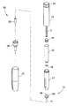
図1および図2に示された例示的なペン注射器50などのペン注射デバイスは、通常、用量ノブ/ボタン24、外側スリーブ13、およびキャップ21を備える。用量ノブ/ボタン24は、使用者が、注射されるべき医薬品の投与量を設定することを可能にする。外側スリーブ13は、医薬品を注射する際に使用者によって握られる。キャップ21は、ペン注射器50をシャツのポケット、ハンドバッグ、または他の適切な場所内に固定して保持するために使用者によって使用される。
Pen injection devices such as the
図2は、図1に示された例示的な薬物送達ペン50の分解図である。用量ノブ/ボタン24は、2つの目的を有し、注射されるべき医薬品の投与量を設定することと、下側ハウジング17内で薬物送達ペンに取り付けられた薬剤カートリッジ12から送りねじ7およびストッパ15を介して投与薬剤を注射することの両方のために使用される。薬剤カートリッジ12は、通常、一方の端部がセプタム16でシールされ、他方の端部がストッパ15でシールされたガラス管である。標準的な薬物送達ペンでは、投与機構および送達機構はすべて、外側スリーブ13内に見出される。これらの機構は、当業者によって理解されるため、本明細書においてはこれ以上詳細に説明されない。
FIG. 2 is an exploded view of the exemplary
ペン針組立体10は、ハブ20と、ペン針組立体の患者端から延びる患者針11と、その非患者側のハブ20内に配設されたセプタムを貫通する針カニューレ18とを含む。セプタムを貫通する針カニューレ18は、患者針11と流体連通状態にある。ハブ20は、好ましくは、下側ハウジング17上にねじ込まれるが、薬剤カートリッジ12に直接取り付けるなどの他の取り付け手段が使用され得る。ハブ20を下側ハウジング17または薬剤カートリッジ12に取り付ける際、セプタムを貫通するカニューレ18は、セプタム16を穿孔するが、セプタム16は、薬剤カートリッジ12に対して移動しない。しかし、ストッパ15は、流体密封シールを維持しながら薬剤カートリッジ12内で軸方向に変位可能である。プランジャまたはストッパ15の薬剤カートリッジ12内での(送りねじ7の前進による)遠位移動により、医薬品がハブ20の患者針11内に押し出される。
The
使用者またはペン注射器50を取り扱うすべての人を保護するために、ハブ20に取り付けた剛性外側シールド29がハブ20を覆う。外側シールド29はまた、ハブ20をペン注射器50上にねじ込むまたはそこから緩めるためのハンドルまたはグリップとしても使用され得る。通常、外側シールド29の上部フランジに取り付けられ、ハンドル用のタブを有する涙滴形状のカバーまたはラベル(図示せず)が、外側シールド29の内容物のための滅菌障壁を提供する。内側シールドまたは針カバー28は、外側シールド29内で患者針11を覆う。内側シールド28は、ハブ20に固定され、干渉嵌合またはスナップ式嵌合などの任意の適切な手段によって患者針11を覆うことができる。外側シールド29および内側シールド28は、使用前に取り外される。キャップ21は、外側スリーブ13にぴったりと嵌合して、使用者がペン注射デバイス50を固定して運ぶことを可能にする。
A rigid
ペン針組立体は、通例では、上記で説明されたような滅菌障壁を提供するためにカバー内の開口部を覆うラベルを備えた(外側シールド29などの)プラスチックカバーの内側に個々に包装されて提供される。これらの個々に包装されたペン針組立体は、箱などの容器内に緩く詰められて販売されることが多い。さまざまなサイズの箱が、個々の包装されたペン針組立体のさまざまな量に対して使用される(たとえば50個用箱または100個用箱)。 The pen needle assembly is typically individually wrapped inside a plastic cover (such as the outer shield 29) with a label covering the opening in the cover to provide a sterilization barrier as described above. Will be provided. These individually wrapped pen needle assemblies are often loosely packed and sold in containers such as boxes. Boxes of different sizes are used for different quantities of individual packaged pen needle assemblies (eg, boxes for 50 or 100).
本発明の一態様は、ペン針などの医療針を格納し取り出すための包装を提供することである。より詳細には、本発明の態様は、医療針をその使用前に、ならびにその使用後において取り出し格納するための包装を提供することである。本発明の別の態様は、医療針の包装を開く方法を提供することである。加えて、本発明の態様は、医療針を包装する方法を提供することである。 One aspect of the present invention is to provide a package for storing and taking out a medical needle such as a pen needle. More specifically, an aspect of the present invention is to provide a packaging for taking out and storing a medical needle before and after its use. Another aspect of the invention is to provide a method of opening the packaging of a medical needle. In addition, an aspect of the present invention is to provide a method of packaging a medical needle.
本発明の前述および/または他の態様は、ハブを有し、その遠位端部から医療針の患者端が突起する医療針用の包装であって、ハブが管の内部と接触するように医療針の患者端が中に挿入される第1の閉端部と、ハブの近位端部を封入する第2の閉端部と、ハブの近位端部と第2の閉端部の間に配設され、包装を開いてハブの近位端部を露出させるための円周領域とを有する管を含む、包装を提供することによって達成される。 A aforementioned and / or other aspect of the invention is a packaging for a medical needle having a hub in which the patient end of the medical needle protrudes from its distal end, such that the hub contacts the interior of the tube. A first closed end into which the patient end of the medical needle is inserted, a second closed end that encloses the proximal end of the hub, and a proximal and second closed end of the hub. Achieved by providing a package that includes a tube that is disposed between and has a circumferential area for opening the package to expose the proximal end of the hub.
本発明の前述および/または他の態様はまた、ハブを有し、その遠位端部から医療針の患者端が突起する医療針用の包装を開く方法を提供することによって達成される。方法は、包装を実質的に円周方向の視覚的表示部の軸方向の対向する両側で握るステップと、軸方向の両側のうち一方を他方に対して包装の長手方向軸に対して実質的に垂直な軸周りで回転させて医療針ハブの近位端部を露出させるステップとを含む。 The aforementioned and / or other aspects of the invention are also achieved by providing a method of opening a packaging for a medical needle that has a hub and the patient end of the medical needle projects from its distal end. The method is substantially the step of gripping the packaging on the axially opposite sides of the visual display in the circumferential direction, and substantially one of the axial sides to the other with respect to the longitudinal axis of the packaging. Includes a step of rotating about an axis perpendicular to to expose the proximal end of the medical needle hub.
本発明の前述および/または他の態様はまた、ハブを有し、その遠位端部から針の患者端が突起する医療針を包装する方法を提供することによって達成される。方法は、実質的に円筒状の管を形成するステップと、管の第1の端部をシールするステップと、針の遠位端部を管のシールされた第1の端部に挿入するステップと、第1の端部の反対側の管の第2の端部をシールするステップとを含む。 The aforementioned and / or other aspects of the invention are also achieved by providing a method of packaging a medical needle that has a hub and the patient end of the needle projects from its distal end. The method consists of forming a substantially cylindrical tube, sealing the first end of the tube, and inserting the distal end of the needle into the sealed first end of the tube. And the step of sealing the second end of the tube opposite the first end.
本発明の追加ならびに/または他の態様および利点は、後続の説明において部分的に記載され、部分的には説明から明確になり、または本発明を実践することによって習得され得る。 Additions and / or other aspects and advantages of the invention may be described in part in subsequent discussions, partially clarified from the description, or learned by practicing the invention.
本発明の上記ならびに/または他の態様および利点は、添付の図と共に以下の詳細な説明から明らかになり、より容易に理解されるであろう。
次に、本発明の実施形態に対する参照がより詳細になされ、その例は添付の図に示され、図中、全体を通して、同じ参照番号は同じ要素を示す。本明細書において説明される実施形態は、図を参照することによって本発明を例示するものであるが、限定はしない。当業者によって理解されるように、上、下、底、および上部などの用語は相対的なものであり、図を補助するために使用されるが、限定するものではない。 References to embodiments of the present invention are then made in more detail, examples of which are shown in the accompanying figures, in which the same reference numbers indicate the same elements throughout the figure. The embodiments described herein illustrate, but are not limited to, the present invention by reference to the figures. As will be appreciated by those skilled in the art, terms such as top, bottom, bottom, and top are relative and are used, but not limited to, to assist the figure.
図3および図4は、本発明の実施形態で使用され得るペン針組立体60の斜視図である。簡潔にするために、語句「ペン針60」が、これ以後、「ペン針組立体60」の代わりに使用される。とりわけ、図2のペン針10もまた、本発明の実施形態でも使用され得るが、他のタイプ医療針も同様に可能である。ペン針10のように、ペン針60は、ハブ64と、ペン針60の患者端から延びる患者針(または針の患者端)68と、ハブ64内のその非患者側に配設されたセプタムを貫通する針カニューレ72とを含む。
3 and 4 are perspective views of a
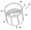
図3に示されるように、プラスチックハブ64は、ペン針60の非患者端に配設される。ハブ64は、以下でより詳細に説明される回り止め/保持構造および/または表面と係合するための複数のリブまたはスプライン76を含む。加えて、突起部80がハブ64の患者端から延び、患者針68はこの突起部80から延びる。任意選択では、針シールド84(図6に最適に示される)が、突起部80上に嵌合され得る。ハブ64の非患者端内に配設されたセプタムを貫通する針カニューレ72(図4で最適に示される)は、患者針68と流体連通する。ハブ64はまた、その近位端部に円周方向リム88も含む。1つの実施形態によれば、リム88は、スプライン76より大きい外径を有する。
As shown in FIG. 3, the
加えて、図4に示されるように、ハブ64の非患者端の内部は、図1のペン注射器50などの注射デバイスと連結するためのねじ山92を含む。簡潔にするために、これ以後、ペン注射器50は、例示的な注射デバイスとして使用される。しかし、他のタイプの注射デバイスが、本発明の範囲から逸脱することなく使用されてよいことを当業者は理解するであろう。さらに、ペン針が例示的な実施形態で示されているが、本発明の実施形態は、本発明の範囲から逸脱することなく、ハブと、ハブから突起する針の患者端とを備えた皮下注射針などの他の針と共に使用され得ることを当業者は理解するであろう。
In addition, as shown in FIG. 4, the interior of the non-patient end of the
図5は、本発明の実施形態によるペン針包装または容器100(これ以後、簡潔にするために包装100または容器100)の斜視図であり、図6は、容器100の断面図である。図5および図6に示されるように、容器100は、ハブ64が管104の内部と接触するように針68の患者端が中に挿入される第1の閉端部108を含む。加えて、容器は、ハブ64の近位端部を封入する第2の閉端部112と、ハブ64の近位端部と第2の閉端部112の間に配設された、包装100を開いてハブ64の近位端部を露出させるための円周方向領域116とを有する。
FIG. 5 is a perspective view of a pen needle wrapping or
円周方向領域116では、容器100にかかる応力は、ハブ64によって抵抗されず、したがって円周方向の「裂ける」または「破裂する」線を作り出す。図7に示されるように、たとえば第1の閉端部108および第2の閉端部112を反対方向に曲げることによって容器100に応力をかけた後、容器100は、円周方向領域において開き、それによってハブ64の近位端部を露出させる。換言すれば、1つの実施形態によれば、患者は容器100を、円周方向領域116の軸方向の向かい合う両側で握ることができ、軸方向の両側のうち一方を他方に対して容器100の長手方向軸に対して実質的に垂直な軸周りで回転させ、容器100を円周方向領域116に沿って「破裂させて」開くことによって針ハブ64の近位端部を露出させることができる。別の実施形態によれば、患者は、軸方向の両側のうち一方を他方に対して容器100の長手方向軸に対して実質的に平行な軸周りで回転させ、容器を円周方向領域116に沿って「裂いて」開くことができる。
In the
1つの実施形態によれば、また図5〜図7に示されるように、円周方向領域116は、好ましくは、容器100の外部に、円周方向領域116の場所を示す(印刷された色バンドなどの)可視的表示部120を含む。患者が、上記で説明された方法の1つを用いて容器を開いた場合、視覚的表示部120は、容器100を円周方向領域116の対向する両側で握るためのガイドとして働く。
According to one embodiment, and as shown in FIGS. 5-7, the
1つの実施形態によれば、円周方向領域116は、好ましくは、容器100を円周方向に開くのに必要とされる力を低減する脆弱化された領域を含む。脆弱化された領域を作り出す1つのやり方は、容器の外部の少なくとも一部分を、たとえば視覚的表示部120を含む実施形態では視覚的表示部120において折り目を付けることである。脆弱化された領域を作り出す別のやり方は、視覚的表示部120にミシン目を入れることである。脆弱化された領域を作り出すさらに別のやり方は、容器100の一部分を浮き彫りにすることである。以下でより詳細に説明される1つの実施形態によれば、脆弱化された領域は、容器100の内部に形成される。
According to one embodiment, the
1つの実施形態によれば、容器100は、容器100の第1の端部108に入るペン針60の挿入深さを限定するための挿入深さ停止形状を含む。図6に示された実施形態では、たとえば、挿入深さ停止形状は、針の患者端68を覆う針シールド84と干渉する第1の閉端部108を含む。挿入深さ停止形状は、挿入されたペン針60を容器100内に位置決めして、円周方向領域116、視覚的表示部120、および/または脆弱化された領域の位置決めを補助する。
According to one embodiment, the
1つの実施形態によれば、管104は、押し出し成形によって形成され得る。図8は、単一の管として押し出し成形された複数の管104を示している。個々の管104は、その後、従来の方法を用いて単位長さに切断され得る。個々の管104の第1の端部108が、図9に示されるように閉じられた後、ペン針60の遠位端部が管104内に挿入される。端部108および112は、たとえば、接着剤を用いることによって、またはつまんでヒートシールすることによって閉じられ得る。ペン針の挿入に続いて、管104の第2の端部112が閉じられる。
According to one embodiment, the
1つの実施形態によれば、管104は、ポリエチレン(PE)またはポリプロピレン(PP)などの押し出しプラスチックである。別の実施形態によれば、管104は、紙、板紙、またはボール紙上に共押し出されたプラスチックである。たとえば、プラスチックは管の内部になることができ、紙は管104の外部になることができる。PEまたはPPなどのプラスチックの使用は、容器100の端部108および112を圧着するまたはつまんでヒートシールすることに適する。1つの実施形態によれば、製造者は、紙管104の内部のみにプラスチックを形成する。別の実施形態によれば、製造者は、紙管104の内部および外部の両方にプラスチックを形成する。さらに別の実施形態によれば、製造者は、紙管104の内側にプラスチックを形成し、管104の外部に防水ワックスコーティングを形成する。管104の外部に紙を有するものとは異なり、そのような外部コーティング(ワックスおよび/またはプラスチック)は非常に清潔であり、すなわちワックスおよび/またはプラスチックは、粒子状物質を落とさずまたは発生させない。
According to one embodiment, the
1つの実施形態によれば、管104は、ペン針60を挿入した後に管104とペン針60の間の嵌合がトルクを伝えるのに十分緊密になるように、ハブ64に対してわずかに小さくサイズ設定されることが可能であり、それによって、ペン針60が容器100の第1の端部108内に保持されながらペン針60をペン注射器50に取り付けることを容易にする。別の実施形態によれば、ハブ64のスプライン76は、管104の内部表面と係合して回転に抵抗し、ペン針60のペン注射器50に対する取り付けを容易にすることができる。さらに別の実施形態によれば、管104は、ペン注射器50の取り付け中、ペン針60の回転を防止するために使用者が容器100を握ることができる十分な可撓性のものになることができる。
According to one embodiment, the
管104を押し出し成形することにより、回転防止形状は、押し出し成形中に管104の内部に形成され得る。たとえば、図8および図9に示されるように、管104は、複数の軸方向スプライン124を含む。軸方向スプライン124は、ハブ64と係合し、ペン針60の回転を防止し、それによってペン針60が容器100の第1の端部108内に保持されながらペン針60をペン注射器50に取り付けることを容易にする。薬剤の注射後、患者は、ペン針60を第1の端部108に再挿入し、スプラインの124の回転防止を使用してペン注射器50からペン針60を取り外すことができる。その後、患者は、ペン針60を安全に廃棄することができる。
By extruding the
1つの実施形態によれば、管104は、スパイラル巻き紙、板紙、またはボール紙を含む。スパイラル巻き紙は、紙タオル、包装紙、およびビスケットなどの食品を包装するために使用されている。通常、プラスチックコーティングされたスパイラル巻き紙を作製するために、未加工紙の幅広のロールが広げられ、次いでプラスチックでコーティングされる。コーティングされた紙は、次いで、プラスチックの層の厚さを調節するために平滑加圧ローラの下方を通る。その後、紙は長い紙片になるように切断され、この紙片は紙管形成機に送られ、そこで接着剤が施され、紙片はスパイラルシームを備えた管に形成される。
According to one embodiment, the
しかし、表面模様を加圧ローラに加えることによって、1つの表面模様付きパターンまたは複数の表面模様付きパターンが、プラスチックコーティング内に形成され得る。たとえば、図10〜図13に示されるように、加圧ローラ上の、加圧ローラの回転軸に対して角度を有する表面模様を使用し、スパイラルシームの角度を考慮することにより、完成されたスパイラル管内に円周方向の1つの形状または複数の形状を結果的に生じさせる表面模様パターンが、プラスチック層内に形成され得る。 However, by adding the surface pattern to the pressure roller, one surface patterned pattern or multiple surface patterned patterns can be formed within the plastic coating. For example, as shown in FIGS. 10 to 13, it was completed by using a surface pattern on the pressure roller having an angle with respect to the rotation axis of the pressure roller and considering the angle of the spiral seam. A surface pattern pattern that results in one or more circumferential shapes in the spiral tube can be formed in the plastic layer.
より詳細には、図10では、紙ロール132が巻き出されるとき、押し出しコータ136がPEまたはPPなどのプラスチックの層で紙132をコーティングする。表面模様付き加圧ローラ140が次いで、プラスチックの層の厚さを調節し、方向性のあるパターンをプラスチック層内に押印して表面模様付き紙144を形成する。任意選択では、紙132は、他方の面にもコーティングを有することができる。好ましくは、プラスチックまたはワックスなどのそのような追加のコーティングは、表面模様付き加圧ローラ140の使用前にまたはそれと同時に施される。図11に示されるように、スリッタ148が、表面模様付き紙144を表面模様付き紙片152になるように切断し、これらの紙片はその後、従来の紙管形成機に送られる。長いスパイラル管を形成した後、スパイラル管は、単位長さに切断されて管104を形成する。先に説明されたように、第1の端部108がその後シールされ、ペン針60が第1の端部108内に挿入され、第2の端部112がシールされて容器100を形成する。
More specifically, in FIG. 10, when the
図12は、表面模様付き紙144の切断斜視図である。表面模様付き紙144は、紙層132と、押し出しコータ136によって施されたプラスチック層156とを含む。好ましくは、表面模様付き紙144はまた、紙132の他方の面にプラスチックまたはワックスなどの追加のコーティング160も含む。1つの実施形態によれば、表面模様付きローラ140により、プラスチック層156は、隆起形状164および窪み形状168を含み、これらの形状は、表面模様付き紙144の進行方向に対して角度を付けて形成される。
FIG. 12 is a cut perspective view of the surface-patterned
図13に示されるように、スパイラルシーム172がらせん巻きによって形成され、管104が単位サイズに切断されると、隆起形状164は、管104の内部において、挿入されたペン針60のリム88と係合するための円周方向深さ停止部または停止レッジ164となる。挿入深さ停止部として機能することに加えて、隆起形状164はまた、ハブ64のスプラインまたはつぶしリブ76と係合することによって回転防止形状として働くこともできる。そのような実施形態では、リム88は、スプライン76より大きい外径を有する。円周方向深さ停止部164の軸方向厚さが、患者がペン針60を容器100から引き出すことの所望の容易さを維持しながら所望の回転防止性能をもたらすように調整され得ることを当業者は理解するであろう。図示しない別の実施形態によれば、表面模様付き加圧ローラ140上の表面模様パターンを変更することにより、管104の内部は、挿入深さ停止部164および図8および図9に示される軸方向スプライン124などの回転防止軸方向スプラインを含むことができる。
As shown in FIG. 13, when the
加えて、図13に示されるように、窪み形状168は、管104の内部の円周方向脆弱化された領域となり、容器100が円周方向に開くことを容易にする。深さ停止部および脆弱化された領域が円周方向であるものとして示されているが、そのような形状は、本発明の範囲から逸脱することなく円周方向の非連続性のものでもよいことを当業者は理解するであろう。
In addition, as shown in FIG. 13, the recessed
本発明のわずかな実施形態のみが示され説明されてきたが、本発明は、説明された実施形態に限定されない。その代わり、付属の特許請求の範囲およびその等価物で定義された本発明の原理および趣旨から逸脱することなく、これらの実施形態に変更がなされてよいことが当業者によって理解されるであろう。 Although only a few embodiments of the invention have been shown and described, the invention is not limited to the described embodiments. Instead, it will be appreciated by those skilled in the art that modifications may be made to these embodiments without departing from the principles and gist of the invention as defined in the appended claims and their equivalents. ..
Claims (5)
管であって、
第1の閉端部と、
第2の閉端部と、
前記第1の閉端部と前記第2の閉端部との間に配設され、前記包装を開いて前記医療針を除去させるための円周方向領域と、
前記包装の前記第1の閉端部に入る前記医療針の挿入深さを限定するための挿入深さ停止形状と
を有する、管
を備え、
前記円周方向領域は、前記包装を前記円周方向領域において開くことを容易にする脆弱化された領域を含み、
前記管は、前記医療針を除去させるため、前記円周方向領域に破断することを特徴とする包装。 A packaging for the medical needle that has a hub and the patient end of the medical needle protrudes from its distal end.
It ’s a tube,
The first closed end and
The second closed end and
A circumferential region that is disposed between the first closed end and the second closed end to open the package and remove the medical needle.
A tube comprising a tube having an insertion depth stop shape for limiting the insertion depth of the medical needle entering the first closed end of the packaging.
The circumferential region includes a fragile region that facilitates opening of the packaging in the circumferential region.
The packaging is characterized in that the tube breaks in the circumferential region in order to remove the medical needle.
Applications Claiming Priority (2)
| Application Number | Priority Date | Filing Date | Title |
|---|---|---|---|
| US13/714,044 US9517298B2 (en) | 2012-12-13 | 2012-12-13 | Low cost medical needle container and manufacturing methods therefor |
| US13/714,044 | 2012-12-13 |
Related Parent Applications (1)
| Application Number | Title | Priority Date | Filing Date |
|---|---|---|---|
| JP2017250117A Division JP7048307B2 (en) | 2012-12-13 | 2017-12-26 | Low-priced medical needle container and its manufacturing method |
Publications (2)
| Publication Number | Publication Date |
|---|---|
| JP2021007794A true JP2021007794A (en) | 2021-01-28 |
| JP7113416B2 JP7113416B2 (en) | 2022-08-05 |
Family
ID=49911164
Family Applications (5)
| Application Number | Title | Priority Date | Filing Date |
|---|---|---|---|
| JP2013255936A Active JP6397619B2 (en) | 2012-12-13 | 2013-12-11 | Low-cost medical needle container and manufacturing method thereof |
| JP2017250116A Active JP7018764B2 (en) | 2012-12-13 | 2017-12-26 | Manufacturing method of low-priced medical needle container |
| JP2017250117A Active JP7048307B2 (en) | 2012-12-13 | 2017-12-26 | Low-priced medical needle container and its manufacturing method |
| JP2020158837A Active JP7001780B2 (en) | 2012-12-13 | 2020-09-23 | Manufacturing method of low-priced medical needle container |
| JP2020174798A Active JP7113416B2 (en) | 2012-12-13 | 2020-10-16 | Low cost medical needle container and manufacturing method thereof |
Family Applications Before (4)
| Application Number | Title | Priority Date | Filing Date |
|---|---|---|---|
| JP2013255936A Active JP6397619B2 (en) | 2012-12-13 | 2013-12-11 | Low-cost medical needle container and manufacturing method thereof |
| JP2017250116A Active JP7018764B2 (en) | 2012-12-13 | 2017-12-26 | Manufacturing method of low-priced medical needle container |
| JP2017250117A Active JP7048307B2 (en) | 2012-12-13 | 2017-12-26 | Low-priced medical needle container and its manufacturing method |
| JP2020158837A Active JP7001780B2 (en) | 2012-12-13 | 2020-09-23 | Manufacturing method of low-priced medical needle container |
Country Status (6)
| Country | Link |
|---|---|
| US (1) | US9517298B2 (en) |
| EP (2) | EP2742960B1 (en) |
| JP (5) | JP6397619B2 (en) |
| CN (1) | CN203736637U (en) |
| CA (1) | CA2836029C (en) |
| ES (2) | ES2866878T3 (en) |
Families Citing this family (5)
| Publication number | Priority date | Publication date | Assignee | Title |
|---|---|---|---|---|
| AU2015315334B2 (en) * | 2014-09-08 | 2018-04-05 | Becton, Dickinson And Company | System and method for preparing a pharmaceutical compound |
| CN104528082B (en) * | 2014-12-24 | 2016-11-30 | 苏州捷碧医疗科技有限公司 | The pen-type injector syringe needle of a kind of simple packaging and using method thereof |
| DE102017121374A1 (en) * | 2017-09-14 | 2019-03-14 | Rösler IP GmbH | Packing sleeve with vacuum-packed outer packaging |
| EP4271625A1 (en) | 2020-12-31 | 2023-11-08 | Saint-Gobain Performance Plastics Corporation | Packaging container and method of making and using the same |
| CN112999074B (en) * | 2021-04-01 | 2022-08-23 | 张伟 | Intelligent treatment device of traditional Chinese medicine acupuncture pot |
Citations (6)
| Publication number | Priority date | Publication date | Assignee | Title |
|---|---|---|---|---|
| GB920341A (en) * | 1960-03-09 | 1963-03-06 | Roy Acton Glasson | Surgical needles |
| US5114409A (en) * | 1991-01-23 | 1992-05-19 | Design Opportunity Corp. | Blank for and method of fabricating a needle cap finger guard |
| JPH11137687A (en) * | 1997-09-12 | 1999-05-25 | Becton Dickinson & Co | Disposable pen needle |
| JP2001294248A (en) * | 2000-02-10 | 2001-10-23 | Dainippon Printing Co Ltd | Easy-to-open packaging bag |
| JP2003190177A (en) * | 2001-12-28 | 2003-07-08 | Becton Dickinson & Co | Medical needle assembly |
| US20120051967A1 (en) * | 2010-08-26 | 2012-03-01 | Combat Medical Systems, Llc. | Protective containers for medical devices and methods of use |
Family Cites Families (32)
| Publication number | Priority date | Publication date | Assignee | Title |
|---|---|---|---|---|
| US3036700A (en) * | 1959-08-26 | 1962-05-29 | Becton Dickinson Co | Sterile hypodermic needle assembly and package |
| BE626565A (en) * | 1959-10-28 | |||
| US3095972A (en) * | 1961-10-06 | 1963-07-02 | James L Sorenson | Self-sealing sterile packaging and method |
| US3825002A (en) | 1972-02-07 | 1974-07-23 | Amalgamated Dental Co Ltd | Cartridge syringe and crimped needle assembly |
| JPS49144618U (en) * | 1973-04-12 | 1974-12-13 | ||
| JPS5926641U (en) * | 1982-08-12 | 1984-02-18 | テルモ株式会社 | Packaging container for indwelling needles |
| JPH05193648A (en) * | 1992-01-10 | 1993-08-03 | Fujikou Kk | Container for packing |
| JPH09509087A (en) | 1994-02-28 | 1997-09-16 | ノボ ノルディスク アクティーゼルスカブ | Needle unit |
| US5482205A (en) * | 1994-08-01 | 1996-01-09 | Sonoco Products Company | Spirally-wound easy-open container having a score cut opening panel |
| US5545145A (en) | 1994-08-16 | 1996-08-13 | Becton Dickinson And Company | Pen needle despenser |
| JP3014113U (en) * | 1995-01-30 | 1995-08-01 | 盛 西村 | Easy-open packaging bag and its material |
| EP0916355A3 (en) | 1997-11-07 | 1999-09-01 | Rudolf Dr. med. Türk | Injection set |
| JP2974212B2 (en) * | 1998-04-14 | 1999-11-10 | 京王製紙株式会社 | Paper container structure |
| JPH11314680A (en) * | 1998-05-08 | 1999-11-16 | Fuji Photo Film Co Ltd | Packaging material for photosensitive printing plate |
| JP2000084076A (en) * | 1998-09-09 | 2000-03-28 | Shinji Kondo | Injection needle and injection needle protective cap |
| JP2001275747A (en) * | 2000-03-28 | 2001-10-09 | Nippon Uiringu Kk | Rod-type extensible cosmetic container |
| JP3535446B2 (en) * | 2000-04-03 | 2004-06-07 | 田中紙管株式会社 | Paper tube and method of manufacturing the same |
| US6689106B2 (en) * | 2000-07-31 | 2004-02-10 | Becton Dickinson And Company | Retracting needle assembly for a syringe |
| JP3931700B2 (en) | 2002-03-14 | 2007-06-20 | セイコーエプソン株式会社 | Lighting device |
| JP2005211336A (en) * | 2004-01-29 | 2005-08-11 | Terumo Corp | Liquid guide appliance storage body |
| US7645264B2 (en) | 2005-04-11 | 2010-01-12 | Becton, Dickinson And Company | Injection device with secondary reservoir |
| JP5030963B2 (en) * | 2005-10-13 | 2012-09-19 | ベクトン・ディキンソン・アンド・カンパニー | Disposable needle and hub assembly |
| GB2437923B (en) | 2006-05-11 | 2011-11-23 | Owen Mumford Ltd | Needle tip storage and removal device |
| US7874426B2 (en) | 2007-01-23 | 2011-01-25 | North American Rescue, Llc | Crush resistant needle packaging assembly having rapid needle access |
| CA2648097A1 (en) * | 2008-01-04 | 2009-07-04 | Kraft Foods Global Brands Llc | Method and apparatus for laser scored packaging |
| GB0817296D0 (en) | 2008-09-22 | 2008-10-29 | Pilkington Group Ltd | Methods of switching and apparatus comprising an electrically actuated variable transmission material |
| EP2201976A1 (en) | 2008-12-23 | 2010-06-30 | Sanofi-Aventis Deutschland GmbH | Apparatus for holding a cover of a needle unit and method |
| JP5366751B2 (en) * | 2008-12-26 | 2013-12-11 | 株式会社クラレ | Paper container |
| CA2751619C (en) | 2009-02-06 | 2018-11-20 | Becton, Dickinson And Company | Pen needle assembly having biodegradable components |
| JP2011088640A (en) * | 2009-10-21 | 2011-05-06 | Osamu Mizunaka | Packaged commodity for vending machine |
| US9186452B2 (en) * | 2010-08-16 | 2015-11-17 | Becton, Dickinson And Company | Pen needle dispensing apparatus |
| US20120061274A1 (en) | 2010-09-14 | 2012-03-15 | Tyco Healthcare Group Lp | Hardpack Needle Package Laser Heat Seal |
-
2012
- 2012-12-13 US US13/714,044 patent/US9517298B2/en active Active
-
2013
- 2013-12-09 CA CA2836029A patent/CA2836029C/en active Active
- 2013-12-11 JP JP2013255936A patent/JP6397619B2/en active Active
- 2013-12-12 EP EP13197024.6A patent/EP2742960B1/en active Active
- 2013-12-12 ES ES17207633T patent/ES2866878T3/en active Active
- 2013-12-12 EP EP17207633.3A patent/EP3323445B1/en active Active
- 2013-12-12 ES ES13197024T patent/ES2928048T3/en active Active
- 2013-12-13 CN CN201320824237.2U patent/CN203736637U/en not_active Expired - Lifetime
-
2017
- 2017-12-26 JP JP2017250116A patent/JP7018764B2/en active Active
- 2017-12-26 JP JP2017250117A patent/JP7048307B2/en active Active
-
2020
- 2020-09-23 JP JP2020158837A patent/JP7001780B2/en active Active
- 2020-10-16 JP JP2020174798A patent/JP7113416B2/en active Active
Patent Citations (6)
| Publication number | Priority date | Publication date | Assignee | Title |
|---|---|---|---|---|
| GB920341A (en) * | 1960-03-09 | 1963-03-06 | Roy Acton Glasson | Surgical needles |
| US5114409A (en) * | 1991-01-23 | 1992-05-19 | Design Opportunity Corp. | Blank for and method of fabricating a needle cap finger guard |
| JPH11137687A (en) * | 1997-09-12 | 1999-05-25 | Becton Dickinson & Co | Disposable pen needle |
| JP2001294248A (en) * | 2000-02-10 | 2001-10-23 | Dainippon Printing Co Ltd | Easy-to-open packaging bag |
| JP2003190177A (en) * | 2001-12-28 | 2003-07-08 | Becton Dickinson & Co | Medical needle assembly |
| US20120051967A1 (en) * | 2010-08-26 | 2012-03-01 | Combat Medical Systems, Llc. | Protective containers for medical devices and methods of use |
Also Published As
| Publication number | Publication date |
|---|---|
| EP3323445A1 (en) | 2018-05-23 |
| ES2928048T3 (en) | 2022-11-15 |
| JP7048307B2 (en) | 2022-04-05 |
| JP2018043144A (en) | 2018-03-22 |
| CN203736637U (en) | 2014-07-30 |
| CA2836029A1 (en) | 2014-06-13 |
| JP6397619B2 (en) | 2018-09-26 |
| CA2836029C (en) | 2021-01-19 |
| EP2742960B1 (en) | 2022-08-03 |
| EP3323445B1 (en) | 2021-04-07 |
| US20140165505A1 (en) | 2014-06-19 |
| JP2018043145A (en) | 2018-03-22 |
| EP2742960A1 (en) | 2014-06-18 |
| ES2866878T3 (en) | 2021-10-20 |
| JP2020199384A (en) | 2020-12-17 |
| JP7113416B2 (en) | 2022-08-05 |
| US9517298B2 (en) | 2016-12-13 |
| JP7018764B2 (en) | 2022-02-14 |
| JP7001780B2 (en) | 2022-01-20 |
| JP2014117606A (en) | 2014-06-30 |
Similar Documents
| Publication | Publication Date | Title |
|---|---|---|
| JP7001780B2 (en) | Manufacturing method of low-priced medical needle container | |
| JP7154254B2 (en) | medical cannula package | |
| JP6339546B2 (en) | Pen needle packaging method | |
| CA2714260C (en) | Shipping container integrating a sharps disposal container with a new product storage container | |
| JP7341169B2 (en) | medical cannula package |
Legal Events
| Date | Code | Title | Description |
|---|---|---|---|
| A621 | Written request for application examination |
Free format text: JAPANESE INTERMEDIATE CODE: A621 Effective date: 20201111 |
|
| A977 | Report on retrieval |
Free format text: JAPANESE INTERMEDIATE CODE: A971007 Effective date: 20210908 |
|
| A131 | Notification of reasons for refusal |
Free format text: JAPANESE INTERMEDIATE CODE: A131 Effective date: 20210928 |
|
| A521 | Request for written amendment filed |
Free format text: JAPANESE INTERMEDIATE CODE: A523 Effective date: 20211228 |
|
| TRDD | Decision of grant or rejection written | ||
| A01 | Written decision to grant a patent or to grant a registration (utility model) |
Free format text: JAPANESE INTERMEDIATE CODE: A01 Effective date: 20220510 |
|
| A601 | Written request for extension of time |
Free format text: JAPANESE INTERMEDIATE CODE: A601 Effective date: 20220608 |
|
| A711 | Notification of change in applicant |
Free format text: JAPANESE INTERMEDIATE CODE: A711 Effective date: 20220616 |
|
| A61 | First payment of annual fees (during grant procedure) |
Free format text: JAPANESE INTERMEDIATE CODE: A61 Effective date: 20220707 |
|
| R150 | Certificate of patent or registration of utility model |
Ref document number: 7113416 Country of ref document: JP Free format text: JAPANESE INTERMEDIATE CODE: R150 |