JP2020531924A - Eyeglass lens element configured to see both front and back - Google Patents
Eyeglass lens element configured to see both front and back Download PDFInfo
- Publication number
- JP2020531924A JP2020531924A JP2020512834A JP2020512834A JP2020531924A JP 2020531924 A JP2020531924 A JP 2020531924A JP 2020512834 A JP2020512834 A JP 2020512834A JP 2020512834 A JP2020512834 A JP 2020512834A JP 2020531924 A JP2020531924 A JP 2020531924A
- Authority
- JP
- Japan
- Prior art keywords
- lens element
- spectacle lens
- user
- mirror
- transparent portion
- Prior art date
- Legal status (The legal status is an assumption and is not a legal conclusion. Google has not performed a legal analysis and makes no representation as to the accuracy of the status listed.)
- Pending
Links
Images


Classifications
-
- G—PHYSICS
- G02—OPTICS
- G02C—SPECTACLES; SUNGLASSES OR GOGGLES INSOFAR AS THEY HAVE THE SAME FEATURES AS SPECTACLES; CONTACT LENSES
- G02C7/00—Optical parts
- G02C7/14—Mirrors; Prisms
-
- G—PHYSICS
- G02—OPTICS
- G02C—SPECTACLES; SUNGLASSES OR GOGGLES INSOFAR AS THEY HAVE THE SAME FEATURES AS SPECTACLES; CONTACT LENSES
- G02C9/00—Attaching auxiliary optical parts
Abstract
使用者による前方および後方の両方の視認のために構成された眼鏡レンズ要素(10)は、使用者の両目の前、上、間および下ならびに前記使用者の両目の側部から横に使用者の頭の概略側部までの距離に延在する少なくとも一つの曲線状の透明部分と、レンズ要素(10)の下方部分(12)における端部に配置されレンズ要素から突出する収納部(11)と、曲線状の透明部分からずれた位置において収納部に配置されるミラー(15)とを含む。The spectacle lens element (10) configured for both anterior and posterior visibility by the user is in front of, above, between and below the user's eyes and laterally from the side of both eyes of the user. At least one curved transparent portion extending to the approximate side of the head and a storage portion (11) arranged at the end of the lower portion (12) of the lens element (10) and protruding from the lens element. And a mirror (15) arranged in the storage portion at a position deviated from the curved transparent portion.
Description
自転車走行や他の多くのスポーツ、特に高速度のスポーツにおいて、アスリート達は「後方視認」という問題を経験する。特に自転車で走行する際に認識される、長きにわたって必要とされてきている事項は、乗り手が、身体をぐるりと回して見るということをせずに、後方から接近してくる交通車両を見ることである。このやり方で後ろを見ることは、乗り手が片側に寄ってしまい接近してくる走行車両の走行経路にふらふらと入り込んでしまうという結果をしばしば招くことになるので、非常に危険である。この結果を招く理由は、過剰な頭部の動きであり、乗り手が自分の見ている方向に向かい自然に身体を傾ける傾向があるという単純な事実である。従って、「後方視認」しつつバランスを良好に保つためには、乗り手が自分の頭を動かさないようにしている必要がある。交通走行中に自転車を追い越すときのモーター付車両に対して要求される最低安全距離といったものは通常は存在しない。自転車の乗り手は背後からやってくる交通車両に対する耳に聞える手がかりに全面的に依存することは出来ない。乗り手はしばしば車線を変更したり方向転換をしたりしなければならないが、このような操作は空間的な位置が良好であることおよび信頼出来る情報を必要とする。交通条件に関する間違った推測または不確かさは、あまりにもしばしば悲惨な結果を招くことになる。 In biking and many other sports, especially high speed sports, athletes experience the problem of "backward visibility". A long-standing need, especially when riding a bicycle, is to see a traffic vehicle approaching from behind, rather than having the rider look around. Is. Looking behind in this way is extremely dangerous, as it often results in the rider leaning to one side and wandering into the path of the approaching vehicle. The reason for this result is the simple fact that excessive head movements tend to cause the rider to lean naturally in the direction he or she is looking. Therefore, in order to maintain a good balance while "visualizing backwards", it is necessary for the rider to keep his head still. There is usually no minimum safe distance required for a motorized vehicle when overtaking a bicycle while driving in traffic. Bicycle riders cannot rely entirely on audible clues to traffic vehicles coming from behind. Riders often have to change lanes or change direction, but such operations require good spatial location and reliable information. False guesses or uncertainties about traffic conditions can have disastrous consequences too often.
この問題のために後方を見るためのミラー装置を開発することによって、「後方視認」という自転車走行者にとっての問題を解決するための努力がなされてきた。それらは幾つかの類型に広くは分けられる:ハンドルに取り付けたミラー、ヘルメットに取り付けたミラーおよび眼鏡に取り付けたミラーである。ハンドルに取りつけたミラーは、多大な路面の衝撃を、前輪のフォークおよび自転車のフレームから直接受ける。従ってミラーは非常に振動しやすく、その結果視界がぼやけたり、たびたび再調整しなければならない。ヘルメットに取り付けるタイプのものは同様に、美しさに欠け、空気力学的性質が乏しく、乗り手の顔面の前に前方から突き出る物体がある場合に頭部が先に衝突することから生じる安全性の危険要素が認められることから、最小限に甘受されているに過ぎない。眼鏡に取り付けたミラーは空気力学的性質が乏しいことや前方の見え方がある程度犠牲になることを含め、多くの同様な欠点がある。使用者の面前にいつまでも釣り下がっている定着物があるという鬱陶しさは、大部分の乗り手に一般的に拒絶される、歓迎されない順応を必要とする。 Efforts have been made to solve the problem of "rear view" for cyclists by developing a mirror device for looking backwards for this problem. They are broadly divided into several types: handle-mounted mirrors, helmet-mounted mirrors, and eyeglass-mounted mirrors. The mirror attached to the steering wheel receives a great deal of road surface impact directly from the front wheel fork and bicycle frame. Therefore, the mirror is very prone to vibration, resulting in a blurred view and frequent readjustments. Helmet-mounted types are also lacking in aesthetics, poor aerodynamics, and safety risks resulting from a head collision first when there is an object protruding from the front in front of the rider's face. Since the element is recognized, it is only minimally accepted. Mirrors attached to spectacles have many similar drawbacks, including poor aerodynamic properties and some sacrifice in forward visibility. The annoyance of having an indefinitely hanging anchor in front of the user requires unwelcome adaptation, which is generally rejected by most riders.
特許文献1は、中央の内部透明部を横に延びた外部ミラー部と一体的に結合した空気力学的眼鏡レンズ要素を開示している。これにより前方の物体だけでなく背後の物体をも前方に向かっている使用者が見ることが出来る。 Patent Document 1 discloses an aerodynamic spectacle lens element in which a central internal transparent portion is integrally coupled with a laterally extending external mirror portion. As a result, not only the object in front but also the object in the back can be seen by the user who is heading forward.
特許文献2は、スポーツ用眼鏡のレンズや、自動二輪車のヘルメットの覆い、および特に自転車走行用眼鏡のレンズの外面に取り付けた、取り外し可能の後方視認用ミラーに関している。ミラーは、背後および側方の領域を装着者が見るための補助として使われており、回転によって調整することが出来る。 Patent Document 2 relates to a lens for sports spectacles, a cover for a helmet of a motorcycle, and particularly a removable rear view mirror attached to the outer surface of the lens for spectacles for biking. Mirrors are used as an aid for the wearer to see the back and side areas and can be adjusted by rotation.
これらのおよび他の先行技術によるミラー装置の問題点は、装着者の視野の相当部分を遮る事、充分なまたは必要とされる見え方を提供出来ないこと、および/または使用が不便であることである。 The problem with these and other prior art mirror devices is that they block a significant portion of the wearer's field of vision, fail to provide sufficient or required visibility, and / or are inconvenient to use. Is.
本発明の目的は、上に述べた問題を解決する、前方および後方の両方を視認するように構成された眼鏡レンズ要素および眼鏡を提供することである。 It is an object of the present invention to provide spectacle lens elements and spectacles configured to see both anterior and posterior to solve the problems described above.
本発明の目的は特許請求項に記載された特徴によって達成される。 An object of the present invention is achieved by the features described in the claims.
一実施例においては、前方および後方の両方を視認するように構成された眼鏡レンズ要素は、使用者の両目の前、上、間および下に延在し、かつ前記使用者の両目の側部から横に使用者の頭の概略側部までの空間距離に延在する、少なくとも一つの曲線状の透明部分を含む。 In one embodiment, the spectacle lens element configured to see both anterior and posterior extends in front of, above, between and below the user's eyes, and the sides of the user's eyes. Includes at least one curved transparent portion extending laterally from to the approximate side of the user's head.
曲線状の透明部分は、実質的に回転楕円面状にカーブしていてもよく、あるいはいかなる他の適切な形状を有していてもよい。大部分のスポーツ用眼鏡においては、邪魔加減を最小にし、日除けおよび風除けを最大限にするように、レンズ要素は使用者の顔面の輪郭に実質的に沿うようになっていることを目指している。焦点を合わせることができるように後方視認用のミラーを両目から適切な位置に持ってくるために、本発明はこれらのタイプの眼鏡に特に有用である。レンズ要素は、しばしばただ一つの連続した曲線状透明部分を含むが、横に並べて配置され、使用時に使用者の両目の各々の前に実質的に配置されるような、二つの分離した曲線状透明部分をレンズ要素が含むといった、いくつかの応用例もある。 The curved transparent portion may be curved substantially into a rotating ellipsoidal surface, or may have any other suitable shape. For most sports eyeglasses, the lens element aims to be substantially in line with the contours of the user's face so as to minimize obstruction and maximize awnings and windbreaks. .. The present invention is particularly useful for these types of spectacles in order to bring the rear view mirror from both eyes to the proper position so that it can be focused. The lens element often contains only one continuous curved transparent area, but two separate curved lines that are placed side by side and substantially placed in front of each of the user's eyes during use. There are also some application examples, such as the lens element containing a transparent part.
収納部は、レンズ要素の端縁部分にレンズ要素から突出して配置される。収納部は、レンズ要素の外端と同一面に配置されてもよく、あるいは端部に対してある距離をおいて、すなわち収納部がレンズ要素の部分によって取り囲まれているように、配置されてもよい。一実施例においては、収納部はレンズ要素の下方部分に配置されるが、例えば曲線状透明部分の寸法に応じて、あるいは所望の視界に応じて、いかなる好都合な高さに配置することもできる。曲線状透明部分が大きい場合、最良の視界を提供するように、また使用者が最善の後方視野を得ようと彼の/彼女の頭を実質的に動かす必要を無くするように、収納部は、曲線状透明部分がより小さい場合よりも上方に配置してよい。 The accommodating portion is arranged at the edge portion of the lens element so as to project from the lens element. The housing may be located flush with the outer edge of the lens element, or at a distance from the end, i.e., such that the housing is surrounded by a portion of the lens element. May be good. In one embodiment, the housing is located below the lens element, but may be located at any convenient height, for example, depending on the dimensions of the curved transparent portion or the desired field of view. .. When the curved transparency is large, the compartment is designed to provide the best visibility and to eliminate the need for the user to substantially move his / her head to get the best rear view. , The curved transparent portion may be placed above the smaller one.
収納部は、任意の適切な材料から作られていてもよい。一実施例において収納部は形状が三角柱として形成されるが、他の多面体の形状を有していてもよい。他の実施例では、収納部は、四つの側壁部とすべての側壁部に接続した一つの端壁部とを有する開放立方体の形状として実質的に形成される。収納部は、他の形状、例えば円柱状、または楕円状のような形状を有していてもよい。大部分の実施例において収納部は、曲線状透明部分の正面部分、すなわち使用者の両目の間の領域をカバーするのに適合した部分における曲線状透明部分の表面に対して実質的に平行となる端壁部を有することになる。 The compartment may be made of any suitable material. In one embodiment, the storage portion is formed as a triangular prism in shape, but may have the shape of another polyhedron. In another embodiment, the accommodating portion is substantially formed in the form of an open cube having four side wall portions and one end wall portion connected to all the side wall portions. The accommodating portion may have other shapes, such as a columnar or elliptical shape. In most embodiments, the compartment is substantially parallel to the surface of the curved transparent portion in the front portion of the curved transparent portion, i.e., a portion suitable for covering the area between the user's eyes. It will have an end wall portion.
収納部は、外側に突き出ている、すなわち、曲線状透明部分の凸面側から外に突き出ていて、曲線状透明部分と突き出た収納部の最も遠い部分との間に垂直の距離を設けている。これが、使用者による使用時に曲線状透明部分よりも使用者の顔面からより遠くの距離に端壁部を置くことになる。収納部の一つの側は開放されていて、使用者に内部への視線が直接届くようにしている。曲線状透明部分と収納部とは一つの一体化したユニットであってよい。例えば、レンズ要素のうち収納部が配置される部分は切り取られるかあるいは最初から空いているものとし、代わりにそこに収納部が置かれ、すなわち収納部はレンズ要素の一部として配置される。収納部と曲線状透明部分とは一つのユニットとして一緒に製造されてもよい。この一体化した設計は、確実に視野の妨害を最小にし、より強靭な構造をもたらし、また光がいくつかの層を通過することで生ずる像の歪みを避けるものである。 The storage portion protrudes outward, that is, protrudes outward from the convex side of the curved transparent portion, and provides a vertical distance between the curved transparent portion and the farthest portion of the protruding storage portion. .. This results in placing the end wall at a greater distance from the user's face than the curved transparent portion when used by the user. One side of the compartment is open so that the user can see directly inside. The curved transparent portion and the storage portion may be one integrated unit. For example, it is assumed that the portion of the lens element on which the accommodating portion is arranged is cut off or vacant from the beginning, and instead the accommodating portion is placed there, that is, the accommodating portion is arranged as a part of the lens element. The storage portion and the curved transparent portion may be manufactured together as one unit. This integrated design ensures that field of view is minimized, provides a tougher structure, and avoids image distortion caused by light passing through several layers.
収納部内にはミラーが配置される。ミラーは、一実施例においては曲線状透明部分の湾曲すなわち突き出た湾曲に関してある角度をもって収納部内に配置される。これは、収納部の形状によって、収納部内のミラーの固定取り付けによって、あるいはミラーを収納部に可動的に接続する角度調節機構を使用することによって達成されうる。これは、装着者の背後からの光がミラーの表面で反射して装着者の目の方に向かうような位置にミラーを配置する。ミラーの角度は、最適の後方視界を提供するために曲線状透明部分の異なる湾曲度に応じて異なったものとなりうる。 A mirror is arranged in the storage part. The mirror is arranged in the housing at an angle with respect to the curvature or protruding curvature of the curved transparent portion in one embodiment. This can be achieved by the shape of the housing, by the fixed mounting of the mirror in the housing, or by using an angle adjustment mechanism that movably connects the mirror to the housing. This places the mirror in a position where the light from behind the wearer is reflected off the surface of the mirror and directed towards the wearer's eyes. The angle of the mirror can vary depending on the different degrees of curvature of the curved transparent portion to provide optimal rear view.
角度調節機構は、レンズ要素に関するミラーの角度が所望の後方視認を得るように調節されうるようなやり方で、ミラーを調節可能に収納部に接続しうる。一実施例において角度調節機構は収納部の端部壁に接続される。 The angle adjustment mechanism may connect the mirror to the housing in an adjustable manner such that the angle of the mirror with respect to the lens element can be adjusted to obtain the desired rear view. In one embodiment, the angle adjustment mechanism is connected to the end wall of the housing.
曲線状透明部分(単数または複数)は実質的に左右対称になっており、対称軸を有する。一実施例において、ミラーは、対称軸に対して実質的に垂直になるように収納部に配置されており、これはすなわちミラーが、この眼鏡レンズ要素を有する眼鏡を装着した使用者の動きの方向に対して実質的に垂直であることになる。 The curved transparent portion (s) are substantially symmetrical and have an axis of symmetry. In one embodiment, the mirror is arranged in the housing so that it is substantially perpendicular to the axis of symmetry, that is, the mirror is the movement of a user wearing spectacles having this spectacle lens element. It will be substantially perpendicular to the direction.
収納部の主たる目的は、曲線状透明部分に対してミラーをずらして配置することであり、その結果、後方視認に対して必要な視界の深さを提供するために装着者の目から十分な距離を設けることである。一実施例においてミラーはレンズ要素の表面に対して0−1cmずらされており(即ち、オフセットされており)、後方視認に対して必要な視界の深さを許容している。即ち 、収納部は曲線状透明分の表面から0−1cm外に延びており、角度調節機構または他の接続装置の寸法に足しあわせた収納部の突出距離がレンズ要素の外側表面に対してミラーを0−1cmずらして(オフセットして)配置することになる。 The main purpose of the compartment is to stagger the mirrors relative to the curved transparent areas, resulting in sufficient visibility from the wearer's eyes to provide the required depth of vision for rearward viewing. It is to provide a distance. In one embodiment, the mirror is offset (ie, offset) by 0-1 cm with respect to the surface of the lens element, allowing the required depth of view for rearward viewing. That is, the storage portion extends 0-1 cm outward from the surface of the curved transparent component, and the protrusion distance of the storage portion added to the dimensions of the angle adjustment mechanism or other connecting device mirrors the outer surface of the lens element. Will be arranged with a 0-1 cm shift (offset).
収納部はただ一つでも良いしあるいは曲線状透明部分の横方向に延在した部分の側端部の両方に収納部を配置しても良い。 There may be only one storage portion, or storage portions may be arranged on both side ends of the laterally extending portion of the curved transparent portion.
角度調節機構は、レンズ要素を使用者の各々に適合させるために提供されるもので、使用者は、彼/彼女がより最適の後方視認を得られるような角度にミラーを調節することができることになる。使用者の頭は寸法および形状がそれぞれ異なるから、この調節はレンズ要素を一般向け使用に供するために有用である。 The angle adjustment mechanism is provided to adapt the lens element to each of the users so that the user can adjust the mirror to an angle that gives him / her more optimal rear view. become. Since the user's head is different in size and shape, this adjustment is useful for making the lens element available for general use.
角度調節機構は、ボールとソケットとの組み合わせ構成の回転機能によってミラーの角度調節を提供するのに適合したボールおよびソケットを含んでよい。このような機構では、角度調節が三次元で許容される。すなわち、回転と、レンズ要素に対する平行垂直軸の周りを0度と45度との間で縦に上げるまたは下げる動きと、レンズ要素に対する左または右の水平軸の周りを0度および45度だけ偏動させる動きである。他の種類の調節機構も使用してもよい。 The angle adjustment mechanism may include balls and sockets adapted to provide angle adjustment of the mirror by the rotational function of the ball and socket combination configuration. In such a mechanism, angle adjustment is allowed in three dimensions. That is, rotation, vertical up or down movements around the parallel vertical axis with respect to the lens element between 0 and 45 degrees, and deviations around the left or right horizontal axis with respect to the lens element by 0 and 45 degrees. It is a movement to move. Other types of adjustment mechanisms may also be used.
レンズ要素は、通常は、完全な眼鏡を形成するように使用者の両目の前に所定の空間距離をおいて中央に配置しかつ頭部に保持する手段とともに使用されることになる。 The lens element will typically be used with a means of centrally centering and holding on the head at a predetermined spatial distance in front of the user's eyes to form a perfect spectacle.
次に本発明を、実施例によってかつ付随する図面を参照して、より詳細に説明する。
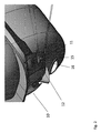
図1は、使用者による前方および後方の両方の視認のために構成された眼鏡レンズ要素10を図示している。レンズ要素10は、一対の眼鏡の一部であり、使用者の頭部に設置するための保持手段14に接続されている。保持手段14は、使用者の両目の前の中央に所定の距離でレンズ要素10を配置するのに適合したものとなっている。レンズ要素10は、使用者の両目の前、上、間および下、ならびに前記使用者の両目の側部から横に使用者の頭部の概略側部までの空間距離に延在する少なくとも一つの曲線状透明部分13を含み、使用者の視界は当該透明部によって実質的に覆われることになる。レンズ要素10はさらに、レンズ要素10の下方部分12における端縁部に配置された収納部11を含み、当該収容部11はレンズ要素から外に突き出ている、すなわち使用者の顔面から離れるように突き出ている。本例において、収納部はレンズ要素の下方の最も遠い端部に設置されるが、他の実施例では収納部はレンズ要素の他の場所に、下端、側端、またはその両方のいずれかに対して少なくともある程度の距離をおいて設置されうる。
FIG. 1 illustrates a
収納部11には、後方視認のために、内部にミラー15が、その反射面が使用者を向くように配置されている。
A
図2および4は、使用者に彼/彼女の背後で何が進んでいるかを見させることが出来るようにミラー15によって光がどのように反射されるかをより明確に図示している。図4の例に見られるようにミラー15は使用者の頭の側部を通過した入射光を反射して目に送る。図面から理解することが出来るように、収納部11はレンズ要素10/曲線状透明部分13の表面に置かれてはおらず、レンズ要素の一部を形成しており、レンズ要素の一部分に置き換わったものになっており、その結果、光がいくつかの層を通過することが無いようにしている。
Figures 2 and 4 more clearly illustrate how the light is reflected by the
図3は、ミラー15が収納部11に関してどのように傾けられるかをより詳細に示している。ミラーは、本実施例においては角度調節機構16に取り付けられており、一方角度調節機構は収納部11に接続されている。角度調節機構はミラー15を収納部11に対して調節可能な状態で接続している。この調節可能な接続は、ミラーが使用者によって調節され使用者の視界の中に反射されてきて使用者の背後の視認のために正しい角度を提供することを確実にするものである。角度調節機構は全方向に動かすことが出来、ミラーの傾斜角度を変更することが出来るようにしている。傾斜は、単にミラーに触れてミラーの面を、使用者が後方視認を得られるような所望の位置に動かすことによって変更することが出来る。他の実施例においては、ミラーは固定位置に設置されその結果角度も固定される。特に図2および4から理解することが出来るように、曲線状透明部分および収納部は一つの一体化したユニットとして作られている。
FIG. 3 shows in more detail how the
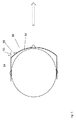
図5は真上から見た眼鏡レンズ要素50を概略的に図示している。収納部51は曲線状透明部分53の左端に配置されている。収納部は本実施例ではその形状が三角柱として形成されており、その一方の隅の端は透明部分53と同一面をなし、他方は透明部分の端部から距離Aを有している。ミラーは、収納部の外壁の内側に配置されており、その結果曲線状透明部分53の湾曲面に対して角度φを形成している。この図で角度φは、本発明の多くの実施例におけると同様に、使用者の進行方向、ここでは矢印で図示されている、に対して実質的に垂直である。
FIG. 5 schematically illustrates the
本発明は自転車等の走行の際に使用される眼鏡レンズ要素(eyeglass lens piece)及び眼鏡(eyeglass)に関する。 The present invention relates to an eyeglass lens piece and eyeglasses used when traveling a bicycle or the like .
収納部はただ一つでも良いしあるいは曲線状透明部分の横方向に延在した部分の側端部の両方に収納部を配置しても良い。収納部の突出距離は0−2cmであっても良い。
There may be only one storage portion, or storage portions may be arranged on both side ends of the laterally extending portion of the curved transparent portion. The protruding distance of the storage portion may be 0-2 cm .
Claims (10)
使用者の両目の前、上、間および下ならびに前記使用者の両目の側部から横に使用者の頭の概略側部までの距離に延在する少なくとも一つの曲線状の透明部分(13)と、
レンズ要素(10)の端部(12)に配置されレンズ要素から、突き出た収納部(11)と、
曲線状の透明部分からずれた位置において収納部に配置されたミラー(15)と
を含む眼鏡レンズ要素。 An spectacle lens element (10) configured for both anterior and posterior visibility by the user.
At least one curved transparent portion extending in front of, above, between and below the user's eyes and laterally from the sides of both eyes of the user to the approximate side of the user's head (13). When,
A storage portion (11) arranged at the end portion (12) of the lens element (10) and protruding from the lens element,
A spectacle lens element including a mirror (15) arranged in a storage portion at a position deviated from a curved transparent portion.
Priority Applications (1)
| Application Number | Priority Date | Filing Date | Title |
|---|---|---|---|
| JP2023118805A JP2023133402A (en) | 2017-08-29 | 2023-07-21 | Eyeglass lens piece configured for both forward and rearward viewing |
Applications Claiming Priority (3)
| Application Number | Priority Date | Filing Date | Title |
|---|---|---|---|
| NO20171398 | 2017-08-29 | ||
| NO20171398A NO20171398A1 (en) | 2017-08-29 | 2017-08-29 | Eyeglass lens piece configured for both forward and rearward viewing |
| PCT/EP2018/073198 WO2019043041A1 (en) | 2017-08-29 | 2018-08-29 | Eyeglass lens piece configured for both forward and rearward viewing |
Related Child Applications (1)
| Application Number | Title | Priority Date | Filing Date |
|---|---|---|---|
| JP2023118805A Division JP2023133402A (en) | 2017-08-29 | 2023-07-21 | Eyeglass lens piece configured for both forward and rearward viewing |
Publications (2)
| Publication Number | Publication Date |
|---|---|
| JP2020531924A true JP2020531924A (en) | 2020-11-05 |
| JP2020531924A5 JP2020531924A5 (en) | 2021-10-07 |
Family
ID=63452642
Family Applications (2)
| Application Number | Title | Priority Date | Filing Date |
|---|---|---|---|
| JP2020512834A Pending JP2020531924A (en) | 2017-08-29 | 2018-08-29 | Eyeglass lens element configured to see both front and back |
| JP2023118805A Pending JP2023133402A (en) | 2017-08-29 | 2023-07-21 | Eyeglass lens piece configured for both forward and rearward viewing |
Family Applications After (1)
| Application Number | Title | Priority Date | Filing Date |
|---|---|---|---|
| JP2023118805A Pending JP2023133402A (en) | 2017-08-29 | 2023-07-21 | Eyeglass lens piece configured for both forward and rearward viewing |
Country Status (7)
| Country | Link |
|---|---|
| US (1) | US11256111B2 (en) |
| EP (1) | EP3679419B1 (en) |
| JP (2) | JP2020531924A (en) |
| CN (2) | CN117647899A (en) |
| ES (1) | ES2949560T3 (en) |
| NO (1) | NO20171398A1 (en) |
| WO (1) | WO2019043041A1 (en) |
Families Citing this family (2)
| Publication number | Priority date | Publication date | Assignee | Title |
|---|---|---|---|---|
| GB201804838D0 (en) * | 2018-03-26 | 2018-05-09 | Hindsight Vision Ltd | Lens and eyewear |
| CN116430588A (en) * | 2023-03-24 | 2023-07-14 | 珠海小熙科技有限公司 | HUD device and helmet |
Citations (6)
| Publication number | Priority date | Publication date | Assignee | Title |
|---|---|---|---|---|
| US4651357A (en) * | 1984-05-31 | 1987-03-24 | Yoram Gershoni | Helmet mirror |
| US5416536A (en) * | 1991-11-07 | 1995-05-16 | Waht If Solutions, Inc. | Eyeglass lens piece with rear view reflective surfaces |
| US5537160A (en) * | 1994-02-24 | 1996-07-16 | King; Kevin R. | Rear view eyewear mirror adjusted by rotation |
| US5917667A (en) * | 1996-08-19 | 1999-06-29 | Turner; Philip R. | Helmet shield mirror |
| US20120162801A1 (en) * | 2009-09-01 | 2012-06-28 | Tronvig William J | Headwear comprising rearview mirrors |
| US20170075145A1 (en) * | 2014-09-10 | 2017-03-16 | Brawnski Lee Armstrong | Rear Lens |
Family Cites Families (10)
| Publication number | Priority date | Publication date | Assignee | Title |
|---|---|---|---|---|
| IT215722Z2 (en) * | 1989-02-21 | 1990-10-26 | Giancarlo De Giacomi | GLASSES WITH REARVIEW MIRRORS ADJUSTABLE IN ALL DIRECTIONS. |
| US5048943A (en) * | 1990-01-09 | 1991-09-17 | `Totes`, Incorporated | Eyewear with rearview mirror |
| DE4019911C2 (en) * | 1990-06-22 | 1994-02-24 | Ludwig Dr Wiedenmann | Spectacle lens with spectacle mirror |
| CN2338770Y (en) | 1996-09-21 | 1999-09-15 | 邹韦书 | Back viewing glasses with mirror |
| US6076924A (en) * | 1998-12-23 | 2000-06-20 | Wysocki; John | Optical device with rearview capabilities |
| US6065832A (en) * | 1999-02-02 | 2000-05-23 | Fuziak; Robert J. | Eyeglasses with integrated rear view mirrors |
| CN2375976Y (en) | 1999-06-09 | 2000-04-26 | 刘景� | Glasses capable of rear viewing |
| US20130148220A1 (en) | 2011-12-07 | 2013-06-13 | Roger D. Garrels | Motorcycle Helmet Mirror |
| US20140036220A1 (en) * | 2012-08-02 | 2014-02-06 | Nnamdi Jerry Ashiogwu | Personal Security Eyeglasses |
| US9720254B1 (en) * | 2016-04-26 | 2017-08-01 | Wen-Tse HUANG | Eyeglass structure with rear-view mirror |
-
2017
- 2017-08-29 NO NO20171398A patent/NO20171398A1/en unknown
-
2018
- 2018-08-29 WO PCT/EP2018/073198 patent/WO2019043041A1/en unknown
- 2018-08-29 CN CN202311818495.4A patent/CN117647899A/en active Pending
- 2018-08-29 CN CN201880056235.9A patent/CN111373309A/en active Pending
- 2018-08-29 US US16/643,388 patent/US11256111B2/en active Active
- 2018-08-29 EP EP18762819.3A patent/EP3679419B1/en active Active
- 2018-08-29 ES ES18762819T patent/ES2949560T3/en active Active
- 2018-08-29 JP JP2020512834A patent/JP2020531924A/en active Pending
-
2023
- 2023-07-21 JP JP2023118805A patent/JP2023133402A/en active Pending
Patent Citations (6)
| Publication number | Priority date | Publication date | Assignee | Title |
|---|---|---|---|---|
| US4651357A (en) * | 1984-05-31 | 1987-03-24 | Yoram Gershoni | Helmet mirror |
| US5416536A (en) * | 1991-11-07 | 1995-05-16 | Waht If Solutions, Inc. | Eyeglass lens piece with rear view reflective surfaces |
| US5537160A (en) * | 1994-02-24 | 1996-07-16 | King; Kevin R. | Rear view eyewear mirror adjusted by rotation |
| US5917667A (en) * | 1996-08-19 | 1999-06-29 | Turner; Philip R. | Helmet shield mirror |
| US20120162801A1 (en) * | 2009-09-01 | 2012-06-28 | Tronvig William J | Headwear comprising rearview mirrors |
| US20170075145A1 (en) * | 2014-09-10 | 2017-03-16 | Brawnski Lee Armstrong | Rear Lens |
Also Published As
| Publication number | Publication date |
|---|---|
| EP3679419A1 (en) | 2020-07-15 |
| US20200225509A1 (en) | 2020-07-16 |
| US11256111B2 (en) | 2022-02-22 |
| CN111373309A (en) | 2020-07-03 |
| WO2019043041A1 (en) | 2019-03-07 |
| JP2023133402A (en) | 2023-09-22 |
| ES2949560T3 (en) | 2023-09-29 |
| EP3679419B1 (en) | 2023-06-07 |
| EP3679419C0 (en) | 2023-06-07 |
| NO20171398A1 (en) | 2019-03-01 |
| CN117647899A (en) | 2024-03-05 |
Similar Documents
| Publication | Publication Date | Title |
|---|---|---|
| JP2023133402A (en) | Eyeglass lens piece configured for both forward and rearward viewing | |
| JP4369534B2 (en) | Eccentric non-correcting lens for eyeglasses | |
| US4647165A (en) | Optical viewing accessory | |
| US5416536A (en) | Eyeglass lens piece with rear view reflective surfaces | |
| US4722101A (en) | Optical system for protective headgear | |
| US4679916A (en) | Optical viewing apparatus with two mirrors consecutively reflecting the line of sight | |
| WO2017212767A1 (en) | Lens body mounting mechanism | |
| US9720254B1 (en) | Eyeglass structure with rear-view mirror | |
| JP2007264666A (en) | Decentered noncorrective lens for eyeglasses | |
| CN106455736A (en) | Expanded field of view for full-face motorcycle helmet | |
| US6280031B1 (en) | Prismatic optical viewing glasses | |
| US5929965A (en) | Headwear with optical elements for extending the field of vision | |
| US20130148220A1 (en) | Motorcycle Helmet Mirror | |
| US5760865A (en) | Glasses for viewing two scenes simultaneously | |
| US4651357A (en) | Helmet mirror | |
| GB2097147A (en) | Rear view device for helmets and a helmet incorporating same | |
| CN201184933Y (en) | Eye part adorning object with refractive function | |
| US9678365B2 (en) | Rear lens | |
| WO1997021138A1 (en) | Optically corrected shield for safety helmet | |
| US5005964A (en) | Spectacles with combined sliding and pivoting rear vision elements | |
| WO1997021138A9 (en) | Optically corrected shield for safety helmet | |
| US20120314317A1 (en) | Headgear Accessory Attachment System with Adjustable Rearview Mirror | |
| TW202121015A (en) | Eyeglass lens piece configured for both forward and rearward viewing | |
| US20090128938A1 (en) | Visors and rearview mirrors for helmets | |
| US4354733A (en) | Rearview device incorporable in helmets |
Legal Events
| Date | Code | Title | Description |
|---|---|---|---|
| A521 | Request for written amendment filed |
Free format text: JAPANESE INTERMEDIATE CODE: A523 Effective date: 20200513 |
|
| A521 | Request for written amendment filed |
Free format text: JAPANESE INTERMEDIATE CODE: A523 Effective date: 20210824 |
|
| A621 | Written request for application examination |
Free format text: JAPANESE INTERMEDIATE CODE: A621 Effective date: 20210824 |
|
| A977 | Report on retrieval |
Free format text: JAPANESE INTERMEDIATE CODE: A971007 Effective date: 20220826 |
|
| A131 | Notification of reasons for refusal |
Free format text: JAPANESE INTERMEDIATE CODE: A131 Effective date: 20220907 |
|
| A521 | Request for written amendment filed |
Free format text: JAPANESE INTERMEDIATE CODE: A523 Effective date: 20221206 |
|
| A02 | Decision of refusal |
Free format text: JAPANESE INTERMEDIATE CODE: A02 Effective date: 20230322 |