JP2020528307A - Methods and systems for adjusting ventricular assist devices using wearable devices - Google Patents
Methods and systems for adjusting ventricular assist devices using wearable devices Download PDFInfo
- Publication number
- JP2020528307A JP2020528307A JP2020502199A JP2020502199A JP2020528307A JP 2020528307 A JP2020528307 A JP 2020528307A JP 2020502199 A JP2020502199 A JP 2020502199A JP 2020502199 A JP2020502199 A JP 2020502199A JP 2020528307 A JP2020528307 A JP 2020528307A
- Authority
- JP
- Japan
- Prior art keywords
- sensor
- pressure
- blood pressure
- vad
- sensors
- Prior art date
- Legal status (The legal status is an assumption and is not a legal conclusion. Google has not performed a legal analysis and makes no representation as to the accuracy of the status listed.)
- Pending
Links
- 238000000034 method Methods 0.000 title claims abstract description 83
- 230000002861 ventricular Effects 0.000 title claims description 6
- 238000013442 quality metrics Methods 0.000 claims abstract description 17
- 230000036772 blood pressure Effects 0.000 claims description 90
- 230000000694 effects Effects 0.000 claims description 19
- 210000002321 radial artery Anatomy 0.000 claims description 19
- 238000004422 calculation algorithm Methods 0.000 claims description 15
- 230000000004 hemodynamic effect Effects 0.000 claims description 12
- 230000001314 paroxysmal effect Effects 0.000 claims description 12
- 238000009530 blood pressure measurement Methods 0.000 claims description 11
- 238000012706 support-vector machine Methods 0.000 claims description 10
- 238000009125 cardiac resynchronization therapy Methods 0.000 claims description 8
- 230000000747 cardiac effect Effects 0.000 claims description 7
- 230000035487 diastolic blood pressure Effects 0.000 claims description 7
- 230000003205 diastolic effect Effects 0.000 claims description 7
- 210000004072 lung Anatomy 0.000 claims description 7
- 238000010801 machine learning Methods 0.000 claims description 7
- 238000005259 measurement Methods 0.000 claims description 6
- 230000035488 systolic blood pressure Effects 0.000 claims description 6
- 238000007637 random forest analysis Methods 0.000 claims description 5
- 230000004872 arterial blood pressure Effects 0.000 claims description 4
- 210000002302 brachial artery Anatomy 0.000 claims description 4
- 238000001514 detection method Methods 0.000 claims description 4
- 206010039163 Right ventricular failure Diseases 0.000 claims description 3
- QVGXLLKOCUKJST-UHFFFAOYSA-N atomic oxygen Chemical compound [O] QVGXLLKOCUKJST-UHFFFAOYSA-N 0.000 claims description 3
- 229910052760 oxygen Inorganic materials 0.000 claims description 3
- 239000001301 oxygen Substances 0.000 claims description 3
- 206010003119 arrhythmia Diseases 0.000 claims description 2
- 230000000302 ischemic effect Effects 0.000 claims description 2
- 230000002685 pulmonary effect Effects 0.000 claims description 2
- 238000013528 artificial neural network Methods 0.000 claims 3
- 238000003066 decision tree Methods 0.000 claims 3
- 238000013135 deep learning Methods 0.000 claims 3
- 238000013186 photoplethysmography Methods 0.000 claims 2
- 230000001515 vagal effect Effects 0.000 claims 2
- 206010002915 Aortic valve incompetence Diseases 0.000 claims 1
- 206010047281 Ventricular arrhythmia Diseases 0.000 claims 1
- 210000001765 aortic valve Anatomy 0.000 claims 1
- 201000002064 aortic valve insufficiency Diseases 0.000 claims 1
- 230000006793 arrhythmia Effects 0.000 claims 1
- 238000007635 classification algorithm Methods 0.000 claims 1
- 230000002008 hemorrhagic effect Effects 0.000 claims 1
- 238000010586 diagram Methods 0.000 abstract description 35
- 210000000707 wrist Anatomy 0.000 description 18
- 230000006870 function Effects 0.000 description 10
- 238000004590 computer program Methods 0.000 description 9
- 206010020772 Hypertension Diseases 0.000 description 8
- 230000003287 optical effect Effects 0.000 description 8
- 238000012545 processing Methods 0.000 description 8
- 210000001367 artery Anatomy 0.000 description 7
- 239000008280 blood Substances 0.000 description 7
- 210000004369 blood Anatomy 0.000 description 7
- 210000004204 blood vessel Anatomy 0.000 description 7
- 210000002559 ulnar artery Anatomy 0.000 description 7
- 230000009471 action Effects 0.000 description 6
- 230000017531 blood circulation Effects 0.000 description 6
- 238000004891 communication Methods 0.000 description 6
- 238000012986 modification Methods 0.000 description 6
- 230000004048 modification Effects 0.000 description 6
- 230000008569 process Effects 0.000 description 6
- 238000004364 calculation method Methods 0.000 description 5
- 230000000875 corresponding effect Effects 0.000 description 5
- 230000003044 adaptive effect Effects 0.000 description 4
- 230000002411 adverse Effects 0.000 description 4
- 230000007246 mechanism Effects 0.000 description 4
- 230000036316 preload Effects 0.000 description 4
- 238000011282 treatment Methods 0.000 description 4
- 206010019280 Heart failures Diseases 0.000 description 3
- 230000015572 biosynthetic process Effects 0.000 description 3
- 239000002131 composite material Substances 0.000 description 3
- 210000005240 left ventricle Anatomy 0.000 description 3
- 230000000670 limiting effect Effects 0.000 description 3
- 230000007774 longterm Effects 0.000 description 3
- 238000012544 monitoring process Methods 0.000 description 3
- 238000003786 synthesis reaction Methods 0.000 description 3
- 210000000709 aorta Anatomy 0.000 description 2
- 230000008901 benefit Effects 0.000 description 2
- 230000005540 biological transmission Effects 0.000 description 2
- 230000036541 health Effects 0.000 description 2
- 230000005802 health problem Effects 0.000 description 2
- 230000033001 locomotion Effects 0.000 description 2
- 239000000463 material Substances 0.000 description 2
- 208000010125 myocardial infarction Diseases 0.000 description 2
- 230000000926 neurological effect Effects 0.000 description 2
- 208000024172 Cardiovascular disease Diseases 0.000 description 1
- WQZGKKKJIJFFOK-GASJEMHNSA-N Glucose Natural products OC[C@H]1OC(O)[C@H](O)[C@@H](O)[C@@H]1O WQZGKKKJIJFFOK-GASJEMHNSA-N 0.000 description 1
- 208000006011 Stroke Diseases 0.000 description 1
- 206010053648 Vascular occlusion Diseases 0.000 description 1
- 230000001133 acceleration Effects 0.000 description 1
- 230000002730 additional effect Effects 0.000 description 1
- 208000019269 advanced heart failure Diseases 0.000 description 1
- 230000004888 barrier function Effects 0.000 description 1
- 230000006399 behavior Effects 0.000 description 1
- 230000009286 beneficial effect Effects 0.000 description 1
- 230000001684 chronic effect Effects 0.000 description 1
- 230000004087 circulation Effects 0.000 description 1
- 230000008602 contraction Effects 0.000 description 1
- 230000002596 correlated effect Effects 0.000 description 1
- 230000034994 death Effects 0.000 description 1
- 231100000517 death Toxicity 0.000 description 1
- 230000001419 dependent effect Effects 0.000 description 1
- 238000013461 design Methods 0.000 description 1
- 238000003745 diagnosis Methods 0.000 description 1
- 201000010099 disease Diseases 0.000 description 1
- 208000037265 diseases, disorders, signs and symptoms Diseases 0.000 description 1
- 239000003814 drug Substances 0.000 description 1
- 229940079593 drug Drugs 0.000 description 1
- 210000001105 femoral artery Anatomy 0.000 description 1
- 239000008103 glucose Substances 0.000 description 1
- PCHJSUWPFVWCPO-UHFFFAOYSA-N gold Chemical compound [Au] PCHJSUWPFVWCPO-UHFFFAOYSA-N 0.000 description 1
- 235000004280 healthy diet Nutrition 0.000 description 1
- 208000019622 heart disease Diseases 0.000 description 1
- 230000001631 hypertensive effect Effects 0.000 description 1
- 238000011221 initial treatment Methods 0.000 description 1
- 238000000691 measurement method Methods 0.000 description 1
- 230000005055 memory storage Effects 0.000 description 1
- 239000013307 optical fiber Substances 0.000 description 1
- 230000036961 partial effect Effects 0.000 description 1
- 238000003825 pressing Methods 0.000 description 1
- 230000002265 prevention Effects 0.000 description 1
- 230000000541 pulsatile effect Effects 0.000 description 1
- 238000005086 pumping Methods 0.000 description 1
- 238000011084 recovery Methods 0.000 description 1
- 230000000306 recurrent effect Effects 0.000 description 1
- 230000009467 reduction Effects 0.000 description 1
- 230000002829 reductive effect Effects 0.000 description 1
- 230000003252 repetitive effect Effects 0.000 description 1
- 230000002441 reversible effect Effects 0.000 description 1
- 239000004065 semiconductor Substances 0.000 description 1
- 208000024891 symptom Diseases 0.000 description 1
- 208000011580 syndromic disease Diseases 0.000 description 1
- 230000002123 temporal effect Effects 0.000 description 1
- 210000001519 tissue Anatomy 0.000 description 1
- 238000002054 transplantation Methods 0.000 description 1
- 210000000623 ulna Anatomy 0.000 description 1
- 238000002604 ultrasonography Methods 0.000 description 1
- 230000002792 vascular Effects 0.000 description 1
- 208000021331 vascular occlusion disease Diseases 0.000 description 1
Images


Classifications
-
- A—HUMAN NECESSITIES
- A61—MEDICAL OR VETERINARY SCIENCE; HYGIENE
- A61M—DEVICES FOR INTRODUCING MEDIA INTO, OR ONTO, THE BODY; DEVICES FOR TRANSDUCING BODY MEDIA OR FOR TAKING MEDIA FROM THE BODY; DEVICES FOR PRODUCING OR ENDING SLEEP OR STUPOR
- A61M60/00—Blood pumps; Devices for mechanical circulatory actuation; Balloon pumps for circulatory assistance
- A61M60/10—Location thereof with respect to the patient's body
- A61M60/122—Implantable pumps or pumping devices, i.e. the blood being pumped inside the patient's body
- A61M60/126—Implantable pumps or pumping devices, i.e. the blood being pumped inside the patient's body implantable via, into, inside, in line, branching on, or around a blood vessel
- A61M60/148—Implantable pumps or pumping devices, i.e. the blood being pumped inside the patient's body implantable via, into, inside, in line, branching on, or around a blood vessel in line with a blood vessel using resection or like techniques, e.g. permanent endovascular heart assist devices
-
- A—HUMAN NECESSITIES
- A61—MEDICAL OR VETERINARY SCIENCE; HYGIENE
- A61M—DEVICES FOR INTRODUCING MEDIA INTO, OR ONTO, THE BODY; DEVICES FOR TRANSDUCING BODY MEDIA OR FOR TAKING MEDIA FROM THE BODY; DEVICES FOR PRODUCING OR ENDING SLEEP OR STUPOR
- A61M60/00—Blood pumps; Devices for mechanical circulatory actuation; Balloon pumps for circulatory assistance
- A61M60/50—Details relating to control
-
- A—HUMAN NECESSITIES
- A61—MEDICAL OR VETERINARY SCIENCE; HYGIENE
- A61M—DEVICES FOR INTRODUCING MEDIA INTO, OR ONTO, THE BODY; DEVICES FOR TRANSDUCING BODY MEDIA OR FOR TAKING MEDIA FROM THE BODY; DEVICES FOR PRODUCING OR ENDING SLEEP OR STUPOR
- A61M60/00—Blood pumps; Devices for mechanical circulatory actuation; Balloon pumps for circulatory assistance
- A61M60/10—Location thereof with respect to the patient's body
- A61M60/122—Implantable pumps or pumping devices, i.e. the blood being pumped inside the patient's body
- A61M60/165—Implantable pumps or pumping devices, i.e. the blood being pumped inside the patient's body implantable in, on, or around the heart
- A61M60/178—Implantable pumps or pumping devices, i.e. the blood being pumped inside the patient's body implantable in, on, or around the heart drawing blood from a ventricle and returning the blood to the arterial system via a cannula external to the ventricle, e.g. left or right ventricular assist devices
-
- A—HUMAN NECESSITIES
- A61—MEDICAL OR VETERINARY SCIENCE; HYGIENE
- A61B—DIAGNOSIS; SURGERY; IDENTIFICATION
- A61B5/00—Measuring for diagnostic purposes; Identification of persons
- A61B5/01—Measuring temperature of body parts ; Diagnostic temperature sensing, e.g. for malignant or inflamed tissue
-
- A—HUMAN NECESSITIES
- A61—MEDICAL OR VETERINARY SCIENCE; HYGIENE
- A61B—DIAGNOSIS; SURGERY; IDENTIFICATION
- A61B5/00—Measuring for diagnostic purposes; Identification of persons
- A61B5/02—Detecting, measuring or recording pulse, heart rate, blood pressure or blood flow; Combined pulse/heart-rate/blood pressure determination; Evaluating a cardiovascular condition not otherwise provided for, e.g. using combinations of techniques provided for in this group with electrocardiography or electroauscultation; Heart catheters for measuring blood pressure
- A61B5/021—Measuring pressure in heart or blood vessels
- A61B5/02141—Details of apparatus construction, e.g. pump units or housings therefor, cuff pressurising systems, arrangements of fluid conduits or circuits
-
- A—HUMAN NECESSITIES
- A61—MEDICAL OR VETERINARY SCIENCE; HYGIENE
- A61B—DIAGNOSIS; SURGERY; IDENTIFICATION
- A61B5/00—Measuring for diagnostic purposes; Identification of persons
- A61B5/02—Detecting, measuring or recording pulse, heart rate, blood pressure or blood flow; Combined pulse/heart-rate/blood pressure determination; Evaluating a cardiovascular condition not otherwise provided for, e.g. using combinations of techniques provided for in this group with electrocardiography or electroauscultation; Heart catheters for measuring blood pressure
- A61B5/024—Detecting, measuring or recording pulse rate or heart rate
- A61B5/02416—Detecting, measuring or recording pulse rate or heart rate using photoplethysmograph signals, e.g. generated by infrared radiation
-
- A—HUMAN NECESSITIES
- A61—MEDICAL OR VETERINARY SCIENCE; HYGIENE
- A61B—DIAGNOSIS; SURGERY; IDENTIFICATION
- A61B5/00—Measuring for diagnostic purposes; Identification of persons
- A61B5/145—Measuring characteristics of blood in vivo, e.g. gas concentration, pH value; Measuring characteristics of body fluids or tissues, e.g. interstitial fluid, cerebral tissue
- A61B5/1455—Measuring characteristics of blood in vivo, e.g. gas concentration, pH value; Measuring characteristics of body fluids or tissues, e.g. interstitial fluid, cerebral tissue using optical sensors, e.g. spectral photometrical oximeters
- A61B5/14551—Measuring characteristics of blood in vivo, e.g. gas concentration, pH value; Measuring characteristics of body fluids or tissues, e.g. interstitial fluid, cerebral tissue using optical sensors, e.g. spectral photometrical oximeters for measuring blood gases
-
- A—HUMAN NECESSITIES
- A61—MEDICAL OR VETERINARY SCIENCE; HYGIENE
- A61B—DIAGNOSIS; SURGERY; IDENTIFICATION
- A61B5/00—Measuring for diagnostic purposes; Identification of persons
- A61B5/68—Arrangements of detecting, measuring or recording means, e.g. sensors, in relation to patient
- A61B5/6801—Arrangements of detecting, measuring or recording means, e.g. sensors, in relation to patient specially adapted to be attached to or worn on the body surface
- A61B5/6802—Sensor mounted on worn items
- A61B5/681—Wristwatch-type devices
-
- A—HUMAN NECESSITIES
- A61—MEDICAL OR VETERINARY SCIENCE; HYGIENE
- A61B—DIAGNOSIS; SURGERY; IDENTIFICATION
- A61B5/00—Measuring for diagnostic purposes; Identification of persons
- A61B5/68—Arrangements of detecting, measuring or recording means, e.g. sensors, in relation to patient
- A61B5/6846—Arrangements of detecting, measuring or recording means, e.g. sensors, in relation to patient specially adapted to be brought in contact with an internal body part, i.e. invasive
- A61B5/6847—Arrangements of detecting, measuring or recording means, e.g. sensors, in relation to patient specially adapted to be brought in contact with an internal body part, i.e. invasive mounted on an invasive device
- A61B5/686—Permanently implanted devices, e.g. pacemakers, other stimulators, biochips
-
- A—HUMAN NECESSITIES
- A61—MEDICAL OR VETERINARY SCIENCE; HYGIENE
- A61B—DIAGNOSIS; SURGERY; IDENTIFICATION
- A61B5/00—Measuring for diagnostic purposes; Identification of persons
- A61B5/72—Signal processing specially adapted for physiological signals or for diagnostic purposes
- A61B5/7235—Details of waveform analysis
- A61B5/7264—Classification of physiological signals or data, e.g. using neural networks, statistical classifiers, expert systems or fuzzy systems
-
- A—HUMAN NECESSITIES
- A61—MEDICAL OR VETERINARY SCIENCE; HYGIENE
- A61M—DEVICES FOR INTRODUCING MEDIA INTO, OR ONTO, THE BODY; DEVICES FOR TRANSDUCING BODY MEDIA OR FOR TAKING MEDIA FROM THE BODY; DEVICES FOR PRODUCING OR ENDING SLEEP OR STUPOR
- A61M60/00—Blood pumps; Devices for mechanical circulatory actuation; Balloon pumps for circulatory assistance
- A61M60/20—Type thereof
- A61M60/205—Non-positive displacement blood pumps
- A61M60/216—Non-positive displacement blood pumps including a rotating member acting on the blood, e.g. impeller
-
- A—HUMAN NECESSITIES
- A61—MEDICAL OR VETERINARY SCIENCE; HYGIENE
- A61M—DEVICES FOR INTRODUCING MEDIA INTO, OR ONTO, THE BODY; DEVICES FOR TRANSDUCING BODY MEDIA OR FOR TAKING MEDIA FROM THE BODY; DEVICES FOR PRODUCING OR ENDING SLEEP OR STUPOR
- A61M60/00—Blood pumps; Devices for mechanical circulatory actuation; Balloon pumps for circulatory assistance
- A61M60/50—Details relating to control
- A61M60/508—Electronic control means, e.g. for feedback regulation
- A61M60/515—Regulation using real-time patient data
- A61M60/531—Regulation using real-time patient data using blood pressure data, e.g. from blood pressure sensors
-
- A—HUMAN NECESSITIES
- A61—MEDICAL OR VETERINARY SCIENCE; HYGIENE
- A61M—DEVICES FOR INTRODUCING MEDIA INTO, OR ONTO, THE BODY; DEVICES FOR TRANSDUCING BODY MEDIA OR FOR TAKING MEDIA FROM THE BODY; DEVICES FOR PRODUCING OR ENDING SLEEP OR STUPOR
- A61M60/00—Blood pumps; Devices for mechanical circulatory actuation; Balloon pumps for circulatory assistance
- A61M60/50—Details relating to control
- A61M60/508—Electronic control means, e.g. for feedback regulation
- A61M60/538—Regulation using real-time blood pump operational parameter data, e.g. motor current
-
- A—HUMAN NECESSITIES
- A61—MEDICAL OR VETERINARY SCIENCE; HYGIENE
- A61M—DEVICES FOR INTRODUCING MEDIA INTO, OR ONTO, THE BODY; DEVICES FOR TRANSDUCING BODY MEDIA OR FOR TAKING MEDIA FROM THE BODY; DEVICES FOR PRODUCING OR ENDING SLEEP OR STUPOR
- A61M60/00—Blood pumps; Devices for mechanical circulatory actuation; Balloon pumps for circulatory assistance
- A61M60/50—Details relating to control
- A61M60/585—User interfaces
-
- A—HUMAN NECESSITIES
- A61—MEDICAL OR VETERINARY SCIENCE; HYGIENE
- A61M—DEVICES FOR INTRODUCING MEDIA INTO, OR ONTO, THE BODY; DEVICES FOR TRANSDUCING BODY MEDIA OR FOR TAKING MEDIA FROM THE BODY; DEVICES FOR PRODUCING OR ENDING SLEEP OR STUPOR
- A61M60/00—Blood pumps; Devices for mechanical circulatory actuation; Balloon pumps for circulatory assistance
- A61M60/80—Constructional details other than related to driving
- A61M60/855—Constructional details other than related to driving of implantable pumps or pumping devices
- A61M60/871—Energy supply devices; Converters therefor
- A61M60/873—Energy supply devices; Converters therefor specially adapted for wireless or transcutaneous energy transfer [TET], e.g. inductive charging
-
- A—HUMAN NECESSITIES
- A61—MEDICAL OR VETERINARY SCIENCE; HYGIENE
- A61M—DEVICES FOR INTRODUCING MEDIA INTO, OR ONTO, THE BODY; DEVICES FOR TRANSDUCING BODY MEDIA OR FOR TAKING MEDIA FROM THE BODY; DEVICES FOR PRODUCING OR ENDING SLEEP OR STUPOR
- A61M2205/00—General characteristics of the apparatus
- A61M2205/33—Controlling, regulating or measuring
- A61M2205/3303—Using a biosensor
-
- A—HUMAN NECESSITIES
- A61—MEDICAL OR VETERINARY SCIENCE; HYGIENE
- A61M—DEVICES FOR INTRODUCING MEDIA INTO, OR ONTO, THE BODY; DEVICES FOR TRANSDUCING BODY MEDIA OR FOR TAKING MEDIA FROM THE BODY; DEVICES FOR PRODUCING OR ENDING SLEEP OR STUPOR
- A61M2205/00—General characteristics of the apparatus
- A61M2205/35—Communication
- A61M2205/3507—Communication with implanted devices, e.g. external control
-
- A—HUMAN NECESSITIES
- A61—MEDICAL OR VETERINARY SCIENCE; HYGIENE
- A61M—DEVICES FOR INTRODUCING MEDIA INTO, OR ONTO, THE BODY; DEVICES FOR TRANSDUCING BODY MEDIA OR FOR TAKING MEDIA FROM THE BODY; DEVICES FOR PRODUCING OR ENDING SLEEP OR STUPOR
- A61M2230/00—Measuring parameters of the user
- A61M2230/005—Parameter used as control input for the apparatus
-
- A—HUMAN NECESSITIES
- A61—MEDICAL OR VETERINARY SCIENCE; HYGIENE
- A61M—DEVICES FOR INTRODUCING MEDIA INTO, OR ONTO, THE BODY; DEVICES FOR TRANSDUCING BODY MEDIA OR FOR TAKING MEDIA FROM THE BODY; DEVICES FOR PRODUCING OR ENDING SLEEP OR STUPOR
- A61M2230/00—Measuring parameters of the user
- A61M2230/04—Heartbeat characteristics, e.g. ECG, blood pressure modulation
-
- A—HUMAN NECESSITIES
- A61—MEDICAL OR VETERINARY SCIENCE; HYGIENE
- A61M—DEVICES FOR INTRODUCING MEDIA INTO, OR ONTO, THE BODY; DEVICES FOR TRANSDUCING BODY MEDIA OR FOR TAKING MEDIA FROM THE BODY; DEVICES FOR PRODUCING OR ENDING SLEEP OR STUPOR
- A61M2230/00—Measuring parameters of the user
- A61M2230/20—Blood composition characteristics
- A61M2230/205—Blood composition characteristics partial oxygen pressure (P-O2)
-
- A—HUMAN NECESSITIES
- A61—MEDICAL OR VETERINARY SCIENCE; HYGIENE
- A61M—DEVICES FOR INTRODUCING MEDIA INTO, OR ONTO, THE BODY; DEVICES FOR TRANSDUCING BODY MEDIA OR FOR TAKING MEDIA FROM THE BODY; DEVICES FOR PRODUCING OR ENDING SLEEP OR STUPOR
- A61M2230/00—Measuring parameters of the user
- A61M2230/50—Temperature
-
- A—HUMAN NECESSITIES
- A61—MEDICAL OR VETERINARY SCIENCE; HYGIENE
- A61M—DEVICES FOR INTRODUCING MEDIA INTO, OR ONTO, THE BODY; DEVICES FOR TRANSDUCING BODY MEDIA OR FOR TAKING MEDIA FROM THE BODY; DEVICES FOR PRODUCING OR ENDING SLEEP OR STUPOR
- A61M2230/00—Measuring parameters of the user
- A61M2230/63—Motion, e.g. physical activity
Abstract
本明細書では患者の手に置かれたウェアラブルデバイスを使用してVADデバイスパラメータを調整するための方法が提供され、この方法はウェアラブルデバイス内のセンサから信号のセットを取得するステップと、少なくとも1つの品質メトリックを計算するステップと、少なくとも1つの品質メトリックを最適化するように少なくとも1つのVAD動作パラメータを調整するステップとを含む。【選択図】図1The present specification provides a method for adjusting VAD device parameters using a wearable device placed in the patient's hand, which method obtains a set of signals from a sensor in the wearable device and at least one. It includes the step of calculating one quality metric and the step of adjusting at least one VAD operating parameter to optimize at least one quality metric. [Selection diagram] Fig. 1
Description
高血圧はよくある状態であるが、動脈壁に対する血液の長期的な力が最終的に心臓病などの健康上の問題を引き起こし得るほどに高くなる。血圧は、心臓が押し出す血液の量と動脈の血流抵抗量との両方によって決まる。心臓からの血液の押し出し量が多くなればなるほど、また、動脈が狭くなればなるほど、血圧は高くなる。 Hypertension is a common condition, but the long-term force of blood on the arterial wall is high enough to ultimately cause health problems such as heart disease. Blood pressure is determined by both the amount of blood pumped by the heart and the resistance to blood flow in the arteries. The greater the amount of blood pushed out of the heart and the narrower the arteries, the higher the blood pressure.
高血圧であっても何年も症状がないことがある。症状がなくても、血管および心臓への損傷は継続し、検出することができる。コントロールされていない高血圧は、心臓発作および脳卒中を含む重篤な健康問題のリスクを増大させる。高血圧は一般に、長年にわたって発症し、最終的には、ほとんどすべての人に影響を及ぼす。幸いなことに、高血圧の検出は容易である。 Even high blood pressure may be asymptomatic for years. Damage to blood vessels and the heart continues and can be detected in the absence of symptoms. Uncontrolled hypertension increases the risk of serious health problems, including heart attacks and strokes. Hypertension generally develops over the years and ultimately affects almost everyone. Fortunately, hypertension is easy to detect.
現在、心臓血管疾患は、世界中で報告されている全ての死亡の大部分を占めている。これらの疾患は、重篤で共通のリスクと考えられ、低所得国および中所得国において顕著である。高血圧は、心不全または脳卒中の危険性を増大させ、血管の硬化を加速させ、平均余命を減少させる主な要因である。 Currently, cardiovascular disease accounts for the majority of all reported deaths worldwide. These diseases are considered a serious and common risk and are prominent in low- and middle-income countries. Hypertension is a major factor that increases the risk of heart failure or stroke, accelerates hardening of blood vessels, and reduces life expectancy.
高血圧は、循環血液が血管壁に及ぼす圧力が上昇する慢性健康状態である。血管内の血液の適切な循環を確保するために、高血圧患者の心臓は、正常よりも激しく働かなければならず、心臓発作、卒中、および心不全のリスクが増大することとなる。しかしながら、健康的な食事をし、運動をすることは、血圧コントロールを有意に改善し、合併症のリスクを減少させることができる。効率的な薬物治療も利用可能である。したがって、血圧が上昇した人を見つけ出し、定期的に血圧情報を監視することが重要である。 Hypertension is a chronic health condition in which the pressure exerted by circulating blood on the walls of blood vessels increases. To ensure proper circulation of blood in the blood vessels, the heart of hypertensive patients must work harder than normal, increasing the risk of heart attack, stroke, and heart failure. However, eating a healthy diet and exercising can significantly improve blood pressure control and reduce the risk of complications. Efficient drug treatment is also available. Therefore, it is important to find out who has elevated blood pressure and monitor blood pressure information on a regular basis.
各心拍の間、血圧は最大(すなわち、収縮期)圧力と最小(すなわち、拡張期)圧力との間で変化する。血圧を測定する従来の非侵襲的な方法は加圧カフを使用し、血流が脈動し始める(すなわち、カフ圧が収縮期圧と拡張期圧との間にある)圧力レベルと、全く流れがない(すなわち、カフ圧が収縮期圧を超える)圧力レベルとを検出することであった。しかしながら、ユーザは特に長期間のモニタリングにおいて、退屈でストレスのかかる加圧カフと同様に、測定状況を考慮する傾向があることが分かっている。さらに、周知の白衣症候群は、測定中に血圧を上昇させる傾向があり、不正確な診断につながる。 During each heartbeat, blood pressure varies between maximum (ie, systolic) pressure and minimum (ie, diastolic) pressure. The traditional non-invasive method of measuring blood pressure uses a pressurized cuff, with the pressure level at which blood flow begins to pulsate (ie, the cuff pressure is between systolic and diastolic pressure) and no flow. Was to detect a pressure level that was absent (ie, cuff pressure exceeded systolic pressure). However, it has been found that users tend to consider measurement conditions as well as boring and stressful pressure cuffs, especially in long-term monitoring. In addition, the well-known lab coat syndrome tends to increase blood pressure during measurements, leading to inaccurate diagnosis.
身体生理学的パラメータ(例えば、血圧、心拍数(HR)パルス、体温、血糖値、運動パターンなど)を非侵襲的に、連続的に、および/または断続的に長期間にわたって監視するためのウェアラブル(装着型)デバイスの使用は、健康を監視および改善する方法として一般的になってきている。 Wearables for non-invasive, continuous, and / or intermittent long-term monitoring of sociophysiological parameters (eg, blood pressure, heart rate (HR) pulses, temperature, blood glucose, exercise patterns, etc.) The use of (wearable) devices has become a popular way to monitor and improve health.
従来の血圧測定は膨張可能なカフを必要とし、このカフは機械的センサ(例えば、聴診器)を使用して、血管内の血流渦によって生成される音を聴きながら、完全な血管閉塞の状態からより低い圧力まで徐々に収縮される。この方法の利点は、動きに対するその相対的な安定性である。その反面、その大きなフォームファクタと、ユーザによる手動膨張または自動ポンプのいずれかを必要とするため大量のエネルギーを要する点とにおいて、不利である。エネルギー効率および小さいフォームファクタは、ウェアラブルデバイスにおける主要な要件であるので、膨張可能カフによる血圧感知は、ここでの有用なパラダイムではない。 Traditional blood pressure measurements require an inflatable cuff, which uses a mechanical sensor (eg, a stethoscope) to listen to the sound produced by the blood flow vortex in the blood vessel while providing complete vascular occlusion. It gradually contracts from the state to the lower pressure. The advantage of this method is its relative stability to movement. On the other hand, it is disadvantageous in that it requires a large form factor and a large amount of energy because it requires either manual expansion or automatic pumping by the user. Blood pressure sensing with an inflatable cuff is not a useful paradigm here, as energy efficiency and a small form factor are key requirements in wearable devices.
従来技術の血圧測定デバイスは、重大な欠点を有する。第1に、橈骨動脈上のセンサの位置決めまたは配置は、ユーザにとって困難である。第2に、センサは、通常、正確な読み取り値を得るために較正を必要とする。第3に、センサから得られる信号対雑音比(SNR)は、信頼性のある血圧測定値を得るのに充分ではないかもしれない。 Conventional blood pressure measuring devices have serious drawbacks. First, positioning or placement of the sensor on the radial artery is difficult for the user. Second, sensors usually require calibration to obtain accurate readings. Third, the signal-to-noise ratio (SNR) obtained from the sensor may not be sufficient to obtain a reliable blood pressure measurement.
したがって、従来技術のデバイスおよび方法の欠点を克服する、血圧を連続的に測定および監視することができる機構が必要とされている。例えば、血圧を測定する機構は、関連する高エネルギー要件を有する膨張可能なカフの使用を必要とすべきではない。さらに、この機構は、腕の動脈(すなわち、橈骨動脈および尺骨動脈)のうちの1つまたは複数の動脈上の血圧波形を、この波形からの動きアーチファクト(motion artifacts)を顕著に減少させまたは除去しつつ、感知することができなければならない。 Therefore, there is a need for a mechanism capable of continuously measuring and monitoring blood pressure that overcomes the shortcomings of prior art devices and methods. For example, the mechanism for measuring blood pressure should not require the use of inflatable cuffs with associated high energy requirements. In addition, this mechanism significantly reduces or eliminates blood pressure waveforms on one or more of the arm arteries (ie, the radial and ulnar arteries) and motion artifacts from this waveform. However, it must be able to be sensed.
機械的循環補助(すなわち、心室補助デバイス−VAD)は、移植への橋渡し、目的の治療、または回復への橋渡しの両方として、進行した心不全の患者のための主な治療となった。しかしながら、この治療は依然として、病院への複数回の再入院を必要とする有害事象プロファイルを有し、このことは、この技術の有益な効果を限定的なものとする。具体的には、患者の8〜25%が、1年以内に神経学的事象を経験する。神経学的事象の危険因子としての血圧コントロールの役割についての証拠が増えつつあるが、血圧をどのように測定するか、およびこの技術の連続的な流れの性質においてどのパラメータを追跡するかについての知識には、かなりのギャップがある。現在、血圧コントロールに関する推奨は、収縮期血圧および拡張期血圧が従来の振動測定技術(患者の40%)を使用して測定され得る触知可能な脈拍を有する患者と、拍動性脈拍がなく、平均動脈圧を評価するために開放ドップラー血圧が使用されている患者とにおいて、分けられる。デバイスの設定を最適化し、恐ろしい合併症のリスクを低減するために、最適な血圧測定技術が必要であることは明らかである。 Mechanical circulatory assist (ie, ventricular assist device-VAD) has become the primary treatment for patients with advanced heart failure, both as a bridge to transplantation, a desired treatment, or a bridge to recovery. However, this treatment still has an adverse event profile that requires multiple readmissions to the hospital, which limits the beneficial effects of this technique. Specifically, 8-25% of patients experience neurological events within a year. There is increasing evidence of the role of blood pressure control as a risk factor for neurological events, but on how to measure blood pressure and what parameters to track in the nature of the continuous flow of the technique. There is a considerable gap in knowledge. Currently, recommendations for blood pressure control are for patients with palpable pulse in which systolic and diastolic blood pressure can be measured using conventional vibration measurement techniques (40% of patients) and without pulsatile pulse. , Divided in patients for whom open Doppler blood pressure is used to assess mean arterial pressure. It is clear that optimal blood pressure measurement techniques are needed to optimize device settings and reduce the risk of dreaded complications.
さらに、10〜20%は一般に心不全のために再入院し(右心室不全がより一般的であると思われる)、5〜15%は再発性心不整脈を経験する。デバイスフローは、流入カニューレが左心室の内側に露出される予荷重と、上行大動脈で測定される後荷重とに依存する。デバイスフローに影響を及ぼす第2のパラメータは設定速度であり、この設定速度は、現在、医学的臨床処置中にのみ変更することができる。心拍出量の動的変化を要する日常生活は、上記の有害事象につながる既存の技術を用いては達成することができない。 In addition, 10 to 20% are generally readmitted due to heart failure (right ventricular failure appears to be more common) and 5 to 15% experience recurrent cardiac arrhythmias. Device flow depends on the preload at which the inflow cannula is exposed inside the left ventricle and the postload measured at the ascending aorta. The second parameter that affects the device flow is the set speed, which can currently only be changed during medical clinical procedures. Daily life, which requires dynamic changes in cardiac output, cannot be achieved using existing techniques that lead to the adverse events described above.
本開示は、いくつかの実施形態によれば、ベースとなる圧力センサアレイを使用して血圧信号を取得するためのシステムおよび方法を含む。いくつかの実施形態によれば、非膨張性、非侵襲性、連続的な血圧波形および血圧取得システムのための解決策が提供される。システムはより正確でないセンサ素子がより正確なセンサ素子を利用して較正される場合に、様々な感知素子からの信号を結合するように動作する。 The present disclosure includes systems and methods for acquiring blood pressure signals using a base pressure sensor array, according to some embodiments. According to some embodiments, solutions for non-expansive, non-invasive, continuous blood pressure waveforms and blood pressure acquisition systems are provided. The system operates to combine signals from various sensing elements when the less accurate sensor elements are calibrated using the more accurate sensor elements.
いくつかの実施形態によれば、血圧を取得するための1つの技法は感圧センサを使用して実装される非常に感度の高い圧力センサを使用することである。感圧センサは例えば、容量性または抵抗性感知手段によってマイクロ電気機械システム(MEMS)で実装することができる。橈骨動脈または尺骨動脈上に慎重に配置されたそのようなセンサは、皮膚を通るわずかな圧力変化を検出することができ、それは慎重にサンプリングされて処理された場合、血圧信号を生成することができる。血圧信号をさらに、実際の収縮期および拡張期の連続的および/または断続的な血圧読み取り値が得られるように処理することができる。 According to some embodiments, one technique for obtaining blood pressure is to use a very sensitive pressure sensor, which is implemented using a pressure sensor. Pressure sensitive sensors can be implemented in microelectromechanical systems (MEMS), for example, by capacitive or resistance sensing means. Carefully placed on the radial or ulnar artery, such a sensor can detect slight pressure changes through the skin and can generate blood pressure signals if it is carefully sampled and processed. it can. Blood pressure signals can be further processed to obtain continuous and / or intermittent blood pressure readings during actual systole and diastole.
いくつかの実施形態によれば、本発明はそのようなシステムの3つの重要な技術的障壁、すなわち、(1)どのようにしてセンサを標的動脈上に正確に配置するか、(2)どのようにしてセンサを較正するか、および(3)どのようにして血圧波形の信号対雑音比を改善するか、を克服する。 According to some embodiments, the present invention presents with three key technical barriers to such a system: (1) how to accurately place the sensor on the target artery, (2) which. How to calibrate the sensor and (3) how to improve the signal-to-noise ratio of the blood pressure waveform.
センサの配置に関して、典型的な橈骨動脈の直径は数ミリメートルに過ぎない。センサ圧力センサを、それが垂直であり、橈骨動脈上の皮膚に触れるように整列させることは、特にウェアラブルデバイスの場合、困難であり得る。いくつかの実施形態によれば、本発明はセンサアレイ(例えば、線形、二次元など)を提供することによってこの困難を克服し、それによって、センサは、少なくとも1つのセンサが橈骨動脈または尺骨動脈上に最適に配置されるか、または最適に近接して配置される可能性が高くなるように、手首の充分な領域をカバーする。 With respect to sensor placement, a typical radial artery has a diameter of only a few millimeters. Sensors Aligning the pressure sensor so that it is vertical and touches the skin on the radial artery can be difficult, especially for wearable devices. According to some embodiments, the present invention overcomes this difficulty by providing a sensor array (eg, linear, two-dimensional, etc.), whereby the sensor has at least one sensor in the radial or ulnar artery. Cover a sufficient area of the wrist so that it is more likely to be optimally placed on top or in optimal proximity.
センサ較正に関して、容量性MEMS圧力センサは、温度、バッチ、および他のパラメータに極端に依存するため、本質的には、較正なしで、mmHg精度で絶対圧力を測定することには適していない。いくつかの実施形態によれば、本発明はセンサアレイに容量型(すなわち、より低い精度)センサおよび抵抗型(すなわち、高い精度)センサの両方を含めることによって、この困難を克服する。より正確な抵抗型センサは、より正確でない容量型センサを較正するために使用される。 With respect to sensor calibration, capacitive MEMS pressure sensors are essentially unsuitable for measuring absolute pressure with mmHg accuracy without calibration, as they are extremely dependent on temperature, batch, and other parameters. According to some embodiments, the present invention overcomes this difficulty by including both capacitive (ie, lower accuracy) and resistance (ie, higher accuracy) sensors in the sensor array. More accurate resistance sensors are used to calibrate less accurate capacitive sensors.
信号対雑音比(SNR)に関して、血圧測定値は良好な信号対雑音比を有することが要求されるが、感知される実際の信号は血管境界および皮膚組織を通って伝達される圧力波形であるため、信号対雑音比の低減につながる著しい減衰がある。これは、患者内の生理学的変化と相まって、圧力波を一貫して感知することを非常に困難にする。いくつかの実施形態によれば、本発明は、センサデータのSNRを改善する技術を提供することによって、この問題を克服する。合成血圧波形はスケールファクタ(すなわち、重み)を推定し、センサデータに適用することによって生成される。スケーリングされたデータは合計され、合成波形が出力される。あるいは、すべてのセンサからのデータが読み取られ、1つまたは複数の品質メトリックが計算され、先頭のメトリックに対応するセンサデータはさらなる処理のために選択される一方で、選択されていないセンサからのデータは破棄される。 With respect to signal-to-noise ratio (SNR), blood pressure measurements are required to have a good signal-to-noise ratio, but the actual signal perceived is the pressure waveform transmitted through the vascular boundary and skin tissue. Therefore, there is significant attenuation leading to a reduction in the signal-to-noise ratio. This, coupled with physiological changes within the patient, makes it very difficult to consistently perceive pressure waves. According to some embodiments, the present invention overcomes this problem by providing techniques for improving the SNR of sensor data. Synthetic blood pressure waveforms are generated by estimating scale factors (ie, weights) and applying them to sensor data. The scaled data is summed and a composite waveform is output. Alternatively, data from all sensors is read, one or more quality metrics are calculated, and the sensor data corresponding to the first metric is selected for further processing, while from unselected sensors. The data is discarded.
したがって、本開示のいくつかの実施形態によるシステムおよび方法は、上述の3つの設計上の懸念をすべて軽減するコンパクトなセンサ素子群を提供する。複数のセンサのために、精度の低いセンサ、すなわち容量性圧力MEMSセンサまたは感圧抵抗器(FSR)デバイスを較正することができるいくつかのセンサタイプを使用することができる。 Therefore, the systems and methods according to some embodiments of the present disclosure provide a compact set of sensor elements that alleviates all three design concerns described above. For multiple sensors, inaccurate sensors can be used, i.e. several sensor types that can calibrate capacitive pressure MEMS sensors or pressure sensitive resistors (FSR) devices.
さらに、本システムは、センサの各々において信号をサンプリングし、検出することができるので、どのセンサが目標動脈上に最良に配置されているかを検出し、そのセンサからの信号を使用するか、または信号品質に基づいて様々な要素からの信号を重み付けすることができる。 In addition, the system can sample and detect signals at each of the sensors, so it can detect which sensor is best placed on the target artery and use the signal from that sensor, or Signals from various factors can be weighted based on signal quality.
さらに、センサアレイは、ほぼ標的動脈上に配置されるので、2つ以上の要素が動脈から信号を取得する可能性が高い。複数のこのような相関信号を無相関雑音と組み合わせることにより、信号対雑音の強調が得られ、はるかに正確な血圧読み取り値が得られる。 In addition, since the sensor array is located approximately on the target artery, it is likely that more than one element will acquire the signal from the artery. Combining a plurality of such correlated signals with uncorrelated noise provides signal-to-noise enhancement and provides a much more accurate blood pressure reading.
いくつかの実施形態によれば、本開示は、初期入院および患者の日常生活の間、血圧および他の血行動態パラメータを測定し続けるデバイスのための有用かつ新規な方法およびデバイスである。手首装着デバイスおよび任意選択で他の埋め込み可能デバイスから、および任意選択でVADデバイス自体からの信号を測定することによって、システムは、様々な血行動態パラメータならびに大動脈不全の予防に重要な弁活動を計算することができる。さらに、リスク分類を計算することによって、有害作用または有害事象について患者に充分な警告をすることを可能とし、または、専門的なケアを求める時間を患者に与えることができる。 According to some embodiments, the present disclosure is a useful and novel method and device for devices that continue to measure blood pressure and other hemodynamic parameters during initial hospitalization and the patient's daily life. By measuring signals from wrist-worn devices and optionally other implantable devices, and optionally from the VAD device itself, the system calculates various hemodynamic parameters and valve activity important for the prevention of aortic failure. can do. In addition, calculating the risk classification can allow the patient to be fully alerted to adverse effects or events, or give the patient time to seek professional care.
いくつかの実施形態によれば、本開示はまた、前負荷および後負荷などのパラメータを測定し、それをポンプと通信し、任意選択で、ポンプおよび他の埋め込みデバイスから導出された他のパラメータと共に、ポンプ速度の自動制御ループを作成して、日常生活中の心拍出量の動的変化に対処することができる方法およびデバイスを教示する。 According to some embodiments, the disclosure also measures parameters such as preload and afterload, communicates them with the pump, and optionally other parameters derived from the pump and other embedded devices. Together, it teaches methods and devices that can create automatic control loops for pump speed to address dynamic changes in cardiac output during daily life.
本発明は、添付の図面を参照して、単なる例として、いくつかの実施形態に従って本明細書に記載される。
以下の詳細な説明では、本発明の完全な理解を提供するために多くの具体的な詳細について述べる。しかしながら、本発明はこれらの特定の詳細なしに実施され得ることが、当業者によって理解されるであろう。他の例では、周知の方法、手順、および構成要素は、本発明を曖昧にしないように、詳細には説明されていない。 The following detailed description describes many specific details in order to provide a complete understanding of the present invention. However, it will be appreciated by those skilled in the art that the present invention can be practiced without these particular details. In other examples, well-known methods, procedures, and components are not described in detail so as not to obscure the invention.
本発明と見なされる主題は、本明細書の最後の部分において特に指摘され、明確に特許請求される。しかしながら、本発明はその目的、特徴、および利点と共に、構成および動作方法の両方に関して、添付の図面を参照しながら以下の詳細な説明を参照することによって最もよく理解することができる。 The subject matter considered to be the present invention is specifically pointed out and explicitly claimed in the last part of the specification. However, the present invention, as well as its purpose, features, and advantages, can be best understood by reference to the following detailed description with reference to the accompanying drawings, both in terms of configuration and method of operation.
説明を簡単かつ明確にするために、図に示される要素は必ずしも一定の縮尺で描かれていないことが理解されるであろう。例えば、いくつかの要素の寸法は、明確性を考慮し、他の要素に対して誇張されていることがある。さらに、適切であると考えられる場合、参照番号は対応するまたは類似の要素を示すために、図面間で繰り返され得る。 For the sake of simplicity and clarity, it will be understood that the elements shown in the figure are not necessarily drawn to a certain scale. For example, the dimensions of some elements may be exaggerated relative to others for clarity. In addition, reference numbers may be repeated between drawings to indicate corresponding or similar elements, where deemed appropriate.
本発明の図示された実施形態はほとんどの場合、当業者に知られている電子構成要素および回路を使用して実施することができるので、本発明の基礎となる概念の理解および理解のために、また本発明の教示を曖昧にしたり、混乱させたりしないようにするために、必要と考えられる以上に詳細な説明は行わない。 The illustrated embodiments of the present invention can most often be implemented using electronic components and circuits known to those of skill in the art for the purpose of understanding and understanding the underlying concepts of the present invention. In addition, in order not to obscure or confuse the teachings of the present invention, no explanation will be given in more detail than necessary.
本明細書における方法へのいかなる言及も、その方法を実行することができるシステムに必要な変更を加えて適用されるべきである。本明細書におけるシステムへのいかなる言及も、システムによって実行され得る方法に、必要な変更を加えて適用されるべきである。 Any reference to a method herein should be applied with any necessary changes to the system in which the method can be performed. Any reference to the system herein should be applied with the necessary modifications to the methods that may be performed by the system.
当業者には理解されるように、本発明は、システム、方法、コンピュータプログラム製品、またはそれらの組合せとして実施することができる。さらに、本発明の部分は、媒体内に具現化されたコンピュータ使用可能プログラムコードを有する表現の任意の有形の媒体内に具現化されたコンピュータプログラム製品の形態をとることができる。本発明がハードウェアの実施形態、ソフトウェアの実施形態(ファームウェア、常駐ソフトウェア、マイクロコードなどを含む)、または本明細書ではすべて一般に「回路」、「モジュール」、または「システム」と呼ぶことができるソフトウェアおよびハードウェアの態様を組み合わせた実施形態の形態をとることができる。 As will be appreciated by those skilled in the art, the present invention can be implemented as a system, method, computer program product, or a combination thereof. Further, a portion of the invention can take the form of a computer program product embodied in any tangible medium of representation having a computer-usable program code embodied in the medium. The present invention may be referred to as hardware embodiments, software embodiments (including firmware, resident software, microcode, etc.), or all herein as "circuits," "modules," or "systems." It can take the form of an embodiment that combines aspects of software and hardware.
本発明は、コンピュータによって実行されるプログラムモジュールなどのコンピュータ実行可能命令の一般的な文脈で説明することができる。一般に、プログラムモジュールは特定のタスクを行ったり、特定の抽象的データ型を有するような、ルーチン、プログラム、オブジェクト、コンポーネント、データ構造等を含む。本発明はまた、タスクが、通信ネットワークを通してリンクされた分散型理装置によって実行される、分散型計算環境において実行されてもよい。分散コンピューティング環境では、プログラムモジュールがメモリ記憶装置を含むローカルおよびリモートコンピュータ記憶媒体の両方に配置することができる。 The present invention can be described in the general context of computer executable instructions such as program modules executed by a computer. In general, a program module includes routines, programs, objects, components, data structures, etc. that perform a particular task or have a particular abstract data type. The present invention may also be performed in a distributed computing environment in which the task is performed by a distributed computing device linked through a communication network. In a distributed computing environment, program modules can be located on both local and remote computer storage media, including memory storage.
1つまたは複数のコンピュータ使用可能媒体またはコンピュータ可読媒体の任意の組合せを利用することができる。コンピュータ使用可能媒体またはコンピュータ可読媒体は例えば、電子、磁気、光学、電磁気、赤外線、または半導体システム、装置、デバイス、または伝搬媒体であってもよいが、これらに限定されない。コンピュータ可読媒体のより具体的な例(非網羅的なリスト)には、1つまたは複数のワイヤを有する電気接続、ポータブルコンピュータディスケット、ハードディスク、ランダムアクセスメモリ(RAM)、リードオンリメモリ(ROM)、消去可能プログラマブルリードオンリメモリ(EPROMまたはフラッシュメモリ)、光ファイバ、ポータブルコンパクトディスクリードオンリメモリ(CDROM)、光記憶デバイス、インターネットまたはイントラネットをサポートする伝送媒体などの伝送媒体、または磁気記憶デバイスが含まれる。コンピュータ使用可能またはコンピュータ可読媒体は、プログラムが例えば、紙または他の媒体の光学走査を介して電子的に取り込まれ、次いで、必要に応じて、コンパイルされ、解釈され、または他の方法で適切な方法で処理され、次いで、コンピュータメモリに記憶され得るので、プログラムが印刷される紙または他の適切な媒体でさえあり得ることに留意されたい。本文書の文脈において、コンピュータ使用可能又はコンピュータ読み取り可能な媒体は指示執行システム、装置により、又はそれに関連して使用するためにプログラムを含む又は記憶することができる任意の媒体であることができる。 Any combination of one or more computer-enabled or computer-readable media can be utilized. Computer-enabled or computer-readable media may be, but are not limited to, for example, electronic, magnetic, optical, electromagnetic, infrared, or semiconductor systems, devices, devices, or propagation media. More specific examples (non-exhaustive lists) of computer-readable media include electrical connections with one or more wires, portable computer disksets, hard disks, random access memory (RAM), read-only memory (ROM), Includes erasable programmable read-only memory (EPROM or flash memory), optical fiber, portable compact disk read-only memory (CDROM), optical storage devices, transmission media such as transmission media that support the Internet or intranet, or magnetic storage devices. .. A computer-enabled or computer-readable medium is one in which the program is electronically captured, for example, via optical scanning of paper or other medium, and then compiled, interpreted, or otherwise suitable as needed. Note that the program can be printed on paper or even other suitable medium, as it can be processed in a way and then stored in computer memory. In the context of this document, computer-enabled or computer-readable media can be any medium that can contain or store programs for use by or in connection with instruction enforcement systems, devices.
本発明の動作を実行するためのコンピュータプログラムコードは、Java(登録商標)、Smalltalk(登録商標)、C++、C#などのオブジェクト指向プログラミング言語、「C」プログラミング言語などの従来の手続き型プログラミング言語、およびPrologおよびLispなどの機能プログラミング言語、マシンコード、アセンブラ、または任意の他の適切なプログラミング言語を含む、1つまたは複数のプログラミング言語の任意の組合せで書くことができる。プログラムコードは、ウェアラブルデバイス上で、ホストデバイス上で、および/またはクラウド内で、完全にまたは部分的に実行することができる。後者のシナリオでは、ウェアラブルデバイス、ホスト、および/またはクラウドは例えば、ローカルエリアネットワーク(LAN)またはワイドエリアネットワーク(WAN)を含む任意のタイプのネットワークプロトコルを使用して任意のタイプのネットワークを介して接続されてもよく、または接続は(例えば、インターネットサービスプロバイダを使用するインターネットを介して)外部コンピュータに行われてもよい。 Computer program code for performing the operations of the present invention is an object-oriented programming language such as Java®, Smalltalk®, C ++, C #, or a conventional procedural programming language such as "C" programming language. , And functional programming languages such as Prolog and Lisp, machine code, assemblers, or any combination of one or more programming languages, including any other suitable programming language. The program code can be run entirely or partially on the wearable device, on the host device, and / or in the cloud. In the latter scenario, wearable devices, hosts, and / or clouds are over any type of network using any type of network protocol, including, for example, local area networks (LANs) or wide area networks (WANs). It may be connected, or the connection may be made to an external computer (eg, via the Internet using an Internet service provider).
本発明は、本発明の実施形態による方法、デバイス(システム)、およびコンピュータプログラム製品のフローチャート図および/またはブロック図を参照して以下に説明される。フローチャート図および/またはブロック図の各ブロック、ならびにフローチャート図および/またはブロック図のブロックの組み合わせは、コンピュータプログラム命令によって実装またはサポートされ得ることが理解されるのであろう。これらのコンピュータプログラム命令は、汎用コンピュータ、専用コンピュータ、または他のプログラマブルデータ処理装置のプロセッサに提供されて、コンピュータまたは他のプログラマブルデータ処理装置のプロセッサを介して実行される命令が流れ図および/またはブロック図の1つまたは複数のブロックで指定された機能/動作を実施するための手段を作成するように、マシンを生成することができる。 The present invention will be described below with reference to flowcharts and / or block diagrams of methods, devices (systems), and computer program products according to embodiments of the present invention. It will be appreciated that each block of the flowchart and / or block diagram, as well as the combination of blocks of the flowchart and / or block diagram, can be implemented or supported by computer program instructions. These computer program instructions are provided to a general purpose computer, a dedicated computer, or the processor of another programmable data processor, and instructions executed through the processor of the computer or other programmable data processor flow diagram and / or block. Machines can be generated to create means for performing the specified function / operation in one or more blocks of the figure.
これらのコンピュータプログラム命令はまた、コンピュータ可読媒体に格納された命令が流れ図および/またはブロック図の1つまたは複数のブロックで指定された機能/動作を実装する命令手段を含む製品を生成するように、コンピュータまたは他のプログラマブルデータプロセッシングデバイスに特定の方法で機能するように指示することができるコンピュータ可読媒体に格納されてもよい。 These computer program instructions also cause the instructions stored on a computer-readable medium to produce a product that includes instructional means that implement the function / operation specified in one or more blocks of a flow diagram and / or block diagram. , May be stored on a computer-readable medium that can instruct a computer or other programmable data processing device to function in a particular way.
コンピュータプログラム命令はまた、コンピュータまたは他のプログラマブルデータ処理装置にロードされて、コンピュータまたは他のプログラマブル装置上で実行される命令がフローチャートおよび/またはブロック図の1つまたは複数のブロックで指定された機能/動作を実装するためのプロセスを提供するように、コンピュータまたは他のプログラマブル装置上で一連の動作ステップを実行させて、コンピュータ実装プロセスを生成することができる。 Computer program instructions are also loaded into a computer or other programmable data processing device, and the instructions executed on the computer or other programmable device are the functions specified in one or more blocks of the flowchart and / or block diagram. A computer-implemented process can be spawned by running a series of operation steps on a computer or other programmable device to provide a process for implementing the operation.
本発明は、多数の汎用または専用コンピューティングシステム環境または構成で動作可能である。ウェアラブルデバイスプロセッサ、ホストデバイス、およびクラウドを含む、本発明と共に使用するのに適し得る周知のコンピューティングシステム、環境、および/または構成の例にはパーソナルコンピュータ、サーバコンピュータ、クラウドコンピューティング、ハンドヘルドまたはラップトップデバイス、マルチプロセッサシステム、マイクロプロセッサ、マイクロコントローラまたはマイクロコンピュータベースのシステム、セットトップボックス、プログラマブル消費者電子機器、ASICまたはFPGAコア、DSPコア、ネットワークPC、ミニコンピュータ、メインフレームコンピュータ、上記のシステムまたはデバイスのいずれかを含む分散コンピューティング環境などが含まれるが、これらに限定されない。 The present invention can operate in a number of general purpose or dedicated computing system environments or configurations. Examples of well-known computing systems, environments, and / or configurations that may be suitable for use with the present invention, including wearable device processors, host devices, and clouds, include personal computers, server computers, cloud computing, handheld or wrap. Top devices, multi-processor systems, microprocessors, microprocessors or microcomputer-based systems, set-top boxes, programmable consumer electronics, ASIC or FPGA cores, DSP cores, network PCs, minicomputers, mainframe computers, systems above Or a distributed computing environment that includes any of the devices, but is not limited to these.
図中のフローチャートおよびブロック図は、本発明の様々な実施形態によるシステム、方法、およびコンピュータプログラム製品の可能な実装のアーキテクチャ、機能、および動作を示す。この点に関して、フローチャートまたはブロック図の各ブロックは、指定された論理機能を実装するための1つまたは複数の実行可能命令を備える、モジュール、セグメント、またはコードの一部を表すことができる。また、いくつかの代替実施形態では、ブロック内に示された機能が図に示された順序とは異なる順序で行われてもよいことに留意されたい。例えば、連続して示される2つのブロックは実際には実質的に同時に実行されてもよく、またはブロックが含まれる機能に応じて、時には逆の順序で実行されてもよい。また、ブロック図および/またはフローチャート図の各ブロック、ならびにブロック図および/またはフローチャート図のブロックの組合せは、指定された機能または動作を実行する専用ハードウェアベースのシステムによって、または専用ハードウェアとコンピュータ命令との組合せによって実装できることに留意されたい。 The flowcharts and block diagrams in the figure show the architecture, functionality, and operation of possible implementations of systems, methods, and computer program products according to various embodiments of the present invention. In this regard, each block in the flowchart or block diagram can represent a module, segment, or part of code that contains one or more executable instructions for implementing a specified logical function. It should also be noted that in some alternative embodiments, the functions shown within the block may be performed in a different order than shown in the figure. For example, two blocks shown in succession may actually be executed at substantially the same time, or may be executed in reverse order, depending on the function in which the blocks are contained. Also, each block of the block diagram and / or flowchart diagram, and the combination of blocks of the block diagram and / or flowchart diagram, may be performed by a dedicated hardware-based system that performs a specified function or operation, or by dedicated hardware and a computer. Note that it can be implemented in combination with instructions.
いくつかの実施形態による、ユーザの血圧を測定するように動作可能な、例示的なウェアラブルデバイスの第1の図が、図1に示されている。いくつかの実施形態による、ユーザの血圧を測定するように動作可能な、例示的なウェアラブルデバイスの第2の図が、図2に示されている。ウェアラブルデバイスは一般に10で参照され、CPU、メモリ、有線および無線通信などを含むハウジング内に取り付けられたディスプレイ16(例えば、可視OLEDなど)と、1つまたは複数のボタン22と、圧力センサアレイ12を収容するリストバンド14と、1つまたは複数の光学または他の非圧力センサ18と、ストラップ閉鎖、保持、またはロック機構20とを備える。リストバンドストラップはその上に埋め込まれた圧力センサを有し、センサアレイ12を橈骨動脈、尺骨動脈、および上腕動脈のうちの少なくとも1つに適用し、その上に中程度の圧力(すなわち、収縮期圧力よりも有意に低いが、圧力波を感知するのに充分な圧力)を加えながら、手首に対して閉じられることが意図される。
A first diagram of an exemplary wearable device, according to some embodiments, capable of operating to measure a user's blood pressure, is shown in FIG. A second diagram of an exemplary wearable device, according to some embodiments, capable of operating to measure a user's blood pressure is shown in FIG. The wearable device is commonly referred to as 10, a display 16 (eg, visible OLED, etc.) mounted within a housing that includes a CPU, memory, wired and wireless communications, etc., one or
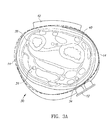
血管、圧力センサ、およびデバイスハウジングの向きを示す、ユーザの手首の、全体的に30で示される、手を内側に向けた左手首の断面(すなわち、横断面)を、図3Aに示す。ウェアラブルのメインハウジング42は、ストラップ14が手首の周りに配置された状態で、手首の頂部に配置される。この断面は、橈骨40および尺骨38と、腕の橈骨動脈34および尺骨動脈36とを示す。この例では、圧力センサアレイ12が、橈骨動脈34が位置する手首の領域に配置される。
A cross section (ie, cross section) of the user's wrist, with the hand facing inward, indicated by 30 overall, indicating the orientation of the blood vessels, pressure sensor, and device housing is shown in FIG. 3A. The wearable
いくつかの実施形態による、腕に配置されるように適合され、ユーザの血圧を測定するように動作する、例示的なウェアラブルデバイスが、図3Bに示される。代替実施形態では、ウェアラブルデバイスが、肘の上または下のユーザの腕に配置されるように構成される。ウェアラブルデバイスは、アームバンド33と、複数のセンサ素子37を含むセンサアレイ31と、電子機器、ディスプレイ、ボタン等を含むハウジング35とを備える。
An exemplary wearable device, according to some embodiments, adapted to be placed on the arm and acting to measure a user's blood pressure is shown in FIG. 3B. In an alternative embodiment, the wearable device is configured to be placed on the user's arm above or below the elbow. The wearable device includes an
動作中、センサアレイ31はアームバンドの底部に配置され、破線で示されるように、橈骨動脈および尺骨動脈に分岐する前に、上腕動脈39の上に配置される。あるいは、センサアレイおよびアームバンドが肘の下の腕に配置されてもよく、そこで、橈骨動脈または尺骨動脈からの血圧を感知する。デバイスは通信システムを備えてもよい。血圧データは、通信システムにより外部ホスト装置へ中継される。外部ホスト装置は、信号データを処理し、それから血圧測定値を生成するように動作する。あるいは、デバイスがセンサ信号データ自体を処理し、連続的な血圧測定値を生成するように適合された、適切にプログラムされたプロセッサを備えてもよい。別の実施形態では、デバイスが上述のように手首装着型デバイスと組み合わせて動作するように構成されてもよく、それによって、アームバンドデバイスは手首装着型デバイスと無線で通信する。例えば、生のセンサ信号データは、アームバンドデバイスから手首装着型デバイスに無線で通信され、そこで処理され、血圧測定値が手首装着型デバイス上でユーザに表示される。
During operation, the
圧力センサアレイは、多数の異なる構成を含むことができることに留意されたい。本発明は、多数の構成が考えられるので、いずれの1つの構成にも限定されない。いくつかの例示的な構成を次に提示する。 Note that the pressure sensor array can contain many different configurations. The present invention is not limited to any one configuration, as many configurations are conceivable. Some exemplary configurations are presented below.
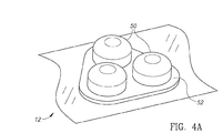
いくつかの実施形態による、例示的な血圧センサアレイの第1の実施形態が、図4Aに示されている。この例では、センサアレイ12が3つの圧力センサを備える。3つのセンサは、リストストラップ上に構成され、ユーザの手首に配置されると、ほぼ橈骨動脈上に配置される。デバイスは、3つのセンサ全てから同時に信号を受信するように構成される。信号のうちの1つはさらなる処理のための血圧波形として選択されてもよく、またはすべての信号の重み付けされた和からなる合成信号が血圧波形を生成するために使用されてもよい。
A first embodiment of an exemplary blood pressure sensor array, with some embodiments, is shown in FIG. 4A. In this example, the
複数の圧力センサから複数の信号を取得することが、圧力センサアレイの正しい配置の問題を解消することに留意することが重要である。圧力センサの少なくとも1つが正しく又は充分に正しく配置されている限り、受信された信号は、血圧波形から正しい血圧読み取り値を導出するのに充分であり得る。 It is important to note that acquiring multiple signals from multiple pressure sensors solves the problem of correct placement of the pressure sensor array. As long as at least one of the pressure sensors is placed correctly or sufficiently correctly, the received signal may be sufficient to derive the correct blood pressure reading from the blood pressure waveform.
いくつかの実施形態による、例示的な血圧センサアレイの第2の実施形態が、図4Bに示されている。この例では、リストバンド14上の圧力センサアレイ13が線形アレイに構成された複数のセンサ15を備える。デバイスは、全てのセンサからの信号を同時に受信するように構成される。信号のうちの1つは、さらなる処理のための血圧波形として選択されてもよく、またはすべての信号の重み付けされた和からなる合成信号が、血圧波形を生成するために使用されてもよい。線形アレイに配置された複数の圧力センサから複数の信号を取得することは、圧力センサアレイの正しい配置の問題を解消する。圧力センサの少なくとも1つが正しく又は充分に正しくに配置されている限り、受信された信号は、血圧波形から正しい血圧読み取り値を導出するのに充分であり得る。センサの線形アレイは、図4Bに示されるようにリストストラップに対して垂直に構成されてもよく、またはリストストラップに対して任意の所望の角度で構成されてもよいことが理解される。
A second embodiment of an exemplary blood pressure sensor array, with some embodiments, is shown in FIG. 4B. In this example, the
いくつかの実施形態による、例示的な血圧センサアレイの第3の実施形態が、図4Cに示されている。この例では、リストバンド14上の圧力センサアレイ17が2次元(2D)アレイに構成された複数のセンサ19を備える。デバイスは、全てのセンサからの信号を同時に受信するように構成される。信号のうちの1つはさらなる処理のための血圧波形として選択されてもよく、またはすべての信号の重み付けされた和からなる合成信号が血圧波形を生成するために使用されてもよい。2Dアレイに配置された複数の圧力センサから複数の信号を取得することは、圧力センサアレイの正しい配置の問題を解消する。圧力センサの少なくとも1つが正しく又は充分に正しく配置されている限り、受信された信号は、血圧波形から正しい血圧読み取り値を導出するのに充分であり得る。センサの2Dアレイは、図4Bに示されるようにリストストラップに対して垂直に構成されてもよく、またはリストストラップに対して任意の所望の角度で構成されてもよいことが理解される。
A third embodiment of an exemplary blood pressure sensor array, with some embodiments, is shown in FIG. 4C. In this example, the
図5は、各センサがユーザの手首上の異なる位置を有する複数の圧力センサの信号出力を表す複数の波形を示す。5つの波形、すなわち、波形150、152、154、156、158は、上述のようなセンサアレイに構成され、ユーザの手首上に配置された5つの異なる圧力センサからの出力信号を表す。x軸は時間を表し、y軸はセンサ出力信号の振幅に関連するmmHgを表す。 FIG. 5 shows a plurality of waveforms representing the signal outputs of a plurality of pressure sensors, each sensor having a different position on the user's wrist. The five waveforms, namely waveforms 150, 152, 154, 156, 158, represent output signals from five different pressure sensors configured on the sensor array as described above and placed on the user's wrist. The x-axis represents time and the y-axis represents mmHg associated with the amplitude of the sensor output signal.
予想されるように、いくつかの信号は、他の信号よりも高品質である。特に、波形152および156内の信号は、ほとんど信号を拾わず、非常に弱く、それらが橈骨動脈から圧力を拾う位置にないことを示す。波形150および154内の信号はより強い信号をピックアップするが、依然としてかなり弱く、それらが橈骨動脈上の所定の位置にないことを示す。しかしながら、波形158内の信号は比較的強力であり、それが橈骨動脈上に良好に配置されていることを示し、後続の処理のための血圧波形として使用することができる。この例では5つの圧力センサ信号が示されているが、本発明の範囲から逸脱することなく、任意の数の2つ以上のセンサを使用することができることを理解されたい。
As expected, some signals are of higher quality than others. In particular, the signals in the
別の実施形態では、アレイを構成する個々の圧力センサが異なるタイプのセンサを含むことができる。例えば、センサの第1の部分は、典型的には低電力消費及び低精度を有する容量性圧力センサを含むことができる。センサの第2の部分は典型的には高い電力消費を有するが、より良好な精度を有する抵抗圧力センサを含むことができる。一実施形態では、1つまたは複数の抵抗圧力センサ(すなわち、比較的高精度のセンサ)から得られた信号を使用して、1つまたは複数の容量圧力センサ(すなわち、比較的低精度のセンサ)からの読み取り値を較正し、それによって、かなり高い精度を有する血圧読み取り値をもたらす。 In another embodiment, the individual pressure sensors that make up the array can include different types of sensors. For example, the first portion of the sensor can typically include a capacitive pressure sensor with low power consumption and low accuracy. The second part of the sensor typically has high power consumption, but can include a resistance pressure sensor with better accuracy. In one embodiment, signals obtained from one or more resistance pressure sensors (ie, relatively high precision sensors) are used to use one or more capacitive pressure sensors (ie, relatively low precision sensors). ) Is calibrated, thereby resulting in a blood pressure reading with fairly high accuracy.
一実施形態では、アレイ内の圧力センサのうちの1つからの信号が血圧測定値を導出するために使用される血圧波形として選択される。他の全ての選択されていないセンサからの信号は、無視又は廃棄される。センサ信号は任意の所望の1つ以上の品質メトリック、例えば、SNR、RSSIなどについて分析されてもよい。 In one embodiment, a signal from one of the pressure sensors in the array is selected as the blood pressure waveform used to derive the blood pressure measurement. Signals from all other unselected sensors are ignored or discarded. The sensor signal may be analyzed for any desired quality metric, such as SNR, RSSI, and the like.
別の実施形態では、アレイ内の圧力センサの全部または一部からの信号が重み付けスキームを使用して結合され、改善された信号対雑音比(SNR)を有する合成血圧波形を生成する。次に、合成血圧波形を使用して、より正確な血圧測定値を生成する。 In another embodiment, signals from all or part of the pressure sensors in the array are combined using a weighting scheme to produce a synthetic blood pressure waveform with an improved signal-to-noise ratio (SNR). The synthetic blood pressure waveform is then used to generate more accurate blood pressure measurements.
別の実施形態では、1つ以上のセンサ信号が任意の所望の品質メトリックに基づいて選択され、これらの信号が重み付けされ、合成血圧波形を生成するために合成される、上述の2つの手法を組み合わせることができる。 In another embodiment, the two techniques described above, in which one or more sensor signals are selected based on any desired quality metric, these signals are weighted and synthesized to generate a synthetic blood pressure waveform. Can be combined.
いくつかの実施形態に従って構成された例示的なウェアラブルデバイスを示すブロック図が図6に示されている。ウェアラブルデバイスは、全体的に70で参照され、デジタルバス84によって互いに通信するリストバンドセンサユニット72および制御ユニット74を備える。リストバンドセンサユニット72は、N78を通る複数の圧力センサ1から構成され、各々がADコンバータ80に連結されている。ADコンバータの出力は、デジタルバス84に乗算された全ての入力信号を送信するために設定されているマルチプルエキサ82に入力される。一実施形態では、全てのセンサ78から出力された信号が制御ユニット74に入力される。
A block diagram showing an exemplary wearable device configured according to some embodiments is shown in FIG. The wearable device includes a wristband sensor unit 72 and a control unit 74, which are generally referred to by 70 and communicate with each other by a digital bus 84. The wristband sensor unit 72 is composed of a plurality of pressure sensors 1 passing through the N78, each of which is connected to the AD converter 80. The output of the AD converter is input to the
制御ユニット74は、例えばCPU、マイクロコントローラ、マイクロプロセッサ等のプロセッサ86、ディスプレイサブシステム88、例えば揮発性、不揮発性、フラッシュ等のメモリ102、無線及び有線通信サブシステム100、および、例えば光学式センサ、フォトプレチスモグラフセンサ、温度センサ等を含む1つ以上の他の非圧力センサ104とを含む。制御ユニット74は、無線LAN、BLE(Bluetooth(登録商標) Low Energy)、USB(Universal Serial Bus)接続などの無線および/または有線通信チャネルを介してホストデバイス76と通信する。プロセッサ86は、デジタルバス84を介してリストバンドセンサユニットとデータを送受信するように構成されている。表示サブシステムは、血圧測定値を表示するように構成される。
The control unit 74 includes, for example, a processor 86 such as a CPU, a microcontroller, a microprocessor, a
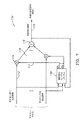
いくつかの実施形態に従い、合成血圧波形を生成するための回路を説明するブロック図を、図7に示す。全体として110で参照される回路は、適応重み付けアルゴリズムブロック118、乗算器1〜N 114、加算器116から構成されている。動作中、N個の圧力センサから受信された血圧波形データサンプル112にN個のスケールファクタが適用される。血圧波形データは、乗算器114及び適応重み付けアルゴリズムブロック118に入力される。合成血圧波形119は、適応重み付けアルゴリズムにも入力される。
A block diagram illustrating a circuit for generating a synthetic blood pressure waveform according to some embodiments is shown in FIG. The circuit referred to by 110 as a whole is composed of an adaptive weighting algorithm block 118, multipliers 1 to N 114, and
このアルゴリズムは入力データからN個のスケールファクタ113(すなわち、係数)α1からαNを生成するように動作し、それを介してN個の乗算器114にそれぞれ適用される。乗数によって生成された積115は、加算器116を介して加算され、合成血圧波形119が生成され、次に更に加工されて血圧読み取りが生成される。
This algorithm operates to generate α N from N scale factors 113 (ie, coefficients) α 1 from the input data, through which it is applied to each of the N multipliers 114. The
適応重み付けアルゴリズム118は、N個の血圧波形信号ならびに合成出力波形119を受け入れ、合成血圧波形119上のSNRが最大になるように係数α1からαNを推定するように構成される。
The adaptive weighting algorithm 118 is configured to accept N blood pressure waveform signals and a
例示的な実施形態では、重みはブロック147を介して、以下の式に従って最小二乗最大比合成(MRC)法に基づいて計算される。
![]()

![]()
一実施形態では、信号の振幅は、二乗平均平方根推定(RMS)、分散などの任意の適切な周知の技法を使用して推定することができる。 In one embodiment, the amplitude of the signal can be estimated using any suitable well-known technique such as root mean square estimation (RMS), variance.
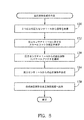
いくつかの実施形態による血圧波形合成(または較正)の例示的な方法を示す流れ図が図8に示されている。この例示的な方法では、N個のセンサの一部Pがより高い精度であり(例えば、抵抗MEMSタイプの圧力センサ)、N個のセンサの一部Rはより低い精度であり(例えば、容量MEMSタイプの圧力センサ)、ここで、R+P=Nであることに留意されたい。センサ1からPはより高い精度のセンサであり、センサP+1からNは、より低い精度のセンサである。 A flow diagram illustrating an exemplary method of blood pressure waveform synthesis (or calibration) according to some embodiments is shown in FIG. In this exemplary method, some P of the N sensors have higher accuracy (eg, resistance MEMS type pressure sensor) and some R of the N sensors have lower accuracy (eg, capacitance). MEMS type pressure sensor), note that here R + P = N. Sensors 1 to P are sensors with higher accuracy, and sensors P + 1 to N are sensors with lower accuracy.
図8を参照すると、まず、複数のN個の圧力センサからの信号が取得される(ステップ130)。次に、R個の圧力センサP+1〜Nからの血圧波形に対するスケールファクタ較正が推定される(ステップ132)。R個の圧力センサP+1〜Nからの血圧波形に、ステップ132で得られた推定スケールファクタを乗算する(ステップ134)。次に、センサ1〜Nから得られたスケーリングされた血圧波形が組み合わされ(ステップ136)、合成血圧波形が、さらなる処理のために出力され、そこから血圧読み取り値を導出する(ステップ138)。この方法は、より高いSNRを有する合成血圧波形を生成する。 Referring to FIG. 8, first, signals from a plurality of N pressure sensors are acquired (step 130). Next, scale factor calibration for blood pressure waveforms from R pressure sensors P + 1-N is estimated (step 132). The blood pressure waveforms from the R pressure sensors P + 1 to N are multiplied by the estimated scale factor obtained in step 132 (step 134). The scaled blood pressure waveforms obtained from sensors 1-N are then combined (step 136) and the synthetic blood pressure waveform is output for further processing from which the blood pressure reading is derived (step 138). This method produces a synthetic blood pressure waveform with a higher SNR.
いくつかの実施形態による、複数の圧力センサのうちの1つから血圧波形を選択するための例示的な回路を示すブロック図を、図9に示す。この回路は、全体的に120で参照され、複数のN個の圧力センサ入力モジュール122と、マルチプレクサ121と、電力管理ユニット127と、プロセッサブロック129とを備える。各圧力センサ入力モジュール122は、圧力センサ124と、オプションのフィルタ回路126と、ADコンバータ(ADC)128とを備える。プロセッサ129は、とりわけ、スキャンシーケンサ143および品質メトリック計算ブロック147を備える。
FIG. 9 shows a block diagram showing an exemplary circuit for selecting a blood pressure waveform from one of a plurality of pressure sensors, according to some embodiments. This circuit is referred to as a whole at 120 and includes a plurality of N pressure
上述のように、一実施形態では、ウェアラブルデバイスが単一の圧力センサによって出力される信号を選択し、他のすべてのセンサからの信号を無視することによって、1つまたは複数の品質メトリックを最大化する。これは、プロセッサ86(図6)を介してソフトウェアを使用して達成することができ、それによって、すべてのセンサからの信号波形が受信され、1つを除いてすべてが破棄される。 As mentioned above, in one embodiment, the wearable device maximizes one or more quality metrics by selecting the signal output by a single pressure sensor and ignoring the signals from all other sensors. To become. This can be achieved using software via processor 86 (FIG. 6), which receives signal waveforms from all sensors and discards all but one.
この実施形態120では、1つを除く全ての圧力センサ入力モジュールへの電力を無効にすることによって、電力消費が低減される。動作中、N個のセンサ入力モジュールすべてからの信号がプロセッサに入力され、ブロック147を介して1つまたは複数の品質メトリックが計算される。スキャンシーケンサは、N個のセンサ入力モジュールからの信号データの収集を制御する。計算されたメトリックに従って、センサ入力モジュールのうちの1つが、先行メトリックに基づいて選択される。
In this
センサ入力モジュールが選択されると、N−1個の非選択センサ入力モジュールへの電力は、電力管理ブロック127によって生成される電力イネーブル信号145を介してディスエーブルされる。プロセッサはまた、選択されたセンサ入力モジュールによって生成された信号を渡すために、マルチプレクサ121に適切な選択コマンド141を生成する。次いで、マルチプレクサから出力された血圧波形125は、血圧読み取り値を生成するためにさらに処理される。一実施形態では、N個すべての圧力センサからのデータを再評価(すなわち、再スキャン)し、新しいセンサを選択することができる。再評価は周期的に、例えば10秒ごとに、または動的に実行することができ、それによって、センサデータから計算された何らかのメトリックが閾値を下回る、例えばセンサ出力が特定のSNRまたはRSSIを下回ると、走査が開始される。
When the sensor input module is selected, the power to the N-1 non-selective sensor input modules is disabled via the power enable
プロセッサブロック147によって計算された1つまたは複数の品質メトリックは、任意の所望のメトリックを含むことができることに留意されたい。メトリックの例には、SNRおよびRSSIが含まれる。しかしながら、本発明は、これらのメトリックに限定されないことが理解される。
Note that one or more quality metrics calculated by
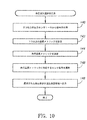
幾つかの実施形態に従った血圧波形選択の一例を図10に示す。まず、複数のN圧力センサからの信号を取得し、プロセッサに入力する(ステップ140)。1つ以上の品質メトリック(例えば、SNR、RSSI等)が計算される(ステップ142)。メトリック計算が比較され、先行メトリックが決定される(ステップ144)。次に、先行品質メトリックに対応するセンサ信号が選択される(ステップ146)。選択された血圧波形は、血圧判定処理に出力される(ステップ148)。任意選択で、電力消費を低減するために、選択されていないセンサに対応するセンサ入力モジュールへの電力が無効にされる。上述したように、N個の圧力センサすべてからのデータを再スキャンし、新しいセンサを選択することができる。 An example of blood pressure waveform selection according to some embodiments is shown in FIG. First, signals from a plurality of N pressure sensors are acquired and input to the processor (step 140). One or more quality metrics (eg, SNR, RSSI, etc.) are calculated (step 142). The metric calculations are compared and the leading metric is determined (step 144). Next, the sensor signal corresponding to the advanced quality metric is selected (step 146). The selected blood pressure waveform is output to the blood pressure determination process (step 148). Optionally, power to the sensor input module corresponding to the unselected sensor is disabled to reduce power consumption. As mentioned above, data from all N pressure sensors can be rescanned and new sensors can be selected.
以下の詳細な説明では、本発明の完全な理解を提供するために多くの具体的な詳細について述べる。しかしながら、本発明はこれらの特定の詳細なしに実施され得ることが、当業者によって理解されるであろう。他の例では、周知の方法、手順、および構成要素は本発明を曖昧にしないように詳細には説明されていない。 The following detailed description describes many specific details in order to provide a complete understanding of the present invention. However, it will be appreciated by those skilled in the art that the present invention can be practiced without these particular details. In other examples, well-known methods, procedures, and components are not described in detail so as not to obscure the invention.
図11は、本発明の1つの好ましい実施形態によるシステムの高レベルブロック図を示す。患者210は、患者の心臓214の心尖内の左心室と上行大動脈との間で血液をポンピングする移植可能な心室補助デバイス(LVAD)212を有する。心臓再同期デバイス及び除細動器216も患者210に埋め込まれる。患者は、本発明の実施形態の教示に従って、自分の手首にウェアラブルデバイス218を着用している。ウェアラブルデバイス218は圧力、PPG(フォトフォトプレチスモグラフ)、SpO2(酸素飽和)、加速度および/または皮膚温度などの信号を収集し、外部VADコントローラ222と無線で通信することができる。VADシステムは、患者の皮膚を通ってVADポンプに電力を供給する1組の駆動線(ワイヤ)224を介してVAD212に接続された再充電可能なバッテリ220によって電力を供給される。
FIG. 11 shows a high level block diagram of the system according to one preferred embodiment of the invention.
いくつかの実施形態によれば、本発明はウェアラブルな手首デバイス、VADデバイス自体内のセンサ、および他の埋め込み可能なデバイス(例えば、CRT)から信号を取得し、様々な血行動態パラメータを測定し、弁活動を検出するための有用で新規なデバイスおよび方法である。 According to some embodiments, the present invention obtains signals from wearable wrist devices, sensors within the VAD device itself, and other implantable devices (eg, CRTs) and measures various hemodynamic parameters. , A useful and novel device and method for detecting valve activity.
本発明の別の好ましい実施形態では、上述の様々なソースから抽出されたパラメータが特定の品質メトリック(すなわち、一定の心拍出量、血圧、または通常の弁活動)を最適化するように、閉ループにおけるVAD設定(すなわち、速度)を制御するために使用される。 In another preferred embodiment of the invention, parameters extracted from the various sources described above optimize a particular quality metric (ie, constant cardiac output, blood pressure, or normal valve activity). It is used to control the VAD setting (ie, speed) in a closed loop.
図12は、いくつかの実施形態による方法の高レベル図を示す。開始ステップ230の後、ステップ232において、様々なセンサによって信号が取得される。これらの信号は、圧力、SpO2、活動(加速度計)、手首装着型デバイスからの光学PPGセンサで検出された皮膚温度または血流、および/またはCRTデバイスなどの埋め込み型デバイスからの信号、および/またはVADデバイス自体内のセンサからの信号を含むことができる。当業者は、患者の身体に埋め込まれた、または患者に装着された様々な他のセンサから、他の信号およびセンサを考案することができることを理解されたい。ステップ234において、品質メトリックが計算され、この品質メトリックは例えば、前負荷(すなわち、肺キャピタリーウェッジ圧)、後負荷(すなわち、血圧)および/または心拍出量であってもよい。
FIG. 12 shows a high level diagram of the method according to some embodiments. After the start step 230, in
ステップ236では、特定のVADパラメータ(すなわち速度)が、ステップ234で計算された品質メトリックを最適化するように、最適化される。
In
本発明の好ましい実施形態によれば、システムは、後負荷(血圧)をある許容最大値に制限しながら、前負荷を一定に保つように構成することができる。したがって、臨床的証拠の高まりによれば、脳卒中(虚血性またはヘモラジック)、右室不全、心室性アリスミア、超心室性アリスミア、低ボレミアまたは高ボレミアのような有害作用のリスクを減少させる。本発明の別の好ましい実施形態によれば、システムは時間のある部分において弁活動を維持し、したがって大動脈不全のリスクを低減するように構成することができる。 According to a preferred embodiment of the invention, the system can be configured to keep the preload constant while limiting the afterload (blood pressure) to a certain permissible maximum value. Therefore, increasing clinical evidence reduces the risk of adverse effects such as stroke (ischemic or hemorazic), right ventricular insufficiency, ventricular alicemia, hyperventricular alicemia, low volenna or high volenna. According to another preferred embodiment of the invention, the system can be configured to maintain valve activity over time and thus reduce the risk of aortic failure.
次いで、システムはステップ236からステップ232にループバックし、閉ループ制御ループを生成する。これによって、患者の心臓を、一定の設定速度を有する既存のシステムよりもはるかに良好な状態に維持することができる。
The system then loops back from
本発明による方法を、図13に示す。開始ステップ250の後、システムはいくつかの実施形態によれば、様々なセンサから信号を取得する。これらの信号は、圧力、SpO2、活動(加速度計)、手首装着型デバイスからの光学PPGセンサで検出された皮膚温度または血流、および/またはCRTデバイスなどの埋め込み型デバイスからの信号、および/またはVADデバイス自体内のセンサからの信号を含むことができる。これらの信号は、ステップ254における特徴計算の基礎である。これらの特徴は、収縮期立ち上がり時間、拡張期立ち下がり時間、心拍数、発作性ノッチ位置、発作性ノッチタイミング、発作性ノッチ検出、フーリエパルス係数、パルス振幅を含むことができる。当業者は、前記センサ信号から多数の他の特徴を導出することができることを理解されたい。ステップ254で導出された特徴は、ステップ256における弁活動の基礎である。次いで、システムはステップ252にループバックし、それによって、弁活動を定期的に事前測定する。ステップ256における弁活動の計算は、経胸腔エコー(TTE Ultrasound)などのゴールドスタンダード弁測定に対する教師付き学習における予め測定されたデータベースに基づくサポートベクトルマシン(SVM)、ランダムフォレストなどのようなマシン学習アルゴリズムに基づくことができる。
The method according to the present invention is shown in FIG. After the
さらに、いくつかの実施形態によれば、本発明は、ステップ256において弁活動を計算するために使用されるアルゴリズムがTTEなどの充分に確立された弁活動測定に対して最初のまたは繰り返しの医療的遭遇においてVADが埋め込まれる特定の患者に対して最適化/機械学習され、それによって非常に正確なアルゴリズムを提供し得ることを教示する。
Further, according to some embodiments, the present invention is the first or repetitive medical treatment for a well-established valve activity measurement such as TTE where the algorithm used to calculate the valve activity in
いくつかの実施形態によるさらに別の方法を図14に示す。開始ステップ270の後、ステップ272において、様々なセンサから信号が取得される。これらの信号は、圧力、SpO2、活動(加速度計)、手首装着型デバイスからの光学PPGセンサで検出された皮膚温度または血流、および/またはCRTデバイスなどの埋め込み型デバイスからの信号、および/または圧力センサなどのVADデバイス自体内のセンサからの信号、またはVADが現在動作している実際の回転速度/周波数を含むことができる。
Yet another method according to some embodiments is shown in FIG. After the
ステップ274では、ステップ272で得られた種々の信号から特徴が計算される。これらの特徴は、収縮期立ち上がり時間、拡張期立ち下がり時間、心拍数、発作性ノッチ位置、発作性ノッチタイミング、発作性ノッチ検出、フーリエパルス係数、パルス振幅、または実際のパルスサンプルを含み得る。当業者は、前記センサ信号から多数の他の特徴を導出することができることを理解されたい。ステップ276では、血行動態パラメータがステップ274で計算された特徴から計算される。血行動態パラメータは、収縮期血圧、拡張期血圧、平均動脈圧、心拍数、心拍変動性または収縮期肺圧、拡張期肺圧、平均肺圧、肺毛細血管ウェッジ圧または左心室および拡張期圧を含み得る。ステップ256における血行動態パラメータの計算は、橈骨動脈または大腿動脈における動脈ラインなどの標準的な血行動態測定に対する教師付き学習における予め測定されたデータベースに基づく、サポートベクトルマシン(SVM)、ランダムフォレスト、ディープ学習などのような機械学習アルゴリズムに基づくことができる。
In
ステップ278は、ステップ274で計算された特徴とステップ276で計算された血行動態パラメータの両方からリスク分類が計算される任意のステップである。これらのパラメータはシステムが患者に警告し、医療を求めるように患者に助言することを可能にする、近い将来に起こる脳卒中などの有害な影響の確率を示すことができる。
Step 278 is any step in which the risk classification is calculated from both the features calculated in
当業者であれば、論理ブロックと回路ブロックとの間の境界は単に例示的なものであり、代替の実施形態は、論理ブロックまたは回路要素をマージするか、または様々な論理ブロックまたは回路要素に機能の配置換えをすることが可能であることを理解するであろう。したがって、本明細書に示されたアーキテクチャは単に例示的なものであり、実際には、同じ機能を達成する多くの他のアーキテクチャを実装できることを理解されたい。 For those skilled in the art, the boundaries between logic blocks and circuit blocks are merely exemplary, and alternative embodiments are to merge logic blocks or circuit elements or into various logic blocks or circuit elements. You will understand that it is possible to rearrange the functions. Therefore, it should be understood that the architectures presented herein are merely exemplary and in practice many other architectures that achieve the same functionality can be implemented.
同じ機能性を達成するための構成要素の任意の配置は所望の機能性が達成されるように効果的に「関連付けられる」したがって、特定の機能性を達成するために本明細書で組み合わされた任意の2つの構成要素はアーキテクチャまたは中間構成要素にかかわらず、所望の機能性が達成されるように互いに「関連付けられる」と見なすことができる。同様に、そのように関連付けられた任意の2つの構成要素は所望の機能性を達成するために互いに「動作可能に接続される」または「動作可能に結合される」と見なすこともできる。 Any arrangement of components to achieve the same functionality is effectively "associated" to achieve the desired functionality and is therefore combined herein to achieve a particular functionality. Any two components, regardless of architecture or intermediate components, can be considered "associated" with each other to achieve the desired functionality. Similarly, any two components so associated can also be considered "operably connected" or "operably combined" with each other to achieve the desired functionality.
さらに、当業者は、上述の動作間の境界が単に例示的であることを認識するであろう。複数の動作は、単一の動作に組み合わされてもよい。単一の動作は追加の動作に分散されてもよく、動作は時間的に少なくとも部分的にオーバーラップして実行されてもよい。さらに、代替実施形態は特定の動作の複数のインスタンスを含むことができ、動作の順序は、様々な他の実施形態で変更することができる。 Moreover, one of ordinary skill in the art will recognize that the boundaries between the above actions are merely exemplary. Multiple actions may be combined into a single action. A single action may be distributed over additional actions, and the actions may be performed with at least partial overlap in time. Further, the alternative embodiment can include multiple instances of a particular operation, and the order of the operations can be changed in various other embodiments.
本明細書で使用される用語は特定の実施形態を説明するためだけのものであり、本発明を限定することを意図するものではない。本明細書で使用されるように、単数形「a」、「an」および「the」は文脈が明確に沿わないことを示さない限り、複数形も含むことが意図される。用語「備える(comprises)」および/または「備える(comprising)」は本明細書で使用される場合、述べられた特徴、整数、ステップ、動作、要素、および/または構成要素の存在を指定するが、1つまたは複数の他の特徴、整数、ステップ、動作、要素、構成要素、および/またはそれらのグループの存在または追加を排除しないことがさらに理解される。 The terms used herein are for illustration purposes only and are not intended to limit the invention. As used herein, the singular forms "a," "an," and "the" are intended to include the plural, unless the context clearly indicates that they are not. Although the terms "comprises" and / or "comprising" as used herein specify the presence of the features, integers, steps, actions, elements, and / or components described. It is further understood that it does not preclude the existence or addition of one or more other features, integers, steps, behaviors, elements, components, and / or groups thereof.
特許請求の範囲において、括弧の間に置かれたいかなる参照符号も、特許請求の範囲を限定するものとして解釈されるべきではない。請求項における「少なくとも1つ」および「1つ以上」などの導入句の使用は、同じ請求項が導入句「1つ以上」または「少なくとも1つ」、および「a」または「an」などの不定冠詞を含む場合であっても、不定冠詞「a」または「an」による別の請求項要素の導入がそのような導入された請求項要素を含む任意の特定の請求項を1つのみのそのような要素を含む発明に限定することを暗示するように解釈されるべきではない。特に断らない限り、「第1の」、「第2の」などの用語は、そのような用語が記述する要素を任意に区別するために使用される。従って、これらの語は必ずしも要素間の時間的又は他の優先順位を示すものではない。特定の手段が相互に異なる請求項に記載されているという単なる事実は、これらの手段の組み合わせが有利に使用されることができないことを示すものではない。 Within the claims, any reference code placed between parentheses should not be construed as limiting the scope of the claims. The use of introductory phrases such as "at least one" and "one or more" in a claim is such that the same claim has introductory phrases "one or more" or "at least one" and "a" or "an". Even if it contains an indefinite article, the introduction of another claim element by the indefinite article "a" or "an" is only one claim of any particular claim containing such an introduced claim element. It should not be construed to imply limiting to inventions that include such elements. Unless otherwise noted, terms such as "first" and "second" are used to arbitrarily distinguish the elements described by such terms. Therefore, these terms do not necessarily indicate temporal or other priorities between elements. The mere fact that the particular means are described in different claims does not indicate that the combination of these means cannot be used in an advantageous manner.
以下の特許請求の範囲におけるすべての手段または工程および機能要素の対応する構造、材料、動作、および等価物は、特に特許請求される他の特許請求される要素と組合せて機能を実行するための任意の構造、材料、または動作を含むことが意図される。本発明の説明は例示および説明の目的で提示されているが、網羅的であることも、開示された形態の本発明に限定されることも意図されていない。多数の修正および変更が当業者に容易に想起されるので、本発明は、本明細書に記載される限定された数の実施形態に限定されないことが意図される。したがって、本発明の精神および範囲内に入る、すべての適切な変形、修正、および均等物に頼ることができることが理解されるであろう。実施形態は、本発明の原理および実際の用途を最もよく説明するために、また、当業者が企図される特定の使用に適した様々な修正を伴う様々な実施形態について本発明を理解することを可能にするために、選択され、説明された。 Corresponding structures, materials, operations, and equivalents of all means or processes and functional elements in the claims below are specifically intended to perform a function in combination with other claimed elements. It is intended to include any structure, material, or operation. The description of the invention is presented for purposes of illustration and illustration, but is not intended to be exhaustive or limited to the disclosed form of the invention. It is intended that the invention is not limited to the limited number of embodiments described herein, as numerous modifications and modifications will be readily recalled to those skilled in the art. It will therefore be appreciated that one can rely on all appropriate modifications, modifications, and equivalents that fall within the spirit and scope of the invention. Embodiments are intended to best illustrate the principles and practical use of the invention, and to understand the invention for various embodiments with various modifications suitable for a particular use intended by those skilled in the art. Was selected and explained to enable.
Claims (29)
前記ウェアラブルデバイス内のセンサからの信号のセットを取得するステップと、
少なくとも1つの品質メトリックを計算するステップと、
少なくとも1つの前記品質メトリックを最適化するように少なくとも1つのVAD動作パラメータを調整するステップとを含む、方法。 A method of adjusting VAD device parameters using a wearable device placed in the patient's hand.
The step of acquiring a set of signals from the sensor in the wearable device, and
Steps to calculate at least one quality metric,
A method comprising adjusting at least one VAD operating parameter to optimize at least one said quality metric.
前記ウェアラブルデバイス内のセンサから信号を取得するステップと、
前記信号から特徴のセットを計算し、弁活動が存在する時間部分を抽出するアルゴリズムを実行するステップとを含む、方法。 A method of detecting valve activity in a VAD patient using a wrist-worn device that includes at least one sensor.
The step of acquiring a signal from the sensor in the wearable device and
A method comprising the step of calculating a set of features from the signal and executing an algorithm to extract the time portion in which valve activity is present.
前記ウェアラブルデバイス内のセンサから信号を取得するステップと、
前記信号から特徴のセットを計算し、前記血行動態パラメータを計算するためのアルゴリズムを実行するステップとを含む、方法。 A method of calculating hemodynamic parameters of at least one VAD-implanted patient using a wrist-worn device that includes at least one sensor.
The step of acquiring a signal from the sensor in the wearable device and
A method comprising calculating a set of features from the signal and executing an algorithm for calculating the hemodynamic parameters.
Applications Claiming Priority (3)
| Application Number | Priority Date | Filing Date | Title |
|---|---|---|---|
| US201762533146P | 2017-07-17 | 2017-07-17 | |
| US62/533,146 | 2017-07-17 | ||
| PCT/IL2018/050786 WO2019016802A1 (en) | 2017-07-17 | 2018-07-17 | Method and system for ventricular assistive device adjustment using a wearable device |
Publications (2)
| Publication Number | Publication Date |
|---|---|
| JP2020528307A true JP2020528307A (en) | 2020-09-24 |
| JP2020528307A5 JP2020528307A5 (en) | 2021-08-26 |
Family
ID=65015116
Family Applications (1)
| Application Number | Title | Priority Date | Filing Date |
|---|---|---|---|
| JP2020502199A Pending JP2020528307A (en) | 2017-07-17 | 2018-07-17 | Methods and systems for adjusting ventricular assist devices using wearable devices |
Country Status (8)
| Country | Link |
|---|---|
| US (1) | US20200215246A1 (en) |
| EP (1) | EP3655055A4 (en) |
| JP (1) | JP2020528307A (en) |
| KR (1) | KR20200067831A (en) |
| CN (1) | CN111107891A (en) |
| BR (1) | BR112020005122A2 (en) |
| CA (1) | CA3070346A1 (en) |
| WO (1) | WO2019016802A1 (en) |
Families Citing this family (5)
| Publication number | Priority date | Publication date | Assignee | Title |
|---|---|---|---|---|
| KR20210004376A (en) | 2019-07-04 | 2021-01-13 | 삼성전자주식회사 | Apparatus and method for calibrating bio-information estimation model and, apparatus for estimating bio-information |
| CN114340477A (en) * | 2019-09-03 | 2022-04-12 | 皇家飞利浦有限公司 | Reliable detection of blood pressure measurements |
| CN111657875B (en) * | 2020-07-09 | 2021-01-29 | 深圳市则成电子股份有限公司 | Blood oxygen testing method, device and storage medium thereof |
| KR20220053364A (en) * | 2020-10-22 | 2022-04-29 | 삼성전자주식회사 | Wearable device and method for measuring biometric information |
| WO2024006556A2 (en) * | 2022-06-30 | 2024-01-04 | Lehigh University | System, software and methods of using software for treating and modeling heart disease |
Citations (1)
| Publication number | Priority date | Publication date | Assignee | Title |
|---|---|---|---|---|
| US20150174307A1 (en) * | 2012-07-19 | 2015-06-25 | Regents Of The University Of Minnesota | Cardiac assist device with pulse wave analysis |
Family Cites Families (13)
| Publication number | Priority date | Publication date | Assignee | Title |
|---|---|---|---|---|
| WO2003015609A2 (en) * | 2001-08-16 | 2003-02-27 | Apex Medical, Inc. | Physiological heart pump control |
| AU2002951685A0 (en) * | 2002-09-30 | 2002-10-17 | Ventrassist Pty Ltd | Physiological demand responsive control system |
| WO2005051838A2 (en) | 2003-11-19 | 2005-06-09 | Transoma Medical, Inc. | Feedback control of ventricular assist devices |
| US20050165456A1 (en) * | 2003-12-19 | 2005-07-28 | Brian Mann | Digital electrode for cardiac rhythm management |
| US9820658B2 (en) * | 2006-06-30 | 2017-11-21 | Bao Q. Tran | Systems and methods for providing interoperability among healthcare devices |
| CN102334986B (en) * | 2011-07-08 | 2013-09-25 | 重庆大学 | Method for identifying dicrotic notch point in arterial tension signal |
| US20180126053A1 (en) * | 2011-08-19 | 2018-05-10 | Leviticus Cardio Ltd. | Wristwatch for monitoring operation of an implanted ventricular assist device |
| US10022480B2 (en) * | 2012-09-21 | 2018-07-17 | Reinheart Gmbh | Ventricular assist device and method of controlling same |
| US9789236B2 (en) * | 2013-03-14 | 2017-10-17 | Yale University | Implantable heart pump controller |
| US9919088B2 (en) * | 2013-03-14 | 2018-03-20 | Yale University | Implantable heart pump controller |
| EP2851099A1 (en) * | 2013-09-20 | 2015-03-25 | Berlin Heart GmbH | Blood pump control system for controlling a blood pump |
| WO2016065476A1 (en) * | 2014-10-30 | 2016-05-06 | 2352409 Ontario Inc. | A wearable device and method for non-invasive monitoring continuous blood pressure and other physiological parameters with reduced movement artifacts |
| WO2019178519A1 (en) * | 2018-03-15 | 2019-09-19 | Tc1 Llc | Methods and systems for preventing right heart failure |
-
2018
- 2018-07-17 EP EP18835720.6A patent/EP3655055A4/en active Pending
- 2018-07-17 WO PCT/IL2018/050786 patent/WO2019016802A1/en unknown
- 2018-07-17 CA CA3070346A patent/CA3070346A1/en active Pending
- 2018-07-17 BR BR112020005122-5A patent/BR112020005122A2/en unknown
- 2018-07-17 KR KR1020207004460A patent/KR20200067831A/en not_active Application Discontinuation
- 2018-07-17 US US16/630,708 patent/US20200215246A1/en active Pending
- 2018-07-17 CN CN201880060203.6A patent/CN111107891A/en active Pending
- 2018-07-17 JP JP2020502199A patent/JP2020528307A/en active Pending
Patent Citations (1)
| Publication number | Priority date | Publication date | Assignee | Title |
|---|---|---|---|---|
| US20150174307A1 (en) * | 2012-07-19 | 2015-06-25 | Regents Of The University Of Minnesota | Cardiac assist device with pulse wave analysis |
Also Published As
| Publication number | Publication date |
|---|---|
| KR20200067831A (en) | 2020-06-12 |
| CA3070346A1 (en) | 2019-01-24 |
| BR112020005122A2 (en) | 2021-09-08 |
| CN111107891A (en) | 2020-05-05 |
| US20200215246A1 (en) | 2020-07-09 |
| EP3655055A1 (en) | 2020-05-27 |
| EP3655055A4 (en) | 2020-07-29 |
| WO2019016802A1 (en) | 2019-01-24 |
Similar Documents
| Publication | Publication Date | Title |
|---|---|---|
| JP7350806B2 (en) | Observational heart failure monitoring system | |
| JP7175509B2 (en) | Method and apparatus for obtaining output blood pressure signal | |
| JP6854612B2 (en) | Biological information measuring device, biometric information measuring method, and computer-readable recording medium | |
| JP2020528307A (en) | Methods and systems for adjusting ventricular assist devices using wearable devices | |
| US20190090760A1 (en) | Non-invasive blood pressure measurement system | |
| US10092268B2 (en) | Method and apparatus to monitor physiologic and biometric parameters using a non-invasive set of transducers | |
| JP2021519168A (en) | Systems and methods for non-invasive determination of blood pressure drop based on trained predictive models | |
| JP2022176978A (en) | Physiological monitor for monitoring patients undergoing hemodialysis | |
| WO2009125349A2 (en) | Multi-sensor apparatus and method for monitoring of circulatory parameters | |
| JP2016509504A (en) | Method, logical operation apparatus, and system for obtaining parameter representing patient volume responsiveness | |
| Landreani et al. | Smartphone accelerometers for the detection of heart rate | |
| WO2020182010A1 (en) | Method for determining pulse transmission time, and arteriosclerosis detection device and system | |
| KR20190048878A (en) | Method and apparatus for measuring blood pressure using optical sensor | |
| US20230225623A1 (en) | Methods And Systems For Non-Invasive Cuff-Less Blood Pressure Monitoring | |
| JP2023515256A (en) | Systems and methods for measuring venous oxygen saturation using intelligent pulse averaging with integrated EKG and PPG sensors | |
| CN208876506U (en) | Pulse wave velocity device and blood pressure continuous measurement device | |
| US11850039B2 (en) | Apparatus and method for determining a change in left ventricular twist of a subject's heart | |
| TWM547951U (en) | Biophysical signal detection apparatus | |
| Lui et al. | A novel calibration procedure of pulse transit time based blood pressure measurement with heart rate and respiratory rate | |
| US20200297225A1 (en) | Vital sign measurement device | |
| Mühlsteff et al. | Systems, sensors, and devices in personal healthcare applications | |
| Tokmak | Exploring Mechanocardiography as a Tool to Monitor Systolic Function Improvement with Resynchronization Pacing | |
| WO2022152657A1 (en) | Blood pressure estimation | |
| KR20230023671A (en) | Systems, methods and apparatus for non-invasive and continuous hemodynamic measurement |
Legal Events
| Date | Code | Title | Description |
|---|---|---|---|
| A521 | Request for written amendment filed |
Free format text: JAPANESE INTERMEDIATE CODE: A523 Effective date: 20210713 |
|
| A621 | Written request for application examination |
Free format text: JAPANESE INTERMEDIATE CODE: A621 Effective date: 20210713 |
|
| A977 | Report on retrieval |
Free format text: JAPANESE INTERMEDIATE CODE: A971007 Effective date: 20220729 |
|
| A131 | Notification of reasons for refusal |
Free format text: JAPANESE INTERMEDIATE CODE: A131 Effective date: 20220809 |
|
| A601 | Written request for extension of time |
Free format text: JAPANESE INTERMEDIATE CODE: A601 Effective date: 20221107 |
|
| A02 | Decision of refusal |
Free format text: JAPANESE INTERMEDIATE CODE: A02 Effective date: 20230404 |