JP2020521927A - Actuator with reducer - Google Patents
Actuator with reducer Download PDFInfo
- Publication number
- JP2020521927A JP2020521927A JP2020515792A JP2020515792A JP2020521927A JP 2020521927 A JP2020521927 A JP 2020521927A JP 2020515792 A JP2020515792 A JP 2020515792A JP 2020515792 A JP2020515792 A JP 2020515792A JP 2020521927 A JP2020521927 A JP 2020521927A
- Authority
- JP
- Japan
- Prior art keywords
- gear
- stator
- gears
- actuator
- planet
- Prior art date
- Legal status (The legal status is an assumption and is not a legal conclusion. Google has not performed a legal analysis and makes no representation as to the accuracy of the status listed.)
- Abandoned
Links
Images


Classifications
-
- F—MECHANICAL ENGINEERING; LIGHTING; HEATING; WEAPONS; BLASTING
- F16—ENGINEERING ELEMENTS AND UNITS; GENERAL MEASURES FOR PRODUCING AND MAINTAINING EFFECTIVE FUNCTIONING OF MACHINES OR INSTALLATIONS; THERMAL INSULATION IN GENERAL
- F16H—GEARING
- F16H3/00—Toothed gearings for conveying rotary motion with variable gear ratio or for reversing rotary motion
- F16H3/44—Toothed gearings for conveying rotary motion with variable gear ratio or for reversing rotary motion using gears having orbital motion
- F16H3/72—Toothed gearings for conveying rotary motion with variable gear ratio or for reversing rotary motion using gears having orbital motion with a secondary drive, e.g. regulating motor, in order to vary speed continuously
- F16H3/724—Toothed gearings for conveying rotary motion with variable gear ratio or for reversing rotary motion using gears having orbital motion with a secondary drive, e.g. regulating motor, in order to vary speed continuously using external powered electric machines
-
- H—ELECTRICITY
- H02—GENERATION; CONVERSION OR DISTRIBUTION OF ELECTRIC POWER
- H02K—DYNAMO-ELECTRIC MACHINES
- H02K7/00—Arrangements for handling mechanical energy structurally associated with dynamo-electric machines, e.g. structural association with mechanical driving motors or auxiliary dynamo-electric machines
- H02K7/14—Structural association with mechanical loads, e.g. with hand-held machine tools or fans
- H02K7/16—Structural association with mechanical loads, e.g. with hand-held machine tools or fans for operation above the critical speed of vibration of the rotating parts
-
- F—MECHANICAL ENGINEERING; LIGHTING; HEATING; WEAPONS; BLASTING
- F16—ENGINEERING ELEMENTS AND UNITS; GENERAL MEASURES FOR PRODUCING AND MAINTAINING EFFECTIVE FUNCTIONING OF MACHINES OR INSTALLATIONS; THERMAL INSULATION IN GENERAL
- F16H—GEARING
- F16H1/00—Toothed gearings for conveying rotary motion
- F16H1/28—Toothed gearings for conveying rotary motion with gears having orbital motion
- F16H1/2863—Arrangements for adjusting or for taking-up backlash
-
- F—MECHANICAL ENGINEERING; LIGHTING; HEATING; WEAPONS; BLASTING
- F16—ENGINEERING ELEMENTS AND UNITS; GENERAL MEASURES FOR PRODUCING AND MAINTAINING EFFECTIVE FUNCTIONING OF MACHINES OR INSTALLATIONS; THERMAL INSULATION IN GENERAL
- F16H—GEARING
- F16H55/00—Elements with teeth or friction surfaces for conveying motion; Worms, pulleys or sheaves for gearing mechanisms
- F16H55/02—Toothed members; Worms
- F16H55/08—Profiling
-
- F—MECHANICAL ENGINEERING; LIGHTING; HEATING; WEAPONS; BLASTING
- F16—ENGINEERING ELEMENTS AND UNITS; GENERAL MEASURES FOR PRODUCING AND MAINTAINING EFFECTIVE FUNCTIONING OF MACHINES OR INSTALLATIONS; THERMAL INSULATION IN GENERAL
- F16H—GEARING
- F16H55/00—Elements with teeth or friction surfaces for conveying motion; Worms, pulleys or sheaves for gearing mechanisms
- F16H55/02—Toothed members; Worms
- F16H55/17—Toothed wheels
- F16H55/18—Special devices for taking up backlash
-
- H—ELECTRICITY
- H01—ELECTRIC ELEMENTS
- H01F—MAGNETS; INDUCTANCES; TRANSFORMERS; SELECTION OF MATERIALS FOR THEIR MAGNETIC PROPERTIES
- H01F7/00—Magnets
- H01F7/06—Electromagnets; Actuators including electromagnets
- H01F7/08—Electromagnets; Actuators including electromagnets with armatures
-
- H—ELECTRICITY
- H02—GENERATION; CONVERSION OR DISTRIBUTION OF ELECTRIC POWER
- H02K—DYNAMO-ELECTRIC MACHINES
- H02K16/00—Machines with more than one rotor or stator
- H02K16/04—Machines with one rotor and two stators
-
- H—ELECTRICITY
- H02—GENERATION; CONVERSION OR DISTRIBUTION OF ELECTRIC POWER
- H02K—DYNAMO-ELECTRIC MACHINES
- H02K21/00—Synchronous motors having permanent magnets; Synchronous generators having permanent magnets
- H02K21/12—Synchronous motors having permanent magnets; Synchronous generators having permanent magnets with stationary armatures and rotating magnets
- H02K21/24—Synchronous motors having permanent magnets; Synchronous generators having permanent magnets with stationary armatures and rotating magnets with magnets axially facing the armatures, e.g. hub-type cycle dynamos
-
- H—ELECTRICITY
- H02—GENERATION; CONVERSION OR DISTRIBUTION OF ELECTRIC POWER
- H02K—DYNAMO-ELECTRIC MACHINES
- H02K7/00—Arrangements for handling mechanical energy structurally associated with dynamo-electric machines, e.g. structural association with mechanical driving motors or auxiliary dynamo-electric machines
- H02K7/10—Structural association with clutches, brakes, gears, pulleys or mechanical starters
- H02K7/116—Structural association with clutches, brakes, gears, pulleys or mechanical starters with gears
-
- F—MECHANICAL ENGINEERING; LIGHTING; HEATING; WEAPONS; BLASTING
- F16—ENGINEERING ELEMENTS AND UNITS; GENERAL MEASURES FOR PRODUCING AND MAINTAINING EFFECTIVE FUNCTIONING OF MACHINES OR INSTALLATIONS; THERMAL INSULATION IN GENERAL
- F16H—GEARING
- F16H1/00—Toothed gearings for conveying rotary motion
- F16H1/28—Toothed gearings for conveying rotary motion with gears having orbital motion
-
- F—MECHANICAL ENGINEERING; LIGHTING; HEATING; WEAPONS; BLASTING
- F16—ENGINEERING ELEMENTS AND UNITS; GENERAL MEASURES FOR PRODUCING AND MAINTAINING EFFECTIVE FUNCTIONING OF MACHINES OR INSTALLATIONS; THERMAL INSULATION IN GENERAL
- F16H—GEARING
- F16H57/00—General details of gearing
- F16H57/02—Gearboxes; Mounting gearing therein
- F16H2057/02034—Gearboxes combined or connected with electric machines
-
- H—ELECTRICITY
- H01—ELECTRIC ELEMENTS
- H01F—MAGNETS; INDUCTANCES; TRANSFORMERS; SELECTION OF MATERIALS FOR THEIR MAGNETIC PROPERTIES
- H01F7/00—Magnets
- H01F7/06—Electromagnets; Actuators including electromagnets
- H01F7/08—Electromagnets; Actuators including electromagnets with armatures
- H01F7/121—Guiding or setting position of armatures, e.g. retaining armatures in their end position
- H01F7/122—Guiding or setting position of armatures, e.g. retaining armatures in their end position by permanent magnets
Abstract
減速機を有する電磁式アクチュエータは、ステーターと、ステーターに対して回転するように配置されたローターとを有する。駆動ギアがローターに固定されている。少なくとも3つの遊星ギアがステーターに取り付けられ、少なくとも3つの遊星ギアのそれぞれが駆動ギアによって係合されている。環状ギアが第1のステーターに回転可能に取り付けられており、環状ギアが少なくとも3つの遊星ギアのそれぞれによって係合される。An electromagnetic actuator having a speed reducer has a stator and a rotor arranged to rotate with respect to the stator. The drive gear is fixed to the rotor. At least three planet gears are attached to the stator, and each of the at least three planet gears is engaged by the drive gear. An annular gear is rotatably mounted on the first stator, the annular gear being engaged by each of the at least three planetary gears.
Description
減速機を有する電磁式アクチュエータ Electromagnetic actuator with reducer
(関連出願の相互参照)
この出願は、2017年5月31日に出願された「トルク増幅器」という名称の米国仮特許出願第62/513,431号から優先権を主張する非仮出願である。本出願は、その全体が参照により本明細書に組み込まれる。
(Cross-reference of related applications)
This application is a non-provisional application claiming priority from US Provisional Patent Application No. 62/513,431, entitled "Torque Amplifier," filed May 31, 2017. This application is incorporated herein by reference in its entirety.
従来のギア同士をしっかりと予圧すると、熱膨張中にそれらを結合させる可能性があるとともに、バネ同士のギアのロードは常に最大トルクの予圧を必要とし、低負荷状態では高い摩擦及び摩耗につながることから、ギアボックスからのバックラッシュをなくすことは、非常に困難である。 Firmly preloading conventional gears can cause them to couple during thermal expansion, and loading the gears between springs always requires maximum torque preload, leading to high friction and wear under low load conditions Therefore, eliminating backlash from the gearbox is very difficult.
実施形態では、高レベルの逆駆動性と高比率ギアボックスよりも高速出力とを可能にするため、ロボット又はモーション制御の用途に有益でとすることができる、高トルクモーターと組み合わせた低比率減速機が開示されている。例えば国際公開第2017/024409号及び関連出願に開示されているLiveDrive(商標)モーターなどの高トルクモーターと対にすると、それはまた、高トルク対慣性比を有する非常に高トルクを提供することもできる。 In embodiments, a low ratio deceleration combined with a high torque motor, which may be beneficial for robotic or motion control applications, as it allows a high level of reverse drive and faster output than a high ratio gearbox. Machine is disclosed. When paired with a high torque motor, such as, for example, the LiveDrive™ motor disclosed in WO 2017/024409 and related applications, it also provides very high torque with a high torque to inertia ratio. it can.
実施形態では、高トルク中であっても常にバックラッシュがゼロであり、低負荷状態中に高い逆駆動性及び低摩擦を提供するギア減速装置が開示されている。 Embodiments disclose a gear reducer that provides zero backlash at all times, even during high torque, and provides high reverse driveability and low friction during low load conditions.
実施形態では、ステーターの背面に1つ以上の遊星ギア及び環帯出力ギアを回転可能に固定する2つのステーターの間に挟持された軸方向磁束ローターがある。このステーターに固体材料を使用すると、ステーターと一体として遊星軸(又は遊星軸孔)を有するステーターを製造することができる。これは、トルク、精度及びコスト削減の点で利点を有する。遊星ギアは、一般的な遊星ギアボックスのように公転しない。代わりに、遊星ギア軸は、ステーターに対して固定されており、太陽ギア入力と環状リングギア出力との間のアイドラプーリーとして機能する。これは、回転する遊星キャリアの必要性、それに関連するコスト、複雑さ、及びロストモーションの可能性をなくす。 In an embodiment, there is an axial flux rotor sandwiched between two stators that rotatably secure one or more planet gears and annulus output gears to the back of the stator. When a solid material is used for this stator, it is possible to manufacture a stator having a planetary shaft (or planetary shaft hole) integrally with the stator. This has advantages in terms of torque, accuracy and cost savings. Planetary gears do not revolve like general planetary gearboxes. Instead, the planet gear shaft is fixed relative to the stator and acts as an idler pulley between the sun gear input and the annular ring gear output. This eliminates the need for a spinning planet carrier, its associated costs, complexity, and potential for lost motion.
実施形態では、減速機を有する電磁式アクチュエータがある。第1のステーターと、第1のステーターに対して回転運動するように配置されたローターとがある。駆動ギアがローターに固定されている。少なくとも3つの遊星ギアが第1のステーターに取り付けられており、少なくとも3つの遊星ギアのそれぞれが駆動ギアによって係合されている。環状ギアが第1のステーターに回転可能に取り付けられており、環状ギアが少なくとも3つの遊星ギアのそれぞれによって係合される。 In the embodiment, there is an electromagnetic actuator having a speed reducer. There is a first stator and a rotor arranged for rotational movement with respect to the first stator. The drive gear is fixed to the rotor. At least three planet gears are attached to the first stator, and each of the at least three planet gears is engaged by the drive gear. An annular gear is rotatably mounted on the first stator and the annular gear is engaged by each of the at least three planetary gears.
他の実施形態では、第1のギア及び第2のギアを有するギアアセンブリがあり、第1及び第2のギアのそれぞれは、複数の歯を有し、複数の歯のそれぞれは、長さと各歯の長さに沿った歯先とを有する。各歯は、その長さに沿ってテーパー状になっており、各歯の長さに沿ったテーパーに対して歯先が変化する。第1のギアの正のシフト面が第2のギアの負のシフト面と係合すると、第1のギア及び第2のギアは、係合位置に嵌合する。 In another embodiment, there is a gear assembly having a first gear and a second gear, each of the first and second gears having a plurality of teeth, each of the plurality of teeth having a length and a respective length. A tooth tip along the length of the tooth. Each tooth is tapered along its length and the tip changes with respect to the taper along the length of each tooth. When the positive shift surface of the first gear engages the negative shift surface of the second gear, the first gear and the second gear engage in the engaged position.
ここで、同様の参照文字が同様の要素を示す図面を参照して、減速機を有する電磁式アクチュエータの実施形態を、例として説明する。 Embodiments of electromagnetic actuators with speed reducers will now be described by way of example with reference to the drawings in which like reference characters indicate like elements.
図1及び図2に示すように、減速機を有する電磁式アクチュエータ10は、少なくとも第1のステーター12と、第1のステーター12に対して回転するように配置されたローター14とを含む。図示のように、第1のステーター12は、互いに固定された2つのステーター12、16のうちの1つであってよく、ローター14は、2つのステーターの間に配置され、2つのステーターのそれぞれに対して回転運動する。ローター14及びステーター16は、軸受38に取り付けられることができる。図1には、両方のステーターが示されているが、単一のステーターのみを使用することも可能である。「第1のステーター」という用語は、環状ギア、又は環帯ギア28を支持するステーターを記載するために使用される。特許請求の範囲において、「第1のステーター」という用語は、単一のステーターのみが存在する可能性を排除するものではない。駆動ギア18又は太陽ギアは、ローターのシャフト46に固定されている。3つの遊星ギア20、22、24は、第1のステーター12に取り付けられており、3つの遊星ギアのそれぞれは、駆動ギア18によって係合されている。他の実施形態では、4つ以上を含む他の数の遊星ギアを使用することができる。環状ギア28は、第1のステーター12に回転可能に取り付けられている。環状ギア28は、3つの遊星ギア20、22、24のそれぞれによって係合されている。3つの遊星ギア20、22、24は、それぞれ、第1のステーター12と同じモノリシック材料の一部として形成された3つのポスト52、54、56のうちの1つに取り付けられている。環状ギア28は、軸受30によって第1のステーター12に固定されている。駆動ギア18は、キャップ44の下に隠れていてもよい。
As shown in FIGS. 1 and 2, an
3つの遊星ギア20、22、24は、それぞれ、環状ギア28及び駆動ギア18上の対応する歯と係合する複数の歯を有する。歯50(図4)のそれぞれは、長さを有し、歯のそれぞれは、図4に示すように、その長さに沿ってテーパー状になっている。3つの遊星ギアのそれぞれは、軸方向に予圧されることができる。
The three
図8に示すように、3つの遊星ギア20、22、24は、それぞれ、3つの遊星ギア20と第1のステーター12との間の対応する軸受32に作用するバネ60などの対応するバネによって軸方向に予圧されることができる。
As shown in FIG. 8, the three
図9に示すように、遊星ギア20などの3つの遊星ギアは、対応する磁石66によって軸方向に予圧されることができる。
As shown in FIG. 9, three planet gears, such as
図1を参照すると、磁気コイル42などの3つの電磁コイルがステーター12に固定的に取り付けられ、駆動ギア18及び環状ギア28に対する3つの遊星ギア20、22、24の軸方向の移動を提供することができる。遊星ギア20に対する電磁コイル42の位置は、遊星ギア22及び24に対する他の2つの電磁コイルの位置と同じである。3つの電磁コイル42は、パルス幅変調制御通電により設定される第1の電流により作動されることができる。ステーター12及びローター14は、複数の電磁コイル及び永久磁石によって作動される軸方向磁束モーターを形成する。例えば、第1のステーター12は、第2の電流によって作動される複数の電磁コイルを含むことができ、ローター14は、複数の永久磁石を含むことができる。3つの電磁コイル42は、第2の電流に比例する第1の電流によって作動されることができる。駆動ギア18は、スピノーダル青銅又は他の適切な材料から作製されることができる。環状ギア28もまた、スピノーダル青銅又は他の適切な材料から作製されることができる。
Referring to FIG. 1, three electromagnetic coils, such as
図10に示すように、第1のステーター12は、作動中にアクチュエータ10を通して空気流を導く開口68を更に備える。
As shown in FIG. 10, the
3つの遊星ギア20、22、24は、3つの遊星ギアのそれぞれの内径と3つのポストのそれぞれの外径との間に位置する3つの遊星軸受32、34、36によって3つのポスト52、54、56のそれぞれに接続される。3つの遊星軸受32、34、36は、それぞれ、少なくとも3つのポストのそれぞれの外径と一体の内側溝と、少なくとも3つの遊星軸受のそれぞれの内径と一体の外側溝とに位置する玉軸受の列を備える。玉軸受の列はまた、3つの遊星ギア20、22、24及び3つのポスト52、54、56のスリーブの間に配置されることもできる。
The three
3つの遊星軸受32、34、36は、少なくとも3つの遊星ギア20、22、24のそれぞれに対して半径方向に少量の動きを可能にするように配置される。
The three
環状リングギア28は、OD及び/又はIDの周りの軸受30によりステーター12に回転可能に取り付けられている。ローター14の回転は、ローター構造12に固定された太陽ギア18を回転させる。太陽ギア18の回転は、アイドラ遊星ギア20、22、24を回転させ、これにより環状ギア、又は環帯ギア28を回転させる。
The
このギア駆動系では、直線又は螺旋カットギアを使用することができる。バックラッシュを低減又は排除するために、様々な既知のギアインターフェースの予圧構成を使用することができる。ここに開示されているのは、駆動部を介して伝達されるトルク負荷に応じて予圧が調整されることができる、独自のギア予圧構成である。 Linear or spiral cut gears can be used in this gear drive system. Various known gear interface preload configurations can be used to reduce or eliminate backlash. Disclosed herein is a unique gear preload arrangement in which the preload can be adjusted in response to the torque load transmitted via the drive.
実施形態では、太陽、遊星及び環帯の歯先及び歯元は、アスペクト比を変更することなくテーパー状の歯の効果が達成されるように調整される。この詳細は、以下のように及び図3から図7に示されるように説明される。テーパーの上部及びテーパーの下部の太陽、遊星、及び環帯の歯元及び歯先は、規定のテーパー角及びギア本体の厚さに必要な直径の変化を使用して決定された。図5は、歯50の前部の断面を示している。図6は、歯50の中央の断面を示している。図7は、歯50の後部の断面を示している。歯及び予圧は、ともに機能してバックラッシュを排除する。バネ、磁石若しくは電磁気又は他の付勢手段によって形成されたかどうかにかかわらず、予圧は、対応する歯のテーパーが係合接触するように歯を引っ張る。予圧は、対応するテーパーの向きに応じて、遊星ギアをステーター及び他のギアから遠ざけるように押圧したり、遊星ギアをステーター及び他のギアに向かうように引っ張ったりすることができる。組み立ての目的で、ステーターに向かって引っ張られる遊星ギアを有することが望ましい。
In embodiments, the tips and roots of the sun, planets and annulus are adjusted so that the tapered tooth effect is achieved without changing the aspect ratio. This detail is explained as follows and as shown in FIGS. The roots and tips of the sun, planets, and annulus above the taper and below the taper were determined using the prescribed taper angle and the change in diameter required for the gear body thickness. FIG. 5 shows a cross section of the front of the
本体のテーパー角は、テーパー角が可能な最高の軸方向荷重を確保するが、自己ロックと見なされる領域の外側に留まるように、ギアを構成する材料と協調して選択された。 The taper angle of the body was chosen in concert with the material of which the gear was constructed so that the taper angle ensures the highest axial load possible, but stays outside the area considered self-locking.
太陽、遊星、及び環帯ギアのピッチ直径は、それぞれ、ギア本体の厚さにわたって一定であった。歯のプロファイルの結果としてゼロのバックラッシュが発生することを保証するために、純粋な数学的インボリュートがギアのそれぞれの歯に使用された。 The pitch diameters of the sun, planet, and annulus gear were each constant over the thickness of the gear body. A pure mathematical involute was used on each tooth of the gear to ensure that zero backlash occurred as a result of the tooth profile.
太陽、遊星、及び環帯ギアのそれぞれについて、ギア本体のテーパーによる歯先及び歯元の変化は、数学的インボリュートの異なるセクションが使用されたため、歯のプロファイルの変化をもたらした。 For each of the sun, planet, and annulus gears, the tip and root changes due to the tapering of the gear body resulted in changes in the tooth profile because different sections of the mathematical involute were used.
図2及び図3に示す構成では、遊星20、22、24に対する軸方向の力は、テーパー状のギアインターフェース上の軸方向予圧を増加させ、装置からのバックラッシュを除去する。
In the configuration shown in FIGS. 2 and 3, the axial force on the
図8に示すように、この予圧は、軸受に作用するバネによって提供されることができる。 As shown in FIG. 8, this preload can be provided by a spring acting on the bearing.
図9に示すように、この予圧は、遊星に作用する永久磁石によって提供されることができる。これは、鉄系遊星材料と、ハウジングに取り付けられた固定永久磁石によるものとすることができる。それはまた、ハウジング又は他の部材の鉄材料に引き付けられるギアに埋め込まれた永久磁石によっても達成されることができる。 As shown in FIG. 9, this preload can be provided by a permanent magnet acting on the planet. This may be due to the ferrous planetary material and a fixed permanent magnet mounted in the housing. It can also be achieved by a permanent magnet embedded in the gear that is attracted to the ferrous material of the housing or other member.
環帯28及び太陽18は、好ましくは、軸方向に固定されているが、いくつかの構成では軸方向に移動可能とすることができる。
The
図1に示すように、好ましい実施形態では、磁気コイル42を使用して、遊星ギア20、22、24を軸方向に引っ張る。この実施形態では、ギアのテーパー角は、太陽ギアによって提供される最大トルクが、吸引コイル42と遊星との間の最大電磁力よりも小さい軸方向の力を遊星20、22、24にもたらすようなものである。テーパー角が小さいほど、必要な磁力は小さくなる。しかしながら、テーパー角が小さすぎる場合、遊星の軸方向の位置を一定に維持するには、精度が高すぎる必要があり得る。
In the preferred embodiment, as shown in FIG. 1, a
バネ又は磁気予圧を使用して、電力が供給されていないときにバックラッシュがゼロの動作を維持し、吸引コイルに必要な電力及び磁力を減らすことができる。 A spring or magnetic preload can be used to maintain zero backlash operation when not powered and reduce the power and magnetic force required for the suction coil.
ギアのうちの1つ以上へのスピノーダル青銅の使用は、潤滑の必要性をなくすことが望ましい。スピノーダル青銅は、摩擦及び摩耗を減らす半固体潤滑剤によって接合面をコーティングするという独自の特性を有する。太陽ギア及び場合によっては環帯ギアにスピノーダル青銅を使用することにより(これは、より高価になるが)、無潤滑ギアボックス用の固体潤滑剤によって鋼製遊星ギアをコーティングすることを可能にすることができる。 The use of spinodal bronze in one or more of the gears desirably eliminates the need for lubrication. Spinodal bronze has the unique property of coating the joint surfaces with a semi-solid lubricant that reduces friction and wear. The use of spinodal bronze in the sun gear and possibly the annulus gear (which is more expensive) allows coating the steel planetary gear with a solid lubricant for unlubricated gearboxes be able to.
本装置は、バックラッシュを吸収するために遊星ギアが軸方向に動くことを可能にされる必要がある。これらのギアの軸方向に摺動する機構は、トルクが反転したときにロストモーションにつながる負荷経路にクリアランスを導入するため、これは困難を生み出す。装置の実施形態は、遊星ギア20、22、24及びそれらの軸受32、34、36の軸方向の動きを可能にしつつ、負荷経路におけるいかなる遊びも排除する転動要素軸受構成を使用する。この軸受構成はまた、太陽ギア及び環状リングギアに対する遊星ギアの歯の一貫した予圧を提供するために必要な遊星ギアの少量の半径方向の動きも可能にする。この軸受構成では、遊星軸受シャフトの接線方向両側の軸受溝は、溝と遊星ギアの内側軸受レース(又は軸受レース内のスリーブ)のIDとの間を転動する玉軸受の列を有する。遊星シャフトの円周側だけに球面転動要素を使用すると、遊星ギアが太陽ギアから軸方向に且つ少量の半径方向外側に移動することを可能にする。転動要素を使用することにより、全ての遊びがこのインターフェースから取り出されるように、これらの軸受に予圧をかけることができる。ギアIDに圧入されることができる遊星ギアカートリッジ軸受はまた、全ての遊びがカートリッジ軸受から周方向に取り出されるが、(太陽ギアに対して)半径方向には取り出されないように、2つの場所(太陽ギア軸に対して周方向に)に外側に強制されることができる内側レースの弾性変形によって予圧されることもできる。これは、カートリッジ軸受及び2組の周方向に配置された軸受の両方が周方向の遊びを減少又は排除し、リングギアへの遊星及び遊星軸受を介して太陽ギアからの負荷経路におけるバックラッシュ及びロストモーションをゼロにする状況を提供する。同時に、カートリッジ軸受及び2組の周方向に配置された軸受は、遊星ギアが適切な半径方向位置に落ち着くことを可能にする(太陽ギアに対して)半径方向における少量の動きを可能にするため、(バネや磁力などの任意の手段によって提供される)遊星における軸方向の力は、負荷の全範囲にわたる太陽ギア及びリングギアとの遊星の相互作用から全てのバックラッシュを取り除く。
The device needs to allow the planetary gears to move axially to absorb backlash. This creates difficulties because the axial sliding mechanism of these gears introduces clearance in the load path that leads to lost motion when the torque reverses. Embodiments of the device use rolling element bearing configurations that allow axial movement of the
電磁遊星ギアの予圧によって上記装置を作動させるために、所定の電磁力及び対応する電流(PWM制御通電により設定可能)が遊星予圧コイル42に送られる。この予圧電流は、モーターに送られる電流レベルに比例するため、バックラッシュを防止するための遊星の軸方向予圧は、常に、ギアボックスを介して伝達されるトルクに起因する遊星の逆方向の軸方向の動きを引き起こす軸方向の力よりも高くなる(ただし、僅かに高いことが好ましい)。このようにして、例えば高トルク負荷で摩擦の増加をもたらす遊星の軸方向の予圧は、高トルクがそれらから必要な場合にのみギアが軸方向に高度に予圧されることから、低トルク負荷で非常に低い摩擦レベルまで低減し、摩耗が低減された高度に逆駆動可能なギアボックスを達成することができる。
A predetermined electromagnetic force and a corresponding current (which can be set by PWM control energization) are sent to the
アセンブリ内で熱を放散させるために、空気などの流体を部品によって囲まれた領域内を移動させ、磁気コイル上に導くことができる。いくつかの実施形態では、セパレータプレート40又は一連のセパレータプレートを使用して、アセンブリ内及びアセンブリを通る流れを導くことができる。必要に応じて、冷却流体の流れは、アセンブリに押し込まれたり又は引かれたりすることができ、各シナリオにおいてオリフィス開口68(図8)の特定の構成を適用し、アセンブリ内の流れ方向及び静圧に基づいて空気流をマニホールドすることができる。オリフィス開口は、任意の冷却領域48(図1)において冷却が発生することを可能にすることができる。冷却領域の任意の配置は、電磁コイルに隣接し、ローターシャフト46に隣接し且つステーター12とセパレータプレート40との間に含むことができる。
To dissipate heat within the assembly, a fluid such as air can be moved within the area surrounded by the components and directed onto the magnetic coil. In some embodiments, a
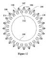
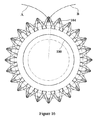
図11から図16は、テーパー状のギア歯のプロファイルの実施形態及び設計を示している。示されているギアの設計は、図1に示されているアクチュエータによって又は他の用途において使用されることができる。 11-16 show embodiments and designs of tapered gear tooth profiles. The gear design shown can be used with the actuator shown in FIG. 1 or in other applications.
図11及び図12に示すように、複数の歯102を有するギア100がある。歯は、各歯の後端106が各歯の前端104よりも更にギアの中心軸から半径方向外側に延びるようにテーパー状になっている。同様に、各歯間の間隙108は、テーパー状になっている。各間隙の後端110は、各間隙の前端112よりも更にギアの中心軸から半径方向外側に延びている。その側面114及び116によって画定される各歯の歯先は、図14から図16により詳細に示されるように、テーパーに応じてシフトされる。
As shown in FIGS. 11 and 12, there is a
図13は、正の歯先シフトプロファイルと、歯先、ピッチ、基部及び歯元の直径を含むラベル付けされた注目すべき直径の例示的なスケッチを示している。 FIG. 13 shows an exemplary sketch of the positive tip shift profile and labeled notable diameters including tip, pitch, base and root diameters.
図14から図16は、歯の長さに沿った3点でのギア歯のプロファイルを示している。図14は、各歯の後部106を通る線A及びBによって画定される歯先の形状を示している。図15は、各歯102の中央を通る線A及びBによって画定される歯先の形状を示している。図16は、各歯の前部104を通る線A及びBによって画定される歯先の形状を示している。中間面は、その標準構成における歯のプロファイルを定義するために使用される。ギアの軸方向の両端において、歯先のシフトが完了し、ギア歯が上方向又は下方向にシフトする。これらの3つの平面間には、ギア歯の線形補間がある。
14 to 16 show gear tooth profiles at three points along the tooth length. FIG. 14 shows the shape of the addendum defined by the lines A and B passing through the
通常、ギアの長さ全体にわたって歯先のシフトが完了する。歯の長さにわたって歯先のシフトを変化させ、ギア歯体の円錐形のテーパーを組み合わせることにより、テーパー状のギアが形成される。同じ歯先のシフトを使用して、第2のテーパー状のギアと組み合わせると、2つのギアは、1つのギアの正のシフト面が他のギアの負のシフト面と交差したときに噛合する。 Usually, the tooth tip shift is completed over the entire length of the gear. A tapered gear is formed by varying the tip shift over the length of the tooth and combining the conical taper of the gear teeth. Using the same tip shift, combined with a second tapered gear, the two gears mesh when the positive shift surface of one gear intersects the negative shift surface of the other gear. ..
テーパー状のギアは、ギアに軸方向負荷をかけることで予圧することができる。これは、ギア間のバックラッシュを排除する効果を有する。更に、それは、ギアがより容易に射出成形されることを可能にする。 Tapered gears can be preloaded by applying an axial load to the gear. This has the effect of eliminating backlash between gears. Moreover, it allows the gear to be more easily injection molded.
先の説明は本発明の好ましい実施形態に関して行われてきたが、多くの変形及び改変が可能であることは、当業者によって理解されるであろう。これらの変形のいくつかは上で考察してきたものであり、他の変形は当業者にとって明らかであろう。例えば、様々なコンポーネントが特定の他のコンポーネントに固定される又は取り付けられる又は固定的に取り付けられると本明細書において記載される場合、それらのコンポーネントは、記載されたコンポーネントに直接的に又は間接的に固定されることができることが理解されよう。コンポーネント間にも固定される介在接続部品の追加は、元の2つのコンポーネントが互いに固定されていると見なされるかどうかを変化させない。例えば、図1に示すように、遊星ギア20、22及び24は、セパレータプレート40に固定されて示されているが、それにもかかわらず、遊星ギアは、セパレータプレート40がそれ自体ステーターに固定されており且つステーターの一部であるかのように機能するため、ステーターに取り付けられていると記載される。
While the above description has been made with respect to the preferred embodiments of the present invention, it will be appreciated by those skilled in the art that many variations and modifications are possible. Some of these variations have been discussed above, others will be apparent to those of ordinary skill in the art. For example, if various components are described herein as being fixed or attached or fixedly attached to certain other components, those components are either directly or indirectly attached to the described components. It will be appreciated that can be fixed to. The addition of intervening connections, which are also fixed between the components, does not change whether the original two components are considered fixed to each other. For example, as shown in FIG. 1, the planet gears 20, 22 and 24 are shown fixed to the
特許請求の範囲では、「含む(comprising)」という用語は、その包含的意味で使用されており、他の要素が存在する可能性を排除するものではない。請求項の特徴の前にある不定冠詞「1つ(a/an)」は、1つのみの要素が意図されていることが文脈から明らかでない限り、2つ以上のこの特徴が存在することを排除するものではない。 In the claims, the term "comprising" is used in its inclusive sense and does not exclude the presence of other elements. The indefinite article "a/an" preceding a feature in a claim means that there is more than one of this feature unless the context clearly indicates that only one element is intended. It does not exclude.
Claims (21)
第1のステーターと、
前記第1のステーターに対して回転するように配置されたローターと、
前記ローターに固定された駆動ギアと、
前記第1のステーターに取り付けられた少なくとも3つの遊星ギアであって、前記少なくとも3つの遊星ギアのそれぞれが前記駆動ギアによって係合されている、少なくとも3つの遊星ギアと、
前記第1のステーターに回転可能に取り付けられた環状ギアであって、前記少なくとも3つの遊星ギアのそれぞれによって係合される環状ギアとを備える、電磁式アクチュエータ。 An electromagnetic actuator having a speed reducer,
The first stator,
A rotor arranged to rotate with respect to the first stator;
A drive gear fixed to the rotor,
At least three planet gears attached to the first stator, wherein each of the at least three planet gears is engaged by the drive gear;
An electromagnetic actuator comprising an annular gear rotatably mounted on the first stator, the annular gear engaged by each of the at least three planetary gears.
第1及び第2のギアを備え、前記第1及び第2のギアのそれぞれが、複数の歯を有し、前記複数の歯のそれぞれが、長さと、各歯の前記長さに沿って画定される歯先とを有し、各歯が、その長さに沿ってテーパー状になっており、前記歯先が、各歯の前記長さに沿ってテーパーに関連して変化し、
前記第1のギアの正のシフト面が前記第2のギアの負のシフト面と係合すると、前記第1のギア及び前記第2のギアが係合位置に嵌合する、ギアアセンブリ。 A gear assembly,
A first gear and a second gear, each of the first and second gears having a plurality of teeth, each of the plurality of teeth defining a length and a length along the length of each tooth. A tooth tip that is tapered along its length, the tooth tip varying in relation to the taper along the length of each tooth,
A gear assembly wherein the first gear and the second gear are engaged in an engaged position when a positive shift surface of the first gear engages a negative shift surface of the second gear.
Applications Claiming Priority (3)
| Application Number | Priority Date | Filing Date | Title |
|---|---|---|---|
| US201762513431P | 2017-05-31 | 2017-05-31 | |
| US62/513,431 | 2017-05-31 | ||
| PCT/CA2018/050646 WO2018218363A1 (en) | 2017-05-31 | 2018-05-31 | Actuator with speed reducer |
Publications (1)
| Publication Number | Publication Date |
|---|---|
| JP2020521927A true JP2020521927A (en) | 2020-07-27 |
Family
ID=64454142
Family Applications (1)
| Application Number | Title | Priority Date | Filing Date |
|---|---|---|---|
| JP2020515792A Abandoned JP2020521927A (en) | 2017-05-31 | 2018-05-31 | Actuator with reducer |
Country Status (5)
| Country | Link |
|---|---|
| US (1) | US20200088268A1 (en) |
| EP (1) | EP3631244A4 (en) |
| JP (1) | JP2020521927A (en) |
| CA (1) | CA3062445A1 (en) |
| WO (1) | WO2018218363A1 (en) |
Families Citing this family (8)
| Publication number | Priority date | Publication date | Assignee | Title |
|---|---|---|---|---|
| CN110741181A (en) * | 2017-06-17 | 2020-01-31 | 詹尼斯机器人移动技术加拿大公司 | Torque amplifier |
| GB201915014D0 (en) * | 2019-10-17 | 2019-12-04 | Genesis Robotics And Motion Tech Lp | Pulley and cable arrangement |
| DE112021001392T5 (en) * | 2020-03-03 | 2022-12-15 | Genesis Advanced Technology Inc. | WHEEL WHEEL AND METHOD OF MANUFACTURE THEREOF |
| JP7416349B2 (en) | 2020-03-31 | 2024-01-17 | ニデックドライブテクノロジー株式会社 | Reducer and motorized reducer |
| US20220376592A1 (en) * | 2021-05-19 | 2022-11-24 | GM Global Technology Operations LLC | Axial flux motor drive unit with two independent rotors sharing a stator |
| DE102021127161A1 (en) | 2021-10-20 | 2022-12-15 | Schaeffler Technologies AG & Co. KG | Disc motor and method of assembling a disc motor |
| DE102021129989A1 (en) | 2021-11-17 | 2022-11-24 | Schaeffler Technologies AG & Co. KG | Axial flux machine, method of manufacturing an axial flux machine and geared motor unit |
| DE102022118426A1 (en) * | 2022-07-22 | 2024-01-25 | Auma Riester Gmbh & Co. Kg | Planetary gear |
Family Cites Families (7)
| Publication number | Priority date | Publication date | Assignee | Title |
|---|---|---|---|---|
| GB2373304A (en) * | 2001-02-20 | 2002-09-18 | Bryan Nigel Victor Parsons | Tapered involute gear profile |
| WO2008101235A1 (en) * | 2007-02-16 | 2008-08-21 | Delbert Tesar | Manufacture and use of parallel eccentric electro-mechanical actuator |
| JP2012223081A (en) * | 2011-04-14 | 2012-11-12 | Jtekt Corp | Electric actuator and joint apparatus |
| CN202535213U (en) * | 2012-02-28 | 2012-11-14 | 常州五王电机有限公司 | Brushless planetary gear hub motor |
| US20140131016A1 (en) * | 2012-11-15 | 2014-05-15 | JVS Associates, Inc. | Contra-Rotating Fan Arrangement And Fan Drive System For Evaporative Cooling Equipment |
| CN203883613U (en) * | 2014-05-16 | 2014-10-15 | 朱荣辉 | Planet deceleration wheel hub motor |
| CN205901557U (en) * | 2016-08-12 | 2017-01-18 | 河南行星智能电子科技有限公司 | Novel brushless motor that built -in planetary reducer constructs |
-
2018
- 2018-05-31 WO PCT/CA2018/050646 patent/WO2018218363A1/en active Application Filing
- 2018-05-31 CA CA3062445A patent/CA3062445A1/en not_active Abandoned
- 2018-05-31 EP EP18810331.1A patent/EP3631244A4/en not_active Withdrawn
- 2018-05-31 JP JP2020515792A patent/JP2020521927A/en not_active Abandoned
- 2018-05-31 US US16/616,493 patent/US20200088268A1/en not_active Abandoned
Also Published As
| Publication number | Publication date |
|---|---|
| CA3062445A1 (en) | 2018-12-06 |
| US20200088268A1 (en) | 2020-03-19 |
| EP3631244A1 (en) | 2020-04-08 |
| WO2018218363A1 (en) | 2018-12-06 |
| EP3631244A4 (en) | 2021-08-11 |
Similar Documents
| Publication | Publication Date | Title |
|---|---|---|
| JP2020521927A (en) | Actuator with reducer | |
| KR102359816B1 (en) | differential planetary gearbox | |
| US20210310546A1 (en) | Speed change device | |
| US11391366B2 (en) | Electromagnetically operated band brake | |
| JP2006022950A (en) | Reduction gear ratio automatic switching device | |
| JP2017536511A (en) | Compound planetary friction drive | |
| KR102372783B1 (en) | gearbox | |
| CN108036034B (en) | Bidirectional output type harmonic speed reducer | |
| JP3186812U (en) | Variable speed transmission bearing | |
| KR20210142197A (en) | gearbox | |
| WO2018088161A1 (en) | Speed-decreasing or speed-increasing device and actuator | |
| US11411486B2 (en) | Gearbox | |
| TW201833449A (en) | Reduction bearing and electric motor | |
| JP6491832B2 (en) | Finite speed reducer | |
| JP7367351B2 (en) | Multistage planetary roller power transmission device | |
| JP2002181154A (en) | Rolling bearing-type reduction gear | |
| JP2003028250A5 (en) |
Legal Events
| Date | Code | Title | Description |
|---|---|---|---|
| A521 | Written amendment |
Free format text: JAPANESE INTERMEDIATE CODE: A523 Effective date: 20191126 |
|
| A621 | Written request for application examination |
Free format text: JAPANESE INTERMEDIATE CODE: A621 Effective date: 20191126 |
|
| A762 | Written abandonment of application |
Free format text: JAPANESE INTERMEDIATE CODE: A762 Effective date: 20200807 |