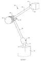
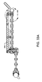
先行技術の器具ホルダの概略図である。1 is a schematic view of a prior art instrument holder.
図1に示す従来の器具ホルダの部分分解斜視図である。It is a partially exploded perspective view of the conventional instrument holder shown in FIG.
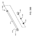
手術用器具ホルダの改良された実施形態の一部をロック解除位置にある状態で示す側面図である。FIG. 9 is a side view of a portion of the improved embodiment of the surgical instrument holder in the unlocked position.
図3Aの手術用器具ホルダの一部をロック位置にある状態で示す側面図である。FIG. 3B is a side view showing a portion of the surgical instrument holder of FIG. 3A in a locked position.
手術用器具ホルダの実施形態の側面図であり、内視鏡を保持した状態で示す。FIG. 3 is a side view of an embodiment of a surgical instrument holder, shown with an endoscope held.
図4の手術用器具ホルダの組み立て方法を示す一連の分解斜視図の1つであり、ベースを省いて示す。FIG. 5 is one of a series of exploded perspective views showing the method for assembling the surgical instrument holder of FIG. 4, with the base omitted.
同手術用器具ホルダの組み立て方法を示す一連の分解斜視図の1つである。It is one of a series of exploded perspective views showing an assembly method of the surgical instrument holder.
同手術用器具ホルダの組み立て方法を示す一連の分解斜視図の1つである。It is one of a series of exploded perspective views showing an assembly method of the surgical instrument holder.
同手術用器具ホルダの組み立て方法を示す一連の分解斜視図の1つである。It is one of a series of exploded perspective views showing an assembly method of the surgical instrument holder.
図5A〜図5Dに示す手術用器具ホルダを、組み立てられた状態でかつ内視鏡を取り付けた状態で示す斜視図である。FIG. 5A is a perspective view showing the surgical instrument holder shown in FIGS. 5A to 5D in an assembled state and with an endoscope attached.
図5Eの手術用器具ホルダのレバーの動作を示す側面図であり、ロック位置にある状態で示す。FIG. 5E is a side view showing the operation of the lever of the surgical instrument holder of FIG. 5E, shown in the locked position.
同手術用器具ホルダのレバーの動作を示す側面図であり、ロック解除位置にある状態で示す。It is a side view which shows operation|movement of the lever of the same surgical instrument holder, and is shown in the state in a lock release position.
手術用器具ホルダに用いることのできるアームの実施形態の斜視図である。FIG. 6 is a perspective view of an embodiment of an arm that can be used in a surgical instrument holder.
手術用器具ホルダの別の実施形態の側面図である。FIG. 8 is a side view of another embodiment of a surgical instrument holder.
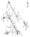
図8の手術用器具ホルダの調節可能なアームの組み立てを示す一連の分解斜視図の1つである。FIG. 9 is one of a series of exploded perspective views showing assembly of the adjustable arm of the surgical instrument holder of FIG. 8.
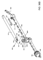
同アームの組み立てを示す一連の分解斜視図の1つである。It is one of a series of exploded perspective views showing the assembly of the arm.
同アームの組み立てを示す一連の分解斜視図の1つである。It is one of a series of exploded perspective views showing the assembly of the arm.
同アームの組み立てを示す一連の分解斜視図の1つである。It is one of a series of exploded perspective views showing the assembly of the arm.
同アームの組み立てを示す一連の分解斜視図の1つである。It is one of a series of exploded perspective views showing the assembly of the arm.
同アームの組み立てを示す一連の分解斜視図の1つである。It is one of a series of exploded perspective views showing the assembly of the arm.
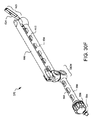
図8の手術用器具ホルダの調節可能なアームを組み立てられた状態で示す斜視図である。FIG. 9 is a perspective view showing the adjustable arm of the surgical instrument holder of FIG. 8 in an assembled state.
図8の手術用器具ホルダにおけるレバーラッチとキャッチのシステムの一実施形態の動作を示す部分断面図である。FIG. 9 is a partial cross-sectional view showing the operation of one embodiment of the lever latch and catch system in the surgical instrument holder of FIG. 8.
同レバーラッチとキャッチのシステムの動作での異なる状態を示す部分断面図である。It is a fragmentary sectional view showing a different state in operation of the system of the lever latch and the catch.
同レバーラッチとキャッチのシステムの動作でのさらに異なる状態を示す部分断面図である。FIG. 8 is a partial cross-sectional view showing a further different state in the operation of the system of the lever latch and the catch.
同レバーラッチとキャッチのシステムの動作でのさらに異なる状態を示す部分断面図である。FIG. 8 is a partial cross-sectional view showing a further different state in the operation of the system of the lever latch and the catch.
図8の手術用器具ホルダの一部の側断面図であり、レバーをロック解除位置で示す。FIG. 9 is a side sectional view of a portion of the surgical instrument holder of FIG. 8, showing the lever in the unlocked position.
図12Aの手術用器具ホルダにおける第1アームと第2アームとの間の中間ジョイントインターフェイスの拡大側断面図であり、ロック解除状態で示す。FIG. 12B is an enlarged side sectional view of the intermediate joint interface between the first arm and the second arm of the surgical instrument holder of FIG. 12A, shown in the unlocked state.
図12Bの中間ジョイントインターフェイスの側断面図であり、テンションロッドの停止端部とスペーシングワッシャとの空間的関係を強調して示す。FIG. 12B is a side cross-sectional view of the intermediate joint interface of FIG. 12B, highlighting the spatial relationship between the stop end of the tension rod and the spacing washer.
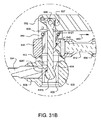
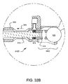
図8の手術用器具ホルダの一部の側断面図であり、レバーをロック位置で示す。FIG. 9 is a side sectional view of a portion of the surgical instrument holder of FIG. 8, showing the lever in the locked position.
図13Aの手術用器具ホルダにおける第1アームと第2アームとの間の中間ジョイントインターフェイスの拡大側断面図であり、ロック状態で示す。FIG. 13B is an enlarged side cross-sectional view of the intermediate joint interface between the first arm and the second arm of the surgical instrument holder of FIG. 13A, shown in the locked state.
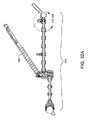
手術用器具ホルダのさらに改良された実施形態の側面図であり、内視鏡を保持した状態で示す。FIG. 6 is a side view of a further improved embodiment of the surgical instrument holder, shown with the endoscope held.
図14の手術用器具ホルダの調節可能なアームの組み立てを示す一連の分解斜視図の1つである。FIG. 15 is one of a series of exploded perspective views showing assembly of the adjustable arm of the surgical instrument holder of FIG. 14.
同アームの組み立てを示す一連の分解斜視図の1つである。It is one of a series of exploded perspective views showing the assembly of the arm.
同アームの組み立てを示す一連の分解斜視図の1つである。It is one of a series of exploded perspective views showing the assembly of the arm.
同アームの組み立てを示す一連の分解斜視図の1つである。It is one of a series of exploded perspective views showing the assembly of the arm.
同アームの組み立てを示す一連の分解斜視図の1つである。It is one of a series of exploded perspective views showing the assembly of the arm.
図14の手術用器具ホルダの調節可能なアームの斜視図である。FIG. 15 is a perspective view of an adjustable arm of the surgical instrument holder of FIG. 14.
図14の手術用器具ホルダの調節可能なアームの斜視図であり、レバーがロック位置にある状態で示す。FIG. 15 is a perspective view of the adjustable arm of the surgical instrument holder of FIG. 14, shown with the lever in the locked position.
同アームの斜視図であり、レバーがロック解除位置にある状態で示す。FIG. 6 is a perspective view of the arm, showing the lever in a lock release position.
同アームの斜視図であり、レバーが洗浄位置にある状態で示す。It is a perspective view of the same arm, and shows a state in which a lever is in a cleaning position.
手術用器具ホルダのための器具アダプタの一実施形態の組み立てを示す分解図である。FIG. 7 is an exploded view showing the assembly of one embodiment of an instrument adapter for a surgical instrument holder.
図17の器具アダプタを組み立てられた状態で示す斜視図である。FIG. 18 is a perspective view showing the instrument adapter of FIG. 17 in an assembled state.
図17の器具アダプタの斜視図であり、図14の手術用器具ホルダへの器具アダプタのラッチ機構を示す。FIG. 18 is a perspective view of the instrument adapter of FIG. 17, showing a latching mechanism of the instrument adapter to the surgical instrument holder of FIG. 14.
図15Fの調節可能なアームの端部に焦点を当てた斜視図であり、図18Aの器具アダプタの実施形態が、いかにして図14の手術用器具ホルダに接続するかを示す。FIG. 19A is a perspective view focusing on the end of the adjustable arm of FIG. 15F and showing how the embodiment of the instrument adapter of FIG. 18A connects to the surgical instrument holder of FIG.
手術用器具ホルダのための器具アダプタの別の実施形態の分解図である。FIG. 7 is an exploded view of another embodiment of an instrument adapter for a surgical instrument holder.
図20の器具アダプタを組み立てられた状態で示す斜視図である。It is a perspective view which shows the instrument adapter of FIG. 20 in the assembled state.
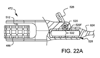
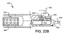
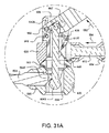
図21の器具アダプタの部分断面図であり、ロック解除状態で示す。FIG. 22 is a partial cross-sectional view of the instrument adapter of FIG. 21, shown in the unlocked state.
図21の器具アダプタの部分断面図であり、ロック状態で示す。FIG. 22 is a partial cross-sectional view of the instrument adapter of FIG. 21, shown in the locked state.
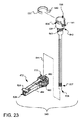
図20の器具アダプタへのカニューレの挿入を詳しく示す斜視図である。FIG. 21 is a perspective view detailing insertion of a cannula into the instrument adapter of FIG. 20.
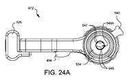
図23の器具アダプタ及びカニューレの上端部の平面図である。FIG. 24 is a plan view of the upper end of the instrument adapter and cannula of FIG. 23.
図23のカニューレ及び器具アダプタへのオブチュレータの挿入を詳しく示す斜視図である。FIG. 24 is a perspective view detailing insertion of an obturator into the cannula and instrument adapter of FIG. 23.
図23のカニューレ及び器具アダプタに挿入された図24Bのオブチュレータの頂部の側面図である。24B is a side view of the top of the obturator of FIG. 24B inserted into the cannula and instrument adapter of FIG.
図23のカニューレ及び器具アダプタへの内視鏡の挿入を詳しく示す斜視図である。FIG. 24 is a perspective view detailing insertion of an endoscope into the cannula and instrument adapter of FIG. 23.
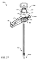
図23のカニューレ及び器具アダプタに挿入されロックされた内視鏡の斜視図である。FIG. 24 is a perspective view of the endoscope inserted and locked in the cannula and instrument adapter of FIG. 23.
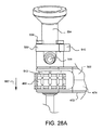
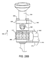
図27の器具アダプタ及び内視鏡を示すとともに回転ダイヤルの機能を詳しく示す斜視図である。FIG. 28 is a perspective view showing the instrument adapter and the endoscope of FIG. 27 and showing the function of the rotary dial in detail.
同回転ダイヤルの機能を詳しく示す斜視図である。It is a perspective view which shows in detail the function of the rotary dial.
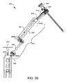
手術用器具ホルダのさらに改良された実施形態の側面図であり、内視鏡を保持した状態で示す。FIG. 6 is a side view of a further improved embodiment of the surgical instrument holder, shown with the endoscope held.
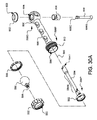
図29の手術用器具ホルダの調節可能なアームの組み立てを示す一連の分解斜視図の1つである。30 is one of a series of exploded perspective views showing assembly of the adjustable arm of the surgical instrument holder of FIG. 29. FIG.
同調節可能なアームの組み立てを示す一連の分解斜視図の1つである。FIG. 3 is one of a series of exploded perspective views showing the assembly of the adjustable arm.
同調節可能なアームの組み立てを示す一連の分解斜視図の1つである。FIG. 3 is one of a series of exploded perspective views showing the assembly of the adjustable arm.
同調節可能なアームの組み立てを示す一連の分解斜視図の1つである。FIG. 3 is one of a series of exploded perspective views showing the assembly of the adjustable arm.
同調節可能なアームの組み立てを示す一連の分解斜視図の1つである。FIG. 3 is one of a series of exploded perspective views showing the assembly of the adjustable arm.
図29の手術用器具ホルダの調節可能なアームの斜視図である。30 is a perspective view of an adjustable arm of the surgical instrument holder of FIG. 29. FIG.
図29の手術用器具ホルダにおける第1アームと第2アーム間の中間ジョイントインターフェイスの拡大側断面図であり、ロック解除状態で示す。FIG. 30 is an enlarged side sectional view of an intermediate joint interface between the first arm and the second arm in the surgical instrument holder of FIG. 29, shown in the unlocked state.
同中間ジョイントインターフェイスの拡大側断面図であり、ロック状態で示す。It is an expanded side sectional view of the intermediate joint interface, and is shown in a locked state.
図29の手術用器具ホルダ(ベースを除く)の側断面図であり、ロック解除状態で示す。FIG. 30 is a side sectional view of the surgical instrument holder (excluding the base) of FIG. 29, shown in an unlocked state.
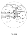
図29の手術用器具ホルダにおける第2アームとクイック接続ポストのボールとの間のインターフェイスを示す拡大側断面図であり、ロック解除状態で示す。FIG. 30 is an enlarged side cross-sectional view showing the interface between the second arm and the ball of the quick connect post in the surgical instrument holder of FIG. 29, shown in the unlocked state.
図29の手術用器具ホルダ(ベースを除く)の側断面図であり、ロック状態で示す。FIG. 30 is a side sectional view of the surgical instrument holder (excluding the base) of FIG. 29, shown in a locked state.
図29の手術用器具ホルダにおける第2アームとクイックコネクトポストのボールとの間のインターフェイスを示す拡大側断面図であり、ロック状態で示す。FIG. 30 is an enlarged side sectional view showing the interface between the second arm and the ball of the quick connect post in the surgical instrument holder of FIG. 29, shown in the locked state.
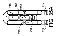
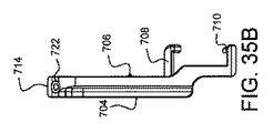
図4、図8、図14、図18及び図29の手術用器具ホルダに用いるためのベースの実施形態の右側面図である。FIG. 30 is a right side view of an embodiment of a base for use with the surgical instrument holder of FIGS. 4, 8, 14, 18, and 29.
図34のベースの正面図である。It is a front view of the base of FIG.
図34のベースの右側面図である。FIG. 35 is a right side view of the base of FIG. 34.
図34のベースの左側面図である。FIG. 35 is a left side view of the base of FIG. 34.
図34のベースの背面図である。FIG. 35 is a rear view of the base of FIG. 34.
図34のベースの上面図である。FIG. 35 is a top view of the base of FIG. 34.
図34のベースの底面図である。FIG. 35 is a bottom view of the base of FIG. 34.
図29の手術用器具ホルダの斜視図であり、手術台に取り付けられる状態で示す。FIG. 30 is a perspective view of the surgical instrument holder of FIG. 29 and is shown attached to an operating table.
図29の手術用器具ホルダの斜視図であり、手術台に取り付けられる状態で示す。FIG. 30 is a perspective view of the surgical instrument holder of FIG. 29 and is shown attached to an operating table.
図29の手術用器具ホルダとともに用いられる器具アダプタの別の実施例の斜視図である。FIG. 30 is a perspective view of another embodiment of an instrument adapter for use with the surgical instrument holder of FIG. 29.
図29の手術用器具ホルダとともに用いる器具アダプタのさらに別の実施例の斜視図である。30 is a perspective view of yet another embodiment of an instrument adapter for use with the surgical instrument holder of FIG. 29. FIG.
図29の手術用器具ホルダとともに用いられる縫合管理システム及びリブリトラクタの斜視図である。FIG. 30 is a perspective view of a suture management system and a rib retractor used with the surgical instrument holder of FIG. 29.
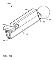
図29の手術用器具ホルダとともに用いるディスプレイマウントアダプタの斜視図である。FIG. 30 is a perspective view of a display mount adapter for use with the surgical instrument holder of FIG. 29.
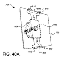
図39のディスプレイマウントアダプタに取り付けられたディスプレイの斜視図である。FIG. 40 is a perspective view of a display attached to the display mount adapter of FIG. 39.
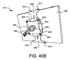
図39のディスプレイマウントアダプタに取り付けられたディスプレイの斜視図である。FIG. 40 is a perspective view of a display attached to the display mount adapter of FIG. 39.
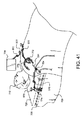
手術台に取り付けられた3つの手術用器具ホルダ(図29)の斜視図であり、異なるアダプタ及び器具を装備した状態で示す。FIG. 30 is a perspective view of three surgical instrument holders (FIG. 29) attached to an operating table, shown with different adapters and instruments.
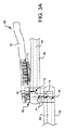
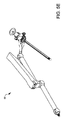
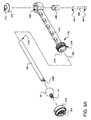
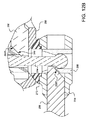
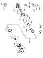
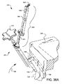
図3Aは、手術用器具ホルダ56の改良された実施形態を示す。第1アーム58と第2アーム60が示されている。第1アーム58はその中でスライド可能なロッド62を有し、ロッド62は一端にテーパ状端部64を有している。ロッド62の他端は図示されていないが、図1の装置のボールコネクタ24のようなボールコネクタと接合するように構成されている。このボールコネクタはベースと連結することができる。第2アーム60はその中でスライド可能なロッド66を有し、ロッド66は一端にテーパ状端部68を有している。ロッド66の他端は図示されていないが、別のボールコネクタと接合するように構成されている。このボールコネクタはエンドエフェクタと連結することができる。レバー70は一方のアーム(本実施形態においては第2アーム60)にアライメント(配置)されているが、レバー70の大部分は、スプリング要素72によって、アーム60から離れる方向に付勢されている。図3Aの例においてはスプリング要素72として特殊なタイプのスプリングが示されているが、当業者は図示されたスプリング要素72の代わりに使用し得る多種多様なスプリングに精通していることを理解されたい。
FIG. 3A illustrates an improved embodiment of surgical instrument holder 56. A first arm 58 and a second arm 60 are shown. The first arm 58 has a rod 62 slidable therein, the rod 62 having a tapered end 64 at one end. The other end of rod 62, not shown, is configured to mate with a ball connector, such as ball connector 24 of the device of FIG. The ball connector can be connected to the base. The second arm 60 has a rod 66 slidable therein, the rod 66 having a tapered end 68 at one end. Although not shown, the other end of the rod 66 is configured to be joined to another ball connector. This ball connector can be connected to an end effector. The lever 70 is aligned (arranged) with one arm (the second arm 60 in the present embodiment), but most of the lever 70 is biased by the spring element 72 in the direction away from the arm 60. .. Although a special type of spring is shown as the spring element 72 in the example of FIG. 3A, those skilled in the art will understand that it is familiar with a wide variety of springs that can be used in place of the illustrated spring element 72. I want to.
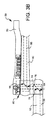
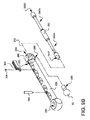
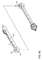
レバー70はウエッジ74(楔)に連結されている。レバー70が図3Aに示す位置にある時、ウエッジ74は第2アーム60内のロッド66のテーパ状端部68に押し付けられる。これにより、第2アーム60の他端にあるボールコネクタ(図示せず)が位置保持される。レバー70が図3Bに示す位置に絞られると、ウエッジ74が第2アーム60のロッド66のテーパ状端部68から引き離される。これにより、第2アーム60の他端にあるボールコネクタ(図示せず)は、第2アーム60に対して相対移動可能となる。
The lever 70 is connected to a wedge 74 (wedge). When the lever 70 is in the position shown in FIG. 3A, the wedge 74 is pressed against the tapered end 68 of the rod 66 in the second arm 60. As a result, the ball connector (not shown) at the other end of the second arm 60 is held in position. When lever 70 is squeezed to the position shown in FIG. 3B, wedge 74 is pulled away from tapered end 68 of rod 66 of second arm 60. As a result, the ball connector (not shown) at the other end of the second arm 60 can move relative to the second arm 60.
レバー70はさらに、ウエッジ74の開口を通るポスト76に連結されている。このポスト76にはウエッジ78が連結されている。レバー70が図3Aに示す位置(ロック位置)にある時、ウエッジ78は第1アーム58のロッド62のテーパ状端部64に向かって引き上げられている。これにより、第1アーム58の他端にあるボールコネクタ(図示せず)が位置保持される。レバー70が図3Bに示す位置(ロック解除位置)に絞られると、ポスト76がレバーとともに押し下げられ、ウエッジ78が第1アーム58のロッド62のテーパ状端部64から押し離される。これにより、第1アーム58の他端にあるボールコネクタ(図示せず)は、ベース(図示せず)に対して相対移動可能となる。
Lever 70 is further coupled to a post 76 that passes through an opening in wedge 74. A wedge 78 is connected to the post 76. When the lever 70 is in the position (locked position) shown in FIG. 3A, the wedge 78 is pulled up toward the tapered end 64 of the rod 62 of the first arm 58. As a result, the ball connector (not shown) at the other end of the first arm 58 is held in position. When the lever 70 is squeezed to the position (unlocked position) shown in FIG. 3B, the post 76 is pushed down together with the lever, and the wedge 78 is pushed away from the tapered end portion 64 of the rod 62 of the first arm 58. As a result, the ball connector (not shown) at the other end of the first arm 58 can move relative to the base (not shown).
さらに、レバー70が図3Aに示す位置にある時、レバー70のクランプ端部80が第2アーム60の端部に押し付けられ、ポスト76とウエッジ78も、第2アーム60に対する第1アーム58の相対的位置を保持するクランプ力の生成を助ける。レバー70が図3Bに示す位置へと絞られると、レバー70のクランプ端部80が第2アームから持ち上げられ、ポスト76とウエッジ78がクランプ力を解放する。これにより、第1アーム58と第2アーム60は互いに対して相対的に動くことができる。その結果、この1つの操作フィーチャであるレバー70を片手で絞り、3つの異なるロックポイントを同時に解除できることが分かる。これにより、外科医は、片手でレバーを握り(レバーを絞り)、もう片方の手で、エンドエフェクタによって保持されたスコープを位置決めすることができる。位置決めの際、外科医はすべての自由度を利用でき、スコープの位置決めを容易に行うことができる。所望のスコープ位置が確定したら、外科医がレバー70を放すだけで、3つの全てのロックポイントは再び位置ロックされる。例えば、1)ボールコネクタに対する第1アームの相対的位置、2)第2アームに対する第1アームの相対的位置、3)ボールコネクタに対する第2アームの相対的位置である。従来の装置においては、これをするには少なくとも2人の人間と4つの手が必要となったであろう。したがって、本実施形態は、従来技術よりも明らかに利点を有している。
Further, when the lever 70 is in the position shown in FIG. 3A, the clamp end 80 of the lever 70 is pressed against the end of the second arm 60 and the post 76 and wedge 78 also of the first arm 58 relative to the second arm 60. Helps generate a clamping force that holds the relative position. When the lever 70 is squeezed to the position shown in FIG. 3B, the clamping end 80 of the lever 70 is lifted from the second arm and the post 76 and wedge 78 release the clamping force. This allows the first arm 58 and the second arm 60 to move relative to each other. As a result, it can be seen that this one operating feature, lever 70, can be squeezed with one hand to unlock three different lock points simultaneously. This allows the surgeon to grasp the lever with one hand (squeeze the lever) and position the scope held by the end effector with the other hand. When positioning, the surgeon has all the degrees of freedom available and can easily position the scope. Once the desired scope position is established, the surgeon simply releases lever 70 to reposition all three lock points. For example, 1) relative position of the first arm to the ball connector, 2) relative position of the first arm to the second arm, and 3) relative position of the second arm to the ball connector. In conventional devices, this would have required at least two people and four hands. Therefore, this embodiment has clear advantages over the prior art.
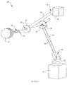
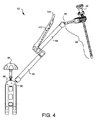
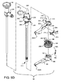
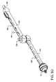
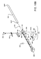
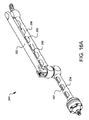
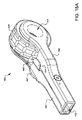
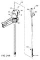
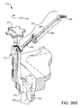
図4は、別の実施形態をなす手術用器具ホルダ82を示す。ここでは、内視鏡84を保持している。この手術用器具ホルダ82はベース86を有している。この実施形態において、このベース86は、手術台の側部にクランプするよう構成されている。ベースのクランプアームの1つを上げ下げするベース内のネジを調節するため、着脱可能なキー88が提供される。他の実施形態においては、当業者に公知の、他の種類の着脱可能なキー、ベース、及びクランプベースを用いてよい。ベース86は前述したボールコネクタに類似のボールコネクタ90を有している。第1アーム92と第2アーム94が示されている。第1アーム92はその中でスライド可能なロッド(図示せず)を有し、このロッドはテーパ状端部(図示せず)を有している。第1アーム92内のスライド可能なロッドはボールコネクタ90と接合するように構成されている。同様に、第2アーム94はその中でスライド可能なロッド(図示せず)を有し、このロッドはテーパ状端部を有している。第2アーム94内のスライド可能なロッド(図示せず)は、第2のボールコネクタ96と接合するように構成されている。このボールコネクタ96はエンドエフェクタ98と連結されている。本実施形態においては、エンドエフェクタ98が内視鏡84を保持し、位置付けるように構成されている。レバー100は一方のアーム(本実施形態においては第2アーム94)にアライメント(配置)されている。レバー100の大部分は、スプリング要素102によって、第2アーム94から離れる方向に付勢されている。図4の例においては特殊なタイプのスプリングが示されているが、当業者は図示されたスプリング要素102の代わりに使用し得る多種多様なスプリングに精通していることを理解されたい。
FIG. 4 illustrates another embodiment of a surgical instrument holder 82. Here, the endoscope 84 is held. The surgical instrument holder 82 has a base 86. In this embodiment, the base 86 is configured to clamp to the side of the operating table. A removable key 88 is provided to adjust a screw in the base that raises and lowers one of the clamp arms of the base. In other embodiments, other types of removable keys, bases, and clamp bases known to those of skill in the art may be used. The base 86 has a ball connector 90 similar to the ball connector described above. A first arm 92 and a second arm 94 are shown. The first arm 92 has a rod (not shown) slidable therein, the rod having a tapered end (not shown). The slidable rod within the first arm 92 is configured to join the ball connector 90. Similarly, the second arm 94 has a rod (not shown) slidable therein, which rod has a tapered end. A slidable rod (not shown) within the second arm 94 is configured to mate with the second ball connector 96. The ball connector 96 is connected to the end effector 98. In this embodiment, the end effector 98 is configured to hold and position the endoscope 84. The lever 100 is aligned (arranged) with one arm (the second arm 94 in this embodiment). Most of the lever 100 is biased by the spring element 102 in a direction away from the second arm 94. Although a special type of spring is shown in the example of FIG. 4, those skilled in the art should be aware of a wide variety of springs that could be used in place of the illustrated spring element 102.
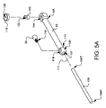
図5A〜図5Dは、図4の手術用器具ホルダ82の組み立て方法を示す一連の分解図である。簡潔にするために、ベース86のボールコネクタ90のみを示す。前述のとおり、当業者に公知の利用可能なベースの構成は多種多様である。使用されるベースの種類に関わりなく、主たる要件は、ボールコネクタ90を有することである。図5Aに示すとおり、第1アーム92の先端105の収容部104(receiver;受部)内にウエッジ103が配置されている。第1ロッド106がソケット108の開口107内に滑り込み、第1アーム92の内部空洞に滑り込む。ソケット108は第1アーム92の基端110にあり、開口107は第1アーム92の長手軸とアライメントされている。ロッド106はテーパ状端部106Tを有している。このテーパ状端部106Tはウエッジ103に押し付けられ、ウエッジ103を収容部104内に保持することができる。ボールコネクタ90は、第2開口114を通ってソケット108に挿入されている。第2開口114は第1開口107よりも大きく、ボールコネクタ90全体がそこを通ってソケット108内に入り込めるほど大きい。ボールコネクタ90が第2開口114を通って挿入される際、ボールコネクタ90の取付部116が第1開口107を通って外に出される。第1開口107はボールコネクタ90の全体が第1開口107を通り抜けないようなサイズにされている。ロッドの基端106Pはボールコネクタ90に乗り、ボールコネクタ90をソケット108内に保持するのを助ける。スペーサ118は穴120を有し、この穴120は、ウエッジ103の穴122とアライメントされている。2つの穴120、122は、必ずしも同じ寸法である必要はない。ボールコネクタ90の取付部116はベース(図示せず)に取り付けることができる。
5A to 5D are a series of exploded views showing a method of assembling the surgical instrument holder 82 of FIG. Only ball connector 90 of base 86 is shown for simplicity. As mentioned above, there are a wide variety of available base configurations known to those skilled in the art. Regardless of the type of base used, the main requirement is to have a ball connector 90. As shown in FIG. 5A, the wedge 103 is arranged in the housing portion 104 (receiver) of the tip 105 of the first arm 92. The first rod 106 slides into the opening 107 of the socket 108 and into the internal cavity of the first arm 92. The socket 108 is at the proximal end 110 of the first arm 92 and the opening 107 is aligned with the longitudinal axis of the first arm 92. The rod 106 has a tapered end 106T. The tapered end portion 106T is pressed against the wedge 103 so that the wedge 103 can be held in the housing portion 104. The ball connector 90 is inserted into the socket 108 through the second opening 114. The second opening 114 is larger than the first opening 107 and is large enough to allow the entire ball connector 90 to pass through and into the socket 108. When the ball connector 90 is inserted through the second opening 114, the mounting portion 116 of the ball connector 90 is pushed out through the first opening 107. The first opening 107 is sized so that the entire ball connector 90 does not pass through the first opening 107. The proximal end 106P of the rod rides on the ball connector 90 and helps retain the ball connector 90 in the socket 108. The spacer 118 has a hole 120, which is aligned with the hole 122 in the wedge 103. The two holes 120, 122 do not necessarily have to be the same size. The mounting portion 116 of the ball connector 90 can be mounted on a base (not shown).
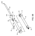
図5Bに示すように、第2ロッド124がソケット128の開口126内に滑り込み、第2アーム94の内部空洞に滑り込む。ソケット128は第2アーム94の先端130にあり、第1開口126は第2アーム94の長手軸132とアライメントされている。第2ロッド124はテーパ状端部124Tを有している。このテーパ状端部124Tは収容部134(receiver;受部)内にアクセス可能である。ボールコネクタ96が、第2開口138を通ってソケット128に挿入される。第2開口138は第1開口126よりも大きく、ボールコネクタ96全体がそこを通ってソケット128内に入り込めるほど大きい。ボールコネクタ96が開口部138を通って挿入される際、ボールコネクタ96の取付部140が第1開口126を通って外に出される。第1開口126の穴は、ボールコネクタ96の全体が第1開口126を通り抜けないようなサイズにされている。ロッドの先端124Dはボールコネクタ96に乗り、ボールコネクタ96をソケット128内に保持するのを助ける。第2アーム94の基端142にある収容部134の開口は、第2アーム94を貫通し、スペーサ118及びその穴120とアライメントすることができる。
As shown in FIG. 5B, the second rod 124 slides into the opening 126 of the socket 128 and slides into the internal cavity of the second arm 94. The socket 128 is at the tip 130 of the second arm 94 and the first opening 126 is aligned with the longitudinal axis 132 of the second arm 94. The second rod 124 has a tapered end portion 124T. The tapered end portion 124T is accessible inside the housing portion 134 (receiver). The ball connector 96 is inserted into the socket 128 through the second opening 138. The second opening 138 is larger than the first opening 126 and is large enough to allow the entire ball connector 96 to pass through and into the socket 128. When the ball connector 96 is inserted through the opening 138, the mounting portion 140 of the ball connector 96 is pushed out through the first opening 126. The hole of the first opening 126 is sized so that the entire ball connector 96 does not pass through the first opening 126. The tip 124D of the rod rides on the ball connector 96 and helps retain the ball connector 96 in the socket 128. An opening in the housing portion 134 at the proximal end 142 of the second arm 94 can penetrate the second arm 94 and be aligned with the spacer 118 and its hole 120.
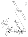
図5Cに示すように、ポスト146にヒンジ受け144が連結されている。このポスト146は、レバーブロック150のクリアランス穴148を貫通する。ウエッジ152がレバーブロック150から外側に延びている。ポストの下端146Lが、レバーブロック150のクリアランス穴148を通り、ウエッジ152を通り、その下まで延びる。部分的に組立されたヒンジ受け144、ポスト146、レバーブロック150及びウエッジ152が一緒に移動され、ポストの下端146Lとウエッジ152が収容部134に挿入される。これにより、ポストの下端146Lがウエッジ103(図5Cには図示せず)の穴122に連結され、ウエッジ152が第2ロッド124のテーパ状端部124Tに着座する。
As shown in FIG. 5C, the hinge receiver 144 is connected to the post 146. The post 146 penetrates the clearance hole 148 of the lever block 150. A wedge 152 extends outward from the lever block 150. The lower end 146L of the post extends through the clearance hole 148 in the lever block 150, through the wedge 152, and below. The partially assembled hinge receiver 144, post 146, lever block 150 and wedge 152 are moved together and the lower end 146L of the post and wedge 152 are inserted into the receiving portion 134. This connects the lower end 146L of the post to the hole 122 in the wedge 103 (not shown in FIG. 5C) and seats the wedge 152 on the tapered end 124T of the second rod 124.
スプリング154は、レバーブロック150のノッチ156に入るようにアライメントされ、レバー158の穴162及び対応するスプリング154の穴164を貫通するピン160により、レバー158に取り付けられる。レバー158の基端は、ヒンジ受け144及びレバーブロック150に被さるように配置される。レバー158の第1穴168はヒンジ受け144のタップ穴170とアライメントされる。第1ピボットネジ172が第1穴168を貫通し、タップ穴170にネジ込まれる。第2ピボットネジ174が同様に、レバー158とヒンジ受け144の反対側の左右対称の穴にネジ込まれる(これらの左右対称の穴は図示せず)。
The spring 154 is aligned to enter the notch 156 of the lever block 150 and is attached to the lever 158 by a pin 160 that extends through a hole 162 in the lever 158 and a corresponding hole 164 in the spring 154. The base end of the lever 158 is arranged so as to cover the hinge receiver 144 and the lever block 150. The first hole 168 of the lever 158 is aligned with the tap hole 170 of the hinge receiver 144. The first pivot screw 172 penetrates the first hole 168 and is screwed into the tap hole 170. The second pivot screw 174 is similarly screwed into a symmetrical hole on the opposite side of the lever 158 and the hinge receiver 144 (the symmetrical holes are not shown).
レバー158の別の穴176は、レバーブロック150の穴178、ヒンジ受け144の穴180、レバーブロック150の別の穴182、及びレバー158の反対側の左右対称の穴(図示せず)と、アライメントされている。これら全ての穴を通ってピン184が配置され、もう1つの回動軸線を提供する。
Another hole 176 in the lever 158 includes a hole 178 in the lever block 150, a hole 180 in the hinge receiver 144, another hole 182 in the lever block 150, and a symmetrical hole (not shown) on the opposite side of the lever 158. It is aligned. A pin 184 is placed through all these holes to provide another axis of rotation.
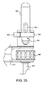
図5Dは、第2ボールコネクタ96(この図5Dには図示せず)に連結されたアダプタないしはエンドエフェクタ98の分解図である。下部ヨーク186は、開口190を画成する円形のポスト188を有している。ポスト188の外側には、スプリングラッチ192を受け入れる凹部(図示せず)がある。このスプリングラッチ192はラッチ192Lを有し、このラッチ192Lは、スプリングラッチ192が凹部に入り込んでいる時、ポスト188の外面を超えて突出している。ポスト188に被さるようにカニューレ回転ダイヤル194が配置される。このカニューレ回転ダイヤルの内周に溝が形成されている。図5Dではこの溝のごく一部しか見えない。スプリングラッチ192のラッチ192Lがこの溝と係合し、カニューレ回転ダイヤル194を定位置に保持するのを助ける。ラッチ192Lは回転ダイヤル194の内側の全周を通る溝196に乗ることができるため、カニューレ回転ダイヤル194はこの位置で自由に回転できるが、ダイヤルの軸方向の動きはラッチ192Lによって妨げられる。カニューレラッチ198は上部ヨーク202のスロット200内にアライメントされ、回動点204がピン208によって、上部ヨーク202の穴206にアライメントされてピン止めされる。カニューレラッチ198はスプリング210を有し、このスプリング210が、ラッチ198を上部ヨーク202によって画成された開口212内へ押す。カニューレラッチ198はまた解放部214を有している。この解放部214を押すと、ラッチがピン208を中心に回動して開口212から退く。解放部214から圧力を解除すると、カニューレラッチ198は開口212に押し戻される。
FIG. 5D is an exploded view of the adapter or end effector 98 coupled to the second ball connector 96 (not shown in this FIG. 5D). The lower yoke 186 has a circular post 188 that defines an opening 190. Outside the post 188, there is a recess (not shown) that receives the spring latch 192. The spring latch 192 has a latch 192L which projects beyond the outer surface of the post 188 when the spring latch 192 is recessed. A cannula rotation dial 194 is positioned over the post 188. A groove is formed on the inner circumference of the cannula rotary dial. Only a small part of this groove is visible in FIG. 5D. Latch 192L of spring latch 192 engages in this groove to help hold cannula rotary dial 194 in place. Because the latch 192L can ride in the groove 196 that runs around the entire inside of the rotary dial 194, the cannula rotary dial 194 is free to rotate in this position, but axial movement of the dial is impeded by the latch 192L. The cannula latch 198 is aligned within the slot 200 of the upper yoke 202 and the pivot point 204 is aligned and pinned by the pin 208 with the hole 206 of the upper yoke 202. Cannula latch 198 has a spring 210 that pushes latch 198 into opening 212 defined by upper yoke 202. Cannula latch 198 also has a release portion 214. When the release portion 214 is pushed, the latch rotates around the pin 208 and retracts from the opening 212. Releasing the pressure from release section 214 pushes cannula latch 198 back into opening 212.
回転防止ピン216が上部ヨーク202の穴218に挿入されている。この回転防止ピン216は、上部ヨーク202の下面を越えて下方に延びる。上部ヨーク202は下部ヨーク186に連結されている。カニューレ回転ダイヤル194の内側の溝196は下部ヨーク186に向かって押されていてラッチ192Lと係合していない時は、カニューレ回転ダイヤル194は自由に回動可能である。回転ダイヤル194をロックすることが所望される時は、回転ダイヤル194を上部ヨーク202に向かって軸方向に動かす。すると、回転ダイヤル194の周りに配置された複数のピン受部220の1つが、上部ヨーク202から下方に延びる回転防止ピン216に係合する。ほぼ同時に、ラッチ192Lがカニューレ回転ダイヤル194の内側の溝196と係合し、ダイヤルの軸方向の動きの防止を助ける。ダイヤルが軸方向に動けば、回転ダイヤル194が再び回転することが許容されるであろう。回転ダイヤル194がこの位置にとどまる限り、回転ダイヤル194は保持される。回転ダイヤル194を再度回転させるためには、回転ダイヤル194を下部ヨーク186に向けて軸方向に動かし、回転防止ピン216がピン受部220から外れるようにする必要がある。
The rotation prevention pin 216 is inserted into the hole 218 of the upper yoke 202. The rotation prevention pin 216 extends downward beyond the lower surface of the upper yoke 202. The upper yoke 202 is connected to the lower yoke 186. When the inner groove 196 of the cannula rotary dial 194 is pushed toward the lower yoke 186 and is not engaged with the latch 192L, the cannula rotary dial 194 is freely rotatable. When it is desired to lock the rotary dial 194, the rotary dial 194 is moved axially toward the upper yoke 202. Then, one of the plurality of pin receiving portions 220 arranged around the rotary dial 194 engages with the rotation preventing pin 216 extending downward from the upper yoke 202. At about the same time, the latch 192L engages with the groove 196 inside the cannula rotary dial 194 to help prevent axial movement of the dial. If the dial moves axially, the rotary dial 194 will be allowed to rotate again. As long as the rotary dial 194 stays in this position, the rotary dial 194 is held. In order to rotate the rotary dial 194 again, it is necessary to move the rotary dial 194 in the axial direction toward the lower yoke 186 so that the rotation prevention pin 216 can be disengaged from the pin receiving portion 220.
スコープポートカニューレ222が装備される。スコープポートカニューレ222は基端側開口224を有し、この基端側開口224は先端側開口226と連通している。基端側開口224は、内視鏡の光源取付部を収容するためのノッチ228を含んでいてもよい。保持リング230がスコープポートカニューレの保持溝232にスナップ留めされる。保持リング230は、1)内視鏡84がスコープポートカニューレ222に挿入された時に、内視鏡84の光源取付部234がノッチ228内に入ることを許容する向きから、2)内視鏡84がスコープポートカニューレ222から外れるのを防ぐ向きへ、回動可能である。ノッチ228はまた、内視鏡84とスコープポートカニューレ222との間の既知の回動位置を維持する役割をも担う。スコープポートカニューレ222は、その外部に1つ以上のキーの役割をなす歯236を有している。使用に際し、カニューレ222の1つ以上のキー歯236が、カニューレ回転ダイヤル194の内側の1つ以上の対応するキーフィーチャ238と係合するまで、スコープポートカニューレ222の先端が、上部ヨークの開口212に挿入され、カニューレ回転ダイヤル194を通り、下部ヨーク186の開口190を通る。ラッチ198はカニューレ222の溝240に係合し、スコープポートカニューレ222の望ましくない外れを防ぐが、上述のとおり、カニューレ回転ダイヤル194が回転防止ピン216と係合していない時は、スコープポートカニューレ222はカニューレ回転ダイヤル194によって(相互に噛み合うキー236と対応するキーフィーチャ238を介して)所望の回動が可能である。
A scope port cannula 222 is equipped. The scope port cannula 222 has a proximal opening 224, which communicates with a distal opening 226. The proximal opening 224 may include a notch 228 for receiving the light source mounting portion of the endoscope. The retaining ring 230 snaps into the retaining groove 232 of the scope port cannula. The retaining ring 230 is 1) from a direction that allows the light source mounting portion 234 of the endoscope 84 to enter the notch 228 when the endoscope 84 is inserted into the scope port cannula 222. 2) The endoscope 84 Can be pivoted in a direction that prevents it from coming off the scope port cannula 222. Notch 228 is also responsible for maintaining a known pivoted position between endoscope 84 and scope port cannula 222. The scope port cannula 222 has one or more key teeth 236 on its exterior. In use, the distal end of the scope port cannula 222 is adjusted so that the tip of the scope port cannula 222 is open 212 of the upper yoke until the one or more key teeth 236 of the cannula 222 engage one or more corresponding key features 238 inside the cannula rotary dial 194. Through the cannula rotary dial 194 and through the opening 190 in the lower yoke 186. The latch 198 engages the groove 240 of the cannula 222 to prevent undesired disengagement of the scope port cannula 222, but as described above, when the cannula rotation dial 194 is not engaged with the anti-rotation pin 216, the scope port cannula 216. 222 can be pivoted as desired (via interlocking keys 236 and corresponding key features 238) by a cannula rotary dial 194.
上部ヨーク202と下部ヨーク186が連結されると、対応する取付部242A、242Bがスタブを形成する。このスタブは、上述のボールコネクタ90の取付部140と連結することができる。
When the upper yoke 202 and the lower yoke 186 are connected, the corresponding mounting portions 242A and 242B form stubs. The stub can be connected to the mounting portion 140 of the ball connector 90 described above.
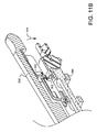
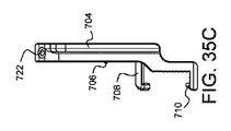
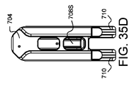
図5Eは図5A〜図5Dに示す手術用器具ホルダ82を組み立てた状態で示しており、内視鏡が組み込まれている。上述の理由でベースは示されていないが、容易に取り付け可能である。
FIG. 5E shows the surgical instrument holder 82 shown in FIGS. 5A to 5D in an assembled state, in which an endoscope is incorporated. The base is not shown for the reasons mentioned above, but can be easily mounted.
図6A及び図6Bはレバー158の作用を示している。レバー158はヒンジ受け144を介して、ウエッジ152の開口を貫通するポスト146に連結されている。ウエッジ103もまたポスト146に連結されている。レバー158が図6Aに示す位置(ロック位置)にある時、ウエッジ103は、第1アーム92内のロッド106のテーパ状端部106Tに向かって引き上げられている。これにより、ボールコネクタ(図示せず)が第1アーム92の他端に位置固定される。同様に、図6Aに示す位置において、ウエッジ152は、第2アーム94内のロッド124のテーパ状端部124Tに対して押し下げられている。これにより、ボールコネクタ(図示せず)が第2アーム94の他端に位置固定される。レバー158が図6Bに示す位置(解放位置ないしはロック解除位置)に絞られると、ポスト146がレバーと共に押し下げられ、それにより、ウエッジ103が第1アーム92内のロッド106のテーパ状端部106Tから押し離される。これにより、第1アーム92の他端にあるボールコネクタ(図示せず)は、第1アーム92に対して相対的な動きが可能となる。図6Bの絞られたレバーはまた、テーパ状端部124Tからウエッジ152への圧力を解放するのに十分な量だけ、レバーブロック150を上方に回動させる。これにより、第2アーム94の他端にあるボールコネクタ(図示せず)は、第2アームに対して相対的な動きが可能となる。
6A and 6B show the operation of the lever 158. The lever 158 is connected to a post 146 penetrating the opening of the wedge 152 via a hinge receiver 144. The wedge 103 is also connected to the post 146. When the lever 158 is in the position (locked position) shown in FIG. 6A, the wedge 103 is pulled up toward the tapered end 106T of the rod 106 in the first arm 92. As a result, the ball connector (not shown) is positionally fixed to the other end of the first arm 92. Similarly, in the position shown in FIG. 6A, the wedge 152 is depressed against the tapered end 124T of the rod 124 within the second arm 94. As a result, the ball connector (not shown) is positionally fixed to the other end of the second arm 94. When the lever 158 is squeezed to the position shown in FIG. 6B (released or unlocked position), the post 146 is pushed down with the lever, which causes the wedge 103 to disengage from the tapered end 106T of the rod 106 in the first arm 92. Pushed away. As a result, a ball connector (not shown) on the other end of the first arm 92 can move relative to the first arm 92. The squeezed lever of FIG. 6B also pivots the lever block 150 upwards by an amount sufficient to relieve pressure on the wedge 152 from the tapered end 124T. This allows the ball connector (not shown) at the other end of the second arm 94 to move relative to the second arm.
さらに、レバーブロック158が図6Aに示す位置にある時、レバー158のクランプ端部244が第2アーム94の端部に押し付けられ、ポスト146とウエッジ103も、第2アーム94に対する第1アーム92の相対的位置を保持するクランプ力の生成を助ける。レバー158が図6Bに示す位置に絞られると、レバー158のクランプ端部244が第2アームから持ち上げられ、ポスト146とウエッジ103がクランプ力を解放する。それにより、第1アーム92と第2アーム94は互いに対して相対的に動くことができるようになる。その結果、この1つの操作フィーチャ(レバー158)を片手で絞り、3つの異なるロックポイントを同時に外すことができる。これにより、外科医は片手でレバーを握り(レバーを絞り)、もう片方の手で、エンドエフェクタによって保持されたスコープを位置決めすることができる。位置決めの際、外科医はすべての自由度を利用でき、スコープの位置決めを容易に行うことができる。所望のスコープ位置が確定したら、外科医がレバー158を放すだけで、3つのロックポイントは全て再びその位置でロックされる例えば、1)ボールコネクタに対する第1アームの相対的位置、2)第2アームに対する第1アームの相対的位置、3)ボールコネクタに対する第2アームの相対的位置である。図1の従来の装置においては、同時に行うには少なくとも2人の人間と4つの手が必要であろう。したがって、本実施形態は、従来技術よりも明らかに利点を有している。
Further, when the lever block 158 is in the position shown in FIG. 6A, the clamp end 244 of the lever 158 is pressed against the end of the second arm 94, and the post 146 and the wedge 103 also move to the first arm 92 relative to the second arm 94. Helps generate a clamping force that holds the relative position of. When lever 158 is squeezed to the position shown in FIG. 6B, clamp end 244 of lever 158 is lifted from the second arm and post 146 and wedge 103 release the clamping force. This allows the first arm 92 and the second arm 94 to move relative to each other. As a result, this one operating feature (lever 158) can be squeezed with one hand to unlock three different lock points simultaneously. This allows the surgeon to grasp the lever (squeeze the lever) with one hand and position the scope held by the end effector with the other hand. When positioning, the surgeon has all the degrees of freedom available and can easily position the scope. Once the desired scope position is established, the surgeon simply releases lever 158 and all three lock points are locked in that position again, eg 1) relative position of the first arm to the ball connector, 2) the second arm. Relative position of the first arm with respect to 3) relative position of the second arm with respect to the ball connector. In the conventional device of FIG. 1, at least two humans and four hands would be required to perform at the same time. Therefore, this embodiment has clear advantages over the prior art.
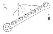
図7は、手術用器具ホルダに用いることのできるアーム246の別の実施形態の斜視図である。アーム246は上述のアームと類似であるが、アームに沿って1以上のスロット248が追加されている。スロット248は、その中でスライドする必要のあるロッドの動作に影響を与えることはないが、手術用器具ホルダを用いた部位の外科的処置の終了後、アームをより簡単に洗浄できるようにする。スロット付きアームの別の利点は、求められる機能と構造的完全性を維持しながら、組み立てられたアームの軽量化が図れることであろう。
FIG. 7 is a perspective view of another embodiment of an arm 246 that can be used with a surgical instrument holder. Arm 246 is similar to the arm described above, but with the addition of one or more slots 248 along the arm. The slots 248 do not affect the movement of the rods that need to slide therein, but allow the arms to be more easily cleaned after the surgical procedure at the site with the surgical instrument holder is completed. .. Another advantage of the slotted arm would be the light weight of the assembled arm while maintaining the required functionality and structural integrity.
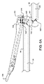
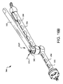
図8は手術用器具ホルダ250の別の実施形態を示している。図4の実施形態と同様に、手術用器具ホルダ250は、取り外し可能なキー88を受け入れるように構成されたベース86を有している。その詳細は上述のとおりである。ボールコネクタ90は上述のようにベース86に連結される。また、図4の実施形態のように、手術用器具ホルダ250は、エンドエフェクタ98に連結された第2のボールコネクタ96を有している。その詳細も上述のとおりである。この実施形態において、エンドエフェクタ98は、内視鏡84を保持し位置付けるように構成されている。ボールコネクタ90、96は調節可能なアーム252に連結されている。この実施形態の調節可能なアームは、図9A〜図9F及び図10にさらに詳しく示されている。
FIG. 8 illustrates another embodiment of surgical instrument holder 250. Similar to the embodiment of FIG. 4, surgical instrument holder 250 has a base 86 configured to receive a removable key 88. The details are as described above. The ball connector 90 is connected to the base 86 as described above. Also, like the embodiment of FIG. 4, the surgical instrument holder 250 includes a second ball connector 96 coupled to the end effector 98. The details are also as described above. In this embodiment, the end effector 98 is configured to hold and position the endoscope 84. The ball connectors 90, 96 are connected to the adjustable arm 252. The adjustable arm of this embodiment is shown in more detail in Figures 9A-9F and 10.
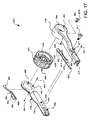
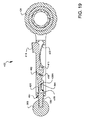
図9A〜図9Fは、調節可能なアーム252の組み立て方法を示す一連の分解図である。図9Aに示すように、接続端部264Cと停止端部264Sとを有するテンションロッド264が、接続端部264Cの方から第1ウエッジ266に通される。テンションロッド264の停止端部264Sの寸法は、テンションロッド264がウエッジ266を貫通するのを防ぐような寸法を有している。本実施形態においては、停止端部264Sは丸みを帯び、事実上球形である。組み立てられたテンションロッド264とウエッジ266は、第1アーム254の収容部268の下面の穴(図示せず)を通って、上方に通される。テンションロッド264の接続端部264Cは、収容部268から突出する。収容部268から突出する接続端部264Cの上からスペーシングワッシャ270が配置される。本実施形態においては、スペーシングワッシャ270は凸面状の外面を有し、この外面は、理想的には、球状の停止端部264Sの中心とほぼ一致する組立中心点を共有する。スペーシングワッシャの開口は、テンションロッド264の回動を許容する寸法を有し、これにより、第1アーム254が第2アームに対して、テンションロッドによって連結される部品間の相対的間隔を変えることなく複数の平面において相対運動することを許容している。第1ロッド258はソケット276内の開口274に滑り込み、第1アーム254の内部空洞に滑り込む。ソケット276は第1アーム254の基端278にあり、開口274は第1アーム254の長手軸280とアライメントされている。ロッド258はテーパ状端部258Tを有している。このテーパ状端部258Tはウエッジ266を押し付けることができ、ウエッジ266を収容部268内に保持することができる。ボールコネクタ90は、ロッド258の基端258Pに対峙して、ソケット276に挿入されている。ボールコネクタ90をソケット276内に保持するために、リテイナー282がボールコネクタ90を覆うようにしてソケット276に取り付けられる。ボールコネクタ90に乗るロッドの基端258Pは凹形状にすることができ、ロッドの基端258Pの周縁がボールコネクタ90に実際に接する。リテイナー282は開口284を有し、この開口を通って取付部116が突出する。前記の実施形態と同様に、取付部はベース(図示せず)に取り付けることができる。
9A-9F are a series of exploded views showing how the adjustable arm 252 is assembled. As shown in FIG. 9A, a tension rod 264 having a connecting end 264C and a stop end 264S is passed through the first wedge 266 from the connecting end 264C. The dimension of the stop end 264S of the tension rod 264 is dimensioned to prevent the tension rod 264 from penetrating the wedge 266. In this embodiment, the stop end 264S is rounded and is substantially spherical. The assembled tension rod 264 and wedge 266 are passed upward through holes (not shown) in the lower surface of the housing portion 268 of the first arm 254. The connection end portion 264C of the tension rod 264 projects from the housing portion 268. The spacing washer 270 is disposed above the connection end portion 264C protruding from the housing portion 268. In the present embodiment, spacing washer 270 has a convex outer surface that ideally shares an assembly center point that is substantially coincident with the center of spherical stop end 264S. The opening of the spacing washer is sized to allow rotation of the tension rod 264, which causes the first arm 254 to change the relative spacing of the second arm between the components connected by the tension rod. Without allowing relative movement in a plurality of planes. The first rod 258 slides into the opening 274 in the socket 276 and into the internal cavity of the first arm 254. The socket 276 is at the proximal end 278 of the first arm 254 and the opening 274 is aligned with the longitudinal axis 280 of the first arm 254. The rod 258 has a tapered end 258T. The tapered end 258T can press the wedge 266 and retain the wedge 266 within the housing 268. The ball connector 90 faces the base end 258P of the rod 258 and is inserted into the socket 276. To retain the ball connector 90 within the socket 276, a retainer 282 is attached to the socket 276 over the ball connector 90. The proximal end 258P of the rod that rides on the ball connector 90 can be concave and the peripheral edge of the proximal end 258P of the rod actually contacts the ball connector 90. The retainer 282 has an opening 284 through which the mounting portion 116 projects. As with the previous embodiments, the mount can be mounted on a base (not shown).
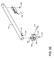
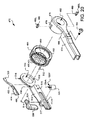
図9Bに示すように、第2ロッド260がソケット288の開口286に滑り込み、第2アーム256の内部空洞に滑り込む。ソケット288は第2アーム256の先端290にあり、開口286は第2アーム256の長手軸292とアライメントされている。本実施形態においては、ロッド260は細い部分260Nを有しており、装置全体の重量軽減に供している。ロッド260はまた、第2アーム256の収容部294内にアクセス可能なテーパ状端部260Tを有している。ボールコネクタ96が、第2開口296を通ってソケット288に挿入される。第2開口296は、第1開口286よりも大きく、取付部298が第1開口286を通って外に出る間に、ボールコネクタ96全体が第2開口296を通ってソケット288内に入り込めるほど大きい。第1開口286はボールコネクタ96の全体が第1開口286を通り抜けないような寸法を有している。ロッドの先端260Dはボールコネクタ96に乗り、ボールコネクタ96がソケット288内に保持されるのを助ける。レバーアライメントガイド300も第2アーム256に連結される。さらに、レバーキャッチ302も、例えばピン304等の当業者には公知の取付方法で、第2アーム256に連結される。
As shown in FIG. 9B, the second rod 260 slides into the opening 286 of the socket 288 and into the internal cavity of the second arm 256. The socket 288 is at the tip 290 of the second arm 256 and the opening 286 is aligned with the longitudinal axis 292 of the second arm 256. In the present embodiment, the rod 260 has a thin portion 260N, which serves to reduce the weight of the entire device. The rod 260 also has a tapered end 260T accessible within the housing 294 of the second arm 256. The ball connector 96 is inserted into the socket 288 through the second opening 296. The second opening 296 is larger than the first opening 286 and is large enough to allow the entire ball connector 96 to fit into the socket 288 through the second opening 296 while the mounting portion 298 exits through the first opening 286. .. The first opening 286 has a size such that the entire ball connector 96 does not pass through the first opening 286. The tip 260D of the rod rides on the ball connector 96 and helps retain the ball connector 96 in the socket 288. The lever alignment guide 300 is also connected to the second arm 256. Furthermore, the lever catch 302 is also connected to the second arm 256 by a mounting method known to those skilled in the art, such as the pin 304.
図9Cに示すように、収容部開口294(第2アーム256の収容部306を貫通する)がテンションロッド264とアライメントされる。図9Dは図9Cに示す部材を組み立てた状態を示す。
As shown in FIG. 9C, the housing opening 294 (which penetrates the housing 306 of the second arm 256) is aligned with the tension rod 264. FIG. 9D shows a state where the members shown in FIG. 9C are assembled.
図9Eは、ウエッジ310を有するレバーブロック308の周りの別の部分組立体を示す。レバー312は、レバーブロック308の穴316、レバー312の穴318、及びレバーブロック308の穴320に挿入されたレバーピボットピン314によって、レバーブロック308に回動可能に連結されている。レバーラッチ322が、例えばピン324等の当業者には公知の適切な方法で、レバー312に連結されている。
FIG. 9E shows another subassembly around a lever block 308 having a wedge 310. The lever 312 is rotatably connected to the lever block 308 by a hole 316 of the lever block 308, a hole 318 of the lever 312, and a lever pivot pin 314 inserted in a hole 320 of the lever block 308. Lever latch 322 is coupled to lever 312 in any suitable manner known to those of skill in the art, such as pin 324.
図9Fに示すように、図9Eのレバーアーム組立体を図9Dの組立体と合体させることができる。図9Eで部分的に見えるように、レバーブロック308とウエッジ310は、それらを貫通するチャンネル326を有している。図9Fを参照すると、このチャンネル326は、テンションロッド264がウエッジ310を通ることを許容する。この挿通状態で、ウエッジ310は第2ロッド260のテーパ状端部260T(この図には図示せず)に着座することができる。レバー312の底部のテンションクリアランス開口328は、接続端部264Cがレバー312の中に入ることを許容する。レバー312をアライメントし、これによりテンションピボットピン330が、レバーブロック308の貫通穴332を貫通し、穴334(図9Eに図示)に入り、テンションロッド264の穴336を通り、穴334に対応するレバー312の穴(この図には図示せず)に入ることができる。いったん組み込まれれば、テンションピボットピン330は、レバーブロック308と干渉せず、テンションロッド264をレバー312に対して回動させることができる。
As shown in FIG. 9F, the lever arm assembly of FIG. 9E can be combined with the assembly of FIG. 9D. As partially visible in Figure 9E, the lever block 308 and wedge 310 have channels 326 therethrough. Referring to FIG. 9F, this channel 326 allows the tension rod 264 to pass through the wedge 310. In this inserted state, the wedge 310 can be seated on the tapered end portion 260T (not shown in this figure) of the second rod 260. A tension clearance opening 328 in the bottom of the lever 312 allows the connecting end 264C to enter the lever 312. Align lever 312 so that tension pivot pin 330 penetrates through hole 332 in lever block 308, enters hole 334 (shown in FIG. 9E), passes through hole 336 in tension rod 264, and corresponds to hole 334. A hole in lever 312 (not shown in this figure) can be entered. Once assembled, the tension pivot pin 330 does not interfere with the lever block 308 and allows the tension rod 264 to pivot with respect to the lever 312.
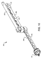
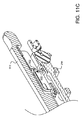
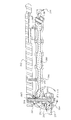
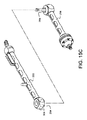
図10に示す組み立てられた調節可能なアーム252は、ボールコネクタ90、96に連結されている。第1アーム254と第2アーム256が示されている。第1アーム254はロッド258を有し、このロッドは第1アーム254の中をスライド可能で、テーパ状端部(テーパ状端部はこの図には図示せず)を有している。第1アーム254内のスライド可能な第1ロッド258は、第1ボールコネクタ90と接合可能に構成されている。同様に、第2アーム256はロッド260を有し、そのロッドは第2アーム256内をスライド可能で、テーパ状端部(テーパ状端部はこの図には図示せず)を有している。第2アーム256内のスライド可能な第2ロッド260は、第2ボールコネクタ96と接合可能に構成されている。レバー262が一方のアーム、この実施形態においては第2アーム256とアライメントされている。
The assembled adjustable arm 252 shown in FIG. 10 is connected to the ball connectors 90, 96. A first arm 254 and a second arm 256 are shown. The first arm 254 has a rod 258 that is slidable within the first arm 254 and has a tapered end (tapered end not shown in this figure). The slidable first rod 258 in the first arm 254 is configured to be connectable to the first ball connector 90. Similarly, the second arm 256 has a rod 260 that is slidable within the second arm 256 and has a tapered end (tapered end not shown in this figure). .. The slidable second rod 260 in the second arm 256 is configured to be connectable to the second ball connector 96. Lever 262 is aligned with one arm, in this embodiment the second arm 256.
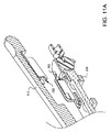
設置された時に、レバー312の長い部分が第2アーム256から離れて上方に回動するように、テンションロッド264は構成されている。図11Aの部分断面図に示すように、レバー312の上方への回動により、レバーラッチ322は、レバーキャッチ302から離れたロック解除位置にある。図11Bの矢印338で示すように、レバー312を第2アーム256に向けて押す又は絞ると、レバーラッチ322がレバーキャッチ302と接することができる。あと少し絞ると、レバーラッチ322はレバーキャッチ302を乗り超え、押圧を解除すると、図11Cに示すように、ラッチ322とキャッチ302は係合する。この状態において、レバーラッチ322とレバーキャッチ302は通常の位置からやや偏倚しており、レバー312は押圧された状態(ロック位置)で保持され、これにより、テンションロッド(この図には図示せず)は引張状態(テンション状態)にある。テンションロッド264が引張状態にない時(図12A、図12B)と引張状態にある時(図13A、図13B)の動作の違いについては、後述する。張力を解放するには、図11Dの矢印340で示すように、レバー312をさらに、第2アーム256に向けて絞る。これにより、レバーラッチ322とレバーキャッチ302は互いを解放し、非偏倚位置に弾性復帰ことを許容する。この非偏倚位置において、レバーキャッチ302がレバーラッチ322より上にある間は、ラッチ322とキャッチ302は互いを噛み合うことはない。しかし、レバー312を絞る力が解放されると、テンションロッド264(この図には図示せず)の張力によって、レバー312が再び図11Aに示すロック解除位置に戻る。このように、ラッチ322とキャッチ302の機構は、調節可能なアーム252を、張力のかからない(ロック解除)状態(図12A)にしたり、張力下の(ロック)状態(図13A)に保持することができる。操作者は、片手だけで、所望の位置決めと、ロック状態又はロック解除状態の選択を行なうことができる。
The tension rod 264 is configured such that when installed, the long portion of the lever 312 pivots upward away from the second arm 256. As shown in the partial cross-sectional view of FIG. 11A, the upward rotation of lever 312 causes lever latch 322 to be in the unlocked position away from lever catch 302. When the lever 312 is pushed or squeezed toward the second arm 256, the lever latch 322 can contact the lever catch 302, as shown by arrow 338 in FIG. 11B. When the lever 322 is squeezed a little further, the lever latch 322 gets over the lever catch 302, and when the pressing is released, the latch 322 and the catch 302 are engaged as shown in FIG. In this state, the lever latch 322 and the lever catch 302 are slightly deviated from the normal position, and the lever 312 is held in the pressed state (locked position), whereby the tension rod (not shown in this figure). ) Is in a tension state (tension state). The difference in operation between when the tension rod 264 is not in the tension state (FIGS. 12A and 12B) and when it is in the tension state (FIGS. 13A and 13B) will be described later. To release the tension, the lever 312 is further squeezed towards the second arm 256, as indicated by arrow 340 in FIG. 11D. This allows the lever latch 322 and the lever catch 302 to release each other and elastically return to the non-biased position. In this non-biased position, the latch 322 and the catch 302 do not interlock with each other while the lever catch 302 is above the lever latch 322. However, when the force to squeeze the lever 312 is released, the tension of the tension rod 264 (not shown in this figure) causes the lever 312 to return to the unlocked position shown in FIG. 11A again. Thus, the mechanism of the latch 322 and the catch 302 keeps the adjustable arm 252 in a tensionless (unlocked) state (FIG. 12A) or in tension (locked) state (FIG. 13A). You can The operator can perform desired positioning and select the locked state or the unlocked state with only one hand.
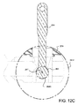
図12Aは、調節可能なアームの一部の部分断面図である。図12Aの状態において、テンションロッド264は引張状態(テンション状態)ではない。レバー312はレバーピボットピン314を中心に回動可能であり、図12Aの位置において、レバー312は取り付けられたテンションロッド264を押し下げている(図示の方向)。これにより、ウエッジ266はロッド258のテーパ状端部258Tを少し解放することが許容され、それにより、ボールコネクタ90(この図には図示せず)に対してロッド258のグリップを緩める。この位置において、レバー312はウエッジ310を押し下げておらず、そのためウエッジ310とテーパ状端部260Tとの間の圧力もまた減じられており、それによりボールコネクタ96に対するロッド260のグリップも緩んでいる。第1アーム254と第2アーム256との間のスペーシングワッシャ270の圧縮も減少し、それにより、第1アーム254の第2アーム256に対する回動が許容される。本実施形態においては、スペーシングワッシャ270が湾曲しているため、アーム254、256は同一平面、又は異なる平面において、互いに対して回動可能である。これにより、操作者は、アームと、ボールコネクタ96に接続されたエンドエフェクタを、容易にいかなる所望の位置にも位置付けることができる。本実施形態のロック解除状態又は開き状態のより詳細な断面を、図12Bに示す。
FIG. 12A is a partial cross-sectional view of a portion of the adjustable arm. In the state of FIG. 12A, the tension rod 264 is not in the tension state (tension state). The lever 312 is rotatable about the lever pivot pin 314, and in the position of FIG. 12A, the lever 312 pushes down the attached tension rod 264 (direction shown). This allows wedge 266 to release the tapered end 258T of rod 258 slightly, thereby loosening the grip of rod 258 against ball connector 90 (not shown in this figure). In this position, the lever 312 is not pushing down the wedge 310, so the pressure between the wedge 310 and the tapered end 260T is also reduced, which also loosens the grip of the rod 260 on the ball connector 96. .. The compression of spacing washer 270 between first arm 254 and second arm 256 is also reduced, which allows pivoting of first arm 254 relative to second arm 256. In this embodiment, the spacing washer 270 is curved so that the arms 254, 256 are rotatable relative to each other in the same plane or in different planes. This allows the operator to easily position the arm and the end effector connected to the ball connector 96 at any desired position. A more detailed cross section of the unlocked or opened state of the present embodiment is shown in FIG. 12B.
図12Cは、テンションロッド264のさらに詳しい断面図であり、第1アーム254の収容部268内での位置、及び、図10Aに示すスペーシングワッシャ270との相対的位置関係を詳しく示す。本図は、テンションロッド264の停止端部264Sとスペーシングワッシャ270との空間的関係の一態様を示している。図12Cの内側の同心円265の寸法は、テンションロッド264の停止端部264の球形部分に対応する円と同じ寸法であり、外側の同心円265Eの寸法は、スペーシングワッシャ270の凸曲面状の外面に対応する弧に一致する。さらに、スペーシングワッシャは、テンションロッドの球状の停止端部の中心とほぼ一致する組立中心点267を共有する。このテンションロッドの停止端部264とスペーシングワッシャ270との幾何学的及び空間的関係により、手術用器具ホルダ250のロック位置(図13A、図13B)を係合するためにレバー312を絞る際、第1アーム254の第2アーム256に対する相対的角度又は位置とは無関係に、一定の力を与えることができる。
FIG. 12C is a more detailed cross-sectional view of the tension rod 264, showing in detail the position of the first arm 254 inside the housing portion 268 and the relative positional relationship with the spacing washer 270 shown in FIG. 10A. The figure shows one aspect of the spatial relationship between the stop end 264S of the tension rod 264 and the spacing washer 270. The size of the inner concentric circles 265 in FIG. 12C is the same as the circle corresponding to the spherical portion of the stop end 264 of the tension rod 264, and the size of the outer concentric circles 265E is the convex curved outer surface of the spacing washer 270. Matches the arc corresponding to. In addition, the spacing washers share an assembly center point 267 that is substantially coincident with the center of the spherical stop end of the tension rod. Due to the geometric and spatial relationship between the stop end 264 of the tension rod and the spacing washer 270, when the lever 312 is squeezed to engage the locked position (FIGS. 13A, 13B) of the surgical instrument holder 250. , A constant force can be applied regardless of the relative angle or position of the first arm 254 with respect to the second arm 256.
所望の位置に達したら、レバー312を絞って、図13Aの部分的断面図に示すように、張力を与えられた状態(ロック状態)にすることができる。ここでも、レバー312はレバーピボットピン314を中心に回動し、図13Aの位置において、レバー312はテンションロッド264を引き上げ、テンションロッド264を引張り状態にする。テンションロッド264の停止端部264Sは、ウエッジ266をテーパ状端部258Tに向かって引き上げる。これにより、ロッド258はボールコネクタ90に押し付けられ、ボールコネクタ90、ひいてはベース(この図には図示せず)に対して第1アーム254の位置がロックされる。図13Aの位置において、レバー312はウエッジ310を押し下げ、それにより、ウエッジ310と第2ロッド260のテーパ状端部260Tとの間に圧力を生じさせる。これにより、ロッド260はボールコネクタ96に押し付けられ、第2アーム256に対して、ボールコネクタ96に連結されたエンドエフェクタ(この図には図示せず)の位置が固定される。図13Aの位置において、第1アーム254と第2アーム256がスペーシングワッシャ270をクランプし、これにより、第2アーム256に対して第1アーム254を固定する。この実施形態のロック状態での詳細な断面図が図13Bに示されている。この1つのレバー312は、レバー312を片手で絞るだけで、エンドエフェクタをベースに対して効果的にロックすることができる。片手でレバーを再度絞ると、3つの異なるジョイント(ボールコネクタ90、第1アームと第2アームの接合部およびボールコネクタ96)が一緒に解放され、もう一方の手を自由にしてエンドエフェクタを位置づける。これは、従来技術に対して非常に有効な改善である。また、従来技術に比べて自由度が高くなり、装置全体をロックまたはロック解除するために必要なのは単一の絞りだけである。
Once the desired position is reached, the lever 312 can be squeezed into a tensioned state (locked state), as shown in the partial cross-sectional view of FIG. 13A. Again, the lever 312 pivots about the lever pivot pin 314 and, in the position of FIG. 13A, the lever 312 pulls up the tension rod 264 and pulls the tension rod 264. The stop end 264S of the tension rod 264 pulls the wedge 266 up towards the tapered end 258T. As a result, the rod 258 is pressed against the ball connector 90, and the position of the first arm 254 is locked with respect to the ball connector 90 and thus the base (not shown in this figure). In the position of FIG. 13A, the lever 312 depresses the wedge 310, thereby creating pressure between the wedge 310 and the tapered end 260T of the second rod 260. As a result, the rod 260 is pressed against the ball connector 96, and the position of the end effector (not shown in this figure) connected to the ball connector 96 is fixed with respect to the second arm 256. In the position of FIG. 13A, the first arm 254 and the second arm 256 clamp the spacing washer 270, which secures the first arm 254 to the second arm 256. A detailed cross-sectional view of this embodiment in the locked state is shown in Figure 13B. This one lever 312 can effectively lock the end effector with respect to the base simply by squeezing the lever 312 with one hand. Re-squeezing the lever with one hand releases the three different joints (ball connector 90, first arm and second arm joint and ball connector 96) together, freeing the other hand to position the end effector. .. This is a very effective improvement over the prior art. Also, it has more freedom than the prior art and only a single aperture is needed to lock or unlock the entire device.
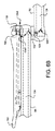
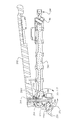
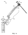
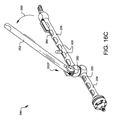
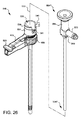
図14は、手術用器具ホルダ342の第3の実施形態を示している。図4、図8の実施形態と同様に、手術用器具ホルダ342は、取り外し可能なキー88を受け入れるように構成されたベース86を有する。前述のように、ボールコネクタ90をベース86に連結することができる。手術用器具ホルダ342は、エンドエフェクタ345に連結される第2のボールコネクタ366を有する。このエンドエフェクタ345は、ボールコネクタ366の端部のクイック接続ポート(この図には示されていない)に解放可能に保持されるように構成されている。この実施形態では、エンドエフェクタ345は、内視鏡84を保持するスコープポートカニューレ222を保持し位置決めするように構成される。ボールコネクタ90、366は、調節可能なアーム344に連結されている。この実施形態の調節可能なアームの組立体は、図15A〜図15Fにおいて詳細に示されている。
FIG. 14 shows a third embodiment of the surgical instrument holder 342. Similar to the embodiment of FIGS. 4 and 8, surgical instrument holder 342 has a base 86 configured to receive a removable key 88. The ball connector 90 can be coupled to the base 86 as previously described. Surgical instrument holder 342 has a second ball connector 366 that is coupled to end effector 345. The end effector 345 is configured to be releasably retained in a quick connect port (not shown in this figure) at the end of the ball connector 366. In this embodiment, the end effector 345 is configured to hold and position the scope port cannula 222 holding the endoscope 84. Ball connectors 90, 366 are connected to adjustable arm 344. The adjustable arm assembly of this embodiment is shown in detail in FIGS. 15A-15F.
図15A〜図15Fは、図14に示されている調節可能なアーム344がどのように組み込まれるかを示す分解図である。図15Aに示すように、接続端部354Cおよび停止端部354Sを有するテンションロッド354は、最初に接続端部354Cが第1ウエッジ266に通される。テンションロッド354の停止端部354Sは、テンションロッド354がウエッジ266を完全に通過するのを防止するようなサイズになっている。この実施形態では、停止端部354Sは、本質的に丸みを帯びているか、または球形である。組み立てられたテンションロッド354とウエッジ266は、第1アーム254の収容部268の底部の穴を通り、上方に挿通可能である。テンションロッド354の接続端部354Cは、収容部268から突き出る。スペースワッシャ270は、収容部268から突出する接続端部354Cの上から配置することができる。この実施形態では、前述のように、スペースワッシャ270は、凸面状の外面を有し、この外面は、理想的には、球状の停止端部354Sの中心とほぼ一致する組立中心点を共有する。スペーシングワッシャの開口は、テンションロッド264の回動を許容する寸法を有し、これにより、第1アーム254が第2アーム256に対して、テンションロッドによって連結される部品間の相対的間隔を変えることなく複数の平面において相対運動することを許容している。第1ロッド355はソケット276内の開口274に滑り込み、第1アーム254の内部空洞に滑り込む。ソケット276は第1アーム254の基端278にあり、開口274は第1アーム254の長手軸280とアライメントされている。ロッド355はテーパ状端部355Tを有している。このテーパ状端部355Tはウエッジ266を押し付けることができ、ウエッジ266を収容部268内に保持することができる。ロッド355は細い中間部355Nを有しており、この中間部355Nは、重量を減じるとともに、第1アーム254の内径とロッド355の外径との間に、洗浄と滅菌を改善するための間隔を提供する。ソケットストップ350は、ソケット276に螺合されているが、別の取り付け手段を用いてもよい。ボールコネクタ90は、ロッド355の基端355Pに対峙して、ソケット276に挿入されている。ボールコネクタ90をソケット276内に保持するために、リテイナー282がボールコネクタ90を覆うようにしてソケットストップ350に取り付けられる。この実施形態では、リテイナー346が、ボールコネクタ90をソケットストップ350に対して保持するため、ボールはソケット276内で回動可能である。調節可能なアーム344の組立およびセットアップ中に、ソケットストップ350をネジ付きソケット276に締め付けて、ボールコネクタ90、第1ロッド355、およびウエッジ266の間に、所望量のロック解除時のテンションを提供する。リテイナー346は、ソケットストップ350のネジ穴351に固定される数個の止めネジ348により、ソケットストップ350に固定される。ソケット276に対するソケットストップ350の調節可能性は、調節可能アーム344がロック位置またはロック解除位置にある時に、第1アーム254と第2アーム254との間の動き易さを調節可能にする。リテイナー346は開口349を有し、この開口349を通って取付部116が突出する。前の実施形態と同様に、取付部116はベース(図示せず)に取り付けられる。
15A-15F are exploded views showing how the adjustable arm 344 shown in FIG. 14 may be incorporated. As shown in FIG. 15A, in the tension rod 354 having the connecting end 354C and the stop end 354S, the connecting end 354C is first passed through the first wedge 266. The stop end 354S of the tension rod 354 is sized to prevent the tension rod 354 from completely passing the wedge 266. In this embodiment, the stop end 354S is essentially rounded or spherical. The assembled tension rod 354 and wedge 266 can be inserted upward through the hole at the bottom of the housing portion 268 of the first arm 254. The connection end portion 354C of the tension rod 354 projects from the housing portion 268. The space washer 270 can be arranged from above the connection end portion 354C protruding from the housing portion 268. In this embodiment, as previously mentioned, the space washer 270 has a convex outer surface that ideally shares an assembly center point that is approximately coincident with the center of the spherical stop end 354S. .. The opening of the spacing washer is dimensioned to allow pivoting of the tension rod 264, thereby allowing the first arm 254 to the second arm 256 relative spacing between the components connected by the tension rod. Allowing relative movement in multiple planes without change. The first rod 355 slides into the opening 274 in the socket 276 and into the internal cavity of the first arm 254. The socket 276 is at the proximal end 278 of the first arm 254 and the opening 274 is aligned with the longitudinal axis 280 of the first arm 254. The rod 355 has a tapered end 355T. The tapered end portion 355T can press the wedge 266, and the wedge 266 can be held in the housing portion 268. The rod 355 has a thin middle portion 355N, which reduces weight and provides a spacing between the inner diameter of the first arm 254 and the outer diameter of the rod 355 to improve cleaning and sterilization. I will provide a. The socket stop 350 is threaded into the socket 276, but other attachment means may be used. The ball connector 90 faces the base end 355P of the rod 355 and is inserted into the socket 276. To retain the ball connector 90 in the socket 276, a retainer 282 is attached to the socket stop 350 over the ball connector 90. In this embodiment, retainer 346 holds ball connector 90 against socket stop 350 so that the ball is pivotable within socket 276. During assembly and setup of the adjustable arm 344, the socket stop 350 is tightened onto the threaded socket 276 to provide the desired amount of unlock tension between the ball connector 90, the first rod 355, and the wedge 266. To do. The retainer 346 is fixed to the socket stop 350 by several setscrews 348 fixed to the screw holes 351 of the socket stop 350. The adjustability of the socket stop 350 with respect to the socket 276 allows the ease of movement between the first arm 254 and the second arm 254 to be adjustable when the adjustable arm 344 is in the locked or unlocked position. The retainer 346 has an opening 349, and the mounting portion 116 projects through the opening 349. As in the previous embodiment, the mounting portion 116 is mounted on the base (not shown).
図15Bに示すように、第2ロッド364は、ソケット288の開口部286および第2アーム256の内部空洞に滑り込む。ソケット288は、第2アーム256の先端290にあり、開口部286は、第2アーム256の長手軸292とアライメントしている。ロッド364は、第2アーム256の収容部306内にアクセス可能なテーパ状端部364Tを有する。ボールコネクタ366と取付部を有するクイック接続ポート392が提供される。取付部390は、中心に沿うギャップ390Gと穴396を有する。この穴396に、ピン394が、溶接、圧入、または当業者に知られている他の方法で、挿入固定される。ピン394は、取付部390のギャップ390Gを横切っている。クイック接続ポート392は、ソケット288の第2の開口296に挿入される。第2の開口296は、第1の開口286よりも大きく、取付部390が第1の開口286を通って出る間に、ボールコネクタ366全体がソケット288に入るのに十分な大きさを有している。第1の開口286は、ボールコネクタ366の全体が第1の開口286を通過することを防止するようなサイズである。ロッドの先端364Dは、ボールコネクタ366に乗り、ボールコネクタ366をソケット288に保持するのを助ける。
As shown in FIG. 15B, the second rod 364 slides into the opening 286 of the socket 288 and the internal cavity of the second arm 256. The socket 288 is at the tip 290 of the second arm 256 and the opening 286 is aligned with the longitudinal axis 292 of the second arm 256. The rod 364 has a tapered end 364T accessible within the housing 306 of the second arm 256. A quick connect port 392 having a ball connector 366 and a mount is provided. The mounting portion 390 has a gap 390G and a hole 396 along the center. A pin 394 is welded, press fit, or otherwise inserted and secured in the hole 396 by any method known to those skilled in the art. The pin 394 crosses the gap 390G of the mounting portion 390. The quick connect port 392 is inserted into the second opening 296 in the socket 288. The second opening 296 is larger than the first opening 286 and is large enough to allow the entire ball connector 366 to enter the socket 288 while the mounting portion 390 exits through the first opening 286. ing. The first opening 286 is sized to prevent the entire ball connector 366 from passing through the first opening 286. The tip 364D of the rod rides on the ball connector 366 and helps retain the ball connector 366 in the socket 288.
レバーアライメントガイド356が第2アーム256に連結されている。さらに、レバーキャッチ358は、ネジ362で第2アーム256に固定することにより、キャッチシールド360内で第2のアーム256に連結される。キャッチ358およびキャッチシールド360は、他の方法、例えば、当業者に知られているピンまたは他の取り付け技術を用いて、第2アーム256に固定することができる。 キャッチシールド360は、手術用器具ホルダ342の操作中に手袋、衣類、または皮膚がキャッチ358に引っかかる可能性を低減するために、キャッチ358の両側を覆う。
The lever alignment guide 356 is connected to the second arm 256. Further, the lever catch 358 is connected to the second arm 256 in the catch shield 360 by fixing the lever catch 358 to the second arm 256 with a screw 362. The catch 358 and catch shield 360 can be secured to the second arm 256 using other methods, such as pins or other attachment techniques known to those of ordinary skill in the art. The catch shield 360 covers both sides of the catch 358 to reduce the likelihood of gloves, clothing, or skin being caught on the catch 358 during operation of the surgical instrument holder 342.
図15Cに示すように、第2アーム256の収容部306を完全に貫通する収容部開口294は、テンションロッド354とアライメントされる。図15Dは、図15Cから得られた構成要素の組立体を示している。レバーブロック368は、ウエッジ370と、それを貫通するチャンネル371を有する。このチャネル371は、ウエッジ370をテンションロッド354が通ることを可能にし、これによりウエッジ370が第2ロッド354のテーパ状端部364T(この図では見えない)に着座するようにする。レバー352の基端352Pの底部のテンションクリアランス開口387は、接続端部354Cがレバー352内に入ることを可能にする。
As shown in FIG. 15C, the housing opening 294 that completely penetrates the housing 306 of the second arm 256 is aligned with the tension rod 354. Figure 15D shows the assembly of components obtained from Figure 15C. The lever block 368 has a wedge 370 and a channel 371 extending therethrough. This channel 371 allows the tension rod 354 to pass through the wedge 370, thereby allowing the wedge 370 to seat on the tapered end 364T of the second rod 354 (not visible in this view). A tension clearance opening 387 at the bottom of the proximal end 352P of the lever 352 allows the connecting end 354C to enter the lever 352.
図15Eは、図14の手術用器具ホルダ342のさらなる部分組立体の分解斜視図である。レバーラッチシールド376とラッチ374は、ネジ378によってレバー352に連結されるが、当業者に知られている他の適切な方法によって取り付けられてもよい。レバーラッチシールド376およびキャッチシールドは、手術用器具ホルダ342の操作中に手袋、衣類、または皮膚がラッチ374およびキャッチ358の機構に引っ掛かることを防ぐのに役立つように協働する。この実施形態のラッチ374およびキャッチ358の機構は、図11A〜図11Dについて説明したラッチ322およびキャッチ302と同様に機能する。この実施形態のレバー352は、クリーニングリリース380をさらに含む。このクリーニングリリース380には、スプリング381が部分的に挿入される。クリーニングリリース380を従えたスプリング381は、レバー352の基端352Pのマッチングスロット383に挿入される。クリーニングリリース380は、内側に押されてスプリング381を圧縮し、これにより、レバー352の基端352Pがテンションロッド354を越えてレバーブロック368内にセットされるようになる。クリーニングリリース380が解放されると、スプリング381がクリーニングリリース380のポスト385をレバーブロックのスロット375内に押し込む。 ポスト385がスロット375にある間、組み立てられた装置のレバー352は、ロック解除位置とロック位置との間で移動できる。レバー352を洗浄位置に移動させるために、クリーニングリリース380を押して、スプリング381をさらに圧縮し、レバーが通常のロック解除位置よりもアーム256から離れて開かれた時に、ポスト385がスロット375から凹部377に飛ぶことができるようにする。クリーニングリリース380の動作は、図16A〜図16Cでさらに説明する。
15E is an exploded perspective view of a further subassembly of surgical instrument holder 342 of FIG. Lever latch shield 376 and latch 374 are coupled to lever 352 by screws 378, but may be attached by any other suitable method known to those of ordinary skill in the art. Lever latch shield 376 and catch shield cooperate to help prevent gloves, clothing, or skin from getting caught in the latch 374 and catch 358 mechanism during operation of surgical instrument holder 342. The latch 374 and catch 358 mechanism of this embodiment functions similarly to the latch 322 and catch 302 described with respect to FIGS. 11A-11D. The lever 352 in this embodiment further includes a cleaning release 380. The spring 381 is partially inserted into the cleaning release 380. The spring 381 with the cleaning release 380 is inserted into the matching slot 383 of the base end 352P of the lever 352. The cleaning release 380 is pushed inwardly to compress the spring 381, which causes the proximal end 352P of the lever 352 to clear the tension rod 354 and set in the lever block 368. When the cleaning release 380 is released, the spring 381 pushes the post 385 of the cleaning release 380 into the slot 375 of the lever block. While the post 385 is in the slot 375, the lever 352 of the assembled device can move between the unlocked and locked positions. To move the lever 352 to the wash position, the cleaning release 380 is pushed to further compress the spring 381 and the post 385 is recessed from the slot 375 when the lever is opened further from the arm 256 than in the normal unlocked position. Be able to fly to 377. The operation of cleaning release 380 is further described in FIGS. 16A-16C.
レバー352がアライメントされ、これにより、テンションピボットピン386は、レバーブロック368の貫通穴372Tを通り、レバー352の穴382を通り、テンションロッド354の穴354Hを通り、穴382に対向するレバー352の反対側の穴に挿入することができる。組み立てられたとき、ピン386は、レバーブロック368と係合せず、レバー352の基端352Pをテンションロッド354に回動可能に連結する。レバー352は、レバーピボットピン388によってレバーブロック368に回動可能に連結される。このレバーピボットピン388は、レバーブロック368の穴372L、レバー352の穴384、およびレバーブロック368の穴373Lに挿入される。この連結は、図15Dに示すアーム部分組立体をレバー352に連結するためにも提供される。
The lever 352 is aligned so that the tension pivot pin 386 passes through the through hole 372T in the lever block 368, through the hole 382 in the lever 352, through the hole 354H in the tension rod 354, and in the lever 352 opposite the hole 382. Can be inserted into the opposite hole. When assembled, the pin 386 does not engage the lever block 368, but pivotally connects the proximal end 352P of the lever 352 to the tension rod 354. The lever 352 is rotatably connected to the lever block 368 by a lever pivot pin 388. The lever pivot pin 388 is inserted into the hole 372L of the lever block 368, the hole 384 of the lever 352, and the hole 373L of the lever block 368. This connection is also provided to connect the arm subassembly shown in FIG. 15D to the lever 352.
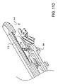
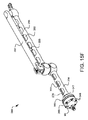
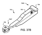
図15Fは、完全に組み立てられた調節可能なアーム344をレバー352がロック位置にある状態で示す図である。
Figure 15F shows the fully assembled adjustable arm 344 with the lever 352 in the locked position.
図16A〜16Cは、いくつかのレバー352の動作位置を示し、図14に示される手術用器具ホルダ342の実施形態の洗浄性を強調している。図16Aは、レバー352が閉じ位置またはロック位置にある状態を示している。 ロック位置およびロック解除位置のメカニズム、および様々な器具ホルダの連結要素に対するそれらの相対的な影響は、例えば図11A〜図11D、図12A〜12C、図13A〜13Bで以前に議論されている。
16A-16C show the operating positions of some levers 352, highlighting the cleanability of the embodiment of the surgical instrument holder 342 shown in FIG. FIG. 16A shows the lever 352 in the closed or locked position. The locked and unlocked position mechanisms and their relative impact on the coupling elements of various instrument holders have been previously discussed, for example, in Figures 11A-11D, 12A-12C, 13A-13B.
図16Bは、レバー352が開き位置またはロック解除位置にある状態を示す。レバー352は、第2アーム256に対して幾分開いているが、外科処置または手術の後に完全な洗浄をするためには、第2アーム256および第2アーム256内の第2ロッド364へのアクセスが制限される場合がある。クリーニングリリース380のポストは、手術用器具ホルダ342の通常のロックおよびロック解除操作中に、レバーブロック368のスロット375内に拘束される。レバー352の基端352Pに位置するクリーニングリリース380は、方向379に移動してスプリング381を圧縮し、レバーがさらに図16Cに示す洗浄位置へと持ち上げられると、クリーニングリリース380のポスト385がスロット375から凹部377に飛ぶことができる。これにより、手術用器具ホルダ342のアクセスが改善され、洗浄性が強化される。このメカニズムは、図15Eについて詳述された組み立て工程において説明している。
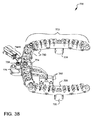
図17は、図5Dで説明したものと同様のスコープポートカニューレ222のための器具アダプタ402の組立体を示す分解図である。
FIG. 16B shows the lever 352 in the open or unlocked position. The lever 352 is somewhat open to the second arm 256, but to provide a thorough lavage after surgery or surgery, the lever 352 is attached to the second arm 256 and to the second rod 364 within the second arm 256. Access may be restricted. The post of cleaning release 380 is captured within slot 375 of lever block 368 during normal locking and unlocking operations of surgical instrument holder 342. The cleaning release 380 located at the proximal end 352P of the lever 352 moves in the direction 379 to compress the spring 381 and when the lever is further raised to the wash position shown in FIG. 16C, the post 385 of the cleaning release 380 is slot 375. Can fly to the recess 377. This improves access to surgical instrument holder 342 and enhances cleanability. This mechanism is described in the assembly process detailed in Figure 15E.
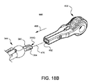
17 is an exploded view showing an assembly of an instrument adapter 402 for a scope port cannula 222 similar to that described in FIG. 5D.
下部ヨーク404は、開口458を画成する円形ポスト406を有する。ポスト406の外側には、スプリングラッチ480を受け入れるサイズの凹部(この図では見えない)がある。スプリングラッチ408はラッチ480Lを有する。スプリングラッチ408が凹部にあるときにラッチ480Lはポスト406の外面を越えて突出している。カニューレ回転ダイヤル424は、ポスト406を囲うように配置される。溝428は、カニューレ回転ダイヤル424の内周に沿って形成されている。スプリングラッチ480のラッチ480Lは、この溝と係合し、カニューレ回転ダイヤル424を所定の位置に保持する。ラッチ480Lが、回転ダイヤル424の内側の全周に形成された溝428に乗ることができるため、カニューレ回転ダイヤル424はこの位置で自由に回転することができる。しかし、ダイヤルの軸方向の動きはラッチ480Lによって禁じられる。
The lower yoke 404 has a circular post 406 that defines an opening 458. Outside the post 406 is a recess (not visible in this view) sized to receive the spring latch 480. The spring latch 408 has a latch 480L. Latch 480L projects beyond the outer surface of post 406 when spring latch 408 is in the recess. The cannula rotation dial 424 is arranged to surround the post 406. The groove 428 is formed along the inner circumference of the cannula rotation dial 424. Latch 480L of spring latch 480 engages with this groove and holds cannula rotation dial 424 in place. Since the latch 480L can ride on the groove 428 formed all around the inside of the rotary dial 424, the cannula rotary dial 424 can freely rotate in this position. However, axial movement of the dial is prohibited by latch 480L.
アダプタリリース414は下部ヨーク404の凹部448にアライメントされ、これにより、器具アダプタ402が組み立てられた時に、ピボット点416を、ネジ410によって下部ヨーク404の穴412とアライメントされた状態で保持できるようになる。ネジ410は、下部ヨーク404の穴412を通り、アダプタリリース414のピボット点416を通り、上部ヨーク434の対応するネジ穴436へと入る。器具アダプタ402が組み立てられる時、アダプタリリース414のスロット418に入る制限ピン462は、下部ヨーク404の穴466に配置され、アダプタリリース414のスロット418を通って、上部ヨーク434の対応する穴464に保持される。アダプタリリース414は、より詳細に後述するように、手術用器具ホルダ342の取付部390に器具アダプタ402を解放可能に保持するように構成されたスプリング422とラッチ420を有している。
The adapter release 414 is aligned with the recess 448 in the lower yoke 404 to allow the pivot point 416 to be held in alignment with the holes 412 in the lower yoke 404 by the screws 410 when the instrument adapter 402 is assembled. Become. Screws 410 pass through holes 412 in lower yoke 404, through pivot point 416 in adapter release 414 and into corresponding screw holes 436 in upper yoke 434. When the instrument adapter 402 is assembled, the limiting pin 462 that enters the slot 418 of the adapter release 414 is located in the hole 466 of the lower yoke 404 and through the slot 418 of the adapter release 414 and into the corresponding hole 464 of the upper yoke 434. Retained. The adapter release 414 includes a spring 422 and a latch 420 configured to releasably retain the instrument adapter 402 in a mounting portion 390 of the surgical instrument holder 342, as described in more detail below.
カニューレラッチ450は、上部ヨーク434のスロット438にアライメントされており、これにより、ピボット点454がピン444によって上部ヨーク434の穴440とアライメントされてピン留めされる。カニューレラッチ450はスプリング456を有しており、このスプリング456は、ラッチ450を上部ヨーク434に形成された開口460内へ押す。カニューレラッチ450はまた、押圧可能な解放部452を有しており、これによりラッチをピン444の周りに回動させ、開口460から後退させる。解放部452から圧力が除去されると、カニューレラッチ450は開口460へ押し戻される。
Cannula latch 450 is aligned with slot 438 in upper yoke 434, which causes pivot point 454 to be pinned by pin 444 in alignment with hole 440 in upper yoke 434. Cannula latch 450 has a spring 456 that pushes latch 450 into opening 460 formed in upper yoke 434. Cannula latch 450 also has a depressible release 452 that pivots the latch about pin 444 and retracts through opening 460. When pressure is removed from release 452, cannula latch 450 is pushed back into opening 460.
回転防止ピン446は、上部ヨーク434の穴442に挿入される。回転防止ピン446は、上部ヨーク434の下側を越えて下方に突出している。上部ヨーク434は、上述したネジ410により下部ヨーク404に連結される。カニューレ回転ダイヤル424の内側の溝428が下部ヨーク404に向かって押され、ラッチ480Lと係合していない間は、カニューレ回転ダイヤル424は自由に回転することができる。回転ダイヤル424をロックすることが望まれる場合には、回転ダイヤル424は、上部ヨーク434に向かって軸方向に移動することができる。そうすることで、回転ダイヤル424の周りに配置された複数のピン受け430(この図には示されていないが、図5Dでは同様の受け220が示されている)の1つが、上部ヨークから下方に突出する回転防止ピン446と係合する。ほぼ同時に、ラッチ480Lが、カニューレ回転ダイヤル424の内側の溝428に係合し、ダイヤルの軸方向の動きを防ぎ、回転ダイヤル424が再び回転できるようにするのを助ける。回転ダイヤル424がこの位置にある限り、回転ダイヤル424は保持される。回転ダイヤル424を再び回転させるには、回転ダイヤル424を下部ヨーク404に向かって軸方向に動かして、回転防止ピン446をピン受け430から外す必要がある。この動作は、カニューレアダプタの別の実施形態を示す図28Aおよび図28Bでさらに詳細に説明される。
The rotation prevention pin 446 is inserted into the hole 442 of the upper yoke 434. The rotation prevention pin 446 projects downward beyond the lower side of the upper yoke 434. The upper yoke 434 is connected to the lower yoke 404 by the screw 410 described above. The cannula rotary dial 424 is free to rotate while the inner groove 428 of the cannula rotary dial 424 is pushed toward the lower yoke 404 and is not engaged with the latch 480L. If it is desired to lock the rotary dial 424, the rotary dial 424 can move axially toward the upper yoke 434. In doing so, one of the plurality of pin receptacles 430 (not shown in this figure, but a similar receptacle 220 is shown in FIG. 5D) disposed around the rotary dial 424 is removed from the upper yoke. It engages with a rotation preventing pin 446 protruding downward. At about the same time, the latch 480L engages a groove 428 inside the cannula rotary dial 424, preventing axial movement of the dial and helping the rotary dial 424 to rotate again. As long as the rotary dial 424 is in this position, the rotary dial 424 is held. In order to rotate the rotary dial 424 again, it is necessary to move the rotary dial 424 axially toward the lower yoke 404 to remove the rotation prevention pin 446 from the pin receiver 430. This operation is described in further detail in Figures 28A and 28B, which illustrate another embodiment of the cannula adapter.
図18Aは、図17の器具アダプタ402が組み立てられた状態を斜視図である。図18Bは、図15Fの調節可能アーム344の端部の斜視図であり、図14の手術用器具ホルダ342の取付部390と接続するためにアライメント状態にある器具アダプタ402を示している。器具アダプタ402は、次のようにして手術用器具ホルダ342に接続される。すなわち、器具アダプタ402を調節可能なアーム344に向かって長手軸470に沿う方向468に移動させ、取付部390をアダプタチャネル432とアライメントして、ピン394がアダプタリリースラッチ(この図には示されていないが、前述および以下の図19にも記載されている)に係合するまで挿入する。この実施形態は、スコープポートカニューレ222のための器具アダプタ402を示しているが、他の器具アダプタを同様の方法で手術用器具ホルダ342に取り付けることができる。アダプタ402をアーム344に着脱可能に連結することを可能にするこの実施形態の構成要素は、マウントである。この実施形態では、マウントは、上部ヨーク434、下部ヨーク404、カニューレラッチ450、回転ダイヤル424、アダプタリリース414およびチャネル432を含む。また、ボールコネクタ366を有するクイック接続ポート392、ピン394を有する取付部390、レバー352を含む調節可能なアーム344のセットを含むことができ、システム全体が取り外されり場合には取り外し可能なキー88を備えたベース86を含むことができる。他のタイプのマウントが本明細書に開示されており、これらの実施形態およびそれらの均等物は、特許請求の範囲内に含まれることが意図されている。
FIG. 18A is a perspective view showing a state in which the instrument adapter 402 of FIG. 17 is assembled. 18B is a perspective view of the end of the adjustable arm 344 of FIG. 15F, showing the instrument adapter 402 in alignment for connection with the mounting portion 390 of the surgical instrument holder 342 of FIG. Instrument adapter 402 is connected to surgical instrument holder 342 as follows. That is, instrument adapter 402 is moved toward adjustable arm 344 in a direction 468 along longitudinal axis 470 to align attachment 390 with adapter channel 432 and pin 394 to the adapter release latch (shown in this figure). No, but also described above and below in FIG. 19). Although this embodiment shows the instrument adapter 402 for the scope port cannula 222, other instrument adapters can be attached to the surgical instrument holder 342 in a similar manner. The component of this embodiment that allows the adapter 402 to be removably coupled to the arm 344 is the mount. In this embodiment, the mount includes an upper yoke 434, a lower yoke 404, a cannula latch 450, a rotary dial 424, an adapter release 414 and a channel 432. It may also include a quick connect port 392 with a ball connector 366, a mount 390 with a pin 394, a set of adjustable arms 344 including a lever 352, and a removable key if the entire system is removed. A base 86 with 88 may be included. Other types of mounts are disclosed herein and these embodiments and their equivalents are intended to be included within the scope of the claims.
図19は、図18Bの器具アダプタの平断面図であり、取付部390への器具アダプタ402の取り付けを示している。第2のボールコネクタ366に接続された取付部390がアダプタチャネル432に挿入されると、ピン394はアダプタリリースラッチ420の先端縁420Lと係合する。リリースラッチ420は、ピボット点416を中心に回動しながらピン394に乗り上げる。取付部390がアダプタチャネル432にさらに挿入されると、取付部のピン394は、先端縁420Lを越えてラッチ420のノッチ420Nに至る。スプリング422はアダプタリリース414への圧力を維持し、これにより、ラッチのノッチ420Nがピン394と係合し続け、アダプタ402が取付部390に保持される。アダプタチャネル432から取付部390を取り外し、それにより取付部390から器具アダプタ402を取り外すには、アダプタ解放部414を押し下げ、これによりラッチ420のノッチ420Nを取付部のピン394から離れるように回動させる。この状態で、アダプタ402を取付部390から引き抜くことができる。ラッチ420が取付部390から離れた後、アダプタ解放部414を解放することができる。スプリング422は再びラッチ420を回動させるが、制限ピン462はラッチ420の先端縁420Lをアライメント状態に保ち、そこで次の挿入時に取付部のピン394に有利に接することができる。
FIG. 19 is a plan sectional view of the instrument adapter of FIG. 18B showing attachment of the instrument adapter 402 to the attachment portion 390. When the mounting portion 390 connected to the second ball connector 366 is inserted into the adapter channel 432, the pin 394 engages with the leading edge 420L of the adapter release latch 420. The release latch 420 rides on the pin 394 while rotating around the pivot point 416. As attachment 390 is further inserted into adapter channel 432, attachment pin 394 extends beyond leading edge 420L to notch 420N of latch 420. Spring 422 maintains pressure on adapter release 414 so that notch 420N in the latch continues to engage pin 394 and adapter 402 is retained in mount 390. To remove the attachment 390 from the adapter channel 432 and thereby the instrument adapter 402 from the attachment 390, push down on the adapter release 414, thereby pivoting the notch 420N of the latch 420 away from the attachment pin 394. Let In this state, the adapter 402 can be pulled out from the mounting portion 390. After the latch 420 is separated from the mounting portion 390, the adapter releasing portion 414 can be released. The spring 422 again causes the latch 420 to pivot, but the limiting pin 462 keeps the leading edge 420L of the latch 420 in alignment, where it can advantageously come into contact with the pin 394 of the mount during the next insertion.
図20は、器具アダプタ472の改良された実施形態の分解図である。下部ヨーク474は、開口482を画成する円形ポスト476を有する。ポスト476の両側の外側には凹部478がある。各凹部478はスプリングラッチ480を受け入れるサイズを有している。この図では、1つの凹部のみが表示されている。各スプリングラッチ480はラッチ480Lを有する。このラッチ480Lは、スプリングラッチ480が凹部478内にある時に、ポスト476の外面を越えて突出する。カニューレ回転ダイヤル488は、ポスト476を覆うように配置される。カニューレ回転ダイヤル488の内面は、いくつかのキーフィーチャ489と、カニューレ回転ダイヤル488の内周を走る溝492とを有する。溝492のわずかな部分とキーフィーチャのみが図20に示されている。各スプリングラッチ480のラッチ480Lは、溝492と係合し、カニューレ回転ダイヤル488の意図しない動きを制限する。両方のラッチ480Lが回転ダイヤル488の内側を一周する溝492に乗ることができるため、カニューレ回転ダイヤル488はこの位置で自由に回転できるが、回転ダイヤル488の軸方向の動きはラッチ480Lの抵抗を受ける。カニューレラッチ500は、上部ヨーク502のスロット516内にアライメントされ、これにより、ピボットピボット点498が上部ヨーク502の穴508とアライメントされて、ピン514によりピン付けされるようになっている。カニューレラッチ500はスプリング496を有する。このスプリング496は、ラッチ500を上部ヨーク502に形成された開口510内へ回動させる。カニューレラッチ500は解放部494を有し、この開放部494は押されることにより、ラッチ500をピン514の周りに回動させて開口510から後退させることができる。解放部494から圧力が除去されると、スプリング496はカニューレラッチ500を回動させて開口510に戻す。平坦面520Fとキー穴524Aを有するカム520は、上部ヨーク502の凹部517Aに挿入される。アタッチメントレバー526の対応するキー524は、穴517を通ってキー穴524Aと係合する。アタッチメントレバー526は回動することができ、これにより、アダプタ472内においてカム520をロック位置とロック解除位置との間で回動させることができる。アタッチメントレバー526の操作については、本明細書で後述する。
FIG. 20 is an exploded view of an improved embodiment of instrument adapter 472. The lower yoke 474 has a circular post 476 that defines an opening 482. There are recesses 478 on the outside of each side of the post 476. Each recess 478 is sized to receive a spring latch 480. In this figure, only one recess is shown. Each spring latch 480 has a latch 480L. The latch 480L projects beyond the outer surface of the post 476 when the spring latch 480 is in the recess 478. Cannula rotation dial 488 is positioned over post 476. The inner surface of the cannula rotary dial 488 has a number of key features 489 and a groove 492 running around the inner circumference of the cannula rotary dial 488. Only a small portion of the groove 492 and key features are shown in FIG. The latch 480L of each spring latch 480 engages the groove 492 and limits unintentional movement of the cannula rotary dial 488. Since both latches 480L can ride in the groove 492 that goes around the inside of the rotary dial 488, the cannula rotary dial 488 can rotate freely in this position, but the axial movement of the rotary dial 488 resists the resistance of the latch 480L. receive. Cannula latch 500 is aligned within slot 516 of upper yoke 502 such that pivot pivot point 498 is aligned with hole 508 in upper yoke 502 and is pinned by pin 514. Cannula latch 500 has a spring 496. The spring 496 pivots the latch 500 into an opening 510 formed in the upper yoke 502. Cannula latch 500 has a release 494 that can be pushed to pivot latch 500 around pin 514 and retract back through opening 510. When pressure is removed from release 494, spring 496 pivots cannula latch 500 back into opening 510. The cam 520 having the flat surface 520F and the key hole 524A is inserted into the recess 517A of the upper yoke 502. The corresponding key 524 on the attachment lever 526 passes through the hole 517 and engages the key hole 524A. The attachment lever 526 can rotate, which allows the cam 520 in the adapter 472 to rotate between a locked position and an unlocked position. The operation of the attachment lever 526 will be described later in this specification.
回転防止ピン512は、上部ヨーク502の穴506に挿入される。回転防止ピン512は、上部ヨーク502の下側から下方に突出する。上部ヨーク502はネジ484により下部ヨーク474に連結される。ネジ484は、下部ヨーク474の穴486を通り、上部ヨーク502の対応するネジ穴518に螺合される。他の態様では、上部ヨーク502は、限定されないが、溶接または圧入などの他の技術を使用して下部ヨーク474に固定することができる。カニューレ回転ダイヤル488の内側溝492が下部ヨーク474に向かって押されるため内側溝492はラッチ480Lと係合しないが、カニューレ回転ダイヤル488は自由に回転することができる。回転ダイヤル488をロックすることが望まれるとき、回転ダイヤル488を上部ヨーク502に向かって軸方向に動かすことができる。そうすることで、回転ダイヤル488の周りに配置された複数のピン受け490のうちの1つが、上部ヨーク502から下方に突出する回転防止ピン512と係合する。ほぼ同時に、ラッチ480Lが、カニューレ回転ダイヤル488の内側の内側溝492と係合し、これにより回転ダイヤル488が再び回転可能となるダイヤルの軸方向の動きを防ぐ。回転ダイヤル488がこの位置にある限り、回転ダイヤル488は保持される。回転ダイヤル488を再び回転させるには、回転ダイヤル488を下部ヨーク474に向かって軸方向に移動させて、回転防止ピン512をピン受け490から外す必要がある。
The rotation prevention pin 512 is inserted into the hole 506 of the upper yoke 502. The rotation prevention pin 512 projects downward from the lower side of the upper yoke 502. The upper yoke 502 is connected to the lower yoke 474 by screws 484. The screw 484 passes through the hole 486 of the lower yoke 474 and is screwed into the corresponding screw hole 518 of the upper yoke 502. In other aspects, the upper yoke 502 can be secured to the lower yoke 474 using other techniques such as, but not limited to, welding or press fitting. Although the inner groove 492 of the cannula rotary dial 488 is pushed toward the lower yoke 474, the inner groove 492 does not engage with the latch 480L, but the cannula rotary dial 488 is free to rotate. When it is desired to lock the rotary dial 488, the rotary dial 488 can be moved axially toward the upper yoke 502. By doing so, one of the plurality of pin receivers 490 arranged around the rotary dial 488 engages with the rotation preventing pin 512 protruding downward from the upper yoke 502. At about the same time, the latch 480L engages the inner groove 492 on the inside of the cannula rotary dial 488, thereby preventing axial movement of the rotary dial 488 that allows it to rotate again. As long as the rotary dial 488 is in this position, the rotary dial 488 will be retained. In order to rotate the rotary dial 488 again, it is necessary to move the rotary dial 488 in the axial direction toward the lower yoke 474 and remove the anti-rotation pin 512 from the pin receiver 490.
図21は、図20の器具アダプタの組み立てられた状態を示す斜視図である。上部ヨーク502と下部ヨーク474が一緒に連結されると、アダプタチャネル528が形成される。手術用器具ホルダの取付部は、アダプタチャネル528内に嵌るように構成されている。適切な取付部624の一例が図30Cに示されており、図22A、図22Bに断面で示されている。
21 is a perspective view showing the assembled state of the instrument adapter of FIG. When upper yoke 502 and lower yoke 474 are coupled together, adapter channel 528 is formed. The mounting portion of the surgical instrument holder is configured to fit within the adapter channel 528. An example of a suitable mounting 624 is shown in Figure 30C and shown in cross section in Figures 22A and 22B.
図22Aおよび図22Bは、図21の器具アダプタを、アダプタチャネル528に挿入された取付部624に対して、それぞれロック解除状態とロック状態で示す部分断面図である。図22Aでは、アタッチメントレバー526は、カム520を回転させてカム面520Fをチャネル528にアライメントさせた位置にあり、手術用器具ホルダの取付部624を器具アダプタ472のアダプタチャネル528に挿入できる位置にある。図22Bは、レバー526が、カム520を矢印533方向に回転させて取付部624の凹部532に入り込ませた位置にある状態を示す。これによりアダプタ472が取付部624にロックされる。この実施形態では、取付部624はその両側に凹部532を有しており、これによりアダプタ472を複数の向きで取り付けることができる。
22A and 22B are partial cross-sectional views showing the instrument adapter of FIG. 21 in an unlocked state and a locked state, respectively, with respect to the attachment portion 624 inserted in the adapter channel 528. In FIG. 22A, the attachment lever 526 is in a position where the cam 520 is rotated to align the cam surface 520F with the channel 528 and the surgical instrument holder mounting portion 624 is in a position for insertion into the adapter channel 528 of the instrument adapter 472. is there. FIG. 22B shows a state in which the lever 526 is in a position where the cam 520 is rotated in the direction of the arrow 533 to enter the recess 532 of the mounting portion 624. As a result, the adapter 472 is locked to the mounting portion 624. In this embodiment, the mounting portion 624 has recesses 532 on either side thereof to allow the adapter 472 to be mounted in multiple orientations.
図23は、図21の器具アダプタ472に挿入できるカニューレ534の向きを示す斜視図である。器具アダプタ472は、カニューレ534を開口510に受け入れるように構成される。カニューレ534は、先端開口536と連通する基端開口535を有する。カニューレ534には、基端開口535と連通するノッチ541が形成されており、このノッチ541は、内視鏡の光源アタッチメントやオブチュレータ(obturator;閉塞具)の深さ規制ストップ、またはカニューレに挿入され得る他の器具のフィーチャを収容する。保持リング538は、カニューレ534の保持溝539にカチッとはまる。保持リング538は、保持リングハンドル540を用いて回転可能である。すなわち、ノッチ541が基端開口535からアクセス可能なある位置と、ノッチ541が基端開口からアクセスできない別の位置との間で、回転可能である。カニューレ534はまた、その外側に1つ以上のキー歯543を有する。使用に際し、カニューレ534の先端537は、1つ以上のキー歯543がカニューレ回転ダイヤル488の内側の1つ以上のキーフィーチャと係合するまで、カニューレ回転ダイヤル488を通る軸544に沿って、器具アダプタ472の開口510に挿入される。カニューレラッチ500(この図では示さないが、図20に関して記述している)は、カニューレ534の溝542と係合し、アダプタ472に対するカニューレ534の望ましくない軸方向の動きを防止するが、カニューレ回転ダイヤル488が回転防止ピン512に係合していない時には、カニューレ534は、カニューレ回転ダイヤル488により(噛み合ったキー歯543および対応するキーフィーチャ489を介して)所望通りに回転することができる。この点については、図28A,図28Bに関して詳述することにする。
23 is a perspective view showing the orientation of a cannula 534 that can be inserted into the instrument adapter 472 of FIG. Instrument adapter 472 is configured to receive cannula 534 in opening 510. Cannula 534 has a proximal opening 535 that communicates with a distal opening 536. The cannula 534 is formed with a notch 541 communicating with the proximal opening 535. The notch 541 is inserted into a light source attachment of an endoscope or a depth restriction stop of an obturator, or is inserted into a cannula. Accommodates other instrument features to obtain. The retaining ring 538 snaps into the retaining groove 539 of the cannula 534. Retaining ring 538 can be rotated using retaining ring handle 540. That is, it is rotatable between one position where the notch 541 is accessible from the proximal opening 535 and another position where the notch 541 is not accessible from the proximal opening. Cannula 534 also has one or more key teeth 543 on its outside. In use, the tip 537 of the cannula 534 is instrumented along the axis 544 through the cannula rotation dial 488 until the one or more key teeth 543 engage one or more key features inside the cannula rotation dial 488. It is inserted into the opening 510 of the adapter 472. Cannula latch 500 (not shown in this figure, but described with respect to FIG. 20) engages groove 542 in cannula 534 to prevent undesired axial movement of cannula 534 relative to adapter 472, but to allow cannula rotation. When the dial 488 is not engaged with the anti-rotation pin 512, the cannula 534 can be rotated as desired (via the intermeshed key teeth 543 and corresponding key features 489) by the cannula rotation dial 488. This point will be described in detail with reference to FIGS. 28A and 28B.
図24Aは、器具アダプタ472に挿入されたカニューレ534の平面図である。この図は、キー開口548Aを画成する数個の長手方向に延びる凸部547および凹部548を示す。キー開口548Aは、カニューレ534に通されている観察スコープ(この図には示されていない)が凹部548と接触しないように、維持する。凹部548は、内視鏡と共に使用される時に、望ましくない流体がスコープレンズに接触したり汚したりしないように、この流体を蓄積することができる領域を提供する。いくつかの実施形態では、凹部548は、カニューレに挿入されたスコープから流体を引き離すための親水性コーティングを含むことができる。突出部547は、実質的に長手方向の突出部とすることができるが、必ずしもカニューレ534の全長にわたって延びている必要はない。
FIG. 24A is a plan view of cannula 534 inserted into instrument adapter 472. This figure shows several longitudinally extending protrusions 547 and recesses 548 that define a key opening 548A. Key opening 548A maintains the viewing scope (not shown in this figure) threaded through cannula 534 from contacting recess 548. Recesses 548 provide an area where fluid can accumulate so that unwanted fluid does not contact or contaminate the scope lens when used with an endoscope. In some embodiments, the recess 548 can include a hydrophilic coating to pull the fluid away from the scope inserted into the cannula. The protrusion 547 can be a substantially longitudinal protrusion, but need not necessarily extend the entire length of the cannula 534.
図24Bは、カニューレ534に挿入可能なオブチュレータ552と図23の器具アダプタとを示す斜視図である。オブチュレータ552の先端552Dは、カニューレの開口535に挿入されるように構成されている。オブチュレータ552はまた、基端552Pに深さ制限ストップ553を有し、先端552Dに数個のキーフィーチャ551を有する。キーフィーチャ551は、図5に示される凸部547および凹部548に対応するように構成される。キーフィーチャは、オブチュレータ552のアダプタ組立体546への挿入をアライメントし、垂直軸550に沿ったオブチュレータ552の挿入により、深さ制限ストップ553をカニューレ534のノッチ541とアライメントさせる。
FIG. 24B is a perspective view of obturator 552 insertable into cannula 534 and the instrument adapter of FIG. The tip 552D of the obturator 552 is configured to be inserted into the opening 535 of the cannula. The obturator 552 also has a depth limiting stop 553 at the proximal end 552P and several key features 551 at the distal end 552D. Key features 551 are configured to correspond to protrusions 547 and recesses 548 shown in FIG. The key feature aligns the insertion of the obturator 552 into the adapter assembly 546, and the insertion of the obturator 552 along the vertical axis 550 aligns the depth limiting stop 553 with the notch 541 of the cannula 534.
図25は、カニューレ534に挿入された図24Bのオブチュレータ552の上部と、図23の器具アダプタ472の側面図である。保持リング539は閉じた位置に回転されており、挿入状態において、オブチュレータ552の深さ制限ストップ553が閉じたカニューレの保持リング539に乗っている。これにより、オブチュレータ552がカニューレ534内の第1の挿入深さに制限される。オブチュレータ552の先端552Dの近傍部は、深さ制限ストップ553がリング539に乗っている時にカニューレ534の先端開口部536から突出せず、吸収性のレースやカバーなどの洗浄材で覆うことができる。保持リング539が開いている場合、オブチュレータの深さ制限ストップ553をノッチ541により深い挿入深さまで挿入することができる。これにより、洗浄材(この図には示されていない)をカニューレ534の先端開口536から突出させることができ、オブチュレータ552を取り外した後にカニューレ534内に配置されるスコープの邪魔になるデブリ及び/又は流体を、拭き取ることができる。
FIG. 25 is a side view of the top of obturator 552 of FIG. 24B and instrument adapter 472 of FIG. 23 inserted into cannula 534. The retaining ring 539 has been rotated to the closed position and, in the inserted state, the depth limiting stop 553 of the obturator 552 rests on the retaining ring 539 of the closed cannula. This limits obturator 552 to a first insertion depth within cannula 534. The vicinity of the tip 552D of the obturator 552 does not protrude from the tip opening 536 of the cannula 534 when the depth limiting stop 553 rides on the ring 539 and can be covered with a cleaning material such as absorbent lace or cover. .. When the retaining ring 539 is open, the depth limit stop 553 of the obturator can be inserted to a deeper insertion depth by the notch 541. This allows cleaning material (not shown in this figure) to project through the tip opening 536 of the cannula 534, and debris and/or obstruct the scope that is placed in the cannula 534 after removal of the obturator 552. Alternatively, the fluid can be wiped off.
図26は内視鏡554を示す斜視図である。内視鏡554は、基端554Pと、カニューレの開口535に挿入されるように構成された先端554Dとを有する。内視鏡554はまた、基端554Pの近くのライトポート555を有する。ライトポートは、内視鏡554に光を送達するように構成されている。スコープのライトポート555は、有利には、カニューレ534のノッチ541に嵌り、アダプタの回転ダイヤル488が回転すると、内視鏡554がカニューレ534と共に回転する。
FIG. 26 is a perspective view showing the endoscope 554. The endoscope 554 has a proximal end 554P and a distal end 554D configured to be inserted into the opening 535 of the cannula. The endoscope 554 also has a light port 555 near the proximal end 554P. The light port is configured to deliver light to the endoscope 554. The scope light port 555 advantageously fits into the notch 541 of the cannula 534 such that rotation of the rotary dial 488 of the adapter causes the endoscope 554 to rotate with the cannula 534.
図27は、器具アダプタ472によって保持されたカニューレ534に、内視鏡554が挿入されロックされた状態を示す斜視図である。回転ダイヤル488の上部に数個のピン受け490が見える。 これらのピン受490については、図28A,図28Bについてさらに説明するが、この図でも見ることができる。この図では、組み立てられた内視鏡エンドエフェクタ556も示している。内視鏡の先端554Dがカニューレ534の先端開口536から突出している。保持リング539は、ロック位置または閉位置で示されており、図23に関して説明したように、内視鏡をカニューレ534から取り外すことができないようにしている。
FIG. 27 is a perspective view showing a state in which the endoscope 554 is inserted and locked in the cannula 534 held by the instrument adapter 472. Several pin receivers 490 are visible on the top of the rotary dial 488. These pin receptacles 490 will be further described with respect to FIGS. 28A and 28B and can be seen in this figure as well. The view also shows the assembled endoscopic end effector 556. The tip 554D of the endoscope projects from the tip opening 536 of the cannula 534. The retaining ring 539 is shown in the locked or closed position, which prevents the endoscope from being removed from the cannula 534, as described with respect to FIG.
図28A、図28Bは、器具アダプタ472の回転ダイヤル488の機能を詳細に示す概略図である。内視鏡554は、上述のようにカニューレ534に挿入される。図28Aに示されるカニューレ回転ダイヤル488は、器具アダプタ472の下部ヨーク474に向かって(方向557へ)軸方向に移動されており、器具アダプタ472の回転防止ピン512が露出している。この位置では、カニューレ回転ダイヤル488は自由に回転できる。図28Bに示されるように、回転ダイヤル488をロックして内視鏡554の回転を防止することが望まれる場合、回転ダイヤル488は、器具アダプタ472の上部ヨーク502に向かって(方向558へ)軸方向に移動することができる。そうすることで、回転ダイヤル488の周りに配置された複数のピン受け490(この図には示されていないが、図27に示されている)の1つが、上部ヨーク502から下方に突出する回転防止ピン512と係合する。ほぼ同時に、ラッチ480L(この図では見えない)が、カニューレ回転ダイヤル488の内側の溝492(この図では見えない)と係合し、ダイヤル488の軸方向の動きを防ぐ。これにより、回転ダイヤル488はピン512によって回転しないように維持されている。回転ダイヤル488を再び回転させるには、回転ダイヤル488を下部ヨーク474に向かって(方向557へ)軸方向に移動させて、回転防止ピン512をピン受け490から外す必要がある。
28A and 28B are schematic diagrams showing in detail the function of the rotary dial 488 of the instrument adapter 472. The endoscope 554 is inserted into the cannula 534 as described above. The cannula rotation dial 488 shown in FIG. 28A has been axially moved (in direction 557) towards the lower yoke 474 of the instrument adapter 472, exposing the anti-rotation pin 512 of the instrument adapter 472. In this position, the cannula rotation dial 488 is free to rotate. When it is desired to lock the rotation dial 488 to prevent rotation of the endoscope 554, as shown in FIG. 28B, the rotation dial 488 is directed toward the upper yoke 502 of the instrument adapter 472 (in direction 558). It can move in the axial direction. In doing so, one of the plurality of pin receptacles 490 (not shown in this figure, but shown in FIG. 27) disposed about the rotary dial 488 projects downwardly from the upper yoke 502. Engages with anti-rotation pin 512. At about the same time, a latch 480L (not visible in this view) engages a groove 492 (not visible in this view) inside cannula rotary dial 488, preventing axial movement of dial 488. As a result, the rotary dial 488 is maintained by the pin 512 so as not to rotate. In order to rotate the rotary dial 488 again, it is necessary to axially move the rotary dial 488 toward the lower yoke 474 (in the direction 557) to remove the anti-rotation pin 512 from the pin receiver 490.
図29は、手術用器具ホルダ570のさらなる実施形態を概略的に示す。図4、図8、図14の実施形態と同様に、手術用器具ホルダ570は、取り外し可能なキー572を受け入れるように構成されたベース574を有する。ボールコネクタ586がベース574に連結され、ベース574と第1アーム598との間にベースジョイント580Bを形成する。第2アーム654は、中間ジョイント580Mで第1アーム598およびレバー660に連結される。前述の実施形態のように、手術用器具ホルダ570は、第2アーム654の端部に連結された第2のボールコネクタ622を有し、このボールコネクタ622は端部ジョイント580Eでアダプタ578に連結される。この実施形態では、アダプタ578は、内視鏡554を受け入れるカニューレ534を保持および位置決めするように構成される。ボールコネクタ586、622は、調節可能なアーム576にその端部で連結される。この実施形態の調節可能なアーム576は、レバー660がロック解除位置ないしは解放位置にある時、ベースジョイント580B、中間ジョイント580M、および端部ジョイント580Eの周りで回動可能である。図29に示されるレバー660は、ロック位置にある。この実施形態の追加の利点は、レバー660がロック位置または閉じ位置にある時、調節可能なアーム576はベースジョイント580Bおよび中間ジョイント580Mの周りで回動可能ではないが、アダプタ578は締められているものの微調整のために依然として回動可能である点である。この実施形態の調節可能なアーム576、ならびにそれらの組み立ておよび動作は、図30A〜図30F、図31A〜図31B、図32A〜図32B、図33A〜図33Bにおいてさらに詳細に説明される。
FIG. 29 schematically illustrates a further embodiment of a surgical instrument holder 570. Similar to the embodiments of FIGS. 4, 8, and 14, surgical instrument holder 570 has a base 574 configured to receive a removable key 572. The ball connector 586 is connected to the base 574 to form a base joint 580B between the base 574 and the first arm 598. The second arm 654 is connected to the first arm 598 and the lever 660 with an intermediate joint 580M. As in the previous embodiments, the surgical instrument holder 570 has a second ball connector 622 connected to the end of the second arm 654, which ball connector 622 connects to the adapter 578 at an end joint 580E. To be done. In this embodiment, the adapter 578 is configured to hold and position the cannula 534 that receives the endoscope 554. The ball connectors 586, 622 are connected at their ends to an adjustable arm 576. Adjustable arm 576 of this embodiment is pivotable about base joint 580B, intermediate joint 580M, and end joint 580E when lever 660 is in the unlocked or released position. The lever 660 shown in FIG. 29 is in the locked position. An additional advantage of this embodiment is that when the lever 660 is in the locked or closed position, the adjustable arm 576 is not pivotable about the base joint 580B and the intermediate joint 580M, but the adapter 578 is tightened. However, it is still rotatable for fine adjustment. Adjustable arms 576 of this embodiment, and their assembly and operation, are described in further detail in FIGS. 30A-30F, 31A-31B, 32A-32B, 33A-33B.
図30A〜30Fは、調節可能なアーム576がどのように組み立てられるかを示す一連の分解斜視図である。 図30Aに示すように、接続端部608Cと停止端部608Sを有するテンションロッド608は、最初に接続端部608Cがウエッジ606を通過する。テンションロッド608の停止端部608Sは、テンションロッド608がウエッジ606を完全に通過するのを防ぐような大きさになっている。この実施形態では、停止端部608Sは、本質的に丸みを帯びているか、または球形である。組み立てられたテンションロッド608とウエッジ606は、第1アーム598の先端598Dにおいて収容部600の穴604を上方へと通る。テンションロッド608の接続端608Cは、収容部600から突出する。スペーシングワッシャ602は、収容部600から突出する接続端部608Cの上から配置される。この実施形態では、スペーシングワッシャ602は凸曲面をなす外面603を有する。この外面603は理想的には、球状の停止端部608Sの中心とほぼ一致する組立中心点を共有する。スペーシングワッシャ602の開口は、テンションロッド608が回動できるサイズを有しており、そのため、テンションロッド608によって連結された部品間の相対間隔を変えることなく、第1アーム598が第2アーム654に対して複数の平面において回動できるようになっている。第1ロッド594は、ソケット610の開口596および第1アーム598の内部空洞に滑り込む。ソケット610はネジ切りされており、第1アーム598の基端598Pにある。開口596は第1アーム598の長手軸590とアライメントしている。ロッド594はテーパ状端部594Tを有する。このテーパ状端部594Tは、ウエッジ606を収容部600内に保持するためにウエッジ606に押し付けられる。第1ロッドの基端594Pにはフランジ592がある。ロッド594は、重量軽減と装置全体の改善された洗浄能力を提供する細い部分594Nも有している。ネジ付きソケット610は、リングナット588、ボールコネクタ586、およびリテイナー582を受け入れるように構成されている。ジャムナット588はソケット610に螺合され、これにより、リテイナー582を締め付けることができる範囲が制限される。ボールコネクタ586は、ロッド594の基端594Pに固定されたフランジ592に対峙してソケット610内に配置される。ボールコネクタ586をソケット610内で保持するために、リテイナー582はボールコネクタ586を覆うようにしてソケット610に取り付けられる。リングナット588およびリテーナ582は、ボールコネクタ586をフランジ592に対して保持するために、互いに逆回転し、これにより、ボール596がロッド594に対して所望の圧力を付与された状態でソケット610内で回動できるようにする。ジャムナット588およびリテーナ582の調節の能力は、調節可能なアーム576がロック解除位置にある時に、第1アーム598と第2アーム654との間の調節可能な動き易さを提供する。リテイナー582は、取付部584を通して突出させる開口583を有する。前の実施形態と同様に、取付部584は、ベース(この図には示されていない)に取り付けることができる。
30A-30F are a series of exploded perspective views showing how adjustable arm 576 is assembled. As shown in FIG. 30A, a tension rod 608 having a connecting end 608C and a stop end 608S first has the connecting end 608C pass through a wedge 606. The stop end 608S of the tension rod 608 is sized to prevent the tension rod 608 from completely passing the wedge 606. In this embodiment, the stop end 608S is essentially rounded or spherical. The assembled tension rod 608 and wedge 606 pass upward through the hole 604 of the housing portion 600 at the tip 598D of the first arm 598. The connection end 608C of the tension rod 608 projects from the accommodating portion 600. The spacing washer 602 is arranged from above the connection end portion 608C protruding from the housing portion 600. In this embodiment, spacing washer 602 has a convex curved outer surface 603. This outer surface 603 ideally shares an assembly center point that is substantially coincident with the center of the spherical stop end 608S. The opening of the spacing washer 602 is sized to allow the tension rod 608 to rotate, so that the first arm 598 can move to the second arm 654 without changing the relative spacing between the components connected by the tension rod 608. It is possible to rotate in a plurality of planes. The first rod 594 slides into the opening 596 of the socket 610 and the internal cavity of the first arm 598. The socket 610 is threaded and is located at the proximal end 598P of the first arm 598. The opening 596 is aligned with the longitudinal axis 590 of the first arm 598. The rod 594 has a tapered end 594T. The tapered end 594T is pressed against the wedge 606 to retain the wedge 606 within the housing 600. There is a flange 592 at the proximal end 594P of the first rod. The rod 594 also has a narrow portion 594N that provides weight savings and improved cleaning capabilities of the overall device. Threaded socket 610 is configured to receive ring nut 588, ball connector 586, and retainer 582. The jam nut 588 is screwed into the socket 610, which limits the range in which the retainer 582 can be tightened. The ball connector 586 is arranged in the socket 610 so as to face the flange 592 fixed to the base end 594P of the rod 594. To retain the ball connector 586 within the socket 610, the retainer 582 is attached to the socket 610 over the ball connector 586. The ring nut 588 and the retainer 582 rotate counter to each other to retain the ball connector 586 against the flange 592, which causes the ball 596 to remain in the socket 610 with the desired pressure against the rod 594. To be able to rotate. The adjustable ability of jam nut 588 and retainer 582 provides adjustable ease of movement between first arm 598 and second arm 654 when adjustable arm 576 is in the unlocked position. The retainer 582 has an opening 583 that projects through the mounting portion 584. As with the previous embodiment, the attachment 584 can be attached to the base (not shown in this figure).
図30Bは、第2ロッド612を示すとともに、それが第2アーム654(図30Cに関して説明する)に挿入される前の事前組み立て工程を示している。 第2ロッド612はテーパ状端部612Tを有する。テーパ状端部612Tには、制限ピン646(図30Cで示す)を受け入れるための穴612Hが形成されている。第2ロッド612は先端612Dにおいて、第2アーム654の最終組立前に、長手方向軸620に沿って皿バネ614のスタック(重ね)、シム616のスタック(重ね)、およびロッドキャップ618を受けるように、構成されている。皿バネ614のスタック、シム616のスタック、およびロッドキャップ618は、図30C〜図30Fに示される後続の組立工程では、緩く保持されるが、かしめや溶接などの他の方法によって、第2ロッド612に固定されてもよい。
FIG. 30B shows the second rod 612 and shows the pre-assembly process before it is inserted into the second arm 654 (described with respect to FIG. 30C). The second rod 612 has a tapered end 612T. The tapered end 612T is formed with a hole 612H for receiving the limiting pin 646 (shown in FIG. 30C). The second rod 612 receives the stack of disc springs 614, the stack of shims 616, and the rod cap 618 along the longitudinal axis 620 at the tip 612D prior to final assembly of the second arm 654. Is configured. The stack of disc springs 614, the stack of shims 616, and the rod cap 618 are held loosely in subsequent assembly steps shown in FIGS. 30C-30F, but by a second method such as caulking or welding. It may be fixed to 612.
図30Cに示すように、図30Bの完全に組み立てられた第2ロッド612が、第2アーム654の先端630に位置する開口628に滑り込み、第2アーム654の内部空洞に滑り込む。開口628は、第2アーム654の長手軸634とアライメントしている。第2ロッド612のテーパ状端部612Tは第2アーム654に十分に深く滑り込み、これにより、ボールコネクタ622と取付部624を有するクイック接続ポート625を、第2アーム654の先端630の底部の穴626内で、開口628の外に配置できるようにする。穴626は、ボールコネクタ622部分を通過させるのに十分大きいが、開口628は、第2ボールコネクタ622が完全に通過するのを制限するのに十分小さい。テーパを有するロッド612は、その先端612Dが、第2アーム654の先端630に向かって移動し、アーム654の穴647を第2ロッド612のテーパ状端部612Tの穴612Hとアライメントする。次に、ピン646を穴647に挿入し、次に第2ロッド612のテーパ状端部612Tの穴612Hに挿入する。穴647は、アーム654にピン646を保持するが、穴612Hの直径はピン646の直径よりも大きいため、テーパをなすロッド612の長手軸634に対する動きが、穴612Hの制限内で可能である。この点については、図31A,31Bに関してさらに詳細に説明するであろう。図30Cに示すように、第2ロッド612の先端612Dは、ボールコネクタ622に乗り、ボールコネクタ622を先端630に保持するのを助ける。レバーアライメントガイド648は、ネジ652を用いて第2アームに連結され、レバーアライメントガイド648を第2アーム654の穴650に固定する。キャッチシールド658に連結されたキャッチ656も、別のネジ652を用いて第2アーム654に取り付けられ、キャッチシールド658を穴651に固定する。この実施形態ではネジが使用されているが、他の固定方法を使用してもよい。ウエッジ640を有するレバーブロック642は、軸645に沿って第2アーム654の穴643内に配置され、ウエッジ640は第2ロッド612のテーパ状端部612Tに乗るように構成される。レバーブロック642は、テンションロッド608の接続端部608Cを受け入れるように構成されたチャネル644を有する。接続端部608Cは、図30Dに示すように、調節可能なアーム576の最終組立前にレバーブロック642の上に突出する。
As shown in FIG. 30C, the fully assembled second rod 612 of FIG. 30B slides into the opening 628 located at the tip 630 of the second arm 654 and into the internal cavity of the second arm 654. The opening 628 is aligned with the longitudinal axis 634 of the second arm 654. The tapered end 612T of the second rod 612 slides deeply into the second arm 654, which allows the quick connect port 625 with the ball connector 622 and mounting 624 to fit into the bottom hole of the tip 630 of the second arm 654. Allowed to be placed within 626 and out of opening 628. The hole 626 is large enough to pass through the ball connector 622 portion, while the opening 628 is small enough to limit the complete passage of the second ball connector 622. The tapered rod 612 has its tip 612D moved toward the tip 630 of the second arm 654 to align the hole 647 of the arm 654 with the hole 612H of the tapered end 612T of the second rod 612. The pin 646 is then inserted into the hole 647 and then into the hole 612H in the tapered end 612T of the second rod 612. The hole 647 holds the pin 646 in the arm 654, but since the diameter of the hole 612H is larger than the diameter of the pin 646, movement of the tapered rod 612 relative to the longitudinal axis 634 is possible within the limits of the hole 612H. .. This will be described in more detail with respect to Figures 31A and 31B. As shown in FIG. 30C, the tip 612D of the second rod 612 rides on the ball connector 622 and helps hold the ball connector 622 at the tip 630. The lever alignment guide 648 is connected to the second arm using a screw 652, and fixes the lever alignment guide 648 in the hole 650 of the second arm 654. The catch 656 coupled to the catch shield 658 is also attached to the second arm 654 using another screw 652 to secure the catch shield 658 in the hole 651. Although screws are used in this embodiment, other fastening methods may be used. A lever block 642 having a wedge 640 is disposed within the hole 643 of the second arm 654 along an axis 645, the wedge 640 configured to ride on the tapered end 612T of the second rod 612. The lever block 642 has a channel 644 configured to receive the connecting end 608C of the tension rod 608. The connecting end 608C projects above the lever block 642 prior to final assembly of the adjustable arm 576, as shown in FIG. 30D.
図30Dは、図29の手術用器具ホルダ570の調節可能なアーム576にレバー660が取り付けられる組立工程を示す。ラッチ670がネジ672でレバー660に取り付けられる。ボールスプリング要素662が、レバー660の穴664に挿入される。レバー660は、レバーピボットピン667および反対側の対応するピンによりレバーブロック642に回動可能に連結される。レバー660は、レバーブロック642のチャンネル644から突出するテンションロッド608の接続端608Cを覆うように配置される。レバーピボットピン667に対向する反対側のレバーピボットピンは、レバーブロック642の凹部671に保持され、図示されているピン667はレバーブロックプレート674(この図には示されていない)の対応する凹部に保持される。穴664および穴668の近傍においてレバー660の下側に位置する開口665は、テンションロッド608の接続端部608Cと嵌合するように構成されている。テンションピボットピン666は、レバー660の穴668を通し、テンションロッド608の接続端部608Cの穴608Hを通して挿入され、レバーブロック642の背部673に当たって保持される。設置されると、テンションピボットピン666は、テンションロッド608がレバー660に対して回動するのを可能にする
30D illustrates the assembly process in which the lever 660 is attached to the adjustable arm 576 of the surgical instrument holder 570 of FIG. Latch 670 is attached to lever 660 with screw 672. Ball spring element 662 is inserted into hole 664 of lever 660. The lever 660 is pivotally coupled to the lever block 642 by a lever pivot pin 667 and a corresponding pin on the opposite side. The lever 660 is arranged so as to cover the connection end 608C of the tension rod 608 protruding from the channel 644 of the lever block 642. The opposite lever pivot pin opposite the lever pivot pin 667 is retained in the recess 671 of the lever block 642 and the pin 667 shown is the corresponding recess of the lever block plate 674 (not shown in this figure). Held in. An opening 665 located below the lever 660 near the holes 664 and 668 is configured to fit with the connecting end 608C of the tension rod 608. The tension pivot pin 666 is inserted through the hole 668 of the lever 660 and through the hole 608H of the connecting end 608C of the tension rod 608 and is held against the back 673 of the lever block 642. When installed, the tension pivot pin 666 allows the tension rod 608 to pivot relative to the lever 660.
図30Eは、レバー660の最終組立工程を示す斜視図である。レバーブロックプレート674がネジ676で取り付けられ、これにより、レバー660を所定の位置に保持し、レバーピボットピン667、テンションピボットピン666、およびボールスプリング要素662を覆う。レバーブロック642およびブロックプレート674の内側は、ガイドスロット642Sを有する。このガイドスロット642Sは、レバー660のロックおよびロック解除の際に、ボールスプリング要素662の端部がガイドスロット642S内を自由に移動できるように構成されている。レバー660を第2のアーム654からさらに離して洗浄位置まで移動させるには、ボールスプリング要素662によって設定される最小の力に打ち勝って、ボールスプリング要素662を圧縮させ、レバーブロック642の背板673とブロックプレート674の内側に位置する洗浄位置凹部669へと移さなければならない。ボールスプリング要素が洗浄位置凹部669にある間、レバー660は、通常のロック解除位置にあるよりも第2アーム654から遠く離れて開かれる。
FIG. 30E is a perspective view showing a final assembly process of the lever 660. A lever block plate 674 is attached with screws 676, which holds the lever 660 in place and covers the lever pivot pin 667, tension pivot pin 666, and ball spring element 662. The inside of the lever block 642 and the block plate 674 has a guide slot 642S. The guide slot 642S is configured such that the end of the ball spring element 662 is free to move within the guide slot 642S when the lever 660 is locked and unlocked. To move the lever 660 further away from the second arm 654 to the wash position, the minimum force set by the ball spring element 662 is overcome to compress the ball spring element 662 and the back plate 673 of the lever block 642. And the cleaning position recess 669 located inside the block plate 674. While the ball spring element is in the wash position recess 669, the lever 660 is opened further away from the second arm 654 than it is in the normal unlocked position.
図30Fは、図30A〜図30Eまでの工程の結果としてのアーム組立体576を、レバー660がロック位置にある状態で示す。ロック位置およびロック解除位置のメカニズム、および様々な器具ホルダのジョイント要素に対する相対的な影響は、例えば図11A〜図11D、図12A〜図12C、図13A〜図13Bにおいて既に記述している。図30Fの実施形態も同様に動作する。図31A〜図31Bは、図30Fの中間ジョイント580Mの一部の断面図であり、レバー660と第2アーム654の間のロック機構がそれぞれロック解除位置およびロック位置にある時の、レバー660、テンションロッド608および第2ロッド612のテーパ状端部612Tの位置を比較する。
FIG. 30F shows the arm assembly 576 as a result of the steps of FIGS. 30A-30E with the lever 660 in the locked position. The mechanism of the locked and unlocked positions and the relative influence of the various instrument holders on the joint elements has already been described, for example, in FIGS. 11A-11D, 12A-12C, 13A-13B. The embodiment of FIG. 30F operates similarly. 31A-31B are cross-sectional views of a portion of the intermediate joint 580M of FIG. 30F, showing the lever 660 when the locking mechanism between the lever 660 and the second arm 654 is in the unlocked and locked positions, respectively. The positions of the tension rod 608 and the tapered end 612T of the second rod 612 are compared.
図31Aは、調節可能なアーム576の中間ジョイント580Mの断面図であり、第2のアーム654に対するレバー660の位置がロック解除位置ないしは解放位置にある状態を示す。図31Aの状態では、テンションロッド608に張力がかかっていない。レバー660は、レバーピボットピン667の周りを回動する。図31Aの状態では、テンションピボットピン666は、テンションロッド608を下方に押している。これにより、ウエッジ606をロッド594のテーパ状端部594Tからわずかに外すことができ、それにより、ボールコネクタ586(この図には示されていない)へのロッド594のグリップが緩和される。この位置では、レバー660はウエッジ640を押し下げていないため、ウエッジ640とテーパ状端部612Tとの間の圧力も減じられている。それによりボールコネクタ622へのロッド612のグリップが緩和される。また、第1アーム598と第2アーム654との間のスペーシングワッシャ602の圧縮が減じられ、それにより、第1アーム598を第2アーム654に対して回動させることができる。この実施形態では、スペーシングワッシャ602が湾曲面を有しているため、アーム598、654は、同じ平面内または異なる平面内で互いに対して回動することができる。このことから、操作者は、アームおよびボールコネクタ622に連結されたエンドエフェクタを任意の所望の位置に簡単に配置することができる。このロック解除位置では、制限ピン646が第2ロッド612の穴612Hの先端612D側に当たるように、第2ロッド612が方向684に移動しており、ロッド612の端部からの皿バネ614のスタックの圧縮力が減じられている(この図には示されていないが、図32Bに関してさらに説明される)。
FIG. 31A is a cross-sectional view of the intermediate joint 580M of the adjustable arm 576 showing the position of the lever 660 relative to the second arm 654 in either the unlocked or released position. In the state of FIG. 31A, no tension is applied to the tension rod 608. The lever 660 pivots around a lever pivot pin 667. In the state of FIG. 31A, the tension pivot pin 666 pushes the tension rod 608 downward. This allows the wedge 606 to be slightly disengaged from the tapered end 594T of the rod 594, which relieves the grip of the rod 594 on the ball connector 586 (not shown in this figure). In this position, the lever 660 has not pushed down the wedge 640, so the pressure between the wedge 640 and the tapered end 612T is also reduced. This relaxes the grip of the rod 612 on the ball connector 622. Also, compression of the spacing washer 602 between the first arm 598 and the second arm 654 is reduced, which allows the first arm 598 to pivot with respect to the second arm 654. In this embodiment, spacing washer 602 has a curved surface so that arms 598, 654 can pivot relative to each other in the same plane or in different planes. This allows the operator to easily position the end effector coupled to the arm and ball connector 622 at any desired location. In this unlocked position, the second rod 612 is moving in the direction 684 so that the limiting pin 646 hits the tip 612D side of the hole 612H of the second rod 612, and the stack of the disc springs 614 from the end of the rod 612 is stacked. Has been reduced (not shown in this figure, but further described with respect to FIG. 32B).
図31Bは、調節可能なアーム576の中間ジョイント580Mの断面図であり、第2アーム654に対するレバー660の位置がロック位置ないしは閉じ位置にある状態を示す。アダプタ578および調節可能なアーム576の所望の位置が確立された時に、レバー660は、図31Bの部分断面図に示されるロック状態なるまで絞ることができる。再びレバー660は、レバーピボットピン667の周りで回動し、図31Bの位置では、テンションピボットピン666がテンションロッド608を上方に引っ張り、テンションロッド608を張力が付与された状態にする。テンションロッド608の停止端部608Sが、ウエッジ606をテーパ状端部594Tに向けて引き上げる。これにより、ロッド594を基端側へボールコネクタ586に向けて押し、ボールコネクタ586ひいてはベース574(この図には示されていない)に対して、第1アーム598の位置をロックする。図31Bの位置では、レバー660はウエッジ640を押し下げており、それによりウエッジ640と第2ロッド612のテーパ状端部612Tとの間に圧力を生じさせる。このロック位置では、第2ロッド612は方向680でボールコネクタ622に押し付けられ、制限ピン646はロッド612のテーパ状端部612T側に当たる。第2ロッド612が第2ボールコネクタ622に向かって押され、これにより、第2アーム654に対するアダプタ578(この図には示されていない)の位置を固定するが、動きが前の実施形態と同じ力で制限されるわけではない。制限ピン646のこの制限機能は、第2ロッド612の反対側の端部の皿バネ614のスタック(図32A〜図32Bおよび図33A〜図33Bに示す)と組み合わせることにより、第2アーム654構成要素への圧力を、第1アーム598構成要素への圧力に比べて低減させる。これにより、第1アーム598と第2アーム654が互いに対してロックされる時、アダプタ578(図31Bには図示せず)のいくらかの微調節を可能にする。この1つのレバー660は、第2アームに対するアダプタ578の若干の微調節を可能にしつつ、レバー660を片手で絞るだけでベースに対してアダプタ578を効果的にロックすることができる。再び片手でレバーを絞ると、3つの異なるジョイント(ベースジョイント580B、第1アームと第2アーム間の中間ジョイント580M、および端部ジョイント580E)が一緒に開放され、もう一方の手でアダプタ578を自由に位置決めできる。これは、従来技術に対する極めて有効な改善である。また、従来技術に比べて自由度が高くなり、装置全体をロックまたはロック解除するために必要なのは単一の絞りだけである。
FIG. 31B is a cross-sectional view of the intermediate joint 580M of the adjustable arm 576, showing the position of the lever 660 relative to the second arm 654 in the locked or closed position. When the desired positions of adapter 578 and adjustable arm 576 are established, lever 660 can be squeezed to the locked condition shown in the partial cross-sectional view of FIG. 31B. Again, the lever 660 pivots around the lever pivot pin 667, and in the position of FIG. 31B the tension pivot pin 666 pulls the tension rod 608 upwards, leaving the tension rod 608 in tension. The stop end 608S of the tension rod 608 pulls the wedge 606 up towards the tapered end 594T. This pushes the rod 594 proximally toward the ball connector 586, locking the position of the first arm 598 with respect to the ball connector 586 and thus the base 574 (not shown in this figure). In the position of FIG. 31B, the lever 660 is pushing down on the wedge 640, thereby creating a pressure between the wedge 640 and the tapered end 612T of the second rod 612. In this locked position, the second rod 612 is pressed against the ball connector 622 in direction 680 and the limiting pin 646 abuts the tapered end 612T side of the rod 612. The second rod 612 is pushed towards the second ball connector 622, which locks the position of the adapter 578 (not shown in this figure) relative to the second arm 654, but the movement is similar to the previous embodiment. It is not limited by the same force. This limiting feature of the limiting pin 646 is combined with a stack of disc springs 614 at the opposite end of the second rod 612 (shown in FIGS. 32A-32B and 33A-33B) to provide a second arm 654 configuration. The pressure on the element is reduced relative to the pressure on the first arm 598 component. This allows some fine adjustment of the adapter 578 (not shown in FIG. 31B) when the first arm 598 and the second arm 654 are locked to each other. This one lever 660 allows the adapter 578 to be effectively locked with respect to the base by simply squeezing the lever 660 with one hand while allowing a slight fine adjustment of the adapter 578 relative to the second arm. When the lever is squeezed again with one hand, the three different joints (base joint 580B, intermediate joint 580M between the first and second arms, and the end joint 580E) are opened together, and the adapter 578 is opened with the other hand. Can be positioned freely. This is a very effective improvement over the prior art. Also, it has more freedom than the prior art and only a single aperture is needed to lock or unlock the entire device.
図32A〜図32Bは、レバー660がロック解除位置にある時の皿バネ614のスタックの位置を示している。図32Aは、調節可能なアーム576の側断面図であり、レバー660が開き位置ないしはロック解除位置にある状態を示している。 図32Bは、ロック解除位置における皿バネ614のスタックの状態を拡大して示す要部の側断面図である。レバー660がロック解除位置にあるとき、第2ロッド612は端部ジョイント580Eに向かって押されず、したがって、ロッドキャップ618および第2ロッド612の先端612Dは、皿バネ614をロッドキャップ618に向かって押していない。これにより、皿バネ614のスタックが弛緩した自由状態にある。そのため、第2ボールコネクタ622の自由な動きが可能になり、手術用器具ホルダ570に取り付けられたアダプタ578を第2アーム654に対して自由に動かすことができる。
32A-32B show the position of the stack of disc springs 614 when the lever 660 is in the unlocked position. 32A is a side cross-sectional view of the adjustable arm 576, showing the lever 660 in the open or unlocked position. FIG. 32B is a side cross-sectional view of an essential part showing an enlarged state of the stack of disc springs 614 in the unlocked position. When the lever 660 is in the unlocked position, the second rod 612 is not pushed toward the end joint 580E, so the rod cap 618 and the tip 612D of the second rod 612 move the disc spring 614 toward the rod cap 618. Not pressed. This leaves the stack of disc springs 614 in a relaxed, free state. Therefore, the second ball connector 622 can be freely moved, and the adapter 578 attached to the surgical instrument holder 570 can be freely moved with respect to the second arm 654.
図33A〜図33Bは、レバー660がロック位置にある時の皿バネ614のスタックの位置を示している。図33Aは、調節可能なアーム576の側断面図であり、レバー660が閉じ位置ないしはロック位置にある状態を示している。図33Bは、皿バネ614のスタックの状態を拡大して示す要部の側断面図である。レバー660がロック位置にあるとき、第2ロッド612は端部ジョイント580Eに向かって押され、そのため、ロッド612は、先端側へ方向680へ、皿バネ614を押す。皿バネ614は、ロッドキャップ618を押し、ロッドキャップ618をボールコネクタ622に押し付ける。この状態では、皿バネ614のスタックは圧縮状態にある。皿バネのこの圧縮状態は、第2ボールコネクタ622の動きを制限するが、第2ボールコネクタ622の動きは、皿バネ614のスタックを含まない実施形態ほど制限されない。これにより、手術用器具ホルダ570がロック状態にある間に、第2アーム654に対して第2ボールコネクタ622に取り付けられたアダプタ578を微調節可能に動かすことができる。微調節の容易さは、皿バネ614によって決定できる。より硬いバネは微調節のためにより大きな力を必要とし、柔らかいバネ614はより少ない力での微調節を可能にする。いったん移動すると、アダプタ578は操作者が望む位置に維持される。皿バネ614のスタック内の個々の皿バネの剛性は、ロック位置で所望の力の力を提供し、調節可能なアームにおけるレバー660がロック位置にある時に、アダプタ578とベース574との間の制限された相対運動を許容する。
33A-33B show the position of the stack of disc springs 614 when the lever 660 is in the locked position. 33A is a side cross-sectional view of adjustable arm 576, showing lever 660 in the closed or locked position. FIG. 33B is a side cross-sectional view of a main part showing an enlarged state of the stack of disc springs 614. When the lever 660 is in the locked position, the second rod 612 is pushed towards the end joint 580E, so that the rod 612 pushes the disc spring 614 distally in the direction 680. The disc spring 614 pushes the rod cap 618 and pushes the rod cap 618 against the ball connector 622. In this state, the stack of disc springs 614 is in a compressed state. This compressed state of the disc spring limits the movement of the second ball connector 622, but the movement of the second ball connector 622 is not as limited as in the embodiment without the stack of disc springs 614. This allows the adapter 578 attached to the second ball connector 622 relative to the second arm 654 to be finely adjustable while the surgical instrument holder 570 is in the locked state. The ease of fine adjustment can be determined by the disc spring 614. Harder springs require more force for fine adjustment, and soft springs 614 allow fine adjustment with less force. Once moved, the adapter 578 is maintained in the position desired by the operator. The rigidity of the individual disc springs in the stack of disc springs 614 provides the desired force force in the locked position, between the adapter 578 and the base 574 when the lever 660 in the adjustable arm is in the locked position. Allows limited relative movement.
図34は、図4、図8、図14、図18、図29の手術用具ホルダと共に使用するためのベースの実施形態の右側面図である。ベース574は、ベース本体704と取り外し可能なキー572を有する。取り外し可能なキーは、ベース本体704のスクリュードライブ714と接合するギア712を有する。スクリュードライブ714は、上部クランプシャフト708S(この図には示されていない)内のスクリューネジを駆動させて、ベース本体704に連結された一対の下部クランプジョー710に対して上部クランプジョー708を上下させる。ストップピン706が上部クランプジョー708に取り付けられており、これによりストップピン706が干渉フィーチャ(図35Aに示される)と相互作用して、ベース本体704に沿うスクリュードライブ716の移動を制限する。
34 is a right side view of an embodiment of a base for use with the surgical tool holder of FIGS. 4, 8, 14, 18, and 29. The base 574 has a base body 704 and a removable key 572. The removable key has a gear 712 that mates with a screw drive 714 of the base body 704. The screw drive 714 drives a screw screw in an upper clamp shaft 708S (not shown in this figure) to move the upper clamp jaw 708 up and down with respect to a pair of lower clamp jaws 710 connected to the base body 704. Let A stop pin 706 is attached to the upper clamp jaw 708, which interacts with the interference feature (shown in FIG. 35A) to limit movement of the screw drive 716 along the base body 704.
図35A〜図35Fは、図34のベースの正面図、右側面図、左側面図、背面図、平面図、および底面図である。図35Aの平面図に示されるように、ベース574は上部ジョーシャフト708Sを有する。この上部ジョーシャフト708Sは、上部クランプジョー708に連結され、スクリューネジ(この図には示されていない)に取り付けられている。上部クランプジョー708と上部ジョーシャフト708Sは、下部クランプジョー710に向かったり離れたりスライド可能に移動する。図34に示される取り外し可能なキー572のギア712は、スクリュードライブ714(図34Eに示す)に挿入されており、スクリューネジを回すことにより、ベース本体704に連結された下部クランプジョー710に対して上部クランプジョー708を上下させるようになっている。ベースは、干渉フィーチャ718を有する。干渉フィーチャ718は、上部ジョー708の移動を制限することによって、ジョー708、710の開き可能な範囲を制限する。干渉フィーチャは、ストップピン706とも接触し、ジョー708、710の閉じ可能な範囲を制限する。図35B、図35Cは、ベース本体704の右側および左側の両方にあるアームマウント722を示しており、このアームマウント722に調節可能なアーム576のセットが取り付けられる。ベース574は、手術台の付属レールにクランプされる。この実施形態ではネジ式クランプが使用されるが、本明細書に記載の手術用器具ホルダでは、ベースを固定または取り付ける他の方法を用いてもよい。
35A to 35F are a front view, a right side view, a left side view, a rear view, a plan view, and a bottom view of the base of FIG. 34. As shown in the plan view of FIG. 35A, the base 574 has an upper jaw shaft 708S. The upper jaw shaft 708S is connected to the upper clamp jaw 708 and attached to a screw screw (not shown in this figure). The upper clamp jaw 708 and the upper jaw shaft 708S slidably move toward and away from the lower clamp jaw 710. The gear 712 of the removable key 572 shown in FIG. 34 is inserted in the screw drive 714 (shown in FIG. 34E) and is rotated by rotating the screw screw to the lower clamp jaw 710 connected to the base body 704. The upper clamp jaw 708 is moved up and down. The base has interference features 718. The interference feature 718 limits the openable extent of the jaws 708, 710 by limiting the movement of the upper jaw 708. The interference feature also contacts the stop pin 706 and limits the closeable extent of the jaws 708,710. 35B and 35C show arm mounts 722 on both the right and left sides of base body 704, to which a set of adjustable arms 576 are attached. The base 574 is clamped to the accessory rail of the operating table. Although screw clamps are used in this embodiment, the surgical instrument holders described herein may use other methods of securing or attaching the base.
図36A〜図36Bは、図34、図35A〜図35Fのベース574に取り付けられる図29の手術用器具ホルダ570の斜視図である。ベース574は手術台728に取り付けられる。図36Aは、図29の手術用器具ホルダ570のベース574が、手術用ドレープ729で覆われた手術台728の付属レール726に、どのように取り付けられるかを示す。下部クランプジョー710は、付属レール726の下に引っ掛けられ、上部クランプジョー708が下部クランプジョー710と垂直にアライメントして付属レールに引っかかる位置になるまで、方向730に回動する。図36Aに示す実施形態は、図29に関して説明したように調節可能なアーム576を有する。調節可能なアーム576は、第1アーム598、第2アーム654、レバー660を有するとともに、外科処置のためのアダプタおよび手術用器具を接続し位置決めするための取付部624またはアダプタ578(この図には示されていない)を有する。この手術用器具ホルダ570と共にこのベース574を利用する利点は、手術用ドレープ729を取り外したり再配置したりすることなく、ドレープ729の上から付属レール726に直接クランプできることである。これは、器具ホルダや類似の装置の他の方法よりも改善されている。上部クランプジョー708および下部クランプジョー710が付属レール726の所望の水平位置に配置されると、取り外し可能なキー572を時計回り方向742に回してスクリューネジ716と係合し、上部クランプジョー708を下部クランプジョー710に近づける。これにより、図36Bに示すように、ベース574ひいては外科手術用器具ホルダ570全体が、付属レールにしっかりと取り付けられる。ベースがクランプされると、ノブまたはキー572は、手術用器具ホルダ570の取り外しが必要になるまで、無菌の場所に保管することができる。クランプするベースを図示しているが、ベース574を手術台728の付属レール726にクランプまたは取り付ける他の方法も採用可能である。
36A-36B are perspective views of the surgical instrument holder 570 of FIG. 29 attached to the base 574 of FIGS. 34, 35A-35F. The base 574 is attached to the operating table 728. 36A shows how the base 574 of the surgical instrument holder 570 of FIG. 29 is attached to the accessory rail 726 of the operating table 728 covered by the surgical drape 729. The lower clamp jaw 710 is hooked under the accessory rail 726 and pivoted in the direction 730 until the upper clamp jaw 708 is vertically aligned with the lower clamp jaw 710 and is in a position to engage the accessory rail. The embodiment shown in FIG. 36A has an adjustable arm 576 as described with respect to FIG. The adjustable arm 576 has a first arm 598, a second arm 654, a lever 660 and is provided with a mounting portion 624 or adapter 578 for connecting and positioning adapters for surgical procedures and surgical instruments. Are not shown). An advantage of using this base 574 with the surgical instrument holder 570 is that it can be clamped directly onto the accessory rail 726 from above the drape 729 without removing or repositioning the surgical drape 729. This is an improvement over other methods of instrument holders and similar devices. When the upper clamp jaw 708 and the lower clamp jaw 710 are in the desired horizontal position on the accessory rail 726, the removable key 572 is rotated clockwise 742 to engage the screw screw 716, which causes the upper clamp jaw 708 to move. Approach lower clamp jaw 710. This securely attaches the base 574 and thus the entire surgical instrument holder 570 to the accessory rail, as shown in FIG. 36B. Once the base is clamped, the knob or key 572 can be stored in a sterile location until the surgical instrument holder 570 needs to be removed. Although a base to be clamped is shown, other methods of clamping or attaching the base 574 to the accessory rails 726 of the operating table 728 are also possible.
図37A〜図37Bは、図29の手術用器具ホルダと共に使用するための器具アダプタ744、762の他の実施形態の斜視図である。図37Aは、本体746を備えたアダプタ744を示す。本体746はチャンネル(この図では図示せず)を有し、このチャンネルは、クイック接続ポート625(ここでは図示せず)にスライド可能に係合でき、図21で説明した器具アダプタ472と同様のレバー748でロックすることができる。上部アーム754および下部アーム756が所望の位置に調節されると、ノブ750を用いて関節ヒンジ752を締め付けることにより、さらなる位置調節を達成することができる。上部アクセサリ取付点758は上部アーム754の端部に位置し、下部アクセサリ取付点760は下部アーム756の端部に位置する。このタイプのアダプタは、例えば、図38に鏡像744Mとして示されるように、上アーム754と下アーム756の代替配置で構成されていてもよい。図37Bは、図37Aに示されるアダプタ744と同様のアダプタ762を示す。アダプタ762は本体766を備え、この本体766には、アダプタ762の先端766Dにおいてロックレバー764が設けられ、アダプタ766の基端766Pにおいて単一のアクセサリ取付点768が設けられている。
37A-37B are perspective views of another embodiment of an instrument adapter 744, 762 for use with the surgical instrument holder of FIG. FIG. 37A shows an adapter 744 with a body 746. The body 746 has a channel (not shown in this figure) that is slidably engageable with a quick connect port 625 (not shown here), similar to the instrument adapter 472 described in FIG. It can be locked by lever 748. Once the upper arm 754 and lower arm 756 have been adjusted to the desired positions, further position adjustment can be accomplished by tightening the articulating hinge 752 with the knob 750. The upper accessory attachment point 758 is located at the end of the upper arm 754 and the lower accessory attachment point 760 is located at the end of the lower arm 756. This type of adapter may be configured with an alternative arrangement of upper arm 754 and lower arm 756, for example, as shown in FIG. 38 as mirror image 744M. FIG. 37B shows an adapter 762 similar to the adapter 744 shown in FIG. 37A. The adapter 762 includes a body 766 that is provided with a locking lever 764 at the tip 766D of the adapter 762 and a single accessory attachment point 768 at the proximal end 766P of the adapter 766.
図38は、図29の手術用器具ホルダ570と共に用いられる縫合(縫合糸)管理システム772とリブリトラクタ(肋骨開創器)776の斜視図である。適切な縫合糸管理システムは、ニューヨーク州ビクターのLSI Solutions、Inc.(lsisolutions.com)のRAM(登録商標)Ringである。図27Aのアダプタ744の鏡像として示されるアダプタ744Mは、手術用器具ホルダ570に接続されるように構成されている。外科用リブリトラクタ776は、アダプタ744の上部アクセサリ取付点758に取り付けられる。適切なリブリトラクタは、ニューヨーク州ビクターのLSI Solutions、Inc.(lsisolutions.com)の3D(登録商標)Retractorである。外科用リブリトラクタ776は2つの調節可能なアームユニット782を有する。アームユニット782の各々は、肋骨を受け肋骨を広げ、最小侵襲性外科処置中に、患者の胸腔へのより多くのアクセスを提供する。縫合糸管理のための装置772は、ボルト774によってアダプタ744の下部アクセサリ取付点760(この図では見えない)に取り付けられている。縫合糸管理のための装置772は3つのセグメント780を含み、これらセグメント780は、外科手術中に縫合糸(ここでは図示せず)を保持し管理するように構成されている。サポート778がセグメント780のそれぞれに連結されている。このサポート778は、低侵襲外科手術中に縫合糸管理のための装置772を支持する。アダプタ744、762と組み合わされた手術用器具ホルダの回動可能な関節は、低侵襲外科処置中において切開部位の周りの手術器具の正確な位置のための微調節可能な位置決めシステムを、外科チームに提供する。これらのアダプタには、機械的ヒンジとボルト締めされた機械的接続が示されているが、他のタイプのヒンジ、ファスナー、または取り付け方法を使用することもできる。
FIG. 38 is a perspective view of a suture management system 772 and rib retractor 776 for use with the surgical instrument holder 570 of FIG. A suitable suture management system is the RAM® Ring from LSI Solutions, Inc. (lsisolutions.com), Victor, NY. Adapter 744M, shown as a mirror image of adapter 744 in FIG. 27A, is configured to connect to surgical instrument holder 570. Surgical rib retractor 776 is attached to upper accessory attachment point 758 of adapter 744. A suitable rib retractor is 3D Retractor from LSI Solutions, Inc. (lsisolutions.com), Victor, NY. Surgical rib retractor 776 has two adjustable arm units 782. Each of the arm units 782 receives ribs to spread the ribs and provide more access to the patient's chest cavity during minimally invasive surgery. Device 772 for suture management is attached by bolts 774 to a lower accessory attachment point 760 (not visible in this view) of adapter 744. The device 772 for suture management includes three segments 780 that are configured to hold and manage sutures (not shown here) during a surgical procedure. Supports 778 are connected to each of the segments 780. This support 778 supports a device 772 for suture management during minimally invasive surgery. The rotatable joint of the surgical instrument holder in combination with the adapters 744, 762 provides a finely adjustable positioning system for precise positioning of the surgical instrument around the incision site during a minimally invasive surgical procedure, surgical team. To provide. While these adapters show mechanical hinges and bolted mechanical connections, other types of hinges, fasteners, or attachment methods can be used.
図39は、図29の手術用器具ホルダ570と共に使用するためのディスプレイマウントアダプタ784の斜視図である。ディスプレイマウントアダプタ784は、ネジ(ここでは図示せず)により互いに固定された上部ヨーク794と下部ヨーク796を有する。ディスプレイマウントアダプタ784は、クイック接続ポート625(ここでは図示せず)にスライド可能に係合し、図21に関して説明した器具アダプタ472と同様にレバー786でロックされる。上部ヨーク794と下部ヨーク796は、チャンネル788を画成する。このチャンネル788は、手術用器具ホルダ570に連結されたクイック接続ポート625を受け入れる。ネジ付きポスト(ここでは図示せず)を有するディスプレイボールコネクタ790は、ディスプレイマウントアダプタ784に取り付けられ、ナット792を用いて締め付けられるが、溶接、かしめなどの他の固定方法を用いてもよい。
39 is a perspective view of a display mount adapter 784 for use with the surgical instrument holder 570 of FIG. The display mount adapter 784 has an upper yoke 794 and a lower yoke 796 fixed to each other by screws (not shown here). Display mount adapter 784 slidably engages quick connect port 625 (not shown here) and is locked with lever 786 similar to instrument adapter 472 described with respect to FIG. The upper yoke 794 and the lower yoke 796 define a channel 788. This channel 788 receives a quick connect port 625 connected to a surgical instrument holder 570. A display ball connector 790 having a threaded post (not shown here) is attached to the display mount adapter 784 and tightened with nuts 792, although other fastening methods such as welding, staking, etc. may be used.
図40A〜図40Bは、図39のディスプレイマウントアダプタに取り付けられたディスプレイの斜視図である。ディスプレイアダプタ797は、ディスプレイボールコネクタ790に事前に組み付けられたピボットナット800を備えている。このピボットナット800は、マウントプレート802の背面に配置されたネジ部材(この図では示さない)に固定されている。このピボットナット800が締め付けられるまでは、マウントプレート802ひいてはディスプレイ798全体が、ディスプレイボールコネクタ790において、自由に回動できる。マウントプレート802は、いくつかのマウントボルト803を用いてディスプレイマウント804に取り付けられている。ディスプレイマウント804は、ディスプレイホルダ806を有する。ディスプレイホルダ806は、2つの調節可能なディスプレイアーム808を有する。ディスプレイアーム808の終端には、ディスプレイ798を確実に保持するように構成されたディスプレイグリップ810が配置されている。調節可能なディスプレイアーム808は、互いに反対側において移動可能かつロック可能に構成されており、これにより、タブレット、デバイス、またはモニターなどの搭載ディスプレイ798を確実に保持するようになっている。搭載ディスプレイ798は、外科手術中に内視鏡または他のビデオ取得装置からの出力を見るために用いられる。ディスプレイアダプタ797とディスプレイ798を手術用器具ホルダ570と共に使用することにより、低侵襲性外科処置中に便利で望ましい場所にディスプレイ798を配置するための多くの自由度を提供することができる。
40A-40B are perspective views of a display attached to the display mount adapter of FIG. 39. The display adapter 797 includes a pivot nut 800 that is preassembled with the display ball connector 790. The pivot nut 800 is fixed to a screw member (not shown in this figure) arranged on the back surface of the mount plate 802. Until the pivot nut 800 is tightened, the mount plate 802 and thus the entire display 798 can freely rotate on the display ball connector 790. Mount plate 802 is attached to display mount 804 using several mount bolts 803. The display mount 804 has a display holder 806. The display holder 806 has two adjustable display arms 808. At the end of the display arm 808 is a display grip 810 configured to securely hold the display 798. Adjustable display arm 808 is configured to be movable and lockable on opposite sides to securely hold an on-board display 798, such as a tablet, device, or monitor. The on-board display 798 is used to view the output from an endoscope or other video acquisition device during a surgical procedure. The use of display adapter 797 and display 798 with surgical instrument holder 570 can provide many degrees of freedom for placing display 798 in a convenient and desirable location during minimally invasive surgical procedures.
図41は、3つの図29の手術用器具ホルダ570の斜視図である。これら手術用器具ホルダは、手術台728に取り付けられ、患者812に対する低侵襲外科手術中に使用するために異なるアダプタおよびこのアダプタに取り付けられた器具を装備している。1つの手術用器具ホルダ570は、図29に関して記述したものと似たカニューレ534および内視鏡を保持するように構成されている。別の手術用器具ホルダ570は、図38に示た縫合糸管理のための装置772と外科用リブリトラクタ776を保持するように構成される。3番目の手術用器具ホルダ570は、図40A、図40Bに関して記述したディスプレイマウントアダプタ784とディスプレイ798を保持するように構成される。3つの手術用器具ホルダ570は、手術台728の付属レール726に取り付けられ、各手術用器具ホルダ570のベース574は、それぞれの器具ホルダ570を手術用ドレープ729上からクランプする。
41 is a perspective view of three surgical instrument holders 570 of FIG. These surgical instrument holders are attached to an operating table 728 and are equipped with different adapters and instruments attached to the adapters for use during minimally invasive surgical procedures on a patient 812. One surgical instrument holder 570 is configured to hold a cannula 534 and endoscope similar to that described with respect to FIG. Another surgical instrument holder 570 is configured to hold a device 772 for suture management and a surgical libretor 776 shown in FIG. The third surgical instrument holder 570 is configured to hold the display mount adapter 784 and display 798 described with respect to FIGS. 40A and 40B. The three surgical instrument holders 570 are attached to the accessory rails 726 of the operating table 728, and the base 574 of each surgical instrument holder 570 clamps the respective instrument holder 570 from the surgical drape 729.
手術用器具ホルダのさまざまな利点については述べた。本明細書で説明した実施形態は、例として説明されている。前述の詳細な開示は、例としてのみ提示することを意図しており限定するものではないことは、当業者には明らかであろう。 ほんの一例として説明したエンドエフェクタはスコープの使用に焦点を合わせていることが多かったが、そのようなシステムは、他の種類の手術器具を位置決めするために用いることができる。本明細書では明示的に述べられていないが、様々な変更、改善、および修正が当業者に意図されるが、これらの変更、改善、および修正は、本明細書に示唆されており、請求される発明の精神および範囲内にある。本明細書に含まれる図面は必ずしも縮尺通りに描かれていない。加えて、要素またはシーケンスの記述順序、または数字、文字、またはその他の指定の使用は、特許請求の範囲で指定されている場合を除き、いかなる順序に限定することを意図しない。本発明は、特許請求の範囲およびその均等物によってのみ制限される。
The various advantages of surgical instrument holders have been mentioned. The embodiments described herein are described by way of example. It will be apparent to those skilled in the art that the foregoing detailed disclosure is intended to be presented by way of example only and not limitation. Although the end effectors described as just one example were often focused on the use of scopes, such systems can be used to position other types of surgical instruments. Although not expressly stated herein, various alterations, improvements, and modifications are intended to those of ordinary skill in the art, and these alterations, improvements, and modifications are suggested herein and Within the spirit and scope of the invention as made. The drawings included herein are not necessarily drawn to scale. Additionally, the order in which elements or sequences are described or the use of numbers, letters, or other designations is not intended to be limited in any order, except as specified in the claims. The invention is limited only by the claims and their equivalents.