JP2020511269A - Method and apparatus for removal of intracranial hemorrhage - Google Patents
Method and apparatus for removal of intracranial hemorrhage Download PDFInfo
- Publication number
- JP2020511269A JP2020511269A JP2019552106A JP2019552106A JP2020511269A JP 2020511269 A JP2020511269 A JP 2020511269A JP 2019552106 A JP2019552106 A JP 2019552106A JP 2019552106 A JP2019552106 A JP 2019552106A JP 2020511269 A JP2020511269 A JP 2020511269A
- Authority
- JP
- Japan
- Prior art keywords
- probe shaft
- shaft
- blade
- tubular probe
- lumen
- Prior art date
- Legal status (The legal status is an assumption and is not a legal conclusion. Google has not performed a legal analysis and makes no representation as to the accuracy of the status listed.)
- Pending
Links
Images


Classifications
-
- A—HUMAN NECESSITIES
- A61—MEDICAL OR VETERINARY SCIENCE; HYGIENE
- A61B—DIAGNOSIS; SURGERY; IDENTIFICATION
- A61B17/00—Surgical instruments, devices or methods, e.g. tourniquets
- A61B17/32—Surgical cutting instruments
- A61B17/320016—Endoscopic cutting instruments, e.g. arthroscopes, resectoscopes
- A61B17/32002—Endoscopic cutting instruments, e.g. arthroscopes, resectoscopes with continuously rotating, oscillating or reciprocating cutting instruments
-
- A—HUMAN NECESSITIES
- A61—MEDICAL OR VETERINARY SCIENCE; HYGIENE
- A61B—DIAGNOSIS; SURGERY; IDENTIFICATION
- A61B17/00—Surgical instruments, devices or methods, e.g. tourniquets
- A61B17/00234—Surgical instruments, devices or methods, e.g. tourniquets for minimally invasive surgery
-
- A—HUMAN NECESSITIES
- A61—MEDICAL OR VETERINARY SCIENCE; HYGIENE
- A61B—DIAGNOSIS; SURGERY; IDENTIFICATION
- A61B17/00—Surgical instruments, devices or methods, e.g. tourniquets
- A61B17/16—Bone cutting, breaking or removal means other than saws, e.g. Osteoclasts; Drills or chisels for bones; Trepans
- A61B17/1695—Trepans or craniotomes, i.e. specially adapted for drilling thin bones such as the skull
-
- A—HUMAN NECESSITIES
- A61—MEDICAL OR VETERINARY SCIENCE; HYGIENE
- A61B—DIAGNOSIS; SURGERY; IDENTIFICATION
- A61B17/00—Surgical instruments, devices or methods, e.g. tourniquets
- A61B17/22—Implements for squeezing-off ulcers or the like on the inside of inner organs of the body; Implements for scraping-out cavities of body organs, e.g. bones; Calculus removers; Calculus smashing apparatus; Apparatus for removing obstructions in blood vessels, not otherwise provided for
- A61B17/22031—Gripping instruments, e.g. forceps, for removing or smashing calculi
-
- A—HUMAN NECESSITIES
- A61—MEDICAL OR VETERINARY SCIENCE; HYGIENE
- A61B—DIAGNOSIS; SURGERY; IDENTIFICATION
- A61B17/00—Surgical instruments, devices or methods, e.g. tourniquets
- A61B17/32—Surgical cutting instruments
- A61B17/3205—Excision instruments
- A61B17/3207—Atherectomy devices working by cutting or abrading; Similar devices specially adapted for non-vascular obstructions
- A61B17/320758—Atherectomy devices working by cutting or abrading; Similar devices specially adapted for non-vascular obstructions with a rotating cutting instrument, e.g. motor driven
-
- A—HUMAN NECESSITIES
- A61—MEDICAL OR VETERINARY SCIENCE; HYGIENE
- A61B—DIAGNOSIS; SURGERY; IDENTIFICATION
- A61B17/00—Surgical instruments, devices or methods, e.g. tourniquets
- A61B17/22—Implements for squeezing-off ulcers or the like on the inside of inner organs of the body; Implements for scraping-out cavities of body organs, e.g. bones; Calculus removers; Calculus smashing apparatus; Apparatus for removing obstructions in blood vessels, not otherwise provided for
- A61B17/22004—Implements for squeezing-off ulcers or the like on the inside of inner organs of the body; Implements for scraping-out cavities of body organs, e.g. bones; Calculus removers; Calculus smashing apparatus; Apparatus for removing obstructions in blood vessels, not otherwise provided for using mechanical vibrations, e.g. ultrasonic shock waves
- A61B17/22012—Implements for squeezing-off ulcers or the like on the inside of inner organs of the body; Implements for scraping-out cavities of body organs, e.g. bones; Calculus removers; Calculus smashing apparatus; Apparatus for removing obstructions in blood vessels, not otherwise provided for using mechanical vibrations, e.g. ultrasonic shock waves in direct contact with, or very close to, the obstruction or concrement
- A61B17/2202—Implements for squeezing-off ulcers or the like on the inside of inner organs of the body; Implements for scraping-out cavities of body organs, e.g. bones; Calculus removers; Calculus smashing apparatus; Apparatus for removing obstructions in blood vessels, not otherwise provided for using mechanical vibrations, e.g. ultrasonic shock waves in direct contact with, or very close to, the obstruction or concrement the ultrasound transducer being inside patient's body at the distal end of the catheter
-
- A—HUMAN NECESSITIES
- A61—MEDICAL OR VETERINARY SCIENCE; HYGIENE
- A61B—DIAGNOSIS; SURGERY; IDENTIFICATION
- A61B17/00—Surgical instruments, devices or methods, e.g. tourniquets
- A61B2017/00367—Details of actuation of instruments, e.g. relations between pushing buttons, or the like, and activation of the tool, working tip, or the like
- A61B2017/00398—Details of actuation of instruments, e.g. relations between pushing buttons, or the like, and activation of the tool, working tip, or the like using powered actuators, e.g. stepper motors, solenoids
-
- A—HUMAN NECESSITIES
- A61—MEDICAL OR VETERINARY SCIENCE; HYGIENE
- A61B—DIAGNOSIS; SURGERY; IDENTIFICATION
- A61B17/00—Surgical instruments, devices or methods, e.g. tourniquets
- A61B2017/00681—Aspects not otherwise provided for
- A61B2017/00685—Archimedes screw
-
- A—HUMAN NECESSITIES
- A61—MEDICAL OR VETERINARY SCIENCE; HYGIENE
- A61B—DIAGNOSIS; SURGERY; IDENTIFICATION
- A61B17/00—Surgical instruments, devices or methods, e.g. tourniquets
- A61B17/22—Implements for squeezing-off ulcers or the like on the inside of inner organs of the body; Implements for scraping-out cavities of body organs, e.g. bones; Calculus removers; Calculus smashing apparatus; Apparatus for removing obstructions in blood vessels, not otherwise provided for
- A61B2017/22079—Implements for squeezing-off ulcers or the like on the inside of inner organs of the body; Implements for scraping-out cavities of body organs, e.g. bones; Calculus removers; Calculus smashing apparatus; Apparatus for removing obstructions in blood vessels, not otherwise provided for with suction of debris
-
- A—HUMAN NECESSITIES
- A61—MEDICAL OR VETERINARY SCIENCE; HYGIENE
- A61B—DIAGNOSIS; SURGERY; IDENTIFICATION
- A61B17/00—Surgical instruments, devices or methods, e.g. tourniquets
- A61B17/32—Surgical cutting instruments
- A61B17/320016—Endoscopic cutting instruments, e.g. arthroscopes, resectoscopes
- A61B17/32002—Endoscopic cutting instruments, e.g. arthroscopes, resectoscopes with continuously rotating, oscillating or reciprocating cutting instruments
- A61B2017/320024—Morcellators, e.g. having a hollow cutting tube with an annular cutter for morcellating and removing tissue
-
- A—HUMAN NECESSITIES
- A61—MEDICAL OR VETERINARY SCIENCE; HYGIENE
- A61B—DIAGNOSIS; SURGERY; IDENTIFICATION
- A61B17/00—Surgical instruments, devices or methods, e.g. tourniquets
- A61B17/32—Surgical cutting instruments
- A61B17/320016—Endoscopic cutting instruments, e.g. arthroscopes, resectoscopes
- A61B17/32002—Endoscopic cutting instruments, e.g. arthroscopes, resectoscopes with continuously rotating, oscillating or reciprocating cutting instruments
- A61B2017/320028—Endoscopic cutting instruments, e.g. arthroscopes, resectoscopes with continuously rotating, oscillating or reciprocating cutting instruments with reciprocating movements
-
- A—HUMAN NECESSITIES
- A61—MEDICAL OR VETERINARY SCIENCE; HYGIENE
- A61B—DIAGNOSIS; SURGERY; IDENTIFICATION
- A61B17/00—Surgical instruments, devices or methods, e.g. tourniquets
- A61B17/32—Surgical cutting instruments
- A61B17/320016—Endoscopic cutting instruments, e.g. arthroscopes, resectoscopes
- A61B17/32002—Endoscopic cutting instruments, e.g. arthroscopes, resectoscopes with continuously rotating, oscillating or reciprocating cutting instruments
- A61B2017/320032—Details of the rotating or oscillating shaft, e.g. using a flexible shaft
-
- A—HUMAN NECESSITIES
- A61—MEDICAL OR VETERINARY SCIENCE; HYGIENE
- A61B—DIAGNOSIS; SURGERY; IDENTIFICATION
- A61B17/00—Surgical instruments, devices or methods, e.g. tourniquets
- A61B17/32—Surgical cutting instruments
- A61B17/320068—Surgical cutting instruments using mechanical vibrations, e.g. ultrasonic
- A61B2017/32007—Surgical cutting instruments using mechanical vibrations, e.g. ultrasonic with suction or vacuum means
-
- A—HUMAN NECESSITIES
- A61—MEDICAL OR VETERINARY SCIENCE; HYGIENE
- A61B—DIAGNOSIS; SURGERY; IDENTIFICATION
- A61B2217/00—General characteristics of surgical instruments
- A61B2217/002—Auxiliary appliance
- A61B2217/005—Auxiliary appliance with suction drainage system
Abstract
本願発明はサポートアセンブリを含む頭蓋内アクセスシステムに関する。このシステムは、患者の頭蓋骨の穴を通して前進することができる管状プローブシャフトを含む。管状プローブシャフトは、凝血塊を切る回転要素を収容し、真空源に接続されて凝血塊の断片と血液を部位から吸引する。回転要素はバイデント形状を有していてもよい。【選択図】図3The present invention relates to an intracranial access system including a support assembly. The system includes a tubular probe shaft that can be advanced through a hole in a patient's skull. The tubular probe shaft contains a rotating element that cuts the clot and is connected to a vacuum source to aspirate clot fragments and blood from the site. The rolling element may have a bident shape. [Selection diagram] Fig. 3
Description
本発明は、一般に、医療機器および方法の分野に関する。より具体的には、本明細書に記載される本発明は、頭蓋内出血の最小侵襲性除去のための機器および方法に関する。 The present invention relates generally to the field of medical devices and methods. More specifically, the invention described herein relates to devices and methods for minimally invasive removal of intracranial hemorrhage.
関連出願の相互参照
本出願は、2017年3月20日に出願された米国仮出願第62/473,779(代理人整理番号No.41507−723.101)の優先権の利益を主張するものであり、この出願は参照により本明細書に組み入れられる。
Cross Reference to Related Applications This application claims the benefit of priority of US Provisional Application No. 62 / 473,779 (Attorney Docket No. 41507-723.101) filed March 20, 2017. , Which is hereby incorporated by reference.
脳卒中は、障害および死亡の重大な原因であり、世界的なヘルスケアにとってますます大きな問題となっている。米国だけで毎年70万人以上が脳卒中に苦しんでおり、そのうち15万人以上が死亡している。脳卒中を生き延びた人の約90%は、軽度から重度の範囲で、運動、感覚、記憶、または推理力が長期的に障害を被る。米国のヘルスケアシステムに関する総額費用は、年間500億ドルを超えると推定されている。 Stroke is a significant cause of disability and death, and is an increasing problem for global healthcare. More than 700,000 people suffer strokes each year in the United States alone, of which more than 150,000 die. About 90% of people who survive a stroke suffer from long-term impairment in motor, sensory, memory, or reasoning, ranging from mild to severe. The total cost of healthcare systems in the United States is estimated to exceed $ 50 billion annually.
脳卒中は、血栓塞栓症に起因する脳動脈の閉塞(「虚血性脳卒中」と呼ばれる)、または脳動脈の破裂(「出血性脳卒中」と呼ばれる)によって引き起こされる場合がある。出血性脳卒中は、頭蓋骨内の出血を引き起こし、脳細胞への血液供給を制限し、繊細な脳組織に有害な圧力をかける。失血、腫脹、脳組織のヘルニア、および頭蓋骨内の凝血塊の形成をもたらす血液の貯留はすべて、脳組織を急速に破壊する。出血性脳卒中は生命を脅かす医学的緊急事態であり、治療の選択肢は限られている。 A stroke may be caused by an obstruction of a cerebral artery due to a thromboembolism (referred to as "ischemic stroke") or a rupture of the cerebral artery (referred to as "hemorrhagic stroke"). Hemorrhagic stroke causes intracranial hemorrhage, limiting the blood supply to brain cells and exerting detrimental pressure on delicate brain tissue. Blood pools that result in blood loss, swelling, herniation of brain tissue, and clot formation within the skull all rapidly destroy brain tissue. Hemorrhagic stroke is a life-threatening medical emergency and treatment options are limited.
本発明にとって特に興味深いのは、Apollo(商標)システムは、頭蓋骨の穿頭孔から挿入された棒状の用具を用いて、経頭蓋ドップラー(TCD)超音波と呼ばれる高周波、低強度超音波の投与により出血性脳卒中によって引き起こされる凝血塊を治療することである。超音波療法は凝血塊を破壊し、脳組織にかかる有害な圧力を即座に軽減する。視覚化と吸引を組み合わせることで、この治療法は出血性脳卒中を安全に治療することが示されている。他の脳障害も、高周波、低強度超音波、またはTCDの投入により有益な効果を得られる場合がある。これらの例には、認知症、頭部外傷、頭蓋内血腫、アルツハイマー病、およびその他の異常が含まれる。 Of particular interest to the present invention, the Apollo ™ system uses a rod-shaped tool inserted through a burr hole in the skull to deliver high-frequency, low-intensity ultrasound, called transcranial Doppler (TCD) ultrasound. To treat a clot caused by a hemorrhagic stroke. Ultrasound therapy destroys blood clots and immediately relieves harmful pressure on brain tissue. By combining visualization and aspiration, this treatment has been shown to safely treat hemorrhagic stroke. Other brain disorders may also benefit from the introduction of high frequency, low intensity ultrasound, or TCD. Examples of these include dementia, head trauma, intracranial hematomas, Alzheimer's disease, and other abnormalities.
非常に効果的ではあるが、出血性脳卒中または他の病変組織に起因する密な凝血塊を治療するためのTCD超音波の使用には、ある種の欠点がある。たとえば、超音波発生器から棒状の用具の先端へのエネルギーの伝達は、棒状の用具の先端でのエネルギーの減少をもたらす。その結果、棒状の用具の先端で利用可能なエネルギー量は、筋腫、腫瘍、嚢胞、または他の比較的密な組織などの状態の治療には十分ではない場合がある。 Although highly effective, the use of TCD ultrasound to treat dense clots due to hemorrhagic stroke or other diseased tissue has certain drawbacks. For example, the transfer of energy from an ultrasonic generator to the tip of a rod-shaped tool results in a reduction of energy at the tip of the rod-shaped tool. As a result, the amount of energy available at the tip of the rod-shaped device may not be sufficient to treat conditions such as fibroids, tumors, cysts, or other relatively dense tissues.
したがって、出血性脳卒中を患った患者の凝血塊の最小侵襲性破壊および除去のための改良された装置および方法を提供することが望ましい。そのような改良された装置および方法が、認知症、頭部外傷、頭蓋内血腫、アルツハイマー病、および他の異常の治療にも有用であれば、特に望ましい。これらの目的の少なくともいくつかは、本明細書で以下に記載された発明によって満たされるであろう。 Therefore, it would be desirable to provide improved devices and methods for minimally invasive destruction and removal of blood clots in patients with hemorrhagic stroke. It would be particularly desirable if such improved devices and methods would also be useful in treating dementia, head trauma, intracranial hematomas, Alzheimer's disease, and other disorders. At least some of these objectives will be met by the inventions described herein below.
Apollo(商標)システムは、Apolloシステムの使用説明書に記載されている。US8,366,620およびUS2012/0330196は、出血性凝血塊を除去するためのTCDの使用について記述している。機械的血栓切除および粥腫切除装置は、US9,055,964; US9,017,294; US8,764,779; US8,246,752; US8,114,106; US7,172,610; 及びUS9,282,992に記載されている。 The Apollo ™ system is described in the Apollo System instructions for use. US 8,366,620 and US 2012/0330196 describe the use of TCD for removing hemorrhagic clots. Mechanical thrombectomy and atherectomy devices are described in US9,055,964; US9,017,294; US8,764,779; US8,246,752; US8,114,106; US7,172,610; 282,992.
本発明は、患者の病変組織および凝血塊を組織から最小侵襲破壊および除去するための改良された装置および方法を提供する。この方法と装置は、患者の脳の頭蓋内出血に起因する凝血塊の除去に特に有用であるが、人体の他の部分から病変を除去するのにも有用である。本発明の装置およびツールは、過剰な体液の除去、腫瘍生検、腫瘍排出、および他の内視鏡を用いる他の処置を実施するのにも有用である。 The present invention provides improved devices and methods for minimally invasive disruption and removal of patient diseased tissue and clots from tissue. The method and device are particularly useful for removing clots resulting from intracranial hemorrhage in a patient's brain, but also for removing lesions from other parts of the human body. The devices and tools of the present invention are also useful for removing excess fluid, tumor biopsies, tumor drainage, and other procedures using other endoscopes.
第1の態様では、本発明は、患者の脳から病変を除去する方法を含む。この方法は、管状プローブシャフトの遠位端を患者の頭蓋骨を通して病変部位まで前進させることを含む。プローブシャフトの遠位端にある要素を作動させて病変を切断または摩耗させ、それにより病変断片の生成をもたらす。病変断片は、管状プローブシャフトを通して部位から吸引される。 In a first aspect, the invention includes a method of removing a lesion from a patient's brain. The method involves advancing the distal end of a tubular probe shaft through the patient's skull to the lesion site. An element at the distal end of the probe shaft is actuated to cut or wear the lesion, thereby resulting in the production of lesion fragments. Lesion fragments are aspirated from the site through the tubular probe shaft.
例示的な実施形態では、この方法は、典型的にはブレードを回転または回転振動させることによって、ブレードを作動させて病変を切断または摩耗させることを含む。ブレードは、典型的には、管状プローブシャフトの長手方向のアクセスと位置合わせされた中心軸を有する平面ブレードである。特定の実施形態では、ブレードは「バイデント」または「コーヌ」構成を有する。一般に、そのような「バイデント」または「コーヌ」構成は、一般に軸を横切る先端遠位切断エッジと、遠位切断エッジの反対側に基端部を有する。一対の側面は、一般に、遠位切断エッジから基端部に向かう方向に先細になっていてもよい。基端部は、螺旋または他の駆動シャフトの遠位端に固定または取り外し可能に取り付けられるように構成される(以下で説明する)。先端切断エッジは、その横方向の端に切断点を持ち、通常、横方向の端の間に凹状またはそうでなければくぼんだ領域を持つ。 In an exemplary embodiment, the method includes actuating the blade to cut or ablate the lesion, typically by rotating or oscillating the blade. The blade is typically a flat blade with a central axis aligned with the longitudinal access of the tubular probe shaft. In certain embodiments, the blades have a "bident" or "corne" configuration. In general, such "bident" or "corne" configurations have a distal distal cutting edge, generally transverse to the axis, and a proximal end opposite the distal cutting edge. The pair of sides may generally taper in a direction from the distal cutting edge toward the proximal end. The proximal end is configured to be fixedly or removably attached to the distal end of a spiral or other drive shaft (discussed below). The tip cutting edge has a cutting point at its lateral edges and typically has a concave or otherwise recessed area between the lateral edges.
本発明の例示的なブレードは、典型的には、駆動シャフトまたはワイヤ、より典型的には、管状プローブシャフトの管腔に配置された螺旋状駆動シャフトまたはワイヤに取り付けられる。次に、病変部を切断または摩耗させるために、螺旋状または他の駆動シャフトが、回転または回転振動してさらにブレードを回転または回転振動させる。 The exemplary blades of the present invention are typically mounted on a drive shaft or wire, more typically a helical drive shaft or wire located in the lumen of a tubular probe shaft. The helical or other drive shaft then rotates or rotationally oscillates to further rotate or rotationally oscillate the blade to cut or wear the lesion.
他の特定の態様において、本発明の螺旋状または他の駆動シャフトまたはワイヤは、駆動シャフトの近位端に取り付けられたモータによって駆動される。ほとんどの場合、モータは、管状プローブシャフトの近位端に取り付けられたハンドルに配置されている。管状プローブシャフトは、その全長にわたって延びる少なくとも1つの管腔を有し、凝血塊または他の病変断片を排出するために、管状プローブシャフト内の管腔の近位端を真空に引くことができる。特定の実施形態では、真空は、管状駆動シャフトの近位端に取り付けられ、その中の管腔と流体連通する吸引チューブを通して引かれる。吸引チューブの近位端は、さらに、好適な真空源に接続されてもよく、真空源は通常、収集キャニスターまたは病変断片の為の他の容器に接続される。螺旋状駆動シャフトは、「アルキメデススクリュー」として機能し、回転すると、管状プローブシャフトの管腔を介して流体及びそれと同伴した病変断片を「ポンピング」し、詰まりを防ぐ。螺旋状ワイヤは、その長さに沿ってハイポチューブとの接触を維持する。螺旋はその全長にわたってハイポチューブとの接触を維持し、ハイポチューブ内での螺旋状ワイヤの回転により、ハイポチューブによるワイヤの継続的な摩耗または拭き取りにより、ワイヤ上への凝血塊の蓄積が防止される。ハイポチューブとの接触の結果、ワイヤから落とされた凝血塊は収集チャンバに向かって流れる。この継続的なプロセスにより、目詰まりが防止され、真空の継続が確実となる。 In another particular aspect, the helical or other drive shaft or wire of the present invention is driven by a motor attached to the proximal end of the drive shaft. In most cases, the motor is located on a handle attached to the proximal end of the tubular probe shaft. The tubular probe shaft has at least one lumen extending the length thereof, and a vacuum can be drawn on the proximal end of the lumen within the tubular probe shaft for draining clots or other lesion fragments. In certain embodiments, a vacuum is attached to the proximal end of the tubular drive shaft and drawn through a suction tube in fluid communication with the lumen therein. The proximal end of the suction tube may also be connected to a suitable vacuum source, which is usually connected to a collection canister or other container for lesion fragments. The helical drive shaft acts as an "Archimedes screw" and when rotated "pumps" the fluid and entrained lesion fragments through the lumen of the tubular probe shaft, preventing clogging. The spiral wire maintains contact with the hypotube along its length. The helix maintains contact with the hypotube over its entire length, and rotation of the spiral wire within the hypotube prevents continued wear or wiping of the wire by the hypotube, preventing buildup of clots on the wire. It As a result of contact with the hypotube, clots dropped from the wire flow towards the collection chamber. This continuous process prevents clogging and ensures that the vacuum continues.
第2の態様では、本発明は、患者の脳から凝血塊または他の病変を除去するための装置を含む。この装置は、管腔と、患者の頭蓋骨に形成された穴を通って前進するように構成された遠位端とを有する管状プローブシャフトを含む。管状プローブシャフトの遠位端を病変部位まで前進させてもよく、管状プローブシャフトの遠位端の要素は、凝血塊を切断または摩耗させて病変断片を生成するように構成される。管状シャフト管腔の近位端は、真空源に接続されて、管状プローブシャフトを通して部位から病変断片を吸引するように構成される。 In a second aspect, the invention includes an apparatus for removing a clot or other lesion from a patient's brain. The device includes a tubular probe shaft having a lumen and a distal end configured to be advanced through a hole formed in a patient's skull. The distal end of the tubular probe shaft may be advanced to the lesion site, and the element at the distal end of the tubular probe shaft is configured to cut or abrade the clot to produce lesion fragments. The proximal end of the tubular shaft lumen is connected to a vacuum source and is configured to aspirate lesion fragments from the site through the tubular probe shaft.
特定の実施形態では、螺旋状駆動シャフトが管状プローブシャフトの管腔に配置され、この要素は、螺旋状駆動シャフトによって回転または回転振動するように構成されたブレードを含む。ブレードは、典型的には、管腔の遠位開口部に配置され、ここで、ブレードは、通常、管状プローブシャフトの長手方向のアクセスと位置合わせされた平面ブレードである。特定の構成では、前述のように、ブレードはバイデントまたはコーヌ構成である。 In certain embodiments, a helical drive shaft is disposed in the lumen of the tubular probe shaft, the element including a blade configured to rotate or rotationally oscillate by the helical drive shaft. The blade is typically located at the distal opening of the lumen, where the blade is typically a planar blade aligned with the longitudinal access of the tubular probe shaft. In certain configurations, the blades are in a bident or cone configuration, as described above.
本発明の装置は、通常、管状プローブシャフトの近位端にハンドルを備える。螺旋状または他の駆動シャフトを駆動するためのモータは、典型的にはハンドル内に配置され、駆動シャフトの近位端に連結される。モータは、駆動シャフトを回転および/または回転振動させ、次にブレードを回転および/または回転振動させるように構成される。 The device of the present invention typically comprises a handle at the proximal end of the tubular probe shaft. A motor for driving a spiral or other drive shaft is typically located within the handle and is coupled to the proximal end of the drive shaft. The motor is configured to rotate and / or rotationally oscillate the drive shaft, which in turn rotates and / or rotationally oscillates the blade.
特定の実施形態では、モータおよび駆動シャフトは、プローブシャフトの長手方向のアクセスと軸方向に位置合わせされている。対照的に、吸引チューブは、モータとプローブシャフトがハンドル内で互いに干渉しないように、プローブシャフトの軸からずれているまたは逸れている。通常、モータはバッテリー駆動であり、モータを駆動するためのバッテリーは通常ハンドル内にある。吸引チューブは、管状プローブシャフトの近位端に接続されるため、吸引チューブを介して吸引される真空は、吸引チューブに病変断片を引き込み、最終的に真空源と廃棄キャニスターに引き込む。さらに螺旋状駆動シャフトは、前述のように、アルキメデススクリューとして機能することができ、プローブシャフトの管腔を通して断片を近位に移動するのを助ける。 In certain embodiments, the motor and drive shaft are axially aligned with the longitudinal access of the probe shaft. In contrast, the suction tube is offset or offset from the axis of the probe shaft so that the motor and probe shaft do not interfere with each other in the handle. Usually, the motor is battery powered and the battery for driving the motor is usually in the handle. Since the aspiration tube is connected to the proximal end of the tubular probe shaft, the vacuum drawn through the aspiration tube draws the lesion fragments into the aspiration tube and ultimately the vacuum source and waste canister. In addition, the helical drive shaft can function as an Archimedes screw, as described above, to help move the fragment proximally through the lumen of the probe shaft.
吸引制御部をハンドル上に設けることができる。例示的な実施形態では、吸引制御部は、吸引チューブから真空を抜くように構成された吸引構造にスロットまたはほぼ円形の開口部、あるいはその両方を含む。そのような実施形態の一例として、吸引制御のために、通常、フクシマスロットと呼ばれるスロットを、ユーザーの親指または指により手動で覆い、吸引システムから真空が抜ける速度を制御することができる。スロットを完全に覆うことにより、最大の真空が維持される。逆に、スロットに対するカバーを完全に外すことにより、真空は最小に維持される。任意選択的に、ブレードモータのオン/オフおよび/または速度を制御するスイッチを、真空制御スロットに隣接して、またはその一部として設けることができる。このようにして、ユーザーは、モータの制御と真空吸引の両方の制御を片手だけですることができる。 A suction control can be provided on the handle. In the exemplary embodiment, the suction control includes a slot and / or a generally circular opening in the suction structure configured to evacuate the suction tube. As an example of such an embodiment, for suction control, a slot, commonly referred to as a Fukushima slot, can be manually covered by the user's thumb or finger to control the rate at which vacuum is drawn from the suction system. Maximum vacuum is maintained by completely covering the slots. Conversely, the vacuum is kept to a minimum by completely removing the cover for the slot. Optionally, a switch for controlling on / off and / or speed of the blade motor can be provided adjacent to or as part of the vacuum control slot. In this way, the user can control both the motor and the vacuum suction with one hand.
本発明のいくつかの実施形態を以下に説明する。説明を明確にするために、実際の各実施形態のすべての特徴がこの明細書に記載されているものではない。実際の装置の開発において、実施形態にいくつかの修正が行われ得るがそれらも本願発明の範囲内にある。 Several embodiments of the present invention are described below. In the interest of clarity, not all features of each actual embodiment are described in this specification. Some modifications may be made to the embodiments in the development of the actual device, which are also within the scope of the invention.
本発明の装置および方法は、頭蓋内血腫および他の病変の除去、過剰な体液の除去、腫瘍生検、腫瘍排出、または他の内視鏡を用いる処置を含む様々な医療処置のいずれか1つ以上を実行するために使用できる。この装置および方法は、通常、凝血塊または他の病変を切断および/または摩耗させることによる機械的分断と、機械的分断によって生じた破片を除去するための吸引の組み合わせを提供する。医療処置手順は、蛍光透視法または他の画像化技術を利用して実行される可能性が最も高いが、そのような画像化技術は必ずしも本発明の一部ではない。 The devices and methods of the present invention can be used in any of a variety of medical procedures including removal of intracranial hematomas and other lesions, removal of excess fluid, tumor biopsy, tumor drainage, or other endoscopic procedures. Can be used to do more than one. The device and method typically provide a combination of mechanical disruption by cutting and / or ablating a clot or other lesion and aspiration to remove debris produced by the mechanical disruption. Medical procedures are most likely performed using fluoroscopy or other imaging techniques, but such imaging techniques are not necessarily part of the invention.
図1では、患者の頭蓋骨10が示さる。頭蓋骨10は、病変、塊、または凝血塊14の領域に悩まされる内部12を示すために部分的に切り取られている。処置の前のステップでは、患者の頭蓋骨10に穿頭孔16が形成され、この穿頭孔を通して頭蓋骨10の外部から内部12へのアクセスが提供される。穿頭孔16を通して塊14の治療のためのアクセスが可能となる。
In FIG. 1, a patient's
図2は、本発明の原理に従って構築された病変切断装置20を示している。病変切断装置20は、その近位端がハンドル24に取り付けられた管状プローブシャフト22を備える。吸引チューブ26は、ハンドル24の近位端から外向きに延び、通常、病変切断装置20から収集キャニスター30に病変断片を吸引し、導く真空ポンプまたは他のソース28を含む含む外部コンソール18に取り付けられる。病変切断装置20は、典型的には、吸引チューブ26(図示せず)の一部であるコネクタを介して、外部コンソール18中の真空源28に接続および接続解除することができる。図示された実施形態では、病変切断装置20は、真空源への接続を必要とする以外は、完全に自己充足タイプである。すなわち、摩耗具/カッターを駆動するための電力は、ハンドル内のバッテリーによって提供され、カッターを駆動するモータの制御および吸引真空の量を調整するための制御もハンドル上にあり、通常は制御要素32によって提供される。
FIG. 2 illustrates a
図3および図3Aを参照すると、プローブシャフト22の近位端23は、通常、ハンドル24内の位置で吸引チューブ26の遠位端27に接続される。螺旋状駆動シャフト36は、管状プローブシャフト22の管腔34内に配置され、吸引管腔34の遠位部分を通って近位方向に延びている。駆動シャフト36の近位端は、吸引チューブの壁を貫通するブッシングまたはベアリング48を通って吸引チューブ26から延びている。したがって、駆動シャフトの遠位端は、吸引チューブのフロー管腔の外側にあり、バッテリー40にさらに接続されている駆動モータ38に接続されている。特に、モータ38は、フェルール44およびポリマースリーブ46により駆動シャフト36の遠位端に連結されているスピンドル42を駆動する。フェルール44は、より大きな有効直径を提供するために、駆動シャフト36の遠位端に圧着されるか、さもなければ接続される。より大きな直径は、一般にスピンドル42の直径と一致し、スピンドルと駆動シャフトの近位端は、スピンドル42とフェルール44の両方の端部を橋渡しするポリマースリーブ46を用いて結合されてもよい。通常、電気的絶縁のために、ドライブシャフトとスピンドルの隣接する端部の間にスペースが残される。ハイポチューブと吸引チューブは通常、吸引チャンバーアセンブリによって分離される(図3には図示せず)。このアセンブリは、吸引ボタン、吸引チューブ、およびハイポチューブを接続するジャンクションとして機能する。さらに、それを通してすべてのモータワイヤが回転するが非常にタイトなパスがあるが、気密シールを形成している。
Referring to FIGS. 3 and 3A, the
吸引チューブ26内の真空制御は、吸引チューブの分岐部50に形成された開口スロット52(図3A)によって提供することができる。分岐部50は、図2に示すように、一般に制御要素領域32でハンドルから延びる。次に、ユーザーはスロットを通る真空漏れの量を調整するために、手動でスロットを覆うことができる。すなわち、スロットが全く覆われていない場合は、妨げられない空気がスロット52を通って入ることができるため真空は最小になる。逆に、スロットの全部または一部を手で覆うことにより、真空の程度を最小から最大まで制御できる。代わりに、プッシュボタンまたは他のスイッチを使用して吸引を制御してもよい。
Vacuum control within the
図3Bは、駆動モータ62とその中に収容されたバッテリー64とを有する、片側が取り外されたハンドル60の例示的な代替実施形態を示す。バッテリー64は、駆動モータ62に電力を供給する。駆動モータ62は、シャフトの遠位端またはモータワイヤ(図3Bでは見えない)に結合され、シャフトまたはモータワイヤを回転させるように機能するスピンドル65を駆動する。図3Bでは見えないシャフトまたはモータワイヤは、ハイポチューブ66内に収容されている。ユーザーによって作動されると、モータワイヤ(見えない)はハイポチューブ66内で回転し、上述の実施形態と同様の方法で機能し、凝血塊または他の病変組織を切断し、吸引チューブの詰まりを防ぐ。
FIG. 3B illustrates an exemplary alternative embodiment of the
ここで図4を参照すると、螺旋状駆動シャフト36は、管状プローブシャフト22の中央管腔54を通って延び、その遠位端に平面ブレード56を担持する。次に、平面ブレード56は、チューブ22の開いた遠位端60に露出しているので、駆動シャフト36がモータ36によって回転または回転振動すると、ブレードが病変に係合して断片化することができる。このようにして、患者の脳内の凝血塊の領域などの標的組織に管状プローブシャフト22を前進させることによって、組織に存在する病変、凝血塊、または他の解剖学的構造を断片化するために組織に対してブレードを係合させることができる。
Referring now to FIG. 4, the
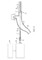
図5に示すように、患者の頭蓋骨の穿頭孔16を通して管状プローブシャフト22の遠位端を前進させることにより、頭蓋内凝血塊14の領域を患者の脳から除去することができる。シャフトの遠位先端の深さは、通常、シャフトまたは他のイントロデューサーデバイスのインジケーターを介して観察でき、さらに先端の位置は、たとえば、内視鏡カメラによる視覚化によって観察され、適切な位置にある場合、ブレードを作動させ、真空を調整して、患者を治療するために凝血塊または他の病変断片を断片化し除去することができる。管腔54内の螺旋状駆動シャフト36の存在は、凝血塊の断片をシャフトを通して吸引チューブ26に搬送するのを助け、そこから真空源28(図1)によってそれらを除去することができる。
As shown in FIG. 5, the area of
前述の例は、本発明の範囲を限定することを意図するものではない。すべての修正、同等物および代替物は本発明の範囲内にある。 The above examples are not intended to limit the scope of the invention. All modifications, equivalents and alternatives are within the scope of the present invention.
Claims (19)
管状プローブシャフトの遠位端を患者の頭蓋骨を通して病変部位まで前進させ;
プローブシャフトの遠位端にある要素を作動させて病変を切断または摩耗させて病変断片を生成し;及び
管状プローブシャフトを通して部位から病変断片を吸引すること、
を含む、方法。 A method of removing a lesion from a patient's brain, the method comprising:
Advance the distal end of the tubular probe shaft through the patient's skull to the lesion site;
Activating an element at the distal end of the probe shaft to cut or wear the lesion to produce lesion fragments; and aspirating the lesion fragments from the site through the tubular probe shaft,
Including the method.
管腔と患者の頭蓋骨の穴を通って病変部位に前進するように構成された遠位端とを有する管状プローブシャフト;
凝血塊を切断または摩耗させて病変断片を生成するように構成された管状プローブシャフトの遠位端の要素を、備え、
管状シャフト管腔の近位端は真空源に接続されて、管状プローブシャフトを通して部位から病変断片を吸引するように構成される、装置。 A device for removing lesions from a patient's brain,
A tubular probe shaft having a lumen and a distal end configured to be advanced through a hole in a patient's skull to a lesion site;
An element at the distal end of the tubular probe shaft configured to cut or abrade the clot to produce lesion fragments,
The device, wherein the proximal end of the tubular shaft lumen is connected to a vacuum source and is configured to aspirate lesion fragments from the site through the tubular probe shaft.
Applications Claiming Priority (3)
| Application Number | Priority Date | Filing Date | Title |
|---|---|---|---|
| US201762473779P | 2017-03-20 | 2017-03-20 | |
| US62/473,779 | 2017-03-20 | ||
| PCT/US2018/023348 WO2018175431A1 (en) | 2017-03-20 | 2018-03-20 | Methods and apparatus for removal of intracranial hemorrhage |
Publications (2)
| Publication Number | Publication Date |
|---|---|
| JP2020511269A true JP2020511269A (en) | 2020-04-16 |
| JP2020511269A5 JP2020511269A5 (en) | 2021-05-06 |
Family
ID=63521375
Family Applications (1)
| Application Number | Title | Priority Date | Filing Date |
|---|---|---|---|
| JP2019552106A Pending JP2020511269A (en) | 2017-03-20 | 2018-03-20 | Method and apparatus for removal of intracranial hemorrhage |
Country Status (7)
| Country | Link |
|---|---|
| US (2) | US10716590B2 (en) |
| EP (1) | EP3600089B1 (en) |
| JP (1) | JP2020511269A (en) |
| KR (1) | KR20200012828A (en) |
| AU (1) | AU2018239346B2 (en) |
| CA (1) | CA3057102A1 (en) |
| WO (1) | WO2018175431A1 (en) |
Cited By (1)
| Publication number | Priority date | Publication date | Assignee | Title |
|---|---|---|---|---|
| WO2022149396A1 (en) * | 2021-01-11 | 2022-07-14 | テルモ株式会社 | Medical care device |
Families Citing this family (8)
| Publication number | Priority date | Publication date | Assignee | Title |
|---|---|---|---|---|
| CN109730806B (en) | 2013-03-15 | 2023-01-24 | 伊瑟拉医疗公司 | Vascular treatment device and method |
| WO2017142874A2 (en) | 2016-02-16 | 2017-08-24 | Insera Therapeutics, Inc. | Aspiration devices and anchored flow diverting devices |
| US20220104839A1 (en) | 2017-10-16 | 2022-04-07 | Retriever Medical, Inc. | Clot Removal Methods and Devices with Multiple Independently Controllable Elements |
| US10258357B1 (en) | 2017-10-16 | 2019-04-16 | Michael Bruce Horowitz | Catheter based retrieval device with proximal body having axial freedom of movement |
| AU2021362245A1 (en) | 2017-10-16 | 2023-05-25 | Retriever Medical, Inc. | Clot removal methods and devices with multiple independently controllable elements |
| USD847864S1 (en) | 2018-01-22 | 2019-05-07 | Insera Therapeutics, Inc. | Pump |
| US10531883B1 (en) | 2018-07-20 | 2020-01-14 | Syntheon 2.0, LLC | Aspiration thrombectomy system and methods for thrombus removal with aspiration catheter |
| CN110141303B (en) | 2019-06-06 | 2022-09-02 | 赛诺神畅医疗科技有限公司 | Apparatus for breaking thrombus and sucking thrombus |
Citations (5)
| Publication number | Priority date | Publication date | Assignee | Title |
|---|---|---|---|---|
| WO1994024941A1 (en) * | 1993-04-30 | 1994-11-10 | Px Holding S.A. | Device for removing tissue by means of endoscopy |
| JP2001505460A (en) * | 1996-12-02 | 2001-04-24 | アンジオトラックス,インコーポレイテッド | Apparatus and method for performing surgery percutaneously |
| US20060095046A1 (en) * | 2004-11-01 | 2006-05-04 | Sdgi Holdings, Inc. | Devices and methods for explantation of intervertebral disc implants |
| JP2011502709A (en) * | 2007-11-12 | 2011-01-27 | メドトロニック・ゾーメド・インコーポレーテッド | System and method for surgical removal of brain tumors |
| US20160374717A1 (en) * | 2015-06-25 | 2016-12-29 | Covidien Lp | Tissue-removing catheter with reciprocating tissue-removing head |
Family Cites Families (21)
| Publication number | Priority date | Publication date | Assignee | Title |
|---|---|---|---|---|
| US4986807A (en) * | 1989-01-23 | 1991-01-22 | Interventional Technologies, Inc. | Atherectomy cutter with radially projecting blade |
| US6666874B2 (en) | 1998-04-10 | 2003-12-23 | Endicor Medical, Inc. | Rotational atherectomy system with serrated cutting tip |
| US8414543B2 (en) | 1999-10-22 | 2013-04-09 | Rex Medical, L.P. | Rotational thrombectomy wire with blocking device |
| US7344546B2 (en) * | 2000-04-05 | 2008-03-18 | Pathway Medical Technologies | Intralumenal material removal using a cutting device for differential cutting |
| WO2005084562A2 (en) | 2004-03-04 | 2005-09-15 | Straub Medical Ag | Catheter for sucking, fragmenting removing material extractable from blood vessels |
| CA2506961C (en) * | 2004-05-11 | 2013-05-07 | Inrad, Inc. | Core biopsy device |
| US7717853B2 (en) | 2005-06-24 | 2010-05-18 | Henry Nita | Methods and apparatus for intracranial ultrasound delivery |
| US20120330196A1 (en) | 2005-06-24 | 2012-12-27 | Penumbra Inc. | Methods and Apparatus for Removing Blood Clots and Tissue from the Patient's Head |
| US8852219B2 (en) * | 2006-10-04 | 2014-10-07 | Bayer Medical Care Inc. | Interventional catheters having cutter assemblies and differential cutting surfaces for use in such assemblies |
| EP2083877A2 (en) * | 2006-11-06 | 2009-08-05 | Aardvark Medical, LLC | Irrigation and aspiration device and method |
| US10307340B2 (en) * | 2007-11-21 | 2019-06-04 | Actuated Medical, Inc. | Devices for clearing blockages in artificial and natural lumens |
| US8246752B2 (en) | 2008-01-25 | 2012-08-21 | Clear Catheter Systems, Inc. | Methods and devices to clear obstructions from medical tubes |
| US8469981B2 (en) * | 2010-02-11 | 2013-06-25 | Ethicon Endo-Surgery, Inc. | Rotatable cutting implement arrangements for ultrasonic surgical instruments |
| US8764779B2 (en) | 2010-05-13 | 2014-07-01 | Rex Medical, L.P. | Rotational thrombectomy wire |
| US9055964B2 (en) | 2011-03-15 | 2015-06-16 | Angio Dynamics, Inc. | Device and method for removing material from a hollow anatomical structure |
| PL221914B1 (en) | 2011-10-25 | 2016-06-30 | Andrzej Sobolewski | Manually powered vehicle |
| US9603610B2 (en) * | 2013-03-15 | 2017-03-28 | DePuy Synthes Products, Inc. | Tools and methods for tissue removal |
| US10219814B2 (en) * | 2013-12-13 | 2019-03-05 | Rex Medical, L.P. | Aspiration system for thrombectomy procedures |
| CN106456207B (en) * | 2014-04-28 | 2020-09-29 | 密涅瓦外科有限公司 | Tissue resector with cutting wire, manually operated tissue resector system, and related methods |
| US10667836B2 (en) * | 2014-04-28 | 2020-06-02 | Boston Scientific Scimed, Inc. | Tissue resectors, hand operated tissue resecting systems, and associated methods |
| US10555834B2 (en) * | 2016-07-11 | 2020-02-11 | Novartis Ag | Vitrectomy probe with rotary cutter and associated devices, systems, and methods |
-
2018
- 2018-03-20 EP EP18770942.3A patent/EP3600089B1/en active Active
- 2018-03-20 KR KR1020197030602A patent/KR20200012828A/en not_active Application Discontinuation
- 2018-03-20 AU AU2018239346A patent/AU2018239346B2/en active Active
- 2018-03-20 CA CA3057102A patent/CA3057102A1/en active Pending
- 2018-03-20 WO PCT/US2018/023348 patent/WO2018175431A1/en unknown
- 2018-03-20 US US15/926,357 patent/US10716590B2/en active Active
- 2018-03-20 JP JP2019552106A patent/JP2020511269A/en active Pending
-
2020
- 2020-06-30 US US16/917,413 patent/US11389186B2/en active Active
Patent Citations (5)
| Publication number | Priority date | Publication date | Assignee | Title |
|---|---|---|---|---|
| WO1994024941A1 (en) * | 1993-04-30 | 1994-11-10 | Px Holding S.A. | Device for removing tissue by means of endoscopy |
| JP2001505460A (en) * | 1996-12-02 | 2001-04-24 | アンジオトラックス,インコーポレイテッド | Apparatus and method for performing surgery percutaneously |
| US20060095046A1 (en) * | 2004-11-01 | 2006-05-04 | Sdgi Holdings, Inc. | Devices and methods for explantation of intervertebral disc implants |
| JP2011502709A (en) * | 2007-11-12 | 2011-01-27 | メドトロニック・ゾーメド・インコーポレーテッド | System and method for surgical removal of brain tumors |
| US20160374717A1 (en) * | 2015-06-25 | 2016-12-29 | Covidien Lp | Tissue-removing catheter with reciprocating tissue-removing head |
Cited By (1)
| Publication number | Priority date | Publication date | Assignee | Title |
|---|---|---|---|---|
| WO2022149396A1 (en) * | 2021-01-11 | 2022-07-14 | テルモ株式会社 | Medical care device |
Also Published As
| Publication number | Publication date |
|---|---|
| US10716590B2 (en) | 2020-07-21 |
| EP3600089A4 (en) | 2020-12-30 |
| AU2018239346B2 (en) | 2020-11-26 |
| US20180263646A1 (en) | 2018-09-20 |
| WO2018175431A1 (en) | 2018-09-27 |
| US11389186B2 (en) | 2022-07-19 |
| EP3600089A1 (en) | 2020-02-05 |
| CA3057102A1 (en) | 2018-09-27 |
| EP3600089B1 (en) | 2023-09-06 |
| US20200330117A1 (en) | 2020-10-22 |
| KR20200012828A (en) | 2020-02-05 |
| AU2018239346A1 (en) | 2019-10-03 |
Similar Documents
| Publication | Publication Date | Title |
|---|---|---|
| EP3600089B1 (en) | Apparatus for removal of intracranial hemorrhage | |
| US10537669B2 (en) | Interventional catheters having cutter assemblies and differential cutting surfaces for use in such assemblies | |
| US11737778B2 (en) | Devices and methods for intrabody surgery | |
| US11141185B2 (en) | Devices and methods for intrabody surgery | |
| JP5866421B2 (en) | Surgical cutting instrument with distal suction function | |
| US6827725B2 (en) | Surgical instrument | |
| US8394078B2 (en) | Interventional catheters incorporating an active aspiration system | |
| US11547435B2 (en) | Cooled burr surgical instruments | |
| JP2019529053A (en) | Tissue excisor, manual tissue ablation system and related methods | |
| EP2034902A2 (en) | Tissue debulking device and method of using the same | |
| KR20130031275A (en) | Rotary cutting tool with improved cutting and reduced clogging on soft tissue and thin bone | |
| WO2009114259A1 (en) | Systems for surgical removal of tissue | |
| JP2002514460A (en) | Apparatus and method for exhausting refuse from body tissue | |
| AU2001277279B2 (en) | Ultrasonic medical device for tissue remodeling | |
| EP3801312A2 (en) | Devices and methods for intrabody surgery | |
| RU2797292C2 (en) | Device for intracorporeal surgery (versions) |
Legal Events
| Date | Code | Title | Description |
|---|---|---|---|
| A521 | Request for written amendment filed |
Free format text: JAPANESE INTERMEDIATE CODE: A523 Effective date: 20210322 |
|
| A621 | Written request for application examination |
Free format text: JAPANESE INTERMEDIATE CODE: A621 Effective date: 20210322 |
|
| A521 | Request for written amendment filed |
Free format text: JAPANESE INTERMEDIATE CODE: A523 Effective date: 20210323 |
|
| A977 | Report on retrieval |
Free format text: JAPANESE INTERMEDIATE CODE: A971007 Effective date: 20220131 |
|
| A131 | Notification of reasons for refusal |
Free format text: JAPANESE INTERMEDIATE CODE: A131 Effective date: 20220201 |
|
| A601 | Written request for extension of time |
Free format text: JAPANESE INTERMEDIATE CODE: A601 Effective date: 20220414 |
|
| A601 | Written request for extension of time |
Free format text: JAPANESE INTERMEDIATE CODE: A601 Effective date: 20220701 |
|
| A02 | Decision of refusal |
Free format text: JAPANESE INTERMEDIATE CODE: A02 Effective date: 20221004 |