JP2020505529A - Equipment for removing particulates from air - Google Patents
Equipment for removing particulates from air Download PDFInfo
- Publication number
- JP2020505529A JP2020505529A JP2019559411A JP2019559411A JP2020505529A JP 2020505529 A JP2020505529 A JP 2020505529A JP 2019559411 A JP2019559411 A JP 2019559411A JP 2019559411 A JP2019559411 A JP 2019559411A JP 2020505529 A JP2020505529 A JP 2020505529A
- Authority
- JP
- Japan
- Prior art keywords
- gas
- flow path
- face mask
- flow
- maze
- Prior art date
- Legal status (The legal status is an assumption and is not a legal conclusion. Google has not performed a legal analysis and makes no representation as to the accuracy of the status listed.)
- Pending
Links
Images


Classifications
-
- A—HUMAN NECESSITIES
- A62—LIFE-SAVING; FIRE-FIGHTING
- A62B—DEVICES, APPARATUS OR METHODS FOR LIFE-SAVING
- A62B23/00—Filters for breathing-protection purposes
- A62B23/02—Filters for breathing-protection purposes for respirators
- A62B23/025—Filters for breathing-protection purposes for respirators the filter having substantially the shape of a mask
-
- A—HUMAN NECESSITIES
- A62—LIFE-SAVING; FIRE-FIGHTING
- A62B—DEVICES, APPARATUS OR METHODS FOR LIFE-SAVING
- A62B23/00—Filters for breathing-protection purposes
- A62B23/02—Filters for breathing-protection purposes for respirators
-
- B—PERFORMING OPERATIONS; TRANSPORTING
- B01—PHYSICAL OR CHEMICAL PROCESSES OR APPARATUS IN GENERAL
- B01D—SEPARATION
- B01D45/00—Separating dispersed particles from gases or vapours by gravity, inertia, or centrifugal forces
- B01D45/04—Separating dispersed particles from gases or vapours by gravity, inertia, or centrifugal forces by utilising inertia
- B01D45/08—Separating dispersed particles from gases or vapours by gravity, inertia, or centrifugal forces by utilising inertia by impingement against baffle separators
-
- A—HUMAN NECESSITIES
- A41—WEARING APPAREL
- A41D—OUTERWEAR; PROTECTIVE GARMENTS; ACCESSORIES
- A41D13/00—Professional, industrial or sporting protective garments, e.g. surgeons' gowns or garments protecting against blows or punches
- A41D13/05—Professional, industrial or sporting protective garments, e.g. surgeons' gowns or garments protecting against blows or punches protecting only a particular body part
- A41D13/11—Protective face masks, e.g. for surgical use, or for use in foul atmospheres
Abstract
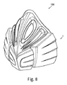
ガスから微粒子を除去する装置が提供される。装置は、ガス流れを受け入れる入口と、ガス流れが排出される出口と、ガス流れの入口と出口との間に延びる迷路流路とを備え、迷路流路は、ガスの流れを誘導して、ガス中の微粒子が衝突する微粒子を吸着するために配置された迷路流路の吸着面に衝突するように配置され、ガスが入口から出口に流れるにつれて、ガス中の微粒子は吸着面への衝突によってガスから除去される。装置はフェイスマスクの一部である。1m/秒未満の速度の大きさを有する装置内の空気量は、装置内の空気の総量の4%より大きい。【選択図】 図2An apparatus for removing particulates from a gas is provided. The apparatus comprises an inlet for receiving the gas flow, an outlet from which the gas flow is discharged, and a maze flow path extending between the gas flow inlet and the outlet, the maze flow path directing the gas flow, The particles in the gas are arranged to collide with the adsorption surface of the labyrinth flow path, which is arranged to adsorb the colliding particles, and as the gas flows from the inlet to the exit, the particles in the gas become Removed from gas. The device is part of a face mask. The amount of air in the device having a velocity magnitude of less than 1 m / sec is greater than 4% of the total amount of air in the device. [Selection diagram] Fig. 2
Description
本発明は、ガスから微粒子を除去するためのフェイスマスクなどの装置、及びガスから微粒子を除去するための関連方法に関する。ガスは、微粒子が除去される空気であり得る。これは例えば、呼吸中に微粒子が人の肺に入るのを防ぐためや、大気への放出を止めるためである。 The present invention relates to an apparatus such as a face mask for removing particulates from a gas, and to a related method for removing particulates from a gas. The gas can be air from which particulates are removed. This is, for example, to prevent particulates from entering the human lungs during breathing or to stop emission to the atmosphere.
空気及び他のガス中の微粒子は、触媒コンバータなどの化学的手段では容易に除去できないことが多いため、特に厄介な汚染形態である。都市部では、大気中の微粒子汚染の主な原因は自動車からの排気ガスであり、特にディーゼル車は、いわゆるPM10粒子及びより小さなサイズの粒子を含む大量の小さなサイズの粒子を生成することが知られている(PM5、PM2.5、PM1.0又はより小さい微粒子、即ち超微粒子)。
微粒子は、肺の奥深くまで浸透してから血流に入り込んで体の周りに分布する能力があるため、特に危険な形の大気汚染である。吸入すると、そのような微粒子は健康を非常に損なう可能性がある。それらは癌を引き起こす。国際癌研究機関(IARC)と世界保健機関(WHO)は、空中浮遊微粒子をグループ1の発がん物質と指定している。微粒子は急性及び慢性の呼吸器疾患(例えば、喘息及び慢性閉塞性肺疾患の悪化)、ならびに心血管疾患(脳卒中及び心臓発作など)を引き起こし得る。
Particulates in air and other gases are a particularly troublesome form of pollution because they are often not easily removed by chemical means such as catalytic converters. In urban areas, the main source of particulate contamination in the atmosphere is exhaust gases from vehicles, especially diesel vehicles are known to produce large amounts of small sized particles, including so-called PM10 particles and smaller sized particles. (PM5, PM2.5, PM1.0 or smaller particles, ie ultrafine particles).
Microparticles are a particularly dangerous form of air pollution because of their ability to penetrate deep into the lungs and then enter the bloodstream and distribute around the body. If inhaled, such particulates can be very harmful to health. They cause cancer. The International Agency for Research on Cancer (IARC) and the World Health Organization (WHO) have designated airborne particulates as
2013年に、ヨーロッパ9カ国で312,944人が参加した研究では、安全なレベルの粒子は存在せず、PM10粒子が10μg/m3増加するごとに肺がん発生率が22%上昇したことが明らかになった。より小さなPM2.5粒子は肺の組織内に深く浸透することができるの特に致命的であり、10μg/m3あたり36%の肺がんの増加がある。1999年のWHO大気汚染ガイドラインでは、これらの微粒子が10万人あたり6250人の早期死亡、年間300万人の死亡でアジアだけで100万人の死亡、1000人あたり5150の喘息症例、40%の喘息発作と、呼吸器疾患を伴う30%の入院に寄与すると提案している。より最近では、世界保健機関は、屋内空気汚染によって引き起こされた380万人の死に加えて、屋外空気汚染が2012年に370万人の死を引き起こしたと報告した。このような問題は、世界の貧困、発展途上国、先進国の両方で起こる。英国王立医科大学は、(2016年に)大気汚染で毎年4万人が英国で死亡していると報告した。 In 2013, a study of 312,944 people in nine European countries participated, is a safe level of particle does not exist, clear that lung cancer incidence has risen 22 percent each time the PM10 particles increases 10μg / m 3 Became. It is particularly lethal that smaller PM2.5 particles can penetrate deeply into lung tissue, with a 36% increase in lung cancer per 10 μg / m 3 . According to the 1999 WHO Air Pollution Guidelines, these microparticles show that 6250 premature deaths per 100,000 people, 3 million deaths per year in Asia alone, 1 million deaths in Asia alone, 5150 asthma cases per 1000 people, 40% It is proposed to contribute to asthma attacks and 30% hospitalization with respiratory disease. More recently, the World Health Organization reported that in addition to 3.8 million deaths caused by indoor air pollution, outdoor air pollution caused 3.7 million deaths in 2012. Such problems occur in both world poverty, developing and developed countries. The Royal College of Medicine reported that 40,000 people die each year in the UK from air pollution (in 2016).
従来技術にて、種々のタイプのフィルタが提案されてきた。例えば、医療用のフェイスマスクが米国特許出願公開第2008/295843号明細書に開示されており、歩行者及び自転車用のフェイスマスクにおいて同様のフィルタリングシステムが提案されている。フィルターはその性質上、大きな粒子を除去するのに効果的である。しかしながら、フィルターは、フィルター材料の開口部を通って嵌合することができる小さい微粒子に対してはそれほど効果的ではない。より細かいグレードの高いフィルターを使用し、接触時に微粒子を吸収することができる材料を使用することによって改良を行うことができるが、これは空気流に対する抵抗が著しく増加するという犠牲を払う。これは、例えば呼吸用のフェイスマスクに使用される場合、この種の装置を十分に活用することを不可能にする可能性がある。使用者は粒子状物質からある程度、保護されているが、使用者は大きな努力なしでは呼吸することができず、そして身体活動は非常に制限されている。同様に、かなりの圧力勾配はマスクの「周囲」に空気を引き込み、その効力を低下させる。最終的に、吸収性材料は粒子又は水蒸気/凝縮物で急速に飽和することがあり、結果として効力が低下し、そして容易に再使用することができないかもしれない。 Various types of filters have been proposed in the prior art. For example, a medical face mask is disclosed in U.S. Patent Application Publication No. 2008/295843, and similar filtering systems have been proposed for pedestrian and bicycle face masks. Filters, by their nature, are effective at removing large particles. However, filters are not as effective on small particulates that can fit through openings in the filter material. Improvements can be made by using finer, higher grade filters and by using materials that can absorb particulates on contact, but at the expense of a significant increase in resistance to air flow. This may make it impossible to make full use of such devices, for example when used in respiratory face masks. Although the user is somewhat protected from particulate matter, the user cannot breathe without great effort and physical activity is very limited. Similarly, significant pressure gradients draw air into the "perimeter" of the mask, reducing its effectiveness. Finally, the absorbent material may quickly become saturated with particles or water vapor / condensate, resulting in reduced efficacy and may not be easily reusable.
他の提案が成されてきた。中国特許103933682号においては、空気を処理するための装置は、水バブラーシステムと組み合わせた迷路流路からなる。迷路流路の壁は吸収性材料でできている。中国特許103933682号に従って、水と、ガスが流れなければならない複雑な流路との組み合わせは、より大きい粒子及びより小さい粒子の両方が吸収によって除去されるという結果をもたらす。しかし、水に空気を通す必要性はガスの流れにかなりの抵抗を加え、そしてこれもまた使用者が呼吸するために余分な努力をする必要があることを意味する。更に、中国特許103933682号の装置は、大きくて扱いにくく、水溜めの故に装置を直立に維持することを使用者に要求する。その結果、装置個人的な使用に開示されているけれども、特にサイクリングやランニングのようなより激しい身体活動の間、明らかにそれほど携帯性がなくあるいは着用可能ではない。 Other proposals have been made. In Chinese Patent No. 109333682, the device for treating air consists of a maze channel in combination with a water bubbler system. The walls of the maze channel are made of an absorbent material. According to Chinese Patent No. 109333682, the combination of water and the complex flow path through which the gas has to flow results in that both larger and smaller particles are removed by absorption. However, the need to air the water adds considerable resistance to the gas flow, which also means that the user needs to make extra effort to breathe. Further, the device of Chinese Patent No. 109333682 is bulky and cumbersome and requires the user to keep the device upright due to the sump. As a result, although disclosed for personal use of the device, it is clearly less portable or wearable, especially during more intense physical activity such as cycling and running.
直接呼吸されるべき空気以外の他のガスから微粒子を除去するための装置も公知である。例えば、汚染物質が大気に入るのを防ぐために、排ガスから微粒子を除去するためのシステムが提案されてきた。同じ欠点が流動抵抗に関しても生じ、そして既知の製品は、特により小さいサイズの微粒子に対しては十分に効果的ではないので、微粒子をより効果的に除去することに対する要求が継続している。 Devices for removing particulates from gases other than air to be breathed directly are also known. For example, systems have been proposed for removing particulates from exhaust gases to prevent contaminants from entering the atmosphere. The same disadvantages arise with respect to flow resistance, and the demand for more effective removal of particulates continues, as known products are not sufficiently effective, especially for smaller sized particulates.
それ故に、例えばフェイスマスクまたは同様のものを使用して身体への進入点で微粒子を除去することによって、または排気ガス等の処理を通して微粒子が生成されるときに除去することによって空気から及び他のガスからも微粒子を除去するための改良された方法に対する明らかなニーズがある。 Thus, for example, by removing particulates at the point of entry into the body using a face mask or the like, or by removing particulates as they are produced through processing such as exhaust gas, and other There is a clear need for improved methods for removing particulates from gases.
第1の態様から見て、本発明はガスから微粒子(例えば、都市公害)を除去する装置を提供し、装置はガス流れを受け入れる入口と、ガス流れが排出される出口と、入口と出口との間に延び、ガス流れの通路である迷路流路とを備える。
迷路流路は、(使用時に)ガスの流れを誘導して、ガス中の微粒子が衝突する微粒子を吸着するために配置された迷路流路の吸着面に衝突するように配置され、ガスが入口から出口に流れるにつれて(使用時に)、ガス中の微粒子は吸着面への衝突によってガスから除去され、及び/又は微粒子がそれらに付着するように微粒子を吸着面にごく接近させる。
Viewed from a first aspect, the present invention provides an apparatus for removing particulates (e.g., urban pollution) from a gas, the apparatus comprising an inlet for receiving a gas stream, an outlet from which the gas stream is discharged, an inlet and an outlet. And a maze flow path which is a gas flow path.
The maze flow path is arranged so as to guide the flow of gas (when used) so that the fine particles in the gas collide with the adsorbing surface of the maze flow path arranged to adsorb the colliding fine particles. As they flow from the outlet to the outlet (in use), particulates in the gas are removed from the gas by impact on the adsorption surface and / or bring the particles into close proximity to the adsorption surface so that the particles adhere to them.
第2の態様において、本発明はガスから微粒子を除去する方法を提供する。方法は、ガスから微粒子を除去する装置を配備するステップであって、装置は、ガス流れを受け入れる入口と、ガス流れが排出される出口と、入口と出口との間に延び、ガス流れの通路である迷路流路とを備えるステップと、入口から出口へガス流れを通過させるステップとを備える。迷路流路は、ガスの流れを誘導して、ガス中の微粒子が衝突する微粒子を吸着するために配置された迷路流路の吸着面に衝突させ、ガスが入口から出口に流れるにつれて、ガス中の微粒子は吸着面への衝突によってガスから除去され、及び/又は微粒子がそれらに付着するように微粒子を吸着面にごく接近させる。 In a second aspect, the present invention provides a method for removing particulates from a gas. The method includes providing an apparatus for removing particulates from a gas, the apparatus including an inlet for receiving a gas flow, an outlet for discharging the gas flow, and a gas flow passage extending between the inlet and the outlet. And a step of passing the gas flow from the inlet to the outlet. The maze channel guides the flow of the gas and causes the particles in the gas to collide with the adsorbing surface of the maze channel arranged to adsorb the colliding particles.As the gas flows from the inlet to the outlet, the gas flows through the gas. These particles are removed from the gas by collision with the adsorption surface and / or bring the particles very close to the adsorption surface so that the particles adhere to them.
本発明の発明者らは、ガス中の微粒子、即ち固体粒子は、粒子が衝突するように位置する吸着面及び/又は流路を設けることによってガス流れから効果的に除去されることができることに気付いた。微粒子が吸着面に衝突することにより、ガス流れから微粒子を除去する。微粒子は、迷路流路の吸着面上への吸着によってガスから除去される。 The inventors of the present invention have found that fine particles in a gas, i.e., solid particles, can be effectively removed from a gas stream by providing an adsorption surface and / or a channel located where the particles collide. Noticed. The particles collide with the adsorption surface, thereby removing the particles from the gas stream. Fine particles are removed from the gas by adsorption on the adsorption surface of the maze channel.
本発明者らは、装置をフェイスマスクに使用して固体微粒子を除去できるように(例えば許容可能な圧力降下とともに適切な大きさで)配置できることに気付いた。
従って、本発明の第3の態様では、ガスから固体微粒子を除去する装置を備えたフェイスマスクを提供する。装置は、装置はガス流れを受け入れる入口と、ガス流れが排出される出口と、入口と出口との間に延び、ガス流れの通路である迷路流路とを備え、迷路流路は、ガスの流れを誘導して、ガス中の微粒子が衝突する微粒子を吸着するために配置された迷路流路の吸着面に衝突するように配置され、ガスが入口から出口に流れるにつれて、ガス中の微粒子は吸着面への衝突によってガスから除去される。
The present inventors have realized that the device can be used to remove solid particulates using a face mask (e.g., of an appropriate size with an acceptable pressure drop).
Accordingly, a third aspect of the present invention provides a face mask including a device for removing solid fine particles from a gas. The device includes an inlet for receiving the gas flow, an outlet from which the gas flow is discharged, and a maze flow path extending between the inlet and the outlet and being a passage for the gas flow, wherein the maze flow path includes a gas flow path. It is arranged to guide the flow so that the particles in the gas collide with the adsorbing surface of the maze channel arranged to adsorb the colliding particles, and as the gas flows from the inlet to the outlet, the particles in the gas become It is removed from the gas by collision with the adsorption surface.
本発明の第4の態様では、ガスから微粒子を除去する方法を提供する。方法は、ガスから微粒子を除去する装置を備えたフェイスマスクを配備するステップであって、装置は、ガス流れを受け入れる入口と、ガス流れが排出される出口と、入口と出口との間に延び、ガス流れの通路である迷路流路とを備えるステップと、入口から出口へガス流れを通過させるステップとを備える。迷路流路は、ガスの流れを誘導して、ガス中の微粒子が衝突する微粒子を吸着するために配置された迷路流路の吸着面に衝突させ、ガスが入口から出口に流れるにつれて、ガス中の微粒子は吸着面への衝突によってガスから除去される。
本発明の発明者らはまた、使用時に、1m/秒未満の速度、及び/又は平均入力空気流速度の10%未満の大きさの速度を有する装置内の空気量が、装置内の空気の総量の4%より大きいと、微粒子を除去する効率は改善されることに気付いた。
According to a fourth aspect of the present invention, there is provided a method of removing particulates from a gas. The method comprises providing a face mask with a device for removing particulates from a gas, the device extending between an inlet for receiving a gas flow, an outlet for discharging the gas flow, and the inlet and outlet. A maze flow path that is a gas flow path, and a step of passing the gas flow from an inlet to an outlet. The maze channel guides the flow of the gas and causes the particles in the gas to collide with the adsorbing surface of the maze channel arranged to adsorb the colliding particles.As the gas flows from the inlet to the outlet, the gas flows through the gas. Are removed from the gas by collision with the adsorption surface.
The inventors of the present invention also suggest that, in use, the amount of air in the device having a velocity of less than 1 m / sec and / or a velocity of less than 10% of the average input airflow velocity will cause the amount of air in the It has been found that above 4% of the total amount, the efficiency of removing particulates is improved.
従って、本発明の第5の態様では、ガスから微粒子を除去する装置を提供する。装置は、装置はガス流れを受け入れる入口と、ガス流れが排出される出口と、入口と出口との間に延び、ガス流れの通路である迷路流路とを備え、迷路流路は、ガスの流れを誘導して、ガス中の微粒子が衝突する微粒子を吸着するために配置された迷路流路の吸着面に衝突するように配置され、ガスが入口から出口に流れるにつれて、ガス中の微粒子は吸着面への衝突によってガスから除去され、使用時に1m/秒未満の速度、及び/又は平均入力空気流速度の10%未満の大きさの速度を有する装置内の空気量は、装置内の空気の総量の4%より大きい。 Accordingly, a fifth aspect of the present invention provides an apparatus for removing particulates from a gas. The device includes an inlet for receiving the gas flow, an outlet from which the gas flow is discharged, and a maze flow path extending between the inlet and the outlet and being a passage for the gas flow, wherein the maze flow path includes a gas flow path. It is arranged to guide the flow so that the particles in the gas collide with the adsorbing surface of the maze channel arranged to adsorb the colliding particles, and as the gas flows from the inlet to the outlet, the particles in the gas become The amount of air in the device that is removed from the gas by impact on the adsorption surface and has a velocity in use of less than 1 m / sec and / or a magnitude of less than 10% of the average input air flow velocity is the air in the apparatus Is greater than 4% of the total amount of
本発明の第6の態様では、ガスから微粒子を除去する方法を提供する。方法は、ガスから微粒子を除去する装置を配備するステップであって、装置は、ガス流れを受け入れる入口と、ガス流れが排出される出口と、入口と出口との間に延び、ガス流れの通路である迷路流路とを備えるステップと、入口から出口へガス流れを通過させるステップとを備える。迷路流路は、ガスの流れを誘導して、ガス中の微粒子が衝突する微粒子を吸着するために配置された迷路流路の吸着面に衝突させ、ガスが入口から出口に流れるにつれて、ガス中の微粒子は吸着面への衝突によってガスから除去され、使用時に1m/秒未満の速度、及び/又は平均入力空気流速度の10%未満の大きさの速度を有する装置内の空気量は、装置内の空気の総量の4%より大きい。 In a sixth aspect of the present invention, a method is provided for removing particulates from a gas. The method includes providing an apparatus for removing particulates from a gas, the apparatus including an inlet for receiving a gas flow, an outlet for discharging the gas flow, and a gas flow passage extending between the inlet and the outlet. And a step of passing the gas flow from the inlet to the outlet. The maze channel guides the flow of the gas and causes the particles in the gas to collide with the adsorbing surface of the maze channel arranged to adsorb the colliding particles.As the gas flows from the inlet to the outlet, the gas flows through the gas. Particulates are removed from the gas by impact on the adsorption surface and the amount of air in the device having a velocity in use of less than 1 m / s and / or a magnitude of less than 10% of the average input air flow velocity is reduced by the apparatus. Greater than 4% of the total amount of air inside.
微粒子は、主に装置の表面に吸着させることによってガス流れから除去される。この吸着は装置の表面に衝突(即ち、打撃)したときに生じる。境界層(即ち、壁に隣接する静止層)が薄いとき、及び/又は装置内に十分な量、例えば4%以上の蓄積空気があるとき、装置の表面上の微粒子のより多くの衝突が起こり得る。微粒子の堆積率は、境界層の厚さが減少するにつれて、及び/又は遅い流れの量が増加するにつれて増加する。乱流が大きいほど境界層は薄くなる。装置を通る空気流れを連続的に遮断することによって乱流を増加させることができる。 Particulates are removed from the gas stream primarily by adsorption on the surface of the device. This adsorption occurs when the device strikes (ie, hits) the surface of the device. When the boundary layer (i.e., the stationary layer adjacent to the wall) is thin and / or when there is a sufficient amount of stored air in the device, e.g., 4% or more, more collisions of particulates on the surface of the device occur. obtain. The particulate deposition rate increases as the thickness of the boundary layer decreases and / or as the amount of slow flow increases. The greater the turbulence, the thinner the boundary layer. Turbulence can be increased by continuously blocking the air flow through the device.
壁への微粒子の衝突量が増加すると吸着量が増加し、これは境界層の厚さが減少するにつれて、及び/又は遅い流れの体積が増加するにつれて発生する。
流路方向の変更及び遅い流れを伴う領域の形成を利用して、衝突/保持事象の発生率を最大にすることができる。
Increasing amounts of particles impinging on the wall increase adsorption, which occurs as the thickness of the boundary layer decreases and / or as the volume of the slow flow increases.
Changing the flow direction and creating regions with slow flow can be used to maximize the incidence of collision / retention events.
ガス流れからの微粒子の除去及び微粒子の壁への吸着は、壁への微粒子の流束によって特徴付けられる。壁上の微粒子の密度は(微粒子が壁と衝突するとすぐに吸着されるので)ゼロであり得、壁からある距離でゼロ以外の値を有し得る。壁でのゼロ値と壁から遠く離れた非ゼロ密度との間の差は「密度境界層」と呼ばれることがあり、密度境界層はある程度の厚さを有する。壁への粒子流束は、密度境界層の厚さが最小化されるとき、及び/又は遅い流れの量が最適化されるときに最大化され得る。 Removal of particulates from gas streams and adsorption of particulates to walls is characterized by the flux of particulates on the walls. The density of the particles on the wall may be zero (since the particles are adsorbed as soon as they hit the wall) and may have a non-zero value at some distance from the wall. The difference between the zero value at the wall and the non-zero density far away from the wall is sometimes referred to as the "density boundary layer," which has a certain thickness. Particle flux to the wall can be maximized when the density boundary layer thickness is minimized and / or when the amount of slow flow is optimized.
密度境界層は、(i)密度境界層の発達を止めるために障壁で流れを遮断することによって層を最小化することができる、何故ならそうでなければ連続的に成長する可能性があるからである。(ii)乱流は密度境界層を減少させるので、乱流のレベルを増加させるために障壁で流れを遮断することによって層を最小化することができる。及び/又は(iii)粗面化又はテクスチャード加工の表面を使用することによって、密度境界層を最小化することができる、何故なら粗さが壁への密度境界層の付着に寄与することがあり、それによって密度境界層の発達を減少させることがあるからである。 The density boundary layer can be minimized by (i) blocking the flow with a barrier to stop the development of the density boundary layer, because otherwise it could grow continuously It is. (ii) Turbulence reduces the density boundary layer, so the layer can be minimized by blocking the flow with a barrier to increase the level of turbulence. And / or (iii) by using a roughened or textured surface, the density boundary layer can be minimized, because roughness can contribute to the adhesion of the density boundary layer to the wall. Because it can reduce the development of the density boundary layer.
密度境界層は、「粘性境界層」内に含まれていてもよい。この粘性境界層は、壁におけるゼロ値と非ゼロ値または「バルク」値との間の距離によって定義することができる。粘性境界層は気流速度に関係し、一方、密度境界層は密度に関係する。密度境界層を減じるとした上記の3つの要素は、「粘性境界層」を減じ、このようにして「密度境界層」を減じる。 The density boundary layer may be included in the “viscous boundary layer”. This viscous boundary layer can be defined by the distance between zero and non-zero or "bulk" values at the wall. The viscous boundary layer is related to airflow velocity, while the density boundary layer is related to density. The above three factors that reduce the density boundary layer reduce the "viscous boundary layer" and thus the "density boundary layer".
更に又これに代えて、微粒子の除去は、装置が使用されているときに装置内に十分な量の遅い流れを有することによって改善され得る。遅い流れの量が増加するにつれて、装置を通って流れるガスから除去される微粒子の割合が増加する。
遅い流れの量は、装置の総量の少なくとも4%、または少なくとも8%であり得る。
本発明は、吸着面への衝突により、空気から小さな微粒子(特に10ミクロン(PM10)より小さい、または1ミクロン(PM1)より小さい微粒子)を除去するための装置を提供する。
Still further alternatively, particulate removal can be improved by having a sufficient amount of slow flow through the device when the device is in use. As the amount of slow flow increases, the percentage of particulate removed from the gas flowing through the device increases.
The amount of slow flow may be at least 4%, or at least 8% of the total volume of the device.
The present invention provides an apparatus for removing small particles (particularly particles smaller than 10 microns (PM 10 ) or smaller than 1 micron (PM 1 )) from air by collision with an adsorption surface.
装置は、少なくとも30%、少なくとも35%又は少なくとも39%のPM1粒子を除去するように構成されている。
従って、この装置は、人が燃焼関連の粒子状物質及び/又は大気エアロゾルを吸入するのを防ぐために使用することができる。
迷路流路は、迷路流路を通るガス流れ中のバルク乱流を増大させるように、及び/又は装置内の遅い流れの量を増大させるように構成される。装置内で引き起こされる乱気流は、装置を通って流れるガスから微粒子を除去するか又は除去するのを助けるために使用され得る。
迷路流路は、発達した境界層の形成を防ぐように構成され得る。
Apparatus, at least 30%, and is configured to remove at least 35% or at least 39% of the PM 1 particles.
Thus, the device can be used to prevent a person from inhaling combustion-related particulate matter and / or atmospheric aerosols.
The maze flow path is configured to increase bulk turbulence in the gas flow through the maze flow path and / or to increase the amount of slow flow in the device. Turbulence created in the device may be used to remove or assist in removing particulates from the gas flowing through the device.
The maze channel may be configured to prevent the formation of a developed boundary layer.
発達した境界層の形成を防止すること及び/又はバルク乱流を増大させることは、衝突率を増大させる。
遅い流れの量を増やすと、空気流れから落下する懸濁粒子の数が増える可能性があり、それによって装置によって除去され得る。
迷路流路は、流れ方向を変化させながら、複数の曲がり角及び/又は分岐部を通り及び/又は通過するガス流れを誘導する、又は使用時に誘導するように構成され得る。従って、迷路流路は、空気が装置を通って直線的に移動するのを妨げることができ、換言すれば、ガスは曲がりくねった流路を辿る。流れ方向のこれらの変化は、前の流れ方向に対して垂直または同様に反対の任意の方向であり得る。例えば、新しい流れ方向と前の流れ方向との間の角度は、少なくとも(又は約)90度であり得る。これは、粒子を衝撃によって除去することができるようにガスを壁に衝突させるためである。これは、例えば、衝突をもたらす乱流の増加によるものであり得る。
Preventing the formation of a developed boundary layer and / or increasing bulk turbulence increases the collision rate.
Increasing the amount of slow flow can increase the number of suspended particles falling from the air stream, which can be removed by the device.
The maze flow path may be configured to direct a gas flow through and / or through a plurality of turns and / or branches while changing the flow direction. Thus, the maze flow path can prevent air from moving linearly through the device, in other words, the gas follows a tortuous flow path. These changes in flow direction can be in any direction perpendicular to or similar to the previous flow direction. For example, the angle between the new flow direction and the previous flow direction can be at least (or about) 90 degrees. This is because the gas impinges on the wall so that the particles can be removed by impact. This may be due, for example, to increased turbulence leading to collisions.
曲がり角はより大きな微粒子(より大きな慣性を有する)が壁に衝突することを引き起こす、何故なら粒子は表面に打撃する前に、ガスの流れによって方向が変わらないためである。曲がり角が乱流を増やし、小さな粒子が乱流渦を通って円を描くように閉じ込められるため、より小さな粒子が堆積する可能性がある。
装置は、流れ方向の曲がり角の間(例えば、流路の直線部分)に遅い流れの領域があるように配置されてもよい。これは、流路内にバッフルを配置することによって達成される。微粒子は、遅い流れでこれらの領域から落下する微粒子によって空気流れから除去され得る。これらの遅い流れの領域内の微粒子は、装置の表面に引き寄せられ及び/又は付着することがあり、及び/又は空気流れから沈殿することがある。
迷路流路の壁は、主流方向に沿って延在する面と、(例えばその面に続く)ガス流れに対して(例えば、ガス流れ内に又はガス流れから離れるように)少なくとも90度である面とを含み、ガス流れ内の微粒子は迷路流路の壁に衝突する。
The bend causes larger particles (with greater inertia) to hit the wall because the particles are not redirected by the gas flow before striking the surface. Smaller particles may accumulate as the bend increases turbulence and small particles are trapped in a circular motion through the turbulent vortices.
The device may be arranged such that there is a region of slow flow between the turns in the flow direction (eg, a straight section of the flow path). This is achieved by placing a baffle in the flow path. Particulates can be removed from the air stream by particles falling from these areas with a slow flow. Particles in these slow flow regions may be attracted and / or adhere to the surface of the device and / or may settle out of the air flow.
The wall of the maze flow path is at least 90 degrees relative to the plane extending along the main flow direction and the gas flow (e.g., following that plane) (e.g., into or away from the gas flow). Particles in the gas stream impinge on the walls of the maze flow path.
従って、本発明の第7の態様では、ガスから微粒子を除去する装置を提供する。装置は、装置はガス流れを受け入れる入口と、ガス流れが排出される出口と、入口と出口との間に延び、ガス流れの通路である迷路流路とを備え、迷路流路は、ガスの流れを誘導して、流れの方向を変えながら、ガスの流れは複数の曲がり角及び/又は分岐部を通り、及び/又は通過し、迷路流路の壁は、主流方向に沿って延びる面と、それに続いてガス流れを妨害する(例えば、ガスの流れに対して少なくとも90度の角度をなす)面とを含み、(使用時に)迷路流路の壁に微粒子が衝突する率を増加させ、迷路流路の壁は吸着面に接触する衝突した微粒子を吸着するように配置され、ガスが入口から出口に流れるにつれて、ガス中の微粒子は吸着面への衝突によってガスから除去される。 Accordingly, a seventh aspect of the present invention provides an apparatus for removing particulates from a gas. The device includes an inlet for receiving the gas flow, an outlet from which the gas flow is discharged, and a maze flow path extending between the inlet and the outlet and being a passage for the gas flow, wherein the maze flow path includes a gas flow path. Directing the flow and changing the direction of the flow, the gas flow passes through and / or through a plurality of bends and / or branches, the wall of the maze flow path having a surface extending along the main flow direction; A surface that obstructs the gas flow (eg, at an angle of at least 90 degrees to the gas flow) to increase the rate at which particulates impinge upon the walls of the maze flow path (when in use); The walls of the flow path are arranged to adsorb the colliding particles that contact the adsorption surface, and as the gas flows from the inlet to the outlet, the particles in the gas are removed from the gas by collision with the adsorption surface.
第8の態様において、本発明はガスから微粒子を除去する方法を提供する。方法はガスから微粒子を除去する装置を配備するステップであって、装置は、ガス流れを受け入れる入口と、ガス流れが排出される出口と、入口と出口との間に延びてガスが通過する迷路流路とを備えるステップと、入口から出口へ装置を通るガス流れを通過させるステップとを備え、
迷路流路は、流れ方向を変化させながら、複数の曲がり角及び/又は分岐部を通り及び/又は通過するガス流れを誘導し、迷路流路の壁は、主流方向に沿って並ぶ及び/又は延びる面と、それに続く流れの主流方向に対向する(例えば、少なくとも90度回転した)面とを含み、ガスの流れを遮断して、発達した境界層の形成を防ぎ、バルク乱流を増大させるために、(使用中に)迷路流路の壁に衝突するガス流れ中の微粒子の衝突率を増大させる。
迷路流路の壁は吸着面に接触する衝突した微粒子を吸着するように配置され、ガスが入口から出口に流れるにつれて、ガス中の微粒子は吸着面への衝突によってガスから除去される。
In an eighth aspect, the present invention provides a method for removing particulates from a gas. The method comprises providing a device for removing particulates from a gas, the device comprising an inlet for receiving a gas flow, an outlet for discharging the gas flow, and a maze extending between the inlet and the outlet for passing the gas. Providing a gas flow through the device from an inlet to an outlet, comprising the steps of:
The maze channel guides the gas flow through and / or through multiple turns and / or branches while changing the flow direction, and the walls of the maze channel line and / or extend along the main flow direction To include a surface and a surface opposing (e.g., rotated by at least 90 degrees) the main flow direction of the subsequent flow to block gas flow, prevent formation of a developed boundary layer, and increase bulk turbulence. In addition, it increases the collision rate of particulates in the gas stream that impinges on the walls of the maze channel (during use).
The walls of the maze flow path are arranged to adsorb the colliding particulates that contact the adsorption surface, and as the gas flows from the inlet to the outlet, the particulates in the gas are removed from the gas by collision with the adsorption surface.
第9の態様において、本発明はガスから微粒子を除去する装置を提供する。装置は、装置はガス流れを受け入れる入口と、ガス流れが排出される出口と、入口と出口との間に延び、ガス流れの通路である迷路流路とを備え、迷路流路は、流れ方向を少なくとも90度に変化させながら、複数の曲がり角及び/又は分岐部を通り及び/又は通過するガス流れを誘導する。迷路流路の壁は、主流方向に沿って延びる面と、それに続くガス流れ内に又はガス流れから離れるように少なくとも90度回転した面とを含み、ガス流れ内の微粒子は迷路流路の壁に衝突する。迷路流路の壁は吸着面に接触する衝突した微粒子を吸着するように配置され、ガスが入口から出口に流れるにつれて、ガス中の微粒子は吸着面への衝突によってガスから除去される。 In a ninth aspect, the present invention provides an apparatus for removing particulates from a gas. The apparatus comprises an inlet for receiving the gas flow, an outlet from which the gas flow is discharged, and a maze flow path extending between the inlet and the outlet and being a passage for the gas flow, wherein the maze flow path has a flow direction. To at least 90 degrees to induce a gas flow through and / or through a plurality of turns and / or branches. The wall of the maze flow path includes a surface extending along the main flow direction and a surface rotated at least 90 degrees into or away from the gas flow, wherein particulates in the gas flow are Collide with The walls of the maze flow path are arranged to adsorb the colliding particulates that contact the adsorption surface, and as the gas flows from the inlet to the outlet, the particulates in the gas are removed from the gas by collision with the adsorption surface.
本発明の装置に関して、公知の微粒子除去装置とは対照的に、微粒子を除去するための主な機構(即ち、除去された微粒子のうち最も大きな割合がこの機構によって除去される)は、吸着面への衝突などの吸着面への接触である。これは、濾過、微粒子と液体との接触、または多孔性表面などの吸収性表面との接触とは対照的である。発明者らは衝突のような接触を促進する幾何学的形状を有する迷路流路を壁での吸着と組み合わせて使用し、吸収を促進することで、ガスから微粒子、特に小さい微粒子を除去する際の装置の有効性を高めることができることを見出した。装置はまた、装置を通る圧力降下を最小にするように、即ち、装置からのガスの流れに対する抵抗を最小にするように構成されてもよい。圧力降下は、例えば140mmH2O未満であり得る。 For the device of the present invention, in contrast to known particle removal devices, the primary mechanism for removing particles (ie, the largest percentage of the removed particles is removed by this mechanism) is the adsorption surface. Contact with the adsorption surface such as collision with This is in contrast to filtration, contact of microparticles with a liquid, or contact with an absorbent surface, such as a porous surface. We use a maze channel with a geometry that promotes contact, such as a collision, in combination with adsorption at the wall to enhance absorption, thereby removing particulates, especially small particulates, from the gas. It has been found that the effectiveness of the device can be enhanced. The device may also be configured to minimize pressure drop through the device, ie, to minimize resistance to gas flow from the device. The pressure drop may be, for example 140mmH less than 2 O.
装置は、比較的低い圧力勾配で大きな流れ(例えば最大300/分)を可能にし得る。例えば、圧力降下は、70ミリバール未満、50ミリバール未満、25ミリバール未満、10ミリバール未満、または5ミリバール未満であり得る。この装置は、圧力降下が10ミリバール未満である間に、遅い流れの体積が4%を超える場合に人が呼吸する他の装置のフェイスマスク内の粒子を除去するために使用され得ることに気付いた。35%を超えるまたは39%を超えるPM1粒子の濾過を達成しながら、装置がこれらの制約を満たすように設計され得ることが見出された。装置内の遅い流れの最適量は、濾過と装置を通る圧力降下との間の妥協点であり得る。 The apparatus may allow for large flows (eg, up to 300 / min) with relatively low pressure gradients. For example, the pressure drop can be less than 70 mbar, less than 50 mbar, less than 25 mbar, less than 10 mbar, or less than 5 mbar. Note that this device can be used to remove particles in the face mask of other devices that humans breathe if the slow flow volume is greater than 4% while the pressure drop is less than 10 mbar. Was. While achieving filtration more than 35%, or greater than 39% PM 1 particles, apparatus was found that may be designed to meet these constraints. The optimal amount of slow flow in the device can be a compromise between filtration and pressure drop through the device.
例えば、遅い流れの量が4%を超えると2つの180度の曲がり角を備えた装置では、超微粒子(PM1)(ISO 12103−1 A1 Ultrafine Test Dustを表す)の除去量が40%以上になる可能性がある。流路内に2つの180°の曲がり角があっても、装置は例えば10ミリバール未満の低い圧力降下を有する。
遅い流速は、空気が1m/秒未満の速度の大きさを有するときとして定義することができる。
装置は、装置を通るガスの流量を増加させるためにファン/インペラー及び/又は(ノッチャー)動力装置を含むことができる。装置を通る空気流量を増加させると、堆積工程が改善され得る。
For example, slow in the amount of flow is more than 4% apparatus having a corner of two 180 degrees, ultrafine particles (PM 1) removal of (ISO 12103-1 A1 Ultrafine Test represents a Dust) is more than 40% Could be. Even with two 180 ° turns in the flow path, the device has a low pressure drop, for example less than 10 mbar.
Slow flow velocity can be defined as when the air has a velocity magnitude of less than 1 m / sec.
The device may include a fan / impeller and / or (notcher) power unit to increase the flow of gas through the device. Increasing the air flow through the device can improve the deposition process.
吸着とは表面への物質の付着である。この工程は、吸着剤の表面上に吸着質(分子、原子または粒子が蓄積されている)の膜を作り出す。これは物質は吸収剤の材料に浸透するかまたは吸収される吸収とは異なる。 Adsorption is the attachment of a substance to a surface. This process creates a film of adsorbate (accumulating molecules, atoms or particles) on the surface of the adsorbent. This is different from absorption where the substance penetrates or is absorbed by the material of the absorbent.
人間の呼吸器系は肺に吸い込まれるときに空気から微粒子を捕獲するために同じアプローチを使用するので、衝突面の使用は生物模倣に触発される。PM10粒子及びより小さいサイズの微粒子などの漸増する微粒子量の存在は、呼吸器系の能力を圧倒する可能性がある。しかし。ここで提案された装置は、装置内に少なくとも4%の量の遅い流れを有することなどによって、衝突に基づく微粒子の除去に適応して改善することができ、従って、空気をより安全に呼吸させるために使用可能である。提案された装置は、ガスから広範囲の固体及び液体汚染物質を除去することができ、そして装置の利点は、より小さい微粒子の除去に焦点を当てているが、そのような微粒子だけに限定されない。 Since the human respiratory system uses the same approach to capture particulates from air as it is inhaled into the lungs, the use of impact surfaces is inspired by biomimetic. The presence of increasing amounts of particulates, such as PM 10 particles and smaller sized particulates, can overwhelm the performance of the respiratory system. However. The device proposed here can be adapted and improved for the removal of particulates based on collisions, such as by having a slow flow of at least 4% in the device, thus allowing air to be breathed more safely Available for use. The proposed device is capable of removing a wide range of solid and liquid contaminants from gas, and the advantages of the device focus on the removal of smaller particulates, but are not limited to such particulates alone.
この装置は、「超微細」粒子(直径<1ミクロン)を含む、肉眼視可能な粒子(>1mm)から小さいPM2.5粒子(<2.5ミクロン直径)及びそれ以下の範囲にわたって吸入された液滴又は乾燥固体粒子を除去することができる。
装置は、装置を通過する空気中の粒子の90%超、または80%超または60%超、50%超、40%超、または35%超を除去することができる。
This device is inhaled from a range of macroscopic particles (> 1 mm), including "ultrafine" particles (<1 micron diameter) to small particles of PM 2.5 (<2.5 micron diameter) and below. Droplets or dry solid particles can be removed.
The device can remove more than 90%, or more than 80% or more than 60%, more than 50%, more than 40%, or more than 35% of the particles in the air passing through the device.
更に、微粒子は吸収ではなく吸着(衝撃による)によって保持されるから、微粒子は例えば水または他の溶媒で洗い流すことによって、迷路流路の表面から容易に洗浄することができる。装置の清掃は通常の動作モード中ではなく、むしろ装置が使用されておらず清掃されているときである。
従って、装置は、装置を水などの溶媒で洗浄することによって洗浄/更新される。
In addition, because the particles are retained by adsorption (by impact) rather than absorption, the particles can be easily washed off the surface of the maze channel, for example, by rinsing with water or another solvent. Cleaning of the device is not in the normal mode of operation, but rather when the device is not in use and is being cleaned.
Thus, the device is cleaned / renewed by cleaning the device with a solvent such as water.
装置はカートリッジタイプの装置にような再使用可能な装置であり、清掃用に取り外され、フェイスマスク又は他の空気清掃ユニットのような器具内に再挿入される。
装置は、迷路流路の清掃を可能にするために取り外し可能なカバー(装置の一側部であり得る)を有してもよい。これにより、便利な清掃が可能となる。
装置は、1日、1週間または1ヶ月などの特定の回数使用され、その後廃棄されるように構成された使い捨て装置であり得る。
迷路流路は、少なくとも部分的にボール紙の挿入物によって提供されてもよい。ボール紙の挿入物は、例えばフラットパックから開く格子を形成することができる。これをシェルに収容して装置を形成することができる。ボール紙は以下に記載する材料などを用いて被覆される。これにより、ボール紙の挿入物を複数回使用することができる。
The device is a reusable device, such as a cartridge-type device, which is removed for cleaning and reinserted into a tool such as a face mask or other air cleaning unit.
The device may have a removable cover (which may be one side of the device) to allow cleaning of the maze channel. This enables convenient cleaning.
The device can be a disposable device configured to be used a certain number of times, such as a day, a week, or a month, and then discarded.
The maze channel may be provided at least in part by a cardboard insert. The cardboard insert can form a grid that opens from a flat pack, for example. This can be housed in a shell to form the device. The cardboard is coated with the materials described below. This allows the cardboard insert to be used multiple times.
この装置は微粒子を吸収によって除去することはできない。例えば、装置はいかなる吸収性(例えば多孔質)表面を有していなくてもよい。あるいは、装置が吸収性表面を含む場合、微粒子を除去するための主な機構は吸着によるものであり得る。吸収性表面を持たない、または吸収が除去のための主要な機構ではないことの利点は、装置が清掃し易い表面を有することである。これにより、装置の耐用年数が延びる可能性がある。 This device cannot remove particulates by absorption. For example, the device may not have any absorbent (eg, porous) surface. Alternatively, if the device includes an absorbent surface, the primary mechanism for removing particulates may be by adsorption. An advantage of not having an absorbent surface, or that absorption is not the primary mechanism for removal, is that the device has a surface that is easy to clean. This can extend the useful life of the device.
第10の態様から見て、本発明はガスから微粒子を除去する装置を提供する。装置は、装置はガス流れを受け入れる入口と、ガス流れが排出される出口と、入口と出口との間に延び、ガス流れの通路である迷路流路とを備え、迷路流路は、ガスの流れを誘導して、ガス流れ中の微粒子が衝突する微粒子を堆積させるために(例えば、吸着によって)配置された迷路流路の堆積面に衝突するように配置され、ガスが入口から出口に流れるにつれて、ガス中の微粒子は堆積面への衝突によってガスから除去される。装置は入口から出口に連続したガス流路を有し、即ちいかなる部分も壁と壁とが異なる材料で構成されていなくても、ガスで連続的に満たされた容積を有することができる。例えば、ガスは流体を通過しない。 Viewed from a tenth aspect, the present invention provides an apparatus for removing particulates from a gas. The device includes an inlet for receiving the gas flow, an outlet from which the gas flow is discharged, and a maze flow path extending between the inlet and the outlet and being a passage for the gas flow, wherein the maze flow path includes a gas flow path. The gas flows from the inlet to the outlet, directing the flow so that the particles in the gas stream are arranged to impinge on the deposition surface of the maze channel arranged to deposit the impinging particles (e.g., by adsorption). As a result, fine particles in the gas are removed from the gas by collision with the deposition surface. The device has a continuous gas flow path from the inlet to the outlet, i.e. it can have a volume continuously filled with gas, even if no part is made of different materials. For example, gas does not pass through the fluid.
第11の態様にて、本発明はガスから微粒子を除去する方法を提供する。方法は、ガスから微粒子を除去する装置を配備するステップであって、装置は、ガス流れを受け入れる入口と、ガス流れが排出される出口と、入口と出口との間に延びてガスが通過する迷路流路とを備えるステップと、入口から出口へ装置を通るガス流れを通過させるステップとを備え、迷路流路は、ガスの流れを誘導して、ガス中の微粒子が衝突する微粒子を堆積するために(例えば、吸着によって)配置された迷路流路の堆積面に衝突させ、ガスが入口から出口に流れるにつれて、ガス中の微粒子は堆積面への衝突によってガスから除去される。装置は入口から出口に連続したガス流路を有し、即ちいかなる部分も壁と壁とが異なる材料で構成されていなくても、ガスで連続的に満たされた容積を有することができる。例えば、ガスは流体を通過しない。 In an eleventh aspect, the present invention provides a method for removing particulates from a gas. The method includes providing an apparatus for removing particulates from a gas, the apparatus including an inlet for receiving a gas flow, an outlet for discharging the gas flow, and a gas extending between the inlet and the outlet for passing the gas. Providing a flow of gas through the apparatus from an inlet to an outlet, wherein the flow guides the flow of the gas to deposit particulates that collide with particulates in the gas. For this reason, the labyrinth is arranged (for example, by adsorption) to impinge on the deposition surface, and as the gas flows from the inlet to the outlet, particulates in the gas are removed from the gas by collision with the deposition surface. The device has a continuous gas flow path from the inlet to the outlet, i.e. it can have a volume continuously filled with gas, even if no part is made of different materials. For example, gas does not pass through the fluid.
本発明の迷路流路は、装置の入口と出口との間にて、互いに平行に結合された複数の流路を含む。各流路は、流路自体の入口及び/又は出口を有する。或いは、各流路の入口及び出口の一方または両方が共通の入口または出口である。各流路は壁によって互いに分離されていてもよい。或いは、迷路流路は、入口と出口との間に延びる単一の流路(単一の流路内で(同時に)多くの異なる方向に流れることができるが)であってもよい。 The maze flow path of the present invention includes a plurality of flow paths connected in parallel with each other between an inlet and an outlet of the device. Each channel has its own inlet and / or outlet. Alternatively, one or both of the inlet and outlet of each channel is a common inlet or outlet. Each channel may be separated from one another by walls. Alternatively, the maze flow path may be a single flow path extending between the inlet and the outlet, although it can flow in many different directions (simultaneously) within a single flow path.
入口と出口との間の流路は蛇行流路であり得る。蛇行流路は、(正味のガス流に対して)互いに反対方向に延びる部分を有する。例えば、流路は1つまたは複数の180度の曲がり角を含む。主流(即ち、正味の流れ)方向は、装置の異なる部分において互いに反対であってもよい。これにより、装置の吸着/堆積表面上のガス中の粒子の衝突を引き起こすために長い流路及び方向変化を有しながら、装置をコンパクトにすることが可能になる。これはまた、微粒子の除去を助けるために迷路流路内の表面積を増大させるのを助け得る。迷路流路は蛇行流路であってもよい。 The flow path between the inlet and the outlet may be a serpentine flow path. The serpentine flow path has portions that extend in opposite directions (relative to the net gas flow). For example, the flow path includes one or more 180 degree turns. The mainstream (ie, net flow) directions may be opposite each other in different parts of the device. This allows the device to be compact while having long flow paths and directional changes to cause collisions of particles in the gas on the adsorption / deposition surface of the device. This may also help increase the surface area in the maze flow path to help remove particulates. The maze channel may be a meandering channel.
装置は空気流路を延ばすように構成され得る。これは、微粒子が装置から除去されるための長さ(従って、表面積)を増大させるためである。180度の曲がり角の数は、入口と出口が装置の両側に配置されるように偶数である。入口及び出口は、装置の反対側及び反対側の端部(即ち、装置の互いに反対側の対角部)にある。 The device may be configured to extend the air flow path. This is to increase the length (and thus the surface area) for particulates to be removed from the device. The number of 180 degree turns is even so that the inlet and outlet are located on both sides of the device. The inlet and outlet are at opposite and opposite ends of the device (ie, opposite diagonals of the device).
迷路流路を通る流路は、少なくとも2つ、3つ、4つ、5つ、6つ、8つ、9つまたは20つの分岐部及び/又は曲がり角を含み得る。例えば、流路は、少なくとも90度の方向に1−6回の変化を有してもよい。迷路流路を通る流路は、奇数の分岐部及び/又は曲がり角を含み得る。これは、入口と出口が互いに対向することができるようにするためである。分岐部及び/又は曲がり角は、少なくとも45度、少なくとも60度、または少なくとも90度である。より大きな数の曲がり角により、微粒子が吸着/堆積面と接触する可能性を高めることができる。従って、曲がり角の数は、除去する装置の効率と装置を通る許容可能な圧力降下との間の妥協点である。 The flow path through the maze flow path may include at least 2, 3, 4, 5, 6, 8, 9, or 20 branches and / or turns. For example, the flow path may have 1-6 changes in at least a 90 degree direction. The flow path through the maze flow path may include an odd number of branches and / or turns. This is so that the inlet and the outlet can face each other. The bifurcations and / or turns are at least 45 degrees, at least 60 degrees, or at least 90 degrees. A higher number of turns can increase the likelihood that the particulate will contact the adsorption / deposition surface. Thus, the number of turns is a compromise between the efficiency of the removing device and the acceptable pressure drop through the device.
分岐部が存在する場合、これらの分岐部はガスの流れを通すよりもむしろ微粒子の捕捉のためのものである。分岐部は、袋小路(即ち、行き止まり)、凹部及び/又は角部であってもよい。これらの分岐部は大量の遅い流れを生み出す可能性がある。
流路内の迷路流路の壁は、少なくとも45度、少なくとも60度、または少なくとも90度の範囲でガスの流れの中へ又はガスの流れから離れるように延びる面の複数の例を有し、例えば壁の表面には少なくとも10個又は少なくとも20個のそのような曲がり角があってもよい。
曲がり角の所望の数及び/又は遅い流れの量は、粒子の除去効率と装置を通る許容可能な圧力損失との間の所望のバランスに依存する。
If there are branches, these branches are for trapping particulates rather than for passing gas flow. The bifurcation may be a blind alley (ie, a dead end), a recess, and / or a corner. These branches can create large amounts of slow flow.
The wall of the maze channel within the channel has a plurality of examples of surfaces that extend into and away from the gas flow in a range of at least 45 degrees, at least 60 degrees, or at least 90 degrees; For example, the surface of the wall may have at least 10 or at least 20 such turns.
The desired number of turns and / or the amount of slow flow depends on the desired balance between particle removal efficiency and acceptable pressure drop through the device.
曲がり角のうねりは湾曲していてもよいし、縁のある角であってもよい。流れ方向の曲がり角、流れ方向へ/流れ方向からの分岐部、及び/又は壁の曲がり角は、迷路のような構造によって提供され得る(または提供する)。
バッフル、羽根、ペグなどの突起は、ガスが通過するチャネルの任意の数の面/壁から流路内またはそれを横切って延びるように設けられる。これらの突起は、迷路流路を形成してもよく、及び/又は迷路流路内に設けられてもよい。これらの突起は、流路内に曲がり角及び分岐部を提供/作成し、及び/又は追加の曲がり角及び分岐部を作成する。突起は、入口から出口への流れに大きな乱流を生じさせる可能性がある。突起は、遅い流れを伴う領域を作り出すことができる。
The undulations at the corners may be curved or have corners. The turn in the flow direction, the turn in / out of the flow direction, and / or the turn in the wall may be provided (or provided) by a maze-like structure.
Protrusions such as baffles, vanes, pegs, etc. are provided to extend into or across the flow path from any number of faces / walls of the channel through which the gas passes. These projections may form a maze channel and / or may be provided within the maze channel. These protrusions provide / create bends and branches in the flow path and / or create additional bends and branches. The protrusions can cause significant turbulence in the flow from the inlet to the outlet. The protrusions can create areas with slow flow.
突起、例えばバッフルは、空気流路に位置する、例えば吊るされている。突起は、各曲がり角まで、流路の少なくとも1つ、2つ、3つ、4つ、または全ての縁に沿って明確な視線が見られるように配置されてもよい。突起は、浮遊粒子が空気流れから落下するように、ある量の遅い流れを作り出すことによって微粒子を除去することができる。
各突起は、流路断面積の10%−90%、30−70%または約50%の間の流路内の面積を有する。
A protrusion, for example a baffle, is located in the air flow path, for example, is suspended. The protrusions may be arranged such that a clear line of sight is seen along at least one, two, three, four, or all edges of the flow path up to each turn. The protrusions can remove particulates by creating an amount of slow flow such that suspended particles fall from the air stream.
Each protrusion has an area within the flow channel between 10% -90%, 30-70% or about 50% of the flow channel cross-sectional area.
各突起間の間隔は、流路の断面直径の50%から300%の間であり得る。非円形流路の場合の直径は、流路の断面積に等しい断面積を有する円の直径である。
突起、例えばバッフルは、凹面と凸面の間の形状にすることができる。例えば、各バッフルの中心は、バッフルの幅の+/−75%、+/−50%、+/−25%、または+/−10%以下でその端部から偏向されてもよい(例えば、+/−75%の場合、バッフルが10mm×10mmの場合、中心はバッフルの端からどちらの方向にも7.5mm以下で偏向する)。
The spacing between each protrusion may be between 50% and 300% of the cross-sectional diameter of the channel. The diameter for a non-circular channel is the diameter of a circle having a cross-sectional area equal to the cross-sectional area of the channel.
The protrusion, for example a baffle, can be shaped between concave and convex. For example, the center of each baffle may be deflected from its end no more than +/- 75%, +/- 50%, +/- 25%, or +/- 10% of the width of the baffle (e.g., For +/- 75%, if the baffle is 10 mm x 10 mm, the center will deflect 7.5 mm or less from either end of the baffle in either direction).
流路内にて、突起、例えばバッフルを吊り下げる各部材の幅は、チャネルの幅の20%未満である。
例えばバッフル、羽根、ペグなどを含む突起は、空気流れを導き、及び/又は遅い流れの領域を生成する。幾つかの例において、迷路流路は人間の鼻の鼻甲介の骨の形状を模したペグなどの構造を含む。
突起は、例えば、コンマ形状またはc形状であり得る。
突起が曲面を有する場合、この曲面はガスの主流方向を向く。これにより、流路を通って流れるガスが曲面の凸面または凹面に当たるため、ガスに乱流が生じる。
突起は、ガスが直線的に流れることができる距離を減らすように配置されてもよい。
Within the channel, the width of each member that suspends the protrusion, eg, the baffle, is less than 20% of the width of the channel.
Protrusions, including, for example, baffles, vanes, pegs, etc., direct airflow and / or create regions of slow flow. In some examples, the maze channel includes a structure such as a peg that mimics the shape of the bones of the turbinates of the human nose.
The protrusions may be, for example, comma-shaped or c-shaped.
When the projection has a curved surface, the curved surface faces the main flow direction of the gas. Thereby, the gas flowing through the flow path hits the convex or concave surface of the curved surface, and thus a turbulent flow occurs in the gas.
The protrusions may be arranged to reduce the distance over which gas can flow linearly.
しかし、突起は流路の曲がり角の間に流路の区画の壁に沿って明確な視線を残す。これは装置を通る圧力降下を減らす。
突起の少なくとも幾つかは、ガスの通過のために入口と出口との間に延びる流路の表面(すなわち壁)に設けられる。
迷路流路は、堆積/吸着面への微粒子の衝突を最大にするように構成されてもよく、従って、迷路流路の幾何学形状は、ガス流れが連続的に中断されることを促進してもよい、即ち、ガス流れが迷路流路を通って直線的に移動することは不可能であり、流路を通って長距離移動することはできないのが好ましい。例えば、迷路流路内の直線通路は、長さが最大10mmである。
迷路流路内の直線通路(例えば、正味の流体の流れ方向)は、流路の幅(即ち、正味のガス流れ方向に対して垂直な寸法)の1−2倍または最大2−3倍であり得る。
However, the projections leave a clear line of sight along the walls of the compartment of the flow path during the bend of the flow path. This reduces the pressure drop through the device.
At least some of the projections are provided on a surface (ie, a wall) of a flow path that extends between an inlet and an outlet for gas passage.
The maze flow path may be configured to maximize the impact of particulates on the deposition / adsorption surface, and thus the geometry of the maze flow path facilitates continuous interruption of gas flow. Alternatively, the gas flow may not be able to move linearly through the maze flow path, and may not be able to travel long distances through the flow path. For example, a straight path in a maze flow path has a maximum length of 10 mm.
A straight path (e.g., net fluid flow direction) in the maze flow path is 1-2 or up to 2-3 times the width of the flow path (i.e., dimension perpendicular to the net gas flow direction). possible.
対象である微粒子のような小さな粒子は、壁に隣接して形成される「境界層」がより薄い場合、それらがより大きな速度で通過する表面上に堆積することを見出した。重要な変数間の関係は、第1の原理から説明することができる。境界層の厚さ(δ)及び乱流(Re)と流路の長さ(x)との間の単純化された(1次元)関係は、以下である。
δ=(0.382x)/Re1/5
Small particles, such as those of interest, have been found to deposit on surfaces where they pass at a greater rate if the "boundary layer" formed adjacent to the wall is thinner. The relationship between important variables can be explained from the first principle. The simplified (one-dimensional) relationship between boundary layer thickness (δ) and turbulence (Re) and channel length (x) is:
δ = (0.382x) / Re 1/5
δを減らすには、高い乱流(高いRe)と短い長さ(短いx)が必要である。従って、迷路流路は、流れ抵抗の過度の増加を回避しながら、Reを最大化し、最大流路長(x)を最小化するように構成されている。例えば、フェイスマスクの場合、装置は以下のように、人間の許容換気圧力低下の制限内で作動するように構成されている。進路方向の変更は、衝突/堆積(即ち、保持)事象の発生率を最大にするように利用される。
(圧力損失が大きい)高速では、境界層の厚さはより薄くなる可能性があり、したがって吸着/堆積はより高くなる。
To reduce δ, high turbulence (high Re) and short length (short x) are required. Thus, the maze channel is configured to maximize Re and minimize the maximum channel length (x) while avoiding an excessive increase in flow resistance. For example, in the case of a face mask, the device is configured to operate within the limits of the permissible ventilation pressure drop for humans, as follows. The course change is utilized to maximize the incidence of collision / sedimentation (ie, retention) events.
At high speeds (high pressure drop), the thickness of the boundary layer can be thinner, and thus the adsorption / deposition is higher.
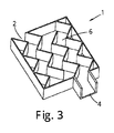
装置は複数の(例えば、4つ)平行なな流路を備えている。各流路内には、その流路を横切って延びて迷路流路を形成する複数(例えば4つ)の突起があってもよい。突起は、コンマ形状及び/又は鼻甲介形状である。突起の間のギャップは、正味の流れ方向に対して流れ方向の変化(例えば、少なくとも90度)を伴う分岐部を形成し得る。突起は、ガス中の微粒子を装置の表面に衝突させるように、装置を通るガス流の乱流及び/又は方向の変化を引き起こす。これにより、装置の表面への吸着によってガスから微粒子を除去することが可能になる。 The device comprises a plurality (eg four) of parallel flow channels. Within each flow path, there may be multiple (eg, four) protrusions extending across the flow path to form a maze flow path. The protrusions are in a comma shape and / or turbinate shape. The gap between the protrusions can form a bifurcation with a change in flow direction (eg, at least 90 degrees) relative to the net flow direction. The protrusions cause turbulence and / or change in direction of gas flow through the device such that particulates in the gas impinge on the surface of the device. This makes it possible to remove particulates from the gas by adsorption to the surface of the device.
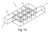
装置は、流路内に2つ以上の180度の曲がり角を有する蛇行流路を含む。180度の曲がり角間の流路の一部は、流路の区域と呼ばれる。2回の180度の曲がり角を伴う蛇行流路の場合、流路の3つの区域があり、中間区域は、ガスの主流方向に関して、流路の最初の区域と最後の区域との逆流配置である。
蛇行流路内に突起を設けてもよく、蛇行流路と突起は一緒になってガスが流れる迷路流路を形成する。
The apparatus includes a serpentine flow path having two or more 180 degree turns in the flow path. The portion of the flow path between the 180 degree turns is referred to as the area of the flow path. In the case of a meandering channel with two 180 degree turns, there are three sections of the channel and the middle section is a counterflow arrangement of the first and last sections of the channel with respect to the main flow direction of the gas. .
A projection may be provided in the meandering channel, and the meandering channel and the projection together form a maze channel through which gas flows.
流路は流路の高さによって分離された頂部と底部と、流路の幅によって分離された2つの側面とを有する。
突起はバッフルである、バッフルは流路の壁から流路内に延びる。バッフルは、流路の幅全体に亘って延在し、流路の高さにわたって流路内に部分的に延在するか、またはその逆である。1つ以上又は各バッフルは、流路の少なくとも25%、少なくとも50%または約60%まで一方向に延びる。バッフルは、流路に沿ったオフセット位置で、流路の反対側の面(上面及び底面など)に設けられてもよい。バッフルは、経路の長さ方向に沿って上下のバッフルを交互にして配置することができる。これにより、ガスは、底部バッフルの上と上部バッフルの下を交互に曲がりくねった流路を辿る。
The flow path has a top and a bottom separated by the height of the flow path, and two sides separated by the width of the flow path.
The protrusion is a baffle, the baffle extending from the wall of the flow path into the flow path. The baffle extends over the entire width of the flow path and partially within the flow path over the height of the flow path, or vice versa. One or more or each baffle extends in one direction to at least 25%, at least 50% or about 60% of the flow path. The baffle may be provided at an offset position along the flow path, on an opposite surface (upper surface, bottom surface, etc.) of the flow path. The baffles can be arranged alternately with upper and lower baffles along the length of the path. This causes the gas to follow a meandering flow path alternately above the bottom baffle and below the top baffle.
バッフルが流路内に延びる距離は、少なくとも50%又は少なくとも60%であり、蛇行している流路の各区域に沿って直線はない。換言すれば、装置を通るガス流れに直線がないことを確実にするのを手助けするために、反対方向から延びるバッフルは(例えば、流路の高さ方向に)重なってもよい。
バッフルは、第1の側から第2の反対側に向かって、上側又は底側から底側又は上側の他方へ、第2の側から第1の側へ、底部又は上部の他方から流路の上部又は底部の他方へ延びる間で交互になってもよい。従って、バッフルは左から右に、右から左に、上部から底部へ及び/又は底部から上部へ延びる。換言すれば、バッフルは、局所的な空気の流れを、正味の空気流束の方向に対して垂直な任意の方向に向けることができる。
The distance that the baffle extends into the flow path is at least 50% or at least 60% and there is no straight line along each section of the meandering flow path. In other words, baffles extending in opposite directions may overlap (e.g., in the height direction of the flow path) to help ensure that the gas flow through the device is not straight.
The baffle has a flow path from the first side to the second opposite side, from the top or bottom side to the bottom or top side, from the second side to the first side, from the bottom or top side to the other side. It may alternate between extending to the other of the top or bottom. Thus, the baffle extends from left to right, right to left, top to bottom and / or bottom to top. In other words, the baffle can direct the local airflow in any direction perpendicular to the direction of the net air flux.
側部から延在するバッフルは、流路の幅及び高さ全体の一部に亘って延在してもよく、上部または下部から延在するバッフルは、幅全体と、流路の高さの一部まで延在している。この構成では、装置を通って流れるガスは、流路の片側に向かって、そして次に流路の上部または底部に向かって進められ/誘導され、それから流路の反対側へ、そして流路の底部または上部の反対側へ進められ/誘導される。 The baffle extending from the side may extend over a portion of the entire width and height of the flow path, and the baffle extending from the top or bottom may reduce the overall width and height of the flow path. It extends to a part. In this configuration, gas flowing through the device is advanced / directed toward one side of the flow path and then toward the top or bottom of the flow path, and then to the other side of the flow path and to the flow path. Propelled / guided to opposite side of bottom or top.
或いは、バッフルは流路の中央に配置されてもよい。これにより、バッフルが壁から突き出ることなく各壁の少なくとも一部を残すことができる。
流路は、更に又はこれに代えて、流路の表面を横切ってかつ流路の表面から延びる隆起部の形態の突起を備えていてもよい。これらの隆起部は流路の表面に凹部を形成する。これらの隆起部及び凹部は、流路の壁に形成される境界層の厚さを最小限に抑えるのに役立つ。装置は、流路を横切って延びる、例えばC字形のペグである湾曲したような、ペグの形状の突起を備える。突起の湾曲した/凹状の表面は、接近するガス流れに面してもよい。
これはガス流れにおける乱流を増加させる。
Alternatively, the baffle may be located in the center of the channel. This allows at least a portion of each wall to remain without the baffle protruding from the wall.
The channel may further or alternatively include a protrusion in the form of a ridge extending across and from the surface of the channel. These ridges form depressions on the surface of the channel. These ridges and depressions help to minimize the thickness of the boundary layer formed on the walls of the flow path. The device comprises a projection in the form of a peg that extends across the flow path, such as a curve, eg, a C-shaped peg. The curved / concave surface of the projection may face the oncoming gas flow.
This increases turbulence in the gas stream.
ペグにぶつからずに流路の一部を通る真っ直ぐな流路がないように、ペグは配置される。ペグは流路の長さに沿ってオフセットした高さに配置されてもよい。例えば、第1の位置では1つのペグが流路の中央に配置され、第2の位置ではさらに流路に沿って配置され、2つのペグは第1のペグの上下の位置で第3の位置に配置される。ペグは流路の反対側の表面に設けられてもよい。このパターンが流路の長さに沿って繰り返される。ペグの高さ(即ち、ペグが流路の全幅を横切って延びる方向に対して垂直であり得る流路の高さ方向の寸法)は、流路の高さの3分の1であり得る。これにより、装置を通して許容可能な圧力降下を生じながら、表面へのガスの衝突を促進することの間の適切な妥協点が与えられる。 The pegs are arranged such that there is no straight flow path through a portion of the flow path without hitting the pegs. The pegs may be located at an offset height along the length of the channel. For example, in the first position, one peg is located in the center of the flow path, in the second position, it is further disposed along the flow path, and the two pegs are in the third position above and below the first peg. Placed in Pegs may be provided on the opposite surface of the flow path. This pattern repeats along the length of the channel. The height of the peg (ie, the height dimension of the flow path, which may be perpendicular to the direction in which the peg extends across the entire width of the flow path), may be one third of the height of the flow path. This provides a good compromise between promoting gas impingement on the surface while producing an acceptable pressure drop through the device.
流路の壁(例えば、蛇行通路の区域内)は、区域の正味のガス流れ方向に対して傾斜していてもよい。例えば、壁は、蛇行する流路の各区域で、ジグザグ形状の流路を形成するように流路に交互に出入りするように角度を付けられてもよい。
流路に沿って横方向にオフセットした位置にある上面及び底面の頂部は、互いを越えて流路の高さ、例えば、各方向の中間点を超えて延びることができる。蛇行流路の各区域に沿って流路を通るガス流れによって採られる直線流路は存在しない。傾斜した上面及び底面は、ガスを流路に沿ってジグザグ流路で流動させることができる。
The walls of the flow path (eg, in the area of the serpentine path) may be inclined with respect to the net gas flow direction of the area. For example, the walls may be angled to alternately enter and exit the flow path at each section of the meandering flow path to form a zig-zag shaped flow path.
The tops of the top and bottom surfaces, which are laterally offset along the flow path, can extend beyond each other and beyond the height of the flow path, for example, the midpoint in each direction. There is no straight flow path taken by the gas flow through the flow path along each section of the serpentine flow path. The inclined top and bottom surfaces allow gas to flow along the flow path in a zigzag flow path.
装置を通って入口から出口へのガス流れ流路がある。迷路流路に加えて、又は迷路流路の一部として、ガス流路は入口と出口との間のガス流れ方向の90−180度の変化を含み得る。この屈曲部は、装置の出口に、又は装置の出口に向かって位置する。そのような方向の変化は、空気がのどに入るときの屈曲部など、人間の呼吸器系の気流の方向の変化を模倣することができる。装置のガス流路は、迷路流路の前、後または内部に90−180度の間、または付随的に120−180度の間の屈曲部を含むことができる。
この屈曲部は、(存在する場合)蛇行する流路の屈曲部に追加的であり得る。この追加の屈曲部、蛇行流路の面から外れている(即ち、そこから離れる)ことがある。
There is a gas flow path from the inlet to the outlet through the device. In addition to or as part of the maze flow path, the gas flow path may include a 90-180 degree change in gas flow direction between the inlet and the outlet. This bend is located at or towards the outlet of the device. Such a change in direction can mimic a change in direction of airflow in the human respiratory system, such as a bend when air enters the throat. The gas flow path of the device may include a bend between 90-180 degrees, or optionally between 120-180 degrees, before, after or within the maze flow path.
This bend (if present) may be in addition to the meandering channel bend. This additional bend may be out of (ie, away from) the plane of the serpentine flow path.
この屈曲部は、少なくとも曲線の外側に吸着面を有する壁を有してもよく、これにより、微粒子のさらなる捕捉を可能にし得る。好ましくは、ガスの流れは、屈曲部への入口または出口で実質的に妨げられない。これにより、屈曲部を通る流量が最大になり、従って微粒子の衝突が増大する。一例において、屈曲部は迷路流路の後で出口の直前に置かれる。迷路流路はまた、迷路流路の2つの端部の間でガスの流れ方向を変化させ、従って迷路流路内のガスの流れ方向の変化は、装置の入口と出口との間の流路の方向の全体的な変化に寄与する。 The bend may have a wall with an adsorption surface at least outside the curve, which may allow for further capture of particulates. Preferably, the gas flow is substantially unobstructed at the entrance or exit to the bend. This maximizes the flow through the bend, thus increasing the impact of particulates. In one example, the bend is located after the maze channel and just before the outlet. The maze flow path also changes the gas flow direction between the two ends of the maze flow path, so that the change in the gas flow direction in the maze flow path is the flow path between the inlet and outlet of the device. Contribute to the overall change in direction.
装置は、入口から出口までの連続的なガス流路を有することができ、即ち、いかなる部分も異なる材料の壁同士で構成されることなく、ガスによって連続的に充填される容積を有することができる。例えば、ガスは流体を通過しない。流路は液体によって妨げられず、例えば、水などを通るガスの泡立ちがない。例えば中国特許03933682号のように液体を使用すると、ガスの流れに対して望ましくないほど高い抵抗が生じる可能性がある。
ガスが誘導されて、ガスが表面にぶつかり、微粒子が衝突及び/又は吸着によって除去される場合、この水はガスから微粒子、特に小さい及び/又は超微粒子を除去するのに必要ではないことが認識されている。
装置は、流れを妨げる可能性があるフィルタ(即ち、メッシュ型デバイス)を含まない。
The device may have a continuous gas flow path from the inlet to the outlet, i.e. it may have a volume that is continuously filled with gas without any part being composed of walls of different materials. it can. For example, gas does not pass through the fluid. The flow path is not obstructed by the liquid and there is no gas bubbling through, eg, water. The use of liquids, such as in Chinese Patent 0 933 3682, can result in undesirably high resistance to gas flow.
It is recognized that this water is not necessary to remove particulates, especially small and / or ultra-fine particulates, from the gas if the gas is induced to hit the surface and the particulates are removed by impact and / or adsorption. Have been.
The apparatus does not include a filter (ie, a mesh-type device) that may impede flow.
剛毛(例えば、繊維及び/又は毛)が、例えば装置の入口またはその近くに、流路を横切って配置されてもよい。これらの剛毛は、より大きな粒子を除去する装置である。これらの剛毛は、大きな粒子(舗装やブレーキの磨耗、繊維や巨視的なほこりのような製品)の一次除去に役立つ。
上記の如く、衝突面及び吸着面を使用する迷路流路では、水、他の液体及び/又はメッシュタイプのフィルタを必要とせずに微粒子を非常に効果的に除去することが可能であることが分かった。これは、ガスからの微粒子の高い捕捉率と共に、ガスの流れに対する比較的低い抵抗が得られることを意味する。本発明において、ガスは曲がりくねった流路をたどるように強いられ/誘導され、従って、装置の壁に衝突することを強いられ、及び/又は遅い流れの領域に入ることを強いられる。これは別の方法で妨げられない流路を通り(例えば装置は入口から出口まで連続的なガス流路を有する、即ち、いかなる部分も異なる材料の壁と壁からなることなく、ガスで連続的に満たされる容積を有することができる。例えば、ガスは流体を通らない)、装置を通る圧力降下は最小化され、及び/又は許容可能な限界を保つ。
Bristles (eg, fibers and / or bristles) may be positioned across the flow path, for example, at or near the entrance of the device. These bristles are devices that remove larger particles. These bristles serve for the primary removal of large particles (products such as pavement and brake wear, fibers and macroscopic dust).
As described above, in a maze channel using a collision surface and an adsorption surface, it is possible to remove particles very effectively without the need for water, other liquids and / or a mesh type filter. Do you get it. This means that a relatively low resistance to gas flow is obtained, together with a high capture rate of particulates from the gas. In the present invention, the gas is forced / directed to follow a tortuous flow path, and thus is forced to strike the walls of the device and / or enter a region of slow flow. This is through an otherwise unobstructed flow path (for example, the device has a continuous gas flow path from inlet to outlet, i.e., a continuous gas flow without any part consisting of walls of different materials). (Eg, gas does not pass through the fluid), the pressure drop through the device is minimized, and / or keeps acceptable limits.
従って、本発明の装置は低い抵抗の乱流を発生させることによって、鼻甲介の骨の作用を再現することができる。
本発明の装置は、乾式精製段階であり得るただ1つの精製段階を有し得る。
装置は受動装置であり得る。装置はポンプ又は電源無しで動作してもよい。
Thus, the device of the present invention can reproduce the effects of the turbinate bone by generating low resistance turbulence.
The apparatus of the present invention may have only one purification stage, which may be a dry purification stage.
The device can be a passive device. The device may operate without a pump or power supply.
幾つかの例において、ガス流路は入口から出口まで物理的な障壁なしに延びている。換言すると、流路が複数の方向の変化及び/又は分岐部を含む一方で、ガスの流れは、例えば液体または膜などの濾過媒体などの物理的な障壁を通って流れる必要はない。好ましくは、ガスの流れは、0.5mm2未満、2mm2未満、又は25mm2以上の最大細孔または開口サイズを有する任意の物理的障壁を通過する必要がない。しかしながら、幾つかの場合にて、反対方向、即ち出口から入口へ流れる障壁を設けることが有利であることに留意されたい。従って、ガス流路内に一方向弁(フラッタ弁など)があってもよく、この弁は、入口から出口への空気の流れを可能にし、出口から入口への空気の流れを制限または防止するように構成される。医療目的のフェイスマスクなどのフェイスマスクと共に使用するのに適した弁が知られている。 In some examples, the gas flow path extends from the inlet to the outlet without a physical barrier. In other words, the gas flow does not need to flow through a physical barrier, such as a filtration medium such as a liquid or a membrane, while the flow path includes multiple directional changes and / or branches. Preferably, the gas flow is less than 0.5 mm 2, less than 2 mm 2, or 25mm is not necessary to pass through any physical barrier having two or more of the maximum pore or aperture size. However, it should be noted that in some cases it is advantageous to provide a barrier that flows in the opposite direction, ie from the outlet to the inlet. Thus, there may be a one-way valve (such as a flutter valve) in the gas flow path, which allows air flow from the inlet to the outlet and restricts or prevents air flow from the outlet to the inlet. It is configured as follows. Valves suitable for use with face masks, such as face masks for medical purposes, are known.
迷路流路の壁は、微粒子の吸着のために配置されてもよく、幾つかの例では、壁は微粒子を吸収することができなくてもよい。従って、吸着が微粒子の捕獲の主な機構であることを確実にすることができる。吸着面は、迷路流路内のガス流路の方向の変化部分の外側にあってもよく、幾つかの場合にあっては、迷路流路の全ての壁は、全ての壁が吸着することができるように、微粒子の吸着のために選択された材料で作られてもよい。迷路流路の幾何学的形状は、壁の特定の領域での衝突を促進するが、それでもなお、全ての壁表面を吸着可能にする、及び/又は吸着するように構成することは有利であることは勿論、理解されるだろう。単一の材料を使用することができるので、これは迷路流路の製造をより容易にすることができる。 The walls of the maze channel may be arranged for the adsorption of particulates, and in some cases the walls may not be able to absorb the particulates. Therefore, it can be ensured that adsorption is the main mechanism of capturing fine particles. The adsorbing surface may be outside the changing part of the direction of the gas flow path in the maze flow path, and in some cases, all the walls of the maze flow path are adsorbed by all the walls. May be made of a material selected for the adsorption of particulates. The geometry of the maze channel facilitates collisions in specific areas of the wall, but it is still advantageous to be able to adsorb and / or adsorb all wall surfaces Of course, that will be understood. This can make the production of the maze channel easier, since a single material can be used.
迷路流路の全ての壁であり得る吸着/堆積表面は、テクスチャード加工、粗面化表面又は繊維状表面を含み得る。粗い表面を使用する利点は2つあり、それは1)この方法で表面積を増加させることは吸着率を増加させ、2)このタイプの表面仕上げを使用すると、境界層のサイズも小さくなり、衝撃を助長する。そのような特徴は巨視的な曲線、波紋、隆起部及び点の高さからこれらの同じ特徴までの微視的レベルでサイズ及びスケールが異なり得る(表面の「粗度」と考えられる)。
幾つかの例において、表面は、隆起部の高さの1−10倍の間隔で、0.1mm−1mmの隆起部、例えば、約0.5mmの隆起部、又は流路の幅及び/又は高さの20倍以下の隆起部を有することができる。
The adsorption / deposition surface, which may be all the walls of the maze channel, may include a textured, roughened or fibrous surface. There are two advantages of using a rough surface: 1) increasing the surface area in this way increases the adsorption rate, and 2) using this type of surface finish also reduces the size of the boundary layer and reduces the impact. Encourage. Such features can vary in size and scale at the microscopic level from macroscopic curves, ripples, ridges and point heights to these same features (considered surface "roughness").
In some examples, the surface may be 0.1 mm-1 mm ridges, for example, about 0.5 mm ridges, or 10.5 times the height of the ridges, or the width of the channel and / or It may have a ridge no greater than 20 times its height.
装置は2つの異なる大きさの空気流れへの障害物を備え、1つの突起/障害物のサイズは流路幅のスケールである(例えば、流路の25%から75%の幅)。他の突起/障害物のサイズは流路幅の1/10未満のスケールである。大きなサイズの突起/障害物は、1)大規模の乱流を生成し、2)境界層の成長を回避し、及び/又は3)遅い流れの領域を生成するためであり、小さなサイズの突起/障害物は、境界層を壁に取り付けるためのものである。 The device is equipped with two different sized obstacles to the air flow, one protrusion / obstacle size being the scale of the channel width (eg 25% to 75% width of the channel). Other protrusion / obstacle sizes are on the scale of less than 1/10 of the channel width. Large sized protrusions / obstacles are to 1) create large turbulence, 2) avoid boundary layer growth, and / or 3) create regions of slow flow, and small sized protrusions / obstacles. The / obstacle is for attaching the boundary layer to the wall.
流路の壁は、粗い表面(例えば、サブミリメートルから巨視的(例えば、数センチメートルオーダー)の隆起や折り目などの粗さの範囲)な特徴を有することができる。これは、ガス流れからの微粒子の除去を助けるために、流路長を短くすること、及び/又は微粒子と表面との間の引力を増大させることを手助けする。粗さは境界層の厚さを減少させ、それは上述のように粒子堆積率を増加させ得る。表面粗さは、表面のきめ(例えば、粒子のサイズよりもかなり大きい突起、例えば101から1mm)、大規模な表面の形状(例えば波紋や線など、突起のあるパターン)、及び/又は表面の形状(転動表面など)を変えることによって達成することができる。 The walls of the channel may have rough surface features (e.g., ranging from sub-millimeters to macroscopic (e.g., on the order of several centimeters) roughness, such as bumps and folds). This helps shorten the flow path length and / or increase the attractive force between the particles and the surface to help remove the particles from the gas stream. Roughness reduces the thickness of the boundary layer, which can increase the particle deposition rate as described above. Surface roughness can be based on surface texture (e.g., protrusions that are significantly larger than the size of the particles, e.g., 101 to 1 mm), large surface features (e.g., patterns with protrusions, such as ripples and lines), and / or surface roughness. This can be achieved by changing the shape (rolling surface, etc.).
壁(粗面化された)は自然の粗面である。壁は使用中は乾いていても乾いているように構成されていてもよい。壁は硬い表面でもよい
壁、または少なくとも壁の一部は、湿った又は粘着性の表面を有してもよい。これは、スプレーなどによって迷路流路の内面に塗布されるゲル又は液体によって達成される。
内部表面は、ヒトの呼吸器系における粘液の影響を模倣している。これは、装置を通って流れるガスからの粒子の除去を助けるという効果を有する。これは表面の付着特性を増大させるが吸着を増強する。
Walls (roughened) are natural rough surfaces. The walls may be dry or configured to be dry during use. The wall may be a hard surface. The wall, or at least a part of the wall, may have a wet or sticky surface. This is achieved by a gel or liquid applied to the inner surface of the maze channel by spraying or the like.
The inner surface mimics the effects of mucus on the human respiratory system. This has the effect of helping to remove particles from the gas flowing through the device. This increases the adhesion properties of the surface but enhances adsorption.
迷路流路の壁は、非多孔質及び/又は非吸収性材料、例えばアクリロニトリルブタジエンスチレン(ABS)、ポリプロピレン(PP)または高密度ポリエチレン(HDPE)などのポリマープラスチック材料を含むかまたはそれらから成る。壁は、これらの材料から形成されてもよく、及び/又はこれらの材料の有益な効果を得るためにこれらの材料で被覆されてもよい。
微粒子付着性を高めるために表面を被覆してもよい。これは、粗さ及び/又は静電荷を含むがこれらに限定されない特性を変える被覆による。
壁の材料の水に対する透過性(25℃)は100×10−13cm3cm/cm2/秒/Pa以下であり、50×10−13cm3cm/cm2/秒/Pa未満が好ましい。壁の材料の空気に対する透過性(25℃)は2×10−13cm3cm/cm2/秒/Pa以下であり、1×10−13cm3cm/cm2/秒/Pa未満が好ましい。これにより、材料を通る水分及びガスの輸送を回避または最小限に抑えることができる。
低透過性を含むABSの特性の組み合わせを考慮して、ABSを使用することができる。
The walls of the maze channel comprise or consist of a non-porous and / or non-absorbing material, for example a polymeric plastic material such as acrylonitrile butadiene styrene (ABS), polypropylene (PP) or high density polyethylene (HDPE). The walls may be formed from these materials and / or may be coated with these materials to obtain the beneficial effects of these materials.
The surface may be coated to enhance the adhesion of the fine particles. This is due to the coating changing properties, including but not limited to roughness and / or static charge.
The water permeability (25 ° C.) of the wall material is 100 × 10 −13 cm 3 cm / cm 2 / sec / Pa or less, and preferably less than 50 × 10 −13 cm 3 cm / cm 2 / sec / Pa. . The permeability of the wall material to air (25 ° C.) is 2 × 10 −13 cm 3 cm / cm 2 / sec / Pa or less, preferably less than 1 × 10 −13 cm 3 cm / cm 2 / sec / Pa. . This can avoid or minimize the transport of moisture and gas through the material.
ABS can be used in view of the combination of ABS properties including low permeability.
迷路流路の壁の材料は、迷路流路の残りの部分にも使用することができる。材料は、吸着性表面を提供するその能力について選択され、そして上述のようにテクスチャード加工、粗面化または繊維性表面を用いて製造されるその能力について選択される。
微粒子の表面保持は、高い表面電気抵抗率を有する材料を使用することによって向上させることができる。従って、壁は、高い表面電気抵抗率を有する材料を含み得る(例えば、該材料から作製されるか、またはそのコーティングを有する)。これは、表面が電荷を吸収しないため、静電気が表面に蓄積することを意味する。この場合、吸着は依然として粒子が除去される主な機構であるが、静電気はこの除去プロセスを助ける。上記したようなポリマーは、良好な表面電気抵抗率特性を提供する。
The maze channel wall material can also be used for the rest of the maze channel. The material is selected for its ability to provide an adsorptive surface, and for its ability to be textured, roughened, or manufactured using a fibrous surface as described above.
The surface retention of the microparticles can be improved by using a material having a high surface electrical resistivity. Thus, the wall may include a material having a high surface electrical resistivity (eg, made from or having a coating thereof). This means that static electricity accumulates on the surface because the surface does not absorb charge. In this case, adsorption is still the main mechanism by which particles are removed, but static electricity assists in this removal process. Polymers such as those described above provide good surface resistivity properties.
装置の表面は、ガス流れからの粒子の除去を助けるために静電気を帯びていてもよい。やはり、吸着は依然として粒子が除去される主な機構であり得るが、電荷はこの除去プロセスを助ける。
材料は、抗菌特性及び/又は抗ウイルス特性を有してもよい。例えば、装置の内壁は、抗菌性及び/又は抗ウイルス性であるプラスチックなどの材料から作られ得る。装置が使用者によって直接吸い込まれる空気(フェイスマスク内など)のために使用されるとき、装置は感染の拡大に対してある程度の保護を提供することができる。
The surface of the device may be electrostatically charged to help remove particles from the gas stream. Again, adsorption may still be the primary mechanism by which particles are removed, but charge assists in this removal process.
The material may have antibacterial and / or antiviral properties. For example, the inner wall of the device may be made from a material such as plastic that is antibacterial and / or antiviral. When the device is used for air sucked directly by the user (such as in a face mask), the device can provide some protection against the spread of infection.
幾つかの例において、装置及び/又は迷路流路は、成形または機械加工によって製造することができる。射出成形は1つの可能な製造方法である。射出成形は、部品の表面に細部を形成するために使用することができ、それは好ましい材料と共に使用するためによく開発されている方法である。
付加製造技術(additive manufacturing techniques、所謂「3−D印刷」を含む)を使用することができる。付加製造法は、表面が粒状の質感を有するようにすることができ、それは上記のように有益であり得る。付加製造法は、内部構造を含む複雑な形状も可能にし、迷路流路の構成のより大きな自由を可能にし、迷路流路を単一の部品にすべく単一の製造工程を使用することを可能にすることができ、従って、後の組み立て工程を回避することができる。幾つかの例において、従って、迷路流路は付加製造法によって製造された単一部品である。これには、3−D印刷プラスチックの使用が含まれ得る。
In some examples, the devices and / or maze channels may be manufactured by molding or machining. Injection molding is one possible manufacturing method. Injection molding can be used to form details on the surface of the part, which is a well-developed method for use with preferred materials.
Additional manufacturing techniques (including so-called "3-D printing") can be used. The additive manufacturing method can cause the surface to have a granular texture, which can be beneficial as described above. The additive manufacturing method also allows for complex geometries, including internal structures, allows greater freedom in the configuration of the maze flow path, and uses a single manufacturing process to make the maze flow path a single part. This can be possible, thus avoiding a later assembly step. In some instances, therefore, the maze channel is a single piece manufactured by additive manufacturing. This may include the use of 3-D printed plastic.
装置は種々の用途に用いられる。用途は、フェイスマスク、建物の空調/給気などの人によって吸い込まれようとしている空気を清浄するためのものであり得る。用途は、例えば屋内(例えば建築現場、住宅改修、工場、特にれんが粉塵、石膏粉塵などの粒子にさらされる可能性のある場所、または航空機などの乗り物の中にある場所)、採鉱、例えば花粉を除去するため(花粉症から保護するため)の屋外、駅で、農業従事者の環境のほこりである。用途は、汚染物質が大気中に放出されるのを防止するために汚染物質が生成される源またはその近くの空気を清浄するためのものであり、源は例えば工場や発電所における組み合わせ煙突、及び(例えば自動車であれ発電機であれ)燃焼機関の排気ガスである。 The device is used for various applications. Applications may be for cleaning air that is about to be inhaled by people, such as face masks, building air conditioning / air supply. Applications include, for example, indoors (e.g., building sites, home renovations, factories, especially where there is potential for exposure to particles such as brick dust, gypsum dust, or in vehicles such as aircraft), mining, e.g., pollen Outdoors, at stations, for removal (to protect against hay fever), is the dust of the environment of farmers. Applications are for cleaning air at or near the source where the pollutants are generated to prevent the pollutants from being released into the atmosphere, such as combined chimneys in factories and power plants, And the exhaust gas of a combustion engine (whether an automobile or a generator).
装置は人のフェイスマスクに組み込まれてもよい。装置はフェイスマスクの一体部分であり得る。好ましくは、装置はフェイスマスクの他の部分と共に顔上または顔の周りに保持される。従って、有利なことに、フェイスマスクは、中国特許103933682号の別個のハウジング及び同様の装置のように、フェイスマスクから離れた他のいかなる部品も必要としない。提案されたフェイスマスクは、運動中に使用するためのものであり得る。 The device may be incorporated into a human face mask. The device can be an integral part of the face mask. Preferably, the device is held on or around the face along with other parts of the face mask. Thus, advantageously, the face mask does not require any other components remote from the face mask, such as a separate housing and similar device of Chinese Patent No. 109333682. The proposed face mask may be for use during exercise.
従って、第12の態様において、本発明はフェイスマスクを提供し、フェイスマスクはガスから微粒子を除去する1以上の(2つのような)装置を備え、各装置はガス流れを受け入れる入口と、ガス流れが排出される出口と、入口と出口との間に延び、ガス流れの通路である迷路流路とを備え、迷路流路は、ガスの流れを誘導して、ガス中の微粒子が衝突する微粒子を吸着するために配置された迷路流路の吸着面に衝突するように配置され、ガスが入口から出口に流れるにつれて、ガス中の微粒子は吸着面への衝突によってガスから除去される。 Accordingly, in a twelfth aspect, the present invention provides a face mask, wherein the face mask comprises one or more (such as two) devices for removing particulates from the gas, each device having an inlet for receiving a gas stream, and a gas inlet; An outlet from which the flow is discharged, and a maze flow path extending between the inlet and the outlet and serving as a gas flow path, the maze flow path guides the flow of the gas, and the fine particles in the gas collide with the flow. The gas is arranged to collide with the adsorption surface of the labyrinth flow path arranged to adsorb the fine particles, and as the gas flows from the inlet to the outlet, the particles in the gas are removed from the gas by collision with the adsorption surface.
第13の態様において、本発明はガスから微粒子を除去する方法を提供し、該方法はフェイスマスクを配備するステップであって、該フェイスマスクはガスから微粒子を除去する1以上の(2つのような)装置を備え、各装置はガス流れを受け入れる入口と、ガス流れが排出される出口と、入口と出口との間に延び、ガス流れの通路である迷路流路とを備え、迷路流路は、ガスの流れを誘導して、ガス中の微粒子が衝突する微粒子を堆積するために(例えば吸着及び/又は吸収によって)配置された迷路流路の堆積面に衝突するように配置され、ガスが入口から出口に流れるにつれて、ガス中の微粒子は堆積面への衝突によってガスから除去される。 In a thirteenth aspect, the present invention provides a method of removing particulates from a gas, the method comprising the step of providing a face mask, wherein the face mask removes one or more (two or more) particles from the gas. Each device includes an inlet for receiving a gas flow, an outlet from which the gas flow is discharged, and a maze flow path extending between the inlet and the outlet and being a passage for the gas flow. The gas is arranged to impinge on the deposition surface of a maze flow path that is arranged to guide the flow of the gas so that the particulates in the gas impinge upon the impinging particulates (e.g., by adsorption and / or absorption). As gas flows from the inlet to the outlet, particulates in the gas are removed from the gas by impact on the deposition surface.
装置は上記の装置であり、上記した1以上の付随的な特徴を含む。
装置は、使用者の顔に着座するフェイスマスクと一体であってもよい。
装置は、装置自体を通してよりもむしろ使用中にフェイスマスクの側面の周りの空気を取り込むことを防ぐのを助ける。これは装置がガスに低い抵抗の流路を付与するから達成される。これは、吸入すると、フェイスマスクの側面の周りよりもむしろ装置を通して優先的に空気が引き込まれることがあることを意味する。
The apparatus is an apparatus as described above and includes one or more of the optional features described above.
The device may be integral with a face mask that sits on the user's face.
The device helps prevent entrapment of air around the sides of the face mask during use, rather than through the device itself. This is achieved because the device provides a low resistance flow path to the gas. This means that upon inhalation, air may be preferentially drawn through the device rather than around the sides of the face mask.
例えばフェイスマスクに使用される微粒子除去装置のための入口は、使用者の顔に対して後方(使用中)を向いている。後方を向いた入口は、使用者が車両の後ろを移動しているときに排気ガスの強制呼吸を回避するのに役立つ。
出口は、フェイスマスクの内側で、使用者の口及び鼻に向いていても、口及び鼻の前(接近するように)の場所に向いていてもよい。
フェイスマスクには、呼気のための短い保護された流路がある。これは効率的な呼気を可能にする。また、保護された流路は、汚染物質があれば、呼気流路を通ってフェイスマスクに入ることが殆ど無いを意味する。
フェイスマスクは、呼気が装置を通過して戻ることなくフェイスマスクから出ることを可能にする呼気弁を有することができる。呼気弁は、使用者の鼻及び口の前に配置される。
The entrance for a particulate removal device used, for example, in a face mask points rearward (in use) to the user's face. The rear-facing entrance helps to avoid forced breathing of exhaust gas when the user is moving behind the vehicle.
The exit may be inside the face mask, facing the mouth and nose of the user, or at a location in front of (as close to) the mouth and nose.
The face mask has a short, protected flow path for exhalation. This allows for efficient exhalation. Also, a protected channel means that if contaminants are present, very little enters the face mask through the exhalation channel.
The face mask may have an exhalation valve that allows exhaled air to exit the face mask without returning through the device. The exhalation valve is placed in front of the user's nose and mouth.
フェイスマスクは、入口及び出口の一方向弁(例えばフラッタ弁であり得る)を含む。入口の弁は、装置の入口から装置の出口への空気流を可能にし、出口から入口への空気流を制限または防止するように構成されている。出口弁は、吐き出された空気がフェイスマスクから出ることを可能にし、装置を通過しない外部環境からの空気の流れを制限または防止するように構成される。フェイスマスク内の圧力が低いとき(使用者による吸入中など)、空気は装置を通って入口弁を通って引き込まれ、フェイスマスク内の圧力が高いとき(使用者による呼気中など)、空気は出口弁から押し出される。 The face mask includes an inlet and outlet one-way valve (which may be, for example, a flutter valve). The inlet valve is configured to allow air flow from the inlet of the device to the outlet of the device and to restrict or prevent air flow from the outlet to the inlet. The outlet valve is configured to allow exhaled air to exit the face mask and to limit or prevent the flow of air from the outside environment that does not pass through the device. When the pressure in the face mask is low (e.g. during inhalation by the user), air is drawn through the device through the inlet valve, and when the pressure in the face mask is high (e.g. during exhalation by the user), the air is It is pushed out of the outlet valve.
装置の出口は、(使用中に)使用者の鼻及び/又は口の前にあるフェイスマスクの内面に向けられる。この内面は各呼気で温かい湿った空気を受けるという事実のために、この面は湿っているであろう。フェイスマスク及び装置は、装置を出る空気がこの表面に向けられるように配置されてもよい。内面の表面は、フェイスマスクを通過する途中で空気が遭遇する表面とは異なる表面であり得る。従って、この表面は、装置によってまだ除去されていない微粒子を空気から除去するために使用され得る。 The outlet of the device is directed (in use) to the inside of the face mask in front of the user's nose and / or mouth. This surface will be moist due to the fact that this inner surface receives warm, moist air with each exhalation. The face mask and device may be arranged so that air exiting the device is directed at this surface. The inner surface may be a different surface than the surface encountered by air on its way through the face mask. Thus, this surface can be used to remove particulates from the air that have not yet been removed by the device.
フェイスマスクは、冷却及び快適さのために最大量の顔面領域を露出させながら、使用者の鼻及び口の周りにしっかりと嵌合するように構成され得る。
フェイスマスクは、上述したように抗菌特性を有する材料から構成され得る。
フェイスマスクは、少なくとも部分的に、眼を外部環境から保護するためにアイシールドをも含み得る。
The face mask may be configured to fit tightly around the user's nose and mouth while exposing a maximum amount of facial area for cooling and comfort.
The face mask may be composed of a material having antimicrobial properties as described above.
The face mask may also include, at least in part, an eye shield to protect the eyes from the external environment.
上記の如く、現在の装置の特徴により、サイクリングまたはランニングなどの運動中に快適に使用されるのに十分に低い抵抗で十分な気流が可能となる。フェイスマスクに組み込まれた装置は、入口から出口への空気の流れを可能にするが出口から入口への空気の流れを制限する上述のタイプの一方向弁を含み得る。このようにして、入ってくる空気は、使用者による吸入の前に微粒子が除去された状態で迷路流路を通過することができ、然るに、吐き出された空気は、他の経路を介して、例えばマスクの側面の周りまたは他の一方向弁を介して排出され得る。これにより、湿った呼気による微粒子除去装置内の湿気の蓄積を防ぎ、且つ使用者が咳やくしゃみをした場合に微粒子除去装置の汚れを防ぐ。更に、「デッドスペース」のサイズを制限することは、ごくわずかな空気しか再呼吸されないことを意味し、より快適で生理学的に許容されるものにする。 As noted above, features of current devices allow for sufficient airflow with low enough resistance to be used comfortably during exercises such as cycling or running. The device incorporated into the face mask may include a one-way valve of the type described above that allows air flow from the inlet to the outlet, but restricts air flow from the outlet to the inlet. In this way, incoming air can pass through the maze flow path with particulates removed prior to inhalation by the user, while exhaled air will pass through other paths, For example, it can be discharged around the side of the mask or through another one-way valve. This prevents moisture from accumulating in the particle removing device due to moist expiration, and prevents the particle removing device from becoming dirty when the user coughs or sneezes. Furthermore, limiting the size of the "dead space" means that very little air is rebreathed, making it more comfortable and physiologically acceptable.
上記の如く、装置は有利なことに、変動する作業負荷にわたる人間の換気の許容範囲に沿って(吸気と呼気の両方の)ガス流れを可能にするように構成され得る。変動範囲は、(i)軽作業の場合には最大150リットル/分もしくは約120リットル/分(例えば125.6リットル/分)、または重作業の場合は最大300リットル/分もしくは約250リットル/分(例えば、254.7リットル/分)のピーク吸気流量、及び/又は(ii)<8mmH2O/リットル/秒(これは人間の検出限界である)または最大35mH2O/リットル/秒の吸気抵抗を含む。
装置は、使用者の上気道と同様の、またはそれより小さい気流抵抗を有するように構成され得る。
As noted above, the device may be advantageously configured to allow gas flow (both inspiration and expiration) within acceptable ranges of human ventilation over varying workloads. The variation range is (i) up to 150 l / min or about 120 l / min (eg 125.6 l / min) for light work, or up to 300 l / min or about 250 l / min for heavy work. min (e.g., 254.7 liters / minute) peak inspiratory flow rates, and / or (ii) <8mmH (This is the detection limit of the human) 2 O / l / sec or up to 35mH 2 O / l / sec Including intake resistance.
The device may be configured to have an airflow resistance similar to or less than the upper airway of the user.
これにより、例えばランニング又はサイクリング中に、正常なレベルの身体的運動及び高いレベルの身体的運動の両方の呼吸用に、空気から微粒子を除去する装置を使用することが可能になる。異なる範囲の換気速度及び吸気/呼気流量において、効率的な微粒子除去と許容可能な「通気性」との間の最良の妥協点を提供するために、異なる構成が提供され得る。従って、「高作業率」仕様では、「通気性」のために効率が犠牲になる可能性がある。可能性のある要求に応じて装置を適合させることができる、例えば装置は使用者に依存する、例えば異なる最大流量、及び/又はサイクリング、工場内または建築現場での作業、ウォーキングなどのフェイスマスクを装着している間に行われる活動に応じて、大人用仕様と子供用仕様が設けられる。 This allows the use of devices that remove particles from the air for breathing both normal and high levels of physical exercise, for example during running or cycling. Different configurations may be provided to provide the best compromise between efficient particulate removal and acceptable "breathability" at different ranges of ventilation rates and inspiratory / expiratory flow rates. Thus, with the "high work rate" specification, efficiency may be sacrificed for "breathability". The device can be adapted according to possible demands, e.g. the device depends on the user, e.g. different maximum flow rates and / or face masks such as cycling, working in a factory or building site, walking etc. Depending on the activities that take place while wearing it, there is an adult version and a child version.
装置の吸気抵抗及び呼気抵抗は最小化され、使用者に重大な不快感や換気疲労を引き起こさない範囲内で厳密に保持される。
建物の換気、または排気ガスからの微粒子の除去など、フェイスマスク以外の装置の他の用途に対応するために、同様の構成が選択される。範囲は正確な用途(家や発電機の大きさなど)によって異なる。一例として、Caterpillar社の「3616」エンジンの場合、ガス流量は毎分約34000標準立方フィート(CFM)(毎秒16000リットル)(たとえば毎秒15759リットル)であるが、Allis Chalmers 213モデルの場合は75CFM(毎秒35リットル)である。Caterpillar、Cummins、John Deereのディーゼル発電機セットエンジン(15−>1000kW)は、ガス温度、流量、ターボチャージャーの性能及び燃料消費量などの要因に応じて設定される、6.7〜10.2kPaの背圧限度を有する。特定のエンジンが許容できる限界は、特定の設計要素によって異なる。エンジン機能に適合する背圧を許容しながら、必要なガス流量を許容するように構成によって抵抗を調整することができる。
The inspiratory and expiratory resistance of the device is minimized and kept strictly within a range that does not cause significant discomfort or ventilation fatigue to the user.
A similar configuration is selected to accommodate other uses of the device other than a face mask, such as building ventilation or removing particulates from exhaust gases. The range depends on the exact application (house, generator size, etc.). As an example, for the Caterpillar "3616" engine, the gas flow rate is approximately 34,000 standard cubic feet per minute (CFM) (16000 liters per second) (for example, 15759 liters per second), while the Allis Chalmers 213 model has a gas flow of 75 CFM ( 35 liters per second). Caterpillar, Cummins and John Deere's diesel generator set engines (15-> 1000 kW) have a back pressure of 6.7 to 10.2 kPa that is set according to factors such as gas temperature, flow rate, turbocharger performance and fuel consumption. Has limitations. The limits that a particular engine can tolerate will depend on the particular design factor. The resistance can be adjusted by the configuration to allow the required gas flow while allowing the back pressure to match the engine function.
一例において、ここで記載したようにフェイスマスクは2つの微粒子除去装置を含む。1つの装置は(使用時に)使用者の頬に隣接して使用者の口の両側に配置されてもよい。このフェイスマスクは、2つの微粒子除去装置のための入口を有し、該入口はフェイスマスクの外側でフェイスの側面に沿って後方に面し、2つの微粒子除去装置のための出口がフェイスマスクの内側の口及び鼻の方に向いているか又はその正面の位置に向いている。
装置のサイズはその用途に依存する。
装置は、約5−15cm、約5−15cm、及び/又は約0.5−5cmの寸法(例えば、幅、高さ、及び長さ)を有することができる。チャネルの幅及び高さは10mmから100mmであり、長さは200mm×1000mmである。
任意選択の特徴を含む上記の特徴のいずれも、本発明の上記の態様の1つまたは複数または全てに適用可能である。
In one example, a face mask as described herein includes two particulate removal devices. One device may be placed on both sides of the user's mouth adjacent to the user's cheek (when in use). The face mask has an entrance for two particle removal devices, the entrance facing rearward along the side of the face outside the face mask, and an exit for the two particle removal devices at the face mask. It faces the inside mouth and nose or in front of it.
The size of the device depends on its application.
The device can have dimensions (e.g., width, height, and length) of about 5-15 cm, about 5-15 cm, and / or about 0.5-5 cm. The width and height of the channel are from 10 mm to 100 mm and the length is 200 mm × 1000 mm.
Any of the above features, including optional features, are applicable to one or more or all of the above aspects of the invention.
本発明のある好ましい実施形態は、添付の図面を参照して例示によってのみより詳細に記載される。
図1は、ガスから微粒子を除去する装置1を示す。装置1は、ガスの流れを受けるための入口2と、そこからガスの流れを放出することができる出口4とを備える。入口2と出口4との間には、ガス流れを通過させるための迷路流路6がある。迷路流路6はガスの流れを案内するように構成され、ガス中の微粒子が衝突した微粒子を吸着するように構成された迷路流路6の吸着面に衝突して、ガスが入口2から出口4に流れるにつれて、ガス内の微粒子が吸着面に衝突することによって除去される。装置1内には、空気流れの速度の大きさが1m/s未満及び/又は平均入力空気流速度の10%未満である領域もあり得る。これらは遅い流れの領域と言及される。装置1内の遅い流れの領域の容積は、装置1の総容積の少なくとも4%であり得る。図は、出口4に円錐を有する装置を示す。この円錐は存在しなくてもよい。
様々な例示的な迷路流路6が図2乃至図7、図9及び図13乃至図15に示されている。これらの例は決して排他的ではない。
FIG. 1 shows an
Various
図2は、2つの180度の屈曲部を有する蛇行流路6と、流路6内に配置された複数のバッフル8とを有する構成を示す。バッフル8は夫々、流路6の全高を横切って延び、流路6の幅を部分的に横切って延びる。バッフル8は、流路6の両側から延在するように交互に配置されている。バッフル8は夫々、流路6の幅を横切って50%を超えて延びている。その結果、流路6を通るガス流れについての直線は存在しない。
図2に示される装置1の長さ、幅及び高さは、例えば106mm×64mm×24mmであり得る。入口と内部の断面積は20mm×20mmである。各バッフルの長さは11mmであり、バッフルは20mm離れていてもよい。蛇行流路を形成する2つの内壁の夫々の長さは85mmであり得る。
FIG. 2 shows a configuration including a
The length, width and height of the
図3は、2つの実質的に180度の屈曲部を有する蛇行流路6を有する構成を示す。流路6は、ジグザグ形の流路を形成するように流路に出入りする方向に傾斜した傾斜壁を有する。図3に示される装置を通るガス流れはジグザグ流路を進むように強制される。ジグザグの頂点は、隣接する壁のジグザグの谷のうちの1つの中に延びて、ガス流れについて、装置を通る直線状の通路がないようにする。
図3に示す装置1の長さ、幅及び高さは、例えば90mm×79mm×24mmである。入口及び出口領域は、19.17mm×20mmである。流路の壁の各傾斜部分の長さは、19.8mmである。
FIG. 3 shows a configuration with a
The length, width and height of the
図4は、2つの180度の屈曲部を有する、広いが高さの低い蛇行流路6を有する構成を示す。図4に示される装置1の長さ、幅及び高さは、例えば60mm×84mm×24mmであり得る。入口及び流路は5mm×40mmであり得る。蛇行流路を形成する2つの壁の夫々の長さは55mmであり得る。
FIG. 4 shows a configuration with a wide but low
図5は、2つの180度の屈曲部を有する蛇行流路6と、流路6内に配置された複数のバッフル10とを有する構成を示す。バッフル10はそれぞれ、流路6の高さ又は幅を完全に横切って延び、流路6の幅又は高さの他方を部分的に横切って延びる。バッフル10は、流路6の第1の側から第2の反対側に向かって、上から下に向かって、第2の側から第1の側に向かって、そして下から上に向かって延びる流路の長さに沿って交互に並ぶ。
バッフル10はそれぞれ長さが等しいが、流路6の4つの壁のうちの1つから長さに沿って交互に延びることができる。各バッフルは流路6内に1mmだけ延びる。
バッフルは夫々、流路6の幅または高さの60%に亘って延在してもよい。この構成では、装置1を通って流れるガスは、流路の一方の側、次に流路の頂部、次に他方の側、そして次に流路6の底部の方向に向けられる。再び、この構成では流路6を通るガス流れについて直線状の通路はない。
FIG. 5 shows a configuration having a meandering
The
The baffles may each extend over 60% of the width or height of the
図6は、2つの180度の屈曲部を有する蛇行流路6と、流路6内に配置された複数のペグ12とを有する構成を示す。ペグ12は夫々、流路6の高さを完全に横切って延びる。流路の長さに沿ってペグ12は幅を横切って様々な位置に配置され、流路に沿ったいくつかの位置は流路の幅のほぼ中間点に単一のペグ12を有し、長さに沿った幾つかの位置は、流路の幅の中心の両側に等間隔に配置した2つのペグ12(単一の中央ペグ12より小さくてもよい)を有し、幾つかの位置では片側に壁から延びるペグ12を有する。ライン14で示されるように、ペグ12は、ペグ12に遭遇することなく装置を横切る直線が存在しないように配置される。
1つの中央ペグは、流路6の幅の約1/3の幅を有することができる。ペグ12が両側の壁から延びる位置では、2つのペグは一緒に流路6の幅の約1/3延びて流路6の中央に約2/3のギャップfを残してもよい。
ペグ12は夫々、対向するガス流れの方向を向く凹面及び/又は湾曲面を有することができる。これは、図6の左上に示されているように、流れに乱流を発生させるのに役立つ。
FIG. 6 shows a configuration having a meandering
One central peg can have a width that is about / of the width of the
The
図7は、2つの180度の屈曲部を有する蛇行流路6と、流路6内に配置された複数のバッフル16とを有する構成を示す。バッフル16は夫々、流路6の全高を横切って延在し、部分的に流路6の幅を横切って延在する。バッフル16は、流路6の両側から延在するように交互に配置されている。バッフル16は夫々、流路6の幅の50%を超えて延びている。その結果、流路6を通るガスの流れについての直線状の通路は存在しない。
流路の全ての壁は、その上に等間隔の隆起部18を有する。隆起部は、境界層を減らすのを助けるために流路6の表面にくぼみを作り出す。隆起部18間の間隙は、隆起部の高さの約2倍に等しい。隆起部18は夫々流路内に約1.5mm延在してもよく、従って各隆起部間の間隙は約3mmであってもよい。
FIG. 7 shows a configuration having a meandering
All walls of the channel have equally spaced
図8、図9及び図10は、その中に一体化された2つの上記の微粒子除去装置1を有するフェイスマスク100を示す。フェイスマスクが着用されているとき、1つの装置が使用者の口の両側、使用者の頬に隣接して配置される。
カバー22を取り除いた図9は、迷路流路6のためのさらに別の構成を有する装置1を示すが、装置は、図2乃至図7のいずれかに示される構成、または堆積表面への衝突によって粒子を除去することを可能にするであろう他の任意の構成を有することができる。
図9に示す各装置の構成は、4つの平行な流路6を含む。各流路6内には4つのペグ18がある。ペグ18は夫々、各流路6の高さを横切って延びる。ペグ18はコンマ型であり、人間の鼻の鼻甲介の骨の効果を模倣している。
ペグ18は、流路内に分岐部を形成して、各流路6を通って流れるガス内に乱流を生じさせ、堆積表面上の粒子の衝突を引き起こす。
各流路6はそれ自身のそれぞれの入口2を有するが、各装置の流路6は共通の出口4を有する。
各入口2はその上に剛毛20を有する。これにより、大きな粒子が装置1に入るのを防ぐことができる。
各装置は取り外し可能なカバー222を有する。これにより、装置1の流路を容易に洗浄して、装置1によって捕捉された微粒子を除去することが可能になる。
FIGS. 8, 9 and 10 show a
FIG. 9 with the
The configuration of each device shown in FIG. 9 includes four
The
Each
Each
Each device has a removable cover 222. This makes it possible to easily clean the channel of the
図10に最も明瞭に示されるように、フェイスマスクは、入口及び出口に一方向弁24、26(例えばフラッタ弁であり得る)を含む。入口弁24は、装置1の入口2から装置1の出口4への空気の流れを可能にし、出口4から入口2への空気の流れを制限または防止するように配置されている。出口弁26は、吐出された空気がフェイスマスク100から出ることを可能にし、装置1を通過することなく外部環境からの空気の流れを制限または防止するように構成される。フェイスマスク100内の圧力が低いとき(使用者による吸入中など)には、空気が入口弁24を通って装置1を通って引き込まれ、フェイスマスク内の圧力が高いとき(使用者による呼気中など)、空気は出口弁26を通って押し出される。
As shown most clearly in FIG. 10, the face mask includes one-
説明したように、本発明の原理は、人用のフェイスマスク100に関して適用することができる。これは、例えば、都市または他の潜在的な大気汚染のある地域のサイクリストまたは歩行者によって使用されるフェイスマスク100とすることができる。この装置は他の製品、例えば工業環境のように微粒子が問題となり得る他の状況で使用されるフェイスマスクに関しても使用され、微粒子が大気に到達する前にそれを除去するための排気ガスの浄化、または建物または航空機のような環境のための空調のような、呼吸中の空気の浄化以外の目的でエアフィルタ装置に関して使用することもできる。
As described, the principles of the present invention can be applied with respect to a
図13、図14及び図15はまた、入口2と出口4との間に迷路/蛇行流路6があり、その中にバッフル8が配置されている例示的な装置1を示す。
これらの例示的な装置1の夫々において、バッフルは、曲がり角の間の流路6の各内面の少なくとも一部に沿って明確な線があるように配置されている。
図13の装置1において、バッフル8は、バッフル8の隅にある吊下げ部材によって流路の中央に吊り下げられている。吊下げ部材の各側面の全体に沿って、また吊下げ部材の上面及び底面の一部に沿って、及び外側に明確な線がある。
図13、図14及び図15のこれらの装置1は計算流体力学の主題であり、その結果を以下に提供する。
FIGS. 13, 14 and 15 also show an
In each of these
In the
These
実験データ
例示的なフィルタは2回のテストを受けた。概要として、それらは以下のプロトコルに従って試験された。ISO5011:2014(内燃機関やコンプレッサの吸気浄化装置のマルチパス性能試験)及びBS EN779:2012仕様(空調システムに使用されるエアフィルタの濾過性能テスト用に構成されている)。
両方の場合も、設定は図11に概略的に示された通りであった。
第1回目のテストでは、カセットの上流及び下流の空気流の特性を測定できるように適合させたアダプターを有する片面「カセット」を使用した。試験機関はプロトコルに従い、スムーズで再現性のある空気流れが装置に入るようにした。目標密度に到達するのに十分なテストダストが空気流れに挿入された。
Experimental Data The exemplary filter underwent two tests. As a summary, they were tested according to the following protocol. ISO5011: 2014 (multi-pass performance test of intake air purifiers for internal combustion engines and compressors) and BS EN779: 2012 specifications (configured for testing the filtration performance of air filters used in air conditioning systems).
In both cases, the settings were as shown schematically in FIG.
The first test used a single-sided "cassette" with adapters adapted to measure the characteristics of airflow upstream and downstream of the cassette. The testing lab followed the protocol to ensure a smooth and reproducible air flow into the device. Sufficient test dust was inserted into the air stream to reach the target density.
2回目のテストはMK2バージョンの装置で行われ、装置は2つの「カセット」と、1つのカセットが面の両側に装着される場合を表す接合片から成り、接合片を通して空気が吸い込まれる。MK2(マーク2)の内部構造は、1つの「バッフル」が取り除かれ、接合片の結果として余分なフル180度の曲がり角が含まれることを除いて、テストの第1回目のラウンドで使用された構造と同じである。この異なる配置は、フェイスマスクの場合には、使用中の2つのカセットの夫々が使用者の頬の一方に当たる可能性があり、マウスピース(即ち、接合片)が存在する可能性があるという事実を模倣するものである。 The second test is performed with the MK2 version of the device, which consists of two "cassettes" and a splice representing the case where one cassette is mounted on both sides of the surface, through which air is sucked. The internal structure of MK2 (Mark 2) was used in the first round of testing, except that one "baffle" was removed and an extra full 180 degree turn was included as a result of the splice. Same as structure. This different arrangement is due to the fact that in the case of a face mask, each of the two cassettes in use may hit one of the user's cheeks, and a mouthpiece (i.e., a splice) may be present. It is to imitate.
テストの第1回目のラウンドでは2401pmまたは4l/秒の空気流を使用し、次にこれをこの標準流の次のパーセント50%、75%、100%及び125%に変え、以下の表のように粉塵密度でテストした。
テストの第2回目のラウンドでは、両側で1201pm、又はmk2二重フィルタ全体で2401pmを使用した。

The second round of testing used 1201 pm on both sides, or 2401 pm across the mk2 duplex filter.
分別効率は、Welas3000粒子計数器を用いて決定した。装置の上流及び下流に位置する2つのサンプラーが、存在する粒子の数、大きさ及び密度を測定した。次に上流と下流の結果が比較され、図12に示すように分別効率曲線が作成された。図12はテストの第1回目のラウンドの結果を示す。テストA及びBで試験した除去装置は、図2に示す装置に対応する内部構造を有しており、テストCで試験した除去装置は、図3に示す装置に対応する内部構造を有していた。 Fractionation efficiency was determined using a Welas 3000 particle counter. Two samplers located upstream and downstream of the instrument measured the number, size and density of particles present. Next, the upstream and downstream results were compared, and a fractionation efficiency curve was created as shown in FIG. FIG. 12 shows the results of the first round of the test. The removal devices tested in tests A and B have an internal structure corresponding to the device shown in FIG. 2, and the removal device tested in test C has an internal structure corresponding to the device shown in FIG. Was.
図は、最も細かい粒子画分(PM1に近似する)の90%ほどの除去を伴う細かい画分について特に優れた粒子除去を示し、異なる線はフィルタの内部構造の異なる変化を指す。例えば、B−1とB−2と記された線は、図2に示すような迷路のような内部構造を持つフィルター用であり、これらは2つの別々のテストの結果である。フィルターの内部構造に応じて、PM1サイズの粒子の40−90%の減少が見られる。
これらの結果は単純なカセットからのものであり(即ち、テストの第1回目のラウンド)、テストの第2回目のラウンドは、マスクの一部としてのそれらの使用をよりよく反映するために、上で記載したようにフィルターに修正を加えた。特に、各カセットは1つのバッフルを取り除き、マウスピースの一部として180度の屈曲部を導入した。これらの変更は、同様の圧力降下を維持するためであるが、より現実的なフォームファクタを用いている。修正されたテストからの結果は、依然としてPM1の40−90%の減少の範囲内であったが、スペクトルの40%の終わりにより近い。
The figure shows particularly good particle removal for fine fractions with as much as 90% removal of the finest particulate fraction (approximate to PM1), with different lines pointing to different changes in the internal structure of the filter. For example, the lines marked B-1 and B-2 are for filters having a maze-like internal structure as shown in FIG. 2, which are the results of two separate tests. Depending on the internal structure of the filter, a 40-90% reduction in PM1 size particles is seen.
These results are from a simple cassette (i.e., the first round of testing) and the second round of testing is to better reflect their use as part of a mask, Modifications were made to the filters as described above. In particular, each cassette removed one baffle and introduced a 180 degree bend as part of the mouthpiece. These changes are to maintain a similar pressure drop, but use a more realistic form factor. The results from the modified test were still within the 40-90% reduction of PM1, but closer to the end of 40% of the spectrum.
計算流体力学
更に、様々な形状の装置の有効性を評価するために、計算流体力学(CFD)が実行された。レイノルズ平均ナビエストークス(RANS)アプローチによる気流のシミュレーションと乱流分散モデルによる粒子輸送を用いて、単一の動作条件で各形状の装置における定常状態のCFD解析を行った。
気流はLag EB K−Epsilon RANSアプローチを使ってモデル化され、該アプローチは回転または強い流線曲率を受ける流れによく適している。各装置の流入には120L/分の流入速度が適用された。所定の装置の圧力降下は、流入と流出との間の圧力差として定義された。
Computational Fluid Dynamics In addition, Computational Fluid Dynamics (CFD) was performed to evaluate the effectiveness of variously shaped devices. Steady-state CFD analysis was performed for each shape device under a single operating condition using simulation of airflow by Reynolds average Navier Stokes (RANS) approach and particle transport by turbulence dispersion model.
The airflow is modeled using the Lag EB K-Epsilon RANS approach, which is well suited for flows subject to rotation or strong streamline curvature. An inflow rate of 120 L / min was applied to the inflow of each device. The pressure drop for a given device was defined as the pressure difference between inflow and outflow.
粒子輸送は、粒子を抗力(Schiller−Naumann)、圧力勾配力、及び乱流分散にさらして、Lagrangian多相アプローチを使用してモデル化した。流入時に0.5g/m3の粒子密度が適用された。微粒子物質の密度は2600kg/m3に設定され、これはISO 12103−1 A1超微細テスト粉塵の代表値である。全ての粒子は1ミクロンの直径を有すると仮定された。固体壁との粒子の相互作用は、臨界速度VCによってパラメータ化された脱出/跳ね返り条件、及び反発係数CRを使用してモデル化され、ここでVC=1.2m/秒であり、CR=0.4である。所与の装置についての濾過率(1ミクロン粒子について)は以下のように定義された。
[1−(C0/C1)]x100%
ここでC0は流出時の1ミクロン粒子数であり、C1は流入時の1ミクロン粒子数である。
Particle transport was modeled using a Lagrangian multiphase approach, exposing the particles to drag (Schiller-Naumann), pressure gradient forces, and turbulent dispersion. A particle density of 0.5 g / m 3 was applied on entry. The density of the particulate matter was set at 2600 kg / m 3 , which is representative of ISO 12103-1 A1 ultrafine test dust. All particles were assumed to have a diameter of 1 micron. The interaction of the particles with the solid wall is modeled using escape / bounce conditions parameterized by the critical velocity V C and the coefficient of restitution C R , where V C = 1.2 m / s, C R = 0.4. The filtration rate (for 1 micron particles) for a given device was defined as:
[1- (C 0 / C 1 )] × 100%
Here, C 0 is the number of 1 micron particles at the time of outflow, and C 1 is the number of 1 micron particles at the time of inflow.
図13の装置に対する最低の圧力降下は、各バッフルの表面積の減少、及び流路内の曲がり角間の各流路に沿った明確な視線による可能性が高い。
The lowest pressure drop for the device of FIG. 13 is likely due to the reduced surface area of each baffle and a clear line of sight along each channel between turns in the channel.
図13及び図14の装置は、同様の濾過率(−40%)を有する。図15の装置は、著しく低い濾過率(6.5%)を有する。この装置の著しく低い濾過率は流速の増加によるものであり、これは流路面積の減少の結果である。
所与の装置に対して、遅い流れの量は、1m/秒未満の速度の大きさを有する空気の量として定義される。
図13及び図14に示される装置は、遅い流れの最大量を有し、また最も低い予測圧力降下及び最も高い予測濾過率を有する。
13 and 14 have similar filtration rates (-40%). The device of FIG. 15 has a significantly lower filtration rate (6.5%). The significantly lower filtration rate of this device is due to the increased flow rate, which is a result of the reduced flow area.
For a given device, the amount of slow flow is defined as the amount of air having a velocity magnitude of less than 1 m / sec.
The apparatus shown in FIGS. 13 and 14 has a maximum amount of slow flow and has the lowest expected pressure drop and the highest expected filtration rate.
以下の節は、現在特許請求の範囲に記載していないが、将来の特許請求の範囲及び/又は1つもしくは複数の分割出願の基礎を提供する可能性がある本発明の特徴を説明する。
[節1]
ガスから微粒子を除去する装置であって、
ガス流れを受け入れる入口と、
ガス流れが排出される出口と、
入口と出口との間に延び、ガス流れの通路である迷路流路とを備え、
迷路流路は、ガスの流れを誘導して、ガス中の微粒子が衝突する微粒子を吸着するために配置された迷路流路の吸着面に衝突するように配置され、ガスが入口から出口に流れるにつれて、ガス中の微粒子は吸着面への衝突によってガスから除去される、装置。
[節2]
ガスから微粒子を除去する装置であって、
ガス流れを受け入れる入口と、
ガス流れが排出される出口と、
ガス流れの入口と出口との間に延びる迷路流路とを備え、
迷路流路は、ガスの流れを誘導して、ガス流れ中の微粒子が衝突する微粒子を堆積させるために配置された迷路流路の堆積面に衝突するように配置され、ガスが入口から出口に流れるにつれて、ガス中の微粒子は堆積面への衝突によってガスから除去される、装置。
The following sections describe features of the present invention that are not currently claimed but may provide the basis for future claims and / or one or more divisional applications.
[Section 1]
A device for removing particulates from a gas,
An inlet for receiving a gas flow;
An outlet from which the gas stream is discharged,
A labyrinth flow path extending between the inlet and the outlet and being a gas flow path;
The maze flow path is arranged so as to guide the flow of gas so that the fine particles in the gas collide with the adsorption surface of the maze flow path arranged to adsorb the colliding fine particles, and the gas flows from the inlet to the outlet As an apparatus, the particulates in the gas are removed from the gas by collision with the adsorption surface.
[Section 2]
A device for removing particulates from a gas,
An inlet for receiving a gas flow;
An outlet from which the gas stream is discharged,
A maze channel extending between an inlet and an outlet of the gas flow,
The maze flow path is arranged so as to guide the flow of the gas so that the fine particles in the gas flow collide with the deposition surface of the maze flow path arranged for depositing the colliding fine particles, and the gas flows from the inlet to the outlet. An apparatus in which particulates in a gas are removed from the gas as it flows by impacting a deposition surface.
[節3]
迷路流路は、ガスの流れを誘導するように構成され、ガスの流れの方向を変えながら、複数の曲がり角及び/又は分岐部を通り、及び/又は通過する、節1又は2に記載の装置。
[節4]
流れの方向の変化は少なくとも90度である、節3に記載の装置。
[節5]
迷路流路の壁は、主流方向に沿って延びる面と、ガスの流れに対して少なくとも90度の角度をなす面とを含む、節1乃至4の何れかに記載の装置。
[節6]
迷路流路の壁は、非多孔質及び/又は非吸収性材料からなる、節1乃至5の何れかに記載の装置。
[節7]
使用時に、ガスは流体を通らない、節1乃至6の何れかに記載の装置。
[節8]
フィルタを含まない、節1乃至7の何れかに記載の装置。
[節9]
入口と出口との間にて、互いに平行に結合された複数の流路を含む、節1乃至8の何れかに記載の装置。
[節10]
入口と出口との間の流路は、蛇行流路を含む、節1乃至9の何れかに記載の装置。
[Section 3]
3. The apparatus according to
[Section 4]
4. The apparatus according to clause 3, wherein the change in the direction of the flow is at least 90 degrees.
[Section 5]
5. The apparatus of any of clauses 1-4, wherein the walls of the maze flow path include a surface extending along the main flow direction and a surface making an angle of at least 90 degrees with the gas flow.
[Section 6]
6. The device according to any of
[Section 7]
7. The apparatus according to any of
[Section 8]
8. Apparatus according to any of
[Section 9]
9. The apparatus according to any of
[Section 10]
Apparatus according to any of
[節11]
流路は、ガス流れを通すよりも微粒子を捕捉するための分岐部を含む、節1乃至10の何れかに記載の装置。
[節12]
迷路流路の壁は、テクスチャード加工、粗面化表面又は繊維状表面を有する、節1乃至11の何れかに記載の装置。
[節13]
流路に延び及び/又は流路を横切る突起を含む、節1乃至12の何れかに記載の装置。
[節14]
流路内に人間の鼻の鼻甲介の骨を模倣したペグを備えた、節1乃至13の何れかに記載の装置。
[節15]
迷路流路内の直線状の通路の最大長さは、流路の幅の最大2倍である、節1乃至14の何れかに記載の装置。
[節16]
バッフルを含む、節1乃至15の何れかに記載の装置。
[節17]
各バッフルは流路内に少なくとも50%延在する、節16に記載の装置。
[節18]
バッフルは、流路の長さに沿って上下のバッフルとして交互に配置されている、節16又は17の何れかに記載の装置。
[Section 11]
11. The apparatus of any of
[Section 12]
12. The apparatus according to any of
[Section 13]
13. An apparatus according to any of
[Section 14]
14. The device according to any of
[Section 15]
15. Apparatus according to any of
[Section 16]
16. The device according to any of
[Section 17]
17. The apparatus of
[Section 18]
18. The apparatus of any of
[節19]
バッフルは、流路の長さに沿って、流路の第1の側から第2の反対側に向かって、上又は底から底又は上の他方に向かって、第2の側部から第1の側部に向かって、底又は上の他方から上又は底の他方へ延びる間で交互に並ぶ、節16又は17の何れかに記載の装置。
[節20]
通路の壁を横切って延び、通路の壁に凹部を形成する隆起部の形態の突起を含む、節1乃至19の何れかに記載の装置。
[節21]
隆起部の高さは、流路の幅及び/又は高さの20分の1よりも小さい、節20に記載の装置。
[節22]
流路に沿って延びるペグを備える、節1乃至21の何れかに記載の装置。
[節23]
ペグは凹状及び/又は湾曲しており、使用中、ペグの凹状及び/又は湾曲した表面は対向するガス流に面する、節22に記載の装置。
[節24]
流路の壁は、装置を通ってガスがジグザグに流路を流れるように、流路に交互に出入りするように傾斜している、節1乃至23の何れかに記載の装置。
[節25]
流路の幅の大きさに対して2つの異なる大きさの流路内の突起を含む、節1乃至24の何れかに記載の装置。
[Section 19]
The baffle extends along the length of the flow path from the first side of the flow path to the second opposite side, from the top or bottom to the bottom or the other above, from the second side to the first side. 18. The device of any of
[Section 20]
20. The apparatus of any of
[Section 21]
21. The apparatus according to
[Section 22]
22. The apparatus of any of
[Section 23]
23. The apparatus of
[Section 24]
24. Apparatus according to any of
[Section 25]
25. The apparatus of any of
[節26]
装置のガス流路は、迷路流路の後に90−180度の間の屈曲部を含む、節1乃至25の何れかに記載の装置。
[節27]
装置の入口又はその近くで流路を横切って位置する剛毛を含む、節1乃至26の何れかに記載の装置。
[節28]
一方向弁を含み、該一方向弁は入口から出口への空気流を可能にし、出口から入口への空気流を制限または防止するように構成される、節1乃至27の何れかに記載の装置。
[節29]
ガス流路の壁はアクリロニトリルブタジエンスチレン(ABS)製である、節1乃至28の何れかに記載の装置。
[Section 26]
26. The device of any of
[Section 27]
27. The device of any of clauses 1-26, comprising bristles located across the flow path at or near the entrance of the device.
[Section 28]
28. Any of the preceding clauses, including a one-way valve, wherein the one-way valve is configured to allow air flow from the inlet to the outlet and to restrict or prevent air flow from the outlet to the inlet. apparatus.
[Section 29]
29. The apparatus according to any of
[節30]
装置の内壁は、抗菌性及び/又は抗ウイルス性である材料から作られる、節1乃至29の何れかに記載の装置。
[節31]
迷路流路の壁は静電的に帯電している、節1乃至30の何れかに記載の装置。
[節32]
迷路流路の清掃を助けるための取り外し可能なカバーを有する、節1乃至31の何れかに記載の装置。
[節33]
装置は5−15cm、5−15cm、0.5−5cmの寸法を有する、節1乃至32の何れかに記載の装置。
[節34]
装置は、最大300リットル/分の最大吸気流量を可能にするように構成される、節1乃至33の何れかに記載の装置。
[節35]
装置は8mmH2O/L/秒の吸気抵抗を有するように構成されている、節1乃至34の何れかに記載の装置。
[節36]
装置は、微粒子が吸着面に衝突することによって空気から1ミクロン未満の微粒子を除去するように構成されている、節1乃至35の何れかに記載の装置。
[Section 30]
30. The device of any of
[Section 31]
31. The apparatus according to any of clauses 1-30, wherein a wall of the maze channel is electrostatically charged.
[Section 32]
32. The apparatus of any of clauses 1-31, having a removable cover to assist in cleaning the maze flow path.
[Section 33]
33. The device according to any of
[Section 34]
34. The device according to any of
[Section 35]
Device is configured to have a suction resistance of 8mmH 2 O / L / sec Apparatus according to any one of
[Section 36]
36. The apparatus of any of
[節37]
節1乃至36の何れかに記載の装置を備えたフェイスマスク。
[節38]
装置はフェイスマスクの一体部分である、節37に記載のフェイスマスク。
[節39]
使用者がフェイスマスクを着用すると、装置の入口は使用者の顔に対して後方を向く、節37又は38に記載のフェイスマスク。
[節40]
フェイスマスクは、呼気が装置を通過することなくフェイスマスクから出るのを可能にする呼気弁を有する、節37乃至39の何れかに記載のフェイスマスク。
[節41]
装置の出口は、使用時に使用者の鼻及び/又は口の正面にあるフェイスマスクの内面に向けられる、節37乃至40の何れかに記載のフェイスマスク。
[節42]
2つの装置を含み、1つの装置は使用中、使用者の口の両側で使用者の頬に隣接して配置される、節37乃至41の何れかに記載のフェイスマスク。
[Section 37]
A face mask comprising the apparatus according to any one of
[Section 38]
38. The face mask according to clause 37, wherein the device is an integral part of the face mask.
[Section 39]
39. A face mask according to clause 37 or 38, wherein when the user wears the face mask, the entrance of the device faces rearward relative to the user's face.
[Section 40]
40. The face mask of any of clauses 37-39, wherein the face mask has an exhalation valve that allows exhalation to exit the face mask without passing through the device.
[Section 41]
41. A face mask according to any of clauses 37 to 40, wherein the outlet of the device is directed at the inside of the face mask in front of the user's nose and / or mouth during use.
[Section 42]
42. The face mask of any of clauses 37-41, comprising two devices, one device positioned in use adjacent to the user's cheek on both sides of the user's mouth.
[節43]
ガスから微粒子を除去する方法であって、
ガスから微粒子を除去する装置を配備するステップであって、装置は、
ガス流れを受け入れる入口と、
ガス流れが排出される出口と、
入口と出口との間に延びてガスが通過する迷路流路とを備えるステップと、
入口から出口へ装置を通るガス流れを通過させるステップとを備え、
迷路流路は、ガスの流れを誘導して、ガス中の微粒子が衝突する微粒子を吸着するために配置された迷路流路の吸着面に衝突させ、ガスが入口から出口に流れるにつれて、ガス中の微粒子は吸着面への衝突によってガスから除去される、方法。
[節44]
装置は節1乃至36の何れかに記載の装置である、節43に記載の方法。
[節45]
方法は、人が吸い込もうとしている空気を浄化する、節43又は44に記載の方法。
[節46]
方法は、汚染物質が大気中に放出されるのを防ぐために汚染物質が発生する場所で空気を浄化するためのものである、節43又は44に記載の方法。
[節47]
ガスから微粒子を除去する方法であって、
節37乃至42の何れかのフェイスマスクを配備するステップと、
入口から出口へ装置を通ってガスを通過させるステップを備える、方法。
[Section 43]
A method for removing particulates from a gas, comprising:
Providing a device for removing particulates from a gas, the device comprising:
An inlet for receiving a gas flow;
An outlet from which the gas stream is discharged,
A maze flow path extending between the inlet and the outlet and through which gas passes;
Passing a gas flow through the device from the inlet to the outlet.
The maze channel guides the flow of the gas and causes the particles in the gas to collide with the adsorbing surface of the maze channel arranged to adsorb the colliding particles.As the gas flows from the inlet to the outlet, the gas flows through the gas. The fine particles of are removed from the gas by impact on the adsorption surface.
[Section 44]
43. The method according to clause 43, wherein the device is a device according to any of clauses 1-36.
[Section 45]
45. The method of clause 43 or 44, wherein the method purifies air that a person is trying to inhale.
[Section 46]
45. The method according to clause 43 or 44, wherein the method is for purifying air where pollutants occur to prevent the pollutants from being released into the atmosphere.
[Section 47]
A method for removing particulates from a gas, comprising:
Deploying a face mask according to any of clauses 37 to 42;
A method comprising passing gas through the device from an inlet to an outlet.
Claims (57)
ガス流れを受け入れる入口と、
ガス流れが排出される出口と、
入口と出口との間に延び、ガス流れの通路である迷路流路とを備え、
迷路流路は、ガスの流れを誘導して、ガス中の微粒子が衝突する微粒子を吸着するために配置された迷路流路の吸着面に衝突するように配置され、ガスが入口から出口に流れるにつれて、ガス中の微粒子は吸着面への衝突によってガスから除去される、フェイスマスク。 A face mask including a device for removing solid particulates from a gas, the device comprising:
An inlet for receiving a gas flow;
An outlet from which the gas stream is discharged,
A labyrinth flow path extending between the inlet and the outlet and being a gas flow path;
The maze flow path is arranged so as to guide the flow of gas so that the fine particles in the gas collide with the adsorbing surface of the maze flow path arranged to adsorb the colliding fine particles, and the gas flows from the inlet to the outlet As the fine particles in the gas are removed from the gas by collision with the adsorption surface, a face mask.
ガスから微粒子を除去する装置を備えたフェイスマスクを配備するステップであって、装置は、
ガス流れを受け入れる入口と、
ガス流れが排出される出口と、
入口と出口との間に延び、ガス流れの通路である迷路流路とを備えるステップと、
入口から出口へガス流れを通過させるステップとを備え、
迷路流路は、ガスの流れを誘導して、ガス中の微粒子が衝突する微粒子を吸着するために配置された迷路流路の吸着面に衝突させ、ガスが入口から出口に流れるにつれて、ガス中の微粒子は吸着面への衝突によってガスから除去される、方法。 A method for removing particulates from a gas, comprising:
Providing a face mask with a device for removing particulates from the gas, the device comprising:
An inlet for receiving a gas flow;
An outlet from which the gas stream is discharged,
A labyrinth flow path extending between the inlet and the outlet and being a gas flow path;
Passing the gas flow from the inlet to the outlet.
The maze channel guides the flow of the gas and causes the particles in the gas to collide with the adsorbing surface of the maze channel arranged to adsorb the colliding particles.As the gas flows from the inlet to the outlet, the gas flows in the gas. The fine particles of are removed from the gas by impact on the adsorption surface.
ガス流れを受け入れる入口と、
ガス流れが排出される出口と、
入口と出口との間に延び、ガス流れの通路である迷路流路とを備え、
迷路流路は、ガスの流れを誘導して、ガス中の微粒子が衝突する微粒子を吸着するために配置された迷路流路の吸着面に衝突するように配置され、ガスが入口から出口に流れるにつれて、ガス中の微粒子は吸着面への衝突によってガスから除去され、
使用時に、1m/秒未満の速度の大きさを有する装置内の空気量は、装置内の空気の総量4%より多い、装置。 A device for removing particulates from a gas,
An inlet for receiving a gas flow;
An outlet from which the gas stream is discharged,
A labyrinth flow path extending between the inlet and the outlet and being a gas flow path;
The maze flow path is arranged so as to guide the flow of gas so that the fine particles in the gas collide with the adsorption surface of the maze flow path arranged to adsorb the colliding fine particles, and the gas flows from the inlet to the outlet As the fine particles in the gas are removed from the gas by collision with the adsorption surface,
The device, wherein in use, the amount of air in the device having a velocity magnitude of less than 1 m / sec is greater than 4% of the total amount of air in the device.
ガスから微粒子を除去する装置を配備するステップであって、装置は、
ガス流れを受け入れる入口と、
ガス流れが排出される出口と、
入口と出口との間に延びてガスが通過する迷路流路とを備えるステップと、
入口から出口へ装置を通るガス流れを通過させるステップとを備え、
迷路流路は、ガスの流れを誘導して、ガス中の微粒子が衝突する微粒子を吸着するために配置された迷路流路の吸着面に衝突させ、ガスが入口から出口に流れるにつれて、ガス中の微粒子は吸着面への衝突によってガスから除去され、
使用時に、1m/秒未満の速度の大きさを有する装置内の空気量は、装置内の空気の総量4%より多い、方法。 A method for removing particulates from a gas, comprising:
Providing a device for removing particulates from a gas, the device comprising:
An inlet for receiving a gas flow;
An outlet from which the gas stream is discharged,
A maze flow path extending between the inlet and the outlet and through which gas passes;
Passing a gas flow through the device from the inlet to the outlet.
The maze channel guides the flow of the gas and causes the particles in the gas to collide with the adsorbing surface of the maze channel arranged to adsorb the colliding particles.As the gas flows from the inlet to the outlet, the gas flows through the gas. Particles are removed from the gas by collision with the adsorption surface,
The method, wherein in use, the amount of air in the device having a velocity magnitude of less than 1 m / sec is greater than 4% of the total amount of air in the device.
請求項46乃至52の何れかに記載のフェイスマスクを配備するステップと、
入口から出口へ装置を通ってガスを通過させるステップを備える、方法。 A method for removing particulates from a gas, comprising:
Deploying the face mask according to any one of claims 46 to 52,
A method comprising passing gas through the device from an inlet to an outlet.
Applications Claiming Priority (3)
| Application Number | Priority Date | Filing Date | Title |
|---|---|---|---|
| GB1700845.9 | 2017-01-18 | ||
| GBGB1700845.9A GB201700845D0 (en) | 2017-01-18 | 2017-01-18 | Apparatus for removal of particulates from air |
| PCT/GB2018/050150 WO2018134603A1 (en) | 2017-01-18 | 2018-01-18 | Apparatus for removal of particulates from air |
Publications (2)
| Publication Number | Publication Date |
|---|---|
| JP2020505529A true JP2020505529A (en) | 2020-02-20 |
| JP2020505529A5 JP2020505529A5 (en) | 2021-02-04 |
Family
ID=58463264
Family Applications (1)
| Application Number | Title | Priority Date | Filing Date |
|---|---|---|---|
| JP2019559411A Pending JP2020505529A (en) | 2017-01-18 | 2018-01-18 | Equipment for removing particulates from air |
Country Status (6)
| Country | Link |
|---|---|
| US (1) | US20190336799A1 (en) |
| EP (1) | EP3570941A1 (en) |
| JP (1) | JP2020505529A (en) |
| CN (1) | CN110225782A (en) |
| GB (1) | GB201700845D0 (en) |
| WO (1) | WO2018134603A1 (en) |
Cited By (2)
| Publication number | Priority date | Publication date | Assignee | Title |
|---|---|---|---|---|
| WO2021206343A1 (en) * | 2020-04-10 | 2021-10-14 | 임수현 | Mask having air passage |
| KR102318423B1 (en) * | 2020-12-28 | 2021-10-26 | 이성현 | mask of maze type with ultraviolet rays sterilization function |
Families Citing this family (10)
| Publication number | Priority date | Publication date | Assignee | Title |
|---|---|---|---|---|
| SE540830C2 (en) * | 2015-07-01 | 2018-11-27 | Munkplast Ab | Device for collecting aerosol particles in an exhaled airflow |
| US10738670B2 (en) * | 2018-10-11 | 2020-08-11 | Kawasaki Jukogyo Kabushiki Kaisha | Utility vehicle |
| US20210113860A1 (en) * | 2019-10-17 | 2021-04-22 | Rpb Safety, Llc | Powered air purifying respirator device |
| IT202000010192A1 (en) * | 2020-05-08 | 2021-11-08 | Egidio Armando | PROTECTIVE MASK WITH ACCESSORY VISOR, SELF-REGULATING, SELF-COLLAPSABLE AND NOT REUSABLE AFTER REMOVING, DISPOSABLE, BIOCOMPATIBLE, BIODEGRADABLE, COMPOSTABLE, WITH INCREASED PROTECTION, CHEAP, FOR TARGETED USE BY HAIR SALON USERS , BEAUTY, AESTHETICS AND THE LIKE, AND IN GENERAL DURING SHORT AND CONTROLLED PERSONAL CARE ACTIVITIES. |
| IT202000013192A1 (en) * | 2020-06-04 | 2021-12-04 | Tacchificio Zanzani S R L | FILTER GROUP FOR PROTECTIVE MASKS. |
| US11235181B2 (en) | 2020-06-05 | 2022-02-01 | The Government of the United States of America, as represented by the Secretary of Homeland Security | Breathable respirator mask with multiple layered filters |
| CN114425207B (en) * | 2020-09-17 | 2023-01-10 | 中国石油化工股份有限公司 | Gas dust removal device and dust removal filler thereof |
| US11123584B1 (en) * | 2020-10-05 | 2021-09-21 | Iowa State University Research Foundation, Inc. | Personal protective anti-viral face mask |
| CN113769487B (en) * | 2021-09-02 | 2022-06-10 | 山东中移能节能环保科技股份有限公司 | Put out stove dust removal structure futilely |
| WO2024054139A1 (en) * | 2022-09-09 | 2024-03-14 | Munkplast Ab | Device for collecting particles in an exhaled airflow and method for extracting collected particles |
Citations (4)
| Publication number | Priority date | Publication date | Assignee | Title |
|---|---|---|---|---|
| JPS62254775A (en) * | 1986-04-30 | 1987-11-06 | 株式会社 大明企画 | Smoke mask |
| JP2004057750A (en) * | 2002-07-26 | 2004-02-26 | Makkusu:Kk | Adhesive filter type mask |
| CN103933682A (en) * | 2014-04-17 | 2014-07-23 | 三峡大学 | Portable dust removing device |
| US20160001108A1 (en) * | 2014-07-03 | 2016-01-07 | Ling Zhou | Breathing apparatus with ultraviolet light emitting diode |
Family Cites Families (4)
| Publication number | Priority date | Publication date | Assignee | Title |
|---|---|---|---|---|
| GB191322944A (en) * | 1913-10-10 | 1915-06-17 | Carl Travers | |
| US3548823A (en) * | 1968-05-10 | 1970-12-22 | Joh A Bogacik | Respirators |
| US6460539B1 (en) * | 2000-09-21 | 2002-10-08 | 3M Innovative Properties Company | Respirator that includes an integral filter element, an exhalation valve, and impactor element |
| CN205626762U (en) * | 2016-05-06 | 2016-10-12 | 北京豪盛恒大科技有限公司 | Filtration purification malleation gauze mask |
-
2017
- 2017-01-18 GB GBGB1700845.9A patent/GB201700845D0/en not_active Ceased
-
2018
- 2018-01-18 JP JP2019559411A patent/JP2020505529A/en active Pending
- 2018-01-18 CN CN201880007050.9A patent/CN110225782A/en active Pending
- 2018-01-18 US US16/476,607 patent/US20190336799A1/en not_active Abandoned
- 2018-01-18 EP EP18701222.4A patent/EP3570941A1/en not_active Withdrawn
- 2018-01-18 WO PCT/GB2018/050150 patent/WO2018134603A1/en unknown
Patent Citations (4)
| Publication number | Priority date | Publication date | Assignee | Title |
|---|---|---|---|---|
| JPS62254775A (en) * | 1986-04-30 | 1987-11-06 | 株式会社 大明企画 | Smoke mask |
| JP2004057750A (en) * | 2002-07-26 | 2004-02-26 | Makkusu:Kk | Adhesive filter type mask |
| CN103933682A (en) * | 2014-04-17 | 2014-07-23 | 三峡大学 | Portable dust removing device |
| US20160001108A1 (en) * | 2014-07-03 | 2016-01-07 | Ling Zhou | Breathing apparatus with ultraviolet light emitting diode |
Cited By (4)
| Publication number | Priority date | Publication date | Assignee | Title |
|---|---|---|---|---|
| WO2021206343A1 (en) * | 2020-04-10 | 2021-10-14 | 임수현 | Mask having air passage |
| KR20210126435A (en) * | 2020-04-10 | 2021-10-20 | 임수현 | Mask having air passage |
| KR102429964B1 (en) * | 2020-04-10 | 2022-08-05 | 임수현 | Mask having air passage |
| KR102318423B1 (en) * | 2020-12-28 | 2021-10-26 | 이성현 | mask of maze type with ultraviolet rays sterilization function |
Also Published As
| Publication number | Publication date |
|---|---|
| EP3570941A1 (en) | 2019-11-27 |
| US20190336799A1 (en) | 2019-11-07 |
| CN110225782A (en) | 2019-09-10 |
| WO2018134603A1 (en) | 2018-07-26 |
| GB201700845D0 (en) | 2017-03-01 |
Similar Documents
| Publication | Publication Date | Title |
|---|---|---|
| JP2020505529A (en) | Equipment for removing particulates from air | |
| WO2011050626A1 (en) | Portable air purifier | |
| CN111156624A (en) | Air purification device and air purifier with same | |
| KR20200073111A (en) | A fine dust blocking mask having air curtain | |
| CN101557865A (en) | Respirators for delivering clean air to an individual user | |
| WO2011047549A1 (en) | High efficiency labyrinth air treatment device | |
| KR102114655B1 (en) | Replaceable face mask with exhaust vent | |
| WO2021224671A1 (en) | Device and method for separating particles from a fluid | |
| WO2017089912A1 (en) | Endo-nasal air purification system (enaps) | |
| US20190255367A1 (en) | Personalized forced air purifier | |
| KR101856361B1 (en) | High electric field filter mask | |
| KR102065578B1 (en) | Mask having e-film filter | |
| JP2011092897A (en) | High performance labyrinth type air treatment apparatus | |
| KR20130020164A (en) | Push-fan and pull-fan type air cleaning device | |
| CN206572625U (en) | Electrostatic spray is combined wet filter system | |
| CN205683422U (en) | A kind of hanging air cleaning system of neck | |
| US20230201753A1 (en) | An improved mechanical electrostatic filter assembly | |
| US20230356009A1 (en) | Mask device having air curtain function | |
| KR101134541B1 (en) | High-Performance Labyrinth Type Air Treatment Apparatus | |
| JP3159313U (en) | High efficiency maze type air treatment device | |
| WO2012162876A1 (en) | Labyrinth type dust collecting box | |
| TWM614198U (en) | Tubular filter and system for filtration of polluted ambient air | |
| WO2022018458A2 (en) | Biological air filtration assembly, cartridge and system | |
| KR200384178Y1 (en) | Air cleaning apparatus | |
| JP3037445U (en) | Air purification structure in the playground |
Legal Events
| Date | Code | Title | Description |
|---|---|---|---|
| A521 | Request for written amendment filed |
Free format text: JAPANESE INTERMEDIATE CODE: A523 Effective date: 20201217 |
|
| A621 | Written request for application examination |
Free format text: JAPANESE INTERMEDIATE CODE: A621 Effective date: 20201217 |
|
| A977 | Report on retrieval |
Free format text: JAPANESE INTERMEDIATE CODE: A971007 Effective date: 20211025 |
|
| A131 | Notification of reasons for refusal |
Free format text: JAPANESE INTERMEDIATE CODE: A131 Effective date: 20211102 |
|
| A601 | Written request for extension of time |
Free format text: JAPANESE INTERMEDIATE CODE: A601 Effective date: 20220128 |
|
| A02 | Decision of refusal |
Free format text: JAPANESE INTERMEDIATE CODE: A02 Effective date: 20220628 |