JP2020502612A - Hierarchical set of optical elements for machine-readable articles - Google Patents
Hierarchical set of optical elements for machine-readable articles Download PDFInfo
- Publication number
- JP2020502612A JP2020502612A JP2019517024A JP2019517024A JP2020502612A JP 2020502612 A JP2020502612 A JP 2020502612A JP 2019517024 A JP2019517024 A JP 2019517024A JP 2019517024 A JP2019517024 A JP 2019517024A JP 2020502612 A JP2020502612 A JP 2020502612A
- Authority
- JP
- Japan
- Prior art keywords
- optical elements
- code
- optical
- encoded value
- distance
- Prior art date
- Legal status (The legal status is an assumption and is not a legal conclusion. Google has not performed a legal analysis and makes no representation as to the accuracy of the status listed.)
- Pending
Links
Images


Classifications
-
- G—PHYSICS
- G06—COMPUTING; CALCULATING OR COUNTING
- G06K—GRAPHICAL DATA READING; PRESENTATION OF DATA; RECORD CARRIERS; HANDLING RECORD CARRIERS
- G06K19/00—Record carriers for use with machines and with at least a part designed to carry digital markings
- G06K19/06—Record carriers for use with machines and with at least a part designed to carry digital markings characterised by the kind of the digital marking, e.g. shape, nature, code
- G06K19/06009—Record carriers for use with machines and with at least a part designed to carry digital markings characterised by the kind of the digital marking, e.g. shape, nature, code with optically detectable marking
- G06K19/06046—Constructional details
- G06K19/06056—Constructional details the marking comprising a further embedded marking, e.g. a 1D bar code with the black bars containing a smaller sized coding
-
- G—PHYSICS
- G06—COMPUTING; CALCULATING OR COUNTING
- G06K—GRAPHICAL DATA READING; PRESENTATION OF DATA; RECORD CARRIERS; HANDLING RECORD CARRIERS
- G06K7/00—Methods or arrangements for sensing record carriers, e.g. for reading patterns
- G06K7/10—Methods or arrangements for sensing record carriers, e.g. for reading patterns by electromagnetic radiation, e.g. optical sensing; by corpuscular radiation
- G06K7/14—Methods or arrangements for sensing record carriers, e.g. for reading patterns by electromagnetic radiation, e.g. optical sensing; by corpuscular radiation using light without selection of wavelength, e.g. sensing reflected white light
- G06K7/1404—Methods for optical code recognition
- G06K7/1408—Methods for optical code recognition the method being specifically adapted for the type of code
- G06K7/1417—2D bar codes
-
- G—PHYSICS
- G06—COMPUTING; CALCULATING OR COUNTING
- G06K—GRAPHICAL DATA READING; PRESENTATION OF DATA; RECORD CARRIERS; HANDLING RECORD CARRIERS
- G06K19/00—Record carriers for use with machines and with at least a part designed to carry digital markings
- G06K19/06—Record carriers for use with machines and with at least a part designed to carry digital markings characterised by the kind of the digital marking, e.g. shape, nature, code
- G06K19/06009—Record carriers for use with machines and with at least a part designed to carry digital markings characterised by the kind of the digital marking, e.g. shape, nature, code with optically detectable marking
- G06K19/06018—Record carriers for use with machines and with at least a part designed to carry digital markings characterised by the kind of the digital marking, e.g. shape, nature, code with optically detectable marking one-dimensional coding
- G06K19/06028—Record carriers for use with machines and with at least a part designed to carry digital markings characterised by the kind of the digital marking, e.g. shape, nature, code with optically detectable marking one-dimensional coding using bar codes
-
- G—PHYSICS
- G06—COMPUTING; CALCULATING OR COUNTING
- G06K—GRAPHICAL DATA READING; PRESENTATION OF DATA; RECORD CARRIERS; HANDLING RECORD CARRIERS
- G06K19/00—Record carriers for use with machines and with at least a part designed to carry digital markings
- G06K19/06—Record carriers for use with machines and with at least a part designed to carry digital markings characterised by the kind of the digital marking, e.g. shape, nature, code
- G06K19/06009—Record carriers for use with machines and with at least a part designed to carry digital markings characterised by the kind of the digital marking, e.g. shape, nature, code with optically detectable marking
- G06K19/06037—Record carriers for use with machines and with at least a part designed to carry digital markings characterised by the kind of the digital marking, e.g. shape, nature, code with optically detectable marking multi-dimensional coding
-
- G—PHYSICS
- G06—COMPUTING; CALCULATING OR COUNTING
- G06K—GRAPHICAL DATA READING; PRESENTATION OF DATA; RECORD CARRIERS; HANDLING RECORD CARRIERS
- G06K7/00—Methods or arrangements for sensing record carriers, e.g. for reading patterns
- G06K7/10—Methods or arrangements for sensing record carriers, e.g. for reading patterns by electromagnetic radiation, e.g. optical sensing; by corpuscular radiation
- G06K7/14—Methods or arrangements for sensing record carriers, e.g. for reading patterns by electromagnetic radiation, e.g. optical sensing; by corpuscular radiation using light without selection of wavelength, e.g. sensing reflected white light
- G06K7/1404—Methods for optical code recognition
- G06K7/1408—Methods for optical code recognition the method being specifically adapted for the type of code
- G06K7/1413—1D bar codes
-
- G—PHYSICS
- G06—COMPUTING; CALCULATING OR COUNTING
- G06K—GRAPHICAL DATA READING; PRESENTATION OF DATA; RECORD CARRIERS; HANDLING RECORD CARRIERS
- G06K7/00—Methods or arrangements for sensing record carriers, e.g. for reading patterns
- G06K7/10—Methods or arrangements for sensing record carriers, e.g. for reading patterns by electromagnetic radiation, e.g. optical sensing; by corpuscular radiation
- G06K7/14—Methods or arrangements for sensing record carriers, e.g. for reading patterns by electromagnetic radiation, e.g. optical sensing; by corpuscular radiation using light without selection of wavelength, e.g. sensing reflected white light
- G06K7/1404—Methods for optical code recognition
- G06K7/1408—Methods for optical code recognition the method being specifically adapted for the type of code
- G06K7/1434—Barcodes with supplemental or add-on codes
Abstract
いくつかの実施例では、物品は、基材を含み、基材は、物理的表面を含み、親光学要素の組と子光学要素の組の階層が物理的表面に組み込まれ、親光学要素の組によって表される第1の符号化された値は、子光学要素の組のうち特定の光学要素の視覚的外観に少なくとも部分的に基づいており、特定の光学要素によって表される第2の符号化された値は、視覚的外観に少なくとも部分的に基づいており、第1の符号化された値と第2の符号化された値は異なり、第2の符号化された値は、閾値距離よりも長い距離から復号可能ではなく、第1の符号化された値は、閾値距離よりも長い距離から復号可能である。In some embodiments, the article comprises a substrate, wherein the substrate comprises a physical surface, wherein a hierarchy of a set of parent optical elements and a set of child optical elements is incorporated into the physical surface, The first encoded value represented by the set is based at least in part on a visual appearance of a particular optical element of the set of child optical elements, and the second encoded value represented by the particular optical element. The encoded value is based at least in part on the visual appearance, the first encoded value and the second encoded value are different, and the second encoded value is a threshold value. Rather than being decodable from a distance greater than the distance, the first encoded value is decodable from a distance greater than the threshold distance.
Description
本開示は、物品の物理的表面上に情報を符号化すること、並びにそのような情報を符号化及び復号するためのシステムに関する。 The present disclosure relates to encoding information on the physical surface of an article, and a system for encoding and decoding such information.
バーコードは、一般的に、データ又は情報の光学的機械可読表現である。一部のバーコードは、平行な線の幅及び間隔を体系的に変化させることによってデータを表していた。これらの種類のバーコードは、一般に、線形又は1次元(1D)バーコードと呼ばれる。バーコードに符号化されたデータ又は情報は、バーコードが付されている対象に関連することもある。 Bar codes are generally optical machine readable representations of data or information. Some barcodes represented data by systematically varying the width and spacing of parallel lines. These types of barcodes are commonly referred to as linear or one-dimensional (1D) barcodes. The data or information encoded in the barcode may relate to the object to which the barcode is attached.
後に、2次元(2D)バーコードが開発された。これらのバーコードは、データを符号化するために2次元の幾何学的パターンを用いていた。一般的な種類の2Dバーコードは、クイックレスポンス(QR)コードであり、これは正方形の形状のマトリックス型コードである。QRコードは、多くの場合、コードの境界と向きを画定する、角にある3つの特有な正方形と、大きさ、向き、及び視野角について画像を正規化するために用いられる第4の角の近くにあるより小さい正方形を含む。 Later, two-dimensional (2D) barcodes were developed. These barcodes used a two-dimensional geometric pattern to encode the data. A common type of 2D barcode is a quick response (QR) code, which is a square shaped matrix type code. The QR code often has three distinct squares at the corners that define the boundaries and orientation of the code, and a fourth corner that is used to normalize the image for size, orientation, and viewing angle. Includes nearby smaller squares.
情報は、8ビットコードワード又はブロックを用いてQRコードに符号化され、各ビットは、白又は黒の正方形のいずれかによって表される。ビットは、基本的なマトリックス又は格子パターンに配置され、各ビットは同じ大きさの正方形である。マトリックスが作成されるとき、コードワードは、右下の角からコード内で右から左へとジグザグに上下してコードの他の要素の周りを移動して行く2画素幅のストリップをたどる。QRコードでは、符号化された情報は、典型的には、復号する装置が符号化された情報を確実に回復することを可能にするように、標準化されたレイアウト配列体系に従う。QRコードに符号化できる文字の数は、各ビットの大きさ、QRコード自体の大きさ、文字の字母の大きさ、及び使用される誤り訂正のレベルに依存する。一般的に、誤り訂正のレベルが高いほど、保存容量は小さくなる。バーコードに関連する既存の技術の点からみて、バーコード及びそのようなバーコードを含む標識又は他の物品には、様々な欠点が存在する。 The information is encoded into a QR code using an 8-bit codeword or block, where each bit is represented by either a white or black square. The bits are arranged in a basic matrix or lattice pattern, each bit being a square of the same size. When the matrix is created, the codeword follows a two-pixel wide strip that moves around the other elements of the code up and down zigzag from right to left in the code from the lower right corner. For QR codes, the encoded information typically follows a standardized layout arrangement to allow the decoding device to reliably recover the encoded information. The number of characters that can be encoded in the QR code depends on the size of each bit, the size of the QR code itself, the size of the character's character, and the level of error correction used. In general, the higher the level of error correction, the smaller the storage capacity. In view of existing technologies associated with barcodes, barcodes and signs or other articles containing such barcodes have various disadvantages.
本開示の物品、技術及びシステムは、光学要素の組の階層内に符号化された1つ以上の値を含む機械可読コードを対象とし、機械可読コードは、物品上に組み込まれ、コードの画像を受け取る計算装置によって復号可能である。光学要素の組の階層は、Nレベルの親−レベル及び子−レベルの光学要素の組に構造化されることができ、子光学要素の組の光学要素は、親光学要素の組の光学要素よりも小さい。いくつかの例では、親光学要素の符号化された値及び子光学要素の符号化された値は、それぞれの符号化された値は異なるが、子及び親光学要素内の同じ光学要素位置に基づくことができる。同じ子光学要素の画像の解像度は、物品と画像取り込み装置との間の異なる距離に基づいて異なる階調度値を提供することができるので、異なる階調度値は、異なる符号化された値に関連づけられることができる。親光学要素は(その大きさに起因して)、子光学要素に比べて物品と画像取り込み装置との間のより長い距離から復号可能であることができるので、一つの同じ光学要素を用いて、光学要素の階層の異なるレベルにおいて異なる情報を表すことができる。このようにして、機械可読コードの階層構造は、物品の有限の表面スペースの中により多くの情報が符号化されることを可能にすることができる。したがって、画像取り込み装置と物品との間の距離が減少するにつれて、階層構造内の異なる光学要素の組からの異なる情報が、機械可読コードから復号されることができる。 The articles, techniques, and systems of the present disclosure are directed to machine readable code that includes one or more values encoded in a hierarchy of sets of optical elements, wherein the machine readable code is embedded on the article and an image of the code is provided. Can be decoded by a computing device that receives The hierarchy of sets of optical elements can be structured into N levels of parent-level and child-level sets of optical elements, wherein the optical elements of the set of child optical elements are the optical elements of the set of parent optical elements. Less than. In some examples, the encoded value of the parent optical element and the encoded value of the child optical element are different at their respective encoded values, but at the same optical element position in the child and parent optical elements. Can be based on Different gradient values are associated with different encoded values because the resolution of the image of the same child optical element can provide different gradient values based on different distances between the article and the image capture device. Can be done. Using one and the same optical element, the parent optical element can be decodable from a longer distance between the article and the image capture device (due to its size) than the child optical element. , Different information can be represented at different levels of the hierarchy of optical elements. In this way, the hierarchical structure of the machine readable code can allow more information to be encoded within the finite surface space of the article. Thus, as the distance between the image capture device and the article decreases, different information from different sets of optical elements in the hierarchical structure can be decoded from the machine readable code.
いくつかの実施例では、物品は、物理的表面を有する基材と、上記物理的表面に組み込まれた親光学要素の組と子光学要素の組の階層であって、上記親光学要素の組は、それぞれが第1の大きさである第1の複数の光学要素を含み、上記子光学要素の組は、それぞれが上記第1の大きさよりも小さい第2の大きさである第2の複数の光学要素を含む、親光学要素の組と子光学要素の組の階層を含み、上記親光学要素の組によって表される第1の符号化された値は、上記子光学要素の組のうち特定の光学要素の視覚的外観に少なくとも部分的に基づいており、上記特定の光学要素によって表される第2の符号化された値は、上記視覚的外観に少なくとも部分的に基づいており、上記第1の符号化された値と上記第2の符号化された値は異なり、上記第2の符号化された値は、閾値距離よりも長い距離から復号可能ではなく、上記第1の符号化された値は、上記閾値距離よりも長い上記距離から復号可能である。 In some embodiments, the article comprises a substrate having a physical surface and a hierarchy of a set of parent optical elements and a set of child optical elements incorporated into the physical surface, wherein the set of parent optical elements is Includes a first plurality of optical elements each having a first size, and the set of sub-optical elements includes a second plurality each having a second size smaller than the first size. A first encoded value represented by the set of parent optical elements, wherein the first encoded value represented by the set of parent optical elements includes a hierarchy of the set of parent optical elements. Wherein the second encoded value represented by the particular optical element is based at least in part on a visual appearance of the particular optical element, wherein the second encoded value represented by the particular optical element is based at least in part on the visual appearance, The first encoded value and the second encoded value are different, Serial second encoded value is not decodable from a distance greater than a threshold distance, the first encoded value can be decoded from a long the distance than the threshold distance.
いくつかの実施例では、物品は、物理的表面を含む基材と、上記物理的表面に組み込まれた親光学要素の組と子光学要素の組の階層であって、上記親光学要素の組は、それぞれが第1の大きさである第1の複数の光学要素を含み、上記子光学要素の組は、それぞれが上記第1の大きさよりも小さい第2の大きさである第2の複数の光学要素を含む、親光学要素の組と子光学要素の組の階層を含み、上記親光学要素の組によって表される第1の符号化された値は、上記子光学要素の組のうち特定の光学要素の視覚的外観に少なくとも部分的に基づいており、上記特定の光学要素によって表される第2の符号化された値は、上記視覚的外観に少なくとも部分的に基づいており、上記第1の符号化された値と上記第2の符号化された値は異なり、上記第2の符号化された値は、閾値距離よりも長い距離から復号可能ではなく、上記第1の符号化された値は、上記閾値距離よりも長い上記距離から復号可能である。 In some embodiments, the article comprises a substrate comprising a physical surface and a hierarchy of a set of parent optical elements and a set of child optical elements incorporated into the physical surface, wherein the set of parent optical elements is Includes a first plurality of optical elements each having a first size, and the set of sub-optical elements includes a second plurality each having a second size smaller than the first size. A first encoded value represented by the set of parent optical elements, wherein the first encoded value represented by the set of parent optical elements includes a hierarchy of the set of parent optical elements. Wherein the second encoded value represented by the particular optical element is based at least in part on a visual appearance of the particular optical element, wherein the second encoded value represented by the particular optical element is based at least in part on the visual appearance, The first encoded value and the second encoded value are different, The second encoded value, rather than be decoded from a distance greater than the threshold distance, the first encoded value can be decoded from a long the distance than the threshold distance.
いくつかの実施例では、方法は、物理的表面を含む基材を有する物品の画像を、計算装置によって受け取ることであって、親光学要素の組と子光学要素の組の階層が、上記物理的表面に組み込まれ、上記親光学要素の組は、第1の複数のそれぞれ第1の大きさの光学要素を含み、上記子光学要素の組は、それぞれが上記第1の大きさよりも小さい第2の大きさである第2の複数の光学要素を含み、上記親光学要素の組によって表される第1の符号化された値は、上記子光学要素の組のうち特定の光学要素の視覚的外観に少なくとも部分的に基づいており、上記特定の光学要素によって表される第2の符号化された値は、上記視覚的外観に少なくとも部分的に基づいており、上記第1の符号化された値と上記第2の符号化された値は異なり、上記第2の符号化された値は、閾値距離よりも長い第1の距離から復号可能ではなく、上記第1の符号化された値は、上記閾値距離よりも長い上記第1の距離から復号可能である、ことと、上記閾値距離よりも長い上記第1の距離において取り込まれた上記画像を用いて、上記第2の符号化された値を復号することなく上記第1の符号化された値を復号することと、上記第1の符号化された値に少なくとも部分的に基づいて少なくとも1つの動作を実行することを含む。 In some embodiments, the method is for receiving, by a computing device, an image of an article having a substrate including a physical surface, wherein the hierarchy of the set of parent optical elements and the set of child optical elements comprises Embedded in a target surface, the set of parent optical elements includes a first plurality of optical elements of a respective first size, and the set of child optical elements includes a first plurality of optical elements each having a smaller size than the first size. A second plurality of optical elements having a magnitude of two, wherein the first encoded value represented by the set of parent optical elements is a visual value of a particular optical element of the set of child optical elements. A second encoded value that is based at least in part on a visual appearance and is represented at least in part by the visual appearance and is represented by the first encoded element. Value and the second encoded value are different, The second encoded value is not decodable from a first distance greater than a threshold distance, and the first encoded value is decodable from the first distance greater than the threshold distance. And the first encoded value without decoding the second encoded value using the image captured at the first distance greater than the threshold distance. And performing at least one operation based at least in part on the first encoded value.
いくつかの実施例では、システムは、画像取り込み装置と、上記画像取り込み装置に通信可能に結合された計算装置と、を備え、上記計算装置は、1つ以上のコンピュータプロセッサと、命令を含むメモリと、を備え、命令は、上記1つ以上のコンピュータプロセッサによって実行されたときに上記1つ以上のコンピュータプロセッサに、物理的表面を含む基材を有する物品の画像を受け取らせ、ここで、親光学要素の組と子光学要素の組の階層が、上記物理的表面に組み込まれ、上記親光学要素の組は、それぞれが第1の大きさである第1の複数の光学要素を含み、上記子光学要素の組は、それぞれが上記第1の大きさよりも小さい第2の大きさである第2の複数の光学要素を含み、上記親光学要素の組によって表される第1の符号化された値は、上記子光学要素の組のうち特定の光学要素の視覚的外観に少なくとも部分的に基づいており、上記特定の光学要素によって表される第2の符号化された値は、上記視覚的外観に少なくとも部分的に基づいており、上記第1の符号化された値と上記第2の符号化された値は異なり、上記第2の符号化された値は、閾値距離よりも長い第1の距離から復号可能ではなく、上記第1の符号化された値は、上記閾値距離よりも長い上記第1の距離から復号可能であり、上記命令は上記1つ以上のコンピュータプロセッサに、上記閾値距離よりも長い上記第1の距離において取り込まれた上記画像を用いて、上記第2の符号化された値を復号することなく上記第1の符号化された値を復号させ、上記第1の符号化された値に少なくとも部分的に基づいて少なくとも1つの動作を実行させる。 In some embodiments, a system comprises an image capture device and a computing device communicatively coupled to the image capture device, the computing device including one or more computer processors, and a memory including instructions. Wherein the instructions, when executed by the one or more computer processors, cause the one or more computer processors to receive an image of an article having a substrate including a physical surface, wherein the A hierarchy of a set of optical elements and a set of child optical elements is embedded in the physical surface, wherein the set of parent optical elements includes a first plurality of optical elements each having a first size; The set of child optical elements includes a second plurality of optical elements, each having a second size smaller than the first size, and a first encoded representation represented by the set of parent optical elements. The value is based at least in part on a visual appearance of a particular optical element of the set of child optical elements, and a second encoded value represented by the particular optical element is Based at least in part on appearance, wherein the first encoded value and the second encoded value are different, and the second encoded value is a first encoded value that is greater than a threshold distance. And the first encoded value is decodable from the first distance that is greater than the threshold distance, and the instructions provide the one or more computer processors with the one or more computer processors. Using the image captured at the first distance longer than the distance, decoding the first encoded value without decoding the second encoded value, At least partially to the encoded value Zui and to execute at least one operation.
1つ以上の実施例の詳細が、添付の図面及び以下の説明において明らかにされる。本開示の他の特徴、目的、及び利点は、説明及び図面から及び特許請求の範囲から明らかであろう。 The details of one or more embodiments are set forth in the accompanying drawings and the description below. Other features, objects, and advantages of the disclosure will be apparent from the description and drawings, and from the claims.
図1は、例示的なコンテンツ光学要素及びコンテキスト光学要素を有する機械可読光学コード100(又は「コード100」)を表す。本開示のいくつかの実施例では、機械可読コード100は、人間にとって読み取り可能でない、及び/又は意味をもつ情報を含まないことがある、バイナリ又はn進数の情報を表す光学要素を含む。例えば、n進数の情報は、基数nの文字又は数の体系を用いて表されることができる。図1では、コード100は、行と列を含む構造に配置された正方形又は光学要素からなる多次元データマトリックスである。いくつかの実施例では、用語「光学要素」及び「モジュール」は、互いに置き換えて用いられることができる。本開示の機械可読光学コードはQRコードではなく、本開示から明らかになるようにQRコードを上回る1つ以上の利点を提供することができる。本開示の物品、システム及び技術は交通標識に関して記載されているが、他の物品は、ナンバープレート、衣類、又はデカールを含むことができる。
FIG. 1 illustrates a machine-readable optical code 100 (or “
図1に示されたように、コード100は、いくつかの光学要素が、データのビットを表し、白か黒の何れかであり、白及び黒の色がそれぞれ「0」及び「1」に対応して、コード内の機械可読情報を符号化するバイナリコードを表すことができる。前述の実施例におけるバイナリなどの任意の可能な符号化体系が用いられることができる。より一般的には、光学要素は、その視覚的外観(例えば、階調度値)に基づいて、符号化された値の組のうちの符号化された値を表すことができる。ここで、符号化された値の組の大きさは、特定の光学要素に割り当てられることができる多数の異なる可能な階調度値に対応する。アルファベット文字、数字文字又は任意の他の記号などの、符号化された値の任意の数の異なる組が、用いられることができる。図1に示されたように、符号化された値は、それぞれの光学要素の視覚的区別性可能性に基づいて区別可能である。図示の目的のために、図1に示された正方形は、コード100において異なる符号化された値をn進数の符号化された値として表すn階調のシェーディングを含む。
As shown in FIG. 1,
いくつかの実施例では、符号化された値の組は、N個の符号化された値を含む。光学要素の組は、M個の光学要素を含むことができ、ここで、光学要素の組は、光学要素の組のそれぞれの光学要素に割り当てられたぞれぞれの視覚的階調度値に少なくとも部分的に基づいて、符号化された値のNMの組み合わせの組の符号化された値の組み合わせを表す。いくつかの実施例では、それぞれの階調度値は、それぞれ、M個の視覚的に区別可能な階調度値の組に含まれる。図1の光学要素は正方形として示されているが、本開示に整合する光学要素は任意の形状であってよい。 In some embodiments, the set of encoded values includes N encoded values. The set of optical elements can include M optical elements, where the set of optical elements is a combination of each visual gradient value assigned to each optical element of the set of optical elements. based at least in part on represent a combination of encoded encoded value of the combination of the set of N M values. In some embodiments, each gradient value is each included in a set of M visually distinguishable gradient values. Although the optical elements of FIG. 1 are shown as squares, the optical elements consistent with the present disclosure may be of any shape.
いくつかの実施例では、コード100は、3種類の光学要素、すなわち、ファインダ光学要素、コンテキスト光学要素及びコンテンツ光学要素を含むことができる。図1のファインダ光学要素は、行D及び列4の光学要素(合計13個の光学要素)である。具体的には、光学要素A4、D1、D4、D7及びG4は「0」であり、ファインダ光学要素の残りは「1」である。ファインダ光学要素は、マシンビジョンシステムが画像内の2Dバーコードを認識することを可能にするか、又はコード100の外縁を含む、画像内の光学コードの場所を突き止めることを可能にすることができる。
In some embodiments,
ファインダコード又は光学要素は、光学コードが空間的に開始する及び終了する場所を決定するために、画像に現れる様々な線及び他の視覚的特徴を通して、機械又はマシンビジョンシステムが区分けすることを可能にする。ファインダコード又は光学要素は、典型的には、所定の位置に固定され、十分に視覚的に区別可能であるか又は通常は全く発生しないように複雑である。ファインダコード又は光学要素をこのように設計することにより、マシンビジョンは復号すべき2Dコードを識別したことをかなり確実視することができる。より複雑なファインダコードは、マシンビジョンシステムが2Dコードを見つけて復号する可能性を増大させる。より視覚的に複雑なファインダコードは、コードを実装するために必要とされるファインダ光学要素の数の増加を必要とすることもあり、結果的により小さい光学要素大きさ(これは光学要素のオクルージョン及び誤読の可能性を増大させることができる)となり、データ又は情報を符号化するために用いる残りの光学要素がより少なくなり得る。 The finder code or optical element allows the machine or machine vision system to segment through various lines and other visual features that appear in the image to determine where the optical code starts and ends spatially To The finder code or optical element is typically fixed in place and is sufficiently visually distinguishable or so complex that it usually does not occur at all. By designing the finder code or optical element in this way, machine vision can be quite certain that it has identified the 2D code to be decoded. More complex finder codes increase the likelihood that machine vision systems will find and decode 2D codes. More visually complex finder codes may require an increase in the number of finder optics required to implement the code, resulting in a smaller optical element size (this is a consequence of optical occlusion). And may increase the likelihood of misreading), and may use less of the remaining optical elements to encode data or information.
いくつかの構成では、ファインダ光学要素は、マシンビジョンシステムが2Dバーコードの向きを決定することを可能にする。しかし、他の用途では、2Dバーコードの向きは、2Dバーコードの画像を処理する計算装置によって推測されることができる(2Dバーコードが標識又は静止した物体上にあるときなど)。これらの用途では、向きの情報が計算装置によって符号化される必要がないので、必要とされるファインダ光学要素(及び情報のビット)がより少ない。コード100に示されたようなファインダ光学要素は、ラスタスキャンを通して迅速に識別されることができる。一例では、本開示に整合する光学コードは、36よりも少ないファインダ光学要素を含む。別の例では、本開示に整合する光学コードは、例えば、25、23、21、19、17、15、又は13よりも少ないファインダ光学要素を含む。
In some configurations, the finder optic allows the machine vision system to determine the orientation of the 2D barcode. However, in other applications, the orientation of the 2D barcode can be inferred by a computing device that processes the image of the 2D barcode (such as when the 2D barcode is on a sign or a stationary object). In these applications, less finder optics (and bits of information) are needed because the orientation information does not need to be encoded by the computing device. Viewfinder optical elements, such as those shown in
以下の表は、本開示に整合する様々な大きさの光学コードに符号化されることができる、ファインダ光学要素、コンテキスト光学要素、コンテンツ光学要素、全光学要素及びデータのビットの数を示す。これらはコード大きさの例であるが、本開示に整合する様々な大きさの他のコードが生成されて、以下の光学要素情報を外挿することができる。以下の表では、ファインダ光学要素の数は、ファインダ光学要素用の中心交差パターンに基づいている。使用されるパターンに応じて、より多い又はより少ないファインダ光学要素があってもよい。加えて、一覧にされたコンテンツ光学要素の数は、コンテンツ光学要素が標準の光学要素又はコンテキスト光学要素の面積の25%であると仮定する。コードは、所望の用途の必要性に応じて、より多くの又はより少ないコンテキスト光学要素又はコンテンツ光学要素を用いて設計されることができる。符号化されたデータのビットの数は、コンテンツ光学要素とコンテキスト光学要素との間の変動性を補償し、各標準ビット大きさが1ビットのデータを符号化する(ファインダ光学要素を除く)と仮定する。 The following table shows the number of finder optics, context optics, content optics, all optics and data bits that can be encoded into various sizes of optical codes consistent with the present disclosure. Although these are examples of code size, other codes of various sizes consistent with the present disclosure may be generated to extrapolate the following optical element information. In the table below, the number of finder optics is based on the center intersection pattern for the finder optics. There may be more or less finder optical elements depending on the pattern used. In addition, the number of content optics listed assumes that the content optics is 25% of the area of the standard or context optics. The code can be designed with more or less contextual or content optics, depending on the needs of the desired application. The number of bits of the encoded data compensates for the variability between the content optical element and the context optical element, and when encoding data having a standard bit size of 1 bit (excluding the finder optical element). Assume.

ファインダ光学要素は、光学コード100内に様々な方法で配置されることができる。ファインダ光学要素は、コード100内の中央交差十字パターンに配置されているが、ファインダ光学要素の他の配置又は構成は、3つの白色光学要素をそれぞれの角に配置することを含む。追加の変形例は、隣接する角の光学要素間で1つ以上の縁に沿ってクロッキング画素(白、黒)を交互に配置することを含む。本開示に整合するコードにおけるファインダ光学要素のための他の場所は、本開示を読めば当業者には明らかであろう。
The finder optical element can be arranged in the
コンテキスト光学要素は、一般に、コード100が載る、物品若しくは物体に関連する機械可読データ若しくは情報、又は物品若しくは物体の場所若しくは環境を符号化する、ビット又は光学要素である。一例では、コンテキスト光学要素は、ファインダ光学要素と同じ大きさであり、第1の距離、すなわち、ファインダ光学要素が検出可能である距離と同じ距離から、マシンビジョンシステムによって検出可能である。そのような距離は、2Dコードの大きさ、2Dコード内の光学要素の数、各光学要素の大きさ及び2Dコードを検出するマシンビジョンシステムの解像度に依存する。コンテキスト光学要素に符号化されたデータの例は、物品又は物体の場所、物品又は物体に関連する製造情報、コードが載る交通標識の分類、特定の領域、時間、日付又は気象条件に適用可能な法律又は他の運転制限、標識が適用される車線を含む。他の種類の情報は、本開示を読めば当業者には明らかであろう。図1では、光学要素A2、A3、B2、B3、B5、B6、B7、C2、C3、C5、C6、C7、E1、E2、E3、E5、E6、F1、F2、F3、F5、F6、G5及びG6は、全てコンテキスト光学要素である。これらの光学要素のうち、図示のみを目的として、光学要素A2、B2、B5、B6、B7、C2、E6、F1、F2、F3、F6、及びG6は「1」に対応し、コンテキスト光学要素の残りは「0」に対応する。なぜならば、1に対する階調度の色又はシェーディングの間のマッピングは、光学要素A2、B2、B5、B6、B7、C2、E6、F1、F2、F3、F6、及びG6に対する階調度の色又はシェーディングに対応するからである。
The contextual optical element is generally a bit or optical element that encodes machine-readable data or information associated with the article or object, or the location or environment of the article or object, on which the
様々な符号化技術が、情報をコード100の中に符号化するために使用されることができる。1つのそのような例示的な技術は、当業者によって理解されるように、及び参照により本明細書に組み込まれる、http://downloads.bbc.co.uk/rd/pubs/whp/whp−pdf−files/WHP031.pdfにおいて入手可能である、2002年7月の、C.K.P.Clarkeによる、R&D White Paper WHP031、「リードソロモン誤り訂正」に記載されているように、リードソロモン符号である。本開示と整合して用いられることができる他の種類の誤り訂正符号は、ゴレイ符号、低密度パリティ検査符号及びターボ符号を含む。他の種類のコードは、当業者に明らかであろう。コード100では、ベース3拡張リードソロモン符号を用いて、コンテキスト光学要素は、24個の全コンテキスト光学要素に12ビットの情報を埋め込むことができる。光学要素は2つまでオクルージョンされ又は失われてもよく、コンテキスト光学要素に符号化されたデータは依然として回復可能である。本明細書に記載されたコード100用の符号化を用いて、コンテキスト光学要素が標識の種類を表す場合、4096個までの独特の標識が区分されることができる。
Various encoding techniques can be used to encode information into
コード100はまた、36個のコンテンツ光学要素を含み、4つずつが、より大きい光学要素A1、B1、C1、E7、F7、G1、G2、G3、及びG7内にある。コンテンツ光学要素は、第2の距離からマシンビジョンシステムによって検出可能であり(しかし、第1の距離においてはマシンビジョンシステムによって検出可能ではない)、第2の距離は第1の距離よりも短い。コンテンツ光学要素は、一般的に、コード100が載る、物品若しくは物体に関連する機械可読データ若しくは情報、又は物品若しくは物体の場所及び環境を符号化する、ビット又は光学要素である。コンテンツ光学要素は、コンテキスト光学要素に符号化された情報を拡張するために用いられることができる。例えば、コンテキスト光学要素が物品は速度制限標識であることを示す場合、コンテンツ光学要素は、速度制限がその標識が位置する区間内で時速55マイルであることを示すために用いられてもよい。このようにして、コンテンツ情報は、コンテキスト情報を記述することができる。コンテンツ光学要素がマシンビジョンシステムによって読み取られることができる距離は、コード100の大きさ、コード100内の光学要素の数、各光学要素の大きさ及びマシンビジョンシステムの解像度に依存する。
A1、B1、C1、E7、F7、G1、G2、G3、及びG7におけるコンテンツ光学要素は、速度制限、指示情報、GPS座標又は資産番号などの、標識に固有の情報を含む、様々な種類の情報を符号化することができる。コンテンツ光学要素はまた、コンテキスト光学要素に対して更なる誤り訂正として動作するように使用されることができる。 The content optics in A1, B1, C1, E7, F7, G1, G2, G3, and G7 can be of various types including sign-specific information such as speed limits, pointing information, GPS coordinates or asset numbers. The information can be encoded. Content optics can also be used to operate as additional error correction for context optics.
データは、様々な方法で又は様々なアルゴリズムを用いて、コンテンツ光学要素に符号化されることができる。1つのそのようなアルゴリズムは、12ビットのデータがコンテンツ光学要素に符号化されることを可能にする、ベース6リードソロモン符号である。コンテンツコードは一般的にコンテキストコードよりも小さいので、コンテンツ光学要素がマシンビジョンシステムの視界から誤読される又はオクルージョンされる可能性が増大する。ベース6リードソロモン符号化体系を用いることで、コンテキスト光学要素について、ベース3リードソロモン符号と比較して追加の冗長度又は誤り検査を提供することができる。12個までの隣接するコンテンツ光学要素が、この特定の構成ではオクルージョンされることができ、コンテンツ光学要素からのデータは正確に読み取られることができる。
The data can be encoded on the content optical element in various ways or using various algorithms. One such algorithm is the
光学要素A5、A6及びA7は、設置時にカスタムデータを標識に追加するために用いられることができる。一例では、それらは全て白に見えてもよく、標識が適用される車線などの情報は、設置者によって所望の光学要素の上に赤外線遮光材料を加えることにより示されることができる。 Optical elements A5, A6 and A7 can be used to add custom data to the sign during installation. In one example, they may all appear white and information such as the lane to which the sign applies may be indicated by the installer by adding an infrared light-blocking material over the desired optical element.
コード100は、ファインダ光学要素の大きさによって決定され、7×7行列として示されているが、他のコードが本開示の範囲内にある。例えば、コードは、8×8、9×9、10×10、11×11、12×12、13×13、N×N、又はN×Mであってもよい。いくつかの構成では、本開示に整合するコードは、正方行列でなくてもよい。光学コードは、円形、三角形、多角形、矩形又は任意の所望の不規則な形状であってもよい。そのような光学コードの大きさは、単一の光学要素の標準の大きさを決定するファインダ光学要素の大きさを用いて、標準の光学要素の総数を計算することによって決定されることができる。
Although the
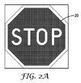
図2Aは、本開示に従う、機械可読光学コードを含むことができる標識20の例示的な図である。標識20は、米国中の多くの道路に配置された交通標識の一例である。本開示に整合する光学コードは、一例として、任意の標識に、又は任意の他の物品に、応用されることができる。図2Aなどの、一例では、光学コードは、赤外スペクトルにおいてのみ可視であるように作成されてもよく、それによって、光学コードは、視覚的な光ではドライバ又は人間の目によっては見られないが、IR光でマシンビジョンシステムによって読み取られることができる。本開示に整合する光学コードを実装するための他の方法は、全体を通して論じられており、本開示を読めば当業者には明らかであろう。
FIG. 2A is an exemplary illustration of a
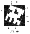
図2Bは、赤外線スペクトルにおいて見られる、標識(例えば、図2Aの標識20)上の機械可読光学コード22の例示的な図である。光学コード22は、光学コード22がどこで開始し終了するかを検出する際にマシンビジョンシステムを支援する移行縁23を有する。移行縁は、本明細書で論じられる再帰性反射表面又は標識上に様々な方法で作成されることができる。標識20の部分24は、光学コード22が標識20とは異なる形状であるので、光学コード22を取り囲んでいる。光学コード22は、大きさの計算のための最初(又はコンテキスト光学要素)の大きさを用いて、7×7マトリックスの大きさを有する。光学コード22は、ファインダ、コンテンツ、クロッキング、タイミング及びコンテキスト光学要素を含む、「1」(25)及び「0」(26)の両方を表す光学要素を含む。
FIG. 2B is an exemplary illustration of a machine-readable
図3は、本開示に従う、例示的な標識構成300である。本開示に整合する光学コードは、移動するものか静止したものかを問わず任意の物品に適用することができるが、図4は、光学コードが、その上に組み込まれた再帰性反射シートを有する標識に適用される実施形態を表す。図3は、本明細書に記載されたような複数の層、再帰性反射シート及び光学コードを有する標識の断面を示す。層410は、基材である。典型的には、基材410は、金属などの、剛体の又は非可撓性の及び耐久性のある材料である。1つのそのような好適な金属は、アルミニウムである。他の実施形態では、基材410は、任意の剛体の、半剛体の、若しくは可撓性のある表面であってもよく、又はそれを含んでいてもよい。
FIG. 3 is an
再帰性反射シート320は、本開示に記載されたような再帰性反射シートであってもよい。接着剤の層(図示されていない)が、再帰性反射シート320と基材310との間に設けられて、再帰性反射シート320を基材310に接着してもよい。本開示に整合して用いられることができる再帰性反射シートの一例は、ミネソタ州St.Paulの3M社から入手可能な、3M Diamond Grade(商標)DG3反射シートシリーズ4000である。
層330は、典型的には層320上に印刷される、メッセージ又は画像を含む。層330は、図2Aに示された一時停止標識などの、交通標識画像であってもよい。層330は、可視光スペクトルにおける任意のメッセージ若しくは画像、又は層340内の光学コード以外の波長において可視であるメッセージ若しくは画像を含んでもよい。単一の標識、ライセンスプレート又は他の基材における異なる波長において可視である情報又は画像を含む例は、参照によりその全体が本明細書に明示的に組み込まれる米国特許第8,865,293号に、より詳細に記載されている。
層340は、図2Bに示された光学コードなどの、本開示に整合する光学コードを含む。層340における光学コードは、様々な方法で形成することができる。例えば、光学コード340が、可視スペクトルにおいて可視であるように設計されている場合、それは、明るい(又は白)基材上に暗い色(黒など)で印刷されることができる。層340における光学コードがIRスペクトルで可視であるように設計される場合(典型的には700〜1000nmの範囲であるが、いくつかの例では850nm又は900nmなどの波長が使用されることもある)、層440における光学コードは、様々な方法で作成することができる。具体的には、層340の下の再帰性反射層320を用いると、赤外スペクトルにおいて再帰性反射を吸収する、散乱する、又はその他の形で阻害する材料又は物質で覆われていない層320の部分はいずれも、白く、又は明るく見えることになる。したがって、赤外スペクトルにおける再帰性反射を吸収する、散乱する、又はその他の形で消す材料を利用することは、層340における黒の光学要素及び光学コードの周囲の境界を形成するために用いることができる。
使用することができる材料の例は、IR吸収黒インクを用いて黒い又は暗いことが望ましい標識の部分を印刷することを含む。他の例では、IR吸収多層光学フィルム(MOF)は、白であることが望ましい標識の何れかの部分が除去され、フィルムが層330上に重ねられるように、選択的に切断されることができる。赤外線スペクトルで見られたとき、フィルムは、白になることが意図されている光学コードの領域における再帰性反射のみを可能にすることになる。赤外線(IR)スペクトルが本明細書で論じられているが、近赤外スペクトル(約950nmの波長を有する光)などの、他のスペクトルが使用されることもできる。層340における光学コードが950nm光吸収フィルムに作成されるとき、950nmの光が光学コードを照らすとき、黒に印刷された部分は、光を吸収し、マシンビジョンシステムには黒に見え、印刷されていない部分は、明るく又は白に見える。
Examples of materials that can be used include printing portions of the sign where black or dark is desired using IR absorbing black ink. In another example, the IR-absorbing multilayer optical film (MOF) may be selectively cut such that any portion of the sign that is desired to be white is removed and the film is overlaid on
標識300は、それが層340の上に形成され又は接着されるオーバーラミネート350を任意選択的に含んでもよい。オーバーラミネート350は、限定されずに、多層光学フィルムなどの、視覚的に透明な赤外線透過材料で構成されてもよい。
The
標識300の構成における再帰性反射層の使用は、いくつかの利点を提供することができる。例えば、情報が主に赤外スペクトルにおいて取り込まれ、画像内の唯一の可視領域が、再帰性反射シート320から反射する光によって生成された明るい又は白い光学要素であるとき、カメラに戻される光の当たり方の状態は、画像取り込み装置及び/又は計算装置が画像内でIR再帰性反射性でない何れかの物体を識別するための困難性を生じさせることがある。これは、標識又は光学コードの周囲の背景、及び個人の顔、画像、又は他の識別情報などの、他の個人情報を含む。
The use of a retroreflective layer in the construction of the
更に、光学コードの白い又は明るい部分を発生させる層340からの再帰性反射光は、結果的に、光学コードと周囲の画像との間の自然な境界又は遷移を含む、画像における黒い領域の間に著しいコントラストを有する画像をもたらすことができる。そのような遷移は、図2Bの項目23として示されている。いくつかの既存のQRコードでは、黒の光学要素が、マシンビジョンシステムに対してQRコードがどこで開始及び終了するかを図で表すコードの境界の全体又は一部の周りに必要であることがある。対照的に、標識300上の光学コードを取り囲む領域はIRスペクトルで黒に見えることになるので、いくつかの実施例では、追加の境界光学要素が必要とされず、より大きな符号化効率を可能にする。
In addition, the retroreflected light from
図4Aは、入れ子状のコンテンツ光学要素を有する機械可読光学コード400を表す。いくつかの実施例では、入れ子状又は「子」光学要素は、親光学要素内に含まれることができる。例えば、親光学要素の組402は、少なくとも1つの親光学要素406を含むことができ、親光学要素406は、子光学要素の組(例えば、図4Aのセル[A、1]内の4つの光学要素を含む)を更に含み、子光学要素の組は、子光学要素406などの、光学要素の対応する組を含む。
FIG. 4A illustrates a machine readable
いくつかの実施例では、親光学要素の少なくとも1つの光学要素に対応する第1の符号化された値は、閾値距離よりも長いか又は等しい、画像取り込み装置と物品との間の特定の距離において、復号可能である。子光学要素の組の中の光学要素の組にそれぞれ対応する子の符号化された値は、画像取り込み装置と物品との間の特定の距離において復号可能でないことがある。いくつかの実施例では、特定の距離は、第1の距離であり、子光学要素の組の中の光学要素の組にそれぞれ対応する子の符号化された値は、画像取り込み装置と物品との間の、第1の距離よりも短い、第2の距離において復号可能である。いくつかの実施例では、閾値距離は、画像取り込み装置によって取り込まれた画像の解像度が、子光学要素の組のうち視覚的に異なる1つ以上の光学要素同士を、区別可能性閾値を超えて、視覚的に区別しない距離である。いくつかの実施例では、区別可能性閾値は、ユーザ定義されるか、ハードコードされるか、又は機械生成されてもよい。 In some embodiments, the first encoded value corresponding to at least one optical element of the parent optical element is a specific distance between the image capture device and the article that is greater than or equal to a threshold distance. Can be decoded. The child encoded values corresponding to each set of optical elements in the set of child optical elements may not be decodable at a particular distance between the image capture device and the article. In some embodiments, the particular distance is a first distance, and the encoded values of the children, each corresponding to a set of optical elements in the set of child optical elements, are determined by the image capture device and the article. , And a second distance shorter than the first distance. In some embodiments, the threshold distance is such that the resolution of the image captured by the image capture device exceeds one or more visually distinct optical elements of the set of child optical elements above a distinguishability threshold. Is a distance that is not visually distinguished. In some embodiments, the differentiability threshold may be user-defined, hard-coded, or machine-generated.
いくつかの実施例では、光学コードは、コンテンツ光学要素とコンテキスト光学要素の両方を含むことができる。入れ子状のコンテンツ光学要素は、それぞれデータのビットとして個別に読み取られることができる、又は単一のコンテキスト光学要素として一緒に読み取られることができる4つのコンテンツ光学要素のブロックである。第1の距離から、光学コード400は、行A−B、C−D、E−F、G−H、I−J、K−L及びM−N、並びに列1−2、3−4、5−6、7−8、9−10、11−12及び13−14を有する、7×7コードとして見える。図1に示された画像と同様に、行G−H及び列7−8の光学要素は、ファインダ光学要素である。図4Aの機械可読光学コードは、それが入れ子状のコンテンツ光学要素を可能にする光学要素内の階調度の使用を示す点において、図1とは異なる。
In some embodiments, the optical code can include both a content optical element and a context optical element. A nested content optical element is a block of four content optical elements that can each be read individually as bits of data, or that can be read together as a single context optical element. From a first distance, the
図4Bは、入れ子状のコンテンツ光学要素を有する機械可読光学コードの部分を示す。多くのマシンビジョンシステムでは、システムは、画像内の最も明るい明暗及び画像内の最も暗い明暗を検出することによって光学要素が「白」か又は「黒」かどうかを決定する。機械は、次に、検出された白と黒との間の中間である明暗よりも暗い何れのものも黒であると決定されると決定することよって、画像を「二値化する」。中間(又は50%)の明暗よりも明るいものはいずれも、白であると決定される。この同じ原理は、コンテンツ光学要素の複数の層が入れ子にされたとき適用されることができる。 FIG. 4B shows a portion of a machine-readable optical code having nested content optical elements. In many machine vision systems, the system determines whether an optical element is "white" or "black" by detecting the brightest light and shade in the image and the darkest light and dark in the image. The machine then "binarizes" the image by determining that anything darker than the light and dark that is halfway between the detected white and black is determined to be black. Anything lighter than the medium (or 50%) light and dark is determined to be white. This same principle can be applied when multiple layers of content optical elements are nested.
図4Bは、物理的表面に組み込まれた親光学要素の組及び子光学要素の組の階層を更に表す。例えば、光学要素の組424(異なる詳細さのレベルで425及び426として描かれている)は、4つの子光学要素A11、A12、B11、B12を有する親光学要素の組であることができる。親光学要素の組は、それぞれが第1の大きさである第1の複数の光学要素(例えば、A11、A12、B11、B12)を含む。子光学要素の組427は、それぞれが第1の大きさよりも小さい第2の大きさである第2の複数の光学要素A12a、A12b、A12c、及びA12dを含む。図4Bの例では、親光学要素の組424によって表される第1の符号化された値(「1」)は、子光学要素の組のうち特定の光学要素A12b(例としてA12bを用いる)の視覚的外観に少なくとも部分的に基づいており、部分的に特定の光学要素A12bによって表される第2の符号化された値(「0」)は、特定の光学要素A12bの視覚的外観に少なくとも部分的に基づいており、第1と第2の符号化された値は異なる。光学要素A12に対する第2の符号化された値(「0」)は、閾値距離よりも長い距離からは復号可能でないことがあり、第1の符号化された値(「1」)は閾値距離よりも長い距離から復号可能である。図4Bに示されたように、子光学要素の組の各光学要素は、親光学要素の組の1つの光学要素内に含まれることができる。他の実施例では、子光学要素の組は、親光学要素の組と重ならなくてもよく又は親光学要素の組に含まれていなくてもよい。 FIG. 4B further illustrates the hierarchy of the set of parent optical elements and the set of child optical elements incorporated into the physical surface. For example, optical element set 424 (depicted as 425 and 426 at different levels of detail) can be a parent optical element set having four child optical elements A11, A12, B11, B12. The set of parent optical elements includes a first plurality of optical elements (eg, A11, A12, B11, B12) each having a first size. The sub-optical element set 427 includes a second plurality of optical elements A12a, A12b, A12c, and A12d each having a second size smaller than the first size. In the example of FIG. 4B, the first encoded value ("1") represented by the parent optical element set 424 is a particular optical element A12b (using A12b as an example) of the child optical element set. The second encoded value ("0"), which is based at least in part on the visual appearance of the particular optical element A12b, is based on the visual appearance of the particular optical element A12b. Based at least in part on the first and second encoded values are different. The second encoded value ("0") for optical element A12 may not be decodable from a distance greater than the threshold distance, and the first encoded value ("1") may be the threshold distance. Can be decoded from a longer distance. As shown in FIG. 4B, each optical element of the set of child optical elements can be included within one optical element of the set of parent optical elements. In other embodiments, the set of child optical elements may not overlap with or be included in the set of parent optical elements.
図4Bに示されたように符号化された値を階層的に配列することによって、より重要な情報(例えば、「STOP」標識の存在)は、画像取り込み装置と光学要素を含む物品との間の距離から更に離れた距離から復号されることができる、より高いレベルの階層(例えば、親光学要素の組)における光学要素に符号化されることができる。重要性がより小さい情報(例えば、物品の製造日)は、画像取り込み装置が光学要素を含む物品により近いときにのみ復号されることができる、より低いレベルの階層における光学要素(例えば、子光学要素の組)に符号化されることができる。図4Bの3つのレベルなどの、光学要素の組の任意のN個の階層レベルが使用されることができる。 By arranging the encoded values in a hierarchical manner as shown in FIG. 4B, more important information (eg, the presence of a “STOP” sign) is transmitted between the image capture device and the article containing the optical element. Can be encoded into optical elements in a higher level hierarchy (eg, a set of parent optical elements) that can be decoded from a distance further away from the distance. Information of lesser importance (eg, the date of manufacture of the article) can be decoded only when the image capture device is closer to the article containing the optical element (eg, child optics at a lower level hierarchy). Element set). Any N hierarchical levels of the set of optical elements, such as the three levels in FIG. 4B, can be used.
層状にされたコンテンツ光学要素の他の例が、ブロック11−12、列C−Dに示されている。コード400を生成するとき、ブロック11−12、列C−Dからなるブロック411は、単一のブロックとして(コンテキスト光学要素として)一緒に読み取られるとき、累積的に「0」として復号される。マシンビジョンシステムは、尺度410で示された陰影0、0を領域内で最も明るい色であると検出し、尺度410で示された陰影1、1を最も暗い色として検出するので、光学要素C−D、11−12内の全てのブロックが「0」として読まれるようにするために、411内の4つのブロックのそれぞれにおける陰影は、尺度410上で50%のラインを下回っていなければならない。
Another example of a layered content optical element is shown in blocks 11-12, columns CD. When generating
ブロック411において4つのコンテンツ光学要素のそれぞれに入れ子状にされた情報を読み取るかそうでなければ復号するために、マシンビジョンシステムは、ブロック411を分離し、ブロック411内のみの陰影にその二値化器の目盛を調整することができる。陰影は尺度410の50%ラインを下回るので、二値化器は、次に、25%ラインを下回る黒レベル(例えば、輝度に基づいて)を有する領域は何れも「0」であり、25%ラインを上回るものは何れも「1」であると決定する。したがって、411及び412における4つのブロックが単一の光学要素として一緒に読み取られたときに「0」として読み取られることにたとえなっても、コンテンツ光学要素として、個別に読み取られたときに、C11とD12は、「0」であり、一方C12及びD11は「1」である。
In order to read or otherwise decode the information nested in each of the four content optical elements in
同様に、ブロック413は、コンテキスト光学要素として第1の距離から読み取られたときに、「1」として読み取られる必要がある。これを達成するために、コンテキスト光学要素413が第1の距離から読み取られるとき、マシンビジョンシステムが、4つのブロック全てが階調度尺度上の50%ラインを上回るので、4つのブロック全てが「暗い」又は「黒」であると決定するように、尺度410上の50%ラインよりも大きい陰影のみが用いられる。ブロック414内のコンテンツ光学要素が個別に読み取られるとき、ブロック414を分離して読み取るときに50%ラインを上回る階調度範囲のみを見ているマシンビジョンシステムに基づくと、E11は「0」であり、E12、F11、及びF12は「1」である。いくつかの実施例では、視覚的外観は、異なる度合の輝度を有する階調度値の範囲内における輝度の度合を示す視覚的階調度値によって表される、又は表されることができる。
Similarly, block 413 needs to be read as a "1" when read from a first distance as a context optic. To accomplish this, when the
ブロック又は光学要素421〜426は、3レベルの入れ子状のデータを用いた実装を例示している。ブロック421は、第1の距離から読み取られるとき、「1」であり、これは、全ての陰影が尺度420上の50%ラインよりも大きいためである。しかし、第2のより近い距離から読み取られるとき、(ブロック422に示されたように)光学要素A11とA12は、これらの光学要素のそれぞれの内の陰影が、ブロック422を二値化するために用いられる分割点となった、75%ラインを下回るため、「0」として読み取られる。光学要素B11とB12は、1として読み取られる。ブロック423が第3の(及び最も近い)距離から読み取られるとき、マシンビジョンシステムは、光学要素A11、A12、B11及びB12のそれぞれが4つの入れ子状の光学要素からなっていることを検出することができる。光学要素A11及びA12では、カラースペクトルは、尺度420上で1、0、0と1、0、1との間のみの範囲にあるため、A11内の4つの入れ子状の光学要素は、0、0、0、0として読み取られ、A12内の4つの入れ子状の光学要素は1、1、0、1として読み取られる。
Blocks or optical elements 421-426 illustrate an implementation using three levels of nested data.
光学要素424は、第1の距離において単一のコンテキスト光学要素として読み取られたときに、「0」として符号化され、そのため、光学要素424内で用いられた全ての陰影は、尺度420上の50%の黒レベルを下回る。ブロック425が第2の距離において4つの別個のコンテンツ光学要素として読み取られるとき、光学要素A11は「1」であり、A12、B11及びB12はそれぞれ「0」である。ブロック426は、第1の距離又は第2の距離の何れよりも近い、第3の距離において読み取られることができ、ブロック425について述べられた各コンテンツ光学要素は、今度は4つの別個のコンテンツ光学要素として読み出されることができる。ブロックA11内のコンテンツ光学要素は、1、1、0、0である。ブロックA12内のコンテンツ光学要素は、1、0、1、0である。ブロックB11内のコンテンツ光学要素は1、0、1、0であり、ブロックB12内のコンテンツ光学要素は1、0、0、1である。50%の黒レベルラインは一例として設けられているが、100〜1%間の任意の値が可能である。
コンテンツ光学要素とコンテキスト光学要素を入れ子にする特定の方法が本明細書に記載されているが、本開示の範囲内の他の方法は、本開示を読めば当業者には明らかであろう。本開示は2レベルの入れ子及び3レベルの入れ子を具体的に記載しているが、任意の所望のレベルの入れ子にすることが、画像取り込み及び処理技術の制限に基づいて、達成されることができる。例えば、5レベルの入れ子を有するコードを実装するためには、階調度の尺度は、25又は32の階調度の色(又は灰色)に分割される必要があることになる。 Although specific ways of nesting content and context optics are described herein, other methods within the scope of this disclosure will be apparent to those of skill in the art upon reading this disclosure. Although the present disclosure specifically describes two levels of nesting and three levels of nesting, any desired level of nesting may be achieved based on limitations of image capture and processing techniques. it can. For example, to implement a code with five levels of nesting, the gradient measure would need to be split into 25 or 32 gradient colors (or gray).
図5は、多次元機械可読光学コードを読み取るシステム500の例である。システム500は、標識520を含む。標識面522は、可視光スペクトルで見られることができる画像、一時停止画像522、及び可視光スペクトルの外側の可視光スペクトルにおいて可視であることができる、機械可読光学コード530を含む。標識500は、基材を有し、光学コード530の後に再帰性反射シートの層も含むことができる。
FIG. 5 is an example of a
光学コード530は、パターンに配置された、第1の距離から車両510に搭載されたマシンビジョンシステム512によって検出可能な複数のファインダ光学要素を含む。光学コード530はまた、コンテキスト情報を表す複数のコンテキスト光学要素を含み、コンテキスト光学要素は、第1の距離からマシンビジョンシステムによって検出可能である。光学コード530はまた、コンテンツ情報を表す複数のコンテンツ光学要素を含み、コンテンツ光学要素は、第1の距離においてマシンビジョンシステムによって検出可能ではないが、第2の距離からマシンビジョンシステムによって検出可能であり、第2の距離は第1の距離よりも短い。
車両510が標識520に近づくにつれ、マシンビジョンシステム512は、機械可読光学コードを検出し、処理する。マシンビジョンシステム512は図5において移動可能に車両510に装着されているように示されているが、マシンビジョンシステムは、静止していてもよく、又は他の機器や装置に取り付けられてもよい。マシンビジョンシステム512は、画像センサ及び光源を含む、赤外線カメラであってよい。いくつかの例では、マシンビジョンシステムは、IRスペクトルに対する画像センサの感度を増大させるフィルタを含むことになる。他の種類のマシンビジョンシステムは、本開示を読めば当業者には明らかであろう。
As the
マシンビジョンシステム512は、ネットワークを必要としない有線又は無線の接続を介して計算装置540と直接接続されるように、計算装置540を含むことができる。他の例では、マシンビジョンシステム512は、1つ以上の通信リンク550A、550Bを用いて、計算装置540と通信可能に結合されることができる。計算装置540は、ネットワーク552によって車両510に接続されているように表されているが、他の実施例では、計算装置540は、車両510内に又は車両510に直接的に含まれて、車両の直接通信又は内部ネットワークを通して車両の構成部品と通信することができてもよい。
マシンビジョンシステム512は、光学コードの画像を計算装置540に送ることができる。通信リンク550Aと550Bは、有線又は無線の接続であってもよい。例えば、通信リンク550A及び550Bは、WiFiプロトコルを用いる無線イーサネット接続であってもよく及び/又はカテゴリ5又はカテゴリ6のケーブルを用いる有線イーサネット接続であってもよい。何れの好適な通信リンクも可能である。いくつかの実施例では、マシンビジョンシステム512は、ネットワーク552によって計算装置540に通信可能に結合される。ネットワーク552は、パケット及び/又はフレーム型のデータの転送を提供するルータ、スイッチ、ハブ及び相互接続通信リンクを限定されることなく含む1つ以上の任意の数のネットワークに接続された装置を表することができる。例えば、ネットワーク552は、インターネット、サービスプロバイダのネットワーク、顧客のネットワーク又は任意の他の好適なネットワークを表することができる。他の実施例では、マシンビジョンシステム512は、ユニバーサルシリアルバス(USB)リンクなどの、直接接続によって計算装置540に通信可能に結合される。
The
計算装置540は、マシンビジョンシステム512に情報を送ること及びマシンビジョンシステム512から情報を受け取ることができる、1つ以上のデスクトップコンピュータ、ラップトップコンピュータ、メインフレーム、サーバ、クラウドコンピューティングシステム等などの、マシンビジョンシステム512を有する又はマシンビジョンシステム512から離れた単一の装置であってもよい、任意の好適なコンピューティングシステムを表す。いくつかの実施例では、計算装置540は、本開示の技術を実行する。
図5の実施例では、計算装置540は、符号化コンポーネント542、データ層626、サービスコンポーネント546及びユーザインタフェース(UI)コンポーネント548を含む。符号化コンポーネント542は、必要なデータ符号化体系又はアルゴリズムを光学コード530上のデータに適用することによって、光学コード530内の符号化されたデータを検出することができる。符号化コンポーネント542は、データ層626に問い合わせて、光学コード530から検出されたバイナリコードを機械可読情報に変換することができる。
In the example of FIG. 5, the
サービスコンポーネント546は、1つ以上の動作を実行することによって、任意の数のサービスを提供することができる。例えば、サービスコンポーネント546は、光学コードから読み取られたデータを受け取ると、車両510上の自動運転コンポーネントを含む、1つ以上の他の計算装置に送られる1つ以上のアラート、レポート又は他の通信を生成することができる。かかるアラートは、電子メール、テキストメッセージ、リスト、電話呼又は他の好適な通信を、限定されることなく、含む。いくつかの実施例では、ユーザインタフェース(UI)コンポーネント548は、計算装置540のさまざまな構成要素及び光学要素の間の媒介として作動して、入力装置によって検出された入力を処理し他の構成要素及び光学要素に送信し、1つ以上の出力装置において提示されることができる、他の構成要素及び光学要素からの出力を生成することができる。例えば、UIコンポーネント548は、アラート、報告又は他の通信の、データ及び/又はグラフィック表現を含むことができる、表示用の1つ以上のユーザインタフェースを生成することができる。
The
コンポーネント542、626、546、及び548は、計算装置540、及び/又は1つ以上の他の遠隔の計算装置に常駐して実行されるソフトウェア、ハードウェア、ファームウェア、又は、ハードウェア、ソフトウェア、及びファームウェアの混合を使用して、本明細書で説明する動作を実行することができる。いくつかの実施例では、コンポーネント542、626、及び546は、ハードウェア、ソフトウェア、及び/又はハードウェアとソフトウェアの組み合わせとして実装することができる。計算装置540は、コンポーネント626、546、及び548を1つ以上のプロセッサを用いて実行することができる。計算装置540は、基盤ハードウェア上で動作するバーチャルマシンとして、又はバーチャルマシン内で、コンポーネント542、626、546、又は548のいずれも実行することができる。コンポーネント542、626、546、548は、さまざまなやり方で実装することができる。例えば、コンポーネント542、626、546、又は548のいずれかも、ダウンロード可能な、又はプリインストールされているアプリケーション又は「アプリ」として実装することができる。別の実施例では、コンポーネント542、626、546、又は548のいずれも、計算装置540のオペレーティングシステムの一部として実装することができる。
例えば、図5において、マシンビジョンシステムは、車両510の一部として、又は車両510搭載されているものとして図示されている。車両510は、自動車、オートバイ、航空機、船舶、軍装備品、自転車、列車、又は任意の他の輸送車両とすることができる。他の実施例では、マシンビジョンシステム512は、ほんのいくつかの例を挙げれば、文書、衣類、ウェアラブル機器、建物、固定設備、又は任意の他の物体に取り付ける、含める、又は埋め込む、又は他のやり方でこれらを構成することができる。
For example, in FIG. 5, the machine vision system is illustrated as being part of or mounted on the
光学コード530は、図5には標識として組み込まれて示されているが、光学コードは、いくつかの例のみを挙げると、文書、衣類、ウェアラブル機器、建物、固定設備、又は他の任意の物体に、設置する、取り付ける、含める、又は埋め込むことができる。
Although the
いくつかの実施例では、光学コード530、又は光学コード530が取り付けられる物品は、基板面に貼り付けられた反射性、非反射性、及び/又は再帰反射性シートを含むことができる。文字、画像、及び/又はその他の情報等の、ただし、それらに限定されない、可視メッセージが、光学コード530物品上に印刷、形成、又は他のやり方で組み込まれてもよい。反射性、非反射性、及び/又は再帰反射性シートは、機械的接着、熱接着、化学的接着、又は、再帰反射性のシートを基板面に取り付けるための任意の他の好適な技術を含むが、それらに限定されない、1つ以上の技術及び/又は材料を使用して、基板面に貼り付けることができる。基板面は、反射性、非反射性、及び/又は再帰反射性シートを取り付けることができる物体(上述のような、例えば、アルミ板など)の任意の表面を含むことができる。物品メッセージは、インク、染料、熱転写リボン、着色剤、顔料、及び/又は接着被覆フィルムのうちのいずれか1つ以上を使用して、シート材に印刷し、形成し、又は他のやり方で実現することができる。いくつかの実施例では、コンテンツは、多層光学フィルム、光学活性顔料あるいは染料を含む材料、又は光学活性顔料あるいは染料から形成されるか、又はそれらを含む。
In some embodiments, the
最初に光学コード530を製造又は作成するために、製作デバイス570を、製作デバイス570の動作を制御する計算装置560ととともに使用することができる。いくつかの実施例では、製作デバイス570は、光学コード530及び/又は標識520を印刷、配置、又は別の方法で形成する任意のデバイスとすることができる。製作デバイス138の例としては、ニードルダイ、グラビア印刷機、スクリーン印刷機、熱転写印刷機、レーザプリンタ/刻印機、ラミネータ、フレキソ印刷機、インクジェットプリンタ、赤外線インクプリンタが挙げられるが、これらに限定されない。いくつかの実施例では、光学コード530は、製作デバイス570、及び別の製作プロセス又はデバイスによって製作された再帰反射性シート材又は赤外線吸収あるいは散乱フィルムによって可能にされてもよく、いくつかのケースでは、計算装置560とは別のオペレータ又はエンティティによって操作される別の製作プロセス又はデバイスが、シート材に物品メッセージを、及び/又は基板層(アルミ板など)にシート材を、貼り付けてもよい。
The
製作デバイス570は、通信リンク550Dによって計算装置560に通信可能に結合してもよい。計算装置560は、製作デバイス570の動作を制御してもよい。例えば、計算装置560は、1つ以上の印刷仕様を備ええもよい。印刷仕様は、可視標識面522及び光学コード530の特性(例えば、位置、形状、サイズ、パターン、構成、又は他の空間的特性)を定義するデータを含んでもよい。いくつかの実施例では、印刷仕様は、人間のオペレータ又は機械によって作成することができる。いずれの場合にも、製作コンポーネント562は、製作デバイス570にデータを送信して、プリンタ仕様に従って、可視の画像又はメッセージ及び光学コードを製作デバイス570に印刷させてもよい。
いくつかの実施例では、製作コンポーネント562は、視覚的にオクルージョンされる可能性がある、標識の1つ以上の蓋然性の高い領域又はエリアを決定してもよい。そのような領域又はエリアは、少なくとも潜在的な視覚的オクルージョン又はオクルージョンの表現を含む1つ以上の画像に基づいて、ユーザによって定義されてもよく、ハードコードされてもよく、又は製作コンポーネント562によって決定されてもよい。いくつかの実施例では、製作コンポーネント562は、視覚的にオクルージョンされ得る特定の標識の異なる領域又はエリアをユーザが指定することができるグラフィカルユーザインターフェースを出力してもよい。視覚的にオクルージョンされ得る領域又はエリアの決定に基づいて、製作コンポーネント562は、物品上のブロックの形状、サイズ、及び/又は位置を構成して、潜在的な視覚的オクルージョンの1つ以上の領域又はエリアがオクルージョンされた場合に、光学要素の組に符号化されているメッセージがなお計算装置によって復号可能である蓋然性を高めることができる。一例として、光学コードの右上象限の領域又はエリアが視覚的にオクルージョンされる可能性が高い場合、製作コンポーネント562は、メッセージを表す光学要素の組を右上隅以外の位置に配置してもよいが、更に、右上象限の領域又はエリアに配置された光学要素の組にエラー訂正データを含んでもよい。機械可読コードの視覚的オクルージョンの既知の、又は蓋然性の高い、エリアに基づいて、光学要素のサイズ、形状、及び位置の、その他の任意の数の分布があり得る。
In some embodiments,
いくつかの実施例では、機械可読コード内のメッセージを復号するために、符号化コンポーネント542は、画像内の各光学要素の組のそれぞれの予め定められた場所を示す光学要素の組の場所データに少なくとも部分的に基づいて、光学要素の組を決定することができる。すなわち、光学要素の組の場所データは、異なる光学要素の組及び/又は個々の光学要素にマッピングされる座標又は他の位置値を示してもよい。符号化コンポーネント542は、光学要素の組のうちの各光学要素のそれぞれの予め定められた場所を示す光学要素の場所データに少なくとも部分的に基づいて、光学要素の各々について、それぞれの階調度値を決定してもよい。例えば、画像の予め定められた場所と光学要素の間の既知のマッピングを考えて、符号化コンポーネントは、(いくつかの実施例では、単一の点又は画素に対応する点のセットであってもよい)その予め定められた場所の階調度値を測定するか、又は別の方法で決定してもよい。符号化コンポーネント542は、階調度値と符号化された値の間のマッピングに少なくとも部分的に基づいて、メッセージの少なくとも一部分を決定してもよい。例えば、符号化コンポーネント542は、階調度値と符号化された値の間の1つ以上の記憶されたマッピングにアクセスし、光学要素の検知された階調度値に基づいて、メッセージの一部分を表す復号された値のストリングを再構成する。
In some embodiments, to decode the message in the machine readable code, the
いくつかの実施例では、車両の計算装置は、ドリフトを除去し、GPS精度の不確実性を除去する、1組の基準(又はナビゲーションマーカ)を必要とするものとしてもよい。本開示の機械可読コード、及び、コードを含む物品に近接する物体又は危険についてのデータにマップされる一意又は準一意(例えば、特定のクラス又は属を示す)のIDが、そのような基準を提供してもよい。いくつかの実施例では、本開示の機械可読コードはまた、コンテンツとコンテキストの光学要素の間に冗長性の広がりを含むことができ、それにより、車両の計算装置は、データベースから参照されたデータが、その特定の交通標識又は物品に適用され、物品に関してエラー又は偽造の発生がなかったことを、十分な信頼度をもって(例えば、閾値を超えるなど)判定することができる。このような技術及び機械可読コードは、セキュリティにまで拡張されてもよく、それにより、冗長性情報がローカル及びベータベースに記憶され、この使用事例ではセキュリティの更なる尺度として計算装置によって比較又は検証され得る。 In some embodiments, the vehicle's computing device may require a set of fiducials (or navigation markers) to eliminate drift and remove GPS accuracy uncertainties. The machine readable code of the present disclosure, and a unique or semi-unique (eg, indicating a particular class or genus) ID that maps to data about an object or danger in proximity to the article containing the code, satisfies such criteria. May be provided. In some embodiments, the machine readable code of the present disclosure may also include a spread of redundancy between the content and contextual optics, so that the computing device of the vehicle may be able to access the data referenced from the database. Is applied to that particular traffic sign or item, and it can be determined with sufficient confidence (e.g., a threshold is exceeded, etc.) that no error or counterfeit has occurred for the item. Such techniques and machine readable code may be extended to security whereby redundancy information is stored locally and in a beta base, and in this use case compared or verified by a computing device as a further measure of security. Can be done.
いくつかの実施例では、車両又はその他の計算装置は、標識が真正であること、及び/又は、機械可読コードに符号化されたメッセージが正しいことを検証してもよい。このようにして、このような検証は、標識があるべき所に配置されており、それが有効な符号化を有することについて、より高い信頼性を与えてもよい。例えば、機械可読コードに符号化されたGPS位置が、標識が読み取られた時に、車両によって判定されたGPS位置と比較されてもよい。他のこのような比較も可能であり、本開示の範囲及び趣旨の範囲内である。 In some embodiments, the vehicle or other computing device may verify that the sign is authentic and / or that the message encoded in the machine readable code is correct. In this way, such verification may be placed where the indicator should be, and may give more confidence that it has a valid encoding. For example, the GPS position encoded in the machine readable code may be compared to the GPS position determined by the vehicle when the sign was read. Other such comparisons are possible and within the scope and spirit of the present disclosure.
図6は、多次元機械可読光学コードを読み取るためのシステムにおいて使用するための計算装置の一例である。図6は、図5に示すように、計算装置540の1つの特定の実施例のみを図示するものである。計算装置540の多くの他の実施例が、他の例において使用されてもよく、例示的な計算装置540に含まれるコンポーネントのサブセットを含んでもよく、又は、図6の例示的な計算装置540に示されていない追加のコンポーネントを含んでもよい。いくつかの実施例では、計算装置540は、アプリケーション620に含まれた機能のセット、サブセット、又はスーパーセットを実行してもよい、サーバ、タブレット計算装置、スマートフォン、手首、あるいは頭部装着型計算装置、ラップトップ、デスクトップ計算装置、又は任意の他の計算装置とすることができる。
FIG. 6 is an example of a computing device for use in a system for reading multidimensional machine readable optical codes. FIG. 6 illustrates only one particular embodiment of a
図6の実施例に示すように、計算装置540は、ユーザ空間602、カーネル空間604、及びハードウェア606に論理的に分割してもよい。ハードウェア606は、ユーザ空間602及びカーネル空間604内で実行するコンポーネントのための動作環境を提供する1つ以上のハードウェアコンポーネントを備えてもよい。ユーザ空間602及びカーネル空間604は、メモリの異なるセクション又はセグメンテーションを表してもよく、カーネル空間604は、プロセス及びスレッドに対して、ユーザ空間602よりも高い権限を提供する。例えば、カーネル空間604は、ユーザ空間602内で動作するコンポーネントより高い権限を有して動作するオペレーティングシステム620を備えることができる。
As shown in the embodiment of FIG. 6, the
図6に示すように、ハードウェア606は、1つ以上のプロセッサ608、入力コンポーネント610、ストレージデバイス612、通信ユニット614、及び出力コンポーネント616を備える。プロセッサ608、入力コンポーネント610、ストレージデバイス612、通信ユニット614、及び出力コンポーネント616は各々、1つ以上の通信チャネル618によって相互接続してもよい。通信チャネル618は、コンポーネント間通信のために、コンポーネント608、610、612、614、及び616の各々を(物理的に、通信によって、及び/又は動作可能に)相互接続することができる。いくつかの実施例では、通信チャネル618は、ハードウェアバス、ネットワーク接続、1つ以上のプロセス間通信データ構造、又は、ハードウェア及び/あるいはソフトウェア間でデータを通信するための任意の他のコンポーネントを備えてもよい。
As shown in FIG. 6, the
1つ以上のプロセッサ608は、計算装置540内の機能を実現し、及び/又は、命令を実行することができる。例えば、計算装置540上のプロセッサ608は、カーネル空間604及びユーザ空間602に含まれるコンポーネントの機能を提供する、ストレージデバイス612によって記憶された命令を受信して実行してもよい。プロセッサ608により実行されるこれらの命令が、計算装置616に、プログラム実行中に、ストレージデバイス612内の情報を記憶及び/又は変更させてもよい。プロセッサ608が、カーネル空間604及びユーザ空間602内のコンポーネントの命令を実行して、本開示の技術に係る1つ以上の動作を行ってもよい。即ち、ユーザ空間602及びカーネル空間604に含まれるコンポーネントが、本明細書に記載されるさまざまな機能を実行するように、プロセッサ208によって操作可能であってもよい。
One or
計算装置540の1つ以上の入力コンポーネント642が、入力を受信してもよい。入力の例としては、ほんのいくつかの例を挙げれば、触知入力、オーディオ入力、運動入力、及び光入力がある。1つの実施例では、計算装置616の入力コンポーネント642としては、マウス、キーボード、音声応答システム、ビデオカメラ、ボタン、制御パッド、マイクロホン、又は人間あるいは機械からの入力を検知するための任意のその他の種類のデバイスが挙げられる。いくつかの実施例では、入力コンポーネント642は、存在感知スクリーン、タッチ感知スクリーンなどを含むことができる存在感知入力コンポーネントとしてもよい。
One or more input components 642 of
計算装置616の1つ以上の出力コンポーネント616は、出力を生成することができる。出力の例としては、触知出力、オーディオ出力、及びビデオ出力がある。いくつかの実施例では、計算装置540の出力コンポーネント616には、存在感知スクリーン、サウンドカード、ビデオグラフィックアダプタカード、スピーカ、陰極線管(CRT)モニタ、液晶ディスプレイ(LCD)、又は人間あるいは機械への出力を生成するための任意のその他の種類のデバイスが含まれる。出力コンポーネントとしては、陰極線管(CRT)モニター、液晶ディスプレイ(LCD)、発光ダイオード(LED)、又は触知出力、オーディオ出力、及び/あるいは視覚出力を生成するための任意のその他の種類のデバイスなどの、ディスプレイコンポーネントを挙げることができる。出力コンポーネント616は、いくつかの実施例では、計算装置540と一体であってもよい。他の実施例では、出力コンポーネント616は、計算装置540に対して物理的に外部にあり、かつ分離していてもよいが、有線又は無線通信を介して計算装置540に動作可能なように接続してもよい。出力コンポーネントは、計算装置540の外側筐体内に配置され、それに物理的に接続された、計算装置540の内蔵コンポーネント(例えば、携帯電話上のスクリーン)とすることができる。別の実施例では、存在感知ディスプレイ602は、計算装置540の筐体の外側に配置されて物理的に分離された、計算装置540の外部コンポーネント(例えば、タブレットコンピュータと有線及び/又は無線データ経路を共有するモニタ、プロジェクタなど)とすることができる。
One or more output components 616 of computing device 616 can generate output. Examples of outputs include tactile output, audio output, and video output. In some embodiments, output component 616 of
計算装置540の1つ以上の通信ユニット614は、データを送信及び/又は受信することにより、外部デバイスと通信してもよい。例えば、計算装置540は、通信ユニット614を使用して、セルラ無線ネットワークなどの無線ネットワーク上で無線信号を送信及び/又は受信してもよい。一部の例では、通信ユニット614は、全地球測位システム(GPS)ネットワークなどの衛星ネットワーク上で衛星信号を送信及び/又は受信してもよい。通信ユニット614の例としては、ネットワークインターフェイスカード(例えば、イーサネットカードなど)、光トランシーバー、無線周波数トランシーバー、GPS受信機、又は情報を送信及び/あるいは受信することができる任意のその他の種類のデバイスが挙げられる。通信ユニット614の他の例としては、モバイルデバイスに見られるBluetooth(登録商標)、GPS、3G、4G、及びWi−Fi(登録商標)無線、並びにユニバーサルシリアルバス(USB)コントローラなどを挙げることができる。
One or more communication units 614 of
計算装置540内の1つ以上のストレージデバイス612は、計算装置540の動作中に処理するための情報を記憶してもよい。いくつかの例では、ストレージデバイス612は、一時メモリであり、これはストレージデバイス612の主要目的が長期の格納ではないことを意味する。計算装置540上のストレージデバイス612は、情報の短期格納用に揮発性メモリとして構成されてもよく、したがって、動作停止されると格納された内容を保持しない。揮発性メモリの例としては、ランダムアクセスメモリ(RAM)、ダイナミックランダムアクセスメモリ(DRAM)、スタティックランダムアクセスメモリ(SRAM)、及び当該技術分野で既知の他の形態の揮発性メモリが挙げられる。
One or more storage devices 612 within
いくつかの実施例では、ストレージデバイス612はまた、1つ以上のコンピュータ可読記憶媒体を含む。ストレージデバイス612は、揮発性メモリより大量の情報を記憶するように構成することができる。ストレージデバイス612は、更に、情報の長期記憶用に不揮発性メモリスペースとして構成され、起動/停止サイクルの後、情報を保持してもよい。不揮発性メモリの例としては、磁気ハードディスク、光ディスク、フロッピィディスク、フラッシュメモリ、又は電気的プログラマブルメモリ(EPROM)あるいは電気的消去可能及びプログラマブルメモリ(EEPROM)の形態が挙げられる。ストレージデバイス212は、ユーザ空間602及び/又はカーネル空間604に含まれるコンポーネントに関連付けられたプログラム命令及び/又はデータを記憶してもよい。
In some embodiments, storage device 612 also includes one or more computer-readable storage media. The storage device 612 can be configured to store more information than volatile memory. The storage device 612 may further be configured as a non-volatile memory space for long term storage of information and retain information after a start / stop cycle. Examples of non-volatile memory include magnetic hard disk, optical disk, floppy disk, flash memory, or electrically programmable memory (EPROM) or electrically erasable and programmable memory (EEPROM). Storage device 212 may store program instructions and / or data associated with components included in
図6に示すように、アプリケーション628は、計算装置540のユーザ空間602で実行される。アプリケーション628は、プレゼンテーション層622、アプリケーション層624、及びデータ層626に論理的に分割することができる。プレゼンテーション層622は、アプリケーション628のユーザインターフェースを生成して表示するユーザインターフェース(UI)コンポーネント548を含んでもよい。アプリケーション228は、UIコンポーネント548、符号化コンポーネント542、データ層626、及び1つ以上のサービスコンポーネント546を含んでもよいが、これらに限定はされない。プレゼンテーション層622は、UIコンポーネント548を含むことができる。
As shown in FIG. 6, the
データ層626は、1つ以上のデータストアを含んでもよい。データストアは、構造化形式又は非構造化形式でデータを記憶することができる。例示的なデータストアは、リレーショナルデータベース管理システム、オンライン解析処理データベース、テーブル、又はデータを記憶するための任意のその他の好適な構造、のうちのいずれか1つ以上であってよい。コンテンツデータストア634は、コンテンツ光学要素からのペイロードからなる一連のビット及びそれらの一連のビットに関連付けられた情報を含んでもよい。いくつかの実施例では、コンテンツデータストア634は、符号化又は復号された形式のメッセージを含んでもよい。コンテキストデータストア636は、コンテキスト光学要素からのペイロードからなる一連のビット、及びそれらの一連のビットに関連付けられた情報を含んでもよい。いくつかの実施例では、コンテキストデータストア634は、符号化又は復号された形式のメッセージを含んでもよい。エラー訂正データ632は、コンテンツ光学要素及びコンテキスト光学要素に見られるペイロードデータの再構成及び確認を支援する、エラー訂正アルゴリズムによって構築されたコードワードを形成する一連のビットを含んでもよい。サービスデータ638は、サービスコンポーネント546のサービスを提供するための、及び/又はその提供の結果として得られる、任意のデータを含んでもよい。例えば、サービスデータは、光学活性物品に関する情報(例えば、車両登録情報)、ユーザ情報、又は任意の他の情報を含むことができる。
マシンビジョンシステム510は、光学コード530を含む画像を取り込み、ファインダ光学要素を使用して、光学コード530が画像内に存在すると判定し、それをUIコンポーネント548又は通信チャネル550A、及び550Bを通じて計算装置540に伝達してもよい。画像の受信に応答して、符号化コンポーネント542が、画像の特定の画像領域が光学コードを表すと判定してもよい。リード・ソロモン復号又はエラー検知技術などの1つ以上の復号技術を適用することによって、符号化コンポーネント542は、コンテンツデータストア636及びコンテキストデータストア634との通信を通じて、画像内の光学コードが、速度制限標識が前方にあり、その標識の速度制限が時速50kmであることを示す一連のデータを表すと判定してもよい。
The
サービスコンポーネント546は、UIコンポーネント548に、アラート又はレポートを出力のために生成させる、UIコンポーネント548へのデータを送信するなど、コードコンポーネント542によって生成されたデータに基づいて、1つ以上の動作を実行してもよい。いくつかの実施例では、1つ以上のコンポーネントは、復号された結果を示すメッセージ、又はその結果に基づいて処理された他のデータを記憶してもよい。いくつかの実施例では、サービスコンポーネント546は、車両の運転を変更することができる。例えば、サービスコンポーネント546が、速度、加速度、方向、サスペンション、ブレーキ、又は車両の任意のその他の機能を変更してもよい。UIコンポーネント548は、出力コンポーネント616のうちの1つの出力コンポーネントにデータを送信して、その出力コンポーネントにアラートを表示させてもよい。本明細書にはコンピューティングシステムの1つの特定の実装が記載されているが、本開示の範囲に一致し、その範囲内のコンピューティングシステムの他の構成及び実施形態は、当業者にとって、本開示を読めば、明らかであろう。
The
図7は、本開示の1つ以上の技術に従って、計算装置によって実行される動作の例を含むフロー図700を示す。例示目的でのみ、この例の動作は、図5及び図6の計算装置540によって実行されるものとして以下に記載される。図7のいくつかの技術は、1つ以上の画像キャプチャデバイス、計算装置、又はその他のハードウェアによって実行されてもよい。
FIG. 7 illustrates a flow diagram 700 that includes examples of operations performed by a computing device in accordance with one or more techniques of this disclosure. For illustrative purposes only, the operations of this example are described below as being performed by the
図7では、計算装置540は、第1の距離において取り込まれた物品の画像を受け取り、ここで、親子光学要素の組の階層が物品の物理的表面に組み込まれ、親光学要素の組は、それぞれが第1の大きさである第1の複数の光学要素を含み、子光学要素の組は、それぞれが第2の大きさである第2の複数の光学要素を含む(702)。計算装置540は、閾値距離よりも大きい第1の距離において取り込まれた画像を使用して、第2の符号化された値を復号することなく第1の符号化された値を復号することができる(704)。計算装置540は、第1の符号化された値に少なくとも部分的に基づいて少なくとも1つの動作を実行することができる(706)。
In FIG. 7, the
計算装置540は、第1の距離未満の第2の距離において取り込まれた物品の第2の画像を受け取ることができる(708)。計算装置540は、第2の距離において取り込まれた画像を使用して、第2の符号化された値を復号することができる(710)。計算装置540は、第2の符号化された値に少なくとも部分的に基づいて少なくとも1つの動作を実行することができる(712)。
図8は、本開示の技術による、再帰反射性物品及び例示的なヨー、ピッチ、及びロール軸を示す。いくつかの実施例では、再帰反射性性物品(例えば、速度制限標識)は、本開示の技術による光学コードを含んでもよい。いくつかの実施例では、本開示の光学コードは、道路標示への適用など、インフラストラクチャ識別及びコンテキスト通信のために使用することができる。いくつかの実施例では、光学コードは、姿勢正規化の関連で配置される2次元バーコードのわずかな回転を考慮してもよい。したがって、オクルージョンに対する堅牢性が、可能な実装の中でも、インフラストラクチャへの適用において、そのような光学コードを実装する利点又は利益であり得る。いくつかの実施例では、光学コードは、所定のメッセージにマッピングされた可変ビットペイロードを可能にする。 FIG. 8 illustrates a retroreflective article and exemplary yaw, pitch, and roll axes according to the techniques of this disclosure. In some examples, a retroreflective article (eg, a speed limiting sign) may include an optical code according to the techniques of this disclosure. In some embodiments, the optical codes of the present disclosure can be used for infrastructure identification and context communication, such as for road marking applications. In some embodiments, the optical code may account for a slight rotation of the two-dimensional barcode positioned in the context of attitude normalization. Thus, robustness to occlusion may be an advantage or benefit of implementing such an optical code in an infrastructure application, among other possible implementations. In some embodiments, the optical code allows for a variable bit payload mapped to a given message.
いくつかの実施例では、本開示の光学コードは、道路標示インフラストラクチャにおいて利点を提供し得る多数の最適化を含むことによって、多くの他のブロックマトリックスコードから差別化される。本開示の光学コードは、一般的なコード破壊のメカニズムから、正確な検知、読み取り距離、及びエラー回復を最適化することができる。 In some embodiments, the optical codes of the present disclosure are differentiated from many other block matrix codes by including a number of optimizations that may provide benefits in road marking infrastructure. The optical codes of the present disclosure can optimize accurate detection, reading distance, and error recovery from common code breaking mechanisms.
インフラストラクチャの環境のゆえに、標識及びインフラストラクチャの材料は、特定の一般的な光学的オクルージョン及び変形のセットを有する。本開示の光学コードは、これらのタイプのオクルージョンに対してエラー訂正及びデータレイアウトを最適化又は改善してもよい。光学コードは、他のオクルージョン態様よりも、縁部のオクルージョンからのデータ回復を行うものとすることができる。縁部のオクルージョンは、典型的なインフラストラクチャのドライブのシナリオにおいて一般的であり得る。 Because of the infrastructure environment, the signage and the infrastructure material have a particular general set of optical occlusions and variations. The optical codes of the present disclosure may optimize or improve error correction and data layout for these types of occlusion. The optical code may perform data recovery from edge occlusion rather than other occlusion modes. Edge occlusion can be common in typical infrastructure drive scenarios.
いくつかの実施例では、本開示の光学コードの読み取り距離を増加させるために、これらの光学コードは、コードの発見及び姿勢推定に特化した、より少数のモジュールを有してもよい。このファインダの細目は、本開示において更に説明される。 In some embodiments, to increase the read distance of the optical codes of the present disclosure, these optical codes may have a smaller number of modules dedicated to code discovery and pose estimation. The details of this finder are described further in this disclosure.
いくつかの実施例では、本開示の光学コードは、メタデータ情報を有さなくてもよく、いくつかの例では、クワイエットゾーンを有さなくてもよい。これは、データマトリックス及びQRコードなどの他の一般的なコードから、光学コードを差別化する。このメタデータモジュールの減少は、本開示の光学コードが、データ伝送に関して空間効率を高めることを可能にし得る。標識の例で、物理的なコード寸法が標識のサイズによって限界を定められる場合、空間効率が重要であり得る。必要とされるモジュールの数を低減すると、コードをより大きくすることができるで、より遠くからデータを復号することが可能にされるか、又は、同じようなサイズのコードに、より多くのエラー訂正を配置することができることを意味する。 In some embodiments, an optical code of the present disclosure may not have metadata information, and in some examples, may not have a quiet zone. This differentiates the optical code from other common codes such as data matrices and QR codes. This reduction in metadata modules may enable the optical codes of the present disclosure to increase space efficiency with respect to data transmission. In the sign example, space efficiency can be important if the physical code size is limited by the sign size. Reducing the number of required modules allows the code to be larger, allowing the data to be decoded from a greater distance, or for a code of similar size to have more errors It means that corrections can be deployed.
いくつかの実施例では、本開示の光学コードは、1個のインフラストラクチャの、典型的な想定される方向を利用する。図8は、任意の物品を使用することができるが、標識の軸を示す。いくつかの実施例では、車両は、小量のロール回転、小量のピッチ回転、及び潜在的に顕著なヨー回転を、最大として有する、光学コードを有する標識に遭遇する。 In some embodiments, the optical codes of the present disclosure take advantage of the typical assumed orientation of a single infrastructure. FIG. 8 shows the axis of the sign, although any article can be used. In some embodiments, the vehicle encounters a sign with an optical code that has as a maximum a small amount of roll rotation, a small amount of pitch rotation, and a potentially significant yaw rotation.
いくつかの実施例では、以下のような様々な用語が参照され得る。 In some embodiments, various terms may be referenced, such as:
いくつかの実施例では、「アライメントパターン」は、マトリックス記号において、定義された位置の固定基準パターンとすることができ、これは、復号ソフトウェアが、画像の歪みの量が中程度である場合、画像モジュールの座標マッピングを再同期することを可能にする。 In some embodiments, the "alignment pattern" may be a fixed reference pattern at a defined position in the matrix symbol, which means that if the decoding software has a moderate amount of image distortion, Allows resynchronization of the coordinate mapping of the image module.
いくつかの実施例では、「ブロブ」は、象限に含まれる抽出された画像を意味することがある。 In some embodiments, "blob" may refer to an extracted image contained in a quadrant.
いくつかの実施例では、「クロッキングエッジ」は、タイミング情報が符号化されている光学コードの縁部を指すことがある。 In some embodiments, a "clocking edge" may refer to an edge of an optical code where timing information is encoded.
いくつかの実施例では、「クロッキングパターン」は、タイミング又はクロッキングモジュールを指すことができる。 In some embodiments, a “clocking pattern” may refer to a timing or clocking module.
いくつかの実施例では、「輪郭抽出」は、湾曲面又は輪郭面を、適正又は有効なモジュール/コードの遠近法を可能な限り小さい歪み、又は歪み閾値未満の歪みを持つものに維持する働きをしつつ、それを平坦化し、2次元平坦な画像に変換するプロセスであってもよい。 In some embodiments, “contour extraction” serves to maintain a curved or contoured surface with proper or valid module / code perspective with as little distortion as possible, or with distortion below a distortion threshold. And a process of flattening it and converting it to a two-dimensional flat image.
いくつかの実施例では、「符号化領域」が、オーバーヘッドパターンによって占有されず、データ及びエラー訂正コードワードの符号化のために利用可能な、シンボルの領域であってもよい。いくつかの実施においては、符号化領域は、バージョン及びフォーマット情報を含み得る。 In some embodiments, the “coding region” may be a region of symbols that is not occupied by an overhead pattern and that is available for encoding data and error correction codewords. In some implementations, the coding region may include version and format information.
いくつかの実施例では、「ファインダパターン」は、光学コードシンボルの存在を識別/認識するために使用されるモジュールのパターンであってもよい。多解像度コードでは、ファインダ及びクロッキングパターンは、最大モジュールから作成されてもよい。 In some embodiments, a “finder pattern” may be a pattern of modules used to identify / recognize the presence of an optical code symbol. For multi-resolution codes, the finder and clocking patterns may be created from the largest module.
いくつかの実施例では、「固定パターン」は、位置が固定された光学コードシンボルの一部、部分、又はセクションであってもよい。これは、ファインダパターン、タイミングパターン、及び近くのクワイエットゾーンモジュールを含む。 In some embodiments, the “fixed pattern” may be a part, portion, or section of a fixed position optical code symbol. This includes the finder pattern, timing pattern, and nearby quiet zone module.
いくつかの実施例では、「カーネルサイズ」は、ピクセル数又は他の測定値を尺度として定義されるサンプルウィンドウのサイズであってもよい。このカーネルは、数理形態学的操作を実行するために利用することができる。 In some embodiments, "kernel size" may be the size of the sample window defined in terms of pixels or other measurements. This kernel can be used to perform mathematical morphological operations.
いくつかの実施例では、「モジュール間隔」は、コードの周囲の空間を指すことができる。モジュール間隔は、いかなるコードも存在し得ない、必要なクワイエットゾーンを定義することができる。一部の標識類の実装(明るい地に暗い標識)では、モジュール間隔は明るい画素のスペースであってもよい。 In some embodiments, "module spacing" may refer to the space around the code. The module interval can define the required quiet zone where no code can exist. In some sign implementations (dark signs on a light background), the module spacing may be a space of light pixels.
いくつかの実施例では、構造化要素Bによる集合Aの浸食作用の「形態学的開化」膨張作用は、
![]()
![]()
![]()
![]()
いくつかの実施例では、「形態学的閉示」は、構造化要素Bによる集合(2値画像)Aの閉示作用であり、その集合の膨張作用の浸食作用であり、
![]()
![]()
![]()
![]()
いくつかの実施例では、「多解像度」は、単一のコード内の複数のモジュールサイズクラスを有する光学コードシンボルを意味してもよく、このコードは、単一解像度光学コードと異なっていてもよい。 In some embodiments, “multi-resolution” may refer to an optical code symbol having multiple module size classes within a single code, which may be different from the single-resolution optical code. Good.
いくつかの実施例では、「オクルージョン」は、障害物のせいで標識のセクションを読み取れないことを意味し得る。これは、部分でも全体でもあり得る。 In some embodiments, “occlusion” may mean that the section of the sign cannot be read due to an obstacle. This can be partial or total.
いくつかの実施例では、「オーバーヘッドパターン」は、シンボルの位置及びサイズ特性のために必要なファインダパターン及びタイミングパターンを含むシンボルのオーバーヘッドコンポーネントであってもよい。 In some embodiments, an "overhead pattern" may be an overhead component of a symbol, including a finder pattern and a timing pattern required for the location and size characteristics of the symbol.
いくつかの実施例では、「クアド」は、光学コードの場所を画定する平行四辺形の四隅であってもよい。 In some embodiments, "quads" may be the four corners of a parallelogram that defines the location of the optical code.
いくつかの実施例では、「クワイエットゾーン」は、バックグラウンドから光学コードを分離するために使用されるバッファエリアであってもよい。クワイエットゾーンのサイズは、バッファ又はモジュール間隔を構築するために必要とされる空間のモジュールの数で指定されてもよい。 In some embodiments, a "quiet zone" may be a buffer area used to separate optical codes from the background. The size of the quiet zone may be specified by the number of modules in the space required to build a buffer or module spacing.
いくつかの実施例では、「レイマー−ダグラス−プッカーアルゴリズム」は、線分(ポリライン)から構成された曲線を考慮して、より少ない点を有する相似曲線を見つけるための、1つ以上の動作を指定することができる。このアルゴリズムは、元の曲線と単純化された曲線との間の最大距離に基づいて、「非相似」を定義する。単純化された曲線は、元の曲線を画定する点の下位集合からなる。 In some embodiments, the “Raimer-Douglas-Pucker algorithm” may include one or more operations to find a similar curve having fewer points, considering a curve composed of line segments (polylines). Can be specified. This algorithm defines "dissimilarity" based on the maximum distance between the original curve and the simplified curve. A simplified curve consists of a subset of the points that define the original curve.
いくつかの実施例では、「繰り返しビット」は、ブロック内のセクションを冗長に表すビットを位置づける、又は配置することができ、したがって、オクルージョン回復を可能にする。 In some embodiments, "repeated bits" can locate or place bits that redundantly represent a section within a block, thus enabling occlusion recovery.
いくつかの実施例では、「再帰反射性」は、最小の散乱量で、広範囲の進入角度から、いっそう多くの光量を、光源に向けて反射し返すように、設計された表面又は材料を指し得る。 In some embodiments, "retroreflective" refers to a surface or material designed to reflect more light back toward the light source from a wide range of angles of incidence with minimal scattering. obtain.
いくつかの実施例では、「単一解像度」とは、1つのモジュールサイズのみを有する光学コードの実装を指すことができ、これは、多解像度光学コードとは異なっていてもよい。 In some embodiments, “single resolution” may refer to an implementation of an optical code having only one module size, which may be different from a multi-resolution optical code.
いくつかの実施例では、「タイミングパターン」は、シンボルにおけるモジュール座標の決定を可能にする暗いモジュールと明るいモジュールの交互配列とすることができる。 In some embodiments, the "timing pattern" may be an alternating arrangement of dark and light modules that allows for the determination of module coordinates in the symbol.
いくつかの実施例では、数式及び等式で使用される数学的シンボルは、それらが現れる数式又は等式の後に定義される。本文書においては、以下の数学的操作が適用される。
図9は、本開示の技術による光学コードの例示的な構造を示す。参照を容易にするために、モジュール位置は、(i,j)形式のシンボルの行列座標によって定義され、この形式は、0から始まって、iは、モジュールが位置する行(上から下へ数える)を、jは、それが位置する列(左から右へ数える)を指定する。したがって、モジュール(0,0)は、シンボルの左上隅に位置する。いくつかの実施例では、多解像度光学コードにおいては、2つ以上のモジュールサイズが存在する。サイズは、分類され、モジュールサイズによって参照されてもよい。したがって、最大モジュールクラスは、1とラベル付けされてもよい。サイズ1は、サイズ2よりも大きいモジュールを有し、サイズ2は、サイズ3よりも大きいモジュールを有し、以下同様に続く。
FIG. 9 illustrates an exemplary structure of an optical code according to the technology of the present disclosure. For ease of reference, the module position is defined by the matrix coordinates of the symbol of the form (i, j), where the form starts at 0 and i is the row where the module is located (counting from top to bottom). ) And j specifies the column in which it is located (counting from left to right). Therefore, module (0,0) is located at the upper left corner of the symbol. In some embodiments, in a multi-resolution optical code, there are two or more module sizes. The sizes may be categorized and referenced by module size. Thus, the largest module class may be labeled as one.
いくつかの実施例では、バージョン情報は、光学コードに符号化されず、その代わりに、全てのファインダテンプレートが候補画像に対してチェックされる。他の例では、バージョン情報は、光学コードに符号化されてもよい。 In some embodiments, the version information is not encoded into an optical code; instead, all finder templates are checked against the candidate image. In another example, the version information may be encoded in an optical code.
いくつかの実施例では、本開示に従って実装される光学コードは、以下の特性を含んでもよい。 In some embodiments, an optical code implemented according to the present disclosure may include the following characteristics.
a)フォーマット: a) Format:
1)オクルージョン回復能力とデータ容量の所定のバランスを有する単一解像度コード。 1) A single resolution code having a predetermined balance between occlusion recovery capability and data capacity.
2)複数の層の符号化された情報、及び各層のオクルージョン回復能力とデータ容量のバランスを含む、多解像度コード。 2) A multi-resolution code that includes multiple layers of encoded information and a balance between occlusion recovery capabilities and data capacity of each layer.
b)符号化可能なデータ: b) Encodable data:
1)単一解像度:数値データのみ。有効数の範囲は、1〜2(#データビット)であってもよい。 1) Single resolution: only numerical data. The range of the effective number may be 1 to 2 (# data bits) .
2)多解像度コード:各層に1つの数値データ。有効な数字の範囲は、その層について、1〜2(#データビット)であってもよい。2層の多解像度光学コードの1つの実施においては、第1の層は、米国の標識については、(連邦高速道路局の発行する)MUTCD:統一交通管理装置数に関するマニュアルを表す。 2) Multi-resolution code: one numerical data for each layer. The range of valid numbers may be 1-2 (# data bits) for that layer. In one implementation of the two-layer multi-resolution optical code, the first layer represents the MUTCD (issued by the Federal Highway Authority): United Nations Traffic Management Equipment Manual for US signs.
c)データの表現: c) Representation of data:
暗いモジュールは、名義的に、2進数「0」であり、明るいモジュールは、名義的に、2進数「1」である。この表現は、特定のアプリケーションについて、逆転させることができる。 Dark modules are nominally binary "0" and bright modules are nominally binary "1". This representation can be reversed for certain applications.
d)シンボルサイズ(クワイエットゾーンを含まない) d) Symbol size (not including quiet zone)
1)単一解像度コード:少なくとも、幅方向に5個のモジュールと、高さ方向に5個のモジュールであるが、0を超える任意の数が可能であり得る。いくつかの実施例では、コードには上部の境界はないが、例示的な最大サイズは、高さ方向又は幅方向において、21個のモジュールである。いくつかの実施例では、そのような寸法に使用される最大サイズは、0よりも大きい任意の数であってもよい。 1) Single resolution code: at least 5 modules in the width direction and 5 modules in the height direction, but any number greater than 0 may be possible. In some embodiments, the code has no upper boundary, but an exemplary maximum size is 21 modules in the height or width direction. In some embodiments, the maximum size used for such dimensions may be any number greater than zero.
2)多解像度コード:層1のモジュールによって定義される、少なくとも、幅方向に7個のモジュールと高さ方向に7個のモジュール、ただし、0を超える任意の数であってよい。いくつかの実施例では、定義された上部境界は存在しない。いくつかの実施例では、そのような寸法に使用される最大サイズは、0よりも大きい任意の数であってよい。
2) Multi-resolution code: at least seven modules in the width direction and seven modules in the height direction, as defined by the
e)コードタイプ:マトリックス e) Code type: Matrix
f)方向独立性: f) Direction independence:
ありいくつかの実施例では、光学コードは方向独立性を有する。他の実施例では、光学コードは方向依存性であってもよい。いくつかの実施例では、固定方向が、コード設計及び復号アルゴリズムにおけるいくつかの利点を可能にすることができる。 In some embodiments, the optical code is direction independent. In other embodiments, the optical code may be direction dependent. In some embodiments, fixed directions may allow for some advantages in code design and decoding algorithms.
いくつかの実施例では、光学コードは反射率反転を使用してもよい。シンボルは、画像が明るい地に暗い画像又は暗い地に明るい画像となるように表示されたときに、読み取られるように意図されてもよい。いくつかの実施例では、本明細書は、明るいバックグラウンド上の暗い画像に基づくが、これが当てはまらない場合、明るいモジュールは暗いモジュールとして、そして、暗いモジュールは明るいモジュールとして取得されてもよい。いくつかの復号技術は、標準的なコード及び反射率反転コードの両方を復号することを試みないこともあるが、両方を同時に復号することも、他の実施例では、実行されてもよい。 In some embodiments, the optical code may use reflectance reversal. The symbol may be intended to be read when the image is displayed as a dark image on a light background or a bright image on a dark background. In some embodiments, the present description is based on a dark image on a light background, but if this is not the case, the light module may be obtained as a dark module and the dark module may be obtained as a light module. Some decoding techniques may not attempt to decode both the standard code and the reflectivity inverted code, but decoding both at the same time or in other embodiments may be performed.
いくつかの実施例では、繰り返しビットが、光学コードとともに使用されてもよい。例えば、オクルージョン回復の潜在能力を更に増加させるために、光学コードは繰り返しビットを利用することができる。 In some embodiments, repeating bits may be used with the optical code. For example, to further increase the occlusion recovery potential, the optical code may utilize repeated bits.
図9に示すように、光学コードは、コードスタイルとデータペイロードによって定まる規則に従って、位置決め又はレイアウトされた正方形モジュールの集合からなる矩形行列とすることができる。 As shown in FIG. 9, the optical code can be a rectangular matrix consisting of a set of square modules positioned or laid out according to the rules defined by the code style and the data payload.
図10は、本開示の技術による単一解像度の光学コードを示す。単一解像度の光学コードは、クワイエットゾーンを含まずに、少なくとも、幅方向に5個のモジュールと高さ方向に5個のモジュールとすることができるが、0を超える任意の数であってよい。いくつかの実施例では、コードのサイズに絶対的上限はない。 FIG. 10 illustrates a single resolution optical code according to the techniques of this disclosure. The single resolution optical code can be at least 5 modules in the width direction and 5 modules in the height direction without including the quiet zone, but can be any number greater than 0 . In some embodiments, there is no absolute upper limit on the size of the code.
図11は、本開示の技術による多解像度光学コードを示す。多解像度光学コードは、様々なサイズのモジュールで構成されてもよい。モジュールは、なお、形状が正方形であってもよく、特定の解像度データペイロードの全てのモジュールが同じサイズであるように、作成されてもよい。いくつかの実施例では、サイズに関する参照モジュールは、最大モジュールに関する。いくつかの実施例では、データペイロードは、分類され、モジュールサイズによって参照される。いくつかの実施例では、データペイロード1は、データペイロード2よりも大きいモジュールを有し、データペイロード2は、データペイロード3よりも大きいモジュールを有し、以下続くものとすることができる。
FIG. 11 shows a multi-resolution optical code according to the technology of the present disclosure. The multi-resolution optical code may be composed of modules of various sizes. The modules may still be square in shape and may be created such that all modules of a particular resolution data payload are the same size. In some embodiments, the reference module for size relates to the largest module. In some embodiments, the data payload is categorized and referenced by module size. In some embodiments,
いくつかの実施例では、多解像度光学コードの最小サイズは、少なくとも、幅方向に7個のモジュールと高さ方向に7個のモジュールであるが、0を超える任意の数であってよい。いくつかの実施例では、多解像度光学コードについて最大サイズは存在しない。いくつかの実施例では、最大の数のデータペイロードは存在しない。いくつかの実施例では、コードは、サイズ上に15個以下のモジュールとしてよく、2個のデータペイロードが、一般的に、使用される。 In some embodiments, the minimum size of the multi-resolution optical code is at least seven modules in the width direction and seven modules in the height direction, but can be any number greater than zero. In some embodiments, there is no maximum size for a multi-resolution optical code. In some embodiments, there is no maximum number of data payloads. In some embodiments, the code may be no more than 15 modules in size, and two data payloads are typically used.
図11は、2個のペイロードを有する多解像度コードの例示的レイアウトを示す。図11では、最大のモジュール、したがって最大距離から読み取ることができるものは、番号付けされたブロックによって指示されている。モジュールの第2の解像度は、小文字のブロックによって示される。このコードでは、データペイロード1とデータペイロード2の両方とも8ビットのサイズであるが、これは必要条件ではない。各ペイロードのブロックサイズは、別のペイロードのブロックサイズとは無関係であってよい。実際には、データペイロード1のブロックサイズは、任意の他のデータペイロードブロックサイズと等しいか、又はそれより小さくてもよい。
FIG. 11 shows an exemplary layout of a multi-resolution code with two payloads. In FIG. 11, the largest module, and thus what can be read from the largest distance, is indicated by the numbered blocks. The second resolution of the module is indicated by a lower case block. In this code, both
いくつかの実施例では、光学コードのためのファインダ及びクロッキングパターンは、コードの発見と物体の姿勢の正規化の両方に必要とされるモジュールを、最小化又は閾値以下に低減するように選択されてもよい。いくつかの実施例では、このファインダ及びクロッキングパターンは、サイズを縮小して、データ及びエラー訂正に対して、より高い割合のコード空間をもたらしてもよい。 In some embodiments, the finder and clocking patterns for the optical code are selected to minimize or reduce the modules required for both code finding and object pose normalization below a threshold. May be done. In some embodiments, the finder and clocking patterns may reduce size and provide a higher percentage of code space for data and error correction.
図12及び図13は、光学コードのためのファインダ及びクロッキングパターンを示す。光学コードのファインダパターンの隅は、クワイエットゾーンの反対の色であってもよい、又は常にそのようにする。クロッキングパターンは、上縁部に沿って配置され、白色モジュールと暗いモジュールの間に交互配置されてもよい。この動作の例外として、光学コードの幅が、モジュールの数にして偶数である場合とすることができる。その場合、中間の2つのモジュールは、両方とも同じ色である。いくつかの実施例では、ファインダ及びクロッキングパターンの規則は、単一解像度と多解像度の光学コードの両方に適用される。多解像度コードでは、ファインダ及びクロッキングパターンは、最大モジュールによって構成されてもよい。 12 and 13 show a finder and a clocking pattern for an optical code. The corners of the finder pattern of the optical code may be, or always be, the opposite color of the quiet zone. The clocking patterns are arranged along the upper edge and may be interleaved between white and dark modules. An exception to this operation may be where the width of the optical code is an even number of modules. In that case, the two middle modules are both the same color. In some embodiments, the rules of the finder and clocking pattern apply to both single-resolution and multi-resolution optical codes. For multi-resolution codes, the finder and clocking pattern may be constituted by a maximum module.
いくつかの実施例では、クワイエットゾーンは、光学コードの全ての4つの辺にあって、全ての他のマーキングを含まないものとされる。ファインダパターンの幅は、少なくとも1個のモジュールとしてよいが、0を超える任意の数とすることができる。多解像度コードの場合、幅は、少なくとも光学コードに含まれる最大モジュールサイズの幅とすることができる。反転されたコードスタイルでは、クワイエットゾーンを含む、コードの全てのモジュールを反転させることができ、クワイエットゾーンは、コードの周囲の明るい帯となり、幅が少なくとも2個のモジュールまで増加するが、これは、0を超える任意の数とすることができる。 In some embodiments, the quiet zone is on all four sides of the optical code and does not include any other markings. The width of the finder pattern may be at least one module, but may be any number greater than zero. For multi-resolution codes, the width can be at least the width of the largest module size included in the optical code. In the inverted code style, all modules of the code, including the quiet zone, can be inverted, the quiet zone becoming a light band around the code and increasing in width to at least two modules, , 0, any number.
光学コードが再帰反射性物品(例えば、交通標識)に貼り付けられた場合、バックグラウンドは十分なファインダパターンとして機能し得る。このような例では、追加のファインダパターンが必要とされないこともある。光学コードは、再帰反射性物品の外側縁部のファインダ及びクロッキングパターンで作成されてもよい。 If the optical code is affixed to a retroreflective article (eg, a traffic sign), the background can function as a sufficient finder pattern. In such an example, no additional finder pattern may be needed. The optical code may be made with a finder and clocking pattern on the outer edge of the retroreflective article.
いくつかの実施例では、光学コードの繰り返しビットパターンは、ブロックに冗長性を追加することによってオクルージョンの影響を最小限に抑えるか、又は閾値未満に低減するように実装されてもよい。いくつかの実施例では、繰り返しビットは、特定のブロックの、より高いレベルのオクルージョンを可能にするように位置付けられてもよい。 In some embodiments, the repeating bit pattern of the optical code may be implemented to minimize the effect of occlusion by adding redundancy to the block or to reduce it below a threshold. In some embodiments, the repetition bits may be positioned to allow for a higher level of occlusion of a particular block.
図12〜13は、本開示の技術による、異なるクロッキングパターンを例示する。図12は、偶数サイズのクロッキングパターンを例示する。図13は、奇数サイズのクロッキングパターンを例示する。 12-13 illustrate different clocking patterns according to the techniques of this disclosure. FIG. 12 illustrates a clocking pattern of even size. FIG. 13 illustrates a clocking pattern of odd size.
図14は、本開示の1つ以上の技術による、光学コードに含まれ得る、反復ビット又は繰り返しビットを例示する。例えば、図14は、繰り返しビットを使用する例を実証する。図14では、データ及びエラー訂正ブロックからの特定のビットが繰り返され、パディングビットで使用される。これは、復号において、より高い潜在的オクルージョン回復を可能にする効果を有する。 FIG. 14 illustrates repetitive bits or bits that may be included in an optical code according to one or more techniques of this disclosure. For example, FIG. 14 demonstrates an example using repeated bits. In FIG. 14, certain bits from the data and error correction blocks are repeated and used for padding bits. This has the effect of allowing higher potential occlusion recovery in decoding.
いくつかの実施例では、符号化手順は、1つ以上の計算装置によって実装されてもよい。符号化手順は、データを、光学コードに含まれるパターン又は他の視覚的しるしに変換してもよい。以下の動作は、単一解像度の光学コードの符号化の一例を提供し、多解像度は、各層データについてこの動作を繰り返すことによって作成することができる。 In some embodiments, the encoding procedure may be implemented by one or more computing devices. The encoding procedure may convert the data into patterns or other visual indicia contained in the optical code. The following operation provides an example of encoding a single resolution optical code, and multiple resolutions can be created by repeating this operation for each layer of data.
動作1:コード選択。計算装置は、例えば、データブロック及びエラー訂正ブロックの数などのパラメータ、又は任意のその他の好適なパラメータに基づいて、光学コードを選択する。 Operation 1: code selection. The computing device selects the optical code based on parameters such as, for example, the number of data blocks and error correction blocks, or any other suitable parameters.
動作2:データ符号化。計算装置は、数又はその他の値をバイナリビットストリームに変換し、ビットストリームを選択されたブロックサイズに分割する。 Operation 2: Data encoding. The computing device converts the numbers or other values into a binary bit stream and divides the bit stream into a selected block size.
動作3:計算装置は、誤り訂正符号を計算するが、これは符号化されたデータのエラー訂正データブロックの計算を含んでもよい。 Action 3: The computing device computes an error correction code, which may include computing an error correction data block of the encoded data.
動作4:計算装置は、各ブロックからのデータ及びエラー訂正コードを付加し、繰り返し又はパディングビットを追加することによって、最終メッセージを構造化する。 Action 4: The computing device structures the final message by adding data and error correction codes from each block and adding repetition or padding bits.
動作5:計算装置は、構成デバイスとともに、最終メッセージに基づいて、モジュールを配置してマトリックスにする。計算装置は、構成デバイスに、コードワードモジュールを、ファインダ及びクロッキングパターンとともに、このマトリックスに配置させる。多解像度の光学コードについては、ファインダ及びクロッキングパターンは、いくつかの実施例では、最大モジュール上にのみ配置されてもよい。 Action 5: The computing device places the modules together with the constituent devices into a matrix based on the final message. The computing device causes the component devices to place the codeword modules in this matrix along with the finder and clocking patterns. For multi-resolution optical codes, the finder and clocking pattern may be located only on the largest module in some embodiments.
いくつかの実施例では、符号化手順は、1つ以上の動作を含み得る。例えば、計算装置は、所与の光学コードレイアウトのために計画的データペイロードを決定することができる。符号化される数字は、ビッグエンディアン2進数に変換されてもよい。次いで、計算装置は、データビット空間全体が使用され尽くされるまで、その数の前に0をパッドしてもよい。 In some embodiments, the encoding procedure may include one or more operations. For example, the computing device can determine a planned data payload for a given optical code layout. The number to be encoded may be converted to a big-endian binary number. The computing device may then pad the number with zeros before the entire data bit space is used up.
いくつかの実施例では、計算装置は、得られたビットストリームを分割して、可変ビットコードワードにしてもよい。計算装置は、あるバージョンのために必要なデータコードワードの数を満たすように文字をパッドしてもよい。いくつかの実施例では、計算装置は、入力データストリングを分析してそのコンテンツを決定し、デフォルト又は他の適切な拡張チャネル解釈(ECI)、及び本開示に記載する各シーケンスを符号化するための適切なモードを選択してもよい。 In some embodiments, the computing device may split the resulting bit stream into a variable bit codeword. The computing device may pad the characters to satisfy the number of data codewords required for a version. In some embodiments, the computing device analyzes the input data string to determine its contents and encodes a default or other suitable enhanced channel interpretation (ECI), and each sequence described in this disclosure. May be selected.
いくつかの実施例では、計算装置は、エラー訂正コードワードを用いて符号化を実行することができる。計算装置は、単一解像度と多解像度の光学コードの両方について、データ及びエラー訂正コードワードを生成する、1つ以上の動作を実行してもよい。例えば、計算装置は、所与の光学コードレイアウトのための計画的データペイロードを決定することができる。符号化される数又は値は、計算装置によってビッグエンディアン2進数に変換されてもよい。その数は、計算装置によってデータビット空間全体が使い尽くされるまで、その前に0がパッドされてもよい。 In some embodiments, the computing device may perform the encoding using the error correction codeword. The computing device may perform one or more operations that generate data and error correction codewords for both single-resolution and multi-resolution optical codes. For example, the computing device can determine a planned data payload for a given optical code layout. The number or value to be encoded may be converted to a big endian binary number by a computing device. The number may be padded with zeros before it until the entire data bit space is exhausted by the computing device.
シンボル印刷及びマーキングのための様々な技術が本明細書に記載される。単一解像度の光学コードに関して、X寸法、例えば、モジュールの幅は、読み取る距離、固定の物理的サイズのシンボルのために望まれるデータペイロード、使用される走査技術、及びシンボルを生成するために使用されるテクノロジー、又は任意のその他の好適なパラメータを含むが、これらに限定されないパラメータを指定する、ユーザ又は機械生成入力によって指定されてもよい。Y寸法に関しては、モジュールの高さは、いくつかの実施例では、X寸法に等しくてもよく、他の実施例では、X寸法とY寸法は異なっていてもよい。一部の実施例では、最小限のクワイエットゾーンに関しては、コンピューティングデバイス計算装置は、クワイエットゾーン(暗い地に白色であって、不可視光スペクトルを有する)を定義しなくてもよいが、その他の場合では、最小限1個のモジュールのクワイエットゾーンを使用してもよく、最小限2個のモジュールのクワイエットゾーンを使用してもよく、又は、1より大きい任意の他の数とすることができる。 Various techniques for symbol printing and marking are described herein. For single resolution optical codes, the X dimension, e.g., the width of the module, is used to generate the reading distance, the data payload desired for a fixed physical size symbol, the scanning technique used, and the symbol. May be specified by a user or machine-generated input specifying parameters including, but not limited to, the technology to be implemented, or any other suitable parameters. With respect to the Y dimension, the height of the module may be equal to the X dimension in some embodiments, and in other embodiments the X and Y dimensions may be different. In some embodiments, for a minimal quiet zone, the computing device computing device may not define a quiet zone (white on a dark background and having an invisible light spectrum), In some cases, a minimum of one module quiet zone may be used, a minimum of two module quiet zones may be used, or any other number greater than one. .
多解像度光学コードの場合、X寸法、例えば、最小モジュールの幅は、読み取り距離、固定の物理的サイズのシンボルのために望まれるデータペイロード、使用される走査技術、シンボルの製造に使用されるテクノロジー、又は任意のその他の好適なパラメータを含むが、これらに限定されないパラメータを指定する、ユーザ又は機械生成入力によって指定されてもよい。 In the case of multi-resolution optical codes, the X dimension, eg, the minimum module width, is determined by the read distance, the data payload desired for a fixed physical size symbol, the scanning technique used, and the technology used to manufacture the symbol , Or any other suitable parameter, including but not limited to parameters specified by a user or machine-generated input.
いくつかの実施例では、各々の、より大きいモジュールサイズクラスは、最小モジュールサイズの倍数とすることができる。使用されるモジュールサイズクラスの数は、光学コードに符号化されるデータの量に基づくことができ、より大きい距離から復号可能な、より大きなモジュールクラスと、より高いデータ密度を含むことができる、より小さいモジュールクラスのバランスが、生成されてもよい。いくつかの実施例では、計算装置は、2つのモジュールクラスサイズを決定することができるが、これは、任意の定義されたクラスサイズが可能である。Y次元に関して、モジュールの高さは、いくつかの実施例では、所与のモジュールクラスのX寸法と等しくてもよいが、他の実施例では、X及びY寸法は異なっていてもよい。 In some embodiments, each larger module size class may be a multiple of the minimum module size. The number of module size classes used can be based on the amount of data encoded in the optical code, and can include larger module classes and higher data densities that can be decoded from greater distances. A smaller balance of module classes may be created. In some embodiments, the computing device can determine two module class sizes, which can be any defined class size. With respect to the Y dimension, the height of the module may in some embodiments be equal to the X dimension of a given module class, but in other embodiments the X and Y dimensions may be different.
いくつかの実施例では、クワイエットゾーンのサイズは、光学コードのために計算装置によって利用される最大モジュールサイズに基づき、ファインダ、タイミング、及びその他のオーバーヘッドモジュールも同様である。最小限クワイエットゾーンは、1個のクラス1(最大)モジュールであってもよく、いくつかの実施例では、2個のモジュールのクワイエットゾーンバッファが存在してもよい。他の実施例では、最小限クワイエットゾーン及びクワイエットゾーンバッファのサイズは、0を超える任意の数とすることができる。 In some embodiments, the size of the quiet zone is based on the maximum module size utilized by the computing device for the optical code, as is the finder, timing, and other overhead modules. The minimum quiet zone may be one class 1 (maximum) module, and in some embodiments there may be a two module quiet zone buffer. In other embodiments, the size of the minimum quiet zone and the quiet zone buffer can be any number greater than zero.
いくつかの実施例では、人間が読み取れる又は人間の解釈可能な記述が使用されてもよい。人間の解釈可能性は、人間の理解を意図した形式であること意味し得る。いくつかの実施例では、付随する人間の読み取り可能な記述を光学コードに付随させてもよい。しかしながら、他の実施例では、人間が読み取り可能なデータ文字の解釈は実用的ではないこともある。代替として、文字テキストではない記述的テキストを、光学コードに付随させてもよい。文字サイズ及びフォントは指定されなくてもよく、メッセージは、光学コードを取り囲む領域内のどこかに印刷されてもよい。いくつかの実施例では、人間の読み取り可能な解釈は、光学コード自体もクワイエットゾーンも邪魔しないものとすることができるが、機能性を妨げないようなやり方で印刷されるのであれば、光学コード又はそのクワイエットゾーンの上又は下に印刷されてもよい。 In some embodiments, a human readable or human interpretable description may be used. Human interpretability can mean that the form is intended for human understanding. In some embodiments, an accompanying human readable description may be associated with the optical code. However, in other embodiments, the interpretation of human readable data characters may not be practical. Alternatively, descriptive text that is not character text may be associated with the optical code. The character size and font may not be specified, and the message may be printed somewhere in the area surrounding the optical code. In some embodiments, the human readable interpretation may be one that does not interfere with the optical code itself or the quiet zone, but if printed in a manner that does not interfere with functionality, the optical code Or it may be printed above or below its quiet zone.
いくつかの実施例では、シンボル品質パラメータが定義され、使用されてもよい。グリッド不均一性については、グリッドは、本開示で提供される参照復号アルゴリズムの使用によって配置される、アンカー点として、ファインダパターン及びアライメントパターンを使用することによって計算してもよい。いくつかの実施例では、計算装置は、グリッドの均一性を評価するために、コードが曲面に巻かれた場合に、画像を平坦化してもよい。光学コードが曲面上に組み込まれる場合、グリッド不均一性測定は、既に平坦化された画像に対して計算装置によって実行されてもよい。 In some embodiments, symbol quality parameters may be defined and used. For grid non-uniformity, the grid may be calculated by using the finder pattern and the alignment pattern as anchor points, located by using the reference decoding algorithm provided in this disclosure. In some embodiments, the computing device may flatten the image when the code is wound on a curved surface to evaluate grid uniformity. If the optical code is embedded on a curved surface, grid non-uniformity measurements may be performed by the computing device on the already flattened image.
スキャングレードについて、スキャングレードを、シンボルの個々の画像における、シンボルコントラスト、変調、固定パターン損傷、復号、軸方向不均一性、グリッド不均一性、及び未使用エラー訂正についてのグレードのうちの最低(又は閾値未満)のものとする。全体的なシンボルグレードは、2つ以上の画像が分析される場合、個々のスキャンの平均であってもよい。 For scan grade, the scan grade is the lowest of the grades for symbol contrast, modulation, fixed pattern damage, decoding, axial non-uniformity, grid non-uniformity, and unused error correction in individual images of the symbol. Or less than the threshold). The overall symbol grade may be the average of individual scans when more than one image is analyzed.
いくつかの実施例では、計算装置は、本明細書に記載されるように、1つ以上の復号動作を実行することができる。例えば、計算装置は、光学コードの画像を取得してもよい。計算装置は、画像内の光学コードの位置を特定(例えば、識別)し、明るいモジュールと暗いモジュールを1(明るい)と0(暗い)(又は反転コードについて逆)に変換してもよい。計算装置が、候補コードスタイルのためのファインダを探索することによって、コードサイズ/スタイルを認識してもよい。計算装置は、コードレイアウトマップを用いて、リード・ソロモンコードワードを抽出することができる。複数の解像度を含むスタイルでは、計算装置は、1つ以上の定義された解像度で、コードを再サンプリングし、1つ以上の定義されたレイアウトを使用して、追加のコードワードを抽出してもよい。いくつかの実施例では、計算装置は、各々の抽出されたコード解像度のための適切なコードワードのサイズ及びエラー訂正レベルのためのリード・ソロモン復号器を構成してもよく、次いで、計算装置は、各々について、エラーを検知及び訂正することができる。計算装置は、ペイロードを生成するか、又は他の方法で提供してもよく、それは、本開示に記載される1つ以上の動作において更なる処理のために、訂正可能であったか、又は、訂正を必要としなかったものである。 In some embodiments, a computing device may perform one or more decoding operations as described herein. For example, the computing device may acquire an image of the optical code. The computing device may identify (eg, identify) the position of the optical code in the image and convert the light and dark modules to 1 (bright) and 0 (dark) (or vice versa for the inverted code). The computing device may recognize the code size / style by searching for a finder for the candidate code style. The computing device can extract the Reed-Solomon codeword using the code layout map. In a style that includes multiple resolutions, the computing device may resample the code at one or more defined resolutions and use one or more defined layouts to extract additional codewords. Good. In some embodiments, the computing device may configure a Reed-Solomon decoder for the appropriate codeword size and error correction level for each extracted code resolution, and then the computing device Can detect and correct errors for each. The computing device may generate or otherwise provide the payload, which may be correctable or correctable for further processing in one or more operations described in this disclosure. Was not required.
図15は、本開示の技術による、参照復号アルゴリズムを示す。参照復号アルゴリズムは、認識されている光学コードが、周辺環境よりもコードを明るくするのに十分な光強度を有する、撮像センサと並置された光源によって照明され得る、再帰反射性パラダイムを実装することができる。 FIG. 15 illustrates a reference decoding algorithm according to the technique of the present disclosure. The reference decoding algorithm implements a retroreflective paradigm in which the optical code being recognized can be illuminated by a light source juxtaposed with the imaging sensor, having sufficient light intensity to make the code brighter than the surrounding environment. Can be.
図15に例示するように、参照復号は、クアド抽出を含む1つ以上の動作を含んでもよい。例えば、計算装置は、画像内の非再帰反射性要素(太陽又は他の光源からの周囲照明)より明るい画像について、1つ又は複数の閾値(例えば、8ビット画像について80,50,33)を決定してもよい。計算装置は、この閾値を使用して、画像を閾値超の画素と閾値未満の画素の2値画像(又は複数画像)に変換することができる。反転されたコードの第2のパスのために、計算装置は、8ビット画像に対して210,230の画素値閾値を使用することができる。 As illustrated in FIG. 15, reference decoding may include one or more operations including quad extraction. For example, the computing device may set one or more thresholds (eg, 80, 50, 33 for an 8-bit image) for images that are brighter than non-retroreflective elements (ambient illumination from the sun or other light sources) in the image. You may decide. The computing device can use this threshold to convert the image into a binary image (or multiple images) of pixels above and below the threshold. For the second pass of the inverted code, the computing device can use 210,230 pixel value thresholds for the 8-bit image.
計算装置は、画像内の点反射要素及び他の明るいアーチファクトを除去するために、小さいカーネルサイズ(例えば、3×3pxの矩形、ただし、0より大きい任意の数とすることができる)で、形態学的開化を実行してもよい。いくつかの実施例では、この動作は、反転されたコード探索をともなう第1のパスについては省略されてもよい。計算装置は、光学コードモジュールを結合して単一のブロブにする、又は、反転されたコードが周囲の明るいクワイエットゾーン内の穴/欠陥を充填する、形態学的閉示動作を実行してもよい。反転されたコードについては、画像は、光学コードが組み込まれている物品の周囲に、ほとんど隣接する明るいクワイエットゾーンを有してもよいので、このカーネルサイズは、9×9px(0よりも大きい任意の数が可能であるが)程度に小さいものとすることができる。非反転コードに関しては、計算装置は、異なるサイズ/スケール(例えば、15×15、45×45、90×90、ただし、0より大きい任意の数が可能である)で、複数の形態学的開化のカーネルのハンドルコードを使用することができる。 The computing device may be configured with a small kernel size (eg, a 3 × 3 px rectangle, but can be any number greater than 0) to remove point reflection elements and other bright artifacts in the image. A chemical cleavage may be performed. In some embodiments, this operation may be omitted for the first pass with inverted code search. The computing device may perform a morphological closing operation that combines the optical code module into a single blob, or the inverted code fills a hole / defect in the surrounding bright quiet zone. Good. For inverted codes, the image may have a bright quiet zone almost adjacent to the article in which the optical code is embedded, so this kernel size is 9 × 9 px (any larger than 0). Can be as small as possible). For the non-inverted code, the computing device may generate multiple morphological expansions at different sizes / scales (eg, 15 × 15, 45 × 45, 90 × 90, but any number greater than 0 is possible). You can use the kernel's handle code.
いくつかの実施例では、計算装置は、レイマー−ダグラス−プッカー・アルゴリズムを使用して、輪郭を四辺形に再近似してもよい。計算装置は、長縁部を単一のセグメント(例えば、輪郭周辺部の0.2%)に低減することができる近似正確度(ε)を使用することができる。いくつかの実施例では、4個を超えるセグメントが残っている場合(湾曲した隅を有する標識、クアドとしてはうまく表されない形状など)、計算装置は、それらの交点の計算とともに、最も長い4個のセグメントを用いて、境界クアドを引き出すことができる。代替的に(又は追加的に)、計算装置は、4つのセグメントのみが残る(境界ボックスを完成することなく、これらのみを用いると、より可変のクアド隅選択をもたらす傾向がある)まで、εを調整してもよい。いくつかの実施例では、計算装置は、得られた四辺形のアスペクト比(例えば、0.3〜3)及び隅角度(例えば、標準(角度)<10度)をチェックして、矩形と有意に異なる(例えば、閾値を超える)候補を破棄してもよい。 In some embodiments, the computing device may use the Leimer-Douglas-Pucker algorithm to re-approve the contour to a quadrilateral. The computing device can use an approximation accuracy (ε) that can reduce the long edge to a single segment (eg, 0.2% of the contour perimeter). In some embodiments, if more than four segments remain (signs with curved corners, shapes not well represented as quads, etc.), the computing device will calculate the longest four Can be used to derive the boundary quad. Alternatively (or additionally), the computing device may calculate ε until only four segments remain (using them alone without completing the bounding box tends to result in a more variable quad corner selection). May be adjusted. In some embodiments, the computing device may check the resulting quadrilateral aspect ratio (e.g., 0.3-3) and corner angles (e.g., standard (angle) <10 degrees) to determine if a rectangle is significant. (E.g., exceeding a threshold) may be discarded.
いくつかの実施例では、参照復号アルゴリズムは、ブロブ抽出を実行することができる。例えば、計算装置は、四辺形の四辺領域に対して透視変換を行って、標準化されたサイズ(例えば、様々なコードサイズの縁部長さの公倍数、11×11と9×9−>99×99、ただし、0を超える任意の数とすることができる)にしてもよい。反転されたコードを探索する場合、超過解像度を提供して、物品上のモジュールについて、2ppmよりも有意に大きくなるようにしてもよい(例えば、297×297、ただし、0を超える任意の数が可能である)。8×8近傍にわたるランチョス補間などの高次補間を用いて、コード縁部を保存してもよい。 In some embodiments, the reference decoding algorithm may perform blob extraction. For example, the computing device may perform a perspective transformation on the quadrilateral region to obtain a standardized size (eg, a common multiple of the edge lengths of various code sizes, 11 × 11 and 9 × 9−> 99 × 99). However, it can be any number exceeding 0). When searching for the inverted code, an over-resolution may be provided to allow the module on the article to be significantly greater than 2 ppm (eg, 297 × 297, where any number greater than 0 is greater than zero). Is possible). Code edges may be preserved using higher order interpolation, such as Lanczos interpolation over 8 × 8 neighborhoods.
いくつかの実施例では、計算装置は、反転されたコードを探索する場合に使用し得る、第2の又は複数の追加のパスを実行してもよい。計算装置は、左縁部から5%の幅、右縁部から5%の幅、頂部から5%の高さ、底部から5%の高さをトリムしてもよい。本例では、5%は一例であるが、1%を超える任意の他の割合(例えば、1%〜25%の範囲)が使用されてもよい。計算装置は、画像から5%のパーセンタイル値を減算してもよい(コードを暗くする)。いくつかの実施例では、計算装置は、最大値及び最小値を0〜255に正規化してもよい。計算装置は、クリップ限度1及び4×4グリッドを有するコントラスト制限適応ヒストグラム均等化を適用することができる。他の実施例では、クリップ限度及びグリッドサイズは、1を超える任意の数とすることができる。計算装置は、画像(例えば、255−(画素値))を反転させてもよい。計算装置は、平均値(後に形態閉示されるために用いられる最大のカーネルよりも大きい)を有する各縁部に、55画素(又は、0よりも大きい任意のその他の好適な数)を、パッドしてもよい。 In some embodiments, the computing device may perform a second or multiple additional passes that may be used when searching for the inverted code. The computing device may trim a 5% width from the left edge, a 5% width from the right edge, a 5% height from the top, and a 5% height from the bottom. In this example, 5% is an example, but any other percentage above 1% (e.g., in the range of 1% to 25%) may be used. The computing device may subtract the 5% percentile value from the image (darken the code). In some embodiments, the computing device may normalize the maximum and minimum values to 0-255. The computing device can apply contrast limited adaptive histogram equalization with a clip limit of 1 and a 4x4 grid. In other embodiments, the clip limit and grid size can be any number greater than one. The computing device may invert the image (eg, 255- (pixel value)). The computing device pads 55 pixels (or any other suitable number greater than 0) at each edge having an average value (greater than the largest kernel used to be subsequently closed). May be.
計算装置は、クアド及びブロブ抽出を繰り返して、次のファインダ探索のフェーズに進んでもよい。いくつかの実施例では、計算装置は、ブロブ抽出のために、クアド抽出における閾値を210及び230の画素値に置き換えてもよいが、ただし、0を超える他の例示的な閾値が可能である。計算装置は、3×3形態開化カーネルを用いることができるが、各次元で0を超える他の寸法も可能である。計算装置は、形態学的閉示のためのカーネルサイズを、25×25、35×24、45×45に置き換えてもよいが、各々、大きさが0を超える任意の他の寸法とすることが可能である。計算装置は、ブロブ抽出のために108×108の出力ブロブサイズを用いてもよいが、各々、大きさが1より大きい任意のその他の寸法とすることが可能である。計算装置は、直径3(0より大きい任意の直径が可能であるが)を有するバイラテラルフィルタを適用してもよく、空間及び色の両方についてσを40とすることができるが、0を超える任意のσが可能であり得る。いくつかの実施例では、計算装置は、最大値及び最小値を0〜255に正規化してもよい。計算装置は、画像を反転してもよい(255−(画素値))。計算装置は、反転されたコードのみを探索する場合、第1のパスからソースブロブを落としてもよい。 The computing device may repeat the quad and blob extraction to proceed to the next finder search phase. In some embodiments, the computing device may replace the threshold in the quad extraction with pixel values of 210 and 230 for blob extraction, although other exemplary thresholds greater than 0 are possible. . The computing device may use a 3 × 3 morphological kernel, but other dimensions beyond zero in each dimension are possible. The computing device may replace the kernel size for the morphological closure with 25x25, 35x24, 45x45, but with any other dimension that is greater than 0 each Is possible. The computing device may use an output blob size of 108 x 108 for blob extraction, but each may be any other size greater than one. The computing device may apply a bilateral filter having a diameter of 3 (although any diameter greater than 0 is possible), allowing σ to be 40 for both space and color, but exceeding 0 Any σ may be possible. In some embodiments, the computing device may normalize the maximum and minimum values to 0-255. The computing device may invert the image (255- (pixel value)). The computing device may drop the source blob from the first pass when searching for only the inverted code.
いくつかの実施例では、参照復号アルゴリズムは、ファインダ探索を実行してもよい。例えば、計算装置によって実行されるファインダ探索は、(例えば、11×11、9×9、N×N、又はN×M)閾値について探索される光学コード形状にクアドを補間し、2値化し、回転を変えてファインダモジュール構成と比較してもよい。計算装置は、どれだけ多くのモジュールがファインダ領域に一致するかによって、候補にスコアを与えてもよい。 In some embodiments, the reference decoding algorithm may perform a finder search. For example, a finder search performed by a computing device may interpolate and binarize a quad into an optical code shape searched for a threshold (eg, 11 × 11, 9 × 9, N × N, or N × M), The rotation may be changed to compare with the finder module configuration. The computing device may score the candidates according to how many modules match the finder area.
いくつかの実施例では、参照復号アルゴリズムは、光学コードからデータを復号してもよい。例えば、計算装置は、ファインダ探索から、最も高い、又は高い、スコアを得た候補から2値化された画像を使用して、対応するコードレイアウトに従ってコードワードを抽出してもよい。いくつかの実施例では、明るいセクションは、2値の1を反映し、暗いセクションは0を反映する(反転されたコードについては、元の画像キャプチャの反対である)。計算装置は、存在するコードの追加解像度のために、元の画像を補間し、2値化して適切なレイアウトマップを用いて、コードワードを抽出してもよい。計算装置は、対応するコードスタイルのブロックサイズ、訂正可能なブロックのためのリード・ソロモンエラー訂正を構成し、本開示に記載するエラー訂正を行ってもよい。いくつかの実施例では、計算装置は、本開示に記載する1つ以上の動作で使用するために、エラー訂正を使用して、正しい又は訂正可能なコードのペイロードを生成又は提供してもよい。 In some embodiments, the reference decoding algorithm may decode data from the optical code. For example, the computing device may use the binarized image from the highest or highest scoring candidate from the finder search to extract codewords according to the corresponding code layout. In some embodiments, light sections reflect a binary one and dark sections reflect a zero (for inverted codes, the opposite of the original image capture). The computing device may interpolate the original image, binarize it, and extract codewords using an appropriate layout map for additional resolution of existing codes. The computing device may configure the corresponding code style block size, Reed-Solomon error correction for correctable blocks, and perform the error correction described in this disclosure. In some embodiments, a computing device may use error correction to generate or provide a correct or correctable code payload for use in one or more operations described in this disclosure. .
図16〜17は、本開示の技術による、物品上に組み込まれた光学コードのモジュール間隔を例示する。図16は、縁部に1つのモジュール間隔を有する光学コードレイアウトの例を示す。図17は、菱形物品形状(例えば、インフラストラクチャ物品)上の45度反時計回りに回転された代替レイアウトを示す。 16-17 illustrate the module spacing of optical codes embedded on an article according to the techniques of this disclosure. FIG. 16 shows an example of an optical code layout with one module spacing at the edge. FIG. 17 shows an alternative layout rotated 45 degrees counterclockwise on a diamond shaped article shape (eg, an infrastructure article).
光学コードは、図16〜17に示す、コードのクロッキング縁部が標識の上部の方を向くように、物品又は標識上に組み込まれてもよい(例えば、図16)。いくつかの実施例では、これは、計算装置がシーン内のコードの位置を発見し、それを復号するときに、追加の仮定が行われ得るように行われる。いくつかの実施例では、光学コードは、クワイエットゾーンを残すが、コード内のモジュールサイズを最大にするために、標識縁部から1モジュールまで延ばしてもよい。いくつかの実施例では、クワイエットゾーンに最大限及び/又は最小限はない。 The optical code may be incorporated on the article or sign such that the clocking edge of the code is directed toward the top of the sign, as shown in FIGS. 16-17 (eg, FIG. 16). In some embodiments, this is done so that additional assumptions can be made when the computing device locates the code in the scene and decodes it. In some embodiments, the optical code leaves a quiet zone, but may extend from the marker edge to one module to maximize module size in the code. In some embodiments, there is no maximum and / or minimum quiet zone.
反転されたコードスタイルの場合、クワイエットゾーン/縁部間隔は、最小2個のモジュールのサイズに増加してもよい。この構成では、最大限クワイエットゾーンは存在しなくてもよいが、第1パスの間のブロブ抽出は、復号のためにコードモジュールに十分な解像度(少なくとも2ppmであるが、潜在的にはより大きいこともあり得る)を残してもよい。 For inverted code styles, the quiet zone / edge spacing may be increased to a minimum of two module sizes. In this configuration, the maximum quiet zone may not be present, but the blob extraction during the first pass is sufficient resolution for the code module for decoding (at least 2 ppm, but potentially larger) May be left).
標識のサイズに対するコードの最大サイズを可能にするために、いくつかのバリエーションが可能であり、例えば、クロッキング縁部を(反時計回りに45度回転させた図17)標識の上左縁部と平行に向けることができる、菱形の標識などがある。しかしながら、光学コードが(クロッキングが上縁部に沿ってある)非回転レイアウトに少なくとも1個のモジュール間隔を有する標識上に配置することができるのであれば、それは、撮像性能を改善及び/又は最大化することができる。 Several variations are possible to allow for the maximum size of the code relative to the size of the sign, for example, the top left edge of the sign (FIG. 17 rotated 45 degrees counterclockwise). There is a diamond-shaped sign that can be turned in parallel with. However, if the optical code can be placed on a sign with at least one module spacing in a non-rotating layout (where the clocking is along the upper edge), it improves imaging performance and / or Can be maximized.
いくつかの実施例では、計算装置は、エラー検知を実行してもよく、及び/又は訂正原始多項式を使用してもよい。リード・ソロモンエラー訂正は、ガロア体(gf)の下で動作するように計算装置によって実行してもよい。光学コードは、この体をタイプgf(2m)とすることができる。いくつかの実施例では、mの値は6又は8である。mは0を超える任意の値であってよいが、6又は8などの値は、コード密度/コードサイズと復号偽陽性率との間のトレードオフとして選択することができる。いくつかの実施例では、mの値が増加するにつれて、光学コードは、より大きいサイズになり、より低い偽陽性復号率を有する。 In some embodiments, the computing device may perform error detection and / or use a correction primitive polynomial. Reed-Solomon error correction may be performed by a computing device to operate under the Galois field (gf). The optical cord can be of this type gf (2 m ). In some embodiments, the value of m is 6 or 8. m can be any value above 0, but a value such as 6 or 8 can be chosen as a trade-off between code density / code size and decoding false positive rate. In some embodiments, as the value of m increases, the optical code becomes larger in size and has a lower false positive decoding rate.
表2は、最大gf(216)の体サイズのための原始多項式を提供する。
いくつかの実施例では、計算装置は、本開示の光学コードを符号化及び/又は復号するために、gf(2m)の下で、リード・ソロモンエラー訂正アルゴリズムを使用してもよい。リード・ソロモンコードを復号するための多数の潜在的アルゴリズムが存在する。以下の動作は、本開示により計算装置によって使用される動作であるが、多くの他の動作も可能である。計算装置は、受信したコードワードメッセージ及びエラー訂正シンボルの数を所与として、シンドローム多項式を計算してもよい。計算装置は、削除が処理されていないと仮定して、元のシンドロームから、フォーニーシンドロームを計算してもよい。計算装置は、バーレカンプ・マッシアルゴリズムを使用して、エラーロケータ多項式を計算してもよい。計算装置は、エラー位置を計算するために、エラーロケータ多項式とともにチエン探索アルゴリズムを使用してもよい。エラー位置を考慮して、計算装置は、エラーを解決し、得られたデータを返してもよい。 In some embodiments, the computing device may use a Reed-Solomon error correction algorithm under gf (2 m ) to encode and / or decode the optical codes of the present disclosure. There are a number of potential algorithms for decoding Reed-Solomon codes. The following operations are those used by the computing device according to the present disclosure, but many other operations are possible. The computing device may compute the syndrome polynomial given the number of received codeword messages and error correction symbols. The computing device may calculate the Forney syndrome from the original syndrome, assuming that the deletion has not been processed. The computing device may compute the error locator polynomial using the Berlekamp-Massi algorithm. The computing device may use a chain search algorithm with the error locator polynomial to calculate the error location. Considering the error location, the computing device may resolve the error and return the obtained data.
図18は、本開示の技術による、固定パターン情報を有する光学コードを示す。光学コードへの固定パターン損傷については、(a)2個のモジュールと4個のクワイエットゾーンモジュールの上左ファインダパターン(ファインダ1L)、2個のモジュールと4個のクワイエットゾーンモジュールの上右ファインダパターン(ファインダ1R)、3個のモジュールと5個のクワイエットゾーンモジュールの下左ファインダパターン(ファインダ2L)、3個のモジュールと5個のクワイエットゾーンモジュールの下右ファインダパターン(ファインダ2R)を含む、ファインダパターン、及び、(b)左と右のファインダの間のパターン化されたモジュール行(クロッキング)を含むタイミング情報が、評価されてもよい、との特徴を含むが、これに限定されない。 FIG. 18 illustrates an optical code having fixed pattern information according to the technology of the present disclosure. For the fixed pattern damage to the optical code, (a) the upper left finder pattern of the two modules and the four quiet zone modules (finder 1L), the upper right finder pattern of the two modules and the four quiet zone modules (Finder 1R) Finder including lower left finder pattern (finder 2L), 3 modules and 5 quiet zone modules (finder 2R), lower right finder pattern (finder 2R), 3 modules and 5 quiet zone modules Includes, but is not limited to, the pattern and (b) timing information including the patterned module row (clocking) between the left and right finder may be evaluated.
固定パターン損傷のグレード付けについては、固定パターンの各セグメントへの損傷は、そのセグメント内で不正確にスコア付与されたモジュールの数に基づいて、計算装置によってグレード付けされてもよい。次いで、全体的な固定パターン損傷のグレードは、任意の個々のセグメントの最低スコアに基づいて、計算装置によって付与されてもよい。 For fixed pattern damage grading, damage to each segment of the fixed pattern may be graded by a computing device based on the number of incorrectly scored modules within that segment. The overall fixed pattern damage grade may then be assigned by the computing device based on the lowest score of any individual segment.
計算装置は、候補グレースケール画像に対して画像2値化を実行してもよい。(最小グレースケール値と最大グレースケール値との間の中点に基づいて閾値を計算する。計算装置は、中点を超えるいずれに対しても1をスコア付与し、その下にあるものについては0をスコア付与してもよい。
The computing device may perform image binarization on the candidate grayscale image. (Calculate the threshold based on the midpoint between the minimum grayscale value and the maximum grayscale value. The
以下の手順に従ってスコアを付与される各セグメントについては、計算装置は、(a)得られた2値のモジュールを、所与のセグメントの各モジュールの予想値を比較し、(b)不一致の数を数え、(c)下の表3にスコア付けされた、エラーの数に基づいて、セグメントグレードを適用してもよい。
いくつかの実施例では、スキャングレードは、ISO/IEC 15415に従って評価された標準パラメータのグレード、及び本開示に従って評価された固定パターン損傷のグレードのうちの最低のものとすることができる。 In some embodiments, the scan grade may be the lowest of a standard parameter grade evaluated according to ISO / IEC 15415 and a fixed pattern damage grade evaluated according to the present disclosure.
いくつかの実施例では、作業ゾーンなどの動的環境は、自律的又は半自律的車両に対して、より困難を与えることがあり得る。例えば、向上強化された地図及びGPSに依存することは、危険又は作業者が分毎又は時間毎に動的に再配置され得るため、制限を有し得る。自律型、半自律型、又は視覚支援型車両などの車両に実装されたとき、計算装置540は、このような車両が、高い信頼度をもって、人及びデバイスの位置を特定し、コードの一部分が、その地域において他の物体又はオクルージョン物によって視覚的に閉塞されている場合でも、その地域を通って誘導することを可能にする、本開示に記載するコードを備えるリアルタイムのナビゲーションマーカーを提供してもよい。いくつかの実施例では、本開示に記載するように、コードは人間の目には見えないが、市販の機械センサにとっては特定の波長の光で可視である。作業ゾーンデバイスに取り付けることができる、これらの特有の機械可読コードは、自律的、半自律的、又は視覚支援型ナビゲーションを可能にするために、精密な物体検知及び高速処理を提供してもよい。したがって、本開示に記載するような計算装置及び画像キャプチャデバイスを含む車両は、1つ以上のコードで符号化された情報の判定に応答して、その動作を変更してもよい。
In some embodiments, a dynamic environment, such as a work zone, may provide more difficulties for autonomous or semi-autonomous vehicles. For example, relying on enhanced maps and GPS may have limitations due to danger or because workers can be dynamically repositioned every minute or hour. When implemented in a vehicle, such as an autonomous, semi-autonomous, or vision-assisted vehicle, the
いくつかの実施例では、本開示におけるそのようなコードを読み取るための機械可読光学コード及びシステムは、既存の統一交通管理装置に関するマニュアル(MUTCD)規則及び/又は従来の作業ゾーン資料に適合する。いくつかの実施例では、本開示の機械可読光学コードは、車両を誘導するための他のモダリティ(例えば、GPS、地図など)よりも高速、かつ/又は、車両によるより正確な検知及び処理のための情報を提供してもよい。いくつかの実施例では、普遍的機械可読光学コードは、コードが組み込まれる各特定のタイプの物品について、標準化され、又は一定であってもよい。いくつかの実施例では、特定の作業ゾーン又はその他の有界領域又は地域内の異なるタイプの物品について、別個の機械可読コードを使用してもよい。いくつかの実施例では、機械可読コードは、人間又は作業者を表す光学要素及び/又はそこに符号化された情報の、特有の空間構成を含んでもよい。 In some embodiments, the machine readable optical codes and systems for reading such codes in this disclosure comply with existing Unified Traffic Management Equipment Manual (MUTCD) regulations and / or conventional work zone materials. In some embodiments, the machine readable optical codes of the present disclosure may be faster than other modalities for guiding a vehicle (eg, GPS, maps, etc.) and / or may provide more accurate detection and processing by the vehicle. May be provided. In some embodiments, the universal machine-readable optical code may be standardized or constant for each particular type of article into which the code is incorporated. In some embodiments, separate machine readable codes may be used for different types of articles within a particular work zone or other bounded area or area. In some embodiments, the machine readable code may include a unique spatial composition of optical elements representing a human or operator and / or information encoded thereon.
いくつかの実施例では、位置特定データは、機械可読コードで符号化されてもよく、このような位置特定情報は、物品又は物品の周囲エリアに関する局所的な特有の情報を示し、いくつかの実施例では、コードが位置する環境が動的に変化するため、GPS又は地図で利用できないこともある。標識の分類及びデータ品質の改善に加えて、インフラストラクチャ物品は、高精細地図作成によって提供される場所データを補完する機会を与えてもよい。地図作成会社は、運転者及び自動車両が経路を計画し、車両を道路上に適切に位置付けることを支援する、極めて詳細な動的地図を作成している。現在の高解像度(HD)地図作成は、SIFT(スケール不変特徴変換)特徴の連続解析に依存して、位置特定を提供する。信頼性のある特徴を開発するためには、データ高密度地図作成が発生し、車両によって参照のためにアクセス可能な方法で記憶されてもよい。いくつかの例では、これは、時間がかかり、かつコストがかかる(経済的及び計算上の両方の意味で)。いくつかの例では、SIFT特徴として使用されるランドマークが変化する可能性があり、車両にとっては難しい問題を生じるが、その一方、SLAM(同時位置特定及び地図作成)の実行を試みる。 In some embodiments, the locating data may be encoded in a machine readable code, such locating information indicating local unique information about the article or the area surrounding the article, and some location information. In some embodiments, the environment in which the code is located changes dynamically and may not be available on GPS or maps. In addition to improving landmark classification and data quality, infrastructure items may provide an opportunity to complement the location data provided by high definition mapping. Cartographic companies create highly detailed dynamic maps that help drivers and motor vehicles plan routes and position vehicles properly on roads. Current high resolution (HD) mapping relies on continuous analysis of SIFT (Scale Invariant Feature Transform) features to provide localization. To develop reliable features, data dense mapping may occur and be stored in a manner accessible for reference by the vehicle. In some cases, this is time consuming and costly (both economic and computational). In some examples, landmarks used as SIFT features may change, creating difficult problems for vehicles, while attempting to perform SLAM (simultaneous localization and mapping).
本開示の技術は、高精度のGPS情報を与えるとともに、SIFT特徴を点群データと照合する、あいまい又はエラーを生じがちな動作を低減することができる、情報を標識に埋め込むことによって、計算費用を軽減してもよい。 The techniques of this disclosure provide highly accurate GPS information, reduce SIFT features against point cloud data, reduce ambiguity or error-prone operations, and embed information in signs to reduce computational costs. May be reduced.
いくつかの光学コードは、高精度のGPS座標、及び標識固有の識別子を含んでもよい。光学コード上のファインダ及びタイミングモジュールは、平面姿勢推定技術を用いて、正確な読み取り距離ベクトル判定を可能にし得る。計算装置は、この距離ベクトルと復号されたGPS座標とを組み合わせて、現在GPS座標と比較する基準位置を指定し、オフセット/ドリフト/エラー訂正を、したがって、GPSデータが信頼できない(例えば)都市峡谷においてさえ、位置特定を提供する。 Some optical codes may include high precision GPS coordinates and a sign-specific identifier. The viewfinder and timing module on the optical code may enable accurate reading distance vector determination using planar attitude estimation techniques. The computing device combines this distance vector with the decoded GPS coordinates to specify a reference position to compare with the current GPS coordinates and to determine the offset / drift / error correction, and thus the GPS canyon (for example) the urban gorge where the GPS data is Even in provides location identification.
一例として、車両マシンビジョンシステムは、その埋め込まれた光学コードを露出させる赤外線光の中に、標識の画像をキャプチャする。ファインダモジュールのサイズ及びスキューは、計算装置により、その画像を正規化して、正方形に戻すことを可能にする。モジュールのサイズは、2つの分離されたファインダモジュール間に広がる多数のピクセルによって測定されてもよい。この画素計数は、画素サイズに相関し、画素サイズは距離に比例し、それは、画像の歪曲量に基づく計算装置によるベクトル決定を可能にし、画素サイズが、標識に対する特定の距離及び方向を示すことを可能にする。標識位置の高精度のGPS座標と、車両がカメラの車両上のどこにあるかを認識してさえいれば、カメラが在る場所の正確な投影により、そこで、計算装置により、提供された標識GPS及び適切な並進ベクトルから、車両のGPS位置を決定することができる。 As an example, a vehicle machine vision system captures an image of a sign in infrared light that exposes its embedded optical code. The size and skew of the finder module allow the computing device to normalize the image back to a square. The size of the module may be measured by a number of pixels spanning between two separate finder modules. This pixel count correlates to the pixel size, which is proportional to the distance, which allows the computing device to determine the vector based on the amount of image distortion, and that the pixel size indicates a particular distance and direction to the sign. Enable. With the precise GPS coordinates of the sign location and the exact location of the camera on the vehicle, the sign projection GPS provided by the computing device, due to the accurate projection of where the camera is located. And the appropriate translation vector, the GPS position of the vehicle can be determined.
一意に識別された道路標識又は位置特定のためのその他の物品を用いることは、標識が座標位置及び標識のIDを能動的に確認し、それは、誤った又は偽の一致が生じる可能性を低くするので、SIFT特徴に依存するよりもおそらくは好ましい。点群データ又はスケール不変特徴のリストは、実際には、それらの形状自体以外には、固有の識別を何も有しないかもしれない。それは、しばしば、車両は、それが、地球上の特定の場所に相関させる点又は特徴の集合を選択したことを、合理的に確信し得るが、確実ではないという状態に置かれる。つまり、車両は、恐らくその識別においておそらくは正しかったであろうが、誤った可能性もあり、それは、誤って位置を特定した予想特徴を得られない状態が始まるまで分からない。位置特定のために光学コードを使用する本開示の技術は、信頼性及び/又は確実性の向上を実現することができる。 Using a uniquely identified road sign or other item for localization means that the sign actively verifies the coordinate location and the ID of the sign, which reduces the likelihood of false or false matches. So it is probably preferable to relying on SIFT features. Point cloud data or lists of scale-invariant features may actually have no unique identification other than their shape itself. It is often put in a situation where the vehicle can reasonably be convinced, but not sure, that it has selected a set of points or features that correlate to a particular location on the earth. That is, although the vehicle was probably correct in its identification, it could also be wrong, which is not known until a situation has begun in which the wrongly located predictive features cannot be obtained. Techniques of the present disclosure that use optical codes for location identification can achieve improved reliability and / or reliability.
固有のID及び高精度の位置特定を有する標識又はその他の物品を使用することにより、正しい標識が識別され、その位置が確認される、確認又は追加の信頼性情報を提供することができる。車両が標識の記憶されたGPS座標を使用する必要がない場合であっても、車両は、GPS座標を予想SIFT特徴に照合することができる。これは、そのSIFT特徴の識別性を増強することができ、その関連性の信頼レベルの増大を可能にする。いくつかの実施例では、特定の標識が、それが示すとおりの標識であり、偽装でもなければ、無効でもないことを証明するために、セキュリティ要素が導入されてもよい。 By using a sign or other article with a unique ID and high precision location, the correct sign can be identified and its location confirmed, providing confirmation or additional reliability information. Even if the vehicle does not need to use the stored GPS coordinates of the sign, the vehicle can match the GPS coordinates to expected SIFT features. This can enhance the discrimination of the SIFT feature and allow for an increased level of confidence in its relevance. In some embodiments, a security element may be introduced to prove that the particular sign is the sign as it indicates and is neither spoofed nor invalid.
いくつかの実施例では、光学コードは、他のシステム又はモデルを訓練するために、地上真データのソースとして使用されてもよい。例示的モデルは、ニューラルネットワーク、SVM分類子、又は任意のその他の、教師あり学習モデルを含んでもよい。光学コードに符号化されたデータは、そのようなモデルを訓練するための、地上真情報として使用されてもよい。一例として、位置特定データなどの光学コードからのデータは、任意の他の特徴とともに、特徴ベクトルにおいて構造化され、例えば画像データを分類するために使用されてもよい。例示的な分類は、画像データが特定の道路標識を示すか否かを分類することを含んでもよい。モデルに適用される特徴ベクトルに地上真の情報を含むことによって、モデルは、画像データを、特定の道路標識を含むものとして、より正確に分類することができる。デジタル的な特定データ(例えば、いくつかのECCを有する光学コードデータ)は、非デジタル的な特定データ(例えば、不十分に解像度の画像データ)とともに使用されて、非デジタル的な特定データの分類を改善してもよい。道路標識の画像データの分類の関連で説明されているが、光学コードからの地上真データを使用する技術は、より一般的に、デジタル的な特定データを使用して非デジタル的な特定データの分類子をより正確なものにするシナリオに適用されてもよい。このような技術は、分類子のための追加信号を提供してもよく、又は、分類子の結果が正しいことを検証するチェックとして働いてもよい。 In some embodiments, the optical code may be used as a source of ground truth data to train other systems or models. Exemplary models may include neural networks, SVM classifiers, or any other supervised learning model. The data encoded in the optical code may be used as ground truth information for training such models. As an example, data from an optical code, such as location data, along with any other features, may be structured in a feature vector and used, for example, to classify image data. An exemplary classification may include classifying whether the image data indicates a particular road sign. By including true ground information in the feature vectors applied to the model, the model can more accurately classify the image data as including specific road signs. Digital specific data (eg, optical code data with some ECC) is used with non-digital specific data (eg, poor resolution image data) to classify non-digital specific data. May be improved. Although described in the context of classifying road sign image data, techniques that use ground truth data from optical codes are more commonly used to identify non-digital specific data using digital specific data. It may be applied to scenarios that make the classifier more accurate. Such techniques may provide additional signals for the classifier, or may serve as a check to verify that the result of the classifier is correct.
いくつかの実施例では、本開示の機械可読コードは、レーダー、光検知と測距(LIDAR)、近遠赤外線、又は任意のその他の好適なテクノロジーなどの1つ以上のセンサに適合してもよい。いくつかの実施例では、本開示の技術を実装する1台以上の車両は、V2X、又はその他の好適な無線テクノロジーを用いて、本開示の機械可読コードから復号された情報を交換してもよい。いくつかの実施例では、本開示の機械可読コードは、物品製作の間に物品上に直接具体化されてもよく、又は、既存の物品に後付け適用されるデカール又はその他の層を後付けしてもよい。 In some embodiments, the machine readable codes of the present disclosure may also be compatible with one or more sensors, such as radar, light detection and ranging (LIDAR), near-infrared, or any other suitable technology. Good. In some embodiments, one or more vehicles implementing the techniques of this disclosure may also exchange information decoded from the machine readable code of the present disclosure using V2X, or other suitable wireless technology. Good. In some embodiments, the machine readable codes of the present disclosure may be embodied directly on the article during article fabrication, or with the addition of decals or other layers that are retrofitted to existing articles. Is also good.
本開示は、既存のバーコードテクノロジーに勝る様々な利点を提供する。例えば、本開示は、バーコードから異なる距離でマシンビジョンシステムによって読み取られる異なる情報を提供するものとすることができる。本開示は、従来のバーコードに符号化され得るものよりも、コンテンツ及びコンテキスト光学要素を使用することによって、2Dバーコードに符号化される、より多くの情報を提供することができる。本開示は、再帰反射性基板の使用によって、より単純で、より高密度の情報符号化を提供することができる。本開示のいくつかの実施形態は、偽符号の有意な増加を伴わずに、低減された数のファインダ光学要素を提供することができ、同時に、同じコードエリアに、より大きなデータペイロードを可能にする。本開示はまた、ファインダ光学要素の複雑性、コードワードのサイズ、コードの物理的エリア、符号化されるデータの量など、2Dコード設計の様々な面に優先順位をつけ、同時に、データの削減、有効なデータ回復の低減、又は偽陽性コードの識別の増加などの設計選択のコストを意図的に重み付けする、意図的な決定を行うことができるように、コード設計に柔軟性をもたせてもよい。本開示は、適用エリアのサイズを最大化するために、1:1(矩形)以外のアスペクト比を含む、様々な形状を有するコードの作成を提供することができる。 The present disclosure provides various advantages over existing barcode technology. For example, the present disclosure may provide different information that is read by a machine vision system at different distances from a barcode. The present disclosure can provide more information encoded into a 2D barcode by using content and context optics than can be encoded into a conventional barcode. The present disclosure can provide simpler, higher density information encoding through the use of a retroreflective substrate. Some embodiments of the present disclosure can provide a reduced number of finder optical elements without significant increase in false codes, while allowing for a larger data payload in the same code area. I do. The present disclosure also prioritizes various aspects of the 2D code design, such as the complexity of the finder optics, the size of the codeword, the physical area of the code, the amount of data to be encoded, while simultaneously reducing data. Code design flexibility to allow intentional decisions to be made, deliberately weighting the cost of design choices, such as reducing effective data recovery or increasing false positive code identification. Good. The present disclosure may provide for the creation of code having various shapes, including aspect ratios other than 1: 1 (rectangular), to maximize the size of the application area.
本開示は、1つの例において、多次元機械可読光学コードを含む。光学コードは、複数のファインダ光学要素と、複数のコンテキスト光学要素と、複数のコンテンツ光学要素と、を含む。ファインダ光学要素は、パターンに配置され、第1の距離からマシンビジョンシステムによって検知可能である。コンテキスト光学要素は、コンテキスト情報を表し、第1の距離からマシンビジョンシステムによって検知可能である。コンテンツ光学要素は、コンテンツ情報を表し、第1の距離からマシンビジョンシステムによって検知可能ではなく、第2の距離からマシンビジョンシステムによって検知可能であり、第2の距離は第1の距離よりも小さい。 The present disclosure, in one example, includes a multi-dimensional machine-readable optical code. The optical code includes a plurality of finder optics, a plurality of context optics, and a plurality of content optics. The finder optics are arranged in the pattern and are detectable by the machine vision system from a first distance. The context optical element represents context information and is detectable by the machine vision system from a first distance. The content optical element represents content information and is not detectable by the machine vision system from a first distance, but is detectable by the machine vision system from a second distance, wherein the second distance is less than the first distance. .
いくつかの例では、光学コードは、行と列を含むマトリックス構成に配置された複数の光学要素を含む。 In some examples, the optical code includes a plurality of optical elements arranged in a matrix configuration including rows and columns.
いくつかの例では、ファインダ光学要素は、マシンビジョンシステムが画像内の光学コードの位置を特定することを可能にする。 In some examples, the finder optic allows the machine vision system to locate the optical code in the image.
いくつかの例では、光学コードは、36個未満のファインダ光学要素を含む。 In some examples, the optical code includes less than 36 finder optical elements.
いくつかの例では、ファインダ光学要素は、中心交差パターンに配置される。 In some examples, the finder optical elements are arranged in a center-crossing pattern.
いくつかの例では、コンテキスト光学要素及びコンテンツ光学要素は、リード・ソロモンエラー訂正を可能にするように配置される。 In some examples, the context optics and content optics are arranged to allow Reed-Solomon error correction.
いくつかの例では、光学コードは、少なくとも756ビットのデータを表す。 In some examples, the optical code represents at least 756 bits of data.
いくつかの例では、コンテンツ光学要素は命令情報を含む。 In some examples, the content optical element includes instruction information.
いくつかの例では、コンテキスト光学要素は、インストール、位置、又は製造業者の情報を含む。 In some examples, the context optics includes installation, location, or manufacturer information.
いくつかの例では、本開示は、本明細書に記する基板、フィルム層、及び2次元機械可読光学コードを含む標識を含む。いくつかの例では、標識は再帰反射性層を含む。 In some examples, the present disclosure includes a substrate, a film layer, and a sign including a two-dimensional machine-readable optical code as described herein. In some examples, the indicia includes a retroreflective layer.
本開示は、2次元機械可読光学コードを読み取るためのシステムを更に含む。システムは、基板と、2次元機械可読光学コードとを含む標識を含む。光学コードは、パターンに配置され、第1の距離からマシンビジョンシステムによって検知可能な複数のファインダ光学要素を備える。光学コードはまた、コンテキスト情報を表す複数のコンテキスト光学要素を含み、コンテキスト光学要素は、第1の距離からマシンビジョンシステムによって検知可能である。光学コードはまた、コンテンツ情報を表す複数のコンテンツ光学要素を備え、コンテンツ光学要素は、第1の距離でマシンビジョンシステムによって検知可能ではなく、第2の距離からマシンビジョンシステムによって検知可能であり、第2の距離は第1の距離よりも小さい。システムは、2次元機械可読光学コードを検知し、処理するためのマシンビジョンシステムを更に含む。 The present disclosure further includes a system for reading a two-dimensional machine readable optical code. The system includes an indicia including a substrate and a two-dimensional machine readable optical code. The optical code comprises a plurality of finder optical elements arranged in the pattern and detectable by the machine vision system from a first distance. The optical code also includes a plurality of context optics representing context information, wherein the context optic is detectable by the machine vision system from a first distance. The optical code also comprises a plurality of content optical elements representing content information, wherein the content optical element is not detectable by the machine vision system at a first distance, but is detectable by the machine vision system from a second distance. The second distance is smaller than the first distance. The system further includes a machine vision system for detecting and processing the two-dimensional machine readable optical code.
本開示はまた、2次元機械可読光学コードを読み取る方法を含む。本方法は、第1の距離から、マシンビジョンシステムを用いて、パターンに配置された複数のファインダ光学要素を検知することを含む。本方法は、第1の距離から、マシンビジョンシステムを用いて、コンテキスト情報を表す複数のコンテキスト光学要素を検知することを更に含む。本方法は、第2の距離から、マシンビジョンシステムを用いて、コンテンツ情報を表す複数のコンテンツ光学要素を検知することを更に含み、コンテンツ光学要素は、第1の距離でマシンビジョンシステムによって検知可能ではなく、第2の距離は第1の距離よりも短い。 The present disclosure also includes a method of reading a two-dimensional machine readable optical code. The method includes detecting, from a first distance, a plurality of finder optical elements arranged in the pattern using a machine vision system. The method further includes detecting, from the first distance, a plurality of context optical elements representing the context information using a machine vision system. The method further includes detecting, from a second distance, a plurality of content optical elements representing content information using a machine vision system, wherein the content optical elements are detectable by the machine vision system at a first distance. Rather, the second distance is shorter than the first distance.
いくつかの例では、光学コードは、行と列を含むマトリックス構成に配置された複数の光学要素を含む。 In some examples, the optical code includes a plurality of optical elements arranged in a matrix configuration including rows and columns.
いくつかの例では、ファインダ光学要素は、マシンビジョンシステムが画像内の光学コードの位置を特定することを可能にする。 In some examples, the finder optic allows the machine vision system to locate the optical code in the image.
いくつかの例では、光学コードは、36個未満のファインダ光学要素を含む。 In some examples, the optical code includes less than 36 finder optical elements.
いくつかの例では、ファインダ光学要素は、中心交差パターンに配置される。 In some examples, the finder optical elements are arranged in a center-crossing pattern.
いくつかの例では、コンテキスト光学要素及びコンテンツ光学要素は、リード・ソロモンエラー訂正を可能にするように配置される。 In some examples, the context optics and content optics are arranged to allow Reed-Solomon error correction.
いくつかの例では、光学コードは、7×7のサイズを有し、少なくとも63ビットのデータを表す。 In some examples, the optical code has a size of 7x7 and represents at least 63 bits of data.
いくつかの例では、コンテンツ光学要素は命令情報を含む。 In some examples, the content optical element includes instruction information.
いくつかの例では、コンテキスト光学要素は、インストール、場所、又は製造業者の情報を含む。 In some examples, the context optics includes installation, location, or manufacturer information.
バーコードは、様々な車両への適用に使用されてきた。車両への適用で使用される場合、バーコードは、ライセンスプレート又は標識上に置くことができる。バーコードは、いくつかの例では自動車両認識(AVR)システムであってもよいマシンビジョンシステムを使用して読み取ることができる。そのようなシステムの例示的な用途には、例えば、自動料金徴収(例えば、電子料金徴収システム)、交通法執行(例えば、赤信号無視システム、速度取締りシステム)、交通標識又は輸送インフラストラクチャのその他の要素の情報検知、犯罪に関連する車両の捜査、アクセス制御システム、及び施設アクセス制御が含まれる。理想的なマシンビジョンシステムは、高い正確度(すなわち、100%正確度)の結果を提供し、高い正確度で、距離を置いてバーコードを読み取ることができる。 Bar codes have been used for various vehicle applications. When used in a vehicle application, the barcode can be placed on a license plate or sign. The barcode can be read using a machine vision system, which in some examples can be an automatic vehicle recognition (AVR) system. Exemplary applications of such systems include, for example, automatic tolling (eg, electronic tolling systems), traffic law enforcement (eg, red light ignoring systems, speed enforcement systems), traffic signs or other in traffic infrastructures. Information detection, crime related vehicle investigation, access control systems, and facility access control. An ideal machine vision system would provide a result with high accuracy (ie, 100% accuracy) and be able to read barcodes at a distance with high accuracy.
ナンバープレート、標識、又は任意のその他の制御されない環境上のバーコードを読み取ることは、(1)ナンバープレート又は標識材料の反射特性を変化させること、(2)マシンビジョンシステムの解像度を変化させること、(3)マシンビジョンシステムが取り付けられている物体の、バーコードを有する物体と比較した相対速度、(4)周囲照明の幅広いばらつき、(5)ナンバープレート又は標識の設置位置及び/又は傾斜、(6)例えば、他の車両、汚れ、雪、道路上の物品、自然の障壁などによる、ナンバープレート又は標識のオクルージョン、(7)道路の垂直又は水平の湾曲などを含む、多様な難しい課題に直面する。 Reading a license plate, sign, or any other uncontrolled environmental bar code may include (1) changing the reflective properties of the license plate or sign material, (2) changing the resolution of the machine vision system. (3) the relative speed of the object on which the machine vision system is mounted compared to the object with the barcode; (4) wide variation in ambient lighting; (5) the location and / or tilt of the license plate or sign; (6) Occlusion of license plates or signs due to other vehicles, dirt, snow, objects on the road, natural barriers, etc .; (7) Vertical or horizontal curving of the road; encounter.
標識及びナンバープレート上のバーコードは、数多くの特許及び出願に記載されているように、既知である。いくつかの刊行物(例えば、欧州特許公開第0416742号、及び米国特許第6,832,728号)が、ナンバープレートの機械可読部分に、所有者情報、連続番号、車両タイプ、車両重量、プレートナンバー、州、プレートタイプ、及び郡のうちの1つ以上を含めることについて論じている。国際特許公開第WO 2013/149142号には、バーコードが記載されており、そこでは、フレーム化及び可変情報が、2つの異なる条件の下で得られる。いくつかの実施形態において、フレーム化情報は、人間により可読な情報によって提供され、可変情報は、機械可読情報によって提供される。欧州特許公開第0416742号、米国特許第6,832,728号、及び国際特許公開第WO 2013/149142号はすべて、その全体が本明細書に組み込まれる。
Bar codes on signs and license plates are known, as described in numerous patents and applications. Some publications (eg,
高コントラストナンバープレート及び標識を作成する、いくつかの従来技術の方法は、赤外波長範囲で吸収し、可視波長範囲で透過する材料を含むことを伴う。例えば、米国特許第6,832,728号には、可視光透過、赤外線不透過のしるしを含むナンバープレートが記載されている。米国特許第7,387,393号には、ナンバープレートにコントラストを生み出す赤外遮断材料を含むナンバープレートが記載されている。米国特許第3,758,193号には、再帰反射性シート材において使用するための赤外線透過、可視光吸収性の材料が記載されている。米国特許第3,758,193号及び第7,387,393号は、全体が、参照により本明細書に組み込まれる。 Some prior art methods of making high contrast license plates and labels involve including materials that absorb in the infrared wavelength range and transmit in the visible wavelength range. For example, U.S. Patent No. 6,832,728 describes a license plate that includes visible and infrared opaque indicia. U.S. Patent No. 7,387,393 describes a license plate that includes an infrared blocking material that creates contrast in the license plate. U.S. Pat. No. 3,758,193 describes an infrared transmissive, visible light absorbing material for use in retroreflective sheeting. U.S. Patent Nos. 3,758,193 and 7,387,393 are incorporated herein by reference in their entirety.
各々、2017年4月14日に出願された代理人整理番号76355US003及び78874US003によって識別される米国特許仮出願は、全体が、参照により本明細書に組み込まれる。 The US Patent Provisional Applications identified by Attorney Docket Nos. 76355US003 and 78874US003, each filed on April 14, 2017, are hereby incorporated by reference in their entirety.
ALPRシステムで使用するための高コントラストナンバープレートを作成する、別の方法が、米国特許公開第2010−0151213号に記載されており、この方法は、赤外線反射材料を光学活性(例えば、反射性又は再帰反射性)基板に隣接して配置し、それにより、光学活性基板が赤外線放射源によって照明されたときに、赤外反射材料が、赤外線センサによって読取り可能なパターンを形成することを伴う。米国特許公開第2010−0151213号は、全体が、参照により本明細書に組み込まれる。 Another method of making a high contrast license plate for use in the ALPR system is described in U.S. Patent Publication No. 2010-0151213, which discloses an infrared reflective material that is optically active (e.g., reflective or reflective). Retroreflective) disposed adjacent to the substrate, thereby involving the infrared-reflective material forming a pattern readable by an infrared sensor when the optically active substrate is illuminated by an infrared radiation source. U.S. Patent Publication No. 2010-0151213 is incorporated herein by reference in its entirety.
上記の実施形態のいずれかに関連して説明される特徴は、異なる実施形態の間で互換的に適用可能であることは、当業者には明らかであろう。上記の実施形態は、本開示の様々な特徴を例示するための実施例である。 It will be apparent to one skilled in the art that features described in connection with any of the above embodiments are interchangeably applicable between different embodiments. The above embodiments are examples for illustrating various features of the present disclosure.
本明細書の説明及び特許請求の範囲を通じて、「含む(comprise)」及び「含む(contain)」という語、及びそれらの変形は、「含むが、これらに限定されない(including but not limited to)」を意味し、それらは、他の半分部分、付加、構成部分、整数、又はステップを排除することを意図するものではない(そして、除外しない)。本明細書の説明及び特許請求の範囲を通じて、単数形は、文脈が別に要求しない限り、複数を包含する。特に、不定冠詞が使用される場合、本明細書は、文脈が別に要求しない限り、単数性とともに、複数性も意図していると理解されるべきである。 Throughout the description and claims of this specification, the words "comprise" and "contain", and variations thereof, are "including, but not limited to". And they are not intended (and do not exclude) to exclude other halves, additions, components, integers, or steps. Throughout the description and claims of this specification, the singular encompasses the plural unless the context otherwise requires. In particular, where the indefinite article is used, it is to be understood that the specification contemplates singularity as well as singularity, unless the context requires otherwise.
本開示の特定の態様、実施形態、又は実施例と併せて説明される特徴、整数、特性、又は群は、そこで矛盾しない限り本明細書に記載の任意のその他の態様、実施形態、又は実施例に適用可能であると理解されるべきである。本明細書(添付の特許請求の範囲、要約書及び図面を含む)に開示される全ての特徴、及び/又は、そこに開示される方法あるいはプロセスの全てのステップは、任意の組み合わせで、組み合わせてよいが、そのような特徴及び/又はステップの少なくともいくつかが相互排除的である組み合わせは除外される。本開示は、前述の実施形態の詳細に限定されない。本開示は、本明細書(添付の特許請求の範囲、要約書及び図面を含む)に開示される特徴の任意の新規な1つ、又は任意の新規な組み合わせまで、又は、そこに開示される方法あるいはプロセスのステップの、新規な1つあるいは任意の新規な組み合わせまで、拡張される。 A feature, integer, property, or group described in conjunction with a particular aspect, embodiment, or example of the present disclosure may be used to describe any other aspect, embodiment, or implementation described herein unless inconsistent therewith. It should be understood that it is applicable to the examples. All features disclosed herein (including the appended claims, abstracts and drawings) and / or all steps of the methods or processes disclosed therein may be combined in any combination. However, combinations where at least some of such features and / or steps are mutually exclusive are excluded. The present disclosure is not limited to the details of the above-described embodiments. The present disclosure is disclosed up to, or disclosed in, any new one or any novel combination of features disclosed herein, including the appended claims, abstract and drawings. It is extended to a new one or any new combination of method or process steps.
1つ以上の実施例において、記述された機能は、ハードウェア、ソフトウェア、ファームウェア、又はそれらの任意の組み合わせにより実現してよい。ソフトウェアで実現された場合、これらの機能は、1つ以上の命令又はコードとして、コンピュータ可読媒体に記憶されるか、又はそれを介して送信され、ハードウェアベースの処理ユニットによって実行してもよい。コンピュータ可読媒体としては、データ記憶媒体などの有形媒体に対応するコンピュータ可読記憶媒体、又は、例えば、通信プロトコルに従って1つの場所から別の場所へのコンピュータプログラムの伝送を容易にする任意の媒体を含む通信媒体を挙げることができる。このようにして、コンピュータ可読媒体は、一般的に(1)非一時的な有形コンピュータ可読記憶媒体、又は(2)信号あるいは搬送波などの通信媒体に対応してもよい。データ記憶媒体は、本開示に記述される技術の実現のための命令、コード、及び/又はデータ構造を検索取得するために、1つ以上のコンピュータ又は1つ以上のプロセッサによってアクセスすることができる、任意の利用可能な媒体とすることができる。コンピュータプログラム製品は、コンピュータ可読媒体を含むことができる。 In one or more embodiments, the functions described may be implemented by hardware, software, firmware, or any combination thereof. If implemented in software, these functions may be stored on or transmitted through a computer-readable medium as one or more instructions or code, and executed by a hardware-based processing unit. . Computer readable media includes computer readable storage media corresponding to tangible media, such as data storage media, or any media that facilitates transmission of a computer program from one place to another, eg, according to a communication protocol. Communication media may be mentioned. In this manner, a computer-readable medium may generally correspond to (1) a non-transitory tangible computer-readable storage medium, or (2) a communication medium such as a signal or carrier wave. A data storage medium may be accessed by one or more computers or one or more processors to retrieve instructions, code, and / or data structures for implementing the techniques described in this disclosure. , Any available medium. A computer program product may include a computer-readable medium.
例として、このようなコンピュータ可読記憶媒体は、RAM、ROM、EEPROM、CD−ROM、あるいはその他の光ディスクストレージ、磁気ディスクストレージ、あるいはその他の磁気ストレージデバイス、フラッシュメモリ、又は、命令あるいはデータ構造の形式で所望のプログラムコードを格納するのに用いることができるとともに、コンピュータによってアクセス可能な、その他の任意の媒体を含むことができるが、これらに限定されない。また、いかなる接続も、正しくは、コンピュータ可読媒体と呼ばれる。例えば、命令が、同軸ケーブル、光ファイバケーブル、ツイストペア、デジタル加入者回線(DSL)、又は、赤外線、無線通信、及びマイクロ波などの無線テクノロジーを用いて、ウェブサイト、サーバ、又は他のリモートソースから送信されるのであれば、同軸ケーブル、光ファイバケーブル、ツイストペア、DSL、又は、赤外線、無線通信、及びマイクロ波などの無線テクノロジーは、媒体の定義に含まれる。しかし、コンピュータ可読記憶媒体及びデータ記憶媒体は、接続、搬送波、信号、又はその他の一時的媒体を含まず、代わりに、非一時的の有形記憶媒体を対象としていることを理解されたい。使用されるディスク(disk)及びディスク(disc)は、コンパクトディスク(compact disc,CD)、レーザディスク(laser disc)、光ディスク(optical disc)、デジタル多用途ディスク(digital versatile disc,DVD)、フロッピーディスク(floppy disk)、及びブルーレイディスク(Blu−ray disc)を含み、diskは、たいていは、データを磁気的に再生し、discは、データをレーザによって光学的に再生する。上記の組み合わせもまた、コンピュータ可読媒体の範囲内に含まれなければならない。 By way of example, such computer readable storage media includes RAM, ROM, EEPROM, CD-ROM, or other optical disk storage, magnetic disk storage, or other magnetic storage device, flash memory, or a form of instruction or data structure. Can include, but is not limited to, any other medium that can be used to store desired program code and that is accessible by a computer. Also, any connection is properly termed a computer-readable medium. For example, the instructions may be on a website, server, or other remote source using coaxial cable, fiber optic cable, twisted pair, digital subscriber line (DSL), or wireless technology such as infrared, wireless, and microwave. If transmitted from, coaxial cable, fiber optic cable, twisted pair, DSL, or wireless technologies such as infrared, wireless, and microwave are included in the definition of medium. It should be understood, however, that computer readable storage media and data storage media do not include connections, carriers, signals, or other transitory media, but instead are directed to non-transitory tangible storage media. The disc and the disc used are a compact disc (compact disc, CD), a laser disc (laser disc), an optical disc (optical disc), a digital versatile disc (DVD), and a floppy disc. (Floppy disk) and Blu-ray discs, which mostly reproduce data magnetically, and discs reproduce data optically with lasers. Combinations of the above should also be included within the scope of computer readable media.
命令は、1つ以上のデジタル信号プロセッサ(DSP)、汎用マイクロプロセッサ、特定用途向け集積回路(ASIC)、フィールドプログラマブル論理アレイ(FPGA)、又は他の同等な集積あるいは離散型論理回路などの、1つ以上のプロセッサによって実行されてよい。したがって、使用される用語「プロセッサ」は、前述の構造のうちのいずれか、又は説明した技術の実装に適した任意のその他の構造を指すことができる。加えて、いくつかの態様では、記述された機能は、専用のハードウェア及び/又はソフトウェアモジュール内に設けることができる。また、その技術は、1つ以上の回路又は論理要素に完全に実装することができる。 The instructions are in one or more digital signal processors (DSPs), general purpose microprocessors, application specific integrated circuits (ASICs), field programmable logic arrays (FPGAs), or other equivalent integrated or discrete logic circuits. It may be performed by one or more processors. Thus, the term "processor" as used may refer to any of the above structures, or any other structure suitable for implementing the described technology. In addition, in some aspects, the functions described may be provided in dedicated hardware and / or software modules. Also, the techniques could be fully implemented in one or more circuits or logic elements.
本開示の技術は、無線ハンドセット、集積回路(IC)、又はICのセット(例えば、チップセット)を含む、多様なデバイス又は装置に実装することができる。開示された技術を実行するように構成されたデバイスの機能的な側面を強調するために、様々なコンポーネント、モジュール、又はユニットを本開示で説明しているが、様々なハードウェアユニットによる具現化が必ずしも必要ではない。むしろ、上述したように、様々なユニットは、好適なソフトウェア及び/又はファームウェアと併せて、上述したような1つ以上のプロセッサを含む、ハードウェアユニットに組み合わされるか、又は相互動作するハードウェアユニットの集合によって提供されてもよい。 The techniques of this disclosure may be implemented in a variety of devices or apparatuses, including a wireless handset, an integrated circuit (IC), or a set of ICs (eg, a chipset). Although various components, modules, or units are described in this disclosure to emphasize functional aspects of devices configured to perform the disclosed technology, implementations with various hardware units are provided. Is not always necessary. Rather, as described above, the various units may be combined or interoperable with hardware units, including one or more processors as described above, in conjunction with suitable software and / or firmware. May be provided by a set of
実施例により、本明細書で説明した方法のいずれかの特定の行為又はイベントは、異なる順序で実行することができ、追加、結合、又はまったく省略することができる(例えば、説明した行為又はイベントのすべてが方法の実践のために必要であるわけではない)ことを認識されたい。更に、特定の実施例では、行為又はイベントは、順次ではなく、例えば、マルチスレッド処理、割込処理、又は複数のプロセッサにより、同時に実行することができる。 Depending on the embodiment, certain acts or events of any of the methods described herein can be performed in a different order, added, combined, or omitted altogether (eg, the described acts or events). Is not necessary for the practice of the method). Further, in certain embodiments, the actions or events may be performed concurrently, for example, by multi-threading, interrupt processing, or multiple processors, rather than sequentially.
いくつかの実施例では、コンピュータ可読記憶媒体は、非一時的媒体を含む。用語「非一時的」とは、いくつかの実施例では、記憶媒体が搬送波又は伝搬信号に具現化されないことを示す。特定の実施例では、非一時的記憶媒体は、経時的に変化し得るデータを(例えば、RAM又はキャッシュに)記憶する。 In some embodiments, computer readable storage media includes non-transitory media. The term "non-transitory" indicates, in some embodiments, that the storage medium is not embodied in a carrier or propagated signal. In certain embodiments, the non-transitory storage media stores data that can change over time (eg, in RAM or cache).
様々な実施例を説明した。これらの及び他の実施例は、以下の特許請求の範囲内である。 Various embodiments have been described. These and other embodiments are within the scope of the following claims.
Claims (30)
前記物理的表面に組み込まれた親光学要素の組と子光学要素の組の階層であって、前記親光学要素の組は、それぞれが第1の大きさである第1の複数の光学要素を含み、前記子光学要素の組は、それぞれが前記第1の大きさよりも小さい第2の大きさである第2の複数の光学要素を含む、親光学要素の組と子光学要素の組の階層と、
を備え、
前記親光学要素の組によって表される第1の符号化された値は、前記子光学要素の組のうち特定の光学要素の視覚的外観に少なくとも部分的に基づいており、前記特定の光学要素によって表される第2の符号化された値は、前記視覚的外観に少なくとも部分的に基づいており、前記第1の符号化された値と前記第2の符号化された値は異なり、前記第2の符号化された値は、閾値距離よりも長い距離から復号可能ではなく、前記第1の符号化された値は、前記閾値距離よりも長い前記距離から復号可能である、物品。 A substrate including a physical surface;
A hierarchy of a set of parent optical elements and a set of child optical elements incorporated into the physical surface, wherein the set of parent optical elements comprises a first plurality of optical elements, each having a first size; A set of parent optical elements and a set of child optical elements, wherein the set of child optical elements includes a second plurality of optical elements each having a second size smaller than the first size. When,
With
The first encoded value represented by the set of parent optical elements is based at least in part on a visual appearance of a particular optical element of the set of child optical elements; The second encoded value represented by is based at least in part on the visual appearance, wherein the first encoded value and the second encoded value are different, and An article wherein the second encoded value is not decodable from a distance greater than a threshold distance, and the first encoded value is decodable from the distance greater than the threshold distance.
前記第2の複数の光学要素は、前記コンテキスト情報を記述するコンテンツ情報を表す、
請求項1に記載の物品。 The first plurality of optical elements represents contextual information describing the article;
The second plurality of optical elements represents content information describing the context information;
An article according to claim 1.
親光学要素の組と子光学要素の組の階層が前記物理的表面に組み込まれ、前記親光学要素の組は、それぞれが第1の大きさである第1の複数の光学要素を含み、前記子光学要素の組は、それぞれが前記第1の大きさよりも小さい第2の大きさである第2の複数の光学要素を含み、
前記親光学要素の組によって表される第1の符号化された値は、前記子光学要素の組のうち特定の光学要素の視覚的外観に少なくとも部分的に基づいており、前記特定の光学要素によって表される第2の符号化された値は、前記視覚的外観に少なくとも部分的に基づいており、前記第1の符号化された値と前記第2の符号化された値は異なり、前記第2の符号化された値は、閾値距離よりも長い第1の距離から復号可能ではなく、前記第1の符号化された値は、前記閾値距離よりも長い前記第1の距離から復号可能である、ことと、
前記閾値距離よりも長い前記第1の距離において取り込まれた画像を用いて、前記第2の符号化された値を復号することなく前記第1の符号化された値を復号することと、
前記第1の符号化された値に少なくとも部分的に基づいて少なくとも1つの動作を実行することと、
を含む方法。 Receiving, by a computing device, an image of an article having a substrate including a physical surface,
A hierarchy of a set of parent optical elements and a set of child optical elements is incorporated into the physical surface, the set of parent optical elements including a first plurality of optical elements each having a first size; The set of daughter optical elements includes a second plurality of optical elements each having a second size smaller than the first size;
The first encoded value represented by the set of parent optical elements is based at least in part on a visual appearance of a particular optical element of the set of child optical elements; The second encoded value represented by is based at least in part on the visual appearance, wherein the first encoded value and the second encoded value are different, and A second encoded value is not decodable from a first distance greater than a threshold distance, and the first encoded value is decodable from the first distance greater than the threshold distance. Is that
Decoding the first encoded value without decoding the second encoded value using an image captured at the first distance longer than the threshold distance;
Performing at least one operation based at least in part on the first encoded value;
A method that includes
前記画像内のそれぞれの光学要素の組のそれぞれの予め定められた場所を示す光学要素の組の場所データに少なくとも部分的に基づいて、前記親光学要素の組を決定することと、
前記親光学要素の組の中でのそれぞれの光学要素のそれぞれの予め定められた場所を示す光学要素の場所データに少なくとも部分的に基づいて、前記親光学要素の組の前記それぞれの光学要素各々に対応するそれぞれの階調度値を決定することと、
前記それぞれの階調度値と符号化された値との間のマッピングに少なくとも部分的に基づいて、メッセージの少なくとも一部分を決定することと、
を含む請求項11に記載の方法。 Decoding the first encoded value comprises:
Determining the set of parent optical elements based at least in part on location data of the set of optical elements indicating respective predetermined locations of each set of optical elements in the image;
Each of the respective optical elements of the set of parent optical elements based at least in part on location data of the optical elements indicating respective predetermined locations of the respective optical elements in the set of parent optical elements. Determining a respective gradient value corresponding to
Determining at least a portion of a message based at least in part on a mapping between the respective gradient value and an encoded value;
The method of claim 11, comprising:
前記第2の複数の光学要素は、前記コンテキスト情報を記述するコンテンツ情報を表す、
請求項11に記載の方法。 The first plurality of optical elements represents contextual information describing the article;
The second plurality of optical elements represents content information describing the context information;
The method according to claim 11.
出力用にアラートを生成すること、
出力用にレポートを生成すること、
前記メッセージを保存すること、又は
車両の動作を変更すること、
のうちの少なくとも1つを含む、請求項1に記載の方法。 Performing the at least one operation comprises:
Generate alerts for output,
Generate reports for output,
Saving the message, or changing the behavior of the vehicle,
The method of claim 1, comprising at least one of the following.
前記閾値距離を下回るか又は前記閾値距離に等しい第2の距離において取り込まれた、前記物品の第2の画像を受け取ることと、
前記第2の符号化された値を復号することと、
前記第2の符号化された値を復号することに少なくとも部分的に基づいて少なくとも1つの動作を実行することと、
を更に含む、請求項11に記載の方法。 The image is a first image, and the method comprises:
Receiving a second image of the article captured at a second distance below or equal to the threshold distance;
Decoding the second encoded value;
Performing at least one operation based at least in part on decoding the second encoded value;
The method of claim 11, further comprising:
前記1つ以上のコンピュータプロセッサによって実行されたときに、前記1つ以上のコンピュータプロセッサに請求項11〜24のいずれか一項に記載の方法を実行させる命令を含むメモリと、
を含む計算装置。 One or more computer processors;
A memory comprising instructions that, when executed by the one or more computer processors, cause the one or more computer processors to perform the method of any one of claims 11 to 24;
A computing device including:
前記画像取り込み装置に通信可能に結合された計算装置と、
を備えるシステムであって、前記計算装置は、1つ以上のコンピュータプロセッサと、命令を含むメモリと、を備え、前記命令は、前記1つ以上のコンピュータプロセッサによって実行されたときに前記1つ以上のコンピュータプロセッサに、
物理的表面を含む基材を有する物品の画像を受け取らせ、
親光学要素の組と子光学要素の組の階層が前記物理的表面に組み込まれ、前記親光学要素の組は、それぞれが第1の大きさである第1の複数の光学要素を含み、前記子光学要素の組は、それぞれが前記第1の大きさよりも小さい第2の大きさである第2の複数の光学要素を含み、
前記親光学要素の組によって表される第1の符号化された値は、前記子光学要素の組のうち特定の光学要素の視覚的外観に少なくとも部分的に基づいており、前記特定の光学要素によって表される第2の符号化された値は、前記視覚的外観に少なくとも部分的に基づいており、前記第1の符号化された値と前記第2の符号化された値は異なり、前記第2の符号化された値は、閾値距離よりも長い第1の距離から復号可能ではなく、前記第1の符号化された値は、前記閾値距離よりも長い前記第1の距離から復号可能であり、
前記命令は前記1つ以上のコンピュータプロセッサに、
前記閾値距離よりも長い前記第1の距離において取り込まれた画像を用いて、前記第2の符号化された値を復号することなく前記第1の符号化された値を復号させ、
前記第1の符号化された値に少なくとも部分的に基づいて少なくとも1つの動作を実行させる、
システム。 An image capture device;
A computing device communicatively coupled to the image capture device;
A computing device comprising: one or more computer processors; and a memory containing instructions, wherein the instructions are executed by the one or more computer processors. Computer processor,
Receiving an image of an article having a substrate including a physical surface;
A hierarchy of a set of parent optical elements and a set of child optical elements is incorporated into the physical surface, the set of parent optical elements including a first plurality of optical elements each having a first size; The set of daughter optical elements includes a second plurality of optical elements each having a second size smaller than the first size;
The first encoded value represented by the set of parent optical elements is based at least in part on a visual appearance of a particular optical element of the set of child optical elements; The second encoded value represented by is based at least in part on the visual appearance, wherein the first encoded value and the second encoded value are different, and A second encoded value is not decodable from a first distance greater than a threshold distance, and the first encoded value is decodable from the first distance greater than the threshold distance. And
The instructions are to the one or more computer processors;
Using the image captured at the first distance longer than the threshold distance, decoding the first encoded value without decoding the second encoded value;
Causing at least one operation to be performed based at least in part on the first encoded value;
system.
親光学要素の組と子光学要素の組の階層とを特定する印刷仕様を受け取ることであって、前記親光学要素の組は、それぞれが第1の大きさである第1の複数の光学要素を含み、前記子光学要素の組は、それぞれが前記第1の大きさよりも小さい第2の大きさである第2の複数の光学要素を含む、ことと、
前記印刷仕様に少なくとも部分的に基づいて、前記親光学要素及び前記子光学要素が前記物理的表面に組み込まれた前記物品を構築することであって、前記親光学要素の組によって表される第1の符号化された値は、前記子光学要素の組のうち特定の光学要素の視覚的外観に少なくとも部分的に基づいており、前記特定の光学要素によって表される第2の符号化された値は、前記視覚的外観に少なくとも部分的に基づいており、前記第1の符号化された値と前記第2の符号化された値は異なり、前記第2の符号化された値は、閾値距離よりも長い第1の距離から復号可能ではなく、前記第1の符号化された値は、前記閾値距離よりも長い前記第1の距離から復号可能である、ことと、
を含む方法。 A method of constructing an article having a substrate including a physical surface,
Receiving a printing specification identifying a set of parent optical elements and a hierarchy of sets of child optical elements, wherein the set of parent optical elements is a first plurality of optical elements each having a first size. Wherein the set of child optical elements includes a second plurality of optical elements each having a second size smaller than the first size;
Constructing, based at least in part on the printing specification, the article in which the parent optical element and the child optical element are embedded in the physical surface, wherein the article is represented by the set of parent optical elements. The encoded value of 1 is based at least in part on a visual appearance of a particular optical element of the set of child optical elements, and a second encoded value represented by the particular optical element. The value is based at least in part on the visual appearance, wherein the first encoded value and the second encoded value are different, and wherein the second encoded value is a threshold value. Not being decodable from a first distance longer than the distance, the first encoded value is decodable from the first distance longer than the threshold distance;
A method that includes
Applications Claiming Priority (5)
| Application Number | Priority Date | Filing Date | Title |
|---|---|---|---|
| US201662400865P | 2016-09-28 | 2016-09-28 | |
| US62/400,865 | 2016-09-28 | ||
| US201762485449P | 2017-04-14 | 2017-04-14 | |
| US62/485,449 | 2017-04-14 | ||
| PCT/US2017/053777 WO2018064198A1 (en) | 2016-09-28 | 2017-09-27 | Hierarchichal optical element sets for machine-read articles |
Publications (2)
| Publication Number | Publication Date |
|---|---|
| JP2020502612A true JP2020502612A (en) | 2020-01-23 |
| JP2020502612A5 JP2020502612A5 (en) | 2020-11-12 |
Family
ID=60051585
Family Applications (1)
| Application Number | Title | Priority Date | Filing Date |
|---|---|---|---|
| JP2019517024A Pending JP2020502612A (en) | 2016-09-28 | 2017-09-27 | Hierarchical set of optical elements for machine-readable articles |
Country Status (6)
| Country | Link |
|---|---|
| US (1) | US10691908B2 (en) |
| EP (1) | EP3520030B1 (en) |
| JP (1) | JP2020502612A (en) |
| KR (1) | KR102494742B1 (en) |
| CN (1) | CN109791623B (en) |
| WO (1) | WO2018064198A1 (en) |
Families Citing this family (17)
| Publication number | Priority date | Publication date | Assignee | Title |
|---|---|---|---|---|
| JP2019534507A (en) | 2016-09-28 | 2019-11-28 | スリーエム イノベイティブ プロパティズ カンパニー | Multidimensional optical code including static data and dynamic lookup data optical element sets |
| KR102427514B1 (en) | 2016-09-28 | 2022-08-01 | 쓰리엠 이노베이티브 프로퍼티즈 캄파니 | Occlusion elastic optical codes for machine readable articles |
| EP3520032B1 (en) | 2016-09-28 | 2021-12-15 | 3M Innovative Properties Company | Retroreflective multiscale codes |
| CN110312951B (en) | 2017-02-20 | 2022-08-09 | 3M创新有限公司 | Personal protective equipment management system and method for integrated monitoring, warning and preventative safety event avoidance using optical articles |
| WO2018151760A1 (en) | 2017-02-20 | 2018-08-23 | 3M Innovative Properties Company | Optical articles and systems interacting with the same |
| US11314971B2 (en) | 2017-09-27 | 2022-04-26 | 3M Innovative Properties Company | Personal protective equipment management system using optical patterns for equipment and safety monitoring |
| US11138880B2 (en) * | 2017-09-29 | 2021-10-05 | 3M Innovative Properties Company | Vehicle-sourced infrastructure quality metrics |
| WO2019191235A1 (en) | 2018-03-27 | 2019-10-03 | 3M Innovative Properties Company | Identifier allocation for optical element sets in machine-read articles |
| US10733402B2 (en) | 2018-04-11 | 2020-08-04 | 3M Innovative Properties Company | System for vehicle identification |
| FR3082643A1 (en) * | 2018-06-18 | 2019-12-20 | Soletanche Freyssinet | GEOLOCATION METHOD AND SYSTEM FOR ITS IMPLEMENTATION |
| WO2020021458A1 (en) | 2018-07-24 | 2020-01-30 | 3M Innovative Properties Company | A patterned wavelength-selective image |
| EP3861478A1 (en) * | 2018-10-04 | 2021-08-11 | 3M Innovative Properties Company | Multi-distance information processing using retroreflected light properties |
| WO2020070584A1 (en) | 2018-10-04 | 2020-04-09 | 3M Innovative Properties Company | Hyperspectral optical patterns on retroreflective articles |
| US10853609B2 (en) * | 2019-03-12 | 2020-12-01 | Microsoft Technology Licensing, Llc | Hybrid two-dimensional barcode reader |
| CN110661775A (en) * | 2019-07-13 | 2020-01-07 | 中国矿业大学(北京) | Underground personnel identification positioning and communication system based on miner lamp with special structure |
| US11755854B2 (en) | 2020-07-14 | 2023-09-12 | Apple Inc. | Visual marker |
| US20210097313A1 (en) * | 2020-11-27 | 2021-04-01 | Intel Corporation | Methods, systems, and devices for verifying road traffic signs |
Citations (6)
| Publication number | Priority date | Publication date | Assignee | Title |
|---|---|---|---|---|
| JPH0519694A (en) * | 1990-10-30 | 1993-01-29 | Omniplanar Inc | Readable symbol of multiple resolution machine |
| US5223701A (en) * | 1990-10-30 | 1993-06-29 | Ommiplanar Inc. | System method and apparatus using multiple resolution machine readable symbols |
| JP2007207221A (en) * | 2005-12-19 | 2007-08-16 | Palo Alto Research Center Inc | Using multi-resolution visual code to facilitate information browsing |
| JP2013196281A (en) * | 2012-03-19 | 2013-09-30 | Fujitsu Ltd | Code image reading device, operation method for code image reading device and code image reading program |
| WO2015067725A1 (en) * | 2013-11-07 | 2015-05-14 | Scantrust Sa | Two dimensional barcode and method of authentication of such barcode |
| US20160124431A1 (en) * | 2014-10-29 | 2016-05-05 | Amazon Technologies, Inc. | Multi-scale fiducials |
Family Cites Families (41)
| Publication number | Priority date | Publication date | Assignee | Title |
|---|---|---|---|---|
| US3758193A (en) | 1971-07-02 | 1973-09-11 | Minnesota Mining & Mfg | Infrared-transmissive, visible-light-absorptive retro-reflectors |
| US4924078A (en) | 1987-11-25 | 1990-05-08 | Sant Anselmo Carl | Identification symbol, system and method |
| IE902400A1 (en) | 1989-08-03 | 1991-02-13 | Minnesota Mining & Mfg | Retroreflective vehicle identififcation articles having¹improved machine legibility |
| US5591956A (en) | 1995-05-15 | 1997-01-07 | Welch Allyn, Inc. | Two dimensional data encoding structure and symbology for use with optical readers |
| US5726435A (en) | 1994-03-14 | 1998-03-10 | Nippondenso Co., Ltd. | Optically readable two-dimensional code and method and apparatus using the same |
| US6751352B1 (en) | 2000-05-25 | 2004-06-15 | Hewlett-Packard Development Company, L.P. | Method and apparatus for generating and decoding a visually significant barcode |
| US6832728B2 (en) | 2001-03-26 | 2004-12-21 | Pips Technology, Inc. | Remote indicia reading system |
| US7016518B2 (en) | 2002-03-15 | 2006-03-21 | Extreme Cctv Inc. | Vehicle license plate imaging and reading system for day and night |
| JP3996520B2 (en) | 2003-01-30 | 2007-10-24 | 株式会社デンソーウェーブ | Two-dimensional information code and generation method thereof |
| CN100481117C (en) | 2004-03-15 | 2009-04-22 | 武汉矽感科技有限公司 | A two dimensional bar code coding-decoding method |
| US7543748B2 (en) | 2005-02-16 | 2009-06-09 | Pisafe, Inc. | Method and system for creating and using redundant and high capacity barcodes |
| US7213761B2 (en) * | 2005-03-23 | 2007-05-08 | Microscan Systems Incorporated | Apparatus and process for two-stage decoding of high-density optical symbols |
| US20090057420A1 (en) | 2005-04-06 | 2009-03-05 | Content Idea Of Asia Co., Ltd. | Clear Two-Dimensional Code, Article Having Clear Two-Dimensional Code Attached Thereto, Method for Printing Two-Dimensional Code and Method For Displaying Two-Dimensional Code |
| US7387393B2 (en) | 2005-12-19 | 2008-06-17 | Palo Alto Research Center Incorporated | Methods for producing low-visibility retroreflective visual tags |
| CN1885311A (en) * | 2006-05-29 | 2006-12-27 | 深圳矽感科技有限公司 | Two-dimensional code, encoding and decoding method thereof |
| JP4442624B2 (en) * | 2006-06-22 | 2010-03-31 | 株式会社デンソーウェーブ | Optical information reader |
| GB2440003A (en) | 2006-07-10 | 2008-01-16 | Retainagroup Ltd | Vehicle identification system consisting of a machine readable pattern on the vehicle and a imaging device to read the encoded pattern |
| KR101348494B1 (en) * | 2006-07-19 | 2014-01-06 | 비-코아 인코포레이티드 | Optical symbol, article to which the optical symbol is attached, method for attaching optical symbol to article, optical symbol decoding method, related device, and related program |
| US20080233404A1 (en) | 2007-03-22 | 2008-09-25 | 3M Innovative Properties Company | Microreplication tools and patterns using laser induced thermal embossing |
| US8107110B2 (en) | 2007-09-21 | 2012-01-31 | Silverbrook Research Pty Ltd | Computer system for printing a page and generating interactive elements |
| JP5120156B2 (en) | 2008-03-27 | 2013-01-16 | 株式会社デンソーウェーブ | 2D code |
| GB2458701C (en) | 2008-03-28 | 2018-02-21 | Pips Tech Limited | Vehicle identification system |
| US8865293B2 (en) | 2008-12-15 | 2014-10-21 | 3M Innovative Properties Company | Optically active materials and articles and systems in which they may be used |
| CN101964145A (en) | 2009-07-23 | 2011-02-02 | 北京中星微电子有限公司 | Automatic license plate recognition method and system |
| EP2485899B1 (en) | 2009-10-08 | 2017-12-27 | 3M Innovative Properties Company | High contrast retroreflective sheeting and license plates |
| CN102103764A (en) | 2009-12-18 | 2011-06-22 | 沈阳新松机器人自动化股份有限公司 | Self-service toll collector |
| US8430315B2 (en) | 2010-06-29 | 2013-04-30 | SignaKey LLC | Data encoding and decoding |
| US9092979B2 (en) | 2010-12-14 | 2015-07-28 | Xerox Corporation | Automated license plate recognition system and method using human-in-the-loop based adaptive learning |
| US8807435B2 (en) | 2011-04-06 | 2014-08-19 | Eastman Kodak Company | Decoding multi-resolution optical codes |
| EP2831815A1 (en) | 2012-03-30 | 2015-02-04 | 3M Innovative Properties Company | Retroreflective articles having a machine-readable code |
| US20140103123A1 (en) * | 2012-10-16 | 2014-04-17 | J. Andrew McKinney, Jr. | System and Method for Encoding and Using a Digital Camouflage Pattern with a Two-Dimensional Code Linked to an Internet Uniform Resource Locator or Context-Sensitive Coded Message |
| US8851381B2 (en) | 2012-10-17 | 2014-10-07 | Rockwell Automation Technologies, Inc. | Motor and motor drive diagnostic system using barcode |
| AU2015243488A1 (en) | 2014-04-10 | 2016-10-27 | Anki, Inc. | Generating and decoding machine-readable optical codes with aesthetic component |
| CN106663206A (en) | 2014-08-13 | 2017-05-10 | 3M创新有限公司 | Optically active articles and systems in which they may be used |
| EP3241203A1 (en) * | 2014-12-30 | 2017-11-08 | 3M Innovative Properties Company | A sign to vehicle identification system |
| KR102028851B1 (en) | 2015-12-08 | 2019-10-04 | 쓰리엠 이노베이티브 프로퍼티즈 캄파니 | Prismatic retroreflective sheets comprising infrared absorbing material |
| EP3229047A1 (en) | 2016-04-05 | 2017-10-11 | 3M Innovative Properties Company | Retroflective article with infrared-detectable pattern |
| KR102427514B1 (en) | 2016-09-28 | 2022-08-01 | 쓰리엠 이노베이티브 프로퍼티즈 캄파니 | Occlusion elastic optical codes for machine readable articles |
| JP2019534507A (en) | 2016-09-28 | 2019-11-28 | スリーエム イノベイティブ プロパティズ カンパニー | Multidimensional optical code including static data and dynamic lookup data optical element sets |
| JP7060198B2 (en) | 2017-02-20 | 2022-04-26 | スリーエム イノベイティブ プロパティズ カンパニー | Retroreflective article containing retarder |
| JP2021500631A (en) | 2017-10-27 | 2021-01-07 | スリーエム イノベイティブ プロパティズ カンパニー | Light oriented article with conformal retarder |
-
2017
- 2017-09-27 JP JP2019517024A patent/JP2020502612A/en active Pending
- 2017-09-27 KR KR1020197011868A patent/KR102494742B1/en active IP Right Grant
- 2017-09-27 US US16/335,707 patent/US10691908B2/en active Active
- 2017-09-27 EP EP17781601.4A patent/EP3520030B1/en active Active
- 2017-09-27 CN CN201780060174.9A patent/CN109791623B/en active Active
- 2017-09-27 WO PCT/US2017/053777 patent/WO2018064198A1/en active Search and Examination
Patent Citations (7)
| Publication number | Priority date | Publication date | Assignee | Title |
|---|---|---|---|---|
| JPH0519694A (en) * | 1990-10-30 | 1993-01-29 | Omniplanar Inc | Readable symbol of multiple resolution machine |
| US5223701A (en) * | 1990-10-30 | 1993-06-29 | Ommiplanar Inc. | System method and apparatus using multiple resolution machine readable symbols |
| JP2007207221A (en) * | 2005-12-19 | 2007-08-16 | Palo Alto Research Center Inc | Using multi-resolution visual code to facilitate information browsing |
| JP2013196281A (en) * | 2012-03-19 | 2013-09-30 | Fujitsu Ltd | Code image reading device, operation method for code image reading device and code image reading program |
| WO2015067725A1 (en) * | 2013-11-07 | 2015-05-14 | Scantrust Sa | Two dimensional barcode and method of authentication of such barcode |
| CN105706107A (en) * | 2013-11-07 | 2016-06-22 | 斯坎特拉斯特股份有限公司 | Two dimensional barcode and method of authentication of such barcode |
| US20160124431A1 (en) * | 2014-10-29 | 2016-05-05 | Amazon Technologies, Inc. | Multi-scale fiducials |
Also Published As
| Publication number | Publication date |
|---|---|
| EP3520030B1 (en) | 2023-05-24 |
| KR102494742B1 (en) | 2023-02-01 |
| WO2018064198A1 (en) | 2018-04-05 |
| CN109791623A (en) | 2019-05-21 |
| EP3520030A1 (en) | 2019-08-07 |
| US20200034590A1 (en) | 2020-01-30 |
| KR20190060798A (en) | 2019-06-03 |
| US10691908B2 (en) | 2020-06-23 |
| CN109791623B (en) | 2022-06-28 |
Similar Documents
| Publication | Publication Date | Title |
|---|---|---|
| EP3520093B1 (en) | Multi-dimensional optical code with static data and dynamic lookup data optical element sets | |
| EP3520030B1 (en) | Hierarchichal optical element sets for machine-read articles | |
| JP7088597B2 (en) | Shielding resistant optics for machine-readable articles | |
| EP3520032B1 (en) | Retroreflective multiscale codes | |
| JP7140453B2 (en) | Encoding data into symbols placed on the optically active article | |
| US11429803B2 (en) | Identifier allocation for optical element sets in machine-read articles | |
| KR102378907B1 (en) | Counterfeit detection of optically active articles using secure elements |
Legal Events
| Date | Code | Title | Description |
|---|---|---|---|
| RD03 | Notification of appointment of power of attorney |
Free format text: JAPANESE INTERMEDIATE CODE: A7423 Effective date: 20200601 |
|
| RD04 | Notification of resignation of power of attorney |
Free format text: JAPANESE INTERMEDIATE CODE: A7424 Effective date: 20200610 |
|
| A521 | Request for written amendment filed |
Free format text: JAPANESE INTERMEDIATE CODE: A523 Effective date: 20200925 |
|
| A621 | Written request for application examination |
Free format text: JAPANESE INTERMEDIATE CODE: A621 Effective date: 20200925 |
|
| A977 | Report on retrieval |
Free format text: JAPANESE INTERMEDIATE CODE: A971007 Effective date: 20210929 |
|
| A131 | Notification of reasons for refusal |
Free format text: JAPANESE INTERMEDIATE CODE: A131 Effective date: 20211019 |
|
| A02 | Decision of refusal |
Free format text: JAPANESE INTERMEDIATE CODE: A02 Effective date: 20220301 |
|
| C60 | Trial request (containing other claim documents, opposition documents) |
Free format text: JAPANESE INTERMEDIATE CODE: C60 Effective date: 20220607 |
|
| C22 | Notice of designation (change) of administrative judge |
Free format text: JAPANESE INTERMEDIATE CODE: C22 Effective date: 20220906 |
|
| C22 | Notice of designation (change) of administrative judge |
Free format text: JAPANESE INTERMEDIATE CODE: C22 Effective date: 20221011 |
|
| C23 | Notice of termination of proceedings |
Free format text: JAPANESE INTERMEDIATE CODE: C23 Effective date: 20221101 |
|
| C03 | Trial/appeal decision taken |
Free format text: JAPANESE INTERMEDIATE CODE: C03 Effective date: 20221206 |
|
| C30A | Notification sent |
Free format text: JAPANESE INTERMEDIATE CODE: C3012 Effective date: 20221206 |