JP2019534507A - Multidimensional optical code including static data and dynamic lookup data optical element sets - Google Patents
Multidimensional optical code including static data and dynamic lookup data optical element sets Download PDFInfo
- Publication number
- JP2019534507A JP2019534507A JP2019516673A JP2019516673A JP2019534507A JP 2019534507 A JP2019534507 A JP 2019534507A JP 2019516673 A JP2019516673 A JP 2019516673A JP 2019516673 A JP2019516673 A JP 2019516673A JP 2019534507 A JP2019534507 A JP 2019534507A
- Authority
- JP
- Japan
- Prior art keywords
- optical element
- code
- data
- optical
- dld
- Prior art date
- Legal status (The legal status is an assumption and is not a legal conclusion. Google has not performed a legal analysis and makes no representation as to the accuracy of the status listed.)
- Pending
Links
Images


Classifications
-
- G—PHYSICS
- G06—COMPUTING; CALCULATING OR COUNTING
- G06K—GRAPHICAL DATA READING; PRESENTATION OF DATA; RECORD CARRIERS; HANDLING RECORD CARRIERS
- G06K19/00—Record carriers for use with machines and with at least a part designed to carry digital markings
- G06K19/06—Record carriers for use with machines and with at least a part designed to carry digital markings characterised by the kind of the digital marking, e.g. shape, nature, code
- G06K19/06009—Record carriers for use with machines and with at least a part designed to carry digital markings characterised by the kind of the digital marking, e.g. shape, nature, code with optically detectable marking
- G06K19/06046—Constructional details
- G06K19/06075—Constructional details the marking containing means for error correction
-
- G—PHYSICS
- G06—COMPUTING; CALCULATING OR COUNTING
- G06K—GRAPHICAL DATA READING; PRESENTATION OF DATA; RECORD CARRIERS; HANDLING RECORD CARRIERS
- G06K19/00—Record carriers for use with machines and with at least a part designed to carry digital markings
- G06K19/06—Record carriers for use with machines and with at least a part designed to carry digital markings characterised by the kind of the digital marking, e.g. shape, nature, code
- G06K19/06009—Record carriers for use with machines and with at least a part designed to carry digital markings characterised by the kind of the digital marking, e.g. shape, nature, code with optically detectable marking
- G06K19/06037—Record carriers for use with machines and with at least a part designed to carry digital markings characterised by the kind of the digital marking, e.g. shape, nature, code with optically detectable marking multi-dimensional coding
-
- G—PHYSICS
- G06—COMPUTING; CALCULATING OR COUNTING
- G06K—GRAPHICAL DATA READING; PRESENTATION OF DATA; RECORD CARRIERS; HANDLING RECORD CARRIERS
- G06K19/00—Record carriers for use with machines and with at least a part designed to carry digital markings
- G06K19/06—Record carriers for use with machines and with at least a part designed to carry digital markings characterised by the kind of the digital marking, e.g. shape, nature, code
- G06K19/06009—Record carriers for use with machines and with at least a part designed to carry digital markings characterised by the kind of the digital marking, e.g. shape, nature, code with optically detectable marking
- G06K19/06046—Constructional details
- G06K19/06056—Constructional details the marking comprising a further embedded marking, e.g. a 1D bar code with the black bars containing a smaller sized coding
-
- G—PHYSICS
- G06—COMPUTING; CALCULATING OR COUNTING
- G06K—GRAPHICAL DATA READING; PRESENTATION OF DATA; RECORD CARRIERS; HANDLING RECORD CARRIERS
- G06K19/00—Record carriers for use with machines and with at least a part designed to carry digital markings
- G06K19/06—Record carriers for use with machines and with at least a part designed to carry digital markings characterised by the kind of the digital marking, e.g. shape, nature, code
- G06K19/06009—Record carriers for use with machines and with at least a part designed to carry digital markings characterised by the kind of the digital marking, e.g. shape, nature, code with optically detectable marking
- G06K19/06046—Constructional details
- G06K19/0614—Constructional details the marking being selective to wavelength, e.g. color barcode or barcodes only visible under UV or IR
-
- G—PHYSICS
- G08—SIGNALLING
- G08G—TRAFFIC CONTROL SYSTEMS
- G08G1/00—Traffic control systems for road vehicles
- G08G1/09—Arrangements for giving variable traffic instructions
- G08G1/0962—Arrangements for giving variable traffic instructions having an indicator mounted inside the vehicle, e.g. giving voice messages
- G08G1/09623—Systems involving the acquisition of information from passive traffic signs by means mounted on the vehicle
Landscapes
- Physics & Mathematics (AREA)
- General Physics & Mathematics (AREA)
- Engineering & Computer Science (AREA)
- Theoretical Computer Science (AREA)
- Image Processing (AREA)
Abstract
いくつかの例では、物品は、物理的表面を有する基板を含み、物理的表面上で多次元機械可読コードが実施され、多次元機械可読光コードは、静的データ(SD)光学要素セット及び動的ルックアップデータ(DLD)光学要素セットを含み、各セットは物理的表面上で実施され、DLD光学要素セットは、動的に可変のデータを参照するルックアップ値を符号化し、SD光学要素セットは、他のデータを参照しない静的データを符号化し、DLD光学要素セットは、閾値距離より大きい距離において復号可能でない。In some examples, the article includes a substrate having a physical surface, wherein the multidimensional machine readable code is implemented on the physical surface, the multidimensional machine readable optical code comprising a static data (SD) optical element set and A dynamic lookup data (DLD) optical element set, each set implemented on a physical surface, the DLD optical element set encoding a lookup value that references dynamically variable data, and an SD optical element set Encodes static data that does not reference other data, and the DLD optical element set is not decodable at distances greater than the threshold distance.
Description
本開示は、物品の物理的表面に関する情報の符号化並びにそのような情報を符号化及び復号するシステムに関する。 The present disclosure relates to encoding information relating to the physical surface of an article and a system for encoding and decoding such information.
バーコードは、概して、データ又は情報の光学的機械可読表現である。いくつかのバーコードは、平行な線の幅及び間隔を体系的に変動させることによってデータを表した。これらのタイプのバーコードは、一般に、線形又は1次元(one-dimensional、1D)バーコードと呼ばれている。バーコード内に符号化されたデータ又は情報は、バーコードが取り付けられている物体に関することがある。 A bar code is generally an optical machine-readable representation of data or information. Some barcodes represented data by systematically varying the width and spacing of parallel lines. These types of barcodes are commonly referred to as linear or one-dimensional (1D) barcodes. The data or information encoded in the barcode may relate to the object to which the barcode is attached.
後に、2次元(two-dimensional、2D)バーコードが開発された。これらのバーコードは、2次元の幾何学的パターンを使用してデータを符号化した。一般的なタイプの2Dバーコードは、正方形の形状をしたマトリックスタイプのコードであるクイックレスポンス(quick response、QR)コードである。QRコードは、多くの場合、コードの境界及び向きを画定する3つの特徴的な正方形をその角部に含み、寸法、向き、及び視野角に対して画像を正規化するために使用されるより小さい正方形を第4の角部付近に含む。 Later, two-dimensional (2D) barcodes were developed. These barcodes encoded data using a two-dimensional geometric pattern. A common type of 2D barcode is a quick response (QR) code which is a matrix type code having a square shape. QR codes often contain three characteristic squares at their corners that define the boundaries and orientation of the code, rather than being used to normalize the image with respect to size, orientation, and viewing angle. A small square is included near the fourth corner.
情報は8ビットの文字を使用してQRコード内に符号化され、各ビットは白色又は黒色の正方形によって表される。これらのビットは基本的なマトリックス又は格子パターンで配置され、各ビットは同じ寸法の正方形である。マトリックスが作成されるとき、コード内で右下角部から右から左へ上下にジグザグにコードの他の要素をよけて進む幅2画素のストリップにコード語が続く。QRコードでは、符号化された情報は、典型的には、標準化されたレイアウトスキームに従って、復号デバイスが符号化された情報を確実に回収することを可能にする。QRコード内に符号化することができる文字の数は、各ビットの寸法、QRコード自体の寸法、文字のアルファベットの寸法、及び使用される誤り補正レベルに依存する。バーコードに関係する既存の技術を考慮しても、バーコード、並びにそのようなバーコードを含む標識又は他の物品には様々な欠点が存在する。 Information is encoded in the QR code using 8-bit characters, each bit represented by a white or black square. These bits are arranged in a basic matrix or lattice pattern, and each bit is a square of the same size. When the matrix is created, the code word follows a strip of 2 pixels wide that progresses in the code from the lower right corner to the left to right, up and down, zigzag around other elements of the code. In a QR code, the encoded information typically enables a decoding device to reliably recover the encoded information according to a standardized layout scheme. The number of characters that can be encoded in the QR code depends on the size of each bit, the size of the QR code itself, the size of the alphabet of characters, and the error correction level used. Even considering the existing technology related to barcodes, there are various drawbacks to barcodes, as well as signs or other articles containing such barcodes.
本開示の物品、技法、及びシステムは、静的データ(static data、SD)光学要素セット及び動的ルックアップデータ(dynamic lookup data、DLD)光学要素セットを含む機械可読コードを対象とし、機械可読コードは、物品上で実施され、コードの画像を受信するコンピューティングデバイスによって復号可能である。DLD光学要素セットは、動的に可変のデータを参照するルックアップ値を符号化し、SD光学要素セットは、他のデータを参照しない静的データを符号化する。DLD光学要素セットは、閾値距離より大きい距離において復号可能でないことがあり、静的データを符号化するSD光学要素セットは、閾値距離より大きい距離において復号可能であることがある。このようにして、SD光学要素セットに対する情報は、画像捕捉デバイスと光学要素を含む物品との間に更なる距離において復号することができる光学要素内に符号化することができる。DLD光学要素セットに対する情報は、画像捕捉デバイスが光学要素を含む物品により近いときのみ復号することができる光学要素内に符号化することができる。このようにして、物品は、物品に対して不変及び恒久的な特定の情報を提供しながら、動的に変化するデータへのアクセスを提供することができる。本開示に更に記載するように、そのような情報には誤り補正データが付随して、視覚的な遮蔽に対する弾力性を提供することができ、そのような情報を階層的内に符号化して、物品の有限の空間により高密度の情報配置を提供することができる。 Articles, techniques, and systems of the present disclosure are directed to machine readable code that includes a static data (SD) optical element set and a dynamic lookup data (DLD) optical element set. Is decodable by a computing device implemented on the article and receiving an image of the code. The DLD optical element set encodes lookup values that reference dynamically variable data, and the SD optical element set encodes static data that does not reference other data. The DLD optical element set may not be decodable at distances greater than the threshold distance, and the SD optical element set encoding static data may be decodable at distances greater than the threshold distance. In this way, information for the SD optical element set can be encoded in an optical element that can be decoded at a further distance between the image capture device and the article containing the optical element. Information for the DLD optical element set can be encoded in an optical element that can be decoded only when the image capture device is closer to the article containing the optical element. In this way, an article can provide access to dynamically changing data while providing specific, permanent and permanent information to the article. As further described in this disclosure, such information can be accompanied by error correction data to provide elasticity against visual occlusion, such information can be encoded in a hierarchy, and A finite space of articles can provide a high density information arrangement.
いくつかの例では、物品は、物理的表面を含む基板を含み、物理的表面上で多次元機械可読コードが実施され、多次元機械可読光コードは、静的データ(SD)光学要素セット及び動的ルックアップデータ(DLD)光学要素セットを含み、各セットは物理的表面上で実施され、DLD光学要素セットは、動的に可変のデータを参照するルックアップ値を符号化し、SD光学要素セットは、他のデータを参照しない静的データを符号化し、DLD光学要素セットは、閾値距離より大きい距離において復号可能でない。 In some examples, the article includes a substrate that includes a physical surface, where the multidimensional machine readable code is implemented on the physical surface, the multidimensional machine readable optical code includes a static data (SD) optical element set and A dynamic lookup data (DLD) optical element set, each set implemented on a physical surface, the DLD optical element set encoding a lookup value that references dynamically variable data, and an SD optical element set Encodes static data that does not reference other data, and the DLD optical element set is not decodable at distances greater than the threshold distance.
いくつかの例では、物品は、物理的表面を含む基板を含み、物理的表面上で多次元機械可読コードが実施され、多次元機械可読光コードは、静的データ(SD)光学要素セット及び動的ルックアップデータ(DLD)光学要素セットを含み、各セットは物理的表面上で実施され、DLD光学要素セットは、動的に可変のデータを参照するルックアップ値を符号化し、SD光学要素セットは、他のデータを参照しない静的データを符号化し、DLD光学要素セットは、閾値距離より大きい距離において復号可能でない。 In some examples, the article includes a substrate that includes a physical surface, where the multidimensional machine readable code is implemented on the physical surface, the multidimensional machine readable optical code includes a static data (SD) optical element set and A dynamic lookup data (DLD) optical element set, each set implemented on a physical surface, the DLD optical element set encoding a lookup value that references dynamically variable data, and an SD optical element set Encodes static data that does not reference other data, and the DLD optical element set is not decodable at distances greater than the threshold distance.
いくつかの例では、方法が、画像捕捉デバイスによって閾値距離より小さい距離において捕捉された、多次元機械可読コードを含む物品の画像を受信することであって、物品が基板を含み、基板が物理的表面を有し、多次元機械可読光コードが、静的データ(SD)光学要素セット及び動的ルックアップデータ(DLD)光学要素セットを含み、各セットが物理的表面上で実施され、DLD光学要素セットが、動的に可変のデータを参照するルックアップ値を符号化し、SD光学要素セットが、他のデータを参照しない静的データを符号化する、受信することと、DLD光学要素セットからのルックアップ値を復号することであって、DLD光学要素セットが、閾値距離より大きい距離において復号可能でない、復号することと、ルックアップ値をリモートコンピューティングデバイスへ送信したことに応じて、動的に可変のデータを受信することと、動的に可変のデータに少なくとも部分的に基づいて、少なくとも1つの動作を実行することと、を含む。 In some examples, the method receives an image of an article that includes a multi-dimensional machine-readable code captured at a distance less than a threshold distance by an image capture device, the article including a substrate, and the substrate is physically A multi-dimensional machine readable optical code comprising a static data (SD) optical element set and a dynamic lookup data (DLD) optical element set, each set being implemented on a physical surface, From the DLD optical element set, the element set encodes lookup values that reference dynamically variable data, and the SD optical element set encodes static data that does not reference other data; The DLD optical element set is not decodable at a distance greater than the threshold distance, Receiving dynamically variable data in response to transmitting a value to a remote computing device; performing at least one operation based at least in part on the dynamically variable data; including.
いくつかの例では、システムが、基板を含む物品であって、基板が物理的表面を有し、多次元機械可読光コードが、静的データ(SD)光学要素セット及び動的ルックアップデータ(DLD)光学要素セットを含み、各セットが物理的表面上で実施され、DLD光学要素セットが、動的に可変のデータを参照するルックアップ値を符号化し、SD光学要素セットが、他のデータを参照しない静的データを符号化する、物品と、画像捕捉デバイスと、画像捕捉デバイスに通信的に結合されたコンピューティングデバイスとを含み、コンピューティングデバイスは、1つ以上のコンピュータプロセッサ及び命令を含むメモリを含み、命令は、1つ以上のコンピュータプロセッサによって実行されたとき、1つ以上のコンピュータプロセッサに、閾値距離より大きい距離であって、DLD光学要素セットが、閾値距離より大きい距離において復号可能でない、閾値距離より大きい距離において捕捉された、多次元機械可読コードを含む物品の画像を受信させ、DLD光学要素セットからのルックアップ値を復号させ、ルックアップ値をリモートコンピューティングデバイスへ送信したことに応じて、動的に可変のデータを受信させ、動的に可変のデータに少なくとも部分的に基づいて、少なくとも1つの動作を実行させる。 In some examples, the system is an article that includes a substrate, the substrate has a physical surface, and the multi-dimensional machine readable optical code includes a static data (SD) optical element set and dynamic look-up data (DLD). ) Optical element sets, each set being implemented on a physical surface, the DLD optical element set encodes a lookup value that references dynamically variable data, and the SD optical element set stores other data An article, an image capture device, and a computing device communicatively coupled to the image capture device that encode non-referenced static data, the computing device including one or more computer processors and instructions. Including instructions, and when the instructions are executed by one or more computer processors, the one or more computer processors are thresholded. An image of an article comprising multi-dimensional machine readable code captured at a distance greater than the threshold distance, wherein the DLD optical element set is not decodable at a distance greater than the threshold distance, and greater than the threshold distance; In response to having the lookup value from the element set decoded and transmitted to the remote computing device, dynamically variable data is received and based at least in part on the dynamically variable data , Causing at least one operation to be executed.
1つ以上の例の詳細について、添付の図面及び以下の説明で述べる。本開示の他の特徴、目的、及び利点は、説明及び図面並びに特許請求の範囲から明らかになるであろう。 The details of one or more examples are set forth in the accompanying drawings and the description below. Other features, objects, and advantages of the disclosure will be apparent from the description and drawings, and from the claims.
図1は、例示的なコンテンツ及びコンテキスト光学要素を含む機械可読光コード100(又は「コード100」)を示す。本開示のいくつかの例では、機械可読コード100は、可読でない及び/又は人間にとって意味のある情報を含まない、2進又はn進情報を表す光学要素を含む。例えば、n進情報は、nベースの文字又は数体系を使用して表すことができる。図1で、コード100は、行及び列を含む構成で配置されている正方形又は光学要素から構成された多次元のデータマトリックスである。いくつかの例では、「光学要素」及び「モジュール」という用語は互換的に使用することができる。本開示の機械可読光コードはQRコードではなく、本開示から明らかになるように、QRコードに対して1つ以上の利点を提供することができる。本開示の物品、システム、及び技法について、交通標識に関して説明するが、他の物品は、ライセンスプレート、衣服、又はデカールを含むことができる。
FIG. 1 shows a machine-readable optical code 100 (or “
図1に示すように、コード100は、いくつかの光学要素がデータのビットを表す2進コードを表すことができ、白色又は黒色であり、白色及び黒色は、それぞれ「0」及び「1」に対応し、機械可読情報をコード内に符号化する。上述した例の2進などの任意の可能な符号化スキームを使用することができる。より概略的には、1つの光学要素は、その外観(例えば、勾配値)に基づいて、一組の符号化値のうちの1つの符号化値を表すことができ、一組の符号化値の寸法は、特定の光学要素に割り当てることができる異なる可能な勾配値の数に対応する。アルファベット文字、数値文字、又は任意の他の記号など、任意の数の異なる組の符号化値を使用することができる。図1に示すように、符号化値は、それぞれの光学要素の視覚的な区別可能性に基づいて区別可能である。例示を目的として、図1に示す正方形は、コード100内の異なる符号化値を示すために、n進の勾配のシェーディングを含む。図1の光学要素は正方形として示されているが、本開示に一貫した光学要素は、任意の形状とすることができる。
As shown in FIG. 1,
機械可読光コード内に符号化されたデータは、それだけに限定するものではないが、静的データ又はルックアップコードを含む複数のタイプのうちの1つとすることができる。静的データは、ビット、数字、又は文字シーケンスとすることができる。静的データは、複数回使用することができ、多くの場合、複数の異なる物品又は標識上で使用することができる。いくつかの例では、複数の異なる物品又は標識上で実施される静的データは、同じ意味を有することができる。静的情報の一例は、標識分類である。光コード内にデータシーケンスを符号化して、コードが位置する標識のタイプ(例えば、停止標識)を指定することができる。すべての停止標識に同じコードを使用することができ、その結果、機械視覚システムを含む車両が停止標識に接近するとき、車両は常に標識のタイプを識別することが可能になる。 The data encoded in the machine readable optical code can be one of several types including, but not limited to, static data or lookup codes. Static data can be bits, numbers, or character sequences. Static data can be used multiple times, often on multiple different articles or signs. In some examples, static data implemented on multiple different articles or signs can have the same meaning. An example of static information is a label classification. The data sequence can be encoded in the optical code to specify the type of sign (eg, stop sign) where the code is located. The same code can be used for all stop signs so that the vehicle can always identify the type of sign when the vehicle containing the machine vision system approaches the stop sign.
ルックアップコード(又は「ルックアップ値」)は、変化する情報に関連付け又はマッピングすることができるデータのシーケンス又はセットとすることができる。ルックアップコードは、固有とすることができ、したがって単一の光コードが、特定のルックアップコードを符号化する。場合によっては、ルックアップコードは、特定の地理、物品のタイプ、応用例、又は他のセット若しくはグループの範囲内で固有とすることができる。ルックアップコードは典型的に固有であるが、複数のルックアップコードを同じ情報に関連付けることができる。いくつかの例では、ルックアップコードは、ポインタ、統一資源識別子、又は一組のデータへの他の参照とすることができる。このようにして、コンピューティングデバイスは、ルックアップコードによって参照されるデータを回収又は変更することができる。 A lookup code (or “lookup value”) can be a sequence or set of data that can be associated or mapped to changing information. Lookup codes can be unique, so a single optical code encodes a particular lookup code. In some cases, the lookup code may be unique within a particular geography, article type, application, or other set or group. The lookup code is typically unique, but multiple lookup codes can be associated with the same information. In some examples, the lookup code can be a pointer, a uniform resource identifier, or other reference to a set of data. In this way, the computing device can retrieve or modify the data referenced by the lookup code.
ルックアップコードの1つの応用例は、機械視覚システムを含む車両に対して、交通領域内で作業又は工事区間が近づいていることなど、環境が変化していることを警報することとすることができる。交通領域付近の停止標識は、停止標識上の光コード内に符号化された標識のタイプを指定する静的データを有することができる。停止標識はまた、ルックアップコードを含むことができる。ルックコードは、標識上のルックアップコードを読み取る機械視覚システムを使用して工事作業員又は他の個人によって、工事区間が前方にあるという警報に関連付けることができる。データストアのオペレータは、ルックアップコードをこれらのルックアップコードによって参照されるデータにマッピングし、次いでこれらのルックアップコードを、ルックアップコードデータベース内の工事区間警報に関連付けられるように割り当てることができる。機械視覚システムを含む車両が停止標識に接近するとき、機械視覚システムは、ルックアップコードを復号し、ルックアップコードデータベースに問い合わせて、ルックアップコードに関連付けられた情報を受信することができる。次いで機械視覚システムは、工事区間警報を受信し、この情報を使用して、車両の運転者に警報すること、又は車両内の自動運転光学要素へ入力を提供することが可能になる。ルックアップコードの応用例及び用途については、本明細書で更に詳細に論じる。 One application of a lookup code may be to alert a vehicle that contains a machine vision system that the environment has changed, such as a work or construction section approaching in a traffic area. it can. A stop sign near the traffic area may have static data specifying the type of sign encoded in the optical code on the stop sign. The stop indicator can also include a lookup code. The look code can be associated with a warning that the construction section is ahead by a construction worker or other individual using a machine vision system that reads the lookup code on the sign. Data store operators can map lookup codes to the data referenced by these lookup codes and then assign these lookup codes to be associated with construction section alerts in the lookup code database. . When a vehicle that includes a machine vision system approaches a stop sign, the machine vision system can decode the lookup code and query a lookup code database to receive information associated with the lookup code. The machine vision system can then receive the construction section alert and use this information to alert the vehicle driver or provide input to the autonomous driving optical elements in the vehicle. Lookup code applications and applications are discussed in more detail herein.
いくつかの例では、コード100は、それだけに限定するものではないが、3つのタイプの光学要素、すなわちファインダ光学要素、コンテキスト光学要素、及びコンテンツ光学要素を含むことができる。図1のファインダ光学要素は、行D及び列4にある光学要素である(合計13個の光学要素)。具体的には、光学要素A4、D1、D4、D7、及びG4が「0」であり、残りのファインダ光学要素が「1」である。ファインダ光学要素は概して、機械視覚システムが画像内の2Dバーコードを認識すること、又はコード100の外縁部を含む画像内の光コードの位置を特定することを可能にする。
In some examples, the
ファインダコード又は光学要素は、機械又は機械視覚システムが、画像内に現れる様々な線及び他の視覚的な特徴を分類して、光コードが空間的に開始及び終了する位置を判定することを可能にする。ファインダコード又は光学要素は、典型的には定位置に固定されており、十分に視覚的に特質的又は複雑であり、本質的に通常は生じないはずである。このようにしてファインダコード又は光学要素を設計することで、機械視覚は、復号するべき2Dコードを識別したという相当の確実性を有することが可能になる。より複雑なファインダコードは、機械視覚システムが2Dコードを発見及び復号する尤度を増大させる。より視覚的に複雑なファインダコードは、コードを実施するために必要とされるファインダ光学要素の数の増大を必要とすることがあり、その結果、光学要素の寸法がより小さくなり(光学要素の遮蔽及び誤読の尤度を増大させることがある)、データ又は情報を符号化するために使用する残りの光学要素がより少なくなることがある。 A finder code or optical element allows a machine or machine vision system to categorize the various lines and other visual features that appear in an image to determine where the light code starts and ends spatially To. A finder code or optical element is typically fixed in place and is sufficiently visually distinctive or complex and should not normally occur. By designing the finder code or optical element in this way, machine vision can have considerable certainty that it has identified the 2D code to be decoded. More complex finder codes increase the likelihood that the machine vision system will find and decode 2D codes. More visually complex finder codes may require an increase in the number of finder optical elements needed to implement the code, resulting in smaller optical element dimensions (optical element dimensions). May increase the likelihood of occlusion and misreading), and may use fewer remaining optical elements to encode data or information.
いくつかの構成では、ファインダ光学要素は、機械視覚システムが2Dバーコードの向きを判定することを可能にする。しかし、他の応用例では、2Dバーコードの向きは、コンピューティングデバイスが2Dバーコードの画像を処理することによって仮定することができる(2Dバーコードが標識又は静止した物体上にあるときなど)。これらの応用例では、向き情報を符号化する必要がないため、より少ないファインダ光学要素(及び情報ビット)が必要とされる。コード100に示すファインダ光学要素は、ラスタ走査によって迅速に識別することができる。ある場合には、本開示に一貫した光コードは、36より少ないファインダ光学要素を含む。別の場合には、本開示に一貫した光コードは、例えば、25、23、21、19、17、15、又は13より少ないファインダ光学要素を含む。
In some configurations, the finder optical element allows the machine vision system to determine the orientation of the 2D barcode. However, in other applications, the orientation of the 2D barcode can be assumed by the computing device processing the 2D barcode image (such as when the 2D barcode is on a sign or a stationary object). . In these applications, fewer viewfinder optical elements (and information bits) are required because there is no need to encode orientation information. The viewfinder optical element shown in
下表は、ファインダ光学要素、コンテキスト光学要素、コンテンツ光学要素、全光学要素、及び本開示に一貫した様々な寸法の光コード内に符号化することができるデータビットの数を示す。これらはコード寸法の例であり、本開示に一貫した変動する寸法の他のコードを作成して、以下の光学要素情報を外挿することもできる。下表では、ファインダ光学要素の数は、ファインダ光学要素に対する交差中心パターンに基づいている。使用されるパターンに応じて、より多い又はより少ないファインダ光学要素が存在することができる。加えて、列挙したコンテンツ光学要素の数は、コンテンツ光学要素が標準又はコンテキスト光学要素の面積のうちの25%であると仮定する。所望される応用例の必要に応じて、より多い又はより少ないコンテキスト光学要素又はコンテンツ光学要素を含むコードを設計することができる。符号化データビットの数は、コンテンツ光学要素及びコンテキスト光学要素間の変動性を補償し、各標準ビット寸法が1データビットを符号化すると仮定する(ファインダ光学要素を除く)。 The table below shows the number of data bits that can be encoded in a finder optical element, context optical element, content optical element, all optical element, and various sized optical codes consistent with this disclosure. These are examples of code dimensions, and other codes of variable dimensions consistent with this disclosure can be created to extrapolate the following optical element information. In the table below, the number of finder optical elements is based on the intersecting center pattern for the finder optical elements. There can be more or fewer finder optical elements depending on the pattern used. In addition, the number of content optical elements listed assumes that the content optical element is 25% of the area of the standard or context optical element. Depending on the needs of the desired application, a code can be designed that includes more or fewer contextual or content optical elements. The number of encoded data bits compensates for variability between the content and context optical elements and assumes that each standard bit size encodes one data bit (except for the finder optical element).

ファインダ光学要素は、様々なやり方で光コード100内に配置することができる。ファインダ光学要素が中心交差パターンでコード100内に配置されているが、ファインダ光学要素に対する他の配置又は構成は、3つの白色光学要素を各角部に配置することを含む。追加のバリエーションは、隣接する角部の光学要素間の1つ以上の縁部に沿って交互にクロッキングする画素(白色、黒色)を含む。本開示に一貫したコード内のファインダ光学要素に対する他の位置は、本開示を読めば当業者には明らかであろう。
The viewfinder optical element can be arranged in the
コンテキスト光学要素は、概して、コード100が位置する物品若しくは物体、又はその物品若しくは物体の位置若しくは環境に関係する機械可読データ又は情報を符号化するビット又は光学要素である。場合によっては、コンテキスト光学要素を使用して、静的データを符号化することができる。他の場合には、コンテキスト光学要素を使用して、ルックアップコードを符号化することができる。ある場合には、コンテキスト光学要素は、ファインダ光学要素と同じ寸法であり、ファインダ光学要素が検出可能である距離と同じ距離である第1の距離から、機械視覚システムによって検出可能である。そのような距離は、2Dコードの寸法、2Dコード内の光学要素の数、各光学要素の寸法、及び2Dコードを検出する機械視覚システムの分解能に依存する。コンテキスト光学要素内に符号化されたデータの例としては、物品又は物体の位置、物品又は物体に関係する製造情報、コードが位置する交通標識の分類、特定の地域、時間、日、又は気象条件に該当する法律又は他の運転制限、及びその標識が適用される車線が挙げられる。他のタイプの情報は、本開示を読めば当業者には明らかであろう。図1では、光学要素A2、A3、B2、B3、B5、B6、B7、C2、C3、C5、C6、C7、E1、E2、E3、E5、E6、F1、F2、F3、F5、F6、G5、及びG6はすべて、コンテキスト光学要素である。これらの光学要素のうち、例示のみを目的として、1に対する勾配色又はシェーディング間のマッピングが、光学要素A2、B2、B5、B6、B7、C2、E6、F1、F2、F3、F6、及びG6に対する勾配色又はシェーディングに対応するため、光学要素A2、B2、B5、B6、B7、C2、E6、F1、F2、F3、F6、及びG6は「1」であり、残りのコンテキスト光学要素は「0」である。
A contextual optical element is generally a bit or optical element that encodes machine readable data or information related to the article or object in which the
様々なコード化技法を使用して、情報をコード100に符号化することができる。1つのそのような例示的な技法は、当業者には理解されるように、リード−ソロモン符号であり、これは参照により本明細書に組み込まれている、http://downloads.bbc.co.uk/rd/pubs/whp/whp−pdf−files/WHP031.pdfで入手可能な「Reed−Solomon Error Correction」、C.K.P.Clarke、R&D White Paper WHP031、2002年7月に記載されている。本開示に一貫して使用することができる他のタイプの誤り補正コードには、ゴレイ符号、低密度パリティ検査符号、ターボ符号が含まれる。他のタイプのコードは、当業者には明らかであろう。コード100では、ベース3の拡張リード−ソロモン符号を使用して、コンテキスト光学要素は、計24個のコンテキスト光学要素内に12ビットの情報を埋め込むことができる。最大2つの光学要素が遮蔽又は損失されることがあるが、コンテキスト光学要素内に符号化されたデータはそれでもなお回復可能である。本明細書に記載するコード100に対する符号化を使用して、コンテキスト光学要素が標識のタイプを表す場合、最大4096個の固有の標識を分類することができる。
Various encoding techniques can be used to encode information into
コード100はまた、36個のコンテンツ光学要素を含み、より大きい光学要素A1、B1、C1、E7、F7、G1、G2、G3、及びG7内に4つずつ位置する。コンテンツ光学要素は、第2の距離から機械視覚システムによって検出可能であり(ただし第1の距離において機械視覚システムによって検出可能でない)、第2の距離は第1の距離より小さい。コンテンツ光学要素を使用して、コンテキスト光学要素内に符号化された情報を延ばすことができる。例えば、コンテキスト光学要素が、物品が速度制限標識であることを示す場合、コンテンツ光学要素を使用して、標識が位置する区間内で速度制限が時速55マイルであることを示すことができる。このようにして、コンテンツ情報は、コンテキスト情報について記述することができる。
The
場合によっては、コンテンツ光学要素内に符号化されたデータをGPS座標、標識設置日などの他のデータセットと組み合わせて、組み合わせたコードUUIDを作成することができ、UUIDをルックアップコードとして使用することができる。コンテンツ光学要素は、コード100が位置する物品若しくは物体、又はその物品若しくは物体の位置及び環境に関係する機械可読データ又は情報を符号化するビット又は光学要素とすることができる。場合によっては、コンテンツ光学要素を使用して、静的データを符号化することができる。場合によっては、コンテンツ光学要素を使用して、ルックアップコードを符号化することができる。機械視覚システムによってコンテンツ光学要素を読み取ることができる距離は、コード100の寸法、コード100内の光学要素の数、各光学要素の寸法、及び機械視覚システムの分解能に依存する。
In some cases, the data encoded in the content optical element can be combined with other data sets such as GPS coordinates, sign placement date, etc. to create a combined code UUID, using the UUID as a lookup code be able to. The content optical element can be a bit or optical element that encodes machine readable data or information related to the article or object in which the
A1、B1、C1、E7、F7、G1、G2、G3、及びG7のコンテンツ光学要素は、ルックアップコードに加えて、速度制限、指示情報、GPS座標、若しくは資産番号などの標識に特有の情報、又はデータベース内の詳細な情報を探索するために使用することができる識別子を含む、様々なタイプの情報を符号化することができる。コンテンツ光学要素はまた、コンテキスト光学要素に対する更なる誤り補正として動作するように使用することもできる。 A1, B1, C1, E7, F7, G1, G2, G3, and G7 content optical elements, in addition to lookup codes, information specific to signs such as speed limits, instruction information, GPS coordinates, or asset numbers Various types of information can be encoded, including identifiers that can be used to search detailed information in the database. The content optical element can also be used to operate as a further error correction for the context optical element.
標識の分類及びデータ品質を改善することに加えて、基盤設備の物品が、高解像度マッピングによって提供される位置データを補う機会を提供することができる。マッピング会社は、運転者及び自動化車両が経路を計画するのを助け、車両を道路上に適当に位置決めするために、極めて詳細な動的マッピングを作成している。現在の高解像度(high-definition、HD)マッピングは、SIFT(スケール不変特徴変換)特徴を連続して分析し、位置特定を提供することに依拠している。確実な特徴を引き出すために、高密度データマッピングを行い、車両によって参照できるようにアクセス可能に記憶することができる。場合によっては、これは時間がかかりかつ高価である(経済上及び計算上両方の意味で)。場合によっては、SIFT特徴として使用される目標物が変化する可能性もあり、これはそのSLAM(同時位置特定及びマッピング)を実行しようとしている車両にとって困難である。 In addition to improving sign classification and data quality, infrastructure equipment items can provide an opportunity to supplement the location data provided by high resolution mapping. Mapping companies are creating highly detailed dynamic mappings to help drivers and automated vehicles plan routes and to properly position vehicles on the road. Current high-definition (HD) mapping relies on continuously analyzing SIFT (Scale Invariant Feature Transform) features and providing localization. In order to derive certain features, high density data mapping can be performed and stored accessible for reference by the vehicle. In some cases this is time consuming and expensive (in both economic and computational sense). In some cases, the target used as a SIFT feature may change, which is difficult for the vehicle trying to perform its SLAM (simultaneous localization and mapping).
本開示の技法は、精密なGPS情報を与えることができる情報を標識に埋め込むことによって、計算上の費用を軽減することができ、並びにSIFT特徴を点群データと整合させる曖昧な又は誤りがちな動作を低減させることができる。例えば、いくつかの光コードは、高精度のGPS座標並びに標識固有の識別子を含むことができる。光コード上のファインダ及びタイミングモジュールは、平面ポーズ推定技法を使用して距離ベクトル判定を正確に読み取ることを可能にすることができる。この距離ベクトル及び復号されたGPS座標を組み合わせるコンピューティングデバイスは、GPSデータが不確実になりうる(例えば)都市ビルの谷間でも、参照位置を指定して現在のGPS座標を比較し、オフセット/ドリフト/誤り補正、したがって位置特定を提供する。 The techniques of this disclosure can reduce computational costs by embedding information into the sign that can provide precise GPS information, as well as ambiguous or error prone to align SIFT features with point cloud data. The operation can be reduced. For example, some optical codes can include high-precision GPS coordinates as well as sign-specific identifiers. A finder and timing module on the optical code can allow the plane vector pose estimation technique to be used to accurately read the distance vector determination. A computing device that combines this distance vector and the decoded GPS coordinates will compare the current GPS coordinates by specifying a reference location, even in the valleys of city buildings where GPS data may be uncertain (for example), offset / drift / Provides error correction and thus location.
一例として、車両機械視覚システムは、その埋め込まれた光コードを露出させる赤外光で標識の画像を捕捉する。ファインダモジュールの寸法及びスキューが、コンピューティングデバイスによってその画像を再び正方形に正規化することを可能にする。モジュールの寸法は、2つの分離されたファインダモジュール間に広がった複数の画素によって測定することができる。この画素数は、距離に比例する画素寸法に相関し、画像の歪度、並びに標識に対する特有の距離及び方向を示す画素寸法に基づいて、コンピューティングデバイスによるベクトル判定を可能にする。標識位置の高精度GPS座標、及びカメラ位置の正確な投影図により、カメラが車両上のどこに位置するかを車両が分かっている限り、ここでコンピューティングデバイスによって、提供された標識GPS及び適当な並進ベクトルから、車両のGPS位置を判定することができる。 As an example, a vehicle machine vision system captures an image of a sign with infrared light that exposes its embedded light code. The size and skew of the finder module allows the image to be normalized again to a square by the computing device. The module dimensions can be measured by a plurality of pixels spread between two separate viewfinder modules. This number of pixels correlates to a pixel size that is proportional to the distance and allows vector determination by the computing device based on the image skewness and the pixel size that indicates the specific distance and direction relative to the sign. As long as the vehicle knows where the camera is located on the vehicle, with high-accuracy GPS coordinates of the sign location, and an accurate projection of the camera location, it will now provide the sign GPS provided by the computing device and the appropriate From the translation vector, the GPS position of the vehicle can be determined.
固有に識別された道路標識又は他の物品を位置特定に使用することは、標識により座標位置及び標識IDを能動的に確認することができ、正しくない又は誤った整合が行われる可能性が低くなるため、SIFT特徴に依拠するより好ましいであろう。点群データ又はスケール不変特徴リストは、形状自体以外の固有の識別子を実際に有することができない。これにより多くの場合、車両は地上の特有の位置に相関する一組の点又は特徴を選択したとほぼ考えているが、確信はもてない。つまり、車両はおそらくその識別に関して正しかったが、正しくなかった可能性もあり、車両は、不正確に位置を特定した場合、期待する特徴を次に見失い始めるまで気付かない。位置特定に光コードを使用する本開示の技法は、改善された信頼性及び/又は確実性を提供することができる。 The use of uniquely identified road signs or other items for locating can actively confirm the coordinate position and sign ID with the sign, and is less likely to be incorrect or incorrect alignment. Therefore, it would be preferable to rely on SIFT features. The point cloud data or scale invariant feature list cannot actually have a unique identifier other than the shape itself. Thus, in many cases, the vehicle almost believes that it has selected a set of points or features that correlate to a unique location on the ground, but there is no certainty. That is, the vehicle was probably correct with respect to its identification, but could have been incorrect, and if it was incorrectly located, it would not notice until the next start to lose sight of the expected features. The techniques of this disclosure that use optical codes for localization can provide improved reliability and / or certainty.
固有のid並びに高精度の位置を有する標識又は他の物品を使用することで、正しい標識が識別され、その位置が検証されたという確認又は追加の信頼性情報を提供することができる。車両が記憶されている標識のGPS座標を使用する必要がない場合でも、車両は、期待するSIFT特徴にGPS座標を整合させることができる。これにより、そのSIFT特徴に正のIDを提供することができ、その関連付けに関する信頼レベルを増大させることが可能になる。いくつかの例では、特定の標識が正確な標識であり、偽装されていない又はその他の形で無効でないことを認証するために、セキュリティ要素を導入することができる。 Using a sign or other article with a unique id as well as a high-precision location can provide confirmation or additional reliability information that the correct sign has been identified and that the position has been verified. Even if the vehicle does not need to use the GPS coordinates of the stored sign, the vehicle can match the GPS coordinates to the expected SIFT features. This can provide a positive ID for the SIFT feature and increase the confidence level for that association. In some examples, a security element may be introduced to authenticate that a particular sign is an accurate sign and is not impersonated or otherwise invalid.
いくつかの例では、他のシステム又はモデルを列車ためのグランドトルース源として、光コードを使用することができる。例示的なモデルには、ニューラルネットワーク、SVM分類器、又は任意の他の教師あり学習モデルを含むことができる。光コード内に符号化されたデータは、そのようなモデルを変換するためのグランドトルース情報として使用することができる。一例として、位置特定データなどの光コードからのデータは、任意の他の特徴とともに特徴ベクトルで構造化することができ、それを使用して、例えば画像データを分類することができる。例示的な分類には、画像データが特定の道路標識を示すかどうかを分類することを含むことができる。モデルに適用される特徴ベクトル内にグランドトルース情報を含むことによって、モデルは、特定の道路標識を含むものとして画像データをより正確に分類することができる。非デジタルの特定のデータ(例えば、不十分な解像度の画像データ)とともにデジタルの特定のデータ(例えば、何らかのECCを含む光コードデータ)を使用することで、非デジタルの特定のデータの分類を改善することができる。道路標識に対する画像データを分類するという文脈で説明するが、光コードからのグランドトルースを使用する技法は、より一般的には、デジタルの特定のデータを使用して非デジタルの特定のデータに対する分類器より正確にする任意のシナリオに適用することができる。そのような技法は、分類器に対する追加の信号を提供することができ、又は分類器の結果が正しいことを認証するためのチェックとして動作することができる。 In some examples, the optical cord can be used as a ground truth source for other trains or models. Exemplary models can include neural networks, SVM classifiers, or any other supervised learning model. Data encoded in the optical code can be used as ground truth information for converting such a model. As an example, data from an optical code, such as position location data, can be structured with feature vectors along with any other features, which can be used to classify, for example, image data. An exemplary classification may include classifying whether the image data shows a particular road sign. By including ground truth information in the feature vector applied to the model, the model can more accurately classify the image data as including specific road signs. Improve the classification of non-digital specific data by using digital specific data (eg optical code data containing some ECC) along with non-digital specific data (eg image data with insufficient resolution) can do. Although described in the context of classifying image data for road signs, techniques that use ground truth from light codes are more commonly used to classify non-digital specific data using digital specific data. It can be applied to any scenario that makes it more accurate. Such techniques can provide additional signals for the classifier or can act as a check to authenticate that the classifier results are correct.
データは、様々なやり方で、又は様々なアルゴリズムを使用して、コンテンツ光学要素内に符号化することができる。1つのそのようなアルゴリズムは、ベース6のリード−ソロモン符号であり、それにより12ビットのデータをコンテンツ光学要素内に符号化することが可能になる。コンテンツコードは概してコンテキストコードより小さいため、コンテンツ光学要素が誤読される又は機械視覚システムの視野から遮蔽される尤度は増大する。ベース6のリード−ソロモン符号化スキームを使用することで、コンテキスト光学要素に対するベース3のリード−ソロモン符号と比較すると、追加の冗長性又は誤り検査を提供することができる。
Data can be encoded within the content optical element in various ways or using various algorithms. One such algorithm is a
光学要素A5、A6、及びA7を使用して、設置時に標識にカスタムデータを追加することができる。ある場合には、これらの光学要素はすべて白色に見えており、所望の光学要素の上にIR黒色材料を追加することによって、設置者により、標識が適用される車線などの情報を示すことができる。 Optical elements A5, A6, and A7 can be used to add custom data to the sign during installation. In some cases, these optical elements all appear white, and by adding an IR black material over the desired optical element, the installer may indicate information such as the lane to which the sign applies. it can.
コード100は、ファインダ光学要素の寸法によって判定されるように、7×7のマトリックスとして示されているが、他のコードも本開示の範囲内である。例えば、コードは、8×8、9×9、10×10、11×11、12×12、13×13、N×N、又はN×Mとすることができる。いくつかの構成では、本開示に一貫したコードは、正方形のマトリックスでなくてもよい。光コードは、円形、三角形、多角形、長方形、又は任意の所望の不規則な形状とすることができる。そのような光コードの寸法は、ファインダ光学要素の寸法を使用して単一の光学要素の標準的な寸法を判定し、標準的な光学要素の総数を計算することによって判定することができる。
The
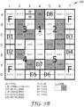
図2Aは、本開示による機械可読光コードを含むことができる機械可読光コードの一例である。光コード200は、光コード200の角部に位置する12個のファインダ光学要素A1、A2、A6、A7、B1、B7、F1、F7、G1、G2、G6、及びG7を含む。ファインダ光学要素のグループ又はブロックが、図2Aに「F」で示されている。コンテキスト光学要素は、光コード200の中心付近に位置することができ、コンテキスト光学要素のブロックには1〜5の番号が付けられている。コンテキスト光学要素ブロックは、以下の光学要素を含む。
FIG. 2A is an example of a machine readable optical code that may include a machine readable optical code according to the present disclosure. The
コンテキストブロック1:A4、B4、C4、D4、E4 Context block 1: A4, B4, C4, D4, E4
コンテキストブロック2:B5、B6、C5、C6、D5 Context block 2: B5, B6, C5, C6, D5
コンテキストブロック3:B2、B3、C2、C3、D2 Context block 3: B2, B3, C2, C3, D2
コンテキストブロック4:D3、E3、E4、F3、F4 Context block 4: D3, E3, E4, F3, F4
コンテキストブロック5:D6、E5、E6、F5、F6 Context block 5: D6, E5, E6, F5, F6
これらのコンテキストブロックは、コンテキストブロック1がデータペイロードブロックになり、コンテキストブロック2〜5がそれぞれリード−ソロモン誤り補正専用になるように使用される。これにより、最大2つの不正確に読み取ったコンテキストブロックの補正が可能になる。コンテンツブロック1は5ビットを有するため、最大25(又は32)種類の車両(又は任意の所望の分類セット)を符号化することができる。言い換えれば、左若しくは右から最大3つの列(1、2、及び3、若しくは5、6、及び7)を完全に遮蔽することができ、又は下から最大2つの行(F及びG)を完全に遮蔽することができ、それでもなおコンテキストデータを確実に復号することができる。
These context blocks are used so that
図2Aは、コンテンツ光学要素の8つのブロックを含み、各ブロックが6つの光学要素を含む。例示的な光学要素ブロック202は、コンテンツ光学要素ブロックD1を表す。例示的な光学要素ブロック204は、コンテキスト光学要素ブロック1を表す。図2Aに示すように、コンテンツ光学要素ブロックD7及びD8は、光コード200の2つ以上の近接領域にまたがって分散する。これらのコンテンツ光学要素ブロックは、図2AにD1〜D8として示されている。各コンテンツ光学要素ブロック内のビットは、次のとおりである。
FIG. 2A includes eight blocks of content optical elements, each block including six optical elements. The exemplary
コンテンツブロックD1:C1及びD1の上半分 Content block D1: upper half of C1 and D1
コンテンツブロックD2:D1の下半分及びE1 Content block D2: lower half of D1 and E1
コンテンツブロックD3:C7及びD7の上半分 Content block D3: upper half of C7 and D7
コンテンツブロックD4:D7の下半分及びE7 Content block D4: lower half of D7 and E7
コンテンツブロックD5:G3及びG4の左半分 Content block D5: left half of G3 and G4
コンテンツブロックD6:G4の右半分及びG5 Content block D6: right half of G4 and G5
コンテンツブロックD7:A3の上半分及びF4 Content block D7: upper half of A3 and F4
コンテンツブロックD8:A3の下半分及びA5 Content block D8: lower half of A3 and A5
8つのコンテンツブロックのうち、4つのコンテンツブロック(D1〜D4)はデータペイロードに使用され、4つのコンテンツブロック(D5〜D8)はリード−ソロモン誤り補正に使用され、したがって本開示の機械視覚システムは、コード300を読み取るとき、最大2つのコンテンツブロック誤りを補正することができる。4つのコンテンツブロックがデータペイロードに使用されるため、これらのコンテンツブロックは、最大224(又は16,777,216)個の固有コードを符号化することができる。
Of the 8 content blocks, 4 content blocks (D1-D4) are used for the data payload and 4 content blocks (D5-D8) are used for Reed-Solomon error correction, so the machine vision system of the present disclosure is When reading the
図2Aは、ファインダ光学要素の寸法を使用して標準的な光学要素寸法を判定する、7×7の標準的な光学要素寸法の光コードに対する構成を示す。光コード200は、12個のファインダ光学要素だけを必要とし、本明細書に論じる実質的な遮蔽に耐えながら、コンテキスト光学要素内の32個の固有コード及びコンテンツ光学要素内の16,777,216個の固有コードを符号化することが可能である。光コード2Aでは、コンテキスト光学要素を使用して、静的データを符号化することができ、コンテンツ光学要素を使用して、ルックアップコードを符号化することができる。
FIG. 2A shows a configuration for a 7 × 7 standard optical element size optical code that uses the finder optical element dimensions to determine standard optical element dimensions. The
図2Aはブロック1〜5を示し、ブロックD1〜D8を更に示す。ブロック1〜5はそれぞれ、静的データ(SD)光学要素セットとすることができ、ブロックD1〜D8はそれぞれ、動的ルックアップデータ(DLD)光学要素セットとすることができる。いくつかの例では、DLD光学要素セットは、動的に可変のデータを参照するルックアップ値を符号化する。いくつかの例では、SD光学要素セットは、他のデータを参照しない静的データを符号化する。いくつかの例では、DLD光学要素セットは、閾値距離より大きい距離において復号可能でない。いくつかの例では、SD光学要素セット及びDLD光学要素セットのうちの一方又は両方に対して、それぞれの光学要素セット内に誤り補正データを含むことができる。いくつかの例では、距離閾値は、区別可能性閾値を上回ると、画像捕捉デバイスによって捕捉される画像の分解能が、互いに視覚的に異なるDLD光学要素セットの光学要素を視覚的に区別しない距離である。 FIG. 2A shows blocks 1-5 and further shows blocks D1-D8. Each of blocks 1-5 can be a static data (SD) optical element set, and each of blocks D1-D8 can be a dynamic lookup data (DLD) optical element set. In some examples, the DLD optical element set encodes a lookup value that references dynamically variable data. In some examples, the SD optical element set encodes static data that does not reference other data. In some examples, the DLD optical element set is not decodable at distances greater than the threshold distance. In some examples, error correction data can be included in each optical element set for one or both of the SD optical element set and the DLD optical element set. In some examples, when the distance threshold exceeds the distinguishability threshold, the resolution of the images captured by the image capture device is a distance that does not visually distinguish optical elements of a set of DLD optical elements that are visually different from each other. is there.
いくつかの例では、SD光学要素セット内の第1の複数の光学要素は、物品を記述するコンテキスト情報を表し、DLD光学要素セット内の第2の複数の光学要素は、コンテキスト情報を記述するコンテンツ情報を表す。いくつかの例では、SD光学要素セットは、それぞれ第1の寸法である第1の複数の光学要素を含み、DLD光学要素セットは、それぞれ第1の寸法より小さい第2の寸法である第2の複数の光学要素を含む。いくつかの例では、SD及びDLD光学要素セットのそれぞれの各光学要素は、一組の符号化値のうちの1つの符号化値を表す。一組の符号化値は、それぞれの光学要素の視覚的な区別可能性に基づいて区別可能とすることができる。いくつかの例では、それぞれの各光学要素は外観を有し、その外観は、異なる輝度を有する勾配値の範囲内の1つの輝度を示す視覚的勾配値である。いくつかの例では、SD又はDLD光学要素セットは、QRコード内に含まれていない。 In some examples, the first plurality of optical elements in the SD optical element set represents context information describing the article, and the second plurality of optical elements in the DLD optical element set describes context information. Represents content information. In some examples, the SD optical element set includes a first plurality of optical elements that are each of a first dimension, and the DLD optical element set is a second dimension that is each of a second dimension that is less than the first dimension. A plurality of optical elements. In some examples, each optical element in each of the SD and DLD optical element sets represents one encoded value of a set of encoded values. The set of encoded values may be distinguishable based on the visual distinguishability of each optical element. In some examples, each optical element has an appearance, which is a visual gradient value that indicates one luminance within a range of gradient values having different luminance. In some examples, the SD or DLD optical element set is not included in the QR code.
図2Bは、データペイロードを含む図2Aの機械可読光コードを示す。図2Bは、データペイロードを含む機械可読光コードの一例である。図2Bは、図2Aに示すファインダ光学要素、コンテンツ光学要素、及びコンテキスト光学要素と同じ配置を有するが、図2Bは、各光学要素のビット状態を更に示す(コンテンツ光学要素を除く)。例えば、ファインダ光学要素の12個すべて(A1、A2、A6、A7、B1、B7、F1、F7、G1、G2、G6、及びG7)が、「1」のビット状態を有する(したがって、図2Bに白色として示されている)。図2Bの光コードは、反射性シート層を含む八角形の停止標識上に配置されるように設計されている。この光コードは、ビットが「0」又は黒色になる領域内及び光コードの境界の周りで、停止標識の再帰反射性基板の上に、黒色の赤外線インクを印刷すること又は別の黒色材料若しくは物質を配置することによって形成することができ、その結果、ファインダ光学要素は、コードの画像が捕捉されるとき、コードの周りに黒色の背景に対して強いコントラストをもたらす。 FIG. 2B shows the machine readable optical code of FIG. 2A including a data payload. FIG. 2B is an example of a machine readable optical code that includes a data payload. FIG. 2B has the same arrangement as the finder optical element, content optical element, and context optical element shown in FIG. 2A, but FIG. 2B further shows the bit state of each optical element (excluding the content optical element). For example, all twelve finder optical elements (A1, A2, A6, A7, B1, B7, F1, F7, G1, G2, G6, and G7) have a bit state of “1” (thus FIG. 2B). Shown as white). The optical code of FIG. 2B is designed to be placed on an octagonal stop sign that includes a reflective sheet layer. This light code is printed on the stop sign retroreflective substrate within the area where the bit is “0” or black and around the boundary of the light code, or another black material or It can be formed by placing material, so that the finder optical element provides a strong contrast around the code against a black background when the image of the code is captured.
図2Bの光コードは、停止標識に適用されるように設計されているため、コンテキスト光学要素は、停止標識に対する分類情報を提供するために書き込まれている。例示を目的として、例示的な分類システムでは、停止標識は「クラス28」標識であり、コンテキストブロック1のビットが数字「28」(又は2進で「11100」)を読み取るように設定されていることを示す。したがって、コンテキスト光学要素1内のビットは次のとおりである。
Since the optical code of FIG. 2B is designed to be applied to a stop sign, the context optical element is written to provide classification information for the stop sign. For illustrative purposes, in the exemplary classification system, the stop indicator is a “class 28” indicator and the bits of
光学要素1.0:ビット0
Optical element 1.0:
ビット光学要素1.1:ビット0
Bit optical element 1.1:
ビット光学要素1.2:ビット1
Bit optical element 1.2:
ビット光学要素1.3:ビット1
Bit optical element 1.3:
ビット光学要素1.4:ビット1
Bit optical element 1.4:
残りのコンテキストブロック2〜5は、リード−ソロモン誤り補正データによって符号化されている。誤り補正データは、符号化されたメッセージ内に符号化された未加工のメッセージに対する誤り補正関数の適用に基づいている。リード−ソロモン誤り補正及びアルゴリズムが例示的な目的に対して使用されているが、他のアルゴリズム及び誤り補正技法は、本開示を読めば当業者には明らかであろう。 The remaining context blocks 2-5 are encoded with Reed-Solomon error correction data. The error correction data is based on application of an error correction function to the raw message encoded within the encoded message. While Reed-Solomon error correction and algorithms are used for exemplary purposes, other algorithms and error correction techniques will be apparent to those skilled in the art upon reading this disclosure.
図2Cは、右からの遮蔽(トラック210)を含む図2Aの機械可読光コード300の一例である。図示の例では、右上及び右下のファインダ光学要素ブロック、コンテキスト光学要素ブロック2及び5、並びにコンテンツ光学要素ブロックD3、D4、D6、及びD8を含むコード200の大部分が遮蔽されている。この例では、遮蔽されているコンテンツ光学要素の数が、コンテンツ光学要素内に符号化された情報の再構築が可能でなくなる前に遮蔽することができるコンテンツ光学要素の数を超過しているため、コンテンツ情報が可読であると見なされない。しかし、コンテキスト光学要素の2つ(2及び5)だけが遮蔽されているため、コンテキスト光学要素を復号することができる。
FIG. 2C is an example of the machine readable
図2Dは、トラック210の形の下からの遮蔽を含む図2Aの機械可読光コード200の一例を示す。この状況で、両方の下角部内のファインダ光学要素ブロックが遮蔽されている。コンテキスト光学要素は遮蔽されていない。コンテンツ光学要素ブロックD5及びD6は遮蔽されている。コンテキスト光学要素ブロックが遮蔽されていないため、コンテンツデータを復号することができる。2つのコンテンツ光学要素ブロックだけが遮蔽されているため、誤り補正によってコンテンツ光学要素データを回復することができ、24ビットすべてのコンテンツデータも確実に読み取り又は復号することができる。
FIG. 2D shows an example of the machine-readable
2A〜2Dの画像は、様々な遮蔽シナリオを示し、それらのシナリオにおける遮蔽されたデータの回復可能性について説明するが、データ回復に関する限界は、リード−ソロモン符号化技法に基づいた例示的なものである。他の符号化技法又はアルゴリズムは、データの回復可能性に対して他の結果をもたらすことができる。 2A-2D images show various occlusion scenarios and describe the recoverability of occluded data in those scenarios, but the limitations on data recovery are exemplary based on Reed-Solomon coding techniques It is. Other encoding techniques or algorithms can have other consequences on data recoverability.
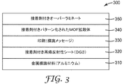
図3は、本開示に一貫した例示的な標識構造300を示す。本開示に一貫した光コードは、移動しているか、それとも静止しているかにかかわらず、任意の物品に適用することができるが、図3は、再帰反射性シートが実施された標識に光コードが適用される一実施形態を示す。図3は、本明細書に記載する複数の層、再帰反射性シート、及び光コードを含むそのような標識の断面図を示す。層310は、基板とすることができる。典型的には、基板310は、金属などの剛性又は非可撓性の耐久性のある材料である。1つのそのような好適な金属はアルミニウムである。他の実施形態では、基板210は、任意の剛性、半剛性、若しくは可撓性の物理的表面とすることができ、又はそのような物理的表面を含むことができる。
FIG. 3 illustrates an
再帰反射性シート320は、本開示に記載する再帰反射性シートとすることができる。再帰反射性シート320と基板310との間には、再帰反射性シート320を基板310に付着させるために、接着剤層(図示せず)を配置することができる。本開示に一貫して使用することができる再帰反射性シートの一例は、ミネソタ州セントポールの3M Companyから入手可能な3M Diamond Grade(商標)DG3 Reflective Sheeting Series 4000である。
The
層330は、メッセージ又は画像を含み、典型的には層320上へ印刷される。層330は、停止標識などの交通標識画像とすることができる。層330は、可視光スペクトル内の任意のメッセージ若しくは画像、又は層340内の光コード以外の波長で可視のメッセージ若しくは画像を含むことができる。単一の標識、ライセンスプレート、又は他の基板内に異なる波長で可視の情報又は画像を含む例は、全体として明示的に参照により本明細書に組み込まれている、米国特許第8,865,293号により詳細に記載されている。
層340は、図1及び図2に示す光コードなどの本開示に一貫した光コードを含む。層340内の光コードは、様々なやり方で形成することができる。例えば、光コード340が可視スペクトル内で可視になるように設計される場合、明色(又は白色)の基板上へ暗色(黒色など)で印刷することができる。層340内の光コードがIRスペクトル(典型的には、700nm〜1000nmの範囲内であるが、場合によっては、850nm又は900nmなどの波長を使用することができる)内で可視になるように設計される場合、層440内の光コードは、様々なやり方で作成することができる。具体的には、層340の下の再帰反射層320によって、層320のうち赤外線スペクトル内の再帰反射を吸収、散乱、又は他の形で阻止する材料又は物質によって覆われていないあらゆる部分が、白色又は明色に見える。したがって、赤外線スペクトル内の再帰反射を吸収、散乱、又は他の形で抑制する材料の適用を使用して、黒色の光学要素及び層340内の光コードの周りの境界を作成することができる。使用することができる材料の例としては、IR吸収黒色インクを使用して、標識のうち黒色又は暗色にすることが所望される部分を印刷することが挙げられる。別の場合には、標識のうち白色にすることが所望されるあらゆる部分が除去されるように、IR吸収多層光学フィルム(multi-layer optical film、MOF)を選択的に切断することができ、このフィルムが層330に重ねられる。赤外線スペクトルで見ると、このフィルムは、光コードのうち白色になることが意図される領域内でのみ、再帰反射を可能にする。赤外線(infrared、IR)スペクトルについて本明細書に論じるが、近赤外線スペクトル(約950nmの波長の光)など、他のスペクトルも使用することができる。層340内の光コードが950nmの光吸収フィルムから作成されているとき、950nmの光で光コードを照らすと、黒色で印刷された区分はその光を吸収し、機械視覚システムには黒色に見え、印刷されていない区分は明るく又は白色に見える。
標識300は、任意選択で、層340の上に形成又は付着されたオーバーラミネート350を含むことができる。オーバーラミネート350は、それだけに限定するものではないが多層光学フィルムなど、目に見えて透明の赤外線透過材料から構築することができる。
標識300の構造内で再帰反射層を使用することで、いくつかの利点を提供することができる。例えば、主に赤外線スペクトル内で情報が捕捉され、画像内の可視領域のみが、再帰反射性シート320から反射する光によって作成された明るい又は白色の光学要素であるとき、カメラに返される照明条件は、画像捕捉デバイス及び/又はコンピューティングデバイスが画像内のIR再帰反射性でない物体を識別するのに問題となる可能性がある。これは、標識又は光コードの周りの背景、及び個人の顔、画像、又は他の識別情報などの他の個人情報を含む。
Using a retroreflective layer within the structure of the
更に、光コードの白色又は明るい部分を生成する層340から再帰反射した光の結果、画像内には、光コードと周囲の画像との間の自然の境界又は遷移を含む画像内の黒色領域間に明白なコントラストを得ることができる。いくつかの既存のQRコードでは、機械視覚システムに対してどこでQRコードが開始及び終了するかを示す輪郭を描くために、コードの境界の全体又は一部の周りに黒色の光学要素が必要になることがある。対照的に、標識300上の光コードを取り囲む領域はIRスペクトル内で黒色に見えるため、追加の境界光学要素は不要であり、より大きい符号化効率が可能になる。
In addition, as a result of light retroreflected from the
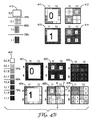
図4Aは、入れ子状のコンテンツ光学要素を含む例示的な機械可読光コード400である。いくつかの例では、親光学要素内に、入れ子状又は「子」の光学要素を含むことができる。例えば、親光学要素セット402は、少なくとも1つの親光学要素406を含むことができ、親光学要素406は、子光学要素セットを更に含み(例えば、セル[A,1]内に4つの光学要素を含む)、子光学要素セットは、子光学要素406などのそれぞれ一組の光学要素を含む。
FIG. 4A is an exemplary machine readable
いくつかの例では、親光学要素の少なくとも1つの光学要素に対応する第1の符号化値は、画像捕捉デバイスと物品との間に閾値距離以上の特定の距離において復号可能である。子光学要素セットのうちの一組の光学要素にそれぞれ対応する子符号化値は、画像捕捉デバイスと物品との間に特定の距離において復号可能でないことがある。いくつかの例では、特定の距離は第1の距離であり、子光学要素セットのうちの一組の光学要素にそれぞれ対応する子符号化値は、画像捕捉デバイスと物品との間に第2の距離において復号可能であり、第2の距離は第1の距離より小さい。いくつかの例では、閾値距離は、区別可能性閾値を上回ると、画像捕捉デバイスによって捕捉される画像の分解能が、視覚的に異なる子光学要素セットの1つ以上の光学要素を視覚的に区別しない距離である。いくつかの例では、区別可能性閾値は、ユーザ定義、ハードコード、又は機械生成することができる。 In some examples, the first encoded value corresponding to at least one optical element of the parent optical element is decodable at a particular distance greater than or equal to a threshold distance between the image capture device and the article. The child encoded values that respectively correspond to a set of optical elements of the set of child optical elements may not be decodable at a particular distance between the image capture device and the article. In some examples, the specific distance is a first distance, and the child encoded values corresponding to each of the set of optical elements of the child optical element set are second between the image capture device and the article. The second distance is smaller than the first distance. In some examples, when the threshold distance exceeds a distinguishability threshold, the resolution of the image captured by the image capture device visually distinguishes one or more optical elements of a child optical element set that are visually different. Not a distance. In some examples, the distinguishability threshold may be user defined, hard coded, or machine generated.
本明細書に論じるように、光コードは、コンテンツ光学要素及びコンテキスト光学要素の両方を含むことができる。静的データ及びルックアップコードの一方又は両方に、コンテキスト光学要素及びコンテンツ光学要素を使用することができる。入れ子状のコンテンツ光学要素は、4つのコンテンツ光学要素からなるブロックであり、これらのコンテンツ光学要素はそれぞれ、1データビットとして個々に読み取ることができ、又は単一のコンテキスト光学要素としてともに読み取ることができる。第1の距離から、光コード400は、7×7のコードとして見え、行A−B、C−D、E−F、G−H、I−J、K−L、及びM−N、並びに列1−2、3−4、5−6、7−8、9−10、11−12、及び13−14を含む。図1に示す画像と同様に、行G−H及び列7−8の光学要素は、ファインダ光学要素である。図4Aの機械可読光コードは、入れ子状のコンテンツ光学要素を可能にするために光学要素内の勾配の使用を示すという点で、図1とは異なる。
As discussed herein, the optical code can include both content optical elements and context optical elements. Context optical elements and content optical elements can be used for one or both of the static data and the lookup code. A nested content optical element is a block of four content optical elements, each of which can be read individually as one data bit, or read together as a single context optical element. it can. From the first distance, the
図4Bは、入れ子状のコンテンツ光学要素を含む機械可読光コードの区分を示す。多くの機械視覚システムでは、システムは、画像内の最も明るいトーン及び画像内の最も暗いトーンを検出することによって、光学要素が「白色」であるか、それとも「黒色」であるかを判定する。機械は次いで、検出された白色と黒色との間の中途であるトーンより暗いものはすべて黒色であると判定することによって、画像を「2値化」する。中途(又は50%)のトーンより明るいものはすべて白色であると判定される。この同じ原理は、コンテンツ光学要素の複数の層が入れ子状であるときにも適用することができる。 FIG. 4B shows a section of a machine readable optical code that includes nested content optical elements. In many machine vision systems, the system determines whether the optical element is “white” or “black” by detecting the brightest tone in the image and the darkest tone in the image. The machine then "binarizes" the image by determining that everything darker than the detected tone between white and black is black. Anything brighter than the midway (or 50%) tone is determined to be white. This same principle can also be applied when multiple layers of content optical elements are nested.
2層からなるコンテンツ光学要素の1つのそのような例が、列11−12、行C−Dの交差部を含むブロック内に示されている。コード400を作成するとき、交差する列11−12、行C−Dから構成されたブロック411は、単一のブロック(コンテキスト光学要素)としてともに読み取られるとき、「0」として累積的に復号される。機械視覚システムは、スケール410に示す色度0,0を領域内の最も明るい色として検出し、スケール410に示す色度1,1を最も暗い色として検出するため、光学要素C−D、11−12内のすべてのブロックが「0」として読み取られるには、411内の4つの各ブロック内の色度がスケール410上の50%ラインを下回るはずである。
One such example of a two-layer content optical element is shown in a block that includes the intersection of columns 11-12, rows CD. When creating
ブロック411内の4つの各コンテンツ光学要素内に入れ子状にした情報を読み取り又は他の形で復号するために、機械視覚システムは、ブロック411を分離して、そのバイナライザをブロック411内の色度のみに較正することができる。色度がスケール410の50%ラインを下回るため、バイナライザは次いで、黒色レベル(例えば、輝度に基づく)が25%ラインを下回るあらゆる領域が「0」であり、25%ラインを上回るものはすべて「1」であると判定する。したがって、単一の光学要素としてともに読み取られるとき、411及び412内の4つのブロックは「0」として読み取られるはずであるが、コンテンツ光学要素として個々に読み取られるとき、C11及びD12は「0」であり、C12及びD11は「1」である。
To read or otherwise decode the information nested within each of the four content optical elements in
同様に、ブロック413は、第1の距離からコンテキスト光学要素として読み取られるとき、「1」として読み取られる必要がある。これを実現するために、スケール410上の50%ラインより大きい黒色の色度のみが使用され、したがってコンテキスト光学要素413が第1の距離から読み取られるとき、機械視覚システムは、4つすべてのブロックが勾配スケール上の50%ラインを上回るため、「暗色」又は「黒色」であると判定する。ブロック414内のコンテンツ光学要素が個々に読み取られるとき、機械視覚システムがブロック414を単独で読み取るときに50%ラインを上回る勾配範囲のみを見ることに基づいて、E11は「0」であり、E12、F11、及びF12は「1」である。
Similarly, block 413 needs to be read as “1” when read as the context optical element from the first distance. To accomplish this, only the black chromaticity greater than 50% line on the
ブロック又は光学要素421〜426は、3つのレベルの入れ子状のデータを使用する実装形態を実証する。ブロック421は、第1の距離から読み取られるとき、すべての黒色の色度がスケール420上の50%ラインより大きいため、「1」である。しかし、第2のより近い距離から読み取られるとき(ブロック422に示す)、光学要素A11及びA12は、これらの各光学要素内の色度が、ブロック422を2値化するために使用される分割点となった75%ラインを下回るため、「0」として読み取られる。光学要素B11及びB12は、1として読み取られる。ブロック423が第3の(最も近い)距離から読み取られるとき、機械視覚システムは、光学要素A11、A12、B11、及びB12がそれぞれ、4つの入れ子状の光学要素から構成されていることを検出することが可能である。光学要素A11及びA12内で、色スペクトルは、スケール420上の1,0,0と1,0,1との間のみの範囲であり、したがってA11内の4つの入れ子状の光学要素は0,0,0,0として読み取られ、A12内の4つの入れ子状の光学要素は1,1,0,1として読み取られる。
Blocks or optical elements 421-426 demonstrate an implementation that uses three levels of nested data.
光学要素424は、単一のコンテキスト光学要素として第1の距離において読み取られるときは「0」として符号化され、したがって光学要素424内で使用されるすべての色度は、スケール420上の50%の黒色レベルラインを下回る。ブロック425が4つの別個のコンテンツ光学要素として第2の距離において読み取られるとき、光学要素A11は「1」であり、2つのB11及びB12はそれぞれ「0」である。ブロック426は、第1の距離又は第2の距離のうちのどちらよりも近い第3の距離において読み取ることができ、ブロック425に関して上述した各コンテンツ光学要素を、ここでは4つの別個のコンテンツ光学要素として読み取ることができる。ブロックA11内のコンテンツ光学要素は、1,1,0,0である。ブロックA12内のコンテンツ光学要素は、1,0,1,0である。ブロックB11内のコンテンツ光学要素は、1,0,1,0であり、ブロックB12内のコンテンツ光学要素は、1,0,0,1である。50%の黒色レベルラインが一例として提供されているが、100〜1%の任意の値が可能である。
図4Bの例では、ブロック424は、静的データ(SD)光学要素セットの一部とすることができ(SD光学要素セットの他の光学要素は図示せず)、光学要素A11、A12、B11、B12は、動的ルックアップデータ(DLD)光学要素セットの一部とすることができる。図4Bは、SD及びDLD光学要素セットの物理的表面上で実施される親子の光学要素セットの階層を更に示す。例えば、光学要素セット424(異なる詳細レベルで425及び426として示す)は、4つの子光学要素A11、A12、B11、B12を含む親光学要素セットとすることができる。親光学要素セットは、第1の複数の光学要素(例えば、A11、A12、B11、B12)を含み、これらはそれぞれ第1の寸法である。子光学要素セット427は、第2の複数の光学要素A12a、A12b、A12c、及びA12dを含み、これらはそれぞれ、第1の寸法より小さい第2の寸法である。図4Bの例では、親光学要素セット424によって表される第1の符号化値(「1」)は、子光学要素セット内の特定の光学要素A12b(一例としてA12bを使用する)の外観に少なくとも部分的に基づいており、特定の光学要素A12bによって部分的に表される第2の符号化値(「0」)は、特定の光学要素A12bの外観に少なくとも部分的に基づいており、第1の符号化値と第2の符号化値とは異なる。光学要素A12に対する第2の符号化値(「0」)は、閾値距離より大きい距離からでは復号可能でないことがあり、第1の符号化値(「1」)は、閾値距離より大きい距離から復号可能である。図4Bに示すように、子光学要素セットの各光学要素は、親光学要素セットの1つの光学要素内に含むことができる。他の例では、子光学要素セットは、親光学要素セットに重複したり又は親光学要素セット内に含まれたりすることはない。 In the example of FIG. 4B, block 424 may be part of a static data (SD) optical element set (other optical elements of the SD optical element set are not shown) and optical elements A11, A12, B11. , B12 can be part of a dynamic look-up data (DLD) optical element set. FIG. 4B further illustrates the hierarchy of parent-child optical element sets implemented on the physical surface of the SD and DLD optical element sets. For example, optical element set 424 (shown as 425 and 426 at different levels of detail) can be a parent optical element set that includes four child optical elements A11, A12, B11, B12. The parent optical element set includes a first plurality of optical elements (eg, A11, A12, B11, B12), each having a first dimension. The child optical element set 427 includes a second plurality of optical elements A12a, A12b, A12c, and A12d, each having a second dimension that is smaller than the first dimension. In the example of FIG. 4B, the first encoded value (“1”) represented by the parent optical element set 424 is the appearance of a particular optical element A12b (using A12b as an example) in the child optical element set. The second encoded value ("0") that is based at least in part and represented in part by the particular optical element A12b is based at least in part on the appearance of the particular optical element A12b, The encoded value of 1 and the second encoded value are different. The second encoded value (“0”) for optical element A12 may not be decodable from a distance greater than the threshold distance, and the first encoded value (“1”) is from a distance greater than the threshold distance. Decoding is possible. As shown in FIG. 4B, each optical element of the child optical element set can be included within one optical element of the parent optical element set. In other examples, the child optical element set does not overlap or be contained within the parent optical element set.
図4Bに示すように符号化値を階層的に配置することによって、SD光学要素セットに対する情報を階層のより高いレベルにある光学要素(例えば、親光学要素セット)内に符号化することができ、これは画像捕捉デバイスと光学要素を含む物品との間に更なる距離において復号することができる。DLD光学要素セットに対する情報は、階層のより低いレベルにある光学要素(例えば、子光学要素セット)内に符号化することができ、これは画像捕捉デバイスが光学要素を含む物品により近いときにしか復号することができない。図4Bの3つのレベルなど、光学要素セットの任意のN個の階層レベルを使用することができる。 By arranging the encoded values in a hierarchical manner as shown in FIG. 4B, information for the SD optical element set can be encoded in an optical element at a higher level of the hierarchy (eg, the parent optical element set). This can be decoded at a further distance between the image capture device and the article containing the optical element. Information for the DLD optical element set can be encoded in an optical element at a lower level of the hierarchy (eg, a child optical element set), only when the image capture device is closer to the article containing the optical element. It cannot be decrypted. Any N hierarchical levels of the optical element set can be used, such as the three levels of FIG. 4B.
コンテンツ光学要素及びコンテキスト光学要素を入れ子状にする特有の方法について本明細書に記載するが、本開示の範囲内の他の方法は、本開示を読めば当業者には明らかであろう。本開示は、具体的に2つのレベルの入れ子及び3つのレベルの入れ子について記載するが、画像捕捉及び処理技術の制限に基づいて、任意の所望のレベルの入れ子を実現することができる。例えば、5つのレベルの入れ子を含むコードを実施するためには、勾配スケールを25又は32の色勾配(又はグレー)に分割する必要がある。 While specific methods for nesting content and contextual optical elements are described herein, other methods within the scope of this disclosure will be apparent to those skilled in the art upon reading this disclosure. Although the present disclosure specifically describes two levels of nesting and three levels of nesting, any desired level of nesting can be realized based on limitations in image capture and processing techniques. For example, to implement a code that includes five levels of nesting, the gradient scale needs to be divided into 25 or 32 color gradients (or gray).
図5は、物品又は標識上の多次元機械可読光コードを読み取るシステムの図である。システム500は、標識520を含む。標識面522は、可視光スペクトルで見ることができる画像、停止画像522、及び可視光スペクトル外の可視光スペクトルで見ることができる機械可読光コード530を含む。標識500は基板を有し、また光コード530の後ろに再帰反射性シート層を含むことができる。2次元の光コードが物品上に位置する場合、物品はまた、基板を含むことができ、任意選択で帰反射層を含むことができ、印刷又は他の形で適用又は作成された光コードを含むことができる。
FIG. 5 is a diagram of a system for reading a multi-dimensional machine readable optical code on an article or sign.
光コード530は、あるパターンで配置された複数のファインダ光学要素を含み、これらのファインダ光学要素は、車両510上に取り付けられた機械視覚システム512によって第1の距離から検出可能である。光コード530はまた、コンテキスト情報を表す複数のコンテキスト光学要素を含み、コンテキスト光学要素は、機械視覚システムによって第1の距離から検出可能であり、場合によっては、コンテキスト光学要素は、物品又は標識に関係する静的情報又はデータを符号化することができる。光コード530はまた、コンテンツ情報を表す複数のコンテンツ光学要素を含み、コンテンツ光学要素は、第1の距離において機械視覚システムによって検出可能でないが、機械視覚システムによって第2の距離から検出可能であり、第2の距離は第1の距離より小さい。コンテンツ光学要素は、ルックアップコードを符号化することができる。コンテンツ光学要素は、ルックアップコード及び静的情報の両方を符号化することができる。
The
車両510が標識520に接近すると、機械視覚システム512は、機械可読光コードを検出して処理する。機械視覚システム512は、車両510に取り付けられて移動するものとして図5に示されているが、機械視覚システムは、静止したものとすることができ、又は可動若しくは静止の物品若しくは物体から光コード530を読み取るために使用することができる他の機器若しくはデバイスに取り付けることができる。機械視覚システム512は、画像センサ及び光源を含む赤外線カメラとすることができる。場合によっては、機械視覚システムは、IRスペクトルに対する画像センサの感度を増大させるためのフィルタを含む。他のタイプの機械視覚システムは、本開示を読めば当業者には明らかであろう。
As the
機械視覚システム512は、コンピューティングデバイス540を含むことができ、又はコンピューティングデバイス540と一体化することができ、したがって機械視覚システム512は、ネットワークを必要としない有線又は無線の接続を介してコンピューティングデバイス540に直接接続される。他の場合には、機械視覚システム512は、1つ以上の通信リンク550A、550Bを使用して、コンピューティングデバイス540に通信的に結合することができる。コンピューティングデバイス540は、ネットワーク552によって車両510に接続されるものとして示されているが、他の例では、コンピューティングデバイス540は、車両510に直接含むことができ、直接通信又は車両の内部ネットワークを介して車両構成要素と通信することができる。
The
機械視覚システム512は、光コード530の1つ以上の画像を捕捉し、光コードの画像をコンピューティングデバイス540へ送信することができる。通信リンク550A及び550Bは、有線又は無線の接続とすることができる。例えば通信リンク550A及び550Bは、WiFiプロトコルを使用する無線イーサネット接続、及び/又はカテゴリ5若しくはカテゴリ6のケーブルを使用する有線イーサネット接続とすることができる。任意の好適な通信リンクが可能である。いくつかの例では、機械視覚システム512は、ネットワーク552によってコンピューティングデバイス540に通信的に結合される。ネットワーク552は、それだけに限定されるものではないが、パケット及び/又はフレームベースのデータの転送を提供するルータ、スイッチ、ハブ、及び相互接続通信リンクを含む、任意の数の1つ以上のネットワーク接続されたデバイスとすることができる。例えば、ネットワーク552は、インターネット、サービスプロバイダネットワーク、カスタマネットワーク、又は任意の他の好適なネットワークとすることができる。他の例では、機械視覚システム512は、ユニバーサルシリアルバス(Universal Serial Bus、USB)リンクなどの直接接続によって、コンピューティングデバイス540に通信的に結合される。
The
コンピューティングデバイス540は、機械視覚システム512と情報を送信及び受信することが可能な1つ以上のデスクトップコンピュータ、ラップトップコンピュータ、メインフレーム、サーバ、クラウドコンピューティングシステムなど、任意の好適なコンピューティングシステムであり、機械視覚システム512を有する又は機械視覚システム512とは離れた単一のデバイスとすることができる。いくつかの例では、コンピューティングデバイス540は、本開示の技法を実施する。
The
図5の例では、コンピューティングデバイス540は、コード化構成要素542、データ層626、サービス構成要素546、及びユーザインターフェース(user interface、UI)構成要素548を含む。コード化構成要素542は、必要とされるデータ符号化スキーム又はアルゴリズムを光コード530上のデータに適用することによって、光コード530内に符号化されたデータを検出することができる。コード化構成要素542は、データ層626に問い合わせて、検出された2進コードを人間可読情報に変換することができる。より具体的には、コード化構成要素542は、データベースに問い合わせて、静的データ又はルックアップコードに関係する情報を受信することができる。
In the example of FIG. 5,
静的データに関係する情報は一定であり、更新できないが、ルックアップコードに関係する情報は更新することができる。データベース542が機械視覚システムに一体化され又は機械視覚システムの一部である場合には、ネットワーク552を介して毎日ダウンロードする、又は機械視覚システムを含む車両がルックアップコードに関係する情報をダウンロードすることができるアクセス可能な有線若しくは無線ネットワークの範囲内にあるときはいつでもダウンロードするなど、ルックアップコードに関係する情報を定期的に繰返し更新することができる。ある場合には、ネットワークに接続された集中データベース内にルックアップコードに関係する情報を記憶することができ、それにより複数の個人又は実体がルックアップコードに関係する情報を更新することを可能にする。ルックアップコードに関係する情報へのアクセスを必要とする機械視覚システム又は他の実体は次いで、集中データベースからの情報を更新することができ、その結果、この情報をローカルに記憶することができ、アクセス可能なネットワーク接続とは独立したリアルタイムでローカルコピーにアクセスすることができる。別の場合には、機械視覚システムは、ネットワーク552に接続し、ネットワーク552を介して通信して、ルックアップコードに関係する情報を記憶しているデータベース又は集中データベース(図示せず)に問い合わせることができる。いくつかの例では、コンピューティングデバイスは、複数の異なるデータベースに問い合わせることができ、いくつかの例では、複数の異なるデータベースから問い合わせされるデータベースは、ルックアップコード内に含まれるデータに少なくとも部分的に基づくことができる。
Information related to static data is constant and cannot be updated, but information related to lookup codes can be updated. If the
ルックアップコードに関係する情報は、広範囲の情報を含むことができる。ルックアップコードに関係する情報のいくつかの例としては、物品の状態、物品付近の物理的領域の状態、物品が割り当てられた個人の識別情報、物品のユーザに対する指示、及び物品に近接する個人又はデバイスに対する指示が挙げられる。 Information related to the lookup code can include a wide range of information. Some examples of information related to lookup codes include the state of the item, the state of the physical area near the item, the identity of the individual to whom the item is assigned, instructions to the user of the item, and an individual in proximity to the item Or the instruction | indication with respect to a device is mentioned.
サービス構成要素546は、1つ以上の動作を実行することによって、任意の数のサービスを提供することができる。例えば、サービス構成要素546は、光コードから読み取ったデータを受信したとき、1つ以上の警報、報告、又は他の通信を生成することができ、これらは車両510上の自動運転構成要素を含む1つ以上の他のコンピューティングデバイスへ送信される。そのような警報は、それだけに限定されるものではないが、電子メール、テキストメッセージ、リスト、通話、又は任意の他の好適な通信を含むことができる。場合によっては、機械視覚システムを含む車両は、ルックアップコードに関係する情報を使用して、人間語フィードバックを運転者に提供することができる。場合によっては、機械視覚システムを含む車両は、ルックアップコードに関係する情報を使用して、触覚的フィードバック、可聴フィードバック、又は視覚的フィードバックのうちの少なくとも1つを車両の運転者へ提供することができる。
いくつかの例では、ユーザインターフェース(UI)構成要素548は、コンピューティングデバイス540の様々な構成要素及び光学要素間の中間として作用して、入力デバイスによって検出された入力を処理して他の構成要素及び光学要素へ送信することができ、他の構成要素及び光学要素からの出力を生成し、1つ以上の出力デバイスで提示することができる。例えば、UI構成要素548は、警報、報告、又は他の通信のデータ及び/又はグラフを含むことができる表示のための1つ以上のユーザインターフェースを生成することができる。
In some examples, a user interface (UI)
構成要素542、626、546、及び548は、ソフトウェア、ハードウェア、ファームウェア、又はハードウェア、ソフトウェア、及びファームウェアの混合物を使用して本明細書に記載する動作を実行することができ、これらは、コンピューティングデバイス540内に常駐してコンピューティングデバイス540上で実行し、かつ/又は1つ以上の他のリモートコンピューティングデバイスに位置する。いくつかの例では、構成要素542、626、及び546は、ハードウェア、ソフトウェア、並びに/又はハードウェア及びソフトウェアの組合せとして実施することができる。コンピューティングデバイス540は、構成要素626、546、及び548を1つ以上のプロセッサによって実行することができる。コンピューティングデバイス540は、構成要素542、626、546、又は548のうちのいずれかは、下にあるハードウェア上で実行する仮想機械として、又は仮想機械内で、実行することができる。構成要素542、626、546、548は、様々なやり方で実施することができる。例えば、構成要素542、626、546、又は548のうちのいずれかは、ダウンロード可能な又はプリインストールされたアプリケーション又は「アプリ」として実施することができる。別の例では、構成要素542、626、546、又は548のいずれかは、コンピューティングデバイス540のオペレーティングシステムの一部として実施することができる。
例示を目的として、図5で、機械視覚システムは、車両510の一部として示されており、又は車両510に取り付けられている。車両510は、自動車、自動二輪車、飛行機、船舶、軍用機器、自転車、列車、又は任意の他の輸送車両とすることができる。他の例では、機械視覚システム512は、2〜3例だけを挙げると文書、衣類、ウェアラブル機器、建物、静止機器、又は任意の他の物体に取り付けることができ、これらに含み又は埋め込むことができ、又は他の形でこれらを含むことができる。
For illustrative purposes, in FIG. 5 the machine vision system is shown as being part of or attached to the
光コード530は、図5で標識として組み込まれたものとして示されているが、光コードは、2〜3例だけを挙げると文書、衣類、ウェアラブル機器、建物、静止機器、又は任意の他の物体上に取り付けることができ、これらに含むことができ、又はこれらに埋め込むことができる。
Although the
データベースは、アクセス又は許可及びルックアップコードを有していれば誰でも遠隔で更新することができ、センサは、作業区間内の動き、橋の上の氷、環境条件の感知、又は運転上の判断を支援しうる他の情報などの情報に基づいて、データベースを遠隔で更新することができる。 The database can be updated remotely by anyone with access or authorization and lookup codes, and sensors can be used to detect movement in the work section, ice on the bridge, sensing environmental conditions, or driving The database can be updated remotely based on information such as other information that can assist in the determination.
いくつかの例では、光コード530、又は光コード530が取り付けられた物品は、ベース面に適用された反射性、非反射性、及び/又は再帰反射性のシートを含むことができる。それだけに限定するものではないが、文字、画像、及び/又は任意の他の情報などの可視メッセージを、光コード530の物品上に印刷、形成、又は他の形で実施することができる。反射性、非反射性、及び/又は再帰反射性のシートは、それだけに限定するものではないが、機械的接着、熱接着、化学的接着、又は再帰反射性シートをベース面に取り付けるための任意の他の好適な技法を含む1つ以上の技法及び/又は材料を使用して、ベース面に適用することができる。ベース面は、反射性、非反射性、及び/又は再帰反射性のシートを取り付けることができる物体の任意の表面(上述したように、例えばアルミニウム板)を含むことができる。物品メッセージは、インク、染料、熱転写リボン、着色剤、顔料、及び/又は接着剤でコートされたフィルムのうちのいずれか1つ以上を使用して、シート上に印刷、形成、又は他の形で実施することができる。いくつかの例では、コンテンツは、多層光学フィルム、光学的に活性の顔料若しくは染料を含む材料、又は光学的に活性の顔料若しくは染料から形成され、又はこれらを含む。
In some examples, the
光コード530を最初に製造又は他の形で作成するために、構築デバイス570をコンピューティングデバイス560とともに使用することができ、コンピューティングデバイス560は、構築デバイス570の動作を制御する。いくつかの例では、構築デバイス570は、光コード530及び/又は標識520を印刷、配置、又は他の形で形成する任意のデバイスとすることができる。構築デバイス138の例としては、それだけに限定されるものではないが、ニードルダイ、グラビアプリンタ、スクリーンプリンタ、熱転写プリンタ、レーザプリンタ/エングレーバ、ラミネータ、フレキソプリンタ、インクジェットプリンタ、赤外線インクプリンタが挙げられる。いくつかの例では、光コード530は、構築デバイス570によって構築された再帰反射性シート又は赤外線吸収若しくは散乱フィルムによって可能にすることができ、場合によってはコンピューティングデバイス560とは異なるオペレータ又は実体によって動作する別個の構築プロセス又はデバイスが、物品メッセージをシートに適用すること及び/又はシートをベース層(例えば、アルミニウム板)に適用することができる。
The
構築デバイス570は、通信リンク550Dによってコンピューティングデバイス560に通信的に結合することができる。コンピューティングデバイス560は、構築デバイス570の動作を制御することができる。例えば、コンピューティングデバイス560は、1つ以上の印刷仕様を含むことができる。印刷仕様は、可視の標識面522及び光コード530の特性(例えば、位置、形状、寸法、パターン、組成、又は他の空間的特徴)を定義するデータを含むことができる。いくつかの例では、印刷仕様は、人間のオペレータ又は機械によって生成することができる。いずれにせよ、構築構成要素562が、データを構築デバイス570に送信することができ、それにより構築デバイス570は、プリンタ仕様に従って、可視の画像又はメッセージ及び光コードを印刷する。
場合によっては、構築構成要素は、光コードが最初に製造されるときに光コード内に符号化されたルックアップコードに関係する初期情報を生成することができ、その情報を集中データベースへ伝送することができる。ルックアップコードに関係する情報は、集中データベース内の関係する情報にアクセスして修正するための必要な許可及びネットワークアクセスを有していれば誰でも、後に更新することができる。場合によっては、複数の固有のルックアップコードを、単一の情報に関連付け又は関係付けることができる。場合によっては、単一のルックアップコードを、複数の情報に関係付け又は関連付けることができる。 In some cases, the building component can generate initial information related to the lookup code encoded in the optical code when the optical code is first manufactured and transmits that information to a centralized database. be able to. Information related to the lookup code can be updated later by anyone with the necessary permissions and network access to access and modify the relevant information in the centralized database. In some cases, multiple unique lookup codes can be associated or associated with a single piece of information. In some cases, a single lookup code can be associated or associated with multiple pieces of information.
いくつかの例では、コード化構成要素542は、画像内のそれぞれの光学要素セットのそれぞれの事前定義された位置を示す光学要素セット位置データに少なくとも部分的に基づいて、SD又はDLD光学要素セットのうちの少なくとも1つを判定することができる。コード化構成要素542は、SD又はDLD光学要素セットのうちの光学要素セット内のそれぞれの光学要素のそれぞれの事前定義された位置を示す光学要素位置データに少なくとも部分的に基づいて、SD又はDLD光学要素セットのうちの少なくとも1つのそれぞれの各光学要素に対するそれぞれの勾配値を判定することができる。いくつかの例では、コード化構成要素542は、それぞれの勾配値及び符号化値間のマッピングに少なくとも部分的に基づいて、メッセージの少なくとも一部分を判定することができる。
In some examples, the
図6は、多次元機械可読光コードを読み取るために動的システムで使用されるコンピューティングデバイスの一例である。図6は、図5に示すコンピューティングデバイス540の1つの特定の例のみを示す。他の場合には、コンピューティングデバイス540の多くの他の例を使用することができ、例示的なコンピューティングデバイス540内に含まれる構成要素の部分集合を含むことができ、又は図6の例示的なコンピューティングデバイス540には示されていない追加の構成要素を含むことができる。いくつかの例では、コンピューティングデバイス540は、アプリケーション620内に含まれる機能性のセット、サブセット、又はスーパーセットを実行することができるサーバ、タブレットコンピューティングデバイス、スマートフォン、手首若しくは頭に着用するコンピューティングデバイス、ラップトップ、デスクトップコンピューティングデバイス、又は任意の他のコンピューティングデバイスとすることができる。
FIG. 6 is an example of a computing device used in a dynamic system to read a multi-dimensional machine readable optical code. FIG. 6 shows only one specific example of the
図6の例に示すように、コンピューティングデバイス540は、ユーザ空間602、カーネル空間604、及びハードウェア606に論理的に分割することができる。ハードウェア606は、ユーザ空間602及びカーネル空間604内で実行する構成要素に対する動作環境を提供する1つ以上のハードウェア構成要素を含むことができる。ユーザ空間602及びカーネル空間604は、異なる区分又は分割のメモリとすることができ、カーネル空間604は、ユーザ空間602より高い特権をプロセス及びスレッドに提供する。例えば、カーネル空間604は、ユーザ空間602内で実行する構成要素より高い特権で動作するオペレーティングシステム620を含むことができる。
As shown in the example of FIG. 6, the
図6に示すように、ハードウェア606は、1つ以上のプロセッサ608、入力構成要素610、記憶デバイス612、通信ユニット614、及び出力構成要素616を含む。プロセッサ608、入力構成要素610、記憶デバイス612、通信ユニット614、及び出力構成要素616はそれぞれ、1つ以上の通信チャネル618によって相互接続することができる。通信チャネル618は、構成要素間通信のために、構成要素608、610、612、614、及び616をそれぞれ(物理的、通信的、及び/又は動作的に)相互接続することができる。いくつかの例では、通信チャネル618は、ハードウェア及び/又はソフトウェア間でデータを通信するハードウェアバス、ネットワーク接続、1つ以上のプロセス間通信データ構造、又は任意の他の構成要素を含むことができる。
As shown in FIG. 6, the
1つ以上のプロセッサ608は、コンピューティングデバイス540内で機能性を実施すること及び/又は命令を実行することができる。例えば、コンピューティングデバイス540上のプロセッサ608は、カーネル空間604及びユーザ空間602内に含まれている構成要素の機能性を提供する記憶デバイス612によって記憶された命令を受信及び実行することができる。プロセッサ608によって実行されるこれらの命令により、コンピューティングデバイス616は、プログラム実行中に記憶デバイス612内で情報を記憶及び/又は修正することができる。プロセッサ608は、本開示の技法による1つ以上の動作を実行するために、カーネル空間604及びユーザ空間602内で構成要素の命令を実行することができる。すなわち、ユーザ空間602及びカーネル空間604内に含まれている構成要素は、本明細書に記載する様々な機能を実行するために、プロセッサ208によって動作可能とすることができる。
One or
コンピューティングデバイス540の1つ以上の入力構成要素642は、入力を受信することができる。入力の例としては、2〜3例だけを挙げると、触覚、音声、運動、及び光入力がある。一例では、コンピューティングデバイス616の入力構成要素642には、マウス、キーボード、音声応答システム、ビデオカメラ、ボタン、制御パッド、マイクロフォン、又は人間若しくは機械からの入力を検出する任意の他のタイプのデバイスが含まれる。いくつかの例では、入力構成要素642は、存在感知性入力構成要素とすることができ、これには存在感知性スクリーン、接触式スクリーンなどを含むことができる。
One or more input components 642 of
コンピューティングデバイス616の1つ以上の出力構成要素616は、出力を生成することができる。出力の例としては、触覚、音声、及びビデオ出力が挙げられる。いくつかの例では、コンピューティングデバイス540の出力構成要素616には、存在感知性スクリーン、サウンドカード、ビデオグラフィックスアダプタカード、スピーカ、陰極線管(cathode ray tube、CRT)モニタ、液晶ディスプレイ(liquid crystal display、LCD)、又は人間若しくは機械への出力を生成する任意の他のタイプのデバイスが含まれる。出力構成要素は、陰極線管(CRT)モニタ、液晶ディスプレイ(LCD)、発光ダイオード(Light-Emitting Diode、LED)、又は触覚、音声、及び/若しくは視覚出力を生成する任意の他のタイプのデバイスなどの表示構成要素を含むことができる。いくつかの例では、出力構成要素616は、コンピューティングデバイス540と一体化することができる。他の例では、出力構成要素616は、コンピューティングデバイス540の物理的に外部に位置し、コンピューティングデバイス540から別にすることができるが、有線又は無線の通信を介してコンピューティングデバイス540に動作可能に結合することができる。出力構成要素は、コンピューティングデバイス540の外部包装内に位置し、コンピューティングデバイス540に物理的に接続された、コンピューティングデバイス540の内蔵式構成要素とすることができる(例えば、移動電話上のスクリーン)。別の例では、存在感知性ディスプレイ602は、コンピューティングデバイス540の包装の外側に位置し、コンピューティングデバイス540から物理的に分離された、コンピューティングデバイス540の外部構成要素とすることができる(例えば、タブレットコンピュータによって有線及び/又は無線のデータ経路を共用するモニタ、プロジェクタなど)。
One or
コンピューティングデバイス540の1つ以上の通信ユニット614は、データを伝送及び/又は受信することによって、外部デバイスと通信することができる。例えば、コンピューティングデバイス540は、通信ユニット614を使用して、セルラー無線ネットワークなどの無線ネットワーク上で無線信号を伝送及び/又は受信することができる。いくつかの例では、通信ユニット614は、衛星航法システム(Global Positioning System、GPS)ネットワークなどの衛星ネットワーク上で衛星信号を伝送及び/又は受信することができる。通信ユニット614の例としては、ネットワークインターフェースカード(例えば、イーサネットカードなど)、光トランシーバ、無線周波トランシーバ、GPSレシーバ、又は情報を送信及び/又は受信することができる任意の他のタイプのデバイスが挙げられる。通信ユニット614の他の例としては、移動デバイス並びにユニバーサルシリアルバス(USB)コントローラなどに見られるBluetooth(登録商標)、GPS、3G、4G、及びWi−Fi(登録商標)無線が挙げられる。
One or
コンピューティングデバイス540内の1つ以上の記憶デバイス612は、コンピューティングデバイス540の動作中に処理するための情報を記憶することができる。いくつかの例では、記憶デバイス612は一時メモリであり、記憶デバイス612の主な目的が長期記憶はないことを意味する。コンピューティングデバイス540上の記憶デバイス612は、揮発性メモリとして情報の短期記憶向けに構成することができ、したがって非活動化された場合、記憶コンテンツを保持しない。揮発性メモリの例としては、ランダムアクセスメモリ(random access memory、RAM)、ダイナミックランダムアクセスメモリ(dynamic random access memory、DRAM)、スタティックランダムアクセスメモリ(static random access memory、SRAM)、及び当技術分野では知られている他の形態の揮発性メモリが挙げられる。
One or
いくつかの例では、記憶デバイス612はまた、1つ以上のコンピュータ可読記憶媒体を含む。記憶デバイス612は、揮発性メモリより大量の情報を記憶するように構成することができる。記憶デバイス612は、不揮発性メモリ空間として情報の長期記憶向けに更に構成することができ、起動/オフ周期後に情報を保持することができる。不揮発性メモリの例としては、磁気ハードディスク、光ディスク、フロッピーディスク、フラッシュメモリ、又は電気的プログラマブルメモリ(electrically programmable memory、EPROM)若しくは電気的消去可能及びプログラマブル(electrically erasable and programmable、EEPROM)メモリの形態が挙げられる。記憶デバイス212は、ユーザ空間602及び/又はカーネル空間604内に含まれている構成要素に関連付けられたプログラム命令及び/又はデータを記憶することができる。
In some examples, the
図6に示すように、アプリケーション628は、コンピューティングデバイス540のユーザ空間602内で実行する。アプリケーション628は、プレゼンテーション層622、アプリケーション層624、及びデータ層626に論理的に分割することができる。プレゼンテーション層622は、アプリケーション628のユーザインターフェースを生成及び描画するユーザインターフェース(UI)構成要素548を含むことができる。アプリケーション228は、それだけに限定するものではないが、UI構成要素548、アルゴリズムコード化構成要素542、データ層626、及び1つ以上のサービス構成要素546を含むことができる。プレゼンテーション層622は、UI構成要素548含むことができる。
As shown in FIG. 6,
データ層626は、1つ以上のデータストアを含むことができる。データストアは、構造又は非構造化の形態でデータを記憶することができる。例示的なデータストアには、リレーショナルデータベース管理システム、オンライン分析処理データベース、表、又はデータを記憶する任意の他の好適な構造のうちのいずれか1つ以上を挙げることができる。コンテンツデータストア634は、コンテンツ光学要素からのペイロードからなる一連のビット及びそれらの一連のビットに関連付けられた情報を含むことができる。いくつかの例では、コンテンツデータストア634は、符号化又は復号された形態でメッセージを含むことができる。コンテキストデータストア636は、コンテキスト光学要素からのペイロードからなる一連のビット及びそれらの一連のビットに関連付けられた情報を含むことができる。いくつかの例では、コンテキストデータストア634は、符号化又は復号された形態でメッセージを含むことができる。誤り補正データ632は、コンテンツ光学要素及びコンテキスト光学要素に見られるペイロードデータの再構築及び検証を支援する誤り補正アルゴリズムによって構築されたコード語を形成する一連のビットを含むことができる。サービスデータ638は、サービス構成要素546のサービスを提供する任意のデータ及び/又はサービスの提供に起因する任意のデータを含むことができる。例えば、サービスデータは、光学的に活性の物品に関する情報(例えば、車両位置合わせ情報)、ユーザ情報、又は任意の他の情報を含むことができる。
The
機械視覚システム510は、光コードを含む画像を捕捉し、ファインダ光学要素を使用して画像内に光コード530が存在することを判定し、UI構成要素548又は通信チャネル550A及び550Bを介してこれをコンピューティングデバイス540へ通信することができる。画像を受信したことに応じて、コード化構成要素542は、画像の特定の画像領域が光コードを表すことを判定することができる。リード−ソロモン復号又は誤り検出技法などの1つ以上の復号技法を適用することによって、コード化構成要素542は、コンテンツデータストア636及びコンテキストデータストア634との通信を介して、画像内の光コードが、速度制限標識が前方にあること及び標識上の速度制限が時速50キロメートルであることを示す一連のデータを表すことを判定することができる。サービス構成要素546は、コード化構成要素542によって生成されるデータに基づいて、UI構成要素548に表示用の警報を生成させるデータをUI構成要素548へ送信することなどの1つ以上の動作を実行することができる。UI構成要素548は、出力構成要素に警報を表示させるデータを出力構成要素616の出力構成要素へ送信することができる。
The
サービス構成要素546は、コード化構成要素542によって生成されるデータに基づいて、UI構成要素548に表示用の警報を生成させるデータをUI構成要素548へ送信することなどの1つ以上の動作を実行することができる。他の動作には、コード化構成要素524によって生成されるデータに基づいて、報告を生成すること、又はメッセージを記憶することを含むことができる。いくつかの例では、サービス構成要素546は、車両の動作を修正することができる。例えば、サービス構成要素546は、速度、加速度、方向、サスペンション、ブレーキ、又は車両の任意の他の機能を変更することができる。UI構成要素548は、出力構成要素に警報を表示させるデータを出力構成要素616の出力構成要素へ送信することができる。
The
コンピューティングシステムの1つの特定の実装形態について本明細書に記載するが、本開示に一貫した本開示の範囲内のコンピューティングシステムの他の構成及び実施形態は、本開示を読めば当業者には明らかであろう。 Although one particular implementation of a computing system is described herein, other configurations and embodiments of a computing system within the scope of this disclosure consistent with this disclosure will occur to those skilled in the art upon reading this disclosure. Will be clear.
図7は、ルックアップコードを含む多次元機械可読光コードを読み取るプロセスを示す流れ図700である。本開示のすべての実施形態で、流れ図700のすべてのステップが必要とされるわけではない。図示のステップは、本開示の特定の実施形態に応じて、図示の順序又は変更した順序で実行することができる。
FIG. 7 is a flow diagram 700 illustrating a process for reading a multi-dimensional machine readable optical code that includes a lookup code. Not all embodiments of the
機械視覚システム(例えば、機械視覚システム510又はコンピューティングデバイス540)は、画像を捕捉し、光コードのファインダ光学要素を識別することによって、光コードを求めて画像を検索することができる(710)。機械視覚システムが画像を捕捉し、光コードが存在しないと判定した場合、機械視覚システムは、光コードを含む画像を識別するまで、引き続き画像を捕捉する。画像は、ビデオストリーム内のフレームとすることができる。画像は、可視光、赤外光、又は光コードの画像が可視になる任意の他の照明条件で捕捉することができる。場合によっては、機械視覚システムは、機械視覚システムと復号との間の距離が減少すると、光コードの複数の画像を捕捉する。複数の画像を捕捉する1つの理由は、コンテンツ及びコンテキスト光学要素に対する寸法が異なること、並びに光学要素が入れ子状である可能性があることである。いくつかの例では、流れ図700で実行される動作は、捕捉される画像の数に応じて、複数回又は繰返し繰り返すことができる(760)。
A machine vision system (eg,
機械視覚システム、又は機械視覚システムと通信する若しくは一体化されているプロセッサは、光コードの画像からデータを復号することができる(720)。このステップで、データは、画像からビット(又は2進)フォーマットに変換される。プロセッサは、光コードを作成するために使用される特定のアルゴリズムに応じて、リード−ソロモン復号アルゴリズム又は別のタイプのアルゴリズムを使用して、データを復号することができる。 A machine vision system, or a processor in communication with or integrated with the machine vision system, can decode data from the image of the light code (720). In this step, the data is converted from the image to a bit (or binary) format. The processor can decode the data using a Reed-Solomon decoding algorithm or another type of algorithm, depending on the particular algorithm used to create the optical code.
機械視覚システムは、静的情報及びルックアップコードを検出することができる(730)。機械視覚システムは、復号された光学画像からのすべてのビットコードに対してローカルデータベースを検査し、ローカルデータベース内の情報に恒久的に関連付けられていないコードがルックアップコードであると判定することによって、2つのタイプのコードを区別することができる。場合によっては、機械視覚が静的情報を検出した後、定期的に更新可能なデータベース内を探索する必要がないため、機械視覚システムは、次に静的情報を使用してフィードバックを提供することができる(750)。 The machine vision system can detect 730 static information and lookup codes. The machine vision system examines the local database for all bit codes from the decoded optical image and determines that the code that is not permanently associated with the information in the local database is a lookup code. Two types of codes can be distinguished. In some cases, after machine vision detects static information, the machine vision system may then use the static information to provide feedback, since it may not be necessary to periodically search through an updatable database. (750).
場合によっては、ルックアップコードは、コンテンツ光学要素内に埋め込まれたデータを、静的データ、GPSデータなどの車両内の他のシステムを介して獲得したデータ、又はルックアップコードをUUIDにする働きをすることができる任意の他のタイプのデータと組み合わせて含むことができる。 In some cases, the lookup code serves to make the data embedded in the content optical element a static data, data obtained via other systems in the vehicle, such as GPS data, or the lookup code as a UUID. Can be included in combination with any other type of data that can.
機械視覚システムは、ルックアップコードに関係する情報に関してデータベースに問い合わせることができる(740)。場合によっては、データベースは、機械視覚システムと一体化することができ、又は機械視覚システムの一部とすることができ、更新可能とすることができる。場合によっては、機械視覚は、有線又は無線の通信プロトコルを使用して、遠隔データベースに問い合わせる。機械視覚システムは、データベースに問い合わせた後、ルックアップコードに関係する情報をデータベースから回収又は受信する。 The machine vision system can query the database for information related to the lookup code (740). In some cases, the database can be integrated with the machine vision system or can be part of the machine vision system and can be updatable. In some cases, machine vision queries a remote database using a wired or wireless communication protocol. The machine vision system retrieves or receives information related to the lookup code from the database after querying the database.
機械視覚システム、又は機械視覚システムがその一部である、取り付けられている、若しくは通信している物品若しくは車両は、ルックアップコードに関係する情報に基づいて、フィードバック又は入力を提供することができる(750)。ある場合には、機械視覚システム又は車両は、人間語フィードバックを車両の運転者に提供することができる。他の場合には、機械視覚システム又は車両は、触覚的、可聴、又は視覚的フィードバックを車両の運転者に提供することができる。別の場合には、機械視覚システムは、車両内の自動運転光学要素に入力を提供することができ、車両は、その入力を変数として使用して、車両の方向、速度、及び全体的な動きを制御することができる。 A machine vision system, or an article or vehicle on which the machine vision system is a part, attached or communicating, can provide feedback or input based on information related to the lookup code (750). In some cases, the machine vision system or vehicle can provide human language feedback to the vehicle driver. In other cases, the machine vision system or vehicle may provide tactile, audible, or visual feedback to the vehicle driver. In another case, the machine vision system can provide input to an autonomous driving optical element in the vehicle that uses that input as a variable to determine the vehicle's direction, speed, and overall motion. Can be controlled.
図8は、本開示の技法による再帰反射性の物品並びに例示的なヨー、ピッチ、及びロール軸を示す。いくつかの例では、再帰反射性の物品(例えば、速度制限標識)は、本開示の技法による光コードを含むことができる。いくつかの例では、本開示の光コードは、道路の応用例などで、基盤設備の識別及びコンテキストの通信に使用することができる。いくつかの例では、光コードは、ポーズの正規化に関連してその上に配置されている2次元バーコードのわずかな回転を補償することができる。したがって、遮蔽に対する堅牢性は、他の可能な実装形態の中でも基盤設備の応用例でそのような光コードを実施する利点又は利益となることができる。いくつかの例では、光コードは、所定のメッセージにマッピングされた可変ビットペイロードを可能にする。 FIG. 8 illustrates a retroreflective article and an exemplary yaw, pitch, and roll axis according to the techniques of this disclosure. In some examples, a retroreflective article (eg, a speed limiting sign) can include an optical code according to the techniques of this disclosure. In some examples, the optical codes of the present disclosure can be used for infrastructure identification and context communication, such as in road applications. In some examples, the light code can compensate for a slight rotation of the two-dimensional barcode placed thereon in connection with pose normalization. Thus, robustness against shielding can be an advantage or benefit of implementing such an optical code in an infrastructure application, among other possible implementations. In some examples, the optical code allows a variable bit payload that is mapped to a given message.
いくつかの例では、本開示の光コードは、道路の基盤設備で利点を提供することができる複数の最適化を含むことによって、多くの他のブロックマトリックスコードから区別される。本開示の光コードは、一般的なコード破壊機構から、正確な検出、読取り距離、及び誤り回復を最適化することができる。 In some examples, the optical code of the present disclosure is distinguished from many other block matrix codes by including multiple optimizations that can provide benefits in road infrastructure. The optical code of the present disclosure can optimize accurate detection, read distance, and error recovery from common code destruction mechanisms.
基盤設備の環境のため、標識及び基盤設備の材料は、特有の一組の一般的な遮蔽及び変形を有する。本開示の光コードは、これらのタイプの遮蔽に対する誤り補正及びデータレイアウトを最適化又は改善することができる。光コードは、他の遮蔽形式より縁部遮蔽からデータを回復することができる。縁部遮蔽は、典型的な基盤設備の運転シナリオで広く見られるものである。 Because of the infrastructure environment, the signage and infrastructure materials have a unique set of general shielding and deformations. The optical code of the present disclosure can optimize or improve error correction and data layout for these types of shielding. The optical code can recover data from edge shielding more than other shielding types. Edge shielding is common in typical infrastructure operating scenarios.
いくつかの例では、本開示の光コードの読取り距離を増大させるために、これらの光コードは、コード発見及びポーズ推定に専用のより少数のモジュールを有することができる。このファインダの詳細は、本開示で更に論じる。 In some examples, these optical codes may have fewer modules dedicated to code discovery and pose estimation in order to increase the optical code reading distance of the present disclosure. Details of this finder are discussed further in this disclosure.
いくつかの例では、本開示の光コードは、メタデータ情報を有しておらず、特定の場合ではクワイエットゾーンを有していない。これにより、データマトリックス及びQRコードなどの他の一般的なコードから光コードが区別される。このメタデータモジュールの低減により、本開示の光コードをデータ伝送に関してより空間効率的にすることが可能になる。物理的コード次元が標識の寸法によって境界される標識の場合、空間効率は重要になることがある。必要とされるモジュールの数の低減は、コードをより大きくすることができるため、更に離れた場所からデータを復号することができること、又は類似の寸法のコード上により多くの誤り補正を配置することができることを意味する。 In some examples, the optical code of the present disclosure does not have metadata information and in certain cases does not have a quiet zone. This distinguishes the optical code from other common codes such as data matrix and QR code. This reduction in metadata modules allows the optical code of the present disclosure to be more space efficient with respect to data transmission. Space efficiency can be important for signs where the physical code dimension is bounded by the dimensions of the sign. The reduction in the number of modules required allows the code to be larger, so that the data can be decoded from a more remote location, or more error corrections can be placed on similarly sized codes Means you can.
いくつかの例では、本開示の光コードには、基盤設備の典型的な向きが仮定されるという利点がある。図8は、標識に対する軸を示すが、任意の物品を使用することができる。いくつかの例では、車両は、最大として、わずかな量のロール回転、わずかな量のピッチ回転、及び場合によりかなりのヨー回転を有する光コードを含む標識に遭遇する。 In some examples, the optical cords of the present disclosure have the advantage that a typical orientation of the infrastructure is assumed. FIG. 8 shows an axis for the sign, but any article can be used. In some examples, the vehicle encounters a sign that includes a light code that has, as a maximum, a small amount of roll rotation, a small amount of pitch rotation, and possibly significant yaw rotation.
いくつかの例では、以下のように、様々な用語を参照することができる。 In some examples, various terms may be referenced as follows:
いくつかの例では、「位置合わせパターン」は、マトリックス記号法における画定の位置内の固定の参照パターンとすることができ、画像の歪み量が中程度である場合に、復号ソフトウェアが画像モジュールの座標マッピングを再同期することを可能にする。 In some examples, the “alignment pattern” can be a fixed reference pattern within a defined position in matrix notation, and if the amount of image distortion is moderate, the decoding software can be Allows coordinate mapping to be resynchronized.
いくつかの例では、「ブラブ」は、クアッド内に含まれている抽出された画像とすることができる。 In some examples, a “blub” can be an extracted image contained within a quad.
いくつかの例では、「クロッキングエッジ」は、タイミング情報が符号化されている光コードの縁部を指すことができる。 In some examples, a “clocking edge” can refer to an edge of an optical code where timing information is encoded.
いくつかの例では、「クロッキングパターン」は、タイミング又はクロッキングモジュールを指すことができる。 In some examples, a “clocking pattern” can refer to a timing or clocking module.
いくつかの例では、「輪郭抽出」は、可能な限り小さい歪み又は歪みの閾値レベルを下回る歪みで適切又は有効なモジュール/コードの視点を維持するように努めながら、湾曲又は凹凸のある表面を平坦化し、それを2次元の(平坦な)画像に分解する、プロセスとすることができる。 In some examples, “contour extraction” may be used to remove curved or uneven surfaces while trying to maintain a proper or effective module / code perspective with as little distortion or distortion below a distortion threshold level as possible. It can be a process that flattens and decomposes it into a two-dimensional (flat) image.
いくつかの例では、「符号化領域」は、記号のうち、オーバヘッドパターンによって占められていない、データ及び誤り補正コード語の符号化に利用可能な領域とすることができる。いくつかの実装形態では、符号化領域は、バージョン及びフォーマット情報を含むことができる。 In some examples, the “encoding area” may be an area of the symbol that is not occupied by an overhead pattern and that is available for encoding data and error correction codewords. In some implementations, the encoding region can include version and format information.
いくつかの例では、「ファインダパターン」は、光コード記号の存在を識別/認識するために使用されるモジュールのパターンとすることができる。多分解能コードでは、最大のモジュールからファインダ及びクロッキングパターンを形成することができる。 In some examples, a “finder pattern” may be a pattern of modules used to identify / recognize the presence of an optical code symbol. In a multi-resolution code, the finder and clocking pattern can be formed from the largest module.
いくつかの例では、「固定のパターン」は、光コード記号のうち定位置に固定された一部、部分、又は区分とすることができる。これには、ファインダパターン、タイミングパターン、及び近傍クワイエットゾーンのモジュールが含まれる。 In some examples, a “fixed pattern” can be a portion, part, or section of an optical code symbol that is fixed in place. This includes modules for finder patterns, timing patterns, and neighborhood quiet zones.
いくつかの例では、「カーネル寸法」は、画素の数又は他の尺度で定義されるサンプル窓の寸法とすることができる。このカーネルは、数学的モルフォロジー演算を実行するために利用することができる。 In some examples, the “kernel dimension” may be the dimension of the sample window defined by the number of pixels or other scale. This kernel can be used to perform mathematical morphological operations.
いくつかの例では、「モジュール隙間」は、コードの周りの空間を指すことができる。モジュール隙間は、コードが存在することができない必要なクワイエットゾーンを画定することができる。いくつかの標識の実装形態(明色上の暗色)では、モジュール隙間は、明るい画素の空間とすることができる。 In some examples, a “module gap” can refer to the space around the code. The module gap can define a necessary quiet zone where no cord can be present. In some sign implementations (light over dark), the module gap may be a bright pixel space.
いくつかの例では、「形態的開放」は、構造化要素Bによる集合(2進画像)Aの侵食の拡張
![]()
![]()
![]()
![]()
いくつかの例では、「形態的閉鎖」は、構造化要素Bによる集合(2進画像)Aの閉鎖であり、これはその集合の拡張の侵食、
![]()
![]()
![]()
![]()
いくつかの例では、「多分解能」は、単一のコード内に複数のモジュール寸法クラスを含む光コード記号を意味することができ、これは単一分解能の光コードとは異なることができる。 In some examples, “multi-resolution” can mean an optical code symbol that includes multiple module dimension classes within a single code, which can be different from a single resolution optical code.
いくつかの例では、「遮蔽」は、障害物のために標識の一区分を読み取ることができないことを意味することができる。これは部分的であることも全体的であることもある。 In some examples, “shielding” can mean that a section of a sign cannot be read due to an obstacle. This can be partial or total.
いくつかの例では、「オーバヘッドパターン」は、記号のうち、記号の位置特定及び寸法設定特徴のために必要とされるファインダパターン及びタイミングパターンを含むオーバヘッド成分とすることができる。 In some examples, an “overhead pattern” may be an overhead component that includes a finder pattern and a timing pattern of symbols that are required for symbol locating and sizing features.
いくつかの例では、「クアッド」は、光コードの位置を画定する平行四辺形の4つの角部とすることができる。 In some examples, a “quad” may be the four corners of a parallelogram that defines the location of the optical code.
いくつかの例では、「クワイエットゾーン」は、光コードを背景から分離するために使用されるバッファ領域とすることができる。クワイエットゾーンの寸法は、バッファ又はモジュール隙間を構築するために必要とされる空間のモジュールの数で指定することができる。 In some examples, the “quiet zone” may be a buffer area used to separate the light code from the background. The quiet zone dimensions can be specified by the number of modules in the space required to build the buffer or module gap.
いくつかの例では、「Ramer−Douglas−Peuckerアルゴリズム」は、線分から構成された曲線(折れ線)を考慮して、より少ない点を含む類似の曲線を発見するための1つ以上の動作を指定することができる。このアルゴリズムは、元の曲線と簡略化された曲線との間の最大距離に基づいて「異種」を定義する。簡略化された曲線は、元の曲線を画定した点の部分集合からなる。 In some examples, the “Ramer-Douglas-Peucker algorithm” specifies one or more actions to find a similar curve with fewer points, considering a curve composed of line segments (polygonal lines) can do. This algorithm defines “heterogeneous” based on the maximum distance between the original curve and the simplified curve. A simplified curve consists of a subset of the points that defined the original curve.
いくつかの例では、「反復ビット」は、ブロック内の区分を冗長に表している位置決め又は配置されたビットとすることができ、したがって遮蔽の回復を可能にする。 In some examples, “repetitive bits” can be positioned or arranged bits that redundantly represent partitions within a block, thus allowing for occlusion recovery.
いくつかの例では、「再帰反射性」は、増加した量の光を光源から最小量の散乱で広範囲の入射角から後方反射するように設計された表面又は材料を指すことができる。 In some examples, “retroreflective” can refer to a surface or material that is designed to reflect an increased amount of light back from a wide range of incident angles with minimal amount of scattering from the light source.
いくつかの例では、「単一分解能」は、1つのモジュール寸法のみを含む光コードの実装形態を指すことができ、これは多分解能の光コードとは異なることができる。 In some examples, “single resolution” may refer to an optical code implementation that includes only one module dimension, which may be different from a multi-resolution optical code.
いくつかの例では、「タイミングパターン」は、暗色モジュールと明色モジュールとの交互のシーケンスとすることができ、記号内のモジュール座標を判定することを可能にする。 In some examples, the “timing pattern” can be an alternating sequence of dark and light modules, allowing module coordinates within a symbol to be determined.
いくつかの例では、式及び等式で使用される数学記号は、それらの記号が現れる式又は等式の後に定義される。本明細書の目的で、以下の数学的演算が適用される。
図9は、本開示の技法による光コードの例示的な構造を示す。参照を容易にするため、モジュール位置は、記号内の行及び列座標によって(i,j)の形で画定され、ここでiは、モジュールが位置する行(上から下へ数える)を指定し、jは列(左から右へ数える)を指定し、計数は0から始まる。したがって、モジュール(0,0)は、記号の左上角部に位置する。いくつかの例では、多分解能の光コード内に、2つ以上のモジュール寸法が存在する。これらの寸法は、モジュール寸法によって分類及び参照することができる。したがって、最大のモジュールクラスを1と示すことができる。寸法1は、寸法2より大きいモジュールを有し、寸法2は、寸法3より大きいモジュールを有し、以下同様である。
FIG. 9 illustrates an exemplary structure of an optical code according to the techniques of this disclosure. For ease of reference, the module location is defined in the form of (i, j) by the row and column coordinates in the symbol, where i specifies the row where the module is located (counting from top to bottom). , J specifies a column (counting from left to right), and the counting starts from zero. Therefore, module (0,0) is located in the upper left corner of the symbol. In some examples, there are two or more module dimensions in a multi-resolution optical code. These dimensions can be classified and referenced by module dimensions. Therefore, the maximum module class can be indicated as 1.
いくつかの例では、バージョン情報は、光コード内へ符号化されておらず、代わりにすべてのファインダテンプレートが候補画像に対して検査される。他の例では、バージョン情報を光コード内へ符号化することができる。 In some examples, the version information is not encoded into the optical code and instead all finder templates are examined against the candidate image. In another example, version information can be encoded into an optical code.
いくつかの例では、本開示によって実施される光コードは、以下の特徴を含むことができる。 In some examples, an optical code implemented in accordance with the present disclosure may include the following features.
a)フォーマット a) Format
1)単一分解能コードは、遮蔽回復能力及びデータ容量の所定のバランスを有する。 1) A single resolution code has a predetermined balance of shielding recovery capability and data capacity.
2)多分解能コードは、符号化された情報の複数の層を含み、各層に対して遮蔽回復能力及びデータ容量のバランスを有する。 2) The multi-resolution code includes multiple layers of encoded information and has a balance of shielding recovery capability and data capacity for each layer.
b)符号化可能データ b) Encodable data
1)単一分解能:数値データのみ。有効な数の範囲は、1〜2(#データビット)とすることができる。 1) Single resolution: Numeric data only. The range of valid numbers can be 1-2 (# data bits) .
2)多分解能コード:各層に1つずつ数値データ。有効な数の範囲は、その層に対して1〜2(#データビット)とすることができる。2層からなる多分解能の光コードの一実装形態では、第1の層が、米国の標識に対するMUTCD:Manual on Uniform Traffic Control Devices(連邦道路管理局発行)の番号を表す。 2) Multi-resolution code: Numerical data, one for each layer. The valid number range can be 1-2 (# data bits) for that layer. In one implementation of a two-layer multi-resolution optical code, the first layer represents the number of MUTCD: Manual on Uniform Traffic Control Devices (issued by the Federal Highway Administration) for US signs.
c)データの表現 c) Data representation
暗色モジュールは、公称で2進の「0」であり、明色モジュールは、公称で2進の「1」である。この表現は、特定の応用例に対して反転させることができる。 The dark color module is nominally binary “0”, and the light color module is nominally binary “1”. This representation can be reversed for specific applications.
d)記号寸法(クワイエットゾーンを含まない) d) Symbol dimensions (excluding quiet zones)
1)単一分解能コード:少なくとも幅5モジュール及び高さ5モジュールであるが、0より大きい任意の数が可能である。いくつかの例では、コード上に上部境界が存在しないが、例示的な高さ又は幅の最大寸法は21モジュールである。いくつかの例では、そのような次元に使用される最大寸法は、0より大きい任意の数とすることができる。 1) Single resolution code: at least 5 modules wide and 5 modules high, but any number greater than 0 is possible. In some examples, there is no upper boundary on the cord, but an exemplary height or width maximum dimension is 21 modules. In some examples, the maximum dimension used for such a dimension can be any number greater than zero.
2)多分解能コード:層1モジュールによって画定される少なくとも幅7モジュール及び高さ7モジュールであるが、0より大きい任意の数が可能である。いくつかの例では、画定された上部境界は存在しない。いくつかの例では、そのような次元に使用される最大寸法は、0より大きい任意の数とすることができる。
2) Multi-resolution code: at least 7 modules wide and 7 modules high defined by
e)コードタイプ:マトリックス e) Code type: Matrix
f)向き独立性 f) Orientation independence
ありいくつかの例では、光コードは、向き独立性を有する。他の例では、光コードは、向き依存性とすることができる。いくつかの例では、固定の向きにより、コード設計及び復号アルゴリズムにおいて特定の利点を可能にすることができる。 In some examples, the optical code is orientation independent. In another example, the optical code can be orientation dependent. In some examples, the fixed orientation may allow certain advantages in code design and decoding algorithms.
いくつかの例では、光コードは、反射反転を使用することができる。記号は、マークされたときに読み取られると意図することができ、したがって画像は明色上の暗色又は暗色上の明色である。いくつかの例では、指示は、明色の背景上の暗色の画像に基づいているが、これが当てはまらない場合、明色モジュールを暗色モジュールとして、暗色モジュールを明色モジュールとして解釈することができる。いくつかの復号技法では、標準コード及び反射反転コードの両方の復号を試行することができないが、他の例では、両方の同時復号を実行することもできる。 In some examples, the optical code can use reflection reversal. The symbol can be intended to be read when marked, so the image is dark over light or light over dark. In some examples, the indication is based on a dark image on a light background, but if this is not the case, the light module can be interpreted as a dark module and the dark module as a light module. Some decoding techniques cannot attempt to decode both standard and reflected inversion codes, but in other examples, both simultaneous decoding can be performed.
いくつかの例では、繰返しビットを光コードとともに使用することができる。例えば、遮蔽回復に対する可能性を更に増大させるために、光コードは繰返しビットを利用することができる。 In some examples, repeated bits can be used with an optical code. For example, the optical code can make use of repetitive bits to further increase the possibility for shielding recovery.
図9に示すように、光コードは、コードスタイル及びデータペイロードによって指示される規則に従って位置決め又は配置された一組の正方形モジュールからなる方形のマトリックスとすることができる。 As shown in FIG. 9, the optical code can be a square matrix of a set of square modules positioned or arranged according to the rules dictated by the code style and data payload.
図10は、本開示の技法による単一分解能の光コードを示す。単一分解能の光コードは、クワイエットゾーンを含まず少なくとも幅5モジュール及び高さ5モジュールとすることができるが、0より大きい任意の数が可能である。いくつかの例では、コードの寸法に関して絶対的な上限は存在しない。 FIG. 10 illustrates a single resolution optical code according to the techniques of this disclosure. The single-resolution optical code can be at least 5 modules wide and 5 modules high without a quiet zone, but any number greater than 0 is possible. In some examples, there is no absolute upper limit on the cord dimensions.
図11は、本開示の技法による多分解能の光コードを示す。多分解能の光コードは、様々な寸法のモジュールから構成することができる。モジュールはそれでもなお、正方形の形状とすることができ、特定の分解能のデータペイロードのすべてのモジュールが同じ寸法になるように形成することができる。いくつかの例では、寸法に対する参照モジュールは、最大モジュールに関する。いくつかの例では、データペイロードは、モジュール寸法によって分類及び参照される。いくつかの例では、データペイロード1は、データペイロード2より大きいモジュールを有することができ、データペイロード2は、データペイロード3より大きいモジュールを有し、以下同様である。
FIG. 11 illustrates a multi-resolution optical code according to the techniques of this disclosure. A multi-resolution optical code can be composed of modules of various dimensions. The modules can still be square in shape and can be formed so that all modules of a data payload of a particular resolution have the same dimensions. In some examples, the reference module for the dimension relates to the largest module. In some examples, the data payload is classified and referenced by module dimensions. In some examples, the
いくつかの例では、多分解能光コードに対する最小寸法は、少なくとも幅7モジュール及び高さ7モジュールであるが、0より大きい任意の数が可能である。いくつかの例では、多分解能光コードに対する最大寸法は存在しない。いくつかの例では、データペイロードの最大数は存在しない。いくつかの例では、コードは、15モジュール以下の寸法とすることができ、典型的には2つのデータペイロードが使用される。 In some examples, the minimum dimensions for a multi-resolution optical code are at least 7 modules wide and 7 modules high, but any number greater than zero is possible. In some examples, there is no maximum dimension for a multi-resolution optical code. In some examples, there is no maximum number of data payloads. In some examples, the code can be 15 modules or less in size, and typically two data payloads are used.
図11は、2つのペイロードを含む多分解能コードに対する例示的なレイアウトを示す。図11で、最大のモジュール、したがって最大の距離から読み取ることができるものが、番号付きブロックによって示されている。モジュールの第2の分解能は、小文字のブロックによって示されている。このコードでは、データペイロード1及びデータペイロード2の両方が8ビットの寸法であるが、これは必須条件ではない。各ペイロードのブロック寸法は、別のペイロードのブロック寸法とは独立したものとすることができる。実際には、データペイロード1のブロック寸法は、任意の他のデータペイロードブロック寸法以下とすることができる。
FIG. 11 shows an exemplary layout for a multi-resolution code that includes two payloads. In FIG. 11, the largest module, and hence what can be read from the largest distance, is indicated by numbered blocks. The second resolution of the module is indicated by the lower case block. In this code, both
いくつかの例では、光コードに対するファインダ及びクロッキングパターンは、コードを発見しかつ物体ポーズを正規化するために必要とされるモジュールを閾値未満に最小化又は低減させるように選択することができる。いくつかの例では、このファインダ及びクロッキングパターンの寸法は、データ及び誤り補正に対するコード空間の百分率がより大きくなるように低減させることができる。 In some examples, the finder and clocking pattern for the optical code can be selected to minimize or reduce below the threshold the modules required to find the code and normalize the object pose. . In some examples, the size of this finder and clocking pattern can be reduced such that the percentage of code space for data and error correction is larger.
図12及び図13は、光コードに対するファインダ及びクロッキングパターンを示す。光コードのファインダパターンの角部は、クワイエットゾーンの反対色とすることができ、又は常にクワイエットゾーンの反対色である。クロッキングパターンは、上縁部に沿って配置することができ、白色モジュールと暗色モジュールとの間で交互になる。この動作に対する例外は、光コードの幅がモジュールの数で偶数になるときである。この場合、中央2つのモジュールはどちらも同じ色になる。いくつかの例では、ファインダ及びクロッキングパターン規則が、単一分解能光コードと多分解能の光コードとの両方に適用される。多分解能コードでは、ファインダ及びクロッキングパターンは、最大のモジュールから形成することができる。 12 and 13 show the finder and clocking pattern for the optical code. The corners of the finder pattern of the optical code can be the opposite color of the quiet zone or are always the opposite color of the quiet zone. The clocking pattern can be arranged along the top edge and alternates between white and dark modules. An exception to this operation is when the optical code width is an even number of modules. In this case, the two central modules have the same color. In some examples, finder and clocking pattern rules are applied to both single resolution and multi-resolution optical codes. In a multi-resolution code, the finder and clocking pattern can be formed from the largest module.
いくつかの例では、クワイエットゾーンでは、光コードの4つすべての辺で、他のいかなるマーキングも存在することはできない。ファインダパターンの幅は、少なくとも1モジュールとすることができるが、0より大きい任意の数が可能である。多分解能コードの場合、幅は、少なくとも光コード内に含まれる最大モジュール寸法の幅とすることができる。反転コードスタイルの場合、クワイエットゾーンを含むコードのすべてのモジュールを反転させることができ、クワイエットゾーンは、コードの周りで明るい帯状になり、幅は少なくとも2モジュールに増大するが、0より大きい任意の数が可能である。 In some examples, in the quiet zone, no other markings can be present on all four sides of the optical code. The width of the finder pattern can be at least one module, but can be any number greater than zero. In the case of a multi-resolution code, the width can be at least the width of the largest module size included in the optical code. For the reversed code style, all modules of the code including the quiet zone can be reversed, the quiet zone will be a light band around the code, the width will increase to at least 2 modules, but any greater than 0 Numbers are possible.
光コードが再帰反射性の物品(例えば、交通標識)に取り付けられているとき、背景は、十分なファインダパターンとして働くことができる。そのような例では、追加のファインダパターンは必要ない。光コードは、ファインダ及びクロッキングパターンによって再帰反射性の物品の外縁部上に作成することができる。 When the light cord is attached to a retroreflective article (eg, a traffic sign), the background can serve as a sufficient finder pattern. In such an example, no additional finder pattern is required. The optical code can be created on the outer edge of the retroreflective article by a finder and clocking pattern.
いくつかの例では、ブロックに冗長性を加えることによって、遮蔽の影響を閾値未満に最小化又は低減させるように、光コードに対する繰返しビットパターンを実施することができる。いくつかの例では、繰返しビットは、特有のブロック上でより大きいレベルの遮蔽を可能にするように位置決めすることができる。 In some examples, a repetitive bit pattern for the optical code can be implemented to add redundancy to the block to minimize or reduce the effects of shielding below a threshold. In some examples, the repeated bits can be positioned to allow a greater level of occlusion on a particular block.
図12〜13は、本開示の技法による異なるクロッキングパターンを示す。図12は、偶数の寸法のクロッキングパターンを示す。図13は、奇数の寸法のクロッキングパターンを示す。 12-13 illustrate different clocking patterns according to the techniques of this disclosure. FIG. 12 shows an even dimensioned clocking pattern. FIG. 13 shows an odd dimensioned clocking pattern.
図14は、本開示の1つ以上の技法による光コード内に含むことができる繰返し又は反復ビットを示す。例えば、図14は、繰返しビットを使用する一例を実証する。図14で、データ及び誤り補正ブロックからの特定のビットが、パディングビットに繰返し使用される。これには、復号する際、より大きい潜在的な遮蔽回復を可能になるという効果がある。 FIG. 14 illustrates repetitive or repetitive bits that may be included in an optical code according to one or more techniques of this disclosure. For example, FIG. 14 demonstrates an example using repetitive bits. In FIG. 14, specific bits from the data and error correction blocks are used repeatedly for padding bits. This has the effect of allowing greater potential shielding recovery when decoding.
いくつかの例では、1つ以上のコンピューティングデバイスによって、符号化手順を実施することができる。符号化手順は、データを光コード内に含まれるパターン又は他の視覚表示に変換することができる。以下の動作は、単一分解能の光コードに対する符号化の一例を提供し、多分解能の光コードは、これらの動作をデータの各層に対して繰り返すことによって作成することができる。 In some examples, the encoding procedure may be performed by one or more computing devices. The encoding procedure can convert the data into a pattern or other visual representation contained within the light code. The following operations provide an example of encoding for a single resolution optical code, which can be created by repeating these operations for each layer of data.
動作1:コードの選択。コンピューティングデバイスは、例えばデータブロック及び誤り補正ブロックの数などのパラメータ又は任意の他の好適なパラメータに基づいて、光コードを選択する。 Action 1: Select code. The computing device selects the optical code based on parameters such as, for example, the number of data blocks and error correction blocks, or any other suitable parameter.
動作2:データの符号化。コンピューティングデバイスは、数又は他の値を2進ビットストリームに変換し、このビットストリームを選択されたブロック寸法に分割する。 Operation 2: Data encoding. The computing device converts a number or other value into a binary bitstream and divides this bitstream into selected block dimensions.
動作3:コンピューティングデバイスは、誤り補正コードを計算することができ、これには符号化されたデータに対する誤り補正データブロックを計算することを含むことができる。 Action 3: The computing device can calculate an error correction code, which can include calculating an error correction data block for the encoded data.
動作4:コンピューティングデバイスは、各ブロックからのデータ及び誤り補正コードを付加し、反復又はパディングビットを追加することによって、最終メッセージを構造化することができる。 Action 4: The computing device can structure the final message by adding the data and error correction code from each block and adding repetition or padding bits.
動作5:コンピューティングデバイスは、最終メッセージに基づいて、構築デバイスとともに、マトリックス内にモジュールを配置することができる。コンピューティングデバイスは、構築デバイスに、ファインダ及びクロッキングパターンとともにマトリックス内にコード語モジュールを配置させることができる。いくつかの例では、多分解能の光コードの場合、ファインダ及びクロッキングパターンは、最大のモジュール上にのみ配置することができる。 Action 5: The computing device can place the module in the matrix along with the construction device based on the final message. The computing device can cause the construction device to place the codeword module in a matrix along with a finder and a clocking pattern. In some examples, in the case of a multi-resolution optical code, the finder and clocking pattern can only be placed on the largest module.
いくつかの例では、符号化手順は、1つ以上の動作を含むことができる。例えば、コンピューティングデバイスは、所与の光コードレイアウトに対して意図されるデータペイロードを判定することができる。符号化すべき数は、ビッグエンディアン2進数に変換することができる。次いで、コンピューティングデバイスは、データビット空間全体が消費されるまで、その数を先行ゼロでパディングすることができる。 In some examples, the encoding procedure may include one or more operations. For example, the computing device can determine the intended data payload for a given optical code layout. The number to be encoded can be converted to a big endian binary number. The computing device can then pad that number with leading zeros until the entire data bit space is consumed.
いくつかの例では、コンピューティングデバイスは、その結果得られるビットストリームを可変ビットコード語に分割することができる。コンピューティングデバイスは、文字をパディングし、バージョンに必要とされる複数のデータコード語を充填することができる。いくつかの例では、コンピューティングデバイスは、入力データ列を分析して、そのコンテンツを判定し、デフォルト又は他の適当な拡張チャネル解釈(Extended Channel Interpretation、ECI)及び適当なモードを選択して、本開示に記載する各シーケンスを符号化することができる。 In some examples, the computing device may split the resulting bitstream into variable bit codewords. The computing device can pad the characters and fill multiple data code words required for the version. In some examples, the computing device analyzes the input data sequence to determine its content, selects a default or other suitable Extended Channel Interpretation (ECI) and an appropriate mode, Each sequence described in this disclosure can be encoded.
いくつかの例では、コンピューティングデバイスは、誤り補正コード語による符号化を実行することができる。コンピューティングデバイスは、単一分解能の光コード及び多分解能の光コードの両方に対してデータ及び誤り補正コード語を生成するための1つ以上の動作を実行することができる。例えば、コンピューティングデバイスは、所与の光コードレイアウトに対して意図されるデータペイロードを判定することができる。符号化すべき数又は値は、コンピューティングデバイスによってビッグエンディアン2進数に変換することができる。その数は、データビット空間全体が消費されるまで、コンピューティングデバイスによって先行ゼロでパディングすることができる。 In some examples, the computing device may perform encoding with error correction codewords. The computing device may perform one or more operations to generate data and error correction codewords for both single resolution and multi-resolution optical codes. For example, the computing device can determine the intended data payload for a given optical code layout. The number or value to be encoded can be converted to a big endian binary number by the computing device. That number can be padded with leading zeros by the computing device until the entire data bit space is consumed.
記号の印刷及びマーキングのための様々な技法は、本明細書に記載されている。単一分解能の光コードの場合、X次元、例えばモジュールの幅は、それだけに限定するものではないが、読み取るべき距離、固定の物理的寸法記号に所望されるデータペイロード、使用される走査技術、及び記号を生成するために使用される技術、又は任意の他の好適なパラメータを含むパラメータを指定するユーザ又は機械生成入力によって指定することができる。Y次元の場合、いくつかの例では、モジュールの高さはX次元に等しくすることができ、他の例では、X次元及びY次元は異なってもよい。いくつかの例では、最小のクワイエットゾーンの場合、コンピューティングデバイスは、クワイエットゾーン(非可視光スペクトルで暗色上に白色)を画定することができないが、他の場合では、最小1モジュールのクワイエットゾーンを使用することができ、最小2モジュールのクワイエットゾーンを使用することができ、又は1より大きい任意の他の数を使用することができる。 Various techniques for symbol printing and marking are described herein. In the case of a single resolution optical code, the X dimension, eg, the width of the module, is not so limited, but the distance to be read, the desired data payload for a fixed physical dimension symbol, the scanning technique used, and It can be specified by a user or machine generated input that specifies parameters including the technique used to generate the symbol, or any other suitable parameter. In the Y dimension, in some examples, the height of the module can be equal to the X dimension, and in other examples, the X and Y dimensions can be different. In some examples, for the smallest quiet zone, the computing device cannot define a quiet zone (white on dark in the invisible light spectrum), but in other cases a minimum one module quiet zone. Can be used, a minimum of 2 module quiet zones can be used, or any other number greater than 1 can be used.
多分解能の光コードの場合、X次元、例えば最小のモジュールの幅は、それだけに限定するものではないが、読み取るべき距離、固定の物理的寸法記号に所望されるデータペイロード、使用される走査技術、記号を生成するために使用される技術、又は任意の他の好適なパラメータを含むパラメータを指定するユーザ又は機械生成入力によって指定することができる。 In the case of a multi-resolution optical code, the X dimension, for example, the minimum module width is not limited to this, but the distance to be read, the desired data payload for a fixed physical dimension symbol, the scanning technique used, It can be specified by a user or machine generated input that specifies parameters including the technique used to generate the symbol, or any other suitable parameter.
いくつかの例では、それぞれのより大きいモジュール寸法のクラスは、最小のモジュール寸法の倍数とすることができる。利用されるモジュール寸法クラスの数は、光コード内に符号化すべきデータの量に基づくことができ、より大きい距離において復号することができるより大きいモジュールクラスと、より高いデータ密度を含むことができるより小さいモジュールクラスとのバランスを生成することができる。いくつかの例では、コンピューティングデバイスは、2つのモジュールクラス寸法を判定することができるが、任意の画定されたクラス寸法が可能である。Y次元の場合、モジュールの高さは、いくつかの例では、所与のモジュールクラスに対するX次元に等しくすることができ、他の例では、X次元及びY次元は異なってもよい。 In some examples, each larger module dimension class may be a multiple of the smallest module dimension. The number of module dimension classes utilized can be based on the amount of data to be encoded in the optical code and can include larger module classes that can be decoded at greater distances and higher data densities. Balance with smaller module classes can be generated. In some examples, the computing device can determine two module class dimensions, but any defined class dimension is possible. In the Y dimension, the module height may be equal to the X dimension for a given module class in some examples, and in other examples, the X and Y dimensions may be different.
いくつかの例では、クワイエットゾーン寸法は、ファインダ、タイミング、及び他のオーバヘッドモジュールと同様に、コンピューティングデバイスによって光コードに利用される最大のモジュール寸法に基づいている。最小のクワイエットゾーンは、1つのクラス1(最大)モジュールとすることができ、いくつかの例では、2モジュールのクワイエットゾーンバッファが存在することができる。他の例では、最小のクワイエットゾーン及びクワイエットゾーンバッファ寸法は、0より大きい任意の数とすることができる。 In some examples, the quiet zone dimension is based on the largest module dimension utilized for the optical code by the computing device, as well as the finder, timing, and other overhead modules. The smallest quiet zone can be one class 1 (maximum) module, and in some examples, there can be a two-module quiet zone buffer. In other examples, the minimum quiet zone and quiet zone buffer dimensions can be any number greater than zero.
いくつかの例では、人間可読又は人間解釈可能な記述を使用することができる。人間解釈可能とは、人間が理解することが意図される形式であることを意味することができる。いくつかの例では、付随する人間可読記述は、光コードに付随することができる。しかし、他の例では、データ文字の人間可読解釈は実際的でないこともある。代替として、逐語的テキストではなく記述的テキストが、光コードに付随することができる。文字寸法及びフォントを指定することはできないが、光コードを取り囲む領域内の任意の場所にメッセージを印刷することができる。いくつかの例では、人間可読解釈は、光コード自体にもクワイエットゾーンにも干渉することができないが、機能性に干渉しないように行う場合、光コード又はそのクワイエットゾーンの上又は下に印刷することができる。 In some examples, a human readable or human interpretable description may be used. Human interpretable can mean a form that is intended to be understood by humans. In some examples, the accompanying human readable description can be associated with the optical code. However, in other examples, human-readable interpretation of data characters may not be practical. Alternatively, descriptive text rather than verbatim text can accompany the optical code. The character size and font cannot be specified, but the message can be printed anywhere in the area surrounding the optical code. In some examples, the human readable interpretation cannot interfere with the optical code itself or the quiet zone, but if it is done so as not to interfere with the functionality, it prints above or below the optical code or its quiet zone. be able to.
いくつかの例では、記号品質パラメータを定義及び使用することができる。格子の不均一性の場合、本開示に提供する参照復号アルゴリズムの使用によって位置特定されるファインダパターン及び位置合わせパターンをアンカポイントとして使用することによって、格子を計算することができる。いくつかの例では、コンピューティングデバイスは、コードが曲面上に巻かれている場合、格子の均一性を評価するために、画像を平坦化することができる。光コードが曲面上で実施される場合、格子の不均一性測定は、コンピューティングデバイスによって、すでに平坦化された画像上で実行することができる。 In some examples, symbol quality parameters may be defined and used. In the case of grid non-uniformity, the grid can be calculated by using the finder pattern and the alignment pattern located by use of the reference decoding algorithm provided in this disclosure as anchor points. In some examples, the computing device can flatten the image to assess grid uniformity when the code is wound on a curved surface. If the optical code is implemented on a curved surface, the grid non-uniformity measurement can be performed by the computing device on the already flattened image.
走査グレードの場合、走査グレードは、記号の個々の画像における記号コントラスト、変調、固定のパターン損傷、復号、軸方向の不均一性、格子の不均一性、及び未使用の誤り補正に対するグレードのうち最も低い(又は閾値を下回る)ものとする。2つ以上の画像が分析される場合、全体的な記号のグレードは、個々の走査の平均とすることができる。 For scan grades, the scan grade is one of the grades for symbol contrast, modulation, fixed pattern damage, decoding, axial non-uniformity, grid non-uniformity, and unused error correction in individual images of the symbol. It shall be the lowest (or below the threshold). If more than one image is analyzed, the overall symbol grade can be the average of individual scans.
いくつかの例では、コンピューティングデバイスは、本明細書に記載する1つ以上の復号動作を実行することができる。例えば、コンピューティングデバイスは、光コードの画像を獲得することができる。コンピューティングデバイスは、画像内で光コードを位置特定(例えば、識別)し、明色モジュール及び暗色モジュールを1(明るい)及び0(暗い)(又は反転コードの場合は逆)に変換することができる。コンピューティングデバイスは、候補コードスタイルに対するファインダを検索することによって、コード寸法/スタイルを識別することができる。コンピューティングデバイスは、コードレイアウトマップを使用して、リード−ソロモン符号語を抽出することができる。複数の分解能を含むスタイルの場合、コンピューティングデバイスは、1つ以上の定義された分解能でコードを再びサンプリングし、1つ以上の定義されたレイアウトを使用して、追加のコード語を抽出することができる。いくつかの例では、コンピューティングデバイスは、それぞれの抽出されたコード分解能に対する適当なコード語寸法及び誤り補正レベルに対するリード−ソロモン復号器を構成することができ、次いでコンピューティングデバイスは、それぞれに対する誤りを検出及び補正することができる。コンピューティングデバイスは、本開示に記載する1つ以上の動作における更なる処理のために補正可能であった又は補正を必要としなかったペイロードを生成又は他の形で提供することができる。 In some examples, the computing device may perform one or more decoding operations described herein. For example, the computing device can acquire an image of the optical code. The computing device may locate (eg, identify) the light code in the image and convert the light and dark modules to 1 (bright) and 0 (dark) (or vice versa for inverted code). it can. The computing device can identify code dimensions / styles by searching a finder for candidate code styles. The computing device can extract the Reed-Solomon codeword using the code layout map. For styles that include multiple resolutions, the computing device may resample the code with one or more defined resolutions and use one or more defined layouts to extract additional code words Can do. In some examples, the computing device can configure a Reed-Solomon decoder for the appropriate codeword size and error correction level for each extracted code resolution, and the computing device can then configure the error for each Can be detected and corrected. The computing device may generate or otherwise provide a payload that was correctable or did not require correction for further processing in one or more operations described in this disclosure.
図15は、本開示の技法による参照復号アルゴリズムを示す。参照復号アルゴリズムは、再帰反射性パラダイムを実施することができ、認識されている光コードを、撮像センサとともに配置した光源によって、そのコードを周辺環境より明るくするのに十分な光強度で照明することができる。 FIG. 15 illustrates a reference decoding algorithm according to the techniques of this disclosure. The reference decoding algorithm can implement a retroreflective paradigm and illuminate a recognized light code with a light source placed with an imaging sensor at a light intensity sufficient to make the code brighter than the surrounding environment. Can do.
図15に示すように、参照復号は、クアッド抽出を含む1つ以上の動作を含むことができる。例えば、コンピューティングデバイスは、画像内の非再帰反射性の要素より明るい画像に対して、1つ以上の閾値(例えば、8ビットの画像の場合は80、50、33)を判定することができる(日光又は他の光源からの周囲照明)。コンピューティングデバイスは、この閾値を使用して、画像を閾値画素の上下の2進画像(又は複数の画像)に変換することができる。反転したコードの第2の通過の場合、コンピューティングデバイスは、8ビット画像に対して210,230の画素値閾値を使用することができる。 As shown in FIG. 15, reference decoding may include one or more operations including quad extraction. For example, the computing device can determine one or more thresholds (eg, 80, 50, 33 for 8-bit images) for images brighter than non-retroreflective elements in the image. (Ambient illumination from sunlight or other light source). The computing device can use this threshold to convert the image into a binary image (or images) above and below the threshold pixel. For the second pass of the inverted code, the computing device can use a pixel value threshold of 210, 230 for the 8-bit image.
コンピューティングデバイスは、小さいカーネル寸法(例えば、3×3画素の方形であるが、0より大きい任意の数が可能である)による形態的開放を実行して、画像内の点反射性要素及び他の明るいアーティファクトを除去することができる。いくつかの例では、この動作は、反転したコード検索による第1の通過の場合は省くことができる。コンピューティングデバイスは、形態的閉鎖動作を実行して、光コードモジュールを単一のブラブに接続することができ、又は反転させたコードの場合、周囲の明るいクワイエットゾーン内の孔/欠陥を充填することができる。反転させたコードの場合、画像は光コードが実施されている物品の周りに明るく主として近接するクワイエットゾーンを有することができるため、このカーネル寸法は、9×9画素のように小さくすることができる(ただし0より大きい任意の数が可能である)。反転していないコードの場合、コンピューティングデバイスは、異なる寸法/スケール(例えば、15×15、45×45、90×90であるが、0より大きい任意の数が可能である)の複数の形態的開放カーネルハンドルコードを使用することができる。 The computing device performs morphological opening with small kernel dimensions (eg, a 3 × 3 pixel square, but any number greater than 0 is possible) to provide point reflective elements and others in the image Can remove bright artifacts. In some examples, this operation may be omitted for the first pass with an inverted code search. The computing device can perform a morphological closing operation to connect the optical code module to a single blob, or in the case of an inverted code, fills holes / defects in the surrounding bright quiet zone be able to. In the case of an inverted code, the kernel size can be as small as 9 × 9 pixels because the image can have a bright, mainly close quiet zone around the article where the optical code is being implemented. (However, any number greater than 0 is possible). For non-inverted code, the computing device is in multiple forms of different dimensions / scales (eg, 15 × 15, 45 × 45, 90 × 90, but any number greater than 0 is possible). Open kernel handle code can be used.
いくつかの例では、コンピューティングデバイスは、Ramer−Douglas−Peuckerアルゴリズムを使用して、輪郭を四辺形に再近似させることができる。コンピューティングデバイスは、長辺を単一のセグメント(例えば、輪郭外周の0.2%)に低減させることができる近似精度(イプシロン)を使用することができる。いくつかの例では、残っているセグメントが4より大きい場合(湾曲した角部を有する標識、クアッドとしてうまく表されない形状など)、コンピューティングデバイスは、最長の4をそれらの交差点の演算とともに使用して、境界をなすクアッドを引き出すことができる。別法(又は追加)として、コンピューティングデバイスは、4セグメントのみが残るまで、イプシロンを調整することができる(単独で使用され、境界をなすボックスが完成しなければ、より多くの可変クアッド角部選択を招く傾向がある)。いくつかの例では、コンピューティングデバイスは、その結果得られる四辺形のアスペクト比(例えば、0.3〜3)及び角部の角度(例えば:std(角度)<10度)を検査して、長方形から著しく異なる(例えば、閾値より大きい)候補を廃棄することができる。 In some examples, the computing device can re-approximate the contour to a quadrilateral using the Ramer-Douglas-Peucker algorithm. The computing device can use approximate accuracy (epsilon) that can reduce the long side to a single segment (eg, 0.2% of the contour perimeter). In some examples, if the remaining segment is greater than 4 (a sign with a curved corner, a shape that does not represent well as a quad, etc.), the computing device uses the longest 4 with their intersection calculation. And pull out the quad that makes the boundary. Alternatively (or in addition), the computing device can adjust the epsilon until only 4 segments remain (if used alone and the bounding box is not complete, more variable quad corners Tend to invite choice). In some examples, the computing device examines the resulting quadrilateral aspect ratio (eg, 0.3-3) and corner angle (eg: std (angle) <10 degrees), Candidates that differ significantly from the rectangle (eg, greater than a threshold) can be discarded.
いくつかの例では、参照復号アルゴリズムは、ブラブ抽出を実行することができる。例えば、コンピューティングデバイスは、四辺形の四辺形領域上で標準寸法への視点変換を実行することができる(例えば:様々なコード寸法の縁部長さの公倍数、11×11及び9×9→99×99であるが、0より大きい任意の数が可能である。反転させたコードを検索する場合、余分の分解能を提供して、物品上のモジュールに対して2ppmより著しく大きいこと、例えば297×297であることを確実にすることができるが、0より大きい任意の数が可能である)。8×8の近傍に対してランチョス補間などのより高次の補間を使用することで、コード縁部を保存することができる。 In some examples, the reference decoding algorithm can perform blob extraction. For example, the computing device may perform a viewpoint conversion to standard dimensions on a quadrilateral region of the quadrilateral (eg: common multiple of edge lengths of various code dimensions, 11 × 11 and 9 × 9 → 99). X99, but can be any number greater than 0. When searching for inverted code, it provides extra resolution to be significantly greater than 2 ppm for modules on the article, eg 297x 297, but any number greater than 0 is possible). By using higher order interpolation such as Ranchos interpolation for the 8 × 8 neighborhood, code edges can be preserved.
いくつかの例では、コンピューティングデバイスは、第2又は複数の追加の通過を実行することができ、これは反転させたコードを検索する場合に使用することができる。コンピューティングデバイスは、左縁部から幅の5%、右縁部から幅の5%、上部から高さの5%、底部から高さの5%を切り取ることができる。この場合、5%は一例であるが、1%より大きい任意の他の百分率を使用することができる(例えば、1%〜25%の範囲)。コンピューティングデバイスは、5%の百分率値を画像から引くことができる(コードを暗くする)。いくつかの例では、コンピューティングデバイスは、最大値及び最小値を0〜255に正規化することができる。コンピューティングデバイスは、1及び4×4の格子のクリップ制限を含むコントラストが制限された適応ヒストグラム均一化を適用することができる。他の例では、クリップ制限及び格子寸法は、1より大きい任意の数とすることができる。コンピューティングデバイスは、画像(例えば、255−(画素値))を反転させることができる。コンピューティングデバイスは、各縁部上の55画素(又は0より大きい任意の他の好適な数)を平均値(後に形態的閉鎖に使用される最大カーネルより大きい)でパディングすることができる。 In some examples, the computing device can perform a second or multiple additional passes, which can be used when searching for inverted code. The computing device can cut 5% of the width from the left edge, 5% of the width from the right edge, 5% of the height from the top, and 5% of the height from the bottom. In this case, 5% is an example, but any other percentage greater than 1% can be used (eg, in the range of 1% to 25%). The computing device can subtract a 5% percentage value from the image (darken the code). In some examples, the computing device can normalize the maximum and minimum values to 0-255. The computing device can apply adaptive histogram equalization with limited contrast including clip limitations of 1 and 4 × 4 grids. In other examples, clip limits and grid dimensions can be any number greater than one. The computing device can invert the image (eg, 255- (pixel value)). The computing device can pad 55 pixels (or any other suitable number greater than 0) on each edge with an average value (greater than the largest kernel that will be used later for morphological closure).
コンピューティングデバイスは、クアッド及びブラブ抽出を繰り返し、次の位相のファインダ検索のへ進むことができる。いくつかの例では、コンピューティングデバイスは、ブラブ抽出のために、クアッド抽出における閾値を210及び230の画素値と交換することができるが、0より大きい他の例示的な閾値も可能である。コンピューティングデバイスは、3×3の形態的開放カーネルを使用することができるが、各次元で0より大きい他の次元も可能である。コンピューティングデバイスは、形態的閉鎖に対するカーネル寸法を25×25、35×24、45×45に交換することができるが、それぞれ0より大きい寸法である任意の他の次元も可能である。コンピューティングデバイスは、ブラブ抽出に対して108×108の出力ブラブ寸法を使用することができるが、それぞれ1より大きい寸法である任意の他の次元も可能である。コンピューティングデバイスは、直径が3であり(ただし0より大きい任意の直径も可能である)、空間及び色の両方に対するシグマが40である双方向フィルタを適用することができるが、0より大きい任意のシグマが可能である。いくつかの例では、コンピューティングデバイスは、最大値及び最小値を0〜255に正規化することができる。コンピューティングデバイスは、画像を反転させることができる(255−(画素値))。コンピューティングデバイスは、反転させたコードだけを検索する場合、第1の通過からのソースブラブを省くことができる。 The computing device may repeat the quad and blob extraction and proceed to the next phase finder search. In some examples, the computing device can replace the threshold in quad extraction with 210 and 230 pixel values for blob extraction, although other exemplary thresholds greater than zero are possible. The computing device can use a 3x3 morphological open kernel, but other dimensions greater than zero in each dimension are possible. The computing device can swap kernel dimensions for morphological closure to 25x25, 35x24, 45x45, but any other dimension, each with a dimension greater than 0, is also possible. The computing device can use 108 × 108 output blobs dimensions for blobs extraction, but any other dimension, each larger than one, is also possible. The computing device can apply a bi-directional filter with a diameter of 3 (but any diameter greater than 0 is possible) and a sigma of 40 for both space and color, but any greater than 0 Sigma is possible. In some examples, the computing device can normalize the maximum and minimum values to 0-255. The computing device can invert the image (255- (pixel value)). If the computing device retrieves only the inverted code, it can omit the source blob from the first pass.
いくつかの例では、参照復号アルゴリズムは、ファインダ検索を実行することができる。例えば、コンピューティングデバイスによって実施されるファインダ検索は、(例えば、11×11、9×9、N×N、又はN×M)に関して検索されている光コード形状に対してクアッドを補間し、閾値化し、2値化し、変動する回転におけるファインダモジュール構成と比較することができる。コンピューティングデバイスは、どれだけ多くのモジュールがファインダ領域と整合するかによって、候補を採点することができる。 In some examples, the reference decoding algorithm can perform a finder search. For example, a finder search performed by a computing device may interpolate quads for the optical code shape being searched for (eg, 11 × 11, 9 × 9, N × N, or N × M) and threshold Can be binarized and compared to the finder module configuration at varying rotations. The computing device can score candidates according to how many modules match the finder area.
いくつかの例では、参照復号アルゴリズムは、光コードからのデータを復号することができる。例えば、コンピューティングデバイスは、ファインダ検索から最も高い又は高い採点候補からの2値化画像を使用し、対応するコードレイアウトに従ってコード語を抽出することができる。いくつかの例では、明るい区分は2進の1を反射し、暗色区分は0を反射する(反転させたコードの場合、これは元の画像捕捉で反対になる)。コンピューティングデバイスは、元の画像を補間し、存在するコードの任意の追加の分解能に対して2値化し、適当なレイアウトマップを使用してコード語を抽出することができる。コンピューティングデバイスは、補正可能なブロックの対応するコードスタイルのブロック寸法に対してリード−ソロモン誤り補正を構成し、本開示に記載する誤り補正を実行することができる。いくつかの例では、コンピューティングデバイスは、本開示に記載する1つ以上の動作に使用するための誤り補正を使用して正しい又は補正可能なコードに対するペイロードを生成又は提供することができる。 In some examples, the reference decoding algorithm can decode data from the optical code. For example, the computing device can use the binarized image from the highest or highest scoring candidate from the finder search and extract code words according to the corresponding code layout. In some examples, the bright segment reflects binary 1's and the dark segment reflects 0's (for inverted code this is the opposite of the original image capture). The computing device can interpolate the original image, binarize for any additional resolution of the existing code, and extract code words using an appropriate layout map. The computing device may configure Reed-Solomon error correction for the corresponding code-style block size of the correctable block and perform the error correction described in this disclosure. In some examples, the computing device may generate or provide a payload for the correct or correctable code using error correction for use in one or more operations described in this disclosure.
図16〜17は、本開示の技法による物品上で実施される光コードに対するモジュール隙間を示す。図16は、縁部に1のモジュール隙間を含むサンプル光コードレイアウトを示す。図17は、ダイヤモンドの物品形状(例えば、基盤設備の物品)の45度半時計回りに回転させた代替レイアウトを示す。 FIGS. 16-17 illustrate module gaps for optical cords implemented on an article according to the techniques of this disclosure. FIG. 16 shows a sample optical code layout that includes one module gap at the edge. FIG. 17 shows an alternative layout of a diamond article shape (eg, a piece of infrastructure equipment) rotated 45 degrees counterclockwise.
光コードは、物品又は標識上で実施することができ、その結果、図16〜17に示すコードのクロッキングエッジは、標識の上部に向けられている(例えば、図16)。いくつかの例では、これは、コンピューティングデバイスがシーン内でコードを位置特定及び復号するときに追加の仮定を行うことができるように行われる。いくつかの例では、光コードは、標識縁部から最大1モジュール延びて、クワイエットゾーンを残すが、コード内のモジュール寸法を最大化にすることができる。いくつかの例では、最大及び/又は最小のクワイエットゾーンは存在しない。 The optical code can be implemented on an article or sign, so that the clocking edge of the code shown in FIGS. In some examples, this is done so that the computing device can make additional assumptions when locating and decoding the code in the scene. In some examples, the optical code can extend up to one module from the sign edge, leaving a quiet zone, but maximizing the module dimensions within the code. In some examples, there is no maximum and / or minimum quiet zone.
反転させたコードスタイルの場合、クワイエットゾーン/縁部の隙間は、最小で2モジュールの寸法まで増大することができる。この構成では、最大のクワイエットゾーンは存在しないが、第1の通過中のブラブ抽出は、復号するのに十分な分解能(少なくとも2ppmであるが、場合によってはより大きい)をコードモジュールに残すことができる。 For an inverted code style, the quiet zone / edge gap can be increased to a minimum of two modules. In this configuration, there is no maximum quiet zone, but the blob extraction during the first pass may leave the code module with enough resolution (at least 2 ppm, but possibly greater) to decode. it can.
クロッキングエッジを標識の左上縁部に平行に向けることができる(図17のように、45度反時計回りに回転させる)ダイヤモンド形状の標識など、標識寸法に対してコードの最大寸法を可能にするために、いくつかのバリエーションが可能になる。しかし、回転されていないレイアウトで少なくとも1モジュールの隙間を含む標識上に光コードを配置することができる場合(上縁部に沿ったクロッキング)、これは、撮像性能を改善及び/又は最大化することができる。 Allows clocking edge to be parallel to the upper left edge of the sign (such as a diamond-shaped sign that rotates 45 degrees counterclockwise as in Figure 17), allowing maximum code dimensions relative to the sign size Several variations are possible to do. However, if the optical code can be placed on a sign that includes at least one module gap in an unrotated layout (clocking along the upper edge), this improves and / or maximizes imaging performance can do.
いくつかの例では、コンピューティングデバイスは、誤り検出を実行すること及び/又は補正原始多項式を使用することができる。リード−ソロモン誤り補正は、コンピューティングデバイスによって、ガロア域(Galois Field、gf)下で動作するように実施することができる。光コードは、この領域をgfタイプ(2m)にすることができる。いくつかの例では、mの値は6又は8である。mは0より大きい任意の値とすることができるが、6又は8のそのような値は、コード密度/コード寸法と復号偽陽性率との間のトレードオフとして選択することができる。いくつかの例では、mの値が増大するにつれて、光コードは寸法がより大きくなり、偽陽性復号率がより小さくなる。
表2は、最大gf(216)の領域寸法に対する原始多項式を提供する。
In some examples, the computing device may perform error detection and / or use a corrected primitive polynomial. Reed-Solomon error correction can be implemented by a computing device to operate under the Galois Field (gf). The optical code can make this region gf type (2 m ). In some examples, the value of m is 6 or 8. Although m can be any value greater than 0, such a value of 6 or 8 can be selected as a trade-off between code density / code size and decoding false positive rate. In some examples, as the value of m increases, the optical code becomes larger in size and has a smaller false positive decoding rate.
Table 2 provides the primitive polynomial for a region size of maximum gf (2 16 ).
いくつかの例では、コンピューティングデバイスは、gf(2m)下でリード−ソロモン誤り補正アルゴリズムを使用して、本開示の光コードを符号化及び/又は復号することができる。リード−ソロモンコードを復号するために、多数の可能なアルゴリズムが存在する。以下の動作は、本開示によるコンピューティングデバイスによって使用されるものであるが、多くの他の動作も可能である。コンピューティングデバイスは、受信したコード語メッセージ及び誤り補正記号の数を考慮して、シンドローム多項式を計算することができる。コンピューティングデバイスは、消去を取り扱わないと仮定し、元のシンドロームからフォーニーシンドロームを計算することができる。コンピューティングデバイスは、Berlekamp−Masseyアルゴリズムを使用して、誤りロケータ多項式を計算することができる。コンピューティングデバイスは、誤りロケータ多項式とともにChien検索アルゴリズムを使用して、誤り位置を計算することができる。誤り位置を考慮して、コンピューティングデバイスは、誤りを解決し、その結果得られたデータを返すことができる。 In some examples, the computing device may encode and / or decode the optical code of the present disclosure using a Reed-Solomon error correction algorithm under gf (2 m ). There are many possible algorithms for decoding Reed-Solomon codes. The following operations are those used by the computing device according to the present disclosure, but many other operations are possible. The computing device may calculate a syndrome polynomial taking into account the received codeword message and the number of error correction symbols. Assuming the computing device does not handle erasures, the Forney syndrome can be calculated from the original syndrome. The computing device can calculate the error locator polynomial using the Berlekamp-Massey algorithm. The computing device can use the Chien search algorithm with the error locator polynomial to calculate the error location. Considering the error location, the computing device can resolve the error and return the resulting data.
図18は、本開示の技法による固定のパターン情報を含む光コードを示す。光コードに対する固定のパターン損傷の場合、それだけに限定するものではないが、(a)2つのモジュール及び4つのクワイエットゾーンモジュールの左上ファインダパターン(ファインダ1L)、2つのモジュール及び4つのクワイエットゾーンモジュールの右上ファインダパターン(ファインダ1R)、左下の3モジュールのファインダパターン及び5つのクワイエットゾーンモジュール(ファインダ2L)、右下の3モジュールのファインダパターン及び5つのクワイエットゾーンモジュール(ファインダ2R)を含むファインダパターン、及び(b)左及び右のファインダ(クロッキング)間のモジュールのパターン化された行を含むタイミング情報を含む特徴を評価することができる。 FIG. 18 illustrates an optical code that includes fixed pattern information according to the techniques of this disclosure. In the case of fixed pattern damage to the optical code, but not limited to: (a) Upper left finder pattern of two modules and four quiet zone modules (finder 1L), upper right of two modules and four quiet zone modules A finder pattern including a finder pattern (finder 1R), a lower left three module finder pattern and five quiet zone modules (finder 2L), a lower right three module finder pattern and five quiet zone modules (finder 2R), and ( b) A feature including timing information including a patterned row of modules between the left and right finder (clocking) can be evaluated.
固定のパターン損傷のグレーディングの場合、固定のパターンの各セグメントに対する損傷は、コンピューティングデバイスによって、そのセグメント内で不正確に採点されたモジュールの数に基づいてグレーディングされることがある。このとき全体的な固定のパターン損傷グレードは、任意の個々のセグメントの最も低いスコアに基づいて、コンピューティングデバイスによって割り当てることができる。 In the case of fixed pattern damage grading, damage to each segment of the fixed pattern may be graded by the computing device based on the number of modules scored incorrectly in that segment. The overall fixed pattern damage grade can then be assigned by the computing device based on the lowest score of any individual segment.
コンピューティングデバイスは、候補グレースケール画像上で画像の2値化を実行することができる(グレースケールの最小値と最大値との間の中間点に基づいて閾値を計算する。コンピューティングデバイスは、中間点を上回るものはどれでも1、中間点を下回るものはどれでも0と採点することができる)。 The computing device may perform binarization of the image on the candidate grayscale image (calculating a threshold based on a midpoint between the grayscale minimum and maximum values. The computing device Anything above the midpoint can be scored as 1, and anything below the midpoint can be scored as 0).
各セグメントが以下の採点手順をたどるため、コンピューティングデバイスは、(a)その結果得られる2値化されたモジュールを、所与のセグメントの各モジュールに対する期待値と比較し、(b)不一致の数を数え、(c)以下の表3で採点された誤りの数に基づいてセグメントグレードを適用することができる。
いくつかの例では、走査グレードは、ISO/IEC15415に従って評価される標準パラメータグレード及び本開示によって評価される固定のパターン損傷に対するグレードのうちの最低のものとすることができる。 In some examples, the scanning grade may be the lowest of the standard parameter grades evaluated according to ISO / IEC 15415 and the fixed pattern damage grades evaluated according to the present disclosure.
ライセンスプレート、標識、又は任意の他の制御されていない環境上でバーコードを読み取ることには、(1)ライセンスプレート又は標識材料の反射特性の変動、(2)機械視覚システムの分解能の変動、(3)バーコードを含む物体と比較した機械視覚システムが取り付けられている物体の相対的な速度、(4)周囲の照明の広い変動、(5)ライセンスプレート又は標識の取付け位置及び/又は傾斜、(6)例えば他の車両、汚れ、雪、道路上の物品、自然の障壁によるライセンスプレート又は標識の遮蔽、(7)道路の垂直又は水平の湾曲などを含む様々な難題がある。 Reading barcodes on license plates, signs, or any other uncontrolled environment includes (1) variations in the reflective properties of the license plate or sign material, (2) variations in the resolution of the machine vision system, (3) the relative speed of the object to which the machine vision system is attached compared to the object containing the barcode, (4) wide variations in ambient lighting, (5) the location and / or inclination of the license plate or sign (6) There are various challenges including, for example, other vehicles, dirt, snow, articles on the road, shielding of license plates or signs by natural barriers, (7) vertical or horizontal curvature of the road, etc.
標識及びライセンスプレート上のバーコードは、複数の特許及び出願で論じられていることが知られている。いくつかの公開(例えば、欧州特許公開第0416742号及び米国特許第6,832,728号)は、ライセンスプレートの機械可読部分上のオーナ情報、シリアルナンバ、車両タイプ、車両重量、プレート番号、状態、プレートタイプ、及び国のうちの1つ以上を含めて論じている。国際公開第WO2013−149142号は、2つの異なる条件下でフレーミング及び可変情報が得られるバーコードについて記載している。いくつかの実施形態では、フレーミング情報は、人間可読情報によって提供され、可変情報は、機械可読情報によって提供される。欧州特許公開第0416742号、米国特許第6,832,728号、及び国際公開第WO2013−149142号はすべて、全体として本明細書に組み込まれている。 Bar codes on signs and license plates are known to be discussed in multiple patents and applications. Some publications (eg, European Patent Publication No. 0416742 and US Pat. No. 6,832,728) describe owner information on the machine readable portion of the license plate, serial number, vehicle type, vehicle weight, plate number, status , Including one or more of: plate type, and country. International Publication No. WO2013-149142 describes a barcode that provides framing and variable information under two different conditions. In some embodiments, the framing information is provided by human readable information and the variable information is provided by machine readable information. European Patent Publication No. 0416742, US Pat. No. 6,832,728, and International Publication No. WO2013-149142 are all incorporated herein in their entirety.
高コントラストのライセンスプレート及び標識を作成するいくつかの従来技術の方法は、赤外波長範囲を吸収しかつ可視波長範囲で伝送する材料を含むことを伴う。例えば、米国特許第6,832,728号は、可視光透過性であるが赤外線不透明な表示を含むライセンスプレートについて記載している。米国特許第7,387,393号は、ライセンスプレート上にコントラストを生じさせる赤外ブロック材料を含むライセンスプレートについて記載している。米国特許第3,758,193号は、再帰反射性シート上で使用される赤外透過性であるが可視光吸収性の材料について記載している。米国特許第3,758,193号及び第7,387,393号の全体が、参照により本明細書に組み込まれている。 Some prior art methods of making high contrast license plates and labels involve including materials that absorb in the infrared wavelength range and transmit in the visible wavelength range. For example, US Pat. No. 6,832,728 describes a license plate that includes a visible light transmissive but infrared opaque display. U.S. Pat. No. 7,387,393 describes a license plate that includes an infrared blocking material that produces contrast on the license plate. U.S. Pat. No. 3,758,193 describes an infrared transmissive but visible light absorbing material used on retroreflective sheets. U.S. Pat. Nos. 3,758,193 and 7,387,393 are hereby incorporated by reference in their entirety.
交通システムで使用される高コントラストのライセンスプレート又は標識を作成する別の方法は、米国特許公開第2010−0151213号に記載されており、光学的に活性(例えば、反射性又は再帰反射性)の基板に隣接して赤外線反射材料を位置決めすることを伴い、したがって光学的に活性の基板が赤外線放射源によって照射されたとき、赤外線反射材料が、赤外線センサによって読み取ることができるパターンを形成する。米国特許公開第2010−0151213号の全体が、参照により本明細書に組み込まれている。 Another method of creating high contrast license plates or signs used in transportation systems is described in US Patent Publication No. 2010-0151213, which is optically active (eg, reflective or retroreflective). It involves positioning an infrared reflective material adjacent to the substrate, so that when the optically active substrate is illuminated by an infrared radiation source, the infrared reflective material forms a pattern that can be read by an infrared sensor. US Patent Publication No. 2010-0151213 is hereby incorporated by reference in its entirety.
代理人整理番号76355US003及び76355US003によって識別されるそれぞれ2017年4月14日出願の米国仮出願の全体が、参照により本明細書に組み込まれている。 The entirety of US provisional applications, each filed on April 14, 2017, identified by attorney docket numbers 76355US003 and 76355US003, are hereby incorporated by reference.
本開示は、既存のバーコード技術及び既存の交通又は道路用の標識に対して、利点を提供することができる。例えば、本開示は、本明細書に論じるように作業区間、作業員の存在、及び多くの他の変数などの道路条件の変化を車両に警報する方法を可能にすることができる。本開示は、静的な又は変化しない物品又は標識上で情報を符号化することを可能にしながら、標識又は物品上に記憶された情報をリアルタイムで更新するやり方を提供することができる。本開示はまた、符号化されたデータを、GPS座標、又は位置、項目タイプ、グループ、若しくはセットを識別する他のタイプの情報などの他の情報と組み合わせることによって、より少ないデータビットを使用してユニバーサルユニーク識別子(universally unique identifier、UUID)を作成する方法を提供することができる。 The present disclosure can provide advantages over existing barcode technology and existing traffic or road signs. For example, the present disclosure can enable a method to alert a vehicle of changes in road conditions such as work sections, presence of workers, and many other variables as discussed herein. The present disclosure can provide a way to update information stored on a sign or article in real time while allowing the information to be encoded on a static or unchanging article or sign. The present disclosure also uses fewer data bits by combining the encoded data with other information, such as GPS coordinates or other types of information identifying position, item type, group, or set. A method for creating a universally unique identifier (UUID).
ある場合には、本開示は、2次元の機械可読光コードを読み取るための動的システムを含むことができる。システムは、物品を含むことができる。物品は、基板と、基板上の2次元の機械可読光コードとを含むことができる。光コードは、あるパターンで配置され、機械視覚システムによって第1の距離から検出可能である複数のファインダ光学要素と、コンテキスト情報を表し、機械視覚システムによって第1の距離から検出可能であり、物品に関係する静的情報を符号化する複数のコンテキスト光学要素と、少なくとも1つのルックアップコードを符号化し、第1の距離において機械視覚システムによって検出可能ではないが、機械視覚システムによって第2の距離から検出可能である複数のコンテンツ光学要素とを含むことができ、第2の距離は、第1の距離より小さい。システムは、物品からのコンテキスト情報及びルックアップコードを検出する機械視覚システムと、具体的にはルックアップコードに関係する情報を記憶する動的データベースとを更に含むことができる。機械視覚システムは、動的データベースに問い合わせて、ルックアップコードに関係する情報を受信することができる。 In some cases, the present disclosure can include a dynamic system for reading a two-dimensional machine-readable optical code. The system can include an article. The article can include a substrate and a two-dimensional machine readable optical code on the substrate. The light code is arranged in a pattern and represents a plurality of finder optical elements that are detectable from a first distance by the machine vision system and context information, and is detectable from the first distance by the machine vision system, A plurality of contextual optical elements that encode static information related to and at least one lookup code that is not detectable by the machine vision system at a first distance, but that is not detected by the machine vision system at a second distance And a plurality of content optical elements that can be detected from the second distance is less than the first distance. The system can further include a machine vision system that detects contextual information and lookup codes from the article, and specifically a dynamic database that stores information related to the lookup codes. The machine vision system can query the dynamic database to receive information related to the lookup code.
場合によっては、光コードは、赤外線スペクトルで可視である。 In some cases, the optical code is visible in the infrared spectrum.
場合によっては、光コードは、行及び列を含むマトリックス構成で配置された複数の光学要素を含む。 In some cases, the optical code includes a plurality of optical elements arranged in a matrix configuration including rows and columns.
場合によっては、光コードは、36個より少ないファインダ光学要素を含む。 In some cases, the optical code includes fewer than 36 viewfinder optical elements.
場合によっては、ファインダ光学要素は、中心交差パターンで配置される。 In some cases, the finder optical elements are arranged in a central intersection pattern.
場合によっては、コンテキスト光学要素及びコンテンツ光学要素は、リード−ソロモン誤り補正を可能にするように配置される。 In some cases, the context optical element and the content optical element are arranged to allow Reed-Solomon error correction.
場合によっては、光コードは、7×7の寸法を有し、少なくとも63ビットのデータを表す。 In some cases, the optical code has dimensions of 7 × 7 and represents at least 63 bits of data.
場合によっては、ルックアップコードに関係する情報を更新することができる。 In some cases, information related to the lookup code can be updated.
場合によっては、ルックアップコードは固有である。 In some cases, the lookup code is unique.
場合によっては、ルックアップコードに関係する情報は、物品の状態、物品付近の物理的領域の状態、物品が割り当てられた個人の識別情報、及び物品のユーザに対する指示、物品に近接する個人又はデバイスに対する指示のうちの少なくとも1つを含む。 In some cases, the information related to the lookup code includes the state of the item, the state of the physical area near the item, the identity of the individual to whom the item is assigned, and instructions to the user of the item, the individual or device in proximity to the item Including at least one of the instructions.
場合によっては、コンテキスト光学要素はまた、少なくとも1つのルックアップコードを符号化する。 In some cases, the context optical element also encodes at least one lookup code.
場合によっては、物品は、再帰反射層を更に含む。 In some cases, the article further includes a retroreflective layer.
本開示は、2次元の機械可読光コードを読み取るための動的システムを更に含むことができる。このシステムは、標識を含むことができ、標識は、基板及び2次元の機械可読光コードを含む。光コードは、あるパターンで配置され、機械視覚システムによって第1の距離から検出可能である複数のファインダ光学要素と、少なくとも1つのルックアップコードを符号化し、機械視覚システムによって第1の距離から検出可能である複数のコンテキスト光学要素とを含むことができる。このシステムは、標識からファインダ光学要素及びルックアップコードを検出する移動機械視覚システムと、具体的にはルックアップコードに関係する情報を記憶する動的データベースとを含むことができる。機械視覚システムは、動的データベースに問い合わせて、ルックアップコードに関係する情報を回収することができ、機械視覚システムは、この情報を機械視覚のユーザ又は機械視覚システムを含む車両へ提供する。 The present disclosure may further include a dynamic system for reading a two-dimensional machine readable optical code. The system can include a sign that includes a substrate and a two-dimensional machine-readable optical code. The light code is arranged in a pattern and encodes a plurality of finder optical elements that are detectable from a first distance by the machine vision system and at least one lookup code, and is detected from the first distance by the machine vision system It can include multiple contextual optical elements that are possible. The system can include a mobile machine vision system that detects a finder optical element and a lookup code from the sign, and a dynamic database that stores information related specifically to the lookup code. The machine vision system can query a dynamic database to retrieve information related to the lookup code, and the machine vision system provides this information to a machine vision user or vehicle including the machine vision system.
場合によっては、車両は、この情報を自動運転光学要素への入力として使用することができる。 In some cases, the vehicle can use this information as input to the autonomous driving optical element.
場合によっては、車両は、この情報を使用して、人間語フィードバックを運転者へ提供することができる。 In some cases, the vehicle can use this information to provide human language feedback to the driver.
場合によっては、車両は、この情報を使用して、触覚的フィードバック、可聴フィードバック、又は視覚的フィードバックのうちの少なくとも1つを運転者へ提供することができる。 In some cases, the vehicle can use this information to provide the driver with at least one of tactile feedback, audible feedback, or visual feedback.
場合によっては、光コードは、赤外線スペクトルで可視とすることができる。 In some cases, the optical code can be visible in the infrared spectrum.
場合によっては、ルックアップコードに関係する情報は、速度の低下、車線の閉鎖、車線の変更、迂回、道路形状の変化、道路舗装の変化、推奨車間距離の変化、予期される道路作業員、予期されるコーン、予期される遅延、作業区間の長さ、制限される車両タイプ、及び高さ制限のうちの少なくとも1つを含むことができる。 In some cases, information related to the lookup code can be slow down, lane closure, lane change, detour, road shape change, road pavement change, recommended inter-vehicle distance change, expected road workers, It may include at least one of an expected cone, an expected delay, a working section length, a restricted vehicle type, and a height restriction.
場合によっては、標識は、再帰反射性シートを含むことができる。 In some cases, the sign can include a retroreflective sheet.
場合によっては、データベースは、機械視覚システム上でローカルに記憶することができる。 In some cases, the database can be stored locally on the machine vision system.
場合によっては、機械視覚システムは、無線通信プロトコルを使用してデータベースと通信することができる。 In some cases, the machine vision system can communicate with the database using a wireless communication protocol.
上述した実施形態のいずれかに関連して記載する特徴は、異なる実施形態間で区別なく適用することができることが、当業者には明らかであろう。上述した実施形態は、本開示の様々な特徴について説明するための例である。 It will be apparent to those skilled in the art that the features described in connection with any of the above-described embodiments can be applied without distinction between the different embodiments. The above-described embodiments are examples for describing various features of the present disclosure.
本明細書の説明及び特許請求の範囲の全体にわたって、「含む(comprise)」及び「含む(contain)」という語句、並びにそれらの変形体は、「含むが、それだけに限定するものではない」ことを意味し、他の半分、追加、構成要素、整数、又はステップを除外することを意図するものではない(かつ除外しない)。本明細書の説明及び特許請求の範囲の全体にわたって、文脈上別途必要としない限り、単数形は複数を包含する。特に、無限の物品が使用される場合、本明細書は、文脈上別途必要としない限り、複数並びに単数を企図すると理解されたい。 Throughout the description and claims, the phrases “comprise” and “contain”, and variations thereof, include “but are not limited to”. It does not mean (and does not exclude) other halves, additions, components, integers, or steps. Throughout the description and claims, the singular includes the plural unless the context otherwise requires. In particular, where infinite articles are used, it should be understood that the specification contemplates the plural as well as the singular unless the context requires otherwise.
本開示の特定の態様、実施形態、又は例とともに記載する特徴、整数、特性、又はグループは、矛盾しない限り、本明細書に記載する任意の他の態様、実施形態、又は例にも適用することができると理解されたい。本明細書(添付の特許請求の範囲、要約書、及び図面を含む)に開示するすべての特徴、及び/又は本明細書に開示するあらゆる方法若しくはプロセスのすべてのステップは、そのような特徴及び/又はステップの少なくともいくつかが相互に排他的である組合せを除いて、任意の組合せで組み合わせることができる。本開示は、上述した実施形態の詳細に制限されない。本開示は、本明細書(添付の特許請求の範囲、要約書、及び図面を含む)に開示する特徴のうちの任意の新規な特徴若しくは任意の新規な特徴の組合せ、又は本明細書に開示する任意の方法若しくはプロセスステップのうちの任意の新規なステップ若しくは任意の新規なステップの組合せに及ぶ。 Any feature, integer, characteristic, or group described with a particular aspect, embodiment, or example of this disclosure applies to any other aspect, embodiment, or example described herein, unless there is a conflict. I hope you can. All features disclosed in this specification (including the appended claims, abstracts, and drawings), and / or every step of any method or process disclosed herein, It can be combined in any combination, except combinations where at least some of the steps are mutually exclusive. The present disclosure is not limited to the details of the above-described embodiments. The present disclosure may be any novel feature or combination of any novel features disclosed herein (including the appended claims, abstract, and drawings), or any novel feature combination disclosed herein. It covers any new step or combination of any new steps of any method or process step to be performed.
1つ以上の例で、記載した機能は、ハードウェア、ソフトウェア、ファームウェア、又はこれらの任意の組合せで実施することができる。ソフトウェアで実施される場合、これらの機能は、1つ以上の命令又はコードとして、コンピュータ可読媒体上で記憶又は伝送することができ、ハードウェアベースの処理ユニットによって実行することができる。コンピュータ可読媒体は、データ記憶媒体などの有形の媒体、又は例えば通信プロトコルによる1つの場所から別の場所へのコンピュータプログラムの伝達を容易にする任意の媒体を含む通信媒体に対応するコンピュータ可読記憶媒体を含むことができる。このようにして、コンピュータ可読媒体は、概して、(1)非一過性である有形のコンピュータ可読記憶媒体、又は(2)信号若しくはキャリア波などの通信媒体に対応することができる。データ記憶媒体は、本開示に記載する技法の実装のための命令、コード、及び/又はデータ構造を回収するために1つ以上のコンピュータ又は1つ以上のプロセッサによってアクセスすることができる任意の利用可能な媒体とすることができる。コンピュータプログラム製品は、コンピュータ可読媒体を含むことができる。 In one or more examples, the functions described can be implemented in hardware, software, firmware, or any combination thereof. If implemented in software, the functions may be stored on or transmitted over as one or more instructions or code on a computer-readable medium and may be performed by a hardware-based processing unit. The computer-readable medium corresponds to a communication medium including a tangible medium such as a data storage medium, or any medium that facilitates transmission of a computer program from one place to another, for example, via a communication protocol. Can be included. In this manner, computer-readable media generally may correspond to (1) tangible computer-readable storage media that is non-transitory or (2) a communication medium such as a signal or carrier wave. A data storage medium may be accessed by one or more computers or one or more processors to retrieve instructions, code, and / or data structures for implementation of the techniques described in this disclosure. It can be a possible medium. The computer program product can include a computer-readable medium.
限定ではなく例として、そのようなコンピュータ可読記憶媒体は、RAM、ROM、EEPROM、CD−ROM、若しくは他の光ディスク記憶、磁気ディスク記憶、若しくは他の磁気記憶デバイス、フラッシュメモリ、又は命令若しくはデータ構造の形態で所望のプログラムコードを記憶するために使用することができ、コンピュータによってアクセスすることができる任意の他の媒体を含むことができる。また、正確には、任意の接続がコンピュータ可読媒体と呼ばれる。例えば、同軸ケーブル、光ファイバケーブル、ツイストペア、デジタル加入者回線(digital subscriber line、DSL)、又は赤外線、無線、及びマイクロ波などの無線技術を使用して、ウェブサイト、サーバ、又は他の遠隔源から命令が伝送される場合、この同軸ケーブル、光ファイバケーブル、ツイストペア、DSL、又は赤外線、無線、及びマイクロ波などの無線技術は、媒体の定義範囲内に含まれる。しかし、コンピュータ可読記憶媒体及びデータ記憶媒体は、接続、キャリア波、信号、又は他の過渡的媒体を含まないが、非過渡的な有形の記憶媒体は対象とすることを理解されたい。使用されるディスク(disk)及びディスク(disc)は、コンパクトディスク(compact disc、CD)、レーザディスク、光ディスク、デジタル多用途ディスク(digital versatile disc、DVD)、フロッピーディスク、及びBlu−rayディスクを含み、通常、ディスク(disk)はデータを磁気的に再現し、ディスク(disc)はデータをレーザによって光学的に再現する。上記の組合せもまた、コンピュータ可読媒体の範囲内に含まれるべきである。 By way of example, and not limitation, such computer readable storage media may be RAM, ROM, EEPROM, CD-ROM, or other optical disk storage, magnetic disk storage, or other magnetic storage device, flash memory, or instruction or data structure Any other medium that can be used to store the desired program code in the form of and can be accessed by a computer can be included. Also, precisely, any connection is referred to as a computer readable medium. For example, a website, server, or other remote source using coaxial technology, fiber optic cable, twisted pair, digital subscriber line (DSL), or wireless technology such as infrared, wireless, and microwave If the command is transmitted from this coaxial cable, fiber optic cable, twisted pair, DSL, or wireless technologies such as infrared, wireless, and microwave are within the definition of the medium. However, it should be understood that computer-readable storage media and data storage media do not include connections, carrier waves, signals, or other transient media, but are intended to be non-transient tangible storage media. The disks and discs used include compact discs (CDs), laser discs, optical discs, digital versatile discs (DVDs), floppy discs, and Blu-ray discs. Usually, a disk reproduces data magnetically, and a disc optically reproduces data by a laser. Combinations of the above should also be included within the scope of computer-readable media.
1つ以上のデジタル信号プロセッサ(digital signal processor、DSP)、汎用マイクロプロセッサ、特定用途向け集積回路(application specific integrated circuit、ASIC)、フィールドプログラマブル論理アレイ(field programmable logic array、FPGA)、又は他の同等の一体若しくは個別の論理回路などの1つ以上のプロセッサによって、命令を実行することができる。したがって、使用される「プロセッサ」という用語は、上述した構造又は記載する技法の実装に好適な任意の他の構造のいずれかを指すことができる。加えて、いくつかの態様では、記載する機能性は、専用のハードウェア及び/又はソフトウェア光学要素内で提供することができる。また、これらの技法は、1つ以上の回路又は論理素子内で完全に実施することができる。 One or more digital signal processors (DSPs), general purpose microprocessors, application specific integrated circuits (ASICs), field programmable logic arrays (FPGAs), or other equivalent The instructions can be executed by one or more processors, such as a single or separate logic circuit. Thus, the term “processor” as used can refer to any of the structures described above or any other structure suitable for implementation of the described techniques. In addition, in some aspects, the described functionality can be provided in dedicated hardware and / or software optical elements. Also, these techniques can be implemented entirely within one or more circuits or logic elements.
本開示の技法は、無線ハードセット、集積回路(integrated circuit、IC)、又は一組のIC(例えば、チップセット)を含む多種多様なデバイス又は装置内で実施することができる。様々な構成要素、光学要素、又はユニットは、開示する技法を実行するように構成されたデバイスの機能的態様を強調するために、本開示に記載されているが、必ずしも異なるハードウェアユニットによる実現を必要とするものではない。逆に、上述したように、様々なユニットは、ハードウェアユニット内で組み合わせることができ、又は上述した1つ以上のプロセッサを含む一群の相互動作するハードウェアユニットによって、好適なソフトウェア及び/若しくはファームウェアとともに提供することができる。 The techniques of this disclosure may be implemented in a wide variety of devices or apparatuses, including a wireless hardset, an integrated circuit (IC), or a set of ICs (eg, a chipset). Various components, optical elements, or units are described in this disclosure to highlight functional aspects of a device configured to perform the disclosed techniques, but are not necessarily realized by different hardware units. Is not what you need. Conversely, as described above, the various units can be combined within a hardware unit or suitable software and / or firmware by a group of interoperating hardware units including one or more processors as described above. Can be provided with.
例に応じて、本明細書に記載する方法のいずれかの特定の動作又は事象は、異なる順序で実行することができ、すべてともに追加、結合、又は省略することができることを認識されたい(例えば、記載されている動作又は事象のすべてが方法の実行に必要であるとは限らない)。更に、特定の例では、動作又は事象は、例えば複数のスレッドからなる処理、割込み処理、又は複数のプロセッサによって、順次ではなく同時に実行することができる。 It will be appreciated that depending on the examples, any particular acts or events of the methods described herein can be performed in a different order, all added, combined, or omitted together (eg, Not all described actions or events are necessary for the execution of the method). Further, in particular examples, operations or events can be performed simultaneously rather than sequentially, for example, by processing consisting of multiple threads, interrupt processing, or multiple processors.
いくつかの例では、コンピュータ可読記憶媒体は、非一過性媒体を含む。「非一過性」という用語は、いくつかの例では、記憶媒体がキャリア波又は伝播信号で実施されないことを示す。特定の例では、非一過性記憶媒体は、時間とともに変化しうるデータを記憶することができる(例えば、RAM又はキャッシュ内)。 In some examples, computer readable storage media includes non-transitory media. The term “non-transient” indicates that in some examples the storage medium is not implemented with a carrier wave or a propagating signal. In particular examples, the non-transitory storage medium can store data that can change over time (eg, in RAM or cache).
様々な例について説明した。上記その他の例は、以下の特許請求の範囲の範囲内である。 Various examples have been described. Other examples are within the scope of the following claims.
Claims (30)
前記物理的表面上で実施される多次元機械可読コードと、を備え、前記多次元機械可読光コードが、静的データ(SD)光学要素セット及び動的ルックアップデータ(DLD)光学要素セットを含み、各セットが前記物理的表面上で実施され、前記DLD光学要素セットが、動的に可変のデータを参照するルックアップ値を符号化し、前記SD光学要素セットが、他のデータを参照しない静的データを符号化し、前記DLD光学要素セットが、閾値距離より大きい距離において復号可能でない、物品。 A substrate including a physical surface;
Multi-dimensional machine readable code implemented on the physical surface, the multi-dimensional machine readable optical code comprising a static data (SD) optical element set and a dynamic lookup data (DLD) optical element set Each set is implemented on the physical surface, the DLD optical element set encodes a lookup value that references dynamically variable data, and the SD optical element set does not reference other data. An article that encodes dynamic data and wherein the DLD optical element set is not decodable at a distance greater than a threshold distance.
前記DLD光学要素セット内の第2の複数の光学要素が、前記コンテキスト情報を記述するコンテンツ情報を表す、請求項1に記載の物品。 A first plurality of optical elements in the SD optical element set represents contextual information describing the article;
The article of claim 1, wherein a second plurality of optical elements in the DLD optical element set represents content information describing the context information.
前記DLD光学要素セットからの前記ルックアップ値を復号することであって、前記DLD光学要素セットが、前記閾値距離より大きい距離において復号可能でない、復号することと、
前記ルックアップ値をリモートコンピューティングデバイスへ送信したことに応じて、前記動的に可変のデータを受信することと、
前記動的に可変のデータに少なくとも部分的に基づいて、少なくとも1つの動作を実行することと、を含む方法。 Receiving an image of an article comprising a multi-dimensional machine-readable code captured at a distance less than a threshold distance by an image capture device, the article comprising a substrate, the substrate having a physical surface, The multi-dimensional machine readable optical code includes a static data (SD) optical element set and a dynamic lookup data (DLD) optical element set, each set implemented on the physical surface, the DLD optical element set comprising: Encoding a lookup value that references dynamically variable data, wherein the SD optical element set encodes static data that does not reference other data;
Decoding the lookup value from the DLD optical element set, wherein the DLD optical element set is not decodable at a distance greater than the threshold distance;
Receiving the dynamically variable data in response to transmitting the lookup value to a remote computing device;
Performing at least one operation based at least in part on the dynamically variable data.
前記第1の画像が前記画像捕捉デバイスによって前記閾値距離以上の距離において捕捉される前に、第2の画像を受信することと、
他のデータを参照しない前記静的データを復号することと、
前記静的データに少なくとも部分的に基づいて、少なくとも1つの動作を実行することと、を更に含む、請求項11に記載の方法。 The image is a first image, the distance is a first distance, and the method comprises:
Receiving a second image before the first image is captured by the image capture device at a distance greater than or equal to the threshold distance;
Decrypting the static data without reference to other data;
The method of claim 11, further comprising performing at least one operation based at least in part on the static data.
前記DLD光学要素セット内の第2の複数の光学要素が、前記コンテキスト情報を記述するコンテンツ情報を表す、請求項11に記載の方法。 A first plurality of optical elements in the SD optical element set represents contextual information describing the article;
The method of claim 11, wherein a second plurality of optical elements in the DLD optical element set represents content information describing the context information.
前記画像内のそれぞれの光学要素セットのそれぞれの事前定義された位置を示す光学要素セット位置データに少なくとも部分的に基づいて、前記SD又はDLD光学要素セットのうちの少なくとも1つを判定することと、
前記SD又はDLD光学要素セットのうちの前記光学要素セット内のそれぞれの光学要素のそれぞれの事前定義された位置を示す光学要素位置データに少なくとも部分的に基づいて、前記SD又はDLD光学要素セットのうちの前記少なくとも1つの前記それぞれの各光学要素に対するそれぞれの勾配値を判定することと、
前記それぞれの勾配値及び符号化値間のマッピングに少なくとも部分的に基づいて、メッセージの少なくとも一部分を判定することと、を更に含む、請求項11に記載の方法。 The image is a first image, the distance is a first distance, and the method comprises:
Determining at least one of the SD or DLD optical element sets based at least in part on optical element set position data indicative of a respective predefined position of each optical element set in the image; ,
Of the SD or DLD optical element set based at least in part on optical element position data indicating a respective predefined position of each optical element in the optical element set of the SD or DLD optical element set. Determining a respective gradient value for each of the at least one of the respective optical elements;
The method of claim 11, further comprising determining at least a portion of a message based at least in part on a mapping between the respective slope value and encoded value.
出力のために警報を生成すること、
出力のために報告を生成すること、
前記メッセージを記憶すること、又は
車両の前記動作を修正することを含む、請求項11に記載の方法。 Performing the at least one operation;
Generating an alarm for output,
Generating a report for output,
12. The method of claim 11, comprising storing the message or modifying the movement of a vehicle.
命令を含むメモリと、を備え、前記命令は、前記1つ以上のコンピュータプロセッサによって実行されたとき、前記1つ以上のコンピュータプロセッサに、請求項11〜24に記載の方法のうちのいずれかを実行させる、コンピューティングデバイス。 One or more computer processors;
25. A memory comprising instructions, wherein the instructions, when executed by the one or more computer processors, cause the one or more computer processors to perform any of the methods of claims 11-24. A computing device to be executed.
画像捕捉デバイスと、
前記画像捕捉デバイスに通信的に結合されたコンピューティングデバイスと、を備え、前記コンピューティングデバイスが、1つ以上のコンピュータプロセッサ及び命令を含むメモリを含み、前記命令は、前記1つ以上のコンピュータプロセッサによって実行されたとき、前記1つ以上のコンピュータプロセッサに、
閾値距離より大きい距離であって、前記DLD光学要素セットが、前記閾値距離より大きい前記距離において復号可能でない、閾値距離より大きい距離において捕捉された前記多次元機械可読コードを含む前記物品の画像を受信させ、
前記DLD光学要素セットからの前記ルックアップ値を復号させ、
前記ルックアップ値をリモートコンピューティングデバイスへ送信したことに応じて、前記動的に可変のデータを受信させ、
前記動的に可変のデータに少なくとも部分的に基づいて、少なくとも1つの動作を実行させる、システム。 An article comprising a substrate, wherein the substrate has a physical surface, and the multi-dimensional machine-readable optical code includes a static data (SD) optical element set and a dynamic look-up data (DLD) optical element set, A set is implemented on the physical surface, the DLD optical element set encodes a lookup value that references dynamically variable data, and the SD optical element set is a static that does not reference other data An article that encodes data;
An image capture device;
A computing device communicatively coupled to the image capture device, the computing device including one or more computer processors and a memory including instructions, wherein the instructions are the one or more computer processors. When executed by the one or more computer processors,
An image of the article comprising the multi-dimensional machine readable code captured at a distance greater than a threshold distance, wherein the DLD optical element set is not decodable at the distance greater than the threshold distance. Let
Decoding the lookup value from the DLD optical element set;
In response to transmitting the lookup value to a remote computing device, receiving the dynamically variable data;
A system that causes at least one operation to be performed based at least in part on the dynamically variable data.
多次元機械可読コードを指定する印刷仕様を受信することであって、前記多次元機械可読光コードが、静的データ(SD)光学要素セット及び動的ルックアップデータ(DLD)光学要素セットを含み、各セットが、前記物理的表面上で実施され、前記DLD光学要素セットが、動的に可変のデータを参照するルックアップ値を符号化し、前記SD光学要素セットが、他のデータを参照しない静的データを符号化し、前記DLD光学要素セットが、閾値距離より大きい距離において復号可能でない、受信することと、
前記印刷仕様に少なくとも部分的に基づいて、前記多次元機械可読光コードを含む前記物品を構築することと、を含む方法。 A method of constructing an article having a substrate that includes a physical surface comprising:
Receiving a printing specification specifying a multi-dimensional machine readable code, wherein the multi-dimensional machine readable optical code includes a static data (SD) optical element set and a dynamic lookup data (DLD) optical element set; Each set is implemented on the physical surface, the DLD optical element set encodes a lookup value that references dynamically variable data, and the SD optical element set does not reference other data. Receiving, wherein the DLD optical element set is not decodable at a distance greater than a threshold distance;
Constructing the article comprising the multi-dimensional machine readable optical code based at least in part on the printing specification.
Applications Claiming Priority (5)
| Application Number | Priority Date | Filing Date | Title |
|---|---|---|---|
| US201662400879P | 2016-09-28 | 2016-09-28 | |
| US62/400,879 | 2016-09-28 | ||
| US201762485471P | 2017-04-14 | 2017-04-14 | |
| US62/485,471 | 2017-04-14 | ||
| PCT/US2017/053801 WO2018064212A1 (en) | 2016-09-28 | 2017-09-27 | Multi-dimensional optical code with static data and dynamic lookup data optical element sets |
Publications (2)
| Publication Number | Publication Date |
|---|---|
| JP2019534507A true JP2019534507A (en) | 2019-11-28 |
| JP2019534507A5 JP2019534507A5 (en) | 2020-11-12 |
Family
ID=60051586
Family Applications (1)
| Application Number | Title | Priority Date | Filing Date |
|---|---|---|---|
| JP2019516673A Pending JP2019534507A (en) | 2016-09-28 | 2017-09-27 | Multidimensional optical code including static data and dynamic lookup data optical element sets |
Country Status (6)
| Country | Link |
|---|---|
| US (1) | US11250303B2 (en) |
| EP (1) | EP3520093B1 (en) |
| JP (1) | JP2019534507A (en) |
| KR (1) | KR102494746B1 (en) |
| CN (1) | CN109791730B (en) |
| WO (1) | WO2018064212A1 (en) |
Families Citing this family (27)
| Publication number | Priority date | Publication date | Assignee | Title |
|---|---|---|---|---|
| US10691908B2 (en) | 2016-09-28 | 2020-06-23 | 3M Innovative Properties Company | Hierarchichal optical element sets for machine-read articles |
| JP7088597B2 (en) | 2016-09-28 | 2022-06-21 | スリーエム イノベイティブ プロパティズ カンパニー | Shielding resistant optics for machine-readable articles |
| CN109791622A (en) | 2016-09-28 | 2019-05-21 | 3M创新有限公司 | Retroreflective multiple dimensioned code |
| WO2018151759A1 (en) | 2017-02-20 | 2018-08-23 | 3M Innovative Properties Company | Optical articles and systems interacting with the same |
| WO2018152475A1 (en) | 2017-02-20 | 2018-08-23 | 3M Innovative Properties Company | Personal protective equipment system using optical articles for integrated monitoring, alerting, and predictive safety event avoidance |
| US11314971B2 (en) | 2017-09-27 | 2022-04-26 | 3M Innovative Properties Company | Personal protective equipment management system using optical patterns for equipment and safety monitoring |
| US11138880B2 (en) * | 2017-09-29 | 2021-10-05 | 3M Innovative Properties Company | Vehicle-sourced infrastructure quality metrics |
| US10874759B2 (en) | 2018-03-20 | 2020-12-29 | 3M Innovative Properties Company | Sterilization process management |
| US11244439B2 (en) | 2018-03-20 | 2022-02-08 | 3M Innovative Properties Company | Vision system for status detection of wrapped packages |
| US11462319B2 (en) | 2018-03-20 | 2022-10-04 | 3M Innovative Properties Company | Sterilization process management |
| EP3776336A1 (en) | 2018-03-27 | 2021-02-17 | 3M Innovative Properties Company | Identifier allocation for optical element sets in machine-read articles |
| US10733402B2 (en) | 2018-04-11 | 2020-08-04 | 3M Innovative Properties Company | System for vehicle identification |
| US11417072B2 (en) | 2018-05-21 | 2022-08-16 | 3M Innovative Properties Company | Automated fitting of multiple articles of personal protection equipment concurrently worn by a user |
| WO2019234655A2 (en) * | 2018-06-07 | 2019-12-12 | 3M Innovative Properties Company | Infrastructure articles with differentiated service access using pathway article codes and on-vehicle credentials |
| EP3827290A4 (en) | 2018-07-24 | 2022-04-27 | 3M Innovative Properties Company | A patterned wavelength-selective film |
| WO2020021458A1 (en) | 2018-07-24 | 2020-01-30 | 3M Innovative Properties Company | A patterned wavelength-selective image |
| WO2020070584A1 (en) | 2018-10-04 | 2020-04-09 | 3M Innovative Properties Company | Hyperspectral optical patterns on retroreflective articles |
| WO2020070627A1 (en) | 2018-10-04 | 2020-04-09 | 3M Innovative Properties Company | Multi-distance information processing using retroreflected light properties |
| KR20200069084A (en) * | 2018-12-06 | 2020-06-16 | 팅크웨어(주) | Method, apparatus, electronic device, computer program and computer readable recording medium for determining road speed limit |
| CN110110831B (en) * | 2019-05-17 | 2022-06-24 | 深圳智控佳科技有限公司 | Composite two-dimensional code, generation and display method thereof and electronic equipment |
| US11405761B2 (en) * | 2019-05-23 | 2022-08-02 | Connected Wise LLC | On-board machine vision device for activating vehicular messages from traffic signs |
| CN111309300A (en) * | 2020-01-17 | 2020-06-19 | 深圳壹账通智能科技有限公司 | Code generation method, device, computer system and readable storage medium |
| EP4118385A4 (en) | 2020-03-13 | 2024-04-24 | Henley, Julian | Electro-ionic devices for improved protection from airborne biopathogens |
| US12017232B2 (en) | 2020-03-13 | 2024-06-25 | Julian HENLEY | Electro-ionic mask devices for improved protection from airborne biopathogens |
| JP2021163108A (en) * | 2020-03-31 | 2021-10-11 | 株式会社デンソーウェーブ | Information code reading system, information code reading device, and information code |
| US20210097313A1 (en) * | 2020-11-27 | 2021-04-01 | Intel Corporation | Methods, systems, and devices for verifying road traffic signs |
| US20220237396A1 (en) * | 2021-01-26 | 2022-07-28 | Nec Corporation Of America | Invisible coated infrared patterns |
Citations (8)
| Publication number | Priority date | Publication date | Assignee | Title |
|---|---|---|---|---|
| JPH10177532A (en) * | 1996-12-16 | 1998-06-30 | Access:Kk | Method and device for displaying automatically internet home page on television screen in cooperation with television program |
| JP2001347733A (en) * | 2000-06-12 | 2001-12-18 | Canon Inc | Printing device |
| JP2002351762A (en) * | 2001-05-22 | 2002-12-06 | Toyota Central Res & Dev Lab Inc | Information disclosure system |
| JP2007207221A (en) * | 2005-12-19 | 2007-08-16 | Palo Alto Research Center Inc | Using multi-resolution visual code to facilitate information browsing |
| JP2007241327A (en) * | 2006-03-03 | 2007-09-20 | Namco Bandai Games Inc | Program, information storage medium, two-dimensional code generation system, image generation system and two-dimensional code |
| JP2009124258A (en) * | 2007-11-12 | 2009-06-04 | Ricoh Co Ltd | Multifunctional input/output device |
| US20160275329A1 (en) * | 2015-03-20 | 2016-09-22 | Ford Global Technologies, Llc | Apparatus and method for transmitting traffic-related data in road traffic |
| JP2016170599A (en) * | 2015-03-12 | 2016-09-23 | 株式会社デンソーウェーブ | Information code reading device |
Family Cites Families (50)
| Publication number | Priority date | Publication date | Assignee | Title |
|---|---|---|---|---|
| US3758193A (en) | 1971-07-02 | 1973-09-11 | Minnesota Mining & Mfg | Infrared-transmissive, visible-light-absorptive retro-reflectors |
| US4924078A (en) | 1987-11-25 | 1990-05-08 | Sant Anselmo Carl | Identification symbol, system and method |
| IE902400A1 (en) | 1989-08-03 | 1991-02-13 | Minnesota Mining & Mfg | Retroreflective vehicle identififcation articles having¹improved machine legibility |
| US5223701A (en) * | 1990-10-30 | 1993-06-29 | Ommiplanar Inc. | System method and apparatus using multiple resolution machine readable symbols |
| US5591956A (en) | 1995-05-15 | 1997-01-07 | Welch Allyn, Inc. | Two dimensional data encoding structure and symbology for use with optical readers |
| US5726435A (en) | 1994-03-14 | 1998-03-10 | Nippondenso Co., Ltd. | Optically readable two-dimensional code and method and apparatus using the same |
| US6751352B1 (en) | 2000-05-25 | 2004-06-15 | Hewlett-Packard Development Company, L.P. | Method and apparatus for generating and decoding a visually significant barcode |
| US6832728B2 (en) | 2001-03-26 | 2004-12-21 | Pips Technology, Inc. | Remote indicia reading system |
| US6690868B2 (en) * | 2001-05-30 | 2004-02-10 | 3M Innovative Properties Company | Optical waveguide article including a fluorine-containing zone |
| US7016518B2 (en) | 2002-03-15 | 2006-03-21 | Extreme Cctv Inc. | Vehicle license plate imaging and reading system for day and night |
| JP2004117285A (en) * | 2002-09-27 | 2004-04-15 | Equos Research Co Ltd | Route searching system and position information conversion system |
| JP3996520B2 (en) | 2003-01-30 | 2007-10-24 | 株式会社デンソーウェーブ | Two-dimensional information code and generation method thereof |
| CN100481117C (en) | 2004-03-15 | 2009-04-22 | 武汉矽感科技有限公司 | A two dimensional bar code coding-decoding method |
| EP1752201A1 (en) | 2004-05-31 | 2007-02-14 | Sega Corporation | Data recording medium and game apparatus |
| CN1960786A (en) * | 2004-05-31 | 2007-05-09 | 世嘉股份有限公司 | Data recording medium and game apparatus |
| US7543748B2 (en) | 2005-02-16 | 2009-06-09 | Pisafe, Inc. | Method and system for creating and using redundant and high capacity barcodes |
| JP4607179B2 (en) | 2005-04-06 | 2011-01-05 | コンテンツアイデアオブアジア株式会社 | Transparent two-dimensional code, article with two-dimensional code, two-dimensional code printing method and display method |
| US7387393B2 (en) | 2005-12-19 | 2008-06-17 | Palo Alto Research Center Incorporated | Methods for producing low-visibility retroreflective visual tags |
| GB2440003A (en) | 2006-07-10 | 2008-01-16 | Retainagroup Ltd | Vehicle identification system consisting of a machine readable pattern on the vehicle and a imaging device to read the encoded pattern |
| US20080233404A1 (en) | 2007-03-22 | 2008-09-25 | 3M Innovative Properties Company | Microreplication tools and patterns using laser induced thermal embossing |
| EP2203808A4 (en) | 2007-09-21 | 2012-08-08 | Silverbrook Res Pty Ltd | Printer driver for interactive printer |
| JP5120156B2 (en) | 2008-03-27 | 2013-01-16 | 株式会社デンソーウェーブ | 2D code |
| GB2458701C (en) | 2008-03-28 | 2018-02-21 | Pips Tech Limited | Vehicle identification system |
| US8865293B2 (en) | 2008-12-15 | 2014-10-21 | 3M Innovative Properties Company | Optically active materials and articles and systems in which they may be used |
| CN101964145A (en) | 2009-07-23 | 2011-02-02 | 北京中星微电子有限公司 | Automatic license plate recognition method and system |
| BR112012007870A2 (en) | 2009-10-08 | 2020-08-18 | 3M Innovative Properties Company | retroreflective lamination, license plate and optical character recognition system |
| CN102103764A (en) | 2009-12-18 | 2011-06-22 | 沈阳新松机器人自动化股份有限公司 | Self-service toll collector |
| US8430315B2 (en) | 2010-06-29 | 2013-04-30 | SignaKey LLC | Data encoding and decoding |
| US9092979B2 (en) | 2010-12-14 | 2015-07-28 | Xerox Corporation | Automated license plate recognition system and method using human-in-the-loop based adaptive learning |
| US8807435B2 (en) | 2011-04-06 | 2014-08-19 | Eastman Kodak Company | Decoding multi-resolution optical codes |
| EP2810267A1 (en) * | 2012-02-03 | 2014-12-10 | Continental Teves AG&Co. Ohg | Signal generator, system and method for highlighting objects in road traffic, use of the system, and use of the signal generator |
| JP6576240B2 (en) | 2012-03-30 | 2019-09-18 | スリーエム イノベイティブ プロパティズ カンパニー | Retroreflective article having machine-readable code |
| US8851381B2 (en) | 2012-10-17 | 2014-10-07 | Rockwell Automation Technologies, Inc. | Motor and motor drive diagnostic system using barcode |
| DE102013221007A1 (en) | 2013-10-16 | 2015-04-16 | Ford Global Technologies, Llc | Method for providing machine-readable traffic information on traffic signs |
| US9594993B2 (en) | 2013-11-07 | 2017-03-14 | Scantrush Sa | Two dimensional barcode and method of authentication of such barcode |
| AU2015243488A1 (en) | 2014-04-10 | 2016-10-27 | Anki, Inc. | Generating and decoding machine-readable optical codes with aesthetic component |
| US10219140B2 (en) * | 2014-06-30 | 2019-02-26 | Nokia Technologies Oy | Vehicle communication identifiers based on license plate information |
| WO2016025207A1 (en) | 2014-08-13 | 2016-02-18 | 3M Innovative Properties Company | Optically active articles and systems in which they may be used |
| US9791865B2 (en) | 2014-10-29 | 2017-10-17 | Amazon Technologies, Inc. | Multi-scale fiducials |
| SG11201705382WA (en) * | 2014-12-30 | 2017-07-28 | 3M Innovative Properties Co | A sign to vehicle identification system |
| US9418326B1 (en) * | 2015-04-30 | 2016-08-16 | International Business Machines Corporation | Enhanced quick response codes |
| US10482361B2 (en) | 2015-07-05 | 2019-11-19 | Thewhollysee Ltd. | Optical identification and characterization system and tags |
| WO2017034938A1 (en) | 2015-08-21 | 2017-03-02 | 3M Innovative Properties Company | Encoding data in symbols disposed on an optically active article |
| US10551530B2 (en) | 2015-12-08 | 2020-02-04 | 3M Innovative Properties Company | Prismatic retroreflective sheeting including infrared absorbing material |
| EP3229047A1 (en) | 2016-04-05 | 2017-10-11 | 3M Innovative Properties Company | Retroflective article with infrared-detectable pattern |
| US10691908B2 (en) | 2016-09-28 | 2020-06-23 | 3M Innovative Properties Company | Hierarchichal optical element sets for machine-read articles |
| JP7088597B2 (en) | 2016-09-28 | 2022-06-21 | スリーエム イノベイティブ プロパティズ カンパニー | Shielding resistant optics for machine-readable articles |
| US10417541B1 (en) | 2016-12-21 | 2019-09-17 | Amazon Technologies, Inc. | Reflected light identification (RLID) device |
| EP3583451A4 (en) | 2017-02-20 | 2020-12-23 | 3M Innovative Properties Company | Retroreflecting article including retarder |
| US20200341180A1 (en) | 2017-10-27 | 2020-10-29 | 3M Innovative Properties Company | Light directing article with a conformal retarder |
-
2017
- 2017-09-27 EP EP17781602.2A patent/EP3520093B1/en active Active
- 2017-09-27 CN CN201780060402.2A patent/CN109791730B/en active Active
- 2017-09-27 JP JP2019516673A patent/JP2019534507A/en active Pending
- 2017-09-27 WO PCT/US2017/053801 patent/WO2018064212A1/en active Search and Examination
- 2017-09-27 KR KR1020197012054A patent/KR102494746B1/en active IP Right Grant
- 2017-09-27 US US16/336,551 patent/US11250303B2/en active Active
Patent Citations (8)
| Publication number | Priority date | Publication date | Assignee | Title |
|---|---|---|---|---|
| JPH10177532A (en) * | 1996-12-16 | 1998-06-30 | Access:Kk | Method and device for displaying automatically internet home page on television screen in cooperation with television program |
| JP2001347733A (en) * | 2000-06-12 | 2001-12-18 | Canon Inc | Printing device |
| JP2002351762A (en) * | 2001-05-22 | 2002-12-06 | Toyota Central Res & Dev Lab Inc | Information disclosure system |
| JP2007207221A (en) * | 2005-12-19 | 2007-08-16 | Palo Alto Research Center Inc | Using multi-resolution visual code to facilitate information browsing |
| JP2007241327A (en) * | 2006-03-03 | 2007-09-20 | Namco Bandai Games Inc | Program, information storage medium, two-dimensional code generation system, image generation system and two-dimensional code |
| JP2009124258A (en) * | 2007-11-12 | 2009-06-04 | Ricoh Co Ltd | Multifunctional input/output device |
| JP2016170599A (en) * | 2015-03-12 | 2016-09-23 | 株式会社デンソーウェーブ | Information code reading device |
| US20160275329A1 (en) * | 2015-03-20 | 2016-09-22 | Ford Global Technologies, Llc | Apparatus and method for transmitting traffic-related data in road traffic |
Also Published As
| Publication number | Publication date |
|---|---|
| KR20190055213A (en) | 2019-05-22 |
| WO2018064212A1 (en) | 2018-04-05 |
| CN109791730A (en) | 2019-05-21 |
| EP3520093A1 (en) | 2019-08-07 |
| CN109791730B (en) | 2022-04-08 |
| KR102494746B1 (en) | 2023-02-01 |
| US20200042849A1 (en) | 2020-02-06 |
| US11250303B2 (en) | 2022-02-15 |
| EP3520093B1 (en) | 2021-05-05 |
Similar Documents
| Publication | Publication Date | Title |
|---|---|---|
| JP2019534507A (en) | Multidimensional optical code including static data and dynamic lookup data optical element sets | |
| EP3520030B1 (en) | Hierarchichal optical element sets for machine-read articles | |
| JP7088597B2 (en) | Shielding resistant optics for machine-readable articles | |
| EP3520032B1 (en) | Retroreflective multiscale codes | |
| JP7140453B2 (en) | Encoding data into symbols placed on the optically active article | |
| US11429803B2 (en) | Identifier allocation for optical element sets in machine-read articles | |
| KR102378907B1 (en) | Counterfeit detection of optically active articles using secure elements |
Legal Events
| Date | Code | Title | Description |
|---|---|---|---|
| RD03 | Notification of appointment of power of attorney |
Free format text: JAPANESE INTERMEDIATE CODE: A7423 Effective date: 20200601 |
|
| RD04 | Notification of resignation of power of attorney |
Free format text: JAPANESE INTERMEDIATE CODE: A7424 Effective date: 20200615 |
|
| A521 | Request for written amendment filed |
Free format text: JAPANESE INTERMEDIATE CODE: A523 Effective date: 20200925 |
|
| A621 | Written request for application examination |
Free format text: JAPANESE INTERMEDIATE CODE: A621 Effective date: 20200925 |
|
| A977 | Report on retrieval |
Free format text: JAPANESE INTERMEDIATE CODE: A971007 Effective date: 20210825 |
|
| A131 | Notification of reasons for refusal |
Free format text: JAPANESE INTERMEDIATE CODE: A131 Effective date: 20210928 |
|
| A521 | Request for written amendment filed |
Free format text: JAPANESE INTERMEDIATE CODE: A523 Effective date: 20211215 |
|
| A02 | Decision of refusal |
Free format text: JAPANESE INTERMEDIATE CODE: A02 Effective date: 20220222 |
|
| C60 | Trial request (containing other claim documents, opposition documents) |
Free format text: JAPANESE INTERMEDIATE CODE: C60 Effective date: 20220602 |
|
| C22 | Notice of designation (change) of administrative judge |
Free format text: JAPANESE INTERMEDIATE CODE: C22 Effective date: 20220906 |
|
| C22 | Notice of designation (change) of administrative judge |
Free format text: JAPANESE INTERMEDIATE CODE: C22 Effective date: 20221011 |
|
| C23 | Notice of termination of proceedings |
Free format text: JAPANESE INTERMEDIATE CODE: C23 Effective date: 20221101 |
|
| C03 | Trial/appeal decision taken |
Free format text: JAPANESE INTERMEDIATE CODE: C03 Effective date: 20221206 |
|
| C30A | Notification sent |
Free format text: JAPANESE INTERMEDIATE CODE: C3012 Effective date: 20221206 |