JP2020204656A - Display installation device - Google Patents

Display installation device Download PDF

Info

Publication number
JP2020204656A
JP2020204656A JP2019111124A JP2019111124A JP2020204656A JP 2020204656 A JP2020204656 A JP 2020204656A JP 2019111124 A JP2019111124 A JP 2019111124A JP 2019111124 A JP2019111124 A JP 2019111124A JP 2020204656 A JP2020204656 A JP 2020204656A
Authority
JP
Japan
Prior art keywords
display
pair
members
strut
pillar structure
Prior art date
Legal status (The legal status is an assumption and is not a legal conclusion. Google has not performed a legal analysis and makes no representation as to the accuracy of the status listed.)
Granted
Application number
JP2019111124A
Other languages
Japanese (ja)
Other versions
JP7296789B2 (en
Inventor
新二 田畑
Shinji Tabata
新二 田畑
Current Assignee (The listed assignees may be inaccurate. Google has not performed a legal analysis and makes no representation or warranty as to the accuracy of the list.)
Sharp Corp
Original Assignee
Sharp Corp
Priority date (The priority date is an assumption and is not a legal conclusion. Google has not performed a legal analysis and makes no representation as to the accuracy of the date listed.)
Filing date
Publication date
Application filed by Sharp Corp filed Critical Sharp Corp
Priority to JP2019111124A priority Critical patent/JP7296789B2/en
Publication of JP2020204656A publication Critical patent/JP2020204656A/en
Application granted granted Critical
Publication of JP7296789B2 publication Critical patent/JP7296789B2/en
Active legal-status Critical Current
Anticipated expiration legal-status Critical

Links

Images

Landscapes

  • Devices For Indicating Variable Information By Combining Individual Elements (AREA)

Abstract

To provide a display installation device that facilitates installation work.SOLUTION: A display installation device 100 installs a first display DP1 on a pillar structure PT. The display installation device 100 comprises a first column part 1 and a fixing part 3. The first column part 1 supports the first display DP1. The fixing part 3 fixes the first column part 1 to the pillar structure PT. The first column part 1 includes one or more first column members 11. The first column members 11 extend along a first face F1 of the entire peripheral side faces of the pillar structure PT along the vertical direction VD. The first face F1 is a portion facing a predetermined direction PD of one face constituting the entire peripheral side faces of the pillar structure PT, or a face facing the predetermined direction PD of the plurality of faces constituting the entire peripheral side faces of the pillar structure PT. The fixing part 3 surrounds the pillar structure PT around the periphery along the entire peripheral side faces of the pillar structure PT by the fixing part 3 itself or in cooperation with the first column part 1.SELECTED DRAWING: Figure 2

Description

本発明は、ディスプレイ設置装置に関する。 The present invention relates to a display installation device.

特許文献1に記載された表示装置は、構造物の高所に設置される。表示装置は、固定フレームと、表示体と、表示体を保持する保持体と、昇降装置とを備える。 The display device described in Patent Document 1 is installed at a high place in the structure. The display device includes a fixed frame, a display body, a holding body that holds the display body, and an elevating device.

固定フレームは、構造物の高所に固定される。具体的には、固定フレームは、上下に間隔をあけて配置された上枠材と下枠材と左枠材とを備える。上枠材の固定端部側と下枠材の固定端部側とが、構造物に固定されている。また、上枠材の固定端部側は、構造物に斜めに固定されている支持材で支持され、下枠材の固定端部側は、構造物に斜めに固定されている支持材で支持されている。 The fixed frame is fixed at a high place in the structure. Specifically, the fixed frame includes an upper frame member, a lower frame member, and a left frame member arranged at intervals above and below. The fixed end side of the upper frame material and the fixed end side of the lower frame material are fixed to the structure. Further, the fixed end side of the upper frame material is supported by a support material diagonally fixed to the structure, and the fixed end side of the lower frame material is supported by a support material diagonally fixed to the structure. Has been done.

昇降装置は保持体を昇降させる。具体的には、昇降装置は、保持体を、固定フレーム内から固定フレームの下枠材の開口部を通過して下枠材の下方まで引き下げ可能である。さらに、昇降装置は、固定フレームの下方から下枠材の開口部を通過して固定フレーム内まで引き上げ可能である。従って、表示体を保持した保持体を地上に引き下げて、表示体を交換したり、掃除したりすることができる。 The elevating device raises and lowers the holding body. Specifically, the elevating device can pull down the holding body from inside the fixed frame through the opening of the lower frame member of the fixed frame to the lower part of the lower frame member. Further, the elevating device can be pulled up from below the fixed frame through the opening of the lower frame material into the fixed frame. Therefore, the holding body holding the display body can be pulled down to the ground to replace or clean the display body.

特開2015−106049号公報JP-A-2015-106049

しかしながら、特許文献1に記載された表示装置では、固定フレームの上枠材及び下枠材の固定端部側を構造物に強固に固定することと、固定フレームの上枠材及び下枠材の固定端部側を構造物に斜めに固定されている支持材で支持することとが要求される。従って、固定フレームを構造体に固定するときの作業に多大な労力を要する。換言すれば、表示体自体の設置ではなく、表示体を設置するための装置(ディスプレイ設置装置)の設置に多大な労力を要する。 However, in the display device described in Patent Document 1, the fixed end side of the upper frame material and the lower frame material of the fixed frame is firmly fixed to the structure, and the upper frame material and the lower frame material of the fixed frame are fixed. It is required that the fixed end side is supported by a support material diagonally fixed to the structure. Therefore, a great deal of labor is required for the work of fixing the fixed frame to the structure. In other words, it takes a lot of labor to install a device (display installation device) for installing the display body, not to install the display body itself.

本発明は上記課題に鑑みてなされたものであり、その目的は、設置作業の容易なディスプレイ設置装置を提供することにある。 The present invention has been made in view of the above problems, and an object of the present invention is to provide a display installation device that can be easily installed.

本発明の一局面によれば、ディスプレイ設置装置は、第1ディスプレイを柱構造物に設置する。ディスプレイ設置装置は、第1支柱部と、固定部とを備える。第1支柱部は、前記第1ディスプレイを支持する。固定部は、前記第1支柱部を前記柱構造物に固定する。前記第1支柱部は、少なくとも1つの第1支柱部材を含む。第1支柱部材は、前記柱構造物の全周の側面のうちの第1面に沿って鉛直方向に沿って延びる。前記第1面は、前記柱構造物の前記全周の側面を構成する1の面のうちの所定方向の側の部位であるか、または、前記柱構造物の前記全周の側面を構成する複数の面のうちの前記所定方向の側の面である。前記固定部は、前記固定部単独または前記第1支柱部との協働により、前記柱構造物の前記全周の側面に沿って一周にわたり前記柱構造物を外囲する。 According to one aspect of the present invention, the display installation device installs the first display on the pillar structure. The display installation device includes a first support column portion and a fixing portion. The first strut portion supports the first display. The fixing portion fixes the first strut portion to the pillar structure. The first strut portion includes at least one first strut member. The first column member extends in the vertical direction along the first surface of the entire peripheral side surface of the column structure. The first surface is a portion of one surface constituting the all-around side surface of the pillar structure on the side in a predetermined direction, or constitutes the all-around side surface of the pillar structure. It is a surface on the side of the plurality of surfaces in the predetermined direction. The fixing portion surrounds the pillar structure all around along the side surface of the entire circumference of the pillar structure in cooperation with the fixing portion alone or the first pillar portion.

本発明によれば、ディスプレイ設置装置の設置作業を容易にできる。 According to the present invention, the installation work of the display installation device can be facilitated.

本発明の実施形態1に係るディスプレイ設置装置及び第1ディスプレイを示す斜視図である。It is a perspective view which shows the display installation apparatus and 1st display which concerns on Embodiment 1 of this invention. 実施形態1に係るディスプレイ設置装置を示す斜視図である。It is a perspective view which shows the display installation apparatus which concerns on Embodiment 1. FIG. 実施形態1に係るディスプレイ設置装置の上部を示す斜視図である。It is a perspective view which shows the upper part of the display installation apparatus which concerns on Embodiment 1. FIG. 実施形態1に係るディスプレイ設置装置の下部を示す斜視図である。It is a perspective view which shows the lower part of the display installation apparatus which concerns on Embodiment 1. FIG. 実施形態1に係る第1ディスプレイ支持部材を示す斜視図である。It is a perspective view which shows the 1st display support member which concerns on Embodiment 1. FIG. 本発明の実施形態2に係るディスプレイ設置装置、第1ディスプレイ、及び、第2ディスプレイを示す斜視図である。It is a perspective view which shows the display installation apparatus, 1st display, and 2nd display which concerns on Embodiment 2 of this invention. 実施形態2に係るディスプレイ設置装置を示す斜視図である。It is a perspective view which shows the display installation apparatus which concerns on Embodiment 2. 実施形態2に係るディスプレイ設置装置の上部を示す斜視図である。It is a perspective view which shows the upper part of the display installation apparatus which concerns on Embodiment 2. FIG. 実施形態2に係るディスプレイ設置装置の下部を示す斜視図である。It is a perspective view which shows the lower part of the display installation apparatus which concerns on Embodiment 2. FIG. 実施形態2に係る第1ディスプレイ支持部材及び第2ディスプレイ支持部材を示す斜視図である。It is a perspective view which shows the 1st display support member and the 2nd display support member which concerns on Embodiment 2. 本発明の実施形態3に係るディスプレイ設置装置を示す斜視図である。It is a perspective view which shows the display installation apparatus which concerns on Embodiment 3 of this invention. 実施形態3に係るディスプレイ設置装置を示す側面図である。It is a side view which shows the display installation apparatus which concerns on Embodiment 3. 実施形態3に係る第1可変機構を示す斜視図である。It is a perspective view which shows the 1st variable mechanism which concerns on Embodiment 3. 実施形態3に係る軸ユニットを示す斜視図である。It is a perspective view which shows the shaft unit which concerns on Embodiment 3. 実施形態3に係る軸部材及び取付部材を示す斜視図である。It is a perspective view which shows the shaft member and the attachment member which concerns on Embodiment 3. 実施形態3の変形例に係る第1可変機構を示す斜視図である。It is a perspective view which shows the 1st variable mechanism which concerns on the modification of Embodiment 3.

以下、本発明の実施形態について、図面を参照しながら説明する。なお、図中、同一または相当部分については同一の参照符号を付して説明を繰り返さない。また、図面には、説明の便宜のため、三次元直交座標系(X、Y、Z)を適宜記載している。そして、図中、X軸及びY軸は水平方向に平行であり、Z軸は鉛直方向に平行である。 Hereinafter, embodiments of the present invention will be described with reference to the drawings. In the drawings, the same or corresponding parts are designated by the same reference numerals and the description is not repeated. Further, in the drawings, a three-dimensional Cartesian coordinate system (X, Y, Z) is appropriately described for convenience of explanation. In the figure, the X-axis and the Y-axis are parallel in the horizontal direction, and the Z-axis is parallel in the vertical direction.

(実施形態1)
図1〜図5を参照して、本発明の実施形態1に係るディスプレイ設置装置100を説明する。まず、図1及び図2を参照して、ディスプレイ設置装置100を説明する。
(Embodiment 1)
The display installation device 100 according to the first embodiment of the present invention will be described with reference to FIGS. 1 to 5. First, the display installation device 100 will be described with reference to FIGS. 1 and 2.

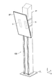
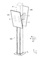
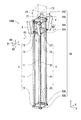
図1は、実施形態1に係るディスプレイ設置装置100及び第1ディスプレイDP1を示す斜視図である。図1に示すように、ディスプレイ設置装置100は、第1ディスプレイDP1を柱構造物PTに設置する。実施形態1では、ディスプレイ設置装置100は、第1ディスプレイDP1の表示面を斜め下方に向かせて、第1ディスプレイDP1を柱構造物PTに設置する。また、実施形態1では、柱構造物PTは、略四角柱である。柱構造物PTは、例えば、建造物の柱である。柱構造物PTは、床FLから鉛直方向VDに沿って起立している。第1ディスプレイDP1は、動画を表示してもよいし、静止画を表示してもよい。第1ディスプレイDP1は、例えば、液晶ディスプレイ、又は、有機エレクトロルミネッセンスディスプレイである。 FIG. 1 is a perspective view showing a display installation device 100 and a first display DP1 according to the first embodiment. As shown in FIG. 1, the display installation device 100 installs the first display DP1 on the pillar structure PT. In the first embodiment, the display installation device 100 installs the first display DP1 on the pillar structure PT with the display surface of the first display DP1 facing diagonally downward. Further, in the first embodiment, the pillar structure PT is a substantially square pillar. The pillar structure PT is, for example, a pillar of a building. The column structure PT stands up from the floor FL along the vertical VD. The first display DP1 may display a moving image or a still image. The first display DP1 is, for example, a liquid crystal display or an organic electroluminescence display.

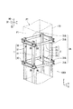
図2は、ディスプレイ設置装置100を示す斜視図である。図2に示すように、ディスプレイ設置装置100は、第1支柱部1と、固定部3と、少なくとも1つの第1ディスプレイ支持部材5とを含む。実施形態1では、ディスプレイ設置装置100は、複数の第1ディスプレイ支持部材5(具体的には、2つの第1ディスプレイ支持部材5)を含む。 FIG. 2 is a perspective view showing the display installation device 100. As shown in FIG. 2, the display installation device 100 includes a first support column portion 1, a fixing portion 3, and at least one first display support member 5. In the first embodiment, the display installation device 100 includes a plurality of first display support members 5 (specifically, two first display support members 5).

第1支柱部1は、第1ディスプレイ支持部材5を介して、第1ディスプレイDP1(図1)を支持する。具体的には、第1支柱部1は、少なくとも1つの第1支柱部材11と、少なくとも1つの第1連結部材13と、少なくとも1つの第2連結部材15とを含む。実施形態1では、第1支柱部1は、複数の第1支柱部材11(具体的には、2つの第1支柱部材11)と、複数の第1連結部材13(具体的には、2つの第1連結部材13)と、1つの第2連結部材15とを含む。なお、第1連結部材13及び第2連結部材15の詳細については後述する。 The first support column portion 1 supports the first display DP1 (FIG. 1) via the first display support member 5. Specifically, the first strut portion 1 includes at least one first strut member 11, at least one first connecting member 13, and at least one second connecting member 15. In the first embodiment, the first strut portion 1 includes a plurality of first strut members 11 (specifically, two first strut members 11) and a plurality of first connecting members 13 (specifically, two first strut members 13). It includes a first connecting member 13) and one second connecting member 15. The details of the first connecting member 13 and the second connecting member 15 will be described later.

複数の第1支柱部材11の各々は、床FLから鉛直方向VDに沿って起立している。具体的には、複数の第1支柱部材11の各々は、柱構造物PTの全周の側面のうちの第1面F1に沿って鉛直方向VDに沿って延びる。 Each of the plurality of first strut members 11 stands up from the floor FL along the vertical VD. Specifically, each of the plurality of first column members 11 extends along the vertical direction VD along the first surface F1 of the side surfaces of the entire circumference of the column structure PT.

第1面F1は、柱構造物PTの全周の側面を構成する複数の面(実施形態1では4つの面)のうちの所定方向PDの側の面である。所定方向PDは、水平方向に略平行であり、柱構造物PTから第1ディスプレイDP1に向かう方向を示す。 The first surface F1 is a surface on the side of the PD in a predetermined direction among a plurality of surfaces (four surfaces in the first embodiment) constituting the side surfaces of the entire circumference of the column structure PT. The predetermined direction PD is substantially parallel to the horizontal direction and indicates a direction from the column structure PT toward the first display DP1.

なお、例えば、柱構造物PTが略円柱である場合、第1面F1は、柱構造物PTの全周の側面を構成する1の面のうちの所定方向PDの側の部位であってもよい。 In addition, for example, when the pillar structure PT is a substantially cylindrical shape, the first surface F1 may be a portion of one surface constituting the side surface of the entire circumference of the pillar structure PT on the side of the PD in the predetermined direction. Good.

複数の第1支柱部材11の各々は略長尺形状を有する。実施形態1では、複数の第1支柱部材11の各々は、断面視において略矩形形状を有し、中空である。複数の第1支柱部材11は、第1方向D1に所定間隔をあけて互いに略平行に配置される。第1方向D1は、鉛直方向VDに略直交し、第1面F1に略平行な方向を示す。第2方向D2は、鉛直方向VD及び第1方向D1に略直交する方向を示す。第2方向D2は所定方向PDに略平行である。第1支柱部材11は、例えば、金属製(例えば鉄製)である。 Each of the plurality of first strut members 11 has a substantially elongated shape. In the first embodiment, each of the plurality of first strut members 11 has a substantially rectangular shape in cross-sectional view and is hollow. The plurality of first support column members 11 are arranged substantially parallel to each other with a predetermined interval in the first direction D1. The first direction D1 indicates a direction substantially orthogonal to the vertical direction VD and substantially parallel to the first surface F1. The second direction D2 indicates a direction substantially orthogonal to the vertical direction VD and the first direction D1. The second direction D2 is substantially parallel to the predetermined direction PD. The first strut member 11 is made of metal (for example, iron), for example.

固定部3は、第1支柱部1を柱構造物PTに固定する。具体的には、固定部3は、少なくとも1つの第1固定部材31と、少なくとも1つの第2固定部材33とを含む。実施形態1では、固定部3は、複数の第1固定部材31(具体的には、2つの第1固定部材31)と、1つの第2固定部材33とを含む。なお、第1固定部材31及び第2固定部材33の詳細については後述する。 The fixing portion 3 fixes the first strut portion 1 to the column structure PT. Specifically, the fixing portion 3 includes at least one first fixing member 31 and at least one second fixing member 33. In the first embodiment, the fixing portion 3 includes a plurality of first fixing members 31 (specifically, two first fixing members 31) and one second fixing member 33. The details of the first fixing member 31 and the second fixing member 33 will be described later.

固定部3は、第1支柱部1との協働により、柱構造物PTの全周の側面に沿って一周にわたり柱構造物PTを外囲する。つまり、平面視において固定部3と第1支柱部1とを柱構造物PTに巻くように配置することで、第1支柱部材11を柱構造物PTに容易に固定できる。その結果、実施形態1によれば、第1支柱部材11を柱構造物PTに固定するときの労力を軽減できて、ディスプレイ設置装置100の設置作業が容易になる。また、実施形態1によれば、第1支柱部材11を柱構造物PTに固定するための部材を、柱構造物PTに、捻じ込んだり、打ち込んだりすることが要求されない。従って、柱構造物PTが損傷することを抑制できる。本明細書において、平面視は、鉛直方向VDから対象物を見ることを示す。 The fixing portion 3 surrounds the pillar structure PT over the entire circumference along the side surface of the entire circumference of the pillar structure PT in cooperation with the first pillar portion 1. That is, by arranging the fixing portion 3 and the first strut portion 1 so as to be wound around the pillar structure PT in a plan view, the first strut member 11 can be easily fixed to the pillar structure PT. As a result, according to the first embodiment, the labor required to fix the first support column member 11 to the column structure PT can be reduced, and the installation work of the display installation device 100 becomes easy. Further, according to the first embodiment, it is not required that the member for fixing the first column member 11 to the column structure PT is screwed or driven into the column structure PT. Therefore, it is possible to prevent the column structure PT from being damaged. As used herein, plan view indicates viewing an object from a vertical VD.

なお、例えば、固定部3は、固定部3単独により、柱構造物PTの全周の側面に沿って一周にわたり柱構造物PTを外囲してもよい。この場合は、第1支柱部材11が固定部3と柱構造物PTとの間に挟まれるように、固定部3が柱構造物PTに巻かれる。 In addition, for example, the fixing portion 3 may surround the pillar structure PT over the entire circumference along the side surface of the entire circumference of the pillar structure PT by the fixing portion 3 alone. In this case, the fixing portion 3 is wound around the pillar structure PT so that the first strut member 11 is sandwiched between the fixing portion 3 and the pillar structure PT.

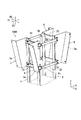
次に、図3を参照して、第1支柱部1の第1連結部材13及び固定部3の第1固定部材31について説明する。図3は、ディスプレイ設置装置100の上部を示す斜視図である。 Next, with reference to FIG. 3, the first connecting member 13 of the first strut portion 1 and the first fixing member 31 of the fixing portion 3 will be described. FIG. 3 is a perspective view showing the upper part of the display installation device 100.

図3に示すように、複数の第1連結部材13の各々は、複数の第1支柱部材11を連結する。従って、実施形態1によれば、複数の第1支柱部材11を補強できる。また、実施形態1では、複数の第1連結部材13は、複数の第1支柱部材11の上部に配置される。第1連結部材13は、例えば、金属製(例えば鉄製)である。 As shown in FIG. 3, each of the plurality of first connecting members 13 connects the plurality of first strut members 11. Therefore, according to the first embodiment, the plurality of first support column members 11 can be reinforced. Further, in the first embodiment, the plurality of first connecting members 13 are arranged above the plurality of first strut members 11. The first connecting member 13 is made of, for example, metal (for example, iron).

複数の第1連結部材13は、鉛直方向VDに所定間隔をあけて互いに略平行に配置される。複数の第1連結部材13の各々は、第1方向D1に沿って延びている。従って、複数の第1連結部材13は、複数の第1支柱部材11に交差している。実施形態1では、複数の第1連結部材13は、複数の第1支柱部材11に略直交している。複数の第1連結部材13の各々の主要部は、略平板形状を有する。第1連結部材13は、例えば、ビスBSによって第1支柱部材11に接続される。 The plurality of first connecting members 13 are arranged substantially parallel to each other at predetermined intervals in the vertical direction VD. Each of the plurality of first connecting members 13 extends along the first direction D1. Therefore, the plurality of first connecting members 13 intersect the plurality of first strut members 11. In the first embodiment, the plurality of first connecting members 13 are substantially orthogonal to the plurality of first strut members 11. Each main part of the plurality of first connecting members 13 has a substantially flat plate shape. The first connecting member 13 is connected to the first strut member 11 by, for example, a screw BS.

複数の第1固定部材31は、それぞれ、複数の第1連結部材13に対応して配置される。つまり、複数の第1固定部材31は、複数の第1支柱部材11の上部に配置される。複数の第1固定部材31は、それぞれ、複数の第1連結部材13に接続される。第1固定部材31は、例えば、ビスBSによって第1連結部材13に接続される。そして、複数の第1固定部材31の各々は、対応する第1連結部材13との協働により、柱構造物PTの全周の側面に沿って一周にわたり柱構造物PTを外囲する。つまり、平面視において第1固定部材31及び第1連結部材13を柱構造物PTに巻くように配置することで、複数の第1支柱部材11を柱構造物PTに容易に固定できる。その結果、実施形態1によれば、第1支柱部材11を柱構造物PTに固定するときの労力を軽減できて、ディスプレイ設置装置100の設置作業が容易になる。また、柱構造物PTに対する部材の捻じ込み及び打ち込みが要求されないため、柱構造物PTが損傷することを抑制できる。 The plurality of first fixing members 31 are arranged corresponding to the plurality of first connecting members 13, respectively. That is, the plurality of first fixing members 31 are arranged above the plurality of first support column members 11. Each of the plurality of first fixing members 31 is connected to the plurality of first connecting members 13. The first fixing member 31 is connected to the first connecting member 13 by, for example, a screw BS. Then, each of the plurality of first fixing members 31 surrounds the pillar structure PT over the entire circumference along the side surface of the entire circumference of the pillar structure PT in cooperation with the corresponding first connecting member 13. That is, by arranging the first fixing member 31 and the first connecting member 13 so as to be wound around the pillar structure PT in a plan view, the plurality of first pillar members 11 can be easily fixed to the pillar structure PT. As a result, according to the first embodiment, the labor required to fix the first column member 11 to the column structure PT can be reduced, and the installation work of the display installation device 100 becomes easy. Further, since it is not required to screw and drive the member into the column structure PT, it is possible to prevent the column structure PT from being damaged.

具体的には、第1固定部材31は、柱構造物PTの全周の側面のうち第1面F1以外の側面に沿った形状を有している。実施形態1では、第1固定部材31は、柱構造物PTの全周の側面のうち第1面F1以外の側面に沿って屈曲し、角張った略U字形状を有している。また、第1固定部材31は略平板形状を有している。そして、第1固定部材31は、第1連結部材13の第1方向D1の一端から、柱構造物PTの側面に沿って、第1連結部材13の第1方向D1の他端まで延びる。 Specifically, the first fixing member 31 has a shape along the side surfaces other than the first surface F1 among the side surfaces of the entire circumference of the column structure PT. In the first embodiment, the first fixing member 31 is bent along a side surface other than the first surface F1 among the side surfaces of the entire circumference of the column structure PT, and has an angular substantially U-shape. Further, the first fixing member 31 has a substantially flat plate shape. Then, the first fixing member 31 extends from one end of the first direction D1 of the first connecting member 13 to the other end of the first direction D1 of the first connecting member 13 along the side surface of the column structure PT.

さらに、第1連結部材13の第1方向D1の一端に第1固定部材31の一端が接続され、第1連結部材13の第1方向D1の他端に第1固定部材31の他端が接続される。従って、第1固定部材31及び第1連結部材13は、柱構造物PTの全周の側面に沿って一周にわたり柱構造物PTを外囲する。つまり、第1固定部材31及び第1連結部材13が柱構造物PTに巻かれることで、第1支柱部材11が柱構造物PTに固定される。実施形態1では、柱構造物PTが略四角柱であるため、第1固定部材31及び第1連結部材13は、略矩形形状を形成している。 Further, one end of the first fixing member 31 is connected to one end of the first direction D1 of the first connecting member 13, and the other end of the first fixing member 31 is connected to the other end of the first direction D1 of the first connecting member 13. Will be done. Therefore, the first fixing member 31 and the first connecting member 13 surround the pillar structure PT over the entire circumference along the side surface of the pillar structure PT. That is, the first fixing member 31 and the first connecting member 13 are wound around the pillar structure PT, so that the first pillar member 11 is fixed to the pillar structure PT. In the first embodiment, since the pillar structure PT is a substantially square pillar, the first fixing member 31 and the first connecting member 13 form a substantially rectangular shape.

なお、例えば、第1固定部材31は、第1固定部材31単独により、柱構造物PTの全周の側面に沿って一周にわたり柱構造物PTを外囲してもよい。つまり、第1固定部材31が柱構造物PTに単独で巻かれることで、第1支柱部材11が柱構造物PTに固定される。この場合、第1支柱部材11が第1固定部材31と柱構造物PTとの間に挟まれるように、第1固定部材31が柱構造物PTに巻かれる。また、この場合、例えば、第1固定部材31は、柱構造物PTの全周の側面に沿った形状を有する。柱構造物PTが略四角柱の場合は、例えば、第1固定部材31は略矩形形状を有する。 In addition, for example, the first fixing member 31 may surround the pillar structure PT around the entire circumference of the pillar structure PT by the first fixing member 31 alone. That is, by winding the first fixing member 31 around the pillar structure PT independently, the first pillar member 11 is fixed to the pillar structure PT. In this case, the first fixing member 31 is wound around the pillar structure PT so that the first pillar member 11 is sandwiched between the first fixing member 31 and the pillar structure PT. Further, in this case, for example, the first fixing member 31 has a shape along the side surface of the entire circumference of the column structure PT. When the pillar structure PT is a substantially square pillar, for example, the first fixing member 31 has a substantially rectangular shape.

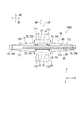
次に、図4を参照して、第1支柱部1の第2連結部材15及び固定部3の第2固定部材33について説明する。図4は、ディスプレイ設置装置100の下部を示す斜視図である。 Next, with reference to FIG. 4, the second connecting member 15 of the first strut portion 1 and the second fixing member 33 of the fixing portion 3 will be described. FIG. 4 is a perspective view showing the lower part of the display installation device 100.

図4に示すように、第2連結部材15は、複数の第1支柱部材11を連結する。従って、実施形態1によれば、複数の第1支柱部材11をさらに補強できる。特に、実施形態1では、第2連結部材15は、複数の第1連結部材13(図2)よりも下方に配置される。つまり、第2連結部材15は、複数の第1支柱部材11の下部に配置される。従って、第1連結部材13及び第2連結部材15によって、複数の第1支柱部材11の上部及び下部を補強することで、複数の第1支柱部材11の強度を効果的に向上できる。第2連結部材15は、例えば、金属製(例えば鉄製)である。 As shown in FIG. 4, the second connecting member 15 connects a plurality of first strut members 11. Therefore, according to the first embodiment, the plurality of first support column members 11 can be further reinforced. In particular, in the first embodiment, the second connecting member 15 is arranged below the plurality of first connecting members 13 (FIG. 2). That is, the second connecting member 15 is arranged below the plurality of first strut members 11. Therefore, the strength of the plurality of first strut members 11 can be effectively improved by reinforcing the upper portion and the lower portion of the plurality of first strut members 11 by the first connecting member 13 and the second connecting member 15. The second connecting member 15 is made of, for example, metal (for example, iron).

具体的には、第2連結部材15は、複数の第1支柱部材11を床FLの近傍で連結する。第2連結部材15は、第1方向D1に沿って延びている。実施形態1では、第2連結部材15は、第1支柱部材11に対して略直角になるように、第1支柱部材11に接続されている。第2連結部材15の主要部は、略平板形状を有する。第2連結部材15は、例えば、ビスBSによって第1支柱部材11に接続される。 Specifically, the second connecting member 15 connects a plurality of first strut members 11 in the vicinity of the floor FL. The second connecting member 15 extends along the first direction D1. In the first embodiment, the second connecting member 15 is connected to the first strut member 11 so as to be substantially perpendicular to the first strut member 11. The main part of the second connecting member 15 has a substantially flat plate shape. The second connecting member 15 is connected to the first strut member 11 by, for example, a screw BS.

第2固定部材33は、第2連結部材15に対応して配置される。従って、第2固定部材33は、第1固定部材31(図2)よりも下方に配置される。そして、第2固定部材33は第2連結部材15に接続される。実施形態1では、第2固定部材33は床FLの近傍で第2連結部材15に接続される。第2固定部材33は、例えば、ビスBSによって第2連結部材15に接続される。 The second fixing member 33 is arranged corresponding to the second connecting member 15. Therefore, the second fixing member 33 is arranged below the first fixing member 31 (FIG. 2). Then, the second fixing member 33 is connected to the second connecting member 15. In the first embodiment, the second fixing member 33 is connected to the second connecting member 15 in the vicinity of the floor FL. The second fixing member 33 is connected to the second connecting member 15 by, for example, a screw BS.

そして、第2固定部材33は、第2連結部材15との協働により、柱構造物PTの全周の側面に沿って一周にわたり柱構造物PTを外囲する。つまり、平面視において第2固定部材33及び第2連結部材15を柱構造物PTの下部に巻くように配置することで、第1支柱部材11の下部を柱構造物PTの下部に容易に固定できる。その結果、実施形態1によれば、第1支柱部材11を柱構造物PTの下部に固定するときの労力を軽減できて、ディスプレイ設置装置100の設置作業が更に容易になる。また、柱構造物PTに対する部材の捻じ込み及び打ち込みが要求されないため、柱構造物PTが損傷することを抑制できる。 Then, the second fixing member 33 surrounds the pillar structure PT over the entire circumference along the side surface of the entire circumference of the pillar structure PT in cooperation with the second connecting member 15. That is, by arranging the second fixing member 33 and the second connecting member 15 so as to be wound around the lower part of the column structure PT in a plan view, the lower part of the first column member 11 can be easily fixed to the lower part of the column structure PT. it can. As a result, according to the first embodiment, the labor required to fix the first column member 11 to the lower part of the column structure PT can be reduced, and the installation work of the display installation device 100 becomes easier. Further, since it is not required to screw and drive the member into the column structure PT, it is possible to prevent the column structure PT from being damaged.

具体的には、第2固定部材33は、第2連結部材15の第1方向D1の一端から、柱構造物PTの側面に沿って、第2連結部材15の第1方向D1の他端まで延びる。第2固定部材33の形状は、第1固定部材31の形状と同様である。 Specifically, the second fixing member 33 extends from one end of the first direction D1 of the second connecting member 15 to the other end of the first direction D1 of the second connecting member 15 along the side surface of the column structure PT. Extend. The shape of the second fixing member 33 is the same as the shape of the first fixing member 31.

また、第2連結部材15の第1方向D1の一端に第2固定部材33の一端が接続され、第2連結部材15の第1方向D1の他端に第2固定部材33の他端が接続される。従って、第2固定部材33及び第2連結部材15は、柱構造物PTの全周の側面に沿って一周にわたり柱構造物PTを外囲する。つまり、第2固定部材33及び第2連結部材15が柱構造物PTの下部に巻かれることで、第1支柱部材11が柱構造物PTの下部に固定される。実施形態1では、柱構造物PTが略四角柱であるため、第2固定部材33及び第2連結部材15は、略矩形形状を形成している。 Further, one end of the second fixing member 33 is connected to one end of the first direction D1 of the second connecting member 15, and the other end of the second fixing member 33 is connected to the other end of the first direction D1 of the second connecting member 15. Will be done. Therefore, the second fixing member 33 and the second connecting member 15 surround the pillar structure PT all around the side surface of the pillar structure PT. That is, the second fixing member 33 and the second connecting member 15 are wound around the lower part of the pillar structure PT, so that the first pillar member 11 is fixed to the lower part of the pillar structure PT. In the first embodiment, since the pillar structure PT is a substantially square pillar, the second fixing member 33 and the second connecting member 15 form a substantially rectangular shape.

なお、例えば、第2固定部材33は、第2固定部材33単独により、柱構造物PTの全周の側面に沿って一周にわたり柱構造物PTを外囲してもよい。つまり、第2固定部材33が柱構造物PTの下部に単独で巻かれることで、第1支柱部材11が柱構造物PTの下部に固定される。この場合、第1支柱部材11が第2固定部材33と柱構造物PTとの間に挟まれるように、第2固定部材33が柱構造物PTに巻かれる。また、この場合、例えば、第2固定部材33は、柱構造物PTの全周の側面に沿った形状を有する。柱構造物PTが略四角柱の場合は、例えば、第2固定部材33は略矩形形状を有する。 In addition, for example, the second fixing member 33 may surround the pillar structure PT around the entire circumference of the pillar structure PT by the second fixing member 33 alone. That is, the second fixing member 33 is independently wound around the lower part of the pillar structure PT, so that the first pillar member 11 is fixed to the lower part of the pillar structure PT. In this case, the second fixing member 33 is wound around the pillar structure PT so that the first pillar member 11 is sandwiched between the second fixing member 33 and the pillar structure PT. Further, in this case, for example, the second fixing member 33 has a shape along the side surface of the entire circumference of the column structure PT. When the pillar structure PT is a substantially square pillar, for example, the second fixing member 33 has a substantially rectangular shape.

次に、図5を参照して、第1ディスプレイ支持部材5について説明する。図5は、第1ディスプレイ支持部材5を示す斜視図である。 Next, the first display support member 5 will be described with reference to FIG. FIG. 5 is a perspective view showing the first display support member 5.

図5に示す複数の第1ディスプレイ支持部材5は、第1ディスプレイDP1(図1)を支持する。特に、複数の第1ディスプレイ支持部材5は、第1ディスプレイDP1の表示面を斜め下方に向かせて第1ディスプレイDP1を支持することが好ましい。この好ましい例によれば、第1ディスプレイDP1の表示面が水平方向を向くように支持される場合と比較して、第1ディスプレイDP1の自重によって第1支柱部1をより安定させることができる。 The plurality of first display support members 5 shown in FIG. 5 support the first display DP1 (FIG. 1). In particular, it is preferable that the plurality of first display support members 5 support the first display DP1 with the display surface of the first display DP1 facing diagonally downward. According to this preferred example, the first strut portion 1 can be made more stable by the weight of the first display DP1 as compared with the case where the display surface of the first display DP1 is supported so as to face the horizontal direction.

具体的には、複数の第1ディスプレイ支持部材5の各々は、取付面5aと、第1爪部5bと、第2爪部5cとを有する。取付面5aは、鉛直方向VDに対して下方に向けて傾斜している。複数の第1ディスプレイ支持部材5の取付面5aに、第1ディスプレイDP1(図1)の裏面が取り付けられる。その結果、第1ディスプレイDP1の表示面が斜め下方を向く。 Specifically, each of the plurality of first display support members 5 has a mounting surface 5a, a first claw portion 5b, and a second claw portion 5c. The mounting surface 5a is inclined downward with respect to the vertical VD. The back surface of the first display DP1 (FIG. 1) is attached to the attachment surface 5a of the plurality of first display support members 5. As a result, the display surface of the first display DP1 faces diagonally downward.

第1爪部5bは、取付面5aと反対側において、第1ディスプレイ支持部材5の上部に配置される。第1爪部5bは、上側の第1連結部材13に引っ掛けられる。加えて、第2爪部5cは、取付面5aと反対側において、第1ディスプレイ支持部材5の下部に配置される。第2爪部5cは、下側の第1連結部材13に引っ掛けられる。その結果、複数の第1ディスプレイ支持部材5の各々は、複数の第1連結部材13に支持される。 The first claw portion 5b is arranged on the upper side of the first display support member 5 on the side opposite to the mounting surface 5a. The first claw portion 5b is hooked on the upper first connecting member 13. In addition, the second claw portion 5c is arranged below the first display support member 5 on the side opposite to the mounting surface 5a. The second claw portion 5c is hooked on the lower first connecting member 13. As a result, each of the plurality of first display support members 5 is supported by the plurality of first connecting members 13.

なお、例えば、第1ディスプレイ支持部材5の取付面5aに第1ディスプレイDP1を取り付けた後に、第1ディスプレイ支持部材5の第1爪部5b及び第2爪部5cを、それぞれ、上側の第1連結部材13及び下側の第1連結部材13に引っ掛ける。 For example, after mounting the first display DP1 on the mounting surface 5a of the first display support member 5, the first claw portion 5b and the second claw portion 5c of the first display support member 5 are respectively placed on the upper first side. It is hooked on the connecting member 13 and the lower first connecting member 13.

(実施形態2)
図6〜図10を参照して、本発明の実施形態2に係るディスプレイ設置装置100Aを説明する。実施形態2では、ディスプレイ設置装置100Aが、第1ディスプレイDP1に加えて、第2ディスプレイDP2を柱構造物PTに設置する点で、実施形態2は実施形態1と主に異なる。以下、実施形態2が実施形態1と異なる点を主に説明する。
(Embodiment 2)
The display installation device 100A according to the second embodiment of the present invention will be described with reference to FIGS. 6 to 10. In the second embodiment, the second embodiment is mainly different from the first embodiment in that the display installation device 100A installs the second display DP2 on the pillar structure PT in addition to the first display DP1. Hereinafter, the points that the second embodiment differs from the first embodiment will be mainly described.

まず、図6及び図7を参照して、ディスプレイ設置装置100Aを説明する。図6は、実施形態2に係るディスプレイ設置装置100A、第1ディスプレイDP1、及び、第2ディスプレイDP2を示す斜視図である。 First, the display installation device 100A will be described with reference to FIGS. 6 and 7. FIG. 6 is a perspective view showing the display installation device 100A, the first display DP1, and the second display DP2 according to the second embodiment.

図6に示すように、ディスプレイ設置装置100Aは、第1ディスプレイDP1及び第2ディスプレイDP2を柱構造物PTに設置する。具体的には、ディスプレイ設置装置100Aは、第1ディスプレイDP1の裏面と第2ディスプレイDP2の裏面とが柱構造物PTを挟んで第2方向D2に対向するように、第1ディスプレイDP1及び第2ディスプレイDP2を柱構造物PTに設置する。実施形態2では、ディスプレイ設置装置100Aは、第1ディスプレイDP1の表示面及び第2ディスプレイDP2の表示面の各々を斜め下方に向かせて、第1ディスプレイDP1及び第2ディスプレイDP2を柱構造物PTに設置する。第2ディスプレイDP2の構成は、第1ディスプレイDP1の構成と同様である。 As shown in FIG. 6, the display installation device 100A installs the first display DP1 and the second display DP2 on the pillar structure PT. Specifically, in the display installation device 100A, the first display DP1 and the second display DP1 and the second display DP1 and the second display DP1 so that the back surface of the first display DP1 and the back surface of the second display DP2 face the second direction D2 with the pillar structure PT interposed therebetween. Display DP2 is installed in the column structure PT. In the second embodiment, the display installation device 100A directs the display surface of the first display DP1 and the display surface of the second display DP2 diagonally downward, and directs the first display DP1 and the second display DP2 to the pillar structure PT. Install in. The configuration of the second display DP2 is the same as the configuration of the first display DP1.

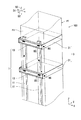
図7は、ディスプレイ設置装置100Aを示す斜視図である。図7に示すように、ディスプレイ設置装置100Aは、第1支柱部1と、固定部3Aと、少なくとも1つの第1ディスプレイ支持部材5と、第2支柱部2と、少なくとも1つの第2ディスプレイ支持部材6とを含む。実施形態2では、ディスプレイ設置装置100Aは、複数の第2ディスプレイ支持部材6(具体的には、2つの第2ディスプレイ支持部材6)を含む。 FIG. 7 is a perspective view showing the display installation device 100A. As shown in FIG. 7, the display installation device 100A includes a first support column portion 1, a fixing portion 3A, at least one first display support member 5, a second support column portion 2, and at least one second display support. Includes member 6. In the second embodiment, the display installation device 100A includes a plurality of second display support members 6 (specifically, two second display support members 6).

第2支柱部2は、第1支柱部1と第2方向D2に対向する。第2支柱部2は、第2ディスプレイ支持部材6を介して、第2ディスプレイDP2(図6)を支持する。具体的には、第2支柱部2は、少なくとも1つの第2支柱部材21と、少なくとも1つの第3連結部材23と、少なくとも1つの第4連結部材25とを含む。実施形態2では、第2支柱部2は、複数の第2支柱部材21(具体的には、2つの第2支柱部材21)と、複数の第3連結部材23(具体的には、2つの第3連結部材23)と、1つの第4連結部材25とを含む。なお、第3連結部材23及び第4連結部材25の詳細については後述する。 The second strut portion 2 faces the first strut portion 1 and the second direction D2. The second support column portion 2 supports the second display DP2 (FIG. 6) via the second display support member 6. Specifically, the second strut portion 2 includes at least one second strut member 21, at least one third connecting member 23, and at least one fourth connecting member 25. In the second embodiment, the second strut portion 2 includes a plurality of second strut members 21 (specifically, two second strut members 21) and a plurality of third connecting members 23 (specifically, two). A third connecting member 23) and one fourth connecting member 25 are included. The details of the third connecting member 23 and the fourth connecting member 25 will be described later.

複数の第2支柱部材21の各々は、床FLから鉛直方向VDに沿って起立している。具体的には、複数の第2支柱部材21の各々は、柱構造物PTの全周の側面のうちの第2面F2に沿って鉛直方向VDに沿って延びる。 Each of the plurality of second support column members 21 stands up from the floor FL along the vertical VD. Specifically, each of the plurality of second column members 21 extends along the vertical VD along the second surface F2 of the side surfaces of the entire circumference of the column structure PT.

第2面F2は、柱構造物PTの第1面F1とは逆の側の面である。換言すれば、第2面F2は、柱構造物PTの全周の側面を構成する複数の面(実施形態1では4つの面)のうちの所定方向PDに対して反対方向RDの側の面である。更に換言すれば、第2面F2は、第1面F1と第2方向D2に対向する面である。 The second surface F2 is a surface on the opposite side of the first surface F1 of the column structure PT. In other words, the second surface F2 is a surface on the side opposite to the predetermined direction PD among the plurality of surfaces (four surfaces in the first embodiment) constituting the side surfaces of the entire circumference of the column structure PT. Is. In other words, the second surface F2 is a surface facing the first surface F1 and the second direction D2.

なお、例えば、柱構造物PTが略円柱である場合、第2面F2は、柱構造物PTの第1面F1とは逆の側の部位であってもよい。換言すれば、第2面F2は、柱構造物PTの全周の側面を構成する1の面のうちの所定方向PDに対して反対方向RDの側の部位であってもよい。 In addition, for example, when the column structure PT is a substantially cylindrical shape, the second surface F2 may be a portion on the opposite side of the first surface F1 of the column structure PT. In other words, the second surface F2 may be a portion on the side of the RD in the direction opposite to the predetermined direction PD among the one surfaces forming the side surface of the entire circumference of the column structure PT.

第2支柱部材21のその他の構成は、図2等を参照して説明した第1支柱部材11の構成と同様であり、説明を省略する。 Other configurations of the second strut member 21 are the same as the configuration of the first strut member 11 described with reference to FIG. 2 and the like, and the description thereof will be omitted.

固定部3Aは、第1支柱部1及び第2支柱部2を柱構造物PTに固定する。具体的には、固定部3Aは、複数の第1固定部材31A(実施形態2では、4つの第1固定部材31A)と、複数の第2固定部材33A(実施形態2では、2つの第2固定部材33A)とを含む。なお、第1固定部材31A及び第2固定部材33Aの詳細については後述する。 The fixing portion 3A fixes the first strut portion 1 and the second strut portion 2 to the column structure PT. Specifically, the fixing portion 3A includes a plurality of first fixing members 31A (four first fixing members 31A in the second embodiment) and a plurality of second fixing members 33A (two second fixing members 33A in the second embodiment). Includes fixing member 33A). The details of the first fixing member 31A and the second fixing member 33A will be described later.

固定部3Aは、第1支柱部1及び第2支柱部2の両方との協働により、柱構造物PTの全周の側面に沿って一周にわたり柱構造物PTを外囲する。つまり、平面視において固定部3と第1支柱部1と第2支柱部2とを柱構造物PTに巻くように配置することで、第1支柱部材11及び第2支柱部材21を柱構造物PTに容易に固定できる。その結果、実施形態2によれば、第1支柱部材11及び第2支柱部材21を柱構造物PTに固定するときの労力を軽減できて、ディスプレイ設置装置100Aの設置作業が容易になる。また、柱構造物PTに対する部材の捻じ込み及び打ち込みが要求されないため、柱構造物PTが損傷することを抑制できる。 The fixing portion 3A surrounds the pillar structure PT over the entire circumference along the side surface of the entire circumference of the pillar structure PT in cooperation with both the first pillar portion 1 and the second pillar portion 2. That is, by arranging the fixing portion 3, the first strut portion 1 and the second strut portion 2 so as to be wound around the pillar structure PT in a plan view, the first strut member 11 and the second strut member 21 are arranged so as to be wound around the pillar structure PT. Can be easily fixed to PT. As a result, according to the second embodiment, the labor required to fix the first support column member 11 and the second support column member 21 to the column structure PT can be reduced, and the installation work of the display installation device 100A becomes easy. Further, since it is not required to screw and drive the member into the column structure PT, it is possible to prevent the column structure PT from being damaged.

なお、例えば、固定部3Aは、第1支柱部1及び第2支柱部2のうちの一方との協働により、柱構造物PTの全周の側面に沿って一周にわたり柱構造物PTを外囲してもよい。 In addition, for example, the fixing portion 3A removes the pillar structure PT around the entire circumference of the pillar structure PT in cooperation with one of the first pillar portion 1 and the second pillar portion 2. You may enclose it.

また、例えば、固定部3A単独により、柱構造物PTの全周の側面に沿って一周にわたり柱構造物PTを外囲してもよい。この場合は、第1支柱部材11及び第2支柱部材21が固定部3Aと柱構造物PTとの間に挟まれるように、固定部3Aが柱構造物PTに巻かれる。 Further, for example, the pillar structure PT may be surrounded by the fixing portion 3A alone along the entire peripheral side surface of the pillar structure PT. In this case, the fixing portion 3A is wound around the pillar structure PT so that the first pillar member 11 and the second pillar member 21 are sandwiched between the fixing portion 3A and the pillar structure PT.

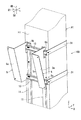
次に、図8を参照して、第2支柱部2の第3連結部材23及び固定部3Aの第1固定部材31Aについて説明する。図8は、ディスプレイ設置装置100Aの上部を示す斜視図である。 Next, with reference to FIG. 8, the third connecting member 23 of the second strut portion 2 and the first fixing member 31A of the fixing portion 3A will be described. FIG. 8 is a perspective view showing the upper part of the display installation device 100A.

図8に示すように、複数の第3連結部材23の各々は、複数の第2支柱部材21を連結する。従って、実施形態2によれば、複数の第2支柱部材21を補強できる。第3連結部材23は、柱構造物PTを介して、第1連結部材13と第2方向D2に対向する。第3連結部材23は第2支柱部材21の上部に配置される。第3連結部材23は、例えば、金属製(例えば鉄製)である。 As shown in FIG. 8, each of the plurality of third connecting members 23 connects the plurality of second strut members 21. Therefore, according to the second embodiment, the plurality of second support column members 21 can be reinforced. The third connecting member 23 faces the first connecting member 13 and the second direction D2 via the column structure PT. The third connecting member 23 is arranged above the second strut member 21. The third connecting member 23 is made of, for example, metal (for example, iron).

第3連結部材23のその他の構成は、図3等を参照して説明した第1連結部材13の構成と同様であり、説明を省略する。また、第3連結部材23と第2支柱部材21との位置関係は、図3等を参照して説明した第1連結部材13と第1支柱部材11との位置関係と同様であり、説明を省略する。 Other configurations of the third connecting member 23 are the same as the configuration of the first connecting member 13 described with reference to FIG. 3 and the like, and the description thereof will be omitted. Further, the positional relationship between the third connecting member 23 and the second strut member 21 is the same as the positional relationship between the first connecting member 13 and the first strut member 11 described with reference to FIG. Omit.

複数の第1固定部材31Aは、第1支柱部材11及び第2支柱部材21の上部に配置される。第1方向D1に互いに対向する一対の第1固定部材31Aは、第2方向D2に互いに対向する第1連結部材13及び第3連結部材23に対応して設けられる。第1連結部材13の第1方向D1の一端と第3連結部材23の第1方向D1の一端とは、一対の第1固定部材31Aのうちの一方によって連結される。第1連結部材13の第1方向D1の他端と第3連結部材23の第1方向D1の他端とは、一対の第1固定部材31Aのうちの他方によって連結される。第1固定部材31Aは、例えば、ビスBSによって第1連結部材13及び第3連結部材23に接続される。 The plurality of first fixing members 31A are arranged above the first strut member 11 and the second strut member 21. The pair of first fixing members 31A facing each other in the first direction D1 are provided corresponding to the first connecting member 13 and the third connecting member 23 facing each other in the second direction D2. One end of the first direction D1 of the first connecting member 13 and one end of the first direction D1 of the third connecting member 23 are connected by one of a pair of first fixing members 31A. The other end of the first direction D1 of the first connecting member 13 and the other end of the first direction D1 of the third connecting member 23 are connected by the other of the pair of first fixing members 31A. The first fixing member 31A is connected to the first connecting member 13 and the third connecting member 23 by, for example, a screw BS.

そして、一対の第1固定部材31Aは、対応する第1連結部材13及び第3連結部材23の両方との協働により、柱構造物PTの全周の側面に沿って一周にわたり柱構造物PTを外囲する。つまり、平面視において一対の第1固定部材31と1つの第1連結部材13と1つの第3連結部材23とを柱構造物PTに巻くように配置することで、複数の第1支柱部材11及び複数の第2支柱部材21を柱構造物PTに容易に固定できる。その結果、実施形態2によれば、第1支柱部材11及び第2支柱部材21を柱構造物PTに固定するときの労力を軽減できて、ディスプレイ設置装置100Aの設置作業が容易になる。また、柱構造物PTに対する部材の捻じ込み及び打ち込みが要求されないため、柱構造物PTが損傷することを抑制できる。 Then, the pair of first fixing members 31A cooperates with both the corresponding first connecting member 13 and the third connecting member 23, so that the column structure PT goes around the entire circumference of the column structure PT. Enclose. That is, by arranging the pair of first fixing members 31, one first connecting member 13, and one third connecting member 23 so as to be wound around the column structure PT in a plan view, a plurality of first column members 11 And a plurality of second column members 21 can be easily fixed to the column structure PT. As a result, according to the second embodiment, the labor required to fix the first support column member 11 and the second support column member 21 to the column structure PT can be reduced, and the installation work of the display installation device 100A becomes easy. Further, since it is not required to screw and drive the member into the column structure PT, it is possible to prevent the column structure PT from being damaged.

具体的には、第1固定部材31Aは、第2方向D2に沿って延びており、略平板形状を有している。従って、一対の第1固定部材31Aと、対応する第1連結部材13及び第3連結部材23とによって、略矩形形状が形成されている。 Specifically, the first fixing member 31A extends along the second direction D2 and has a substantially flat plate shape. Therefore, a substantially rectangular shape is formed by the pair of the first fixing member 31A and the corresponding first connecting member 13 and the third connecting member 23.

なお、例えば、第1固定部材31Aは、第1連結部材13及び第3連結部材23のうちの一方との協働により、柱構造物PTの全周の側面に沿って一周にわたり柱構造物PTを外囲してもよい。この場合は、第1固定部材31Aは、実施形態1に係る第1固定部材31と同様の構成を有する。 In addition, for example, the first fixing member 31A cooperates with one of the first connecting member 13 and the third connecting member 23, and the pillar structure PT goes around the entire circumference of the pillar structure PT. May be enclosed. In this case, the first fixing member 31A has the same configuration as the first fixing member 31 according to the first embodiment.

また、例えば、第1固定部材31A単独により、柱構造物PTの全周の側面に沿って一周にわたり柱構造物PTを外囲してもよい。この場合は、第1支柱部材11及び第2支柱部材21が第1固定部材31Aと柱構造物PTとの間に挟まれるように、第1固定部材31Aが柱構造物PTに巻かれる。 Further, for example, the pillar structure PT may be surrounded by the first fixing member 31A alone along the entire peripheral side surface of the pillar structure PT. In this case, the first fixing member 31A is wound around the pillar structure PT so that the first pillar member 11 and the second pillar member 21 are sandwiched between the first fixing member 31A and the pillar structure PT.

次に、図9を参照して、第2支柱部2の第4連結部材25及び固定部3Aの第2固定部材33Aについて説明する。図9は、ディスプレイ設置装置100Aの下部を示す斜視図である。図9では、図面の簡略化のため、柱構造物PTを省略している。 Next, with reference to FIG. 9, the fourth connecting member 25 of the second strut portion 2 and the second fixing member 33A of the fixing portion 3A will be described. FIG. 9 is a perspective view showing the lower part of the display installation device 100A. In FIG. 9, the column structure PT is omitted for simplification of the drawing.

図9に示すように、第4連結部材25は、複数の第2支柱部材21を連結する。従って、実施形態2によれば、複数の第2支柱部材21をさらに補強できる。特に、実施形態2では、第4連結部材25は、複数の第3連結部材23(図7)よりも下方に配置される。つまり、第4連結部材25は、複数の第2支柱部材21の下部に配置される。従って、第3連結部材23及び第4連結部材25によって、複数の第2支柱部材21の上部及び下部を補強することで、複数の第2支柱部材21の強度を効果的に向上できる。 As shown in FIG. 9, the fourth connecting member 25 connects a plurality of second strut members 21. Therefore, according to the second embodiment, the plurality of second support column members 21 can be further reinforced. In particular, in the second embodiment, the fourth connecting member 25 is arranged below the plurality of third connecting members 23 (FIG. 7). That is, the fourth connecting member 25 is arranged below the plurality of second strut members 21. Therefore, the strength of the plurality of second strut members 21 can be effectively improved by reinforcing the upper portion and the lower portion of the plurality of second strut members 21 by the third connecting member 23 and the fourth connecting member 25.

第4連結部材25のその他の構成は、図4等を参照して説明した第2連結部材15の構成と同様であり、説明を省略する。また、第4連結部材25と第2支柱部材21との位置関係は、図4等を参照して説明した第2連結部材15と第1支柱部材11との位置関係と同様であり、説明を省略する。 Other configurations of the fourth connecting member 25 are the same as the configuration of the second connecting member 15 described with reference to FIG. 4 and the like, and the description thereof will be omitted. Further, the positional relationship between the fourth connecting member 25 and the second strut member 21 is the same as the positional relationship between the second connecting member 15 and the first strut member 11 described with reference to FIG. Omit.

第1方向D1に互いに対向する一対の第2固定部材33Aは、第2連結部材15及び第4連結部材25に対応して配置される。従って、一対の第2固定部材33Aは、第1固定部材31A(図7)よりも下方に配置される。 The pair of second fixing members 33A facing each other in the first direction D1 are arranged corresponding to the second connecting member 15 and the fourth connecting member 25. Therefore, the pair of second fixing members 33A are arranged below the first fixing member 31A (FIG. 7).

一対の第2固定部材33Aは、第2方向D2に互いに対応する第2連結部材15及び第4連結部材25に対応して設けられる。第2連結部材15の第1方向D1の一端と第4連結部材25の第1方向D1の一端とは、一対の第2固定部材33Aのうちの一方によって連結される。第2連結部材15の第1方向D1の他端と第4連結部材25の第1方向D1の他端とは、一対の第2固定部材33Aのうちの他方によって連結される。第2固定部材33Aは、例えば、ビスBSによって第2連結部材15及び第4連結部材25に接続される。 The pair of second fixing members 33A are provided corresponding to the second connecting member 15 and the fourth connecting member 25 corresponding to each other in the second direction D2. One end of the first direction D1 of the second connecting member 15 and one end of the first direction D1 of the fourth connecting member 25 are connected by one of a pair of second fixing members 33A. The other end of the first direction D1 of the second connecting member 15 and the other end of the first direction D1 of the fourth connecting member 25 are connected by the other of the pair of second fixing members 33A. The second fixing member 33A is connected to the second connecting member 15 and the fourth connecting member 25 by, for example, a screw BS.

そして、一対の第2固定部材33Aは、第2連結部材15及び第4連結部材25の両方との協働により、柱構造物PTの全周の側面に沿って一周にわたり柱構造物PTを外囲する。従って、複数の第1支柱部材11の下部及び複数の第2支柱部材21の下部を柱構造物PTに容易に固定できる。 Then, the pair of second fixing members 33A, in cooperation with both the second connecting member 15 and the fourth connecting member 25, remove the pillar structure PT around the entire circumference of the pillar structure PT. Enclose. Therefore, the lower part of the plurality of first column members 11 and the lower part of the plurality of second column members 21 can be easily fixed to the column structure PT.

具体的には、第2固定部材33Aは、第2方向D2に沿って延びており、略平板形状を有している。従って、一対の第2固定部材33Aと第2連結部材15と第4連結部材25とによって、略矩形形状が形成されている。 Specifically, the second fixing member 33A extends along the second direction D2 and has a substantially flat plate shape. Therefore, a substantially rectangular shape is formed by the pair of the second fixing member 33A, the second connecting member 15, and the fourth connecting member 25.

なお、例えば、第2固定部材33Aは、第2連結部材15及び第4連結部材25のうちの一方との協働により、柱構造物PTの全周の側面に沿って一周にわたり柱構造物PTを外囲してもよい。この場合は、第2固定部材33Aは、実施形態1に係る第2固定部材33と同様の構成を有する。 In addition, for example, the second fixing member 33A cooperates with one of the second connecting member 15 and the fourth connecting member 25, so that the column structure PT goes around the entire circumference of the column structure PT. May be enclosed. In this case, the second fixing member 33A has the same configuration as the second fixing member 33 according to the first embodiment.

また、例えば、第2固定部材33A単独により、柱構造物PTの全周の側面に沿って一周にわたり柱構造物PTを外囲してもよい。この場合は、第1支柱部材11及び第2支柱部材21が第2固定部材33Aと柱構造物PTとの間に挟まれるように、第2固定部材33Aが柱構造物PTに巻かれる。 Further, for example, the second fixing member 33A alone may surround the column structure PT over the entire circumference along the side surface of the column structure PT. In this case, the second fixing member 33A is wound around the pillar structure PT so that the first pillar member 11 and the second pillar member 21 are sandwiched between the second fixing member 33A and the pillar structure PT.

次に、図10を参照して、第2ディスプレイ支持部材6について説明する。図10は、第2ディスプレイ支持部材6を示す斜視図である。図10では、図面の簡略化のため、柱構造物PTを省略している。 Next, the second display support member 6 will be described with reference to FIG. FIG. 10 is a perspective view showing the second display support member 6. In FIG. 10, the column structure PT is omitted for simplification of the drawing.

図10に示すように、複数の第2ディスプレイ支持部材6は、第2ディスプレイDP2(図6)を支持する。特に、複数の第2ディスプレイ支持部材6は、第2ディスプレイDP2の表示面を斜め下方に向かせて第2ディスプレイDP2を支持することが好ましい。加えて、実施形態1と同様に、複数の第1ディスプレイ支持部材5もまた、第1ディスプレイDP1の表示面を斜め下方に向かせて第1ディスプレイDP1を支持することが好ましい。この好ましい例によれば、第1支柱部1の側と第2支柱部2の側とで、重量のバランスが良いため、ディスプレイ設置装置100Aを安定して設置できる。 As shown in FIG. 10, the plurality of second display support members 6 support the second display DP2 (FIG. 6). In particular, it is preferable that the plurality of second display support members 6 support the second display DP2 with the display surface of the second display DP2 facing diagonally downward. In addition, as in the first embodiment, it is preferable that the plurality of first display support members 5 also support the first display DP1 with the display surface of the first display DP1 facing diagonally downward. According to this preferred example, since the weight is well-balanced between the side of the first strut portion 1 and the side of the second strut portion 2, the display installation device 100A can be stably installed.

具体的には、第1ディスプレイDP1の裏面と第2ディスプレイDP2の裏面とが柱構造物PTを挟んで第2方向D2に対向するように、第1ディスプレイ支持部材5は第1ディスプレイDP1を支持し、第2ディスプレイ支持部材6は第2ディスプレイDP2を支持する。 Specifically, the first display support member 5 supports the first display DP1 so that the back surface of the first display DP1 and the back surface of the second display DP2 face the second direction D2 with the pillar structure PT interposed therebetween. Then, the second display support member 6 supports the second display DP2.

第2ディスプレイ支持部材6の構成は、第1ディスプレイ支持部材5の構成と同様である。ただし、第2ディスプレイ支持部材6の取付面5aに、第2ディスプレイDP2(図6)の裏面が取り付けられる。また、第2ディスプレイ支持部材6の第1爪部5bは、上側の第3連結部材23に引っ掛けられる。加えて、第2ディスプレイ支持部材6の第2爪部5cは、下側の第3連結部材23に引っ掛けられる。その結果、複数の第2ディスプレイ支持部材6の各々は、複数の第3連結部材23に支持される。 The configuration of the second display support member 6 is the same as the configuration of the first display support member 5. However, the back surface of the second display DP2 (FIG. 6) is attached to the attachment surface 5a of the second display support member 6. Further, the first claw portion 5b of the second display support member 6 is hooked on the upper third connecting member 23. In addition, the second claw portion 5c of the second display support member 6 is hooked on the lower third connecting member 23. As a result, each of the plurality of second display support members 6 is supported by the plurality of third connecting members 23.

(実施形態3)
図11〜図15を参照して、本発明の実施形態3に係るディスプレイ設置装置100Bを説明する。実施形態3では、ディスプレイ設置装置100Bが、高さを変更する可変機構を有する点で、実施形態3は実施形態2と主に異なる。以下、実施形態3が実施形態2と異なる点を主に説明する。
(Embodiment 3)
The display installation device 100B according to the third embodiment of the present invention will be described with reference to FIGS. 11 to 15. In the third embodiment, the display installation device 100B is mainly different from the second embodiment in that the display installation device 100B has a variable mechanism for changing the height. Hereinafter, the points that the third embodiment is different from the second embodiment will be mainly described.

まず、図11〜図13を参照して、ディスプレイ設置装置100Bを説明する。図11は、実施形態3に係るディスプレイ設置装置100Bを示す斜視図である。図11では、図面の簡略化のため、第1ディスプレイ支持部材5及び第2ディスプレイ支持部材6(図10)を省略し、第1ディスプレイDP1及び第2ディスプレイDP2を二点鎖線で示している。 First, the display installation device 100B will be described with reference to FIGS. 11 to 13. FIG. 11 is a perspective view showing the display installation device 100B according to the third embodiment. In FIG. 11, for simplification of the drawings, the first display support member 5 and the second display support member 6 (FIG. 10) are omitted, and the first display DP1 and the second display DP2 are shown by a two-dot chain line.

図11に示すように、ディスプレイ設置装置100Bは、第1可変機構7及び第2可変機構8をさらに備える。第1可変機構7と第2可変機構8とは、柱構造物PTを介して、互いに第2方向D2に対向している。第1可変機構7は「可変機構」の一例に相当する。 As shown in FIG. 11, the display installation device 100B further includes a first variable mechanism 7 and a second variable mechanism 8. The first variable mechanism 7 and the second variable mechanism 8 face each other in the second direction D2 via the column structure PT. The first variable mechanism 7 corresponds to an example of a "variable mechanism".

第1可変機構7は、第1支柱部材11の上端から下端までの間の位置に配置される。そして、第1可変機構7は、第1支柱部材11の下端から上端までの高さを変更する。加えて、第2可変機構8は、第2支柱部材21(図7)の上端から下端までの間の位置に配置される。そして、第2可変機構8は、第2支柱部材21の下端から上端までの高さを変更する。従って、実施形態3によれば、第1ディスプレイDP1及び第2ディスプレイDP2を容易に上昇又は下降させることができる。その結果、第1ディスプレイDP1及び第2ディスプレイDP2の設置作業時及び交換作業時の労力を軽減できる。 The first variable mechanism 7 is arranged at a position between the upper end and the lower end of the first support column member 11. Then, the first variable mechanism 7 changes the height from the lower end to the upper end of the first strut member 11. In addition, the second variable mechanism 8 is arranged at a position between the upper end and the lower end of the second support column member 21 (FIG. 7). Then, the second variable mechanism 8 changes the height from the lower end to the upper end of the second support column member 21. Therefore, according to the third embodiment, the first display DP1 and the second display DP2 can be easily raised or lowered. As a result, labor during installation work and replacement work of the first display DP1 and the second display DP2 can be reduced.

図11では、第2可変機構8は柱構造物PTに隠れて見えないが、第2可変機構8の構成は、第1可変機構7の構成と同様である。また、第2可変機構8は、例えば手動工具又は電動工具によって、第1可変機構7と同期して駆動される。従って、以下、第1可変機構7を主に説明し、第2可変機構8の説明を適宜省略する。 In FIG. 11, the second variable mechanism 8 is hidden behind the column structure PT and cannot be seen, but the configuration of the second variable mechanism 8 is the same as that of the first variable mechanism 7. Further, the second variable mechanism 8 is driven in synchronization with the first variable mechanism 7 by, for example, a manual tool or a power tool. Therefore, the first variable mechanism 7 will be mainly described below, and the description of the second variable mechanism 8 will be omitted as appropriate.

図12は、ディスプレイ設置装置100Bを示す側面図である。図12では、第1ディスプレイDP1が第1可変機構7によって下降された状態を示している。なお、図12では、図面の簡略化のため、第1ディスプレイ支持部材5及び柱構造物PTを省略している。 FIG. 12 is a side view showing the display installation device 100B. FIG. 12 shows a state in which the first display DP1 is lowered by the first variable mechanism 7. In FIG. 12, the first display support member 5 and the column structure PT are omitted for simplification of the drawings.

図12に示すように、第1可変機構7は、屈折可動部71と、複数の可動関節部73(実施形態3では6つの可動関節部73)とを含む。屈折可動部71は、複数の可動関節部73により屈折可動する。具体的には、屈折可動部71は、伸長状態と屈折状態との間で可動する。伸長状態は、屈折可動部71が柱構造物PTの第1面F1(図11)に沿って鉛直方向VDに直線状に伸長した状態を示す。屈折状態は、屈折可動部71が屈折した状態を示す。具体的には、屈折状態は、屈折可動部71が最大限屈折した状態を示す。図12では、屈折状態の屈折可動部71が示され、図11では、伸長状態の屈折可動部71が示されている。 As shown in FIG. 12, the first variable mechanism 7 includes a refraction movable portion 71 and a plurality of movable joint portions 73 (six movable joint portions 73 in the third embodiment). The refraction movable portion 71 is refracted and movable by a plurality of movable joint portions 73. Specifically, the refraction movable portion 71 moves between the extended state and the refracted state. The extended state indicates a state in which the refracting movable portion 71 is linearly extended in the vertical direction VD along the first surface F1 (FIG. 11) of the column structure PT. The refracted state indicates a state in which the refracting movable portion 71 is refracted. Specifically, the refraction state indicates a state in which the refraction movable portion 71 is maximally refracted. FIG. 12 shows the refraction movable portion 71 in the refraction state, and FIG. 11 shows the refraction movable portion 71 in the extended state.

図13は、第1可変機構7を示す斜視図である。図13では、伸長状態の屈折可動部71が示される。図13に示すように、第1可変機構7は、伸長状態固定部78をさらに含む。伸長状態固定部78は、屈折可動部71が伸長状態となった状態で屈折可動部71の屈折動作を制限するように、屈折可動部71を固定する。従って、実施形態3によれば、第1ディスプレイDP1及び第2ディスプレイDP2を上昇させて設置した後に、屈折可動部71が伸長状態から屈折状態に変化することを抑制できる。 FIG. 13 is a perspective view showing the first variable mechanism 7. In FIG. 13, the refracting movable portion 71 in the extended state is shown. As shown in FIG. 13, the first variable mechanism 7 further includes an extended state fixing portion 78. The extended state fixing portion 78 fixes the refraction movable portion 71 so as to limit the refraction operation of the refraction movable portion 71 in the extended state. Therefore, according to the third embodiment, it is possible to prevent the refraction movable portion 71 from changing from the extended state to the refracted state after the first display DP1 and the second display DP2 are raised and installed.

引き続き図12及び図13を参照して、第1可変機構7の詳細を説明する。第1支柱部1における複数の第1支柱部材11の各々は、上側支柱部材111と、下側支柱部材112とを含む。上側支柱部材111及び下側支柱部材112の各々は鉛直方向VDに沿って延びている。なお、第2支柱部2における複数の第2支柱部材21の各々も同様に、上側支柱部材111と、下側支柱部材112とを含む。 The details of the first variable mechanism 7 will be described subsequently with reference to FIGS. 12 and 13. Each of the plurality of first strut members 11 in the first strut portion 1 includes an upper strut member 111 and a lower strut member 112. Each of the upper strut member 111 and the lower strut member 112 extends along the vertical VD. In addition, each of the plurality of second strut members 21 in the second strut portion 2 also includes the upper strut member 111 and the lower strut member 112.

また、第1支柱部1は、上側接続部材14と、下側接続部材16とをさらに含む。上側接続部材14及び下側接続部材16の各々は第2方向D2に沿って延びる。上側接続部材14は、複数の上側支柱部材111の下端部に固定される。下側接続部材16は、複数の下側支柱部材112の上端部に固定される。なお、第2支柱部2も同様に、上側接続部材14と、下側接続部材16とをさらに含む。 Further, the first support column portion 1 further includes an upper connecting member 14 and a lower connecting member 16. Each of the upper connecting member 14 and the lower connecting member 16 extends along the second direction D2. The upper connecting member 14 is fixed to the lower ends of the plurality of upper strut members 111. The lower connecting member 16 is fixed to the upper ends of the plurality of lower strut members 112. Similarly, the second strut portion 2 further includes an upper connecting member 14 and a lower connecting member 16.

第1可変機構7は、上側接続部材14と下側接続部材16との間に配置される。そして、第1可変機構7の上部が上側接続部材14に接続され、第1可変機構7の下部が下側接続部材16に接続される。 The first variable mechanism 7 is arranged between the upper connecting member 14 and the lower connecting member 16. Then, the upper part of the first variable mechanism 7 is connected to the upper connecting member 14, and the lower part of the first variable mechanism 7 is connected to the lower connecting member 16.

具体的には、第1可変機構7はパンタグラフジャッキ機構である。従って、簡素な構成によって、第1支柱部材11の下端から上端までの高さを変更できる。同様に、第2可変機構8もパンタグラフジャッキ機構である。従って、簡素な構成によって、第2支柱部材21の下端から上端までの高さを変更できる。 Specifically, the first variable mechanism 7 is a pantograph jack mechanism. Therefore, the height from the lower end to the upper end of the first strut member 11 can be changed by a simple configuration. Similarly, the second variable mechanism 8 is also a pantograph jack mechanism. Therefore, the height from the lower end to the upper end of the second strut member 21 can be changed by a simple configuration.

第1可変機構7がパンタグラフジャッキ機構であるため、第1可変機構7は次のような構成を有する。すなわち、屈折可動部71は、一対の第1アーム711と、一対の第2アーム712とを含む。一対の第2アーム712は、一対の第1アーム711の上方に配置される。また、複数の可動関節部73は、一対の軸部材730と、一対の軸部材731と、一対の軸部材732とを含む。さらに、第1可変機構7は、ベース75と、受け台77と、一対の軸支持部材74とをさらに含む。 Since the first variable mechanism 7 is a pantograph jack mechanism, the first variable mechanism 7 has the following configuration. That is, the refraction movable portion 71 includes a pair of first arms 711 and a pair of second arms 712. The pair of second arms 712 are arranged above the pair of first arms 711. Further, the plurality of movable joint portions 73 include a pair of shaft members 730, a pair of shaft members 731, and a pair of shaft members 732. Further, the first variable mechanism 7 further includes a base 75, a pedestal 77, and a pair of shaft support members 74.

一対の第1アーム711と一対の第2アーム712とが一対の軸部材730の回りに回動可能なように、一対の軸部材730は、一対の第1アーム711と一対の第2アーム712とを連結する。具体的には、一対の第1アーム711のうちの一方の第1アーム711の一端と一対の第2アーム712のうちの一方の第2アーム712の一端とが、一対の軸部材730のうちの一方によって回動可能なように連結される。また、一対の第1アーム711のうちの他方の第1アーム711の一端と一対の第2アーム712のうちの他方の第2アーム712の一端とが、一対の軸部材730のうちの他方によって回動可能なように連結される。 The pair of shaft members 730 has a pair of first arms 711 and a pair of second arms 712 so that the pair of first arms 711 and the pair of second arms 712 can rotate around the pair of shaft members 730. And concatenate. Specifically, one end of one of the first arm 711 of the pair of first arms 711 and one end of the second arm 712 of the pair of second arms 712 are among the pair of shaft members 730. It is rotatably connected by one of them. Further, one end of the other first arm 711 of the pair of first arms 711 and one end of the other second arm 712 of the pair of second arms 712 are formed by the other of the pair of shaft members 730. It is connected so that it can rotate.

一対の軸部材730は、それぞれ、一対の軸支持部材74に支持される。一対の軸支持部材74は、それぞれ、一対の第1アーム711の一端に固定される。 Each of the pair of shaft members 730 is supported by the pair of shaft support members 74. Each of the pair of shaft support members 74 is fixed to one end of the pair of first arms 711.

一対の第1アーム711がそれぞれ一対の軸部材731の回りに回動可能なように、一対の軸部材731は、一対の第1アーム711をベース75に接続する。ベース75は下側接続部材16に接続される。 The pair of shaft members 731 connects the pair of first arms 711 to the base 75 so that the pair of first arms 711 can each rotate around the pair of shaft members 731. The base 75 is connected to the lower connecting member 16.

一対の第2アーム712がそれぞれ一対の軸部材732の回りに回動可能なように、一対の軸部材732は、一対の第2アーム712を受け台77に接続する。受け台77は上側接続部材14に接続される。 The pair of shaft members 732 are connected to the pedestal 77 so that the pair of second arms 712 can each rotate around the pair of shaft members 732. The cradle 77 is connected to the upper connecting member 14.

図13に示すように、伸長状態固定部78は、第1伸長状態固定部材79と、一対の第2伸長状態固定部材80とを含む。そして、第1可変機構7において、屈折可動部71の状態が伸長状態であるときに、一対の第2アーム712の下端部には、第1伸長状態固定部材79が取り付けられる。実施形態3では、第1伸長状態固定部材79は、第1方向D1に沿って延びており、略平板形状を有する。具体的には、第1伸長状態固定部材79の一端が一対の第2アーム712のうちの一方の第2アーム712の下端部に接続される。第1伸長状態固定部材79の他端が一対の第2アーム712のうちの他方の第2アーム712の下端部に接続される。従って、第1ディスプレイDP1及び第2ディスプレイDP2を上昇させて設置した後に、屈折可動部71が伸長状態から屈折状態になることを抑制できる。 As shown in FIG. 13, the extended state fixing portion 78 includes a first extended state fixing member 79 and a pair of second extended state fixing members 80. Then, in the first variable mechanism 7, when the refraction movable portion 71 is in the extended state, the first extended state fixing member 79 is attached to the lower end portions of the pair of second arms 712. In the third embodiment, the first extended state fixing member 79 extends along the first direction D1 and has a substantially flat plate shape. Specifically, one end of the first extended state fixing member 79 is connected to the lower end of one of the second arm 712 of the pair of second arms 712. The other end of the first extended state fixing member 79 is connected to the lower end of the other second arm 712 of the pair of second arms 712. Therefore, it is possible to prevent the refraction movable portion 71 from changing from the extended state to the refracted state after the first display DP1 and the second display DP2 are raised and installed.

一対の第2伸長状態固定部材80の各々は、第2方向D2に沿って延びており、略平板形状を有する。第2伸長状態固定部材80は、第1アーム711と第2アーム712との境界を跨ぐように、第1アーム711と第2アーム712とに接続される。従って、第1ディスプレイDP1及び第2ディスプレイDP2を上昇させて設置した後に、屈折可動部71が伸長状態から屈折状態になることを更に抑制できる。 Each of the pair of second extended state fixing members 80 extends along the second direction D2 and has a substantially flat plate shape. The second extended state fixing member 80 is connected to the first arm 711 and the second arm 712 so as to straddle the boundary between the first arm 711 and the second arm 712. Therefore, it is possible to further prevent the refraction movable portion 71 from changing from the extended state to the refracted state after the first display DP1 and the second display DP2 are raised and installed.

また、第2伸長状態固定部材80は、第2可変機構8の第1アーム711と第2アーム712との境界を跨ぐように、第1アーム711と第2アーム712とに接続される。従って、第1ディスプレイDP1及び第2ディスプレイDP2を上昇させて設置した後に、第2可変機構8の屈折可動部71が伸長状態から屈折状態になることを抑制できる。 Further, the second extended state fixing member 80 is connected to the first arm 711 and the second arm 712 so as to straddle the boundary between the first arm 711 and the second arm 712 of the second variable mechanism 8. Therefore, it is possible to prevent the refraction movable portion 71 of the second variable mechanism 8 from changing from the extended state to the refracted state after the first display DP1 and the second display DP2 are raised and installed.

さらに、第2伸長状態固定部材80は、第1可変機構7の第1アーム711及び第2アーム712と、第2可変機構8の第1アーム711及び第2アーム712とを連結している。従って、第1可変機構7及び第2可変機構8の屈折可動部71が伸長状態から屈折状態になることを効果的に抑制できる。 Further, the second extended state fixing member 80 connects the first arm 711 and the second arm 712 of the first variable mechanism 7 and the first arm 711 and the second arm 712 of the second variable mechanism 8. Therefore, it is possible to effectively prevent the refracting movable portion 71 of the first variable mechanism 7 and the second variable mechanism 8 from changing from the extended state to the refracted state.

次に、図14及び図15を参照して、第1可変機構7を更に詳細に説明する。図14は、第1可変機構7の一部を示す斜視図である。図14では、屈折可動部71の状態は伸長状態である。図15は、一対の軸部材730及び一対の取付部材803を示す斜視図である。 Next, the first variable mechanism 7 will be described in more detail with reference to FIGS. 14 and 15. FIG. 14 is a perspective view showing a part of the first variable mechanism 7. In FIG. 14, the state of the refraction movable portion 71 is an extended state. FIG. 15 is a perspective view showing a pair of shaft members 730 and a pair of mounting members 803.

図14に示すように、第1可変機構7は軸ユニット85をさらに含む。軸ユニット85は、ネジ軸部材801と、一対の取付部材803と、一対のストッパー805と、第1ナット807と、第2ナット809と、第3ナット811とを含む。第1ナット807は、「ネジ」の一例に相当する。 As shown in FIG. 14, the first variable mechanism 7 further includes a shaft unit 85. The shaft unit 85 includes a screw shaft member 801, a pair of mounting members 803, a pair of stoppers 805, a first nut 807, a second nut 809, and a third nut 811. The first nut 807 corresponds to an example of a “screw”.

ネジ軸部材801は、略棒状であり、第1方向D1に沿って延びる雄ネジである。ネジ軸部材801は、一対の軸部材730に跨って取り付けられる。第1ナット807は、雌ネジである。第1ナット807は、ネジ軸部材801に螺合し、ネジ軸部材801に対する締緩により一対の軸部材730の間隔を調整する。 The screw shaft member 801 has a substantially rod shape and is a male screw extending along the first direction D1. The screw shaft member 801 is attached so as to straddle the pair of shaft members 730. The first nut 807 is a female screw. The first nut 807 is screwed into the screw shaft member 801 and the distance between the pair of shaft members 730 is adjusted by tightening and loosening the screw shaft member 801.

一対の取付部材803は、ネジ軸部材801を一対の軸部材730に対して取り付ける。第1アーム711と第2アーム712とが柱構造物PTに沿って直線状に伸びた状態において(つまり、屈折可動部71の伸長状態において)、一対の取付部材803の少なくとも一方はネジ軸部材801から着脱可能であり、一対の取付部材803の少なくとも一方がネジ軸部材801から取り外された状態において、ネジ軸部材801が一対の軸部材730に対して着脱可能である。従って、実施形態3によれば、比較的長さの長いネジ軸部材801を第1可変機構7から取り外すことができる。その結果、ネジ軸部材801が、ディスプレイ設置装置100Bの周囲の人にとって邪魔になることを防止できる。 The pair of mounting members 803 attaches the screw shaft member 801 to the pair of shaft members 730. When the first arm 711 and the second arm 712 extend linearly along the column structure PT (that is, in the extended state of the refracting movable portion 71), at least one of the pair of mounting members 803 is a screw shaft member. It is removable from 801 and the screw shaft member 801 is removable from the pair of shaft members 730 in a state where at least one of the pair of mounting members 803 is removed from the screw shaft member 801. Therefore, according to the third embodiment, the screw shaft member 801 having a relatively long length can be removed from the first variable mechanism 7. As a result, it is possible to prevent the screw shaft member 801 from becoming an obstacle to people around the display installation device 100B.

ここで、一対の軸部材730は、それぞれ、一対の取付部材803に支持される。 Here, each of the pair of shaft members 730 is supported by the pair of mounting members 803.

図15に示すように、一対の取付部材803の各々は、第1壁部9と、第2壁部4とを含む。第2壁部4は、略平板形状を有し、第1方向D1に略直交する。第2壁部4は貫通孔815を有する。 As shown in FIG. 15, each of the pair of mounting members 803 includes a first wall portion 9 and a second wall portion 4. The second wall portion 4 has a substantially flat plate shape and is substantially orthogonal to the first direction D1. The second wall portion 4 has a through hole 815.

第1壁部9は、略平板形状を有し、第2方向D2に略直交する。第1壁部9は、略U字形状の切欠813を有する。そして、切欠813に、軸部材730が緩く装着される。従って、一対の軸部材730は、それぞれ、一対の第1壁部9に支持される。軸部材730は第2方向D2に沿って延びる。 The first wall portion 9 has a substantially flat plate shape and is substantially orthogonal to the second direction D2. The first wall portion 9 has a substantially U-shaped notch 813. Then, the shaft member 730 is loosely attached to the notch 813. Therefore, each of the pair of shaft members 730 is supported by the pair of first wall portions 9. The shaft member 730 extends along the second direction D2.

図14及び図15に示すように、軸部材730が切欠813に装着された後に、ストッパー805が、切欠813を跨ぐように第1壁部9に固定される。その結果、軸部材730が取付部材803から抜けることを抑制できる。 As shown in FIGS. 14 and 15, after the shaft member 730 is attached to the notch 813, the stopper 805 is fixed to the first wall portion 9 so as to straddle the notch 813. As a result, it is possible to prevent the shaft member 730 from coming off the mounting member 803.

ネジ軸部材801は、一対の取付部材803を貫通している。具体的には、ネジ軸部材801は、一対の第2壁部4の貫通孔815(図15)を貫通している。 The screw shaft member 801 penetrates a pair of mounting members 803. Specifically, the screw shaft member 801 penetrates through the through hole 815 (FIG. 15) of the pair of second wall portions 4.

ネジ軸部材801は第1端部E1及び第2端部E2を有する。第1端部E1は、ネジ軸部材801の第1方向D1の両端部のうちの一方の端部を示す。第2端部E2は、ネジ軸部材801の第1方向D1の両端部のうちの他方の端部を示す。 The screw shaft member 801 has a first end portion E1 and a second end portion E2. The first end portion E1 indicates one end portion of both end portions of the screw shaft member 801 in the first direction D1. The second end portion E2 indicates the other end portion of both end portions of the screw shaft member 801 in the first direction D1.

以下、ネジ軸部材801の第1端部E1の側の第1壁部9及び第2壁部4をそれぞれ第1壁部9a及び第2壁部4aと記載する場合がある。ネジ軸部材801の第1端部E1の側の取付部材803を取付部材803aと記載する場合がある。また、ネジ軸部材801の第2端部E2の側の第1壁部9及び第2壁部4をそれぞれ第1壁部9b及び第2壁部4bと記載する場合がある。ネジ軸部材801の第2端部E2の側の取付部材803を取付部材803bと記載する場合がある。 Hereinafter, the first wall portion 9 and the second wall portion 4 on the side of the first end portion E1 of the screw shaft member 801 may be described as the first wall portion 9a and the second wall portion 4a, respectively. The mounting member 803 on the side of the first end portion E1 of the screw shaft member 801 may be referred to as a mounting member 803a. Further, the first wall portion 9 and the second wall portion 4 on the side of the second end portion E2 of the screw shaft member 801 may be described as the first wall portion 9b and the second wall portion 4b, respectively. The mounting member 803 on the side of the second end portion E2 of the screw shaft member 801 may be referred to as a mounting member 803b.

第2壁部4aの外面には、第1ナット807が回動不能に固定されている。実施形態3では、第2壁部4aの外面には、第1ナット807が溶接固定されている。そして、ネジ軸部材801は第1ナット807に螺合している。 A first nut 807 is non-rotatably fixed to the outer surface of the second wall portion 4a. In the third embodiment, the first nut 807 is welded and fixed to the outer surface of the second wall portion 4a. Then, the screw shaft member 801 is screwed into the first nut 807.

ネジ軸部材801の第2端部E2には、第2ナット809が回動不能に固定されている。実施形態3では、第2端部E2には、第2ナット809が溶接固定されている。第2ナット809は第2壁部4bの外面に対向する。さらに、第3ナット811がネジ軸部材801に螺合されている。第3ナット811は雌ネジである。第3ナット811は第2壁部4bの内面に対向する。第2ナット809と第3ナット811との間隔は、第2壁部4bを挟んで所定長に維持される。第2壁部4bでは、ネジ軸部材801は空回りする。 A second nut 809 is non-rotatably fixed to the second end E2 of the screw shaft member 801. In the third embodiment, the second nut 809 is welded and fixed to the second end E2. The second nut 809 faces the outer surface of the second wall portion 4b. Further, the third nut 811 is screwed into the screw shaft member 801. The third nut 811 is a female screw. The third nut 811 faces the inner surface of the second wall portion 4b. The distance between the second nut 809 and the third nut 811 is maintained at a predetermined length with the second wall portion 4b interposed therebetween. At the second wall portion 4b, the screw shaft member 801 runs idle.

次に、図14を参照して、軸ユニット85を第1可変機構7から取り外す方法の一例を説明する。まず、第3ナット811を緩めて、第3ナット811と第2ナット809との間隔を大きくする。次に、ネジ軸部材801を回転させて、第1ナット807からネジ軸部材801を抜き取る。次に、取付部材803bの第1壁部9bのストッパー805を取り外す。次に、ネジ軸部材801が付いたままの取付部材803bを、軸部材730から引き抜く。次に、取付部材803aの第1壁部9aからストッパー805を取り外す。次に、軸部材730から取付部材803aを引き抜く。その結果、図13に示すように、軸ユニット85が取り外される。 Next, an example of a method of removing the shaft unit 85 from the first variable mechanism 7 will be described with reference to FIG. First, the third nut 811 is loosened to increase the distance between the third nut 811 and the second nut 809. Next, the screw shaft member 801 is rotated to remove the screw shaft member 801 from the first nut 807. Next, the stopper 805 of the first wall portion 9b of the mounting member 803b is removed. Next, the mounting member 803b with the screw shaft member 801 attached is pulled out from the shaft member 730. Next, the stopper 805 is removed from the first wall portion 9a of the mounting member 803a. Next, the mounting member 803a is pulled out from the shaft member 730. As a result, as shown in FIG. 13, the shaft unit 85 is removed.

(変形例)
図16を参照して、本発明の実施形態3の変形例に係るディスプレイ設置装置100Cを説明する。変形例が、軸ユニット85に代えて軸保持部材90を有する点で、変形例は図11〜図15を参照して説明した実施形態3と主に異なる。以下、変形例が実施形態3と異なる点を主に説明する。
(Modification example)
The display installation device 100C according to the modified example of the third embodiment of the present invention will be described with reference to FIG. The modified example is mainly different from the third embodiment described with reference to FIGS. 11 to 15 in that the modified example has the shaft holding member 90 instead of the shaft unit 85. Hereinafter, the points that the modified example differs from the third embodiment will be mainly described.

図16は、実施形態3の変形例に係るディスプレイ設置装置100Cの第1可変機構7Aを示す側面図である。図16に示すように、ディスプレイ設置装置100Cは、第1可変機構7Aを備える。なお、図16には表れていないが、ディスプレイ設置装置100Cは、第2可変機構8Aを備える。第1可変機構7Aと第2可変機構8Aとは、柱構造物PTを介して、互いに第2方向D2に対向している。第2可変機構8Aの構成は第1可変機構7Aの構成と同様であり、説明を省略する。第1可変機構7Aは「可変機構」の一例に相当する。 FIG. 16 is a side view showing the first variable mechanism 7A of the display installation device 100C according to the modified example of the third embodiment. As shown in FIG. 16, the display installation device 100C includes a first variable mechanism 7A. Although not shown in FIG. 16, the display installation device 100C includes a second variable mechanism 8A. The first variable mechanism 7A and the second variable mechanism 8A face each other in the second direction D2 via the column structure PT. The configuration of the second variable mechanism 8A is the same as the configuration of the first variable mechanism 7A, and the description thereof will be omitted. The first variable mechanism 7A corresponds to an example of a "variable mechanism".

第1可変機構7Aは、図14を参照して説明した実施形態3に係る軸ユニット85に代えて、軸保持部材90を備える。 The first variable mechanism 7A includes a shaft holding member 90 in place of the shaft unit 85 according to the third embodiment described with reference to FIG.

軸保持部材90は、一対の軸部材730を保持する。具体的には、軸保持部材90は、一対の第1アーム711および一対の第2アーム712が柱構造物PTに対して屈折した状態から柱構造物PTに沿って直線状に伸びた状態に変化する方向UDに動作する過程において、一対の第1アーム711および一対の第2アーム712が方向UDと逆方向LDへ動作することを制限することにより、一対の第1アーム711および一対の第2アーム712の姿勢を段階的に維持する。従って、変形例によれば、屈折可動部71を屈折状態から伸長状態に変化させる作業時の労力を軽減できる。例えば、方向UDは鉛直上方向を示し、方向LDは鉛直下方向を示す。 The shaft holding member 90 holds a pair of shaft members 730. Specifically, the shaft holding member 90 is in a state in which a pair of first arms 711 and a pair of second arms 712 are bent with respect to the column structure PT and extend linearly along the column structure PT. In the process of operating in the changing direction UD, the pair of first arms 711 and the pair of first arms 711 and the pair of second arms 712 are restricted from operating in the direction LD opposite to the direction UD. The posture of the two-arm 712 is maintained stepwise. Therefore, according to the modified example, it is possible to reduce the labor during the work of changing the refracting movable portion 71 from the refracted state to the extended state. For example, the direction UD indicates a vertically upward direction, and the direction LD indicates a vertically downward direction.

具体的には、軸保持部材90は、一対の軸部材730のうちの一方の軸部材730を、軸保持部材90の第1方向D1の一方端部で保持する。また、軸保持部材90は保持部91を含む。保持部91は、略鋸歯状であり、第1方向D1に沿って延びる。つまり、保持部91は、第1方向D1に沿って並んだ複数の凹部92を含む。一対の軸部材730のうちの他方の軸部材730が凹部92に嵌まる。従って、一対の第1アーム711および一対の第2アーム712が柱構造物PTに対して屈折した状態から柱構造物PTに沿って直線状に伸びた状態に変化する方向UDに動作する過程において、一対の軸部材730の間隔が広がる方向への一対の軸部材730の移動が制限される。その結果、屈折可動部71を屈折状態から伸長状態に変化させる過程において、一対の第1アーム711および一対の第2アーム712の姿勢を段階的に維持できる。 Specifically, the shaft holding member 90 holds one of the pair of shaft members 730, the shaft member 730, at one end of the shaft holding member 90 in the first direction D1. Further, the shaft holding member 90 includes a holding portion 91. The holding portion 91 is substantially serrated and extends along the first direction D1. That is, the holding portion 91 includes a plurality of recesses 92 arranged along the first direction D1. The other shaft member 730 of the pair of shaft members 730 fits into the recess 92. Therefore, in the process of operating in the direction UD in which the pair of first arms 711 and the pair of second arms 712 change from the state of being refracted with respect to the column structure PT to the state of extending linearly along the column structure PT. , The movement of the pair of shaft members 730 in the direction in which the distance between the pair of shaft members 730 is widened is restricted. As a result, the postures of the pair of first arms 711 and the pair of second arms 712 can be maintained stepwise in the process of changing the refraction movable portion 71 from the refraction state to the extension state.

以上、図面を参照して本発明の実施形態について説明した。ただし、本発明は、上記の実施形態に限られるものではなく、その要旨を逸脱しない範囲で種々の態様において実施できる(例えば、下記(1)〜(3))。また、上記の実施形態に開示される複数の構成要素は適宜改変可能である。例えば、ある実施形態に示される全構成要素のうちのある構成要素を別の実施形態の構成要素に追加してもよく、または、ある実施形態に示される全構成要素のうちのいくつかの構成要素を実施形態から削除してもよい。 The embodiments of the present invention have been described above with reference to the drawings. However, the present invention is not limited to the above-described embodiment, and can be implemented in various embodiments without departing from the gist thereof (for example, (1) to (3) below). In addition, the plurality of components disclosed in the above embodiment can be appropriately modified. For example, one component of all components shown in one embodiment may be added to another component of another embodiment, or some component of all components shown in one embodiment. The element may be removed from the embodiment.

また、図面は、発明の理解を容易にするために、それぞれの構成要素を主体に模式的に示しており、図示された各構成要素の厚さ、長さ、個数、間隔等は、図面作成の都合上から実際とは異なる場合もある。また、上記の実施形態で示す各構成要素の構成は一例であって、特に限定されるものではなく、本発明の効果から実質的に逸脱しない範囲で種々の変更が可能であることは言うまでもない。 In addition, the drawings are schematically shown mainly for each component in order to facilitate understanding of the invention, and the thickness, length, number, spacing, etc. of each of the illustrated components are shown in the drawing. It may be different from the actual one for the convenience of. Further, the configuration of each component shown in the above embodiment is an example and is not particularly limited, and it goes without saying that various changes can be made without substantially deviating from the effect of the present invention. ..

(1)図11〜図15を参照して説明した実施形態3に係る第1可変機構7が、図1〜図5を参照して説明した実施形態1に係るディスプレイ設置装置100に設けられてもよい。 (1) The first variable mechanism 7 according to the third embodiment described with reference to FIGS. 11 to 15 is provided in the display installation device 100 according to the first embodiment described with reference to FIGS. 1 to 5. May be good.

図16を参照して説明した実施形態3の変形例に係る第1可変機構7Aが、図1〜図5を参照して説明した実施形態1に係るディスプレイ設置装置100に設けられてもよい。 The first variable mechanism 7A according to the modification of the third embodiment described with reference to FIG. 16 may be provided in the display installation device 100 according to the first embodiment described with reference to FIGS. 1 to 5.

これらの場合、実施形態1において、第1支柱部材11は上側支柱部材111及び下側支柱部材112を含む。また、第1支柱部1は、上側接続部材14及び下側接続部材16を含む。 In these cases, in the first embodiment, the first strut member 11 includes an upper strut member 111 and a lower strut member 112. Further, the first support column portion 1 includes an upper connecting member 14 and a lower connecting member 16.

(2)ディスプレイ設置装置100、100A〜100Cは、3以上のディスプレイを設置してもよい。 (2) Display installation devices 100, 100A to 100C may install three or more displays.

(3)図11〜図16を参照して説明した実施形態3及び変形例において、複数の第1可変機構7、7A及び複数の第2可変機構8、8Aが設けられていてもよい。この場合、複数の第1可変機構7、7Aは鉛直方向VDに沿って配置され、複数の第2可変機構8、8Aは鉛直方向VDに沿って配置される。この場合は、各第1可変機構7、7A及び各第2可変機構8、8Aのサイズを小さくしつつ、高さの変更幅を大きくできる。 (3) In the third embodiment and the modified examples described with reference to FIGS. 11 to 16, a plurality of first variable mechanisms 7 and 7A and a plurality of second variable mechanisms 8 and 8A may be provided. In this case, the plurality of first variable mechanisms 7 and 7A are arranged along the vertical direction VD, and the plurality of second variable mechanisms 8 and 8A are arranged along the vertical direction VD. In this case, the height change width can be increased while reducing the sizes of the first variable mechanisms 7 and 7A and the second variable mechanisms 8 and 8A.

本発明は、ディスプレイ設置装置を提供するものであり、産業上の利用可能性を有する。 The present invention provides a display installation device and has industrial applicability.

1 第1支柱部
2 第2支柱部
3、3A 固定部
5 第1ディスプレイ支持部材
6 第2ディスプレイ支持部材
7、7A 第1可変機構(可変機構)
11 第1支柱部材
13 第1連結部材
15 第2連結部材
21 第2支柱部材
31 第1固定部材
71 屈折可動部
73 可動関節部
78 伸長状態固定部
90 軸保持部材
100、100A〜100C ディスプレイ設置装置
711 第1アーム
712 第2アーム
730 軸部材
801 ネジ軸部材
803 取付部材
807 第1ナット(ネジ)
1 1st strut part 2 2nd strut part 3, 3A fixing part 5 1st display support member 6 2nd display support member 7, 7A 1st variable mechanism (variable mechanism)
11 1st strut member 13 1st connecting member 15 2nd connecting member 21 2nd strut member 31 1st fixing member 71 Refractive movable part 73 Movable joint part 78 Extended state fixing part 90 Axis holding member 100, 100A-100C Display installation device 711 1st arm 712 2nd arm 730 Shaft member 801 Screw Shaft member 803 Mounting member 807 1st nut (screw)

Claims (11)

第1ディスプレイを柱構造物に設置するディスプレイ設置装置であって、
前記第1ディスプレイを支持する第1支柱部と、
前記第1支柱部を前記柱構造物に固定する固定部と
を備え、
前記第1支柱部は、前記柱構造物の全周の側面のうちの第1面に沿って鉛直方向に沿って延びる少なくとも1つの第1支柱部材を含み、
前記第1面は、前記柱構造物の前記全周の側面を構成する1の面のうちの所定方向の側の部位であるか、または、前記柱構造物の前記全周の側面を構成する複数の面のうちの前記所定方向の側の面であり、
前記固定部は、前記固定部単独または前記第1支柱部との協働により、前記柱構造物の前記全周の側面に沿って一周にわたり前記柱構造物を外囲する、ディスプレイ設置装置。
A display installation device that installs the first display on a pillar structure.
A first strut portion that supports the first display and
A fixing portion for fixing the first pillar portion to the pillar structure is provided.
The first column portion includes at least one first column member extending in the vertical direction along the first surface of the side surfaces of the entire circumference of the column structure.
The first surface is a portion of one surface constituting the all-around side surface of the pillar structure on the side in a predetermined direction, or constitutes the all-around side surface of the pillar structure. It is a surface on the side of the plurality of surfaces in the predetermined direction.
The fixing portion is a display installation device that surrounds the pillar structure around the entire circumference of the pillar structure in cooperation with the fixing portion alone or the first pillar portion.
前記第1支柱部は、
互いに平行に配置された複数の前記第1支柱部材と、
前記複数の第1支柱部材を連結する第1連結部材と
を含み、
前記固定部は、前記第1連結部材と接続される第1固定部材を含み、
前記第1固定部材は、前記第1連結部材との協働により、前記柱構造物を前記全周の側面に沿って一周にわたり外囲する、請求項1に記載のディスプレイ設置装置。
The first strut portion
A plurality of the first strut members arranged in parallel with each other,
Including a first connecting member that connects the plurality of first strut members.
The fixing portion includes a first fixing member connected to the first connecting member.
The display installation device according to claim 1, wherein the first fixing member surrounds the pillar structure over the entire circumference along the side surface of the entire circumference in cooperation with the first connecting member.
前記第1支柱部は、前記複数の第1支柱部材を連結する第2連結部材をさらに含み、
前記第2連結部材は、前記第1連結部材よりも下方に配置され、
前記固定部は、前記第2連結部材と接続される第2固定部材をさらに含み、
前記第2固定部材は、前記第2連結部材との協働により、前記柱構造物を前記全周の側面に沿って一周にわたり外囲する、請求項2に記載のディスプレイ設置装置。
The first strut portion further includes a second connecting member that connects the plurality of first strut members.
The second connecting member is arranged below the first connecting member.
The fixing portion further includes a second fixing member connected to the second connecting member.
The display installation device according to claim 2, wherein the second fixing member surrounds the pillar structure over the entire circumference along the side surface of the entire circumference in cooperation with the second connecting member.
前記第1支柱部材の上端から下端までの間の位置に、前記第1支柱部材の下端から上端までの高さを変更する可変機構をさらに備え、
前記可変機構は、
複数の可動関節部と、
前記複数の可動関節部により屈折可動する屈折可動部と
を含み、
前記屈折可動部は、前記柱構造物の前記第1面に沿って鉛直方向に直線状に伸長した伸長状態と、屈折した屈折状態との間で可動する、請求項1から請求項3のいずれか1項に記載のディスプレイ設置装置。
A variable mechanism for changing the height from the lower end to the upper end of the first strut member is further provided at a position between the upper end and the lower end of the first strut member.
The variable mechanism is
With multiple movable joints,
Including a refraction movable part that is refracted by the plurality of movable joint parts.
Any of claims 1 to 3, wherein the refracting movable portion is movable between an extended state extending linearly in the vertical direction along the first surface of the column structure and a refracted refracted state. The display installation device according to item 1.
前記可変機構は、前記屈折可動部が前記伸長状態となった状態で前記屈折可動部の屈折動作を制限するように、前記屈折可動部を固定する伸長状態固定部をさらに含む、請求項4に記載のディスプレイ設置装置。 4. The variable mechanism further includes an extended state fixing portion for fixing the refracting movable portion so as to limit the refraction operation of the refracting movable portion in the extended state. The display installation device described. 前記可変機構は、パンタグラフジャッキ機構である、請求項4または請求項5に記載のディスプレイ設置装置。 The display installation device according to claim 4 or 5, wherein the variable mechanism is a pantograph jack mechanism. 前記屈折可動部は、一対の第1アームと、前記一対の第1アームの上方に配置される一対の第2アームとを含み、
前記複数の可動関節部は、前記一対の第1アームと前記一対の第2アームとを連結する一対の軸部材を含み、
前記可変機構は、前記一対の軸部材に跨って取り付けられたネジ軸部材と、
前記ネジ軸部材に螺合し、前記ネジ軸部材に対する締緩により前記一対の軸部材の間隔を調整するネジと、
前記ネジ軸部材を前記一対の軸部材に対して取り付ける一対の取付部材と
をさらに含み、
前記第1アームと前記第2アームとが前記柱構造物に沿って直線状に伸びた状態において、前記一対の取付部材の少なくとも一方は前記ネジ軸部材から着脱可能であり、前記一対の取付部材の少なくとも一方が前記ネジ軸部材から取り外された状態において、前記ネジ軸部材が前記一対の軸部材に対して着脱可能である、請求項6に記載のディスプレイ設置装置。
The refraction movable portion includes a pair of first arms and a pair of second arms arranged above the pair of first arms.
The plurality of movable joint portions include a pair of shaft members connecting the pair of first arms and the pair of second arms.
The variable mechanism includes a screw shaft member attached across the pair of shaft members and a screw shaft member.
A screw that is screwed into the screw shaft member and adjusts the distance between the pair of shaft members by tightening and loosening the screw shaft member.
Further including a pair of mounting members for mounting the screw shaft member to the pair of shaft members.
In a state where the first arm and the second arm extend linearly along the pillar structure, at least one of the pair of mounting members is removable from the screw shaft member, and the pair of mounting members The display installation device according to claim 6, wherein the screw shaft member is detachable from the pair of shaft members in a state where at least one of the screw shaft members is removed from the screw shaft member.
前記屈折可動部は、一対の第1アームと、前記一対の第1アームの上方に配置される一対の第2アームとを含み、
前記複数の可動関節部は、前記一対の第1アームと前記一対の第2アームとを連結する一対の軸部材を含み、
前記可変機構は、前記一対の軸部材を保持する軸保持部材を含み、
前記軸保持部材は、前記一対の第1アームおよび前記一対の第2アームが前記柱構造物に対して屈折した状態から前記柱構造物に沿って直線状に伸びた状態に変化する方向に動作する過程において、前記一対の第1アームおよび前記一対の第2アームが前記方向と逆方向へ動作することを制限することにより、前記一対の第1アームおよび前記一対の第2アームの姿勢を段階的に維持する、請求項4または請求項5に記載のディスプレイ設置装置。
The refraction movable portion includes a pair of first arms and a pair of second arms arranged above the pair of first arms.
The plurality of movable joint portions include a pair of shaft members connecting the pair of first arms and the pair of second arms.
The variable mechanism includes a shaft holding member that holds the pair of shaft members.
The shaft holding member operates in a direction in which the pair of first arms and the pair of second arms change from a state of being bent with respect to the pillar structure to a state of extending linearly along the pillar structure. By limiting the movement of the pair of first arms and the pair of second arms in the direction opposite to the direction, the postures of the pair of first arms and the pair of second arms are stepped. The display installation device according to claim 4 or 5, which is maintained in a stable manner.
前記第1支柱部は、前記第1ディスプレイの表示面を斜め下方に向かせて前記第1ディスプレイを支持する第1ディスプレイ支持部材をさらに含む、請求項1から請求項8のいずれか1項に記載のディスプレイ設置装置。 The first support column portion further includes a first display support member that supports the first display with the display surface of the first display facing diagonally downward, according to any one of claims 1 to 8. The display installation device described. 第2ディスプレイを支持する第2支柱部をさらに備え、
前記第2支柱部は、前記柱構造物の前記全周の側面のうちの第2面に沿って鉛直方向に延びる少なくとも1つの第2支柱部材を含み、
前記第2面は、前記柱構造物の前記第1面とは逆の側の部位または面であり、
前記固定部は、前記第2支柱部を前記柱構造物に固定し、
前記固定部は、前記固定部単独により、または、前記第1支柱部および前記第2支柱部のうちの一方または両方との協働により、前記柱構造物の前記全周の側面に沿って一周にわたり前記柱構造物を外囲する、請求項1から請求項8のいずれか1項に記載のディスプレイ設置装置。
Further provided with a second strut that supports the second display,
The second strut portion includes at least one second strut member extending vertically along the second surface of the all-around side surface of the pillar structure.
The second surface is a portion or surface on the side opposite to the first surface of the column structure.
The fixing portion fixes the second strut portion to the pillar structure and
The fixing portion goes around the entire peripheral side surface of the pillar structure by the fixing portion alone or in cooperation with one or both of the first strut portion and the second strut portion. The display installation device according to any one of claims 1 to 8, which surrounds the pillar structure.
前記第1支柱部は、前記第1ディスプレイの表示面を斜め下方に向かせて前記第1ディスプレイを支持する第1ディスプレイ支持部材をさらに含み、
前記第2支柱部は、前記第2ディスプレイの表示面を斜め下方に向かせて前記第2ディスプレイを支持する第2ディスプレイ支持部材をさらに含む、請求項10に記載のディスプレイ設置装置。
The first support column further includes a first display support member that supports the first display with the display surface of the first display facing diagonally downward.
The display installation device according to claim 10, wherein the second support column further includes a second display support member that supports the second display with the display surface of the second display facing diagonally downward.
JP2019111124A 2019-06-14 2019-06-14 Display installation device Active JP7296789B2 (en)

Priority Applications (1)

Application Number Priority Date Filing Date Title
JP2019111124A JP7296789B2 (en) 2019-06-14 2019-06-14 Display installation device

Applications Claiming Priority (1)

Application Number Priority Date Filing Date Title
JP2019111124A JP7296789B2 (en) 2019-06-14 2019-06-14 Display installation device

Publications (2)

Publication Number Publication Date
JP2020204656A true JP2020204656A (en) 2020-12-24
JP7296789B2 JP7296789B2 (en) 2023-06-23

Family

ID=73837957

Family Applications (1)

Application Number Title Priority Date Filing Date
JP2019111124A Active JP7296789B2 (en) 2019-06-14 2019-06-14 Display installation device

Country Status (1)

Country Link
JP (1) JP7296789B2 (en)

Citations (5)

* Cited by examiner, † Cited by third party
Publication number Priority date Publication date Assignee Title
JPS55175163U (en) * 1979-06-04 1980-12-16
JPS62113370U (en) * 1986-01-10 1987-07-18
JPH07225559A (en) * 1994-02-15 1995-08-22 Koike Ningiyouten:Kk Long-sized display tool
JP2001175189A (en) * 1999-12-20 2001-06-29 Fujitsu General Ltd Installation device for display device
JP2011150012A (en) * 2010-01-19 2011-08-04 Fujifilm Imagetec Co Ltd Compact digital signage

Patent Citations (5)

* Cited by examiner, † Cited by third party
Publication number Priority date Publication date Assignee Title
JPS55175163U (en) * 1979-06-04 1980-12-16
JPS62113370U (en) * 1986-01-10 1987-07-18
JPH07225559A (en) * 1994-02-15 1995-08-22 Koike Ningiyouten:Kk Long-sized display tool
JP2001175189A (en) * 1999-12-20 2001-06-29 Fujitsu General Ltd Installation device for display device
JP2011150012A (en) * 2010-01-19 2011-08-04 Fujifilm Imagetec Co Ltd Compact digital signage

Also Published As

Publication number Publication date
JP7296789B2 (en) 2023-06-23

Similar Documents

Publication Publication Date Title
JP2012161174A (en) Power line suspension device insulator chain lifting device
US20080237430A1 (en) Display apparatus
JP2007210076A (en) Assembling jig for lower flange connecting splice plates of h-section steel frame, and method of assembling splice plates using the same
JP2020204656A (en) Display installation device
JP2007146524A (en) Post support device
US20100000136A1 (en) Flat panel display mount and methods of making the same
JP7101540B2 (en) Workbench and construction method using it
JP5968190B2 (en) Construction method of the mount
JP6045741B1 (en) Solar panel construction method
JP5302226B2 (en) Ceiling joint device
KR101669428B1 (en) Universal Stand for Multi Display
JP2015037115A (en) Cable suspension aerial photovoltaic power generator
EP2158581A2 (en) Support for direct light displays
JP2022122243A (en) Assembly method for cage and assembly device
JP2012158951A (en) Scaffold structure
JP3156070U (en) Marking table
JP2010208859A (en) Tower crane frame, tower crane supporting method, and tower crane frame mounting structure
CN207105186U (en) A kind of concrete vibrator and its workbench
JP5059567B2 (en) Wall panel assembly apparatus and wall panel assembly method
JP3210332U (en) Fence installation bracket
JP7201885B1 (en) Robot hanging jig, robot hanging jig set, and robot installation method
JP2015096690A (en) Steel frame construction method and column fall prevention device
JP2020133126A (en) Stabilization structure for temporary structure, installation method of foot post and connection metal fitting for foot post
CN212385470U (en) Visual grabbing system platform
CN114709642B (en) Holding pole device

Legal Events

Date Code Title Description
A621 Written request for application examination

Free format text: JAPANESE INTERMEDIATE CODE: A621

Effective date: 20220323

A977 Report on retrieval

Free format text: JAPANESE INTERMEDIATE CODE: A971007

Effective date: 20230125

A131 Notification of reasons for refusal

Free format text: JAPANESE INTERMEDIATE CODE: A131

Effective date: 20230207

A521 Request for written amendment filed

Free format text: JAPANESE INTERMEDIATE CODE: A523

Effective date: 20230328

TRDD Decision of grant or rejection written
A01 Written decision to grant a patent or to grant a registration (utility model)

Free format text: JAPANESE INTERMEDIATE CODE: A01

Effective date: 20230606

A61 First payment of annual fees (during grant procedure)

Free format text: JAPANESE INTERMEDIATE CODE: A61

Effective date: 20230613

R150 Certificate of patent or registration of utility model

Ref document number: 7296789

Country of ref document: JP

Free format text: JAPANESE INTERMEDIATE CODE: R150