JP2020201328A - Heater control system - Google Patents
Heater control system Download PDFInfo
- Publication number
- JP2020201328A JP2020201328A JP2019106649A JP2019106649A JP2020201328A JP 2020201328 A JP2020201328 A JP 2020201328A JP 2019106649 A JP2019106649 A JP 2019106649A JP 2019106649 A JP2019106649 A JP 2019106649A JP 2020201328 A JP2020201328 A JP 2020201328A
- Authority
- JP
- Japan
- Prior art keywords
- heater
- temperature
- lens
- unit
- control system
- Prior art date
- Legal status (The legal status is an assumption and is not a legal conclusion. Google has not performed a legal analysis and makes no representation as to the accuracy of the status listed.)
- Pending
Links
- 239000000919 ceramic Substances 0.000 claims description 5
- 238000003384 imaging method Methods 0.000 abstract description 9
- 230000020169 heat generation Effects 0.000 abstract description 6
- 230000002093 peripheral effect Effects 0.000 description 16
- 230000003287 optical effect Effects 0.000 description 8
- 230000006866 deterioration Effects 0.000 description 6
- 238000000034 method Methods 0.000 description 4
- 230000008569 process Effects 0.000 description 4
- 238000007789 sealing Methods 0.000 description 4
- 230000005494 condensation Effects 0.000 description 3
- 238000009833 condensation Methods 0.000 description 3
- 238000010586 diagram Methods 0.000 description 3
- 239000011347 resin Substances 0.000 description 3
- 229920005989 resin Polymers 0.000 description 3
- 239000011521 glass Substances 0.000 description 2
- 229910052751 metal Inorganic materials 0.000 description 2
- 239000002184 metal Substances 0.000 description 2
- 229920000915 polyvinyl chloride Polymers 0.000 description 2
- 239000004800 polyvinyl chloride Substances 0.000 description 2
- RYGMFSIKBFXOCR-UHFFFAOYSA-N Copper Chemical compound [Cu] RYGMFSIKBFXOCR-UHFFFAOYSA-N 0.000 description 1
- 239000000853 adhesive Substances 0.000 description 1
- 230000001070 adhesive effect Effects 0.000 description 1
- 230000004075 alteration Effects 0.000 description 1
- JRPBQTZRNDNNOP-UHFFFAOYSA-N barium titanate Chemical compound [Ba+2].[Ba+2].[O-][Ti]([O-])([O-])[O-] JRPBQTZRNDNNOP-UHFFFAOYSA-N 0.000 description 1
- 229910002113 barium titanate Inorganic materials 0.000 description 1
- 230000008859 change Effects 0.000 description 1
- 238000006243 chemical reaction Methods 0.000 description 1
- 239000002131 composite material Substances 0.000 description 1
- 239000011889 copper foil Substances 0.000 description 1
- RKTYLMNFRDHKIL-UHFFFAOYSA-N copper;5,10,15,20-tetraphenylporphyrin-22,24-diide Chemical compound [Cu+2].C1=CC(C(=C2C=CC([N-]2)=C(C=2C=CC=CC=2)C=2C=CC(N=2)=C(C=2C=CC=CC=2)C2=CC=C3[N-]2)C=2C=CC=CC=2)=NC1=C3C1=CC=CC=C1 RKTYLMNFRDHKIL-UHFFFAOYSA-N 0.000 description 1
- 239000013078 crystal Substances 0.000 description 1
- 239000000428 dust Substances 0.000 description 1
- 230000000694 effects Effects 0.000 description 1
- 230000008014 freezing Effects 0.000 description 1
- 238000007710 freezing Methods 0.000 description 1
- 238000010438 heat treatment Methods 0.000 description 1
- 238000003702 image correction Methods 0.000 description 1
- WABPQHHGFIMREM-UHFFFAOYSA-N lead(0) Chemical compound [Pb] WABPQHHGFIMREM-UHFFFAOYSA-N 0.000 description 1
- HWSZZLVAJGOAAY-UHFFFAOYSA-L lead(II) chloride Chemical compound Cl[Pb]Cl HWSZZLVAJGOAAY-UHFFFAOYSA-L 0.000 description 1
- 238000002844 melting Methods 0.000 description 1
- 230000008018 melting Effects 0.000 description 1
- 239000003973 paint Substances 0.000 description 1
- 229920001721 polyimide Polymers 0.000 description 1
- 238000007650 screen-printing Methods 0.000 description 1
- 229910052709 silver Inorganic materials 0.000 description 1
- 239000004332 silver Substances 0.000 description 1
- 238000005476 soldering Methods 0.000 description 1
- 239000000758 substrate Substances 0.000 description 1
- 238000010257 thawing Methods 0.000 description 1
- 230000007704 transition Effects 0.000 description 1
- XLYOFNOQVPJJNP-UHFFFAOYSA-N water Substances O XLYOFNOQVPJJNP-UHFFFAOYSA-N 0.000 description 1
Images


Abstract
Description
本発明は、ヒータ制御システムに関する。 The present invention relates to a heater control system.
近年、車両にカメラが搭載され、車載カメラが撮像した画像は、自動ブレーキ機能、自動運転機能等の機能に利用されている。それらの機能は車両の走行を制御する機能であり、車載カメラの撮像機能の低下は、事故等の発生につながってしまう虞がある。 In recent years, a camera is mounted on a vehicle, and an image captured by the in-vehicle camera is used for functions such as an automatic braking function and an automatic driving function. These functions are functions for controlling the running of the vehicle, and deterioration of the imaging function of the in-vehicle camera may lead to the occurrence of an accident or the like.
車載カメラは、最も物体側のレンズ(第1レンズ)が外部に曝されるため、降雪時に第1レンズの前面(物体側の面)に雪が付着することがある。また、外気温が氷点下以下になった場合に第1レンズ1の前面が凍結し、霜、氷が付着することがある。また、外気との気温差により第1レンズ1に結露が生じ、曇ってしまうことがある。それらの場合、車載カメラの撮像画像が不鮮明となり、カメラの撮像性能が低下を招く。そのため、融雪機能や曇りを解消する機能を備えた車載カメラの開発が求められている。特許文献1には、結露を防止することを目的とし、作動時に発熱するCCDと、カメラ内部の空気を循環させるファンとを備えたカメラが開示されている。 In an in-vehicle camera, since the lens on the most object side (first lens) is exposed to the outside, snow may adhere to the front surface (plane on the object side) of the first lens during snowfall. Further, when the outside air temperature falls below the freezing point, the front surface of the first lens 1 may freeze, and frost and ice may adhere to it. In addition, dew condensation may occur on the first lens 1 due to the temperature difference from the outside air, resulting in cloudiness. In such a case, the captured image of the in-vehicle camera becomes unclear, and the imaging performance of the camera deteriorates. Therefore, there is a demand for the development of an in-vehicle camera having a snow melting function and a function of eliminating fogging. Patent Document 1 discloses a camera including a CCD that generates heat during operation and a fan that circulates air inside the camera for the purpose of preventing dew condensation.
ところで、レンズの霜除去や曇り除去を目的とし、カメラ内部にヒータ部を設ける場合、雪や霜除去に必要となるヒータ部の温度と、曇り除去に必要となるヒータ部の温度とは異なることから、それらを適切に制御しなければ、必要以上にヒータ部を発熱させてしまうことや、ヒータ部の発熱量が不十分となってしまうことがある。すなわち、曇りを除去したいにも拘わらず、霜除去が可能な温度までヒータ部を発熱させてしまうことがあり、この場合、ヒータ部での消費電力が増大し、例えば車両バッテリの消耗という問題を招く虞がある。また、霜を除去したいにも拘わらず、曇り除去が可能な温度までしかヒータ部を発熱させない場合、所定時間経過しても霜除去が不十分となり、撮像画像が不鮮明となってしまう虞がある。 By the way, when the heater part is provided inside the camera for the purpose of removing frost and fogging of the lens, the temperature of the heater part required for removing snow and frost and the temperature of the heater part required for removing fogging are different. Therefore, if they are not properly controlled, the heater portion may generate heat more than necessary, or the amount of heat generated by the heater portion may become insufficient. That is, even though it is desired to remove fogging, the heater section may generate heat to a temperature at which frost can be removed. In this case, the power consumption of the heater section increases, and for example, the problem of vehicle battery consumption occurs. There is a risk of inviting. Further, if the heater unit is heated only to a temperature at which fogging can be removed even though it is desired to remove frost, the frost removal may be insufficient even after a predetermined time has passed, and the captured image may become unclear. ..
本発明は、上記事情に鑑みてなされたものであり、外気温に応じてカメラのヒータ部の発熱温度が適切に制御されることにより、車両での余分な電力の消費や車載カメラの撮像性能の低下を招くことのないヒータ制御システムを提供することを目的とする。 The present invention has been made in view of the above circumstances, and by appropriately controlling the heat generation temperature of the heater portion of the camera according to the outside air temperature, extra power consumption in the vehicle and imaging performance of the in-vehicle camera are performed. It is an object of the present invention to provide a heater control system which does not cause a decrease in temperature.
前記課題を解決するために、本発明のヒータ制御システムは、車両に搭載され、
鏡筒の内部に配置された複数のレンズのうち、最も物体側に位置するレンズを加熱するヒータ部を有するカメラと、
車両の外気温を検知するセンサと、
入力操作を受け付けるヒータスイッチと、
前記ヒータ部に印加する電圧を制御する制御部とを備え、
前記制御部は、前記ヒータスイッチの入力を受け付けた際に、外気温が所定の温度未満であることを前記センサが示している場合、所定の高電圧を前記ヒータ部に印加するとともに、前記ヒータスイッチの入力を受け付けた際に、外気温が所定の温度以上であることを前記センサが示している場合、所定の低電圧を前記ヒータ部に印加することを特徴とする。
In order to solve the above problems, the heater control system of the present invention is mounted on a vehicle.
A camera having a heater unit that heats the lens located closest to the object among the plurality of lenses arranged inside the lens barrel, and
A sensor that detects the outside temperature of the vehicle and
A heater switch that accepts input operations and
A control unit for controlling the voltage applied to the heater unit is provided.
When the sensor indicates that the outside air temperature is lower than a predetermined temperature when the control unit receives the input of the heater switch, the control unit applies a predetermined high voltage to the heater unit and the heater. When the sensor indicates that the outside air temperature is equal to or higher than a predetermined temperature when the input of the switch is received, a predetermined low voltage is applied to the heater unit.
このような構成によれば、制御部が、ヒータスイッチの入力を受け付けた際に、外気温が所定の温度未満であることをセンサが示している場合、所定の高電圧をヒータ部に印加するとともに、ヒータスイッチの入力を受け付けた際に、外気温が所定の温度以上であることをセンサが示している場合、所定の低電圧をヒータ部に印加するため、外気温に応じて、カメラのヒータ部の発熱温度が適切に制御される。すなわち、レンズの曇りを除去したい場合には、曇り除去が可能な温度までヒータ部が発熱して最も物体側に位置するレンズ(第1レンズ)を加熱し、レンズの霜を除去したい場合には、霜除去が可能な温度までヒータ部が発熱して第1レンズを加熱する。これにより、車両での余分な電力の消費や車載カメラの撮像性能の低下を防ぐことができる。 According to such a configuration, when the control unit receives the input of the heater switch and the sensor indicates that the outside air temperature is lower than the predetermined temperature, a predetermined high voltage is applied to the heater unit. At the same time, when the sensor indicates that the outside air temperature is above the specified temperature when the input of the heater switch is received, a predetermined low voltage is applied to the heater unit, so that the camera's temperature depends on the outside air temperature. The heat generation temperature of the heater section is appropriately controlled. That is, when it is desired to remove the fogging of the lens, the heater portion generates heat to a temperature at which the fogging can be removed, and the lens (first lens) located closest to the object is heated to remove the frost on the lens. The heater section heats up to a temperature at which frost can be removed, heating the first lens. As a result, it is possible to prevent the consumption of extra power in the vehicle and the deterioration of the imaging performance of the in-vehicle camera.
また、本発明の前記構成において、前記制御部は、前記所定の高電圧の印加を第1所定時間が経過すると停止するとともに、前記所定の低電圧の印加を第2所定時間が経過すると停止することを特徴とする。 Further, in the configuration of the present invention, the control unit stops the application of the predetermined high voltage when the first predetermined time elapses, and stops the application of the predetermined low voltage when the second predetermined time elapses. It is characterized by that.
このような構成によれば、制御部は、所定の高電圧の印加を第1所定時間が経過すると停止するとともに、所定の低電圧の印加を第2所定時間が経過すると停止する。このように、所定時間が経過するとヒータ部の発熱が停止するように構成することで、余分の電力の消費を抑え、車両バッテリの消耗を防ぐことができる。 According to such a configuration, the control unit stops the application of a predetermined high voltage when the first predetermined time elapses, and stops the application of the predetermined low voltage after the second predetermined time elapses. In this way, by configuring the heater unit to stop heat generation after a lapse of a predetermined time, it is possible to suppress the consumption of excess electric power and prevent the consumption of the vehicle battery.
また、本発明の前記構成において、前記制御部は、車両に搭載されている他の機器の稼働状態に応じて、前記第1所定時間および前記第2所定時間の長さを変更することを特徴とする。このような構成によれば、制御部は、車両に搭載されている他の機器の稼働状態に応じて、第1所定時間および第2所定時間の長さを変更するので、例えば、制御部は、他の機器の電力消費量が大きい場合には、第1所定時間および第2所定時間をより短く設定する。これにより、車両での電力消費量が過多となることに起因するバッテリ上がりを抑制することができる。 Further, in the configuration of the present invention, the control unit is characterized in that the lengths of the first predetermined time and the second predetermined time are changed according to the operating state of other devices mounted on the vehicle. And. According to such a configuration, the control unit changes the lengths of the first predetermined time and the second predetermined time according to the operating state of other devices mounted on the vehicle. Therefore, for example, the control unit When the power consumption of other devices is large, the first predetermined time and the second predetermined time are set shorter. As a result, it is possible to suppress the battery exhaustion caused by the excessive power consumption in the vehicle.
また、本発明の前記構成において、前記ヒータ部は、自己温度制御機能を有するセラミックスで形成されている。このような構成によれば、ヒータ部が自己温度制御機能、すなわち温度が上昇し、所定の温度に到達すると、抵抗値が大きくなる機能を有しているため、ON/OFFを制御することなく、一定の温度を保つことができる。 Further, in the above-mentioned configuration of the present invention, the heater portion is made of ceramics having a self-temperature control function. According to such a configuration, since the heater unit has a self-temperature control function, that is, a function in which the resistance value increases when the temperature rises and reaches a predetermined temperature, ON / OFF is not controlled. , Can keep a constant temperature.
また、本発明の前記構成において、前記カメラは、前記ヒータ部に接続される配線部と、前記鏡筒に軸方向に沿って形成された貫通孔とを備え、前記配線部は、前記貫通孔を介して像側に引き出されていることを特徴とする。このような構成によれば、配線部を、軸方向に沿って設けられた鏡筒の貫通孔を介して像側に引き出すようにしているため、配線部を鏡筒の外周側を通して像側に引き出す場合に生じるシール性の低下という問題を防ぐことができる。 Further, in the configuration of the present invention, the camera includes a wiring portion connected to the heater portion and a through hole formed in the lens barrel along the axial direction, and the wiring portion is the through hole. It is characterized in that it is pulled out to the image side through. According to such a configuration, since the wiring portion is pulled out to the image side through the through hole of the lens barrel provided along the axial direction, the wiring portion is pulled out to the image side through the outer peripheral side of the lens barrel. It is possible to prevent the problem of deterioration of sealing property that occurs when pulling out.
本発明によれば、外気温に応じてカメラのヒータ部の発熱温度が適切に制御されることにより、車両での余分な電力の消費や車載カメラの撮像性能の低下を防ぐことができる。 According to the present invention, by appropriately controlling the heat generation temperature of the heater portion of the camera according to the outside air temperature, it is possible to prevent the consumption of extra power in the vehicle and the deterioration of the imaging performance of the in-vehicle camera.
以下、図面を参照しながら本発明の実施の形態について説明する。
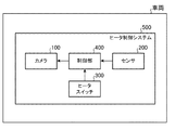
図1は、本実施の形態に係るヒータ制御システム500の概略構成図である。
ヒータ制御システム500は、車両に搭載され、カメラ100、センサ200、ヒータスイッチ300、および制御部400等を備えている。以下、センサ200および制御部400がカメラ100とは別体に設けられている場合を示すが、センサ200および制御部400の一方または両方は、カメラ100と一体に構成されるものであってもよい。
Hereinafter, embodiments of the present invention will be described with reference to the drawings.
FIG. 1 is a schematic configuration diagram of a
The
(カメラ100)
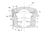
図2を用いてカメラ100について説明する。図2は、カメラ100に用いられるレンズユニット101の軸方向断面図である。カメラ100は、少なくともレンズユニット101と、レンズユニット101の像側に配置される撮像素子(図示せず)とを備え、カメラモジュールを構成している。このカメラモジュールがカメラ100となる。カメラ100としては、例えば、車両のサイドミラーに搭載されて車両の後方を撮像するリアビューカメラがある。
(Camera 100)
The
レンズユニット101は、鏡筒10、第1レンズ1、第2レンズ2、第3レンズ3、第4レンズ4、光学フィルタ5、絞り6、シール部材8、配線部9、およびヒータ部20等を備えている。レンズユニット101において、第1レンズ1、第2レンズ2、第3レンズ3、および第4レンズ4が像を結ぶ像側(結像側)の端部に、光学フィルタ5が配置されている。また、レンズユニット101の像側であって、光学フィルタ5と対向する位置に、撮像素子が配置されている。この撮像素子は、第1レンズ1〜第4レンズ4で結像された画像を撮像する。
The
また、レンズユニット101は、像側とは反対側の端部、すなわち物体側の端部が撮像対象を向くように配置されている。このレンズユニット101は、物体の像を像側に形成する。レンズユニット101は、撮像素子、カメラケース、基板、信号処理回路、フレキシブル配線シート、およびコネクタ(いずれも図示せず)等とともにカメラモジュールを構成している。
Further, the
カメラモジュールは次のように動作する。物体側から入射する光は、レンズユニット101のレンズ群を介して撮像素子に入射する。撮像素子は、入射した像を電気信号に変換する。信号処理回路は、撮像素子からの電気信号に対して信号処理(A/D変換、画像補正処理等)を行う。信号処理回路から出力される電気信号は、フレキシブル配線シートおよびコネクタを介して外部の電子機器に出力される。
The camera module works as follows. The light incident from the object side is incident on the image sensor via the lens group of the
鏡筒10は、円筒状の部材であり、樹脂で形成されている。第1レンズ1は、略円形状のガラス製レンズであり、第2レンズ2〜第4レンズ4は、略円形状のガラス製または樹脂製レンズである。第1レンズ1〜第4レンズ4は、それぞれの光軸を一致させた状態で、鏡筒10の内側に配置されている。第1レンズ1〜第4レンズ4は、その外周面が鏡筒10の内周面と当接することにより、光軸方向と直交する方向に対して位置決めされている。
光学フィルタ5は、例えば円形状に形成された赤外線カットフィルタである。この光学フィルタ5は、特定の周波数成分を除去する目的で配置されている。光学フィルタ5は、鏡筒10の像側の端面に、例えば接着により固定されている。接着剤としては、紫外線硬化樹脂等が用いられる。
絞り6は、環状の部材であり、例えば金属で形成されている。この絞り6は、鏡筒10の内側のレンズ間に配置されている。絞り6としては、透過光量を制限し、明るさの指標となるF値を決定する開口絞り、またはゴーストの原因となる光線や収差の原因となる光線を遮光する遮光絞りがある。
The
The
The
鏡筒10の最も像側の内周面には、径方向内側に向かって突出し、軸方向から見て環状となっている支持部10aが設けられている。この支持部10aには、第4レンズ4の外周部における像側の面が当接している。なお、レンズの外周部とは、レンズにおける有効径の外周側に形成されている部位(フランジ部)である。
また、鏡筒10の最も物体側の端部には、カシメ部10bが設けられている。カシメ部10bは、鏡筒10の内側に部品が収容された後、カシメにより形成される。このカシメ部10bの内径は、第1レンズ1の外径より小さくなっている。カシメ部10bの内周側の面は、第1レンズ1の物体側の面の外周部に当接している。
鏡筒10の内部に収容される部品は、支持部10aとカシメ部10bとの間に挟まれるようにして支持されている。これにより、各部品の間に隙間が形成されないようになっている。
The inner peripheral surface of the
Further, a
The parts housed inside the
第1レンズ1の像側外周面には、外径が物体側外周面より小さく形成された縮径部1aが形成されている。この縮径部1aと鏡筒10の内周面との間には、シール部材8としてのOリングが配置されている。このシール部材8は、例えばゴムで弾性変形可能に形成され、第1レンズ1と鏡筒10との間に圧縮(押圧)された状態で配置されており、レンズユニット101の物体側の端部における隙間を封止し、鏡筒10の内部に水や埃等が侵入するのを防いでいる。
また、鏡筒10の外周面における軸方向略中央部には、径方向外側に向かって突出した鍔状のフランジ部10cが全周にわたって設けられている。このフランジ部10cの物体側の面には、シール部材としてのOリングを介在させた状態で、カメラケースが配置されるようになっている。
A reduced
Further, a flange-shaped
ヒータ部20は、環状(ドーナツ形)のセラミックヒータまたは透明導電膜(ITO膜)であり、所定の厚さで形成されている。ヒータ部20は、第1レンズ1のフランジ部の像側の面と、第2レンズ2のフランジ部の物体側の面との間に挟まれて配置されている。フランジ部とは、レンズ有効径の外周側に形成されている部位であり、本実施の形態では、第1レンズ1のフランジ部の像側の面と、第2レンズ2のフランジ部の物体側の面とがそれぞれ平面となっている。なお、ヒータ部20は、レンズユニット101の撮像性能に影響を及ぼすことのない内径で形成されている。
The
ヒータ部20には配線部9が接続され、配線部9を介して電力が供給されるようになっている。このヒータ部20は、電力が供給されると発熱するようになっている。ヒータ部20が発熱すると、第1レンズ1が加熱され、第1レンズ1の温度が上昇する。
第1レンズ1の温度が第1の所定温度となると、デフォグ(曇り除去)が実現される。すなわち、第1レンズ1の曇り、結露等が取り除かれる。また、第1レンズ1の温度が第2の所定温度となると、デフロスト(霜除去)が実現される。すなわち、第1レンズ1に付着した霜、雪、氷等が除去される。
A
When the temperature of the first lens 1 reaches the first predetermined temperature, defog (fog removal) is realized. That is, fogging, dew condensation, etc. of the first lens 1 are removed. Further, when the temperature of the first lens 1 reaches the second predetermined temperature, defrosting (frost removal) is realized. That is, frost, snow, ice, etc. adhering to the first lens 1 are removed.
なお、ヒータ部20を、チタン酸バリウムを主成分とするセラミックスで構成し、PTC(Positive Temperature Coefficient)特性を有するものとしてもよい。PTC特性とは、キュリー温度(キュリー点)を有し、温度がキュリー温度を超えると、結晶系がそれまでの正方晶系から立方晶系へと相転移し、電気抵抗値が急上昇する特性である。PTC特性を有するヒータ部20は、周囲温度を検知し、温度がキュリー温度を超えると、抵抗が急激に増加し、流れる電流を小さくする。なお、キュリー温度(キュリー点)は25℃における抵抗値の2倍の抵抗値となる温度として定義される。PTC特性は、自己温度制御機能ということもできる。ヒータ部20がPTC特性を有している場合、ON/OFFを制御することなく、一定の温度を保つことができる。ヒータ部20のキュリー点は、80℃から120℃の範囲内であることが好ましい。すなわち、ヒータ部20は、80℃から120℃の間で電気抵抗値が急上昇するようになっていることが好ましい。
The
配線部9としては、導線(リード線)が用いられる。配線部9は、外部からの電力をヒータ部20に供給するために設けられている。配線部9は、一方の端部がはんだ付け等によりヒータ部20に接続(接合)され、他方の端部が制御部400に接続されている。なお、当該他方の端部は他の部材を介して制御部400に接続されているものであってもよい。導線は、電流を流すための金属線であり、例えばPVC(ポリ塩化ビニル)で被覆されている。鏡筒10には、配線部9としての2本の導線(正極用、負極用)を、像側に導くための貫通孔10dが、鏡筒10の内周側に、軸方向と平行に設けられている。貫通孔10dは2本の導線に対応するように2箇所に、導線の径に対応した径で円形状(丸孔)に形成されている。このように、配線部9を鏡筒の内側を通すことで、配線部9を鏡筒10の外周側を通して像側に引き出す場合に生じるシール部材8でのシール性低下という問題を防ぐことができる。
なお、配線部9として、FPC(Flexible printed
circuits)を用いてもよい。配線部9としてFPCを用いる場合、貫通孔10dは、FPCの幅および厚さに対応したサイズで円弧状に形成される。
また、ヒータ部20はセラミックヒータではなく、フレキシブルプリント配線板にPTC機能を有する有機塗料でヒータ回路を形成したものであってもよく、鉛塩化銀をスクリーン印刷してヒータ回路を形成し、PTC機能を有するサーミスタチップを回路上に形成したもの、ポリイミドフィルムと銅箔の複合フィルムをエッチングしてヒータ回路を構成したものであってもよい。
サーミスタチップを有するヒータ部20のキュリー温度は、ヒータ回路およびサーミスタ回路(配線)とサーミスタチップの全体として、定義されるものとする。室温(25℃)から開始して温度がある一定値以上に上昇すると急激に抵抗値が増加に転じ、25℃時の抵抗の2倍になる温度がキュリー温度と定義される。この値が、80℃から120℃の範囲内であることが好ましい。
A lead wire is used as the
The
circuits) may be used. When the FPC is used as the
Further, the
The Curie temperature of the
(センサ200)
センサ200は、車両の外気温を検知可能であり、外気温が所定の温度Te以上であることを検知すると、その旨を示す信号を制御部400に出力する。本実施の形態では、所定の温度Teを0[℃]とし、センサ200が、外気温が0℃以上であることを検知すると、0℃以上であることを示す信号を制御部400に出力する。ただし、この所定の温度Teは適宜設定することができる。センサ200は、車両の所定の箇所に搭載されているものであればよいが、例えばカメラ100が車両のサイドミラーに用いられるカメラである場合、その付近に配置されていることが好ましい。なお、センサ200の出力信号は外気温(例えば数値)であってもよい。
(Sensor 200)
The
(ヒータスイッチ300)
ヒータスイッチ300は、入力操作を受け付けることができる。ヒータスイッチ300は、例えばモーメンタリ型またはオルタネイト型のプッシュスイッチであり、押下されてON状態になると、ON信号を制御部400に出力する。このヒータスイッチ300は、車両のドライバー等が操作可能な位置、例えば車両のインストルメントパネルに配置されている。
(Heater switch 300)
The
(制御部400)
制御部400は、車両における所定の箇所に搭載されており、カメラ100のヒータ部20への電圧の印加を制御する。制御部400は、車両のボディ制御ECUに設けられているものであってもよい。
図3に示すフローチャートを用いて、制御部400の動作について説明する。なお、このフローチャートの開始時点において、エンジンが作動し、ヒータスイッチ300が操作を受け付け可能な状態になっているものとする。
まず、制御部400は、ヒータスイッチ300からON信号を取得しているか否か判定する(ステップST1)。制御部400は、ヒータスイッチ300からON信号を取得していると判定した場合(ステップST1:YES)、ステップST2の処理に進む。一方、制御部400は、ヒータスイッチ300からON信号を取得していないと判定した場合(ステップST1:NO)、ステップST1の処理を繰り返す。
(Control unit 400)
The
The operation of the
First, the
次に、制御部400は、センサ200から0℃以上であることを示す信号を取得しているか否か判定する(ステップST2)。制御部400は、センサ200から0℃以上であることを示す信号を取得していると判定した場合(ステップST2:YES)、すなわち外気温が0℃以上であることをセンサ200が示している場合、第2所定時間T2[min]の間、所定の低電圧が、ヒータ部20に印加されるように回路を制御する(ステップST3)。なお、回路の制御については後述する。所定の低電圧とは、例えば4[V]であり、所定の低電圧がヒータ部20に印加されると、デフォグ(曇り除去)が実現される温度まで、第1レンズ1が加熱される。また、第2所定時間T2とは、例えば約2[min]である。制御部400は、第2所定時間T2が経過すると、所定の低電圧の印加を停止し、ステップST1の処理に戻る。第2所定時間T2が経過するとヒータ部20の発熱が停止するように構成することで、余分の電力の消費を抑え、車両バッテリの消耗を防ぐことができる。なお、出力信号として外気温(例えば数値)を出力するセンサ200を用いる場合、ステップST2において、制御部400は、センサ200の出力が0℃以上であるか否かを判定する。
Next, the
一方、制御部400は、センサ200から0℃以上であることを示す信号を取得していないと判定した場合(ステップST2:NO)、すなわちセンサ200が0℃未満を検知している場合(外気温が0℃未満であることをセンサ200が示している場合)、第1所定時間T1[min]の間、所定の高電圧が、ヒータ部20に印加されるように回路を制御する(ステップST4)。所定の高電圧とは、例えば8[V]であり、所定の高電圧がヒータ部20に印加されると、デフロスト(霜除去)が実現される温度まで、第1レンズ1が加熱される。また、第1所定時間T1とは、例えば約1[min]である。制御部400は、第1所定時間T1が経過すると、所定の高電圧の印加を停止し、ステップST1の処理に戻る。第1所定時間T1が経過するとヒータ部20の発熱が停止するように構成することで、余分の電力の消費を抑え、車両バッテリの消耗を防ぐことができる。
On the other hand, when the
次に、図4を用いて、制御部400による回路制御の詳細について説明する。
ヒータスイッチ300は、ON状態になると「1」を出力し、OFF状態では「0」を出力する。また、センサ200は、0℃以上であることを検知するとスイッチをONにして「1」を出力し、0℃未満であることを検知するとスイッチをOFFにして「0」を出力する。
Next, the details of the circuit control by the
The
(外気温が0℃以上でヒータスイッチ300が操作された場合)
ヒータスイッチ300から「1」が出力され、OR回路401から「1」が出力され、「1」がAND回路403およびAND回路404に入力される。また、センサ200から「1」が出力され、NOT回路402から「0」が出力され、「0」がAND回路403に入力される。
AND回路403に「1」と「0」が入力され、AND回路403から「0」が出力され、「0」がタイマー451に入力される。「0」が入力されたタイマー451は、作動しない。すなわち、スイッチ491はONとならない。
一方、AND回路403から出力された「0」が、NOR回路405に入力され、NOR回路405から「1」が出力され、AND回路404に「1」と「1」が入力され、AND回路404から「1」が出力され、「1」がタイマー452に入力される。「1」が入力されたタイマー452は、T2[min]の間、トランジスタ472に電流が流れるように制御する。トランジスタ472に電流が流れると、コイル482での磁界の発生によりスイッチ492がONし、抵抗499を介した電圧(所定の低電圧)が出力される。
(When the
“1” is output from the
"1" and "0" are input to the AND
On the other hand, "0" output from the AND
(外気温が0℃未満でヒータスイッチ300が操作された場合)
ヒータスイッチ300から「1」が出力され、OR回路401から「1」が出力され、「1」がAND回路403およびAND回路404に入力される。また、センサ200から「0」が出力され、NOT回路402から「1」が出力され、「1」がAND回路403に入力される。
AND回路403に「1」と「1」が入力され、AND回路403から「1」が出力され、「1」がタイマー451に入力される。「1」が入力されたタイマー451は、T1[min]の間、トランジスタ471に電流が流れるように制御する。トランジスタ471に電流が流れると、コイル481での磁界の発生によりスイッチ491がONし、抵抗499を介さない電圧(所定の高電圧)が出力される。
一方、AND回路403から出力された「1」が、NOR回路405に入力され、NOR回路405から「0」が出力され、AND回路404に「1」と「0」が入力されて、AND回路404から「0」が出力され、「0」がタイマー452に入力される。「0」が入力されたタイマー452は作動しない。すなわち、スイッチ492はONとならない。
なお、図4に示すX部に、過電流保護用のPTCを配置してもよい。
(When the
“1” is output from the
"1" and "1" are input to the AND
On the other hand, the "1" output from the AND
In addition, PTC for overcurrent protection may be arranged in part X shown in FIG.
次に、図5を用いて、ヒータスイッチ300の操作とヒータ部20に印加される電圧との関係を時系列に沿って説明する。
図5(a)に示すように、外気温が0℃未満の場合に、ヒータスイッチ300がONとなると、T1の間、所定の高電圧がヒータ部20に印加される。
図5(b)に示すように、外気温が0℃以上の場合に、ヒータスイッチ300がOFFとなると、T2の間、所定の低電圧がヒータ部20に印加される。なお、図5では、T2がT1よりも長いものを示したがこの限りではなく、T1およびT2は印加電圧と発熱量との関係に応じて適宜設定することができる。
また、制御部400は、車両における他の機器の稼働状態(電力消費状態)に応じて、T1およびT2を変更してもよい。他の機器とは、例えば、エアコン、オーディオ、ワイパー、パワーウインド等である。制御部400は、他の機器の稼働状態を示す情報を取得し、負荷(電力消費量)が大きい場合には、T1およびT2をより短い時間に設定する。これにより、車両での電力消費量が過多となることに起因するバッテリ上がりを抑制することができる。
Next, with reference to FIG. 5, the relationship between the operation of the
As shown in FIG. 5A, when the
As shown in FIG. 5B, when the
Further, the
このヒータ制御システム500にあっては、制御部400が、ヒータスイッチ300の入力を受け付けた際に、外気温が所定の温度未満であることをセンサ200が示している場合、所定の高電圧をヒータ部20に印加するとともに、ヒータスイッチ300の入力を受け付けた際に、外気温が所定の温度以上であることをセンサ200が示している場合、所定の低電圧をヒータ部20に印加する。このため、外気温に応じてカメラ100のヒータ部20の発熱温度が適切に制御される。これにより、車両での余分な電力消費や車載カメラの撮像性能の低下を防ぐことができる。
In the
1 ヒータ制御システム
1,2,3,4 レンズ
9 配線部
10 鏡筒
10d 貫通孔
20 ヒータ部
100 カメラ
200 センサ
300 ヒータスイッチ
400 制御部
1
Claims (5)
前記ヒータ制御システムは、
鏡筒の内部に配置された複数のレンズのうち、最も物体側に位置するレンズを加熱するヒータ部を有するカメラと、
車両の外気温を検知するセンサと、
入力操作を受け付けるヒータスイッチと、
前記ヒータ部に印加する電圧を制御する制御部とを備え、
前記制御部は、前記ヒータスイッチの入力を受け付けた際に、外気温が所定の温度未満であることを前記センサが示している場合、所定の高電圧を前記ヒータ部に印加するとともに、前記ヒータスイッチの入力を受け付けた際に、外気温が所定の温度以上であることを前記センサが示している場合、所定の低電圧を前記ヒータ部に印加することを特徴とするヒータ制御システム。 A heater control system installed in a vehicle
The heater control system
A camera having a heater unit that heats the lens located closest to the object among the plurality of lenses arranged inside the lens barrel, and
A sensor that detects the outside temperature of the vehicle and
A heater switch that accepts input operations and
A control unit for controlling the voltage applied to the heater unit is provided.
When the sensor indicates that the outside temperature is lower than the predetermined temperature when the control unit receives the input of the heater switch, the control unit applies a predetermined high voltage to the heater unit and the heater. A heater control system characterized in that a predetermined low voltage is applied to the heater portion when the sensor indicates that the outside temperature is equal to or higher than a predetermined temperature when an input of a switch is received.
前記ヒータ部に接続される配線部と、
前記鏡筒に軸方向に沿って形成された貫通孔とを備え、
前記配線部は、前記貫通孔を介して像側に引き出されていることを特徴とする請求項1から請求項4のいずれか1項に記載のヒータ制御システム。 The camera
The wiring part connected to the heater part and
The lens barrel is provided with a through hole formed along the axial direction.
The heater control system according to any one of claims 1 to 4, wherein the wiring portion is drawn out to the image side through the through hole.
Priority Applications (1)
| Application Number | Priority Date | Filing Date | Title |
|---|---|---|---|
| JP2019106649A JP2020201328A (en) | 2019-06-07 | 2019-06-07 | Heater control system |
Applications Claiming Priority (1)
| Application Number | Priority Date | Filing Date | Title |
|---|---|---|---|
| JP2019106649A JP2020201328A (en) | 2019-06-07 | 2019-06-07 | Heater control system |
Publications (1)
| Publication Number | Publication Date |
|---|---|
| JP2020201328A true JP2020201328A (en) | 2020-12-17 |
Family
ID=73744233
Family Applications (1)
| Application Number | Title | Priority Date | Filing Date |
|---|---|---|---|
| JP2019106649A Pending JP2020201328A (en) | 2019-06-07 | 2019-06-07 | Heater control system |
Country Status (1)
| Country | Link |
|---|---|
| JP (1) | JP2020201328A (en) |
Cited By (2)
| Publication number | Priority date | Publication date | Assignee | Title |
|---|---|---|---|---|
| WO2023027530A1 (en) * | 2021-08-25 | 2023-03-02 | 엘지이노텍 주식회사 | Power supply device |
| CN116027521A (en) * | 2022-12-08 | 2023-04-28 | 福建福光股份有限公司 | Optical athermalization lens with anti-fog function and imaging method thereof |
Citations (6)
| Publication number | Priority date | Publication date | Assignee | Title |
|---|---|---|---|---|
| JPH04135076U (en) * | 1991-06-04 | 1992-12-16 | 株式会社日立製作所 | VTR integrated camera with anti-condensation device |
| JPH06258713A (en) * | 1993-03-04 | 1994-09-16 | Sharp Corp | On-vehicle camera apparatus |
| JPH0675932U (en) * | 1993-04-07 | 1994-10-25 | 株式会社村上開明堂 | Dew condensation prevention heater device |
| JP2004325603A (en) * | 2003-04-22 | 2004-11-18 | Kyocera Corp | Lens module and camera using the same |
| JP2017144937A (en) * | 2016-02-19 | 2017-08-24 | トヨタ自動車株式会社 | Imaging System |
| JP2018034522A (en) * | 2016-08-29 | 2018-03-08 | トヨタ自動車株式会社 | Window pane heater |
-
2019
- 2019-06-07 JP JP2019106649A patent/JP2020201328A/en active Pending
Patent Citations (6)
| Publication number | Priority date | Publication date | Assignee | Title |
|---|---|---|---|---|
| JPH04135076U (en) * | 1991-06-04 | 1992-12-16 | 株式会社日立製作所 | VTR integrated camera with anti-condensation device |
| JPH06258713A (en) * | 1993-03-04 | 1994-09-16 | Sharp Corp | On-vehicle camera apparatus |
| JPH0675932U (en) * | 1993-04-07 | 1994-10-25 | 株式会社村上開明堂 | Dew condensation prevention heater device |
| JP2004325603A (en) * | 2003-04-22 | 2004-11-18 | Kyocera Corp | Lens module and camera using the same |
| JP2017144937A (en) * | 2016-02-19 | 2017-08-24 | トヨタ自動車株式会社 | Imaging System |
| JP2018034522A (en) * | 2016-08-29 | 2018-03-08 | トヨタ自動車株式会社 | Window pane heater |
Cited By (2)
| Publication number | Priority date | Publication date | Assignee | Title |
|---|---|---|---|---|
| WO2023027530A1 (en) * | 2021-08-25 | 2023-03-02 | 엘지이노텍 주식회사 | Power supply device |
| CN116027521A (en) * | 2022-12-08 | 2023-04-28 | 福建福光股份有限公司 | Optical athermalization lens with anti-fog function and imaging method thereof |
Similar Documents
| Publication | Publication Date | Title |
|---|---|---|
| JP7312164B2 (en) | Lens unit and camera module | |
| US11172105B2 (en) | Lens barrel and camera module comprising same | |
| US11086092B2 (en) | Camera lens heater | |
| JP2020201328A (en) | Heater control system | |
| JP2004325603A (en) | Lens module and camera using the same | |
| JP2011066560A (en) | Camera module and electronic information apparatus | |
| JP2023153344A (en) | Lens unit and camera module | |
| CA2730903A1 (en) | Heating device for heating a glass surface, particularly a protective glass of an outdoor camera, and electronic and/or optical device having a protective glass | |
| US20220163751A1 (en) | Heating device and camera module | |
| KR20180006045A (en) | Lens assembly and camera module including the same | |
| JP6894748B2 (en) | Vehicle lights and heaters | |
| CN114189617A (en) | Automatic antifogging lens device, camera module and electronic device | |
| WO2021220541A1 (en) | Imaging device | |
| WO2020218212A1 (en) | Lens unit and camera module | |
| WO2021049479A1 (en) | Screen heater system | |
| JP2007069772A (en) | Head-up display device for vehicle | |
| KR20220083175A (en) | Moisture Removing System for Vehicle Camera and Method Therefor | |
| JP2021192499A (en) | Camera module | |
| CN214474368U (en) | Lens cone, imaging assembly and camera module | |
| TWI790888B (en) | Defrost lens | |
| WO2023169266A1 (en) | Camera assembly, vehicle-mounted system and vehicle | |
| JP2023059852A (en) | Camera module and assembling method thereof | |
| JP2022034211A (en) | Lens unit and camera module | |
| KR20230101556A (en) | Camera module and manufacturing method of the same | |
| KR20230064237A (en) | Lens foreign body detection heater and camera device |
Legal Events
| Date | Code | Title | Description |
|---|---|---|---|
| A711 | Notification of change in applicant |
Free format text: JAPANESE INTERMEDIATE CODE: A712 Effective date: 20211022 |
|
| A621 | Written request for application examination |
Free format text: JAPANESE INTERMEDIATE CODE: A621 Effective date: 20220526 |
|
| A977 | Report on retrieval |
Free format text: JAPANESE INTERMEDIATE CODE: A971007 Effective date: 20230222 |
|
| A131 | Notification of reasons for refusal |
Free format text: JAPANESE INTERMEDIATE CODE: A131 Effective date: 20230404 |
|
| A601 | Written request for extension of time |
Free format text: JAPANESE INTERMEDIATE CODE: A601 Effective date: 20230601 |
|
| A521 | Request for written amendment filed |
Free format text: JAPANESE INTERMEDIATE CODE: A523 Effective date: 20230802 |
|
| A131 | Notification of reasons for refusal |
Free format text: JAPANESE INTERMEDIATE CODE: A131 Effective date: 20231003 |
|
| A521 | Request for written amendment filed |
Free format text: JAPANESE INTERMEDIATE CODE: A523 Effective date: 20231109 |
|
| A02 | Decision of refusal |
Free format text: JAPANESE INTERMEDIATE CODE: A02 Effective date: 20240206 |