JP2020192011A - Device with discharge head, method for discharging liquid and system - Google Patents
Device with discharge head, method for discharging liquid and system Download PDFInfo
- Publication number
- JP2020192011A JP2020192011A JP2019098540A JP2019098540A JP2020192011A JP 2020192011 A JP2020192011 A JP 2020192011A JP 2019098540 A JP2019098540 A JP 2019098540A JP 2019098540 A JP2019098540 A JP 2019098540A JP 2020192011 A JP2020192011 A JP 2020192011A
- Authority
- JP
- Japan
- Prior art keywords
- liquid discharge
- discharge head
- nail
- inkjet head
- head
- Prior art date
- Legal status (The legal status is an assumption and is not a legal conclusion. Google has not performed a legal analysis and makes no representation as to the accuracy of the status listed.)
- Pending
Links
Images


Classifications
-
- A—HUMAN NECESSITIES
- A45—HAND OR TRAVELLING ARTICLES
- A45D—HAIRDRESSING OR SHAVING EQUIPMENT; EQUIPMENT FOR COSMETICS OR COSMETIC TREATMENTS, e.g. FOR MANICURING OR PEDICURING
- A45D29/00—Manicuring or pedicuring implements
- A45D29/18—Manicure or pedicure sets, e.g. combinations without case, etui, or the like
-
- A—HUMAN NECESSITIES
- A45—HAND OR TRAVELLING ARTICLES
- A45D—HAIRDRESSING OR SHAVING EQUIPMENT; EQUIPMENT FOR COSMETICS OR COSMETIC TREATMENTS, e.g. FOR MANICURING OR PEDICURING
- A45D31/00—Artificial nails
-
- B—PERFORMING OPERATIONS; TRANSPORTING
- B41—PRINTING; LINING MACHINES; TYPEWRITERS; STAMPS
- B41J—TYPEWRITERS; SELECTIVE PRINTING MECHANISMS, i.e. MECHANISMS PRINTING OTHERWISE THAN FROM A FORME; CORRECTION OF TYPOGRAPHICAL ERRORS
- B41J3/00—Typewriters or selective printing or marking mechanisms characterised by the purpose for which they are constructed
- B41J3/407—Typewriters or selective printing or marking mechanisms characterised by the purpose for which they are constructed for marking on special material
Landscapes
- Ink Jet (AREA)
- Coating Apparatus (AREA)
Abstract
Description
本発明は、吐出ヘッドを備えた装置に関するものであり、さらには、三次元の曲面に描画する装置に関するものである。 The present invention relates to a device including a discharge head, and further relates to a device for drawing on a three-dimensional curved surface.
プリンタヘッドからインクを噴射して爪にネイルデザインを印刷するネイルプリンタが知られている。一般的なネイルプリンタの構成はインクジェット方式プリンタヘッドを印刷対象物の上方を水平移動しながら印刷を行うというものである。しかし、爪の形状は紙のように平面ではなく、爪の両脇部は爪の中央部と比較して大きな曲率を持つ曲面である。そのため、インク着弾面とインク飛行方向が成す角が直角から離れてしまう爪の両脇部では、インク着弾面とインク飛行方向が成す角が浅いため、インクの着弾性が低下し、画像品質が低下する不具合が生じる。 Nail printers that inject ink from a printer head to print a nail design on the nail are known. A general configuration of a nail printer is to print while moving the inkjet printer head horizontally above the object to be printed. However, the shape of the nail is not flat like paper, and both sides of the nail are curved surfaces with a large curvature compared to the central part of the nail. Therefore, at both sides of the claw where the angle formed by the ink landing surface and the ink flight direction is separated from the right angle, the angle formed by the ink landing surface and the ink flight direction is shallow, so that the ink landing elasticity is lowered and the image quality is improved. There is a problem of deterioration.
このような課題に対し、特許文献1では、爪部の湾曲が大きなところではインクを濃縮して噴出することで印刷のぼやけを低減する技術が開示されている。
In response to such a problem,
また特許文献2では、チルト角が可変のインクジェットヘッドを用いて主走査方向の移動中に、距離センサによって検出された印刷媒体表面の凹凸に応じて、インクジェットヘッドを倣わせて描画する技術が開示されている。具体的にはヘッド位置調節機構によるギャップ距離を伸縮させつつ、昇降駆動部により回転軸を昇降させるとともに、回転駆動部によってインクジェットヘッドを回動させるものである。 Further, Patent Document 2 discloses a technique of drawing by imitating an inkjet head according to the unevenness of the surface of a print medium detected by a distance sensor while moving in the main scanning direction using an inkjet head having a variable tilt angle. Has been done. Specifically, the rotation shaft is moved up and down by the elevating drive unit, and the inkjet head is rotated by the rotation drive unit while expanding and contracting the gap distance by the head position adjusting mechanism.
しかしながら、特許文献1における装置は、インク着弾面とインク飛行方向が成す角が浅い爪の両脇部では、着弾できなかったインクがミストとなり、印刷画質が低下する問題がある。また特許文献2における装置は、インクジェットヘッド吐出口の上方に回転軸が設置されている。そのため、インクジェットヘッドからのインクの噴出方向の制御には、主走査方向の位置座標と昇降駆動部の位置座標と回転角度の制御を同時に行う必要があり、それにともない装置および制御機構が複雑化、大型化する問題があった。
However, the device in
簡素な構成で、曲面に対するインク着弾性の低下を抑制する吐出ヘッドを備えた装置を提供する。 Provided is a device provided with a discharge head that suppresses a decrease in ink adhesion on a curved surface with a simple configuration.
上記課題を解決する装置は、
液体吐出ヘッドと
前記液体吐出ヘッドを回転可能に支持する支持手段と
対象物を載置するステージを有し、
前記液体吐出ヘッドの外部の回転中心に対して、
前記液体吐出ヘッドの吐出口を対向させつつ回転可能に支持されている。
The device that solves the above problems is
It has a liquid discharge head, a support means for rotatably supporting the liquid discharge head, and a stage on which an object is placed.
With respect to the external rotation center of the liquid discharge head
The liquid discharge head is rotatably supported while facing the discharge port.
上述の特徴的な装置を用いることで、簡素な構成で、曲面に対するインク着弾性の低下を抑制し、印刷画質を向上させることができる。 By using the above-mentioned characteristic device, it is possible to suppress a decrease in ink adhesion on a curved surface and improve print quality with a simple configuration.
以下、本発明の第1実施形態にかかる吐出ヘッドを備えた装置を、図面を参照して説明する。 Hereinafter, the apparatus provided with the discharge head according to the first embodiment of the present invention will be described with reference to the drawings.
本願発明にかかる液体吐出ヘッドを備えた装置は、一例として液体吐出ヘッドと液体吐出ヘッドを回転可能に支持する支持手段と、対象物を載置するステージを有している。そして、液体吐出ヘッドの外部の回転中心に対して、液体吐出ヘッドの吐出口を対向させつつ回転可能に支持されている装置である。さらには撮影手段を有し、対象物の撮影情報に基づき、対象物の表面に描画するものである。 As an example, the device provided with the liquid discharge head according to the present invention has a support means for rotatably supporting the liquid discharge head and the liquid discharge head, and a stage on which an object is placed. The device is rotatably supported while facing the discharge port of the liquid discharge head with respect to the rotation center outside the liquid discharge head. Further, it has a photographing means and draws on the surface of the object based on the photographing information of the object.
図8には液体吐出ヘッドを一例とする加工部を備えた装置を含む加工システムを示す。
加工システムの本体は、カメラ等を有する撮像部を有し、対象物の表面形状データをデジタル信号として取得できるように構成されている。撮像部で得られた対象物の表面形状データは画像処理部にて画像処理され、対象物の輪郭、エッジ、あるいは領域等が抽出されることで対象物の表面形状が認識される。認識された対象物の表面形状と、メモリに蓄積されたデザインデータとが制御部にてマッチングし、適宜デザインデータが修正され、加工データとして加工部へ出力される。この加工データに基づき対象物が加工部にて加工され、対象物の表面に前述したデザインデータあるいは修正されたデザインデータに基づく加工がなされる。加工部による加工の際には対象物と加工部とは相対的な位置姿勢が可変に構成されていてよい。
FIG. 8 shows a processing system including a device provided with a processing unit using a liquid discharge head as an example.
The main body of the processing system has an imaging unit having a camera or the like, and is configured to be able to acquire surface shape data of an object as a digital signal. The surface shape data of the object obtained by the imaging unit is image-processed by the image processing unit, and the surface shape of the object is recognized by extracting the contour, edge, region, or the like of the object. The surface shape of the recognized object and the design data stored in the memory are matched by the control unit, the design data is appropriately modified, and the design data is output to the processing unit as processing data. The object is processed in the processing section based on this processing data, and the surface of the object is processed based on the above-mentioned design data or the modified design data. When machining by the machined portion, the relative position and orientation of the object and the machined portion may be variably configured.
このような一連の処理は、本体に設けられたユーザインターフェース(UI)にてユーザーの操作による入力を受け付けることで実行されてもよいし、通信可能に構成された操作端末が有する本体制御部に格納されたソフトウェアに基づき、ユーザーの操作による入力を受け付けることで実行されてもよい。また操作端末はインターネットやインターネット上に仮想的に構成されたクラウドに接続され、必要なデータおよびプログラムが操作端末に適宜配信あるいはダウンロードできるように構成されてよい。 Such a series of processes may be executed by accepting input by a user's operation through a user interface (UI) provided in the main body, or may be executed by a main body control unit of an operation terminal configured to be communicable. It may be executed by accepting input by user operation based on the stored software. Further, the operation terminal may be connected to the Internet or a cloud virtually configured on the Internet, and may be configured so that necessary data and programs can be appropriately distributed or downloaded to the operation terminal.
以下、一例としてネイルプリンタ装置を挙げて具体的に説明するが、本発明の趣旨を逸脱しない限り、様々な曲面描画の装置および用途に適用できる。 Hereinafter, a nail printer device will be specifically described as an example, but the device and application for drawing curved surfaces can be applied as long as the gist of the present invention is not deviated.
液体が吐出される対象物の表面は、曲面あるいは異なる平面を複数有するものであってよい。 The surface of the object on which the liquid is discharged may have a curved surface or a plurality of different planes.
[第1実施形態]
図1はネイルプリンタ装置を示す図であり、(a)は装置正面、(b)は装置側面を、ネイルプリンタ装置の外装を一部省略して示す図である。図1において、インクジェットヘッド101はインクを吐出するインクジェットヘッド吐出口102を備えており連結部材111に支持されており、連結部材111は回転軸110に対して回転可能な構成となっている。液体吐出ヘッドはサーマル式、あるいはピエゾ式のインクジェットヘッドを用いてよく、加圧式のディスペンサーヘッドを用いてもよい。
[First Embodiment]
1A and 1B are views showing a nail printer device, in which FIG. 1A shows the front surface of the device, FIG. 1B shows the side surface of the device, and the exterior of the nail printer device is partially omitted. In FIG. 1, the
インクジェットヘッド吐出口102より、インクは飛行方向103の向きに吐出される。上述の構成により、インクジェットヘッド吐出口102は軌道104に沿って移動可能に構成される。画像情報を取得するための視野角106をもつカメラ105をさらに備えており、不図示の照明とともに用いる。指を載置するためのステージ107はネイルプリンタ装置の外部から指あるいはネイルチップを、不図示の外装の外部から挿通可能に構成されており、不図示のステージ上下機構により高さ調整が可能である。インクジェットヘッド吐出口102をクリーニングするためのウエスで構成されたクリーニング部材108がさらに設けられている。回転可能であり、かつ、エンコーダを有しており回転角度を取得可能なモータ109によって、回転軸110に対して連結部材111とインクジェットヘッド101が一体的に回転する。この回転軸110は液体吐出ヘッドの外部の回転中心である。
Ink is ejected from the inkjet
本実施形態においてはインクジェットヘッド101、カメラ105、モータ109が連結する連結部材111に設けられている。
In this embodiment, it is provided on the connecting
ステージ107とクリーニング部材108とモータ109との連結はフレーム112が担っている。入出力部113はインクジェットヘッド101とカメラ105とモータ109を制御する不図示の制御部への入力と制御部からの出力を行うものであり、フレーム112へ取り付けられている。
The
制御部はネイルプリンタ装置に設けられていてもよいし、ネイルプリンタ装置とは別の端末に設けられていてもよい。また端末はモバイル端末であってもよく、スマートフォンやタブレット端末等のデバイス上で起動するアプリとして構成されてもよい。 The control unit may be provided in the nail printer device, or may be provided in a terminal different from the nail printer device. Further, the terminal may be a mobile terminal, and may be configured as an application that is started on a device such as a smartphone or a tablet terminal.
このように、本実施形態にかかる装置は、吐出ヘッドと、吐出ヘッドを回転可能にする回転手段と、対象物を載置するステージと、回転手段で吐出ヘッドの吐出口と前記ステージとを対向させつつ回転可能に支持する手段と、を有する。 As described above, in the device according to the present embodiment, the discharge head, the rotating means for rotating the discharge head, the stage on which the object is placed, and the discharge port of the discharge head and the stage are opposed by the rotating means. It has a means for rotatably supporting it while allowing it to rotate.
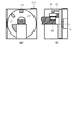
図2は爪を備えた指を載せた状態のネイルプリンタ装置を示す図であり、(a)は装置正面、(b)は装置側面を示す図である。図2において、201は指、202は爪である。 2A and 2B are views showing a nail printer device in a state where a finger having a claw is placed, where FIG. 2A shows the front surface of the device and FIG. 2B shows the side surface of the device. In FIG. 2, 201 is a finger and 202 is a nail.
図3はネイルプリンタ装置の動きを示す図であり、(a)、(b)、(c)、(d)、(e)、(f)の順に動作する。図3を用いてネイルプリンタ装置の動きを説明する。図3(a)のように、入出力部113よりネイルデザインの選択を行い、指201をステージ107に載置する。
FIG. 3 is a diagram showing the movement of the nail printer device, and operates in the order of (a), (b), (c), (d), (e), and (f). The operation of the nail printer device will be described with reference to FIG. As shown in FIG. 3A, the nail design is selected from the input /
<(a)工程>
カメラ105が指201と爪202を認識し、爪202の全域が視野角106内に載置されるとカメラ105による撮影が実行され、その取得画像を用いて、カメラ105と指201および爪202との相対位置情報を取得する。相対位置情報は、距離情報であってよく、その場合は三角測量方式を採用してもよい。例えばモータ109の回転を利用して少なくとも二つの異なる位置および姿勢から撮影することにより、複数の取得画像を用いて三角測量方式で距離情報を取得することができる。また相対位置情報は、爪202の輪郭情報や面積情報であってもよい。このように撮影工程を実行することによりカメラ105と爪202との相対位置情報を取得し、インクジェットヘッド吐出口102の位置と爪202の位置を関連付けることができる。
<(A) step>
When the
ステージ107は不図示の上下機構より指201および爪202の載置高さを調整する。この際、ステージ107位置とカメラ105位置とインクジェットヘッド101およびインクジェットヘッド吐出口102の位置とモータ回転軸110は設計値より既知である。よって、ステージ107位置はインクジェットヘッド吐出口102がモータ109の回転により移動するインクジェットヘッド吐出口軌道104と指201および爪202が接触しないように調整される。なお相対位置情報を元に載置高さを調整してもよいし、載置高さを調整した後に前述した撮影工程を実行してもよい。
The
なお、本実施形態の設計値としては、自身の指の測定値よりモータ回転軸110とインクジェットヘッド吐出口102との距離を12mmとした。カメラ105が取得した爪202の画像情報とインクジェットヘッド吐出口軌道104より吐出移動領域が算出される。ステージ107の高さ調整値は、その吐出移動領域においてインクジェットヘッド吐出口102と指201および爪202の最小距離を1mmとなるように設定した。さらに、カメラ105の取得画像と予め準備しておいた爪モデルデータとを比較することにより爪領域を認識する。爪モデルデータは爪形状に対応する三次元モデルであってもよいし、撮影された画像情報に対応する二次元モデルであってもよい。
As the design value of this embodiment, the distance between the
この爪領域を認識した結果情報と上述の相対位置情報(たとえば距離情報)より爪部と爪部以外の指部が区別された爪部の三次元形状情報を作成する。モータ回転軸110と、インクジェットヘッド吐出口102位置から算出される極座標情報と、爪部の三次元形状情報と、選択されたネイルデザインに基づいて、インクジェットヘッド101へ吐出指示する描画制御情報を作成する。
From the result information of recognizing this nail region and the above-mentioned relative position information (for example, distance information), the three-dimensional shape information of the nail portion in which the nail portion and the finger portion other than the nail portion are distinguished is created. Based on the polar coordinate information calculated from the position of the
<(b)工程>
図3(b)のように、インクジェットヘッド吐出口102はモータ109の回転により、ウエスで構成されたクリーニング部材108にてクリーニングされる工程が、必要に応じて実行される。この際、クリーニング部材108の位置とインクジェットヘッド101およびインクジェットヘッド吐出口102の位置とモータ回転軸110は設計値より既知であることを利用してもよい。すなわち、クリーニング工程を実行する際には、モータ回転軸110に対して所定の角度に回転させるとよい。そうすることで、クリーニング部材108とインクジェットヘッド吐出口102とが接し、インクジェットヘッド吐出口102の近傍の付着物を除去するクリーニング工程を実行することができる。また、インクジェットヘッド101へ吐出指示の信号が無い場合にはクリーニング部材108とインクジェットヘッド吐出口102とが接するように動作するモードを構成し、必要に応じてクリーニングモードを起動するように構成してもよい。このように、付着物を除去する、あるいはインクジェットヘッド吐出口を良好な状態に保つクリーニング工程を実行することにより、インクジェットヘッド吐出口102の目詰まりや乾燥物の付着などによる印字精度の低下を抑えることができる。
<(B) step>
As shown in FIG. 3B, the step of cleaning the inkjet
<(c)工程>
図3(c)のように、(a)工程で作成した描画制御情報に基づき、描画開始位置へ、モータ109の回転によりインクジェットヘッド101を移動する。
<Step (c)>
As shown in FIG. 3C, the
<(d)工程>
図3(d)のように、描画制御情報に基づいて、インクジェットヘッド吐出口102からインクの吐出を開始し、爪202に対する選択されたネイルデザインの描画工程を開始する。
<(D) step>
As shown in FIG. 3D, based on the drawing control information, ink ejection is started from the inkjet
<(e)工程>
図3(e)のように、描画制御情報に基づいて描画する。つまり、インクジェットヘッド101の外部の回転中心(モータ回転軸110)に対して、インクジェットヘッド吐出口102を対向させつつ回転するとともに爪202に対してインクを吐出する。
<(E) step>
As shown in FIG. 3E, drawing is performed based on the drawing control information. That is, the inkjet
<(f)工程>
選択されたネイルデザインの描画が完了した場合、図3(f)のように、描画制御情報に基づいて描画を完了する。
<Step (f)>
When the drawing of the selected nail design is completed, the drawing is completed based on the drawing control information as shown in FIG. 3 (f).
このように、曲率を持つ爪の両脇部においても簡素な構成でインク着弾面とインク飛行方向が成す角を直角に近づけることができ、インク着弾性の低下を抑制でき、画像品位を高めることができる。 In this way, even on both sides of the curved nail, the angle formed by the ink landing surface and the ink flight direction can be brought close to a right angle with a simple configuration, the decrease in ink landing elasticity can be suppressed, and the image quality can be improved. Can be done.
なお、本実施例1の構成や各部材などは記載内容に限定されるものではなく、機能を満足すれば、様々なものが使用可能になる。例えば、装置の入出力部を装置とは別の通信端末であるPCやスマートフォンに導入されるアプリを介して行っても良い。ネイルデザインのデザインデータは、予め保持しておく他、インターネットを介して装置部とは別のスマートフォン等の入出力部にダウンロード可能に構成してもよい。その際には入出力部の端末で課金機能を備え、端末を介して決済できる機能を構成してもよい。 The configuration and each member of the first embodiment are not limited to the description contents, and various ones can be used if the functions are satisfied. For example, the input / output unit of the device may be performed via an application installed in a PC or smartphone which is a communication terminal different from the device. In addition to holding the design data of the nail design in advance, the design data may be configured to be downloadable to an input / output unit of a smartphone or the like other than the device unit via the Internet. In that case, the terminal of the input / output unit may be provided with a billing function, and a function for making a payment via the terminal may be configured.
このように液滴を吐出する液体吐出ヘッドを備えた装置と、インターネットと接続可能に構成された前記装置とは別の入出力部を備えたシステムが構成される。 A device including a liquid discharge head for discharging droplets in this way and a system having an input / output unit different from the device configured to be connectable to the Internet are configured.
カメラ105と指201および爪202との相対位置情報としての距離情報を取得する方法としては、カメラを複数配置して距離を測定するステレオカメラ方式やカメラのピントボケから距離を測定するDFD方式を用いても良い。またカメラとともにレーザーを用いてLIDAR方式により距離を取得しても良い。TOF方式距離画像センサと光源を用いてTOF方式で距離を取得しても良い。ステージの上下機構は電動でも手動でも良い。ステージの高さ調整値に許容範囲を設定して、その許容範囲に指を載置できていない場合はエラーを出力してユーザーに喚起しても良い。
As a method of acquiring the distance information as the relative position information between the
その許容範囲に指を載置した場合は描画実行可能であることをユーザーの操作端末に出力して表示することにより、ユーザーに注意喚起しても良い。モータ回転軸110とインクジェットヘッド吐出口102との距離の設計値は12mmとする以外にも服のサイズのように、S、M、Lとサイズ別に設計して個人によって異なる指の大きさに対応しても良い。また、個人毎に指の測定を事前に行い、適切な値に設計してオーダーメイドとしても良い。クリーニング部材はワイパ、ブレード、スポンジ、ゴムローラーなどのプリンタ部品に用いられているものを用いても良い。カメラとインクジェットヘッドは同心円上に配置されているので、インク吐出後の印刷対象物の様子を画像取得しても良い。この画像より印刷状態を取得してインクおよび吐出材料の品質向上に活用しても良い。この画像よりインクの着弾形状、色または反応色を取得して爪のケア状態またはユーザーの健康状態を評価しても良い。この画像と描画制御情報とを比較してカメラとインクジェットヘッドとモータ回転軸と回転角度の位置関係を補正しても良い。この画像と描画制御情報とを比較して次の描画制御情報を補正しても良い。インクジェットヘッドから吐出する物質はインク以外にもネイルのベースコート材やトップコート材でも良い。インクジェットヘッドから吐出する物質はオイル、ビタミン、イオウ、ケイ素、香料などで構成される美容液でも良い。インクジェットヘッドはインクカートリッジを交換可能または不可能な構成としても良い。インクカートリッジにはICタグなどを設けて、中身の名称または、物性を読み取り、入出力部へ表示しても良く、中身に応じて吐出制御を変更しても良い。印刷方向は時計回りでも反時計回りでも良い。印刷工程を時計回りと反時計回りの往復動作を1セットとして印刷しても良い。または、複数セットを印刷1工程としても良い。モータの回転は一方向に360度回転しても良い。その際はステージ下にインクジェットヘッドとカメラが干渉しないように空間を設ける。モータは電磁式でも超音波式(USM)でも良い。インクジェットヘッド吐出口には装置未使用時のインクジェットヘッド保護のための蓋を設けても良い。インクジェットヘッド保護の機能を満たすのであれば、ステージの左右および下に空間を設けて装置内に配置しても良い。
When a finger is placed in the permissible range, the user may be alerted by outputting and displaying on the user's operation terminal that drawing can be executed. In addition to setting the design value of the distance between the
以上の説明では印刷対象物は爪202を中心に説明したが、ネイルチップや皮膚でも良い。上述してきたような構成、動作をすることにより、本発明の装置では簡素な構成でインク着弾面とインク飛行方向が成す角を直角に近づけ、インク着弾性の低下を抑制することができる。
In the above description, the object to be printed is mainly the
[第2実施形態]
本実施形態にかかる装置は、液体吐出ヘッドを複数備え、複数の前記液体吐出ヘッドを同心円状に配置した点に特徴がある。以下、本発明の第2実施形態を、図面を参照して説明する。第1実施形態と同様の構成物は同符号を付し、説明を省略する。
[Second Embodiment]
The apparatus according to the present embodiment is characterized in that a plurality of liquid discharge heads are provided and the plurality of liquid discharge heads are arranged concentrically. Hereinafter, the second embodiment of the present invention will be described with reference to the drawings. The same components as those in the first embodiment are designated by the same reference numerals, and the description thereof will be omitted.
図4はネイルプリンタ装置を示す図である。図4において、401はシアンインクを備えたインクジェットヘッドである。402はマゼンダインクを備えたインクジェットヘッドである。403はイエローインクを備えたインクジェットヘッドである。404はホワイトインクを備えたインクジェットヘッドである。これらのインクジェットヘッドが連結部材111に対して設けられており、一体的に回転可能に構成されている。またインクジェットヘッド吐出口をクリーニングするためのクリーニング部材405を備えている。
FIG. 4 is a diagram showing a nail printer device. In FIG. 4, 401 is an inkjet head provided with cyan ink.
図5はネイルプリンタ装置の動きを示す図であり、(a)、(b)、(c)、(d)、(e)、(f)の順に動作する。なお、装置の動きで実施例1と異なる部分である(b)、(c)、(e)について説明するとともに、図中で相対位置が変わらない各インクジェットヘッドに関しては、煩雑を避けるためシアンインクを備えたインクジェットヘッド401を表記し、他は省略する。
FIG. 5 is a diagram showing the movement of the nail printer device, and operates in the order of (a), (b), (c), (d), (e), and (f). In addition, (b), (c), and (e), which are different parts from the first embodiment due to the movement of the apparatus, will be described, and cyan ink is used for each inkjet head whose relative position does not change in the drawing in order to avoid complication. The
(b)のようにクリーニング部材405より、ホワイトインクジェットヘッド404とイエローインクジェットヘッド403をクリーニングする。(c)のようにクリーニング部材405より、シアンインクジェットヘッド401とマゼンダインクジェットヘッド402をクリーニングする。(e)のように、各インクジェットヘッドが同心円上に配置されているので、一軸の回転のみで各インクの飛行方向を制御できるという効果がある。なお、本実施例2の構成や各部材などは記載内容に限定されるものではなく、機能を満足すれば、様々なものが使用可能になる。例えば、カメラの位置とインクジェットヘッドの位置の順番を入れ替えても良い。カメラの位置に対してインクジェットヘッドの位置を片寄らせても良い。インクジェットヘッドから吐出する物質の組み合わせをトップコート材、ホワイトインク、レッドインク、ベースコート材としても良く、インクジェットヘッドの数は限定せず、増やしても減らしても良い。本装置を複数設置して複数指を同時に印刷する装置構成へと応用しても良い。
The
[第3実施形態]
本実施形態にかかる装置は、液体吐出ヘッドを前記支持手段の回転半径方向に移動可能にする移動手段を備えている点に特徴がある。以下、本発明の第3実施形態を、図面を参照して説明する。
[Third Embodiment]
The apparatus according to the present embodiment is characterized in that it includes a moving means that makes the liquid discharge head movable in the radial direction of the support means. Hereinafter, a third embodiment of the present invention will be described with reference to the drawings.
図6はネイルプリンタ装置を示す図であり、(a)は装置正面、(b)は装置側面を示す図である。図6において、インクジェットヘッドをモータ回転軸110の回転半径方向に移動可能である直動ユニット601が設けられている点が他の実施形態と異なる。
6A and 6B are views showing a nail printer device, in which FIG. 6A shows the front surface of the device and FIG. 6B shows the side surface of the device. FIG. 6 is different from other embodiments in that a
図7はネイルプリンタ装置の動きを示す図であり、(a)、(b)、(c)、(d)、(e)、(f)の順に動作する。なお、装置の動きで実施例1と異なる部分である(d)、(e)、(f)について説明する。(d)のように直動ユニット601によりインクジェットヘッドを爪へ近づけてインクを吐出する。(e)のように直動ユニット601によりインクジェットヘッドを爪より遠ざけてインクを吐出する(f)のように直動ユニット601によりインクジェットヘッドを爪へ近づけてインクを吐出する。なお、本実施例3の構成や各部材などは記載内容に限定されるものではなく、機能を満足すれば、様々なものが使用可能になる。例えば、直動ユニットは電磁式でも超音波式(USM)でも良い。直動ユニットの移動量はインクジェットヘッド吐出口と爪との距離が一定となるように設定できる。これにより、インクジェットヘッド吐出口と爪との距離の差異による印刷ドット径の差異を低減できるという効果がある。さらに、この直動ユニットの移動によってはインク飛行方向が変化しないため、制御が容易であるという効果もある。また、ステージとインクジェットヘッド吐出口の距離(回転半径)を変更できるので、適応できる指または爪の大きさの範囲を拡大させることができるという効果もある。
FIG. 7 is a diagram showing the movement of the nail printer device, and operates in the order of (a), (b), (c), (d), (e), and (f). It should be noted that (d), (e), and (f), which are different parts from the first embodiment in the movement of the device, will be described. As shown in (d), the
101 インクジェットヘッド
102 インクジェットヘッド吐出口
103 インク飛行方向
104 インクジェットヘッド吐出口軌道
105 カメラ
106 カメラの視野角
107 ステージ
108 クリーニング部材
109 モータ
110 モータ回転軸
111 連結部材
112 フレーム
113 入出力部
201 指
202 爪
401 シアンインクジェットヘッド
402 マゼンダインクジェットヘッド
403 イエローインクジェットヘッド
404 ホワイトインクジェットヘッド
405 クリーニング部材
601 直動ユニット
101
Claims (17)
前記液体吐出ヘッドを回転可能に支持する支持手段と
対象物を載置するステージを有し、
前記液体吐出ヘッドの外部の回転中心に対して、
前記液体吐出ヘッドの吐出口を対向させつつ回転可能に支持されている装置。 It has a liquid discharge head, a support means for rotatably supporting the liquid discharge head, and a stage on which an object is placed.
With respect to the external rotation center of the liquid discharge head
A device that is rotatably supported while facing the discharge ports of the liquid discharge head.
Priority Applications (2)
| Application Number | Priority Date | Filing Date | Title |
|---|---|---|---|
| JP2019098540A JP2020192011A (en) | 2019-05-27 | 2019-05-27 | Device with discharge head, method for discharging liquid and system |
| PCT/JP2020/020443 WO2020241538A1 (en) | 2019-05-27 | 2020-05-25 | Device having discharge head, liquid discharging method, and system |
Applications Claiming Priority (1)
| Application Number | Priority Date | Filing Date | Title |
|---|---|---|---|
| JP2019098540A JP2020192011A (en) | 2019-05-27 | 2019-05-27 | Device with discharge head, method for discharging liquid and system |
Publications (1)
| Publication Number | Publication Date |
|---|---|
| JP2020192011A true JP2020192011A (en) | 2020-12-03 |
Family
ID=73546090
Family Applications (1)
| Application Number | Title | Priority Date | Filing Date |
|---|---|---|---|
| JP2019098540A Pending JP2020192011A (en) | 2019-05-27 | 2019-05-27 | Device with discharge head, method for discharging liquid and system |
Country Status (2)
| Country | Link |
|---|---|
| JP (1) | JP2020192011A (en) |
| WO (1) | WO2020241538A1 (en) |
Family Cites Families (4)
| Publication number | Priority date | Publication date | Assignee | Title |
|---|---|---|---|---|
| JPH05318715A (en) * | 1992-05-18 | 1993-12-03 | Olympus Optical Co Ltd | Curved surface printer |
| JP2001287408A (en) * | 2000-04-10 | 2001-10-16 | Seiko Epson Corp | Solid printer |
| US9079439B2 (en) * | 2012-04-13 | 2015-07-14 | Hewlett-Packard Development Company, L.P. | Rotatable printhead assembly |
| JP6915396B2 (en) * | 2017-06-16 | 2021-08-04 | カシオ計算機株式会社 | Drawing system, drawing device and terminal device |
-
2019
- 2019-05-27 JP JP2019098540A patent/JP2020192011A/en active Pending
-
2020
- 2020-05-25 WO PCT/JP2020/020443 patent/WO2020241538A1/en active Application Filing
Also Published As
| Publication number | Publication date |
|---|---|
| WO2020241538A1 (en) | 2020-12-03 |
Similar Documents
| Publication | Publication Date | Title |
|---|---|---|
| JP6897167B2 (en) | Droplet ejection device, droplet ejection method, program | |
| US8083422B1 (en) | Handheld tattoo printer | |
| JP6926535B2 (en) | Droplet ejection device, droplet ejection method, program | |
| JP6834765B2 (en) | Inkjet printer and 3D printing method | |
| JP2017185758A (en) | Printing device and printing method | |
| JP6439582B2 (en) | Handy mobile printer and its program | |
| US20110007331A1 (en) | Handheld printer | |
| JP2017018589A (en) | Injection device | |
| US9789683B2 (en) | Ejection device | |
| JP2013169756A (en) | Inkjet printer and correction value acquisition method | |
| CN110997334A (en) | Printer with a movable platen | |
| CN111267491A (en) | Printer architecture with multi-sensor printing head | |
| WO2020241538A1 (en) | Device having discharge head, liquid discharging method, and system | |
| JP6881992B2 (en) | Inkjet recording device and its control method | |
| US20180257380A1 (en) | Inkjet recording apparatus and ink discharge method | |
| CN111801084B (en) | Printing apparatus and printing method | |
| JP6776521B2 (en) | Image forming equipment, programs and methods | |
| JP7283493B2 (en) | PRINTING DEVICE, PRINT CONTROL METHOD AND PROGRAM | |
| JP6256045B2 (en) | Liquid ejection device and moving unit | |
| JP2024042741A (en) | Printing device, printing control method and program | |
| WO2021053943A1 (en) | Printing device, terminal device, printing system, printing method, and program | |
| JP7206974B2 (en) | LIQUID EJECTING APPARATUS, LIQUID EJECTING METHOD, AND PROGRAM | |
| US20220304448A1 (en) | Printing apparatus and controlling method | |
| JP2016159567A (en) | Head unit and liquid discharge device | |
| JP2022171176A (en) | Program, droplet discharge device, droplet discharge system, and information display method |