JP2020184897A - Harvester - Google Patents
Harvester Download PDFInfo
- Publication number
- JP2020184897A JP2020184897A JP2019090038A JP2019090038A JP2020184897A JP 2020184897 A JP2020184897 A JP 2020184897A JP 2019090038 A JP2019090038 A JP 2019090038A JP 2019090038 A JP2019090038 A JP 2019090038A JP 2020184897 A JP2020184897 A JP 2020184897A
- Authority
- JP
- Japan
- Prior art keywords
- case
- engine
- top plate
- engine bonnet
- driver
- Prior art date
- Legal status (The legal status is an assumption and is not a legal conclusion. Google has not performed a legal analysis and makes no representation as to the accuracy of the status listed.)
- Pending
Links
Images
Landscapes
- Cooling, Air Intake And Gas Exhaust, And Fuel Tank Arrangements In Propulsion Units (AREA)
- Combines (AREA)
- Harvester Elements (AREA)
Abstract
Description
本発明は、作物を収穫する収穫部と、前記収穫部の後方に設けられた原動部と、前記原動部の上方に設けられた運転部と、が備えられた収穫機に関する。 The present invention relates to a harvester provided with a harvesting unit for harvesting crops, a driving unit provided behind the harvesting unit, and an operating unit provided above the driving unit.
上記した収穫機における原動部として、エンジンボンネット、及び、エンジンボンネットにおける前壁部の前側に設けられ、エンジン冷却風がエンジンボンネットの前方から取り入られ、取り入れられたエンジン冷却風がエンジンボンネットの内側に導入されることを許容する吸気ケースを有するものがある。この種の収穫機としては、例えば特許文献1に示される普通型コンバインがある。特許文献1に示される普通型コンバインでは、吸気ケースとしての第二吸気ケースが備えられている。
この種の収穫機における運転部として、エンジンボンネットの天板部上にスライド機構を介して前後スライド可能に設けられた運転座席と、運転座席の前下方に設けられた床部とを有するものがある。
As the driving part in the above-mentioned harvester, the engine bonnet and the front side of the front wall part of the engine bonnet are provided, the engine cooling air is taken in from the front of the engine bonnet, and the taken-in engine cooling air is inside the engine bonnet. Some have an intake case that allows it to be introduced. As an example of this kind of harvester, there is a common type combine shown in
The driving unit of this type of harvester has a driver's seat provided on the top plate of the engine bonnet so as to be slidable back and forth via a sliding mechanism, and a floor portion provided below the front of the driver's seat. is there.
従来の収穫機においては、スライド機構がエンジンボンネットの天板部上の範囲でしかスライドしなくて、運転座席を狭い調節範囲でしか位置変更できず、たとえば、調節範囲の前部分まで運転座席の位置を変更しても、運転座席に着座したままで作業走行しようとすると、収穫部を見通しにくくて作業を行い難くいことがある。 In a conventional harvester, the slide mechanism slides only within the range on the top plate of the engine bonnet, and the driver's seat can be repositioned only within a narrow adjustment range, for example, the driver's seat to the front part of the adjustment range. Even if the position is changed, if you try to drive while sitting in the driver's seat, it may be difficult to see the harvesting part and work.
本発明は、運転座席を広い調節範囲で位置変更できる収穫機を提供する。 The present invention provides a harvester capable of repositioning the driver's seat over a wide adjustment range.
本発明による収穫機は、
作物を収穫する収穫部と、前記収穫部の後方に設けられた原動部と、前記原動部の上方に設けられた運転部と、が備えられた収穫機であって、前記原動部は、エンジンボンネットと、前記エンジンボンネットにおける前壁部の前側に設けられ、エンジン冷却風が前記エンジンボンネットの前方から取り入られること、及び、取り入れられたエンジン冷却風が前記エンジンボンネットの内側に導入されることを許容する吸気ケースと、を有し、前記運転部は、前記エンジンボンネットの天板部上にスライド機構を介して前後スライド可能に設けられた運転座席と、前記運転座席の前下方に設けられた床部と、を有し、平面視において、前記スライド機構は、前記天板部と前記吸気ケースとに亘って設けられている。
The harvester according to the present invention
The harvester is provided with a harvesting unit for harvesting crops, a driving unit provided behind the harvesting unit, and an operating unit provided above the driving unit. The driving unit is an engine. The bonnet and the front side of the front wall portion of the engine bonnet are provided so that the engine cooling air is taken in from the front of the engine bonnet and the taken-in engine cooling air is introduced inside the engine bonnet. It has an allowable intake case, and the driver's seat is provided on the top plate of the engine bonnet so as to be slidable back and forth via a slide mechanism, and the driver's seat is provided below the front of the driver's seat. It has a floor portion, and in a plan view, the slide mechanism is provided over the top plate portion and the intake case.
本構成によると、エンジンボンネットの天板部上と、エンジンボンネットの前側に位置する吸気ケースとにわたってスライド機構がスライドするので、運転座席を従来よりも広い調節範囲で前後に位置変更できる。たとえば、運転座席を調節範囲の前部分まで位置変更すれば、運転座席が従来よりも前側に位置し、運転座席に着座したままでも収穫部を見通しやすくなる。 According to this configuration, the slide mechanism slides over the top plate of the engine bonnet and the intake case located on the front side of the engine bonnet, so that the driver's seat can be repositioned back and forth within a wider adjustment range than before. For example, if the driver's seat is repositioned to the front part of the adjustment range, the driver's seat is located closer to the front than before, and it becomes easier to see the harvesting part even while seated in the driver's seat.
本発明においては、
前記エンジンボンネットにおける前記天板部の前側部分に、前記エンジンボンネットの内側に向かって凹入する凹入部が形成されており、前記スライド機構は、前記凹入部と前記吸気ケースとに亘って設けられていると好適である。
In the present invention
A recessed portion that is recessed toward the inside of the engine bonnet is formed in a front portion of the top plate portion of the engine bonnet, and the slide mechanism is provided over the recessed portion and the intake case. It is preferable to have.
本構成によると、運転座席の位置変更の調節範囲を広くするのに、運転座席の取付け高さを凹入部によって低くしつつできる。 According to this configuration, in order to widen the adjustment range of the position change of the driver's seat, the mounting height of the driver's seat can be lowered by the recessed portion.
本発明においては、
前記吸気ケースにおけるケース天板部が前記エンジンボンネットの前記天板部上に延ばされ、前記凹入部の上方が前記ケース天板部によって塞がれ、かつ、前記吸気ケースの内部と前記凹入部の内部とが連通されていると好適である。
In the present invention
The case top plate portion of the intake case is extended over the top plate portion of the engine bonnet, the upper portion of the recessed portion is closed by the case top plate portion, and the inside of the intake case and the recessed portion are formed. It is preferable that the inside of the is communicated with.
本構成によると、吸気ケースに取り入れられる冷却用空気の収容量が凹入部によって多くなるので、エンジンボンネット内に多くの冷却風を供給し易い。 According to this configuration, since the capacity of the cooling air taken into the intake case is increased by the recessed portion, it is easy to supply a large amount of cooling air into the engine bonnet.
本発明においては、
前記エンジンボンネットの機体横外側端部に接続され、前記エンジンボンネットの内側に導入されるエンジン冷却風を通過させつつ、エンジン冷却風の塵埃を除去する防塵ケースが備えられ、前記吸気ケースは、前記防塵ケースに繋がれており、前記吸気ケースに取り入れられたエンジン冷却風が前記防塵ケースを介して前記エンジンボンネットの内側に導入されると好適である。
In the present invention
A dustproof case is provided which is connected to the lateral outer end of the engine bonnet and removes dust from the engine cooling air while passing the engine cooling air introduced inside the engine bonnet. It is preferable that the engine cooling air connected to the dustproof case and taken into the intake case is introduced into the inside of the engine bonnet via the dustproof case.
本構成によると、防塵ケース及び吸気ケースの両方から冷却風をエンジンボンネット内に取り入れることができるので、エンジン冷却を効率よくできる。また、吸気ケースに目詰まりができても、吸気ケースによってエンジン冷却風を取り入れることができるので、エンジン冷却を行える。 According to this configuration, cooling air can be taken into the engine bonnet from both the dustproof case and the intake case, so that the engine can be cooled efficiently. Further, even if the intake case is clogged, the engine cooling air can be taken in by the intake case, so that the engine can be cooled.
本発明においては、
前記凹入部は、前記エンジンボンネットの前記天板部の左右方向での中央部に形成されており、前記吸気ケースのケース前壁部は、前記エンジンボンネットにおける前記天板部の左右両端部に亘っており、前記吸気ケースの前記ケース天板部は、前記エンジンボンネットにおける前記天板部の左右両端部に亘っており、前記吸気ケースの両側壁部のうち、前記防塵ケース側と反対側の側壁部は、閉じられており、前記吸気ケースの両側壁部のうち、前記防塵ケース側の側壁部は、前記防塵ケースの内部と連なる開口を有していると好適である。
In the present invention
The recessed portion is formed at the center of the top plate portion of the engine bonnet in the left-right direction, and the case front wall portion of the intake case extends over the left and right ends of the top plate portion of the engine bonnet. The case top plate portion of the intake case extends over the left and right ends of the top plate portion of the engine bonnet, and is a side wall of both side wall portions of the intake case, which is opposite to the dustproof case side. The portion is closed, and it is preferable that the side wall portion on the dustproof case side of the side wall portions of the intake case has an opening connected to the inside of the dustproof case.
本構成によると、吸気ケースを後壁部がない簡素な構造のもので済ませられるので、安価で済む。 According to this configuration, the intake case can be made of a simple structure without a rear wall, so that the cost is low.
本発明においては、
前記スライド機構に、前記運転座席を支持する支柱部と、前記支柱部に取付けられた水平状の板体とが備えられており、前記吸気ケースにおける前記ケース天板部に、前記支柱部が前後移動可能に挿通する長穴が備えられており、前記支柱部の前記長穴における位置の変化にかかわらず、前記長穴が前記板体によって閉塞されていると好適である。
In the present invention
The slide mechanism is provided with a strut portion that supports the driver's seat and a horizontal plate body attached to the strut portion, and the strut portion is front-rear to the case top plate portion of the intake case. It is preferable that the elongated hole is provided so as to be movable, and the elongated hole is closed by the plate body regardless of the change in the position of the column portion in the elongated hole.
本構成によると、支柱部が長穴に入り込むことによって運転座席の取付け高さを低くできながら、運転座席を調節可能などのような位置に位置変更しても、長穴から凹入部に塵埃が入り込むことを板体によって防止できる。 According to this configuration, the mounting height of the driver's seat can be lowered by inserting the support column into the elongated hole, and dust is collected from the elongated hole to the recessed portion regardless of the adjustable position of the driver's seat. The plate body can prevent it from entering.
本発明においては、
前記運転座席の後方において、前記エンジンボンネットの前記天板部の上方にエンジン用のエアクリーナが配置されており、前記エンジンボンネットのうち、前記エアクリーナの下方に位置する部分以外のクリーナ以外部分が機体横外方へ揺動した開き位置と、機体上に位置した閉じ位置とに揺動開閉可能であり、前記吸気ケースが前記クリーナ以外部分に付随して揺動可能であると好適である。
In the present invention
Behind the driver's seat, an air cleaner for the engine is arranged above the top plate of the engine bonnet, and a portion of the engine bonnet other than the portion located below the air cleaner is lateral to the machine body. It is preferable that the intake case can be swung open and closed at an open position that swings outward and a closed position that is located on the machine body, and that the intake case can swing along with a portion other than the cleaner.
本構成によると、エンジンボンネットのうちのクリーナ以外部分を開き位置に位置変更することによってエンジンなどを開放できる。クリーナ以外部分を開き位置にすると、吸気ケースがクリーナ以外部分に附随して揺動して吸気ケースがエンジンなどの前方に残らないので、エンジンの点検などを行いやすい。 According to this configuration, the engine or the like can be opened by changing the position of the engine bonnet other than the cleaner to the open position. When the part other than the cleaner is opened, the intake case swings along with the part other than the cleaner and the intake case does not remain in front of the engine, etc., so it is easy to inspect the engine.
本発明においては、
前記運転座席の両横側方のうち、前記運転部の乗降口が位置する側と反対側の横側方にサイド運転パネルが設けられており、前記サイド運転パネルの下方において、前記サイド運転パネルと前記エンジンボンネットとの境界よりも前記運転座席とは反対側に配置され、エンジンの排ガスを浄化処理する排ガス処理装置が備えられていると好適である。
In the present invention
A side operation panel is provided on the side opposite to the side where the entrance / exit of the driver unit is located on both sides of the driver's seat, and below the side operation panel, the side operation panel is provided. It is preferable that an exhaust gas treatment device is provided, which is arranged on the side opposite to the driver's seat from the boundary between the engine and the engine bonnet and purifies the exhaust gas of the engine.
本構成によると、エンジンルームを開けると排ガス処理装置も開放できるので、エンジンの点検などに併せて排ガス処理装置の点検をできる。 According to this configuration, when the engine room is opened, the exhaust gas treatment device can also be opened, so that the exhaust gas treatment device can be inspected at the same time as the engine inspection.
以下、本発明の一例である実施形態を図面に基づいて説明する。
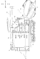
なお、以下の説明では、普通型コンバイン(「収穫機」の一例)の走行機体に関し、図1に示される矢印Fの方向を「機体前方」、矢印Bの方向を「機体後方」、矢印Uの方向を「機体上方」、矢印Dの方向を「機体下方」、紙面表側の方向を「機体右方」、紙面裏側の方向を「機体左方」とする。
Hereinafter, embodiments that are an example of the present invention will be described with reference to the drawings.
In the following description, with respect to the traveling aircraft of the ordinary type combine (an example of the "harvesting machine"), the direction of the arrow F shown in FIG. 1 is "the front of the aircraft", the direction of the arrow B is the "rear of the aircraft", and the arrow U. The direction of is "upper body", the direction of the arrow D is "lower side of the machine", the direction on the front side of the paper is "right side of the machine", and the direction on the back side of the paper is "left side of the machine".
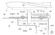
普通型コンバインの走行機体は、角パイプ材などの複数の鋼材を連結して構成された機体フレーム1を備えている。機体フレーム1の下部に、左右一対のクローラ式走行装置2が装備されている。機体フレーム1の前部の横一側部分に、エンジン3を有する原動部4が設けられている。原動部4の上方に、運転座席5を有する運転部6が設けられている。機体フレーム1の前端部に収穫搬送装置7が昇降可能に設けられている。収穫搬送装置7は、走行機体の前方に位置する作物としての植立穀稈の株元をバリカン型の刈取装置8によって刈取り、穀稈を収穫する収穫部7Aと、収穫部7Aの後部から後方に延ばされ、収穫部7Aが収穫した穀稈の株元から穂先までの全稈を後方に搬送する搬送装置7Bと、を備えている。搬送装置7Bは、運転部6の横側方を機体前後方向に通る状態で収穫部7Aと走行機体とに亘って設けられている。原動部4は、収穫部7Aの後方に設けられている。運転部6は、原動部4の上方に設けられている。搬送装置7Bの後方に脱穀装置9が設けられている。脱穀装置9は、機体フレーム1に支持されている。脱穀装置9は、搬送装置7Bが搬送して来た刈取穀稈の株元から穂先までの全稈を扱室(図示せず)に投入して脱穀し、脱穀によって得た脱穀粒を塵埃と選別する選別処理を行う。運転部6の後方に、脱穀装置9から供給された脱穀粒を貯留する穀粒タンク10が設けられている。穀粒タンク10は、機体フレーム1に支持されている。穀粒タンク10の後部に、穀粒タンク10から穀粒を排出する穀粒排出装置11が接続されている。
The traveling body of the ordinary combine harvester includes a
〔運転部について〕
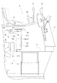
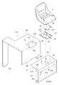
運転部6は、図2,3に示されるように、エンジンボンネット12の上方に設けられた運転座席5、運転座席5の前下方に設けられた床部13、床部13の前端部から上向きに立設された操縦塔14、運転座席5の両横側方のうち、乗降口6Aが位置する方と反対側の横側方に設けられたサイド運転パネル15を有している。床部13は、運転座席5に着座した運転者が足を置くことが可能な状態で設けられている。操縦塔14には、走行機体の操向操作を行う操作レバー16が設けられている。サイド運転パネル15の前部には、走行速度の主変速を行う主変速レバー17、走行速度の副変速を行う副変速レバー18が設けられている。
[About the driving part]
As shown in FIGS. 2 and 3, the driving
〔運転座席について〕
図2,3に示されるように、運転座席5は、運転座席5の前後スライドを可能にするスライド機構Sを介してエンジンボンネット12の天板部上に設けられている。スライド機構Sによって設定される調節範囲で運転座席5の取付位置を機体前後方向に調節できる。
[About the driver's seat]
As shown in FIGS. 2 and 3, the driver's
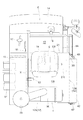
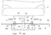
具体的には、図2,3に示されるように、エンジンボンネット12の前壁部12fの前側に、吸気ケース21が設けられている。吸気ケース21は、エンジンボンネット12の前方箇所からエンジンボンネット12の内側にエンジン冷却風が導入されることを可能にするものである。図3,5,6に示されるように、エンジンボンネット12における天板部12tの前側部分のうち、天板部12tの左右方向での中央部に位置する箇所に、エンジンボンネット12の内側に向かって凹入する凹入部19が形成されている。凹入部19の形成は、図5,6に示されるように、エンジンボンネット12の前壁部12f及び天板部12tに切欠き部を設け、切欠き部に対応する内部空間を有する容器状部材20を天板部12tの内側と前壁部12fの内側とに取付けることによって行われている。容器状部材20は、底板部20bと、底板部20bの両横端部から天板部12tの切欠き部の横縁まで立ち上がる横板部20sと、底板部20bの後端部から天板部12tの切欠き部の後縁まで立ち上がる後板部20rと、を有している。
Specifically, as shown in FIGS. 2 and 3, an
図5,6に示されるように、吸気ケース21のケース天板部21tがエンジンボンネット12の天板部12tの上まで延ばされ、凹入部19の上方がケース天板部21tによって塞がられ、かつ、吸気ケース21の内部21Aと凹入部19の内部19Aとが連通されている。凹入部19の内部19AとエンジンルームRとが容器状部材20によって仕切られてエンジンルームRの熱気が凹入部19の内部19Aに流入しない。これにより、エンジンルームRの熱気が吸気ケース21に流入することを回避できる。
As shown in FIGS. 5 and 6, the case
スライド機構Sは、図5,6,7に示されるように、運転座席5を支持する機体上下向きの支柱部25と、支柱部25に取付けられ、ケース天板部21tの上側に位置する水平状の板体26と、ケース天板部21tの四箇所に支持されるガイド軸27と、を有している。ケース天板部21tのうちのガイド軸27を支持する部分における内面側に、補強部材28が取り付けられている。
As shown in FIGS. 5, 6 and 7, the slide mechanism S is attached to the
図5,6に示されるように、運転座席5の取付杆5aが支柱部25の支持穴に上方から差し込まれ、取付杆5aの上下複数箇所に備えられた取付け高さ調節穴5bのうちの一つの取付け高さ調節穴5bと、支柱部25とに抜止め杆29が装着されて、取付杆5aの支柱部25からの抜け止めが行われることにより、支柱部25に対する運転座席5の支持が行われている。抜止め杆29の支柱部側と反対側の端部がブラケット30の支持穴に装着されている。ブラケット30は、板体26に支持されている。抜止め杆29の折曲げ端部と、抜止め杆29に装着されたピン部材31とによって、ブラケット30に対する抜止め杆29に位置決めが行われている。これにより、抜止め杆29が抜止め作用を行う状態に維持されている。
As shown in FIGS. 5 and 6, the mounting
支柱部25のうちの板体26から下方に突出している下部25aは、ケース天板部21tに備えられた機体前後方向の長穴32(図7,9参照)に移動可能に挿通している。ケース天板部21tの長穴32は、ケース天板部21tのうちの凹入部19の内部19Aに対応する部分と、ケース天板部21tのうちの吸気ケース21の内部21Aに対応する部分とに亘って形成されている。
The
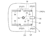
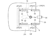
四箇所のガイド軸27のうち、吸気ケース21の上部においてケース天板部21tの左右二箇所に支持される前ガイド軸27fは、板体26の前部に機体前後方向に長い状態で形成された前長穴33に相対移動可能に係入されている。四箇所のガイド軸27のうち、凹入部19の上部においてケース天板部21tの左右二箇所に支持される後ガイド軸27rは、板体26の後部に機体前後方向に長い状態で形成された後長穴34に相対移動可能に係入されている。
Of the four
長穴32、前長穴33及び後長穴34の長さは、支柱部25が凹入部19から吸気ケース21の内部21Aに至る範囲で前後移動することを許容する長さになっている。図5,7,8に示されるように、スライド機構Sは、平面視において、エンジンボンネット12の天板部12tと吸気ケース21とに亘って位置する状態で設けられている。スライド機構Sは、凹入部19と吸気ケース21とに亘って位置する状態で設けられている。
The lengths of the
左右の前ガイド軸27fは、図5,6,9に示されるように、操作ハンドル35を有するネジ軸によって構成されている。前ガイド軸27fがケース天板部21tの内側に設けられたネジ部材36(図6参照)に締込み操作されることにより、板体26が前ガイド軸27fによってケース天板部21tに締め付け固定され、左右の前ガイド軸27fが緩め操作されると、ケース天板部21tに対する板体26の締め付け固定が解除される。
The left and right
スライド機構Sにおいては、左右の前ガイド軸27fが緩め操作されることにより、スライド機構Sがスライドロックの解除状態に状態変更され、前長穴33及び後長穴34によって設定されるスライド範囲において、板体26が前ガイド軸27f及び後ガイド軸27rによって案内されて、ケース天板部21tに対してスライドされることが可能になる。スライド機構Sにおいては、左右の前ガイド軸27fが締め込み操作されることにより、スライドロックの状態に状態変更され、ケース天板部21tに対する板体26のスライド移動が不能になる。
In the slide mechanism S, the left and right
図7に、スライド機構Sが後側にスライド範囲の限界までスライドした状態でのケース天板部21tに対する板体26の位置が示されている。図8に、スライド機構Sが前側にスライド範囲の限界までスライドした状態でのケース天板部21tに対する板体26の位置が示されている。図7,8に示されるように、板体26がケース天板部21tに対してスライドされて支柱部25の長穴32における位置が変化しても、この変化にかかわらず、板体26が長穴32の全体を上方から覆う状態になり、長穴32が長穴32の全長に亘って板体26によって塞がれる。
FIG. 7 shows the position of the
左右の前ガイド軸27fの締め付けを解除し、スライド機構Sがスライドロックを解除された状態になると、運転座席5を前後方向に移動操作する。すると、スライド機構Sが作動する。すなわち、板体26が前ガイド軸27f及び後ガイド軸27rによって案内されてケース天板部21tの上を前後方向にスライドし、支柱部25が長穴32の内部を前後方向に移動し、運転座席5の取付位置を前長穴33及び後長穴34によって設定される調節範囲で前後方向に調節できる。運転座席5が調節目標の取付位置になると、左右の前ガイド軸27fを締め付け操作することにより、スライド機構Sがスライドロックされた状態になり、運転座席5を調節目標の取付位置に固定できる。
When the tightening of the left and right
平面視において、スライド機構Sがエンジンボンネット12の天板部12tと吸気ケース21とに亘って位置し、支柱部25がエンジンボンネット12の天板部上と吸気ケース21とに亘ってスライドするので、運転座席5の取付位置を広い調節範囲にわたって前後調節できる。たとえば、運転座席5の取付位置を調節範囲の前側部分に変更することにより、運転座席5に着座したままでも、操縦塔14が前方を見通すことに対する障害にならず、収穫部7Aの刈取装置8の付近などを容易に見通しながら作業走行を行える。運転座席5の取付位置を調節範囲におけるどの部分に設定しても、長穴32が板体26によって塞がれるので、塵埃が長穴32を通って凹入部19に入ることを回避できる。
In a plan view, the slide mechanism S is located over the
スライド機構Sが凹入部19と吸気ケース21とに亘って位置するので、運転座席5の取付高さをあまり高くしないで、スライド機構Sによって設定される調節範囲を広くできる。
Since the slide mechanism S is located over the recessed
〔原動部について〕
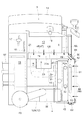
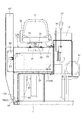
原動部4は、図4に示されるように、エンジンルームRを形成するエンジンボンネット12と、エンジンルームRに設けられたエンジン3と、を有している。エンジン3の機体横外側方にエンジン冷却用のラジエータ40が設けられ、ラジエータ40とエンジン3との間に冷却ファン41が回転可能に設けられ、エンジンボンネット12の機体横外側端部に防塵ケース42が接続され、エンジンボンネット12の前壁部12fの前側に吸気ケース21が設けられ、エンジン3の冷却を可能にされている。ラジエータ40は、支持ケース43を介して機体フレーム1に支持されている。
[About the driving part]
As shown in FIG. 4, the driving
具体的には、防塵ケース42は、図1,4に示されるように、防塵ケース42の横壁部42sの上部に開口された上吸気口44と、横壁部42sの下部に開口された下吸気口45とを、有している。上吸気口44及び下吸気口45には、除塵部材としの除塵プレート46が備えられている。
Specifically, as shown in FIGS. 1 and 4, the
防塵ケース42においては、防塵ケース42の外部から内部へエンジン冷却風を導入することが上吸気口44及び下吸気口45によって許容され、エンジン冷却風とともに導入されようとする塵埃が除塵プレート46によって除去される。
In the
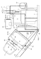
吸気ケース21は、図2,4,9に示されるように、ケース前壁部21fと、ケース前壁部21fの上端部から後向きにエンジンボンネット12の天板部12tの上まで延びるケース天板部21tと、ケース前壁部21fの下端部から後向きにエンジンボンネット12の前壁部12fまで延びる底壁部21bと、ケース前壁部21fの両横端部から後向きにエンジンボンネット12の前壁部12fまで延びる側壁部21sと、を有している。吸気ケース21には、後壁部が備えられず、吸気ケース21の後壁部は、エンジンボンネット12の前壁部12fによって構成されている。ケース前壁部21f、ケース天板部21t及び底壁部21bのそれぞれは、エンジンボンネット12の左右両端部に亘る状態で設けられている。吸気ケース21の横幅は、エンジンボンネット12の横幅とほぼ同じ大きさの横幅になっている。ケース前壁部21fに、吸気口47が開口されている。吸気口47には、除塵部材としの除塵プレート48が備えられている。両側壁部21sのうちの防塵ケース側と反対側の側壁部21sは、閉じられている。両側壁部21sのうちの防塵ケース側の側壁部21sに、開口49が設けられている。開口49は、図4に示されるように、防塵ケース42の前部に設けられた開口42aに対して連通ケース50によって連通されている。
As shown in FIGS. 2, 4 and 9, the
吸気ケース21においては、吸気ケース21の外部から内部へエンジン冷却風が導入されることを吸気口47によって許容され、エンジン冷却風とともに導入されようとする塵埃が除塵プレート48によって除去される。吸気ケース21の内部21Aに導入されたエンジン冷却風が開口49を介して防塵ケース42の内部に導入されることを許容する。吸気ケース21の内部21Aにエンジンボンネット12の凹入部19の内部19Aが連通しているので、吸気ケース21に取り入れられる冷却用空気の収容量が凹入部19によって多くなっている。
In the
冷却ファン41がエンジン3の動力によって駆動され、冷却ファン41の回転によって発生する吸引力により、エンジンボンネット12の機体横外側方の箇所からエンジン冷却風が防塵ケース42の上吸気口44及び下吸気口45を通過して、上吸気口44及び下吸気口45を通過するときに除塵プレート46によって除塵されて、除塵されたエンジン冷却風がエンジンボンネット12の内側に導入される。冷却ファン41の回転によって発生する吸引力により、エンジンボンネット12の前方の箇所からエンジン冷却風が吸気ケース21の吸気口47を通過して、吸気口47を通過するとき除塵プレート48によって除塵され、除塵されたエンジン冷却風が吸気ケース21の内部21Aに導入され、導入されたエンジン冷却風が吸気ケース21の開口49、連通ケース50、防塵ケース42の開口42aを通過して防塵ケース42の内部に導入されて、防塵ケース42の上吸気口44及び下吸気口45から防塵ケース42の内部に導入されたエンジン冷却風に合流され、合流したエンジン冷却風がエンジンボンネット12の内側に導入される。エンジンボンネット12の内側に導入されたエンジン冷却風がラジエータ40に供給されてラジエータ40に位置するエンジン冷却水がエンジン冷却風によって冷却され、冷却されたエンジン冷却水がラジエータ40からエンジン3に供給されてエンジン3の冷却が行われる。
The cooling
図4に示されるように、ラジエータ40と防塵ケース42との間に、作業用のオイルクーラ51及びインタークーラ52が設けられている。インタークーラ52は、支持ケース43に支持されている。オイルクーラ51は、防塵ケース42に支持されている。ラジエータ40に供給される冷却風によってオイルクーラ51及びインタークーラ52の冷却が行われる。ラジエータ40と防塵ケース42との間に、エンジン冷却風の除塵を行う第2除塵部材53が設けられている。第2除塵部材53は、支持ケース43に支持されている。
As shown in FIG. 4, a working
図4に示されるように、プレエアクリーナ55からエンジン3に供給される燃焼用空気の塵埃除去を行うエンジン用のエアクリーナ56、及び、エンジン3から排出される排ガスを浄化処理する排ガス処理装置57が原動部4に備えられている。図3に示されるように、エアクリーナ56は、運転座席5の後方において、エンジンボンネット12の天板部12tの上方に配置されている。排ガス処理装置57は、サイド運転パネル15の下方において、サイド運転パネル15とエンジンボンネット12との境界Xに対して運転座席5が位置する側とは反対側に配置されている。
As shown in FIG. 4, an
図3,4,9に示されるように、エンジンボンネット12のうちのエアクリーナ56の下方に位置するクリーナ下方部分12Aと、エンジンボンネット12のうちのクリーナ下方部分12A以外のクリーナ以外部分12Bとは、別体に形成されている。図10に示されるように、クリーナ以外部分12Bの機体横外側部分における下端部12dが機体フレーム1に設けられたブラケット58に枢支軸59を介して支持されている。クリーナ以外部分12Bは、枢支軸59の機体前後方向に延びる軸芯Yを揺動支点にして図11に示される如く機体横外方へ揺動して、エンジンルームRを開放する開き位置と、図10に示される如く機体上に揺動して、エンジンルームRを閉じる閉じ位置とに亘って揺動可能な状態で機体フレーム1に支持されている。図11に示されるように、クリーナ以外部分12Bが開閉されるとき、吸気ケース21は、クリーナ以外部分12Bに附随して揺動可能である。
As shown in FIGS. 3, 4 and 9, the cleaner
エンジン3の点検を行うなどの場合、クリーナ以外部分12Bの機体横内側端部とサイド運転パネル15とに亘って設けられているロック部材としてのパッチン錠60(図3,10参照)を開錠すれば、クリーナ以外部分12Bを開き位置に位置させて、エアクリーナ56を取り外す手間を掛けないでエンジンルームRを開放できる。クリーナ以外部分12Bを開き位置に位置変更したとき、吸気ケース21がクリーナ以外部分12Bに附随して揺動して、エンジン3の前方に吸気ケース21が残らず、エンジン3の前方を広く開放できる。このとき、排ガス処理装置57の横側方が開放される。
When inspecting the
クリーナ以外部分12Bの位置変更を行うとき、連通ケース50と吸気ケース21とに亘って設けられているパッチン錠61(図3,10参照)を閉錠状態にしておき、かつ、防塵ケース42の後部とクリーナ以外部分12Bとに亘って設けられているパッチン錠62(図3,4参照)を閉錠状態にしておくことにより、クリーナ以外部分12Bと防塵ケース42とが一体に揺動する。
When changing the position of the
〔別実施形態〕
(1)上記した実施形態では、スライド機構Sが凹入部19と吸気ケース21とに亘って設けられた例を示したが、これに限らない。スライド機構Sが凹入部19及び吸気ケース21よりも上方に設けられたものであってもよい。すなわち、平面視界において、スライド機構Sがエンジンボンネット12の天板部上と吸気ケース21とに亘って設けられているものであってもよい。スライド機構Sが平面視において、エンジンボンネット12の天板部上と吸気ケース21とに亘って設けられるものにあっては、凹入部19を備えるもの、及び、凹入部19を備えないもののいずれであってもよい。
[Another Embodiment]
(1) In the above-described embodiment, an example in which the slide mechanism S is provided over the recessed
(2)上記した実施形態では、吸気ケース21が防塵ケース42を介してエンジンボンネット12の内側に連通する例を示されたが、これに限らない。たとえば、エンジンボンネット12の前壁部12fに開口が設けられ、この開口を介してエンジンボンネットの内側に連通するものであってもよい。
(2) In the above embodiment, an example is shown in which the
(3)エアクリーナ56が運転座席5の後方においてエンジンボンネット12の上方に配置された例を示したが、これに限らない。たとえば、エアクリーナ56がエンジンボンネット12の内部に配置されたものであってもよい。
(3) An example in which the
(4)上記した実施形態では、排ガス処理装置57が設けられた例を示したが、排ガス処理装置57を備えないものであってもよい。
(4) In the above-described embodiment, the example in which the exhaust
本発明は、運転部にキャビンが備えられたコンバイン、自脱型コンバインに適用できる。また、玉ねぎ、人参など各種の作物を収穫対象とする収穫機に適用できる。 The present invention can be applied to a combine having a cabin in the driving unit and a head-feeding combine. It can also be applied to a harvester that targets various crops such as onions and carrots.
4 原動部
5 運転座席
6 運転部
6A 乗降口
7A 収穫部
12 エンジンボンネット
12B クリーナ以外部分
12f 前壁部
12t 天板部
13 床部
15 サイド運転パネル
19 凹入部
19A 内部
21 吸気ケース
21A 内部
21f ケース前壁部
21s 側壁部
21t ケース天板部
25 支柱部
26 板体
32 長穴
42 防塵ケース
49 開口
56 エアクリーナ
57 排ガス処理装置
S スライド機構
X 境界
4 Driving
Claims (8)
前記原動部は、エンジンボンネットと、前記エンジンボンネットにおける前壁部の前側に設けられ、エンジン冷却風が前記エンジンボンネットの前方から取り入られること、及び、取り入れられたエンジン冷却風が前記エンジンボンネットの内側に導入されることを許容する吸気ケースと、を有し、
前記運転部は、前記エンジンボンネットの天板部上にスライド機構を介して前後スライド可能に設けられた運転座席と、前記運転座席の前下方に設けられた床部と、を有し、
平面視において、前記スライド機構は、前記天板部と前記吸気ケースとに亘って設けられている収穫機。 It is a harvester provided with a harvesting unit for harvesting crops, a driving unit provided behind the harvesting unit, and an operating unit provided above the driving unit.
The driving portion is provided on the front side of the engine bonnet and the front wall portion of the engine bonnet so that the engine cooling air is taken in from the front of the engine bonnet and the taken-in engine cooling air is inside the engine bonnet. Has an intake case, which allows it to be introduced into
The driving unit has a driver's seat provided on the top plate of the engine bonnet so as to be slidable back and forth via a slide mechanism, and a floor portion provided in front of and below the driver's seat.
In a plan view, the slide mechanism is a harvester provided over the top plate portion and the intake case.
前記スライド機構は、前記凹入部と前記吸気ケースとに亘って設けられている請求項1に記載の収穫機。 A recessed portion that is recessed toward the inside of the engine bonnet is formed on the front side portion of the top plate portion of the engine bonnet.
The harvester according to claim 1, wherein the slide mechanism is provided over the recessed portion and the intake case.
前記吸気ケースは、前記防塵ケースに繋がれており、前記吸気ケースに取り入れられたエンジン冷却風が前記防塵ケースを介して前記エンジンボンネットの内側に導入される請求項3に記載の収穫機。 A dustproof case is provided which is connected to the lateral outer end of the engine bonnet and removes dust from the engine cooling air while allowing the engine cooling air introduced inside the engine bonnet to pass through.
The harvester according to claim 3, wherein the intake case is connected to the dustproof case, and the engine cooling air taken into the intake case is introduced into the inside of the engine bonnet via the dustproof case.
前記吸気ケースのケース前壁部は、前記エンジンボンネットにおける前記天板部の左右両端部に亘っており、
前記吸気ケースの前記ケース天板部は、前記エンジンボンネットにおける前記天板部の左右両端部に亘っており、
前記吸気ケースの両側壁部のうち、前記防塵ケース側と反対側の側壁部は、閉じられており、
前記吸気ケースの両側壁部のうち、前記防塵ケース側の側壁部は、前記防塵ケースの内部と連なる開口を有しており、
前記吸気ケースの底部に、底壁部が備えられており、
前記吸気ケースの後部は、壁が備えられず、前記エンジンボンネットの前壁部によって閉じられている請求項4に記載の収穫機。 The recessed portion is formed in the central portion of the top plate portion of the engine bonnet in the left-right direction.
The case front wall portion of the intake case extends over the left and right ends of the top plate portion of the engine bonnet.
The case top plate portion of the intake case extends over the left and right ends of the top plate portion in the engine bonnet.
Of the wall portions on both sides of the intake case, the side wall portions on the side opposite to the dustproof case side are closed.
Of the wall portions on both sides of the intake case, the side wall portion on the dustproof case side has an opening connected to the inside of the dustproof case.
A bottom wall portion is provided at the bottom of the intake case.
The harvester according to claim 4, wherein the rear portion of the intake case is not provided with a wall and is closed by the front wall portion of the engine bonnet.
前記吸気ケースにおける前記ケース天板部に、前記支柱部が前後移動可能に挿通する長穴が備えられており、
前記支柱部の前記長穴における位置の変化にかかわらず、前記長穴が前記板体によって閉塞されている請求項3から4のいずれか一項に記載の収穫機。 The slide mechanism is provided with a support column portion that supports the driver's seat and a horizontal plate body attached to the support column portion.
The case top plate portion of the intake case is provided with an elongated hole through which the strut portion can be moved back and forth.
The harvester according to any one of claims 3 to 4, wherein the long hole is closed by the plate body regardless of a change in the position of the support column in the long hole.
前記エンジンボンネットのうち、前記エアクリーナの下方に位置する部分以外のクリーナ以外部分が機体横外方へ揺動した開き位置と、機体上に位置した閉じ位置とに揺動開閉可能であり、
前記吸気ケースが前記クリーナ以外部分に付随して揺動可能である請求項1から6のいずれか一項に記載の収穫機。 Behind the driver's seat, an air cleaner for the engine is arranged above the top plate of the engine bonnet.
Of the engine bonnet, the parts other than the part other than the part located below the air cleaner can be swung open and closed at the opening position where the part other than the cleaner swings laterally outward of the airframe and the closed position located on the airframe.
The harvester according to any one of claims 1 to 6, wherein the intake case can swing along with a portion other than the cleaner.
前記サイド運転パネルの下方において、前記サイド運転パネルと前記エンジンボンネットとの境界よりも前記運転座席とは反対側に配置され、エンジンの排ガスを浄化処理する排ガス処理装置が備えられている請求項7に記載の収穫機。 Of the two lateral sides of the driver's seat, side operation panels are provided on the lateral side opposite to the side where the entrance / exit of the driver's unit is located.
7. An exhaust gas treatment device is provided below the side operation panel, which is arranged on the side opposite to the driver's seat from the boundary between the side operation panel and the engine bonnet and purifies the exhaust gas of the engine. The harvester described in.
Priority Applications (1)
| Application Number | Priority Date | Filing Date | Title |
|---|---|---|---|
| JP2019090038A JP2020184897A (en) | 2019-05-10 | 2019-05-10 | Harvester |
Applications Claiming Priority (1)
| Application Number | Priority Date | Filing Date | Title |
|---|---|---|---|
| JP2019090038A JP2020184897A (en) | 2019-05-10 | 2019-05-10 | Harvester |
Publications (1)
| Publication Number | Publication Date |
|---|---|
| JP2020184897A true JP2020184897A (en) | 2020-11-19 |
Family
ID=73220587
Family Applications (1)
| Application Number | Title | Priority Date | Filing Date |
|---|---|---|---|
| JP2019090038A Pending JP2020184897A (en) | 2019-05-10 | 2019-05-10 | Harvester |
Country Status (1)
| Country | Link |
|---|---|
| JP (1) | JP2020184897A (en) |
-
2019
- 2019-05-10 JP JP2019090038A patent/JP2020184897A/en active Pending
Similar Documents
| Publication | Publication Date | Title |
|---|---|---|
| JP6351499B2 (en) | Harvesting machine | |
| CN103369954B (en) | Ordinary combine harvester | |
| US10104829B2 (en) | System for directional control of air flow in a harvestor | |
| JP4675181B2 (en) | Combine | |
| US20060270473A1 (en) | Combine shoe with airflow-control | |
| CN103369956A (en) | Ordinary Combine Harvester | |
| JP4691188B2 (en) | Combine | |
| US12507625B2 (en) | Combine harvesters having louvers to adjust air flow, and related methods | |
| JP2020184897A (en) | Harvester | |
| JP7433207B2 (en) | combine | |
| JP2010042031A5 (en) | ||
| US6796897B1 (en) | Airfoil for an axial separator cleaning air blast duct | |
| WO2017038641A1 (en) | Combine | |
| CN100420364C (en) | combine harvester | |
| JP3511813B2 (en) | Radiator cooling air intake device | |
| CN100553430C (en) | Cleaning device for combine harvester | |
| JP2016140302A (en) | Combine | |
| JP7645635B2 (en) | combine | |
| JP7682131B2 (en) | Work equipment | |
| JP2020099270A (en) | Work vehicle | |
| WO2024219009A1 (en) | Combine harvester | |
| US12527259B2 (en) | Longitudinal sieve compensation | |
| JP6861111B2 (en) | Harvester | |
| JPH0726904Y2 (en) | Combine | |
| JPH0767463A (en) | Combine threshing equipment |