JP2020184873A - Device and method for determining rotation of induction machine - Google Patents
Device and method for determining rotation of induction machine Download PDFInfo
- Publication number
- JP2020184873A JP2020184873A JP2020065542A JP2020065542A JP2020184873A JP 2020184873 A JP2020184873 A JP 2020184873A JP 2020065542 A JP2020065542 A JP 2020065542A JP 2020065542 A JP2020065542 A JP 2020065542A JP 2020184873 A JP2020184873 A JP 2020184873A
- Authority
- JP
- Japan
- Prior art keywords
- space vector
- current
- stator
- voltage
- component
- Prior art date
- Legal status (The legal status is an assumption and is not a legal conclusion. Google has not performed a legal analysis and makes no representation as to the accuracy of the status listed.)
- Granted
Links
- 230000006698 induction Effects 0.000 title claims abstract description 59
- 238000000034 method Methods 0.000 title claims description 32
- 239000000411 inducer Substances 0.000 claims abstract description 56
- 230000004907 flux Effects 0.000 claims abstract description 29
- 238000004590 computer program Methods 0.000 claims description 14
- 239000011800 void material Substances 0.000 claims description 6
- 230000008859 change Effects 0.000 claims description 4
- 230000004044 response Effects 0.000 claims description 3
- 238000010586 diagram Methods 0.000 description 5
- 238000004804 winding Methods 0.000 description 4
- 230000001419 dependent effect Effects 0.000 description 3
- 230000006870 function Effects 0.000 description 3
- 238000005516 engineering process Methods 0.000 description 2
- 230000005284 excitation Effects 0.000 description 2
- 238000004364 calculation method Methods 0.000 description 1
- 238000006243 chemical reaction Methods 0.000 description 1
- 230000007423 decrease Effects 0.000 description 1
- 238000001514 detection method Methods 0.000 description 1
- 230000005415 magnetization Effects 0.000 description 1
- 239000011159 matrix material Substances 0.000 description 1
- 238000005259 measurement Methods 0.000 description 1
- 238000000691 measurement method Methods 0.000 description 1
- 230000007246 mechanism Effects 0.000 description 1
- 238000012544 monitoring process Methods 0.000 description 1
- 230000001360 synchronised effect Effects 0.000 description 1
Images
Classifications
-
- H—ELECTRICITY
- H02—GENERATION; CONVERSION OR DISTRIBUTION OF ELECTRIC POWER
- H02P—CONTROL OR REGULATION OF ELECTRIC MOTORS, ELECTRIC GENERATORS OR DYNAMO-ELECTRIC CONVERTERS; CONTROLLING TRANSFORMERS, REACTORS OR CHOKE COILS
- H02P21/00—Arrangements or methods for the control of electric machines by vector control, e.g. by control of field orientation
- H02P21/14—Estimation or adaptation of machine parameters, e.g. flux, current or voltage
-
- H—ELECTRICITY
- H02—GENERATION; CONVERSION OR DISTRIBUTION OF ELECTRIC POWER
- H02P—CONTROL OR REGULATION OF ELECTRIC MOTORS, ELECTRIC GENERATORS OR DYNAMO-ELECTRIC CONVERTERS; CONTROLLING TRANSFORMERS, REACTORS OR CHOKE COILS
- H02P23/00—Arrangements or methods for the control of AC motors characterised by a control method other than vector control
- H02P23/14—Estimation or adaptation of motor parameters, e.g. rotor time constant, flux, speed, current or voltage
-
- H—ELECTRICITY
- H02—GENERATION; CONVERSION OR DISTRIBUTION OF ELECTRIC POWER
- H02P—CONTROL OR REGULATION OF ELECTRIC MOTORS, ELECTRIC GENERATORS OR DYNAMO-ELECTRIC CONVERTERS; CONTROLLING TRANSFORMERS, REACTORS OR CHOKE COILS
- H02P1/00—Arrangements for starting electric motors or dynamo-electric converters
- H02P1/02—Details of starting control
- H02P1/029—Restarting, e.g. after power failure
-
- H—ELECTRICITY
- H02—GENERATION; CONVERSION OR DISTRIBUTION OF ELECTRIC POWER
- H02P—CONTROL OR REGULATION OF ELECTRIC MOTORS, ELECTRIC GENERATORS OR DYNAMO-ELECTRIC CONVERTERS; CONTROLLING TRANSFORMERS, REACTORS OR CHOKE COILS
- H02P21/00—Arrangements or methods for the control of electric machines by vector control, e.g. by control of field orientation
- H02P21/24—Vector control not involving the use of rotor position or rotor speed sensors
-
- H—ELECTRICITY
- H02—GENERATION; CONVERSION OR DISTRIBUTION OF ELECTRIC POWER
- H02P—CONTROL OR REGULATION OF ELECTRIC MOTORS, ELECTRIC GENERATORS OR DYNAMO-ELECTRIC CONVERTERS; CONTROLLING TRANSFORMERS, REACTORS OR CHOKE COILS
- H02P21/00—Arrangements or methods for the control of electric machines by vector control, e.g. by control of field orientation
- H02P21/14—Estimation or adaptation of machine parameters, e.g. flux, current or voltage
- H02P21/18—Estimation of position or speed
-
- H—ELECTRICITY
- H02—GENERATION; CONVERSION OR DISTRIBUTION OF ELECTRIC POWER
- H02P—CONTROL OR REGULATION OF ELECTRIC MOTORS, ELECTRIC GENERATORS OR DYNAMO-ELECTRIC CONVERTERS; CONTROLLING TRANSFORMERS, REACTORS OR CHOKE COILS
- H02P21/00—Arrangements or methods for the control of electric machines by vector control, e.g. by control of field orientation
- H02P21/24—Vector control not involving the use of rotor position or rotor speed sensors
- H02P21/28—Stator flux based control
- H02P21/30—Direct torque control [DTC] or field acceleration method [FAM]
-
- H—ELECTRICITY
- H02—GENERATION; CONVERSION OR DISTRIBUTION OF ELECTRIC POWER
- H02P—CONTROL OR REGULATION OF ELECTRIC MOTORS, ELECTRIC GENERATORS OR DYNAMO-ELECTRIC CONVERTERS; CONTROLLING TRANSFORMERS, REACTORS OR CHOKE COILS
- H02P21/00—Arrangements or methods for the control of electric machines by vector control, e.g. by control of field orientation
- H02P21/34—Arrangements for starting
-
- H—ELECTRICITY
- H02—GENERATION; CONVERSION OR DISTRIBUTION OF ELECTRIC POWER
- H02P—CONTROL OR REGULATION OF ELECTRIC MOTORS, ELECTRIC GENERATORS OR DYNAMO-ELECTRIC CONVERTERS; CONTROLLING TRANSFORMERS, REACTORS OR CHOKE COILS
- H02P23/00—Arrangements or methods for the control of AC motors characterised by a control method other than vector control
- H02P23/0004—Control strategies in general, e.g. linear type, e.g. P, PI, PID, using robust control
- H02P23/0027—Control strategies in general, e.g. linear type, e.g. P, PI, PID, using robust control using different modes of control depending on a parameter, e.g. the speed
-
- H—ELECTRICITY
- H02—GENERATION; CONVERSION OR DISTRIBUTION OF ELECTRIC POWER
- H02P—CONTROL OR REGULATION OF ELECTRIC MOTORS, ELECTRIC GENERATORS OR DYNAMO-ELECTRIC CONVERTERS; CONTROLLING TRANSFORMERS, REACTORS OR CHOKE COILS
- H02P23/00—Arrangements or methods for the control of AC motors characterised by a control method other than vector control
- H02P23/24—Controlling the direction, e.g. clockwise or counterclockwise
-
- H—ELECTRICITY
- H02—GENERATION; CONVERSION OR DISTRIBUTION OF ELECTRIC POWER
- H02P—CONTROL OR REGULATION OF ELECTRIC MOTORS, ELECTRIC GENERATORS OR DYNAMO-ELECTRIC CONVERTERS; CONTROLLING TRANSFORMERS, REACTORS OR CHOKE COILS
- H02P25/00—Arrangements or methods for the control of AC motors characterised by the kind of AC motor or by structural details
- H02P25/02—Arrangements or methods for the control of AC motors characterised by the kind of AC motor or by structural details characterised by the kind of motor
-
- H—ELECTRICITY
- H02—GENERATION; CONVERSION OR DISTRIBUTION OF ELECTRIC POWER
- H02P—CONTROL OR REGULATION OF ELECTRIC MOTORS, ELECTRIC GENERATORS OR DYNAMO-ELECTRIC CONVERTERS; CONTROLLING TRANSFORMERS, REACTORS OR CHOKE COILS
- H02P27/00—Arrangements or methods for the control of AC motors characterised by the kind of supply voltage
- H02P27/04—Arrangements or methods for the control of AC motors characterised by the kind of supply voltage using variable-frequency supply voltage, e.g. inverter or converter supply voltage
- H02P27/06—Arrangements or methods for the control of AC motors characterised by the kind of supply voltage using variable-frequency supply voltage, e.g. inverter or converter supply voltage using DC to AC converters or inverters
- H02P27/08—Arrangements or methods for the control of AC motors characterised by the kind of supply voltage using variable-frequency supply voltage, e.g. inverter or converter supply voltage using DC to AC converters or inverters with pulse width modulation
- H02P27/12—Arrangements or methods for the control of AC motors characterised by the kind of supply voltage using variable-frequency supply voltage, e.g. inverter or converter supply voltage using DC to AC converters or inverters with pulse width modulation pulsing by guiding the flux vector, current vector or voltage vector on a circle or a closed curve, e.g. for direct torque control
-
- H—ELECTRICITY
- H02—GENERATION; CONVERSION OR DISTRIBUTION OF ELECTRIC POWER
- H02P—CONTROL OR REGULATION OF ELECTRIC MOTORS, ELECTRIC GENERATORS OR DYNAMO-ELECTRIC CONVERTERS; CONTROLLING TRANSFORMERS, REACTORS OR CHOKE COILS
- H02P6/00—Arrangements for controlling synchronous motors or other dynamo-electric motors using electronic commutation dependent on the rotor position; Electronic commutators therefor
- H02P6/14—Electronic commutators
- H02P6/16—Circuit arrangements for detecting position
-
- H—ELECTRICITY
- H02—GENERATION; CONVERSION OR DISTRIBUTION OF ELECTRIC POWER
- H02P—CONTROL OR REGULATION OF ELECTRIC MOTORS, ELECTRIC GENERATORS OR DYNAMO-ELECTRIC CONVERTERS; CONTROLLING TRANSFORMERS, REACTORS OR CHOKE COILS
- H02P2207/00—Indexing scheme relating to controlling arrangements characterised by the type of motor
- H02P2207/01—Asynchronous machines
Landscapes
- Engineering & Computer Science (AREA)
- Power Engineering (AREA)
- Control Of Ac Motors In General (AREA)
Abstract
Description
本開示は、誘導機の回転速度および/または回転方向を推定する装置および方法に関する。本装置は、誘導機が回転速度および/または回転方向を磁束ベースで判断するための磁束を十分に有していない場合に使用可能である。さらに、本開示は、誘導機を駆動するための電子式電力変換器に関する。さらに、本開示は、誘導機の回転速度および/または回転方向を推定するためのコンピュータプログラムに関する。 The present disclosure relates to devices and methods for estimating the rotational speed and / or rotational direction of an induction machine. This device can be used when the induction machine does not have sufficient magnetic flux to determine the rotation speed and / or the rotation direction on a magnetic flux basis. Further, the present disclosure relates to an electronic power converter for driving an induction machine. Further, the present disclosure relates to a computer program for estimating the rotation speed and / or rotation direction of the induction machine.
多くの場合、回転速度が測定されず、回転速度および/または回転方向を磁束ベースで判断するための磁束を十分に有していない回転誘導機には動力を加える必要がある。この種の状況は、タコメータまたは他の速度測定手段がない場合の使用法、および回転子が回転を停止する前なのに磁束が消えてしまった後に電源がオフになった後に誘導機が再稼働する場合の使用法で起こる。前述の類の使用法では、誘導機に供給する装置、例えば電子式電力変換器などが、回転電圧空間ベクトルを構成する電圧で誘導機を磁化する。電圧空間ベクトルの回転方向および/または回転速度が回転子の回転方向および回転速度とあまりにも異なる場合、高電流が発生する可能性があり、これは誘導機および/または誘導機に供給する装置を損傷するおそれがある。電圧空間ベクトルと誘導機の回転子の回転方向が逆の場合、状況は特に困難になることがある。したがって、回転電圧空間ベクトルを構成する電圧で誘導機の磁化を開始する前に、回転子の回転方向を推定し、有利には回転子の回転速度も推定する必要がある。 In many cases, it is necessary to apply power to a rotation inducer whose rotation speed is not measured and does not have sufficient magnetic flux to determine the rotation speed and / or the direction of rotation on a magnetic flux basis. This type of situation is used in the absence of a tachometer or other speed measuring instrument, and the inducer restarts after the power is turned off after the magnetic flux has disappeared before the rotor has stopped rotating. It happens with the usage of the case. In the above-mentioned usage, a device that supplies the induction machine, such as an electronic power converter, magnetizes the induction machine with a voltage that constitutes a rotational voltage space vector. If the direction and / or speed of rotation of the voltage space vector is too different from the direction and speed of rotation of the rotor, high currents can occur, which can feed the inducer and / or the inducer. It may be damaged. The situation can be particularly difficult when the voltage space vector and the direction of rotation of the rotor of the induction machine are opposite. Therefore, it is necessary to estimate the rotation direction of the rotor and advantageously estimate the rotation speed of the rotor before starting the magnetization of the inducer with the voltage constituting the rotation voltage space vector.
誘導機の回転速度および/または回転方向を推定する公知の方法は、誘導機の固定子巻線に直流電流パルスを供給することと、回転の方向および速度に依存する固定子の電圧を測定することとを含む。この方法に関わる課題は、固定子電圧の回転依存成分が小さいこと、そして固定子電圧にはスイッチングリップルがあるほか、固定子の抵抗および固定子の浮遊インダクタンスに関連する他の成分もあることである。そのため、前述の固定子電圧に基づいて回転速度および/または回転方向を十分確実に推定することは困難である。 Known methods for estimating the rotational speed and / or direction of rotation of an inducer are to supply a DC current pulse to the stator windings of the inducer and to measure the stator voltage, which depends on the direction and speed of rotation. Including that. The challenges with this method are that the stator voltage has a small rotation-dependent component, and that the stator voltage has switching ripples, as well as other components related to stator resistance and stator stray inductance. is there. Therefore, it is difficult to sufficiently reliably estimate the rotation speed and / or the rotation direction based on the above-mentioned stator voltage.
特開2007‐274900および欧州特許第1536552号には、フリーランニング誘導機の回転速度および回転方向を判断する方法が記載されている。この方法は、誘導機の固定子の第1の空間ベクトル方向に直流電流を供給し、第1の空間ベクトル方向に垂直な第2の空間ベクトル方向に誘導された電流の挙動を検知することに基づいている。 Japanese Patent Application Laid-Open No. 2007-274900 and European Patent No. 15366552 describe a method for determining the rotation speed and rotation direction of a free-running induction machine. In this method, a direct current is supplied in the first space vector direction of the stator of the inducer, and the behavior of the current induced in the second space vector direction perpendicular to the first space vector direction is detected. Is based.
米国特許第2012098472号には、回転するモータを作動させるためのモータコントローラの機構が記載されている。モータに電力を供給するために電源セクションが構成される。電源セクションを制御するために制御装置が構成される。制御装置は、小さい励起電圧をモータに印加することによってモータのモータ周波数を調べるように構成され、励起電圧は、最初に最大周波数である電圧周波数で印加される。制御装置は、モータ周波数が同等の速度コマンドを下回るまでモータ周波数を追跡し、モータにより高い電圧を印加することによってモータを作動させるように構成される。 U.S. Pat. No. 2,12098472 describes the mechanism of a motor controller for operating a rotating motor. A power supply section is configured to power the motor. A control unit is configured to control the power supply section. The control device is configured to check the motor frequency of the motor by applying a small excitation voltage to the motor, the excitation voltage is initially applied at the maximum frequency, the voltage frequency. The controller is configured to track the motor frequency until the motor frequency falls below an equivalent speed command and activate the motor by applying a higher voltage to the motor.
欧州特許第1049243号には、固定子電圧ベクトルを判断する手段、固定子巻線の電流ベクトルを測定する手段、電流ベクトルおよび電圧ベクトルに基づいて推定した固定子磁束ベクトルまたはモデルの固定子磁束ベクトルを導出する手段、ならびに磁束ベクトルに基づいて固定子電流ベクトルの需要値を導出する手段を含むシステムが記載されている。電流調整器が、固定子電流を調節して需要値になるように固定子電圧ベクトルの値を生成する。 European Patent No. 1049243 describes a means for determining the stator voltage vector, a means for measuring the current vector of the stator winding, a stator flux vector estimated based on the current vector and the voltage vector, or a stator flux vector of the model. A system is described that includes means for deriving the demand value of the stator current vector based on the magnetic flux vector. The current regulator adjusts the stator current to generate a value for the stator voltage vector to the required value.
Kondo Keiichiroの文献:「Re−stating technologies for rotational sensorless controlled AC motors at the rotating status」、2015年第10回アジア制御会議(ASCC)、IEEE、2015年5月31日、第1〜6頁には、誘導機と永久磁石同期機の両方に対する回転センサレス制御方法に関連する再稼働方法が記載されている。 Kondo Keiichiro's literature: "Re-stating technologies for rotation sensorless control AC motors at the rotating status", 2015 10th Asian Control Conference (ASCC), 2015, 10th Asian Control Conference (ASCC), 2015 to 5th, 31st, 2015, IEEE, 20th , The restart method related to the rotation sensorless control method for both the induction machine and the permanent magnet synchronous machine is described.
以下は、発明の様々な実施形態のいくつかの態様の基本的な理解をしてもらうために簡略化した概要を提示するものである。この概要は、本発明の広範囲に及ぶ全体像ではない。本発明の要点または重要な要素を特定することも本発明の範囲を線引きすることも意図してはない。以下の概要は、本発明のいくつかの概念を、本発明の例示的かつ非限定的な実施形態のさらに詳細な説明の前置きとして簡略化した形態で提示しているにすぎない。 The following is a simplified overview to provide a basic understanding of some aspects of the various embodiments of the invention. This overview is not a broad overview of the invention. It is not intended to identify the gist or important elements of the invention or to delineate the scope of the invention. The following summary merely presents some concepts of the invention in a simplified form as a prelude to a more detailed description of exemplary and non-limiting embodiments of the invention.
本発明によれば、誘導機が回転速度および/または回転方向を磁束ベースで判断するための磁束を十分に有していない場合に誘導機の回転速度および/または回転方向を推定する新規な装置が提供される。本発明による装置は、
−誘導機の固定子電圧を制御して、誘導機の固定子に対して方向が一定の電圧空間ベクトルを構成し、
−電圧空間ベクトルの長さを制御して誘導機の固定子電流を調節し、固定子電流によって構成された電流空間ベクトルが所定の長さを有するという条件を満たし、
−電流空間ベクトルのq成分の波形に基づいて、誘導機の回転子の回転速度と回転子の回転方向の少なくとも一方を推定する
ように構成された1つ以上のプロセッサ回路を用いて実行される処理システムを備え、
電流空間ベクトルのd成分は電圧空間ベクトルに平行であり、電流空間ベクトルのq成分は電圧空間ベクトルに垂直である。
According to the present invention, a novel device for estimating the rotation speed and / or the rotation direction of the induction machine when the induction machine does not have sufficient magnetic flux for determining the rotation speed and / or the rotation direction on a magnetic flux basis. Is provided. The device according to the present invention
-Control the stator voltage of the induction machine to form a voltage space vector with a constant direction with respect to the stator of the induction machine.
-Controlling the length of the voltage space vector to adjust the stator current of the inducer, satisfying the condition that the current space vector composed of the stator current has a predetermined length.
− Executed using one or more processor circuits configured to estimate at least one of the rotor rotation speed and rotor rotation direction of the inducer based on the waveform of the q component of the current space vector. Equipped with a processing system
The d component of the current space vector is parallel to the voltage space vector, and the q component of the current space vector is perpendicular to the voltage space vector.
固定子電流は、本質的には誘導機の巻線によってフィルター処理されるため、電圧に基づいた方法と比較して、電流空間ベクトルのq成分の波形に基づいて誘導機の回転速度および/または回転方向の十分に信頼できる推定値を形成しやすい。 Since the stator current is essentially filtered by the windings of the inducer, the speed and / or rotation speed of the inducer is based on the waveform of the q component of the current space vector compared to the voltage based method. It is easy to form a sufficiently reliable estimate of the direction of rotation.
本発明によれば、
−誘導機の固定子電圧を形成する変換器段、
−少なくとも部分的に誘導機の固定子電流に基づいて固定子電圧を制御するコントローラ、および
−誘導機の回転子の回転速度と回転子の回転方向の少なくとも一方を推定する本発明による装置
を含む新規な電子式電力変換器も提供される。
According to the present invention
− Transducer stage, which forms the stator voltage of the induction machine,
-Includes a controller that controls the stator voltage at least in part based on the stator current of the inducer, and-a device according to the invention that estimates at least one of the rotor rotation speed and rotor rotation direction of the inducer. A new electronic power converter will also be provided.
本発明によれば、誘導機が回転速度および/または回転方向を磁束ベースで判断するための磁束を十分に有していない場合に誘導機の回転速度および/または回転方向を推定する新規な方法も提供される。本発明による方法は、
−誘導機の固定子電圧を制御して、誘導機の固定子に対して方向が一定の電圧空間ベクトルを構成すること、
−電圧空間ベクトルの長さを制御して誘導機の固定子電流を調節し、固定子電流によって構成された電流空間ベクトルが所定の長さを有するという条件を満たすこと、および
−電流空間ベクトルのq成分の波形に基づいて、誘導機の回転子の回転速度と回転子の回転方向の少なくとも一方を推定すること
を含む。
According to the present invention, a novel method for estimating the rotation speed and / or the rotation direction of the induction machine when the induction machine does not have sufficient magnetic flux for determining the rotation speed and / or the rotation direction on a magnetic flux basis. Is also provided. The method according to the present invention
-Controlling the stator voltage of the induction machine to form a voltage space vector with a constant direction with respect to the stator of the induction machine.
-Controlling the length of the voltage space vector to adjust the stator current of the inducer, satisfying the condition that the current space vector composed of the stator current has a predetermined length, and-of the current space vector It includes estimating at least one of the rotation speed of the rotor of the inducer and the rotation direction of the rotor based on the waveform of the q component.
本発明によれば、誘導機が回転速度および/または回転方向を磁束ベースで判断するための磁束を十分に有していない場合に誘導機の回転速度および/または回転方向を推定する新規なコンピュータプログラムも提供される。本発明によるコンピュータプログラムは、
−誘導機の固定子電圧を制御して、誘導機の固定子に対して方向が一定の電圧空間ベクトルを構成し、
−電圧空間ベクトルの長さを制御して、固定子電流によって構成された電流空間ベクトルが所定の長さを有するという条件を満たすように誘導機の固定子電流を調節し、
−電流空間ベクトルのq成分の波形に基づいて、誘導機の回転子の回転速度と回転子の回転方向の少なくとも一方を推定する
ようにプログラム可能なプロセッサを制御するためにコンピュータで実行可能な命令を含む。
According to the present invention, a novel computer that estimates the rotation speed and / or rotation direction of an induction machine when the induction machine does not have sufficient magnetic flux for determining the rotation speed and / or the rotation direction on a magnetic flux basis. A program is also provided. The computer program according to the present invention
-Control the stator voltage of the induction machine to form a voltage space vector with a constant direction with respect to the stator of the induction machine.
-Controlling the length of the voltage space vector, adjusting the stator current of the inducer so that the condition that the current space vector composed of the stator current has a predetermined length is satisfied.
-Computer-executable instructions to control a programmable processor to estimate at least one of the rotor speed of the inducer and the direction of rotation of the rotor based on the waveform of the q component of the current space vector. including.
本発明によれば、新規なコンピュータプログラム製品も提供される。コンピュータプログラム製品には、不揮発性コンピュータ可読媒体、例えば本発明によるコンピュータプログラムで符号化されたコンパクトディスク「CD」が含まれる。 According to the present invention, a novel computer program product is also provided. Computer program products include non-volatile computer readable media, such as compact discs "CDs" encoded by computer programs according to the invention.
様々な例示的かつ非限定的な実施形態を添付の従属請求項に記載している。 Various exemplary and non-limiting embodiments are described in the accompanying dependent claims.
構造と動作方法の両方の点に関する例示的かつ非限定的な実施形態は、その追加の目的および利点と共に、添付の図面と併せて読むと、以下の特定の例示的な実施形態の説明から最もよく理解される。 An exemplary and non-limiting embodiment in terms of both structure and method of operation, along with its additional objectives and advantages, is best read in conjunction with the accompanying drawings from the description of the particular exemplary embodiment below. Well understood.
「備える」および「含む」という動詞は、本明細書では、記載していない特徴の存在を排除することも必要とすることもない開かれた限定として使用している。従属請求項に記載した特徴は、特に明記しない限り、互いに自由に組み合わせ可能である。さらに、本明細書全体を通して「a」または「an」、すなわち単数形の使用は、複数形を排除するものではないことを理解されたい。 The verbs "prepare" and "include" are used herein as open limitations that do not exclude or require the presence of features not described. The features described in the dependent claims can be freely combined with each other unless otherwise specified. Further, it should be understood that the use of "a" or "an", i.e. the singular, throughout the specification does not preclude the plural.
例示的かつ非限定的な実施形態およびその利点を添付の図面を参照して以下にさらに詳細に説明する。 An exemplary and non-limiting embodiment and its advantages are described in more detail below with reference to the accompanying drawings.
以下の説明に記載した具体的な例を、添付の請求項の範囲および/または適応性を限定するものと解釈してはならない。以下の説明に記載した例の一覧および集まりは、特に明記されていない限り徹底的なものではない。 The specific examples given in the description below shall not be construed as limiting the scope and / or adaptability of the appended claims. The list and collection of examples described below is not exhaustive unless otherwise stated.
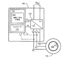
図1は、例示的かつ非限定的な実施形態による電子式電力変換器100を示している。電子式電力変換器100は、誘導機105の固定子電圧を形成するための変換器段104を含む。誘導機105の相数は、証明目的の場合は3つだが、別の相数も可能である。図1では、固定子の相電圧は、uu、uv、およびuwと表記されている。図1に示した例示的な事例では、電子式電力変換器100の入力電圧は、直流の「DC」電圧UDCである。入力電圧が、例えば三相交流の「AC」電圧であることも可能である。この例示的な事例では、電子式電力変換器は、例えば整流器および整流器と変換器段104との間のDC電圧中間回路を備えていてよい。変換器段104は、DC電圧UDCを固定子電圧uu、uv、およびuwに変換するために例えばパルス幅変調「PWM」を用いるように構成され得る。ただし、変換器段104は、例えば三相入力AC電圧から誘導機105の固定子電圧uu、uv、およびuwへの直接変換を実行するためのマトリクス変換器段であることも可能である。電子式電力変換器100はさらに、誘導機105の固定子電圧uu、uv、およびuwを制御するコントローラ103を備えている。図1では、コントローラ103によって変換器段104に供給される一連のスイッチ制御値は、sで表記されている。コントローラ103は、1つ以上のベクトル制御モードと1つのスカラー制御モードなどの異なる制御モードを実施する手段を含んでいてよい。ベクトル制御モードでは、少なくとも部分的に、コントローラ103は、誘導機105の固定子電流iuおよびivと、機械のパラメータ、すなわち誘導機105のインダクタンスおよび抵抗とに基づいて、固定子電圧uu、uv、およびuwを制御してよい。図1に示した例示的な状況では、固定子電流iu、iv、およびiwの和はゼロであり、よってiw=-iu-ivであるためコントローラ103に必要な固定子電流はiuおよびivの2つのみであると仮定される。
FIG. 1 shows an
電子式電力変換器100はさらに、誘導機が回転速度ωrおよび/または回転方向を磁束ベースで判断するための磁束を十分に有していない場合に誘導機105の回転速度ωrおよび/または回転方向を推定する例示的かつ非限定的な実施形態による装置101を備えている。
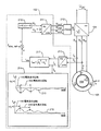
図2aは、処理システム102が誘導機105の回転速度ωrおよび/または回転方向を推定しているときの装置101の処理システム102に相当する例示的な機能ブロック図を示している。処理システム102は、誘導機105の固定子電圧uu、uv、およびuwを制御して、誘導機105の固定子に対して方向が一定の電圧空間ベクトルを構成するように構成される。電圧空間ベクトルは、(2/3)(uu+auv+a2uw)で定義され、式中a=(−1+j√3)/2であり、jは虚数単位である。図2aでは、電圧空間ベクトルは方向が固定子に対して一定のため、電圧空間ベクトルの方向は、誘導機105の固定子に固定されているdq座標系のd軸で描かれている。そのため、電圧空間ベクトルはudである。処理システム102は、電圧空間ベクトルを基準固定子電圧uuref、uvref、およびuwrefに変換する機能ブロック211を実施するように構成され、それによってuuref=udcos(θ)、uvref=udcos(θ−120°)、およびuwref=udcos(θ−240°)となり、式中θは、dq座標系のd軸と固定子巻線の相uの磁気軸との間の角度である。角度θは、例えば電気度または電気ラジアンで表現され得る。図1に示したコントローラ103で実施されている機能ブロック212が基準固定子電圧uuref、uvref、およびuwrefを、変換器段104に送られるスイッチ制御値のセットsに変換する。
FIG. 2a shows an exemplary functional block diagram corresponding to the
処理システム102は、固定子電流iu、iv、およびiwで構成される電流空間ベクトルのd成分およびq成分を計算する機能ブロック213を実施するように構成され、以下のようになり、
id=(2/3)(iu−iv/2−iw/2)cos(θ)+(1/√3)(iv-iw)sin(θ)、および
iq=(1/√3)(iv−iw)cos(θ)-(2/3)(iu−iv/2−iw/2)sin(θ)
式中iw=−iu−ivであり、電流空間ベクトルのd成分idは電圧空間ベクトルに平行で、電流空間ベクトルのq成分iqは電圧空間ベクトルに垂直である。一般性を限定することなく、電圧空間ベクトルの固定方向は、相uの磁気軸の方向、すなわちθ=0となるように選択され得る。この例示的な事例では、
id=(2/3)(iu−iv/2−iw/2)およびiq=(1/√3)(iv-iw)
である。
The
i d = (2/3) (i u -i v / 2-i w / 2) cos (θ) + (1 / √3) (i v -i w) sin (θ), and i q = ( 1 / √3) (i v -i w) cos (θ) - (2/3) (i u -i v / 2-i w / 2) sin (θ)
In the equation, i w = −i u −i v , the d component i d of the current space vector is parallel to the voltage space vector, and the q component i q of the current space vector is perpendicular to the voltage space vector. Without limiting the generality, the fixed direction of the voltage space vector can be chosen to be the direction of the magnetic axis of phase u, i.e. θ = 0. In this exemplary case
i d = (2/3) (i u -i v / 2-i w / 2) and i q = (1 / √3) (i v -i w)
Is.
処理システム102は、電流空間ベクトルの長さiabsおよび電圧空間ベクトルの長さを制御する機能ブロック210を計算する機能ブロック217を実施するように構成され、それによって固定子電流iu、iv、およびiwは、電流空間ベクトルが所定の長さiabs,refを有するという条件を満たす。機能ブロック210は、例えば比例の「P」レギュレータ、比例および積分の「PI」レギュレータ、比例、積分、および微分の「PID」レギュレータ、または何らかの他の適切なレギュレータとすることができる。電流空間ベクトルの所定の長さiabs,refは、例えば誘導機105の公称電流のピーク値の30%〜100%の範囲内とすることができる。
The
処理システム102は、電流空間ベクトルのq成分iqの波形に基づいて回転方向および/または回転速度ωrを推定する機能ブロック214を実施するように構成される。回転方向および/または回転速度ωrを推定する例示的な方法を以下に説明する。
The
例示的かつ非限定的な実施形態による装置では、処理システム102は、前述の条件iabs=iabs,refを満たした最初の時点でq成分iqの変化方向を検知するように、かつ検知した変化方向に基づいて回転方向を判断するように構成される。q成分iqが最初に図2aに示した例示的な波形215で示したように下がれば、回転方向は正であると判断される。同様に、q成分iqが最初に図2aに示した例示的な波形216で示したように上がれば、回転方向は負であると判断される。
In an apparatus according to an exemplary and non-limiting embodiment, the
例示的かつ非限定的な実施形態による装置では、処理システム102は、条件iabs=iabs,refを満たした最初の時点の後に発生するq成分iqの波形の最初の局所極値の極性を検知するように、かつ検知した極性に基づいて回転方向を判断するように構成される。最初の局所極値が図2aに示した例示的な波形215で示したように負であれば、回転方向は正であると判断される。同様に、最初の局所極値が図2aに示した例示的な波形216で示したように正であれば、回転方向は負であると判断される。
In an apparatus according to an exemplary and non-limiting embodiment, the
例示的かつ非限定的な実施形態による装置では、処理システム102は、条件iabs=iabs,refを満たした最初の時点からq成分iqの波形がその最初の局所極値に達する瞬間までの経過時間を示す第1の時間値T1を測定するように構成される。処理システム102は、ωr,estimate=π/T1/pとなるように、測定した第1の時間値T1に基づいて回転速度ωrを推定するように構成され、式中pは誘導機105の極性のペア数である。
In an apparatus according to an exemplary and non-limiting embodiment, the
例示的かつ非限定的な実施形態による装置では、処理システム102は、q成分iqの波形の2つの連続する局所最大値の間または2つの連続する局所最小値の間に経過した時間を示す少なくとも1つの第2の時間値T2を測定するように構成される。処理システム102は、ωr,estimate=2π/T2/pとなるように、測定した第2の時間値T2に基づいて回転速度ωrの推定値を形成するように構成される。
In an apparatus according to an exemplary and non-limiting embodiment, the
例示的かつ非限定的な実施形態による装置では、処理システム102は、前述した例示的な方法の2つ以上を適用して回転方向および/または回転速度ωを推定するように構成される。回転速度ωrの推定値は、q成分iqの波形の多くの局所最大値、および/または多くの局所最小値を観察することによってさらに正確なものにできるが、これには推定値を得るのに必要な時間が多くかかる。
In an apparatus according to an exemplary and non-limiting embodiment, the
例示的かつ非限定的な実施形態による装置では、処理システム102は、1つ以上の前述した方法で回転速度ωrを推定し、続いて固定子電圧uu、uv、およびuwを制御するように構成され、それによって電流空間ベクトルは、推定した回転速度で回転する。電流空間ベクトルは、例えば電圧空間ベクトル(2/3)(uu+auv+a2uw)の長さを制御することによって電流空間ベクトル(2/3)(iu+aiv+a2iw)の長さを制御し、電圧空間ベクトルの回転速度を制御することによって電流空間ベクトルの回転速度を制御するように回転できる。
In an apparatus according to an exemplary and non-limiting embodiment, the
例示的かつ非限定的な実施形態による装置では、処理システム102は、電流空間ベクトルが回転するときの固定子電圧uu、uv、およびuw、固定子電流iu、iv、およびiw、ならびに固定子抵抗に基づいて、誘導機105の空隙電力Pagが流れる方向を推定するように構成される。処理システム102は、推定した流れる方向が誘導機の回転子106に向かっているときに電流空間ベクトルの回転速度を下げ、推定した流れる方向が誘導機の回転子から外れているときに電流空間ベクトルの回転速度を上げるように構成される。誘導機105によって取り込まれた磁気エネルギーが実質的に一定であるとき、空隙電力を以下にように推定でき、
Pag=uuiu+uviv+uwiw-Rs(iu 2+iv 2+iw 2)
式中Rsは固定子抵抗である。推定した空隙電力が回転子に向かって流れる場合、誘導機105はモータとして作用し、回転速度の推定値、すなわち電流空間ベクトルの回転速度は大きすぎる。同様に、推定した空隙電力が回転子から外れて流れる場合、誘導機105は発電機として作用し、回転速度の推定値、すなわち電流空間ベクトルの回転速度は小さすぎる。
In an apparatus according to an exemplary and non-limiting embodiment, the
P ag = u u i u + u v i v + u w i w -R s (i u 2 + i v 2 + i w 2 )
In the equation, R s is the stator resistance. When the estimated void power flows toward the rotor, the
例示的かつ非限定的な実施形態による装置では、処理システム102は、前述の条件iabs=iabs,refを満たした最初の時点の後でq成分iqの波形が所定期間内に局所極値に達しているかどうかを監視するように構成される。回転子が非常にゆっくりと回転しているためにq成分iqが前述の期間内に局所極値に達しない場合、回転子は固定子電流によって磁化され、前述の所定期間の後に磁化した回転子に対して適切な公知の測定検知方法を用いることができる。換言すると、処理システム102は、前述の所定期間内に達する局所極値がない状況に応答して、前述の所定期間に発生した磁束を有する誘導機105の挙動に基づいて回転速度ωrおよび/または回転方向を推定するように構成され得る。磁化した回転子の速度検知方法には、例えば、一連の固定子短絡を配置すること、固定子の短絡電流を測定すること、および測定して短絡電流に基づいて速度および/または回転方向を推定することが含まれてよい。
In apparatus according to an exemplary and non-limiting embodiment, the
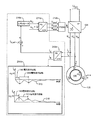
図2bは、例示的かつ非限定的な実施形態による装置の処理システムに相当する例示的な機能ブロック図を示している。図2bに示した機能ブロック図は、処理システムが誘導機105の回転速度ωrおよび/または回転方向を推定したいるときの処理システムに相当する。この例示的な事例では、処理システムは、電圧空間ベクトルの長さを制御するように構成され、それによって固定子電流iu、iv、およびiwは、電流空間ベクトルが所定のd成分id,refを有する、すなわちid=id,refという条件を満たす。電流空間ベクトルの所定のd成分id,refは、例えば誘導機105の公称電流のピーク値の20%〜70%の範囲内であってよい。図2bに示した機能ブロック210b、211b、212b、213b、および214bは、図2aに示した機能ブロック210〜211とそれぞれ同じようなものであってよい。電流空間ベクトルの長さは、図2bで示した例示的な実施形態では計算されないため、図2bに示した例示的な実施形態は、図2aに示した例示的な実施形態よりも必要な計算が少ない。ただし状況によっては、例えば図2aに示した例示的な実施形態を用いる場合は誘導機105の飽和状態をより良好に制御できるため、図2aに示した例示的な実施形態の方が良好な結果になり得る。
FIG. 2b shows an exemplary functional block diagram corresponding to the processing system of the apparatus according to exemplary and non-limiting embodiments. The functional block diagram shown in FIG. 2b corresponds to the processing system when the processing system estimates the rotation speed ω r and / or the rotation direction of the
図1に示した処理システム102は、1つ以上のプロセッサ回路を用いて実行でき、各々のプロセッサ回路は、適切なソフトウェア、例えば特定用途向け集積回路「ASIC」などの専用のハードウェアプロセッサ、または例えばフィールドプログラマブルゲートアレイ「FPGA」などの構成可能なハードウェアプロセッサを備えたプログラム可能なプロセッサ回路であってよい。さらに、処理システムは、1つ以上の記憶装置を備えていてよく、各々の記憶装置は、例えばランダムアクセスメモリ「RAM」回路であってよい。多くの電子式電力変換器では、回転速度および/または回転方向を推定する例示的かつ非限定的な実施形態による装置は、電子式電力変換器の制御システムのハードウェアを用いて実行できる。
The
前述の装置101は、
−誘導機の固定子電圧を制御して、誘導機の固定子に対して方向が一定の電圧空間ベクトルを構成する手段、
−電圧空間ベクトルの長さを制御して、以下の条件:a)固定子電流によって構成された電流空間ベクトルが所定の長さを有する、b)電流空間ベクトルは、電圧空間ベクトルと平行な所定のd成分を有する、のいずれか一方を満たすように誘導機の固定子電流を調節する手段、および
−誘導機の回転子の回転速度および/または回転子の回転方向を、電流空間ベクトルのq成分の波形に基づいて推定する手段であって、q成分は電圧空間ベクトルに垂直である、手段
を含む、装置の一例である。
The
-Means that control the stator voltage of the induction machine to form a voltage space vector with a constant direction with respect to the stator of the induction machine.
-Controlling the length of the voltage space vector, the following conditions: a) The current space vector composed of the stator current has a predetermined length, b) The current space vector is a predetermined parallel to the voltage space vector. Means for adjusting the stator current of the inducer so as to satisfy either of the d components of, and-the rotation speed and / or rotation direction of the rotor of the inducer, q of the current space vector. A means of estimating based on the waveform of the component, the q component is an example of an apparatus including means that is perpendicular to the voltage space vector.
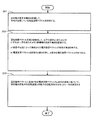
図3は、誘導機が回転速度および/または回転方向を磁束ベースで判断するための磁束を十分に有していない場合に、誘導機の回転速度および/または回転方向を推定するための例示的かつ非限定的な実施形態による方法のフローチャートを示している。本方法は、以下の行為:
−行為301:誘導機の固定子電圧を制御して、誘導機の固定子に対して方向が一定の電圧空間ベクトルを構成すること、
−行為302:電圧空間ベクトルの長さを制御して、以下の条件:a)固定子電流によって構成された電流空間ベクトルが所定の長さを有する、b)電流空間ベクトルは、電圧空間ベクトルと平行な所定のd成分を有する、のいずれか一方を満たすように誘導機の固定子電流を調節すること、および
−行為303:誘導機の回転子の回転速度および/または回転子の回転方向を、電流空間ベクトルのq成分の波形に基づいて推定することであって、q成分は電圧空間ベクトルに垂直であること
を含む。
FIG. 3 is an example for estimating the rotation speed and / or the rotation direction of the induction machine when the induction machine does not have enough magnetic flux to determine the rotation speed and / or the rotation direction on a magnetic flux basis. Moreover, the flowchart of the method by a non-limiting embodiment is shown. This method has the following actions:
-Act 301: Controlling the stator voltage of the induction machine to form a voltage space vector with a constant direction with respect to the stator of the induction machine.
− Act 302: Controlling the length of the voltage space vector, the following conditions: a) The current space vector composed of the stator current has a predetermined length, b) The current space vector is the voltage space vector. Adjusting the stator current of the inducer to satisfy either one of having a parallel predetermined d component, and-action 303: the rotation speed and / or the rotation direction of the rotor of the inducer. , Estimating based on the waveform of the q component of the current space vector, including that the q component is perpendicular to the voltage space vector.
例示的かつ非限定的な実施形態による方法は、
−固定子電流に関する条件を満たした最初の時点での電流空間ベクトルのq成分の変化方向を検知すること、および
−検知した変化方向に基づいて回転方向を判断すること
を含む。
The method according to an exemplary and non-limiting embodiment
-It includes detecting the changing direction of the q component of the current space vector at the first time when the condition regarding the stator current is satisfied, and-determining the rotation direction based on the detected changing direction.
例示的かつ非限定的な実施形態による方法は、
−固定子電流に関する条件を満たした最初の時点の後に発生する電流空間ベクトルのq成分の波形の最初の局所極値の極性を検知すること、および
−検知した極性に基づいて回転方向を判断すること
を含む。
The method according to an exemplary and non-limiting embodiment
-Detecting the polarity of the first local extremum of the waveform of the q component of the current space vector that occurs after the first time point when the conditions for stator current are met, and-determining the direction of rotation based on the detected polarity. Including that.
例示的かつ非限定的な実施形態による方法は、
−固定子電流に関する条件を満たした最初の時点から電流空間ベクトルのq成分の波形がその最初の局所極値に達する瞬間までの経過時間を示す第1の時間値を測定すること、および
−測定した第1の時間値に基づいて回転速度を推定すること
を含む。
The method according to an exemplary and non-limiting embodiment
-Measuring the first time value indicating the elapsed time from the first time when the condition for stator current is satisfied to the moment when the waveform of the q component of the current space vector reaches its first local pole value, and-measurement. It includes estimating the rotation speed based on the first time value.
例示的かつ非限定的な実施形態による方法は、
−電流空間ベクトルのq成分の波形の2つの局所最大値の間または2つの局所最小値の間に経過した時間を示す少なくとも1つの第2の時間値を測定すること、および
−測定した少なくとも1つの第2の時間値に基づいて回転速度を推定すること
を含む。
The method according to an exemplary and non-limiting embodiment
-Measuring at least one second time value indicating the time elapsed between the two local maximums or between the two local minimums of the waveform of the q component of the current space vector, and-at least one measured It involves estimating the rotational speed based on two second time values.
例示的かつ非限定的な実施形態による方法は、電流空間ベクトルのq成分の波形に基づいて回転速度を推定し、続いて推定した回転速度で電流空間ベクトルを回転させるように固定子電圧を制御することを含む。 The method according to an exemplary and non-limiting embodiment estimates the rotation speed based on the waveform of the q component of the current space vector, and then controls the stator voltage to rotate the current space vector at the estimated rotation speed. Including doing.
例示的かつ非限定的な実施形態による方法は、
−電流空間ベクトルが推定した回転速度で回転しているときの固定子電流、および固定子抵抗固定子電圧に基づいて、誘導機の空隙電力が流れる方向を推定すること、
−推定した流れる方向が誘導機の回転子に向かっているときに電流空間ベクトルの回転速度を下げること、および
−推定した流れる方向が誘導機の回転子から外れているときに電流空間ベクトルの回転速度を上げること
を含む。
The method according to an exemplary and non-limiting embodiment
-Estimating the direction in which the void power of the inducer flows based on the stator current when the current space vector is rotating at the estimated rotation speed and the stator resistance stator voltage.
-Reduce the rotation speed of the current space vector when the estimated flow direction is toward the rotor of the inducer, and-Rotate the current space vector when the estimated flow direction is out of the rotor of the inducer. Including speeding up.
例示的かつ非限定的な実施形態による方法は、
−固定子電流に関する条件を満たした最初の時点の後で電流空間ベクトルのq成分の波形が所定期間内に局所極値に達しているかどうかを監視すること、および
−所定期間内に達する局所極値がない状況に応答して、所定期間に発生した磁束を有する誘導機の挙動に基づいて回転速度および/または回転方向を推定すること
を含む。
The method according to an exemplary and non-limiting embodiment
-Monitoring whether the waveform of the q component of the current space vector reaches the local extremum within a predetermined period after the first time when the conditions for stator current are met, and-the local pole reaching within a predetermined period. It involves estimating the rotational speed and / or direction of rotation based on the behavior of the inducer with the magnetic flux generated over a given period of time in response to a situation of no value.
例示的かつ非限定的な実施形態による方法では、固定子電流に関する条件は、電流空間ベクトルが所定の長さを有し、その所定の長さが誘導機の公称電流のピーク値の30%〜100%の範囲内であることである。 In the method according to an exemplary and non-limiting embodiment, the condition regarding the stator current is that the current space vector has a predetermined length, and the predetermined length is from 30% of the peak value of the nominal current of the inducer. It is within the range of 100%.
例示的かつ非限定的な実施形態による方法では、固定子電流に関する条件は、電流空間ベクトルが所定のd成分を有し、その所定のd成分が、誘導機の公称電流のピーク値の20%〜70%の範囲内であることである。 In a method according to an exemplary and non-limiting embodiment, the condition for the stator current is that the current space vector has a predetermined d component, which is 20% of the peak value of the nominal current of the inducer. It is in the range of ~ 70%.
例示的かつ非限定的な実施形態によるコンピュータプログラムは、前述した例示的かつ非限定的な実施形態のいずれかによる方法に関する行為を実行するプログラム可能なプロセッサを制御するためにコンピュータで実行可能な命令を含む。 A computer program according to an exemplary and non-limiting embodiment is a computer-executable instruction to control a programmable processor that performs an act relating to a method according to any of the exemplary and non-limiting embodiments described above. including.
例示的かつ非限定的な実施形態によるコンピュータプログラムは、誘導機が回転速度および/または回転方向を磁束ベースで判断するための磁束を十分に有していない場合に誘導機の回転速度および/または回転方向を推定するソフトウェアモジュールを含む。ソフトウェアモジュールは、
−誘導機の固定子電圧を制御して、誘導機の固定子に対して方向が一定の電圧空間ベクトルを構成し、
−電圧空間ベクトルの長さを制御して、以下の条件:a)固定子電流によって構成された電流空間ベクトルが所定の長さを有する、b)電流空間ベクトルは、電圧空間ベクトルと平行な所定のd成分を有する、のいずれか一方を満たすように誘導機の固定子電流を調節し、
−誘導機の回転子の回転速度および/または回転子の回転方向を、電流空間ベクトルのq成分の波形に基づいて推定し、q成分は電圧空間ベクトルに垂直である
ようにプログラム可能なプロセッサを制御するためにコンピュータで実行可能な命令を含む。
A computer program according to an exemplary and non-limiting embodiment shows that the induction machine does not have sufficient magnetic flux to determine the rotational speed and / or direction of rotation on a magnetic flux basis. Includes a software module that estimates the direction of rotation. Software module
-Control the stator voltage of the induction machine to form a voltage space vector with a constant direction with respect to the stator of the induction machine.
-Controlling the length of the voltage space vector, the following conditions: a) The current space vector composed of the stator current has a predetermined length, b) The current space vector is a predetermined parallel to the voltage space vector. Adjust the stator current of the inducer to satisfy either one of the d components of
-Estimate the rotation speed and / or rotation direction of the rotor of the inducer based on the waveform of the q component of the current space vector, and make the processor programmable so that the q component is perpendicular to the voltage space vector. Includes computer-executable instructions for control.
前述したソフトウェアモジュールは、例えば、検討しているプログラム可能なプロセッサに適したプログラミング言語を用いて実行されるサブルーチンおよび/または機能であってよい。 The software modules described above may be, for example, subroutines and / or functions executed using a programming language suitable for the programmable processor under consideration.
例示的かつ非限定的な実施形態によるコンピュータプログラム製品には、コンピュータ可読媒体、例えば例示的な実施形態によるコンピュータプログラムで符号化されたコンパクトディスク「CD」が含まれる。 Computer program products according to exemplary and non-limiting embodiments include computer-readable media, such as compact discs "CDs" encoded by computer programs according to exemplary embodiments.
例示的かつ非限定的な実施形態による信号は、例示的な実施形態によるコンピュータプログラムを規定する情報を運ぶように符号化される。 A signal according to an exemplary and non-limiting embodiment is encoded to carry information that defines a computer program according to the exemplary embodiment.
上記の説明に記載した非限定的で特定の例は、添付の請求項の範囲および/または適応性を限定するものと解釈してはならない。さらに、本明細書に提示した例の一覧およびまとまりは、特に明記されていない限り徹底的なものではない。 The non-limiting and specific examples described above shall not be construed as limiting the scope and / or adaptability of the appended claims. Moreover, the list and cohesiveness of the examples presented herein is not exhaustive unless otherwise stated.
100 電子式電力変換器
101 装置
102 処理システム
103 コントローラ
104 変換器段
105 誘導機
106 回転子
210、211、212、213、214、217 機能ブロック
210b、211b、212b、213b、214b 機能ブロック
215、216 波形
UDC DC電圧
uu、uv、uw 固定子電圧
iu、iv、iw 固定子電流
ωr 回転速度
s スイッチ制御値
ud、uq 電圧空間ベクトル
uuref、uvref、uwref 基準固定子電圧
iabs 電流空間ベクトルの長さ
iabs,ref 電流空間ベクトルの所定の長さ
id 電流空間ベクトルのd成分
iq 電流空間ベクトルのq成分
100
215, 216 waveform
U DC DC voltage u u, u v, u w stator voltage i u, i v, i w stator current omega r speed s switch control values u d, u q voltage space vector u uref, u vref, u wref Reference stator voltage i abs Current space vector length i abs, ref Current space vector predetermined length i d Current space vector d component i q Current space vector q component
Claims (14)
−誘導機(105)の固定子電圧(uu、uv、uw)を制御して、前記誘導機の固定子に対して方向が一定の電圧空間ベクトルを構成し、
−前記電圧空間ベクトルの長さを制御して、前記固定子電流によって構成された電流空間ベクトルが所定の長さを有するという条件を満たすように前記誘導機の固定子電流(iu、iv、iw)を調節し、
−電流空間ベクトルのq成分の波形に基づいて、前記誘導機の回転子(106)の回転速度、前記回転子の回転方向の少なくとも一方を推定する
ように構成された1つ以上のプロセッサ回路を用いて実行される処理システム(102)を備え、
前記電流空間ベクトルのd成分は前記電圧空間ベクトルに平行であり、前記電流空間ベクトルの前記q成分は前記電圧空間ベクトルに垂直であることを特徴とする、装置(101)。 Device (101)
− By controlling the stator voltage (u u , u v , u w ) of the induction machine (105), a voltage space vector having a constant direction with respect to the stator of the induction machine is formed.
- wherein by controlling the length of the voltage space vector, wherein the current space vector which is constituted by the stator current so as to satisfy the condition of having a predetermined length induction machine stator current (i u, i v , I w )
-One or more processor circuits configured to estimate at least one of the rotation speed of the rotor (106) of the inducer and the rotation direction of the rotor based on the waveform of the q component of the current space vector. Equipped with a processing system (102) to be executed using
The apparatus (101), characterized in that the d component of the current space vector is parallel to the voltage space vector, and the q component of the current space vector is perpendicular to the voltage space vector.
−前記固定子電流に関する前記条件を満たした最初の時点の後で前記電流空間ベクトルの前記q成分の前記波形が所定期間内に局所極値に達しているかどうかを監視し、
−前記電流空間ベクトルの前記q成分が前記所定期間内に局所極値に達していない状況に応答して、前記所定期間に発生した磁束を有する前記誘導機の挙動に基づいて、前記回転速度と前記回転方向の少なくとも一方を推定する
ように構成される、請求項1〜7のいずれか一項に記載の装置。 The processing system
-Monitor whether the waveform of the q component of the current space vector reaches a local extremum within a predetermined period after the first time point when the condition for the stator current is met.
-In response to the situation where the q component of the current space vector has not reached the local extremum within the predetermined period, the rotation speed and the rotation speed are based on the behavior of the inducer having the magnetic flux generated in the predetermined period. The device according to any one of claims 1 to 7, which is configured to estimate at least one of the rotation directions.
−少なくとも部分的に前記誘導機の固定子電流に基づいて前記固定子電圧を制御するコントローラ(103)、および
−前記誘導機の回転子(106)の回転速度と前記回転子の回転方向の少なくとも一方を推定する請求項1〜10のいずれか一項に記載の装置(101)
を含む、電子式電力変換器(100)。 -The transducer stage (104), which forms the stator voltage of the inducer (105),
-A controller (103) that controls the stator voltage based on the stator current of the inducer at least partially, and-at least the rotation speed of the rotor (106) of the inducer and the rotation direction of the rotor. The apparatus (101) according to any one of claims 1 to 10 for estimating one.
Electronic power converter (100), including.
−誘導機(105)の固定子電圧(uu、uv、uw)を制御して、前記誘導機の固定子に対して方向が一定の電圧空間ベクトルを構成すること(301)、
−前記電圧空間ベクトルの長さを制御して、前記誘導機の固定子電流(iu、iv、iw)を調節して、前記固定子電流によって構成された電流空間ベクトルが所定の長さを有するという条件を満たすこと(302)、および
−前記電流空間ベクトルのq成分の波形に基づいて、前記誘導機の回転子(106)の回転速度と前記回転子の回転方向の少なくとも一方を推定すること(303)
を含み、
前記電流空間ベクトルのd成分は前記電圧空間ベクトルに平行であり、前記電流空間ベクトルの前記q成分は前記電圧空間ベクトルに垂直である
ことを特徴とする、方法。 A method, said method
-Controlling the stator voltage (u u , u v , u w ) of the induction machine (105) to form a voltage space vector having a constant direction with respect to the stator of the induction machine (301),
-By controlling the length of the voltage space vector and adjusting the stator currents ( iu , iv , i w ) of the inducer, the current space vector composed of the stator current has a predetermined length. (302), and-based on the waveform of the q component of the current space vector, at least one of the rotation speed of the rotor (106) of the inducer and the rotation direction of the rotor. Estimate (303)
Including
A method, wherein the d component of the current space vector is parallel to the voltage space vector, and the q component of the current space vector is perpendicular to the voltage space vector.
−誘導機(105)の固定子電圧(uu、uv、uw)を制御して、前記誘導機の固定子に対して方向が一定の電圧空間ベクトルを構成し、
−前記電圧空間ベクトルの長さを制御して前記誘導機の固定子電流(iu、iv、iw)を調節し、前記固定子電流によって構成された電流空間ベクトルが所定の長さを有するという条件を満たし、
−前記電流空間ベクトルのq成分の波形に基づいて、前記誘導機の回転子(106)の回転速度と前記回転子の回転方向の少なくとも一方を推定する
ようにプログラム可能なプロセッサを制御するためにコンピュータで実行可能な命令を含み、
前記電流空間ベクトルのd成分は前記電圧空間ベクトルに平行であり、前記電流空間ベクトルの前記q成分は前記電圧空間ベクトルに垂直である
ことを特徴とする、コンピュータプログラム。 A computer program, the computer program
− By controlling the stator voltage (u u , u v , u w ) of the induction machine (105), a voltage space vector having a constant direction with respect to the stator of the induction machine is formed.
-The length of the voltage space vector is controlled to adjust the stator currents ( iu , iv , i w ) of the inducer, and the current space vector composed of the stator current has a predetermined length. Satisfy the condition of having
-To control a programmable processor to estimate at least one of the rotation speed of the rotor (106) of the inducer and the rotation direction of the rotor based on the waveform of the q component of the current space vector. Includes computer-executable instructions
A computer program characterized in that the d component of the current space vector is parallel to the voltage space vector, and the q component of the current space vector is perpendicular to the voltage space vector.
Applications Claiming Priority (2)
| Application Number | Priority Date | Filing Date | Title |
|---|---|---|---|
| EP19171846.9A EP3734831B1 (en) | 2019-04-30 | 2019-04-30 | Device and method for determining rotation of an induction machine |
| EP19171846.9 | 2019-04-30 |
Publications (2)
| Publication Number | Publication Date |
|---|---|
| JP2020184873A true JP2020184873A (en) | 2020-11-12 |
| JP7569156B2 JP7569156B2 (en) | 2024-10-17 |
Family
ID=66334295
Family Applications (1)
| Application Number | Title | Priority Date | Filing Date |
|---|---|---|---|
| JP2020065542A Active JP7569156B2 (en) | 2019-04-30 | 2020-04-01 | Apparatus and method for determining induction machine rotation |
Country Status (5)
| Country | Link |
|---|---|
| US (1) | US11114966B2 (en) |
| EP (1) | EP3734831B1 (en) |
| JP (1) | JP7569156B2 (en) |
| KR (1) | KR20200127125A (en) |
| CN (1) | CN111865162B (en) |
Family Cites Families (17)
| Publication number | Priority date | Publication date | Assignee | Title |
|---|---|---|---|---|
| FR2614481B1 (en) * | 1987-02-13 | 1990-08-31 | Pk I | METHOD FOR CONTROLLING AN ASYNCHRONOUS MOTOR AND ELECTRIC DRIVE IMPLEMENTING THIS METHOD |
| US5559419A (en) * | 1993-12-22 | 1996-09-24 | Wisconsin Alumni Research Foundation | Method and apparatus for transducerless flux estimation in drives for induction machines |
| US7539549B1 (en) * | 1999-09-28 | 2009-05-26 | Rockwell Automation Technologies, Inc. | Motorized system integrated control and diagnostics using vibration, pressure, temperature, speed, and/or current analysis |
| DE19919752C5 (en) * | 1999-04-29 | 2010-12-16 | Sew-Eurodrive Gmbh & Co. Kg | Method for connecting an inverter to an asynchronous motor |
| US6239575B1 (en) * | 2000-02-11 | 2001-05-29 | Ford Motor Company | Induction motor power/torque clamping for electric vehicle performance |
| DE60318066T2 (en) * | 2002-07-08 | 2008-04-10 | Kabushiki Kaisha Yaskawa Denki, Kitakyushu | SENSORLESS VECTOR CONTROL METHOD FOR AN ALTERNATOR GENERATOR AND CONTROL DEVICE THEREFOR |
| US7141949B2 (en) * | 2005-03-07 | 2006-11-28 | Fisher & Paykel Appliances Limited | Low noise back EMF sensing brushless DC motor |
| JP4539689B2 (en) * | 2007-07-26 | 2010-09-08 | 株式会社安川電機 | AC motor control method and control apparatus |
| US8102140B2 (en) * | 2008-05-16 | 2012-01-24 | Schneider Electric USA, Inc. | Method and apparatus for estimating induction motor electrical parameters |
| EP2192413A1 (en) * | 2008-12-01 | 2010-06-02 | ABB Oy | Method and apparatus for estimating a rotation speed of an electric motor |
| CN101650390B (en) * | 2009-08-31 | 2011-11-23 | 苏州经贸职业技术学院 | On-line measurement method of stator inductance parameters of surface type AC permanent magnet synchronous motor |
| US8536811B2 (en) * | 2010-10-21 | 2013-09-17 | Hamilton Sundstrand Corporation | Engagement of a spinning AC induction motor |
| JP6177623B2 (en) * | 2013-08-09 | 2017-08-09 | 株式会社日立産機システム | Synchronous motor controller |
| EP2887538B1 (en) * | 2013-12-20 | 2016-03-16 | Baumüller Nürnberg GmbH | Method for controlling and regulating an electromagnetic machine |
| JP6279507B2 (en) * | 2015-04-07 | 2018-02-14 | 日立オートモティブシステムズ株式会社 | Motor driving device and phase current detection method for three-phase brushless motor |
| CN108155838A (en) * | 2016-12-02 | 2018-06-12 | 长沙市日业电气有限公司 | A kind of rotating speed method for tracing based on permanent magnet synchronous motor open loop |
| EP3340456B1 (en) * | 2016-12-21 | 2021-04-14 | Danfoss Mobile Electrification Oy | An electric system for an electromechanical power transmission chain |
-
2019
- 2019-04-30 EP EP19171846.9A patent/EP3734831B1/en active Active
-
2020
- 2020-04-01 JP JP2020065542A patent/JP7569156B2/en active Active
- 2020-04-13 KR KR1020200044555A patent/KR20200127125A/en not_active Withdrawn
- 2020-04-20 CN CN202010310464.8A patent/CN111865162B/en active Active
- 2020-04-29 US US16/861,391 patent/US11114966B2/en active Active
Also Published As
| Publication number | Publication date |
|---|---|
| US20200350845A1 (en) | 2020-11-05 |
| JP7569156B2 (en) | 2024-10-17 |
| CN111865162B (en) | 2024-07-05 |
| US11114966B2 (en) | 2021-09-07 |
| EP3734831B1 (en) | 2022-02-02 |
| EP3734831A1 (en) | 2020-11-04 |
| KR20200127125A (en) | 2020-11-10 |
| CN111865162A (en) | 2020-10-30 |
Similar Documents
| Publication | Publication Date | Title |
|---|---|---|
| US8362732B2 (en) | Motor phase winding fault detection method and apparatus | |
| US9825579B2 (en) | Temperature estimating apparatus for synchronous motor | |
| KR101530731B1 (en) | Method and apparatus for determining a field current in brushless electrical machines | |
| AU2013294419B2 (en) | Motor drive control device | |
| CN103518320A (en) | Brushless motor control apparatus and brushless motor control method | |
| CN105453410B (en) | Control device and the AC motor system using the control device | |
| CN107111284A (en) | Detecting Faults in Field Oriented Control Permanent Magnet Synchronous Motors | |
| JP2013021843A (en) | Initial magnetic pole position adjustment device for permanent magnet synchronous motor | |
| Horie et al. | Experimental study on a restarting procedure at coasting condition for a rotational angle sensorless PMSM | |
| JP4437151B2 (en) | Starting method of sensorless DC motor capable of electronic commutation | |
| JP6203784B2 (en) | Control device for synchronous motor | |
| US20110089883A1 (en) | Motor phase winding fault detection method and apparatus | |
| CN105580267A (en) | Power conversion device and power conversion method | |
| CN104521131B (en) | Synchronous electric motor driving system | |
| JP2019140904A (en) | Inverter-controlling device | |
| JP6562881B2 (en) | Constant identification apparatus and constant identification method for permanent magnet synchronous motor | |
| JP2018098856A (en) | Control device of permanent magnet synchronous motor, image formation apparatus and control method | |
| JP2017112680A (en) | Inverter control device | |
| JP2020184873A (en) | Device and method for determining rotation of induction machine | |
| JP5405224B2 (en) | Motor driving device and method for determining relative position of rotor provided in motor | |
| JP5257661B2 (en) | Synchronous motor control method and control apparatus | |
| US20160211781A1 (en) | Motor Control System And Method Of Controlling A Motor | |
| Kroics et al. | Practical method for experimental detection of DC motor inertia to design a speed regulator | |
| JP7800860B2 (en) | How to stop a permanent magnet motor | |
| JP2019146405A (en) | Motor control device and motor control method |
Legal Events
| Date | Code | Title | Description |
|---|---|---|---|
| A621 | Written request for application examination |
Free format text: JAPANESE INTERMEDIATE CODE: A621 Effective date: 20230315 |
|
| A131 | Notification of reasons for refusal |
Free format text: JAPANESE INTERMEDIATE CODE: A131 Effective date: 20240130 |
|
| A711 | Notification of change in applicant |
Free format text: JAPANESE INTERMEDIATE CODE: A711 Effective date: 20240315 |
|
| RD03 | Notification of appointment of power of attorney |
Free format text: JAPANESE INTERMEDIATE CODE: A7423 Effective date: 20240321 |
|
| RD04 | Notification of resignation of power of attorney |
Free format text: JAPANESE INTERMEDIATE CODE: A7424 Effective date: 20240419 |
|
| A601 | Written request for extension of time |
Free format text: JAPANESE INTERMEDIATE CODE: A601 Effective date: 20240430 |
|
| A521 | Request for written amendment filed |
Free format text: JAPANESE INTERMEDIATE CODE: A523 Effective date: 20240628 |
|
| TRDD | Decision of grant or rejection written | ||
| A01 | Written decision to grant a patent or to grant a registration (utility model) |
Free format text: JAPANESE INTERMEDIATE CODE: A01 Effective date: 20241001 |
|
| A61 | First payment of annual fees (during grant procedure) |
Free format text: JAPANESE INTERMEDIATE CODE: A61 Effective date: 20241004 |
|
| R150 | Certificate of patent or registration of utility model |
Ref document number: 7569156 Country of ref document: JP Free format text: JAPANESE INTERMEDIATE CODE: R150 |