JP2020184861A - Electric wire protector - Google Patents
Electric wire protector Download PDFInfo
- Publication number
- JP2020184861A JP2020184861A JP2019088992A JP2019088992A JP2020184861A JP 2020184861 A JP2020184861 A JP 2020184861A JP 2019088992 A JP2019088992 A JP 2019088992A JP 2019088992 A JP2019088992 A JP 2019088992A JP 2020184861 A JP2020184861 A JP 2020184861A
- Authority
- JP
- Japan
- Prior art keywords
- electric wire
- wire protector
- circumferential direction
- convex portion
- ridge portion
- Prior art date
- Legal status (The legal status is an assumption and is not a legal conclusion. Google has not performed a legal analysis and makes no representation as to the accuracy of the status listed.)
- Abandoned
Links
Images
Landscapes
- Protection Of Pipes Against Damage, Friction, And Corrosion (AREA)
- Details Of Indoor Wiring (AREA)
Abstract
Description
本発明は、電線を保護する電線保護具に関する。 The present invention relates to an electric wire protector that protects an electric wire.
従来から、車両に用いられるワイヤハーネス等を製造するにあたり、電線を保護するための種々の電線保護具が用いられている。この種の電線保護具として、代表的には、コルゲートチューブが挙げられる。コルゲートチューブは、一般に、電線を外部からの衝撃などから保護する強度を有するだけでなく、電線の配索形状に沿って変形し得る柔軟性を有する(例えば、特許文献1を参照。)。 Conventionally, in manufacturing wire harnesses and the like used in vehicles, various electric wire protectors for protecting electric wires have been used. A typical example of this type of electric wire protector is a corrugated tube. The corrugated tube generally has not only the strength to protect the electric wire from an external impact or the like, but also the flexibility to be deformed along the wiring shape of the electric wire (see, for example, Patent Document 1).
ところで、コルゲートチューブは、電線の保護性能を考慮してある程度の硬さを有する材料(樹脂など)から構成される。一方、そのような硬さをコルゲートチューブが有するため、コルゲートチューブを装着した電線を実際に車両の車体などに配索すると、車両の走行時の振動などに起因してコルゲートチューブと車体とが接触したとき、接触時に生じる音が異音として車両のユーザに捉えられる場合がある。特に、車両のドア内に配索される電線は、ユーザとの距離が近いため、異音の抑制が特に望まれる。 By the way, the corrugated tube is made of a material (resin or the like) having a certain degree of hardness in consideration of the protection performance of the electric wire. On the other hand, since the corrugated tube has such hardness, when an electric wire equipped with the corrugated tube is actually arranged on the vehicle body, the corrugated tube and the vehicle body come into contact with each other due to vibration during running of the vehicle. At that time, the sound generated at the time of contact may be perceived by the user of the vehicle as an abnormal noise. In particular, since the electric wires laid in the door of the vehicle are close to the user, it is particularly desired to suppress abnormal noise.
そのような異音を抑制するための方策として、例えば、コルゲートチューブの外周面に弾性体(例えば、スポンジシート等)を取り付け、コルゲートチューブと周辺部材とが接触した際の衝撃等を弾性体で吸収することが考えられる。しかし、そのような弾性体をコルゲートチューブに一つ一つ取り付ける工程は煩雑であり、ワイヤハーネスの生産性を低下させる要因となり得る。また、そのような弾性体により、コルゲートチューブの配索経路に沿った変形が妨げられる可能性もある。なお、このような異音の抑制に伴う課題は、コルゲートチューブに限らず、他の電線保護具においても生じ得る。 As a measure for suppressing such abnormal noise, for example, an elastic body (for example, a sponge sheet) is attached to the outer peripheral surface of the corrugated tube, and the impact when the corrugated tube and the peripheral member come into contact with the corrugated tube is subjected to the elastic body. It is possible to absorb it. However, the process of attaching such elastic bodies to the corrugated tubes one by one is complicated and can be a factor of reducing the productivity of the wire harness. In addition, such an elastic body may prevent deformation of the corrugated tube along the wiring path. It should be noted that the problem associated with suppressing such abnormal noise may occur not only in the corrugated tube but also in other electric wire protective equipment.
本発明は、上述した事情に鑑みてなされたものであり、その目的は、電線保護具としての機能を損なうことなく周辺部材との接触による異音の発生を容易に抑制可能な電線保護具、を提供することにある。 The present invention has been made in view of the above circumstances, and an object of the present invention is to provide an electric wire protector capable of easily suppressing the generation of abnormal noise due to contact with peripheral members without impairing the function as the electric wire protector. Is to provide.
前述した目的を達成するために、本発明に係る電線保護具は、下記[1]〜[4]を特徴としている。
[1]
電線を挿通可能な中空部を有する筒状の電線保護具であって、
当該電線保護具の外周面から当該電線保護具の径方向外側に向けて突出し且つ周方向に延びるとともに、当該電線保護具の軸方向に沿って並ぶように配列された、複数の突条部と、
前記複数の前記突条部のうちの少なくとも一つから前記径方向外側に向けて突出し且つ前記周方向に沿うように配置された、一又は複数の凸部と、を備え、
前記凸部は、前記突条部に比べて小さな外力によって屈曲可能である、
電線保護具であること。
[2]
上記[1]に記載の電線保護具において、
前記軸方向に直交する断面において、前記凸部の前記突条部からの前記径方向における突出高さが、前記突条部の前記外周面からの前記径方向における突出高さの60%〜120%である、
電線保護具であること。
[3]
上記[1]又は上記[2]に記載の電線保護具において、
複数の互いに独立した前記凸部が前記突条部上に前記周方向に並ぶように構成された、
電線保護具であること。
[4]
上記[1]又は上記[2]に記載の電線保護具において、
単一の連続した前記凸部が前記突条部上に前記周方向に延びるように構成された、
電線保護具であること。
In order to achieve the above-mentioned object, the electric wire protector according to the present invention is characterized by the following [1] to [4].
[1]
A tubular electric wire protector having a hollow portion through which an electric wire can be inserted.
A plurality of ridges arranged so as to protrude outward in the radial direction of the electric wire protector and extend in the circumferential direction from the outer peripheral surface of the electric wire protector and are arranged along the axial direction of the electric wire protector. ,
A plurality of convex portions, which are arranged so as to project outward in the radial direction from at least one of the plurality of ridge portions and are arranged along the circumferential direction.
The convex portion can be bent by a smaller external force than the ridge portion.
Must be a wire protector.
[2]
In the electric wire protector described in the above [1],
In the cross section orthogonal to the axial direction, the protrusion height of the convex portion from the ridge portion in the radial direction is 60% to 120% of the protrusion height of the ridge portion from the outer peripheral surface in the radial direction. %,
Must be a wire protector.
[3]
In the electric wire protector according to the above [1] or the above [2],
A plurality of independent convex portions are arranged on the ridge portion in the circumferential direction.
Must be a wire protector.
[4]
In the electric wire protector according to the above [1] or the above [2],
A single continuous convex portion is configured to extend on the ridge portion in the circumferential direction.
Must be a wire protector.
上記[1]の構成の電線保護具によれば、電線保護具の外周面の凹凸部分(複数の突条部)の少なくとも一つから突出するように、突条部よりも柔軟な凸部が設けられる。よって、周辺部材と電線保護具が接近したとき、電線保護具の突条部よりも先に凸部が周辺部材に接触する。凸部は突条部よりも柔軟であり、突条部が周辺部材に直接接触する場合に比べ、接触に伴う異音が生じ難い。よって、このような凸部が設けられない場合に比べ、周辺部材との接触による異音の発生が抑制される。 According to the electric wire protector having the configuration of the above [1], the convex portion more flexible than the ridge portion is formed so as to protrude from at least one of the uneven portions (plurality of ridge portions) on the outer peripheral surface of the electric wire protector. Provided. Therefore, when the peripheral member and the electric wire protector come close to each other, the convex portion comes into contact with the peripheral member before the ridge portion of the electric wire protector. The convex portion is more flexible than the ridge portion, and is less likely to generate abnormal noise due to the contact as compared with the case where the ridge portion directly contacts the peripheral member. Therefore, as compared with the case where such a convex portion is not provided, the generation of abnormal noise due to contact with the peripheral member is suppressed.
更に、凸部は電線保護具の周方向に沿うように突条部に設けられるため、電線保護具が電線の配索経路に沿って湾曲することを凸部が妨げることがない。よって、電線保護具としての機能が損なわれることがない。また、凸部は電線保護具自体に設けられるため、電線保護具に別部材として弾性体などを取り付ける場合に比べ、低コストであり、ワイヤハーネス等の生産性を低下させることもない。したがって、本構成の電線保護具は、電線保護具としての機能を損なうことなく周辺部材との接触による異音の発生を容易に抑制可能である。 Further, since the convex portion is provided on the ridge portion along the circumferential direction of the electric wire protector, the convex portion does not prevent the electric wire protector from bending along the wiring path of the electric wire. Therefore, the function as an electric wire protector is not impaired. Further, since the convex portion is provided on the electric wire protector itself, the cost is lower than the case where an elastic body or the like is attached to the electric wire protector as a separate member, and the productivity of the wire harness or the like is not lowered. Therefore, the electric wire protector having this configuration can easily suppress the generation of abnormal noise due to contact with the peripheral members without impairing the function as the electric wire protector.
上記[2]の構成の電線保護具について、発明者が行った実験および考察によれば、電線保護具の軸方向に直交する断面において、凸部の突条部からの径方向における突出高さが、突条部の外周面からの径方向おける突出高さの60%〜120%である場合、上述した異音の発生を抑制する効果と、電線保護具そのものの生産性と、を両立できることが明らかになっている。 According to the experiments and discussions conducted by the inventor of the electric wire protector having the configuration of the above [2], the protrusion height of the convex portion in the radial direction from the ridge portion in the cross section orthogonal to the axial direction of the electric wire protector. However, when the protrusion height in the radial direction from the outer peripheral surface of the ridge portion is 60% to 120%, the above-mentioned effect of suppressing the generation of abnormal noise and the productivity of the electric wire protective device itself can be compatible with each other. Has been clarified.
上記[3]の構成の電線保護具によれば、突条部上に周方向に並ぶように複数の互いに独立した凸部が配置される。これにより、周辺部材が電線保護具に対して様々な向きから接触する場合であっても、凸部によって周辺部材との接触による衝撃などを吸収でき、異音の発生を適正に抑制できる。 According to the electric wire protector having the configuration of the above [3], a plurality of independent convex portions are arranged on the ridge portion so as to be arranged in the circumferential direction. As a result, even when the peripheral member comes into contact with the electric wire protector from various directions, the convex portion can absorb the impact caused by the contact with the peripheral member, and the generation of abnormal noise can be appropriately suppressed.
上記[4]の構成の電線保護具によれば、突条部上に周方向に延びるように単一の凸部が配置される。これにより、凸部そのものの強度が高まるため、例えば周辺部材が勢いよく電線保護具に接触した場合であっても、凸部によって周辺部材との接触による衝撃などを吸収でき、異音の発生を適正に抑制できる。 According to the electric wire protector having the configuration of [4] above, a single convex portion is arranged on the ridge portion so as to extend in the circumferential direction. As a result, the strength of the convex portion itself is increased, so that even when the peripheral member vigorously contacts the electric wire protector, for example, the convex portion can absorb the impact due to the contact with the peripheral member and generate an abnormal noise. It can be suppressed properly.
本発明によれば、電線保護具としての機能を損なうことなく周辺部材との接触による異音の発生を容易に抑制可能な電線保護具、を提供できる。 According to the present invention, it is possible to provide an electric wire protector capable of easily suppressing the generation of abnormal noise due to contact with peripheral members without impairing the function as the electric wire protector.
以上、本発明について簡潔に説明した。更に、以下に説明される発明を実施するための形態(以下、「実施形態」という。)を添付の図面を参照して通読することにより、本発明の詳細は更に明確化されるであろう。 The present invention has been briefly described above. Further, the details of the present invention will be further clarified by reading through the embodiments for carrying out the invention described below (hereinafter, referred to as "embodiments") with reference to the accompanying drawings. ..
<実施形態>
以下、図面を参照しながら、本発明の実施形態に係る電線保護具であるコルゲートチューブ1について説明する。コルゲートチューブ1は、挿通された電線(図示省略)を保護するための外装部材であり、本例では、軸方向の全域に亘って軸方向に延びる1本のスリット(図示省略)が設けられた、可撓性を有する樹脂製の円筒状部材(樹脂成型品)である。以下、説明の便宜上、コルゲートチューブ1の軸方向、径方向及び周方向をそれぞれ、単に「軸方向」、「径方向」及び「周方向」と呼ぶ。
<Embodiment>
Hereinafter, the
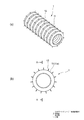
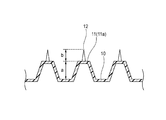
図1及び図2に示すように、コルゲートチューブ1の外周面10(円筒面。図2参照)には、径方向外側に向けて突出する円環状の複数の突条部11が、軸方向に沿って所定の間隔(ピッチ)を空けて並ぶように設けられている。この結果、軸方向に隣接する突条部11の間には、径方向内側に窪む円環状の凹部が存在している。本例では、突条部11は、外周面10から径方向外側に向かうにつれて軸方向寸法(図2において横寸法)が小さくなり、且つ、頂面11a(図1(b)及び図2参照)が軸方向に短い円筒面となる形状を有している。
As shown in FIGS. 1 and 2, a plurality of
各突条部11の頂面11aには、径方向外側に向けて突出する複数の凸部12が、互いに独立して周方向に等間隔で並ぶように、突条部11と一体に設けられている。本例では、各凸部12は、先細りの(径方向外側に向かうにつれて径方向に垂直な断面の面積が増大する)円錐形状を有している。凸部12は、先細りの多角錐形状(典型的には、三角錐形状、四角錐形状等)であってもよい。各凸部12は、突条部11に比べて小さな外力によって屈曲可能となっている。
On the
本例では、複数の突条部11の全てについて、複数の凸部12が設けられている周方向の位置が一致している。複数の凸部12が周方向の第1位置に設けられた突条部11と、複数の凸部12が周方向の第1位置と異なる第2位置に設けられた突条部11とが、軸方向において交互に位置していてもよい。
In this example, the positions of the plurality of
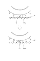
本実施形態に係るコルゲートチューブ1によれば、コルゲートチューブ1の外周面10の複数の突条部11から突出するように、突条部11よりも柔軟な凸部12が設けられている。よって、図3に示すように、周辺部材20とコルゲートチューブ1が接近したとき、コルゲートチューブ1の突条部11の頂面11aよりも先に柔軟な凸部12が周辺部材20に接触して変形する。この柔軟な凸部12の変形により、接触に伴う衝撃などを凸部12が吸収し得る。よって、このような凸部12が設けられない場合に比べ、異音の発生が抑制される。更に、凸部12はコルゲートチューブ1の周方向に沿うように突条部11に設けられているため、コルゲートチューブ1の湾曲を凸部12が妨げることもない。よって、コルゲートチューブ1としての機能が損なわれることもない。したがって、本実施形態に係るコルゲートチューブ1は、コルゲートチューブ1としての機能を損なうことなく周辺部材20との接触による異音の発生を抑制可能である。
According to the
更に、突条部11の頂面11a上に周方向に並ぶように複数の互いに独立した凸部12が配置されている。これにより、周辺部材20がコルゲートチューブ1に対して様々な向きから近づいた場合であっても、凸部12によって効率良く周辺部材20との接触による衝撃などを吸収できる。
Further, a plurality of independent
また、発明者が行った実験および考察によれば、コルゲートチューブ1の軸方向に直交する断面において、凸部12の突条部11の頂面11aからの径方向における突出高さb(図2参照)が、突条部11の外周面10からの径方向における突出高さa(図2参照)の60%〜120%である場合、上述した異音の発生を抑制する効果を高めながら、コルゲートチューブ1そのものの生産性を向上できる(即ち、突条部11上に凸部12を設ける困難度を低くできる)ことが明らかになっている。
Further, according to experiments and discussions conducted by the inventor, in a cross section orthogonal to the axial direction of the
<他の形態>
なお、本発明は上記各実施形態に限定されることはなく、本発明の範囲内において種々の変形例を採用することができる。例えば、本発明は、上述した実施形態に限定されるものではなく、適宜、変形、改良、等が可能である。その他、上述した実施形態における各構成要素の材質、形状、寸法、数、配置箇所、等は本発明を達成できるものであれば任意であり、限定されない。
<Other forms>
The present invention is not limited to each of the above embodiments, and various modifications can be adopted within the scope of the present invention. For example, the present invention is not limited to the above-described embodiment, and can be appropriately modified, improved, and the like. In addition, the material, shape, size, number, arrangement location, etc. of each component in the above-described embodiment are arbitrary and are not limited as long as the present invention can be achieved.
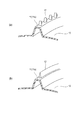
上記実施形態では、突条部11の頂面11aに設けられる凸部12が円錐形状を有している。これに対し、図4(a)に示すように、突条部11の頂面11aに設けられる凸部12が、周方向からみて四角形状且つ軸方向からみて先細りの三角形状を有する立体形状を有していてもよい。
In the above embodiment, the
また、図4(b)に示すように、単一の連続した凸部12が、突条部11の頂面11a上にて周方向の全周に亘って環状に延びるように(円環状の突条であるように)構成されていてもよい。図4(b)に示す例では、凸部12における周方向に垂直な断面の形状が、先細りの三角形状を有している。これにより、凸部12そのものの強度が高まるため、例えば周辺部材20が勢いよくコルゲートチューブ1に近づいた場合であっても、凸部12によって効率良く周辺部材20との接触による衝撃などを吸収できる。
Further, as shown in FIG. 4B, a single continuous
更に、上記実施形態では、複数の突条部11の全てにおいて凸部12が設けられている。これに対し、例えば、凸部12が設けられた突条部11と、凸部12が設けられない突条部11とが、軸方向において交互に位置していてもよい。また、上記実施形態では、1つの突条部11に複数の凸部12が設けられているが、1つの突条部11に1つの凸部12が設けられていてもよい。この場合、軸方向に隣接する突条部11について、凸部12が設けられる周方向の位置が異なることが好適である。
Further, in the above embodiment, the
更に、上述した凸部12を用いた異音抑制は、コルゲートチューブ以外の電線保護具に適用されてもよい。
Further, the above-mentioned abnormal noise suppression using the
ここで、上述した本発明に係るコルゲートチューブ1の実施形態の特徴をそれぞれ以下[1]〜[4]に簡潔に纏めて列記する。
[1]
電線を挿通可能な中空部を有する筒状の電線保護具(1)であって、
当該電線保護具(1)の外周面(10)から当該電線保護具(1)の径方向外側に向けて突出し且つ周方向に延びるとともに、当該電線保護具(1)の軸方向に沿って並ぶように配列された、複数の突条部(11)と、
前記複数の前記突条部(11)のうちの少なくとも一つから前記径方向外側に向けて突出し且つ前記周方向に沿うように配置された、一又は複数の凸部(12)と、を備え、
前記凸部(12)は、前記突条部(11)に比べて小さな外力によって屈曲可能である、
電線保護具(1)。
[2]
上記[1]に記載の電線保護具(1)において、
前記軸方向に直交する断面において、前記凸部(12)の前記突条部(11)からの前記径方向における突出高さ(b)が、前記突条部(11)の前記外周面(10)からの前記径方向における突出高さ(a)の60%〜120%である、
電線保護具(1)。
[3]
上記[1]又は上記[2]に記載の電線保護具(1)において、
複数の互いに独立した前記凸部(12)が前記突条部(11)上に前記周方向に並ぶように構成された、
電線保護具(1)。
[4]
上記[1]又は上記[2]に記載の電線保護具(1)において、
単一の連続した前記凸部(12)が前記突条部(11)上に前記周方向に延びるように構成された、
電線保護具(1)。
Here, the features of the above-described embodiment of the
[1]
A tubular electric wire protector (1) having a hollow portion through which an electric wire can be inserted.
It projects from the outer peripheral surface (10) of the electric wire protector (1) toward the radial outer side of the electric wire protector (1) and extends in the circumferential direction, and is lined up along the axial direction of the electric wire protector (1). Multiple ridges (11) arranged so as
It is provided with one or a plurality of convex portions (12) protruding outward in the radial direction from at least one of the plurality of ridge portions (11) and arranged along the circumferential direction. ,
The convex portion (12) can be bent by a smaller external force than the ridge portion (11).
Wire protector (1).
[2]
In the electric wire protector (1) described in the above [1],
In the cross section orthogonal to the axial direction, the protrusion height (b) of the convex portion (12) from the ridge portion (11) in the radial direction is the outer peripheral surface (10) of the ridge portion (11). ) Is 60% to 120% of the protrusion height (a) in the radial direction.
Wire protector (1).
[3]
In the electric wire protector (1) according to the above [1] or the above [2],
A plurality of independent convex portions (12) are arranged on the ridge portion (11) in the circumferential direction.
Wire protector (1).
[4]
In the electric wire protector (1) according to the above [1] or the above [2],
A single continuous convex portion (12) is configured to extend in the circumferential direction on the ridge portion (11).
Wire protector (1).
1 コルゲートチューブ(電線保護具)
10 外周面
11 突条部
12 凸部
1 Corrugated tube (electric wire protector)
10
Claims (4)
当該電線保護具の外周面から当該電線保護具の径方向外側に向けて突出し且つ周方向に延びるとともに、当該電線保護具の軸方向に沿って並ぶように配列された、複数の突条部と、
前記複数の前記突条部のうちの少なくとも一つから前記径方向外側に向けて突出し且つ前記周方向に沿うように配置された、一又は複数の凸部と、を備え、
前記凸部は、前記突条部に比べて小さな外力によって屈曲可能である、
電線保護具。 A tubular electric wire protector having a hollow portion through which an electric wire can be inserted.
A plurality of ridges arranged so as to protrude outward in the radial direction of the electric wire protector and extend in the circumferential direction from the outer peripheral surface of the electric wire protector and are arranged along the axial direction of the electric wire protector. ,
A plurality of convex portions, which are arranged so as to project outward in the radial direction from at least one of the plurality of ridge portions and are arranged along the circumferential direction.
The convex portion can be bent by a smaller external force than the ridge portion.
Wire protector.
前記軸方向に直交する断面において、前記凸部の前記突条部からの前記径方向における突出高さが、前記突条部の前記外周面からの前記径方向における突出高さの60%〜120%である、
電線保護具。 In the electric wire protector according to claim 1,
In the cross section orthogonal to the axial direction, the protrusion height of the convex portion from the ridge portion in the radial direction is 60% to 120% of the protrusion height of the ridge portion from the outer peripheral surface in the radial direction. %,
Wire protector.
複数の互いに独立した前記凸部が前記突条部上に前記周方向に並ぶように構成された、
電線保護具。 In the electric wire protector according to claim 1 or 2.
A plurality of independent convex portions are arranged on the ridge portion in the circumferential direction.
Wire protector.
単一の連続した前記凸部が前記突条部上に前記周方向に延びるように構成された、
電線保護具。 In the electric wire protector according to claim 1 or 2.
A single continuous convex portion was configured to extend on the ridge portion in the circumferential direction.
Wire protector.
Priority Applications (1)
| Application Number | Priority Date | Filing Date | Title |
|---|---|---|---|
| JP2019088992A JP2020184861A (en) | 2019-05-09 | 2019-05-09 | Electric wire protector |
Applications Claiming Priority (1)
| Application Number | Priority Date | Filing Date | Title |
|---|---|---|---|
| JP2019088992A JP2020184861A (en) | 2019-05-09 | 2019-05-09 | Electric wire protector |
Publications (1)
| Publication Number | Publication Date |
|---|---|
| JP2020184861A true JP2020184861A (en) | 2020-11-12 |
Family
ID=73044759
Family Applications (1)
| Application Number | Title | Priority Date | Filing Date |
|---|---|---|---|
| JP2019088992A Abandoned JP2020184861A (en) | 2019-05-09 | 2019-05-09 | Electric wire protector |
Country Status (1)
| Country | Link |
|---|---|
| JP (1) | JP2020184861A (en) |
Cited By (2)
| Publication number | Priority date | Publication date | Assignee | Title |
|---|---|---|---|---|
| JP2022140884A (en) * | 2021-03-15 | 2022-09-29 | 古河電気工業株式会社 | wire protector |
| JP7630312B2 (en) | 2021-03-15 | 2025-02-17 | 古河電気工業株式会社 | Wire protection equipment |
Citations (3)
| Publication number | Priority date | Publication date | Assignee | Title |
|---|---|---|---|---|
| JPH0548521U (en) * | 1991-11-26 | 1993-06-25 | 矢崎総業株式会社 | Corrugated tube |
| JP2000350332A (en) * | 1999-06-04 | 2000-12-15 | Sumitomo Wiring Syst Ltd | Noise reduction structure of resin molding mounted on vehicle |
| JP2017011786A (en) * | 2015-06-17 | 2017-01-12 | 住友電装株式会社 | Corrugated tube and wiring harness with corrugated tube |
-
2019
- 2019-05-09 JP JP2019088992A patent/JP2020184861A/en not_active Abandoned
Patent Citations (3)
| Publication number | Priority date | Publication date | Assignee | Title |
|---|---|---|---|---|
| JPH0548521U (en) * | 1991-11-26 | 1993-06-25 | 矢崎総業株式会社 | Corrugated tube |
| JP2000350332A (en) * | 1999-06-04 | 2000-12-15 | Sumitomo Wiring Syst Ltd | Noise reduction structure of resin molding mounted on vehicle |
| JP2017011786A (en) * | 2015-06-17 | 2017-01-12 | 住友電装株式会社 | Corrugated tube and wiring harness with corrugated tube |
Cited By (3)
| Publication number | Priority date | Publication date | Assignee | Title |
|---|---|---|---|---|
| JP2022140884A (en) * | 2021-03-15 | 2022-09-29 | 古河電気工業株式会社 | wire protector |
| JP7593838B2 (en) | 2021-03-15 | 2024-12-03 | 古河電気工業株式会社 | Wire protection equipment |
| JP7630312B2 (en) | 2021-03-15 | 2025-02-17 | 古河電気工業株式会社 | Wire protection equipment |
Similar Documents
| Publication | Publication Date | Title |
|---|---|---|
| EP2360063B1 (en) | Grommet for wire harness and wire harness provided therewith | |
| JP5891961B2 (en) | Grommet and wire harness with grommet | |
| JP6132216B2 (en) | Wire Harness | |
| JP6200454B2 (en) | Wire Harness | |
| JP5804744B2 (en) | Wire harness protection tube and wire harness protection member | |
| JP2013046505A (en) | Clamp with belt and wire harness | |
| CN114162059B (en) | Protective cover | |
| JP2020184861A (en) | Electric wire protector | |
| WO2016013429A1 (en) | Grommet | |
| JP6926044B2 (en) | Corrugated tube and wire harness | |
| JPH0969320A (en) | Grommet | |
| JP5781848B2 (en) | WIRE HARNESS PROTECTION STRUCTURE AND TUBE MANUFACTURING METHOD | |
| JP2018117497A (en) | Waterproof cover and wire harness | |
| JP2009005422A (en) | Corrugated tube | |
| JP2018191383A (en) | Sheath material for wire harness, and wire harness using the same | |
| JP2017011786A (en) | Corrugated tube and wiring harness with corrugated tube | |
| JP6153252B2 (en) | Grommet | |
| JP5648592B2 (en) | Corrugated tube with path maintenance member and wire harness | |
| JP2017175801A (en) | Exterior member and wire harness | |
| JP7019272B2 (en) | Corrugated tube and wire harness | |
| JP2019009839A (en) | Wire harness protection member and manufacturing method thereof | |
| JP7666880B2 (en) | Corrugated tubes and wire harnesses | |
| JP2010124593A (en) | Electric-wire protective material | |
| JP2007185067A (en) | Flexible cable protection tube | |
| JP6066321B2 (en) | Grommet |
Legal Events
| Date | Code | Title | Description |
|---|---|---|---|
| A621 | Written request for application examination |
Free format text: JAPANESE INTERMEDIATE CODE: A621 Effective date: 20220415 |
|
| A977 | Report on retrieval |
Free format text: JAPANESE INTERMEDIATE CODE: A971007 Effective date: 20230131 |
|
| A131 | Notification of reasons for refusal |
Free format text: JAPANESE INTERMEDIATE CODE: A131 Effective date: 20230207 |
|
| A762 | Written abandonment of application |
Free format text: JAPANESE INTERMEDIATE CODE: A762 Effective date: 20230321 |