JP2020184814A - Stepping motor controller and program - Google Patents
Stepping motor controller and program Download PDFInfo
- Publication number
- JP2020184814A JP2020184814A JP2019086581A JP2019086581A JP2020184814A JP 2020184814 A JP2020184814 A JP 2020184814A JP 2019086581 A JP2019086581 A JP 2019086581A JP 2019086581 A JP2019086581 A JP 2019086581A JP 2020184814 A JP2020184814 A JP 2020184814A
- Authority
- JP
- Japan
- Prior art keywords
- stepping motor
- amplitude
- current
- signal
- current command
- Prior art date
- Legal status (The legal status is an assumption and is not a legal conclusion. Google has not performed a legal analysis and makes no representation as to the accuracy of the status listed.)
- Granted
Links
Images
Landscapes
- Control Of Stepping Motors (AREA)
Abstract
【課題】ステッピングモータ制御装置において、外乱の影響抑制と演算量を軽減する技術を提供する。【解決手段】マイクロステップ駆動するステッピングモータを制御するステッピングモータ制御装置1で、インバータ112と、ステッピングモータ9の電流を制御するための電流制御器111と、検出部と、位相変化がステッピングモータの回転角の時間変化に同一な正弦波を基本波とし、第1条件を満たすように基本波と基本波の高調波とが合成された合成波を第1合成波として、位相変化が前記第1合成波の位相変化に同一な信号であって振幅が前記ステッピングモータの回転速度に応じた第1振幅に調整された信号を生成する角度指令補正部105を備え、ステッピングモータの電流の位相の時間変化は角度補正信号の時間変化と同一であるステッピングモータ制御装置。【選択図】図1A technology for suppressing the influence of disturbance and reducing the amount of calculation in a stepping motor control device is provided. A stepping motor controller 1 for controlling a stepping motor driven by microsteps includes an inverter 112, a current controller 111 for controlling the current of the stepping motor 9, a detector, and a phase change of the stepping motor. A sine wave having the same sine wave as the time change of the rotation angle is used as a fundamental wave. An angle command correction unit 105 is provided for generating a signal that is the same as the phase change of the composite wave and whose amplitude is adjusted to a first amplitude corresponding to the rotation speed of the stepping motor, and the phase time of the current of the stepping motor. A stepper motor controller in which the change is identical to the time change of the angle correction signal. [Selection drawing] Fig. 1
Description
本発明は、ステッピングモータ制御装置及びプログラムに関する。 The present invention relates to a stepping motor control device and a program.
これまで、マイクロステップ駆動するステッピングモータの振動を抑制する技術が提案されている(特許文献1を参照)。従来の技術においては、ステッピングモータに発生するコギングトルク、トルクリップ等の外乱を除去する。従来の技術においては、例えば、ステッピングモータの振動が測定され、測定された振動に対する周波数解析が行われ、周波数解析の結果に基づいて外乱と逆位相の信号がq軸電流に印加される。 So far, a technique for suppressing vibration of a stepping motor driven by a microstep has been proposed (see Patent Document 1). In the conventional technique, disturbances such as cogging torque and torque clip generated in the stepping motor are removed. In the conventional technique, for example, the vibration of the stepping motor is measured, frequency analysis is performed on the measured vibration, and a signal having a phase opposite to the disturbance is applied to the q-axis current based on the result of the frequency analysis.
しかしながら、このように従来の技術においては、ステッピングモータの振動を周波数解析する必要があるため、ステッピングモータの制御に要する演算量の多さが問題であった。 However, in the conventional technique as described above, since it is necessary to analyze the frequency of the vibration of the stepping motor, there is a problem that a large amount of calculation is required to control the stepping motor.
上記事情に鑑み、本発明は、外乱の影響を抑制しつつマイクロステップ駆動するステッピングモータの動作の制御における演算量を軽減する技術を提供することを目的としている。 In view of the above circumstances, it is an object of the present invention to provide a technique for reducing the amount of calculation in controlling the operation of a stepping motor driven by a microstep while suppressing the influence of disturbance.
本発明の一態様は、マイクロステップ駆動するステッピングモータを制御するステッピングモータ制御装置であって、前記ステッピングモータを駆動するインバータと、前記ステッピングモータの電流を制御するための電流制御器と、前記ステッピングモータの回転を検出する検出部と、位相変化が前記ステッピングモータの回転角の時間変化に同一な正弦波を基本波とし、振幅及び位相に関する第1条件を満たすように前記基本波と前記基本波の高調波とが合成された合成波を第1合成波として、位相変化が前記第1合成波の位相変化に同一な信号であって振幅が前記ステッピングモータの回転速度に応じた第1振幅に調整された信号である角度補正信号を生成する角度指令補正部と、を備え、前記ステッピングモータの電流の位相の時間変化は前記角度補正信号の時間変化に同一である、ステッピングモータ制御装置である。 One aspect of the present invention is a stepping motor control device that controls a stepping motor driven by microsteps, the inverter driving the stepping motor, a current controller for controlling the current of the stepping motor, and the stepping. A detection unit that detects the rotation of the motor and a sinusoidal wave whose phase change is the same as the time change of the rotation angle of the stepping motor are used as fundamental waves, and the fundamental wave and the fundamental wave so as to satisfy the first conditions regarding amplitude and phase. The composite wave in which the harmonics of the above are combined is used as the first composite wave, and the phase change is the same signal as the phase change of the first composite wave, and the amplitude becomes the first amplitude according to the rotation speed of the stepping motor. It is a stepping motor control device including an angle command correction unit that generates an angle correction signal which is an adjusted signal, and the time change of the phase of the current of the stepping motor is the same as the time change of the angle correction signal. ..
本発明の一態様は、上記のステッピングモータ制御装置であって、位相変化が前記ステッピングモータの回転角の時間変化に同一な正弦波を基本波とし、振幅及び位相に関する第2条件を満たすように前記基本波と前記基本波の高調波とが合成された合成波を第2合成波として、位相変化が前記第2合成波の位相変化に同一な信号であって振幅が前記ステッピングモータの回転速度に応じた第2振幅に調整された信号である振幅補正信号を生成する電流指令補正部、をさらに備え、前記ステッピングモータの電流の振幅の時間変化は前記振幅補正信号の時間変化に同一である。 One aspect of the present invention is the stepping motor control device described above, wherein a sinusoidal wave whose phase change is the same as the time change of the rotation angle of the stepping motor is used as a fundamental wave, and the second condition regarding amplitude and phase is satisfied. The composite wave in which the fundamental wave and the harmonics of the fundamental wave are combined is used as the second composite wave, the phase change is the same signal as the phase change of the second composite wave, and the amplitude is the rotation speed of the stepping motor. A current command correction unit that generates an amplitude correction signal, which is a signal adjusted to a second amplitude according to the above, is further provided, and the time change of the current amplitude of the stepping motor is the same as the time change of the amplitude correction signal. ..
本発明の一態様は、上記のステッピングモータ制御装置であって、前記ステッピングモータの回転速度に比例する値を電流指令として、前記第1振幅を前記電流指令で割り算した値は、前記電流指令が所定の値未満である場合に、前記電流指令が小さいほど大きな値である。 One aspect of the present invention is the stepping motor control device, wherein the value proportional to the rotation speed of the stepping motor is a current command, and the value obtained by dividing the first amplitude by the current command is the current command. When the value is less than a predetermined value, the smaller the current command, the larger the value.
本発明の一態様は、上記のステッピングモータ制御装置であって、マイクロステップ駆動するステッピングモータを制御するステッピングモータ制御装置であって、前記ステッピングモータを駆動するインバータと、前記ステッピングモータの電流を制御するための電流制御器と、前記ステッピングモータの回転を検出する検出部と、位相変化が前記ステッピングモータの回転角の時間変化に同一な正弦波を基本波とし、振幅及び位相に関する第2条件を満たすように前記基本波と前記基本波の高調波とが合成された合成波を第2合成波として、位相変化が前記第2合成波の位相変化に同一な信号であって振幅が前記ステッピングモータの回転速度に応じた第2振幅に調整された信号である振幅補正信号を生成する電流指令補正部と、を備え、前記ステッピングモータの電流の振幅の時間変化は、前記振幅補正信号の時間変化に同一である。 One aspect of the present invention is the stepping motor control device, which is a stepping motor control device that controls a stepping motor that drives a microstep, and controls an inverter that drives the stepping motor and a current of the stepping motor. A second condition regarding amplitude and phase is set as a fundamental wave of a current controller for performing the above, a detection unit for detecting the rotation of the stepping motor, and a sinusoidal wave whose phase change is the same as the time change of the rotation angle of the stepping motor. The composite wave in which the fundamental wave and the harmonics of the fundamental wave are combined so as to satisfy is used as the second composite wave, the phase change is the same signal as the phase change of the second composite wave, and the amplitude is the stepping motor. A current command correction unit that generates an amplitude correction signal which is a signal adjusted to a second amplitude according to the rotation speed of the stepping motor is provided, and a time change of the current amplitude of the stepping motor is a time change of the amplitude correction signal. Is the same as.
本発明の一態様は、上記のステッピングモータ制御装置であって、前記ステッピングモータの回転速度に比例する値を電流指令として、前記第2振幅を前記電流指令で割り算した値は、前記電流指令が所定の値以上である場合に、前記電流指令が大きいほど大きい値である。 One aspect of the present invention is the stepping motor control device, wherein the value proportional to the rotation speed of the stepping motor is a current command, and the value obtained by dividing the second amplitude by the current command is the current command. When it is equal to or more than a predetermined value, the larger the current command is, the larger the value is.
本発明の一態様は、上記のステッピングモータ制御装置であって、前記高調波の次数は、2次及び4次である。 One aspect of the present invention is the stepping motor control device described above, wherein the order of the harmonics is secondary and quaternary.
本発明の一態様は、上記のステッピングモータ制御装置としてコンピュータを機能させるためのプログラムである。 One aspect of the present invention is a program for operating a computer as the stepping motor control device described above.
本発明により、外乱の影響を抑制しつつステッピングモータを動作させる制御における演算量を軽減することが可能となる。 According to the present invention, it is possible to reduce the amount of calculation in the control for operating the stepping motor while suppressing the influence of disturbance.
以下、実施形態のステッピングモータ制御装置及びプログラムを、図面を参照して説明する。
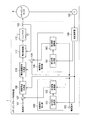
図1は、実施形態のステッピングモータ制御装置1の機能構成の一例を示す図である。
ステッピングモータ制御装置1は、ステッピングモータ9を駆動する。
ステッピングモータ9は、電力の供給を受けて回転することでトルクを発生する2相のステッピングモータである。すなわちステッピングモータ9は、電気エネルギーを運動エネルギーに変換する2相のステッピングモータである。
ステッピングモータ9は、式(1)及び(2)で表される波形(すなわち、角速度ω_<exc>(t)が時間に依存する角速度である正弦波)の電流が駆動電流(ステッピングモータの電流)として印加されることでマイクロステップ駆動する。なお、_<・・・>は、下付き文字を表す。例えば、ω_<exc>は、ωexcを表す。以下、角速度ω_<exc>(t)を励磁角度という。
Hereinafter, the stepping motor control device and the program of the embodiment will be described with reference to the drawings.
FIG. 1 is a diagram showing an example of the functional configuration of the stepping
The stepping
The stepping motor 9 is a two-phase stepping motor that generates torque by rotating in response to the supply of electric power. That is, the stepping motor 9 is a two-phase stepping motor that converts electrical energy into kinetic energy.
In the stepping motor 9, the drive current (current of the stepping motor) is the current of the waveforms represented by the equations (1) and (2) (that is, the sine wave whose angular velocity ω_ <exc> (t) is the angular velocity depending on the time). ) Is applied to drive the microstep. Note that _ <...> represents a subscript. For example, ω_ <exc> represents ω exc . Hereinafter, the angular velocity ω_ <exc> (t) is referred to as an excitation angle.
式(1)及び式(2)において、tは時刻を表す。H_<1>(t)は、ステッピングモータ9の一方の相に印加される電流の波形を表す。H_<2>(t)は、ステッピングモータ9の他方の相に印加される電流の波形を表す。以下、波形H_<1>(t)及び波形H_<2>(t)をそれぞれ区別しない場合、波形H(t)という。また、以下、波形H(t)の信号を信号H(t)という。式(1)及び式(2)において、Iは、電流指令である。電流指令Iは、電流の振幅の次元の値であって、ステッピングモータ9の回転速度に応じた値である。例えば、電流指令Iは、ステッピングモータ9の回転速度が大きいほど大きな値である。例えば、電流指令Iは、ステッピングモータ9の回転速度の上昇に比例して増加する値である。以下、説明の簡単のため、電流指令は、ステッピングモータ9の回転速度の上昇に比例して増加する値であると仮定する。式(1)及び式(2)において、gは、励磁角度ω_<exc>(t)とIとの関数である。 In equations (1) and (2), t represents the time. H_ <1> (t) represents the waveform of the current applied to one phase of the stepping motor 9. H_ <2> (t) represents the waveform of the current applied to the other phase of the stepping motor 9. Hereinafter, when the waveform H_ <1> (t) and the waveform H_ <2> (t) are not distinguished, they are referred to as the waveform H (t). Hereinafter, the signal having the waveform H (t) is referred to as the signal H (t). In equations (1) and (2), I is a current command. The current command I is a value in the dimension of the amplitude of the current, and is a value corresponding to the rotation speed of the stepping motor 9. For example, the current command I has a larger value as the rotation speed of the stepping motor 9 increases. For example, the current command I is a value that increases in proportion to an increase in the rotation speed of the stepping motor 9. Hereinafter, for the sake of simplicity, it is assumed that the current command is a value that increases in proportion to an increase in the rotation speed of the stepping motor 9. In equations (1) and (2), g is a function of the excitation angle ω_ <exc> (t) and I.
ステッピングモータ制御装置1は、角度指令取得端子101、電流指令取得端子102、エンコーダ103、角度演算器104、角度指令補正部105、電流指令補正部106、第1加算器107、励磁角度生成器108、第2加算器109、電流振幅指令生成器110、電流制御器111、インバータ112及びシャント抵抗113を備える。
角度指令取得端子101は、角度指令ω_<ref>・tを示すパルス列の信号を取得する。角度指令ω_<ref>・tは、ステッピングモータ9を回転させる角度を示す。ω_<ref>は角速度の次元の値である。電流指令取得端子102は、電流指令Iを取得する。
The stepping
The angle
エンコーダ103は、ステッピングモータ9の回転を検出する。具体的には、ステッピングモータ9は回転に応じた波形の信号を取得する。エンコーダ103は、取得した信号を角度演算器104に出力する。角度演算器104は、エンコーダ103が出力する信号に基づいて、ステッピングモータ9の回転角ω_<enc>・t(以下「エンコーダ角」という。)を取得する。ω_<enc>は角速度の次元の値である。以下、ω_<enc>をエンコーダ角速度という。角度演算器104は、取得したエンコーダ角を角度指令補正部105、電流指令補正部106及び励磁角度生成器108に出力する。
The
角度指令補正部105は、エンコーダ角と電流指令とを取得する。角度指令補正部105は、第1信号生成部151と第1振幅調整器152とを備える。第1信号生成部151は、エンコーダ角に基づいて、振幅及び位相に関する第1条件を満たす信号f_<0>を生成する。信号f_<0>は、具体的には、以下の式(3)で表される。以下、信号f_<0>を第1信号という。
The angle
式(3)において、A1、A2及びA3は、振幅の次元の値を表す。A1、A2及びA3は、予め定められた所定の値である。式(3)において、φ1、φ2及びφ3は、予め定められた所定の初期位相を表す。φ1及びφ3は、例えば、同位相であって、φ2は、φ1よりも例えば、π/4だけ進んだ位相である。式(3)におけるA1、A2、A3、φ1、φ2及びφ3は、信号f_<0>が満たすべき第1条件の一例である。具体的には、第1条件は、基本波の振幅がA1であって、第2高調波の振幅がA2であって、第4高調波の振幅がA3であって、基本波の初期位相がφ1であって、第2高調波の初期位相がφ2であって、第4高調波の初期位相がφ3という条件である。
式(3)は、第1信号が基本波と第2高調波と第4高調波との合成波であることを表す。式(3)における合成波の基本波は、角速度がエンコーダ角速度の正弦波である。
In formula (3), A1, A2 and A3 represent values in the amplitude dimension. A1, A2 and A3 are predetermined predetermined values. In the formula (3), φ1, φ2 and φ3 represent a predetermined initial phase. φ1 and φ3 are, for example, in-phase, and φ2 is, for example, a phase advanced by π / 4 from φ1. A1, A2, A3, φ1, φ2 and φ3 in the formula (3) are examples of the first condition that the signal f_ <0> should satisfy. Specifically, the first condition is that the amplitude of the fundamental wave is A1, the amplitude of the second harmonic is A2, the amplitude of the fourth harmonic is A3, and the initial phase of the fundamental wave is. The condition is that the initial phase of the second harmonic is φ2 and the initial phase of the fourth harmonic is φ3.
Equation (3) represents that the first signal is a composite wave of the fundamental wave, the second harmonic, and the fourth harmonic. The fundamental wave of the composite wave in the equation (3) is a sine wave whose angular velocity is the encoder angular velocity.
第1振幅調整器152は、電流指令に基づいて第1信号の振幅を調整する。第1振幅調整器152による調整の結果出力される信号(以下、「角度補正信号」という。)は、以下の式(4)で表される信号である。
The
式(4)は、第1振幅調整器152が、第1信号の振幅を(d_<1>・I)倍することを示す。d_<1>は、電流指令の大きさに応じた値である。d_<1>は、電流指令の大きさが小さいほど大きな値である。以下、式(4)のd_<1>を第1振幅調整値という。式(4)が表すように、角度補正信号は、振幅が電流指令の大きさに応じた振幅に調整された信号であって、位相変化が第1信号の位相変化に同一な信号である。
Equation (4) indicates that the
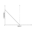
図2は、実施形態における第1振幅調整値d_<1>と電流指令Iとの関係の一例を示す図である。
図2は、電流指令Iと第1振幅調整値d_<1>とが、Iが0以上I_<b>未満の場合には、線形の関係であることを示す。図2は、電流指令IがI_<b>未満の場合には、電流指令Iが小さいほど第1振幅調整値d_<1>が大きな値であることを示す。図2は、IがI_<b>以上では、第1振幅調整値d_<1>が0であることを示す。なお、電流指令Iは、ステッピングモータ9の回転速度の上昇に比例して増加する値であるため、電流指令Iが小さくなることは、ステッピングモータ9の回転速度が遅くなることを意味する。
FIG. 2 is a diagram showing an example of the relationship between the first amplitude adjustment value d_ <1> and the current command I in the embodiment.
FIG. 2 shows that the current command I and the first amplitude adjustment value d_ <1> have a linear relationship when I is 0 or more and less than I_ <b>. FIG. 2 shows that when the current command I is less than I_ <b>, the smaller the current command I is, the larger the first amplitude adjustment value d_ <1> is. FIG. 2 shows that when I is I_ <b> or more, the first amplitude adjustment value d_ <1> is 0. Since the current command I is a value that increases in proportion to the increase in the rotation speed of the stepping motor 9, a smaller current command I means that the rotation speed of the stepping motor 9 is slowed down.
電流指令補正部106は、エンコーダ角と電流指令とを取得する。電流指令補正部106は、第2信号生成部161と第2振幅調整器162とを備える。第2信号生成部161は、エンコーダ角に基づいて、振幅及び位相に関する第2条件を満たす信号g_<0>を生成する。信号g_<0>は、具体的には、以下の式(5)で表される。以下、信号g_<0>を第2信号という。
The current
式(5)において、A4、A5及びA6は、振幅の次元の値を表す。A4、A5及びA6は、予め定められた所定の値である。式(5)において、φ4、φ5及びφ6は、予め定められた所定の初期位相を表す。φ4及びφ6は、例えば、同位相であって、φ5は、φ4よりも例えば、π/4だけ進んだ位相である。式(5)におけるA4、A5、A6、φ4、φ5及びφ6は、信号g_<0>が満たすべき第2条件の一例である。具体的には、第2条件は、基本波の振幅がA4であって、第2高調波の振幅がA5であって、第4高調波の振幅がA6であって、基本波の初期位相がφ4であって、第2高調波の初期位相がφ5であって、第4高調波の初期位相がφ6という条件である。
式(5)は、第2信号が基本波と第2高調波と第4高調波との合成波であることを表す。式(5)における合成波の基本波は、角速度がエンコーダ角速度の正弦波である。
In equation (5), A4, A5 and A6 represent values in the amplitude dimension. A4, A5 and A6 are predetermined predetermined values. In the formula (5), φ4, φ5 and φ6 represent a predetermined initial phase. φ4 and φ6 are, for example, in-phase, and φ5 is, for example, a phase advanced by π / 4 from φ4. A4, A5, A6, φ4, φ5 and φ6 in the formula (5) are examples of the second condition that the signal g_ <0> should satisfy. Specifically, the second condition is that the amplitude of the fundamental wave is A4, the amplitude of the second harmonic is A5, the amplitude of the fourth harmonic is A6, and the initial phase of the fundamental wave is The condition is that the initial phase of the second harmonic is φ5 and the initial phase of the fourth harmonic is φ6.
Equation (5) represents that the second signal is a composite wave of the fundamental wave, the second harmonic, and the fourth harmonic. The fundamental wave of the composite wave in the equation (5) is a sine wave whose angular velocity is the encoder angular velocity.
第2振幅調整器162は、電流指令に基づいて第2信号の振幅を調整する。第2振幅調整器162による調整の結果出力される信号(以下、「振幅補正信号」という。)は、以下の式(6)で表される信号である。
The
式(6)は、第2振幅調整器162が、第2信号の振幅を(d_<2>・I)倍することを示す。d_<2>は、電流指令の大きさに応じた値である。d_<2>は、電流指令の大きさが小さいほど大きな値である。以下、式(4)のd_<2>を第2振幅調整値という。式(6)が表すように、振幅補正信号は、振幅が電流指令の大きさに応じた振幅に調整された信号であって、位相変化が第2信号の位相変化に同一な信号である。
Equation (6) indicates that the
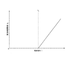
図3は、実施形態における第2振幅調整値d_<2>と電流指令Iとの関係の一例を示す図である。
図3は、電流指令Iと第2振幅調整値d_<2>とが、IがI_<b>以上の場合には、線形の関係であることを示す。図3は、電流指令IがI_<b>以上の場合には、電流指令Iが大きいほど第2振幅調整値d_<2>が大きな値であることを示す。図3は、IがI_<b>未満では、第2振幅調整値d_<2>が0であることを示す。なお、電流指令Iは、ステッピングモータ9の回転速度の上昇に比例して増加する値であるため、電流指令Iが大きくなることは、ステッピングモータ9の回転速度が速くなることを意味する。
FIG. 3 is a diagram showing an example of the relationship between the second amplitude adjustment value d_ <2> and the current command I in the embodiment.
FIG. 3 shows that the current command I and the second amplitude adjustment value d_ <2> have a linear relationship when I is I_ <b> or more. FIG. 3 shows that when the current command I is I_ <b> or more, the larger the current command I is, the larger the second amplitude adjustment value d_ <2> is. FIG. 3 shows that when I is less than I_ <b>, the second amplitude adjustment value d_ <2> is 0. Since the current command I is a value that increases in proportion to the increase in the rotation speed of the stepping motor 9, an increase in the current command I means that the rotation speed of the stepping motor 9 is increased.
第1加算器107は、角度指令ω_<ref>・tを示すパルス列と角度補正信号とを加算する。加算後の信号は、励磁角度ω_<ext>(t)・tを示す。励磁角度ω_<ext>(t)・tは、以下の式(7)で表される。第1加算器107は、加算後の信号を励磁角度生成器108に出力する。
The
励磁角度生成器108は、第1加算器107が出力した励磁角度ω_<ext>(t)・tを示す信号に基づいて、以下の式(8)及び式(9)で表される信号h_<1>(t)及び信号h_<2>(t)を生成する。
The
信号h_<1>(t)は、位相変化が励磁角度の時間変化と同一なsin波である。信号h_<2>(t)は、位相変化が励磁角度の時間変化と同一なcos波である。すなわち、信号h_<1>(t)及びh_<2>(t)は位相変化が励磁角度の時間変化と同一な正弦波である。 The signal h_ <1> (t) is a sine wave whose phase change is the same as the time change of the excitation angle. The signal h_ <2> (t) is a cos wave whose phase change is the same as the time change of the excitation angle. That is, the signals h_ <1> (t) and h_ <2> (t) are sine waves whose phase changes are the same as the time changes of the excitation angle.
第2加算器109は、電流指令Iと振幅補正信号とを加算し、加算後の信号を電流振幅指令生成器110に出力する。電流振幅指令生成器110は、第2加算器109が出力した信号に励磁角度生成器108が生成した信号を乗算することで、上記式(1)及び式(2)で表される信号H(t)を生成する。
The
電流制御器111は、電流振幅指令生成器110が生成した信号を受信する。電流制御器111は、受信した信号と同様の波形の信号(すなわち、信号H(t))をステッピングモータ9に印加するように、インバータ112の動作を制御する。
The
インバータ112は、電流制御器111の制御によって動作し、波形H_<1>(t)の電流と波形H_<2>(t)の電流とをステッピングモータ9に印加する。
インバータ112とステッピングモータ9との間にはシャント抵抗113が位置する。シャント抵抗113に流れる電流を電流制御器111は取得する。電流制御器111は、取得したシャント抵抗113を流れる電流に応じて、波形H(t)の電流がステッピングモータ9に印加されるようにインバータ112の動作を制御する。すなわち、電流制御器111は、シャント抵抗113を流れる電流に基づくフィードバック制御によって、波形H(t)の電流がステッピングモータ9に印加されるようにインバータ112の動作を制御する。
The
A
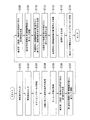
図4は、実施形態におけるステッピングモータ制御装置1が実行する処理の流れの一例を示すフローチャートである。
角度指令取得端子101に、角度指令が入力される(ステップS101)。電流指令取得端子102に、電流指令が入力される(ステップS102)。ステッピングモータ9が回転を開始する(ステップS103)。エンコーダ103が回転中のステッピングモータ9から回転に応じた波形の信号を取得する(ステップS104)。角度演算器104が、ステップS104において取得された信号に基づいてエンコーダ角を取得する(ステップS105)。
FIG. 4 is a flowchart showing an example of the flow of processing executed by the stepping
An angle command is input to the angle command acquisition terminal 101 (step S101). A current command is input to the current command acquisition terminal 102 (step S102). The stepping motor 9 starts rotating (step S103). The
第1信号生成部151が、エンコーダ角に基づいて、第1信号を生成する(ステップS106)。第1振幅調整器152が、第1信号に対して、電流指令に応じた値である第1振幅調整値と電流指令とを乗算する(ステップS107)。第2信号生成部161が、エンコーダ角に基づいて、第2信号を生成する(ステップS108)。第2振幅調整器162が、第2信号に対して、電流指令に応じた値である第2振幅調整値と電流指令とを乗算する(ステップS109)。
The first
第1加算器107が、角度指令ω_<ref>・tを示すパルス列と振幅調整後の第1信号(すなわち、角度補正信号)とを加算し、励磁角度を示す信号を生成する(ステップS110)。ステップS110で生成された励磁角度を示す信号に基づいて、励磁角度生成器108は、信号h_<1>(t)と信号h_<2>(t)とを生成する(ステップS111)。第2加算器109が、電流指令Iと振幅調整後の第2信号(すなわち、振幅補正信号)とを加算する(ステップS112)。電流振幅指令生成器110は、ステップS112の加算の結果の信号と信号h_<1>(t)及び信号h_<2>(t)とを積算することで、信号H(t)を生成する(ステップS113)。電流制御器111は、インバータ112の動作をフィードバック制御によって制御することで、ステッピングモータ9に、波形H(t)の電流を印加する(ステップS114)。
The
なお、ステップS106及びステップS107の処理が実行されるタイミングは、ステップS105の処理の後であってステップS110の処理の前であればよく、必ずしも、ステップS105の次に実行される必要は無い。なお、ステップS108及びステップS109の処理が実行されるタイミングは、ステップS105の処理の後であってステップS112の処理の前であればよく、必ずしも、ステップS107の次に実行される必要は無い。 The timing at which the processes of steps S106 and S107 are executed may be after the process of step S105 and before the process of step S110, and may not necessarily be executed after the process of step S105. The timing at which the processes of steps S108 and S109 are executed may be after the process of step S105 and before the process of step S112, and may not necessarily be executed after the process of step S107.
(実験結果)
図5は、実施形態のステッピングモータ制御装置1によって外乱の影響が抑制されることを示す実験結果の一例を示す図である。
図5(A)は、従来のステッピングモータにおける振動レベルと回転速度との関係を示す図である。図5(A)において、横軸は回転速度を表す。図5(A)において縦軸は振動レベルを表す。
図5(B)は、ステッピングモータ制御装置1の制御によって動作するステッピングモータ9の振動レベルと回転速度との関係を示す図である。図5(B)において、横軸は回転速度を表す。図5(B)において縦軸は振動レベルを表す。
(Experimental result)
FIG. 5 is a diagram showing an example of experimental results showing that the influence of disturbance is suppressed by the stepping
FIG. 5A is a diagram showing the relationship between the vibration level and the rotation speed in the conventional stepping motor. In FIG. 5A, the horizontal axis represents the rotation speed. In FIG. 5A, the vertical axis represents the vibration level.
FIG. 5B is a diagram showing the relationship between the vibration level and the rotation speed of the stepping motor 9 operated by the control of the stepping
図5(A)は、基本波の振動レベルが略(−35)〜略(−26)であることを示す。図5(A)は、第2高調波の振動レベルが略(−50)〜略(−5)であることを示す。図5(A)は、第4高調波の振動レベルが略(−50)〜略(−5)であることを示す。
図5(B)は、基本波の振動レベルが略(−50)〜略(−30)であることを示す。図5(B)は、第2高調波の振動レベルが略(−50)〜略(−25)であることを示す。図5(B)は、第4高調波の振動レベルが略(−50)〜略(−20)であることを示す。
FIG. 5A shows that the vibration levels of the fundamental waves are approximately (-35) to approximately (-26). FIG. 5A shows that the vibration level of the second harmonic is approximately (-50) to approximately (-5). FIG. 5A shows that the vibration level of the 4th harmonic is approximately (-50) to approximately (-5).
FIG. 5B shows that the vibration levels of the fundamental waves are approximately (-50) to approximately (-30). FIG. 5B shows that the vibration level of the second harmonic is approximately (-50) to approximately (-25). FIG. 5B shows that the vibration level of the 4th harmonic is approximately (-50) to approximately (-20).
このように、図5(A)が示す振動レベルは、図5(B)が示す振動レベルよりも低い。そのため、図5の実験結果は、実施形態のステッピングモータ制御装置1によって外乱の影響が抑制されたことを示す。
As described above, the vibration level shown in FIG. 5 (A) is lower than the vibration level shown in FIG. 5 (B). Therefore, the experimental result of FIG. 5 shows that the influence of the disturbance was suppressed by the stepping
従来は、ステップS104又はステップS105の次に周波数解析が必要であった。しかしながら、このように構成された実施形態におけるステッピングモータ制御装置1は、角度指令と電流指令とエンコーダ角度とに応じ、式(1)及び式(2)で表される波形の電流をステッピングモータ9に印加する。式(1)及び式(2)で表される波形の電流をステッピングモータ9に印加することで、コギングトルク及びトルクリップルの発生が抑制される。そのため、このように構成された実施形態におけるステッピングモータ制御装置1は周波数解析する必要が無いため、振動を抑制しつつステッピングモータ9を動作させる制御に要する演算量を軽減することができる。
Conventionally, frequency analysis has been required after step S104 or step S105. However, the stepping
このように構成された実施形態におけるステッピングモータ制御装置1は、角度指令と電流指令とエンコーダ角度とに応じ、波形H(t)の電流によってステッピングモータ9を駆動する。波形H(t)は、基本波と第2高調波と第4高調波とが合成された合成波の波形に基づいた波形である。基本波は、位相の時間変化がエンコーダ角の時間変化に同一である正弦波である。ステッピングモータ制御装置1は、電流指令に応じた振幅調整値d_<1>及びd_<2>のによって振幅が調整された波形H(t)の電流をステッピングモータ9に印加する。そのため、ステッピングモータ制御装置1は、ステッピングモータ9の回転の速度によらず、コギングトルク及びトルクリップルの発生を抑制することができる。
The stepping
(変形例)
なお、ステッピングモータ9は必ずしも2相でなくてもよい。ステッピングモータ9は、2相以上の複数相であってもよい。
なお、励磁角度は、次数が4以上の偶数次の高調波に基づいてもよい。すなわち、式(3)及び式(5)において、合成波は、基本波と第2高調波と第4高調波とにくわえて、さらに、Q×ωenc(Qは6以上の偶数)を角速度とする正弦波の和であってもよい。
なお、励磁角度は、基本波と第2高調波と第4高調波とに代えて、基本波と、第3高調波と、次数が3の倍数の高調波とに基づいてもよい。次数が3の倍数の高調波は、例えば、第6高調波である。
(Modification example)
The stepping motor 9 does not necessarily have to be two-phase. The stepping motor 9 may have a plurality of phases of two or more phases.
The excitation angle may be based on even-numbered harmonics having a degree of 4 or more. That is, in the equations (3) and (5), the composite wave includes the fundamental wave, the second harmonic, and the fourth harmonic, and further, Q × ω enc (Q is an even number of 6 or more) has an angular velocity. It may be the sum of the sine waves.
The excitation angle may be based on the fundamental wave, the third harmonic, and the harmonic whose order is a multiple of 3, instead of the fundamental wave, the second harmonic, and the fourth harmonic. The harmonic of which the order is a multiple of 3 is, for example, the 6th harmonic.
なお、電流指令は、所定の値であってもよいし、角度演算器104が取得したエンコーダ角に応じて生成された値であってもよい。
The current command may be a predetermined value or a value generated according to the encoder angle acquired by the
なお、ステッピングモータ制御装置1は、ステッピングモータ9に流れる電流を検出可能なものを備えていれば必ずしもシャント抵抗113を備えなくてもよい。
The stepping
なお、上述した実施形態のステッピングモータ制御装置1の一部をコンピュータで実現するようにしてもよい。ステッピングモータ制御装置1の一部とは、例えば、角度演算器104、角度指令補正部105及び電流指令補正部106である。その場合、この機能を実現するためのプログラムをコンピュータ読み取り可能な記録媒体に記録して、この記録媒体に記録されたプログラムをコンピュータシステムに読み込ませ、実行することによって実現してもよい。なお、ここでいう「コンピュータシステム」とは、OSや周辺機器等のハードウェアを含むものとする。また、「コンピュータ読み取り可能な記録媒体」とは、フレキシブルディスク、光磁気ディスク、ROM、CD−ROM等の可搬媒体、コンピュータシステムに内蔵されるハードディスク等の記憶装置のことをいう。さらに「コンピュータ読み取り可能な記録媒体」とは、インターネット等のネットワークや電話回線等の通信回線を介してプログラムを送信する場合の通信線のように、短時間の間、動的にプログラムを保持するもの、その場合のサーバやクライアントとなるコンピュータシステム内部の揮発性メモリのように、一定時間プログラムを保持しているものも含んでもよい。また上記プログラムは、前述した機能の一部を実現するためのものであってもよく、さらに前述した機能をコンピュータシステムにすでに記録されているプログラムとの組み合わせで実現できるものであってもよく、FPGA(Field Programmable Gate Array)等のプログラマブルロジックデバイスを用いて実現されるものであってもよい。
A part of the stepping
なお、角度指令取得端子101は、指令角度取得部の一例である。なお、電流指令取得端子102は、電流指令取得部の一例である。なお、式(4)における(d_<1>・I)は、第1振幅の一例である。なお、d_<1>は、第1振幅を電流指令で割り算した値の一例である。なお、式(6)における(d_<2>・I)は、第2振幅の一例である。なお、d_<2>は、第2振幅を電流指令で割り算した値の一例である。なお、第1合成波は第1信号の一例である。なお、第2合成波は、第2信号の一例である。なお、エンコーダ103は検出部の一例である。なお、エンコーダ103は、ステッピングモータ9の回転を検出可能であれば、必ずしもエンコーダでなくてもよい。
The angle
以上、この発明の実施形態について図面を参照して詳述してきたが、具体的な構成はこの実施形態に限られるものではなく、この発明の要旨を逸脱しない範囲の設計等も含まれる。 Although the embodiments of the present invention have been described in detail with reference to the drawings, the specific configuration is not limited to this embodiment, and includes designs and the like within a range that does not deviate from the gist of the present invention.
1…ステッピングモータ制御装置、 101…角度指令取得端子、 102…電流指令取得端子、 103…エンコーダ、 104…角度演算器、 105…角度指令補正部、 106…電流指令補正部、 107…第1加算器、 108…励磁角度生成器、 109…第2加算器、 110…電流振幅指令生成器、 111…電流制御器、 112…インバータ、 113…シャント抵抗 1 ... Stepping motor control device, 101 ... Angle command acquisition terminal, 102 ... Current command acquisition terminal, 103 ... Encoder, 104 ... Angle calculator, 105 ... Angle command correction unit, 106 ... Current command correction unit, 107 ... First addition Instrument, 108 ... Excitation angle generator, 109 ... Second adder, 110 ... Current amplitude command generator, 111 ... Current controller, 112 ... Inverter, 113 ... Shunt resistance
Claims (7)
前記ステッピングモータを駆動するインバータと、
前記ステッピングモータの電流を制御するための電流制御器と、
前記ステッピングモータの回転を検出する検出部と、
位相変化が前記ステッピングモータの回転角の時間変化に同一な正弦波を基本波とし、振幅及び位相に関する第1条件を満たすように前記基本波と前記基本波の高調波とが合成された合成波を第1合成波として、位相変化が前記第1合成波の位相変化に同一な信号であって振幅が前記ステッピングモータの回転速度に応じた第1振幅に調整された信号である角度補正信号を生成する角度指令補正部と、
を備え、
前記ステッピングモータの電流の位相の時間変化は前記角度補正信号の時間変化に同一である、
ステッピングモータ制御装置。 A stepping motor control device that controls a stepping motor driven by microsteps.
The inverter that drives the stepping motor and
A current controller for controlling the current of the stepping motor and
A detection unit that detects the rotation of the stepping motor,
A sine wave whose phase change is the same as the time change of the rotation angle of the stepping motor is used as the fundamental wave, and the fundamental wave and the harmonics of the fundamental wave are combined so as to satisfy the first condition regarding amplitude and phase. Is a first composite wave, and an angle correction signal is a signal whose phase change is the same as the phase change of the first composite wave and whose amplitude is adjusted to the first amplitude according to the rotation speed of the stepping motor. The generated angle command correction unit and
With
The time change of the phase of the current of the stepping motor is the same as the time change of the angle correction signal.
Stepping motor control device.
をさらに備え、
前記ステッピングモータの電流の振幅の時間変化は前記振幅補正信号の時間変化に同一である、
請求項1に記載のステッピングモータ制御装置。 A sine wave whose phase change is the same as the time change of the rotation angle of the stepping motor is used as the fundamental wave, and the fundamental wave and the harmonics of the fundamental wave are combined so as to satisfy the second condition regarding amplitude and phase. Is a second composite wave, and an amplitude correction signal is a signal whose phase change is the same as the phase change of the second composite wave and whose amplitude is adjusted to the second amplitude according to the rotation speed of the stepping motor. Current command correction unit to generate,
With more
The time change of the amplitude of the current of the stepping motor is the same as the time change of the amplitude correction signal.
The stepping motor control device according to claim 1.
請求項1又は2に記載のステッピングモータ制御装置。 The value obtained by dividing the first amplitude by the current command with a value proportional to the rotation speed of the stepping motor as the current command is a value larger as the current command is smaller when the current command is less than a predetermined value. Is,
The stepping motor control device according to claim 1 or 2.
前記ステッピングモータを駆動するインバータと、
前記ステッピングモータの電流を制御するための電流制御器と、
前記ステッピングモータの回転を検出する検出部と、
位相変化が前記ステッピングモータの回転角の時間変化に同一な正弦波を基本波とし、振幅及び位相に関する第2条件を満たすように前記基本波と前記基本波の高調波とが合成された合成波を第2合成波として、位相変化が前記第2合成波の位相変化に同一な信号であって振幅が前記ステッピングモータの回転速度に応じた第2振幅に調整された信号である振幅補正信号を生成する電流指令補正部と、
を備え、
前記ステッピングモータの電流の振幅の時間変化は、前記振幅補正信号の時間変化に同一である、
ステッピングモータ制御装置。 A stepping motor control device that controls a stepping motor driven by microsteps.
The inverter that drives the stepping motor and
A current controller for controlling the current of the stepping motor and
A detection unit that detects the rotation of the stepping motor,
A sine wave whose phase change is the same as the time change of the rotation angle of the stepping motor is used as the fundamental wave, and the fundamental wave and the harmonics of the fundamental wave are combined so as to satisfy the second condition regarding amplitude and phase. Is a second composite wave, and an amplitude correction signal is a signal whose phase change is the same as the phase change of the second composite wave and whose amplitude is adjusted to the second amplitude according to the rotation speed of the stepping motor. The generated current command correction unit and
With
The time change of the amplitude of the current of the stepping motor is the same as the time change of the amplitude correction signal.
Stepping motor control device.
請求項2又は4に記載のステッピングモータ制御装置。 The value obtained by dividing the second amplitude by the current command with a value proportional to the rotation speed of the stepping motor as the current command is a value larger as the current command is larger when the current command is equal to or more than a predetermined value. Is,
The stepping motor control device according to claim 2 or 4.
請求項1から5のいずれか一項に記載のステッピングモータ制御装置。 The order of the harmonics is second and fourth.
The stepping motor control device according to any one of claims 1 to 5.
Priority Applications (1)
| Application Number | Priority Date | Filing Date | Title |
|---|---|---|---|
| JP2019086581A JP7267561B2 (en) | 2019-04-26 | 2019-04-26 | Stepping motor controller and program |
Applications Claiming Priority (1)
| Application Number | Priority Date | Filing Date | Title |
|---|---|---|---|
| JP2019086581A JP7267561B2 (en) | 2019-04-26 | 2019-04-26 | Stepping motor controller and program |
Publications (2)
| Publication Number | Publication Date |
|---|---|
| JP2020184814A true JP2020184814A (en) | 2020-11-12 |
| JP7267561B2 JP7267561B2 (en) | 2023-05-02 |
Family
ID=73044720
Family Applications (1)
| Application Number | Title | Priority Date | Filing Date |
|---|---|---|---|
| JP2019086581A Active JP7267561B2 (en) | 2019-04-26 | 2019-04-26 | Stepping motor controller and program |
Country Status (1)
| Country | Link |
|---|---|
| JP (1) | JP7267561B2 (en) |
Citations (5)
| Publication number | Priority date | Publication date | Assignee | Title |
|---|---|---|---|---|
| JPS6264293A (en) * | 1985-08-22 | 1987-03-23 | Yokogawa Electric Corp | Motor driving circuit |
| JPH06245592A (en) * | 1993-02-18 | 1994-09-02 | Toshiba Corp | Drive motor controller |
| JP2005210786A (en) * | 2004-01-20 | 2005-08-04 | Sanmei Denshi Sangyo Kk | Microstep driving unit for stepping motor, and its control method, and its operation method |
| US20080116835A1 (en) * | 2006-11-21 | 2008-05-22 | Tsui Wang Hay Kenneth | Model-based active electronic damping for stepper motors |
| JP2008278643A (en) * | 2007-04-27 | 2008-11-13 | Canon Inc | Stepping motor drive device |
-
2019
- 2019-04-26 JP JP2019086581A patent/JP7267561B2/en active Active
Patent Citations (5)
| Publication number | Priority date | Publication date | Assignee | Title |
|---|---|---|---|---|
| JPS6264293A (en) * | 1985-08-22 | 1987-03-23 | Yokogawa Electric Corp | Motor driving circuit |
| JPH06245592A (en) * | 1993-02-18 | 1994-09-02 | Toshiba Corp | Drive motor controller |
| JP2005210786A (en) * | 2004-01-20 | 2005-08-04 | Sanmei Denshi Sangyo Kk | Microstep driving unit for stepping motor, and its control method, and its operation method |
| US20080116835A1 (en) * | 2006-11-21 | 2008-05-22 | Tsui Wang Hay Kenneth | Model-based active electronic damping for stepper motors |
| JP2008278643A (en) * | 2007-04-27 | 2008-11-13 | Canon Inc | Stepping motor drive device |
Also Published As
| Publication number | Publication date |
|---|---|
| JP7267561B2 (en) | 2023-05-02 |
Similar Documents
| Publication | Publication Date | Title |
|---|---|---|
| KR100790914B1 (en) | Method and apparatus for actively reducing torque irregularities in rotating electromagnetic devices | |
| JP4685509B2 (en) | AC motor drive control device and drive control method | |
| EP3264593B1 (en) | Control arrangement for a generator | |
| CN106050565B (en) | Apparatus and method for noise control of a wind turbine | |
| CN102823127B (en) | Based on torsional mode damping system and the method for phase-locked loop | |
| EP3494635B1 (en) | Control arrangement for a generator | |
| WO2018139295A1 (en) | Inverter control device | |
| CN102246409B (en) | Direct power and stator flux vector control of generators for wind energy conversion systems | |
| JP2006033993A (en) | Origin offset amount calculation method for motor rotational position detection device and motor control device using this calculation method | |
| KR102604003B1 (en) | Apparatus for controlling motor, system for controlling motor and method for controlling motor | |
| EP3454469A1 (en) | Torque ripple reduction for a generator | |
| TW201642573A (en) | Method for controlling a synchronous generator of a gearless wind turbine | |
| JP2006020397A (en) | Motor controller | |
| JP6536460B2 (en) | Inverter controller | |
| CN110603729B (en) | Method for adjusting an electric motor, adjusting device for an electric motor, and electric drive system | |
| JP2020184814A (en) | Stepping motor controller and program | |
| JP5808210B2 (en) | Motor control device and motor control method | |
| JP5298452B2 (en) | Motor inverter control device and motor control method | |
| JP4380271B2 (en) | Control device for synchronous motor | |
| US20120274251A1 (en) | Harmonic noise reduction | |
| JP3814826B2 (en) | Vector control method for synchronous motor | |
| JP2005176566A (en) | Single phase induction motor controller | |
| KR100933393B1 (en) | Direct torque control device and method of induction motor | |
| JP5862691B2 (en) | Control device for motor drive device and motor drive system | |
| JP2022074821A (en) | Synchronous motor control device |
Legal Events
| Date | Code | Title | Description |
|---|---|---|---|
| A621 | Written request for application examination |
Free format text: JAPANESE INTERMEDIATE CODE: A621 Effective date: 20220330 |
|
| RD03 | Notification of appointment of power of attorney |
Free format text: JAPANESE INTERMEDIATE CODE: A7423 Effective date: 20220330 |
|
| RD04 | Notification of resignation of power of attorney |
Free format text: JAPANESE INTERMEDIATE CODE: A7424 Effective date: 20220401 |
|
| A977 | Report on retrieval |
Free format text: JAPANESE INTERMEDIATE CODE: A971007 Effective date: 20230111 |
|
| A131 | Notification of reasons for refusal |
Free format text: JAPANESE INTERMEDIATE CODE: A131 Effective date: 20230117 |
|
| A521 | Request for written amendment filed |
Free format text: JAPANESE INTERMEDIATE CODE: A523 Effective date: 20230309 |
|
| TRDD | Decision of grant or rejection written | ||
| A01 | Written decision to grant a patent or to grant a registration (utility model) |
Free format text: JAPANESE INTERMEDIATE CODE: A01 Effective date: 20230322 |
|
| A61 | First payment of annual fees (during grant procedure) |
Free format text: JAPANESE INTERMEDIATE CODE: A61 Effective date: 20230411 |
|
| R150 | Certificate of patent or registration of utility model |
Ref document number: 7267561 Country of ref document: JP Free format text: JAPANESE INTERMEDIATE CODE: R150 |
|
| R250 | Receipt of annual fees |
Free format text: JAPANESE INTERMEDIATE CODE: R250 |