JP2020181507A - smoke detector - Google Patents
smoke detector Download PDFInfo
- Publication number
- JP2020181507A JP2020181507A JP2019085910A JP2019085910A JP2020181507A JP 2020181507 A JP2020181507 A JP 2020181507A JP 2019085910 A JP2019085910 A JP 2019085910A JP 2019085910 A JP2019085910 A JP 2019085910A JP 2020181507 A JP2020181507 A JP 2020181507A
- Authority
- JP
- Japan
- Prior art keywords
- light
- light receiving
- smoke
- unit
- light emitting
- Prior art date
- Legal status (The legal status is an assumption and is not a legal conclusion. Google has not performed a legal analysis and makes no representation as to the accuracy of the status listed.)
- Pending
Links
- 239000000779 smoke Substances 0.000 title claims abstract description 219
- 230000003287 optical effect Effects 0.000 claims abstract description 54
- 238000001514 detection method Methods 0.000 claims abstract description 46
- 230000010287 polarization Effects 0.000 claims description 27
- 230000006870 function Effects 0.000 description 4
- 238000004519 manufacturing process Methods 0.000 description 4
- 238000010586 diagram Methods 0.000 description 3
- 230000000694 effects Effects 0.000 description 3
- 239000000428 dust Substances 0.000 description 2
- 238000007689 inspection Methods 0.000 description 2
- 238000000034 method Methods 0.000 description 2
- 239000004065 semiconductor Substances 0.000 description 2
- 239000000758 substrate Substances 0.000 description 2
- XAGFODPZIPBFFR-UHFFFAOYSA-N aluminium Chemical compound [Al] XAGFODPZIPBFFR-UHFFFAOYSA-N 0.000 description 1
- 229910052782 aluminium Inorganic materials 0.000 description 1
- 239000002131 composite material Substances 0.000 description 1
- 229910052736 halogen Inorganic materials 0.000 description 1
- 150000002367 halogens Chemical class 0.000 description 1
- 239000002245 particle Substances 0.000 description 1
- 239000011347 resin Substances 0.000 description 1
- 229920005989 resin Polymers 0.000 description 1
- 238000011144 upstream manufacturing Methods 0.000 description 1
- 238000007740 vapor deposition Methods 0.000 description 1
Images


Abstract
Description
本発明は、散乱光式の煙感知器に関する。 The present invention relates to a scattered light type smoke detector.
従来、発光部が検煙空間に光を発し、煙の粒子により生じる散乱光を受光部で受光することで煙を検知する散乱光式の煙感知器が知られている。このような散乱光式の煙感知器において、煙の種類を判定し、判定した煙の種類に応じて火災の有無を判定する技術が提案されている(たとえば、特許文献1参照)。特許文献1に記載の煙感知器は、異なった偏光方向の光強度を求めるとともに、これらの光強度から偏光度を演算している。そして、偏光度と煙の種類との間に相関関係があることを利用して、偏光度に基づいて煙の種類を判定し、判定した煙の種類に応じて火災の有無を判断している。
Conventionally, a scattered light type smoke detector is known in which a light emitting unit emits light into a smoke detection space and the light receiving unit receives scattered light generated by smoke particles to detect smoke. In such a scattered light type smoke detector, a technique has been proposed in which the type of smoke is determined and the presence or absence of a fire is determined according to the determined type of smoke (see, for example, Patent Document 1). The smoke detector described in
上記特許文献1に記載の煙感知器では、光を発する発光部として、複数の波長成分を有する光を発するハロゲンランプ等を用いることが示されている。また、散乱光を受光するための構造として、2つの受光素子を備え、これら受光素子の受光面の前側にそれぞれ偏光フィルタが設けられることが開示されている。これらの構成により、2つの受光素子は、異なった偏光方向の光を受光している。このように特許文献1では、異なる偏光方向の光を受光するために偏光フィルタが必要であり、煙感知器の構造の複雑化につながっていた。
In the smoke detector described in
本発明は、上記のような課題を背景としたものであり、偏光フィルタを用いることなく、煙の種類に応じた火災の有無の判定を行うことのできる煙感知器を提供するものである。 The present invention is based on the above problems, and provides a smoke detector capable of determining the presence or absence of a fire according to the type of smoke without using a polarizing filter.
本発明に係る煙感知器は、検煙空間に対して直線偏波の光を発する発光部と、前記発光部の光軸と交差する第1受光軸を有する第1受光部と、前記発光部の前記光軸と交差し、かつ前記発光部の前記光軸に直交する面内において前記第1受光軸と交差する第2受光軸を有する第2受光部と、前記第1受光部が受光した光に応じた第1信号及び前記第2受光部が受光した光に応じた第2信号に基づいて、前記検煙空間に存在する煙の種類を判定し、前記煙の種類に基づいて火災の有無を判定する制御部とを備える。
また、本発明に係る煙感知器は、検煙空間に対して直線偏波の光を発する発光部と、受光部と、前記発光部と前記受光部との位置関係を、第1状態と第2状態との間で切り替えるように、前記発光部と前記受光部のいずれか又は両方を移動又は回転させる装置と、制御部とを備え、前記第1状態にある前記受光部の受光軸は、前記発光部の光軸と交差し、前記第2状態にある前記受光部の前記受光軸は、前記発光部の光軸と交差し、かつ、前記発光部の光軸に直交する面内において前記第1状態における前記受光部の前記受光軸と交差し、前記制御部は、前記第1状態にある前記受光部が受光した光に応じた第1信号と、前記第2状態にある前記受光部が受光した光に応じた第2信号とに基づいて、前記検煙空間に存在する煙の種類を識別し、前記煙の種類に基づいて火災の有無を判定する。
また、本発明に係る煙感知器は、検煙空間に対して直線偏波の光を発する第1発光部と、前記検煙空間に対して、前記第1発光部からの光の偏波面と交差する偏波面を有する直線偏波の光を発する第2発光部と、前記第1発光部の光軸及び前記第2発光部の光軸と交差する受光軸を有する受光部と、異なるタイミングで光を発するように前記第1発光部と前記第2発光部とを制御する制御部とを備え、前記制御部は、前記第1発光部が光を発したときに前記受光部が受光した光に応じた第1信号と、前記第2発光部が光を発したときに前記受光部が受光した光に応じた第2信号と、に基づいて、前記検煙空間に存在する煙の種類を識別し、前記煙の種類に基づいて火災の有無を判定する。
The smoke detector according to the present invention has a light emitting unit that emits light linearly polarized with respect to a smoke detection space, a first light receiving unit having a first light receiving axis that intersects the optical axis of the light emitting unit, and the light emitting unit. A second light receiving section having a second light receiving axis that intersects the optical axis of the light emitting unit and intersects the first light receiving axis in a plane orthogonal to the optical axis of the light emitting unit, and the first light receiving unit receive light. The type of smoke existing in the smoke detection space is determined based on the first signal corresponding to the light and the second signal corresponding to the light received by the second light receiving unit, and the type of smoke causes a fire. A control unit for determining the presence / absence is provided.
Further, in the smoke detector according to the present invention, the positional relationship between the light emitting unit that emits linearly polarized light with respect to the smoke detection space, the light receiving unit, and the light emitting unit and the light receiving unit is the first state and the first state. The light receiving shaft of the light receiving unit in the first state includes a device for moving or rotating either or both of the light emitting unit and the light receiving unit so as to switch between the two states, and a control unit. The light receiving axis of the light receiving unit that intersects the optical axis of the light emitting unit and is in the second state intersects the optical axis of the light emitting unit and is orthogonal to the optical axis of the light emitting unit. The control unit intersects the light receiving shaft of the light receiving unit in the first state, and the control unit has a first signal corresponding to the light received by the light receiving unit in the first state and the light receiving unit in the second state. The type of smoke existing in the smoke detection space is identified based on the second signal corresponding to the light received by the smoke, and the presence or absence of a fire is determined based on the type of smoke.
Further, the smoke detector according to the present invention has a first light emitting unit that emits linearly polarized light with respect to the smoke detection space, and a polarization plane of light from the first light emitting unit with respect to the smoke detection space. At different timings, the second light emitting unit that emits linearly polarized light having intersecting polarization planes and the light receiving unit having a light receiving axis that intersects the optical axis of the first light emitting unit and the optical axis of the second light emitting unit. A control unit that controls the first light emitting unit and the second light emitting unit so as to emit light is provided, and the control unit includes light received by the light receiving unit when the first light emitting unit emits light. Based on the first signal according to the above and the second signal according to the light received by the light receiving unit when the second light emitting unit emits light, the type of smoke existing in the smoke detection space is determined. Identify and determine the presence or absence of a fire based on the type of smoke.
本発明によれば、偏光フィルタを用いることなく、煙の種類に応じた火災の有無の判定を行うことができる。 According to the present invention, it is possible to determine the presence or absence of a fire according to the type of smoke without using a polarizing filter.
以下、本発明の実施の形態を、図面を参照して説明する。本発明は、以下の実施の形態に限定されるものではなく、本発明の主旨を逸脱しない範囲で種々に変形することが可能である。また、本発明は、以下の実施の形態に示す構成のうち、組合せ可能な構成のあらゆる組合せを含むものである。また、図面に示す装置は、本発明の装置の一例を示すものであり、図面に示された装置によって本発明の装置が限定されるものではない。また、各図において、同一の符号を付したものは、同一の又はこれに相当するものであり、これは明細書の全文において共通している。 Hereinafter, embodiments of the present invention will be described with reference to the drawings. The present invention is not limited to the following embodiments, and can be variously modified without departing from the gist of the present invention. In addition, the present invention includes all combinations of configurations that can be combined among the configurations shown in the following embodiments. Further, the apparatus shown in the drawings shows an example of the apparatus of the present invention, and the apparatus shown in the drawings does not limit the apparatus of the present invention. Further, in each figure, those having the same reference numerals are the same or equivalent thereof, which are common in the entire text of the specification.
実施の形態1.
(煙感知器)
図1は、実施の形態1に係る煙感知器100が設置された煙感知システムを説明する図である。煙感知器100は、配管101から煙感知器100内に導入された空気に含まれる煙の有無を感知するものである。配管101には、煙感知器100に対して煙の感知対象となる空気を送るファン102が設けられている。また配管101には、空気の流れ方向において煙感知器100の上流側に、フィルタ103が設けられている。フィルタ103は、塵埃等の異物を捕獲して、煙感知器100への異物の流入を抑制する。図1では、配管101内の空気の流れを矢印で概念的に示している。ファン102の吸引力によって、火災監視対象の室内から吸い込まれた空気は、配管101を流れ、フィルタ103を介して煙感知器100に流入する。煙感知器100に流入した空気は、煙感知器100内を通過し、配管101を通って排気される。
(smoke detector)
FIG. 1 is a diagram illustrating a smoke sensing system in which the
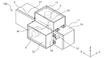
図2は、実施の形態1に係る煙感知器100の斜視図である。図2に矢印で示すX方向、Y方向及びZ方向は、それぞれ互いに直交する。煙感知器100は、筐体1と、発光部2と、第1受光部3と、第2受光部4とを備える。筐体1は、たとえば樹脂で構成され、外面にアルミ蒸着が施されている。筐体1のうち、内部に検煙空間14を形成する部分を本体部15と称し、第1受光部3を収容する空間を形成する部分を第1収容部11と称し、第2受光部4を収容する空間を形成する部分を第2収容部12と称する。本体部15、第1収容部11及び第2収容部12は、それぞれ概ね直方体の外形を有している。本実施の形態の筐体1は、これら直方体の第1収容部11、第2収容部12及び本体部15が組み合わされて構成されている。なお、筐体1の構成はこの例に限定されず、1つの構造物にて第1収容部11、第2収容部12及び本体部15に相当するものを構成してもよい。
FIG. 2 is a perspective view of the
筐体1には、検煙空間14への空気の入口である流入部13が設けられている。流入部13は、本実施の形態では筐体1の側面から突出した筒状の部材である。流入部13には、図1で示した配管101が接続される。また図2には示されないが、検煙空間14の内側と外側とを連通させ、検煙空間14に流入した空気の筐体1からの出口である流出部が、本体部15の壁に形成されている。
The
図2では、発光部2の光軸21と、第1受光部3の第1受光軸31と、第2受光部4の第2受光軸41とを、二点鎖線で概念的に示している。
In FIG. 2, the
発光部2は、直線偏波の光を発する発光素子を備える。発光素子はたとえばレーザーダイオードである。発光部2は、検煙空間14のうち第1受光部3及び第2受光部4が配置された領域に向かって光軸21が延びるようにして、筐体1内に配置されている。本実施の形態では、発光部2の光軸21は、逆X方向に沿って延びている。
The
第1受光部3は、発光部2から発せられた光が検煙空間14内の煙に反射して生じる散乱光を検出する。第1受光部3は、たとえばフォトダイオードである。第1受光部3は、第1受光軸31が検煙空間14内において発光部2の光軸21と交差するようにして、設置されている。
The first
第2受光部4は、発光部2から発せられた光が検煙空間14内の煙に反射して生じる散乱光を検出する。第2受光部4は、たとえばフォトダイオードである。第2受光部4は、第2受光軸41が検煙空間14内において発光部2の光軸21と交差するようにして、設置されている。
The second light receiving unit 4 detects scattered light generated by reflecting the light emitted from the
また、第1受光部3及び第2受光部4は、発光部2の光軸21と直交する面内において、第1受光軸31と第2受光軸41とが交差するようにして、設置されている。図2の例では、逆X方向に沿って延びる光軸21に直交する面、すなわち、Y方向及びZ方向によって規定されるY−Z面内において、第1受光軸31と第2受光軸41とが交差する。
Further, the first
発光部2が発する直線偏波が、第1受光軸31と第2受光軸41の一方に対して垂直偏波となり、他方に対して水平偏波となるのが好ましい。第1の例として、発光部2が、X−Y平面に平行な直線偏波の光を発する例を挙げる。この場合、発光部2からの光の偏光面はX−Y平面に平行な面となる。図2に示した配置では、第1受光軸31が、逆Z方向に沿って延び、発光部2からの光の偏光面と、第1受光軸31及び光軸21を含む面とが垂直となる。このとき、第1受光軸31に対して、発光部2からの直線偏波は垂直偏波となる。また図2に示した配置では、第2受光軸41が、Y方向に沿って延び、発光部2からの光の偏光面と、第2受光軸41及び光軸21を含む面とが平行となる。このとき、第2受光軸41に対して、発光部2からの直線偏波は水平偏波となる。第2の例として、発光部2が、X−Y平面に垂直な直線偏波の光を発する例を挙げる。この場合、発光部2からの光の偏光面は、X−Z平面に平行な光となる。図2に示した配置では、第1受光軸31が、逆Z方向に沿って延び、発光部2からの光の偏光面と、第1受光軸31及び光軸21を含む面とが平行となる。このとき、第1受光軸31に対して、発光部2からの直線偏波は水平偏波となる。また図2に示した配置では、第2受光軸41が、Y方向に沿って延び、発光部2からの光の偏光面と、第2受光軸41及び光軸21を含む面とが垂直となる。このとき、第2受光軸41に対して、発光部2からの直線偏波は垂直偏波となる。
It is preferable that the linearly polarized waves emitted by the
なお、流入部13は、第1受光部3の第1受光軸31及び第2受光部4の第2受光軸41を避けた位置に配置されているのが望ましい。流入部13の内側(流入部13の出口付近である本体部15の内壁面)には、通過する空気の含まれる塵埃等によって汚れが付着するおそれがある。流入部13が第1受光軸31又は第2受光軸41と重なっていると、その汚れによってノイズ光が発生し、第1受光部3又は第2受光部4によってノイズ光が感知されて煙の感知精度が低下するおそれがある。流入部13を、第1受光軸31及び第2受光軸41を避けた位置に配置することで、このような感知精度の低下を抑制することができる。さらに、流入部13は、第1受光部3及び第2受光部4の受光視野の外側に配置されているのがより望ましい。検煙空間14からの空気の流出部もまた、第1受光軸31及び第2受光軸41を避けた位置に配置されているのが望ましく、第1受光部3及び第2受光部4の受光視野の外側に配置されているのがより望ましい。すなわち、流入部13と上記流出部は、検煙空間14内に汚れが付着しないように、検煙空間14を避けた位置で、本体部15に配置されているのが望ましい。
It is desirable that the
図3は、図2のZ−Y平面での煙感知器100の断面主要部を、X方向に見た図である。図3は、第1受光部3及び第2受光部4を通る煙感知器100の断面の主要部を示している。図4は、図2のX−Y平面での煙感知器100の断面主要部を、Z方向に見た図である。図4は、第2受光部4を通る煙感知器100の断面の主要部を示している。
FIG. 3 is a view of the main cross section of the
図3に示すように、本実施の形態では、本体部15と第1収容部11とはZ方向に隣接して設置されている。第1収容部11と本体部15の隣接する壁には、それぞれ同形状の開口が形成されており、これらの開口によって第1開口部16が構成されている。第1開口部16は、第1受光部3の受光面と対面する位置にある。第1受光軸31は、第1開口部16を通る。本体部15と第2収容部12とは、Y方向に隣接して設置されている。第2収容部12と本体部15の隣接する壁には、それぞれ同型状の開口が形成されており、これらの開口によって第2開口部17が構成されている。第2開口部17は、第2受光部4の受光面と対面する位置にある。第2受光軸41は、第2開口部17を通る。
As shown in FIG. 3, in the present embodiment, the
図2の説明にて示したように、発光部2の光軸21(図2参照)に直交する面内、すなわちY−Z面内において、第1受光軸31と第2受光軸41とは交差する。図3では、Y−Z面内において第1受光軸31と第2受光軸41とがなす角度を角度θ1で表している。
As shown in the explanation of FIG. 2, in the plane orthogonal to the optical axis 21 (see FIG. 2) of the
図4において、第2受光部4の第2受光軸41と発光部2の光軸21とが交差して形成される角の角度を、散乱角θ2として示している。散乱角θ2は、特に限定されないが、たとえば50°〜120°とすることができる。図示されないが、発光部2の光軸21に対する第1受光部3の第1受光軸31の角度、すなわち散乱角も、特に限定されないが、たとえば50°〜120°とすることができる。第1受光軸31の光軸21に対する散乱角と、第2受光軸41の光軸21に対する散乱角θ2とは、同じであってもよいし、異なっていてもよい。
In FIG. 4, the angle formed by the intersection of the second
図5は、実施の形態1に係る煙感知器100の機能ブロック図である。煙感知器100は、発光部2、第1受光部3及び第2受光部4に加えて、制御部5を備える。制御部5は、発光部2の発光動作を制御する。第1受光部3及び第2受光部4は、受光した光の強度に応じた信号を、制御部5に出力する。第1受光部3からの信号を第1信号S1、第2受光部4からの信号を第2信号S2、と称する。制御部5は、第1受光部3から出力される第1信号S1及び第2受光部4から出力される第2信号S2に基づいて、火災発生の有無を判定する。
FIG. 5 is a functional block diagram of the
制御部5は、発光制御部51と、煙判定部52と、火災判定部53と、記憶部54とを備える。発光制御部51は、発光部2と電気的に接続されており、発光部2に対して発光及び発光停止の信号を送ることで、発光部2の動作を制御する。
The
煙判定部52は、発光部2が発光しているときに第1受光部3から出力される第1信号S1と、発光部2が発光しているときに第2受光部4から出力される第2信号S2との比に基づいて、煙の種類を判定する。
The
ここで、煙の種類について説明する。火災が発生したときには、1種類の煙のみが発生するのではなく、白煙、灰色煙、黒煙等、燃焼物に応じて種々の種類の煙が発生する。また、煙感知器100が設置される室内には、火災による煙ではなく湯気が発生する場合もある。煙感知器100は、これら種々の煙のいずれが発生しても火災を検知して発報する必要がある一方で、湯気が発生した場合には火災と判定しないようにする必要がある。
Here, the types of smoke will be described. When a fire breaks out, not only one type of smoke is generated, but various types of smoke such as white smoke, gray smoke, and black smoke are generated depending on the combustibles. Further, in the room where the
白煙及び灰色煙が煙感知器100の検煙空間14内にある場合の第1受光部3及び第2受光部4の受光強度は、黒煙が検煙空間14内にある場合の第1受光部3及び第2受光部4の受光強度よりも大きい。言い換えると、黒煙が検煙空間14内にある場合には、第1受光部3及び第2受光部4の受光強度が相対的に小さい。このため、黒煙、白煙及び灰色煙とで同じ火災閾値を用いるとすると、黒煙の場合には火災が発生していると判定しにくい。そこで本実施の形態では、煙の種類に基づいて第1信号S1を補正して補正後の第1補正信号SC1を得て、この第1補正信号SC1を用いて火災の判定を行う。なお、本実施の形態では、第1受光部3から出力される第1信号S1を用いて火災判定を行う例を示すが、第2受光部4から出力される第2信号S2を用いても第1信号S1を用いた場合と同様に火災判定を行うことができる。
The light receiving intensities of the first
煙判定部52による煙の種類の判定は、第1受光部3からの第1信号S1によって表される第1受光部3の受光強度と、第2受光部4からの第2信号S2によって表される第2受光部4の受光強度と、を比較することによって行う。ここで、直線偏波の光からの散乱光を、垂直偏波の光からの散乱光として受光する受光素子の受光強度と、水平偏波の光からの散乱光として受光する受光素子の受光強度とは、煙の種類によって異なる。白煙の場合、水平偏波の光からの散乱光として受光する受光素子の受光強度と、垂直偏波の光からの散乱光として受光する受光素子の受光強度とは、同等である。他方、黒煙の場合、水平偏波の光からの散乱光として受光する受光素子の受光強度は、垂直偏波の光からの散乱光として受光する受光素子の受光強度の1/4程度であり、小さい。このように、白煙であるか黒煙であるかによって、直線偏波の偏光方向を異ならせたときの受光素子の受光強度が異なることを利用し、煙の種類を判定する。
The smoke type determination by the
火災判定部53は、煙判定部52から煙の種類の判定結果を取得し、また、第1受光部3からの第1信号S1を取得する。火災判定部53は、煙判定部52によって判定された煙の種類に基づいて第1信号S1を補正することで第1補正信号SC1を得て、この補正後の第1補正信号SC1を用いて火災の有無を判定する。
The
記憶部54には、煙の種類に対応づけられた補正係数Cfが記憶されている。また、記憶部54には、火災の判定に用いられる火災閾値が記憶されている。火災判定部53は、記憶部54に記憶された補正係数Cfを用いて第1信号S1を補正して、第1補正信号SC1を得る。火災判定部53は、第1補正信号SC1と、記憶部54に記憶された火災閾値とを比較して、火災の発生の有無を判定する。
The
ここで、制御部5は、専用のハードウェア、又はメモリに格納されるプログラムを実行するMPU(Micro Processing Unit)で構成される。制御部5が専用のハードウェアである場合、制御部5は、例えば、単一回路、複合回路、ASIC(Application Specific Integrated Circuit)、FPGA(Field-Programmable Gate Array)、又はこれらを組み合わせたものが該当する。制御部5が実現する各機能のそれぞれを、個別のハードウェアで実現してもよいし、各機能を一つのハードウェアで実現してもよい。制御部5がMPUの場合、制御部5が実行する各機能は、ソフトウェア、ファームウェア、又はソフトウェアとファームウェアとの組み合わせにより実現される。ソフトウェア又はファームウェアはプログラムとして記述され、内部メモリに格納される。MPUは、内部メモリに格納されたプログラムを読み出して実行することにより、制御部5の各機能を実現する。内部メモリは、例えば、RAM、ROM、フラッシュメモリ、EPROM、EEPROM等の、不揮発性又は揮発性の半導体メモリである。また、記憶部54は、例えば、RAM、ROM、フラッシュメモリ、EPROM、EEPROM等の、不揮発性又は揮発性の半導体メモリである。
Here, the
(煙感知処理)
以下、発光部2が、図2〜図4に示すX−Y平面に平行な偏波面を有する直線偏波の光を発する場合を例に、煙感知器100による煙感知処理を説明する。定常状態においては、図1に示すように、ファン102の作用によって配管101を流れる空気が、煙感知器100に流入する。詳しくは、図2に示す流入部13を介して、煙感知器100の検煙空間14内に空気が流入する。発光部2は、直線偏波の光を発している状態である。検煙空間14内に煙を含まない清浄な空気が流入していれば、検煙空間14内において発光部2からの光が散乱することはなく、第1受光部3及び第2受光部4は散乱光を受光しない。火災の判定に用いられる第1受光部3からの第1信号S1が示す煙濃度は低レベルであり、火災と判定されることはない。
(Smoke detection processing)
Hereinafter, the smoke detection process by the
火災発生時には、配管101を介して煙感知器100の検煙空間14内に煙が流入する。検煙空間14内の煙を発光部2からの直線偏波の光で照射すると、検煙空間14内で散乱光が発生する。第1受光部3は、この散乱光を受光し、受光強度に応じた第1信号S1を出力する。第2受光部4も同様に、散乱光を受光し、受光強度に応じた第2信号S2を出力する。
When a fire breaks out, smoke flows into the
X−Y平面に平行な発光部2の偏波面に対し、第1受光軸31は平行よりも垂直に近く、第2受光軸41は垂直よりも平行に近い。すなわち、発光部2からの直線偏波の光を、第1受光部3は垂直偏波の光からの散乱光として受光し、第2受光部4は水平偏波の光からの散乱光として受光する。このような構成において、煙判定部52は、発光部2が発光しているときの第1受光部3の受光強度と、第2受光部4の受光強度とを、第1信号S1及び第2信号S2を用いて比較する。そして、煙判定部52は、第1受光部3の受光強度と第2受光部4の受光強度とが同等であれば、白煙であると判定する。他方、第1受光部3の受光強度の方が第2受光部4よりも閾値以上大きい場合、たとえば第1受光部3の受光強度が第2受光部4の受光強度の4倍程度である場合には、黒煙であると判定する。
The first
火災判定部53は、煙判定部52によって判定された煙の種類に応じて、第1信号S1を補正する補正係数Cfを記憶部54から取得し、補正係数Cfを用いて第1補正信号SC1を得る。たとえば、第1補正信号SC1は、第1補正信号SC1=Cf×第1信号S1、のようにして得る。CS計(減光率計)による測定値に追従した第1補正信号SC1を得るべく、黒煙である場合の補正係数Cfは、白煙である場合の補正係数Cfよりも大きい値である。補正後の第1補正信号SC1は、煙濃度に相当する値を示すので、第1補正信号SC1の値を煙濃度と称する。
The
火災判定部53は、第1補正信号SC1の値すなわち煙濃度が火災閾値よりも大きい場合に、火災が発生していると判定する。火災が発生していると判定した場合には、制御部5は、火災発報を行う。
The
以上のように本実施の形態の煙感知器100は、検煙空間14に対して直線偏波の光を発する発光部2を備える。さらに煙感知器100は、第1受光部3と第2受光部4とを備える。第1受光部3の第1受光軸31は、発光部2の光軸21と交差する。第2受光部4の第2受光軸41は、発光部2の光軸21と交差し、かつ発光部2の光軸21に直交する面(Y−Z平面)内において第1受光軸31と交差する。そして、煙感知器100の制御部5は、第1受光部3が受光した光に応じた第1信号S1及び第2受光部4が受光した光に応じた第2信号S2に基づいて、検煙空間14に存在する煙の種類を判定し、煙の種類に基づいて火災の有無を判定する。このように、煙の種類に基づいて火災の有無を判定するため、精度よく火災の有無を判定することができる。また、本実施の形態の発光部2は、直線偏波の光を発するため、煙感知器100は、偏光フィルタを用いることなく煙の種類に応じた火災の有無の判定を行うことができる。
As described above, the
本実施の形態の煙感知器100において、発光部2から発せられる直線偏波の光の偏光面に対して、第1受光軸31及び光軸21を含む面が厳密に垂直でなくともよく、第2受光軸41及び光軸21を含む面が厳密に平行でなくともよい。すなわち、第1受光部3の第1受光軸31に対して発光部2からの光が厳密に垂直偏波でなくともよいし、第2受光部4の第2受光軸41に対して発光部2からの光が厳密に水平偏波でなくともよい。なお、白煙と黒煙による散乱光の受光強度の差は、受光部が水平偏波の光からの散乱光を受光したときと垂直偏波の光からの散乱光を受光したときとで、最も大きくなり、煙の種類がより精度よく判定される。
In the
また、本実施の形態の煙感知器100において、発光部2の光軸21に直交する面(Y−Z平面)内において、第1受光軸31と第2受光軸41とを直交させてもよい。すなわち、図3に示した角度θ1が90°になるようにして、第1受光部3と第2受光部4とを配置してもよい。このとき、光軸21と第1受光軸31とで規定される散乱角と、光軸21と第2受光軸41とで規定される散乱角とは、ともに90°であるといえる。このようにすると、第1受光部3と第2受光部4とを、筐体1内に設置する際の位置決めが容易となり、煙感知器100の製造誤差を抑制できるとともに、製造も容易になる。
Further, in the
また、本実施の形態では、検煙空間14を形成する本体部15に対し、第1受光部3を収容した第1収容部11と、第2受光部4を収容した第2収容部12とが取り付けられて、筐体1が構成されている。このような構成において、第1受光部3及び第1収容部11と、第2受光部4及び第2収容部12とを、同じ構造物で構成し、それぞれ本体部15の異なる側面に取り付けるとよい。すなわち、受光部とその収容部とからなる2組のユニットの一方を、第1受光部3及び第1収容部11として用い、他方を第2受光部4及び第2収容部12として用いる。このようにすることで、煙感知器100の製造工程の複雑化が抑制され、煙感知器100の製造コストを抑制することができる。
Further, in the present embodiment, with respect to the
なお、本実施の形態では、煙感知器100の制御部5にて火災の発生の有無を感知することとして説明した。しかし、火災受信機に煙感知器100が接続される場合には、煙感知器100は火災発生の有無を判定せず、第1信号S1及び第2信号S2を火災受信機に送信し、火災受信機にて煙の判定及び火災発生の有無の判定を行うこともできる。
In the present embodiment, it has been described that the
実施の形態2.
実施の形態1では、1つの直線偏波の光を発する発光部2と、発光部2からの光による散乱光を受光する第1受光部3及び第2受光部4を備えた煙感知器100を説明した。本実施の形態では、1つの発光部と1つの受光部とを備えた煙感知器を説明する。以下、実施の形態1との相違点を中心に説明する。
In the first embodiment, the
本実施の形態の発光部は、実施の形態1の発光部2と同様に、直線偏波の光を発する発光素子を備える。発光素子はたとえばレーザーダイオードである。本実施の形態の受光部は、実施の形態1の第1受光部3及び第2受光部4と同様に、発光部から発せられた光が検煙空間内の煙に反射して生じる散乱光を検出する。受光部は、たとえばフォトダイオードである。
The light emitting unit of the present embodiment includes a light emitting element that emits linearly polarized light, similarly to the
本実施の形態の煙感知器は、発光部と受光部との位置関係を、第1状態と第2状態との間で切り替えるように、発光部と受光部のいずれか又は両方を移動又は回転させる装置を備える。以下、受光部を移動させる移動装置を備えた例を説明する。移動装置は、受光部に機械的に接続されており、受光部の位置を第1位置と第2位置との間で移動させる。移動装置は、たとえば、受光部に接続された回動軸を有するモータである。受光部が第1位置にあるとき、発光部と受光部との位置関係は、第1状態となり、受光部が第2位置にあるとき、発光部と受光部との位置関係は、第2状態となる。たとえば、図2の第1受光部3の位置が第1位置となるように、第2受光部4の位置が第2位置となるように、移動装置が受光部を移動させる。
The smoke detector of the present embodiment moves or rotates either or both of the light emitting unit and the light receiving unit so as to switch the positional relationship between the light emitting unit and the light receiving unit between the first state and the second state. Equipped with a device to make it. Hereinafter, an example including a moving device for moving the light receiving unit will be described. The moving device is mechanically connected to the light receiving unit and moves the position of the light receiving unit between the first position and the second position. The moving device is, for example, a motor having a rotating shaft connected to a light receiving unit. When the light receiving unit is in the first position, the positional relationship between the light emitting unit and the light receiving unit is in the first state, and when the light receiving unit is in the second position, the positional relationship between the light emitting unit and the light receiving unit is in the second state. It becomes. For example, the moving device moves the light receiving unit so that the position of the first
第1状態にあるとき、受光部の受光軸は、発光部の光軸と交差する。また、第2状態にあるとき、受光部の受光軸は、発光部の光軸と交差し、かつ、発光部の光軸に直交する面内において第1状態における受光部の受光軸と交差する。このように、第1状態と第2状態とでは、発光部の光軸に対する受光部の受光軸の位置が、異なる。第1状態のときと第2状態のときとでは、発光部からの直線偏波の偏光面に対する、受光部の受光軸の位置関係が異なるといえる。このように本実施の形態では、1つの受光部の位置を移動装置によって移動させることにより、実施の形態1の第1受光部3が散乱光を受光する状態と、第2受光部4が散乱光を受光する状態と、の両方を実現する。
In the first state, the light-receiving axis of the light-receiving part intersects the optical axis of the light-emitting part. Further, in the second state, the light receiving axis of the light receiving unit intersects the optical axis of the light emitting unit and intersects the light receiving axis of the light receiving unit in the first state in a plane orthogonal to the optical axis of the light emitting unit. .. As described above, the position of the light receiving shaft of the light receiving unit with respect to the optical axis of the light emitting unit is different between the first state and the second state. It can be said that the positional relationship of the light receiving shaft of the light receiving unit with respect to the linearly polarized polarization plane from the light emitting unit differs between the first state and the second state. As described above, in the present embodiment, by moving the position of one light receiving unit by the moving device, the first
制御部は、発光部から直線偏波の光を出射させる。そして制御部は、第1状態にあるときの受光部の受光強度に応じた第1信号S1と、第2状態にあるときの受光部の受光強度に応じた第2信号S2とに基づいて、実施の形態1で説明したように検煙空間に存在する煙の種類を識別する。そして、煙の種類に基づいて、第1信号S1又は第2信号S2を補正し、補正した第1補正信号SC1又は第2補正信号SC2に基づいて、火災の有無を発生する。 The control unit emits linearly polarized light from the light emitting unit. Then, the control unit is based on the first signal S1 according to the light receiving intensity of the light receiving unit in the first state and the second signal S2 according to the light receiving intensity of the light receiving unit in the second state. As described in the first embodiment, the type of smoke existing in the smoke detection space is identified. Then, the first signal S1 or the second signal S2 is corrected based on the type of smoke, and the presence or absence of a fire is generated based on the corrected first correction signal SC1 or the second correction signal SC2.
本実施の形態のように煙感知器を構成した場合にも、直線偏波の偏光方向を異ならせたときの受光素子の受光強度が異なることを利用して、煙の種類を判定することができる。したがって、実施の形態1と同様の効果を得ることができる。 Even when the smoke detector is configured as in the present embodiment, it is possible to determine the type of smoke by utilizing the fact that the light receiving intensity of the light receiving element is different when the polarization directions of the linearly polarized waves are different. it can. Therefore, the same effect as that of the first embodiment can be obtained.
なお、本実施の形態では、受光部を移動させる移動装置を例示したが、この移動装置に代えて、発光部を回転させる回転装置を設けてもよい。回転装置は、たとえば、発光部に機械的に接続された回転軸を有するモータである。回転装置は、発光部からの直線偏波の偏光面の向きの異なる第1状態と第2状態とを切り替えるようにして、発光部を回転させる。発光部の位置を異ならせることなく発光部を回転させると、受光部の受光軸は、発光部の回転状態によらず発光部の光軸と交差する。このようにしても、実施の形態2と同様の効果を得ることができる。発光部を回転させる場合には、発光部を構成するレーザーダイオード等の発光素子が実装された基板を円形とし、この円形の基板ごと発光部を回転させるとよい。 In the present embodiment, a moving device for moving the light receiving unit is illustrated, but instead of this moving device, a rotating device for rotating the light emitting unit may be provided. The rotating device is, for example, a motor having a rotating shaft mechanically connected to a light emitting unit. The rotating device rotates the light emitting unit so as to switch between the first state and the second state in which the directions of the planes of polarized light linearly polarized from the light emitting unit are different. When the light emitting unit is rotated without changing the position of the light emitting unit, the light receiving axis of the light receiving unit intersects the optical axis of the light emitting unit regardless of the rotational state of the light emitting unit. Even in this way, the same effect as that of the second embodiment can be obtained. When rotating the light emitting unit, it is preferable that the substrate on which the light emitting element such as the laser diode constituting the light emitting unit is mounted is circular, and the light emitting unit is rotated together with the circular substrate.
実施の形態3.
実施の形態1では、1つの直線偏波の光を発する発光部2と、発光部2からの光による散乱光を受光する第1受光部3及び第2受光部4を備えた煙感知器100を説明した。本実施の形態では、第1発光部及び第2発光部と、1つの受光部とを備えた煙感知器を説明する。以下、実施の形態1との相違点を中心に説明する。
In the first embodiment, the
本実施の形態の煙感知器は、検煙空間に対して直線偏波の光を発する第1発光部と第2発光部とを備える。第1発光部及び第2発光部は、図2で示した発光部2の位置に、並んで配置される。第1発光部及び第2発光部は、実施の形態1の発光部2と同様に、直線偏波の光を発する発光素子を備える。発光素子はたとえばレーザーダイオードである。本実施の形態の受光部は、実施の形態1の第1受光部3及び第2受光部4と同様に、第1発光部及び第2発光部から発せられた光が検煙空間内の煙に反射して生じる散乱光を検出する。受光部は、たとえばフォトダイオードである。
The smoke detector of the present embodiment includes a first light emitting unit and a second light emitting unit that emit light linearly polarized light with respect to the smoke detection space. The first light emitting unit and the second light emitting unit are arranged side by side at the position of the
第1発光部及び第2発光部は、第1発光部からの光の偏波面と第2発光部からの光の偏波面とが交差するような位置関係にて煙感知器に設置される。受光部は、その受光軸が、第1発光部の光軸と交差し、かつ第2発光部の光軸と交差するようにして、煙感知器に設置される。 The first light emitting unit and the second light emitting unit are installed in the smoke detector in a positional relationship such that the plane of polarization of light from the first light emitting unit and the plane of polarization of light from the second light emitting unit intersect. The light receiving unit is installed in the smoke detector so that its light receiving axis intersects the optical axis of the first light emitting unit and intersects the optical axis of the second light emitting unit.
制御部は、第1発光部と第2発光部とが、異なるタイミングで光を発するように、第1発光部と第2発光部とを制御する。また制御部は、第1発光部が直線偏波の光を出射したときの受光部の受光強度に応じた第1信号S1と、第2発光部が直線偏波の光を出射したときの受光部の受光強度に応じた第2信号S2とに基づいて、実施の形態1で説明したように煙の種類を識別する。そして、制御部は、煙の種類に基づいて、第1信号S1又は第2信号S2を補正し、補正した第1補正信号SC1又は第2補正信号SC2に基づいて、火災の有無を発生する。 The control unit controls the first light emitting unit and the second light emitting unit so that the first light emitting unit and the second light emitting unit emit light at different timings. Further, the control unit receives the first signal S1 according to the light receiving intensity of the light receiving unit when the first light emitting unit emits linearly polarized light, and the light received when the second light emitting unit emits linearly polarized light. The type of smoke is identified as described in the first embodiment based on the second signal S2 according to the light receiving intensity of the unit. Then, the control unit corrects the first signal S1 or the second signal S2 based on the type of smoke, and generates the presence or absence of a fire based on the corrected first correction signal SC1 or the second correction signal SC2.
本実施の形態の煙感知器においても、直線偏波の偏光方向を異ならせたときの受光素子の受光強度が異なることを利用して、煙の種類を判定できる。したがって、実施の形態1と同様の効果を得ることができる。 Also in the smoke detector of the present embodiment, the type of smoke can be determined by utilizing the fact that the light receiving intensity of the light receiving element is different when the polarization directions of the linearly polarized waves are different. Therefore, the same effect as that of the first embodiment can be obtained.
1 筐体、2 発光部、3 第1受光部、4 第2受光部、5 制御部、11 第1収容部、12 第2収容部、13 流入部、14 検煙空間、15 本体部、16 第1開口部、17 第2開口部、21 光軸、31 第1受光軸、41 第2受光軸、51 発光制御部、52 煙判定部、53 火災判定部、54 記憶部、100 煙感知器、101 配管、102 ファン、103 フィルタ。 1 Housing, 2 Light emitting unit, 3 1st light receiving unit, 4 2nd light receiving unit, 5 Control unit, 11 1st accommodating unit, 12 2nd accommodating unit, 13 Inflow unit, 14 Smoke detection space, 15 Main body unit, 16 1st opening, 17 2nd opening, 21 optical axis, 31 1st light receiving shaft, 41 2nd light receiving shaft, 51 light emission control unit, 52 smoke judgment unit, 53 fire judgment unit, 54 storage unit, 100 smoke detector , 101 piping, 102 fans, 103 filters.
Claims (5)
前記発光部の光軸と交差する第1受光軸を有する第1受光部と、
前記発光部の前記光軸と交差し、かつ前記発光部の前記光軸に直交する面内において前記第1受光軸と交差する第2受光軸を有する第2受光部と、
前記第1受光部が受光した光に応じた第1信号及び前記第2受光部が受光した光に応じた第2信号に基づいて、前記検煙空間に存在する煙の種類を判定し、前記煙の種類に基づいて火災の有無を判定する制御部と
を備えた煙感知器。 A light emitting part that emits linearly polarized light with respect to the smoke detection space,
A first light receiving part having a first light receiving axis intersecting the optical axis of the light emitting part,
A second light receiving unit having a second light receiving axis that intersects the optical axis of the light emitting unit and intersects the first light receiving axis in a plane orthogonal to the optical axis of the light emitting unit.
The type of smoke existing in the smoke detection space is determined based on the first signal corresponding to the light received by the first light receiving unit and the second signal corresponding to the light received by the second light receiving unit. A smoke detector with a control unit that determines the presence or absence of a fire based on the type of smoke.
前記第2受光軸及び前記光軸を含む面は、前記発光部から発せられる前記直線偏波の光の前記偏光面に対して平行である
請求項1記載の煙感知器。 The surface including the first light receiving axis and the optical axis is perpendicular to the plane of polarization of the linearly polarized light emitted from the light emitting unit.
The smoke detector according to claim 1, wherein the surface including the second light receiving axis and the optical axis is parallel to the polarization surface of the linearly polarized light emitted from the light emitting unit.
請求項1又は請求項2に記載の煙感知器。 The smoke detector according to claim 1 or 2, wherein the first light receiving axis and the second light receiving axis are orthogonal to each other in a plane orthogonal to the optical axis of the light emitting unit.
受光部と、
前記発光部と前記受光部との位置関係を、第1状態と第2状態との間で切り替えるように、前記発光部と前記受光部のいずれか又は両方を移動又は回転させる装置と、
制御部とを備え、
前記第1状態にある前記受光部の受光軸は、前記発光部の光軸と交差し、
前記第2状態にある前記受光部の前記受光軸は、前記発光部の光軸と交差し、かつ、前記発光部の光軸に直交する面内において前記第1状態における前記受光部の前記受光軸と交差し、
前記制御部は、
前記第1状態にある前記受光部が受光した光に応じた第1信号と、前記第2状態にある前記受光部が受光した光に応じた第2信号とに基づいて、前記検煙空間に存在する煙の種類を識別し、前記煙の種類に基づいて火災の有無を判定する
煙感知器。 A light emitting part that emits linearly polarized light with respect to the smoke detection space,
Light receiving part and
A device for moving or rotating either or both of the light emitting unit and the light receiving unit so as to switch the positional relationship between the light emitting unit and the light receiving unit between the first state and the second state.
Equipped with a control unit
The light-receiving axis of the light-receiving part in the first state intersects the optical axis of the light-emitting part.
The light receiving axis of the light receiving unit in the second state intersects the optical axis of the light emitting unit and is orthogonal to the optical axis of the light emitting unit. Crosses the axis,
The control unit
Based on the first signal corresponding to the light received by the light receiving unit in the first state and the second signal corresponding to the light received by the light receiving unit in the second state, the smoke detection space is entered. A smoke detector that identifies the type of smoke that is present and determines the presence or absence of a fire based on the type of smoke.
前記検煙空間に対して、前記第1発光部からの光の偏波面と交差する偏波面を有する直線偏波の光を発する第2発光部と、
前記第1発光部の光軸及び前記第2発光部の光軸と交差する受光軸を有する受光部と、
異なるタイミングで光を発するように前記第1発光部と前記第2発光部とを制御する制御部とを備え、
前記制御部は、前記第1発光部が光を発したときに前記受光部が受光した光に応じた第1信号と、前記第2発光部が光を発したときに前記受光部が受光した光に応じた第2信号と、に基づいて、前記検煙空間に存在する煙の種類を識別し、前記煙の種類に基づいて火災の有無を判定する
煙感知器。 The first light emitting part that emits linearly polarized light with respect to the smoke detection space,
A second light emitting unit that emits linearly polarized light having a plane of polarization intersecting the plane of polarization of the light from the first light emitting unit with respect to the smoke detection space.
A light receiving unit having an optical axis of the first light emitting unit and a light receiving axis intersecting the optical axis of the second light emitting unit,
A control unit that controls the first light emitting unit and the second light emitting unit so as to emit light at different timings is provided.
The control unit receives a first signal corresponding to the light received by the light receiving unit when the first light emitting unit emits light, and the light receiving unit receives light when the second light emitting unit emits light. A smoke detector that identifies the type of smoke existing in the smoke detection space based on a second signal corresponding to light and determines the presence or absence of a fire based on the type of smoke.
Priority Applications (1)
| Application Number | Priority Date | Filing Date | Title |
|---|---|---|---|
| JP2019085910A JP2020181507A (en) | 2019-04-26 | 2019-04-26 | smoke detector |
Applications Claiming Priority (1)
| Application Number | Priority Date | Filing Date | Title |
|---|---|---|---|
| JP2019085910A JP2020181507A (en) | 2019-04-26 | 2019-04-26 | smoke detector |
Publications (2)
| Publication Number | Publication Date |
|---|---|
| JP2020181507A true JP2020181507A (en) | 2020-11-05 |
| JP2020181507A5 JP2020181507A5 (en) | 2022-04-08 |
Family
ID=73024338
Family Applications (1)
| Application Number | Title | Priority Date | Filing Date |
|---|---|---|---|
| JP2019085910A Pending JP2020181507A (en) | 2019-04-26 | 2019-04-26 | smoke detector |
Country Status (1)
| Country | Link |
|---|---|
| JP (1) | JP2020181507A (en) |
Cited By (3)
| Publication number | Priority date | Publication date | Assignee | Title |
|---|---|---|---|---|
| WO2023210548A1 (en) * | 2022-04-27 | 2023-11-02 | 能美防災株式会社 | Smoke detecting device |
| WO2023238849A1 (en) * | 2022-06-09 | 2023-12-14 | 能美防災株式会社 | Smoke detecting device |
| WO2024034491A1 (en) * | 2022-08-12 | 2024-02-15 | 能美防災株式会社 | Smoke detecting device |
Citations (3)
| Publication number | Priority date | Publication date | Assignee | Title |
|---|---|---|---|---|
| JPH0712724A (en) * | 1993-04-30 | 1995-01-17 | Hochiki Corp | Fire alarm device and fire detecting method |
| JP2004325211A (en) * | 2003-04-24 | 2004-11-18 | Hochiki Corp | Light scattering smoke detector |
| JP2011242909A (en) * | 2010-05-17 | 2011-12-01 | Hochiki Corp | High sensitivity smoke sensor |
-
2019
- 2019-04-26 JP JP2019085910A patent/JP2020181507A/en active Pending
Patent Citations (3)
| Publication number | Priority date | Publication date | Assignee | Title |
|---|---|---|---|---|
| JPH0712724A (en) * | 1993-04-30 | 1995-01-17 | Hochiki Corp | Fire alarm device and fire detecting method |
| JP2004325211A (en) * | 2003-04-24 | 2004-11-18 | Hochiki Corp | Light scattering smoke detector |
| JP2011242909A (en) * | 2010-05-17 | 2011-12-01 | Hochiki Corp | High sensitivity smoke sensor |
Cited By (3)
| Publication number | Priority date | Publication date | Assignee | Title |
|---|---|---|---|---|
| WO2023210548A1 (en) * | 2022-04-27 | 2023-11-02 | 能美防災株式会社 | Smoke detecting device |
| WO2023238849A1 (en) * | 2022-06-09 | 2023-12-14 | 能美防災株式会社 | Smoke detecting device |
| WO2024034491A1 (en) * | 2022-08-12 | 2024-02-15 | 能美防災株式会社 | Smoke detecting device |
Similar Documents
| Publication | Publication Date | Title |
|---|---|---|
| JP2020181507A (en) | smoke detector | |
| TWI497454B (en) | Attractive smoke detection system | |
| JP5640247B2 (en) | Photoelectric smoke detector and suction smoke detection system | |
| US9134224B2 (en) | Gas component detection device | |
| JP4980101B2 (en) | smoke detector | |
| US7677962B2 (en) | Electronic device and filtering unit | |
| US9569946B2 (en) | Smoke alarm according to the scattered light principle having a two-color light-emitting diode with different sizes of LED chips | |
| US7062953B2 (en) | Sampling tube-type smoke detector | |
| EP3220124B1 (en) | Particle sensor, and electronic device provided with same | |
| JP2007147613A (en) | Gas sensor array | |
| JPH08233736A (en) | Microparticle detection sensor | |
| JP2002031685A (en) | Reflection measuring device | |
| US11417187B2 (en) | Scattered light detector and suction fire detection system having a scattered light detector | |
| TWI664398B (en) | Optical rotary encoder | |
| JP2011203892A (en) | Smoke detector | |
| JP2013109751A (en) | Smoke sensor | |
| JP2019046112A (en) | Scattered light type sensor | |
| JP2011203889A (en) | Smoke detector | |
| US20170153177A1 (en) | Assembly for attenuating impinging light of a beam of radiation | |
| JP5333944B2 (en) | smoke detector | |
| JP3957639B2 (en) | Oil mist detection device | |
| JP2009289739A (en) | Photoelectric sensor | |
| JPH08271423A (en) | Microparticle sensor | |
| JP2003281643A (en) | Extinction type smoke sensor | |
| KR102065671B1 (en) | Wafer-type particle sensor |
Legal Events
| Date | Code | Title | Description |
|---|---|---|---|
| A521 | Request for written amendment filed |
Free format text: JAPANESE INTERMEDIATE CODE: A523 Effective date: 20220330 |
|
| A621 | Written request for application examination |
Free format text: JAPANESE INTERMEDIATE CODE: A621 Effective date: 20220330 |
|
| A977 | Report on retrieval |
Free format text: JAPANESE INTERMEDIATE CODE: A971007 Effective date: 20230412 |
|
| A131 | Notification of reasons for refusal |
Free format text: JAPANESE INTERMEDIATE CODE: A131 Effective date: 20230418 |
|
| A521 | Request for written amendment filed |
Free format text: JAPANESE INTERMEDIATE CODE: A523 Effective date: 20230614 |
|
| A131 | Notification of reasons for refusal |
Free format text: JAPANESE INTERMEDIATE CODE: A131 Effective date: 20230919 |
|
| A521 | Request for written amendment filed |
Free format text: JAPANESE INTERMEDIATE CODE: A523 Effective date: 20231108 |
|
| A02 | Decision of refusal |
Free format text: JAPANESE INTERMEDIATE CODE: A02 Effective date: 20240123 |