JP2020176826A - Air-conditioning system - Google Patents

Air-conditioning system Download PDF

Info

Publication number
JP2020176826A
JP2020176826A JP2020072734A JP2020072734A JP2020176826A JP 2020176826 A JP2020176826 A JP 2020176826A JP 2020072734 A JP2020072734 A JP 2020072734A JP 2020072734 A JP2020072734 A JP 2020072734A JP 2020176826 A JP2020176826 A JP 2020176826A
Authority
JP
Japan
Prior art keywords
air
heat exchanger
unit
fan
conditioning system
Prior art date
Legal status (The legal status is an assumption and is not a legal conclusion. Google has not performed a legal analysis and makes no representation as to the accuracy of the status listed.)
Granted
Application number
JP2020072734A
Other languages
Japanese (ja)
Other versions
JP6860106B2 (en
Inventor
脩一 田中
Shuichi Tanaka
脩一 田中
義照 野内
Yoshiteru Nouchi
義照 野内
Current Assignee (The listed assignees may be inaccurate. Google has not performed a legal analysis and makes no representation or warranty as to the accuracy of the list.)
Daikin Industries Ltd
Original Assignee
Daikin Industries Ltd
Priority date (The priority date is an assumption and is not a legal conclusion. Google has not performed a legal analysis and makes no representation as to the accuracy of the date listed.)
Filing date
Publication date
Application filed by Daikin Industries Ltd filed Critical Daikin Industries Ltd
Publication of JP2020176826A publication Critical patent/JP2020176826A/en
Application granted granted Critical
Publication of JP6860106B2 publication Critical patent/JP6860106B2/en
Active legal-status Critical Current
Anticipated expiration legal-status Critical

Links

Images

Classifications

    • FMECHANICAL ENGINEERING; LIGHTING; HEATING; WEAPONS; BLASTING
    • F24HEATING; RANGES; VENTILATING
    • F24FAIR-CONDITIONING; AIR-HUMIDIFICATION; VENTILATION; USE OF AIR CURRENTS FOR SCREENING
    • F24F3/00Air-conditioning systems in which conditioned primary air is supplied from one or more central stations to distributing units in the rooms or spaces where it may receive secondary treatment; Apparatus specially designed for such systems
    • F24F3/001Air-conditioning systems in which conditioned primary air is supplied from one or more central stations to distributing units in the rooms or spaces where it may receive secondary treatment; Apparatus specially designed for such systems in which the air treatment in the central station takes place by means of a heat-pump or by means of a reversible cycle
    • FMECHANICAL ENGINEERING; LIGHTING; HEATING; WEAPONS; BLASTING
    • F24HEATING; RANGES; VENTILATING
    • F24FAIR-CONDITIONING; AIR-HUMIDIFICATION; VENTILATION; USE OF AIR CURRENTS FOR SCREENING
    • F24F11/00Control or safety arrangements
    • F24F11/70Control systems characterised by their outputs; Constructional details thereof
    • F24F11/72Control systems characterised by their outputs; Constructional details thereof for controlling the supply of treated air, e.g. its pressure
    • F24F11/74Control systems characterised by their outputs; Constructional details thereof for controlling the supply of treated air, e.g. its pressure for controlling air flow rate or air velocity
    • F24F11/77Control systems characterised by their outputs; Constructional details thereof for controlling the supply of treated air, e.g. its pressure for controlling air flow rate or air velocity by controlling the speed of ventilators
    • FMECHANICAL ENGINEERING; LIGHTING; HEATING; WEAPONS; BLASTING
    • F24HEATING; RANGES; VENTILATING
    • F24FAIR-CONDITIONING; AIR-HUMIDIFICATION; VENTILATION; USE OF AIR CURRENTS FOR SCREENING
    • F24F11/00Control or safety arrangements
    • F24F11/70Control systems characterised by their outputs; Constructional details thereof
    • F24F11/72Control systems characterised by their outputs; Constructional details thereof for controlling the supply of treated air, e.g. its pressure
    • F24F11/79Control systems characterised by their outputs; Constructional details thereof for controlling the supply of treated air, e.g. its pressure for controlling the direction of the supplied air
    • FMECHANICAL ENGINEERING; LIGHTING; HEATING; WEAPONS; BLASTING
    • F24HEATING; RANGES; VENTILATING
    • F24FAIR-CONDITIONING; AIR-HUMIDIFICATION; VENTILATION; USE OF AIR CURRENTS FOR SCREENING
    • F24F11/00Control or safety arrangements
    • F24F11/70Control systems characterised by their outputs; Constructional details thereof
    • F24F11/80Control systems characterised by their outputs; Constructional details thereof for controlling the temperature of the supplied air
    • F24F11/83Control systems characterised by their outputs; Constructional details thereof for controlling the temperature of the supplied air by controlling the supply of heat-exchange fluids to heat-exchangers
    • F24F11/84Control systems characterised by their outputs; Constructional details thereof for controlling the temperature of the supplied air by controlling the supply of heat-exchange fluids to heat-exchangers using valves
    • FMECHANICAL ENGINEERING; LIGHTING; HEATING; WEAPONS; BLASTING
    • F24HEATING; RANGES; VENTILATING
    • F24FAIR-CONDITIONING; AIR-HUMIDIFICATION; VENTILATION; USE OF AIR CURRENTS FOR SCREENING
    • F24F11/00Control or safety arrangements
    • F24F11/89Arrangement or mounting of control or safety devices
    • FMECHANICAL ENGINEERING; LIGHTING; HEATING; WEAPONS; BLASTING
    • F24HEATING; RANGES; VENTILATING
    • F24FAIR-CONDITIONING; AIR-HUMIDIFICATION; VENTILATION; USE OF AIR CURRENTS FOR SCREENING
    • F24F3/00Air-conditioning systems in which conditioned primary air is supplied from one or more central stations to distributing units in the rooms or spaces where it may receive secondary treatment; Apparatus specially designed for such systems
    • F24F3/044Systems in which all treatment is given in the central station, i.e. all-air systems
    • YGENERAL TAGGING OF NEW TECHNOLOGICAL DEVELOPMENTS; GENERAL TAGGING OF CROSS-SECTIONAL TECHNOLOGIES SPANNING OVER SEVERAL SECTIONS OF THE IPC; TECHNICAL SUBJECTS COVERED BY FORMER USPC CROSS-REFERENCE ART COLLECTIONS [XRACs] AND DIGESTS
    • Y02TECHNOLOGIES OR APPLICATIONS FOR MITIGATION OR ADAPTATION AGAINST CLIMATE CHANGE
    • Y02BCLIMATE CHANGE MITIGATION TECHNOLOGIES RELATED TO BUILDINGS, e.g. HOUSING, HOUSE APPLIANCES OR RELATED END-USER APPLICATIONS
    • Y02B30/00Energy efficient heating, ventilation or air conditioning [HVAC]
    • Y02B30/70Efficient control or regulation technologies, e.g. for control of refrigerant flow, motor or heating

Abstract

To suppress a malfunction of an air-conditioning system resulting from a wind volume passing a use-side heat exchanger, in the air-conditioning system for supplying conditioned air to a plurality of points in a building by using ducts.SOLUTION: A heat exchanger unit 10 includes a use-side heat exchanger 11. A plurality of ducts 20 are connected to the heat exchanger unit 10. A plurality of fan units 30 suck conditioned air from the heat exchanger unit 10 via the plurality of ducts 20, and supply it to a plurality of flow-out ports 71. The fan units 30 include fan motors 33 being a plurality of actuators which are constituted so as to be capable of changing an individual supply air amount of conditioned air. A main controller 40 controls the plurality of fan motors 33 so that a wind volume passing the use-side heat exchanger 11 satisfies a prescribed condition.SELECTED DRAWING: Figure 1

Description

複数のファンユニットを備える空気調和システム Air conditioning system with multiple fan units

建物の内部の空気調和を行う従来の空気調和システムの中には、例えば特許文献1(特開平11−132489号公報)に記載されているように、利用側熱交換器で熱交換が行なわれた調和空気をダクトによって建物内の複数の箇所に調和空気を供給する空気調和システムがある。 In the conventional air-conditioning system for air-conditioning the inside of a building, heat exchange is performed by a user-side heat exchanger, for example, as described in Patent Document 1 (Japanese Unexamined Patent Publication No. 11-132489). There is an air conditioning system that supplies conditioned air to multiple locations in the building through ducts.

しかしながら、特許文献1に記載されている空気調和システムでは、空気調和システムの熱源側の運転に対する考慮と利用側熱交換器での熱交換との関係についての記載がない。利用側熱交換器を通過する風量によって熱源側の運転が止まったり、運転に支障が出たりすることも考えられる。 However, in the air conditioning system described in Patent Document 1, there is no description about the relationship between the consideration for the operation of the heat source side of the air conditioning system and the heat exchange in the heat exchanger on the user side. Depending on the amount of air passing through the heat exchanger on the user side, the operation on the heat source side may stop or the operation may be hindered.

このようなダクトを使って建物内の複数の箇所に調和空気を供給する空気調和システムでは、利用側熱交換器を通過する風量に起因する空気調和システムの不具合を抑制するという課題がある。 An air-conditioning system that supplies conditioned air to a plurality of locations in a building using such a duct has a problem of suppressing a malfunction of the air-conditioning system due to the amount of air passing through the heat exchanger on the user side.

第1観点の空気調和システムは、利用側熱交換器を有する熱交換器ユニットを備え、利用側熱交換器での熱交換によって調和空気を生成し、調和空気を熱交換器ユニットに連通する複数の分配流路を介して空調対象空間に供給する空気調和システムである。各分配流路は、熱交換器ユニットに接続され、調和空気を分配するためのダクトと、ダクトに対応して設けられ、熱交換器ユニットからダクトを介して空調対象空間に供給するファンユニットと、から構成されると共に、空調対象空間に調和空気を供給する供給空気量を個別に変更できるように構成されているアクチュエータを含む。空気調和システムは、利用側熱交換器を通過する風量が所定条件を満たすようにアクチュエータを制御するメインコントローラを備えることを特徴とする。 The air conditioning system of the first aspect includes a heat exchanger unit having a heat exchanger on the user side, generates conditioned air by heat exchange in the heat exchanger on the user side, and communicates the conditioned air to the heat exchanger unit. It is an air conditioning system that supplies air-conditioning target space through the distribution flow path of. Each distribution flow path is connected to the heat exchanger unit and has a duct for distributing the harmonized air, and a fan unit provided corresponding to the duct and supplying the heat exchanger unit to the air-conditioned space via the duct. , And includes an actuator configured to individually change the amount of supply air that supplies harmonious air to the air-conditioned space. The air conditioning system is characterized by including a main controller that controls an actuator so that the air volume passing through the heat exchanger on the user side satisfies a predetermined condition.

第1観点の空気調和システムでは、メインコントローラが利用側熱交換器を通過する風量が所定条件を満たすようアクチュエータを制御する。これにより、利用側熱交換器を通過する風量によって空気調和システムの不具合を抑制することができる。 In the air conditioning system of the first aspect, the main controller controls the actuator so that the air volume passing through the user side heat exchanger satisfies a predetermined condition. As a result, it is possible to suppress a malfunction of the air conditioning system due to the amount of air passing through the heat exchanger on the user side.

第2観点の空気調和システムは、第1観点のシステムであって、ダクト及びファンユニットのうちの少なくとも一つに風量検知部を備える。メインコントローラは、風量検知部で検出される各分配流路に流れる風量を合計して合計が所定条件を満たすようにアクチュエータを制御するように構成されている。 The air conditioning system of the second aspect is the system of the first aspect, and at least one of the duct and the fan unit is provided with an air volume detecting unit. The main controller is configured to control the actuator so that the total amount of air flowing through each distribution flow path detected by the air volume detection unit satisfies a predetermined condition.

第2観点の空気調和システムでは、利用側熱交換器を通過する風量をメインコントローラが精度良く把握することができ、熱源側の不具合を精度良く抑制することができる。 In the air conditioning system of the second aspect, the main controller can accurately grasp the amount of air passing through the heat exchanger on the user side, and defects on the heat source side can be accurately suppressed.

第3観点の空気調和システムは、第2観点のシステムであって、アクチュエータは、ファンユニットのファンモータである。メインコントローラは、風量検知部の値に応じてファンモータの回転数を制御する。 The air conditioning system of the third aspect is the system of the second aspect, and the actuator is a fan motor of the fan unit. The main controller controls the rotation speed of the fan motor according to the value of the air volume detection unit.

第3観点の空気調和システムでは、風量検知部の値に応じて複数のファンモータの回転数を制御するので、メインコントローラによって利用側熱交換器を通過する風量が所定条件を満たすように制御し易くなる。 In the air conditioning system of the third viewpoint, since the rotation speeds of a plurality of fan motors are controlled according to the value of the air volume detector, the main controller controls the air volume passing through the heat exchanger on the user side so as to satisfy a predetermined condition. It will be easier.

第4観点の空気調和システムは、第2観点または第3観点のシステムであって、アクチュエータは、ファンユニットのダンパの開度を調節する開閉装置であり、メインコントローラは、風量検知部の値に応じて開閉装置によりダンパの開度を制御する。 The air conditioning system of the fourth viewpoint is a system of the second viewpoint or the third viewpoint, the actuator is an opening / closing device for adjusting the opening degree of the damper of the fan unit, and the main controller is set to the value of the air volume detection unit. The opening and closing device controls the opening of the damper accordingly.

第4観点の空気調和システムでは、メインコントローラは、風量検知部の値に応じて開閉装置によりダンパの開度を制御する。これにより利用側熱交換器を通過する風量が所定条件を満たすように制御し易くなる。 In the air conditioning system of the fourth aspect, the main controller controls the opening degree of the damper by the opening / closing device according to the value of the air volume detecting unit. This makes it easier to control the amount of air passing through the user-side heat exchanger so as to satisfy a predetermined condition.

第5観点の空気調和システムは、第1観点から第4観点のいずれかのシステムであって、所定条件が、利用側熱交換器を通過する風量を、所定値以上にする。 The air conditioning system of the fifth aspect is any of the systems from the first aspect to the fourth aspect, and the predetermined condition sets the air volume passing through the heat exchanger on the user side to a predetermined value or more.

第5観点の空気調和システムでは、利用側熱交換器を通過する風量を、所定値以上になるようにアクチュエータを制御する。これにより、利用側熱交換器を通過する風量が所定値未満となることにより、利用側熱交換器での熱交換不足により発生する空気調和システムの不具合を抑制することができる。 In the air conditioning system of the fifth aspect, the actuator is controlled so that the air volume passing through the heat exchanger on the user side becomes equal to or higher than a predetermined value. As a result, the amount of air passing through the user-side heat exchanger becomes less than a predetermined value, so that it is possible to suppress a malfunction of the air conditioning system caused by insufficient heat exchange in the user-side heat exchanger.

第6観点の空気調和システムは、第5観点のシステムであって、利用側熱交換器に接続され、圧縮機を有し、利用側熱交換器とともに蒸気圧縮式の冷凍サイクルを行う冷媒回路を構成する熱源装置をさらに備える。メインコントローラは、アクチュエータの制御を冷媒回路の制御と連動させている。 The air conditioning system of the sixth aspect is the system of the fifth aspect, and is a refrigerant circuit which is connected to the heat exchanger on the user side, has a compressor, and performs a vapor compression refrigeration cycle together with the heat exchanger on the user side. Further includes a heat source device to be configured. The main controller links the control of the actuator with the control of the refrigerant circuit.

第6観点の空気調和システムでは、アクチュエータの制御を冷媒回路の制御とを連動させているので、冷媒回路の状態に合わせてアクチュエータにより利用側熱交換器を通過する風量を適正化でき、効率の良い運転を行わせることができる。 In the air conditioning system of the sixth aspect, since the control of the actuator is linked with the control of the refrigerant circuit, the air volume passing through the heat exchanger on the user side can be optimized by the actuator according to the state of the refrigerant circuit, and the efficiency is improved. You can get good driving.

第7観点の空気調和システムは、第6観点のシステムであって、所定値が、冷媒回路を循環する冷媒の状態または循環量に影響を与える熱源装置のパラメータに応じて変わるように設定されている。 The air conditioning system of the seventh aspect is the system of the sixth aspect, and is set so that a predetermined value changes according to the state of the refrigerant circulating in the refrigerant circuit or the parameter of the heat source device affecting the circulation amount. There is.

第7観点の空気調和システムでは、冷媒回路を循環する冷媒の状態または循環量に適した熱交換を利用側熱交換器に行なわせることにより、利用側熱交換器を通過する冷媒の状態を適切にして、熱源装置の不具合を抑制することができる。 In the air conditioning system of the seventh aspect, the state of the refrigerant circulating in the refrigerant circuit or the state of the refrigerant passing through the user side heat exchanger is appropriately adjusted by causing the user side heat exchanger to perform heat exchange suitable for the circulation amount. Therefore, it is possible to suppress a malfunction of the heat source device.

第8観点の空気調和システムは、第7観点のシステムであって、パラメータが、循環量に関係する値である。 The air conditioning system of the eighth aspect is the system of the seventh aspect, and the parameter is a value related to the circulation amount.

第8観点の空気調和システムでは、利用側熱交換器において冷媒回路を循環する冷媒の循環量に合った適切な風量の所定値で熱交換させられ、熱源装置の不具合を抑制することができる。 In the air conditioning system of the eighth aspect, heat is exchanged at a predetermined value of an appropriate air volume corresponding to the circulation amount of the refrigerant circulating in the refrigerant circuit in the user side heat exchanger, and it is possible to suppress a malfunction of the heat source device.

第9観点の空気調和システムは、第7観点のシステムであって、パラメータが、冷媒回路の凝縮温度、冷媒回路の蒸発温度、利用側熱交換器の熱交換器温度、圧縮機の運転周波数、利用側熱交換器の入口温度と出口温度の組み合わせ、及び利用側熱交換器の入口圧力と出口温度の組合せのうちの少なくとも一つを含む。 The air conditioning system of the ninth viewpoint is the system of the seventh viewpoint, and the parameters are the condensation temperature of the refrigerant circuit, the evaporation temperature of the refrigerant circuit, the heat exchanger temperature of the heat exchanger on the user side, the operating frequency of the compressor, and so on. It includes at least one of a combination of inlet and outlet temperatures of the utilization side heat exchanger and a combination of inlet and outlet temperatures of the utilization side heat exchanger.

第9観点の空気調和システムでは、冷媒回路を循環する冷媒の状態または循環量に適した熱交換を利用側熱交換器に行なわせることにより、空気調和システムの消費エネルギーは、抑制される。 In the air conditioning system of the ninth aspect, the energy consumption of the air conditioning system is suppressed by causing the utilization side heat exchanger to perform heat exchange suitable for the state or circulation amount of the refrigerant circulating in the refrigerant circuit.

第10観点の空気調和システムは、第5観点から第9観点のいずれかのシステムであって、メインコントローラは、ファンユニットの風量を減少させる指示によって利用側熱交換器を通過する風量が所定値未満になるときには、ファンユニットが停止している場合、ファンユニットを起動させる。 The air conditioning system of the tenth viewpoint is any of the systems of the fifth to ninth viewpoints, and the main controller sets a predetermined value of the air volume passing through the heat exchanger on the user side according to an instruction to reduce the air volume of the fan unit. When it becomes less than, if the fan unit is stopped, the fan unit is started.

第10観点の空気調和システムでは、1台当りの風量の増加量を抑えることができ、空調対象空間において部分的に温度が所望の温度から乖離するのを避けることができる。 In the air conditioning system of the tenth aspect, the increase in the air volume per unit can be suppressed, and it is possible to prevent the temperature from partially deviating from the desired temperature in the air-conditioned space.

第11観点の空気調和システムは、第5観点から第10観点のいずれかのシステムであって、メインコントローラは、ファンユニットの風量を減少させる指示によって利用側熱交換器を通過する風量が所定値未満になるときには、ファンユニットの風量を増加させる。 The air conditioning system of the eleventh viewpoint is any of the systems of the fifth to tenth viewpoints, and the main controller sets a predetermined value of the air volume passing through the heat exchanger on the user side according to an instruction to reduce the air volume of the fan unit. When it becomes less than, the air volume of the fan unit is increased.

第11観点の空気調和システムでは、ファンユニットのうちの運転されているファンユニットに風量を振り分けるので、ファンユニットのうちの停止が指示されているファンユニットを動かさなくて済む。これにより、ファンユニットの空気調和を停止させたいところを確実に停止させることができ、空気調和システムの動作がユーザの要求から外れるのを抑制することができる。 In the air conditioning system of the eleventh aspect, since the air volume is distributed to the operating fan unit among the fan units, it is not necessary to move the fan unit instructed to stop among the fan units. As a result, it is possible to reliably stop the place where the air conditioning of the fan unit is desired to be stopped, and it is possible to prevent the operation of the air conditioning system from deviating from the user's request.

空気調和システムの構成の概要を示す模式図。The schematic diagram which shows the outline of the structure of the air conditioning system. 熱交換器ユニット、ダクト、ファンユニットおよび吹出口ユニットの接続の一例を示す模式的な斜視図。The schematic perspective view which shows an example of the connection of a heat exchanger unit, a duct, a fan unit and an outlet unit. ファンユニットの送風ファンの一例を示す断面図。The cross-sectional view which shows an example of the blower fan of a fan unit. 制御系統の一例を示すブロック図。The block diagram which shows an example of a control system. ファンユニットの構成の他の例を示す模式図。The schematic diagram which shows another example of the structure of a fan unit.

<第1実施形態>
(1)全体構成
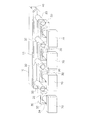
図1に示されている空気調和システム1は、空調対象空間SAに調和空気を供給するシステムである。空調対象空間SAには、建物BLの中の部屋RA1,RA2などがある。ここでは、空調対象空間SAが2つの部屋RA1,RA2である場合について説明するが、空気調和システム1は、種々の大きさ、種々の形状、及び様々な個数の部屋に対応させることができる。空気調和システム1が調和空気を供給する空調対象空間SAは、部屋RA1,RA2のように周囲(前後・上下・左右)が壁面で囲まれていることが好ましい。なお、空調対象空間SAは、部屋RA1,RA2に限られず、例えば、廊下、階段及びエントランスであってもよい。
<First Embodiment>
(1) Overall configuration The air conditioning system 1 shown in FIG. 1 is a system that supplies harmonized air to the air-conditioned space SA. The air-conditioned space SA includes rooms RA1 and RA2 in the building BL. Here, the case where the air-conditioned space SA is two rooms RA1 and RA2 will be described, but the air conditioning system 1 can correspond to various sizes, various shapes, and various numbers of rooms. It is preferable that the air-conditioned space SA to which the air-conditioning system 1 supplies the conditioned air is surrounded by a wall surface (front-rear, up-down, left-right) like the rooms RA1 and RA2. The air-conditioned space SA is not limited to the rooms RA1 and RA2, and may be, for example, a corridor, stairs, and an entrance.

空気調和システム1は、図1に示されているように、利用側熱交換器11を有する熱交換器ユニット10と、メインコントローラ40とを備えている。空気調和システム1は、利用側熱交換器11での熱交換によって調和空気を生成し、調和空気を熱交換器ユニット10に連通する複数の分配流路を介して空調対象空間SAに供給する。各分配流路は、熱交換器ユニット10に接続され、調和空気を分配するためのダクト20と、ダクト20に対応して設けられ、熱交換器ユニット10からダクト20を介して空調対象空間SAに供給するファンユニット30と、から構成される。また、各分配流路は、空調対象空間SAに調和空気を供給する供給空気量を個別に変更できるように構成されているアクチュエータを含む。 As shown in FIG. 1, the air conditioning system 1 includes a heat exchanger unit 10 having a user-side heat exchanger 11 and a main controller 40. The air conditioning system 1 generates harmonized air by heat exchange in the user side heat exchanger 11, and supplies the harmonized air to the air-conditioned space SA via a plurality of distribution channels communicating with the heat exchanger unit 10. Each distribution flow path is connected to the heat exchanger unit 10 and is provided with a duct 20 for distributing the harmonized air and a duct 20 corresponding to the duct 20. The space SA to be air-conditioned from the heat exchanger unit 10 via the duct 20. It is composed of a fan unit 30 for supplying to. Further, each distribution flow path includes an actuator configured to be able to individually change the amount of supply air for supplying the harmonious air to the air-conditioned space SA.

なお、複数のダクト20を区別する場合には、ダクト20aのようにアルファベットの添え字を付して表す。ここでは、ダクト20として、4つのダクト20a〜20dが示されている。また、ファンユニット30として、4台のファンユニット30a〜30dが示されている。また、吹出口ユニット70、リモートコントローラ60として、それぞれ4つの吹出口ユニット70a〜70d、リモートコントローラ60a〜60dが示されている。 When distinguishing a plurality of ducts 20, they are represented by adding alphabetic subscripts such as duct 20a. Here, four ducts 20a to 20d are shown as ducts 20. Further, as the fan unit 30, four fan units 30a to 30d are shown. Further, as the outlet unit 70 and the remote controller 60, four outlet units 70a to 70d and remote controllers 60a to 60d are shown, respectively.

熱交換器ユニット10は、利用側熱交換器11での熱交換によって調和空気を生成する機能を有している。複数のダクト20は、一端21が熱交換器ユニット10に接続されている。複数のダクト20は、熱交換器ユニット10が生成した調和空気を送る複数の管であって、調和空気を分配する機能を有する。 The heat exchanger unit 10 has a function of generating conditioned air by heat exchange in the user side heat exchanger 11. One end 21 of the plurality of ducts 20 is connected to the heat exchanger unit 10. The plurality of ducts 20 are a plurality of pipes for sending the conditioned air generated by the heat exchanger unit 10, and have a function of distributing the conditioned air.

複数のファンユニット30は、複数のダクト20の他端22に接続されている。ここでは、例えば熱交換器ユニット10に接続されている1つのダクト20aに、対応する1つのファンユニット30aが接続されている。同様に、ファンユニット30b〜30dも、それぞれ、対応するダクト20b〜20dに接続されている。ここでは、各ダクト20が1つの一端21と1つの他端22を持つ場合について説明するが、1つのダクト20が、1つの一端21と複数の他端22を持つように分岐していてもよく、そのように分岐した複数の他端22にそれぞれファンユニット30が接続されていてもよい。また、ファンユニット30a〜30dは、吹出口ユニット70a〜70dおよびリモートコントローラ60a〜60dに接続されている。 The plurality of fan units 30 are connected to the other end 22 of the plurality of ducts 20. Here, for example, one corresponding fan unit 30a is connected to one duct 20a connected to the heat exchanger unit 10. Similarly, the fan units 30b to 30d are also connected to the corresponding ducts 20b to 20d, respectively. Here, the case where each duct 20 has one end 21 and one other end 22 will be described, but even if one duct 20 is branched so as to have one end 21 and a plurality of other ends 22. Often, the fan unit 30 may be connected to each of the plurality of other ends 22 that are branched in this way. Further, the fan units 30a to 30d are connected to the outlet units 70a to 70d and the remote controllers 60a to 60d.

空気調和システム1は、空調対象空間SAに配置された複数の吹出口71を有している。各ファンユニット30は、対応する各吹出口71に調和空気を供給する。各吹出口71に調和空気を供給するため、各ファンユニット30は、熱交換器ユニット10から各ダクト20を介して、調和空気を吸引する。各ファンユニット30は、調和空気を吸引するため、各ファンユニット30の各ケーシング31の中に、送風ファン32を有している。各送風ファン32は、各ダクト20の他端22から各吹出口71に向って送風する。各ファンユニット30が有する送風ファン32の台数は、1台でもよく、複数台であってもよい。ここでは、ファンユニット30a〜30dのケーシング31の中に、それぞれ送風ファン32a〜32dが1台ずつ設けられている。 The air conditioning system 1 has a plurality of outlets 71 arranged in the air-conditioned space SA. Each fan unit 30 supplies conditioned air to each corresponding outlet 71. In order to supply conditioned air to each outlet 71, each fan unit 30 sucks conditioned air from the heat exchanger unit 10 through each duct 20. Each fan unit 30 has a blower fan 32 in each casing 31 of each fan unit 30 in order to suck conditioned air. Each blower fan 32 blows air from the other end 22 of each duct 20 toward each outlet 71. The number of blower fans 32 included in each fan unit 30 may be one or a plurality. Here, one blower fan 32a to 32d is provided in each of the casings 31 of the fan units 30a to 30d.

空気調和システム1は、アクチュエータによって、各吹出口71に供給する調和空気の個別の供給空気量を変更できるように構成されている。ここでは、回転数を変更可能なファンモータ33が、アクチュエータである。ここでは、4台のファンモータ33a〜33dが個別に回転数を変更できるように構成されており、ファンモータ33a〜33dがそれぞれ個別に回転数を変更することによって、ファンユニット30a〜30dが個別に供給空気量を変更することができる。 The air conditioning system 1 is configured so that the individual supply air amount of the conditioned air supplied to each outlet 71 can be changed by an actuator. Here, the fan motor 33 whose rotation speed can be changed is an actuator. Here, the four fan motors 33a to 33d are configured so that the rotation speeds can be individually changed, and the fan units 30a to 30d are individually changed by changing the rotation speeds of the fan motors 33a to 33d individually. The amount of air supplied can be changed.

空気調和システム1は、メインコントローラ40から複数のアクチュエータに供給空気量の増減に関する指示を出す。メインコントローラ40を含む空気調和システム1の制御系統については後述する。 The air conditioning system 1 issues instructions regarding an increase / decrease in the amount of supplied air from the main controller 40 to a plurality of actuators. The control system of the air conditioning system 1 including the main controller 40 will be described later.

空気調和システム1は、上記の構成に加えて、熱源ユニット50と、リモートコントローラ60と、吹出口ユニット70と、吸込口ユニット80と、種々のセンサとを備えている。空気調和システム1が備えるセンサについては後述する。 In addition to the above configuration, the air conditioning system 1 includes a heat source unit 50, a remote controller 60, an outlet unit 70, a suction port unit 80, and various sensors. The sensor included in the air conditioning system 1 will be described later.

(2)詳細構成
(2−1)熱交換器ユニット10
熱交換器ユニット10は、利用側熱交換器11と、利用側熱交換器11を収納する中空のハウジング12と、メインコントローラ40とを備えている。ハウジング12は、吸込口81に接続される1つの空気入口12aと、複数のダクト20に接続される複数の空気出口12bとを有している。ここでは、空気入口12aが1つの場合を示しているが、空気入口12aは複数設けられてもよい。利用側熱交換器11は、例えば、フィンアンドチューブ式の熱交換器であり、伝熱フィンの間を通過する空気と、伝熱管の中を流れる冷媒の間で熱交換が行なわれる。空気入口12aから吸い込まれる空気が利用側熱交換器11を通過するときに、利用側熱交換器11を通過する冷媒と空気との間で熱交換が行なわれ、調和空気が生成される。利用側熱交換器11で生成された調和空気は、空気出口12bから各ダクト20a〜20bに吸い込まれる。
(2) Detailed configuration (2-1) Heat exchanger unit 10
The heat exchanger unit 10 includes a user-side heat exchanger 11, a hollow housing 12 for accommodating the user-side heat exchanger 11, and a main controller 40. The housing 12 has one air inlet 12a connected to the suction port 81 and a plurality of air outlets 12b connected to the plurality of ducts 20. Here, the case where there is one air inlet 12a is shown, but a plurality of air inlets 12a may be provided. The user-side heat exchanger 11 is, for example, a fin-and-tube heat exchanger in which heat exchange is performed between the air passing between the heat transfer fins and the refrigerant flowing in the heat transfer tube. When the air sucked from the air inlet 12a passes through the utilization side heat exchanger 11, heat exchange is performed between the refrigerant passing through the utilization side heat exchanger 11 and the air, and conditioned air is generated. The conditioned air generated by the user-side heat exchanger 11 is sucked into the ducts 20a to 20b from the air outlet 12b.

熱交換器ユニット10には、ファンが設けられていない。空気入口12aから熱交換器ユニット10が空気を吸い込むことができるのは、複数のダクト20が全て複数の空気出口12bから空気を吸い込むことにより熱交換器ユニット10の中が負圧になるからである。 The heat exchanger unit 10 is not provided with a fan. The heat exchanger unit 10 can suck air from the air inlet 12a because the inside of the heat exchanger unit 10 becomes negative pressure because the plurality of ducts 20 all suck air from the plurality of air outlets 12b. is there.

(2−2)ダクト20
調和空気を分配する機能を有する複数のダクト20は、熱交換器ユニット10の複数の空気出口12bと複数のファンユニット30とを接続している。ここでは、各ファンユニット30と各吹出口ユニット70が直接接続されている場合について説明するが、ファンユニット30と吹出口ユニット70との間にもダクト20が配置され、ファンユニット30と吹出口ユニット70がダクト20で接続されてもよい。
(2-2) Duct 20
A plurality of ducts 20 having a function of distributing conditioned air connect a plurality of air outlets 12b of the heat exchanger unit 10 and a plurality of fan units 30. Here, a case where each fan unit 30 and each outlet unit 70 are directly connected will be described. However, a duct 20 is also arranged between the fan unit 30 and the outlet unit 70, and the fan unit 30 and the outlet are provided. The unit 70 may be connected by a duct 20.

ダクト20には、金属製の形状が固定された管が用いられてもよく、自在に曲げられる素材からなる管が用いられてもよい。このようなダクト20をつなぎ合せることで、熱交換器ユニット10、複数のファンユニット30及び複数の吹出口ユニット70の様々な配置が可能になる。 For the duct 20, a pipe having a fixed metal shape may be used, or a pipe made of a freely bendable material may be used. By connecting such ducts 20, various arrangements of the heat exchanger unit 10, the plurality of fan units 30, and the plurality of outlet units 70 become possible.

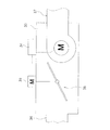
図2には、天井裏室ATで接続されている熱交換器ユニット10と、4つのファンユニット30と、4つの吹出口ユニット70が概念的に示されている。このように構成されている熱交換器ユニット10とファンユニット30と吹出口ユニット70は、薄く形成することが容易であるので、部屋RM1,RM2の床下の空間に配置してもよい。 FIG. 2 conceptually shows a heat exchanger unit 10 connected by an attic AT, four fan units 30, and four outlet units 70. Since the heat exchanger unit 10, the fan unit 30, and the air outlet unit 70 configured in this way can be easily formed thin, they may be arranged in the space under the floor of the rooms RM1 and RM2.

(2−3)ファンユニット30
各ファンユニット30が備える送風ファン32には、例えば遠心ファンを用いることができる。送風ファン32として用いられる遠心ファンには、例えばシロッコファンがある。各ファンユニット30が備えるケーシング31には、吸気口36と排出口37を有している。各ケーシング31の吸気口36には、各ダクト20の他端22が接続されている。各ケーシング31の排出口37には、各送風ファン32の吹出口が接続されるとともに、対応する吹出口ユニット70が接続される。送風ファン32から吹出された調和空気は、吹出口ユニット70の中を通って、吹出口71から吹出される。
(2-3) Fan unit 30
For the blower fan 32 included in each fan unit 30, for example, a centrifugal fan can be used. The centrifugal fan used as the blower fan 32 includes, for example, a sirocco fan. The casing 31 included in each fan unit 30 has an intake port 36 and an exhaust port 37. The other end 22 of each duct 20 is connected to the intake port 36 of each casing 31. The outlets of the blower fans 32 are connected to the outlets 37 of each casing 31, and the corresponding outlet units 70 are connected to the outlets 37. The conditioned air blown out from the blower fan 32 passes through the air outlet unit 70 and is blown out from the air outlet 71.

ケーシング31には、ファンコントローラ34が取り付けられている。ここでは、全てのファンコントローラ34が、メインコントローラ40に接続されている。 A fan controller 34 is attached to the casing 31. Here, all the fan controllers 34 are connected to the main controller 40.

図3には、送風ファン32の一例として、シロッコファンが示されている。この送風ファン32のファンロータ35を回転させるファンモータ33は、回転数を変更することができる。従って、送風ファン32は、ファンモータ33の回転数を変えることによって供給空気量を変更することができる。ファンコントローラ34は、ファンモータ33に接続されており、ファンモータ33の回転数を制御することができる。 In FIG. 3, a sirocco fan is shown as an example of the blower fan 32. The rotation speed of the fan motor 33 that rotates the fan rotor 35 of the blower fan 32 can be changed. Therefore, the blower fan 32 can change the supply air amount by changing the rotation speed of the fan motor 33. The fan controller 34 is connected to the fan motor 33 and can control the rotation speed of the fan motor 33.

各ファンユニット30は、後述する風量検知部として機能する差圧センサ121を備えており、ダクト長さによって各ファンユニット30までのダクト20で生じる空気抵抗が異なっても、必要な供給空気量を出すために必要なファンモータ33の回転数を各ファンコントローラ34が自動的に補正できるように構成されている。ただし、このような補正機能をファンユニット30に搭載しなくてもよい場合もある。 Each fan unit 30 is provided with a differential pressure sensor 121 that functions as an air volume detection unit described later, and even if the air resistance generated in the duct 20 up to each fan unit 30 differs depending on the duct length, the required supply air amount can be obtained. It is configured so that each fan controller 34 can automatically correct the rotation speed of the fan motor 33 required to output the fan motor 33. However, it may not be necessary to equip the fan unit 30 with such a correction function.

(2−4)熱源ユニット50
熱源ユニット50は、熱交換器ユニット10の利用側熱交換器11の熱交換に要する熱エネルギーを供給する。図1に示されている空気調和システム1では、熱源ユニット50と熱交換器ユニット10との間で冷媒が循環し、蒸気圧縮式の冷凍サイクルが行なわれる。熱源ユニット50と熱交換器ユニット10は、蒸気圧縮式の冷凍サイクルを行う冷凍サイクル装置を構成している。図1に示された例では、熱源ユニット50が建物BLの外に置かれ、外気を熱源としているが、熱源ユニット50の配置箇所は建物BLの外には限られない。
(2-4) Heat source unit 50
The heat source unit 50 supplies the heat energy required for heat exchange of the heat exchanger 11 on the user side of the heat exchanger unit 10. In the air conditioning system 1 shown in FIG. 1, the refrigerant circulates between the heat source unit 50 and the heat exchanger unit 10, and a vapor compression refrigeration cycle is performed. The heat source unit 50 and the heat exchanger unit 10 constitute a refrigeration cycle apparatus that performs a vapor compression refrigeration cycle. In the example shown in FIG. 1, the heat source unit 50 is placed outside the building BL and uses the outside air as the heat source, but the location of the heat source unit 50 is not limited to the outside of the building BL.

熱源ユニット50は、圧縮機51と、熱源側熱交換器52と、膨張弁53と、四方弁54と、熱源側ファン55と、熱源コントローラ56と、ユニット内冷媒配管57,58とを備えている。圧縮機51の吐出口が四方弁54の第1ポートに接続され、圧縮機51の吸入口が四方弁54の第3ポートに接続されている。圧縮機51は、吸入口から吸入したガス状態の冷媒(以下、ガス冷媒ともいう)または気液二相状態の冷媒を圧縮して吐出口から吐出する。圧縮機51は、例えばインバータ制御により回転数(または運転周波数)を変更することのできる圧縮機モータを内蔵している。圧縮機51は、運転周波数を変更することにより吐出する冷媒の単位時間当たりの吐出量を変更することができる。 The heat source unit 50 includes a compressor 51, a heat source side heat exchanger 52, an expansion valve 53, a four-way valve 54, a heat source side fan 55, a heat source controller 56, and refrigerant pipes 57 and 58 in the unit. There is. The discharge port of the compressor 51 is connected to the first port of the four-way valve 54, and the suction port of the compressor 51 is connected to the third port of the four-way valve 54. The compressor 51 compresses the gas-state refrigerant (hereinafter, also referred to as gas refrigerant) sucked from the suction port or the gas-liquid two-phase state refrigerant and discharges it from the discharge port. The compressor 51 has a built-in compressor motor that can change the rotation speed (or operating frequency) by, for example, inverter control. The compressor 51 can change the discharge amount of the refrigerant to be discharged per unit time by changing the operating frequency.

四方弁54は、第2ポートに熱源側熱交換器52の一方の出入口を接続し、第4ポートにユニット内冷媒配管58を接続している。四方弁54は、冷房運転時には、実線で示されているように、第1ポートから第2ポートに冷媒が流れて圧縮機51から吐出された冷媒が熱源側熱交換器52に送られ、利用側熱交換器11からユニット内冷媒配管132と冷媒連絡配管92とユニット内冷媒配管58とを介して第4ポートから第3ポートに冷媒が流れて圧縮機51の吸入口に冷媒が送られる。四方弁54は、暖房運転時には、破線で示されているように、第1ポートから第4ポートに冷媒が流れて圧縮機51から吐出された冷媒がユニット内冷媒配管58と冷媒連絡配管92とユニット内冷媒配管132とを介して利用側熱交換器11に送られ、第2ポートから第3ポートに冷媒が流れて熱源側熱交換器52から圧縮機51の吸入口に冷媒が送られる。熱源側熱交換器52は、例えば、フィンアンドチューブ式の熱交換器であり、伝熱フィンの間を通過する空気と、伝熱管の中を流れる冷媒の間で熱交換が行なわれる。 The four-way valve 54 connects one inlet / outlet of the heat source side heat exchanger 52 to the second port, and connects the refrigerant pipe 58 in the unit to the fourth port. During the cooling operation, the four-way valve 54 is used by the refrigerant flowing from the first port to the second port and the refrigerant discharged from the compressor 51 being sent to the heat source side heat exchanger 52 as shown by the solid line. Refrigerant flows from the side heat exchanger 11 from the fourth port to the third port via the refrigerant pipe 132 in the unit, the refrigerant communication pipe 92, and the refrigerant pipe 58 in the unit, and the refrigerant is sent to the suction port of the compressor 51. In the four-way valve 54, as shown by the broken line, during the heating operation, the refrigerant flows from the first port to the fourth port and the refrigerant discharged from the compressor 51 is the refrigerant pipe 58 in the unit and the refrigerant connecting pipe 92. It is sent to the utilization side heat exchanger 11 via the refrigerant pipe 132 in the unit, the refrigerant flows from the second port to the third port, and the refrigerant is sent from the heat source side heat exchanger 52 to the suction port of the compressor 51. The heat source side heat exchanger 52 is, for example, a fin-and-tube heat exchanger, and heat exchange is performed between the air passing between the heat transfer fins and the refrigerant flowing in the heat transfer tube.

熱源側熱交換器52の他方の出入口は膨張弁53の一方端に接続され、膨張弁53の他方端はユニット内冷媒配管57と冷媒連絡配管91とユニット内冷媒配管131とを介して利用側熱交換器11の一方の出入口に接続されている。利用側熱交換器11の他方の出入口は、ユニット内冷媒配管132に接続されている。 The other inlet / outlet of the heat source side heat exchanger 52 is connected to one end of the expansion valve 53, and the other end of the expansion valve 53 is on the utilization side via the refrigerant pipe 57 in the unit, the refrigerant connecting pipe 91, and the refrigerant pipe 131 in the unit. It is connected to one of the inlets and outlets of the heat exchanger 11. The other inlet / outlet of the user-side heat exchanger 11 is connected to the refrigerant pipe 132 in the unit.

このような熱源ユニット50と熱交換器ユニット10が接続されることで冷媒回路200が構成されている。冷媒回路200では、冷房運転時に、圧縮機51、四方弁54、熱源側熱交換器52、膨張弁53、利用側熱交換器11、四方弁54、圧縮機51の順に冷媒が流れる。また、暖房運転時に、冷媒回路200では、圧縮機51、四方弁54、利用側熱交換器11、膨張弁53、熱源側熱交換器52、四方弁54、圧縮機51の順に冷媒が流れる。 The refrigerant circuit 200 is configured by connecting the heat source unit 50 and the heat exchanger unit 10. In the refrigerant circuit 200, during the cooling operation, the refrigerant flows in the order of the compressor 51, the four-way valve 54, the heat source side heat exchanger 52, the expansion valve 53, the utilization side heat exchanger 11, the four-way valve 54, and the compressor 51. Further, during the heating operation, in the refrigerant circuit 200, the refrigerant flows in the order of the compressor 51, the four-way valve 54, the user side heat exchanger 11, the expansion valve 53, the heat source side heat exchanger 52, the four-way valve 54, and the compressor 51.

(2−4−1)冷房運転時の冷媒の循環
冷房運転時には、圧縮機51で圧縮されたガス冷媒が、四方弁54を通って熱源側熱交換器52に送られる。この冷媒は、熱源側ファン55によって流れる空気に熱源側熱交換器52で放熱し、膨張弁53で膨張して減圧され、ユニット内冷媒配管57と冷媒連絡配管91とユニット内冷媒配管131とを通って利用側熱交換器11に送られる。膨張弁53から送られてきた低温低圧の冷媒は、利用側熱交換器11で熱交換を行って吸込口81から送られてきた空気から熱を奪う。利用側熱交換器11で熱交換を終えたガス冷媒または気液二相の冷媒は、ユニット内冷媒配管132と冷媒連絡配管92とユニット内冷媒配管58及び四方弁54を通って圧縮機51に吸入される。利用側熱交換器11で熱を奪われた調和空気が、複数のダクト20、複数のファンユニット30及び複数の吹出口71を通って部屋RA1,RA2に吹出されることにより、部屋RA1,RA2の冷房が行われる。
(2-4-1) Circulation of Refrigerant During Cooling Operation During cooling operation, the gas refrigerant compressed by the compressor 51 is sent to the heat source side heat exchanger 52 through the four-way valve 54. This refrigerant dissipates heat to the air flowing by the heat source side fan 55 by the heat source side heat exchanger 52, expands by the expansion valve 53 and is depressurized, and connects the refrigerant pipe 57 in the unit, the refrigerant connecting pipe 91 and the refrigerant pipe 131 in the unit. It is sent to the user side heat exchanger 11 through. The low-temperature low-pressure refrigerant sent from the expansion valve 53 exchanges heat with the user-side heat exchanger 11 to remove heat from the air sent from the suction port 81. The gas refrigerant or the gas-liquid two-phase refrigerant that has completed heat exchange in the user-side heat exchanger 11 passes through the unit internal refrigerant pipe 132, the refrigerant communication pipe 92, the unit internal refrigerant pipe 58, and the four-way valve 54 to the compressor 51. Inhaled. The conditioned air that has been deprived of heat by the user-side heat exchanger 11 is blown out to the rooms RA1 and RA2 through the plurality of ducts 20, the plurality of fan units 30, and the plurality of outlets 71, thereby causing the rooms RA1 and RA2. Cooling is done.

冷房運転では、圧縮機51で液圧縮が起きないように、例えば、圧縮機51の吸入口に吸入される冷媒の過熱度を過熱度目標値に一致させるような膨張弁53の開度調節の制御が行なわれる。また、このような膨張弁53の開度調節が行なわれつつ、冷房負荷を処理できるように、圧縮機51の運転周波数を変更する制御が行われる。過熱度は、例えば、利用側熱交換器11から送り出されるガス冷媒の温度から利用側熱交換器の中の冷媒の蒸発温度を差し引いて算出される。 In the cooling operation, for example, the opening degree of the expansion valve 53 is adjusted so that the degree of superheat of the refrigerant sucked into the suction port of the compressor 51 matches the target value of the degree of superheat so that liquid compression does not occur in the compressor 51. Control is performed. Further, while adjusting the opening degree of the expansion valve 53 in this way, control is performed to change the operating frequency of the compressor 51 so that the cooling load can be processed. The degree of superheat is calculated by subtracting the evaporation temperature of the refrigerant in the user side heat exchanger from the temperature of the gas refrigerant sent out from the user side heat exchanger 11, for example.

(2−4−2)暖房運転時の冷媒の循環
暖房運転時には、圧縮機51で圧縮されたガス冷媒が、四方弁54及びユニット内冷媒配管58と冷媒連絡配管92とユニット内冷媒配管132を通って利用側熱交換器11に送られる。この冷媒は、利用側熱交換器11で熱交換を行って吸込口81から送られてきた空気に熱を与える。利用側熱交換器11で熱交換を行った冷媒は、ユニット内冷媒配管131と冷媒連絡配管91とユニット内冷媒配管57を通って膨張弁53に送られる。膨張弁53で膨張して減圧された低温低圧の冷媒は、熱源側熱交換器52に送られ、熱源側熱交換器52で熱交換を行い、熱源側ファン55によって流れる空気から熱を得る。熱源側熱交換器52で熱交換を終えたガス冷媒または気液二相の冷媒は、四方弁54を通って圧縮機51に吸入される。利用側熱交換器11で熱を与えられた調和空気が、複数のダクト20、複数のファンユニット30及び複数の吹出口71を通って部屋RA1,RA2に吹出されることにより、部屋RA1,RA2の暖房が行われる。
(2-4-2) Circulation of refrigerant during heating operation During heating operation, the gas refrigerant compressed by the compressor 51 connects the four-way valve 54, the refrigerant pipe 58 in the unit, the refrigerant connecting pipe 92, and the refrigerant pipe 132 in the unit. It is sent to the user side heat exchanger 11 through. This refrigerant exchanges heat with the user side heat exchanger 11 and gives heat to the air sent from the suction port 81. The refrigerant that has undergone heat exchange in the user-side heat exchanger 11 is sent to the expansion valve 53 through the refrigerant pipe 131 in the unit, the refrigerant connecting pipe 91, and the refrigerant pipe 57 in the unit. The low-temperature low-pressure refrigerant expanded and decompressed by the expansion valve 53 is sent to the heat source side heat exchanger 52, heat exchange is performed by the heat source side heat exchanger 52, and heat is obtained from the air flowing by the heat source side fan 55. The gas refrigerant or the gas-liquid two-phase refrigerant that has completed heat exchange in the heat source side heat exchanger 52 is sucked into the compressor 51 through the four-way valve 54. The conditioned air heated by the user-side heat exchanger 11 is blown out to the rooms RA1 and RA2 through the plurality of ducts 20, the plurality of fan units 30, and the plurality of outlets 71, thereby causing the rooms RA1 and RA2. Heating is done.

暖房運転では、例えば、利用側熱交換器11の出口(ユニット内冷媒配管131)における冷媒の過冷却度を過熱度目標値に一致させるように膨張弁53の開度を調節する制御が行われる。また、このような膨張弁53の開度調節が行なわれつつ、暖房負荷を処理できるように、圧縮機51の運転周波数を変更する制御が行われる。利用側熱交換器11の過冷却度は、例えば、利用側熱交換器11の中の冷媒の凝縮温度から利用側熱交換器11から出る液冷媒の温度を差し引くことにより算出される。 In the heating operation, for example, control is performed to adjust the opening degree of the expansion valve 53 so that the degree of supercooling of the refrigerant at the outlet of the user side heat exchanger 11 (refrigerant pipe 131 in the unit) matches the target value of the degree of superheat. .. Further, while adjusting the opening degree of the expansion valve 53 in this way, control is performed to change the operating frequency of the compressor 51 so that the heating load can be processed. The degree of supercooling of the user-side heat exchanger 11 is calculated by, for example, subtracting the temperature of the liquid refrigerant discharged from the user-side heat exchanger 11 from the condensation temperature of the refrigerant in the user-side heat exchanger 11.

吹出口ユニット70は、例えば、吹出口71を下方に向けて天井CEに取り付けられる。ここでは、吹出口ユニット70が天井CEに取り付けられる場合を例に示しているが、例えば吹出口ユニット70が壁に取り付けられてもよく、吹出口ユニット70の取り付け箇所は天井CEには限られない。 The air outlet unit 70 is attached to the ceiling CE, for example, with the air outlet 71 facing downward. Here, the case where the outlet unit 70 is attached to the ceiling CE is shown as an example, but for example, the outlet unit 70 may be attached to the wall, and the attachment location of the outlet unit 70 is limited to the ceiling CE. Absent.

(2−5)吹出口ユニット70
吹出口ユニット70は、中空のケーシング72の中に、エアフィルタ73を備えている。吹出口ユニット70a〜70dは、それぞれファンユニット30a〜30dに接続している。ファンユニット30から送られてきた調和空気は、エアフィルタ73を通って吹出口71から吹出される。ここでは、吹出口ユニット70がエアフィルタ73を備えている場合について説明しているが、吹出口ユニット70はエアフィルタ73を備えない構成であってもよい。
(2-5) Outlet unit 70
The air outlet unit 70 includes an air filter 73 in a hollow casing 72. The outlet units 70a to 70d are connected to the fan units 30a to 30d, respectively. The conditioned air sent from the fan unit 30 is blown out from the outlet 71 through the air filter 73. Although the case where the air outlet unit 70 includes the air filter 73 is described here, the air outlet unit 70 may be configured not to include the air filter 73.

また、吹出口ユニット70は、中空のケーシング72の中に、風向板74を備えている。吹出口ユニット70は、風向板74を駆動するための風向板用モータ75を備えている。ここでは、風向板74を駆動するための風向板用モータ75が、アクチュエータである。風向板74は、風向板用モータ75によって移動することができ、風向を調節することができる。さらに、風向板74は、吹出口71を締め切れる位置に移動することもできる。風向板用モータ75は、例えばファンユニット30のファンコントローラ34に接続される。従って、ファンコントローラ34は、風向及び吹出口71の開閉を制御することができる。ここでは、吹出口ユニット70が風向板74及び風向板用モータ75を備えている場合について説明しているが、吹出口ユニット70は風向板74及び風向板用モータ75を備えない構成であってもよい。 Further, the air outlet unit 70 includes a wind direction plate 74 in a hollow casing 72. The air outlet unit 70 includes a wind direction plate motor 75 for driving the wind direction plate 74. Here, the wind direction plate motor 75 for driving the wind direction plate 74 is an actuator. The wind direction plate 74 can be moved by the wind direction plate motor 75, and the wind direction can be adjusted. Further, the wind direction plate 74 can be moved to a position where the air outlet 71 can be closed. The wind direction plate motor 75 is connected to, for example, the fan controller 34 of the fan unit 30. Therefore, the fan controller 34 can control the wind direction and the opening / closing of the air outlet 71. Here, the case where the air outlet unit 70 includes the wind direction plate 74 and the wind direction plate motor 75 is described, but the air outlet unit 70 does not include the wind direction plate 74 and the wind direction plate motor 75. May be good.

吸込口ユニット80は、例えば、吸込口81を空調対象空間SAに向けて天井CEに取り付けられる。ここでは、吸込口ユニット80が天井CEに取り付けられる場合を例に示しているが、例えば吸込口ユニット80が建物BLの壁に取り付けられてもよく、吸込口ユニット80の取り付け箇所は天井CEには限られない。 The suction port unit 80 is attached to the ceiling CE, for example, with the suction port 81 facing the air-conditioned space SA. Here, the case where the suction port unit 80 is attached to the ceiling CE is shown as an example, but for example, the suction port unit 80 may be attached to the wall of the building BL, and the attachment point of the suction port unit 80 is attached to the ceiling CE. Is not limited.

吸込口ユニット80は、中空のケーシング82の中に、エアフィルタ83を備えている。熱交換器ユニット10に送られる空気は、エアフィルタ83を通って吸込口81から取り入れられる。ここでは、吸込口ユニット80がエアフィルタ83を備えている場合について説明しているが、吸込口ユニット80がエアフィルタ83を備えない構成であってもよい。 The suction port unit 80 includes an air filter 83 in a hollow casing 82. The air sent to the heat exchanger unit 10 is taken in from the suction port 81 through the air filter 83. Although the case where the suction port unit 80 is provided with the air filter 83 is described here, the suction port unit 80 may be configured not to be provided with the air filter 83.

(2−6)制御系統
図4に示されているように、メインコントローラ40は、複数のファンコントローラ34及び熱源コントローラ56に接続されている。熱源コントローラ56は、例えば熱源ユニット50の中の各種の機器に接続されたプリント配線基板上に設けられている各種の回路により構成されており、圧縮機51、膨張弁53、四方弁54及び熱源側ファン55などの熱源ユニット50の中の各種の機器を制御する。また、メインコントローラ40は、各ファンコントローラ34を介して各リモートコントローラ60に接続されている。リモートコントローラ60a〜60dは、吹出口ユニット70a〜70dに対応しており、ファンユニット30a〜30dに接続されている。ここでは、リモートコントローラ60がファンコントローラ34を介してメインコントローラ40に接続される場合について説明しているが、リモートコントローラ60を直接メインコントローラ40に接続してもよい。ここでは、メインコントローラ40と複数のファンコントローラ34と熱源コントローラ56と複数のリモートコントローラ60が、有線で接続されている場合を示しているが、これらの全てまたは一部が無線通信によって接続されてもよい。
(2-6) Control system
As shown in FIG. 4, the main controller 40 is connected to a plurality of fan controllers 34 and heat source controllers 56. The heat source controller 56 is composed of various circuits provided on a printed wiring board connected to various devices in the heat source unit 50, for example, and includes a compressor 51, an expansion valve 53, a four-way valve 54, and a heat source. It controls various devices in the heat source unit 50 such as the side fan 55. Further, the main controller 40 is connected to each remote controller 60 via each fan controller 34. The remote controllers 60a to 60d correspond to the outlet units 70a to 70d and are connected to the fan units 30a to 30d. Although the case where the remote controller 60 is connected to the main controller 40 via the fan controller 34 is described here, the remote controller 60 may be directly connected to the main controller 40. Here, the case where the main controller 40, the plurality of fan controllers 34, the heat source controller 56, and the plurality of remote controllers 60 are connected by wire is shown, but all or a part of them are connected by wireless communication. May be good.

メインコントローラ40と複数のファンコントローラ34と熱源コントローラ56と複数のリモートコントローラ60は、例えばコンピュータにより実現されるものである。メインコントローラ40と複数のファンコントローラ34と熱源コントローラ56と複数のリモートコントローラ60を構成するコンピュータは、制御演算装置と記憶装置とを備える。制御演算装置には、CPU又はGPUといったプロセッサを使用できる。制御演算装置は、記憶装置に記憶されているプログラムを読み出し、このプログラムに従って所定の画像処理や演算処理を行う。さらに、制御演算装置は、プログラムに従って、演算結果を記憶装置に書き込んだり、記憶装置に記憶されている情報を読み出したりすることができる。しかし、メインコントローラ40と複数のファンコントローラ34と熱源コントローラ56と複数のリモートコントローラ60は、CPUとメモリを用いて行うのと同様の制御を行うことができる集積回路(IC)を用いて構成されてもよい。ここでいうICには、LSI(large-scale integrated circuit)、ASIC(application-specific integrated circuit)、ゲートアレイ、FPGA(field programmable gate array)等が含まれる。 The main controller 40, the plurality of fan controllers 34, the heat source controller 56, and the plurality of remote controllers 60 are realized by, for example, a computer. The computer constituting the main controller 40, the plurality of fan controllers 34, the heat source controller 56, and the plurality of remote controllers 60 includes a control arithmetic unit and a storage device. A processor such as a CPU or GPU can be used as the control arithmetic unit. The control arithmetic unit reads a program stored in the storage device and performs predetermined image processing and arithmetic processing according to the program. Further, the control arithmetic unit can write the arithmetic result to the storage device and read the information stored in the storage device according to the program. However, the main controller 40, the plurality of fan controllers 34, the heat source controller 56, and the plurality of remote controllers 60 are configured by using an integrated circuit (IC) capable of performing the same control as that performed by using the CPU and the memory. You may. The IC referred to here includes an LSI (large-scale integrated circuit), an ASIC (application-specific integrated circuit), a gate array, an FPGA (field programmable gate array), and the like.

熱交換器ユニット10には、吸込温度センサ101、ガス側温度センサ102、液側温度センサ103及び利用側熱交換器温度センサ104が配置されている。なお、これらの温度センサあるいは後述する温度センサには例えばサーミスタを用いることができる。また、利用側熱交換器11を通過した直後の空気温度を検出する空気出口温度センサ105を有してもよい。吸込温度センサ101、ガス側温度センサ102、液側温度センサ103及び利用側熱交換器温度センサ104は、メインコントローラ40に接続され、これらの検出結果がメインコントローラ40に送信される。吸込温度センサ101は、空気入口12aから吸い込まれる空気の温度を検出する。ガス側温度センサ102は、ユニット内冷媒配管58に接続された利用側熱交換器11の一方の出入口の冷媒の温度を検出する。液側温度センサ103は、ユニット内冷媒配管57に接続された利用側熱交換器11の他方の出入口の冷媒の温度を検出する。利用側熱交換器温度センサ104は、利用側熱交換器11の中を流れる気液二相状態の熱交換器温度を検出する。 A suction temperature sensor 101, a gas side temperature sensor 102, a liquid side temperature sensor 103, and a user side heat exchanger temperature sensor 104 are arranged in the heat exchanger unit 10. For example, a thermistor can be used for these temperature sensors or the temperature sensors described later. Further, it may have an air outlet temperature sensor 105 that detects the air temperature immediately after passing through the user side heat exchanger 11. The suction temperature sensor 101, the gas side temperature sensor 102, the liquid side temperature sensor 103, and the user side heat exchanger temperature sensor 104 are connected to the main controller 40, and the detection results thereof are transmitted to the main controller 40. The suction temperature sensor 101 detects the temperature of the air sucked from the air inlet 12a. The gas side temperature sensor 102 detects the temperature of the refrigerant at one inlet / outlet of the utilization side heat exchanger 11 connected to the refrigerant pipe 58 in the unit. The liquid side temperature sensor 103 detects the temperature of the refrigerant at the other inlet / outlet of the utilization side heat exchanger 11 connected to the refrigerant pipe 57 in the unit. The user-side heat exchanger temperature sensor 104 detects the temperature of the gas-liquid two-phase heat exchanger flowing through the user-side heat exchanger 11.

熱源ユニット50には、熱源側空気温度センサ111、吐出管温度センサ112及び熱源側熱交換器温度センサ113が配置されている。熱源側空気温度センサ111、吐出管温度センサ112及び熱源側熱交換器温度センサ113は、熱源コントローラ56に接続されている。熱源側空気温度センサ111、吐出管温度センサ112及び熱源側熱交換器温度センサ113の検出結果は、熱源コントローラ56を介してメインコントローラ40に送信される。熱源側空気温度センサ111は、熱源側ファン55によって生じる熱源側熱交換器52を通過する前の気流の温度を検出する。吐出管温度センサ112は、圧縮機51から吐出される冷媒の温度を検出する。熱源側熱交換器温度センサ113は、熱源側熱交換器52内の冷媒流路の中途付近に取り付けられ、熱源側熱交換器52の中を流れる気液二相状態の熱交換器温度を検出する。 A heat source side air temperature sensor 111, a discharge pipe temperature sensor 112, and a heat source side heat exchanger temperature sensor 113 are arranged in the heat source unit 50. The heat source side air temperature sensor 111, the discharge pipe temperature sensor 112, and the heat source side heat exchanger temperature sensor 113 are connected to the heat source controller 56. The detection results of the heat source side air temperature sensor 111, the discharge pipe temperature sensor 112, and the heat source side heat exchanger temperature sensor 113 are transmitted to the main controller 40 via the heat source controller 56. The heat source side air temperature sensor 111 detects the temperature of the air flow before passing through the heat source side heat exchanger 52 generated by the heat source side fan 55. The discharge pipe temperature sensor 112 detects the temperature of the refrigerant discharged from the compressor 51. The heat source side heat exchanger temperature sensor 113 is attached near the middle of the refrigerant flow path in the heat source side heat exchanger 52, and detects the temperature of the gas-liquid two-phase heat exchanger flowing in the heat source side heat exchanger 52. To do.

ファンユニット30には、差圧センサ121及び吹出温度センサ122が配置されている。差圧センサ121では、例えば、ファンユニット30の設置箇所の風上側と風下側の気流の差圧を検出する。差圧センサ121は、ファンコントローラ34に接続されており、ファンコントローラ34に検出した差圧のデータを送信する。例えば、差圧センサ121が取り付けられる箇所の流路の断面積が予め決められており、ファンコントローラ34は、差圧センサ121の検出値から供給空気量を算出することができる。また、差圧センサ121の圧力差から風向を検出することができる。吹出温度センサ122は、例えば各ファンユニット30のケーシング31の中に設置され、各ファンユニット30から吹出される調和空気の温度を検出する。ここでは、吹出温度センサ122が、ファンユニット30のケーシング31の中に設置される場合について説明するが、吹出温度センサ122の設置場所は、他の場所であってもよく、例えば吹出口ユニット70の中を設置場所としてもよい。 A differential pressure sensor 121 and a blowout temperature sensor 122 are arranged in the fan unit 30. The differential pressure sensor 121 detects, for example, the differential pressure between the windward side and the leeward side of the installation location of the fan unit 30. The differential pressure sensor 121 is connected to the fan controller 34, and transmits the detected differential pressure data to the fan controller 34. For example, the cross-sectional area of the flow path where the differential pressure sensor 121 is attached is predetermined, and the fan controller 34 can calculate the supply air amount from the detected value of the differential pressure sensor 121. Further, the wind direction can be detected from the pressure difference of the differential pressure sensor 121. The blowout temperature sensor 122 is installed in, for example, the casing 31 of each fan unit 30 and detects the temperature of the conditioned air blown out from each fan unit 30. Here, the case where the outlet temperature sensor 122 is installed in the casing 31 of the fan unit 30 will be described. However, the outlet temperature sensor 122 may be installed in another location, for example, the outlet unit 70. The inside may be used as the installation location.

複数のリモートコントローラ60は、それぞれ、室内温度センサ61を内蔵しており、空気調和システム1及び/またはファンユニット30の運転のオン・オフの指示、冷暖房の切替、設定温度及び設定風量を入力できるように構成されている。設定温度は例えば、数値で入力できるように構成され、設定風量は微風、弱風、中風、強風の中から選択することで入力できるように構成されている。例えば、ユーザは、リモートコントローラ60の入力ボタンを使って、冷房運転を選択し、設定温度を28℃に設定し、設定風量として中風を選択する。 Each of the plurality of remote controllers 60 has a built-in indoor temperature sensor 61, and can instruct the operation of the air conditioning system 1 and / or the fan unit 30 to be turned on / off, switch between heating and cooling, and input the set temperature and the set air volume. It is configured as follows. For example, the set temperature is configured so that it can be input numerically, and the set air volume is configured so that it can be input by selecting from light wind, weak wind, medium wind, and strong wind. For example, the user selects the cooling operation by using the input button of the remote controller 60, sets the set temperature to 28 ° C., and selects the medium air as the set air volume.

メインコントローラ40は、各吹出温度センサ122で検出される吹出温度と設定温度から各ファンユニット30から吹出させる必要な供給空気量を算出し、ファンモータ33の回転数を制御して、室内温度センサ61の検出値を設定温度に近づける制御を行う。 The main controller 40 calculates the amount of supply air required to be blown from each fan unit 30 from the blowout temperature and the set temperature detected by each blowout temperature sensor 122, controls the rotation speed of the fan motor 33, and controls the indoor temperature sensor. Control is performed so that the detected value of 61 approaches the set temperature.

例えば、初期には、3台のファンユニット30が熱交換器ユニット10に接続され、熱交換器ユニット10の空気出口12bの1つが塞がれている場合を想定する。このような場合に、さらに1台のファンユニット30を追加するときには、塞がれていた空気出口12bにダクト20を接続し、そのダクト20に追加するファンユニット30を接続し、追加されたファンユニット30に吹出口ユニット70を接続する。このようにして追加されたファンユニット30のファンコントローラ34をメインコントローラ40に接続すれば、メインコントローラ40と4つのファンコントローラ34のネットワークが完成し、メインコントローラ40の指示を伝えるネットワークを簡単に構築することができる。 For example, it is assumed that three fan units 30 are initially connected to the heat exchanger unit 10 and one of the air outlets 12b of the heat exchanger unit 10 is blocked. In such a case, when adding one more fan unit 30, a duct 20 is connected to the blocked air outlet 12b, a fan unit 30 to be added to the duct 20 is connected, and the added fan is connected. The outlet unit 70 is connected to the unit 30. By connecting the fan controller 34 of the fan unit 30 added in this way to the main controller 40, the network of the main controller 40 and the four fan controllers 34 is completed, and a network for transmitting the instructions of the main controller 40 can be easily constructed. can do.

(3)空気調和システム1の動作
空気調和システム1では、複数のリモートコントローラ60から入力される設定風量が、複数のファンユニット30の供給空気量を決める基本的な供給空気量になる。しかしながら、設定風量を変えないとすると、設定温度に達した後に冷房運転では設定温度を下回り、暖房運転では設定温度を上回ってしまう。そこで、メインコントローラ40からの指令によって、室内空気温度を設定温度に収束させるために、各ファンユニット30の供給空気量を設定風量から変更する。メインコントローラ40は、室内空気温度と設定温度の温度差から空調負荷を算出し、各ファンユニット30の空調負荷と送風温度から必要な供給空気量を決める。例えば、室内空気温度が設定温度に一致して温度差がない場合には空調負荷が0になるので、メインコントローラ40は、室内空気温度が設定温度に一致しているファンユニット30については、設定風量が0でなくても送風を停止させる。ただし、吹出口71から熱交換器ユニット10に向けて空気を逆流させないために、空調負荷で判断すれば停止させるファンユニット30であっても逆流を抑制するために供給空気量を0にしないように制御されてもよい。
(3) Operation of Air Conditioning System 1 In the air conditioning system 1, the set air volume input from the plurality of remote controllers 60 becomes the basic supply air amount that determines the supply air amount of the plurality of fan units 30. However, if the set air volume is not changed, the temperature will be lower than the set temperature in the cooling operation and higher than the set temperature in the heating operation after reaching the set temperature. Therefore, in order to converge the indoor air temperature to the set temperature by the command from the main controller 40, the supply air amount of each fan unit 30 is changed from the set air volume. The main controller 40 calculates the air conditioning load from the temperature difference between the indoor air temperature and the set temperature, and determines the required supply air amount from the air conditioning load and the blowing temperature of each fan unit 30. For example, if the indoor air temperature matches the set temperature and there is no temperature difference, the air conditioning load becomes 0. Therefore, the main controller 40 sets the fan unit 30 whose indoor air temperature matches the set temperature. Stops blowing even if the air volume is not zero. However, in order to prevent air from flowing back from the outlet 71 toward the heat exchanger unit 10, even if the fan unit 30 is stopped based on the air conditioning load, the amount of supplied air should not be set to 0 in order to suppress backflow. It may be controlled by.

(3−1)起動時
ファンユニット30a〜30dのファンコントローラ34は、それぞれ、4つのリモートコントローラ60の設定風量から各ファンユニット30a〜30dが供給する供給空気量を、メインコントローラ40に送信する。なお、停止しているファンユニット30も、吹出口71から熱交換器ユニット10に向けて空気を逆流させないために極めて僅かに送風する運転しているときには、その微少供給空気量を総風量に含めるように空気調和システム1を構成してもよい。あるいは、その微少供給空気量を総風量に含めないように空気調和システム1を構成してもよい。
(3-1) At startup The fan controllers 34 of the fan units 30a to 30d transmit the amount of supply air supplied by each fan unit 30a to 30d from the set air volumes of the four remote controllers 60 to the main controller 40, respectively. The stopped fan unit 30 also includes the minute amount of supplied air in the total air volume when the fan unit 30 is operating by blowing a very small amount of air from the outlet 71 toward the heat exchanger unit 10 so as not to cause the air to flow back. The air conditioning system 1 may be configured as described above. Alternatively, the air conditioning system 1 may be configured so that the minute supply air amount is not included in the total air volume.

メインコントローラ40は、全てのファンユニット30から送信されてきた供給空気量を合計して、利用側熱交換器11を通過する総風量を算出する。メインコントローラ40は、熱交換器ユニット10の吸込温度センサ101から、熱交換器ユニット10に吸い込まれた空気温度を算出する。そして、メインコントローラ40は、利用側熱交換器11を通過する空気の総風量と空気温度から算出した必要な冷媒循環量を熱源ユニット50の熱源コントローラ56に要求する。熱源ユニット50の熱源コントローラ56は、メインコントローラ40からの要求に応じて、圧縮機51の運転周波数を変更して冷媒循環量を変更する。 The main controller 40 totals the supply air amounts transmitted from all the fan units 30 to calculate the total air volume passing through the user side heat exchanger 11. The main controller 40 calculates the temperature of the air sucked into the heat exchanger unit 10 from the suction temperature sensor 101 of the heat exchanger unit 10. Then, the main controller 40 requests the heat source controller 56 of the heat source unit 50 for the required refrigerant circulation amount calculated from the total air volume of the air passing through the user side heat exchanger 11 and the air temperature. The heat source controller 56 of the heat source unit 50 changes the operating frequency of the compressor 51 to change the amount of refrigerant circulating in response to a request from the main controller 40.

(3−2)通常運転時
空気調和システム1は、通常運転において、総風量が下限値以上の場合と、下限値より小さい場合で制御を変えている。
(3-2) During normal operation In normal operation, the air conditioning system 1 changes the control depending on whether the total air volume is equal to or more than the lower limit value or smaller than the lower limit value.

なお、ここでは、下限値により制御を変える場合について説明するが、空気調和システム1が制御を変えるために用いる値は下限値には限られない。空気調和システム1は、総風量が所定値以上の場合と、所定値より小さい場合で制御を変えるように構成することができる。重ねて説明すると、この所定値に、下限値を用いる場合もあるが、下限値以外の値の場合もある。 Although the case where the control is changed by the lower limit value will be described here, the value used by the air conditioning system 1 to change the control is not limited to the lower limit value. The air conditioning system 1 can be configured to change the control depending on whether the total air volume is equal to or more than a predetermined value or smaller than a predetermined value. To be described again, a lower limit value may be used for this predetermined value, but a value other than the lower limit value may be used.

(3−2−1)総風量が下限値以上のとき
起動時から所定時間が経過して通常運転状態になったときに、メインコントローラ40は、総風量が下限値以上になっているか否かを判断する。下限値の設定については後述する。総風量が下限値以上になっていれば、メインコントローラ40は、次の手順で空気調和システム1の制御を行う。
(3-2-1) When the total air volume is equal to or higher than the lower limit value Whether or not the total air volume of the main controller 40 is equal to or higher than the lower limit value when a predetermined time elapses from the start and the normal operation state is entered. To judge. The setting of the lower limit value will be described later. If the total air volume is equal to or higher than the lower limit, the main controller 40 controls the air conditioning system 1 in the following procedure.

起動時から所定時間が経過して通常運転状態になったときには、所定のインターバルで各ファンコントローラ34が個々の供給空気量を再計算するように構成されている。この再計算においては、例えばリモートコントローラ60が検知した室内空気温度を使って、各吹出口ユニット70の近傍の室内空気温度が、設定温度に対して「近づいている」「離れている」等の状況に基づいて空調負荷を算出し、各ファンコントローラ34が設定風量を補正する。そして、各ファンユニット30が補正した補正供給空気量をメインコントローラ40に送信する。なお、設定風量の補正に関する計算は、メインコントローラ40で行うように構成してもよい。メインコントローラ40は、インターバルごとに複数のファンコントローラ34から送られてくる供給空気量を再計算して総風量を算出し、総風量が下限値以上であれば、インターバルごとの利用側熱交換器11を通過する空気の総風量と空気温度から算出した必要な冷媒循環量を熱源ユニット50の熱源コントローラ56に要求する。熱源ユニット50の熱源コントローラ56は、メインコントローラ40からの要求に応じて、圧縮機51の運転周波数を変更して冷媒循環量を変更する。 When a predetermined time elapses from the start-up and the normal operation state is reached, each fan controller 34 is configured to recalculate the individual supply air amount at a predetermined interval. In this recalculation, for example, using the indoor air temperature detected by the remote controller 60, the indoor air temperature in the vicinity of each outlet unit 70 is "approaching" or "away" from the set temperature. The air conditioning load is calculated based on the situation, and each fan controller 34 corrects the set air volume. Then, the corrected supply air amount corrected by each fan unit 30 is transmitted to the main controller 40. The calculation related to the correction of the set air volume may be performed by the main controller 40. The main controller 40 recalculates the amount of supply air sent from the plurality of fan controllers 34 for each interval to calculate the total air volume, and if the total air volume is equal to or greater than the lower limit, the heat exchanger on the user side for each interval. The heat source controller 56 of the heat source unit 50 is requested to obtain the required refrigerant circulation amount calculated from the total air volume of the air passing through 11 and the air temperature. The heat source controller 56 of the heat source unit 50 changes the operating frequency of the compressor 51 to change the amount of refrigerant circulating in response to a request from the main controller 40.

(3−2−2)総風量が下限値より小さいとき
メインコントローラ40は、総風量が下限値より小さいときには、算出した総風量と下限値との差である不足分を計算する。メインコントローラ40は、予め決められている風量分配規則に従って不足分を複数のファンユニット30に割り振る。複数のファンユニット30に不足分を割り振る際には、総風量が下限値以上であればよいので、不足分に一致する供給空気量を割り振る場合と、不足分以上の供給空気量を割り振る場合とがある。
(3-2-2) When the total air volume is smaller than the lower limit value When the total air volume is smaller than the lower limit value, the main controller 40 calculates the shortage which is the difference between the calculated total air volume and the lower limit value. The main controller 40 allocates the shortage to the plurality of fan units 30 according to a predetermined air volume distribution rule. When allocating the shortage to a plurality of fan units 30, it is sufficient that the total air volume is equal to or higher than the lower limit. Therefore, there are cases where the supply air amount corresponding to the shortage is allocated and cases where the supply air amount equal to or larger than the shortage is allocated. There is.

例えば、下限値が30m/分であり、ファンユニット30aのファンコントローラ34が16m/分、ファンユニット30bのファンコントローラ34が0m/分、ファンユニット30cのファンコントローラ34が10m/分、ファンユニット30dのファンコントローラ34が6m/分をメインコントローラ40に要求している場合を考える。このとき、メインコントローラ40が算出した総風量が32m/分>30m/分となり、メインコントローラ40は、総風量が下限値よりも大きいと判断する。 For example, the lower limit is 30 m 3 / min, the fan controller 34 of the fan unit 30a is 16 m 3 / min, the fan controller 34 of the fan unit 30b is 0 m 3 / min, and the fan controller 34 of the fan unit 30c is 10 m 3 / min. Consider a case where the fan controller 34 of the fan unit 30d requests the main controller 40 to be 6 m 3 / min. At this time, the total air volume calculated by the main controller 40 is 32 m 3 / min> 30 m 3 / min, and the main controller 40 determines that the total air volume is larger than the lower limit value.

次に、ファンユニット30cのファンコントローラ34にリモートコントローラ60から送風停止の指示が入ると、ファンユニット30cのファンコントローラ34の要求が10m/分から0m/分に変更される。そうすると、総風量が32m/分から22m/分に低下するため、メインコントローラ40は、総風量が下限値以下となる変更が指示された判断する。 Next, when the instruction of the blower is stopped from the remote controller 60 to the fan controller 34 of the fan unit 30c enters the request fan controller 34 of the fan unit 30c is changed to 10 m 3 / min to 0 m 3 / min. Then, since the total air volume is reduced to 32m 3 / min to 22m 3 / min, main controller 40 determines changes the total air volume is less than the lower limit value is designated.

一つの例としては、下限値以下となる変更が指示された判断をしたとき、メインコントローラ40は、不足分を、例えば、運転しているファンユニット30に均等に割り振る。上述の場合、8(=30−22)m/分をファンユニット30aに4m/分とファンユニット30bに4m/分とに割り振り、ファンユニット30aが20m/分、ファンユニット30dが10m/分に変更される。 As one example, when it is determined that the change to be equal to or less than the lower limit value is instructed, the main controller 40 evenly allocates the shortage to, for example, the operating fan unit 30. In the above case, 8 (= 30-22) m 3 / min is allocated to the fan unit 30a as 4 m 3 / min and the fan unit 30b as 4 m 3 / min, and the fan unit 30a is 20 m 3 / min and the fan unit 30d is. It will be changed to 10m 3 / min.

他の例としては、下限値以下となる変更が指示された判断をしたとき、メインコントローラ40は、不足分を、例えば、全てのファンユニット30に均等に割り振る。上述の場合、8(=30−22)m/分をファンユニット30a〜30dに2m/分ずつ割り振り、ファンユニット30aが18m/分、ファンユニット30bが2m/分、ファンユニット30bが2m/分、ファンユニット30dが8m/分に変更される。 As another example, when it is determined that the change to be equal to or less than the lower limit value is instructed, the main controller 40 evenly allocates the shortage to, for example, all the fan units 30. In the above case, 8 (= 30-22) m 3 / min is allocated to the fan units 30a to 30d by 2 m 3 / min, the fan unit 30a is 18 m 3 / min, the fan unit 30b is 2 m 3 / min, and the fan unit 30b. Is changed to 2 m 3 / min and the fan unit 30d is changed to 8 m 3 / min.

(3−2−3)下限値の設定
空気調和システム1の総風量の下限値は、メインコントローラ40が、例えば熱交換器温度に基づいて判断する。例えば、冷房運転において、熱交換器温度が高い場合には、熱源ユニット50の熱エネルギーの供給能力が足りていないと判断して、総風量の下限値を高く設定する。そのような場合と比較して、冷房運転において、熱交換器温度が低い場合には、熱源ユニット50の熱エネルギーの供給能力に余裕があると判断して、総風量の下限値を前述の場合に比べて低く設定する。下限値の具体的な値については、例えば、空気調和システム1の実機の試験および/またはシミュレーションによって決定する。
(3-2-3) Setting of lower limit value The lower limit value of the total air volume of the air conditioning system 1 is determined by the main controller 40 based on, for example, the heat exchanger temperature. For example, in the cooling operation, when the heat exchanger temperature is high, it is determined that the heat energy supply capacity of the heat source unit 50 is insufficient, and the lower limit of the total air volume is set high. Compared to such a case, when the heat exchanger temperature is low in the cooling operation, it is determined that the heat energy supply capacity of the heat source unit 50 has a margin, and the lower limit of the total air volume is set as described above. Set lower than. The specific value of the lower limit value is determined by, for example, a test and / or a simulation of an actual machine of the air conditioning system 1.

(3−2−4)空気逆流の検出
例えば、ダクト20aとファンユニット30aと吹出口ユニット70aからなる分配流路において、熱交換器ユニット10から吹出口71に向う気流が正常な気流であり、逆に、吹出口71から熱交換器ユニット10に向う気流が、異常な気流であって、空気逆流である。ダクト20b〜20dとファンユニット30b〜30dと吹出口ユニット70b〜70dからなる分配流路においても同様に、吹出口71から熱交換器ユニット10に向う気流が空気逆流である。ファンユニット30a〜30dのそれぞれに1つずつ設けられている差圧センサ121は、その検出結果を、ファンコントローラ34を介してメインコントローラ40に送信する。
(3-2-4) Detection of air backflow For example, in the distribution flow path including the duct 20a, the fan unit 30a, and the outlet unit 70a, the airflow from the heat exchanger unit 10 to the outlet 71 is a normal airflow. On the contrary, the airflow from the outlet 71 toward the heat exchanger unit 10 is an abnormal airflow, which is an air backflow. Similarly, in the distribution flow path including the ducts 20b to 20d, the fan units 30b to 30d, and the outlet units 70b to 70d, the airflow from the outlet 71 toward the heat exchanger unit 10 is an air backflow. The differential pressure sensor 121 provided for each of the fan units 30a to 30d transmits the detection result to the main controller 40 via the fan controller 34.

メインコントローラ40は、ファンユニット30a〜30dの吸気口36の空気圧に比べて排出口37の空気圧が低いかまたは同じときには正常な気流であると判断し、逆に、ファンユニット30a〜30dの吸気口36の空気圧に比べて排出口37の空気圧が高いときには空気逆流が発生していると判断する。 The main controller 40 determines that the air flow is normal when the air pressure of the discharge port 37 is lower than or is the same as the air pressure of the intake ports 36 of the fan units 30a to 30d, and conversely, the intake port of the fan units 30a to 30d. When the air pressure at the discharge port 37 is higher than the air pressure at 36, it is determined that an air backflow has occurred.

(3−2−5)空気逆流が発生したときの動作
メインコントローラ40は、ファンユニット30の連動により空気逆流を解消する。具体的には、メインコントローラ40は、空気逆流が発生している分配流路に繋がっているファンユニット30を検知する。空気逆流の発生している分配流路のファンユニット30のファンコントローラ34に対して、メインコントローラ40からファンモータ33の回転数を増加させる指令を送信する。例えば、ファンモータ33が停止していた場合には、予め決まっている回転数で駆動を始める指令が送信される。また、例えば、ファンモータ33が低速で回転している場合には、さらにファンモータ33の回転数を上げる指令が送信される。
(3-2-5) Operation when air backflow occurs The main controller 40 eliminates air backflow by interlocking with the fan unit 30. Specifically, the main controller 40 detects the fan unit 30 connected to the distribution flow path in which air backflow is generated. A command for increasing the rotation speed of the fan motor 33 is transmitted from the main controller 40 to the fan controller 34 of the fan unit 30 of the distribution flow path in which air backflow is generated. For example, when the fan motor 33 is stopped, a command to start driving at a predetermined rotation speed is transmitted. Further, for example, when the fan motor 33 is rotating at a low speed, a command for further increasing the rotation speed of the fan motor 33 is transmitted.

なお、風向板74で空気抵抗を変更できるときには、空気逆流を解消するために風向板74を使ってもよい。例えば、ファンモータ33が停止していた場合には、空気逆流が発生している吹出口ユニット70の風向板74を全閉にするように構成してもよい。ファンモータ33が低速で回転している場合には、さらにファンモータ33の回転数を上げるとともに風向板74の空気抵抗を増加させる指令が送信されるように構成してもよい。 When the air resistance can be changed by the wind direction plate 74, the wind direction plate 74 may be used to eliminate the air backflow. For example, when the fan motor 33 is stopped, the wind direction plate 74 of the air outlet unit 70 in which the air backflow is generated may be fully closed. When the fan motor 33 is rotating at a low speed, a command to further increase the rotation speed of the fan motor 33 and increase the air resistance of the wind direction plate 74 may be transmitted.

また、空気逆流の気流の力だけで全閉する逆流防止ダンパを分配流路の中に設ける構成を採用してもよい。その場合には、メインコントローラ40からの指令がなくても逆流を防止することができる。 Further, a configuration may be adopted in which a backflow prevention damper that is fully closed only by the force of the air backflow is provided in the distribution flow path. In that case, backflow can be prevented even if there is no command from the main controller 40.

(4)変形例
(4−1)変形例1A
上記第1実施形態では、熱交換器ユニット10にダクト20を直接接続する場合について説明したが、ダクト20を熱交換器ユニット10に間接的に接続してもよい。例えば、ダクト20と熱交換器ユニット10の間に、ダクト20を熱交換器ユニット10に接続するための複数の空気出口を持つアタッチメントを取り付けるように構成してもよい。接続可能なダクト20の本数が異なる複数種類のアタッチメントを準備することで、同じ機種の熱交換器ユニット10に接続できるダクト20の本数を変更することができる。
(4) Modification example (4-1) Modification example 1A
In the first embodiment, the case where the duct 20 is directly connected to the heat exchanger unit 10 has been described, but the duct 20 may be indirectly connected to the heat exchanger unit 10. For example, an attachment having a plurality of air outlets for connecting the duct 20 to the heat exchanger unit 10 may be attached between the duct 20 and the heat exchanger unit 10. By preparing a plurality of types of attachments having different numbers of connectable ducts 20, the number of ducts 20 that can be connected to the heat exchanger unit 10 of the same model can be changed.

(4−2)変形例1B
上記第1実施形態では、1台のファンユニット30に1つの吹出口ユニット70を接続する場合について説明したが、1台のファンユニット30に複数の吹出口ユニット70を接続するように構成してもよい。1台のファンユニット30に対して複数の吹出口71を設けてもよいということである。この場合、各吹出口ユニット70に対して、1つのリモートコントローラ60を設けるなど、各ファンユニット30に複数のリモートコントローラ60を接続してもよい。
(4-2) Modification 1B
In the first embodiment, the case where one outlet unit 70 is connected to one fan unit 30 has been described, but a plurality of outlet units 70 are configured to be connected to one fan unit 30. May be good. It means that a plurality of outlets 71 may be provided for one fan unit 30. In this case, a plurality of remote controllers 60 may be connected to each fan unit 30, such as providing one remote controller 60 for each outlet unit 70.

(4−3)変形例1C
上記第1実施形態では、部屋RA1,RA2の間の壁に、通風口79を設けて、吸込口81を1つだけ設ける場合について説明した。しかし、吸込口81を設ける数は、1つに限られず、複数であってもよい。また、吸込口81は、例えば、同じ部屋RA1に複数設けてもよく、異なる部屋RA1,RA2の両方に設けてもよい。吸込口81を各部屋RA1,RA2に設ける場合には、通風口79を設けなくてもよい。
(4-3) Modification 1C
In the first embodiment, the case where the ventilation port 79 is provided on the wall between the rooms RA1 and RA2 and only one suction port 81 is provided has been described. However, the number of suction ports 81 provided is not limited to one, and may be plural. Further, a plurality of suction ports 81 may be provided in the same room RA1 or in both different rooms RA1 and RA2, for example. When the suction port 81 is provided in each room RA1 and RA2, it is not necessary to provide the ventilation port 79.

(4−4)変形例1D
熱交換器ユニット10に一端21が接続されたダクト20の他端22に接続されたファンユニット30に、さらに他のダクト20と他のファンユニット30が接続されてもよい。
(4-4) Modification 1D
Another duct 20 and another fan unit 30 may be connected to the fan unit 30 connected to the other end 22 of the duct 20 to which one end 21 is connected to the heat exchanger unit 10.

例えば、1つの分配流路に対して、複数のファンユニット30を直列に接続してもよい。このような接続態様の一例として、熱交換器ユニット10からダクト20、ファンユニット30、ダクト20、ファンユニット30、吹出口ユニット70の順に、2つのダクト20と2つのファンユニット30と1つの吹出口ユニット70を直列に接続する態様がある。1つの分配流路に複数の動力源を設けることで、熱交換器ユニット10から吹出口71までの距離を、同じ動力源を一つだけ設ける場合に比べて長く設定することが可能になる。 For example, a plurality of fan units 30 may be connected in series to one distribution flow path. As an example of such a connection mode, two ducts 20, two fan units 30, and one blow are in the order of the heat exchanger unit 10, the duct 20, the fan unit 30, the duct 20, the fan unit 30, and the outlet unit 70. There is an embodiment in which the outlet units 70 are connected in series. By providing a plurality of power sources in one distribution flow path, the distance from the heat exchanger unit 10 to the outlet 71 can be set longer than in the case where only one same power source is provided.

(4−5)変形例1E
上記第1実施形態では、1台の熱源ユニット50に1台の熱交換器ユニット10が接続される場合について説明したが、熱源ユニット50と熱交換器ユニット10の接続態様は、このような態様には限られない。例えば、1台の熱源ユニット50に複数台の熱交換器ユニット10を接続してもよい。また、複数台の熱交換器ユニット10に対して複数の熱源ユニット50を接続するように構成してもよい。これらの接続態様では、熱交換器ユニット10に、利用側熱交換器11を流れる冷媒の流量を調節する流量調整装置を設けてもよい。このような流量調整装置としては、弁開度を変更可能な流量調整弁がある。また、一つの冷媒回路200の中に複数の熱交換器ユニット10が設けられている場合に、複数の熱交換器ユニット10の中の特定の熱交換器ユニット10に冷媒を循環させる冷媒系統が冷媒回路200の中に形成されているときに、特定の熱交換器ユニット10の利用側熱交換器11を通過する風量の下限値が当該冷媒系統を循環する冷媒の状態または循環量に影響を与えるパラメータに応じて変わるように設定されていてもよい。
(4-5) Modification 1E
In the first embodiment, the case where one heat exchanger unit 10 is connected to one heat source unit 50 has been described, but the connection mode between the heat source unit 50 and the heat exchanger unit 10 is such a mode. Not limited to. For example, a plurality of heat exchanger units 10 may be connected to one heat source unit 50. Further, a plurality of heat source units 50 may be connected to the plurality of heat exchanger units 10. In these connection modes, the heat exchanger unit 10 may be provided with a flow rate adjusting device for adjusting the flow rate of the refrigerant flowing through the user-side heat exchanger 11. As such a flow rate adjusting device, there is a flow rate adjusting valve capable of changing the valve opening degree. Further, when a plurality of heat exchanger units 10 are provided in one refrigerant circuit 200, a refrigerant system for circulating the refrigerant to a specific heat exchanger unit 10 in the plurality of heat exchanger units 10 is provided. When formed in the refrigerant circuit 200, the lower limit of the air volume passing through the user-side heat exchanger 11 of the specific heat exchanger unit 10 affects the state or circulation amount of the refrigerant circulating in the refrigerant system. It may be set to change according to the given parameters.

(4−6)変形例1F
上記第1実施形態では、熱源ユニット50の圧縮機51が回転数を変更できるタイプである場合について説明した。しかし、熱源ユニット50には、圧縮機51として、回転数を変更できないタイプのものを用いてもよい。
(4-6) Modification 1F
In the first embodiment, the case where the compressor 51 of the heat source unit 50 is of a type capable of changing the rotation speed has been described. However, as the heat source unit 50, a compressor 51 of a type whose rotation speed cannot be changed may be used.

(4−7)変形例1G
上記第1実施形態では、空気調和システム1が冷房運転と暖房運転を切り換えられるように構成されている場合について説明した。しかし、上記第1実施形態の技術コンセプトは、冷房専用または暖房専用の空気調和システムに適用することができる。
(4-7) Modification 1G
In the first embodiment, the case where the air conditioning system 1 is configured to switch between the cooling operation and the heating operation has been described. However, the technical concept of the first embodiment can be applied to an air conditioning system dedicated to cooling or heating.

(4−8)変形例1H
上記第1実施形態では、熱源ユニット50と熱交換器ユニット10が接続されて、利用側熱交換器11に冷媒を流す冷凍サイクル装置を構成する場合について説明したが、熱源ユニット50は熱交換器ユニット10が接続されて冷凍サイクル装置を構成する場合に限らない。利用側熱交換器11に熱エネルギーを供給する熱源ユニットは、例えば、温水及び/または冷水などの熱媒体を供給するように構成してもよい。
(4-8) Modification 1H
In the first embodiment, the case where the heat source unit 50 and the heat exchanger unit 10 are connected to form a refrigeration cycle device in which the refrigerant flows to the user side heat exchanger 11 has been described. However, the heat source unit 50 is a heat exchanger. It is not limited to the case where the units 10 are connected to form a refrigeration cycle apparatus. The heat source unit that supplies heat energy to the user-side heat exchanger 11 may be configured to supply a heat medium such as hot water and / or cold water.

このように利用側熱交換器11に熱媒体を流すように構成する場合、利用側熱交換器11に流れる熱媒体の流量を調節するための流量調整装置を熱交換器ユニット10に設けてもよい。 When the heat medium is configured to flow through the user side heat exchanger 11 in this way, the heat exchanger unit 10 may be provided with a flow rate adjusting device for adjusting the flow rate of the heat medium flowing through the user side heat exchanger 11. Good.

また、このような熱媒体を供給する熱源ユニットに熱交換器ユニット10を接続する場合、1台の熱源ユニットに複数台の熱交換器ユニット10を接続するように構成してもよい。 Further, when the heat exchanger unit 10 is connected to the heat source unit that supplies such a heat medium, a plurality of heat exchanger units 10 may be connected to one heat source unit.

(4−9)変形例1I
上記第1実施形態では、起動時において、メインコントローラ40が、算出した利用側熱交換器11を通過する空気の総風量と、算出した熱交換器ユニット10に吸い込まれた空気温度から計算した冷媒回路200の必要な冷媒循環量を要求する場合について説明した。しかし、メインコントローラ40が要求する必要な冷媒循環量の決定方法は前述の方法には限られない。
(4-9) Modification 1I
In the first embodiment, the refrigerant calculated by the main controller 40 from the calculated total air volume of air passing through the user-side heat exchanger 11 and the calculated air temperature sucked into the heat exchanger unit 10 at the time of startup. The case where the required refrigerant circulation amount of the circuit 200 is required has been described. However, the method for determining the required refrigerant circulation amount required by the main controller 40 is not limited to the above-mentioned method.

例えば、空気調和システム1を次のように構成してもよい。起動時に、メインコントローラ40は、全てのファンユニット30から送信されてきた供給空気量を合計して、利用側熱交換器11を通過する総風量を算出する。メインコントローラ40は、例えば内部のメモリに総風量と必要な冷媒循環量との関係を示す風量テーブルを記憶している。メインコントローラ40は、算出した総風量に最も近い風量を風量テーブルに記述されている風量の中から選択する。風量テーブルの中の選択された総風量に対応する冷媒循環量を、メインコントローラ40が熱源コントローラ56に要求する。そして、風量テーブルの中の選択された風量と総風量との差分については、メインコントローラ40からファンコントローラ34に指令を出して、差分に相当する供給空気量を複数のファンユニット30に変更させるように空気調和システム1を構成してもよい。 For example, the air conditioning system 1 may be configured as follows. At startup, the main controller 40 totals the supply air amounts transmitted from all the fan units 30 to calculate the total air volume passing through the user side heat exchanger 11. The main controller 40 stores, for example, an air volume table showing the relationship between the total air volume and the required refrigerant circulation amount in an internal memory. The main controller 40 selects the air volume closest to the calculated total air volume from the air volumes described in the air volume table. The main controller 40 requests the heat source controller 56 for a refrigerant circulation amount corresponding to the selected total air volume in the air volume table. Then, regarding the difference between the selected air volume and the total air volume in the air volume table, the main controller 40 issues a command to the fan controller 34 to change the supply air volume corresponding to the difference to the plurality of fan units 30. The air conditioning system 1 may be configured.

また、例えば、空気調和システム1を次のように構成してもよい。起動時において、メインコントローラ40は、ファンコントローラ34を介してリモートコントローラ60の設定温度を受信する。また、メインコントローラ40は、リモートコントローラ60で検出される室内空気温度、吸込温度センサ101の検出値から算出される室内空気温度、またはメインコントローラ40に室内空気温度を送信可能な室内温度センサから室内空気温度を受信する。メインコントローラ40は、受信した設定温度と室内空気温度から空気調和システム1の全体の空調負荷を算出する。メインコントローラ40は、算出した空調負荷から総風量と必要な冷媒循環量を算出する。メインコントローラ40は、各ファンユニット30の個々の供給空気量を、総風量と各ファンユニット30の空調負荷の比率との積によって算出して複数のファンコントローラ34に指令を出す。メインコントローラ40から指示された個々の供給空気量に合わせて各ファンコントローラ34が各自で調整を行うように空気調和システム1を構成してもよい。 Further, for example, the air conditioning system 1 may be configured as follows. At startup, the main controller 40 receives the set temperature of the remote controller 60 via the fan controller 34. Further, the main controller 40 is indoors from an indoor air temperature detected by the remote controller 60, an indoor air temperature calculated from a value detected by the suction temperature sensor 101, or an indoor air temperature sensor capable of transmitting the indoor air temperature to the main controller 40. Receive air temperature. The main controller 40 calculates the entire air conditioning load of the air conditioning system 1 from the received set temperature and the indoor air temperature. The main controller 40 calculates the total air volume and the required refrigerant circulation amount from the calculated air conditioning load. The main controller 40 calculates the individual supply air amount of each fan unit 30 by the product of the total air volume and the ratio of the air conditioning load of each fan unit 30, and issues a command to the plurality of fan controllers 34. The air conditioning system 1 may be configured so that each fan controller 34 adjusts by itself according to the individual supply air amount instructed by the main controller 40.

(4−10)変形例1J
上記第1実施形態の空気調和システム1では、総風量を主に決定して、それに熱源ユニット50の冷媒に係る条件を従わせるような制御をメインコントローラ40が行う場合について説明した。しかし、逆に熱源ユニット50の冷媒に係わる条件を主に決定し、その条件に従わせるように総風量を決定するように、空気調和システム1を構成してもよい。
(4-10) Modification 1J
In the air conditioning system 1 of the first embodiment, the case where the main controller 40 mainly determines the total air volume and controls the heat source unit 50 to comply with the conditions related to the refrigerant has been described. However, conversely, the air conditioning system 1 may be configured so as to mainly determine the conditions related to the refrigerant of the heat source unit 50 and determine the total air volume so as to comply with the conditions.

例えば、熱源コントローラ56が、圧縮機51の運転周波数及び/または膨張弁53の弁開度の制御を行うように、空気調和システム1が構成される。このように構成された空気調和システム1では、熱源コントローラ56が、現在の利用側熱交換器11を通過する空気の総風量に関する情報を把握する。熱源コントローラ56は、圧縮機51の運転周波数及び/または膨張弁53の開度に関する情報から、現在の総風量に対して、風量を増減させる必要があることをメインコントローラ40に送信する。メインコントローラ40は、熱源コントローラ56からの風量の増減の指示を受けて、複数のファンユニット30に対し、どのような割合で各ファンユニット30の風量を増減させるのがシステム全体のエネルギーを抑制するのに適しているかを計算して指示を出す。 For example, the air conditioning system 1 is configured so that the heat source controller 56 controls the operating frequency of the compressor 51 and / or the valve opening degree of the expansion valve 53. In the air conditioning system 1 configured in this way, the heat source controller 56 grasps information regarding the total air volume of the air passing through the current utilization side heat exchanger 11. The heat source controller 56 transmits to the main controller 40 that it is necessary to increase or decrease the air volume with respect to the current total air volume based on the information regarding the operating frequency of the compressor 51 and / or the opening degree of the expansion valve 53. The main controller 40 receives an instruction from the heat source controller 56 to increase or decrease the air volume, and increasing or decreasing the air volume of each fan unit 30 with respect to the plurality of fan units 30 suppresses the energy of the entire system. Calculate whether it is suitable for and give instructions.

(4−11)変形例1K
上記第1実施形態の空気調和システム1では、圧縮機51の運転周波数を変更することで、冷媒回路200の冷媒循環量を調節している。しかし、空気調和システム1における冷媒循環量の制御は、圧縮機51の運転周波数の制御に限られない。例えば、圧縮機51の運転周波数とともに膨張弁53の弁開度を調節することによって冷媒回路200の冷媒循環量を調節するように制御してもよく、膨張弁53の弁開度を調節することによって冷媒回路200の冷媒循環量を調節するように制御してもよい。
(4-11) Modification 1K
In the air conditioning system 1 of the first embodiment, the refrigerant circulation amount of the refrigerant circuit 200 is adjusted by changing the operating frequency of the compressor 51. However, the control of the refrigerant circulation amount in the air conditioning system 1 is not limited to the control of the operating frequency of the compressor 51. For example, it may be controlled to adjust the refrigerant circulation amount of the refrigerant circuit 200 by adjusting the valve opening degree of the expansion valve 53 together with the operating frequency of the compressor 51, and adjusting the valve opening degree of the expansion valve 53. It may be controlled so as to adjust the refrigerant circulation amount of the refrigerant circuit 200.

(4−12)変形例1L
上記第1実施形態では、利用側熱交換器11の熱交換器温度で総風量の下限値を決めたが、凝縮温度(TC)、蒸発温度(TE)、過熱度(SH)及び過冷却度(SC)を用いてもよい。過熱度は、例えば、利用側熱交換器11の入口温度と出口温度、あるいは利用側熱交換器11の入口圧力と出口温度を用いて算出することができる。過冷却度は、例えば、利用側熱交換器11の入口温度と出口温度、あるいは利用側熱交換器11の入口圧力と出口温度を用いて算出することができる。
(4-12) Modification 1L
In the first embodiment, the lower limit of the total air volume is determined by the heat exchanger temperature of the user side heat exchanger 11, but the condensation temperature (TC), evaporation temperature (TE), superheat degree (SH) and supercooling degree are determined. (SC) may be used. The degree of superheat can be calculated using, for example, the inlet temperature and outlet temperature of the utilization side heat exchanger 11, or the inlet pressure and outlet temperature of the utilization side heat exchanger 11. The degree of supercooling can be calculated using, for example, the inlet temperature and outlet temperature of the utilization side heat exchanger 11, or the inlet pressure and outlet temperature of the utilization side heat exchanger 11.

総風量の下限値は、例えば、予め決めていた固定された値であってもよく、予め下限値が8m/分と決められていれば、その下限値8m/分を常に下回らないように、メインコントローラ40が制御を行う。 The lower limit of the total air volume may be, for example, a predetermined fixed value, and if the lower limit is set to 8 m 3 / min in advance, the lower limit should not always fall below the lower limit of 8 m 3 / min. In addition, the main controller 40 controls.

また、総風量の下限値は、例えば、冷房運転では、過熱度と現在の総風量と熱交換器ユニット10に吸い込まれる空気の吸込温度に応じて決められるように空気調和システム1を構成してもよい。また、暖房運転では、過冷却度と現在の総風量と熱交換器ユニット10に吸い込まれる空気の吸込温度に応じて総風量の下限値が決められるように、空気調和システム1を構成してもよい。また、冷媒循環量(例えば、圧縮機51の運転周波数)と蒸発温度(TE)と熱交換器ユニット10に吸い込まれる吸込空気温度及び吸込風量に応じて総風量の下限値が決められるように、空気調和システム1を構成してもよい。また、利用側熱交換器11の通過後の冷媒の渇き度または湿り度から算出される風量過不足風量と現在風量に応じて総風量の下限値が決められるように、空気調和システム1を構成してもよい。さらには、利用側熱交換器11の出口の冷媒圧力と冷媒の温度に応じて総風量の下限値が決められるように、空気調和システム1を構成してもよい。 Further, for example, in the cooling operation, the lower limit value of the total air volume is configured in the air conditioning system 1 so as to be determined according to the degree of superheat, the current total air volume, and the suction temperature of the air sucked into the heat exchanger unit 10. May be good. Further, in the heating operation, the air conditioning system 1 may be configured so that the lower limit of the total air volume is determined according to the degree of supercooling, the current total air volume, and the suction temperature of the air sucked into the heat exchanger unit 10. Good. Further, the lower limit of the total air volume is determined according to the refrigerant circulation amount (for example, the operating frequency of the compressor 51), the evaporation temperature (TE), the suction air temperature sucked into the heat exchanger unit 10, and the suction air volume. The air conditioning system 1 may be configured. Further, the air conditioning system 1 is configured so that the lower limit of the total air volume is determined according to the air volume excess / deficiency air volume calculated from the degree of thirst or dampness of the refrigerant after passing through the user side heat exchanger 11 and the current air volume. You may. Further, the air conditioning system 1 may be configured so that the lower limit of the total air volume is determined according to the refrigerant pressure at the outlet of the user-side heat exchanger 11 and the temperature of the refrigerant.

(4−13)変形例1M
(4−13−1)
第1実施形態では、熱交換器ユニット10から複数のダクト20を介して吸引して空調対象空間SAの複数の吹出口71に供給する調和空気の個別の供給空気量を変更できるように構成されている複数のアクチュエータとして、回転数を変更できるファンモータ33を例に挙げて説明した。しかし、アクチュエータはファンモータ33に限られず、例えば、複数のアクチュエータとして、図5に示されているダンパ38の駆動モータ39を用いてもよい。図5に示されている送風ファン32のファンモータ33は、第1実施形態と同様の回転数を変更できるタイプのモータであってもよいが、回転数を変更できないタイプのモータであってもよい。ファンモータ33が回転数を変更できないタイプであるときには、ダンパ38だけでファンユニット30から吹出口ユニット70への供給空気量(風量)を変更することになる。それに対して、ファンモータ33が回転数を変更できるタイプであるときには、ダンパ38の開度の変更だけでなく、ファンモータ33の回転数の変更も合わせてファンユニット30から吹出口ユニット70への供給空気量(風量)を変更することになる。
(4-13) Modification 1M
(4-13-1)
In the first embodiment, it is configured so that the individual supply air amount of the harmonized air sucked from the heat exchanger unit 10 through the plurality of ducts 20 and supplied to the plurality of outlets 71 of the air-conditioned space SA can be changed. As the plurality of actuators, the fan motor 33 capable of changing the number of rotations has been described as an example. However, the actuator is not limited to the fan motor 33, and for example, the drive motor 39 of the damper 38 shown in FIG. 5 may be used as a plurality of actuators. The fan motor 33 of the blower fan 32 shown in FIG. 5 may be a type of motor whose rotation speed can be changed as in the first embodiment, but may be a type of motor whose rotation speed cannot be changed. Good. When the fan motor 33 is of a type whose rotation speed cannot be changed, the amount of air supplied from the fan unit 30 to the outlet unit 70 (air volume) is changed only by the damper 38. On the other hand, when the fan motor 33 is of a type capable of changing the rotation speed, not only the opening degree of the damper 38 is changed but also the rotation speed of the fan motor 33 is changed from the fan unit 30 to the outlet unit 70. The supply air volume (air volume) will be changed.

(4−13−2)逆流が発生したときの動作
メインコントローラ40は、ファンユニット30の連動により空気逆流を解消する。空気逆流解消のために先ず、メインコントローラ40は、空気逆流が発生している分配流路に繋がっているファンユニット30を検知する。ファンユニット30がダンパ38のみで供給空気量を調整する構成の場合には、空気逆流の発生している分配流路のファンユニット30のファンコントローラ34に対して、メインコントローラ40からダンパ38の開度を変更させる指令を送信する。例えば、空気逆流が発生しているファンユニット30が運転していない場合には、ダンパ38を全閉にする指令が送信される。ファンモータ33を一定の回転で送風しながらダンパ38の開度によって送風しているときには通常は空気逆流が発生することは無いので、メインコントローラ40は、そのような場合に空気逆流が発生した場合には、例えばリモートコントローラ60を使って異常の発生をユーザに報知する。
(4-13-2) Operation when backflow occurs The main controller 40 eliminates air backflow by interlocking with the fan unit 30. In order to eliminate the air backflow, the main controller 40 first detects the fan unit 30 connected to the distribution flow path in which the air backflow is generated. When the fan unit 30 is configured to adjust the supply air amount only by the damper 38, the damper 38 is opened from the main controller 40 with respect to the fan controller 34 of the fan unit 30 of the distribution flow path in which the air backflow is generated. Send a command to change the degree. For example, when the fan unit 30 in which air backflow is generated is not operating, a command to fully close the damper 38 is transmitted. Normally, no air backflow occurs when the fan motor 33 is blown at a constant rotation and the air is blown by the opening degree of the damper 38. Therefore, when the air backflow occurs in such a case, the main controller 40 does not generate the air backflow. For example, the remote controller 60 is used to notify the user of the occurrence of an abnormality.

ファンユニット30がファンモータ33の回転数とダンパ38の開度の両方で供給空気量を調整できる構成の場合には、空気逆流の発生している分配流路のファンユニット30のファンコントローラ34に対して、メインコントローラ40からファンモータ33の回転数および/またはダンパ38の開度を変更させる指令を送信する。例えば、空気逆流が発生しているファンユニット30が運転していない場合には、ダンパ38を全閉にする指令が送信される。また、例えば、ファンモータ33が低速で回転している場合には、さらに回転数を上げる指令が送信される。あるいは、例えば、ファンモータ33が低速で回転している場合には、ダンパ38の開度を小さくするとともにファンモータ33の回転数を上げる指令が送信されるように構成されてもよい。 When the fan unit 30 has a configuration in which the supply air amount can be adjusted by both the rotation speed of the fan motor 33 and the opening degree of the damper 38, the fan controller 34 of the fan unit 30 of the distribution flow path in which the air backflow is generated is used. On the other hand, the main controller 40 transmits a command to change the rotation speed of the fan motor 33 and / or the opening degree of the damper 38. For example, when the fan unit 30 in which air backflow is generated is not operating, a command to fully close the damper 38 is transmitted. Further, for example, when the fan motor 33 is rotating at a low speed, a command to further increase the rotation speed is transmitted. Alternatively, for example, when the fan motor 33 is rotating at a low speed, a command for reducing the opening degree of the damper 38 and increasing the rotation speed of the fan motor 33 may be transmitted.

(4−14)変形例1N
上記第1実施形態では、空気逆流を検出する検出装置として、差圧センサ121が用いられる場合について説明したが、空気逆流を検出する検出装置は差圧センサ121を用いるものには限られない。このような検出装置として、指向性のある風速センサを用いてもよい。差圧センサ121に変えて指向性のある風向センサを用いる場合には、風向センサを例えばファンユニット30に配置してファンコントローラ34に接続する。指向性のある風向センサを用いる場合には、例えば、正の方向の風速を示すときには正常な方向に空気が流れ、その逆の負の方向の風速を示すときには空気逆流が発生していることを、メインコントローラ40が検知することができる。また、検出装置を複数の無指向性の風速センサを用いて構成することもできる。複数の無指向性の風速センサで風速の分布を検出し、風速の分布が逆流の際に生じる分布であれば、メインコントローラ40で、逆流が発生していると判断することができる。
(4-14) Modification 1N
In the first embodiment, the case where the differential pressure sensor 121 is used as the detection device for detecting the air backflow has been described, but the detection device for detecting the air backflow is not limited to the one using the differential pressure sensor 121. A directional wind speed sensor may be used as such a detection device. When a directional wind direction sensor is used instead of the differential pressure sensor 121, the wind direction sensor is arranged in, for example, the fan unit 30 and connected to the fan controller 34. When using a directional wind direction sensor, for example, when the wind speed in the positive direction is shown, air flows in the normal direction, and when the wind speed in the opposite negative direction is shown, air backflow occurs. , The main controller 40 can detect it. Further, the detection device can be configured by using a plurality of omnidirectional wind speed sensors. The distribution of the wind speed is detected by a plurality of omnidirectional wind speed sensors, and if the distribution of the wind speed is a distribution generated at the time of backflow, the main controller 40 can determine that backflow is occurring.

(4−15)変形例1O
上記第1実施形態では、差圧センサ121(風量検知部)を用いて決められた区間内の差圧を検出する構成について説明したが、風量を検知する構成はこのような構成には限られない。風量を検知する構成は、例えば、差圧センサを用いてファンユニット30の送風ファン32の前後の差圧を検知し、送風ファン32の前後の差圧特性からメインコントローラ40またはファンコントローラ34が風量を算出するように構成することもできる。この場合も差圧センサが風量検知部になる。例えば、風速センサを用いて特定の位置の風速を検知し、特定の位置の風速特性からメインコントローラ40またはファンコントローラ34が風量を算出するように構成することもできる。この場合には風速センサが風量検知部になる。例えば、圧力センサを用いて内部圧力変位を検知し、既定の風量が流れた際の内部圧力変位と、検知された圧力変位とを比較してメインコントローラ40またはファンコントローラ34が風量を算出するように構成することもできる。この場合には、圧力センサが風量検知部になる。また、例えば、送風ファン32の運転電流を用いて、ファンモータ33の仕事量からメインコントローラ40またはファンコントローラ34が風量を算出するように構成することもできる。この場合には運転電流を検知する機器が風量検知部になる。
(4-15) Modification 1O
In the first embodiment, the configuration for detecting the differential pressure in the section determined by using the differential pressure sensor 121 (air volume detection unit) has been described, but the configuration for detecting the air volume is limited to such a configuration. Absent. In the configuration for detecting the air volume, for example, the differential pressure sensor is used to detect the differential pressure before and after the blower fan 32 of the fan unit 30, and the main controller 40 or the fan controller 34 determines the air volume from the differential pressure characteristics before and after the blower fan 32. Can also be configured to calculate. In this case as well, the differential pressure sensor serves as the air volume detection unit. For example, the wind speed sensor may be used to detect the wind speed at a specific position, and the main controller 40 or the fan controller 34 may be configured to calculate the air volume from the wind speed characteristic at the specific position. In this case, the wind speed sensor becomes the air volume detection unit. For example, the internal pressure displacement is detected using a pressure sensor, and the internal pressure displacement when a predetermined air volume flows is compared with the detected pressure displacement so that the main controller 40 or the fan controller 34 calculates the air volume. It can also be configured in. In this case, the pressure sensor becomes the air volume detection unit. Further, for example, the operating current of the blower fan 32 can be used, and the main controller 40 or the fan controller 34 can be configured to calculate the air volume from the work amount of the fan motor 33. In this case, the device that detects the operating current becomes the air volume detection unit.

(4−16)変形例1P
上記第1実施形態では、メインコントローラ40が冷媒循環量を算出し、熱源コントローラ56に圧縮機51の運転周波数の変更の要求を送信し、熱源コントローラ56が圧縮機51の運転周波数を制御する場合を例に挙げて説明した。しかし、メインコントローラ40が、圧縮機51の運転周波数の制御及び/または膨張弁53の弁開度の制御を行うように、空気調和システム1が構成されてもよい。
(4-16) Modification 1P
In the first embodiment, the main controller 40 calculates the amount of refrigerant circulation, sends a request for changing the operating frequency of the compressor 51 to the heat source controller 56, and the heat source controller 56 controls the operating frequency of the compressor 51. Was explained as an example. However, the air conditioning system 1 may be configured such that the main controller 40 controls the operating frequency of the compressor 51 and / or the valve opening degree of the expansion valve 53.

(4−17)変形例1Q
上記第1実施形態では、メインコントローラ40が熱交換器ユニット10に設けられる場合を例に挙げて説明した。しかし、メインコントローラ40が設けられる場所は、熱交換器ユニット10に限られるものではない。例えば、メインコントローラ40は、ファンユニット30に設けられてもよい。
(4-17) Modification 1Q
In the first embodiment, the case where the main controller 40 is provided in the heat exchanger unit 10 has been described as an example. However, the place where the main controller 40 is provided is not limited to the heat exchanger unit 10. For example, the main controller 40 may be provided in the fan unit 30.

(5)特徴
(5−1)
上記の空気調和システム1のメインコントローラ40が、利用側熱交換器11を通過する風量が所定条件を満たすように、複数のファンユニット30の複数のアクチュエータであるファンモータ33もしくはダンパ38の駆動モータ39または風向板74の風向板用モータ75を制御する。その結果、利用側熱交換器11を通過する風量によって空気調和システム1の不具合を抑制することができる。
(5) Features (5-1)
The drive motor of the fan motor 33 or the damper 38, which is a plurality of actuators of the plurality of fan units 30, so that the main controller 40 of the air conditioning system 1 satisfies a predetermined condition for the air volume passing through the user side heat exchanger 11. It controls the wind direction plate motor 75 of 39 or the wind direction plate 74. As a result, the malfunction of the air conditioning system 1 can be suppressed by the amount of air passing through the heat exchanger 11 on the user side.

(5−2)
上記の空気調和システム1では、ダクト20aとファンユニット30aと吹出口ユニット70aの吹出口71によって構成される分配流路と、同様にダクト20b〜20dとファンユニット30b〜30dと吹出口ユニット70b〜70dの吹出口71によって構成される3つの分配流路の合計4つの分配流路において、それぞれの風量が検出される。メインコントローラ40が、検出された風量を合計した総風量により、アクチュエータであるファンモータ33、駆動モータ39または風向板用モータ75を制御する。
(5-2)
In the above air conditioning system 1, the distribution flow path composed of the duct 20a, the fan unit 30a, and the outlet 71 of the outlet unit 70a, and similarly the ducts 20b to 20d, the fan units 30b to 30d, and the outlet unit 70b to The air volume is detected in a total of four distribution channels of the three distribution channels composed of the 70d outlet 71. The main controller 40 controls the fan motor 33, the drive motor 39, or the wind direction plate motor 75, which are actuators, based on the total air volume obtained by summing the detected air volumes.

(5−3)
さらに具体的には、メインコントローラ40は、複数の風量検知部である差圧センサ1121または風速センサにより検出される複数の分配流路の複数の風量を使って、複数のファンモータ33の回転数を制御する。これにより、利用側熱交換器11を通過する所定条件を満たすように制御し易くなる。
(5-3)
More specifically, the main controller 40 uses the plurality of air volumes of the plurality of distribution channels detected by the differential pressure sensor 1121 which is a plurality of air volume detection units or the wind speed sensor to rotate the plurality of fan motors 33. To control. This facilitates control so as to satisfy a predetermined condition of passing through the user-side heat exchanger 11.

(5−4)
変形例で説明したように、メインコントローラ40は、複数の差圧センサ121または風速センサにより検出される複数の分配流路の複数の風量の検出値を使って、複数の開閉装置である駆動モータ39により複数のダンパ38の開度を変えて複数の風量を変更する制御する。これにより、メインコントローラ40による利用側熱交換器11を通過する所定条件を満たすように制御し易くなる。
(5-4)
As described in the modified example, the main controller 40 uses the detection values of the plurality of air volumes of the plurality of distribution channels detected by the plurality of differential pressure sensors 121 or the wind speed sensor to drive the drive motor which is a plurality of switchgear. Control is performed by changing the opening degree of the plurality of dampers 38 by 39 to change the plurality of air volumes. This facilitates control by the main controller 40 so as to satisfy a predetermined condition of passing through the user side heat exchanger 11.

(5−5)
上述の空気調和システム1では、上述の所定条件は、利用側熱交換器11を通過する風量を下限値以上とすることである。これにより、利用側熱交換器11を通過する風量が下限値未満となることによって生じる利用側熱交換器11での熱交換不足により発生する空気調和システム1の不具合を抑制することができる。
(5-5)
In the above-mentioned air conditioning system 1, the above-mentioned predetermined condition is that the amount of air passing through the user-side heat exchanger 11 is at least the lower limit value. As a result, it is possible to suppress the malfunction of the air conditioning system 1 caused by insufficient heat exchange in the user side heat exchanger 11 caused by the air volume passing through the user side heat exchanger 11 becoming less than the lower limit value.

(5−6)
熱源ユニット50は、圧縮機51を有し、利用側熱交換器11とともに冷媒回路200を構成する熱源装置である。冷媒回路200では、蒸気圧縮式の冷凍サイクルが行われる。メインコントローラ40は、熱源コントローラ56と接続され、ファンモータ33、ダンパ38の駆動モータ39または風向板74の風向板用モータ75の制御を冷媒回路200の制御と連動させている。その結果、空気調和システム1は、冷媒回路200の状態に合わせて複数のアクチュエータであるファンモータ33、駆動モータ39または風向板用モータ75により利用側熱交換器11を通過する風量を適正化でき、効率の良い運転を行うことができる。
(5-6)
The heat source unit 50 is a heat source device having a compressor 51 and forming a refrigerant circuit 200 together with a user-side heat exchanger 11. In the refrigerant circuit 200, a vapor compression refrigeration cycle is performed. The main controller 40 is connected to the heat source controller 56, and controls the fan motor 33, the drive motor 39 of the damper 38, or the wind direction plate motor 75 of the wind direction plate 74 in conjunction with the control of the refrigerant circuit 200. As a result, the air conditioning system 1 can optimize the amount of air passing through the utilization side heat exchanger 11 by the fan motor 33, the drive motor 39, or the wind direction plate motor 75, which are a plurality of actuators, according to the state of the refrigerant circuit 200. , Efficient operation can be performed.

(5−7)
上述の空気調和システム1では、利用側熱交換器11を通過する風量の下限値が、冷媒回路200を循環する冷媒の状態または循環量に影響を与える熱源ユニット50のパラメータに応じて変わるように設定されている。従って、空気調和システム1は、冷媒回路200を循環する冷媒の状態または循環量に適した熱交換を利用側熱交換器11に行なわせることにより、利用側熱交換器11を通過する冷媒の状態を適切にして、熱源装置である熱源ユニット50の不具合を抑制することができる。
(5-7)
In the above-mentioned air conditioning system 1, the lower limit of the air volume passing through the utilization side heat exchanger 11 changes according to the state of the refrigerant circulating in the refrigerant circuit 200 or the parameter of the heat source unit 50 affecting the circulation amount. It is set. Therefore, the air conditioning system 1 causes the utilization side heat exchanger 11 to perform heat exchange suitable for the state of the refrigerant circulating in the refrigerant circuit 200 or the circulation amount, so that the state of the refrigerant passing through the utilization side heat exchanger 11 It is possible to suppress a malfunction of the heat source unit 50, which is a heat source device.

(5−8)
利用側熱交換器11を通過する風量の下限値が、冷媒回路200の冷媒の循環量に関係する値に応じて変わるように設定されている場合には、利用側熱交換器11において冷媒回路200を循環する冷媒の循環量に合った適切な風量の下限値で熱交換させられ、熱源装置である熱源ユニット50の不具合を抑制することができる。
(5-8)
When the lower limit of the air volume passing through the utilization side heat exchanger 11 is set to change according to the value related to the circulation amount of the refrigerant in the refrigerant circuit 200, the refrigerant circuit in the utilization side heat exchanger 11 The heat is exchanged at an appropriate lower limit of the air volume that matches the circulation amount of the refrigerant circulating in 200, and it is possible to suppress a malfunction of the heat source unit 50 which is a heat source device.

(5−9)
風量の下限値が、冷媒回路200を循環する冷媒の状態または循環量に影響を与える熱源装置である熱源ユニット50のパラメータに応じて変わるように設定されている。冷媒回路200を循環する冷媒の状態または循環量に適した熱交換を利用側熱交換器11に行なわせることにより、空気調和システム1の消費エネルギーは、抑制される。利用側熱交換器11を通過する風量の下限値を変えることにより空気調和システム1の消費エネルギーを抑制することができる熱源ユニット50のパラメータとしては、冷媒回路200の凝縮温度、冷媒回路200の蒸発温度、利用側熱交換器11の熱交換器温度、圧縮機51の運転周波数、利用側熱交換器11の入口温度と出口温度の組み合わせ、及び利用側熱交換器11の入口圧力と出口温度の組合せがある。
(5-9)
The lower limit of the air volume is set so as to change according to the state of the refrigerant circulating in the refrigerant circuit 200 or the parameters of the heat source unit 50 which is a heat source device that affects the circulation amount. The energy consumption of the air conditioning system 1 is suppressed by causing the utilization side heat exchanger 11 to perform heat exchange suitable for the state of the refrigerant circulating in the refrigerant circuit 200 or the circulation amount. The parameters of the heat source unit 50 that can suppress the energy consumption of the air conditioning system 1 by changing the lower limit of the air volume passing through the user side heat exchanger 11 include the condensation temperature of the refrigerant circuit 200 and the evaporation of the refrigerant circuit 200. Temperature, heat exchanger temperature of user side heat exchanger 11, operating frequency of compressor 51, combination of inlet temperature and outlet temperature of user side heat exchanger 11, and inlet pressure and outlet temperature of user side heat exchanger 11. There is a combination.

(5−10)
空気調和システム1は、複数のファンユニット30のうちの少なくとも1台について、例えば送風を停止または更に小さな風量に変更する指示がリモートコントローラ60から送信され、利用側熱交換器11を通過する風量が下限値未満になると算出されるときには、メインコントローラ40は、複数のファンユニット30のうちの送風の停止が指示されているファンユニット30にも風量を振り分ける制御をするように構成されてもよい。このような制御をするときには、ファンユニット1台当たりの風量の増加を抑えることができ、空調対象空間SAにおいて部分的に室内空気温度が設定温度からの乖離するのを抑制することができる。
(5-10)
In the air conditioning system 1, for at least one of the plurality of fan units 30, for example, an instruction to stop the blowing or change the air volume to a smaller air volume is transmitted from the remote controller 60, and the air volume passing through the heat exchanger 11 on the user side is transmitted. When it is calculated that the value is less than the lower limit, the main controller 40 may be configured to control the distribution of the air volume to the fan unit 30 instructed to stop the blowing of the plurality of fan units 30. When such control is performed, it is possible to suppress an increase in the air volume per fan unit, and it is possible to partially suppress the deviation of the indoor air temperature from the set temperature in the air-conditioned space SA.

(5−11)
空気調和システム1は、メインコントローラ40が複数のファンユニット30のうちの運転されているファンユニット30に風量を振り分ける制御を行うように構成されてもよい。メインコントローラ40がこのような制御をするときには、複数のファンユニット30のうちの停止が指示されているファンユニット30を動かさなくて済むことから、複数のファンユニット30の空気調和を停止させたいところを確実に停止させることができ、空気調和システム1の動作がユーザの要求から外れて動き出さないようにすることができる。
(5-11)
The air conditioning system 1 may be configured such that the main controller 40 controls to distribute the air volume to the operating fan unit 30 among the plurality of fan units 30. When the main controller 40 performs such control, it is not necessary to move the fan unit 30 instructed to stop among the plurality of fan units 30, so that the air conditioning of the plurality of fan units 30 is desired to be stopped. Can be reliably stopped, and the operation of the air conditioning system 1 can be prevented from starting to deviate from the user's request.

<第2実施形態>
(6)全体構成
第1実施形態の空気調和システム1では、複数のファンユニット30の供給空気量に関する複数の指示により複数のアクチュエータをメインコントローラ40が制御する。このような形態は、第1実施形態の空気調和システム1の形態には限られない。複数のファンユニット30の供給空気量に関する複数の指示により複数のアクチュエータをメインコントローラ40が制御する空気調和システム1は、第2実施形態のように構成されてもよい。
<Second Embodiment>
(6) Overall Configuration In the air conditioning system 1 of the first embodiment, the main controller 40 controls a plurality of actuators according to a plurality of instructions regarding the supply air amounts of the plurality of fan units 30. Such a form is not limited to the form of the air conditioning system 1 of the first embodiment. The air conditioning system 1 in which the main controller 40 controls a plurality of actuators according to a plurality of instructions regarding the supply air amounts of the plurality of fan units 30 may be configured as in the second embodiment.

第2実施形態の空気調和システムでは、メインコントローラが送信した複数の指示を複数のサブコントローラである複数のファンコントローラが受信する。第2実施形態の空気調和システムでは、複数のファンコントローラの各々が、複数の指示のうちの少なくとも一つに基づき、複数のアクチュエータのうちの少なくとも一つを制御する。 In the air conditioning system of the second embodiment, a plurality of fan controllers, which are a plurality of sub controllers, receive a plurality of instructions transmitted by the main controller. In the air conditioning system of the second embodiment, each of the plurality of fan controllers controls at least one of the plurality of actuators based on at least one of the plurality of instructions.

具体的には、第2実施形態の空気調和システム1が、第1実施形態の空気調和システム1と同様に、図1に示されている構成を有している場合を例に挙げて説明する。第2実施形態では、図1に示されている空気調和システム1が、ファンモータ33により供給空気量を変更し、ダンパ38及び風向板74が供給空気量の変更に関与しない場合について説明する。 Specifically, a case where the air conditioning system 1 of the second embodiment has the configuration shown in FIG. 1 as in the air conditioning system 1 of the first embodiment will be described as an example. .. In the second embodiment, the case where the air conditioning system 1 shown in FIG. 1 changes the supply air amount by the fan motor 33 and the damper 38 and the wind direction plate 74 are not involved in the change of the supply air amount will be described.

第2実施形態のメインコントローラ40が、第1実施形態のメインコントローラ40と同様に、各吹出温度センサ122で検出される吹出温度と設定温度から各ファンユニット30から吹出させる必要な供給空気量を算出する。具体的には、例えば、メインコントローラ40は、複数のファンユニット30a〜30dの各々の調整する室内空気温度と設定温度との温度差及び送風温度から各ファンユニット30a〜30dの供給空気量を算出する。メインコントローラ40は、算出した各ファンユニット30a〜30dの供給空気量(目標供給空気量)を、各ファンユニット30a〜30dに与える指示として決定する。 Similar to the main controller 40 of the first embodiment, the main controller 40 of the second embodiment determines the required supply air amount to be blown out from each fan unit 30 from the blowout temperature and the set temperature detected by each blowout temperature sensor 122. calculate. Specifically, for example, the main controller 40 calculates the supply air amount of each fan unit 30a to 30d from the temperature difference between the indoor air temperature adjusted by each of the plurality of fan units 30a to 30d and the set temperature and the ventilation temperature. To do. The main controller 40 determines the calculated supply air amount (target supply air amount) of each fan unit 30a to 30d as an instruction to be given to each fan unit 30a to 30d.

メインコントローラ40は、算出した複数の供給空気量を目標供給空気量として、複数のファンコントローラ34に送信する。言い換えると、メインコントローラ40は、ファンユニット30a〜30dを制御する複数のファンコントローラ34に、複数の指示を送信する。メインコントローラ40は、例えば、ファンユニット30aに取り付けられているファンコントローラ34に、ファンユニット30aの目標供給空気量を送信する。このファンユニット30aの目標供給空気量が、ファンユニット30の供給空気量に関する指示である。ファンユニット30aのファンコントローラ34は、供給空気量を目標供給空気量に近づけるようにファンモータ33aの回転数を制御する。同様に、メインコントローラ40は、ファンユニット30b〜30dに取り付けられているファンコントローラ34に、ファンユニット30b〜30dの目標供給空気量を送信する。ファンユニット30b〜30dのファンコントローラ34は、供給空気量を目標供給空気量に近づけるようにファンモータ33b〜33dを制御する。 The main controller 40 transmits the calculated plurality of supply air amounts to the plurality of fan controllers 34 as the target supply air amount. In other words, the main controller 40 transmits a plurality of instructions to the plurality of fan controllers 34 that control the fan units 30a to 30d. The main controller 40 transmits, for example, the target supply air amount of the fan unit 30a to the fan controller 34 attached to the fan unit 30a. The target supply air amount of the fan unit 30a is an instruction regarding the supply air amount of the fan unit 30. The fan controller 34 of the fan unit 30a controls the rotation speed of the fan motor 33a so that the supply air amount approaches the target supply air amount. Similarly, the main controller 40 transmits the target supply air amount of the fan units 30b to 30d to the fan controllers 34 attached to the fan units 30b to 30d. The fan controller 34 of the fan units 30b to 30d controls the fan motors 33b to 33d so that the supply air amount approaches the target supply air amount.

さらに詳細に説明すると、第2実施形態のファンユニット30a〜30dは、それぞれ、ユニット内を通過する風量を検知する風量検知部として差圧センサ121の代わりに、差圧センサ121が配置されていた位置に風速センサを有する。なお、風量検知部は、風速センサには限られない。例えば、風量検知部は、差圧センサ121であってもよい。例えば、ファンユニット30aのファンコントローラ34は、ファンユニット30aの風速と目標風量(目標供給空気量)とを比較する。ファンユニット30aのファンコントローラ34は、ファンユニット30aの中を通過する風量が目標風量よりも小さければ、ファンモータ33aの回転数を増加させて、ファンユニット30aの風量(供給空気量)を増加させて目標風量に近づける。逆に、ファンユニット30aの中を通過する風量が目標風量よりも大きければ、ファンモータ33aの回転数を減少させて、ファンユニット30aの風量(供給空気量)を減少させて目標風量に近づける。 More specifically, in each of the fan units 30a to 30d of the second embodiment, the differential pressure sensor 121 is arranged instead of the differential pressure sensor 121 as the air volume detecting unit for detecting the air volume passing through the unit. It has a wind speed sensor at the position. The air volume detection unit is not limited to the wind speed sensor. For example, the air volume detection unit may be a differential pressure sensor 121. For example, the fan controller 34 of the fan unit 30a compares the wind speed of the fan unit 30a with the target air volume (target supply air amount). If the air volume passing through the fan unit 30a is smaller than the target air volume, the fan controller 34 of the fan unit 30a increases the rotation speed of the fan motor 33a to increase the air volume (supply air volume) of the fan unit 30a. To bring it closer to the target air volume. On the contrary, if the air volume passing through the fan unit 30a is larger than the target air volume, the rotation speed of the fan motor 33a is reduced to reduce the air volume (supplied air volume) of the fan unit 30a to approach the target air volume.

ここでは、ファンコントローラ34がファンユニット30に取り付けられている場合について説明している。しかし、ファンコントローラ34はファンユニット30に取り付けられていなくてもよい。 Here, the case where the fan controller 34 is attached to the fan unit 30 will be described. However, the fan controller 34 does not have to be attached to the fan unit 30.

以上、本開示の実施形態を説明したが、特許請求の範囲に記載された本開示の趣旨及び範囲から逸脱することなく、形態や詳細の多様な変更が可能なことが理解されるであろう。 Although the embodiments of the present disclosure have been described above, it will be understood that various modifications of the forms and details are possible without departing from the purpose and scope of the present disclosure described in the claims. ..

1 空気調和システム
10 熱交換器ユニット
11 利用側熱交換器
20,20a〜20d ダクト
30,30a〜30d ファンユニット
33 ファンモータ(アクチュエータの例)
38 ダンパ
39 駆動モータ(アクチュエータ、開閉装置の例)
40 メインコントローラ
50 熱源ユニット(熱源装置の例)
51 圧縮機
52 熱源側熱交換器
53 膨張弁
60 リモートコントローラ
74 風向板
75 風向板用モータ(アクチュエータの例)
121 差圧センサ(風量検知部の例)
200 冷媒回路
1 Air conditioning system 10 Heat exchanger unit 11 User side heat exchanger 20, 20a to 20d Duct 30, 30a to 30d Fan unit 33 Fan motor (example of actuator)
38 Damper 39 Drive motor (example of actuator and switchgear)
40 Main controller 50 Heat source unit (example of heat source device)
51 Compressor 52 Heat source side heat exchanger 53 Expansion valve 60 Remote controller 74 Wind direction plate 75 Wind direction plate motor (example of actuator)
121 Differential pressure sensor (example of air volume detector)
200 Refrigerant circuit

特開平11−132489号公報Japanese Unexamined Patent Publication No. 11-132489

Claims (11)

利用側熱交換器(11)を有する熱交換器ユニット(10)を備え、前記利用側熱交換器での熱交換によって調和空気を生成し、前記調和空気を前記熱交換器ユニットに連通する複数の分配流路を介して空調対象空間に供給する空気調和システム(1)であって、
前記各分配流路は、前記熱交換器ユニットに接続され、前記調和空気を分配するためのダクト(20,20a〜20d)と、前記ダクトに対応して設けられ、前記熱交換器ユニットから前記ダクトを介して前記空調対象空間に供給するファンユニット(30,30a〜30d)と、から構成されると共に、前記空調対象空間に前記調和空気を供給する供給空気量を個別に変更できるように構成されているアクチュエータ(33,39,75)を含み、
前記利用側熱交換器を通過する風量が所定条件を満たすように前記アクチュエータを制御するメインコントローラ(40)を備えることを特徴とする、空気調和システム(1)。
A plurality of heat exchanger units (10) having a user-side heat exchanger (11), generating conditioned air by heat exchange in the user-side heat exchanger, and communicating the conditioned air to the heat exchanger unit. It is an air conditioning system (1) that supplies air-conditioning target space through the distribution flow path of
Each of the distribution channels is connected to the heat exchanger unit and is provided with ducts (20, 20a to 20d) for distributing the conditioned air and corresponding to the ducts, from the heat exchanger unit to the said. It is composed of a fan unit (30, 30a to 30d) supplied to the air-conditioned space via a duct, and is configured so that the amount of supply air for supplying the harmonized air to the air-conditioned space can be individually changed. Includes actuators (33, 39, 75)
An air conditioning system (1) comprising a main controller (40) that controls the actuator so that the amount of air passing through the user-side heat exchanger satisfies a predetermined condition.
前記ダクト及び前記ファンユニットのうちの少なくとも一つに風量検知部(121)を備え、
前記メインコントローラは、前記風量検知部で検出される前記各分配流路に流れる風量を合計して合計が前記所定条件を満たすように前記アクチュエータを制御するように構成されている、
請求項1に記載の空気調和システム(1)。
At least one of the duct and the fan unit is provided with an air volume detection unit (121).
The main controller is configured to control the actuator so that the total amount of air flowing through each distribution flow path detected by the air volume detection unit satisfies the predetermined condition.
The air conditioning system (1) according to claim 1.
前記アクチュエータは、前記ファンユニットのファンモータ(33)であり、
前記メインコントローラは、前記風量検知部の値に応じて前記ファンモータの回転数を制御する、
請求項2に記載の空気調和システム(1)。
The actuator is a fan motor (33) of the fan unit.
The main controller controls the rotation speed of the fan motor according to the value of the air volume detecting unit.
The air conditioning system (1) according to claim 2.
前記アクチュエータは、前記ファンユニットのダンパ(38)の開度を調節する開閉装置(39)であり、
前記メインコントローラは、前記風量検知部の値に応じて前記開閉装置により前記ダンパの開度を制御する、
請求項2または請求項3に記載の空気調和システム(1)。
The actuator is a switchgear (39) that adjusts the opening degree of the damper (38) of the fan unit.
The main controller controls the opening degree of the damper by the switchgear according to the value of the air volume detecting unit.
The air conditioning system (1) according to claim 2 or 3.
前記所定条件が、前記利用側熱交換器を通過する風量を、所定値以上にすることである、
請求項1から4のいずれか一項に記載の空気調和システム(1)。
The predetermined condition is that the air volume passing through the user-side heat exchanger is set to a predetermined value or more.
The air conditioning system (1) according to any one of claims 1 to 4.
前記利用側熱交換器に接続され、圧縮機(51)を有し、前記利用側熱交換器とともに蒸気圧縮式の冷凍サイクルを行う冷媒回路(200)を構成する熱源装置(50)をさらに備え、
前記メインコントローラは、前記アクチュエータの制御を前記冷媒回路の制御と連動させている、
請求項5に記載の空気調和システム(1)。
Further provided is a heat source device (50) connected to the utilization side heat exchanger, having a compressor (51), and constituting a refrigerant circuit (200) that performs a vapor compression refrigeration cycle together with the utilization side heat exchanger. ,
The main controller links the control of the actuator with the control of the refrigerant circuit.
The air conditioning system (1) according to claim 5.
前記所定値が、前記冷媒回路を循環する冷媒の状態または循環量に影響を与える熱源装置のパラメータに応じて変わるように設定されている、
請求項6に記載の空気調和システム(1)。
The predetermined value is set to change according to the state of the refrigerant circulating in the refrigerant circuit or the parameter of the heat source device that affects the circulation amount.
The air conditioning system (1) according to claim 6.
前記パラメータが、前記循環量に関係する値である、
請求項7に記載の空気調和システム(1)。
The parameter is a value related to the circulation amount.
The air conditioning system (1) according to claim 7.
前記パラメータが、前記冷媒回路の凝縮温度、前記冷媒回路の蒸発温度、前記利用側熱交換器の熱交換器温度、前記圧縮機の運転周波数、前記冷媒回路の過熱度、前記冷媒回路の過冷却度、前記利用側熱交換器の入口温度と出口温度の組み合わせ、及び前記利用側熱交換器の出口圧力と出口温度の組合せのうちの少なくとも一つを含む、
請求項7に記載の空気調和システム(1)。
The parameters are the condensation temperature of the refrigerant circuit, the evaporation temperature of the refrigerant circuit, the heat exchanger temperature of the heat exchanger on the user side, the operating frequency of the compressor, the degree of overheating of the refrigerant circuit, and the overcooling of the refrigerant circuit. Including at least one of the combination of the inlet temperature and the outlet temperature of the utilization side heat exchanger and the combination of the outlet pressure and the outlet temperature of the utilization side heat exchanger.
The air conditioning system (1) according to claim 7.
前記メインコントローラは、前記ファンユニットの風量を減少させる指示によって前記利用側熱交換器を通過する風量が前記所定値未満になるとき、前記ファンユニットが停止している場合、前記ファンユニットを起動させる、
請求項5から請求項9のいずれか一項に記載の空気調和システム(1)。
The main controller activates the fan unit when the fan unit is stopped when the air volume passing through the utilization side heat exchanger becomes less than the predetermined value according to the instruction to reduce the air volume of the fan unit. ,
The air conditioning system (1) according to any one of claims 5 to 9.
前記メインコントローラは、前記ファンユニットの風量を減少させる指示によって前記利用側熱交換器を通過する風量が前記所定値未満になるときには、前記ファンユニットの風量を増加させる、
請求項5から請求項10のいずれか一項に記載の空気調和システム(1)。
The main controller increases the air volume of the fan unit when the air volume passing through the utilization side heat exchanger becomes less than the predetermined value according to the instruction to decrease the air volume of the fan unit.
The air conditioning system (1) according to any one of claims 5 to 10.
JP2020072734A 2019-04-15 2020-04-15 Air conditioning system Active JP6860106B2 (en)

Applications Claiming Priority (2)

Application Number Priority Date Filing Date Title
JP2019077307 2019-04-15

Related Child Applications (1)

Application Number Title Priority Date Filing Date
JP2020181340A Division JP7181477B2 (en) 2019-04-15 2020-10-29 air conditioning system

Publications (2)

Publication Number Publication Date
JP2020176826A true JP2020176826A (en) 2020-10-29
JP6860106B2 JP6860106B2 (en) 2021-04-14

Family

ID=72837232

Family Applications (2)

Application Number Title Priority Date Filing Date
JP2020072734A Active JP6860106B2 (en) 2019-04-15 2020-04-15 Air conditioning system
JP2020181340A Active JP7181477B2 (en) 2019-04-15 2020-10-29 air conditioning system

Family Applications After (1)

Application Number Title Priority Date Filing Date
JP2020181340A Active JP7181477B2 (en) 2019-04-15 2020-10-29 air conditioning system

Country Status (6)

Country Link
US (1) US20220178576A1 (en)
EP (1) EP3957921A4 (en)
JP (2) JP6860106B2 (en)
CN (1) CN113692515B (en)
AU (1) AU2020258187B2 (en)
WO (1) WO2020213656A1 (en)

Families Citing this family (1)

* Cited by examiner, † Cited by third party
Publication number Priority date Publication date Assignee Title
JP6892179B1 (en) * 2020-03-19 2021-06-23 株式会社Fhアライアンス Air conditioning system

Citations (2)

* Cited by examiner, † Cited by third party
Publication number Priority date Publication date Assignee Title
JPH0432634A (en) * 1990-05-29 1992-02-04 Toshiba Corp Air conditioner
JP2015206519A (en) * 2014-04-18 2015-11-19 株式会社竹中工務店 Air-conditioning system

Family Cites Families (38)

* Cited by examiner, † Cited by third party
Publication number Priority date Publication date Assignee Title
JPS6021653U (en) * 1983-07-22 1985-02-14 株式会社東芝 air conditioner
US4513574A (en) * 1984-04-30 1985-04-30 Tempmaster Corporation Low Temperature air conditioning system and method
KR900001875B1 (en) * 1985-02-20 1990-03-26 미쓰비시전기주식회사 Air-conditioner
AU618534B2 (en) * 1987-06-17 1992-01-02 Mitsubishi Denki Kabushiki Kaisha Air conditioner
US5179524A (en) * 1988-04-01 1993-01-12 Carrier Corporation Fan-powered mixing box assembly
JPH0278849A (en) * 1988-09-14 1990-03-19 Toshiba Corp Air conditioner
US4997030A (en) * 1989-01-24 1991-03-05 Kabushiki Kaisha Toshiba Central air conditioning system having remote controller in a plurality of rooms for starting or stopping air conditioning apparatus
US5004149A (en) * 1989-01-24 1991-04-02 Kabushiki Kaisha Toshiba Central air conditioning system having compensating control function for total heat load in a plurality of rooms
JPH0350440A (en) * 1989-07-17 1991-03-05 Toshiba Corp Air conditioner
JPH05149605A (en) * 1991-11-30 1993-06-15 Toshiba Corp Air conditioner
JPH05223328A (en) * 1992-02-14 1993-08-31 Three K Kk Method for controlling air volume in centralized type air-conditioning equipment
JPH0650598A (en) * 1992-08-03 1994-02-22 Toshiba Corp Air conditioner
JP3181116B2 (en) * 1992-11-30 2001-07-03 東芝キヤリア株式会社 Air conditioner
US5305953A (en) * 1993-06-30 1994-04-26 Carrier Corporation Reactive heating control system
US5417368A (en) * 1994-03-04 1995-05-23 Carrier Corporation Leaving air temperature control of heating system
US5417077A (en) * 1994-03-04 1995-05-23 Carrier Corporation Leaving air temperature control of cooling system
JP3383458B2 (en) * 1995-02-16 2003-03-04 高砂熱学工業株式会社 VAV type air conditioning system
US5772501A (en) * 1995-10-12 1998-06-30 Gas Research Institute Indoor environmental conditioning system and method for controlling the circulation of non-conditioned air
IL116764A (en) * 1996-01-15 2001-01-11 Acclim Line Ltd Central air conditioning system
US5863246A (en) * 1997-12-15 1999-01-26 Carrier Corporation Variable air volume control system
JP3463623B2 (en) * 1999-09-24 2003-11-05 日立プラント建設株式会社 Air conditioning control method
JP2002031388A (en) * 2000-07-18 2002-01-31 Shimizu Corp Air volume controller for air-conditioning facility
JP2004286295A (en) * 2003-03-20 2004-10-14 Showa Mfg Co Ltd Air conditioning system
US20060116067A1 (en) * 2004-12-01 2006-06-01 Federspiel Clifford C Method and apparatus for determining critical pressure of variable air volume heating, ventilating, and air-conditioning systems
US20080242218A1 (en) * 2007-03-27 2008-10-02 Matsushita Electric Works, Ltd. Ventilation system
US9534797B2 (en) * 2009-05-13 2017-01-03 Mitsubishi Electric Corporation Air-conditioning apparatus
US8483883B1 (en) * 2009-06-16 2013-07-09 David Stanley Watson System and method for controlling supply fan speed within a variable air volume system
JP2012007865A (en) * 2010-06-28 2012-01-12 Hitachi Plant Technologies Ltd Cooling system
JP2012154596A (en) * 2011-01-28 2012-08-16 Azbil Corp Air conditioning control device and method
WO2014128830A1 (en) * 2013-02-19 2014-08-28 三菱電機株式会社 Air conditioning device
NZ731322A (en) * 2014-12-11 2019-04-26 Mitsubishi Electric Corp Duct type air conditioning system
WO2016132496A1 (en) * 2015-02-18 2016-08-25 三菱電機株式会社 Air conditioner
EP3260791B1 (en) * 2015-02-18 2019-04-10 Daikin Industries, Ltd. Air conditioning system
JP2019011905A (en) * 2017-06-30 2019-01-24 アズビル株式会社 VAV system and air conditioning control method
DE102017116399A1 (en) * 2017-07-20 2019-01-24 Ebm-Papst Mulfingen Gmbh & Co. Kg Method for controlling at least two fans
JP6976779B2 (en) * 2017-09-11 2021-12-08 株式会社竹中工務店 Air conditioning system
WO2020144808A1 (en) * 2019-01-10 2020-07-16 三菱電機株式会社 Air conditioning and ventilation system
WO2020213655A1 (en) * 2019-04-15 2020-10-22 ダイキン工業株式会社 Air conditioning system

Patent Citations (2)

* Cited by examiner, † Cited by third party
Publication number Priority date Publication date Assignee Title
JPH0432634A (en) * 1990-05-29 1992-02-04 Toshiba Corp Air conditioner
JP2015206519A (en) * 2014-04-18 2015-11-19 株式会社竹中工務店 Air-conditioning system

Also Published As

Publication number Publication date
AU2020258187B2 (en) 2023-02-02
JP7181477B2 (en) 2022-12-01
EP3957921A1 (en) 2022-02-23
WO2020213656A1 (en) 2020-10-22
JP2021009021A (en) 2021-01-28
AU2020258187A1 (en) 2021-12-09
CN113692515A (en) 2021-11-23
CN113692515B (en) 2023-02-17
JP6860106B2 (en) 2021-04-14
US20220178576A1 (en) 2022-06-09
EP3957921A4 (en) 2022-06-08

Similar Documents

Publication Publication Date Title
JP6761890B1 (en) Air conditioning system
JP5780892B2 (en) Air conditioning system
WO2020213216A1 (en) Air conditioning system
JPH10232040A (en) Air-conditioning system device
JP6860106B2 (en) Air conditioning system
JP3622754B2 (en) Air conditioning system
JP6856154B2 (en) Air conditioning system
JP6546870B2 (en) Air conditioning system and control method thereof
WO2023148854A1 (en) Heat-exchange-type ventilation device
JP2018096601A (en) Air-conditioning system

Legal Events

Date Code Title Description
A621 Written request for application examination

Free format text: JAPANESE INTERMEDIATE CODE: A621

Effective date: 20200415

A131 Notification of reasons for refusal

Free format text: JAPANESE INTERMEDIATE CODE: A131

Effective date: 20200630

A601 Written request for extension of time

Free format text: JAPANESE INTERMEDIATE CODE: A601

Effective date: 20200831

A521 Request for written amendment filed

Free format text: JAPANESE INTERMEDIATE CODE: A523

Effective date: 20201029

TRDD Decision of grant or rejection written
A01 Written decision to grant a patent or to grant a registration (utility model)

Free format text: JAPANESE INTERMEDIATE CODE: A01

Effective date: 20210224

A61 First payment of annual fees (during grant procedure)

Free format text: JAPANESE INTERMEDIATE CODE: A61

Effective date: 20210309

R151 Written notification of patent or utility model registration

Ref document number: 6860106

Country of ref document: JP

Free format text: JAPANESE INTERMEDIATE CODE: R151