JP2020176744A - Support member and blower device - Google Patents
Support member and blower device Download PDFInfo
- Publication number
- JP2020176744A JP2020176744A JP2019077824A JP2019077824A JP2020176744A JP 2020176744 A JP2020176744 A JP 2020176744A JP 2019077824 A JP2019077824 A JP 2019077824A JP 2019077824 A JP2019077824 A JP 2019077824A JP 2020176744 A JP2020176744 A JP 2020176744A
- Authority
- JP
- Japan
- Prior art keywords
- ceiling material
- opening
- support member
- region
- main body
- Prior art date
- Legal status (The legal status is an assumption and is not a legal conclusion. Google has not performed a legal analysis and makes no representation as to the accuracy of the status listed.)
- Pending
Links
Images


Abstract
Description
本発明は、開口が形成された天井材に取り付けられる支持部材および送風装置に関する。 The present invention relates to a support member and a blower attached to a ceiling material having an opening.
特許文献1に開示されているように、開口が形成された天井材の上方、いわゆる天井裏に設けられる本体と、開口を覆う化粧パネルと、を備える送風装置がある。このような送風装置では、本体に設けられた送風機によって、室外から室内に向かう給気流や室内から室外に向かう排気流が生成される。本体で生成された給気流によって、化粧パネルに形成された給気口を通じて室外の空気が室内に給気される。本体で生成された排気流によって、化粧パネルに形成された還気口から室内の空気が吸い込まれて室外に排気される。
As disclosed in
送風装置が、給気流と排気流との間で熱交換させる熱交換換気装置である場合には、本体の内部に熱交換素子が設けられる。 When the blower is a heat exchange ventilation device that exchanges heat between the air supply and the exhaust flow, a heat exchange element is provided inside the main body.
熱交換換気装置の本体には、送風機、熱交換器、さらには制御基板が設けられている。そのため、上下方向の投影面積が化粧パネルよりも大きくなる場合がある。この場合には、化粧パネルで覆うことができる程度の大きさで形成された開口では、本体を天井裏から引き出すことはできない。したがって、天井裏に設けられた本体を入れ替える場合には、天井材に形成された開口を大きくして本体を出し入れする必要がある。開口を大きくすれば、本体の入れ替え後に開口を塞ぐ面倒な復旧作業が必要になったり、広げられた開口部分に用いられていた天井材が廃材となってその処理が必要になったりするため、入れ替え工事の費用が増大しやすい。 The main body of the heat exchange ventilator is provided with a blower, a heat exchanger, and a control board. Therefore, the projected area in the vertical direction may be larger than that of the decorative panel. In this case, the main body cannot be pulled out from the ceiling with an opening formed so large that it can be covered with a decorative panel. Therefore, when replacing the main body provided behind the ceiling, it is necessary to enlarge the opening formed in the ceiling material to move the main body in and out. If the opening is enlarged, it will be necessary to perform troublesome restoration work to close the opening after replacing the main body, or the ceiling material used for the widened opening will be scrapped and it will be necessary to dispose of it. The cost of replacement work tends to increase.
熱交換換気装置のような送風装置は、上述した入れ替え工事の費用が敬遠されて、他の設備に比べてなかなか更新されにくいという問題がある。そのため、省エネルギー性能の低い送風装置の使用が継続されたり、送風装置が故障したまま放置されたりしてしまう。 A blower device such as a heat exchange ventilation device has a problem that the cost of the above-mentioned replacement work is avoided and it is difficult to update the device as compared with other facilities. Therefore, the use of the blower having low energy saving performance is continued, or the blower is left in a broken state.
本発明は、上記に鑑みてなされたものであって、天井裏に設けられた送風装置の本体の更新の際に広げられた開口の復旧の容易化および廃材の発生の抑制を図ることができる支持部材を得ることを目的とする。 The present invention has been made in view of the above, and it is possible to facilitate the restoration of the opening widened when the main body of the blower provided in the ceiling is renewed and to suppress the generation of waste materials. The purpose is to obtain a support member.
上述した課題を解決し、目的を達成するために、本発明は、天井材に当接される第1の部位と、第1の部位の一端から延びる第2の部位と、第1の部位と第2の部位の境界から突出された第3の部位と、を有する第1の部材と、第1の部位との間に天井材を挟み込む第4の部位と、第4の部位が第1の部位との間に天井材を挟み込んだ状態で第3の部位が差し込まれる第5の部位と、を有する第2の部材と、を備える。第2の部位には、第1の部位と第4の部位とに挟み込まれた天井材と異なる天井材が載置可能な載置面を有する。 In order to solve the above-mentioned problems and achieve the object, the present invention includes a first portion that comes into contact with the ceiling material, a second portion that extends from one end of the first portion, and a first portion. A first member having a third portion protruding from the boundary of the second portion, a fourth portion sandwiching the ceiling material between the first portion, and a fourth portion are the first. A second member having a fifth portion into which the third portion is inserted with the ceiling material sandwiched between the portions is provided. The second portion has a mounting surface on which a ceiling material different from the ceiling material sandwiched between the first portion and the fourth portion can be placed.
本発明にかかる支持部材によれば、天井裏に設けられた送風装置の本体の更新の際に広げられた開口の復旧の容易化および廃材の発生の抑制を図ることができるという効果を奏する。 According to the support member according to the present invention, it is possible to facilitate the restoration of the widened opening when the main body of the blower device provided in the ceiling is renewed and to suppress the generation of waste materials.
以下に、本発明の実施の形態にかかる支持部材および送風装置を図面に基づいて詳細に説明する。なお、この実施の形態によりこの発明が限定されるものではない。 Hereinafter, the support member and the blower according to the embodiment of the present invention will be described in detail with reference to the drawings. The present invention is not limited to this embodiment.
実施の形態1.
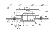
図1は、本発明の実施の形態1にかかる天井支持部材を用いた熱交換換気装置の取付け状態を模式的に示す断面図である。図2は、図1に示す矢印IIに沿って見た矢視図である。まず、送風装置である熱交換換気装置20について説明する。熱交換換気装置20は、本体1と化粧パネル2とを備える。本体1は、建物の室内に設けられた天井材8よりも上方、すなわち天井裏に設けられる。本体1は、建物の躯体30から支持されている。本体1は、箱体形状であり、内部には熱交換素子11、図示を省略した給気送風機12および排気送風機13が設けられている。なお、図1において、本体1と化粧パネル2のハッチングは省略している。
FIG. 1 is a cross-sectional view schematically showing an attached state of a heat exchange ventilation device using the ceiling support member according to the first embodiment of the present invention. FIG. 2 is an arrow view taken along the arrow II shown in FIG. First, the heat
給気送風機12は、室外から室内に向かう空気の流れである給気流を生成する。給気流は、矢印Xにて図示されている。排気送風機13は、室内から室外に向かう空気の流れである排気流を生成する。排気流は、矢印Yにて図示されている。熱交換素子11は、給気流と排気流との間で熱交換させる。また、本体1には、室外につながるダクトが接続されているが、図示は省略する。
The
化粧パネル2は、天井材8に形成された第1の開口14を塞ぐ。化粧パネル2は、合成樹脂で形成される。本体1と化粧パネル2との間には隙間が設けられている。熱交換換気装置20は、本体1と化粧パネル2とをつなぐ接続部材9を備える。
The
図1および図2に示すように、化粧パネル2には、給気口2aと還気口2bとが形成されている。本体1には、外気口2cと排気口2dとが形成されている。外気口2cと排気口2dとには、室外につながるダクトが接続されているが、図示は省略する。給気送風機12によって生成された給気流によって、外気口2cから本体1に取り込まれた室外の空気が給気口2aを通じて室内に給気される。排気送風機13によって生成された排気流によって、還気口2bから本体1に取り込まれた室内の空気が排気口2dを通じて室外に排気される。なお、給気口2aおよび還気口2bの向きは、例示した向きに限られない。また、熱交換素子11、給気送風機12、および排気送風機13の配置は、例示した配置に限られない。
As shown in FIGS. 1 and 2, the
このように、熱交換換気装置20は、給気流と排気流との間で熱交換しながら、室外の空気を室内に給気し、室内の空気を室外に排気する熱交換換気を行う。
In this way, the heat
図2に示すように、天井材8には、第1の開口14よりも大きい第2の開口15が形成されている。なお、以下の説明において、第2の開口15が形成された天井材8を第1の天井材8aと称し、第2の開口15と化粧パネル2との間を塞ぐ天井材8を第2の天井材8bと第3の天井材8cと称する。図1に示す状態では、第1の開口14は、第1の天井材8aと第2の天井材8bと第3の天井材8cとによって形成されている。
As shown in FIG. 2, the
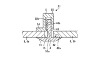
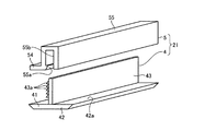
熱交換換気装置20は、第2の天井材8bおよび第3の天井材8cを支持する支持部材21を備える。図3は、図1に示すIII部分を拡大した部分拡大断面図である。図4は、実施の形態1にかかる支持部材の分解斜視図である。
The heat
支持部材21は、第1の部材4と、第2の部材5とを備える。第1の部材4と、第2の部材5とは、例えば合成樹脂で形成される。例えば、化粧パネル2を形成する合成樹脂と同じ合成樹脂で支持部材21が形成されてもよい。
The
第1の部材4は、第1の天井材8aのうち室内側を向く面に当接される第1の部位41を有する。第1の部材4は、第1の部位41のうち第2の開口15の内側を向く一端から延びる第2の部位42を有する。第1の部材4は、第1の部位41と第2の部位42の境界から天井裏に向けて突出された第3の部位43を有する。第3の部位43の先端側は、天井裏に突出する。第3の部位43には根元から先端に向けて並ぶ複数の突部43aが形成されている。
The
第2の部材5は、第1の天井材8aのうち天井裏側を向く面に当接されて、第1の部位41との間に第1の天井材8aを挟み込む第4の部位54を有する。第2の部材5は、第4の部位54が第1の部位41との間に第1の天井材8aを挟み込んだ状態で、第3の部位43が差し込まれる凹部55bが形成された第5の部位55を有する。第1の部材4および第2の部材5は、全体として、第2の開口15の開口縁に沿った方向を長手方向とする形状となっている。なお、長手方向は、第1の部位41と第2の部位42の境界が延びる方向でもある。本実施の形態1では、第1の部材4および第2の部材5は、長手方向に垂直な面で切断した断面の形状が、長手方向に沿ったどの位置で切断しても同一となる形状で形成されている。
The
なお、第1の部材4および第2の部材5のうち、第3の部位43および第5の部位55は、長手方向に沿って分割して形成されていても構わない。この場合には、第1の部材4および第2の部材5の長手方向に垂直な面で切断した断面は、長手方向に沿った位置によって切断した断面の形状が異なる。
Of the
凹部55bの内側には、第3の部位43に形成された突部43aに噛み合う突部55aが形成されている。突部43aと突部55aとが噛み合うことで、第3の部位43が第5の部位55の凹部55bから抜け落ちることが防がれる。なお、第5の部位55の凹部55bに第3の部位43を差し込む際には、突部55aが形成された面と対向する面が形成された部位が弾性変形することで、突部43aが突部55aを乗り越えて、第3の部位43が凹部55bに差し込まれる。すなわち、第3の部位43と第5の部位55とはスナップフィットで固定される。
Inside the
上述したように、支持部材21は、第2の開口15の開口縁である第1の天井材8aを、第1の部位41と第4の部位54とで挟み込んで、第1の天井材8aに固定される。第2の部位42は、支持部材21が第1の天井材8aに固定された状態で、第2の天井材8bまたは第3の天井材8cが載置される載置面42aを有する。第2の天井材8bおよび第3の天井材8cは、第1の天井材8aとは異なる天井材である。
As described above, the
第2の天井材8bおよび第3の天井材8cは、外縁の一部が載置面42aに載置されることで、支持部材21に支持される。なお、第2の天井材8bおよび第3の天井材8cは、外縁の一部が化粧パネル2にも支持される。第2の天井材8bおよび第3の天井材8cは、支持部材21および化粧パネル2に支持されることで、第2の開口15と化粧パネル2との隙間を塞ぐ。
The second ceiling material 8b and the third ceiling material 8c are supported by the
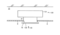
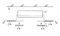
以上説明した熱交換換気装置20は、既存の熱交換換気装置の入れ替えが行われた後の状態が想定される。次に、既存の熱交換換気装置から、上述して熱交換換気装置20への入替の手順について説明する。図5は、実施の形態1にかかる熱交換換気装置への入れ替えの手順を説明するフローチャートである。図6は、既存の熱交換換気装置の設置状態を示す断面図である。図7は、図6に示す矢印VIIに沿って見た矢視図である。図8は、既存の熱交換換気装置を入れ替える過程を示す断面図である。図9は、図8に示すIX−IX線で切断した断面図である。
The
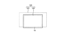
既存の熱交換換気装置120は、熱交換換気装置20と同様に本体121と化粧パネル122とを備えている。なお、図6では、本体121と化粧パネル122へのハッチングを省略している。本体121および化粧パネル122の構成は、本体1および化粧パネル2とほぼ同様であるため、詳細な説明は省略する。既存の熱交換換気装置120は、天井材8が設けられる前に本体121が設置されている。図6および図7に示すように、天井材8には、化粧パネル122で塞げる大きさの第3の開口16が形成されている。したがって、第3の開口16の大きさが足らず、このままでは天井裏から本体121を引き出すことができない。
The existing
そこで、図8および図9に示すように、第3の開口16の周囲の天井材8が切り落とされて、本体121を引き出せる第2の開口15が形成される(ステップS1)。このとき切り落とされた天井材8が、第2の天井材8bおよび第3の天井材8cとなる。また、切り落とされずに残った天井材8が、第1の天井材8aとなる。
Therefore, as shown in FIGS. 8 and 9, the
次に、第2の開口15を通して本体121が天井裏から引き出される(ステップS2)。次に、第2の開口15を通して熱交換換気装置20の本体1が天井裏に設置される(ステップS3)。次に、第2の開口15の開口縁に支持部材21が固定される(ステップS4)。次に、図1および図3に示すように、支持部材21が有する載置面42aに、第2の天井材8bおよび第3の天井材8cが載置される(ステップS5)。これにより、化粧パネル2で塞ぐことのできる大きさの第1の開口14が形成される。
Next, the
次に、第1の開口14が化粧パネル2で塞がれるとともに、化粧パネル2と本体1とが接続部材9で接続されて、熱交換換気装置20への入れ替えが完了する(ステップS6)。第1の開口14が化粧パネル2に塞がれることで、第2の天井材8bおよび第3の天井材8cのうち、第1の開口14の開口縁に沿った部分が、化粧パネル2に支持される。
Next, the
以上説明したように、本実施の形態1にかかる熱交換換気装置20によれば、既存の熱交換換気装置120との入れ替えのために、天井材8に形成された第3の開口16を広げた第2の開口15を形成しても、その復旧作業が、支持部材21の固定と、第2の天井材8bおよび第3の天井材8cの載置面42aへの載置で済む。そのため、第2の開口15の復旧の容易化が図られる。また、第2の開口15を塞ぐ第2の天井材8bおよび第3の天井材8cは、第3の開口16を広げる際に切り落とされて廃材となる天井材8である。本実施の形態1では、廃材となる第2の天井材8bおよび第3の天井材8cを再利用して第2の開口15を塞いでいるので、廃材の発生の抑制を図ることができる。
As described above, according to the
したがって、熱交換換気装置20の入れ替え工事の費用を抑制することができる。熱交換換気装置20の入れ替え工事の費用が抑制されれば、省エネルギー性能に優れた熱交換換気装置への交換がしやすくなる。また、熱交換換気装置が故障したまま放置されにくくなるため、適切な換気がなされずに住環境が悪化することを防ぐことができる。
Therefore, the cost of the replacement work of the heat
また、支持部材21を切断して長さを調節すれば、入れ替え工事を行う現地で第2の開口15の大きさに合わせて、支持部材21を第1の天井材8aに固定することができる。したがって、長さの異なる支持部材21を予め用意しておく必要がないため、在庫の面からも入れ替え工事の費用を抑制することができる。
Further, if the
なお、送風装置として熱交換換気装置を例に挙げて説明したが、これに限られない。天井裏に配置される本体が、化粧パネルで塞がれる開口よりも大きい送風装置であれば、排気のみを行う送風装置であってもよいし、給気のみを行う送風装置であってもよい。また、給排気は行うが熱交換は行わない送風装置であってもよい。また、送風装置は空気調和機であってもよい。 Although the heat exchange ventilation device has been described as an example of the blower, the present invention is not limited to this. If the main body arranged behind the ceiling is a blower device larger than the opening closed by the decorative panel, it may be a blower device that only exhausts air or a blower device that only supplies air. .. Further, a blower device that supplies and exhausts air but does not exchange heat may be used. Further, the blower may be an air conditioner.
以上の実施の形態に示した構成は、本発明の内容の一例を示すものであり、別の公知の技術と組み合わせることも可能であるし、本発明の要旨を逸脱しない範囲で、構成の一部を省略、変更することも可能である。 The configuration shown in the above-described embodiment shows an example of the content of the present invention, can be combined with another known technique, and is one of the configurations without departing from the gist of the present invention. It is also possible to omit or change the part.
1 本体、2 化粧パネル、2a 給気口、2b 還気口、2c 外気口、2d 排気口、4 第1の部材、5 第2の部材、8 天井材、8a 第1の天井材、8b 第2の天井材、8c 第3の天井材、9 接続部材、11 熱交換素子、12 給気送風機、13 排気送風機、14 第1の開口、15 第2の開口、16 第3の開口、20 熱交換換気装置、21 支持部材、30 躯体、41 第1の部位、42 第2の部位、42a 載置面、43 第3の部位、43a 突部、54 第4の部位、55 第5の部位、55a 突部、55b 凹部、120 熱交換換気装置、121 本体、122 化粧パネル。 1 main body, 2 decorative panel, 2a air supply port, 2b return air port, 2c outside air port, 2d exhaust port, 4 first member, 5 second member, 8 ceiling material, 8a first ceiling material, 8b first 2 ceiling material, 8c 3rd ceiling material, 9 connecting member, 11 heat exchange element, 12 air supply blower, 13 exhaust blower, 14 1st opening, 15 2nd opening, 16 3rd opening, 20 heat Exchange ventilator, 21 support member, 30 skeleton, 41 1st part, 42 2nd part, 42a mounting surface, 43 3rd part, 43a protrusion, 54 4th part, 55 5th part, 55a protrusions, 55b recesses, 120 heat exchange ventilators, 121 body, 122 decorative panels.
Claims (4)
前記第1の部位との間に前記天井材を挟み込む第4の部位と、前記第4の部位が前記第1の部位との間に前記天井材を挟み込んだ状態で前記第3の部位が差し込まれる第5の部位と、を有する第2の部材と、を備え、
前記第2の部位には、前記第1の部位と前記第4の部位とに挟み込まれた前記天井材と異なる天井材が載置可能な載置面を有することを特徴とする支持部材。 A first portion that comes into contact with the ceiling material, a second portion that extends from one end of the first portion, and a third portion that protrudes from the boundary between the first portion and the second portion. The first member having, and
The third portion is inserted with the ceiling material sandwiched between the fourth portion that sandwiches the ceiling material between the first portion and the first portion and the fourth portion. A second member with a fifth portion,
The support member is characterized in that the second portion has a mounting surface on which a ceiling material different from the ceiling material sandwiched between the first portion and the fourth portion can be mounted.
前記開口の一部を塞ぐとともに前記本体に接続されて前記本体によって生成された前記給気流および前記排気流の少なくとも一方を通過させる化粧パネルと、
前記化粧パネルに塞がれない前記開口の開口縁である前記天井材に取り付けられた請求項1から3のいずれか1つに記載の支持部材と、を備えることを特徴とする送風装置。 A body that is provided above the ceiling material with an opening to generate at least one of the airflow and exhaustflow.
A decorative panel that closes a part of the opening and is connected to the main body to pass at least one of the air supply and the exhaust flow generated by the main body.
The blower device comprising the support member according to any one of claims 1 to 3, which is attached to the ceiling material, which is the opening edge of the opening that is not blocked by the decorative panel.
Priority Applications (1)
| Application Number | Priority Date | Filing Date | Title |
|---|---|---|---|
| JP2019077824A JP2020176744A (en) | 2019-04-16 | 2019-04-16 | Support member and blower device |
Applications Claiming Priority (1)
| Application Number | Priority Date | Filing Date | Title |
|---|---|---|---|
| JP2019077824A JP2020176744A (en) | 2019-04-16 | 2019-04-16 | Support member and blower device |
Publications (1)
| Publication Number | Publication Date |
|---|---|
| JP2020176744A true JP2020176744A (en) | 2020-10-29 |
Family
ID=72936000
Family Applications (1)
| Application Number | Title | Priority Date | Filing Date |
|---|---|---|---|
| JP2019077824A Pending JP2020176744A (en) | 2019-04-16 | 2019-04-16 | Support member and blower device |
Country Status (1)
| Country | Link |
|---|---|
| JP (1) | JP2020176744A (en) |
Citations (8)
| Publication number | Priority date | Publication date | Assignee | Title |
|---|---|---|---|---|
| JPS5154511U (en) * | 1974-10-23 | 1976-04-26 | ||
| JPH04288430A (en) * | 1991-03-18 | 1992-10-13 | Matsushita Seiko Co Ltd | Panel removal device for ventilation unit |
| JPH0514340U (en) * | 1991-08-02 | 1993-02-23 | 株式会社竹中工務店 | Electromagnetic shield system ceiling |
| JPH11324211A (en) * | 1998-03-10 | 1999-11-26 | Nippon Light Metal Co Ltd | Ceiling panel and mounting structure of ceiling equipment |
| JP2000179085A (en) * | 1998-12-15 | 2000-06-27 | Nippon Light Metal Co Ltd | Fixture for ceiling panel |
| JP2005174949A (en) * | 2003-11-18 | 2005-06-30 | Toyo Aluminium Kk | Method of producing aluminum foil for electrolytic capacitor |
| KR20110103250A (en) * | 2010-03-12 | 2011-09-20 | 상명엔프라(주) | Ceiling panel mounting structure |
| JP2012067494A (en) * | 2010-09-22 | 2012-04-05 | Takasago Thermal Eng Co Ltd | Ceiling construction method for clean room |
-
2019
- 2019-04-16 JP JP2019077824A patent/JP2020176744A/en active Pending
Patent Citations (8)
| Publication number | Priority date | Publication date | Assignee | Title |
|---|---|---|---|---|
| JPS5154511U (en) * | 1974-10-23 | 1976-04-26 | ||
| JPH04288430A (en) * | 1991-03-18 | 1992-10-13 | Matsushita Seiko Co Ltd | Panel removal device for ventilation unit |
| JPH0514340U (en) * | 1991-08-02 | 1993-02-23 | 株式会社竹中工務店 | Electromagnetic shield system ceiling |
| JPH11324211A (en) * | 1998-03-10 | 1999-11-26 | Nippon Light Metal Co Ltd | Ceiling panel and mounting structure of ceiling equipment |
| JP2000179085A (en) * | 1998-12-15 | 2000-06-27 | Nippon Light Metal Co Ltd | Fixture for ceiling panel |
| JP2005174949A (en) * | 2003-11-18 | 2005-06-30 | Toyo Aluminium Kk | Method of producing aluminum foil for electrolytic capacitor |
| KR20110103250A (en) * | 2010-03-12 | 2011-09-20 | 상명엔프라(주) | Ceiling panel mounting structure |
| JP2012067494A (en) * | 2010-09-22 | 2012-04-05 | Takasago Thermal Eng Co Ltd | Ceiling construction method for clean room |
Similar Documents
| Publication | Publication Date | Title |
|---|---|---|
| JP5194987B2 (en) | Duct unit, duct arrangement structure using duct unit and outer wall structure | |
| JP5249892B2 (en) | Panel device | |
| US11421912B2 (en) | Packing system including packing material for air conditioner and air conditioner | |
| JP2020176744A (en) | Support member and blower device | |
| JP5517859B2 (en) | Clean room ceiling installation method | |
| JP5201049B2 (en) | Bathroom ventilation dryer | |
| JP2018119738A (en) | Ceiling-embedded duct type air conditioner | |
| JP2014092333A (en) | Heat exchange ventilation device | |
| JP2010159909A (en) | Air conditioner | |
| JP2018054191A (en) | Heat exchanger | |
| JP2007205589A (en) | Ceiling cassette-type air conditioner | |
| KR101715430B1 (en) | Underfloor air-conditioning duct structure | |
| JP2006226640A (en) | Chamber unit for air conditioning/ventilation, and duct construction method using it | |
| JPWO2019225278A1 (en) | Air conditioning indoor unit | |
| WO2022209680A1 (en) | Mounting bracket, mounting structure for heat insulation panel, and radiation air-conditioning device | |
| KR200463265Y1 (en) | Air-conditioner | |
| KR101064556B1 (en) | Airconditioner with frame structure for assembly unlike two casing | |
| JP6110598B2 (en) | Heat exchange ventilator | |
| JP2008190745A (en) | Duct installation structure in building and duct installation method | |
| JP5589420B2 (en) | Air conditioner | |
| JP5286053B2 (en) | Clean room equipment and operation method thereof | |
| JP2009079868A (en) | Air conditioning device | |
| JP2009058206A (en) | Air-conditioner indoor unit | |
| JP2004301478A (en) | Air conditioner | |
| JP3825563B2 (en) | Air filter support device for wall-embedded air conditioner |
Legal Events
| Date | Code | Title | Description |
|---|---|---|---|
| A621 | Written request for application examination |
Free format text: JAPANESE INTERMEDIATE CODE: A621 Effective date: 20210917 |
|
| A977 | Report on retrieval |
Free format text: JAPANESE INTERMEDIATE CODE: A971007 Effective date: 20220613 |
|
| A131 | Notification of reasons for refusal |
Free format text: JAPANESE INTERMEDIATE CODE: A131 Effective date: 20220628 |
|
| A02 | Decision of refusal |
Free format text: JAPANESE INTERMEDIATE CODE: A02 Effective date: 20221220 |