JP2020176005A - Insulation hook, and overhead crane for electrolytic refining facility using the same - Google Patents
Insulation hook, and overhead crane for electrolytic refining facility using the same Download PDFInfo
- Publication number
- JP2020176005A JP2020176005A JP2019080899A JP2019080899A JP2020176005A JP 2020176005 A JP2020176005 A JP 2020176005A JP 2019080899 A JP2019080899 A JP 2019080899A JP 2019080899 A JP2019080899 A JP 2019080899A JP 2020176005 A JP2020176005 A JP 2020176005A
- Authority
- JP
- Japan
- Prior art keywords
- hook
- insulating
- crane
- flange
- side substrate
- Prior art date
- Legal status (The legal status is an assumption and is not a legal conclusion. Google has not performed a legal analysis and makes no representation as to the accuracy of the status listed.)
- Granted
Links
Images

Landscapes
- Control And Safety Of Cranes (AREA)
- Jib Cranes (AREA)
- Electrolytic Production Of Metals (AREA)
Abstract
Description
本発明は、絶縁フック、及び、それを用いた電解精錬設備用の天井クレーンに関する。 The present invention relates to an insulating hook and an overhead crane for an electrolytic refining facility using the same.
銅やニッケル、亜鉛等の金属の精錬には、一般的に電解精錬が採用される。この電解精錬においては、粗金属により形成された陽極板と電気分解された金属を析出させる陰極板とを、電解液等が収容された電解槽に浸漬した状態で通電することによって、電気分解された純度が高い金属を陰極板の表面に析出させる操業が行われている。そして、電解槽が多数並置されている電解精錬設備においては、上記の電極板(陽極板、陰極板)を、多数の電解槽に効率良く出し入れするための天井クレーンが設置されている(特許文献1参照)。 Electrorefining is generally used for refining metals such as copper, nickel, and zinc. In this electrolytic refining, an anode plate formed of crude metal and a cathode plate for precipitating electrolyzed metal are electrolyzed by energizing while immersed in an electrolytic cell containing an electrolytic solution or the like. An operation is being carried out in which a highly pure metal is deposited on the surface of the cathode plate. In an electrolytic refining facility in which a large number of electrolytic cells are juxtaposed, an overhead crane is installed to efficiently put the above electrode plates (anode plate, cathode plate) in and out of a large number of electrolytic cells (Patent Documents). 1).
上述の天井クレーンは、建物も含めた設備の天井付近において建物躯体に上架されている金属製のガイドレールを含め、その大部分が金属性の部材で構成されている。このような天井クレーンを用いる電解精錬設備においては、電極板に残留した電気の地絡を防止し、設備内で作業者及び設備自体の安全性を確保するために、天井クレーンについて、電極板を引き上げる下部側(フック側)の末端と、上記の金属ガイドレールとの間の何れかの箇所において十分な絶縁性を有する絶縁体を配置することが必須とされている。 Most of the above-mentioned overhead cranes are made of metal members, including metal guide rails mounted on the building frame near the ceiling of the equipment including the building. In an electrolytic refining facility that uses such an overhead crane, in order to prevent electrical ground faults remaining on the electrode plate and to ensure the safety of workers and the equipment itself in the facility, the electrode plate is used for the overhead crane. It is essential to dispose an insulator having sufficient insulating properties at any position between the end on the lower side (hook side) to be pulled up and the metal guide rail described above.
上記の絶縁性を担保するために、天井クレーンにおいて絶縁フックを用いることが広く行われている。絶縁フックとは、一例として、上部側(天井側)の構造部分と、下部側(床面側)の構造部分との間に磁器等からなる絶縁体を配したフックである(特許文献2参照)。 In order to ensure the above-mentioned insulation properties, it is widely practiced to use an insulating hook in an overhead crane. The insulating hook is, for example, a hook in which an insulator made of porcelain or the like is arranged between a structural portion on the upper side (ceiling side) and a structural portion on the lower side (floor surface side) (see Patent Document 2). ).
又、実際に、多くの電解精錬設備においては、ポリ塩化ビニル(PVC)等の絶縁体を中間層部分に配した絶縁フックが天井クレーンに設置されている。但し、電解精錬設備内の高湿環境での使用においては、絶縁フックの各構造部分の絶縁劣化、腐食の進行は殊の外早く、一定期間毎に絶縁フックの分解整備或いは交換を余儀なくされていた。 In fact, in many electrolytic refining facilities, an insulating hook in which an insulator such as polyvinyl chloride (PVC) is arranged in an intermediate layer portion is installed in an overhead crane. However, when used in a high-humidity environment in an electrolytic refining facility, the insulation deterioration and corrosion of each structural part of the insulating hook progresses particularly quickly, and the insulating hook must be disassembled, maintained, or replaced at regular intervals. It was.
本発明は、電解精錬設備用の天井クレーンに用いる絶縁フックの耐久性を向上させることを課題とする。 An object of the present invention is to improve the durability of an insulating hook used in an overhead crane for an electrolytic refining facility.
本発明者らは、強化基材を含有するフェノール樹脂で形成されている、中間絶縁板や絶縁ワッシャー、及び、絶縁スリーブによって構成される絶縁構造を有する絶縁フックとすることで、上記課題を解決することができることを見出し、本発明を完成するに至った。具体的には、本発明は以下のものを提供する。 The present inventors have solved the above problems by using an insulating hook having an insulating structure composed of an intermediate insulating plate, an insulating washer, and an insulating sleeve, which is formed of a phenol resin containing a reinforced base material. We have found that we can do this, and have completed the present invention. Specifically, the present invention provides the following.
(1) 金属製のクレーン側基体と、金属製のフック側基体との間に、中間絶縁板が挟持されてなる、絶縁フックであって、前記クレーン側基体及び前記フック側基体は、何れも中間絶縁板の側の端部にフランジが形成されていて、前記クレーン側基体、前記中間絶縁板、及び、前記フック側基体は、前記クレーン側基体のフランジ、前記中間絶縁板、及び、前記フック側基体のフランジを貫通するボルトと、ナットと、によって締結されていて、前記ボルトの頭部又は前記ナットと前記クレーン側基体のフランジとの当接面、及び、前記ボルトの頭部又は前記ナットと前記フック側基体のフランジとの当接面には、絶縁ワッシャーが配置されていて、前記ボルトの軸部の側面には、該側面の全周を被覆する円筒形状の絶縁スリーブが配置されていて、前記中間絶縁板及び前記絶縁ワッシャーは、強化基材を含有する布基材フェノール樹脂を主たる材料とし、前記絶縁スリーブは、強化基材を含有しないフェノール樹脂又は前記布基材フェノール樹脂を主たる材料とする、絶縁フック。 (1) An insulating hook in which an intermediate insulating plate is sandwiched between a metal crane-side base and a metal hook-side base, and the crane-side base and the hook-side base are both. A flange is formed at the end on the side of the intermediate insulating plate, and the crane-side base, the intermediate insulating plate, and the hook-side base are the flange of the crane-side base, the intermediate insulating plate, and the hook. A bolt and a nut that penetrate the flange of the side base are fastened by the head of the bolt or the contact surface between the nut and the flange of the crane side base, and the head of the bolt or the nut. An insulating washer is arranged on the contact surface between the hook and the flange of the hook-side substrate, and a cylindrical insulating sleeve covering the entire circumference of the side surface is arranged on the side surface of the shaft portion of the bolt. The intermediate insulating plate and the insulating washer are mainly made of a cloth-based phenol resin containing a reinforced base material, and the insulating sleeve is mainly made of a phenol resin containing no reinforced base material or the cloth-based phenol resin. Insulation hook as a material.
(1)の発明によれば、電解精錬設備用の天井クレーンに用いる絶縁フックにおいて、強化基材を含有し、高い絶縁性と機械的強度を有するエンジニアリングプラスチック材である布基材フェノール樹脂で形成されている中間絶縁板及び絶縁ワッシャー、と、高い絶縁性を有するフェノール樹脂で形成されている絶縁スリーブによって構成される絶縁構造を付与することにより、絶縁構造物の耐久性を向上させることができる。 According to the invention of (1), the insulating hook used for an overhead crane for electrolytic refining equipment is formed of a cloth base material phenol resin which is an engineering plastic material containing a reinforced base material and having high heat insulating properties and mechanical strength. The durability of the insulating structure can be improved by providing an insulating structure composed of an intermediate insulating plate and an insulating washer, and an insulating sleeve formed of a phenol resin having high insulating properties. ..
(2) 前記絶縁スリーブが、強化基材を含有しないフェノール樹脂製である、(1)に記載の絶縁フック。 (2) The insulating hook according to (1), wherein the insulating sleeve is made of a phenol resin containing no reinforced base material.
(2)の発明によれば、特有の絶縁構造を構成するにあたって、特段の機械的強度が要求される部分のみに、高価な強化基材を含有する布基材フェノール樹脂を用いる構成とした。これにより、(1)の発明の有する絶縁性や耐久性に係る諸性能を維持したまま、製造コストを抑えることができる。 According to the invention of (2), in constructing a unique insulating structure, a cloth-based phenol resin containing an expensive reinforcing substrate is used only in a portion where special mechanical strength is required. As a result, the manufacturing cost can be suppressed while maintaining various performances related to the insulating property and durability of the invention of (1).
(3) 前記クレーン側基体のフランジ、前記中間絶縁板、及び、前記フック側基体のフランジによって構成されているクレーン側基体とフック側基体との接合構造体である絶縁接合部の全表面が、防湿樹脂材によって被覆されている、(1)又は(2)に記載の絶縁フック。 (3) The entire surface of the insulating joint portion, which is a joint structure between the crane side base and the hook side base, which is composed of the flange of the crane side base, the intermediate insulating plate, and the flange of the hook side base, is formed. The insulating hook according to (1) or (2), which is coated with a moisture-proof resin material.
(3)の発明によれば、中間絶縁板周囲への水分侵入、ボルト・ナットへの水分付着を防止して、絶縁フックの優れた絶縁性をより長期間に亘って維持することができる。又、絶縁接合部表面への水滴の付着に起因する絶縁低下に対しても、簡単な拭き取り作業で容易にこれを除去して絶縁性を回復させることができる。これにより、絶縁フックの分解整備が必要となる周期を従来よりも大幅に延長することができる。 According to the invention of (3), it is possible to prevent moisture from entering the periphery of the intermediate insulating plate and moisture from adhering to the bolts and nuts, and to maintain the excellent insulating property of the insulating hook for a longer period of time. Further, even if the insulation is deteriorated due to the adhesion of water droplets to the surface of the insulating joint, it can be easily removed by a simple wiping operation to restore the insulating property. As a result, the cycle in which the insulating hook needs to be disassembled and maintained can be significantly extended as compared with the conventional case.
(4) 前記防湿樹脂材が、エポキシ系樹脂である、(3)に記載の絶縁フック。 (4) The insulating hook according to (3), wherein the moisture-proof resin material is an epoxy resin.
(4)の発明によれば、優れた防湿性を発揮しつつ、防湿樹脂材の被覆に係る作業を、電解精錬設備内で簡単に実施することができる。 According to the invention of (4), the work related to the coating of the moisture-proof resin material can be easily carried out in the electrolytic refining facility while exhibiting excellent moisture-proof property.
(5) 金属性のガイドレールと、前記ガイドレール上を走行可能な金属車輪を備える金属性のクレーン基台と、前記クレーン基台から垂下されている吊り下げワイヤーと、前記吊り下げワイヤーの下端部に接続されているフックと、を備え、前記フックが、(1)から(4)の何れかに記載の絶縁フックである、電解精錬設備用の天井クレーン。 (5) A metal guide rail, a metal crane base provided with metal wheels capable of traveling on the guide rail, a hanging wire hanging from the crane base, and a lower end of the hanging wire. An overhead crane for an electrolytic refining facility, comprising a hook connected to a portion, wherein the hook is an insulating hook according to any one of (1) to (4).
(5)の発明によれば、(1)から(4)の絶縁フックの奏する上記効果を享受することにより、電解精錬設備用の天井クレーンの保守作業の効率を向上させることができる。 According to the invention of (5), the efficiency of the maintenance work of the overhead crane for the electrolytic refining equipment can be improved by enjoying the above-mentioned effects of the insulating hooks (1) to (4).
本発明によれば、電解精錬設備用の天井クレーンに用いる絶縁フックの耐久性を向上させることができる。 According to the present invention, the durability of an insulating hook used in an overhead crane for an electrolytic refining facility can be improved.
以下、本発明の実施形態について適宜図面を参照しながら説明する。 Hereinafter, embodiments of the present invention will be described with reference to the drawings as appropriate.
<絶縁フック>
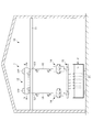
図1に示す通り、本発明の絶縁フック14は、電解精錬設備10において、電解槽2に電極板21を出し入れする天井クレーン1のフック部分を構成する部材である。絶縁フック14は、その外形については、多数の電極板21を同時に吊り下げることが可能な電極吊り下げ枠15を着脱可能に懸垂することができるフック部145を有する構造であれば特に限定されない。
<Insulation hook>
As shown in FIG. 1, the
(全体構成)
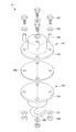
図2に示す通り、絶縁フック14は、天井クレーンの上部側の構造に接続されるクレーン側基体141、中間絶縁板146、フック部145を有するフック側基体143が、この順で積層されてなる構造を必須の構造として構成される。
(overall structure)
As shown in FIG. 2, the
絶縁フック14を構成するクレーン側基体141、中間絶縁板146、及び、フック側基体143は、両基体の端部に形成されている鍔状のフランジ142、144の間に、中間絶縁板146が挟持される構成で結合されている。この配置状態において、クレーン側基体141、中間絶縁板146、及び、フック側基体143は、ボルト147と、ナット148とによって締結されることにより一体化されている。この状態において、ボルト147は、フランジ142、中間絶縁板146、及び、フランジ144を貫通している状態でナット148と螺合して上記各部材を十分な強度で締結している。
The crane-
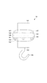
又、絶縁フック14は、図3に示すように、クレーン側基体141とフック側基体143との接合部分であって、フランジ142、中間絶縁板146、フランジ144によって構成される絶縁接合部において、この絶縁接合部(フランジ142、中間絶縁板146、フランジ144)の全表面が防湿樹脂材によって被覆されていることがより好ましい。尚、この防湿樹脂材によって形成されている被覆構造部分を本明細書においては、防湿樹脂部(防湿樹脂部152)と称する。
Further, as shown in FIG. 3, the
(クレーン側基体、フック側基体)
クレーン側基体141とフック側基体143は何れも金属製の部材である。図2、3に示す通り、絶縁フック14を構成するクレーン側基体141の一方の端部には鍔状のフランジ142が形成されている。又、フック側基体143の端部にも同様に鍔状のフランジ144が形成されている。
(Crane side base, hook side base)
Both the crane-
(中間絶縁板)
中間絶縁板146は、十分な絶縁性に加え、優れた圧縮強度、優れた耐久性を兼ね備える絶縁性材料である「布基材フェノール樹脂」を主たる材料として形成される板状の絶縁部材である。布基材フェノール樹脂としては、一般的に「布入りベークライト」と呼ばれる部材を用いることができる。尚、「布入りベークライト」とは、ベークライトをベース樹脂とし強化基材として布を含有するベークライト系樹脂材料のことを言う。ベークライトは商標登録名であり、一般名はポリオキシベンジルメチレングリコールアンハイドライドである。中間絶縁板146は、フランジ142とフランジ144の間を絶縁している。
(Intermediate insulation plate)
The intermediate insulating
(絶縁ワッシャー)
絶縁フック14においては、図2、4に示す通り、ボルト147の頭部の背面側(中間絶縁板146の側)及びナット148の背面側(中間絶縁板146の側)に、絶縁ワッシャー150、151が配置されている。それぞれの絶縁ワッシャー150、151は、ボルト147の頭部とフランジ142の表面の当接面、及び、ナット148とフランジ144の表面の当接面において両者の間を絶縁している。この絶縁ワッシャー150、151は、上記の「布基材フェノール樹脂」を主たる材料として形成されるドーナッツ形状のワッシャーである。
(Insulation washer)
In the insulating
(絶縁スリーブ)
絶縁フック14においては、図2、4に示す通り、更に、ボルト147の軸部の側面の全周を被覆する円筒形状の絶縁スリーブ149が配置されている。絶縁スリーブ149は、図4に示す通り、軸部の側面のうち絶縁ワッシャー150、151に被覆されている部分を除く全側面を被覆していることが好ましい。
(Insulation sleeve)
In the insulating
絶縁スリーブ149は、上記の「布基材フェノール樹脂」、又は、強化基材を含有しないフェノール樹脂を主たる材料として形成される円筒形状のスリーブである。本明細書において、単に「フェノール樹脂」という場合は、ベース樹脂内に強化基材を含有しないフェノール樹脂のことを言うものとする。
The insulating
ここで、中間絶縁板146及び絶縁ワッシャー150、151には、ボルト147とナット148による締め付け力を十分な強さとするために相応の圧縮強度が求められる。逆に言えば、十分な強さの締付け力を受けても、変形したり割れたりしないだけの圧縮強度、破壊強度が求められる。しかしながら、絶縁スリーブ149については、必ずしも同等の強度は必要ではない。よって、この部分については、高価な「布基材フェノール樹脂」を使用する必要は無く、強化基材を含有しないフェノール樹脂製のスリーブとすることにより、絶縁性や耐久性を保持したまま、製造コストを抑えることができる。絶縁スリーブ149は、フランジ142とボルト147の間、フランジ144とボルト147の間を、それぞれ絶縁している。
Here, the intermediate insulating
(防湿樹脂部)
クレーン側基体141とフック側基体143との絶縁接合部を被覆する防湿樹脂部152は、例えば、図3に示すような略楕円球形状に形成されていることが好ましい。又、耐熱性を有する熱硬化性樹脂により形成することが好ましい。好ましく用いることができる熱硬化性樹脂として、耐熱温度150℃〜200℃のエポキシ系樹脂を挙げることができる。防湿樹脂部152は、このような材料樹脂を上記の絶縁接合部の全表面に塗布し、これを硬化させることによって形成することができる。
(Moisture-proof resin part)
The moisture-
防湿樹脂部152の外形形状は、上記の絶縁接合部の全表面を被覆できる限りにおいて特に限定されない。但し、表面についた水滴が流れ落ちやすく、水滴が付着した場合であっても、容易に拭きとることができる、上記のような略楕円球形状であることが好ましい。
The outer shape of the moisture-
尚、エポキシ系樹脂の防湿樹脂材として、例えば、一般的に販売されている、2液性常温硬化型の住友スリーエム(株)製スコッチキャストTMレジンNo.4を用いることができる。中間絶縁板146及び絶縁ワッシャー150、151に使われる「布入りベークライト」は、絶縁性に優れ、機械的強度も高い素材であるが、特に積層板の切断面部分が吸湿し易いという欠点がある。そこで、防湿樹脂部152の形成により、より絶縁フックの耐久性を向上させることができる。
As a moisture-proof resin material of an epoxy resin, for example, a generally sold two-component room temperature curing type Scotchcast TM Resin No. 2 manufactured by Sumitomo 3M Ltd. 4 can be used. "Bakelite with cloth" used for the intermediate insulating
(絶縁構造)
上記構成からなる絶縁フック14においては、中間絶縁板146によって、クレーン側基体141とフック側基体143との間の絶縁が保持されている。又、電解精錬設備10で用いられる天井クレーンに設置されて用いられる場合、クレーン側基体141とフック側基体143との間の接合強度は、通常、1500〜2000kg程度の荷重に耐えることが必要であるため、複数のボルト147及びナット148による強固な締結が必須である。このボルト147とナット148の周辺については、絶縁スリーブ149、絶縁ワッシャー150、151がそれぞれ適切に配置されていることによって、中間絶縁板146を貫通するボルト147を通じての導通を防ぐようにされている。
(Insulation structure)
In the insulating
尚、前述の通り、中間絶縁板146及び絶縁ワッシャー150、151には、十分な絶縁性に加え、ボルト147及びナット148による強固な締付け力に耐え得る十分な圧縮強度が要求される。一方で、絶縁スリーブ149には、フランジ142とボルト147の間、フランジ144とボルト147の間を、それぞれ絶縁する機能のみが要求される。そこで、絶縁ワッシャー150、151と絶縁スリーブ149の位置関係については、図4に示すように、絶縁ワッシャー150、絶縁スリーブ149、絶縁ワッシャー151の順に重なり合わせることが好ましく、絶縁ワッシャー150、151と絶縁スリーブ149の間には、若干の隙間を持たせ、絶縁ワッシャー151には加重が掛からない構造とすることが好ましい。
As described above, the intermediate insulating
<電解精製設備用の天井クレーン>
上記において詳細を説明した絶縁フック14を用いることにより、安全性と保守作業の効率に優れる電解精錬設備用の天井クレーン1を構成することができる。
<Overhead crane for electrolytic refining equipment>
By using the insulating
本発明の電解精錬設備用の天井クレーンは、例えば、図1に示す構成とすることができる。図1に示す電解精錬設備用の天井クレーン1においては、金属性のガイドレール11上を、金属車輪121を備える金属性のクレーン基台12が、前後方向(g方向、b方向)に走行可能に設置されている。
The overhead crane for the electrolytic refining equipment of the present invention can have, for example, the configuration shown in FIG. In the overhead crane 1 for the electrolytic refining facility shown in FIG. 1, the
又、クレーン基台12は、図面上の奥行方向にも十分な長さを持ち、吊り下げワイヤー13を垂下している巻き上げモーター122を含む部分のみを、その長さ方向、即ち、ガイドレールと直交する方向に、独立して移動させることができる構造とすることができる。多くの電解精錬設備においては、縦横両方向に多数の電解槽2が格子状に整列配置されているが、上記構造により、これらの多数の電解槽2への電極板21の出し入れの作業を、天井クレーン1によって効率よく行うことができる。
Further, the
絶縁フック14は、吊り下げワイヤー13の下端部に接続されていて、巻き上げモーター122によって上下方向(u方向、d方向)に移動可能とされている。又、4本の吊り下げワイヤー13によって、絶縁フック14を介して電極吊り下げ枠15が保持され、電極吊り下げ枠15の昇降によって、電解槽2への多数の電極板21の出し入れ作業を一度に行うことができる。
The insulating
1 天井用クレーン
11 ガイドレール
12 クレーン基台
121 金属車輪
122 巻き上げモーター
2 電解槽
21 電極板
13 吊り下げワイヤー
14 絶縁フック
141 クレーン側基体
142 フランジ
143 フック側基体
144 フランジ
145 フック部
146 中間絶縁板
147 ボルト
148 ナット
149 絶縁スリーブ
150、151 絶縁ワッシャー
152 防湿樹脂部
15 電極吊り下げ枠
10 電解精製設備
1 Crane for ceiling 11
Claims (5)
前記クレーン側基体及び前記フック側基体は、何れも中間絶縁板の側の端部にフランジが形成されていて、
前記クレーン側基体、前記中間絶縁板、及び、前記フック側基体は、前記クレーン側基体のフランジ、前記中間絶縁板、及び、前記フック側基体のフランジを貫通するボルトと、ナットと、によって締結されていて、
前記ボルトの頭部又は前記ナットと前記クレーン側基体のフランジとの当接面、及び、前記ボルトの頭部又は前記ナットと前記フック側基体のフランジとの当接面には、絶縁ワッシャーが配置されていて、
前記ボルトの軸部の側面には、該側面の全周を被覆する円筒形状の絶縁スリーブが配置されていて、
前記中間絶縁板及び前記絶縁ワッシャーは、強化基材を含有する布基材フェノール樹脂を主たる材料とし、
前記絶縁スリーブは、強化基材を含有しないフェノール樹脂又は前記布基材フェノール樹脂を主たる材料とする、絶縁フック。 An insulating hook in which an intermediate insulating plate is sandwiched between a metal crane-side substrate and a metal hook-side substrate.
Both the crane-side substrate and the hook-side substrate have a flange formed at the end on the side of the intermediate insulating plate.
The crane-side substrate, the intermediate insulating plate, and the hook-side substrate are fastened by bolts and nuts penetrating the flange of the crane-side substrate, the intermediate insulating plate, and the flange of the hook-side substrate. And
Insulating washers are arranged on the head of the bolt or the contact surface between the nut and the flange of the crane side base, and on the head of the bolt or the contact surface between the nut and the flange of the hook side base. Has been
On the side surface of the shaft portion of the bolt, a cylindrical insulating sleeve covering the entire circumference of the side surface is arranged.
The intermediate insulating plate and the insulating washer are mainly made of a cloth-based phenol resin containing a reinforced base material.
The insulating sleeve is an insulating hook mainly made of a phenol resin containing no reinforced base material or the cloth base material phenol resin.
前記ガイドレール上を走行可能な金属車輪を備える金属性のクレーン基台と、
前記クレーン基台から垂下されている吊り下げワイヤーと、
前記吊り下げワイヤーの下端部に接続されているフックと、を備え、
前記フックが、請求項1から4の何れかに記載の絶縁フックである、
電解精錬設備用の天井クレーン。 With a metallic guide rail
A metal crane base having metal wheels that can run on the guide rail,
The hanging wire hanging from the crane base and
With a hook connected to the lower end of the hanging wire,
The hook is the insulating hook according to any one of claims 1 to 4.
Overhead crane for electrolytic refining equipment.
Priority Applications (1)
| Application Number | Priority Date | Filing Date | Title |
|---|---|---|---|
| JP2019080899A JP7302257B2 (en) | 2019-04-22 | 2019-04-22 | Insulated hook and overhead crane for electrolytic refining equipment using it |
Applications Claiming Priority (1)
| Application Number | Priority Date | Filing Date | Title |
|---|---|---|---|
| JP2019080899A JP7302257B2 (en) | 2019-04-22 | 2019-04-22 | Insulated hook and overhead crane for electrolytic refining equipment using it |
Publications (2)
| Publication Number | Publication Date |
|---|---|
| JP2020176005A true JP2020176005A (en) | 2020-10-29 |
| JP7302257B2 JP7302257B2 (en) | 2023-07-04 |
Family
ID=72935568
Family Applications (1)
| Application Number | Title | Priority Date | Filing Date |
|---|---|---|---|
| JP2019080899A Active JP7302257B2 (en) | 2019-04-22 | 2019-04-22 | Insulated hook and overhead crane for electrolytic refining equipment using it |
Country Status (1)
| Country | Link |
|---|---|
| JP (1) | JP7302257B2 (en) |
Citations (5)
| Publication number | Priority date | Publication date | Assignee | Title |
|---|---|---|---|---|
| JPS4936699Y1 (en) * | 1970-07-24 | 1974-10-07 | ||
| JPS567065U (en) * | 1979-06-28 | 1981-01-22 | ||
| JPS594887U (en) * | 1982-06-30 | 1984-01-12 | 大阪瓦斯株式会社 | Insulating gasket for high pressure |
| JPH0544383U (en) * | 1991-11-11 | 1993-06-15 | 有限会社山一製作所 | Resistance welder |
| JP2010236050A (en) * | 2009-03-31 | 2010-10-21 | Sumitomo Heavy Industries Engineering-Service Co Ltd | Crane for electrode |
-
2019
- 2019-04-22 JP JP2019080899A patent/JP7302257B2/en active Active
Patent Citations (5)
| Publication number | Priority date | Publication date | Assignee | Title |
|---|---|---|---|---|
| JPS4936699Y1 (en) * | 1970-07-24 | 1974-10-07 | ||
| JPS567065U (en) * | 1979-06-28 | 1981-01-22 | ||
| JPS594887U (en) * | 1982-06-30 | 1984-01-12 | 大阪瓦斯株式会社 | Insulating gasket for high pressure |
| JPH0544383U (en) * | 1991-11-11 | 1993-06-15 | 有限会社山一製作所 | Resistance welder |
| JP2010236050A (en) * | 2009-03-31 | 2010-10-21 | Sumitomo Heavy Industries Engineering-Service Co Ltd | Crane for electrode |
Also Published As
| Publication number | Publication date |
|---|---|
| JP7302257B2 (en) | 2023-07-04 |
Similar Documents
| Publication | Publication Date | Title |
|---|---|---|
| US8733560B2 (en) | ULT cable support system | |
| US8517186B1 (en) | ULT cable support system with saddles | |
| WO2007124034B1 (en) | Stabilizer with cathodic protection | |
| US9970160B2 (en) | Rail gauge-plate insulator | |
| JP2020176005A (en) | Insulation hook, and overhead crane for electrolytic refining facility using the same | |
| RU2018125253A (en) | CARRIER ROPES FOR ELECTRIC TRAINS, METHODS OF MANUFACTURE AND METHODS FOR INSTALLATION | |
| JP4819558B2 (en) | Method of cathodic protection for reinforced concrete structure and cathodic protection structure | |
| CN112761247B (en) | Fabricated box plate steel structure anticorrosion building system and construction method | |
| CN104600637A (en) | Cable bridge with composite epoxy resin | |
| RU107808U1 (en) | REINFORCED CONCRETE STAND FOR SUPPORTS OF HIGH-VOLTAGE ELECTRIC TRANSMISSION LINES | |
| US20190119819A1 (en) | Method for laying an anode system for cathodic corrosion protection | |
| US3291899A (en) | Electric insulators in the form of framed structures incorporating rods of resin bonded fibre | |
| CN205315208U (en) | Prestressing force fan pylon structure | |
| CN104157379B (en) | A kind of multistage composite insulator | |
| CN210074434U (en) | Safety protection device for transformer substation | |
| CN209228165U (en) | A kind of unicuspid cross-arm and power transmission tower | |
| CN207551732U (en) | A kind of lifting insulation suspension hook | |
| CN202580312U (en) | Support frame for cable of transformer substation | |
| CN210404552U (en) | Special wire clamp for live replacement of linear rod insulator at earth potential | |
| KR20200128790A (en) | Structure Of Environmentally Friendly Concrete Pole | |
| RU123589U1 (en) | BRACKET FOR SUSPENSION OF A DIELECTRIC FIBER OPTICAL CABLE AND / OR WIRES OF A WAVEGUIDE | |
| JP2013158189A (en) | Cross arm | |
| CN211597407U (en) | Lightning protection structure for parapet of assembled concrete house | |
| RU160982U1 (en) | PANEL Fence | |
| CN201487382U (en) | Cable holder capable of being assembled conveniently |
Legal Events
| Date | Code | Title | Description |
|---|---|---|---|
| A621 | Written request for application examination |
Free format text: JAPANESE INTERMEDIATE CODE: A621 Effective date: 20220215 |
|
| A977 | Report on retrieval |
Free format text: JAPANESE INTERMEDIATE CODE: A971007 Effective date: 20221109 |
|
| A131 | Notification of reasons for refusal |
Free format text: JAPANESE INTERMEDIATE CODE: A131 Effective date: 20221213 |
|
| A521 | Request for written amendment filed |
Free format text: JAPANESE INTERMEDIATE CODE: A523 Effective date: 20230208 |
|
| TRDD | Decision of grant or rejection written | ||
| A01 | Written decision to grant a patent or to grant a registration (utility model) |
Free format text: JAPANESE INTERMEDIATE CODE: A01 Effective date: 20230523 |
|
| A61 | First payment of annual fees (during grant procedure) |
Free format text: JAPANESE INTERMEDIATE CODE: A61 Effective date: 20230605 |
|
| R150 | Certificate of patent or registration of utility model |
Ref document number: 7302257 Country of ref document: JP Free format text: JAPANESE INTERMEDIATE CODE: R150 |