JP2020171427A - Dynamic image analysis apparatus, dynamic image analysis system, and program - Google Patents
Dynamic image analysis apparatus, dynamic image analysis system, and program Download PDFInfo
- Publication number
- JP2020171427A JP2020171427A JP2019074282A JP2019074282A JP2020171427A JP 2020171427 A JP2020171427 A JP 2020171427A JP 2019074282 A JP2019074282 A JP 2019074282A JP 2019074282 A JP2019074282 A JP 2019074282A JP 2020171427 A JP2020171427 A JP 2020171427A
- Authority
- JP
- Japan
- Prior art keywords
- subject
- area
- volume
- dynamic
- calculated
- Prior art date
- Legal status (The legal status is an assumption and is not a legal conclusion. Google has not performed a legal analysis and makes no representation as to the accuracy of the status listed.)
- Granted
Links
- 238000010191 image analysis Methods 0.000 title claims description 20
- 230000004202 respiratory function Effects 0.000 claims abstract description 83
- 238000003384 imaging method Methods 0.000 claims abstract description 80
- 230000005855 radiation Effects 0.000 claims abstract description 68
- 238000011156 evaluation Methods 0.000 claims abstract description 33
- 238000004364 calculation method Methods 0.000 claims description 34
- 238000012937 correction Methods 0.000 claims description 29
- 238000000605 extraction Methods 0.000 claims description 14
- 238000007689 inspection Methods 0.000 claims description 4
- 210000004072 lung Anatomy 0.000 abstract description 170
- 210000000038 chest Anatomy 0.000 description 81
- 230000029058 respiratory gaseous exchange Effects 0.000 description 39
- 238000000034 method Methods 0.000 description 38
- 238000001514 detection method Methods 0.000 description 29
- 230000000241 respiratory effect Effects 0.000 description 24
- 230000003434 inspiratory effect Effects 0.000 description 21
- 230000008569 process Effects 0.000 description 18
- 238000004891 communication Methods 0.000 description 17
- 230000000284 resting effect Effects 0.000 description 15
- 230000006870 function Effects 0.000 description 11
- 238000012545 processing Methods 0.000 description 10
- 206010003598 Atelectasis Diseases 0.000 description 8
- 208000007123 Pulmonary Atelectasis Diseases 0.000 description 8
- 230000008859 change Effects 0.000 description 8
- 238000012360 testing method Methods 0.000 description 6
- 230000004217 heart function Effects 0.000 description 5
- 239000004065 semiconductor Substances 0.000 description 4
- 210000002376 aorta thoracic Anatomy 0.000 description 3
- 238000006243 chemical reaction Methods 0.000 description 3
- 230000008602 contraction Effects 0.000 description 3
- 238000003745 diagnosis Methods 0.000 description 3
- 239000011159 matrix material Substances 0.000 description 3
- 238000002601 radiography Methods 0.000 description 3
- 230000005540 biological transmission Effects 0.000 description 2
- 230000010343 cardiac dilation Effects 0.000 description 2
- 230000000747 cardiac effect Effects 0.000 description 2
- 238000012790 confirmation Methods 0.000 description 2
- 238000010586 diagram Methods 0.000 description 2
- 238000003708 edge detection Methods 0.000 description 2
- 238000013123 lung function test Methods 0.000 description 2
- 230000004044 response Effects 0.000 description 2
- 238000005070 sampling Methods 0.000 description 2
- 239000000758 substrate Substances 0.000 description 2
- 210000000115 thoracic cavity Anatomy 0.000 description 2
- 206010006322 Breath holding Diseases 0.000 description 1
- 238000004458 analytical method Methods 0.000 description 1
- 230000003205 diastolic effect Effects 0.000 description 1
- 230000010339 dilation Effects 0.000 description 1
- 229940079593 drug Drugs 0.000 description 1
- 239000003814 drug Substances 0.000 description 1
- 230000000694 effects Effects 0.000 description 1
- 230000007717 exclusion Effects 0.000 description 1
- 239000011521 glass Substances 0.000 description 1
- 230000005484 gravity Effects 0.000 description 1
- 230000010247 heart contraction Effects 0.000 description 1
- 239000004973 liquid crystal related substance Substances 0.000 description 1
- 238000010801 machine learning Methods 0.000 description 1
- 238000005259 measurement Methods 0.000 description 1
- 230000004660 morphological change Effects 0.000 description 1
- 238000002360 preparation method Methods 0.000 description 1
- 208000023504 respiratory system disease Diseases 0.000 description 1
- 238000012552 review Methods 0.000 description 1
- 238000013125 spirometry Methods 0.000 description 1
- 230000002123 temporal effect Effects 0.000 description 1
- 239000010409 thin film Substances 0.000 description 1
Images


Classifications
-
- G—PHYSICS
- G16—INFORMATION AND COMMUNICATION TECHNOLOGY [ICT] SPECIALLY ADAPTED FOR SPECIFIC APPLICATION FIELDS
- G16H—HEALTHCARE INFORMATICS, i.e. INFORMATION AND COMMUNICATION TECHNOLOGY [ICT] SPECIALLY ADAPTED FOR THE HANDLING OR PROCESSING OF MEDICAL OR HEALTHCARE DATA
- G16H40/00—ICT specially adapted for the management or administration of healthcare resources or facilities; ICT specially adapted for the management or operation of medical equipment or devices
- G16H40/60—ICT specially adapted for the management or administration of healthcare resources or facilities; ICT specially adapted for the management or operation of medical equipment or devices for the operation of medical equipment or devices
- G16H40/63—ICT specially adapted for the management or administration of healthcare resources or facilities; ICT specially adapted for the management or operation of medical equipment or devices for the operation of medical equipment or devices for local operation
-
- G—PHYSICS
- G06—COMPUTING; CALCULATING OR COUNTING
- G06T—IMAGE DATA PROCESSING OR GENERATION, IN GENERAL
- G06T7/00—Image analysis
- G06T7/0002—Inspection of images, e.g. flaw detection
- G06T7/0012—Biomedical image inspection
-
- G—PHYSICS
- G06—COMPUTING; CALCULATING OR COUNTING
- G06T—IMAGE DATA PROCESSING OR GENERATION, IN GENERAL
- G06T7/00—Image analysis
- G06T7/0002—Inspection of images, e.g. flaw detection
- G06T7/0012—Biomedical image inspection
- G06T7/0014—Biomedical image inspection using an image reference approach
- G06T7/0016—Biomedical image inspection using an image reference approach involving temporal comparison
-
- G—PHYSICS
- G06—COMPUTING; CALCULATING OR COUNTING
- G06T—IMAGE DATA PROCESSING OR GENERATION, IN GENERAL
- G06T7/00—Image analysis
- G06T7/60—Analysis of geometric attributes
- G06T7/62—Analysis of geometric attributes of area, perimeter, diameter or volume
-
- G—PHYSICS
- G16—INFORMATION AND COMMUNICATION TECHNOLOGY [ICT] SPECIALLY ADAPTED FOR SPECIFIC APPLICATION FIELDS
- G16H—HEALTHCARE INFORMATICS, i.e. INFORMATION AND COMMUNICATION TECHNOLOGY [ICT] SPECIALLY ADAPTED FOR THE HANDLING OR PROCESSING OF MEDICAL OR HEALTHCARE DATA
- G16H30/00—ICT specially adapted for the handling or processing of medical images
- G16H30/20—ICT specially adapted for the handling or processing of medical images for handling medical images, e.g. DICOM, HL7 or PACS
-
- G—PHYSICS
- G06—COMPUTING; CALCULATING OR COUNTING
- G06T—IMAGE DATA PROCESSING OR GENERATION, IN GENERAL
- G06T2207/00—Indexing scheme for image analysis or image enhancement
- G06T2207/10—Image acquisition modality
- G06T2207/10016—Video; Image sequence
- G06T2207/10021—Stereoscopic video; Stereoscopic image sequence
-
- G—PHYSICS
- G06—COMPUTING; CALCULATING OR COUNTING
- G06T—IMAGE DATA PROCESSING OR GENERATION, IN GENERAL
- G06T2207/00—Indexing scheme for image analysis or image enhancement
- G06T2207/10—Image acquisition modality
- G06T2207/10116—X-ray image
-
- G—PHYSICS
- G06—COMPUTING; CALCULATING OR COUNTING
- G06T—IMAGE DATA PROCESSING OR GENERATION, IN GENERAL
- G06T2207/00—Indexing scheme for image analysis or image enhancement
- G06T2207/30—Subject of image; Context of image processing
- G06T2207/30004—Biomedical image processing
- G06T2207/30061—Lung
Abstract
Description
本発明は、動態画像解析装置、動態画像解析システム及びプログラムに関する。 The present invention relates to a dynamic image analyzer, a dynamic image analysis system and a program.
従来、独立して撮影された胸部正面の単純X線画像と胸部側面の単純X線画像の肺野面積から、全肺気量(Total Lung Capacity:TLC)を推定する手法が提案されている(例
えば、非特許文献1参照)。
Conventionally, a method of estimating total lung capacity (TLC) has been proposed from the lung field area of a simple X-ray image of the front of the chest and a simple X-ray image of the side of the chest taken independently (TLC). For example, see Non-Patent Document 1).
非特許文献1では、強制最大吸気位の正面と側面の独立した撮影により得られた画像のそれぞれから算出した肺野の面積に基づいて肺野の体積を推定し、推定した体積に基づいてTLCの推定を行っている。しかしながら、両撮影において、強制最大吸気位とみなしたタイミングがずれて肺の大きさが違ってしまうことが多く、精度良く肺野の体積を推定できないため、精度良くTLCの推定ができない。また、画像から肺野の面積を算出する場合、同じ肺野を撮影しても撮影条件によって異なる面積として算出されてしまう場合があるが、非特許文献1においては、特にこの点については考慮されていない。さらに、非特許文献1の技術では、TLCの推定に限定されており、残気量(Residual Volume:RV)などの他の重要な呼吸機能の評価指標(呼吸機能指標)や肺容量曲線を得ることができない。
In
本発明の課題は、放射線画像による動きのある被写体の体積の推定精度を向上させることにより、被写体の体積に基づいて推定される被写体の機能の評価指標の推定精度を向上させるとともに、単純X線画像から得られなかった被写体の機能の評価指標を取得できるようにすることである。 An object of the present invention is to improve the estimation accuracy of the volume of a moving subject by a radiographic image, thereby improving the estimation accuracy of the evaluation index of the function of the subject estimated based on the volume of the subject, and the simple X-ray. This is to make it possible to acquire an evaluation index of the function of the subject that could not be obtained from the image.
上記課題を解決するため、請求項1に記載の発明の動態画像解析装置は、
異なる複数の方向から周期性を持つ被写体の動態を放射線撮影することにより得られた複数の動態画像の各フレーム画像から、前記被写体の動態に関する特徴量を算出する特徴量算出手段と、
前記特徴量算出手段により算出された特徴量に基づいて、前記複数の動態画像間において互いに前記被写体の動態の位相が最も近いフレーム画像の組を少なくとも1組以上抽出する抽出手段と、
前記抽出手段により抽出された組毎のフレーム画像のそれぞれから前記被写体の面積を算出する面積算出手段と、
前記面積算出手段により算出された前記被写体の面積に基づいて、前記組毎に前記被写体の体積を算出する体積算出手段と、
前記複数の動態画像から算出される前記被写体の面積及び体積に影響を与える撮影条件の前記放射線撮影時における設定値に基づいて、前記面積算出手段により算出された前記被写体の面積又は前記体積算出手段により算出された前記被写体の体積を補正する補正手段と、
前記補正手段により補正された面積に基づいて算出された体積又は前記補正手段により補正された体積に基づいて、前記被写体の機能の評価指標を推定する推定手段と、
を備える。
In order to solve the above problems, the dynamic image analysis apparatus according to
A feature amount calculation means for calculating a feature amount related to the dynamics of the subject from each frame image of a plurality of dynamic images obtained by radiographing the dynamics of a subject having periodicity from a plurality of different directions.
Based on the feature amount calculated by the feature amount calculating means, an extraction means for extracting at least one set of frame images in which the dynamic phases of the subjects are closest to each other among the plurality of dynamic images, and an extraction means.
An area calculation means for calculating the area of the subject from each of the frame images of each set extracted by the extraction means, and
A volume calculation means for calculating the volume of the subject for each group based on the area of the subject calculated by the area calculation means, and
The area of the subject or the volume calculation means calculated by the area calculation means based on the set values at the time of the radiographic imaging of the imaging conditions that affect the area and volume of the subject calculated from the plurality of dynamic images. A correction means for correcting the volume of the subject calculated by
An estimation means that estimates an evaluation index of the function of the subject based on a volume calculated based on the area corrected by the correction means or a volume corrected by the correction means.
To be equipped.
請求項2に記載の発明は、請求項1に記載の発明において、
前記撮影条件は、前記放射線撮影を行ったときの放射線源の管球と放射線検出器の距離又は前記被写体と前記放射線検出器の距離のいずれかを含む。
The invention according to
The imaging condition includes either the distance between the tube of the radiation source and the radiation detector or the distance between the subject and the radiation detector when the radiography is performed.
請求項3に記載の発明は、請求項1又は2に記載の発明において、
前記推定手段は、複数種類の前記評価指標を推定し、
他の検査による前記評価指標の実測値を取得する取得手段と、
前記取得手段により取得された実測値と同じ種類の前記評価指標の推定結果に基づいて、前記推定手段により推定された他の種類の評価指標の推定結果を補正する指標補正手段をさらに備える。
The invention according to
The estimation means estimates a plurality of types of the evaluation indexes and
An acquisition means for acquiring the measured value of the evaluation index by another inspection, and
An index correction means for correcting the estimation result of another type of evaluation index estimated by the estimation means is further provided based on the estimation result of the evaluation index of the same type as the actually measured value acquired by the acquisition means.
請求項4に記載の発明は、請求項1〜3のいずれか一項に記載の発明において、
前記複数の動態画像は、胸部正面の動態画像と胸部側面の動態画像であり、
前記被写体の機能の評価指標は、呼吸機能の評価指標である。
The invention according to claim 4 is the invention according to any one of
The plurality of dynamic images are a dynamic image of the front surface of the chest and a dynamic image of the side surface of the chest.
The evaluation index of the function of the subject is an evaluation index of the respiratory function.
請求項5に記載の発明は、請求項1〜4のいずれか一項に記載の発明において、
前記推定手段により推定された評価指標を表示する表示手段を備える。
The invention according to claim 5 is the invention according to any one of
A display means for displaying the evaluation index estimated by the estimation means is provided.
請求項6に記載の発明は、請求項5に記載の発明において、
前記表示手段は、さらに、前記抽出手段により前記複数の動態画像から抽出されたフレーム画像の組を並べて表示する。
The invention according to claim 6 is the invention according to claim 5.
The display means further displays a set of frame images extracted from the plurality of dynamic images by the extraction means side by side.
請求項7に記載の発明の動態画像解析システムは、
被写体の動態を放射線撮影する撮影装置と、
請求項1〜4のいずれか一項に記載の動態画像解析装置と、
前記推定手段により推定された評価指標を表示する表示装置と、
を備える。
The dynamic image analysis system of the invention according to
An imaging device that radiographs the dynamics of the subject,
The dynamic image analyzer according to any one of
A display device that displays the evaluation index estimated by the estimation means, and
To be equipped.
請求項8に記載の発明のプログラムは、
コンピューターを、
異なる複数の方向から周期性を持つ被写体の動態を放射線撮影することにより得られた複数の動態画像の各フレーム画像から、前記被写体の動態に関する特徴量を算出する特徴量算出手段、
前記特徴量算出手段により算出された特徴量に基づいて、前記複数の動態画像間において互いに前記被写体の動態の位相が最も近いフレーム画像の組を少なくとも1組以上抽出する抽出手段、
前記抽出手段により抽出された組毎のフレーム画像のそれぞれから前記被写体の面積を算出する面積算出手段、
前記面積算出手段により算出された前記被写体の面積に基づいて、前記組毎に前記被写体の体積を算出する体積算出手段、
前記複数の動態画像から算出される前記被写体の面積及び体積に影響を与える撮影条件の前記放射線撮影時における設定値に基づいて、前記面積算出手段により算出された前記被写体の面積又は前記体積算出手段により算出された前記被写体の体積を補正する補正手段、
前記補正手段により補正された面積に基づいて算出された体積又は前記補正手段により補正された体積に基づいて、前記被写体の機能の評価指標を推定する推定手段、
として機能させる。
The program of the invention according to claim 8 is
Computer,
A feature amount calculation means for calculating a feature amount related to the dynamics of the subject from each frame image of a plurality of dynamic images obtained by radiographing the dynamics of a subject having periodicity from a plurality of different directions.
An extraction means for extracting at least one set of frame images whose dynamic phases of the subject are closest to each other among the plurality of dynamic images based on the feature amount calculated by the feature amount calculating means.
An area calculation means for calculating the area of the subject from each of the frame images of each set extracted by the extraction means.
A volume calculation means that calculates the volume of the subject for each group based on the area of the subject calculated by the area calculation means.
The area of the subject or the volume calculation means calculated by the area calculation means based on the set values at the time of the radiographic imaging of the imaging conditions that affect the area and volume of the subject calculated from the plurality of dynamic images. Correction means for correcting the volume of the subject calculated by
An estimation means that estimates an evaluation index of the function of the subject based on the volume calculated based on the area corrected by the correction means or the volume corrected by the correction means.
To function as.
本発明によれば、放射線画像による動きのある被写体の体積の推定精度を向上させることにより、被写体の体積に基づいて推定される被写体の機能の評価指標の推定精度を向上させることができる。また、単純X線画像から得られなかった被写体の機能の評価指標を取得することが可能となる。 According to the present invention, it is possible to improve the estimation accuracy of the evaluation index of the function of the subject estimated based on the volume of the subject by improving the estimation accuracy of the volume of the moving subject by the radiographic image. In addition, it becomes possible to acquire an evaluation index of the function of the subject that could not be obtained from the simple X-ray image.
以下、図面を参照して本発明の実施形態について説明する。ただし、発明の範囲は、図示例に限定されない。 Hereinafter, embodiments of the present invention will be described with reference to the drawings. However, the scope of the invention is not limited to the illustrated examples.
〔動態画像解析システム100の構成〕
まず、本実施形態の構成を説明する。
図1に、本実施形態における動態画像解析システム100の全体構成を示す。
図1に示すように、動態画像解析システム100は、撮影装置1と、撮影用コンソール2とが通信ケーブル等により接続され、撮影用コンソール2と、診断用コンソール3とがLAN(Local Area Network)等の通信ネットワークNTを介して接続されて構成されている。動態画像解析システム100を構成する各装置は、DICOM(Digital Image and Communications in Medicine)規格に準じており、各装置間の通信は、DICOMに則って行われる。
[Structure of dynamic image analysis system 100]
First, the configuration of this embodiment will be described.
FIG. 1 shows the overall configuration of the dynamic
As shown in FIG. 1, in the dynamic
〔撮影装置1の構成〕
撮影装置1は、例えば、呼吸運動に伴う肺の膨張及び収縮の形態変化、心臓の拍動等の、周期性(サイクル)を持つ被写体の動態を撮影する撮影手段である。動態撮影とは、被写体に対し、X線等の放射線をパルス状にして所定時間間隔で繰り返し照射するか(パルス照射)、もしくは、低線量率にして途切れなく継続して照射する(連続照射)ことで、被写体の動態を示す複数の画像を取得することをいう。動態撮影により得られた一連の画像を動態画像と呼ぶ。また、動態画像を構成する複数の画像のそれぞれをフレーム画像と呼ぶ。なお、以下の実施形態では、パルス照射により胸部正面及び胸部側面の動態撮影を行う場合を例にとり説明する。
[Structure of imaging device 1]
The photographing
放射線源11は、被写体Mを挟んで放射線検出部13と対向する位置に配置され、放射線照射制御装置12の制御に従って、被写体Mに対し放射線(X線)を照射する。
放射線照射制御装置12は、撮影用コンソール2に接続されており、撮影用コンソール2から入力された放射線照射条件に基づいて放射線源11を制御して放射線撮影を行う。撮影用コンソール2から入力される放射線照射条件は、例えば、パルスレート、パルス幅、パルス間隔、1撮影あたりの撮影フレーム数、X線管電流の値、X線管電圧の値、付加フィルター種、SID(放射線源11の管球と放射線検出部13との最短距離)等である。パルスレートは、1秒あたりの放射線照射回数であり、後述するフレームレートと一致している。パルス幅は、放射線照射1回当たりの放射線照射時間である。パルス間隔は、1回の放射線照射開始から次の放射線照射開始までの時間であり、後述するフレーム間隔と一致している。
The
The radiation
放射線検出部13は、FPD(Flat Panel Detector)等の半導体イメージセンサーにより構成される放射線検出器である。FPDは、例えば、ガラス基板等を有しており、基板上の所定位置に、放射線源11から照射されて少なくとも被写体Mを透過した放射線をその強度に応じて検出し、検出した放射線を電気信号に変換して蓄積する複数の検出素子(画素)がマトリックス状に配列されている。各画素は、例えばTFT(Thin Film Transistor)等のスイッチング部を備えて構成されている。FPDにはX線をシンチレーターを介して光電変換素子により電気信号に変換する間接変換型、X線を直接的に電気信号に変換する直接変換型があるが、何れを用いてもよい。
放射線検出部13は、被写体Mを挟んで放射線源11と対向するように設けられている。
The
The
読取制御装置14は、撮影用コンソール2に接続されている。読取制御装置14は、撮影用コンソール2から入力された画像読取条件に基づいて放射線検出部13の各画素のスイッチング部を制御して、当該各画素に蓄積された電気信号の読み取りをスイッチングしていき、放射線検出部13に蓄積された電気信号を読み取ることにより、画像データを取得する。画像データは、各画素の濃度値を表す信号値からなる。この画像データがフレーム画像である。読取制御装置14は、取得したフレーム画像を撮影用コンソール2に出力する。画像読取条件は、例えば、フレームレート、フレーム間隔、サンプリングピッチ(画素サイズ)、画像サイズ(マトリックスサイズ)等である。フレームレートは、1秒あたりに取得するフレーム画像数であり、パルスレートと一致している。フレーム間隔は、1回のフレーム画像の取得動作開始から次のフレーム画像の取得動作開始までの時間であり、パルス間隔と一致している。
The
ここで、放射線照射制御装置12と読取制御装置14は互いに接続され、互いに同期信号をやりとりして放射線照射動作と画像の読み取りの動作を同調させるようになっている。
Here, the radiation
〔撮影用コンソール2の構成〕
撮影用コンソール2は、放射線照射条件や画像読取条件を撮影装置1に出力して撮影装置1による放射線撮影及び放射線画像の読み取り動作を制御するとともに、撮影装置1により取得された動態画像を撮影技師等の撮影実施者によるポジショニングの確認や診断に適した画像であるか否かの確認用に表示する。
撮影用コンソール2は、図1に示すように、制御部21、記憶部22、操作部23、表示部24、通信部25を備えて構成され、各部はバス26により接続されている。
[Configuration of shooting console 2]
The
As shown in FIG. 1, the photographing
制御部21は、CPU(Central Processing Unit)、RAM(Random Access Memory
)等により構成される。制御部21のCPUは、操作部23の操作に応じて、記憶部22に記憶されているシステムプログラムや各種処理プログラムを読み出してRAM内に展開し、展開されたプログラムに従って後述する撮影制御処理を始めとする各種処理を実行し、撮影用コンソール2各部の動作や、撮影装置1の放射線照射動作及び読み取り動作を集中制御する。
The
) Etc. The CPU of the
記憶部22は、不揮発性の半導体メモリーやハードディスク等により構成される。記憶部22は、制御部21で実行される各種プログラムやプログラムにより処理の実行に必要なパラメーター、或いは処理結果等のデータを記憶する。例えば、記憶部22は、図2に示す撮影制御処理を実行するためのプログラムを記憶している。また、記憶部22は、被写体部位(ここでは、胸部とする)に対応付けて放射線照射条件及び画像読取条件を記憶している。各種プログラムは、読取可能なプログラムコードの形態で格納され、制御部21は、当該プログラムコードに従った動作を逐次実行する。
The
操作部23は、カーソルキー、数字入力キー、及び各種機能キー等を備えたキーボードと、マウス等のポインティングデバイスを備えて構成され、キーボードに対するキー操作やマウス操作により入力された指示信号を制御部21に出力する。また、操作部23は、表示部24の表示画面にタッチパネルを備えても良く、この場合、タッチパネルを介して入力された指示信号を制御部21に出力する。
The
表示部24は、LCD(Liquid Crystal Display)やCRT(Cathode Ray Tube)等のモニターにより構成され、制御部21から入力される表示信号の指示に従って、操作部23からの入力指示やデータ等を表示する。
The
通信部25は、LANアダプターやモデムやTA(Terminal Adapter)等を備え、通信ネットワークNTに接続された各装置との間のデータ送受信を制御する。
The
〔診断用コンソール3の構成〕
診断用コンソール3は、撮影用コンソール2から動態画像を取得し、取得した動態画像や動態画像の解析結果を表示して医師の診断を支援するための動態画像解析装置である。
診断用コンソール3は、図1に示すように、制御部31、記憶部32、操作部33、表示部34、通信部35を備えて構成され、各部はバス36により接続されている。
[Configuration of diagnostic console 3]
The
As shown in FIG. 1, the
制御部31は、CPU、RAM等により構成される。制御部31のCPUは、操作部33の操作に応じて、記憶部32に記憶されているシステムプログラムや、各種処理プログラムを読み出してRAM内に展開し、展開されたプログラムに従って、後述する呼吸機能指標推定処理を始めとする各種処理を実行し、診断用コンソール3の各部の動作を集中制御する。制御部31は、特徴量算出手段、抽出手段、面積算出手段、体積算出手段、補正手段、推定手段、取得手段、指標補正手段として機能する。
The
記憶部32は、不揮発性の半導体メモリーやハードディスク等により構成される。記憶部32は、制御部31で呼吸機能指標推定処理を実行するためのプログラムを始めとする各種プログラムやプログラムによる処理の実行に必要なパラメーター、或いは処理結果等のデータを記憶する。これらの各種プログラムは、読取可能なプログラムコードの形態で格納され、制御部31は、当該プログラムコードに従った動作を逐次実行する。
The
また、記憶部32には、撮影された動態画像が患者情報(例えば、患者ID、患者の氏名、身長、体重、年齢、性別等)、検査情報(例えば、検査ID、検査日、被写体部位(ここでは、胸部)、撮影方向(正面、側面)、体位(立位、臥位)、撮影方向が側面の場合の放射線検出部13に近い方の肺野(右又は左)、呼吸状態(安静呼吸、深呼吸、安静呼吸及び深呼吸、息止め等)等)に対応付けて記憶されている。
Further, in the
また、記憶部32には、撮影により得られる画像から算出される面積及び体積に影響を与える撮影条件(例えば、SID、被写体Mと放射線検出部13の距離等)、その撮影条件の基準値(例えば、後述するBASESID、BASEsupine等)及び補正係数(例えば、後述するαSID、αsupine等)が対応付けて記憶されている。
Further, the
また、記憶部32には、被写体の身長や年齢から被写体Mの呼吸機能指標の予測値を算出するための公知の算出式(詳細後述)が記憶されている。
Further, the
操作部33は、カーソルキー、数字入力キー、及び各種機能キー等を備えたキーボードと、マウス等のポインティングデバイスを備えて構成され、ユーザーによるキーボードに対するキー操作やマウス操作により入力された指示信号を制御部31に出力する。また、操作部33は、表示部34の表示画面にタッチパネルを備えても良く、この場合、タッチパネルを介して入力された指示信号を制御部31に出力する。
The
表示部34は、LCDやCRT等のモニターにより構成され、制御部31から入力される表示信号の指示に従って、各種表示を行う。なお、表示部34は、診断用コンソール3とは別体の表示装置(例えば、通信部35を介して接続される表示装置)としてもよい。
The
通信部35は、LANアダプターやモデムやTA等を備え、通信ネットワークNTに接続された各装置との間のデータ送受信を制御する。
The
〔動態画像解析システム100の動作〕
次に、本実施形態における上記動態画像解析システム100の動作について説明する。
[Operation of dynamic image analysis system 100]
Next, the operation of the dynamic
(撮影装置1、撮影用コンソール2の動作)
まず、撮影装置1、撮影用コンソール2による撮影動作について説明する。
図2に、撮影用コンソール2の制御部21において実行される撮影制御処理を示す。撮影制御処理は、制御部21と記憶部22に記憶されているプログラムとの協働により実行される。
(Operation of
First, a shooting operation by the
FIG. 2 shows a shooting control process executed by the
まず、撮影実施者により撮影用コンソール2の操作部23が操作され、被検者(被写体M)の患者情報、検査情報の入力が行われる(ステップS1)。
First, the photographer operates the
次いで、放射線照射条件が記憶部22から読み出されて放射線照射制御装置12に設定されるとともに、画像読取条件が記憶部22から読み出されて読取制御装置14に設定される(ステップS2)。
Next, the radiation irradiation condition is read from the
次いで、操作部23の操作による放射線照射の指示が待機される(ステップS3)。ここで、撮影実施者は、被写体Mを放射線源11と放射線検出部13の間に配置してポジショニングを行う。また、被検者に対し、呼吸状態(安静呼吸、深呼吸、安静呼吸+深呼吸等)を指示する。撮影準備が整った時点で、操作部23を操作して放射線照射指示を入力する。
Next, the instruction of radiation irradiation by the operation of the
操作部23により放射線照射指示が入力されると(ステップS3;YES)、放射線照射制御装置12及び読取制御装置14に撮影開始指示が出力され、動態撮影が開始される(ステップS4)。即ち、放射線照射制御装置12に設定されたパルス間隔で放射線源11により放射線が照射され、放射線検出部13によりフレーム画像が取得される。なお、撮影実施者は、動態撮影中に呼吸状態の指示を行ってもよい。
When the irradiation instruction is input by the operation unit 23 (step S3; YES), the imaging start instruction is output to the radiation
予め定められたフレーム数の撮影が終了すると、制御部21により放射線照射制御装置12及び読取制御装置14に撮影終了の指示が出力され、撮影動作が停止される。撮影されるフレーム数は、少なくとも1呼吸サイクルが撮影できる枚数である。
When the imaging of a predetermined number of frames is completed, the
撮影により取得されたフレーム画像は順次撮影用コンソール2に入力され、撮影順を示す番号(フレーム番号)と対応付けて記憶部22に記憶されるとともに(ステップS5)、表示部24に表示される(ステップS6)。撮影実施者は、表示された動態画像によりポジショニング等を確認し、撮影により診断に適した画像が取得された(撮影OK)か、再撮影が必要(撮影NG)か、を判断する。そして、操作部23を操作して、判断結果を入力する。
The frame images acquired by shooting are sequentially input to the
操作部23の所定の操作により撮影OKを示す判断結果が入力されると(ステップS7;YES)、動態撮影で取得された一連のフレーム画像のそれぞれに、動態画像を識別するための識別IDや、患者情報、検査情報、放射線照射条件、画像読取条件、撮影順を示す番号(フレーム番号)等の情報が付帯され(例えば、DICOM形式で画像データのヘッダ領域に書き込まれ)、通信部25を介して診断用コンソール3に送信される(ステップS8)。そして、本処理は終了する。一方、操作部23の所定の操作により撮影NGを示す判断結果が入力されると(ステップS7;NO)、記憶部22に記憶された一連のフレーム画像が削除され(ステップS9)、本処理は終了する。この場合、再撮影が必要となる。
When a determination result indicating that shooting is OK is input by a predetermined operation of the operation unit 23 (step S7; YES), an identification ID for identifying the dynamic image and each of the series of frame images acquired in the dynamic shooting are used. , Patient information, examination information, irradiation conditions, image reading conditions, numbers (frame numbers) indicating the imaging order, etc. are attached (for example, written in the header area of image data in DICOM format), and the
本実施形態では、上記撮影制御処理に従って胸部正面(又は胸部側面)の動態撮影を行った後、胸部側面(又は胸部正面)の動態撮影を行い、胸部正面の動態画像及び胸部側面の動態画像をそれぞれを取得する。 In the present embodiment, after the dynamic imaging of the front surface of the chest (or the side surface of the chest) is performed according to the above imaging control process, the dynamic imaging of the side surface of the chest (or the front surface of the chest) is performed, and the dynamic image of the front surface of the chest and the dynamic image of the side surface of the chest are obtained. Get each.
(診断用コンソール3の動作)
次に、診断用コンソール3における動作について説明する。
診断用コンソール3においては、通信部35を介して撮影用コンソール2から動態画像の一連のフレーム画像が受信されると、受信された動態画像が記憶部32に記憶される。
操作部33により記憶部32により記憶されている動態画像の中から同一患者の胸部正面の動態画像及び胸部側面の動態画像が選択され、呼吸機能指標の推定が指示されると、制御部31と記憶部32に記憶されているプログラムとの協働により図3に示す呼吸機能指標推定処理が実行される。呼吸機能指標は、肺の呼吸機能を評価するための評価指標である。
(Operation of diagnostic console 3)
Next, the operation in the
In the
When the dynamic image of the front of the chest and the dynamic image of the side of the chest of the same patient are selected from the dynamic images stored by the
以下、図3を参照して呼吸機能指標推定処理の流れについて説明する。
なお、呼吸機能指標推定処理においては、撮影により取得された全てのフレーム画像からなる動態画像を用いることとしてもよいし、撮影により取得された複数のフレーム画像のうち一部のフレーム画像からなる動態画像を用いることとしてもよい。
まず、選択された胸部正面の動態画像及び胸部側面の動態画像が記憶部32から読み出され、各動態画像の各フレーム画像から肺野輪郭が認識される(ステップS11)。
Hereinafter, the flow of the respiratory function index estimation process will be described with reference to FIG.
In the respiratory function index estimation process, a dynamic image consisting of all the frame images acquired by the imaging may be used, or a dynamic image consisting of a part of the plurality of frame images acquired by the imaging may be used. Images may be used.
First, the selected dynamic image of the front surface of the chest and the dynamic image of the side surface of the chest are read from the
肺野輪郭の認識は、公知の何れの手法を用いてもよい。
例えば、各フレーム画像を表示部34に表示して、表示した画像上からユーザーが操作部33により指定した輪郭(線や点)に基づいて肺野輪郭を認識することとしてもよい。この場合、例えば、参照文献1に記載のように、指定された輪郭の重心と輪郭上の可動点を通る直線に対する可動点の移動方向に基づいて、指定された輪郭を自動的に修正する手法等を用いて、肺野輪郭の認識精度を向上させることとしてもよい(参照文献1:特許第5814655号公報)。
Any known method may be used for recognizing the contour of the lung field.
For example, each frame image may be displayed on the
また、エッジ検出、動的輪郭モデル、領域分割等の公知の画像処理技術を用いて自動的に肺野輪郭を認識してもよい。例えば、参照文献2や参照文献3に記載の手法を用いることができる(参照文献2:特開2004−188202号公報、参照文献3:Francisco M. Carrascal et al., “Automatic calculation of total lung capacity from automatically traced lung boundaries in postero-anterior and lateral digital chest radiographs”, Med. Phys. VOL.25 No.7, pp. 1117-1131, July 1998)。
Further, the lung field contour may be automatically recognized by using a known image processing technique such as edge detection, dynamic contour model, or region division. For example, the methods described in
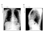
ここで、図4(a)に、胸部正面の放射線画像の一例を示す。図4(b)に、胸部側面の放射線画像の一例を示す。図4(a)に矢印で示すように、左右肺の下端部の位置は異なるため、図4(b)に矢印で示すように、側面の放射線画像においては、2つの肺野の下端部のエッジが存在する。そこで、例えば、以下の(1)〜(3)のいずれかの手法で側面の動態画像の各フレーム画像から両肺の肺野領域の下端部を特定することができる。
(1)肺野領域の最も内側(上側)のエッジを肺野領域の下端部として特定する(図5(a)参照)。
(2)肺野領域の最も外側(下側)のエッジを肺野領域の下端部として特定する(図5(b)参照)。
(3)(1)のエッジと(2)のエッジの代表値(例えば、平均値)を肺野領域の下端部として特定する(図5(c)参照)。(3)の手法は誤差が少ないため好ましい。
Here, FIG. 4A shows an example of a radiographic image of the front of the chest. FIG. 4B shows an example of a radiographic image of the side surface of the chest. As shown by the arrows in FIG. 4 (a), the positions of the lower ends of the left and right lungs are different. Therefore, as shown by the arrows in FIG. 4 (b), in the side radiograph, the lower ends of the two lung fields There is an edge. Therefore, for example, the lower end of the lung field region of both lungs can be identified from each frame image of the lateral dynamic image by any of the following methods (1) to (3).
(1) The innermost (upper) edge of the lung field region is specified as the lower end of the lung field region (see FIG. 5A).
(2) The outermost (lower) edge of the lung field region is specified as the lower end of the lung field region (see FIG. 5 (b)).
(3) A representative value (for example, an average value) of the edge of (1) and the edge of (2) is specified as the lower end of the lung field region (see FIG. 5C). The method (3) is preferable because it has a small error.
次いで、胸部正面と胸部側面の各動態画像の各フレーム画像から、肺野の動態に関する特徴量が算出される(ステップS12)。
ここで、呼吸運動は、呼気位相と吸気位相により構成される。呼気位相は、横隔膜が上がることによって肺から空気が排出され、肺野の領域が小さくなる。これにより肺野の密度は高くなり、動態画像では肺野が低い濃度値(信号値)で描画される。最大呼気位では、横隔膜の位置が最も高い状態となる。吸気位相は、横隔膜が下がることにより肺に空気が取り込まれ、肺野の領域が大きくなる。これにより肺野の密度は低くなり、動態画像では肺野が高い濃度値で描画される。最大吸気位では、横隔膜の位置が最も下がった状態となる。このように、胸部の動態画像の各フレーム画像における肺野内の濃度、肺野の面積、横隔膜の上下位置(或いは、肺尖及び大動脈弓はほとんど動かないため、肺尖と横隔膜の頂点との距離又は大動脈弓と横隔膜の頂点との距離)は、呼吸運動による肺野の動態に関する特徴量となる。
そこで、ステップS12においては、例えば、図6に示すように各フレーム画像の肺尖と横隔膜の頂点との距離Lを肺野の動態に関する特徴量として算出する。
Next, the feature amount related to the dynamics of the lung field is calculated from each frame image of each dynamic image of the front surface of the chest and the side surface of the chest (step S12).
Here, the respiratory movement is composed of an expiratory phase and an inspiratory phase. In the expiratory phase, as the diaphragm rises, air is expelled from the lungs and the area of the lung field becomes smaller. As a result, the density of the lung field becomes high, and the lung field is drawn with a low density value (signal value) in the dynamic image. At the maximum expiratory position, the position of the diaphragm is the highest. In the inspiratory phase, the lowering of the diaphragm causes air to be taken into the lungs, increasing the area of the lung field. As a result, the density of the lung field becomes low, and the lung field is drawn with a high density value in the dynamic image. At the maximum inspiratory position, the position of the diaphragm is in the lowest position. In this way, the concentration in the lung field, the area of the lung field, and the vertical position of the diaphragm (or the distance between the apex of the lung and the apex of the diaphragm because the apex and the aortic arch hardly move) in each frame image of the dynamic image of the chest. Alternatively, the distance between the aortic arch and the apex of the diaphragm) is a characteristic quantity related to the dynamics of the lung field due to respiratory movement.
Therefore, in step S12, for example, as shown in FIG. 6, the distance L between the apex of the lung and the apex of the diaphragm of each frame image is calculated as a feature amount relating to the dynamics of the lung field.
次いで、算出された特徴量に基づいて、胸部正面の動態画像と胸部側面の動態画像から呼吸位相が最も近いフレーム画像の組が抽出される(ステップS13)。
図7は、胸部正面の動態画像と胸部側面の動態画像の肺尖−横隔膜間の距離Lの時間変化をプロットしたグラフの一例である。ステップS13においては、例えば、図7の矢印で示すように、胸部正面と胸部側面の肺尖−横隔膜間の距離Lの値が最も近い(差分が最も小さい)フレーム画像同士からなる組を呼吸位相が最も近いフレーム画像の組として抽出する。本実施形態では、胸部正面の動態画像と胸部側面の動態画像から、互いに算出された特徴量の値が最も近いフレーム画像の組を時間軸に沿って複数抽出する。抽出する間隔は、等間隔であっても不等間隔であってもよい。正面、側面でフレームレートが異なる場合、低フレームレートのほうに合わせてフレーム画像の抽出を行ってもよい。
Then, based on the calculated feature amount, a set of frame images having the closest respiratory phase is extracted from the dynamic image of the front surface of the chest and the dynamic image of the side surface of the chest (step S13).
FIG. 7 is an example of a graph plotting the time change of the distance L between the lung apex and the diaphragm in the dynamic image of the front surface of the chest and the dynamic image of the lateral surface of the chest. In step S13, for example, as shown by the arrow in FIG. 7, the respiratory phase is a set consisting of frame images having the closest (smallest difference) distance L between the apex of the chest and the side of the chest and the diaphragm. Is extracted as the closest set of frame images. In the present embodiment, a plurality of sets of frame images having the closest feature amount values calculated to each other are extracted from the dynamic image of the front surface of the chest and the dynamic image of the side surface of the chest along the time axis. The extraction interval may be equal or unequal. When the frame rates are different on the front side and the side surface, the frame image may be extracted according to the lower frame rate.
次いで、抽出された組毎の胸部正面と胸部側面のフレーム画像のそれぞれから、肺野面積が算出される(ステップS14)。
ステップS13においては、図6に示すように、胸部正面のフレーム画像における右肺の面積S_PA_R、胸部正面のフレーム画像における左肺の面積S_PA_L、胸部側面のフレーム画像における肺野の面積S_LATを算出する。各肺野の面積S(S_PA_R、S_PA_L、S_LAT)は、各肺野の肺野輪郭内の画素数NoPとサンプリングピッチSPに基づいて、(式1)により求めることができる。
S = NoP×SP×SP ・・・(式1)
Next, the lung field area is calculated from each of the extracted frame images of the front chest and the side surface of the chest for each group (step S14).
In step S13, as shown in FIG. 6, the area S_PA_R of the right lung in the frame image of the front of the chest, the area S_PA_L of the left lung in the frame image of the front of the chest, and the area S_LAT of the lung field in the frame image of the side of the chest are calculated. .. The area S (S_PA_R, S_PA_L, S_LAT) of each lung field can be obtained by (Equation 1) based on the number of pixels NoP in the lung field contour of each lung field and the sampling pitch SP.
S = NoP x SP x SP ... (Equation 1)
なお、ステップS11で認識した肺野輪郭内を肺野領域として肺野面積を求める他、側面については、以下の(1)〜(2)の手法で各フレーム画像から肺野面積を求めることもできる。この場合、左右肺のサイズを考慮した体積の推定を行うことができる。
(1)胸部側面のフレーム画像から左右の肺野面積を左右肺の区別なしに算出する。すなわち、図4(a)に示す上側のエッジを下端部とする肺野面積と、図4(b)に示す下側のエッジを下端部とする肺野面積を算出する。一方の面積をS_LAT_A、他方の面積をS_LAT_Bとする。
(2)両肺野の面積を加算し、2で除算した値をS_LATとする。
S_LAT=(S_LAT_A +S_LAT_B)/2・・・(式2)
In addition to obtaining the lung field area with the inside of the lung field contour recognized in step S11 as the lung field area, the lung field area can also be obtained from each frame image by the following methods (1) and (2) for the side surface. it can. In this case, the volume can be estimated in consideration of the sizes of the left and right lungs.
(1) The left and right lung field areas are calculated from the frame image of the side of the chest without distinguishing between the left and right lungs. That is, the lung field area having the upper edge shown in FIG. 4 (a) as the lower end and the lung field area having the lower edge shown in FIG. 4 (b) as the lower end are calculated. Let one area be S_LAT_A and the other area be S_LAT_B.
(2) The value obtained by adding the areas of both lung fields and dividing by 2 is defined as S_LAT.
S_LAT = (S_LAT_A + S_LAT_B) / 2 ... (Equation 2)
また、放射線撮影では、被写体Mと放射線検出部13の距離が離れているほど被写体が大きく映る。胸部正面の画像では、左肺と右肺の放射線検出部13との距離は変わらないが、胸部側面の画像では、放射線検出部13に遠い側の肺野が実際より大きく映る。そこで、側面の動態画像から左肺と右肺が区別できる場合、側面の動態画像における放射線検出部13に遠い側の肺野領域を特定し、放射線検出部13に遠い側の肺野領域の面積を補正することが好ましい。この面積の補正は、以下の(1)〜(5)により行うことができる。
(1)胸部側面のフレーム画像において、撮影時に放射線検出部13に遠い側に配置された肺野を特定する。例えば、動態画像に付帯されている検査情報等から特定することができる。ここでは、撮影時に放射線検出部13に遠い側に配置された肺野が左肺であることとして説明する。
(2)側面のフレーム画像から右肺の肺野面積S_LAT_R、左肺の肺野面積S_LAT_Lを求める。
(3)正面画像から肩幅Widthを算出する。例えば、図8に示すように、画像上端から下向きに走査し、素抜けの信号値→被写体の信号値→素抜けの信号値になったy軸最小値の点を右側と左側でそれぞれ求め、(xa,ya)、(xb,yb)とする。素抜けの信号値及び被写体の信号値は、予め設定された閾値により分類することができる。xb−xaを肩幅Widthとして算出する。
(4)放射線源11の管球と左肺との距離は、SID-Widthで表すことができ、左肺の拡大率は、SID/(SID-Width)となる。そこで、(式3)により左肺野の面積S_LAT_Lを補正し、補正後の左肺の面積S_LAT_Lcorrectedを求める。
S_LAT_Lcorrected = S_LAT_L×(SID-Width)/SID・・・(式3)
(5)(式4)により側面の肺野面積S_LATを求める。
S_LAT =(S_LAT_R+S_LAT_Lcorrected)/2・・・(式4)
これにより、精度よく肺野体積を推定することが可能となるため、精度よく呼吸機能指標を推定することが可能となる。
Further, in radiography, the farther the subject M and the
(1) In the frame image of the side surface of the chest, the lung field located on the distant side of the
(2) Obtain the lung field area S_LAT_R of the right lung and the lung field area S_LAT_L of the left lung from the side frame image.
(3) Calculate the shoulder width Width from the front image. For example, as shown in FIG. 8, scanning is performed downward from the upper end of the image, and the y-axis minimum value points obtained from the signal value of the blank → the signal value of the subject → the signal value of the blank are obtained on the right side and the left side, respectively. Let it be (xa, ya), (xb, yb). The signal value of the blank and the signal value of the subject can be classified according to a preset threshold value. Calculate xb-xa as the shoulder width Width.
(4) The distance between the tube of the
S_LAT_L corrected = S_LAT_L × (SID-Width) / SID ・ ・ ・ (Equation 3)
(5) Obtain the lateral lung field area S_LAT by (Equation 4).
S_LAT = (S_LAT_R + S_LAT_L corrected ) / 2 ... (Equation 4)
As a result, the lung field volume can be estimated with high accuracy, and the respiratory function index can be estimated with high accuracy.
また、無気肺部は、肺胞がつぶれており、呼吸機能を果たしていない部分である。そのため、無気肺部は呼吸機能を推定するための肺野体積から除外する必要がある。そこで、各フレーム画像から肺野面積を算出する際、無気肺部を除いた面積を算出することが好ましい。無気肺部の除外は、以下の(1)〜(3)により行うことができる。
(1)無気肺部は周りの信号値(濃度値)よりも低い。そこで、肺野領域内で予め定められた閾値よりも信号値が低い領域を無気肺部として抽出する。
(2)抽出した無気肺部の面積を算出する。
(3)肺野面積(S_PA_R、S_PA_L、S_LAT)から無気肺部の面積を減算する。
これにより、呼吸機能を果たしている肺野領域のみを用いて呼吸機能指標を推定することが可能となり、より正確に呼吸機能指標を推定することが可能となる。
In addition, the atelectasis is a part where the alveoli are crushed and do not perform respiratory function. Therefore, the atelectasis should be excluded from the lung field volume for estimating respiratory function. Therefore, when calculating the lung field area from each frame image, it is preferable to calculate the area excluding the atelectasis. Exclusion of atelectasis can be performed by the following (1) to (3).
(1) The atelectasis is lower than the surrounding signal value (cardinality value). Therefore, a region in the lung field region where the signal value is lower than a predetermined threshold value is extracted as an atelectasis region.
(2) Calculate the area of the extracted atelectasis.
(3) Subtract the area of the atelectasis from the lung field area (S_PA_R, S_PA_L, S_LAT).
As a result, it becomes possible to estimate the respiratory function index using only the lung field region that fulfills the respiratory function, and it becomes possible to estimate the respiratory function index more accurately.
次いで、算出された肺野面積が、動態画像のフレーム画像から算出される被写体Mの面積及び体積に影響を与える撮影条件の動態撮影時の設定値に基づいて補正される(ステップS15)。
ステップS15においては、例えば、記憶部32が参照され、撮影により得られた画像に基づいて算出される面積及び体積に影響を与える撮影条件及び各撮影条件の基準値及び補正係数が読み出される。ここで、撮影により得られた画像に基づいて算出される面積及び体積に影響を与える撮影条件としては、例えば、SID、被写体Mと放射線検出部13の距離等が挙げられる。また、今回の検査の動態撮影時における上記各撮影条件の設定値が取得される。動態撮影時の撮影条件の設定値は、例えば、動態画像に付帯されている情報(放射線照射条件、画像読取条件、検査情報等)から取得することができる。被写体Mと放射線検出部13の距離については、例えば、予め記憶部32に臥位撮影台と放射線検出部13との隙間の距離を記憶しておき、臥位での撮影の場合に、記憶された距離の値を読み出して取得すればよい(立位の場合はこの撮影条件に基づく補正は行わない)。そして、得られた撮影条件の基準値及び補正係数と動態撮影時の設定値とに基づいて、肺野面積が補正される。
Next, the calculated lung field area is corrected based on the set value at the time of dynamic imaging of the imaging conditions that affect the area and volume of the subject M calculated from the frame image of the dynamic image (step S15).
In step S15, for example, the
SIDが異なると、放射線画像上の被写体の大きさが変わる(SIDが短いほど被写体が大きく映る)。そのため、同じ被写体を撮影してもSIDによって肺野面積の大きさが変わってしまい、フレーム画像に基づく体積の推定に影響する。そこで、SIDの基準値BASESIDと補正係数αSIDを用いて、右肺の面積S_PA_R、左肺の面積S_PA_L、側面肺野の面積S_LATを(式5)により補正する。なお、動態撮影時のSIDの設定値をSID(m)、画像から算出した面積(S_PA_R、S_PA_L、S_LAT)をS、補正後の面積(S_PA_R、S_PA_L、S_LAT)をScorrectedとする。
Scorrected = S×SID/BASESID×αSID ・・・(式5)
If the SID is different, the size of the subject on the radiographic image changes (the shorter the SID, the larger the subject appears). Therefore, even if the same subject is photographed, the size of the lung field area changes depending on the SID, which affects the volume estimation based on the frame image. Therefore, the area S_PA_R of the right lung, the area S_PA_L of the left lung, and the area S_LAT of the lateral lung field are corrected by (Equation 5) using the SID reference value BASE SID and the correction coefficient α SID . The SID setting value during dynamic photography is SID (m), the area calculated from the image (S_PA_R, S_PA_L, S_LAT) is S, and the corrected area (S_PA_R, S_PA_L, S_LAT) is S corrected .
S corrected = S × SID / BASE SID × α SID・ ・ ・ (Equation 5)
被写体Mと放射線検出部13の間に距離があると、放射線画像上の被写体Mの大きさが変わる(距離が大きいほど被写体Mが大きく映る)ため、同じ被写体を撮影しても算出される肺野面積が変わってしまい、フレーム画像に基づく体積の推定に影響する。立位の撮影台の場合は、被写体Mと放射線検出部13を接触させて撮影を行うが、臥位の撮影台は、被写体台の下に放射線検出部13が装着されるため、被写体Mと放射線検出部13の間に隙間が生じる。そこで、被写体Mと放射線検出部13の距離の基準値BASEsupineと補正係数αsupineを用いて、右肺の面積S_PA_R、左肺の面積S_PA_L、側面肺野の面積S_LATを(式6)により補正する。なお、動態撮影時の被写体Mと放射線検出部13の距離の設定値をD(μm)、画像から算出した面積(S_PA_R、S_PA_L、S_LAT)をS、補正後の面積(S_PA_R、S_PA_L、S_LAT)をScorrectedとする。
Scorrected = S×BASEsupine/D×αsupine・・・(式6)
If there is a distance between the subject M and the
S corrected = S × BASE supine / D × α supine・ ・ ・ (Equation 6)
次いで、算出された(補正された)組毎の胸部正面のフレーム画像と胸部側面のフレーム画像の肺野面積に基づいて肺野の体積が推定される(ステップS16)
肺野の体積は、例えば、非特許文献1に記載のように、下記の(式7)、(式8)により推定することができる。
X線画像から簡易的に算出される肺野の体積=右肺の体積 + 左肺の体積
=(S_PA_R × S_LAT)^(3/4) + (S_PA_L × S_LAT)^(3/4) ・・・(式7)
肺野の体積の推定値 = 0.67 ×(X線画像から簡易的に算出される肺野の体積)+ 160
[ml] ・・・(式8)
Next, the volume of the lung field is estimated based on the lung field area of the calculated (corrected) front chest frame image and the chest side frame image (step S16).
The volume of the lung field can be estimated by the following (Equation 7) and (Equation 8), for example, as described in
Volume of lung field simply calculated from X-ray image = Volume of right lung + Volume of left lung
= (S_PA_R × S_LAT) ^ (3/4) + (S_PA_L × S_LAT) ^ (3/4) ・ ・ ・ (Equation 7)
Estimated value of lung field volume = 0.67 × (volume of lung field simply calculated from X-ray image) + 160
[ml] ・ ・ ・ (Equation 8)
なお、正面と側面の撮影条件が同じである場合、ステップS15で説明した撮影条件に基づく肺野面積の補正を行わず、(式7)で算出された肺野の体積を補正してもよい。例えば、動態撮影時のSIDの設定値が基準値と異なる場合は、βSIDを補正係数として、(式7)で算出された体積に(SID/BASESID×βSID)^(3/4)を乗算することで補正可能である。また、動態撮影時の被写体Mと放射線検出部13の間の距離の設定値が基準値と異なる場合は、βsupineを補正係数として、(式7)で算出された体積に(BASEsupine/D×βsupine)^(3/4)を乗算することで補正可能である。
If the front and side imaging conditions are the same, the lung field area calculated in (Equation 7) may be corrected without correcting the lung field area based on the imaging conditions described in step S15. .. For example, if the SID setting value during dynamic shooting is different from the reference value, the volume calculated by (Equation 7) will be added to the volume calculated by (Equation 7) with β SID as the correction coefficient (SID / BASE SID × β SID ) ^ (3/4). It can be corrected by multiplying by. If the set value of the distance between the subject M and the
次いで、推定された肺野の体積に基づいて、呼吸機能指標が推定される(ステップS17)。
例えば、図9に示すように、ステップS17で推定された肺野の体積を時間軸に沿ってプロットして補間することにより肺野の体積の時間変化を示す波形を生成し、生成した波形を肺容量曲線として推定する。また、図10に示すように、肺容量曲線の矢印で示す各点(ピーク)の値に基づいて、TLC、RV等の、スパイロメーターでは測定不可能な呼吸機能指標や、IRV(Inspiratory Reserve Volume)、IC(Inspiratory Capacity)、VC(Vital Capacity)等の呼吸機能検査で得られるその他の呼吸機能指標を推定することができる。例えば、TLCは、強制最大吸気位(深呼吸時の最大吸気位)での肺の体積と推定することができる。RVは、強制最大呼気位(深呼吸時の最大呼気位)での肺の体積と推定することができる。
The respiratory function index is then estimated based on the estimated volume of the lung field (step S17).
For example, as shown in FIG. 9, the lung field volume estimated in step S17 is plotted and interpolated along the time axis to generate a waveform showing the time change of the lung field volume, and the generated waveform is generated. Estimated as a lung volume curve. Further, as shown in FIG. 10, based on the values of each point (peak) indicated by the arrows of the lung capacity curve, respiratory function indexes such as TLC and RV, which cannot be measured by a spirometer, and IRV (Inspiratory Reserve Volume). , IC (Inspiratory Capacity), VC (Vital Capacity) and other respiratory function indices obtained by respiratory function tests can be estimated. For example, the TLC can be estimated as the volume of the lungs at the forced maximum inspiratory position (maximum inspiratory position during deep breathing). RV can be estimated as the volume of the lungs at the forced maximum expiratory position (maximum expiratory position during deep breathing).
なお、撮影された動態画像に安静呼吸が含まれているか、深呼吸が含まれているか、双方が含まれているかによって、推定可能な呼吸機能指標が異なる。例えば、TLC、RVは、深呼吸の画像から推定可能である。FRCは、安静呼吸の画像から推定可能である。そこで、動態撮影時の呼吸状態に基づいて、推定する呼吸機能指標の種類が決定される。動態撮影時の呼吸状態は、例えば、動態画像の付帯情報に基づいて特定することができる。または、動態画像から生成された肺容量曲線を解析して動態撮影時の呼吸状態を判定してもよい。 It should be noted that the estimable respiratory function index differs depending on whether the captured dynamic image includes resting breathing, deep breathing, or both. For example, TLC and RV can be estimated from images of deep breathing. The FRC can be estimated from the image of resting breathing. Therefore, the type of respiratory function index to be estimated is determined based on the respiratory state at the time of dynamic imaging. The respiratory state at the time of dynamic imaging can be specified, for example, based on the incidental information of the dynamic image. Alternatively, the lung volume curve generated from the dynamic image may be analyzed to determine the respiratory state at the time of dynamic imaging.
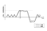
動態撮影時の呼吸状態の自動判定は、以下の(1)〜(4)のアルゴリズムにより行うことができる。以下、図11を参照して動態撮影時の呼吸状態の自動判定アルゴリズムについて説明する。
なお、肺容量曲線の代わりに、正面又は側面の動態画像から求めた画像全体の信号値、横隔膜の位置、又は肺野面積の時間変化を示す波形を用いてもよい。
The automatic determination of the respiratory state at the time of dynamic imaging can be performed by the following algorithms (1) to (4). Hereinafter, an algorithm for automatically determining the respiratory state during dynamic imaging will be described with reference to FIG.
Instead of the lung volume curve, a waveform showing the signal value of the entire image obtained from the frontal or lateral dynamic image, the position of the diaphragm, or the temporal change of the lung field area may be used.
(1)まず、肺容量曲線の最大値Maxと最小値Minの値を求める。
(2)中央値Med=(Max+Min)/2を算出し、その点Mで肺容量曲線に基準線を引く。
(3)基準線から+方向の極値(上に凸のピーク)をMaxn、−方向の極値(下に凸のピーク)をMinn(n=1、2、3・・・)として、Maxn、Minnの組み合わせのそれぞれについて、下記条件にて判定を行う。
(3−1)Maxn-Minn>Tht かつMaxn-Minn<Thdであれば、安静呼吸Flagt=1(真)と判定する。Flagd、Flagnは0(偽)と判定する。
(3−2)Maxn-Minn>Thdであれば、深呼吸Flagd=1と判定する。Flagt、Flagnは0と判定する。
(3−3)上記以外はFlagn=1と判定する。Flagt、Flagdは0と判定する。
ただし、安静呼吸用閾値Tht << 深呼吸用の閾値Thdである。また、各FlagはBool型である。
(4)全ての極値を探索し終えた際のFlagtのORを取り、1であれば、安静呼吸が含まれていると判定する。また、Flagdの判定のORを取り、1であれば深呼吸が含まれていると判定する。FlagtとFlagdの双方が1であれば安静呼吸と深呼吸が含まれていると判定する。また、Flagt=1のフレーム画像の区間は、安静呼吸の区間と判定することができ、Flagd=1のフレーム画像の区間は、深呼吸の区間と判定することができる。
(1) First, the values of the maximum value Max and the minimum value Min of the lung volume curve are obtained.
(2) Calculate the median Med = (Max + Min) / 2, and draw a reference line on the lung volume curve at that point M.
(3) The extreme value in the + direction (upward convex peak) from the reference line is Max n , and the negative extreme value (downward convex peak) is Min n (n = 1, 2, 3, ...). , Max n, and Min n are each combined under the following conditions.
(3-1) If Max n -Min n > Th t and Max n -Min n <Th d, it is determined that rest breathing Flag t = 1 (true). Flag d and Flag n are judged to be 0 (false).
(3-2) If Max n -Min n > Th d, it is determined that deep breathing Flag d = 1. Flag t and Flag n are determined to be 0.
(3-3) Other than the above, it is determined that Flag n = 1. Flag t and Flag d are determined to be 0.
However, the threshold for resting breath Th t << the threshold for deep breathing Th d . Also, each Flag is a Bool type.
(4) Take the OR of Flag t when all the extreme values have been searched, and if it is 1, it is determined that resting breathing is included. In addition, the OR of the determination of Flag d is taken, and if it is 1, it is determined that deep breathing is included. If both Flag t and Flag d are 1, it is determined that rest breathing and deep breathing are included. Further, the section of the frame image with Flag t = 1 can be determined to be the section of resting breathing, and the section of the frame image with Flag d = 1 can be determined to be the section of deep breathing.
上記の呼吸状態の判定アルゴリズムの(1)〜(4)を行えば、図11に示すように安静呼吸と深呼吸が混じっている場合において、どのフレーム番号が安静呼吸(安静呼気位、安静吸気位)、深呼吸(強制最大呼気位、強制最大吸気位)に該当するのかを自動的に判定して呼吸機能指標を推定することが可能となる。 If (1) to (4) of the above respiratory state determination algorithms are performed, which frame number is the resting breathing (resting expiratory position, resting inspiratory position) when resting breathing and deep breathing are mixed as shown in FIG. ), Deep breathing (forced maximum expiratory position, forced maximum inspiratory position) can be automatically determined and the respiratory function index can be estimated.
なお、図11に示すように、動態画像中に、推定に使用する呼吸位相(例えば、安静呼気位、安静吸気位、強制最大呼気位、強制最大吸気位のうちいずれか)が複数含まれている場合には、呼吸が安定している最後の周期のものを呼吸機能指標の推定に使用することが好ましい。または、複数周期のピークの代表値(例えば、最大値、最小値、平均値等)を算出して呼吸機能指標の推定に用いてもよい。または、肺気量曲線又はステップS12で算出した特徴量の時間変化を示す波形を表示部34に表示してユーザーが操作部33により指定したものを使用することとしてもよい。特徴量の波形を表示する場合には、正面と側面のそれぞれで算出された特徴量の波形を並べて(例えば、上下に並べて)表示してもよい。一致する位相の対応がわかりやすくなるように基準点(例えば、強制最大吸気位)に合わせて位相をずらして並べてもよい。
As shown in FIG. 11, a plurality of respiratory phases used for estimation (for example, any one of resting expiratory position, resting inspiratory position, forced maximum expiratory position, and forced maximum inspiratory position) are included in the dynamic image. If so, it is preferred to use the last cycle of stable respiration to estimate respiratory function indicators. Alternatively, representative values of peaks of a plurality of cycles (for example, maximum value, minimum value, average value, etc.) may be calculated and used for estimating the respiratory function index. Alternatively, the lung air volume curve or the waveform indicating the time change of the feature amount calculated in step S12 may be displayed on the
ここで、VCは、スパイロメーターで計測することができる呼吸機能指標である。そこで、スパイロメーターでのVCの実測値を取得し(操作部33による入力又は通信部35を介してVCの実測値をスパイロメーター又は電子カルテシステム等から取得し)、取得されたVCRealと動態画像から算出したVC(VCIm)に基づいて補正係数Cを算出し、補正係数Cに基づいて、動態画像から算出した他の種類の呼吸機能指標(例えば、TLCやRV)の値を補正してもよい。補正係数Cは、以下の(式9)により求めることができる。
C = VCReal/VCIm ・・・(式9)
このように、動態画像とスパイロメーターによる検査を組み合わせることにより、TLC、RV等のスパイロメーターで測定できない呼吸機能指標を、体プレチスモグラフィー等の高コストで患者にとっても負担の大きい精密肺機能検査を実施せずに高精度に算出することができる。
なお、(式9)の算出結果が予め定められた範囲を超えた場合は、アラートを表示又は音声により出力することが好ましい。
Here, VC is a respiratory function index that can be measured by a spirometer. Therefore, the measured value of VC by the spirometer is acquired (the measured value of VC is acquired from the spirometer, the electronic medical record system, etc. via the input by the
C = VC Real / VC Im・ ・ ・ (Equation 9)
In this way, by combining dynamic images and spirometer tests, we carry out precision lung function tests such as body plethysmography, which are costly and burdensome for patients, for respiratory function indicators that cannot be measured by spirometers such as TLC and RV. It can be calculated with high accuracy without doing so.
When the calculation result of (Equation 9) exceeds a predetermined range, it is preferable to display an alert or output it by voice.
そして、推定された呼吸機能指標が表示部34に表示され(ステップS18)、呼吸機能指標推定処理は終了する。呼吸機能指標とともに、ステップS13で抽出されたフレーム画像の組を並べて表示することとしてもよい。 Then, the estimated respiratory function index is displayed on the display unit 34 (step S18), and the respiratory function index estimation process ends. The set of frame images extracted in step S13 may be displayed side by side together with the respiratory function index.
ここで、ステップS18において表示部34に表示される呼吸機能指標の推定結果表示の例について説明する。
例えば、図12に示すように、正面と側面の代表フレーム画像(例えば、強制最大吸気位の画像等)を表示するとともに、呼吸機能指標の推定値を数値でそのまま表示する。
Here, an example of displaying the estimation result of the respiratory function index displayed on the
For example, as shown in FIG. 12, representative frame images of the front surface and the side surface (for example, an image of the forced maximum inspiratory position) are displayed, and the estimated value of the respiratory function index is displayed as it is as a numerical value.
または、図13に示すように、正面と側面の代表フレーム画像(例えば、強制最大吸気位の画像等)を表示するとともに、呼吸機能指標の推定値を肺気量分画のグラフ上に表示する。これにより、推定した呼吸機能指標を直感的に把握することが可能となる。 Alternatively, as shown in FIG. 13, representative frame images of the front and side surfaces (for example, an image of the forced maximum inspiratory position) are displayed, and the estimated value of the respiratory function index is displayed on the graph of the lung air volume fraction. .. This makes it possible to intuitively grasp the estimated respiratory function index.
または、図14に示すように、正面と側面の代表フレーム画像(例えば、強制最大吸気位の画像等)を表示するとともに、患者の性別、身長、年齢、体重等から算出される呼吸機能指標の予測値に対する、呼吸機能指標の推定値の割合(%)を表示する。また、かっこ内には、(推定値/予測値)を表示する。これにより、診療との親和性の高い表示を行うことができる。なお、予測値算出に必要な患者の性別、身長、年齢、体重等の情報は、動態画像の付帯情報から取得してもよいし、画面上で入力することとしてもよい。 Alternatively, as shown in FIG. 14, representative frame images of the front and side surfaces (for example, an image of the forced maximum inspiratory position) are displayed, and a respiratory function index calculated from the patient's gender, height, age, weight, etc. The ratio (%) of the estimated value of the respiratory function index to the predicted value is displayed. In addition, (estimated value / predicted value) is displayed in parentheses. As a result, it is possible to perform a display having a high affinity with medical treatment. Information such as the sex, height, age, and weight of the patient necessary for calculating the predicted value may be acquired from the incidental information of the dynamic image, or may be input on the screen.
ここで、呼吸機能指標の予測値は、記憶部32に記憶されている、呼吸機能指標の予測値を算出するための公知の算出式を用いて算出することとしてもよいし、性別、身長、年齢、体重等の情報と呼吸機能指標の実測値とを対応付けた大量のデータから機械学習等により算出した算出式を用いて予測値を算出してもよい。公知の算出式としては、例えば、参照文献4に記載されている、Baldwin 式(VC-B 式)、Berglund 式(FEV1-B 式)、VC 予測式(VC-J 式)、FEV1予測式(FEV1-J 式)や、参照文献5に記載されている、性別、身長、年齢からのTLC、RV、FRCの予測式等を用いることができる(参照文献4:青木美江、 長内忍、小笠壽之、山崎典美、石田健介、中田寛章、中尾祥子、豊嶋恵理、長谷部直幸、大崎能伸著,「従来から使用されてきた肺活量および1秒量予測式と日本人予測式との比較検討」,日呼吸会誌 48(5),2010.参照文献5:J. Stocks, Ph.H. Quanjer,“REFERENCE VALUES FOR RESIDUAL VOLUME, FUNCTIONAL RESIDUAL CAPACITY AND TOTAL LUNG CAPACITY”, Eur Respir J, 1995, 8, P.492-P.506)。
Here, the predicted value of the respiratory function index may be calculated using a known calculation formula stored in the
または、図15に示すように、正面と側面の代表フレーム画像(例えば、強制最大吸気位の画像等)を表示するとともに、患者の性別、身長、年齢、体重等から算出される呼吸機能指標の予測値に対する、呼吸機能指標の推定値の割合(%)をスケールバー上(又はレーダーチャート上)に表示する。これにより、患者の性別、身長、年齢、体重等から算出される呼吸機能指標の予測値に対する、呼吸機能指標の推定値の割合(%)をユーザーが直感的に容易に把握することが可能となる。 Alternatively, as shown in FIG. 15, representative frame images of the front and side surfaces (for example, an image of the forced maximum inspiratory position, etc.) are displayed, and a respiratory function index calculated from the patient's gender, height, age, weight, etc. The ratio (%) of the estimated value of the respiratory function index to the predicted value is displayed on the scale bar (or on the radar chart). This makes it possible for the user to intuitively and easily grasp the ratio (%) of the estimated value of the respiratory function index to the predicted value of the respiratory function index calculated from the patient's gender, height, age, weight, etc. Become.
または、図16に示すように、正面と側面の代表フレーム画像(例えば、強制最大吸気位の画像等)を表示するとともに、各呼吸機能指標の推定値の数値に、推定に用いた正面と側面のフレームNo.(フレーム番号)を併記する。これにより、呼吸機能指標の推定の根拠となるフレーム画像を確認しやすくすることができる。 Alternatively, as shown in FIG. 16, representative frame images of the front and side surfaces (for example, an image of the forced maximum inspiratory position, etc.) are displayed, and the front and side surfaces used for estimation are added to the estimated values of each respiratory function index. Frame No. (Frame number) is also written. This makes it easier to confirm the frame image that is the basis for estimating the respiratory function index.
または、図17に示すように、肺気量分画のグラフ上に、算出した各呼吸機能指標の推定値と、推定に用いた正面のフレーム画像及び側面のフレーム画像のサムネイル画像と、それぞれのフレーム画像のフレーム番号(図17において#を付して示す)を対応付けて表示する。これにより、呼吸機能指標の推定の根拠となるフレーム画像をユーザーが容易に確認することが可能となる。なお、図17に示すように、算出した全ての呼吸機能指標に関する情報を表示するのではなく、例えば、操作部33で肺気量分画上を押下すると、押下された位置に応じた呼吸機能指標に関する情報が表示されるようにしてもよい。
Alternatively, as shown in FIG. 17, on the graph of the lung air volume fraction, the estimated value of each respiratory function index calculated, the thumbnail image of the front frame image and the side frame image used for the estimation, and each of them. The frame numbers of the frame images (indicated by # in FIG. 17) are associated and displayed. This makes it possible for the user to easily confirm the frame image that is the basis for estimating the respiratory function index. As shown in FIG. 17, instead of displaying all the calculated information on the respiratory function index, for example, when the
または、図18に示すように、正面と側面の代表フレーム画像(例えば、強制最大吸気位の画像等)を表示するとともに、呼吸機能指標の推定値と併せて、スパイロメーターの検査結果(実測値)を表示する。これにより、ユーザーは容易にスパイロメーターの実測値を参照することが可能となる。 Alternatively, as shown in FIG. 18, representative frame images of the front and side surfaces (for example, an image of the forced maximum inspiratory position, etc.) are displayed, and the spirometer test result (actual measurement value) is combined with the estimated value of the respiratory function index. Is displayed. This allows the user to easily refer to the measured value of the spirometer.
また、上述のように、撮影時の呼吸状態によって、推定可能な呼吸機能指標の種類が異なる。そこで、撮影時の呼吸状態によって推定されなかった指標については、図19に示すように、マスキングして表示することとしてもよい。これにより、マスキングされている指標については、ユーザーが撮影時の呼吸状態によって推定されなかったことを認識することができる。 Further, as described above, the types of respiratory function indexes that can be estimated differ depending on the respiratory state at the time of imaging. Therefore, as shown in FIG. 19, the index that is not estimated by the respiratory state at the time of photographing may be masked and displayed. As a result, the user can recognize that the masked index was not estimated by the respiratory state at the time of shooting.
なお、正面、側面のそれぞれについて、安静呼吸状態下での撮影、深呼吸状態下での撮影の2撮影が行われ、正面、側面のそれぞれに安静呼吸状態で撮影した動態画像、深呼吸状態で撮影した動態画像が存在する場合、制御部31は、動態画像の付帯情報を参照するか、又は撮影単位で上述の呼吸状態の自動判定アルゴリズムを実行して各動態画像が安静呼吸の画像であるか深呼吸の画像であるかを判定し、異なる撮影方向(正面、側面)で同一の呼吸状態で撮影された動態画像を用いて呼吸機能指標推定処理を実行する。このようにすれば、誤って異なる呼吸状態で撮影された正面と側面の動態画像を用いて呼吸機能指標が推定されることを防止することができる。
Two images were taken for each of the front and side surfaces, one under a resting breathing state and the other under a deep breathing state, and the front and side surfaces were photographed in a resting breathing state and a deep breathing state, respectively. When a dynamic image is present, the
以上説明したように、診断用コンソール3の制御部31によれば、胸部正面の動態画像と胸部側面の動態画像において、呼吸運動による肺野の動態に関する特徴量が最も近いフレーム画像同士の組を抽出し、抽出された組毎のフレーム画像の肺野領域に基づいて肺野の体積を推定し、推定された体積に基づいて呼吸機能指標を推定する。したがって、肺野の動態の位相が最も近い、肺野の大きさが略揃ったときの胸部正面と胸部側面のフレーム画像から肺野の体積を推定することができ、肺野の体積の推定精度を向上させることができるとともに、呼吸機能指標の推定精度を向上させることができる。また、肺容量曲線を始めとする、呼吸機能検査で得られるTLC以外の呼吸機能指標についても推定することが可能となる。
As described above, according to the
また、制御部31は、動態画像から算出される被写体の面積及び体積に影響を与える撮影条件の放射線撮影時における設定値に基づいて、肺野の体積を推定するために胸部正面と胸部側面のフレーム画像から算出された肺野面積又は肺野体積を補正し、補正された面積に基づいて算出された体積又は補正された体積に基づいて、肺野の呼吸機能指標を推定する。したがって、推定された体積が撮影条件によって変わってしまうことを抑制し、肺野の体積の推定精度を向上させることができるとともに、呼吸機能指標の推定精度を向上させることができる。
In addition, the
また、制御部31は、スパイロメトリー検査等の他の検査による呼吸機能指標の実測値を取得し、取得された実測値と同じ種類の呼吸機能指標の推定結果に基づいて、推定された他の種類の呼吸機能指標の推定結果を補正する。したがって、TLC、RV等のスパイロメーターで測定できない呼吸機能指標を、体プレチスモグラフィー等の高コストで患者にとっても負担の大きい精密肺機能検査を実施せずに高精度に推定することができる。
In addition, the
また、制御部31は、推定された評価指標を表示部34に表示させるので、ユーザーは、推定された呼吸機能指標を確認することができる。
Further, since the
また、制御部31は、さらに、複数の動態画像から抽出されたフレーム画像の組を並べて表示するので、ユーザーは、呼吸機能指標の推定に用いた動態画像を確認することができる。
Further, since the
なお、上記実施形態における記述内容は、本発明の好適な一例であり、これに限定されるものではない。 The description in the above embodiment is a preferable example of the present invention, and is not limited thereto.
例えば、上記実施形態においては、肺野の動態に関する特徴量として肺尖と横隔膜の頂点との距離を用いることとしたが、これに限定されず、呼吸により位置が殆ど変化しないと見なせる構造物上のある位置と呼吸位相に応じて位置が変化する構造物上のある位置を胸部正面と胸部側面の画像の両方で指定できるのであれば、それらの距離を用いても同様の効果が得られる。例えば、大動脈弓と横隔膜の頂点の距離、第三胸椎上端と横隔膜の頂点等を特徴量としてもよい。さらに、特徴量は距離に限定されるものではなく、例えば、肺野面積、肺野内の信号値(例えば、平均値、最大値、最小値等の代表値)等を特徴量としてもよい。上述のように、これらは呼吸による肺の動態に応じて変化するものであり、呼吸よる肺野の大きさの変化に非常に高い相関がある特徴量である。なお、肺野面積及び肺野内の濃度値は、同じ位相であっても正面の画像と側面の画像で絶対値が異なるため、特徴量として用いる際には、例えば、最大値と最小値を使って規格化して用いる。 For example, in the above embodiment, the distance between the apex of the lung and the apex of the diaphragm is used as a feature amount related to the dynamics of the lung field, but the present invention is not limited to this, and the position can be considered to be almost unchanged by respiration. If a certain position on the structure and a certain position on the structure whose position changes according to the respiratory phase can be specified by both the front chest image and the side image of the chest, the same effect can be obtained by using those distances. For example, the distance between the aortic arch and the apex of the diaphragm, the upper end of the third thoracic vertebra and the apex of the diaphragm may be used as feature quantities. Further, the feature amount is not limited to the distance, and for example, the lung field area, the signal value in the lung field (for example, the representative value such as the average value, the maximum value, the minimum value, etc.) may be used as the feature amount. As described above, these are features that change according to the dynamics of the lungs due to respiration and have a very high correlation with changes in the size of the lung field due to respiration. Since the absolute values of the lung field area and the concentration value in the lung field are different between the front image and the side image even if they have the same phase, when using them as feature quantities, for example, the maximum value and the minimum value are used. Standardized and used.
また、例えば、上記実施形態においては、胸部正面と胸部側面の画像から算出した肺野の面積から肺野の体積を求める手法を用いた例について説明したが、胸部正面と胸部側面の画像を用いて肺野の体積を求める手法としては、上記に限定されない。
例えば、参照文献3や参照文献6に記載のように、肺野の断面形状が楕円形であり、肺野が一連の楕円形の円筒形として表されているとの知見に基づいて肺野の体積を求めることとしてもよい。例えば、胸部正面及び胸部側面のフレーム画像から肺野(胸郭)や心臓、脊柱等の領域を認識し、両画像を同じ垂直平面内で整列させ、それらを多数の水平スライスに分割し、スライス内の肺野及び肺野内の各構造物(例えば、心臓、脊椎等)の直径(胸部正面画像における各構造物領域の幅)及び厚さ(胸部側面画像の各構造物領域の幅)を求めて各スライスにおける肺野及び構造物の断面領域(楕円)の面積を推定し、肺野の断面領域の面積から各構造物の断面領域の面積を差し引いて、全てのスライスからの情報を合計することにより、肺野の体積を求めることとしてもよい(参照文献6:R J Pierce et al. “Estimation of lung volumes from chest radiographs using shape information”, Thorax 1979 34: 726-734)。また、この手法により算出される面積や体積についても、撮影により得られる画像に基づいて算出される面積や体積に影響を与える撮影条件の設定値に基づいて補正を行うことが好ましい。
Further, for example, in the above embodiment, an example using a method of obtaining the volume of the lung field from the area of the lung field calculated from the images of the front surface of the chest and the side surface of the chest has been described, but the images of the front surface of the chest and the side surface of the chest are used. The method for determining the volume of the lung field is not limited to the above.
For example, as described in
上記の肺の断面形状が楕円であるとの知見に基づく肺の体積の推定手法(楕円に基づく体積の推定手法と呼ぶ)では、胸部正面と胸部側面のフレーム画像から心臓等の構造物の領域を算出する必要があるが、心臓は、心拍に伴ってその大きさが変化するため、肺野のみならず、心臓についても胸部正面と胸部側面の心周期における位相が最も近いフレーム画像の組を抽出し、抽出したフレーム画像の組に基づいて体積を求めることが好ましい。 In the method for estimating the volume of the lung based on the finding that the cross-sectional shape of the lung is elliptical (called the method for estimating the volume based on the ellipse), the region of the structure such as the heart is obtained from the frame images of the front and side of the chest. However, since the size of the heart changes with the heartbeat, not only the lung field but also the heart should have a set of frame images with the closest phases in the cardiac cycle of the anterior chest and lateral chest. It is preferable to extract and determine the volume based on the set of extracted frame images.
また、上記実施形態においては、本発明を胸部正面と胸部側面の動態画像から呼吸機能指標を推定する場合に適用した例について説明したが、心機能の評価指標を推定する場合にも本発明を適用することができる。例えば、制御部31は、胸部正面と胸部側面の動態画像の各フレーム画像から心臓輪郭を認識して心臓の動態に関する特徴量を算出し、算出した特徴量が心拡張末期及び/又は心収縮末期付近で最も近いフレーム画像の組を抽出し、抽出した胸部正面と胸部側面のフレーム画像から心臓の面積を算出し、算出した正面と側面の面積に基づいて心臓の体積を推定し、推定した体積に基づいて心機能の評価指標を推定することとしてもよい。心機能を評価する指標としては、例えば、心拡張末期及び/又は心収縮末期の心臓の体積を挙げることができる。心機能の評価指標を算出する際に動態画像から算出される心臓の面積や体積についても、上記実施形態と同様に、撮影により得られる画像に基づいて算出される面積や体積に影響を与える撮影条件の撮影時の設定値に基づいて補正を行うことが好ましい。そして、補正された面積に基づいて算出された体積又は補正された体積に基づいて心機能の評価指標を算出することが好ましい。
Further, in the above embodiment, an example in which the present invention is applied when estimating the respiratory function index from the dynamic images of the front surface of the chest and the side surface of the chest has been described, but the present invention is also used when estimating the evaluation index of the cardiac function. Can be applied. For example, the
なお、心臓輪郭の認識については、ユーザー操作による手動による心臓輪郭の指定に基づいて認識してもよいし、エッジ検出、動的輪郭モデル、領域分割等の公知の画像処理技術を用いて自動的に認識してもよい。心臓の体積の推定手法としては、例えば、参照文献4に記載のように、楕円に基づく体積の推定を用いることができる。
心臓の動態に関する特徴量としては、例えば、心臓領域の面積、幅、濃度の高周波成分(例えば、平均値、最大値、最小値等の代表値)等を用いることができる。これらは心拍による心臓の動態に応じて変化するものであり、心拍による心臓の大きさの変化に非常に高い相関がある特徴量である。なお、心臓領域の面積、幅、濃度の高周波成分の値は、心周期における同じ位相で撮影したものであっても正面の画像と側面の画像で絶対値が異なるため、特徴量として用いる際には、例えば、最大値と最小値を使って規格化して用いる。
心拡張末期及び/又は心収縮末期付近のフレーム画像であるか否かは、例えば、フレーム画像から算出した特徴量の値が予め設定された範囲内であるか否かに基づいて判断することができる。
The heart contour may be recognized based on the manual specification of the heart contour by a user operation, or may be automatically recognized by using a known image processing technique such as edge detection, dynamic contour model, or region division. You may recognize it. As a method for estimating the volume of the heart, for example, as described in Reference Document 4, volume estimation based on an ellipse can be used.
As the feature amount related to the dynamics of the heart, for example, a high frequency component of the area, width, and concentration of the heart region (for example, representative values such as an average value, a maximum value, and a minimum value) can be used. These are features that change according to the dynamics of the heart due to the heartbeat and have a very high correlation with the change in the size of the heart due to the heartbeat. It should be noted that the values of the high-frequency components of the area, width, and density of the heart region are different in absolute values between the front image and the side image even if they are taken in the same phase in the cardiac cycle. Is standardized and used, for example, using the maximum value and the minimum value.
Whether or not the frame image is near the end of cardiac dilation and / or the end of contraction of the heart can be determined based on, for example, whether or not the value of the feature amount calculated from the frame image is within a preset range. it can.
また、上記実施形態のステップS13においては、胸部正面の動態画像と胸部側面の動態画像から複数組のフレーム画像の組を抽出することとして説明したが、これに限定されず、1組のフレーム画像の組を抽出することとしてもよい。
例えば、呼吸機能指標としてTLCのみを求める場合には、胸部正面の動態画像と胸部側面の動態画像から、算出された特徴量の値が強制最大吸気位付近(深呼吸時の最大吸気位付近)において最も近いフレーム画像の組を抽出し、抽出されたフレーム画像に基づいて肺野の体積を求めてTLCを推定すればよい。また、例えば、呼吸機能指標としてRVのみを求める場合には、胸部正面の動態画像と胸部側面の動態画像から、算出された特徴量の値が強制最大呼気位付近(深呼吸時の最大呼気位付近)において最も近いフレーム画像の組を抽出し、抽出されたフレーム画像に基づいて肺野の体積を求めてRVを推定すればよい。これにより、処理時間を短縮することができる。所定の呼吸位相付近のフレーム画像であるか否かは、例えば、フレーム画像から算出した特徴量の値が予め設定された範囲内であるか否かに基づいて判断することができる。
Further, in step S13 of the above embodiment, it has been described that a set of a plurality of sets of frame images is extracted from the dynamic image of the front surface of the chest and the dynamic image of the side surface of the chest, but the present invention is not limited to this, and one set of frame images is used. It may be possible to extract a set of.
For example, when only TLC is obtained as a respiratory function index, the value of the feature amount calculated from the dynamic image of the front of the chest and the dynamic image of the side of the chest is near the forced maximum inspiratory position (near the maximum inspiratory position during deep breathing). The closest set of frame images may be extracted, and the volume of the lung field may be determined based on the extracted frame images to estimate the TLC. Further, for example, when only RV is obtained as a respiratory function index, the value of the feature amount calculated from the dynamic image of the front of the chest and the dynamic image of the side of the chest is near the forced maximum expiratory position (near the maximum expiratory position during deep breathing). ), The closest set of frame images may be extracted, and the volume of the lung field may be obtained based on the extracted frame images to estimate RV. As a result, the processing time can be shortened. Whether or not the frame image is in the vicinity of a predetermined respiratory phase can be determined, for example, based on whether or not the value of the feature amount calculated from the frame image is within a preset range.
また、上記実施形態においては、正面と側面の異なる2方向から撮影した動態画像を用いて被写体の体積を推定する場合を例にとり説明したが、撮影する方向は正面と側面に限定されず、他の異なる複数の方向から撮影された動態画像を用いて被写体の体積を推定することとしてもよい。 Further, in the above embodiment, the case where the volume of the subject is estimated by using the dynamic images taken from two different directions of the front and the side surface has been described as an example, but the shooting direction is not limited to the front and the side surface, and other The volume of the subject may be estimated using dynamic images taken from a plurality of different directions.
また、上記実施形態においては、肺野や心臓を被写体とした動態画像に本願発明を適用した場合を例にとり説明したが、例えば、手足の関節等の他の部位を被写体とした動態画像に本発明を適用することとしてもよい。 Further, in the above embodiment, the case where the present invention is applied to a dynamic image of the lung field or the heart as a subject has been described as an example, but for example, the present invention is applied to a dynamic image of another part such as a limb joint as a subject. The invention may be applied.
また、例えば、上記の説明では、本発明に係るプログラムのコンピューター読み取り可能な媒体としてハードディスクや半導体の不揮発性メモリー等を使用した例を開示したが、この例に限定されない。その他のコンピューター読み取り可能な媒体として、CD−ROM等の可搬型記録媒体を適用することが可能である。また、本発明に係るプログラムのデータを通信回線を介して提供する媒体として、キャリアウエーブ(搬送波)も適用される。 Further, for example, in the above description, an example in which a hard disk, a non-volatile memory of a semiconductor, or the like is used as a computer-readable medium of the program according to the present invention has been disclosed, but the present invention is not limited to this example. As another computer-readable medium, a portable recording medium such as a CD-ROM can be applied. A carrier wave is also applied as a medium for providing data of the program according to the present invention via a communication line.
その他、動態画像解析システムを構成する各装置の細部構成及び細部動作に関しても、本発明の趣旨を逸脱することのない範囲で適宜変更可能である。 In addition, the detailed configuration and detailed operation of each device constituting the dynamic image analysis system can be appropriately changed without departing from the spirit of the present invention.
100 動態画像解析システム
1 撮影装置
11 放射線源
12 放射線照射制御装置
13 放射線検出部
14 読取制御装置
2 撮影用コンソール
21 制御部
22 記憶部
23 操作部
24 表示部
25 通信部
26 バス
3 診断用コンソール
31 制御部
32 記憶部
33 操作部
34 表示部
35 通信部
36 バス
100 Dynamic
Claims (8)
前記特徴量算出手段により算出された特徴量に基づいて、前記複数の動態画像間において互いに前記被写体の動態の位相が最も近いフレーム画像の組を少なくとも1組以上抽出する抽出手段と、
前記抽出手段により抽出された組毎のフレーム画像のそれぞれから前記被写体の面積を算出する面積算出手段と、
前記面積算出手段により算出された前記被写体の面積に基づいて、前記組毎に前記被写体の体積を算出する体積算出手段と、
前記複数の動態画像から算出される前記被写体の面積及び体積に影響を与える撮影条件の前記放射線撮影時における設定値に基づいて、前記面積算出手段により算出された前記被写体の面積又は前記体積算出手段により算出された前記被写体の体積を補正する補正手段と、
前記補正手段により補正された面積に基づいて算出された体積又は前記補正手段により補正された体積に基づいて、前記被写体の機能の評価指標を推定する推定手段と、
を備える動態画像解析装置。 A feature amount calculation means for calculating a feature amount related to the dynamics of the subject from each frame image of a plurality of dynamic images obtained by radiographing the dynamics of a subject having periodicity from a plurality of different directions.
Based on the feature amount calculated by the feature amount calculating means, an extraction means for extracting at least one set of frame images in which the dynamic phases of the subjects are closest to each other among the plurality of dynamic images, and an extraction means.
An area calculation means for calculating the area of the subject from each of the frame images of each set extracted by the extraction means, and
A volume calculation means for calculating the volume of the subject for each group based on the area of the subject calculated by the area calculation means, and
The area of the subject or the volume calculation means calculated by the area calculation means based on the set values at the time of the radiographic imaging of the imaging conditions that affect the area and volume of the subject calculated from the plurality of dynamic images. A correction means for correcting the volume of the subject calculated by
An estimation means that estimates an evaluation index of the function of the subject based on a volume calculated based on the area corrected by the correction means or a volume corrected by the correction means.
A dynamic image analyzer equipped with.
他の検査による前記評価指標の実測値を取得する取得手段と、
前記取得手段により取得された実測値と同じ種類の前記評価指標の推定結果に基づいて、前記推定手段により推定された他の種類の評価指標の推定結果を補正する指標補正手段をさらに備える請求項1又は2に記載の動態画像解析装置。 The estimation means estimates a plurality of types of the evaluation indexes and
An acquisition means for acquiring the measured value of the evaluation index by another inspection, and
A claim further comprising an index correction means for correcting the estimation result of another type of evaluation index estimated by the estimation means based on the estimation result of the evaluation index of the same type as the actually measured value acquired by the acquisition means. The dynamic image analyzer according to 1 or 2.
前記被写体の機能の評価指標は、呼吸機能の評価指標である請求項1〜3のいずれか一項に記載の動態画像解析装置。 The plurality of dynamic images are a dynamic image of the front surface of the chest and a dynamic image of the side surface of the chest.
The dynamic image analysis apparatus according to any one of claims 1 to 3, wherein the evaluation index of the function of the subject is an evaluation index of the respiratory function.
請求項1〜4のいずれか一項に記載の動態画像解析装置と、
前記推定手段により推定された評価指標を表示する表示装置と、
を備える動態画像解析システム。 An imaging device that radiographs the dynamics of the subject,
The dynamic image analyzer according to any one of claims 1 to 4,
A display device that displays the evaluation index estimated by the estimation means, and
Dynamic image analysis system equipped with.
異なる複数の方向から周期性を持つ被写体の動態を放射線撮影することにより得られた複数の動態画像の各フレーム画像から、前記被写体の動態に関する特徴量を算出する特徴量算出手段、
前記特徴量算出手段により算出された特徴量に基づいて、前記複数の動態画像間において互いに前記被写体の動態の位相が最も近いフレーム画像の組を少なくとも1組以上抽出する抽出手段、
前記抽出手段により抽出された組毎のフレーム画像のそれぞれから前記被写体の面積を算出する面積算出手段、
前記面積算出手段により算出された前記被写体の面積に基づいて、前記組毎に前記被写体の体積を算出する体積算出手段、
前記複数の動態画像から算出される前記被写体の面積及び体積に影響を与える撮影条件の前記放射線撮影時における設定値に基づいて、前記面積算出手段により算出された前記被写体の面積又は前記体積算出手段により算出された前記被写体の体積を補正する補正手段、
前記補正手段により補正された面積に基づいて算出された体積又は前記補正手段により補正された体積に基づいて、前記被写体の機能の評価指標を推定する推定手段、
として機能させるためのプログラム。 Computer,
A feature amount calculation means for calculating a feature amount related to the dynamics of the subject from each frame image of a plurality of dynamic images obtained by radiographing the dynamics of a subject having periodicity from a plurality of different directions.
An extraction means for extracting at least one set of frame images whose dynamic phases of the subject are closest to each other among the plurality of dynamic images based on the feature amount calculated by the feature amount calculating means.
An area calculation means for calculating the area of the subject from each of the frame images of each set extracted by the extraction means.
A volume calculation means that calculates the volume of the subject for each group based on the area of the subject calculated by the area calculation means.
The area of the subject or the volume calculation means calculated by the area calculation means based on the set values at the time of the radiographic imaging of the imaging conditions that affect the area and volume of the subject calculated from the plurality of dynamic images. Correction means for correcting the volume of the subject calculated by
An estimation means that estimates an evaluation index of the function of the subject based on the volume calculated based on the area corrected by the correction means or the volume corrected by the correction means.
A program to function as.
Priority Applications (2)
| Application Number | Priority Date | Filing Date | Title |
|---|---|---|---|
| JP2019074282A JP7255329B2 (en) | 2019-04-09 | 2019-04-09 | Dynamic image analysis device, dynamic image analysis system and program |
| US16/812,689 US20200327689A1 (en) | 2019-04-09 | 2020-03-09 | Dynamic image analysis apparatus, dynamic image analysis system and storage medium |
Applications Claiming Priority (1)
| Application Number | Priority Date | Filing Date | Title |
|---|---|---|---|
| JP2019074282A JP7255329B2 (en) | 2019-04-09 | 2019-04-09 | Dynamic image analysis device, dynamic image analysis system and program |
Publications (2)
| Publication Number | Publication Date |
|---|---|
| JP2020171427A true JP2020171427A (en) | 2020-10-22 |
| JP7255329B2 JP7255329B2 (en) | 2023-04-11 |
Family
ID=72748023
Family Applications (1)
| Application Number | Title | Priority Date | Filing Date |
|---|---|---|---|
| JP2019074282A Active JP7255329B2 (en) | 2019-04-09 | 2019-04-09 | Dynamic image analysis device, dynamic image analysis system and program |
Country Status (2)
| Country | Link |
|---|---|
| US (1) | US20200327689A1 (en) |
| JP (1) | JP7255329B2 (en) |
Families Citing this family (1)
| Publication number | Priority date | Publication date | Assignee | Title |
|---|---|---|---|---|
| WO2022169858A1 (en) * | 2021-02-03 | 2022-08-11 | The Regents Of The University Of California | Methods for pulmonary function testing with machine learning analysis and systems for same |
Citations (11)
| Publication number | Priority date | Publication date | Assignee | Title |
|---|---|---|---|---|
| JP2009153678A (en) * | 2007-12-26 | 2009-07-16 | Konica Minolta Medical & Graphic Inc | Kinetic image processing system |
| US20100152600A1 (en) * | 2008-04-03 | 2010-06-17 | Kai Sensors, Inc. | Non-contact physiologic motion sensors and methods for use |
| JP2011041656A (en) * | 2009-08-20 | 2011-03-03 | Yamatake Corp | Method of associating volume data with each other |
| WO2011125513A1 (en) * | 2010-03-31 | 2011-10-13 | 株式会社 日立メディコ | Medical image diagnosis device, and method for re-inputting measured value of medical image |
| JP2012115581A (en) * | 2010-12-03 | 2012-06-21 | Konica Minolta Medical & Graphic Inc | Thoracic diagnosis support information generation method and thoracic diagnosis support system |
| JP2012239796A (en) * | 2011-05-24 | 2012-12-10 | Konica Minolta Medical & Graphic Inc | Chest diagnostic support information generating system |
| US20130235080A1 (en) * | 2012-03-12 | 2013-09-12 | General Electric Company | Method and system for displaying information on life support systems |
| US20160367200A1 (en) * | 2015-06-16 | 2016-12-22 | Medizinische Hochschule Hannover | Method of quantitative magnetic resonance lung imaging |
| JP2018000281A (en) * | 2016-06-28 | 2018-01-11 | コニカミノルタ株式会社 | Dynamic state analysis system |
| JP2018157968A (en) * | 2017-03-23 | 2018-10-11 | コニカミノルタ株式会社 | Radiographic image processing apparatus and radiographic imaging system |
| JP2019030492A (en) * | 2017-08-08 | 2019-02-28 | コニカミノルタ株式会社 | X-ray picture processing apparatus and x-ray picture processing method |
-
2019
- 2019-04-09 JP JP2019074282A patent/JP7255329B2/en active Active
-
2020
- 2020-03-09 US US16/812,689 patent/US20200327689A1/en not_active Abandoned
Patent Citations (11)
| Publication number | Priority date | Publication date | Assignee | Title |
|---|---|---|---|---|
| JP2009153678A (en) * | 2007-12-26 | 2009-07-16 | Konica Minolta Medical & Graphic Inc | Kinetic image processing system |
| US20100152600A1 (en) * | 2008-04-03 | 2010-06-17 | Kai Sensors, Inc. | Non-contact physiologic motion sensors and methods for use |
| JP2011041656A (en) * | 2009-08-20 | 2011-03-03 | Yamatake Corp | Method of associating volume data with each other |
| WO2011125513A1 (en) * | 2010-03-31 | 2011-10-13 | 株式会社 日立メディコ | Medical image diagnosis device, and method for re-inputting measured value of medical image |
| JP2012115581A (en) * | 2010-12-03 | 2012-06-21 | Konica Minolta Medical & Graphic Inc | Thoracic diagnosis support information generation method and thoracic diagnosis support system |
| JP2012239796A (en) * | 2011-05-24 | 2012-12-10 | Konica Minolta Medical & Graphic Inc | Chest diagnostic support information generating system |
| US20130235080A1 (en) * | 2012-03-12 | 2013-09-12 | General Electric Company | Method and system for displaying information on life support systems |
| US20160367200A1 (en) * | 2015-06-16 | 2016-12-22 | Medizinische Hochschule Hannover | Method of quantitative magnetic resonance lung imaging |
| JP2018000281A (en) * | 2016-06-28 | 2018-01-11 | コニカミノルタ株式会社 | Dynamic state analysis system |
| JP2018157968A (en) * | 2017-03-23 | 2018-10-11 | コニカミノルタ株式会社 | Radiographic image processing apparatus and radiographic imaging system |
| JP2019030492A (en) * | 2017-08-08 | 2019-02-28 | コニカミノルタ株式会社 | X-ray picture processing apparatus and x-ray picture processing method |
Also Published As
| Publication number | Publication date |
|---|---|
| US20200327689A1 (en) | 2020-10-15 |
| JP7255329B2 (en) | 2023-04-11 |
Similar Documents
| Publication | Publication Date | Title |
|---|---|---|
| JP5672147B2 (en) | Chest diagnosis support information generation system | |
| JP6597548B2 (en) | Dynamic analysis system | |
| JP5962237B2 (en) | Chest diagnosis support information generation method | |
| JP6418091B2 (en) | Chest image display system and image processing apparatus | |
| JP6743662B2 (en) | Dynamic image processing system | |
| JP5919717B2 (en) | Dynamic medical image generation system | |
| JP6701880B2 (en) | Dynamic analysis device, dynamic analysis system, dynamic analysis method and program | |
| US11189025B2 (en) | Dynamic image analysis apparatus, dynamic image analysis method, and recording medium | |
| US11197652B2 (en) | Radiographic image analysis apparatus and radiographic image analysis system | |
| JP2017176202A (en) | Dynamics analysis system | |
| JP6662428B2 (en) | Dynamic analysis system | |
| JP7020125B2 (en) | Dynamic image analyzer and program | |
| JP6740910B2 (en) | Dynamic image processing system | |
| US11151715B2 (en) | Dynamic analysis system | |
| JP6690774B2 (en) | Dynamic analysis system, program and dynamic analysis device | |
| JP7255725B2 (en) | Dynamic image analysis system and dynamic image analysis program | |
| JP7255329B2 (en) | Dynamic image analysis device, dynamic image analysis system and program | |
| JP7196557B2 (en) | Dynamic image analysis device and dynamic image analysis system | |
| JP6962030B2 (en) | Dynamic analysis device, dynamic analysis system, dynamic analysis program and dynamic analysis method | |
| JP7424532B1 (en) | Radiographic image analysis device and program | |
| JP2018064848A (en) | Dynamics analysis system | |
| JP2017217047A (en) | Image display system | |
| JP2020062394A (en) | Image processing device | |
| CN117153348A (en) | Dynamic image analysis device and computer-readable recording medium | |
| JP2020203191A (en) | Dynamic analysis system and program |
Legal Events
| Date | Code | Title | Description |
|---|---|---|---|
| A621 | Written request for application examination |
Free format text: JAPANESE INTERMEDIATE CODE: A621 Effective date: 20211224 |
|
| A977 | Report on retrieval |
Free format text: JAPANESE INTERMEDIATE CODE: A971007 Effective date: 20221122 |
|
| A131 | Notification of reasons for refusal |
Free format text: JAPANESE INTERMEDIATE CODE: A131 Effective date: 20221129 |
|
| A521 | Request for written amendment filed |
Free format text: JAPANESE INTERMEDIATE CODE: A523 Effective date: 20230120 |
|
| TRDD | Decision of grant or rejection written | ||
| A01 | Written decision to grant a patent or to grant a registration (utility model) |
Free format text: JAPANESE INTERMEDIATE CODE: A01 Effective date: 20230228 |
|
| A61 | First payment of annual fees (during grant procedure) |
Free format text: JAPANESE INTERMEDIATE CODE: A61 Effective date: 20230313 |
|
| R150 | Certificate of patent or registration of utility model |
Ref document number: 7255329 Country of ref document: JP Free format text: JAPANESE INTERMEDIATE CODE: R150 |