JP2020152467A - Sheet conveyance device and image forming device - Google Patents
Sheet conveyance device and image forming device Download PDFInfo
- Publication number
- JP2020152467A JP2020152467A JP2019049776A JP2019049776A JP2020152467A JP 2020152467 A JP2020152467 A JP 2020152467A JP 2019049776 A JP2019049776 A JP 2019049776A JP 2019049776 A JP2019049776 A JP 2019049776A JP 2020152467 A JP2020152467 A JP 2020152467A
- Authority
- JP
- Japan
- Prior art keywords
- sheet
- detection
- detection sensor
- detection unit
- image forming
- Prior art date
- Legal status (The legal status is an assumption and is not a legal conclusion. Google has not performed a legal analysis and makes no representation as to the accuracy of the status listed.)
- Pending
Links
Images


Abstract
Description
この発明は、シートを搬送するシート搬送装置と、それを備えた複写機、プリンタ、ファクシミリ、又は、それらの複合機や印刷機等の画像形成装置と、に関するものである。 The present invention relates to a sheet transporting device for transporting sheets, and an image forming apparatus such as a copying machine, a printer, a facsimile, or a multifunction device or a printing machine thereof provided with the sheet transporting device.
従来から、複写機やプリンタや印刷機等の画像形成装置に設置されるシート搬送装置において、搬送経路を搬送されるシートを光学的に検知する反射型フォトセンサなどの検知センサが設置されたものが広く知られている(例えば、特許文献1、2参照。)。 Conventionally, in a sheet transport device installed in an image forming apparatus such as a copying machine, a printer, or a printing machine, a detection sensor such as a reflective photo sensor that optically detects a sheet transported along a transport path is installed. Is widely known (see, for example, Patent Documents 1 and 2).
詳しくは、検知センサは、その検知部が、搬送経路を搬送されるシートに対して略平行になるように配置される。検知センサの検知部では、発光素子から発光された検知光がシートに向けて投光されて、シートで反射した反射光が受光素子で受光される。そして、このように搬送経路を搬送されるシートを検知する検知センサの検知結果に基づいて、シートの有無や先端位置や後端位置などを把握することで、ジャム検知(紙詰り検知)をしたり、種々の制御タイミング上のトリガーとしたりすることになる。 Specifically, the detection sensor is arranged so that its detection unit is substantially parallel to the sheet transported along the transport path. In the detection unit of the detection sensor, the detection light emitted from the light emitting element is projected toward the sheet, and the reflected light reflected by the sheet is received by the light receiving element. Then, based on the detection result of the detection sensor that detects the sheet transported along the transport path in this way, jam detection (paper jam detection) is performed by grasping the presence / absence of the sheet, the tip position, the rear end position, and the like. Or, it will be a trigger on various control timings.
一方、特許文献1には、普通紙とOHPシートとを区別することなく検知することを目的として、搬送されるシートの上方で、搬送方向上流側に傾斜するように反射型センサ(検知センサ)を配置する技術が開示されている。
また、特許文献2には、検知センサの受光面(検知部)の汚れを防止することを目的として、検知センサの受光面に空気を吹き付けて清掃する技術が開示されている。
On the other hand, in Patent Document 1, for the purpose of detecting plain paper and transparencies without distinguishing them, a reflective sensor (detection sensor) is provided so as to incline upstream of the conveyed sheet above the conveyed sheet. The technique of arranging is disclosed.
Further, Patent Document 2 discloses a technique of blowing air on the light receiving surface of the detection sensor to clean it, for the purpose of preventing the light receiving surface (detection unit) of the detection sensor from becoming dirty.
従来のシート搬送装置は、搬送経路をシートが搬送されるときに、搬送方向に沿うように生じる気流とともに、紙粉や浮遊トナーなどの異物が流動して、検知センサの検知部(検知面)に付着してしまうことがあった。そして、そのように検知部に異物が付着してしまうと、検知センサによるシートの検知精度が低下して、シートの有無を誤検知してしまうことがあった。このような不具合は、特許文献1においても、生じる可能性が高かった。
これに対して、特許文献2では、検知センサの検知部に空気を吹き付けて清掃しているため、そのような不具合が軽減される効果が期待できる。しかし、空気を吹き付ける供給装置を設置しているため、装置が高コスト化、大型化してしまっていた。
In the conventional sheet transfer device, when the sheet is conveyed along the transfer path, foreign matter such as paper dust and floating toner flows along with the air flow generated along the transfer direction, and the detection unit (detection surface) of the detection sensor. It sometimes adhered to. If foreign matter adheres to the detection unit in this way, the accuracy of sheet detection by the detection sensor may decrease, and the presence or absence of the sheet may be erroneously detected. Such a defect was also likely to occur in Patent Document 1.
On the other hand, in Patent Document 2, since the detection unit of the detection sensor is cleaned by blowing air, the effect of reducing such a problem can be expected. However, because a supply device that blows air is installed, the cost and size of the device have increased.
この発明は、上述のような課題を解決するためになされたもので、検知センサの検知部に異物が付着しにくい、シート搬送装置、及び、画像形成装置を提供することにある。 The present invention has been made to solve the above-mentioned problems, and an object of the present invention is to provide a sheet transport device and an image forming device in which foreign matter does not easily adhere to the detection unit of the detection sensor.
この発明におけるシート搬送装置は、シートが所定の搬送方向に搬送される搬送経路と、前記搬送経路を搬送されるシートを光学的に検知する検知センサと、を備え、前記検知センサは、検知光がシートに向けて投光されるとともに当該シートで反射した反射光が受光される検知部が、前記搬送方向の下流側に傾斜するように配置されたものである。 The sheet transport device according to the present invention includes a transport path in which the sheet is transported in a predetermined transport direction and a detection sensor that optically detects the sheet transported along the transport path, and the detection sensor is a detection light. The detection unit is arranged so as to be inclined to the downstream side in the transport direction so that the detection unit is projected toward the sheet and receives the reflected light reflected by the sheet.
本発明によれば、検知センサの検知部に異物が付着しにくい、シート搬送装置、及び、画像形成装置を提供することができる。 According to the present invention, it is possible to provide a sheet transfer device and an image forming device in which foreign matter does not easily adhere to the detection unit of the detection sensor.
以下、この発明を実施するための形態について、図面を参照して詳細に説明する。なお、各図中、同一又は相当する部分には同一の符号を付しており、その重複説明は適宜に簡略化ないし省略する。 Hereinafter, embodiments for carrying out the present invention will be described in detail with reference to the drawings. In each figure, the same or corresponding parts are designated by the same reference numerals, and the duplicate description thereof will be appropriately simplified or omitted.
まず、図1にて、画像形成装置1における全体の構成・動作について説明する。
図1において、1は画像形成装置としての複写機、2は原稿Dの画像情報を光学的に読み込む原稿読込部、3は原稿読込部2で読み込んだ画像情報に基いた露光光Lを感光体ドラム5上に照射する露光部、4は感光体ドラム5上にトナー像(画像)を形成する作像部、7は感光体ドラム5上に形成されたトナー像をシートPに転写する転写部(画像形成部)、を示す。
また、10はセットされた原稿Dを原稿読込部2に搬送する原稿搬送部(自動原稿搬送装置)、12、13は給紙カセット内に収容されたシートPを給送する給送装置、16はユーザーが手差しでセットしたシートPを給送する手差し給送装置、を示す。
また、17は転写部7に向けてシートPを搬送するレジストローラ対(搬送ローラ対)、20はシートP上に担持されたトナー像(未定着画像)を定着する定着装置、31は装置本体1から排出されたシートPが積載される排出トレイ、を示す。
また、61〜65は搬送経路Kにおける所定位置にシートPがあるか否かを光学的に検知する検知センサ、100は画像形成装置1における種々の情報を表示したり種々の指令を入力したりするための操作表示パネル、を示す。
First, FIG. 1 describes the overall configuration and operation of the image forming apparatus 1.
In FIG. 1, 1 is a copying machine as an image forming apparatus, 2 is a document reading unit that optically reads image information of a document D, and 3 is a photoconductor that emits exposure light L based on the image information read by the document reading unit 2. The
Further, 10 is a document transporting unit (automatic document transporting device) that transports the set document D to the
Further, 17 is a resist roller pair (conveying roller pair) that conveys the sheet P toward the
Further, 61 to 65 are detection sensors that optically detect whether or not the sheet P is at a predetermined position in the transport path K, and 100 is for displaying various information in the image forming apparatus 1 and inputting various commands. The operation display panel for the operation display panel.
図1を参照して、画像形成装置本体1における、通常の画像形成時の動作について説明する。
まず、原稿Dは、原稿搬送部10の搬送ローラによって、原稿台から図中の矢印方向に搬送(給送)されて、原稿読込部2上を通過する。このとき、原稿読込部2では、上方を通過する原稿Dの画像情報が光学的に読み取られる。
そして、原稿読込部2で読み取られた光学的な画像情報は、電気信号に変換された後に、露光部3(書込部)に送信される。そして、露光部3からは、その電気信号の画像情報に基づいたレーザ光等の露光光Lが、作像部4の感光体ドラム5上に向けて発せられる。
なお、本実施の形態では、原稿Dを原稿搬送部10で搬送しながら原稿読込部2で原稿Dの画像情報を読み取ったが、原稿読込部2の原稿セット部上に原稿Dを手動で載置して原稿Dの画像情報を読み取ってもよい。
また、画像形成装置1がプリンタとして用いられる場合には、パソコンなどの入力装置から画像形成装置1に受信された画像情報に基づいて、露光部3から感光体ドラム5上に露光光Lが発せられることになる。
With reference to FIG. 1, the operation of the image forming apparatus main body 1 at the time of normal image forming will be described.
First, the document D is conveyed (fed) from the document table in the direction of the arrow in the drawing by the transfer roller of the
Then, the optical image information read by the document reading unit 2 is converted into an electric signal and then transmitted to the exposure unit 3 (writing unit). Then, the exposure light L such as a laser beam based on the image information of the electric signal is emitted from the
In the present embodiment, the image information of the original D is read by the original reading unit 2 while the original D is conveyed by the
When the image forming apparatus 1 is used as a printer, the exposure light L is emitted from the
一方、作像部4において、感光体ドラム5は図1の時計方向(シートPの搬送方向に沿う方向である。)に回転しており、所定の作像プロセス(帯電工程、露光工程、現像工程)を経て、感光体ドラム5上に画像情報に対応した画像(トナー像)が形成される。
その後、感光体ドラム5上に形成された画像は、画像形成部としての転写部7で、レジストローラ対17により搬送されたシートP上に転写される。
On the other hand, in the
After that, the image formed on the photoconductor drum 5 is transferred to the sheet P conveyed by the
一方、転写部7(画像形成部)に搬送されるシートPは、次のように動作する。
まず、画像形成装置本体1の複数の給送装置12、13のうち、1つの給送装置が自動又は手動で選択される(例えば、下段の給送装置13が選択されたものとする。)。そして、給送装置13に収納された用紙などのシートPの最上方の1枚が、給送機構52によって給送されて、搬送経路Kに向けて搬送される。その後、シートPは、複数の搬送ローラ対が配設された搬送経路Kを通過して、レジストローラ対17の位置に達する。このとき、レジストローラ対17は、回転停止した状態であって、そのニップにシートPの先端が突き当たることで、シートPの斜行(スキュー)が補正されることになる。
なお、装置本体1の側方に設置された給送装置16(手差し給送装置)が選択された場合には、ユーザーによって給送装置16の載置部(手差しトレイ)に載置されたシートP(複数枚のシートPが積載された場合には、最上方のシートP)が、給送機構52によって搬送経路に向けて給送されて、レジストローラ対17の位置に達することになる。
On the other hand, the sheet P transported to the transfer unit 7 (image forming unit) operates as follows.
First, one of the plurality of
When the feeding device 16 (manual feed feeding device) installed on the side of the device main body 1 is selected, the sheet placed on the mounting portion (manual feed tray) of the
そして、レジストローラ対17の回転が開始されて、レジストローラ対17によって、斜行(スキュー)が補正された後のシートPが、感光体ドラム5上に形成された画像と位置合わせをするためにタイミングを合わせて、転写部7(画像形成部)に向けて搬送される。
Then, the rotation of the
そして、転写工程後のシートPは、転写部7の位置を通過した後に、搬送経路を経て定着装置20に達する。定着装置20に達したシートPは、定着ローラ21と加圧ローラ22との間に送入されて、定着ローラ21から受ける熱と双方の部材21、22から受ける圧力とによってトナー像が定着される(定着工程である)。トナー像が定着された定着工程後のシートPは、定着ローラ21と加圧ローラ22との間(定着ニップである。)から送出された後に、画像形成装置本体1から排出されて、出力画像として排出トレイ31上に積載されることになる。
こうして、一連の画像形成プロセスが完了する。
なお、本実施の形態では、加熱手段をヒータとするローラ方式の定着装置20を用いたが、定着装置20の構成はこれに限定されることなく、例えば、ベルト方式の定着装置や、加熱手段を電磁誘導コイルや抵抗発熱体とする定着装置とすることもできる。
Then, the sheet P after the transfer step reaches the
In this way, a series of image forming processes is completed.
In the present embodiment, a roller
次に、図2等を用いて、本実施の形態におけるシート搬送装置60について詳述する。
本実施の形態における画像形成装置1には、給送装置12、13、16から排出トレイ31に向けてシートPが搬送される搬送経路Kが、設けられている。そして、搬送経路Kには、シートPを検知する複数の検知センサ61〜65が設けられている。そして、これらの検知センサ61〜65によって、シートPの有無や先端位置や後端位置などを検知することで、ジャム検知(紙詰り検知)をしたり、種々の制御タイミング上のトリガーとしたりしている。例えば、定着装置20の下流側に設置された検知センサ64で、所定時間を経過してもシートPの通過が検知されないときには、その位置でシートPがジャムしたものとして、操作表示パネル100の画面上に、その旨を表示する。
Next, the
The image forming apparatus 1 in the present embodiment is provided with a conveying path K in which the sheet P is conveyed from the
図2に示す検知センサ63は、上流側搬送ローラ対18からレジストローラ対17に至る搬送経路Kに設置されていて、シートPの先端の検知タイミングをトリガーにして上流側搬送ローラ対18を回転停止するタイミングを制御するためのものである。これにより、回転停止したレジストローラ対17に、先端が当接した状態のシートPに撓みが形成されて、シートPが斜行補正されて、シートPの搬送タイミングが調整されることになる。
以下、複数の検知センサ61〜65のうち、図2に示す検知センサ61について、代表的に説明する。
The
Hereinafter, among the plurality of
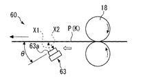
図2を参照して、シート搬送装置60には、シートPが所定の搬送方向(図の矢印方向である。)に搬送される搬送経路Kや、搬送経路Kを搬送されるシートPを光学的に検知する検知センサ63、が設けられている。
搬送経路Kは、隙間(シートPが搬送される隙間である。)をあけて対向する搬送ガイド板によって形成されたものである。図2に示す搬送経路Kは、略水平な搬送経路となっている。
検知センサ63は、発光ダイオードなどの発光素子、フォトダイオードなどの受光素子、などからなるフォトセンサである。検知センサ63には、検知光X1がシートPに向けて投光されるとともに、そのシートPで反射した反射光X2が受光される検知部63a(検知面)が設けられている。すなわち、この検知部63a(検知面)には、発光素子と受光素子とが設けられていて、発光素子からの検知光X1の照射と、受光素子による反射光X2の受光と、がおこなわれることになる。そして、受光素子による反射光X2の受光の有無によって変化するセンサ出力によって、検知センサ63の位置にシートPがあるか否かを検知している。
なお、検知センサ63としては、正反射方式のものを用いることもできるし、拡散反射方式のものを用いることもできる。
With reference to FIG. 2, the
The transport path K is formed by a transport guide plate facing each other with a gap (a gap through which the sheet P is transported). The transport path K shown in FIG. 2 is a substantially horizontal transport path.
The
As the
ここで、本実施の形態における検知センサ63は、図2に示すように、その検知部63a(検知面)が、搬送方向の下流側(図2の左方である。)に傾斜するように配置されている。
すなわち、検知部63aと、シートPの表面(検知光X1が投光される面である。)と、がなす角度θが、ゼロより大きくて、検知部63aに対して下流側で鋭角に形成されるように、検知センサ63が斜めに設置されている。
この検知部63aの傾斜角度θは、検知センサ63の検知許容振れ幅の範囲内となるように設定されている。すなわち、検知センサ63が正反射方式のものであっても拡散反射方式のものであっても、シートPへの検知光X1の照射と、受光素子によるシートPからの反射光X2の受光と、が可能になるように、その傾斜角度θが設定されている。
Here, as shown in FIG. 2, the
That is, the angle θ formed by the
The tilt angle θ of the
このように、本実施の形態では、検知部63aが搬送方向下流側に傾斜するように検知センサ63を配置しているため、搬送経路KをシートPが搬送されるときに、その搬送方向に沿うように生じる気流(図2の白矢印で示す気流である。)とともに、紙粉や浮遊トナーなどの異物が流動して、検知センサ63の検知部63a(検知面)に付着してしまう不具合が生じにくくなる。
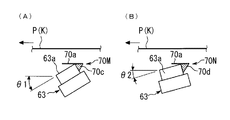
詳しくは、図3(A)に示すように、検知部63aが搬送方向に対して略平行になるように検知センサ63を配置した場合、搬送方向に沿うように生じる白矢印方向の気流とともに、紙粉や浮遊トナーなどの異物が流動して、検知センサ63の検知部63aに異物(破線で囲んだものである。)が付着してしまう。また、図3(B)に示すように、検知部63aが搬送方向上流側に傾斜するように検知センサ63を配置してしまうと、そのような気流を検知部63aがまともに受けることになるため、そのような不具合がさらに助長されてしまう。
As described above, in the present embodiment, since the
Specifically, as shown in FIG. 3A, when the
これに対して、本実施の形態では、検知部63aが搬送方向下流側に傾斜するように検知センサ63を配置しているため、そのような気流を検知部63aが受けにくくなって、検知部63aに異物が付着しにくくなる。そのため、検知部63aに異物が付着してしまい検知センサ63によるシートPの検知精度が低下して、シートPの有無を誤検知してしまう不具合も生じにくくなる。
また、本実施の形態では、検知センサ63の検知部63aに空気を吹き付けるような装置を設けることなく、検知部63aに異物が付着する不具合を軽減することができるため、装置の高コスト化、大型化も防止することができる。
特に、図2に示す検知センサ63は、搬送経路Kを通過するシートPの下方に位置するように配置されていて、検知部63aが上方を向いたレイアウトになり、検知部63aに異物が付着してしまうと、その異物が堆積しやすいため、本発明の適用が有用になる。
On the other hand, in the present embodiment, since the
Further, in the present embodiment, it is possible to reduce the problem that foreign matter adheres to the
In particular, the
<変形例1>
図4は、変形例1としてのシート搬送装置60の要部を示す図であて、本実施の形態における図2の一部を拡大したものに相当する図である。
なお、図4(A)に示す検知センサ63は、正反射方式のものであって、シートPの表面で正反射した反射光X2が受光素子で受光されるものである。また、図4(B)に示す検知センサ63は、拡散反射方式のものであって、シートPの表面で拡散反射した反射光X3が受光素子で受光されるものである。
図4に示すように、変形例1におけるシート搬送装置60には、検知センサ63の検知部63aの上方を覆うカバー部材70が設置されている。特に、変形例1では、検知センサ63にカバー部材70が貼着されている。
このカバー部材70は、PET(ポリエチレンテレフタレート)などの可撓性を有する薄いシート状部材であって、略水平方向に延在するカバー面70aが形成されている。特に、変形例1におけるカバー部材70は、そのカバー面70aが、傾斜した検知部63aの上端から下流側に延びるように配置されている。また、カバー部材70は、検知センサ63が正反射方式のものであっても拡散反射方式のものであっても、検知部63aにおける検知光X1の投光と反射光X2の受光とを妨げないように配置されている。
このようなカバー部材70を設けることで、紙粉や浮遊トナーなどの異物が黒矢印方向に自重落下してしまっても、その多くがカバー面70a上に堆積されるため、検知部63aが異物で汚れる不具合を軽減することができる。
なお、カバー部材70のカバー面70aは、アクリル系、ウレタン系、シリコーン系などの粘着材料で形成することが好ましい。これにより、カバー面70a上に落下した異物を粘着させて保持することができる。
<Modification example 1>
FIG. 4 is a diagram showing a main part of the
The
As shown in FIG. 4, the
The
By providing such a
The
<変形例2>
図5は、変形例2としてのシート搬送装置60の要部を示す図であって、変形例1における図4に対応する図である。
図5に示すように、変形例2におけるカバー部材70は、カバー面70aの端部(下流側端部である。)に繋がり、その端部から離れる方向(斜め上方である。)に起立する返し面70bが形成されている。
このようにカバー部材70に返し面70bを設けることで、カバー面70a上に堆積した異物が、白矢印方向の気流にのって下流側に流動しても、返し面70bで塞き止めることができるため、検知部63aが異物で汚れる不具合を軽減することができる。
<Modification 2>
FIG. 5 is a diagram showing a main part of the
As shown in FIG. 5, the
By providing the
<変形例3>
図6は、変形例3としてのシート搬送装置60の要部を示す図であって、変形例1における図4に対応する図である。
図6に示すように、変形例3における検知センサ63には、複数のガイド部材70A〜70Cが設置されている。具体的に、複数のガイド部材70A〜70Cが、検知センサ63の光路を遮らないように、検知部63aの傾斜方向に段違いに設置されている。
このように複数のガイド部材70A〜70Cを設けることで、広い範囲で、検知部63aへの異物の付着を軽減することができる。また、図6に示すように、複数のガイド部材70A〜70Cは搬送方向の長さが短いため、それらの検知部63aに対する傾斜角度をそれぞれ別々に調整できるように構成することにより、検知部63aでの検知を妨げることなく、検知部63aを覆う範囲を微調整しながら広くとることができる。
<Modification example 3>
FIG. 6 is a diagram showing a main part of the
As shown in FIG. 6, a plurality of
By providing the plurality of
<変形例4>
図7は、変形例4としてのシート搬送装置60の要部を示す図であって、変形例1における図4に対応する図である。
変形例4におけるカバー部材70は、検知センサ63に対して着脱可能(付け替え可能)に設置されている。また、変形例4では、検知部63aに対するカバー部材70の相対的な傾斜角度θ1、θ2を調整可能に構成されている。
詳しくは、画像形成装置1の搬送経路Kに複数の検知センサを設置する場合に、それらの検知センサとして共通部品化されたものを使用したい。しかし、検知センサの傾斜角度θは、対向する搬送経路の傾きの程度などによって変化してしまう。そして、カバー部材70は、そのカバー面70aが略水平になるように配置したい。
これらのことから、図7(A)、(B)に示すように、傾斜角度θ1、θ2の異なる検知センサ63(共通部品)に対して、異なるカバー部材70M、70Nをそれぞれ着脱できるように構成している。具体的に、第1のカバー部材70Mの根元部を支持する角度調整部70cと、第2のカバー部材70Nの根元部を支持する角度調整部70dと、はともに検知センサ63の側面に貼着されるものであるが、互いの形状(傾斜角)が異なるように形成されている。そして、第1のカバー部材70Mは、傾斜角度がθ1となるように配置された検知センサ63に貼着されたときに、カバー面70aが略水平になる。これに対して、第2のカバー部材70Nは、傾斜角度がθ2(<θ1)となるように配置された検知センサ63に貼着されたときに、カバー面70aが略水平になる。なお、角度調整部70c、70dは、いずれも、樹脂材料からなる三角柱状部材である。
このように構成することにより、画像形成装置1の搬送経路Kに複数設置する検知センサ61〜65を共通化することが可能になる。
<Modification example 4>
FIG. 7 is a diagram showing a main part of the
The
Specifically, when a plurality of detection sensors are installed in the transport path K of the image forming apparatus 1, it is desired to use those that are made into common parts as the detection sensors. However, the inclination angle θ of the detection sensor changes depending on the degree of inclination of the opposite transport paths. Then, the
From these facts, as shown in FIGS. 7A and 7B,
With this configuration, it is possible to standardize a plurality of
<変形例5>
図8は、変形例5としてのシート搬送装置60の要部を示す図である。
本実施の形態や変形例1〜4では、レジストローラ対17と上流側搬送ローラ対18との間の搬送経路Kに設置された検知センサ63について説明したが、画像形成装置1における他の検知センサ61、62、64、65についても、当然に本発明を適用することができる。
図8は、給送装置13の側方に配置された搬送経路Kを示す図である。図8に示すような、縦方向に延在する搬送経路Kに設置された検知センサ61に対しても本発明を適用することができる。すなわち、図8(A)、(B)に示すように、検知センサ61の検知部61aが搬送方向下流側に傾斜するように、検知センサ61が配置されている。また、図8(B)に示すように、略水平なカバー面70aを有するカバー部材70が、検知部61aの上方を覆うように設置されている。また、そのカバー面70aの端部(搬送経路に近い側の端部である。)に繋がるように返し面70b(斜め上方に起立する返し面である。)が設けられている。
このように構成した場合であっても、本実施の形態のものと同様の効果を得ることができる。
<Modification 5>
FIG. 8 is a diagram showing a main part of the
In the present embodiment and the modified examples 1 to 4, the
FIG. 8 is a diagram showing a transport path K arranged on the side of the
Even in the case of such a configuration, the same effect as that of the present embodiment can be obtained.
以上説明したように、本実施の形態におけるシート搬送装置60は、シートPが所定の搬送方向に搬送される搬送経路Kと、搬送経路Kを搬送されるシートPを光学的に検知する検知センサ63と、が設けられている。そして、検知センサ63には、検知光X1がシートPに向けて投光されるとともにシートPで反射した反射光X2が受光される検知部63aが、搬送方向の下流側に傾斜するように配置されている。
これにより、検知センサ63の検知部63aに異物を付着しにくくすることができる。
As described above, the
As a result, it is possible to prevent foreign matter from adhering to the
なお、本実施の形態では、モノクロの画像形成装置1に設置されるシート搬送装置60に対して本発明を適用したが、カラーの画像形成装置に設置されるシート搬送装置に対しても当然に本発明を適用することができる。
また、本実施の形態では、電子写真方式の画像形成装置1に設置されるシート搬送装置60に対して本発明を適用したが、本発明の適用はこれに限定されることなく、その他の方式の画像形成装置(例えば、インクジェット方式の画像形成装置や、孔版印刷機などである。)に設置されるシート搬送装置に対しても本発明を適用することができる。
また、本実施の形態では、画像形成装置1において画像が担持される前のシートPを搬送するシート搬送装置60に対して本発明を適用したが、画像(未定着画像、又は、定着画像)が担持された後のシートを搬送するシート搬送装置に対しても本発明を適用することができるし、シート搬送装置としての原稿搬送部10(自動原稿搬送装置)に対しても本発明を適用することができる。
また、画像形成装置1に設置される検知センサの位置や個数は、本実施の形態のものに限定されない。
そして、それらのような場合であっても、本実施の形態のものと同様の効果を得ることができる。
In the present embodiment, the present invention is applied to the
Further, in the present embodiment, the present invention is applied to the
Further, in the present embodiment, the present invention is applied to the
Further, the position and number of the detection sensors installed in the image forming apparatus 1 are not limited to those of the present embodiment.
And even in such a case, the same effect as that of the present embodiment can be obtained.
なお、本発明が本実施の形態に限定されず、本発明の技術思想の範囲内において、本実施の形態の中で示唆した以外にも、本実施の形態は適宜変更され得ることは明らかである。また、前記構成部材の数、位置、形状等は本実施の形態に限定されず、本発明を実施する上で好適な数、位置、形状等にすることができる。 It is clear that the present invention is not limited to the present embodiment, and the present embodiment can be appropriately modified in addition to the suggestions in the present embodiment within the scope of the technical idea of the present invention. is there. Further, the number, position, shape, etc. of the constituent members are not limited to the present embodiment, and can be a suitable number, position, shape, etc. for carrying out the present invention.
なお、本願明細書等において、「シート」とは、用紙(紙)の他に、コート紙、ラベル紙、OHPシート、金属シート、フィルム、等のシート状の記録媒体のすべてを含むものと定義する。 In the specification of the present application and the like, the term "sheet" is defined to include all sheet-shaped recording media such as coated paper, label paper, OHP sheet, metal sheet, film, etc., in addition to paper. To do.
1 画像形成装置(画像形成装置本体)、
60 シート搬送装置、
63 検知センサ(シート検知センサ)、
63a 検知部、
70 カバー部材、
70a カバー面、
70b 返し面、
70c、70d 角度調整部、
P シート、 K 搬送経路、
X1 検知光、 X2、X3 反射光。
1 Image forming apparatus (image forming apparatus main body),
60 sheet transfer device,
63 Detection sensor (seat detection sensor),
63a detector,
70 cover member,
70a cover surface,
70b return surface,
70c, 70d angle adjustment unit,
P sheet, K transport route,
X1 detection light, X2, X3 reflected light.
Claims (8)
前記搬送経路を搬送されるシートを光学的に検知する検知センサと、
を備え、
前記検知センサは、検知光がシートに向けて投光されるとともに当該シートで反射した反射光が受光される検知部が、前記搬送方向の下流側に傾斜するように配置されたことを特徴とするシート搬送装置。 A transport path in which the sheet is transported in a predetermined transport direction, and
A detection sensor that optically detects the sheet transported along the transport path, and
With
The detection sensor is characterized in that a detection unit in which the detection light is projected toward the sheet and the reflected light reflected by the sheet is received is arranged so as to be inclined to the downstream side in the transport direction. Sheet transfer device.
Priority Applications (1)
| Application Number | Priority Date | Filing Date | Title |
|---|---|---|---|
| JP2019049776A JP2020152467A (en) | 2019-03-18 | 2019-03-18 | Sheet conveyance device and image forming device |
Applications Claiming Priority (1)
| Application Number | Priority Date | Filing Date | Title |
|---|---|---|---|
| JP2019049776A JP2020152467A (en) | 2019-03-18 | 2019-03-18 | Sheet conveyance device and image forming device |
Publications (1)
| Publication Number | Publication Date |
|---|---|
| JP2020152467A true JP2020152467A (en) | 2020-09-24 |
Family
ID=72557598
Family Applications (1)
| Application Number | Title | Priority Date | Filing Date |
|---|---|---|---|
| JP2019049776A Pending JP2020152467A (en) | 2019-03-18 | 2019-03-18 | Sheet conveyance device and image forming device |
Country Status (1)
| Country | Link |
|---|---|
| JP (1) | JP2020152467A (en) |
Cited By (1)
| Publication number | Priority date | Publication date | Assignee | Title |
|---|---|---|---|---|
| JP7413898B2 (en) | 2020-04-01 | 2024-01-16 | コニカミノルタ株式会社 | Meandering detection system |
-
2019
- 2019-03-18 JP JP2019049776A patent/JP2020152467A/en active Pending
Cited By (1)
| Publication number | Priority date | Publication date | Assignee | Title |
|---|---|---|---|---|
| JP7413898B2 (en) | 2020-04-01 | 2024-01-16 | コニカミノルタ株式会社 | Meandering detection system |
Similar Documents
| Publication | Publication Date | Title |
|---|---|---|
| US7959151B2 (en) | Image forming apparatus and recording medium conveying device included in the image forming apparatus | |
| JP4663407B2 (en) | Recording material discrimination device and method | |
| US10781065B2 (en) | Detecting device and image forming apparatus incorporating the detecting device | |
| US20120269563A1 (en) | Transporting device and image forming apparatus using the same | |
| JP2005244798A (en) | Automatic document feeder, image reader and image forming apparatus | |
| US9359156B2 (en) | Paper feeding apparatus detecting recording paper presence/absence, paper feed cassette attaching/detaching, and lift plate reaching rising stop position, and image forming apparatus equipped with the same | |
| JP2015009946A (en) | Sheet detection device and image forming apparatus | |
| US11634292B2 (en) | Sheet conveyance apparatus and image forming apparatus | |
| JP2006298579A (en) | Automatic document conveying device and image forming device | |
| JP2008154129A (en) | Document reading apparatus | |
| JP2020152467A (en) | Sheet conveyance device and image forming device | |
| KR20080106692A (en) | Image forming apparatus | |
| JP2007137618A (en) | Sheet carrying device | |
| JP6233683B2 (en) | Feeding apparatus, image forming apparatus, and image reading apparatus | |
| JP2021011382A (en) | Sheet feeding device, image reader and image formation device | |
| JP2006347645A (en) | Image forming apparatus | |
| US8490968B2 (en) | Image forming apparatus with conveyance interval adjustment for recording paper | |
| JP4898553B2 (en) | Double feed detection device, image forming device | |
| JP6901699B2 (en) | Document transfer device and image forming device | |
| JP4712680B2 (en) | Feeding device, image forming device | |
| JPH09278252A (en) | Image forming device | |
| JP2008201512A (en) | Paper conveying device and image forming device | |
| JP6155916B2 (en) | Document reading apparatus and image forming apparatus | |
| JPH0578001A (en) | Carrier device | |
| JP2011209544A (en) | Image forming apparatus |