JP2020144064A - Leakage inspection method and leakage inspection device of battery pack - Google Patents
Leakage inspection method and leakage inspection device of battery pack Download PDFInfo
- Publication number
- JP2020144064A JP2020144064A JP2019042398A JP2019042398A JP2020144064A JP 2020144064 A JP2020144064 A JP 2020144064A JP 2019042398 A JP2019042398 A JP 2019042398A JP 2019042398 A JP2019042398 A JP 2019042398A JP 2020144064 A JP2020144064 A JP 2020144064A
- Authority
- JP
- Japan
- Prior art keywords
- battery pack
- inspection
- gas
- prevention member
- deformation prevention
- Prior art date
- Legal status (The legal status is an assumption and is not a legal conclusion. Google has not performed a legal analysis and makes no representation as to the accuracy of the status listed.)
- Granted
Links
Images


Classifications
-
- G—PHYSICS
- G01—MEASURING; TESTING
- G01M—TESTING STATIC OR DYNAMIC BALANCE OF MACHINES OR STRUCTURES; TESTING OF STRUCTURES OR APPARATUS, NOT OTHERWISE PROVIDED FOR
- G01M3/00—Investigating fluid-tightness of structures
- G01M3/02—Investigating fluid-tightness of structures by using fluid or vacuum
- G01M3/26—Investigating fluid-tightness of structures by using fluid or vacuum by measuring rate of loss or gain of fluid, e.g. by pressure-responsive devices, by flow detectors
- G01M3/32—Investigating fluid-tightness of structures by using fluid or vacuum by measuring rate of loss or gain of fluid, e.g. by pressure-responsive devices, by flow detectors for containers, e.g. radiators
- G01M3/3236—Investigating fluid-tightness of structures by using fluid or vacuum by measuring rate of loss or gain of fluid, e.g. by pressure-responsive devices, by flow detectors for containers, e.g. radiators by monitoring the interior space of the containers
- G01M3/3263—Investigating fluid-tightness of structures by using fluid or vacuum by measuring rate of loss or gain of fluid, e.g. by pressure-responsive devices, by flow detectors for containers, e.g. radiators by monitoring the interior space of the containers using a differential pressure detector
-
- Y—GENERAL TAGGING OF NEW TECHNOLOGICAL DEVELOPMENTS; GENERAL TAGGING OF CROSS-SECTIONAL TECHNOLOGIES SPANNING OVER SEVERAL SECTIONS OF THE IPC; TECHNICAL SUBJECTS COVERED BY FORMER USPC CROSS-REFERENCE ART COLLECTIONS [XRACs] AND DIGESTS
- Y02—TECHNOLOGIES OR APPLICATIONS FOR MITIGATION OR ADAPTATION AGAINST CLIMATE CHANGE
- Y02E—REDUCTION OF GREENHOUSE GAS [GHG] EMISSIONS, RELATED TO ENERGY GENERATION, TRANSMISSION OR DISTRIBUTION
- Y02E60/00—Enabling technologies; Technologies with a potential or indirect contribution to GHG emissions mitigation
- Y02E60/10—Energy storage using batteries
Abstract
Description
本発明は、電池パックのリーク検査方法およびリーク検査装置に関する。詳しくは、差圧式リークテスタを利用した検査方法および検査装置に関する。 The present invention relates to a battery pack leak inspection method and a leak inspection device. More specifically, the present invention relates to an inspection method and an inspection device using a differential pressure type leak tester.
リチウムイオン二次電池やニッケル水素電池等の単電池を複数直列に接続し、一つの部品単位とした高電圧の電池モジュールは、車両の駆動電源として利用される。通常、この種の電池モジュールは、密閉可能な容器に収容され、密閉された電池パック(組電池とも呼ばれる)として車両に搭載される。また、密閉可能な比較的高い剛性の容器を採用することによって、車両の車室外に搭載することが可能となり、大容量の電池パックを車両の駆動電源にすることができる。 A high-voltage battery module in which a plurality of single batteries such as a lithium ion secondary battery and a nickel-metal hydride battery are connected in series and united as one component is used as a driving power source for a vehicle. Usually, this type of battery module is housed in a sealable container and mounted on the vehicle as a sealed battery pack (also called an assembled battery). Further, by adopting a container having a relatively high rigidity that can be sealed, it can be mounted outside the vehicle interior of the vehicle, and a large-capacity battery pack can be used as a driving power source for the vehicle.
この種の電池パックは、複数の単電池(即ち電池モジュール)を内部に密閉可能に収容する外装体を備えており、外装体の開口部がシールされ、内部が密閉されている。
ところで、このような電池パックを製造する工程においては、該電池パックの密閉性を確認するリーク検査が行われている。
リーク検査の従来技術の一つとしては、いわゆるプローブ法が挙げられる。プローブ法においては、例えば、特許文献1に記載されているように、まず、電池パック内にリークチェック用の検査ガス(例えば、水素と窒素の混合気体)が封入される。そして、漏れ検査装置のプローブを用いることにより、電池パックの合わせ面(シール部)等から漏れ出す上記ガスのリーク部位を特定することができるとされている。
This type of battery pack includes an exterior body that houses a plurality of cells (that is, battery modules) so as to be hermetically sealed inside, and the opening of the exterior body is sealed and the inside is sealed.
By the way, in the process of manufacturing such a battery pack, a leak inspection for confirming the airtightness of the battery pack is performed.
One of the conventional techniques for leak inspection is the so-called probe method. In the probe method, for example, as described in
しかしながら、上記プローブ法による電池パックのリーク検査は、検査前に電池パックの空気抜きを行った後で検査ガスが封入されるため、操作が複雑になり、時間がかかりやすい。そのため、プローブ法よりも簡便且つ短時間で実施できるリーク検査方法が求められている。
また、リーク検査においては、多くの場合、電池パックの内部に気体(例えば、検査ガス)を封入する必要がある。この際、上記外装体の一部(例えば、外装体本体を遮蔽する蓋体)が可撓性のある材料(種々の樹脂や薄いアルミニウム板、等)で構成されたものが使用されている電池パックにおいては、リーク検査時の検査用ガスの導入によって当該可撓性のある外装体の一部が膨張し、場合によっては一部分が変形することがある。かかる膨張および変形の程度によっては、電池パックのリーク検査の精度に信頼性が確保されなくなるとともに、当該外装体の可撓部分が破損する虞もある。
そこで本発明は、電池パックのリーク検査において生じ得る上記課題を解決するべく創出されたものであり、特に、電池パックの外装体の一部が可撓性のある材料で構成されている場合であっても、該外装体の一部の膨張、変形、および、これらにともなう破損を抑制し、且つ、操作が従来法に比べて簡便となった電池パックのリーク検査方法を提供することを目的とする。また、かかるリーク検査方法のために使用されるリーク検査装置を提供することを他の目的とする。
However, the leak inspection of the battery pack by the above probe method is complicated in operation and tends to take time because the inspection gas is filled after the air is evacuated from the battery pack before the inspection. Therefore, there is a demand for a leak inspection method that is simpler and can be performed in a shorter time than the probe method.
Further, in the leak inspection, it is often necessary to enclose a gas (for example, an inspection gas) inside the battery pack. At this time, a battery in which a part of the exterior body (for example, a lid that shields the exterior body body) is made of a flexible material (various resins, thin aluminum plates, etc.) is used. In the pack, the introduction of the inspection gas at the time of leak inspection may cause a part of the flexible exterior body to expand and, in some cases, a part to be deformed. Depending on the degree of such expansion and deformation, the accuracy of the leak inspection of the battery pack cannot be ensured, and the flexible portion of the exterior body may be damaged.
Therefore, the present invention has been created to solve the above-mentioned problems that may occur in the leak inspection of the battery pack, and particularly when a part of the outer body of the battery pack is made of a flexible material. Even if there is, it is an object of the present invention to provide a leak inspection method for a battery pack, which suppresses expansion and deformation of a part of the exterior body and damage caused by these, and is easier to operate than the conventional method. And. Another object of the present invention is to provide a leak inspection device used for such a leak inspection method.
本発明者は、差圧式リークテストに基づく電池パックのリーク検査に、該電池パックの外装体の、可撓性を有する幅広面の略全体に変形防止部材を配置することに着目した。そして、電池パック、および、差圧式リークテストの基準となるマスターチャンバーに検査用ガスを導入した際に、上記配置した変形防止部材により当該可撓性の幅広面の変形を防止しつつ正確なリーク検査を行え得ることを見出し、本発明を完成するに至った。 The present inventor has focused on arranging a deformation prevention member on substantially the entire flexible and wide surface of the exterior body of the battery pack in the leak inspection of the battery pack based on the differential pressure type leak test. Then, when the inspection gas is introduced into the battery pack and the master chamber which is the reference of the differential pressure type leak test, the deformation prevention member arranged above prevents the deformation of the flexible wide surface and causes an accurate leak. We have found that inspection can be performed, and have completed the present invention.
即ち、上記目的を実現するべく、本発明は、複数の単電池と、該複数の単電池を密閉された状態で内部に収容する外装体であって少なくとも一の可撓性を有する幅広面を備えた外装体とを備える電池パックの気密性を差圧式リークテストに基づいて検査するリーク検査方法を提供する。
ここに開示されるリーク検査方法では、上記外装体の幅広面の略全体に変形防止部材を配置し、相互に連通させた上記電池パックと差圧式リークテストの基準となるマスターチャンバーとの両方に検査用ガスを導入した際に該変形防止部材が上記幅広面の変形を防止し得る状態で、差圧式リークテストが行われることを特徴とする。
That is, in order to realize the above object, the present invention has a plurality of cell cells and an exterior body that houses the plurality of cell cells in a sealed state and has at least one flexible wide surface. Provided is a leak inspection method for inspecting the airtightness of a battery pack including an exterior body provided based on a differential pressure type leak test.
In the leak inspection method disclosed here, deformation prevention members are arranged on substantially the entire wide surface of the exterior body, and both the battery pack communicated with each other and the master chamber as a reference for the differential pressure type leak test are used. The differential pressure type leak test is performed in a state where the deformation preventing member can prevent the deformation of the wide surface when the inspection gas is introduced.
かかる構成の検査方法では、電池パックの外装体の幅広面の略全体に変形防止部材を配置することによって、該幅広面が可撓性を有する場合であっても、電池パックおよびマスターチャンバーに検査用ガスを供給する際、当該幅広面の変形を防止することができる。 In the inspection method of such a configuration, by arranging the deformation prevention member on substantially the entire wide surface of the outer body of the battery pack, the battery pack and the master chamber are inspected even when the wide surface is flexible. When supplying the gas, it is possible to prevent the wide surface from being deformed.
ここに開示される検査方法の好適な一態様では、上記変形防止部材は、内部に検査用ガスを導入可能であり且つ該導入された検査用ガスのガス圧によって膨張可能な袋状の弾性部材で構成されている。上記差圧式リークテストは、上記変形防止部材の内圧と上記電池パックの内圧とが平衡状態になるように、相互に連通させた上記変形防止部材と上記電池パックとの両方に検査用ガスが供給された後に行われることを特徴とする。
変形防止部材として、内部に検査用ガスを導入でき、これによって膨張可能である部材を採用し、電池パックおよび変形防止部材の内圧を平衡状態とすることによって、電池パックの外装体の変形をより確実に防止することができる。
In a preferred embodiment of the inspection method disclosed herein, the deformation prevention member is a bag-shaped elastic member capable of introducing an inspection gas into the inside and expanding by the gas pressure of the introduced inspection gas. It is composed of. In the differential pressure type leak test, inspection gas is supplied to both the deformation prevention member and the battery pack that are communicated with each other so that the internal pressure of the deformation prevention member and the internal pressure of the battery pack are in an equilibrium state. It is characterized by being performed after it has been done.
As the deformation prevention member, an inspection gas can be introduced inside, and a member that can be expanded by this is adopted, and the internal pressure of the battery pack and the deformation prevention member is in an equilibrium state to further deform the outer body of the battery pack. It can be reliably prevented.
また、本発明は、複数の単電池と、該複数の単電池を密閉された状態で内部に収容する外装体であって少なくとも一の可撓性を有する幅広面を備えた外装体とを備える電池パックの気密性を差圧式リークテストに基づいて検査するリーク検査装置を提供する。
ここに開示される検査装置は、差圧式リークテストの基準となるマスターチャンバーと上記電池パックの両方に検査用ガスを供給するガス供給系と、上記外装体の幅広面の略全体に配置される変形防止部材と、を備えている。上記変形防止部材は、上記ガス供給系から検査用ガスが上記電池パック内に導入された際に上記幅広面の変形を防止するように上記外装体の幅広面の略全体に配置されることを特徴とする。
Further, the present invention includes a plurality of cells and an exterior body that houses the plurality of cells in a sealed state and has a wide surface having at least one flexibility. Provided is a leak inspection device that inspects the airtightness of a battery pack based on a differential pressure leak test.
The inspection devices disclosed herein are arranged substantially on the entire wide surface of the exterior body and the gas supply system that supplies the inspection gas to both the master chamber and the battery pack, which are the standards for the differential pressure type leak test. It is provided with a deformation prevention member. The deformation prevention member is arranged on substantially the entire wide surface of the exterior body so as to prevent deformation of the wide surface when the inspection gas is introduced into the battery pack from the gas supply system. It is a feature.
かかる構成の検査装置は、電池パックの外装体の幅広面の略全体に配置される変形防止部材を備えることによって、外装体の幅広面が可撓性を有する場合であっても、電池パックおよびマスターチャンバーに検査用ガスを供給する際、当該幅広面の変形を防止することができる。 The inspection device having such a configuration includes the battery pack and the battery pack even when the wide surface of the exterior body is flexible by providing the deformation prevention member arranged on substantially the entire wide surface of the exterior body of the battery pack. When the inspection gas is supplied to the master chamber, deformation of the wide surface can be prevented.
さらに、ここに開示される検査装置の好適な一態様では、上記変形防止部材は、内部に検査用ガスを導入可能であり且つ該導入された検査用ガスのガス圧によって膨張可能な袋状の弾性部材で構成されている。上記ガス供給系は、上記マスターチャンバーと上記電池パックと上記変形防止部材とが相互に連通し、該変形防止部材の内部にも検査用ガスを供給可能に構成されている。上記変形防止部材の内圧と上記電池パックの内圧とが平衡状態になるように上記変形防止部材および上記電池パックの両方に検査用ガスが供給された状態で、差圧式リークテストが実行されることを特徴とする。
変形防止部材として、内部に検査用ガスを導入でき、これによって膨張可能である部材を採用し、且つ、電池パックおよび変形防止部材とが相互に連通された構成であることによって、電池パックへの検査用ガスの導入に合わせて変形防止部材を膨張させることができる。そして、電池パックおよび変形防止部材の内圧を平衡状態とすることによって、電池パックの外装体の変形を防止することができる。
Further, in a preferred embodiment of the inspection apparatus disclosed herein, the deformation prevention member has a bag-like shape in which an inspection gas can be introduced therein and can be expanded by the gas pressure of the introduced inspection gas. It is composed of elastic members. The gas supply system is configured such that the master chamber, the battery pack, and the deformation prevention member communicate with each other, and inspection gas can be supplied to the inside of the deformation prevention member. The differential pressure leak test is executed with the inspection gas supplied to both the deformation prevention member and the battery pack so that the internal pressure of the deformation prevention member and the internal pressure of the battery pack are in equilibrium. It is characterized by.
As the deformation prevention member, an inspection gas can be introduced inside, and a member that can be expanded by this is adopted, and the battery pack and the deformation prevention member are communicated with each other, so that the battery pack can be provided. The deformation prevention member can be expanded in accordance with the introduction of the inspection gas. Then, by equilibrating the internal pressures of the battery pack and the deformation prevention member, deformation of the outer body of the battery pack can be prevented.
かかる構成の検査装置において特に好適な一態様では、上記ガス供給系は、上記変形防止部材への検査用ガスの供給を電池パックへの検査用ガスの供給とは独立して調整可能なバルブを備えている。そして、上記差圧式リークテストは、上記変形防止部材の内圧が上記平衡状態になった後、上記バルブを閉栓状態にして上記変形防止部材の内圧を保持した状態で実行されることを特徴とする。
かかるバルブをガス供給系に備えることで変形防止部材への検査ガスの供給が調整可能であることによって、上記平衡状態に達した後これを遮断し、平衡状態の内圧を維持することができる。これにより、電池パックの外装体の変形を防止しながら差圧式リークテストをより精確に実行することができる。
In a particularly preferred embodiment of the inspection apparatus having such a configuration, the gas supply system provides a valve that can adjust the supply of the inspection gas to the deformation prevention member independently of the supply of the inspection gas to the battery pack. I have. The differential pressure type leak test is characterized in that after the internal pressure of the deformation prevention member reaches the equilibrium state, the valve is closed and the internal pressure of the deformation prevention member is maintained. ..
By providing such a valve in the gas supply system, the supply of the inspection gas to the deformation prevention member can be adjusted, so that the internal pressure in the equilibrium state can be maintained by shutting off the valve after reaching the equilibrium state. As a result, the differential pressure type leak test can be performed more accurately while preventing the outer body of the battery pack from being deformed.
以下、図面を参照しながら、ここに開示されるリーク検査方法ならびにリーク検査装置に係る一実施形態を説明する。なお、以下に説明する図面において、同じ作用を奏する部材、部位には同じ符号を付し、重複する説明は省略または簡略化することがある。また、本明細書において特に言及している事項以外の事柄であって本発明の実施に必要な事柄は、当該分野における従来技術に基づく当業者の設計事項として把握され得る。 Hereinafter, an embodiment relating to the leak inspection method and the leak inspection apparatus disclosed herein will be described with reference to the drawings. In the drawings described below, members and parts that perform the same action may be designated by the same reference numerals, and duplicate description may be omitted or simplified. In addition, matters other than those specifically mentioned in the present specification and necessary for carrying out the present invention can be grasped as design matters of those skilled in the art based on the prior art in the art.
本明細書において「電池パック」とは、単電池が複数個配列してなる構成体が密閉容器内に収容されたものをいう。ここで「単電池」は、電池パックを構成するために相互に接続され得る個々の蓄電素子を指す用語であり、特に限定しない限り単電池を構成する蓄電素子は種々の組成の電池(例えばリチウムイオン二次電池)、キャパシタ(例えばリチウムイオンキャパシタ)を包含する。また、本明細書において「差圧式リークテスト」は、従来公知の差圧式リークテストを示す用語であり、特別な限定はない。即ち、基準となるマスターチャンバーと、検査対象(ここでは電池パック)とにおける内圧差に基づいて、検査対象の気密性を評価する試験(テスト)のことをいう一般用語である。 As used herein, the term "battery pack" refers to a structure in which a plurality of cells are arranged in a closed container. Here, "cell" is a term that refers to individual power storage elements that can be interconnected to form a battery pack, and unless otherwise specified, the power storage elements that make up the cell are batteries having various compositions (for example, lithium). Includes ion secondary batteries) and capacitors (eg lithium ion capacitors). Further, in the present specification, the "differential pressure type leak test" is a term indicating a conventionally known differential pressure type leak test, and there is no particular limitation. That is, it is a general term that refers to a test (test) for evaluating the airtightness of an inspection target based on the internal pressure difference between the reference master chamber and the inspection target (battery pack in this case).
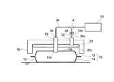
先ず、ここで開示されるリーク検査方法に用いられるリーク検査装置および検査対象たる電池パック10について図1、図2A、および、図2Bを参照しつつ説明する。図1では、一実施形態に係る検査装置100を模式的に示している。図2Aは、一実施形態に係るリーク検査装置の要部を示す模式図であって、変形防止部材に検査用ガスを導入する前の状態を示す図である。図2Bは、一実施形態に係るリーク検査装置の要部を示す模式図であって、変形防止部材に検査用ガスを導入した後の状態を示す図である。
First, the leak inspection device used in the leak inspection method disclosed here and the
<電池パック>
ここで開示されるリーク検査方法の検査対象たる電池パック10について図面を参照しつつ説明する。電池パック10は、複数の単電池(図示なし。典型的には、数十〜300個程度)と、該複数の単電池を密閉された状態で内部に収容する外装体16を備えている。電池パック10の外装体16の形状としては、特に限定されないが、例えば、上部が開口した有底箱状のパックケース本体14の開口部が、幅広面12sを有する蓋体12によって閉塞されており、シール材等(図示なし。)によって固定された構造を好ましく採用することができる。
蓋体12の材質としては、例えば、樹脂成形品または薄いアルミニウム板等の可撓性を有する材料が挙げられる。これにより、蓋体12は少なくとも一の可撓性を有する幅広面12sを有する。また、パックケース本体14の材質としては、この種の電池パックの本体の材料として使用されるものを特に制限なく使用することができる。典型的には、例えば、ステンレス、鉄またはアルミニウム等が挙げられる。
<Battery pack>
The
Examples of the material of the
<検査装置の全体構成>
次に、ここで開示される検査方法に用いられる検査装置100の全体構成を、図1を用いて詳細に説明する。
検査装置100は、差圧式リークテスタ30を備える。差圧式リークテスタ30は、電池パック10の気密性を検査するための装置であり、大まかにいって、差圧計34、第1バルブ33a、第2バルブ33b、および、ガス供給系36によって構成され、ガス供給系36を介して検査用ガスの供給源31およびレギュレータ32と接続されている。また、ガス供給系36を介して、電池パック10と、マスターチャンバー35とは、相互に連通されている。
<Overall configuration of inspection equipment>
Next, the overall configuration of the
The
<圧力レギュレータ>
レギュレータ32は、供給源31から供給される検査用ガスのガス圧を調整する一般的な圧力レギュレータである。これにより、所定のガス圧に調整した検査用ガスを各部に供給することができる。
<差圧計>
差圧計34は、2点間の圧力差(差圧)を測定するための計測器であり、電池パック10と、後述するマスターチャンバー35との間の差圧を測定する。具体的には、差圧計34は、気密性を有する筐体と、該筐体の内部空間を気密的に隔絶しつつ当該内部空間を2つの空間341および空間342とに区画するダイアフラム34dとを有している。差圧計34では、このような2つの空間に圧力の差が生じると、感圧素子であるダイアフラム34dが、圧力が小さい空間側に向かって膨張する。これにより、差圧計34は差圧が生じていることを検出することができ、ダイアフラム34dの変形量から、空間341および空間342の間で生じている差圧の大きさを検出することができる。
そして、図示されるように、空間341とマスターチャンバー35とについては、接続部34aと接続部35aとがガス供給系36を介して接続されている。空間342と電池パック10とについては、接続部34bと接続部10bとがガス供給系36を介して接続されている。即ち、空間341および空間342のいずれもが、マスターチャンバー35および電池パック10のいずれか一方と接続されていることにより、これらの差圧を検出することができる。
<Pressure regulator>
The
<Differential pressure gauge>
The
Then, as shown in the drawing, with respect to the
<マスターチャンバー>
マスターチャンバー35は、気密性が確保された容器であり、差圧計34によって差圧を測定する際に基準となる圧力を保持している。マスターチャンバー35としては、検査対象(この場合は、電池パック10)と同一の内部容積を有し、かつ、漏れがないことが確認された疑似ワーク等、ガス漏れのない種々の容器を用いることが可能である。
<Master chamber>
The
<ガス供給系36>
ガス供給系36は、検査用ガス(空気、窒素ガス等)の供給源31と、レギュレータ32と、差圧式リークテスタの各部と、マスターチャンバー35と、検査対象としての電池パック10とを互いに接続し、マスターチャンバー35と電池パック10の両方に検査用ガスを供給するラインである。ガス供給系36は、気密性を保持する部材で構成されている。
ガス供給系36には第1バルブ33aおよび第2バルブ33bが配置されており、各部への検査用ガスの供給状態(即ち、ONとOFF)を切り替えることができる。具体的には、例えば、第1バルブ33aが開放状態(ON)のとき、第1バルブ33aより下流の配管系に検査用ガスが供給されるため、電池パック10とマスターチャンバー35との両方に検査用ガスが導入される。一方、第1バルブ33aが閉栓状態(OFF)のとき、第1バルブ33aより下流の配管系に検査用ガスが供給されなくなるため、検査用ガスは電池パック10およびマスターチャンバー35に導入されなくなる。
また、第2バルブ33bが開放状態のとき、第2バルブ33bより下流の配管系において検査用ガスが移動できる。一方、第2バルブ33bが閉栓状態のとき、差圧式リークテストの基準となるマスターチャンバー35の内圧と、電池パック10の内圧が、いずれも保持される。
<
The
A
Further, when the
<制御装置>
制御装置60は、差圧式リークテスタ30の一連の動作を制御する装置であり、例えば、CPU、ROM、RAM、HDD等を備えるコンピュータを有する構成である。制御装置60は、例えば、供給源31からの検査用ガスの供給を制御する。また、第1バルブ33a、第2バルブ33b、および、後述する第3バルブ33cの開閉操作を制御する。さらに、制御装置60は、差圧計34によって検出された差圧(具体的には、例えば、ダイアフラム34dによる検出結果)に基づき、検査対象たる電池パック10の気密性の有無を判断する。
<Control device>
The
<変形防止部材>
ここで開示される検査方法に用いられる検査装置100は、変形防止部材20を備える。図示されるように、変形防止部材20は、電池パック10の外装体12の幅広面12sの略全体に配置される。これにより、ガス供給系36から検査用ガスが電池パック10およびマスターチャンバー35内に導入された際に、幅広面12sの変形を防止することができる。
変形防止部材20としては、例えば、内部に検査用ガスを導入可能であり且つ該導入された検査用ガスのガス圧によって膨張可能な袋状の弾性部材で構成されていることが好ましい。具体的には、例えば、ゴム製もしくはエラストマー製の弾性部材が好ましく用いられる。
<Deformation prevention member>
The
The
変形防止部材20として上述する構成の部材が使用される場合、図示されるように、ガス供給系36には、分岐点Xが設けられる。また、分岐点Xを起点としたガス供給系36xが設けられる。これにより、変形防止部材20の内圧と電池パック10の内圧とが平衡状態になるように変形防止部材20および電池パック10の両方に検査用ガスを供給することができる。さらに、ガス供給系36xは、接続部20cを介した変形防止部材20への検査用ガスの供給を、電池パック10への検査用ガスとは独立して調整可能な第3バルブ33cを備えている。即ち、第3バルブ33cが開放状態のとき、検査用ガスが変形防止部材20に導入される。一方、第3バルブ33cが閉栓状態のとき、第3バルブ33cより下流の配管系が密閉される。これにより、変形防止部材20の内圧が保持され、検査用ガスが電池パック内に導入された際に幅広面12sの変形を防止できる。そして、この状態で後述する差圧式リークテストを実行することができる。
When the member having the above-described configuration is used as the
<検査方法>
次に、ここに開示される検査方法の流れについて、図1、図2A、図2B、および、図3を参照して詳細に説明する。図3には、一実施形態に係る検査方法の制御フローが模式的に示されている。
<接続工程>
まず、接続工程S10について説明する。接続工程S10においては、ここに開示される検査方法の検査対象たる電池パック10(図3中における「ワーク」)と、検査装置100とを接続する。具体的には、供給源31、および、レギュレータ32に差圧式リークテスタ30を接続し、これにマスターチャンバー35、電池パック10、および、変形防止部材20を接続する。
電池パック10と差圧式リークテスタ30とを、ガス供給系36の先端に設置されたノズル38を電池パック10に予め設けられている接続部10bに挿入することにより接続する。このときのノズル38の形状は、例えば、これを接続部10bに挿入したときに接続可能な形状に対応させている。また、必要に応じてシール材等を使用してもよい。電池パック10の気密性は、ノズル38と接続部10bとを接続することによっては失われない。
次に、変形防止部材20を幅広面12sの上に配置する。そして、変形防止部材20が上述するような弾性部材で構成されている場合、変形防止部材20と差圧式リークテスタ30とを、ガス供給系36xの先端に設置されたノズル38を変形防止部材20に予め設けられている接続部20cに挿入することにより接続する。このときのノズル38および接続部20cの形状は、相互が接続可能な形状に対応させている。また、必要に応じてシール材等を使用してもよい。変形防止部材20の気密性は、ノズル38と接続部20cとを接続することによっては失われない。
また、図示されるように、変形防止部材20の上には、例えば、フレーム50を配置してもよい。この状態で変形防止部材20が検査用ガスの内圧によって膨張した場合、変形防止部材20の膨張による動きを制限することができ、幅広面12s上における位置ズレを防止することができる。さらに、幅広面12sの変形をより効果的に抑制することができる。なお、フレーム50には、ノズル38が貫通できるように孔52が設けられている。
次に、マスターチャンバー35と、差圧式リークテスタ30とを、ガス供給系36の先端に設置されたノズルを、マスターチャンバー35に設けられた所定の接続部に挿入することにより接続する。マスターチャンバー35と、差圧式リークテスタ30との接続は、本発明を特徴づけるものではないため、詳細な説明は省略する。
<Inspection method>
Next, the flow of the inspection method disclosed herein will be described in detail with reference to FIGS. 1, 2A, 2B, and 3. FIG. 3 schematically shows a control flow of the inspection method according to the embodiment.
<Connection process>
First, the connection step S10 will be described. In the connection step S10, the battery pack 10 (“work” in FIG. 3), which is the inspection target of the inspection method disclosed here, and the
The
Next, the
Further, as shown in the drawing, for example, the
Next, the
<リークテストの実施>
ここで、ワークたる電池パック10に対するリークテストの実施状況について説明する。
リークテストに際し、まず第1バルブ33a、第2バルブ33b、および、第3バルブ33cを開放する(開放工程S20)。次に、レギュレータ32によって所定の圧力(典型的には、5kPa〜大気圧)に調整された検査用ガスを、検査用ガスの供給源31から、電池パック10、および、検査装置100の全体に、ガス供給系36を介して同時に所定量を供給する(ガス供給工程S30)。ここで、所定量のガスが電池パック10および検査装置100の全体に供給され、電池パック10の内圧、変形防止部材20の内圧、および、マスターチャンバー35の内圧が等圧となり、特に変形防止部材20の内圧と電池パック10の内圧とが平衡状態になったかを判定する(S40)。等圧(即ち、平衡状態)と判定された場合(Yes)、次の閉栓工程S50を行う。なお、等圧ではないと判定された場合(No)、等圧になるまでガス供給が行われる(ガス供給工程S30)。
<Implementation of leak test>
Here, the implementation status of the leak test for the
At the time of the leak test, first, the
<バルブの閉栓>
閉栓工程S50においては、第1バルブ33aおよび第3バルブ33cを閉じる。これにより、供給源31からの検査用ガスの供給が止められるとともに、変形防止部材20を、内圧を保持させつつ電池パック10およびマスターチャンバー35から隔絶することができる。
次に、電池パック10の内圧およびマスターチャンバー35の内圧が等圧であるかを判定する(S60)。等圧と判定された場合(Yes)、次の閉栓工程S70を行う。なお、等圧ではないと判定された場合(No)、等圧になるまでは閉栓工程S70を行わない。即ち、差圧式リークテストは、変形防止部材20の内圧と、電池パック10の内圧とが平衡状態になった後、かつ、電池パック10の内圧とマスターチャンバー35の内圧が等圧になった後に実行される。
閉栓工程S70においては、第2バルブ33bを閉じる。これにより、電池パック10およびマスターチャンバー35を、内圧を保持しつつ互いに隔絶することができる。
<Valve closure>
In the closing step S50, the
Next, it is determined whether the internal pressure of the
In the closing step S70, the
<気密性の評価>
次に、電池パック10の気密性を評価する(S80)。
マスターチャンバー35には気密性があるため、検査用ガスの漏出はなく、マスターチャンバー35の内圧は低下しない。また、電池パック10に気密性がある場合は、電池パック10からの検査用ガスの漏出はなく、電池パック10の内圧は低下しない。一方、電池パック10に気密性がない場合は、電池パック10から検査用ガスが漏出し、電池パック10の内圧が低下する。このような場合、上述するように、差圧計34における空間341の内圧および空間342の内圧に差圧が生じる。当該差圧は、差圧計34に備えられたダイアフラム34dによって検出することができる。
そして、上記ダイアフラム34dによる検査結果は制御装置60に取り込まれ、制御装置60は、検査ガスの漏れ量等を演算して電池パック10の気密性を差圧式リークテストにより評価する(S80)。即ち、電池パック10と、マスターチャンバー35とに差圧が生じた場合は、電池パック10に気密性があると判定される。一方、電池パック10と、マスターチャンバー35とに差圧が生じない場合は、電池パック10に気密性がないと判断される。
なお、差圧式リークテストにおける温度変化による検査結果への影響は、電池パック10と、マスターチャンバー35における温度変化が同じであれば考慮しなくてよいことは、従来から知られている。
<Evaluation of airtightness>
Next, the airtightness of the
Since the
Then, the inspection result by the
It has been conventionally known that the influence of the temperature change in the differential pressure type leak test on the inspection result does not need to be considered if the temperature change in the
ここに開示される検査方法および検査装置を用いて、電池パック10のリーク検査を実施する。
上述した構成によると、電池パック10およびマスターチャンバー35に検査用ガスを導入した際に、変形防止部材20が膨張する。そうすると、当該膨張によって、幅広面12sの略全体に、均一に圧力P2が加えられることとなる(図2Aおよび図2B参照)。このとき、検査用ガスが導入された電池パック10においては、圧力P1が生じ、これにより、変形防止部材20には、蓋体12を介して圧力P1が加えられている。電池パック10の内圧と、変形防止部材20の内圧とが平衡状態であれば、圧力P1および圧力P2は同じ大きさであるため、幅広面12sの変形は抑制される。これにより、電池パックのリーク検査の精度に信頼性が確保される。また、電池パックのリーク検査に差圧式リークテスタを使用することによって、従来法で必要とされていた、電池パックからの空気抜き工程を省略することができ、従来法よりも簡便なリーク検査方法を提供できる。
A leak inspection of the
According to the above configuration, when the inspection gas is introduced into the
以上、本発明を詳細に説明したが、上記実施形態は例示に過ぎず、ここで開示される発明には上述の具体例を様々に変形、変更したものが含まれる。
例えば、変形防止部材20として金属材料を採用してもよい。この場合、スプリング等の物理的な力で、変形防止部材20に均一に圧力を加えつつ、幅広面12sの略全体に均一な圧力が加えられる。この場合においても、本発明において上記と同様の効果を得ることができる。
Although the present invention has been described in detail above, the above-described embodiment is merely an example, and the invention disclosed here includes various modifications and modifications of the above-mentioned specific examples.
For example, a metal material may be used as the
10 電池パック
10b 接続部
12 蓋体
12s 幅広面
14 パックケース本体
16 外装体
20 変形防止部材
20c 接続部
30 差圧式リークテスタ
31 供給源
32 レギュレータ
33a 第1バルブ
33b 第2バルブ
33c 第3バルブ
34 差圧計
341 空間
342 空間
34a 接続部
34b 接続部
34d ダイアフラム
35 マスターチャンバー
35a 接続部
36 ガス供給系
36x ガス供給系
38 ノズル
50 フレーム
52 孔
100 検査装置
X 分岐点
60 制御装置
S10 接続工程
S20 開放工程
S30 ガス供給工程
S40 判定
S50 閉栓工程
S60 判定
S70 閉栓工程
S80 差圧式リークテスト
10
Claims (5)
前記外装体の幅広面の略全体に変形防止部材を配置し、相互に連通させた前記電池パックと差圧式リークテストの基準となるマスターチャンバーとの両方に検査用ガスを導入した際に該変形防止部材が前記幅広面の変形を防止し得る状態で、差圧式リークテストが行われることを特徴とする、検査方法。 The airtightness of a battery pack including a plurality of cell cells and an exterior body that houses the plurality of cell cells in a sealed state and has a wide surface having at least one flexibility. It is a leak inspection method that inspects based on the differential pressure leak test.
Deformation prevention members are arranged on substantially the entire wide surface of the exterior body, and the deformation occurs when the inspection gas is introduced into both the battery pack communicated with each other and the master chamber as a reference for the differential pressure type leak test. An inspection method, characterized in that a differential pressure leak test is performed in a state where the preventing member can prevent deformation of the wide surface.
前記差圧式リークテストは、前記変形防止部材の内圧と前記電池パックの内圧とが平衡状態になるように、相互に連通させた前記変形防止部材と前記電池パックとの両方に検査用ガスが供給された後に行われることを特徴とする、請求項1に記載の検査方法。 The deformation prevention member is composed of a bag-shaped elastic member capable of introducing an inspection gas inside and expanding by the gas pressure of the introduced inspection gas.
In the differential pressure type leak test, inspection gas is supplied to both the deformation prevention member and the battery pack that are communicated with each other so that the internal pressure of the deformation prevention member and the internal pressure of the battery pack are in an equilibrium state. The inspection method according to claim 1, wherein the inspection method is performed after the inspection.
差圧式リークテストの基準となるマスターチャンバーと前記電池パックとの両方に検査用ガスを供給するガス供給系と、
前記外装体の幅広面の略全体に配置される変形防止部材と、
を備えており、
前記変形防止部材は、前記ガス供給系から検査用ガスが前記電池パック内に導入された際に前記幅広面の変形を防止するように前記外装体の幅広面の略全体に配置されることを特徴とする、検査装置。 The airtightness of a battery pack including a plurality of cells and an exterior body that houses the plurality of cells in a sealed state and has a wide surface having at least one flexibility. A leak inspection device that inspects based on a differential pressure leak test.
A gas supply system that supplies inspection gas to both the master chamber, which is the reference for the differential pressure leak test, and the battery pack.
Deformation prevention members arranged on substantially the entire wide surface of the exterior body,
Is equipped with
The deformation prevention member is arranged on substantially the entire wide surface of the exterior body so as to prevent deformation of the wide surface when the inspection gas is introduced into the battery pack from the gas supply system. A featured inspection device.
前記ガス供給系は、前記マスターチャンバーと前記電池パックと前記変形防止部材とが相互に連通し、該変形防止部材の内部にも検査用ガスを供給可能に構成されており、
前記変形防止部材の内圧と前記電池パックの内圧とが平衡状態になるように前記変形防止部材および前記電池パックの両方に検査用ガスが供給された後に差圧式リークテストが実行されることを特徴とする、請求項3に記載の検査装置。 The deformation prevention member is composed of a bag-shaped elastic member capable of introducing an inspection gas inside and expanding by the gas pressure of the introduced inspection gas.
The gas supply system is configured such that the master chamber, the battery pack, and the deformation prevention member communicate with each other, and inspection gas can be supplied to the inside of the deformation prevention member.
A differential pressure leak test is executed after the inspection gas is supplied to both the deformation prevention member and the battery pack so that the internal pressure of the deformation prevention member and the internal pressure of the battery pack are in an equilibrium state. The inspection device according to claim 3.
前記差圧式リークテストは、前記変形防止部材の内圧が前記平衡状態になった後、前記バルブを閉栓状態にして前記変形防止部材の内圧を保持した状態で実行されることを特徴とする、請求項4に記載の検査装置。 The gas supply system includes a valve that can adjust the supply of the inspection gas to the deformation prevention member independently of the supply of the inspection gas to the battery pack.
The differential pressure leak test is performed after the internal pressure of the deformation prevention member reaches the equilibrium state, and then the valve is closed and the internal pressure of the deformation prevention member is held. Item 4. The inspection device according to item 4.
Priority Applications (2)
| Application Number | Priority Date | Filing Date | Title |
|---|---|---|---|
| JP2019042398A JP7165303B2 (en) | 2019-03-08 | 2019-03-08 | Battery pack leak inspection method and leak inspection device |
| CN202010098175.6A CN111665003B (en) | 2019-03-08 | 2020-02-18 | Leakage inspection method and leakage inspection device for battery pack |
Applications Claiming Priority (1)
| Application Number | Priority Date | Filing Date | Title |
|---|---|---|---|
| JP2019042398A JP7165303B2 (en) | 2019-03-08 | 2019-03-08 | Battery pack leak inspection method and leak inspection device |
Publications (2)
| Publication Number | Publication Date |
|---|---|
| JP2020144064A true JP2020144064A (en) | 2020-09-10 |
| JP7165303B2 JP7165303B2 (en) | 2022-11-04 |
Family
ID=72353600
Family Applications (1)
| Application Number | Title | Priority Date | Filing Date |
|---|---|---|---|
| JP2019042398A Active JP7165303B2 (en) | 2019-03-08 | 2019-03-08 | Battery pack leak inspection method and leak inspection device |
Country Status (2)
| Country | Link |
|---|---|
| JP (1) | JP7165303B2 (en) |
| CN (1) | CN111665003B (en) |
Cited By (3)
| Publication number | Priority date | Publication date | Assignee | Title |
|---|---|---|---|---|
| CN113964353A (en) * | 2021-11-30 | 2022-01-21 | 合肥召洋电子科技有限公司 | Air tightness detection mechanism on production line of battery pack shell |
| CN114088311A (en) * | 2021-11-03 | 2022-02-25 | 格林美(武汉)动力电池回收有限公司 | Method, system, equipment and storage medium for detecting box security |
| CN116929667A (en) * | 2023-09-14 | 2023-10-24 | 扬州雄鸡电池有限公司 | Bidirectional nondestructive air tightness detection device and method for battery pack |
Citations (6)
| Publication number | Priority date | Publication date | Assignee | Title |
|---|---|---|---|---|
| JP2001027574A (en) * | 1999-07-15 | 2001-01-30 | Yamaha Corp | Method and device for leak test |
| JP2005108481A (en) * | 2003-09-29 | 2005-04-21 | Shin Kobe Electric Mach Co Ltd | Battery pack |
| JP2006329650A (en) * | 2005-05-23 | 2006-12-07 | Shimadzu System Solutions Co Ltd | Packing leakage inspection device |
| US20150040646A1 (en) * | 2011-09-15 | 2015-02-12 | Commissariat A L'energie Atomique Et Aux Ene Alt | Method for evaluating the sealing of a bipolar structure for an electrochemical generator |
| CN106441744A (en) * | 2016-12-13 | 2017-02-22 | 力信(江苏)能源科技有限责任公司 | Leakage checking device of lithium ion square power battery and leakage checking process of leakage checking device |
| CN108731888A (en) * | 2018-03-14 | 2018-11-02 | 中航锂电(洛阳)有限公司 | A kind of battery pack IP67 protection reliability test system |
Family Cites Families (10)
| Publication number | Priority date | Publication date | Assignee | Title |
|---|---|---|---|---|
| JP3348484B2 (en) * | 1993-10-07 | 2002-11-20 | ヤマハ株式会社 | Leak test method and leak test device |
| JP4843947B2 (en) * | 2005-01-19 | 2011-12-21 | トヨタ自動車株式会社 | Sealed battery manufacturing method and airtightness inspection apparatus |
| CN1851432A (en) * | 2006-03-24 | 2006-10-25 | 江苏宝胜电气股份有限公司 | Inflation cell evacuation helium test and insulated medium filling technical method |
| JP5265312B2 (en) * | 2008-11-12 | 2013-08-14 | ヤマハファインテック株式会社 | Leak inspection device |
| DE102011086486B4 (en) * | 2011-11-16 | 2023-01-19 | Inficon Gmbh | Device and method for rapid leak detection on dimensionally stable/slack packaging without the addition of tracer gas |
| DE102012217945A1 (en) * | 2012-10-01 | 2014-04-03 | Inficon Gmbh | Foil chamber and method for leakage detection on a non-rigid test specimen |
| CN104849403B (en) * | 2015-04-22 | 2016-12-14 | 宁德时代新能源科技股份有限公司 | Method for monitoring expansion of lithium ion battery |
| WO2017104643A1 (en) * | 2015-12-14 | 2017-06-22 | 株式会社フクダ | Leakage inspection device and method |
| US11522242B2 (en) * | 2016-03-10 | 2022-12-06 | Nissan Motor Co., Ltd. | Battery pack |
| CN108534963B (en) * | 2018-03-16 | 2020-05-08 | 昆山丘钛微电子科技有限公司 | Waterproof performance detection method and system |
-
2019
- 2019-03-08 JP JP2019042398A patent/JP7165303B2/en active Active
-
2020
- 2020-02-18 CN CN202010098175.6A patent/CN111665003B/en active Active
Patent Citations (6)
| Publication number | Priority date | Publication date | Assignee | Title |
|---|---|---|---|---|
| JP2001027574A (en) * | 1999-07-15 | 2001-01-30 | Yamaha Corp | Method and device for leak test |
| JP2005108481A (en) * | 2003-09-29 | 2005-04-21 | Shin Kobe Electric Mach Co Ltd | Battery pack |
| JP2006329650A (en) * | 2005-05-23 | 2006-12-07 | Shimadzu System Solutions Co Ltd | Packing leakage inspection device |
| US20150040646A1 (en) * | 2011-09-15 | 2015-02-12 | Commissariat A L'energie Atomique Et Aux Ene Alt | Method for evaluating the sealing of a bipolar structure for an electrochemical generator |
| CN106441744A (en) * | 2016-12-13 | 2017-02-22 | 力信(江苏)能源科技有限责任公司 | Leakage checking device of lithium ion square power battery and leakage checking process of leakage checking device |
| CN108731888A (en) * | 2018-03-14 | 2018-11-02 | 中航锂电(洛阳)有限公司 | A kind of battery pack IP67 protection reliability test system |
Cited By (4)
| Publication number | Priority date | Publication date | Assignee | Title |
|---|---|---|---|---|
| CN114088311A (en) * | 2021-11-03 | 2022-02-25 | 格林美(武汉)动力电池回收有限公司 | Method, system, equipment and storage medium for detecting box security |
| CN113964353A (en) * | 2021-11-30 | 2022-01-21 | 合肥召洋电子科技有限公司 | Air tightness detection mechanism on production line of battery pack shell |
| CN113964353B (en) * | 2021-11-30 | 2022-09-02 | 合肥召洋电子科技有限公司 | Air tightness detection mechanism on production line of battery pack shell |
| CN116929667A (en) * | 2023-09-14 | 2023-10-24 | 扬州雄鸡电池有限公司 | Bidirectional nondestructive air tightness detection device and method for battery pack |
Also Published As
| Publication number | Publication date |
|---|---|
| CN111665003B (en) | 2022-09-23 |
| CN111665003A (en) | 2020-09-15 |
| JP7165303B2 (en) | 2022-11-04 |
Similar Documents
| Publication | Publication Date | Title |
|---|---|---|
| CN111665003B (en) | Leakage inspection method and leakage inspection device for battery pack | |
| JP4843947B2 (en) | Sealed battery manufacturing method and airtightness inspection apparatus | |
| CA1335540C (en) | Process and apparatus for testing the airtightness of a hollow body | |
| KR20040065522A (en) | Method for leak testing of electrochemical elements | |
| KR102381108B1 (en) | Leak inspection apparatus and method of secondary battery | |
| KR101726337B1 (en) | Method for manufacturing sealed battery | |
| CN111044234B (en) | System and method for detecting air tightness of polar plate and electric pile of fuel cell | |
| CN107076636B (en) | Thin film chamber with a measurement volume for a coarse leak test | |
| JP2008309698A (en) | Airtightness inspection device, airtightness inspection method and method for manufacturing airtight product | |
| JP6017873B2 (en) | Sealed battery | |
| US3529463A (en) | Method and apparatus for testing battery casings for leaks | |
| JP2007271558A (en) | Leakage testing apparatus | |
| JP2017215310A (en) | Sealability evaluation method, and conductance test method and test device | |
| CN107328671A (en) | A kind of pilot system for being used to test the bellows fatigue life for bearing alternating pressure | |
| JP6631482B2 (en) | Battery inspection method | |
| JP3983479B2 (en) | Battery leakage inspection device | |
| KR20180095984A (en) | The method for detecting malfunction of the high pressure cylinder disposed in a fuel cell system | |
| CN115993215B (en) | Air filling device, air tightness testing device, air filling method and air tightness testing method | |
| JP4793258B2 (en) | Manufacturing method for sealed products | |
| JP2007132875A (en) | Air leak inspection device | |
| US20100212402A1 (en) | Method and apparatus for precision non-destructive non-contact control of super small differences of pressure | |
| CN220625629U (en) | Helium detector | |
| JP2015158522A (en) | Leak test method using differential pressure leak tester | |
| US20180194624A1 (en) | Gas-Loading and Packaging Method and Apparatus | |
| KR20150066992A (en) | Apparatus of inspecting leakage of cap-assembly and inspecting method thereof |
Legal Events
| Date | Code | Title | Description |
|---|---|---|---|
| A621 | Written request for application examination |
Free format text: JAPANESE INTERMEDIATE CODE: A621 Effective date: 20210624 |
|
| A977 | Report on retrieval |
Free format text: JAPANESE INTERMEDIATE CODE: A971007 Effective date: 20220422 |
|
| A131 | Notification of reasons for refusal |
Free format text: JAPANESE INTERMEDIATE CODE: A131 Effective date: 20220506 |
|
| A521 | Request for written amendment filed |
Free format text: JAPANESE INTERMEDIATE CODE: A523 Effective date: 20220530 |
|
| TRDD | Decision of grant or rejection written | ||
| A01 | Written decision to grant a patent or to grant a registration (utility model) |
Free format text: JAPANESE INTERMEDIATE CODE: A01 Effective date: 20220922 |
|
| A61 | First payment of annual fees (during grant procedure) |
Free format text: JAPANESE INTERMEDIATE CODE: A61 Effective date: 20221005 |
|
| R151 | Written notification of patent or utility model registration |
Ref document number: 7165303 Country of ref document: JP Free format text: JAPANESE INTERMEDIATE CODE: R151 |