JP2020121396A - Cover for cutting tool and cutting tool - Google Patents

Cover for cutting tool and cutting tool Download PDF

Info

Publication number
JP2020121396A
JP2020121396A JP2019016441A JP2019016441A JP2020121396A JP 2020121396 A JP2020121396 A JP 2020121396A JP 2019016441 A JP2019016441 A JP 2019016441A JP 2019016441 A JP2019016441 A JP 2019016441A JP 2020121396 A JP2020121396 A JP 2020121396A
Authority
JP
Japan
Prior art keywords
cover
opening
tool
cutting
cutting tool
Prior art date
Legal status (The legal status is an assumption and is not a legal conclusion. Google has not performed a legal analysis and makes no representation as to the accuracy of the status listed.)
Granted
Application number
JP2019016441A
Other languages
Japanese (ja)
Other versions
JP7336719B2 (en
Inventor
田中 尚武
Naotake Tanaka
尚武 田中
敏男 工藤
Toshio Kudo
敏男 工藤
Current Assignee (The listed assignees may be inaccurate. Google has not performed a legal analysis and makes no representation or warranty as to the accuracy of the list.)
Panasonic Intellectual Property Management Co Ltd
Original Assignee
Panasonic Intellectual Property Management Co Ltd
Priority date (The priority date is an assumption and is not a legal conclusion. Google has not performed a legal analysis and makes no representation as to the accuracy of the date listed.)
Filing date
Publication date
Application filed by Panasonic Intellectual Property Management Co Ltd filed Critical Panasonic Intellectual Property Management Co Ltd
Priority to JP2019016441A priority Critical patent/JP7336719B2/en
Publication of JP2020121396A publication Critical patent/JP2020121396A/en
Application granted granted Critical
Publication of JP7336719B2 publication Critical patent/JP7336719B2/en
Active legal-status Critical Current
Anticipated expiration legal-status Critical

Links

Images

Abstract

To provide a cover for a cutting tool which can improve usability of a cutting tool for cutting an object to be cut, and a cutting tool.SOLUTION: A cover 2 for a cutting tool comprises a cover main body 3. The cover main body 3 is mounted on a tool main body 7. The tool main body 7 holds a cutting blade 6 for cutting an object to be cut (a lengthy part 9). The cover main body 3 has a housing part 4 and a lid part 5. The housing part 4 has a first opening part 41 and a second opening part 42. Through the first opening part 41 the object to be cut is passed. The lid part 5 opens and closes the second opening part 42.SELECTED DRAWING: Figure 1

Description

本開示は切断工具用カバー及び切断工具に関し、より詳細には、切断刃を保持する工具本体に取り付けられる切断工具用カバー及びこの切断工具用カバーを備える切断工具に関する。 The present disclosure relates to a cutting tool cover and a cutting tool, and more particularly to a cutting tool cover attached to a tool body that holds a cutting blade and a cutting tool including the cutting tool cover.

カバー(保護カバー)を備えた切断工具の従来例として、特許文献1記載の棒状体切断機を例示する。特許文献1記載の棒状体切断機は、固定刃と、この固定刃に対して接離されて剪断作用により棒状体(切断対象物)を切断する可動刃と、切断機本体に着脱可能に設けられて可動刃と固定刃とを覆う保護カバーとを備える。棒状体切断機としての全ネジ切断機を作業者が操作しないときに、固定刃と可動刃を保護する為に、固定刃と可動刃を覆う保護カバーが配設される。そして、この保護カバーは全ネジ切断機を操作する際に取り外される。 As a conventional example of a cutting tool provided with a cover (protective cover), a rod-shaped body cutting machine described in Patent Document 1 will be illustrated. The rod-shaped body cutting machine described in Patent Document 1 is provided with a fixed blade, a movable blade that is brought into contact with and separated from the fixed blade to cut the rod-shaped body (cutting object) by a shearing action, and is detachably attached to the cutting machine body And a protective cover for covering the movable blade and the fixed blade. A protective cover is provided to cover the fixed blade and the movable blade in order to protect the fixed blade and the movable blade when the operator does not operate the full screw cutting machine as the rod-shaped body cutting machine. The protective cover is then removed when operating the full screw cutting machine.

特開2005−238432号公報JP, 2005-238432, A

特許文献1記載の棒状体切断機では、作業者は、固定刃及び可動刃により棒状体を切断してから、棒状体のうち切り離された部分を手で受けたり拾ったりして回収する必要があった。そのため、こうした回収作業の手間を軽減して切断工具の使い勝手を向上させることを求められることがあった。 In the rod-shaped body cutting machine described in Patent Document 1, the operator needs to cut the rod-shaped body with the fixed blade and the movable blade, and then receive or pick up the separated portion of the rod-shaped body by hand to collect it. there were. Therefore, it has been sometimes required to reduce the time and effort of the recovery work and improve the usability of the cutting tool.

本発明は、切断対象物を切断するための切断工具の使い勝手を向上させる切断工具用カバー及び切断工具を提供することを目的とする。 An object of the present invention is to provide a cutting tool cover and a cutting tool that improve the usability of the cutting tool for cutting an object to be cut.

本開示の一態様に係る切断工具用カバーは、カバー本体を備える。前記カバー本体は、工具本体に取り付けられる。前記工具本体は、切断対象物を切断する切断刃を保持する。前記カバー本体は、収容部と、蓋部と、を含む。前記収容部は、第1の開口部と、第2の開口部と、を有する。前記第1の開口部には、前記切断対象物が通る。前記蓋部は、前記第2の開口部を開閉する。 A cutting tool cover according to an aspect of the present disclosure includes a cover body. The cover body is attached to the tool body. The tool body holds a cutting blade that cuts an object to be cut. The cover body includes a housing portion and a lid portion. The accommodation portion has a first opening and a second opening. The object to be cut passes through the first opening. The lid opens and closes the second opening.

本開示の一態様に係る切断工具は、前記切断工具用カバーと、前記工具本体と、を備える。 A cutting tool according to an aspect of the present disclosure includes the cutting tool cover and the tool body.

本開示は、切断対象物を切断するための切断工具の使い勝手を向上させることができるという利点がある。 The present disclosure has an advantage that the usability of a cutting tool for cutting an object to be cut can be improved.

図1は、一実施形態に係る切断工具の要部の正面断面図である。FIG. 1 is a front sectional view of a main part of a cutting tool according to an embodiment. 図2は、同上の切断工具の斜視図である。FIG. 2 is a perspective view of the above cutting tool. 図3は、同上の切断工具の切断工具用カバーの分解斜視図である。FIG. 3 is an exploded perspective view of a cutting tool cover of the above cutting tool. 図4は、同上の切断工具の切断工具用カバーの要部の平面図である。FIG. 4 is a plan view of a main part of the cutting tool cover of the above cutting tool. 図5は、同上の切断工具の切断工具用カバーの下側から見た斜視図である。FIG. 5 is a perspective view of the same cutting tool as seen from below the cutting tool cover. 図6は、図2のX1−X1断面に対応する断面図である。FIG. 6 is a cross-sectional view corresponding to the X1-X1 cross section of FIG. 図7は、一実施形態に係る切断工具がパイプに吊り下げられた状態を示す図である。FIG. 7: is a figure which shows the state in which the cutting tool which concerns on one Embodiment was suspended by the pipe.

以下、実施形態に係る切断工具用カバー及び切断工具について、図面を用いて説明する。ただし、下記の実施形態は、本開示の様々な実施形態の1つに過ぎない。下記の実施形態は、本開示の目的を達成できれば、設計等に応じて種々の変更が可能である。また、下記の実施形態において説明する各図は、模式的な図であり、図中の各構成要素の大きさ及び厚さそれぞれの比が必ずしも実際の寸法比を反映しているとは限らない。 Hereinafter, a cutting tool cover and a cutting tool according to an embodiment will be described with reference to the drawings. However, the following embodiment is only one of the various embodiments of the present disclosure. The following embodiments can be modified in various ways depending on the design etc. as long as the object of the present disclosure can be achieved. Further, each drawing described in the following embodiments is a schematic drawing, and the ratio of the size and thickness of each constituent element in the drawings does not always reflect the actual dimensional ratio. ..

(1)概要
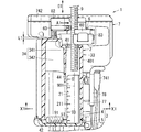
図1に示すように、本実施形態の切断工具1は、切断工具用カバー2と、工具本体7とを備えている。切断工具1は、切断刃6を更に備えている。
(1) Outline As shown in FIG. 1, the cutting tool 1 of the present embodiment includes a cutting tool cover 2 and a tool body 7. The cutting tool 1 further includes a cutting blade 6.

切断工具1は、切断刃6により切断対象物を切断する工具である。切断対象物は、一例として、長尺部9である。長尺部9は、所定の部材の一部分であってもよいし、所定の部材の全体であってもよい。本開示において、長尺部とは、長手方向の長さが、長手方向と直交する各方向の長さの2倍以上の長さである部分を意味する。より好ましくは、長尺部では、長手方向の長さが、長手方向と直交する各方向の長さの5倍以上の長さである。より好ましくは、長尺部では、長手方向の長さが、長手方向と直交する各方向の長さの10倍以上の長さである。本実施形態の長尺部9の長手方向は、図1では紙面の上下方向である。 The cutting tool 1 is a tool for cutting an object to be cut with a cutting blade 6. The object to be cut is, for example, the long portion 9. The elongated portion 9 may be a part of a predetermined member or the entire predetermined member. In the present disclosure, the long portion means a portion whose length in the longitudinal direction is twice or more the length in each direction orthogonal to the longitudinal direction. More preferably, in the long portion, the length in the longitudinal direction is 5 times or more the length in each direction orthogonal to the longitudinal direction. More preferably, in the long portion, the length in the longitudinal direction is 10 times or more the length in each direction orthogonal to the longitudinal direction. The longitudinal direction of the elongated portion 9 of the present embodiment is the vertical direction of the paper surface in FIG.

長尺部を有する所定の部材の具体例は、全ねじ、全ねじ以外のねじ、ボルト、鉄筋、パイプ、又は、木材若しくは金属等で形成された角材若しくは円柱状の部材である。本実施形態では、所定の部材は全ねじであり、長尺部9は全ねじの全体である。本実施形態では、全ねじを切断する切断工具1について説明する。より詳細には、切断工具1は、天井等の構造体から鉛直下向きに突出した長尺部9(全ねじ)を切断する。長尺部9の一端(上端)は、天井等に固定されている。 Specific examples of the predetermined member having the long portion are a full screw, a screw other than the full screw, a bolt, a reinforcing bar, a pipe, or a square or columnar member formed of wood, metal, or the like. In this embodiment, the predetermined member is a full thread, and the elongated portion 9 is the whole full thread. In this embodiment, a cutting tool 1 for cutting all screws will be described. More specifically, the cutting tool 1 cuts a long portion 9 (full screw) that projects vertically downward from a structure such as a ceiling. One end (upper end) of the long portion 9 is fixed to the ceiling or the like.

長尺部9は、切断刃6により切断されて2つの部分に分かれる。以下では、この2つの部分のうち一方を、断片91と称す。天井等から鉛直下向きに突出した長尺部9の下端側の部位が、上端側の部分から切り離されて断片91となる。 The long part 9 is cut by the cutting blade 6 and divided into two parts. Hereinafter, one of the two parts will be referred to as a fragment 91. A portion on the lower end side of the elongated portion 9 protruding vertically downward from the ceiling or the like is separated from the upper end portion to form a fragment 91.

断片91は、切断工具用カバー2に収容される。したがって、切断工具1を使用する作業者が、断片91を手で受けたり拾ったりして回収する必要が無いので、切断工具1の使い勝手が向上する。 The fragment 91 is accommodated in the cutting tool cover 2. Therefore, an operator who uses the cutting tool 1 does not have to receive or pick up the fragments 91 by hand to collect the fragments 91, so that the usability of the cutting tool 1 is improved.

切断工具1は、可搬である。切断工具1が可搬であるとは、切断工具1が、輸送機械又は台車等の道具を用いなくても、人が手に取って持ち歩くことが可能な寸法及び重さであることを言う。 The cutting tool 1 is portable. The cutting tool 1 being portable means that the cutting tool 1 is of a size and weight that a person can take and carry around without using a tool such as a transportation machine or a trolley.

(2)工具本体
図2に示すように、工具本体7は、ハンドル71と、補助ハンドル72と、トリガスイッチ73と、ハウジング74と、装着部75と、固定アーム81と、可動アーム82と、スケール保持部83と、を含む。
(2) Tool main body As shown in FIG. 2, the tool main body 7 includes a handle 71, an auxiliary handle 72, a trigger switch 73, a housing 74, a mounting portion 75, a fixed arm 81, a movable arm 82, and And a scale holder 83.

ハンドル71、補助ハンドル72及びハウジング74の内部には、工具本体7が備えるモータ及びモータの駆動回路等が収容されている。ハウジング74は、円筒状の筒状部741と、筒状部741の軸方向の先端につながった台部742とを有している。台部742のうち、筒状部741側とは反対側の面7421は、平面状である。ハンドル71は、筒状部741の側面から突出している。ハンドル71の外部には、トリガスイッチ73が設けられている。補助ハンドル72は、台部742から突出している。補助ハンドル72の突出している向きは、ハンドル71の突出している向きに沿っている。ハンドル71及び補助ハンドル72は、各々の突出方向の先端側で、装着部75につながっている。装着部75には、電池(2次電池)を収容した電池パック76が取り付けられる。本実施形態では、電池パック76は、切断工具1の構成に含まれないが、電池パック76は、切断工具1の構成に含まれていてもよい。 Inside the handle 71, the auxiliary handle 72, and the housing 74, the motor provided in the tool body 7, the motor drive circuit, and the like are housed. The housing 74 has a cylindrical tubular portion 741 and a base portion 742 connected to the tip end of the tubular portion 741 in the axial direction. A surface 7421 of the base portion 742 on the side opposite to the cylindrical portion 741 side is flat. The handle 71 projects from the side surface of the tubular portion 741. A trigger switch 73 is provided outside the handle 71. The auxiliary handle 72 projects from the base 742. The protruding direction of the auxiliary handle 72 is along the protruding direction of the handle 71. The handle 71 and the auxiliary handle 72 are connected to the mounting portion 75 on the tip end side in the respective protruding directions. A battery pack 76 containing a battery (secondary battery) is attached to the mounting portion 75. In the present embodiment, the battery pack 76 is not included in the configuration of the cutting tool 1, but the battery pack 76 may be included in the configuration of the cutting tool 1.

固定アーム81及び可動アーム82は、ハウジング74の台部742の外面から突出している。固定アーム81及び可動アーム82は、台部742を挟んで補助ハンドル72とは反対側に設けられている。可動アーム82は、固定アーム81に対して、筒状部741の軸方向(図2における紙面の左右方向)にずれて位置している。スケール保持部83は、固定アーム81から突出している。スケール保持部83には、長尺部9の長さを測定するためのスケールが挿入される貫通孔830が形成されている。 The fixed arm 81 and the movable arm 82 project from the outer surface of the base portion 742 of the housing 74. The fixed arm 81 and the movable arm 82 are provided on the opposite side of the auxiliary handle 72 with the base 742 in between. The movable arm 82 is displaced from the fixed arm 81 in the axial direction of the tubular portion 741 (the left-right direction on the paper surface in FIG. 2). The scale holding portion 83 projects from the fixed arm 81. The scale holding portion 83 has a through hole 830 into which a scale for measuring the length of the elongated portion 9 is inserted.

切断工具1の切断刃6は、一対の刃60を含む。一対の刃60の各々は、板状に形成されている。一対の刃60の各々は、半円状の一対の窪みを有し、一対の窪みの底面に形成された一対の刃部61を有する。一対の刃部61は、鋭利に形成されている。 The cutting blade 6 of the cutting tool 1 includes a pair of blades 60. Each of the pair of blades 60 is formed in a plate shape. Each of the pair of blades 60 has a pair of semicircular recesses, and has a pair of blade portions 61 formed on the bottom surfaces of the pair of recesses. The pair of blades 61 are sharply formed.

固定アーム81及び可動アーム82には、刃60が1つずつ取り付けられている。より詳細には、固定アーム81に形成されている貫通孔810に通されたボルト63が、刃60に形成されているボルト孔62にねじ込まれることにより、固定アーム81に刃60が取り付けられている。また、可動アーム82に形成されている貫通孔820に通されたボルト63が、刃60に形成されているボルト孔62にねじ込まれることにより、可動アーム82に刃60が取り付けられている。このようにして、工具本体7は、切断刃6を保持する。可動アーム82は、図1において矢印A1で示す方向に変位可能である。つまり、可動アーム82は、刃60の厚み方向と直交する平面に沿って、固定アーム81に近づいたり、離れたりするように変位可能である。 One blade 60 is attached to each of the fixed arm 81 and the movable arm 82. More specifically, the bolt 63 passed through the through hole 810 formed in the fixed arm 81 is screwed into the bolt hole 62 formed in the blade 60, whereby the blade 60 is attached to the fixed arm 81. There is. The blade 60 is attached to the movable arm 82 by screwing the bolt 63, which is passed through the through hole 820 formed in the movable arm 82, into the bolt hole 62 formed in the blade 60. In this way, the tool body 7 holds the cutting blade 6. The movable arm 82 is displaceable in the direction indicated by arrow A1 in FIG. That is, the movable arm 82 can be displaced so as to move toward and away from the fixed arm 81 along a plane orthogonal to the thickness direction of the blade 60.

長尺部9が、固定アーム81に取り付けられた刃60の刃部61に接した状態で、トリガスイッチ73が押されると、ハウジング74に収容されたモータの駆動力により、可動アーム82が固定アーム81に近づくように変位する。これにより、可動アーム82に取り付けられた刃60と固定アーム81に取り付けられた刃60との間に長尺部9が挟まれ、長尺部9がせん断(切断)される。 When the trigger switch 73 is pressed with the long portion 9 in contact with the blade portion 61 of the blade 60 attached to the fixed arm 81, the movable arm 82 is fixed by the driving force of the motor housed in the housing 74. It is displaced so as to approach the arm 81. Accordingly, the long portion 9 is sandwiched between the blade 60 attached to the movable arm 82 and the blade 60 attached to the fixed arm 81, and the long portion 9 is sheared (cut).

(3)切断工具用カバー
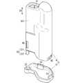
切断工具用カバー2は、カバー本体3を備えている。カバー本体3は、工具本体7に取付けること、及び工具本体7から取外すことが可能である。カバー本体3のうち工具本体7との対向面301(図3参照)の形状は、工具本体7の形状に沿っている。以下の説明では、カバー本体3の長手方向(図1の紙面上下方向)を、カバー本体3の上下方向と規定し、カバー本体3の長手方向の一方側と他方側とのうち、後述の第1の開口部41が設けられた側を上とし、反対側を下とする。
(3) Cutting Tool Cover The cutting tool cover 2 includes a cover body 3. The cover body 3 can be attached to and detached from the tool body 7. The shape of the surface 301 (see FIG. 3) of the cover body 3 that faces the tool body 7 follows the shape of the tool body 7. In the following description, the longitudinal direction of the cover main body 3 (vertical direction in the plane of FIG. 1) is defined as the vertical direction of the cover main body 3, and one of the longitudinal direction of the cover main body 3 and the other side of the longitudinal direction will be described later. The side where the opening 41 of No. 1 is provided is the upper side, and the opposite side is the lower side.

カバー本体3は、収容部4と、蓋部5とを含む。蓋部5は、収容部4に結合されている。ここで、蓋部5が収容部4に結合されているとは、蓋部5が収容部4に取り付けられている場合と、蓋部5と収容部4とが一体に形成されている場合とを含む。本実施形態では、蓋部5は、収容部4に取り付けられている。 The cover body 3 includes a housing portion 4 and a lid portion 5. The lid portion 5 is connected to the housing portion 4. Here, the lid part 5 being coupled to the housing part 4 means that the lid part 5 is attached to the housing part 4 and that the lid part 5 and the housing part 4 are integrally formed. including. In this embodiment, the lid portion 5 is attached to the housing portion 4.

収容部4は、箱状に形成されている。カバー本体3が工具本体7に取り付けられた状態で、収容部4の長手方向は、工具本体7の筒状部741の軸方向に沿っている。収容部4の長手方向の第1端には、第1の開口部41が形成されている。収容部4の長手方向の第2端には、第2の開口部42が形成されている。すなわち、収容部4は、第1の開口部41と第2の開口部42とを有している。カバー本体3の内部空間34は、第1の開口部41を通じてカバー本体3の外部につながっている。第2の開口部42は、蓋部5により開閉される。 The accommodating portion 4 is formed in a box shape. With the cover body 3 attached to the tool body 7, the longitudinal direction of the housing portion 4 is along the axial direction of the tubular portion 741 of the tool body 7. A first opening 41 is formed at the first end of the accommodation portion 4 in the longitudinal direction. A second opening 42 is formed at the second end of the housing portion 4 in the longitudinal direction. That is, the housing portion 4 has the first opening portion 41 and the second opening portion 42. The internal space 34 of the cover body 3 is connected to the outside of the cover body 3 through the first opening 41. The second opening 42 is opened and closed by the lid 5.

第1の開口部41には、長尺部9が通される。より詳細には、カバー本体3が工具本体7に取り付けられている場合に、長尺部9は、第1の開口部41から一の方向D1に沿ってカバー本体3の内部空間34に通される。このとき、長尺部9の長手方向は一の方向D1と一致する。カバー本体3が工具本体7に取り付けられている場合に、切断刃6と、第1の開口部41と、カバー本体3の内部空間34のうち第1の開口部41に通された長尺部9が通る導入領域341とは、一の方向D1においてこの順に並んでいる。この構成により、長尺部9を第1の開口部41に挿入可能である。本実施形態では、一の方向D1は、カバー本体3の長手方向に沿っている。さらに、本実施形態では、一の方向D1は、上下方向に沿っている。つまり、切断刃6の下方に第1の開口部41が位置し、第1の開口部41の下方に導入領域341が位置している。 The elongated portion 9 is passed through the first opening 41. More specifically, when the cover body 3 is attached to the tool body 7, the elongated portion 9 is passed through the internal space 34 of the cover body 3 from the first opening 41 along the one direction D1. It At this time, the longitudinal direction of the elongated portion 9 coincides with the one direction D1. When the cover body 3 is attached to the tool body 7, the cutting blade 6, the first opening portion 41, and the long portion of the inner space 34 of the cover body 3 which is passed through the first opening portion 41. The introduction region 341 through which 9 passes is arranged in this order in the one direction D1. With this configuration, the elongated portion 9 can be inserted into the first opening 41. In the present embodiment, the one direction D1 is along the longitudinal direction of the cover body 3. Further, in the present embodiment, the one direction D1 is along the vertical direction. That is, the first opening 41 is located below the cutting blade 6, and the introduction region 341 is located below the first opening 41.

第2の開口部42は、長尺部9が第1の開口部41に通される場合の長尺部9の延長線(図1の1点鎖線901)上に設けられている。つまり、第1の開口部41と第2の開口部42とが上下方向に並んでいる。 The second opening 42 is provided on an extension line (one-dot chain line 901 in FIG. 1) of the elongated portion 9 when the elongated portion 9 is passed through the first opening 41. That is, the first opening 41 and the second opening 42 are arranged vertically.

図3、4に示すように、カバー本体3は、結合部32を有している。図4では、結合部32を、上下方向と直交する断面における断面図として図示している。結合部32は、収容部4の下端から下向きに突出した円柱状の柱状部321と、柱状部321の側面から突出した保持突起322とを有している。蓋部5は、結合部32が通される結合孔52を有している。結合部32の軸方向と直交する断面における結合孔52の形状は、結合部32の軸方向と直交する断面における結合部32の断面形状と略等しい。すなわち、結合孔52は、円状の領域521と、領域521から突出した領域522とを有している。領域521には、結合部32の柱状部321を通すことが可能である。領域522には、結合部32の保持突起322を通すことが可能である。 As shown in FIGS. 3 and 4, the cover body 3 has a joint portion 32. In FIG. 4, the coupling portion 32 is illustrated as a cross-sectional view in a cross section orthogonal to the vertical direction. The coupling portion 32 has a columnar columnar portion 321 protruding downward from the lower end of the housing portion 4, and a holding protrusion 322 protruding from the side surface of the columnar portion 321. The lid portion 5 has a coupling hole 52 through which the coupling portion 32 passes. The shape of the coupling hole 52 in the cross section orthogonal to the axial direction of the coupling portion 32 is substantially the same as the cross-sectional shape of the coupling portion 32 in the cross section orthogonal to the axial direction of the coupling portion 32. That is, the coupling hole 52 has a circular region 521 and a region 522 protruding from the region 521. The columnar portion 321 of the coupling portion 32 can be passed through the region 521. The holding protrusion 322 of the coupling portion 32 can be passed through the region 522.

収容部4は、その下端付近に2つ(図3では1つのみを図示)の嵌合部45を有している。各嵌合部45は、収容部4の外面から窪んだ窪みである。蓋部5は、2つの爪部53を有している。2つの爪部53は、2つの嵌合部45と一対一で対応する。各爪部53は、対応する嵌合部45に引っ掛けられる。 The accommodating portion 4 has two fitting portions 45 (only one is shown in FIG. 3) near its lower end. Each fitting portion 45 is a hollow recessed from the outer surface of the housing portion 4. The lid 5 has two claws 53. The two claw portions 53 correspond to the two fitting portions 45 on a one-to-one basis. Each claw portion 53 is hooked on the corresponding fitting portion 45.

結合孔52に結合部32が通され、2つの嵌合部45に2つの爪部53が引っ掛けられることで、蓋部5が収容部4に取り付けられる。すなわち、結合孔52、結合部32、2つの嵌合部45及び2つの爪部53はそれぞれ、蓋部5と収容部4との結合箇所である。 The lid portion 5 is attached to the housing portion 4 by passing the coupling portion 32 through the coupling hole 52 and hooking the two claw portions 53 on the two fitting portions 45. That is, the joint hole 52, the joint portion 32, the two fitting portions 45, and the two claw portions 53 are joint portions of the lid portion 5 and the housing portion 4, respectively.

蓋部5を収容部4に取り付けるには、まず、収容部4に対して蓋部5が回転させられる(図4の矢印A2参照)。これにより、結合孔52の領域521と結合部32の柱状部321とを一の方向D1に重ならせ、かつ、結合孔52の領域522と結合部32の保持突起322とを一の方向D1に重ならせる。その状態で結合部32が蓋部5の上から結合孔52に通されると、保持突起322は蓋部5の下方に露出する。さらに、収容部4に対して蓋部5が回転させられる。これにより、各嵌合部45は、対応する爪部53に向かい合う。そして、各嵌合部45に対応する爪部53が引っ掛けられることで、蓋部5が収容部4に取り付けられる。さらに、保持突起322が蓋部5の下面501(図5参照)に接することで、収容部4に対する蓋部5の下方への移動が規制される。 To attach the lid part 5 to the housing part 4, first, the lid part 5 is rotated with respect to the housing part 4 (see arrow A2 in FIG. 4 ). As a result, the region 521 of the coupling hole 52 and the columnar portion 321 of the coupling portion 32 overlap in the one direction D1, and the region 522 of the coupling hole 52 and the holding projection 322 of the coupling portion 32 are aligned in the one direction D1. Overlap. In this state, when the joint portion 32 is passed through the joint hole 52 from above the lid portion 5, the holding protrusion 322 is exposed below the lid portion 5. Further, the lid 5 is rotated with respect to the housing 4. As a result, each fitting portion 45 faces the corresponding claw portion 53. Then, the claw portion 53 corresponding to each fitting portion 45 is hooked, so that the lid portion 5 is attached to the housing portion 4. Further, the holding projection 322 contacts the lower surface 501 (see FIG. 5) of the lid portion 5 to restrict the downward movement of the lid portion 5 with respect to the housing portion 4.

蓋部5は、第2の開口部42を開閉する。作業者は、長尺部9を切断する作業を行う場合は、通常は、収容部4に蓋部5が取り付けられて蓋部5が第2の開口部42を覆った状態にする。つまり、このとき、蓋部5は第2の開口部42を閉状態にしている。第1の開口部41に長尺部9が通された状態で、作業者は、トリガスイッチ73を押して長尺部9を切断する。すると、長尺部9の断片91がカバー本体3の内部空間34に収容される。作業者は、内部空間34に収容された断片91を処分する(捨てる)場合は、収容部4の2つの嵌合部45と蓋部5の2つの爪部53との引っ掛かりを解除して、蓋部5を結合部32を軸として回転させることにより、第2の開口部42を開放する。つまり、このとき、蓋部5は第2の開口部42を開状態にしている。また、作業者は、第2の開口部42を閉状態から開状態にするときとは反対向きに蓋部5を回転させることで、第2の開口部42を閉状態にする。ここで、蓋部5の回転は、結合部32の軸方向(一の方向D1)と直交する平面上における回転である。図5に、第2の開口部42を覆っている閉状態の蓋部5を実線で示し、第2の開口部42を開放している開状態の蓋部5の位置を2点鎖線で示す。断片91は、第2の開口部42を通じて収容部4の外部に取り出されて処分される。 The lid 5 opens and closes the second opening 42. When performing a work of cutting the long portion 9, the operator usually puts the lid portion 5 on the housing portion 4 so that the lid portion 5 covers the second opening portion 42. That is, at this time, the lid 5 closes the second opening 42. The operator presses the trigger switch 73 to cut the long portion 9 while the long portion 9 is passed through the first opening 41. Then, the fragment 91 of the elongated portion 9 is housed in the internal space 34 of the cover body 3. When the operator disposes (discards) the fragments 91 accommodated in the internal space 34, the operator releases the catches between the two fitting portions 45 of the accommodating portion 4 and the two claw portions 53 of the lid portion 5, The second opening 42 is opened by rotating the lid 5 about the coupling portion 32. That is, at this time, the lid portion 5 has the second opening 42 in the open state. Further, the worker turns the second opening 42 into the closed state by rotating the lid 5 in the direction opposite to that when the second opening 42 is moved from the closed state to the open state. Here, the rotation of the lid portion 5 is rotation on a plane orthogonal to the axial direction (one direction D1) of the coupling portion 32. In FIG. 5, the closed lid portion 5 that covers the second opening portion 42 is shown by a solid line, and the position of the opened lid portion 5 that opens the second opening portion 42 is shown by a two-dot chain line. .. The fragment 91 is taken out of the housing 4 through the second opening 42 and disposed of.

蓋部5は、カバー本体3が工具本体7に取り付けられた状態で第2の開口部42を開閉可能である。つまり、カバー本体3が工具本体7に取り付けられた状態で蓋部5の周りには蓋部5が回転するためのスペースが設けられているため、カバー本体3を工具本体7から取り外さなくても、蓋部5を開状態にすることが可能である。 The lid 5 can open and close the second opening 42 in a state where the cover body 3 is attached to the tool body 7. In other words, since the space for rotating the lid body 5 is provided around the lid body 5 with the cover body 3 attached to the tool body 7, it is possible to remove the cover body 3 from the tool body 7. The lid 5 can be opened.

上記の例では、蓋部5は、第2の開口部42を開状態にしている場合に収容部4につながっている。すなわち、この場合に結合部32が結合孔52に通された状態が維持されている。なお、収容部4から蓋部5を取り外すことにより、第2の開口部42を開状態にしてもよい。 In the above example, the lid part 5 is connected to the housing part 4 when the second opening part 42 is in the open state. That is, in this case, the state where the coupling portion 32 is passed through the coupling hole 52 is maintained. The second opening 42 may be opened by removing the lid 5 from the housing 4.

後述するように、長尺部9の切断長さ(すなわち、長尺部9のうち切り離されて断片91となる部位の長さ)がカバー本体3よりも長い場合は、作業者は、蓋部5が収容部4から取り外されていて第2の開口部42が開状態のまま、長尺部9を切断する。 As will be described later, when the cut length of the long portion 9 (that is, the length of the portion of the long portion 9 that is cut off to become the fragments 91) is longer than the cover body 3, the operator may use the lid portion. The long portion 9 is cut while the fifth opening 5 is removed from the housing portion 4 and the second opening portion 42 remains open.

収容部4と蓋部5とは、互いに異なる材料により形成されている。収容部4は、例えば、アクリル樹脂又はポリカーボネート樹脂を材料として形成されている。収容部4は、全体が透明に形成されている。蓋部5は、収容部4よりも強度が高い材料により形成されている。蓋部5は、例えば、ABS(Acrylonitrile Butadiene Styrene)樹脂又はナイロン樹脂を材料として形成されている。蓋部5は、全体が不透明に形成されている。 The housing portion 4 and the lid portion 5 are made of different materials. The housing 4 is made of, for example, acrylic resin or polycarbonate resin. The accommodating portion 4 is entirely transparent. The lid portion 5 is made of a material having higher strength than the housing portion 4. The lid 5 is made of, for example, ABS (Acrylonitrile Butadiene Styrene) resin or nylon resin. The lid 5 is formed so as to be entirely opaque.

図1に示すように、カバー本体3の収容部4は、排出規制機構を更に有している。排出規制機構は、仕切壁44を含む。本実施形態では、排出規制機構は、仕切壁44のみからなる。仕切壁44は、カバー本体3の内部空間34に配置されている。排出規制機構としての仕切壁44は、長尺部9のうち切断刃6により切り離された部分(断片91)がカバー本体3の内部空間34から第1の開口部41を通じてカバー本体3の外部へ移動することを規制する。排出規制機構について、詳しくは後述する。 As shown in FIG. 1, the accommodating portion 4 of the cover body 3 further has a discharge regulation mechanism. The emission control mechanism includes a partition wall 44. In the present embodiment, the discharge regulation mechanism includes only the partition wall 44. The partition wall 44 is arranged in the internal space 34 of the cover body 3. In the partition wall 44 as the discharge control mechanism, a portion (fragment 91) of the long portion 9 cut off by the cutting blade 6 is passed from the internal space 34 of the cover body 3 to the outside of the cover body 3 through the first opening 41. Regulate movement. The emission control mechanism will be described in detail later.

内部空間34は、導入領域341と、奥方領域342とを含む。仕切壁44は、導入領域341と奥方領域342との間を部分的に仕切っている。導入領域341は、第1の開口部41を通じてカバー本体3の外部につながっている。奥方領域342は、一の方向D1と交差する方向(図1の紙面左右方向)において導入領域341につながっている。 The internal space 34 includes an introduction area 341 and a back area 342. The partition wall 44 partially partitions the introduction region 341 and the back region 342. The introduction region 341 is connected to the outside of the cover body 3 through the first opening 41. The back area 342 is connected to the introduction area 341 in a direction intersecting the one direction D1 (left-right direction on the paper surface of FIG. 1).

導入領域341の長手方向は、カバー本体3の長手方向に沿っている。導入領域341は、第1の開口部41から第2の開口部42までに亘る領域である。 The longitudinal direction of the introduction region 341 is along the longitudinal direction of the cover body 3. The introduction region 341 is a region extending from the first opening 41 to the second opening 42.

奥方領域342の長手方向は、カバー本体3の長手方向に沿っている。奥方領域342の上端(第1の開口部41側の端)は、閉塞している。奥方領域342は、その上端から第2の開口部42までに亘る領域である。 The longitudinal direction of the back region 342 is along the longitudinal direction of the cover body 3. The upper end (the end on the first opening 41 side) of the inner region 342 is closed. The back area 342 is an area extending from the upper end to the second opening 42.

ところで、第2の開口部42が蓋部5により閉状態となっている場合、蓋部5は、カバー本体3の底壁として機能する。つまり、カバー本体3は、底壁としての蓋部5を有している。蓋部5は、一の方向D1において第1の開口部41とは反対側に設けられている。導入領域341と奥方領域342とは、蓋部5に隣接した領域においてつながっている。言い換えると、導入領域341と奥方領域342とは、それぞれの下端側においてつながっている。 By the way, when the second opening 42 is closed by the lid 5, the lid 5 functions as a bottom wall of the cover body 3. That is, the cover body 3 has the lid portion 5 as a bottom wall. The lid 5 is provided on the side opposite to the first opening 41 in the one direction D1. The introduction area 341 and the back area 342 are connected to each other in an area adjacent to the lid 5. In other words, the introduction area 341 and the back area 342 are connected to each other at their lower ends.

図6において、向きS2(紙面上下方向)は、カバー本体3の導入領域341から工具本体7の筒状部741に向かう向きを表す。カバー本体3が工具本体7に取り付けられており工具本体7が所定の面を水平な面に対向させて置かれている場合に、向きS2は鉛直下向きに沿う。ここで、所定の面とは、電池パック76(図2参照)の底面761(図2参照)である。底面761は、電池パック76を装着した装着部75(図2参照)側とは反対側の面である。向きS2が鉛直下向きに沿っている場合に、図6に示すように、奥方領域342の少なくとも一部は、導入領域341の少なくとも一部よりも下方に位置する。より詳細には、収容部4の内面のうち工具本体7の筒状部741側の面48は、導入領域341に隣接した部位から奥方領域342に隣接した部位に近づくにつれて下に向かうように傾いている。これにより、奥方領域342のうち面48付近の領域が、導入領域341よりも下に位置する。 In FIG. 6, the direction S2 (vertical direction on the paper surface) represents the direction from the introduction region 341 of the cover body 3 toward the tubular portion 741 of the tool body 7. When the cover main body 3 is attached to the tool main body 7 and the tool main body 7 is placed with a predetermined surface facing a horizontal surface, the direction S2 is vertically downward. Here, the predetermined surface is the bottom surface 761 (see FIG. 2) of the battery pack 76 (see FIG. 2). The bottom surface 761 is a surface on the side opposite to the mounting portion 75 (see FIG. 2) side on which the battery pack 76 is mounted. When the direction S2 is vertically downward, as shown in FIG. 6, at least a part of the inner region 342 is located below at least a part of the introduction region 341. More specifically, the surface 48 of the tool body 7 on the cylindrical portion 741 side of the inner surface of the accommodating portion 4 is inclined downward as it approaches the portion adjacent to the introduction region 341 and the portion adjacent to the inner region 342. ing. As a result, the region near the surface 48 of the inner region 342 is located below the introduction region 341.

第1の開口部41から導入領域341に入った長尺部9は、収容部4の外壁401と仕切壁44とに囲まれた領域を通る。収容部4の外壁401と仕切壁44とは、規制壁33として機能する。すなわち、カバー本体3は、外壁401及び仕切壁44を含む規制壁33を有している。規制壁33は、第1の開口部41からカバー本体3の内部空間34(導入領域341)に通された長尺部9について、一の方向D1と交差する方向への移動を規制する。つまり、長尺部9は、規制壁33にガイドされながら内部空間34を進む。 The elongated portion 9 that has entered the introduction region 341 from the first opening portion 41 passes through a region surrounded by the outer wall 401 and the partition wall 44 of the housing portion 4. The outer wall 401 and the partition wall 44 of the housing portion 4 function as the restriction wall 33. That is, the cover body 3 has the restriction wall 33 including the outer wall 401 and the partition wall 44. The regulation wall 33 regulates the movement of the elongated portion 9 that passes through the internal space 34 (the introduction region 341) of the cover body 3 from the first opening 41 in the direction intersecting with the one direction D1. That is, the elongated portion 9 advances in the internal space 34 while being guided by the restriction wall 33.

切断工具用カバー2は、測定部21を更に備えている。測定部21は、長さを測定するためのスケールである。測定部21は、長さを表す目盛り211を有している。測定部21は、カバー本体3の内部空間34に配置されている。測定部21は、切断刃6から長尺部9の先端(下端)までの長さの測定に用いられる。すなわち、長尺部9の先端が測定部21の近傍に到達している場合に、測定部21のうち長尺部9の先端に隣接する部位の目盛り211の数値が、切断刃6から長尺部9の先端までの長さの測定値に相当する。 The cutting tool cover 2 further includes a measuring unit 21. The measuring unit 21 is a scale for measuring the length. The measuring unit 21 has a scale 211 indicating the length. The measuring unit 21 is arranged in the internal space 34 of the cover body 3. The measuring unit 21 is used to measure the length from the cutting blade 6 to the tip (lower end) of the elongated portion 9. That is, when the tip of the long portion 9 reaches the vicinity of the measuring portion 21, the numerical value of the scale 211 of the portion of the measuring portion 21 adjacent to the tip of the long portion 9 is changed from the cutting blade 6 to the long portion. It corresponds to the measured value of the length to the tip of the portion 9.

なお、測定部21に相当する構成としてのスケールが、スケール保持部83(図2参照)に保持されてもよい。すなわち、測定部21に相当するスケールは、スケール保持部83の貫通孔830(図2参照)に挿入され、スケールの長手方向が上下方向に沿うようにスケール保持部83に保持されてもよい。作業者は、スケール保持部83に保持されたスケールの目盛りを参照して、切断刃6から長尺部9の先端までの長さ(つまり、断片91の長さ)を知ることができる。 Note that a scale as a configuration corresponding to the measuring unit 21 may be held by the scale holding unit 83 (see FIG. 2). That is, the scale corresponding to the measuring unit 21 may be inserted into the through hole 830 (see FIG. 2) of the scale holding unit 83 and held by the scale holding unit 83 so that the longitudinal direction of the scale extends along the vertical direction. The operator can know the length from the cutting blade 6 to the tip of the elongated portion 9 (that is, the length of the fragment 91) by referring to the scale scale held by the scale holding portion 83.

(4)工具本体とカバー本体との取付構造
図3、6に示すように、カバー本体3の収容部4は、取付溝46を有している。図6に示すように、工具本体7は、レバー77を有している。レバー77の形状は、板状である。レバー77は、ハウジング74の円筒状の筒状部741から、筒状部741の接線方向に突出している。レバー77の厚さ方向は、筒状部741の径方向に沿っている。レバー77は、取付突起771を備えている。取付突起771が取付溝46に引っ掛けられることで、カバー本体3が工具本体7に取り付けられる。
(4) Mounting Structure of Tool Main Body and Cover Main Body As shown in FIGS. 3 and 6, the accommodating portion 4 of the cover main body 3 has a mounting groove 46. As shown in FIG. 6, the tool body 7 has a lever 77. The lever 77 has a plate shape. The lever 77 projects from the cylindrical tubular portion 741 of the housing 74 in the tangential direction of the tubular portion 741. The thickness direction of the lever 77 is along the radial direction of the tubular portion 741. The lever 77 includes a mounting protrusion 771. The cover body 3 is attached to the tool body 7 by hooking the attachment protrusion 771 on the attachment groove 46.

より詳細には、カバー本体3は、カバー本体3を工具本体7に対して一の方向D1と交差する方向に移動させることで工具本体7に取付け及び取外し可能である。すなわち、図6の矢印A3の向きに作業者がカバー本体3を動かすことにより、取付突起771が取付溝46に引っ掛けられる。これにより工具本体7へのカバー本体3の取付けが完了する。また、作業者がレバー77を筒状部741の中心に近づく向きに動かすことにより、取付突起771と取付溝46との引っ掛かりが解除される。その状態で、矢印A3とは反対向きに作業者がカバー本体3を動かすことにより、カバー本体3が工具本体7から取り外される。 More specifically, the cover body 3 can be attached to and detached from the tool body 7 by moving the cover body 3 in a direction intersecting the direction D1 with respect to the tool body 7. That is, when the worker moves the cover body 3 in the direction of arrow A3 in FIG. 6, the mounting protrusion 771 is hooked in the mounting groove 46. This completes the attachment of the cover body 3 to the tool body 7. Further, when the operator moves the lever 77 in a direction approaching the center of the tubular portion 741, the catch between the mounting projection 771 and the mounting groove 46 is released. In this state, the operator moves the cover body 3 in the direction opposite to the arrow A3, so that the cover body 3 is removed from the tool body 7.

図1に示すように、カバー本体3が工具本体7に取り付けられた状態で、一の方向D1において、カバー本体3と工具本体7との間には隙間がある。具体的には、カバー本体3の収容部4と、工具本体7の台部742との間に、長さL1の隙間がある。そのため、作業者がカバー本体3を一の方向D1と交差する方向(矢印A3に沿った方向)に移動させながら工具本体7に取付ける又は工具本体7から取外しする場合に、収容部4が台部742に接する可能性を低減できる。 As shown in FIG. 1, when the cover body 3 is attached to the tool body 7, there is a gap between the cover body 3 and the tool body 7 in the one direction D1. Specifically, there is a gap having a length L1 between the housing portion 4 of the cover body 3 and the base portion 742 of the tool body 7. Therefore, when the worker attaches to the tool main body 7 or removes it from the tool main body 7 while moving the cover main body 3 in the direction intersecting the one direction D1 (the direction along the arrow A3), the accommodating portion 4 is the base portion. The possibility of contacting the 742 can be reduced.

(5)吊下部材
図7に示すように、切断工具1は、吊下部材78を更に備えている。本実施形態の吊下部材78は、鉤型のフックである。吊下部材78は、その一端が工具本体7に結合されている。吊下部材78は、工具本体7との結合箇所を中心に回転可能である。ここで、吊下部材78が工具本体7に結合されているとは、吊下部材78が工具本体7に取り付けられている場合と、吊下部材78と工具本体7とが一体に形成されている場合とを含む。本実施形態では、吊下部材78は、工具本体7に取り付けられている。
(5) Suspension Member As shown in FIG. 7, the cutting tool 1 further includes a suspension member 78. The hanging member 78 of this embodiment is a hook-shaped hook. One end of the hanging member 78 is joined to the tool body 7. The hanging member 78 is rotatable around a connection portion with the tool body 7. Here, the suspension member 78 being coupled to the tool body 7 means that the suspension member 78 is attached to the tool body 7 and that the suspension member 78 and the tool body 7 are integrally formed. Including In the present embodiment, the hanging member 78 is attached to the tool body 7.

吊下部材78は、工具本体7を吊下対象部材に吊り下げるための部材である。吊下対象部材の一例は、パイプ等の足場材、脚立の一部分、又は、天井の梁等の構造体である。吊下対象部材は、水平面と略平行に配置されている。図7には、吊下対象部材としてのパイプ101を図示している。工具本体7は、吊下部材78によりパイプ101に吊り下げられる。すなわち、図7に2点鎖線で示すように、吊下部材78がパイプ101に引っ掛けられることで、工具本体7が吊り下げられる。この場合に、内部空間34のうち奥方領域342の少なくとも一部は、導入領域341の少なくとも一部よりも下方に位置する。より詳細には、この場合に、仕切壁44は鉛直方向に対して斜めに配置されており、仕切壁44の上に導入領域341の一部が位置し、仕切壁44の下に奥方領域342の一部が位置する。そのため、カバー本体3の内部空間34に収容された長尺部9の断片91(図1参照)が、導入領域341よりも奥方領域342に配置されやすい。これにより、断片91が第1の開口部41(図1参照)からカバー本体3の外に出る可能性を低減できる。 The suspension member 78 is a member for suspending the tool main body 7 on a suspension target member. An example of the hanging target member is a scaffolding material such as a pipe, a part of a stepladder, or a structure such as a ceiling beam. The hanging target member is arranged substantially parallel to the horizontal plane. FIG. 7 illustrates a pipe 101 as a hanging target member. The tool body 7 is suspended from the pipe 101 by the suspension member 78. That is, as shown by the chain double-dashed line in FIG. 7, the tool main body 7 is suspended by hooking the suspension member 78 on the pipe 101. In this case, at least a part of the inner region 342 of the inner space 34 is located below at least a part of the introduction region 341. More specifically, in this case, the partition wall 44 is obliquely arranged with respect to the vertical direction, a part of the introduction region 341 is located above the partition wall 44, and the depth region 342 is located below the partition wall 44. Part of is located. Therefore, the fragments 91 (see FIG. 1) of the elongated portion 9 accommodated in the internal space 34 of the cover body 3 are more likely to be arranged in the inner region 342 than the introduction region 341. This can reduce the possibility that the fragments 91 will come out of the cover body 3 from the first opening 41 (see FIG. 1 ).

工具本体7は、吊下部材78を保持する保持部743を備えている。保持部743は、ハウジング74の筒状部741から突出している。保持部743は、溝を有しており、この溝に吊下部材78の一部が挿入されることにより、吊下部材78が保持部743に保持される。作業者は、吊下部材78をパイプ101等に吊り下げる場合は、保持部743から吊下部材78を取り出して、吊下部材78を、工具本体7との結合箇所を中心に回転させる。 The tool body 7 includes a holding portion 743 that holds the hanging member 78. The holding portion 743 projects from the tubular portion 741 of the housing 74. The holding portion 743 has a groove, and the hanging member 78 is held by the holding portion 743 by inserting a part of the hanging member 78 into the groove. When suspending the suspending member 78 on the pipe 101 or the like, the operator takes out the suspending member 78 from the holding portion 743 and rotates the suspending member 78 around the connecting portion with the tool body 7.

(6)切断工具の使用方法
以下では、図1、図2を参照して、カバー本体3が工具本体7に取り付けられた状態で長尺部9を切断刃6で切断する場合の切断工具1の使用方法の一例について説明する。以下では、長尺部9が天井に固定されている吊りボルトであり、長尺部9の一端が床側(下)を向いている場合について説明する。
(6) Method of Using Cutting Tool Hereinafter, referring to FIG. 1 and FIG. 2, the cutting tool 1 in the case of cutting the elongated portion 9 with the cutting blade 6 in a state where the cover body 3 is attached to the tool body 7. An example of how to use is described. Below, the case where the long part 9 is a hanging bolt fixed to the ceiling and one end of the long part 9 faces the floor side (down) will be described.

まず、一の方向D1から見て、可動アーム82は固定アーム81から離れており、切断刃6の一対の刃60は互いに離れている。図1に示すように、長尺部9は、一対の刃60の間を通るように、第1の開口部41に通される。これにより、長尺部9の一端(下端)が、カバー本体3の内部に配置される。 First, when viewed from the one direction D1, the movable arm 82 is separated from the fixed arm 81, and the pair of blades 60 of the cutting blade 6 are separated from each other. As shown in FIG. 1, the elongated portion 9 is passed through the first opening 41 so as to pass between the pair of blades 60. As a result, one end (lower end) of the elongated portion 9 is arranged inside the cover body 3.

収容部4は透明なので、作業者は、収容部4の内部に配置された測定部21の目盛り211と長尺部9の下端とを見ることができる。作業者は、必要に応じて、長尺部9の下端の位置を測定部21の目盛り211の所定の位置に合わせる。すなわち、作業者は、測定部21のうち長尺部9の下端に隣接する部位の目盛り211の数値が、作業者の所望する長尺部9の切断長さと一致するように、切断工具1を上下に動かして長尺部9の下端の位置を合わせる。 Since the housing portion 4 is transparent, the operator can see the scale 211 of the measuring portion 21 and the lower end of the elongated portion 9 arranged inside the housing portion 4. The operator adjusts the position of the lower end of the elongated portion 9 to a predetermined position on the scale 211 of the measuring unit 21 as necessary. That is, the operator uses the cutting tool 1 so that the numerical value of the scale 211 of the portion of the measuring unit 21 adjacent to the lower end of the long portion 9 matches the cutting length of the long portion 9 desired by the operator. Move it up and down to align the lower end of the elongated portion 9.

トリガスイッチ73が押されると、ハウジング74に収容されたモータが駆動することにより、可動アーム82は、図1における紙面の右向き(図1において矢印A1で示す向き)に変位する。可動アーム82が変位するのに伴って、可動アーム82に取り付けられている刃60が変位して、当該刃60の刃部61が、固定アーム81に取り付けられている刃60の刃部61との間に長尺部9を挟み、長尺部9にせん断力を作用させる。これにより、切断刃6(一対の刃60)は、長尺部9を長尺部9の長手方向と交差する面で切断する。要するに、一対の刃60は、挟み方向(矢印A1と同じ方向)の両側から長尺部9を挟んで、長尺部9をせん断する。本実施形態では、切断刃6は、長尺部9を長尺部9の長手方向と直交する面で切断する。 When the trigger switch 73 is pressed, the motor accommodated in the housing 74 is driven, whereby the movable arm 82 is displaced rightward on the paper surface of FIG. 1 (direction shown by arrow A1 in FIG. 1). As the movable arm 82 is displaced, the blade 60 attached to the movable arm 82 is displaced, and the blade portion 61 of the blade 60 is replaced with the blade portion 61 of the blade 60 attached to the fixed arm 81. The elongated portion 9 is sandwiched between the two and the shearing force is applied to the elongated portion 9. Thereby, the cutting blade 6 (a pair of blades 60) cuts the long portion 9 along a plane intersecting the longitudinal direction of the long portion 9. In short, the pair of blades 60 sandwich the elongated portion 9 from both sides in the sandwiching direction (the same direction as the arrow A1) and shear the elongated portion 9. In the present embodiment, the cutting blade 6 cuts the long portion 9 along a plane orthogonal to the longitudinal direction of the long portion 9.

長尺部9が切断されて2つに分けられると、2つに分けられた長尺部9のうち下端側の部分(断片91)は、カバー本体3の内部空間34に収容される。このように、作業者は、切断工具1を用いれば、断片91をカバー本体3に収容することができ、断片91を床等に落とす可能性を低減できる。特に、作業者は、片手でハンドル71を握ってトリガスイッチ73を押すことで、片手のみを用いて長尺部9を切断し、かつ、断片91をカバー本体3に収容することができる。 When the long portion 9 is cut and divided into two, the lower end side portion (fragment 91) of the two long portions 9 is accommodated in the internal space 34 of the cover body 3. As described above, the worker can store the fragment 91 in the cover body 3 by using the cutting tool 1, and reduce the possibility of dropping the fragment 91 on the floor or the like. In particular, an operator can hold the handle 71 with one hand and press the trigger switch 73 to cut the long portion 9 with only one hand and store the fragment 91 in the cover body 3.

また、断片91がカバー本体3に収容された後、作業者は、向きS2(図6参照)が鉛直下向きに沿うように切断工具1の向きを変えて、切断工具1を1回又は2回程度、左右に振ってもよい。これにより、断片91が収容部4の面48(図6参照)の傾斜に沿って導入領域341から奥方領域342へ移動させられる。 Further, after the fragments 91 are accommodated in the cover body 3, the worker changes the direction of the cutting tool 1 so that the direction S2 (see FIG. 6) is along the vertically downward direction, and the cutting tool 1 is rotated once or twice. You may shake it to the left or right. As a result, the fragment 91 is moved from the introduction region 341 to the back region 342 along the inclination of the surface 48 (see FIG. 6) of the housing portion 4.

カバー本体3は、排出規制機構としての仕切壁44を有しており、仕切壁44は、断片91について、カバー本体3の内部空間34から第1の開口部41を通じてカバー本体3の外部への移動を規制する。すなわち、カバー本体3の内部空間34では、断片91は、仕切壁44を避けない限り、奥方領域342から導入領域341へ移動しない。そのため、仕切壁44が無い場合と比較して、断片91が奥方領域342から導入領域341を経由して第1の開口部41に到達する可能性が低減する。また、切断工具1を図1とは反対向きに配置した場合(すなわち、第1の開口部41が第2の開口部42の下方に位置するように切断工具1を回転させた場合)に、奥方領域342に配置された断片91は、仕切壁44を越え難い。そのため、仕切壁44が無い場合と比較して、断片91が奥方領域342から導入領域341に移動する可能性が低減する。 The cover main body 3 has a partition wall 44 as an emission control mechanism, and the partition wall 44 allows the fragments 91 from the internal space 34 of the cover main body 3 to the outside of the cover main body 3 through the first opening 41. Regulate movement. That is, in the internal space 34 of the cover body 3, the fragments 91 do not move from the back area 342 to the introduction area 341 unless the partition wall 44 is avoided. Therefore, as compared with the case where the partition wall 44 is not provided, the possibility that the fragment 91 reaches the first opening portion 41 from the back area 342 via the introduction area 341 is reduced. Further, when the cutting tool 1 is arranged in the opposite direction to that of FIG. 1 (that is, when the cutting tool 1 is rotated so that the first opening 41 is located below the second opening 42), The fragments 91 arranged in the back area 342 are less likely to cross the partition wall 44. Therefore, as compared with the case where the partition wall 44 is not provided, the possibility that the fragment 91 moves from the depth area 342 to the introduction area 341 is reduced.

なお、作業者は、長尺部9の全体がカバー本体3の外にある状態で、長尺部9を切断してもよい。すなわち、長尺部9の先端(下端)が第1の開口部41の上にある状態で、長尺部9を切断してもよい。この場合、長尺部9が切断されると、断片91は落下して第1の開口部41を通してカバー本体3の内部空間34に入る。 The worker may cut the long portion 9 while the whole long portion 9 is outside the cover body 3. That is, the long portion 9 may be cut while the tip (lower end) of the long portion 9 is above the first opening 41. In this case, when the long portion 9 is cut, the fragments 91 drop and enter the internal space 34 of the cover body 3 through the first opening 41.

また、カバー本体3の内部空間34に収容された断片91の個数が多くなった場合等、断片91を処分する場合は、作業者は、蓋部5を開状態にすることで、第2の開口部42から断片91を取り出すことができる。 Further, when the fragments 91 are disposed of, such as when the number of the fragments 91 accommodated in the internal space 34 of the cover body 3 increases, the operator opens the lid portion 5 to open the second portion. The fragment 91 can be taken out from the opening 42.

また、長尺部9のうち切り離されて断片91となる部位がカバー本体3よりも長い場合は、蓋部5が収容部4に取り付けられた状態では、長尺部9のうち切断したい箇所に切断刃6が当たる前に長尺部9の先端が蓋部5に当たってしまう。そこで、この場合に作業者は、蓋部5を収容部4から取り外して第2の開口部42を開状態にする。これにより、長尺部9の先端を第2の開口部42よりも下まで移動させることができるので、長尺部9のうち切断したい箇所に切断刃6を当て、長尺部9を切断できる。あるいは、作業者は、カバー本体3を工具本体7から取り外した状態で長尺部9を切断してもよい。 Further, when the portion of the long portion 9 that is cut off to become the fragment 91 is longer than the cover body 3, in the state where the lid portion 5 is attached to the accommodating portion 4, the portion of the long portion 9 to be cut is to be cut. Before the cutting blade 6 hits, the tip of the long portion 9 hits the lid 5. Therefore, in this case, the operator removes the lid portion 5 from the housing portion 4 and opens the second opening portion 42. Thereby, the tip of the long portion 9 can be moved to a position below the second opening 42, so that the cutting blade 6 can be applied to the portion of the long portion 9 to be cut to cut the long portion 9. .. Alternatively, the operator may cut the long portion 9 with the cover body 3 removed from the tool body 7.

(変形例)
次に、実施形態の変形例を列挙する。以下の変形例は、適宜組み合わせて実現されてもよい。
(Modification)
Next, modifications of the embodiment will be listed. The following modified examples may be implemented in appropriate combination.

切断工具1の構成は、切断刃6の一対の刃60で長尺部9を挟むことにより長尺部9をせん断する構成に限定されない。例えば、切断工具1の構成は、長尺部9に接触させた切断刃を回転運動、直線運動又は曲線運動させることにより長尺部9を切断する構成であってもよい。切断刃の形状は、実施形態の切断刃6の形状に限らない。切断刃は、例えば、鋸(丸鋸を含む)であってもよい。 The configuration of the cutting tool 1 is not limited to the configuration in which the long portion 9 is sheared by sandwiching the long portion 9 with the pair of blades 60 of the cutting blade 6. For example, the configuration of the cutting tool 1 may be a configuration in which the long portion 9 is cut by rotating, linearly or curving a cutting blade that is in contact with the long portion 9. The shape of the cutting blade is not limited to the shape of the cutting blade 6 of the embodiment. The cutting blade may be, for example, a saw (including a circular saw).

切断工具1は、電池ではなく商用電源等の外部電源から電力が供給されてもよい。また、電池を電源に用いる場合に、電池は1次電池でも、2次電池でもよい。また、本実施形態の切断工具1は、電力により駆動される電動工具であるが、切断工具1は電動工具に限定されない。切断工具1は、例えば空圧ポンプを動力源とし空圧ポンプから供給される圧縮空気により駆動される空圧式の工具でもよいし、油圧ポンプを動力源とし油圧源から供給される油圧により駆動される油圧式の工具でもよい。 The cutting tool 1 may be supplied with electric power from an external power source such as a commercial power source instead of the battery. When a battery is used as a power source, the battery may be a primary battery or a secondary battery. Further, the cutting tool 1 of the present embodiment is an electric tool driven by electric power, but the cutting tool 1 is not limited to an electric tool. The cutting tool 1 may be, for example, a pneumatic tool driven by compressed air supplied from a pneumatic pump as a power source, or driven by hydraulic pressure supplied from a hydraulic source by a hydraulic pump. It may be a hydraulic tool.

カバー本体3の排出規制機構は、断片91がカバー本体3の内部空間34から第1の開口部41を通じて外部に出ることを抑制する逆流防止弁を備えていてもよい。逆流防止弁は、内部空間34に配置される。 The discharge restricting mechanism of the cover body 3 may include a check valve that prevents the fragments 91 from flowing out of the inner space 34 of the cover body 3 through the first opening 41. The check valve is arranged in the internal space 34.

逆流防止弁は、例えば、ゴム等を材料として形成された板状の部材に十字又は星形の切込みが入った形状を有し、第1の開口部41の付近に配置される。この場合、作業者は、長尺部9を切断する前に、長尺部9の先端を逆流防止弁の切込みに通すことで、長尺部9の先端を逆流防止弁よりも奥(下)に配置する。長尺部9を第1の開口部41に通していない状態においては、第1の開口部41は、逆流防止弁により塞がれることになる。 The check valve has, for example, a plate-shaped member formed of rubber or the like with a cross-shaped or star-shaped cut, and is arranged near the first opening 41. In this case, the operator passes the tip of the long portion 9 through the notch of the check valve before cutting the long portion 9 so that the tip of the long portion 9 is deeper (lower) than the check valve. To place. When the long portion 9 is not passed through the first opening 41, the first opening 41 is closed by the check valve.

第2の開口部42は、収容部4の下端に設けられていることに限定されず、例えば、収容部4の側面に設けられていてもよい。 The second opening 42 is not limited to being provided at the lower end of the accommodating portion 4, and may be provided at a side surface of the accommodating portion 4, for example.

蓋部5の内面51(図1参照)には、段差又は傾斜が設けられていてもよい。例えば、蓋部5の内面51のうち奥方領域342に隣接した部位が、導入領域341に隣接した部位よりも下に位置するように、内面51に段差又は傾斜が設けられていてもよい。 The inner surface 51 (see FIG. 1) of the lid portion 5 may be provided with a step or a slope. For example, a step or an inclination may be provided on the inner surface 51 of the lid portion 5 so that the portion of the inner surface 51 adjacent to the inner area 342 is located below the portion of the inner surface 51 adjacent to the introduction area 341.

測定部21は、カバー本体3の外部に配置されていてもよい。 The measurement unit 21 may be arranged outside the cover body 3.

蓋部5は、ヒンジ構造により収容部4に取り付けられていてもよい。 The lid part 5 may be attached to the housing part 4 by a hinge structure.

蓋部5は、紐又はワイヤ等の接続部材を介して収容部4に接続されていてもよい。この場合、蓋部5が収容部4から取り外されて第2の開口部42を開状態にしている場合に、蓋部5が収容部4につながった状態を接続部材により維持できる。 The lid portion 5 may be connected to the housing portion 4 via a connecting member such as a string or a wire. In this case, the connection member can maintain the state in which the lid 5 is connected to the housing 4 when the lid 5 is removed from the housing 4 and the second opening 42 is opened.

(まとめ)
以上説明した実施形態等から、以下の態様が開示されている。
(Summary)
The following aspects are disclosed from the embodiments and the like described above.

第1の態様に係る切断工具用カバー2は、カバー本体3を備える。カバー本体3は、工具本体7に取り付けられる。工具本体7は、切断対象物(長尺部9)を切断する切断刃6を保持する。カバー本体3は、収容部4と、蓋部5と、を含む。収容部4は、第1の開口部41と、第2の開口部42と、を有する。第1の開口部41には、切断対象物が通る。蓋部5は、第2の開口部42を開閉する。 The cutting tool cover 2 according to the first aspect includes a cover body 3. The cover body 3 is attached to the tool body 7. The tool body 7 holds a cutting blade 6 that cuts an object to be cut (long portion 9). The cover body 3 includes a housing portion 4 and a lid portion 5. The housing portion 4 has a first opening portion 41 and a second opening portion 42. The object to be cut passes through the first opening 41. The lid 5 opens and closes the second opening 42.

上記の構成によれば、切断対象物(長尺部9)のうち切断刃6により切り離された部分(断片91)を、第1の開口部41を通じてカバー本体3の内部空間34に収容できる。また、蓋部5が第2の開口部42を開状態にしているとき、断片91を第2の開口部42を通してカバー本体3の外部に取り出すことができる。これにより、断片91の処分が容易となるので、工具本体7(切断工具1)の使い勝手が向上する。 According to the above configuration, the portion (fragment 91) of the object to be cut (long portion 9) cut off by the cutting blade 6 can be accommodated in the internal space 34 of the cover body 3 through the first opening 41. Further, when the lid portion 5 opens the second opening portion 42, the fragment 91 can be taken out of the cover body 3 through the second opening portion 42. This facilitates the disposal of the fragments 91, which improves the usability of the tool body 7 (cutting tool 1).

また、第2の態様に係る切断工具用カバー2では、第1の態様において、蓋部5は、カバー本体3が工具本体7に取り付けられた状態で第2の開口部42を開閉可能である。 Further, in the cutting tool cover 2 according to the second aspect, in the first aspect, the lid portion 5 can open and close the second opening portion 42 with the cover body 3 attached to the tool body 7. ..

上記の構成によれば、第2の開口部42を開状態にして切断対象物(長尺部9)の断片91をカバー本体3の外部に取り出す場合に、カバー本体3を工具本体7から取り外す必要がないので、断片91の処分が更に容易となる。 According to the above configuration, when the second opening 42 is opened and the fragment 91 of the object to be cut (long portion 9) is taken out of the cover body 3, the cover body 3 is removed from the tool body 7. Disposal of the fragments 91 is further facilitated because they are not required.

また、第3の態様に係る切断工具用カバー2では、第1又は2の態様において、蓋部5は、第2の開口部42を開状態にしている場合に収容部4につながっている。 Further, in the cutting tool cover 2 according to the third aspect, in the first or second aspect, the lid portion 5 is connected to the housing portion 4 when the second opening portion 42 is in the open state.

上記の構成によれば、第2の開口部42を開状態にしている場合に作業者が蓋部5を手に持ち続ける必要がないので、断片91の処分が更に容易となる。 According to the above configuration, it is not necessary for the operator to keep holding the lid 5 in his/her hand when the second opening 42 is in the open state, and thus the disposal of the fragment 91 is further facilitated.

また、第4の態様に係る切断工具用カバー2では、第3の態様において、蓋部5は、収容部4に結合している箇所を軸として回転することで、第2の開口部42を開閉する。 In addition, in the cutting tool cover 2 according to the fourth aspect, in the third aspect, the lid portion 5 rotates around the portion connected to the housing portion 4 as an axis, so that the second opening portion 42 is formed. Open and close.

上記の構成によれば、蓋部5を回転させるという簡易な操作により、第2の開口部42を開閉することができる。 According to the above configuration, the second opening 42 can be opened and closed by a simple operation of rotating the lid 5.

また、第5の態様に係る切断工具用カバー2では、第1〜4の態様のいずれか1つにおいて、第2の開口部42は、切断対象物(長尺部9)が第1の開口部41に通される場合の切断対象物の延長線上に設けられている。 Further, in the cutting tool cover 2 according to the fifth aspect, in any one of the first to fourth aspects, the second opening portion 42 has a first opening in which the object to be cut (long portion 9) is the first opening. It is provided on an extension line of the object to be cut when it is passed through the portion 41.

上記の構成によれば、切断対象物(長尺部9)のうち切り離されて断片91となる部位がカバー本体3よりも長い場合に、開状態にした第2の開口部42に切断対象物を通した状態で切断対象物を切断することができる。そのため、この場合にカバー本体3を工具本体7から取り外す必要がないという利点がある。 According to the above configuration, when the portion of the cut object (long portion 9) that is cut off and becomes the fragment 91 is longer than the cover body 3, the cut object is placed in the opened second opening 42. The object to be cut can be cut in the state of passing through. Therefore, in this case, there is an advantage that it is not necessary to remove the cover body 3 from the tool body 7.

また、第6の態様に係る切断工具用カバー2では、第1〜5の態様のいずれか1つにおいて、カバー本体3は、工具本体7に取付けること及び工具本体7から取外すことが可能である。 Further, in the cutting tool cover 2 according to the sixth aspect, in any one of the first to fifth aspects, the cover body 3 can be attached to the tool body 7 and detached from the tool body 7. ..

上記の構成によれば、切断対象物(長尺部9)の断片91をカバー本体3に収容する必要がないときは、工具本体7からカバー本体3を取り外した状態で工具本体7及び切断刃6を使用することができる。 According to the above configuration, when it is not necessary to store the fragment 91 of the object to be cut (long portion 9) in the cover body 3, the tool body 7 and the cutting blade with the cover body 3 removed from the tool body 7. 6 can be used.

また、第7の態様に係る切断工具用カバー2では、第6の態様において、カバー本体3は、一の方向D1と交差する方向に、カバー本体3を工具本体7に対して移動させることで、工具本体7に取付けること及び工具本体7から取外すことが可能である。一の方向D1は、切断対象物(長尺部9)が開口部(第1の開口部41)から内部空間34に通される方向である。 Further, in the cutting tool cover 2 according to the seventh aspect, in the sixth aspect, the cover body 3 is moved by moving the cover body 3 with respect to the tool body 7 in a direction intersecting with the one direction D1. It can be attached to and detached from the tool body 7. One direction D1 is a direction in which the object to be cut (long portion 9) is passed through the opening (first opening 41) into the internal space 34.

上記の構成によれば、カバー本体3が工具本体7への取付け時及び取外し時に切断刃6に接する可能性を低減できる。 According to the above configuration, it is possible to reduce the possibility that the cover main body 3 comes into contact with the cutting blade 6 when the cover main body 3 is attached to or removed from the tool main body 7.

第1の態様以外の構成については、切断工具用カバー2に必須の構成ではなく、適宜省略可能である。 The configuration other than the first aspect is not an essential configuration for the cutting tool cover 2 and can be appropriately omitted.

また、第8の態様に係る切断工具1は、第1〜7の態様のいずれか1つに係る切断工具用カバー2と、工具本体7と、を備える。 Further, the cutting tool 1 according to the eighth aspect includes the cutting tool cover 2 according to any one of the first to seventh aspects, and a tool body 7.

上記の構成によれば、切断工具1の使い勝手が向上する。 According to the above configuration, the usability of the cutting tool 1 is improved.

1 切断工具
2 切断工具用カバー
3 カバー本体
4 収容部
41 第1の開口部
42 第2の開口部
5 蓋部
6 切断刃
7 工具本体
9 長尺部(切断対象物)
D1 一の方向
1 Cutting Tool 2 Cutting Tool Cover 3 Cover Body 4 Housing 41 First Opening 42 Second Opening 5 Lid 6 Cutting Blade 7 Tool Body 9 Long Part (Cut)
D1 one direction

Claims (8)

切断対象物を切断する切断刃を保持する工具本体に取り付けられるカバー本体を備え、
前記カバー本体は、
前記切断対象物が通る第1の開口部と、第2の開口部と、を有する収容部と、
前記第2の開口部を開閉する蓋部と、を含む、
切断工具用カバー。
With a cover body that is attached to the tool body that holds the cutting blade that cuts the cutting object,
The cover body is
A housing having a first opening through which the cutting object passes and a second opening;
A lid for opening and closing the second opening,
Cutting tool cover.
前記蓋部は、前記カバー本体が前記工具本体に取り付けられた状態で前記第2の開口部を開閉可能である、
請求項1に記載の切断工具用カバー。
The lid portion can open and close the second opening in a state where the cover body is attached to the tool body,
The cover for a cutting tool according to claim 1.
前記蓋部は、前記第2の開口部を開状態にしている場合に前記収容部につながっている、
請求項1又は2に記載の切断工具用カバー。
The lid portion is connected to the housing portion when the second opening is in an open state,
The cover for a cutting tool according to claim 1.
前記蓋部は、前記収容部に結合している箇所を軸として回転することで、前記第2の開口部を開閉する、
請求項3に記載の切断工具用カバー。
The lid section opens and closes the second opening section by rotating around a portion connected to the housing section as an axis.
The cover for a cutting tool according to claim 3.
前記第2の開口部は、前記切断対象物が前記第1の開口部に通される場合の前記切断対象物の延長線上に設けられている、
請求項1〜4のいずれか一項に記載の切断工具用カバー。
The second opening is provided on an extension line of the cutting target when the cutting target is passed through the first opening.
The cutting tool cover according to any one of claims 1 to 4.
前記カバー本体は、前記工具本体に取付けること及び前記工具本体から取外すことが可能である、
請求項1〜5のいずれか一項に記載の切断工具用カバー。
The cover body is attachable to and detachable from the tool body,
The cutting tool cover according to any one of claims 1 to 5.
前記カバー本体は、前記切断対象物が前記第1の開口部から前記カバー本体の内部空間に挿入される方向である一の方向と交差する方向に、前記カバー本体を前記工具本体に対して移動させることで、前記工具本体に取付けること及び前記工具本体から取外すことが可能である、
請求項6に記載の切断工具用カバー。
The cover main body moves the cover main body with respect to the tool main body in a direction intersecting with one direction in which the cutting target is inserted into the internal space of the cover main body from the first opening. By doing so, it is possible to attach it to the tool body and remove it from the tool body,
The cover for a cutting tool according to claim 6.
請求項1〜7のいずれか一項に記載の切断工具用カバーと、
前記工具本体と、を備える、
切断工具。
A cutting tool cover according to any one of claims 1 to 7,
And a tool body,
Cutting tool.
JP2019016441A 2019-01-31 2019-01-31 Cutting tool cover and cutting tool Active JP7336719B2 (en)

Priority Applications (1)

Application Number Priority Date Filing Date Title
JP2019016441A JP7336719B2 (en) 2019-01-31 2019-01-31 Cutting tool cover and cutting tool

Applications Claiming Priority (1)

Application Number Priority Date Filing Date Title
JP2019016441A JP7336719B2 (en) 2019-01-31 2019-01-31 Cutting tool cover and cutting tool

Publications (2)

Publication Number Publication Date
JP2020121396A true JP2020121396A (en) 2020-08-13
JP7336719B2 JP7336719B2 (en) 2023-09-01

Family

ID=71991859

Family Applications (1)

Application Number Title Priority Date Filing Date
JP2019016441A Active JP7336719B2 (en) 2019-01-31 2019-01-31 Cutting tool cover and cutting tool

Country Status (1)

Country Link
JP (1) JP7336719B2 (en)

Citations (4)

* Cited by examiner, † Cited by third party
Publication number Priority date Publication date Assignee Title
JPS5041594Y1 (en) * 1968-09-10 1975-11-26
JPS5773021U (en) * 1980-10-20 1982-05-06
JPS6372001U (en) * 1986-10-31 1988-05-14
US4956907A (en) * 1987-02-10 1990-09-18 John Bruno Method for safely removing, storing and ultimately disposing of needles from hypodermic needle/syringe assemblies

Family Cites Families (1)

* Cited by examiner, † Cited by third party
Publication number Priority date Publication date Assignee Title
US4614035A (en) 1984-07-02 1986-09-30 Andrews William M Hand held apparatus for destroying hypodermic needles

Patent Citations (4)

* Cited by examiner, † Cited by third party
Publication number Priority date Publication date Assignee Title
JPS5041594Y1 (en) * 1968-09-10 1975-11-26
JPS5773021U (en) * 1980-10-20 1982-05-06
JPS6372001U (en) * 1986-10-31 1988-05-14
US4956907A (en) * 1987-02-10 1990-09-18 John Bruno Method for safely removing, storing and ultimately disposing of needles from hypodermic needle/syringe assemblies

Also Published As

Publication number Publication date
JP7336719B2 (en) 2023-09-01

Similar Documents

Publication Publication Date Title
US1898956A (en) Saw attachment for electric drills
EP1679144A1 (en) Power tool with tool storage means
JP6981803B2 (en) Strike tool
US4949464A (en) Battery operated coping saw
JP2022024097A (en) Impact tool
GB2421709A (en) Power tool with detachably mounted tool storage compartment
JP2020121395A (en) Cover for cutting tool and cutting tool
CN107263406A (en) Electric tool with detachable auxiliary handle
US20030145472A1 (en) Reciprocating saw with flush cutting capability
US9108334B2 (en) Flush cut saw
KR101799662B1 (en) Battery-operated drilling machine
JP7336720B2 (en) Cutting tool cover and cutting tool
JP2020121396A (en) Cover for cutting tool and cutting tool
JP2007090473A (en) Hammering work tool
JP6268525B2 (en) File with a file
JPH11347831A (en) Cutter of lightweight shape steel
CN112584979A (en) Power tool and hook
JP7262037B2 (en) cutting tool
CN210705167U (en) Chain saw
US20200198169A1 (en) Flush cut saw
JPH06155403A (en) Ceiling material cutting tool
CN217453808U (en) Electric tool
JP7365636B2 (en) cutting tools
JP2004058388A (en) Portable cutter
CN202240697U (en) Movable shield used for double-side saw

Legal Events

Date Code Title Description
A621 Written request for application examination

Free format text: JAPANESE INTERMEDIATE CODE: A621

Effective date: 20210906

A977 Report on retrieval

Free format text: JAPANESE INTERMEDIATE CODE: A971007

Effective date: 20220523

A131 Notification of reasons for refusal

Free format text: JAPANESE INTERMEDIATE CODE: A131

Effective date: 20220607

A521 Request for written amendment filed

Free format text: JAPANESE INTERMEDIATE CODE: A523

Effective date: 20220808

A131 Notification of reasons for refusal

Free format text: JAPANESE INTERMEDIATE CODE: A131

Effective date: 20221206

A601 Written request for extension of time

Free format text: JAPANESE INTERMEDIATE CODE: A601

Effective date: 20230202

A521 Request for written amendment filed

Free format text: JAPANESE INTERMEDIATE CODE: A523

Effective date: 20230404

TRDD Decision of grant or rejection written
A01 Written decision to grant a patent or to grant a registration (utility model)

Free format text: JAPANESE INTERMEDIATE CODE: A01

Effective date: 20230711

A61 First payment of annual fees (during grant procedure)

Free format text: JAPANESE INTERMEDIATE CODE: A61

Effective date: 20230804

R151 Written notification of patent or utility model registration

Ref document number: 7336719

Country of ref document: JP

Free format text: JAPANESE INTERMEDIATE CODE: R151