JP2020110557A - Air cleaner - Google Patents
Air cleaner Download PDFInfo
- Publication number
- JP2020110557A JP2020110557A JP2019057588A JP2019057588A JP2020110557A JP 2020110557 A JP2020110557 A JP 2020110557A JP 2019057588 A JP2019057588 A JP 2019057588A JP 2019057588 A JP2019057588 A JP 2019057588A JP 2020110557 A JP2020110557 A JP 2020110557A
- Authority
- JP
- Japan
- Prior art keywords
- air
- hypochlorous acid
- dust collecting
- collecting filter
- tray
- Prior art date
- Legal status (The legal status is an assumption and is not a legal conclusion. Google has not performed a legal analysis and makes no representation as to the accuracy of the status listed.)
- Pending
Links
- 239000000428 dust Substances 0.000 claims abstract description 139
- 230000001954 sterilising effect Effects 0.000 claims abstract description 44
- 238000004659 sterilization and disinfection Methods 0.000 claims abstract description 33
- 238000007664 blowing Methods 0.000 claims abstract description 32
- 239000010419 fine particle Substances 0.000 claims abstract description 16
- QWPPOHNGKGFGJK-UHFFFAOYSA-N hypochlorous acid Chemical compound ClO QWPPOHNGKGFGJK-UHFFFAOYSA-N 0.000 claims description 187
- 239000007864 aqueous solution Substances 0.000 claims description 58
- 238000011144 upstream manufacturing Methods 0.000 claims description 39
- 239000007788 liquid Substances 0.000 claims description 38
- 238000000746 purification Methods 0.000 claims description 24
- 238000004887 air purification Methods 0.000 claims description 22
- 230000001877 deodorizing effect Effects 0.000 claims description 20
- 238000004140 cleaning Methods 0.000 abstract description 7
- 230000000694 effects Effects 0.000 abstract description 7
- WQYVRQLZKVEZGA-UHFFFAOYSA-N hypochlorite Chemical compound Cl[O-] WQYVRQLZKVEZGA-UHFFFAOYSA-N 0.000 abstract 4
- XLYOFNOQVPJJNP-UHFFFAOYSA-N water Substances O XLYOFNOQVPJJNP-UHFFFAOYSA-N 0.000 description 56
- 241000894006 Bacteria Species 0.000 description 29
- 241000700605 Viruses Species 0.000 description 20
- 239000000463 material Substances 0.000 description 20
- 230000000249 desinfective effect Effects 0.000 description 9
- 239000007789 gas Substances 0.000 description 9
- 229920005989 resin Polymers 0.000 description 9
- 239000011347 resin Substances 0.000 description 9
- 238000010586 diagram Methods 0.000 description 8
- 239000011800 void material Substances 0.000 description 7
- 244000005700 microbiome Species 0.000 description 6
- 235000019645 odor Nutrition 0.000 description 6
- -1 polypropylene Polymers 0.000 description 6
- 230000005611 electricity Effects 0.000 description 5
- 230000000149 penetrating effect Effects 0.000 description 5
- 239000000126 substance Substances 0.000 description 5
- 238000011109 contamination Methods 0.000 description 4
- 239000006185 dispersion Substances 0.000 description 4
- 238000005868 electrolysis reaction Methods 0.000 description 4
- 229920000139 polyethylene terephthalate Polymers 0.000 description 4
- 239000005020 polyethylene terephthalate Substances 0.000 description 4
- 238000009423 ventilation Methods 0.000 description 4
- 241000233866 Fungi Species 0.000 description 3
- 239000000443 aerosol Substances 0.000 description 3
- GPRLSGONYQIRFK-UHFFFAOYSA-N hydron Chemical compound [H+] GPRLSGONYQIRFK-UHFFFAOYSA-N 0.000 description 3
- 239000002245 particle Substances 0.000 description 3
- VEXZGXHMUGYJMC-UHFFFAOYSA-M Chloride anion Chemical compound [Cl-] VEXZGXHMUGYJMC-UHFFFAOYSA-M 0.000 description 2
- YCKRFDGAMUMZLT-UHFFFAOYSA-N Fluorine atom Chemical compound [F] YCKRFDGAMUMZLT-UHFFFAOYSA-N 0.000 description 2
- 239000004743 Polypropylene Substances 0.000 description 2
- FAPWRFPIFSIZLT-UHFFFAOYSA-M Sodium chloride Chemical compound [Na+].[Cl-] FAPWRFPIFSIZLT-UHFFFAOYSA-M 0.000 description 2
- BZHJMEDXRYGGRV-UHFFFAOYSA-N Vinyl chloride Chemical compound ClC=C BZHJMEDXRYGGRV-UHFFFAOYSA-N 0.000 description 2
- 230000000844 anti-bacterial effect Effects 0.000 description 2
- 210000004666 bacterial spore Anatomy 0.000 description 2
- 238000004332 deodorization Methods 0.000 description 2
- 229920000840 ethylene tetrafluoroethylene copolymer Polymers 0.000 description 2
- 239000000835 fiber Substances 0.000 description 2
- 229910052731 fluorine Inorganic materials 0.000 description 2
- 239000011737 fluorine Substances 0.000 description 2
- 150000002500 ions Chemical class 0.000 description 2
- 238000012423 maintenance Methods 0.000 description 2
- 238000000034 method Methods 0.000 description 2
- 229920011301 perfluoro alkoxyl alkane Polymers 0.000 description 2
- BASFCYQUMIYNBI-UHFFFAOYSA-N platinum Chemical compound [Pt] BASFCYQUMIYNBI-UHFFFAOYSA-N 0.000 description 2
- 229920000728 polyester Polymers 0.000 description 2
- 229920013716 polyethylene resin Polymers 0.000 description 2
- 229920005672 polyolefin resin Polymers 0.000 description 2
- 229920001155 polypropylene Polymers 0.000 description 2
- 239000004810 polytetrafluoroethylene Substances 0.000 description 2
- 229920001343 polytetrafluoroethylene Polymers 0.000 description 2
- 230000035939 shock Effects 0.000 description 2
- 239000000243 solution Substances 0.000 description 2
- ZAMOUSCENKQFHK-UHFFFAOYSA-N Chlorine atom Chemical compound [Cl] ZAMOUSCENKQFHK-UHFFFAOYSA-N 0.000 description 1
- VEXZGXHMUGYJMC-UHFFFAOYSA-N Hydrochloric acid Chemical compound Cl VEXZGXHMUGYJMC-UHFFFAOYSA-N 0.000 description 1
- CBENFWSGALASAD-UHFFFAOYSA-N Ozone Chemical compound [O-][O+]=O CBENFWSGALASAD-UHFFFAOYSA-N 0.000 description 1
- 239000005708 Sodium hypochlorite Substances 0.000 description 1
- RTAQQCXQSZGOHL-UHFFFAOYSA-N Titanium Chemical compound [Ti] RTAQQCXQSZGOHL-UHFFFAOYSA-N 0.000 description 1
- 238000010521 absorption reaction Methods 0.000 description 1
- 239000002253 acid Substances 0.000 description 1
- 230000002378 acidificating effect Effects 0.000 description 1
- 239000013543 active substance Substances 0.000 description 1
- 150000001412 amines Chemical class 0.000 description 1
- 244000052616 bacterial pathogen Species 0.000 description 1
- 239000003054 catalyst Substances 0.000 description 1
- 229920002678 cellulose Polymers 0.000 description 1
- 239000001913 cellulose Substances 0.000 description 1
- 239000000919 ceramic Substances 0.000 description 1
- 229910010293 ceramic material Inorganic materials 0.000 description 1
- 239000000460 chlorine Substances 0.000 description 1
- 229910052801 chlorine Inorganic materials 0.000 description 1
- 230000003749 cleanliness Effects 0.000 description 1
- 238000007599 discharging Methods 0.000 description 1
- 238000010494 dissociation reaction Methods 0.000 description 1
- 230000005593 dissociations Effects 0.000 description 1
- 239000002657 fibrous material Substances 0.000 description 1
- 239000006261 foam material Substances 0.000 description 1
- 239000003365 glass fiber Substances 0.000 description 1
- 230000008821 health effect Effects 0.000 description 1
- 238000002347 injection Methods 0.000 description 1
- 239000007924 injection Substances 0.000 description 1
- 229910052741 iridium Inorganic materials 0.000 description 1
- GKOZUEZYRPOHIO-UHFFFAOYSA-N iridium atom Chemical compound [Ir] GKOZUEZYRPOHIO-UHFFFAOYSA-N 0.000 description 1
- 238000010030 laminating Methods 0.000 description 1
- 239000003595 mist Substances 0.000 description 1
- 239000004745 nonwoven fabric Substances 0.000 description 1
- 229910052697 platinum Inorganic materials 0.000 description 1
- 230000003134 recirculating effect Effects 0.000 description 1
- 230000009291 secondary effect Effects 0.000 description 1
- 238000000926 separation method Methods 0.000 description 1
- 239000011780 sodium chloride Substances 0.000 description 1
- SUKJFIGYRHOWBL-UHFFFAOYSA-N sodium hypochlorite Chemical compound [Na+].Cl[O-] SUKJFIGYRHOWBL-UHFFFAOYSA-N 0.000 description 1
- 210000004215 spore Anatomy 0.000 description 1
- 238000005507 spraying Methods 0.000 description 1
- 239000011550 stock solution Substances 0.000 description 1
- 239000008399 tap water Substances 0.000 description 1
- 235000020679 tap water Nutrition 0.000 description 1
- 229910052719 titanium Inorganic materials 0.000 description 1
- 239000010936 titanium Substances 0.000 description 1
- 239000002759 woven fabric Substances 0.000 description 1
Images


Classifications
-
- Y—GENERAL TAGGING OF NEW TECHNOLOGICAL DEVELOPMENTS; GENERAL TAGGING OF CROSS-SECTIONAL TECHNOLOGIES SPANNING OVER SEVERAL SECTIONS OF THE IPC; TECHNICAL SUBJECTS COVERED BY FORMER USPC CROSS-REFERENCE ART COLLECTIONS [XRACs] AND DIGESTS
- Y02—TECHNOLOGIES OR APPLICATIONS FOR MITIGATION OR ADAPTATION AGAINST CLIMATE CHANGE
- Y02A—TECHNOLOGIES FOR ADAPTATION TO CLIMATE CHANGE
- Y02A50/00—TECHNOLOGIES FOR ADAPTATION TO CLIMATE CHANGE in human health protection, e.g. against extreme weather
- Y02A50/20—Air quality improvement or preservation, e.g. vehicle emission control or emission reduction by using catalytic converters
Landscapes
- Disinfection, Sterilisation Or Deodorisation Of Air (AREA)
- Filtering Of Dispersed Particles In Gases (AREA)
Abstract
Description
本発明は、空気中の細菌、ウイルス、臭いなどの除去を行う空気浄化装置に関するものである。 The present invention relates to an air purification device that removes bacteria, viruses, odors, etc. in the air.
風路上にマイナスイオンやオゾンなどの殺菌物質を発生するとされるイオン発生器を設け、クリーニング運転時に清浄空気を本体内に循環させて、フィルタの上流側に戻すとともに、発生させた殺菌物質によってフィルタや送風ファン、本体ケース内面に付着する細菌や臭気成分を取り除く空気清浄機が知られている(例えば特許文献1)。 An ion generator, which is said to generate sterilizing substances such as negative ions and ozone, is installed on the air passage, and clean air is circulated in the main body during the cleaning operation and returned to the upstream side of the filter, and the generated sterilizing substances filter the filter. Air blowers and air purifiers that remove bacteria and odorous components adhering to the inner surface of the main body case are known (for example, Patent Document 1).
このような従来の空気清浄機は、集塵フィルタ上の細菌などを抑制する効果は得られるものの、集塵フィルタ上に捕集された粉塵や菌、ウイルスに対する対処は十分ではなく、本体からの再飛散による二次汚染のリスクが存在してしまうという課題があった。集塵フィルタの表面に体積した粉塵は、振動や運転停止時に落下して再飛散してしまうため、殺菌物質で殺菌していたとしても、フィルタ上から落ちて床面に落下し、室内を汚してしまうという課題があった。 Although such a conventional air purifier can obtain the effect of suppressing bacteria on the dust collecting filter, it does not sufficiently deal with dust, bacteria, and viruses trapped on the dust collecting filter, and There was a problem that there was a risk of secondary pollution due to re-dispersion. Dust that has accumulated on the surface of the dust collection filter falls and re-scatters when it is vibrated or stopped, so even if it is sterilized with a sterilizing substance, it falls from the filter and falls to the floor surface, polluting the room. There was a problem that it would end up.
そこで、このような課題に対し、フィルタ上に捕集した粉塵や細菌等を、殺菌活性物質を作用させて殺菌するとともに、フィルタの吸い込み面の直下に殺菌作用をもつ次亜塩素酸水溶液を貯留し、開口部分を設けて、フィルタ上から振動などで落下してしまう粉塵や細菌等を水溶液中にトラップできるようにする。これにより、落下する粉塵や細菌等を室内に飛散させない上、殺菌処理して安全に処理することで、確実に再飛散の二次汚染リスクを防ぐことができる空気浄化装置を提供することを目的とする。 Therefore, in order to solve such problems, the dust and bacteria collected on the filter are sterilized by causing a sterilizing active substance to act, and a hypochlorous acid aqueous solution having a sterilizing action is stored immediately below the suction surface of the filter. However, an opening is provided so that dust, bacteria, and the like that fall from the filter due to vibration or the like can be trapped in the aqueous solution. With this, it is an object to provide an air purifying device that can prevent the secondary pollution risk of re-scattering surely by sterilizing and safely processing, in addition to preventing falling dust and bacteria from scattering in the room. And
そして、この目的を達成するために、本発明に係る空気浄化装置は、吸い込み口と吹き出し口を備えた筐体内に、通過させた空気から微粒子を除去する集塵フィルタと、通過させた空気に次亜塩素酸を含有させる除菌部と、少なくとも2方向に吐出口を有した送風部と、前記送風部によって、前記吸い込み口から吸い込んだ空気を前記集塵フィルタに通過させて、前記吹き出し口から吹き出す空気清浄風路と、前記送風部によって、筐体の内部で前記集塵フィルタを通過させた空気をさらに除菌部を通過させて集塵フィルタの上流側へ供給する浄化風路とを備え、前記送風部は、前記集塵フィルタの下流側に備え、前記除菌部は、前記集塵フィルタの下方に配置したトレイ内に備え、平面視において前記集塵フィルタは上流側の面が前記トレイ内に収まるように配置され、前記トレイの上部には前記除菌部よりも下流側において前記集塵フィルタの上流側の面に隣接した開口部を形成し、前記除菌部の上流側に前記送風部の吐出口に連通する流入口を形成した構成としたものであり、これにより所期の目的を達成するものである。 Then, in order to achieve this object, the air purifying apparatus according to the present invention, in a housing provided with an inlet and an outlet, a dust collecting filter for removing fine particles from the passed air, and the passed air. The sterilization unit containing hypochlorous acid, the air blowing unit having the discharge ports in at least two directions, and the air blowing unit allows the air sucked from the suction port to pass through the dust collecting filter, and the blowing port. An air purifying air passage blown out from the air purifying air passage, and a purifying air passage for supplying the air that has passed through the dust collecting filter inside the housing to the upstream side of the dust collecting filter by further passing through the sterilizing portion. Provided, the blower unit is provided on the downstream side of the dust collecting filter, the sterilization unit is provided in a tray arranged below the dust collecting filter, the dust collecting filter has a surface on the upstream side in a plan view. The tray is arranged so as to fit in the tray, and an opening adjacent to the upstream side surface of the dust collecting filter is formed in the upper part of the tray on the downstream side of the sterilization section, and the upstream side of the sterilization section is formed. In addition, an inflow port communicating with the discharge port of the blower unit is formed to achieve the intended purpose.
本発明によれば、吸い込み口と吹き出し口を備えた筐体内に、通過させた空気から微粒子を除去する集塵フィルタと、通過させた空気に次亜塩素酸を含有させる除菌部と、少な
くとも2方向に吐出口を有した送風部と、前記送風部によって、前記吸い込み口から吸い込んだ空気を前記集塵フィルタに通過させて、前記吹き出し口から吹き出す空気清浄風路と、前記送風部によって、筐体の内部で前記集塵フィルタを通過させた空気をさらに除菌部を通過させて集塵フィルタの上流側へ供給する浄化風路とを備え、前記送風部は、前記集塵フィルタの下流側に備え、前記除菌部は、前記集塵フィルタの下方に配置したトレイ内に備え、平面視において前記集塵フィルタは上流側の面が前記トレイ内に収まるように配置され、前記トレイの上部には前記除菌部よりも下流側において前記集塵フィルタの上流側の面に隣接した開口部を形成し、前記除菌部の上流側に前記送風部の吐出口に連通する流入口を形成した構成にしたことにより、集塵フィルタ上に捕集した菌やウイルスなどの微粒子を次亜塩素酸によって強力に除菌、抑制するとともに、開口部を通じて落下する微粒子をトレイ内に捕集することができる。トレイには、次亜塩素酸水溶液が貯留されており、落下した微粒子を強力に除菌、抑制することができ、再飛散による二次汚染を確実に防ぐことができる。
According to the present invention, in a housing provided with a suction port and a blowing port, a dust collection filter for removing fine particles from the passed air, a sterilization unit for containing hypochlorous acid in the passed air, and at least By a blower unit having discharge ports in two directions, an air-cleaning air duct that allows the air sucked from the suction port by the blower unit to pass through the dust collecting filter, and blows out from the blowout port, and the blower unit, And a purifying air passage for supplying the air that has passed through the dust collecting filter inside the housing to the upstream side of the dust collecting filter by further passing through the sterilization portion, and the air blowing portion is located downstream of the dust collecting filter. Provided to the side, the sterilization unit is provided in the tray arranged below the dust collecting filter, the dust collecting filter is arranged so that the upstream side surface is accommodated in the tray in a plan view, An opening is formed in the upper part adjacent to the upstream surface of the dust collecting filter on the downstream side of the sterilization unit, and an inlet port communicating with the outlet of the blower unit is provided on the upstream side of the sterilization unit. Due to the formed structure, the particles of bacteria and viruses collected on the dust collection filter are strongly sterilized and suppressed by hypochlorous acid, and the particles falling through the opening are collected in the tray. be able to. The tray stores an aqueous solution of hypochlorous acid, which can strongly remove and control the fine particles that have fallen, and can reliably prevent secondary contamination due to re-dispersion.
本発明の請求項1に係る空気浄化装置は、吸い込み口と吹き出し口を備えた筐体内に、通過させた空気から微粒子を除去する集塵フィルタと、通過させた空気に次亜塩素酸を含有させる除菌部と、少なくとも2方向に吐出口を有した送風部と、前記送風部によって、前記吸い込み口から吸い込んだ空気を前記集塵フィルタに通過させて、前記吹き出し口から吹き出す空気清浄風路と、前記送風部によって、筐体の内部で前記集塵フィルタを通過させた空気をさらに除菌部を通過させて集塵フィルタの上流側へ供給する浄化風路とを備え、前記送風部は、前記集塵フィルタの下流側に備え、前記除菌部は、前記集塵フィルタの下方に配置したトレイ内に備え、平面視において前記集塵フィルタは上流側の面が前記トレイ内に収まるように配置され、前記トレイの上部には前記除菌部よりも下流側において前記集塵フィルタの上流側の面に隣接した開口部を形成し、前記除菌部の上流側に前記送風部の吐出口に連通する流入口を形成したものである。 An air purifying apparatus according to claim 1 of the present invention includes a dust collecting filter for removing fine particles from the passed air and a hypochlorous acid contained in the passed air in a housing provided with an inlet and an outlet. A sterilizing unit for controlling, an air blowing unit having outlets in at least two directions, and an air purifying air passage for blowing air sucked from the suction port through the dust collecting filter by the blowing unit and blowing from the blowing port. And a purifying air passage for supplying the air that has passed through the dust collecting filter inside the housing to the upstream side of the dust collecting filter by further passing through the disinfecting portion by the air blowing portion, and the air blowing portion Provided on the downstream side of the dust collection filter, the sterilization unit is provided in a tray arranged below the dust collection filter, so that the upstream side surface of the dust collection filter fits in the tray in plan view. The upper part of the tray is formed with an opening adjacent to the upstream surface of the dust collecting filter on the downstream side of the sterilization unit, and the air outlet of the blower unit is provided on the upstream side of the sterilization unit. An inflow port communicating with the outlet is formed.
これにより、集塵フィルタ上に捕集された細菌やウイルスなどの微粒子は、除菌部から放出される次亜塩素酸が、浄化風路を通じて集塵フィルタ上に一様に作用することとなり、集塵フィルタ上の細菌やウイルスなどの微粒子は直ちに除菌されることとなる。さらに、次亜塩素酸は、集塵フィルタ上や風路などに吸着した臭気成分を分解する作用があるため、本体内から臭気が再放出することを防ぐという副次効果も得られる。また、次亜塩素酸は、水溶液中で長期間保存されるため、停止中でも継続的に次亜塩素酸が自然に揮発、放出され、作用を与え続けることができる。また、集塵フィルタの上流側の面がトレイ内に収まるように配置され、連通する開口部が隣接するように上下に配置されているため、停止中に堆積した微粒子が落下した場合に、微粒子をトレイに確実に受け止めることができ、本体外に流出、飛散させることを防ぐことができる。トレイ内には、高い除菌作用を
もつ次亜塩素酸を含む水溶液を貯留しているため、落下した細菌やウイルスなどの微粒子はこの次亜塩素酸の作用によって失活させることができる。
Thereby, fine particles such as bacteria and viruses collected on the dust collection filter are hypochlorous acid released from the sterilization unit, which acts uniformly on the dust collection filter through the purification air passage, Fine particles such as bacteria and viruses on the dust collecting filter will be immediately sterilized. Further, since hypochlorous acid has a function of decomposing the odorous component adsorbed on the dust collecting filter or the air passage, a secondary effect of preventing re-emission of the odor from the inside of the main body can be obtained. Further, since hypochlorous acid is stored in an aqueous solution for a long period of time, hypochlorous acid is continuously volatilized and released spontaneously even when stopped, and the action can be continued. Further, since the upstream surface of the dust collection filter is arranged so as to fit in the tray, and the communicating openings are arranged vertically so as to be adjacent to each other, when the particulates accumulated during the stop fall, the particulates are Can be reliably received by the tray, and can be prevented from flowing out and scattering outside the main body. Since the aqueous solution containing hypochlorous acid having a high disinfecting effect is stored in the tray, fine particles such as bacteria and viruses that have fallen can be inactivated by the effect of this hypochlorous acid.
また、請求項2に係る空気浄化装置は、吹き出し口に開閉可能な吹き出しシャッターを設け、前記吹き出しシャッターを閉止した状態にして浄化風路内で循環を行い、本体内を次亜塩素酸により除菌する構成としたものである。
Further, the air purification apparatus according to
これにより、吹き出し口を閉じて、本体内で浄化風路内での循環だけを行なうことで、本体外に排出せず浄化風路内で循環する風量を増加させることができ、風量に応じて集塵フィルタに作用させる次亜塩素酸の量を増加させることができるため、真菌や芽胞のような抵抗性が高い微生物であっても確実に除菌することができる。 As a result, by closing the outlet and only circulating inside the purification air duct inside the main body, it is possible to increase the amount of air that circulates inside the purification air passage without being discharged to the outside of the main body. Since the amount of hypochlorous acid that acts on the dust collecting filter can be increased, even highly resistant microorganisms such as fungi and spores can be reliably sterilized.
また、請求項3に係る空気清浄装置は、室内に面する前面下部に開閉可能な次亜塩素酸吹き出し口と前記次亜塩素酸吹き出し口を開閉する次亜塩素酸吹き出しシャッターとを設け、開口部に開閉可能な循環風路シャッターを設け、前記次亜塩素酸吹き出し口は、除菌部の下流であって前記開口部よりも上流の位置に備え、次亜塩素酸を室内に放出する構成としたものである。
The air purifying apparatus according to
これにより、本体の風路や集塵フィルタの除菌だけでなく、次亜塩素酸吹き出し口を開放することで、放出した次亜塩素酸によって本体から離れた室内の表面、特に床面に落下して室内の汚染源となる床面の粉塵や空気を除菌することができる。 As a result, not only the air passage of the main body and the dust filter are sterilized, but also by opening the hypochlorous acid outlet, the released hypochlorous acid drops on the indoor surface separated from the main body, especially on the floor surface. As a result, the dust and air on the floor, which is a source of indoor pollution, can be sterilized.
また、請求項4に係る空気浄化装置は、吸い込み口と吹き出し口を備えた筐体内に、通過させた空気から微粒子を除去する集塵フィルタと、通過させた空気の臭気成分を次亜塩素酸水溶液に気液接触させて脱臭する脱臭部と、少なくとも2方向に吐出口を有した送風部と、前記送風部によって、前記吸い込み口から吸い込んだ空気を前記集塵フィルタに通過させて、前記吹き出し口から吹き出す空気清浄風路と、前記送風部によって、筐体の内部で前記集塵フィルタを通過させた空気をさらに脱臭部を通過させて集塵フィルタの上流側へ供給する浄化風路とを備え、前記送風部は、前記集塵フィルタの下流側に備え、前記脱臭部は、前記集塵フィルタの下方に配置したトレイ内に備え、平面視において前記集塵フィルタは上流側の面が前記トレイ内に収まるように配置され、前記トレイの上部には前記脱臭部よりも下流側において前記集塵フィルタの上流側の面に隣接した開口部を形成し、前記脱臭部の上流側に前記送風部の吐出口に連通する流入口を形成する構成としたものである。
Further, in the air purification device according to
これにより、気液接触手段に空気を通風させると、気液接触手段の内部に形成された、水膜に臭気成分が接触して、臭気成分は吸収される。さらに、臭気成分を吸収した水が、自然流下してトレイ7に回収されることで、臭気成分の再放出を防ぐことができる。この二つの作用によって脱臭効果が発揮される。また、気液接触手段に付着している次亜塩素酸水溶液からは次亜塩素酸分子が揮発し、集塵フィルタの表面に一様に接触して集塵フィルタを除菌することができる。つまり、空気中の微生物などのエアロゾルを集塵、殺菌するだけでなく、空気中の臭気成分も脱臭することができるため、空気の浄化効率の高い空気浄化装置とすることができる。
As a result, when air is passed through the gas-liquid contacting means, the odorous component comes into contact with the water film formed inside the gas-liquid contacting means, and the odorous component is absorbed. Further, the water that has absorbed the odorous components is naturally flowed down and collected in the
以下、本発明の実施の形態について図面を参照しながら説明する。 Hereinafter, embodiments of the present invention will be described with reference to the drawings.
(実施の形態1)
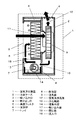
図1に本実施の形態の空気浄化装置1の内部構造の概略図を示す。
(Embodiment 1)
FIG. 1 shows a schematic diagram of the internal structure of the air purification device 1 of the present embodiment.
空気浄化装置1は、略箱形状の本体ケース2を備え、本体ケース2の筐体表面には室内
空気を吸い込む略四角形状の吸い込み口3と、本体の上面には浄化された空気を吹き出す略四角形状の吹き出し口4を設けている。
The air purification device 1 includes a
本体ケース2内部には、空気を通過させて空気中の微粒子を除去する略四角形状の集塵フィルタ5を風の流れ方向に対し垂直に配設し、これにより空気清浄を行なう。集塵フィルタ5は、本体ケース2に設けた支持枠6に密着するように固定され、吸引する空気が集塵フィルタ5の周囲の隙間から漏れないようにする。また、本体ケース2の下方には、次亜塩素酸水溶液を貯留するトレイ7を形成し、このトレイ7内に通過させた空気に次亜塩素酸を含有させる除菌部8を形成する。
Inside the
空気の送風を行なう送風部9は、集塵フィルタ5の下流側に隣接するように配設している。
The
送風部9の吐出口は、少なくとも2方向に空気を吐出することができる構造とし、送風部9の出口側に主として上側に吐出する上側吐出口10と、副として下側に吐出する下側吐出口11を形成する。
The air outlet of the
送風部9の上側吐出口10は、本体上面に設けた吹き出し口4へと連通するものである。
下側吐出口は、トレイ7および除菌部8と連通し、さらに集塵フィルタ5の上流側へと連通するものである。
The upper outlet 10 of the
The lower discharge port communicates with the
そして、本体内に吸い込み口3から吸い込んだ空気を集塵フィルタ5に通過させて、吹き出し口4から吹き出す空気清浄風路12と、本体の内部で集塵フィルタ5を通過させた空気をさらに除菌部8を通過させた集塵フィルタ5上流側へ供給する浄化風路13を形成し備えたものである。
Then, the air that has been sucked into the main body through the
浄化風路13に設けた除菌部8は、次亜塩素酸水溶液を貯留するトレイ7の中に次亜塩素酸水溶液に含浸させるように設置する。次亜塩素酸を放出するための除菌部8は、次亜塩素酸水をミスト状に噴霧、あるいはガス状に揮発させるものであり、本実施の形態においては特に揮発させることに着眼して揮発手段14とする。
The
揮発手段14は、次亜塩素酸水溶液を吸い上げ、通過する空気中に連続的に一定量の次亜塩素酸を揮発させて浄化風路13に次亜塩素酸を放出するためのものであり、表面を浄化風路13に接するように形成する。トレイ7の次亜塩素酸水溶液の濃度に応じて、揮発する次亜塩素酸の量を調整することができるようにする。さらに、トレイ7には、次亜塩素酸水を供給するための次亜塩素酸水供給手段15を設け、トレイ7に所定濃度の次亜塩素酸水溶液を一定水位に保つように供給できるようにする。さらに、トレイ7の次亜塩素酸水溶液を排水するための排水手段16をトレイ7の下方に形成する。
The volatilizing means 14 is for sucking up the hypochlorous acid aqueous solution and continuously volatilizing a constant amount of hypochlorous acid in the passing air to release the hypochlorous acid to the
トレイ7は、集塵フィルタ5の下方に配置する。つまり、除菌部8は集塵フィルタ5の下方に配置したトレイ7内に備えている。
The
さらに、集塵フィルタ5の上流側の面、すなわち吸い込み面17の直下に、トレイ7が位置するようにしている。具体的には、トレイ7の上部には除菌部8よりも下流側おいて集塵フィルタ5の吸い込み面17に隣接した開口部18を形成している。つまり、集塵フィルタ5は、平面視において、トレイ7よりも内側となるようにし、集塵フィルタ5の上流側の面である吸い込み面17は、トレイ7の内に収まるように配置している。これにより、揮発した次亜塩素酸が、近接する集塵フィルタ5の吸い込み面に直接作用しやすくなるとともに、集塵フィルタ5の表面から落下した粉塵や埃などをトレイ7の次亜塩素酸水
溶液に捕集し、次亜塩素酸の作用で強力に殺菌して再飛散を防ぐことができる。
Furthermore, the
また、除菌部8よりも上流側に下側吐出口11に連通する流入口19を形成している。流入口19は、トレイの上部に設けることができる。
Further, an
また、このようにトレイ7を本体の下方に設けることで、水がこぼれても本体内の電気系統に接触しない位置関係にすることができるため好ましい。
Further, by providing the
本体ケース2の吹き出し口4からの吹き出し風量が所定の値となるように、送風部9の風量と、空気清浄風路12、浄化風路13の風路断面積を設定し、圧力損失を調整する。
The pressure loss is adjusted by setting the air volume of the
浄化風路13の内部には、次亜塩素酸を揮発する揮発手段14を形成し、揮発手段14の表面に沿って空気を通風する。次亜塩素酸水溶液からは次亜塩素酸分子が揮発しており、次亜塩素酸水溶液の表面に空気が流れると空気中に次亜塩素酸が含まれる。そのため、本体内を循環する空気中には次亜塩素酸が含まれることになる。この次亜塩素酸を含む空気は、集塵フィルタ5の表面に一様に接触し、集塵フィルタ5は次亜塩素酸に連続的にさらされ除菌される。浄化風路13は、送風部9の下側吐出口11から集塵フィルタ5まで戻る経路である。送風部9下流側の加圧された空間と、集塵フィルタ5手前の減圧された空間とを接続しているため、集塵フィルタ5の上流に向かって通風される。
A volatilizing means 14 for volatilizing hypochlorous acid is formed inside the
トレイ7は、上面を開口した略箱形状とし、次亜塩素酸水溶液を貯水できる構造として、本体下部に配置する。トレイ7のメンテナンスをしやすくするために、例えば、本体ケース2から水平方向にスライドして着脱可能とすると好ましい。
The
送風部9は、本体ケース2の内部に設け、集塵フィルタ5の後段に連通して接続する。送風部9は、少なくともモーターとファン、ケーシング、空気を吐出する吐出口とからなる。送風部9の上側吐出口10は、空気清浄風路12に密着させて接続し、清浄化した空気は、吹き出し口4から室内へと供給される。ファンは、集塵フィルタ5の圧力損失や、空気清浄風路12と浄化風路13の圧力関係であっても必要な風量を発生させるものがよく、遠心式のシロッコ型ファンが好ましい。
The
次亜塩素酸を揮発させるための揮発手段14は、次亜塩素酸水を表面に保持して空気と接触させるものであり、平板状、波状、繊維状、格子状、メッシュ状など、表面に液体を付着させることができるものがよいが、付着水量が大きく空気と接触させやすいメッシュ状が好ましい。揮発手段14の表面から、通気抵抗を高めないように安定して揮発させるために、揮発手段14の表面を気流が沿って流れるように配置する。揮発量は、風速に依存するため、表面を気流の方向に対して平行にすることで、気流の乱れを抑え、安定して揮発できるようになる。揮発手段14は、素材を立体形状に構成すると、揮発量を増加させることができ、より好ましい。例えば、平板を複数用いた多層構造、または曲面状、円筒状、筒状、およびそれらを複数組み合わせた形状であるが、次亜塩素酸水を安定的に表面に供給させるために、円筒状であるとよい。円筒状の揮発手段14は、トレイ7に回転自在に内蔵し、動作中に回転させることで揮発手段14の表面に次亜塩素酸水を安定的に供給することができる。円筒形状の上側表面を、気流の向きに沿うように浄化風路13内に配置する。
The volatilizing means 14 for volatilizing the hypochlorous acid holds the hypochlorous acid water on the surface and makes contact with the air, and has a flat plate shape, a wavy shape, a fibrous shape, a lattice shape, a mesh shape, or the like on the surface. It is preferable that the liquid can be adhered to it, but the mesh-like shape is preferable because it has a large amount of adhered water and can be easily brought into contact with air. In order to stably volatilize the surface of the volatilization means 14 so as not to increase the ventilation resistance, the surface of the volatilization means 14 is arranged so that the airflow flows along the surface. Since the volatilization amount depends on the wind speed, by making the surface parallel to the direction of the air flow, it is possible to suppress the turbulence of the air flow and to volatilize stably. It is more preferable that the volatilization means 14 increase the amount of volatilization when the material is formed into a three-dimensional shape. For example, a multilayer structure using a plurality of flat plates, or a curved surface, a cylindrical shape, a tubular shape, and a shape combining a plurality of them, but in order to stably supply the hypochlorous acid water to the surface, Good to have. The cylindrical volatilizing means 14 is rotatably built in the
揮発手段14を構成する材料としては、次亜塩素酸水に反応性の少ない材料、即ち、次亜塩素酸水による劣化が少ない材料、例えばポリオレフィン系樹脂(ポリエチレン樹脂、ポリプロピレン樹脂等)、PET(ポリエチレン・テレフタラート樹脂)、塩化ビニル樹脂、フッ素系樹脂(PTFE、PFA、ETFE等)、セルロース系材料又はセラミック系材料等が使用され、本実施例では、ポリエステルが採用される。 As a material forming the volatilizing means 14, a material that is less reactive to hypochlorous acid water, that is, a material that is less deteriorated by hypochlorous acid water, such as a polyolefin resin (polyethylene resin, polypropylene resin, etc.), PET ( Polyethylene terephthalate resin), vinyl chloride resin, fluorine resin (PTFE, PFA, ETFE, etc.), cellulosic material or ceramic material is used, and polyester is adopted in this embodiment.
集塵フィルタ5は、不織布などの繊維でプリーツ状に構成された空気清浄フィルタであり、中性能、高性能、HEPA、ULPAなどの性能のフィルタを用いることができる。集塵フィルタ5は、しだいに目が詰まって通気抵抗が上昇してしまうため、定期的に交換できるよう着脱可能な構造とする。尚、集塵フィルタ5の素材は、樹脂やガラス繊維など次亜塩素酸に対して一定の耐久性をもつものであれば特に指定されない。また、集塵フィルタ5の表面に除菌作用や脱臭作用を亢進するような機能性材料を配合してもよく、触媒材料や、アミン類などを使用すると活性が増加するか、持続性を持つなど機能が向上するため好ましい。
The
次亜塩素酸水供給手段15は、次亜塩素酸水溶液を調製し、配管や通水路を通じて次亜塩素酸水溶液をトレイ7に供給するためのものである。次亜塩素酸水溶液は、非解離状態の次亜塩素酸分子(HOCl)を含むものであればよく、次亜塩素酸ナトリウムを希釈するか、塩化物イオンを含有する水を電気分解することで調製するが、濃度を調整しやすく、薬品の扱いがしやすい電気分解式が好ましい。電気分解式では、あらかじめ貯留した水道水に粉末状またはタブレット状の塩化ナトリウムや、濃度が既知の希塩酸溶液、またはその両方を投入して作製した塩化物イオンを含む水溶液を、チタンなどの基材上に白金やイリジウムなどを形成した不溶性電極で電気分解して生成する。水素イオン濃度は2.2から8.6の次亜塩素酸水が生成する。電極に通電すると、陽極側の電極界面で塩素が生成し、直ちに水に溶解して次亜塩素酸水を生じる。この次亜塩素酸水の生成量は、通電量に依存するため、電極に対する通電量をあらかじめ求めておき、適切なタイミングで通電して所定の濃度範囲に調節を行うことが好ましい。
The hypochlorous acid water supply means 15 is for preparing the hypochlorous acid aqueous solution and supplying the hypochlorous acid aqueous solution to the
次亜塩素酸水溶液の濃度と水素イオン濃度は、除菌に必要な次亜塩素酸を放出することができる範囲である必要があり、5mg/L以上、200mg/L以下でかつpH5.0
から8.6の範囲内であることが好ましく、より好ましくは30mg/L以上80mg/L以下でpH5から6の範囲内の微酸性の次亜塩素酸水であると殺菌効果が高い。次亜塩素酸水の濃度は、電気分解式の場合には電極への通電量で制御し、薬剤式の場合には、原液の注入量で制御できるようにしてもよい。この濃度範囲では、栄養型細菌、真菌、ウイルス、抗酸菌、細菌芽胞などを殺菌、抑制できることが知られている。
The concentration of the hypochlorous acid aqueous solution and the hydrogen ion concentration must be within a range capable of releasing hypochlorous acid necessary for disinfection, and the pH is 5.0 mg/L or more and 200 mg/L or less and pH 5.0.
To 8.6, more preferably 30 mg/L or more and 80 mg/L or less and slightly acidic hypochlorous acid water having a pH of 5 to 6 has a high bactericidal effect. The concentration of hypochlorous acid water may be controlled by the amount of electricity supplied to the electrode in the case of the electrolysis type and by the injection amount of the stock solution in the case of the chemical type. It is known that within this concentration range, vegetative bacteria, fungi, viruses, mycobacteria, bacterial spores, etc. can be sterilized and suppressed.
次亜塩素酸水から揮発する次亜塩素酸が除菌作用を得るために、ガス濃度として0.01ppm以上である必要がある。また、人体への吸引による健康影響を考慮すると、0.5ppm以下である必要がある。好ましくは、0.02ppm以上、0.1ppm以下である。この濃度範囲では、栄養型細菌、ウイルス、真菌などが殺菌、抑制できることが知られている。 In order for hypochlorous acid volatilized from hypochlorous acid water to obtain a disinfecting action, the gas concentration must be 0.01 ppm or more. In addition, considering the health effects of suction to the human body, it should be 0.5 ppm or less. It is preferably 0.02 ppm or more and 0.1 ppm or less. It is known that within this concentration range, vegetative bacteria, viruses, fungi, etc. can be sterilized and suppressed.
トレイ7に供給された次亜塩素酸水から、通風により次亜塩素酸ガスが揮発すると、次亜塩素酸水の濃度が低下し、揮発量が減少する。そのため、次亜塩素酸ガスの揮発量が所定の濃度を下回らないようにする必要がある。例えば、適宜、トレイ7の次亜塩素酸水を給水、排水するとよく、次亜塩素酸水供給手段15から新しい次亜塩素酸水溶液を供給して水質を維持する。排水は、トレイ7に配管または通水路で接続された配管を通じて、排水手段16より排水する。排水手段16は、配管などを通じて制御しやすいように、開閉自在な弁を設ける。あるいは吸引するポンプを備えてもよい。これらを用いて電気的に排水するようにすると、プログラム運転制御で自動運転させることができるため、より好ましい。尚、排水された水はタンクに貯留するか、下水管などに直接排水する。
When the hypochlorous acid gas is volatilized from the hypochlorous acid water supplied to the
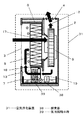
図2は、次亜塩素酸水溶液を貯留するトレイ7を含む構成を示す正面概略図である。トレイ7に次亜塩素酸水溶液を貯留するが、そこに含浸するように揮発手段14、一定水位を保つように次亜塩素酸水供給手段15を形成する。いずれもトレイ7の上方から出し入
れ可能とすると構造が単純化できて好ましい。さらに、トレイ7の下部に設けられた排水手段16は、次亜塩素酸水供給手段15と対角になるように配置することで、トレイ7内部の次亜塩素酸水溶液を効果的に排水できるようにすると好ましい。
FIG. 2 is a schematic front view showing the configuration including the
次亜塩素酸についてもう少し詳細に述べる。次亜塩素酸は、空気中に放出されると、主に気体状の次亜塩素酸ガスとなることが知られている。この次亜塩素酸ガスは、次亜塩素酸水に含まれる非解離状態の次亜塩素酸分子(HOCl)を含む気体であり、作用の本体であると考えられている。非解離状態の次亜塩素酸分子(HOCl)は、次亜塩素酸水中で水素イオン濃度に応じて濃度が変動し、解離定数(pKa)は7.5であることが知られている。この非解離状態の次亜塩素酸分子(HOCl)は、ヘンリー則に基づき一定の蒸気圧を持ち、次亜塩素酸水から揮発する性質があることが知られている。そのため、次亜塩素酸水の液面に空気を通気させると、液面と接する空気が連続的に入れ替わり、表面の次亜塩素酸分子(HOCl)の蒸気圧を下げ、連続的に次亜塩素酸分子(HOCl)を揮発させることができる。さらに、この次亜塩素酸分子(HOCl)は強い殺菌作用を持つことが知られている。そのため、次亜塩素酸水を直接作用させなくても、次亜塩素酸分子(HOCl)を含む気体を集塵フィルタ5に通すことで、集塵フィルタ5の表面に捕集された菌やウイルスなどを除菌することができる。
Hypochlorous acid will be described in more detail. It is known that hypochlorous acid becomes mainly gaseous hypochlorous acid gas when released into the air. This hypochlorous acid gas is a gas containing non-dissociated molecules of hypochlorous acid (HOCl) contained in hypochlorous acid water, and is considered to be the main body of action. It is known that the concentration of non-dissociated hypochlorous acid molecule (HOCl) varies depending on the hydrogen ion concentration in hypochlorous acid water, and the dissociation constant (pKa) is 7.5. It is known that the non-dissociated molecule of hypochlorous acid (HOCl) has a constant vapor pressure based on Henry's law and has a property of volatilizing from hypochlorous acid water. Therefore, when air is passed through the liquid surface of hypochlorous acid water, the air in contact with the liquid surface is continuously replaced, and the vapor pressure of the hypochlorous acid molecule (HOCl) on the surface is lowered, and the hypochlorous acid is continuously supplied. Acid molecules (HOCl) can be volatilized. Furthermore, this hypochlorous acid molecule (HOCl) is known to have a strong bactericidal action. Therefore, even if the hypochlorous acid water is not directly acted on, the gas containing the hypochlorous acid molecule (HOCl) is passed through the
上記構成において、空気浄化装置1は、室内から取り込んだ空気に含まれる菌やウイルスなどを集塵フィルタ5で捕集するとともに、揮発手段14から揮発する次亜塩素酸の作用によって集塵フィルタ5の表面を除菌することができる。集塵フィルタ5の表面に付着した菌やウイルスなどのバイオエアロゾルは、着脱時や、停止状態から運転すると、微粒子が最飛散し、2次汚染などの原因となりうる。本実施の形態の構成においては、次亜塩素酸ガスを集塵フィルタ5に通気することで、これらの菌やウイルスを連続的に殺菌、抑制することができる。さらに、集塵フィルタ5の下方に設けた開口部18を通り、落下した微粒子はトレイ7に捕集される。そのため、このような汚染の問題を解消することができる。
In the above-described configuration, the air purifying device 1 collects the bacteria and viruses contained in the air taken in from the room with the
空気浄化装置1の動作工程について説明を加える。はじめに、次亜塩素酸水供給手段15で、所定濃度の次亜塩素酸水溶液を生成する。次に、この次亜塩素酸水溶液をトレイ7に供給し、円筒形の揮発手段14をモーターで回転動作させて表面に次亜塩素酸水溶液を連続的に含浸して付着させる。続けて、送風部9を動作させると、吸い込み口3から吸引された汚染空気が、集塵フィルタ5に捕集される。集塵フィルタ5を通過した清浄空気は、空気清浄風路12を通って吹き出し口4から室内へ供給されるとともに、浄化風路13を通じて循環される。清浄化された空気が浄化風路13を通過する際、揮発手段14の表面に循環風が通気され、風速に応じて次亜塩素酸が揮発し、次亜塩素酸を含む空気が集塵フィルタ5の前段に合流する。その結果、次亜塩素酸は、室内空気とともに集塵フィルタ5に一様に作用し、フィルタ上に捕集された菌やウイルスに作用して連続的に除菌する。
The operation process of the air purifier 1 will be further described. First, the hypochlorous acid water supply means 15 produces a hypochlorous acid aqueous solution having a predetermined concentration. Next, this hypochlorous acid aqueous solution is supplied to the
また、本体の動作を停止したのち、集塵フィルタ5の吸い込み側表面には細菌やウイルスなどの微粒子が捕集され、堆積したままであるが、衝撃や振動、自然な剥離により落下した微粒子は下方のトレイに捕集され次亜塩素酸水溶液で除菌される。次回運転前に、排水手段16よりトレイ7外に排水とともに排出され、室内に飛散することを防ぐことができる。
Further, after stopping the operation of the main body, fine particles such as bacteria and viruses are collected and accumulated on the suction side surface of the
(実施の形態2)
図3は、空気浄化装置1において本体から空気を吹き出さずに内部除菌運転をするための別の形態を示す。吹き出し口4に開閉可能な機械式の吹き出しシャッター20を形成し、吹き出し口4を閉止する。この吹き出しシャッター20は、吹き出し口の面に対し、同形状の少なくとも1つ以上の平板で形成し、例えば片側の1辺を軸にして回転自在とし、
ステッピングモーターを軸に連結して、回転量によって開閉可能となる構造にする。
(Embodiment 2)
FIG. 3 shows another mode for performing the internal sterilization operation without blowing air from the main body in the air purification device 1. A
A stepping motor is connected to the shaft so that it can be opened and closed depending on the amount of rotation.
上記構成において、吹き出しシャッター20によって吹き出し口4を閉止し、本体内に次亜塩素酸を含む空気を浄化風路13を通じて連続的に循環させる。閉止することによって、次亜塩素酸の濃度が上昇し、集塵フィルタ5や本体内表面に作用する次亜塩素酸の量を増加させることができるため、本体内を強力に除菌することができる。
In the above configuration, the
図3(a)は通常運転時の動作状態であるが、図3(b)のように吹き出しシャッター20を閉止して送風部9を動作すると、気流は、空気清浄風路12には流れずに、全量が浄化風路13に流れることになり、次亜塩素酸を含む空気を本体内に循環させ続けることができる。次亜塩素酸は連続的に揮発し続けるため、浄化風路13内の次亜塩素酸濃度は徐々に増加する。濃度が増加すると、次亜塩素酸による除菌力が高まるため、低濃度では死滅しにくい抗酸菌や細菌芽胞などにも除菌効果を得ることができる。このような運転を、あらかじめ回路基板にプログラムしておき、定期的に自動運転させるか、本体停止前に一定時間動作するようにしておくと、確実に除菌できるため好ましい。
Although FIG. 3(a) shows an operating state during normal operation, when the blowing
(実施の形態3)
図4は、次亜塩素酸を室内に放出する空気浄化装置1の別形態である。本体ケース2の表面下方に、浄化風路13の揮発手段14の後に本体ケース2外と連通する次亜塩素酸吹き出し口21を形成する。さらに、次亜塩素酸吹き出し口21には開閉可能な機械式の次亜塩素酸吹き出しシャッター22と、集塵フィルタ5下方の開口部18に、集塵フィルタ5に戻る循環風量を調節するための開閉可能な機械式の循環風路シャッター23を形成する。次亜塩素酸吹き出しシャッター22は、略四角形状に形成された次亜塩素酸吹き出し口21と重なるように、少なくとも1つ以上の略四角形状の平板で形成し、1辺を軸にして本体ケース2に回転自在に配設する。この軸に、ステッピングモーターを接続して、モーターの回転量で開閉を制御するか、本体ケース2の外側から手動で開閉を行なうようなハンドル形状を形成してもよい。循環風路シャッター23は、同様に回転自在な平板状に形成した構造とするか、本体内の限られた空間で有効に動作できるように、開口部18に対し平行に配して、平板の対向する2辺で支持して1軸上にスライドさせて開閉できるようにしてもよい。
(Embodiment 3)
FIG. 4 shows another form of the air purifying device 1 that discharges hypochlorous acid into the room. Below the surface of the
上記構成において、次亜塩素酸は、室内に放出されると、室内の空気に含まれる菌やウイルス、あるいは室内の表面に付着している菌やウイルスに直接作用してこれらを除菌することができる。図4(a)は、次亜塩素酸吹き出し口21を開放して、次亜塩素酸を床面付近に放出しているものである。開閉式にすることによって、必要時にだけ次亜塩素酸の放出を行なうことができる。尚、開度を調整すると、室内への放出量とフィルタへの循環量を調整することができるため好ましい。また、図4(b)は次亜塩素酸吹き出しシャッター22を閉止し、循環風路シャッター23を開放して、集塵フィルタ5フィルタへの循環を行なうようにしたものである。
In the above-mentioned configuration, when hypochlorous acid is released indoors, it acts directly on the bacteria and viruses contained in the indoor air or the bacteria and viruses attached to the indoor surface to sterilize them. You can In FIG. 4A, the
尚、図3と図4の両方の構成を組み合わせたものとしてもよく、さらにこれらの動作制御を自動で実施できるようにあらかじめマイコンなどにプログラムした電気的制御を搭載しても利便性がよく好ましい。 It should be noted that the configuration of both FIG. 3 and FIG. 4 may be combined, and it is convenient and preferable to install electrical control pre-programmed in a microcomputer or the like so that these operation controls can be automatically performed. ..
以上により、室内の空気を除菌するとともに、再飛散による微生物の二次汚染を防ぐことができる空気浄化装置1を実現することができる。これにより、対象領域の人は、空気を介して人体に影響を与えうる微生物の感染を受けることを防ぐことができる。 As described above, it is possible to realize the air purifying apparatus 1 that can sterilize the indoor air and prevent secondary contamination of microorganisms due to re-scattering. As a result, the person in the target area can be prevented from being infected with microorganisms that may affect the human body through the air.
(実施の形態4)
本実施の形態では、実施の形態1の空気浄化装置1の別の形態を説明する。
(Embodiment 4)
In the present embodiment, another form of the air purification device 1 of the first embodiment will be described.
空気浄化装置1では除菌部8を備えたものを例に説明したが、本実施の形態1の空気浄化装置31では、除菌部8に替えて脱臭部38を備えたものである。なお、理解を容易にするために、実施の形態1から3と同一の構成要件については、同一の符号を付しその詳細な説明は省略する。
Although the air purifying apparatus 1 is described as an example including the
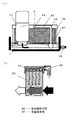
図5は、本実施の形態の空気浄化装置31の内部構造を示す概略図である。
本体ケース2の下方に、次亜塩素酸水溶液を貯留するトレイ7を形成し、このトレイ7内に通過させた空気に含まれる臭気成分を次亜塩素酸水溶液に気液接触させて脱臭する脱臭部38を形成する。
FIG. 5 is a schematic diagram showing the internal structure of the
A
実施の形態1と同様に送風部9の下側吐出口11は、トレイ7および脱臭部38と連通し、さらに集塵フィルタ5の上流側へと連通させている。本体内に、吸い込み口3から吸い込んだ空気を集塵フィルタ5に通過させて、吹き出し口4から吹き出す空気清浄風路12と、本体の内部で集塵フィルタ5を通過させた空気をさらに脱臭部38を通過させたのち、集塵フィルタ5上流側へ供給する浄化風路13を形成し備えたものである。空気の脱臭を行うためには、脱臭部38通過させる空気を確実に次亜塩素酸水溶液へ接触させるようにすることが重要である。
Similar to the first embodiment, the lower outlet 11 of the
そこで、脱臭部38には、気液接触手段39と気液接触手段39へ次亜塩素酸水を供給する水循環手段40を備えている。
Therefore, the
気液接触手段39は、トレイ7内において浄化風路13を遮るように配置した多孔質体である。
The gas-liquid contact means 39 is a porous body arranged so as to block the
図6(a)は、次亜塩素酸水溶液を貯留するトレイ7を含む構成を示す正面概略図である。図6(a)に示すように、気液接触手段39の下部はトレイ7に貯留させた次亜塩素酸水溶液に浸水させている。水循環手段40はトレイ7内の次亜塩酸水溶液をくみ上げるポンプ41と気液接触手段39の上方へ次亜塩酸水溶液を移動させる配管42と配管42の末端において気液接触手段39上方から次亜塩酸水溶液を滴下させる滴下部43を備えている。
FIG. 6A is a schematic front view showing the configuration including the
図6(b)は、図6(a)中のA断面の拡大模式図である。滴下部43を気液接触手段39の上方に離して設けて、汲み上げた次亜塩素酸水溶液が均等に流下するように適当な間隔と開口を設ける。
FIG. 6B is an enlarged schematic view of the A cross section in FIG. The
すなわち、気液接触手段39には、上方から次亜塩素酸水溶液が供給されるものである。 That is, the gas-liquid contact means 39 is supplied with the hypochlorous acid aqueous solution from above.
気液接触手段39は、空気の流れの方向に貫通した空隙44をもつ多層体を用いることで、滴下部43から供給した次亜塩素酸水溶液が空隙44の表面に沿って水膜を形成することができ、空隙44を通過する空気が次亜塩素酸水溶液に接触しやすくすることができる。
The gas-liquid contact means 39 uses a multilayer body having a void 44 penetrating in the direction of air flow, so that the hypochlorous acid aqueous solution supplied from the dropping
より具体的には、気液接触手段39は、効率的に空気が接触できるよう、浄化風路13を塞ぐように配置し、空隙44内部を気流が流れるようにする。臭い成分の次亜塩素酸水溶液に対する吸収効率は、空気が水膜と接触する時間に依存するため、気液接触手段39は、気流の方向に対して気液接触手段39を貫通する空隙44を備え、一定以上の接触長さにすることで、接触時間が長く得られ、効率的に脱臭できるようになる。気液接触手段39は、立体形状に構成すると、次亜塩素酸水溶液と空気との接触時間を増加させること
ができ、より好ましい。例えば、水を吸水する性質をもつスポンジ状の薄い平板を波板上に形成し、さらに平板と重ね合わせ空隙44を形成した多層構造、または曲面状、円筒状、筒状、およびそれらを複数組み合わせた形状であるが、表面積が大きくなり次亜塩素酸水溶液を効率的に空気と接触させるために、波板の多層構造であるとよい。
More specifically, the gas-liquid contact means 39 is arranged so as to block the
図7(a)は、波板と平板を組み合わせた多層構造からなる気液接触手段39の正面からみた構造の一例である。さらに図7(b)には拡大図を示している。 FIG. 7A shows an example of the structure of the gas-liquid contact means 39 having a multilayer structure in which a corrugated plate and a flat plate are combined, as viewed from the front. Further, an enlarged view is shown in FIG.
波板と平板とを交互に積層させると奥行方向に貫通した空隙44を形成することができる。また、スポンジ状の薄い平板を用いることで、素材の内部を矢印に沿って次亜塩素酸水溶液が均等に降下し、素材全体に効率よく次亜塩素酸水溶液を行き渡らせることができる。また、水は材料内を浸透しながら降下していくため、空隙44内および開口面45は水滴によって閉塞されず、通気抵抗が上昇することを防ぐことができる。またこのとき、波板状の多層構造は、開口面45を気流に向け、波板の表面に沿って気流が流れるように浄化風路13内に配置する。このようにして、気液接触手段39に空気の流れの方向に貫通した空隙44を形成することができる。
By alternately laminating the corrugated plates and the flat plates, the
気液接触手段39を構成する材料としては、次亜塩素酸水に反応性の少ない材料、即ち、次亜塩素酸水溶液による劣化が少ない材料、例えばポリオレフィン系樹脂(ポリエチレン樹脂、ポリプロピレン樹脂等)、PET(ポリエチレン・テレフタラート樹脂)、塩化ビニル樹脂、フッ素系樹脂(PTFE、PFA、ETFE等)、セルロース系材料又はセラミック系材料等が使用され、本実施例では、ポリエステルが採用される。
As a material forming the gas-
素材は細かい繊維状の素材を平板状に形成するか、繊維を立体状に固定させたものを薄く裁断して形成させるか、立体織物や編み物、発泡材などを用いることができる。 As the material, a fine fibrous material may be formed into a flat plate shape, a material in which fibers are fixed in a three-dimensional shape may be thinly cut, or a three-dimensional woven fabric, a knitted material, a foam material, or the like may be used.
さらに、トレイ7は、集塵フィルタ5の上流側の面、すなわち吸い込み面17の直下に、位置するようにしている。具体的には、トレイ7の上部には脱臭部38よりも下流側おいて集塵フィルタ5の吸い込み面17に隣接した開口部18を形成している。つまり、集塵フィルタ5は、平面視において、トレイ7よりも内側となるようにし、集塵フィルタ5の上流側の面である吸い込み面17は、トレイ7の内に収まるように配置している。
Further, the
トレイ7は、上面を開口した略箱形状とし、次亜塩素酸水溶液を貯水できる構造として、本体下部に配置する。トレイ7および気液接触手段39、水循環手段40のメンテナンスをしやすくするために、例えば、本体ケース2から水平方向にスライドして着脱可能とすると好ましい。
The
上記構成において、空気浄化装置1は、室内から取り込んだ空気に含まれる菌やウイルスなどを集塵フィルタ5で捕集するとともに、気液接触手段39によって空気中の臭気成分を脱臭することができるため、においをも低減して清浄度を高めた空気を供給することができる。また、脱臭部38では、空隙44に空気を流すことで副次的に次亜塩素酸水溶液から次亜塩素酸を揮発させることもできる。通過する空気に一定量の次亜塩素酸を連続的に揮発させて、下流側に次亜塩素酸を放出する。揮発する次亜塩素酸の量は、トレイ7内の次亜塩素酸水溶液の濃度に応じ調整することができる。
In the above configuration, the air purification device 1 can collect bacteria and viruses contained in the air taken in from the room with the
つまり、気液接触手段39から揮発する次亜塩素酸の作用によって集塵フィルタ5の表面を除菌することができる。
That is, the surface of the
空気浄化装置31の動作工程について説明を加える。はじめに、次亜塩素酸水供給手段15で、所定濃度の次亜塩素酸水溶液を生成する。次に、この次亜塩素酸水溶液をトレイ
7に供給し、水循環手段40のポンプ41を駆動して、気液接触手段39の上方から次亜塩素酸水溶液を連続的に供給することで、気液接触手段39の空隙44の表面に付着させることができる。
The operation process of the
続けて、送風部9を動作させると、吸い込み口3から吸引された汚染空気が、集塵フィルタ5に捕集される。集塵フィルタ5を通過した清浄空気は、空気清浄風路12を通って吹き出し口4から室内へ供給されるとともに、浄化風路13を通じて循環される。粉塵が除去された空気は、浄化風路13を通過する際に、気液接触手段39で、次亜塩素酸水溶液に接触して、含まれる臭気成分が除去される。さらに次亜塩素酸が風速に応じて揮発し、次亜塩素酸を含む空気を集塵フィルタ5の前段に合流させることができる。その結果、次亜塩素酸は、室内空気だけでなく集塵フィルタ5にも一様に作用させ、集塵フィルタ5上に捕集された菌やウイルスに連続的に作用させ除菌することができる。
Subsequently, when the
また、集塵フィルタ5は、平面視において、トレイ7よりも内側となるようにし、集塵フィルタ5の上流側の面である吸い込み面17は、トレイ7の内に収まるように配置している。これにより、揮発した次亜塩素酸が、近接する集塵フィルタ5の吸い込み面に直接作用しやすくなるとともに、集塵フィルタ5の表面から落下した粉塵や埃などをトレイ7の次亜塩素酸水溶液に捕集し、次亜塩素酸の作用で強力に殺菌して再飛散を防ぐことができる。すなわち、本体の動作を停止したのち、集塵フィルタ5の吸い込み側表面に捕集、堆積した細菌やウイルスなどの微粒子は、衝撃や振動、自然な剥離により落下し、下方のトレイに捕集され、次亜塩素酸水溶液で除菌される。
Further, the
以上のように、浄化風路13の内部に、空気中の臭気成分を脱臭するための気液接触手段39を配置し、気液接触手段39に空気を通風させると、気液接触手段39の内部に形成された水膜に臭気成分が接触して、臭気成分は吸収される。さらに、臭気成分を吸収した水が、自然流下してトレイ7に回収されることで、臭気成分の再放出を防ぐことができる。この二つの作用によって脱臭効果が発揮される。
As described above, when the gas-liquid contact means 39 for deodorizing the odor component in the air is arranged inside the
また、気液接触手段39に付着している次亜塩素酸水溶液からは次亜塩素酸分子が揮発し、集塵フィルタ5の表面に一様に接触して集塵フィルタ5を除菌することができる。
Further, hypochlorous acid molecules are volatilized from the hypochlorous acid aqueous solution adhering to the gas-liquid contact means 39 and uniformly contact the surface of the
つまり、室内の空気を除菌するとともに、再飛散による微生物の二次汚染を防ぐことができる空気浄化装置31を実現することができる。これにより、対象領域の人は、空気を介して人体に影響を与えうる微生物の感染を受けることを防ぐことができる。
That is, it is possible to realize the
家庭用や事務用、公共空間などの除菌、殺菌・消毒を行なう空気浄化装置としての活用が期待されるものである。 It is expected to be used as an air purification device for sterilizing, sterilizing and disinfecting households, offices and public spaces.
1 空気浄化装置
2 本体ケース
3 吸い込み口
4 吹き出し口
5 集塵フィルタ
6 支持枠
7 トレイ
8 除菌部
9 送風部
10 上側吐出口
11 下側吐出口
12 空気清浄風路
13 浄化風路
14 揮発手段
15 次亜塩素酸水供給手段
16 排水手段
17 吸い込み面
18 開口部
19 流入口
20 吹き出しシャッター
21 次亜塩素酸吹き出し口
22 次亜塩素酸吹き出しシャッター
23 循環風路シャッター
31 空気浄化装置
38 脱臭部
39 気液接触手段
40 水循環手段
41 ポンプ
42 配管
43 滴下部
44 空隙
45 開口面
1
Claims (4)
通過させた空気から微粒子を除去する集塵フィルタと、
通過させた空気に次亜塩素酸を含有させる除菌部と、
少なくとも2方向に吐出口を有した送風部と、
前記送風部によって、前記吸い込み口から吸い込んだ空気を前記集塵フィルタに通過させて、前記吹き出し口から吹き出す空気清浄風路と、
前記送風部によって、筐体の内部で前記集塵フィルタを通過させた空気をさらに除菌部を通過させて集塵フィルタの上流側へ供給する浄化風路とを備え、
前記送風部は、前記集塵フィルタの下流側に備え、
前記除菌部は、前記集塵フィルタの下方に配置したトレイ内に備え、
平面視において前記集塵フィルタは上流側の面が前記トレイ内に収まるように配置され、前記トレイの上部には前記除菌部よりも下流側において前記集塵フィルタの上流側の面に隣接した開口部を形成し、
前記除菌部の上流側に前記送風部の吐出口に連通する流入口を形成したことを特徴とする空気浄化装置。 In a case with a suction port and a blow port,
A dust collection filter that removes fine particles from the air that has passed through,
A sterilization unit containing hypochlorous acid in the passed air,
A blower unit having discharge ports in at least two directions,
By the air blower, the air sucked from the suction port is passed through the dust collecting filter, and an air purifying air passage blown out from the blowing port,
By the air blower, a purifying air passage that supplies the air that has passed through the dust collection filter inside the housing to the upstream side of the dust collection filter by further passing through the sterilization unit,
The blower unit is provided on the downstream side of the dust collecting filter,
The sterilization unit is provided in a tray arranged below the dust collecting filter,
In a plan view, the dust collecting filter is arranged such that an upstream surface thereof is accommodated in the tray, and an upper surface of the tray is adjacent to an upstream surface of the dust collecting filter downstream of the sterilization unit. Forming an opening,
An air purifier characterized in that an inflow port communicating with a discharge port of the blower unit is formed on the upstream side of the sterilization unit.
前記吹き出しシャッターを閉止した状態にして浄化風路内で循環を行い、本体内を次亜塩素酸により除菌することを特徴とする請求項1記載の空気浄化装置。 A blowout shutter that can be opened and closed is provided at the blowout port,
The air purification apparatus according to claim 1, wherein the blowing shutter is closed, circulation is performed in the purification air passage, and the inside of the main body is sterilized with hypochlorous acid.
前記次亜塩素酸吹き出し口を開閉する次亜塩素酸吹き出しシャッターとを設け、
開口部に開閉可能な循環風路シャッターを設け、
前記次亜塩素酸吹き出し口は、除菌部の下流であって前記開口部よりも上流の位置に備え、次亜塩素酸を室内に放出することを特徴とする請求項1乃至2に記載の空気浄化装置。 A hypochlorous acid outlet that can be opened and closed at the lower front facing the room,
Provided with a hypochlorous acid blowing shutter for opening and closing the hypochlorous acid blowing outlet,
Provided with a circulating air duct shutter that can be opened and closed at the opening,
The hypochlorous acid outlet is provided at a position downstream of the sterilization unit and upstream of the opening to discharge hypochlorous acid into the room. Air purification device.
通過させた空気から微粒子を除去する集塵フィルタと、
通過させた空気の臭気成分を次亜塩素酸水溶液に気液接触させて脱臭する脱臭部と、
少なくとも2方向に吐出口を有した送風部と、
前記送風部によって、前記吸い込み口から吸い込んだ空気を前記集塵フィルタに通過させて、前記吹き出し口から吹き出す空気清浄風路と、
前記送風部によって、筐体の内部で前記集塵フィルタを通過させた空気をさらに脱臭部を通過させて集塵フィルタの上流側へ供給する浄化風路とを備え、
前記送風部は、前記集塵フィルタの下流側に備え、
前記脱臭部は、前記集塵フィルタの下方に配置したトレイ内に備え、
平面視において前記集塵フィルタは上流側の面が前記トレイ内に収まるように配置され、前記トレイの上部には前記脱臭部よりも下流側において前記集塵フィルタの上流側の面に隣接した開口部を形成し、
前記脱臭部の上流側に前記送風部の吐出口に連通する流入口を形成したことを特徴とする空気浄化装置。 In a case with a suction port and a blow port,
A dust collection filter that removes fine particles from the air that has passed through,
A deodorizing section that deodorizes the odorous component of the passed air by contacting the hypochlorous acid aqueous solution with gas-liquid.
A blower unit having discharge ports in at least two directions,
By the air blower, the air sucked from the suction port is passed through the dust collecting filter, and an air purifying air passage blown out from the blowing port,
By the air blower, a purifying air passage that supplies the air that has passed through the dust collecting filter inside the housing to the upstream side of the dust collecting filter by further passing through the deodorizing portion,
The blower unit is provided on the downstream side of the dust collecting filter,
The deodorizing unit is provided in a tray arranged below the dust collecting filter,
In a plan view, the dust collecting filter is arranged such that an upstream surface thereof is contained in the tray, and an opening adjacent to an upstream surface of the dust collecting filter is provided at an upper portion of the tray at a downstream side of the deodorizing portion. Forming a part,
An air purifier characterized in that an inflow port communicating with a discharge port of the blower unit is formed on the upstream side of the deodorizing unit.
Priority Applications (2)
| Application Number | Priority Date | Filing Date | Title |
|---|---|---|---|
| PCT/JP2019/051002 WO2020145165A1 (en) | 2019-01-08 | 2019-12-25 | Air purification device |
| CN201980087811.0A CN113260444B (en) | 2019-01-08 | 2019-12-25 | Air purifying device |
Applications Claiming Priority (2)
| Application Number | Priority Date | Filing Date | Title |
|---|---|---|---|
| JP2019000968 | 2019-01-08 | ||
| JP2019000968 | 2019-01-08 |
Publications (2)
| Publication Number | Publication Date |
|---|---|
| JP2020110557A true JP2020110557A (en) | 2020-07-27 |
| JP2020110557A5 JP2020110557A5 (en) | 2022-03-23 |
Family
ID=71665839
Family Applications (1)
| Application Number | Title | Priority Date | Filing Date |
|---|---|---|---|
| JP2019057588A Pending JP2020110557A (en) | 2019-01-08 | 2019-03-26 | Air cleaner |
Country Status (2)
| Country | Link |
|---|---|
| JP (1) | JP2020110557A (en) |
| CN (1) | CN113260444B (en) |
Cited By (2)
| Publication number | Priority date | Publication date | Assignee | Title |
|---|---|---|---|---|
| JP6917553B1 (en) * | 2020-10-30 | 2021-08-11 | パナソニックIpマネジメント株式会社 | Space purification device and space purification system using it |
| WO2022264656A1 (en) * | 2021-06-14 | 2022-12-22 | パナソニックIpマネジメント株式会社 | Sterilization device |
Citations (5)
| Publication number | Priority date | Publication date | Assignee | Title |
|---|---|---|---|---|
| JP2005046800A (en) * | 2003-07-31 | 2005-02-24 | Tiger Vacuum Bottle Co Ltd | Air cleaner |
| JP2010284635A (en) * | 2009-05-12 | 2010-12-24 | Daikin Ind Ltd | Electrical discharge unit for liquid treatment and humidity conditioning apparatus |
| JP2012026692A (en) * | 2010-07-27 | 2012-02-09 | Panasonic Corp | Air cleaner |
| JP2016202191A (en) * | 2013-10-01 | 2016-12-08 | 株式会社シリウス | Indoor air purification method and apparatus used for the same |
| JP2017127579A (en) * | 2016-01-22 | 2017-07-27 | パナソニックIpマネジメント株式会社 | Air purification apparatus |
Family Cites Families (32)
| Publication number | Priority date | Publication date | Assignee | Title |
|---|---|---|---|---|
| DE2233215B2 (en) * | 1972-07-06 | 1981-04-30 | Drägerwerk AG, 2400 Lübeck | Filter device for removing bacteria from the ventilation air |
| US4118226A (en) * | 1977-03-22 | 1978-10-03 | Richard Lawrence Bourassa | Combination air filter and air treating device |
| EP0566051B1 (en) * | 1992-04-15 | 1996-07-24 | Schuller International, Inc. | Air filter and method for reducing the amount of microorganisms in contaminated air |
| JP2001301721A (en) * | 2000-04-18 | 2001-10-31 | Shibuya Kogyo Co Ltd | Method and apparatus for sterilizing container |
| JP2002286251A (en) * | 2001-01-11 | 2002-10-03 | Mitsubishi Heavy Ind Ltd | Air supply system, method for eliminating fungi from air, and conveyance system and method |
| US20050269254A1 (en) * | 2004-05-24 | 2005-12-08 | Roitman Lipa L | [Air and Water Purifying System And Filter Media] |
| JP2006046730A (en) * | 2004-08-02 | 2006-02-16 | Sharp Corp | Dust collecting filter and air cleaner using it |
| JP2006334212A (en) * | 2005-06-03 | 2006-12-14 | Sanyo Electric Co Ltd | Bactericidal device and air conditioner |
| KR100601363B1 (en) * | 2005-06-21 | 2006-07-13 | 박영순 | Indoor floating dust collecting machine that use convective flow |
| JP4878826B2 (en) * | 2005-12-02 | 2012-02-15 | 三洋電機株式会社 | Air sanitizer |
| JP4878836B2 (en) * | 2005-12-28 | 2012-02-15 | 三洋電機株式会社 | Floor-standing air sanitizer |
| JP4749248B2 (en) * | 2006-06-30 | 2011-08-17 | 三洋電機株式会社 | Blower built-in equipment and sterilization unit |
| JP2008035926A (en) * | 2006-08-02 | 2008-02-21 | Sharp Corp | Air purifying device and air conditioning device |
| JP4928869B2 (en) * | 2006-08-21 | 2012-05-09 | 三洋電機株式会社 | Air sanitizer |
| JP4198169B2 (en) * | 2006-10-20 | 2008-12-17 | 三洋電機株式会社 | Descaling system |
| JP4966708B2 (en) * | 2007-03-28 | 2012-07-04 | 三洋電機株式会社 | Air purification device |
| JP2009142356A (en) * | 2007-12-12 | 2009-07-02 | Panasonic Corp | Air purifier |
| WO2012035757A1 (en) * | 2010-09-14 | 2012-03-22 | パナソニック株式会社 | Ozone/ion generating device for generating ozone and ionic wind, and air conditioner provided therewith |
| JP5800911B2 (en) * | 2011-10-25 | 2015-10-28 | パナセア ディシンフェクタント カンパニー リミテッド | Functional air conditioning apparatus and functional air conditioning method |
| WO2013077303A1 (en) * | 2011-11-21 | 2013-05-30 | 株式会社クボタ | Air purifying device |
| JP2013148327A (en) * | 2011-12-20 | 2013-08-01 | Life Network Co Ltd | Air cleaning device using mist |
| JP6286664B2 (en) * | 2014-01-28 | 2018-03-07 | パナソニックIpマネジメント株式会社 | Humidifier |
| JP6439908B2 (en) * | 2014-02-07 | 2018-12-19 | パナソニックIpマネジメント株式会社 | Microbial killing device in ballast water |
| CN105276696A (en) * | 2014-06-06 | 2016-01-27 | 富士通将军股份有限公司 | Air cleaner |
| JP6331034B2 (en) * | 2015-06-09 | 2018-05-30 | パナソニックIpマネジメント株式会社 | Sanitization mist shower device |
| JP6681540B2 (en) * | 2016-03-18 | 2020-04-15 | パナソニックIpマネジメント株式会社 | Air purifier |
| CN206131278U (en) * | 2016-08-25 | 2017-04-26 | 深圳沃海森科技有限公司 | Utilize humidification air purifier that hypochlorous acid disinfected |
| CN205991564U (en) * | 2016-08-25 | 2017-03-01 | 深圳沃海森科技有限公司 | Wind pipe type indoor set using hypochlorous acid sterilization |
| JP2018050483A (en) * | 2016-09-26 | 2018-04-05 | 株式会社東芝 | Processing method for dry process |
| CN206683060U (en) * | 2017-02-27 | 2017-11-28 | 计冬奎 | A kind of air purifier |
| CN109028287A (en) * | 2017-06-12 | 2018-12-18 | 东莞市隆维智能科技有限公司 | Health salt clarifier |
| CN109107381A (en) * | 2018-08-21 | 2019-01-01 | 四川健尔莱医疗器械科技有限公司 | Photocatalysis air purifying device with self-purification capacity |
-
2019
- 2019-03-26 JP JP2019057588A patent/JP2020110557A/en active Pending
- 2019-12-25 CN CN201980087811.0A patent/CN113260444B/en active Active
Patent Citations (5)
| Publication number | Priority date | Publication date | Assignee | Title |
|---|---|---|---|---|
| JP2005046800A (en) * | 2003-07-31 | 2005-02-24 | Tiger Vacuum Bottle Co Ltd | Air cleaner |
| JP2010284635A (en) * | 2009-05-12 | 2010-12-24 | Daikin Ind Ltd | Electrical discharge unit for liquid treatment and humidity conditioning apparatus |
| JP2012026692A (en) * | 2010-07-27 | 2012-02-09 | Panasonic Corp | Air cleaner |
| JP2016202191A (en) * | 2013-10-01 | 2016-12-08 | 株式会社シリウス | Indoor air purification method and apparatus used for the same |
| JP2017127579A (en) * | 2016-01-22 | 2017-07-27 | パナソニックIpマネジメント株式会社 | Air purification apparatus |
Cited By (4)
| Publication number | Priority date | Publication date | Assignee | Title |
|---|---|---|---|---|
| JP6917553B1 (en) * | 2020-10-30 | 2021-08-11 | パナソニックIpマネジメント株式会社 | Space purification device and space purification system using it |
| WO2022091687A1 (en) * | 2020-10-30 | 2022-05-05 | パナソニックIpマネジメント株式会社 | Space cleaning device and space cleaning system using same |
| JP2022072529A (en) * | 2020-10-30 | 2022-05-17 | パナソニックIpマネジメント株式会社 | Space cleaning device and space cleaning system using the same |
| WO2022264656A1 (en) * | 2021-06-14 | 2022-12-22 | パナソニックIpマネジメント株式会社 | Sterilization device |
Also Published As
| Publication number | Publication date |
|---|---|
| CN113260444B (en) | 2023-06-06 |
| CN113260444A (en) | 2021-08-13 |
Similar Documents
| Publication | Publication Date | Title |
|---|---|---|
| KR101791677B1 (en) | Wet air cleaner | |
| JP5614559B2 (en) | Methods and devices for disinfecting and deodorizing toilets | |
| KR100883011B1 (en) | Sterilization device having a mechanism for removing a foreign matter | |
| JP4928869B2 (en) | Air sanitizer | |
| US7896947B2 (en) | Air filtering apparatus | |
| JP2008048759A (en) | Air sterilizing device and air cleaning device | |
| JP5261062B2 (en) | Air sanitizer | |
| KR20100091734A (en) | Air cleaner | |
| KR20150015880A (en) | The bad smell removing method of an air cleaner and thereof device | |
| KR101095410B1 (en) | Air sterilizing device | |
| KR20180019324A (en) | Air cleaner humidifier and air cleaner humidification method by centrifugal force | |
| JP2008079724A (en) | Air disinfecting apparatus | |
| KR20180029939A (en) | Wet air cleaner | |
| JP2008183182A (en) | Air filtering apparatus | |
| CN113260444B (en) | Air purifying device | |
| CN114046588B (en) | Air purifier with virus sterilization function | |
| KR20160126375A (en) | air cleaner | |
| KR101565094B1 (en) | Air Purifier | |
| JP2004347165A (en) | Air cleaner | |
| KR101034868B1 (en) | Intelligent indoor air handling equipment | |
| WO2020145165A1 (en) | Air purification device | |
| KR20180132290A (en) | Air sterilizer | |
| JP2019045029A (en) | Air cleaner | |
| KR20100003662A (en) | Wet type air cleaner | |
| EP1891982A2 (en) | Air filtering apparatus having foreign material removing mechanism |
Legal Events
| Date | Code | Title | Description |
|---|---|---|---|
| A521 | Request for written amendment filed |
Free format text: JAPANESE INTERMEDIATE CODE: A523 Effective date: 20220314 |
|
| A621 | Written request for application examination |
Free format text: JAPANESE INTERMEDIATE CODE: A621 Effective date: 20220314 |
|
| RD01 | Notification of change of attorney |
Free format text: JAPANESE INTERMEDIATE CODE: A7421 Effective date: 20221020 |
|
| A131 | Notification of reasons for refusal |
Free format text: JAPANESE INTERMEDIATE CODE: A131 Effective date: 20230307 |
|
| A521 | Request for written amendment filed |
Free format text: JAPANESE INTERMEDIATE CODE: A523 Effective date: 20230424 |
|
| A131 | Notification of reasons for refusal |
Free format text: JAPANESE INTERMEDIATE CODE: A131 Effective date: 20230606 |
|
| A02 | Decision of refusal |
Free format text: JAPANESE INTERMEDIATE CODE: A02 Effective date: 20231128 |