JP2020108464A - Game machine - Google Patents

Game machine Download PDF

Info

Publication number
JP2020108464A
JP2020108464A JP2018248792A JP2018248792A JP2020108464A JP 2020108464 A JP2020108464 A JP 2020108464A JP 2018248792 A JP2018248792 A JP 2018248792A JP 2018248792 A JP2018248792 A JP 2018248792A JP 2020108464 A JP2020108464 A JP 2020108464A
Authority
JP
Japan
Prior art keywords
ball
winning opening
game
passage
state
Prior art date
Legal status (The legal status is an assumption and is not a legal conclusion. Google has not performed a legal analysis and makes no representation as to the accuracy of the status listed.)
Pending
Application number
JP2018248792A
Other languages
Japanese (ja)
Inventor
義宏 胡本
Yoshihiro Ebimoto
義宏 胡本
睦 石田
Mutsu Ishida
睦 石田
勝博 牟田
Katsuhiro Muta
勝博 牟田
佐藤 真也
Shinya Sato
真也 佐藤
直人 益子
Naoto Masuko
直人 益子
Current Assignee (The listed assignees may be inaccurate. Google has not performed a legal analysis and makes no representation or warranty as to the accuracy of the list.)
Sanyo Bussan Co Ltd
Original Assignee
Sanyo Bussan Co Ltd
Priority date (The priority date is an assumption and is not a legal conclusion. Google has not performed a legal analysis and makes no representation as to the accuracy of the date listed.)
Filing date
Publication date
Application filed by Sanyo Bussan Co Ltd filed Critical Sanyo Bussan Co Ltd
Priority to JP2018248792A priority Critical patent/JP2020108464A/en
Publication of JP2020108464A publication Critical patent/JP2020108464A/en
Priority to JP2023129668A priority patent/JP2023138700A/en
Pending legal-status Critical Current

Links

Images

Classifications

    • YGENERAL TAGGING OF NEW TECHNOLOGICAL DEVELOPMENTS; GENERAL TAGGING OF CROSS-SECTIONAL TECHNOLOGIES SPANNING OVER SEVERAL SECTIONS OF THE IPC; TECHNICAL SUBJECTS COVERED BY FORMER USPC CROSS-REFERENCE ART COLLECTIONS [XRACs] AND DIGESTS
    • Y02TECHNOLOGIES OR APPLICATIONS FOR MITIGATION OR ADAPTATION AGAINST CLIMATE CHANGE
    • Y02EREDUCTION OF GREENHOUSE GAS [GHG] EMISSIONS, RELATED TO ENERGY GENERATION, TRANSMISSION OR DISTRIBUTION
    • Y02E60/00Enabling technologies; Technologies with a potential or indirect contribution to GHG emissions mitigation
    • Y02E60/10Energy storage using batteries

Abstract

To provide a game machine capable of improving a guide mode of game balls by operation means.SOLUTION: A guide mode of game balls by a moving plate member 4641 can be improved due to the fact that game balls can be guided to a collection hole 752 or guided to a second winning hole 640 via a second ball sending part 736 by forming as downstream flow-down passages from the moving plate member 4641, a first passage flowing right below a first ball sending passage KR1, and a second passage flowing at the right side of the first ball sending passage KR1. Furthermore, a situation where game balls enter into the second winning hole 640 can be easily generated due to the fact that game balls can enter into the second winning hole 640 by completely flowing down to the end side of the moving plate member 4641, compared to a situation where game balls enter into the collection hole 752 by dropping in the middle position (operation of the moving plate member 4641 at a good timing).SELECTED DRAWING: Figure 26

Description

本発明は、パチンコ機などの遊技機に関するものである。 The present invention relates to a gaming machine such as a pachinko machine.

第1始動口および第2始動口を備える遊技機がある(特許文献1)。 There is a game machine having a first starting port and a second starting port (Patent Document 1).

特開2015−144741号公報JP, 2005-144741, A

しかしながら、上述した従来の遊技機では、可動片による遊技球の案内態様に改良の余地があるという問題点があった。本発明は、上記例示した問題点を解決するためになされたものであり、動作手段による遊技球の案内態様を改良することができる遊技機を提供することを目的とする。 However, the above-mentioned conventional gaming machine has a problem that there is room for improvement in the manner of guiding the game ball by the movable piece. The present invention has been made to solve the above-mentioned problems, and an object of the present invention is to provide a gaming machine capable of improving a guidance mode of a game ball by an operating means.

この目的を達成するために請求項1記載の遊技機は、遊技球を発射する遊技球発射装置と、その遊技球発射装置により発射される遊技球が流下する遊技領域を形成する遊技領域構成手段と、前記遊技領域を流下した遊技球が入球可能に構成される第1入球口および第2入球口と、前記遊技領域に配設され遊技球の通過を検出する検出手段と、その検出手段で遊技球の通過が検出されたことに基づいて動作制御される動作手段と、を備える遊技機であって、前記動作手段は、前記動作手段が配置される位置まで流下した遊技球の流下経路を、前記第1入球口側へ向かう第1経路と、前記第2入球口側へ向かう第2経路と、その他の経路と、に分岐可能に構成される。 In order to achieve this object, the gaming machine according to claim 1, a game ball launching device for launching a game ball, and a game region configuring means for forming a game region in which a game ball launched by the game ball launching device flows down. And a first ball entrance and a second ball entrance configured so that a game ball flowing down through the game area can enter, and a detection unit arranged in the game area for detecting passage of the game ball, A gaming machine comprising: an operating means that is operationally controlled based on detection of passage of a game ball by the detecting means, wherein the operating means is a gaming ball that has flowed down to a position where the operating means is arranged. The downflow route is configured to be capable of branching into a first route toward the first entrance side, a second route toward the second entrance side, and other routes.

請求項2記載の遊技機は、請求項1記載の遊技機において、前記第1入球口に遊技球が入球した場合に遊技者に付与可能な利益よりも、前記第2入球口に遊技球が入球した場合に遊技者に付与可能な利益が大きく設定され、前記第1入球口は前記動作手段の中央側の下方に配置され、前記第2入球口は前記動作手段の端側の下方に配置される。 The gaming machine according to claim 2 is, in the gaming machine according to claim 1, characterized in that the profit can be given to the player when the game ball enters the first entrance, rather than the profit that can be given to the player. The profit that can be given to the player when a game ball enters is set to be large, the first entrance is arranged below the center of the operating means, and the second entrance is of the operating means. It is arranged below the end side.

請求項3記載の遊技機は、請求項1又は2に記載の遊技機において、動作手段の端部からの遊技球の零れを防止するための零れ防止手段を備える。 According to a third aspect of the present invention, in the gaming machine according to the first or second aspect, the gaming machine is provided with a spill prevention means for preventing the game ball from spilling from the end of the operating means.

請求項1記載の遊技機によれば、動作手段による遊技球の案内態様を改良することができる。 According to the gaming machine described in claim 1, it is possible to improve the guide mode of the game ball by the operating means.

請求項2記載の遊技機によれば、請求項1記載の遊技機の奏する効果に加え、第2入球口に遊技球が入球する事態を発生し易くすることができる。 According to the gaming machine described in claim 2, in addition to the effect of the gaming machine described in claim 1, it is possible to easily cause a situation in which the gaming ball enters the second ball entrance.

請求項3記載の遊技機によれば、請求項1又は2に記載の遊技機の奏する効果に加え、動作手段に遊技球が到達した場合の遊技者の安心感を高めることができる。 According to the gaming machine described in claim 3, in addition to the effect of the gaming machine described in claim 1 or 2, it is possible to enhance the player's sense of security when the game ball reaches the operation means.

第1実施形態におけるパチンコ機の正面図である。It is a front view of the pachinko machine in the first embodiment. パチンコ機の遊技盤の正面図である。It is a front view of the game board of the pachinko machine. パチンコ機の背面図である。It is a rear view of a pachinko machine. パチンコ機の電気的構成を示すブロック図である。It is a block diagram which shows the electric constitution of a pachinko machine. 経路構成装置の分解正面斜視図である。It is an exploded front perspective view of a route composition device. 経路構成装置の部分拡大正面図である。It is a partially expanded front view of a path|route structure apparatus. (a)及び(b)は、図6のVIIa−VIIa線における経路構成装置の部分断面図である。(A) And (b) is a fragmentary sectional view of the path|route formation apparatus in the VIIa-VIIa line of FIG. (a)及び(b)は、図6の範囲VIIIaにおける経路構成装置の部分正面図である。(A) And (b) is a partial front view of the path|route formation apparatus in the range VIIIa of FIG. (a)及び(b)は、図6の範囲VIIIaにおける経路構成装置の部分正面図である。(A) And (b) is a partial front view of the path|route formation apparatus in the range VIIIa of FIG. (a)及び(b)は、図6の範囲VIIIaにおける経路構成装置の部分正面図である。(A) And (b) is a partial front view of the path|route formation apparatus in the range VIIIa of FIG. (a)及び(b)は、図6の範囲VIIIaにおける経路構成装置の部分正面図である。(A) And (b) is a partial front view of the path|route formation apparatus in the range VIIIa of FIG. 図2の範囲XIIにおける遊技盤の部分正面図である。It is a partial front view of the game board in the range XII of FIG. (a)は、主制御装置内のROMの電気的構成を示すブロック図であり、(b)は、第1当たり種別カウンタと特別図柄における大当たり種別との対応関係を模式的に示した模式図であり、(c)は、第2当たり乱数カウンタと普通図柄における当たりとの対応関係を模式的に示した模式図である。(A) is a block diagram showing an electrical configuration of a ROM in the main control device, (b) is a schematic diagram schematically showing the correspondence relationship between the first hit type counter and the special jackpot type And, (c) is a schematic diagram schematically showing the correspondence relationship between the second random number counter and the hit in the normal symbol. (a)から(d)は、普通入賞口(スルーゲート)における球の通過の検出と、電動役物の状態の計時変化の一例を示した図である。(A)-(d) is the figure which showed the detection of the passage of the ball in a normal winning opening (through gate), and an example of the timekeeping change of the state of an electric accessory. 第2実施形態における遊技盤の分解正面斜視図である。It is an exploded front perspective view of the game board in the second embodiment. (a)は、正面ユニットの正面図であり、(b)は、正面ユニットの背面図である。(A) is a front view of a front unit, (b) is a rear view of a front unit. 正面ユニットの分解正面斜視図である。It is a disassembled front perspective view of a front unit. 正面ユニットの分解背面斜視図である。It is a disassembled rear perspective view of a front unit. (a)は、振分けユニットの正面図であり、(b)は、振分けユニットの背面図である。(A) is a front view of a distribution unit, (b) is a rear view of the distribution unit. (a)は、図19(a)のXXa−XXa線における振分けユニットの断面図であり、(b)は、図20(a)のXXb−XXb線における振分けユニットの断面図である。19A is a cross-sectional view of the distribution unit taken along line XXa-XXa of FIG. 19A, and FIG. 20B is a cross-sectional view of the distribution unit taken along line XXb-XXb of FIG. (a)及び(b)は、図20(a)のXXb−XXb線における振分けユニットの断面図である。20A and 20B are cross-sectional views of the distribution unit taken along line XXb-XXb in FIG. (a)から(d)は、検出装置における球の通過の検出と、羽部材の状態の計時変化の一例を示した図である。(A)-(d) is a figure showing an example of detection of passage of a ball in a detecting device, and time change of a state of a wing member. 図16(a)のXXIII−XXIII線における遊技盤の断面図である。It is sectional drawing of the game board in the XXIII-XXIII line of FIG. 16 (a). (a)及び(b)は、図23のXXIVa−XXIVa線における入賞口ユニット及び送球ユニットの部分断面図である。23A and 23B are partial cross-sectional views of the winning opening unit and the ball sending unit taken along the line XXIVa-XXIVa in FIG. 23. 第3実施形態における遊技盤の部分正面図である。It is a partial front view of the game board in the third embodiment. 第4実施形態における遊技盤の部分正面図である。It is a partial front view of the game board in the fourth embodiment.

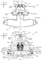
以下、本発明の実施形態について、添付図面を参照して説明する。まず、図1から図14を参照し、第1実施形態として、本発明をパチンコ遊技機(以下、単に「パチンコ機」という)10に適用した場合の一実施形態について説明する。図1は、第1実施形態におけるパチンコ機10の正面図であり、図2はパチンコ機10の遊技盤13の正面図であり、図3はパチンコ機10の背面図である。 Hereinafter, embodiments of the present invention will be described with reference to the accompanying drawings. First, with reference to FIG. 1 to FIG. 14, one embodiment in which the present invention is applied to a pachinko gaming machine (hereinafter, simply referred to as “pachinko machine”) 10 will be described as a first embodiment. FIG. 1 is a front view of a pachinko machine 10 according to the first embodiment, FIG. 2 is a front view of a game board 13 of the pachinko machine 10, and FIG. 3 is a rear view of the pachinko machine 10.

なお、以下の説明では、図1に示す状態のパチンコ機10に対して、紙面手前側を前方(正面)側として、紙面奥側を後方(背面)側として説明する。また、図1に示す状態のパチンコ機10に対して、上側を上方(上)側として、下側を下方(下)側として、右側を右方(右)側として、左側を左方(左)側としてそれぞれ説明する。さらに、図中(例えば、図2参照)の矢印U−D,L−R,F−Bは、パチンコ機10の上下方向,左右方向,前後方向をそれぞれ示している。 In the following description, with respect to the pachinko machine 10 in the state shown in FIG. 1, the front side of the paper is the front (front) side and the back side of the paper is the rear (back) side. Further, with respect to the pachinko machine 10 in the state shown in FIG. 1, the upper side is the upper (upper) side, the lower side is the lower (lower) side, the right side is the right (right) side, and the left side is the left side (left). ) Side, respectively. Further, arrows UD, LR, and FB in the drawing (see, for example, FIG. 2) indicate the up-down direction, the left-right direction, and the front-back direction of the pachinko machine 10, respectively.

図1に示すように、パチンコ機10は、略矩形状に組み合わせた木枠により外殻が形成される外枠2と、その外枠2と略同一の外形形状に形成され外枠2に対して開閉可能に支持された内枠4とを備えている。外枠2には、内枠4を支持するために正面視(図1参照)左側の上下2カ所に金属製のヒンジ18が取り付けられ、そのヒンジ18が設けられた側を開閉の軸として内枠4が正面手前側へ開閉可能に支持されている。 As shown in FIG. 1, the pachinko machine 10 includes an outer frame 2 in which an outer shell is formed by a wooden frame combined in a substantially rectangular shape, and an outer frame 2 having substantially the same outer shape as that of the outer frame 2. And an inner frame 4 that is openably and closably supported. To support the inner frame 4, metal hinges 18 are attached to the outer frame 2 at two upper and lower positions on the left side in a front view (see FIG. 1), and the side on which the hinge 18 is provided serves as an opening/closing shaft. The frame 4 is supported to be openable and closable on the front side.

内枠4には、多数の釘や入賞口63,64等を有する遊技盤13(図2参照)が裏面側から着脱可能に装着される。この遊技盤13の前面を球(遊技球)が流下することにより弾球遊技が行われる。なお、内枠4には、球を遊技盤13の前面領域に発射する球発射ユニット112a(図4参照)やその球発射ユニット112aから発射された球を遊技盤13の前面領域まで誘導する発射レール(図示せず)等が取り付けられている。 A game board 13 (see FIG. 2) having a large number of nails, winning holes 63, 64, etc. is detachably attached to the inner frame 4 from the back side. A ball game is performed by flowing a ball (game ball) on the front surface of the game board 13. In addition, in the inner frame 4, a ball launch unit 112a (see FIG. 4) that launches a ball to the front area of the game board 13 and a launch that guides the ball launched from the ball launch unit 112a to the front area of the game board 13. Rails (not shown) and the like are attached.

内枠4の前面側には、その前面上側を覆う前扉5と、その下側を覆う下皿ユニット15とが設けられている。前扉5および下皿ユニット15を支持するために正面視(図1参照)左側の上下2カ所に金属製のヒンジ19が取り付けられ、そのヒンジ19が設けられた側を開閉の軸として前扉5および下皿ユニット15が正面手前側へ開閉可能に支持されている。なお、内枠4の施錠と前扉5の施錠とは、シリンダ錠20の鍵穴21に専用の鍵を差し込んで所定の操作を行うことでそれぞれ解除される。 On the front side of the inner frame 4, a front door 5 that covers the upper side of the front surface and a lower plate unit 15 that covers the lower side thereof are provided. In order to support the front door 5 and the lower plate unit 15, metal hinges 19 are attached to two upper and lower parts on the left side in a front view (see FIG. 1), and the side where the hinges 19 are provided serves as an opening/closing shaft. 5 and the lower plate unit 15 are supported to be openable and closable toward the front side. The locking of the inner frame 4 and the locking of the front door 5 are released by inserting a dedicated key into the keyhole 21 of the cylinder lock 20 and performing a predetermined operation.

前扉5は、装飾用の樹脂部品や電気部品等を組み付けたものであり、その略中央部には略楕円形状に開口形成された窓部5cが設けられている。前扉5の裏面側には2枚の板ガラス8を有するガラスユニット16が配設され、そのガラスユニット16を介して遊技盤13の前面がパチンコ機10の正面側に視認可能となっている。 The front door 5 is assembled with a decorative resin component, an electrical component, or the like, and a window portion 5c having a substantially elliptical opening is provided at a substantially central portion thereof. A glass unit 16 having two plate glasses 8 is arranged on the back surface side of the front door 5, and the front surface of the game board 13 is visible through the glass unit 16 to the front surface side of the pachinko machine 10.

前扉5には、球を貯留する上皿17が前方へ張り出して上面を開放した略箱状に形成されており、この上皿17に賞球や貸出球などが排出される。上皿17の底面は正面視(図1参照)右側に下降傾斜して形成され、その傾斜により上皿17に投入された球が球発射ユニット112a(図4参照)へと案内される。また、上皿17の上面には、枠ボタン22が設けられている。この枠ボタン22は、例えば、第3図柄表示装置81(図2参照)で表示される演出のステージを変更したり、スーパーリーチの演出内容を変更したりする場合などに、遊技者により操作される。 On the front door 5, an upper plate 17 for storing balls is formed in a substantially box shape with its front surface protruding and its upper surface opened, and prize balls, rental balls, etc. are discharged to the upper plate 17. The bottom surface of the upper plate 17 is formed to be inclined downward to the right in a front view (see FIG. 1), and the ball introduced into the upper plate 17 is guided to the ball firing unit 112a (see FIG. 4) by the inclination. A frame button 22 is provided on the upper surface of the upper plate 17. The frame button 22 is operated by the player, for example, when changing the stage of the effect displayed on the third symbol display device 81 (see FIG. 2) or when changing the effect contents of the super reach. It

前扉5には、その周囲(例えばコーナー部分)に各種ランプ等の発光手段が設けられている。これら発光手段は、大当たり時や所定のリーチ時等における遊技状態の変化に応じて、点灯又は点滅することにより発光態様が変更制御され、遊技中の演出効果を高める役割を果たす。窓部5cの周縁には、LED等の発光手段を内蔵した電飾部29〜33が設けられている。パチンコ機10においては、これら電飾部29〜33が大当たりランプ等の演出ランプとして機能し、大当たり時やリーチ演出時等には内蔵するLEDの点灯や点滅によって各電飾部29〜33が点灯または点滅して、大当たり中である旨、或いは大当たり一歩手前のリーチ中である旨が報知される。また、前扉5の正面視(図1参照)左上部には、LED等の発光手段が内蔵され賞球の払い出し中とエラー発生時とを表示可能な表示ランプ34が設けられている。 The front door 5 is provided with light emitting means such as various lamps around the front door 5 (for example, a corner portion). These light emitting means change the light emitting mode by lighting or blinking according to the change of the game state at the time of a big hit or a predetermined reach, and play a role of enhancing the effect effect during the game. On the periphery of the window portion 5c, there are provided electric decoration portions 29 to 33 which incorporate a light emitting means such as an LED. In the pachinko machine 10, these illumination parts 29 to 33 function as a production lamp such as a jackpot lamp, and when a jackpot or a reach production is performed, each illumination portion 29 to 33 is turned on by turning on or blinking the built-in LED. Alternatively, it blinks to notify that the jackpot is in the midst of hitting, or that the reach is one step ahead of the jackpot. Further, in the upper left portion of the front door 5 as viewed from the front (see FIG. 1), a light-emitting means such as an LED is built-in and a display lamp 34 capable of displaying during payout of a prize ball and when an error occurs is provided.

また、右側の電飾部32下側には、前扉5の裏面側を視認できるように裏面側より透明樹脂を取り付けて小窓35が形成され、遊技盤13前面の貼着スペースK1(図2参照)に貼付される証紙等がパチンコ機10の前面から視認可能とされている。また、パチンコ機10においては、より煌びやかさを醸し出すために、電飾部29〜33の周りの領域にクロムメッキを施したABS樹脂製のメッキ部材36が取り付けられている。 In addition, a small window 35 is formed on the lower side of the right illumination portion 32 by attaching a transparent resin from the back side so that the back side of the front door 5 can be visually recognized, and a pasting space K1 on the front side of the game board 13 (Fig. The certificate or the like attached to (see 2) is visible from the front of the pachinko machine 10. Further, in the pachinko machine 10, a plating member 36 made of ABS resin, which is plated with chrome, is attached to a region around the electric decorations 29 to 33 in order to bring out more brilliance.

窓部5cの下方には、貸球操作部40が配設されている。貸球操作部40には、度数表示部41と、球貸しボタン42と、返却ボタン43とが設けられている。パチンコ機10の側方に配置されるカードユニット(球貸しユニット)(図示せず)に紙幣やカード等を投入した状態で貸球操作部40が操作されると、その操作に応じて球の貸出が行われる。具体的には、度数表示部41はカード等の残額情報が表示される領域であり、内蔵されたLEDが点灯して残額情報として残額が数字で表示される。球貸しボタン42は、カード等(記録媒体)に記録された情報に基づいて貸出球を得るために操作されるものであり、カード等に残額が存在する限りにおいて貸出球が上皿17に供給される。返却ボタン43は、カードユニットに挿入されたカード等の返却を求める際に操作される。なお、カードユニットを介さずに球貸し装置等から上皿17に球が直接貸し出されるパチンコ機、いわゆる現金機では貸球操作部40が不要となるが、この場合には、貸球操作部40の設置部分に飾りシール等を付加して部品構成は共通のものとしても良い。カードユニットを用いたパチンコ機と現金機との共通化を図ることができる。 A ball rental operation unit 40 is arranged below the window 5c. The ball lending operation unit 40 is provided with a frequency display unit 41, a ball lending button 42, and a return button 43. When the ball rental operation unit 40 is operated in a state where banknotes, cards, etc. are inserted into a card unit (ball lending unit) (not shown) arranged on the side of the pachinko machine 10, the ball is operated according to the operation. Lending is done. Specifically, the frequency display unit 41 is an area in which the balance information of a card or the like is displayed, and the built-in LED lights up to display the balance as a number as the balance information. The ball lending button 42 is operated to obtain a loan ball based on information recorded on a card or the like (recording medium), and the loan ball is supplied to the upper plate 17 as long as there is a balance on the card or the like. To be done. The return button 43 is operated when requesting return of a card or the like inserted in the card unit. It should be noted that the ball rental operation unit 40 is not necessary in a pachinko machine, which is a cash machine in which balls are lent directly to the upper plate 17 from a ball lending device or the like without using a card unit, but in this case, the ball rental operation unit 40 is used. It is also possible to add a decorative seal or the like to the installation portion of to make the parts configuration common. A pachinko machine using a card unit and a cash machine can be shared.

上皿17の下側に位置する下皿ユニット15には、その中央部に上皿17に貯留しきれなかった球を貯留するための下皿50が上面を開放した略箱状に形成されている。下皿50の右側には、球を遊技盤13の前面へ打ち込むために遊技者によって操作される操作ハンドル51が配設される。 In the lower plate unit 15 located below the upper plate 17, a lower plate 50 for storing balls that cannot be stored in the upper plate 17 is formed in a central portion of the lower plate unit 15 in a substantially box shape with an open upper surface. There is. On the right side of the lower plate 50, an operation handle 51 operated by the player to drive the ball into the front surface of the game board 13 is provided.

操作ハンドル51の内部には、球発射ユニット112aの駆動を許可するためのタッチセンサ51aと、押下操作している期間中には球の発射を停止する発射停止スイッチ51bと、操作ハンドル51の回動操作量(回動位置)を電気抵抗の変化により検出する可変抵抗器(図示せず)などが内蔵されている。操作ハンドル51が遊技者によって右回りに回動操作されると、タッチセンサ51aがオンされると共に可変抵抗器の抵抗値が回動操作量に対応して変化し、その可変抵抗器の抵抗値に対応した強さ(発射強度)で球が発射され、これにより遊技者の操作に対応した飛び量で遊技盤13の前面へ球が打ち込まれる。また、操作ハンドル51が遊技者により操作されていない状態においては、タッチセンサ51aおよび発射停止スイッチ51bがオフとなっている。 Inside the operation handle 51, a touch sensor 51a for permitting the driving of the ball firing unit 112a, a firing stop switch 51b for stopping the firing of the ball during the pressing operation, and a rotation of the operation handle 51. A variable resistor (not shown) that detects a dynamic operation amount (rotational position) by a change in electric resistance is built in. When the operation handle 51 is rotated clockwise by the player, the touch sensor 51a is turned on and the resistance value of the variable resistor changes in accordance with the rotation operation amount, and the resistance value of the variable resistor is changed. The ball is fired with a strength (firing strength) corresponding to, and thereby the ball is driven into the front surface of the game board 13 with a jump amount corresponding to the operation of the player. Further, when the operation handle 51 is not operated by the player, the touch sensor 51a and the firing stop switch 51b are off.

下皿50の正面下方部には、下皿50に貯留された球を下方へ排出する際に操作するための球抜きレバー52が設けられている。この球抜きレバー52は、常時、右方向に付勢されており、その付勢に抗して左方向へスライドさせることにより、下皿50の底面に形成された底面口が開口して、その底面口から球が自然落下して排出される。この球抜きレバー52の操作は、通常、下皿50の下方に下皿50から排出された球を受け取る箱(一般に「千両箱」と称される)を置いた状態で行われる。下皿50の右方には、上述したように操作ハンドル51が配設され、下皿50の左方には灰皿53が取り付けられている。 At the lower part of the front surface of the lower plate 50, a ball removing lever 52 for operating when the balls stored in the lower plate 50 are discharged downward is provided. This ball-pulling lever 52 is always biased to the right, and by sliding it to the left against the bias, the bottom opening formed on the bottom of the lower plate 50 opens, The sphere falls from the bottom opening and is discharged. The operation of the ball removing lever 52 is usually performed in a state in which a box (generally referred to as a “thousand box”) for receiving the balls discharged from the lower tray 50 is placed below the lower tray 50. As described above, the operation handle 51 is arranged on the right side of the lower tray 50, and the ashtray 53 is attached on the left side of the lower tray 50.

図2に示すように、遊技盤13は、正面視略正方形状に切削加工したベース板60に、球案内用の多数の釘(図示せず)や風車の他、レール61,62、一般入賞口63、第1入賞口64、第2入賞口640、可変入賞装置65、普通入賞口(スルーゲート)66,67、可変表示装置ユニット80等を組み付けて構成され、その周縁部が内枠12(図1参照)の裏面側に取り付けられる。 As shown in FIG. 2, the game board 13 has a base plate 60 cut into a substantially square shape in a front view, a number of nails (not shown) for guiding balls, a windmill, rails 61 and 62, and a general prize. The mouth 63, the first winning opening 64, the second winning opening 640, the variable winning device 65, the normal winning openings (through gates) 66 and 67, the variable display device unit 80 and the like are assembled, and the peripheral portion thereof is the inner frame 12 It is attached to the back side (see FIG. 1).

ベース板60は光透過性の樹脂材料からなり、その正面側からベース板60の背面側に配設された各種構造体を遊技者に視認させることが可能に形成される。一般入賞口63、第1入賞口64、第2入賞口640、可変入賞装置65、可変表示装置ユニット80は、ルータ加工によってベース板60に形成された貫通穴に配設され、遊技盤13の正面側からタッピングネジ等により固定されている。 The base plate 60 is made of a light transmissive resin material, and is formed so that the player can visually recognize various structures arranged on the back side of the base plate 60 from the front side. The general winning opening 63, the first winning opening 64, the second winning opening 640, the variable winning device 65, and the variable display device unit 80 are arranged in through holes formed in the base plate 60 by router processing, and are provided on the game board 13. It is fixed from the front side with tapping screws or the like.

なお、ベース板60の構成は樹脂材料に限られるものではない。例えば、薄い板材を張り合わせた木材からなり、その正面側からベース板60の背面側に配設された各種構造体を遊技者に目視できないように形成されるようにしても良い。 The structure of the base plate 60 is not limited to the resin material. For example, it may be made of wood made by laminating thin plate materials, and various structures provided from the front side to the back side of the base plate 60 may be formed so as not to be seen by the player.

遊技盤13の正面中央部分は、正面枠14の窓部14c(図1参照)を通じて内枠12の正面側から視認することができる。以下に、主に図2を参照して、遊技盤13の構成について説明する。 The front center portion of the game board 13 can be viewed from the front side of the inner frame 12 through the window portion 14c (see FIG. 1) of the front frame 14. The configuration of the game board 13 will be described below mainly with reference to FIG.

遊技盤13の正面には、帯状の金属板を略円弧状に屈曲加工して形成した外レール62が植立され、その外レール62の内側位置には外レール62と同様に帯状の金属板で形成した円弧状の内レール61が植立される。この内レール61と外レール62とにより遊技盤13の正面外周が囲まれ、遊技盤13とガラスユニット16(図1参照)とにより前後が囲まれることにより、遊技盤13の正面には、球の挙動により遊技が行われる遊技領域が形成される。遊技領域は、遊技盤13の正面であって2本のレール61,62とレール間を繋ぐ樹脂製の円弧部材70とにより区画して形成される領域(入賞口等が配設され、発射された球が流下する領域)である。 On the front surface of the game board 13, an outer rail 62 formed by bending a strip-shaped metal plate into a substantially arc shape is erected, and inside the outer rail 62, a strip-shaped metal plate similar to the outer rail 62. The arc-shaped inner rail 61 formed in step 1 is planted. The front outer periphery of the game board 13 is surrounded by the inner rail 61 and the outer rail 62, and the front and rear are surrounded by the game board 13 and the glass unit 16 (see FIG. 1), so that the front surface of the game board 13 has a ball. A game area in which a game is played is formed by the behavior of. The game area is a front area of the game board 13 and is defined by two rails 61 and 62 and an arc member 70 made of resin that connects the rails (a winning opening or the like is arranged and fired). The area where the sphere flows down).

なお、上述の遊技領域は狭義の解釈であり、広義の意味として、遊技領域を、流下した遊技球により遊技者に与えられる利益が確定するまでの遊技球の流下領域として表現しても良い。この意味において、遊技領域は、遊技盤13の正面側の領域に限られるものではない。例えば、後述するセンサSEの上流側に配置される経路も遊技領域に含まれる。 It should be noted that the above-mentioned game area is a narrow interpretation, and in a broader sense, the game area may be expressed as a flow-down area of the game ball until the profit given to the player by the flow-down game ball is determined. In this sense, the game area is not limited to the area on the front side of the game board 13. For example, a route arranged on the upstream side of a sensor SE described later is also included in the game area.

2本のレール61,62は、球発射ユニット112a(図4参照)から発射された球を遊技盤13上部へ案内するために設けられたものである。内レール61の先端部分(図2の左上部)には戻り球防止部材68が取り付けられ、一旦、遊技盤13の上部へ案内された球が再度球案内通路内に戻ってしまうといった事態が防止される。外レール62の先端部(図2の右上部)には、球の最大飛翔部分に対応する位置に返しゴム69が取り付けられ、所定以上の勢いで発射された球は、返しゴム69に当たって、勢いが減衰されつつ中央部側へ跳ね返される。また、内レール61の右下側の先端部と外レール62の右上側の先端部との間には、レール間を繋ぐ円弧を内面側に設けて形成された樹脂製の円弧部材70がベース板60に打ち込んで固定されている。 The two rails 61 and 62 are provided to guide the ball fired from the ball firing unit 112a (see FIG. 4) to the upper part of the game board 13. A return ball prevention member 68 is attached to the tip portion of the inner rail 61 (upper left portion in FIG. 2) to prevent the situation where the ball once guided to the upper part of the game board 13 returns to the ball guide passage again. To be done. At the tip of the outer rail 62 (upper right part in FIG. 2), a return rubber 69 is attached at a position corresponding to the maximum flight portion of the ball, and the ball launched with a momentum higher than a predetermined value hits the return rubber 69 to generate momentum. Is attenuated and bounces back toward the center. In addition, between the lower right end of the inner rail 61 and the upper right end of the outer rail 62, a resin arc member 70 formed by providing an arc connecting the rails on the inner surface side is a base. It is fixed by being driven into the plate 60.

以下、入賞に基づく抽選について詳しく説明する。本実施形態におけるパチンコ機10では、第1入賞口64、および第2入賞口640へ入賞(遊技者に対して何らかの利益(例えば、賞球の払い出し、抽選の実行、更に有利な状態への移行の利益等)の付与が期待できる入球)があったことを契機として特別図柄(第1図柄)の抽選が行われ、球が普通入賞口66,67(又は後述する普通入賞口(スルーゲート)765)を通過した場合に普通図柄(第2図柄)の抽選が行われる。第1入賞口64、および第2入賞口640への入球に対して行われる特別図柄の抽選では、特別図柄の大当たりか否かの当否判定が行われると共に、特別図柄の大当たりと判定された場合にはその大当たり種別の判定も行われる。 The lottery based on winning will be described in detail below. In the pachinko machine 10 according to the present embodiment, a prize is given to the first winning opening 64 and the second winning opening 640 (some benefit to the player (for example, payout of prize balls, execution of lottery, transition to a more advantageous state). (Profit, etc.) can be expected to be awarded) and a special symbol (first symbol) is drawn, and the balls are normal winning holes 66, 67 (or normal winning holes (through gate) to be described later). ) 765) is passed, a lottery of normal symbols (second symbol) is performed. In the lottery of the special symbol performed for the first winning opening 64 and the entry into the second winning aperture 640, it is determined whether or not the special symbol is a big hit, and it is determined that the special symbol is a big hit. In some cases, the jackpot type is also determined.

なお、本パチンコ機10では、特別図柄の低確率状態では、例えば、320分の1の確率で特別図柄の大当たりと判定され、特別図柄の高確率状態(特別図柄の確変状態とも称する)では、例えば、60分の1の確率で特別図柄の大当たりと判定される。なお、説明の便宜上、第1入賞口64へ入球した遊技球が後述するセンサSEに検出された場合に行われる特別図柄の抽選を「特別図柄1の抽選」と称し、第2入賞口640への入球した遊技球が下流側のセンサ(図示せず)に検出された場合に行われる特別図柄の抽選を「特別図柄2の抽選」と称する。 In the pachinko machine 10, in a low probability state of the special symbol, for example, it is determined that the special symbol is a big hit with a probability of 1/320, and in a high probability state of the special symbol (also referred to as a probability variation state of the special symbol), For example, it is determined with a probability of 1/60 that the special symbol is a big hit. For the sake of convenience of explanation, a lottery for special symbols performed when a game ball that has entered the first winning slot 64 is detected by a sensor SE, which will be described later, is referred to as “lottery for special symbol 1”, and a second winning slot 640. The lottery for the special symbol that is performed when the game ball that entered the ball is detected by the sensor (not shown) on the downstream side is referred to as the "lottery for the special symbol 2."

特別図柄の大当たりになると、パチンコ機10が特別遊技状態へ移行すると共に、通常時には閉鎖されている特定入賞口65aが所定時間(例えば、30秒経過するまで、或いは、球が10個(規定個数)入賞するまで)開放される動作が最大15回(15ラウンド)繰り返される。その結果、特定入賞口65aに多量の球が入賞するので、通常時より多量の賞球の払い出しが行われる。なお、特定入賞口65aへの入球に伴い賞球の払い出しがあることや、払い出し個数については後述する。 When the special symbol jackpot hits, the pachinko machine 10 shifts to a special game state, and the specific winning opening 65a that is normally closed is for a predetermined time (for example, 30 seconds have elapsed, or 10 balls (a specified number of balls). ) Up to 15 times (15 rounds) are repeated until the prize is won. As a result, a large number of balls are won in the specific winning opening 65a, and thus a larger amount of prize balls than normal is paid out. It should be noted that the payout of prize balls along with the entry into the specific winning opening 65a and the number of payouts will be described later.

なお、特別図柄の大当たり種別としては、「大当たりA」、「大当たりB」、「大当たりC」、「大当たりa」、「大当たりb」、「大当たりc」の6種類が設けられている。詳細については後述するが、大当たり種別によって、特別遊技のラウンド数や、特別遊技終了後における電動役物640aの作動パターンが異なるように構成される。 In addition, as a jackpot type of the special symbol, six types of "jackpot A", "jackpot B", "jackpot C", "jackpot a", "jackpot b", "jackpot c" are provided. Although the details will be described later, the number of rounds of the special game and the operation pattern of the electric accessory 640a after the end of the special game are configured to be different depending on the type of jackpot.

特別図柄(第1図柄)の抽選が行われると、第1図柄表示装置37において特別図柄の変動表示が開始されて、所定時間(例えば、11秒〜60秒など)が経過した後に、抽選結果を示す特別図柄が停止表示される。第1図柄表示装置37において変動表示が行われている間に球が第1入賞口64、または第2入賞口640へと入球すると、その入球回数は入賞口の種別毎にそれぞれ最大4回まで保留され、その保留球数が第1図柄表示装置37により示されると共に、第3図柄表示装置81においても示される。第1図柄表示装置37において変動表示が終了した場合に、第1入賞口64についての保留球数(特別図柄1の保留球数)、または第2入賞口640についての保留球数(特別図柄2の保留球数)が残っていれば、次の特別図柄の抽選が行われると共に、その抽選に応じた変動表示が開始される。なお、特別図柄1の保留球数と特別図柄2の保留球数が共に残っている場合は、特別図柄2の保留球に基づく抽選が優先的に実行される。 When the special symbol (first symbol) is drawn, the variable display of the special symbol is started on the first symbol display device 37, and after a predetermined time (for example, 11 seconds to 60 seconds) has passed, the lottery result The special symbol indicating is stopped and displayed. When the ball enters the first winning opening 64 or the second winning opening 640 while the variable display is being performed on the first symbol display device 37, the maximum number of winnings is 4 for each type of winning opening. It is reserved up to the number of times, and the number of reserved balls is shown by the first symbol display device 37 and also on the third symbol display device 81. When the variable display is finished on the first symbol display device 37, the number of holding balls for the first winning opening 64 (the number of holding balls of the special symbol 1), or the number of holding balls for the second winning port 640 (special symbol 2 If the number of reserved balls) remains, a lottery for the next special symbol is performed and a variable display corresponding to the lottery is started. In addition, when the number of reserved balls of the special symbol 1 and the number of reserved balls of the special symbol 2 remain, the lottery based on the reserved balls of the special symbol 2 is preferentially executed.

なお、本実施形態では、特別図柄1の保留球数と特別図柄2の保留球数が共に残っている場合は、特別図柄2の保留球に基づく抽選が優先的に実行されるように構成したが、これに限られるものではなく、例えば、特別図柄の取得順(入球順)に優先的に抽選を実行しても良いし、特別図柄1と特別図柄2とで交互に抽選を実行しても良いし、特別図柄1と特別図柄2とで同時に抽選を実行しても良い。 In addition, in the present embodiment, when the number of reserved balls of the special symbol 1 and the number of reserved balls of the special symbol 2 are both remaining, the lottery based on the reserved balls of the special symbol 2 is configured to be preferentially executed. However, it is not limited to this, for example, the lottery may be preferentially executed in the order of obtaining the special symbols (the order of entering the balls), or the special symbol 1 and the special symbol 2 may be alternately selected. Alternatively, the special symbol 1 and the special symbol 2 may be simultaneously drawn.

普通図柄(第2図柄)の抽選では、普通図柄の当たりか否かの当否判定が行われる。普通図柄の当たりになると、所定時間(例えば、0.2秒または1秒)だけ第2入賞口640に付随する電動役物640aが駆動され、第2入賞口640へ球が入球し易い状態になる。つまり、普通図柄の当たりになると、球が第2入賞口640へ入球し易くなり、その結果、特別図柄の抽選が行われ易くなる。 In the lottery for ordinary symbols (second symbol), it is determined whether or not the ordinary symbols are hit. When the normal pattern hits, the electric accessory 640a associated with the second winning opening 640 is driven for a predetermined time (for example, 0.2 seconds or 1 second), and the ball easily enters the second winning opening 640. become. That is, when the normal symbol hits, the ball easily enters the second winning opening 640, and as a result, the special symbol is easily selected by lottery.

また、普通図柄(第2図柄)の抽選が行われると、第2図柄表示装置83において普通図柄の変動表示が開始されて、所定時間(例えば、0.1秒または1秒など)が経過した後に、抽選結果を示す普通図柄が停止表示される。第2図柄表示装置83において変動表示が行われている間に球が普通入賞口66,67,765を通過すると、その通過回数は最大4回まで保留され、その保留球数が第1図柄表示装置37により表示されると共に、第2図柄保留ランプ84においても示される。第2図柄表示装置83において変動表示が終了した場合に、普通入賞口66,67,765についての保留球数が残っていれば、次の普通図柄の抽選が行われると共に、その抽選に応じた変動表示が開始される。 Further, when the regular symbol (second symbol) is drawn, the variable symbol of the regular symbol is started to be displayed on the second symbol display device 83, and a predetermined time (for example, 0.1 seconds or 1 second) has elapsed. After that, the normal symbol indicating the lottery result is stopped and displayed. When the ball passes through the normal winning openings 66, 67, 765 while the variable display is being performed on the second symbol display device 83, the number of passages is reserved up to 4 times, and the number of reserved balls is the first symbol display. While being displayed by the device 37, it is also displayed on the second symbol holding lamp 84. When the variable display ends on the second symbol display device 83, if the number of reserved balls for the regular winning openings 66, 67, 765 remains, the next regular symbol is drawn and the lottery is accepted. The variable display is started.

本実施形態では、大当たり終了後の付加価値として、その大当たり終了後から次に大当たりとなるまでの間、パチンコ機10が特別図柄の高確率状態(特別図柄の確変中)へ移行するように構成される場合(例えば、後述する大当たりA、大当たりB、大当たりa、大当たりb)と、大当たり遊技の後に、特別図柄の抽選が100回終了するまで普通図柄の時短状態となる場合(例えば、後述する大当たりC、大当たりc)と、が用意されている。 In the present embodiment, as the added value after the jackpot is finished, the pachinko machine 10 is configured to shift to a high probability state of the special symbol (during the probability change of the special symbol) from the end of the jackpot to the next jackpot. If (for example, jackpot A, jackpot B, jackpot a, jackpot b) to be described later, and after the jackpot game, if the special symbol lottery is shortened to 100 times until the special symbol lottery ends (eg, to be described later. Jackpot C, jackpot c), and so on.

なお、本実施形態では、特別遊技状態の終了後に特別図柄の確変状態が付与される場合に、その特別図柄の確変状態が次に大当たりとなるまでの間継続される場合を説明したが、これに限られるものではなく、例えば、特別遊技状態が終了してから特別図柄の抽選が100回終了するまで特別図柄の確変状態(高確率状態)が付与され、特別図柄の抽選が100回終了して以降は通常状態に設定されるようにしても良い。 In addition, in the present embodiment, when the probability variation state of the special symbol is given after the end of the special game state, the case where the probability variation state of the special symbol is continued until the next jackpot is explained, but this Not limited to, for example, from the end of the special game state until the special symbol lottery 100 times finished, the special symbol probability change state (high probability state) is given, the special symbol lottery 100 times finished After that, the normal state may be set.

なお、上述した特別図柄の確変状態(高確率状態)が付与される特別図柄の抽選回数は、100回に限られるものではない。例えば、50回でも良いし、200回でも良い。 In addition, the number of times of special symbol lottery to which the probability variation state (high probability state) of the above-mentioned special symbol is given is not limited to 100 times. For example, it may be 50 times or 200 times.

また、上述した普通図柄の時短状態となる特別図柄の抽選回数は、100回に限られる物ではない。例えば、50回でも良いし、5回でも良いし、0回でも良い。 Further, the number of times the special symbols are drawn in the time saving state of the above-mentioned normal symbols is not limited to 100 times. For example, it may be 50 times, 5 times, or 0 times.

ここで、「特別図柄の高確率状態」とは、大当たり終了後に付加価値としてその後の大当たり確率がアップした状態、いわゆる確率変動中(確変中)の時をいい、換言すれば、特別遊技状態へ移行し易い遊技の状態のことである。本実施形態における特別図柄の高確率状態(特別図柄の確変中)は、普通図柄(第2図柄)の当たり確率は変化しないが、第2入賞口640へ球が入賞し易い遊技の状態を含む。一方、「特別図柄の低確率状態」とは、特別図柄の確変中でない時をいい、大当たり確率が通常の状態、即ち、特別図柄の確変中よりも大当たり確率が低い状態をいう。 Here, "high probability state of special symbols" means a state in which the subsequent jackpot probability is increased as an added value after the jackpot is finished, that is, when the probability is changing (probably changing), in other words, to a special game state. It is a game state that is easy to shift. High probability state of the special symbol in the present embodiment (during the change of the special symbol), the probability of hitting the normal symbol (the second symbol) does not change, but includes the state of the game in which the ball easily wins the second winning opening 640. .. On the other hand, the "low probability state of the special symbol" refers to the time when the special symbol is not in the probability change, the jackpot probability is a normal state, that is, the state where the jackpot probability is lower than during the probability change of the special symbol.

また、「普通図柄の時短状態(時短中)」とは、普通図柄の当たり確率は変化しないが、第2入賞口640へ球が入賞し易い遊技の状態のことをいう。また、「通常状態」とは、特別図柄の確変中でも普通図柄の時短中でもない遊技の状態(大当たり確率も普通図柄(第2図柄)の当たり確率も変化しておらず、第2入賞口640へ球が入賞し易いわけでもない状態)のことをいう。 In addition, the "time saving state of the normal symbol (time saving time)" refers to a state of the game in which the ball is likely to win the second winning opening 640, although the hit probability of the normal symbol does not change. In addition, the "normal state" is a state of the game that is not during the special symbol's sudden change or during the normal symbol's time saving (the jackpot probability and the regular symbol (the second symbol) have not changed, and the second winning opening 640). The state that the ball is not easy to win).

特別図柄の確変中や、普通図柄の時短中では、第2入賞口640に付随する電動役物640aが開放される時間が変更され、通常状態に比較して長い時間が設定される。電動役物640aが励磁された状態(励磁状態、後述する移動板部材641が前側位置に配置され第1送球経路KR1に進入している状態)にある場合は、その電動役物640aが非励磁とされ退避した状態(非励磁状態、後述する移動板部材641が後側位置に配置され第1送球経路KR1から退避している状態)にある場合と比較して、第2入賞口640へ球が入賞しやすい状態となる。よって、特別図柄の確変中や普通図柄の時短中は、第2入賞口640へ球が入球し易い状態となる。即ち、特別図柄の抽選が行われやすくなる。 During the probability change of the special symbol, or during the time saving of the normal symbol, the time for which the electric accessory 640a associated with the second winning opening 640 is opened is changed, and a longer time is set as compared with the normal state. When the electric accessory 640a is in the excited state (excited state, the moving plate member 641 described later is located at the front position and enters the first ball sending path KR1), the electric accessory 640a is not excited. Compared with the case of being in the retracted state (non-excited state, a state in which the moving plate member 641 described later is arranged at the rear side position and retracted from the first ball sending route KR1), the ball is transferred to the second winning opening 640. Is in a state where it is easy to win. Therefore, during the probability change of the special symbol or during the time saving of the normal symbol, the ball easily enters the second winning opening 640. That is, the lottery for special symbols is facilitated.

なお、特別図柄の確変中や普通図柄の時短中において、第2入賞口640に付随する電動役物640aの開放時間を変更するのではなく、または、その開放時間を変更することに加えて、普通図柄の当たりとなった場合における電動役物640aの開放回数を、通常状態よりも増やすように構成してもよい。 In addition, during the sudden change of the special symbol or during the time saving of the normal symbol, instead of changing the opening time of the electric accessory 640a attached to the second winning opening 640, or in addition to changing the opening time, You may comprise so that the number of times of opening the electric accessory 640a in the case of a normal symbol hit may be increased more than in the normal state.

また、特別図柄の確変中や普通図柄の時短中において、普通図柄(第2図柄)の当たり確率はアップして、第2入賞口640に付随する電動役物640aが開放される時間、および電動役物640aの開放回数のうち少なくとも一方を変更するものとしてもよい。 Further, during the probability change of the special symbol or during the time saving of the ordinary symbol, the probability of hitting the ordinary symbol (the second symbol) is increased, the time when the electric accessory 640a attached to the second winning opening 640 is opened, and the electric At least one of the number of times of opening the accessory 640a may be changed.

また、特別図柄の確変中や普通図柄の時短中において、第2入賞口640に付随する電動役物640aが開放される時間や、電動役物640aの開放回数は変更せず、普通図柄(第2図柄)の当たり確率だけを、通常状態に比較してアップするように構成してもよい。 In addition, during the sudden change of the special symbol and the time saving of the normal symbol, the time when the electric accessory 640a associated with the second winning opening 640 is opened and the number of times the electric accessory 640a is opened are not changed. Only the winning probability of (2 symbols) may be configured to be increased as compared with the normal state.

遊技領域の正面視左側下部(図2の左側下部)には、発光手段である複数のLEDおよび7セグメント表示器を備える第1図柄表示装置37A,37Bが配設されている。第1図柄表示装置37A,37Bは、主制御装置110(図4参照)で行われる各制御に応じた表示がなされるものであり、主にパチンコ機10の遊技状態の表示が行われる。本実施形態では、第1図柄表示装置37A,37Bは、球が、第1入賞口64へ入賞したか、第2入賞口640へ入賞したかに応じて使い分けられるように構成されている。具体的には、球が、第1入賞口64へ入賞した場合には、第1図柄表示装置37Aが作動し、一方で、球が、第2入賞口640へ入賞した場合には、第1図柄表示装置37Bが作動するように構成されている。 The first symbol display device 37A, 37B provided with a plurality of LEDs, which are light emitting means, and a 7-segment display is disposed on the lower left side of the game area when viewed from the front (lower left side of FIG. 2). The first symbol display devices 37A and 37B are displays according to each control performed by the main control device 110 (see FIG. 4), and mainly display the gaming state of the pachinko machine 10. In the present embodiment, the first symbol display devices 37A and 37B are configured to be used properly depending on whether the ball has won the first winning opening 64 or the second winning opening 640. Specifically, when the ball wins the first winning opening 64, the first symbol display device 37A operates, while when the ball wins the second winning opening 640, the first The symbol display device 37B is configured to operate.

また、第1図柄表示装置37A,37Bは、LEDにより、パチンコ機10が確変中か時短中か通常中であるかを点灯状態により示したり、変動中であるか否かを点灯状態により示したり、停止図柄が確変大当たりに対応した図柄か普通大当たりに対応した図柄か外れ図柄であるかを点灯状態により示したり、保留球数を点灯状態により示すと共に、7セグメント表示装置により、大当たり中のラウンド数やエラー表示を行う。なお、複数のLEDは、それぞれのLEDの発光色(例えば、赤、緑、青)が異なるよう構成され、その発光色の組み合わせにより、少ないLEDでパチンコ機10の各種遊技状態を示唆することができる。 Further, the first symbol display device 37A, 37B, by the LED, indicates whether the pachinko machine 10 is in the process of positive change, time saving, or normal by the lighting state, or indicates whether it is changing or not by the lighting state. , The stop symbol indicates whether it is a symbol corresponding to the probability variation jackpot, a symbol corresponding to the normal jackpot or a symbol that is out of sync with the lighting state, and the number of holding balls is indicated by the lighting state, and the 7-segment display device gives a big hit round. Display numbers and errors. It should be noted that the plurality of LEDs are configured so that the light emission colors (for example, red, green, and blue) of the respective LEDs are different, and the combination of the light emission colors may suggest various game states of the pachinko machine 10 with a small number of LEDs. it can.

この第1図柄表示装置37A,37Bにおいて特別図柄(第1図柄)の変動表示が行われている間に球が第1入賞口64、または第2入賞口640へと入球した場合、その入球回数は入賞口の種別毎にそれぞれ最大4回まで保留され、その保留球数は第1図柄表示装置37A,37Bにより示されると共に、第3図柄表示装置81においても示される。なお、本実施形態においては、第1入賞口64の下流側に配置されるセンサSE、および第2入賞口640への入球は、それぞれ最大4回まで保留されるように構成したが、最大保留回数は4回に限定されるものでなく、3回以下、又は、5回以上の回数(例えば、8回)に設定しても良い。 If the ball enters the first winning opening 64 or the second winning opening 640 while the special symbol (first symbol) is displayed in a variable manner on the first symbol display devices 37A and 37B, the winning The number of balls is reserved up to four times for each type of winning hole, and the number of reserved balls is shown by the first symbol display devices 37A, 37B and also by the third symbol display device 81. In addition, in the present embodiment, the sensor SE arranged on the downstream side of the first winning opening 64 and the balls entering the second winning opening 640 are configured to be held up to four times each, but The number of holding times is not limited to four times, and may be set to three times or less, or five times or more (e.g., eight times).

なお、本パチンコ機10では、第1入賞口64の下流側に配置されるセンサSE、第2入賞口640のいずれかに入賞があったことを契機として抽選が行われる。パチンコ機10は、その抽選において、大当たりか否かの当否判定(大当たり抽選)を行うと共に、大当たりと判定した場合はその大当たり種別の判定も行う。ここで判定される大当たり種別としては、15R確変大当たり、8R確変大当たり、4R通常大当たり、15R通常大当たりが用意されている。第1図柄表示装置37A,37Bには、変動終了後の停止図柄として抽選の結果が大当たりであるか否かが示されるだけでなく、大当たりである場合はその大当たり種別に応じた図柄が示される。 In the pachinko machine 10, the lottery is carried out when a prize is awarded to either the sensor SE arranged on the downstream side of the first winning opening 64 or the second winning opening 640. In the lottery, the pachinko machine 10 determines whether or not it is a big hit (big hit lottery), and when it is a big hit, also makes a determination of the big hit type. As the jackpot type determined here, 15R certainty jackpot, 8R certainty jackpot, 4R regular jackpot, and 15R regular jackpot are prepared. The first symbol display devices 37A, 37B not only show whether or not the result of the lottery is a big hit as a stop symbol after the end of variation, but if it is a big hit, a symbol according to the big hit type is shown. ..

ここで、「15R確変大当たり」とは、最大ラウンド数が15ラウンドの大当たりの後に高確率状態へ移行する確変大当たりのことであり、「8R確変大当たり」とは、最大ラウンド数が8ラウンドの大当たりの後に高確率状態へ移行する確変大当たりのことである。 Here, "15R probability variation jackpot" is a probability variation jackpot in which the maximum round number shifts to a high probability state after 15 rounds of jackpot, and "8R probability variation jackpot" is a jackpot with a maximum round number of 8 rounds. It is a certainty jackpot that shifts to a high probability state after.

また、「4R通常大当たり」は、最大ラウンド数が4ラウンドの大当たりの後に、低確率状態へ移行すると共に、所定の変動回数の間(例えば、100変動回数)は時短状態となる大当たりのことであり、「15R通常大当たり」は、最大ラウンド数が15ラウンドの大当たりの後に、低確率状態へ移行すると共に、所定の変動回数の間(例えば、100変動回数)は時短状態となる大当たりのことである。 In addition, "4R regular jackpot" is a jackpot that shifts to a low probability state after the jackpot with the maximum round number of 4 rounds and becomes a short time state for a predetermined number of fluctuations (for example, 100 fluctuations). Yes, the “15R regular jackpot” is a jackpot in which the maximum number of rounds goes to a low probability state after the jackpot of 15 rounds, and becomes a shortened state for a predetermined number of fluctuations (for example, 100 fluctuations). is there.

また、「高確率状態」とは、大当たり終了後に付加価値としてその後の大当たり確率がアップした状態、いわゆる確率変動中(確変中)の時をいい、換言すれば、特別遊技状態へ移行し易い遊技の状態のことである。 Also, the "high probability state" is a state in which the jackpot probability increases after the jackpot as an added value, that is, when the probability is changing (probably changing), in other words, a game that easily transitions to a special game state. Is the state of.

「低確率状態」とは、確変中でない時をいい、大当たり確率が通常の状態、即ち、確変の時より大当たり確率が低い状態をいう。また、「低確率状態」のうちの時短状態(時短中)とは、大当たり確率が通常の状態であると共に、大当たり確率がそのままで電動役物640aの作動パターンが変化すること(又は第2図柄(普通図柄)の当たり確率がアップすること)で第2入賞口640へ球が入賞し易い遊技の状態のことをいう。一方、パチンコ機10が通常中とは、確変中でも時短中でもない遊技の状態(大当たり確率も第2入賞口640への入賞のし易さもアップしていない状態)である。 The "low probability state" refers to a state where the probability of big jackpot is not occurring, and the jackpot probability is normal, that is, a state where the jackpot probability is lower than when the probability is odd. In addition, the time saving state (in the time saving) of the "low probability state" is that the jackpot probability is a normal state, and the operation pattern of the electric auditors product 640a changes with the jackpot probability being unchanged (or the second symbol). It means that the ball is likely to win the second winning opening 640 because the winning probability of (ordinary symbol) is increased). On the other hand, the normal state of the pachinko machine 10 is a game state that is neither a sudden change nor a short period of time (a state in which the jackpot probability and the ease of winning the second winning opening 640 are not improved).

確変中や時短中は、第2図柄の当たり確率がアップするだけではなく、第2入賞口640に付随する電動役物640aが開放される時間も変更され、通常中と比して長い時間が設定される。電動役物640aが開放された状態(開放状態)にある場合は、その電動役物640aが閉鎖された状態(閉鎖状態)にある場合と比して、第2入賞口640へ球が入賞しやすい状態となる。よって、確変中や時短中は、第2入賞口640へ球が入賞し易い状態となり、大当たり抽選が行われる回数を増やすことができる。 During the probability change or shortening of time, not only the probability of hitting the second symbol is increased, but also the time for which the electric accessory 640a associated with the second winning opening 640 is opened is changed, which is a long time compared to the normal time. Is set. When the electric accessory 640a is in an open state (open state), a ball is won in the second winning opening 640 as compared to when the electric accessory 640a is in a closed state (closed state). It will be in an easy state. Therefore, during the probability change or the shortening of the working hours, it becomes easy for the balls to win the second winning opening 640, and the number of times of the jackpot lottery can be increased.

なお、確変中や時短中において、第2入賞口640に付随する電動役物640aの開放時間を変更するのではなく、または、その開放時間を変更することに加えて、1回の当たりで電動役物640aが開放する回数を通常中よりも増やす変更を行うものとしてもよい。また、確変中や時短中において、第2図柄の当たり確率は変更せず、第2入賞口640に付随する電動役物640aが開放される時間および1回の当たりで電動役物640aが開放する回数の少なくとも一方を変更するものとしてもよい。また、確変中や時短中において、第2入賞口640に付随する電動役物640aが開放される時間や、1回の当たりで電動役物640aを開放する回数はせず、第2図柄の当たり確率だけを、通常中と比してアップするよう変更するものであってもよい。 It should be noted that, during the probability change or the shortening of time, the opening time of the electric accessory 640a associated with the second winning opening 640 is not changed, or in addition to changing the opening time, the electric power is changed by one hit. The number of times that the accessory 640a is opened may be changed to be larger than that during normal operation. Also, during the probability change or shortening of time, the winning probability of the second symbol is not changed, and the electric accessory 640a opens at the time and once when the electric accessory 640a attached to the second winning opening 640 is opened. At least one of the numbers of times may be changed. In addition, during the probability change or shortening of time, the time when the electric accessory 640a associated with the second winning opening 640 is opened or the number of times the electric accessory 640a is opened in one hit is not adjusted, and the second symbol is hit. Only the probability may be changed so as to be higher than that in the normal state.

遊技領域には、球が入賞することにより5個から15個の球が賞球として払い出される複数の一般入賞口63が配設されている。また、遊技領域の中央部分には、可変表示装置ユニット80が配設されている。 In the game area, a plurality of general winning openings 63 are provided in which 5 to 15 balls are paid out as prize balls when the balls are won. Further, a variable display device unit 80 is arranged in the center of the game area.

可変表示装置ユニット80には、第1入賞口64、第2入賞口640のいずれかの入賞(始動入賞)をトリガとして、第1図柄表示装置37A,37Bにおける変動表示と同期させながら、第3図柄の変動表示を行う液晶ディスプレイ(以下単に「表示装置」と略す)で構成された第3図柄表示装置81と、普通入賞口(スルーゲート)66,67の球の通過をトリガとして第2図柄を変動表示するLEDで構成される第2図柄表示装置83と、普通入賞口66,67を遊技球が通過した回数に対応する保留球数を点灯状態により示す第2図柄保留ランプ84と、が設けられている。 The variable display device unit 80 is synchronized with the variable display on the first symbol display devices 37A and 37B by using the winning (starting winning) of either the first winning opening 64 or the second winning opening 640 as a trigger. A third symbol display device 81 composed of a liquid crystal display (hereinafter simply referred to as “display device”) that performs variable display of symbols, and a second symbol triggered by the passage of balls of ordinary winning openings (through gates) 66, 67. The second symbol display device 83, which is composed of an LED that variably displays, and the second symbol holding lamp 84, which indicates the number of holding balls corresponding to the number of times the game balls have passed through the normal winning openings 66 and 67 in a lighting state, It is provided.

また、可変表示装置ユニット80には、第3図柄表示装置81の外周を囲むようにして、センターフレーム86が配設されている。このセンターフレーム86の中央に開口される開口部から第3図柄表示装置81が視認可能とされる。 Further, the variable display device unit 80 is provided with a center frame 86 so as to surround the outer periphery of the third symbol display device 81. The third symbol display device 81 is visible through an opening formed in the center of the center frame 86.

第3図柄表示装置81は9インチサイズの大型の液晶ディスプレイで構成されるものであり、表示制御装置114(図4参照)によって表示内容が制御されることにより、例えば上、中および下の3つの図柄列が表示される。各図柄列は複数の図柄(第3図柄)によって構成され、これらの第3図柄が図柄列毎に横スクロールして第3図柄表示装置81の表示画面上にて第3図柄が可変表示されるようになっている。 The third symbol display device 81 is composed of a large 9-inch liquid crystal display, and the display content is controlled by the display control device 114 (see FIG. 4), for example, upper, middle and lower 3 Two symbol columns are displayed. Each symbol row is composed of a plurality of symbols (third symbol), these third symbols are horizontally scrolled for each symbol column, and the third symbol is variably displayed on the display screen of the third symbol display device 81. It is like this.

本実施形態の第3図柄表示装置81は、主制御装置110(図4参照)の制御に伴った遊技状態の表示が第1図柄表示装置37A,37Bで行われるのに対して、その第1図柄表示装置37A,37Bの表示に応じた装飾的な表示を行うものである。なお、表示装置に代えて、例えばリール等を用いて第3図柄表示装置81を構成するようにしても良い。 In the third symbol display device 81 of the present embodiment, the display of the game state accompanied by the control of the main controller 110 (see FIG. 4) is performed on the first symbol display devices 37A and 37B, whereas the first A decorative display corresponding to the display of the symbol display devices 37A and 37B is performed. Instead of the display device, for example, a reel or the like may be used to configure the third symbol display device 81.

本実施形態では、第3図柄は、「0」から「9」の数字を付した10種類の主図柄により構成されている。本実施形態のパチンコ機10においては、後述する主制御装置110(図4参照)により行われる特別図柄の抽選結果が大当たりであった場合に、同一の主図柄が揃う変動表示(同一の主図柄が揃った状態で最終的に停止する変動表示)が行われ、その変動表示が終わった後に大当たりが発生(特別遊技状態への移行が開始)するよう構成されている。一方、特別図柄の抽選結果が外れであった場合は、同一の主図柄が揃わない変動表示(揃わない状態で最終的に停止する変動表示)が行われる。 In the present embodiment, the third symbol is composed of 10 types of main symbols with numbers “0” to “9”. In the pachinko machine 10 of the present embodiment, when the lottery result of the special symbol performed by the main controller 110 (see FIG. 4) described later is a big hit, a variable display in which the same main symbol is aligned (the same main symbol) The variable display is finally stopped in a state where all are aligned) is performed, and after the variable display ends, a big hit occurs (transition to the special game state is started). On the other hand, when the lottery result of the special symbol is out of order, the variable display in which the same main symbols are not arranged (variation display which is finally stopped in the state where they are not arranged) is performed.

例えば、特別図柄の抽選結果が通常大当たりであれば、偶数番号である「0,2,4,6,8」が付加された主図柄が揃う変動表示が行われる。一方、確変大当たりであれば、奇数番号も加えたすべての番号「0,1,2,3,4,5,6,7,8,9」のうちいずれかの番号が付加された主図柄が揃う変動表示が行われる。一方、特別図柄の抽選結果が外れであれば、同一番号の主図柄が揃わない変動表示が行われる。 For example, if the special symbol lottery result is usually a big jackpot, a variable display in which the main symbols to which even-numbered numbers “0, 2, 4, 6, 8” are added are displayed. On the other hand, if the probability is a big jackpot, the main symbol with one of the numbers "0, 1, 2, 3, 4, 5, 6, 7, 8, 9" including odd numbers The variable display is displayed in a uniform manner. On the other hand, if the special symbol lottery result is out of alignment, a variable display in which the main symbols having the same number are not arranged is displayed.

次に、第3図柄表示装置81に表示される、遊技盤13の右側の経路(流路)を狙って球を打ち出すように促す表示(右打ちナビ)について説明する。 Next, the display (right-handed navigation) that is displayed on the third symbol display device 81 and that prompts the player to hit a ball aiming at the right path (flow path) of the game board 13 will be described.

本実施形態のパチンコ機10では、特別図柄の確変状態や、普通図柄の時短状態となった場合に、電動役物640aにより遊技球が案内され易くなるので、電動役物640aが配置される遊技盤13の右側へと球を打ち出す(右打ちする)ことにより、第2入賞口640へと球を入球させやすくなる。また、詳細については後述するが、第2入賞口640へと球が入球したことに基づいて行われる特別図柄の抽選(特別図柄2の抽選)により大当たりとなると、第1入賞口64へと球が入球したことに基づいて行われる特別図柄の抽選(特別図柄1の抽選)により大当たりとなる場合に比較して、最大賞球個数を獲得できる大当たり(大当たりa,b,c)となりやすい。 In the pachinko machine 10 of the present embodiment, the game ball is easily guided by the electric accessory 640a when the special symbol is in a changed state or when the normal symbol is in the time saving state, so the game in which the electric accessory 640a is arranged. By striking the ball to the right side of the board 13 (striking it to the right), it becomes easier for the ball to enter the second winning opening 640. In addition, as will be described in detail later, when a big prize comes out by a lottery of a special symbol (lottery of the special symbol 2) performed based on the ball entering the second prize hole 640, the first prize hole 64 is given. Compared to the case where a special symbol lottery (lottery for special symbol 1) that is performed based on the entry of a ball results in a jackpot, it is easy to become a jackpot (jackpot a, b, c) that can obtain the maximum number of prize balls. ..

よって、大当たりの終了後に付与される特別図柄の確変状態や、普通図柄の時短状態では、右打ちを実行することにより、遊技者にとって有利となる。換言すれば、特別図柄の確変状態や、普通図柄の時短状態に設定されたとしても、遊技者が右打ちしなければ第2入賞口640へと球を入球させることが難しいため、特別図柄の確変状態や、普通図柄の時短状態の恩恵を遊技者が十分に受けることができなくなってしまう。 Therefore, in the probability change state of the special symbol given after the end of the jackpot or in the time saving state of the normal symbol, it is advantageous for the player to execute the right stroke. In other words, even if the special symbol is changed to the probable state or the normal symbol is set to the time saving state, it is difficult for the player to put the ball into the second winning opening 640 unless the player hits it right. The player will not be able to fully receive the benefits of the sudden change state and the time-saving state of ordinary symbols.

そこで、本実施形態では、特別図柄の確変状態や、普通図柄の時短状態においては、特定の画像(右打ちナビ)を表示させることにより、遊技者が特別図柄の確変状態や普通図柄の時短状態となることによる恩恵を確実に得られるように構成している。 Therefore, in the present embodiment, in the probability variation state of the special symbol or the time saving state of the normal symbol, by displaying a specific image (right-handed navigation), the player has the probability variation state of the special symbol or the time saving state of the normal symbol. It is configured so that the benefits of becoming

右打ちナビでは、第3図柄表示装置81に「右を狙え!!」との文字が表示されると共に、その文字の上下に右向きの矢印が3つずつ表示される。これらの文字、および矢印が表示されることにより、遊技者に対して球を遊技盤13の右側に設けられた経路(流路)へと打ち出すべきであると感じさせることができる。よって、遊技者に対して、特別図柄の確変状態、および普通図柄の時短状態となることによる恩恵を確実に獲得させることができる。 In the right-handed navigation, the character "Aim for the right!!" is displayed on the third symbol display device 81, and three rightward arrows are displayed above and below the character. By displaying these characters and arrows, it is possible to make the player feel that the ball should be launched into the path (flow path) provided on the right side of the game board 13. Therefore, it is possible to surely allow the player to obtain the benefit of the probability change state of the special symbol and the time saving state of the normal symbol.

次に、本実施形態のパチンコ機10において第3図柄表示装置81に対して表示される警告画像の一例について説明する。この警告画像は、遊技者が遊技盤13の右側に設けられた経路(流路)へと球を打ち出す(右打ちする)べき期間でないにもかかわらず、右打ちを実行していると判別された場合に第3図柄表示装置81に対して表示される画像(右打ち警告画像)である。より具体的には、通常状態(特別図柄の確変状態でも、普通図柄の時短状態でもない状態)において、遊技者が右打ちを行っていると判別した場合に表示される。 Next, an example of the warning image displayed on the third symbol display device 81 in the pachinko machine 10 of the present embodiment will be described. This warning image is determined to be right-handed, even though it is not a period in which the player should hit the ball (right-handed) to the path (flow path) provided on the right side of the game board 13. It is an image (right-handed warning image) displayed on the third symbol display device 81 in the case of. More specifically, in a normal state (a state in which the special symbol is neither the probability changing state nor the normal symbol time saving state), it is displayed when it is determined that the player is making a right hit.

本実施形態のパチンコ機10では、通常状態において電動役物640aが第2入賞口640に球を案内し難いよう制御される(右打ちを行ったとしても第2入賞口640へと球を入球させにくい)。このため、通常状態において右打ちを行うと、左打ちにより第1入賞口64を狙って球を打ち出す場合に比較して、特別図柄の抽選を受ける機会が少なくなってしまう。即ち、通常状態において右打ちを行うと、大当たりとなりにくくなるので、遊技者にとって損となってしまう。よって、右打ち警告画像を表示させて左打ちを促すことにより、遊技者が損をしてしまうことを防止(抑制)できるように構成している。 In the pachinko machine 10 of the present embodiment, the electric accessory 640a is controlled so that it is difficult to guide the ball to the second winning port 640 in a normal state (even if the player hits the ball to the right, the ball enters the second winning port 640. It is hard to make a ball). For this reason, if the player hits the ball right in the normal state, the chance of receiving the special symbol lottery decreases as compared to the case of hitting the ball toward the first winning opening 64 by hitting the ball left. That is, if the player hits the ball right in the normal state, it is less likely to be a big hit, which is a loss for the player. Therefore, by displaying the right-handed warning image and urging the player to left-handedly, it is possible to prevent (suppress) the player from losing.

通常状態において遊技者が右打ちを行っていると判別した場合には、第3図柄表示装置81に対して、「警告」との文字と、「左打ちで遊技してね!!」との文字とが表示される。これらの文字が表示されることにより、遊技者に対して右打ちをすべきではない(左打ちを行うべきである)と気付かせることができる。また、ホールの店員も右打ち警告画面の有無を確認することにより、通常状態において右打ちを行う変則的な遊技方法を実行している遊技者がいるか否かを容易に判別することができる。 When it is determined that the player is right-handed in the normal state, the words "warning" and "left-handed game" are displayed on the third symbol display device 81. The characters and are displayed. By displaying these characters, it is possible to make the player notice that the player should not make a right-handed stroke (should make a left-handed stroke). In addition, the clerk in the hall can easily determine whether or not there is a player who is executing the irregular game method of right-handing in the normal state by checking the presence or absence of the right-handing warning screen.

本実施形態では、右打ちを行っているか否かの判断方法として、右打ちを行った場合に球が流入し得る普通入賞口(スルーゲート)67(図2参照)に対して球が入球したか否かによって判断する。 In the present embodiment, as a method of determining whether or not the player has made a right hit, the ball enters a normal winning opening (through gate) 67 (see FIG. 2) into which the ball may flow when the player makes a right hit. It is judged by whether or not it has been done.

本実施形態では、通常状態において普通入賞口(スルーゲート)67(図2参照)に球が入球したことを検出した場合に、右打ち警告画像を表示させるように構成していたが、これに限られるものではない。例えば、特別遊技状態(大当たり状態)以外の状態において、特定入賞口65aへと球が入賞(入球)したことを検出した場合に、不正遊技(右打ち遊技に限らず、例えば、可変入賞装置65に負荷を与えて特定入賞口65aを開放させ、遊技球を無理やり入球させる遊技態様も含む)が行われていると判別して、右打ち警告画像を表示させるように構成してもよい。これにより、ホールの店員は右打ち警告画像の有無を確認するだけで容易に不正の有無を判別することができる。 In the present embodiment, the right-handed warning image is displayed when it is detected that a ball has entered the normal winning opening (through gate) 67 (see FIG. 2) in the normal state. It is not limited to. For example, in a state other than the special game state (big hit state), when it is detected that a ball has won (entered) into the specific winning opening 65a, an illegal game (not limited to a right-handed game, for example, a variable winning device) It may be configured to display the right-handed warning image by determining that the specific winning opening 65a is opened by opening the specific winning opening 65a and the game ball is forcibly entered). .. As a result, the clerk in the hall can easily determine the presence/absence of fraud simply by checking the presence/absence of the right-handed warning image.

また、例えば、特別遊技状態(大当たり状態)以外の状態において、特定入賞口65aへと球が入球したことを検出した場合に、ホールコンピュータに対して不正が行われていることを示す信号を出力するように構成してもよい。これにより、ホールコンピュータの操作者は容易に不正が行われている可能性の有無、および不正行為が行われているパチンコ機10の台番号(位置)を判断することができる。 In addition, for example, in a state other than the special game state (big hit state), when it is detected that a ball has entered the specific winning opening 65a, a signal indicating that a fraud is being performed is sent to the hall computer. It may be configured to output. Thereby, the operator of the hall computer can easily determine whether or not there is a possibility of fraud, and the machine number (position) of the pachinko machine 10 in which the fraudulent activity is performed.

また、例えば、可変表示装置ユニット80の右側流路を狭めることで、遊技球が通過せざるを得ない範囲を構成し、その範囲に、遊技球の通過を検出可能な検出センサを配設するようにしても良い。この場合、その検出センサにより遊技球の通過が検出されたことに基づいて、右打ちが行われていると判断することができる。 Further, for example, by narrowing the right flow path of the variable display device unit 80, a range in which the game ball has to pass is formed, and a detection sensor capable of detecting the passage of the game ball is arranged in the range. You may do it. In this case, it can be determined that a right-handed stroke is being performed based on the fact that the detection sensor has detected the passage of the game ball.

また、例えば、可変表示装置ユニット80の最上位置(図2における左右中心位置に相当)よりも左側に配置される可動部材(例えば、風車)の変位を検出可能な検出センサを配設しても良い。この場合、遊技球の打ち出しが行われている場合に、予想される動作タイミングを過ぎても可動部材の変位が検出されないことに基づいて、右打ちが行われていると判断することができる。 Further, for example, a detection sensor capable of detecting the displacement of a movable member (for example, a wind turbine) arranged on the left side of the uppermost position (corresponding to the horizontal center position in FIG. 2) of the variable display device unit 80 may be provided. good. In this case, when the game ball is being hit, it can be determined that the right hit is being performed based on the fact that the displacement of the movable member is not detected even after the expected operation timing.

次に、可変入賞装置65において異常が発生していることを検知した場合に表示される警告画像について説明する。ここで、可変入賞装置65の異常とは、例えば、特別遊技状態(大当たり状態)でないにもかかわらず特定入賞口65aへの入球を検出した場合などが例示される。 Next, a warning image displayed when it is detected that an abnormality has occurred in the variable winning device 65 will be described. Here, the abnormality of the variable winning a prize device 65 is exemplified by a case where a ball entering the specific winning port 65a is detected although it is not in the special game state (big hit state).

可変入賞装置65において異常が発生していると判別した場合は、第3図柄表示装置81の中央部分に「警告」との文字が大きく表示される。また、その下部には、「ゲートエラー係員を呼んで下さい」との文字が表示される。これらの文字により、遊技者は、パチンコ機10においてエラーが発生していると判別することができるので、ホールの店員等に対して迅速に修理等を依頼することができる。 When it is determined that an abnormality has occurred in the variable winning device 65, the letters "warning" are displayed in large size in the central portion of the third symbol display device 81. In addition, at the bottom of the screen, the words "Please call the gate error staff" are displayed. Since these characters allow the player to determine that an error has occurred in the pachinko machine 10, it is possible to promptly request a clerk or the like in the hall for repair or the like.

第2図柄表示装置83は、球が普通入賞口(スルーゲート)66,67,765を通過する毎に表示図柄(第2図柄)としての「○」の図柄と「×」の図柄とを所定時間交互に点灯させる変動表示を行うものである。パチンコ機10では、球が普通入賞口(スルーゲート)66,67,765を通過したことが検出されると、第2図柄の当たり抽選が行われる。その当たり抽選の結果、当たりであれば、第2図柄表示装置83において、第2図柄の変動表示後に「○」の図柄が停止表示される。また、当たり抽選の結果、外れであれば、第2図柄表示装置83において、第2図柄の変動表示後に「×」の図柄が停止表示される。 The second symbol display device 83 has a predetermined "○" symbol and "x" symbol as a display symbol (second symbol) every time the ball passes through the normal winning openings (through gates) 66, 67, 765. This is a variable display in which the lights are alternately turned on for a time. In the pachinko machine 10, when it is detected that the ball has passed through the normal winning holes (through gates) 66, 67, 765, a winning lottery for the second symbol is performed. As a result of the winning lottery, if it is a win, in the second symbol display device 83, the symbol “◯” is stopped and displayed after the variable display of the second symbol. In addition, as a result of the winning lottery, if it is out, the symbol "x" is stopped and displayed after the variable display of the second symbol on the second symbol display device 83.

パチンコ機10は、第2図柄表示装置83における変動表示が所定図柄(本実施形態においては「○」の図柄)で停止した場合に、第2入賞口640に付随された電動役物640aが所定時間だけ作動状態となる(開放される)よう構成されている。 The pachinko machine 10 has a predetermined electric accessory 640a attached to the second winning opening 640 when the variable display on the second symbol display device 83 is stopped with a predetermined symbol (in the present embodiment, a symbol "○"). It is configured to be active (open) for a period of time.

第2図柄の変動表示にかかる時間(変動時間)は、遊技状態が通常状態中よりも、特別図柄の確変中、または普通図柄の時短中の方が短くなるように設定される。これにより、特別図柄の確変中、および普通図柄の時短中は、第2図柄の変動表示が短い時間で行われるので、普通図柄(第2図柄)の抽選を通常状態中よりも多く行うことができる。よって、普通図柄の当たりとなる機会が増えるので、第2入賞口640の電動役物640aが開放状態となる機会を遊技者に多く与えることができる。従って、特別図柄の確変中、および普通図柄の時短中は、第2入賞口640へ球が入賞しやすい状態とすることができる。 The time required for variable display of the second symbol (fluctuation time) is set so that the special state is changed during probability change or the normal symbol is shorter than the normal state when the gaming state is in the normal state. Thereby, during the probability change of the special symbol, and during the time saving of the normal symbol, since the variable display of the second symbol is performed in a short time, the lottery of the normal symbol (second symbol) may be performed more than in the normal state. it can. Therefore, since the chances of winning the normal symbol increase, it is possible to give the player a lot of chances that the electric accessory 640a of the second winning opening 640 is in the open state. Therefore, during the probability change of the special symbol, and during the time saving of the normal symbol, the ball can easily enter the second winning opening 640.

なお、特別図柄の確変中、または普通図柄の時短中において、当たり確率をアップさせたり、電動役物640aの開放時間や開放回数を増やしたりするなど、その他の方法によって第2入賞口640へ球が入賞しやすい状態としている場合は、第2図柄の変動表示にかかる時間を遊技状態にかかわらず一定としてもよい。一方、第2図柄の変動表示にかかる時間を、特別図柄の確変中、または普通図柄の時短中において、通常状態中よりも短く設定する場合は、普通図柄の当たり確率を遊技状態にかかわらず一定にしてもよいし、1回の普通図柄の当たりに対する電動役物640aの開放時間や開放回数を遊技状態にかかわらず一定にしてもよい。 In addition, during the probability change of the special symbol, or during the time saving of the ordinary symbol, the winning probability is increased, the opening time of the electric accessory 640a and the number of times of opening are increased, or the like, to the second winning opening 640. When is in a state where it is easy to win, the time required for variable display of the second symbol may be constant regardless of the gaming state. On the other hand, the time required for the variable display of the second symbol is set to be shorter than the normal state during the probability change of the special symbol or during the time saving of the normal symbol, and the hit probability of the regular symbol is constant regardless of the gaming state. Alternatively, the opening time and the number of times of opening the electric accessory 640a per one normal symbol may be fixed regardless of the game state.

普通入賞口(スルーゲート)66,67は、可変表示装置ユニット80の両側の領域において遊技盤に組み付けられ、遊技盤に発射された球のうち、遊技盤を流下する球の一部が通過可能に構成されている。また、普通入賞口(スルーゲート)765は、経路構成装置700の内部流路を流下する遊技球を検出可能に配設される。 The normal winning openings (through gates) 66 and 67 are assembled to the game board in the regions on both sides of the variable display device unit 80, and among the balls launched on the game board, some of the balls flowing down the game board can pass through. Is configured. Further, the normal winning opening (through gate) 765 is arranged so as to be able to detect the game ball flowing down the internal flow path of the route forming device 700.

普通入賞口(スルーゲート)66,67,765を球が通過すると、第2図柄の当たり抽選が行われる。当たり抽選の後、第2図柄表示装置にて変動表示を行い、当たり抽選の結果が当たりであれば、変動表示の停止図柄として「○」の図柄を表示し、当たり抽選の結果が外れであれば、変動表示の停止図柄として「×」の図柄を表示する。 When the ball passes through the normal winning openings (through gates) 66, 67, 765, a winning lottery for the second symbol is performed. After the winning lottery, the variable display is performed on the second symbol display device, and if the result of the winning lottery is a win, the symbol "○" is displayed as the stop symbol of the variable display, and the result of the winning lottery is out. For example, the symbol "x" is displayed as the variable display stop symbol.

球の普通入賞口(スルーゲート)66,67,765の通過回数は、合計で最大4回まで保留され、その保留球数が上述した第1図柄表示装置37A,37Bにより表示されると共に第2図柄保留ランプ84においても点灯表示される。第2図柄保留ランプ84は、最大保留数分の4つ設けられ、第3図柄表示装置81の下方に左右対称に配設されている。 The number of passages through the normal winning openings (through gates) 66, 67, 765 of the balls is reserved up to a maximum of four times in total, and the number of reserved balls is displayed by the above-mentioned first symbol display device 37A, 37B and second. The symbol holding lamp 84 is also lit and displayed. Four of the second symbol holding lamps 84 are provided for the maximum number of holdings, and are arranged symmetrically below the third symbol display device 81.

なお、第2図柄の変動表示は、本実施形態のように、第2図柄表示装置83において複数のランプの点灯と非点灯を切り換えることにより行うものの他、第1図柄表示装置37A,37B及び第3図柄表示装置81の一部を使用して行うようにしても良い。同様に、第2図柄保留ランプ84の点灯を第3図柄表示装置81の一部で行うようにしても良い。 The variable display of the second symbol is performed by switching the lighting and non-lighting of a plurality of lamps in the second symbol display device 83 as in the present embodiment, as well as the first symbol display devices 37A, 37B and the first symbol display device. You may make it perform using a part of 3 symbol display device 81. Similarly, the lighting of the second symbol holding lamp 84 may be performed by a part of the third symbol display device 81.

また、普通入賞口(スルーゲート)66,67,765の球の通過に対する最大保留球数は4回に限定されるものでなく、3回以下、又は、5回以上の回数(例えば、8回)に設定しても良い。また、ベース板60に配設される普通入賞口(スルーゲート)66,67の組み付け数は2つに限定されるものではなく、1つでも良いし、その他の複数(例えば、3つ以上)であっても良い。 Further, the maximum number of reserved balls for the passage of the balls at the normal winning openings (through gates) 66, 67, 765 is not limited to four times, but not more than three times or five times or more (for example, eight times). ) May be set. Further, the number of ordinary winning holes (through gates) 66, 67 arranged on the base plate 60 is not limited to two, but may be one, or a plurality of others (for example, three or more). May be

また、普通入賞口(スルーゲート)66,67の組み付け位置は可変表示装置ユニット80の左右両側に限定されるものではなく、例えば、可変表示装置ユニット80の左右いずれか一方でも良いし、可変表示装置ユニット80の上方や下方でも良い。また、第1図柄表示装置37A,37Bにより保留球数が示されるので、第2図柄保留ランプ84により点灯表示を行わないものとしてもよい。 Further, the assembling positions of the normal winning openings (through gates) 66, 67 are not limited to the left and right sides of the variable display device unit 80, and may be, for example, one of the left and right sides of the variable display device unit 80. It may be above or below the device unit 80. Further, since the number of reserved balls is indicated by the first symbol display devices 37A and 37B, it is possible not to perform the lighting display by the second symbol reservation lamp 84.

可変表示装置ユニット80の下方には、球が入賞し得る第1入賞口64が配設されている。この第1入賞口64へ球が入賞すると遊技盤13の裏面側に設けられる第1入賞口スイッチとしてのセンサSEがオンとなり、その第1入賞口スイッチのオンに起因して主制御装置110(図4参照)で大当たりの抽選がなされ、その抽選結果に応じた表示が第1図柄表示装置37Aで示される。 Below the variable display device unit 80, a first winning opening 64 through which a ball can be won is arranged. When the ball wins the first winning opening 64, the sensor SE as the first winning opening switch provided on the back side of the game board 13 is turned on, and the main controller 110 (because of the turning on of the first winning opening switch) Big hit lottery is made (see FIG. 4), and a display corresponding to the lottery result is shown on the first symbol display device 37A.

一方、第1入賞口64の正面視下方には、球が入賞し得る第2入賞口640が配設されている。第2入賞口640へ球が入賞すると遊技盤13の裏面側に設けられる第2入賞口スイッチ(図示せず)がオンとなり、その第2入賞口スイッチのオンに起因して主制御装置110(図4参照)で大当たりの抽選がなされ、その抽選結果に応じた表示が第1図柄表示装置37Bで示される。 On the other hand, below the first winning opening 64 in a front view, a second winning opening 640 in which a ball can win is arranged. When the ball wins the second winning opening 640, a second winning opening switch (not shown) provided on the back side of the game board 13 is turned on, and the main controller 110 ( Big hit lottery is made in (see FIG. 4), and a display corresponding to the lottery result is shown on the first symbol display device 37B.

また、第1入賞口64及び第2入賞口640は、それぞれ、球が入賞すると、第1入賞口スイッチとしてのセンサSE又は第2入賞口スイッチ(流下する球が連続で通過することが無いよう配置される各スイッチ)がオンとなることに基づいて5個の球が賞球として払い出される入賞口(賞球口)の1つにもなっている。 In addition, the first winning opening 64 and the second winning opening 640, respectively, when the ball wins, the sensor SE as the first winning opening switch or the second winning opening switch (the flowing down balls do not pass continuously). The five balls are also one of the winning openings (prize ball openings) that are paid out as prize balls based on the fact that each of the arranged switches) is turned on.

なお、本実施形態においては、第1入賞口64へ球が入賞した場合に払い出される賞球数と第2入賞口640へ球が入賞した場合に払い出される賞球数とを同じに構成したが、第1入賞口64へ球が入賞した場合に払い出される賞球数と第2入賞口640へ球が入賞した場合に払い出される賞球数とを異なる数、例えば、第1入賞口64へ球が入賞した場合に払い出される賞球数を3個とし、第2入賞口640へ球が入賞した場合に払い出される賞球数を5個として構成してもよい。また、賞球数や賞球数の大小関係を逆にしても良い。 In addition, in the present embodiment, the number of prize balls paid out when the balls are won in the first winning opening 64 and the number of prize balls paid out when the balls are won in the second winning opening 640 are the same. , The number of prize balls paid out when a ball is won in the first winning opening 64 and the number of prize balls paid out when a ball is winning in the second winning opening 640, for example, a ball to the first winning opening 64 The number of prize balls to be paid out when a prize is won may be set to 3, and the number of prize balls to be paid out when a ball is won to the second winning port 640 may be set to 5. Further, the number of prize balls and the magnitude relationship of the number of prize balls may be reversed.

第2入賞口640には電動役物640aが付随されている。この電動役物640aはスライド移動可能に構成されており、通常は電動役物640aが非励磁状態(退避状態)となって、球が第2入賞口640へ入賞しにくい状態となっている。一方、普通入賞口(スルーゲート)66,67,765への球の通過を契機として行われる第2図柄の変動表示の結果、「○」の図柄が第2図柄表示装置83に表示された場合、電動役物640aが励磁状態(進入状態)となり、球が第2入賞口640へ入賞しやすい状態となる。 An electric accessory 640a is attached to the second winning opening 640. The electric accessory 640a is configured to be slidable, and normally the electric accessory 640a is in a non-excited state (retracted state), and it is difficult for a ball to enter the second winning opening 640. On the other hand, as a result of the variable display of the second symbol which is performed upon the passage of the ball to the normal winning opening (through gate) 66, 67, 765, the symbol "○" is displayed on the second symbol display device 83. The electric accessory 640a is in an excited state (entry state), and the ball is in a state in which it is easy to win the second winning opening 640.

なお、上述した通り、特別図柄の確変中および普通図柄の時短中は、通常状態中に比較して普通図柄の当たり確率が高く、また、普通図柄の変動表示にかかる時間も短いので、普通図柄の変動表示において「○」の図柄が表示され易くなるようにしても良い。即ち、電動役物640aが開放状態(拡大状態)となる回数が増える。更に、特別図柄の確変中および普通図柄の時短中は、電動役物640aが開放される時間も、通常状態中より長くなるようにしても良い。 As mentioned above, during the probability change of the special symbol and the time saving of the ordinary symbol, the probability of hitting the ordinary symbol is higher than in the normal state, and the time required to display the variation of the ordinary symbol is short, so the ordinary symbol The symbol "○" may be easily displayed in the variable display. That is, the number of times the electric accessory 640a is in the open state (enlarged state) increases. Further, during the probability change of the special symbol and the time saving of the normal symbol, the time when the electric accessory 640a is opened may be longer than that in the normal state.

特別図柄の確変中および普通図柄の時短中は、通常状態に比較して、第2入賞口640へ球が入賞しやすい状態を作ることができる。一方、第1入賞口64は、第2入賞口640に設けられているような電動役物は有しておらず、球が常時入賞可能な状態となっている。 During the probability change of the special symbol and the shortening of the time period of the normal symbol, it is possible to make a state in which the ball can easily win the second winning opening 640 as compared with the normal state. On the other hand, the first winning opening 64 does not have an electric accessory as provided in the second winning opening 640, and the ball is always ready for winning.

ここで、第1入賞口64に球が入賞した場合と第2入賞口640へ球が入賞した場合とで、大当たりとなる確率は、低確率状態であっても高確率状態でも同一である。しかしながら、大当たりとなった場合に選定される大当たりの種別として最大の利益(特別遊技状態における賞球個数)が得られる大当たり(大当たりA,a,b,c)となる確率は、第2入賞口640へ球が入賞した場合のほうが第1入賞口64へ球が入賞した場合よりも高く設定されている。一方、第1入賞口64は、第2入賞口640にあるような電動役物640aは有しておらず、球が常時入賞可能な状態となっている。 Here, the probability of being a jackpot is the same in the case where the ball wins the first winning opening 64 and the case where the ball wins the second winning opening 640 in the low probability state and the high probability state. However, the probability of being a jackpot (jackets A, a, b, c) that gives the maximum profit (the number of prize balls in the special game state) as the type of jackpot that is selected when the jackpot is the second winning hole. The case where the ball wins in 640 is set higher than the case where the ball wins in the first winning opening 64. On the other hand, the first winning opening 64 does not have the electric accessory 640a like the second winning opening 640, and the ball is always ready for winning.

よって、通常中においては、第2入賞口640に付随する電動役物640aが非励磁状態(退避状態)にある場合が多く、第2入賞口640に入賞しづらいので、電動役物640aのない第1入賞口64へ向けて、可変表示装置ユニット80の左方を球が通過するように球を発射し(所謂「左打ち」)、第1入賞口64への入賞によって大当たり抽選の機会を多く得て、大当たりとなることを狙った方が、遊技者にとって有利となる。 Therefore, during normal operation, the electric accessory 640a associated with the second winning opening 640 is often in a non-excited state (retracted state), and it is difficult to win the second winning opening 640. A ball is shot toward the first winning port 64 so that the ball passes through the left side of the variable display device unit 80 (so-called “left hitting”), and a chance of a jackpot lottery is obtained by winning the first winning port 64. It is more advantageous for the player to get more and aim for a big hit.

一方、特別図柄の確変中や普通図柄の時短中は、普通入賞口(スルーゲート)66,67,765に球を通過させることで、第2入賞口640に付随する電動役物640aが励磁状態(進入状態)となりやすく、第2入賞口640に入賞しやすい状態であるので、電動役物640aが配設される側へ向けて、可変表示装置80の右方を球が通過するように球を発射し(所謂「右打ち」)、普通入賞口(スルーゲート)67を通過させて電動役物640aを開放状態にすると共に、第2入賞口640への入賞によって大当たりとなることを狙った方が、遊技者にとって有利となる。 On the other hand, during the sudden change of the special symbol or during the shortening of the time period of the ordinary symbol, the electric prized object 640a attached to the second prize hole 640 is excited by passing the ball through the normal prize hole (through gate) 66, 67, 765. Since the ball easily enters the (entry state) and easily wins the second winning opening 640, the ball passes through the right side of the variable display device 80 toward the side where the electric accessory 640a is disposed. (So-called “right-handed”), the normal winning opening (through gate) 67 is passed through to open the electric accessory 640a, and the second winning opening 640 is awarded a jackpot. It is more advantageous for the player.

このように、本実施形態のパチンコ機10は、パチンコ機10の遊技状態(確変中であるか、時短中であるか、通常中であるか)に応じて、遊技者に対し、球の発射の仕方を「左打ち」と「右打ち」とに変えさせることができる。よって、遊技者に対して、球の打ち方に変化をもたらすことができるので、遊技を楽しませることができる。 In this way, the pachinko machine 10 of the present embodiment shoots a ball at the player according to the gaming state of the pachinko machine 10 (whether it is in the process of being probabilistically changing, shortening time, or being in normal operation). Can be changed to "left-handed" and "right-handed". Therefore, it is possible to change the way the ball is hit for the player, so that the game can be enjoyed.

第1入賞口64の下側には可変入賞装置65が配設されており、その略中央部分に横長矩形状の特定入賞口(大開放口)65aが設けられている。 A variable winning device 65 is arranged below the first winning opening 64, and a horizontally elongated rectangular specific winning opening (large opening) 65a is provided at a substantially central portion thereof.

パチンコ機10においては、第1入賞口64、または第2入賞口640への入賞に起因して行われた特別図柄の抽選で大当たりになると、所定時間(変動時間)が経過した後に、大当たりの停止図柄となるよう第1図柄表示装置37A又は第1図柄表示装置37Bを点灯させる。加えて、その大当たりに対応した停止図柄を第3図柄表示装置81に表示させて、大当たりの発生が報知される。その後、球が入賞し易い特別遊技状態(大当たり)に遊技状態が遷移する。この特別遊技状態として、通常時には閉鎖されている特定入賞口65aが、所定時間(例えば、30秒経過するまで、或いは、球が10個(規定個数)入賞するまで)開放される。 In the pachinko machine 10, when the special symbol lottery performed due to the winning of the first winning opening 64 or the second winning opening 640 is a big hit, after a predetermined time (variable time) has passed, the big hit The first symbol display device 37A or the first symbol display device 37B is lit so as to be a stop symbol. In addition, the stop symbol corresponding to the jackpot is displayed on the third symbol display device 81, and the occurrence of the jackpot is notified. After that, the game state transitions to a special game state (big hit) where the ball is easy to win. In this special game state, the specific winning opening 65a that is normally closed is opened for a predetermined time (for example, until 30 seconds elapse or 10 balls (specified number) are won).

この特定入賞口65aの開閉動作は、最高で例えば15回(15ラウンド)繰り返し可能にされている。この開閉動作が行われている状態が、遊技者にとって有利な特別遊技状態の一形態であり、遊技者には、遊技上の価値(遊技価値)の付与として通常時より多量(本実施形態では、1個の球の入賞に基づき15個)の賞球の払い出しが行われる。 The opening/closing operation of the specific winning opening 65a can be repeated, for example, 15 times (15 rounds) at maximum. The state in which this opening/closing operation is performed is one form of a special game state that is advantageous to the player, and a large amount of game value (game value) is added to the player as compared to the normal time (in the present embodiment, in the present embodiment). Based on the winning of one ball, 15 balls are paid out.

可変入賞装置65は、具体的には、特定入賞口65aを覆う横長矩形状の開閉板と、その開閉板を前後方向に開閉駆動するための大開放口ソレノイド(図示せず)とを備えている。特定入賞口65aは、通常時は、球が入賞できないか又は入賞し難い閉状態になっている。大当たりの際には大開放口ソレノイドを駆動して開閉板を後方に退避させ、球が特定入賞口65aに入賞しやすい開状態を一時的に形成し、その開状態と通常時の閉状態との状態を交互に繰り返すように作動する。 The variable winning device 65 specifically includes a horizontally-long rectangular opening/closing plate that covers the specific winning opening 65a, and a large opening solenoid (not shown) for driving the opening/closing plate in the front-rear direction. There is. The specific winning opening 65a is normally in a closed state in which the ball cannot be won or is difficult to win. In the case of a big hit, the large opening solenoid is driven to retract the opening/closing plate rearward to temporarily form an open state in which the ball easily wins the specific winning opening 65a, and the open state and the normally closed state are set. It operates so as to repeat the state of.

なお、上記した形態に特別遊技状態は限定されるものではない。特定入賞口65aとは別に開閉される大開放口を遊技領域に設け、第1図柄表示装置37A,37Bにおいて大当たりに対応したLEDが点灯した場合に、特定入賞口65aが所定時間開放され、その特定入賞口65aの開放中に、球が特定入賞口65a内へ入賞することを契機として特定入賞口65aとは別に設けられた大開放口が所定時間、所定回数開放される遊技状態を特別遊技状態として形成するようにしても良い。また、特定入賞口65aは1つに限るものではなく、1つ若しくは2以上の複数(例えば3つ)配置しても良く、また配置位置も第1入賞口64の下側に限らず、例えば、可変表示装置ユニット80の左右側や上側でも良い。 The special game state is not limited to the above-mentioned form. A large opening which is opened and closed separately from the specific winning opening 65a is provided in the game area, and when the LED corresponding to the big hit in the first symbol display devices 37A and 37B is turned on, the specific winning opening 65a is opened for a predetermined time, During the opening of the specific winning opening 65a, when the ball wins into the specific winning opening 65a, a large opening provided separately from the specific winning opening 65a is opened for a predetermined time and a predetermined number of times. It may be formed as a state. Further, the specific winning opening 65a is not limited to one, and one or a plurality of two or more (for example, three) may be arranged, and the arrangement position is not limited to the lower side of the first winning opening 64. Alternatively, the variable display device unit 80 may be provided on the left and right sides or the upper side.

遊技盤13の下側における右隅部には、証紙や識別ラベル等を貼着するための貼着スペースK1が設けられ、貼着スペースK1に貼られた証紙等は、正面枠14の小窓35(図1参照)を通じて視認することができる。 A sticking space K1 for sticking a stamp or an identification label is provided in the lower right corner of the game board 13, and the sticker or the like stuck to the sticking space K1 is a small window of the front frame 14. 35 (see FIG. 1).

遊技盤13には、第1アウト口71が設けられている。遊技領域を流下する球であって、いずれの入賞口63,64,65a,640にも入賞しなかった球は、第1アウト口71を通って図示しない球排出路へと案内される。第1アウト口71は、第1入賞口64の下方に配設される。 The game board 13 is provided with a first outlet 71. Balls flowing down the game area that have not won any of the winning openings 63, 64, 65a, 640 are guided to a ball discharging path (not shown) through the first out opening 71. The first outlet 71 is arranged below the first winning opening 64.

遊技盤13には、球の落下方向を適宜分散、調整等するために多数の釘が植設されているとともに、風車等の各種部材(役物)とが配設されている。 On the game board 13, a large number of nails are planted in order to appropriately disperse and adjust the falling direction of the balls, and various members (features) such as a wind turbine are arranged.

図3に示すように、パチンコ機1の背面側には、制御基板ユニット90,91と、裏パックユニット94とが主に備えられている。制御基板ユニット90は、主基板(主制御装置110)と音声ランプ制御基板(音声ランプ制御装置113)と表示制御基板(表示制御装置114)とが搭載されてユニット化されている。制御基板ユニット91は、払出制御基板(払出制御装置111)と発射制御基板(発射制御装置112)と電源基板(電源装置115)とカードユニット接続基板116とが搭載されてユニット化されている。 As shown in FIG. 3, on the back side of the pachinko machine 1, control board units 90 and 91 and a back pack unit 94 are mainly provided. The control board unit 90 is a unit in which a main board (main control device 110), a voice lamp control board (voice lamp control device 113), and a display control board (display control device 114) are mounted. The control board unit 91 is unitized by mounting a payout control board (payout control device 111), a firing control board (firing control device 112), a power supply board (power supply device 115), and a card unit connection board 116.

裏パックユニット94は、保護カバー部を形成する裏パック92と払出ユニット93とがユニット化されている。また、各制御基板には、各制御を司る1チップマイコンとしてのMPU、各種機器との連絡をとるポート、各種抽選の際に用いられる乱数発生器、時間計数や同期を図る場合などに使用されるクロックパルス発生回路等が、必要に応じて搭載されている。 The back pack unit 94 includes a back pack 92 forming a protective cover and a payout unit 93. In addition, each control board is used as an MPU as a one-chip microcomputer that controls each control, a port for communicating with various devices, a random number generator used in various lottery, time counting and synchronization. A clock pulse generating circuit and the like are installed as needed.

なお、主制御装置110、音声ランプ制御装置113および表示制御装置114、払出制御装置111および発射制御装置112、電源装置115、カードユニット接続基板116は、それぞれ基板ボックス100〜104に収納されている。基板ボックス100〜104は、ボックスベースと該ボックスベースの開口部を覆うボックスカバーとを備えており、そのボックスベースとボックスカバーとが互いに連結されて、各制御装置や各基板が収納される。 The main control device 110, the voice lamp control device 113 and the display control device 114, the payout control device 111 and the firing control device 112, the power supply device 115, and the card unit connection board 116 are housed in the board boxes 100 to 104, respectively. .. The board boxes 100 to 104 each include a box base and a box cover that covers an opening of the box base. The box base and the box cover are connected to each other to house each control device and each board.

また、基板ボックス100(主制御装置110)および基板ボックス102(払出制御装置111および発射制御装置112)は、ボックスベースとボックスカバーとを封印ユニット(図示せず)によって開封不能に連結(かしめ構造による連結)している。また、ボックスベースとボックスカバーとの連結部には、ボックスベースとボックスカバーとに亘って封印シール(図示せず)が貼着されている。この封印シールは、脆性な素材で構成されており、基板ボックス100,102を開封するために封印シールを剥がそうとしたり、基板ボックス100,102を無理に開封しようとすると、ボックスベース側とボックスカバー側とに切断される。よって、封印ユニット又は封印シールを確認することで、基板ボックス100,102が開封されたかどうかを知ることができる。 In the board box 100 (main controller 110) and the board box 102 (payout controller 111 and launch controller 112), the box base and the box cover are connected by a sealing unit (not shown) in an unopenable manner (caulking structure). (Consolidated by). In addition, a sealing seal (not shown) is attached to the connecting portion between the box base and the box cover, extending over the box base and the box cover. The seal sticker is made of a brittle material, and if the seal sticker is peeled off to open the board boxes 100 and 102, or if the board boxes 100 and 102 are forcibly opened, the box base side and the box cover are closed. To be cut into sides. Therefore, by checking the sealing unit or the sealing sticker, it is possible to know whether the substrate boxes 100 and 102 have been opened.

払出ユニット93は、裏パックユニット94の最上部に位置して上方に開口したタンク130と、タンク130の下方に連結され下流側に向けて緩やかに傾斜するタンクレール131と、タンクレール131の下流側に縦向きに連結されるケースレール132と、ケースレール132の最下流部に設けられ、払出モータ216(図4参照)の所定の電気的構成により球の払出を行う払出装置133とを備えている。タンク130には、遊技ホールの島設備から供給される球が逐次補給され、払出装置133により必要個数の球の払い出しが適宜行われる。タンクレール131には、当該タンクレール131に振動を付加するためのバイブレータ134が取り付けられている。 The payout unit 93 is located at the uppermost part of the back pack unit 94 and opens upward, a tank rail 131 connected below the tank 130 and gently inclined toward the downstream side, and a downstream side of the tank rail 131. A case rail 132 that is vertically connected to the side, and a payout device 133 that is provided at the most downstream portion of the case rail 132 and that pays out the balls by a predetermined electrical configuration of the payout motor 216 (see FIG. 4). ing. The tank 130 is sequentially replenished with balls supplied from the island facility of the game hall, and the required number of balls are paid out by the payout device 133 as appropriate. A vibrator 134 for applying vibration to the tank rail 131 is attached to the tank rail 131.

また、払出制御装置111には状態復帰スイッチ120が設けられ、発射制御装置112には可変抵抗器の操作つまみ121が設けられ、電源装置115にはRAM消去スイッチ122が設けられている。状態復帰スイッチ120は、例えば、払出モータ216(図4参照)部の球詰まり等、払出エラーの発生時に球詰まりを解消(正常状態への復帰)するために操作される。操作つまみ121は、発射ソレノイドの発射力を調整するために操作される。RAM消去スイッチ122は、パチンコ機10を初期状態に戻したい場合に電源投入時に操作される。 The payout control device 111 is provided with a state return switch 120, the firing control device 112 is provided with a variable resistor operation knob 121, and the power supply device 115 is provided with a RAM erase switch 122. The state return switch 120 is operated to eliminate the ball clogging (return to the normal state) when a dispensing error occurs, such as a ball clogging of the dispensing motor 216 (see FIG. 4). The operation knob 121 is operated to adjust the firing force of the firing solenoid. The RAM erase switch 122 is operated when the power is turned on when it is desired to return the pachinko machine 10 to the initial state.

次に、図4を参照して、本パチンコ機10の電気的構成について説明する。図4は、パチンコ機10の電気的構成を示すブロック図である。 Next, the electrical configuration of the pachinko machine 10 will be described with reference to FIG. FIG. 4 is a block diagram showing an electrical configuration of the pachinko machine 10.

主制御装置110には、演算装置である1チップマイコンとしてのMPU201が搭載されている。MPU201には、該MPU201により実行される各種の制御プログラムや固定値データを記憶したROM202と、そのROM202内に記憶される制御プログラムの実行に際して各種のデータ等を一時的に記憶するためのメモリであるRAM203と、そのほか、割込回路やタイマ回路、データ送受信回路などの各種回路が内蔵されている。主制御装置110では、MPU201によって、大当たり抽選や第1図柄表示装置37A,37Bおよび第3図柄表示装置81における表示の設定、第2図柄表示装置における表示結果の抽選といったパチンコ機10の主要な処理を実行する。 The main controller 110 is equipped with an MPU 201 as a one-chip microcomputer which is an arithmetic unit. The MPU 201 includes a ROM 202 that stores various control programs executed by the MPU 201 and fixed value data, and a memory for temporarily storing various data when the control program stored in the ROM 202 is executed. In addition to a certain RAM 203, various circuits such as an interrupt circuit, a timer circuit, and a data transmission/reception circuit are built in. In the main controller 110, the main processing of the pachinko machine 10 such as jackpot lottery, setting of display on the first symbol display devices 37A and 37B and the third symbol display device 81, and lottery of the display result on the second symbol display device by the MPU 201. To execute.

なお、払出制御装置111や音声ランプ制御装置113などのサブ制御装置に対して動作を指示するために、主制御装置110から該サブ制御装置へ各種のコマンドがデータ送受信回路によって送信されるが、かかるコマンドは、主制御装置110からサブ制御装置へ一方向にのみ送信される。 Note that various commands are transmitted from the main control device 110 to the sub control device by the data transmission/reception circuit in order to instruct the sub control devices such as the payout control device 111 and the voice lamp control device 113 to operate. Such a command is transmitted from the main control device 110 to the sub control device in only one direction.

RAM203は、各種エリア、カウンタ、フラグのほか、MPU201の内部レジスタの内容やMPU201により実行される制御プログラムの戻り先番地などが記憶されるスタックエリアと、各種のフラグおよびカウンタ、I/O等の値が記憶される作業エリア(作業領域)とを有している。なお、RAM203は、パチンコ機10の電源の遮断後においても電源装置115からバックアップ電圧が供給されてデータを保持(バックアップ)できる構成となっており、RAM203に記憶されるデータは、すべてバックアップされる。 The RAM 203 stores, in addition to various areas, counters, and flags, a stack area in which the contents of internal registers of the MPU 201 and return addresses of control programs executed by the MPU 201 are stored, various flags, counters, I/O, etc. And a work area (work area) in which values are stored. Note that the RAM 203 is configured to be able to retain (backup) data by being supplied with a backup voltage from the power supply device 115 even after the power of the pachinko machine 10 is cut off, and all the data stored in the RAM 203 is backed up. ..

停電などの発生により電源が遮断されると、その電源遮断時(停電発生時を含む。以下同様)のスタックポインタや、各レジスタの値がRAM203に記憶される。一方、電源投入時(停電解消による電源投入を含む。以下同様)には、RAM203に記憶される情報に基づいて、パチンコ機10の状態が電源遮断前の状態に復帰される。RAM203への書き込みはメイン処理(図示せず)によって電源遮断時に実行され、RAM203に書き込まれた各値の復帰は電源投入時の立ち上げ処理(図示せず)において実行される。なお、MPU201のNMI端子(ノンマスカブル割込端子)には、停電等の発生による電源遮断時に、停電監視回路252からの停電信号SG1が入力されるように構成されており、その停電信号SG1がMPU201へ入力されると、停電時処理としてのNMI割込処理(図示せず)が即座に実行される。 When the power is cut off due to the occurrence of a power failure or the like, the RAM 203 stores the stack pointer when the power is cut off (including the occurrence of a power failure; the same applies hereinafter) and the value of each register. On the other hand, at the time of power-on (including power-on by elimination of power failure. The same applies hereinafter), the state of the pachinko machine 10 is restored to the state before the power-off, based on the information stored in the RAM 203. Writing to the RAM 203 is executed by a main process (not shown) when the power is cut off, and restoration of each value written in the RAM 203 is executed by a startup process (not shown) when the power is turned on. The NMI terminal (non-maskable interrupt terminal) of the MPU 201 is configured so that the power failure signal SG1 from the power failure monitoring circuit 252 is input when the power is shut off due to a power failure or the like, and the power failure signal SG1 is input to the MPU 201. When input to, an NMI interrupt process (not shown) as a power failure process is immediately executed.

主制御装置110のMPU201には、アドレスバスおよびデータバスで構成されるバスライン204を介して入出力ポート205が接続されている。入出力ポート205には、払出制御装置111、音声ランプ制御装置113、第1図柄表示装置37A,37B、第2図柄表示装置、第2図柄保留ランプ、特定入賞口65aの開閉板の下辺を軸として前方側に開閉駆動するための大開放口ソレノイドや電動役物を駆動するためのソレノイドなどからなるソレノイド209が接続され、MPU201は、入出力ポート205を介してこれらに対し各種コマンドや制御信号を送信する。 An input/output port 205 is connected to the MPU 201 of the main controller 110 via a bus line 204 composed of an address bus and a data bus. In the input/output port 205, the payout control device 111, the voice lamp control device 113, the first symbol display devices 37A and 37B, the second symbol display device, the second symbol holding lamp, the lower side of the opening/closing plate of the specific winning opening 65a is an axis. Is connected to a solenoid 209 including a large opening solenoid for opening/closing driving forward and a solenoid for driving an electric accessory, and the MPU 201 sends various command and control signals to them via an input/output port 205. To send.

また、入出力ポート205には、図示しないスイッチ群およびスライド位置検出センサSや回転位置検出センサRを含むセンサ群などからなる各種スイッチ208、電源装置115に設けられた後述のRAM消去スイッチ回路253が接続され、MPU201は各種スイッチ208から出力される信号や、RAM消去スイッチ回路253より出力されるRAM消去信号SG2に基づいて各種処理を実行する。 Further, the input/output port 205 includes various switches 208 including a switch group (not shown) and a sensor group including the slide position detecting sensor S and the rotational position detecting sensor R, and a RAM erasing switch circuit 253 described later provided in the power supply device 115. Are connected, and the MPU 201 executes various processes based on the signals output from the various switches 208 and the RAM erase signal SG2 output from the RAM erase switch circuit 253.

払出制御装置111は、払出モータ216を駆動させて賞球や貸出球の払出制御を行うものである。演算装置であるMPU211は、そのMPU211により実行される制御プログラムや固定値データ等を記憶したROM212と、ワークメモリ等として使用されるRAM213とを有している。 The payout control device 111 drives the payout motor 216 to perform payout control of prize balls and rental balls. The MPU 211, which is an arithmetic unit, has a ROM 212 that stores a control program executed by the MPU 211, fixed value data, and the like, and a RAM 213 that is used as a work memory and the like.

払出制御装置111のRAM213は、主制御装置110のRAM203と同様に、MPU211の内部レジスタの内容やMPU211により実行される制御プログラムの戻り先番地などが記憶されるスタックエリアと、各種のフラグおよびカウンタ、I/O等の値が記憶される作業エリア(作業領域)とを有している。RAM213は、パチンコ機1の電源の遮断後においても電源装置115からバックアップ電圧が供給されてデータを保持(バックアップ)できる構成となっており、RAM213に記憶されるデータは、すべてバックアップされる。なお、主制御装置110のMPU201と同様、MPU211のNMI端子にも、停電等の発生による電源遮断時に停電監視回路252から停電信号SG1が入力されるように構成されており、その停電信号SG1がMPU211へ入力されると、停電時処理としてのNMI割込処理(図示せず)が即座に実行される。 The RAM 213 of the payout control device 111, like the RAM 203 of the main control device 110, has a stack area in which the contents of the internal registers of the MPU 211 and the return address of the control program executed by the MPU 211 are stored, and various flags and counters. , I/O, and the like are stored in a work area (work area). The RAM 213 is configured to be able to retain (backup) data by being supplied with a backup voltage from the power supply device 115 even after the power of the pachinko machine 1 is cut off, and all the data stored in the RAM 213 is backed up. Like the MPU 201 of the main controller 110, the NMI terminal of the MPU 211 is also configured to receive the power failure signal SG1 from the power failure monitoring circuit 252 when the power is shut off due to the occurrence of a power failure or the like. When input to the MPU 211, an NMI interrupt process (not shown) as a power failure process is immediately executed.

払出制御装置111のMPU211には、アドレスバスおよびデータバスで構成されるバスライン214を介して入出力ポート215が接続されている。入出力ポート215には、主制御装置110や払出モータ216、発射制御装置112などがそれぞれ接続されている。また、図示はしないが、払出制御装置111には、払い出された賞球を検出するための賞球検出スイッチが接続されている。なお、該賞球検出スイッチは、払出制御装置111に接続されるが、主制御装置110には接続されていない。 An input/output port 215 is connected to the MPU 211 of the payout control device 111 via a bus line 214 composed of an address bus and a data bus. The main controller 110, the payout motor 216, the firing controller 112, etc. are connected to the input/output port 215, respectively. Further, although not shown, the payout control device 111 is connected to a prize ball detection switch for detecting the paid prize balls. The prize ball detection switch is connected to the payout control device 111, but is not connected to the main control device 110.

発射制御装置112は、主制御装置110により球の発射の指示がなされた場合に、操作ハンドル51の回動操作量に応じた球の打ち出し強さとなるよう球発射ユニット112aを制御するものである。球発射ユニット112aは、図示しない発射ソレノイドおよび電磁石を備えており、その発射ソレノイドおよび電磁石は、所定条件が整っている場合に駆動が許可される。具体的には、遊技者が操作ハンドル51に触れていることをタッチセンサ51aにより検出し、球の発射を停止させるための発射停止スイッチ51bがオフ(操作されていないこと)を条件に、操作ハンドル51の回動操作量(回動位置)に対応して発射ソレノイドが励磁され、操作ハンドル51の操作量に応じた強さで球が発射される。 The firing control device 112 controls the ball firing unit 112a so that when the main control device 110 gives an instruction to fire a ball, the ball launching unit 112a has a launching strength corresponding to the amount of rotation of the operation handle 51. .. The ball firing unit 112a includes a firing solenoid and an electromagnet, which are not shown, and the firing solenoid and the electromagnet are permitted to be driven when a predetermined condition is satisfied. Specifically, the touch sensor 51a detects that the player is touching the operation handle 51, and operates the firing stop switch 51b for stopping the firing of the ball to be off (not operated). The firing solenoid is excited according to the amount of rotation operation (rotational position) of the handle 51, and a ball is emitted with a strength corresponding to the amount of operation of the operation handle 51.

音声ランプ制御装置113は、音声出力装置(図示しないスピーカなど)226における音声の出力、ランプ表示装置(電飾部29〜33、表示ランプ34など)227における点灯および消灯の出力、変動演出(変動表示)や予告演出といった表示制御装置114で行われる第3図柄表示装置81の表示態様の設定などを制御するものである。演算装置であるMPU221は、そのMPU221により実行される制御プログラムや固定値データ等を記憶したROM222と、ワークメモリ等として使用されるRAM223とを有している。 The voice lamp control device 113 outputs a voice in a voice output device (such as a speaker (not shown)) 226, outputs a light and a light in a lamp display device (such as the illumination units 29 to 33 and the display lamp 34) 227, and produces a variation (variation). It is for controlling the setting of the display mode of the third symbol display device 81, which is performed by the display control device 114 such as display) and notice production. The MPU 221 as an arithmetic unit has a ROM 222 that stores a control program executed by the MPU 221 and fixed value data, and a RAM 223 used as a work memory.

音声ランプ制御装置113のMPU221には、アドレスバスおよびデータバスで構成されるバスライン224を介して入出力ポート225が接続されている。入出力ポート225には、主制御装置110、表示制御装置114、音声出力装置226、ランプ表示装置227、その他装置228、枠ボタン22などがそれぞれ接続されている。 An input/output port 225 is connected to the MPU 221 of the audio lamp control device 113 via a bus line 224 composed of an address bus and a data bus. The main control device 110, the display control device 114, the audio output device 226, the lamp display device 227, the other device 228, the frame button 22, etc. are connected to the input/output port 225, respectively.

音声ランプ制御装置113は、主制御装置110から受信した各種のコマンド(変動パターンコマンド、停止種別コマンド等)に基づいて、第3図柄表示装置81の表示態様を決定し、決定した表示態様をコマンド(表示用変動パターンコマンド、表示用停止種別コマンド等)によって表示制御装置114へ通知する。また、音声ランプ制御装置113は、枠ボタン22からの入力を監視し、遊技者によって枠ボタン22が操作された場合は、第3図柄表示装置81で表示されるステージを変更したり、スーパーリーチ時の演出内容を変更したりするように、表示制御装置114へ指示する。ステージが変更される場合は、変更後のステージに応じた背面画像を第3図柄表示装置81に表示させるべく、変更後のステージに関する情報を含めた背面画像変更コマンドを表示制御装置114へ送信する。ここで、背面画像とは、第3図柄表示装置81に表示させる主要な画像である第3図柄の背面側に表示される画像のことである。表示制御装置114は、この音声ランプ制御装置113から送信されるコマンドに従って、第3図柄表示装置81に各種の画像を表示する。 The voice lamp control device 113 determines the display mode of the third symbol display device 81 based on various commands (variation pattern command, stop type command, etc.) received from the main control device 110, and commands the determined display mode. The display control device 114 is notified by (display variation pattern command, display stop type command, etc.). Further, the voice lamp control device 113 monitors the input from the frame button 22, and when the frame button 22 is operated by the player, the stage displayed on the third symbol display device 81 is changed or the super reach is performed. The display control device 114 is instructed to change the contents of the effect. When the stage is changed, in order to display the rear image corresponding to the changed stage on the third symbol display device 81, a rear image change command including information about the changed stage is transmitted to the display control device 114. .. Here, the back image is an image displayed on the back side of the third symbol which is a main image displayed on the third symbol display device 81. The display control device 114 displays various images on the third symbol display device 81 in accordance with the command transmitted from the voice lamp control device 113.

また、音声ランプ制御装置113は、表示制御装置114から第3図柄表示装置81の表示内容を表すコマンド(表示コマンド)を受信する。音声ランプ制御装置113では、表示制御装置114から受信した表示コマンドに基づき、第3図柄表示装置81の表示内容に合わせて、その表示内容に対応する音声を音声出力装置226から出力し、また、その表示内容に対応させてランプ表示装置227の点灯および消灯を制御する。 Further, the voice lamp control device 113 receives a command (display command) indicating the display content of the third symbol display device 81 from the display control device 114. In the voice lamp control device 113, based on the display command received from the display control device 114, in accordance with the display content of the third symbol display device 81, a voice corresponding to the display content is output from the voice output device 226, and, Lighting and extinguishing of the lamp display device 227 are controlled in accordance with the displayed contents.

表示制御装置114は、音声ランプ制御装置113および第3図柄表示装置81が接続され、音声ランプ制御装置113より受信したコマンドに基づいて、第3図柄表示装置81における第3図柄の変動演出などの表示を制御するものである。また、表示制御装置114は、第3図柄表示装置81の表示内容を通知する表示コマンドを適宜音声ランプ制御装置113へ送信する。音声ランプ制御装置113は、この表示コマンドによって示される表示内容にあわせて音声出力装置226から音声を出力することで、第3図柄表示装置81の表示と音声出力装置226からの音声出力とをあわせることができる。 The display control device 114 is connected to the voice lamp control device 113 and the third symbol display device 81, and based on the command received from the voice lamp control device 113, such as a variation effect of the third symbol on the third symbol display device 81. It controls the display. Further, the display control device 114 appropriately transmits a display command for notifying the display content of the third symbol display device 81 to the voice lamp control device 113. The voice lamp control device 113 outputs the voice from the voice output device 226 in accordance with the display content indicated by this display command, thereby matching the display of the third symbol display device 81 and the voice output from the voice output device 226. be able to.

電源装置115は、パチンコ機10の各部に電源を供給するための電源部251と、停電等による電源遮断を監視する停電監視回路252と、RAM消去スイッチ122(図3参照)が設けられたRAM消去スイッチ回路253とを有している。電源部251は、図示しない電源経路を通じて、各制御装置110〜114等に対して各々に必要な動作電圧を供給する装置である。その概要としては、電源部251は、外部より供給される交流24ボルトの電圧を取り込み、各種スイッチ208などの各種スイッチや、ソレノイド209などのソレノイド、モータ等を駆動するための12ボルトの電圧、ロジック用の5ボルトの電圧、RAMバックアップ用のバックアップ電圧などを生成し、これら12ボルトの電圧、5ボルトの電圧およびバックアップ電圧を各制御装置110〜114等に対して必要な電圧を供給する。 The power supply unit 115 is provided with a power supply unit 251 for supplying power to each unit of the pachinko machine 10, a power failure monitoring circuit 252 for monitoring power interruption due to power failure, etc., and a RAM erase switch 122 (see FIG. 3). And an erase switch circuit 253. The power supply unit 251 is a device that supplies a necessary operating voltage to each of the control devices 110 to 114 and the like through a power supply path (not shown). As an outline thereof, the power supply unit 251 takes in a voltage of 24 V AC supplied from the outside, and 12 V voltage for driving various switches such as various switches 208, solenoids such as the solenoid 209, and motors, A 5 volt voltage for logic, a backup voltage for RAM backup, and the like are generated, and these 12 volt voltage, 5 volt voltage, and backup voltage are supplied to the control devices 110 to 114 and the like as necessary voltages.

停電監視回路252は、停電等の発生による電源遮断時に、主制御装置110のMPU201および払出制御装置111のMPU211の各NMI端子へ停電信号SG1を出力するための回路である。停電監視回路252は、電源部251から出力される最大電圧である直流安定24ボルトの電圧を監視し、この電圧が22ボルト未満になった場合に停電(電源断、電源遮断)の発生と判断して、停電信号SG1を主制御装置110および払出制御装置111へ出力する。停電信号SG1の出力によって、主制御装置110および払出制御装置111は、停電の発生を認識し、NMI割込処理を実行する。なお、電源部251は、直流安定24ボルトの電圧が22ボルト未満になった後においても、NMI割込処理の実行に充分な時間の間、制御系の駆動電圧である5ボルトの電圧の出力を正常値に維持するように構成されている。よって、主制御装置110および払出制御装置111は、NMI割込処理(図示せず)を正常に実行し完了することができる。 The power failure monitoring circuit 252 is a circuit for outputting a power failure signal SG1 to each NMI terminal of the MPU 201 of the main control device 110 and the MPU 211 of the payout control device 111 when the power is shut off due to the occurrence of a power failure or the like. The power failure monitoring circuit 252 monitors the voltage of DC stable 24V which is the maximum voltage output from the power supply unit 251, and determines that a power failure (power cut, power cut) occurs when this voltage becomes less than 22V. Then, the power failure signal SG1 is output to the main controller 110 and the payout controller 111. From the output of the power failure signal SG1, the main controller 110 and the payout controller 111 recognize the occurrence of the power failure and execute the NMI interrupt process. Note that the power supply unit 251 outputs the voltage of 5 V which is the drive voltage of the control system for a time sufficient to execute the NMI interrupt processing even after the voltage of DC stable 24 V becomes less than 22 V. Is maintained at a normal value. Therefore, the main controller 110 and the payout controller 111 can normally execute and complete the NMI interrupt process (not shown).

RAM消去スイッチ回路253は、RAM消去スイッチ122(図3参照)が押下された場合に、主制御装置110へ、バックアップデータをクリアさせるためのRAM消去信号SG2を出力するための回路である。主制御装置110は、パチンコ機10の電源投入時に、RAM消去信号SG2を入力した場合に、バックアップデータをクリアすると共に、払出制御装置111においてバックアップデータをクリアさせるための払出初期化コマンドを払出制御装置111に対して送信する。 The RAM erase switch circuit 253 is a circuit for outputting a RAM erase signal SG2 for clearing backup data to the main controller 110 when the RAM erase switch 122 (see FIG. 3) is pressed. When the RAM erase signal SG2 is input when the pachinko machine 10 is powered on, the main controller 110 clears the backup data, and the payout controller 111 issues a payout initialization command for clearing the backup data. It is transmitted to the device 111.

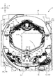
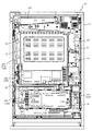
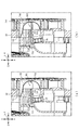
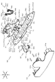
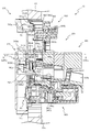
図5から図7を参照して、経路構成装置700の全体構成について説明をする。図5は、経路構成装置700の分解正面斜視図であり、図6は、経路構成装置700の部分拡大正面図であり、図7(a)及び図7(b)は、図6のVIIa−VIIa線における経路構成装置700の部分断面図である。 The overall configuration of the route configuration device 700 will be described with reference to FIGS. 5 to 7. 5 is an exploded front perspective view of the route configuration device 700, FIG. 6 is a partially enlarged front view of the route configuration device 700, and FIGS. 7A and 7B are VIIa- of FIG. FIG. 8 is a partial cross-sectional view of the route configuration device 700 taken along the line VIIa.

図6では、振分け部材760の内周面、シーソー部材762、連通孔751及び回収孔752の外形が破線で図示される。また、図7(a)では、電動役物640aが後述する第1送球経路KR1から退避している退避状態が図示され、図7(b)では、電動役物640aが第1送球経路KR1に進入している進入状態が図示される。 In FIG. 6, outer shapes of the inner peripheral surface of the distribution member 760, the seesaw member 762, the communication hole 751 and the recovery hole 752 are illustrated by broken lines. Further, FIG. 7A shows a retracted state in which the electric accessory 640a is retracted from a first ball sending path KR1 described later, and in FIG. 7B, the electric accessory 640a is moved to the first ball sending path KR1. The approaching state of being approached is illustrated.

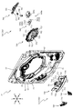
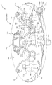
図5に示すように、経路構成装置700は、遊技盤13のセンターフレーム86の下側に配設され、ベース板60に対して正面側に配置される正面側形成部710と、ベース板60に対して背面側に配置される背面側形成部720と、を主に備えて形成される。 As shown in FIG. 5, the path configuration device 700 is disposed below the center frame 86 of the game board 13, and the front side forming portion 710 disposed on the front side with respect to the base plate 60, and the base plate 60. And a rear surface forming portion 720 arranged on the rear surface, mainly.

正面側形成部710は、ベース板60の正面側に取着される入賞部材730と、その入賞部材730の左右両側における正面側に配設される屈曲部材740と、を主に備えて形成される。 The front surface forming portion 710 is mainly provided with a winning member 730 attached to the front surface of the base plate 60, and bending members 740 arranged on the left and right front surfaces of the winning member 730. It

背面側形成部720は、ベース板60の背面側に取着される介設部材750と、その介設部材750の背面側に配設される振分け部材760と、介設部材750にソレノイド640sが固定配置される電動役物640aと、を主に備えて形成される。 The rear surface forming portion 720 includes an interposition member 750 attached to the back surface of the base plate 60, a distribution member 760 disposed on the back surface side of the interposition member 750, and a solenoid 640s on the interposition member 750. The electric accessory 640a fixedly arranged is mainly provided and formed.

入賞部材730は、ベース板60の板正面に配設され貫通孔60aを覆う形状で薄肉に形成されベース板60に装着される覆設板部711と、その覆設板部711の左右中央位置において前後方向に穿設される上側球通過孔713と、その上側球通過孔713の下側に配置され前後方向に穿設される下側球通過孔714と、覆設板部711の左右方向中央上部に位置する第1入賞口64と、その第1入賞口64の下側(下側球通過孔714の下側)に位置する第2入賞口640と、左右方向両側に位置し前後方向に貫通形成される貫通孔731と、その貫通孔731の下側に位置し前後方向に貫通形成される下側挿通孔732と、右側の下側挿通孔732よりも左側において前後方向に貫通形成される球通過孔734aを有する第1球送球部734と、その第1球送球部734の下縁部右端から右上方向に延びる長孔として前後方向に貫通形成される貫通孔735と、右側の下側挿通孔732よりも右側において前後方向に貫通形成される球通過孔736aを有する第2球送球部736と、上側球通過孔713を基準として第1球送球部734と左右対称に形成される第3球送球部737と、を主に備えて形成される。 The winning member 730 is provided on the front surface of the base plate 60, is formed in a thin shape to cover the through hole 60a, and is attached to the base plate 60. In the front-back direction, an upper sphere passing hole 713, a lower sphere passing hole 714 arranged below the upper sphere passing hole 713 and bored in the front-rear direction, and a left-right direction of the covering plate portion 711. The first winning opening 64 located at the upper center, the second winning opening 640 located below the first winning opening 64 (below the lower ball passing hole 714), and on the left and right sides in the front-back direction. A through hole 731 that is formed to penetrate through, a lower insertion hole 732 that is located below the through hole 731 and formed through in the front-rear direction, and a through hole formed in the front-rear direction on the left side of the lower insertion hole 732 on the right side. A first ball sending portion 734 having a ball passing hole 734a formed therein, a through hole 735 formed as a long hole extending in the front right direction from the lower edge right end of the first ball sending portion 734 in the front-rear direction, and a right side A second ball sending portion 736 having a ball passing hole 736a penetratingly formed in the front-rear direction on the right side of the lower insertion hole 732 and a first ball sending portion 734 formed symmetrically with respect to the upper ball passing hole 713. And a third ball sending unit 737 that is mainly provided.

貫通孔731は、その内部に後述する屈曲部材740の上側突出部741が挿通される部材であり、上側突出部741の背面視における外形よりも少し大きく開口する正面視略矩形状に形成される。 The through hole 731 is a member into which an upper protruding portion 741 of a bending member 740, which will be described later, is inserted, and is formed in a substantially rectangular shape in front view that is slightly larger than the outer shape of the upper protruding portion 741 in rear view. ..

下側挿通孔732は、背面側に配設される介設部材750の回収孔752と連通される孔であり、介設部材750の回収孔752と対向する位置に形成される。また、下側挿通孔732は、下面側が湾曲される正面視略D字形状に開口される。 The lower insertion hole 732 is a hole that communicates with the collection hole 752 of the interposition member 750 arranged on the back side, and is formed at a position facing the collection hole 752 of the interposition member 750. Further, the lower insertion hole 732 is opened in a substantially D-shape in a front view in which the lower surface side is curved.

下側挿通孔732の背面には、球の通過を検知するセンサSEは配設される。センサSEは、正面視略矩形状に形成されると共に、その側面に球の直径よりも少し大きい直径の貫通孔が形成される部材であり、その貫通孔の内部を球が通過することで球の通過を検出することができる。センサSEは、貫通孔の軸が下側挿通孔732の下面側の円弧軸と同軸上に位置して配設される。これにより、貫通孔の開口方向を背面側に向かうに従って少し下方に傾斜する様態とすることができるので、センサSEの貫通孔内部を通過する球が貫通孔の内側に留まることを抑制できる。 A sensor SE that detects the passage of a ball is provided on the back surface of the lower insertion hole 732. The sensor SE is a member having a substantially rectangular shape when viewed from the front, and a through hole having a diameter slightly larger than the diameter of the sphere is formed on the side surface of the sensor SE. Can be detected. The sensor SE is arranged such that the axis of the through hole is coaxial with the arc axis on the lower surface side of the lower insertion hole 732. As a result, the opening direction of the through hole can be made to incline slightly downward as it goes toward the back side, so that it is possible to prevent the sphere passing through the inside of the through hole of the sensor SE from staying inside the through hole.

第1球送球部734は、介設部材750の第1傾斜溝755の上流側端部に連通される位置に配置される球通過孔734aと、その球通過孔734aの正面視U字形状の縁部が正面側に突設される突設縁部734bと、その突設縁部734bの下流側部において球経路側に突設され、その突設先端が背面側へ傾斜する形状であることから流下してきた球を背面側に送球可能とされる下流側送球部734cと、を備える。 The first ball sending portion 734 has a sphere passage hole 734a arranged at a position communicating with the upstream end of the first inclined groove 755 of the interposition member 750, and a U-shaped front view of the sphere passage hole 734a. The projecting edge portion 734b having an edge portion projecting toward the front side, and the projecting edge portion 734b projecting toward the ball path side at the downstream side portion of the projecting edge portion 734b and having a shape in which the projecting tip is inclined to the rear surface side And a downstream side ball sending portion 734c capable of sending the ball that has flowed down from the back side.

貫通孔735は、移動板部材641が前後方向に挿通可能な形状から形成される。即ち、移動板部材641の右側案内部643及び左側案内部645とそれらを連結する連結部との正面視における外形よりも若干大きな形状で形成される。 The through hole 735 is formed in a shape that allows the movable plate member 641 to be inserted in the front-rear direction. That is, the right guide portion 643 and the left guide portion 645 of the moving plate member 641 and the connecting portion that connects them are formed in a shape slightly larger than the outer shape in a front view.

これにより、移動板部材641の退避状態では、貫通孔735により移動板部材641の前端部が支持され、移動板部材641の進入状態では、貫通孔735により移動板部材641の後端側が支持されることで、移動板部材641の配置を安定させることができる。 Thus, when the moving plate member 641 is in the retracted state, the through hole 735 supports the front end of the moving plate member 641, and when the moving plate member 641 is in the entering state, the through hole 735 supports the rear end side of the moving plate member 641. By doing so, the arrangement of the moving plate member 641 can be stabilized.

第2球送球部736は、介設部材750の第2傾斜溝757の上流側端部に連通される位置に配置される球通過孔736aと、その球通過孔736aの正面視U字形状の縁部が正面側に突設される突設縁部736bと、その突設縁部736bの下流側部において球経路側に突設され、その突設先端が背面側へ傾斜する形状であることから流下してきた球を背面側に送球可能とされる下流側送球部736cと、を備える。 The second ball feeding portion 736 has a sphere passage hole 736a arranged at a position communicated with the upstream end of the second inclined groove 757 of the interposition member 750, and a U-shaped front view of the sphere passage hole 736a. The projecting edge portion 736b having an edge projecting toward the front side, and the projecting edge portion 736b projecting toward the ball path side on the downstream side of the projecting edge portion 736b, and the projecting tip of which is inclined toward the back side. And a downstream side ball sending portion 736c capable of sending the ball that has flowed down from the back side.

第3球送球部737は、第1球送球部734の左右対称に形成される一方で、電動役物640aにより遊技球が案内されるようには構成されていない。左方向からの球の入球を許容する形状であり、球の入球の頻度を少なくすることができる。第3球送球部737は一般入賞口63(図2参照)と同様の機能を有している。即ち、球の入球により、5個〜15個の球が賞球として払い出される。なお、第3球送球部737への入球が稀なことから、入球した場合の遊技者の利益の最大化を図るために、賞球個数は最大(15個)で設定される。 The third ball sending unit 737 is formed symmetrically to the first ball sending unit 734, but is not configured to guide the game ball by the electric accessory 640a. The shape allows the ball to enter from the left direction, and the frequency of entering the ball can be reduced. The third ball sending unit 737 has the same function as the general winning opening 63 (see FIG. 2). That is, 5 to 15 spheres are paid out as prize balls when the sphere enters. Since it is rare to enter the third ball sending unit 737, the number of prize balls is set to the maximum (15) in order to maximize the profit of the player when entering the third ball.

屈曲部材740は、上述した入賞部材730の貫通孔731と下側挿通孔732との正面側に配設される部材であり、正面視におけるベース板60(図2参照)の左右方向略中央位置を対称に2つ配設され、その外形形状は概略左右対称に形成される。 The bending member 740 is a member disposed on the front side of the through hole 731 and the lower insertion hole 732 of the winning member 730 described above, and is a substantially central position in the left-right direction of the base plate 60 (see FIG. 2) in a front view. Are symmetrically arranged, and their outer shapes are formed substantially symmetrically.

また、屈曲部材740は、正面視において、遊技領域を形成する内レール61(図2参照)との間に、球が通過可能な大きさの隙間が形成される位置に配置される。これにより、屈曲部材740の下側の遊技領域を流下する球が、屈曲部材740と内レール61との間に挟まれて遊技領域に留まることが抑制される。 Further, the bending member 740 is arranged at a position where a gap having a size through which a ball can pass is formed between the bending member 740 and the inner rail 61 (see FIG. 2) that forms the game area in a front view. As a result, it is possible to prevent the ball flowing down the game area on the lower side of the bending member 740 from being sandwiched between the bending member 740 and the inner rail 61 and remaining in the game area.

屈曲部材740は、正面視略矩形の板状体から形成され、その背面から突出する上側突出部741と、その上側突出部741よりも下方から突出する下側突出部743と、上側突出部741及び下側突出部743の対向間に形成される開口744と、を備えて形成される。 The bending member 740 is formed of a plate-shaped body having a substantially rectangular shape in a front view, an upper protruding portion 741 protruding from the back surface thereof, a lower protruding portion 743 protruding below the upper protruding portion 741, and an upper protruding portion 741. And an opening 744 formed between the lower protrusions 743 facing each other.

上側突出部741は、背面視において下側が開放する略U字形状に形成され、その外形が、入賞部材730の貫通孔731の内形よりも少し小さく設定される。これにより、屈曲部材740を入賞部材730に配置する際には、上側突出部741を貫通孔731の内部に挿入して配設できる。よって、屈曲部材740を入賞部材730へ配置する際には、上側突出部741を挿入して位置決めすることができるので、その組み付け工程を簡易にできる。 The upper protruding portion 741 is formed in a substantially U shape whose lower side is opened in a rear view, and its outer shape is set to be slightly smaller than the inner shape of the through hole 731 of the winning member 730. Accordingly, when the bending member 740 is arranged on the winning member 730, the upper protruding portion 741 can be inserted and arranged inside the through hole 731. Therefore, when the bending member 740 is arranged on the winning member 730, the upper protruding portion 741 can be inserted and positioned, so that the assembling process can be simplified.

下側突出部743は、上側突出部741の下側に形成されると共に、上側が開放される背面視略U字形状に形成される。即ち、背面視すると、上側突出部741と下側突出部743との互いの開放部分が上下方向に対向する様態に形成される。 The lower protrusion 743 is formed on the lower side of the upper protrusion 741 and has a substantially U-shape when viewed from the rear, the upper side of which is open. That is, when viewed from the rear, the open portions of the upper protruding portion 741 and the lower protruding portion 743 are formed to face each other in the vertical direction.

下側突出部743は、入賞部材730の貫通孔731から屈曲部材740側に送球される球を入賞部材730の下側挿通孔732に送球するための経路(以下、「第2送球経路KR2」と称す)を形成するための部材であり、下側挿通孔732と前後方向に対向する位置に形成される。 The lower protrusion 743 is a path (hereinafter, referred to as “second ball sending path KR2”) for sending a ball sent from the through hole 731 of the winning member 730 to the bending member 740 side to the lower insertion hole 732 of the winning member 730. (Referred to as “)” and is formed at a position facing the lower insertion hole 732 in the front-rear direction.

下側突出部743の背面側への突出距離は、球の直径よりも大きい寸法に設定される。また、下側突出部743の突出先端面が入賞部材730と当接した状態で屈曲部材740が入賞部材730に配置される。よって、屈曲部材740と入賞部材730との対向間の距離寸法が球の直径よりも大きくされ、屈曲部材740と入賞部材730との対向間に球が鉛直方向に送球される送球路(以下、「第1送球経路KR1」と称す)が形成される。 The protrusion distance of the lower protrusion 743 to the back side is set to be larger than the diameter of the sphere. In addition, the bending member 740 is arranged on the winning member 730 in a state where the protruding tip end surface of the lower protruding portion 743 is in contact with the winning member 730. Therefore, the distance dimension between the facing of the bending member 740 and the winning member 730 is made larger than the diameter of the sphere, and the ball is fed in the vertical direction between the facing of the bending member 740 and the winning member 730 (hereinafter, A "first ball delivery route KR1") is formed.

屈曲部材740には、上側突出部741の上部内面から下側突出部743の下部内面に亘って突出する案内部742が形成される。案内部742は、側面視において背面側が開放される略U字形状に突出される。 The bending member 740 is provided with a guide portion 742 that projects from the upper inner surface of the upper protruding portion 741 to the lower inner surface of the lower protruding portion 743. The guide portion 742 is projected in a substantially U shape whose rear side is open in a side view.

案内部742は、入賞部材730の貫通孔731から屈曲部材740(第1送球経路KR1)に送球される球を鉛直方向に送球した後に、入賞部材730の下側挿通孔732に送球する突壁であり、下側の内縁部の上下方向高さは、背面に配置される下側挿通孔732の下側の内縁部の高さよりも少し小さく形成される。 The guide portion 742 is a projecting wall that sends a ball to the bending member 740 (the first ball sending route KR1) from the through hole 731 of the winning member 730 in the vertical direction and then to the lower insertion hole 732 of the winning member 730. The height of the lower inner edge portion in the vertical direction is slightly smaller than the height of the lower inner edge portion of the lower insertion hole 732 arranged on the back surface.

案内部742は、背面側に配置される貫通孔731の正面視における左右方向中央線に沿って形成される。これにより、案内部742と当接して案内(背面側に折り返し)されるので、球を容易に左右方向に位置ずれさせることができる。 The guide portion 742 is formed along the center line in the left-right direction in a front view of the through hole 731 arranged on the back side. As a result, the guide portion 742 is brought into contact with and guided (folded back to the back side), so that the sphere can be easily displaced in the left-right direction.

開口744は、上側突出部741と下側突出部743との対向間に形成される所定の隙間であり、背面視における左右方向両側に形成される。また、開口744は、側面視において、背面側が開放する略U字形状に形成される。 The opening 744 is a predetermined gap formed between the upper protrusion 741 and the lower protrusion 743 facing each other, and is formed on both sides in the left-right direction in rear view. Further, the opening 744 is formed in a substantially U shape with the rear surface side being opened in a side view.

開口744は、背面側端部の上端の高さが、同じ前後位置の案内部742の先端側部と略同一の上下方向高さに設定されると共に、背面側端部の下端の高さが、移動板部材641の右側案内部643の下側面と略同一の上下方向高さに設定される。開口744は、第1送球経路KR1と第4送球経路KR4との連結部分の左右方向の側面に開口して形成される。 The height of the upper end of the rear end of the opening 744 is set to be substantially the same as that of the front end of the guide portion 742 at the same front-rear position, and the height of the lower end of the rear end is set to the same. The height of the right side guide portion 643 of the moving plate member 641 is set to be substantially the same as the height in the vertical direction. The opening 744 is formed by opening on the side surface in the left-right direction of the connecting portion between the first ball sending path KR1 and the fourth ball sending path KR4.

振分け部材760は、正面視横長矩形に形成されると共に、正面側が開放された箱状体に形成される。また、振分け部材760は、正面視において左右方向略中央位置で屈曲されており、左右方向略中央位置から左右方向外側に向かうに従って下側に傾斜して形成される。また、振分け部材760の左右方向の両端部は、上述した入賞部材730の貫通孔731と対向する位置に設定される。 The distribution member 760 is formed in a horizontally long rectangular shape when viewed from the front, and is also formed in a box-like body whose front side is open. Further, the distribution member 760 is bent at a substantially central position in the left-right direction when viewed from the front, and is formed so as to be inclined downward from the substantially central position in the left-right direction toward the outer side in the left-right direction. Further, the left and right ends of the distribution member 760 are set at positions facing the through holes 731 of the winning member 730 described above.

振分け部材760は、正面視における左右方向中央位置から左右両側へ向けて下方傾斜する一対の傾斜面761と、その互いの傾斜面761の中央に配置されるシーソー部材762と、シーソー部材762の上方に形成される送球口763と、シーソー部材762の回転を規制するための規制壁部764と、右側の傾斜面761に案内される球が通過可能な位置に配設される普通入賞口(スルーゲート)765と、を主に備えて形成される。 The distribution member 760 includes a pair of inclined surfaces 761 that inclines downward from the center position in the left-right direction in a front view toward the left and right sides, a seesaw member 762 arranged at the center of the respective inclined surfaces 761, and above the seesaw member 762. The ball-sending port 763 formed on the base, the restriction wall portion 764 for restricting the rotation of the seesaw member 762, and the normal winning opening (through hole) arranged at a position where the ball guided by the right inclined surface 761 can pass. Gate) 765, and is formed.

一対の傾斜面761は、左右反対方向に延びる傾斜面であって、水平面に対する傾斜角度が左右対称となるように形成される。なお、本実施形態では、上流側において若干急な傾斜角度となる領域を設け、その下流側において傾斜角度が緩やかとなる領域の傾斜角度が水平面に対して5度で形成される。 The pair of inclined surfaces 761 are inclined surfaces extending in the left-right opposite directions, and are formed so that the inclination angles with respect to the horizontal plane are symmetrical. In the present embodiment, a region having a slightly steep inclination angle is provided on the upstream side, and an inclination angle of the region having a gentle inclination angle on the downstream side is formed at 5 degrees with respect to the horizontal plane.

送球口763は、振分け部材760の正面側に開口を形成するための部材であり、入賞部材730の第1入賞口64と対向する位置に形成される。これにより、振分け部材760が後述する介設部材750に配設されると、送球口763と介設部材750との対向間に空間を形成することができる。 The ball delivery port 763 is a member for forming an opening on the front side of the distribution member 760, and is formed at a position facing the first winning port 64 of the winning member 730. Accordingly, when the distribution member 760 is disposed on the interposition member 750, which will be described later, a space can be formed between the ball feeding port 763 and the interposition member 750.

その空間は、球の外径よりも大きい空間(即ち、球が通過可能な空間)に形成されると共に、ベース板60に穿設された貫通孔60bを介して入賞部材730の第1入賞口64の内部空間と連結される。これにより、第1入賞口64に入賞される球を送球口763と介設部材750との対向間の空間に送球して、その空間の内部を送球させることができる。 The space is formed in a space larger than the outer diameter of the sphere (that is, a space through which the sphere can pass), and the first winning hole of the winning member 730 through the through hole 60b formed in the base plate 60. It is connected to 64 internal spaces. As a result, it is possible to send the ball that is won in the first winning port 64 to the space between the ball sending port 763 and the interposition member 750, and to send the inside of the space.

軸部762bは、シーソー部材762を軸周りに回転させるための軸支部であり、円柱形状に形成されると共に、シーソー部材762の円環内側に挿通される。この状態で、軸部762bが、介設部材750と振分け部材760との間に挟持されることで、シーソー部材762は軸部762bを軸に回転可能に配置される。 The shaft portion 762b is a shaft support portion for rotating the seesaw member 762 around the axis, is formed in a cylindrical shape, and is inserted inside the ring of the seesaw member 762. In this state, the shaft portion 762b is sandwiched between the interposition member 750 and the distribution member 760, so that the seesaw member 762 is rotatably arranged around the shaft portion 762b.

突起762aは、上述した送球口763と介設部材750との対向間の空間から球が送球される際に、球を左右の傾斜面761に交互に一球ずつ振り分けるための突起であり、中央部の突起762aの先端が位置する方向と左右方向反対側に球が送球される。両端に突設される突起762aは、シーソー部材762の変位を規制すると共に、球の通過した際にかかる重みにより、中央部の突起762aの先端が位置する方向を変位させる(シーソー部材762を回転させる)部材であり、突起762aの先端面と規制壁部764とが当接することでシーソー部材762の回転が規制される。 The protrusion 762a is a protrusion for alternately distributing the balls to the left and right inclined surfaces 761 one by one when the balls are delivered from the space between the facing of the above-described ball delivery port 763 and the interposition member 750. A ball is sent to the side opposite to the direction in which the tip of the projection 762a of the section is located. The protrusions 762a provided at both ends restrict the displacement of the seesaw member 762, and also displace the direction in which the tip of the protrusion 762a in the central portion is located by rotating the seesaw member 762 due to the weight applied when the ball passes. The rotation of the seesaw member 762 is restricted by the contact between the tip end surface of the protrusion 762a and the restriction wall portion 764.

一方、規制壁部764と当接していない突起762aは、球が中央部の突起762aに案内されると、案内された球がその突起762aと衝突して下方に押し下げられる。これにより反対側の突起762aが上方に変位されると共に、下方に変位された突起762aの先端が規制壁部764と当接してその変位が規制される。 On the other hand, with respect to the projection 762a that is not in contact with the restriction wall portion 764, when the sphere is guided by the central projection 762a, the guided sphere collides with the projection 762a and is pushed downward. As a result, the protrusion 762a on the opposite side is displaced upward, and the tip end of the protrusion 762a displaced downward is brought into contact with the regulation wall portion 764 to regulate the displacement.

傾斜面761は、上述したシーソー部材762によって左右に振り分けられた球が転動して送球される経路(以下、「第3送球経路KR3」と称す)の転動面であり、振分け部材760の左右方向中央位置から外側に向かって下降傾斜して形成される。これにより、振分け部材760のシーソー部材762によって左右に振り分けられた球は、傾斜面761上を転動されて、傾斜面761の下降側の端部に送球(転動)される。 The inclined surface 761 is a rolling surface of a path (hereinafter, referred to as a “third ball sending path KR3”) in which the balls, which are distributed to the left and right by the seesaw member 762 described above, roll and are sent. It is formed to be inclined downward from the center position in the left-right direction toward the outside. As a result, the sphere distributed to the left and right by the seesaw member 762 of the distribution member 760 is rolled on the inclined surface 761 and is fed (rolled) to the descending end of the inclined surface 761.

傾斜面761の下降側の端部には、その端部に向かうに従って、背面側の側面が前方に厚みを増すように介設部材750へ近接する方向へ傾斜して形成される。これにより、傾斜面761を転動してその端部まで送球された球を、振分け部材760の前方に配設される介設部材750の連通孔751に送球することができる。 At the end of the inclined surface 761 on the descending side, the side surface on the back side is formed so as to be inclined toward the intermediate member 750 so as to increase the thickness thereof toward the end. Accordingly, the ball that rolls on the inclined surface 761 and is delivered to the end thereof can be delivered to the communication hole 751 of the interposition member 750 arranged in front of the distribution member 760.

普通入賞口(スルーゲート)765は、介設部材750と振分け部材760との間に配設され、介設部材750と振分け部材760とが連結固定されることで内側に固定配置される。 The normal winning opening (through gate) 765 is arranged between the interposition member 750 and the distribution member 760, and is fixedly arranged inside by connecting and fixing the interposition member 750 and the distribution member 760.

普通入賞口(スルーゲート)765の球通過孔の内側面であって、傾斜面761に沿う側の面が、傾斜面761の上面と面位置となるように、普通入賞口(スルーゲート)765の配置は設計される。 The normal winning opening (through gate) 765 is arranged such that the inner side surface of the ball passing hole of the normal winning opening (through gate) 765 and the surface along the inclined surface 761 is in the surface position with the upper surface of the inclined surface 761. The layout is designed.

これにより、球が普通入賞口(スルーゲート)765を通過する際に、球に与えられる抵抗を最小限に抑えることができ、普通入賞口(スルーゲート)765が配設される右側の傾斜面761を流下する球と、普通入賞口(スルーゲート)765が配設されていない左側の傾斜面761を流下する球との、流下速度を均一化することができる。 Thereby, when the ball passes through the normal winning opening (through gate) 765, the resistance given to the ball can be minimized, and the right inclined surface on which the normal winning opening (through gate) 765 is disposed. It is possible to equalize the flow speeds of the ball flowing down the 761 and the ball flowing down the inclined surface 761 on the left side where the normal winning opening (through gate) 765 is not arranged.

普通入賞口(スルーゲート)765の機能は、上述した普通入賞口(スルーゲート)66,67と共通である。即ち、普通入賞口(スルーゲート)765は、球が通過した場合に普通図柄(第2図柄)の抽選が行われる検出口としての機能を有する。 The function of the normal winning hole (through gate) 765 is common to the above-described normal winning holes (through gate) 66 and 67. In other words, the normal winning opening (through gate) 765 has a function as a detection opening through which a regular symbol (second symbol) is drawn when a ball passes.

また、第2図柄表示装置83において変動表示が行われている間に球が普通入賞口(スルーゲート)765を通過すると、その通過回数は、普通入賞口(スルーゲート)66,67の通過回数と共同で最大4回まで保留され、その保留球数が第1図柄表示装置37により表示されると共に、第2図柄保留ランプ84においても示される。 Further, when the ball passes through the normal winning opening (through gate) 765 while the variable display is being performed on the second symbol display device 83, the number of passing times is the number of passing through the normal winning opening (through gate) 66, 67. The maximum number of times is held up to four times in cooperation with, and the number of holding balls is displayed by the first symbol display device 37, and is also displayed on the second symbol holding lamp 84.

なお、普通入賞口(スルーゲート)66,67,765の球の通過に対する最大保留球数は4回に限定されるものでなく、3回以下、又は、5回以上の回数(例えば、8回)に設定しても良い。 It should be noted that the maximum number of reserved balls for the passage of balls through the normal winning openings (through gates) 66, 67, 765 is not limited to 4 times, and is 3 times or less, or 5 times or more (for example, 8 times). ) May be set.

第2図柄表示装置83は、球が普通入賞口(スルーゲート)66,67,765を通過する毎に表示図柄(第2図柄)としての「○」の図柄と「×」の図柄とを所定時間交互に点灯させる変動表示を行うものである。パチンコ機10では、球が普通入賞口(スルーゲート)66,67,765を通過したことが検出されると、第2図柄の当たり抽選が行われる。その当たり抽選の結果、当たりであれば、第2図柄表示装置83において、第2図柄の変動表示後に「○」の図柄が停止表示される。また、当たり抽選の結果、外れであれば、第2図柄表示装置83において、第2図柄の変動表示後に「×」の図柄が停止表示される。 The second symbol display device 83 has a predetermined "○" symbol and "x" symbol as a display symbol (second symbol) every time the ball passes through the normal winning openings (through gates) 66, 67, 765. This is a variable display in which the lights are alternately turned on for a time. In the pachinko machine 10, when it is detected that the ball has passed through the normal winning holes (through gates) 66, 67, 765, a winning lottery for the second symbol is performed. As a result of the winning lottery, if it is a win, in the second symbol display device 83, the symbol “◯” is stopped and displayed after the variable display of the second symbol. In addition, as a result of the winning lottery, if it is out, the symbol "x" is stopped and displayed after the variable display of the second symbol on the second symbol display device 83.

第2図柄表示装置83において変動表示が終了した場合に、普通入賞口(スルーゲート)66,67,765についての保留球数が残っていれば、次の普通図柄の抽選が行われると共に、その抽選に応じた変動表示が開始される。 When the variable display is finished on the second symbol display device 83, if the number of reserved balls for the normal winning openings (through gates) 66, 67, 765 remains, the next regular symbol is selected and the lottery is performed. The variable display according to the lottery is started.

介設部材750は、屈曲部材740と振分け部材760との前後間に介在する部材であって、正面視横長矩形状に形成されると共に、正面視における左右方向の中央下部に上述した可変入賞装置65と、左右両側に前後方向に貫通される連通孔751と、その連通孔751の下側に開口される回収孔752と、連通孔751及び回収孔752の間で前後方向に左右長尺の形状で貫通形成される支持凹部753と、左右中央位置を下流側端部として正面視左側へ向かって下降傾斜する直線状の第1傾斜溝755と、その第1傾斜溝755の下方において左右中央位置を下流側端部として正面視左側へ向かって下降傾斜する直線状の第2傾斜溝757と、その第2傾斜溝757の下方に配置される第2回収孔758と、を主に備えて形成される。 The interposition member 750 is a member interposed between the bending member 740 and the distribution member 760 and is formed in a horizontally long rectangular shape in a front view, and the variable winning device described above is provided at the lower center in the left-right direction in the front view. 65, a communication hole 751 penetrating in the left and right sides in the front-rear direction, a recovery hole 752 opened below the communication hole 751, and a left-right elongated shape in the front-rear direction between the communication hole 751 and the recovery hole 752. -Shaped supporting recess 753, a first linear slant groove 755 that slopes downward toward the left side when viewed from the front at the left and right center position as the downstream end, and the left and right center below the first slant groove 755. Mainly includes a linear second inclined groove 757 that is inclined downward to the left in front view with the position being the downstream end portion, and a second recovery hole 758 arranged below the second inclined groove 757. It is formed.

連通孔751は、振分け部材760の左右両端部の正面側に形成されると共に、入賞部材730の貫通孔731の背面側に形成される。よって、振分け部材760の左右両端部の空間と、入賞部材730の貫通孔731の内部空間とが連通孔751を介して連結される。従って、上述した振分け部材760の傾斜面761の上部を転動する球を、連通孔751を通過させて、入賞部材730の貫通孔731に送球する経路(以下、「第4送球経路KR4」と称す)を形成することができる。 The communication holes 751 are formed on the front sides of the left and right ends of the distribution member 760 and on the back side of the through holes 731 of the winning member 730. Therefore, the spaces at the left and right ends of the distribution member 760 and the internal space of the through hole 731 of the winning member 730 are connected via the communication hole 751. Therefore, the above-mentioned ball that rolls on the inclined surface 761 of the sorting member 760 passes through the communication hole 751 and sends the ball to the through hole 731 of the winning member 730 (hereinafter, referred to as “fourth ball sending route KR4”). Can be formed).

回収孔752は、上述したように、入賞部材730の下側挿通孔732の背面側に開口形成される開口である。即ち、回収孔752は、センサSEの背面側に連結されており、センサSEを通過する球が、その回収孔752の開口に送球される。回収孔752は、店舗に設置される球を循環する装置に連結されており、回収孔752に回収された球は、循環装置により循環されて遊技球として再び球発射ユニット112aから打出しされる。 As described above, the collection hole 752 is an opening formed on the back side of the lower insertion hole 732 of the winning member 730. That is, the collection hole 752 is connected to the back side of the sensor SE, and the sphere passing through the sensor SE is sent to the opening of the collection hole 752. The collection hole 752 is connected to a device that circulates the balls installed in the store, and the balls collected in the collection hole 752 are circulated by the circulation device and again launched from the ball launch unit 112a as game balls. ..

支持凹部753は、移動板部材641の右側案内部643が前後方向に移動するために十分な空間を確保するために形成される凹設溝部である。右側案内部643の下面と上下方向で対向する支持凹部753の下底面は、左右方向に水平な平面形状で形成される。また、右側案内部643の上面と上下方向で対向する支持凹部753の上天面は、傾斜面643aと同様の傾斜角度の平面形状で形成される。 The support concave portion 753 is a concave groove portion formed to secure a sufficient space for the right guide portion 643 of the moving plate member 641 to move in the front-rear direction. The lower bottom surface of the support recess 753, which faces the lower surface of the right guide portion 643 in the up-down direction, is formed in a planar shape that is horizontal in the left-right direction. Further, the upper top surface of the support recess 753, which faces the upper surface of the right guide portion 643 in the vertical direction, is formed in a planar shape having the same inclination angle as the inclined surface 643a.

即ち、支持凹部753は、左側から右側へ凹設されており、左側が広く右側が狭い楔形状に形成され、機能的には、正面視における右側案内部643の上下幅よりも若干大きな上下幅(若干大きな楔形状)から形成される。 That is, the support recess 753 is recessed from the left side to the right side, is formed in a wedge shape in which the left side is wide and the right side is narrow. (Slightly large wedge shape).

これにより、移動板部材641の利用において、前後方向にスライド移動させる際には、右側案内部643が支持凹部753の内側を案内されることになるので移動をスムーズに実行することができ、右側案内部643を第1送球経路KR1に進入させて流下してきた球を受け止める際には、支持凹部753の下底面により右側案内部643を下支えすることができる。即ち、支持凹部753は、移動板部材641の移動を円滑にさせる効果と、移動板部材641の上下位置を安定させる効果とを奏する。 As a result, when the moving plate member 641 is used, when the slide plate is moved in the front-rear direction, the right guide portion 643 is guided inside the support recess 753, so that the movement can be smoothly performed, and the right side When the guide portion 643 is inserted into the first ball sending path KR1 and receives the ball that has flowed down, the right guide portion 643 can be supported by the lower bottom surface of the support recess 753. That is, the support recess 753 has an effect of smoothing the movement of the moving plate member 641 and an effect of stabilizing the vertical position of the moving plate member 641.

第1傾斜溝755は、上流側端部が球通過孔734aに連通する位置に配設され、下流側端部に到達した球を正面側形成部710の上側球通過孔713を通して正面側に送球可能な形状で構成される。 The first inclined groove 755 is arranged at a position where the upstream end communicates with the sphere passage hole 734a, and the sphere that has reached the downstream end is sent to the front side through the upper sphere passage hole 713 of the front formation portion 710. Composed of possible shapes.

第2傾斜溝757は、上流側端部が球通過孔736aに連通する位置に配設され、下流側端部に到達した球を正面側形成部710の下側球通過孔714を通して正面側に送球可能な形状で構成される。 The second inclined groove 757 is disposed at a position where the upstream end communicates with the sphere passage hole 736a, and the sphere that reaches the downstream end is passed through the lower sphere passage hole 714 of the front formation portion 710 to the front side. It has a shape that allows it to be thrown.

本実施形態では、第1傾斜溝755及び第2傾斜溝757は、直線状溝形状で形成され、各溝が沿う直線が互いに平行となる関係で形成される。 In the present embodiment, the first inclined groove 755 and the second inclined groove 757 are formed in a linear groove shape, and the straight lines along which the grooves are formed are parallel to each other.

第2回収孔758は、第2入賞口640に入球した球が送球される開口であり、第2入賞口スイッチ(図示せず)よりも上流側に配設される。第2回収孔758は、店舗に設置される球を循環する装置に連結されており、第2回収孔758に回収された球は、循環装置により循環されて遊技球として再び球発射ユニット112aから打出しされる。 The second collection hole 758 is an opening through which the ball that has entered the second winning opening 640 is sent, and is arranged on the upstream side of a second winning opening switch (not shown). The second collection hole 758 is connected to a device that circulates the balls installed in the store, and the balls collected in the second collection hole 758 are circulated by the circulation device and again as game balls from the ball launch unit 112a. It is launched.

上側球通過孔713と下側球通過孔714とは、鉛直方向に沿う直線上に並べられ、その同一直線上における下側球通過孔714の下側に第2入賞口640が配置される(図6参照)。 The upper sphere passage hole 713 and the lower sphere passage hole 714 are arranged on a straight line along the vertical direction, and the second winning opening 640 is arranged below the lower sphere passage hole 714 on the same straight line ( (See FIG. 6).

そのため、上側球通過孔713を通して正面側に送球された球は下側球通過孔714の正面側を通過して第2入賞口640に入球する。また、下側球通過孔714を通して正面側に送球された球は、上側球通過孔713から正面側に送球された球の流下経路と合流し、第2入賞口640に入球する。 Therefore, the ball sent to the front side through the upper ball passing hole 713 passes through the front side of the lower ball passing hole 714 and enters the second winning opening 640. In addition, the ball sent to the front side through the lower ball passing hole 714 merges with the flow-down path of the ball sent to the front side from the upper ball passing hole 713, and enters the second winning opening 640.

球の流下経路の合流位置において、上側球通過孔713から流下する球の流下方向は鉛直方向となっており、合流位置における落下速度を大きくすることができるので、上側球通過孔713及び下側球通過孔714から案内された球が合流位置に同時に到達したとしても、上側球通過孔713から流下する球を勢いで下方に通過させることができるので、球詰まりが生じることを回避し易い。 At the merging position of the sphere flow-down path, the sphere flowing down from the upper sphere passing hole 713 is in the vertical direction, and since the falling speed at the merging position can be increased, the upper sphere passing hole 713 and the lower side Even if the spheres guided from the sphere passage hole 714 reach the merging position at the same time, the sphere flowing down from the upper sphere passage hole 713 can be forcedly passed downward, so that it is easy to avoid clogging of the sphere.

また、下側球通過孔714の左右縁部から正面側に延設される壁部714aにより、合流位置から球が左右に逸れることを防止し易くすることができる。また、壁部714aは、左右外側から第2入賞口640へ球が入球することを防止するようにも作用する。 Further, the wall portion 714a extending from the left and right edge portions of the lower ball passage hole 714 to the front side can easily prevent the ball from deviating to the left or right from the joining position. In addition, the wall portion 714a also acts to prevent a ball from entering the second winning opening 640 from the outside on the left and right.

上側球通過孔713の左右縁部および上側縁部から正面側に延設される壁部713aにより、上側球通過孔713から正面側に送球された直後の球に対して、ベース板60の正面側を流下してきた球が衝突することを防止することができる。また、壁部713aは、ベース板60の正面側を流下してきた球が第2入賞口640側へ向けて流下することを妨げるようにも作用する。 By the left and right edges of the upper ball passage hole 713 and the wall portion 713a extending from the upper edge portion to the front side, the front surface of the base plate 60 with respect to the ball immediately after being sent from the upper ball passage hole 713 to the front side. It is possible to prevent the ball flowing down the side from colliding. In addition, the wall portion 713a also acts to prevent a ball that has flowed down on the front surface side of the base plate 60 from flowing down toward the second winning opening 640 side.

電動役物640aは、介設部材750に固定配置されるソレノイド640sと、そのソレノイド640sと連動可能に連結され、ソレノイド640sの駆動により前後方向にスライド移動する移動板部材641と、を備える。 The electric accessory 640 a includes a solenoid 640 s fixedly arranged on the interposition member 750, and a moving plate member 641 that is operably connected to the solenoid 640 s and that slides in the front-rear direction by driving the solenoid 640 s.

移動板部材641は、ソレノイド640sの駆動力が伝達される板状部であって上下方向に延設される伝達板部642と、その伝達板部642の正面側端部に配設され正面側に突設形成される左側案内部645と、その左側案内部645の右方に延設される右側案内部643と、を備える。 The moving plate member 641 is a plate-shaped portion to which the driving force of the solenoid 640s is transmitted, and is a transmission plate portion 642 that extends in the up-down direction, and a front side provided on the front end of the transmission plate portion 642. And a right side guide portion 643 extending rightward from the left side guide portion 645.

右側案内部643は、球の転動面となる上面が右側へ向けて下降傾斜する傾斜面643aとして形成され、正面視で連通孔751と回収孔752との間に配設される。 The right guide portion 643 is formed as an inclined surface 643a whose upper surface serving as a rolling surface of the sphere is inclined downward toward the right side, and is disposed between the communication hole 751 and the recovery hole 752 in a front view.

左側案内部645は、球の転動面となる上面が左側へ向けて下降傾斜する傾斜面645aとして形成され、正面視で屈曲部材740と第1球送球部734とを繋ぐように配設される。傾斜面645aの下流側端部の上面は、第1球送球部734の突設縁部734bの下側端部の上面と面位置となるよう配置される。 The left side guide portion 645 is formed as an inclined surface 645a whose upper surface serving as a rolling surface of the sphere is inclined downward toward the left side, and is arranged so as to connect the bending member 740 and the first ball throwing portion 734 in a front view. It The upper surface of the downstream end portion of the inclined surface 645a is arranged so as to be flush with the upper surface of the lower end portion of the projecting edge portion 734b of the first ball feeding portion 734.

第1送球部734の突設縁部734bが上方に開放された皿状ではなく、開放側は右側に向けられることで上側に蓋がある形状となっているので、左側案内部645で転動する球の受入をスムーズに行いながら、左側案内部645で跳ねた球や、第1送球部734に上側から到達するような経路で流下する球が、球通過孔734aに飛び込み入球することは生じ難いようにすることができる。なお、突設蓋部734bの形状を皿状に形成して、上側からの球の飛び込みを可能とする形状を採用しても良い。 Since the projecting edge portion 734b of the first ball feeding portion 734 is not in the shape of a dish that is opened upward, but the opening side is directed to the right side so that the lid is on the upper side, the left guide portion 645 rolls. While smoothly accepting the sphere that moves, the sphere bounced by the left side guide portion 645 and the sphere that flows down in a route that reaches the first ball sending portion 734 from the upper side do not jump into the sphere passage hole 734a. It can be made difficult to occur. The protruding lid 734b may be formed in a dish shape so as to allow a ball to jump in from above.

なお、左側案内部645に着地した球であっても、跳ね返りが収まるまでは第1送球部734に入りにくい。そのため、左側案内部645での跳ね返りを小さくする構成を採用することが好ましい。 It should be noted that even a ball landed on the left guide portion 645 is unlikely to enter the first ball sending portion 734 until the bounce is settled. Therefore, it is preferable to adopt a configuration in which the bounce at the left side guide portion 645 is reduced.

例えば、左側案内部645の上方において球と衝突可能な釘を密に配置したり、覆設板部711の正面側に突設される減速凸部を複数配置したりすることで、球の流下の勢いを予め落とすようにしても良い。また、傾斜面645aにクッション性の高いシート部材を貼り付けるようにして、球のバウンドを抑制するようにしても良い。 For example, the nails that can collide with the balls are densely arranged above the left guide portion 645, or a plurality of deceleration projections that are projected on the front side of the covering plate portion 711 are arranged so that the balls flow down. You may make it slow down beforehand. Alternatively, a sheet member having a high cushioning property may be attached to the inclined surface 645a to suppress the bouncing of the ball.

移動板部材641は、ソレノイド640sが非励磁とされる非励磁状態では、第1送球経路KR1から退避する退避状態とされ(図7(a)参照)、ソレノイド640sの励磁状態(駆動力が生じている状態)では、第1送球経路KR1に進入する進入状態とされる(図7(b)参照)。 The movable plate member 641 is in a retracted state in which the solenoid 640s is de-energized and is retracted from the first ball sending path KR1 (see FIG. 7A), and the solenoid 640s is excited (driving force is generated). State), the vehicle enters the first ball sending route KR1 (see FIG. 7B).

以上のように構成される経路構成装置700により、遊技球が次のように送球される。第1入賞口64から入る球は、振分け部材760に送球されて振分け部材760のシーソー部材762により左右方向どちらか一方の第3送球経路KR3に送球される。第3送球経路KR3を送球される球は、その第3送球経路KR3の端部まで送球されると、正面側に配置される介設部材750の連通孔751の内部の第4送球経路KR4に送球される。第4送球経路KR4を送球される球は、屈曲部材740の背面側の第1送球経路KR1に送球される。第1送球経路KR1を送球される球は、屈曲部材740の下側突出部743に案内されて第2送球経路KR2に送球される。第2送球経路KR2を送球される球は、入賞部材730の下側挿通孔732を通過して介設部材750の回収孔752に送球され、センサSEの内部を通過する。 With the route configuration device 700 configured as described above, game balls are sent as follows. The ball entering from the first winning opening 64 is delivered to the distribution member 760 and is delivered by the seesaw member 762 of the distribution member 760 to one of the left and right third delivery paths KR3. When the ball sent along the third ball delivery route KR3 is delivered to the end of the third ball delivery route KR3, the ball is delivered to the fourth ball delivery route KR4 inside the communication hole 751 of the intermediate member 750 arranged on the front side. Being thrown. The ball sent along the fourth ball sending route KR4 is sent to the first ball sending route KR1 on the back side of the bending member 740. The sphere that has been sent along the first ball delivery route KR1 is guided by the lower protrusion 743 of the bending member 740 and is delivered to the second ball delivery route KR2. The ball sent along the second ball sending path KR2 passes through the lower insertion hole 732 of the winning member 730 and is sent to the collection hole 752 of the interposition member 750, and passes through the inside of the sensor SE.

第4送球経路KR4から第1送球経路KR1に送球される球は、ベース板60の正面側へ向けて流下することになり、その球は、遊技者視線で遊技者に近づいてきているように見える。これにより、遊技領域を下方に流下する他の遊技球との流下態様の違いが明確化されるので、第4送球経路KR4から第1送球経路KR1に送球される球の存在感を高めることができる。 The ball sent from the fourth ball-sending path KR4 to the first ball-sending path KR1 flows down toward the front side of the base plate 60, and the ball is approaching the player in the player's line of sight. appear. As a result, the difference in the flow-down mode with other game balls flowing down the game area is clarified, so that the presence of the ball sent from the fourth ball-sending route KR4 to the first ball-sending route KR1 can be increased. it can.

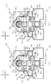
次いで、図8及び図9を参照して、球の流下態様の設定について説明する。図8(a)、図8(b)、図9(a)及び図9(b)は、図6の範囲VIIIaにおける経路構成装置700の部分正面図である。 Next, with reference to FIG. 8 and FIG. 9, setting of the sphere flow-down mode will be described. FIG. 8A, FIG. 8B, FIG. 9A and FIG. 9B are partial front views of the route configuration device 700 in the range VIIIa of FIG.

図8(a)、図8(b)、図9(a)及び図9(b)では、第1入賞口64に3個の球P1〜P3が間を空けずに連続で入球した場合における流下態様が、0.5秒間隔の時系列で図示される。 In FIG. 8(a), FIG. 8(b), FIG. 9(a), and FIG. 9(b), the case where three balls P1 to P3 enter the first winning opening 64 continuously without a gap. The flow-down mode in FIG.

即ち、図8(a)の状態から0.5秒後の状態として図8(b)が図示され、図8(b)の状態から0.5秒後の状態として図9(a)が図示され、図9(a)の状態から0.5秒後の状態として図9(b)が図示される。なお、一例として、図8(a)では、中央部の突起762aの先端が左側を向いた状態が図示される。 That is, FIG. 8B is shown as a state 0.5 seconds after the state of FIG. 8A, and FIG. 9A is shown as a state 0.5 seconds after the state of FIG. 8B. Then, FIG. 9B is illustrated as a state 0.5 seconds after the state of FIG. 9A. In addition, as an example, FIG. 8A illustrates a state in which the tip of the protrusion 762a in the central portion faces the left side.

図8(a)に図示するように、球P1が中央部の突起762aに案内されると、案内された球P1が両端部の突起762aの一方と衝突して下方に押し下げられる。これにより反対側の突起762aが上方に変位されると共に、下方に変位された突起762aの先端が規制壁部764と当接してその変位が規制される(図8(b)参照)。 As illustrated in FIG. 8A, when the sphere P1 is guided by the protrusion 762a at the center, the guided sphere P1 collides with one of the protrusions 762a at both ends and is pushed downward. As a result, the protrusion 762a on the opposite side is displaced upward, and the tip end of the protrusion 762a displaced downward is brought into contact with the regulation wall portion 764 to regulate the displacement (see FIG. 8B).

この状態で、シーソー部材762を押し下げた球P1は右側へ向けて流下しており、同時に次の球P2が中央部の突起762aに案内される。この時、球P2が中央部の突起762aに到達すると同時に、先にシーソー部材762を押し下げた球P1は普通入賞口(スルーゲート)765を通過する(図8(b)参照)。 In this state, the sphere P1 that pushed down the seesaw member 762 flows down toward the right side, and at the same time, the next sphere P2 is guided by the protrusion 762a in the central portion. At this time, the ball P2 reaches the central protrusion 762a, and at the same time, the ball P1 that has previously pushed down the seesaw member 762 passes through the normal winning opening (through gate) 765 (see FIG. 8B).

球P2は、シーソー部材762によって左側へ向けて流下され、同時に次の球P3が中央部の突起762aに案内される。この時、球P3が中央部の突起762aに到達すると同時に、球P1は右側案内部643の下側に配置される(図9(a)参照)。その後、球P3は、シーソー部材762によって右側へ向けて流下される(図9(b)参照)。 The sphere P2 flows down toward the left side by the seesaw member 762, and at the same time, the next sphere P3 is guided to the protrusion 762a in the central portion. At this time, the sphere P3 reaches the central protrusion 762a, and at the same time, the sphere P1 is arranged below the right side guide portion 643 (see FIG. 9A). After that, the sphere P3 flows down toward the right side by the seesaw member 762 (see FIG. 9B).

このように、本実施形態では、普通入賞口(スルーゲート)765の配置が電動役物640aの配置との関係で規定されている。即ち、球P1が普通入賞口(スルーゲート)765を通過してから、右側案内部643の下側に配置されるまでの間に、次の球P3が普通入賞口(スルーゲート)765に到達しないように設計されている。 As described above, in the present embodiment, the arrangement of the normal winning openings (through gates) 765 is defined in relation to the arrangement of the electric accessory 640a. That is, the next ball P3 reaches the normal winning opening (through gate) 765 after the ball P1 passes through the normal winning opening (through gate) 765 and before it is arranged below the right side guide portion 643. It is designed not to.

ここで、普通入賞口(スルーゲート)765で球の通過が検出されると、予め設定されている作動パターンに基づいて電動役物640aの動作が実行される。電動役物640aの動作は、作動パターンの途中で割り込みが生じるというものではない。作動パターンに基づく電動役物640aの動作が継続されている時に普通入賞口(スルーゲート)765で球の通過が検出されたとしても、その検出に因る電動役物640aの動作の実行は、現在実行されている作動パターンに基づく電動役物640aの動作が完了するまで保留される。 Here, when the passage of the ball is detected at the normal winning opening (through gate) 765, the operation of the electric accessory 640a is executed based on the preset operation pattern. The operation of the electric accessory 640a does not mean that an interrupt occurs in the middle of the operation pattern. Even if the passage of a ball is detected at the normal winning opening (through gate) 765 while the operation of the electric accessory 640a based on the operation pattern is continued, the operation of the electric accessory 640a caused by the detection is executed. The operation of the electric accessory 640a based on the currently executed operation pattern is suspended until the operation is completed.

そのため、球の流下時間を基準として普通入賞口(スルーゲート)765を通過した球へ影響を与えられるように電動役物640aの作動パターンを設定しても、電動役物640aの動作の実行が保留される事態が生じると、普通入賞口(スルーゲート)765を通過した球へ与える影響が予想外のものになる可能性がある。 Therefore, even if the operation pattern of the electric accessory 640a is set so as to affect the ball that has passed through the normal winning opening (through gate) 765 on the basis of the flow time of the ball, the operation of the electric accessory 640a is not executed. When a situation occurs in which the ball is suspended, the influence on the ball that has passed through the normal winning opening (through gate) 765 may be unexpected.

これに対し、本実施形態では、球が右側案内部643に到達するまでの時間幅で電動役物640aの作動パターンを設定するという前提において、次の球P3が普通入賞口(スルーゲート)765に検出される時まで、先の球P1が普通入賞口(スルーゲート)765に検出されたことに伴う電動役物640aの動作が継続されている事態を回避することができる(事前に電動役物640aの動作が終了する)。 On the other hand, in the present embodiment, on the assumption that the operation pattern of the electric accessory 640a is set within the time width until the ball reaches the right guide portion 643, the next ball P3 is the normal winning opening (through gate) 765. It is possible to avoid a situation in which the operation of the electric accessory 640a is continued due to the previous ball P1 being detected by the normal winning opening (through gate) 765 until the time of being detected by The operation of the object 640a ends).

従って、球の通過が普通入賞口(スルーゲート)765で検出されたら、電動役物640aの動作の実行が保留されることなく即座に、予め設定されている作動パターンに基づいて電動役物640aの動作を実行させることができる。これにより、普通入賞口(スルーゲート)765を通過した球へ与える影響が予想外のものになる可能性を低くすることができる。 Therefore, when the passage of a ball is detected by the normal winning opening (through gate) 765, the electric accessory 640a is immediately executed without suspending the execution of the operation of the electric accessory 640a based on the preset operation pattern. The operation of can be executed. As a result, it is possible to reduce the possibility of unexpected effects on the ball that has passed through the normal winning opening (through gate) 765.

図10(a)、図10(b)、図11(a)及び図11(b)は、図6の範囲VIIIaにおける経路構成装置700の部分正面図である。図10(a)及び図10(b)と、図11(a)及び図11(b)とでは、右側の傾斜面761を球が流下する様子の異なる一例が、時系列で図示される。 10(a), 10(b), 11(a) and 11(b) are partial front views of the route configuration device 700 in the range VIIIa of FIG. 10(a) and 10(b) and FIGS. 11(a) and 11(b), different examples in which the sphere flows down the inclined surface 761 on the right side are illustrated in time series.

即ち、図10(a)では、球が普通入賞口(スルーゲート)765を通過している状態が図示され、図10(b)では、球の通過時に移動板部材641が第1送球経路KR1から退避した退避状態(図7(a)参照)で維持され、球が回収孔752に案内されている状態が図示される。 That is, FIG. 10A shows a state in which the ball is passing through the normal winning opening (through gate) 765, and in FIG. 10B, the moving plate member 641 is moved by the moving plate member 641 when the ball passes. It is illustrated that the ball is maintained in the retracted state (see FIG. 7A) and is guided by the recovery hole 752.

また、図11(a)では、球が普通入賞口(スルーゲート)765を通過している状態(図10(a)と同様の状態)が図示され、図11(b)では、球の通過直前に移動板部材641が第1送球経路KR1に進入する進入状態とされ(図7(b)参照)、球が第2球送球部736側に案内される状態が図示される。 Further, FIG. 11A shows a state where the ball is passing through the normal winning opening (through gate) 765 (the same state as FIG. 10A), and in FIG. 11B, the passing of the ball is shown. The state in which the moving plate member 641 is immediately before entering the first ball sending path KR1 (see FIG. 7B) and the ball is guided to the second ball sending part 736 is illustrated.

なお、図11(b)において移動板部材641にドットが描画されているのは、移動板部材641が正面側にスライド移動しており手前側を球が通過することを許容しない状態であることを模式的に示すものである。 It should be noted that in FIG. 11B, dots are drawn on the moving plate member 641 when the moving plate member 641 is slidingly moved to the front side and the sphere is not allowed to pass on the front side. Is schematically shown.

ここで、移動板部材641は、ソレノイド640sが非励磁とされる非励磁状態では、第1送球経路KR1から退避する退避状態とされ(図7(a)参照)、ソレノイド640sの励磁状態(駆動力が生じている状態)では、第1送球経路KR1に進入する進入状態とされる(図7(b)参照)から、非励磁状態では、正面視で移動板部材641の上面に到達した球は移動板部材641の正面側を通過して下方向に流下する一方で、励磁状態では、正面視で移動板部材641の上面に到達した球は移動板部材641の傾斜面643a又は傾斜面645aを転動して左右方向に流下する。 Here, the movable plate member 641 is in a retracted state in which the solenoid 640s is de-energized and is retracted from the first ball sending path KR1 (see FIG. 7A), and the solenoid 640s is excited (driven). In the non-excited state, the sphere that has reached the upper surface of the moving plate member 641 in the non-excited state, because the first state is a state in which the force is generated) (see FIG. 7B). While passing through the front side of the moving plate member 641 and flowing downward, in the excited state, the sphere that has reached the upper surface of the moving plate member 641 in the front view is the inclined surface 643a or the inclined surface 645a of the moving plate member 641. Roll down and run down in the left and right direction.

例えば、図11(b)に示す矢印に沿って流下する。詳述すれば、移動板部材641の励磁状態において、第1送球経路KR1に到達した球は傾斜面643aの上面を転動して開口744を通過後落下して第2球送球部736に受け入れられる。 For example, it flows down along the arrow shown in FIG. More specifically, when the moving plate member 641 is in the excited state, the ball that has reached the first ball sending path KR1 rolls on the upper surface of the inclined surface 643a, drops after passing through the opening 744, and is received by the second ball sending part 736. To be

なお、移動板部材641の励磁状態において、右側の屈曲部材740と第1球送球部734との間を流下しようとする球は傾斜面645aの上面を転動して球通過孔734aに案内され、第2入賞口640に入球することになる。 When the moving plate member 641 is in the excited state, the sphere that is about to flow down between the right bending member 740 and the first ball feeding portion 734 rolls on the upper surface of the inclined surface 645a and is guided to the sphere passage hole 734a. , Will enter the second winning opening 640.

図12は、図2の範囲XIIにおける遊技盤13の部分正面図である。図12では、ソレノイド640sが励磁状態とされ移動板部材641の進入状態が図示されている。 FIG. 12 is a partial front view of the game board 13 in the range XII of FIG. In FIG. 12, the solenoid 640s is in an excited state and the moving plate member 641 is in an entering state.

上述したように、普通入賞口(スルーゲート)66,67,765の機能は共通であるので、経路構成装置700に入球した球が普通入賞口(スルーゲート)765を通過することに因る場合に限らず、上述の右打ち遊技を行う場合に、球が普通入賞口(スルーゲート)67を通過することに因っても電動役物640aは作動する。 As described above, since the normal winning openings (through gates) 66, 67, 765 have the same function, the balls that enter the path forming device 700 pass through the normal winning openings (through gate) 765. Not only in the case, when performing the above-mentioned right-handed game, the electric accessory 640a operates even when the ball passes through the normal winning opening (through gate) 67.

この場合、右打ち遊技で発射された遊技球は第1入賞口64に案内される球よりも右側の屈曲部材740の天井面に到達する球の方が多くなるので(約10倍となるので)、移動板部材641の進入状態において、球は、電動役物640aの右側案内部643よりも左側案内部645に到達し易い。 In this case, the number of game balls launched in the right-handed game is greater than the number of balls that reach the ceiling surface of the bending member 740 on the right side than the balls that are guided to the first winning opening 64 (because it is about 10 times, ), when the moving plate member 641 is in the entry state, the ball is more likely to reach the left side guide portion 645 than the right side guide portion 643 of the electric accessory 640a.

左側案内部645に到達した球は、流下して第1球送球部734に到達するまでソレノイド640sが励磁状態で維持されていれば第2入賞口640に入球することになり、第1球送球部734に到達する前にソレノイド640sが非励磁状態に切り替えられたとしても、その真下に流下するだけであり、球が回収孔752に案内されることは無い。即ち、球が左側案内部645に到達した球により特別図柄1の抽選を獲得する事態を防止することができる。 The ball that has reached the left side guide portion 645 will flow into the second winning opening 640 if the solenoid 640s is maintained in the excited state until it flows down and reaches the first ball delivery portion 734. Even if the solenoid 640s is switched to the non-excited state before reaching the ball sending unit 734, it only flows directly below it and the ball is not guided to the recovery hole 752. That is, it is possible to prevent a situation in which the ball reaches the left side guide portion 645 and wins the lottery for the special symbol 1.

進入状態における左側案内部645に到達した球は、着地位置に関わらず約1.0秒あれば、第1球送球部734に受け入れられる。一方で、0.5秒等のごく短い時間で移動板部材641が退避状態に変化する場合には、進入状態における左側案内部645の左端付近に球が着地した場合であっても、第1球送球部734への入球が阻害される可能性がある。 The ball that has reached the left guide portion 645 in the approaching state is accepted by the first ball delivery portion 734 if it takes about 1.0 seconds regardless of the landing position. On the other hand, when the moving plate member 641 changes to the retracted state in a very short time such as 0.5 seconds, even if the ball lands near the left end of the left guide portion 645 in the approached state, There is a possibility that the ball entering the ball sending unit 734 may be blocked.

そのため、第1入賞口64に入球せずに流下する球が、普通入賞口(スルーゲート)66,67,765での球の検出による抽選の結果動作されて進入状態とされる左側案内部645にタイミングよく到達した場合に、その球が第1球送球部734に受け入れられるかどうかは、電動役物640aの作動態様による。 Therefore, the ball that flows down without entering the first winning port 64 is operated as a result of the lottery based on the detection of the ball at the normal winning ports (through gates) 66, 67, 765, and is in the entering state. Whether or not the ball is received by the first ball sending unit 734 when the ball 645 arrives at the right time depends on the operation mode of the electric accessory 640a.

特に、通常状態における作動パターン(後述する第4の作動パターン)では、移動板部材641が進入状態とされる期間が0.5秒よりも短いため、球が第1球送球部734に受け入れられる確率は極端に低くされている。 Particularly, in the operation pattern in the normal state (fourth operation pattern described later), the period during which the moving plate member 641 is in the approach state is shorter than 0.5 seconds, so the ball is received by the first ball sending unit 734. Probability is extremely low.

第1入賞口64に入球した球においては、第1送球経路KR1に到達したタイミングで移動板部材641が進入状態であれば、右側案内部643に案内されて最終的に第2入賞口640に入球することになるので、センサSE(図7(b)参照)を通過することはなく、特別図柄1の抽選を獲得する事態を防止することができる。一方で、球が第1送球経路KR1に到達したタイミングで移動板部材641が退避状態であれば、第2送球経路KR2に案内されてセンサSEを通過することから、特別図柄1の抽選を獲得することになる。 In the ball entering the first winning opening 64, if the moving plate member 641 is in the entry state at the timing when it reaches the first ball sending route KR1, it is guided by the right guide portion 643 and finally the second winning opening 640. Since it will enter the ball, it does not pass through the sensor SE (see FIG. 7(b)), and it is possible to prevent a situation where the lottery for the special symbol 1 is won. On the other hand, if the moving plate member 641 is in the retracted state at the timing when the ball reaches the first ball sending route KR1, it is guided by the second ball sending route KR2 and passes through the sensor SE, so that the special symbol 1 lottery is obtained. Will be done.

このように、本実施形態の電動役物640aによれば、球が右側案内部643に到達し得る経路(第1入賞口64に入球した後の経路)で流下するか、左側案内部645に到達し得る経路で流下するか、によって、その球による特別図柄1の抽選の獲得の可能性(特別図柄2の抽選の獲得の可能性)を異ならせることができる。 As described above, according to the electric accessory 640a of the present embodiment, the ball flows down along the path that allows the ball to reach the right side guide portion 643 (the path after the ball enters the first winning opening 64) or the left side guide portion 645. It is possible to make the possibility of winning the lottery of the special symbol 1 by the ball (possibility of winning the lottery of the special symbol 2) different depending on whether or not it flows down in a route that can reach.

また、右側案内部643へは、球が間隔をあけて到達することは上述した通りであるが、左側案内部645へは、シーソー部材762の作用で間隔が空けられるものではないので、普通入賞口(スルーゲート)67側を流下した複数の球が同時に到達し得る。従って、左側案内部645は、右側案内部643に比較して丈夫に形成しておくことが好ましい。 Further, although the balls reach the right side guide portion 643 with a space as described above, the left side guide portion 645 is not a space that is spaced by the action of the seesaw member 762, so that it is a normal winning prize. A plurality of balls flowing down on the side of the mouth (through gate) 67 can arrive at the same time. Therefore, it is preferable that the left side guide portion 645 be formed to be stronger than the right side guide portion 643.

そのため、本実施形態では、左側案内部645を伝達板部642(図5参照)に配設させるという構成を採用している。即ち、ソレノイド640sに近い側(駆動力伝達経路の上流側)である伝達板部642に左側案内部645を配設させることで、左側案内部645の姿勢変化を抑制するようにしている。これにより、左側案内部645に複数の球が乗ることで重みがかけられた場合であっても、左側案内部645が過度に姿勢変化して移動板部材641の動作抵抗が上昇することを避けることができる。 Therefore, in this embodiment, the left guide portion 645 is arranged on the transmission plate portion 642 (see FIG. 5). That is, by disposing the left guide portion 645 on the transmission plate portion 642, which is the side closer to the solenoid 640s (upstream side of the driving force transmission path), the posture change of the left guide portion 645 is suppressed. This prevents the left guide part 645 from excessively changing its posture and increasing the operating resistance of the moving plate member 641 even when a plurality of balls are placed on the left guide part 645 and weighted. be able to.

なお、左側案内部645を丈夫に形成する手段は、上述したものに限られるものではない。例えば、左側案内部645の板厚を右側案内部643の板厚よりも厚く形成しても良いし、左側案内部645の下部と伝達板部642とを連結するリブを形成しても良い。 It should be noted that the means for forming the left side guide portion 645 robustly is not limited to the above-mentioned means. For example, the plate thickness of the left guide part 645 may be formed thicker than the plate thickness of the right guide part 643, or a rib connecting the lower part of the left guide part 645 and the transmission plate part 642 may be formed.

図13を参照して、ROM202(図4参照)の内容について説明する。図13(a)は、主制御装置110内のROM202の電気的構成を示すブロック図であり、図13(b)は、第1当たり種別カウンタC2と特別図柄における大当たり種別との対応関係を模式的に示した模式図であり、図13(c)は、第2当たり乱数カウンタC4と普通図柄における当たりとの対応関係を模式的に示した模式図である。 The contents of the ROM 202 (see FIG. 4) will be described with reference to FIG. FIG. 13A is a block diagram showing an electrical configuration of the ROM 202 in the main control device 110, and FIG. 13B is a schematic diagram showing the correspondence relationship between the first hit type counter C2 and the big hit type in the special symbol. FIG. 13C is a schematic diagram schematically showing the correspondence relationship between the second random number counter C4 and the winning in the normal symbol.

図13(a)に示すように、主制御装置110のROM202には、上記した固定値データの一部として、第1当たり乱数テーブル202a、第1当たり種別選択テーブル202b、第2当たり乱数テーブル202c、および変動パターン選択テーブル202dが少なくとも記憶されている。 As shown in FIG. 13A, in the ROM 202 of the main controller 110, as a part of the above-mentioned fixed value data, a first per random number table 202a, a first per type selection table 202b, and a second per random number table 202c. , And a variation pattern selection table 202d are stored at least.

第1当たり乱数テーブル202aは、定期的(例えば、2msecごと)に更新される第1当たり乱数カウンタの大当たり判定値が記憶されているデータテーブルである。始動入賞に基づいて取得した第1当たり乱数カウンタの値が、第1当たり乱数テーブル202aに規定されているいずれかの判定値と一致した場合に、特別図柄の大当たりであると判別される。 The first winning random number table 202a is a data table that stores the jackpot determination value of the first winning random number counter that is updated regularly (for example, every 2 msec). When the value of the first per random number counter acquired based on the starting winning is equal to any of the determination values defined in the per first random number table 202a, it is determined that the special symbol is a big hit.

第1当たり種別選択テーブル202b(図13(b)参照)は、大当たり種別を決定するための判定値が記憶されているデータテーブルであり、第1当たり種別カウンタC2の判定値が、各大当たり種別、および特別図柄の抽選契機となった入賞口の種別に対応付けて規定されている。本実施形態のパチンコ機10では特別図柄の大当たりと判定された場合に、始動入賞に基づいて取得した第1当たり種別カウンタC2の値と、第1当たり種別選択テーブル202bとが比較され、第1当たり種別カウンタC2の値に対応する大当たり種別が選択される。 The first hit type selection table 202b (see FIG. 13B) is a data table in which the judgment values for determining the jackpot type are stored, and the judgment value of the first hit type counter C2 is the jackpot type. , And the special winning combination that is the trigger for the lottery of the special symbol. In the pachinko machine 10 of the present embodiment, when it is determined that the special symbol is a big hit, the value of the first hit type counter C2 acquired based on the start winning is compared with the first hit type selection table 202b, and the first hit type selection table 202b is compared. The jackpot type corresponding to the value of the hit type counter C2 is selected.

具体的には、特別図柄1の抽選(第1入賞口64への入球に基づく抽選)で大当たりとなった場合には、第1当たり種別カウンタC2の値が「0〜19」の範囲には、大当たりAが対応付けられて規定されている(図13(b)の202b1参照)。 Specifically, in the case where the special symbol 1 lottery (lottery based on the entry into the first winning opening 64) is a big hit, the value of the first hit type counter C2 falls within the range of "0 to 19". Is defined in association with the jackpot A (see 202b1 in FIG. 13B).

大当たりAとなった場合は、15ラウンドの大当たり遊技(特別遊技)を実行した後における遊技状態が高確率状態とされ、電動役物640aの作動パターンが後述する第1の作動パターンに設定される状態が、次に大当たりを獲得するまで継続する。 When the jackpot A is reached, the gaming state after executing the jackpot game (special game) for 15 rounds is set to a high probability state, and the operation pattern of the electric auditors product 640a is set to a first operation pattern described later. The situation continues until the next jackpot.

第1当たり種別カウンタC2の値が「20〜49」の範囲には、大当たりBが対応付けられて規定されている(図13(b)の202b2参照)。 The big hit B is associated and defined in the range where the value of the first hit type counter C2 is “20 to 49” (see 202b2 in FIG. 13B).

大当たりBとなった場合は、8ラウンドの大当たり遊技(特別遊技)を実行した後における遊技状態が高確率状態とされ、電動役物640aの作動パターンが後述する第2の作動パターンに設定される状態が、次に大当たりを獲得するまで継続する。 When it becomes the big hit B, the game state after executing the big hit game (special game) for 8 rounds is set to a high probability state, and the operation pattern of the electric auditors product 640a is set to the second operation pattern described later. The situation continues until the next jackpot.

第1当たり種別カウンタC2の値が「50〜99」の範囲には、大当たりCが対応付けられて規定されている(図13(b)の202b3参照)。 The jackpot C is defined in the range where the value of the first hit type counter C2 is “50 to 99” (see 202b3 in FIG. 13B).

大当たりCとなった場合は、4ラウンドの大当たり遊技(特別遊技)を実行した後における遊技状態が低確率状態とされ、電動役物640aの作動パターンが後述する第2の作動パターンに設定される状態が、特別図柄の抽選が100回終了するまで継続する。 When the jackpot C is reached, the gaming state after executing the jackpot game (special game) for four rounds is set to a low probability state, and the operation pattern of the electric accessory 640a is set to a second operation pattern described later. The state continues until the special symbol lottery is completed 100 times.

特別図柄1の抽選(第1入賞口64への入球に基づく抽選)に基づく大当たりでは、20%の確率で15ラウンドの大当たりを獲得できる一方、50%の確率で4ラウンドの大当たりとなるので、基本的には、大量の賞球を期待することはできない。一方で、4ラウンドの大当たり遊技は、15ラウンドの大当たり遊技に比較して短時間で終了するので、その後の大当たりの獲得を狙うための球の打ち出しを、早期に開始することができる。 In the jackpot based on the lottery of the special symbol 1 (lottery based on the entry into the first winning opening 64), the jackpot of 15 rounds can be obtained with a probability of 20%, while the jackpot of 4 rounds can be obtained with a probability of 50%. , Basically, you can't expect a lot of prize balls. On the other hand, the four-round jackpot game is completed in a shorter time than the 15-round jackpot game, so that the ball hitting for the subsequent jackpot can be started early.

一方、特別図柄2の抽選(第2入賞口640への入球に基づく抽選)で大当たりとなった場合には、第1当たり種別カウンタC2の値が「0〜19」の範囲には、大当たりaが対応付けられて規定されている(図13(b)の202b4参照)。 On the other hand, in the case where the special symbol 2 is a big hit in the lottery (the lottery based on the entry into the second winning opening 640), the value of the first hit type counter C2 is in the range of “0 to 19”, the big hit. a is associated and defined (see 202b4 in FIG. 13B).

大当たりaとなった場合は、大当たりAの時と同様に、15ラウンドの大当たり遊技(特別遊技)を実行した後における遊技状態が高確率状態とされ、電動役物640aの作動パターンが後述する第1の作動パターンに設定される状態が、次に大当たりを獲得するまで継続する。 When it becomes a big hit a, as in the case of big hit A, the game state after executing the 15 round big hit game (special game) is set to a high probability state, and the operation pattern of the electric accessory 640a will be described later. The state set to the operation pattern of 1 continues until the next jackpot is won.

第1当たり種別カウンタC2の値が「20〜49」の範囲には、大当たりbが対応付けられて規定されている(図13(b)の202b5参照)。 The jackpot b is associated with the range of the value of the first hit type counter C2 of “20 to 49” (see 202b5 of FIG. 13B).

大当たりbとなった場合は、15ラウンドの大当たり遊技(特別遊技)を実行した後における遊技状態が高確率状態とされ、電動役物640aの作動パターンが後述する第1の作動パターンに設定される状態が、次に大当たりを獲得するまで継続する。 When the jackpot b is reached, the gaming state after executing the jackpot game (special game) for 15 rounds is a high-probability state, and the operation pattern of the electric accessory 640a is set to a first operation pattern described later. The situation continues until the next jackpot.

第1当たり種別カウンタC2の値が「50〜99」の範囲には、大当たりcが対応付けられて規定されている(図13(b)の202b6参照)。 In the range where the value of the first hit type counter C2 is “50 to 99”, the big hit c is associated and defined (see 202b6 in FIG. 13B).

大当たりcとなった場合は、15ラウンドの大当たり遊技(特別遊技)を実行した後における遊技状態が低確率状態とされ、電動役物640aの作動パターンが後述する第3の作動パターンに設定される状態が、特別図柄の抽選が100回終了するまで継続する。 When it becomes the big hit c, the game state after executing the big hit game (special game) for 15 rounds is set to the low probability state, and the operation pattern of the electric auditors' product 640a is set to the third operation pattern described later. The state continues until the special symbol lottery is completed 100 times.

上述したように、特別図柄2の抽選(第2入賞口640への入球に基づく抽選)で大当たりとなると、大当たり種別に関わらず15ラウンドの大当たり遊技を実行可能である一方で、大当たり遊技終了後の電動役物640aの作動パターンの振分けが特別図柄1の抽選で大当たりとなった場合と異なるように設定される。特に、大当たりcで違いが顕著となるが、詳細は後述する。 As described above, when the jackpot in the special symbol 2 lottery (lottery based on the entry into the second winning opening 640), a 15-round jackpot game can be executed regardless of the jackpot type, while the jackpot game ends. The distribution of the operation patterns of the later electric accessory 640a is set to be different from the case where the special symbol 1 is selected in the lottery. Especially, the difference is remarkable in the big hit c, but the details will be described later.

第2当たり乱数テーブル202c(図13(c)参照)は、普通図柄の当たり判定値が記憶されているデータテーブルである。具体的には、普通図柄の通常状態において、普通図柄の当たりとなる判定値として、「5〜204」が規定されている(図13(c)の202c1参照)。また、普通図柄の高確率状態において、普通図柄の当たりとなる判定値として、「5〜204」が規定されている(図13(c)の202c2参照)。 The second hit random number table 202c (see FIG. 13C) is a data table in which hit determination values of ordinary symbols are stored. Specifically, in the normal state of the normal symbol, "5 to 204" is defined as the judgment value for hitting the normal symbol (see 202c1 of FIG. 13C). Further, in the high probability state of the normal symbol, "5-204" is stipulated as the judgment value for hitting the ordinary symbol (see 202c2 in FIG. 13C).

本実施形態のパチンコ機10では、普通入賞口(スルーゲート)66,67,765を球が通過することに基づいて取得される第2当たり乱数カウンタC4の値と、第2当たり乱数テーブル202cとを参照し、普通図柄の当たりであるか否かを判定している。変動パターン選択テーブル202dは、変動パターンの表示態様を決定するための変動種別カウンタの判定値が表示態様毎にそれぞれ規定されているデータテーブルである。 In the pachinko machine 10 of the present embodiment, the value of the second per random number counter C4 acquired based on the ball passing through the normal winning openings (through gates) 66, 67, 765, and the second per random number table 202c. With reference to, it is determined whether or not it is a normal symbol hit. The fluctuation pattern selection table 202d is a data table in which the judgment value of the fluctuation type counter for determining the display mode of the fluctuation pattern is defined for each display mode.

図14(a)から図14(d)は、普通入賞口(スルーゲート)765における球の通過の検出と、電動役物640aの状態の計時変化の一例を示した図である。なお、図14(a)では、第1の作動パターンにおける計時変化が図示され、図14(b)では、第2の作動パターンにおける計時変化が図示され、図14(c)では、第3の作動パターンにおける計時変化が図示され、図14(d)では、第4の作動パターンにおける計時変化が図示される。 FIG. 14A to FIG. 14D are diagrams showing an example of detection of passage of a ball through the normal winning opening (through gate) 765 and time change of the state of the electric accessory 640a. In addition, in FIG. 14A, the time change in the first operation pattern is shown, in FIG. 14B, the time change in the second operation pattern is shown, and in FIG. 14C, the third time change is shown. The time change in the operation pattern is illustrated, and in FIG. 14D, the time change in the fourth operation pattern is illustrated.

なお、第4の作動パターンは、通常中や、大当たりC,c(図13(b)参照)の終了後に特別図柄の抽選が100回終了した後において採用される作動パターンである。 The fourth operation pattern is an operation pattern that is adopted during normal operation or after the special symbol lottery has been completed 100 times after the jackpots C and c (see FIG. 13B) have ended.

図14(a)から図14(d)では、普通入賞口(スルーゲート)765で球の通過が検出されたことによる第2図柄の変動表示がされ(本実施形態では約0.1秒後)、「○」の図柄が第2図柄表示装置83に表示された場合、普通入賞口(スルーゲート)765で球の通過が検出された時を基準とする電動役物640aの各作動パターンの内、普通入賞口(スルーゲート)765で球の通過が検出されてから基準時間Td1(本実施形態では約0.5秒)の時間長さにおける電動役物640aの状態の意味について詳述する。 14(a) to 14(d), the variation display of the second symbol due to the detection of the passage of the ball at the normal winning opening (through gate) 765 is displayed (after about 0.1 seconds in this embodiment). ), when a symbol of "○" is displayed on the second symbol display device 83, each operation pattern of the electric accessory 640a is based on the time when the passage of the ball is detected at the normal winning opening (through gate) 765. Of these, the meaning of the state of the electric accessory 640a in the time length of the reference time Td1 (about 0.5 seconds in this embodiment) after the passage of the ball is detected at the normal winning opening (through gate) 765 will be described in detail. ..

基準時間Td1の長さは、球が普通入賞口(スルーゲート)765を通過してから右側案内部643を通過するまでの時間に該当する時間として設定されている。 The length of the reference time Td1 is set as a time corresponding to the time from when the ball passes through the normal winning opening (through gate) 765 until when it passes through the right side guide portion 643.

図14(a)に示すように、第1の作動パターンでは、普通入賞口(スルーゲート)66,67,765で球の通過が検出されてから、第2図柄の変動表示の終了後(普通入賞口(スルーゲート)765で球の通過が検出されてから0.1秒経過後)において基準時間Td1に亘って電動役物640aの移動板部材641が第1送球経路KR1に進入した進入状態(図において、「進」とも示す。以降の図において同様である)で維持される。 As shown in FIG. 14(a), in the first operation pattern, after the passage of the ball is detected at the normal winning openings (through gates) 66, 67, 765, after the end of the variable display of the second symbol (normal An advancing state in which the moving plate member 641 of the electric accessory 640a has entered the first ball sending route KR1 over the reference time Td1 in 0.1 seconds after the passage of the ball is detected at the winning opening (through gate) 765). (Indicated as “advance” in the figures. The same applies in the subsequent figures).

第1の作動パターンでは、基準時間Td1を超えて、普通入賞口(スルーゲート)765で球の通過が検出されてから約3.0秒後まで電動役物640aが第1送球経路KR1に進入した状態が維持される(普通図柄の変動終了までに約3.0秒経過する)。 In the first operation pattern, the electric accessory 640a enters the first ball-sending route KR1 for about 3.0 seconds after the passage of the ball is detected at the normal winning opening (through gate) 765 after exceeding the reference time Td1. The state is maintained (usually about 3.0 seconds elapse by the end of the fluctuation of the symbol).

これにより、右打ちの実行により普通入賞口(スルーゲート)67により球の通過が検出される場合に、左側案内部645に到達した球を第1球送球部734に案内するのに十分な長さで移動板部材641が第1送球経路KR1に進入した状態を維持することができる。これにより、球を第2入賞口640に入球させ易くすることができる。 As a result, when the ball is detected to pass through the normal winning opening (through gate) 67 when the player hits the ball to the right, it is long enough to guide the ball that has reached the left guiding portion 645 to the first ball feeding portion 734. Thus, the moving plate member 641 can be maintained in the state of entering the first ball sending route KR1. As a result, it is possible to make it easier for the ball to enter the second winning opening 640.

加えて、普通入賞口(スルーゲート)765で通過が検出された球が右側案内部643を通過する前に移動板部材641が第1送球経路KR1に進入した状態にすることができるので、球を右側案内部643の上面で転動させ、右側に流すことで第2球送球部736に案内し易くすることができる。 In addition, since the moving plate member 641 can enter the first ball sending route KR1 before the ball detected to pass through the normal winning opening (through gate) 765 passes through the right guide portion 643, By rolling on the upper surface of the right side guide portion 643 and flowing it to the right side, it is possible to facilitate guiding to the second ball sending portion 736.

これにより、第1入賞口64に入球した球の内、シーソー部材762によって右側に流された球が、センサSEに検出され特別図柄1の抽選を獲得する事態に比較して、第2入賞口640に入球され特別図柄2の抽選を獲得する事態の方が、生じ易くすることができる。 As a result, among the balls that have entered the first winning opening 64, the ball that has flown to the right by the seesaw member 762 is detected by the sensor SE, and in comparison with the situation where the special symbol 1 lottery is won, the second winning The situation in which the player enters the mouth 640 and wins the lottery for the special symbol 2 can be more likely to occur.

図14(b)に示すように、第2の作動パターンでは、普通入賞口(スルーゲート)66,67,765で球の通過が検出されてから、基準時間Td1の経過直前に電動役物640aの移動板部材641が第1送球経路KR1に進入した状態に変化し、基準時間Td1の経過直後に電動役物640aの移動板部材641が第1送球経路KR1から退避した退避状態(図において、「退」とも示す。以降の図において同様である)に変化する。 As shown in FIG. 14B, in the second operation pattern, the electric accessory 640a is immediately before the elapse of the reference time Td1 after the passage of the ball is detected at the normal winning openings (through gates) 66, 67, 765. Of the moving plate member 641 of the electric accessory 640a immediately after the elapse of the reference time Td1, the retracted state in which the moving plate member 641 of the electric accessory 640a is retracted from the first ball sending route KR1 (in the figure, It is also referred to as "withdrawal". The same applies in the subsequent figures).

第2の作動パターンでは、基準時間Td1を超えて、普通入賞口(スルーゲート)765で球の通過が検出されてから約1.0秒後まで電動役物640aが第1送球経路KR1に進入した状態が維持される(普通図柄の変動終了までに約1.0秒経過する)。 In the second operation pattern, the electric accessory 640a enters the first ball sending route KR1 until about 1.0 seconds after the passage of the ball is detected at the normal winning opening (through gate) 765 after exceeding the reference time Td1. The state is maintained (usually about 1.0 seconds elapses until the end of fluctuation of the symbol).

これにより、右打ちの実行により普通入賞口(スルーゲート)67により球の通過が検出される場合に、左側案内部645に球が到達した場合であっても、球を第1球送球部734に案内するのに十分な長さで移動板部材641が第1送球経路KR1に進入した状態を維持するとは言えないため、右打ち遊技で球を第2入賞口640に入球させ易くすることはできない。 As a result, even when the ball reaches the left side guide portion 645 when the ball is detected by the normal winning opening (through gate) 67 due to the right hitting, the first ball throwing portion 734 Since it cannot be said that the moving plate member 641 keeps entering the first ball-sending path KR1 with a sufficient length to guide the player, it is easy to make the ball enter the second winning opening 640 by a right-handed game. I can't.

一方、普通入賞口(スルーゲート)765で通過が検出された球が右側案内部643を通過する前に移動板部材641が第1送球経路KR1に進入した状態にすることができるので、球を右側案内部643の上面で転動させ、右側に流すことで第2球送球部736に案内し易くすることができる。球が右側案内部643に到達してから0.5秒間は、移動板部材641が進入状態に維持されるので、球を第2球送球部736側へ安定して送球することができる。 On the other hand, since the moving plate member 641 can enter the first ball sending route KR1 before the ball detected to pass through the normal winning opening (through gate) 765 passes through the right guide portion 643, By rolling on the upper surface of the right side guide portion 643 and flowing to the right side, it is possible to easily guide the ball to the second ball delivery section 736. Since the moving plate member 641 is maintained in the entering state for 0.5 seconds after the ball reaches the right side guide portion 643, the ball can be stably fed to the second ball feeding portion 736 side.

これにより、第1入賞口64に入球した球の内、シーソー部材762によって右側に流された球が、センサSEに検出され特別図柄1の抽選を獲得する事態に比較して、第2入賞口640に入球され特別図柄2の抽選を獲得する事態の方が、生じ易くすることができる。 As a result, among the balls that have entered the first winning opening 64, the ball that has flown to the right by the seesaw member 762 is detected by the sensor SE, and in comparison with the situation where the special symbol 1 lottery is won, the second winning The situation in which the player enters the mouth 640 and wins the lottery for the special symbol 2 can be more likely to occur.

図14(c)に示すように、第3の作動パターンでは、普通入賞口(スルーゲート)66,67,765で球の通過が検出されてから、第2図柄の変動表示の終了後(普通入賞口(スルーゲート)765で球の通過が検出されてから0.1秒経過後)、電動役物640aの移動板部材641が第1送球経路KR1に進入した状態で維持され、基準時間Td1の経過直前に電動役物640aの移動板部材641が第1送球経路KR1から退避した状態(図において、「退」とも示す。以降の図において同様である)に変化し、基準時間Td1の経過直後に電動役物640aの移動板部材641が第1送球経路KR1に進入した状態に変化する。 As shown in FIG. 14C, in the third operation pattern, after the passage of the ball is detected at the normal winning opening (through gate) 66, 67, 765, after the end of the variable display of the second symbol (normal After 0.1 seconds have passed since the passage of the ball was detected at the winning opening (through gate) 765), the moving plate member 641 of the electric accessory 640a is maintained in the state of entering the first ball sending route KR1, and the reference time Td1. Immediately before the lapse of time, the moving plate member 641 of the electric accessory 640a changes to the state of being retracted from the first ball sending route KR1 (also shown as "withdrawal" in the drawings, the same in the following drawings), and the reference time Td1 has elapsed. Immediately after that, the moving plate member 641 of the electric accessory 640a changes into a state in which the moving plate member 641 has entered the first ball sending route KR1.

第3の作動パターンでは、基準時間Td1経過後において、普通入賞口(スルーゲート)765で球の通過が検出されてから約3.0秒間に到達するまで電動役物640aが第1送球経路KR1に進入した状態が維持される(普通図柄の変動終了までに約3.0秒経過する)。 In the third operation pattern, after the elapse of the reference time Td1, the electric accessory 640a moves to the first ball feeding route KR1 until approximately 3.0 seconds have elapsed after the passage of the ball was detected at the normal winning opening (through gate) 765. The state that entered into is maintained (usually about 3.0 seconds elapse by the end of the fluctuation of the symbol).

これにより、右打ちの実行により普通入賞口(スルーゲート)67により球の通過が検出される場合に、左側案内部645に到達した球を第1球送球部734に案内するのに十分な長さで移動板部材641が第1送球経路KR1に進入した状態を維持することができる。これにより、球を第2入賞口640に入球させ易くすることができる。 As a result, when the ball is detected to pass through the normal winning opening (through gate) 67 when the player hits the ball to the right, it is long enough to guide the ball that has reached the left guiding portion 645 to the first ball feeding portion 734. Thus, the moving plate member 641 can be maintained in the state of entering the first ball sending route KR1. As a result, it is possible to make it easier for the ball to enter the second winning opening 640.

一方、普通入賞口(スルーゲート)765で通過が検出された球が右側案内部643を通過する前に移動板部材641が第1送球経路KR1から退避した状態にすることができるので、球を右側案内部643の上面で転動させ、右側に流すことで第2球送球部736に案内する事態の発生を抑えることができる。 On the other hand, since the moving plate member 641 can be retracted from the first ball sending path KR1 before the ball whose passage is detected by the normal winning opening (through gate) 765 passes through the right guide portion 643, By rolling on the upper surface of the right side guide portion 643 and flowing to the right side, it is possible to suppress the occurrence of the situation of guiding the ball to the second ball sending section 736.

これにより、第1入賞口64に入球した球の内、シーソー部材762によって右側に流された球が、センサSEに検出され特別図柄1の抽選を獲得する事態に比較して、第2入賞口640に入球され特別図柄2の抽選を獲得する事態の方が、生じ難くすることができる。 As a result, among the balls that have entered the first winning opening 64, the ball that has flown to the right by the seesaw member 762 is detected by the sensor SE, and in comparison with the situation where the special symbol 1 lottery is won, the second winning The situation in which the player enters the mouth 640 and wins the lottery for the special symbol 2 can be more difficult to occur.

なお、シーソー部材762によって右側に流された球が普通入賞口(スルーゲート)765に検出されるタイミングで普通図柄(第2図柄)の変動が継続中であった場合には、その球が第1送球経路KR1に到達する際に電動役物640aが進入状態とされることは生じ得る。この場合は、シーソー部材762により右側に流された球が第2入賞口640に入球され、特別図柄2の抽選を獲得することができる。 In addition, when the ball which is flown to the right side by the seesaw member 762 is continuously changing at the timing when the normal winning opening (through gate) 765 is detected, if the ball is continuously changing, It is possible that the electric accessory 640a is brought into the entering state when reaching the first ball sending route KR1. In this case, the ball thrown to the right by the seesaw member 762 is inserted into the second winning opening 640, and the lottery for the special symbol 2 can be obtained.

図14(d)に示すように、第4の作動パターンでは、普通入賞口(スルーゲート)66,67,765で球の通過が検出されてから、電動役物640aの移動板部材641が第1送球経路KR1から退避した退避状態で維持され、移動板部材641が進入状態に変化した後、基準時間Td1の経過直前に再び電動役物640aの移動板部材641が退避状態に変化する。第4の作動パターンでは、基準時間Td1で制御が完結する(普通図柄の変動終了までに約0.5秒経過する)。 As shown in FIG. 14D, in the fourth operation pattern, after the passage of the ball is detected at the normal winning openings (through gates) 66, 67, 765, the moving plate member 641 of the electric accessory 640a moves to the first position. The moving plate member 641 is maintained in the retracted state retracted from the one-ball-sending path KR1, and after the moving plate member 641 changes to the entering state, the moving plate member 641 of the electric accessory 640a changes to the retracted state again immediately before the reference time Td1 elapses. In the fourth operation pattern, the control is completed at the reference time Td1 (usually about 0.5 seconds elapses before the end of fluctuation of the symbol).

これにより、右打ちの実行により普通入賞口(スルーゲート)67により球の通過が検出される場合に、左側案内部645に球が到達した場合であっても、球を第1球送球部734に案内するのに十分な長さで移動板部材641が第1送球経路KR1に進入した状態を維持するとは言えないため、右打ち遊技で球を第2入賞口640に入球させ易くすることはできない。 As a result, even when the ball reaches the left side guide portion 645 when the ball is detected by the normal winning opening (through gate) 67 due to the right hitting, the first ball throwing portion 734 Since it cannot be said that the moving plate member 641 keeps entering the first ball-sending path KR1 with a sufficient length to guide the player, it is easy to make the ball enter the second winning opening 640 by a right-handed game. I can't.

一方、普通入賞口(スルーゲート)765で通過が検出された球が右側案内部643を通過する前に移動板部材641が第1送球経路KR1から退避した状態にすることができるので、球を右側案内部643の上面で転動させ、右側に流すことで第2球送球部736に案内する事態の発生を抑えることができる。 On the other hand, since the moving plate member 641 can be retracted from the first ball sending path KR1 before the ball whose passage is detected by the normal winning opening (through gate) 765 passes through the right guide portion 643, By rolling on the upper surface of the right side guide portion 643 and flowing to the right side, it is possible to suppress the occurrence of the situation of guiding the ball to the second ball sending section 736.

これにより、第1入賞口64に入球した球の内、シーソー部材762によって右側に流された球が、センサSEに検出され特別図柄1の抽選を獲得する事態に比較して、第2入賞口640に入球され特別図柄2の抽選を獲得する事態の方が、生じ難くすることができる。即ち、第1入賞口64に複数の球が入球した場合に、特別図柄1の抽選が繰り返し獲得されるよう構成することができる。 As a result, among the balls that have entered the first winning opening 64, the ball that has flown to the right by the seesaw member 762 is detected by the sensor SE, and in comparison with the situation where the special symbol 1 lottery is won, the second winning The situation in which the player enters the mouth 640 and wins the lottery for the special symbol 2 can be more difficult to occur. That is, when a plurality of balls enter the first winning opening 64, the lottery for the special symbol 1 can be repeatedly obtained.

以上詳述した各作動パターンによれば、特別図柄1又は特別図柄2の抽選の獲得により大当たりの獲得を目指す遊技状態において、異なる態様における特別図柄の抽選の獲得パターンを作ることができる。 According to each operation pattern described in detail above, in a gaming state in which the special symbol 1 or the special symbol 2 is drawn to win the jackpot, a winning pattern for the special symbol in a different mode can be created.

例えば、第1の作動パターン及び第3の作動パターンでは、右打ち遊技において特別図柄2の抽選の獲得を目指すことができるので、第3図柄表示装置81において上述した「右打ちナビ」を表示することが好ましい。 For example, in the first operation pattern and the third operation pattern, since it is possible to aim to win the lottery for the special symbol 2 in the right-handed game, the above-mentioned "right-handed navigation" is displayed on the third symbol display device 81. It is preferable.

更に、第1の作動パターンでは、移動板部材641が第1送球経路KR1に進入している状態(図7(b)参照)で維持される期間が長く、普通入賞口(スルーゲート)765で球の通過が検出されてから基準時間Td1経過時において移動板部材641が第1送球経路KR1に進入している状態とされるので、第1入賞口64に入球した場合であっても、シーソー部材762で右側に流された球の一部で特別図柄2の抽選を獲得することができる。これにより、右打ち遊技中に第1入賞口64に球が入球した場合に遊技者が受ける不利益を低く抑えることができる。 Furthermore, in the first operation pattern, the moving plate member 641 is maintained for a long period in the state where the moving plate member 641 is entering the first ball sending route KR1 (see FIG. 7B), and the normal winning opening (through gate) 765 is used. Since the moving plate member 641 is in the state of entering the first ball-sending route KR1 when the reference time Td1 has elapsed since the passage of the ball was detected, even when the player has entered the first winning opening 64, It is possible to win the lottery for the special symbol 2 with a part of the ball which is flown to the right side by the seesaw member 762. As a result, it is possible to reduce the disadvantage to the player when a ball enters the first winning opening 64 during a right-handed game.

一方、第3の作動パターンでは、移動板部材641が進入状態(図7(b)参照)で維持される期間が長いが、普通入賞口(スルーゲート)765で球の通過が検出されてから基準時間Td1経過時において移動板部材641が第1送球経路KR1から退避している退避状態とされるので、普通入賞口(スルーゲート)765での球の通過と同時に普通図柄(第2図柄)の変動が開始される場合において、その球は移動板部材641の正面側を通過して、センサSEに案内される。 On the other hand, in the third operation pattern, the moving plate member 641 is maintained in the entry state (see FIG. 7B) for a long period, but after the passage of the ball is detected at the normal winning opening (through gate) 765. When the reference time Td1 has elapsed, the moving plate member 641 is retracted from the first ball-sending path KR1. Therefore, a normal symbol (second symbol) is passed at the same time when the ball passes through the normal winning opening (through gate) 765. When the fluctuation of 1 is started, the sphere passes the front side of the moving plate member 641 and is guided by the sensor SE.

即ち、第1入賞口64に入球した場合に、シーソー部材762で右側に流された球で特別図柄2の抽選を獲得する可能性を低くすることができる。これにより、右打ち遊技中に第1入賞口64に球が入球した場合に遊技者が受ける不利益を第1の作動パターンでの場合に比較して高くすることができる。 That is, when entering the first winning opening 64, it is possible to reduce the possibility of winning the lottery for the special symbol 2 with the ball that has been cast to the right by the seesaw member 762. This makes it possible to increase the disadvantage to the player when the ball enters the first winning opening 64 during the right-handed game as compared with the case of the first operation pattern.

例えば、第2の作動パターン及び第4の作動パターンでは、右打ち遊技において特別図柄2の抽選の獲得を目指すことは、電動役物640aの動作時間が短すぎることから困難であるので、第3図柄表示装置81において上述した「右打ちナビ」を表示することはせず、左打ち遊技を推奨することが好ましい。 For example, in the second operation pattern and the fourth operation pattern, it is difficult to aim at winning the lottery for the special symbol 2 in the right-handed game, because it is difficult because the operation time of the electric accessory 640a is too short. It is preferable to recommend the left-handed game without displaying the above-mentioned “right-handed navigation” on the symbol display device 81.

この場合において、第2の作動パターンでは、普通入賞口(スルーゲート)765で球の通過が検出されてから基準時間Td1経過時において移動板部材641が第1送球経路KR1に進入している進入状態(図7(b)参照)とされるので、第1入賞口64に入球した場合であっても、シーソー部材762で右側に流された球の一部で特別図柄2の抽選を獲得することができる。 In this case, in the second operation pattern, the moving plate member 641 enters the first ball-sending route KR1 at the elapse of the reference time Td1 after the passage of the ball is detected by the normal winning opening (through gate) 765. Since it is in the state (see FIG. 7(b)), even if the player enters the first winning opening 64, a part of the ball thrown to the right by the seesaw member 762 wins the special symbol 2 lottery. can do.

これにより、左打ち遊技中に第1入賞口64に球が入球した場合に遊技者が獲得できる特別図柄の抽選を、特別図柄1と特別図柄2との交互で生じさせることができる。なお、普通入賞口(スルーゲート)765で球の通過が検出されてから基準時間Td1経過時において移動板部材641が進入状態とされる場合に特別図柄2の抽選を獲得できるのは、普通入賞口(スルーゲート)765での球の通過と同時に普通図柄(第2図柄)の変動が開始される場合なので、普通入賞口(スルーゲート)765で球の通過が検出された時に普通図柄(第2図柄)の変動が継続している場合には、特別図柄2の抽選を獲得し易いという効果を奏することができない。 Thereby, the lottery of the special symbol that the player can obtain when the ball enters the first winning opening 64 during the left-handed game can be generated alternately with the special symbol 1 and the special symbol 2. In addition, when the moving plate member 641 is in the entry state when the reference time Td1 has passed after the passage of the ball at the normal winning opening (through gate) 765 is detected, the lottery of the special symbol 2 can be won is the normal winning. Since the variation of the ordinary symbol (second symbol) is started at the same time as the passage of the ball at the mouth (through gate) 765, the ordinary symbol (the second symbol) is detected when the passage of the ball is detected at the ordinary winning opening (through gate) 765. If the variation of (2 symbols) is continuing, it is not possible to obtain the effect of easily winning the lottery for the special symbol 2.

一方で、第2の作動パターン(又は第4の作動パターン)では、普通入賞口(スルーゲート)765での球の検出から電動役物640aの動作制御の終了までが0.5秒間で設定されるので、同時間幅が3秒間で設定される第1,第3の作動パターンに比較して、普通図柄(第2図柄)の変動が保留される事態が生じる可能性を低くすることができる。従って、特別図柄2の抽選を獲得し易いという効果を高確率で奏することができる。 On the other hand, in the second operation pattern (or the fourth operation pattern), from the detection of the ball at the normal winning opening (through gate) 765 to the end of the operation control of the electric accessory 640a is set in 0.5 seconds. Therefore, as compared with the first and third operation patterns in which the same time width is set to 3 seconds, it is possible to reduce the possibility that a situation in which fluctuation of the normal symbol (second symbol) is suspended occurs .. Therefore, the effect of easily winning the lottery for the special symbol 2 can be achieved with a high probability.

一方、第4の作動パターンでは、移動板部材641の進入状態(図7(b)参照)は第2の作動パターン同様に短いことに加え、普通入賞口(スルーゲート)765で球の通過が検出されてから基準時間Td1経過時において移動板部材641が退避状態とされるので、第1入賞口64に入球した場合に、シーソー部材762で右側に流された球で特別図柄2の抽選を獲得する可能性を低くすることができる。これにより、左打ち遊技中に第1入賞口64に球が入球した場合に遊技者が獲得できる特別図柄の抽選のほとんどを、特別図柄1の抽選で占めることができる。 On the other hand, in the fourth operation pattern, the entering state of the moving plate member 641 (see FIG. 7B) is short as in the second operation pattern, and the normal winning opening (through gate) 765 allows passage of the ball. Since the moving plate member 641 is in the retracted state when the reference time Td1 has elapsed since being detected, when the ball enters the first winning port 64, the special symbol 2 is drawn by the ball that is cast to the right by the seesaw member 762. Can reduce the chances of winning. Thereby, the lottery of the special symbol 1 can occupy most of the lottery of the special symbol that the player can obtain when the ball enters the first winning opening 64 during the left-handed game.

以上詳述したように、各作動パターンによれば、特別図柄1又は特別図柄2の抽選の獲得により大当たりの獲得を目指す遊技状態において、異なる態様における特別図柄の抽選の獲得パターンを作ることができる。 As described above in detail, according to each operation pattern, in the gaming state aiming to win the jackpot by winning the lottery of the special symbol 1 or the special symbol 2, it is possible to make a lottery acquisition pattern of the special symbol in different modes. ..

図13(b)に戻って特別図柄1の大当たりと特別図柄2の大当たりとの、遊技者が得られる利益の違いについて説明する。 Returning to FIG. 13(b), the difference in the profit obtained by the player between the special symbol 1 jackpot and the special symbol 2 jackpot will be described.

まず、最大ラウンド(本実施形態において、15ラウンド)の大当たりを獲得する確率は、特別図柄2の方が高い。特別図柄1の大当たりの内、最大ラウンドの大当たりは20%であるのに比較して、特別図柄2の大当たりは100%で最大ラウンドとなる。従って、少なくとも賞球個数の面から、特別図柄2の大当たりにより遊技者が得られる利益の方が、特別図柄1の大当たりにより遊技者が得られる利益に比較して大きい。 First, the probability of winning the jackpot of the maximum round (15 rounds in this embodiment) is higher in the special symbol 2. Among the jackpots of the special symbol 1, the jackpot of the maximum round is 20%, while the jackpot of the special symbol 2 is 100%, which is the maximum round. Therefore, at least in terms of the number of prize balls, the profit obtained by the jackpot for the special symbol 2 is larger than that for the player obtained by the jackpot for the special symbol 1.

また、大当たり遊技終了後に高確率状態となる場合において、特別図柄2の大当たりであれば100%で右打ち遊技となり、特別図柄2の抽選を繰り返し獲得することができるが、特別図柄1の大当たりの内の30%(大当たりB)では、右打ち遊技とはならず左打ち遊技が推奨され、特別図柄1の抽選と特別図柄2の抽選が交互に生じることになる。 Also, when the high probability state after the jackpot game is over, if it is a jackpot of the special symbol 2, it becomes a right-handed game at 100%, and the lottery of the special symbol 2 can be repeatedly obtained, but the jackpot of the special symbol 1 In 30% (big hit B), a left-handed game is recommended instead of a right-handed game, and a lottery for special symbol 1 and a lottery for special symbol 2 will occur alternately.

この場合、左打ち遊技では、右打ち遊技に比較して特別図柄の抽選を獲得する時間効率が落ちることに加え、1/2で特別図柄1の抽選が実行されることから最大ラウンドの大当たりを獲得するまでのハードルが多くなる。 In this case, in the left-handed game, in addition to the time efficiency of winning the lottery of the special symbol compared to the right-handed game, in addition to the fact that the lottery of the special symbol 1 is executed at 1/2, the jackpot of the maximum round There are many hurdles to get.

また、大当たり遊技終了後に低確率状態となる場合において、特別図柄2の大当たり(大当たりc)であれば右打ち遊技となり、特別図柄2の抽選を繰り返し獲得することができるが、特別図柄1の大当たり(大当たりC)では、右打ち遊技とはならず左打ち遊技が推奨され、特別図柄1の抽選と特別図柄2の抽選が交互に生じることになる。 Also, in the case of a low probability state after the jackpot game ends, if the jackpot of the special symbol 2 (jackpot c) is a right-handed game, you can repeatedly win the lottery of the special symbol 2, but the jackpot of the special symbol 1 In (big hit C), a left-handed game is recommended instead of a right-handed game, and a lottery for special symbol 1 and a lottery for special symbol 2 will occur alternately.

この場合、左打ち遊技では、右打ち遊技に比較して特別図柄の抽選を獲得する時間効率が落ちることに加え、1/2で特別図柄1の抽選が実行されることから最大ラウンドの大当たりを獲得するまでのハードルが多くなる。 In this case, in the left-handed game, in addition to the time efficiency of winning the lottery of the special symbol compared to the right-handed game, in addition to the fact that the lottery of the special symbol 1 is executed at 1/2, the jackpot of the maximum round There are many hurdles to get.

更に、特別図柄の抽選が100回という条件は同じであるが、大当たりcであれば特別図柄2の抽選を100回獲得することが容易であることに対して、大当たりCでは、特別図柄1の抽選が50回、特別図柄2の抽選が50回で100回の抽選が終了してしまうので、実質的には特別図柄2の抽選を50回しか獲得することができない。 Furthermore, the condition that the special symbol lottery is 100 times is the same, but if the jackpot c is 100, it is easy to win the lottery of the special symbol 2 while the jackpot C is the special symbol 1 Since the lottery is 50 times and the lottery for the special symbol 2 is 50 times, the lottery for 100 times is completed, so that the lottery for the special symbol 2 can be practically obtained only 50 times.

まとめると、特別図柄2の抽選による大当たりは、特別図柄1の抽選による大当たりに比較して、少なくとも、第1に、最大ラウンドの大当たりを獲得し易いこと、第2に、特別図柄2の抽選を繰り返し獲得する遊技状態にし易いこと、第3に、右打ち遊技により特別図柄の抽選を獲得する時間効率を高い状態で維持し易いこと、という有利な点を有する。 In summary, the special design 2 lottery, compared to the special design 1 lottery, at least, first, easy to win the maximum round jackpot, second, special symbol 2 lottery It has an advantage that it is easy to make a game state that is repeatedly obtained and thirdly that it is easy to maintain a high time efficiency of obtaining a lottery for a special symbol by a right-handed game.

上記第1実施形態では、特別図柄2での抽選が優先的に実行される場合において、抽選に係る変動時間が3秒〜5分程度の選択肢から確率で選択される前提で説明したが、これに限定されるものではない。例えば、特別図柄1と特別図柄2とで同時に抽選を実行する場合において、特別図柄2の抽選に係る変動時間を意図的に長く設定する遊技状態を構成しても良い。 In the above-described first embodiment, when the lottery with the special symbol 2 is preferentially executed, it has been described on the assumption that the variation time related to the lottery is selected from the choices of about 3 seconds to 5 minutes with probability, but this It is not limited to. For example, when performing the lottery at the same time with the special symbol 1 and the special symbol 2, you may configure a game state in which the variation time related to the lottery of the special symbol 2 is intentionally set long.

即ち、例えば、大当たりBの終了後や、大当たりCの終了後の特別図柄の100回の抽選において、特別図柄2の抽選の変動時間が常に10分で設定されるようにしても良い。この場合、第1入賞口64に入球した球がセンサSEを通過する場合と、第2入賞口640を通過する場合とが交互に生じる前提において、特別図柄2の保留個数が満タンとなった後に第1入賞口64に入球させると、球が第2入賞口640を通過しても特別図柄2の抽選を獲得することができず、特別図柄1の抽選が繰り返し実行されることになる。 That is, for example, in the lottery 100 times after the jackpot B or after the jackpot C, the variation time of the lottery for the special symbol 2 may be set to 10 minutes at all times. In this case, the number of reserved special symbols 2 is full on the assumption that the balls that have entered the first winning opening 64 pass through the sensor SE and the cases that the second winning opening 640 passes alternately. After entering the first winning opening 64, even if the ball passes through the second winning opening 640, the lottery for the special symbol 2 cannot be obtained, and the lottery for the special symbol 1 is repeatedly executed. Become.

また、遊技者は、特別図柄2の保留個数が満タンの場合には第1入賞口64には入球させないように遊技することもできるが、この場合には遊技の時間効率を悪くすることができ、同一時間内における大当たりの発生回数を低減させることができる。これにより、遊技機店側の経営が赤字となることを回避し易くすることができる。 Further, the player can play the game so as not to enter the first winning opening 64 when the number of the reserved special symbols 2 is full, but in this case, the time efficiency of the game is deteriorated. It is possible to reduce the number of jackpots generated in the same time. As a result, it is possible to easily avoid that the management on the gaming machine store side is in the red.

上述の遊技状態では、シーソー部材762から右側に流される球は、特別図柄2の保留個数が満タンになるまでは、特別図柄2の抽選を獲得する利益と賞球の払い出しを受ける利益とを遊技者に与えるので、特別図柄1の抽選を獲得する利益と賞球の払い出しを受ける利益とを遊技者に与えるものとしての、シーソー部材762から左側に流される球よりも遊技者が得られる利益が大きい。 In the above-mentioned gaming state, the balls flown from the seesaw member 762 to the right have the profit of winning the lottery of the special symbol 2 and the profit of receiving the prize balls until the number of the reserved special symbols 2 becomes full. Since the game is given to the player, the profit obtained by the player rather than the ball thrown to the left from the seesaw member 762, which gives the player the profit to win the lottery of the special symbol 1 and the profit to receive the prize balls. Is big.

一方で、特別図柄2の保留個数が満タンになっている状態では、シーソー部材762から右側に流される球は、賞球の払い出しを受ける利益を遊技者に与えるのみとなるので、特別図柄1の抽選を獲得する利益が加算されている分だけシーソー部材762から左側に流される球よりも遊技者が得られる利益が小さい。 On the other hand, in the state where the number of reserved special symbols 2 is full, the balls flown from the seesaw member 762 to the right only give the player profits for receiving the prize balls, so the special symbols 1 The profit obtained by the player is smaller than that of the ball thrown to the left from the seesaw member 762 by the amount that the profit for winning the lottery is added.

即ち、シーソー部材762から右側に流される球と、左側に流される球との、遊技者に与えられる利益の大小を、特別図柄2の保留個数が満タンか否かにより切り替えることができる。 That is, the size of the profit given to the player between the ball flown from the seesaw member 762 to the right and the ball flowed to the left can be switched depending on whether the number of reserved special symbols 2 is full or not.

なお、上述の遊技状態において、普通入賞口(スルーゲート)765で球が検出されたことに基づく移動板部材641の動作は複数の作動パターンから抽選で選択されるよう構成しても良い。 In the gaming state described above, the operation of the moving plate member 641 based on the detection of the ball at the normal winning opening (through gate) 765 may be selected from a plurality of operation patterns by lottery.

例えば、第2の作動パターンでの動作が5%であり、残りの95%は第4の作動パターンで動作するように制御しても良い。この場合、第2の作動パターンで移動板部材641が動作すれば特別図柄2の抽選を獲得できるという利点があるので、移動板部材641に対する注目力を向上することができる。 For example, the operation in the second operation pattern may be 5%, and the remaining 95% may be controlled to operate in the fourth operation pattern. In this case, if the moving plate member 641 operates in the second operation pattern, there is an advantage that the lottery for the special symbol 2 can be obtained, so that attention to the moving plate member 641 can be improved.

一方で、特別図柄2の保留個数が満タンの場合には、第4の作動パターンで動作すれば特別図柄1の抽選を獲得できる一方で、第2の作動パターンで移動板部材641が動作すると特別図柄1,2の抽選共に獲得することができないという不利益があるので、この場合にも移動板部材641に対する注目力を向上することができる。即ち、特別図柄2の保留個数が満タンである場合も、満タンでない場合も、移動板部材641に対する注目力を向上することができる。 On the other hand, when the number of reserved special symbols 2 is full, the lottery for special symbols 1 can be obtained by operating in the fourth operation pattern, while the moving plate member 641 operates in the second operation pattern. Since there is a disadvantage that the special symbols 1 and 2 cannot be obtained by lottery, the attention to the moving plate member 641 can be improved also in this case. That is, whether the number of reserved special symbols 2 is full or not, it is possible to improve the attention to the moving plate member 641.

なお、特別図柄1と特別図柄2とで同時に抽選を実行する場合において、特別図柄1の抽選に係る変動時間を意図的に長く設定する遊技状態を構成しても良い。例えば、特別図柄1の抽選の変動時間を常に10分で設定することで、特別図柄1の抽選と特別図柄2の抽選との両方が生じ得る遊技状態において、特別図柄1の抽選の結果が出る前に特別図柄2の抽選を複数回実行することができる。これにより、特別図柄1の抽選による大当たりが意図せず発生し、遊技者に不利益を与える可能性を低くすることができる。 In addition, when performing the lottery at the same time with the special symbol 1 and the special symbol 2, you may configure a game state in which the variation time related to the lottery of the special symbol 1 is intentionally set to be long. For example, by always setting the variation time of the lottery of the special symbol 1 to 10 minutes, in the gaming state in which both the lottery of the special symbol 1 and the lottery of the special symbol 2 can occur, the result of the lottery of the special symbol 1 appears. The lottery for the special symbol 2 can be executed plural times before. As a result, it is possible to reduce the possibility that a jackpot due to the lottery of the special symbol 1 is unintentionally generated and a disadvantage is given to the player.

以上詳述した本実施形態によれば、以下の優れた効果を奏する。 According to this embodiment described in detail above, the following excellent effects are exhibited.

普通入賞口(スルーゲート)765が配設される右側の傾斜面761を流下する球と、普通入賞口(スルーゲート)765が配設されていない左側の傾斜面761を流下する球との、流下速度の均一化を図ることができる。 A ball flowing down the right inclined surface 761 on which the normal winning opening (through gate) 765 is arranged and a ball flowing down the left inclined surface 761 on which the normal winning opening (through gate) 765 is not arranged, It is possible to make the flow rate uniform.

また、第1入賞口64に入球した球が第2入賞口640側の流路に分岐される位置(例えば、第1送球経路KR1)や、第2入賞口640側に落下する位置(例えば、上側球通過孔713、下側球通過孔714)において、球の流下方向が前後方向成分を有する。これにより、第2入賞口640への球の流下に関係が深い箇所を目立たせることができる。 Further, a position where the ball that has entered the first winning port 64 is branched into a flow path on the second winning port 640 side (for example, the first ball sending route KR1) or a position that drops to the second winning port 640 side (for example, , The upper sphere passage hole 713 and the lower sphere passage hole 714), the downward direction of the sphere has a front-back direction component. As a result, it is possible to make a portion that is closely related to the flow of the ball to the second winning opening 640 stand out.

また、第2入賞口640への経路は下側球通過孔714の正面側で合流することになるが、この合流位置は移動板部材641から十分離れている。これにより、合流位置で衝突した球からの負荷が移動板部材641に付与される事態を避けることができる。なお、上側球通過孔713と下側球通過孔714との左右位置をずらすと共に第2入賞口640の左右幅を球2個分以上に拡大することで、下側球通過孔714の正面側における流路の合流を避けるようにしても良い。 Further, the route to the second winning opening 640 joins on the front side of the lower ball passage hole 714, but this joining position is sufficiently separated from the moving plate member 641. As a result, it is possible to avoid a situation in which the load from the balls that collide at the merging position is applied to the moving plate member 641. In addition, by shifting the left and right positions of the upper ball passing hole 713 and the lower ball passing hole 714 and enlarging the left and right width of the second winning port 640 to two or more balls, the front side of the lower ball passing hole 714. It is also possible to avoid merging of the flow paths in.

また、普通入賞口(スルーゲート)765で球が検出されてから普通図柄の変動表示が終了するまでに、次の球が普通入賞口(スルーゲート)765で検出されないように管理することが可能な場合を形成可能である。これにより、普通入賞口(スルーゲート)765を通過した球に、その球が検出されたことにより動作制御される電動役物640aをタイミングよく作用させることができる。 Also, it is possible to manage so that the next ball will not be detected by the normal winning opening (through gate) 765 after the ball is detected by the normal winning opening (through gate) 765 until the variable display of the normal symbol ends. Any case can be formed. As a result, the electric accessory 640a whose operation is controlled by the detection of the ball can be applied to the ball that has passed through the normal winning opening (through gate) 765 in a timely manner.

また、移動板部材641は、普通入賞口(スルーゲート)765を通過した球に対しても、普通入賞口(スルーゲート)66,67を通過した球に対しても作用可能に配設される。これにより、移動板部材641の利用可能性を高めることができる。 Further, the moving plate member 641 is arranged so as to be able to act on a ball that has passed through the normal winning opening (through gate) 765 and a ball that has passed through the normal winning opening (through gate) 66, 67. .. Thereby, the usability of the moving plate member 641 can be improved.

即ち、移動板部材641を、第1入賞口64への入球を狙う左打ち遊技が推奨される遊技状態においても、普通入賞口(スルーゲート)67への入球を狙う右打ち遊技が推奨される遊技状態においても、有効に利用することができる。なお、これは左右対称盤面に限定された効果ではなく、例えば、非対称盤面(例えば、普通入賞口(スルーゲート)66が省略された構成)においても奏する効果である。 That is, even in the gaming state where the left-handed game aiming at the first winning port 64 with the moving plate member 641 is recommended, the right-handed game aiming at the normal winning port (through gate) 67 is recommended. It can be effectively used even in the playing state. It should be noted that this is not an effect limited to the left-right symmetric board surface, but is an effect also exhibited, for example, on an asymmetric board surface (for example, a configuration in which the normal winning opening (through gate) 66 is omitted).

また、移動板部材641に乗る球の個数について、左側案内部645では同時に複数の球が乗り得る一方で、右側案内部643に乗る球の個数を1個に限定している。これにより、左側案内部645よりも右側案内部643を丈夫に構成することで、移動板部材641の耐久性を向上させることができる。 Further, regarding the number of balls to ride on the moving plate member 641, while the left guide portion 645 can simultaneously ride a plurality of balls, the number of balls to ride on the right guide portion 643 is limited to one. As a result, the durability of the moving plate member 641 can be improved by making the right side guide portion 643 stronger than the left side guide portion 645.

また、電動役物640aの作動パターンを複数用意することで、異なる態様における特別図柄の抽選の獲得パターンを作ることができる。例えば、第1入賞口64に繰り返し入球した場合に、特別図柄1の抽選が繰り返し獲得されるパターンと、特別図柄1の抽選と特別図柄2の抽選とが交互に獲得されるパターンと、を切り替えることができる。 In addition, by preparing a plurality of operation patterns of the electric accessory 640a, it is possible to create a lottery acquisition pattern of special symbols in different modes. For example, when repeatedly entering the first winning opening 64, a pattern in which the lottery for the special symbol 1 is repeatedly acquired, and a pattern in which the lottery for the special symbol 1 and the lottery for the special symbol 2 are alternately acquired, You can switch.

また、特別図柄の抽選の獲得パターンとして、右打ち遊技を推奨する場合において、図らずも第1入賞口64に入球した場合に、特別図柄1の抽選を繰り返し獲得し易いパターンと、シーソー部材762で右側に流された球については高確率で特別図柄1の抽選の獲得が回避されるパターンと、を切り替えることができる。 Further, as a winning pattern for the special symbol, when a right-handed game is recommended, when the player accidentally enters the first winning opening 64, a pattern for easily winning the lottery for the special symbol 1 and a seesaw member It is possible to switch between a pattern in which the lottery of the special symbol 1 is avoided with a high probability for the ball thrown to the right in 762 with a high probability.

次いで、図15から図24を参照して、第2実施形態について説明する。第1実施形態では、経路構成装置700により振り分けられる一方の経路を球が流下する場合に普通入賞口(スルーゲート)765を球が通過する場合を説明したが、第2実施形態の振分ユニット980では、球が振り分けられる複数の経路において球が普通入賞口(スルーゲート)としての検出装置SE4,SE5を通過するよう構成される。なお、上述した各実施形態と同一の部分には同一の符号を付して、その説明は省略する。 Next, a second embodiment will be described with reference to FIGS. 15 to 24. In the first embodiment, the case where the ball passes through the normal winning opening (through gate) 765 when the ball flows down one of the routes sorted by the route configuration device 700 has been described, but the sorting unit of the second embodiment is described. In 980, the spheres are configured to pass the detection devices SE4 and SE5 as the normal winning openings (through gates) in a plurality of paths along which the balls are distributed. The same parts as those in the above-described embodiments are designated by the same reference numerals, and the description thereof will be omitted.

図15は、第2実施形態における遊技盤13の分解正面斜視図である。なお、図15では、ベース板60に配設される入賞口ユニット930及び送球ユニット970以外のユニットの図示が省略される。 FIG. 15 is an exploded front perspective view of the game board 13 in the second embodiment. Note that, in FIG. 15, units other than the winning opening unit 930 and the ball feeding unit 970 arranged on the base plate 60 are omitted.

図15に示すように、ベース板60には、センターフレーム86(図2参照)が取り付けられる中央開口の下側にベース板60の厚み方向に貫通する貫通孔2060aがルータ加工によって形成される。 As shown in FIG. 15, a through hole 2060 a penetrating in the thickness direction of the base plate 60 is formed in the base plate 60 below the central opening to which the center frame 86 (see FIG. 2) is attached by router processing.

貫通孔2060aは、後述する正面ユニット940の正面視における外形よりも若干小さく形成され、内側に正面ユニット940に配設される駆動ユニット960及び特定入賞口ユニット950が挿入される。 The through hole 2060a is formed to be slightly smaller than the outer shape of the front unit 940, which will be described later, in a front view, and the drive unit 960 and the specific winning opening unit 950 arranged in the front unit 940 are inserted inside.

ベース板60には、遊技領域(正面)側から入賞口ユニット930が配設され、遊技領域と反対(背面)側から送球ユニット970が配設され、それぞれタッピングネジ等により締結固定される。なお、入賞口ユニット930及び送球ユニット970の詳細な構成については後述する。 On the base plate 60, a winning opening unit 930 is arranged from the game area (front) side, a ball sending unit 970 is arranged from the opposite side (back surface) to the game area, and they are fastened and fixed by tapping screws or the like. The detailed configurations of the winning opening unit 930 and the ball sending unit 970 will be described later.

入賞口ユニット930は、正面ユニット940と、その正面ユニット940の背面側に配設される特定入賞口ユニット950と、その特定入賞口ユニット950の背面側に配設される駆動ユニット960と、その駆動ユニット960の駆動力で上下方向に動作可能に構成される変位部材966とを主に備えて形成される。なお、変位部材966の説明は後述する。 The winning port unit 930 includes a front unit 940, a specific winning port unit 950 arranged on the back side of the front unit 940, a drive unit 960 arranged on the back side of the specific winning unit 950, and A displacement member 966 configured to be vertically movable by the driving force of the driving unit 960 is mainly provided and formed. The displacement member 966 will be described later.

特定入賞口ユニット950は、正面ユニット940に形成される特定入賞口65aの内側に一部が挿入されており、特定入賞口65aを介して遊技球を特定入賞口ユニット950の内側に送球可能とされる。 Part of the specific winning opening unit 950 is inserted inside the specific winning opening 65a formed in the front unit 940, and it is possible to send a game ball to the inside of the specific winning opening unit 950 via the specific winning opening 65a. To be done.

駆動ユニット960は、特定入賞口ユニット950の背面側に配設されると共に、変位部材966を介して正面ユニット940に配設される羽部材945に連結される。これにより、駆動ユニット960の駆動力で変位部材966を動作させることに伴い、羽部材945を回転変位させることができる。なお、羽部材945の動作についての詳しい説明は後述する。 The drive unit 960 is arranged on the back side of the specific winning opening unit 950, and is connected to the wing member 945 arranged on the front unit 940 via the displacement member 966. Accordingly, the wing member 945 can be rotationally displaced as the displacement member 966 is operated by the driving force of the drive unit 960. The detailed operation of the wing member 945 will be described later.

次いで、図16から図18を参照して、正面ユニット940の詳細な説明をする。図16(a)は、正面ユニット940の正面図であり、図16(b)は、正面ユニット940の背面図である。図17は、正面ユニット940の分解正面斜視図であり、図18は、正面ユニット940の分解背面斜視図である。なお、図16(a)及び図16(b)では、羽部材945の外形が隠れ線で図示される。 Next, the front unit 940 will be described in detail with reference to FIGS. 16 to 18. 16A is a front view of the front unit 940, and FIG. 16B is a rear view of the front unit 940. FIG. 17 is an exploded front perspective view of the front unit 940, and FIG. 18 is an exploded rear perspective view of the front unit 940. 16(a) and 16(b), the outer shape of the wing member 945 is shown by a hidden line.

図16から図18に示すように、正面ユニット940は、ベース板60に締結される背面ベース941と、その背面ベース941に遊技球の直径よりも大きい距離を隔てて配設される正面ベース943と、背面ベース941及び正面ベース943の対向間に回転可能な状態で配設される2個(一対)の羽部材945とを主に備えて形成される。 As shown in FIGS. 16 to 18, the front unit 940 includes a rear base 941 fastened to the base plate 60, and a front base 943 disposed on the rear base 941 at a distance larger than the diameter of the game ball. And two (a pair) wing members 945 that are rotatably disposed between the back base 941 and the front base 943 facing each other.

背面ベース941は、正面視における外形が上下反対向きの略T字状に形成されると共に、所定の板厚を備える板状体から形成される。また、背面ベース941は、無色透明の樹脂材料から形成されており、入賞口ユニット930(正面ユニット940)がベース板60に配設された状態において、背面ベース941を介してベース板60の貫通孔2060aの内部を視認できる。 The back surface base 941 is formed in a plate-like body having a predetermined plate thickness, while the outer shape in a front view is formed in a substantially T shape with the upper and lower sides facing each other. The rear base 941 is made of a colorless transparent resin material, and penetrates the base plate 60 via the rear base 941 when the winning opening unit 930 (front unit 940) is arranged on the base plate 60. The inside of the hole 2060a can be visually recognized.

背面ベース941は、下端部に切り欠き形成される第1アウト口71と、その第1アウト口71の上方に位置し水平方向に長い矩形状に貫通形成される特定入賞口65aと、その特定入賞口65aの上方に貫通形成される第2入賞口640と、第1アウト口71と反対側の縁部(上縁部)に切り欠き形成される第1入賞口64とを主に備える。 The rear surface base 941 has a first out opening 71 formed in a notch at a lower end thereof, a specific winning opening 65a located above the first out opening 71 and penetratingly formed in a horizontally long rectangular shape, and its identification. It mainly includes a second winning opening 640 formed to penetrate above the winning opening 65a and a first winning opening 64 cut out at an edge (upper edge) opposite to the first outlet 71.

背面ベース941は、外縁部に板厚方向に貫通する貫通孔941aを複数個備える。貫通孔941aは、正面側から背面側に向かって縮径する第1貫通孔941a1と、背面側から正面側に向かって縮径する第2貫通孔941a2とから形成される。 The back base 941 has a plurality of through holes 941a that penetrate the outer edge portion in the plate thickness direction. The through hole 941a is formed of a first through hole 941a1 whose diameter is reduced from the front side toward the back side and a second through hole 941a2 whose diameter is reduced from the back side toward the front side.

第1貫通孔941a1は、背面ベース941(入賞口ユニット930)をベース板60に締結固定するためのタッピングネジを挿通する孔であり、内径がタッピングネジの螺入部分の外径よりも大きく設定される。 The first through hole 941a1 is a hole through which a tapping screw for fastening and fixing the back base 941 (winning hole unit 930) to the base plate 60 is inserted, and the inner diameter is set to be larger than the outer diameter of the screwing portion of the tapping screw. To be done.

また、第1貫通孔941a1は、上述したように、正面側から背面側に向かって縮径して形成されるので、タッピングネジの頭部を正面側の拡径部分に収容することができる。従って、タッピングネジの頭部が遊技領域に突出することを抑制できる。さらに、第1貫通孔941a1の近傍には、背面ベース941の背面から円柱状に突出する位置決め突起942aが形成される。 Further, as described above, since the first through hole 941a1 is formed by reducing the diameter from the front side toward the back side, the head portion of the tapping screw can be accommodated in the enlarged diameter portion on the front side. Therefore, it is possible to prevent the head of the tapping screw from protruding into the game area. Further, in the vicinity of the first through hole 941a1, a positioning protrusion 942a protruding in a cylindrical shape from the back surface of the back base 941 is formed.

位置決め突起942aは、ベース板60の貫通孔2060aの周囲に形成される位置決め孔に対応する位置に形成されると共に、位置決め孔の内径と略同一の外径に形成される。これにより、背面ベース941(入賞口ユニット930)をベース板60に対して位置決めして配設できる。 The positioning protrusion 942a is formed at a position corresponding to the positioning hole formed around the through hole 2060a of the base plate 60 and has an outer diameter substantially the same as the inner diameter of the positioning hole. Thereby, the back surface base 941 (the winning opening unit 930) can be positioned and arranged with respect to the base plate 60.

第2貫通孔941a2は、背面ベース941と正面ベース943とを締結するためのネジを背面ベース941側から挿通する孔であり、内径がネジの螺入部分の外径よりも大きく設定される。即ち、正面ベース943は、背面ベース941の背面側からネジで締結される。この場合、正面ベース943の背面ベース941からの取り外しの作業は、入賞口ユニット930をベース板60から取り外した状態とする必要がある。従って、遊技者が不正をして遊技盤13の前面側(遊技領域側)から正面ベース943のみを取り外すことを抑制できる。 The second through hole 941a2 is a hole through which a screw for fastening the back base 941 and the front base 943 is inserted from the back base 941 side, and the inner diameter is set larger than the outer diameter of the screwed portion of the screw. That is, the front base 943 is fastened with screws from the back side of the back base 941. In this case, it is necessary to remove the winning opening unit 930 from the base plate 60 in order to remove the front base 943 from the rear base 941. Therefore, it is possible to prevent the player from unjustly removing only the front base 943 from the front side (game area side) of the game board 13.

また、第2貫通孔941a2は、上述したように、背面側から正面側に向かって縮径して形成されるので、ネジの頭部を背面側の拡径部分に収容することができる。従って、背面ベース941の背面側にネジの頭部が突出することを抑制できる。その結果、背面ベース941の背面側に後述する特定入賞口ユニット950を配設する場合に、ネジの頭が特定入賞口ユニット950に当接することを抑制できる。 In addition, as described above, the second through hole 941a2 is formed by reducing the diameter from the rear surface side toward the front surface side, so that the head portion of the screw can be accommodated in the expanded diameter portion on the rear surface side. Therefore, it is possible to prevent the head of the screw from projecting to the back side of the back base 941. As a result, it is possible to prevent the head of the screw from coming into contact with the specific winning opening unit 950 when the specific winning opening unit 950, which will be described later, is arranged on the back side of the back base 941.

背面べース941は、重力方向下側端部の外形が、遊技盤13の内レール61(図2参照)の内縁に沿って形成される。第1アウト口71は、切欠き底部の縁部(重力方向上側の縁部)が内レール61の内縁と遊技球の直径以上離間する寸法に形成される。これにより、遊技盤13の前面に形成される遊技領域を流下する遊技球のうち第1入賞口64、第2入賞口640、特定入賞口65a及び一般入賞口63(図2参照)のいずれにも流入しなかった遊技球を、第1アウト口71を介して遊技盤13の背面側(遊技領域の反対側)に送球できる。 The back base 941 is formed such that the outer shape of the lower end portion in the gravity direction is along the inner edge of the inner rail 61 (see FIG. 2) of the game board 13. The first out opening 71 is formed in such a size that the edge portion of the cutout bottom portion (the edge portion on the upper side in the direction of gravity) is separated from the inner edge of the inner rail 61 by the diameter of the game ball or more. As a result, in any of the game balls flowing down the game area formed on the front surface of the game board 13, one of the first winning opening 64, the second winning opening 640, the specific winning opening 65a and the general winning opening 63 (see FIG. 2). The game ball that did not flow can be sent to the back side of the game board 13 (the opposite side of the game area) via the first outlet 71.

第1入賞口64は、第1アウト口71と反対側の端部を半円形状に切り欠いて形成される。また、第1入賞口64は、その内縁の寸法が遊技球の直径よりも大きい寸法に形成される。これにより、後述する第1受部941gの内部に流入する遊技球を第1入賞口64を介して背面側(遊技領域の反対側(図16(b)紙面手前側)に送球できる。 The first winning opening 64 is formed by cutting out an end portion opposite to the first outlet opening 71 in a semicircular shape. The first winning opening 64 is formed such that the inner edge of the first winning opening 64 is larger than the diameter of the game ball. Thereby, the game ball flowing into the inside of the first receiving portion 941g described later can be sent to the back side (the opposite side of the game area (the front side of the paper surface of FIG. 16B)) via the first winning opening 64.

第1入賞口64の縁部には、遊技領域側(図16(a)紙面手前側)に突出すると共にカップ状に形成される第1受部941gと、遊技領域と反対側(図16(b)紙面手前側)に断面U字状に突出する第1送球部942gとが形成される。 At the edge of the first winning opening 64, a cup-shaped first receiving portion 941g protruding toward the game area side (front side of FIG. 16A) and a side opposite to the game area (see FIG. b) A first ball sending portion 942g protruding in a U-shaped cross section is formed on the front side of the paper surface.

第1受部941gは、内側に1球分の遊技球を受け入れ可能な大きさに形成される。これにより、第1受部941g(第1入賞口64)の重力方向上側から遊技領域を流下する遊技球を第1受部941gの内側に流入させることができる。 The first receiving portion 941g is formed in a size capable of receiving a game ball for one ball inside. Thereby, the game ball flowing down the game area from the upper side in the gravity direction of the first receiving portion 941g (first winning opening 64) can be flown into the inside of the first receiving portion 941g.

また、第1受部941gは、底面が背面側に下降傾斜して形成される。これにより、第1受部941gに流入した遊技球を第1入賞口64を介して背面側(第1送球部942g側)に送球できる。 Further, the first receiving portion 941g is formed such that the bottom surface is inclined downward to the back side. As a result, the game ball that has flowed into the first receiving portion 941g can be sent to the back side (first ball sending portion 942g side) via the first winning opening 64.

さらに、第1受部941gは、ベース板60の短手方向(図16左右方向)両端の上端部から、下側に向けて左右方向外側に傾斜して延設される案内部941g1を備える。案内部941g1は、所定の厚みを備える板状体に形成されると共に、遊技領域と反対側(背面側)の側面が、背面ベース941の前面側に連結される。これにより、第1受部941gの剛性を高めることができ、流下領域を流下する遊技球が第1受部941gに衝突して、第1受部941gが破損することを抑制できる。 Further, the first receiving portion 941g includes guide portions 941g1 extending downward from the upper end portions of both ends in the lateral direction (the horizontal direction in FIG. 16) of the base plate 60 so as to be inclined outward in the left-right direction. The guide portion 941g1 is formed in a plate-like body having a predetermined thickness, and the side surface opposite to the game area (back surface side) is connected to the front surface side of the back base 941. As a result, the rigidity of the first receiving portion 941g can be increased, and it is possible to prevent the game ball flowing down the flow-down region from colliding with the first receiving portion 941g and damaging the first receiving portion 941g.

また、背面ベース941に第1入賞口64、第2入賞口640及び特定入賞口65を一体に形成すると、遊技領域を流下する遊技球に変化を与える遊技釘の配置が足りなくなる可能性があるため、遊技球の流下方向を変化させ難くなる。従って、遊技者の興趣が損なわれる恐れがあるところ、案内部941g1に遊技球を衝突させることで、遊技球の流下方向に変化を与えることができ、遊技者の興趣が損なわれることを抑制できる。 Further, when the first winning opening 64, the second winning opening 640, and the specific winning opening 65 are integrally formed on the back base 941, there is a possibility that the arrangement of game nails that change the game balls flowing down the game area may be insufficient. Therefore, it becomes difficult to change the flow direction of the game ball. Therefore, where the player's interest may be impaired, by colliding the game ball with the guide portion 941g1, it is possible to change the flow direction of the game ball, and it is possible to suppress the loss of the player's interest. ..

さらに、案内部941g1は、背面ベース941の正面側を第2入賞口640側に向かって流下する遊技球が衝突した場合に、その遊技球を左右方向外側に案内できる。これにより、第2入賞口640に遊技球が入球する確率が過度に高くなることを防止することができる。 Furthermore, when the game ball flowing down the front side of the back base 941 toward the second winning opening 640 collides, the guide portion 941g1 can guide the game ball to the outside in the left-right direction. Thereby, it is possible to prevent the probability that the game ball will enter the second winning opening 640 from becoming excessively high.

第1送球部942gは、重力方向上側が開放するU字に形成されており、その内縁の対向間の距離寸法が遊技球の直径よりも大きく形成される。また、第1送球部942gは、底面が背面側に向かって下降傾斜して形成されると共に、突出先端側が、後述する送球ユニット970の流入口982dの縁部に当接される。これにより、第1受部941gの内側から第1入賞口64を介して第1送球部942gに送球される遊技球を背面側に転動させて、送球ユニット970に送球することができる。 The first ball sending portion 942g is formed in a U shape whose upper side in the gravity direction is open, and the distance dimension between the inner edges facing each other is formed larger than the diameter of the game ball. In addition, the bottom surface of the first ball sending portion 942g is formed to be inclined downward toward the back side, and the projecting tip side is brought into contact with the edge portion of the inflow port 982d of the ball sending unit 970 described later. As a result, the game ball sent from the inside of the first receiving portion 941g to the first ball sending portion 942g via the first winning opening 64 can be rolled to the back side and sent to the ball sending unit 970.

第1送球部942gは、突出先端の上方端部が、側面視矩形状に切り欠かれる第1凹欠部942g1を備える。第1凹欠部942g1は、後述する送球ユニット970の第2突起982d1が載置される切欠きであり、第2突起982d1の側面視形状と略同一の大きさに凹欠される。なお、第1送球部942g及び送球ユニット970の配置についての詳しい説明は後述する。 The first ball sending portion 942g includes a first recessed portion 942g1 in which an upper end portion of the protruding tip is cut out in a rectangular shape in a side view. The first recessed portion 942g1 is a notch on which a second protrusion 982d1 of the ball feeding unit 970, which will be described later, is placed, and is recessed in a size substantially the same as the side view shape of the second protrusion 982d1. A detailed description of the arrangement of the first ball sending unit 942g and the ball sending unit 970 will be described later.

第2入賞口640は、正面視において上方が湾曲した略D字状に貫通形成されると共に、内縁が遊技球の外径よりも大きく形成される。これにより、後述する羽部材945の対向間に送球される遊技球を第2入賞口640から背面側に送球できる。 The second winning opening 640 is formed so as to penetrate in a generally D-shape with its upper portion curved when viewed from the front, and its inner edge is formed to be larger than the outer diameter of the game ball. Thereby, the game ball sent between the facing of the wing member 945 described later can be sent to the back side from the second winning opening 640.

第2入賞口640には、その縁部に、正面側に突出する正面側壁部941bと、背面側に突出する第2送球部942cとが形成される。 At the edge of the second winning opening 640, a front side wall portion 941b protruding to the front side and a second ball sending portion 942c protruding to the back side are formed.

正面側壁部941bは、ベース板60の短手方向における第2入賞口の両側縁部に沿って形成される。正面側壁部941bは、その突出先端面が後述する正面ベース943の送球ガイド部943dと当接する大きさに設定される。 The front side wall portion 941b is formed along both side edges of the second winning opening in the lateral direction of the base plate 60. The front side wall portion 941b is set to have a size such that the protruding tip end surface thereof comes into contact with a pitching guide portion 943d of the front base 943 described later.

第2送球部942cは、第2入賞口640の下側縁部の両端のそれぞれに背面視略L字に屈曲して形成される。第2送球部942cは、重力方向(図16(b)上下方向)における寸法が遊技球の半径よりも大きく設定される。これにより、後述する正面ベース943の転動部943aを転動する遊技球が転動部943aの上面から落下することを抑制できる。 The second ball sending portion 942c is formed by bending the lower edge portion of the second winning opening 640 at both ends thereof into a substantially L shape when viewed from the rear. The second ball sending unit 942c is set such that the dimension in the direction of gravity (vertical direction in FIG. 16B) is larger than the radius of the game ball. As a result, it is possible to prevent the game ball rolling on the rolling portion 943a of the front base 943 described below from falling from the upper surface of the rolling portion 943a.

一対の第2送球部942cは、ベース板60の短手方向(図16(b)左右方向)における対向間の距離寸法が後述する正面ベース943の転動部943aのベース板60の短手方向(図16(b)左右方向)における長さ寸法と略同一に設定され、内側に転動部943aが配設される。 The pair of second ball sending parts 942c has a distance dimension between the opposing sides in the lateral direction of the base plate 60 (left and right direction of FIG. 16B), which will be described later, in the lateral direction of the base plate 60 of the rolling part 943a of the front base 943. The length is set to be substantially the same as that in the left-right direction in FIG. 16B, and the rolling portion 943a is provided inside.

第2送球部942cは、組立状態において変位部材966の内側に配置され、上下左右方向で変位部材966と対向配置される。第2送球部942cの外側面間の左右幅が変位部材966の第2開口966cの内側面間の左右幅よりも若干短く形成される。これにより、第2送球部942cにより、変位部材966の左右方向変位を制限することができる。 The second ball feeding portion 942c is arranged inside the displacement member 966 in the assembled state, and is arranged so as to face the displacement member 966 in the vertical and horizontal directions. The lateral width between the outer surfaces of the second ball feeding portion 942c is formed to be slightly smaller than the lateral width between the inner surfaces of the second opening 966c of the displacement member 966. As a result, the lateral displacement of the displacement member 966 can be limited by the second ball sending portion 942c.

背面ベース941は、第2入賞口640の近傍の上側(第1入賞口64側)に、背面ベース941の遊技領域側から遊技領域と反対側に向かって円形状に2箇所に凹設される第1軸孔941dと、その第1軸孔941dの軸を中心に湾曲して背面ベース941に貫通形成される2箇所の第1開口941eと、その2箇所の第1開口941eの対向方向外側に位置し背面側に突設される第1ガイド壁942bと、を備えて形成される。 The rear surface base 941 is provided in a circular shape at two positions on the upper side near the second winning opening 640 (the first winning opening 64 side) from the game area side of the back base 941 toward the opposite side to the game area. A first shaft hole 941d, two first openings 941e that are curved around the axis of the first shaft hole 941d and are formed through the back surface base 941, and outer sides of the two first openings 941e in the opposing direction. And a first guide wall 942b that is located on the rear side of the first guide wall 942b.

第1軸孔941dは、後述する羽部材945を軸支する軸部材945aを支持可能とされ、軸部材945aの外径と略同一の内径に形成される。これにより、軸部材945aの一端を第1軸孔941dに挿入して支持できる。 The first shaft hole 941d can support a shaft member 945a that pivotally supports a wing member 945, which will be described later, and is formed to have an inner diameter substantially the same as the outer diameter of the shaft member 945a. Accordingly, one end of the shaft member 945a can be inserted into and supported by the first shaft hole 941d.

第1開口941eは、第1軸孔941dの中心を軸とする円弧状に開口される。また、第1開口941eは、羽部材945の突起945bを挿通可能とされ、羽部材945の回転軸(挿通孔945c)の径方向における突起945bの最大幅寸法よりも大きく設定される。これにより、羽部材945が回転した際に突起945bが第1開口941eの内面に当接することを抑制できる。 The first opening 941e is opened in an arc shape with the center of the first shaft hole 941d as an axis. Further, the first opening 941e can be inserted through the protrusion 945b of the wing member 945, and is set to be larger than the maximum width dimension of the protrusion 945b in the radial direction of the rotation shaft (insertion hole 945c) of the wing member 945. This can prevent the protrusion 945b from coming into contact with the inner surface of the first opening 941e when the wing member 945 rotates.

一対の第1ガイド壁942bは、後述する変位部材966が変位される際に、変位部材966の上下方向変位を案内する壁であり、一対の第1ガイド壁942bの対向間における距離寸法が、変位部材966の短手方向(左右方向)の距離寸法よりも若干大きく設定される。 The pair of first guide walls 942b are walls that guide vertical displacement of the displacement member 966 when the displacement member 966 described later is displaced, and the distance dimension between the pair of first guide walls 942b facing each other is: It is set to be slightly larger than the distance dimension of the displacement member 966 in the lateral direction (left-right direction).

また、一対の第1ガイド壁942bは、背面視略L字に形成され、屈曲部分が互いに近づく方向に延設される。これにより、変位部材966の突出部966aを第1ガイド壁942bの屈曲部分に当接させて、変位部材966の変位距離を規制できる。 In addition, the pair of first guide walls 942b are formed in a substantially L shape in a rear view, and extend in a direction in which bent portions approach each other. Accordingly, the protruding portion 966a of the displacement member 966 can be brought into contact with the bent portion of the first guide wall 942b, and the displacement distance of the displacement member 966 can be regulated.

特定入賞口65aは、一対の羽部材945の対向方向(図16(b)左右方向)に長い矩形状に開口形成されており、その開口の内側に後述する特定入賞口ユニット950の開閉板が配設される。 The specific winning opening 65a is formed in a rectangular shape that is long in the opposing direction of the pair of wing members 945 (the left-right direction in FIG. 16B), and the opening/closing plate of the specific winning opening unit 950 described later is formed inside the opening. It is arranged.

背面ベース941は、特定入賞口65aと第2送球部942cとの対向間に膨出する膨出部942hと、特定入賞口65aの外枠から第1ガイド壁942b側(図16(b)上側)に突出する第2ガイド壁942dとを備える。 The back surface base 94 is a bulging portion 942h that bulges between the facing of the specific winning opening 65a and the second ball sending portion 942c, and the first guide wall 942b side (upper side of FIG. 16B) from the outer frame of the specific winning opening 65a. ) And the 2nd guide wall 942d which protrudes.

膨出部942hは、背面ベース941の背面側に膨出すると共に、特定入賞口65aの外枠と第2送球部942cとに連結される。これにより、後述する変位部材966を背面ベース941の背面側に配設した場合に、変位部材966と背面ベース941の背面との接触面積を小さくすることができ、変位部材966の摩擦(摺動)抵抗を抑えることができる。 The bulging portion 942h bulges toward the back side of the back surface base 941 and is connected to the outer frame of the specific winning opening 65a and the second ball sending portion 942c. This makes it possible to reduce the contact area between the displacement member 966 and the back surface of the back surface base 941 when the displacement member 966 described below is arranged on the back surface side of the back surface base 941. ) Resistance can be suppressed.

第2ガイド壁942dは、変位部材966の下端部分の変位を案内する壁面であり、一対の第2ガイド壁942dの対向間の距離寸法が変位部材966の短手方向の距離寸法よりも若干大きく設定される。従って、変位部材966を一対の第2ガイド壁942dの対向間に配設した場合に、変位部材966の下端部分の変位部材966の短手方向(左右方向)への変位距離を規制できる。 The second guide wall 942d is a wall surface that guides the displacement of the lower end portion of the displacement member 966, and the distance dimension between the pair of second guide walls 942d facing each other is slightly larger than the distance dimension of the displacement member 966 in the lateral direction. Is set. Therefore, when the displacement member 966 is disposed between the pair of second guide walls 942d facing each other, the displacement distance of the lower end portion of the displacement member 966 in the lateral direction (horizontal direction) of the displacement member 966 can be regulated.

従って、変位部材966は、上述した第2送球部942cが内側に配置されて左右方向の変位が制限されるだけでなく、第2ガイド壁942dが外側に配置されて左右方向の変位が制限される。これにより、変位部材966の左右方向変位を長期間にわたって制限することができる。 Therefore, in the displacement member 966, not only the above-described second ball feeding portion 942c is disposed inside and the lateral displacement is limited, but also the second guide wall 942d is disposed outside and the lateral displacement is limited. It Thereby, the lateral displacement of the displacement member 966 can be limited for a long period of time.

背面ベース941は、特定入賞口65aの左右両端の上側縁部に下側に向かって半円状に切り欠いて形成される第2アウト口941fを備える。第2アウト口941fは、正面ベース943に形成される第3受部944aに流入した遊技球をベース板60の背面側に送球するための切り欠きであり、遊技球の直径よりも大きい形状に形成される。 The back surface base 941 is provided with second out openings 941f formed by cutting out in a semicircular shape toward the lower side at upper edge portions on both left and right ends of the specific winning opening 65a. The second out port 941f is a notch for sending the game ball that has flowed into the third receiving portion 944a formed in the front base 943 to the back side of the base plate 60, and has a shape larger than the diameter of the game ball. It is formed.

また、第2アウト口941fの縁部には、背面視略U字状に形成され背面側に突出する第3送球部942eが形成される。これにより、第2アウト口941fの内側を介して背面側に送球した遊技球を第3送球部942eの内側に送球できる。 In addition, a third ball sending portion 942e formed in a substantially U-shape when viewed from the rear and protruding to the back side is formed at the edge of the second out port 941f. Thereby, the game ball sent to the back side through the inside of the second outlet 941f can be sent to the inside of the third ball sending portion 942e.

第3送球部942eは、背面視U字の湾曲部分(下側部分)が背面側に突出するに従って重力方向下側に傾斜して形成されており、第2アウト口941fから送球された遊技球を背面側に転動させることができる。 The third ball sending portion 942e is formed to incline downward in the direction of gravity as the curved portion (lower portion) of the U-shape when viewed from the rear projects to the back side, and the game ball sent from the second out port 941f. Can be rolled to the back side.

背面ベース941は、第1開口941eの上側端部から上方に直線的に延びる形状で貫通形成される第3貫通孔941iと、その第3貫通孔941iの上端部から左右外側へ向けて第1軸孔941dの軸を中心とする円弧形状で貫通形成される第4貫通孔941jと、一対の第3貫通孔941iの間に遊技球が通過可能な大きさで穿設される送球孔941kと、その送球孔941kの下縁部を基端として背面側へ延びる転動板部941lと、を備えて形成される。 The back surface base 941 has a third through hole 941i penetratingly formed in a shape that linearly extends upward from an upper end portion of the first opening 941e, and a first through left and right side from an upper end portion of the third through hole 941i. A fourth through hole 941j penetratingly formed in an arc shape centering on the axis of the shaft hole 941d, and a ball feeding hole 941k provided between the pair of third through holes 941i in a size such that a game ball can pass therethrough. And a rolling plate portion 941l extending to the back side with the lower edge of the ball feeding hole 941k as a base end.

第3貫通孔941iは、羽部材945の組み付け時に延設部945d及び板状部945eを背面側へ通すための貫通孔である。また、第4貫通孔941jは、羽部材945の動作時に延設部945dの変位を許容するための貫通孔であり、正面視(軸部材945aの軸方向視)における延設部945dの変位軌跡を丸ごと含む形状で穿設される。なお、板状部945eは背面ベース941を通過して背面側に配置されているので、板状部945eの変位軌跡まで考慮することは不要である。 The third through hole 941i is a through hole for passing the extended portion 945d and the plate-shaped portion 945e to the back side when the wing member 945 is assembled. Further, the fourth through hole 941j is a through hole for allowing the displacement of the extending portion 945d during the operation of the wing member 945, and is a displacement locus of the extending portion 945d in a front view (viewing in the axial direction of the shaft member 945a). Is drilled in a shape including the whole. Since the plate-shaped portion 945e passes through the back surface base 941 and is arranged on the back surface side, it is not necessary to consider the displacement locus of the plate-shaped portion 945e.

送球孔941kは、羽部材945の開放状態において板状部945eの上面を転動した球を正面側に送球するための開口である。送球孔941kの正面側においては送球孔941kの下方が開け放されているので(図17及び図18参照)、送球孔941kに正面側から球が進入する可能性を低くすることができる。 The ball-sending hole 941k is an opening for sending a ball that has rolled on the upper surface of the plate-shaped portion 945e to the front side when the wing member 945 is open. On the front side of the ball-sending hole 941k, the lower part of the ball-sending hole 941k is left open (see FIGS. 17 and 18), so that the possibility of a ball entering the ball-sending hole 941k from the front side can be reduced.

即ち、送球孔941kの前側領域を、板状部945eの上面を転動した球と、羽状本体945の上面を転動した球との合流位置として形成しながら、送球孔941kを通しての球の流れは専ら正面側へ向く流れとすることができる。 That is, while the front area of the ball feeding hole 941k is formed as a confluence position of the ball rolling on the upper surface of the plate-shaped portion 945e and the ball rolling on the upper surface of the wing-shaped main body 945, The flow can be a flow that faces exclusively to the front side.

転動板部941lは、背面側へ向けて上昇傾斜する傾斜板として形成されており、延設先端側で乗った球を基端側(正面側)へ流下させるよう構成されている。転動板部941の上面を転動して基端側まで到達した球は、送球孔941kを通って背面ベース941の正面側(背面ベース941と正面ベース943との間の空間)に到達し、その後、流下することになる。 The rolling plate portion 941l is formed as an inclined plate that inclines upward toward the rear surface side, and is configured to flow down the ball riding on the extended front end side to the base end side (front side). The ball rolling on the upper surface of the rolling plate portion 941 and reaching the base end side reaches the front side of the back base 941 (the space between the back base 941 and the front base 943) through the ball sending hole 941k. , After that, it will flow down.

正面ベース943は、正面視における外形が背面ベースよりも小さい上下反対の略T字状に形成される。また、正面ベース943は、無色透明な板状体から形成される。これにより、正面ベース943と背面ベース941との対向間を流下する遊技球を遊技者に視認させることができる。 The front base 943 is formed in a substantially T-shape that is upside down and has an outer shape that is smaller than that of the back base when viewed from the front. The front base 943 is formed of a colorless and transparent plate-shaped body. This allows the player to visually recognize the game ball flowing down between the front base 943 and the back base 941 facing each other.

正面ベース943は、上述した背面ベース941の第2入賞口640及び第2アウト口941fのそれぞれに対応する位置に突設される第2受部943c及び第3受部944aを主に備えて形成される。 The front base 943 is mainly provided with a second receiving portion 943c and a third receiving portion 944a projecting from positions corresponding to the second winning opening 640 and the second out opening 941f of the above-mentioned back base 941. To be done.

第2受部943cは、背面視略U字に形成され、正面視において内側に背面ベース941の第2入賞口640が配置される。また、第2受部943cの開放側(U字の開放側)には、後述する一対の羽部材945が配設される。 The second receiving portion 943c is formed in a substantially U shape in the rear view, and the second winning opening 640 of the rear base 941 is arranged inside in the front view. A pair of wing members 945, which will be described later, are provided on the open side (U-shaped open side) of the second receiving portion 943c.

さらに、第2受部943cの背面ベース941側への突出距離は、遊技球の直径よりも大きく設定される。よって、背面ベース941及び正面ベース943の対向間に遊技球を送球することができると共に、遊技球が後述する一対の羽部材945の対向間の外側から第2入賞口640に流入することを抑制できる。 Further, the protrusion distance of the second receiving portion 943c to the back base 941 side is set to be larger than the diameter of the game ball. Therefore, it is possible to send the game ball between the facing of the back base 941 and the front base 943, and to prevent the game ball from flowing into the second winning opening 640 from the outside between the facing of a pair of wing members 945 described later. it can.

また、第2受部943cは、その内縁から内側に突設される送球ガイド部943dと、湾曲部分の内側から背面ベース側に突設される転動部943aとを備える。 In addition, the second receiving portion 943c includes a ball sending guide portion 943d that is provided so as to project inward from an inner edge thereof, and a rolling portion 943a that is provided so as to project from the inside of the curved portion to the rear base side.

送球ガイド部943dは、一対の羽部材945の下側に一対形成される。また、一対の送球ガイド部943dは、背面ベース941の正面側壁部941bと対応する位置にそれぞれ形成されており、背面ベース941と正面ベース943とが組み合わされると、その端面同士が当接される。これにより、一対の羽部材945の対向間に流入した遊技球を送球ガイド部943dの対向間に送球できる。 A pair of ball feeding guide portions 943d are formed below the pair of wing members 945. Further, the pair of ball feeding guide portions 943d are respectively formed at positions corresponding to the front side wall portions 941b of the back surface base 941. When the back surface base 941 and the front surface base 943 are combined, their end surfaces are brought into contact with each other. .. As a result, the game ball that has flowed into the pair of wing members 945 facing each other can be sent between the facing ball sending guide portions 943d.

転動部943aは、一対の送球ガイド部943dの対向間の下側に形成されると共に、上側の端面943a1が背面ベース941側に向かって下降傾斜して形成される。また、上述したように、転動部943aは、背面ベース941と正面ベース943とが締結された(組み合わされた)状態において、第2入賞口640の内側下端に配置されると共に、先端が背面ベース941の背面側に突出される。 The rolling portion 943a is formed on the lower side between the pair of ball feeding guide portions 943d facing each other, and the upper end surface 943a1 is formed so as to be inclined downward toward the rear base 941 side. In addition, as described above, the rolling portion 943a is arranged at the inner lower end of the second winning port 640 and the tip is the rear surface in the state where the back base 941 and the front base 943 are fastened (combined). It is projected to the back side of the base 941.

これにより、一対の送球ガイド部943dの対向間に送球された遊技球を転動部943aの端面943a1に送球できると共に、その遊技球を端面943a1の上部を転動させて、背面ベース941の背面側に送球できる。 As a result, the game ball sent between the facings of the pair of ball sending guide parts 943d can be sent to the end surface 943a1 of the rolling part 943a, and the game ball can be rolled on the upper part of the end surface 943a1 so that the back surface of the back surface base 941. You can throw the ball to the side.

また、正面ベース943は、第2受部943cの開口側(上側)に、背面ベース941の第1軸孔941dと対向する位置に円環状に突設される円環突起943bを備える。円環突起943bは、その内縁の第2軸孔943b1を備え、その第2軸孔943b1の内側に後述する羽部材945を軸支する軸部材945aの他端を挿入できる。上述したように、軸部材945aは、一端が背面ベース941の第1軸孔941dに挿入される。よって、背面ベース941と正面ベース943との対向間に軸部材945aを挟持して支持できる。 Further, the front base 943 is provided with an annular projection 943b that is provided in an annular shape on the opening side (upper side) of the second receiving portion 943c at a position facing the first shaft hole 941d of the back base 941. The annular projection 943b has a second shaft hole 943b1 at its inner edge, and the other end of a shaft member 945a that pivotally supports a wing member 945 described later can be inserted inside the second shaft hole 943b1. As described above, one end of the shaft member 945a is inserted into the first shaft hole 941d of the back base 941. Therefore, the shaft member 945a can be sandwiched and supported between the rear base 941 and the front base 943 facing each other.

第3受部944aは、背面視略U字形成されており、その内側に背面ベース941の第2アウト口941fが配置される。これにより、遊技盤13の遊技領域を流下する遊技球を第3受部944aの内側に流入させることができると共に、第3受部944aに流入した遊技球を第2アウト口941fを介して背面側に送球することができる。 The third receiving portion 944a is formed in a substantially U shape in rear view, and the second out port 941f of the rear base 941 is arranged inside thereof. As a result, the game ball flowing down the game area of the game board 13 can be flown into the inside of the third receiving portion 944a, and the game ball flowing into the third receiving portion 944a can be backed through the second outlet 941f. Can be thrown to the side.

羽部材945は、正面視において、背面ベース941に形成される第2入賞口640を間に挟んで一対配設される。羽部材945は、有色の半透明材料から形成されており、正面ベース943を介して遊技者から視認可能とされる。 When viewed from the front, a pair of wing members 945 are arranged with the second winning opening 640 formed on the back base 941 interposed therebetween. The wing member 945 is made of a colored translucent material and is visible to the player via the front base 943.

羽部材945は、正面視略三角形状に形成されると共に、背面ベース941と正面ベース943との対向間幅よりも厚みが小さく形成される羽状本体945mと、その羽状本体945mの背面側から突出する突起945bと、羽状本体945mの厚み方向(背面ベース941側から正面ベース943側)に貫通形成される挿通孔945cと、羽状本体945mの端部であって挿通孔945cが配置される側とは反対側の端部から背面側へ延設される連結部945dと、その延設部945dの先端側から羽状本体945mの長手方向(図16(a)上下方向)に板状で延設される板状部945eと、を主に備える。 The wing member 945 is formed in a substantially triangular shape when viewed from the front, and has a wing-shaped main body 945m formed to have a thickness smaller than the width between the rear base 941 and the front base 943 facing each other, and the rear side of the wing-shaped main body 945m. A projection 945b protruding from the wing-shaped main body 945m, an insertion hole 945c penetratingly formed in the thickness direction of the wing-shaped main body 945m (from the back base 941 side to the front base 943 side), and an insertion hole 945c at the end of the wing-shaped main body 945m. The connecting portion 945d extending from the end on the opposite side to the rear side and the tip side of the extending portion 945d in the longitudinal direction of the wing-shaped main body 945m (vertical direction in FIG. 16A). And a plate-shaped portion 945e extending in a shape.

延設部945d及び板状部945eは、組立状態(図16(a)参照)において貫通孔941i,941jを通過し、振分ユニット980の内部において動作可能に構成される部分であるが、詳細は後述する。 The extended portion 945d and the plate-shaped portion 945e are portions configured to pass through the through holes 941i and 941j in the assembled state (see FIG. 16A) and be operable inside the sorting unit 980. Will be described later.

挿通孔945cは、背面ベース941と正面ベース943との対向間に支持される軸部材945aの外径よりも大きい内径に形成される。よって、背面ベース941と正面ベース943とを締結(組立)する際に、挿通孔945cに軸部材945aを挿通させることで、羽部材945を回転可能な状態で背面ベース941と正面ベース943との対向間に配設できる。これにより、羽部材945は、回転先端側が近接する閉鎖状態(図16(a)参照)と、回転先端側が左右両外側に開くように変位される開放状態とで変位可能とされる。 The insertion hole 945c is formed with an inner diameter larger than the outer diameter of the shaft member 945a supported between the rear base 941 and the front base 943 facing each other. Therefore, when fastening (assembling) the back base 941 and the front base 943, by inserting the shaft member 945a into the insertion hole 945c, the wing member 945 can be rotated and the back base 941 and the front base 943 can be separated from each other. It can be arranged between the opposite sides. Thus, the wing member 945 can be displaced between a closed state (see FIG. 16A) in which the rotation tip side is close to each other and an open state in which the rotation tip side is displaced so as to open to the left and right sides.

突起945bは、後述する変位部材966の摺動溝966a2に挿通され、駆動ユニット960の駆動力が伝達される伝達部分である。突起945bは、その先端が背面ベース941の第1開口941eを通って背面ベース941の背面側に突出して、摺動溝966a2に挿通可能な寸法に設定される。 The protrusion 945b is a transmission portion that is inserted into a sliding groove 966a2 of the displacement member 966 described later and transmits the driving force of the drive unit 960. The projection 945b has a tip end that passes through the first opening 941e of the back surface base 941 and projects toward the back surface side of the back surface base 941, and is set to a size that allows it to be inserted into the sliding groove 966a2.

変位部材966は、正面視において上側が開放したコ字形状で形成されており、上側端部から左右方向外側に突出する突出部966aと、下側端部から背面側に膨出する膨出部966bと、を備え、正面視略中央位置に第2開口966cが貫通形成される。 The displacement member 966 is formed in a U-shape that is open on the upper side in a front view, and has a protruding portion 966a that protrudes outward in the left-right direction from an upper end portion and a bulging portion that bulges rearward from a lower end portion. 966b, and a second opening 966c is formed at a substantially central position in front view.

第2開口966cは、正面視における内縁の形状が第2入賞口640よりも大きく形成されると共に、内側に第2入賞口640が配置される。これにより、第2入賞口640を介して遊技領域と反対側に送球される遊技球が変位部材966の内縁に衝突することを抑制できる。 The shape of the inner edge of the second opening 966c is larger than that of the second winning opening 640 in a front view, and the second winning opening 640 is arranged inside. As a result, it is possible to prevent the game ball sent to the opposite side of the game area through the second winning opening 640 from colliding with the inner edge of the displacement member 966.

突出部966aは、変位部材966の短手方向両外側に位置すると共に長手方向に延設される当接部966a1と、変位部材966の板厚方向に貫通して形成される摺動溝966a2と、を備える。 The projecting portion 966a includes a contact portion 966a1 that is located on both lateral sides of the displacement member 966 and extends in the longitudinal direction, and a sliding groove 966a2 that penetrates the displacement member 966 in the plate thickness direction. , Is provided.

摺動溝966a2は、内側に上述した羽部材945の突起945bが挿入される長孔であり、変位部材966の短手方向に長い長穴に形成される。また、摺動溝966a2は、幅寸法が羽部材945の回転軸(挿通孔945c)の径方向における突起945bの幅寸法よりも大きく設定される。これにより、羽部材945が回転した際に、突起945bが摺動溝966a2の幅方向に対向する両内面に当接して、羽部材945の動作が規制されることを抑制できる。 The sliding groove 966a2 is an elongated hole into which the above-mentioned projection 945b of the wing member 945 is inserted, and is formed in an elongated hole elongated in the lateral direction of the displacement member 966. The width dimension of the sliding groove 966a2 is set to be larger than the width dimension of the protrusion 945b in the radial direction of the rotation shaft (insertion hole 945c) of the wing member 945. Thereby, when the wing member 945 rotates, it is possible to prevent the protrusion 945b from coming into contact with both inner surfaces of the sliding groove 966a2 facing in the width direction and restricting the operation of the wing member 945.

膨出部966bは、背面側(背面ベース941側)に膨出して形成されると共に、背面視における内側部分に横長矩形の連結孔966b1が形成される。連結孔966b1は、駆動ユニット960の伝達部材が挿入される開口であり、内縁の形状が、伝達部材の先端の外形よりも大きく設定される。 The bulging portion 966b is formed so as to bulge toward the back side (back side base 941 side), and a horizontally-long rectangular connecting hole 966b1 is formed in an inner portion in a rear view. The connection hole 966b1 is an opening into which the transmission member of the drive unit 960 is inserted, and the shape of the inner edge is set to be larger than the outer shape of the tip of the transmission member.

駆動ユニット960の伝達部材を介して変位部材966が下側位置に配置されることに対応して、羽部材945は閉鎖状態とされる。一方で、駆動ユニット960の伝達部材を介して変位部材966が上側位置に配置されることに対応して、羽部材945は開放状態とされる。 The wing member 945 is closed corresponding to the displacement member 966 being arranged at the lower position via the transmission member of the drive unit 960. On the other hand, the wing member 945 is opened corresponding to the displacement member 966 being arranged at the upper position via the transmission member of the drive unit 960.

次いで、図19及び図20を参照して、振分けユニット980について説明する。図19(a)は、振分けユニット980の正面図であり、図19(b)は、振分けユニット980の背面図であり、図20(a)は、図19(a)のXXa−XXa線における振分けユニット980の断面図であり、図20(b)は、図20(a)のXXb−XXb線における振分けユニット980の断面図である。 Next, the distribution unit 980 will be described with reference to FIGS. 19 and 20. 19A is a front view of the distribution unit 980, FIG. 19B is a rear view of the distribution unit 980, and FIG. 20A is a line XXa-XXa of FIG. 19A. 20B is a cross-sectional view of the distribution unit 980, and FIG. 20B is a cross-sectional view of the distribution unit 980 taken along line XXb-XXb of FIG.

振分けユニット980は、背面ベース985と、その背面ベース985の遊技者側に配設される正面ベース981と、その正面ベース981と背面ベースとの間に回転可能な状態で配設される振分け部983と、を主に備えて形成される。なお、振分け部983は、第1実施形態におけるシーソー部材762に対応する部材である。 The distribution unit 980 includes a rear surface base 985, a front surface base 981 arranged on the player side of the rear surface base 985, and a distribution portion rotatably arranged between the front surface base 981 and the rear surface base. And 983 mainly. The distribution unit 983 is a member corresponding to the seesaw member 762 in the first embodiment.

背面ベース985は、有色半透明(本実施形態では、青色)の樹脂材料から形成され、板状体に形成されるベース部985aと、そのベース部985aの厚み方向に貫通する複数の開口(開口985b〜985g)と、その複数の開口の上側に凹設される凹部985hと、その凹部985hの反対面から突出する収容部986bとを主に備えて形成される。 The back base 985 is formed of a colored translucent (blue in this embodiment) resin material, and has a base portion 985a formed in a plate-like body and a plurality of openings (openings) penetrating in the thickness direction of the base portion 985a. 985b to 985g), a recess 985h recessed above the plurality of openings, and a housing 986b protruding from the opposite surface of the recess 985h.

ベース部985aは、正面視縦長矩形に形成され、その外縁部に円形状に貫通する複数の締結孔986c及び986dと、を備えて形成される。締結孔986cは、後述する正面ベース981を挿通したネジを螺合する孔である。これにより、正面ベース981及び背面ベース985を締結固定することができる。また、締結孔986dは、後述する通路ユニット990を挿通するネジを螺合する孔である。これにより、背面ベース985(振分けユニット980)及び通路ユニット990を締結固定することができる。 The base portion 985a is formed in a vertically long rectangle in a front view, and is provided with a plurality of fastening holes 986c and 986d penetrating in a circular shape at the outer edge portion thereof. The fastening hole 986c is a hole into which a screw inserted through a front base 981 described later is screwed. Thereby, the front base 981 and the back base 985 can be fastened and fixed. The fastening hole 986d is a hole into which a screw for inserting a passage unit 990 described later is screwed. Thereby, the back base 985 (sorting unit 980) and the passage unit 990 can be fastened and fixed.

凹部985hは、ベース部985aの短手方向(左右方向)略中央位置において正面ベース981側から背面側に向かって凹設される。また、凹部985hは、内側に後述する振分け部983の一部を収容可能な大きさに形成されると共に、底面に円環状に突出する軸受部985jを備える。軸受部985jは、振分け部983を軸支する軸部材988aの一端が挿入される孔であり、軸部材988aの外径よりも大きい内径に形成される。 The recessed portion 985h is recessed from the front base 981 side toward the back side at a substantially central position of the base portion 985a in the lateral direction (horizontal direction). Further, the recess 985h is formed inside so as to have a size capable of accommodating a part of a distribution part 983, which will be described later, and has a bearing part 985j protruding in an annular shape on the bottom surface. The bearing portion 985j is a hole into which one end of a shaft member 988a that pivotally supports the distribution portion 983 is inserted, and has a larger inner diameter than the outer diameter of the shaft member 988a.

開口985b及び開口985cは、それぞれベース部985aの短手方向両端部に形成されるとともに、内縁の寸法が遊技球の直径よりも大きく設定される。また、開口985b及び開口985cは、下側内面が正面ベース981側と反対側に向かうにつれて下降傾斜して形成される。これにより、正面ベース981側から流入する遊技球を正面ベース981の反対側(背面側)に転動させることができる。 The opening 985b and the opening 985c are respectively formed at both ends in the lateral direction of the base portion 985a, and the size of the inner edge is set to be larger than the diameter of the game ball. Further, the opening 985b and the opening 985c are formed so that the lower inner surface is inclined downward as it goes to the side opposite to the front base 981 side. Thereby, the game ball flowing in from the front base 981 side can be rolled to the opposite side (back side) of the front base 981.

開口985eは、左右中央位置よりも開口985b側に形成され、開口985fは、左右中央位置よりも開口985c側に形成される。以下において、開口985e,985fでは同様の構成が採用されるので、第2通路TR2を流下した球を受け入れ可能な開口985fのについて詳細な説明を行い、第1通路TR1を流下した球を受け入れ可能な開口985eの説明は省略する。 The opening 985e is formed closer to the opening 985b side than the left-right center position, and the opening 985f is formed closer to the opening 985c side than the left-right center position. In the following, since the openings 985e and 985f have the same configuration, a detailed description will be given of the opening 985f capable of receiving the ball flowing down the second passage TR2, and the ball flowing down the first passage TR1 can be received. The description of the unique opening 985e is omitted.

開口985fは、正面ベース981側に開口する空間の流入通路985f1と、正面ベース981側と反対側に開口する空間の排出通路985f3と、重力方向に延設され流入通路985f1及び排出通路985f3を連結する中間通路985f2と、その中間通路985f2において遊技球の送球方向(重力方向)と略直交する方向に凹設される凹設部985f4と、を主に備えて形成される(図19(b)及び図20(a)参照)。 The opening 985f extends in the gravity direction and connects the inflow passage 985f1 and the exhaust passage 985f3 to the inflow passage 985f1 in the space open to the front base 981 side, the discharge passage 985f3 in the space open to the side opposite to the front base 981 side. The intermediate passage 985f2 and the recessed portion 985f4 which is recessed in the intermediate passage 985f2 in a direction substantially orthogonal to the ball-sending direction (gravitational direction) of the game ball are formed mainly (FIG. 19(b)). And FIG. 20(a)).

流入通路985f1は、後述する正面ベース981と背面ベース985との対向間に形成される第2通路TR2に連結されると共に、遊技球が通過可能な大きさに形成される。これにより、第2通路TR2を流下する遊技球を流入通路985f1に流入させることができる。 The inflow passage 985f1 is connected to a second passage TR2 formed between a front base 981 and a rear base 985, which will be described later, and is formed to have a size through which a game ball can pass. This allows the game ball flowing down the second passage TR2 to flow into the inflow passage 985f1.

中間通路985f2は、重力方向に延設して形成され、上側が流入通路985f1に連通されると共に、遊技球が通過可能な大きさに形成される。これにより、流入通路985f1を通過する遊技球を中間通路985f2に流入させることができる。 The intermediate passage 985f2 is formed so as to extend in the direction of gravity, the upper side is communicated with the inflow passage 985f1, and is formed to have a size through which the game ball can pass. This allows the game ball passing through the inflow passage 985f1 to flow into the intermediate passage 985f2.

凹設部985f4は、その内側に後述する検出装置SE3を配設するための切り欠きであり、背面視において検出装置SE3の外形と略同一に設定される。これにより、検出装置SE3をベース部985aの背面側(正面ベース981と反対側)から挿入して配設することができる。 The recessed portion 985f4 is a notch for disposing a detection device SE3, which will be described later, inside thereof, and is set to be substantially the same as the outer shape of the detection device SE3 in rear view. As a result, the detection device SE3 can be inserted and arranged from the back side of the base portion 985a (the side opposite to the front base 981).

検出装置SE3は、遊技球の通過を検知する装置であり、その厚み方向に遊技球よりも若干大きい内径の検出孔SE1aが貫通形成される。検出孔SE1aは、検出装置SE3の長手方向の一方に偏って形成されており、検出孔SE1aが形成されていない長手方向の他方に検出装置SE1を制御する検出基板SE1bが配設される。 The detection device SE3 is a device that detects passage of a game ball, and a detection hole SE1a having an inner diameter slightly larger than that of the game ball is formed so as to penetrate in the thickness direction thereof. The detection hole SE1a is formed so as to be biased to one side in the longitudinal direction of the detection device SE3, and the detection substrate SE1b for controlling the detection device SE1 is disposed on the other side in the longitudinal direction where the detection hole SE1a is not formed.

また、検出装置SE3は、検出孔SE1aの軸方向が中間通路985f2の延設方向に平行に設定されると共に、検出孔SE1aの内部空間と中間通路985f2の空間とが略一致する位置に配置される。これにより、遊技球が中間通路985f2の上側から流下する場合に、検出装置SE3の検出孔SE1aを通過させることができる。これにより、第2通路TR2を通過する遊技球を検出することができる。 In addition, the detection device SE3 is arranged such that the axial direction of the detection hole SE1a is set parallel to the extending direction of the intermediate passage 985f2, and the internal space of the detection hole SE1a and the space of the intermediate passage 985f2 substantially coincide with each other. It As a result, when the game ball flows down from the upper side of the intermediate passage 985f2, it can be passed through the detection hole SE1a of the detection device SE3. Thereby, the game ball passing through the second passage TR2 can be detected.

また、検出装置SE3は、検出孔SE1aの軸方向が重力方向と平行に形成されるので、遊技球を検出孔SE1aに送球する際に、遊技球の自重を利用しやすくできる。その結果、遊技球が中間通路985f2及び検出孔SE1aとの連結部分に引っ掛ることを抑制できる。 Further, in the detection device SE3, the axial direction of the detection hole SE1a is formed in parallel with the direction of gravity, so that it is possible to easily utilize the own weight of the game ball when sending the game ball to the detection hole SE1a. As a result, it is possible to prevent the game ball from being caught in the connection portion between the intermediate passage 985f2 and the detection hole SE1a.

凹設部985f4は、流入通路985f1及び排出通路985f3の空間と連なって形成される。即ち、中間通路985f2は、検出装置SE3を利用して形成される。これにより、中間通路985f2の重力方向の長さ寸法が大きくなることを抑制できる。その結果、背面ベース985が重力方向に大型化することを抑制できる。 The recessed portion 985f4 is formed so as to be continuous with the spaces of the inflow passage 985f1 and the exhaust passage 985f3. That is, the intermediate passage 985f2 is formed by using the detection device SE3. Accordingly, it is possible to prevent the length dimension of the intermediate passage 985f2 in the gravity direction from increasing. As a result, it is possible to prevent the back base 985 from increasing in size in the direction of gravity.

排出通路985f3は、中間通路985f2の下側に連結されると共に、遊技球が通過可能な大きさに形成される。また、排出通路985f3は、振分けユニット980及び通路ユニット990が組み合わされた状態において、通路ユニット990の挿通孔に連結される。これにより、中間通路985f2を通過する遊技球を、排出通路985f3に流入させることができると共に、その空間を通過させて通路ユニット990に送球できる。 The discharge passage 985f3 is connected to the lower side of the intermediate passage 985f2 and is formed to have a size through which the game ball can pass. Further, the discharge passage 985f3 is connected to the insertion hole of the passage unit 990 in a state where the sorting unit 980 and the passage unit 990 are combined. Thereby, the game ball passing through the intermediate passage 985f2 can be made to flow into the discharge passage 985f3, and at the same time, the space can be passed to the passage unit 990.

開口985gは、左右中央位置における背面ベース985の下端部に形成される。また、開口985gは、下側の内面が正面ベース981側と反対側に向かって下降傾斜して形成される。これにより、正面ベース981側から流入する遊技球を正面ベース981と反対側に転動させることができる。 The opening 985g is formed in the lower end portion of the back surface base 985 at the left-right center position. The opening 985g is formed such that the inner surface on the lower side is inclined downward toward the side opposite to the front base 981 side. Thereby, the game ball flowing in from the front base 981 side can be rolled to the side opposite to the front base 981.

流入通路985f1は、後述する正面ベース981と背面ベース985との対向間に形成される第2通路TR2に連結されると共に、遊技球が通過可能な大きさに形成される。これにより、第2通路TR2を流下する遊技球を流入通路985f1に流入させることができる。 The inflow passage 985f1 is connected to a second passage TR2 formed between a front base 981 and a rear base 985, which will be described later, and is formed to have a size through which a game ball can pass. This allows the game ball flowing down the second passage TR2 to flow into the inflow passage 985f1.

収容部986bは、一対の半円環体から形成される。また、収容部986bは、後述する磁性体988bを内側に収容する部分であり、その内径が、円柱体に形成される磁性体988bの外径と略同一に設定される。また、収容部986bの突設寸法は、磁性体988bの軸方向寸法よりも大きく設定される。これにより、収容部986bの内側に磁性体988bを収容できる。また、収容部986bは、一対の半円環体から形成されるので、磁性体988bの外径が製造の誤差により微小に大きく形成された場合でも、一対の半円環体を弾性変形させて磁性体988bを配設できる。 The housing portion 986b is formed of a pair of semi-ring bodies. Further, the housing portion 986b is a portion for housing a magnetic body 988b described later inside, and its inner diameter is set to be substantially the same as the outer diameter of the magnetic body 988b formed in the cylindrical body. Further, the protruding size of the housing portion 986b is set to be larger than the axial size of the magnetic body 988b. Accordingly, the magnetic body 988b can be housed inside the housing portion 986b. Further, since the accommodation portion 986b is formed of a pair of semi-annular bodies, even if the outer diameter of the magnetic body 988b is formed to be slightly large due to a manufacturing error, the pair of semi-circular bodies can be elastically deformed. A magnetic body 988b can be provided.

磁性体988bは、磁石から形成されており、収容部986bに配設されることで、ベース部985aを介して正面ベース981側に磁界を発生させることができる。これにより、後述する振分け部983に配設される磁性体988cを反発させて振分け部983を変位させやすくできる。 The magnetic body 988b is formed of a magnet, and by being disposed in the housing portion 986b, it is possible to generate a magnetic field on the front base 981 side via the base portion 985a. As a result, the magnetic body 988c arranged in the distribution unit 983, which will be described later, can be repulsed to easily displace the distribution unit 983.

背面ベース985は、後述する第1通路TR1又は第2通路TR2に検出装置SE4,SE5を配置するための切り欠きである開口部985kが、背面視において検出装置SE4,SE5の外形と略同一の形状で形成される。これにより、検出装置SE4,SE5をベース部985aの背面側(正面ベース981と反対側)から挿入して配設することができる。なお、検出装置SE4,SE5の構造は検出装置SE3の構造として上述したものと同様なので、説明は省略する。 The rear base 985 has an opening 985k that is a notch for disposing the detection devices SE4 and SE5 in a first passage TR1 or a second passage TR2 described later and has substantially the same outer shape as the detection devices SE4 and SE5 in rear view. Formed in a shape. As a result, the detection devices SE4 and SE5 can be inserted and arranged from the back side of the base portion 985a (the side opposite to the front base 981). Since the structures of the detection devices SE4 and SE5 are the same as those described above as the structure of the detection device SE3, the description thereof will be omitted.

また、検出装置SE4,SE5は、検出孔SE1aの軸方向が第1通路TR1及び第2通路TR2の延設方向に平行に設定されると共に、検出孔SE1aの内部空間と第1通路TR1又は第2通路TR2の空間とが略一致する位置に配置される。 In addition, in the detection devices SE4 and SE5, the axial direction of the detection hole SE1a is set parallel to the extending direction of the first passage TR1 and the second passage TR2, and the internal space of the detection hole SE1a and the first passage TR1 or the first passage TR1. It is arranged at a position where the space of the two passages TR2 substantially coincides.

これにより、遊技球が第1通路TR1又は第2通路TR2の上側から流下する場合に、検出装置SE4,SE5の検出孔SE1aを通過させることができる。これにより、第1通路TR1又は第2通路TR2を通過する遊技球を検出することができる。 As a result, when the game ball flows down from the upper side of the first passage TR1 or the second passage TR2, it can be passed through the detection holes SE1a of the detection devices SE4 and SE5. Thereby, the game ball passing through the first passage TR1 or the second passage TR2 can be detected.

また、検出装置SE4,SE5は、検出孔SE1aの軸方向が重力方向と平行に形成されるので、遊技球を検出孔SE1aに送球する際に、遊技球の自重を利用しやすくできる。その結果、遊技球が第1通路TR1又は第2通路TR2と検出孔SE1aとの連結部分に引っ掛ることを抑制できる。 Further, in the detection devices SE4 and SE5, since the axial direction of the detection hole SE1a is formed parallel to the gravity direction, it is possible to easily utilize the own weight of the game ball when sending the game ball to the detection hole SE1a. As a result, it is possible to prevent the game ball from being caught in the connection portion between the first passage TR1 or the second passage TR2 and the detection hole SE1a.

検出装置SE4,SE5は、検出孔SE1aに球が通過したと検出された場合に普通図柄(第2図柄)の抽選が行われる装置として構成される。 The detection devices SE4 and SE5 are configured as devices that perform a lottery of normal symbols (second symbols) when it is detected that a sphere has passed through the detection hole SE1a.

開口部985kは、第1通路TR1又は第2通路TR2の空間と連なって形成される。即ち、第1通路TR1又は第2通路TR2は、検出装置SE3を利用して形成される。これにより、第1通路TR1又は第2通路TR2の重力方向の長さ寸法が大きくなることを抑制できる。その結果、背面ベース985が重力方向に大型化することを抑制できる。 The opening 985k is formed so as to be continuous with the space of the first passage TR1 or the second passage TR2. That is, the first passage TR1 or the second passage TR2 is formed by using the detection device SE3. Accordingly, it is possible to prevent the length dimension of the first passage TR1 or the second passage TR2 in the gravity direction from increasing. As a result, it is possible to prevent the back base 985 from increasing in size in the direction of gravity.

正面ベース981は、有色半透明(本実施形態では、青色)の樹脂材料から形成される。また、正面ベース981は、正面視において背面ベース985よりも大きい略矩形状に形成されると共に、ベース板981aとそのベース板981aから遊技者側(背面ベース985の反対側)に膨出する膨出部982と、を主に備えて形成される。 The front base 981 is formed of a colored and semitransparent (blue in this embodiment) resin material. Further, the front base 981 is formed in a substantially rectangular shape which is larger than the back base 985 in a front view, and swells from the base plate 981a and the base plate 981a to the player side (the side opposite to the back base 985). The protrusion 982 is mainly provided.

ベース板981aは、正面視略矩形状の板部材に形成され、その外周縁部に板厚方向に貫通する複数の挿通孔981gと、背面ベース985側に向けて突設される第1ガイド壁981fと、膨出部982の重力方向一側(重力方向下側)に板厚方向に貫通する貫通孔981cとを主に備えて形成される。 The base plate 981a is formed in a plate member having a substantially rectangular shape in front view, and has a plurality of insertion holes 981g penetrating in the plate thickness direction at the outer peripheral edge thereof and a first guide wall protruding toward the back base 985 side. 981f and a through hole 981c that penetrates in the plate thickness direction are formed mainly on one side of the bulging portion 982 in the direction of gravity (lower side in the direction of gravity).

挿通孔981gは、組み立て状態の送球ユニット970をベース板60(図15参照)に締結するネジ(図示しない)を挿通する孔であり、ネジの先端部分の外径よりも大きい内径に設定される。 The insertion hole 981g is a hole through which a screw (not shown) for fastening the assembled ball-sending unit 970 to the base plate 60 (see FIG. 15) is inserted, and is set to an inner diameter larger than the outer diameter of the tip portion of the screw. ..

第1ガイド壁981fは、半円の円環形状に形成されると共に、後述する膨出部982を間に挟む状態で短手方向に一対形成される。また、第1ガイド壁981fは、半円の開放部分をベース板981aの短手方向略中央側に向けて形成される。 The first guide walls 981f are formed in a semicircular annular shape, and a pair of them are formed in the short-side direction with a bulging portion 982 described later being sandwiched therebetween. In addition, the first guide wall 981f is formed so that the open portion of the semicircle is directed toward the center of the base plate 981a in the lateral direction.

貫通孔981cは、一辺が遊技球の直径よりも大きい正方形に貫通形成される。また、貫通孔981cは、その縁部に沿って正面側に立設される側壁部981bを備えて形成される。 The through hole 981c is formed in a square shape whose one side is larger than the diameter of the game ball. In addition, the through hole 981c is formed with a side wall portion 981b provided upright on the front side along the edge portion thereof.

また、貫通孔981cは、上述した入賞口ユニット930の第2入賞口640に連通する部分であり、入賞口ユニット930及び送球ユニット970がベース板60に装着された状態において、第2入賞口640に流入した遊技球の転動方向と重なる位置に形成される。 The through hole 981c is a portion that communicates with the second winning opening 640 of the winning opening unit 930 described above, and the second winning opening 640 in a state where the winning opening unit 930 and the ball sending unit 970 are attached to the base plate 60. Is formed at a position that overlaps with the rolling direction of the game ball that has flowed into.

側壁部981bは、入賞口ユニット930及び送球ユニット970がベース板60に装着された状態において、立設先端面が入賞口ユニット930の第2送球部942c(図18参照)と当接する寸法に形成される。また、側壁部981bは、下側の内面の転動面981c1が、転動部943aの端面943a1(図18参照)よりも下側に位置されると共に、背面ベース985側に向かって下降傾斜して形成される。 The side wall portion 981b is formed to have a size such that the standing tip end surface of the side wall portion 981b abuts the second ball feeding portion 942c (see FIG. 18) of the winning hole unit 930 when the winning hole unit 930 and the ball sending unit 970 are mounted on the base plate 60. To be done. Further, in the side wall portion 981b, the rolling surface 981c1 of the lower inner surface is located below the end surface 943a1 (see FIG. 18) of the rolling portion 943a, and the sidewall 981b is inclined downward toward the rear base 985. Is formed.

膨出部982は、ベース板981aから膨出するドーム状に形成されると共に、その内側に遊技球を挿通可能な大きさに設定され、その内側に流入口982dから流入される遊技球が通過する送球通路TR0と、その送球通路TR0から分岐する第1通路TR1及び第2通路TR2とを備えて形成される。 The bulging portion 982 is formed in a dome shape that bulges from the base plate 981a, is set to a size that allows a game ball to be inserted therein, and a game ball that flows in from the inflow port 982d passes inside thereof. And a first passage TR1 and a second passage TR2 branching from the ball-sending passage TR0.

膨出部982は、正面視縦長矩形に形成されると共に、上端部を切り欠いて形成される流入口982dと、正面視略左右中央位置において背面ベース985側に向かって延びる壁状に形成される立設壁982aと、重力方向下の複数箇所において遊技球を背面側へ送球可能な湾曲面として形成される凹部982e〜982jとを主に備えて形成される。 The bulging portion 982 is formed in a vertically long rectangular shape in a front view, and is formed in an inflow port 982d formed by cutting out an upper end portion and a wall shape extending toward the back base 985 at a substantially left-right center position in the front view. It is mainly provided with a standing wall 982a and recesses 982e to 982j formed as curved surfaces capable of sending game balls to the back side at a plurality of positions in the gravity direction.

また、膨出部982は、立設壁982aの下側において前後方向で穿設される送球開口982kと、その送球開口982kの左右両側において前後方向に縦長矩形状で穿設される挿通開口982lと、その挿通開口982lの上端部から左右外側に延設される形状で穿設される回転許容開口982mと、を備える。 Further, the bulging portion 982 has a ball-sending opening 982k formed in the front-rear direction below the standing wall 982a, and an insertion opening 982l formed in a vertically long rectangular shape in the front-rear direction on both left and right sides of the ball-sending opening 982k. And a rotation permitting opening 982m formed in a shape extending from the upper end of the insertion opening 982l to the outside on the left and right.

流入口982dは、正面視略U字状に切り欠き形成される。また、流入口982dは、入賞口ユニット930及び送球ユニット970がベース板60に装着された状態において、内縁部分が、入賞口ユニット930の第1入賞口64に流入した遊技球の転動方向と重なる位置に形成される。 The inflow port 982d is notched and formed in a substantially U shape in a front view. Further, the inflow port 982d has an inner edge portion in the rolling direction of the game ball that has flown into the first winning opening 64 of the winning opening unit 930 in a state where the winning opening unit 930 and the ball sending unit 970 are attached to the base plate 60. It is formed at the overlapping position.

また、流入口982dは、上側縁部に背面ベース985側と反対側に突出する第2突起982d1を備える。第2突起982d1は、上述した入賞口ユニット930の第1凹欠部942g1(図18参照)の内縁形状に形成されており、入賞口ユニット930及び送球ユニット970がベース板60に配設された場合に、第1凹欠部942g1の内縁に第2突起982d1が当接される。 In addition, the inflow port 982d is provided with a second protrusion 982d1 that protrudes to the side opposite to the back base 985 side at the upper edge portion. The second protrusion 982d1 is formed in the inner edge shape of the first recessed portion 942g1 (see FIG. 18) of the winning opening unit 930 described above, and the winning opening unit 930 and the ball sending unit 970 are arranged on the base plate 60. In this case, the second protrusion 982d1 is brought into contact with the inner edge of the first recessed portion 942g1.

また、第2突起982d1から流入口982dの下側端面までの距離寸法L14(図19(a)参照)は、第1凹欠部942g1の内縁から第1送球部942gの下側内縁までの距離寸法L15(図16(b)参照)までの距離寸法よりも大きく設定される。これにより、第1入賞口64を介して第1送球部942gに送球された遊技球が、流入口982dに流入する際に、流入口982d(膨出部982)と第1送球部942gとの間に挟まりにくくできる。 The distance dimension L14 from the second protrusion 982d1 to the lower end surface of the inflow port 982d is the distance from the inner edge of the first recessed portion 942g1 to the lower inner edge of the first ball feeding portion 942g. It is set larger than the distance dimension to the dimension L15 (see FIG. 16B). Thereby, when the game ball sent to the first ball sending part 942g through the first winning opening 64 flows into the inflow port 982d, the inflow port 982d (bulging part 982) and the first ball sending part 942g It is difficult to get caught between them.

立設壁982aは、正面視において膨出部982の外縁形状と所定の間隔を隔てる矩形状に形成される。また、立設壁982aは、流入口982dの下側に形成されると共に、上側に立設方向視三角形状に形成される当接部982a1を備えて形成される。 The standing wall 982a is formed in a rectangular shape that is separated from the outer edge shape of the bulging portion 982 by a predetermined distance in a front view. Further, the standing wall 982a is formed below the inflow port 982d, and is provided with an abutting portion 982a1 formed on the upper side in a triangular shape in the standing direction.

立設壁982aは、膨出部982の外周部分の内縁との水平方向間隔が遊技球の直径よりも大きく設定されており、その対向間に遊技球が通過可能な空間の第1通路TR1及び第2通路TR2が形成される。 The standing wall 982a has a horizontal interval with the inner edge of the outer peripheral portion of the bulging portion 982 set to be larger than the diameter of the game ball, and a first passage TR1 of a space through which the game ball can pass between the opposite sides. The second passage TR2 is formed.

第1通路TR1及び第2通路TR2は、後述する振分け部983の下流側に形成されており、振分け部983を通過する遊技球がどちらかに送球される。振分け部983は、流入口982dに流入する遊技球を、第1通路TR1及び第2通路TR2に交互に送球可能に設定される。これにより、第1入賞口64に流入する遊技球の送球が単調になることを抑制できる。その結果、遊技者の興趣が損なわれることを抑制できる。 The first passage TR1 and the second passage TR2 are formed on the downstream side of the distribution unit 983, which will be described later, and the game balls passing through the distribution unit 983 are delivered to either one. The distribution unit 983 is set so that the game balls flowing into the inflow port 982d can be alternately sent to the first passage TR1 and the second passage TR2. As a result, it is possible to prevent the game balls from flowing into the first winning opening 64 from being monotonous. As a result, it is possible to prevent the interest of the player from being impaired.

立設壁982aの上側には、膨出部982の内側面から背面ベース985側に円環状に突出する軸受部982cが形成される。軸受部982cは、後述する振分け部983を軸支する軸部材988aの他端側を支持する部分であり、内径が軸部材988aの外径と略同一に設定される。よって、軸部材988aを軸受部982cに挿入することで、軸部材988aの他端側を支持できる。 A bearing portion 982c is formed on the upper side of the standing wall 982a so as to project in an annular shape from the inner surface of the bulging portion 982 toward the rear base 985. The bearing portion 982c is a portion that supports the other end side of a shaft member 988a that pivotally supports a distribution unit 983 to be described later, and the inner diameter is set to be substantially the same as the outer diameter of the shaft member 988a. Therefore, the other end of the shaft member 988a can be supported by inserting the shaft member 988a into the bearing portion 982c.

また、上述したように、軸部材988aの一端側は、背面ベース985の軸受部985jに挿入されるので、正面ベース981及び背面ベース985を組み合わせる際に、軸部材988aの一端を軸受部985jに挿入すると共に、軸部材988aの他端側を軸受部982cに挿入することで、軸部材988aを正面ベース981及び背面ベース985の間に支持できる。 Further, as described above, since one end side of the shaft member 988a is inserted into the bearing portion 985j of the back base 985, when the front base 981 and the back base 985 are combined, one end of the shaft member 988a is set to the bearing portion 985j. The shaft member 988a can be supported between the front base 981 and the back base 985 by inserting the other end of the shaft member 988a into the bearing portion 982c while inserting the shaft member 988a.

当接部982a1は、後述する振分け部983の回転軌跡上に形成されており、振分け部983の作用部983aが当接することで、振分け部983の回転変位量が規制される。 The contact portion 982a1 is formed on the rotation locus of the distribution portion 983, which will be described later, and the contact portion of the action portion 983a of the distribution portion 983 restricts the rotational displacement amount of the distribution portion 983.

凹部982e及び凹部982fは、膨出部982の下側の内側面から第1通路TR1及び第2通路TR2の延設方向と略直交する方向に凹設される。また、凹部982e及び凹部982fの内側には、第1通路TR1又は第2通路TR2と連通する空間の第1分岐通路BK1又は第2分岐通路BK2が形成される。 The recess 982e and the recess 982f are recessed from the inner surface of the lower side of the bulging portion 982 in a direction substantially orthogonal to the extending direction of the first passage TR1 and the second passage TR2. A first branch passage BK1 or a second branch passage BK2, which is a space communicating with the first passage TR1 or the second passage TR2, is formed inside the recesses 982e and 982f.

第1分岐通路BK1は、正面ベース981及び背面ベース985が組み合わされた状態において背面ベース985の開口985bと連通される。従って、第1分岐通路BK1は、第1通路TR1を流下する遊技球を受け入れ可能に形成されると共に、その受け入れた遊技球を背面ベース985の開口985bに流入可能とされる。 The first branch passage BK1 communicates with the opening 985b of the back base 985 when the front base 981 and the back base 985 are combined. Therefore, the first branch passage BK1 is formed so as to be able to receive the game ball flowing down the first passage TR1, and allows the received game ball to flow into the opening 985b of the back base 985.

第2分岐通路BK2は、正面ベース981及び背面ベース985が組み合わされた状態において背面ベース985の開口985cと連通される。従って、第2分岐通路BK2は、第2通路TR2を流下する遊技球を受け入れ可能に形成されると共に、その受け入れた遊技球を背面ベース985の開口985cに流入可能とされる。 The second branch passage BK2 communicates with the opening 985c of the back base 985 when the front base 981 and the back base 985 are combined. Therefore, the second branch passage BK2 is formed so as to be able to receive the game ball flowing down the second passage TR2, and allows the received game ball to flow into the opening 985c of the back surface base 985.

第1分岐通路BK1又は第2分岐通路BK2に案内された球は、図示しない球排出路へと案内される。即ち、第1分岐通路BK1又は第2分岐通路BK2に案内された球は、第1アウト口71に流入した球と同様、いかなる利益を遊技者に与えることなく排出される。 The ball guided in the first branch passage BK1 or the second branch passage BK2 is guided to a ball discharge passage (not shown). That is, the ball guided to the first branch passage BK1 or the second branch passage BK2 is discharged without giving any benefit to the player, like the ball flowing into the first outlet 71.

なお、第1分岐通路BK1又は第2分岐通路BK2に案内された球により遊技者に与えられる利益については、種々の変更が可能である。例えば、予め設定された個数の賞球が払い出される利益として設計しても良いし、普通図柄の抽選や大当たり抽選を行うための検出装置に球が検出されることで得られる利益として設計しても良い。 Note that various changes can be made to the profit given to the player by the ball guided in the first branch passage BK1 or the second branch passage BK2. For example, a predetermined number of prize balls may be designed as a profit to be paid out, or may be designed as a profit obtained by detecting the balls in a detection device for performing a lottery or jackpot lottery for ordinary symbols. Is also good.

凹部982h及び凹部982jは、膨出部982の下側の内側面から第1通路TR1及び第2通路TR2の延設方向に凹設される。即ち、第1通路TR1及び第2通路TR2は、凹部982h及び凹部982jの分、下側に延設される。 The recess 982h and the recess 982j are recessed in the extending direction of the first passage TR1 and the second passage TR2 from the inner surface of the lower side of the bulging portion 982. That is, the first passage TR1 and the second passage TR2 are extended downward by the recesses 982h and 982j.

第1通路TR1は、正面ベース981及び背面ベース985が組み合わされた状態において背面ベース985の開口985eと連通される。従って、第1通路TR1は、流入口982dに流入した遊技球が流入されると共に、その流入された遊技球を背面ベース985の開口985eに流入可能とされる。 The first passage TR1 communicates with the opening 985e of the back base 985 when the front base 981 and the back base 985 are combined. Therefore, the first passage TR1 allows the game ball that has flowed into the inflow port 982d to flow in, and also allows the flowed-in game ball to flow into the opening 985e of the back base 985.

第2通路TR2は、正面ベース981及び背面ベース985が組み合わされた状態において背面ベース985の開口985fと連通される。従って、第2通路TR2は、流入口982dに流入した遊技球が流入されると共に、その流入された遊技球を背面ベース985の開口985fに流入可能とされる。 The second passage TR2 communicates with the opening 985f of the rear base 985 when the front base 981 and the rear base 985 are combined. Therefore, the second passage TR2 allows the game ball that has flowed into the inflow port 982d to flow in, and allows the flowed-in game ball to flow into the opening 985f of the back base 985.

送球開口982kは、凹部982h及び凹部982jの間に形成される。また、送球開口982kの内側には、第1通路TR1及び第2通路TR2と連通する空間の第3分岐通路BK3が形成される。よって、第1通路TR1及び第2通路TR2に連通する第3分岐通路BK3が、第1通路TR1及び第2通路TR2の間に形成されるので、振分けユニット980の小型化を図ることができる。 The ball delivery opening 982k is formed between the recess 982h and the recess 982j. A third branch passage BK3, which is a space communicating with the first passage TR1 and the second passage TR2, is formed inside the ball delivery opening 982k. Therefore, since the third branch passage BK3 communicating with the first passage TR1 and the second passage TR2 is formed between the first passage TR1 and the second passage TR2, the distribution unit 980 can be downsized.

第3分岐通路BK3の下側に形成される転動面982gは、正面側に向けて下降傾斜する傾斜面として形成される。これにより、第3分岐通路BK3は、正面ベース981及び背面ベース985が組み合わされた状態において、正面ベース981の背面側を流下した遊技球が正面ベース981の正面側に通過可能となる通路となる。 The rolling surface 982g formed on the lower side of the third branch passage BK3 is formed as an inclined surface that descends and slopes toward the front side. As a result, the third branch passage BK3 becomes a passage through which the game ball flowing down the back side of the front base 981 can pass to the front side of the front base 981 in a state where the front base 981 and the back base 985 are combined. ..

本実施形態では、第3分岐通路BK3は、第1通路TR1又は第2通路TR2を流下する遊技球を受け入れ可能に形成されており、その受け入れた遊技球は、送球開口982k及び送球孔941k(図16(a)参照)を通して正面側へ流れ、第2入賞口640に入球可能となるように構成されている。 In the present embodiment, the third branch passage BK3 is formed so as to be able to receive the game ball flowing down the first passage TR1 or the second passage TR2, and the received game ball is the ball feeding opening 982k and the ball feeding hole 941k( 16 (a) (see FIG. 16(a)), and is configured to be able to enter the second winning opening 640.

膨出部982の傾斜部982bは、膨出部982の下側に形成されると共に、下側に向かって背面ベース985側に傾斜して延設される。また、傾斜部982bは、正面ベース981及び背面ベース985を組み合わせた状態において、膨出部982の左右幅方向に亘って形成される。 The sloped portion 982b of the bulging portion 982 is formed below the bulging portion 982, and extends obliquely toward the back base 985 side toward the lower side. Further, the inclined portion 982b is formed across the left-right width direction of the bulging portion 982 in the state where the front base 981 and the back base 985 are combined.

これにより、第1通路TR1、第2通路TR2、第1分岐通路BK1及び第2分岐通路BK2を流下する遊技球を傾斜部982bに当接させることで、流下する遊技球を開口985b〜985f側(背面側)に案内して開口985b〜985fに流入させ易くできる。 As a result, the game ball flowing down the first passage TR1, the second passage TR2, the first branch passage BK1 and the second branch passage BK2 is brought into contact with the inclined portion 982b, so that the flowing down game ball is on the side of the openings 985b to 985f. It can be easily guided to the (rear side) and flow into the openings 985b to 985f.

一方、第3分岐通路BK3を流下する遊技球を転動面982gに当接させることで、流下する遊技球を送球開口982k側(正面側)に案内して、送球開口982kに流入させ易くすることができる。 On the other hand, by bringing the game ball flowing down the third branch passage BK3 into contact with the rolling surface 982g, the flowing down game ball is guided to the side of the ball-sending opening 982k (front side) so that the game ball easily flows into the ball-sending opening 982k. be able to.

転動面982gは、正面視で左右対称形状ではなく、左側部の方が右側部よりも下側に形成されることで左右非対称形状とされる。これにより、第3分岐通路BK3に左右から同時に球が到達した場合に第3分岐通路BK3において球が左右に並ぶことを避け易くすることができ、球の並ぶ方向(直列方向)が上下方向成分を有するようにすることができる。これにより、第3分岐通路BK3で球詰まりが生じることを避け易くすることができ、球詰まりと関連して羽部材945が動作不能となる事態を避けることができる。 The rolling surface 982g does not have a bilaterally symmetrical shape when viewed from the front, but has a bilaterally asymmetrical shape because the left side portion is formed below the right side portion. This makes it easy to avoid the balls from arranging left and right in the third branch passage BK3 when the balls reach the third branch passage BK3 simultaneously from the left and right, and the arranging direction of the balls (serial direction) is the vertical component. Can be provided. Accordingly, it is possible to easily avoid the occurrence of ball clogging in the third branch passage BK3, and it is possible to avoid a situation in which the wing member 945 becomes inoperable due to the ball clogging.

挿通開口982lは、ベース部材60に入賞口ユニット930及び送球ユニット970を組み付ける際に、羽部材945の延設部945d及び板状部945eを膨出部982の背面側へ挿通させるための開口である。 The insertion opening 982l is an opening for inserting the extended portion 945d and the plate-shaped portion 945e of the wing member 945 to the back side of the bulging portion 982 when the winning opening unit 930 and the ball feeding unit 970 are assembled to the base member 60. is there.

即ち、入賞口ユニット930の組立状態において背面ベース941の第3貫通孔941iに挿通され背面側に張り出した延設部945d及び板状部945e(図16(b)参照)は、送球ユニット970の挿通開口982lにも挿通され、延設部945dが挿通開口982lを貫いている状態で、膨出部982の背面側に板状部945eが配置される。 That is, in the assembled state of the winning opening unit 930, the extended portion 945d and the plate-shaped portion 945e (see FIG. 16B) that are inserted into the third through hole 941i of the back base 941 and project to the back side are the same as those of the ball sending unit 970. The plate-shaped portion 945e is arranged on the back surface side of the bulging portion 982 in a state where it is also inserted into the insertion opening 982l and the extension portion 945d penetrates the insertion opening 982l.

回転許容開口982mは、膨出部982を貫いている延設部945dの変位が規制されることを避けるために必要となる範囲に貫通形成される開口である。回転許容開口982mが最小限の大きさ(遊技球の直径よりも小さな幅)で形成されることにより、回転許容開口982mを通して遊技球が正面側に送球されることを避けることができる。次いで、図21を参照して羽部材945の開閉動作に伴う板状部945eの変位について説明する。 The rotation permitting opening 982m is an opening formed to penetrate in a range necessary to prevent the displacement of the extending portion 945d penetrating the bulging portion 982 from being restricted. Since the rotation allowance opening 982m is formed with the minimum size (width smaller than the diameter of the game ball), it is possible to prevent the game ball from being sent to the front side through the rotation allowance opening 982m. Next, the displacement of the plate-shaped portion 945e associated with the opening/closing operation of the wing member 945 will be described with reference to FIG.

図21(a)及び図21(b)は、図20(a)のXXb−XXb線における振分けユニット980の断面図である。図21(a)では、閉鎖状態における羽部材945(板状部945e)が図示され、図21(b)では、開放状態における羽部材945(板状部945e)が図示される。 21A and 21B are cross-sectional views of the distribution unit 980 taken along line XXb-XXb in FIG. 20A. FIG. 21A shows the wing member 945 (plate-shaped portion 945e) in the closed state, and FIG. 21B shows the wing member 945 (plate-shaped portion 945e) in the opened state.

図21(a)に示すように、羽部材945の閉鎖状態では、第1通路TR1及び第2通路TR2から退避されており、第1通路TR1又は第2通路TR2を流下する球は開口985e,985fに流される。そのため、第1通路TR1又は第2通路TR2を流下した球が第3分岐通路BK3側に案内されることの防止を図ることができる。 As shown in FIG. 21A, when the wing member 945 is closed, the wing member 945 is retracted from the first passage TR1 and the second passage TR2, and the sphere flowing down the first passage TR1 or the second passage TR2 has an opening 985e, Flowed to 985f. Therefore, it is possible to prevent the ball flowing down the first passage TR1 or the second passage TR2 from being guided to the third branch passage BK3 side.

図21(b)に示すように、羽部材945の開放状態では、第1通路TR1及び第2通路TR2に板状部945eが進入しており、第1通路TR1又は第2通路TR2を流下する球は第3分岐通路BK3側に流される。そのため、第1通路TR1又は第2通路TR2を流下した球が開口985e,985fに案内されることの防止を図ることができる。 As shown in FIG. 21B, in the open state of the wing member 945, the plate-shaped portion 945e has entered the first passage TR1 and the second passage TR2, and flows down the first passage TR1 or the second passage TR2. The ball is made to flow to the side of the third branch passage BK3. Therefore, it is possible to prevent the sphere flowing down the first passage TR1 or the second passage TR2 from being guided to the openings 985e, 985f.

即ち、羽部材945は、開放状態と閉鎖状態とで切り替えられることで、第1通路TR1又は第2通路TR2を流下する球が案内される側を切り替え可能に構成される。換言すれば、羽部材945は、羽状本体945m(図17参照)が配置される背面ベース941と正面ベース943との間の領域を流下する球の案内方向を切り替えるように作用するのみならず、板状部945eが配置される振分ユニット980の内部領域を流下する球の案内方向を切り替えるように作用する。 That is, the wing member 945 is configured to be switchable between the open state and the closed state so that the side on which the ball flowing down the first passage TR1 or the second passage TR2 is guided can be switched. In other words, the wing member 945 not only acts to switch the guiding direction of the sphere flowing down the region between the back base 941 and the front base 943 in which the wing-shaped main body 945m (see FIG. 17) is arranged. , And acts to switch the guide direction of the sphere flowing down the internal region of the sorting unit 980 in which the plate-shaped portion 945e is arranged.

球が上流分岐位置BK0に到達した直後に羽部材945が開閉動作する場合について説明する。上流分岐位置BK0は、流下する球が羽部材945の作用を受ける位置の直前の位置として設定される。羽部材945の開放状態において球が上流分岐位置BK0に到達した直後に、羽部材945が閉鎖状態へ向けて開閉動作すると、球は板状部945eにより第3分岐通路BK3側に押し込まれる。 A case where the wing member 945 opens and closes immediately after the ball reaches the upstream branch position BK0 will be described. The upstream branch position BK0 is set as a position immediately before the position where the falling ball is affected by the wing member 945. When the wing member 945 opens and closes toward the closed state immediately after the sphere member reaches the upstream branch position BK0 in the open state of the wing member 945, the sphere member is pushed toward the third branch passage BK3 side by the plate-shaped portion 945e.

一方で、羽部材945の閉鎖状態において球が上流分岐位置BK0に到達した直後に、羽部材945が開放状態へ向けて開閉動作すると、球は開口985e,985fに案内されるか、第1分岐通路BK1又は第2分岐通路BK2に案内される。 On the other hand, when the wing member 945 opens and closes toward the open state immediately after the sphere member reaches the upstream branch position BK0 in the closed state of the wing member 945, the sphere is guided to the openings 985e, 985f or the first branch. It is guided to the passage BK1 or the second branch passage BK2.

このように、羽部材945の動作方向側が閉塞されることなく、動作方向側に球を案内可能な程度の空間が形成されるので、羽部材945と膨出部982との間で球が挟まることで球詰まりが生じる事態の発生を回避し易くすることができる。 In this way, since the space in which the sphere can be guided in the operation direction side is formed without closing the operation direction side of the wing member 945, the sphere is sandwiched between the wing member 945 and the bulging portion 982. As a result, it is possible to easily avoid the occurrence of a situation in which a ball is clogged.

開口985e,985fに案内された場合には、球は検出装置SE3に検出されることで特別図柄1の抽選を獲得可能であり、賞球の払い出しの利益を受けることができるが、第1分岐通路BK1又は第2分岐通路BK2に案内された場合には、特別図柄1の抽選も、賞球の払い出しの利益も、得ることはできない。 When the ball is guided to the openings 985e and 985f, the ball is detected by the detection device SE3, so that the lottery of the special symbol 1 can be obtained and the benefit of the payout of the prize ball can be obtained. When the player is guided to the passage BK1 or the second branch passage BK2, neither the lottery for the special symbol 1 nor the profit for paying out the prize balls can be obtained.

従って、羽部材945が閉鎖状態の時に上流分岐位置BK0に球が到達した場合には、その直後に羽部材945が開閉動作することにより遊技者が不利益を受ける可能性がある。そのため、上流分岐位置BK0及び羽部材945に対する注目力を向上することができる。 Therefore, when the ball reaches the upstream branch position BK0 when the wing member 945 is in the closed state, the wing member 945 may be opened and closed immediately after that, which may disadvantage the player. Therefore, the attention to the upstream branch position BK0 and the wing member 945 can be improved.

図21(b)に示すように、羽部材945及び羽状部945eは左右対称形状で構成されるので、第1通路TR1で流下した球と、第2通路TR2で流下した球とで、羽部材945による拾い易さに差は生じないようにすることができる。なお、左右から同時に球が案内された場合における球詰まりの防止は、第3分岐通路BK3の転動面としての転動面982gの形状を上述したように左右非対称とすることにより図っている。 As shown in FIG. 21B, since the wing member 945 and the wing-shaped portion 945e are configured in a bilaterally symmetrical shape, the wing that flows down in the first passage TR1 and the sphere that flows down in the second passage TR2 There can be no difference in ease of picking up by the member 945. The prevention of ball clogging when the balls are simultaneously guided from the left and right is made by making the shape of the rolling surface 982g as the rolling surface of the third branch passage BK3 asymmetrical as described above.

図19及び図20に戻って説明する。振分け部983は、正面ベース981及び背面ベース985の対向間の寸法よりも若干小さい厚みに設定されると共に、正面視略T字状に形成される。また、振分け部983は、T字状の一辺側の作用部983aと、その作用部983aの延設方向略中央位置から突出する中間板983bと、作用部983a及び中間板983bの連結部分に貫通される貫通孔983cと、その貫通孔983cの軸を中心に円形状に膨出する当接部983dと、作用部983a及び中間板983bの背面ベース985側に連結して形成される壁部983eとを主に備えて形成される。 It returns to FIG. 19 and FIG. 20 and demonstrates. The distribution portion 983 is set to have a thickness slightly smaller than the dimension between the front base 981 and the rear base 985 facing each other, and is formed in a substantially T shape in a front view. Further, the distribution portion 983 penetrates the action portion 983a on one side of the T-shape, the intermediate plate 983b protruding from the substantially central position in the extending direction of the action portion 983a, and the connecting portion of the action portion 983a and the intermediate plate 983b. Through hole 983c, a contact portion 983d that bulges in a circular shape around the axis of the through hole 983c, and a wall portion 983e formed by connecting the action portion 983a and the intermediate plate 983b to the back base 985 side. And is mainly formed.

貫通孔983cは、正面ベース981及び背面ベース985の対向間に支持される軸部材988aが挿入される孔であり、軸部材988aの外径よりも若干大きく形成される。これにより、正面ベース981及び背面ベース985を組み上げる場合に、軸部材988aを振分け部983の貫通孔983cに挿入した状態とすることで、振分け部983が回転可能な状態で正面ベース981及び背面ベース985の対向間に配設される。 The through hole 983c is a hole into which the shaft member 988a supported between the front base 981 and the back base 985 is inserted, and is formed slightly larger than the outer diameter of the shaft member 988a. Accordingly, when the front base 981 and the rear base 985 are assembled, the shaft member 988a is inserted into the through hole 983c of the distributing portion 983 so that the distributing portion 983 can rotate. It is arranged between the facing portions of 985.

中間板983bは、貫通孔983cの径方向外側に向かって延設して形成されると共に、振分け部983の変位が一方または他方に回転して規制された状態において、その先端から中間板983bの内側までの離間距離L17(図20(b)参照)が遊技球の直径よりも小さい寸法とされる。これにより、遊技球の送球が第1通路TR1又は第2通路TR2の一方または他方のどちらかに規制される。 The intermediate plate 983b is formed so as to extend outward in the radial direction of the through hole 983c, and in the state where the displacement of the sorting portion 983 is rotated to one side or the other side and regulated, the intermediate plate 983b extends from the tip of the intermediate plate 983b. The distance L17 (see FIG. 20(b)) to the inside is set to be smaller than the diameter of the game ball. Thereby, the sending of the game ball is restricted to either one or the other of the first passage TR1 and the second passage TR2.

また、中間板983bは、振分け部983が貫通孔983cを中心に回転されることで、第1通路TR1の一方に遊技球の送球を規制した状態から第2通路TR2の他方に遊技球の送球を規制した状態に切り換えられる。 Further, the intermediate plate 983b is rotated about the through hole 983c by the distribution portion 983, so that a state in which the delivery of the game ball is restricted to one of the first passages TR1 is delivered to the other of the second passage TR2. Can be switched to the restricted state.

作用部983aは、正面視において中間板983bの延設方向と略直交する方向に延設して形成される。また、作用部983aは、当接部983dとの連結位置が、中間板983bの当接部983dとの連結位置よりも下側に設定される。これにより、流入口982dを介して振分け部983に送球される遊技球は、作用部983a側に荷重をかけた状態とされる。その結果、振分け部983は、貫通孔983cを中心に回転変位される。 The action portion 983a is formed to extend in a direction substantially orthogonal to the extending direction of the intermediate plate 983b in a front view. Further, the action portion 983a is set such that the connection position with the contact portion 983d is lower than the connection position with the contact portion 983d of the intermediate plate 983b. As a result, the game ball sent to the distribution unit 983 via the inflow port 982d is in a state in which a load is applied to the action unit 983a side. As a result, the distribution unit 983 is rotationally displaced about the through hole 983c.

壁部983eは、作用部983a及び中間板983bに連結されると共に、貫通孔983cの軸方向視において略半円状の板状に形成される。壁部983eは、貫通孔983cの軸と直交する方向において作用部983a及び中間板983bよりも外側に突出して形成されると共に、厚み寸法が上述した背面ベース985の凹部985hの凹設寸法よりも小さく設定される。 The wall portion 983e is connected to the action portion 983a and the intermediate plate 983b, and is formed in a substantially semicircular plate shape when viewed in the axial direction of the through hole 983c. The wall portion 983e is formed so as to project outward from the action portion 983a and the intermediate plate 983b in the direction orthogonal to the axis of the through hole 983c, and has a thickness dimension larger than the recessed dimension of the recessed portion 985h of the back surface base 985 described above. Set small.

よって、背面ベース985及び正面ベース981の対向間に振分け部983を配設した状態において、凹部985hの内部に壁部983eを配置できる。これにより、流入口982dから振分けユニット980の内部に送球される遊技球が、凹部985hの内部に引っ掛ることで、その遊技球の流下が阻害されることを抑制できる。 Therefore, the wall portion 983e can be arranged inside the recess 985h in the state where the distributing portion 983 is arranged between the rear base 985 and the front base 981 facing each other. As a result, the game ball sent from the inflow port 982d to the inside of the distribution unit 980 can be prevented from being blocked by the game ball being caught inside the recess 985h.

また、壁部983eは、中間板983bの背面側であって、貫通孔983cから径方向外側端部に、中間板983b側に向かって凹設される収容部983e1を備える。収容部983e1は、円柱状体に形成される磁性体988cを内側に収容する部分であり、磁性体988cの外径と略同一の内径の円形に凹設される。また、収容部983e1は、背面ベース985側から正面ベース981側に向かって凹設されており、磁性体988cが背面ベース985側から内部に収容される。 In addition, the wall portion 983e is provided on the rear surface side of the intermediate plate 983b, and at the radially outer end from the through hole 983c, a housing portion 983e1 recessed toward the intermediate plate 983b side is provided. The housing portion 983e1 is a portion for housing the magnetic body 988c formed in a columnar body inside, and is recessed in a circular shape having an inner diameter substantially the same as the outer diameter of the magnetic body 988c. The housing portion 983e1 is recessed from the back base 985 side toward the front base 981 side, and the magnetic body 988c is housed inside from the back base 985 side.

磁性体988cは、磁石から形成されており、背面ベース985に配設される磁性体988bと反発する状態で配設される。これにより、振分け部983は、磁性体988cが背面ベース985に配設される磁性体988bから磁力が作用されて、貫通孔983cを軸に回転して作用部983aの延設方向を一方または他方に傾いた状態にできる。 The magnetic body 988c is formed of a magnet, and is arranged in a state of repelling the magnetic body 988b arranged on the back base 985. As a result, in the distributing portion 983, a magnetic force is applied from the magnetic material 988b provided on the rear surface base 985 to rotate the magnetic material 988c around the through hole 983c as an axis to extend the extending direction of the operating portion 983a in one or the other direction. Can be tilted to.

また、磁性体988cと磁性体988bとが反発される状態に配設されると共に、収容部983e1が正面側に向かって凹設されるので、収容部983e1に挿入する磁性体988cが収容部983e1から抜け出ることを抑制できる。即ち、収容部983e1に挿入される磁性体988cを係止する部分を必要としないので、振分け部983の構造を簡易にできると共に、振分け部983への磁性体988cの配設を簡易にできる。 Further, since the magnetic body 988c and the magnetic body 988b are arranged in a repulsive state and the accommodation portion 983e1 is recessed toward the front side, the magnetic body 988c to be inserted into the accommodation portion 983e1 is accommodated in the accommodation portion 983e1. You can suppress getting out of. That is, since a portion for locking the magnetic body 988c inserted into the housing portion 983e1 is not required, the structure of the distributing portion 983 can be simplified and the magnetic body 988c can be easily arranged in the distributing portion 983.

なお、磁性体988b及び磁性体988cの磁力は、遊技球の荷重よりも小さい磁着力に設定される。これにより、振分けユニット980の内側を送球される遊技球が磁性体988b及び磁性体988cに磁着して、振分けユニット980の内側に停滞することを抑制できる。 The magnetic forces of the magnetic bodies 988b and 988c are set to magnetic attraction forces smaller than the load of the game ball. As a result, it is possible to prevent the game ball sent inside the distribution unit 980 from being magnetically attached to the magnetic bodies 988b and 988c and staying inside the distribution unit 980.

次いで、駆動ユニット960の駆動による羽部材945の作動パターンについて説明する。まず、図21を参照して、第1入賞口64に入球した球の流下に要する時間の関係について説明する。 Next, the operation pattern of the wing member 945 driven by the drive unit 960 will be described. First, with reference to FIG. 21, the relationship between the times required for the balls entering the first winning opening 64 to flow down will be described.

第1入賞口64に入球した球は、送球通路TR0に到達した後、振分け部983を傾倒動作させて左右片側に流下される。この傾倒動作は、図8(a)及び図8(b)においてシーソー部材762の動作として説明した内容と重複するので説明は省略するが、本実施形態では、その傾倒動作に要する時間を十分長く確保する目的で、磁性体988b,988cの磁力が大きくなるように設計している。即ち、本実施形態では、振分け部983の傾倒動作(図8(a)に示す状態から図8(b)に示す状態までの動作)に少なくとも0.8秒かかるように設計されている。 The ball that has entered the first winning opening 64 reaches the ball-sending path TR0, and then the sorting unit 983 is tilted to flow down to one of the left and right sides. This tilting operation overlaps with the content described as the operation of the seesaw member 762 in FIGS. 8A and 8B, and thus description thereof will be omitted, but in the present embodiment, the time required for the tilting operation is sufficiently long. For the purpose of ensuring, the magnetic forces of the magnetic bodies 988b and 988c are designed to be large. That is, in this embodiment, the tilting operation of the distribution unit 983 (the operation from the state shown in FIG. 8A to the state shown in FIG. 8B) is designed to take at least 0.8 seconds.

振分け部963の傾倒動作後、球が送球通路TR0から第1通路TR1側に流れた場合、その球が検出装置SE4に検出されるまでに0.4秒間要するように通路が設計される。また、振分け部963の傾倒動作後、球が送球通路TR0から第2通路TR2側に流れた場合、その球が検出装置SE5に検出されるまでに0.2秒間要するように通路が設計される。即ち、検出センサSE4と検出センサSE5との上下方向の距離は、球の流下速度で0.2秒間を要する距離として設定される。 After the tilting operation of the distribution unit 963, when the sphere flows from the ball sending passage TR0 to the first passage TR1 side, the passage is designed so that it takes 0.4 seconds before the sphere is detected by the detection device SE4. Further, after the tilting operation of the distribution unit 963, when the ball flows from the ball sending path TR0 to the second path TR2 side, the path is designed so that it takes 0.2 seconds before the ball is detected by the detection device SE5. .. That is, the distance between the detection sensor SE4 and the detection sensor SE5 in the vertical direction is set as a distance that requires 0.2 seconds at the flow velocity of the sphere.

流下する球が羽部材945の作用を受ける直前の位置として、上流分岐位置BK0が左右一対で設定される。送球通路TR0から第1通路TR1側又は第2通路TR2側に球が流れてから、上流分岐位置BK0に到達するまでに0.6秒間を要するように設計される。 The upstream branch position BK0 is set as a left and right pair as a position immediately before the falling ball is affected by the wing member 945. It is designed such that it takes 0.6 seconds from when the ball flows from the ball sending passage TR0 to the first passage TR1 side or the second passage TR2 side to reach the upstream branch position BK0.

即ち、検出装置SE4に球が検出されてから、その球が上流分岐位置BK0に到達するまでに0.2秒間を要する。また、検出装置SE5に球が検出されてから、その球が上流分岐位置BK0に到達するまでに0.4秒間を要する。 That is, it takes 0.2 seconds after the sphere is detected by the detection device SE4 until the sphere reaches the upstream branch position BK0. Further, it takes 0.4 seconds after the sphere is detected by the detection device SE5 until the sphere reaches the upstream branch position BK0.

上流分岐位置BK0に球が到達したタイミングで羽部材945が閉鎖状態であれば、球は開口985b,985c又は開口985e,985fを通過する一方で、上流分岐位置BK0に球が到達したタイミングで羽部材945が開放状態であれば、球は第3分岐通路BK3側に案内され、送球開口982k(図19(a)参照)を通過する。 If the wing member 945 is in the closed state at the timing when the ball reaches the upstream branch position BK0, the wing passes through the openings 985b and 985c or the openings 985e and 985f, while the wing member arrives at the upstream branch position BK0. When the member 945 is in the open state, the ball is guided to the third branch passage BK3 side and passes through the ball sending opening 982k (see FIG. 19A).

上述のような流路構成によれば、駆動ユニット960の駆動による羽部材945の作動パターンを、検出装置SE4,SE5で球が検出されてから0.6秒よりも短い時間で終了する作動パターンで設計するようにすれば、第1入賞口64に間隔をあけずに複数の球が入球した場合であっても、検出装置SE4,SE5で球が検出したら即座に普通図柄の変動を開始することができる。 According to the flow path configuration as described above, the operation pattern of the wing member 945 driven by the drive unit 960 ends in less than 0.6 seconds after the detection device SE4, SE5 detects the sphere. By designing, even if a plurality of spheres enter the first winning opening 64 with no space left between them, when the spheres are detected by the detection devices SE4 and SE5, the fluctuation of the ordinary symbol is immediately started. can do.

例えば、第1入賞口64に複数の球が間隔をあけずに入球した場合において、先の球が第1通路TR1側に流れて検出装置SE4で検出された場合、次の球が第2通路TR2側に流れるまでには0.8秒の空きがあり、検出装置SE5の方が0.2秒分だけ検出装置SE4よりも上側にあるとしても0.6秒の空きが確保される。即ち、先の球が検出装置SE4で検出されてから、次の球が検出装置SE5で検出されるまでに0.6秒を要する。 For example, when a plurality of balls enter the first winning opening 64 without leaving an interval, when the previous ball flows toward the first passage TR1 and is detected by the detection device SE4, the next ball is the second ball. There is an empty space of 0.8 seconds before flowing to the passage TR2 side, and even if the detecting device SE5 is above the detecting device SE4 by 0.2 seconds, the empty space of 0.6 seconds is secured. That is, it takes 0.6 seconds from the detection of the previous sphere by the detection device SE4 to the detection of the next sphere by the detection device SE5.

例えば、第1入賞口64に複数の球が間隔をあけずに入球した場合において、先の球が第2通路TR2側に流れて検出装置SE5で検出された場合、次の球が第1通路TR1側に流れるまでには0.8秒の空きがあり、検出装置SE4の方が0.2秒分だけ検出装置SE5よりも下側にあるので1.0秒の空きが確保される。即ち、先の球が検出装置SE5で検出されてから、次の球が検出装置SE4で検出されるまでに1.0秒を要する。 For example, in the case where a plurality of balls enter the first winning opening 64 without a gap, when the previous ball flows toward the second passage TR2 and is detected by the detection device SE5, the next ball is the first ball. There is an empty space of 0.8 seconds before flowing to the passage TR1 side, and the empty space of 1.0 seconds is secured because the detection device SE4 is located 0.2 seconds below the detection device SE5. That is, it takes 1.0 seconds from the detection of the previous sphere by the detection device SE5 to the detection of the next sphere by the detection device SE4.

このように、第1入賞口64に複数の球が間隔をあけずに入球した場合において、先の球が左右どちらに流れた場合であっても、球が検出装置SE4,SE5に検出される間隔は0.6秒以上となる。 In this way, when a plurality of balls enter the first winning opening 64 without a gap, the balls are detected by the detection devices SE4 and SE5 regardless of whether the previous ball flows left or right. The interval is 0.6 seconds or more.

この前提のもと、本実施形態で説明する第11の作動パターン〜第14の作動パターンは、それぞれ球が検出装置SE4,SE5で検出されてから0.5秒で完了する(普通図柄の変動表示の終了までに0.5秒を要する)ように設計されているので、第1入賞口64に間隔をあけずに複数の球が入球した場合であっても、検出装置SE4,SE5で球が検出したら即座に普通図柄の変動を開始することができる。そのため、検出装置SE4,SE5での球の検出から羽部材945の動作が実行されるまでに時間遅れが生じることを防止することができる。 Based on this premise, the eleventh operation pattern to the fourteenth operation pattern described in the present embodiment are completed within 0.5 seconds after the spheres are detected by the detection devices SE4 and SE5 (ordinary symbol fluctuations). It is designed so that it takes 0.5 seconds until the end of the display. Therefore, even if a plurality of balls enter the first winning opening 64 without a gap, the detecting devices SE4 and SE5 As soon as the sphere is detected, it is possible to start the fluctuation of the normal pattern immediately. Therefore, it is possible to prevent a time delay from being detected by the detection devices SE4 and SE5 until the operation of the wing member 945 is executed.

図22(a)から図22(d)は、検出装置SE4,SE5における球の通過の検出と、羽部材945の状態の計時変化の一例を示した図である。なお、図22(a)では、第11の作動パターンにおける計時変化が図示され、図22(b)では、第12の作動パターンにおける計時変化が図示され、図22(c)では、第13の作動パターンにおける計時変化が図示され、図22(d)では、第14の作動パターンにおける計時変化が図示される。 22(a) to 22(d) are diagrams showing an example of the detection of passage of a sphere in the detection devices SE4 and SE5 and the time change of the state of the wing member 945. Note that FIG. 22(a) shows the timekeeping change in the eleventh operation pattern, FIG. 22(b) shows the timekeeping change in the twelfth operation pattern, and FIG. 22(c) shows the thirteenth time change. The time change in the operation pattern is shown, and in FIG. 22(d), the time change in the fourteenth operation pattern is shown.

図22(a)から図22(d)では、検出装置SE4,SE5で球の通過が検出されたことによる第2図柄の変動表示(0.1秒)の結果、「○」の図柄が第2図柄表示装置83(図2参照)に表示された場合における羽部材945の状態の計時変化について説明する。 In FIGS. 22(a) to 22(d), as a result of the variable display (0.1 seconds) of the second symbol due to the detection of the passage of the sphere by the detection devices SE4 and SE5, the symbol “◯” is the first symbol. The timekeeping change of the state of the wing member 945 when displayed on the two-symbol display device 83 (see FIG. 2) will be described.

図22(a)に示すように、第11の作動パターンでは、検出装置SE4,SE5で球の通過が検出されてから普通図柄が停止表示された後(0.1秒後)に羽部材945が開放状態(図において、「開」とも示す。以降の図において同様である)とされ、その開放状態が0.4秒間維持される。 As shown in FIG. 22A, in the eleventh operation pattern, the wing member 945 is displayed after the normal symbol is stopped and displayed (0.1 seconds) after the passage of the ball is detected by the detection devices SE4 and SE5. Is set to an open state (also referred to as “open” in the drawings. This is the same in the subsequent figures), and the open state is maintained for 0.4 seconds.

これにより、第1入賞口64に入球した球が検出装置SE4,SE5に検出される場合に、検出装置SE4に検出されてから上流分岐位置BK0に到達するまでに経過する0.2秒後においても、検出装置SE5に検出されてから上流分岐位置BK0に到達するまでに経過する0.4秒後においても、羽部材945が開放状態で維持される。 As a result, when the ball entering the first winning opening 64 is detected by the detection devices SE4 and SE5, 0.2 seconds after the detection of the ball by the detection device SE4 until reaching the upstream branch position BK0 In the same manner, the wing member 945 is maintained in the open state even 0.4 seconds after the detection of the detection device SE5 and before reaching the upstream branch position BK0.

これにより、第1入賞口64に入球した球が第1通路TR1で流下するか第2通路TR2で流下するかに関わらず、その球を第3分岐通路BK3側に案内することができ、第2入賞口640に入球させ易くすることができる。即ち、第1入賞口64への入球に基づいて獲得される抽選は、特別図柄1の抽選よりも特別図柄2の抽選の方が多くなる。 Thereby, regardless of whether the ball that has entered the first winning opening 64 flows down in the first passage TR1 or the second passage TR2, the ball can be guided to the third branch passage BK3 side, It is possible to make it easier to enter the second winning opening 640. That is, the lottery for the special symbol 2 is more frequent than the lottery for the special symbol 1 in the lottery obtained based on the entry into the first winning opening 64.

図22(b)に示すように、第12の作動パターンでは、検出装置SE4,SE5で球の通過が検出されてから普通図柄が停止表示された後(0.1秒後)に羽部材945が開放状態(図において、「開」とも示す。以降の図において同様である)とされ、その開放状態が0.2秒間維持される。その後の0.2秒間は、閉鎖状態(図において、「閉」とも示す。以降の図において同様である)とされる。 As shown in FIG. 22B, in the twelfth operation pattern, the wing member 945 is displayed after the normal pattern is stopped and displayed (0.1 seconds later) after the passage of the ball is detected by the detection devices SE4 and SE5. Is in an open state (also shown as "open" in the drawings. The same applies in the subsequent figures), and the open state is maintained for 0.2 seconds. During the subsequent 0.2 seconds, it is in a closed state (also shown as “closed” in the drawings. The same applies in the subsequent drawings).

これにより、第1入賞口64に入球した球が検出装置SE4,SE5に検出される場合に、検出装置SE4に検出されてから上流分岐位置BK0に到達するまでに経過する0.2秒後においては羽部材945が開放状態で維持されるが、検出装置SE5に検出されてから上流分岐位置BK0に到達するまでに経過する0.4秒後においては羽部材945が閉鎖状態とされる。 As a result, when the ball entering the first winning opening 64 is detected by the detection devices SE4 and SE5, 0.2 seconds after the detection of the ball by the detection device SE4 until reaching the upstream branch position BK0 In, the wing member 945 is maintained in the open state, but the wing member 945 is closed in 0.4 seconds after the detection by the detection device SE5 and before reaching the upstream branch position BK0.

これにより、第1入賞口64に入球した球が第1通路TR1で流下する場合には、その球を第3分岐通路BK3側に案内することができ、第2入賞口640に入球させ易くすることができるが、球が第2通路TR2で流下する場合には、その球を第3分岐通路BK3側に案内することはできず、第2入賞口640に入球させることはできないので、その球は検出装置SE3(図20(a)参照)に検出される。 As a result, when the ball that has entered the first winning opening 64 flows down in the first passage TR1, the ball can be guided to the third branch passage BK3 side and enters the second winning opening 640. Although it can be made easier, when the ball flows down in the second passage TR2, the ball cannot be guided to the third branch passage BK3 side and cannot enter the second winning opening 640. The sphere is detected by the detector SE3 (see FIG. 20(a)).

即ち、第1入賞口64への入球に基づいて獲得される抽選は、特別図柄1の抽選と特別図柄2の抽選とが交互に生じる。球が第1通路TR1で流下する場合が特別図柄2の抽選に対応する。 That is, in the lottery obtained based on the entry into the first winning opening 64, the lottery of the special symbol 1 and the lottery of the special symbol 2 occur alternately. The case where the ball flows down in the first passage TR1 corresponds to the lottery for the special symbol 2.

図22(c)に示すように、第13の作動パターンでは、検出装置SE4,SE5で球の通過が検出されてから普通図柄が停止表示された後(0.1秒後)、0.2秒後に羽部材945が開放状態(図において、「開」とも示す。以降の図において同様である)とされ、その開放状態が0.2秒間維持される。その後、閉鎖状態(図において、「閉」とも示す。以降の図において同様である)とされる。 As shown in FIG. 22C, in the thirteenth operation pattern, after the passage of the sphere is detected by the detection devices SE4 and SE5, the normal symbol is stopped and displayed (0.1 seconds later), and then 0.2. After a second, the wing member 945 is brought into the open state (also shown as “open” in the drawings. The same applies in the subsequent figures), and the open state is maintained for 0.2 seconds. After that, the closed state (also referred to as “closed” in the drawings. The same applies in the subsequent drawings).

これにより、第1入賞口64に入球した球が検出装置SE4,SE5に検出される場合に、検出装置SE4に検出されてから上流分岐位置BK0に到達するまでに経過する0.2秒後においては羽部材945が閉鎖状態とされるが、検出装置SE5に検出されてから上流分岐位置BK0に到達するまでに経過する0.4秒後においては羽部材945が開放状態で維持される。 As a result, when the ball entering the first winning opening 64 is detected by the detection devices SE4 and SE5, 0.2 seconds after the detection of the ball by the detection device SE4 until reaching the upstream branch position BK0 In, the wing member 945 is closed, but the wing member 945 is maintained in the open state 0.4 seconds after the detection of the detection device SE5 and before reaching the upstream branch position BK0.

これにより、第1入賞口64に入球した球が第1通路TR1で流下する場合には、その球を第3分岐通路BK3側に案内することはできず、第2入賞口640に入球させることはできないので、その球は検出装置SE3(図20(a)参照)に検出されるが、球が第2通路TR2で流下する場合には、その球を第3分岐通路BK3側に案内することができ、第2入賞口640に入球させ易くすることができる。 As a result, when the ball that has entered the first winning opening 64 flows down in the first passage TR1, the ball cannot be guided to the third branch passage BK3 side and enters the second winning opening 640. The sphere is detected by the detection device SE3 (see FIG. 20(a)) because it cannot be made to move, but when the sphere flows down in the second passage TR2, the sphere is guided to the third branch passage BK3 side. It is possible to make it easy to enter the second winning opening 640.

即ち、第1入賞口64への入球に基づいて獲得される抽選は、特別図柄1の抽選と特別図柄2の抽選とが交互に生じる。球が第2通路TR1で流下する場合が特別図柄2の抽選に対応する。 That is, in the lottery obtained based on the entry into the first winning opening 64, the lottery of the special symbol 1 and the lottery of the special symbol 2 occur alternately. The case where the ball flows down in the second passage TR1 corresponds to the lottery for the special symbol 2.

図22(d)に示すように、第14の作動パターンでは、検出装置SE4,SE5で球の通過が検出されてから普通図柄が停止表示された後(0.1秒後)、0.4秒が経過する直前に羽部材945が開放状態(図において、「開」とも示す。以降の図において同様である)とされ、その直後に閉鎖状態(図において、「閉」とも示す。以降の図において同様である)とされる。 As shown in FIG. 22(d), in the fourteenth operation pattern, the normal symbol is stopped and displayed (0.1 seconds later) after the passage of the sphere is detected by the detection devices SE4 and SE5 (0.1 second later), and then 0.4. Immediately before the elapse of a second, the wing member 945 is brought into an open state (also referred to as “open” in the drawings. The same applies in the following figures), and immediately after that is closed (also referred to as “closed” in the figures.) The same applies in the figure).

これにより、第1入賞口64に入球した球が検出装置SE4,SE5に検出される場合に、検出装置SE4に検出されてから上流分岐位置BK0に到達するまでに経過する0.2秒後においても、検出装置SE5に検出されてから上流分岐位置BK0に到達するまでに経過する0.4秒後においても、羽部材945が閉鎖状態で維持される。 As a result, when the ball entering the first winning opening 64 is detected by the detection devices SE4 and SE5, 0.2 seconds after the detection of the ball by the detection device SE4 until reaching the upstream branch position BK0 In the above, the wing member 945 is maintained in the closed state even 0.4 seconds after the detection of the detection device SE5 and before reaching the upstream branch position BK0.

これにより、第1入賞口64に入球した球が第1通路TR1で流下するか第2通路TR2で流下するかに関わらず、その球を第3分岐通路BK3側に案内することはできず、第2入賞口640に入球させ易くすることはできない。即ち、第1入賞口64への入球に基づいて獲得される抽選は、特別図柄2の抽選よりも特別図柄1の抽選の方が多くなる。 As a result, regardless of whether the ball that has entered the first winning opening 64 flows down the first passage TR1 or the second passage TR2, the ball cannot be guided to the third branch passage BK3 side. , It is not possible to make it easier to enter the second winning opening 640. That is, the lottery for the special symbol 1 is larger than the lottery for the special symbol 2 in the lottery obtained based on the entry into the first winning opening 64.

図22(a)から図22(d)に示すように、羽部材945の作動パターンを異ならせることにより、第1入賞口64に入球した場合に獲得される抽選が、特別図柄1の抽選となるか特別図柄2の抽選となるかを切り替えることができる。 As shown in FIG. 22( a) to FIG. 22( d ), by making the operation pattern of the wing member 945 different, the lottery obtained when the player enters the first winning port 64 is the lottery of the special symbol 1. It is possible to switch whether or not it becomes a lottery for the special symbol 2.

即ち、第11の作動パターンで羽部材945が動作する場合には、特別図柄2の抽選を連続で獲得可能とされる。また、第14の作動パターンで羽部材945が動作する場合には、特別図柄1の抽選を連続で獲得可能とされる。 That is, when the wing member 945 operates in the eleventh operation pattern, the lottery for the special symbol 2 can be continuously obtained. Further, when the wing member 945 operates in the fourteenth operation pattern, the lottery for the special symbol 1 can be continuously obtained.

第12の作動パターン又は第13の作動パターンで羽部材945が動作する場合には、第1通路TR1で流下する球と第2通路TR2で流下する球とで獲得される抽選の特別図柄が異なり、特別図柄1の抽選と特別図柄2の抽選とが交互に獲得されることになる。 When the wing member 945 operates in the twelfth operation pattern or the thirteenth operation pattern, the special symbol of the lottery obtained by the ball flowing down in the first passage TR1 and the ball flowing down in the second passage TR2 is different. The lottery for the special symbol 1 and the lottery for the special symbol 2 will be alternately acquired.

ここで、特別図柄1の抽選による大当たりで遊技者が得られる利益と、特別図柄2の抽選による大当たりで遊技者が得られる利益とが異なる場合、その大当たりが特別図柄1の抽選によるものか、特別図柄2の抽選によるものかについての遊技者の注目度合いは大きい。 Here, if the profit obtained by the jackpot by the lottery of the special symbol 1 and the profit obtained by the jackpot by the lottery of the special symbol 2 are different, whether the jackpot is due to the lottery of the special symbol 1, The degree of attention of the player regarding whether the special symbol 2 is drawn by lot is great.

従来、振分け部983で左右に球が振り分けられる遊技機では、振分け部983により左右一方側(通常は左側)に流された球により特別図柄1の抽選を獲得でき、左右他方側(通常は右側)に流された球により特別図柄2の抽選を獲得できるように構成されていた。 Conventionally, in the gaming machine in which the balls are distributed to the left and right by the distribution unit 983, a lottery of the special symbol 1 can be obtained by the ball that is distributed to the left and right side (usually left side) by the distribution unit 983, and the left and right side (usually right side) ) Was designed to be able to win the lottery for special symbol 2.

そのため、振分け部983により球が左右どちらに流されるかを確認できれば、その後は球から目を離しても、これから実行される抽選が特別図柄1の抽選か特別図柄2の抽選かを把握することができた。この場合、振分け部983の下流側における球の流下経路に対する注目力が低下することになり、遊技領域を演出領域として有効利用できていないという問題点が生じる。 Therefore, if the distribution unit 983 can confirm which of the ball is flown to the left or right, even if the player then takes his/her eyes off the ball, it is necessary to know whether the lottery to be executed from now on is the special symbol 1 or the special symbol 2 lottery. I was able to. In this case, the attention to the flow path of the ball on the downstream side of the distribution unit 983 is reduced, and there is a problem that the game area cannot be effectively used as the effect area.

これに対し、本実施形態では、第12の作動パターンでは第1通路TR1で流下する球により特別図柄2の抽選を獲得でき、第13の作動パターンでは第2通路TR2で流下する球により特別図柄2の抽選を獲得できる。そのため、球が振分け部983により左右どちらに流されるかを確認するだけでは、その球が特別図柄1の抽選を獲得できるのか、特別図柄2の抽選を獲得できるのかを把握することはできない。 On the other hand, in the present embodiment, in the twelfth operation pattern, the special symbol 2 can be won by the ball flowing down in the first passage TR1, and in the thirteenth operation pattern, the special symbol is drawn due to the ball flowing down in the second passage TR2. You can win 2 lottery. Therefore, it is not possible to know whether the ball can win the lottery for the special symbol 1 or the lottery for the special symbol 2 only by confirming whether the ball is flown leftward or rightward by the sorting unit 983.

即ち、振分け部983の下流側において、球が羽部材945の板状部945eに拾われるか否かを確認したり、球が送球孔941k(図18参照)を通り手前側に流れて第2入賞口640に入球するか否かを確認したりしないと、その球が特別図柄1の抽選を獲得できるのか、特別図柄2の抽選を獲得できるのかを把握することはできないように構成できる。これにより、振分け部983の下流側における球の流下経路に対する注目力を向上することができ、遊技領域を演出領域として有効利用することができる。 That is, on the downstream side of the distribution unit 983, it is confirmed whether or not the ball is picked up by the plate-shaped portion 945e of the wing member 945, and the ball passes through the ball-sending hole 941k (see FIG. 18) to the front side and the second Without confirming whether or not to enter the winning opening 640, it can be configured so that it is not possible to grasp whether the ball can win the lottery of the special symbol 1 or the lottery of the special symbol 2. As a result, it is possible to improve the attention to the flow path of the ball on the downstream side of the distribution unit 983, and it is possible to effectively use the game area as the effect area.

なお、各作動パターンにおいて、主に第1入賞口64に入球した球と羽部材945との関係について説明したが、羽部材945の羽状本体945mは背面ベース941(図15参照)よりも正面側に配置されていることから、背面ベース941の正面側を流下する球が、羽部材945が開放状態となったタイミングでちょうどよく羽部材945に到達した場合には、その球が第2入賞口640に案内されることは当然生じ得る。 In each operation pattern, the relationship between the ball entering the first winning opening 64 and the wing member 945 has been mainly described. However, the wing-shaped main body 945m of the wing member 945 is better than the back base 941 (see FIG. 15). Since it is arranged on the front side, if the sphere flowing down on the front side of the back surface base 941 reaches the wing member 945 exactly at the timing when the wing member 945 is in the open state, the sphere moves to the second position. Naturally, the player may be guided to the winning opening 640.

図23は、図16(a)のXXIII−XXIII線における遊技盤13の断面図であり、図24(a)及び図24(b)は、図23のXXIVa−XXIVa線における入賞口ユニット930及び送球ユニット970の部分断面図である。 23 is a cross-sectional view of the game board 13 taken along the line XXIII-XXIII in FIG. 16A, and FIGS. 24A and 24B are winning port units 930 and lines XXIVa-XXIVa in FIG. It is a fragmentary sectional view of the ball sending unit 970.

図24(a)では、羽部材945の閉鎖状態が図示され、図24(b)では、羽部材945の開放状態が図示される。なお、図23及び図24の説明では、図22を適宜参照する。 24A shows the closed state of the wing member 945, and FIG. 24B shows the open state of the wing member 945. Note that FIG. 22 will be appropriately referred to in the description of FIGS. 23 and 24.

図23に示すように、振分ユニット980の送球開口982kよりも転動板部941l及び送球孔941kが正面側に配置されるので、振分ユニット980の内部流路で第3分岐通路BK3に案内された球は正面側へ向けて流下する。 As shown in FIG. 23, since the rolling plate portion 941l and the ball feeding hole 941k are arranged on the front side of the ball feeding opening 982k of the sorting unit 980, the third branch passage BK3 is formed in the inner channel of the sorting unit 980. The guided ball flows down toward the front side.

この球は、遊技者目線で自分側に近づいてくるように見えるので、遊技領域を下方に流下する球や、第1入賞口64や第3受部944a等に入球する球のように後方へと流れることで、遊技者から遠ざかるように見える球とは明確に異なる流下態様で視認される。 Since this ball seems to come closer to the player's side from the player's point of view, like a ball flowing down the game area or a ball entering the first winning opening 64, the third receiving portion 944a, etc. By flowing to, it is visually recognized in a flow-down mode that is distinctly different from the sphere that seems to be moving away from the player.

これにより、遊技者に、自分側に近づいてくるように見える球に注目して遊技させることで、遊技者は、第1入賞口64に入球した球が振分ユニット980の内部流路から抜け出して第2入賞口640側へ流れる事態が生じた場合に、その事態の発生に容易に気づくことができる。 As a result, by causing the player to pay attention to the ball that seems to come closer to him, the player can play the ball that has entered the first winning port 64 from the internal flow path of the sorting unit 980. When a situation occurs in which the player exits and flows to the second winning opening 640 side, the occurrence of the situation can be easily noticed.

従って、遊技者が気づかないうちに球が第2入賞口640に入球し、遊技者が気づかないうちに特別図柄2の抽選が実行される事態の発生を回避し易くすることができる。 Therefore, it is possible to easily avoid occurrence of a situation where the ball enters the second winning opening 640 without the player's knowledge and the lottery for the special symbol 2 is executed without the player's knowledge.

また、振分ユニット980の正面側(背面ベース941の正面側)において流下する球は遊技者の視線を遮るように作用し得る。そのため、振分ユニット980の内部経路を流下している時の球の視認性を低下させ易くすることができるので、第3分岐通路BK3に案内され、自分側に近づいてくるように見える遊技球をより一層目立たせることができる。 Further, the ball flowing down on the front side of the distribution unit 980 (the front side of the back base 941) can act so as to block the line of sight of the player. Therefore, it is possible to easily reduce the visibility of the ball when it is flowing down the internal path of the sorting unit 980, so that the game ball is guided by the third branch passage BK3 and seems to come closer to the player's side. Can be made even more prominent.

なお、送球孔941kは正面ベース943の背面側に配置されるので、正面ベース943が不透明の樹脂材料から形成される場合には、送球孔941k及び送球孔941kを通り正面側に案内される球の視認性を低下させることができる。 Since the ball feeding hole 941k is arranged on the back side of the front base 943, when the front base 943 is made of an opaque resin material, the ball is guided through the ball feeding hole 941k and the ball feeding hole 941k to the front side. Visibility can be reduced.

この場合、第1入賞口64に入球する球は容易に確認できるが、その球が送球孔941kを正面側に流下することの把握を困難とすることができるので、第1入賞口64に入球した球が、遊技者が気づかないうちに第2入賞口640に入球し、特別図柄2の抽選が実行される事態を容易に発生させることができる。 In this case, the ball entering the first winning opening 64 can be easily confirmed, but it can be difficult to grasp that the ball flows down the ball sending hole 941k to the front side. It is possible to easily cause a situation where the entered ball enters the second winning opening 640 without the player being aware of it and the lottery for the special symbol 2 is executed.

図23に示すように、第2入賞口640の下流側(背面側)には、球の通過を検出可能な検出装置SE6が配設される。検出装置SE6は、検出装置SE3と同様の構成からなる遊技球の通過を検知する装置であり、その厚み方向に遊技球よりも若干大きい内径の検出孔SE1aが貫通形成される。 As shown in FIG. 23, a detection device SE6 capable of detecting passage of a ball is arranged on the downstream side (back side) of the second winning opening 640. The detection device SE6 is a device that has the same configuration as the detection device SE3 and detects passage of a game ball, and a detection hole SE1a having an inner diameter slightly larger than that of the game ball is formed in the thickness direction thereof.

検出装置SE3に球が通過することにより獲得できる抽選が特別図柄1の抽選であることに対して、検出装置SE6に球が通過することにより獲得できる抽選は、特別図柄2の抽選とされる。 The lottery that can be acquired by passing the ball to the detection device SE3 is the special symbol 1 lottery, whereas the lottery that can be acquired by passing the ball to the detection device SE6 is the lottery of the special symbol 2.

第11の作動パターン〜第14の作動パターン(図22参照)の内、どの作動パターンで羽部材945が動作するかは、第1当たり種別選択テーブル202b(図13参照)に基づいて、予め設定される。 Which of the eleventh to fourteenth operation patterns (see FIG. 22) the wing member 945 operates is preset based on the first hit type selection table 202b (see FIG. 13). To be done.

本実施形態では、大当たり種別が大当たりA,a,bの場合に、その後の羽部材945の作動パターンが第11の作動パターンに設定される。大当たり種別が大当たりB,Cの場合に、その後の羽部材945の作動パターンが第12の作動パターンに設定される。大当たり種別が大当たりcの場合に、その後の羽部材945の作動パターンが第13の作動パターンに設定される。第11〜第13の作動パターンの継続期間以外の期間においては、羽部材945の作動パターンが第14の作動パターンに設定される。 In the present embodiment, when the types of jackpots are jackpots A, a, and b, the operation pattern of the wing member 945 after that is set to the eleventh operation pattern. When the jackpot type is jackpot B or C, the subsequent operation pattern of the wing member 945 is set to the twelfth operation pattern. When the jackpot type is the jackpot c, the subsequent operation pattern of the wing member 945 is set to the thirteenth operation pattern. In the periods other than the continuation periods of the 11th to 13th operation patterns, the operation pattern of the wing member 945 is set to the 14th operation pattern.

これにより、第1入賞口64に入球し左右側に球が振り分けられるという同一の事象に対して、球により特別図柄1の抽選を獲得できるのか、特別図柄2の抽選を獲得できるのかを、どの作動パターンで動作するかにより変化させることができる。従って、第1入賞口64に入球した球の流下経路に対する注目力を向上することができ、遊技者の視線を引き付けることができる。 Thereby, for the same event of entering the first winning opening 64 and distributing the balls to the left and right, whether the ball can win the special symbol 1 lottery or the special symbol 2 lottery, It can be changed depending on which operation pattern is used. Therefore, it is possible to improve the attention of the ball that has entered the first winning opening 64 with respect to the flow path, and to attract the player's line of sight.

図22で図示した他に、羽部材945の作動パターンとしては、検出装置SE4,SE5や普通入賞口(スルーゲート)66,67(図2参照)で球が検出されたタイミングから羽部材945が長時間(約2秒間)開放する長開放の作動パターンも用意されている。 In addition to the one shown in FIG. 22, as the operation pattern of the wing member 945, the wing member 945 is detected from the timing when the ball is detected by the detection devices SE4 and SE5 and the normal winning holes (through gates) 66 and 67 (see FIG. 2). A long-open operation pattern that opens for a long time (about 2 seconds) is also available.

長開放の作動パターンで羽部材945が動作される場合には、ベース板60(図15参照)の手前側を流下した球が羽状本体945m(図17参照)で拾われ易くすることができる。加えて、第1入賞口64に入球した球が第3分岐通路BK3側に案内され易くすることができる(図21(b)参照)。 When the wing member 945 is operated in the long open operation pattern, the sphere that has flowed down on the front side of the base plate 60 (see FIG. 15) can be easily picked up by the wing-shaped main body 945m (see FIG. 17). .. In addition, the ball that has entered the first winning opening 64 can be easily guided to the third branch passage BK3 side (see FIG. 21(b)).

このように、羽状本体945mに拾われた球が第2入賞口640に繰り返し入球する状態を構成し易い。これに加え、第1入賞口64に一旦入球した球を板状部945e(図21(b)参照)によって第3分岐通路BK3側に案内して最終的には第2入賞口640に入球するように構成し易い。従って、特別図柄1での抽選を避け、特別図柄2での抽選を繰り返し獲得する遊技態様を遊技者に提供することができる。 In this way, it is easy to form a state in which the ball picked up by the wing-shaped main body 945m repeatedly enters the second winning opening 640. In addition to this, the sphere that has once entered the first winning opening 64 is guided to the third branch passage BK3 side by the plate-shaped portion 945e (see FIG. 21B), and finally enters the second winning opening 640. Easy to configure as a ball. Therefore, it is possible to provide the player with a game mode in which the lottery with the special symbol 1 is avoided and the lottery with the special symbol 2 is repeatedly obtained.

図24(b)に示すように、羽部材945の開放状態において、背面ベース941の正面側において羽状本体945mに乗った球P21と、背面ベース941の背面側において板状部945eに乗った球P22とを、異なる前後位置(切り分けられた位置)で同時に案内することができる。 As shown in FIG. 24B, with the wing member 945 open, the ball P21 riding on the wing-shaped main body 945m on the front side of the back base 941 and the plate-shaped portion 945e on the back side of the back base 941. The ball P22 and the ball P22 can be simultaneously guided at different front and rear positions (divided positions).

そのため、この状態で羽部材945が閉鎖状態に変化しても、球P21と球P22とが衝突する事態が発生することを回避できる。これにより、羽部材945の開閉動作を球が邪魔して、開閉動作が完了しないという動作不良を避けることができる。 Therefore, even if the wing member 945 changes to the closed state in this state, it is possible to avoid the situation where the balls P21 and P22 collide with each other. Accordingly, it is possible to avoid a malfunction in which the ball interferes with the opening/closing operation of the wing member 945 and the opening/closing operation is not completed.

更に、羽状本体945mに同時に乗せられる球P21の個数(本実施形態では、片側に1個)よりも、板状部945eの球P22を乗せられる分、羽部材945の開放状態において同時に案内可能な球の個数を増やすことができる。 Furthermore, since the sphere P22 of the plate-shaped portion 945e can be placed on the wing member 945m, the wing members 945 can be guided simultaneously compared to the number of spheres P21 that can be placed on the wing-shaped main body 945m at the same time (one on each side in this embodiment). The number of large spheres can be increased.

例えば、全球を羽部材945へ向けて発射する遊技態様では、羽部材945が開放状態の時に片側の羽部材945の羽状本体945mに同時に乗せられる球は1個であり、複数の球を同時に乗せることは困難である。 For example, in a game mode in which the entire sphere is fired toward the wing member 945, when the wing member 945 is in an open state, only one sphere can be simultaneously placed on the wing-shaped main body 945m of the wing member 945 on one side, and a plurality of spheres are simultaneously formed. It is difficult to carry.

一方で、一部の球を羽部材945へ向けて発射して、残りの球を第1入賞口64へ向けて発射する遊技態様では、羽状本体945mに球が乗っているか否かに関わらず、板状部945eに球を乗せることができるので、片側の羽部材945に球が同時に乗る状態となり易い。 On the other hand, in a game mode in which some balls are fired toward the wing member 945 and the remaining balls are fired toward the first winning opening 64, regardless of whether or not the balls are on the wing-shaped main body 945m. Instead, the ball can be placed on the plate-shaped portion 945e, so that the ball is easily placed on the wing member 945 on one side at the same time.

即ち、全球を羽部材945へ向けて発射する遊技態様か、一部の球を羽部材945の他に第1入賞口64へ向けて発射する遊技態様かで、羽部材945に同時に乗せられる球の個数を変化させることができる。 That is, in a game mode in which all balls are fired toward the wing member 945, or in a game mode in which some balls are fired toward the first winning port 64 in addition to the wing member 945, balls that can be simultaneously placed on the wing member 945. The number of can be changed.

第1入賞口64を経由して羽部材945に到達する球P22と、第1入賞口64を経由せずに羽部材945に到達する球P21とでは、到達前の球の流下方向が異なることから、到達後の球の流下速度が異なることから、同時に到達した球でも見え方が異なる。 The sphere P22 that reaches the wing member 945 through the first winning opening 64 and the sphere P21 that reaches the wing member 945 without passing through the first winning opening 64 have different sphere flow-down directions before reaching. Therefore, since the falling speeds of the spheres after arrival are different, the appearances of spheres that arrive at the same time are also different.

即ち、球P22は、第1通路TR1又は第2通路TR2を鉛直下方に流下して、羽部材945の板状部945eに到達する一方、球P21は、案内部941g1(図16(a)参照)よりも左右外側から左右内側に向く速度成分を有する流下方向で羽状本体945mに到達する。 That is, the sphere P22 flows down vertically in the first passage TR1 or the second passage TR2 and reaches the plate-shaped portion 945e of the wing member 945, while the sphere P21 is guided by the guide portion 941g1 (see FIG. 16(a)). ) To the wing-shaped main body 945m in the downflow direction having a velocity component directed from the left and right outer sides to the left and right inner sides.

従って、左右方向の速度成分が大きい分だけ、球P21の方が球P22に比較して、羽部材945到達後の左右内側への流下速度が速くなる。従って、球P21と球P22とが羽部材945に同時に到達したとしても、球P21と球P22とが正面視で重なる時間を短くすることができるので、羽部材945を転動する球の視認性を向上させることができる。 Therefore, as the velocity component in the left-right direction increases, the velocity of the ball P21 flowing inward in the left-right direction after reaching the wing member 945 is higher than that of the ball P22. Therefore, even if the sphere P21 and the sphere P22 reach the wing member 945 at the same time, the time when the sphere P21 and the sphere P22 overlap with each other in the front view can be shortened, and thus the visibility of the sphere rolling on the wing member 945 can be reduced. Can be improved.

球P22が転動板部941lの上面を転動して送球孔941kを通過して背面ベース941の正面側に流れるタイミングによっては、球P21と衝突し得る(経路が合流する)。 Depending on the timing at which the ball P22 rolls on the upper surface of the rolling plate portion 941l, passes through the ball feeding hole 941k, and flows to the front side of the back surface base 941, the ball P22 may collide with the ball P21 (the paths merge).

ここで、送球孔941kの下縁の上下位置よりも、羽部材945の回転基端側における上面高さ上下位置の方が下側に配置される。これにより、転動板部941lを転動した球が背面ベース941の正面側に飛び込む上下位置と、羽状本体945mを転動した球が一対の羽部材945の間の空間に飛び込む上下位置とを、上下方向でずらすことができる。 Here, the upper and lower positions of the upper surface of the wing member 945 on the rotation base end side are arranged lower than the upper and lower positions of the lower edge of the ball feeding hole 941k. As a result, a vertical position in which the ball rolling on the rolling plate portion 941l jumps to the front side of the back base 941 and a vertical position in which the ball rolling on the wing-shaped main body 945m jumps into the space between the pair of wing members 945. Can be vertically displaced.

そのため、球同士が衝突した場合に、それらの球の上下位置をずらすことができるので、自重に任せて流下させることで複数の球を順番に流下させることができる。これにより、球詰まりの抑制を図ることができる。 Therefore, when the balls collide with each other, the upper and lower positions of the balls can be shifted, so that it is possible to allow the plurality of balls to flow down in order by allowing the balls to flow down under their own weight. Accordingly, it is possible to suppress the ball clogging.

なお、羽部材945の長開放の作動パターンでは、開放の継続期間が0.6秒を超えていることからも分かるように、例えば第1入賞口64に間隔をあけずに複数の球が入球した場合において普通図柄の変動開始に待ち時間が生じる(普通図柄の変動が保留され得る)。 In addition, in the operation pattern of the long opening of the wing member 945, as can be seen from the duration of the opening exceeding 0.6 seconds, for example, a plurality of balls enter the first winning opening 64 without any interval. In the case of a sphere, a waiting time occurs when the variation of the ordinary symbol starts (the variation of the ordinary symbol may be suspended).

そのため、図22で説明したような、検出装置SE4,SE5で球が検出されたタイミングと羽部材945の開閉タイミングとを球の流下に要する時間と対応させて設定した場合と異なり、球の配置と羽部材945の開閉とを対応させることが困難となる。 Therefore, unlike the case where the timing at which the sphere is detected by the detection devices SE4 and SE5 and the opening/closing timing of the wing member 945 are set in correspondence with the time required for the sphere to flow down, as described with reference to FIG. It becomes difficult to correspond the opening and closing of the wing member 945.

従って、全ての球を第2入賞口640側に案内できるものではなく、第1入賞口64に入球する球の内、いくつかは羽部材945が閉鎖状態(図21(a)参照)のタイミングで上流分岐位置BK0に到達する可能性はある。 Therefore, not all the balls can be guided to the second winning opening 640 side, and some of the balls entering the first winning opening 64 have the wing member 945 in the closed state (see FIG. 21(a)). There is a possibility that the upstream branch position BK0 is reached at the timing.

一方で、長開放の作動パターンにおいて、羽部材945が閉鎖状態で維持される時間(動作待ち時間、動作後待ち時間)を短時間(例えば、0.1秒)に設定することで、羽部材945が閉鎖状態(図21(a)参照)のタイミングで上流分岐位置BK0に到達する事態が生じる確率を極力低下させることができる。 On the other hand, in the operation pattern of long opening, by setting the time (operation waiting time, waiting time after operation) for which the wing member 945 is maintained in the closed state to a short time (for example, 0.1 seconds), The probability that the situation in which the 945 reaches the upstream branch position BK0 at the timing of the closed state (see FIG. 21A) occurs can be reduced as much as possible.

板状部945eの上面を転動する球P22は、振分け部983の動作の影響で、少なくとも1.8秒間隔をあけて球が到達する。即ち、複数の球が同時に乗ることは無いように構成される。 The sphere P22 rolling on the upper surface of the plate-shaped portion 945e arrives at an interval of at least 1.8 seconds due to the operation of the distribution unit 983. That is, it is configured so that a plurality of spheres do not ride simultaneously.

一方で、羽状本体945mに球P21が到達する間隔は何ら制限されているものではなく、同時に複数の球が到達し得る。そのため、板状部945eに比較して羽状本体945mを丈夫に形成することが好ましい。 On the other hand, the interval at which the sphere P21 reaches the wing-shaped main body 945m is not limited at all, and a plurality of spheres can reach at the same time. Therefore, it is preferable to make the wing-shaped main body 945m stronger than the plate-shaped portion 945e.

この点、本実施形態では、板状部945eよりも羽状本体945mの方が、板厚が大きく形成されることで、丈夫に形成されている。また、羽状本体945mは軸部材945aに直接支持されることで、球の重みによる前後方向の姿勢変化や撓みを抑制することができる。 In this respect, in the present embodiment, the wing-shaped main body 945m is formed to have a larger plate thickness than the plate-shaped portion 945e, and thus is formed to be strong. Further, since the wing-shaped main body 945m is directly supported by the shaft member 945a, it is possible to suppress the posture change and the bending in the front-rear direction due to the weight of the sphere.

以上詳述した本実施形態によれば、以下の優れた効果を奏する。 According to this embodiment described in detail above, the following excellent effects are exhibited.

ベース板60の正面側に配設される羽部材945の羽状本体945mから背面側に板状部945eを張り出させることで、ベース板60の内部に配設される振分けユニット980の内部を流下する遊技球に作用可能とすることができる。 By extending the plate-shaped portion 945e from the wing-shaped main body 945m of the wing member 945 arranged on the front side of the base plate 60 to the back side, the inside of the distribution unit 980 arranged inside the base plate 60 can be controlled. It is possible to act on the flowing game ball.

即ち、羽部材945は、ベース板60の正面側を流下する遊技球を第2入賞口640側に案内し易い状態と、第2入賞口640側への流下を防止する状態とを切り替えることに加えて、第1入賞口64に入球した遊技球を第2入賞口640側に案内し易い状態と、第2入賞口640側への流下を防止する状態とを切り替えることができる。 That is, the wing member 945 switches between a state where it is easy to guide the game ball flowing down on the front side of the base plate 60 to the second winning port 640 side and a state where it is prevented from flowing down to the second winning port 640 side. In addition, it is possible to switch between a state where it is easy to guide the game ball that has entered the first winning port 64 to the second winning port 640 side and a state where it is prevented from flowing down to the second winning port 640 side.

更に、羽状本体945mの上面を転動している球と、板状部945eの上面を転動している球との間には、仕切り板として機能する背面ベース941が配設されており、球同士の任意の位置での衝突を回避することができる。 Further, between the sphere rolling on the upper surface of the wing-shaped main body 945m and the sphere rolling on the upper surface of the plate-shaped portion 945e, a back base 941 functioning as a partition plate is arranged. It is possible to avoid collision between balls at any position.

これにより、羽状本体945mを転動している球と板状部945eを転動している球とが衝突することで球が羽部材945から零れる(第2入賞口640に案内される側の反対側に零れる)事態が発生することを回避することができる。 As a result, the ball rolling on the wing-shaped main body 945m collides with the ball rolling on the plate-shaped portion 945e, so that the ball spills from the wing member 945 (side guided to the second winning port 640). It is possible to avoid the occurrence of a situation).

また、第1入賞口64に入球した球が第2入賞口640側の流路に分岐される位置(例えば、第3分岐通路BK3)において、球の流下方向が前後方向成分を有する。これにより、第2入賞口640への球の流下に関係が深い箇所を目立たせることができる。 In addition, at the position where the ball that has entered the first winning opening 64 is branched into the flow path on the second winning opening 640 side (for example, the third branch passage BK3), the downward direction of the ball has a front-back direction component. As a result, it is possible to make a portion that is closely related to the flow of the ball to the second winning opening 640 stand out.

また、検出装置SE4,SE5で球が検出されてから普通図柄の変動表示が終了するまでに、検出装置SE4,SE5で検出されないように管理することが可能な場合を形成可能である。これにより、検出装置SE4,SE5を通過した球に、その球が検出されたことにより動作制御される羽部材945をタイミングよく作用させることができる。 Further, it is possible to form a case where it is possible to manage so that the detection devices SE4 and SE5 do not detect the sphere after the spheres are detected by the detection devices SE4 and SE5 until the variable display of the normal symbols ends. As a result, the wing member 945 whose operation is controlled by the detection of the sphere can be acted on the sphere that has passed the detection devices SE4 and SE5 in a timely manner.

第1通路TR1に球が送球されるタイミングと、第2通路TR2に球が送球されるタイミングとは、少なくとも0.8秒間隔が空けられるので、第3分岐通路BK3に左右から同時に球が進入することは無いが、加えて転動面982gが左右非対称に形成されることで、第3分岐通路BK3で球詰まりが生じることをより避け易くすることができる。これにより、球の流下経路の合流位置が羽部材945に近い構成であっても、球詰まりを原因とする羽部材945の動作不良が生じることを防止することができる。 At least 0.8 second intervals are provided between the timing at which the ball is delivered to the first passage TR1 and the timing at which the ball is delivered to the second passage TR2, so that the ball enters the third branch passage BK3 from the left and right simultaneously. However, since the rolling surface 982g is formed asymmetrically in the left-right direction, it is possible to more easily avoid the occurrence of ball clogging in the third branch passage BK3. Accordingly, even if the confluence position of the ball flow-down path is close to the wing member 945, it is possible to prevent malfunction of the wing member 945 due to ball clogging.

また、ベース板60の正面側において羽部材945の上面を転動する球の速度と、ベース板60の内部において羽部材945の上面を転動する球の速度とが異なるように構成される。これにより、前後で球が重なった状態が持続的に続くことを避けることができ、羽部材945の上面を転動している球の個数を把握し易くすることができる。 Further, the speed of the ball rolling on the upper surface of the wing member 945 on the front side of the base plate 60 and the speed of the ball rolling on the upper surface of the wing member 945 inside the base plate 60 are configured to be different. As a result, it is possible to avoid the state in which the balls overlap each other continuously, and it is possible to easily grasp the number of balls rolling on the upper surface of the wing member 945.

また、羽部材945に乗る球の個数について、羽状本体945mでは同時に複数の球が乗り得る一方で、板状部945eに乗る球の個数を1個に限定している。これにより、板状部945eよりも羽状本体945mを丈夫に構成することで、羽部材945の耐久性を向上させることができる。 Further, regarding the number of balls to ride on the wing member 945, while the plurality of balls can ride on the wing-shaped main body 945m at the same time, the number of balls to ride on the plate-shaped portion 945e is limited to one. Thus, by making the wing-shaped main body 945m stronger than the plate-shaped portion 945e, it is possible to improve the durability of the wing member 945.

また、電動役物640aの作動パターンを複数用意することで、異なる態様における特別図柄の抽選の獲得パターンを作ることができる。例えば、第1入賞口64に繰り返し入球した場合に、特別図柄1の抽選が繰り返し獲得されるパターンと、特別図柄1の抽選と特別図柄2の抽選とが交互に獲得されるパターンと、特別図柄2の抽選が繰り返し獲得されるパターンと、を切り替えることができる。 In addition, by preparing a plurality of operation patterns of the electric accessory 640a, it is possible to create a lottery acquisition pattern of special symbols in different modes. For example, when the player repeatedly enters the first winning opening 64, a pattern in which the lottery for the special symbol 1 is repeatedly acquired, a pattern for alternately obtaining the lottery for the special symbol 1 and the lottery for the special symbol 2, and the special It is possible to switch between a pattern in which the lottery for the symbol 2 is repeatedly obtained.

また、特別図柄1の抽選と特別図柄2の抽選とが交互に獲得されるパターンにおいて、左右どちらの遊技球が特別図柄2の抽選に対応するかが反対となるパターンを形成することができる。これにより、振分け部983で球が左右どちらに流れたかを確認するだけでは情報として不十分となるので、振分け部983の下流側の領域に対する注目力を向上させることができる。 In addition, in the pattern in which the lottery for the special symbol 1 and the lottery for the special symbol 2 are alternately obtained, it is possible to form a pattern in which which of the left and right gaming balls corresponds to the lottery for the special symbol 2 is opposite. As a result, it is not sufficient as information to check whether the sphere has flowed to the left or right in the distribution unit 983, so that attention to the downstream region of the distribution unit 983 can be improved.

また、特別図柄の抽選の獲得パターンとして、右打ち遊技を推奨する場合において、図らずも第1入賞口64に入球した場合に、特別図柄1の抽選を獲得し易いパターンと、高確率で特別図柄1の抽選の獲得が回避されるパターンと、を切り替えることができる。 In addition, as a winning pattern for the special symbol, in the case of recommending a right-handed game, if the player accidentally enters the first winning opening 64, the pattern for easily winning the special symbol 1 and with a high probability. It is possible to switch between a pattern in which the lottery of the special symbol 1 is avoided and the pattern is avoided.

次いで、図25を参照して、第3実施形態について説明する。第1実施形態では、経路構成装置700により振り分けられる一方の経路を球が流下する場合に普通入賞口(スルーゲート)765を球が通過する場合を説明したが、第3実施形態の経路構成装置3700では、他方の経路を球が流下する場合に球の通過を検出可能な普通入賞口(スルーゲート)3765が配設される。なお、上述した各実施形態と同一の部分には同一の符号を付して、その説明は省略する。 Next, a third embodiment will be described with reference to FIG. In the first embodiment, the case where the ball passes through the normal winning opening (through gate) 765 when the ball flows down one of the routes sorted by the route configuring device 700 has been described, but the route configuring device of the third embodiment is described. In 3700, a normal winning opening (through gate) 3765 that can detect passage of a ball when the ball flows down the other path is provided. The same parts as those in the above-described embodiments are designated by the same reference numerals, and the description thereof will be omitted.

図25は、第3実施形態における遊技盤13の部分正面図である。経路構成装置3700では、振分け部材760により左右に振り分けられる経路の内、左側の経路に普通入賞口(スルーゲート)3765が配設される。 FIG. 25 is a partial front view of the game board 13 in the third embodiment. In the route configuration device 3700, a normal winning opening (through gate) 3765 is disposed on the left side route among the routes that are sorted to the left and right by the sorting member 760.

普通入賞口(スルーゲート)3765は、シーソー部材762からの左右方向距離が、シーソー部材762と普通入賞口(スルーゲート)765との左右方向距離と同じとなるように配設される。 The normal winning opening (through gate) 3765 is arranged such that the horizontal distance from the seesaw member 762 is the same as the horizontal distance between the seesaw member 762 and the normal winning opening (through gate) 765.

第1入賞口64に入球した遊技球が右側に流れる場合だけでなく、左側に流れる場合も普通図柄の抽選を獲得することができるので、電動役物640aの動作頻度を高めることができる。 Not only when the game ball that has entered the first winning opening 64 flows to the right, but also when the game ball flows to the left, the lottery for the normal symbol can be obtained, so that the operation frequency of the electric accessory 640a can be increased.

上記第1実施形態では、普通入賞口(スルーゲート)66,67,765の通過回数が最大4回まで保留される場合を説明した。この場合、保留が途切れることなく電動役物640aを連続動作させ易く、右打ち遊技をスムーズに実行させることができるという利点がある。 In the above-described first embodiment, the case has been described in which the number of passages through the normal winning openings (through gates) 66, 67, 765 is withheld up to a maximum of four times. In this case, there is an advantage that it is easy to continuously operate the electric accessory 640a without interruption of holding, and the right-handed game can be smoothly executed.

これに対し、本実施形態では、普通入賞口(スルーゲート)66,67,765,3765の通過回数が最大1回まで保留されるように構成される。そして、保留球数が0個の時において普通図柄の抽選で選択される作動パターンと、保留球数が1個の時において普通図柄の抽選で選択される作動パターンとが、異なるように構成されている。保留球数が満タン(1個)という状態は、保留球数が4個の場合に比較して生じ易いので、作動パターンの違いが頻繁に生じる。 On the other hand, in the present embodiment, the number of passages through the normal winning openings (through gates) 66, 67, 765, 3765 is held up to a maximum of one. Then, when the number of reserved balls is 0, the operation pattern selected by the lottery for the normal symbol and the operation pattern selected by the lottery for the ordinary symbol when the number of the reserved balls is 1 are configured to be different. ing. Since the state in which the number of reserved balls is full (1) is more likely to occur than in the case where the number of reserved balls is 4, a difference in operation pattern frequently occurs.

本実施形態では、一例として、確変状態において、普通図柄の保留球数が0個の時には、第2の作動パターンが選択され易く、普通図柄の保留球数が1個の時には、第1の作動パターンが選択され易いよう構成される。 In the present embodiment, as an example, in the probability change state, when the number of holding balls of the normal symbol is 0, the second operation pattern is easily selected, and when the number of holding balls of the normal symbol is 1, the first operation The pattern is configured to be easily selected.

この前提で、第1入賞口64に連続で入球した場合(図8及び図9参照)に、3個目の球P3が移動板部材641に到達するタイミングで電動役物640aを進入状態に維持し易くすることができる。 On this premise, when the player continuously enters the first winning opening 64 (see FIGS. 8 and 9), the electric accessory 640a is brought into the entering state at the timing when the third ball P3 reaches the moving plate member 641. It can be easy to maintain.

即ち、球P1が普通入賞口(スルーゲート)765に検出され、その検出から基準時間Td1が経過するよりも前に球P2が普通入賞口(スルーゲート)3765に検出されることになるので、球P2の検出による普通図柄の抽選で選択される作動パターンは第1の作動パターンになり易い。 That is, the ball P1 is detected by the normal winning opening (through gate) 765, and the ball P2 is detected by the normal winning opening (through gate) 3765 before the reference time Td1 elapses from the detection. The operation pattern selected by the lottery for ordinary symbols by detecting the ball P2 is likely to be the first operation pattern.

そのため、球P3が移動板部材641に到達する前から電動役物640aが進入状態で維持されることになるので、図8(a)に示すような状態から、球P1,P2の双方を第2球送球部736に案内することができる。 Therefore, since the electric accessory 640a is maintained in the approaching state before the ball P3 reaches the moving plate member 641, both the balls P1 and P2 are moved to the first position from the state shown in FIG. 8A. It can be guided to the two-ball pitching unit 736.

なお、図8(a)では、球P1が右側に流れる場合を説明したが、シーソー部材762の傾きが逆となっており、球P1が左側に流れる場合においても、球P2の検出による普通図柄の抽選で選択される作動パターンは第1の作動パターンになり易い。そのため、球P2が移動板部材641に到達する前から電動役物640aが進入状態で維持されることになるので、球P2を第2球送球部736に案内することができる。 In addition, in FIG. 8A, the case where the ball P1 flows to the right has been described, but the inclination of the seesaw member 762 is reversed, and even when the ball P1 flows to the left, the normal pattern by the detection of the ball P2 The operation pattern selected in the lottery is likely to be the first operation pattern. Therefore, since the electric accessory 640a is maintained in the entering state before the ball P2 reaches the moving plate member 641, the ball P2 can be guided to the second ball sending unit 736.

なお、本実施形態では、一例として普通図柄の保留球数が1個の場合を説明したが、必ずしもこれに限られるものではない。例えば、第1実施形態での説明と同様に、普通図柄の保留球数を4個で設定しても良い。 In addition, in this embodiment, the case where the number of reserved balls of the normal symbol is one has been described as an example, but it is not necessarily limited to this. For example, like the description in the first embodiment, the number of reserved balls of the normal symbol may be set to four.

次いで、図26を参照して、第4実施形態について説明する。第1実施形態では、移動板部材641が、第1入賞口64に入球した遊技球を案内する右側案内部643と、第1入賞口64に入球しなかった遊技球を案内する左側案内部645と、を備え、案内部643,645間が仕切られる場合を説明したが、第4実施形態の経路構成装置4700では、第1入賞口64に入球しなかった遊技球が右側案内部643側まで案内可能に構成される。なお、上述した各実施形態と同一の部分には同一の符号を付して、その説明は省略する。 Next, a fourth embodiment will be described with reference to FIG. In the first embodiment, the moving plate member 641 guides the right-side game part 643 that guides the game balls that have entered the first winning port 64, and the left-side guide that guides the game balls that have not entered the first winning port 64. The part 645 is provided, and the case where the spaces between the guide parts 643 and 645 are partitioned has been described, but in the route configuration device 4700 of the fourth embodiment, the game ball that has not entered the first winning opening 64 is the right guide part. It can be guided to the 643 side. The same parts as those in the above-described embodiments are designated by the same reference numerals, and the description thereof will be omitted.

図26は、第4実施形態における遊技盤13の部分正面図である。図26に示すように、電動役物4640aの状態が退避状態と進入状態とで切り替えられることで前後方向にスライド移動する移動板部材4641が、右側案内部643と、その右側案内部643の傾斜面643aの傾斜に沿って右側案内部643の左側端部から左上方向に延設される上流側案内部4645と、を備える。 FIG. 26 is a partial front view of the game board 13 in the fourth embodiment. As shown in FIG. 26, the moving plate member 4641 that slides in the front-rear direction by switching the state of the electric accessory 4640a between the retracted state and the entered state is provided with a right guide portion 643 and an inclination of the right guide portion 643. And an upstream guide portion 4645 extending in the upper left direction from the left end portion of the right guide portion 643 along the slope of the surface 643a.

上流側案内部4645は、球を転動させる傾斜面4645aが右側へ向けて下降傾斜しており、その傾斜角度が右側案内部643の傾斜角度と同じ角度(水平に対して約5度)で形成される。 The upstream guide portion 4645 has a sloping surface 4645a that rolls the sphere and is inclined downward to the right, and its inclination angle is the same as the inclination angle of the right guide portion 643 (about 5 degrees with respect to the horizontal). It is formed.

本実施形態では、屈曲部材740の左右内側壁部に、移動板部材4641の上面を転動する球が通過可能となる大きさの開口が形成される。即ち、開口744(図7(a)参照)と同様の開口部が、屈曲部材740の左右内側壁部(右側案内部643の左側の壁部)に貫通形成される。 In the present embodiment, the left and right inner side wall portions of the bending member 740 are formed with openings of a size that allows a ball rolling on the upper surface of the moving plate member 4641 to pass through. That is, an opening similar to the opening 744 (see FIG. 7A) is formed through the left and right inner side walls of the bending member 740 (the left side wall of the right guide portion 643).

これにより、第1送球経路KR1への流入経路として、第1入賞口64を通過した球の経路の他に、上流側案内部4645を転動して右側案内部643に至る経路を用意することができる。 Thereby, as the inflow route to the first ball sending route KR1, in addition to the route of the ball passing through the first winning opening 64, a route rolling the upstream guide portion 4645 to reach the right guide portion 643 is prepared. You can

図26に示すように、上流側案内部4645から右側案内部643を経て球が転動する場合、移動板部材4641の動作タイミング次第で、球が回収孔752に受け入れられる場合もあるし、第2球送球部736に受け入れられる場合もある。 As shown in FIG. 26, when the sphere rolls from the upstream guide portion 4645 through the right guide portion 643, the sphere may be received in the collection hole 752 depending on the operation timing of the moving plate member 4641. It may be accepted by the two-ball delivery unit 736.

即ち、球が第1送球経路KR1上に配置されている時に電動役物4640aが退避状態に切り替えられると、球は回収孔752へ向けて流下する。一方で、球がKR1上に配置されている時に依然として電動役物4640aが進入状態を維持していると、球は右側案内部643を右側に通過し、第2球送球部736へ向けて流下する。即ち、厳雄板部材4641の上面を右側へ転動する球を、回収孔752又は第2球送球部736へ向けて流下させることができる。 That is, when the electric accessory 4640a is switched to the retracted state while the ball is arranged on the first ball sending route KR1, the ball flows down toward the recovery hole 752. On the other hand, when the electric accessory 4640a still maintains the approaching state when the ball is arranged on the KR1, the ball passes the right side guide portion 643 to the right side and flows down toward the second ball sending portion 736. To do. That is, the ball rolling on the upper surface of the strict male plate member 4641 to the right can be made to flow down toward the recovery hole 752 or the second ball sending portion 736.

移動板部材4641は、右下方向に下降傾斜しているが、右打ちにより発射された球が屈曲部材740の上方を左方に通過して移動板部材4641に到達する場合、左方向への勢いで移動板部材4641を左向きに通過する可能性がある。 The moving plate member 4641 is inclined downward in the lower right direction, but when a ball fired by a right hit passes the upper side of the bending member 740 to the left and reaches the moving plate member 4641, the moving plate member 4641 moves to the left. There is a possibility that the moving plate member 4641 may be passed to the left by vigor.

これに対し、本実施形態では、第1球送球部734の突設縁部734bが、移動板部材4641の左端部よりも上側に張り出すように配設される。即ち、移動板部材4641の左端部を通過しそうになった球を突設縁部734bに衝突させることで、球を跳ね返らせることができ、移動板部材4641の上面において球が右向きに転動する状態を形成し易くすることができる。 On the other hand, in the present embodiment, the protruding edge portion 734b of the first ball delivery portion 734 is arranged so as to project above the left end portion of the moving plate member 4641. That is, by colliding a sphere that is about to pass the left end of the moving plate member 4641 with the projecting edge 734b, the sphere can be rebounded, and the sphere rolls to the right on the upper surface of the moving plate member 4641. It is possible to easily form a state in which the operation is performed.

更に、球の跳ね返りの反発力が右向きに大きくなるほど、球が移動板部材4641の右端に到達するまでの時間を短縮することができる。即ち、突設縁部734bによって、球が移動板部材4641の左端部から零れ落ちることを防止する効果だけでなく、移動板部材4641が進入状態で維持されている間に球を移動板部材4641の右端部まで到達させ易くすることができる。 Further, as the repulsive force of the bounce of the ball increases to the right, the time required for the ball to reach the right end of the moving plate member 4641 can be shortened. That is, the protruding edge portion 734b not only has the effect of preventing the ball from spilling down from the left end portion of the moving plate member 4641, but also moves the ball while the moving plate member 4641 is maintained in the entry state. Can be easily reached to the right end of the.

なお、移動板部材4641の左端部は球通過孔734aよりも上側に配置されている。そのため、電動役物4640aが進入状態の時に、球が移動板部材4641の上面を左側に進行して、左側端部に到達する直前に移動板部材4641が退避状態に変化する場合、球が放物線を描いて左向きに飛ぶことになり、低確率ではあるが、第1球送球部734の球通過孔734aに球を入球させることができる。 The left end of the moving plate member 4641 is arranged above the ball passage hole 734a. Therefore, when the electric accessory 4640a is in the advancing state, the ball travels to the left on the upper surface of the moving plate member 4641, and when the moving plate member 4641 changes to the retracted state immediately before reaching the left end, the ball is a parabola. Therefore, the ball can be inserted into the ball passing hole 734a of the first ball sending unit 734, though with a low probability.

以上、上記実施形態に基づき本発明を説明したが、本発明は上記形態に何ら限定されるものではなく、本発明の趣旨を逸脱しない範囲内で種々の変形改良が可能であることは容易に推察できるものである。 Although the present invention has been described based on the above embodiment, the present invention is not limited to the above embodiment, and various modifications and improvements can be easily made without departing from the spirit of the present invention. It can be guessed.

上記各実施形態において、一の実施形態における構成の一部または全部を、他の実施形態における構成の一部または全部の構成と組み合わせて或いは置き換えて、別の実施形態としても良い。 In each of the above embodiments, part or all of the configuration of one embodiment may be combined with or replaced with part or all of the configuration of another embodiment to form another embodiment.

上記各実施形態では、第1入賞口64に入球した球が可動の電動役物640a又は羽部材945により第2入賞口640側に案内される場合を説明したが、必ずしもこれに限られるものではない。例えば、第1入賞口64に入球した球の流下経路に、球の流下のランダム性を上昇させるための釘が配設し、釘との衝突により確率で球が第2入賞口640側に案内されるようにしても良い。 In each of the above-described embodiments, the case has been described in which the ball entering the first winning port 64 is guided to the second winning port 640 side by the movable electric accessory 640a or the wing member 945, but the present invention is not limited to this. is not. For example, a nail for increasing the randomness of the flow of the ball is arranged in the flow path of the ball that has entered the first winning opening 64, and the ball is likely to reach the second winning opening 640 side due to collision with the nail. You may be guided.

上記各実施形態では、電動役物640a又は羽部材945の動作は、普通図柄の抽選により決定される場合を説明したが、必ずしもこれに限られるものではない。例えば、パチンコ機10の電源投入から一定パターンで動作するように制御されるものでも良い。この場合、電動役物640a又は羽部材945に対する注目力を向上させることができる。 In each of the above-described embodiments, the operation of the electric accessory 640a or the wing member 945 is described as being normally determined by lottery of symbols, but the operation is not limited to this. For example, the pachinko machine 10 may be controlled to operate in a fixed pattern after the power is turned on. In this case, attention to the electric accessory 640a or the wing member 945 can be improved.

また、電動役物640a又は羽部材945が一定動作する場合において、スルーゲート765や検出装置SE4,SE5を依然として配置するようにしても良い。例えば、球の通過が検出されることにより、第3図柄表示装置81や音響装置やLED等により、球が通過したことを遊技者に報知するように制御しても良い。この場合、球が電動役物640a又は羽部材945の近くを流下するタイミングであることを遊技者が把握し易くすることができる。 Further, in the case where the electric accessory 640a or the wing member 945 operates constantly, the through gate 765 and the detection devices SE4 and SE5 may still be arranged. For example, when the passage of the ball is detected, the third symbol display device 81, the acoustic device, the LED, or the like may be controlled to notify the player that the ball has passed. In this case, it is possible for the player to easily understand that it is the timing when the ball flows down near the electric accessory 640a or the wing member 945.

上記各実施形態では、普通図柄の抽選を保留可能に構成される場合を説明したが、必ずしもこれに限られるものではない。例えば、普通図柄の抽選が保留されず、普通図柄の変動中に普通入賞口66等で球の通過が検出されたとしても、普通図柄の抽選がされないように構成しても良い。 In each of the above-described embodiments, a case has been described in which the lottery for normal symbols can be held, but the present invention is not limited to this. For example, the lottery for normal symbols is not held, and even if passage of a ball is detected at the normal winning opening 66 or the like while the regular symbols are changing, the lottery for normal symbols may not be performed.

上記各実施形態では、球の流下経路の分岐位置にシーソー部材762又は振分け部983が配設される場合を説明したが、必ずしもこれに限られるものではない。例えば、分岐位置に釘を配置しても良いし、分岐位置に樹脂材料から形成される突設部を配置しても良い。これらと球とが衝突することで、球の流下経路を分岐させることができる。この場合、球が交互に流下する場合だけでなく、片側に連続で流下する場合(タイミング)を生じさせることができる。 In each of the above-described embodiments, the case where the seesaw member 762 or the distribution unit 983 is arranged at the branch position of the flow path of the sphere has been described, but the present invention is not limited to this. For example, a nail may be arranged at the branch position, or a protruding portion made of a resin material may be arranged at the branch position. By colliding these with the sphere, the flow path of the sphere can be branched. In this case, not only the case where the spheres flow down alternately, but also the case where the spheres continuously flow down to one side (timing) can occur.

上記各実施形態では、電動役物640a又は羽部材945の動作時間を、0.5秒〜3秒程度の短い時間で設定したが、必ずしもこれに限れるものではない。例えば、通常状態における普通図柄の抽選の内の約10%の確率で、3秒よりも長い時間(例えば、5秒間)において、電動役物640aが進入状態で維持され、又は、羽部材945が開放状態で維持されるような長開放作動パターンで動作されるよう設定しても良い。 In each of the above-described embodiments, the operating time of the electric accessory 640a or the wing member 945 is set to a short time of about 0.5 seconds to 3 seconds, but the operation time is not limited to this. For example, with a probability of about 10% of the lottery for normal symbols in the normal state, the electric accessory 640a is maintained in the entry state for a time longer than 3 seconds (for example, 5 seconds), or the wing member 945 is It may be set to operate in a long open operation pattern that is maintained in the open state.

長開放作動パターンで動作されている場合、第1入賞口64に入球した球を電動役物640a又は羽部材945により第2入賞口640側に案内し易くすることができる。そのため、長開放作動パターンで動作している時に発射した球(1分に100球が上限という発射間隔から考えて限られた球数の球)の内、第1入賞口64に入球した球が、第2入賞口640側へは案内されないという事態を回避することができる。 When operated in the long open operation pattern, it is possible to easily guide the ball entering the first winning opening 64 to the second winning opening 640 side by the electric accessory 640a or the wing member 945. Therefore, among the spheres that are fired while operating in the long open operation pattern (100 spheres per minute is the upper limit of the number of spheres considering the firing interval), the sphere that has entered the first winning opening 64 However, it is possible to avoid the situation where the player is not guided to the second winning opening 640 side.

長開放作動パターンで電動役物640a又は羽部材945が動作している場合には、電動役物640a又は羽部材945にめがけて球を発射する方が、特別図柄2の抽選を獲得し易いので遊技者にとって有利である。そのため、長開放作動パターンで電動役物640a又は羽部材945が動作開始する前に、第3図柄表示装置81や、音響装置や、LED等の手段により、遊技者に電動役物640a又は羽部材945めがけて球を発射させるように、予め報知するように制御しても良い。 When the electric accessory 640a or the wing member 945 is operating in the long open operation pattern, it is easier to win the lottery of the special symbol 2 by firing a ball toward the electric accessory 640a or the wing member 945. It is advantageous for the player. Therefore, before the electric accessory 640a or the wing member 945 starts operating in the long open operation pattern, the electric symbol 640a or the wing member is given to the player by means of the third symbol display device 81, the sound device, the LED, or the like. It may be controlled to notify in advance so that the ball is fired at 945.

報知は、電動役物640a又は羽部材945の配置次第で変更されるものであるが、第1実施形態では、右打ちを示唆するよう報知する方が、球が電動役物640に到達し易いので望ましい。 Although the notification is changed depending on the arrangement of the electric accessory 640a or the wing member 945, in the first embodiment, it is easier for the ball to reach the electric accessory 640 if the notification is made so as to suggest a right hit. So desirable.

一方、第2実施形態では、左打ち又は右打ちのどちらで球を発射しても羽部材945に到達し易さに差は無いが、それまでの発射状態を継続する意味で、左打ちを示唆するように報知する方が望ましい。なお、通常状態から右打ち遊技を行う遊技者向けに、発射を継続させるような内容で報知しても良い。 On the other hand, in the second embodiment, there is no difference in the ease of reaching the wing member 945 regardless of whether the ball is shot left-handed or right-handed. It is preferable to notify it as suggested. It should be noted that it may be informed to the player who performs the right-handed game from the normal state, in such a manner as to continue the launch.

上記第1実施形態では、センサSEで通過が検出されることにより特別図柄1の抽選を獲得可能とされ、第2入賞口640を球が通過して下流側のスイッチに球が検出されることで特別図柄2の抽選を獲得可能とされる場合を説明したが、必ずしもこれに限られるものではない。例えば、左側のセンサSEで通過が検出される場合および第2入賞口640の下流側のスイッチで球が検出される場合に特別図柄1の抽選を獲得可能とし、右側のセンサSEで通過が検出される場合に特別図柄2の抽選を獲得可能にしても良い。 In the first embodiment, it is possible to obtain the lottery of the special symbol 1 by detecting the passage by the sensor SE, the ball passes through the second winning opening 640, and the ball is detected by the switch on the downstream side. The case where the lottery for the special symbol 2 can be won is explained, but the present invention is not limited to this. For example, when the passage is detected by the sensor SE on the left side and when the ball is detected by the switch on the downstream side of the second winning opening 640, the lottery for the special symbol 1 can be obtained, and the passage is detected by the sensor SE on the right side. If it is done, you may be able to win the lottery of special symbol 2.

この場合、シーソー部材762により球が右側に流された場合に、電動役物640aの退避状態において球が第1送球経路KR1を通過した方が遊技者の利益が大きくなるという遊技性を構成することができる。 In this case, when the ball is flown to the right by the seesaw member 762, the player's profit is increased when the ball passes through the first ball sending route KR1 in the retracted state of the electric accessory 640a. be able to.

上記第1実施形態では、シーソー部材762の回転動作(左右傾倒動作)が0.5秒よりも短い時間で完了する場合を説明したが、必ずしもこれに限られるものではない。例えば、回転軸部のクリアランスを小さくする等して、動作抵抗を増加させ、シーソー部材762の回転動作にかかる時間を1.0秒以上に設定しても良い。この場合、第1入賞口64に球が連球で入球したとしても、普通入賞口(スルーゲート)765で球が検出されたことによる変動表示が終了してから、次の球がシーソー部材762により左側に流されるという遊技性を構成することができる。 In the above-described first embodiment, a case has been described in which the rotating operation (rightward/leftward tilting operation) of the seesaw member 762 is completed in less than 0.5 seconds, but the present invention is not limited to this. For example, the operating resistance may be increased by reducing the clearance of the rotating shaft portion and the time required for the rotating operation of the seesaw member 762 may be set to 1.0 second or more. In this case, even if a ball enters the first winning opening 64 as a continuous ball, the next ball is displayed on the seesaw member after the variable display ends due to the detection of the ball at the normal winning opening (through gate) 765. With 762, it is possible to configure the game play such that the game is played on the left side.

上記第1実施形態では、案内部742が上側突出部741の内部に形成される流路の左右中央位置に配置される場合を説明したが、必ずしもこれに限られるものではない。例えば、案内部742が左右に並列されるよう構成しても良い。この場合、互いの突出先端面は、互いの対向する面に近づくほど、基部側に向かって傾斜して形成されるようにすることで、2つの案内部742と当接して案内(背面側に折り返し)される球が、左右方向に位置ずれすることを効果的に抑制できる。 In the above-described first embodiment, the case where the guide portion 742 is arranged at the left-right center position of the flow path formed inside the upper protruding portion 741 has been described, but the present invention is not limited to this. For example, the guide portions 742 may be arranged side by side on the left and right. In this case, the protruding tip surfaces of the two are formed so as to incline toward the base side as they come closer to the surfaces facing each other, so that they abut the two guide portions 742 and are guided (to the back side). It is possible to effectively prevent the sphere that is folded back from being displaced in the left-right direction.

上記第1実施形態では、普通入賞口(スルーゲート)765と屈曲部材740との間が樹脂製の経路でつながれる場合を説明したが、必ずしもこれに限られるものではない。例えば、釘で球を案内する経路を構成しても良い。この場合、球の流下速度をばらつかせることができる。 In the above-described first embodiment, a case has been described in which the normal winning opening (through gate) 765 and the bending member 740 are connected by a resin path, but the present invention is not limited to this. For example, a path for guiding the ball with a nail may be configured. In this case, the flow velocity of the sphere can be varied.

上記第1実施形態では、第1傾斜溝755及び第2傾斜溝757が平行な直線形状溝として形成される場合を説明したが、必ずしもこれに限られるものではない。例えば、第1傾斜溝755及び第2傾斜溝757が、非平行でも良い。また、湾曲経路で形成されても良い。湾曲の場合は、金属レールのように球の下側の案内面が湾曲する態様でも良いし、前後に蛇行する態様で湾曲するものでも良い。 In the first embodiment, the case where the first inclined groove 755 and the second inclined groove 757 are formed as parallel linear grooves has been described, but the present invention is not limited to this. For example, the first inclined groove 755 and the second inclined groove 757 may be non-parallel. Further, it may be formed by a curved path. In the case of bending, the guide surface on the lower side of the sphere may be curved like a metal rail, or may be curved in a meandering manner back and forth.

上記第1実施形態では、移動板部材641が進入状態の時に左側案内部645が覆設板部711の正面側に配置され、その上面を球が転動可能となる場合を説明した。この場合において、覆設板部711の正面側に球の転動経路と交差する方向に延びる突条が突設されても良い。これにより、左側案内部645の上面を転動する球を突条に衝突させることによる球の減速を図ることができる。 In the above-described first embodiment, the case where the left guide portion 645 is arranged on the front side of the cover plate portion 711 when the moving plate member 641 is in the entry state and the ball can roll on the upper surface thereof has been described. In this case, a ridge extending in a direction intersecting the rolling path of the ball may be provided on the front side of the cover plate 711. This makes it possible to decelerate the ball by colliding the ball rolling on the upper surface of the left guide portion 645 with the protrusion.

上記第1実施形態では、右側案内部643により右側に流された球は漏れなく第2球送球部736に受け入れられる場合を説明したが、必ずしもこれに限られるものではない。例えば、右側案内部643が第2球送球部736の上側位置まで延長して形成されており、第2球送球部736の右隣に一般入賞口63が配設されるようにしても良い。 In the above-described first embodiment, the case has been described in which the sphere flown to the right by the right guide portion 643 is received by the second sphere sending portion 736 without leakage, but the present invention is not limited to this. For example, the right guide part 643 may be formed to extend to a position above the second ball-sending part 736, and the general winning opening 63 may be arranged to the right of the second ball-sending part 736.

この場合、第2球送球部736の鉛直上方に球が配置されているタイミングで移動板部材641が退避状態に変化すれば球は第2球送球部736に受け入れられるが、第2球送球部736の鉛直上方に球が配置されているタイミングで移動板部材641が依然として進入状態で維持される場合には、球は第2球送球部736を右側に通過し、一般入賞口63に受け入れられる。 In this case, if the moving plate member 641 changes to the retracted state at the timing when the sphere is arranged vertically above the second ball sending unit 736, the ball is received by the second ball sending unit 736. When the moving plate member 641 is still maintained in the entry state at the timing when the ball is arranged vertically above the 736, the ball passes the second ball sending unit 736 to the right and is received by the general winning opening 63. ..

即ち、右側案内部643により球が右側に流された時点では、球が第2球送球部736に案内されるのか、一般入賞口63に案内されるのか判別できないので、球に対する注目力を向上させることができる。 In other words, when the ball is flown to the right by the right guide portion 643, it is not possible to determine whether the ball is guided to the second ball sending portion 736 or the general winning opening 63, so that attention to the ball is improved. Can be made.

上記第1実施形態では、大当たり種別に対応した電動役物640aの作動パターンが一つで制御される場合を説明したが、必ずしもこれに限られるものではない。例えば、大当たり種別に対応して複数の作動パターンが予め設定されており、普通入賞口(スルーゲート)765での球通過検出時にいずれの作動パターンで制御されるかが確率で選択され、選択された作動パターンで電動役物640aの動作が実行されるようにしても良い。 In the above-described first embodiment, the case where the operation pattern of the electric accessory 640a corresponding to the jackpot type is controlled by one is described, but the invention is not necessarily limited to this. For example, a plurality of operation patterns are set in advance corresponding to the jackpot type, and which operation pattern is controlled by the probability when the ball passing through the normal winning opening (through gate) 765 is detected is selected with a probability. The operation of the electric accessory 640a may be executed in such an operation pattern.

上記第1実施形態では、高確率状態における電動役物640aの作動パターンが第1の作動パターンか第2の作動パターンで設定される場合を説明したが、必ずしもこれに限られるものではない。例えば、高確率状態における電動役物640aの作動パターンが第4の作動パターンとなる場合を含むようにしても良い。この場合、高確率状態なのか、低確率状態なのかの判別をし難くすることができる。 In the first embodiment, the case where the operation pattern of the electric accessory 640a in the high probability state is set to be the first operation pattern or the second operation pattern has been described, but the operation pattern is not necessarily limited to this. For example, the operation pattern of the electric accessory 640a in the high probability state may be the fourth operation pattern. In this case, it is possible to make it difficult to discriminate between the high-probability state and the low-probability state.

上記第1実施形態では、第1入賞口64に入球した球がシーソー部材762を経由して下流側に流れる場合を説明したが必ずしもこれに限られるものではない。例えば、シーソー部材762及び左側流路の形成を省略するようにしても良い。即ち、第1入賞口64及び右側経路のみから流路が構成去れるようにしても良い。 In the above-described first embodiment, a case has been described in which the ball entering the first winning opening 64 flows downstream via the seesaw member 762, but the present invention is not limited to this. For example, the formation of the seesaw member 762 and the left flow path may be omitted. That is, the flow path may be configured to be removed only from the first winning opening 64 and the right path.

この場合、連球で入球する場合を排除し難くなるが、例えば、センターフレーム86から第1入賞口64までの流下経路上に、前後方向の回転軸で一定速度で回転する回転体であって外周円の所定位置で球を収容可能な凹設部が配設される回転体を配設して、凹設部に収容された球が回転体の回転により第1入賞口64の上方に到達した場合にのみ第1入賞口64に球が受け入れられるように構成することで、第1入賞口64への連球での入球を防止することができる。 In this case, it is difficult to exclude the case of continuous ball entry, but for example, it is a rotating body that rotates at a constant speed on the rotation axis in the front-rear direction on the flow path from the center frame 86 to the first winning opening 64. By disposing a rotating body in which a recessed portion capable of accommodating a sphere is disposed at a predetermined position on the outer peripheral circle, the sphere accommodated in the recessed portion is moved above the first winning opening 64 by the rotation of the rotating body. The ball is received in the first winning opening 64 only when the ball reaches the first winning opening 64, whereby it is possible to prevent continuous balls from entering the first winning opening 64.

即ち、任意のタイミングでの第1入賞口64への入球を回転体によって防止することができるので、第1入賞口64への入球間隔を回転体の回転速度で規定することができる。 That is, the ball can be prevented from entering the first winning opening 64 at an arbitrary timing by the rotating body, so that the interval of entering the first winning opening 64 can be defined by the rotation speed of the rotating body.

上記第1実施形態では、第1入賞口64に入球した球は、右側案内部643に乗り、左側案内部645とは反対側に流下する場合を説明したが、必ずしもこれに限られるものではない。例えば、右側案内部643の傾斜が左側案内部645側に下降傾斜する形状とされ、第1入賞口64に入球した球が右側案内部643から左側案内部645側に流れ、第1球送球部734に案内されるように構成しても良い。 In the above-described first embodiment, the case where the ball that entered the first winning opening 64 rides on the right side guide portion 643 and flows down to the side opposite to the left side guide portion 645 has been described, but the present invention is not necessarily limited to this. Absent. For example, the inclination of the right side guide portion 643 is formed to be downwardly inclined to the side of the left side guide portion 645, the ball entering the first winning port 64 flows from the right side guide portion 643 to the side of the left side guide portion 645, and the first ball is delivered. You may comprise so that it may be guided to the part 734.

この場合、十分長く移動板部材641が進入状態で維持された場合に、第1送球経路KR1に配置されていた球を第1球送球部734に案内することができ、特別図柄2の抽選を獲得することができる。 In this case, when the moving plate member 641 is maintained in the entry state for a sufficiently long time, the ball placed on the first ball sending path KR1 can be guided to the first ball sending part 734, and the special symbol 2 can be selected. Can be earned.

一方で、移動板部材641の進入状態が短い場合には第1球送球部734と屈曲部材740との間に球が落下することになるが、この位置に、球を受け入れることで遊技者に所定の利益を付与する受入口を配置しても良い。 On the other hand, if the moving plate member 641 is shortly inserted, the ball will fall between the first ball feeding unit 734 and the bending member 740. By accepting the ball at this position, the player can receive it. You may arrange the entrance which gives a predetermined profit.

その受入口に球が入球した場合における利益は、賞球の払い出しでも良いし、特別図柄1又は特別図柄2の抽選でも良いし、普通図柄の抽選でも良いし、転落抽選(高確率状態から低確率状態へ遊技状態を変化させる抽選)でも良いし、その他の利益でも良い。いずれにせよ、移動板部材641の上面を転動する球に対する注目力を向上することができる。 The profit when the ball enters the entrance, the prize ball may be paid out, the special symbol 1 or the special symbol 2 may be drawn, the ordinary symbol may be drawn, or the falling lottery (from the high probability state It may be a lottery that changes the game state to a low probability state) or other profit. In any case, the attention to the ball rolling on the upper surface of the moving plate member 641 can be improved.

なお、右側案内部643の右端からより右側に上昇傾斜するように板を延長して、屈曲部材740の右側において落下した球を受け止め可能に構成しても良い。この場合において、屈曲部材740の右側から移動板部材641の上面を転動する球が第1送球経路KR1に到達するように構成される場合、球が第1送球経路KR1に配置されている状態で移動板部材641が退避状態となるように動作することで、球が第1送球経路KR1で落下してセンサSEに検出され、特別図柄1の抽選を獲得可能となる。 Note that the plate may be extended from the right end of the right guide portion 643 so as to incline upward to the right, and configured to be able to receive the ball that has fallen on the right side of the bending member 740. In this case, when the ball rolling on the upper surface of the moving plate member 641 from the right side of the bending member 740 reaches the first ball sending route KR1, the ball is arranged on the first ball sending route KR1. By moving the moving plate member 641 in the retracted state, the ball falls on the first ball sending route KR1 and is detected by the sensor SE, and the special symbol 1 lottery can be obtained.

上記第1実施形態では、遊技領域の左側に普通入賞口(スルーゲート)66が配設される場合を説明したが、必ずしもこれに限られるものではない。例えば、左側に配置される普通入賞口(スルーゲート)66の配設を省略しても良い。この場合、左打ちで普通図柄の抽選を獲得するのは普通入賞口(スルーゲート)765に限定され、右打ちで普通図柄の抽選を獲得するのは普通入賞口(スルーゲート)67,765とされる。 In the first embodiment, the case where the normal winning opening (through gate) 66 is arranged on the left side of the game area has been described, but the present invention is not necessarily limited to this. For example, the normal winning opening (through gate) 66 arranged on the left side may be omitted. In this case, it is limited to the normal winning opening (through gate) 765 to win the ordinary symbol lottery by left-handing, and the normal winning opening (through gate) 67,765 to win the ordinary symbol lottery by right-handing. To be done.

即ち、左打ちで球を発射させることで、電動役物640aの動作を普通入賞口(スルーゲート)765での普通図柄の抽選による動作に限定することができるので、第1の作動パターン又は第2の作動パターンで電動役物640aが動作する場合に、右側案内部643に案内されずにセンサSEに検出される事態の発生を回避し易くすることができる。 That is, by firing the ball with left-handed stroke, the operation of the electric accessory 640a can be limited to the operation by the lottery of the normal symbol at the normal winning opening (through gate) 765. When the electric accessory 640a operates in the second operation pattern, it is possible to easily avoid the situation in which the sensor SE is detected without being guided by the right guide portion 643.

一方で、右打ちで球を発射させた方が、普通図柄の抽選は獲得し易いので、遊技効率を上げやすい。即ち、遊技者は、遊技効率は低下するがセンサSEに球が検出される事態の発生を回避し易いように遊技を実行するか、遊技効率は上がるがセンサSEに球が検出される可能性が若干上がる遊技を実行するか、好みで選択することができる。 On the other hand, if the ball is fired by hitting to the right, it is easier to win the lottery for normal symbols, so it is easier to improve the game efficiency. That is, the player may execute the game so as to avoid the situation where the ball is detected by the sensor SE, although the game efficiency is lowered, or the ball may be detected by the sensor SE, although the game efficiency is increased. It is possible to execute a game in which is slightly increased, or select it according to preference.

上記第1実施形態では、移動板部材641が屈曲部材740の外方まで張り出す場合を説明したが、必ずしもこれに限られるものではない。例えば、左側案内部645の形成が省略されても良い。この場合において、第2球送球部736を第2入賞口640として機能させても良い。 In the above-described first embodiment, the case where the moving plate member 641 extends to the outside of the bending member 740 has been described, but the present invention is not limited to this. For example, the formation of the left guide portion 645 may be omitted. In this case, the second ball sending unit 736 may function as the second winning opening 640.

上記第1実施形態では、右側案内部643へ球が振分け部材760により形成される経路から案内される場合を説明したが、必ずしもこれに限られるものではない。例えば、ベース板60の正面側から右側案内部643に案内されるものでも良い。この場合、右側案内部643の左端部から同一傾斜で左側に板部が延設され、その板部の上面を転動する球が屈曲部材740の内部に進入できるように屈曲部材740の左側面に開口を形成すればよい。 In the above-described first embodiment, the case where the sphere is guided to the right guide portion 643 from the route formed by the distributing member 760 has been described, but the present invention is not limited to this. For example, it may be guided from the front side of the base plate 60 to the right side guide portion 643. In this case, a plate portion is extended from the left end portion of the right guide portion 643 to the left side at the same inclination, and the left side surface of the bending member 740 is arranged so that a ball rolling on the upper surface of the plate portion can enter the inside of the bending member 740. An opening may be formed in the.

上記第1実施形態では、移動板部材641の上面を転動し左右異なる方向に転動した球の経路が下流側で合流する場合を説明したが、必ずしもこれに限られるものではない。例えば、第1傾斜溝755の下端側において球の通過を検出する検出装置が配設され、その検出装置に球が検出されることで特別図柄2の抽選を獲得可能にしても良いし、第2送球部736の後方に球の通過を検出する検出装置が配設され、その検出装置に球が検出されることで特別図柄2の抽選を獲得可能にしても良い。 In the above-described first embodiment, a case has been described in which the paths of the balls that roll on the upper surface of the moving plate member 641 and roll in different lateral directions merge on the downstream side, but the present invention is not limited to this. For example, a detection device for detecting passage of a sphere may be provided on the lower end side of the first inclined groove 755, and the lottery of the special symbol 2 may be obtained by detecting the sphere by the detection device, or A detection device that detects passage of the ball may be provided behind the two-ball-sending unit 736, and the detection device may detect the ball so that the lottery for the special symbol 2 can be obtained.

即ち、第2傾斜溝757の形成を省略する等して、左側案内部645の上面を転動した球を検出する位置と、右側案内部643の上面を転動した球を検出する位置とを別々に設けるようにしても良い。 That is, by omitting the formation of the second inclined groove 757, a position where a ball rolling on the upper surface of the left guide portion 645 is detected and a position where a ball rolling on the upper surface of the right guide portion 643 is detected are defined. You may make it provide separately.

上記第2実施形態では、羽部材945の上面を前後異なる位置で転動した球の経路が下流側で合流する場合を説明したが、必ずしもこれに限られるものではない。例えば、第3分岐通路BK3の後方に球通過孔が形成され、その下流側に検出装置が配設され、その検出装置により球の通過が検出されることで、検出装置SE6と同様に、特別図柄2の抽選を獲得可能としても良い。 In the second embodiment described above, the case where the paths of the balls rolling on the upper surface of the wing member 945 at different positions in the front and rear join at the downstream side has been described, but the present invention is not limited to this. For example, a sphere passage hole is formed at the rear of the third branch passage BK3, a detection device is disposed downstream of the sphere passage hole, and the passage of the sphere is detected by the detection device. You may be able to win the lottery of symbol 2.

即ち、送球孔941k及び送球開口982kの形成を省略する等して、羽状本体945mの上面を転動した球を検出する位置と、板状部945eの上面を転動した球を検出する位置とを別々に設けるようにしても良い。 That is, by omitting the formation of the ball feeding hole 941k and the ball feeding opening 982k, a position for detecting a ball rolling on the upper surface of the wing-shaped main body 945m and a position for detecting a ball rolling on the upper surface of the plate-shaped portion 945e. And may be provided separately.

上記第2実施形態では、板状部945eが羽部材945の回転先端側で羽状本体945mに連結固定される場合を説明したが、必ずしもこれに限られるものではない。例えば、延設部945dが羽部材945の回転基端側に形成されても良いし、回転径方向の中間位置で形成されても良い。特に、延設部945dの回転基端側に形成される場合には、第4貫通孔941jや回転許容開口982mの形成幅を小さくすることができ、孔形成に伴い生じる背面ベース941や膨出部982の強度低下を最小限に抑えることができる。 In the second embodiment described above, the case where the plate-shaped portion 945e is connected and fixed to the wing-shaped main body 945m at the rotation tip side of the wing member 945 has been described, but the present invention is not limited to this. For example, the extension portion 945d may be formed on the rotation base end side of the wing member 945, or may be formed at an intermediate position in the rotation radial direction. In particular, when it is formed on the rotation base end side of the extended portion 945d, the formation width of the fourth through hole 941j and the rotation allowance opening 982m can be made small, and the back base 941 and the bulging that occur due to the hole formation can be reduced. It is possible to minimize the decrease in strength of the portion 982.

なお、板状部945eに球が乗る場合、延設部945dを起点として板状部945eは撓み変形される可能性があるが、延設部945dが羽部材945の回転先端側に形成されている場合には、板状部945eが撓み変形から弾性回復する際に生じる弾性力が、球を第3分岐通路BK3側へ入れ込む方向で生じる。これにより、板状部945eの上面に到達した球を安定して第3分岐通路BK3側へ案内することができる。 When the sphere rides on the plate-shaped portion 945e, the plate-shaped portion 945e may be flexibly deformed starting from the extended portion 945d, but the extended portion 945d is formed on the rotation tip side of the wing member 945. When the plate-shaped portion 945e is elastically recovered from the flexural deformation, the elastic force is generated in the direction in which the ball is inserted into the third branch passage BK3 side. Accordingly, the sphere that has reached the upper surface of the plate-shaped portion 945e can be stably guided to the third branch passage BK3 side.

上記第2実施形態では、一対の羽部材945の両方に延設部945d及び板状部945eが形成される場合を説明したが、必ずしもこれに限られるものではない。例えば、片方の羽部材945にのみ延設部945d及び板状部945eが形成されても良い。 In the second embodiment, the case where the extended portion 945d and the plate-shaped portion 945e are formed on both of the pair of wing members 945 has been described, but the present invention is not limited to this. For example, the extending portion 945d and the plate-shaped portion 945e may be formed only on one wing member 945.

上記第2実施形態では、羽部材945の開放状態において、羽状本体945mの転動面と、板状部945eの転動面とが、同一の傾斜面で形成される場合を説明したが、必ずしもこれに限られるものではない。例えば、板状部945eの傾斜角度の方が、羽状本体945mの傾斜角度に比較して、浅い(水平との角度が小さい)ように形成しても良い。 In the second embodiment, the case where the rolling surface of the wing-shaped main body 945m and the rolling surface of the plate-shaped portion 945e are formed with the same inclined surface in the opened state of the wing member 945 has been described. It is not necessarily limited to this. For example, the inclination angle of the plate-shaped portion 945e may be shallower (smaller angle with the horizontal) than the inclination angle of the wing-shaped main body 945m.

この場合、羽状本体945mを転動する球の速度の方が、板状部945eを転動する球の速度よりも速くなり易くすることができる。そのため、前後に配置された球が正面視で重なった状態が維持される事態を回避し易くすることができる。 In this case, the speed of the ball rolling on the wing-shaped main body 945m can be made faster than the speed of the ball rolling on the plate-shaped portion 945e. Therefore, it is possible to easily avoid a situation in which the balls arranged in front and behind are maintained in a state of being overlapped in a front view.

また、羽状本体945mに1個の球が乗っている場合に比較して、板状部945eに1個の球が乗っている場合の方が、球から羽部材945にかけられる動作抵抗が大きくなるようにすることができ、羽部材945の動作速度を低下させることができる。 Further, as compared with the case where one ball is placed on the wing-shaped main body 945m, the operation resistance applied from the ball to the wing member 945 is greater when one ball is placed on the plate-shaped portion 945e. And the operating speed of the wing member 945 can be reduced.

また、羽部材945が前後方向のスライド移動で出没するよう構成される場合において、同様に、羽状本体945mの傾斜角度と板状部945eの傾斜角度とを異ならせても良い。この場合、板状部945e及び羽状本体945mに同時に球が乗った場合であっても、羽部材945の動作長さによっては、板状部945e又は羽状本体945mの一方で転動する球が転動板部941lに到達する一方で、板状部945e又は羽状本体945mの他方で転動する球が転動板部941lに到達する前に落下する状態を生じさせることができる。 In the case where the wing member 945 is configured to slide in and out by sliding movement in the front-rear direction, the inclination angle of the wing-shaped main body 945m may be different from the inclination angle of the plate-shaped portion 945e. In this case, even if the sphere rides on the plate-shaped portion 945e and the wing-shaped main body 945m at the same time, depending on the operating length of the wing member 945, one of the plate-shaped portion 945e and the wing-shaped main body 945m rolls. While the ball reaches the rolling plate portion 941l, a state in which a ball rolling on the other of the plate-shaped portion 945e or the wing-shaped main body 945m falls before reaching the rolling plate portion 941l can be generated.

上記第2実施形態では、羽部材945の開放状態における羽状本体945mの上面近傍から延設部945dが延設されることで羽状本体945mの上面と板状部945eの上面とが前後で重なって見える場合を説明したが、必ずしもこれに限られるものではない。例えば、板状部945eの上面と、羽状本体945mの上面とを、上下でずらすように形成しても良い。この場合、板状部945eに球が乗っている状態で羽状本体945mに球が乗ったとしても、その上下位置にずれがあるので、前側の球で後側の球が完全に隠される事態を回避し易くすることができる。 In the second embodiment, the extending portion 945d extends from the vicinity of the upper surface of the wing-shaped main body 945m in the opened state of the wing member 945, so that the upper surface of the wing-shaped main body 945m and the upper surface of the plate-shaped portion 945e are moved forward and backward. The case where they appear to overlap has been described, but the case is not limited to this. For example, the upper surface of the plate-shaped portion 945e and the upper surface of the wing-shaped main body 945m may be vertically shifted. In this case, even if the sphere rides on the wing-shaped main body 945m with the sphere resting on the plate-shaped portion 945e, there is a deviation in the vertical position, and therefore the front sphere completely hides the rear sphere. Can be easily avoided.

上記第2実施形態では、板状部945eが左右対称位置に形成される場合を説明したが、必ずしもこれに限られるものではない。例えば、羽状本体945mを左右対称形状としながら、左側の板状部945eよりも右側の板状部945eの方が上側に配置される(左右非対称で配置される)ように構成しても良い。この場合、正面から見易い羽状本体945mの見映えは左右対称を維持しながら、その背面側においてに配設される板状部945eの上面を転動する球の流下経路を左右非対称とすることができる。これにより、対称線上に球が到達した場合に左右方向の負荷がバランスして球詰まりが生じる事態を回避し易くすることができる。 In the second embodiment, the case where the plate-shaped portion 945e is formed at the left-right symmetrical position has been described, but the present invention is not limited to this. For example, the wing-shaped main body 945m may have a bilaterally symmetrical shape, and the right plate-shaped portion 945e may be arranged above the left plate-shaped portion 945e (arranged left-right asymmetrically). .. In this case, the appearance of the wing-shaped main body 945m that is easy to see from the front should be left-right symmetric, while the downward flow path of the ball rolling on the upper surface of the plate-shaped portion 945e disposed on the rear side should be left-right asymmetric. You can As a result, it is possible to easily avoid the situation where the load in the left-right direction is balanced and the ball is blocked when the ball reaches the line of symmetry.

上記第2実施形態では、磁性体988b,988cを利用して振分け部983の動作抵抗を設計し、球の流下間隔の最短側を規定する場合を説明したが、必ずしもこれに限られるものではない。例えば、センターフレーム86から第1入賞口64までの流下経路上に、前後方向の回転軸で一定速度で回転する回転体であって外周円の所定位置で球を収容可能な凹設部が配設される回転体を配設しても良い。この場合、凹設部に収容された球が回転体の回転により第1入賞口64の上方に到達した場合にのみ第1入賞口64に球が受け入れられるように構成することで、第1入賞口64への連球での入球を防止することができる。 In the second embodiment described above, the magnetic resistances 988b and 988c are used to design the operating resistance of the distribution unit 983 to define the shortest side of the falling distance of the sphere, but the present invention is not necessarily limited to this. .. For example, on the flow path from the center frame 86 to the first winning opening 64, a concave portion that is a rotating body that rotates at a constant speed on a rotation axis in the front-rear direction and that can accommodate a sphere at a predetermined position on the outer circle is arranged. A rotating body may be provided. In this case, the ball is received in the first winning port 64 only when the ball housed in the recessed portion reaches above the first winning port 64 due to the rotation of the rotating body. It is possible to prevent the continuous ball from entering the mouth 64.

即ち、任意のタイミングでの第1入賞口64への入球を回転体によって防止することができるので、第1入賞口64への入球間隔を回転体の回転速度で規定することができる。 That is, the ball can be prevented from entering the first winning opening 64 at an arbitrary timing by the rotating body, so that the interval of entering the first winning opening 64 can be defined by the rotation speed of the rotating body.

上記第4実施形態では、上流側案内部4645の傾斜面4645aと右側案内部643の傾斜面643aとが、同一傾斜である場合を説明したが、必ずしもこれに限られるものではない。 In the fourth embodiment, the case where the inclined surface 4645a of the upstream guide portion 4645 and the inclined surface 643a of the right guide portion 643 have the same inclination has been described, but the present invention is not limited to this.

例えば、傾斜面4645aの傾斜角度が、傾斜面643aの傾斜角度よりも大きくしても良い。この場合、傾斜面4645a上を転動する球の右側への加速を大きくすることができるので、第1送球経路KR1に球が配置されている状態で電動役物4640aが退避状態となったとしても、勢いで第2球送球部736側に流れるという状態を構成することができる。即ち、右方向の加速が大きくなることで、球が回収孔752に流下する事態を回避し易くすることができる。この意味で、第1入賞口64に入球した球に比較して、傾斜面4645aを転動して流下する球の方が、第2球送球部736に入球し易くすることができる。 For example, the inclination angle of the inclined surface 4645a may be larger than the inclination angle of the inclined surface 643a. In this case, since the acceleration of the ball rolling on the inclined surface 4645a to the right can be increased, it is assumed that the electric accessory 4640a is in the retracted state while the ball is arranged on the first ball sending route KR1. Also, it is possible to configure a state in which the ball flows toward the second ball sending unit 736 side with the momentum. That is, by increasing the acceleration in the right direction, it is possible to easily avoid the situation in which the ball flows down into the recovery hole 752. In this sense, a ball that rolls down the inclined surface 4645a and flows down can be made easier to enter the second ball sending unit 736 than a ball that has entered the first winning opening 64.

また、例えば、傾斜面4645aの傾斜角度が、傾斜面643aの傾斜角度よりも小さくしても良い。この場合、傾斜面643a上に球が滞在する時間を長くすることができるので、球が第1送球経路KR1に配置されている時に電動役物4640aが退避状態に変化し、球が回収孔752に流下する事態が生じ易くなる。 Further, for example, the inclination angle of the inclined surface 4645a may be smaller than the inclination angle of the inclined surface 643a. In this case, since it is possible to lengthen the time that the ball stays on the inclined surface 643a, when the ball is arranged on the first ball sending route KR1, the electric auditors object 4640a changes to the retracted state, and the ball recovers the hole 752. It is easy for the situation to flow down to.

本発明を上記各実施形態とは異なるタイプのパチンコ機等に実施してもよい。例えば、一度大当たりすると、それを含めて複数回(例えば2回、3回)大当たり状態が発生するまで、大当たり期待値が高められるようなパチンコ機(通称、2回権利物、3回権利物と称される)として実施してもよい。また、大当たり図柄が表示された後に、所定の領域に球を入賞させることを必要条件として遊技者に所定の遊技価値を付与する特別遊技を発生させるパチンコ機として実施してもよい。また、Vゾーン等の特別領域を有する入賞装置を有し、その特別領域に球を入賞させることを必要条件として特別遊技状態となるパチンコ機に実施してもよい。更に、パチンコ機以外にも、アレパチ、雀球、スロットマシン、いわゆるパチンコ機とスロットマシンとが融合した遊技機などの各種遊技機として実施するようにしても良い。 The present invention may be implemented in a pachinko machine or the like of a type different from those of the above embodiments. For example, once a big hit occurs, a pachinko machine (commonly called a 2nd right property, a 3rd right property, etc.) that can increase the jackpot expected value until a big hit state occurs multiple times (for example, 2 or 3 times) including that. May be implemented as). Further, it may be implemented as a pachinko machine that generates a special game that gives a predetermined game value to a player on the condition that a ball is won in a predetermined area after the jackpot pattern is displayed. Further, it may be implemented in a pachinko machine which is in a special game state, having a winning device having a special area such as a V zone, and winning a ball in the special area is a necessary condition. Further, in addition to the pachinko machine, it may be implemented as various game machines such as arepaches, sparrow balls, slot machines, and game machines in which so-called pachinko machines and slot machines are integrated.

なお、スロットマシンは、例えばコインを投入して図柄有効ラインを決定させた状態で操作レバーを操作することにより図柄が変動され、ストップボタンを操作することにより図柄が停止されて確定される周知のものである。従って、スロットマシンの基本概念としては、「複数の識別情報からなる識別情報列を変動表示した後に識別情報を確定表示する表示装置を備え、始動用操作手段(例えば操作レバー)の操作に起因して識別情報の変動表示が開始され、停止用操作手段(例えばストップボタン)の操作に起因して、或いは、所定時間経過することにより、識別情報の変動表示が停止して確定表示され、その停止時の識別情報の組合せが特定のものであることを必要条件として、遊技者に所定の遊技価値を付与する特別遊技を発生させるスロットマシン」となり、この場合、遊技媒体はコイン、メダル等が代表例として挙げられる。 In the slot machine, for example, a symbol is changed by operating the operation lever in a state where a coin is inserted and the symbol effective line is determined, and by operating the stop button, the symbol is stopped and confirmed. It is a thing. Therefore, the basic concept of the slot machine is that "a display device for confirming and displaying the identification information after variably displaying the identification information sequence including a plurality of identification information is provided, which is caused by the operation of the starting operation means (for example, the operation lever). The variable display of the identification information is started by the operation of the stop operation means (for example, the stop button) or when a predetermined time elapses, the variable display of the identification information is stopped and confirmed, and then stopped. It becomes a slot machine that generates a special game that gives a predetermined game value to the player, provided that the combination of identification information at the time is specific".In this case, the game medium is typically a coin, medal, etc. As an example.

また、パチンコ機とスロットマシンとが融合した遊技機の具体例としては、複数の図柄からなる図柄列を変動表示した後に図柄を確定表示する表示装置を備えており、球打出用のハンドルを備えていないものが挙げられる。この場合、所定の操作(ボタン操作)に基づく所定量の球の投入の後、例えば操作レバーの操作に起因して図柄の変動が開始され、例えばストップボタンの操作に起因して、或いは、所定時間経過することにより、図柄の変動が停止され、その停止時の確定図柄がいわゆる大当たり図柄であることを必要条件として遊技者に所定の遊技価値を付与する特別遊技が発生させられ、遊技者には、下部の受皿に多量の球が払い出されるものである。かかる遊技機をスロットマシンに代えて使用すれば、遊技ホールでは球のみを遊技価値として取り扱うことができるため、パチンコ機とスロットマシンとが混在している現在の遊技ホールにおいてみられる、遊技価値たるメダルと球との別個の取扱による設備上の負担や遊技機設置個所の制約といった問題を解消し得る。 Further, as a specific example of a gaming machine in which a pachinko machine and a slot machine are fused, a display device for confirming and displaying the symbols after variably displaying a symbol row consisting of a plurality of symbols is provided, and a handle for ball launching is provided. Some are not. In this case, after throwing in a predetermined amount of balls based on a predetermined operation (button operation), the fluctuation of the symbol is started, for example, due to the operation of the operation lever, or due to, for example, the operation of the stop button, or By the passage of time, the fluctuation of the symbol is stopped, and a special game that gives a predetermined game value to the player is generated as a necessary condition that the definite symbol at the time of stop is a so-called jackpot symbol, and the player is caused to do so. Is a large amount of balls dispensed to the lower tray. If such a gaming machine is used in place of a slot machine, only balls can be treated as a gaming value in the gaming hall, which is the gaming value seen in the current gaming halls where pachinko machines and slot machines coexist. It is possible to solve problems such as a burden on equipment and a restriction on a place where a game machine is installed due to separate handling of a medal and a ball.

以下に、本発明の遊技機に加えて上述した実施形態に含まれる各種発明の概念を示す。 The concept of various inventions included in the above-described embodiment in addition to the gaming machine of the present invention will be shown below.

<無駄球を減らすための構成>
遊技球を発射する遊技球発射装置と、その遊技球発射装置により発射される遊技球が流下する遊技領域を形成する遊技領域構成手段と、前記遊技領域に配設され遊技球の通過を検出する検出手段と、その検出手段で遊技球の通過が検出されたことに基づいて所定パターンで動作制御される動作手段と、を備える遊技機において、前記検出手段を通過した遊技球を前記動作手段まで所定経路で案内する案内手段を備えることを特徴とする遊技機A1。
<Structure for reducing wasted balls>
A game ball launching device for launching a game ball, a game region forming means for forming a game region in which a game ball launched by the game ball launching device flows down, and a passage of the game ball disposed in the game region is detected. In a gaming machine comprising a detection means and an operation means that is operation-controlled in a predetermined pattern based on the detection of passage of the game ball by the detection means, the game ball that has passed through the detection means to the operation means. A gaming machine A1 comprising guide means for guiding along a predetermined route.

パチンコ機等の遊技機において、検出領域で遊技球の通過を検出してから規定の時間経過後に開閉動作する可動役物を備える遊技機がある(例えば、特開2017−000562号公報を参照)。しかし、上述した従来の遊技機では、検出領域を通過した遊技球の流下経路は複数通りの流下態様で流下するので、遊技球の流下態様次第で、検出領域を通過した遊技球が可動役物に拾われる場合と、可動役物から零れる場合とがランダムに生じることになることから、可動役物から零れる遊技球が多い場合には、遊技者は遊技機店が遊技者に不利になる調整を行っているのではないかと誤解し易く、平等な環境で遊技することができていないと不満に思う可能性があるという問題点があった。 In a gaming machine such as a pachinko machine, there is a gaming machine including a movable accessory that opens and closes after a lapse of a predetermined time after detecting passage of a game ball in a detection area (for example, see JP-A-2017-000562). .. However, in the above-mentioned conventional gaming machine, the flow path of the game ball that has passed through the detection area flows down in a plurality of flow modes, so the game ball that has passed through the detection area is a movable accessory depending on the flow mode of the game ball. If there are many game balls spilling from the movable auction object, the player will adjust the game machine store to be disadvantageous to the player. There is a problem that it is easy to misunderstand that you are playing a game and you may be dissatisfied if you cannot play in an equal environment.

これに対し、遊技機A1によれば、検出手段を通過してからの遊技球の流下はランダムではなく、案内手段により遊技球が動作手段まで案内されるので、検出手段を通過した遊技球が動作手段に拾われるか、動作手段から零れるかの違いが、動作制御(入賞時に予め行われた抽選の当否に基づく制御)によるものであると遊技者に理解させることができる。即ち、案内手段の構成により規定される流下時間に基づいて、動作手段の動作制御のパターンが設定されているのであり、遊技機店の調整によるものではないと理解することができるので、平等な環境で遊技していると感じさせることができる。 On the other hand, according to the gaming machine A1, the flow of the game balls after passing through the detecting means is not random, and the game balls are guided to the operating means by the guiding means, so that the game balls passing through the detecting means are It is possible to make the player understand that the difference between being picked up by the operating means and spilling from the operating means is due to the operation control (control based on the success or failure of the lottery performed in advance at the time of winning the prize). That is, the pattern of operation control of the operation means is set based on the flow-down time defined by the configuration of the guide means, and it can be understood that it is not due to the adjustment of the game machine store, and therefore it is equal. It can make you feel that you are playing in the environment.

なお、遊技領域は、流下した遊技球により遊技者に与えられる利益が確定するまでの遊技球の流下領域を意味し、例えば、遊技盤の正面側の領域に限られるものではない。例えば、遊技球の通過を検出することで第1図柄の抽選がされる検出装置の上流側に形成される流路であって、遊技盤の内部や遊技盤の背面側に配設される流路も遊技領域に含まれる。 The game area means a flow-down area of the game ball until the profit given to the player by the flow-down game ball is determined, and is not limited to the area on the front side of the game board, for example. For example, a flow path that is formed on the upstream side of the detection device in which the first symbol is selected by detecting the passage of a game ball, and is arranged inside the game board or on the back side of the game board. Roads are also included in the game area.

遊技機A1において、前記案内手段は、前記遊技領域の背面側を通るように配設されることを特徴とする遊技機A2。 In the gaming machine A1, the guiding means is arranged so as to pass through a back surface side of the gaming area.

遊技機A2によれば、遊技機A1の奏する効果に加え、案内手段で案内される遊技球を、遊技領域で流下する遊技球により隠すことができるので、案内手段から動作手段までの領域における注目力を向上することができる。 According to the gaming machine A2, in addition to the effect produced by the gaming machine A1, the gaming ball guided by the guiding means can be hidden by the gaming ball flowing down in the gaming area. Therefore, attention is paid to the area from the guiding means to the operating means. You can improve your strength.

遊技機A2において、前記案内手段に案内される遊技球は、所定範囲において遊技領域を構成する遊技盤の正面側に向けて流下することを特徴とする遊技機A3。 In the gaming machine A2, the gaming ball guided by the guide means flows down toward a front side of a gaming board forming a gaming area within a predetermined range.

遊技機A3によれば、遊技機A2の奏する効果に加え、案内手段に案内される遊技球が遊技盤の正面側に流下することから、遊技者に遊技球が近づいてくるように視認させることができる。そのため、通常の下方に流下するだけの遊技球との比較において、案内手段に案内される遊技球を目立たせることができる。 According to the gaming machine A3, in addition to the effect produced by the gaming machine A2, the gaming ball guided by the guide means flows down to the front side of the gaming board, so that the player can visually recognize the gaming ball as approaching. You can Therefore, the game ball guided by the guide means can be conspicuous in comparison with the game ball that normally flows downward.

遊技機A1からA3のいずれかにおいて、前記案内手段は、遊技球が前記検出手段から前記動作手段まで流下するのに要する時間を管理可能に構成されることを特徴とする遊技機A4。 In any one of the gaming machines A1 to A3, the guiding means is configured to be capable of managing a time required for the gaming ball to flow down from the detecting means to the operating means.

遊技機A4によれば、遊技機A1からA3のいずれかの奏する効果に加え、遊技球を動作手段で拾うパターンの動作制御と、零すパターンの動作制御とを、容易に設定することができる。 According to the gaming machine A4, in addition to the effect of any one of the gaming machines A1 to A3, it is possible to easily set the operation control of the pattern of picking up the game ball by the operating means and the operation control of the zeroing pattern. ..

遊技機A1からA4のいずれかにおいて、前記動作手段は、閉鎖状態または開放状態において遊技球を転動させる態様で流下を案内するよう構成され、遊技球の流下方向の幅寸法が、遊技球の直径の2倍以下に設定される第1動作部を備え、その第1動作部に前記案内手段に案内された遊技球が誘導されることを特徴とする遊技機A5。 In any one of the gaming machines A1 to A4, the operation means is configured to guide the downflow in a state of rolling the game ball in the closed state or the open state, and the width dimension of the game ball in the downflow direction is the width of the game ball. A gaming machine A5, comprising a first operation part set to be twice the diameter or less, and the game ball guided by the guide means is guided to the first operation part.

遊技機A5によれば、遊技機A1からA4のいずれかの奏する効果に加え、第1動作部によって、遊技球が動作手段に案内される時間を短縮することができると共に、動作手段で遊技球を1球ずつ案内することができる。動作手段の幅を短くすることができる。 According to the gaming machine A5, in addition to the effect of any one of the gaming machines A1 to A4, it is possible to reduce the time during which the game ball is guided to the operating means by the first operating unit, and the gaming ball is operated by the operating means. You can guide one ball at a time. The width of the operating means can be shortened.

遊技機A5において、前記動作手段は、第1動作部よりも長い第2動作部を備え、遊技球が前記第1動作部を転動するのに要する期間よりも、遊技球が前記第2動作部を転動するのに要する期間の方が長く構成されることを特徴とする遊技機A6。 In the gaming machine A5, the operation means includes a second operation unit longer than the first operation unit, and the game ball has the second operation longer than a period required for the game ball to roll on the first operation unit. A gaming machine A6, characterized in that the period required to roll the part is longer.

遊技機A6によれば、遊技機A5の奏する効果に加え、同様に動作手段に到達した遊技球の案内態様として、動作手段が同様の動作パターンで動作している場合に、遊技球が第1動作部に到達するか、第2動作部に到達するかによって、遊技球が下流側にどのように流下するかを変えることができる。 According to the gaming machine A6, in addition to the effect produced by the gaming machine A5, as a guidance mode of the gaming ball that has also reached the operating means, when the operating means is operating in the same operation pattern, the gaming ball is the first. It is possible to change how the game ball flows down to the downstream side depending on whether it reaches the operation unit or the second operation unit.

遊技機A6において、前記第1動作部に案内される遊技球と、前記第2動作部に案内される遊技球とは、異なる流下領域に案内されることを特徴とする遊技機A7。 In the gaming machine A6, the gaming ball guided to the first operating unit and the gaming ball guided to the second operating unit are guided to different flow-down regions, and the gaming machine A7.

遊技機A7によれば、遊技機A6の奏する効果に加え、一の動作手段を利用して、球の案内方向を複数方向構成することができるので、動作手段による遊技球の案内時の見映えを複数通りで実現することができる。 According to the gaming machine A7, in addition to the effect of the gaming machine A6, it is possible to configure a plurality of ball guiding directions by using one operating means, so that the appearance of the gaming ball when being guided by the operating means is improved. Can be realized in multiple ways.

遊技機A7において、前記検出手段を通過した遊技球は、前記第1動作部に案内され得るよう構成され、前記検出手段を通過せずに流下した遊技球は、前記第2動作部に案内され得ることを特徴とする遊技機A8。 In the gaming machine A7, the game ball that has passed the detection means is configured to be guided to the first operation unit, and the game ball that has flowed down without passing the detection unit is guided to the second operation unit. A gaming machine A8 characterized by being obtained.

遊技機A8によれば、遊技機A7の奏する効果に加え、検出手段を通過した遊技球が、その他の遊技球に弾かれて案内不良が生じる不具合を防止することができる。 According to the gaming machine A8, in addition to the effect produced by the gaming machine A7, it is possible to prevent a problem in which the gaming ball that has passed through the detection means is hit by another gaming ball to cause poor guidance.

遊技機A6からA8のいずれかにおいて、前記第1動作部に案内される遊技球と、前記第2動作部に案内される遊技球とは、動作手段上での衝突が抑制されることを特徴とする遊技機A9。 One of the gaming machines A6 to A8 is characterized in that a collision between the game ball guided to the first operation unit and the game ball guided to the second operation unit is suppressed on the operation means. A game machine A9.

遊技機A9によれば、遊技機A6からA8のいずれかの奏する効果に加え、動作手段上を転動する遊技球が衝突して、流下態様の不均一が生じることを回避し易くすることができる。 According to the gaming machine A9, in addition to the effect of any one of the gaming machines A6 to A8, it is possible to easily avoid the occurrence of non-uniformity in the flow-down state due to the collision of the game balls rolling on the operating means. it can.

なお、第1動作部上に配置される遊技球と、第2動作部上に配置される遊技球との間に壁が配置されることで隔離されても良いし、壁は無いとしても衝突しないような流下態様に管理されても良い。 It should be noted that a wall may be placed between the game ball arranged on the first operation unit and the game ball arranged on the second operation unit, or may be separated, or even if there is no wall, a collision occurs. It may be managed in a flow-down mode that does not.

遊技機A9において、前記第1動作部に案内される遊技球は、前記第2動作部に案内される遊技球の流下方向とは逆側へ流下することを特徴とする遊技機A10。 In the gaming machine A9, the gaming machine A10 guided by the first operating unit flows down in a direction opposite to a direction in which the gaming ball guided by the second operating unit flows down.

遊技機A10によれば、遊技機A9の奏する効果に加え、第1動作部に案内される遊技球と、第2動作部に案内される遊技球とが、同方向に流下する場合と異なり、遊技球の流下速度に関わらず遊技球の衝突を回避することができる。 According to the gaming machine A10, in addition to the effect produced by the gaming machine A9, unlike the case where the gaming ball guided by the first operating unit and the gaming ball guided by the second operating unit flow down in the same direction, It is possible to avoid the collision of the game balls regardless of the flow speed of the game balls.

なお、遊技球の流下方向は、左右逆方向でも良いし、前後逆方向でも良い。また、所定軌跡(例えば、円形状軌跡)に沿う逆方向でも良い。 In addition, the flow-down direction of the game ball may be the left-right reverse direction or the front-back reverse direction. Further, it may be in the opposite direction along a predetermined locus (for example, a circular locus).

遊技機A1からA10のいずれかにおいて、前記案内手段は、前記所定経路として複数経路を備えることを特徴とする遊技機A11。 The gaming machine A11 according to any one of the gaming machines A1 to A10, wherein the guiding means includes a plurality of routes as the predetermined route.

遊技機A11によれば、遊技機A1からA10のいずれかの奏する効果に加え、動作手段の動作パターンの種類は少なくしながら、遊技球の流下パターンを増やすことができる。 According to the gaming machine A11, in addition to the effect of any one of the gaming machines A1 to A10, it is possible to increase the flow-down pattern of the game ball while reducing the number of types of operation patterns of the operating means.

<8チャンスの経路にセンサが配置され不利側から有利側に球を引き抜く構成>
遊技球を発射する遊技球発射装置と、その遊技球発射装置により発射される遊技球が流下する遊技領域を形成する遊技領域構成手段と、遊技球の流下経路を構成する構成手段と、その構成手段の下流側に配設され遊技球が第1入球口に案内される第1経路と、前記構成手段の下流側に配設され遊技球が第2入球口に案内される第2経路と、を備える遊技機において、前記第1経路を流下する遊技球を前記第2経路側へ移動させる移動手段を備えることを特徴とする遊技機B1。
<Structure in which a sensor is placed on the path of 8 chances to pull out the ball from the disadvantage side to the advantage side>
A game ball launching device for launching a game ball, a game region configuring means for forming a game region in which a game ball launched by the game ball launching device flows down, a configuring means for configuring a flow down path of the game ball, and the configuration thereof. A first path which is arranged downstream of the means and which guides the game ball to the first entrance, and a second path which is arranged downstream of the constituent means and which guides the game ball to the second entrance. In the gaming machine provided with, a gaming machine B1 comprising a moving means for moving the game ball flowing down the first path to the second path side.

パチンコ機等の遊技機において、入球口に遊技球が通る順番で、遊技球がどの経路に向かうかが周期的に変化する遊技機がある(例えば、特開2015−144741号公報を参照)。しかし、上述した従来の遊技機では、入球口への入球の有利不利は遊技球が入球する周期でのみ変化することになり、全般的に有利な状態や、全般的に不利な状態を形成することが困難であるという問題点があった。換言すれば、遊技者の有利度合いの変化幅が制限されるという問題点があった。 In a gaming machine such as a pachinko machine, there is a gaming machine in which the course of the game ball periodically changes depending on the order in which the game ball passes through the entrance (for example, see JP-A-2014-144741). .. However, in the above-mentioned conventional game machine, the advantage or disadvantage of entering the game entrance changes only in the cycle in which the game ball enters, which is a generally advantageous condition or a generally disadvantageous condition. However, there is a problem that it is difficult to form. In other words, there is a problem that the range of change in the degree of advantage of the player is limited.

これに対し、遊技機B1によれば、移動手段によって、構成手段に構成される経路を流下した遊技球が第1入球口に入球するか、第2入球口に入球するかを無秩序に生じさせることができるので、遊技球が入球する入球口が周期的に変化する場合に比較して、遊技者の有利度合いの変化幅を拡大することができる。 On the other hand, according to the gaming machine B1, it is determined whether the game ball flowing down the path formed by the constituent means enters the first entrance or the second entrance by the moving means. Since it can be generated randomly, it is possible to expand the range of change in the degree of advantage of the player, as compared with the case where the entrance into which the game ball enters changes periodically.

遊技機B1において、前記構成手段に構成される経路は、分岐経路であることを特徴とする遊技機B2。 In the gaming machine B1, the route configured by the constituent means is a branch route, the gaming machine B2.

遊技機B2によれば、遊技機B1の奏する効果に加え、移動手段の作用により遊技球の流下態様に変化が生じるだけでなく、経路の分岐によっても遊技球の流下態様に変化を生じさせることができるので、構成手段に入球した遊技球に対する注目力を向上させることができる。 According to the gaming machine B2, in addition to the effect exhibited by the gaming machine B1, not only the flow mode of the game ball changes due to the action of the moving means, but also the flow mode of the game ball changes due to the branching of the route. Since it is possible, it is possible to improve the attention to the game ball that has entered the component means.

遊技機B1又はB2において、前記経路を流下する遊技球の通過を検出可能に構成される検出手段を備え、前記移動手段は、前記経路内における遊技球の流下に影響を与える態様で動作可能に構成される動作手段を備え、その動作手段は、第1状態の場合に遊技球が第1入球口へ向けて送球され、第2状態の場合に遊技球が第2入球口へ向けて送球されるよう構成され、前記検出手段で遊技球の通過が検出されることに基づいて動作制御可能に構成されることを特徴とする遊技機B3。 In the gaming machine B1 or B2, a detection means configured to be able to detect the passage of the game ball flowing down the path is provided, and the moving means can operate in a manner that affects the flow down of the game ball in the path. The operating means is provided, and the operating means sends the game ball toward the first entrance in the first state and directs the game ball toward the second entrance in the second state. A gaming machine B3, which is configured to be sent, and whose operation is controllable based on the detection of the passage of the gaming ball by the detecting means.

遊技機B3によれば、遊技機B1又はB2の奏する効果に加え、動作手段の動作パターン次第で、構成手段に入球した遊技球が第1入球口に入球するか、第2入球口に入球するかが切り替えられるので、遊技球が入球する入球口の周期性を低くし易くすることができる。これにより、遊技球が入球する入球口が周期的に変化する場合に比較して、遊技者の有利度合いの変化幅を拡大することができる。 According to the gaming machine B3, in addition to the effect produced by the gaming machine B1 or B2, depending on the operation pattern of the operating means, the game ball entering the constituent means enters the first entrance or the second entrance. Since it is switched whether to enter the mouth, it is possible to easily reduce the periodicity of the entrance into which the game ball enters. As a result, the range of change in the degree of advantage of the player can be expanded as compared with the case where the ball entrance into which the game ball enters changes periodically.

遊技機B3において、前記動作手段は、前記構成手段の外側を流下する遊技球を案内可能に構成されることを特徴とする遊技機B4。 In the gaming machine B3, the operating means is configured to be able to guide a game ball flowing down the outside of the constituting means, the gaming machine B4.

遊技機B4によれば、遊技機B3の奏する効果に加え、構成手段に構成される流路を流下する遊技球を案内する手段と、構成手段に構成される流路外で流下する遊技球を案内する手段と、を動作手段で兼用することができる。 According to the gaming machine B4, in addition to the effect produced by the gaming machine B3, a means for guiding the game ball flowing down the flow path formed by the constituent means, and a game ball flowing down outside the flow path formed by the constituent means are provided. The operating means can be used as the guiding means.

遊技機B3又はB4において、前記構成手段の前記経路外に配設される第2検出手段を備え、前記検出手段を通過した遊技球の前記動作手段への案内態様と、前記第2検出手段を通過した遊技球の前記動作手段への案内態様と、が異なることを特徴とする遊技機B5。 In the gaming machine B3 or B4, a second detection means provided outside the path of the constituent means is provided, and a guide mode of the game ball passing through the detection means to the operation means and the second detection means are provided. A gaming machine B5, which is different from the guiding mode of the game ball that has passed to the operating means.

遊技機B5によれば、遊技機B3又はB4の奏する効果に加え、動作手段への案内態様を複数種類で構成することができる。 According to the gaming machine B5, in addition to the effect produced by the gaming machine B3 or B4, a plurality of types of guide modes to the operating means can be configured.

なお、案内態様の違いについては、何ら限定されるものではなく、種々の態様が例示される。例えば、遊技球の経路の違いであっても良いし、遊技球の流下速度の違いであっても良い。 It should be noted that the difference in the guide mode is not limited at all, and various modes are exemplified. For example, the path of the game ball may be different, or the flow speed of the game ball may be different.

遊技機B3からB5のいずれかにおいて、前記動作手段は、前記第1状態と前記第2状態との切り替えにより、遊技球の流下方向を上下方向と左右方向とで変化させることを特徴とする遊技機B6。 In any one of the gaming machines B3 to B5, the operating means changes the flowing down direction of the game ball between the vertical direction and the horizontal direction by switching between the first state and the second state. Machine B6.

遊技機B6によれば、遊技機B3からB5のいずれかの奏する効果に加え、遊技球の流下方向の変化を遊技者が把握し易いようにすることができる。 According to the gaming machine B6, in addition to the effect of any one of the gaming machines B3 to B5, it is possible for the player to easily understand the change in the downflow direction of the gaming ball.

遊技機B3からB6のいずれかにおいて、前記検出手段は、遊技球の通過に基づいて所定の図柄が所定期間変動するように制御され、前記所定期間は、遊技球が前記経路に入球してから前記検出手段を通過するまでに要する期間よりも短く設定されることを特徴とする遊技機B7。 In any of the gaming machines B3 to B6, the detection means is controlled so that a predetermined symbol changes for a predetermined period based on the passage of the game ball, and the game ball enters the route during the predetermined period. The gaming machine B7 is set to be shorter than the period required to pass from the detecting means to the detecting means.

遊技機B7によれば、遊技機B3からB6のいずれかの奏する効果に加え、構成手段の経路の入口から検出手段までの間に配置される遊技球が1個以下の状態を維持することにより、検出手段を遊技球が通過する時点において図柄が変動中であるという事態を回避することができる。従って、検出手段を遊技球が通過した直後に所定の図柄の変動を開始させることができる。 According to the gaming machine B7, in addition to the effect produced by any of the gaming machines B3 to B6, by maintaining the state of one or less gaming balls arranged between the entrance of the path of the constituent means and the detection means. , It is possible to avoid the situation that the symbol is changing at the time when the game ball passes the detecting means. Therefore, it is possible to start the fluctuation of the predetermined symbol immediately after the game ball passes through the detection means.

従って、遊技球が検出手段を通過するタイミングと、遊技球が検出手段を通過したことに基づく動作手段の動作制御を開始するタイミングと、を合わせることができる。 Therefore, it is possible to match the timing when the game ball passes the detection means and the timing when the operation control of the operation means based on the passage of the game ball passes the detection means.

遊技機B7において、前記動作手段は、前記検出手段で検出された遊技球を案内しない第1制御態様と、前記検出手段で検出された遊技球を案内する第2制御態様とで、制御態様が切替可能とされることを特徴とする遊技機B8。 In the gaming machine B7, the operating means has a control mode of a first control mode that does not guide the game ball detected by the detecting means and a second control mode that guides the game ball detected by the detecting means. A game machine B8 characterized by being switchable.

遊技機B8によれば、遊技機B7の奏する効果に加え、動作手段の動作が実行されたとしても、制御態様の違いにより、動作手段に遊技球が案内される場合と、案内されない場合とを構成できるので、動作手段の動作に対する遊技者の注目力を向上させることができる。 According to the gaming machine B8, in addition to the effect produced by the gaming machine B7, even when the operation of the operating means is executed, there are cases where the game ball is guided to the operating means and where it is not guided due to the difference in the control mode. Since it can be configured, it is possible to improve the player's attention to the operation of the operation means.

遊技機B8において、前記制御態様の切替は、前記検出手段での検出の度に実行可能に構成され、切替可能な前記制御態様の種類は、大当たり遊技の度に変化可能に構成されることを特徴とする遊技機B9。 In the gaming machine B8, the switching of the control mode is configured to be executable each time the detection unit detects, and the type of the control mode that can be switched is configured to be variable for each jackpot game. Characteristic game machine B9.

遊技機B3からB9のいずれかにおいて、遊技球が前記第1入球口に入球することで遊技者が得られる利益と、遊技球が前記第2入球口に入球することで遊技者が得られる利益とが異なることを特徴とする遊技機B10。 In any of the gaming machines B3 to B9, a profit is obtained for the player by the game ball entering the first ball entrance, and a player is obtained by the game ball entering the second ball entrance. A gaming machine B10, which is characterized in that the profit obtained is different.

遊技機B10によれば、遊技機B3からB9のいずれかの奏する効果に加え、動作手段に対する注目力を向上させることができる。 According to the gaming machine B10, in addition to the effect produced by any of the gaming machines B3 to B9, the attention to the operating means can be improved.

<動作手段に複数位置で流下する構成>
遊技球を発射する遊技球発射装置と、その遊技球発射装置により発射される遊技球が流下する遊技領域を形成する遊技領域構成手段と、前記遊技領域に配設され遊技球の通過を検出する検出手段と、その検出手段で遊技球の通過が検出されたことに基づいて動作制御される動作手段と、を備える遊技機において、前記動作手段は、遊技球が流下可能な第1流下位置と、その第1流下位置とは異なる第2流下位置と、を備え、前記第1流下位置を流下する遊技球の流下態様と前記第2流下位置を流下する遊技球の流下態様とが異なるように構成されることを特徴とする遊技機C1。
<Structure that flows down to the operating means at a plurality of positions>
A game ball launching device for launching a game ball, a game region forming means for forming a game region in which a game ball launched by the game ball launching device flows down, and a passage of the game ball arranged in the game region is detected. In a gaming machine comprising a detection means and an operation means that is operation-controlled based on the detection of passage of a game ball by the detection means, the operation means is a first flow-down position at which the game ball can flow down. , A second flow-down position different from the first flow-down position, and so that the flow-down mode of the game ball flowing down the first flow-down position and the flow-down mode of the game ball flowing down the second flow-down position are different. A gaming machine C1 characterized by being configured.

パチンコ機等の遊技機において、検出手段に遊技球が検出されることに基づいて可動役物が開放し、その可動役物により遊技球が入賞口へ案内される遊技機がある(例えば、特開2015−181572号公報を参照)。しかし、上述した従来の遊技機では、遊技球が可動役物に案内される態様は単調であり、可動役物の注目力を向上するという観点で改良の余地があるという問題点があった。 In a gaming machine such as a pachinko machine, there is a gaming machine in which a movable accessory is opened based on the detection of a game ball by a detection means, and the game ball is guided to a winning opening by the movable accessory (for example, (See Japanese Patent Laid-Open No. 2005-181572). However, in the above-mentioned conventional gaming machine, the mode in which the game ball is guided to the movable accessory is monotonous, and there is a problem that there is room for improvement from the viewpoint of improving the attention of the movable accessory.

これに対し、遊技機C1によれば、動作手段が遊技球を流下させる複数の流下位置を備えており、遊技球がどの流下位置を流下するかで流下態様が異なるように構成されるので、遊技球が可動役物に案内される態様にバリエーションを設けることができ、可動役物の注目力を向上させることができる。 On the other hand, according to the gaming machine C1, the operating means is provided with a plurality of flow-down positions for flowing down the game ball, and the flow-down mode is configured to be different depending on which flow-down position the game ball flows down. Variations can be provided in the mode in which the game ball is guided to the movable accessory, and the attention of the movable accessory can be improved.

遊技機C1において、前記流下態様は、遊技球の流下速度、流下方向または流下間隔であることを特徴とする遊技機C2。 In the gaming machine C1, the downflow mode is a downflow speed, downflow direction, or downflow interval of the game balls, wherein

遊技機C2によれば、遊技機C1の奏する効果に加え、動作手段に沿って流下する遊技球の流れをばらつかせることができ、その遊技球への注目力を向上させることができる。 According to the gaming machine C2, in addition to the effect produced by the gaming machine C1, the flow of the gaming balls flowing down along the operating means can be varied, and the attention to the gaming balls can be improved.

遊技機C1又はC2において、前記第1流下位置は、前記検出手段を通過した遊技球が流下可能な位置として設定されることを特徴とする遊技機C3。 In the gaming machine C1 or C2, the first downflow position is set as a position where the game ball passing through the detection means can flow down.

遊技機C3によれば、遊技機C1又はC2の奏する効果に加え、第1流下位置に遊技球が到達していることを確認することで、遊技球が検出手段を通過したことを把握できるので、検出手段を視認する必要をなくすことができる。 According to the gaming machine C3, in addition to the effect produced by the gaming machine C1 or C2, by confirming that the gaming ball has reached the first downflow position, it is possible to know that the gaming ball has passed the detection means. It is possible to eliminate the need for visually recognizing the detecting means.

また、検出手段を通過した遊技球と、検出手段を通過しなかった遊技球とが、動作手段の別位置で流下するようにすることで、動作手段に同時に乗せることができる遊技球の個数を、全球が検出手段を通過するように狙う発射態様か、一部の遊技球は検出手段を逸らすことを狙う発射態様かで、変化させることができる。 In addition, by allowing the game balls that have passed the detection means and the game balls that have not passed the detection means to flow down at different positions of the operation means, the number of game balls that can be placed on the operation means at the same time can be determined. , It is possible to change the firing mode in which all the balls pass through the detecting means, or some of the gaming balls are in the firing mode in which the detecting means is aimed to be deflected.

遊技機C3において、前記検出手段を通過した遊技球の流下経路は、分岐しない経路として構成されることを特徴とする遊技機C4。 In the gaming machine C3, the downflow route of the game ball that has passed through the detection means is configured as a route that does not branch, the gaming machine C4.

遊技機C4によれば、遊技機C3の奏する効果に加え、第1流下位置に遊技球が到達したことを確認することで、その遊技球が検出手段を通過したことを把握することができる。 According to the gaming machine C4, in addition to the effect produced by the gaming machine C3, by confirming that the gaming ball has reached the first downflow position, it is possible to grasp that the gaming ball has passed the detection means.

遊技機C1からC4のいずれかにおいて、前記第1流下位置を流下した遊技球の流下経路と、前記第2流下位置を流下した遊技球の流下経路とは、前記動作手段の下流側における所定の合流位置において合流することを特徴とする遊技機C5。 In any of the gaming machines C1 to C4, the flow path of the game ball flowing down the first flow position and the flow path of the game ball flowing down the second flow position are predetermined on the downstream side of the operating means. A gaming machine C5 characterized by merging at a merging position.

遊技機C5によれば、遊技機C1からC4のいずれかの奏する効果に加え、動作手段により流下された遊技球により遊技球が得られる利益を、その流下位置によらず同じとすることができる。 According to the gaming machine C5, in addition to the effect of any one of the gaming machines C1 to C4, the profit obtained by the gaming ball flowed down by the operating means can be the same regardless of the flow-down position. ..

遊技機C5において、前記合流位置は、前記動作手段から離れた位置に配置されることを特徴とする遊技機C6。 In the gaming machine C5, the merging position is arranged at a position away from the operating means, the gaming machine C6.

遊技機C6によれば、遊技機C5の奏する効果に加え、合流時に遊技球で生じる負荷が動作手段の動作に与える影響を小さくすることができる。これにより、動作手段の動作を円滑に実行することができる。 According to the gaming machine C6, in addition to the effect produced by the gaming machine C5, it is possible to reduce the influence of the load generated in the gaming ball upon joining on the operation of the operating means. Thereby, the operation of the operation means can be smoothly executed.

遊技機C5において、前記合流位置は、前記動作手段に近接配置されることを特徴とする遊技機C7。 In the gaming machine C5, the merging position is disposed in the vicinity of the operating means, the gaming machine C7.

遊技機C7によれば、遊技機C5の奏する効果に加え、動作手段に沿って流下する遊技球の通過を検出する検出装置を、より上流側に配置することができるので、利益を早期に生じさせることができる。従って、動作手段に沿って遊技球が流下してから利益発生までの待ち時間を短縮することができる。 According to the gaming machine C7, in addition to the effect produced by the gaming machine C5, a detection device for detecting the passage of the gaming ball flowing down along the operating means can be arranged on the more upstream side, so that the profit is generated early. Can be made. Therefore, it is possible to shorten the waiting time from the flow of the game ball along the operation means until the profit is generated.

遊技機C5からC7のいずれかにおいて、前記合流位置で遊技球が下方に落下するよう構成されることを特徴とする遊技機C8。 In any one of the gaming machines C5 to C7, the gaming machine C8 is configured such that the gaming ball drops downward at the merging position.

遊技機C8によれば、遊技機C5からC7のいずれかの奏する効果に加え、合流した後の球が逆流したり、球詰まりが生じたりする事態の発生を回避することができる。 According to the gaming machine C8, in addition to the effect of any one of the gaming machines C5 to C7, it is possible to avoid occurrence of a situation in which the spheres that have merged are backflowed or a ball is clogged.

遊技機C1からC8のいずれかにおいて、前記第1流下位置を流下する遊技球と、前記第2流下位置を流下する遊技球との、流下方向が同じように構成されることを特徴とする遊技機C9。 In any of the gaming machines C1 to C8, a game ball flowing down the first flow-down position and a game ball flowing down the second flow-down position are configured to have the same flow-down direction. Machine C9.

遊技機C9によれば、遊技機C1からC8のいずれかの奏する効果に加え、動作手段に到達した遊技球に注目する側を統一することができるので、遊技者が注目すべき箇所を容易に把握させることができる。 According to the gaming machine C9, in addition to the effect of any one of the gaming machines C1 to C8, it is possible to unify the sides that pay attention to the game balls that have reached the operation means, so that it is easy for the player to focus on the spot. Can be grasped.

遊技機C1からC8のいずれかにおいて、前記第1流下位置を流下する遊技球と、前記第2流下位置を流下する遊技球との、流下方向が異なるように構成されることを特徴とする遊技機C10。 In any one of the gaming machines C1 to C8, a game ball flowing down the first flow-down position and a game ball flowing down the second flow-down position are configured to have different flow-down directions. Machine C10.

遊技機C10によれば、遊技機C1からC8のいずれかの奏する効果に加え、遊技球の流下する方向を視認することで、遊技球が第1流下位置を流下したか、遊技球が第2流下位置を流下したかを、判断することができるので、動作手段に近接配置される遊技球が前後に重なり見難い構成においても、動作手段よりも下流側において遊技球の流下方向を把握することができる。 According to the gaming machine C10, in addition to the effect produced by any one of the gaming machines C1 to C8, by visually recognizing the direction in which the gaming ball flows down, whether the gaming ball has flowed down the first downstream position or the second gaming ball Since it is possible to determine whether or not the flow-down position has flowed down, even if the game balls arranged close to the operating means overlap each other in the front and back and are difficult to see, grasp the flowing direction of the game balls on the downstream side of the operating means. You can

遊技機C1からC10のいずれかにおいて、遊技球が入球することで遊技者に第1の利益を付与可能に構成される第1入球口と、遊技球が入球することで遊技者に第1の利益よりも大きな第2の利益を付与可能に構成される第2入球口と、を備え、前記第1流下位置は、前記第1入球口に入球した遊技球の流下経路に配置され、前記動作手段は、前記第1流下位置を流下する遊技球を前記第2入球口側に案内可能に構成されることを特徴とする遊技機C11。 In any of the gaming machines C1 to C10, a first ball entrance configured to allow a first profit to be given to the player by entering the game ball, and a player by entering the game ball. A second ball entrance that is configured to be able to give a second profit that is larger than the first profit, and the first downflow position is a downflow path of the game ball that has entered the first downflow port. And the operating means is configured to be able to guide the game ball flowing down the first flow-down position to the second ball entrance side, the game machine C11.

遊技機C11によれば、遊技機C1からC10のいずれかの奏する効果に加え、動作手段によって、第1入球口に入球した遊技球により利益が付与される前に、その遊技球を第2入球口側に引き抜くことができる。 According to the gaming machine C11, in addition to the effect produced by any one of the gaming machines C1 to C10, before the game ball that has entered the first ball entrance is provided with a profit by the operating means, 2 Can be pulled out to the entrance side.

これにより、例えば、左右対称盤面の遊技機(特別図柄の抽選のための入賞口や、特別遊技において開閉する入賞口が、左右中央位置に縦並びに配置され、それらの入賞口に左打ちでも右打ちでも入球させることができる盤面構成の遊技機)であっても、動作手段の動作によって、第1入球口への入球により利益が生じる頻度を落とすことができる。 As a result, for example, a gaming machine with a symmetrical board surface (a winning opening for lottery of special symbols, and a winning opening that opens and closes in a special game are vertically arranged in the left-right center position, and even if left-handed to the winning opening Even with a game machine having a board surface structure that allows the player to enter a ball by striking it, the frequency of producing a profit by entering the first entrance can be reduced by the operation of the operation means.

そのため、第1入球口への入球頻度を落とすために、第1入球口へ遊技球が案内されない右打ち経路を構成する必要性を下げることができ、遊技領域の設計自由度を向上させることができる。 Therefore, in order to reduce the frequency of entering the first entrance, it is possible to reduce the need to configure a right-handed path in which the game ball is not guided to the first entrance, and improve the degree of freedom in designing the game area. Can be made.

<分岐手段で分岐する第1流路と第2流路との有利不利を変化可能>
遊技球を発射する遊技球発射装置と、その遊技球発射装置により発射される遊技球が流下する遊技領域を形成する遊技領域構成手段と、所定の入球領域の下流側に第1流路および第2流路を構成する構成手段と、を備え、遊技球が前記第1流路を流下する場合に遊技者が得られる第1の利益と、遊技球が前記第2流路を流下する場合に遊技者が得られる第2の利益と、の大小関係を変化可能に構成される変化手段を備えることを特徴とする遊技機D1。
<Advantages and disadvantages of the first flow path and the second flow path branched by the branching means can be changed>
A game ball launching device for launching a game ball, a game region forming means for forming a game region in which a game ball launched by the game ball launching device flows down, and a first flow path on the downstream side of a predetermined ball entry region. A second flow path, and a first benefit provided to the player when the game ball flows down the first flow path, and a case where the game ball flows down the second flow path. A game machine D1 characterized in that the game machine D1 is provided with a changing means configured to be able to change the magnitude relationship between the second profit obtained by the player and the second profit.

パチンコ機等の遊技機において、所定の入球領域を流下した遊技球が左側に流下した場合と、右側に流下した場合とで、遊技者が得られると期待される利益に違いがある遊技機がある(例えば、特開2015−144741号公報を参照)。しかし、上述した従来の遊技機では、遊技球が流下した場合に有利な方向が固定されているため、分岐位置における遊技球の流下方向さえ確認できればその後で得られる利益が予想できてしまい、実際に利益が確定する確定領域に遊技球が到達する前に遊技者の集中力のピークが来てしまうので、分岐位置から確定領域までの経路に対する注目力が低下することになり、遊技領域を演出領域として利用するという観点から改良の余地があるという問題点があった。 In a gaming machine such as a pachinko machine, there is a difference in the profit expected to be obtained by the player depending on whether the gaming ball flowing down a predetermined entry area flows down to the left side or down to the right side. (For example, see JP-A-2005-144741). However, in the above-mentioned conventional gaming machine, the advantageous direction when the game ball flows down is fixed, so if you can only confirm the flow down direction of the game ball at the branch position, you can predict the profit to be obtained after that, in fact Since the peak of the player's concentration comes before the game ball reaches the fixed area where the profit is fixed, the attention to the route from the branch position to the fixed area decreases, and the game area is rendered. There is a problem that there is room for improvement from the viewpoint of using it as an area.

これに対し、遊技機D1によれば、変化手段によって、第1の利益と第2の利益との大小関係が切替可能とされることから、遊技者の集中力のピークを、遊技球が第1流路または第2流路に入球する時点ではなく、実際に利益が確定する確定領域に遊技球が入球する時点に持ってくることができるので、分岐領域から確定領域までの経路に対する注目力を高く維持することができる。これにより、遊技境域を演出領域として有効利用することができる。 On the other hand, according to the gaming machine D1, since the magnitude relationship between the first profit and the second profit can be switched by the changing means, the peak of the player's concentration can be determined by the gaming ball. Since it can be brought to the fixed area where the profit is actually fixed, not when the ball enters the 1st path or the 2nd path, the route from the branch area to the fixed area You can maintain a high level of attention. As a result, the game boundary area can be effectively used as the effect area.

なお、利益が確定する時点としては、何ら限定されるものではなく、種々の態様が例示される。例えば、遊技球が検出口(検出領域、特定領域等)を通過する時点としても良いし、遊技球が検出口を通過したことで確定した利益が遊技者側に報知される時点(遊技者が利益を認識できる時)としても良い。 It should be noted that the time point at which the profit is determined is not limited at all, and various modes are exemplified. For example, it may be the time when the game ball passes through the detection opening (detection area, specific area, etc.), or the time when the profit determined by the game ball passing through the detection opening is reported to the player side ( When you can recognize the profit).

遊技機D1において、前記第1の利益または前記第2の利益の内、大側の利益が遊技者に付与される場合に、遊技球を正面側に流下させる流下領域を備えることを特徴とする遊技機D2。 The gaming machine D1 is provided with a flow-down area for causing the game ball to flow down to the front side when the large-scale profit of the first profit or the second profit is given to the player. Gaming machine D2.

遊技機D2によれば、遊技機D1の奏する効果に加え、遊技球が通常の流下態様(下方に流下する流下態様)と異なる際に大側の利益が遊技者に付与されることから、遊技球を視認させることで、大側の利益が付与されたことを遊技者に把握させ易くすることができる。 According to the gaming machine D2, in addition to the effect produced by the gaming machine D1, when the game ball is different from the normal flow-down mode (flow-down mode in which it flows downward), a large profit is given to the player, so that the game is played. By visually recognizing the sphere, it is possible to make it easier for the player to recognize that the benefit on the large side has been given.

遊技機D1又はD2において、前記第1流路および前記第2流路は合流可能に構成され、その合流位置への進入位置に上下方向の位置差があることを特徴とする遊技機D3。 In the gaming machine D1 or D2, the first flow path and the second flow path are configured so that they can merge with each other, and there is a vertical position difference in the entry position to the merged position.

遊技機D3によれば、遊技機D1又はD2の奏する効果に加え、第1流路および第2流路から、遊技球が合流位置に同時に進入した場合であっても、衝突時の負荷が上下方向(第1流路および第2流路と交差する方向)で生じるので、遊技球が逆流することを回避し易くすることができる。 According to the gaming machine D3, in addition to the effect of the gaming machine D1 or D2, the load at the time of collision rises and falls even when the game balls enter the merging position from the first flow path and the second flow path at the same time. Since it occurs in the direction (direction intersecting the first flow path and the second flow path), it is possible to easily avoid backflow of the game sphere.

遊技機D3において、前記進入位置は、遊技球の通過頻度が高い側が下側配置されることを特徴とする遊技機D4。 In the game machine D3, the approaching position is arranged such that the side on which the game balls pass frequently is arranged on the lower side.

遊技機D4によれば、遊技機D3の奏する効果に加え、高頻度で所定の進入位置を通過する遊技球が、他の進入位置に誤って入球することを避け易くすることができる。 According to the gaming machine D4, in addition to the effect produced by the gaming machine D3, it is possible to easily avoid that a gaming ball that frequently passes a predetermined entry position enters another entry position by mistake.

遊技機D1からD4のいずれかにおいて、前記第1流路および前記第2流路は、遊技球の通過を検出する検出手段と、その検出手段で遊技球の通過が検出されたことに基づいて所定パターンで動作制御される動作手段と、を備え、前記第1流路における前記検出手段と前記動作手段との間隔と、前記第2流路における前記検出手段と前記動作手段との間隔と、が異なるように構成されることを特徴とする遊技機D5。 In any of the gaming machines D1 to D4, the first flow path and the second flow path are based on detection means for detecting passage of a game ball and detection of passage of the game ball by the detection means. An operation unit that is operation-controlled in a predetermined pattern, and an interval between the detection unit and the operation unit in the first flow path, an interval between the detection unit and the operation unit in the second flow path, A gaming machine D5 characterized by different configurations.

遊技機D5によれば、遊技機D1からD4のいずれかの奏する効果に加え、動作手段の動作制御は同一としながら、第1流路を遊技球が流下する場合と、第2流路を遊技球が流下する場合とで、動作手段が遊技球に作用するか否かを異ならせることができる。 According to the gaming machine D5, in addition to the effect of any one of the gaming machines D1 to D4, while the operation control of the operating means is the same, a case where the game ball flows down the first flow path and a case where the second flow path is played. Whether or not the operating means acts on the game ball can be different from the case where the ball flows down.

<3状態で切替>
遊技球を発射する遊技球発射装置と、その遊技球発射装置により発射される遊技球が流下する遊技領域を形成する遊技領域構成手段と、前記遊技領域を流下した遊技球が入球可能に構成される第1入球口および第2入球口と、前記遊技領域に配設され遊技球の通過を検出する検出手段と、その検出手段で遊技球の通過が検出されたことに基づいて動作する動作手段と、を備える遊技機において、前記動作手段の動作態様に対応して、遊技球が第1入球口に入球し易い第1状態と、遊技球が第2入球口に入球し易い第2状態と、遊技球が第1入球口および第2入球口に入球し易い第3状態と、で状態を切り替え可能に構成されることを特徴とする遊技機E1。
<Switch in 3 states>
A game ball launching device that launches a game ball, a game region forming means that forms a game region into which a game ball launched by the game ball launching device flows down, and a game ball that flows down from the game region can enter the game ball. The first ball entrance and the second ball entrance, the detection means disposed in the game area for detecting the passage of the game ball, and the operation based on the detection of the passage of the game ball In a gaming machine provided with the operating means, which corresponds to the operating mode of the operating means, a first state in which the game ball easily enters the first entrance and a game ball enters the second entrance A gaming machine E1 characterized in that the state can be switched between a second state in which it is easy to play a ball and a third state in which a gaming ball is easy to enter the first entrance and the second entrance.

パチンコ機等の遊技機において、第1始動口および第2始動口を備える遊技機がある(例えば、特開2015−144741号公報を参照)。しかし、上述した従来の遊技機では、第1始動口および第2始動口(第1の第2始動口)に入球し易い状態と、第2始動口(第2の第2始動口)のみに入球し易い状態と、で状態を切り替えることはできるが、第1始動口のみに入球し易い状態に切り替えることはできず、遊技球の入球態様の自由度が制限されるという問題点があった。 In gaming machines such as pachinko machines, there is a gaming machine having a first starting opening and a second starting opening (for example, see JP-A-2015-144741). However, in the above-described conventional gaming machine, only the state where it is easy to enter the first starting opening and the second starting opening (first second starting opening) and the second starting opening (second second starting opening) The state in which it is easy to enter, and the state can be switched in, but it is not possible to switch to the state in which it is easy to enter only the first starting port, and the degree of freedom of the entering mode of the game ball is limited. There was a point.

これに対し、遊技機E1によれば、動作手段の動作態様に対応して、第1入球口および第2入球口に入球し易い第3状態と、第2入球口に入球し易い第2状態だけでなく、第1入球口に入球し易い第1状態にも状態を切り替えることができるので、遊技球の入球態様の自由度を向上させることができる。 On the other hand, according to the gaming machine E1, the third state in which it is easy to enter the first entrance and the second entrance and the second entrance corresponding to the operation mode of the operation means Since the state can be switched not only to the second state where it is easy to play, but also to the first state where it is easy to enter the first entrance, it is possible to improve the degree of freedom in the entering mode of the game ball.

遊技機E1において、前記第3状態では、流下した遊技球が第1入球口に入球する場合と、第2入球口に入球する場合とが、交互に生じることを特徴とする遊技機E2。 In the gaming machine E1, in the third state, a case where a flowing down game ball enters the first entrance and a case where the game ball enters the second entrance occur alternately. Machine E2.

遊技機E2によれば、遊技機E1の奏する効果に加え、第3状態における第1入球口への入球個数と第2入球口への入球個数とを均一化することができる。 According to the gaming machine E2, in addition to the effect produced by the gaming machine E1, it is possible to equalize the number of balls to the first ball entrance and the number of balls to the second ball entrance in the third state.

遊技機E1又はE2において、流下した遊技球が、前記第1入球口または前記第2入球口に入球可能に形成される所定流路を備えることを特徴とする遊技機E3。 In the gaming machine E1 or E2, the gaming machine E3 is provided with a predetermined flow path formed so that the gaming ball that has flowed down can enter the first entrance or the second entrance.

遊技機E3によれば、遊技機E1又はE2の奏する効果に加え、所定流路を遊技球が流下している時点では、その遊技球は第1入球口に入球する可能性も、第2入球口に入球する可能性も残されているので、所定流路を流下している遊技球に対する注目力を向上することができる。 According to the gaming machine E3, in addition to the effect produced by the gaming machine E1 or E2, at the time when the gaming ball is flowing down the predetermined flow path, the possibility that the gaming ball will enter the first entry opening Since there is still a possibility of entering the 2 ball entrance, it is possible to improve the attention to the game ball flowing down the predetermined flow path.

<サポートで特1特2の両方が貯まる>
遊技球を発射する遊技球発射装置と、その遊技球発射装置により発射される遊技球が流下する遊技領域を形成する遊技領域構成手段と、前記遊技領域を流下した遊技球が入球可能に構成される第1入球口および第2入球口と、前記遊技領域に配設され遊技球の通過を検出する検出手段と、その検出手段で遊技球の通過が検出されたことに基づいて動作制御される動作手段と、を備える遊技機において、前記動作手段は、前記動作手段が配置される位置まで流下した遊技球の流下経路を、前記第1入球口側へ向かう第1経路と、前記第2入球口側へ向かう第2経路と、その他の経路と、に分岐可能に構成されることを特徴とする遊技機F1。
<Both special 1 and special 2 are accumulated with support>
A game ball launching device that launches a game ball, a game region forming means that forms a game region into which a game ball launched by the game ball launching device flows down, and a game ball that flows down from the game region can enter the game ball. The first ball entrance and the second ball entrance, the detection means disposed in the game area for detecting the passage of the game ball, and the operation based on the detection of the passage of the game ball In a gaming machine provided with an operating means to be controlled, the operating means has a flow path of a game ball flowing down to a position where the operating means is arranged, a first path toward the first entrance opening side, A gaming machine F1 characterized in that it can be branched into a second route toward the second entrance side and other routes.

パチンコ機等の遊技機において、第1始動口および第2始動口を備える遊技機がある(例えば、特開2015−144741号公報を参照)。しかし、上述した従来の遊技機では、可動片の開状態において第2始動口(第2の第2始動口)に入球し易い状態を形成することができるが、第1始動口へ入球し易い状態を形成することはできず、可動片による遊技球の案内態様に改良の余地があるという問題点があった。 In gaming machines such as pachinko machines, there is a gaming machine having a first starting opening and a second starting opening (for example, see JP-A-2015-144741). However, in the above-described conventional gaming machine, it is possible to form a state in which it is easy to enter the second starting opening (second second starting opening) in the open state of the movable piece. There is a problem that it is not possible to form a state that is easy to play and there is room for improvement in the guide mode of the game ball by the movable piece.

これに対し、遊技機F1によれば、動作手段から下流側の流下経路として、第1経路と第2経路とが形成されることで、第1入球口へ遊技球を案内することも第2入球口へ遊技球を案内することもできるので、動作手段による遊技球の案内態様を改良することができる。 On the other hand, according to the gaming machine F1, it is also possible to guide the game ball to the first entrance by forming the first path and the second path as the downstream path from the operating means. Since it is possible to guide the game ball to the 2 ball entrance, it is possible to improve the guide mode of the game ball by the operating means.

遊技機F1において、前記第1入球口に遊技球が入球した場合に遊技者に付与可能な利益よりも、前記第2入球口に遊技球が入球した場合に遊技者に付与可能な利益が大きく設定され、前記第1入球口は前記動作手段の中央側の下方に配置され、前記第2入球口は前記動作手段の端側の下方に配置されることを特徴とする遊技機F2。 In the gaming machine F1, it is possible to give to the player when the game ball enters the second entrance, rather than the profit that can be given to the player when the game ball enters the first entrance. A large profit is set, the first entrance is arranged below the center of the operating means, and the second entrance is arranged below the end of the operating means. Gaming machine F2.

遊技機F2によれば、遊技機F1の奏する効果に加え、動作手段の端側まで遊技球が流れきれば第2入球口に入球可能となるので、途中位置で落下する(タイミングよく動作手段が動作する)ことで第1入球口に入球する事態に比較して、第2入球口に遊技球が入球する事態を発生し易くすることができる。 According to the gaming machine F2, in addition to the effect of the gaming machine F1, if the gaming ball flows to the end side of the operating means, it becomes possible to enter the second entrance, so it falls at an intermediate position (operation with good timing). By operating the means), the situation in which the game ball enters the second entrance can be made easier than the situation in which the game ball enters the first entrance.

遊技機F1又はF2において、動作手段の端部からの遊技球の零れを防止するための零れ防止手段を備えることを特徴とする遊技機F3。 In the gaming machine F1 or F2, a gaming machine F3 is provided with spilling prevention means for preventing spilling of the game ball from the end of the operating means.

遊技機F3によれば、遊技機F1又はF2の奏する効果に加え、零れ防止手段によって動作手段から遊技球が勢い余って零れる事態を回避することができるので、動作手段に遊技球が到達した場合の遊技者の安心感を高めることができる。 According to the gaming machine F3, in addition to the effect produced by the gaming machine F1 or F2, it is possible to avoid the situation in which the game ball is excessively spilled from the operation means by the spill prevention means, so that the game ball reaches the operation means. Can increase the player's sense of security.

また、零れ防止手段で遊技球が高反発で跳ね返るようにすることで、動作手段の上面における遊技球の転動速度を高め、動作手段の上面を遊技球が短時間で通過し易くすることができる。 In addition, by making the game ball bounce with high repulsion by the spill prevention means, it is possible to increase the rolling speed of the game ball on the upper surface of the operating means and facilitate the game ball to pass over the upper surface of the operating means in a short time. it can.

<振分け左右で構成違い>
遊技球を発射する遊技球発射装置と、その遊技球発射装置により発射される遊技球が流下する遊技領域を形成する遊技領域構成手段と、前記遊技領域に配設され遊技球の通過を検出する複数の検出手段と、その検出手段で遊技球の通過が検出されたことに基づいて動作する動作手段と、その動作手段に案内された遊技球が入球可能に構成される被案内入球口と、を備える遊技機において、前記複数の検出手段は、前記動作手段の上流側に配設される第1検出手段と、その第1検出手段とは異なる位置に配設される第2検出手段と、を備えることを特徴とする遊技機G1。
<Different left/right configuration>
A game ball launching device for launching a game ball, a game region forming means for forming a game region in which a game ball launched by the game ball launching device flows down, and a passage of the game ball arranged in the game region is detected. A plurality of detecting means, an operating means that operates based on the detection of the passage of the game ball by the detecting means, and a guided entrance for allowing the game ball guided by the operating means to enter. And a plurality of detection means, the first detection means arranged upstream of the operation means, and the second detection means arranged at a position different from the first detection means. And a gaming machine G1.

パチンコ機等の遊技機において、普図始動口を備える遊技機がある(例えば、特開2016−54970号公報を参照)。しかし、上述した従来の遊技機では、普図始動口に案内される経路と、開閉部材側に案内される経路とが、別経路とされ、それぞれの経路を遊技球が交互に流下するため、普図始動口の真上に配置される釘に遊技球が衝突して普図始動口から逸れる事態が生じると、次に普図始動口に遊技球が案内されるまでに期間が開いてしまうことから、開閉部材が閉じている時に開閉部材側に遊技球が流下するという、期待感の薄い状態になり易い。この場合、遊技が間延びしてしまい、遊技者の興趣を低下させる可能性があるという問題点があった。 Among gaming machines such as pachinko machines, there are gaming machines provided with a universal figure starting port (for example, see JP-A-2016-54970). However, in the above-mentioned conventional gaming machine, the route guided to the universal figure starting port and the route guided to the opening/closing member side are different routes, and the game balls flow down alternately through the respective routes. When a game ball collides with a nail placed directly above the universal figure starting port and deviates from the universal figure starting port, a period opens until the game ball is next guided to the universal figure starting port. Therefore, when the opening/closing member is closed, the game ball flows down to the opening/closing member side, which is likely to be in a state of low expectation. In this case, there is a problem that the game is delayed and the player's interest may be lowered.

これに対し、遊技機G1によれば、動作手段の上流側に配設される第1検出手段と、動作手段の上流側とは異なる位置に配設される第2検出手段と、を備えるので、遊技球が検出手段に検出される状況を頻繁に生じさせることができる。これにより、動作手段の動作頻度を向上させることができるので、遊技者の興趣を向上させることができる。 On the other hand, the gaming machine G1 includes the first detecting means arranged upstream of the operating means and the second detecting means arranged at a position different from the upstream side of the operating means. The situation in which the game ball is detected by the detection means can be frequently caused. As a result, the operating frequency of the operating means can be improved, and the interest of the player can be improved.

遊技機G1において、前記第1検出手段と前記動作手段との間に所定の流路が形成されることを特徴とする遊技機G2。 The gaming machine G2 is characterized in that a predetermined flow path is formed between the first detecting means and the operating means.

遊技機G2によれば、遊技機G1の奏する効果に加え、第1検出手段から動作手段への遊技球の流れを整流化することができる。 According to the gaming machine G2, in addition to the effect of the gaming machine G1, the flow of the gaming ball from the first detecting means to the operating means can be rectified.

遊技機G1又はG2において、前記動作手段は、前記第2検出手段を通過する遊技球の流下経路側へ延びるように形成されることを特徴とする遊技機G3。 In the gaming machine G1 or G2, the operating means is formed so as to extend toward the downstream path side of the game ball passing through the second detecting means.

遊技機G3によれば、遊技機G1又はG2の奏する効果に加え、第2検出手段側の注目力が第1検出手段側の注目力との比較において低くなり過ぎることを回避することができる。 According to the gaming machine G3, in addition to the effect produced by the gaming machine G1 or G2, it is possible to prevent the attention power on the second detection means side from becoming too low in comparison with the attention power on the first detection means side.

遊技機A1からA11、B1からB10、C1からC11、D1からD5、E1からE3、F1からF3及びG1からG3のいずれかにおいて、前記遊技機はスロットマシンであることを特徴とする遊技機Z1。中でも、スロットマシンの基本構成としては、「複数の識別情報からなる識別情報列を動的表示した後に識別情報を確定表示する可変表示手段を備え、始動用操作手段(例えば操作レバー)の操作に起因して識別情報の動的表示が開始され、停止用操作手段(ストップボタン)の操作に起因して、或いは、所定時間経過することにより、識別情報の動的表示が停止され、その停止時の確定識別情報が特定識別情報であることを必要条件として、遊技者に有利な特別遊技状態を発生させる特別遊技状態発生手段とを備えた遊技機」となる。この場合、遊技媒体はコイン、メダル等が代表例として挙げられる。 Any one of the gaming machines A1 to A11, B1 to B10, C1 to C11, D1 to D5, E1 to E3, F1 to F3 and G1 to G3, wherein the gaming machine is a slot machine. .. Among them, as a basic configuration of the slot machine, "a variable display means for dynamically displaying an identification information sequence consisting of a plurality of identification information and then confirming and displaying the identification information is provided to operate a starting operation means (eg, an operation lever) The dynamic display of the identification information is started due to the operation, and the dynamic display of the identification information is stopped due to the operation of the stop operation means (stop button) or after a predetermined time elapses. It is a gaming machine provided with special game state generating means for generating a special game state advantageous to the player, provided that the confirmed identification information is the specific identification information. In this case, typical examples of game media include coins and medals.

遊技機A1からA11、B1からB10、C1からC11、D1からD5、E1からE3、F1からF3及びG1からG3のいずれかにおいて、前記遊技機はパチンコ遊技機であることを特徴とする遊技機Z2。中でも、パチンコ遊技機の基本構成としては操作ハンドルを備え、その操作ハンドルの操作に応じて球を所定の遊技領域へ発射し、球が遊技領域内の所定の位置に配設された作動口に入賞(又は作動口を通過)することを必要条件として、表示手段において動的表示されている識別情報が所定時間後に確定停止されるものが挙げられる。また、特別遊技状態の発生時には、遊技領域内の所定の位置に配設された可変入賞装置(特定入賞口)が所定の態様で開放されて球を入賞可能とし、その入賞個数に応じた有価価値(景品球のみならず、磁気カードへ書き込まれるデータ等も含む)が付与されるものが挙げられる。 Any one of the gaming machines A1 to A11, B1 to B10, C1 to C11, D1 to D5, E1 to E3, F1 to F3 and G1 to G3, wherein the gaming machine is a pachinko gaming machine. Z2. Among them, the basic configuration of the pachinko gaming machine is provided with an operation handle, which shoots a ball to a predetermined game area in accordance with the operation of the operation handle, and the ball is actuated to a working opening arranged at a predetermined position in the game area. As a necessary condition for winning (or passing through the operating port), the identification information dynamically displayed on the display means is fixedly stopped after a predetermined time. In addition, when a special game state occurs, a variable winning device (specific winning port) arranged at a predetermined position in the game area is opened in a predetermined manner to make it possible to win a ball, and the value depending on the number of winning prizes. The value (including not only the gift ball but also the data written to the magnetic card, etc.) is given.

遊技機A1からA11、B1からB10、C1からC11、D1からD5、E1からE3、F1からF3及びG1からG3のいずれかにおいて、前記遊技機はパチンコ遊技機とスロットマシンとを融合させたものであることを特徴とする遊技機Z3。中でも、融合させた遊技機の基本構成としては、「複数の識別情報からなる識別情報列を動的表示した後に識別情報を確定表示する可変表示手段を備え、始動用操作手段(例えば操作レバー)の操作に起因して識別情報の変動が開始され、停止用操作手段(例えばストップボタン)の操作に起因して、或いは、所定時間経過することにより、識別情報の動的表示が停止され、その停止時の確定識別情報が特定識別情報であることを必要条件として、遊技者に有利な特別遊技状態を発生させる特別遊技状態発生手段とを備え、遊技媒体として球を使用すると共に、前記識別情報の動的表示の開始に際しては所定数の球を必要とし、特別遊技状態の発生に際しては多くの球が払い出されるように構成されている遊技機」となる。 Any one of the gaming machines A1 to A11, B1 to B10, C1 to C11, D1 to D5, E1 to E3, F1 to F3 and G1 to G3, wherein the gaming machine is a combination of a pachinko gaming machine and a slot machine. A gaming machine Z3 characterized in that. Among them, the basic configuration of the fused gaming machine is "provided with variable display means for confirming and displaying the identification information after dynamically displaying the identification information sequence consisting of a plurality of identification information, and starting operation means (for example, operation lever). The change of the identification information is started due to the operation of, the operation of the stop operation means (for example, the stop button) or due to the operation of a predetermined time, the dynamic display of the identification information is stopped, the It is provided with special game state generating means for generating a special game state advantageous to the player on condition that the fixed identification information at the time of stop is the specific identification information, and a ball is used as a game medium, and the identification information is also provided. It requires a predetermined number of balls to start the dynamic display of, and a lot of balls are paid out when a special game state occurs.

10 パチンコ機(遊技機)
13 遊技盤(遊技盤本体)
60 ベース板(遊技領域構成手段の一部)
67 普通入賞口(検出手段、第2検出手段)
112a 球発射ユニット(遊技球発射装置)
640 第2入賞口(第2入球口)
640a 電動役物(動作手段)
643 右側案内部(第1動作部、第1流下位置)
645 左側案内部(第2動作部、第2流下位置)
700 経路構成装置(遊技領域構成手段の一部)
734 第1球送球部(零れ防止手段)
736a 球通過孔(被案内入球口)
740 屈曲部材(案内手段の一部)
750 介設部材(案内手段の一部)
760 振分け部材(案内手段の一部)
765 普通入賞口(検出手段、第1検出手段)
930 入賞口ユニット(遊技領域構成手段の一部)
945 羽部材(移動手段、動作手段)
945e 板状部(動作手段の一部、第1流下位置)
945m 羽状本体(動作手段の一部、第2流下位置)
980 振分ユニット(遊技領域構成手段の一部、構成手段の一部)
3765 普通入賞口(検出手段、第2検出手段)
BK3 第3分岐通路(第2経路の一部)
SE3 検出装置(第1入球口)
SE4,SE5 検出装置(検出手段)
SE6 検出装置(第2入球口)
TR1 第1通路(第1経路の一部)
TR2 第2通路(第1経路の一部)
10 Pachinko machines (gaming machines)
13 game board (game board body)
60 base plate (a part of game area constituting means)
67 Normal winning openings (detection means, second detection means)
112a Ball launch unit (game ball launcher)
640 Second prize opening (2nd entrance)
640a Electric accessory (operating means)
643 Right guide part (1st operation part, 1st downflow position)
645 Left guide part (second operating part, second flow-down position)
700 route configuration device (a part of game area configuration means)
734 First ball sending portion (spill prevention means)
736a Ball passing hole (guided ball entrance)
740 Bending member (part of guiding means)
750 Intervening member (part of guide means)
760 Sorting member (part of guide means)
765 Ordinary winning hole (detection means, first detection means)
930 prize-winning unit (a part of game area composition means)
945 Feather member (moving means, operating means)
945e Plate-shaped portion (part of operating means, first flow-down position)
945m Feather-shaped main body (part of operation means, second flow-down position)
980 Sorting unit (a part of game area composing means, a part of composing means)
3765 Ordinary winning a prize mouth (detection means, second detection means)
BK3 3rd branch passage (part of 2nd route)
SE3 detection device (first entrance)
SE4, SE5 detection device (detection means)
SE6 detector (second entrance)
TR1 1st passage (part of 1st route)
TR2 2nd passage (part of 1st route)

Claims (3)

遊技球を発射する遊技球発射装置と、その遊技球発射装置により発射される遊技球が流下する遊技領域を形成する遊技領域構成手段と、前記遊技領域を流下した遊技球が入球可能に構成される第1入球口および第2入球口と、前記遊技領域に配設され遊技球の通過を検出する検出手段と、その検出手段で遊技球の通過が検出されたことに基づいて動作制御される動作手段と、を備える遊技機において、
前記動作手段は、前記動作手段が配置される位置まで流下した遊技球の流下経路を、前記第1入球口側へ向かう第1経路と、前記第2入球口側へ向かう第2経路と、その他の経路と、に分岐可能に構成されることを特徴とする遊技機。
A game ball launching device that launches a game ball, a game region configuring means that forms a game region into which a game ball launched by the game ball launching device flows down, and a game ball that flows down from the game region is configured to be enterable. The first ball entrance and the second ball entrance, the detection means disposed in the game area for detecting the passage of the game ball, and the operation based on the detection of the passage of the game ball In a gaming machine provided with controlled operating means,
The operation means has a first path toward the first entrance side, and a second path toward the second entrance side, and a down path of the game ball flowing down to a position where the operation means is arranged. A gaming machine characterized by being capable of branching to other routes.
前記第1入球口に遊技球が入球した場合に遊技者に付与可能な利益よりも、前記第2入球口に遊技球が入球した場合に遊技者に付与可能な利益が大きく設定され、前記第1入球口は前記動作手段の中央側の下方に配置され、前記第2入球口は前記動作手段の端側の下方に配置されることを特徴とする請求項1記載の遊技機。 The profit that can be given to the player when the game ball enters the second entrance is set to be larger than the profit that can be given to the player when the game ball enters the first entrance. The first entrance is arranged below the center of the operating means, and the second entrance is arranged below the end of the operating means. Amusement machine. 動作手段の端部からの遊技球の零れを防止するための零れ防止手段を備えることを特徴とする請求項1又は2に記載の遊技機。 The game machine according to claim 1 or 2, further comprising: a spill prevention unit for preventing a game ball from spilling from an end of the operating unit.
JP2018248792A 2018-12-29 2018-12-29 Game machine Pending JP2020108464A (en)

Priority Applications (2)

Application Number Priority Date Filing Date Title
JP2018248792A JP2020108464A (en) 2018-12-29 2018-12-29 Game machine
JP2023129668A JP2023138700A (en) 2018-12-29 2023-08-09 Game machine

Applications Claiming Priority (1)

Application Number Priority Date Filing Date Title
JP2018248792A JP2020108464A (en) 2018-12-29 2018-12-29 Game machine

Related Child Applications (1)

Application Number Title Priority Date Filing Date
JP2023129668A Division JP2023138700A (en) 2018-12-29 2023-08-09 Game machine

Publications (1)

Publication Number Publication Date
JP2020108464A true JP2020108464A (en) 2020-07-16

Family

ID=71569650

Family Applications (2)

Application Number Title Priority Date Filing Date
JP2018248792A Pending JP2020108464A (en) 2018-12-29 2018-12-29 Game machine
JP2023129668A Pending JP2023138700A (en) 2018-12-29 2023-08-09 Game machine

Family Applications After (1)

Application Number Title Priority Date Filing Date
JP2023129668A Pending JP2023138700A (en) 2018-12-29 2023-08-09 Game machine

Country Status (1)

Country Link
JP (2) JP2020108464A (en)

Citations (2)

* Cited by examiner, † Cited by third party
Publication number Priority date Publication date Assignee Title
JP2004242787A (en) * 2003-02-12 2004-09-02 Abilit Corp Pachinko machine
JP2007029303A (en) * 2005-07-25 2007-02-08 Kyoraku Sangyo Kk Center accessary device for pachinko game machine

Patent Citations (2)

* Cited by examiner, † Cited by third party
Publication number Priority date Publication date Assignee Title
JP2004242787A (en) * 2003-02-12 2004-09-02 Abilit Corp Pachinko machine
JP2007029303A (en) * 2005-07-25 2007-02-08 Kyoraku Sangyo Kk Center accessary device for pachinko game machine

Also Published As

Publication number Publication date
JP2023138700A (en) 2023-10-02

Similar Documents

Publication Publication Date Title
JP6497295B2 (en) Game machine
JP2017086125A (en) Game machine
JP2008023085A (en) Game machine
JP2017086121A (en) Game machine
JP7371325B2 (en) gaming machine
JP2020108464A (en) Game machine
JP2020108463A (en) Game machine
JP2020108461A (en) Game machine
JP2020108460A (en) Game machine
JP2020108465A (en) Game machine
JP2021137663A (en) Game machine
JP2019084457A5 (en)
JP2019084456A5 (en)
JP2024045783A (en) gaming machine
JP2024045780A (en) gaming machine
JP2024045781A (en) gaming machine
JP2024045782A (en) Gaming Machines
JP2024042052A (en) gaming machine
JP2024032897A (en) gaming machine
JP2020073088A (en) Game machine
JP2024032898A (en) gaming machine
JP2024036432A (en) gaming machine
JP2019150638A (en) Game machine
JP2019134997A (en) Game machine
JP2021100705A (en) Game machine

Legal Events

Date Code Title Description
A621 Written request for application examination

Free format text: JAPANESE INTERMEDIATE CODE: A621

Effective date: 20220104

A977 Report on retrieval

Free format text: JAPANESE INTERMEDIATE CODE: A971007

Effective date: 20221114

A131 Notification of reasons for refusal

Free format text: JAPANESE INTERMEDIATE CODE: A131

Effective date: 20221115

A601 Written request for extension of time

Free format text: JAPANESE INTERMEDIATE CODE: A601

Effective date: 20230116

A02 Decision of refusal

Free format text: JAPANESE INTERMEDIATE CODE: A02

Effective date: 20230509