以下、本開示の複数の実施形態を図面に基づいて説明する。尚、各実施形態において対応する構成要素には同一の符号を付すことにより、重複する説明を省略する場合がある。各実施形態において構成の一部分のみを説明している場合、当該構成の他の部分については、先行して説明した他の実施例の構成を適用することができる。また、各実施形態の説明において明示している構成の組み合わせばかりではなく、特に組み合わせに支障が生じなければ、明示していなくても複数の実施形態の構成同士を部分的に組み合わせることができる。そして、複数の実施形態及び変形例に記述された構成同士の明示されていない組み合わせも、以下の説明によって開示されているものとする。
Hereinafter, a plurality of embodiments of the present disclosure will be described with reference to the drawings. In addition, in each embodiment, the corresponding components may be denoted by the same reference numerals, and redundant description may be omitted. When only a part of the configuration is described in each embodiment, the configurations of the other examples described above can be applied to the other parts of the configuration. Further, not only the combination of the configurations explicitly described in the description of each embodiment, but the configuration of a plurality of embodiments can be partially combined even if they are not explicitly described, unless the combination causes any trouble. Then, a combination in which the configurations described in the plurality of embodiments and the modifications are not explicitly disclosed is also disclosed by the following description.
(第1実施形態)
図1に示す燃焼システム10は、ガソリンエンジン等の内燃機関11、吸気通路12、排気通路13、エアフロメータ20及びECU15を有しており、例えば車両に搭載されている。エアフロメータ20は、吸気通路12に設けられており、内燃機関11に供給される吸入空気の流量や温度、湿度、圧力といった物理量を計測する。エアフロメータ20は、空気の流量を計測する流量計測装置であって、吸入空気等の流体を計測対象とした物理量計測装置に相当する。吸入空気は、内燃機関11の燃焼室11aに供給される気体である。燃焼室11aにおいては、吸入空気と燃料との混合気が点火プラグ17により点火される。
(First embodiment)
The combustion system 10 shown in FIG. 1 has an internal combustion engine 11 such as a gasoline engine, an intake passage 12, an exhaust passage 13, an air flow meter 20, and an ECU 15, and is mounted on, for example, a vehicle. The air flow meter 20 is provided in the intake passage 12, and measures physical quantities such as the flow rate of intake air supplied to the internal combustion engine 11, temperature, humidity, and pressure. The air flow meter 20 is a flow rate measurement device that measures the flow rate of air, and corresponds to a physical quantity measurement device that measures a fluid such as intake air. The intake air is a gas supplied to the combustion chamber 11a of the internal combustion engine 11. In the combustion chamber 11a, a mixture of intake air and fuel is ignited by the spark plug 17.
ECU(Engine Control Unit)15は、燃焼システム10の動作制御を行う制御装置である。ECU15は、プロセッサ、RAM、ROM及びフラッシュメモリ等の記憶媒体、並びに入出力部を含むマイクロコンピュータと、電源回路等と、によって構成された演算処理回路である。ECU15には、エアフロメータ20から出力されるセンサ信号や、多数の車載センサから出力されるセンサ信号などが入力される。ECU15は、エアフロメータ20による計測結果を用いて、インジェクタ16の燃料噴射量やEGR量などについてエンジン制御を行う。ECU15は、内燃機関11の運転制御を行う制御装置であり、燃焼システム10をエンジン制御システムと称することもできる。また、ECU15は、外部装置に相当する。
The ECU (Engine Control Unit) 15 is a control device that controls the operation of the combustion system 10. The ECU 15 is an arithmetic processing circuit including a processor, a storage medium such as a RAM, a ROM and a flash memory, and a microcomputer including an input/output unit, a power supply circuit, and the like. Sensor signals output from the air flow meter 20, sensor signals output from many on-vehicle sensors, and the like are input to the ECU 15. The ECU 15 controls the engine with respect to the fuel injection amount of the injector 16 and the EGR amount using the measurement result of the air flow meter 20. The ECU 15 is a control device that controls the operation of the internal combustion engine 11, and the combustion system 10 can also be referred to as an engine control system. The ECU 15 corresponds to an external device.
ECU15は、電子制御装置(Electronic Control Unit)とも呼ばれる場合がある。制御装置、または制御システムは、(a)if−then−else形式と呼ばれる複数の論理としてのアルゴリズム、または(b)機械学習によってチューニングされた学習済みモデル、例えばニューラルネットワークとしてのアルゴリズムによって提供される。
The ECU 15 may also be called an electronic control unit. The controller or the control system is provided by (a) an algorithm as a plurality of logics called if-then-else form, or (b) a trained model tuned by machine learning, for example, an algorithm as a neural network. ..
制御装置は、少なくとも1つのコンピュータを含む制御システムによって提供される。制御システムは、データ通信装置によってリンクされた複数のコンピュータを含む場合がある。コンピュータは、ハードウェアである少なくとも1つのプロセッサ(ハードウェアプロセッサ)を含む。ハードウェアプロセッサは、下記(i)、(ii)、または(iii)により提供することができる。
The controller is provided by a control system including at least one computer. The control system may include multiple computers linked by a data communication device. The computer includes at least one processor (hardware processor) that is hardware. The hardware processor can be provided by (i), (ii), or (iii) below.
(i)ハードウェアプロセッサは、少なくとも1つのメモリに格納されたプログラムを実行する少なくとも1つのプロセッサコアである場合がある。この場合、コンピュータは、少なくとも1つのメモリと、少なくとも1つのプロセッサコアとによって提供される。プロセッサコアは、CPU:Central Processing Unit、GPU:Graphics Processing Unit、RISC−CPUなどと呼ばれる。メモリは、記憶媒体とも呼ばれる。メモリは、プロセッサによって読み取り可能な「プログラムおよび/またはデータ」を非一時的に格納する非遷移的かつ実体的な記憶媒体である。記憶媒体は、半導体メモリ、磁気ディスク、または光学ディスクなどによって提供される。プログラムは、それ単体で、またはプログラムが格納された記憶媒体として流通する場合がある。
(I) The hardware processor may be at least one processor core that executes a program stored in at least one memory. In this case, the computer is provided with at least one memory and at least one processor core. The processor core is called CPU: Central Processing Unit, GPU: Graphics Processing Unit, RISC-CPU, or the like. The memory is also called a storage medium. A memory is a non-transitional and tangible storage medium that stores "programs and/or data" readable by a processor in a non-transitory manner. The storage medium is provided by a semiconductor memory, a magnetic disk, an optical disk, or the like. The program may be distributed by itself or as a storage medium in which the program is stored.
(ii)ハードウェアプロセッサは、ハードウェア論理回路である場合がある。この場合、コンピュータは、プログラムされた多数の論理ユニット(ゲート回路)を含むデジタル回路によって提供される。デジタル回路は、ロジック回路アレイ、例えば、ASIC:Application-Specific Integrated Circuit、FPGA:Field Programmable Gate Array、PGA:Programmable Gate Array、CPLD:Complex Programmable Logic Deviceなどとも呼ばれる。デジタル回路は、プログラムおよび/またはデータを格納したメモリを備える場合がある。コンピュータは、アナログ回路によって提供される場合がある。コンピュータは、デジタル回路とアナログ回路との組み合わせによって提供される場合がある。
(Ii) The hardware processor may be a hardware logic circuit. In this case, the computer is provided by a digital circuit including a large number of programmed logic units (gate circuits). The digital circuit is also called a logic circuit array, for example, ASIC: Application-Specific Integrated Circuit, FPGA: Field Programmable Gate Array, PGA: Programmable Gate Array, CPLD: Complex Programmable Logic Device. The digital circuit may include a memory that stores programs and/or data. The computer may be provided by analog circuitry. The computer may be provided by a combination of digital circuits and analog circuits.
(iii)ハードウェアプロセッサは、上記(i)と上記(ii)との組み合わせである場合がある。(i)と(ii)とは、異なるチップの上、または共通のチップの上に配置される。これらの場合、(ii)の部分は、アクセラレータとも呼ばれる。
(Iii) The hardware processor may be a combination of (i) and (ii) above. (I) and (ii) are arranged on different chips or on a common chip. In these cases, the part (ii) is also called an accelerator.
制御装置と信号源と制御対象物とは、多様な要素を提供する。それらの要素の少なくとも一部は、ブロック、モジュール、またはセクションと呼ぶことができる。さらに、制御システムに含まれる要素は、意図的な場合にのみ、機能的な手段と呼ばれる。
The control device, the signal source, and the controlled object provide various elements. At least some of these elements can be referred to as blocks, modules, or sections. Furthermore, elements included in the control system are referred to as functional means only if they are intentional.
この開示に記載の制御部及びその手法は、コンピュータプログラムにより具体化された一つ乃至は複数の機能を実行するようにプログラムされたプロセッサ及びメモリを構成することによって提供された専用コンピュータにより、実現されてもよい。代替的に、この開示に記載の制御部及びその手法は、一つ以上の専用ハードウェア論理回路によってプロセッサを構成することによって提供された専用コンピュータにより、実現されてもよい。代替的に、この開示に記載の制御部及びその手法は、一つ乃至は複数の機能を実行するようにプログラムされたプロセッサ及びメモリと一つ以上のハードウェア論理回路によって構成されたプロセッサとの組み合わせにより構成された一つ以上の専用コンピュータにより、実現されてもよい。また、コンピュータプログラムは、コンピュータにより実行されるインストラクションとして、コンピュータ読み取り可能な非遷移有形記録媒体に記憶されていてもよい。
The control unit and the method described in this disclosure are realized by a dedicated computer provided by configuring a processor and a memory programmed to execute one or more functions embodied by a computer program. May be done. Alternatively, the control unit and the method described in this disclosure may be realized by a dedicated computer provided by configuring a processor with one or more dedicated hardware logic circuits. Alternatively, the control unit and method described in this disclosure include a processor and a memory programmed to perform one or more functions and a processor configured with one or more hardware logic circuits. It may be realized by one or more dedicated computers configured by combination. Further, the computer program may be stored in a computer-readable non-transition tangible recording medium as an instruction executed by the computer.
燃焼システム10は、車載センサとして複数の計測部を有している。計測部としては、エアフロメータ20の他に、スロットルセンサ18aや空燃比センサ18bなどがある。これら計測部は、いずれもECU15に電気的に接続されており、ECU15に対して検出信号を出力する。エアフロメータ20は、吸気通路12において、エアクリーナ19の下流側であって、スロットルセンサ18aが取り付けられたスロットルバルブの上流側に設けられている。エアクリーナ19は、吸気通路12の一部を形成するエアケースと、吸入空気からダスト等の異物を除去するエアフィルタとを有しており、エアフィルタがエアケースに取り付けられている。
The combustion system 10 has a plurality of measurement units as in-vehicle sensors. As the measurement unit, in addition to the air flow meter 20, there are a throttle sensor 18a, an air-fuel ratio sensor 18b, and the like. Each of these measuring units is electrically connected to the ECU 15 and outputs a detection signal to the ECU 15. The air flow meter 20 is provided in the intake passage 12 downstream of the air cleaner 19 and upstream of the throttle valve to which the throttle sensor 18a is attached. The air cleaner 19 has an air case forming a part of the intake passage 12 and an air filter for removing foreign matters such as dust from the intake air, and the air filter is attached to the air case.
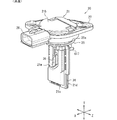
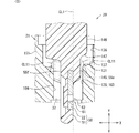
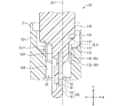
図2、図3、図8に示すように、エアフロメータ20は、取り付け対象としての配管ユニット14に取り付けられている。配管ユニット14は、吸気管14a、管フランジ14c、管ボス14dを有しており、吸気通路12を形成する形成部材である。配管ユニット14は、例えばエアケースの少なくとも一部を形成している。配管ユニット14がエアケースを形成している構成では、エアフロメータ20に加えてエアフィルタが配管ユニット14に取り付けられている。配管ユニット14では、吸気管14a、管フランジ14c及び管ボス14dが樹脂材料等により形成されている。
As shown in FIG. 2, FIG. 3, and FIG. 8, the air flow meter 20 is attached to the piping unit 14 as an attachment target. The piping unit 14 has an intake pipe 14a, a pipe flange 14c, and a pipe boss 14d, and is a forming member that forms the intake passage 12. The piping unit 14 forms at least a part of an air case, for example. In the configuration in which the piping unit 14 forms an air case, an air filter is attached to the piping unit 14 in addition to the air flow meter 20. In the piping unit 14, the intake pipe 14a, the pipe flange 14c, and the pipe boss 14d are formed of a resin material or the like.
吸気管14aは、吸気通路12を形成するダクト等の配管である。吸気管14aには、その外周部を貫通する貫通孔としてエアフロ挿入孔14bが設けられている。管フランジ14cは、円環状に形成されており、エアフロ挿入孔14bの周縁部に沿って延びている。管フランジ14cは、吸気管14aの外面から吸気通路12とは反対側に向けて延びている。管ボス14dは、柱状の部材であり、エアフロメータ20を支持する支持部である。管ボス14dは、吸気管14aの外面から管フランジ14cに沿って延びており、吸気管14aに対して複数(例えば2つ)設けられている。本実施形態では、管フランジ14c及び管ボス14dがいずれも吸気管14aから高さ方向Yに延びている。
The intake pipe 14a is a pipe such as a duct that forms the intake passage 12. The intake pipe 14a is provided with an airflow insertion hole 14b as a through hole penetrating the outer peripheral portion thereof. The pipe flange 14c is formed in an annular shape and extends along the peripheral edge of the airflow insertion hole 14b. The pipe flange 14c extends from the outer surface of the intake pipe 14a toward the side opposite to the intake passage 12. The tube boss 14d is a columnar member, and is a support portion that supports the air flow meter 20. The pipe boss 14d extends from the outer surface of the intake pipe 14a along the pipe flange 14c, and is provided in plurality (for example, two) on the intake pipe 14a. In this embodiment, both the pipe flange 14c and the pipe boss 14d extend in the height direction Y from the intake pipe 14a.
エアフロメータ20は、管フランジ14c及びエアフロ挿入孔14bに挿入されることで吸気通路12に入り込んだ状態になっており、この状態でボルト等の固定具により管ボス14dに固定されている。エアフロメータ20は、管フランジ14cの先端面に接触していない一方で、管ボス14dの先端面に接触している。このため、配管ユニット14に対するエアフロメータ20の相対的な位置や角度は、管フランジ14cではなく管ボス14dによって設定されている。複数の管ボス14dの先端面は、互いに面一になっている。なお、図8では、管ボス14dの図示を省略している。
The air flow meter 20 is inserted into the pipe flange 14c and the air flow insertion hole 14b to enter the intake passage 12, and is fixed to the pipe boss 14d by a fixing tool such as a bolt in this state. The air flow meter 20 is not in contact with the tip surface of the tube flange 14c, but is in contact with the tip surface of the tube boss 14d. Therefore, the relative position and angle of the air flow meter 20 with respect to the piping unit 14 are set by the pipe boss 14d instead of the pipe flange 14c. The tip surfaces of the plurality of tube bosses 14d are flush with each other. Note that the tube boss 14d is not shown in FIG.
本実施形態では、エアフロメータ20について、幅方向X、高さ方向Y及び奥行き方向Zを設定しており、これら方向X,Y,Zは互いに直交している。エアフロメータ20は高さ方向Yに延びており、吸気通路12は奥行き方向Zに延びている。エアフロメータ20は、吸気通路12に入り込んだ入り込み部分20aと、吸気通路12に入り込まずに管フランジ14cから外部にはみ出したはみ出し部分20bとを有しており、これら入り込み部分20aとはみ出し部分20bとは高さ方向Yに並んでいる。
In this embodiment, the width direction X, the height direction Y, and the depth direction Z are set for the air flow meter 20, and these directions X, Y, and Z are orthogonal to each other. The air flow meter 20 extends in the height direction Y, and the intake passage 12 extends in the depth direction Z. The air flow meter 20 has an entrance portion 20a that has entered the intake passage 12 and an extrusion portion 20b that does not enter the intake passage 12 and that protrudes to the outside from the pipe flange 14c. Are arranged in the height direction Y.
図2、図4、図7、図8に示すように、エアフロメータ20は、ハウジング21と、吸入空気の流量を検出する流量センサ22と、吸入空気の温度を検出する吸気温センサ23とを有している。ハウジング21は、例えば樹脂材料等により形成されている。流量センサ22はハウジング21の内部に収容されている。エアフロメータ20においては、ハウジング21が吸気管14aに取り付けられていることで、流量センサ22が、吸気通路12を流れる吸入空気と接触可能な状態になる。
As shown in FIGS. 2, 4, 7, and 8, the air flow meter 20 includes a housing 21, a flow rate sensor 22 that detects the flow rate of intake air, and an intake air temperature sensor 23 that detects the temperature of intake air. Have The housing 21 is made of, for example, a resin material. The flow rate sensor 22 is housed inside the housing 21. In the air flow meter 20, since the housing 21 is attached to the intake pipe 14a, the flow rate sensor 22 can come into contact with the intake air flowing through the intake passage 12.
ハウジング21は、取り付け対象としての配管ユニット14に取り付けられている。ハウジング21の外面においては、高さ方向Yに並んだ一対の端面21a,21bのうち、入り込み部分20aに含まれた方をハウジング先端面21aと称し、はみ出し部分20bに含まれた方をハウジング基端面21bと称する。ハウジング先端面21a及びハウジング基端面21bは高さ方向Yに直交している。管フランジ14cの先端面も高さ方向Yに直交している。なお、エアフロメータ20やハウジング21が取り付けられる取り付け対象は、吸気通路12を形成する形成部材であれば配管ユニット14でなくてもよい。
The housing 21 is attached to the piping unit 14 as an attachment target. On the outer surface of the housing 21, of the pair of end surfaces 21a and 21b arranged in the height direction Y, the one included in the entering portion 20a is referred to as the housing distal end surface 21a, and the one included in the protruding portion 20b is the housing base. It is referred to as the end face 21b. The housing front end surface 21a and the housing base end surface 21b are orthogonal to the height direction Y. The tip surface of the pipe flange 14c is also orthogonal to the height direction Y. Note that the attachment target to which the air flow meter 20 and the housing 21 are attached need not be the piping unit 14 as long as it is a forming member that forms the intake passage 12.
ハウジング21の外面においては、吸気通路12の上流側に配置される面をハウジング上流面21cと称し、ハウジング上流面21cとは反対側に配置される面をハウジング下流面21dと称する。また、ハウジング上流面21c及びハウジング基端面21bを介して対向する一対の面のうち一方をハウジング表面21eと称し、他方をハウジング裏面21fと称する。ハウジング表面21eは、後述するセンサSA50において流量センサ22が設けられた側の面である。
On the outer surface of the housing 21, a surface arranged on the upstream side of the intake passage 12 is referred to as a housing upstream surface 21c, and a surface arranged on the opposite side of the housing upstream surface 21c is referred to as a housing downstream surface 21d. In addition, one of a pair of surfaces facing each other with the housing upstream surface 21c and the housing base end surface 21b is referred to as a housing front surface 21e, and the other is referred to as a housing rear surface 21f. The housing surface 21e is a surface on the side where the flow rate sensor 22 is provided in the sensor SA50 described later.
なお、ハウジング21については、高さ方向Yにおいて、ハウジング先端面21a側をハウジング先端側と称し、ハウジング基端面21b側をハウジング基端側と称することもある。また、奥行き方向Zにおいて、ハウジング上流面21c側をハウジング上流側と称し、ハウジング下流面21d側をハウジング下流側と称することもある。さらに、幅方向Xにおいて、ハウジング表面21e側をハウジング表側と称し、ハウジング裏面21f側をハウジング裏側と称することもある。
Regarding the housing 21, in the height direction Y, the housing front end surface 21a side may be referred to as the housing front end side, and the housing base end surface 21b side may be referred to as the housing base end side. In the depth direction Z, the housing upstream surface 21c side may be referred to as the housing upstream side, and the housing downstream surface 21d side may be referred to as the housing downstream side. Further, in the width direction X, the housing front surface 21e side may be referred to as the housing front side, and the housing back surface 21f side may be referred to as the housing back side.
図2〜図7に示すように、ハウジング21は、シール保持部25、フランジ部27及びコネクタ部28を有している。エアフロメータ20はシール部材26を有しており、シール部材26はシール保持部25に取り付けられている。
As shown in FIGS. 2 to 7, the housing 21 has a seal holding portion 25, a flange portion 27, and a connector portion 28. The air flow meter 20 has a seal member 26, and the seal member 26 is attached to the seal holding portion 25.
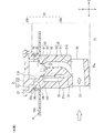
シール保持部25は、管フランジ14cの内部に設けられており、シール部材26を高さ方向Yに位置ずれしないように保持している。シール保持部25は、エアフロメータ20の入り込み部分20aに含まれている。シール保持部25は、シール部材26を保持する保持溝部25aを有している。保持溝部25aは、高さ方向Yに直交する方向X,Zに延びており、ハウジング21の周りを環状に一周している。シール部材26は、管フランジ14cの内部において吸気通路12を密閉するOリング等の部材である。シール部材26は、保持溝部25aの内部に入り込んだ状態になっており、保持溝部25aの内面と管フランジ14cの内周面との両方に密着している。シール部材26と保持溝部25aの内面とが密着した部分と、シール部材26とフランジ14cの内周面とが密着した部分とは、いずれもハウジング21の周りを環状に一周している。
The seal holding portion 25 is provided inside the pipe flange 14c and holds the seal member 26 so as not to be displaced in the height direction Y. The seal holding portion 25 is included in the entry portion 20 a of the air flow meter 20. The seal holding portion 25 has a holding groove portion 25 a that holds the seal member 26. The holding groove portion 25a extends in directions X and Z orthogonal to the height direction Y, and makes one round around the housing 21. The seal member 26 is a member such as an O-ring that seals the intake passage 12 inside the pipe flange 14c. The seal member 26 is in a state of entering the inside of the holding groove portion 25a, and is in close contact with both the inner surface of the holding groove portion 25a and the inner peripheral surface of the pipe flange 14c. The portion where the seal member 26 and the inner surface of the holding groove portion 25a are in close contact with each other and the portion where the seal member 26 and the inner peripheral surface of the flange 14c are in close contact with each other form a ring around the housing 21.
フランジ部27には、ハウジング21を吸気管14aに固定するネジ等の固定具を固定するネジ孔等の固定孔が形成されている。本実施形態では、固定孔が例えばフランジ孔611,612であり、固定具がネジである。なお、図3においては、フランジ孔611,612に挿通されたネジの図示を省略している。
The flange portion 27 is formed with a fixing hole such as a screw hole for fixing a fixing tool such as a screw for fixing the housing 21 to the intake pipe 14a. In this embodiment, the fixing holes are, for example, the flange holes 611 and 612, and the fixing tools are screws. Note that, in FIG. 3, the screws inserted into the flange holes 611 and 612 are not shown.
フランジ部27において、ハウジング先端側の面が管ボス14dの先端面に重ねられた状態で接触しており、この重ねられた部分を角度設定面27aと称する。角度設定面27aと管ボス14dの先端面とは、いずれも高さ方向Yに直交する方向に延びており、幅方向X及び奥行き方向Zに延びている。管ボス14dの先端面は、吸気管14aに対する角度設定面27aの相対的な位置や角度を設定している。角度設定面27aは、エアフロメータ20において、吸気管14aに対するハウジング21の相対的な位置や角度を設定している。
The surface of the flange portion 27 on the front end side of the housing is in contact with the front end surface of the tube boss 14d in a state of being overlapped with each other, and this overlapped portion is referred to as an angle setting surface 27a. Both the angle setting surface 27a and the tip end surface of the tube boss 14d extend in a direction orthogonal to the height direction Y, and extend in the width direction X and the depth direction Z. The tip end surface of the pipe boss 14d sets the relative position and angle of the angle setting surface 27a with respect to the intake pipe 14a. The angle setting surface 27a sets the relative position or angle of the housing 21 with respect to the intake pipe 14a in the air flow meter 20.
配管ユニット14の吸気管14aにおいては、吸気通路12を流れる空気のうち主に流れる主流が奥行き方向Zに進む。主流の進む方向を主流方向と称すると、奥行き方向Zが主流方向になっている。ハウジング21においては、フランジ部27の角度設定面27aが主流方向及び奥行き方向Zに延びている。また、管ボス14dの先端面も主流方向及び奥行き方向Zに延びている。
In the intake pipe 14 a of the piping unit 14, the main flow that mainly flows of the air flowing through the intake passage 12 proceeds in the depth direction Z. When the direction in which the mainstream proceeds is called the mainstream direction, the depth direction Z is the mainstream direction. In the housing 21, the angle setting surface 27a of the flange portion 27 extends in the mainstream direction and the depth direction Z. The tip surface of the tube boss 14d also extends in the mainstream direction and the depth direction Z.
コネクタ部28は、流量センサ22に電気的に接続されたコネクタ端子28aを保護する保護部である。コネクタ端子28aは、ECU15から延びた電気配線がプラグ部を介してコネクタ部28に接続されることでECU15に電気的に接続される。フランジ部27及びコネクタ部28は、エアフロメータ20のはみ出し部分20bに含まれている。
The connector portion 28 is a protection portion that protects the connector terminal 28 a electrically connected to the flow rate sensor 22. The connector terminal 28a is electrically connected to the ECU 15 by connecting the electrical wiring extending from the ECU 15 to the connector portion 28 via the plug portion. The flange portion 27 and the connector portion 28 are included in the protruding portion 20b of the air flow meter 20.
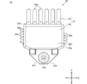
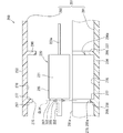
図2、図4、図7に示すように、吸気温センサ23はハウジング21の外側に設けられている。吸気温センサ23は、吸入空気の温度を感知する感温素子であり、ハウジング裏面21f側に設けられている。吸気温センサ23には、配線等により形成されたリード線23aが接続されている。ハウジング21は吸気温支持部618を有している。吸気温支持部618は、ハウジング裏面21fに設けられた凸部であり、幅方向Xにおいて吸気温センサ23よりもハウジング裏側に向けて突出している。吸気温支持部618は、リード線23aを支持していることで吸気温センサ23を支持している。吸気温支持部618は、高さ方向Yにおいて吸気温センサ23よりもハウジング基端側に設けられている。リード線23aは、吸気温支持部618からハウジング先端側に向けて延びている。
As shown in FIGS. 2, 4, and 7, the intake air temperature sensor 23 is provided outside the housing 21. The intake air temperature sensor 23 is a temperature sensitive element that senses the temperature of intake air, and is provided on the rear surface 21f of the housing. To the intake air temperature sensor 23, a lead wire 23a formed by wiring or the like is connected. The housing 21 has an intake air temperature support portion 618. The intake air temperature support portion 618 is a convex portion provided on the back surface 21f of the housing, and protrudes toward the back side of the housing from the intake air temperature sensor 23 in the width direction X. The intake air temperature support portion 618 supports the intake air temperature sensor 23 by supporting the lead wire 23a. The intake air temperature support portion 618 is provided closer to the housing base end side than the intake air temperature sensor 23 in the height direction Y. The lead wire 23a extends from the intake air temperature support portion 618 toward the front end side of the housing.
リード線23aは、吸気温支持部618を高さ方向Yに貫通している。エアフロメータ20の製造時では、吸気温支持部618に、この吸気温支持部618を高さ方向Yに貫通する貫通孔を形成しておく。そして、この貫通孔にリード線23aを挿通した状態で、吸気温支持部618を幅方向Xに押し潰すことで貫通孔を押し潰し、貫通孔に挿通させておいたリード線23aを吸気温支持部618の内部に埋め込んだ状態にする。この場合、吸気温支持部618の先端面をヒータ等の加熱具で加熱しながら押し潰すことで吸気温支持部618を熱変形させ、吸気温支持部618のうち熱変形した部分でリード線23aを覆うように保持する。この作業を、熱かしめと称することもできる。
The lead wire 23a penetrates the intake air temperature support portion 618 in the height direction Y. At the time of manufacturing the air flow meter 20, a through hole is formed in the intake air temperature support portion 618 so as to penetrate the intake air temperature support portion 618 in the height direction Y. Then, with the lead wire 23a inserted through the through hole, the intake temperature support portion 618 is crushed in the width direction X to crush the through hole, and the lead wire 23a inserted through the through hole is supported for intake temperature. It is embedded in the portion 618. In this case, the distal end surface of the intake air temperature support portion 618 is crushed while being heated by a heating tool such as a heater so that the intake air temperature support portion 618 is thermally deformed, and the lead wire 23a is deformed at a portion of the intake air temperature support portion 618 that is thermally deformed. Hold it over. This work can also be called heat staking.
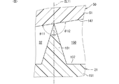
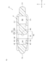
図8に示すように、ハウジング21は、バイパス流路30を有している。バイパス流路30は、ハウジング21の内部に設けられており、ハウジング21の内部空間の少なくとも一部により形成されている。ハウジング21の内面は、バイパス流路30を形成しており、形成面になっている。
As shown in FIG. 8, the housing 21 has a bypass flow passage 30. The bypass flow passage 30 is provided inside the housing 21, and is formed by at least a part of the internal space of the housing 21. The inner surface of the housing 21 forms the bypass flow passage 30 and is a forming surface.
バイパス流路30は、エアフロメータ20の入り込み部分20aに配置されている。バイパス流路30は、通過流路31及び計測流路32を有している。計測流路32には、後述するセンサSA50のうち流量センサ22とその周囲の部分とが入り込んだ状態になっている。通過流路31は、ハウジング21の内面により形成されている。計測流路32は、ハウジング21の内面に加えてセンサSA50の一部の外面により形成されている。なお、吸気通路12を主通路と称し、バイパス流路30を副通路と称することもできる。
The bypass flow passage 30 is arranged in the entry portion 20 a of the air flow meter 20. The bypass flow passage 30 has a passage flow passage 31 and a measurement flow passage 32. The measurement flow path 32 is in a state where the flow rate sensor 22 and its surrounding portion of the sensor SA50 described later are inserted. The passage 31 is formed by the inner surface of the housing 21. The measurement flow path 32 is formed by the outer surface of a part of the sensor SA50 in addition to the inner surface of the housing 21. The intake passage 12 may be referred to as a main passage and the bypass passage 30 may be referred to as a sub passage.
通過流路31は、奥行き方向Zにハウジング21を貫通している。通過流路31は、その上流端部である通過入口33と、下流端部である通過出口34とを有している。計測流路32は、通過流路31の中間部分から分岐した分岐流路であり、この計測流路32に流量センサ22が設けられている。計測流路32は、その上流端部である計測入口35と、下流端部である計測出口36とを有している。通過流路31から計測流路32が分岐した部分はこれら通過流路31と計測流路32との境界部になっており、この境界部に計測入口35が含まれている。また、通過流路31と計測流路32との境界部を流路境界部と称することもできる。計測入口35は、計測出口36側を向くように傾斜した状態でハウジング先端側を向いている。
The passage channel 31 penetrates the housing 21 in the depth direction Z. The passage channel 31 has a passage inlet 33 which is an upstream end thereof and a passage outlet 34 which is a downstream end thereof. The measurement flow channel 32 is a branch flow channel branched from the intermediate portion of the passage flow channel 31, and the flow rate sensor 22 is provided in the measurement flow channel 32. The measurement flow path 32 has a measurement inlet 35 which is an upstream end thereof and a measurement outlet 36 which is a downstream end thereof. The part where the measurement flow path 32 branches from the passage flow path 31 is a boundary portion between the passage flow path 31 and the measurement flow path 32, and the measurement inlet 35 is included in this boundary portion. In addition, the boundary between the passage channel 31 and the measurement channel 32 can be referred to as a channel boundary. The measurement inlet 35 faces the front end side of the housing while being inclined so as to face the measurement outlet 36 side.
計測流路32は、通過流路31からハウジング基端側に向けて延びている。計測流路32は、通過流路31とハウジング基端面21bとの間に設けられている。計測流路32は、計測入口35と計測出口36との間の部分がハウジング基端側に向けて膨らむように曲がっている。計測流路32は、連続的に曲がるように湾曲した部分や、段階的に折れ曲がるように屈折した部分、高さ方向Yや奥行き方向Zに真っ直ぐに延びた部分などを有している。
The measurement flow channel 32 extends from the passage flow channel 31 toward the base end side of the housing. The measurement flow path 32 is provided between the passage flow path 31 and the housing base end surface 21b. The measurement flow path 32 is curved so that the portion between the measurement inlet 35 and the measurement outlet 36 bulges toward the base end side of the housing. The measurement flow path 32 has a curved portion that bends continuously, a bent portion that bends in a stepwise manner, and a portion that extends straight in the height direction Y and the depth direction Z.
流量センサ22は、ヒータ部を有する熱式の流量検出部である。流量センサ22は、ヒータ部の発熱に伴って温度変化が生じた場合に、その温度変化に応じた検出信号を出力する。流量センサ22は直方体状のチップ部品であり、流量センサ22をセンサチップと称することもできる。なお、流量センサ22を、吸入空気の流量を流体の物理量として検出する物理量センサや物理量検出部と称することもできる。
The flow rate sensor 22 is a thermal type flow rate detection unit having a heater unit. The flow rate sensor 22 outputs a detection signal according to the temperature change when the temperature change occurs due to the heat generation of the heater unit. The flow rate sensor 22 is a rectangular parallelepiped chip component, and the flow rate sensor 22 can also be referred to as a sensor chip. The flow rate sensor 22 can also be referred to as a physical quantity sensor or a physical quantity detection unit that detects the flow rate of intake air as a physical quantity of a fluid.
エアフロメータ20は、流量センサ22を含んで構成されたセンササブアッセンブリを有しており、このセンササブアッセンブリをセンサSA50と称する。センサSA50は、センサSA50の一部が計測流路32に入り込んだ状態でハウジング21の内部に埋め込まれている。エアフロメータ20においては、センサSA50とバイパス流路30とが高さ方向Yに並べられている。具体的には、センサSA50と通過流路31とが高さ方向に並べられている。なお、センサSA50が検出ユニットに相当する。また、センサSA50を計測ユニットやセンサパッケージと称することもできる。
The air flow meter 20 has a sensor subassembly including a flow rate sensor 22, and this sensor subassembly is referred to as a sensor SA50. The sensor SA50 is embedded in the housing 21 in a state where a part of the sensor SA50 enters the measurement flow channel 32. In the air flow meter 20, the sensor SA50 and the bypass flow passage 30 are arranged in the height direction Y. Specifically, the sensor SA50 and the passage channel 31 are arranged in the height direction. The sensor SA50 corresponds to the detection unit. The sensor SA50 can also be called a measurement unit or a sensor package.
<構成群Aの説明>
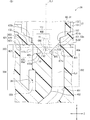
図9、図10、図11に示すように、センサSA50は、流量センサ22に加えてセンサ支持部51を有している。センサ支持部51は、ハウジング21に取り付けられており、流量センサ22を支持している。センサ支持部51は、SA基板53及びモールド部55を有している。SA基板53は、流量センサ22が搭載された基板であり、モールド部55は、流量センサ22の少なくとも一部やSA基板53の少なくとも一部を覆っている。SA基板53をリードフレームと称することもできる。
<Explanation of configuration group A>
As shown in FIGS. 9, 10, and 11, the sensor SA50 has a sensor support portion 51 in addition to the flow rate sensor 22. The sensor support portion 51 is attached to the housing 21 and supports the flow rate sensor 22. The sensor support portion 51 has an SA substrate 53 and a mold portion 55. The SA substrate 53 is a substrate on which the flow sensor 22 is mounted, and the mold portion 55 covers at least a part of the flow sensor 22 and at least a part of the SA substrate 53. The SA substrate 53 can also be called a lead frame.
モールド部55は、全体として板状に形成されている。モールド部55の外面においては、高さ方向Yに並んだ一対の端面55a,55bのうち、ハウジング先端側の方をモールド先端面55aと称し、ハウジング基端側の方をモールド基端面55bと称する。なお、モールド先端面55aが、モールド部55及びセンサ支持部51の先端部になっており、支持先端部に相当する。また、モールド部55が保護樹脂部に相当する。
The mold part 55 is formed in a plate shape as a whole. On the outer surface of the mold portion 55, of the pair of end surfaces 55a and 55b arranged in the height direction Y, the housing front end side is referred to as the mold front end surface 55a, and the housing base end side is referred to as the mold base end surface 55b. .. The mold tip surface 55a is the tip portion of the mold portion 55 and the sensor support portion 51 and corresponds to the support tip portion. The mold portion 55 corresponds to the protective resin portion.
モールド部55の外面においては、モールド先端面55a及びモールド基端面55bを挟んで設けられた一対の面のうち一方をモールド上流面55cと称し、他方をモールド下流面55dと称する。センサSA50は、図8において、モールド先端面55aがエアフロ先端側に配置され、且つモールド上流面55cがモールド下流面55dよりも計測流路32の上流側に配置される向きで、ハウジング21の内部に設置されている。センサ支持部51においては、モールド上流面55cが上流端部に相当し、モールド下流面55dが下流端部に相当する。
On the outer surface of the mold portion 55, one of a pair of surfaces provided with the mold front end surface 55a and the mold base end surface 55b interposed therebetween is referred to as a mold upstream surface 55c, and the other is referred to as a mold downstream surface 55d. In FIG. 8, the sensor SA50 has the interior of the housing 21 with the mold front end surface 55a disposed on the airflow front end side and the mold upstream surface 55c disposed upstream of the measurement flow path 32 relative to the mold downstream surface 55d. It is installed in. In the sensor support portion 51, the mold upstream surface 55c corresponds to the upstream end portion, and the mold downstream surface 55d corresponds to the downstream end portion.
センサSA50のモールド上流面55cは、計測流路32においてモールド下流面55dよりも上流側に配置されている。計測流路32において流量センサ22が設けられた部分においては、空気の流れる向きが吸気通路12での空気の流れる向きとは反対になっている。このため、モールド上流面55cは、吸気通路12においてはモールド下流面55dよりも下流側に配置されていることになる。なお、流量センサ22に沿って流れる空気は奥行き方向Zに流れ、この奥行き方向Zを流れ方向と称することもできる。
The mold upstream surface 55c of the sensor SA50 is arranged on the upstream side of the mold downstream surface 55d in the measurement flow path 32. In the portion of the measurement flow path 32 where the flow rate sensor 22 is provided, the direction of air flow is opposite to the direction of air flow in the intake passage 12. Therefore, the mold upstream surface 55c is arranged on the downstream side of the mold downstream surface 55d in the intake passage 12. The air flowing along the flow rate sensor 22 flows in the depth direction Z, and the depth direction Z can also be referred to as a flow direction.
図9、図10に示すように、センサSA50においては、流量センサ22がセンサSA50の一面側に露出している。モールド部55の外面においては、流量センサ22が露出した側の板面をモールド表面55eと称し、反対側の板面をモールド裏面55fと称する。センサSA50の一方の板面がモールド表面55eにより形成されており、このモールド表面55eが支持表面に相当し、モールド裏面55fが支持裏面に相当する。
As shown in FIGS. 9 and 10, in the sensor SA50, the flow rate sensor 22 is exposed on one surface side of the sensor SA50. On the outer surface of the mold part 55, the plate surface on the side where the flow rate sensor 22 is exposed is referred to as a mold surface 55e, and the plate surface on the opposite side is referred to as a mold back surface 55f. One plate surface of the sensor SA50 is formed by the mold surface 55e, the mold surface 55e corresponds to the support surface, and the mold back surface 55f corresponds to the support back surface.
なお、モールド部55については、高さ方向Yにおいて、モールド先端面55a側をモールド側と称し、モールド基端面55b側をモールド基端側と称することもある。また、奥行き方向Zにおいて、モールド上流面55c側をモールド上流側と称し、モールド下流面55d側をモールド下流側と称することもある。さらに、幅方向Xにおいて、モールド表面55e側をモールド表側と称し、モールド裏面55f側をモールド裏側と称することもある。
Regarding the mold portion 55, in the height direction Y, the mold front end surface 55a side may be referred to as the mold side, and the mold base end surface 55b side may be referred to as the mold base end side. In the depth direction Z, the mold upstream surface 55c side may be referred to as the mold upstream side, and the mold downstream surface 55d side may be referred to as the mold downstream side. Furthermore, in the width direction X, the mold front surface 55e side may be referred to as the mold front side, and the mold back surface 55f side may be referred to as the mold back side.
SA基板53は、金属材料等により全体として板状に形成されており、導電性を有する基板である。SA基板53の板面は、幅方向Xに直交しており、高さ方向Y及び奥行き方向Zに延びている。SA基板53には流量センサ22が搭載されている。SA基板53は、リード端子53a、上流試験端子53b、下流試験端子53cを有している。SA基板53には、モールド部55により覆われた部分と、モールド部55によっては覆われていない部分とを有しており、覆われていない部分により端子53a,53b,53cが形成されている。なお、図8等においては、端子53a,53b,53cの図示を省略している。
The SA substrate 53 is formed of a metal material or the like in a plate shape as a whole, and is a conductive substrate. The plate surface of the SA substrate 53 is orthogonal to the width direction X and extends in the height direction Y and the depth direction Z. The flow rate sensor 22 is mounted on the SA substrate 53. The SA substrate 53 has a lead terminal 53a, an upstream test terminal 53b, and a downstream test terminal 53c. The SA substrate 53 has a portion covered by the mold portion 55 and a portion not covered by the mold portion 55, and terminals 53a, 53b, 53c are formed by the uncovered portion. .. Note that the terminals 53a, 53b, 53c are not shown in FIG. 8 and the like.
リード端子53aは、モールド基端面55bから高さ方向Yに突出した端子であり、複数設けられている。複数のリード端子53aには、コネクタ端子28aに接続された端子や、吸気温センサ23に接続された端子、流量センサ22の検出精度等を調整するための調整端子が含まれている。本実施形態では、センサSA50がリード端子53aを6つ有している。これら6つのリード端子53aには、コネクタ端子28aに接続された端子が3つ、吸気温センサ23に接続された端子が2つ、調整端子が1つ含まれている。コネクタ端子28aに接続された3つの端子には、グランドに接地されたグランド端子と、5V等の所定電圧が印加される電源端子と、流量センサ22の検出結果に関する信号を出力する出力端子とが含まれている。吸気温センサ23に接続された2つの端子には、グランドに接続されたグランド端子と、吸気温センサ23の検出結果に関する信号を出力する出力端子とが含まれている。
The lead terminals 53a are terminals protruding in the height direction Y from the mold base end surface 55b, and a plurality of lead terminals 53a are provided. The lead terminals 53a include terminals connected to the connector terminals 28a, terminals connected to the intake air temperature sensor 23, and adjustment terminals for adjusting the detection accuracy of the flow rate sensor 22 and the like. In the present embodiment, the sensor SA50 has six lead terminals 53a. These six lead terminals 53a include three terminals connected to the connector terminal 28a, two terminals connected to the intake air temperature sensor 23, and one adjustment terminal. The three terminals connected to the connector terminal 28a include a ground terminal grounded to the ground, a power supply terminal to which a predetermined voltage such as 5V is applied, and an output terminal that outputs a signal related to the detection result of the flow rate sensor 22. include. The two terminals connected to the intake air temperature sensor 23 include a ground terminal connected to the ground and an output terminal for outputting a signal regarding the detection result of the intake air temperature sensor 23.
上流試験端子53bは、モールド上流面55cから奥行き方向Zに突出した端子であり、複数設けられている。複数の上流試験端子53bには、SA基板53に搭載されたコンデンサの動作確認等をするためのコンデンサチェック端子や、流量センサ22の動作確認等をするためのICテスト端子、グランドに接地するためのグランド端子が含まれている。
The upstream test terminals 53b are terminals protruding in the depth direction Z from the mold upstream surface 55c, and a plurality of them are provided. For the upstream test terminals 53b, a capacitor check terminal for confirming the operation of a capacitor mounted on the SA substrate 53, an IC test terminal for confirming the operation of the flow sensor 22, and grounding to the ground. The ground terminal of is included.
下流試験端子53cは、モールド下流面55dから奥行き方向Zに突出した端子であり、複数設けられている。複数の下流試験端子53cには、上流試験端子53bと同様に、コンデンサチェック端子やICテスト端子、グランド端子が含まれている。
The downstream test terminals 53c are terminals protruding in the depth direction Z from the mold downstream surface 55d, and a plurality of them are provided. Similar to the upstream test terminal 53b, the plurality of downstream test terminals 53c include a capacitor check terminal, an IC test terminal, and a ground terminal.
図12に示すように、流量センサ22は全体として板状に形成されている。流量センサ22は、一面であるセンサ表面22aと、センサ表面22aとは反対のセンサ裏面22bとを有している。流量センサ22においては、センサ裏面22bがSA基板53に重ねられており、センサ表面22aの一部がセンサSA50の外部に露出している。
As shown in FIG. 12, the flow rate sensor 22 is formed in a plate shape as a whole. The flow rate sensor 22 has a sensor surface 22a, which is one surface, and a sensor back surface 22b opposite to the sensor surface 22a. In the flow rate sensor 22, the sensor back surface 22b is overlaid on the SA substrate 53, and a part of the sensor surface 22a is exposed to the outside of the sensor SA50.
流量センサ22は、センサ凹部61及びメンブレン部62を有している。センサ凹部61はセンサ裏面22bに対して設けられており、メンブレン部62はセンサ表面22aに対して設けられている。メンブレン部62は、センサ凹部61の底面であるセンサ凹底面501を形成している。メンブレン部62のうちセンサ凹底面501を形成している部分は、センサ凹部61にとっての底部になっている。センサ凹部61は、センサ裏面22bがセンサ表面22a側に向けて凹むことで形成されている。センサ凹部61の開口部であるセンサ凹開口503はセンサ裏面22bに設けられている。センサ凹部61の内壁面であるセンサ凹内壁面502は、センサ凹底面501とセンサ凹開口503とにかけ渡されている。メンブレン部62は、流量をセンシングするセンシング部になっている。
The flow rate sensor 22 has a sensor concave portion 61 and a membrane portion 62. The sensor concave portion 61 is provided on the sensor back surface 22b, and the membrane portion 62 is provided on the sensor surface 22a. The membrane portion 62 forms a sensor concave bottom surface 501 which is the bottom surface of the sensor concave portion 61. The portion of the membrane portion 62 forming the sensor concave bottom surface 501 is the bottom portion for the sensor concave portion 61. The sensor recess 61 is formed by recessing the sensor back surface 22b toward the sensor front surface 22a. The sensor recess opening 503 which is the opening of the sensor recess 61 is provided on the sensor back surface 22b. The sensor recess inner wall surface 502, which is the inner wall surface of the sensor recess 61, extends across the sensor recess bottom surface 501 and the sensor recess opening 503. The membrane portion 62 is a sensing portion that senses the flow rate.
流量センサ22は、センサ基板65及びセンサ膜部66を有している。センサ基板65は、流量センサ22の母材であり、シリコン等の半導体材料により板状に形成されている。センサ基板65は、一面であるセンサ基板表面65aと、センサ基板表面65aとは反対のセンサ基板裏面65bとを有している。センサ基板65には、センサ基板65を幅方向Xに貫通する貫通孔が形成されており、この貫通孔によりセンサ凹部61が形成されている。なお、センサ基板65には、貫通孔ではなく、センサ凹部61を形成する凹部が形成されていてもよい。この場合、センサ凹部61の底面はメンブレン部62により形成されるのではなく、センサ基板65の凹部の底面により形成されることになる。
The flow rate sensor 22 has a sensor substrate 65 and a sensor film portion 66. The sensor substrate 65 is a base material of the flow rate sensor 22, and is formed in a plate shape from a semiconductor material such as silicon. The sensor substrate 65 has a sensor substrate front surface 65a, which is one surface, and a sensor substrate back surface 65b opposite to the sensor substrate front surface 65a. The sensor substrate 65 has a through hole penetrating the sensor substrate 65 in the width direction X, and the sensor recess 61 is formed by the through hole. It should be noted that the sensor substrate 65 may be formed with a recess that forms the sensor recess 61 instead of the through hole. In this case, the bottom surface of the sensor recess 61 is not formed by the membrane portion 62, but is formed by the bottom surface of the recess of the sensor substrate 65.
センサ膜部66は、センサ基板65のセンサ基板表面65aに重ねられており、センサ基板表面65aに沿って膜状に延びている。流量センサ22においては、センサ表面22aがセンサ膜部66により形成され、センサ裏面22bがセンサ基板65により形成されている。この場合、センサ裏面22bは、センサ基板65のセンサ基板裏面65bになっている。
The sensor film portion 66 is superposed on the sensor substrate surface 65a of the sensor substrate 65 and extends in a film shape along the sensor substrate surface 65a. In the flow rate sensor 22, the sensor surface 22 a is formed by the sensor film portion 66, and the sensor back surface 22 b is formed by the sensor substrate 65. In this case, the sensor back surface 22b is the sensor board back surface 65b of the sensor board 65.
センサ膜部66は、絶縁層や導電層、保護層など複数の層を有しており、多層構造になっている。これらは、いずれも膜状に形成されており、センサ基板表面65aに沿って延びている。センサ膜部66は、配線や抵抗体などの配線パターンを有しており、この配線パターンは導電層により形成されている。
The sensor film portion 66 has a plurality of layers such as an insulating layer, a conductive layer, and a protective layer, and has a multilayer structure. Each of these is formed in a film shape and extends along the sensor substrate surface 65a. The sensor film portion 66 has a wiring pattern such as wiring and resistors, and this wiring pattern is formed by a conductive layer.
流量センサ22においては、ウェットエッチングによりセンサ基板65の一部を加工することでセンサ凹部61が形成されている。流量センサ22の製造工程においては、シリコン窒化膜等のマスクをセンサ基板65のセンサ基板裏面65bに装着し、エッチング液を用いてセンサ膜部66が露出するまでセンサ基板裏面65bに対して異方性エッチングを行う。なお、センサ基板65に対してドライエッチング加工を行うことでセンサ凹部61を形成してもよい。
In the flow rate sensor 22, the sensor recess 61 is formed by processing a part of the sensor substrate 65 by wet etching. In the manufacturing process of the flow rate sensor 22, a mask such as a silicon nitride film is attached to the sensor substrate back surface 65b of the sensor substrate 65 and is anisotropically applied to the sensor substrate back surface 65b using an etching solution until the sensor film portion 66 is exposed. Etching. The sensor recess 61 may be formed by performing dry etching on the sensor substrate 65.
センサSA50は、空気の流量を検出する流量検出回路を有しており、この流量検出回路の少なくとも一部が流量センサ22に含まれている。図13に示すように、センサSA50は、流量検出回路に含まれる回路素子として、発熱抵抗体71、測温抵抗体72,73、傍熱抵抗体74、を有している。これら抵抗体71〜74は、流量センサ22に含まれており、センサ膜部66の導電層により形成されている。この場合、センサ膜部66が抵抗体71〜74を有しており、これら抵抗体71〜74は導電層の配線パターンに含まれている。抵抗体71〜74が検出素子に相当する。なお、図13においては、抵抗体71〜74を含む配線パターンをドットハッチングで図示している。また、流量検出回路を、空気の流量を計測する流量計測部と称することもできる。
The sensor SA50 has a flow rate detection circuit that detects the flow rate of air, and at least a part of this flow rate detection circuit is included in the flow rate sensor 22. As shown in FIG. 13, the sensor SA50 includes a heating resistor 71, temperature measuring resistors 72 and 73, and an indirectly heated resistor 74 as circuit elements included in the flow rate detection circuit. These resistors 71 to 74 are included in the flow rate sensor 22 and are formed by the conductive layer of the sensor film portion 66. In this case, the sensor film portion 66 has resistors 71 to 74, and these resistors 71 to 74 are included in the wiring pattern of the conductive layer. The resistors 71 to 74 correspond to detection elements. In addition, in FIG. 13, the wiring pattern including the resistors 71 to 74 is illustrated by dot hatching. The flow rate detection circuit can also be referred to as a flow rate measurement unit that measures the flow rate of air.
発熱抵抗体71は、発熱抵抗体71への通電に伴って熱を発生させる抵抗素子である。発熱抵抗体71は、発熱することでセンサ膜部66を加熱し、ヒータ部に相当する。測温抵抗体72,73は、センサ膜部66の温度を検出するための抵抗素子であり、温度検出部に相当する。測温抵抗体72,73の抵抗値は、センサ膜部66の温度に応じて変化する。流量検出回路においては、測温抵抗体72,73の抵抗値を用いてセンサ膜部66の温度を検出する。流量検出回路は、発熱抵抗体71によりセンサ膜部66及び測温抵抗体72,73の温度を上昇させ、計測流路32にて空気の流れが生じた場合に、測温抵抗体72,73による検出温度の変化態様を用いて空気流量や流れの向きを検出する。
The heating resistor 71 is a resistance element that generates heat as the heating resistor 71 is energized. The heating resistor 71 heats the sensor film portion 66 by generating heat, and corresponds to a heater portion. The resistance temperature detectors 72 and 73 are resistance elements for detecting the temperature of the sensor film portion 66, and correspond to the temperature detection portion. The resistance values of the resistance temperature detectors 72 and 73 change according to the temperature of the sensor film portion 66. In the flow rate detection circuit, the temperature of the sensor film portion 66 is detected using the resistance values of the resistance temperature detectors 72 and 73. The flow rate detection circuit raises the temperatures of the sensor film portion 66 and the temperature measuring resistors 72 and 73 by the heat generating resistor 71, and when air flows in the measurement flow path 32, the temperature measuring resistors 72 and 73. The air flow rate and the flow direction are detected using the change mode of the detected temperature according to.
発熱抵抗体71は、高さ方向Y及び奥行き方向Zのそれぞれについてメンブレン部62のほぼ中央に配置されている。発熱抵抗体71は、全体として高さ方向Yに延びる長方形状に形成されている。発熱抵抗体71の中心線CL1は、発熱抵抗体71の中心CO1を通り、高さ方向Yに直線状に延びている。この中心線CL1は、メンブレン部62の中心を通っている。発熱抵抗体71は、メンブレン部62の周縁部から内側に離間した位置に配置されている。発熱抵抗体71においては、中心CO1に対する離間距離が、モールド先端側の端部とモールド基端側の端部とで同じになっている。
The heat-generating resistor 71 is arranged substantially at the center of the membrane portion 62 in each of the height direction Y and the depth direction Z. The heating resistor 71 is formed in a rectangular shape extending in the height direction Y as a whole. The center line CL1 of the heating resistor 71 passes through the center CO1 of the heating resistor 71 and extends linearly in the height direction Y. The center line CL1 passes through the center of the membrane portion 62. The heating resistor 71 is arranged at a position spaced inward from the peripheral portion of the membrane portion 62. In the heating resistor 71, the distance from the center CO1 is the same at the end on the mold front end side and the end on the mold base end side.
測温抵抗体72,73は、いずれも全体として高さ方向Yに延びる長方形状に形成されており、奥行き方向Zに並べられている。これら測温抵抗体72,73の間に発熱抵抗体71が設けられている。測温抵抗体72,73のうち、上流測温抵抗体72は、発熱抵抗体71からモールド上流側に離間した位置に設けられている。下流測温抵抗体73は、発熱抵抗体71からモールド下流側に離間した位置に設けられている。上流測温抵抗体72の中心線CL2及び下流測温抵抗体73の中心線CL3は、いずれも発熱抵抗体71の中心線CL1に平行に直線状に延びている。発熱抵抗体71は、奥行き方向Zにおいて上流測温抵抗体72と下流測温抵抗体73との中間位置に設けられている。
Each of the resistance temperature detectors 72 and 73 is formed in a rectangular shape extending in the height direction Y as a whole, and is arranged in the depth direction Z. A heating resistor 71 is provided between the temperature measuring resistors 72 and 73. Of the temperature measuring resistors 72 and 73, the upstream temperature measuring resistor 72 is provided at a position separated from the heat generating resistor 71 on the upstream side of the mold. The downstream resistance temperature detector 73 is provided at a position separated from the heating resistor 71 on the downstream side of the mold. The center line CL2 of the upstream resistance temperature detector 72 and the center line CL3 of the downstream resistance temperature detector 73 both linearly extend in parallel to the center line CL1 of the heating resistor 71. The heating resistor 71 is provided at an intermediate position between the upstream temperature measuring resistor 72 and the downstream temperature measuring resistor 73 in the depth direction Z.
なお、本実施形態のセンサSA50については、図10において、モールド上流面55c側をモールド上流側と称し、モールド下流面55d側をモールド下流側と称する。また、モールド先端面55a側をモールド先端側と称し、モールド基端面55b側をモールド基端側と称する。
Regarding the sensor SA50 of the present embodiment, in FIG. 10, the mold upstream surface 55c side is referred to as the mold upstream side, and the mold downstream surface 55d side is referred to as the mold downstream side. The mold front end surface 55a side is referred to as the mold front end side, and the mold base end surface 55b side is referred to as the mold base end side.
図13の説明に戻り、傍熱抵抗体74は、発熱抵抗体71の温度を検出するための抵抗素子である。傍熱抵抗体74は、発熱抵抗体71の周縁部に沿って延びている。傍熱抵抗体74の抵抗値は、発熱抵抗体71の温度に応じて変化する。流量検出回路においては、傍熱抵抗体74の抵抗値を用いて発熱抵抗体71の温度を検出する。
Returning to the explanation of FIG. 13, the indirectly heated resistor 74 is a resistance element for detecting the temperature of the heating resistor 71. The indirectly heated resistor 74 extends along the peripheral edge of the heat generating resistor 71. The resistance value of the indirectly heated resistor 74 changes according to the temperature of the heating resistor 71. In the flow rate detection circuit, the resistance value of the indirectly heated resistor 74 is used to detect the temperature of the heating resistor 71.
センサSA50は、発熱配線75、測温配線76,77を有している。これら配線75〜77は、抵抗体71〜74と同様に、センサ膜部66の配線パターンに含まれている。発熱配線75は、発熱抵抗体71からモールド基端側に向けて高さ方向Yに延びている。上流測温配線76は、上流測温抵抗体72からモールド先端側に向けて高さ方向Yに延びている。下流測温配線77は、下流測温抵抗体73からモールド先端側に向けて高さ方向Yに延びている。
The sensor SA50 has a heating wire 75 and temperature measuring wires 76 and 77. These wirings 75 to 77 are included in the wiring pattern of the sensor film portion 66, like the resistors 71 to 74. The heat generating wiring 75 extends in the height direction Y from the heat generating resistor 71 toward the mold base end side. The upstream temperature measuring wiring 76 extends in the height direction Y from the upstream temperature measuring resistor 72 toward the mold front end side. The downstream temperature measuring wiring 77 extends in the height direction Y from the downstream temperature measuring resistor 73 toward the mold front end side.
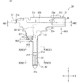
図14、図15に示すように、計測流路32の中心線CL4は、計測入口35の中心CO2と計測出口36の中心CO3とを通り、計測流路32に沿って直線状に延びている。センサSA50は、計測流路32において計測入口35と計測出口36との間に設けられている。センサSA50は、計測入口35から上流側に離間した位置であって、計測出口36から上流側に離間した位置に設けられている。なお、図14においては、計測流路32のうちSA挿入孔107の内部空間を除いた領域の中心線を中心線CL4として図示している。
As shown in FIGS. 14 and 15, the center line CL4 of the measurement flow passage 32 passes through the center CO2 of the measurement inlet 35 and the center CO3 of the measurement outlet 36 and extends linearly along the measurement flow passage 32. .. The sensor SA50 is provided in the measurement flow path 32 between the measurement inlet 35 and the measurement outlet 36. The sensor SA50 is provided at a position separated from the measurement inlet 35 to the upstream side and a position separated from the measurement outlet 36 to the upstream side. Note that in FIG. 14, the center line of the region of the measurement flow path 32 excluding the internal space of the SA insertion hole 107 is shown as the center line CL4.
通過流路31においては、通過出口34の開口面積が通過入口33の開口面積よりも小さくなっている。高さ方向Yについて通過出口34の高さ寸法と通過入口33の高さ寸法は同じになっている一方で、幅方向Xについて通過出口34の幅寸法は通過入口33の幅寸法より小さくなっている。通過入口33の開口面積は、通過入口33の中心CO21を含む領域の面積であり、通過出口34の開口面積は、通過出口34の中心CO24を含む領域の面積である。
In the passage channel 31, the opening area of the passage outlet 34 is smaller than the opening area of the passage inlet 33. The height dimension of the passage outlet 34 and the height dimension of the passage inlet 33 are the same in the height direction Y, while the width dimension of the passage outlet 34 is smaller than the width dimension of the passage inlet 33 in the width direction X. There is. The opening area of the passage inlet 33 is the area of the region including the center CO21 of the passage inlet 33, and the opening area of the passage outlet 34 is the area of the region including the center CO24 of the passage outlet 34.
計測流路32においては、複数の計測出口36の各開口面積を合計した値が計測入口35の開口面積よりも小さくなっている。このことを単に、計測出口36の開口面積が計測入口35の開口面積よりも小さくなっている、と言うこともある。計測入口35の開口面積は、計測入口35の中心CO2を含む領域の面積であり、計測出口36の開口面積は、計測出口36の中心CO3を含む領域の面積である。
In the measurement flow path 32, the total value of the opening areas of the plurality of measurement outlets 36 is smaller than the opening area of the measurement inlet 35. This may be simply referred to as the opening area of the measurement outlet 36 being smaller than the opening area of the measurement inlet 35. The opening area of the measurement inlet 35 is the area of the region including the center CO2 of the measurement inlet 35, and the opening area of the measurement outlet 36 is the area of the region including the center CO3 of the measurement outlet 36.
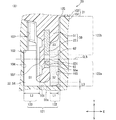
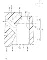
図15、図16に示すように、ハウジング21は、計測流路32を形成する形成面として、計測床面101、計測天井面102、表計測壁面103、裏計測壁面104を有している。これら計測床面101、計測天井面102、表計測壁面103及び裏計測壁面104は、いずれも計測流路32の中心線CL4に沿って延びている。計測床面101、計測天井面102、表計測壁面103及び裏計測壁面104は、計測流路32のうち奥行き方向Zに延びている部分を形成している。なお、計測床面101が床面に相当し、表計測壁面103が表壁面103相当し、裏計測壁面104が裏壁面に相当する。幅方向Xが、表壁面と裏壁面とが並んだ表裏方向に相当する。
As shown in FIGS. 15 and 16, the housing 21 has a measurement floor surface 101, a measurement ceiling surface 102, a front measurement wall surface 103, and a back measurement wall surface 104 as forming surfaces forming the measurement flow path 32. The measurement floor surface 101, the measurement ceiling surface 102, the front measurement wall surface 103, and the back measurement wall surface 104 all extend along the center line CL4 of the measurement flow path 32. The measurement floor surface 101, the measurement ceiling surface 102, the front measurement wall surface 103, and the back measurement wall surface 104 form a portion of the measurement flow path 32 extending in the depth direction Z. The measurement floor surface 101 corresponds to the floor surface, the front measurement wall surface 103 corresponds to the front wall surface 103, and the back measurement wall surface 104 corresponds to the back wall surface. The width direction X corresponds to the front-back direction in which the front wall surface and the back wall surface are lined up.
計測床面101及び計測天井面102は、表計測壁面103と裏計測壁面104との間に設けられている。計測床面101は、センサSA50のモールド先端面55aに対向しており、奥行き方向Zに真っ直ぐに延びている。計測天井面102は、高さ方向Yにおいて中心線CL4を介して計測床面101とは反対側に設けられている。ハウジング21において計測天井面102を形成する部分には、センサSA50が挿入されたSA挿入孔107が設けられている。このSA挿入孔107は、センサSA50によって閉鎖されている。計測流路32には、SA挿入孔107の内部空間のうちセンサSA50とハウジング21との隙間も含まれている。
The measurement floor surface 101 and the measurement ceiling surface 102 are provided between the front measurement wall surface 103 and the back measurement wall surface 104. The measurement floor surface 101 faces the mold front end surface 55a of the sensor SA50 and extends straight in the depth direction Z. The measurement ceiling surface 102 is provided on the opposite side of the measurement floor surface 101 with the center line CL4 in the height direction Y. An SA insertion hole 107 into which the sensor SA50 is inserted is provided in a portion of the housing 21 that forms the measurement ceiling surface 102. The SA insertion hole 107 is closed by the sensor SA50. The measurement flow path 32 also includes a gap between the sensor SA50 and the housing 21 in the internal space of the SA insertion hole 107.
表計測壁面103と裏計測壁面104とは、計測床面101や計測天井面102を介して互いに対向する一対の壁面である。表計測壁面103は、センサSA50のモールド表面55eに対向しており、計測床面101のエアフロ表側の端部からハウジング基端側に向けて延びている。特に、表計測壁面103は、センサSA50の流量センサ22に対向している。裏計測壁面104は、センサSA50のモールド裏面55fに対向しており、計測床面101のエアフロ裏側の端部からハウジング基端側に向けて延びている。なお、図15、図16においては、センサSA50の内部構造について図示を簡略化し、モールド部55及び流量センサ22の図示にとどめている。
The front measurement wall surface 103 and the back measurement wall surface 104 are a pair of wall surfaces facing each other via the measurement floor surface 101 and the measurement ceiling surface 102. The front measurement wall surface 103 faces the mold surface 55e of the sensor SA50, and extends from the end of the measurement floor surface 101 on the airflow front side toward the housing base end side. Particularly, the front measurement wall surface 103 faces the flow rate sensor 22 of the sensor SA50. The back measurement wall surface 104 faces the mold back surface 55f of the sensor SA50 and extends from the end of the measurement floor surface 101 on the back side of the airflow toward the housing base end side. Note that, in FIGS. 15 and 16, the internal structure of the sensor SA50 is simplified and only the mold portion 55 and the flow rate sensor 22 are shown.
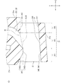
ハウジング21は、表絞り部111及び裏絞り部112を有している。これら絞り部111,112は、計測流路32の断面積S4が計測入口35等の上流から流量センサ22に向けて徐々に小さくなるように計測流路32を徐々に絞っている。また、絞り部111,112は、断面積S4が流量センサ22から計測出口36等の下流から流量センサ22に向けて徐々に小さくなるように計測流路32を徐々に絞っている。なお、計測流路32については、中心線CL4に直交する領域の面積を断面積S4と称しており、この断面積S4を流路面積と称することもできる。
The housing 21 has a front narrowing portion 111 and a back narrowing portion 112. These narrowed portions 111 and 112 gradually narrow the measurement flow passage 32 so that the cross-sectional area S4 of the measurement flow passage 32 gradually decreases from the upstream of the measurement inlet 35 or the like toward the flow rate sensor 22. Further, the narrowed portions 111 and 112 gradually narrow the measurement flow passage 32 so that the cross-sectional area S4 gradually decreases from the downstream of the flow rate sensor 22 such as the measurement outlet 36 toward the flow rate sensor 22. Regarding the measurement flow channel 32, the area of the region orthogonal to the center line CL4 is referred to as the cross-sectional area S4, and this cross-sectional area S4 can also be referred to as the flow channel area.
表絞り部111は、表計測壁面103の一部が裏計測壁面104に向けて突出した凸部である。裏絞り部112は、裏計測壁面104の一部が表計測壁面103に向けて突出した凸部である。表絞り部111と裏絞り部112とは、高さ方向Yに並べられており、高さ方向Yにおいて互いに対向している。これら絞り部111,112は、計測天井面102と計測床面101とにかけ渡されている。絞り部111,112は、幅方向Xでの表計測壁面103と裏計測壁面104との離間距離である計測幅寸法W1を上流から流量センサ22に向けて徐々に小さくしている。また、絞り部111,112は、計測幅寸法W1を下流から流量センサ22に向けて徐々に小さくしている。
The front narrowing portion 111 is a convex portion in which a part of the front measurement wall surface 103 projects toward the back measurement wall surface 104. The back narrowing portion 112 is a convex portion in which a part of the back measurement wall surface 104 projects toward the front measurement wall surface 103. The front narrowing portion 111 and the back narrowing portion 112 are arranged in the height direction Y and face each other in the height direction Y. These diaphragms 111 and 112 are bridged over the measurement ceiling surface 102 and the measurement floor surface 101. The narrowed portions 111 and 112 gradually reduce the measurement width dimension W1 that is the distance between the front measurement wall surface 103 and the back measurement wall surface 104 in the width direction X from the upstream side toward the flow rate sensor 22. Further, the narrowed portions 111 and 112 gradually reduce the measurement width dimension W1 from the downstream side toward the flow rate sensor 22.
絞り部111,112は、計測流路32において上流側から流量センサ22に向けて中心線CL4に徐々に近づいている。計測流路32においては、幅方向Xでの絞り部111,112と中心線CL4との離間距離W2,W3が、上流から流量センサ22に向けて徐々に小さくなっている。また、絞り部111,112は、計測流路32において下流側から流量センサ22に向けて中心線CL4に徐々に近づいている。計測流路32においては、幅方向Xでの絞り部111,112と中心線CL4との離間距離W2,W3が、下流から流量センサ22に向けて徐々に小さくなっている。
The throttles 111 and 112 gradually approach the center line CL4 from the upstream side toward the flow rate sensor 22 in the measurement flow path 32. In the measurement flow path 32, the separation distances W2 and W3 between the narrowed portions 111 and 112 and the center line CL4 in the width direction X gradually decrease from the upstream to the flow sensor 22. Further, the throttle portions 111 and 112 gradually approach the center line CL4 from the downstream side toward the flow rate sensor 22 in the measurement flow path 32. In the measurement flow path 32, the distances W2 and W3 between the narrowed portions 111 and 112 and the center line CL4 in the width direction X gradually decrease from the downstream side toward the flow rate sensor 22.
絞り部111,112においては、中心線CL4に最も接近した部分が頂部111a,112aになっている。この場合、絞り部111,112においては、中心線CL4との離間距離W2,W3が頂部111a,112aにおいて最も小さくなっている。頂部111a,112aのうち、表頂部111aが表絞り部111の頂部であり、裏頂部112aが裏絞り部112の頂部である。表頂部111aと裏頂部112aとは幅方向Xに並べられており、互いに対向している。
In the narrowed portions 111 and 112, the portions closest to the center line CL4 are the top portions 111a and 112a. In this case, in the narrowed portions 111 and 112, the distances W2 and W3 from the center line CL4 are the smallest in the top portions 111a and 112a. Of the tops 111a and 112a, the front top 111a is the top of the front narrowed portion 111, and the back top 112a is the top of the back narrowed portion 112. The front top part 111a and the back top part 112a are arranged in the width direction X and face each other.
流量センサ22は、表絞り部111と裏絞り部112との間に設けられている。具体的には、流量センサ22の発熱抵抗体71の中心CO1が表頂部111aと裏頂部112aとの間に設けられている。発熱抵抗体71について、中心CO1を通り、中心線CL1に直交し且つ幅方向Xに延びる直線状の仮想線を中心線CL5と称すると、表頂部111a及び裏頂部112aはいずれもこの中心線CL5上に配置されている。この場合、発熱抵抗体71の中心CO1と表頂部111aとが幅方向Xに並べられており、発熱抵抗体71の中心CO1と表頂部111aとが幅方向Xにおいて互いに対向している。
The flow rate sensor 22 is provided between the front throttle portion 111 and the back throttle portion 112. Specifically, the center CO1 of the heating resistor 71 of the flow sensor 22 is provided between the front top portion 111a and the back top portion 112a. Regarding the heating resistor 71, when a straight virtual line that passes through the center CO1 and is orthogonal to the center line CL1 and extends in the width direction X is referred to as a center line CL5, both the front top portion 111a and the back top portion 112a are the center line CL5. It is placed on top. In this case, the center CO1 of the heating resistor 71 and the top portion 111a are aligned in the width direction X, and the center CO1 of the heating resistor 71 and the top portion 111a face each other in the width direction X.
図16に示すように、センサSA50のセンサ支持部51は、幅方向Xにおいて裏絞り部112よりも表絞り部111に近い位置に設けられている。すなわち、センサ支持部51は、裏計測壁面104よりも表計測壁面103に近い位置に配置に設けられている。発熱抵抗体71の中心線CL5上においては、幅方向Xでの流量センサ22と表計測壁面103との離間距離である表距離L1が、幅方向Xでの流量センサ22と裏計測壁面104との離間距離である裏距離L2よりも小さくなっている。すなわち、L1<L2の関係が成り立っている。表距離L1は、発熱抵抗体71の中心CO1と表絞り部111の表頂部111aとの離間距離である。裏距離L2は、発熱抵抗体71の中心線CL5上でのモールド裏面55fと裏絞り部112の裏頂部112aとの離間距離である。
As shown in FIG. 16, the sensor support portion 51 of the sensor SA50 is provided at a position closer to the front diaphragm portion 111 than the back diaphragm portion 112 in the width direction X. That is, the sensor support portion 51 is provided at a position closer to the front measurement wall surface 103 than the back measurement wall surface 104. On the center line CL5 of the heating resistor 71, the front distance L1 which is the separation distance between the flow sensor 22 in the width direction X and the front measurement wall surface 103 is the flow sensor 22 in the width direction X and the back measurement wall surface 104. Is smaller than the back distance L2 which is the separation distance. That is, the relationship of L1<L2 is established. The front distance L1 is the distance between the center CO1 of the heating resistor 71 and the front top 111a of the front narrowed portion 111. The back distance L2 is a distance between the back surface 55f of the mold and the back top 112a of the back throttle 112 on the center line CL5 of the heating resistor 71.
センサ支持部51のモールド先端面55aは、高さ方向Yにおいて計測天井面102よりも計測床面101に近い位置に配置されている。この場合、計測流路32においては、床距離L3が表距離L1よりも小さくなっている。すなわち、L1>L3の関係が成り立っている。床距離L3は、高さ方向Yでのモールド先端面55aと計測床面101との離間距離である。具体的には、計測床面101のうちモールド先端面55aに対向する部分において、モールド先端面55aに最も近い部位とモールド先端面55aとの離間距離である。
The mold tip surface 55a of the sensor support portion 51 is arranged at a position closer to the measurement floor surface 101 than the measurement ceiling surface 102 in the height direction Y. In this case, in the measurement flow path 32, the floor distance L3 is smaller than the front distance L1. That is, the relationship of L1>L3 is established. The floor distance L3 is the distance between the mold tip surface 55a and the measurement floor surface 101 in the height direction Y. Specifically, it is the separation distance between the portion of the measurement floor surface 101 facing the mold front end surface 55a and the portion closest to the mold front end surface 55a and the mold front end surface 55a.
計測流路32において、ハウジング21の内面とセンサSA50の外面とで囲まれた領域のうち、中心線CL4に直交し且つ発熱抵抗体71の中心CO1を通る面状の領域をセンサ領域121と称する。計測流路32において計測入口35から計測出口36に向けて流れる空気は、センサ領域121を通過する必要がある。
In the measurement flow path 32, of the area surrounded by the inner surface of the housing 21 and the outer surface of the sensor SA50, a planar area orthogonal to the center line CL4 and passing through the center CO1 of the heating resistor 71 is referred to as a sensor area 121. .. The air flowing from the measurement inlet 35 to the measurement outlet 36 in the measurement flow channel 32 needs to pass through the sensor region 121.
センサ領域121は、表領域122及び裏領域123を有している。表領域122は、幅方向Xにおいてモールド表面55eよりも表計測壁面103側の領域である。裏領域123は、幅方向Xにおいてモールド裏面55fよりも裏計測壁面104側の領域である。これら領域122,123は、高さ方向Yにおいて計測床面101から計測天井面102側に向けて延びている。計測流路32においては、幅方向Xにおいて表領域122と裏領域123との間にセンサSA50が配置されている。
The sensor area 121 has a front area 122 and a back area 123. The front area 122 is an area closer to the front measurement wall surface 103 than the mold surface 55e in the width direction X. The back area 123 is an area closer to the back measurement wall surface 104 than the mold back surface 55f in the width direction X. These regions 122 and 123 extend in the height direction Y from the measurement floor surface 101 toward the measurement ceiling surface 102 side. In the measurement flow channel 32, the sensor SA50 is arranged between the front area 122 and the back area 123 in the width direction X.
表領域122は、床側領域122a及び天井側領域122bを有している。床側領域122aは、表領域122において流量センサ22の床側端部から計測床面101に向けて延びた領域である。床側領域122aにおいては、ハウジング先端側の端部が計測床面101により形成されている。このため、床側領域122aは、高さ方向Yにおいて流量センサ22と計測床面101との間の領域になっている。天井側領域122bは、表領域122において流量センサ22の天井側端部から計測天井面102に向けて延びた領域である。表領域122においては、ハウジング基端側の端部がハウジング21の内面とセンサSA50の外面との境界部である天井側境界部により形成されている。このため、天井側領域122bは、高さ方向Yにおいて流量センサ22と天井側境界部との間の領域になっている。
The front area 122 has a floor side area 122a and a ceiling side area 122b. The floor-side area 122a is an area extending from the floor-side end of the flow rate sensor 22 toward the measurement floor surface 101 in the front area 122. In the floor side region 122a, the end portion on the front end side of the housing is formed by the measurement floor surface 101. Therefore, the floor area 122a is an area between the flow rate sensor 22 and the measurement floor surface 101 in the height direction Y. The ceiling side region 122b is a region that extends from the ceiling side end of the flow rate sensor 22 toward the measurement ceiling surface 102 in the front region 122. In the front region 122, the end portion on the base end side of the housing is formed by a ceiling side boundary portion which is a boundary portion between the inner surface of the housing 21 and the outer surface of the sensor SA50. Therefore, the ceiling side region 122b is a region between the flow rate sensor 22 and the ceiling side boundary portion in the height direction Y.
センサ領域121の面積を領域面積S1と称すると、この領域面積S1は、計測流路32において流量センサ22が設けられた部分の断面積になっている。領域面積S1には、床側領域122aの面積である床側面積S2と、天井側領域122bの面積である天井側面積S3とが含まれている。表領域122においては、天井側面積S3が床側面積S2よりも小さくなっている。すなわち、S3<S2の関係が成り立っている。
When the area of the sensor area 121 is referred to as an area area S1, the area area S1 is a cross-sectional area of a portion of the measurement flow channel 32 where the flow rate sensor 22 is provided. The area area S1 includes a floor area S2, which is the area of the floor area 122a, and a ceiling area S3, which is the area of the ceiling area 122b. In the front area 122, the ceiling side area S3 is smaller than the floor side area S2. That is, the relationship of S3<S2 is established.
ここまで説明した本実施形態によれば、計測流路32において表距離L1が床距離L3よりも大きくなっている。この構成では、計測床面101やモールド先端面55aに沿って流れる空気の量に比べて、表計測壁面103やモールド表面55eに沿って流れる空気の量の方が多くなりやすい。この場合、モールド表面55eの流量センサ22に沿って空気が流れやすくなるため、流量センサ22に沿って流れる空気の量が不足して流量センサ22による流量の検出精度が低下するということが生じにくくなっている。したがって、流量センサ22による流量の検出精度を高めることができ、その結果、エアフロメータ20による空気流量の計測精度を高めることができる。
According to this embodiment described so far, the front distance L1 is larger than the floor distance L3 in the measurement flow path 32. In this configuration, the amount of air flowing along the front measurement wall surface 103 or the mold surface 55e tends to be larger than the amount of air flowing along the measurement floor surface 101 or the mold front end surface 55a. In this case, since air easily flows along the flow rate sensor 22 on the mold surface 55e, it is unlikely that the amount of air flowing along the flow rate sensor 22 becomes insufficient and the flow rate detection accuracy of the flow rate sensor 22 decreases. Has become. Therefore, the flow rate detection accuracy of the flow rate sensor 22 can be increased, and as a result, the air flow rate measurement accuracy of the air flow meter 20 can be increased.
床距離L3が表距離L1よりも小さい構成では、計測流路32が計測床面101側から絞られた状態になって、センサ領域121の領域面積S1が不足することが懸念される。計測流路32において、領域面積S1等の断面積が不足すると圧損が増加し、通過流路31から計測流路32に空気が流れ込みにくくなってしまう。この場合、計測流路32での空気流量が不足して、計測流路32において気流の剥離や乱れが生じやすくなり、これら剥離や乱れによって流量センサ22の検出結果にノイズが含まれやすくなってしまう。
In a configuration in which the floor distance L3 is smaller than the front distance L1, there is a concern that the measurement flow channel 32 is narrowed from the measurement floor surface 101 side and the area S1 of the sensor area 121 becomes insufficient. In the measurement flow channel 32, when the cross-sectional area such as the area S1 is insufficient, pressure loss increases, and it becomes difficult for air to flow from the passage flow channel 31 into the measurement flow channel 32. In this case, the air flow rate in the measurement flow path 32 becomes insufficient, and the air flow is easily separated or disturbed in the measurement flow path 32, and the separation result or the disturbance easily causes noise to be included in the detection result of the flow rate sensor 22. I will end up.
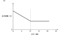
これに対して、本実施形態によれば、計測流路32において表距離L1が裏距離L2よりも小さくなっている。この場合、センサSA50のモールド先端面55aと計測床面101との間の領域が狭くても、モールド裏面55fと裏計測壁面104との間の裏領域123が比較的広くなっている。この構成では、センサ領域121の領域面積S1が不足するということが裏領域123により抑制され、計測流路32での空気流量が不足するということが生じにくくなる。この場合、計測流路32において気流の剥離や乱れが生じにくくなり、流量センサ22の検出結果にノイズが含まれることを抑制できる。また、この場合、計測流路32での圧損が低減されて流量が増加しやすくなるため、流量センサ22による流量検出の範囲を拡大できる。すなわち、エアフロメータ20の出力が変動することが抑制され、エアフロメータ20をダイナミックレンジ化できる。したがって、エアフロメータ20について、出力変動抑制とダイナミックレンジとの両方を実現できる。
On the other hand, according to the present embodiment, the front distance L1 is smaller than the back distance L2 in the measurement flow path 32. In this case, even if the area between the mold tip surface 55a of the sensor SA50 and the measurement floor surface 101 is narrow, the back area 123 between the mold back surface 55f and the back measurement wall surface 104 is relatively wide. In this configuration, the back area 123 suppresses the shortage of the area S1 of the sensor area 121, and the shortage of the air flow rate in the measurement flow path 32 is less likely to occur. In this case, separation or turbulence of the airflow is less likely to occur in the measurement flow path 32, and it is possible to suppress the detection result of the flow rate sensor 22 from including noise. Further, in this case, since the pressure loss in the measurement flow channel 32 is reduced and the flow rate is easily increased, the range of flow rate detection by the flow rate sensor 22 can be expanded. That is, fluctuations in the output of the air flow meter 20 are suppressed, and the air flow meter 20 can have a dynamic range. Therefore, the air flow meter 20 can realize both the output fluctuation suppression and the dynamic range.
また、表距離L1が裏距離L2よりも小さくなっている。この構成では、エアフロメータ20の製造時に、ハウジング21に対するセンサSA50の取り付け誤差によってハウジング21に対するセンサSA50の相対位置が幅方向Xにずれたとしても、表距離L1が裏距離L2よりも小さいという関係を維持しやすい。このように、ハウジング21に対するセンサSA50の取り付け誤差が生じたとしても、流量センサ22の検出精度が低下しにくい構成を表距離L1と裏距離L2との関係によって実現できる。
The front distance L1 is smaller than the back distance L2. With this configuration, when the air flow meter 20 is manufactured, even if the relative position of the sensor SA50 with respect to the housing 21 deviates in the width direction X due to an attachment error of the sensor SA50 with respect to the housing 21, the front distance L1 is smaller than the back distance L2. Easy to maintain. Thus, even if an error in mounting the sensor SA50 on the housing 21 occurs, a configuration in which the detection accuracy of the flow rate sensor 22 is unlikely to be reduced can be realized by the relationship between the front distance L1 and the back distance L2.
本実施形態によれば、ハウジング21が表絞り部111を有している。この構成では、表絞り部111が計測入口35側から流量センサ22に向けて徐々に計測流路32を絞っているため、空気の流れに剥離や乱れが生じていても、表絞り部111によって空気の流れが整流されることでこれら剥離や乱れが低減される。この場合、流量センサ22に剥離や乱れが到達しにくくなるため、流量センサ22の検出精度を高めることができる。しかも、表距離L1は表絞り部111と流量センサ22との離間距離であるため、流量センサ22に沿って流れる空気を表絞り部111により確実に整流することができる。
According to this embodiment, the housing 21 has the front throttle portion 111. In this configuration, since the front throttle portion 111 gradually narrows the measurement flow passage 32 from the measurement inlet 35 side toward the flow rate sensor 22, even if separation or turbulence occurs in the air flow, the front throttle portion 111 causes The separation and turbulence are reduced by rectifying the flow of air. In this case, peeling or turbulence hardly reaches the flow rate sensor 22, so that the detection accuracy of the flow rate sensor 22 can be improved. Moreover, since the front distance L1 is the distance between the front throttle portion 111 and the flow rate sensor 22, the air flowing along the flow rate sensor 22 can be reliably rectified by the front throttle portion 111.
本実施形態によれば、表距離L1が表絞り部111の表頂部111aと流量センサ22との離間距離である。表絞り部111においては、最も整流効果の高い部位が表頂部111aになりやすいため、最も整流効果の高い部位を流量センサ22に対向させることで、流量センサ22に沿って流れる空気に剥離や乱れが含まれることを確実に抑制できる。これにより、流量センサ22の検出精度を更に高めることができる。
According to this embodiment, the front distance L1 is the distance between the front top 111a of the front throttle 111 and the flow sensor 22. In the front throttle portion 111, the portion having the highest rectification effect is likely to be the front top portion 111a. Therefore, by causing the portion having the highest rectification effect to face the flow rate sensor 22, the air flowing along the flow rate sensor 22 is separated or disturbed. It is possible to reliably suppress the inclusion of. Thereby, the detection accuracy of the flow rate sensor 22 can be further improved.
本実施形態によれば、ハウジング21が裏絞り部112を有している。この構成では、裏絞り部112が計測入口35側から流量センサ22に向けて徐々に計測流路32を絞っているため、空気の流れに剥離や乱れが生じても、裏絞り部112によって空気の流れが整流されることでこれら剥離や乱れが低減される。計測流路32では、高さ方向Yにおいて流量センサ22付近の高さ位置を流量センサ22に向けて流れている空気は、センサ支持部51の表側及び裏側のいずれも通りやすいと考えられる。このため、裏計測壁面104に沿って流れている空気についても裏絞り部112によって整流を行っておくことは、剥離や乱れが流量センサ22に到達することを抑制する上で効果的である。
According to this embodiment, the housing 21 has the back drawn portion 112. With this configuration, the back throttle 112 gradually narrows the measurement flow passage 32 from the measurement inlet 35 side toward the flow rate sensor 22, so that even if separation or turbulence occurs in the flow of air, the back throttle 112 causes air to flow. The flow is rectified to reduce these separations and disturbances. In the measurement flow channel 32, it is considered that the air flowing toward the flow rate sensor 22 at a height position near the flow rate sensor 22 in the height direction Y easily passes through both the front side and the back side of the sensor support portion 51. Therefore, rectifying the air flowing along the back measurement wall surface 104 by the back narrowing portion 112 is also effective in suppressing peeling and turbulence from reaching the flow rate sensor 22.
本実施形態によれば、計測流路32においては、天井側領域122bの天井側面積S3が床側領域122aの床側面積S2よりも小さくなっている。この構成では、天井側領域122bの方が床側領域122aよりも圧損が増加しやすく、空気が流れにくくなっている。このため、計測流路32が、計測床面101に沿って流れる空気よりも計測天井面102に沿って流れる空気の方が速くなったり多くなったりしやすい構成だったとしても、天井側領域122bと床側領域122aとで流れる空気の速さや量を均一化できる。これにより、センサ領域121に到達する気流に速い気流と遅い気流とが混ざっていることで流量センサ22の検出精度が低下するということを抑制できる。
According to this embodiment, in the measurement flow path 32, the ceiling side area S3 of the ceiling side area 122b is smaller than the floor side area S2 of the floor side area 122a. With this configuration, the pressure loss in the ceiling side region 122b is more likely to increase than in the floor side region 122a, and it is difficult for air to flow. Therefore, even if the measurement flow path 32 has a configuration in which the air flowing along the measurement ceiling surface 102 tends to become faster or more than the air flowing along the measurement floor surface 101, the ceiling side region 122b. It is possible to equalize the speed and amount of air flowing between the floor area 122a and the floor area 122a. As a result, it is possible to prevent the detection accuracy of the flow rate sensor 22 from being deteriorated due to the mixture of the fast air flow and the slow air flow in the air flow reaching the sensor region 121.
本実施形態によれば、計測流路32が、計測天井面102が外周側になるように且つ計測床面101が内周側になるように曲がっている。この構成では、遠心力等によって、計測床面101に沿って流れる空気よりも計測天井面102に沿って流れる空気の方が速くなったり多くなったりしやすい。このため、天井側領域122bと床側領域122aとで流れる空気の速さや量を均一化する上で、天井側面積S3が床側面積S2よりも小さくなっていることが効果的である。
According to this embodiment, the measurement flow path 32 is curved so that the measurement ceiling surface 102 is on the outer peripheral side and the measurement floor surface 101 is on the inner peripheral side. In this configuration, the air flowing along the measurement ceiling surface 102 tends to be faster or more than the air flowing along the measurement floor surface 101 due to centrifugal force or the like. Therefore, it is effective that the ceiling-side area S3 is smaller than the floor-side area S2 in order to equalize the speed and amount of the air flowing in the ceiling-side area 122b and the floor-side area 122a.
本実施形態によれば、表距離L1が表計測壁面103と発熱抵抗体71との離間距離である。流量センサ22においては、発熱抵抗体71に沿って流れる空気を対象として流量が検出されるため、発熱抵抗体71と表計測壁面103との位置関係を管理することで、流量センサ22の検出精度を高めることができる。
According to the present embodiment, the front distance L1 is the distance between the front measurement wall surface 103 and the heating resistor 71. In the flow rate sensor 22, since the flow rate is detected for the air flowing along the heating resistor 71, the detection accuracy of the flow rate sensor 22 is controlled by managing the positional relationship between the heating resistor 71 and the front measurement wall surface 103. Can be increased.
本実施形態によれば、センサSA50においては、モールド表面55e及びモールド裏面55fがいずれも樹脂製のモールド部55により形成されている。この構成では、モールド表面55eやモールド裏面55fの滑らかさを管理しやすいため、これらモールド表面55eやモールド裏面55fに沿って流れる空気に剥離や乱れが生じにくくなっている。
According to the present embodiment, in the sensor SA50, the mold front surface 55e and the mold back surface 55f are both formed by the resin mold portion 55. With this configuration, since the smoothness of the mold front surface 55e and the mold back surface 55f can be easily managed, the air flowing along the mold front surface 55e and the mold back surface 55f is less likely to be separated or disturbed.
<構成群Bの説明>
図8、図17に示すように、ハウジング21はSA収容領域150を有している。SA収容領域150は、バイパス流路30よりもハウジング基端側に設けられており、センサSA50の一部を収容している。SA収容領域150には、センサSA50の少なくともモールド基端面55bが収容されている。計測流路32とSA収容領域150とは高さ方向Yに並べられている。センサSA50は、計測流路32とSA収容領域150との境界部を高さ方向Yに跨ぐ位置に配置されている。計測流路32には、センサSA50の少なくともモールド先端面55a及び流量センサ22が収容されている。なお、SA収容領域150が収容領域に相当する。また、図17、図18においては、センサSA50の内部構造について図示を簡略化し、モールド部55及び流量センサ22の図示にとどめている。
<Explanation of Group B>
As shown in FIGS. 8 and 17, the housing 21 has an SA accommodation area 150. The SA accommodation area 150 is provided closer to the housing base end side than the bypass flow passage 30 and accommodates a part of the sensor SA50. At least the mold base end surface 55b of the sensor SA50 is housed in the SA housing area 150. The measurement flow path 32 and the SA accommodation area 150 are arranged in the height direction Y. The sensor SA50 is arranged at a position straddling the boundary portion between the measurement flow channel 32 and the SA accommodation area 150 in the height direction Y. At least the mold tip surface 55a of the sensor SA50 and the flow rate sensor 22 are housed in the measurement flow channel 32. The SA accommodation area 150 corresponds to the accommodation area. In addition, in FIGS. 17 and 18, the internal structure of the sensor SA50 is simplified and only the mold portion 55 and the flow rate sensor 22 are shown.
ハウジング21は、第1ハウジング部151及び第2ハウジング部152を有している。これらハウジング部151,152は、互いに組み付けられて一体化されており、この状態でハウジング21を形成している。第1ハウジング部151はSA収容領域150を形成している。第1ハウジング部151は、SA収容領域150に加えてバイパス流路30を形成している。第1ハウジング部151の内面は、ハウジング21の内面として、SA収容領域150やバイパス流路30を形成している。第1ハウジング部151の開放端にはハウジング開口部151a(図19参照)が設けられている。ハウジング開口部151aは、計測流路32とは反対側に向けてSA収容領域150を開口している。
The housing 21 has a first housing part 151 and a second housing part 152. The housing portions 151 and 152 are assembled and integrated with each other, and the housing 21 is formed in this state. The first housing portion 151 forms the SA accommodation area 150. The first housing portion 151 forms the bypass flow passage 30 in addition to the SA accommodation area 150. The inner surface of the first housing portion 151 forms the SA accommodation area 150 and the bypass flow passage 30 as the inner surface of the housing 21. A housing opening 151a (see FIG. 19) is provided at the open end of the first housing portion 151. The housing opening 151a opens the SA accommodation area 150 toward the side opposite to the measurement flow path 32.
SA収容領域150及び計測流路32にセンサSA50が収容された状態では、センサSA50の外面と第1ハウジング部151の内面との間に隙間が形成されている。第2ハウジング部152は、この隙間を埋めている。具体的には、第2ハウジング部152は、SA収容領域150においてセンサSA50の外面と第1ハウジング部151の内面との間に入り込んだ状態になっている。
In the state where the sensor SA50 is housed in the SA housing area 150 and the measurement flow channel 32, a gap is formed between the outer surface of the sensor SA50 and the inner surface of the first housing portion 151. The second housing portion 152 fills this gap. Specifically, the second housing portion 152 is in a state of being inserted between the outer surface of the sensor SA50 and the inner surface of the first housing portion 151 in the SA accommodation area 150.
図17に示すように、ハウジング21はハウジング仕切部131を有している。ハウジング仕切部131は、第1ハウジング部151の内面に設けられた凸部であり、第1ハウジング部151からセンサSA50に向けて突出している。この場合、第1ハウジング部151がハウジング仕切部131を有していることになる。ハウジング仕切部131の先端部はセンサSA50の外面に接触している。ハウジング仕切部131は、センサSA50の外面と第1ハウジング部151の内面との間においてSA収容領域150と計測流路32とを仕切っている。
As shown in FIG. 17, the housing 21 has a housing partition 131. The housing partition portion 131 is a convex portion provided on the inner surface of the first housing portion 151, and projects from the first housing portion 151 toward the sensor SA50. In this case, the first housing portion 151 has the housing partition 131. The tip of the housing partition 131 is in contact with the outer surface of the sensor SA50. The housing partition section 131 partitions the SA housing area 150 and the measurement flow path 32 between the outer surface of the sensor SA50 and the inner surface of the first housing section 151.
第1ハウジング部151の内面は、ハウジング流路面135、ハウジング収容面136及びハウジング段差面137を有している。これらハウジング流路面135、ハウジング収容面136及びハウジング段差面137は、高さ方向Yに交差する方向に延びており、センサSA50の周りを環状に一周している。センサSA50においては、発熱抵抗体71の中心線CL1が高さ方向Yに延びており、ハウジング流路面135、ハウジング収容面136及びハウジング段差面137は、それぞれこの中心線CL1の周りを周方向に延びている。
The inner surface of the first housing portion 151 has a housing flow path surface 135, a housing accommodation surface 136, and a housing step surface 137. The housing flow path surface 135, the housing receiving surface 136, and the housing step surface 137 extend in a direction intersecting the height direction Y, and make a circle around the sensor SA50. In the sensor SA50, the center line CL1 of the heating resistor 71 extends in the height direction Y, and the housing flow path surface 135, the housing housing surface 136, and the housing step surface 137 are circumferentially arranged around the center line CL1. It is extended.
第1ハウジング部151においては、ハウジング先端面21aとハウジング基端面21bとの間にハウジング段差面137が設けられている。ハウジング段差面137は、高さ方向Yにおいてハウジング基端側を向いている。ハウジング段差面137は、中心線CL1に対して傾斜しており、中心線CL1側である径方向内側を向いている。ハウジング段差面137は、高さ方向Yに交差しており、ハウジング交差面に相当する。第1ハウジング部151の内面においては、ハウジング流路面135とハウジング段差面137との出隅部分、及びハウジング収容面136とハウジング段差面137との入隅部分のそれぞれが面取りされている。なお、高さ方向Yが、計測流路と収容領域とが並んだ並び方向に相当する。
In the first housing portion 151, a housing step surface 137 is provided between the housing front end surface 21a and the housing base end surface 21b. The housing step surface 137 faces the housing base end side in the height direction Y. The housing step surface 137 is inclined with respect to the center line CL1 and faces the inner side in the radial direction on the center line CL1 side. The housing step surface 137 intersects in the height direction Y and corresponds to the housing intersecting surface. On the inner surface of the first housing part 151, the corners of the housing flow path surface 135 and the housing step surface 137 and the corners of the housing accommodation surface 136 and the housing step surface 137 are chamfered. The height direction Y corresponds to the arrangement direction in which the measurement flow path and the accommodation area are arranged side by side.
ハウジング流路面135は、計測流路32を形成しており、ハウジング段差面137の内周端部からハウジング先端側に向けて延びている。ハウジング流路面135は、ハウジング段差面137からSA収容領域150とは反対側に向けて延びている。一方、ハウジング収容面136は、SA収容領域150を形成しており、ハウジング段差面137の外周端からハウジング基端側に向けて延びている。ハウジング収容面136は、ハウジング段差面137から計測流路32とは反対側に向けて延びている。ハウジング段差面137は、ハウジング流路面135とハウジング収容面136との間に設けられており、第1ハウジング部151の内面に段差を形成している。ハウジング段差面137は、ハウジング流路面135とハウジング収容面136とを接続している。
The housing flow path surface 135 forms the measurement flow path 32, and extends from the inner peripheral end of the housing step surface 137 toward the housing front end side. The housing flow path surface 135 extends from the housing step surface 137 toward the side opposite to the SA accommodation area 150. On the other hand, the housing housing surface 136 forms the SA housing area 150, and extends from the outer peripheral end of the housing step surface 137 toward the housing base end side. The housing accommodation surface 136 extends from the housing step surface 137 toward the side opposite to the measurement flow path 32. The housing step surface 137 is provided between the housing flow path surface 135 and the housing housing surface 136, and forms a step on the inner surface of the first housing portion 151. The housing step surface 137 connects the housing flow path surface 135 and the housing housing surface 136.
センサSA50の外面は、モールド部55の外面により形成されている。センサSA50の外面は、SA流路面145、SA収容面146及びSA段差面147を有している。これらSA流路面145、SA収容面146及びSA段差面147は、高さ方向Yに交差する方向に延びており、センサSA50の外面において環状に一周した部分である。これらSA流路面145、SA収容面146及びSA段差面147は、発熱抵抗体71の中心線CL1の周りを周方向に延びている。
The outer surface of the sensor SA50 is formed by the outer surface of the mold portion 55. The outer surface of the sensor SA50 has an SA flow path surface 145, an SA housing surface 146, and an SA step surface 147. The SA flow path surface 145, the SA housing surface 146, and the SA step surface 147 extend in a direction intersecting with the height direction Y, and are a portion that makes a circle around the outer surface of the sensor SA50. The SA flow path surface 145, the SA housing surface 146, and the SA step surface 147 extend in the circumferential direction around the center line CL1 of the heating resistor 71.
センサSA50においては、モールド先端面55aとモールド基端面55bとの間にSA段差面147が設けられている。SA段差面147は、高さ方向Yにおいてモールド先端面55a側を向いている。SA段差面147は、中心線CL1に対して傾斜しており、中心線CL1とは反対側である径方向外側を向いている。SA段差面147は、高さ方向Yに交差しており、ユニット交差面に相当する。また、SA流路面145がユニット流路面に相当し、SA収容面146がユニット収容面に相当する。センサSA50の外面においては、SA流路面145とSA段差面147との入隅部分、及びSA収容面146とSA段差面147との出隅部分のそれぞれが面取りされている。
In the sensor SA50, an SA step surface 147 is provided between the mold front end surface 55a and the mold base end surface 55b. The SA step surface 147 faces the mold front end surface 55a side in the height direction Y. The SA step surface 147 is inclined with respect to the center line CL1 and faces the outer side in the radial direction opposite to the center line CL1. The SA step surface 147 intersects in the height direction Y and corresponds to a unit intersection surface. Further, the SA channel surface 145 corresponds to the unit channel surface, and the SA accommodation surface 146 corresponds to the unit accommodation surface. On the outer surface of the sensor SA50, the corners of the SA flow path surface 145 and the SA step surface 147 and the corners of the SA housing surface 146 and the SA step surface 147 are chamfered.
SA流路面145は、計測流路32を形成しており、SA段差面147の内周端部からモールド先端側に向けて高さ方向Yに延びている。SA流路面145は、SA段差面147からSA収容領域150とは反対側に向けて延びている。一方、SA収容面146は、SA収容領域150を形成しており、SA段差面147の外周端部からモールド基端側に向けて延びている。SA収容面146は、SA段差面147から計測流路32とは反対側に向けて延びている。SA段差面147は、SA流路面145とSA収容面146との間に設けられており、センサSA50の外面に段差を形成している。SA段差面147は、SA流路面145とSA収容面146とを接続している。
The SA flow path surface 145 forms the measurement flow path 32, and extends in the height direction Y from the inner peripheral end of the SA step surface 147 toward the mold front end side. The SA flow path surface 145 extends from the SA step surface 147 toward the side opposite to the SA accommodation area 150. On the other hand, the SA housing surface 146 forms the SA housing area 150, and extends from the outer peripheral end of the SA step surface 147 toward the mold base end side. The SA accommodation surface 146 extends from the SA step surface 147 toward the side opposite to the measurement flow channel 32. The SA step surface 147 is provided between the SA flow path surface 145 and the SA housing surface 146, and forms a step on the outer surface of the sensor SA50. The SA step surface 147 connects the SA flow path surface 145 and the SA housing surface 146.
センサSA50においては、SA流路面145、SA収容面146及びSA段差面147のそれぞれが、モールド上流面55c、モールド下流面55d、モールド表面55e及びモールド裏面55fにより形成されている。
In the sensor SA50, each of the SA flow path surface 145, the SA housing surface 146, and the SA step surface 147 is formed by the mold upstream surface 55c, the mold downstream surface 55d, the mold surface 55e, and the mold back surface 55f.
エアフロメータ20においては、ハウジング基端側を向いたハウジング段差面137とハウジング先端側を向いたSA段差面147とが互いに対向している。また、内周側を向いたハウジング流路面135と、外周側を向いたSA流路面145とが互いに対向している。同様に、内周側を向いたハウジング収容面136と、外周側を向いたSA収容面146とが互いに対向している。
In the air flow meter 20, the housing step surface 137 facing the housing base end side and the SA step surface 147 facing the housing front end side face each other. Further, the housing flow path surface 135 facing the inner peripheral side and the SA flow path surface 145 facing the outer peripheral side face each other. Similarly, the housing accommodation surface 136 facing the inner peripheral side and the SA accommodation surface 146 facing the outer peripheral side face each other.
ハウジング仕切部131は、ハウジング段差面137に設けられており、ハウジング基端側に向けて高さ方向Yに延びている。ハウジング仕切部131の中心線CL11は、高さ方向Yに直線状に延びている。ハウジング仕切部131は、ハウジング段差面137と共にセンサSA50の周りを環状に一周している。この場合、図19に示すように、ハウジング仕切部131は、幅方向Xに延びた部分と奥行き方向Zに延びた部分とを有しており、全体として略矩形枠状になっている。
The housing partition 131 is provided on the housing step surface 137 and extends in the height direction Y toward the housing base end side. The center line CL11 of the housing partition 131 extends linearly in the height direction Y. The housing partition 131, together with the housing step surface 137, surrounds the sensor SA50 in an annular shape. In this case, as shown in FIG. 19, the housing partition portion 131 has a portion extending in the width direction X and a portion extending in the depth direction Z, and has a substantially rectangular frame shape as a whole.
図17の説明に戻り、ハウジング仕切部131の先端部は、センサSA50のSA段差面147に接触している。ハウジング仕切部131とSA段差面147とは、互いに密着しており、SA収容領域150と計測流路32とを仕切っている部分のシール性を高めている。SA段差面147は、高さ方向Yに交差する方向に真っ直ぐに延びた平坦面になっている。本実施形態では、ハウジング段差面137とSA段差面147とは平行に延びておらず、SA段差面147がハウジング段差面137に対して傾斜している。このようにSA段差面147とハウジング段差面137とが平行になっていなくても、ハウジング仕切部131がSA段差面147に接触していることで、センサSA50の外面と第1ハウジング部151の内面とが接触した部分でのシール性が高められている。なお、ハウジング段差面137とSA段差面147とは平行に延びていてもよい。
Returning to the description of FIG. 17, the tip of the housing partition 131 contacts the SA step surface 147 of the sensor SA50. The housing partition 131 and the SA step surface 147 are in close contact with each other to enhance the sealing property of the part that partitions the SA accommodation area 150 and the measurement flow path 32. The SA step surface 147 is a flat surface that extends straight in the direction intersecting the height direction Y. In this embodiment, the housing step surface 137 and the SA step surface 147 do not extend in parallel, and the SA step surface 147 is inclined with respect to the housing step surface 137. As described above, even if the SA step surface 147 and the housing step surface 137 are not parallel to each other, the housing partition portion 131 is in contact with the SA step surface 147, so that the outer surface of the sensor SA50 and the first housing portion 151 are in contact with each other. The sealability is improved at the portion where it contacts the inner surface. The housing step surface 137 and the SA step surface 147 may extend in parallel.
ハウジング仕切部131はハウジング段差面137に直交している。この場合、ハウジング仕切部131の中心線CL11とハウジング段差面137とが直交している。ハウジング仕切部131は先細りした形状になっている。高さ方向Yに直交する方向X,Zがハウジング仕切部131にとっての幅方向であり、幅方向でのハウジング仕切部131の幅寸法は、ハウジング仕切部131の先端部に向けて徐々に小さくなっている。ハウジング仕切部131の一対の側面はいずれもハウジング段差面137から真っ直ぐに延びている。この場合、ハウジング仕切部131は、断面テーパ状になっている。
The housing partition 131 is orthogonal to the housing step surface 137. In this case, the center line CL11 of the housing partition 131 and the housing step surface 137 are orthogonal to each other. The housing partition 131 has a tapered shape. The directions X and Z orthogonal to the height direction Y are the width directions for the housing partition 131, and the width dimension of the housing partition 131 in the width direction gradually decreases toward the tip of the housing partition 131. ing. Each of the pair of side surfaces of the housing partition portion 131 extends straight from the housing step surface 137. In this case, the housing partition 131 has a tapered cross section.
ハウジング仕切部131は、ハウジング段差面137においてハウジング収容面136よりもハウジング流路面135に近い位置に配置されている。この場合、高さ方向Yに直交する方向X,Zにおいて、ハウジング仕切部131とハウジング収容面136との離間距離が、ハウジング仕切部131とハウジング流路面135との離間距離よりも小さくなっている。
The housing partition portion 131 is disposed on the housing step surface 137 at a position closer to the housing flow path surface 135 than the housing accommodation surface 136. In this case, in the directions X and Z orthogonal to the height direction Y, the distance between the housing partition 131 and the housing housing surface 136 is smaller than the distance between the housing partition 131 and the housing flow path surface 135. ..
ハウジング段差面137のうち、ハウジング仕切部131よりもハウジング流路面135側の部分は、ハウジング流路面135と共に計測流路32を形成している。ハウジング仕切部131よりもハウジング収容面136側の部分は、ハウジング収容面136と共にSA収容領域150を形成している。
A portion of the housing step surface 137 closer to the housing flow channel surface 135 than the housing partition 131 forms the measurement flow channel 32 together with the housing flow channel surface 135. A portion on the housing accommodation surface 136 side of the housing partition 131 forms the SA accommodation area 150 together with the housing accommodation surface 136.
SA段差面147のうち、ハウジング仕切部131よりもSA流路面145側の部分は、SA流路面145と共に計測流路32を形成している。ハウジング仕切部131よりもSA収容面146側の部分は、SA収容面146と共にSA収容領域150を形成している。
A portion of the SA step surface 147 closer to the SA flow channel surface 145 than the housing partition 131 forms the measurement flow channel 32 together with the SA flow channel surface 145. A portion on the SA accommodation surface 146 side of the housing partition 131 forms an SA accommodation area 150 together with the SA accommodation surface 146.
次に、エアフロメータ20の製造方法について、センサSA50をハウジング21に装着する手順を中心に、図18〜図21を参照しつつ説明する。
Next, a method of manufacturing the air flow meter 20 will be described with reference to FIGS. 18 to 21, focusing on the procedure of mounting the sensor SA50 in the housing 21.
エアフロメータ20の製造工程には、センサSA50を製造する工程と、第1ハウジング部151を樹脂成型等により製造する工程とが含まれている。これら工程の後、センサSA50を第1ハウジング部151に組み付ける工程を行う。
The manufacturing process of the air flow meter 20 includes a process of manufacturing the sensor SA50 and a process of manufacturing the first housing portion 151 by resin molding or the like. After these steps, the step of assembling the sensor SA50 with the first housing portion 151 is performed.
センサSA50を製造する工程では、射出成型機や型装置を有する射出成型装置等を用いて、センサSA50のモールド部55を樹脂成型等により製造する。この工程では、樹脂材料を溶融した溶融樹脂を射出成型機から射出して型装置の内部に圧入する。また、この工程では、モールド部55を形成する樹脂材料として、エポキシ樹脂等のエポキシ系の熱硬化性樹脂を用いる。
In the process of manufacturing the sensor SA50, the molding part 55 of the sensor SA50 is manufactured by resin molding or the like using an injection molding machine or an injection molding device having a mold device. In this step, a molten resin obtained by melting a resin material is injected from an injection molding machine and press-fitted into the mold device. Further, in this step, an epoxy thermosetting resin such as an epoxy resin is used as the resin material forming the mold portion 55.
第1ハウジング部151を製造する工程では、射出成型装置等を用いて第1ハウジング部151を樹脂成型等により製造する。この工程では、第1ハウジング部151を形成する樹脂材料として、ポリブチレンテレフタレート(PBT)やポリフェニレンサルファイド(PPS)等の熱可塑性樹脂を用いる。このように熱可塑性樹脂により形成された第1ハウジング部151は、熱硬化性樹脂により形成されたモールド部55に比べて軟らかくなっている。換言すれば、第1ハウジング部151は、モールド部55に比べて硬度が低く、柔軟性が高くなっている。
In the step of manufacturing the first housing portion 151, the first housing portion 151 is manufactured by resin molding or the like using an injection molding device or the like. In this step, a thermoplastic resin such as polybutylene terephthalate (PBT) or polyphenylene sulfide (PPS) is used as the resin material forming the first housing portion 151. As described above, the first housing portion 151 formed of the thermoplastic resin is softer than the mold portion 55 formed of the thermosetting resin. In other words, the first housing portion 151 has lower hardness and higher flexibility than the mold portion 55.
センサSA50を第1ハウジング部151に組み付ける工程では、図18に示すように、センサSA50をハウジング開口部151aから第1ハウジング部151の内部に挿入する。ここでは、図20に示すように、SA段差面147がハウジング仕切部131の先端部に接触した後、更にセンサSA50をハウジング先端側に向けて第1ハウジング部151の内部に押し込む。この場合、第1ハウジング部151の硬度がモールド部55の硬度よりも低いことに起因して、図21に示すように、ハウジング仕切部131は、その先端部がSA段差面147で押し潰されるように変形する。ハウジング仕切部131においては、先端部が押し潰されることで新たに形成された先端面がSA段差面147に密着しやすくなり、ハウジング仕切部131とSA段差面147とのシール性が高められる。なお、図17においては、ハウジング仕切部131のうちセンサSA50によって押し潰された部分を仮想線として2点鎖線で図示している。
In the step of assembling the sensor SA50 to the first housing part 151, the sensor SA50 is inserted into the first housing part 151 from the housing opening 151a as shown in FIG. Here, as shown in FIG. 20, after the SA step surface 147 comes into contact with the tip of the housing partition 131, the sensor SA50 is further pushed toward the tip of the housing into the first housing 151. In this case, due to the hardness of the first housing portion 151 being lower than the hardness of the mold portion 55, as shown in FIG. 21, the housing partition portion 131 has its tip portion crushed by the SA step surface 147. To be transformed. In the housing partition 131, the newly formed tip surface is easily brought into close contact with the SA step surface 147 by crushing the tip portion, and the sealing performance between the housing partition 131 and the SA step surface 147 is improved. Note that, in FIG. 17, a portion of the housing partition portion 131 crushed by the sensor SA50 is shown by a two-dot chain line as a virtual line.
センサSA50の組み付け工程では、ハウジング仕切部131の先端部がSA段差面147で押し潰された際に、ハウジング仕切部131の破片等が潰れカスとして発生し、この潰れカスが計測流路32に進入する、ということが懸念される。計測流路32に進入した潰れカスが計測流路32において異物として流量センサ22に接触したり付着したりした場合、流量センサ22の検出精度が低下することが想定される。
In the assembly process of the sensor SA50, when the tip of the housing partition 131 is crushed by the SA step surface 147, fragments of the housing partition 131 are generated as crushed scraps, and the crushed scraps are generated in the measurement flow path 32. There is concern that it will enter. When the crushed dust that has entered the measurement flow path 32 comes into contact with or adheres to the flow rate sensor 22 as foreign matter in the measurement flow path 32, it is assumed that the detection accuracy of the flow rate sensor 22 is reduced.
これに対して、本実施形態では、潰れカスが計測流路32に進入しにくい構成になっている。具体的には、図20に示すように、ハウジング仕切部131の中心線CL11とSA段差面147との間の角度のうち、SA収容領域150を向いた収容側角度θ12が、計測流路32を向いた流路側角度θ11よりも大きくなっている。すなわち、θ12>θ11の関係が成り立っている。この構成では、ハウジング仕切部131の先端部が計測流路32側よりもSA収容領域150側に向けて倒れたり潰れたりしやすくなっている。このため、潰れカスが発生したとしても、この潰れカスが計測流路32に進入しにくくなっている。
On the other hand, in the present embodiment, the crushed waste is difficult to enter the measurement flow path 32. Specifically, as shown in FIG. 20, among the angles between the center line CL11 of the housing partition 131 and the SA step surface 147, the accommodation side angle θ12 facing the SA accommodation area 150 is the measurement flow path 32. Is larger than the flow channel side angle θ11 facing toward. That is, the relationship of θ12>θ11 is established. In this configuration, the tip of the housing partition 131 is more likely to fall or collapse toward the SA accommodation area 150 side than the measurement flow channel 32 side. Therefore, even if a crushed residue is generated, it is difficult for the crushed residue to enter the measurement flow path 32.
流路側角度θ11は、ハウジング仕切部131の外面のうち最もSA段差面147に近い部分の角度であり、収容側角度θ12は、中心線CL11を挟んで流路側角度θ11とは反対側の角度である。
The flow path side angle θ11 is an angle of a portion of the outer surface of the housing partition 131 closest to the SA step surface 147, and the accommodation side angle θ12 is an angle opposite to the flow path side angle θ11 with the center line CL11 interposed therebetween. is there.
センサSA50を第1ハウジング部151に組み付けた後、射出成型装置等を用いて第2ハウジング部152を樹脂成型等により製造する工程を行う。この工程では、センサSA50と共に第1ハウジング部151に型装置を装着し、樹脂材料を溶融した溶融樹脂を射出成型機から射出して型装置の内部に圧入する。このように、型装置の内部に溶融樹脂が注入されることで、第1ハウジング部151とセンサSA50との隙間に溶融樹脂が充填される。この場合、上述したようにハウジング仕切部131がセンサSA50の外面に密着しているため、溶融樹脂が第1ハウジング部151とセンサSA50との隙間を通じて計測流路32に入り込むということが規制される。そして、型装置の内部において溶融樹脂を固化させることで第2ハウジング部152を形成する。
After the sensor SA50 is assembled to the first housing part 151, a step of manufacturing the second housing part 152 by resin molding or the like using an injection molding device or the like is performed. In this step, the mold device is mounted on the first housing portion 151 together with the sensor SA50, and the molten resin obtained by melting the resin material is injected from the injection molding machine and press-fitted inside the mold device. In this way, by injecting the molten resin into the mold device, the molten resin is filled in the gap between the first housing portion 151 and the sensor SA50. In this case, since the housing partition 131 is in close contact with the outer surface of the sensor SA50 as described above, it is restricted that the molten resin enters the measurement channel 32 through the gap between the first housing 151 and the sensor SA50. .. Then, the second housing portion 152 is formed by solidifying the molten resin inside the mold device.
第2ハウジング部152を形成する樹脂材料としては、第1ハウジング部151と同様に、ポリブチレンテレフタレート(PBT)やポリフェニレンサルファイド(PPS)等の熱可塑性樹脂を用いる。これら第1ハウジング部151及び第2ハウジング部152のいずれにも、導電性を有するカーボン材料が含まれている。カーボン材料としては、カーボン粉やカーボン繊維、ナノカーボン、グラフェン、炭素マイクロ粒子などが挙げられる。
As the resin material forming the second housing portion 152, a thermoplastic resin such as polybutylene terephthalate (PBT) or polyphenylene sulfide (PPS) is used as in the first housing portion 151. Both of the first housing portion 151 and the second housing portion 152 contain a carbon material having conductivity. Examples of the carbon material include carbon powder, carbon fiber, nanocarbon, graphene, and carbon microparticles.
第1ハウジング部151は、第2ハウジング部152に比べて、帯電した場合に放電しやすくなっている。例えば、第1ハウジング部151の方が、カーボン材料の含有率や含有量が第2ハウジング部152よりも大きくなっている。ハウジング21において、放電時に電荷の通り道になりやすい部分を導電部と称すると、この導電部は第1ハウジング部151の方が第2ハウジング部152よりも多く含まれている。導電部には、カーボン粉、カーボン繊維、ナノカーボン、グラフェン及び炭素マイクロ粒子のうち複数が含まれており、ナノカーボンとしては、カーボンナノチューブやカーボンナノファイバー、フラーレンなどが挙げられる。
The first housing portion 151 is easier to discharge when charged than the second housing portion 152. For example, the first housing portion 151 has a larger carbon material content rate and content than the second housing portion 152. When a portion of the housing 21 that easily becomes a path for electric charges during discharge is referred to as a conductive portion, the conductive portion is larger in the first housing portion 151 than in the second housing portion 152. The conductive portion contains a plurality of carbon powders, carbon fibers, nanocarbons, graphenes, and carbon microparticles, and examples of the nanocarbons include carbon nanotubes, carbon nanofibers, and fullerenes.
ここまで説明した本実施形態によれば、ハウジング21の内面から突出したハウジング仕切部131が、センサSA50とハウジング21との間において計測流路32とSA収容領域150とを仕切っている。この構成では、ハウジング仕切部131の先端部とセンサSA50とが密着しやすいため、ハウジング21の内面とセンサSA50の外面との間に隙間が生じにくくなっている。このため、溶融樹脂を第1ハウジング部151のSA収容領域150に注入して第2ハウジング部152を形成する場合に、溶融樹脂が第1ハウジング部151とセンサSA50との隙間を通じて計測流路32に入り込むということが規制される。
According to the present embodiment described thus far, the housing partition 131 protruding from the inner surface of the housing 21 partitions the measurement flow channel 32 and the SA accommodation area 150 between the sensor SA50 and the housing 21. In this configuration, since the tip portion of the housing partition 131 and the sensor SA50 are easily brought into close contact with each other, a gap is unlikely to be formed between the inner surface of the housing 21 and the outer surface of the sensor SA50. Therefore, when the molten resin is injected into the SA housing area 150 of the first housing portion 151 to form the second housing portion 152, the molten resin passes through the gap between the first housing portion 151 and the sensor SA50 and the measurement flow path 32 It is regulated to enter.
この場合、第1ハウジング部151とセンサSA50との隙間を通じて計測流路32に入り込んだ溶融樹脂が固化し、その固化部分によって計測流路32の形状が意図せずに変化する、ということが生じにくくなっている。また、その固化部分が計測流路32において第1ハウジング部151やセンサSA50から剥がれ落ちて、異物として流量センサ22に接触したり付着したりする、ということが生じにくくなっている。したがって、SA収容領域150から計測流路32に進入した溶融樹脂によって流量センサ22の検出精度が低下するということを抑制できる。これにより、流量センサ22による空気流量の検出精度を高めることができ、その結果、エアフロメータ20による空気流量の計測精度を高めることができる。
In this case, the molten resin that has entered the measurement channel 32 through the gap between the first housing 151 and the sensor SA50 is solidified, and the solidified portion causes the shape of the measurement channel 32 to change unintentionally. It's getting harder. Further, it is less likely that the solidified portion will peel off from the first housing portion 151 and the sensor SA50 in the measurement flow path 32 and come into contact with or adhere to the flow rate sensor 22 as a foreign matter. Therefore, it is possible to prevent the detection accuracy of the flow rate sensor 22 from being lowered by the molten resin that has entered the measurement flow path 32 from the SA accommodation area 150. As a result, the accuracy of the air flow rate detected by the flow rate sensor 22 can be increased, and as a result, the accuracy of the air flow rate measured by the air flow meter 20 can be increased.
本実施形態によれば、ハウジング仕切部131がセンサSA50の周りを環状に一周している。この構成では、センサSA50の外面全周において、センサSA50の外面と第1ハウジング部151の内面とが密着した状態をハウジング仕切部131によりつくり出すことができる。このため、計測流路32とSA収容領域150との境界部全体でのシール性をハウジング仕切部131によって高めることができる。
According to the present embodiment, the housing partition 131 circulates around the sensor SA50 in an annular shape. With this configuration, the housing partition 131 can create a state in which the outer surface of the sensor SA50 and the inner surface of the first housing portion 151 are in close contact with each other on the entire outer surface of the sensor SA50. Therefore, the housing partitioning portion 131 can enhance the sealing property in the entire boundary portion between the measurement flow channel 32 and the SA accommodation area 150.
本実施形態によれば、ハウジング仕切部131は、ハウジング段差面137においてハウジング収容面136よりもハウジング流路面135に近い位置に設けられている。この構成では、計測流路32側に極力寄せた位置でハウジング仕切部131により計測流路32とSA収容領域150とを仕切ることで、第1ハウジング部151とセンサSA50との隙間のうち計測流路32に含まれる部分を極力小さくできる。ここで、計測流路32においては、第1ハウジング部151とセンサSA50との隙間は、計測入口35から計測出口36に向けて流れる空気が流れ込むことなどにより空気の流れに乱れを生じさせやすい領域になっている。このため、第1ハウジング部151とセンサSA50との隙間が小さいほど計測流路32において空気の流れに乱れが生じにくく、流量センサ22の検出精度が向上しやすい。したがって、ハウジング仕切部131がハウジング流路面135に極力近い位置に設けられていることで、流量センサ22の検出精度を高めることができる。
According to the present embodiment, the housing partition 131 is provided at a position closer to the housing flow path surface 135 than the housing accommodation surface 136 on the housing step surface 137. In this structure, the measurement flow path 32 and the SA accommodation area 150 are partitioned by the housing partition 131 at a position as close to the measurement flow path 32 as possible, so that the measurement flow in the gap between the first housing section 151 and the sensor SA50 is separated. The portion included in the path 32 can be made as small as possible. Here, in the measurement flow path 32, the gap between the first housing portion 151 and the sensor SA50 is a region in which the air flowing from the measurement inlet 35 toward the measurement outlet 36 is likely to cause turbulence in the air flow. It has become. For this reason, as the gap between the first housing portion 151 and the sensor SA50 is smaller, the air flow in the measurement flow channel 32 is less likely to be disturbed, and the detection accuracy of the flow rate sensor 22 is likely to be improved. Therefore, since the housing partition 131 is provided at a position as close as possible to the housing flow path surface 135, the detection accuracy of the flow rate sensor 22 can be improved.
本実施形態によれば、収容側角度θ12が流路側角度θ11よりも大きくなっている。この構成では、センサSA50を第1ハウジング部151のSA収容領域150に挿入した場合に、ハウジング仕切部131がSA収容領域150側に折れたり倒れたりするように潰れて変形する、ということが生じやすくなっている。このため、ハウジング仕切部131を変形させてセンサSA50の外面に密着させる際に、ハウジング仕切部131の潰れカスが計測流路32に意図せずに入り込むということが生じにくくなっている。したがって、計測流路32において潰れカスが流量センサ22に接触したり付着したりして流量センサ22の検出精度が低下するということを抑制できる。
According to this embodiment, the accommodation side angle θ12 is larger than the flow path side angle θ11. With this configuration, when the sensor SA50 is inserted into the SA housing area 150 of the first housing portion 151, the housing partition 131 is crushed and deformed so as to be folded or collapsed toward the SA housing area 150 side. It's getting easier. Therefore, when the housing partition 131 is deformed and brought into close contact with the outer surface of the sensor SA50, it is less likely that the crushed residue of the housing partition 131 will unintentionally enter the measurement flow path 32. Therefore, it is possible to prevent the detection accuracy of the flow rate sensor 22 from being deteriorated due to the crushed dust coming into contact with or adhering to the flow rate sensor 22 in the measurement flow path 32.
本実施形態によれば、ハウジング段差面137に設けられたハウジング仕切部131がSA段差面147に接触している。この構成では、ハウジング段差面137とSA段差面147とが、いずれも高さ方向Yに交差し且つ互いに対向しているため、センサSA50を第1ハウジング部151の内部に挿入した場合にSA段差面147がハウジング仕切部131に引っ掛かった状態になる。このため、単にセンサSA50を計測流路32に向けて第1ハウジング部151の内部に押し込むという作業を行うことで、ハウジング仕切部131をSA段差面147に密着させることができる。これにより、計測流路32とSA収容領域150とをハウジング仕切部131により確実に仕切りつつ、センサSA50を第1ハウジング部151に組み付ける際の作業負担の増加を抑制できる。
According to the present embodiment, the housing partition 131 provided on the housing step surface 137 is in contact with the SA step surface 147. In this configuration, since the housing step surface 137 and the SA step surface 147 both intersect in the height direction Y and face each other, when the sensor SA50 is inserted into the first housing portion 151, the SA step surface is formed. The surface 147 is hooked on the housing partition 131. Therefore, the housing partition 131 can be brought into close contact with the SA step surface 147 by simply pushing the sensor SA50 toward the measurement flow path 32 and into the first housing 151. As a result, the measurement flow path 32 and the SA accommodation area 150 can be reliably partitioned by the housing partition 131, and an increase in the work load when the sensor SA50 is assembled to the first housing part 151 can be suppressed.
本実施形態では、第1ハウジング部151においてハウジング段差面137がハウジング開口部151a側を向いている。この構成では、ハウジング開口部151aからSA収容領域150に挿入したセンサSA50を単に計測流路32に向けて奥に押し込むことで、センサSA50のSA段差面147をハウジング段差面137に押し付けることができる。このため、SA段差面147のハウジング仕切部131をハウジング段差面137に密着しやすい構成を実現できる。
In the present embodiment, the housing step surface 137 of the first housing portion 151 faces the housing opening 151a side. With this configuration, the SA step surface 147 of the sensor SA50 can be pressed against the housing step surface 137 by simply pushing the sensor SA50 inserted into the SA accommodation area 150 from the housing opening 151a toward the measurement flow path 32. .. Therefore, it is possible to realize a configuration in which the housing partition 131 of the SA step surface 147 is easily brought into close contact with the housing step surface 137.
<構成群Dの説明>
図22、図23に示すように、計測流路32は、計測入口35と計測出口36との間の部分が流量センサ22に向けて膨らむように曲がっており、全体としてU字状になっている。計測流路32においては、計測入口35と計測出口36とが奥行き方向Zに並んでいる。この場合、奥行き方向Zが並び方向に相当し、高さ方向Yが奥行き方向Zに直交している。計測流路32においては、計測入口35と計測出口36との間の部分が、ハウジング基端側に向けて高さ方向Yに膨らむように曲がっている。
<Explanation of Group D>
As shown in FIG. 22 and FIG. 23, the measurement flow path 32 is curved so that the portion between the measurement inlet 35 and the measurement outlet 36 bulges toward the flow rate sensor 22, and has a U shape as a whole. There is. In the measurement channel 32, the measurement inlet 35 and the measurement outlet 36 are arranged in the depth direction Z. In this case, the depth direction Z corresponds to the arrangement direction, and the height direction Y is orthogonal to the depth direction Z. In the measurement flow path 32, a portion between the measurement inlet 35 and the measurement outlet 36 is curved so as to bulge in the height direction Y toward the base end side of the housing.
ハウジング21の内面は、外計測曲がり面401、内計測曲がり面402を有している。外計測曲がり面401及び内計測曲がり面402は、計測流路32の中心線CL4に沿って延びている。ハウジング21の内面は、これら外計測曲がり面401及び内計測曲がり面402に加えて、上述したように表計測壁面103及び裏計測壁面104を有している。外計測曲がり面401と内計測曲がり面402とは、幅方向Xに直交する方向Y,Zに並べられており、表計測壁面103及び裏計測壁面104を介して対向している。
The inner surface of the housing 21 has an outer measurement curved surface 401 and an inner measurement curved surface 402. The outer measurement curved surface 401 and the inner measurement curved surface 402 extend along the center line CL4 of the measurement flow path 32. The inner surface of the housing 21 has the front measurement wall surface 103 and the back measurement wall surface 104 as described above, in addition to the outer measurement curved surface 401 and the inner measurement curved surface 402. The outer measurement curved surface 401 and the inner measurement curved surface 402 are arranged in the directions Y and Z orthogonal to the width direction X, and face each other via the front measurement wall surface 103 and the back measurement wall surface 104.
外計測曲がり面401は、計測流路32を曲がりの外側から形成しており、計測流路32や流量センサ22の外周側に設けられている。外計測曲がり面401は、計測入口35と計測出口36とにかけ渡されている。外計測曲がり面401は、計測入口35と計測出口36との間の部分が全体として流量センサ22側に凹むように凹状に曲がっている。外計測曲がり面401には、計測天井面102が含まれており、SA挿入孔107が設けられている。
The outer measurement curved surface 401 forms the measurement flow channel 32 from the outside of the curve, and is provided on the outer peripheral side of the measurement flow channel 32 and the flow rate sensor 22. The outer measurement curved surface 401 is bridged over the measurement inlet 35 and the measurement outlet 36. The outer measurement curved surface 401 is curved in a concave shape such that the portion between the measurement inlet 35 and the measurement outlet 36 is recessed toward the flow sensor 22 side as a whole. The outer measurement curved surface 401 includes the measurement ceiling surface 102 and the SA insertion hole 107 is provided.
内計測曲がり面402は、計測流路32を曲がりの内側から形成しており、計測流路32の内周側に設けられている。内計測曲がり面402は、計測入口35と計測出口36とにかけ渡されている。内計測曲がり面402は、計測入口35と計測出口36との間の部分が全体として流量センサ22側に膨らむように曲がっている。内計測曲がり面402は、外計測曲がり面401とは反対側に向けて凹んだ部分を有しておらず、その全体が外計測曲がり面401に向けて膨らむように凸状に曲がっている。内計測曲がり面402には、計測床面101が含まれている。
The inner measurement curved surface 402 forms the measurement channel 32 from the inside of the curve, and is provided on the inner peripheral side of the measurement channel 32. The inner measurement curved surface 402 extends over the measurement inlet 35 and the measurement outlet 36. The inner measurement curved surface 402 is curved so that the portion between the measurement inlet 35 and the measurement outlet 36 bulges toward the flow rate sensor 22 as a whole. The inner measurement curved surface 402 does not have a recessed portion toward the side opposite to the outer measurement curved surface 401, and the whole is curved in a convex shape so as to bulge toward the outer measurement curved surface 401. The inner measurement curved surface 402 includes the measurement floor surface 101.
図23に示すように、計測流路32は、センサ路405、上流曲がり路406、下流曲がり路407を有している。センサ路405は、計測流路32において流量センサ22が設けられた部分である。センサ路405は、奥行き方向Zに真っ直ぐに延びており、フランジ部27の角度設定面27aに平行に主流方向に延びている。上流曲がり路406と下流曲がり路407とは奥行き方向Zに並べられており、センサ路405は、上流曲がり路406と下流曲がり路407との間に設けられ、これら曲がり路406,407を接続している。
As shown in FIG. 23, the measurement flow path 32 has a sensor path 405, an upstream curved path 406, and a downstream curved path 407. The sensor path 405 is a portion of the measurement flow path 32 where the flow rate sensor 22 is provided. The sensor path 405 extends straight in the depth direction Z, and extends in the mainstream direction parallel to the angle setting surface 27a of the flange portion 27. The upstream curved path 406 and the downstream curved path 407 are arranged in the depth direction Z, and the sensor path 405 is provided between the upstream curved path 406 and the downstream curved path 407, and connects these curved paths 406 and 407. ing.
ハウジング21においてセンサ路405を形成する面には、計測床面101の少なくとも一部が含まれている。本実施形態では、奥行き方向Zでのセンサ路405の長さ寸法が計測床面101によって規定されている。具体的には、センサ路405の上流端部に計測床面101の上流端部が含まれており、センサ路405の下流端部に計測床面101の下流端部が含まれている。この場合、奥行き方向Zでのセンサ路405の長さ寸法は計測床面101の長さ寸法と同じになっている。また、ハウジング21においてセンサ路405を形成する面には、計測床面101の少なくとも一部に加えて、計測天井面102の一部や、表計測壁面103の一部、裏計測壁面104の一部が含まれている。本実施形態では、計測床面101が奥行き方向Zに真っ直ぐに延びており、このように計測床面101が真っ直ぐに延びていることをセンサ路405が真っ直ぐに延びていると称する。
The surface of the housing 21 forming the sensor path 405 includes at least a part of the measurement floor surface 101. In this embodiment, the length dimension of the sensor path 405 in the depth direction Z is defined by the measurement floor surface 101. Specifically, the upstream end of the sensor floor 405 includes the upstream end of the measurement floor surface 101, and the downstream end of the sensor path 405 includes the downstream end of the measurement floor surface 101. In this case, the length dimension of the sensor path 405 in the depth direction Z is the same as the length dimension of the measurement floor surface 101. In addition to at least a part of the measurement floor surface 101, a part of the measurement ceiling surface 102, a part of the front measurement wall surface 103, and a part of the back measurement wall surface 104 are formed on the surface of the housing 21 where the sensor path 405 is formed. Parts are included. In the present embodiment, the measurement floor surface 101 extends straight in the depth direction Z, and the fact that the measurement floor surface 101 extends straight in this manner is referred to as the sensor path 405 extending straight.
上流曲がり路406は、計測流路32においてセンサ路405から計測入口35に向けて延びており、センサ路405と計測入口35との間に設けられている。上流曲がり路406は、ハウジング21においてセンサ路405から計測入口35に向けて延びるように曲がっている。上流曲がり路406においては、その下流端部がセンサ路405に向けて奥行き方向Zに開放されている一方で、その上流端部が計測入口35に向けて高さ方向Yに開放されている。このように、上流曲がり路406においては、上流端部の開放向きと下流端部の開放向きとが交差しており、この交差角度は例えば90度になっている。上流曲がり路406の内面には、表計測壁面103の一部や裏計測壁面104の一部が含まれている。
The upstream curved path 406 extends from the sensor path 405 to the measurement entrance 35 in the measurement flow path 32, and is provided between the sensor path 405 and the measurement entrance 35. The upstream curved path 406 is curved in the housing 21 so as to extend from the sensor path 405 toward the measurement inlet 35. In the upstream curved path 406, the downstream end thereof is opened toward the sensor path 405 in the depth direction Z, while the upstream end thereof is opened toward the measurement inlet 35 in the height direction Y. In this way, in the upstream curved path 406, the opening direction of the upstream end portion and the opening direction of the downstream end portion intersect, and the intersecting angle is 90 degrees, for example. A part of the front measurement wall surface 103 and a part of the back measurement wall surface 104 are included on the inner surface of the upstream curved path 406.
下流曲がり路407は、計測流路32においてセンサ路405から計測出口36に向けて延びており、センサ路405と計測出口36との間に設けられている。下流曲がり路407は、ハウジング21においてセンサ路405から計測出口36に向けて延びるように曲がっている。下流曲がり路407においては、その上流端部がセンサ路405に向けて奥行き方向Zに開放されている一方で、その下流端部が計測出口36に向けて高さ方向Yに開放されている。このように、下流曲がり路407においては、上流曲がり路406と同様に、上流端部の開放向きと下流端部の開放向きとが交差しており、この交差角度は例えば90度になっている。下流曲がり路407の内面には、表計測壁面103の一部や裏計測壁面104の一部が含まれている。
The downstream curved path 407 extends from the sensor path 405 to the measurement outlet 36 in the measurement flow path 32, and is provided between the sensor path 405 and the measurement outlet 36. The downstream curved path 407 is curved in the housing 21 so as to extend from the sensor path 405 toward the measurement outlet 36. In the downstream curved path 407, the upstream end thereof is opened in the depth direction Z toward the sensor path 405, while the downstream end thereof is opened in the height direction Y toward the measurement outlet 36. In this way, in the downstream curved path 407, the opening direction of the upstream end intersects with the opening direction of the downstream end, as in the upstream curved path 406, and the intersecting angle is 90 degrees, for example. .. The inner surface of the downstream curved path 407 includes a part of the front measurement wall surface 103 and a part of the back measurement wall surface 104.
計測流路32においては、センサ路405が検出計測路353に含まれている。上流曲がり路406は、案内計測路352と検出計測路353との境界部を高さ方向Yに跨ぐ位置に設けられている。この場合、上流曲がり路406は、案内計測路352の一部と検出計測路353の一部を有している。下流曲がり路407は、検出計測路353と排出計測路354との境界部を高さ方向Yに跨ぐ位置に設けられている。この場合、検出計測路353の一部と排出計測路354の一部とを有している。
In the measurement flow path 32, the sensor path 405 is included in the detection measurement path 353. The upstream curved path 406 is provided at a position straddling the boundary between the guide measurement path 352 and the detection measurement path 353 in the height direction Y. In this case, the upstream curved path 406 has a part of the guide measurement path 352 and a part of the detection measurement path 353. The downstream curved path 407 is provided at a position straddling the boundary portion between the detection measurement path 353 and the discharge measurement path 354 in the height direction Y. In this case, it has a part of the detection measurement path 353 and a part of the discharge measurement path 354.
ハウジング21の内面は、上流曲がり路406を形成する面として、上流外曲がり面411、上流内曲がり面415を有している。上流外曲がり面411は、上流曲がり路406を曲がりの外側から形成しており、上流曲がり路406の外周側に設けられている。上流外曲がり面411は、計測流路32の中心線CL4に沿って凹むように延びており、この中心線CL4に沿って連続的に曲がるように湾曲している。上流外曲がり面411は、上流曲がり路406の上流端部と下流端部とにかけ渡されており、上流外湾曲面に相当する。
The inner surface of the housing 21 has an upstream outer curved surface 411 and an upstream inner curved surface 415 as surfaces forming the upstream curved path 406. The upstream outer curved surface 411 forms the upstream curved path 406 from the outside of the curve, and is provided on the outer peripheral side of the upstream curved path 406. The upstream outer curved surface 411 extends so as to be recessed along the center line CL4 of the measurement flow path 32, and is curved so as to be continuously bent along the center line CL4. The upstream outer curved surface 411 is extended over the upstream end portion and the downstream end portion of the upstream curved passage 406, and corresponds to the upstream outer curved surface.
上流内曲がり面415は、上流曲がり路406を曲がりの内側から形成しており、上流曲がり路406の内周側に設けられている。上流内曲がり面415は、計測流路32の中心線CL4に沿って膨らむように延びており、この中心線CL4に沿って連続的に曲がるように湾曲している。上流内曲がり面415は、上流曲がり路406の上流端部と下流端部とにかけ渡されており、上流内湾曲面に相当する。なお、ハウジング21の内面は、上流曲がり路406を形成する面として、上流外曲がり面411、上流内曲がり面415に加えて、表計測壁面103の一部と裏計測壁面104の一部とを有している。
The upstream inward curved surface 415 forms the upstream curved path 406 from the inside of the curve, and is provided on the inner peripheral side of the upstream curved path 406. The upstream inwardly curved surface 415 extends so as to bulge along the center line CL4 of the measurement flow path 32, and is curved so as to continuously bend along the center line CL4. The upstream inwardly curved surface 415 extends over the upstream end portion and the downstream end portion of the upstream curved passage 406 and corresponds to the upstream inward curved surface. It should be noted that the inner surface of the housing 21 has a part of the front measurement wall surface 103 and a part of the back measurement wall surface 104 in addition to the upstream outer curved surface 411 and the upstream inner curved surface 415 as surfaces forming the upstream curved path 406. Have
ハウジング21の内面は、下流曲がり路407を形成する面として、下流外曲がり面421、下流内曲がり面425を有している。下流外曲がり面421は、下流曲がり路407を曲がりの外側から形成しており、下流曲がり路407の外周側に設けられている。下流外曲がり面421は、計測流路32の中心線CL4に沿って延びており、この中心線CL4に沿って所定角度で折れ曲がっている。下流外曲がり面421の折れ曲がり角度は、例えば90度になっている。
The inner surface of the housing 21 has a downstream outer curved surface 421 and a downstream inner curved surface 425 as surfaces forming the downstream curved path 407. The downstream outer curved surface 421 forms the downstream curved path 407 from the outside of the curve, and is provided on the outer peripheral side of the downstream curved path 407. The downstream outer curved surface 421 extends along the center line CL4 of the measurement flow path 32 and is bent at a predetermined angle along the center line CL4. The bending angle of the downstream outer curved surface 421 is, for example, 90 degrees.
下流外曲がり面421は、下流外横面422、下流外縦面423、下流外入隅部424を有している。下流外横面422は、下流曲がり路407の上流端部から下流側に向けて奥行き方向Zに真っ直ぐに延びている。下流外縦面423は、下流曲がり路407の下流端部から上流側に向けて高さ方向Yに真っ直ぐに延びている。下流外横面422と下流外縦面423とは、互いに接続されており、互いに内向きに入り合った入隅部分として下流外入隅部424を形成している。下流外入隅部424は、下流外曲がり面421がほぼ直角に折れ曲がった形状を形成している。
The downstream outer curved surface 421 has a downstream outer lateral surface 422, a downstream outer vertical surface 423, and a downstream outer corner 424. The downstream outer lateral surface 422 extends straight from the upstream end of the downstream curved path 407 toward the downstream side in the depth direction Z. The downstream outer vertical surface 423 extends straight from the downstream end of the downstream curved path 407 toward the upstream side in the height direction Y. The downstream outer horizontal surface 422 and the downstream outer vertical surface 423 are connected to each other, and form a downstream outer entrance corner portion 424 as an entrance corner portion that is inwardly interdigitated with each other. The downstream outside entry corner portion 424 has a shape in which the downstream outside curved surface 421 is bent at a substantially right angle.
下流内曲がり面425は、下流曲がり路407を曲がりの内側から形成しており、下流曲がり路407の内周側に設けられている。下流内曲がり面425は、計測流路32の中心線CL4に沿って膨らむように延びており、この中心線CL4に沿って連続的に曲がるように湾曲している。下流内曲がり面425は、下流曲がり路407の上流端部と下流端部とにかけ渡されており、下流内湾曲面に相当する。なお、ハウジング21の内面は、下流曲がり路407を形成する面として、下流外曲がり面421、下流内曲がり面425に加えて、表計測壁面103の一部と裏計測壁面104の一部とを有している。
The downstream inner curved surface 425 forms the downstream curved path 407 from the inside of the curve, and is provided on the inner peripheral side of the downstream curved path 407. The downstream inner curved surface 425 extends so as to bulge along the center line CL4 of the measurement flow path 32, and is curved so as to continuously bend along the center line CL4. The downstream inwardly curved surface 425 extends over the upstream end and the downstream end of the downstream inwardly curved passage 407 and corresponds to the downstream inwardly curved surface. The inner surface of the housing 21 forms a part of the front measurement wall surface 103 and a part of the back measurement wall surface 104 in addition to the downstream outer bending surface 421 and the downstream inner bending surface 425 as surfaces forming the downstream bending path 407. Have
計測流路32において、外計測曲がり面401には、上流外曲がり面411及び下流外曲がり面421が含まれている。これら上流外曲がり面411及び下流外曲がり面421のそれぞれには、計測天井面102の一部が含まれている。また、内計測曲がり面402には、上述した計測床面101に加えて、上流内曲がり面415及び下流内曲がり面425が含まれている。
In the measurement flow path 32, the outer measurement curved surface 401 includes an upstream outer curved surface 411 and a downstream outer curved surface 421. Each of the upstream outer curved surface 411 and the downstream outer curved surface 421 includes a part of the measurement ceiling surface 102. The inner measurement curved surface 402 includes an upstream inner curved surface 415 and a downstream inner curved surface 425 in addition to the above-described measurement floor surface 101.
計測流路32においては、計測流路32を拡張する側への下流内曲がり面425の膨らみ度合いが、計測流路32を拡張する側への上流内曲がり面415の膨らみ度合いよりも小さくなっている。具体的には、計測流路32の中心線CL4が延びる方向において、下流内曲がり面425の長さ寸法が上流内曲がり面415の長さ寸法よりも大きくなっている。この場合、下流内曲がり面425の曲率半径R32が上流内曲がり面415の曲率半径R31よりも大きくなっている。すなわち、R32>R31の関係が成り立っている。換言すれば、下流内曲がり面425の曲がりが上流内曲がり面415の曲がりよりもゆるい状態になっている。
In the measurement flow channel 32, the degree of swelling of the downstream inner curved surface 425 toward the side where the measurement channel 32 is expanded is smaller than the degree of swelling of the upstream inner curved surface 415 toward the side where the measurement channel 32 is expanded. There is. Specifically, the length dimension of the downstream inner curved surface 425 is larger than the length dimension of the upstream inner curved surface 415 in the direction in which the centerline CL4 of the measurement flow path 32 extends. In this case, the radius of curvature R32 of the downstream inner curved surface 425 is larger than the radius of curvature R31 of the upstream inner curved surface 415. That is, the relationship of R32>R31 is established. In other words, the bend of the downstream inner curved surface 425 is looser than the bend of the upstream inner curved surface 415.
計測流路32においては、計測流路32を拡張する側への下流外曲がり面421の凹み度合いが、計測流路32を拡張する側への上流外曲がり面411の凹み度合いよりも大きくなっている。具体的には、下流外曲がり面421が直角に折れ曲がっているのに対して、上流外曲がり面411は湾曲している。この場合、計測流路32の中心線CL4が延びる方向において、下流外曲がり面421において折れ曲がった部分の長さ寸法は、非常に小さい値であり、上流外曲がり面411の長さ寸法よりも小さくなっている。ここで、下流外曲がり面421において折れ曲がった部分について曲率半径を算出できるとすると、この曲率半径は、ほぼゼロであり、上流外曲がり面411の曲率半径R33よりも小さくなっている。この場合、下流外曲がり面421の曲がりが上流外曲がり面411の曲がりよりもきつい状態になっている。
In the measurement flow channel 32, the degree of depression of the downstream outer curved surface 421 toward the side where the measurement channel 32 is expanded becomes larger than the degree of depression of the upstream outer curved surface 411 toward the side where the measurement channel 32 is expanded. There is. Specifically, the downstream outer curved surface 421 is bent at a right angle, whereas the upstream outer curved surface 411 is curved. In this case, in the direction in which the center line CL4 of the measurement flow path 32 extends, the length dimension of the bent portion of the downstream outer curved surface 421 is a very small value and smaller than the length dimension of the upstream outer curved surface 411. Has become. If the radius of curvature can be calculated for the bent portion of the downstream outer curved surface 421, this radius of curvature is substantially zero, which is smaller than the radius of curvature R33 of the upstream outer curved surface 411. In this case, the curve of the downstream outer curved surface 421 is tighter than the curve of the upstream outer curved surface 411.
上流曲がり路406においては、計測流路32を拡張する側への上流外曲がり面411の凹み度合いが、計測流路32を拡張する側への上流内曲がり面415の膨らみ度合いよりも小さくなっている。具体的には、計測流路32の中心線CL4が延びる方向において、上流外曲がり面411の長さ寸法が、上流内曲がり面415の長さ寸法よりも大きくなっている。この場合、上流外曲がり面411の曲率半径R33は、上流内曲がり面415の曲率半径R31よりも大きくなっている。すなわち、R33>R31の関係が成り立っている。
In the upstream curved path 406, the degree of depression of the upstream outer curved surface 411 toward the side that expands the measurement flow channel 32 is smaller than the degree of swelling of the upstream inner curved surface 415 toward the side that expands the measurement flow channel 32. There is. Specifically, the length dimension of the upstream outer curved surface 411 is larger than the length dimension of the upstream inner curved surface 415 in the direction in which the center line CL4 of the measurement flow path 32 extends. In this case, the radius of curvature R33 of the upstream outer curved surface 411 is larger than the radius of curvature R31 of the upstream inner curved surface 415. That is, the relationship of R33>R31 is established.
下流曲がり路407においては、計測流路32を拡張する側への下流外曲がり面421の凹み度合いが、計測流路32を拡張する側への下流内曲がり面425の膨らみ度合いよりも大きくなっている。具体的には、計測流路32の中心線CL4が延びる方向において、下流外曲がり面421の長さ寸法が、下流内曲がり面425の長さ寸法よりも小さくなっている。
In the downstream curved path 407, the degree of depression of the downstream outer curved surface 421 toward the side that expands the measurement flow channel 32 becomes larger than the degree of swelling of the downstream inner curved surface 425 toward the side that expands the measurement flow channel 32. There is. Specifically, the length dimension of the downstream outer curved surface 421 is smaller than the length dimension of the downstream inner curved surface 425 in the direction in which the center line CL4 of the measurement flow path 32 extends.
下流曲がり路407においては、下流外曲がり面421の凹み度合いが下流内曲がり面425の膨らみ度合いよりも大きくなっていることで、計測流路32の断面積S4において下流曲がり路407の断面積が極力大きくなっている。具体的には、計測流路32の中心線CL4及び幅方向Xの両方に直交する方向において、下流外曲がり面421と下流内曲がり面425との離間距離L35bが、上流外曲がり面411と上流内曲がり面415との離間距離L35aよりも大きくなっている。すなわち、L35b>L35aの関係が成り立っている。
In the downstream curved path 407, since the degree of depression of the downstream outer curved surface 421 is larger than the degree of swelling of the downstream inner curved surface 425, the cross sectional area of the downstream curved path 407 in the cross sectional area S4 of the measurement flow channel 32 is It is getting as large as possible. Specifically, in the direction orthogonal to both the center line CL4 of the measurement flow path 32 and the width direction X, the distance L35b between the downstream outer curved surface 421 and the downstream inner curved surface 425 is equal to the upstream outer curved surface 411. It is larger than the separation distance L35a from the inner curved surface 415. That is, the relationship of L35b>L35a is established.
下流外曲がり面421と下流内曲がり面425との離間距離L35bは、下流曲がり路407において下流外曲がり面421と下流内曲がり面425とが最も離間した部分での離間距離である。下流外曲がり面421と下流内曲がり面425とが最も離間した部分は、例えば下流外曲がり面421の下流外入隅部424と下流内曲がり面425の中央部分とが対向する部分である。また、上流外曲がり面411と上流内曲がり面415との離間距離L35aは、上流曲がり路406において上流外曲がり面411と上流内曲がり面415とが最も離間した部分での離間距離である。上流外曲がり面411と上流内曲がり面415とが最も離間した部分は、例えば上流外曲がり面411の中央部分と上流内曲がり面415の中央部分とが対向する部分である。
The separation distance L35b between the downstream outer curved surface 421 and the downstream inner curved surface 425 is the distance at the portion where the downstream outer curved surface 421 and the downstream inner curved surface 425 are most distant from each other in the downstream curved path 407. The portion where the downstream outer curved surface 421 and the downstream inner curved surface 425 are most distant from each other is, for example, a portion where the downstream outer corner 424 of the downstream outer curved surface 421 and the central portion of the downstream inner curved surface 425 face each other. Further, the separation distance L35a between the upstream outer curved surface 411 and the upstream inner curved surface 415 is a separation distance in the portion where the upstream outer curved surface 411 and the upstream inner curved surface 415 are most distant from each other in the upstream curved path 406. A portion where the upstream outer curved surface 411 and the upstream inner curved surface 415 are most distant from each other is, for example, a portion where the central portion of the upstream outer curved surface 411 and the central portion of the upstream inner curved surface 415 face each other.
計測流路32について、流量センサ22を通り、奥行き方向Zに延びる仮想の直線として並び線CL31を想定する。並び線CL31は、流量センサ22の発熱抵抗体71の中心CO1を通り、発熱抵抗体71の中心線CL1,CL5のいずれにも直交している。並び線CL31については、奥行き方向Zが上流曲がり路406と下流曲がり路407との並び方向に相当する。センサ路405においては、並び線CL31と計測流路32の中心線CL4とが平行に延びている。並び線CL31は、ハウジング21の角度設定面27aに平行に延びている。
Regarding the measurement flow path 32, the line CL31 is assumed as a virtual straight line that passes through the flow rate sensor 22 and extends in the depth direction Z. The line CL31 passes through the center CO1 of the heating resistor 71 of the flow rate sensor 22 and is orthogonal to both the center lines CL1 and CL5 of the heating resistor 71. Regarding the line CL31, the depth direction Z corresponds to the line direction of the upstream curved path 406 and the downstream curved path 407. In the sensor path 405, the line CL31 and the center line CL4 of the measurement flow path 32 extend in parallel. The line CL31 extends parallel to the angle setting surface 27a of the housing 21.
並び線CL31は、センサ路405、上流曲がり路406、下流曲がり路407のそれぞれを通っており、上流外曲がり面411及び下流外曲がり面421のそれぞれに交差している。下流外曲がり面421においては、下流外縦面423に並び線CL31が交差している。センサ路405は並び線CL31に沿って真っ直ぐに延びている。並び線CL31上において、流量センサ22と下流外曲がり面421との離間距離L31bは、流量センサ22と上流外曲がり面411との離間距離L31aよりも大きくなっている。すなわち、L31b>L31aの関係が成り立っている。このように、流量センサ22は上流外曲がり面411寄りの位置に設けられている。なお、離間距離L31a,L31bは、発熱抵抗体71の中心線CL5までの距離としている。
The line CL31 passes through the sensor path 405, the upstream curved path 406, and the downstream curved path 407, respectively, and intersects the upstream outer curved surface 411 and the downstream outer curved surface 421, respectively. On the downstream outer curved surface 421, the line CL31 intersects with the downstream outer vertical surface 423. The sensor path 405 extends straight along the line CL31. On the line CL31, the separation distance L31b between the flow rate sensor 22 and the downstream outer curved surface 421 is larger than the separation distance L31a between the flow rate sensor 22 and the upstream outer curved surface 411. That is, the relationship of L31b>L31a is established. As described above, the flow rate sensor 22 is provided at a position near the upstream outer curved surface 411. The distances L31a and L31b are set to the center line CL5 of the heating resistor 71.
センサSA50においては、センサ支持部51が上流外曲がり面411寄りの位置に設けられていることで、流量センサ22が上流外曲がり面411寄りの位置に設けられている。並び線CL31上において、センサ支持部51と下流外曲がり面421との離間距離L32bは、センサ支持部51と上流外曲がり面411との離間距離L32aよりも大きくなっている。すなわち、L32b>L32aの関係が成り立っている。なお、計測流路32では、並び線CL31上でない部分においても、奥行き方向Zでのセンサ支持部51と上流外曲がり面411との離間距離が、奥行き方向Zでのセンサ支持部51と下流外曲がり面421との離間距離よりも大きくなっている。
In the sensor SA50, since the sensor support portion 51 is provided at the position near the upstream outer curved surface 411, the flow rate sensor 22 is provided at the position near the upstream outer curved surface 411. On the line CL31, the separation distance L32b between the sensor support portion 51 and the downstream outer curved surface 421 is larger than the separation distance L32a between the sensor support portion 51 and the upstream outer curved surface 411. That is, the relationship of L32b>L32a is established. In addition, in the measurement flow path 32, the distance between the sensor support portion 51 in the depth direction Z and the upstream outer curved surface 411 is the distance between the sensor support portion 51 in the depth direction Z and the outside of the downstream side even in a portion that is not on the line CL31. It is larger than the distance from the curved surface 421.
図23においては、センサ支持部51のモールド上流面55cのうち並び線CL31が通る部分と上流外曲がり面411との離間距離を離間距離L32aとしている。また、センサ支持部51のモールド下流面55dのうち並び線CL31が通る部分と下流外曲がり面421との離間距離を離間距離L32bとしている。
In FIG. 23, the distance between the upstream outer curved surface 411 and the portion of the mold upstream surface 55c of the sensor support portion 51 through which the line CL31 passes is defined as the distance L32a. Further, the separation distance between the portion of the sensor support portion 51 on the mold downstream surface 55d through which the line CL31 passes and the downstream outer curved surface 421 is defined as a separation distance L32b.
センサ路405は、上流外曲がり面411と下流外曲がり面421との間において、上流外曲がり面411寄りの位置に設けられている。この場合、並び線L31上において、センサ路405と下流外曲がり面421との離間距離L33bは、センサ路405と上流外曲がり面411との離間距離L33aよりも大きくなっている。すなわち、L33b>L33aの関係が成り立っている。
The sensor path 405 is provided at a position near the upstream outer curved surface 411 between the upstream outer curved surface 411 and the downstream outer curved surface 421. In this case, on the line L31, the separation distance L33b between the sensor path 405 and the downstream outer curved surface 421 is larger than the separation distance L33a between the sensor path 405 and the upstream outer curved surface 411. That is, the relationship of L33b>L33a is established.
流量センサ22は、センサ路405において上流曲がり路406寄りの位置に設けられている。この場合、並び線L31上において、流量センサ22と下流曲がり路407との離間距離L34bは、流量センサ22と上流曲がり路406との離間距離L34aよりも大きくなっている。すなわち、L34b>L34aの関係が成り立っている。これら離間距離L34aと離間距離L34bとの和が奥行き方向Zでのセンサ路405の長さ寸法になっている。
The flow rate sensor 22 is provided at a position near the upstream curved path 406 in the sensor path 405. In this case, on the line L31, the distance L34b between the flow rate sensor 22 and the downstream curved path 407 is larger than the distance L34a between the flow rate sensor 22 and the upstream curved path 406. That is, the relationship of L34b>L34a is established. The sum of the distance L34a and the distance L34b is the length of the sensor path 405 in the depth direction Z.
上述したように、ハウジング21は、図24、図25に示す絞り部111,112を有している。これら絞り部111,112は、計測壁面103,104に設けられており、計測壁面103,104の一部を形成している。図24、図25には並び断面CS41を示している。並び断面CS41は、並び線CL41に沿って延び、且つ計測壁面103,104が並んだ方向に延びた断面である。また、並び断面CS41は、高さ方向Yに直交している。
As described above, the housing 21 has the throttle portions 111 and 112 shown in FIGS. 24 and 25. These narrowed portions 111 and 112 are provided on the measurement wall surfaces 103 and 104, and form a part of the measurement wall surfaces 103 and 104. 24 and 25 show the aligned section CS41. The aligned section CS41 is a section that extends along the aligned line CL41 and extends in the direction in which the measurement wall surfaces 103 and 104 are aligned. Further, the aligned cross section CS41 is orthogonal to the height direction Y.
表計測壁面103は、表絞り面431、表拡張面432、表絞り上流面433、表拡張下流面434を有している。表絞り面431及び表拡張面432は、表絞り部111により形成されており、表絞り部111の外面に含まれている。すなわち、表絞り部111が表絞り面431及び表拡張面432を有している。表絞り部111においては、表絞り面431が表頂部111aから上流曲がり路406に向けて奥行き方向Zに延びており、表拡張面432が表頂部111aから下流曲がり路407に向けて奥行き方向Zに延びている。表頂部111aは、表絞り面431と表拡張面432との境界部である。
The front measurement wall surface 103 has a front stop surface 431, a front expansion surface 432, a front stop upstream surface 433, and a front expansion downstream surface 434. The front narrowing surface 431 and the front widening surface 432 are formed by the front narrowing portion 111 and are included in the outer surface of the front narrowing portion 111. That is, the front narrowing portion 111 has the front narrowing surface 431 and the front expanding surface 432. In the front narrowing portion 111, the front narrowing surface 431 extends in the depth direction Z from the front top portion 111a toward the upstream curved path 406, and the table expansion surface 432 extends from the front top portion 111a toward the downstream curved path 407 in the depth direction Z. Extends to. The front top 111a is a boundary between the front stop surface 431 and the front expansion surface 432.
表絞り面431は、検出計測路353において計測流路32の中心線CL4に対して傾斜しており、上流外曲がり面411側を向いている。表絞り面431は、計測入口35から流量センサ22に向けて計測流路32を徐々に縮小して絞っている。計測流路32の断面積S4は、表絞り面431の上流端部から表頂部111aに向けて徐々に小さくなっている。表絞り面431は、その上流端部と下流端部との間の部分が計測流路32の中心線CL4に向けて膨らむように湾曲している。
The front stop surface 431 is inclined with respect to the center line CL4 of the measurement flow path 32 in the detection measurement path 353, and faces the upstream outer curved surface 411 side. The front throttle surface 431 gradually reduces and throttles the measurement flow passage 32 from the measurement inlet 35 toward the flow rate sensor 22. The cross-sectional area S4 of the measurement flow path 32 gradually decreases from the upstream end of the front throttle surface 431 toward the front top 111a. The front throttle surface 431 is curved so that the portion between the upstream end portion and the downstream end portion thereof bulges toward the center line CL4 of the measurement flow channel 32.
表拡張面432は、検出計測路353において計測流路32の中心線CL4に対して傾斜しており、下流外曲がり面421側を向いている。表拡張面432は、流量センサ22側から計測出口36に向けて計測流路32を徐々に拡張している。計測流路32の断面積S4は、表頂部111aから表拡張面432の下流端部に向けて徐々に大きくなっている。表拡張面432は、その上流端部と下流端部との間の部分が計測流路32の中心線CL4に向けて膨らむように湾曲している。
The front expansion surface 432 is inclined with respect to the center line CL4 of the measurement flow path 32 in the detection measurement path 353, and faces the downstream outer curved surface 421 side. The front expansion surface 432 gradually expands the measurement flow path 32 from the flow sensor 22 side toward the measurement outlet 36. The cross-sectional area S4 of the measurement flow path 32 gradually increases from the front top 111a toward the downstream end of the front expansion surface 432. The front expansion surface 432 is curved so that the portion between the upstream end portion and the downstream end portion thereof bulges toward the center line CL4 of the measurement flow channel 32.
表絞り上流面433は、表絞り面431の上流端部から計測入口35に向けて、並び線CL31に平行に真っ直ぐに延びている。表絞り上流面433は、上流曲がり路406において上流外曲がり面411と表絞り面431との間に設けられており、これら上流外曲がり面411と表絞り面431とにかけ渡されている。表拡張下流面434は、表拡張面432の下流端部から計測出口36に向けて、並び線CL31に平行に真っ直ぐに延びている。表拡張下流面434は、下流曲がり路407において下流外曲がり面421と表拡張面432との間に設けられており、これら下流外曲がり面421と表拡張面432とにかけ渡されている。表絞り上流面433と表拡張下流面434とは奥行き方向Zに並べられており、幅方向Xの位置が重複していることで面一になっている。
The front stop surface 433 extends straight from the upstream end of the front stop surface 431 toward the measurement inlet 35 in parallel with the line CL31. The front throttle upstream surface 433 is provided between the upstream outer curved surface 411 and the front throttle surface 431 in the upstream curved path 406, and extends over the upstream outer curved surface 411 and the front throttle surface 431. The table expansion downstream surface 434 extends straight from the downstream end of the table expansion surface 432 toward the measurement outlet 36 in parallel with the line CL31. The front expanded downstream surface 434 is provided between the downstream outer curved surface 421 and the front expanded surface 432 in the downstream curved path 407, and extends over the downstream outer curved surface 421 and the front expanded surface 432. The front stop upstream surface 433 and the front expansion downstream surface 434 are arranged in the depth direction Z and are flush with each other because the positions in the width direction X overlap.
裏計測壁面104は、裏絞り面441、裏拡張面442、裏絞り上流面443、裏拡張下流面444を有している。裏絞り面441及び裏拡張面442は、裏絞り部112により形成されており、裏絞り部112の外面に含まれている。すなわち、裏絞り部112が裏絞り面441及び裏拡張面442を有している。裏絞り部112においては、裏絞り面441が裏頂部112aから上流曲がり路406に向けて奥行き方向Zに延びており、裏拡張面442が裏頂部112aから下流曲がり路407に向けて奥行き方向Zに延びている。裏頂部112aは、裏絞り面441と裏拡張面442との境界部である。
The back measurement wall surface 104 has a back drawing surface 441, a back expanding surface 442, a back drawing upstream surface 443, and a back expanding downstream surface 444. The back drawn surface 441 and the back expanded surface 442 are formed by the back drawn portion 112 and are included in the outer surface of the back drawn portion 112. That is, the back drawn portion 112 has the back drawn surface 441 and the back expanded surface 442. In the back drawn portion 112, the back drawn surface 441 extends in the depth direction Z from the back top portion 112a toward the upstream curved path 406, and the back expanded surface 442 extends from the back top portion 112a toward the downstream curved path 407 in the depth direction Z. Extends to. The back top 112a is a boundary between the back drawing surface 441 and the back expanding surface 442.
裏絞り面441は、検出計測路353において計測流路32の中心線CL4に対して傾斜しており、上流外曲がり面411側を向いている。裏絞り面441は、計測入口35から流量センサ22に向けて計測流路32を徐々に縮小して絞っている。計測流路32の断面積S4は、裏絞り面441の上流端部から裏頂部112aに向けて徐々に小さくなっている。裏絞り面441は、その上流端部と下流端部との間の部分が計測流路32の中心線CL4に向けて膨らむように湾曲している。
The back throttle surface 441 is inclined with respect to the center line CL4 of the measurement flow path 32 in the detection measurement path 353, and faces the upstream outer curved surface 411 side. The back throttle surface 441 gradually reduces and narrows the measurement flow passage 32 from the measurement inlet 35 toward the flow rate sensor 22. The cross-sectional area S4 of the measurement flow path 32 gradually decreases from the upstream end of the back throttle surface 441 toward the back top 112a. The back throttle surface 441 is curved so that the portion between the upstream end portion and the downstream end portion thereof bulges toward the center line CL4 of the measurement flow channel 32.
裏拡張面442は、検出計測路353において計測流路32の中心線CL4に対して傾斜しており、下流外曲がり面421側を向いている。裏拡張面442は、流量センサ22側から計測出口36に向けて計測流路32を徐々に拡張している。計測流路32の断面積S4は、裏頂部112aから裏拡張面442の下流端部に向けて徐々に大きくなっている。裏拡張面442は、その上流端部と下流端部との間の部分が計測流路32の中心線CL4に向けて膨らむように湾曲している。
The back expansion surface 442 is inclined with respect to the center line CL4 of the measurement flow path 32 in the detection measurement path 353, and faces the downstream outer curved surface 421 side. The back expansion surface 442 gradually expands the measurement flow path 32 from the flow sensor 22 side toward the measurement outlet 36. The cross-sectional area S4 of the measurement flow channel 32 gradually increases from the back top 112a toward the downstream end of the back expanded surface 442. The back expansion surface 442 is curved so that the portion between the upstream end and the downstream end thereof bulges toward the center line CL4 of the measurement flow path 32.
裏絞り上流面443は、裏絞り面441の上流端部から計測入口35に向けて、並び線CL31に平行に真っ直ぐに延びている。裏絞り上流面443は、上流曲がり路406において上流外曲がり面411と表絞り面431との間に設けられており、これら上流外曲がり面411と表絞り面431とにかけ渡されている。裏拡張下流面444は、裏拡張面442の下流端部から計測出口36に向けて、並び線CL31に平行に真っ直ぐに延びている。裏拡張下流面444は、下流曲がり路407において下流外曲がり面421と裏拡張面442との間に設けられており、これら下流外曲がり面421と裏拡張面442とにかけ渡されている。裏絞り上流面443と裏拡張下流面444とは奥行き方向Zに並べられており、幅方向Xの位置が重複していることで面一になっている。
The back diaphragm upstream surface 443 extends straight from the upstream end of the back diaphragm surface 441 toward the measurement inlet 35 in parallel with the line CL31. The back stop upstream surface 443 is provided between the upstream outer curved surface 411 and the front diaphragm surface 431 in the upstream curved path 406, and extends over the upstream outer curved surface 411 and the front diaphragm surface 431. The back expansion downstream surface 444 extends straight from the downstream end of the back expansion surface 442 toward the measurement outlet 36 in parallel to the line CL31. The back expanded downstream surface 444 is provided between the downstream outer curved surface 421 and the back expanded surface 442 in the downstream curved path 407, and extends over the downstream outer curved surface 421 and the back expanded surface 442. The back diaphragm upstream surface 443 and the back expansion downstream surface 444 are arranged in the depth direction Z and are flush with each other because the positions in the width direction X overlap.
なお、絞り部111,112が計測絞り部に相当する。また、表絞り面431及び裏絞り面441が計測絞り面に相当し、表拡張面432及び裏拡張面442が計測拡張面に相当する。上述したように、発熱抵抗体71の中心CO1と表頂部111aと裏頂部112aとは幅方向Xに並べられており、発熱抵抗体71の中心線CL5上には、表頂部111a及び裏頂部112aが配置されている。
The diaphragm units 111 and 112 correspond to the measurement diaphragm unit. The front stop surface 431 and the rear stop surface 441 correspond to the measurement stop surface, and the front expansion surface 432 and the back expansion surface 442 correspond to the measurement expansion surface. As described above, the center CO1 of the heating resistor 71, the front top portion 111a, and the back top portion 112a are arranged in the width direction X, and the front top portion 111a and the back top portion 112a are located on the center line CL5 of the heating resistor 71. Are arranged.
並び線CL31が延びる奥行き方向Zにおいて、表絞り部111の長さ寸法W31aと、裏絞り部112の長さ寸法W31bとは同じになっている。表絞り部111においては、奥行き方向Zでの表絞り面431の長さ寸法W32aが、奥行き方向Zでの表拡張面432の長さ寸法W33aよりも小さくなっている。裏絞り部112においては、奥行き方向Zでの裏絞り面441の長さ寸法W32bが、奥行き方向Zでの裏拡張面442の長さ寸法W33bよりも小さくなっている。絞り部111,112においては、表絞り面431の長さ寸法W32aと裏絞り面441の長さ寸法W32bとが同じになっており、表拡張面432の長さ寸法W33aと裏拡張面442の長さ寸法W33bとが同じになっている。
In the depth direction Z in which the line CL31 extends, the length dimension W31a of the front narrowing portion 111 and the length dimension W31b of the back narrowing portion 112 are the same. In the front narrowing portion 111, the length dimension W32a of the front narrowing surface 431 in the depth direction Z is smaller than the length dimension W33a of the front expansion surface 432 in the depth direction Z. In the back drawn portion 112, the length dimension W32b of the back drawn surface 441 in the depth direction Z is smaller than the length dimension W33b of the back expanded surface 442 in the depth direction Z. In the narrowed portions 111 and 112, the length dimension W32a of the front narrowed surface 431 and the length dimension W32b of the back narrowed surface 441 are the same, and the length dimension W33a of the front expanded surface 432 and the back expanded surface 442 are the same. The length dimension W33b is the same.
表絞り部111は、奥行き方向Zにおいて上流曲がり路406寄りの位置に設けられている。この場合、並び線CL31上において、表絞り部111と上流外曲がり面411との離間距離W34aが、表絞り部111と下流外曲がり面421との離間距離W35aよりも大きくなっている。裏絞り部112は、表絞り部111と同様に、奥行き方向Zにおいて上流曲がり路406寄りの位置に設けられている。この場合、並び線CL31上において、裏絞り部112と上流外曲がり面411との離間距離W34bが、裏絞り部112と下流外曲がり面421との離間距離W35bよりも大きくなっている。
The front narrowing portion 111 is provided at a position closer to the upstream curved path 406 in the depth direction Z. In this case, the separation distance W34a between the front narrowed portion 111 and the upstream outer curved surface 411 on the line CL31 is larger than the separation distance W35a between the front narrowed portion 111 and the downstream outer curved surface 421. Like the front narrowed portion 111, the back narrowed portion 112 is provided at a position closer to the upstream curved path 406 in the depth direction Z. In this case, the separation distance W34b between the back drawn portion 112 and the upstream outer curved surface 411 is larger than the separation distance W35b between the back drawn portion 112 and the downstream outer curved surface 421 on the line CL31.
上流外曲がり面411と絞り部111,112との位置関係としては、離間距離W34aと離間距離W34bとが同じになっている。下流外曲がり面421と絞り部111,112との位置関係としては、離間距離W35aと離間距離W35bとが同じになっている。
As for the positional relationship between the upstream outer curved surface 411 and the throttle portions 111 and 112, the separation distance W34a and the separation distance W34b are the same. As for the positional relationship between the downstream outer curved surface 421 and the throttle portions 111 and 112, the separation distance W35a and the separation distance W35b are the same.
計測流路32においては、表計測壁面103と裏計測壁面104との計測幅寸法W1(図15参照)が位置によって異なっている。この計測幅寸法W1は、センサ路405と上流曲がり路406と下流曲がり路407とで異なっており、これらセンサ路405、上流曲がり路406及び下流曲がり路407のそれぞれにおいても均一にはなっていない。ただし、上流曲がり路406での表絞り上流面433と裏絞り上流面443との離間距離D34は、下流曲がり路407での表拡張下流面434と裏拡張下流面444との離間距離D38と同じになっている。
In the measurement flow path 32, the measurement width dimension W1 (see FIG. 15) between the front measurement wall surface 103 and the back measurement wall surface 104 differs depending on the position. The measurement width dimension W1 differs between the sensor path 405, the upstream curved path 406, and the downstream curved path 407, and is not uniform in each of the sensor path 405, the upstream curved path 406, and the downstream curved path 407. .. However, the separation distance D34 between the front throttle upstream surface 433 and the back throttle upstream surface 443 in the upstream curved path 406 is the same as the separation distance D38 between the front expansion downstream surface 434 and the back expansion downstream surface 444 in the downstream curved path 407. It has become.
センサ支持部51は、上流曲がり路406において表絞り上流面433と裏絞り上流面443との中央位置に設けられている。ここで、センサSA50の中心線CL32を想定する。この中心線CL32は、発熱抵抗体71の中心線CL5上において幅方向Xでのセンサ支持部51の中心を通り、中心線CL5に直交し且つ奥行き方向Zに延びる直線状の仮想線である。また、この中心線CL32は、並び線CL31と平行に延びている。この場合、上流曲がり路406においては、中心線CL32と表絞り上流面433との離間距離D31aが、中心線CL32と裏絞り上流面443との離間距離D31bと同じになっている。
The sensor support portion 51 is provided in the upstream curved path 406 at a central position between the front diaphragm upstream surface 433 and the back diaphragm upstream surface 443. Here, the centerline CL32 of the sensor SA50 is assumed. The center line CL32 is a straight virtual line that passes through the center of the sensor support portion 51 in the width direction X on the center line CL5 of the heating resistor 71, is orthogonal to the center line CL5, and extends in the depth direction Z. The center line CL32 extends parallel to the line CL31. In this case, in the upstream curved path 406, the distance D31a between the center line CL32 and the front diaphragm upstream surface 433 is the same as the distance D31b between the center line CL32 and the back diaphragm upstream surface 443.
センサ支持部51は、下流曲がり路407においても表拡張下流面434と裏拡張下流面444との中央位置に設けられている。下流曲がり路407においては、中心線CL32と表拡張下流面434との離間距離D35aが、中心線CL32と裏拡張下流面444との離間距離D35bと同じになっている。また、表計測壁面103とセンサ支持部51との位置関係としては、離間距離D31aと離間距離D35aとが同じになっている。裏計測壁面104とセンサ支持部51との位置関係としては、離間距離D31bと離間距離D35bとが同じになっている。
The sensor support portion 51 is provided at the center position between the front expansion downstream surface 434 and the back expansion downstream surface 444 even in the downstream curved path 407. In the downstream curved path 407, the distance D35a between the center line CL32 and the front expansion downstream surface 434 is the same as the distance D35b between the center line CL32 and the back expansion downstream surface 444. As for the positional relationship between the front surface measurement wall surface 103 and the sensor support portion 51, the separation distance D31a and the separation distance D35a are the same. As for the positional relationship between the back measurement wall surface 104 and the sensor support portion 51, the separation distance D31b and the separation distance D35b are the same.
表計測壁面103においては、表絞り上流面433と表拡張下流面434とが面一になっているため、上流曲がり路406での表絞り部111の突出寸法と下流曲がり路407での表絞り部111の突出寸法とが同じになっている。具体的には、表絞り上流面433に対する表頂部111aの突出寸法D32aと、表拡張下流面434に対する表頂部111aの突出寸法D36aとが同じになっている。
In the front measurement wall surface 103, since the front surface upstream surface 433 and the front surface expansion downstream surface 434 are flush with each other, the protruding dimension of the front surface narrowing portion 111 in the upstream curved path 406 and the surface narrowed surface in the downstream curved path 407. The protrusion size of the portion 111 is the same. Specifically, the protrusion dimension D32a of the front top 111a with respect to the front throttle upstream surface 433 and the protrusion dimension D36a of the front top 111a with respect to the front expansion downstream surface 434 are the same.
表絞り上流面433に対する表絞り面431の突出寸法は、表絞り上流面433から表頂部111aに向けて徐々に増加している。この増加率が表絞り上流面433から表頂部111aに向けて徐々に増加していることで、表絞り面431が湾曲面になっている。表拡張下流面434に対する表拡張面432の突出寸法は、表頂部111aから表拡張下流面434に向けて徐々に減少している。この減少率が表頂部111aから表拡張下流面434に向けて徐々に増加していることで、表拡張面432が湾曲面になっている。
The projecting dimension of the front diaphragm surface 431 with respect to the front diaphragm upstream surface 433 gradually increases from the front diaphragm upstream surface 433 toward the front top 111a. This increase rate gradually increases from the front surface upstream surface 433 toward the front top portion 111a, so that the front surface 431 is a curved surface. The projecting dimension of the front expansion surface 432 with respect to the front expansion downstream surface 434 gradually decreases from the front top portion 111a toward the front expansion downstream surface 434. The rate of decrease gradually increases from the surface top portion 111a toward the surface expansion downstream surface 434, so that the surface expansion surface 432 is a curved surface.
上述したように、表絞り部111においては、表拡張面432の長さ寸法W33aが表絞り面431の長さ寸法W32aよりも大きくなっている。この場合、表頂部111aから表拡張下流面434に向けた表拡張面432の突出寸法の減少率が、表絞り上流面433から表頂部111aに向けた表絞り面431の突出寸法の増加率よりも小さくなっている。表絞り面431と表拡張面432とは連続した湾曲面になっており、表頂部111aにおいて表絞り面431の接線及び表拡張面432の接線は、いずれも並び線CL31に平行に延びている。
As described above, in the front narrowing portion 111, the length dimension W33a of the front expansion surface 432 is larger than the length dimension W32a of the front narrowing surface 431. In this case, the decrease rate of the protrusion dimension of the front expansion surface 432 from the front top portion 111a to the front expansion downstream surface 434 is smaller than the increase rate of the protrusion dimension of the front expansion surface 431 from the front throttle upstream surface 433 to the front top portion 111a. Is also getting smaller. The front stop surface 431 and the front expansion surface 432 are continuous curved surfaces, and the tangent line of the front stop surface 431 and the tangent line of the front expansion surface 432 both extend parallel to the alignment line CL31 at the front top 111a. ..
表絞り部111について、表絞り面431の長さ寸法W32aと表頂部111aの絞り側の突出寸法D32aとの比を表絞り率と称し、表拡張面432の長さ寸法W33aと表頂部111aの拡張側の突出寸法D36aとの比を表拡張率と称する。例えば、絞り側の突出寸法D32aを長さ寸法W32aで割った値を表絞り率として算出し、拡張側の突出寸法D36aを長さ寸法W33aで割った値を表拡張率として算出する。この場合、表拡張率が表絞り率よりも小さい値になる。
For the front narrowing portion 111, the ratio of the length dimension W32a of the front narrowing surface 431 and the projection dimension D32a of the front top portion 111a on the narrowing side is referred to as the front narrowing ratio, and the length dimension W33a of the front expanded surface 432 and the front top portion 111a are defined. The ratio with the protrusion dimension D36a on the expansion side is called the front expansion rate. For example, a value obtained by dividing the projecting dimension D32a on the diaphragm side by the length dimension W32a is calculated as the table drawing rate, and a value obtained by dividing the projecting dimension D36a on the expansion side by the length dimension W33a is calculated as the table expansion rate. In this case, the table expansion rate becomes a value smaller than the table reduction rate.
裏計測壁面104においては、裏絞り上流面443と裏拡張下流面444とが面一になっているため、上流曲がり路406での裏絞り部112の突出寸法と下流曲がり路407での裏絞り部112の突出寸法とが同じになっている。具体的には、裏絞り上流面443に対する裏頂部112aの突出寸法D32bと、裏拡張下流面444に対する裏頂部112aの突出寸法D36bとが同じになっている。
In the back measurement wall surface 104, since the back drawing upstream surface 443 and the back expansion downstream surface 444 are flush with each other, the protruding dimension of the back drawing portion 112 in the upstream curved path 406 and the back drawing in the downstream curved path 407. The protrusion size of the portion 112 is the same. Specifically, the protrusion dimension D32b of the back top portion 112a with respect to the back draw upstream surface 443 and the protrusion dimension D36b of the back top portion 112a with respect to the back expansion downstream surface 444 are the same.
裏絞り上流面443に対する裏絞り面441の突出寸法は、裏絞り上流面443から裏頂部112aに向けて徐々に増加している。この増加率が裏絞り上流面443から裏頂部112aに向けて徐々に増加していることで、裏絞り面441が湾曲面になっている。裏拡張下流面444に対する裏拡張面442の突出寸法は、裏頂部112aから裏拡張下流面444に向けて徐々に減少している。この減少率が裏頂部112aから裏拡張下流面444に向けて徐々に増加していることで、裏拡張面442が湾曲面になっている。
The projecting dimension of the back diaphragm surface 441 with respect to the back diaphragm upstream surface 443 gradually increases from the back diaphragm upstream surface 443 toward the back top 112a. The rate of increase gradually increases from the back stop upstream surface 443 toward the back top 112a, so that the back stop surface 441 is a curved surface. The protruding dimension of the back expansion surface 442 with respect to the back expansion downstream surface 444 gradually decreases from the back top 112 a toward the back expansion downstream surface 444. This decreasing rate gradually increases from the back top 112a toward the back expansion downstream surface 444, so that the back expansion surface 442 is a curved surface.
上述したように、裏絞り部112においては、裏拡張面442の長さ寸法W33bが裏絞り面441の長さ寸法W32bよりも大きくなっている。この場合、裏頂部112aから裏拡張下流面444に向けた裏拡張面442の突出寸法の減少率が、裏絞り上流面443から裏頂部112aに向けた裏絞り面441の突出寸法の増加率よりも小さくなっている。裏絞り面441と裏拡張面442とは連続した湾曲面になっており、裏頂部112aにおいて裏絞り面441の接線及び裏拡張面442の接線は、いずれも並び線CL31に平行に延びている。
As described above, in the back drawn portion 112, the length dimension W33b of the back expanded surface 442 is larger than the length dimension W32b of the back drawn surface 441. In this case, the decrease rate of the protruding dimension of the back expansion surface 442 from the back top 112a toward the back expansion downstream surface 444 is smaller than the increase rate of the projection dimension of the back drawing surface 441 from the back draw upstream surface 443 to the back top 112a. Is also getting smaller. The back drawing surface 441 and the back expanding surface 442 are continuous curved surfaces, and the tangent line of the back drawing surface 441 and the tangent line of the back expanding surface 442 both extend parallel to the line CL31 at the back top 112a. ..
裏絞り部112について、裏絞り面441の長さ寸法W32bと裏頂部112aの絞り側の突出寸法D32bとの比を表絞り率と称し、裏拡張面442の長さ寸法W33bと裏頂部112aの拡張側の突出寸法D32bとの比を表拡張率と称する。例えば、絞り側の突出寸法D32bを長さ寸法W32bで割った値を裏絞り率として算出し、拡張側の突出寸法D32bを長さ寸法W33bで割った値を裏拡張率として算出する。この場合、裏拡張率が裏絞り率よりも小さい値になる。
Regarding the back drawn portion 112, the ratio of the length dimension W32b of the back drawn surface 441 and the projection dimension D32b of the back top portion 112a on the drawing side is called the front drawing ratio, and the length dimension W33b of the back expanded surface 442 and the back top portion 112a are defined. The ratio to the protrusion dimension D32b on the expansion side is referred to as the front expansion rate. For example, a value obtained by dividing the projection dimension D32b on the diaphragm side by the length dimension W32b is calculated as the back drawing rate, and a value obtained by dividing the projection dimension D32b on the expansion side by the length dimension W33b is calculated as the back expansion rate. In this case, the back expansion rate becomes a value smaller than the back drawing rate.
表絞り部111と裏絞り部112との関係では、表頂部111aの突出寸法D32a,D36aが裏頂部112aの突出寸法D32b,D36bよりも大きいことに起因して、表絞り率が裏絞り率よりも大きく、且つ表拡張率が裏拡張率よりも大きくなっている。
In the relationship between the front drawing portion 111 and the back drawing portion 112, the front drawing ratio is higher than the back drawing ratio because the projection dimensions D32a and D36a of the front top part 111a are larger than the projection dimensions D32b and D36b of the back top part 112a. And the front-side expansion rate is larger than the back-side expansion rate.
絞り部111,112が計測流路32を縮小する割合を縮小率と称すると、この縮小率は絞り率と比例する。このため、表絞り部111の表絞り率が大きいほど、表絞り部111が計測流路32を縮小する表縮小率が大きくなる。例えば、表縮小率と表絞り率とは同じ値になっている。同様に、裏絞り部112の裏絞り率が大きいほど、裏絞り部112が計測流路32を縮小する裏縮小率が大きくなる。したがって、本実施形態では、表絞り率が裏絞り率よりも大きいことに起因して、表縮小率が裏縮小率よりも大きくなっている。例えば、裏縮小率と裏絞り率とは同じ値になっている。
When the rate at which the throttle portions 111 and 112 reduce the measurement flow path 32 is referred to as a reduction rate, this reduction rate is proportional to the reduction rate. For this reason, the larger the front reduction ratio of the front reduction unit 111, the higher the reduction ratio of the table reduction unit 111 that reduces the measurement flow passage 32. For example, the table reduction rate and the table reduction rate have the same value. Similarly, the larger the back draw ratio of the back draw part 112, the greater the back draw ratio at which the back draw part 112 reduces the measurement flow path 32. Therefore, in the present embodiment, the front reduction ratio is higher than the back reduction ratio, so that the front reduction ratio is higher than the back reduction ratio. For example, the back reduction ratio and the back reduction ratio are the same value.
センサ支持部51は、上流曲がり路406及び下流曲がり路407において表計測壁面103と裏計測壁面104との中央位置に設けられているのに対して、センサ路405においては表計測壁面103寄りの位置に設けられている。これは、表計測壁面103での表絞り部111の突出寸法が、裏計測壁面104での裏絞り部112の突出寸法よりも大きいためである。具体的には、表絞り上流面433及び表拡張下流面434に対する表頂部111aの突出寸法D32a,D36aが、裏絞り上流面443及び裏拡張下流面444に対する裏頂部112aの突出寸法D32b,D36bよりも大きくなっている。これにより、センサ支持部51の中心線CL32と表頂部111aとの離間距離D33aが、中心線CL32と裏頂部112aとの離間距離D33bよりも小さくなっている。
The sensor support portion 51 is provided at the center position between the front measurement wall surface 103 and the back measurement wall surface 104 in the upstream curved path 406 and the downstream curved path 407, whereas it is provided in the sensor path 405 closer to the front measurement wall surface 103. It is provided in the position. This is because the projecting dimension of the front narrowing portion 111 on the front measuring wall surface 103 is larger than the projecting dimension of the back narrowing portion 112 on the back measuring wall surface 104. Specifically, the projection dimensions D32a, D36a of the front top 111a with respect to the front drawing upstream surface 433 and the front expansion downstream surface 434 are larger than the projection dimensions D32b, D36b of the back top 112a with respect to the back drawing upstream surface 443 and the back expansion downstream surface 444. Is also getting bigger. As a result, the distance D33a between the center line CL32 of the sensor support portion 51 and the front top 111a is smaller than the distance D33b between the center line CL32 and the back top 112a.
ハウジング21は計測仕切部451を有している。計測仕切部451は、奥行き方向Zにおいて案内計測路352と排出計測路354との間に設けられており、これら案内計測路352と排出計測路354とを仕切っている。また、計測仕切部451は、高さ方向Yにおいて通過流路31や分岐計測路351と検出計測路353との間に設けられており、これら通過流路31や分岐計測路351と通過流路31とを仕切っている。計測仕切部451は、幅方向Xにおいて表計測壁面103と裏計測壁面104とにかけ渡されており、内計測曲がり面402を形成している。計測仕切部451の外面には、計測床面101や上流内曲がり面415、下流内曲がり面425等の内計測曲がり面402が含まれている。
The housing 21 has a measurement partition 451. The measurement partition section 451 is provided between the guide measurement path 352 and the discharge measurement path 354 in the depth direction Z, and separates the guide measurement path 352 and the discharge measurement path 354. Further, the measurement partitioning portion 451 is provided between the passage channel 31 or the branch measurement passage 351 and the detection measurement passage 353 in the height direction Y, and the passage passage 31 or the branch measurement passage 351 and the passage passage 353 are provided. It is separated from 31. The measurement partition section 451 is extended across the front measurement wall surface 103 and the back measurement wall surface 104 in the width direction X, and forms an inner measurement curved surface 402. The outer surface of the measurement partitioning portion 451 includes inner measurement curved surfaces 402 such as the measurement floor surface 101, the upstream inner curved surface 415, and the downstream inner curved surface 425.
絞り部111,112は、計測仕切部451から計測天井面102に向けて延びている。絞り部111,112は、奥行き方向Zにおいて計測仕切部451から上流外曲がり面411側及び下流外曲がり面421側のいずれにもはみ出していない。奥行き方向Zにおいて、計測仕切部451の幅寸法は、絞り部111,112の長さ寸法W31a,W31bと同じ又はそれよりも小さくなっている。絞り部111,112は、上流曲がり路406と下流曲がり路407との間に設けられている。本実施形態では、絞り部111,112の上流端部が上流曲がり路406に設けられ、下流端部が下流曲がり路407に設けられているが、この構成についても、絞り部111,112が上流曲がり路406と下流曲がり路407との間に設けられている、とする。
The throttles 111 and 112 extend from the measurement partition 451 toward the measurement ceiling surface 102. The narrowed portions 111 and 112 do not protrude from the measurement partitioning portion 451 in the depth direction Z on either the upstream outer curved surface 411 side or the downstream outer curved surface 421 side. In the depth direction Z, the width dimension of the measurement partition portion 451 is the same as or smaller than the length dimension W31a, W31b of the throttle portions 111, 112. The throttles 111 and 112 are provided between the upstream curved path 406 and the downstream curved path 407. In the present embodiment, the upstream end portions of the throttle portions 111 and 112 are provided in the upstream curved path 406 and the downstream end portions are provided in the downstream curved passage 407. In this configuration as well, the throttle portions 111 and 112 are upstream. It is assumed that it is provided between the curved road 406 and the downstream curved road 407.
図4〜図7に示すように、通過入口33はハウジング上流面21cに設けられており、吸気通路12での上流側に向けて開放されている。このため、吸気通路12を主流方向に流れる主流が通過入口33に流れ込みやすくなっている。通過出口34はハウジング下流面21dに設けられており、吸気通路12での下流側に向けて開放されている。このため、通過出口34から流れ出る空気は、吸気通路12において主流と共に下流に向けて流れやすくなっている。
As shown in FIGS. 4 to 7, the passage inlet 33 is provided on the housing upstream surface 21c and is open toward the upstream side in the intake passage 12. Therefore, the main flow flowing in the intake passage 12 in the main flow direction easily flows into the passage inlet 33. The passage outlet 34 is provided on the housing downstream surface 21d and is open toward the downstream side in the intake passage 12. For this reason, the air flowing out from the passage outlet 34 is likely to flow downstream in the intake passage 12 together with the main flow.
計測出口36は、ハウジング表面21e及びハウジング裏面21fのそれぞれに設けられている。ハウジング表面21e及びハウジング裏面21fは並び線CL31に沿って延びており、計測出口36は、並び線CL31に直交する直交方向に向けて開放されている。このため、吸気通路12を主流方向に流れる主流は計測出口36に流れ込みにくくなっており、計測出口36から流れ出る空気は、吸気通路12において主流と共に下流に向けて流れやすくなっている。また、吸気通路12において主流が計測出口36の近くを通過すると、計測流路32内にて計測出口36の近くにある空気が主流に引っ張られるような状態になって、計測出口36から空気が流れ出しやすくなる。これにより、計測流路32内の空気が計測出口36から流れ出しやすくなる。なお、幅方向Xが直交方向に相当する。
The measurement outlet 36 is provided on each of the housing front surface 21e and the housing back surface 21f. The housing front surface 21e and the housing back surface 21f extend along the line CL31, and the measurement outlet 36 is opened in a direction orthogonal to the line CL31. Therefore, the main flow flowing in the intake passage 12 in the main flow direction is less likely to flow into the measurement outlet 36, and the air flowing out of the measurement outlet 36 is likely to flow downstream together with the main flow in the intake passage 12. Further, when the main flow passes near the measurement outlet 36 in the intake passage 12, the air near the measurement outlet 36 is pulled into the main flow in the measurement flow path 32, and the air flows from the measurement outlet 36. It becomes easy to flow out. As a result, the air in the measurement flow channel 32 easily flows out from the measurement outlet 36. The width direction X corresponds to the orthogonal direction.
次に、計測流路32を流れる空気の流れ態様について説明する。
Next, a flow mode of air flowing through the measurement flow channel 32 will be described.
図23に示すように、通過流路31から計測入口35を通って計測流路32に流れ込んだ空気には、外計測曲がり面401に沿って進む外曲がり流AF31と、内計測曲がり面402に沿って進む内曲がり流AF32とが含まれている。上述したように、計測流路32においては、外計測曲がり面401が全体として凹むように曲がっているため、外曲がり流AF31は、外計測曲がり面401に沿って進みやすくなっている。内計測曲がり面402が全体として膨らむように曲がっているため、内曲がり流AF32は、内計測曲がり面402に沿って進みやすくなっている。また、外計測曲がり面401及び内計測曲がり面402が幅方向Xに直交する方向に曲がっているのに対して、絞り部111,112は計測流路32を幅方向Xに絞っている。したがって、計測流路32では、外曲がり流AF31と内曲がり流AF32とが混じり合うように気流の乱れが発生する、ということが生じにくくなっている。
As shown in FIG. 23, the air flowing into the measurement flow path 32 from the passage flow path 31 through the measurement inlet 35 becomes the outer curved flow AF 31 that advances along the outer measurement curved surface 401 and the inner measurement curved surface 402. An inward curving flow AF32 traveling along is included. As described above, in the measurement flow path 32, since the outer measurement curved surface 401 is curved so as to be recessed as a whole, the outer curved flow AF 31 is likely to travel along the outer measurement curved surface 401. Since the inner measurement curved surface 402 is curved so as to bulge as a whole, the inner curved flow AF 32 is likely to travel along the inner measurement curved surface 402. Further, while the outer measurement curved surface 401 and the inner measurement curved surface 402 are curved in the direction orthogonal to the width direction X, the narrowed portions 111 and 112 narrow the measurement flow channel 32 in the width direction X. Therefore, in the measurement flow path 32, the turbulence of the airflow is less likely to occur such that the outer curved flow AF31 and the inner curved flow AF32 are mixed.
計測流路32において上流曲がり路406に到達した外曲がり流AF31は、上流外曲がり面411に沿って流れることで向きを変える。この場合、上流外曲がり面411の曲がりが下流外曲がり面421の曲がりよりもゆるくなっている構成により、上流外曲がり面411の曲がりが十分にゆるくなっているため、外曲がり流AF31に渦等の乱れが生じにくくなっている。
The outer curved flow AF31 that has reached the upstream curved path 406 in the measurement flow channel 32 changes its direction by flowing along the upstream outer curved surface 411. In this case, since the upstream outer curved surface 411 is bent more gently than the downstream outer curved surface 421, the upstream outer curved surface 411 is sufficiently loosened, so that the outer curved flow AF31 is swirled. Disturbances are less likely to occur.
図25に示すように、計測流路32を流れる気流には、センサ支持部51と表絞り面431との間に流れ込んでいく表寄り流AF33と、センサ支持部51と裏絞り面441との間に流れ込んでいく裏寄り流AF34とが含まれている。なお、曲がり流AF31,AF32のうち、表計測壁面103に沿って流れて絞り部111,112に到達した空気が表寄り流AF33に含まれやすく、裏計測壁面104に沿って流れて絞り部111,112に到達した空気が裏寄り流AF34に含まれやすい。
As shown in FIG. 25, in the airflow flowing through the measurement flow path 32, the front side outflow AF 33 flowing between the sensor support portion 51 and the front diaphragm surface 431, and the sensor support portion 51 and the back diaphragm surface 441. The back flow AF34 flowing in between is included. Of the curved flows AF31 and AF32, the air that flows along the front measurement wall surface 103 and reaches the throttle portions 111 and 112 is likely to be included in the front side flow AF33, and flows along the back measurement wall surface 104 to reduce the throttle portion 111. , 112 reaching the backflow AF 34 is likely to be included in the backflow AF 34.
センサ支持部51の表側については、表絞り面431の絞り度合いが表頂部111aに向けて徐々に大きくなっているように、表寄り流AF33の整流効果が表頂部111aに向けて徐々に大きくなっている。しかも、表頂部111aの突出寸法D32a,D36aが裏頂部112aの突出寸法D32b,D36bよりも大きくなっていることで、表絞り面431の整流効果が十分に高められている。これらのことにより、表絞り面431とセンサ支持部51とにより十分に整流された状態の表寄り流AF33が流量センサ22に到達するため、流量センサ22による流量の検出精度が高くなりやすい。
On the front side of the sensor support portion 51, the rectification effect of the out-of-plane flow AF33 gradually increases toward the front surface 111a, just as the degree of reduction of the front surface 431 gradually increases toward the front surface 111a. ing. Moreover, since the protrusion dimensions D32a and D36a of the front top portion 111a are larger than the protrusion dimensions D32b and D36b of the back top portion 112a, the rectifying effect of the front throttle surface 431 is sufficiently enhanced. As a result, the front side outflow AF 33, which is sufficiently rectified by the front throttle surface 431 and the sensor support portion 51, reaches the flow rate sensor 22, so that the flow rate detection accuracy of the flow rate sensor 22 tends to be high.
表寄り流AF33は、表頂部111aに向けて徐々に加速されていく。そして、表寄り流AF33は、表絞り部111とセンサ支持部51との間の領域が表拡張面432により拡張されていることに起因して、表頂部111aとセンサ支持部51との間から噴流として吹き出されるようにして下流曲がり路407に向けて進む。ここで、表拡張面432とセンサ支持部51との間の領域が急激に拡張されていると、表寄り流AF33が表拡張面432から剥離することなどにより渦等の乱れが生じやすくなることが懸念される。これに対して、表拡張面432の長さ寸法W33aが表絞り面431の長さ寸法W32aよりも大きくなっている構成により、表拡張面432とセンサ支持部51との間の領域が緩やかに拡張されている。このため、表拡張面432からの表寄り流AF33の剥離が生じにくく、表頂部111aよりも下流側において渦流等の乱れが生じにくくなっている。
The frontward flow AF 33 is gradually accelerated toward the front top 111a. Then, the front side drift AF 33 is caused by the area between the front narrowing portion 111 and the sensor support portion 51 being expanded by the front expansion surface 432, so that the front top portion 111 a and the sensor support portion 51 are separated from each other. It advances toward the downstream curved path 407 so that it is blown out as a jet flow. Here, when the area between the front expansion surface 432 and the sensor support portion 51 is rapidly expanded, the turbulence such as vortex is likely to occur due to separation of the front offset flow AF33 from the front expansion surface 432. Is concerned. On the other hand, due to the configuration in which the length dimension W33a of the front expansion surface 432 is larger than the length dimension W32a of the front diaphragm surface 431, the area between the front expansion surface 432 and the sensor support portion 51 becomes gentle. It has been extended. Therefore, separation of the out-of-plane flow AF 33 from the surface expansion surface 432 is unlikely to occur, and turbulence such as eddy current is less likely to occur in the downstream side of the surface top 111a.
センサ支持部51の裏側については、裏絞り面441の絞り度合が裏頂部112aに向けて徐々に大きくなっていることで、裏寄り流AF34の整流効果が裏頂部112aに向けて徐々に大きくなっている。この場合、裏絞り面441とセンサ支持部51とにより十分に整流された状態の裏寄り流AF34が裏頂部112aに到達するため、この裏寄り流AF34は、裏頂部112aを通過した後にも乱れにくい。
On the back side of the sensor support portion 51, the degree of squeezing of the back squeezing surface 441 is gradually increased toward the back top portion 112a, so that the rectification effect of the backflow AF34 is gradually increased toward the back top portion 112a. ing. In this case, the backside flow AF34, which has been sufficiently rectified by the back diaphragm surface 441 and the sensor support portion 51, reaches the back top 112a, so the backside flow AF34 is disturbed even after passing through the back top 112a. Hateful.
裏寄り流AF34は、裏頂部112aに向けて徐々に加速されていく。そして、裏寄り流AF34は、裏絞り部112とセンサ支持部51との間の領域が裏拡張面442により拡張されていることに起因して、裏頂部112aとセンサ支持部51との間から噴流として吹き出されるようにして下流曲がり路407に向けて進む。ここで、裏拡張面442とセンサ支持部51との間の領域が急激に拡張されていると、裏寄り流AF34が裏拡張面442から剥離することなどにより渦等の乱れが生じやすくなることが懸念される。これに対して、裏拡張面442の長さ寸法W33bが裏絞り面441の長さ寸法W32bよりも大きくなっている構成により、裏拡張面442とセンサ支持部51との間の領域が緩やかに拡張されている。このため、裏拡張面442からの裏寄り流AF34の剥離が生じにくく、裏頂部112aよりも下流側において渦流等の乱れが生じにくくなっている。
The backflow AF 34 is gradually accelerated toward the back top 112a. The back side flow AF 34 is generated from between the back top 112 a and the sensor support 51 due to the area between the back narrowing 112 and the sensor support 51 being expanded by the back expansion surface 442. It advances toward the downstream curved path 407 so that it is blown out as a jet flow. Here, if the area between the back expansion surface 442 and the sensor support portion 51 is rapidly expanded, the back side flow AF 34 may be separated from the back expansion surface 442, so that turbulence such as vortex is likely to occur. Is concerned. On the other hand, due to the configuration in which the length dimension W33b of the back extension surface 442 is larger than the length dimension W32b of the back drawing surface 441, the region between the back extension surface 442 and the sensor support portion 51 becomes gentle. It has been extended. Therefore, the backside flow AF34 is less likely to be separated from the back extended surface 442, and the turbulence such as a vortex is less likely to occur on the downstream side of the back top 112a.
表寄り流AF33と裏寄り流AF34とは、センサ支持部51を通過した後にセンサ路405や下流曲がり路407にて合流すると考えられる。例えば、裏寄り流AF34の流れが乱れていると、センサ支持部51よりも下流側において気流の乱れが生じ、表寄り流AF33が表絞り部111とセンサ支持部51との間を通過しにくくなりやすい。この場合、流量センサ22を通過する表寄り流AF33の流量や流速が不足して、流量センサ22による流量の検出精度が低下することが懸念される。これに対して、本実施形態では、裏寄り流AF34が裏絞り部112により整流されるため、センサ支持部51を通過した裏寄り流AF34が乱れていることでセンサ支持部51よりも下流側において気流の乱れが生じるということが抑制される。
It is considered that the front side offset flow AF33 and the back side offset flow AF34 merge at the sensor path 405 and the downstream curved path 407 after passing through the sensor support portion 51. For example, if the flow of the back flow AF34 is disturbed, the air flow is disturbed on the downstream side of the sensor support portion 51, and the front flow AF33 is unlikely to pass between the front throttle portion 111 and the sensor support portion 51. Prone. In this case, there is a concern that the flow rate and flow velocity of the out-of-plane flow AF 33 that passes through the flow rate sensor 22 will be insufficient, and the flow rate detection accuracy of the flow rate sensor 22 will decrease. On the other hand, in the present embodiment, the back side flow AF 34 is rectified by the back narrowing portion 112, so that the back side flow AF 34 that has passed through the sensor support portion 51 is disturbed, so that the back side flow AF 34 is downstream of the sensor support portion 51. The occurrence of turbulence in the air flow is suppressed.
表寄り流AF33及び裏寄り流AF34が、センサ支持部51と絞り部111,112との間から下流曲がり路407に向けて吹き出された場合、これら寄り流AF33,AF34は、並び線CL31に沿って下流外曲がり面421に向けて順流として進む。寄り流AF33,AF34が下流外曲がり面421に当たった場合、この寄り流AF33,AF34は、下流外曲がり面421にて跳ね返って流量センサ22側に戻る向きに計測流路32を逆流することが懸念される。特に、下流外縦面423に当たった場合には、寄り流AF33,AF34が並び線CL31に沿って流量センサ22に向けて逆流しやすいと考えられる。逆流が順流に抗して流量センサ22に到達した場合には、流量センサ22が検出する空気の流れの向きが実際の流れとは逆になるなど、流量センサ22の検出精度が低下してしまう。また、逆流が流量センサ22に到達しなくても、逆流によって順流が流れにくくなることで、流量センサ22の検出流量が実際の流量よりも小さくなるなど、流量センサ22の検出精度が低下してしまう。
When the front side offset flow AF33 and the back side offset flow AF34 are blown out from between the sensor support portion 51 and the throttle portions 111 and 112 toward the downstream curved path 407, the side offset flow AF33 and AF34 follow the alignment line CL31. And advances toward the downstream outer curved surface 421 as a forward flow. When the offset flows AF33, AF34 hit the downstream outward curved surface 421, the offset flows AF33, AF34 may bounce back on the downstream outward curved surface 421 and flow backward in the measurement flow path 32 in the direction of returning to the flow rate sensor 22 side. I'm worried. In particular, when hitting the downstream outer vertical surface 423, it is considered that the offset flows AF33 and AF34 are likely to flow backward toward the flow rate sensor 22 along the line CL31. When the reverse flow reaches the flow rate sensor 22 against the forward flow, the direction of the air flow detected by the flow rate sensor 22 is opposite to the actual flow, and the detection accuracy of the flow rate sensor 22 decreases. .. Even if the backflow does not reach the flow rate sensor 22, the backflow makes it difficult for the forward flow to flow, so that the flow rate detected by the flow rate sensor 22 becomes smaller than the actual flow rate, and the detection accuracy of the flow rate sensor 22 decreases. I will end up.
これに対して、本実施形態では、流量センサ22が下流外曲がり面421よりも上流外曲がり面411に近い位置に設けられていることで、流量センサ22が下流外曲がり面421から極力離れた位置にある。この構成では、センサ支持部51と絞り部111,112との間から吹き出された寄り流AF33,AF34が下流外曲がり面421に到達するまでにこの寄り流AF33,AF34の勢いが低下しやすい。このため、寄り流AF33,AF34が下流外曲がり面421にて跳ね返って逆流になったとしても、この逆流の勢いがなくて流量センサ22までは到達しにくい。また、流量センサ22が下流外曲がり面421から離れているほど、逆流が流量センサ22に到達するまでの距離も長くなるため、逆流が流量センサ22に到達することが確実に抑制される。
On the other hand, in the present embodiment, since the flow rate sensor 22 is provided at a position closer to the upstream outer curved surface 411 than the downstream outer curved surface 421, the flow rate sensor 22 is separated from the downstream outer curved surface 421 as much as possible. In position. In this configuration, the momentum of the offset flows AF33, AF34 is likely to decrease by the time the offset flows AF33, AF34 blown out between the sensor support part 51 and the throttle parts 111, 112 reach the downstream outward curved surface 421. For this reason, even if the offset flows AF33 and AF34 bounce back on the downstream outer curved surface 421 and become a reverse flow, there is no momentum of the reverse flow and it is difficult to reach the flow rate sensor 22. Further, the farther the flow sensor 22 is from the downstream curved outer surface 421, the longer the backflow reaches the flow sensor 22, so that the backflow is reliably suppressed from reaching the flow sensor 22.
流量センサ22を通る仮想線を並び線CL31としているため、表寄り流AF33のうち流量センサ22を通過した空気は並び線CL31に沿って流れやすい。このため、並び線CL31上での流量センサ22と下流外曲がり面421との離間距離L31bを極力大きくすることで、表寄り流AF33のうち流量センサ22を通過した空気が下流外曲がり面421に到達するまでの距離を極力大きくできる。ここで、本実施形態のように、並び線CL31が下流外縦面423を通っている構成では、流量センサ22を通過した空気が下流外縦面423に当たって跳ね返ると、そのまま流量センサ22に戻るように逆流しやすいと考えられる。このため、並び線CL31が下流外縦面423を通っている構成では、並び線CL31での流量センサ22と下流外曲がり面421との離間距離L31bを極力大きい値にすることは、流量センサ22に逆流が到達しにくくする上で効果的である。
Since the imaginary line passing through the flow rate sensor 22 is the line CL31, the air that has passed through the flow rate sensor 22 in the outflow AF33 easily flows along the line CL31. Therefore, by making the separation distance L31b between the flow rate sensor 22 and the downstream outer curved surface 421 on the line CL31 as large as possible, the air that has passed through the flow rate sensor 22 in the front side offflow AF33 is directed to the downstream outer curved surface 421. The distance to reach can be maximized. Here, in the configuration in which the line CL31 passes through the downstream outer vertical surface 423 as in the present embodiment, when the air that has passed through the flow rate sensor 22 hits the downstream outer vertical surface 423 and bounces back, it returns to the flow rate sensor 22 as it is. It is thought that it is easy to regurgitate. Therefore, in the configuration in which the line CL31 passes through the downstream outer vertical surface 423, it is necessary to make the separation distance L31b between the flow sensor 22 and the downstream outer curved surface 421 on the line CL31 as large as possible. It is effective in making it difficult for the backflow to reach.
ここまで説明した本実施形態によれば、下流外曲がり面421の凹み度合いが上流外曲がり面411の凹み度合いよりも大きくなっている。この構成では、下流外曲がり面421の凹み度合いを極力大きくすることで、下流曲がり路407の断面積や容積を極力大きくすることが可能であるため、下流曲がり路407を空気が流れる際の圧力損失を低減することができる。このように、下流曲がり路407での圧力損失を低減することで、流量センサ22を通過した空気が下流曲がり路407で詰まったような状態が発生しにくくなり、流量センサ22を通過する空気の量や流速が不足するということが生じにくくなる。このため、流量センサ22による流量の検出精度が低下することができ、その結果、エアフロメータ20による流量の計測精度を高めることができる。
According to this embodiment described so far, the degree of depression of the downstream outer curved surface 421 is larger than the degree of depression of the upstream outer curved surface 411. In this configuration, the cross-sectional area and volume of the downstream curved path 407 can be maximized by maximizing the degree of depression of the downstream outer curved surface 421, and therefore the pressure when air flows through the downstream curved path 407. The loss can be reduced. As described above, by reducing the pressure loss in the downstream curved path 407, it becomes difficult for the air passing through the flow rate sensor 22 to become clogged in the downstream curved path 407, and the air passing through the flow rate sensor 22 is prevented. Insufficient amount and flow velocity are less likely to occur. For this reason, the flow rate detection accuracy of the flow rate sensor 22 can be reduced, and as a result, the flow rate measurement accuracy of the air flow meter 20 can be improved.
ここで、下流曲がり路407の断面積や容積を極力大きくするには、下流曲がり路407を幅方向Xや奥行き方向Zに拡張する方法が考えられる。ところが、この方法では、ハウジング21が幅方向Xや奥行き方向Zに大型化することが懸念される。この場合、吸気通路12での空気の流れがハウジング21によって乱れ、流量センサ22の検出精度が低下しやすくなる。また、この場合、ハウジング21の成型に必要な樹脂材料が増加し、ハウジング21の製造コストが増加しやすくなる。
Here, in order to maximize the cross-sectional area and volume of the downstream curved path 407, a method of expanding the downstream curved path 407 in the width direction X and the depth direction Z can be considered. However, in this method, there is a concern that the housing 21 may become large in the width direction X and the depth direction Z. In this case, the air flow in the intake passage 12 is disturbed by the housing 21, and the detection accuracy of the flow rate sensor 22 is likely to deteriorate. Further, in this case, the resin material required for molding the housing 21 increases, and the manufacturing cost of the housing 21 tends to increase.
これに対して、本実施形態では、下流外曲がり面421の凹み度合いを極力大きくすることで、下流曲がり路407の断面積や容積を極力大きくしているため、ハウジング21の大型化を回避できる。この場合、吸気通路12での空気の流れがハウジング21によって乱れるということが生じにくくなるため、流量センサ22の検出精度を高めることができる。また、この場合、ハウジング21の成型に必要な樹脂材料を低減しやすくなるため、ハウジング21を製造する際のコスト増加を抑制できる。
On the other hand, in the present embodiment, the cross-sectional area and volume of the downstream curved path 407 are maximized by maximizing the degree of depression of the downstream outer curved surface 421, so that the housing 21 can be prevented from becoming large. .. In this case, the flow of air in the intake passage 12 is less likely to be disturbed by the housing 21, so that the detection accuracy of the flow rate sensor 22 can be improved. Further, in this case, since the resin material required for molding the housing 21 can be easily reduced, an increase in cost when manufacturing the housing 21 can be suppressed.
本実施形態によれば、下流外曲がり面421の曲がり部分が下流外入隅部424により形成されている。この構成では、下流外曲がり面421が遠回りしない範囲で下流外曲がり面421の凹み度合いを最も大きくすることができる。すなわち、下流外曲がり面421の形状によって下流曲がり路407を拡張できる範囲のうち、下流曲がり路407の断面積や容積が最も大きい構成を実現できる。
According to the present embodiment, the curved portion of the downstream outer curved surface 421 is formed by the downstream outer corner 424. With this configuration, the degree of depression of the downstream outer curved surface 421 can be maximized in the range where the downstream outer curved surface 421 does not make a detour. That is, it is possible to realize a configuration in which the downstream curved path 407 has the largest cross-sectional area and volume within the range in which the downstream curved path 407 can be expanded due to the shape of the downstream curved surface 421.
本実施形態によれば、下流外曲がり面421と下流内曲がり面425との離間距離L35bが、上流外曲がり面411と上流内曲がり面415との離間距離L35aよりも大きくなっている。この構成では、計測流路32の中心線CL4に直交した方向において、下流外曲がり面421と下流内曲がり面425とが互いに極力離れた構成を実現できる。このため、下流曲がり路407やハウジング21を幅方向Xに拡張しなくても、下流外曲がり面421と下流内曲がり面425との位置関係によって、下流曲がり路407の断面積や容積を極力大きくすることができる。
According to the present embodiment, the distance L35b between the downstream outer curved surface 421 and the downstream inner curved surface 425 is larger than the distance L35a between the upstream outer curved surface 411 and the upstream inner curved surface 415. With this configuration, it is possible to realize a configuration in which the downstream outer curved surface 421 and the downstream inner curved surface 425 are separated from each other as much as possible in the direction orthogonal to the center line CL4 of the measurement flow path 32. Therefore, even if the downstream curved path 407 and the housing 21 are not expanded in the width direction X, the cross-sectional area and volume of the downstream curved path 407 are maximized due to the positional relationship between the downstream outer curved surface 421 and the downstream inner curved surface 425. can do.
本実施形態によれば、下流内曲がり面425の膨らみ度合いが上流内曲がり面415の膨らみ度合いよりも小さくなっている。このため、下流曲がり路407やハウジング21を幅方向Xに拡張しなくても、下流内曲がり面425の形状によって、下流曲がり路407の断面積や容積を極力大きくすることができる。
According to this embodiment, the degree of swelling of the downstream inner curved surface 425 is smaller than that of the upstream inner curved surface 415. Therefore, even if the downstream curved path 407 and the housing 21 are not expanded in the width direction X, the cross-sectional area and volume of the downstream curved path 407 can be maximized due to the shape of the downstream inner curved surface 425.
本実施形態によれば、下流内曲がり面425の曲率半径R32が上流内曲がり面415の曲率半径R31よりも大きいことで、下流内曲がり面425の膨らみ度合いが上流内曲がり面415の膨らみ度合いよりも小さい構成が実現されている。この構成では、下流内曲がり面425の膨らみ度合いを極力小さくしつつ、流量センサ22側から下流曲がり路407に到達した空気が下流内曲がり面425の湾曲に沿って計測出口36に向けて流れやすくなる。このため、下流曲がり路407に空気が留まって下流曲がり路407での圧力損失が増加するということを、下流内曲がり面425の形状によって抑制できる。
According to this embodiment, since the radius of curvature R32 of the downstream inner curved surface 425 is larger than the radius of curvature R31 of the upstream inner curved surface 415, the degree of swelling of the downstream inner curved surface 425 is greater than the degree of swelling of the upstream inner curved surface 415. A small configuration has been realized. With this configuration, while the degree of swelling of the downstream inner curved surface 425 is minimized, the air that has reached the downstream curved path 407 from the flow sensor 22 side easily flows toward the measurement outlet 36 along the curve of the downstream inner curved surface 425. Become. Therefore, it is possible to suppress that the air stays in the downstream curved path 407 and the pressure loss in the downstream curved path 407 increases by the shape of the downstream inner curved surface 425.
本実施形態によれば、並び線CL31上において、流量センサ22と下流外曲がり面421との離間距離L31bが、流量センサ22と上流外曲がり面411との離間距離L31aよりも大きくなっている。この構成では、上流外曲がり面411と下流外曲がり面421との間において、流量センサ22を下流外曲がり面421から極力離れた位置に配置することができる。このため、仮に、計測流路32において流量センサ22を通過した空気が下流外曲がり面421に当たって流量センサ22側に戻る向きに逆流したとしても、その逆流が流量センサ22に届きにくくなっている。また、逆流に伴う気流の乱れが下流曲がり路407にて生じたとしても、この乱れが流量センサ22に届きにくくなっている。したがって、流量センサ22による流量検出の精度低下を抑制できる。この結果、エアフロメータ20による流量の計測精度を高めることができる。
According to the present embodiment, the separation distance L31b between the flow rate sensor 22 and the downstream outer curved surface 421 is larger than the separation distance L31a between the flow sensor 22 and the upstream outer curved surface 411 on the line CL31. With this configuration, the flow rate sensor 22 can be arranged as far as possible from the downstream outer curved surface 421 between the upstream outer curved surface 411 and the downstream outer curved surface 421. Therefore, even if the air that has passed through the flow rate sensor 22 in the measurement flow path 32 hits the downstream outer curved surface 421 and flows back in the direction of returning to the flow rate sensor 22 side, the backflow is difficult to reach the flow rate sensor 22. Further, even if the turbulence of the air flow due to the backflow occurs in the downstream curved path 407, this turbulence is hard to reach the flow rate sensor 22. Therefore, it is possible to suppress a decrease in the accuracy of flow rate detection by the flow rate sensor 22. As a result, the accuracy of measuring the flow rate by the air flow meter 20 can be improved.
ここで、流量センサ22と下流外曲がり面421との離間距離L31bを極力大きくするには、検出計測路353を奥行き方向Zに伸ばすことなどにより下流外曲がり面421を流量センサ22から離間させる方法が考えられる。ところが、この方法では、ハウジング21が奥行き方向Zに大型化することが懸念される。これに対して、本実施形態では、検出計測路353での流量センサ22の位置を上流外曲がり面411寄りの位置に設定することで、流量センサ22と下流外曲がり面421との離間距離L31bを極力大きくしているため、ハウジング21の大型化を回避できる。
Here, in order to maximize the separation distance L31b between the flow rate sensor 22 and the downstream outer curved surface 421, a method of separating the downstream outer curved surface 421 from the flow rate sensor 22 by extending the detection measurement path 353 in the depth direction Z or the like. Is possible. However, with this method, there is a concern that the housing 21 may become large in the depth direction Z. On the other hand, in the present embodiment, the distance L31b between the flow sensor 22 and the downstream outer curved surface 421 is set by setting the position of the flow sensor 22 in the detection measurement path 353 to a position closer to the upstream outer curved surface 411. Since it is made as large as possible, it is possible to avoid an increase in size of the housing 21.
本実施形態によれば、流量センサ22が設置されたセンサ路405が並び線CL31に沿って延びている。この構成では、流量センサ22に沿って流れる空気が並び線CL31に沿って真っ直ぐに進みやすくなるため、流量センサ22周辺において気流の乱れが生じにくくなる。この場合、流量センサ22周辺での空気の流速が安定しやすくなるため、流量センサ22の検出精度を高めることができる。しかも、流量センサ22が下流外曲がり面421から極力離れた位置に配置されていることで、下流曲がり路407での気流の乱れが流量センサ22に付与されにくくなっているため、流量センサ22周辺での気流の乱れをより確実に抑制できる。この場合、流量センサ22周辺での空気の流速が更に安定しやすくなるため、流量センサ22の検出精度を更に高めることができる。
According to this embodiment, the sensor path 405 in which the flow rate sensor 22 is installed extends along the line CL31. In this configuration, the air flowing along the flow rate sensor 22 is likely to travel straight along the line CL31, so that the turbulence of the air flow is less likely to occur around the flow rate sensor 22. In this case, the flow velocity of the air around the flow rate sensor 22 is easily stabilized, so that the detection accuracy of the flow rate sensor 22 can be improved. Moreover, since the flow rate sensor 22 is arranged at a position as far as possible from the downstream outer curved surface 421, the turbulence of the air flow in the downstream curved path 407 is less likely to be imparted to the flow rate sensor 22, so that the flow rate sensor 22 periphery It is possible to more reliably suppress the turbulence of the air flow in. In this case, the flow velocity of air around the flow rate sensor 22 is more easily stabilized, so that the detection accuracy of the flow rate sensor 22 can be further increased.
本実施形態によれば、並び線CL31に沿って延びているセンサ路405において、流量センサ22が下流曲がり路407よりも上流曲がり路406に近い位置に設けられている。この構成では、センサ路405において、流量センサ22周辺での空気の乱れを抑制し且つ空気の流速を安定化させた上で、流量センサ22を下流外曲がり面421から極力離れた位置に配置できる。
According to the present embodiment, in the sensor path 405 extending along the line CL31, the flow rate sensor 22 is provided at a position closer to the upstream curved path 406 than the downstream curved path 407. With this configuration, in the sensor path 405, turbulence of air around the flow rate sensor 22 is suppressed and the flow velocity of air is stabilized, and then the flow rate sensor 22 can be arranged at a position as far as possible from the downstream outer curved surface 421. ..
本実施形態によれば、並び線CL31上において、センサ支持部51が下流曲がり路407よりも上流外曲がり面411に近い位置に設けられている。この構成では、センサ支持部51を下流曲がり路407から極力離れた位置に配置することができるため、下流曲がり路407に流れ込んだ気流がセンサ支持部51の存在によって乱れやすくなってしまうということを抑制できる。
According to the present embodiment, the sensor support portion 51 is provided on the line CL31 at a position closer to the upstream outer curved surface 411 than the downstream curved path 407. With this configuration, since the sensor support portion 51 can be arranged at a position as far as possible from the downstream curved path 407, the airflow flowing into the downstream curved path 407 is likely to be disturbed by the presence of the sensor support portion 51. Can be suppressed.
本実施形態によれば、並び線CL31が下流外曲がり面421の下流外縦面423を通っている。この構成では、下流外縦面423が下流曲がり路407の下流端部から上流側に向けて真っ直ぐに延びていることに起因して、下流外曲がり面421のうち最も流量センサ22から遠い部分を並び線CL31が通っていることになる。このように、流量センサ22を通った空気が下流外曲がり面421に到達するまでに要する距離を極力大きくすることで、流量センサ22を通った空気が下流外曲がり面421で跳ね返って逆流として流量センサ22まで戻るということを確実に抑制できる。
According to the present embodiment, the line CL31 passes through the downstream outer vertical surface 423 of the downstream outer curved surface 421. In this configuration, since the downstream outer vertical surface 423 extends straight from the downstream end of the downstream curved path 407 toward the upstream side, a portion of the downstream outer curved surface 421 farthest from the flow rate sensor 22 is formed. The line CL31 passes through. In this way, by making the distance required for the air passing through the flow rate sensor 22 to reach the downstream outer curved surface 421 as large as possible, the air passing through the flow rate sensor 22 bounces at the downstream outer curved surface 421 and flows as a backflow. It is possible to reliably suppress the return to the sensor 22.
本実施形態によれば、下流内曲がり面425が湾曲しているため、下流曲がり路407において下流外曲がり面421と下流内曲がり面425との離間距離L35bを極力大きくできる。この構成では、下流内曲がり面425が湾曲していることで下流曲がり路407の断面積が極力大きくされていることで、下流曲がり路407の容積が極力大きくなっている。このため、仮に下流外曲がり面421での空気の跳ね返り等により下流曲がり路407にて気流の乱れが生じたとしても、この乱れごと下流曲がり路407の空気が計測出口36に向けて流れやすくなっている。したがって、下流曲がり路407から流量センサ22に逆流が到達するということをより確実に抑制できる。
According to this embodiment, since the downstream inner curved surface 425 is curved, the separation distance L35b between the downstream outer curved surface 421 and the downstream inner curved surface 425 in the downstream curved path 407 can be maximized. In this configuration, since the downstream inner curved surface 425 is curved and the cross-sectional area of the downstream curved path 407 is maximized, the volume of the downstream curved path 407 is maximized. Therefore, even if turbulence of the air flow occurs in the downstream curved path 407 due to rebound of air on the downstream outer curved surface 421 or the like, the air in the downstream curved path 407 easily flows toward the measurement outlet 36 due to this turbulence. ing. Therefore, it is possible to more reliably prevent the backflow from reaching the flow rate sensor 22 from the downstream curved path 407.
本実施形態によれば、計測流路32を徐々に絞った後に徐々に拡張する絞り部111,112が上流曲がり路406の上流端部と下流曲がり路407の下流端部との間に設けられている。この構成では、絞り部111,112を通過した空気が噴流として下流曲がり路407に向けて勢いよく吹き出され、下流外曲がり面421にて跳ね返りやすくなることが懸念される。このため、下流外曲がり面421にて跳ね返った空気が流量センサ22に到達することを抑制する上で、流量センサ22を下流外曲がり面421から極力離間した位置に設けることは効果的である。
According to this embodiment, the throttle portions 111 and 112 that gradually narrow the measurement flow passage 32 and then gradually expand are provided between the upstream end portion of the upstream curved passage 406 and the downstream end portion of the downstream curved passage 407. ing. In this configuration, the air that has passed through the throttle portions 111 and 112 is jetted out as a jet flow toward the downstream curved path 407, and there is a concern that the downstream outer curved surface 421 easily bounces. Therefore, it is effective to provide the flow rate sensor 22 at a position as far as possible from the downstream outer curved surface 421 in order to prevent the air rebounded at the downstream outer curved surface 421 from reaching the flow rate sensor 22.
本実施形態によれば、絞り部111,112においては、拡張面432,442の長さ寸法W33a,W33bが絞り面431,441の長さ寸法W32aよりも大きくなっている。この構成では、計測流路32の急激な拡張によって気流の剥離などの乱れが生じないように、拡張面432,442による計測流路32の拡張度合いや拡張率が穏やかになっている。これにより、絞り部111,112を通過した空気によって下流曲がり路407での流れが乱れるということを抑制できる。
According to the present embodiment, the length dimensions W33a and W33b of the expansion surfaces 432 and 442 in the throttle portions 111 and 112 are larger than the length dimension W32a of the throttle surfaces 431 and 441. In this configuration, the degree of expansion and the expansion rate of the measurement flow path 32 by the expansion surfaces 432 and 442 are gentle so that the turbulence such as the separation of the air flow does not occur due to the rapid expansion of the measurement flow path 32. As a result, it is possible to prevent the flow in the downstream curved path 407 from being disturbed by the air that has passed through the throttle portions 111 and 112.
本実施形態によれば、絞り部111,112が下流外曲がり面421よりも上流外曲がり面411に近い位置に設けられている。この構成では、上流外曲がり面411と下流外曲がり面421との間において、絞り部111,112を下流外曲がり面421から極力離れた位置に配置することができる。このため、ハウジング21を大型化させることなく、絞り部111,112を通過した空気が下流外曲がり面421に当たる勢いを低減させることができる。
According to the present embodiment, the throttle portions 111 and 112 are provided at positions closer to the upstream outer curved surface 411 than the downstream outer curved surface 421. With this configuration, the narrowed portions 111 and 112 can be arranged as far as possible from the downstream outer curved surface 421 between the upstream outer curved surface 411 and the downstream outer curved surface 421. Therefore, without enlarging the housing 21, it is possible to reduce the momentum that the air passing through the throttle portions 111 and 112 hits the downstream outer curved surface 421.
本実施形態によれば、表計測壁面103と裏計測壁面104とが上流曲がり路406を挟んで対向しており、これら計測壁面103,104に絞り部111,112が設けられている。この構成では、上流曲がり路406にて空気が曲がる向きと、絞り部111,112によって空気が絞られる向きとがほぼ直交している。このため、上流外曲がり面411に沿って流れる外曲がり流AF31等の気流と、上流内曲がり面415に沿って流れる内曲がり流AF32等の気流とが、絞り部111,112を通過する際に混じり合うようにして乱れが発生する、ということが生じにくい。したがって、絞り部111,112による気流の整流効果を高めることができる。
According to the present embodiment, the front measurement wall surface 103 and the back measurement wall surface 104 face each other with the upstream curved path 406 interposed therebetween, and the measurement wall surfaces 103 and 104 are provided with the narrowed portions 111 and 112. In this configuration, the direction in which the air bends in the upstream curved path 406 and the direction in which the air is throttled by the throttles 111 and 112 are substantially orthogonal to each other. Therefore, when the airflow such as the outer curved flow AF31 flowing along the upstream outer curved surface 411 and the airflow such as the inner curved flow AF32 flowing along the upstream inner curved surface 415 pass through the throttle portions 111 and 112. It is unlikely that turbulence will occur as a result of mixing. Therefore, it is possible to enhance the air flow rectifying effect by the throttle portions 111 and 112.
本実施形態によれば、上流外曲がり面411が湾曲している。この構成では、外計測曲がり面401に沿って流れる外曲がり流AF31等の気流の向きが上流外曲がり面411によって徐々に変わるため、上流外曲がり面411に沿って流れる気流が乱れにくくなっている。このため、流量センサ22に到達する外曲がり流AF31等の空気が乱れにくく、下流曲がり路407に向けて吹き出される空気も乱れにくい。
According to this embodiment, the upstream curved surface 411 is curved. In this configuration, since the direction of the airflow such as the outer curving flow AF31 flowing along the outer measurement curving surface 401 is gradually changed by the upstream outer curving surface 411, the airflow flowing along the upstream outer curving surface 411 is less likely to be disturbed. .. Therefore, the air that reaches the flow rate sensor 22 such as the outward curved flow AF31 is less likely to be disturbed, and the air blown toward the downstream curved path 407 is also less likely to be disturbed.
本実施形態によれば、計測流路32に沿って延びる内計測曲がり面402が全体として流量センサ22に向けて膨らむように曲がっている。この構成では、内計測曲がり面402に凹部が形成されていないため、内計測曲がり面402に沿って流れる内曲がり流AF32等の空気が凹部に入り込んで渦等の乱れが生じるということが生じにくくなっている。このため、流量センサ22に到達する内曲がり流AF32等の空気が乱れにくく、下流曲がり路407に向けて吹き出される空気も乱れにくい。
According to the present embodiment, the inner measurement curved surface 402 extending along the measurement flow path 32 is curved so as to bulge toward the flow rate sensor 22 as a whole. In this configuration, since the concave portion is not formed on the inner measurement curved surface 402, it is unlikely that air such as the inner curved flow AF32 flowing along the inner measurement curved surface 402 enters the concave portion to cause turbulence such as vortex. Has become. Therefore, air such as the inward curved flow AF32 that reaches the flow rate sensor 22 is less likely to be disturbed, and the air blown toward the downstream curved path 407 is also less likely to be disturbed.
本実施形態によれば、ハウジング21の外面のうちハウジング表面201e及びハウジング裏面21fに計測出口36が設けられている。この構成では、吸気通路12においてハウジング表面21eやハウジング裏面21fに沿って計測出口36に沿って空気が流れると、この空気に引っ張られるようにして計測流路32内の空気が計測出口36から流れ出す、という事象が生じやすくなっている。このため、仮に下流曲がり路407において空気の跳ね返り等によって気流の乱れが生じても、吸気通路12においてハウジング21の外部を流れる空気を利用して、気流の乱れごと下流曲がり路407から計測出口36に向けて空気が流れやすくできる。
According to the present embodiment, the measurement outlet 36 is provided on the housing front surface 201e and the housing back surface 21f of the outer surface of the housing 21. In this configuration, when the air flows along the housing front surface 21e and the housing rear surface 21f along the measurement outlet 36 in the intake passage 12, the air in the measurement flow path 32 flows out from the measurement outlet 36 as if it is pulled by this air. The phenomenon of, is likely to occur. Therefore, even if turbulence of the air flow occurs in the downstream curved path 407 due to bounce of air or the like, the air flowing outside the housing 21 in the intake passage 12 is used to measure the turbulence of the air flow from the downstream curved path 407 to the measurement outlet 36. Air can easily flow toward.
<構成群Eの説明>
図10、図11、図26に示すように、センサSA50のモールド上流面55cはモールド上流傾斜面471を有している。モールド上流傾斜面471は、モールド先端面55aの上流端部からモールド基端面55bに向けて斜めに真っ直ぐに延びており、高さ方向Yに対して傾斜した上流傾斜部に相当する。また、モールド下流面55dはモールド下流傾斜面472を有している。モールド下流傾斜面472は、モールド先端面55aの下流端部からモールド基端面55bに向けて斜めに延びており、高さ方向Yに対して傾斜した下流傾斜部に相当する。モールド上流傾斜面471及びモールド下流傾斜面472は、いずれも並び断面CS41に対して傾斜しており、この並び断面CS41を高さ方向Yに跨いだ状態になっている。
<Explanation of configuration group E>
As shown in FIGS. 10, 11, and 26, the mold upstream surface 55c of the sensor SA50 has a mold upstream inclined surface 471. The mold upstream inclined surface 471 extends obliquely and straight from the upstream end portion of the mold front end surface 55a toward the mold base end surface 55b, and corresponds to an upstream inclined portion inclined with respect to the height direction Y. Further, the mold downstream surface 55d has a mold downstream inclined surface 472. The mold downstream inclined surface 472 obliquely extends from the downstream end portion of the mold front end surface 55a toward the mold base end surface 55b, and corresponds to a downstream inclined portion inclined with respect to the height direction Y. The mold upstream inclined surface 471 and the mold downstream inclined surface 472 are both inclined with respect to the aligned section CS41, and are in a state of straddling the aligned section CS41 in the height direction Y.
図26、図27に示すように、表絞り部111の上流端部である表上流端部111bは、表絞り面431と表絞り上流面433との境界部に配置されている。表絞り部111の下流端部である表下流端部111cは、表拡張面432と表拡張下流面434との境界部に配置されている。また、裏絞り部112の上流端部である裏上流端部112bは、裏絞り面441と裏絞り上流面443との境界部に配置されている。裏絞り部112の0下流端部である裏下流端部112cは、裏拡張面442と裏拡張下流面444との境界部に配置されている。
As shown in FIGS. 26 and 27, the front upstream end 111b, which is the upstream end of the front narrowed portion 111, is arranged at the boundary between the front narrowed surface 431 and the front narrowed surface 433. The front downstream end 111c, which is the downstream end of the front narrowed portion 111, is arranged at the boundary between the front expansion surface 432 and the front expansion downstream surface 434. The back upstream end 112 b, which is the upstream end of the back drawn portion 112, is arranged at the boundary between the back drawn surface 441 and the back drawn upstream surface 443. The back downstream end 112 c, which is the 0 downstream end of the back narrowing portion 112, is arranged at the boundary between the back expanded surface 442 and the back expanded downstream surface 444.
センサSA50のモールド上流傾斜面471は、表絞り部111の表上流端部111bと裏絞り部112の裏上流端部112bとの両方を奥行き方向Zに跨ぐ位置に配置されている。ここで、モールド上流傾斜面471のモールド先端側の端部を先端側端部471aと称し、モールド基端側の端部を基端側端部471bと称する。この場合先端側端部471aは、奥行き方向Zにおいて絞り部111,112の上流端部111b,112bよりも下流側に設けられている。また、モールド上流傾斜面471の基端側端部471bは、奥行き方向Zにおいて絞り部111,裏絞り部112よりも上流側に設けられている。絞り部111,112の上流端部111b,112bは、奥行き方向Zにおいて、モールド上流傾斜面471の基端側端部471bよりも先端側端部471aに近い位置に設けられている。
The mold upstream inclined surface 471 of the sensor SA50 is arranged at a position straddling both the front upstream end portion 111b of the front narrowed portion 111 and the back upstream end portion 112b of the back narrowed portion 112 in the depth direction Z. Here, an end portion of the mold upstream inclined surface 471 on the mold front end side is referred to as a front end side end portion 471a, and a mold base end side end portion is referred to as a base end side end portion 471b. In this case, the front end portion 471a is provided downstream of the upstream end portions 111b and 112b of the narrowed portions 111 and 112 in the depth direction Z. Further, the base-side end portion 471b of the mold upstream inclined surface 471 is provided on the upstream side of the narrowed portion 111 and the back narrowed portion 112 in the depth direction Z. The upstream end portions 111b and 112b of the narrowed portions 111 and 112 are provided at positions closer to the front end portion 471a than the base end portion 471b of the mold upstream inclined surface 471 in the depth direction Z.
モールド下流傾斜面472は、表絞り部111の表下流端部111cと裏絞り部112の裏下流端部112cとの両方を奥行き方向Zに跨ぐ位置に配置されている。ここで、モールド下流傾斜面472のモールド先端側の端部を先端側端部472aと称し、モールド基端側の端部を基端側端部472bと称する。この場合、先端側端部472aは、奥行き方向Zにおいて絞り部111,112の下流端部111c,112cよりも上流側に設けられている。また、モールド下流傾斜面472の基端側端部472bは、奥行き方向Zにおいて絞り部111,112よりも下流側に設けられている。絞り部111,112の下流端部111c,112cは、奥行き方向Zにおいて、モールド下流傾斜面472の先端側端部472aよりも基端側端部471bに近い位置に設けられている。
The mold downstream inclined surface 472 is arranged at a position straddling both the front downstream end portion 111c of the front narrowed portion 111 and the back downstream end portion 112c of the back narrowed portion 112 in the depth direction Z. Here, the end on the mold front end side of the mold downstream inclined surface 472 is referred to as the front end end 472a, and the end on the mold base end side is referred to as the base end end 472b. In this case, the front end portion 472a is provided on the upstream side of the downstream end portions 111c and 112c of the narrowed portions 111 and 112 in the depth direction Z. The base end 472b of the mold downstream inclined surface 472 is provided on the downstream side of the narrowed portions 111 and 112 in the depth direction Z. The downstream end portions 111c and 112c of the narrowed portions 111 and 112 are provided in the depth direction Z at positions closer to the proximal end portion 471b than the distal end portion 472a of the mold downstream inclined surface 472.
図27に示すように、エアフロメータ20の並び断面CS41では、モールド上流面55cのモールド上流傾斜面471が、絞り部111,112よりも上流側に設けられている。この場合、モールド上流傾斜面471は、絞り部111,112の上流端部111b,112bと上流外曲がり面411との間に設けられている。並び断面CS41においては、奥行き方向Zでのモールド上流傾斜面471と表絞り部111との離間距離W41aが、モールド上流傾斜面471と裏絞り部112との離間距離W41bと同じになっている。また、離間距離W41aは表絞り面431の長さ寸法W32aよりも小さく、離間距離W41bは裏絞り面441の長さ寸法W32bよりも小さくなっている。
As shown in FIG. 27, in the array cross section CS41 of the air flow meter 20, the mold upstream inclined surface 471 of the mold upstream surface 55c is provided on the upstream side of the throttle portions 111 and 112. In this case, the mold upstream inclined surface 471 is provided between the upstream end portions 111b and 112b of the narrowed portions 111 and 112 and the upstream outer curved surface 411. In the aligned section CS41, the separation distance W41a between the mold upstream inclined surface 471 and the front drawn portion 111 in the depth direction Z is the same as the separation distance W41b between the mold upstream inclined surface 471 and the back drawn portion 112. Further, the separation distance W41a is smaller than the length dimension W32a of the front diaphragm surface 431, and the separation distance W41b is smaller than the length dimension W32b of the back diaphragm surface 441.
また、並び断面CS41では、モールド下流面55dのモールド下流傾斜面472が、絞り部111,112の下流端部111c,112cよりも上流側に設けられている。この場合、奥行き方向Zにおいて、モールド下流面55dのモールド下流傾斜面472が、絞り部111,112の頂部111a,112aと下流端部111c,112cとの間に設けられている。並び断面CS41においては、奥行き方向Zでのモールド下流傾斜面472と表絞り部111の表下流端部111cとの離間距離W42aが、モールド下流傾斜面472と裏絞り部112の裏下流端部112cとの離間距離W42bと同じになっている。離間距離W42aは表拡張面432の長さ寸法W33aよりも小さく、離間距離W42bは裏拡張面442の長さ寸法W33bよりも小さくなっている。
Further, in the aligned section CS41, the mold downstream inclined surface 472 of the mold downstream surface 55d is provided on the upstream side of the downstream end portions 111c and 112c of the narrowed portions 111 and 112. In this case, in the depth direction Z, the mold downstream inclined surface 472 of the mold downstream surface 55d is provided between the tops 111a and 112a of the narrowed portions 111 and 112 and the downstream ends 111c and 112c. In the aligned cross-section CS41, the separation distance W42a between the mold downstream inclined surface 472 and the front downstream end portion 111c of the front narrowed portion 111 in the depth direction Z is equal to the mold downstream inclined surface 472 and the back downstream end portion 112c of the back narrowed portion 112. It is the same as the separation distance W42b from. The separation distance W42a is smaller than the length dimension W33a of the front expansion surface 432, and the separation distance W42b is smaller than the length dimension W33b of the back expansion surface 442.
センサ支持部51のモールド上流傾斜面471のうち並び断面CS41に配置された部分は、案内計測路352と高さ方向Yに並ぶ位置にある。この部分は、上流曲がり路406において、上流内曲がり面415よりもハウジング下流側に設けられている。なお、計測流路32においては、案内計測路352を第1区間と称し、検出計測路353を第2区間と称し、排出計測路354を第3区間と称することもできる。また、排出計測路354は、高さ方向Yに真っ直ぐに延びた部分と、計測出口36から高さ方向Yに傾斜した方向に延びた部分とを有している。
A portion of the sensor support portion 51, which is arranged on the aligned section CS41 of the mold upstream inclined surface 471, is located at a position aligned with the guide measurement path 352 in the height direction Y. This portion is provided on the upstream curved path 406 on the downstream side of the housing with respect to the upstream inner curved surface 415. In the measurement flow path 32, the guide measurement path 352 may be referred to as a first section, the detection measurement path 353 may be referred to as a second section, and the discharge measurement path 354 may be referred to as a third section. The discharge measurement path 354 has a portion that extends straight in the height direction Y and a portion that extends from the measurement outlet 36 in a direction inclined in the height direction Y.
流量センサ22は、計測流路32を流れる空気の流速が最も大きくなる位置に合わせて配置されている。具体的には、流量センサ22は、空気の流速が最も大きくなる位置に設けられている。本実施形態では、計測流路32において空気の流速が最も大きくなる位置が表頂部111aが設けられた位置であり、流量センサ22は、表頂部111aに対向する位置に設けられている。
The flow rate sensor 22 is arranged according to the position where the flow velocity of the air flowing through the measurement flow channel 32 is maximized. Specifically, the flow rate sensor 22 is provided at a position where the flow velocity of air is the highest. In the present embodiment, the position where the flow velocity of air is the highest in the measurement flow path 32 is the position where the front top 111a is provided, and the flow rate sensor 22 is provided at the position facing the front top 111a.
ここまで説明した本実施形態によれば、計測流路32に絞り部111が設けられているため、計測流路32を流れる空気を整流することができる。しかも、並び断面CS41において、センサ支持部51のモールド上流面55cが絞り部111,112よりも上流側に設けられている。この構成では、並び断面CS41に沿ってモールド上流面55cを通過した空気は、並び断面CS41において絞り部111,112の全体で整流される。この場合、計測流路32を流れる空気がセンサ支持部51に到達することで気流の乱れが発生したとしても、この気流の乱れを絞り部111,112の全体で低減することができる。すなわち、絞り部111,112による整流効果がセンサ支持部51の存在によって低下するということが生じにくい。このため、流量センサ22による流量の検出精度が低下するということを抑制でき、その結果、エアフロメータ20による流量の計測精度を高めることができる。
According to the present embodiment described up to this point, since the measurement flow passage 32 is provided with the throttle portion 111, the air flowing through the measurement flow passage 32 can be rectified. Moreover, in the aligned section CS41, the mold upstream surface 55c of the sensor support portion 51 is provided on the upstream side of the throttle portions 111 and 112. In this configuration, the air that has passed through the mold upstream surface 55c along the aligned section CS41 is rectified by the entire throttle portions 111 and 112 in the aligned section CS41. In this case, even if turbulence of the air flow occurs due to the air flowing through the measurement flow path 32 reaching the sensor support portion 51, this turbulence of the air flow can be reduced in the entire throttle portions 111 and 112. That is, it is unlikely that the rectification effect of the throttle portions 111 and 112 is reduced by the presence of the sensor support portion 51. For this reason, it is possible to suppress a decrease in the flow rate detection accuracy of the flow rate sensor 22, and as a result, it is possible to improve the flow rate measurement accuracy of the air flow meter 20.
本実施形態によれば、モールド上流傾斜面471が絞り部111,112の上流端部111b,112bを奥行き方向Zに跨ぐ位置に配置されている。この構成では、計測流路32において、モールド上流傾斜面471の全体やモールド上流面55cの全体を絞り部111,112よりも上流側に配置するという必要がないため、センサ支持部51やモールド部55を小型化することができる。このため、上流側へのセンサ支持部51の大型化によって計測流路32での気流が乱れる、ということを抑制できる。
According to this embodiment, the mold upstream inclined surface 471 is arranged at a position straddling the upstream end portions 111b and 112b of the narrowed portions 111 and 112 in the depth direction Z. With this configuration, it is not necessary to arrange the entire mold upstream inclined surface 471 and the entire mold upstream surface 55c on the upstream side of the throttle portions 111 and 112 in the measurement flow path 32, and therefore, the sensor support portion 51 and the mold portion. 55 can be miniaturized. Therefore, it is possible to prevent the air flow in the measurement flow channel 32 from being disturbed due to the increase in size of the sensor support portion 51 on the upstream side.
また、計測流路32の断面積S4を計測入口35側から流量センサ22に向けて減少させていく構成を、計測流路32を絞る構成と称すると、絞り面431,441と共にセンサ支持部51も計測流路32を絞る構成に含まれることになる。このため、モールド上流傾斜面471が絞り部111,112の上流端部111b,112bを奥行き方向Zに跨ぐ位置に設けられていることで、センサ支持部51と絞り部111,112とが計測流路32を流量センサ22に向けて連続的に絞ることができる。これにより、計測流路32の断面積S4が計測入口35側から流量センサ22に向けて増加したり減少したりして、センサ支持部51や絞り部111,112による整流効果が低下する、ということを抑制できる。
Further, a configuration in which the cross-sectional area S4 of the measurement flow channel 32 is reduced from the measurement inlet 35 side toward the flow rate sensor 22 is referred to as a configuration in which the measurement flow channel 32 is narrowed, together with the throttle surfaces 431 and 441, the sensor support portion 51. Will also be included in the configuration of narrowing the measurement flow path 32. For this reason, since the mold upstream inclined surface 471 is provided at a position straddling the upstream end portions 111b and 112b of the narrowed portions 111 and 112 in the depth direction Z, the sensor support portion 51 and the narrowed portions 111 and 112 can be measured. The passage 32 can be continuously throttled toward the flow sensor 22. As a result, the cross-sectional area S4 of the measurement flow path 32 increases or decreases from the measurement inlet 35 side toward the flow rate sensor 22, and the rectification effect by the sensor support portion 51 and the throttle portions 111 and 112 is reduced. Can be suppressed.
これに対して、例えば、計測流路32が延びる方向において、例えばセンサ支持部51と絞り部111,112とが互いに離間した位置に設けられた構成では、センサ支持部51と絞り部111,112との間で流量センサ22の断面積S4が増加してしまう。すなわち、センサ支持部51と絞り部111,112とで計測流路32を流量センサ22に向けて連続的に絞ることができない。この場合、計測流路32の断面積S4が計測入口35側から流量センサ22に向けて増加したり減少したりして、センサ支持部51や絞り部111,112による整流効果が低下する、ということが懸念される。
On the other hand, for example, in the configuration in which the sensor support portion 51 and the throttle portions 111 and 112 are provided at positions separated from each other in the direction in which the measurement flow path 32 extends, for example, the sensor support portion 51 and the throttle portions 111 and 112. And the cross-sectional area S4 of the flow rate sensor 22 increases. In other words, the sensor support portion 51 and the throttle portions 111 and 112 cannot continuously throttle the measurement flow path 32 toward the flow rate sensor 22. In this case, the cross-sectional area S4 of the measurement flow path 32 increases or decreases from the measurement inlet 35 side toward the flow rate sensor 22, and the rectification effect by the sensor support portion 51 and the throttle portions 111 and 112 is reduced. Is concerned.
しかも、モールド上流傾斜面471が絞り部111,112の上流端部111b,112bを奥行き方向Zに跨ぐ位置に設けられた構成では、計測流路32でのセンサ支持部51の体積が計測入口35側から流量センサ22に向けて徐々に増加している。この場合、センサ支持部51は、計測入口35側から流量センサ22に向けて計測流路32の断面積S4が徐々に減少させることで、計測流路32を徐々に絞ることができる。このため、センサ支持部51による絞り度合いが急すぎて計測流路32においてかえって気流の乱れが生じる、ということを抑制することができる。
Moreover, in the configuration in which the mold upstream inclined surface 471 is provided at a position that straddles the upstream end portions 111b and 112b of the throttle portions 111 and 112 in the depth direction Z, the volume of the sensor support portion 51 in the measurement flow channel 32 is equal to the measurement inlet 35. It gradually increases from the side toward the flow sensor 22. In this case, the sensor support portion 51 can gradually narrow the measurement flow passage 32 by gradually reducing the cross-sectional area S4 of the measurement flow passage 32 from the measurement inlet 35 side toward the flow rate sensor 22. Therefore, it is possible to prevent the degree of throttling by the sensor support portion 51 from being too steep and causing turbulence of the air flow in the measurement flow channel 32.
本実施形態によれば、並び断面CS41において、センサ支持部51のモールド下流面55dが絞り部111,112の下流端部111c,112cよりも上流側に設けられている。この構成では、センサ支持部51の下流端部111c,112cを通過した空気が乱れることを、絞り部111,112の整流効果によって抑制することができる。絞り部111,112の整流効果は、頂部111a,112aよりも下流側であっても拡張面432,442よって発揮される。しかも、この構成では、例えば、並び断面CS41においてモールド下流面55dが絞り部111,112よりも下流側に配置された構成に比べて、センサ支持部51を小型化することができる。これにより、絞り部111,112による整流効果がセンサ支持部51の大型化によって低下するということが生じにくい。
According to the present embodiment, in the aligned section CS41, the mold downstream surface 55d of the sensor support portion 51 is provided on the upstream side of the downstream end portions 111c and 112c of the throttle portions 111 and 112. With this configuration, the turbulence of the air passing through the downstream end portions 111c and 112c of the sensor support portion 51 can be suppressed by the rectifying effect of the throttle portions 111 and 112. The rectifying effect of the throttle portions 111 and 112 is exerted by the expansion surfaces 432 and 442 even on the downstream side of the top portions 111a and 112a. Moreover, in this configuration, for example, the sensor support portion 51 can be made smaller than a configuration in which the mold downstream surface 55d is arranged on the downstream side of the throttle portions 111 and 112 in the aligned cross section CS41. As a result, it is difficult for the rectifying effect of the throttle portions 111 and 112 to decrease due to the increase in size of the sensor support portion 51.
本実施形態によれば、モールド下流傾斜面472が絞り部111,112の下流端部111c,112cを奥行き方向Zに跨ぐ位置に配置されている。この構成では、計測流路32において、モールド下流傾斜面472の全体やモールド下流面55dの全体を絞り部111,112の下流端部111c,112cよりも上流側に配置するという必要がないため、センサ支持部51やモールド部55を小型化できる。このため、下流側へのセンサ支持部51の大型化によって計測流路32での気流が乱れる、ということを抑制できる。
According to the present embodiment, the mold downstream inclined surface 472 is arranged at a position straddling the downstream end portions 111c and 112c of the narrowed portions 111 and 112 in the depth direction Z. In this configuration, it is not necessary to arrange the entire mold downstream inclined surface 472 and the entire mold downstream surface 55d on the upstream side of the downstream end portions 111c and 112c of the throttle portions 111 and 112 in the measurement flow channel 32. The sensor support portion 51 and the mold portion 55 can be downsized. Therefore, it is possible to prevent the air flow in the measurement flow path 32 from being disturbed due to the size increase of the sensor support portion 51 on the downstream side.
また、計測流路32の断面積S4を流量センサ22から計測出口36に向けて増加させていく構成を、計測流路32を拡張する構成と称すると、拡張面432,442と共にセンサ支持部51も計測流路32を拡張する構成に含まれることになる。このため、モールド下流傾斜面472が絞り部111,112の下流端部111c,112cを奥行き方向Zに跨ぐ位置に設けられていることで、センサ支持部51と絞り部111,112とが計測流路32を計測出口36に向けて連続的に拡張できる。これにより、計測流路32の断面積S4が流量センサ22から計測出口36に向けて増加したり減少したりして、センサ支持部51や絞り部111,112による整流効果が低下する、ということを抑制できる。
Further, when a configuration in which the cross-sectional area S4 of the measurement flow channel 32 is increased from the flow rate sensor 22 toward the measurement outlet 36 is referred to as a configuration for expanding the measurement flow channel 32, the sensor support portion 51 together with the extension surfaces 432 and 442 is called. Will also be included in the configuration for expanding the measurement channel 32. For this reason, since the mold downstream inclined surface 472 is provided at a position straddling the downstream end portions 111c and 112c of the narrowed portions 111 and 112 in the depth direction Z, the sensor support portion 51 and the narrowed portions 111 and 112 are measured. The passage 32 can be continuously expanded towards the measuring outlet 36. As a result, the cross-sectional area S4 of the measurement flow path 32 increases or decreases from the flow rate sensor 22 toward the measurement outlet 36, and the rectification effect of the sensor support portion 51 and the throttle portions 111 and 112 decreases. Can be suppressed.
本実施形態によれば、並び断面CS41においてセンサ支持部51のモールド先端面55aよりも下流側に設けられた絞り部111,112では、拡張面432,442の長さ寸法W33a,W33bが絞り面431,441の長さ寸法W32aよりも大きい。この構成では、モールド先端面55aを通過して絞り部111,112に到達した気流について、絞り部111,112による計測流路32の急激な拡張によって剥離などの乱れが生じないように、計測流路32が計測出口36に向けて緩やかに拡張されている。このため、センサ支持部51や絞り部111,112を通過した気流が乱れるということを抑制できる。
According to the present embodiment, in the narrowed portions 111, 112 provided on the downstream side of the mold front end surface 55a of the sensor support portion 51 in the aligned cross section CS41, the length dimensions W33a, W33b of the expanded surfaces 432, 442 are the narrowed surfaces. It is larger than the length dimension W32a of 431,441. With this configuration, the flow of measurement that has passed through the mold tip surface 55a and reached the throttles 111 and 112 is measured so that turbulence such as separation does not occur due to rapid expansion of the measurement flow channel 32 by the throttles 111 and 112. The passage 32 is gently expanded towards the measuring outlet 36. Therefore, it is possible to suppress the turbulence of the airflow that has passed through the sensor support portion 51 and the throttle portions 111 and 112.
本実施形態によれば、表計測壁面103において流量センサ22に対向する位置に表絞り部111が設けられている。このため、並び断面CS41でモールド上流面55cを表絞り部111よりも上流側に配置して表絞り部111の整流効果を高めた構成において、流量センサ22に沿って流れる空気を表絞り部111により更に効果的に整流することができる。
According to the present embodiment, the front throttle portion 111 is provided on the front measurement wall surface 103 at a position facing the flow rate sensor 22. Therefore, in the arrangement cross section CS41, the mold upstream surface 55c is arranged on the upstream side of the front throttle portion 111 to enhance the rectification effect of the front throttle portion 111, and the air flowing along the flow rate sensor 22 is made to flow through the front throttle portion 111. By this, it is possible to rectify more effectively.
本実施形態によれば、流量センサ22を介して表絞り部111とは反対側に裏絞り部112が設けられている。このため、並び断面CS41でモールド上流面55cを表絞り部111よりも上流側に配置して表絞り部111の整流効果を高めた構成において、センサ支持部51と裏計測壁面104との間を流れる空気についても裏絞り部112により整流することができる。したがって、センサ支持部51と裏計測壁面104との間を流れる空気が乱れることで、流量センサ22に沿って流れる空気が乱れて流量センサ22の検出精度が低下する、ということを抑制できる。
According to this embodiment, the back throttle 112 is provided on the opposite side of the front throttle 111 with the flow sensor 22 interposed therebetween. Therefore, in the arrangement in which the mold upstream surface 55c is arranged on the upstream side of the front throttle portion 111 in the aligned section CS41 to enhance the rectification effect of the front throttle portion 111, the space between the sensor support portion 51 and the back measurement wall surface 104 is increased. The flowing air can also be rectified by the back throttle 112. Therefore, it can be suppressed that the air flowing along the flow rate sensor 22 is disturbed and the detection accuracy of the flow rate sensor 22 is lowered due to the air flow flowing between the sensor support portion 51 and the back measurement wall surface 104 being disturbed.
本実施形態によれば、幅方向Xにおいて、センサ支持部51が裏絞り部112よりも表絞り部111に近い位置に設けられている。このため、並び断面CS41でモールド上流面55cを表絞り部111よりも上流側に配置して表絞り部111の整流効果を高めた構成において、流量センサ22に沿って流れる空気を対象とした表絞り部111による整流効果を更に高めることができる。
According to the present embodiment, the sensor support portion 51 is provided at a position closer to the front diaphragm portion 111 than the back diaphragm portion 112 in the width direction X. Therefore, in a configuration in which the mold upstream surface 55c is arranged on the upstream side of the front throttle portion 111 in the aligned cross section CS41 to enhance the rectification effect of the front throttle portion 111, a table intended for air flowing along the flow rate sensor 22. The rectification effect of the throttle unit 111 can be further enhanced.
本実施形態によれば、表絞り部111による計測流路32の縮小率が、裏絞り部112による計測流路32の縮小率よりも大きくなっている。このため、並び断面CS41でモールド上流面55cを表絞り部111よりも上流側に配置して表絞り部111の整流効果を高めた構成において、表絞り部111による整流効果を裏絞り部112による整流効果よりも高めることができる。しかも、流量センサ22に向けて流れる空気に含まれたダスト等の異物が、センサ支持部51と表絞り部111との間よりもセンサ支持部51と裏絞り部112との間に進入しやすい構成を実現できる。
According to this embodiment, the reduction ratio of the measurement flow channel 32 by the front narrowing unit 111 is larger than the reduction ratio of the measurement flow channel 32 by the back narrowing unit 112. Therefore, in a configuration in which the mold upstream surface 55c is arranged on the upstream side of the front narrowing portion 111 in the aligned section CS41 to enhance the straightening effect of the front narrowing portion 111, the straightening effect of the front narrowing portion 111 is reduced by the back narrowing portion 112. It can be enhanced more than the rectification effect. Moreover, foreign matter such as dust contained in the air flowing toward the flow rate sensor 22 is more likely to enter between the sensor support portion 51 and the back throttle portion 112 than between the sensor support portion 51 and the front throttle portion 111. A configuration can be realized.
本実施形態によれば、計測流路32において最も流速が大きくなる位置に合わせて流量センサ22が配置されている。このため、並び断面CS41でモールド上流面55cを表絞り部111よりも上流側に配置して表絞り部111の整流効果を高めた構成において、流量センサ22に沿って流れる空気の量や速度が不足することを抑制できる。
According to the present embodiment, the flow rate sensor 22 is arranged at the position where the flow velocity is highest in the measurement flow channel 32. Therefore, in the arrangement cross section CS41, the mold upstream surface 55c is arranged on the upstream side of the front throttle portion 111 to enhance the rectifying effect of the front throttle portion 111, and the amount and speed of the air flowing along the flow rate sensor 22 are It is possible to suppress the shortage.
本実施形態によれば、センサ支持部51のモールド上流面55cのうち並び断面CS41に配置された部分は、上流曲がり路406に含まれている。このため、並び断面CS41でモールド上流面55cを表絞り部111よりも上流側に配置して表絞り部111の整流効果を高めた構成において、仮に上流曲がり路406において気流の乱れが生じたとしても、この乱れを絞り部111,112により低減できる。
According to this embodiment, the portion of the mold upstream surface 55c of the sensor support portion 51 that is arranged in the aligned cross section CS41 is included in the upstream curved path 406. Therefore, in a configuration in which the mold upstream surface 55c is arranged on the upstream side of the front throttle portion 111 in the aligned cross section CS41 to enhance the rectification effect of the front throttle portion 111, it is assumed that the turbulence of the air flow occurs in the upstream curved path 406. However, this turbulence can be reduced by the diaphragm portions 111 and 112.
本実施形態によれば、計測出口36の開口面積が計測入口35の開口面積よりも小さくなっている。このように、計測出口36が計測入口35よりも絞られていることで、計測流路32の全体が計測出口36に向けて絞られたような構成を実現できる。このため、並び断面CS41でモールド上流面55cを表絞り部111よりも上流側に配置して表絞り部111の整流効果を高めた構成において、計測流路32の全体で更に整流効果を高めることができる。
According to this embodiment, the opening area of the measurement outlet 36 is smaller than the opening area of the measurement inlet 35. Since the measurement outlet 36 is narrower than the measurement inlet 35 in this way, it is possible to realize a configuration in which the entire measurement flow path 32 is narrowed toward the measurement outlet 36. Therefore, in a configuration in which the mold upstream surface 55c is arranged on the upstream side of the front narrowing portion 111 in the aligned cross section CS41 and the straightening effect of the front narrowing portion 111 is enhanced, the straightening effect is further enhanced in the entire measurement flow channel 32. You can
本実施形態によれば、通過出口34の開口面積が通過入口33の開口面積よりも小さくなっている。このように、通過出口34が通過入口33よりも絞られていることで、通過流路31の全体が計測入口35や通過出口34に向けて絞られたような構成を実現できる。このため、並び断面CS41でモールド上流面55cを表絞り部111よりも上流側に配置して表絞り部111の整流効果を高めた構成において、通過流路31の全体で更に整流効果を高めることができる。
According to this embodiment, the opening area of the passage outlet 34 is smaller than the opening area of the passage inlet 33. As described above, since the passage outlet 34 is narrower than the passage inlet 33, it is possible to realize a configuration in which the entire passage passage 31 is narrowed toward the measurement inlet 35 and the passage outlet 34. Therefore, in a configuration in which the mold upstream surface 55c is arranged on the upstream side of the front narrowing portion 111 in the aligned cross section CS41 to enhance the straightening effect of the front narrowing portion 111, the straightening effect is further enhanced in the entire passage passage 31. You can
<構成群Hの説明>
図3に示すように、ハウジング21は、フランジ孔611,612を有している。フランジ孔611,612は、フランジ部27に設けられており、このフランジ部27を高さ方向Yに貫通した貫通孔である。フランジ孔611,612は、幅方向X及び奥行き方向Zのそれぞれについて互いに離間した位置に設けられている。幅方向Xにおいて、これらフランジ孔611,612の間に通過流路31が配置されている。フランジ孔611,612のうち、第1フランジ孔611は、幅方向Xにおいてコネクタ部28と通過流路31との間に設けられており、第2フランジ孔612は、幅方向Xにおいて通過流路31を介して第1フランジ孔611とは反対側に設けられている。
<Explanation of configuration group H>
As shown in FIG. 3, the housing 21 has flange holes 611 and 612. The flange holes 611 and 612 are provided in the flange portion 27 and are through holes that penetrate the flange portion 27 in the height direction Y. The flange holes 611 and 612 are provided at positions separated from each other in the width direction X and the depth direction Z, respectively. The passage 31 is arranged between the flange holes 611 and 612 in the width direction X. Of the flange holes 611 and 612, the first flange hole 611 is provided between the connector portion 28 and the passage channel 31 in the width direction X, and the second flange hole 612 is the passage channel in the width direction X. It is provided on the opposite side of the first flange hole 611 through the hole 31.
第1フランジ孔611の中心CO61と第2フランジ孔612の中心CO62とを通る直線状の仮想線としてフランジ孔線CL61を想定すると、このフランジ孔線CL61は通過流路31の通過入口33に重複する。換言すれば、エアフロメータ20をハウジング基端側から見た場合の平面視において、通過入口33が第1フランジ孔611と第2フランジ孔612との間に設けられている。フランジ孔611,612に挿通されたネジの中心線は、高さ方向Yに延びており、フランジ孔611,612の中心CO61,CO62を通っている。
Assuming a flange hole line CL61 as a straight virtual line passing through the center CO61 of the first flange hole 611 and the center CO62 of the second flange hole 612, this flange hole line CL61 overlaps with the passage inlet 33 of the passage passage 31. To do. In other words, the passage inlet 33 is provided between the first flange hole 611 and the second flange hole 612 in a plan view when the air flow meter 20 is viewed from the housing base end side. The center line of the screw inserted into the flange holes 611 and 612 extends in the height direction Y and passes through the centers CO61 and CO62 of the flange holes 611 and 612.
ネジによりハウジング21を管ボス14dに固定する場合に、フランジ孔611,612に対してネジが位置ずれするなどして、ネジの中心線がフランジ孔611,612の中心CO61,CO62からずれることが想定される。この場合、ハウジング21は、ネジを軸に幅方向Xや奥行き方向Zに位置ずれすることになるが、ハウジング21のうち、平面視でフランジ孔線CL61に重複する部分は、他の部分に比べて幅方向Xや奥行き方向Zに位置ずれしにくくなっている。上述したように、通過入口33の一部が平面視でフランジ孔線CL61に重複しているため、吸気通路12において通過入口33の位置ずれが生じにくくなっている。このため、吸気通路12での通過入口33の位置について製品誤差が生じにくくなっており、吸気通路12での通過入口33への空気の流れ込みやすさが製品ごとに異なるということを抑制できる。これにより、エアフロメータ20による流量の計測精度を高めることができる。
When the housing 21 is fixed to the tube boss 14d with a screw, the center line of the screw may be displaced from the center CO61, CO62 of the flange hole 611, 612 due to the position shift of the screw with respect to the flange hole 611, 612. is assumed. In this case, the housing 21 is displaced in the width direction X and the depth direction Z around the screw as an axis, but the portion of the housing 21 that overlaps the flange hole line CL61 in a plan view is compared to other portions. It is difficult for the position to shift in the width direction X and the depth direction Z. As described above, since a part of the passage inlet 33 overlaps the flange hole line CL61 in a plan view, the displacement of the passage inlet 33 in the intake passage 12 is unlikely to occur. Therefore, a product error is less likely to occur in the position of the passage inlet 33 in the intake passage 12, and it is possible to suppress that the easiness of the air flowing into the passage inlet 33 in the intake passage 12 varies depending on the product. Thereby, the accuracy of measuring the flow rate by the air flow meter 20 can be improved.
なお、通過入口33は、奥行き方向Zに直交する方向X,Yにおいて吸気通路12の中央又は中央に近い位置に配置されていることが好ましい。これは、吸気通路12の中央が、流量や流速が最も大きくなりやすく且つ空気の流れが最も安定しやすい位置であるためである。
The passage inlet 33 is preferably arranged at the center of the intake passage 12 or at a position close to the center in the directions X and Y orthogonal to the depth direction Z. This is because the center of the intake passage 12 is the position where the flow rate and the flow velocity are most likely to be the largest and the air flow is most likely to be stable.
フランジ孔611,612には、金属製のブッシュが設けられていない。この構成では、フランジ部27のうちフランジ孔611,612を形成する部分にネジが直接的に接触しやすい。なお、フランジ孔611,612には金属製のブッシュが設けられていてもよい。この構成では、フランジ部27のうちフランジ孔611,612を形成する部分よりもブッシュにネジが接触しやすい。
No metal bush is provided in the flange holes 611 and 612. With this configuration, the screw is likely to directly contact the portion of the flange portion 27 where the flange holes 611 and 612 are formed. The flange holes 611 and 612 may be provided with metal bushes. In this configuration, the screw is more likely to contact the bush than the portion of the flange portion 27 where the flange holes 611 and 612 are formed.
図28に示すように、ハウジング21は、コネクタガイド部613を有している。コネクタガイド部613は、コネクタ部28の外面に設けられており、コネクタ部28の開放方向に延びている。コネクタガイド部613は、プラグ部がコネクタ部28に装着される際にコネクタ部28に対するプラグ部の位置を案内し、且つプラグ部の差し込み方向を案内する部位である。コネクタガイド部613は、例えば、コネクタ部28のうちハウジング基端面21bを形成する部分に設けられており、ハウジング21において最もハウジング基端側に突出した部位になっている。
As shown in FIG. 28, the housing 21 has a connector guide portion 613. The connector guide portion 613 is provided on the outer surface of the connector portion 28 and extends in the opening direction of the connector portion 28. The connector guide portion 613 is a portion that guides the position of the plug portion with respect to the connector portion 28 when the plug portion is mounted on the connector portion 28, and also guides the inserting direction of the plug portion. The connector guide portion 613 is provided, for example, in a portion of the connector portion 28 that forms the housing base end surface 21b, and is a portion of the housing 21 that projects most toward the housing base end side.
フランジ部27の角度設定面27aは、高さ方向YにおいてセンサSA50のモールド部55よりもハウジング基端側に設けられている。この構成では、角度設定面27aが管ボス14dに引っ掛かっていることに起因してフランジ部27が変形したとしても、この変形によってモールド部55の位置が意図せずに変化するということが生じにくくなっている。このため、計測流路32での流量センサ22が意図せずに変化するということを抑制できる。
The angle setting surface 27a of the flange portion 27 is provided closer to the housing base end side than the mold portion 55 of the sensor SA50 in the height direction Y. With this configuration, even if the flange portion 27 is deformed due to the angle setting surface 27a being caught by the pipe boss 14d, it is unlikely that the position of the mold portion 55 is unintentionally changed due to this deformation. Has become. Therefore, it is possible to prevent the flow sensor 22 in the measurement flow channel 32 from changing unintentionally.
コネクタ部28のコネクタ端子28aは、高さ方向YにおいてセンサSA50のモールド部55よりもハウジング基端側に設けられている。この構成では、コネクタ部28へのプラグ部の装着に伴ってプラグ端子がコネクタ端子28aに接続されたことに起因してコネクタ端子28aが変形したとしても、この変形によってモールド部55の位置が意図せずに変化するということが生じにくくなっている。
The connector terminal 28a of the connector portion 28 is provided closer to the housing base end side than the mold portion 55 of the sensor SA50 in the height direction Y. With this configuration, even if the connector terminal 28a is deformed due to the plug terminal being connected to the connector terminal 28a when the plug portion is mounted on the connector portion 28, the deformation allows the position of the mold portion 55 to be intended. It is hard to change without changing.
コネクタ端子28aは、高さ方向Yにおいて角度設定面27aよりもハウジング基端側に設けられている。この場合、高さ方向Yでのコネクタ端子28aとモールド部55との離間距離H62が、高さ方向Yでの角度設定面27aとモールド部55との離間距離H61よりも大きくなっている。なお、コネクタ端子28aは、角度設定面27aよりもハウジング基端側に設けられていなくてもよい。
The connector terminal 28a is provided closer to the housing base end side than the angle setting surface 27a in the height direction Y. In this case, the distance H62 between the connector terminal 28a and the mold portion 55 in the height direction Y is larger than the distance H61 between the angle setting surface 27a and the mold portion 55 in the height direction Y. The connector terminal 28a may not be provided on the housing proximal end side with respect to the angle setting surface 27a.
シール保持部25の保持溝部25aは、ハウジング21のハウジング仕切部131よりもハウジング基端側に設けられている。この構成では、シール部材26が保持溝部25aの内面と管フランジ14cの内面との両方に密着していることに起因して保持溝部25aが変形したとしても、この変形によってハウジング仕切部131が意図せずに変形するということが生じにくくなっている。このため、ハウジング仕切部131がSA収容領域150と計測流路32とを仕切っている状態が意図せずに解除されるということを抑制できる。
The holding groove portion 25 a of the seal holding portion 25 is provided closer to the housing base end side than the housing partition portion 131 of the housing 21. In this configuration, even if the holding groove 25a is deformed due to the sealing member 26 being in close contact with both the inner surface of the holding groove 25a and the inner surface of the pipe flange 14c, the housing partition 131 is intended to be deformed by this deformation. It is less likely to deform without doing it. Therefore, it is possible to prevent the state in which the housing partition portion 131 partitions the SA accommodation area 150 and the measurement flow path 32 from being unintentionally released.
ハウジング21は、先端保護凸部615、上流保護凸部616、下流保護凸部617を有している。これら保護凸部615〜617は、いずれもハウジング裏面21fに設けられた凸部である。先端保護凸部615は、高さ方向Yにおいて吸気温センサ23よりもハウジング先端側に設けられており、幅方向Xにおいて吸気温センサ23よりもハウジング裏側に突出していない。上流保護凸部616は、奥行き方向Zにおいて吸気温センサ23よりもハウジング上流側に設けられている。下流保護凸部617は、奥行き方向Zにおいて吸気温センサ23よりもハウジング下流側に設けられている。上流保護凸部616及び下流保護凸部617は、幅方向Xにおいて吸気温センサ23よりもハウジング裏側に突出しており、高さ方向Yにおいて吸気温センサ23よりもハウジング基端側に設けられている。
The housing 21 has a tip protection protrusion 615, an upstream protection protrusion 616, and a downstream protection protrusion 617. All of these protective convex portions 615 to 617 are convex portions provided on the housing back surface 21f. The tip protection protrusion 615 is provided closer to the housing tip side than the intake air temperature sensor 23 in the height direction Y, and does not project to the housing back side from the intake air temperature sensor 23 in the width direction X. The upstream protection convex portion 616 is provided on the upstream side of the housing with respect to the intake air temperature sensor 23 in the depth direction Z. The downstream protection convex portion 617 is provided on the housing downstream side of the intake air temperature sensor 23 in the depth direction Z. The upstream protection protrusion 616 and the downstream protection protrusion 617 protrude toward the back side of the housing in the width direction X from the intake air temperature sensor 23, and are provided closer to the housing base end side than the intake air temperature sensor 23 in the height direction Y. ..
高さ方向Yにおいて、保持溝部25aとハウジング仕切部131との離間距離H63は、先端保護凸部615のハウジング先端側の端部と吸気温センサ23との離間距離H64よりも大きくなっている。また、離間距離H63は、離間距離H61,H62,H64のいずれよりも大きくなっている。
In the height direction Y, the distance H63 between the holding groove 25a and the housing partition 131 is larger than the distance H64 between the end of the tip protection protrusion 615 on the front end side of the housing and the intake air temperature sensor 23. Further, the separation distance H63 is larger than any of the separation distances H61, H62, and H64.
ハウジング21には、コネクタ端子28aを有する接続ターミナル620が取り付けられている。図29、図30に示すように、接続ターミナル620は、コネクタ端子28aに加えて、リード接続端子621、吸気温接続端子622、調整接続端子623を有している。リード接続端子621は、接続ターミナル620に複数設けられており、高さ方向Yに延びている。複数のリード接続端子621には、コネクタ端子28aに接続された端子と、吸気温接続端子622に接続された端子と、調整接続端子623に接続された端子とが含まれている。
A connection terminal 620 having a connector terminal 28a is attached to the housing 21. As shown in FIGS. 29 and 30, the connection terminal 620 has a lead connection terminal 621, an intake air temperature connection terminal 622, and an adjustment connection terminal 623 in addition to the connector terminal 28a. A plurality of lead connection terminals 621 are provided on the connection terminal 620 and extend in the height direction Y. The lead connection terminals 621 include a terminal connected to the connector terminal 28a, a terminal connected to the intake air temperature connection terminal 622, and a terminal connected to the adjustment connection terminal 623.
コネクタ端子28a、吸気温接続端子622及び調整接続端子623は、リード接続端子621から高さ方向Yに直交する方向X,Zに延びている。吸気温接続端子622は、吸気温センサ23のリード線23aに電気的に接続された端子である。吸気温接続端子622は、自由端が折り曲げられており、リード接続端子621と同様に高さ方向Yに延びている。吸気温接続端子622において折り曲げられた端部が延びる向きと、リード接続端子621が延びる向きとは同じになっている。このため、接続ターミナル620の母材を単に同じ向きに折り曲げるという作業を行うことで、吸気温接続端子622とリード接続端子621とを形成することができる。調整接続端子623は、エアフロメータ20の製造時等においてコネクタ端子28aからの出力信号などを調整するための端子である。
The connector terminal 28a, the intake air temperature connection terminal 622, and the adjustment connection terminal 623 extend from the lead connection terminal 621 in the directions X and Z orthogonal to the height direction Y. The intake air temperature connection terminal 622 is a terminal electrically connected to the lead wire 23 a of the intake air temperature sensor 23. The intake air temperature connection terminal 622 has a free end bent, and extends in the height direction Y similarly to the lead connection terminal 621. The direction in which the bent end portion of the intake air temperature connection terminal 622 extends is the same as the direction in which the lead connection terminal 621 extends. Therefore, the intake temperature connection terminal 622 and the lead connection terminal 621 can be formed by simply bending the base material of the connection terminal 620 in the same direction. The adjustment connection terminal 623 is a terminal for adjusting the output signal from the connector terminal 28a when the air flow meter 20 is manufactured.
コネクタ端子28aは、コネクタベース部625、コネクタ接続部626を有している。コネクタベース部625は、コネクタ端子28aのうちリード接続端子621から延びた部分であり、コネクタ端子28aの基端部を形成している。コネクタ接続部626は、コネクタ端子28aのうちコネクタベース部625から延びた部分であり、コネクタ端子28aの先端部を形成している。コネクタベース部625とコネクタ接続部626とは、高さ方向Yの厚さ寸法が同じになっている一方で、コネクタベース部625は、奥行き方向Zの幅寸法がコネクタ接続部626よりも大きくなっている。すなわち、コネクタベース部625の方がコネクタ接続部626よりも太くなっている。
The connector terminal 28a has a connector base portion 625 and a connector connecting portion 626. The connector base portion 625 is a portion of the connector terminal 28a extending from the lead connection terminal 621, and forms a base end portion of the connector terminal 28a. The connector connecting portion 626 is a portion of the connector terminal 28a extending from the connector base portion 625, and forms a tip portion of the connector terminal 28a. The connector base portion 625 and the connector connecting portion 626 have the same thickness dimension in the height direction Y, while the connector base portion 625 has a width dimension in the depth direction Z larger than that of the connector connecting portion 626. ing. That is, the connector base portion 625 is thicker than the connector connecting portion 626.
本実施形態では、コネクタ端子28aが3つ設けられており、これらコネクタ端子28aは、互いに平行な状態で奥行き方向Zに並べられている。3つのコネクタ端子28aのうち、真ん中に配置されたコネクタ端子28aにおいては、奥行き方向Zにおいてコネクタベース部625の中央位置からコネクタ接続部626が延びている。一方の端部に配置されたコネクタ端子28aにおいては、コネクタベース部625において隣のコネクタ端子28aから遠い側の端部からコネクタ接続部626が延びている。このコネクタ端子28aにおいては、コネクタベース部625がコネクタ接続部626から隣のコネクタ端子28a側に向けて突出した状態になっている。他方の端部に配置されたコネクタ端子28aにおいても、コネクタベース部625において隣のコネクタ端子28aから遠い側の端部からコネクタ接続部626が延びている。
In this embodiment, three connector terminals 28a are provided, and these connector terminals 28a are arranged in the depth direction Z in parallel with each other. Among the three connector terminals 28a, in the connector terminal 28a arranged in the middle, the connector connecting portion 626 extends from the central position of the connector base portion 625 in the depth direction Z. In the connector terminal 28a arranged at one end, the connector connecting portion 626 extends from the end of the connector base portion 625 farther from the adjacent connector terminal 28a. In this connector terminal 28a, the connector base portion 625 is in a state of protruding from the connector connecting portion 626 toward the adjacent connector terminal 28a side. Also in the connector terminal 28a arranged at the other end, the connector connecting portion 626 extends from the end of the connector base portion 625 farther from the adjacent connector terminal 28a.
接続ターミナル620においては、奥行き方向Zの幅寸法が吸気温接続端子622により規定されている。接続ターミナル620は吸気温接続端子622を2つ有しており、これら接続ターミナル620は奥行き方向Zに並べられている。また、接続ターミナル620はリード接続端子621を6つ有しており、これらリード接続端子621は奥行き方向Zに並べられている。吸気温接続端子622とリード接続端子621とは幅方向Xに並べられており、奥行き方向Zにおいて、2つの接続ターミナル620が設置された領域の幅寸法は、6つのリード接続端子621が設置された領域の幅寸法よりも大きくなっている。この場合、奥行き方向Zにおいて、6つのリード接続端子621が設置された領域は、2つの接続ターミナル620が設置された領域よりも小さくなっており、はみ出していない。
In the connection terminal 620, the width dimension in the depth direction Z is defined by the intake air temperature connection terminal 622. The connection terminal 620 has two intake air temperature connection terminals 622, and these connection terminals 620 are arranged in the depth direction Z. The connection terminal 620 has six lead connection terminals 621, and these lead connection terminals 621 are arranged in the depth direction Z. The intake air temperature connection terminal 622 and the lead connection terminal 621 are arranged in the width direction X, and the width dimension of the region where the two connection terminals 620 are installed in the depth direction Z is such that the six lead connection terminals 621 are installed. It is larger than the width of the area. In this case, in the depth direction Z, the area in which the six lead connection terminals 621 are installed is smaller than the area in which the two connection terminals 620 are installed, and does not protrude.
図32に示すように、ハウジング21の内面は、通過流路31を形成する形成面として、通過天井面341、通過床面345に加えて、表通過壁面631、裏通過壁面632を有している。表通過壁面631と裏通過壁面632とは、通過天井面341や通過床面345を介して互いに対向する一対の壁面であり、これら通過天井面341と通過床面345とにかけ渡されている。表通過壁面631は、表計測壁面103からハウジング先端側に向けて延びており、裏通過壁面632は、裏計測壁面104からハウジング先端側に向けて延びている。
As shown in FIG. 32, the inner surface of the housing 21 has a front passage wall surface 631 and a back passage wall surface 632 in addition to the passage ceiling surface 341 and the passage floor surface 345 as formation surfaces forming the passage passage 31. There is. The front passage wall surface 631 and the back passage wall surface 632 are a pair of wall surfaces that face each other via the passage ceiling surface 341 and the passage floor surface 345, and are extended over the passage ceiling surface 341 and the passage floor surface 345. The front passage wall surface 631 extends from the front measurement wall surface 103 toward the housing front end side, and the back passage wall surface 632 extends from the back measurement wall surface 104 toward the housing front end side.
ハウジング21の内面は、表通過絞り面635及び裏通過絞り面636を有している。表通過絞り面635は表通過壁面631に含まれており、裏通過絞り面636は裏通過壁面632に含まれている。これら通過絞り面635,636は、通過流路31の断面積が通過入口33側から通過出口34に向けて徐々に小さくなるように通過流路31を徐々に絞っている。通過絞り面635,636は、通過流路31において計測入口35と通過出口34との間に設けられている。通過絞り面635,636は、出口天井面343と通過床面345とにかけ渡されており、幅方向Xでの表通過壁面631と裏通過壁面632との離間距離を計測入口35から通過出口34に向けて徐々に小さくしている。通過絞り面635,636は、通過流路31の中心線が延びる方向である奥行き方向Zに対して傾斜しており、いずれも通過入口33側を向いている。
The inner surface of the housing 21 has a front passage diaphragm surface 635 and a back passage diaphragm surface 636. The front passage diaphragm surface 635 is included in the front passage wall surface 631, and the back passage diaphragm surface 636 is included in the back passage wall surface 632. These passage restricting surfaces 635 and 636 gradually narrow the passage passage 31 so that the cross-sectional area of the passage passage 31 gradually decreases from the passage inlet 33 side toward the passage outlet 34. The passage restricting surfaces 635 and 636 are provided in the passage passage 31 between the measurement inlet 35 and the passage outlet 34. The passage restricting surfaces 635 and 636 are spanned by the outlet ceiling surface 343 and the passage floor surface 345, and measure the distance between the front passage wall surface 631 and the back passage wall surface 632 in the width direction X from the measurement inlet 35 to the passage outlet 34. Gradually decreasing toward. The passage restricting surfaces 635 and 636 are inclined with respect to the depth direction Z, which is the direction in which the center line of the passage passage 31 extends, and all face the passage inlet 33 side.
ハウジング21の内面は、表絞り頂部637及び裏絞り頂部638を有している。表絞り頂部637は、表通過壁面631に含まれており、表通過絞り面635と通過出口34とにかけ渡された面である。裏絞り頂部638は、裏通過壁面632に含まれており、裏通過絞り面636と通過出口34とにかけ渡された面である。これら絞り頂部637,638は、通過流路31の中心線と平行に奥行き方向Zに延びており、互いに対向している。
The inner surface of the housing 21 has a front diaphragm top 637 and a back diaphragm top 638. The front diaphragm top portion 637 is included in the front passage wall surface 631 and is a surface that extends over the front passage diaphragm surface 635 and the passage outlet 34. The back diaphragm top portion 638 is included in the back passage wall surface 632, and is a surface spanned by the back passage diaphragm surface 636 and the passage exit 34. The throttle tops 637 and 638 extend in the depth direction Z in parallel with the center line of the passage 31 and face each other.
図32に示すように、ハウジング21はハウジング外壁651を有している。ハウジング外壁651は、ハウジング21の外面を形成しており、高さ方向Yに延びる筒状の部位になっている。ハウジング外壁651の外面は、ハウジング上流面21cやハウジング下流面21d、ハウジング表面21e、ハウジング裏面21fを形成している。ハウジング表面21e及びハウジング裏面21fには、奥行き方向Zに真っ直ぐに延びた平坦面と、ハウジング上流側を向くようにこの平坦面に対して傾斜した傾斜面とが含まれている。計測出口36は、ハウジング表面21e及びハウジング裏面21fのそれぞれにおいて、平坦面と傾斜面との境界部を奥行き方向Zに跨ぐ位置に設けられている。
As shown in FIG. 32, the housing 21 has a housing outer wall 651. The housing outer wall 651 forms the outer surface of the housing 21, and is a cylindrical portion extending in the height direction Y. The outer surface of the housing outer wall 651 forms a housing upstream surface 21c, a housing downstream surface 21d, a housing front surface 21e, and a housing back surface 21f. The housing front surface 21e and the housing rear surface 21f include a flat surface that extends straight in the depth direction Z and an inclined surface that is inclined with respect to the flat surface so as to face the housing upstream side. The measurement outlet 36 is provided at a position across the boundary between the flat surface and the inclined surface in the depth direction Z on each of the housing front surface 21e and the housing back surface 21f.
ハウジング外壁651には、計測孔部652が設けられている。計測孔部652は、ハウジング表面21e及びハウジング裏面21fのそれぞれに対して設けられており、これら計測孔部652の外側端部が計測出口36をそれぞれ形成している。計測孔部652は、計測出口36から幅方向Xに延びている。ハウジング表側に設けられた計測孔部652は、ハウジング表面21eに設けられた計測出口36と表計測壁面103とにかけ渡されている。ハウジング裏側に設けられた計測孔部652は、ハウジング裏面21fに設けられた計測出口36と裏計測壁面104とにかけ渡されている。
A measurement hole portion 652 is provided on the housing outer wall 651. The measurement hole portion 652 is provided on each of the housing front surface 21e and the housing back surface 21f, and the outer ends of these measurement hole portions 652 form the measurement outlets 36, respectively. The measurement hole portion 652 extends in the width direction X from the measurement outlet 36. The measurement hole portion 652 provided on the front surface side of the housing is spanned between the measurement outlet 36 provided on the housing surface 21e and the front measurement wall surface 103. The measurement hole portion 652 provided on the back side of the housing is spanned between the measurement outlet 36 provided on the rear surface 21f of the housing and the back measurement wall surface 104.
計測孔部652の内面は、上流形成面661、下流形成面662を有している。上流形成面661は、計測孔部652のハウジング上流側の端部を形成しており、ハウジング下流側を向いている。下流形成面662は、計測孔部652のハウジング下流側の端部を形成しており、ハウジング上流側を向いている。これら上流形成面661及び下流形成面662は、幅方向Xにおいて計測出口36と計測壁面103,104とにかけ渡されている。
The inner surface of the measurement hole portion 652 has an upstream forming surface 661 and a downstream forming surface 662. The upstream forming surface 661 forms the end of the measurement hole 652 on the upstream side of the housing, and faces the downstream side of the housing. The downstream forming surface 662 forms the end of the measurement hole 652 on the downstream side of the housing, and faces the upstream side of the housing. The upstream forming surface 661 and the downstream forming surface 662 extend across the measurement outlet 36 and the measurement wall surfaces 103 and 104 in the width direction X.
下流形成面662は、下流傾斜面662a、下流対向面662bを有している。下流傾斜面662aは、幅方向Xに対して傾斜した方向に延び、且つ斜め外側を向いた状態で高さ方向Yに延びている。下流対向面662bは、幅方向Xに延びており、上流形成面661と平行に対向している。幅方向Xでの下流傾斜面662aの幅寸法は、幅方向Xでの上流形成面661の幅寸法よりも小さくなっている。一方で、幅方向Xでの下流傾斜面662aの幅寸法は、幅方向Xでの下流対向面662bの幅寸法よりも大きくなっている。
The downstream forming surface 662 has a downstream inclined surface 662a and a downstream facing surface 662b. The downstream inclined surface 662a extends in a direction inclined with respect to the width direction X, and extends in the height direction Y in a state of facing obliquely outward. The downstream facing surface 662b extends in the width direction X and faces the upstream forming surface 661 in parallel. The width dimension of the downstream inclined surface 662a in the width direction X is smaller than the width dimension of the upstream formation surface 661 in the width direction X. On the other hand, the width dimension of the downstream inclined surface 662a in the width direction X is larger than the width dimension of the downstream facing surface 662b in the width direction X.
計測孔部652においては、下流形成面662の下流傾斜面662aが斜め外側を向いているため、計測出口36から流れ出る空気が、計測流路32において下流傾斜面662aに沿ってハウジング下流側に向けて斜めに進むことになる。この場合、計測出口36から流れ出た空気は、幅方向Xに対して傾斜してハウジング下流側に向けて進むことで、吸気通路12を主流方向に流れる空気に合流しやすくなっている。このため、例えば、計測出口36から幅方向Xに空気が流れ出る場合に比べて、計測出口36の周辺において気流の乱れが生じにくくなっている。
In the measurement hole portion 652, since the downstream inclined surface 662a of the downstream forming surface 662 faces obliquely outside, the air flowing out from the measurement outlet 36 is directed toward the housing downstream side along the downstream inclined surface 662a in the measurement flow path 32. It will proceed diagonally. In this case, the air flowing out from the measurement outlet 36 is inclined with respect to the width direction X and advances toward the housing downstream side, so that the air easily flows into the intake passage 12 in the mainstream direction. Therefore, for example, as compared with the case where the air flows out from the measurement outlet 36 in the width direction X, the turbulence of the airflow is less likely to occur around the measurement outlet 36.
(第2実施形態)
上記第1実施形態では、SA収容領域150に通じるハウジング開口部151aが第1ハウジング部151のハウジング基端側に設けられていた。これに対して、第2実施形態では、SA収容領域290に通じるベース開口部291aがベース部材291のハウジング表側に設けられている。本実施形態では、物理量計測装置としてエアフロメータ20に代えてエアフロメータ200が燃焼システム10に含まれている。本実施形態において、第1実施形態での図面と同一符号を付した構成部品及び説明しない構成は、上記第1実施形態と同様であり、同様の作用効果を奏するものである。本実施形態では、上記第1実施形態との相違点を中心に説明する。
(Second embodiment)
In the first embodiment, the housing opening 151a communicating with the SA accommodation area 150 is provided on the housing proximal end side of the first housing 151. On the other hand, in the second embodiment, the base opening 291a communicating with the SA accommodation area 290 is provided on the front surface side of the housing of the base member 291. In the present embodiment, an air flow meter 200 is included in the combustion system 10 as a physical quantity measuring device instead of the air flow meter 20. In the present embodiment, the components denoted by the same reference numerals as those in the drawings in the first embodiment and the configuration not described are the same as those in the first embodiment, and have the same operational effects. In this embodiment, differences from the first embodiment will be mainly described.
図33、図34に示すように、エアフロメータ200が吸気通路12に設けられている。エアフロメータ200は、上記第1実施形態のエアフロメータ20と同様に、物理量を計測する物理量計測装置であり、配管ユニット14(図2、図8参照)に取り付けられている。
As shown in FIGS. 33 and 34, the air flow meter 200 is provided in the intake passage 12. The air flow meter 200 is a physical quantity measuring device that measures a physical quantity, like the air flow meter 20 of the first embodiment, and is attached to the piping unit 14 (see FIGS. 2 and 8).
エアフロメータ200は、吸気通路12に入り込んだ入り込み部分200aと、吸気通路12に入り込まずに管フランジ14cから外部にはみ出したはみ出し部分200bとを有している。これら入り込み部分200aとはみ出し部分200bとは高さ方向Yに並んでいる。
The air flow meter 200 has an entry portion 200a that has entered the intake passage 12, and an extension portion 200b that has protruded outside from the pipe flange 14c without entering the intake passage 12. The entering portion 200a and the protruding portion 200b are aligned in the height direction Y.
エアフロメータ200は、ハウジング201と、吸入空気の流量を検出する流量センサ202とを有している。ハウジング201は、例えば樹脂材料等により形成されている。流量センサ202はハウジング201の内部に収容されている。エアフロメータ200においては、ハウジング201が吸気管14aに取り付けられていることで、流量センサ202が、吸気通路12を流れる吸入空気と接触可能な状態になる。
The air flow meter 200 has a housing 201 and a flow rate sensor 202 that detects the flow rate of intake air. The housing 201 is made of, for example, a resin material. The flow rate sensor 202 is housed inside the housing 201. In the air flow meter 200, since the housing 201 is attached to the intake pipe 14a, the flow rate sensor 202 can come into contact with the intake air flowing through the intake passage 12.
ハウジング21は、取り付け対象としての配管ユニット14に取り付けられている。ハウジング201の外面においては、高さ方向Yに並んだ一対の端面201a,201bのうち、入り込み部分200aに含まれた方をハウジング先端面201aと称し、はみ出し部分200bに含まれた方をハウジング基端面201bと称する。ハウジング先端面201a及びハウジング基端面201bは高さ方向Yに直交している。
The housing 21 is attached to the piping unit 14 as an attachment target. On the outer surface of the housing 201, of the pair of end surfaces 201a and 201b arranged in the height direction Y, the one included in the entering portion 200a is referred to as a housing front end surface 201a, and the one included in the protruding portion 200b is the housing base. It is referred to as the end surface 201b. The housing front end surface 201a and the housing base end surface 201b are orthogonal to the height direction Y.
ハウジング201の外面においては、吸気通路12の上流側に配置される面をハウジング上流面201cと称し、ハウジング上流面201cとは反対側に配置される面をハウジング下流面201dと称する。また、ハウジング上流面201c及びハウジング基端面201bを介して対向する一対の面のうち一方をハウジング表面201eと称し、他方をハウジング裏面201fと称する。ハウジング表面201eは、後述するセンサSA220において流量センサ202が設けられた側の面である。
On the outer surface of the housing 201, a surface arranged on the upstream side of the intake passage 12 is referred to as a housing upstream surface 201c, and a surface arranged on the opposite side of the housing upstream surface 201c is referred to as a housing downstream surface 201d. Further, one of a pair of surfaces facing each other through the housing upstream surface 201c and the housing base end surface 201b is referred to as a housing front surface 201e, and the other is referred to as a housing back surface 201f. The housing surface 201e is a surface of the sensor SA220, which will be described later, on which the flow rate sensor 202 is provided.
なお、ハウジング201については、高さ方向Yにおいて、ハウジング先端面201a側をハウジング先端側と称し、ハウジング基端面201b側をハウジング基端側と称する。また、奥行き方向Zにおいて、ハウジング上流面201c側をハウジング上流側と称し、ハウジング下流面201d側をハウジング下流側と称する。さらに、幅方向Xにおいて、ハウジング表面201e側をハウジング表側と称し、ハウジング裏面201fをハウジング裏側と称する。
Regarding the housing 201, in the height direction Y, the housing front end surface 201a side is referred to as the housing front end side, and the housing base end surface 201b side is referred to as the housing base end side. Further, in the depth direction Z, the housing upstream surface 201c side is referred to as the housing upstream side, and the housing downstream surface 201d side is referred to as the housing downstream side. Further, in the width direction X, the housing front surface 201e side is referred to as the housing front side, and the housing back surface 201f is referred to as the housing back side.
図33、図34、図35に示すように、ハウジング201は、シール保持部205、フランジ部207及びコネクタ部208を有している。エアフロメータ200はシール部材206を有しており、シール部材206はシール保持部25に取り付けられている。
As shown in FIGS. 33, 34, and 35, the housing 201 has a seal holding portion 205, a flange portion 207, and a connector portion 208. The air flow meter 200 has a seal member 206, and the seal member 206 is attached to the seal holder 25.
シール保持部205は、管フランジ14cの内部に設けられており、シール部材206を高さ方向Yに位置ずれしないように保持している。シール保持部205は、エアフロメータ200の入り込み部分200aに含まれている。シール部材206は、管フランジ14cの内部において吸気通路12を密閉するOリング等の部材であり、シール保持部205の外周面と管フランジ14cの内周面との両方に密着している。コネクタ部208は、流量センサ202に電気的に接続されたコネクタ端子208aを保護する保護部である。コネクタ端子208aは、ECU15から延びた電気配線がプラグ部を介してコネクタ部208に接続されることでECU15に電気的に接続される。例えば、コネクタ端子208aは、プラグ部のプラグ端子に電気的に且つ機械的に接続される。フランジ部207及びコネクタ部208は、エアフロメータ200のはみ出し部分200bに含まれている。
The seal holding portion 205 is provided inside the pipe flange 14c and holds the seal member 206 so as not to be displaced in the height direction Y. The seal holder 205 is included in the entry portion 200a of the air flow meter 200. The seal member 206 is a member such as an O-ring that seals the intake passage 12 inside the pipe flange 14c, and is in close contact with both the outer peripheral surface of the seal holding portion 205 and the inner peripheral surface of the pipe flange 14c. The connector unit 208 is a protection unit that protects the connector terminal 208a electrically connected to the flow rate sensor 202. The connector terminal 208a is electrically connected to the ECU 15 by connecting the electrical wiring extending from the ECU 15 to the connector portion 208 via the plug portion. For example, the connector terminal 208a is electrically and mechanically connected to the plug terminal of the plug portion. The flange portion 207 and the connector portion 208 are included in the protruding portion 200b of the air flow meter 200.
ハウジング201は、バイパス流路210を有している。バイパス流路210は、ハウジング201の内部に設けられており、ハウジング201の内部空間の少なくとも一部により形成されている。ハウジング201の内面は、バイパス流路210を形成しており、形成面になっている。
The housing 201 has a bypass flow path 210. The bypass channel 210 is provided inside the housing 201 and is formed by at least a part of the internal space of the housing 201. The inner surface of the housing 201 forms a bypass flow path 210, which is a forming surface.
バイパス流路210は、エアフロメータ200の入り込み部分200aに配置されている。バイパス流路210は、通過流路211及び計測流路212を有している。計測流路212には、後述するセンサSA220のうち流量センサ202とその周囲の部分とが入り込んだ状態になっている。通過流路211は、ハウジング201の内面により形成されている。計測流路212は、ハウジング201の内面に加えてセンサSA220の一部の外面により形成されている。なお、吸気通路12を主通路と称し、バイパス流路210を副通路と称することもできる。
The bypass flow passage 210 is arranged in the entry portion 200a of the air flow meter 200. The bypass flow passage 210 has a passage flow passage 211 and a measurement flow passage 212. The measurement flow path 212 is in a state in which the flow rate sensor 202 of the sensor SA 220, which will be described later, and a portion around the flow rate sensor 202 enter. The passage 211 is formed by the inner surface of the housing 201. The measurement flow path 212 is formed by the outer surface of a part of the sensor SA 220 in addition to the inner surface of the housing 201. The intake passage 12 may be referred to as a main passage and the bypass passage 210 may be referred to as a sub passage.
通過流路211は、奥行き方向Zにハウジング201を貫通している。通過流路211は、その上流端部である通過入口213と、下流端部である通過出口214とを有している。計測流路212は、通過流路211の中間部分から分岐した分岐流路であり、この計測流路212に流量センサ202が設けられている。計測流路212は、その上流端部である計測入口215と、下流端部である計測出口216とを有している。通過流路211から計測流路212が分岐した部分はこれら通過流路211と計測流路212との境界部になっており、この境界部に計測入口215が含まれている。また、通過流路211と計測流路212との境界部を流路境界部と称することもできる。
The passage channel 211 penetrates the housing 201 in the depth direction Z. The passage channel 211 has a passage inlet 213 which is an upstream end thereof and a passage outlet 214 which is a downstream end thereof. The measurement flow path 212 is a branch flow path branched from an intermediate portion of the passage flow path 211, and the measurement flow path 212 is provided with the flow rate sensor 202. The measurement flow path 212 has a measurement inlet 215 that is an upstream end thereof and a measurement outlet 216 that is a downstream end thereof. A portion where the measurement flow path 212 branches from the passage flow path 211 is a boundary portion between the passage flow path 211 and the measurement flow path 212, and the measurement inlet 215 is included in this boundary portion. Further, the boundary portion between the passage channel 211 and the measurement channel 212 can also be referred to as a channel boundary portion.
計測流路212は、通過流路211からハウジング基端側に向けて延びている。計測流路212は、通過流路211とハウジング基端面201bとの間に設けられている。計測流路212は、計測入口215と計測出口216との間の部分がハウジング基端側に向けて膨らむように曲がっている。計測流路212は、連続的に曲がるように湾曲した部分や、段階的に折れ曲がるように屈折した部分、高さ方向Yや奥行き方向Zに真っ直ぐに延びた部分などを有している。
The measurement flow path 212 extends from the passage flow path 211 toward the housing base end side. The measurement flow path 212 is provided between the passage flow path 211 and the housing base end surface 201b. The measurement flow path 212 is curved so that the portion between the measurement inlet 215 and the measurement outlet 216 bulges toward the base end side of the housing. The measurement flow path 212 has a portion which is curved so as to be bent continuously, a portion which is bent so as to be bent in a stepwise manner, and a portion which extends straight in the height direction Y and the depth direction Z.
エアフロメータ200は、流量センサ202を含んで構成されたセンササブアッセンブリを有しており、このセンササブアッセンブリをセンサSA220と称する。センサSA220は、センサSA220の一部が計測流路212に入り込んだ状態でハウジング201の内部に埋め込まれている。エアフロメータ200においては、センサSA220とバイパス流路210とが高さ方向Yに並べられている。具体的には、センサSA220と通過流路211とが高さ方向に並べられている。なお、センサSA220が検出ユニットに相当する。また、センサSA220を計測ユニットやセンサパッケージと称することもできる。
The air flow meter 200 has a sensor subassembly including a flow rate sensor 202, and this sensor subassembly is referred to as a sensor SA220. The sensor SA220 is embedded in the housing 201 in a state where a part of the sensor SA220 enters the measurement flow channel 212. In the air flow meter 200, the sensor SA 220 and the bypass flow passage 210 are arranged in the height direction Y. Specifically, the sensor SA220 and the passage channel 211 are arranged in the height direction. The sensor SA220 corresponds to the detection unit. Further, the sensor SA220 can also be referred to as a measurement unit or a sensor package.
ハウジング201は、上流壁部231、下流壁部232、表壁部233、裏壁部234、先端壁部235を有している。上流壁部231はハウジング上流面201cを形成しており、下流壁部232はハウジング下流面201dを形成している。表壁部233はハウジング表面201eを形成しており、裏壁部234はハウジング裏面201fを形成している。上流壁部231と下流壁部232とは奥行き方向Zに互いに離間した位置に設けられており、表壁部233と裏壁部234とは幅方向Xに互いに離間した位置に設けられている。計測流路212と後述するSA収容領域290とは、上流壁部231と下流壁部232との間であって、表壁部233と裏壁部234との間に設けられている。先端壁部235は、ハウジング先端面201aを形成しており、高さ方向Yにおいてシール保持部205から離間した位置に設けられている。
The housing 201 has an upstream wall portion 231, a downstream wall portion 232, a front wall portion 233, a back wall portion 234, and a front end wall portion 235. The upstream wall portion 231 forms the housing upstream surface 201c, and the downstream wall portion 232 forms the housing downstream surface 201d. The front wall portion 233 forms the housing front surface 201e, and the back wall portion 234 forms the housing back surface 201f. The upstream wall portion 231 and the downstream wall portion 232 are provided at positions separated from each other in the depth direction Z, and the front wall portion 233 and the back wall portion 234 are provided at positions separated from each other in the width direction X. The measurement flow path 212 and the SA accommodation area 290 described later are provided between the upstream wall portion 231 and the downstream wall portion 232, and between the front wall portion 233 and the back wall portion 234. The front end wall portion 235 forms the front end surface 201a of the housing, and is provided at a position apart from the seal holding portion 205 in the height direction Y.
ハウジング201は第1中間壁部236、第2中間壁部237を有している。中間壁部236,237は、先端壁部235と同様に高さ方向Yに直交する方向X,Zに板状に延びており、高さ方向Yにおいて先端壁部235とシール保持部205との間に設けられている。第1中間壁部236は、先端壁部235と第2中間壁部237との間に設けられており、第1中間壁部236と先端壁部235との間にはバイパス流路210が設けられている。第1中間壁部236は、計測流路32とSA収容領域290との間に設けられており、これら計測流路212とSA収容領域290とを高さ方向Yに仕切っている。第2中間壁部237は、第1中間壁部236とシール保持部205との間に設けられており、SA収容領域290を高さ方向Yに仕切っている。
The housing 201 has a first intermediate wall portion 236 and a second intermediate wall portion 237. The intermediate wall portions 236 and 237 extend in a plate shape in the directions X and Z orthogonal to the height direction Y, similarly to the tip wall portion 235, and in the height direction Y, the tip wall portion 235 and the seal holding portion 205. It is provided in between. The first intermediate wall portion 236 is provided between the distal end wall portion 235 and the second intermediate wall portion 237, and the bypass flow path 210 is provided between the first intermediate wall portion 236 and the distal end wall portion 235. Has been. The first intermediate wall portion 236 is provided between the measurement flow path 32 and the SA accommodation area 290, and partitions the measurement flow path 212 and the SA accommodation area 290 in the height direction Y. The second intermediate wall portion 237 is provided between the first intermediate wall portion 236 and the seal holding portion 205, and partitions the SA accommodation area 290 in the height direction Y.
第1中間壁部236には第1中間孔236aが設けられている。第1中間孔236aは、第1中間壁部236を高さ方向Yに貫通している。第1中間壁部236の内周面は、ハウジング201の内面に含まれており、第1中間孔236aの周縁部に沿って環状に延びている。センサSA220においては、流量センサ202側の部分が第1中間孔236aを高さ方向Yに貫通している。これにより、センサSA220においては、モールド先端面225a及び流量センサ202が計測流路32に設置され、モールド基端面225bがSA収容領域290に設置されている。
The first intermediate wall portion 236 is provided with a first intermediate hole 236a. The first intermediate hole 236a penetrates the first intermediate wall portion 236 in the height direction Y. The inner peripheral surface of the first intermediate wall portion 236 is included in the inner surface of the housing 201, and extends annularly along the peripheral edge portion of the first intermediate hole 236a. In the sensor SA220, the portion on the flow sensor 202 side penetrates the first intermediate hole 236a in the height direction Y. As a result, in the sensor SA220, the mold front end surface 225a and the flow rate sensor 202 are installed in the measurement flow path 32, and the mold base end surface 225b is installed in the SA accommodation area 290.
第2中間壁部237には第2中間孔237aが設けられている。第2中間孔237aは、第2中間壁部237を高さ方向Yに貫通している。センサSA220においては、後述するリード端子53aが第2中間孔237aを高さ方向Yに貫通している。これにより、センサSA220においては、後述するモールド部225が第2中間壁部237よりもハウジング先端側に配置され、リード端子53aの少なくとも先端部が第2中間壁部237よりもハウジング基端側に配置されている。
The second intermediate wall portion 237 is provided with a second intermediate hole 237a. The second intermediate hole 237a passes through the second intermediate wall portion 237 in the height direction Y. In the sensor SA220, a lead terminal 53a described later penetrates the second intermediate hole 237a in the height direction Y. As a result, in the sensor SA220, the mold portion 225 described later is arranged closer to the housing front end side than the second intermediate wall portion 237, and at least the distal end portion of the lead terminal 53a is closer to the housing base end side than the second intermediate wall portion 237. It is arranged.
SA収容領域290においては、ハウジング201とセンサSA220との隙間に図示しない充填部が充填されている。充填部は、エポキシ樹脂やウレタン樹脂、シリコン樹脂などの熱硬化性樹脂により形成されている。ここでは、熱硬化性樹脂を溶融させた状態の溶融樹脂をポッティングによりSA収容領域290に充填し、この溶融樹脂がポッティング樹脂として固化することで充填部が形成される。充填部をポッティング部やポッティング樹脂部と称することもできる。
In the SA accommodation area 290, a filling portion (not shown) is filled in the gap between the housing 201 and the sensor SA220. The filling part is formed of a thermosetting resin such as an epoxy resin, a urethane resin, or a silicone resin. Here, the filling portion is formed by filling the SA accommodation area 290 with the molten resin in a state where the thermosetting resin is melted by potting and solidifying the molten resin as the potting resin. The filling part can also be called a potting part or a potting resin part.
<構成群Aの説明>
センサSA220は、流量センサ202に加えてセンサ支持部221を有している。センサ支持部221は、ハウジング201に取り付けられており、流量センサ202を支持している。センサ支持部221は、SA基板223及びモールド部225を有している。SA基板223は、流量センサ202が搭載された基板であり、モールド部225は、流量センサ202の少なくとも一部やSA基板223の少なくとも一部を覆っている。SA基板223をリードフレームと称することもできる。
<Explanation of configuration group A>
The sensor SA220 has a sensor support portion 221 in addition to the flow rate sensor 202. The sensor support portion 221 is attached to the housing 201 and supports the flow rate sensor 202. The sensor support part 221 has an SA substrate 223 and a mold part 225. The SA substrate 223 is a substrate on which the flow sensor 202 is mounted, and the mold portion 225 covers at least a part of the flow sensor 202 and at least a part of the SA substrate 223. The SA substrate 223 can also be called a lead frame.
モールド部225は、全体として板状に形成されている。モールド部225においては、高さ方向Yに並んだ一対の端面225a,225bのうち、ハウジング先端側の方をモールド先端面225aと称し、ハウジング基端側の方をモールド基端面225bと称する。なお、モールド先端面225aが、モールド部225及びセンサ支持部221の先端部になっており、支持先端部に相当する。また、モールド部225が保護樹脂部に相当する。
The mold part 225 is formed in a plate shape as a whole. In the mold portion 225, of the pair of end surfaces 225a and 225b arranged in the height direction Y, the housing front end side is referred to as the mold front end surface 225a, and the housing base end side is referred to as the mold base end surface 225b. The mold tip surface 225a is the tip of the mold portion 225 and the sensor support portion 221, and corresponds to the support tip portion. The mold part 225 corresponds to the protective resin part.
モールド部225においては、モールド先端面225a及びモールド基端面225bを挟んで設けられた一対の面のうち一方をモールド上流面225cと称し、他方をモールド下流面225dと称する。センサSA220は、モールド先端面225aがエアフロ先端側に配置され、且つモールド上流面225cがモールド下流面225dよりも計測流路212の上流側に配置される向きで、ハウジング201の内部に設置されている。
In the mold portion 225, one of a pair of surfaces provided with the mold front end surface 225a and the mold base end surface 225b sandwiched therebetween is referred to as a mold upstream surface 225c, and the other is referred to as a mold downstream surface 225d. The sensor SA220 is installed inside the housing 201 so that the mold front end surface 225a is arranged on the air flow front end side and the mold upstream surface 225c is arranged on the upstream side of the measurement flow path 212 with respect to the mold downstream surface 225d. There is.
センサSA220のモールド上流面225cは、計測流路212においてモールド下流面225dよりも上流側に配置されている。計測流路212において流量センサ202が設けられた部分においては、空気の流れる向きが吸気通路12での空気の流れる向きとは反対になっている(図8参照)。このため、モールド上流面225cは、吸気通路12においてはモールド下流面225dよりも下流側に配置されていることになる。なお、流量センサ202に沿って流れる空気は奥行き方向Zに流れ、この奥行き方向Zを流れ方向と称することもできる。
The mold upstream surface 225c of the sensor SA220 is arranged on the upstream side of the mold downstream surface 225d in the measurement flow path 212. In the portion where the flow rate sensor 202 is provided in the measurement flow path 212, the direction of air flow is opposite to the direction of air flow in the intake passage 12 (see FIG. 8). Therefore, the mold upstream surface 225c is arranged on the downstream side of the mold downstream surface 225d in the intake passage 12. The air flowing along the flow rate sensor 202 flows in the depth direction Z, and this depth direction Z can also be referred to as a flow direction.
センサSA220においては、流量センサ202がセンサSA220の一面側に露出している。モールド部225においては、流量センサ202が露出した側の板面をモールド表面225eと称し、反対側の板面をモールド裏面225fと称する。センサSA220の一方の板面がモールド表面225eにより形成されており、このモールド表面225eが支持表面に相当し、モールド裏面225fが支持裏面に相当する。
In the sensor SA220, the flow rate sensor 202 is exposed on one surface side of the sensor SA220. In the mold part 225, the plate surface on the side where the flow rate sensor 202 is exposed is referred to as a mold front surface 225e, and the plate surface on the opposite side is referred to as a mold back surface 225f. One plate surface of the sensor SA220 is formed by the mold surface 225e, the mold surface 225e corresponds to the support surface, and the mold back surface 225f corresponds to the support back surface.
SA基板223は、金属材料等により全体として板状に形成されており、導電性を有する基板である。SA基板223の板面は、幅方向Xに直交しており、高さ方向Y及び奥行き方向Zに延びている。SA基板223には流量センサ202が搭載されている。SA基板223は、コネクタ端子208aに接続されたリード端子223aを形成している。SA基板223は、モールド部225により覆われた部分と、モールド部225により覆われていない部分とを有しており、覆われていない部分がリード端子223aになっている。リード端子223aは、モールド基端面225bから高さ方向Yに突出している。なお、図33、図34においては、リード端子223aの図示を省略している。
The SA substrate 223 is formed of a metal material or the like in a plate shape as a whole, and is a conductive substrate. The plate surface of the SA substrate 223 is orthogonal to the width direction X and extends in the height direction Y and the depth direction Z. The flow rate sensor 202 is mounted on the SA substrate 223. The SA substrate 223 forms the lead terminal 223a connected to the connector terminal 208a. The SA substrate 223 has a portion covered by the mold portion 225 and a portion not covered by the mold portion 225, and the uncovered portion serves as the lead terminal 223a. The lead terminal 223a projects in the height direction Y from the mold base end surface 225b. 33 and 34, the lead terminal 223a is not shown.
流量センサ202は、上記第1実施形態の流量センサ22と同様の構成になっている。流量センサ202は、例えば、流量センサ22のセンサ凹部61やメンブレン部62、センサ基板65、センサ膜部66、発熱抵抗体71、測温抵抗体72,73、傍熱抵抗体74、配線75〜77のそれぞれに対応する部位や部材を有している。
The flow rate sensor 202 has the same configuration as the flow rate sensor 22 of the first embodiment. The flow rate sensor 202 includes, for example, the sensor recess 61 of the flow rate sensor 22, the membrane section 62, the sensor substrate 65, the sensor film section 66, the heating resistor 71, the temperature measuring resistors 72 and 73, the side heating resistor 74, and the wiring 75 to. It has parts and members corresponding to the respective 77.
<構成群Bの説明>
図33、図34に示すように、ハウジング201はSA収容領域290を有している。SA収容領域290は、バイパス流路210よりもハウジング基端側に設けられており、センサSA220の一部を収容している。SA収容領域290には、センサSA220の少なくともモールド基端面225bが収容されている。計測流路212とSA収容領域290とは高さ方向Yに並べられている。センサSA220は、計測流路212とSA収容領域290との境界部を高さ方向Yに跨ぐ位置に配置されている。計測流路212には、センサSA220の少なくともモールド先端面225a及び流量センサ202が収容されている。なお、SA収容領域290が収容領域に相当する。
<Explanation of Group B>
As shown in FIGS. 33 and 34, the housing 201 has an SA accommodation area 290. The SA accommodation area 290 is provided closer to the base end side of the housing than the bypass channel 210, and accommodates a part of the sensor SA220. At least the mold base end surface 225b of the sensor SA220 is housed in the SA housing area 290. The measurement flow path 212 and the SA accommodation area 290 are arranged in the height direction Y. The sensor SA220 is arranged at a position straddling the boundary portion between the measurement flow channel 212 and the SA accommodation area 290 in the height direction Y. At least the mold tip surface 225a of the sensor SA220 and the flow rate sensor 202 are housed in the measurement flow path 212. The SA accommodation area 290 corresponds to the accommodation area.
図36、図37に示すように、ハウジング201はハウジング仕切部271を有している。ハウジング仕切部271は、第1中間壁部236の内周面に設けられた凸部であり、第1中間壁部236からセンサSA220に向けて突出している。ハウジング仕切部271の先端部はセンサSA220の外面に接触している。ハウジング仕切部271は、センサSA220の外面とハウジング201の内面との間においてSA収容領域290と計測流路212とを仕切っている。
As shown in FIGS. 36 and 37, the housing 201 has a housing partition 271. The housing partition portion 271 is a convex portion provided on the inner peripheral surface of the first intermediate wall portion 236, and projects from the first intermediate wall portion 236 toward the sensor SA220. The tip of the housing partition 271 is in contact with the outer surface of the sensor SA220. The housing partition portion 271 partitions the SA accommodation area 290 and the measurement flow path 212 between the outer surface of the sensor SA 220 and the inner surface of the housing 201.
ハウジング201の内面は、ハウジング流路面275、ハウジング収容面276及びハウジング段差面277を有している。これらハウジング流路面275、ハウジング収容面276及びハウジング段差面277は、高さ方向Yに交差する方向に延びており、センサSA220の周りを環状に一周している。センサSA220においては、上記第1実施形態と同様に発熱抵抗体の中心線CL1aが高さ方向Yに直線状に延びており、ハウジング流路面275、ハウジング収容面276及びハウジング段差面277は、それぞれこの中心線の周りを周方向に延びている。
The inner surface of the housing 201 has a housing flow path surface 275, a housing housing surface 276, and a housing step surface 277. The housing flow path surface 275, the housing housing surface 276, and the housing step surface 277 extend in a direction intersecting the height direction Y, and make a circle around the sensor SA220. In the sensor SA220, the center line CL1a of the heating resistor extends linearly in the height direction Y as in the first embodiment, and the housing flow path surface 275, the housing accommodation surface 276, and the housing step surface 277 are respectively It extends around the center line in the circumferential direction.
ハウジング段差面277は、第1中間壁部236のハウジング基端側の壁面であり、高さ方向Yにおいてハウジング基端側を向いている。ハウジング段差面277は、中心線CL1aに対して傾斜しており、中心線CL1a側である径方向内側を向いている。ハウジング段差面277は、高さ方向Yに交差しており、ハウジング交差面に相当する。本実施形態では、ハウジング段差面277が中心線CL1aに直交している。ハウジング201の内面においては、ハウジング流路面275とハウジング段差面277との出隅部分、及びハウジング収容面276とハウジング段差面277との入隅部分のそれぞれが面取りされている。
The housing step surface 277 is a wall surface of the first intermediate wall portion 236 on the housing base end side, and faces the housing base end side in the height direction Y. The housing step surface 277 is inclined with respect to the center line CL1a and faces the inner side in the radial direction on the center line CL1a side. The housing step surface 277 intersects in the height direction Y and corresponds to a housing intersecting surface. In this embodiment, the housing step surface 277 is orthogonal to the center line CL1a. On the inner surface of the housing 201, the projecting corner portion of the housing flow passage surface 275 and the housing step surface 277 and the entering corner portion of the housing receiving surface 276 and the housing step surface 277 are chamfered.
ハウジング流路面275は、第1中間壁部236の内周面である。ハウジング流路面275は、計測流路212を形成しており、ハウジング段差面277の内周端部からハウジング先端側に向けて延びている。ハウジング流路面275は、ハウジング段差面277からSA収容領域290とは反対側に向けて延びている。
The housing flow path surface 275 is an inner peripheral surface of the first intermediate wall portion 236. The housing flow path surface 275 forms the measurement flow path 212, and extends from the inner peripheral end of the housing step surface 277 toward the housing front end side. The housing flow path surface 275 extends from the housing step surface 277 toward the side opposite to the SA accommodation area 290.
一方、ハウジング収容面276は、上流壁部231、下流壁部232、表壁部233及び裏壁部234のそれぞれの内面である。ハウジング収容面276は、SA収容領域290を形成しており、ハウジング段差面277の外周端からハウジング基端側に向けて延びている。ハウジング収容面276は、ハウジング段差面277から計測流路212とは反対側に向けて延びている。ハウジング段差面277は、ハウジング流路面275とハウジング収容面276との間に設けられており、ハウジング201の内面に段差を形成している。ハウジング段差面277は、ハウジング流路面275とハウジング収容面276とを接続している。
On the other hand, the housing accommodation surface 276 is an inner surface of each of the upstream wall portion 231, the downstream wall portion 232, the front wall portion 233, and the back wall portion 234. The housing housing surface 276 forms an SA housing area 290, and extends from the outer peripheral end of the housing step surface 277 toward the housing base end side. The housing housing surface 276 extends from the housing step surface 277 toward the side opposite to the measurement flow path 212. The housing step surface 277 is provided between the housing flow path surface 275 and the housing housing surface 276, and forms a step on the inner surface of the housing 201. The housing step surface 277 connects the housing flow path surface 275 and the housing housing surface 276.
センサSA220の外面は、モールド部225の外面により形成されている。センサSA220の外面は、SA流路面285、SA収容面286及びSA段差面287を有している。これらSA流路面285、SA収容面286及びSA段差面287は、高さ方向Yに交差する方向に延びており、センサSA220の外面において環状に一周した部分である。これらSA流路面285、SA収容面286及びSA段差面287は、発熱抵抗体の中心線CL1aの周りを周方向に延びている。
The outer surface of the sensor SA220 is formed by the outer surface of the mold portion 225. The outer surface of the sensor SA220 has an SA flow path surface 285, an SA housing surface 286, and an SA step surface 287. The SA flow path surface 285, the SA housing surface 286, and the SA step surface 287 extend in a direction intersecting with the height direction Y, and are a portion that makes a circle around the outer surface of the sensor SA220. The SA flow path surface 285, the SA housing surface 286, and the SA step surface 287 extend in the circumferential direction around the center line CL1a of the heating resistor.
センサSA220においては、モールド先端面225aとモールド基端面225bとの間にSA段差面287が設けられている。SA段差面287は、高さ方向Yにおいてモールド先端面225a側を向いている。SA段差面287は、中心線CL1aに対して傾斜しており、中心線CL1aとは反対側である径方向外側を向いている。SA段差面287は、高さ方向Yに交差しており、ユニット交差面に相当する。また、SA流路面285がユニット流路面に相当し、SA収容面286がユニット収容面に相当する。本実施形態では、SA段差面287が中心線CL1aに直交している。センサSA220の外面においては、SA流路面285とSA段差面287との入隅部分、及びSA収容面286とSA段差面287との出隅部分のそれぞれが面取りされている。
In the sensor SA220, an SA step surface 287 is provided between the mold front end surface 225a and the mold base end surface 225b. The SA step surface 287 faces the mold front end surface 225a side in the height direction Y. The SA step surface 287 is inclined with respect to the center line CL1a and faces the radially outer side opposite to the center line CL1a. The SA step surface 287 intersects in the height direction Y and corresponds to a unit intersection surface. Further, the SA channel surface 285 corresponds to the unit channel surface, and the SA accommodation surface 286 corresponds to the unit accommodation surface. In this embodiment, the SA step surface 287 is orthogonal to the center line CL1a. On the outer surface of the sensor SA220, the corner portion of the SA flow path surface 285 and the SA step surface 287 and the corner portion of the SA housing surface 286 and the SA step surface 287 are chamfered.
SA流路面285は、計測流路212を形成しており、SA段差面287の内周端部からモールド先端側に向けて高さ方向Yに延びている。SA流路面285は、SA段差面287からSA収容領域290とは反対側に向けて延びている。一方、SA収容面286は、SA収容領域290を形成しており、SA段差面287の外周端部からモールド基端側に向けて延びている。SA収容面286は、SA段差面287から計測流路212とは反対側に向けて延びている。SA段差面287は、SA流路面285とSA収容面286との間に設けられており、センサSA220の外面に段差を形成している。SA段差面287は、SA流路面285とSA収容面286とを接続している。
The SA flow path surface 285 forms the measurement flow path 212, and extends in the height direction Y from the inner peripheral end of the SA step surface 287 toward the mold front end side. The SA flow path surface 285 extends from the SA step surface 287 toward the side opposite to the SA accommodation area 290. On the other hand, the SA housing surface 286 forms the SA housing area 290, and extends from the outer peripheral end of the SA step surface 287 toward the mold base end side. The SA accommodation surface 286 extends from the SA step surface 287 toward the side opposite to the measurement flow path 212. The SA step surface 287 is provided between the SA flow path surface 285 and the SA housing surface 286, and forms a step on the outer surface of the sensor SA220. The SA step surface 287 connects the SA flow path surface 285 and the SA housing surface 286.
センサSA220においては、SA流路面285、SA収容面286及びSA段差面287のそれぞれが、モールド上流面225c、モールド下流面225d、モールド表面225e及びモールド裏面225fにより形成されている。
In the sensor SA220, each of the SA flow path surface 285, the SA housing surface 286, and the SA step surface 287 is formed by the mold upstream surface 225c, the mold downstream surface 225d, the mold front surface 225e, and the mold back surface 225f.
エアフロメータ200においては、ハウジング基端側を向いたハウジング段差面277とハウジング先端側を向いたSA段差面287とが互いに対向している。また、内周側を向いたハウジング流路面275と、外周側を向いたSA流路面285とが互いに対向している。同様に、内周側を向いたハウジング収容面276と、外周側を向いたSA収容面286とが互いに対向している。
In the air flow meter 200, the housing step surface 277 facing the housing base end side and the SA step surface 287 facing the housing front end side face each other. Further, the housing flow path surface 275 facing the inner peripheral side and the SA flow path surface 285 facing the outer peripheral side face each other. Similarly, the housing accommodation surface 276 facing the inner peripheral side and the SA accommodation surface 286 facing the outer peripheral side face each other.
本実施形態のハウジング仕切部271は、上記第1実施形態のようにハウジング段差面277に設けられているのではなく、ハウジング流路面275に設けられている。この場合、ハウジング仕切部271は、第1中間孔236aに向けて高さ方向Yに交差する方向X,Zbに延びている。ハウジング仕切部271の中心線CL12は、高さ方向Yに交差する方向に直線状に延びている。本実施形態では、中心線CL12が高さ方向Yに直交している。ハウジング仕切部271は、ハウジング流路面275と共にセンサSA220の周りを環状に一周している。この場合、ハウジング仕切部271の先端部が第1中間孔236aを形成しており、ハウジング仕切部271の先端面が第1中間孔236aの内周面になっている。また、ハウジング仕切部271は、幅方向Xに延びた部分と奥行き方向Zに延びた部分とを有しており、全体として略矩形枠状になっている。
The housing partition portion 271 of the present embodiment is not provided on the housing step surface 277 as in the first embodiment, but is provided on the housing flow path surface 275. In this case, the housing partition portion 271 extends toward the first intermediate hole 236a in the directions X and Zb intersecting the height direction Y. The center line CL12 of the housing partition portion 271 extends linearly in a direction intersecting the height direction Y. In this embodiment, the center line CL12 is orthogonal to the height direction Y. The housing partition portion 271 makes a loop around the sensor SA 220 together with the housing flow passage surface 275. In this case, the front end of the housing partition 271 forms the first intermediate hole 236a, and the front end surface of the housing partition 271 is the inner peripheral surface of the first intermediate hole 236a. Further, the housing partition portion 271 has a portion extending in the width direction X and a portion extending in the depth direction Z, and has a substantially rectangular frame shape as a whole.
ハウジング仕切部271の先端部は、センサSA220のSA流路面285に接触している。ハウジング仕切部271とSA流路面285とは、互いに密着しており、SA収容領域290と計測流路212とを仕切っている部分のシール性を高めている。SA流路面285は、高さ方向Yに交差する方向に真っ直ぐに延びた平坦面になっている。本実施形態では、ハウジング流路面275とSA流路面285とが互いに平行に延びている。この場合、ハウジング仕切部271がSA流路面285に接触していることで、センサSA220の外面とハウジング201の内面とが接触した部分でのシール性が高められている。なお、ハウジング流路面275とSA流路面285とは平行ではなく、相対的に傾斜していてもよい。
The tip of the housing partition 271 is in contact with the SA flow path surface 285 of the sensor SA220. The housing partition 271 and the SA flow path surface 285 are in close contact with each other, and the sealing property of the part that partitions the SA accommodation area 290 and the measurement flow path 212 is improved. The SA flow path surface 285 is a flat surface that extends straight in a direction intersecting the height direction Y. In the present embodiment, the housing flow channel surface 275 and the SA flow channel surface 285 extend parallel to each other. In this case, since the housing partition portion 271 is in contact with the SA flow path surface 285, the sealability is improved at the portion where the outer surface of the sensor SA220 and the inner surface of the housing 201 are in contact. The housing flow channel surface 275 and the SA flow channel surface 285 may not be parallel to each other but may be relatively inclined.
ハウジング仕切部271はハウジング流路面275に直交している。この場合、ハウジング仕切部271の中心線CL12とハウジング流路面275とが直交している。ハウジング仕切部271は先細りした形状になっている。本実施形態では、高さ方向Yがハウジング仕切部271にとっての幅方向であり、幅方向でのハウジング仕切部271の幅寸法は、ハウジング仕切部271の先端部に向けて徐々に小さくなっている。ハウジング仕切部271の一対の側面はいずれもハウジング流路面275から真っ直ぐに延びている。この場合、ハウジング仕切部271は、断面テーパ状になっている。
The housing partition 271 is orthogonal to the housing flow path surface 275. In this case, the center line CL12 of the housing partition portion 271 and the housing flow passage surface 275 are orthogonal to each other. The housing partition 271 has a tapered shape. In the present embodiment, the height direction Y is the width direction for the housing partition 271, and the width dimension of the housing partition 271 in the width direction is gradually reduced toward the tip of the housing partition 271. .. Each of the pair of side surfaces of the housing partition portion 271 extends straight from the housing flow path surface 275. In this case, the housing partition 271 has a tapered cross section.
ハウジング仕切部271は、高さ方向Yにおいてハウジング流路面275の中央に設けられている。この場合、ハウジング流路面275のハウジング先端側端部とハウジング仕切部271との離間距離が、ハウジング流路面275のハウジング基端側端部とハウジング仕切部271との離間距離と同じになっている。なお、ハウジング仕切部271は、ハウジング流路面275においてハウジング先端側に寄った位置に設けられていてもよく、ハウジング基端側に寄った位置に設けられていてもよい。
The housing partition 271 is provided at the center of the housing flow path surface 275 in the height direction Y. In this case, the distance between the housing distal end of the housing flow surface 275 and the housing partition 271 is the same as the distance between the housing proximal end of the housing flow surface 275 and the housing partition 271. .. The housing partition portion 271 may be provided at a position closer to the housing front end side on the housing flow passage surface 275, or may be provided at a position closer to the housing base end side.
ハウジング段差面277のうち、ハウジング仕切部271よりもハウジング流路面275側の部分は、ハウジング流路面275と共に計測流路212を形成している。ハウジング仕切部271よりもハウジング収容面276側の部分は、ハウジング収容面276と共にSA収容領域290を形成している。
A portion of the housing step surface 277 closer to the housing flow path surface 275 than the housing partition 271 forms a measurement flow path 212 together with the housing flow path surface 275. A portion on the housing accommodation surface 276 side of the housing partition portion 271 forms an SA accommodation area 290 together with the housing accommodation surface 276.
SA段差面287のうち、ハウジング仕切部271よりもSA流路面285側の部分は、SA流路面285と共に計測流路212を形成している。ハウジング仕切部271よりもSA収容面286側の部分は、SA収容面286と共にSA収容領域290を形成している。
A portion of the SA step surface 287 closer to the SA flow path surface 285 than the housing partition 271 forms a measurement flow path 212 together with the SA flow path surface 285. A portion closer to the SA accommodation surface 286 than the housing partition 271 forms an SA accommodation area 290 together with the SA accommodation surface 286.
図38に示すように、ハウジング201は、ベース部材291、カバー部材292を有している。これらベース部材291とカバー部材292とは、互いに組み付けられて一体化されており、この状態でハウジング201を形成している。ベース部材291は、ハウジング201において上流壁部231、下流壁部232、裏壁部234、先端壁部235、シール保持部205、フランジ部207及びコネクタ部208を形成している。ベース部材291は、全体として、ハウジング表側に開放された箱状の部材になっている。ベース部材291においては、表側端部である開放端にベース開口部291aが設けられている。ベース開口部291aは、上流壁部231、下流壁部232、先端壁部235及びシール保持部205の各ハウジング表側端部により形成されており、バイパス流路210及びSA収容領域290をハウジング表側に向けて開口している。
As shown in FIG. 38, the housing 201 has a base member 291 and a cover member 292. The base member 291 and the cover member 292 are assembled and integrated with each other, and the housing 201 is formed in this state. The base member 291 forms an upstream wall portion 231, a downstream wall portion 232, a back wall portion 234, a front end wall portion 235, a seal holding portion 205, a flange portion 207, and a connector portion 208 in the housing 201. The base member 291 is a box-shaped member that is open to the front side of the housing as a whole. In the base member 291, a base opening 291a is provided at the open end which is the front end. The base opening portion 291a is formed by the housing front side end portions of the upstream wall portion 231, the downstream wall portion 232, the tip end wall portion 235, and the seal holding portion 205, and the bypass flow passage 210 and the SA accommodation area 290 are located on the housing front side. It opens towards.
カバー部材292は、ハウジング201において表壁部233を形成しており、全体として板状の部材になっている。カバー部材292は、ベース部材291の開放端に取り付けられており、ベース開口部291aを閉鎖している。ハウジング201においては、ベース部材291とカバー部材292との間に通過流路211、計測流路212及びSA収容領域290が設けられている。
The cover member 292 forms the front wall portion 233 in the housing 201, and is a plate-shaped member as a whole. The cover member 292 is attached to the open end of the base member 291 and closes the base opening 291a. In the housing 201, the passage channel 211, the measurement channel 212, and the SA accommodation area 290 are provided between the base member 291 and the cover member 292.
ハウジング201においては、第1中間壁部236が第1ベース凸部295及び第1カバー凸部297を有している。第1ベース凸部295は、ベース部材291の裏壁部234からカバー部材292に向けて突出した突出部である。第1ベース凸部295は、第1凹部295aを有している。第1凹部295aは、第1ベース凸部295の先端面に設けられた凹部であり、第1ベース凸部295を高さ方向Yに貫通している。第1カバー凸部297は、カバー部材292の表壁部233からベース部材291に向けて突出した突出部である。第1カバー凸部297は、第1凹部295aの内部に入り込んでいる。第1中間壁部236においては、第1カバー凸部297の先端面と第1凹部295aの底面とが互いに離間しており、この離間部分が第1中間孔236aになっている。
In the housing 201, the first intermediate wall portion 236 has a first base convex portion 295 and a first cover convex portion 297. The first base protrusion 295 is a protrusion that protrudes from the back wall portion 234 of the base member 291 toward the cover member 292. The first base convex portion 295 has a first concave portion 295a. The first concave portion 295a is a concave portion provided on the tip surface of the first base convex portion 295, and penetrates the first base convex portion 295 in the height direction Y. The first cover protrusion 297 is a protrusion that protrudes from the front wall portion 233 of the cover member 292 toward the base member 291. The first cover convex portion 297 enters the inside of the first concave portion 295a. In the first intermediate wall portion 236, the tip end surface of the first cover convex portion 297 and the bottom surface of the first concave portion 295a are separated from each other, and the separated portion serves as the first intermediate hole 236a.
ハウジング201においては、第2中間壁部237が第2ベース凸部296及び第2カバー凸部298を有している。第2ベース凸部296は、ベース部材291の裏壁部234からカバー部材292に向けて突出した突出部である。第2ベース凸部296は、第2凹部296aを有している。第2凹部296aは、第2ベース凸部296の先端面に設けられた凹部であり、第2ベース凸部296を高さ方向Yに貫通している。第2カバー凸部298は、カバー部材292の表壁部233からベース部材291に向けて突出した突出部である。第2カバー凸部298は、第2凹部296aの内部に入り込んでいる。第2中間壁部237においては、第2カバー凸部298の先端面と第2凹部296aの底面とが互いに離間しており、この離間部分が第2中間孔237aになっている。
In the housing 201, the second intermediate wall portion 237 has a second base convex portion 296 and a second cover convex portion 298. The second base protrusion 296 is a protrusion that protrudes from the back wall portion 234 of the base member 291 toward the cover member 292. The second base convex portion 296 has a second concave portion 296a. The second concave portion 296a is a concave portion provided on the tip surface of the second base convex portion 296, and penetrates the second base convex portion 296 in the height direction Y. The second cover protrusion 298 is a protrusion that protrudes from the front wall portion 233 of the cover member 292 toward the base member 291. The second cover convex portion 298 enters the inside of the second concave portion 296a. In the second intermediate wall portion 237, the tip end surface of the second cover convex portion 298 and the bottom surface of the second concave portion 296a are separated from each other, and the separated portion is the second intermediate hole 237a.
第1ベース凸部295、第2ベース凸部296はベース部材291に含まれている。これらベース凸部295,296は、ベース部材291の裏壁部234からカバー部材292に向けて突出している。ベース凸部295,296の先端面には凹部295a,296aが設けられている。第1凹部295aは、奥行き方向Zにおいて第1ベース凸部295の中間位置に設けられている。第2凹部296aは、奥行き方向Zにおいて第2ベース凸部296の中間位置に設けられている。
The first base protrusion 295 and the second base protrusion 296 are included in the base member 291. The base protrusions 295 and 296 project from the back wall portion 234 of the base member 291 toward the cover member 292. Recesses 295a and 296a are provided on the tip surfaces of the base protrusions 295 and 296. The first recess 295a is provided at an intermediate position of the first base protrusion 295 in the depth direction Z. The second recess 296a is provided at an intermediate position of the second base protrusion 296 in the depth direction Z.
第1カバー凸部297、第2カバー凸部298はカバー部材292に含まれている。これらカバー凸部297,298は、カバー部材292の表壁部233からベース部材291に向けて突出している。
The first cover protrusion 297 and the second cover protrusion 298 are included in the cover member 292. The cover protrusions 297 and 298 project from the front wall portion 233 of the cover member 292 toward the base member 291.
ハウジング仕切部271は、ベース突起271a、カバー突起271bを有している。ベース突起271aは、ベース部材291に含まれている。ベース突起271aは、第1ベース凸部295において第1凹部295aの内周面に設けられた突起である。第1凹部295aの底面に設けられたベース突起271aは、カバー部材292に向けて幅方向Xに延びている。第1凹部295aの一対の壁面のそれぞれに設けられたベース突起271aは、互いに対向した状態で奥行き方向Zに延びている。一対の壁面のそれぞれに設けられていることで互いに対向したベース突起271aの離間距離は、センサSA220のうち第1凹部295aに差し入れられる部分の奥行き方向Zでの幅寸法よりも若干小さくなっている。
The housing partition 271 has a base protrusion 271a and a cover protrusion 271b. The base protrusion 271a is included in the base member 291. The base protrusion 271a is a protrusion provided on the inner peripheral surface of the first recess 295a in the first base protrusion 295. The base protrusion 271a provided on the bottom surface of the first recess 295a extends in the width direction X toward the cover member 292. The base protrusions 271a provided on each of the pair of wall surfaces of the first recess 295a extend in the depth direction Z while facing each other. The distance between the base protrusions 271a facing each other provided on each of the pair of wall surfaces is slightly smaller than the width dimension in the depth direction Z of the portion of the sensor SA220 inserted into the first recess 295a. ..
カバー突起271bは、カバー部材292に含まれている。カバー突起271bは、第1ベース凸部295の先端面に設けられた突起であり、ベース部材291に向けて幅方向Xに延びている。
The cover protrusion 271b is included in the cover member 292. The cover protrusion 271b is a protrusion provided on the tip surface of the first base protrusion 295, and extends in the width direction X toward the base member 291.
次に、エアフロメータ200の製造方法について、センサSA220をハウジング201に装着する手順を中心に、図38、図39を参照しつつ説明する。
Next, a method of manufacturing the air flow meter 200 will be described with reference to FIGS. 38 and 39, centering on the procedure of mounting the sensor SA 220 in the housing 201.
エアフロメータ200の製造工程には、センサSA220を製造する工程と、ベース部材291を製造する工程と、カバー部材292を製造する工程とが含まれている。これら工程の後、センサSA220とベース部材291とカバー部材292とを互いに組み付ける工程を行う。
The manufacturing process of the air flow meter 200 includes a process of manufacturing the sensor SA220, a process of manufacturing the base member 291, and a process of manufacturing the cover member 292. After these steps, a step of assembling the sensor SA220, the base member 291, and the cover member 292 with each other is performed.
センサSA220を製造する工程では、射出成型機や型装置を有する射出成型装置等を用いて、センサSA220のモールド部225を樹脂成型等により製造する。この工程は、上記第1実施形態のモールド部55を製造する工程と同様に、樹脂材料を溶融した溶融樹脂を射出成型機から射出して型装置の内部に圧入する。また、この工程では、モールド部225を形成する樹脂材料として、エポキシ樹脂等のエポキシ系の熱硬化性樹脂を用いる。
In the process of manufacturing the sensor SA220, the molding part 225 of the sensor SA220 is manufactured by resin molding or the like using an injection molding machine or an injection molding device having a mold device. In this step, similarly to the step of manufacturing the mold part 55 of the first embodiment, the molten resin obtained by melting the resin material is injected from the injection molding machine and press-fitted into the mold device. Further, in this step, an epoxy thermosetting resin such as an epoxy resin is used as the resin material forming the mold portion 225.
ベース部材291を製造する工程では、射出成型装置等を用いてベース部材291を樹脂成型等により製造する。また、カバー部材292を製造する工程では、射出成型装置等を用いてカバー部材292を樹脂成型等により製造する。これら工程では、ベース部材291及びカバー部材292を形成する樹脂材料として、ポリブチレンテレフタレート(PBT)やポリフェニレンサルファイド(PPS)等の熱可塑性樹脂を用いる。このように熱可塑性樹脂により形成されたベース部材291及びカバー部材292は、熱硬化性樹脂により形成されたモールド部225に比べて軟らかくなっている。換言すれば、ベース部材291及びカバー部材292は、モールド部225に比べて硬度が低く、柔軟性が高くなっている。
In the step of manufacturing the base member 291, the base member 291 is manufactured by resin molding or the like using an injection molding device or the like. In the step of manufacturing the cover member 292, the cover member 292 is manufactured by resin molding or the like using an injection molding device or the like. In these steps, a thermoplastic resin such as polybutylene terephthalate (PBT) or polyphenylene sulfide (PPS) is used as a resin material forming the base member 291 and the cover member 292. In this way, the base member 291 and the cover member 292 formed of the thermoplastic resin are softer than the mold portion 225 formed of the thermosetting resin. In other words, the base member 291 and the cover member 292 have lower hardness and higher flexibility than the mold portion 225.
センサSA220とベース部材291とカバー部材292とを組み付ける工程では、図38、BH7において、まず、センサSA220をベース開口部291aからベース部材291の内部に挿入する作業を行う。この作業では、センサSA220のSA流路面145を第1凹部295aの内部に挿入しつつ、リード端子223aを第2凹部296aの内部に挿入することで、センサSA220を第1ベース凸部295と第2ベース凸部296との間に嵌め込む。ここでは、センサSA220のSA流路面285が第1ベース凸部295のベース突起271aに接触した後、更にセンサSA220を裏壁部234に向けてベース部材291の内部に押し込む。この場合、ベース部材291の硬度がモールド部225の硬度よりも低いことに起因して、ベース突起271aは、その先端部がSA流路面285でハウジング裏側に向けて押し潰されるように変形する。
In the step of assembling the sensor SA220, the base member 291, and the cover member 292, first, in FIG. 38, BH7, the sensor SA220 is inserted into the base member 291 through the base opening 291a. In this operation, the SA flow path surface 145 of the sensor SA220 is inserted into the first concave portion 295a, and the lead terminal 223a is inserted into the second concave portion 296a, so that the sensor SA220 and the first base convex portion 295 are inserted. 2 It fits in between the base convex portion 296. Here, after the SA flow path surface 285 of the sensor SA220 contacts the base protrusion 271a of the first base convex portion 295, the sensor SA220 is further pushed toward the back wall portion 234 into the base member 291. In this case, since the hardness of the base member 291 is lower than the hardness of the mold portion 225, the base protrusion 271a is deformed so that the tip portion thereof is crushed by the SA flow path surface 285 toward the back side of the housing.
上述したように、ベース部材291の第1凹部295aの内周面においては、互いに対向する一対の壁面のそれぞれにベース突起271aが設けられている。この構成では、一対の壁面の間に単にセンサSA220を嵌め込むことで、センサSA220がSA流路面285で壁面のベース突起271aの先端部を削る状態になり、壁面のベース突起271aが変形する。これにより、ベース突起271aにおいて先端部が削られることで新たに形成された先端面がセンサSA220のSA流路面285に密着しやすくなる。
As described above, on the inner peripheral surface of the first recess 295a of the base member 291, the base protrusion 271a is provided on each of the pair of wall surfaces facing each other. In this configuration, by simply fitting the sensor SA220 between the pair of wall surfaces, the sensor SA220 is in a state of scraping the tip portion of the base projection 271a on the wall at the SA flow path surface 285, and the base projection 271a on the wall is deformed. As a result, the tip surface newly formed by scraping the tip portion of the base protrusion 271a can be easily attached to the SA flow path surface 285 of the sensor SA220.
また、第1凹部295aの内部にセンサSA220を押し込んだ場合、センサSA220のSA流路面285が第1凹部295aの内周面のうち底面のベース突起271aを裏壁部234に向けて押し潰すことになる。この場合、底面のベース突起271aの先端部がSA流路面285によって押し潰されるように変形し、ベース突起271aにおいては先端部が押し潰されることで新たに形成された先端面がセンサSA220のSA流路面285に密着しやすくなる。
When the sensor SA220 is pushed into the first recess 295a, the SA flow path surface 285 of the sensor SA220 should crush the base projection 271a on the bottom of the inner peripheral surface of the first recess 295a toward the back wall portion 234. become. In this case, the tip end portion of the base protrusion 271a on the bottom surface is deformed so as to be crushed by the SA flow path surface 285, and the tip end portion newly formed by crushing the tip end portion of the base protrusion 271a is the SA of the sensor SA220. It becomes easy to adhere to the flow path surface 285.
さらに、上述したように、カバー部材292において第1カバー凸部297の先端面にはカバー突起271bが設けられている。この構成では、カバー部材292をベース部材291に組み付ける場合に、カバー部材292のカバー突起271bをセンサSA220のSA流路面285に押し付けることになる。このため、カバー部材292を単にベース部材291に押し付けることで、第1カバー凸部297のカバー突起271bの先端部がSA流路面285によって押し潰されるように変形する。この場合、カバー突起271bにおいては先端部が押し潰されることで新たに形成された先端面がセンサSA220のSA流路面285に密着しやすくなる。
Further, as described above, the cover protrusion 271b is provided on the tip end surface of the first cover protrusion 297 in the cover member 292. With this configuration, when the cover member 292 is assembled to the base member 291, the cover protrusion 271b of the cover member 292 is pressed against the SA flow path surface 285 of the sensor SA220. Therefore, by simply pressing the cover member 292 against the base member 291, the tip portion of the cover protrusion 271b of the first cover protrusion 297 is deformed so as to be crushed by the SA flow path surface 285. In this case, the tip portion of the cover protrusion 271b is crushed, so that the newly formed tip surface easily comes into close contact with the SA flow path surface 285 of the sensor SA220.
そして、カバー部材292がベース開口部291a及びセンサSA220を覆うように、カバー部材292をベース部材291に取り付ける作業を行う。この作業では、カバー部材292の第1カバー凸部297を第1凹部295aの内部に挿入する。ここでは、第1カバー凸部297の先端面にあるカバー突起271bがセンサSA220のSA流路面285に接触した後、更にカバー部材292をベース部材291の内部に向けてセンサSA220に押し付ける。この場合、カバー部材292の硬度がモールド部225の硬度よりも低いことに起因して、カバー突起271bは、その先端部がSA流路面285でハウジング表側に向けて押し潰されるように変形する。これにより、押し潰された状態のカバー突起271bの先端面がSA流路面285に密着しやすくなり、カバー突起271bとSA流路面285とのシール性が高められる。
Then, the work of attaching the cover member 292 to the base member 291 is performed so that the cover member 292 covers the base opening 291a and the sensor SA220. In this operation, the first cover convex portion 297 of the cover member 292 is inserted into the first concave portion 295a. Here, after the cover protrusion 271b on the tip end surface of the first cover protrusion 297 comes into contact with the SA flow path surface 285 of the sensor SA220, the cover member 292 is further pressed toward the inside of the base member 291 against the sensor SA220. In this case, since the hardness of the cover member 292 is lower than the hardness of the mold portion 225, the cover protrusion 271b is deformed so that the tip portion thereof is crushed by the SA flow path surface 285 toward the front surface side of the housing. As a result, the tip end surface of the cover protrusion 271b in the crushed state is easily brought into close contact with the SA channel surface 285, and the sealing property between the cover protrusion 271b and the SA channel surface 285 is improved.
なお、上記第1実施形態では、ハウジング仕切部131の潰れた部分を2点鎖線で図17に図示していたが、本実施形態では、ベース突起271a及びカバー突起271bのうちセンサSA220により押し潰された部分を2点鎖線で図示することはしていない。
In the first embodiment, the crushed portion of the housing partition 131 is illustrated by a two-dot chain line in FIG. 17, but in the present embodiment, the sensor SA220 crushes the base protrusion 271a and the cover protrusion 271b. The drawn portion is not shown by a chain double-dashed line.
その後、ベース部材291とカバー部材292との接触部分を接着材等により接合することで、センサSA220とベース部材291とカバー部材292とを互いに固定する。この場合、ベース部材291とカバー部材292とを一体化することでハウジング201が形成される。また、この場合、ベース突起271a及びカバー突起271bによりハウジング仕切部271が形成される。
After that, the sensor SA220, the base member 291, and the cover member 292 are fixed to each other by joining the contact portion between the base member 291 and the cover member 292 with an adhesive or the like. In this case, the housing 201 is formed by integrating the base member 291 and the cover member 292. Further, in this case, the housing partition 271 is formed by the base protrusion 271a and the cover protrusion 271b.
ここまで説明した本実施形態によれば、ハウジング201の内面から突出したハウジング仕切部271が、センサSA220とハウジング201との間において計測流路212とSA収容領域290とを仕切っている。この構成では、ハウジング仕切部271の先端部とセンサSA220とが密着しやすいため、ハウジング201の内面とセンサSA220の外面との間に隙間が生じにくくなっている。このため、溶融状態のポッティング樹脂をハウジング201のSA収容領域290に注入して充填部を形成する場合に、このポッティング樹脂がハウジング201とセンサSA220との隙間を通じて計測流路212に入り込むということが規制される。
According to the present embodiment described thus far, the housing partition portion 271 protruding from the inner surface of the housing 201 partitions the measurement flow path 212 and the SA accommodation area 290 between the sensor SA220 and the housing 201. In this configuration, since the tip of the housing partition 271 and the sensor SA220 are likely to come into close contact with each other, a gap is unlikely to be formed between the inner surface of the housing 201 and the outer surface of the sensor SA220. Therefore, when the molten potting resin is injected into the SA accommodation area 290 of the housing 201 to form the filling portion, the potting resin may enter the measurement flow channel 212 through the gap between the housing 201 and the sensor SA220. Regulated.
この場合、ハウジング201とセンサSA220との隙間を通じて計測流路212に入り込んだ溶融樹脂が固化し、その固化部分によって計測流路212の形状が意図せずに変化する、ということが生じにくくなっている。また、その固化部分が計測流路212においてハウジング201やセンサSA220から剥がれ落ちて、異物として流量センサ202に接触したり付着したりする、ということが生じにくくなっている。したがって、SA収容領域290から計測流路212に進入した溶融樹脂によって流量センサ202の検出精度が低下するということを抑制できる。これにより、流量センサ202による空気流量の検出精度を高めることができ、その結果、エアフロメータ200による空気流量の計測精度を高めることができる。
In this case, it is less likely that the molten resin that has entered the measurement channel 212 through the gap between the housing 201 and the sensor SA 220 is solidified and the solidified portion causes the shape of the measurement channel 212 to change unintentionally. There is. Further, it is less likely that the solidified portion will be peeled off from the housing 201 or the sensor SA 220 in the measurement flow path 212 and come into contact with or adhere to the flow rate sensor 202 as a foreign matter. Therefore, it is possible to prevent the detection accuracy of the flow rate sensor 202 from being lowered by the molten resin that has entered the measurement flow path 212 from the SA accommodation area 290. Thereby, the detection accuracy of the air flow rate by the flow rate sensor 202 can be improved, and as a result, the measurement accuracy of the air flow rate by the air flow meter 200 can be improved.
本実施形態によれば、ハウジング仕切部271がセンサSA220の周りを環状に一周している。この構成では、センサSA220の外面全周において、センサSA220の外面とハウジング201の内面とが密着した状態をハウジング仕切部271によりつくり出すことができる。このため、計測流路212とSA収容領域290との境界部全体でのシール性をハウジング仕切部271によって高めることができる。
According to the present embodiment, the housing partition portion 271 makes a circle around the sensor SA220. With this configuration, the housing partition portion 271 can create a state in which the outer surface of the sensor SA 220 and the inner surface of the housing 201 are in close contact with each other over the entire outer surface of the sensor SA 220. Therefore, the housing partition portion 271 can enhance the sealing property in the entire boundary portion between the measurement flow channel 212 and the SA accommodation area 290.
本実施形態では、ハウジング仕切部271は、ハウジング流路面275に設けられている。この構成では、計測流路212側に極力寄せた位置でハウジング仕切部271により計測流路212とSA収容領域290とを仕切ることで、ハウジング201とセンサSA220との隙間のうち計測流路32に含まれる部分を極力小さくできる。ここで、計測流路212においては、ハウジング201とセンサSA220との隙間は、計測入口215から計測出口216に向けて流れる空気が流れ込むことなどにより空気の流れに乱れを生じさせやすい領域になっている。このため、ハウジング201とセンサSA220との隙間が小さいほど計測流路212において空気の流れに乱れが生じにくく、流量センサ202の検出精度が向上しやすい。したがって、ハウジング仕切部271がハウジング流路面275に設けられていることで、流量センサ202の検出精度を高めることができる。
In the present embodiment, the housing partition 271 is provided on the housing flow passage surface 275. In this configuration, the housing partition 271 partitions the measurement channel 212 and the SA accommodation area 290 at a position as close to the measurement channel 212 as possible, so that the measurement channel 32 is provided in the gap between the housing 201 and the sensor SA220. The included part can be made as small as possible. Here, in the measurement flow path 212, the gap between the housing 201 and the sensor SA 220 is a region where the air flowing from the measurement inlet 215 toward the measurement outlet 216 is likely to cause turbulence in the air flow. There is. Therefore, as the gap between the housing 201 and the sensor SA 220 is smaller, the flow of air is less likely to be disturbed in the measurement flow path 212, and the detection accuracy of the flow rate sensor 202 is likely to be improved. Therefore, since the housing partition portion 271 is provided on the housing flow passage surface 275, the detection accuracy of the flow rate sensor 202 can be improved.
(第3実施形態)
上記第1実施形態では、通過入口33から計測入口35に向けて通過流路31が高さ方向Yにほぼ絞られていない構成になっていたが、第3実施形態では、通過入口33から計測入口35に向けて通過流路31が高さ方向Yに絞られた構成になっている。本実施形態において、第1実施形態での図面と同一符号を付した構成部品及び説明しない構成は、上記第1実施形態と同様であり、同様の作用効果を奏するものである。本実施形態では、上記第1実施形態との相違点を中心に説明する。
(Third Embodiment)
In the first embodiment described above, the passage channel 31 is not narrowed in the height direction Y from the passage inlet 33 toward the measurement inlet 35, but in the third embodiment, the passage passage 33 is measured from the passage inlet 33. The passage channel 31 is narrowed in the height direction Y toward the inlet 35. In the present embodiment, the components denoted by the same reference numerals as those in the drawings in the first embodiment and the configuration not described are the same as those in the first embodiment, and have the same operational effects. In this embodiment, differences from the first embodiment will be mainly described.
<構成群Cの説明>
図40、図41に示すように、通過流路31は、入口通過路331、出口通過路332、分岐通過路333を有している。入口通過路331は、通過入口33から通過出口34に向けて延びており、通過入口33と計測入口35の上流端部とにかけ渡されている。出口通過路332は、通過出口34から通過入口33に向けて延びており、通過出口34と計測入口35の下流端部とにかけ渡されている。分岐通過路333は、入口通過路331と出口通過路332との間に設けられており、これら入口通過路331と出口通過路332とを接続している。分岐通過路333は、計測入口35に沿って奥行き方向Zに延びており、通過流路31のうち計測流路32を分岐させた部分である。分岐通過路333は、計測入口35からハウジング先端側に向けて延びている。
<Explanation of configuration group C>
As shown in FIGS. 40 and 41, the passage passage 31 has an inlet passage 331, an outlet passage 332, and a branch passage 333. The inlet passage 331 extends from the passage inlet 33 toward the passage outlet 34 and spans the passage inlet 33 and the upstream end of the measurement inlet 35. The outlet passage 332 extends from the passage outlet 34 toward the passage inlet 33 and spans the passage outlet 34 and the downstream end of the measurement inlet 35. The branch passage 333 is provided between the entrance passage 331 and the exit passage 332, and connects the entrance passage 331 and the exit passage 332. The branch passage 333 extends in the depth direction Z along the measurement inlet 35 and is a portion of the passage passage 31 where the measurement passage 32 is branched. The branch passage 333 extends from the measurement inlet 35 toward the front end side of the housing.
ハウジング21の内面は、通過流路31を形成する形成面として、通過天井面341、通過床面345を有している。通過天井面341と通過床面345とは高さ方向Yに並べられており、これら通過天井面341と通過床面345との間に通過流路31が設けられている。通過天井面341及び通過床面345は、通過入口33と通過出口34とにかけ渡されている。通過天井面341及び通過床面345は、いずれも高さ方向Yに交差しており、幅方向X及び奥行き方向Zに延びている。通過天井面341には、計測出口36が設けられている。
The inner surface of the housing 21 has a passage ceiling surface 341 and a passage floor surface 345 as formation surfaces forming the passage passage 31. The passing ceiling surface 341 and the passing floor surface 345 are arranged in the height direction Y, and the passing passage 31 is provided between the passing ceiling surface 341 and the passing floor surface 345. The passage ceiling surface 341 and the passage floor surface 345 are bridged over the passage inlet 33 and the passage outlet 34. Both the passing ceiling surface 341 and the passing floor surface 345 intersect in the height direction Y and extend in the width direction X and the depth direction Z. A measurement outlet 36 is provided on the passing ceiling surface 341.
通過天井面341は、入口天井面342及び出口天井面343を有している。入口天井面342は、入口通過路331の天井面を形成しており、奥行き方向Zにおいて通過入口33と計測入口35の上流端部とにかけ渡されている。この場合、奥行き方向Zが通過入口33と通過出口34とが並んだ方向に相当する。入口天井面342は、通過入口33から計測入口35の上流端部に向けて真っ直ぐに延びている。出口天井面343は、出口通過路332の天井面を形成しており、通過出口34と計測入口35の下流端部とにかけ渡されている。出口天井面343は、通過出口34から計測入口35の下流端部に向けて真っ直ぐに延びている。
The passing ceiling surface 341 has an entrance ceiling surface 342 and an exit ceiling surface 343. The entrance ceiling surface 342 forms the ceiling surface of the entrance passage 331, and extends over the passage entrance 33 and the upstream end of the measurement entrance 35 in the depth direction Z. In this case, the depth direction Z corresponds to the direction in which the passage inlet 33 and the passage outlet 34 are lined up. The entrance ceiling surface 342 extends straight from the passage entrance 33 toward the upstream end of the measurement entrance 35. The outlet ceiling surface 343 forms the ceiling surface of the outlet passage 332, and extends over the passage outlet 34 and the downstream end of the measurement inlet 35. The outlet ceiling surface 343 extends straight from the passage outlet 34 toward the downstream end of the measurement inlet 35.
通過床面345は、入口床面346、出口床面347、分岐床面348を有している。入口床面346は、入口通過路331の床面を形成しており、通過入口33から通過出口34に向けて延びている。入口床面346と入口天井面342とは、入口通過路331及び通過入口33を介して互いに対向している。出口床面347は、出口通過路332の床面を形成しており、通過出口34から通過入口33に向けて延びている。出口床面347と出口天井面343とは、出口通過路332及び通過出口34を介して互いに対向している。分岐床面348は、分岐通過路333の床面を形成している。分岐床面348は、入口床面346と出口床面347との間に設けられており、これら入口床面346と出口床面347とを接続している。分岐床面348は、分岐通過路333を介して計測入口35に対向している。
The passing floor surface 345 has an entrance floor surface 346, an exit floor surface 347, and a branch floor surface 348. The entrance floor surface 346 forms a floor surface of the entrance passage 331, and extends from the entrance 33 to the exit 34. The entrance floor surface 346 and the entrance ceiling surface 342 face each other via the entrance passage 331 and the passage entrance 33. The outlet floor surface 347 forms the floor surface of the outlet passage 332, and extends from the passage outlet 34 toward the passage inlet 33. The outlet floor surface 347 and the outlet ceiling surface 343 face each other via the outlet passage 332 and the passage outlet 34. The branch floor surface 348 forms the floor surface of the branch passage 333. The branch floor surface 348 is provided between the entrance floor surface 346 and the exit floor surface 347, and connects the entrance floor surface 346 and the exit floor surface 347. The branch floor surface 348 faces the measurement inlet 35 via the branch passage 333.
入口天井面342と出口天井面343とは、いずれも奥行き方向Zに真っ直ぐに延びており、互いに平行になっている。また、これら天井面342,343は、いずれも幅方向Xに真っ直ぐに延びており、互いに平行になっている。通過床面345は、奥行き方向Zに真っ直ぐに延びており、天井面342,343と平行になっている。また、通過床面345は、幅方向Xに真っ直ぐに延びており、天井面342,343と平行になっている。このように、天井面342,343及び通過床面345が幅方向Xに真っ直ぐに延びていること、および後述する通過壁面631,632(図31参照)が高さ方向Yに真っ直ぐに延びていることに起因して、通過入口33及び通過出口34が矩形状になっている。
The entrance ceiling surface 342 and the exit ceiling surface 343 both extend straight in the depth direction Z and are parallel to each other. Further, both of the ceiling surfaces 342 and 343 extend straight in the width direction X and are parallel to each other. The passing floor surface 345 extends straight in the depth direction Z and is parallel to the ceiling surfaces 342 and 343. The passing floor surface 345 extends straight in the width direction X and is parallel to the ceiling surfaces 342 and 343. In this way, the ceiling surfaces 342 and 343 and the passing floor surface 345 extend straight in the width direction X, and passing wall surfaces 631 and 632 (see FIG. 31) described later extend straight in the height direction Y. Due to this, the passage inlet 33 and the passage outlet 34 have a rectangular shape.
なお、入口天井面342や出口天井面343、通過床面345は、奥行き方向Zにおいてそれぞれの上流端部と下流端部との間の部分が凹んだり膨らんだりするように曲がっていてもよい。また、入口天井面342や出口天井面343、通過床面345は、幅方向Xにおいて通過壁面631,632の間の部分が凹んだり膨らんだりするように曲がっていてもよい。これらのように、通過入口33や通過出口34は、少なくとも1つの辺が凹んだり膨らんだりするように曲がっていてもよい。すなわち、これら通過入口33や通過出口34は、矩形状になっていなくてもよい。例えば、入口天井面342、出口天井面343及び通過床面345が、通過壁面631,632の間の部分が膨らむように湾曲していることで、通過入口33や通過出口34において幅方向Xに延びる各辺が膨らむように湾曲した形状になっていてもよい。
In addition, the entrance ceiling surface 342, the exit ceiling surface 343, and the passing floor surface 345 may be curved so that the portion between the upstream end portion and the downstream end portion in the depth direction Z is recessed or bulged. Further, the entrance ceiling surface 342, the exit ceiling surface 343, and the passage floor surface 345 may be curved so that the portion between the passage wall surfaces 631 and 632 in the width direction X is recessed or bulged. As described above, the passage inlet 33 and the passage outlet 34 may be curved so that at least one side is recessed or bulged. That is, the passage inlet 33 and the passage outlet 34 do not have to be rectangular. For example, the entrance ceiling surface 342, the exit ceiling surface 343, and the passage floor surface 345 are curved so that the portion between the passage wall surfaces 631 and 632 is swollen, so that the passage entrance 33 and the passage outlet 34 in the width direction X. The extending sides may be curved so as to bulge.
入口天井面342は、通過入口33側を向くように入口床面346に対して傾斜している。入口床面346に対する入口天井面342の傾斜角度θ21は、10度以上になっている。すなわち、傾斜角度θ21は、10度と同じ値又は10度よりも大きい値になっており、θ21≧10という関係が成り立っている。図41に示すように、入口床面346と平行に延びる仮想の直線として床平行線CL21を想定すると、傾斜角度θ21は、入口天井面342と床平行線CL21との間であって通過入口33側を向いた部分の角度である。通過天井面341においては、床平行線CL21に対する傾斜角度が入口天井面342と出口天井面343とで異なっている。具体的には、床平行線CL21に対する入口天井面342の傾斜角度θ21は、床平行線CL21に対する出口天井面343の傾斜角度よりも大きい。
The entrance ceiling surface 342 is inclined with respect to the entrance floor surface 346 so as to face the passage entrance 33 side. The inclination angle θ21 of the entrance ceiling surface 342 with respect to the entrance floor surface 346 is 10 degrees or more. That is, the inclination angle θ21 is the same value as 10 degrees or a value larger than 10 degrees, and the relationship of θ21≧10 is established. As shown in FIG. 41, assuming the floor parallel line CL21 as a virtual straight line extending parallel to the entrance floor surface 346, the inclination angle θ21 is between the entrance ceiling surface 342 and the floor parallel line CL21 and the passage entrance 33. It is the angle of the part that points to the side. In the passage ceiling surface 341, the inclination angle with respect to the floor parallel line CL21 is different between the entrance ceiling surface 342 and the exit ceiling surface 343. Specifically, the inclination angle θ21 of the entrance ceiling surface 342 with respect to the floor parallel line CL21 is larger than the inclination angle of the exit ceiling surface 343 with respect to the floor parallel line CL21.
なお、入口天井面342が天井傾斜面に相当する。また、入口天井面342が通過入口33側を向いていること以外の構成については、基本的に本実施形態の構成が上記第1実施形態の構成と同じであり、この構成についての本実施形態の説明は上記第1実施形態の説明でもある。
The entrance ceiling surface 342 corresponds to the ceiling inclined surface. The configuration of the present embodiment is basically the same as the configuration of the first embodiment except that the entrance ceiling surface 342 faces the passage entrance 33 side. Is also the description of the first embodiment.
入口通過路331においては、高さ方向Yでの入口天井面342と入口床面346との離間距離H21が、通過入口33から通過出口34に向けて徐々に小さくなっている。ここでの高さ方向Yは、主流線CL22に直交する方向になっている。この離間距離H21の減少率は、入口通過路331において一定の値になっている。
In the entrance passage 331, the separation distance H21 between the entrance ceiling surface 342 and the entrance floor surface 346 in the height direction Y gradually decreases from the entrance 33 to the exit 34. The height direction Y here is a direction orthogonal to the main streamline CL22. The reduction rate of the separation distance H21 is a constant value in the entrance passage 331.
通過床面345は、奥行き方向Zに真っ直ぐに延びている。通過床面345においては、入口床面346、出口床面347及び分岐床面348が同一平面を形成している。図41に示すように、主流方向である奥行き方向Zに延びる仮想の直線として主流線CL22を想定すると、通過床面345は、通過入口33側を向くように主流線CL22に対して傾斜している。この場合、入口床面346、出口床面347及び分岐床面348のそれぞれが主流線CL22に対して傾斜している。上述したように、フランジ部27の角度設定面27aが主流方向に延びていることに起因して、主流線CL22は角度設定面27aに平行に延びている。
The passing floor surface 345 extends straight in the depth direction Z. In the passage floor surface 345, the entrance floor surface 346, the exit floor surface 347, and the branch floor surface 348 form the same plane. As shown in FIG. 41, assuming the main streamline CL22 as a virtual straight line extending in the depth direction Z which is the mainstream direction, the passage floor surface 345 is inclined with respect to the main streamline CL22 so as to face the passage inlet 33 side. There is. In this case, each of the inlet floor surface 346, the outlet floor surface 347, and the branch floor surface 348 is inclined with respect to the main streamline CL22. As described above, the main streamline CL22 extends parallel to the angle setting surface 27a due to the angle setting surface 27a of the flange portion 27 extending in the mainstream direction.
入口天井面342は、入口床面346に加えて、主流線CL22に対しても傾斜している。主流線CL22に対する入口天井面342の傾斜角度θ22は、傾斜角度θ21と同様に10度以上になっている。すなわち、傾斜角度θ22は、10度同じ値又は10度よりも大きい値になっており、θ22≧10という関係が成り立っている。本実施形態では、傾斜角度θ22は例えば10度に設定されている。図41に示すように、傾斜角度θ22は、入口天井面342と主流線CL22との間であった通過入口33側を向いた部分の角度である。主流線CL22に対する入口天井面342の傾斜角度θ22は、入口床面346に対する入口天井面342の傾斜角度θ21よりも小さくなっている。
The entrance ceiling surface 342 is inclined with respect to the main streamline CL22 in addition to the entrance floor surface 346. The inclination angle θ22 of the entrance ceiling surface 342 with respect to the main streamline CL22 is 10 degrees or more, similarly to the inclination angle θ21. That is, the inclination angle θ22 is the same value as 10 degrees or a value larger than 10 degrees, and the relationship of θ22≧10 is established. In this embodiment, the inclination angle θ22 is set to, for example, 10 degrees. As shown in FIG. 41, the inclination angle θ22 is the angle of the portion facing the passage entrance 33 side between the entrance ceiling surface 342 and the main streamline CL22. The inclination angle θ22 of the entrance ceiling surface 342 with respect to the main streamline CL22 is smaller than the inclination angle θ21 of the entrance ceiling surface 342 with respect to the entrance floor surface 346.
入口通過路331は、通過入口33から通過出口34に向けて少なくとも入口天井面342及び入口床面346によって徐々に絞られた形状になっている。この場合、図42に示すように、主流線CL22に直交する方向X,Yでの入口通過路331の断面積S21が、通過入口33から通過出口34に向けて徐々に小さくなっている。この断面積S21は、入口通過路331の上流端部である通過入口33において最も大きい値になっており、入口通過路331の下流端部において最も小さい値になっている。断面積S21の減少率は、入口通過路331において一定の値になっており、入口通過路331での断面積S21の値を示すグラフは、図42に示すように直線的に延びている。
The inlet passage 331 has a shape that is gradually narrowed from the passage inlet 33 toward the passage outlet 34 by at least the inlet ceiling surface 342 and the inlet floor surface 346. In this case, as shown in FIG. 42, the cross-sectional area S21 of the entrance passage 331 in the directions X and Y orthogonal to the main streamline CL22 gradually decreases from the entrance 33 to the exit 34. This cross-sectional area S21 has the largest value at the passage inlet 33, which is the upstream end of the inlet passage 331, and has the smallest value at the downstream end of the inlet passage 331. The reduction rate of the cross-sectional area S21 has a constant value in the inlet passage 331, and the graph showing the value of the cross-sectional area S21 in the inlet passage 331 extends linearly as shown in FIG.
なお、出口通過路332は、出口通過路332の上流端部から通過出口34に向けて徐々に絞られた形状になっている。この場合、主流線CL22に直交する方向X,Yでの出口通過路332の断面積が、出口通過路332の上流端部から通過出口34に向けて徐々に小さくなっている。また、入口通過路331の断面積を、入口通過路331の流路面積と称することもできる。
The outlet passage 332 has a shape that is gradually narrowed from the upstream end of the outlet passage 332 toward the passage outlet 34. In this case, the cross-sectional area of the outlet passage 332 in the directions X and Y orthogonal to the main streamline CL22 gradually decreases from the upstream end of the outlet passage 332 toward the passage outlet 34. The cross-sectional area of the inlet passage 331 can also be referred to as the flow passage area of the inlet passage 331.
図40に示すように、計測流路32は、計測入口35と計測出口36との間にて折り返された折り返し形状になっている。計測流路32は、分岐計測路351、案内計測路352、検出計測路353、排出計測路354を有している。計測流路32においては、計測入口35側から分岐計測路351、案内計測路352、検出計測路353、排出計測路354、の順で計測出口36に向けて並べられている。
As shown in FIG. 40, the measurement flow path 32 has a folded shape that is folded back between the measurement inlet 35 and the measurement outlet 36. The measurement flow path 32 has a branch measurement path 351, a guide measurement path 352, a detection measurement path 353, and a discharge measurement path 354. In the measurement flow path 32, the branch measurement path 351, the guide measurement path 352, the detection measurement path 353, and the discharge measurement path 354 are arranged in this order from the measurement inlet 35 side toward the measurement outlet 36.
分岐計測路351は、計測入口35からハウジング基端側に向けて延びており、計測流路32のうち通過流路31から分岐した部分である。分岐計測路351が計測入口35を形成しており、分岐計測路351の上流端部が計測入口35になっている。分岐計測路351は、高さ方向Y及び奥行き方向Zの両方に対して傾斜している。また、分岐計測路351は、通過流路31に対して傾斜している。
The branch measurement path 351 extends from the measurement inlet 35 toward the base end side of the housing, and is a portion of the measurement flow path 32 branched from the passage flow path 31. The branch measurement path 351 forms the measurement inlet 35, and the upstream end of the branch measurement path 351 serves as the measurement inlet 35. The branch measurement path 351 is inclined with respect to both the height direction Y and the depth direction Z. The branch measurement path 351 is inclined with respect to the passage flow path 31.
案内計測路352は、分岐計測路351の下流端部から通過流路31とは反対側に向けて高さ方向Yに延びている。案内計測路352は、分岐計測路351から流れ込んできた空気を流量センサ22に向けて案内する。
The guide measurement path 352 extends in the height direction Y from the downstream end of the branch measurement path 351 toward the side opposite to the passage flow path 31. The guide measurement path 352 guides the air flowing in from the branch measurement path 351 toward the flow rate sensor 22.
検出計測路353は、案内計測路352の下流端部から奥行き方向Zに延びており、案内計測路352を介して分岐計測路351とは反対側に設けられている。検出計測路353には、流量センサ22が設けられている。
The detection measurement path 353 extends in the depth direction Z from the downstream end of the guide measurement path 352, and is provided on the opposite side of the branch measurement path 351 via the guide measurement path 352. The flow rate sensor 22 is provided in the detection measurement path 353.
排出計測路354は、検出計測路353の下流端部から通過流路31側に向けて高さ方向Yに延びており、案内計測路352と平行に設けられている。排出計測路354が計測出口36を形成しており、排出計測路354の下流端部が計測出口36になっている。この場合、排出計測路354は、検出計測路353から流れ込んだ空気を計測出口36から排出する。
The discharge measurement passage 354 extends in the height direction Y from the downstream end of the detection measurement passage 353 toward the passage passage 31 side, and is provided in parallel with the guide measurement passage 352. The discharge measurement path 354 forms the measurement outlet 36, and the downstream end of the discharge measurement path 354 is the measurement outlet 36. In this case, the discharge measurement path 354 discharges the air flowing from the detection measurement path 353 from the measurement outlet 36.
図41に示すように、分岐計測路351は、計測入口35から案内計測路352に向けて真っ直ぐに延びた部分を有している。この部分の中心線を分岐計測線CL23と称すると、この分岐計測線CL23は、入口天井面342に対して傾斜した状態で直線状に延びている。分岐計測線CL23は、計測入口35から分岐計測路351の下流側に向けて通過入口33とは反対側に斜めに延びている。換言すれば、分岐計測線CL23は、計測入口35から分岐計測路351の下流側に向けて通過出口34側に斜めに延びている。
As shown in FIG. 41, the branch measurement path 351 has a portion that extends straight from the measurement inlet 35 toward the guide measurement path 352. When the center line of this portion is referred to as a branch measurement line CL23, the branch measurement line CL23 extends linearly while being inclined with respect to the entrance ceiling surface 342. The branch measurement line CL23 extends obliquely from the measurement inlet 35 toward the downstream side of the branch measurement path 351 on the side opposite to the passage inlet 33. In other words, the branch measurement line CL23 extends obliquely from the measurement inlet 35 toward the downstream side of the branch measurement path 351 toward the passage outlet 34 side.
なお、図41では、通過流路31と計測流路32との分岐部分においてハウジング21の内面が面取りされているが、この面取りがない構成を想定して分岐計測線CL23を設定している。また、分岐計測線CL23は、計測入口35での分岐計測路351の中心線を通過流路31側に向けて延長した延長線にもなっている。
Note that, in FIG. 41, the inner surface of the housing 21 is chamfered at the branch portion between the passage channel 31 and the measurement channel 32, but the branch measurement line CL23 is set assuming a configuration without this chamfer. The branch measurement line CL23 is also an extension line that extends the center line of the branch measurement path 351 at the measurement inlet 35 toward the passage channel 31 side.
分岐計測線CL23は、入口床面346に対して傾斜している。入口床面346に対する分岐計測線CL23の傾斜角度θ23は、90度以上になっている。すなわち、傾斜角度θ23は、90度と同じ値又は90度よりも大きい値になっており、θ23≧90という関係が成り立っている。傾斜角度θ23は、床平行線CL21と分岐計測線CL23との間であって通過入口33側を向いた部分の角度である。なお、θ23は、90度以上の範囲において、150度以下であることが好ましく、更には120度以下であることが好ましい。
The branch measurement line CL23 is inclined with respect to the entrance floor surface 346. The inclination angle θ23 of the branch measurement line CL23 with respect to the entrance floor surface 346 is 90 degrees or more. That is, the inclination angle θ23 is the same value as 90 degrees or a value larger than 90 degrees, and the relationship of θ23≧90 is established. The inclination angle θ23 is the angle between the floor parallel line CL21 and the branch measurement line CL23 and facing the passage entrance 33 side. In addition, in the range of 90 degrees or more, θ23 is preferably 150 degrees or less, and more preferably 120 degrees or less.
分岐計測線CL23は、入口床面346に加えて、主流線CL22に対して傾斜している。主流線CL22に対する分岐計測線CL23の傾斜角度θ24は、傾斜角度θ23と同様に90度以上になっている。すなわち、傾斜角度θ24は、90度と同じ値又は90度よりも大きい値になっており、θ24≧90という関係が成り立っている。傾斜角度θ24は、主流線CL22と分岐計測線CL23との間であって通過入口33側を向いた部分の角度である。なお、傾斜角度θ24は鈍角に含まれる。また、θ24は、90度以上の範囲において、150度以下であることが好ましく、更には120度以下であることが好ましい。
The branch measurement line CL23 is inclined with respect to the main streamline CL22 in addition to the entrance floor surface 346. The inclination angle θ24 of the branch measurement line CL23 with respect to the main stream line CL22 is 90 degrees or more, similarly to the inclination angle θ23. That is, the inclination angle θ24 is the same value as 90 degrees or a value larger than 90 degrees, and the relationship of θ24≧90 is established. The inclination angle θ24 is the angle between the main streamline CL22 and the branch measurement line CL23 and the portion facing the passage inlet 33 side. The inclination angle θ24 is included in the obtuse angle. Further, in the range of 90 degrees or more, θ24 is preferably 150 degrees or less, and more preferably 120 degrees or less.
なお、傾斜角度θ23,θ24は鈍角に含まれる。また、分岐計測線CL23は、入口床面346及び主流線CL22に加えて、入口天井面342に対して傾斜している。入口天井面342に対する分岐計測線CL23の傾斜角度は、傾斜角度θ23,θ24と同様に10度以上になっている。
The inclination angles θ23 and θ24 are included in the obtuse angle. The branch measurement line CL23 is inclined with respect to the entrance ceiling surface 342 in addition to the entrance floor surface 346 and the main streamline CL22. The inclination angle of the branch measurement line CL23 with respect to the entrance ceiling surface 342 is 10 degrees or more, like the inclination angles θ23 and θ24.
分岐計測路351は、入口通過路331に対して傾斜している。この場合、分岐計測路351の中心線である分岐計測線CL23は、入口通過路331の中心線である入口通過線CL24に対して傾斜している。入口通過線CL24に対する分岐計測線CL23の傾斜角度θ25は、90度以上になっている。すなわち、傾斜角度θ25は、90度と同じ値又は90度よりも大きい値になっており、θ25≧90という関係が成り立っている。傾斜角度θ25は、分岐計測線CL23と入口通過線CL24との間であって通過入口33側を向いた部分の角度である。入口通過線CL24は、入口通過路331の上流端部である計測入口35の中心CO21と、入口通過路331の下流端部の中心CO22とを通る直線状の仮想線である。
The branch measurement path 351 is inclined with respect to the entrance passage 331. In this case, the branch measurement line CL23 that is the center line of the branch measurement path 351 is inclined with respect to the entrance passage line CL24 that is the center line of the entrance passage path 331. The inclination angle θ25 of the branch measurement line CL23 with respect to the entrance passage line CL24 is 90 degrees or more. That is, the inclination angle θ25 has the same value as 90 degrees or a value larger than 90 degrees, and the relationship of θ25≧90 is established. The inclination angle θ25 is an angle between the branch measurement line CL23 and the entrance passage line CL24 and facing the passage entrance 33 side. The inlet passage line CL24 is a straight line imaginary line that passes through the center CO21 of the measurement inlet 35 that is the upstream end of the inlet passage 331 and the center CO22 of the downstream end of the inlet passage 331.
分岐計測路351は、出口通過路332に対して傾斜している。この場合、分岐計測線CL23は、出口通過路332の中心線である出口通過線CL25に対して傾斜している。出口通過線CL25に対する分岐計測線CL23の傾斜角度θ26は、60度以下になっている。すなわち、傾斜角度θ26は、60度と同じ値は又は60度よりも小さい値になっており、θ26≦60という関係が成り立っている。傾斜角度θ26は例えば60度に設定されている。出口通過線CL25は、出口通過路332の上流端部の中心CO23と、出口通過路332の下流端部である通過出口34の中心CO24とを通る直線状の仮想線である。また、出口通過線CL25が入口通過線CL24に対して傾斜している。
The branch measurement path 351 is inclined with respect to the exit passage 332. In this case, the branch measurement line CL23 is inclined with respect to the exit passage line CL25 which is the center line of the exit passage 332. The inclination angle θ26 of the branch measurement line CL23 with respect to the exit passage line CL25 is 60 degrees or less. That is, the inclination angle θ26 is the same value as 60 degrees or a value smaller than 60 degrees, and the relationship of θ26≦60 is established. The inclination angle θ26 is set to, for example, 60 degrees. The outlet passage line CL25 is a straight imaginary line that passes through the center CO23 at the upstream end of the outlet passage 332 and the center CO24 of the passage outlet 34 that is the downstream end of the outlet passage 332. Further, the exit passage line CL25 is inclined with respect to the entrance passage line CL24.
なお、出口通過線CL25に対する分岐計測線CL23の傾斜角度θ26は、分岐通過路333に対する分岐計測路351の傾斜角度であり、通過流路31から計測流路32が分岐した角度を示す分岐角度に相当する。
The inclination angle θ26 of the branch measurement line CL23 with respect to the outlet passage line CL25 is the inclination angle of the branch measurement line 351 with respect to the branch passage line 333, and is a branch angle indicating the angle at which the measurement flow passage 32 branches from the passage flow passage 31. Equivalent to.
次に、バイパス流路30での空気の流れ態様について、図43〜図46を参照しつつ説明する。吸気通路12を流れる気流には、主流AF21,AF22、偏流AF23〜AF26が含まれている。
Next, the mode of air flow in the bypass passage 30 will be described with reference to FIGS. 43 to 46. The airflows flowing through the intake passage 12 include main flows AF21 and AF22 and non-uniform flows AF23 to AF26.
図43に示すように、主流AF21,AF22は、吸気通路12を主流線CL22に沿って主流方向に流れており、その流れの向きのまま通過入口33から入口通過路331に流れ込む。主流AF21,AF22のうち、通過入口33から入口天井面342側に流れ込んだ主流AF21は、入口天井面342に向かって進み、その入口天井面342に接近すると入口天井面342によって進む向きが変化する。この場合、入口天井面342が、主流AF21の進む向きを通過床面345に向かう向きに変化させることになる。このため、ダスト等の異物が主流AF21と共に通過入口33から進入したとしても、この異物は通過床面345に向かって進みやすく、この異物が計測入口35に進入するということが生じにくくなる。
As shown in FIG. 43, the mainstreams AF21 and AF22 flow in the intake passage 12 along the mainstream line CL22 in the mainstream direction, and flow into the inlet passageway 331 from the passage inlet 33 in the direction of the flow. Of the mainstreams AF21 and AF22, the mainstream AF21 flowing into the entrance ceiling surface 342 from the passage entrance 33 advances toward the entrance ceiling surface 342, and when approaching the entrance ceiling surface 342, the direction in which the entrance ceiling surface 342 advances changes. .. In this case, the entrance ceiling surface 342 changes the traveling direction of the mainstream AF 21 toward the passing floor surface 345. For this reason, even if foreign matter such as dust enters from the passage inlet 33 together with the mainstream AF 21, the foreign matter easily advances toward the passage floor surface 345, and the foreign matter does not easily enter the measurement inlet 35.
一方、通過入口33から入口床面346側に流れ込んだ主流AF22は、入口床面346や分岐床面348などの通過床面345に向かって進み、その通過床面345に接近すると通過床面345によって進む向きが変化する。この場合、通過床面345が、主流AF22の進む向きを通過出口34に向かう向きに変化させることになる。このため、異物が主流AF22と共に通過入口33から進入したとしても、この異物は通過床面345に沿って通過出口34に向けて進みやすく、異物が計測入口35に進入するということが生じにくくなる。
On the other hand, the mainstream AF 22 flowing from the passage entrance 33 toward the entrance floor surface 346 advances toward the passage floor surface 345 such as the entrance floor surface 346 and the branch floor surface 348, and when approaching the passage floor surface 345, the passage floor surface 345. The direction to move changes. In this case, the passing floor surface 345 changes the traveling direction of the mainstream AF 22 toward the passing outlet 34. Therefore, even if the foreign matter enters from the passage inlet 33 together with the mainstream AF 22, the foreign matter easily travels along the passage floor surface 345 toward the passage outlet 34, and the foreign matter does not easily enter the measurement inlet 35. ..
図44、図45に示すように、偏流AF23〜AF26は、吸気通路12を主流線CL22及び主流方向に対して傾いた向きに流れており、その流れの向きのまま通過入口33から入口通過路331に流れ込む。
As shown in FIGS. 44 and 45, the non-uniform flows AF23 to AF26 flow in the intake passage 12 in a direction inclined with respect to the main stream line CL22 and the main flow direction, and the flow direction is maintained from the passage inlet 33 to the inlet passage. It flows into 331.
図44に示すように、偏流AF23〜AF26のうち、下向き偏流AF23,AF24は、ハウジング21の周辺においてハウジング基端側からハウジング先端側に向かうように吸気通路12を斜めに進む気流である。ここでは、主流線CL22に対する傾斜角度が入口天井面342よりも小さい気流を下向き偏流AF23,AF24としている。
As shown in FIG. 44, among the drifts AF23 to AF26, the downward drifts AF23 and AF24 are airflows that obliquely advance in the intake passage 12 from the housing base end side toward the housing front end side around the housing 21. Here, the airflows whose inclination angle with respect to the main streamline CL22 is smaller than that of the entrance ceiling surface 342 are defined as downward drifts AF23 and AF24.
下向き偏流AF23,AF24のうち、通過入口33から入口天井面342側に流れ込んだ下向き偏流AF23は、入口天井面342に沿って通過床面345に向かって進みやすい。特に、主流方向に対する傾斜角度が下向き偏流AF23と入口天井面342とでほぼ同じであれば、下向き偏流AF23の進む向きが入口天井面342によって変化するということが生じにくい。これらの場合、異物が下向き偏流AF23と共に通過入口33から進入したとしても、この異物は通過床面345に向かって進みやすく、この異物が計測入口35に進入するということが生じにくくなる。
Among the downward biased flows AF23 and AF24, the downward biased flow AF23 flowing into the entrance ceiling surface 342 side from the passage entrance 33 easily advances toward the passage floor surface 345 along the entrance ceiling surface 342. In particular, if the downward biased flow AF 23 and the entrance ceiling surface 342 have substantially the same inclination angle with respect to the mainstream direction, the direction in which the downward biased flow AF 23 advances is unlikely to change due to the entrance ceiling surface 342. In these cases, even if the foreign matter enters from the passage entrance 33 together with the downward drift AF 23, the foreign matter easily advances toward the passing floor surface 345, and the foreign matter does not easily enter the measurement entrance 35.
一方、通過入口33から入口床面346側に流れ込んだ下向き偏流AF24は、通過床面345に向かって進み、その通過床面345に接近すると通過床面345によって進む向きが変化する。この場合、通過床面345が、下向き偏流AF24の進む向きを通過出口34に向かう向きに変化させることになる。この場合、異物が下向き偏流AF24と共に通過入口33から進入したとしても、この異物は通過床面345に沿って通過出口34に向けて進みやすく、異物が計測入口35に進入するということが生じにくくなる。
On the other hand, the downward biased flow AF 24 flowing from the passage entrance 33 toward the entrance floor surface 346 advances toward the passage floor surface 345, and when approaching the passage floor surface 345, the direction of advance by the passage floor surface 345 changes. In this case, the passing floor surface 345 changes the advancing direction of the downward drift AF 24 toward the passing outlet 34. In this case, even if the foreign matter enters from the passage inlet 33 together with the downward-biased AF 24, the foreign matter is likely to travel along the passage floor surface 345 toward the passage outlet 34, and the foreign matter rarely enters the measurement inlet 35. Become.
図45に示すように、偏流AF23〜AF26のうち、上向き偏流AF25,AF26は、ハウジング21の周辺においてハウジング先端側からハウジング基端側に向かうように吸気通路12を斜めに進む気流である。ここでは、主流線CL22に対する傾斜角度が入口床面346よりも大きい気流を上向き偏流AF25,AF26としている。
As shown in FIG. 45, among the drifts AF23 to AF26, the upward drifts AF25 and AF26 are airflows that obliquely travel in the intake passage 12 from the housing front end side toward the housing base end side around the housing 21. Here, the airflows whose inclination angle with respect to the main streamline CL22 is larger than the inlet floor surface 346 are defined as upward drifts AF25 and AF26.
上向き偏流AF25,AF26のうち、通過入口33から入口天井面342側に流れ込んだ上向き偏流AF25は、入口天井面342に向かって進み、その入口天井面342に接近すると入口天井面342によって進む向きが変化する。この場合、入口天井面342が、上向き偏流AF25の進む向きを通過床面345に向かう向きに変化させることになる。このため、ダスト等の異物が上向き偏流AF25と共に通過入口33から進入したとしても、この異物は通過床面345に向かって進みやすく、この異物が計測入口35に進入するということが生じにくくなる。
Out of the upward drifts AF25 and AF26, the upward drift AF25 flowing into the entrance ceiling surface 342 from the passage entrance 33 advances toward the entrance ceiling surface 342, and when approaching the entrance ceiling surface 342, the entrance ceiling surface 342 advances in a direction. Change. In this case, the entrance ceiling surface 342 changes the direction in which the upward-flowing drift AF 25 advances toward the passage floor surface 345. For this reason, even if a foreign matter such as dust enters together with the upward biased flow AF 25 from the passage entrance 33, the foreign matter easily advances toward the passage floor surface 345, and the foreign matter does not easily enter the measurement entrance 35.
一方、通過入口33から入口床面346側に流れ込んだ上向き偏流AF26は、入口天井面342や計測入口35に向けて進みやすい。すなわち、上向き偏流AF26は、通過入口33から入口通過路331に流れ込んだ後、入口床面346等の通過床面345から離間する向きに進みやすい。この場合、上向き偏流AF26について通過床面345からの剥離が生じることで、通過床面345側に巻き込むように流れる渦流AF27が発生するなどして上向き偏流AF26の流れが乱れやすくなる。このように上向き偏流AF26の流れが乱れた場合、上向き偏流AF26の乱れによって入口天井面342側の上向き偏流AF25の流れも乱れることなどにより通過流路31全体で気流が乱れやすくなってしまう。この場合、乱れた気流が計測入口35から計測流路32に流れ込むことで、流量センサ22による流量の検出精度が低下することが懸念される。
On the other hand, the upward biased flow AF 26 that has flowed from the passage entrance 33 to the entrance floor surface 346 side easily advances toward the entrance ceiling surface 342 and the measurement entrance 35. That is, the upward-direction drift AF 26 easily flows in the direction away from the passing floor surface 345 such as the inlet floor surface 346 after flowing into the inlet passage 331 from the passing inlet 33. In this case, separation of the upward biased flow AF 26 from the passing floor surface 345 causes a vortex AF27 that flows so as to wrap around the passing floor surface 345, and the flow of the upward biased flow AF 26 is easily disturbed. When the flow of the upward biased flow AF 26 is disturbed in this way, the flow of the upward biased flow AF 26 also disturbs the flow of the upward biased flow AF 25 on the inlet ceiling surface 342 side, and thus the air flow tends to be disturbed throughout the passage channel 31. In this case, there is a concern that the turbulent airflow may flow from the measurement inlet 35 into the measurement flow path 32, and the flow rate detection accuracy of the flow rate sensor 22 may deteriorate.
これに対して、入口天井面342によって向きが変えられた上向き偏流AF25が通過床面345に向かって進んでいるため、この上向き偏流AF25が、上向き偏流AF26を通過床面345に向けて押し付けるような状態になる。この場合、通過床面345に向かって進む上向き偏流AF25が、入口床面346側の上向き偏流AF26の進む向きを通過床面345に向かう向きに変化させることになる。このため、上向き偏流AF26が通過床面345から剥離するということが生じにくくなり、その結果、剥離に伴う渦流AF27も発生しにくくなる。したがって、渦流AF27が発生するなどして通過流路31での気流が乱れるということが抑制される。
On the other hand, since the upward biased flow AF25, which has been turned by the entrance ceiling surface 342, is advancing toward the passing floor surface 345, the upward biasing current AF25 presses the upward biasing flow AF26 toward the passing floor surface 345. It becomes a state. In this case, the upward biased flow AF25 advancing toward the passing floor surface 345 changes the advancing direction of the upward biased flow AF26 on the inlet floor surface 346 side toward the passing floor surface 345. For this reason, it is unlikely that the upward biased flow AF 26 separates from the passing floor surface 345, and as a result, the eddy current AF 27 that accompanies separation is also unlikely to occur. Therefore, the turbulence of the air flow in the passage 31 due to the generation of the vortex AF 27 is suppressed.
エアフロメータ20においては、流量計測に関する出力の変動態様と、入口床面346に対する入口天井面342の傾斜角度θ21とが相関している。具体的には、吸気通路12での真の空気流量に対するエアフロメータ20の計測値の変動態様を出力変動として算出した場合、この出力変動は、入口床面346に対する入口天井面342の傾斜角度θ21が10度以上である構成で適正に管理されている。例えば、傾斜角度θ21が0度より大きく且つ10度よりも小さい範囲では、傾斜角度θ21が10度に近い値であるほどエアフロメータ20の出力変動が小さくなる。そして、傾斜角度θ21が10度以上にある範囲では、エアフロメータ20の出力変動が適正に小さい値に保たれる。なお、傾斜角度θ21は、10度以上の範囲において、60度以下であることが好ましく、更には30度以下であることが好ましい。
In the air flow meter 20, the variation mode of the output related to the flow rate measurement is correlated with the inclination angle θ21 of the entrance ceiling surface 342 with respect to the entrance floor surface 346. Specifically, when the variation of the measured value of the air flow meter 20 with respect to the true air flow rate in the intake passage 12 is calculated as the output variation, the output variation is the inclination angle θ21 of the entrance ceiling surface 342 with respect to the entrance floor surface 346. Is properly managed with a configuration of 10 degrees or more. For example, in a range where the inclination angle θ21 is larger than 0 degree and smaller than 10 degrees, the output fluctuation of the air flow meter 20 becomes smaller as the inclination angle θ21 is closer to 10 degrees. Then, in a range in which the inclination angle θ21 is 10 degrees or more, the output fluctuation of the air flow meter 20 is appropriately kept at a small value. The inclination angle θ21 is preferably 60 degrees or less, and more preferably 30 degrees or less in the range of 10 degrees or more.
また、エアフロメータ20の出力変動は、主流線CL22に対する入口天井面342の傾斜角度θ22とも相関している。この出力変動は、主流線CL22に対する入口天井面342の傾斜角度θ22が10度以上である構成で適正に管理されている。例えば、図46に示すように、傾斜角度θ22が0度より大きく且つ10度よりも小さい範囲では、傾斜角度θ22が10度に近い値であるほどエアフロメータ20の出力変動が小さくなっている。そして、傾斜角度θ22が10度以上にある範囲では、エアフロメータ20の出力変動が適正に小さい値に保たれる。なお、傾斜角度θ22は、10度以上の範囲において、60度以下であることが好ましく、更には30度以下であることが好ましい。
The output fluctuation of the air flow meter 20 is also correlated with the inclination angle θ22 of the entrance ceiling surface 342 with respect to the main streamline CL22. This output fluctuation is properly managed by the configuration in which the inclination angle θ22 of the entrance ceiling surface 342 with respect to the main streamline CL22 is 10 degrees or more. For example, as shown in FIG. 46, in the range where the inclination angle θ22 is larger than 0 degrees and smaller than 10 degrees, the output fluctuation of the air flow meter 20 is smaller as the inclination angle θ22 is closer to 10 degrees. Then, in a range in which the inclination angle θ22 is 10 degrees or more, the output fluctuation of the air flow meter 20 is appropriately kept at a small value. The inclination angle θ22 is preferably 60 degrees or less, and more preferably 30 degrees or less in the range of 10 degrees or more.
図41に示す吸気通路12において、エンジンの運転状態などに起因して吸入空気の流れに脈動が生じた場合、この脈動に伴って、上流側から流れる順流に加えて、下流側から順流とは逆向きに流れる逆流が発生することがある。順流は通過入口33から通過流路31に流入するのに対して、逆流は通過出口34から通過流路31に流入することが懸念される。例えば、順流が通過入口33から流入し、更に通過流路31から計測流路32に流れ込んだ場合、この順流の流量が流量センサ22により検出される。一方、吸気通路12にて発生した逆流が通過出口34から流入し、更に通過流路31から計測流路32に流れ込んだ場合、この逆流の流量が流量センサ22により検出される。
In the intake passage 12 shown in FIG. 41, when a pulsation occurs in the flow of intake air due to an engine operating condition or the like, with this pulsation, in addition to the forward flow flowing from the upstream side, the forward flow from the downstream side is A backflow that flows in the opposite direction may occur. It is feared that the forward flow will flow into the passage channel 31 from the passage inlet 33, while the reverse flow will flow into the passage channel 31 from the passage outlet 34. For example, when a forward flow flows in from the passage inlet 33 and further flows from the passage passage 31 into the measurement passage 32, the flow rate of the forward flow is detected by the flow sensor 22. On the other hand, when the backflow generated in the intake passage 12 flows in from the passage outlet 34 and further flows from the passage passage 31 into the measurement passage 32, the flow rate of this backflow is detected by the flow sensor 22.
流量センサ22は、計測流路32での空気の流量に加えて、計測流路32での空気の流れを検出することが可能になっている。しかしながら、通過出口34から流入した逆流が計測流路32に流れ込んだ場合、この逆流は、通過入口33から流入した順流と同様に計測流路32を計測入口35から計測出口36に向けて流れることになる。このように、計測流路32においては、通過出口34から流入した逆流が流れる向きと通過入口33から流入した順流が流れる向きとが同じになるため、流量センサ22は順流と逆流とを区別して検出することができない。このため、実際には計測流路32を流れる空気に逆流が含まれているにもかかわらず、計測流路32を流れる空気の全てが順流であるとして、エアフロメータ20が空気の流量を計測することになってしまう。この結果、エアフロメータ20の計測精度が低下することが懸念される。
The flow rate sensor 22 is capable of detecting the flow rate of air in the measurement flow channel 32 as well as the flow rate of air in the measurement flow channel 32. However, when the backflow flowing from the passage outlet 34 flows into the measurement flow passage 32, the backflow flows from the measurement inlet 35 toward the measurement outlet 36 in the same manner as the forward flow flowing from the passage inlet 33. become. As described above, in the measurement flow path 32, the direction in which the reverse flow that flows in from the passage outlet 34 flows and the direction in which the forward flow that flows in from the passage inlet 33 flow are the same, so the flow rate sensor 22 distinguishes between the forward flow and the reverse flow. Cannot be detected. Therefore, although the air flowing through the measurement flow channel 32 actually contains a backflow, the air flow meter 20 measures the flow rate of the air assuming that all the air flowing through the measurement flow channel 32 is a forward flow. It will be decided. As a result, there is a concern that the measurement accuracy of the air flow meter 20 may be reduced.
また、吸気通路12においては、空気がエアフロメータ20の周囲を通過することに伴って渦流やよどみなど気流の乱れが生じることがある。例えば、吸気通路12を順流として流れている空気が、ハウジング表面21eやハウジング裏面21fを通り過ぎる場合、そのまま主流方向に進もうとする流れと、ハウジング下流面21dに沿って進もうとする流れとが混在して気流の乱れが生じることがある。この気流の乱れが、ハウジング下流面21dの下流側など通過出口34の周辺に存在している場合、吸気通路12で逆流が生じると、この逆流が気流の乱れを含んで不安定になり、この不安定な逆流が通過出口34から通過流路31に進入することが懸念される。
Further, in the intake passage 12, turbulence of the airflow such as vortex or stagnation may occur as the air passes around the airflow meter 20. For example, when the air flowing as a forward flow in the intake passage 12 passes through the housing front surface 21e and the housing back surface 21f, there are a flow that tries to proceed in the mainstream direction and a flow that tries to travel along the housing downstream surface 21d. Airflow turbulence may occur when mixed. When the turbulence of the airflow exists in the vicinity of the passage outlet 34 such as the downstream side of the housing downstream surface 21d, when a backflow occurs in the intake passage 12, the backflow becomes unstable due to the turbulence of the airflow. It is feared that an unstable backflow enters the passage channel 31 from the passage outlet 34.
そこで、エアフロメータ20では、通過出口34から通過流路31に逆流が流入したとしても、分岐計測路351が通過流路31から通過出口34側に向けて延びていることで、この逆流が通過流路31から分岐計測路351に流れ込みにくくなっている。特に、上述したように、出口通過線CL25に対する分岐計測線CL23の傾斜角度θ26が60度以下になっているため、通過流路31から分岐計測路351に逆流が流れ込むということが更に生じにくくなっている。
Therefore, in the air flow meter 20, even if a backflow flows from the passage outlet 34 into the passage passage 31, the branch measurement passage 351 extends from the passage passage 31 toward the passage outlet 34 side, so that the backflow passes. It is difficult for the flow path 31 to flow into the branch measurement path 351. In particular, as described above, since the inclination angle θ26 of the branch measurement line CL23 with respect to the outlet passage line CL25 is 60 degrees or less, it is even less likely that a backflow will flow from the passage channel 31 into the branch measurement channel 351. ing.
バイパス流路30においては、上述したように計測入口35が通過入口33側を向いていない。このため、通過入口33から流入した順流の動圧が計測入口35に付与されにくく、計測流路32での空気の流速が大きくなりやすい。また、この構成では、砂塵やダスト、水滴、油滴等の異物が順流と共に通過入口33から通過流路31に進入しても、この異物が通過流路31から分岐計測路351に進入しにくくなっている。この場合、計測流路32において流量センサ22に到達した異物が流量センサ22を破損させることや流量センサ22に付着することが生じにくくなっているため、流量センサ22の検出精度が異物により低下するということが抑制される。
In the bypass passage 30, the measurement inlet 35 does not face the passage inlet 33 side as described above. Therefore, the dynamic pressure of the forward flow flowing in from the passage inlet 33 is hard to be applied to the measurement inlet 35, and the flow velocity of the air in the measurement flow passage 32 tends to increase. Further, in this configuration, even if foreign matter such as sand dust, dust, water droplets, oil drops, etc. enters the passage channel 31 from the passage inlet 33 along with the forward flow, this foreign matter is unlikely to enter the branch measurement channel 351 from the passage channel 31. Has become. In this case, the foreign matter reaching the flow rate sensor 22 in the measurement flow path 32 is less likely to damage the flow rate sensor 22 or adhere to the flow rate sensor 22, so that the foreign matter reduces the detection accuracy of the flow rate sensor 22. That is suppressed.
通過出口34の全体と通過入口33の少なくとも一部とが、主流方向である奥行き方向Zに重複している。この構成では、吸気通路12において、通過入口33のうち通過出口34に奥行き方向Zに重複した部分に流れ込んだ主流に異物が含まれている場合に、この異物は主流と共にそのまま主流方向に真っ直ぐ進むことで通過出口34から外部に排出される。このため、異物が計測入口35に進入しにくくなっている。
The entire passage outlet 34 and at least a part of the passage inlet 33 overlap in the depth direction Z, which is the mainstream direction. With this configuration, when foreign matter is contained in the main flow that has flowed into the portion of the passage inlet 33 that overlaps the passage outlet 34 in the depth direction Z in the intake passage 12, the foreign matter advances straight along with the main stream in the mainstream direction. As a result, it is discharged from the passage outlet 34 to the outside. Therefore, it is difficult for foreign matter to enter the measurement inlet 35.
吸気通路12において発生した脈動の状態を脈動特性と称すると、流量センサ22の検出結果を用いてエアフロメータ20が計測した脈動特性には、吸気通路12において実際に発生した脈動の脈動特性に対して誤差が含まれていることがある。エアフロメータ20が計測した脈動特性に誤差が含まれる場合としては、通過出口34から流入した逆流が通過流路31から計測流路32に進入した場合が挙げられる。
The state of pulsation generated in the intake passage 12 is referred to as pulsation characteristic. The pulsation characteristic measured by the air flow meter 20 using the detection result of the flow rate sensor 22 is different from the pulsation characteristic of the pulsation actually generated in the intake passage 12. Error may be included. As a case where the pulsation characteristic measured by the air flow meter 20 includes an error, there is a case where a backflow flowing from the passage outlet 34 enters the measurement passage 32 from the passage passage 31.
ここで、エアフロメータ20が計測した流量を流量計測値GAと称し、この流量計測値GAの平均値を計測平均値GAaveと称し、吸気通路12を流れる吸入空気の実際の流量を実流量GBと称し、この実流量GBの平均値を実平均値GBaveと称する。図47に示すように、流量計測値GAに誤差が含まれていることで流量計測値GAが実流量GBより小さい値になった場合、計測平均値GAaveも実平均値GBaveより小さくなる。
Here, the flow rate measured by the air flow meter 20 is referred to as a flow rate measurement value GA, the average value of this flow rate measurement value GA is referred to as a measurement average value GAave, and the actual flow rate of the intake air flowing through the intake passage 12 is referred to as the actual flow rate GB. The average value of the actual flow rate GB is referred to as an actual average value GBave. As shown in FIG. 47, when the flow rate measurement value GA has a value smaller than the actual flow rate GB because the flow rate measurement value GA includes an error, the measured average value GAave also becomes smaller than the actual average value GBave.
計測平均値GAaveと実平均値GBaveとの差を実平均値GBaveで除した値で脈動特性を数値化することができる。この場合、脈動特性を算出する数式を(GAave−GBave)/GBaveと示すことができる。脈動特性の数値は、脈動の振幅が増加することに伴って増加しやすい。例えば、実流量GBの最大値GBmaxと実平均値GBaveとの差を実平均値GBaveで除した値を振幅比と称すると、図48に示すように、振幅比の増加に伴って脈動特性の数値が増加する。特に、振幅比が1より大きい領域においては、振幅比の増加に伴う脈動特性の増加率が大きくなっている。ここで、振幅比が大きいほど通過出口34からの逆流の量が大きいことになる。なお、振幅比を算出する数式を(GBmax−GBave)/GBaveと示すことができる。
The pulsation characteristic can be digitized by a value obtained by dividing the difference between the measured average value GAave and the actual average value GBave by the actual average value GBave. In this case, the mathematical expression for calculating the pulsation characteristic can be expressed as (GAave-GBave)/GBave. The pulsation characteristic value tends to increase as the pulsation amplitude increases. For example, when a value obtained by dividing the difference between the maximum value GBmax of the actual flow rate GB and the actual average value GBave by the actual average value GBave is referred to as an amplitude ratio, as shown in FIG. 48, as shown in FIG. The number increases. In particular, in a region where the amplitude ratio is larger than 1, the rate of increase of the pulsation characteristic increases with the increase of the amplitude ratio. Here, the larger the amplitude ratio, the larger the amount of backflow from the passage outlet 34. The mathematical expression for calculating the amplitude ratio can be expressed as (GBmax-GBave)/GBave.
本実施形態では、主流線CL22に対する分岐計測線CL23の傾斜角度θ26が例えば60度に設定されているが、脈動特性の数値は傾斜角度θ26に応じて変化しやすくなっている。例えば、図49に示すように、傾斜角度θ26が30度、45度、60度、90度の構成について、通過出口34から通過流路31に逆流を流入させると、傾斜角度θ26が30度、45度、60度の構成では、逆流が計測流路32に流れ込みにくくなっている。一方、傾斜角度θ26が90度の構成では、逆流が計測流路32に流れ込みやすくなっている。この場合、エアフロメータ20による脈動特性の検出精度が低下しやすい。
In the present embodiment, the inclination angle θ26 of the branch measurement line CL23 with respect to the main streamline CL22 is set to, for example, 60 degrees, but the numerical value of the pulsation characteristic is likely to change according to the inclination angle θ26. For example, as shown in FIG. 49, when a backflow is made to flow from the passage outlet 34 into the passage channel 31 in the configuration where the inclination angle θ26 is 30, 45, 60 and 90 degrees, the inclination angle θ26 is 30 degrees, With the configuration of 45 degrees and 60 degrees, it is difficult for backflow to flow into the measurement flow channel 32. On the other hand, when the inclination angle θ26 is 90 degrees, the backflow is likely to flow into the measurement flow channel 32. In this case, the accuracy of detection of the pulsation characteristic by the air flow meter 20 is likely to decrease.
エアフロメータ20においては、傾斜角度θ26に応じて計測流路32への逆流の流れ込みやすさが異なり、この結果、脈動特性の数値が異なると考えられる。例えば、図50に示すように、傾斜角度θ26が60度以下の構成では、脈動特性の数値が比較的小さい値になっている。これは、傾斜角度θ26が60度以下だと逆流が計測流路32に流れ込みにくくなる、という事象に起因していると考えられる。一方、傾斜角度θ26が60度より大きい構成では、脈動特性の数値が比較的大きい値になっている。これは、傾斜角度θ26が60度より大きいと逆流が計測流路32に流れ込みやすくなる、という事象に起因していると考えられる。しかも、この構成では、傾斜角度θ26が大きくなるほど脈動特性の数値が増加している。これは、傾斜角度θ26が60度より大きい範囲では傾斜角度θ26が大きくなるほど逆流が計測流路32に流れ込みやすくなる、という事象に起因していると考えられる。
In the air flow meter 20, it is considered that the easiness of backflow into the measurement flow channel 32 differs depending on the inclination angle θ26, and as a result, the numerical values of the pulsation characteristics differ. For example, as shown in FIG. 50, when the inclination angle θ26 is 60 degrees or less, the numerical value of the pulsation characteristic is a relatively small value. It is considered that this is because the backflow is difficult to flow into the measurement flow channel 32 when the inclination angle θ26 is 60 degrees or less. On the other hand, in the configuration in which the inclination angle θ26 is larger than 60 degrees, the numerical value of the pulsation characteristic is relatively large. It is considered that this is because the backflow easily flows into the measurement flow path 32 when the inclination angle θ26 is larger than 60 degrees. Moreover, in this configuration, the numerical value of the pulsation characteristic increases as the inclination angle θ26 increases. It is considered that this is because the backflow is more likely to flow into the measurement flow channel 32 as the inclination angle θ26 increases in the range where the inclination angle θ26 is larger than 60 degrees.
ここまで説明した本実施形態によれば、入口天井面342が入口床面346に対して傾斜している。この構成では、通過入口33から入口通過路331に流れ込んだ空気のうち、入口天井面342側に流れ込んだ上向き偏流AF25等の空気が、入口天井面342によって進む向きが変えられて入口天井面342に沿って入口床面346に向けて進みやすくなる。このため、仮に上向き偏流AF26等の空気が入口床面346から剥離したり剥離しそうになったりしても、この剥離する空気が、入口天井面342に沿って入口床面346に向けて進む上向き偏流AF25等の空気によって入口床面346に押し付けられる。この場合、入口床面346から空気が剥離して渦等の乱れが生じることが、入口天井面342に沿って流れる流体により規制され、その結果、入口通過路331において空気の乱れが生じにくくなる。したがって、流量センサ22による流量の検出精度を高めることができ、ひいては、エアフロメータ20による流量の計測精度を高めることができる。
According to the present embodiment described thus far, the entrance ceiling surface 342 is inclined with respect to the entrance floor surface 346. In this configuration, of the air flowing into the entrance passage 331 from the passage entrance 33, the upwardly-displaced airflow AF25, etc., flowing into the entrance ceiling surface 342 is changed in the advancing direction by the entrance ceiling surface 342, and the entrance ceiling surface 342 is changed. It becomes easy to follow along to the entrance floor surface 346. Therefore, even if the air such as the upward-flowing drift AF 26 is separated from the entrance floor surface 346 or is about to be separated, the separated air travels along the entrance ceiling surface 342 toward the entrance floor surface 346. It is pressed against the inlet floor surface 346 by the air such as the nonuniform flow AF25. In this case, the occurrence of turbulence such as vortex due to the separation of air from the inlet floor surface 346 is restricted by the fluid flowing along the inlet ceiling surface 342, and as a result, the turbulence of air is less likely to occur in the inlet passage 331. .. Therefore, the flow rate detection accuracy of the flow rate sensor 22 can be improved, and the flow rate measurement accuracy of the air flow meter 20 can be improved.
本実施形態によれば、入口床面346に対する入口天井面342の傾斜角度θ21が10度以上である。この構成では、入口天井面342によって進む向きが変えられた上向き偏流AF25等の空気が、通過出口34ではなく入口床面346に向けて進むように、傾斜角度θ21がある程度大きい値に設定されている。このため、傾斜角度θ21が例えば10度より小さい値に設定された構成に比べて、入口天井面342によって進む向きが変えられた上向き偏流AF25等の空気により、入口床面346付近にて空気の剥離が生じることを確実に抑制できる。
According to this embodiment, the inclination angle θ21 of the entrance ceiling surface 342 with respect to the entrance floor surface 346 is 10 degrees or more. In this configuration, the inclination angle θ21 is set to a relatively large value so that the air, such as the upward drift AF25 whose direction of travel is changed by the entrance ceiling surface 342, advances toward the entrance floor surface 346 instead of the passage exit 34. There is. Therefore, as compared with the configuration in which the inclination angle θ21 is set to a value smaller than 10 degrees, for example, the air flows upward near the entrance floor surface 346 due to the air such as the upward drift AF25 whose traveling direction is changed by the entrance ceiling surface 342. It is possible to reliably suppress the occurrence of peeling.
本実施形態によれば、入口天井面342が通過入口33側を向くように入口床面346に対して傾斜している。この構成では、通過入口33から入口天井面342側に流れ込んだ主流AF21や下向き偏流AF23等の空気が、入口天井面342から剥離するということが生じにくくなっている。このため、通過入口33から入口天井面342側に流れ込んだ空気に渦流等の乱れが生じるということを抑制できる。
According to this embodiment, the entrance ceiling surface 342 is inclined with respect to the entrance floor surface 346 so as to face the passage entrance 33 side. In this configuration, air such as the mainstream AF 21 and the downward-flowing drift AF 23 that has flowed from the passage entrance 33 to the entrance ceiling surface 342 side is less likely to be separated from the entrance ceiling surface 342. Therefore, it is possible to suppress the occurrence of turbulence or other turbulence in the air flowing from the passage entrance 33 to the entrance ceiling surface 342 side.
例えば、入口天井面342が通過出口34側を向くように入口床面346に対して傾斜した構成では、通過入口33から入口天井面342側に流れ込んだ主流AF21が、通過出口34に向けて進むほど入口天井面342から離間し、剥離しやすくなる。この場合、主流AF21によって渦流等が発生することなどにより通過流路31にて気流の乱れが生じやすくなってしまう。
For example, in a configuration in which the entrance ceiling surface 342 is inclined with respect to the entrance floor surface 346 so as to face the passage outlet 34 side, the mainstream AF 21 flowing from the passage entrance 33 to the entrance ceiling surface 342 side proceeds toward the passage outlet 34. The farther it is from the entrance ceiling surface 342, the easier it is to peel off. In this case, the turbulence of the airflow is likely to occur in the passage 31 due to the generation of vortexes and the like by the mainstream AF 21.
本実施形態によれば、主流線CL22が延びる主流方向に対して、入口天井面342が通過入口33を向くように傾斜している。この構成では、主流方向に流れる主流AF21等の空気が通過入口33から入口天井面342側に流れ込んだ場合に、この空気を入口天井面342によって入口床面346側に案内することができる。このため、仮に、主流方向に流れる主流AF22等の空気が、通過入口33から入口床面346側に流れ込んで剥離したり剥離しそうになったりしても、この空気を入口天井面342から入口床面346に向けて進む空気で入口床面346に押し付けることができる。したがって、入口床面346周辺で気流に渦流AF27等の乱れが発生することを抑制できる。
According to this embodiment, the entrance ceiling surface 342 is inclined so as to face the passage entrance 33 with respect to the mainstream direction in which the mainstream line CL22 extends. With this configuration, when air such as the mainstream AF21 flowing in the mainstream direction flows into the entrance ceiling surface 342 side from the passage entrance 33, the air can be guided to the entrance floor surface 346 side by the entrance ceiling surface 342. Therefore, even if air such as the mainstream AF22 that flows in the mainstream direction flows into the inlet floor surface 346 side from the passage inlet 33 and is peeled off or is likely to be peeled off, this air is passed from the inlet ceiling surface 342 to the inlet floor surface 342. Air advancing toward surface 346 can be pressed against inlet floor 346. Therefore, it is possible to suppress the occurrence of turbulence such as the vortex AF27 in the airflow around the entrance floor surface 346.
本実施形態によれば、主流方向に対する入口天井面342の傾斜角度θ22が10度以上である。この構成では、ハウジング21の周辺においてハウジング基端側からハウジング先端側に向けて斜めに進む下向きの偏流のうち、主流線CL22に対する傾斜角度が入口天井面342よりも小さい下向き偏流AF23,AF24が極力多くなっている。これにより、通過入口33から入口天井面342側に流れ込む下向きの偏流等の空気が入口天井面342から剥離することで気流に渦流等の乱れが生じるということを抑制できる。
According to this embodiment, the inclination angle θ22 of the entrance ceiling surface 342 with respect to the mainstream direction is 10 degrees or more. In this configuration, among the downward drifts that obliquely proceed from the housing base end side toward the housing front end side around the housing 21, the downward drifts AF23 and AF24 whose inclination angle with respect to the main streamline CL22 is smaller than that of the entrance ceiling surface 342 are as much as possible. Is increasing. As a result, it is possible to suppress the occurrence of turbulence such as vortex in the air flow due to the downwardly-biased air flowing from the passage inlet 33 toward the inlet ceiling surface 342 side being separated from the inlet ceiling surface 342.
これに対して、例えば、主流方向に対する入口天井面342の傾斜角度θ22が10度より小さい構成では、ハウジング21の周辺においてハウジング基端側からハウジング先端側に向けて進む下向きの偏流の傾斜角度が、傾斜角度θ22よりも大きくなりやすい。このため、通過入口33から入口天井面342側に流れ込む下向きの偏流等の空気が、入口天井面342から剥離して気流に渦流等の乱れが生じる、ということが懸念される。
On the other hand, for example, in a configuration in which the inclination angle θ22 of the inlet ceiling surface 342 with respect to the mainstream direction is smaller than 10 degrees, the inclination angle of the downward bias flow that advances from the housing proximal end side to the housing distal end side around the housing 21 is small. , The inclination angle θ22 tends to be larger. Therefore, there is a concern that downward biased air or the like flowing from the passage entrance 33 toward the entrance ceiling surface 342 may be separated from the entrance ceiling surface 342 to cause turbulence such as swirl in the airflow.
本実施形態によれば、主流線CL22が延びる主流方向は、ハウジング21の角度設定面27aが延びている方向である。このため、配管ユニット14に対するハウジング21の取り付け角度を設定する場合に角度設定面27aを利用することで、吸気通路12の周流方向に合わせてハウジング21を適正な向きで配管ユニット14に取り付けることができる。すなわち、入口天井面342が剥離抑制効果を発揮できる向きでハウジング21を配管ユニット14に取り付けることができる。
According to this embodiment, the mainstream direction in which the mainstream line CL22 extends is the direction in which the angle setting surface 27a of the housing 21 extends. Therefore, when the mounting angle of the housing 21 with respect to the piping unit 14 is set, the angle setting surface 27a is used to mount the housing 21 on the piping unit 14 in an appropriate direction according to the circumferential flow direction of the intake passage 12. You can That is, the housing 21 can be attached to the piping unit 14 in a direction in which the entrance ceiling surface 342 can exert the peeling suppression effect.
本実施形態によれば、入口通過路331の断面積S21は、通過入口33から通過出口34に向けて徐々に小さくなっている。この構成では、通過入口33から入口通過路331に流れ込んだ空気が通過出口34に向けて進むほど、入口通過路331の絞り度合いが大きくなるため、この空気がハウジング21の内面によって整流されやすい。このため、入口天井面342によって進む向きが変えられた上向き偏流AF25等の空気が、入口床面346よりもハウジング表側やハウジング裏側に広がらずに入口床面346に向けて進みやすくなり、入口床面346付近での空気の乱れを抑制できる。このように、入口通過路331を、入口天井面342の剥離抑制効果が発揮されやすい形状にすることができる。
According to this embodiment, the cross-sectional area S21 of the inlet passage 331 is gradually reduced from the passage inlet 33 toward the passage outlet 34. In this configuration, as the air flowing from the passage inlet 33 to the passage passage 331 advances toward the passage outlet 34, the degree of throttling of the passage passage 331 increases, so that the air is easily rectified by the inner surface of the housing 21. For this reason, the air such as the upwardly-displaced AF25 whose direction of travel has been changed by the entrance ceiling surface 342 is more likely to travel toward the entrance floor surface 346 without spreading to the front surface of the housing or the back side of the housing than the entrance floor surface 346. Air turbulence near the surface 346 can be suppressed. In this way, the entrance passage 331 can be shaped so that the effect of suppressing the separation of the entrance ceiling surface 342 can be easily exerted.
本実施形態によれば、入口通過線CL24に対する分岐計測線CL23の傾斜角度θ25が90度以上である。この構成では、通過入口33から入口通過路331に流れ込んで入口通過線CL24に沿って流れている空気は、その進む向きを鋭角的に急激に変化させなくても鈍角的に穏やかに変化させることで、入口通過路331から計測流路32に流れ込むことができる。したがって、通過流路31を流れる空気が計測流路32に流れ込む際に、進む向きの急激な変化によって気流の乱れが生じる、ということを抑制できる。
According to the present embodiment, the inclination angle θ25 of the branch measurement line CL23 with respect to the entrance passage line CL24 is 90 degrees or more. In this configuration, the air flowing from the passage entrance 33 into the entrance passage 331 and flowing along the entrance passage line CL24 is allowed to change gently in an obtuse angle without changing the direction of advance sharply in an acute angle. Thus, it can flow into the measurement flow channel 32 from the inlet passage 331. Therefore, when the air flowing through the passage channel 31 flows into the measurement channel 32, it is possible to suppress the occurrence of turbulence of the air flow due to a rapid change in the traveling direction.
本実施形態によれば、主流線CL22に対する分岐計測線CL23の傾斜角度θ26が60度以下になっている。この構成では、通過流路31に対する計測流路32の分岐角度が60度以下であるため、通過入口33から入口通過路331に流れ込んだ空気について、その進む向きを急激に変化させなくても、入口通過路331から計測流路32に流れ込ませることができる。したがって、通過流路31を流れる空気が計測流路32に流れ込む際に気流の乱れが生じにくくなっている。
According to the present embodiment, the inclination angle θ26 of the branch measurement line CL23 with respect to the main streamline CL22 is 60 degrees or less. In this configuration, since the branch angle of the measurement flow path 32 with respect to the passage flow path 31 is 60 degrees or less, the direction in which the air flowing from the passage inlet 33 into the inlet passage 331 is not suddenly changed, It can flow into the measurement flow path 32 from the inlet passage 331. Therefore, turbulence of the airflow is less likely to occur when the air flowing through the passage channel 31 flows into the measurement channel 32.
また、この構成では、通過出口34から流入した逆流が通過流路31から分岐計測路351に流れ込むには鋭角的に急旋回する必要がある。このため、逆流が分岐計測路351に流れ込みにくいという事象が生じやすくなり、逆流が流量センサ22に到達するということを抑制できる。この場合、実際には通過出口34から流入した逆流が流量センサ22に到達したにもかかわらず、通過入口33から流入した順流が流量センサ22に到達したとしてエアフロメータ20が流量の計測を行ってしまう、ということが生じにくくなる。したがって、エアフロメータ20による吸入空気の流量の計測精度を高めることができる。
Further, in this configuration, in order for the backflow flowing from the passage outlet 34 to flow into the branch measurement passage 351 from the passage passage 31, it is necessary to sharply turn sharply. For this reason, the phenomenon that the backflow is difficult to flow into the branch measurement path 351 is likely to occur, and the backflow can be suppressed from reaching the flow rate sensor 22. In this case, although the backflow that has flowed in from the passage outlet 34 actually reaches the flow rate sensor 22, the airflow meter 20 measures the flow rate because the forward flow that has flowed in from the passage inlet 33 has reached the flow rate sensor 22. It is less likely that it will end up. Therefore, the accuracy of measuring the flow rate of the intake air by the air flow meter 20 can be improved.
さらに、この構成では、順流が通過流路31から分岐計測路351に流れ込む場合に、その順流の流れの向きが分岐計測路351に向けて徐々に変わればよい。この場合では、上述したように逆流が分岐計測路351に流れ込みにくくなっている一方で、順流は分岐計測路351に流れ込みやすくなっている。このように、計測流路32に流れ込む順流の流速が不足するということが抑制されるため、通過入口33から流入した順流について、流量センサ22による流量の検出精度を高めることができる。
Further, in this configuration, when the forward flow flows from the passage channel 31 into the branch measurement path 351, the direction of the flow of the forward flow may gradually change toward the branch measurement path 351. In this case, the backflow is less likely to flow into the branch measurement path 351 as described above, while the forward flow is more likely to flow into the branch measurement path 351. In this way, it is possible to prevent the flow velocity of the forward flow flowing into the measurement flow path 32 from being insufficient, so that it is possible to improve the detection accuracy of the flow rate of the forward flow that has flowed in from the passage inlet 33 by the flow rate sensor 22.
本実施形態によれば、通過出口34の開口面積が通過入口33の開口面積より小さいため、吸気通路12にて発生した逆流が通過出口34に流れ込みにくくなっている。したがって、分岐計測路351への逆流の流れ込みをより確実に抑制することができる。
According to the present embodiment, since the opening area of the passage outlet 34 is smaller than the opening area of the passage inlet 33, it is difficult for the backflow generated in the intake passage 12 to flow into the passage outlet 34. Therefore, it is possible to more reliably suppress the backflow from flowing into the branch measurement path 351.
(他の実施形態)
以上、本開示による複数の実施形態について説明したが、本開示は、上記実施形態に限定して解釈されるものではなく、本開示の要旨を逸脱しない範囲内において種々の実施形態及び組み合わせに適用することができる。
(Other embodiments)
Although a plurality of embodiments according to the present disclosure have been described above, the present disclosure should not be construed as being limited to the above embodiments, and is applied to various embodiments and combinations without departing from the gist of the present disclosure. can do.
<構成群Aの変形例>
変形例A1として、計測流路32において表頂部111aと裏頂部112aとは、幅方向Xに並べられていなくてもよい。例えば、頂部111a,112aのうち表頂部111aだけが発熱抵抗体71の中心線CL5上に配置されていてもよい。この場合、裏頂部112aは、中心線CL5に対して高さ方向Y及び奥行き方向Zの少なくとも一方にずれた位置に配置されていることになる。
<Modification of Configuration Group A>
As a modified example A1, the front top portion 111a and the back top portion 112a in the measurement flow channel 32 do not have to be arranged in the width direction X. For example, of the tops 111a and 112a, only the front top 111a may be arranged on the center line CL5 of the heating resistor 71. In this case, the back top portion 112a is arranged at a position displaced in at least one of the height direction Y and the depth direction Z with respect to the center line CL5.
変形例A2として、表絞り部111の表頂部111aは、発熱抵抗体71の中心線CL5上に配置されていなくてもよい。例えば、表頂部111aが、発熱抵抗体71の一部と幅方向Xに並び、発熱抵抗体71の一部と対向していればよい。また、表頂部111aが、メンブレン部62の一部と幅方向Xに並び、メンブレン部62の一部と対向していればよい。さらに、表頂部111aが、流量センサ22の一部と幅方向Xに並び、流量センサ22の一部と対向していればよい。
As a modified example A2, the front top portion 111a of the front narrowed portion 111 may not be arranged on the center line CL5 of the heating resistor 71. For example, the top portion 111 a may be aligned with a part of the heating resistor 71 in the width direction X and may face a part of the heating resistor 71. Further, it is sufficient that the front surface 111 a is aligned with a part of the membrane 62 in the width direction X and faces the part of the membrane 62. Further, it is sufficient that the front surface 111 a is aligned with a part of the flow sensor 22 in the width direction X and faces a part of the flow sensor 22.
変形例A3として、表絞り部111や裏絞り部112等の絞り部は、計測流路32において計測天井面102や計測床面101に設けられていてもよい。例えば、計測流路32において、計測床面101、計測天井面102、表計測壁面103及び裏計測壁面104のうち少なくとも1つに絞り部が設けられていればよい。
As a modified example A3, throttle portions such as the front throttle portion 111 and the back throttle portion 112 may be provided on the measurement ceiling surface 102 or the measurement floor surface 101 in the measurement flow channel 32. For example, in the measurement flow path 32, it is sufficient that at least one of the measurement floor surface 101, the measurement ceiling surface 102, the front measurement wall surface 103, and the back measurement wall surface 104 is provided with a throttle portion.
変形例A4として、吸入空気の流量とは異なる物理量を検出する物理量センサが計測流路に設けられていてもよい。計測流路に設けられる物理量センサとしては、流量センサ22,202の他に、温度を検出する検出部や、湿度を検出する検出部、圧力を検出する検出部などが挙げられる。これら検出部は、検出ユニットとしてのセンサSA50,220に搭載されていてもよく、センサSA50,220とは別体として設けられていてもよい。
As a modified example A4, a physical quantity sensor that detects a physical quantity different from the flow rate of intake air may be provided in the measurement flow path. As the physical quantity sensor provided in the measurement flow path, in addition to the flow rate sensors 22 and 202, a detection unit that detects temperature, a detection unit that detects humidity, a detection unit that detects pressure, and the like can be given. These detection units may be mounted on the sensors SA50 and 220 as detection units, or may be provided separately from the sensors SA50 and 220.
変形例A5として、エアフロメータ20,200は通過流路31,211を有していなくてもよい。すなわち、バイパス流路30,210は分岐していなくてもよい。例えば、計測流路32,212の計測入口35,215がハウジング21,201の外面に設けられた構成とする。この構成では、計測入口35,215からハウジング21,201の内部に流れ込んだ空気の全てが計測出口36,216から流出する。
As a modified example A5, the air flow meters 20 and 200 do not have to include the passage channels 31 and 211. That is, the bypass flow paths 30 and 210 may not be branched. For example, the measurement inlets 35, 215 of the measurement flow paths 32, 212 are provided on the outer surfaces of the housings 21, 201. In this configuration, all the air that has flowed into the housings 21, 201 from the measurement inlets 35, 215 flows out from the measurement outlets 36, 216.
<構成群Bの変形例>
変形例B1として、ハウジング仕切部はハウジング収容面に設けられていてもよい。例えば、上記第1実施形態において、図51に示すように、ハウジング仕切部131がハウジング収容面136に設けられた構成とする。この構成では、ハウジング仕切部131がセンサSA50のSA収容面146に向けて延びている。ハウジング仕切部131の中心線CL11は、高さ方向Yに交差する方向に延びている。ハウジング仕切部131は、高さ方向Yに直交する方向X,Yに延びているのではなく、ハウジング基端側に向けてハウジング収容面136から斜めに延びている。このため、ハウジング仕切部131の中心線CL11もハウジング収容面136に直交せずに斜めに交差している。
<Modification of Configuration Group B>
As a modified example B1, the housing partition part may be provided on the housing housing surface. For example, in the first embodiment, as shown in FIG. 51, the housing partition 131 is provided on the housing housing surface 136. In this configuration, the housing partition 131 extends toward the SA accommodation surface 146 of the sensor SA50. The center line CL11 of the housing partition 131 extends in a direction intersecting the height direction Y. The housing partition portion 131 does not extend in the directions X and Y orthogonal to the height direction Y, but extends obliquely from the housing housing surface 136 toward the housing base end side. For this reason, the center line CL11 of the housing partition 131 does not intersect the housing housing surface 136 at a right angle but intersects diagonally.
本変形例では、ハウジング仕切部131がハウジング収容面136に設けられている。このため、単にセンサSA50をSA収容領域150の奥側に向けて押し込むことで、ハウジング段差面137とハウジング収容面136との出隅部分でハウジング仕切部131の先端部を削るように変形させることができる。これにより、ハウジング仕切部131がハウジング収容面136に密着しやすくなる。なお、図51では、ハウジング仕切部131のうちセンサSA50によって削り取られるように変形した部分を2点鎖線で図示している。
In this modification, the housing partition 131 is provided on the housing housing surface 136. Therefore, by simply pushing the sensor SA50 toward the inner side of the SA accommodation area 150, the tip of the housing partition 131 is deformed so as to be scraped at the projected corner portion of the housing step surface 137 and the housing accommodation surface 136. You can As a result, the housing partition 131 is easily brought into close contact with the housing accommodation surface 136. Note that, in FIG. 51, a portion of the housing partition 131 that is deformed so as to be scraped off by the sensor SA50 is shown by a two-dot chain line.
変形例B2として、上記第1実施形態と同様に、上記第2実施形態でもハウジング仕切部がハウジング段差面に設けられていてもよい。例えば、図52に示すように、ハウジング仕切部271がハウジング段差面277に設けられた構成とする。この構成では、第1中間壁部236の第1中間孔236aが、ハウジング仕切部271の先端部ではなく第1中間壁部236の先端面により形成されている。なお、図52においては、ハウジング仕切部271のうちセンサSA220によって押し潰された部分を2点鎖線で図示している。
As a modified example B2, similarly to the first embodiment, the housing partition may be provided on the housing step surface in the second embodiment. For example, as shown in FIG. 52, the housing partition 271 is provided on the housing step surface 277. In this configuration, the first intermediate hole 236a of the first intermediate wall portion 236 is formed by the front end surface of the first intermediate wall portion 236 rather than the front end portion of the housing partition portion 271. Note that, in FIG. 52, a portion of the housing partition portion 271 that is crushed by the sensor SA220 is illustrated by a two-dot chain line.
また、図53に示すように、ベース部材291においては、ベース突起271aが第1ベース凸部295のハウジング基端側の壁面に設けられている。カバー部材292においては、カバー突起271bが第1カバー凸部297のハウジング基端側の面に設けられている。
Further, as shown in FIG. 53, in the base member 291, the base protrusion 271 a is provided on the wall surface of the first base protrusion 295 on the housing base end side. In the cover member 292, the cover protrusion 271b is provided on the surface of the first cover protrusion 297 on the housing base end side.
変形例B3として、上記第2実施形態と同様に、上記第1実施形態でもハウジング仕切部がハウジング流路面に設けられていてもよい。例えば、ハウジング仕切部131がハウジング流路面135に設けられた構成とする。
As a modified example B3, the housing partitioning portion may be provided on the housing flow path surface in the first embodiment as in the second embodiment. For example, the housing partition 131 is provided on the housing flow path surface 135.
変形例B4として、ハウジング仕切部が入り込むユニット凹部が検出ユニットに設けられていてもよい。例えば、図54に示すように、上記第1実施形態において、センサSA50のSA段差面147にユニット凹部としてのSA凹部161が設けられた構成とする。この構成では、センサSA50が第1ハウジング部151に装着された状態では、ハウジング仕切部131がSA凹部161の内部に入り込んでいる。SA段差面147からのSA凹部161の凹み方向は、ハウジング段差面137からのハウジング仕切部131の突出方向と同じになっている。すなわち、SA凹部161の中心線はハウジング仕切部131の中心線CL11に一致している。
As a modified example B4, a unit recess into which the housing partition enters may be provided in the detection unit. For example, as shown in FIG. 54, in the first embodiment, the SA step surface 147 of the sensor SA50 is provided with the SA recess 161 as a unit recess. In this configuration, when the sensor SA50 is attached to the first housing portion 151, the housing partition 131 is inside the SA recess 161. The concave direction of the SA concave portion 161 from the SA step surface 147 is the same as the protruding direction of the housing partition 131 from the housing step surface 137. That is, the center line of the SA recessed portion 161 coincides with the center line CL11 of the housing partition 131.
この構成では、ハウジング仕切部131とSA凹部161の内面とが密着しやすくなっている。具体的には、SA段差面147からの凹み寸法であるSA凹部161の深さ寸法が、ハウジング段差面137からのハウジング仕切部131の突出寸法よりも小さくなっている。この場合、センサSA50をハウジング開口部151aから挿入してハウジング仕切部131をSA凹部161の内部に入り込ませた後、更にセンサSA50を押し込むことでハウジング仕切部131がSA凹部161の内面に接触して潰れるように変形する。これにより、ハウジング仕切部131がSA凹部161の内面に密着しやすくなる。
With this configuration, the housing partition 131 and the inner surface of the SA recess 161 are easily brought into close contact with each other. Specifically, the depth dimension of the SA recessed portion 161 which is the recessed dimension from the SA step surface 147 is smaller than the projecting dimension of the housing partition 131 from the housing step surface 137. In this case, after inserting the sensor SA50 from the housing opening 151a to insert the housing partition 131 into the SA recess 161 and further pressing the sensor SA50, the housing partition 131 comes into contact with the inner surface of the SA recess 161. It deforms so that it collapses. This facilitates the housing partition 131 to closely contact the inner surface of the SA recess 161.
仮に、ハウジング仕切部131がSA凹部161の内面に接触していなくても、ハウジング仕切部131の外面とSA凹部161の内面との隙間が曲がった形状になっているため、この隙間を異物や空気が通過するということが生じにくくなっている。したがって、第2ハウジング部152の製造に際して、溶融樹脂が第1ハウジング部151とセンサSA50との隙間を通じて計測流路32に進入するということを、ハウジング仕切部131がSA凹部161の内部に入り込んでいることで抑制できる。
Even if the housing partition 131 is not in contact with the inner surface of the SA recess 161, the gap between the outer surface of the housing partition 131 and the inner surface of the SA recess 161 has a curved shape. It is less likely that air will pass through. Therefore, in manufacturing the second housing part 152, the fact that the molten resin enters the measurement flow path 32 through the gap between the first housing part 151 and the sensor SA50 means that the housing partition part 131 enters the SA recessed part 161. Can be suppressed by being present.
変形例B5として、検出ユニットが有するユニット仕切部によりハウジングと検出ユニットとの隙間が仕切られていてもよい。例えば、図55に示すように、上記第2実施形態において、検出ユニットとしてのセンサSA220がユニット仕切部としてのSA仕切部302を有している。SA仕切部302は、センサSA220の外面に設けられた凸部であり、センサSA220からハウジング201に向けて突出している。SA仕切部302の先端部はハウジング201の内面に接触している。SA仕切部302は、センサSA220の外面とハウジング201の内面との間においてSA収容領域290と計測流路212とを仕切っている。
As a modified example B5, the gap between the housing and the detection unit may be partitioned by the unit partition section of the detection unit. For example, as shown in FIG. 55, in the second embodiment, the sensor SA220 as the detection unit has the SA partition section 302 as the unit partition section. The SA partition portion 302 is a convex portion provided on the outer surface of the sensor SA 220, and projects from the sensor SA 220 toward the housing 201. The front end of the SA partition 302 is in contact with the inner surface of the housing 201. The SA partition section 302 partitions the SA accommodation area 290 and the measurement flow path 212 between the outer surface of the sensor SA 220 and the inner surface of the housing 201.
SA仕切部302は、センサSA220のSA流路面285に設けられている。SA仕切部302は、SA流路面285のうちハウジング201のハウジング流路面275に対向する部分に設けられており、高さ方向Yに交差する方向においてハウジング流路面275に向けて外側に突出している。SA仕切部302の中心線CL14は、高さ方向Yに直交する方向X,Zに直線状に延びている。SA仕切部302は、SA流路面285と共にセンサSA220の外周を環状に一周している。この場合、SA仕切部302は、幅方向Xに延びた部分と奥行き方向Zに延びた部分とを有しており、全体として略矩形枠状になっている。
The SA partition section 302 is provided on the SA flow path surface 285 of the sensor SA 220. The SA partition portion 302 is provided in a portion of the SA flow path surface 285 that faces the housing flow path surface 275 of the housing 201, and projects outward toward the housing flow path surface 275 in a direction intersecting the height direction Y. .. The center line CL14 of the SA partition portion 302 extends linearly in the directions X and Z orthogonal to the height direction Y. The SA partition section 302 circles the outer circumference of the sensor SA 220 together with the SA flow path surface 285 in an annular shape. In this case, the SA partition portion 302 has a portion extending in the width direction X and a portion extending in the depth direction Z, and has a substantially rectangular frame shape as a whole.
SA仕切部302は、上記第1実施形態のハウジング仕切部131と同様に先細りした形状になっている。ハウジング201において、第1中間壁部236の先端面は平坦面になっており、この平坦面にSA仕切部302の先端部が接触している。
The SA partition section 302 has a tapered shape like the housing partition section 131 of the first embodiment. In the housing 201, the front end surface of the first intermediate wall portion 236 is a flat surface, and the front end portion of the SA partition portion 302 is in contact with this flat surface.
エアフロメータ200の製造工程において、図56に示すようにセンサSA220をベース部材291に組み付ける場合、上記第1実施形態のベース突起271aが変形するのと同様に、SA仕切部302が変形する。具体的には、センサSA220をベース開口部291aからベース部材291の内部に押し込むことで、SA仕切部302の先端部がベース部材291の第1ベース凸部295により押し潰されたり削られたりして変形する。また、カバー部材292をベース部材291に組み付ける場合、上記第1実施形態のカバー突起271bが変形するのと同様に、SA仕切部302が変形する。具体的には、カバー部材292をセンサSA220及びベース部材291に押し付けることで、SA仕切部302の先端部がカバー部材292の第1カバー凸部297により押し潰されて変形する。これらの場合、SA仕切部302においては、先端部が押し潰されたり削られたりすることで新たに形成された先端面がハウジング201のハウジング流路面275に密着しやすくなり、SA仕切部302とハウジング流路面275とのシール性が高められる。
In the manufacturing process of the air flow meter 200, when the sensor SA220 is assembled to the base member 291, as shown in FIG. 56, the SA partition portion 302 is deformed in the same manner as the base protrusion 271a of the first embodiment is deformed. Specifically, by pushing the sensor SA220 into the base member 291 through the base opening 291a, the tip of the SA partition 302 is crushed or scraped by the first base protrusion 295 of the base member 291. To transform. Further, when the cover member 292 is assembled to the base member 291, the SA partition portion 302 is deformed in the same manner as the cover protrusion 271b of the first embodiment is deformed. Specifically, by pressing the cover member 292 against the sensor SA 220 and the base member 291, the tip portion of the SA partition 302 is crushed and deformed by the first cover protrusion 297 of the cover member 292. In these cases, in the SA partition portion 302, the tip portion that is newly formed by the tip portion being crushed or scraped becomes easy to adhere to the housing flow path surface 275 of the housing 201, and the SA partition portion 302 and The sealability with the housing flow passage surface 275 is improved.
変形例B6として、上記変形例B5において、図57に示すように、SA仕切部302がセンサSA220のSA段差面287に設けられていてもよい。SA仕切部302は、ハウジング段差面277に向けて高さ方向Yに延びている。SA仕切部302の中心線CL4は高さ方向Yに延びている。SA仕切部302は、SA段差面287と共にセンサSA220の外周を環状に一周している。
As a modified example B6, in the modified example B5, as shown in FIG. 57, the SA partition portion 302 may be provided on the SA step surface 287 of the sensor SA220. The SA partition portion 302 extends in the height direction Y toward the housing step surface 277. The center line CL4 of the SA partition portion 302 extends in the height direction Y. The SA partition section 302 circles the outer circumference of the sensor SA 220 together with the SA step surface 287 in an annular shape.
エアフロメータ200の製造工程において、図58に示すようにセンサSA220をベース部材291に組み付ける場合、上記変形例B5と同様に、ベース部材291やカバー部材292の凸部295,297によりSA仕切部302が変形する。これにより、SA仕切部302の新たな先端面がハウジング流路面275に密着しやすくなる。
In the process of manufacturing the air flow meter 200, when the sensor SA220 is assembled to the base member 291, as shown in FIG. 58, the SA partition portion 302 is formed by the convex portions 295 and 297 of the base member 291 and the cover member 292 as in the modification B5. Is transformed. This makes it easier for the new front end surface of the SA partition portion 302 to come into close contact with the housing flow path surface 275.
図58に示すように、SA仕切部302は、SA段差面287においてSA収容面286よりもSA流路面285に近い位置に設けられている。この構成では、計測流路212側に極力寄せた位置でSA仕切部302により計測流路212とSA収容領域290とを仕切ることで、ハウジング201とセンサSA220との隙間のうち計測流路212に含まれる部分を極力小さくできる。このため、SA仕切部302がSA流路面285に極力近い位置に設けられていることで、流量センサ202の検出精度を高めることができる。
As shown in FIG. 58, the SA partition section 302 is provided at a position closer to the SA flow path surface 285 than the SA accommodation surface 286 on the SA step surface 287. In this configuration, the SA partition portion 302 partitions the measurement flow path 212 and the SA accommodation area 290 at a position as close to the measurement flow path 212 as possible, so that the measurement flow path 212 is provided in the gap between the housing 201 and the sensor SA220. The included part can be made as small as possible. Therefore, since the SA partition section 302 is provided at a position as close as possible to the SA flow path surface 285, the detection accuracy of the flow rate sensor 202 can be improved.
図57、図58のように、SA段差面287に設けられたSA仕切部302がハウジング段差面277に接触している構成では、SA段差面287とハウジング段差面277とが、いずれも高さ方向Yに交差し且つ互いに対向している。このため、センサSA220を第1中間壁部236の第1中間孔236aに挿入した場合に、SA仕切部302がハウジング段差面277に引っ掛かった状態になる。このため、単にセンサSA220を計測流路212に向けてハウジング201の内部に押し込むという作業を行うことで、SA仕切部302をハウジング段差面277に密着させることができる。
As shown in FIGS. 57 and 58, in the configuration in which the SA partition portion 302 provided on the SA step surface 287 is in contact with the housing step surface 277, both the SA step surface 287 and the housing step surface 277 are high. They intersect the direction Y and face each other. Therefore, when the sensor SA220 is inserted into the first intermediate hole 236a of the first intermediate wall portion 236, the SA partition portion 302 is caught by the housing step surface 277. Therefore, the SA partition portion 302 can be brought into close contact with the housing step surface 277 by simply pushing the sensor SA 220 toward the measurement flow path 212 and into the housing 201.
変形例B7として、上記変形例B4とB5とを組み合わせて、ユニット仕切部が入り込むハウジング凹部がハウジングに設けられていてもよい。例えば、図59に示すように、上記第1実施形態において、検出ユニットとしてのセンサSA50がユニット仕切部としてのSA仕切部162を有し、ハウジング21がハウジング凹部163を有している構成とする。この構成では、SA仕切部162は、センサSA50の外面に設けられた凸部であり、センサSA50からハウジング21に向けて突出している。SA仕切部162はハウジング凹部163の内部に入り込んだ状態になっている。
As a modified example B7, a combination of the modified examples B4 and B5 described above may be provided in the housing with a housing recess into which the unit partition enters. For example, as shown in FIG. 59, in the first embodiment, the sensor SA50 as the detection unit has the SA partition 162 as the unit partition, and the housing 21 has the housing recess 163. .. In this configuration, the SA partition portion 162 is a convex portion provided on the outer surface of the sensor SA50 and protrudes from the sensor SA50 toward the housing 21. The SA partition 162 is in a state of entering the inside of the housing recess 163.
SA仕切部162は、センサSA50のSA段差面147に設けられている。SA仕切部162は高さ方向Yに延びており、SA仕切部162の中心線CL13は、SA段差面147及びハウジング段差面137の両方に対して傾斜した状態で直線状に延びている。SA仕切部162は、SA段差面147と共にセンサSA50の外周を環状に一周している。この場合、SA仕切部162は、幅方向Xに延びた部分と奥行き方向Zに延びた部分とを有しており、全体として略矩形枠状になっている。SA仕切部162は、上記第1実施形態のハウジング仕切部131と同様に先細りした形状になっている。
The SA partition 162 is provided on the SA step surface 147 of the sensor SA50. The SA partition 162 extends in the height direction Y, and the center line CL13 of the SA partition 162 extends linearly in a state of being inclined with respect to both the SA step surface 147 and the housing step surface 137. The SA partition 162 circles the outer circumference of the sensor SA50 together with the SA step surface 147 in an annular shape. In this case, the SA partition 162 has a portion extending in the width direction X and a portion extending in the depth direction Z, and has a substantially rectangular frame shape as a whole. The SA partition part 162 has a tapered shape like the housing partition part 131 of the first embodiment.
ハウジング凹部163は、ハウジング段差面137に設けられている。ハウジング段差面137からのハウジング凹部163の凹み方向は、SA段差面147からのSA仕切部162の突出方向と同じになっている。すなわち、ハウジング凹部163の中心線はSA仕切部162の中心線CL13に一致している。
The housing recess 163 is provided on the housing step surface 137. The recessed direction of the housing recess 163 from the housing step surface 137 is the same as the protruding direction of the SA partition 162 from the SA step surface 147. That is, the center line of the housing recess 163 coincides with the center line CL13 of the SA partition 162.
SA仕切部162はハウジング凹部163の内部に入り込んでいる。この構成では、SA仕切部162とハウジング凹部163の内面とが密着しやすくなっている。具体的には、ハウジング凹部163の深さ寸法がSA仕切部162の突出寸法よりも小さくなっている。この場合、センサSA50をハウジング開口部151aから挿入してSA仕切部162をハウジング凹部163の内部に入り込ませた後、更にセンサSA50を押し込むことでSA仕切部162がハウジング凹部163の内面に接触して潰れるように変形する。これにより、SA仕切部162がハウジング凹部163の内面に密着しやすくなる。また、仮にSA仕切部162がハウジング凹部163の内面に接触していなくても、SA仕切部162の外面とハウジング凹部163との隙間が曲がった形状になっているため、この隙間を異物や空気が通過するということが生じにくくなっている。
The SA partition 162 is inserted into the housing recess 163. With this configuration, the SA partition 162 and the inner surface of the housing recess 163 are easily brought into close contact with each other. Specifically, the depth dimension of the housing recess 163 is smaller than the projection dimension of the SA partition 162. In this case, the sensor SA50 is inserted through the housing opening 151a, the SA partition 162 is inserted into the housing recess 163, and then the sensor SA50 is further pressed so that the SA partition 162 contacts the inner surface of the housing recess 163. It deforms so that it collapses. This facilitates the SA partition 162 to closely contact the inner surface of the housing recess 163. Even if the SA partition 162 is not in contact with the inner surface of the housing recess 163, the clearance between the outer surface of the SA partition 162 and the housing recess 163 has a curved shape. Is less likely to pass.
図59では、SA仕切部162の中心線CL13とハウジング段差面137との間の角度のうち、SA収容領域150を向いた収容側角度θ14が、計測流路32を向いた流路側角度θ13よりも大きくなっている。すなわち、θ14>θ13の関係が成り立っている。この構成では、SA仕切部162の先端部がハウジング段差面137に接触した場合に、SA仕切部162の先端部が計測流路32側よりもSA収容領域150側に向けて倒れたり潰れたりしやすくなっている。このため、SA仕切部162がハウジング段差面137により押し潰されることで破片等の潰れカスが発生したとしても、この潰れカスが計測流路32に進入しにくくなっている。
In FIG. 59, of the angles between the center line CL13 of the SA partition 162 and the housing step surface 137, the housing side angle θ14 facing the SA housing area 150 is smaller than the channel side angle θ13 facing the measurement channel 32. Is also getting bigger. That is, the relationship of θ14>θ13 is established. With this configuration, when the front end of the SA partition 162 contacts the housing step surface 137, the front end of the SA partition 162 falls or collapses toward the SA accommodation area 150 side rather than the measurement flow channel 32 side. It's getting easier. Therefore, even if the SA partition 162 is crushed by the housing step surface 137 and crushed scraps such as fragments are generated, the crushed scraps are less likely to enter the measurement flow path 32.
図59のように、SA段差面147に設けられたSA仕切部162がハウジング段差面137に接触している構成では、SA段差面147とハウジング段差面137とがいずれも高さ方向Yに交差し且つ互いに対向している。このため、センサSA50を第1ハウジング部151の内部に挿入した場合に、SA仕切部162がハウジング段差面137に引っ掛かった状態になる。この場合、単にセンサSA50を計測流路32に向けて第1ハウジング部151の内部に押し込むという作業を行うことで、SA仕切部162をハウジング段差面137に密着させることができる。
As shown in FIG. 59, in the configuration in which the SA partition 162 provided on the SA step surface 147 is in contact with the housing step surface 137, both the SA step surface 147 and the housing step surface 137 intersect in the height direction Y. And are opposite each other. Therefore, when the sensor SA50 is inserted into the first housing part 151, the SA partition part 162 is caught by the housing step surface 137. In this case, the SA partition part 162 can be brought into close contact with the housing step surface 137 by simply pushing the sensor SA50 toward the measurement flow path 32 and into the first housing part 151.
変形例B8として、ハウジング段差面に設けられたハウジング仕切部の設置位置は、ハウジング収容面よりもハウジング流路面に近い位置でなくてもよい。例えば、上記第2実施形態において、ハウジング仕切部271がハウジング段差面277においてハウジング流路面275よりもハウジング収容面276に近い位置に設けられた構成とする。また、ハウジング段差面137において、ハウジング仕切部131までの離間距離がハウジング流路面135とハウジング収容面136とで同じになっていてもよい。
As a modified example B8, the installation position of the housing partition provided on the housing step surface may not be closer to the housing flow path surface than the housing accommodation surface. For example, in the second embodiment, the housing partition 271 is provided at a position closer to the housing housing surface 276 than the housing flow path surface 275 on the housing step surface 277. In the housing step surface 137, the distance to the housing partition 131 may be the same between the housing flow path surface 135 and the housing housing surface 136.
変形例B9として、ユニット段差面に設けられたユニット仕切部の設置位置は、ユニット収容面よりもユニット流路面に近い位置でなくてもよい。例えば、上記変形例B6において、SA仕切部302がSA段差面287においてSA流路面285よりもSA収容面286に近い位置に設けられた構成とする。また、SA段差面287において、SA仕切部302までの離間距離がSA流路面285とSA収容面286とで同じになっていてもよい。
As a modified example B9, the installation position of the unit partition provided on the unit step surface may not be closer to the unit channel surface than the unit accommodation surface. For example, in the modified example B6, the SA partition portion 302 is provided on the SA step surface 287 at a position closer to the SA housing surface 286 than the SA flow path surface 285. Further, in the SA step surface 287, the separation distance to the SA partition portion 302 may be the same between the SA flow path surface 285 and the SA accommodation surface 286.
変形例B10として、ハウジング仕切部は、ハウジング段差面、ハウジング流路面及びハウジング収容面のうち複数の面に設けられていてもよい。この構成では、複数の面のそれぞれに設けられたハウジング仕切部が、互いに接続されていてもよく、互いに独立していてもよい。例えば、上記第1実施形態において、ハウジング段差面137及びハウジング流路面135のそれぞれに設けられたハウジング仕切部131が、互いに独立した状態で高さ方向Yに並べられた構成とする。
As a modified example B10, the housing partition portion may be provided on a plurality of surfaces of the housing step surface, the housing flow path surface, and the housing accommodation surface. In this configuration, the housing partition portions provided on each of the plurality of surfaces may be connected to each other or may be independent of each other. For example, in the first embodiment described above, the housing partition portions 131 provided on the housing step surface 137 and the housing flow path surface 135 are arranged in the height direction Y independently of each other.
変形例B11として、ユニット仕切部は、ユニット段差面、ユニット流路面及びユニット収容面のうち複数の面に設けられていてもよい。この構成では、複数の面のそれぞれに設けられたユニット仕切部が、互いに接続されていてもよく、互いに独立していてもよい。例えば、上記変形例B7において、SA段差面147及びSA流路面145のそれぞれに設けられたSA仕切部162が、互いに独立した状態で高さ方向Yに並べられた構成とする。
As a modified example B11, the unit partition may be provided on a plurality of surfaces among the unit step surface, the unit flow path surface, and the unit housing surface. In this configuration, the unit partition portions provided on each of the plurality of surfaces may be connected to each other or may be independent of each other. For example, in the modified example B7, the SA partition portions 162 provided on the SA step surface 147 and the SA flow path surface 145 are arranged in the height direction Y independently of each other.
変形例B12として、ハウジング仕切部やユニット仕切部は、検出ユニットの周りを環状に一周していなくてもよい。例えば、上記第1実施形態のハウジング段差面137において、高さ方向Yでの高さ位置が高い部分と低い部分とが周方向に並べられた構成とする。この構成では、高い部分と低い部分とのうち低い部分にだけハウジング仕切部131が設けられている。この場合、ハウジング段差面137のうち高い部分とハウジング仕切部131とがSA段差面147に接触していることで、第1ハウジング部151の内面とセンサSA50との間に隙間が生じないようになっている。なお、このハウジング仕切部131は、幅方向Xや奥行き方向Zに延びていても、環状にはなっていない。
As a modified example B12, the housing partition and the unit partition do not have to make a circle around the detection unit. For example, in the housing step surface 137 of the first embodiment, a portion having a high height position in the height direction Y and a portion having a low height position are arranged in the circumferential direction. In this configuration, the housing partition 131 is provided only in the lower part of the higher part and the lower part. In this case, since the high portion of the housing step surface 137 and the housing partition 131 are in contact with the SA step surface 147, no gap is generated between the inner surface of the first housing part 151 and the sensor SA50. Has become. The housing partition 131 does not have an annular shape even if it extends in the width direction X and the depth direction Z.
変形例B13として、物理量計測装置はハウジング仕切部及びユニット仕切部の両方を有していてもよい。例えば、ハウジング仕切部とユニット仕切部とが高さ方向Yに並べられた構成とする。この構成では、ハウジング段差面、ハウジング流路面及びハウジング収容面のうちハウジング仕切部が設けられた面とは対向しない面にユニット仕切部が設けられていてもよく、対向する面にユニット仕切部が設けられていてもよい。また、ハウジング仕切部とユニット仕切部とが互いに接触する構成としてもよい。この構成では、ハウジングの内部への検出ユニットの挿入に伴ってハウジング仕切部とユニット仕切部とが互いに押し付けられることで、これらハウジング仕切部及びユニット仕切部の少なくとも一方が変形しやすくなる。この場合、ハウジング仕切部とユニット仕切部とが互いに密着しやすくなるため、計測流路と収容領域との境界部でのシール性がハウジング仕切部及びユニット仕切部の両方により高められる。
As a modification B13, the physical quantity measuring device may have both a housing partition and a unit partition. For example, the housing partition section and the unit partition section are arranged in the height direction Y. In this configuration, the unit partition may be provided on a surface of the housing step surface, the housing flow surface, and the housing housing surface that does not face the surface provided with the housing partition, and the unit partition may be provided on the facing surface. It may be provided. The housing partition and the unit partition may be in contact with each other. With this configuration, the housing partition and the unit partition are pressed against each other as the detection unit is inserted into the housing, so that at least one of the housing partition and the unit partition is easily deformed. In this case, since the housing partition and the unit partition easily come into close contact with each other, the sealing property at the boundary between the measurement flow path and the accommodation area is improved by both the housing partition and the unit partition.
変形例B14として、ハウジング仕切部は検出ユニットの外面に接触していれば、ハウジングへの検出ユニットの装着前後で形状が変化していなくてもよい。同様に、ユニット仕切部はハウジングの内面に接触していれば、ハウジングへの検出ユニットの装着前後で形状が変化していなくてもよい。
As a modified example B14, the shape of the housing partition does not need to change before and after the detection unit is attached to the housing as long as it is in contact with the outer surface of the detection unit. Similarly, the shape of the unit partition does not need to change before and after the detection unit is attached to the housing as long as it is in contact with the inner surface of the housing.
変形例B15として、ハウジングの内面からハウジング仕切部が延びている向きは上記各実施形態に制限されない。例えば、上記第1実施形態において、収容側角度θ12が流路側角度θ11に比べて大きくなっていなくてもよい。同様に、検出ユニットの外面からユニット仕切部が延びている向きは上記各実施形態に制限されない。例えば、上記変形例B7において、収容側角度θ14が流路側角度θ11に比べて大きくなっていなくてもよい。
As Modification B15, the direction in which the housing partition portion extends from the inner surface of the housing is not limited to the above-described embodiments. For example, in the first embodiment, the accommodation side angle θ12 may not be larger than the flow path side angle θ11. Similarly, the direction in which the unit partition portion extends from the outer surface of the detection unit is not limited to the above-described embodiments. For example, in the modification B7, the accommodation side angle θ14 may not be larger than the flow path side angle θ11.
変形例B16として、ハウジング仕切部やユニット仕切部は先細りの形状になっていなくてもよい。例えば、上記第1実施形態において、ハウジング仕切部131が縦断面矩形状になっていてもよい。この場合、高さ方向Yに直交する方向X,Zにおいて、ハウジング仕切部131の幅寸法は、ハウジング仕切部131の基端部と先端部とで同じになっている。
As a modification B16, the housing partition and the unit partition do not have to have a tapered shape. For example, in the first embodiment, the housing partition 131 may have a rectangular vertical cross section. In this case, the width dimension of the housing partition 131 in the directions X and Z orthogonal to the height direction Y is the same at the base end and the tip of the housing partition 131.
変形例B17として、ハウジングの内部において収容領域は空気等の気体が存在する空間になっていてもよい。この構成では、収容領域と計測流路との境界部でのシール性がハウジング仕切部やユニット仕切部により高められていることで、収容領域と計測流路との間で空気の行き来が阻止される。このため、計測流路から収容領域に空気が漏れることや、収容領域から計測流路に空気が進入すること、に起因して計測流路において流量センサによる流量の検出精度が低下する、ということを抑制できる。
As a modification B17, the accommodation area may be a space in which a gas such as air exists inside the housing. In this configuration, the sealability at the boundary between the accommodation area and the measurement flow path is improved by the housing partition and the unit partition, so that air can be prevented from flowing back and forth between the accommodation area and the measurement flow path. It For this reason, the accuracy of flow rate detection by the flow rate sensor in the measurement flow channel decreases due to air leaking from the measurement flow channel to the storage region and air entering the measurement flow channel from the storage region. Can be suppressed.
<構成群Cの変形例>
変形例C1として、入口床面は、通過入口側を向いていなくてもよい。例えば、上記第3実施形態において、図60に示すように、入口床面346が通過出口34側を向いた構成とする。この構成では、入口床面346が、奥行き方向Zにおいて通過入口33とは反対側を向くように、主流線CL22、出口床面347及び分岐床面348のいずれに対しても傾斜している。また、入口床面346は、図61に示すように、主流線CL22と平行に延びていてもよい。さらに、通過床面345の全体が、通過出口34側を向いていてもよく、図61に示すように主流線CL22と平行に延びていてもよい。いずれの構成であっても、入口天井面342が入口床面346に対して傾斜していればよい。
<Modification of Configuration Group C>
As a modification C1, the entrance floor surface may not face the passage entrance side. For example, in the third embodiment described above, as shown in FIG. 60, the inlet floor surface 346 faces the passage outlet 34 side. In this configuration, the inlet floor surface 346 is inclined with respect to the main streamline CL22, the outlet floor surface 347, and the branch floor surface 348 so as to face the side opposite to the passage inlet 33 in the depth direction Z. Further, the entrance floor surface 346 may extend parallel to the main streamline CL22, as shown in FIG. Further, the entire passage floor surface 345 may face the passage outlet 34 side and may extend in parallel with the main streamline CL22 as shown in FIG. 61. In either configuration, the entrance ceiling surface 342 may be inclined with respect to the entrance floor surface 346.
変形例C2として、計測入口が通過出口側を向いていなくてもよい。例えば、上記第3実施形態において、図61に示すように、計測入口35が通過入口33側及び通過出口34側のいずれにも向いていない構成とする。この計測入口35は、主流線CL22と平行に延びており、通過床面345側を向いている。この構成では、通過床面345が主流線CL22と平行に延びている一方で、出口天井面343が主流線CL22に対して傾斜している。この出口天井面343は、通過出口34側を向くように出口床面347にたいして傾斜している。
As a modified example C2, the measurement inlet may not face the passage outlet side. For example, in the third embodiment, as shown in FIG. 61, the measurement inlet 35 does not face either the passage inlet 33 side or the passage outlet 34 side. The measurement inlet 35 extends parallel to the main streamline CL22 and faces the passing floor surface 345 side. In this configuration, the passing floor surface 345 extends in parallel with the main streamline CL22, while the outlet ceiling surface 343 is inclined with respect to the main streamline CL22. The exit ceiling surface 343 is inclined with respect to the exit floor surface 347 so as to face the passage exit 34 side.
変形例C3として、入口天井面の一部が天井傾斜面になっていてもよい。例えば、上記第3実施形態において、図62に示すように、入口天井面342が天井傾斜面342a及び天井接続面342bを有する構成とする。この構成において、天井傾斜面342aは、通過入口33から通過出口34に向けて延びており、入口床面346に対して傾斜している。天井傾斜面342aは、通過入口33側を向いており、入口床面346に加えて主流線CL22に対して傾斜している。奥行き方向Zにおいて、天井傾斜面342aの長さ寸法は入口床面346の長さ寸法よりも小さくなっている。天井接続面342bは、天井傾斜面342aの下流端部と奥行き方向Zでの計測入口35の上流端部とを接続しており、主流方向に延びる主流線CL22と平行に延びている。奥行き方向Zにおいて、例えば、天井傾斜面342aの長さ寸法は天井接続面342bの長さ寸法よりも大きくなっている。
As a modified example C3, a part of the entrance ceiling surface may be an inclined ceiling surface. For example, in the third embodiment described above, as shown in FIG. 62, the entrance ceiling surface 342 has a ceiling inclined surface 342a and a ceiling connecting surface 342b. In this configuration, the ceiling sloped surface 342 a extends from the passage entrance 33 toward the passage exit 34 and is inclined with respect to the entrance floor surface 346. The ceiling inclined surface 342a faces the passage entrance 33 side, and is inclined with respect to the main streamline CL22 in addition to the entrance floor surface 346. In the depth direction Z, the length dimension of the inclined ceiling surface 342a is smaller than the length dimension of the entrance floor surface 346. The ceiling connecting surface 342b connects the downstream end of the ceiling inclined surface 342a and the upstream end of the measurement inlet 35 in the depth direction Z, and extends parallel to the main streamline CL22 extending in the mainstream direction. In the depth direction Z, for example, the length dimension of the ceiling inclined surface 342a is larger than the length dimension of the ceiling connecting surface 342b.
本変形例では、天井傾斜面342aが上記第3実施形態の入口天井面342に対応する部位である。このため、入口床面346に対する天井傾斜面342aの傾斜角度が傾斜角度θ21であり、主流線CL22に対する天井傾斜面342aの傾斜角度が傾斜角度θ22である。また、高さ方向Yにおいて天井傾斜面342aと入口床面346との離間距離が離間距離H21である。
In this modified example, the ceiling inclined surface 342a is a portion corresponding to the entrance ceiling surface 342 of the third embodiment. Therefore, the inclination angle of the ceiling inclined surface 342a with respect to the entrance floor surface 346 is the inclination angle θ21, and the inclination angle of the ceiling inclined surface 342a with respect to the main streamline CL22 is the inclination angle θ22. Further, in the height direction Y, the separation distance between the ceiling inclined surface 342a and the entrance floor surface 346 is the separation distance H21.
変形例C4として、上記第3実施形態において、入口床面346に対する入口天井面342の傾斜角度θ21が、主流線CL22に対する入口天井面342の傾斜角度θ22以下の値であってもよい。例えば、上記変形例C1のように、入口床面346が通過出口34側を向くように主流線CL22に対して傾斜した構成とする。
As a modified example C4, in the third embodiment, the inclination angle θ21 of the entrance ceiling surface 342 with respect to the entrance floor surface 346 may be a value equal to or less than the inclination angle θ22 of the entrance ceiling surface 342 with respect to the main streamline CL22. For example, as in the modification C1, the inlet floor surface 346 is inclined with respect to the main streamline CL22 so as to face the passage outlet 34 side.
変形例C5として、上記第3実施形態において、入口床面346に対する入口天井面342の傾斜角度θ21が10度以上の値であれば、主流線CL22に対する入口天井面342の傾斜角度θ22は10度以上の値でなくてもよい。例えば、入口天井面342が通過出口34を向いた構成とする。この構成では、主流線CL22に対する入口天井面342の傾斜角度θ22が0度より小さい値になっている一方で、入口床面346に対する入口天井面342の傾斜角度θ21が10度以上になっている。この場合、入口床面346は、通過入口33側を向くように主流線CL22に対して大きく傾斜している。
As a modified example C5, in the third embodiment, if the inclination angle θ21 of the entrance ceiling surface 342 with respect to the entrance floor surface 346 is a value of 10 degrees or more, the inclination angle θ22 of the entrance ceiling surface 342 with respect to the main streamline CL22 is 10 degrees. The value does not have to be the above value. For example, the entrance ceiling surface 342 is configured to face the passage exit 34. In this configuration, the inclination angle θ22 of the entrance ceiling surface 342 with respect to the main streamline CL22 is smaller than 0 degrees, while the inclination angle θ21 of the entrance ceiling surface 342 with respect to the entrance floor surface 346 is 10 degrees or more. .. In this case, the entrance floor surface 346 is largely inclined with respect to the main streamline CL22 so as to face the passage entrance 33 side.
変形例C6として、上記第3実施形態において、入口床面346に対する分岐計測線CL23の傾斜角度θ23が、主流線CL22に対する分岐計測線CL23の傾斜角度θ24以上の値であってもよい。例えば、上記変形例C4と同様に、入口床面346が通過出口34側を向くように主流線CL22に対して傾斜した構成とする。
As a modified example C6, in the third embodiment, the inclination angle θ23 of the branch measurement line CL23 with respect to the entrance floor surface 346 may be a value equal to or greater than the inclination angle θ24 of the branch measurement line CL23 with respect to the main streamline CL22. For example, similarly to the modification C4, the inlet floor surface 346 is inclined with respect to the main streamline CL22 so as to face the passage outlet 34 side.
変形例C7として、上記第3実施形態において、入口床面346に対する入口天井面342の傾斜角度θ21は、0度より大きく且つ10度より小さい範囲の値になっていてもよい。また、主流線CL22に対する入口天井面342の傾斜角度θ22は、0度より大きく且つ10度より小さい範囲の値になっていてもよい。
As a modified example C7, in the third embodiment, the inclination angle θ21 of the entrance ceiling surface 342 with respect to the entrance floor surface 346 may be a value in a range larger than 0 degrees and smaller than 10 degrees. Further, the inclination angle θ22 of the entrance ceiling surface 342 with respect to the main streamline CL22 may be a value in a range larger than 0 degrees and smaller than 10 degrees.
変形例C8として、上記第3実施形態において、入口床面346に対する分岐計測線CL23の傾斜角度θ23は、0度より大きく且つ90度より小さい範囲の値になっていてもよい。また、主流線CL22に対する分岐計測線CL23の傾斜角度θ24は、0度より大きく且つ90度より小さい範囲の値になっていてもよい。
As a modified example C8, in the third embodiment described above, the inclination angle θ23 of the branch measurement line CL23 with respect to the entrance floor surface 346 may be a value in a range larger than 0 degrees and smaller than 90 degrees. Further, the inclination angle θ24 of the branch measurement line CL23 with respect to the main streamline CL22 may be a value in a range larger than 0 degrees and smaller than 90 degrees.
変形例C9として、上記第3実施形態において、入口天井面342や入口床面346がハウジング先端側に向けて膨らんだり凹んだりするように曲がっていてもよい。この構成では、例えば、入口天井面342の上流端部と下流端部とを通る直線状の仮想線を想定し、入口床面346や主流線CL22に対するこの仮想線の傾斜態様を入口天井面342の傾斜態様とする。また、入口床面346の上流端部と下流端部とを通る直線状の仮想線を想定し、入口天井面342や分岐計測線CL23に対するこの仮想線の傾斜態様を入口床面346の傾斜態様とする。
As a modified example C9, in the third embodiment, the inlet ceiling surface 342 and the inlet floor surface 346 may be curved so as to bulge or be recessed toward the housing front end side. In this configuration, for example, a straight imaginary line passing through the upstream end portion and the downstream end portion of the entrance ceiling surface 342 is assumed, and the inclination manner of this imaginary line with respect to the entrance floor surface 346 and the main streamline CL22 is set to the entrance ceiling surface 342. The inclination mode is. Further, assuming a straight virtual line passing through the upstream end portion and the downstream end portion of the entrance floor surface 346, the inclination mode of this virtual line with respect to the entrance ceiling surface 342 and the branch measurement line CL23 is the inclination mode of the entrance floor surface 346. And
変形例C10として、上記第3実施形態において、通過流路31は、入口通過路331及び分岐通過路333を有していれば、出口通過路332を有していなくてもよい。この構成では、分岐通過路333の下流端部が通過出口34になる。また、この構成では、通過天井面341が、入口天井面342を有している一方で、出口天井面343を有していないことになる。さらに、この構成では、通過床面345が、入口床面346及び分岐床面348を有している一方で、出口床面347を有していないことになる。
As a modified example C10, in the third embodiment, the passage passage 31 need not have the outlet passage 332 as long as it has the inlet passage 331 and the branch passage 333. In this configuration, the downstream end of the branch passage 333 serves as the passage outlet 34. Further, in this configuration, the passing ceiling surface 341 has the entrance ceiling surface 342, but does not have the exit ceiling surface 343. Further, in this configuration, the passing floor surface 345 has the entrance floor surface 346 and the branch floor surface 348, but does not have the exit floor surface 347.
変形例C11として、上記第3実施形態において、入口通過路331の断面積S21の減少率は、入口通過路331の上流端部と下流端部との間において一定の値でなくてもよい。例えば、断面積S21の減少率が通過入口33から通過出口34に向けて徐々に小さくなっていく構成とする。この構成では、入口通過路331での断面積S21の値を示すグラフが、図42とは異なり下方に向けて膨らんだような形状になる。また、断面積S21の減少率が通過入口33から通過出口34に向けて徐々に大きくなっていく構成とする。この構成では、入口通過路331での断面積S21の値を示すグラフが、図42とは異なり上方に向けて膨らんだような形状になる。
As a modified example C11, in the third embodiment, the reduction rate of the cross-sectional area S21 of the inlet passage 331 does not have to be a constant value between the upstream end portion and the downstream end portion of the inlet passage 331. For example, the reduction rate of the cross-sectional area S21 is gradually reduced from the passage inlet 33 toward the passage outlet 34. In this configuration, the graph showing the value of the cross-sectional area S21 in the inlet passage 331 has a shape that bulges downward unlike in FIG. Further, the reduction rate of the cross-sectional area S21 gradually increases from the passage inlet 33 toward the passage outlet 34. With this configuration, the graph showing the value of the cross-sectional area S21 in the inlet passage 331 has a shape that bulges upward, unlike FIG. 42.
変形例C12として、上記第3実施形態において、入口通過路331の断面積S21は、主流線CL22に直交する方向での断面積ではなく、入口通過線CL24に直交する方向での断面積であってもよい。
As a modified example C12, in the third embodiment, the cross-sectional area S21 of the inlet passage 331 is not the cross-sectional area in the direction orthogonal to the main streamline CL22, but the cross-sectional area in the direction orthogonal to the inlet passline CL24. May be.
変形例C13として、上記第3実施形態において、分岐計測路351は計測入口35から真っ直ぐに延びずに曲がっていてもよい。すなわち、分岐計測路351の中心線が真っ直ぐに延びずに曲がっていてもよい。分岐計測路351の中心線が曲がっている構成については、分岐計測路351の中心線について計測入口35での接線を想定し、この接線を分岐計測線CL23とする。
As a modified example C13, in the third embodiment, the branch measurement path 351 may be curved without extending straight from the measurement inlet 35. That is, the center line of the branch measurement path 351 may be curved without extending straight. Regarding the configuration in which the center line of the branch measurement path 351 is curved, a tangent line at the measurement inlet 35 is assumed with respect to the center line of the branch measurement path 351 and this tangent line is defined as the branch measurement line CL23.
変形例C14として、上記第3実施形態において、出口通過線CL25に対する分岐計測線CL23の傾斜角度θ26は、0度より大きく且つ60度より小さい範囲の値になっていてもよい。
As a modified example C14, in the third embodiment, the inclination angle θ26 of the branch measurement line CL23 with respect to the exit passage line CL25 may be a value in a range larger than 0 degrees and smaller than 60 degrees.
変形例C15として、計測流路32においては、流量センサ22が分岐計測路351や案内計測路352、排出計測路354に設けられていてもよい。
As a modification C15, in the measurement flow path 32, the flow rate sensor 22 may be provided in the branch measurement path 351, the guide measurement path 352, and the discharge measurement path 354.
変形例C16として、エアフロメータ20においては、吸気通路12に対するハウジング21の設置角度を設定する角度設定面27aを有する部位がフランジ部27でなくてもよい。例えば、ハウジング21の一部が配管ユニット14の管フランジ14cの先端面に引っかかった状態で、ハウジング21が管フランジ14cに対してボルト等により固定された構成とする。この構成では、ハウジング21において管フランジ14cの先端面に重なっている面が角度設定面になっており、この角度設定面が管フランジ14cの先端面に重なっていることで、吸気通路12に対するハウジング21の設置角度が設定されている。
As a modified example C16, in the air flow meter 20, the portion having the angle setting surface 27a for setting the installation angle of the housing 21 with respect to the intake passage 12 may not be the flange portion 27. For example, the housing 21 is fixed to the pipe flange 14c with bolts or the like in a state in which a part of the housing 21 is hooked on the tip surface of the pipe flange 14c of the piping unit 14. In this configuration, the surface of the housing 21 that overlaps the tip surface of the pipe flange 14c is the angle setting surface, and the angle setting surface overlaps the tip surface of the pipe flange 14c, so that the housing for the intake passage 12 is formed. 21 installation angles are set.
<構成群Dの変形例>
変形例D1として、下流外曲がり面421は湾曲した部分を有していてもよい。例えば、図63に示すように、下流外曲がり面421が下流外横面422及び下流外縦面423に加えて下流外湾曲面461を有する構成とする。下流外湾曲面461は、計測流路32の中心線CL4に沿って膨らむように延びており、この中心線CL4に沿って連続的に曲がるように湾曲している。下流外湾曲面461は、中心線CL4が延びる方向において下流外横面422と下流外縦面423との間に設けられており、これら下流外横面422と下流外縦面423とを接続している。
<Modification of Configuration Group D>
As a modified example D1, the downstream outer curved surface 421 may have a curved portion. For example, as shown in FIG. 63, the downstream outer curved surface 421 has a downstream outer curved surface 461 in addition to the downstream outer lateral surface 422 and the downstream outer vertical surface 423. The downstream outer curved surface 461 extends so as to bulge along the center line CL4 of the measurement flow path 32, and is curved so as to continuously bend along the center line CL4. The downstream outer curved surface 461 is provided between the downstream outer lateral surface 422 and the downstream outer vertical surface 423 in the direction in which the center line CL4 extends, and connects the downstream outer lateral surface 422 and the downstream outer vertical surface 423. ing.
下流外湾曲面461の曲率半径R34は、上流外曲がり面411の曲率半径R33よりも小さくなっている。このため、上記第1実施形態と同様に、下流外曲がり面421の曲がりは上流外曲がり面411の曲がりよりもきつい状態になっている。一方で、下流外湾曲面461の曲率半径R34は、下流内曲がり面425の曲率半径R32よりも大きくなっている。このため、下流外曲がり面421の曲がりは下流内曲がり面425の曲がりよりもゆるい状態になっている。
The radius of curvature R34 of the downstream outer curved surface 461 is smaller than the radius of curvature R33 of the upstream outer curved surface 411. Therefore, similarly to the first embodiment, the downstream outer curved surface 421 is bent more tightly than the upstream outer curved surface 411. On the other hand, the radius of curvature R34 of the downstream outer curved surface 461 is larger than the radius of curvature R32 of the downstream inner curved surface 425. Therefore, the bend of the downstream outer curved surface 421 is looser than the bend of the downstream inner curved surface 425.
並び線CL31は、下流外曲がり面421において下流外縦面423ではなく下流外湾曲面461を通っている。この構成では、流量センサ22を通過して並び線CL31に沿って進んだ空気は、下流外湾曲面461に当たることで向きが変わり、下流曲がり路407の下流側に向けて進みやすくなる。
The line CL31 passes through the downstream outer curved surface 421 instead of the downstream outer vertical surface 423 in the downstream outer curved surface 421. In this configuration, the air that has passed through the flow rate sensor 22 and traveled along the line CL31 changes its direction by hitting the downstream outer curved surface 461, and thus it becomes easier to travel toward the downstream side of the downstream curved path 407.
本変形例によれば、下流外曲がり面421が下流外湾曲面461を有しているため、センサ支持部51と絞り部111,112との間から下流曲がり路407に向けて吹き出された空気が下流外湾曲面461に沿って流れやすくなる。この場合、流量センサ22を通過した空気が下流曲がり路407にてとどまりにくくなるため、流量センサ22を通過する空気の流量や流速が低下するということを抑制できる。
According to this modification, since the downstream outer curved surface 421 has the downstream outer curved surface 461, the air blown out from between the sensor support portion 51 and the throttle portions 111 and 112 toward the downstream curved passage 407. Becomes easier to flow along the downstream curved surface 461. In this case, the air that has passed through the flow rate sensor 22 is less likely to stay in the downstream curved path 407, so that it is possible to prevent the flow rate and flow velocity of the air that passes through the flow rate sensor 22 from decreasing.
また、下流外湾曲面461の曲率半径R34が上流外曲がり面411の曲率半径R33よりも小さいことで、下流外曲がり面421の凹み度合いが上流外曲がり面411の凹み度合いよりも大きくなっていることが好ましい。この構成では、下流外曲がり面421の凹み度合いを極力大きくしつつ、流量センサ22側から下流曲がり路407に到達した空気が下流外湾曲面461に沿って計測出口36に向けて流れやすくなる。このため、下流曲がり路407に空気が留まって下流曲がり路407での圧力損失が増加するということを、下流外曲がり面421の形状によって抑制できる。
Further, since the radius of curvature R34 of the downstream outer curved surface 461 is smaller than the radius of curvature R33 of the upstream outer curved surface 411, the degree of depression of the downstream outer curved surface 421 is larger than the degree of depression of the upstream outer curved surface 411. It is preferable. In this configuration, while the degree of depression of the downstream curved outer surface 421 is maximized, the air reaching the downstream curved passage 407 from the flow sensor 22 side easily flows toward the measurement outlet 36 along the downstream curved outer surface 461. Therefore, the shape of the downstream outer curved surface 421 can suppress that the air stays in the downstream curved path 407 and the pressure loss in the downstream curved path 407 increases.
変形例D2として、上記変形例D1において、下流外曲がり面421は、下流外湾曲面461を有している一方で、下流外横面422及び下流外縦面423の少なくとも一方を有していなくてもよい。例えば、下流外曲がり面421が下流外横面422及び下流外縦面423の両方を有していない構成とする。この構成では、下流外湾曲面461が下流曲がり路407の上流端部と下流端部とにかけ渡されている。この場合、下流外曲がり面421の全体が下流外湾曲面461になっており、下流外曲がり面421が下流外湾曲面に相当する。
As the modified example D2, in the modified example D1, the downstream outer curved surface 421 has the downstream outer curved surface 461, but does not have at least one of the downstream outer lateral surface 422 and the downstream outer vertical surface 423. May be. For example, the downstream outer curved surface 421 does not have both the downstream outer lateral surface 422 and the downstream outer vertical surface 423. In this configuration, the downstream outer curved surface 461 is bridged between the upstream end portion and the downstream end portion of the downstream curved path 407. In this case, the entire downstream outer curved surface 421 is the downstream outer curved surface 461, and the downstream outer curved surface 421 corresponds to the downstream outer curved surface.
変形例D3として、上流外曲がり面411は、上流曲がり路406の上流端部から真っ直ぐに延びた上流外縦面と、上流曲がり路406の下流端部から真っ直ぐに延びた上流外横面と、のうち少なくとも一方を有していてもよい。この構成では、上流外曲がり面411の全体が上流外湾曲面になっているのではなく、上流外曲がり面411が、上流外縦面及び上流外横面の少なくとも一方に加えて、上流外湾曲面を有していることになる。例えば、上流外曲がり面411が上流外縦面及び上流外湾曲面を有している構成では、並び線CL31が上流外縦面を通っていてもよい。また、上流外曲がり面411においては、上流外縦面と上流外横面とが互いに内向きに入り合った入隅部分として上流外入隅部が形成されていてもよい。
As a modified example D3, the upstream curved outer surface 411 includes an upstream outer longitudinal surface that extends straight from the upstream end of the upstream curved passage 406, an upstream outer lateral surface that extends straight from the downstream end of the upstream curved passage 406, You may have at least one of these. In this configuration, the entire upstream outer curved surface 411 is not the upstream outer curved surface, but the upstream outer curved surface 411 is not only the upstream outer vertical surface and the upstream outer lateral surface but also the upstream outer curved surface. Will have a face. For example, in a configuration in which the upstream outer curved surface 411 has an upstream outer vertical surface and an upstream outer curved surface, the line CL31 may pass through the upstream outer vertical surface. Further, in the upstream outer curved surface 411, an upstream outer corner portion may be formed as an inner corner portion in which the upstream outer vertical surface and the upstream outer lateral surface are inwardly interdigitated with each other.
変形例D4として、上流内曲がり面415は、上流曲がり路406の上流端部から真っ直ぐに延びた上流内縦面と、上流曲がり路406の下流端部から真っ直ぐに延びた上流内横面と、のうち少なくとも一方を有していてもよい。この構成では、上流内曲がり面415の全体が上流内湾曲面になっているのではなく、上流内曲がり面415が、上流内縦面及び上流内横面の少なくとも一方に加えて、上流内湾曲面を有していることになる。また、上流内曲がり面415においては、上流内縦面と上流内横面とが外向きに出合った出隅部分として上流内出隅部が形成されていてもよい。
As a modified example D4, the upstream inner curved surface 415 has an upstream inner vertical surface that extends straight from the upstream end portion of the upstream curved passage 406, and an upstream inner lateral surface that extends straight from the downstream end portion of the upstream curved passage 406. You may have at least one of these. In this configuration, the entire upstream inner curved surface 415 is not the upstream inner curved surface, but the upstream inner curved surface 415 has at least one of the upstream inner vertical surface and the upstream inner lateral surface, and the upstream inner curved surface. Will have. Further, in the upstream inward curved surface 415, an upstream inward corner portion may be formed as an outward corner portion where the upstream inner vertical surface and the upstream inner lateral surface face outward.
変形例D5として、下流内曲がり面425は、下流曲がり路407の上流端部から真っ直ぐに延びた下流内縦面と、下流曲がり路407の下流端部から真っ直ぐに延びた下流内横面と、のうち少なくとも一方を有していてもよい。この構成では、下流内曲がり面425の全体が下流内湾曲面になっているのではなく、下流内曲がり面425が、下流内縦面及び下流内横面の少なくとも一方に加えて、下流内湾曲面を有していることになる。また、下流内曲がり面425においては、下流内縦面と下流内横面とが外向きに出合った出隅部分として下流内出隅部が形成されていてもよい。
As a modified example D5, the downstream inner curved surface 425 includes a downstream inner vertical surface that extends straight from the upstream end portion of the downstream curved passage 407, and a downstream inner lateral surface that extends straight from the downstream end portion of the downstream curved passage 407. You may have at least one of these. In this configuration, the entire downstream inner curved surface 425 is not a downstream inner curved surface, and the downstream inner curved surface 425 has at least one of the downstream inner vertical surface and the downstream inner lateral surface, and further has the downstream inner curved surface. Will have. In the downstream inward curved surface 425, a downstream inward corner may be formed as an outward corner in which the downstream inner vertical surface and the downstream inner lateral surface face outward.
変形例D6として、外曲がり面411,421や内曲がり面415,425は、並び線CL31に対して傾斜した傾斜面を少なくとも1つ有していることで、連続的ではなく段階的に曲がっていてもよい。例えば、下流外曲がり面421が並び線CL31に対して傾斜した方向に真っ直ぐに延びた傾斜面として下流外傾斜面を有している構成とする。この構成では、下流外横面422と下流外縦面423との接続部分が下流外傾斜面により面取りされた状態になっており、下流外曲がり面421が下流外入隅部424を有していない。また、計測流路32の中心線CL4に沿って下流外傾斜面が複数並べられていてもよく、この構成では、下流外曲がり面421が複数の下流外傾斜面により段階的に曲がった形状になる。
As a modified example D6, the outer curved surfaces 411, 421 and the inner curved surfaces 415, 425 have at least one inclined surface inclined with respect to the alignment line CL31, and thus are curved not stepwise but stepwise. May be. For example, the downstream outer curved surface 421 has a downstream outer inclined surface as an inclined surface that extends straight in a direction inclined with respect to the line CL31. In this configuration, the connecting portion between the downstream outer lateral surface 422 and the downstream outer vertical surface 423 is chamfered by the downstream outer inclined surface, and the downstream outer curved surface 421 has the downstream outer entry corner portion 424. Absent. Further, a plurality of downstream outer inclined surfaces may be arranged along the center line CL4 of the measurement flow path 32, and in this configuration, the downstream outer curved surface 421 has a shape curved stepwise by the plurality of downstream outer inclined surfaces. Become.
変形例D7として、下流外曲がり面421の凹み度合いが上流外曲がり面411の凹み度合いよりも大きい構成は、曲率半径に関係なく実現されていてもよい。例えば、下流外曲がり面421全体が下流外湾曲面であり、上流外曲がり面411全体が上流外湾曲面であり、下流外曲がり面421の曲率半径R34が上流外曲がり面411の曲率半径R33よりも大きい構成を想定する。この構成でも、計測流路32の中心線CL4が延びる方向において、下流外曲がり面421の長さ寸法が上流外曲がり面411の長さ寸法よりも小さければ、下流外曲がり面421の凹み度合いが上流外曲がり面411の凹み度合いよりも大きくなっている。
As a modification D7, a configuration in which the degree of depression of the downstream outer curved surface 421 is larger than the degree of depression of the upstream outer curved surface 411 may be realized regardless of the radius of curvature. For example, the entire downstream outer curved surface 421 is the downstream outer curved surface, the entire upstream outer curved surface 411 is the upstream outer curved surface, and the radius of curvature R34 of the downstream outer curved surface 421 is greater than the radius of curvature R33 of the upstream outer curved surface 411. Also assume a large configuration. Also in this configuration, if the length dimension of the downstream outer curved surface 421 is smaller than the length dimension of the upstream outer curved surface 411 in the direction in which the center line CL4 of the measurement flow channel 32 extends, the degree of depression of the downstream outer curved surface 421 is It is larger than the degree of depression of the upstream outer curved surface 411.
変形例D8として、センサ路405においては、少なくとも計測床面101が並び線CL31に沿って真っ直ぐに延びていればよい。また、センサ路405の上流端部に流量センサ22の上流端部が設けられていてもよく、センサ路405の下流端部に流量センサ22の下流端部が設けられていてもよい。例えば、奥行き方向Zにおいてセンサ路405の長さ寸法と流量センサ22の長さ寸法とが同じになっていてもよい。
As a modified example D8, in the sensor path 405, it is sufficient that at least the measurement floor surface 101 extends straight along the line CL31. Further, the upstream end of the flow rate sensor 22 may be provided at the upstream end of the sensor path 405, and the downstream end of the flow rate sensor 22 may be provided at the downstream end of the sensor path 405. For example, the length dimension of the sensor path 405 and the length dimension of the flow rate sensor 22 may be the same in the depth direction Z.
変形例D9として、奥行き方向Zにおいて、上流外曲がり面411の下流端部が上流内曲がり面415の下流端部よりも流量センサ22に近い位置に設けられていてもよい。この場合、センサ路405の上流端部は、上流内曲がり面415の下流端部ではなく、上流外曲がり面411の下流端部により規定されることになる。また、奥行き方向Zにおいて、下流外曲がり面421の上流端部が下流内曲がり面425の上流端部よりも流量センサ22に近い位置に設けられていてもよい。この場合、センサ路405の下流端部は、下流内曲がり面425の上流端部ではなく、下流外曲がり面421の上流端部により規定されることになる。
As a modified example D9, in the depth direction Z, the downstream end of the upstream outer curved surface 411 may be provided at a position closer to the flow rate sensor 22 than the downstream end of the upstream inner curved surface 415. In this case, the upstream end of the sensor path 405 is defined by the downstream end of the upstream outer curved surface 411, not by the downstream end of the upstream inner curved surface 415. Further, in the depth direction Z, the upstream end of the downstream outer curved surface 421 may be provided at a position closer to the flow rate sensor 22 than the upstream end of the downstream inner curved surface 425. In this case, the downstream end of the sensor path 405 is defined not by the upstream end of the downstream inner curved surface 425 but by the upstream end of the downstream outer curved surface 421.
変形例D10として、並び線CL31は、流量センサ22を通っていればよい。並び線CL31は、例えば、発熱抵抗体71の中心CO1でなくても発熱抵抗体71の一部を通っていればよい。また、並び線CL31は、メンブレン部62の中心や一部を通っていてもよく、流量センサ22の中心や一部を通っていてもよい。さらに、並び線CL31は、上流曲がり路406と下流曲がり路407との並び方向に延びていれば、ハウジング21の角度設定面27aや、奥行き方向Z、主流方向に対して傾斜していてもよい。
As a modified example D10, the line CL31 may pass through the flow rate sensor 22. The line CL31 does not have to be the center CO1 of the heating resistor 71, for example, as long as it passes through a part of the heating resistor 71. Further, the line CL31 may pass through the center or a part of the membrane portion 62, or may pass through the center or a part of the flow rate sensor 22. Further, the line CL31 may be inclined with respect to the angle setting surface 27a of the housing 21, the depth direction Z, and the mainstream direction as long as the line CL31 extends in the direction in which the upstream curved line 406 and the downstream curved line 407 are arranged. ..
変形例D11として、並び線CL31上で、流量センサ22が下流外曲がり面421よりも上流外曲がり面411に近い位置に配置されていれば、センサ支持部51は下流外曲がり面421よりも上流外曲がり面411に近い位置に配置されていなくてもよい。この場合、センサ支持部51において、並び線CL31上では、流量センサ22がモールド下流面55dよりもモールド上流面55cに近い位置に配置されている。
As a modified example D11, on the line CL31, if the flow rate sensor 22 is arranged at a position closer to the upstream outer curved surface 411 than the downstream outer curved surface 421, the sensor support portion 51 is located upstream of the downstream outer curved surface 421. It may not be arranged at a position close to the outer curved surface 411. In this case, in the sensor support portion 51, on the line CL31, the flow rate sensor 22 is arranged at a position closer to the mold upstream surface 55c than the mold downstream surface 55d.
変形例D12として、並び線CL31上において、流量センサ22は、下流外曲がり面421よりも上流外曲がり面411に近い位置に配置されていれば、センサ路405の下流端部よりも上流端部に近い位置に配置されていなくてもよい。この場合、並び線CL31上において、下流曲がり路407の上流端部と下流外曲がり面421との離間距離が、上流曲がり路406の下流端部と上流外曲がり面411との離間距離よりも大きくなっている。
As a modified example D12, on the line CL31, if the flow rate sensor 22 is arranged at a position closer to the upstream outer curved surface 411 than the downstream outer curved surface 421, the upstream end portion of the sensor path 405 than the downstream end portion thereof. It does not have to be arranged at a position close to. In this case, on the line CL31, the distance between the upstream end of the downstream curved path 407 and the downstream outer curved surface 421 is larger than the distance between the downstream end of the upstream curved path 406 and the upstream outer curved surface 411. Has become.
変形例D13として、計測流路32においては、上流曲がり路406と下流曲がり路407とがセンサ路405に対して反対向きに曲がっていてもよい。例えば、上流曲がり路406及び下流曲がり路407がいずれもセンサ路405からハウジング先端側に向けて延びるのではなく、一方がハウジング先端側に向けて延び、他方がハウジング基端側に向けて延びた構成とする。仮に、上流曲がり路406がセンサ路405からハウジング先端側に向けて延び、下流曲がり路407がセンサ路405からハウジング基端側に向けて延びていれば、下流外曲がり面421は、計測床面101ではなく計測天井面102から延びることになる。また、下流内曲がり面425は、計測天井面102ではなく計測床面101から延びることになる。
As a modified example D13, in the measurement flow path 32, the upstream curved path 406 and the downstream curved path 407 may be curved in opposite directions with respect to the sensor path 405. For example, both the upstream curved path 406 and the downstream curved path 407 do not extend from the sensor path 405 toward the housing front end side, but one extends toward the housing front end side and the other extends toward the housing base end side. The configuration. If the upstream curved path 406 extends from the sensor path 405 toward the housing front end side, and the downstream curved path 407 extends from the sensor path 405 toward the housing proximal end side, the downstream outer curved surface 421 becomes the measurement floor surface. It extends from the measurement ceiling surface 102 instead of 101. Further, the downstream curved surface 425 extends from the measurement floor surface 101 instead of the measurement ceiling surface 102.
変形例D14として、計測絞り部の計測絞り面や計測拡張面は凹むように湾曲していてもよく、湾曲せずに真っ直ぐに延びていてもよい。例えば、図64に示すように、絞り部111,112において、絞り面431,441が頂部111a,112aから上流側に向けて真っ直ぐに延び、拡張面432,442が頂部111a,112aから下流側に向けて真っ直ぐに延びた構成とする。絞り面431,441は、計測流路32の上流側を向くように並び線CL31に対して傾斜しており、拡張面432,442は、計測流路32の下流側を向くように並び線CL31に対して傾斜している。絞り面431,441の突出寸法の増加率は、絞り上流面433,443から頂部111a,112aに向けて均一になっている。また、拡張面432,442の突出寸法の減少率は、頂部111a,112aから拡張下流面434,444に向けて均一になっている。
As a modified example D14, the measurement diaphragm surface and the measurement expansion surface of the measurement diaphragm unit may be curved so as to be concave, or may be straight without being curved. For example, as shown in FIG. 64, in the throttle portions 111 and 112, the throttle surfaces 431 and 441 extend straight from the tops 111a and 112a toward the upstream side, and the expansion surfaces 432 and 442 extend from the tops 111a and 112a to the downstream side. The structure extends straight toward the user. The throttle surfaces 431 and 441 are inclined with respect to the line CL31 so as to face the upstream side of the measurement flow channel 32, and the expansion surfaces 432 and 442 have the line CL31 so as to face the downstream side of the measurement flow channel 32. Is inclined to. The increase rate of the protrusion size of the diaphragm surfaces 431 and 441 is uniform from the diaphragm upstream surfaces 433 and 443 to the tops 111a and 112a. Further, the reduction rate of the protrusion dimension of the expansion surfaces 432, 442 is uniform from the tops 111a, 112a to the expansion downstream surfaces 434, 444.
絞り部111,112は、並び線CL1に沿って延びた先端面を有しており、これら先端面が頂部111a,112aになっている。奥行き方向Zでの頂部111a,112aの中心は、発熱抵抗体71の中心線CL5よりも下流曲がり路407寄りの位置に配置されている。
The narrowed portions 111 and 112 have front end surfaces extending along the line CL1, and the front end surfaces are top portions 111a and 112a. The centers of the tops 111a and 112a in the depth direction Z are arranged at positions closer to the downstream curved path 407 than the center line CL5 of the heating resistor 71.
本変形例によれば、表絞り面431や裏絞り面441が真っ直ぐに延びているため、これら絞り面431,441による気流の整流効果を高めることができる。また、表拡張面432や裏拡張面442が真っ直ぐに延びているため、流量センサ22の検出精度を低下させない程度に、これら拡張面432,442からの気流の剥離が生じることなどにより気流が乱れやすくなっている。この場合、センサ支持部51と拡張面432,442との間から下流曲がり路407に向けて噴流として吹き出される空気の勢いを弱めることができる。このため、噴流が下流外曲がり面421で跳ね返って逆流として流量センサ22まで戻るということを抑制できる。
According to this modification, since the front diaphragm surface 431 and the back diaphragm surface 441 extend straight, it is possible to enhance the air flow rectifying effect by these diaphragm surfaces 431 and 441. Further, since the front expansion surface 432 and the back expansion surface 442 extend straight, the airflow is disturbed by the separation of the airflow from the expansion surfaces 432 and 442 to the extent that the detection accuracy of the flow rate sensor 22 is not deteriorated. It's getting easier. In this case, the momentum of the air blown as a jet stream toward the downstream curved path 407 from between the sensor support portion 51 and the expansion surfaces 432 and 442 can be weakened. Therefore, it is possible to prevent the jet flow from bouncing back on the downstream curved surface 421 and returning to the flow rate sensor 22 as a back flow.
なお、計測絞り部においては、計測絞り面及び計測拡張面のうち一方だけが真っ直ぐに延びていてもよい。具体的には、表絞り面431、表拡張面432、裏絞り面441及び裏拡張面442の少なくとも1つが真っ直ぐに延びていてもよい。また、表頂部111aや裏頂部112aは、膨らむように湾曲していてもよく、凹むように湾曲していてもよい。
In the measurement diaphragm unit, only one of the measurement diaphragm surface and the measurement expansion surface may extend straight. Specifically, at least one of the front diaphragm surface 431, the front expansion surface 432, the back diaphragm surface 441, and the back expansion surface 442 may extend straight. Further, the front top portion 111a and the back top portion 112a may be curved so as to bulge or may be curved so as to be recessed.
変形例D15として、絞り部111,112の形状や大きさは上記第1実施形態の構成とは異なっていてもよい。例えば、絞り部111,112において、絞り面431,441の長さ寸法W32a,W32bが拡張面432,442の長さ寸法W33a,W33bよりも小さくなくてもよい。また、表絞り上流面433と表拡張下流面434とが面一になっていなくてもよい。この場合、表絞り上流面433からの表絞り面431の突出寸法と、表拡張下流面434からの表拡張面432の突出寸法とが異なる。裏絞り部112についても、表絞り部111と同様に、裏絞り上流面443と裏拡張下流面444とが面一になっていなくてもよい。この場合、裏絞り上流面443からの裏絞り面441の突出寸法と、裏拡張下流面444からの裏拡張面442の突出寸法とが異なる。
As a modified example D15, the shapes and sizes of the narrowed portions 111 and 112 may be different from the configuration of the first embodiment. For example, in the throttle portions 111 and 112, the length dimensions W32a and W32b of the throttle surfaces 431 and 441 may not be smaller than the length dimensions W33a and W33b of the expansion surfaces 432 and 442. Further, the front restriction upstream surface 433 and the front expansion downstream surface 434 may not be flush with each other. In this case, the protrusion dimension of the front throttle surface 431 from the front throttle upstream surface 433 is different from the protrusion dimension of the front expansion surface 432 from the front expansion downstream surface 434. Regarding the back drawn portion 112 as well, like the front drawn portion 111, the back drawn upstream surface 443 and the back expanded downstream surface 444 may not be flush with each other. In this case, the projecting size of the back drawn surface 441 from the back drawn upstream surface 443 and the projected size of the back expanded surface 442 from the back expanded downstream surface 444 are different.
変形例D16として、表絞り部111と裏絞り部112とで形状や大きさが異なっていてもよい。例えば、表絞り部111の長さ寸法W31aが裏絞り部112の長さ寸法W31bよりも大きくなっていてもよく、小さくなっていてもよい。表絞り面431の長さ寸法W32aが裏絞り面441の長さ寸法W32bよりも大きくなっていてもよく、小さくなっていてもよい。また、表拡張面432の長さ寸法W33aが裏拡張面442の長さ寸法W33bよりも大きくなっていてもよく、小さくなっていてもよい。表頂部111aの突出寸法D32a,D36aが裏頂部112aの突出寸法D32b,D36bと同じ又はそれよりも小さくなっていてもよい。
As a modified example D16, the front narrowing portion 111 and the back narrowing portion 112 may have different shapes and sizes. For example, the length dimension W31a of the front drawn portion 111 may be larger or smaller than the length dimension W31b of the back drawn portion 112. The length dimension W32a of the front drawing surface 431 may be larger or smaller than the length dimension W32b of the back drawing surface 441. Further, the length dimension W33a of the front expanded surface 432 may be larger or smaller than the length dimension W33b of the back expanded surface 442. The protrusion dimensions D32a and D36a of the front top portion 111a may be the same as or smaller than the protrusion dimensions D32b and D36b of the back top portion 112a.
変形例D17として、絞り部111,112は、奥行き方向Zにおいて計測仕切部451から外側にはみ出していてもよい。また、絞り部111,112は、上流曲がり路406や下流曲がり路407の内部に入り込まない位置に設けられていてもよい。例えば、絞り部111,112がセンサ路405、上流曲がり路406及び下流曲がり路407のうちセンサ路405だけに設けられた構成とする。さらに、絞り部111,112は、計測天井面102と計測床面101とにかけ渡されていなくてもよい。例えば、絞り部111,112が計測天井面102及び計測床面101のうち一方だけから延びた構成とする。また、絞り部111,112が計測天井面102及び計測床面101の間において、これら計測天井面102及び計測床面101のいずれからも離間した位置に設けられた構成とする。
As a modified example D17, the narrowed portions 111 and 112 may extend outside the measurement partitioning portion 451 in the depth direction Z. Further, the narrowed portions 111 and 112 may be provided at positions that do not enter the inside of the upstream curved path 406 and the downstream curved path 407. For example, the throttle portions 111 and 112 are provided only on the sensor path 405 among the sensor path 405, the upstream curved path 406, and the downstream curved path 407. Furthermore, the diaphragm units 111 and 112 do not have to span the measurement ceiling surface 102 and the measurement floor surface 101. For example, the narrowed portions 111 and 112 are configured to extend from only one of the measurement ceiling surface 102 and the measurement floor surface 101. Further, the diaphragm portions 111 and 112 are provided between the measurement ceiling surface 102 and the measurement floor surface 101 at positions apart from both the measurement ceiling surface 102 and the measurement floor surface 101.
変形例D18として、絞り部111,112等の計測絞り部は、計測流路32において表計測壁面103、裏計測壁面104、外計測曲がり面401及び内計測曲がり面402の少なくとも1つに設けられていればよい。例えば、表絞り部111及び裏絞り部112の少なくとも一方が設けられた構成とする。また、計測壁面103,104及び計測曲がり面401,402のそれぞれに計測絞り部が設けられた構成とする。
As a modified example D18, measurement diaphragms such as diaphragms 111 and 112 are provided on at least one of the front measurement wall surface 103, the back measurement wall surface 104, the outer measurement curved surface 401, and the inner measurement curved surface 402 in the measurement flow path 32. It should be. For example, at least one of the front narrowing portion 111 and the back narrowing portion 112 is provided. In addition, the measurement diaphragm portions are provided on the measurement wall surfaces 103 and 104 and the measurement curved surfaces 401 and 402, respectively.
変形例D19として、下流内曲がり面425の膨らみ度合いは、上流内曲がり面415の膨らみ度合いより小さくなくてもよい。また、下流外曲がり面421の凹み度合いが下流内曲がり面425の膨らみ度合いよりも小さくてもよい。さらに、上流外曲がり面411の凹み度合いが上流内曲がり面415の膨らみ度合いよりも大きくてもよい。いずれの構成でも、計測流路32においてL35b>L35aの関係が成り立っていることが好ましい。
As a modification D19, the degree of swelling of the downstream inner curved surface 425 does not have to be smaller than the degree of swelling of the upstream inner curved surface 415. Further, the degree of depression of the downstream outer curved surface 421 may be smaller than the degree of swelling of the downstream inner curved surface 425. Further, the degree of depression of the upstream outer curved surface 411 may be larger than the degree of bulge of the upstream inner curved surface 415. In any configuration, it is preferable that the relationship of L35b>L35a is established in the measurement flow channel 32.
変形例D20として、計測流路32においてL35b>L35aの関係が成り立っていなくてもよい。すなわち、下流外曲がり面421と下流内曲がり面425との離間距離L35bが、上流外曲がり面411と上流内曲がり面415との離間距離L35aよりも大きくなっていなくてもよい。
As a modified example D20, the relationship of L35b>L35a may not be established in the measurement flow channel 32. That is, the distance L35b between the downstream outer curved surface 421 and the downstream inner curved surface 425 may not be larger than the distance L35a between the upstream outer curved surface 411 and the upstream inner curved surface 415.
変形例D21として、下流外曲がり面421の凹み度合いは上流外曲がり面411の凹み度合いよりも大きくなくてもよい。
As a modified example D21, the degree of depression of the downstream outer curved surface 421 may not be larger than the degree of depression of the upstream outer curved surface 411.
変形例D22として、並び線CL31上において、流量センサ22が下流外曲がり面421よりも上流外曲がり面411に近い位置に配置されていなくてもよい。
As a modified example D22, the flow rate sensor 22 does not have to be arranged on the line CL31 at a position closer to the upstream outer curved surface 411 than the downstream outer curved surface 421.
<構成群Eの変形例>
変形例E1として、センサ支持部51のモールド上流面55cのうち、計測流路32に設けられた部分の全体が絞り部111,112よりも上流側に配置されていてもよい。すなわち、計測流路32においては、モールド上流面55cのうち並び断面CS41に含まれた部分が絞り部111,112よりも上流側に設けられていれば、他の部分は絞り部111,112よりも上流側に設けられていなくてもよい。
<Modification of Configuration Group E>
As a modified example E1, of the mold upstream surface 55c of the sensor support portion 51, the entire portion provided in the measurement flow path 32 may be arranged upstream of the throttle portions 111 and 112. That is, in the measurement flow path 32, if a portion of the mold upstream surface 55c included in the aligned cross section CS41 is provided on the upstream side of the narrowed portions 111 and 112, the other portion is formed from the narrowed portions 111 and 112. Also need not be provided on the upstream side.
変形例E2として、並び断面CS41では、モールド上流面55cが表絞り部111及び裏絞り部112の少なくとも一方よりも上流側に配置されていればよい。例えば、裏絞り部112が並び断面CS41においてモールド上流面55cよりも下流側に配置された構成とする。
As a modified example E2, in the aligned cross-section CS41, the mold upstream surface 55c may be arranged on the upstream side of at least one of the front draw part 111 and the back draw part 112. For example, the back drawn portion 112 is arranged and arranged on the downstream side of the mold upstream surface 55c in the cross section CS41.
変形例E3として、センサ支持部51において、モールド上流傾斜面471は、モールド基端面55bに向けてモールド下流面55dに徐々に近づくように高さ方向Yに対して傾斜していてもよい。また、モールド上流傾斜面471は、奥行き方向Zに膨らんだり凹んだりするように曲がった湾曲面等の曲がり面になっていてもよい。
As a modified example E3, in the sensor support portion 51, the mold upstream inclined surface 471 may be inclined with respect to the height direction Y so as to gradually approach the mold downstream surface 55d toward the mold base end surface 55b. Further, the mold upstream inclined surface 471 may be a curved surface such as a curved surface that is curved so as to bulge or be recessed in the depth direction Z.
変形例E4として、センサ支持部51のモールド上流面55cがモールド上流傾斜面471を有していなくてもよい。例えば、モールド上流面55cが高さ方向Yに対して傾斜せずにモールド先端面55aからモールド基端面55bに向けて延びた構成とする。
As a modified example E4, the mold upstream surface 55c of the sensor support portion 51 may not have the mold upstream inclined surface 471. For example, the mold upstream surface 55c does not incline with respect to the height direction Y and extends from the mold front end surface 55a toward the mold base end surface 55b.
変形例E5として、センサ支持部51のモールド上流面55cの少なくとも一部が上流曲がり路406に設けられていてもよい。例えば、モールド上流傾斜面471の全体が上流曲がり路406に設けられた構成とする。また、センサ支持部51は上流曲がり路406から離間した位置に設けられていてもよい。
As a modified example E5, at least a part of the mold upstream surface 55c of the sensor support portion 51 may be provided in the upstream curved path 406. For example, the entire mold upstream inclined surface 471 is provided in the upstream curved path 406. Further, the sensor support portion 51 may be provided at a position separated from the upstream curved path 406.
変形例E6として、センサ支持部51のモールド下流面55dのうち、計測流路32に設けられた部分の全体が絞り部111,112の下流端部111c,112cよりも上流側に配置されていてもよい。すなわち、計測流路32では、モールド下流面55dのうち並び断面CS41に含まれた部分が絞り部111,112の下流端部111c,112cよりも上流側にあれば、他の部分は下流端部111c,112cよりも上流側に設けられていなくてもよい。
As a modified example E6, in the mold downstream surface 55d of the sensor support portion 51, the entire portion provided in the measurement flow path 32 is arranged on the upstream side of the downstream end portions 111c and 112c of the throttle portions 111 and 112. Good. That is, in the measurement flow path 32, if the portion of the mold downstream surface 55d included in the aligned cross section CS41 is on the upstream side of the downstream end portions 111c and 112c of the narrowed portions 111 and 112, the other portion is the downstream end portion. It may not be provided on the upstream side of 111c and 112c.
変形例E7として、並び断面CS41では、モールド下流面55dが表絞り部111の表下流端部111c及び裏絞り部112の裏下流端部112cの少なくとも一方よりも上流側に配置されていればよい。例えば、裏絞り部112の裏下流端部112cが並び断面CS41においてモールド下流面55dよりも下流側に配置された構成とする。
As a modified example E7, in the aligned cross-section CS41, the mold downstream surface 55d may be arranged on the upstream side of at least one of the front downstream end 111c of the front narrowed portion 111 and the back downstream end 112c of the back narrowed portion 112. .. For example, the back downstream end 112c of the back drawn portion 112 is arranged and arranged on the downstream side of the mold downstream surface 55d in the cross section CS41.
変形例E8として、センサ支持部51において、モールド下流傾斜面472は、モールド基端面55bに向けてモールド上流面55cに徐々に近づくように高さ方向Yに対して傾斜していてもよい。また、モールド下流傾斜面472は、奥行き方向Zに膨らんだり凹んだりするように曲がった湾曲面等の曲がり面になっていてもよい。
As a modification E8, in the sensor support portion 51, the mold downstream inclined surface 472 may be inclined with respect to the height direction Y so as to gradually approach the mold upstream surface 55c toward the mold base end surface 55b. Further, the mold downstream inclined surface 472 may be a curved surface such as a curved surface that is curved so as to bulge or be recessed in the depth direction Z.
変形例E9として、センサ支持部51のモールド下流面55dがモールド下流傾斜面472を有していてなくてもよい。例えば、モールド下流面55dが高さ方向Yに対して傾斜せずにモールド先端面55aからモールド基端面55bに向けて延びた構成とする。
As a modified example E9, the mold downstream surface 55d of the sensor support portion 51 may not have the mold downstream inclined surface 472. For example, the mold downstream surface 55d does not incline with respect to the height direction Y and extends from the mold front end surface 55a toward the mold base end surface 55b.
変形例E10として、センサ支持部51のモールド下流面55dの少なくとも一部が下流曲がり路407に設けられていてもよい。例えば、モールド下流傾斜面472の全体が下流曲がり路407に設けられた構成とする。また、センサ支持部51は下流曲がり路407から離間した位置に設けられていてもよい。
As a modified example E10, at least a part of the mold downstream surface 55d of the sensor support portion 51 may be provided in the downstream curved path 407. For example, the entire mold downstream inclined surface 472 is provided in the downstream curved path 407. Further, the sensor support portion 51 may be provided at a position separated from the downstream curved path 407.
変形例E11として、センサ支持部51のモールド下流面55dのうち、計測流路32に設けられた部分の全体が絞り部111,112よりも下流側に配置されていてもよい。
As a modified example E11, of the mold downstream surface 55d of the sensor support portion 51, the entire portion provided in the measurement flow path 32 may be arranged on the downstream side of the throttle portions 111 and 112.
変形例E12として、流量センサ22は、計測流路32において最も流速が大きくなる位置であれば、表頂部111aや裏頂部112aよりも下流側や上流側に設けられていてもよい。また、流量センサ22は、計測流路32において最も流速が大きくなる位置とは異なる位置に設けられていてもよい。
As a modified example E12, the flow rate sensor 22 may be provided on the downstream side or the upstream side of the front top portion 111a or the back top portion 112a at a position where the flow velocity is highest in the measurement flow path 32. In addition, the flow rate sensor 22 may be provided at a position different from the position where the flow velocity is highest in the measurement flow channel 32.
変形例E13として、計測出口36の開口面積は計測入口35の開口面積よりも小さくなくてもよい。また、通過出口34の開口面積は通過入口33の開口面積よりも小さくなくてもよい。
As a modified example E13, the opening area of the measurement outlet 36 does not have to be smaller than the opening area of the measurement inlet 35. Further, the opening area of the passage outlet 34 need not be smaller than the opening area of the passage inlet 33.
<構成群Aの特徴>
本明細書にて開示された構成には、下記のように構成群Aの特徴が含まれている。
<Characteristics of configuration group A>
The features disclosed in the configuration group A are included in the configurations disclosed in this specification as described below.
[特徴A1]
流体の物理量を計測する物理量計測装置(20)であって、
流体が流れる計測流路(32)と、
計測流路を形成しているハウジング(21)と、
計測流路において流体の物理量を検出する物理量センサ(22)と、物理量センサを支持する板状のセンサ支持部(51)とを有し、センサ支持部の先端部である支持先端部(55a)と物理量センサとが計測流路に収容されるようにハウジングに取り付けられた検出ユニット(50)と、
を備え、
センサ支持部は、
センサ支持部の一方の板面であり、物理量センサが設けられた支持表面(55e)と、
支持表面とは反対の支持裏面(55f)と、
を有しており、
ハウジングは、
支持先端部に対向する床面(101)と、
支持表面に対向する表壁面(103)と、
床面を介して表壁面とは反対側に設けられ、支持裏面に対向する裏壁面(104)と、
を計測流路を形成する形成面として有しており、
表壁面と裏壁面とが並んだ表裏方向(X)での表壁面と物理量センサとの離間距離である表距離(L1)は、表裏方向に直交し且つ床面と支持先端部とが並んだ高さ方向(Y)での床面と支持先端部との離間距離である床距離(L3)よりも大きい、物理量計測装置。
[Characteristic A1]
A physical quantity measuring device (20) for measuring a physical quantity of a fluid, comprising:
A measurement channel (32) through which the fluid flows,
A housing (21) forming a measurement flow path,
A physical quantity sensor (22) for detecting the physical quantity of the fluid in the measurement flow path, and a plate-shaped sensor support section (51) for supporting the physical quantity sensor, and a support tip section (55a) that is the tip section of the sensor support section. A detection unit (50) attached to the housing so that the sensor and the physical quantity sensor are housed in the measurement flow path;
Equipped with
The sensor support is
A support surface (55e) which is one plate surface of the sensor support portion and on which a physical quantity sensor is provided;
A support back surface (55f) opposite to the support surface,
Has
The housing is
A floor surface (101) facing the support tip,
A front wall surface (103) facing the support surface,
A back wall surface (104) provided on the opposite side of the front wall surface through the floor surface and facing the support back surface;
Has as a forming surface forming a measurement flow path,
The front distance (L1), which is the distance between the front surface and the rear surface in the front-back direction (X) and the physical quantity sensor, is orthogonal to the front-back direction, and the floor surface and the support tip are aligned. A physical quantity measuring device that is larger than a floor distance (L3), which is the distance between the floor surface and the supporting tip in the height direction (Y).
[特徴A2]
表距離は、表裏方向での裏壁面と支持裏面との離間距離である裏距離(L2)よりも小さい、特徴A1に記載の物理量計測装置。
[Feature A2]
The physical quantity measuring device according to Feature A1, wherein the front distance is smaller than a back distance (L2) that is a distance between the back wall surface and the support back surface in the front and back directions.
[特徴A3]
ハウジングは、
表壁面を形成し、表裏方向において裏壁面に向けて膨らんでおり、表裏方向での表壁面と裏壁面との離間距離である計測幅寸法(W1)が上流側から物理量センサに向けて徐々に小さくなるように計測流路を絞っている表絞り部(111)を有しており、
表距離は、表裏方向での表絞り部と物理量センサとの離間距離である、特徴A1又はA2に記載の物理量計測装置。
[Feature A3]
The housing is
The front wall surface is formed and bulges toward the back wall surface in the front-back direction. The measurement width dimension (W1), which is the distance between the front wall surface and the back wall surface in the front-back direction, gradually increases from the upstream side toward the physical quantity sensor. It has a front throttle part (111) that narrows the measurement flow path so as to be small,
The front distance is the physical quantity measurement device according to Feature A1 or A2, which is the distance between the front diaphragm portion and the physical quantity sensor in the front-back direction.
[特徴A4]
計測流路は、
計測流路の上流端部であり、流体が流れ込む計測入口(35)と、
計測流路の下流端部であり、流体が流れ出す計測出口(36)と、
を有しており、
計測流路の中心線(CL4)は、計測入口の中心(CO2)と計測出口の中心(CO3)とを通り、計測流路に沿って延びており、
表絞り部は、表絞り部と計測流路の中心線との離間距離(W2)が最も小さい頂部である表頂部(111a)を有しており、表裏方向において表頂部と物理量センサとが対向する位置に設けられており、
表距離は、表頂部と物理量センサとの離間距離である、特徴A3に記載の物理量計測装置。
[Feature A4]
The measurement channel is
A measurement inlet (35) at the upstream end of the measurement flow path, into which the fluid flows,
A measurement outlet (36) at the downstream end of the measurement flow path, through which the fluid flows,
Has
The center line (CL4) of the measurement flow passage extends along the measurement flow passage through the center (CO2) of the measurement inlet and the center (CO3) of the measurement outlet,
The front narrowing portion has a front top portion (111a) that is the top portion having the smallest separation distance (W2) between the front narrowing portion and the center line of the measurement flow path, and the front top portion and the physical quantity sensor face each other in the front-back direction. It is provided in the position to
The physical distance measurement device according to Feature A3, wherein the front distance is a distance between the front top and the physical quantity sensor.
[特徴A5]
ハウジングは、
裏壁面を形成し、表裏方向において表壁面に向けて膨らんでおり、計測幅寸法が上流側から物理量センサに向けて徐々に小さくなるように計測流路を絞っている裏絞り部(112)を有している、特徴A3又はA4に記載の物理量計測装置。
[Feature A5]
The housing is
A back diaphragm part (112) that forms a back wall surface and bulges toward the front wall surface in the front-back direction, and narrows the measurement flow channel so that the measurement width dimension gradually decreases from the upstream side toward the physical quantity sensor. The physical quantity measuring device according to the feature A3 or A4, which has.
[特徴A6]
計測流路は、
表裏方向において表壁面と支持表面との間の領域である表領域(122)を有しており、
表領域は、
高さ方向において物理量センサと床面との間の床側領域(122a)と、
高さ方向において物理量センサを介して床側領域とは反対側の天井側領域(122b)と、
を有しており、
計測流路において物理量センサが設けられた部分の断面積(S1)には、
床側領域の面積である床側面積(S2)と、
天井側領域の面積である天井側面積(S3)と、
が含まれており、
天井側面積が床側面積よりも小さい、特徴A1〜A5のいずれか1つに記載の物理量計測装置。
[Feature A6]
The measurement channel is
It has a front area (122) which is an area between the front wall surface and the support surface in the front-back direction,
The tablespace is
A floor area (122a) between the physical quantity sensor and the floor surface in the height direction,
A ceiling side area (122b) on the side opposite to the floor side area through the physical quantity sensor in the height direction;
Has
In the cross-sectional area (S1) of the portion where the physical quantity sensor is provided in the measurement flow path,
A floor side area (S2) which is an area of a floor side region,
A ceiling side area (S3) which is an area of a ceiling side region,
Is included,
The physical quantity measuring device according to any one of features A1 to A5, in which the area on the ceiling side is smaller than the area on the floor side.
[特徴A7]
計測流路は、床面が内周側になるように曲がっており、
表領域においては、床側領域が天井側領域よりも内周側に設けられている、特徴A6に記載の物理量計測装置。
[Feature A7]
The measurement flow path is curved so that the floor surface is on the inner peripheral side,
In the front area, the physical quantity measuring device according to Feature A6, in which the floor side area is provided on the inner peripheral side of the ceiling side area.
[特徴A8]
物理量センサは、
発熱するヒータ部(71)と、
物理量センサの一面(65a)に沿ってヒータ部に沿って並べられ、温度を検出する温度検出部(72,73)と、
を有しており、
表距離は、表壁面とヒータ部との離間距離である、特徴A1〜A7のいずれか1つに記載の物理量計測装置。
[Feature A8]
The physical quantity sensor is
A heater section (71) that generates heat;
A temperature detection section (72, 73) arranged along the heater section along one surface (65a) of the physical quantity sensor, for detecting the temperature;
Has
The physical distance measuring device according to any one of features A1 to A7, wherein the surface distance is a distance between the surface wall surface and the heater portion.
[特徴A9]
センサ支持部は、
物理量センサを搭載した基板であるセンサ基板(65)と、
樹脂材料により形成され、センサ基板及び物理量センサを保護する保護樹脂部(55)と、
を有しており、
支持表面及び支持裏面は保護樹脂部により形成されている、特徴A1〜A7のいずれか1つに記載の物理量計測装置。
[Feature A9]
The sensor support is
A sensor board (65) which is a board on which a physical quantity sensor is mounted;
A protective resin portion (55) formed of a resin material and protecting the sensor substrate and the physical quantity sensor;
Has
The physical quantity measuring device according to any one of features A1 to A7, in which the supporting front surface and the supporting back surface are formed of a protective resin portion.
<構成群Bの特徴>
本明細書にて開示された構成には、下記のように構成群Bの特徴が含まれている。
<Characteristics of configuration group B>
The features disclosed in the configuration group B are included in the configurations disclosed in this specification as described below.
[特徴B1]
流体の物理量を計測する物理量計測装置(20,200)であって、
流体が流れる計測流路(32,212)と、
計測流路に設けられ流体の物理量を検出する物理量センサ(22,202)と、物理量センサを支持するセンサ支持部(51,221)とを有する検出ユニット(50,220)と、
計測流路と、検出ユニットの一部を収容している収容領域(150,290)と、を形成しているハウジング(21,201)と、
を備え、
ハウジングの内面は、
計測流路と収容領域とが並んだ並び方向(Y)に交差しているハウジング交差面(137,277)と、
ハウジング交差面から計測流路側に向けて延びたハウジング流路面(135,275)と、
ハウジング交差面から収容領域側に向けて延びたハウジング収容面(136,276)と、
を有しており、
ハウジングは、
ハウジング交差面、ハウジング流路面及びハウジング収容面の少なくとも1つに設けられ、検出ユニットに向けて突出し、検出ユニットに接触した状態でハウジングと検出ユニットとの間において計測流路と収容領域とを仕切っているハウジング仕切部(131,271)を有している、物理量計測装置。
[Feature B1]
A physical quantity measuring device (20, 200) for measuring a physical quantity of a fluid,
A measurement flow path (32, 212) through which the fluid flows,
A detection unit (50, 220) having a physical quantity sensor (22, 202) provided in the measurement flow path for detecting the physical quantity of the fluid, and a sensor support portion (51, 221) supporting the physical quantity sensor,
A housing (21, 201) forming a measurement flow path and an accommodation area (150, 290) accommodating a part of the detection unit;
Equipped with
The inner surface of the housing is
A housing intersecting surface (137, 277) intersecting in a direction (Y) in which the measurement flow path and the housing region are arranged side by side;
A housing channel surface (135, 275) extending from the housing intersecting surface toward the measurement channel side;
A housing housing surface (136, 276) extending from the housing intersecting surface toward the housing area side;
Has
The housing is
It is provided on at least one of the housing intersecting surface, the housing flow path surface, and the housing accommodation surface, projects toward the detection unit, and partitions the measurement flow path and the accommodation area between the housing and the detection unit in a state of being in contact with the detection unit. A physical quantity measuring device having a housing partition part (131, 271).
[特徴B2]
ハウジング仕切部は、検出ユニットの周りを環状に一周している、特徴B1に記載の物理量計測装置。
[Feature B2]
The physical quantity measuring device according to Feature B1, wherein the housing partitioning portion makes a circle around the detection unit.
[特徴B3]
ハウジング仕切部は、ハウジング交差面においてハウジング収容面よりもハウジング流路面に近い位置に設けられている、特徴B1又はB2に記載の物理量計測装置。
[Feature B3]
The physical quantity measuring device according to feature B1 or B2, wherein the housing partition portion is provided at a position closer to the housing flow path surface than the housing accommodation surface on the housing intersecting surface.
[特徴B4]
ハウジング交差面に設けられたハウジング仕切部の中心線(CL11)とハウジング交差面とが交差する部分において、収容領域を向いた収容側角度(θ12)が計測流路を向いた流路側角度(θ11)よりも大きくなっている、特徴B1〜B3のいずれか1つに記載の物理量計測装置。
[Feature B4]
At a portion where the center line (CL11) of the housing partition provided on the housing intersecting surface and the housing intersecting surface intersect, the accommodation side angle (θ12) facing the accommodation area is the channel side angle (θ11) facing the measurement channel. The physical quantity measuring device according to any one of the features B1 to B3.
[特徴B5]
検出ユニットは、検出ユニットに設けられた凹部であるユニット凹部(161)を有しており、
ハウジング仕切部は、ユニット凹部に入り込んでユニット凹部の内面に接触している、特徴B1〜B4のいずれか1つに記載の物理量計測装置。
[Feature B5]
The detection unit has a unit recess (161) that is a recess provided in the detection unit,
The physical quantity measuring device as described in any one of the features B1 to B4, wherein the housing partition portion enters the unit recess and is in contact with the inner surface of the unit recess.
[特徴B6]
検出ユニットの外面は、
計測流路と収容領域とが並んだ並び方向(Y)に交差しているユニット交差面(147,287)と、
ユニット交差面から計測流路側に向けて延びたユニット流路面(145,285)と、
ユニット交差面から収容領域側に向けて延びたユニット収容面(146,286)と、
を検出ユニットの外面として有しており、
ハウジング仕切部は、ユニット交差面、ユニット流路面及びユニット収容面の少なくとも1つに接触している、特徴B1〜B5のいずれか1つに記載の物理量計測装置。
[Feature B6]
The outer surface of the detection unit is
Unit intersection planes (147, 287) intersecting in the arrangement direction (Y) in which the measurement channel and the accommodating region are arranged side by side,
A unit channel surface (145, 285) extending from the unit intersection surface toward the measurement channel side;
A unit housing surface (146, 286) extending from the unit intersection surface toward the housing area side;
Has as an outer surface of the detection unit,
The physical quantity measuring device according to any one of the features B1 to B5, wherein the housing partition portion is in contact with at least one of the unit intersecting surface, the unit flow path surface, and the unit housing surface.
[特徴B7]
ハウジング仕切部は、ハウジング交差面に設けられ、ユニット交差面に接触している、特徴B6に記載の物理量計測装置。
[Feature B7]
The physical quantity measuring device according to Feature B6, wherein the housing partition portion is provided on the housing intersecting surface and is in contact with the unit intersecting surface.
[特徴B8]
流体の物理量を計測する物理量計測装置(20,200)であって、
流体が流れる計測流路(32,212)と、
計測流路に設けられ流体の物理量を検出する物理量センサ(22,202)と、物理量センサを支持するセンサ支持部(51,221)とを有する検出ユニット(50,220)と、
計測流路と、検出ユニットの一部を収容している収容領域(150,290)と、を形成しているハウジング(21,201)と、
を備え、
検出ユニットの外面は、
計測流路と収容領域とが並んだ並び方向(Y)に交差しているユニット交差面(147,287)と、
ユニット交差面から計測流路側に向けて延びたユニット流路面(145,285)と、
ユニット交差面から収容領域側に向けて延びたユニット収容面(146,286)と、
を有しており、
検出ユニットは、
ユニット交差面、ユニット流路面及びユニット収容面の少なくとも1つに設けられ、ハウジングに向けて突出し、ハウジングに接触した状態でハウジングと検出ユニットとの間において計測流路と収容領域とを仕切っているユニット仕切部(162,302)を有している、物理量計測装置。
[Feature B8]
A physical quantity measuring device (20, 200) for measuring a physical quantity of a fluid,
A measurement flow path (32, 212) through which the fluid flows,
A detection unit (50, 220) having a physical quantity sensor (22, 202) provided in the measurement flow path for detecting the physical quantity of the fluid, and a sensor support portion (51, 221) supporting the physical quantity sensor,
A housing (21, 201) forming a measurement flow path and an accommodation area (150, 290) accommodating a part of the detection unit;
Equipped with
The outer surface of the detection unit is
Unit intersection planes (147, 287) intersecting in the arrangement direction (Y) in which the measurement channel and the accommodating region are arranged side by side,
A unit channel surface (145, 285) extending from the unit intersection surface toward the measurement channel side;
A unit housing surface (146, 286) extending from the unit intersection surface toward the housing area side;
Has
The detection unit is
It is provided on at least one of the unit intersecting surface, the unit flow path surface, and the unit accommodating surface, projects toward the housing, and partitions the measurement flow path and the accommodating region between the housing and the detection unit in a state of being in contact with the housing. A physical quantity measuring device having unit partition parts (162, 302).
[特徴B9]
ユニット仕切部は、検出ユニットの周りを環状に一周している、特徴B8に記載の物理量計測装置。
[Feature B9]
The physical quantity measuring device according to Feature B8, wherein the unit partitioning portion makes a circle around the detection unit.
[特徴B10]
ユニット仕切部は、ユニット交差面においてユニット収容面よりもユニット流路面に近い位置に設けられている、特徴B8又はB9に記載の物理量計測装置。
[Feature B10]
The physical quantity measuring device according to feature B8 or B9, wherein the unit partition portion is provided at a position closer to the unit flow path surface than the unit housing surface at the unit intersecting surface.
[特徴B11]
ユニット交差面に設けられたユニット仕切部の中心線(CL13)とユニット交差面とが交差する部分において、収容領域を向いた収容側角度(θ14)が計測流路を向いた流路側角度(θ13)よりも大きくなっている、特徴B8〜B10のいずれか1つに記載の物理量計測装置。
[Feature B11]
At the intersection of the center line (CL13) of the unit partition provided on the unit intersecting surface and the unit intersecting surface, the accommodation side angle (θ14) facing the accommodation area is the channel side angle (θ13) facing the measurement channel. ) Is larger than the above), the physical quantity measuring device according to any one of features B8 to B10.
[特徴B12]
ハウジングは、ハウジングに設けられた凹部であるハウジング凹部(163)を有しており、
ユニット仕切部は、ハウジング凹部に入り込んでハウジング凹部の内面に接触している、特徴B8〜B11のいずれか1つに記載の物理量計測装置。
[Feature B12]
The housing has a housing recess (163) which is a recess provided in the housing,
The physical quantity measuring device according to any one of the features B8 to B11, wherein the unit partition portion enters the housing recess and is in contact with the inner surface of the housing recess.
[特徴B14]
ハウジングの内面は、
計測流路と収容領域とが並んだ並び方向(Y)に交差しているハウジング交差面(137,277)と、
ハウジング交差面から計測流路側に向けて延びたハウジング流路面(135,275)と、
ハウジング交差面から収容領域側に向けて延びたハウジング収容面(136,276)と、
を有しており、
ユニット仕切部は、ハウジング交差面、ハウジング流路面及びハウジング収容面の少なくとも1つに接触している、特徴B8〜B13のいずれか1つに記載の物理量計測装置。
[Feature B14]
The inner surface of the housing is
A housing intersecting surface (137, 277) intersecting in a direction (Y) in which the measurement flow path and the housing region are arranged side by side;
A housing channel surface (135, 275) extending from the housing intersecting surface toward the measurement channel side;
A housing housing surface (136, 276) extending from the housing intersecting surface toward the housing area side;
Has
The physical quantity measuring device according to any one of features B8 to B13, wherein the unit partition portion is in contact with at least one of the housing intersecting surface, the housing flow path surface, and the housing housing surface.
[特徴B15]
ユニット仕切部は、ユニット交差面に設けられ、ハウジング交差面に接触している、特徴B14に記載の物理量計測装置。
[Feature B15]
The physical quantity measuring device according to Feature B14, wherein the unit partition is provided on the unit intersecting surface and is in contact with the housing intersecting surface.
<構成群Cの特徴>
本明細書にて開示された構成には、下記のように構成群Cの特徴が含まれている。
<Characteristics of configuration group C>
The features disclosed in the configuration group C are included in the configurations disclosed in this specification as described below.
[特徴C1]
流体の物理量を計測する物理量計測装置(20)であって、
流体が流入する通過入口(33)と、通過入口から流入した流体が流出する通過出口(34)とを有する通過流路(31)と、
通過流路から分岐し、流体の物理量を計測するための計測流路(32)であって、通過入口と通過出口との間に設けられ通過流路から流体が流入する計測入口(35)と、計測入口から流入した流体が流出する計測出口(36)とを有する計測流路(32)と、
計測流路に設けられ、流体の物理量を検出する物理量センサ(22)と、
通過流路及び計測流路を形成しているハウジング(21)と、
を備え、
ハウジングの内面は、
通過流路のうち通過入口と計測入口とにかけ渡された入口通過路(331)を形成し、通過入口と通過出口とが並んだ方向(Z)において通過入口と計測入口とにかけ渡された入口天井面(342)と、
入口通過路を形成し、入口通過路を介して入口天井面に対向する入口床面(346)と、
を有しており、
入口天井面は、
入口床面との離間距離(H21)が通過入口から通過出口に向けて徐々に小さくなるように入口床面に対して傾斜し、通過入口から計測入口に向けて延びた天井傾斜面(342,342a)を有している、物理量計測装置。
[Characteristic C1]
A physical quantity measuring device (20) for measuring a physical quantity of a fluid, comprising:
A passage channel (31) having a passage inlet (33) into which the fluid flows, and a passage outlet (34) from which the fluid introduced from the passage inlet flows out;
A measurement flow path (32) branched from the passage flow path for measuring the physical quantity of the fluid, the measurement flow path being provided between the passage entrance and the passage exit and having the measurement flow inlet (35) into which the fluid flows. A measurement flow path (32) having a measurement outlet (36) through which the fluid flowing from the measurement inlet flows out;
A physical quantity sensor (22) provided in the measurement flow path for detecting the physical quantity of the fluid;
A housing (21) forming a passage and a measurement passage,
Equipped with
The inner surface of the housing is
An inlet passage that forms an inlet passage (331) that extends over the passage inlet and the measurement inlet of the passage passage and that extends over the passage inlet and the measurement inlet in the direction (Z) in which the passage inlet and the passage outlet are aligned. The ceiling surface (342),
An entrance floor surface (346) that forms an entrance passage and faces the entrance ceiling surface through the entrance passage;
Has
The entrance ceiling surface is
The ceiling inclined surface (342, which is inclined with respect to the entrance floor surface so that the distance (H21) from the entrance floor surface gradually decreases from the passage entrance toward the passage exit and extends from the passage entrance toward the measurement entrance (342, 342a) having a physical quantity measuring device.
[特徴C2]
入口床面に対する天井傾斜面の傾斜角度(θ21)は10度以上である、特徴C1に記載の物理量計測装置。
[Characteristic C2]
The physical quantity measuring device according to Feature C1, wherein the inclination angle (θ21) of the ceiling inclined surface with respect to the entrance floor surface is 10 degrees or more.
[特徴C3]
天井傾斜面は、通過入口側を向くように入口床面に対して傾斜している、特徴C1又はC2に記載の物理量計測装置。
[Characteristic C3]
The physical quantity measuring device according to feature C1 or C2, wherein the ceiling inclined surface is inclined with respect to the entrance floor surface so as to face the passage entrance side.
[特徴C4]
天井傾斜面は、流体のうち通過入口に主に流れ込む主流が進む方向である主流方向(Z)に対して、通過入口側を向くように傾斜している、特徴C1〜C3のいずれか1つに記載の物理量計測装置。
[Characteristic C4]
One of the features C1 to C3, wherein the ceiling inclined surface is inclined so as to face the passage inlet side with respect to the main flow direction (Z), which is the direction in which the main flow of the fluid that mainly flows into the passage inlet advances. The physical quantity measuring device described in.
[特徴C5]
主流方向に対する天井傾斜面の傾斜角度(θ22)は10度以上である、特徴C4に記載の物理量計測装置。
[Characteristic C5]
The physical quantity measuring device according to Feature C4, wherein the inclination angle (θ22) of the ceiling inclined surface with respect to the mainstream direction is 10 degrees or more.
[特徴C6]
ハウジングは、
ハウジングが取り付けられる取り付け対象(14)に対するハウジングの取り付け角度を設定する角度設定面(27a)を有しており、
主流方向は、角度設定面が延びている方向である、特徴C4又はC5に記載の物理量計測装置。
[Characteristic C6]
The housing is
It has an angle setting surface (27a) for setting the mounting angle of the housing with respect to the mounting target (14) to which the housing is mounted,
The physical quantity measuring device according to feature C4 or C5, in which the mainstream direction is a direction in which the angle setting surface extends.
[特徴C7]
入口通過路の断面積(S21)は、通過入口から計測入口に向けて徐々に小さくなっている、特徴C1〜C6のいずれか1つに記載の物理量計測装置。
[Characteristic C7]
The physical quantity measuring device according to any one of features C1 to C6, in which a cross-sectional area (S21) of the entrance passage is gradually reduced from the passage entrance toward the measurement entrance.
[特徴C8]
入口通過路の中心線である入口通過線(CL24)に対する計測入口での計測流路の中心線(CL23)の傾斜角度(θ25)が90度以上である、特徴C1〜C7のいずれか1つに記載の物理量計測装置。
[Characteristic C8]
Any one of the features C1 to C7 in which the inclination angle (θ25) of the center line (CL23) of the measurement flow path at the measurement entrance with respect to the entrance passage line (CL24) that is the center line of the entrance passage is 90 degrees or more The physical quantity measuring device described in.
[特徴C9]
通過流路に対する計測流路の分岐角度(θ26)が60度以下である、特徴C1〜C8のいずれか1つに記載の物理量計測装置。
[Characteristic C9]
The physical quantity measuring device according to any one of features C1 to C8, in which a branch angle (θ26) of the measurement flow path with respect to the passage flow path is 60 degrees or less.
<構成群Dの特徴>
本明細書にて開示された構成には、下記のように構成群Dの特徴が含まれている。
<Characteristics of Group D>
The configuration disclosed in this specification includes the features of the configuration group D as described below.
[特徴D1]
流体の物理量を計測する物理量計測装置(20)であって、
流体が流入する計測入口(35)と、計測入口から流入した流体が流出する計測出口(36)とを有する計測流路(32)と、
計測流路に設けられ、流体の物理量を検出する物理量センサ(22)と、
計測流路を形成しているハウジング(21)と、
を備え、
計測流路は、
物理量センサが設けられたセンサ路(405)と、
計測流路においてセンサ路と計測入口との間に設けられ、ハウジングにおいてセンサ路から計測入口に向けて延びるように曲がっている上流曲がり路(406)と、
計測流路においてセンサ路と計測出口との間に設けられ、ハウジングにおいてセンサ路から計測出口に向けて延びるように曲がっている下流曲がり路(407)と、
を有しており、
ハウジングの内面は、
上流曲がり路を曲がりの外側から形成する上流外曲がり面(411)と、
下流曲がり路を曲がりの外側から形成する下流外曲がり面(421)と、
を有しており、
計測流路を拡張する側への下流外曲がり面の凹み度合いが、計測流路を拡張する側への上流外曲がり面の凹み度合いよりも大きい、物理量計測装置。
[Feature D1]
A physical quantity measuring device (20) for measuring a physical quantity of a fluid, comprising:
A measurement flow path (32) having a measurement inlet (35) into which the fluid flows, and a measurement outlet (36) from which the fluid introduced from the measurement inlet flows out;
A physical quantity sensor (22) provided in the measurement flow path for detecting the physical quantity of the fluid;
A housing (21) forming a measurement flow path,
Equipped with
The measurement channel is
A sensor path (405) provided with a physical quantity sensor;
An upstream curved path (406) provided in the measurement flow path between the sensor path and the measurement entrance, and curved in the housing so as to extend from the sensor path toward the measurement entrance;
A downstream curved path (407) provided between the sensor path and the measurement outlet in the measurement flow path, and curved in the housing so as to extend from the sensor path toward the measurement exit;
Has
The inner surface of the housing is
An upstream outer curved surface (411) forming an upstream curved path from the outside of the curve,
A downstream outer curved surface (421) forming a downstream curved path from the outside of the curve;
Has
A physical quantity measuring device in which the degree of depression of the downstream outer curved surface toward the side that expands the measurement flow path is greater than the degree of depression of the upstream outer curved surface toward the side that expands the measurement flow path.
[特徴D2]
上流外曲がり面は、上流曲がり路に沿って湾曲した上流外湾曲面(411)を有しており、
下流外曲がり面は、下流曲がり路に沿って湾曲した下流外湾曲面(461)を有しており、
下流外湾曲面の曲率半径(R34)が上流外湾曲面の曲率半径(R33)よりも小さいことで、下流外曲がり面の凹み度合いが上流外曲がり面の凹み度合いよりも大きくなっている、特徴D1に記載の物理量計測装置。
[Feature D2]
The upstream outer curved surface has an upstream outer curved surface (411) curved along the upstream curved path,
The downstream outer curved surface has a downstream outer curved surface (461) curved along the downstream curved path,
Since the radius of curvature (R34) of the downstream outer curved surface is smaller than the radius of curvature of the upstream outer curved surface (R33), the degree of depression of the downstream outer curved surface is larger than that of the upstream outer curved surface. The physical quantity measuring device according to D1.
[特徴D3]
上流外曲がり面は、上流曲がり路に沿って湾曲した上流外湾曲面(411)を有しており、
下流外曲がり面は、下流外曲がり面の凹み度合いが上流外曲がり面の凹み度合いよりも大きくなるように、下流曲がり路において内向きに入り合うように凹んだ入隅部(424)を形成している、特徴D1に記載の物理量計測装置。
[Feature D3]
The upstream outer curved surface has an upstream outer curved surface (411) curved along the upstream curved path,
The downstream outer curved surface is formed with an inward corner portion (424) which is recessed so as to enter inward in the downstream curved path so that the degree of dent of the downstream outer curved surface is larger than that of the upstream outer curved surface. The physical quantity measurement device according to Feature D1.
[特徴D4]
ハウジングの内面は、
上流曲がり路を曲がりの内側から形成する上流内曲がり面(415)と、
下流曲がり路を曲がりの内側から形成する下流内曲がり面(425)と、
を有しており、
計測流路の中心線(CL4)に直交する方向において、下流外曲がり面と下流内曲がり面とが最も離間した部分の離間距離(L35b)が、上流外曲がり面と上流内曲がり面とが最も離間した部分の離間距離(L35a)よりも大きい、特徴D1〜D3のいずれか1つに記載の物理量計測装置。
[Feature D4]
The inner surface of the housing is
An upstream inward curved surface (415) forming an upstream curved path from the inside of the curve;
A downstream inward curved surface (425) forming a downstream curved path from the inside of the curve;
Has
In the direction orthogonal to the center line (CL4) of the measurement flow path, the separation distance (L35b) of the portion where the downstream outer curved surface and the downstream inner curved surface are most separated is the largest between the upstream outer curved surface and the upstream inner curved surface. The physical quantity measurement device according to any one of features D1 to D3, which is larger than a separation distance (L35a) of a separated portion.
[特徴D5]
計測流路を拡張する側への下流内曲がり面の膨らみ度合いが、計測流路を拡張する側への上流内曲がり面の膨らみ度合いよりも小さい、特徴D4に記載の物理量計測装置。
[Feature D5]
The physical quantity measuring device according to Feature D4, wherein the degree of swelling of the downstream inwardly curved surface toward the side where the measurement channel is expanded is smaller than the degree of swelling of the upstream internally curved surface toward the side where the measurement channel is expanded.
[特徴D6]
上流内曲がり面は、上流曲がり路に沿って湾曲した上流内湾曲面(415)を有しており、
下流内曲がり面は、下流曲がり路に沿って湾曲した下流内湾曲面(425)を有しており、
下流内湾曲面の曲率半径(R32)が上流内湾曲面の曲率半径(R31)よりも大きいことで、下流内曲がり面の膨らみ度合いが上流内曲がり面の膨らみ度合いよりも小さくなっている、特徴D4又はD5に記載の物理量計測装置。
[Feature D6]
The upstream inward curved surface has an upstream inward curved surface (415) curved along the upstream curved path,
The downstream inner curved surface has a downstream inner curved surface (425) curved along the downstream curved path,
Since the radius of curvature (R32) of the downstream inward curved surface is larger than the radius of curvature of the upstream inward curved surface (R31), the degree of swelling of the downstream inner curved surface is smaller than that of the upstream inner curved surface. The physical quantity measuring device according to D5.
[特徴D7]
センサ路は上流曲がり路と下流並び路との並び方向(Z)に延びている、特徴D1〜D6のいずれか1つに記載の物理量計測装置。
[Feature D7]
The physical quantity measuring device according to any one of features D1 to D6, in which the sensor path extends in a direction (Z) in which an upstream curved path and a downstream aligned path are arranged.
[特徴D8]
ハウジングは、
計測入口側から物理量センサに向けて計測流路を徐々に縮小して絞っていき、且つ物理量センサ側から計測出口に向けて計測流路を徐々に拡張していく計測絞り部(111,112)を有しており、
計測絞り部は、計測流路において上流曲がり路の上流端部と下流曲がり路の下流端部との間に設けられている、特徴D1〜D7のいずれか1つに記載の物理量計測装置。
[Feature D8]
The housing is
A measurement narrowing unit (111, 112) that gradually reduces and narrows the measurement flow path from the measurement inlet side toward the physical quantity sensor, and gradually expands the measurement flow path from the physical quantity sensor side toward the measurement outlet. Has
The physical quantity measuring device according to any one of the features D1 to D7, wherein the measurement throttle unit is provided between the upstream end of the upstream curved path and the downstream end of the downstream curved path in the measurement flow path.
[特徴D9]
計測絞り部は、
ハウジングの内面を形成し、計測入口側から物理量センサに向けて計測流路を徐々に縮小して絞っていく計測絞り面(431,441)と、
物理量センサ側から計測出口に向けて計測流路を徐々に拡張していく計測拡張面(432,442)と、
を有しており、
上流曲がり路と下流曲がり路との並び方向(Z)において、計測拡張面の長さ寸法(W33a,W33b)が計測絞り面の長さ寸法(W32a,W32b)よりも大きい、特徴D8に記載の物理量計測装置。
[Feature D9]
The measurement diaphragm is
A measurement throttle surface (431, 441) that forms the inner surface of the housing and gradually reduces and throttles the measurement flow path from the measurement inlet side toward the physical quantity sensor;
A measurement expansion surface (432, 442) that gradually expands the measurement flow path from the physical quantity sensor side toward the measurement outlet,
Has
Feature D8, in which the length dimension (W33a, W33b) of the measurement expansion surface is larger than the length dimension (W32a, W32b) of the measurement diaphragm surface in the direction (Z) in which the upstream curved path and the downstream curved path are arranged. Physical quantity measuring device.
[特徴D10]
計測拡張面は、物理量センサ側から計測出口に向けて真っ直ぐに向けて延びている、特徴D8又はD9に記載の物理量計測装置。
[Characteristic D10]
The physical quantity measuring device according to Feature D8 or D9, in which the measurement extension surface extends straight from the physical quantity sensor side toward the measurement outlet.
[特徴D11]
上流曲がり路と下流曲がり路との並び方向(Z)での下流外曲がり面と計測絞り部との離間距離(W34a,W35a)は、並び方向での上流外曲がり面と計測絞り部との離間距離(W34b,W35b)よりも大きい、特徴D8〜D10のいずれか1つに記載の物理量計測装置。
[Feature D11]
The separation distance (W34a, W35a) between the downstream outer curved surface and the measurement throttle portion in the alignment direction (Z) of the upstream curved road and the downstream curved road is the distance between the upstream outer curved surface and the measurement throttle portion in the alignment direction. The physical quantity measuring device according to any one of features D8 to D10, which is larger than the distance (W34b, W35b).
[特徴D12]
ハウジングの内面は、
計測流路を形成し、上流外曲がり面及び下流外曲がり面を挟んで対向する一対の計測壁面(103,104)を有しており、
計測絞り部は、一対の計測壁面の少なくとも一方に設けられている、特徴D8〜D11のいずれか1つに記載の物理量計測装置。
[Feature D12]
The inner surface of the housing is
It has a pair of measurement wall surfaces (103, 104) that form a measurement flow path and face each other with the upstream curved surface and the downstream curved surface sandwiched therebetween.
The measurement diaphragm unit is the physical quantity measuring device according to any one of the features D8 to D11, which is provided on at least one of the pair of measurement wall surfaces.
[特徴D13]
ハウジングの内面は、
計測流路を形成し、上流外曲がり面及び下流外曲がり面を挟んで対向する一対の壁面(103,104)を有しており、
計測出口は、一対の壁面が並んだ方向(X)に計測流路を開放する向きで、一対の壁面の少なくとも一方に設けられている、特徴D1〜D12のいずれか1つに記載の物理量計測装置。
[Feature D13]
The inner surface of the housing is
It has a pair of wall surfaces (103, 104) that form a measurement flow path and face each other with the upstream curved surface and the downstream curved surface sandwiched therebetween.
The physical quantity measurement according to any one of the features D1 to D12, in which the measurement outlet is provided in at least one of the pair of wall surfaces in a direction in which the measurement flow path is opened in the direction (X) in which the pair of wall surfaces are arranged side by side. apparatus.
[特徴Da1]
流体の物理量を計測する物理量計測装置(20)であって、
流体が流入する計測入口(35)と、計測入口から流入した流体が流出する計測出口(36)とを有する計測流路(32)と、
計測流路に設けられ、流体の物理量を検出する物理量センサ(22)と、
計測流路を形成しているハウジング(21)と、
を備え、
計測流路は、
物理量センサが設けられたセンサ路(405)と、
計測流路においてセンサ路と計測入口との間に設けられ、ハウジングにおいてセンサ路から計測入口に向けて延びるように曲がっている上流曲がり路(406)と、
計測流路においてセンサ路と計測出口との間に設けられ、ハウジングにおいてセンサ路から計測出口に向けて延びるように曲がっている下流曲がり路(407)と、
を有しており、
ハウジングの内面は、
上流曲がり路を曲がりの外側から形成する上流外曲がり面(411)と、
下流曲がり路を曲がりの外側から形成する下流外曲がり面(421)と、
を有しており、
物理量センサを通り且つ上流曲がり路と下流曲がり路との並び方向(Z)に延びた仮想の直線として並び線(CL31)を想定し、
並び線上での下流外曲がり面と物理量センサとの離間距離(L31b)が、並び線上での上流外曲がり面と物理量センサとの離間距離(L31a)よりも大きい、物理量計測装置。
[Characteristic Da1]
A physical quantity measuring device (20) for measuring a physical quantity of a fluid, comprising:
A measurement flow path (32) having a measurement inlet (35) into which the fluid flows, and a measurement outlet (36) from which the fluid introduced from the measurement inlet flows out;
A physical quantity sensor (22) provided in the measurement flow path for detecting the physical quantity of the fluid;
A housing (21) forming a measurement flow path,
Equipped with
The measurement channel is
A sensor path (405) provided with a physical quantity sensor;
An upstream curved path (406) provided in the measurement flow path between the sensor path and the measurement entrance, and curved in the housing so as to extend from the sensor path toward the measurement entrance;
A downstream curved path (407) provided between the sensor path and the measurement outlet in the measurement flow path, and curved in the housing so as to extend from the sensor path toward the measurement exit;
Has
The inner surface of the housing is
An upstream outer curved surface (411) forming an upstream curved path from the outside of the curve,
A downstream outer curved surface (421) forming a downstream curved path from the outside of the curve;
Has
An alignment line (CL31) is assumed as a virtual straight line that passes through the physical quantity sensor and extends in the alignment direction (Z) of the upstream curved road and the downstream curved road,
A physical quantity measuring device in which a distance (L31b) between the downstream outer curved surface and the physical quantity sensor on the line is larger than a distance (L31a) between the upstream outer curved surface and the physical quantity sensor on the row.
[特徴Da2]
センサ路は並び線に沿って延びている、特徴Da1に記載の物理量計測装置。
[Characteristic Da2]
The physical quantity measuring device according to Feature Da1, wherein the sensor path extends along the line.
[特徴Da3]
センサ路において、物理量センサと下流曲がり路との離間距離(L34b)は、物理量センサと上流曲がり路との離間距離(L34a)よりも大きい、特徴Da1又はDa2に記載の物理量計測装置。
[Characteristic Da3]
The physical quantity measuring device according to feature Da1 or Da2, wherein in the sensor road, a separation distance (L34b) between the physical quantity sensor and the downstream curved road is larger than a separation distance (L34a) between the physical quantity sensor and the upstream curved road.
[特徴Da4]
計測流路において物理量センサを支持しているセンサ支持部(51)を備え、
並び線上での下流外曲がり面とセンサ支持部との離間距離(L32b)が、並び線上での上流外曲がり面とセンサ支持部との離間距離(L32a)よりも大きい、特徴Da1〜Da3のいずれか1つに記載の物理量計測装置。
[Characteristic Da4]
A sensor support part (51) supporting a physical quantity sensor in the measurement flow path,
Any of the features Da1 to Da3 in which the distance (L32b) between the downstream outer curved surface and the sensor support portion on the line of alignment is larger than the distance (L32a) between the upstream outer curved surface and the sensor support portion on the line of alignment. The physical quantity measuring device according to one.
[特徴Da5]
下流外曲がり面は、
並び線が通る位置に設けられ、下流曲がり路の下流端部から上流側に向けて真っ直ぐに延びた下流外縦面(423)を有している、
特徴Da1〜Da4のいずれか1つに記載の物理量計測装置。
[Characteristic Da5]
The downstream curved surface is
It has a downstream outer vertical surface (423) that is provided at a position where the line passes and that extends straight from the downstream end of the downstream curved path toward the upstream side.
The physical quantity measuring device according to any one of the features Da1 to Da4.
[特徴Da6]
ハウジングの内面は、
下流曲がり路を曲がりの内側から形成する下流内曲がり面(425)を有しており、
下流内曲がり面は、
下流曲がり路に沿って湾曲した下流内湾曲面(425)を有している、特徴Da1〜Da5のいずれか1つに記載の物理量計測装置。
[Characteristic Da6]
The inner surface of the housing is
It has a downstream inward curved surface (425) forming a downstream curved path from the inside of the curve,
The curved surface in the downstream is
The physical quantity measuring device according to any one of the features Da1 to Da5, which has a downstream inner curved surface (425) that is curved along a downstream curved path.
[特徴Da7]
ハウジングは、
計測入口側から物理量センサに向けて計測流路を徐々に縮小して絞っていき、且つ物理量センサ側から計測出口に向けて計測流路を徐々に拡張していく計測絞り部(111,112)を有しており、
計測絞り部は、計測流路において上流曲がり路の上流端部と下流曲がり路の下流端部との間に設けられている、特徴Da1〜Da6のいずれか1つに記載の物理量計測装置。
[Characteristic Da7]
The housing is
A measurement narrowing unit (111, 112) that gradually reduces and narrows the measurement flow path from the measurement inlet side toward the physical quantity sensor, and gradually expands the measurement flow path from the physical quantity sensor side toward the measurement outlet. Has
The physical quantity measuring device according to any one of the features Da1 to Da6, wherein the measurement throttle unit is provided between the upstream end of the upstream curved path and the downstream end of the downstream curved path in the measurement flow path.
[特徴Da8]
計測絞り部は、
ハウジングの内面を形成し、計測入口側から物理量センサに向けて計測流路を徐々に縮小して絞っていく計測絞り面(431,441)と、
物理量センサ側から計測出口に向けて計測流路を徐々に拡張していく計測拡張面(432,442)と、
を有しており、
並び方向において、計測拡張面の長さ寸法(W33a,W33b)が計測絞り面の長さ寸法(W32a,W32b)よりも大きい、特徴Da7に記載の物理量計測装置。
[Characteristic Da8]
The measurement diaphragm is
A measurement throttle surface (431, 441) that forms the inner surface of the housing and gradually reduces and throttles the measurement flow path from the measurement inlet side toward the physical quantity sensor;
A measurement expansion surface (432, 442) that gradually expands the measurement flow path from the physical quantity sensor side toward the measurement outlet,
Has
The physical quantity measuring device as described in the feature Da7, in which the length dimension (W33a, W33b) of the measurement expansion surface is larger than the length dimension (W32a, W32b) of the measurement diaphragm surface in the arrangement direction.
[特徴Da9]
計測拡張面は、物理量センサ側から計測出口に向けて真っ直ぐに向けて延びている、特徴Da8に記載の物理量計測装置。
[Characteristic Da9]
The physical quantity measuring device according to Feature Da8, wherein the measurement extension surface extends straight from the physical quantity sensor side toward the measurement outlet.
[特徴Da10]
並び線上での下流外曲がり面と計測絞り部との離間距離(W34a,W35a)は、並び線上での上流外曲がり面と計測絞り部との離間距離(W34b,W35b)よりも大きい、特徴Da7〜Da9のいずれか1つに記載の物理量計測装置。
[Characteristic Da10]
The distance Da (W34a, W35a) between the downstream outer curved surface and the measurement throttle section on the line is larger than the distance (W34b, W35b) between the upstream external curved surface and the measurement throttle section on the line, which is characteristic Da7. ~ The physical quantity measuring device according to any one of Da9.
[特徴Da11]
ハウジングの内面は、
計測流路を形成し、上流外曲がり面及び下流外曲がり面を挟んで対向する一対の計測壁面(103,104)を有しており、
計測絞り部は、一対の計測壁面の少なくとも一方に設けられている、特徴Da7〜Da10のいずれか1つに記載の物理量計測装置。
[Characteristic Da11]
The inner surface of the housing is
It has a pair of measurement wall surfaces (103, 104) that form a measurement flow path and face each other with the upstream curved surface and the downstream curved surface sandwiched therebetween.
The physical quantity measuring device according to any one of the features Da7 to Da10, in which the measurement diaphragm unit is provided on at least one of the pair of measurement wall surfaces.
[特徴Da12]
上流外曲がり面は、
上流曲がり路の上流端部と下流端部とにかけ渡され、上流曲がり路に沿って湾曲した上流外湾曲面(411)を有している、特徴Da1〜Da11のいずれか1つに記載の物理量計測装置。
[Characteristic Da12]
The curved surface outside the upstream is
The physical quantity according to any one of the features Da1 to Da11, which has an upstream outer curved surface (411) that is bridged between the upstream end and the downstream end of the upstream curved road and curved along the upstream curved road. Measuring device.
[特徴Da13]
ハウジングの内面は、
計測入口と計測出口とにかけ渡された状態で物理量センサに向けて膨らむように曲がっており、計測流路を曲がりの内側から形成する内計測曲がり面(402)を有している、特徴Da1〜Da12のいずれか1つに記載の物理量計測装置。
[Characteristic Da13]
The inner surface of the housing is
Features Da1 to B1 that are curved so as to bulge toward the physical quantity sensor in a state of being bridged over the measurement inlet and the measurement outlet, and have an inner measurement curved surface (402) that forms the measurement flow path from the inside of the curve. The physical quantity measuring device according to any one of Da12.
[特徴Da14]
ハウジングの内面は、
計測流路を形成し、上流外曲がり面及び下流外曲がり面を挟んで対向する一対の壁面(103,104)を有しており、
計測出口は、一対の壁面が並び且つ並び線に直交する直交方向(X)に計測流路を開放する向きで、一対の壁面の少なくとも一方に設けられている、特徴Da1〜Da13のいずれか1つに記載の物理量計測装置。
[Characteristic Da14]
The inner surface of the housing is
It has a pair of wall surfaces (103, 104) that form a measurement flow path and face each other with the upstream curved surface and the downstream curved surface sandwiched therebetween.
The measurement outlet is provided on at least one of the pair of wall surfaces in a direction in which the pair of wall surfaces are aligned and opens the measurement flow channel in an orthogonal direction (X) orthogonal to the line of alignment, and the measurement outlet is any one of the features Da1 to Da13. Physical quantity measuring device described in.
<構成群Eの特徴>
本明細書にて開示された構成には、下記のように構成群Eの特徴が含まれている。
<Characteristics of configuration group E>
The features disclosed in the configuration group E are included in the configurations disclosed in this specification as described below.
[特徴E1]
流体の物理量を計測する物理量計測装置(20)であって、
流体が流入する計測入口(35)と、計測入口から流入した流体が流出する計測出口(36)とを有する計測流路(32)と、
計測流路に設けられ、流体の物理量を検出する物理量センサ(22)と、
計測流路において物理量センサを支持しているセンサ支持部(51)と、
計測流路を形成しているハウジング(21)と、
を備え、
計測流路は、
物理量センサが設けられたセンサ路(405)と、
計測流路においてセンサ路と計測入口との間に設けられ、ハウジングにおいてセンサ路から計測入口に向けて延びるように曲がっている上流曲がり路(406)と、
計測流路においてセンサ路と計測出口との間に設けられ、ハウジングにおいてセンサ路から計測出口に向けて延びるように曲がっている下流曲がり路(407)と、
を有しており、
ハウジングは、
計測入口側から物理量センサに向けて計測流路を徐々に縮小して絞っていく計測絞り部(111,112)を有しており、
物理量センサを通り且つ上流曲がり路と下流曲がり路との並び方向(Z)に延びた仮想の直線として並び線(CL31)を想定すると、並び線に沿って延びる並び断面(CS41)では、センサ支持部の上流端部(55c,471)が計測絞り部よりも上流側に設けられている、物理量計測装置。
[Feature E1]
A physical quantity measuring device (20) for measuring a physical quantity of a fluid, comprising:
A measurement flow path (32) having a measurement inlet (35) into which the fluid flows, and a measurement outlet (36) from which the fluid introduced from the measurement inlet flows out;
A physical quantity sensor (22) provided in the measurement flow path for detecting the physical quantity of the fluid;
A sensor support part (51) supporting a physical quantity sensor in the measurement flow path,
A housing (21) forming a measurement flow path,
Equipped with
The measurement channel is
A sensor path (405) provided with a physical quantity sensor;
An upstream curved path (406) provided in the measurement flow path between the sensor path and the measurement entrance, and curved in the housing so as to extend from the sensor path toward the measurement entrance;
A downstream curved path (407) provided between the sensor path and the measurement outlet in the measurement flow path, and curved in the housing so as to extend from the sensor path toward the measurement exit;
Has
The housing is
It has a measurement throttle unit (111, 112) that gradually reduces and throttles the measurement flow path from the measurement inlet side toward the physical quantity sensor,
Assuming a line (CL31) as an imaginary straight line that passes through the physical quantity sensor and extends in the line direction (Z) of the upstream curved road and the downstream curved road, the sensor support is provided in the line cross section (CS41) extending along the line. A physical quantity measuring device in which an upstream end portion (55c, 471) of the portion is provided on the upstream side of the measurement throttle unit.
[特徴E2]
センサ支持部の上流端部は、
並び断面に対して傾斜し、計測絞り部の上流端部を並び方向に跨ぐ上流傾斜部(471)を有している、特徴E1に記載の物理量計測装置。
[Feature E2]
The upstream end of the sensor support is
The physical quantity measuring device according to Feature E1, which has an upstream inclined portion (471) that is inclined with respect to the aligned cross section and that straddles the upstream end portion of the measurement throttle unit in the aligned direction.
[特徴E3]
並び断面では、センサ支持部の下流端部(55d,472)が計測絞り部の下流端部(111c,112c)よりも上流側に設けられている、特徴E1又はE2に記載の物理量計測装置。
[Feature E3]
The physical quantity measuring device according to feature E1 or E2, in which the downstream end portions (55d, 472) of the sensor support portion are provided on the upstream side with respect to the downstream end portions (111c, 112c) of the measurement diaphragm portion in the aligned cross section.
[特徴E4]
センサ支持部の下流端部は、
並び断面に対して傾斜し、計測絞り部の下流端部を並び方向に跨ぐ下流傾斜部(472)を有している、特徴E3に記載の物理量計測装置。
[Feature E4]
The downstream end of the sensor support is
The physical quantity measuring device according to Feature E3, which has a downstream inclined portion (472) that is inclined with respect to the aligned cross section and that straddles the downstream end portion of the measurement aperture unit in the aligned direction.
[特徴E5]
計測絞り部は、
ハウジングの内面を形成し、計測入口側から物理量センサに向けて計測流路を徐々に縮小して絞っていく計測絞り面(431,441)と、
物理量センサ側から計測出口に向けて計測流路を徐々に拡張していく計測拡張面(432,442)と、
を有しており、
並び方向において、計測拡張面の長さ寸法(W33a,W33b)が計測絞り面の長さ寸法(W32a,W32b)よりも大きい、特徴E1〜E4のいずれか1つに記載の物理量計測装置。
[Feature E5]
The measurement diaphragm is
A measurement throttle surface (431, 441) that forms the inner surface of the housing and gradually reduces and throttles the measurement flow path from the measurement inlet side toward the physical quantity sensor;
A measurement expansion surface (432, 442) that gradually expands the measurement flow path from the physical quantity sensor side toward the measurement outlet,
Has
The physical quantity measuring device according to any one of features E1 to E4, in which the length dimension (W33a, W33b) of the measurement expansion surface is larger than the length dimension (W32a, W32b) of the measurement diaphragm surface in the arrangement direction.
[特徴E6]
物理量センサは、センサ支持部の一面である表面(55e)に搭載されており、
ハウジングの内面は、
センサ支持部の表面に対向する表計測壁面(103)と、
センサ支持部の表面とは反対の裏面(55f)に対向する裏計測壁面(104)と、
を、計測流路を形成し且つセンサ支持部を挟んで対向する一対の壁面として有しており、
ハウジングは、
計測絞り部として、表計測壁面において物理量センサに対向する位置に設けられた表絞り部(111)を有している、特徴E1〜E5のいずれか1つに記載の物理量計測装置。
[Feature E6]
The physical quantity sensor is mounted on the surface (55e) that is one surface of the sensor support portion,
The inner surface of the housing is
A front measurement wall surface (103) facing the surface of the sensor support,
A back measurement wall surface (104) facing the back surface (55f) opposite to the front surface of the sensor support,
Has a pair of wall surfaces that form a measurement flow path and face each other with the sensor support portion interposed therebetween.
The housing is
The physical quantity measuring device as described in any one of the features E1 to E5, which includes, as a measurement diaphragm section, a surface diaphragm section (111) provided at a position facing a physical quantity sensor on a surface measurement wall surface.
[特徴E7]
ハウジングは、
計測絞り部として、裏計測壁面において物理量センサを介して表絞り部とは反対側の位置に設けられた裏絞り部(112)を有している、特徴E6に記載の物理量計測装置。
[Feature E7]
The housing is
The physical quantity measuring device according to Feature E6, which includes, as the measurement diaphragm section, a back diaphragm section (112) provided at a position opposite to the front diaphragm section on the back measurement wall surface via a physical quantity sensor.
[特徴E8]
並び断面では、センサ支持部と表絞り部との離間距離(D33a)がセンサ支持部と裏絞り部との離間距離(D33b)よりも小さい、特徴E7に記載の物理量計測装置。
[Feature E8]
The physical quantity measuring device according to feature E7, in which the distance (D33a) between the sensor support portion and the front diaphragm portion is smaller than the distance (D33b) between the sensor support portion and the rear diaphragm portion in the aligned cross section.
[特徴E9]
計測流路の中心線(CL4)は、計測入口の中心(CO2)と計測出口の中心(CO3)とを通り、計測流路に沿って延びており、
表絞り部は、表絞り部と計測流路の中心線との離間距離(W2)が最も小さくなる頂部として表頂部(111a)を有しており、
裏絞り部は、裏絞り部と計測流路の中心線との離間距離(W3)が最も小さくなる頂部として裏頂部(112a)を有しており、
表絞り部が計測流路を縮小する縮小率が、裏絞り部が計測流路を縮小する縮小率よりも大きい、特徴E7又はE8に記載の物理量計測装置。
[Feature E9]
The center line (CL4) of the measurement flow passage extends along the measurement flow passage through the center (CO2) of the measurement inlet and the center (CO3) of the measurement outlet,
The front narrowing portion has a front top portion (111a) as a top portion at which the distance (W2) between the front narrowing portion and the center line of the measurement flow path is smallest.
The back narrowing portion has a back top portion (112a) as a top portion where the distance (W3) between the back narrowing portion and the center line of the measurement flow path is smallest.
The physical quantity measuring device according to feature E7 or E8, in which a reduction rate at which the front throttle section reduces the measurement flow channel is larger than a reduction rate at which the back throttle section reduces the measurement flow channel.
[特徴E10]
計測流路では、計測絞り部が計測流路を絞ることで最も流速が大きくなる位置に合わせて物理量センサが設けられている、特徴E1〜E9のいずれか1つに記載の物理量計測装置。
[Feature E10]
The physical quantity measuring device according to any one of features E1 to E9, in which a physical quantity sensor is provided in the measurement flow passage in accordance with a position where the flow velocity is maximized by the measurement throttle portion narrowing the measurement flow passage.
[特徴E11]
並び断面においては、センサ支持部の上流端部が上流曲がり路に設けられている、特徴E1〜E10のいずれか1つに記載の物理量計測装置。
[Feature E11]
The physical quantity measuring device according to any one of features E1 to E10, in which the upstream end portion of the sensor support portion is provided in the upstream curved path in the aligned cross section.
[特徴E12]
計測出口の開口面積は計測入口の開口面積よりも小さい、特徴E1〜E11のいずれか1つに記載の物理量計測装置。
[Feature E12]
The physical quantity measuring device according to any one of features E1 to E11, in which the opening area of the measurement outlet is smaller than the opening area of the measurement inlet.
[特徴E13]
流体が流入する通過入口(33)と、通過入口から流入した流体が流出する通過出口(34)とを有する通過流路(31)を備え、
計測流路は、通過流路から分岐した分岐流路であり、
通過出口の開口面積は通過入口の開口面積よりも小さい、特徴E1〜E12のいずれか1つに記載の物理量計測装置。
[Feature E13]
A passage channel (31) having a passage inlet (33) into which the fluid flows, and a passage outlet (34) from which the fluid introduced from the passage inlet flows out;
The measurement channel is a branch channel branched from the passage channel,
The physical quantity measuring device according to any one of features E1 to E12, in which the opening area of the passage outlet is smaller than the opening area of the passage inlet.
<構成群Zの特徴>
本明細書にて開示された構成には、下記のように構成群Zの特徴が含まれている。
<Characteristics of Component Group Z>
The configuration disclosed in this specification includes the features of the configuration group Z as described below.
[特徴Z1]
流体の物理量を計測する物理量計測装置(20)であって、
流体が流入する計測入口(35)と、計測入口から流入した流体が流出する計測出口(36)とを有する計測流路(32)と、
計測流路に設けられ、流体の物理量を検出する物理量センサ(22)と、
計測流路を形成しているハウジング(21)と、
を備えている物理量計測装置。
[Characteristic Z1]
A physical quantity measuring device (20) for measuring a physical quantity of a fluid, comprising:
A measurement flow path (32) having a measurement inlet (35) into which the fluid flows, and a measurement outlet (36) from which the fluid introduced from the measurement inlet flows out;
A physical quantity sensor (22) provided in the measurement flow path for detecting the physical quantity of the fluid;
A housing (21) forming a measurement flow path,
A physical quantity measuring device equipped with.
この特徴Z1によれば、計測入口から計測流路に流れ込んだ流体を対象として、物理量センサにより物理量を検出することができる。なお、本明細書にて開示された構成のうち、特徴Z1に含まれていない構成は必須の構成ではない。本明細書ではいくつかの課題が存在しているが、これら課題を解決する上で特徴Z1は必須の構成である。
According to this feature Z1, the physical quantity can be detected by the physical quantity sensor for the fluid flowing from the measurement inlet into the measurement flow path. Note that, among the configurations disclosed in this specification, the configurations not included in the feature Z1 are not essential configurations. Although there are some problems in this specification, the feature Z1 is an indispensable configuration for solving these problems.