JP2020090936A5 - - Google Patents
Download PDFInfo
- Publication number
- JP2020090936A5 JP2020090936A5 JP2018228937A JP2018228937A JP2020090936A5 JP 2020090936 A5 JP2020090936 A5 JP 2020090936A5 JP 2018228937 A JP2018228937 A JP 2018228937A JP 2018228937 A JP2018228937 A JP 2018228937A JP 2020090936 A5 JP2020090936 A5 JP 2020090936A5
- Authority
- JP
- Japan
- Prior art keywords
- trailing edge
- virtual line
- turbine
- leading edge
- line
- Prior art date
- Legal status (The legal status is an assumption and is not a legal conclusion. Google has not performed a legal analysis and makes no representation as to the accuracy of the status listed.)
- Granted
Links
- 230000037250 Clearance Effects 0.000 description 58
- 230000035512 clearance Effects 0.000 description 58
- 238000001816 cooling Methods 0.000 description 42
- 238000011144 upstream manufacturing Methods 0.000 description 40
- 239000007789 gas Substances 0.000 description 29
- 239000000567 combustion gas Substances 0.000 description 23
- 239000002826 coolant Substances 0.000 description 15
- 238000010586 diagram Methods 0.000 description 13
- 230000001629 suppression Effects 0.000 description 12
- 210000003800 Pharynx Anatomy 0.000 description 11
- 230000000875 corresponding Effects 0.000 description 6
- 230000014509 gene expression Effects 0.000 description 5
- 238000005259 measurement Methods 0.000 description 5
- 230000015572 biosynthetic process Effects 0.000 description 3
- 238000005755 formation reaction Methods 0.000 description 3
- 239000000446 fuel Substances 0.000 description 3
- 238000005192 partition Methods 0.000 description 3
- 230000000694 effects Effects 0.000 description 2
- 230000002452 interceptive Effects 0.000 description 2
- 239000002184 metal Substances 0.000 description 2
- 238000000034 method Methods 0.000 description 2
- 230000003068 static Effects 0.000 description 2
- 230000003685 thermal hair damage Effects 0.000 description 2
- 241001270131 Agaricus moelleri Species 0.000 description 1
- 238000006073 displacement reaction Methods 0.000 description 1
- 230000005611 electricity Effects 0.000 description 1
- 239000012530 fluid Substances 0.000 description 1
- 239000000463 material Substances 0.000 description 1
- 238000000691 measurement method Methods 0.000 description 1
- 238000010248 power generation Methods 0.000 description 1
Images


Description
本開示は、タービン動翼、タービン及びチップクリアランス計測方法に関する。 The present disclosure relates to turbine blades, turbines and tip clearance measuring methods.
タービンにおけるタービンケーシング側の静止壁面とタービン動翼の頂面との隙間の大きさ(以下、「チップクリアランス」という。)は、タービン動翼の熱変形及び遠心力による変形の影響を受けて変化する。特許文献1には、このようなタービン動翼の変形に応じたタービン動翼のチップ形状の例が開示されている。
The size of the gap between the stationary wall surface on the turbine casing side of the turbine and the top surface of the turbine blade (hereinafter referred to as "chip clearance") changes due to the effects of thermal deformation and centrifugal force deformation of the turbine blade. do.
ところで、ガスタービン運転中において、適正なチップクリアランスを選定して、タービン動翼チップにおけるリーク流れを抑制することが、ガスタービンの性能を向上させるために望まれている。 By the way, in order to improve the performance of the gas turbine, it is desired to select an appropriate tip clearance and suppress the leak flow in the turbine rotor blade tip during the operation of the gas turbine.
本発明の少なくとも一実施形態は、上述したような従来の課題に鑑みなされたものであって、その目的とするところは、適正なチップクリアランスを備えたタービン動翼、タービン及びチップクリアランス計測方法を提供することである。 At least one embodiment of the present invention has been made in view of the above-mentioned conventional problems, and an object of the present invention is to provide a turbine blade, a turbine, and a tip clearance measuring method having an appropriate tip clearance. To provide.
(1)本発明の少なくとも一実施形態に係るタービン動翼は、
ロータ軸に固定される基端部と、
正圧面と、負圧面と、前記正圧面と前記負圧面とを接続する頂面と、を含み、内部に冷却流路が形成された翼型部と、
を備えるタービン動翼であって、
前記頂面は、前縁側に位置し前記ロータ軸に平行に形成される前縁領域と、前記前縁領域に隣接する後縁領域とを含み、
前記後縁領域は、後縁に近づくにつれて径方向内側に向かうように傾斜する傾斜面を備える。
(1) The turbine blade according to at least one embodiment of the present invention is
The base end fixed to the rotor shaft and
An airfoil portion including a positive pressure surface, a negative pressure surface, and a top surface connecting the positive pressure surface and the negative pressure surface, and a cooling flow path formed therein.
Turbine blades equipped with
The top surface includes a leading edge region located on the leading edge side and formed parallel to the rotor axis, and a trailing edge region adjacent to the leading edge region.
The trailing edge region comprises an inclined surface that inclines inward in the radial direction as it approaches the trailing edge.
ガスタービンの運転時(タービン動翼の温度が上昇した高温状態)において、タービン動翼は、遠心力、ガス流れから受ける力、及び熱伸びの影響を受けて変形する。特に、冷却流路を流れる冷却媒体の温度はタービン動翼の後縁側で高くなりやすく、後縁側の熱伸び量が大きくなりやすい。このため、ガスタービンの運転停止時(タービン動翼の温度が上昇しておらず常温に近い状態)においてタービン動翼の頂面とタービン車室の静止壁面とのチップクリアランスが前縁から後縁にかけて一定に設定されている場合には、ガスタービンの運転時において熱伸び量が大きい後縁側でタービン動翼の頂面とタービン車室の静止壁面との接触リスクが高くなりやすい。一方、後縁側でタービン動翼の頂面とタービン車室の静止壁面とが接触しないように、チップクリアランスを前縁から後縁にかけて一様に大きくすると、ガスタービンの運転時に前縁側におけるチップクリアランスが過度に大きくなり、ガスタービンの性能が低下する。 During operation of the gas turbine (high temperature state in which the temperature of the turbine blades rises), the turbine blades are deformed under the influence of centrifugal force, force received from gas flow, and thermal elongation. In particular, the temperature of the cooling medium flowing through the cooling flow path tends to increase on the trailing edge side of the turbine blade, and the amount of heat elongation on the trailing edge side tends to increase. Therefore, when the operation of the gas turbine is stopped (the temperature of the turbine blades has not risen and is close to room temperature), the tip clearance between the top surface of the turbine blades and the stationary wall surface of the turbine cabin is from the front edge to the trailing edge. When the value is set constant, the risk of contact between the top surface of the turbine blade and the stationary wall surface of the turbine cabin tends to increase on the trailing edge side where the amount of heat elongation is large during operation of the gas turbine. On the other hand, if the tip clearance is uniformly increased from the leading edge to the trailing edge so that the top surface of the turbine moving blade and the stationary wall surface of the turbine cabin do not come into contact with each other on the trailing edge side, the tip clearance on the leading edge side during operation of the gas turbine is increased. Excessively increases, and the performance of the gas turbine deteriorates.
上記(1)の構成によれば、熱伸び量が大きくなりやすい後縁側に設けられた後縁領域が、後縁に近づくにつれて径方向内側に向かうように傾斜する傾斜面を含んでいる。このため、ガスタービンの運転時に前縁領域と比較して後縁領域が大きく変形することで、頂面の各所におけるチップクリアランスを均一に近づけることができる。 According to the configuration of (1) above, the trailing edge region provided on the trailing edge side where the amount of heat elongation tends to increase includes an inclined surface that inclines inward in the radial direction as it approaches the trailing edge. Therefore, when the gas turbine is operated, the trailing edge region is significantly deformed as compared with the leading edge region, so that the chip clearances at various points on the top surface can be made uniform.
(2)本発明の少なくとも一実施形態に係るタービン動翼は、
ロータ軸に固定される基端部と、
正圧面と、負圧面と、前記正圧面と前記負圧面とを接続する頂面と、を含み、内部に冷却流路が形成された翼型部と、
を備えるタービン動翼であって、
前記頂面は、前縁側に位置する前縁領域と、前記前縁領域に隣接する後縁領域とを含み、
前記後縁領域は、後縁に近づくにつれて径方向内側に向かうように前記前縁領域に対して傾斜する傾斜面を備え、
前記頂面において、前記前縁領域と前記後縁領域との境界線と前記負圧面との交点の位置をP1、前記負圧面上の位置のうち隣接するタービン動翼の後縁と前記負圧面との間にスロートが形成される位置をP2とすると、
前記位置P1は、前記位置P2と一致する又は前記位置P2よりも前記翼型部の後縁側に位置する。
(2) The turbine blade according to at least one embodiment of the present invention is
The base end fixed to the rotor shaft and
An airfoil portion including a positive pressure surface, a negative pressure surface, and a top surface connecting the positive pressure surface and the negative pressure surface, and a cooling flow path formed therein.
Turbine blades equipped with
The top surface includes a leading edge region located on the leading edge side and a trailing edge region adjacent to the leading edge region.
The trailing edge region comprises an inclined surface that slopes inward in the radial direction as it approaches the trailing edge region with respect to the leading edge region.
On the top surface, the position of the intersection of the boundary line between the leading edge region and the trailing edge region and the negative pressure surface is P1, and the trailing edge of the adjacent turbine blade and the negative pressure surface among the positions on the negative pressure surface. Assuming that the position where the throat is formed between and is P2,
The position P1 coincides with the position P2 or is located closer to the trailing edge of the airfoil portion than the position P2.
上記(2)の構成によれば、タービン動翼のチップの熱伸びによる変形が、前縁領域と比較して後縁領域の方が大きい翼の場合、タービン車室の静止壁面との接触リスクが低減し、適正なチップクリアランスが維持される。 According to the configuration of (2) above, if the deformation of the turbine blade tip due to thermal elongation is larger in the trailing edge region than in the leading edge region, there is a risk of contact with the stationary wall surface of the turbine casing. Is reduced and proper tip clearance is maintained.
(3)幾つかの実施形態では、上記(1)の構成において、
前記頂面において、前記前縁領域と前記後縁領域との境界線と前記負圧面との交点の位置をP1、前記負圧面上の位置のうち隣接するタービン動翼の後縁と前記負圧面との間にスロートが形成される位置をP2とすると、
前記位置P1は、前記位置P2と一致する又は前記位置P1は前記位置P2よりも後縁側に位置する。
(3) In some embodiments, in the configuration of (1) above,
On the top surface, the position of the intersection of the boundary line between the leading edge region and the trailing edge region and the negative pressure surface is P1, and the trailing edge of the adjacent turbine blade and the negative pressure surface among the positions on the negative pressure surface. Assuming that the position where the throat is formed between and is P2,
The position P1 coincides with the position P2, or the position P1 is located on the trailing edge side of the position P2.
上記(3)の構成のように位置P1が位置P2と一致する又は位置P2よりも後縁側に位置することにより、適正なチップクリアランスが維持できる。 When the position P1 coincides with the position P2 or is located on the trailing edge side of the position P2 as in the configuration of (3) above, an appropriate chip clearance can be maintained.
(4)幾つかの実施形態では、上記(2)又は(3)の構成において、
前記頂面は、少なくとも一つの出口開口を有し、
前記頂面において、前縁側に位置し前記位置P2を通る第1仮想線、と後縁側に位置し前記出口開口の中心位置P3を通る第2仮想線とを選定し、
前記第1仮想線は、前記位置P2を通り周方向に延在する第1周方向仮想線と、前記位置P2を通りキャンバーラインに直交する方向に延在する第1キャンバーライン直交仮想線と、前記位置P2を通りロータ軸方向に延在する第1ロータ軸方向仮想線と、によって画定される範囲に位置し、
前記第2仮想線は、前記位置P3を通り周方向に延在する第2周方向仮想線と、前記位置P3を通りキャンバーラインに直交する方向に延在する第2キャンバーライン直交仮想線と、前記位置P3を通りロータ軸方向に延在する第2ロータ軸方向仮想線と、によって画定される範囲に位置し、
前記境界線は、前記位置P1を通る直線であり、前記第1仮想線と前記第2仮想線との間の前記頂面上に形成される。
(4) In some embodiments, in the configuration of (2) or (3) above,
The top surface has at least one outlet opening and
On the top surface, a first virtual line located on the front porch and passing through the position P2 and a second virtual line located on the trailing porch and passing through the center position P3 of the outlet opening are selected.
The first virtual line includes a first circumferential virtual line that passes through the position P2 and extends in the circumferential direction, and a first camber line orthogonal virtual line that passes through the position P2 and extends in a direction orthogonal to the camber line. It is located in the range defined by the first rotor axial virtual line extending in the rotor axial direction through the position P2.
The second virtual line includes a second circumferential virtual line that passes through the position P3 and extends in the circumferential direction, and a second camber line orthogonal virtual line that passes through the position P3 and extends in a direction orthogonal to the camber line. It is located in a range defined by a second rotor axial virtual line extending in the rotor axial direction through the position P3.
The boundary line is a straight line passing through the position P1 and is formed on the top surface between the first virtual line and the second virtual line.
(5)幾つかの実施形態では、上記(4)の構成において、
前記第2周方向仮想線と前記負圧面との交点の位置をP4とすると、
前記位置P1は、前記位置P4よりも前記翼型部の前縁側に位置する。
(5) In some embodiments, in the configuration of (4) above,
Assuming that the position of the intersection of the second circumferential virtual line and the negative pressure surface is P4,
The position P1 is located on the front edge side of the airfoil portion with respect to the position P4.
冷却流路における後縁に最も近い出口開口の近傍では、特に熱伸び量が大きくなりやすく、頂面と静止壁面との接触リスクが高くなりやすい。このため、上記(5)の構成のように、位置P1を位置P4よりも前縁側に位置させることにより、出口開口の近傍における頂面と静止壁面との接触リスクを効果的に低減しつつ、タービン動翼の頂面からの燃焼ガスのリーク流れを抑制できる。 In the vicinity of the outlet opening closest to the trailing edge in the cooling flow path, the amount of heat elongation tends to be particularly large, and the risk of contact between the top surface and the stationary wall surface tends to be high. Therefore, by locating the position P1 on the front edge side of the position P4 as in the configuration of the above (5), the risk of contact between the top surface and the stationary wall surface in the vicinity of the exit opening is effectively reduced, while the risk of contact with the stationary wall surface is effectively reduced. It is possible to suppress the leakage flow of combustion gas from the top surface of the turbine blades.
(6)幾つかの実施形態では、上記(4)の構成において、
前記第2キャンバーライン直交仮想線と前記負圧面との交点の位置をP5とすると、
前記位置P1は、前記位置P5よりも前記翼型部の前縁側に位置する。
(6) In some embodiments, in the configuration of (4) above,
Assuming that the position of the intersection of the second camber line orthogonal virtual line and the negative pressure surface is P5,
The position P1 is located on the front edge side of the airfoil portion with respect to the position P5.
冷却流路における後縁に最も近い出口開口の近傍では、特に熱伸び量が大きくなりやすい。このため、上記(6)の構成のように、位置P1を位置P5よりも前縁側に位置させることにより、頂面と静止壁面との接触リスクを効果的に低減しつつ、出口近傍における適正なチップクリアランスを維持することができる。 The amount of heat elongation tends to be particularly large in the vicinity of the outlet opening closest to the trailing edge in the cooling flow path. Therefore, by locating the position P1 on the front edge side of the position P5 as in the configuration of (6) above, the risk of contact between the top surface and the stationary wall surface is effectively reduced, and the position P1 is appropriate in the vicinity of the exit. Tip clearance can be maintained.
(7)幾つかの実施形態では、上記(4)の構成において、
前記ロータ軸方向仮想線と前記負圧面との交点の位置をP6とすると、
前記位置P1は、前記位置P6よりも前記翼型部の前縁側に位置する。
(7) In some embodiments, in the configuration of (4) above,
Assuming that the position of the intersection of the rotor axial virtual line and the negative pressure surface is P6,
The position P1 is located on the front edge side of the airfoil portion with respect to the position P6.
冷却流路における後縁に最も近い出口開口の近傍では、特に熱伸び量が大きくなりやすい。このため、上記(7)の構成のように、位置P1を位置P6よりも前縁側に位置させることにより、頂面と静止壁面との接触リスクを効果的に低減しつつ、出口近傍における適正なチップクリアランスを維持することができる。 The amount of heat elongation tends to be particularly large in the vicinity of the outlet opening closest to the trailing edge in the cooling flow path. Therefore, by locating the position P1 on the front edge side of the position P6 as in the configuration of (7) above, the risk of contact between the top surface and the stationary wall surface is effectively reduced, and the position P1 is appropriate in the vicinity of the exit. Tip clearance can be maintained.
(8)幾つかの実施形態では、上記(2)乃至(7)の何れかの構成において、
前記境界線は、前記ロータ軸に直交する方向に沿って延在する。
(8) In some embodiments, in any of the configurations (2) to (7) above,
The boundary line extends along a direction orthogonal to the rotor axis.
前縁領域と後縁領域との境界線がロータ軸に直交する周方向に沿って延在するようにタービン動翼の頂面を構成することにより、境界線の形成が容易になる。 By configuring the top surface of the turbine blade so that the boundary line between the leading edge region and the trailing edge region extends along the circumferential direction orthogonal to the rotor axis, the formation of the boundary line becomes easy.
(9)幾つかの実施形態では、上記(2)乃至(7)の何れかの構成において、
前記境界線は、前記ロータ軸の軸方向に沿って延在する。
前縁領域と後縁領域との境界線がロータ軸の軸方向に沿って延在するようにタービン動翼の頂面を構成することにより、境界線の形成が容易になる。
(9) In some embodiments, in any of the configurations (2) to (7) above,
The boundary line extends along the axial direction of the rotor shaft.
By configuring the top surface of the turbine blade so that the boundary line between the leading edge region and the trailing edge region extends along the axial direction of the rotor shaft, the formation of the boundary line becomes easy.
(10)幾つかの実施形態では、上記(2)乃至(7)の何れかの構成において、
前記境界線は、キャンバーラインに直交する方向に沿って延在する。
前縁領域と後縁領域との境界線がキャンバーラインに直交する方向に沿って延在するようにタービン動翼の頂面を構成することにより、境界線の形成が容易になる。
(10) In some embodiments, in any of the configurations (2) to (7) above,
The boundary line extends along a direction orthogonal to the camber line.
By configuring the top surface of the turbine blade so that the boundary line between the leading edge region and the trailing edge region extends along the direction orthogonal to the camber line, the formation of the boundary line becomes easy.
(11)幾つかの実施形態では、上記(1)乃至(10)の何れかの構成において、前記頂面の周方向の前記負圧面側の端部には、前記頂面から径方向外側に突出する凸部が翼面に沿って形成され、前記凸部の頂部の前記頂面に対する径方向の高さは、前縁から後縁まで一定である。 (11) In some embodiments, in any of the configurations (1) to (10), the end portion on the negative pressure surface side in the circumferential direction of the top surface is radially outward from the top surface. A protruding convex portion is formed along the blade surface, and the radial height of the top portion of the convex portion with respect to the top surface is constant from the leading edge to the trailing edge.
前記頂面の負圧面側端部に凸部を備えるようにタービン動翼の頂面を構成することにより、頂面を流れるリーク流れが一層低減され、タービンの空力性能が改善される。 By configuring the top surface of the turbine blade so that the end surface on the negative pressure surface side of the top surface is provided with a convex portion, the leak flow flowing through the top surface is further reduced, and the aerodynamic performance of the turbine is improved.
(12)幾つかの実施形態では、上記(1)乃至(11)の何れかの構成において、
前記翼型部は、前記頂面を形成する天板を含み、
前記天板は、前記前縁領域の少なくとも一部に対応する範囲において、前記後縁に近づくにつれて厚さが大きくなるように構成されており、
前記天板は、前記後縁領域の少なくとも一部に対応する範囲において、前記後縁に近づくにつれて厚さが小さくなるように構成されている。
(12) In some embodiments, in any of the configurations (1) to (11) above,
The airfoil includes a top plate that forms the top surface.
The top plate is configured to increase in thickness as it approaches the trailing edge in a range corresponding to at least a part of the leading edge region.
The top plate is configured to become thinner as it approaches the trailing edge in a range corresponding to at least a part of the trailing edge region.
上記(12)の構成によれば、前縁領域と後縁領域の温度が均一化され、天板のメタル温度の上昇が抑制される。 According to the configuration of (12) above, the temperatures of the leading edge region and the trailing edge region are made uniform, and the rise of the metal temperature of the top plate is suppressed.
(13)幾つかの実施形態では、上記(1)乃至(12)の何れかの構成において、
前記翼型部は、前記頂面を形成する天板を含み、
前記天板は、前記前縁領域及び前記後縁領域において同じ厚さで形成されている。
(13) In some embodiments, in any of the configurations (1) to (12) above,
The airfoil includes a top plate that forms the top surface.
The top plate is formed to have the same thickness in the leading edge region and the trailing edge region.
上記(13)の構成によれば、前縁領域から後縁領域に至る天板の厚さが均一化されているので、天板における熱応力の発生を抑制することができる。 According to the configuration of (13) above, since the thickness of the top plate from the leading edge region to the trailing edge region is made uniform, it is possible to suppress the generation of thermal stress in the top plate.
(14)幾つかの実施形態では、上記(1)乃至(13)の何れかの構成において、
前記翼型部は、前記頂面を形成する天板を含み、
前記冷却流路は、前縁側から後縁側まで配置されたサーペンタイン流路を含み、
前記サーペンタイン流路の径方向外側端部は、流れを反転させるための少なくとも一つのリターン部を含み、
前記天板のうち前記頂面と反対側の内壁面は、前記リターン部を形成する少なくとも一つのリターン部形成壁面を含み、
前記リターン部形成壁面は、前記後縁に近づくにつれて径方向内側に向かうように傾斜している。
(14) In some embodiments, in any of the configurations (1) to (13) above,
The airfoil includes a top plate that forms the top surface.
The cooling flow path includes a serpentine flow path arranged from the front edge side to the trailing edge side.
The radial outer end of the serpentine flow path includes at least one return portion for reversing the flow.
The inner wall surface of the top plate opposite to the top surface includes at least one return portion forming wall surface forming the return portion.
The return portion forming wall surface is inclined inward in the radial direction as it approaches the trailing edge.
上記(14)の構成によれば、後縁に近づくにつれて径方向内側に向かうように傾斜する傾斜面を設けた場合であっても、リターン部形成壁面の各々を後縁に近づくにつれて径方向内側に向かうように傾斜させることにより、天板の厚さが均一化され、熱応力の発生を抑制できる。 According to the configuration (14) above, even when an inclined surface that inclines inward in the radial direction as it approaches the trailing edge is provided, each of the return portion forming wall surfaces is radially inward as it approaches the trailing edge. By inclining toward, the thickness of the top plate is made uniform, and the generation of thermal stress can be suppressed.
(15)幾つかの実施形態では、上記(1)乃至(14)の何れかの構成において、
前記翼型部は、前記頂面を形成する天板を含み、
前記冷却流路は、前縁側から後縁側まで配置されたサーペンタイン流路を含み、
前記サーペンタイン流路の径方向外側端部は、流れを反転させるための第1リターン部及び第2リターン部を含み、
前記天板のうち前記頂面と反対側の壁面は、前記第1リターン部を形成する第1リターン部形成壁面と、前記第1リターン部形成壁面に対して仕切壁を挟んで後縁側に隣接するとともに前記第2リターン部を形成する第2リターン部形成壁面とを含み、
前記第1リターン部形成壁面及び前記第2リターン部形成壁面の各々は、前記ロータ軸に平行に形成され、
前記第1リターン部形成壁面の前記ロータ軸からの高さは、前記第2リターン部形成壁面の前記ロータ軸からの高さより大きい。
(15) In some embodiments, in any of the configurations (1) to (14) above,
The airfoil includes a top plate that forms the top surface.
The cooling flow path includes a serpentine flow path arranged from the front edge side to the trailing edge side.
The radial outer end of the serpentine flow path includes a first return portion and a second return portion for reversing the flow.
The wall surface of the top plate opposite to the top surface is adjacent to the first return portion forming wall surface forming the first return portion and the trailing edge side with the partition wall sandwiched from the first return portion forming wall surface. And also includes the second return portion forming wall surface that forms the second return portion.
Each of the first return portion forming wall surface and the second return portion forming wall surface is formed parallel to the rotor shaft.
The height of the first return portion forming wall surface from the rotor shaft is larger than the height of the second return portion forming wall surface from the rotor shaft.
上記(15)の構成によれば、後縁に近づくにつれて径方向内側に向かうように傾斜する傾斜面を設けた場合であっても、第1リターン部形成壁面のロータ軸からの高さを第2リターン部形成壁面のロータ軸からの高さより大きくすることにより、天板の厚さが均一化され、熱応力の発生を抑制できる。 According to the configuration (15) above, even when an inclined surface that inclines inward in the radial direction as it approaches the trailing edge is provided, the height of the first return portion forming wall surface from the rotor axis is the second. 2 By making the height of the return portion forming wall surface larger than the height from the rotor shaft, the thickness of the top plate can be made uniform and the generation of thermal stress can be suppressed.
(16)本発明の少なくとも一実施形態に係るタービンは、
ロータ軸と、
上記(1)乃至(15)の何れか1項に記載のタービン動翼と、
前記タービン動翼の頂面に対向する環状の静止壁面と、
を備える。
(16) The turbine according to at least one embodiment of the present invention is
With the rotor shaft
The turbine blade according to any one of (1) to (15) above,
An annular stationary wall surface facing the top surface of the turbine blade and
To be equipped.
上記(16)の構成によれば、上記(1)乃至(15)の何れか1項に記載のタービン動翼を備えるため、チップクリアランスを均一に近づけて、頂面と静止壁面との隙間におけるリーク流れに起因した損失を効果的に抑制することができる。 According to the configuration of (16) above, since the turbine blade according to any one of (1) to (15) above is provided, the tip clearance is made uniform and in the gap between the top surface and the stationary wall surface. The loss caused by the leak flow can be effectively suppressed.
(17)本発明の少なくとも一実施形態に係るチップクリアランス計測方法は、
タービン動翼の頂面とタービンの静止壁面とのチップクリアランスを計測するチップクリアランス計測方法であって、
前記頂面は、前縁側に位置し前記静止壁面に平行に形成される前縁領域と、後縁に近づくにつれて前記静止壁面との間隔が大きくなるように傾斜した後縁領域とを含み、
前記チップクリアランス計測方法は、前記前縁領域と前記静止壁面とのチップクリアランスを計測する前縁領域計測ステップを含む。
(17) The chip clearance measuring method according to at least one embodiment of the present invention is
This is a chip clearance measurement method that measures the chip clearance between the top surface of the turbine blade and the stationary wall surface of the turbine.
The top surface includes a leading edge region located on the leading edge side and formed parallel to the stationary wall surface, and a trailing edge region inclined so that the distance between the stationary wall surface increases as the distance from the trailing edge approaches the trailing edge.
The chip clearance measuring method includes a leading edge region measuring step for measuring the chip clearance between the leading edge region and the stationary wall surface.
上記(17)の方法によれば、熱伸び量が大きくなりやすい後縁側に設けられた後縁領域が、後縁に近づくにつれて静止壁面との間隔が大きくなるように傾斜した傾斜面を含んでいる。このため、ガスタービンの運転時に主として後縁領域が変形することで、頂面の各所におけるチップクリアランスを均一に近づけることができる。 According to the method (17) above, the trailing edge region provided on the trailing edge side where the amount of heat elongation tends to increase includes an inclined surface that is inclined so that the distance from the stationary wall surface increases as the trailing edge approaches the trailing edge. There is. Therefore, the tip clearance at various points on the top surface can be made uniform by mainly deforming the trailing edge region during operation of the gas turbine.
また、前縁領域がロータ軸に平行に形成されているため、前縁領域のチップクリアランスが各所において均一である。このため、前縁領域計測ステップにて前縁領域のチップクリアランスを計測する際に、前縁領域の何れの位置で計測しても精度よくチップクリアランスを計測することができ、チップクリアランスの管理が容易である。 Further, since the leading edge region is formed parallel to the rotor shaft, the tip clearance of the leading edge region is uniform in various places. Therefore, when measuring the chip clearance of the leading edge region in the leading edge region measuring step, the chip clearance can be measured accurately regardless of the position of the leading edge region, and the chip clearance can be managed. It's easy.
(18)幾つかの実施形態では、上記(17)の方法において、
前記前縁領域計測ステップでは、前記タービン動翼の負圧面側から前記前縁領域と前記静止壁面とのチップクリアランスを計測する。
(18) In some embodiments, in the method of (17) above,
In the leading edge region measurement step, the tip clearance between the leading edge region and the stationary wall surface is measured from the negative pressure surface side of the turbine blade.
上記(18)の方法によれば、タービン動翼の負圧面側からテーパーゲージ等の計測器を頂面と静止壁面との隙間に差し込むことにより、チップクリアランスを精度よく計測することができる。 According to the method (18) above, the tip clearance can be measured accurately by inserting a measuring instrument such as a taper gauge into the gap between the top surface and the stationary wall surface from the negative pressure surface side of the turbine blade.
本発明の少なくとも一つの実施形態によれば、チップクリアランスを適切に設定することを容易とし、チップクリアランスにおけるリーク流れに起因した損失を抑制でき、ガスタービンの熱効率が向上する。 According to at least one embodiment of the present invention, it is easy to set the tip clearance appropriately, the loss due to the leak flow in the tip clearance can be suppressed, and the thermal efficiency of the gas turbine is improved.
以下、図面を参照して本発明の幾つかの実施形態について説明する。ただし、実施形態として記載されている又は図面に示されている構成部品の寸法、材質、形状、その相対的配置等は、本発明の範囲をこれに限定する趣旨ではなく、単なる説明例にすぎない。
例えば、「ある方向に」、「ある方向に沿って」、「平行」、「直交」、「中心」、「同心」或いは「同軸」等の相対的或いは絶対的な配置を表す表現は、厳密にそのような配置を表すのみならず、公差、若しくは、同じ機能が得られる程度の角度や距離をもって相対的に変位している状態も表すものとする。
例えば、「同一」、「等しい」及び「均質」等の物事が等しい状態であることを表す表現は、厳密に等しい状態を表すのみならず、公差、若しくは、同じ機能が得られる程度の差が存在している状態も表すものとする。
例えば、四角形状や円筒形状等の形状を表す表現は、幾何学的に厳密な意味での四角形状や円筒形状等の形状を表すのみならず、同じ効果が得られる範囲で、凹凸部や面取り部等を含む形状も表すものとする。
一方、一の構成要素を「備える」、「具える」、「具備する」、「含む」、又は、「有する」という表現は、他の構成要素の存在を除外する排他的な表現ではない。
Hereinafter, some embodiments of the present invention will be described with reference to the drawings. However, the dimensions, materials, shapes, relative arrangements, etc. of the components described as embodiments or shown in the drawings are not intended to limit the scope of the present invention to this, but are merely explanatory examples. No.
For example, expressions that represent relative or absolute arrangements such as "in a certain direction", "along a certain direction", "parallel", "orthogonal", "center", "concentric" or "coaxial" are exact. Not only does it represent such an arrangement, but it also represents a state of relative displacement with tolerances or angles and distances to the extent that the same function can be obtained.
For example, expressions such as "same", "equal", and "homogeneous" that indicate that things are in the same state not only represent exactly the same state, but also have tolerances or differences to the extent that the same function can be obtained. It shall also represent the existing state.
For example, an expression representing a shape such as a quadrangular shape or a cylindrical shape not only represents a shape such as a quadrangular shape or a cylindrical shape in a geometrically strict sense, but also an uneven portion or chamfering within a range in which the same effect can be obtained. The shape including the part and the like shall also be represented.
On the other hand, the expressions "equipped", "equipped", "equipped", "included", or "have" one component are not exclusive expressions that exclude the existence of other components.
図1は、一実施形態に係るガスタービンの概略構成図である。
図1に示すように、ガスタービン1は、圧縮空気を生成するための圧縮機2と、圧縮空気及び燃料を用いて燃焼ガスを発生させるための燃焼器4と、燃焼ガスによって回転駆動されるように構成されたタービン6と、を備える。発電用のガスタービン1の場合、タービン6には不図示の発電機が連結される。
FIG. 1 is a schematic configuration diagram of a gas turbine according to an embodiment.
As shown in FIG. 1, the
圧縮機2は、圧縮機車室10側に固定された複数の静翼16と、静翼16に対して交互に配列されるようにロータ軸8に植設された複数の動翼18と、を含む。
圧縮機2には、空気取入口12から取り込まれた空気が送られるようになっており、この空気は、複数の静翼16及び複数の動翼18を通過して圧縮されることで高温高圧の圧縮空気となる。
The
Air taken in from the
燃焼器4には、燃料と、圧縮機2で生成された圧縮空気とが供給されるようになっており、該燃焼器4において燃料が燃焼され、タービン6の作動流体である燃焼ガスが生成される。図1に示すように、ガスタービン1は、ケーシング20内にロータを中心として周方向に沿って複数配置された燃焼器4を有する。
Fuel and compressed air generated by the
タービン6は、タービン車室22によって形成される燃焼ガス流路28を有し、該燃焼ガス流路28に設けられる複数のタービン静翼24及びタービン動翼26を含む。タービン静翼24はタービン車室22側から支持されており、ロータ軸8の周方向に沿って配列される複数のタービン静翼24が静翼列を構成している。また、タービン動翼26はロータ軸8に植設されており、ロータ軸8の周方向に沿って配列される複数のタービン動翼26が動翼列を構成している。静翼列と動翼列とは、ロータ軸8の軸線方向において交互に配列されている。
The
タービン6では、燃焼ガス流路28に流れ込んだ燃焼器4からの燃焼ガスが複数のタービン静翼24及び複数のタービン動翼26を通過することでロータ軸8が回転駆動され、ロータ軸8に連結された発電機が駆動されて電力が生成されるようになっている。タービン6を駆動した後の燃焼ガスは、排気室30を介して外部へ排出される。
In the
以下では、ガスタービン1の軸方向(ロータ軸8の軸線方向)を単に「軸方向」と記載し、ガスタービン1の径方向(ロータ軸8の径方向)を単に「径方向」と記載し、ガスタービン1の周方向(ロータ軸8の周方向)を単に「周方向」と記載することとする。また、燃焼ガス流路28における燃焼ガスの流れ方向について、軸方向における上流側を単に「上流側」と記載し、軸方向における下流側を単に「下流側」と記載することとする。
In the following, the axial direction of the gas turbine 1 (the axial direction of the rotor shaft 8) is simply referred to as the “axial direction”, and the radial direction of the gas turbine 1 (the radial direction of the rotor shaft 8) is simply referred to as the “radial direction”. , The circumferential direction of the gas turbine 1 (the circumferential direction of the rotor shaft 8) is simply referred to as the "circumferential direction". Further, regarding the flow direction of the combustion gas in the combustion
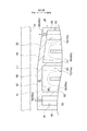
図2は、一実施形態に係るタービン動翼26の概略構成図である。図3は、互いに周方向に隣接するタービン動翼26を示した動翼列を径方向外側から視た図である。
FIG. 2 is a schematic configuration diagram of the
図2に示すように、タービン動翼26は、ロータ軸8に固定される基端部32と、内部に冷却流路34が形成された翼型部36とを備える。また、図3に示すように、翼型部36は、正圧面38と、負圧面40と、正圧面38と負圧面40とを接続する頂面42と、を含む。頂面42は、タービン車室22(図1参照)の環状の静止壁面54(図2参照)と対向するように配置されている。
As shown in FIG. 2, the
幾つかの実施形態では、例えば図2及び図3に示すように、頂面42は、前縁48側に位置しロータ軸8(ロータ軸8の軸線)に平行に形成される前縁領域44と、前縁領域44に対して軸方向に隣接する後縁領域46とを含み、前縁領域44と後縁領域46との間に境界線LLが形成される。後縁領域46は、後縁50に近づくにつれて径方向内側に向かうように境界線LLを境にして前縁領域44に対して傾斜する傾斜面52を含む。
In some embodiments, for example, as shown in FIGS. 2 and 3, the
ガスタービン1の翼型部36が、ロータ軸8に平行なフラットな頂面42で形成された動翼26の場合は、通常の運転時(例えば、定格負荷運転時のタービン動翼の温度が上昇した高温状態)において、タービン動翼26は、遠心力、ガス流れから受ける力、及び熱伸びの影響を受けて変形する。特に、冷却流路を流れる冷却媒体の温度は、タービン動翼26の後縁50側で燃焼ガスからの入熱によるヒートアップにより高くなりやすく、後縁50側の径方向の熱伸び量が大きくなりやすい。このため、ガスタービン1の運転停止時(タービン動翼26の温度が上昇しておらず常温又は常温に近い状態)においてタービン動翼26の頂面42とタービン車室22の静止壁面54との距離(以下、「チップクリアランス」という。)が前縁48から後縁50にかけて一定の隙間量に設定されている場合には、ガスタービン1の運転時において熱伸び量が大きい後縁50側でタービン動翼26の頂面42とタービン車室22の静止壁面54との接触リスクが高くなりやすい。一方、後縁50側でタービン動翼26の頂面42とタービン車室22の静止壁面54とが接触しないように、運転停止時におけるチップクリアランスが前縁48から後縁50にかけて一様に大きくなるような翼型部36を形成すると、ガスタービンの通常運転時における前縁側におけるチップクリアランスが過度に大きくなり、ガスタービンの性能が低下する。すなわち、前縁48側は、後縁50側と比較して翼型部36内を流れる冷却媒体の温度が低く、径方向の熱伸び量が比較的小さく抑えられているため、ガスタービン1の通常運転時における前縁48側のクリアランスが大きくなる傾向になる。
従って、前縁48から後縁50までのチップ高さ(ロータ軸8の中心から頂面42までの高さ)を同じとすると、通常運転時における前縁48側のチップクリアランスが、後縁50側と比較して相対的に大きくなり、前縁48側のチップ(頂面42)からの燃焼ガスのリーク流れが増加して、タービン動翼26の空力性能が低下する原因になる。
When the
Therefore, assuming that the tip height from the leading
これに対し、図2に示すタービン動翼26では、熱伸び量が大きくなりやすい後縁50側に設けられた後縁領域46が、後縁50に近づくにつれて径方向内側に向かうように傾斜する傾斜面52を含んでいる。すなわち、後縁領域46は、ガスタービンの運転停止時において、後縁50に近づくにつれてチップクリアランスが大きくなるように傾斜した傾斜面52を含む。このため、図2の破線に示すように、ガスタービン1の通常運転時に主として後縁領域46が熱伸びにより径方向外側方向へ変形して、頂面42の前縁48から後縁50までのチップクリアランスが均一な隙間量に近づくように傾斜面52を形成している。
On the other hand, in the
また、前縁領域44がロータ軸8に平行に形成されているため、前縁領域44において、ロータ軸8の中心から頂面42(天板60)までの高さが均一に形成され、タービン動翼26のチップクリアランスが前縁領域44の各所において均一である。このため、テーパーゲージ等の計測器14によりチップクリアランスを計測する際に、前縁領域44の何れの位置で計測してもチップクリアランスを適切に管理することができ、チップクリアランスの管理が容易である。すなわち、前縁領域44は翼型部36の径方向への熱伸びが小さいため、定常運転中におけるチップクリアランスの変化量が小さく、天板60(頂面42)と静止壁面54との間の隙間量を適正量に管理し易い。このため、前縁領域44における頂面42と静止壁面54との隙間におけるリーク流れに起因した損失を効果的に抑制することができる。
Further, since the
上述したように、タービン動翼26の運転条件及び翼構造等により、前縁領域と後縁領域を区分けする最適境界線SLLの位置が変化し、条件に合った最適境界線SLLを選定する必要がある。
ここで、最適境界線SLLの選定の基本的な考え方を以下に説明する。チップクリアランスは、タービン車室22の静止壁面54とタービン動翼26の頂面との間の隙間計測を前提として、管理される。すなわち、翼型部36の熱伸びの変化が前縁48側に近い範囲まで及ぶタービン動翼26の場合には、最適境界線SLLは前縁48に近い位置に配置する必要があり、熱伸びが小さいタービン動翼26の場合は、後縁50に近い位置に配置してもよい。
As described above, the position of the optimum boundary line SLL that separates the leading edge region and the trailing edge region changes depending on the operating conditions and blade structure of the
Here, the basic concept of selecting the optimum boundary line SLL will be described below. The tip clearance is managed on the premise of measuring the gap between the
しかし、前縁48に近い位置に最適境界線SLLを配置する場合、最適境界線SLLを配置する位置の選定には限界がある。すなわち、上述したように、チップクリアランス管理の前提になる隙間量の計測は、計測器を翼面37に垂直に当てて計測する必要があり、それが不可能であれば正確な隙間量は計測できない。以下に説明するように、前縁48近傍で隙間計測をする場合、タービン動翼26の翼面37である負圧面40のスロート位置が、軸方向で最も上流側の計測可能な限界位置である。この位置より軸方向上流側での計測は、隣接する動翼26が障害になり、正確な計測が不可能である。図3に示すように、隣接するタービン動翼26の後縁50(後縁端部50a)から負圧面40上に下した垂線Vが、隣接する動翼26との間のスロート58に相当し、垂線Vと負圧面40との交点が、負圧面40上のスロートの位置P2である。位置P2を通り、前縁領域44と後縁領域46とを区画する仮の境界線を仮想線と呼び、最も前縁48に近い位置に形成される仮想線を最上流側仮想線(第1仮想線)LL1として選定する。
However, when arranging the optimal border SLL at a position closer to the leading
但し、位置P2を通る最上流側仮想線LL1は無数に存在するが、頂面42上に境界線LLを形成する容易さの観点からは、ある程度の範囲に限定される。図3に示す仮想線L1は、位置P2を通りロータ軸8に直交し周方向に伸びる最上流側周方向仮想線である。仮想線L2は、位置P2を通りキャンバーラインCLに直交するキャンバーライン最上流側直交仮想線である。仮想線L3は、位置P2を通りロータ軸8に沿って延びる最上流側ロータ軸方向仮想線である。いずれの仮想線も、位置P2を起点として、位置P2を通り直線状に延在し、両端で翼面37と交わる線である。
但し、3つの仮想線の中では、仮想線L3が最も前縁48に近い最上流側仮想線LL1である。最上流側仮想線LL1は、仮想線L1、仮想線L2及び仮想線L3によって画定される範囲に位置し、仮想線L1(最上流側周方向仮想線)から反時計方向廻りで仮想線L3(最上流側ロータ軸方向仮想線)までの間の範囲で選定し得る。
However, although the most upstream side virtual line LL1 passing through the position P2 exists innumerably, it is limited to a certain range from the viewpoint of the ease of forming the boundary line LL on the
However, among the three virtual lines, the virtual line L3 is the most upstream side virtual line LL1 closest to the leading
次に、最適境界線SLLを画定する他の仮想線として想定する最下流側仮想線LL2の選定について、以下に説明する。詳細は後述するが、図3に示す後縁50側に配置された出口開口56の位置である位置P3を通る直線が、最下流側仮想線(第2仮想線)LL2に相当する。出口開口56付近の翼型部36は、最も径方向に伸び易い構造である。
図3に示す仮想線L11は、位置P3を通りロータ軸8に直交し周方向に伸びる最下流側周方向仮想線である。仮想線L12は、位置P3を通りキャンバーラインCLに直交する最下流側キャンバーライン直交仮想線である。仮想線L13は、位置P3を通りロータ軸8に沿って延びる最下流側ロータ軸方向仮想線である。最下流側仮想線LL2は、仮想線L11、仮想線L12及び仮想線L13によって画定される範囲に位置し、仮想線L11(最下流側周方向仮想線)から反時計方向廻りで仮想線L13(最下流側ロータ軸方向仮想線)の間の範囲で選定し得る。
Next, selection of the most downstream side virtual line LL2 assumed as another virtual line defining the optimum boundary line SLL will be described below. Although the details will be described later, the straight line passing through the position P3, which is the position of the
The virtual line L11 shown in FIG. 3 is the most downstream side circumferential virtual line that passes through the position P3, is orthogonal to the
タービン動翼26は、翼構造及び運転条件及び翼型部36の位置により熱伸び量が異なる。図4は、最適境界線LLが、最上流側仮想線L1、L2、L3と、最下流側仮想線L11、L12、L13との間に形成された例を示す。図4に示す例は、最適境界線LLとして、位置P1を通りロータ軸8に直交し周方向に伸びる周方向仮想線を一例として示したものである。
以上に述べた基本的な考え方に基づき、以下に具体的に説明する。
The amount of heat elongation of the
Based on the basic idea described above, a specific description will be given below.
幾つかの実施形態では、例えば図3に示すように、仮想線L1、L2、L3と負圧面40上の交点の位置を、隣接するタービン動翼26との間にスロート58が形成される位置P2とする。なお、「負圧面40上の隣接するタービン動翼26との間にスロート58が形成される位置」とは、隣接するタービン動翼26の後縁50から負圧面40上に下した垂線Vと負圧面40との交点であり、負圧面40上のスロート58の位置を示す位置P2を意味する。
In some embodiments, for example, as shown in FIG. 3, the position of the intersection of the virtual lines L1, L2, L3 and the
チップクリアランスを精度よく計測するためには、タービン動翼26の負圧面40側から負圧面40に垂直な方向である垂線Vに沿ってテーパーゲージ等の計測器14を頂面42と静止壁面54との間の隙間に差し込むことが望ましい。隙間量を正確に計測するためには、計測器14は、計測点の翼面(負圧面40)に対して垂直に当てることが望ましい。
つまり、隣接するタービン動翼26側から計測器14を当ててチップクリアランスの隙間量を計測する場合、前縁48から後縁50までの負圧面40上の内、最も前縁48に近い位置は、上述の負圧面40上のスロート58の位置P2である。この位置P2より前縁48側に寄った位置は、隣接する動翼26が障害になり、計測器14を負圧面40に対して垂直に当てることが出来ず、正確な隙間量の計測が困難である。
In order to measure the tip clearance accurately, a measuring
That is, when the measuring
幾つかの実施形態では、例えば図3に示すように、位置P2を通る仮想線は、最も前縁48に近い最上流側仮想線LL1を画定する。上述のように、最上流側仮想線LL1として、仮想線L1、L2、L3が選定できる。仮想線L1は、ロータ軸8に直交し周方向に沿って直線状に延在して、前縁48側の前縁領域44と、後縁50側の後縁領域46を区分けする仮想線である。
仮想線L1をロータ軸8に直交する方向に定めれば、仮想線L1の位置決めが容易になる。このため、前縁領域44と後縁領域46との仮想線L1がロータ軸8に直交する周方向に沿って延在するように頂面42を構成することにより、前縁領域44と後縁領域46との間の仮想線L1を頂面42上の正確な位置に形成でき、チップクリアランスである天板60(頂面42)と静止壁面54との間の隙間量を正確に管理が可能になる。
In some embodiments, for example, as shown in FIG. 3, the imaginary line passing through position P2 defines the most upstream imaginary line LL1 closest to the leading
If the virtual line L1 is set in the direction orthogonal to the
仮想線L2は、位置P2を通りキャンバーラインCLに直交する方向に直線状に延びるキャンバーライン方向仮想線である。仮想線L2は、キャンバーラインCLに直交する直線であるため、位置決めが容易であり、境界線の加工も容易である。 The virtual line L2 is a camber line direction virtual line that passes through the position P2 and extends linearly in a direction orthogonal to the camber line CL. Since the virtual line L2 is a straight line orthogonal to the camber line CL, positioning is easy and the boundary line can be easily processed.
仮想線L3は、位置P2を通りロータ軸8方向に沿って直線状に延びるロータ軸方向仮想線である。仮想線L3は、ロータ軸8方向にロータ軸8に平行に伸びる直線であるため、位置決めが容易であり、境界線の加工も容易である。
The virtual line L3 is a rotor axial virtual line that passes through the position P2 and extends linearly along the
次に、最下流側仮想線LL2の選定について、以下に説明する。
幾つかの実施形態では、例えば図2及び図3に示すように、冷却流路34は、後述するサーペンタイン流路62を形成し、最も後縁50に近い最終冷却流路34aを流下した冷却媒体は、頂面42に形成された出口開口56から排出される。なお、出口開口56は、最終冷却流路34aの径方向外側端の天板60に形成され、最終冷却流路34aに直結している。冷却媒体の一部は、最終冷却流路34aから分岐して、後縁50の端部50aの軸方向下流側を向く後縁端面50bに開口し、径方向に配列された複数の冷却孔63から燃焼ガス中に排出される。冷却媒体が複数の冷却孔63を介して燃焼ガス中に排出される過程で、後縁50の端部50aが冷却され、後縁端部50aの熱損傷が防止される。
Next, the selection of the most downstream side virtual line LL2 will be described below.
In some embodiments, for example, as shown in FIGS. 2 and 3, the
最も後縁50に近い出口開口56近傍の翼型部36は、冷却媒体のヒートアップ等に対する対策により、冷却が種々強化されているが、それでも最も径方向の熱伸びが大きくなる部分である。そのため、出口開口56bの中心の位置をP3として、位置P3を通る仮想線L11、L12、L13が、最下流側仮想線LL2の一部として形成される。なお、出口開口56bの位置P3は、図3において破線で示すように、径方向外側から翼断面を見た場合、最終冷却流路34aの流路断面内に形成されている。
The
仮想線L11は、位置P3を通り、ロータ軸8に直交し、周方向に伸びる直線状の周方向仮想線である。仮想線L11が、負圧面40上で交わる交点が位置P4である。仮想線L11は、ロータ軸8に直交する直線であるため、位置決めが容易であり、境界線の加工も容易である。
The virtual line L11 is a linear virtual line in the circumferential direction that passes through the position P3, is orthogonal to the
仮想線L12は、位置P3を通り、キャンバーラインCLに直交する方向に直線状に延びるキャンバーライン方向仮想線である。仮想線L12が、負圧面40上で交わる交点が位置P5である。仮想線L12は、キャンバーラインCLに直交する直線であるため、位置決めが容易であり、境界線の加工も容易である。
The virtual line L12 is a camber line direction virtual line that passes through the position P3 and extends linearly in a direction orthogonal to the camber line CL. The intersection where the virtual line L12 intersects on the
仮想線L13は、位置P3を通りロータ軸8方向に沿って直線状に延びるロータ軸方向仮想線である。仮想線L13が、負圧面40上で交わる交点が位置P6である。仮想線L13は、ロータ軸8方向にロータ軸8に平行に伸びる直線であるため、位置決めが容易であり、境界線の加工も容易である。
The virtual line L13 is a rotor axial virtual line that passes through the position P3 and extends linearly along the
最下流側仮想線LL2は、上述のように、最下流側周方向線である仮想線L11と最下流側ロータ軸方向仮想線であるL13の間の境界線LLを選定することが望ましい。つまり、最下流側仮想線LL2は、仮想線L11(最下流側周方向仮想線)から反時計方向廻りで仮想線L13(最下流側ロータ軸方向仮想線)までの範囲で選定することが望ましい。 As described above, for the most downstream side virtual line LL2, it is desirable to select a boundary line LL between the most downstream side circumferential direction line L11 and the most downstream side rotor axial direction virtual line L13. That is, it is desirable to select the most downstream side virtual line LL2 in the range from the virtual line L11 (the most downstream side circumferential virtual line) to the virtual line L13 (the most downstream side rotor axial direction virtual line) in a counterclockwise direction. ..
図4は、タービン動翼26の頂面42において、最適境界線SLLの軸方向上流側の限界である最上流側仮想線LL1と、軸方向下流側の限界である最下流側仮想線LL2を示すとともに、翼構造や運転条件から選定される最適境界線SLLを一例として表示した構成図である。最適境界線SLLは、最上流側仮想線LL1と最下流側仮想線LL2の間に形成される。最適境界線SLLの選定にあたっては、翼構造や運転条件等を考慮して、チップクリアランス(隙間量)を推測し、位置P1と最適境界線SLLを選定する。
FIG. 4 shows, on the
図4において、前縁48に近い軸方向上流側の位置P1は、少なくとも位置P2と一致するか又は位置P1が位置P2よりも後縁50側に位置することが望ましい。また、後縁50側に近い軸方向下流側の位置P1は、仮想線L11(最下流側周方向仮想線)との交点である位置P4と一致するか、位置P4より前縁48側に配置することが望ましい。或いは、位置P1は、仮想線L12(最下流側キャンバーライン直交方向仮想線)との交点である位置P5と一致するか、位置P5より前縁48側に配置することが望ましい。或いは、位置P1は、仮想線L13(最下流側ロータ軸方向仮想線)との交点である位置P6と一致するか、位置P6より前縁48側に配置することが望ましい。このような位置P1を配置して、最上流側仮想線LL1と最下流側仮想線LL2との間に形成される所定の境界線LLを最適境界線SLLとして選定すれば、前縁領域44と静止壁面54とのチップクリアランスを容易に精度よく計測することができる。また、正確な最適境界線SLLを形成できれば、正確なチップクリアランス(隙間量)が選定できるので、頂面42からの燃焼ガスのリーク流れを抑制できる。また、隣接するタービン動翼26の後縁50に干渉することなくスムーズにテーパーゲージ等の計測器14を前縁領域44と静止壁面54との間の隙間に差し込むことができる。
In FIG. 4, it is desirable that the position P1 on the upstream side in the axial direction near the leading
上述のように、冷却流路34における後縁50に最も近い出口開口56bの近傍では、特に熱伸び量が大きくなりやすく、頂面42と静止壁面54との接触リスクが高くなりやすい。このため、上記のように、位置P1を、仮想線L11との交点である位置P4よりも前縁48側に位置させることにより、出口開口56bの近傍における頂面42と静止壁面54との接触リスクを効果的に低減できる。
As described above, in the vicinity of the
幾つかの実施形態では、例えば図3に示すように、頂面42において位置P3を通り周方向に平行な直線L3と負圧面40との交点をP5とすると、位置P1は、位置P5よりも翼型部36の前縁48側に位置する。
In some embodiments, for example, as shown in FIG. 3, if the intersection of the straight line L3 passing through the position P3 and parallel to the circumferential direction on the
冷却流路34における後縁50に最も近い出口開口56bの近傍では、サーペンタイン流路62を流れる冷却媒体の温度が燃焼ガスからの入熱によりヒートアップされる。従って、特に熱伸び量が大きくなりやすく、頂面42と静止壁面54との接触リスクが高くなりやすい。このため、上記のように、位置P1を仮想線L12との交点である位置P5よりも前縁48側に位置させることにより、頂面42と静止壁面54との接触リスクを効果的に低減しつつ、タービン動翼26の頂面42(傾斜面52)からの燃焼ガスのリーク流れを抑制できる。
In the vicinity of the nearest outlet opening 56b to the trailing
冷却流路34における後縁50に最も近い出口開口56bの近傍では、特に径方向外側への熱伸び量が大きくなりやすく、頂面42と静止壁面54との接触リスクが高くなりやすい。このため、上述のように、位置P1を仮想線L13との交点である位置P6よりも前縁48側に位置させることにより、出口開口56bの近傍における頂面42と静止壁面54との接触リスクを効果的に低減できる。
In the vicinity of the
最適境界線SLLを選定する場合、最上流側仮想線LL1と最下流側仮想線LL2の位置を勘案して、推定する隙間量の分布から境界線LLの位置P1を選定し、前縁領域44と後縁領域46の隙間量の分布から位置P1を通る仮想線を選定し、この仮想線を最適境界線SLLとしてもよい。
When selecting the optimum boundary line SLL , the position P1 of the boundary line LL is selected from the estimated clearance amount distribution in consideration of the positions of the most upstream side virtual line LL1 and the most downstream side virtual line LL2, and the leading edge region 44 A virtual line passing through the position P1 may be selected from the distribution of the gap amount in the trailing
幾つかの実施形態では、図5及び図6に示すように、タービン動翼26の後縁50に冷却媒体の出口開口がない態様を示す。図5は、他の実施形態に係るタービン動翼の概略構成図である。図6は、他の実施形態に係る最適境界線SLLと最上流側境界線LL1を示した構成図である。タービン動翼26の翼型部36の内部に形成される冷却流路34は、サーペンタイン流路62を形成し、最も後縁50に近い最終冷却流路34aの径方向外側端には、前述のような頂面42に最終冷却流路34aに直結して形成された出口開口を備えていない。最終冷却流路34aは、一端が前記最終冷却流路34aの上流側の冷却流路34に連通し、他端が後縁50の軸方向下流側を向く後縁端部50aに開口して、径方向に配列された複数の冷却孔63に接続している。最終冷却流路34aに供給された冷却媒体の全量は、最終冷却流路34aから冷却孔63を流れ、後縁端部50aから燃焼ガス中に排出される過程で、後縁50の後縁端部50aを対流冷却して、後縁端部50aの熱損傷を防止している。
In some embodiments, as shown in FIGS. 5 and 6, the trailing
最終冷却流路34aの径方向外側端近傍の翼型部36は、サーペンタイン流路62を流れる過程で冷却媒体がヒートアップされる。従って、径方向外側近傍の最終冷却流路34aに接続する冷却孔63近傍の頂面42側の後縁端部50a近傍は、冷却媒体で冷却されるものの、翼型部36の中では最も過熱される箇所になり、径方向外側方向への熱伸びが最も大きくなる。
The cooling medium of the
図6に示すように、本実施形態の場合、最適境界線SLLは、軸方向上流側に位置する最上流側仮想線LL1を上限とし、後縁端部50aである最下流側仮想線LL2(実質、後縁端面50bに相当)を下限として、この間に形成される。最適境界線SLLが負圧面40と交わる位置P1は、少なくとも位置P2と一致するか又は位置P1が位置P2よりも後縁50側に位置することが望ましい。また、最適境界線SLLの下限を定める位置P1は、上述のように後縁端部50aの位置と一致する。なお、図6において破線で示すように、径方向外側から翼断面を見た場合、後縁50側の最終冷却流路34aの流路断面内の頂面42上には、冷却媒体の出口開口が形成されていない。冷却媒体は、冷却孔63を流れ、後縁端面50bの開口から排出される。
As shown in FIG. 6, in the case of the present embodiment, the optimum boundary line SLL has the uppermost stream side virtual line LL1 located on the upstream side in the axial direction as the upper limit, and the most downstream side virtual line LL2 which is the trailing
このような位置P1を配置して、最上流側仮想線LL1と最下流側仮想線LL2との間に形成される所定の境界線LLを最適境界線SLLとして選定すれば、隣接するタービン動翼26の後縁50に干渉することなく、スムーズにテーパーゲージ等の計測器14を前縁領域44と静止壁面54との間の隙間に差し込むことができる。これにより、前縁領域44と静止壁面54とのチップクリアランスを容易に精度よく計測することができる。また、正確な最適境界線SLLを形成できれば、正確なチップクリアランス(隙間量)が選定できるので、頂面42からの燃焼ガスのリーク流れを抑制できる。
If such a position P1 is arranged and a predetermined boundary line LL formed between the most upstream side virtual line LL1 and the most downstream side virtual line LL2 is selected as the optimum boundary line SLL , the adjacent turbine blades A measuring
図7は、他の実施形態に係るタービン動翼26の頂面42の構造を示す平面図である。図8は、他の実施形態に係るタービン動翼26の軸方向から見た断面図であり、図7におけるA−A断面を示す図である。
FIG. 7 is a plan view showing the structure of the
幾つかの実施形態では、例えば図7及び図8に示すように、タービン動翼26は、頂面42上の周方向の負圧面40側の端部であって、翼面37に沿って前縁48から後縁50までの間に形成され、頂面42から径方向外側方向に突出する凸部51(チップシニング又はスキーラとも呼ぶ)を含んでいる。
In some embodiments, for example, as shown in FIGS. 7 and 8, the
図8に示すように、凸部51はタービン動翼26の負圧面40側の翼面37に沿って、頂面42の表面から高さHで径方向外側方向に突出するように形成され、前縁48から後縁50まで延在する。
As shown in FIG. 8, the
本実施形態においても、例えば図7及び図8に示すように、頂面42は、前縁48側に位置しロータ軸8に平行に形成される前縁領域44と、前縁領域44に対して軸方向に隣接する後縁領域46とを含んでいる。後縁領域46は、後縁50に近づくにつれて径方向内側に向かうように前縁領域44に対して傾斜する傾斜面52を含んでいる。
Also in the present embodiment, for example, as shown in FIGS. 7 and 8, the
図8に示すように、頂面42上の負圧面40側の翼面37に沿って延在する凸部51は、頂面42から径方向外側方向に高さHを維持して、前縁48から後縁50まで形成されている。すなわち、頂面42上に形成される前縁領域44及び後縁領域46は、周方向に隣接する凸部51の径方向外側を向く平面形状の頂部51aにも形成される。
As shown in FIG. 8, the
本実施形態の場合、タービン動翼26の翼型部36と静止壁面54の間の隙間計測は、負圧面40側に形成された凸部51の頂部51aと静止壁面54の間の隙間量を計測して行われる。従って、スロート位置に相当する位置P2は、凸部51の頂部51a上に形成される。本実施形態においても、凸部51の頂部51aに定められた位置P2を通る仮想線は、最も前縁48に近い最上流側仮想線LL1を画定し、最上流側仮想線LL1として、仮想線L1、L2、L3が選定される。具体的には、図7に示すように、仮想線L1、L2、L3は、ロータ軸8に直交する最上流側周方向仮想線L1及びキャンバーラインCLに直交する最上流側キャンバーライン直交仮想線L2並びにロータ軸8に平行に伸びる最上流側ロータ軸方向仮想線L3が相当する。
In the case of the present embodiment, the gap measurement between the
但し、最上流側仮想線LL1は、仮想線L1、仮想線L2及び仮想線L3によって画定される範囲に位置し、仮想線L1(最上流側周方向仮想線)から反時計方向廻りで仮想線L3(最上流側ロータ軸方向仮想線)までの間の範囲で選定し得る。 However, the most upstream side virtual line LL1 is located in the range defined by the virtual line L1, the virtual line L2, and the virtual line L3, and is a virtual line counterclockwise from the virtual line L1 (the most upstream side circumferential virtual line). It can be selected in the range up to L3 (topstream side rotor axial direction virtual line).
凸部51の頂部51aの翼面37に沿って形成された位置P2を一端として、直線状に
他方の翼面37の位置まで延長された最上流側仮想線LL1は、頂面42上にも形成される。
The most upstream side virtual line LL1 linearly extended to the position of the
幾つかの実施形態では、例えば図7及び図8に示すように、頂面42に形成された最終冷却流路34aの出口開口56bの中心の位置をP3として、位置P3を通る仮想線が、最下流側仮想線を形成する。ロータ軸8に直交し、周方向に伸びる直線状の周方向仮想線L11及びキャンバーラインCLに直交するキャンバーライン方向仮想線L12並びにロータ軸8に平行に伸びるロータ軸方向仮想線L13が、最下流側仮想線LL2の一部として形成される。なお、最下流側仮想線LL2は、仮想線L11(最下流側周方向仮想線)から反時計方向廻りで仮想線L13(最下流側ロータ軸方向仮想線)までの範囲で選定することが望ましい。最下流側仮想線LL2は、頂面42上に形成されると共に、凸部51の頂部51a上にも形成される。
In some embodiments, for example, as shown in FIGS. 7 and 8, a virtual line passing through the position P3 is formed with the center position of the outlet opening 56b of the final
本実施形態における最適境界線SLLの一例を図7に示す。頂面42上に形成された最適境界線SLLは、翼面37に沿った同じ位置で、凸部51の頂部51a上にも形成される。従って、頂面42に対する凸部51の頂部51aの間の高さHは、前縁48から後縁50まで同じ高さが維持される。なお、最適境界線SLLは、翼構造や運転条件等を考慮して、チップクリアランス(隙間量)を推測値等から選定され、その位置P1と最適境界線SLLが延在する方向が選定される。
An example of the optimum boundary line SLL in this embodiment is shown in FIG. The optimum boundary line SLL formed on the
最適境界線SLLを境界として、頂面42上に形成された前縁領域44及び後縁領域46は、凸部51の頂部51a上にも形成される。頂面42に形成された前縁領域44と後縁領域46の境界線LLの位置は、凸部51の頂部51a上に形成された前縁領域44と後縁領域46の境界線LLの位置P1と、翼面37の径方向に沿った方向で一致する。従って、頂面42上の前縁領域44と凸部51の頂部51a上の前縁領域44は、ロータ軸8に平行に形成される。また、凸部51の頂部51a上の後縁領域46には、頂面42上の後縁領域46と同様に、最適境界線SLLの位置から後縁50の方向に、後縁50に近づくと共に径方向内側に傾く傾斜面51bが形成されている。この場合であっても、上述のように、頂面42に対する凸部51の頂部51aの間の高さHは、前縁48から後縁50まで同じ高さHが維持される。
The
本実施形態の構成によれば、翼型部36の頂面42上の負圧面40側に形成された凸部51を設けることにより、凸部51の頂部51aと静止壁面54との間の隙間が小さくなり、凸部51の頂部51aを越える燃焼ガスのリーク流れが減少して、タービンの空力性能が向上する。
According to the configuration of the present embodiment, the
凸部51の頂部51aの前縁48から後縁50までの翼面37に沿った形状を頂面42と同じ形状とするので、燃焼ガスのリーク流れが減少すると共に、静止壁面54との干渉も回避され、ガスタービン1の安定運転が可能になる。
Since the shape of the top 51a of the
図9は、一実施形態に係る翼型部36の構成の一例を示す断面図である。図10は、一実施形態に係る翼型部36の他の構成を示す断面図である。図11は、一実施形態に係る翼型部36の他の構成を示す断面図である。
FIG. 9 is a cross-sectional view showing an example of the configuration of the
幾つかの実施形態では、例えば図9〜図11に示すように、翼型部36は、頂面42を形成する天板60を含む。
In some embodiments, the
幾つかの実施形態では、例えば図9に示すように、天板60の厚さtは、前縁領域44の少なくとも一部に対応する範囲において、後縁50に近づくにつれて大きくなる。また、天板60の厚さtは、後縁領域46の少なくとも一部に対応する範囲において、後縁50に近づくにつれて小さくなる。図示する例示的形態では、天板60は、前縁領域44の全範囲において、後縁50に近づくにつれて厚さtが大きくなるように構成されており、後縁領域46の全範囲において、後縁50に近づくにつれて厚さtが小さくなるように構成されている。
かかる構成によれば、前縁48から後縁50までの天板60の厚さtの変化が小さく、前縁領域44と後縁領域46の温度が均一化され、天板60のメタル温度の上昇が抑制される。
In some embodiments, for example, as shown in FIG. 9, the thickness t of the
According to such a configuration, the change in the thickness t of the
幾つかの実施形態では、例えば図10に示すように、天板60は、前縁領域44及び後縁領域46のいずれにおいても同じ厚さtで形成されている。
かかる構成によれば、翼型部36の前縁領域から後縁領域に至る天板の厚さが均一化されているので、天板における熱応力の発生を抑制ことができる。
In some embodiments, for example, as shown in FIG. 10, the
According to such a configuration, since the thickness of the top plate from the leading edge region to the trailing edge region of the
幾つかの実施形態では、例えば図2及び図9〜図11に示すように、冷却流路34は、前縁48側に配置されたストレート流路59を含む。ストレート流路59は、基端部32に設けられた入口開口35aと、頂面42に設けられた出口開口56aとを含み、翼型部36の内部を径方向に沿って一方向に延在する。
In some embodiments, the
幾つかの実施形態では、例えば図2及び図9〜図11に示すように、冷却流路34は、前縁48側から後縁50側まで配置されたサーペンタイン流路62を含む。図示する例示的形態では、サーペンタイン流路62は、前縁48側にて基端部32に設けられた入口開口35bと、後縁50側にて頂面42に設けられた上述の出口開口56bと、を含み、入口開口35bと出口開口56bとの間で径方向に折り返しながら蛇行するように構成されている。サーペンタイン流路62の径方向外側端部64は、冷却媒体の流れを反転させるための少なくとも一つ以上のリターン部66(66a,66b)を含む。図示する例示的形態では、サーペンタイン流路62の径方向外側端部64は、流れを反転させるための第1リターン部66a及び第2リターン部66bを含む。
In some embodiments, for example, as shown in FIGS. 2 and 9-11, the
図9〜図11に示すように、天板60のうち頂面42と径方向内側の反対側の壁面68は、リターン部66を形成する少なくとも一つ以上のリターン部形成壁面70(70a,70b)を含む。図示する例示的形態では、天板60のうち頂面42と径方向内側の反対側の壁面68は、第1リターン部66aを形成する第1リターン部形成壁面70aと、第1リターン部形成壁面70aに対して仕切壁72を挟んで後縁50側に隣接するとともに第2リターン部66bを形成する第2リターン部形成壁面70bとを含む。
As shown in FIGS. 9 to 11, at least one or more return portion forming wall surfaces 70 (70a, 70b) forming the
幾つかの実施形態では、例えば図9に示すように、リターン部形成壁面70(70a,70b)の各々は、後縁50に近づくにつれて径方向内側に向かうように傾斜している。図示する例示的形態では、軸方向に対する傾斜面52の傾斜角をθ1、軸方向に対するリターン部形成壁面70(70a,70b)の各々の傾斜角をθ2とすると、θ1>θ2を満たす。
In some embodiments, for example, as shown in FIG. 9, each of the return portion forming wall surfaces 70 (70a, 70b) is inclined inward in the radial direction as it approaches the trailing
かかる構成によれば、後縁50に近づくにつれて径方向内側に向かうように傾斜する傾斜面52を設けた場合であっても、リターン部形成壁面70(70a,70b)の各々を後縁50に近づくにつれて径方向内側に向かうように傾斜させることにより、熱伸び量の大きくなりやすい後縁50側の天板60の肉厚を確保することが容易となる。
According to such a configuration, even when the
幾つかの実施形態では、例えば図11に示すように、第1リターン部形成壁面70a及び第2リターン部形成壁面70bの各々は、ロータ軸8に平行に形成され、第1リターン部形成壁面70aのロータ軸8からの高さh1は、第2リターン部形成壁面70bのロータ軸8からの高さh2より大きい。すなわち、天板60のうち頂面42と反対側の内壁面68は、下流側に向かうにつれてロータ軸8からの高さが小さくなるように階段状になっている。
In some embodiments, for example, as shown in FIG. 11, each of the first return portion forming
かかる構成によれば、後縁50に近づくにつれて径方向内側に向かうように傾斜する傾斜面52を設けた場合であっても、第1リターン部形成壁面70aのロータ軸8からの高さh1を第2リターン部形成壁面70bのロータ軸8からの高さh2より大きくすることにより、熱伸び量の大きくなりやすい後縁50側の天板60の比較的一様な肉厚を確保することが容易となり、熱応力の発生を抑制できる。
According to such a configuration, the height h1 of the first return portion forming
本発明は上述した実施形態に限定されることはなく、上述した実施形態に変形を加えた形態や、これらの形態を適宜組み合わせた形態も含む。 The present invention is not limited to the above-described embodiment, and includes a modified form of the above-described embodiment and a combination of these embodiments as appropriate.
1 ガスタービン
2 圧縮機
4 燃焼器
6 タービン
8 ロータ軸
10 圧縮機車室
12 入口
14 計測器
16 静翼
18 動翼
22 タービン車室
24 タービン静翼
26 タービン動翼
28 燃焼ガス流路
30 排気室
32 基端部
34 冷却流路
35(35a,35b) 入口開口
36 翼型部
37 翼面
38 正圧面
40 負圧面
42 頂面
44 前縁領域
46 後縁領域
48 前縁
50 後縁
50a 後縁端部
50b 後縁端面
51 凸部
51a 頂部
52,51b 傾斜面
54 静止壁面
56(56a,56b) 出口開口
58 スロート
59 ストレート流路
60 天板
62 サーペンタイン流路
63 冷却孔
64 径方向外側端部
66 リターン部
66a 第1リターン部
66b 第2リターン部
68 内壁面
70 リターン部形成壁面
70a 第1リターン部形成壁面
70b 第2リターン部形成壁面
72 仕切壁
LL 境界線(仮想線)
SLL 最適境界線
LL1 最上流側仮想線(第1仮想線)
LL2 最下流側仮想線(第2仮想線)
L1 第1周方向仮想線(最上流側仮想線)
L2 第1キャンバーライン直交仮想線(最上流側仮想線)
L3 第1ロータ軸方向仮想線(最上流側仮想線)
L11 第2周方向仮想線(最下流側仮想線)
L12 第2キャンバーライン直交仮想線(最下流側仮想線)
L13 第2ロータ軸方向仮想線(最下流側仮想線)
1
SLL optimum boundary line LL1 upstream virtual line (first virtual line)
LL2 most downstream side virtual line (second virtual line)
L1 1st circumference virtual line (uppermost stream side virtual line)
L2 1st camber line orthogonal virtual line (upstream side virtual line)
L3 1st rotor axial direction virtual line (upstream side virtual line)
L11 2nd circumferential virtual line (most downstream virtual line)
L12 2nd camber line orthogonal virtual line (most downstream virtual line)
L13 2nd rotor axial direction virtual line (most downstream side virtual line)
Priority Applications (6)
| Application Number | Priority Date | Filing Date | Title |
|---|---|---|---|
| JP2018228937A JP7223570B2 (en) | 2018-12-06 | 2018-12-06 | Turbine rotor blade, turbine and tip clearance measurement method |
| US17/281,003 US11499430B2 (en) | 2018-12-06 | 2019-11-20 | Turbine rotor blade, turbine, and tip clearance measurement method |
| KR1020217011776A KR102594268B1 (en) | 2018-12-06 | 2019-11-20 | How to Measure Turbine Rotor, Turbine and Tip Clearances |
| CN201980071221.9A CN112969841B (en) | 2018-12-06 | 2019-11-20 | Turbine moving blade, turbine and head clearance measuring method |
| DE112019004838.4T DE112019004838T5 (en) | 2018-12-06 | 2019-11-20 | Turbine rotor blade, turbine and blade gap measurement method |
| PCT/JP2019/045349 WO2020116155A1 (en) | 2018-12-06 | 2019-11-20 | Turbine rotor blade, turbine, and chip clearance measurement method |
Applications Claiming Priority (1)
| Application Number | Priority Date | Filing Date | Title |
|---|---|---|---|
| JP2018228937A JP7223570B2 (en) | 2018-12-06 | 2018-12-06 | Turbine rotor blade, turbine and tip clearance measurement method |
Publications (3)
| Publication Number | Publication Date |
|---|---|
| JP2020090936A JP2020090936A (en) | 2020-06-11 |
| JP2020090936A5 true JP2020090936A5 (en) | 2021-11-04 |
| JP7223570B2 JP7223570B2 (en) | 2023-02-16 |
Family
ID=70973604
Family Applications (1)
| Application Number | Title | Priority Date | Filing Date |
|---|---|---|---|
| JP2018228937A Active JP7223570B2 (en) | 2018-12-06 | 2018-12-06 | Turbine rotor blade, turbine and tip clearance measurement method |
Country Status (6)
| Country | Link |
|---|---|
| US (1) | US11499430B2 (en) |
| JP (1) | JP7223570B2 (en) |
| KR (1) | KR102594268B1 (en) |
| CN (1) | CN112969841B (en) |
| DE (1) | DE112019004838T5 (en) |
| WO (1) | WO2020116155A1 (en) |
Families Citing this family (1)
| Publication number | Priority date | Publication date | Assignee | Title |
|---|---|---|---|---|
| EP4311914A1 (en) * | 2022-07-26 | 2024-01-31 | Siemens Energy Global GmbH & Co. KG | Turbine blade |
Family Cites Families (24)
| Publication number | Priority date | Publication date | Assignee | Title |
|---|---|---|---|---|
| JPS6317184A (en) * | 1986-07-08 | 1988-01-25 | Toyota Motor Corp | Rear wheel steering device for front/rear wheel-steered vehicle |
| JPH06317184A (en) * | 1993-05-10 | 1994-11-15 | Ishikawajima Harima Heavy Ind Co Ltd | Tip clearance controller |
| US5818242A (en) * | 1996-05-08 | 1998-10-06 | United Technologies Corporation | Microwave recess distance and air-path clearance sensor |
| JP3192978B2 (en) * | 1996-10-01 | 2001-07-30 | 三菱重工業株式会社 | Clearance gauge |
| US6190129B1 (en) * | 1998-12-21 | 2001-02-20 | General Electric Company | Tapered tip-rib turbine blade |
| US6652235B1 (en) * | 2002-05-31 | 2003-11-25 | General Electric Company | Method and apparatus for reducing turbine blade tip region temperatures |
| US7695243B2 (en) * | 2006-07-27 | 2010-04-13 | General Electric Company | Dust hole dome blade |
| US8500396B2 (en) * | 2006-08-21 | 2013-08-06 | General Electric Company | Cascade tip baffle airfoil |
| US7891938B2 (en) * | 2007-03-20 | 2011-02-22 | General Electric Company | Multi sensor clearance probe |
| US20100043576A1 (en) * | 2007-12-29 | 2010-02-25 | Craig Terry A | Apparatus for Measuring Blade Tip Clearance |
| EP2351908B1 (en) * | 2008-10-30 | 2016-08-17 | Mitsubishi Hitachi Power Systems, Ltd. | Turbine blade |
| US8366392B1 (en) * | 2009-05-06 | 2013-02-05 | Florida Turbine Technologies, Inc. | Composite air cooled turbine rotor blade |
| JP5558095B2 (en) * | 2009-12-28 | 2014-07-23 | 株式会社東芝 | Turbine blade cascade and steam turbine |
| GB201006449D0 (en) * | 2010-04-19 | 2010-06-02 | Rolls Royce Plc | Blades |
| FR2961564B1 (en) * | 2010-06-17 | 2016-03-04 | Snecma | COMPRESSOR AND OPTIMIZED TURBOMACHINE |
| EP2789799B1 (en) * | 2011-12-07 | 2020-03-18 | Mitsubishi Hitachi Power Systems, Ltd. | Turbine rotor blade, corresponding gas turbine and method for cooling a turbine rotor blade |
| US10329916B2 (en) * | 2014-05-01 | 2019-06-25 | United Technologies Corporation | Splayed tip features for gas turbine engine airfoil |
| DE102014212652A1 (en) * | 2014-06-30 | 2016-01-14 | MTU Aero Engines AG | flow machine |
| JP6374760B2 (en) | 2014-10-24 | 2018-08-15 | 三菱重工業株式会社 | Axial turbine and turbocharger |
| US10041371B1 (en) * | 2015-02-06 | 2018-08-07 | Siemens Energy, Inc. | In-situ measurement of blade tip-to-shroud gap in turbine engine |
| US10316686B2 (en) * | 2015-12-04 | 2019-06-11 | United Technologies Corporation | High response turbine tip clearance control system |
| US10808539B2 (en) * | 2016-07-25 | 2020-10-20 | Raytheon Technologies Corporation | Rotor blade for a gas turbine engine |
| JP6596399B2 (en) * | 2016-08-30 | 2019-10-23 | 三菱重工業株式会社 | Clearance measuring device and clearance control system |
| US10961854B2 (en) * | 2018-09-12 | 2021-03-30 | Raytheon Technologies Corporation | Dirt funnel squealer purges |
-
2018
- 2018-12-06 JP JP2018228937A patent/JP7223570B2/en active Active
-
2019
- 2019-11-20 US US17/281,003 patent/US11499430B2/en active Active
- 2019-11-20 WO PCT/JP2019/045349 patent/WO2020116155A1/en active Application Filing
- 2019-11-20 DE DE112019004838.4T patent/DE112019004838T5/en active Granted
- 2019-11-20 CN CN201980071221.9A patent/CN112969841B/en active Active
- 2019-11-20 KR KR1020217011776A patent/KR102594268B1/en active IP Right Grant
Similar Documents
| Publication | Publication Date | Title |
|---|---|---|
| US10113433B2 (en) | Gas turbine engine components with lateral and forward sweep film cooling holes | |
| US8414262B2 (en) | Turbine blade having squealer | |
| US8277192B2 (en) | Turbine blade | |
| US11732593B2 (en) | Flared central cavity aft of airfoil leading edge | |
| JP2012102726A (en) | Apparatus, system and method for cooling platform region of turbine rotor blade | |
| US20220106884A1 (en) | Turbine engine component with deflector | |
| US11549377B2 (en) | Airfoil with cooling hole | |
| US9816389B2 (en) | Turbine rotor blades with tip portion parapet wall cavities | |
| US11891920B2 (en) | Turbine stator vane and gas turbine | |
| US11242759B2 (en) | Turbine blade and gas turbine | |
| KR20170128128A (en) | Blade with stress-reducing bulbous projection at turn opening of coolant passages | |
| KR102594268B1 (en) | How to Measure Turbine Rotor, Turbine and Tip Clearances | |
| JP2020090936A5 (en) | ||
| US11643935B2 (en) | Turbine blade and gas turbine | |
| US11939882B2 (en) | Turbine rotor blade and gas turbine | |
| US20170122111A1 (en) | Turbine airfoil internal core profile | |
| US11629601B2 (en) | Turbomachine rotor blade with a cooling circuit having an offset rib | |
| US20240159151A1 (en) | Airfoil for a turbine engine | |
| US20230383661A1 (en) | Turbine stator vane and gas turbine | |
| KR20240031436A (en) | Turbine blades and gas turbines |