JP2020090765A - Fiber assembly forming method and fiber assembly forming device - Google Patents
Fiber assembly forming method and fiber assembly forming device Download PDFInfo
- Publication number
- JP2020090765A JP2020090765A JP2019031639A JP2019031639A JP2020090765A JP 2020090765 A JP2020090765 A JP 2020090765A JP 2019031639 A JP2019031639 A JP 2019031639A JP 2019031639 A JP2019031639 A JP 2019031639A JP 2020090765 A JP2020090765 A JP 2020090765A
- Authority
- JP
- Japan
- Prior art keywords
- web
- liquid
- unit
- fibrous body
- fibers
- Prior art date
- Legal status (The legal status is an assumption and is not a legal conclusion. Google has not performed a legal analysis and makes no representation as to the accuracy of the status listed.)
- Withdrawn
Links
- 239000000835 fiber Substances 0.000 title claims abstract description 102
- 238000000034 method Methods 0.000 title claims abstract description 42
- 239000007788 liquid Substances 0.000 claims abstract description 243
- 239000011230 binding agent Substances 0.000 claims abstract description 33
- 238000000465 moulding Methods 0.000 claims description 117
- 238000010438 heat treatment Methods 0.000 claims description 58
- 238000003825 pressing Methods 0.000 claims description 45
- 229920005989 resin Polymers 0.000 claims description 27
- 239000011347 resin Substances 0.000 claims description 27
- 239000011248 coating agent Substances 0.000 claims description 11
- 238000000576 coating method Methods 0.000 claims description 11
- 229920005992 thermoplastic resin Polymers 0.000 claims description 10
- 229920001187 thermosetting polymer Polymers 0.000 claims description 10
- 239000012466 permeate Substances 0.000 abstract description 3
- 239000000463 material Substances 0.000 description 59
- 230000000052 comparative effect Effects 0.000 description 23
- 230000032798 delamination Effects 0.000 description 20
- 230000004048 modification Effects 0.000 description 19
- 238000012986 modification Methods 0.000 description 19
- XLYOFNOQVPJJNP-UHFFFAOYSA-N water Substances O XLYOFNOQVPJJNP-UHFFFAOYSA-N 0.000 description 19
- 239000002994 raw material Substances 0.000 description 18
- 238000007493 shaping process Methods 0.000 description 15
- 239000000047 product Substances 0.000 description 14
- 238000009864 tensile test Methods 0.000 description 14
- 238000005520 cutting process Methods 0.000 description 13
- 238000000151 deposition Methods 0.000 description 13
- 239000000428 dust Substances 0.000 description 13
- 238000011156 evaluation Methods 0.000 description 13
- 230000007246 mechanism Effects 0.000 description 12
- 230000008021 deposition Effects 0.000 description 11
- 230000032258 transport Effects 0.000 description 10
- 239000004372 Polyvinyl alcohol Substances 0.000 description 8
- 239000003795 chemical substances by application Substances 0.000 description 8
- 229920002451 polyvinyl alcohol Polymers 0.000 description 8
- 239000010419 fine particle Substances 0.000 description 7
- 239000002245 particle Substances 0.000 description 7
- 238000010586 diagram Methods 0.000 description 6
- 230000005484 gravity Effects 0.000 description 6
- 238000004519 manufacturing process Methods 0.000 description 6
- 239000003595 mist Substances 0.000 description 6
- 239000010893 paper waste Substances 0.000 description 6
- 239000007921 spray Substances 0.000 description 6
- 239000000853 adhesive Substances 0.000 description 5
- 230000001070 adhesive effect Effects 0.000 description 5
- 230000015572 biosynthetic process Effects 0.000 description 5
- 239000002184 metal Substances 0.000 description 5
- -1 that is Substances 0.000 description 5
- 239000000654 additive Substances 0.000 description 4
- 230000000694 effects Effects 0.000 description 4
- 230000005611 electricity Effects 0.000 description 4
- 239000010410 layer Substances 0.000 description 4
- 230000035699 permeability Effects 0.000 description 4
- 229920002401 polyacrylamide Polymers 0.000 description 4
- 230000003068 static effect Effects 0.000 description 4
- 239000004094 surface-active agent Substances 0.000 description 4
- DNIAPMSPPWPWGF-UHFFFAOYSA-N Propylene glycol Chemical compound CC(O)CO DNIAPMSPPWPWGF-UHFFFAOYSA-N 0.000 description 3
- 230000009471 action Effects 0.000 description 3
- 230000008859 change Effects 0.000 description 3
- 238000004040 coloring Methods 0.000 description 3
- 229920001577 copolymer Polymers 0.000 description 3
- MTHSVFCYNBDYFN-UHFFFAOYSA-N diethylene glycol Chemical compound OCCOCCO MTHSVFCYNBDYFN-UHFFFAOYSA-N 0.000 description 3
- 238000001035 drying Methods 0.000 description 3
- 239000004814 polyurethane Substances 0.000 description 3
- 229920000036 polyvinylpyrrolidone Polymers 0.000 description 3
- 239000001267 polyvinylpyrrolidone Substances 0.000 description 3
- 235000013855 polyvinylpyrrolidone Nutrition 0.000 description 3
- 239000000126 substance Substances 0.000 description 3
- PUPZLCDOIYMWBV-UHFFFAOYSA-N (+/-)-1,3-Butanediol Chemical compound CC(O)CCO PUPZLCDOIYMWBV-UHFFFAOYSA-N 0.000 description 2
- SVTBMSDMJJWYQN-UHFFFAOYSA-N 2-methylpentane-2,4-diol Chemical compound CC(O)CC(C)(C)O SVTBMSDMJJWYQN-UHFFFAOYSA-N 0.000 description 2
- PEDCQBHIVMGVHV-UHFFFAOYSA-N Glycerine Chemical compound OCC(O)CO PEDCQBHIVMGVHV-UHFFFAOYSA-N 0.000 description 2
- MHAJPDPJQMAIIY-UHFFFAOYSA-N Hydrogen peroxide Chemical compound OO MHAJPDPJQMAIIY-UHFFFAOYSA-N 0.000 description 2
- 229920002472 Starch Polymers 0.000 description 2
- HSFWRNGVRCDJHI-UHFFFAOYSA-N alpha-acetylene Natural products C#C HSFWRNGVRCDJHI-UHFFFAOYSA-N 0.000 description 2
- WERYXYBDKMZEQL-UHFFFAOYSA-N butane-1,4-diol Chemical compound OCCCCO WERYXYBDKMZEQL-UHFFFAOYSA-N 0.000 description 2
- LYCAIKOWRPUZTN-UHFFFAOYSA-N ethylene glycol Natural products OCCO LYCAIKOWRPUZTN-UHFFFAOYSA-N 0.000 description 2
- 239000004744 fabric Substances 0.000 description 2
- 230000009477 glass transition Effects 0.000 description 2
- WGCNASOHLSPBMP-UHFFFAOYSA-N hydroxyacetaldehyde Natural products OCC=O WGCNASOHLSPBMP-UHFFFAOYSA-N 0.000 description 2
- 239000011229 interlayer Substances 0.000 description 2
- 239000000203 mixture Substances 0.000 description 2
- 230000003020 moisturizing effect Effects 0.000 description 2
- 239000004745 nonwoven fabric Substances 0.000 description 2
- 238000007645 offset printing Methods 0.000 description 2
- 229920002635 polyurethane Polymers 0.000 description 2
- 230000008569 process Effects 0.000 description 2
- 238000000926 separation method Methods 0.000 description 2
- 238000001179 sorption measurement Methods 0.000 description 2
- 238000005507 spraying Methods 0.000 description 2
- 239000008107 starch Substances 0.000 description 2
- 235000019698 starch Nutrition 0.000 description 2
- 238000005728 strengthening Methods 0.000 description 2
- 230000008961 swelling Effects 0.000 description 2
- 230000008016 vaporization Effects 0.000 description 2
- 238000004804 winding Methods 0.000 description 2
- DNIAPMSPPWPWGF-VKHMYHEASA-N (+)-propylene glycol Chemical compound C[C@H](O)CO DNIAPMSPPWPWGF-VKHMYHEASA-N 0.000 description 1
- 229940015975 1,2-hexanediol Drugs 0.000 description 1
- 229940058015 1,3-butylene glycol Drugs 0.000 description 1
- YPFDHNVEDLHUCE-UHFFFAOYSA-N 1,3-propanediol Substances OCCCO YPFDHNVEDLHUCE-UHFFFAOYSA-N 0.000 description 1
- 229940043375 1,5-pentanediol Drugs 0.000 description 1
- KTSVVTQTKRGWGU-UHFFFAOYSA-N 1-[2-[2-(2-butoxyethoxy)ethoxy]ethoxy]butane Chemical compound CCCCOCCOCCOCCOCCCC KTSVVTQTKRGWGU-UHFFFAOYSA-N 0.000 description 1
- SNAQINZKMQFYFV-UHFFFAOYSA-N 1-[2-[2-(2-methoxyethoxy)ethoxy]ethoxy]butane Chemical compound CCCCOCCOCCOCCOC SNAQINZKMQFYFV-UHFFFAOYSA-N 0.000 description 1
- KIAMPLQEZAMORJ-UHFFFAOYSA-N 1-ethoxy-2-[2-(2-ethoxyethoxy)ethoxy]ethane Chemical compound CCOCCOCCOCCOCC KIAMPLQEZAMORJ-UHFFFAOYSA-N 0.000 description 1
- RWLALWYNXFYRGW-UHFFFAOYSA-N 2-Ethyl-1,3-hexanediol Chemical compound CCCC(O)C(CC)CO RWLALWYNXFYRGW-UHFFFAOYSA-N 0.000 description 1
- COBPKKZHLDDMTB-UHFFFAOYSA-N 2-[2-(2-butoxyethoxy)ethoxy]ethanol Chemical compound CCCCOCCOCCOCCO COBPKKZHLDDMTB-UHFFFAOYSA-N 0.000 description 1
- VNAWKNVDKFZFSU-UHFFFAOYSA-N 2-ethyl-2-methylpropane-1,3-diol Chemical compound CCC(C)(CO)CO VNAWKNVDKFZFSU-UHFFFAOYSA-N 0.000 description 1
- JVZZUPJFERSVRN-UHFFFAOYSA-N 2-methyl-2-propylpropane-1,3-diol Chemical compound CCCC(C)(CO)CO JVZZUPJFERSVRN-UHFFFAOYSA-N 0.000 description 1
- QWGRWMMWNDWRQN-UHFFFAOYSA-N 2-methylpropane-1,3-diol Chemical compound OCC(C)CO QWGRWMMWNDWRQN-UHFFFAOYSA-N 0.000 description 1
- XPFCZYUVICHKDS-UHFFFAOYSA-N 3-methylbutane-1,3-diol Chemical compound CC(C)(O)CCO XPFCZYUVICHKDS-UHFFFAOYSA-N 0.000 description 1
- SXFJDZNJHVPHPH-UHFFFAOYSA-N 3-methylpentane-1,5-diol Chemical compound OCCC(C)CCO SXFJDZNJHVPHPH-UHFFFAOYSA-N 0.000 description 1
- HRPVXLWXLXDGHG-UHFFFAOYSA-N Acrylamide Chemical compound NC(=O)C=C HRPVXLWXLXDGHG-UHFFFAOYSA-N 0.000 description 1
- 229920001817 Agar Polymers 0.000 description 1
- 241000894006 Bacteria Species 0.000 description 1
- 229920002134 Carboxymethyl cellulose Polymers 0.000 description 1
- 239000004375 Dextrin Substances 0.000 description 1
- 229920001353 Dextrin Polymers 0.000 description 1
- 239000004641 Diallyl-phthalate Substances 0.000 description 1
- XTHFKEDIFFGKHM-UHFFFAOYSA-N Dimethoxyethane Chemical compound COCCOC XTHFKEDIFFGKHM-UHFFFAOYSA-N 0.000 description 1
- YCKRFDGAMUMZLT-UHFFFAOYSA-N Fluorine atom Chemical compound [F] YCKRFDGAMUMZLT-UHFFFAOYSA-N 0.000 description 1
- 108010010803 Gelatin Proteins 0.000 description 1
- 239000004640 Melamine resin Substances 0.000 description 1
- 229920000877 Melamine resin Polymers 0.000 description 1
- 239000004909 Moisturizer Substances 0.000 description 1
- ALQSHHUCVQOPAS-UHFFFAOYSA-N Pentane-1,5-diol Chemical compound OCCCCCO ALQSHHUCVQOPAS-UHFFFAOYSA-N 0.000 description 1
- 239000004642 Polyimide Substances 0.000 description 1
- ZJCCRDAZUWHFQH-UHFFFAOYSA-N Trimethylolpropane Chemical compound CCC(CO)(CO)CO ZJCCRDAZUWHFQH-UHFFFAOYSA-N 0.000 description 1
- 229920001807 Urea-formaldehyde Polymers 0.000 description 1
- 238000009825 accumulation Methods 0.000 description 1
- 239000008272 agar Substances 0.000 description 1
- 229920000180 alkyd Polymers 0.000 description 1
- 239000003963 antioxidant agent Substances 0.000 description 1
- 230000003078 antioxidant effect Effects 0.000 description 1
- 239000002216 antistatic agent Substances 0.000 description 1
- 230000005540 biological transmission Effects 0.000 description 1
- QUDWYFHPNIMBFC-UHFFFAOYSA-N bis(prop-2-enyl) benzene-1,2-dicarboxylate Chemical compound C=CCOC(=O)C1=CC=CC=C1C(=O)OCC=C QUDWYFHPNIMBFC-UHFFFAOYSA-N 0.000 description 1
- 230000000903 blocking effect Effects 0.000 description 1
- 235000019437 butane-1,3-diol Nutrition 0.000 description 1
- 239000001768 carboxy methyl cellulose Substances 0.000 description 1
- 235000010948 carboxy methyl cellulose Nutrition 0.000 description 1
- 239000008112 carboxymethyl-cellulose Substances 0.000 description 1
- 239000005018 casein Substances 0.000 description 1
- BECPQYXYKAMYBN-UHFFFAOYSA-N casein, tech. Chemical compound NCCCCC(C(O)=O)N=C(O)C(CC(O)=O)N=C(O)C(CCC(O)=N)N=C(O)C(CC(C)C)N=C(O)C(CCC(O)=O)N=C(O)C(CC(O)=O)N=C(O)C(CCC(O)=O)N=C(O)C(C(C)O)N=C(O)C(CCC(O)=N)N=C(O)C(CCC(O)=N)N=C(O)C(CCC(O)=N)N=C(O)C(CCC(O)=O)N=C(O)C(CCC(O)=O)N=C(O)C(COP(O)(O)=O)N=C(O)C(CCC(O)=N)N=C(O)C(N)CC1=CC=CC=C1 BECPQYXYKAMYBN-UHFFFAOYSA-N 0.000 description 1
- 235000021240 caseins Nutrition 0.000 description 1
- 239000001913 cellulose Substances 0.000 description 1
- 229920002678 cellulose Polymers 0.000 description 1
- 238000004140 cleaning Methods 0.000 description 1
- 239000002761 deinking Substances 0.000 description 1
- 239000008367 deionised water Substances 0.000 description 1
- 229910021641 deionized water Inorganic materials 0.000 description 1
- 235000019425 dextrin Nutrition 0.000 description 1
- SZXQTJUDPRGNJN-UHFFFAOYSA-N dipropylene glycol Chemical compound OCCCOCCCO SZXQTJUDPRGNJN-UHFFFAOYSA-N 0.000 description 1
- 238000007599 discharging Methods 0.000 description 1
- 239000012153 distilled water Substances 0.000 description 1
- 239000000839 emulsion Substances 0.000 description 1
- 239000003822 epoxy resin Substances 0.000 description 1
- 239000005038 ethylene vinyl acetate Substances 0.000 description 1
- 238000001704 evaporation Methods 0.000 description 1
- 239000011737 fluorine Substances 0.000 description 1
- 229910052731 fluorine Inorganic materials 0.000 description 1
- 239000006260 foam Substances 0.000 description 1
- 239000012634 fragment Substances 0.000 description 1
- 230000000855 fungicidal effect Effects 0.000 description 1
- 239000000417 fungicide Substances 0.000 description 1
- 229920000159 gelatin Polymers 0.000 description 1
- 239000008273 gelatin Substances 0.000 description 1
- 235000019322 gelatine Nutrition 0.000 description 1
- 235000011852 gelatine desserts Nutrition 0.000 description 1
- 239000003292 glue Substances 0.000 description 1
- 235000011187 glycerol Nutrition 0.000 description 1
- FHKSXSQHXQEMOK-UHFFFAOYSA-N hexane-1,2-diol Chemical compound CCCCC(O)CO FHKSXSQHXQEMOK-UHFFFAOYSA-N 0.000 description 1
- XXMIOPMDWAUFGU-UHFFFAOYSA-N hexane-1,6-diol Chemical compound OCCCCCCO XXMIOPMDWAUFGU-UHFFFAOYSA-N 0.000 description 1
- 239000003906 humectant Substances 0.000 description 1
- 229920003063 hydroxymethyl cellulose Polymers 0.000 description 1
- 229940031574 hydroxymethyl cellulose Drugs 0.000 description 1
- 238000002347 injection Methods 0.000 description 1
- 239000007924 injection Substances 0.000 description 1
- 239000000155 melt Substances 0.000 description 1
- 230000001333 moisturizer Effects 0.000 description 1
- SLCVBVWXLSEKPL-UHFFFAOYSA-N neopentyl glycol Chemical compound OCC(C)(C)CO SLCVBVWXLSEKPL-UHFFFAOYSA-N 0.000 description 1
- 230000035515 penetration Effects 0.000 description 1
- 239000005011 phenolic resin Substances 0.000 description 1
- 229920001200 poly(ethylene-vinyl acetate) Polymers 0.000 description 1
- 229920000647 polyepoxide Polymers 0.000 description 1
- 229920000728 polyester Polymers 0.000 description 1
- 229920001721 polyimide Polymers 0.000 description 1
- 229920001296 polysiloxane Polymers 0.000 description 1
- 229920000166 polytrimethylene carbonate Polymers 0.000 description 1
- 229920002689 polyvinyl acetate Polymers 0.000 description 1
- 239000011118 polyvinyl acetate Substances 0.000 description 1
- 239000000843 powder Substances 0.000 description 1
- 239000003755 preservative agent Substances 0.000 description 1
- 230000002335 preservative effect Effects 0.000 description 1
- 238000007639 printing Methods 0.000 description 1
- 238000004080 punching Methods 0.000 description 1
- 238000001223 reverse osmosis Methods 0.000 description 1
- 239000007779 soft material Substances 0.000 description 1
- 239000003381 stabilizer Substances 0.000 description 1
- 229920003048 styrene butadiene rubber Polymers 0.000 description 1
- 239000002562 thickening agent Substances 0.000 description 1
- ZIBGPFATKBEMQZ-UHFFFAOYSA-N triethylene glycol Chemical compound OCCOCCOCCO ZIBGPFATKBEMQZ-UHFFFAOYSA-N 0.000 description 1
- 229910021642 ultra pure water Inorganic materials 0.000 description 1
- 239000012498 ultrapure water Substances 0.000 description 1
- 239000006097 ultraviolet radiation absorber Substances 0.000 description 1
- 229920006337 unsaturated polyester resin Polymers 0.000 description 1
- 238000009834 vaporization Methods 0.000 description 1
- 229920001567 vinyl ester resin Polymers 0.000 description 1
- 238000004078 waterproofing Methods 0.000 description 1
- 239000002759 woven fabric Substances 0.000 description 1
Images


Abstract
Description
本発明は、繊維体成形方法および繊維体成形装置に関する。 The present invention relates to a fiber body molding method and a fiber body molding apparatus.
小型化、省エネルギーのために、水を極力利用しない乾式によるシート製造装置が提案されている。例えば特許文献1には、乾式によるシート製造装置において、メッシュベルト上に堆積された脱墨繊維の堆積物に対して、澱粉やPVA(polyvinyl alcohol)等の紙力増強剤が添加された水分を噴霧することで、紙力を増強させることが記載されている。
For miniaturization and energy saving, a dry type sheet manufacturing apparatus that does not use water as much as possible has been proposed. For example, in
しかしながら、特許文献1に記載の方法では、メッシュベルト上に堆積された堆積物のかさ密度が低く、堆積物の複数の繊維を接着させるPVA等のバインダーを、堆積物の内部まで浸透させることが困難であった。そのため、堆積物の内部は接着不足となり、例えば、オフセット印刷する際、成形されたシートにおいて層間剥離が発生する場合があった。
However, according to the method described in
本発明に係る繊維体成形方法の一態様は、
複数の繊維を含み、かさ密度が0.09g/cm3以上のウェブを準備する工程と、
前記ウェブに、複数の前記繊維を結着させるバインダーを含む液体を塗布する工程と、を含む。
One aspect of the fibrous body molding method according to the present invention is
Preparing a web containing a plurality of fibers and having a bulk density of 0.09 g/cm 3 or more;
Applying a liquid containing a binder for binding the plurality of fibers to the web.
本発明に係る繊維体成形方法の一態様は、
複数の繊維を含むウェブを準備する工程と、
前記ウェブを加圧する工程と、
加圧された前記ウェブに、複数の前記繊維を結着させるバインダーを含む液体を塗布する工程と、
を含む。
One aspect of the fibrous body molding method according to the present invention is
Preparing a web containing a plurality of fibers,
Pressurizing the web,
Applying a liquid containing a binder for binding the plurality of fibers to the pressed web;
including.
前記繊維体成形方法の一態様において、
前記バインダーは、熱可塑性樹脂または熱硬化性樹脂であってもよい。
In one aspect of the fibrous body molding method,
The binder may be a thermoplastic resin or a thermosetting resin.
前記繊維体成形方法の一態様において、
前記バインダーは、水溶性樹脂であってもよい。
In one aspect of the fibrous body molding method,
The binder may be a water-soluble resin.
前記繊維体成形方法の一態様において、
前記液体が塗布された前記ウェブを加熱する工程を含んでもよい。
In one aspect of the fibrous body molding method,
The method may include heating the web coated with the liquid.
前記繊維体成形方法の一態様において、
前記液体が塗布された前記ウェブを加圧する工程を含んでもよい。
In one aspect of the fibrous body molding method,
The method may include the step of pressurizing the web coated with the liquid.
前記繊維体成形方法の一態様において、
前記液体を塗布する工程では、
インクジェット方式で前記液体を塗布してもよい。
In one aspect of the fibrous body molding method,
In the step of applying the liquid,
The liquid may be applied by an inkjet method.
前記繊維体成形方法の一態様において、
前記液体を塗布する工程では、
かさ密度が0.80g/cm3以下の前記ウェブに前記液体を塗布してもよい。
In one aspect of the fibrous body molding method,
In the step of applying the liquid,
The liquid may be applied to the web having a bulk density of 0.80 g/cm 3 or less.
前記繊維体成形方法の一態様において、
前記液体を塗布する工程では、
かさ密度が0.20g/cm3以上0.70g/cm3以下の前記ウェブに前記液体を塗布してもよい。
In one aspect of the fibrous body molding method,
In the step of applying the liquid,
The liquid may be applied to the web having a bulk density of 0.20 g/cm 3 or more and 0.70 g/cm 3 or less.
本発明に係る繊維体成形装置の一態様は、
複数の繊維を含み、かさ密度が0.09g/cm3以上のウェブに、複数の前記繊維を結着させるバインダーを含む液体を塗布する液体塗布装置を含む。
One aspect of the fibrous body molding apparatus according to the present invention,
A liquid application device for applying a liquid containing a binder for binding the plurality of fibers to a web containing a plurality of fibers and having a bulk density of 0.09 g/cm 3 or more.
本発明に係る繊維体成形装置の一態様は、
複数の繊維を含むウェブを加圧する加圧部と、
前記加圧部で加圧された前記ウェブに、複数の前記繊維を結着させるバインダーを含む液体を塗布する液体塗布装置と、
を含む。
One aspect of the fibrous body molding apparatus according to the present invention,
A pressing unit for pressing a web containing a plurality of fibers,
A liquid application device that applies a liquid containing a binder that binds the plurality of fibers to the web pressed by the pressing unit,
including.
前記繊維体成形装置の一態様において、
前記バインダーは、熱可塑性樹脂または熱硬化性樹脂であってもよい。
In one aspect of the fibrous body molding device,
The binder may be a thermoplastic resin or a thermosetting resin.
前記繊維体成形装置の一態様において、
前記バインダーは、水溶性樹脂であってもよい。
In one aspect of the fibrous body molding device,
The binder may be a water-soluble resin.
前記繊維体成形装置の一態様において、
前記液体塗布装置によって前記液体が塗布された前記ウェブを加熱する加熱部を含んでもよい。
In one aspect of the fibrous body molding device,
The liquid application device may include a heating unit that heats the web applied with the liquid.
前記繊維体成形装置の一態様において、
前記液体塗布装置によって前記液体が塗布された前記ウェブを加圧する加圧部を含んでもよい。
In one aspect of the fibrous body molding device,
The liquid application device may include a pressing unit that presses the web applied with the liquid.
前記繊維体成形装置の一態様において、
前記液体塗布装置は、インクジェットヘッドであってもよい。
In one aspect of the fibrous body molding device,
The liquid application device may be an inkjet head.
前記繊維体成形装置の一態様において、
前記液体塗布装置は、かさ密度が0.80g/cm3以下の前記ウェブに、前記液体を塗布してもよい。
In one aspect of the fibrous body molding device,
The liquid application device may apply the liquid to the web having a bulk density of 0.80 g/cm 3 or less.
前記繊維体成形装置の一態様において、
前記液体塗布装置は、かさ密度が0.20g/cm3以上0.70g/cm3以下の前記ウェブに、前記液体を塗布してもよい。
In one aspect of the fibrous body molding device,
The liquid application device may apply the liquid to the web having a bulk density of 0.20 g/cm 3 or more and 0.70 g/cm 3 or less.
以下、本発明の好適な実施形態について、図面を用いて詳細に説明する。なお、以下に説明する実施形態は、特許請求の範囲に記載された本発明の内容を不当に限定するものではない。また、以下で説明される構成の全てが本発明の必須構成要件であるとは限らない。 Hereinafter, preferred embodiments of the present invention will be described in detail with reference to the drawings. The embodiments described below do not unduly limit the contents of the invention described in the claims. In addition, not all of the configurations described below are essential configuration requirements of the invention.
1. 繊維体成形装置
1.1. 構成
まず、本実施形態に係る繊維体成形装置について、図面を参照しながら説明する。図1は、本実施形態に係る繊維体成形装置100を模式的に示す図である。
1. Fibrous body forming apparatus 1.1. Configuration First, the fibrous body molding apparatus according to the present embodiment will be described with reference to the drawings. FIG. 1 is a diagram schematically showing a fibrous
繊維体成形装置100は、例えば、原料としての使用済みの古紙を乾式で解繊して繊維化した後、加圧、加熱、切断することによって、新しい紙を製造するのに好適な装置である。繊維体成形装置100では、紙の密度や厚さ、形状をコントロールして成形することで、A4やA3のオフィス用紙、名刺用紙など、用途に合わせて、さまざまな厚さ・サイズの紙を製造することができる。
The fibrous
繊維体成形装置100は、例えば、供給部10と、粗砕部12と、解繊部20と、選別部40と、第1ウェブ形成部45と、回転体49と、堆積部60と、第2ウェブ形成部70と、搬送部79と、シート形成部80と、切断部90と、を含む。
The fibrous
さらに、繊維体成形装置100は、例えば、原料に対する加湿、および原料が移動する空間を加湿する目的で、加湿部202,204,206,208,210,212を含む。
Further, the fibrous
加湿部202,204,206,208は、例えば、気化式または温風気化式の加湿器で構成されている。すなわち、加湿部202,204,206,208は、水を浸潤させる図示しないフィルターを有し、フィルターに空気を通過させることにより、湿度を高めた加湿空気を供給する。加湿部202,204,206,208は、加湿空気の湿度を効果的に高める図示しないヒーターを備えてもよい。
The
加湿部210,212は、例えば、超音波式加湿器で構成されている。すなわち、加湿部210,212は、水を霧化する図示しない振動部を有し、振動部により発生するミストを供給する。
The
供給部10は、粗砕部12に原料を供給する。粗砕部12に供給される原料は、繊維を含むものであればよく、例えば、紙、パルプ、パルプシート、不織布、布、あるいは織物等が挙げられる。以下では、繊維体成形装置100が古紙を原料とする構成を例示する。供給部10は、例えば、古紙を重ねて蓄積するスタッカーと、スタッカーから古紙を粗砕部12に送り出す自動投入装置と、を有している。また、必ずしも古紙を整列させて重ねる必要はなく、種々のサイズの古紙や種々の形状の古紙をばらばらにスタッカーに供給してもよい。
The
粗砕部12は、供給部10によって供給された原料を粗砕刃14によって裁断して、粗砕片にする。粗砕刃14は、大気中等の気中で原料を裁断する。粗砕部12は、例えば、原料を挟んで裁断する一対の粗砕刃14と、粗砕刃14を回転させる駆動部と、を有し、いわゆるシュレッダーと同様の構成とすることができる。粗砕片の形状や大きさは、任意であり、解繊部20における解繊処理に適していればよい。粗砕部12は、原料を、例えば1cm〜数cm四方またはそれ以下のサイズの紙片に裁断する。
The coarse crushing
粗砕部12は、粗砕刃14により裁断されて落下する粗砕片を受けるシュート9を有する。シュート9は、例えば、粗砕片が流れる方向において、徐々に幅が狭くなるテーパー形状を有する。そのため、シュート9は、多くの粗砕片を受けとめることができる。シュート9には、解繊部20に連通する管2が連結され、管2は、粗砕片を、解繊部20に搬送させるための搬送路を形成する。粗砕片は、シュート9により集められ、管2を通って解繊部20に搬送される。粗砕片は、例えば図示しないブロアーが発生する気流により、管2中を解繊部20に向けて搬送される。
The coarse crushing
粗砕部12が有するシュート9、あるいはシュート9の近傍には、加湿部202により加湿空気が供給される。これにより、粗砕刃14により裁断された粗砕物が、静電気によってシュート9や管2の内面に吸着する現象を抑制できる。また、粗砕刃14が裁断した粗砕物は、加湿された高湿度の空気とともに解繊部20に搬送されるので、解繊部20の内部における解繊物の付着を抑制する効果も期待できる。また、加湿部202は、粗砕刃14に加湿空気を供給して、供給部10が供給する原料を除電する構成としてもよい。また、加湿部202とともにイオナイザーを用いて除電してもよい。
Humidified air is supplied by the
解繊部20は、粗砕部12で裁断された粗砕物を解繊する。より具体的には、解繊部20は、粗砕部12によって裁断された原料を解繊処理し、解繊物を生成する。ここで、「解繊する」とは、複数の繊維が結着されてなる原料を、繊維1本1本に解きほぐすことをいう。解繊部20は、原料に付着した樹脂粒やインク、トナー、にじみ防止剤等の物質を、繊維から分離させる機能を有する。
The
解繊部20を通過したものを解繊物という。解繊物には、解きほぐされた解繊物繊維の他に、繊維を解きほぐす際に繊維から分離した樹脂粒、すなわち複数の繊維同士を結着させるための樹脂粒や、インク、トナーなどの色材や、にじみ防止剤、紙力増強剤等の添加剤を含んでいる場合もある。解きほぐされた解繊物の形状は、ひも状や平ひも状である。解きほぐされた解繊物は、他の解きほぐされた繊維と絡み合っていない状態、すなわち独立した状態で存在してもよいし、他の解きほぐされた解繊物と絡み合って塊状となった状態、すなわちダマを形成している状態で存在してもよい。
What passed through the
解繊部20は、乾式で解繊を行う。ここで、液体中ではなく、大気中等の気中において、解繊等の処理を行うことを乾式と称する。解繊部20は、例えば、インペラーミルを用いて構成されている。具体的には、解繊部20は、図示しないが、高速回転するローターと、ローターの外周に位置するライナーと、を有している。粗砕部12で裁断された粗砕片は、解繊部20のローターとライナーとの間に挟まれて解繊される。解繊部20は、ローターの回転により気流を発生させる。この気流により、解繊部20は、原料である粗砕片を管2から吸引し、解繊物を排出口24へと搬送できる。解繊物は、排出口24から管3に送り出され、管3を介して選別部40に搬送される。
The
このように、解繊部20で生成される解繊物は、解繊部20が発生する気流により解繊部20から選別部40に搬送される。さらに、図示の例では、繊維体成形装置100は、気流発生装置である解繊ブロアー26を備え、解繊ブロアー26が発生する気流により解繊物が選別部40に搬送される。解繊ブロアー26は、管3に取り付けられ、解繊部20から解繊物とともに空気を吸引し、選別部40に送風する。
As described above, the defibrated material generated in the
選別部40には、管3から解繊部20により解繊された解繊物が気流とともに流入する導入口42が設けられている。選別部40は、導入口42に導入する解繊物を、繊維の長さによって選別する。詳細には、選別部40は、解繊部20により解繊された解繊物のうち、予め定められたサイズ以下の解繊物を第1選別物とし、第1選別物より大きい解繊物を第2選別物として、選別する。第1選別物は、繊維または粒子等を含み、第2選別物は、例えば、大きい繊維、未解繊片、十分に解繊されていない粗砕片、解繊された繊維が凝集し、あるいは絡まったダマ等を含む。
The sorting
選別部40は、例えば、ドラム部41と、ドラム部41を収容するハウジング部43と、を有している。
The
ドラム部41は、モーターによって回転駆動される円筒の篩である。ドラム部41は、網を有し、篩として機能する。この網の目により、ドラム部41は、網の目開きの大きさより小さい第1選別物と、網の目開きより大きい第2選別物と、を選別する。ドラム部41の網としては、例えば、金網、切れ目が入った金属板を引き延ばしたエキスパンドメタル、金属板にプレス機等で穴を形成したパンチングメタルを用いることができる。
The
導入口42に導入された解繊物は、気流とともにドラム部41の内部に送り込まれ、ドラム部41の回転によって第1選別物がドラム部41の網の目から下方に落下する。ドラム部41の網の目を通過できない第2選別物は、導入口42からドラム部41に流入する気流により流されて排出口44に導かれ、管8に送り出される。
The defibrated material introduced into the
管8は、ドラム部41の内部と管2とを連結する。管8を通って流される第2選別物は、粗砕部12により裁断された粗砕片とともに管2を流れ、解繊部20の導入口22に導かれる。これにより、第2選別物は解繊部20に戻されて、解繊処理される。
The
また、ドラム部41により選別される第1選別物は、ドラム部41の網の目を通って空気中に分散し、ドラム部41の下方に位置する第1ウェブ形成部45のメッシュベルト46に向けて降下する。
Further, the first sorted matter sorted by the
第1ウェブ形成部45は、メッシュベルト46と、ローラー47と、吸引部48と、を有している。メッシュベルト46は、無端形状のベルトであって、3つのローラー47に懸架され、ローラー47の動きにより、図中矢印で示す方向に搬送される。メッシュベルト46の表面は、所定サイズの開口が並ぶ網で構成される。選別部40から降下する第1選別物のうち、網の目を通過するサイズの微粒子は、メッシュベルト46の下方に落下し
、網の目を通過できないサイズの繊維がメッシュベルト46に堆積し、メッシュベルト46とともに矢印方向に搬送される。メッシュベルト46から落下する微粒子は、解繊物の中で比較的小さいものや密度の低いもの、すなわち、繊維と繊維との結着に不要な樹脂粒や色材や添加剤などを含み、繊維体成形装置100がシートSの製造に使用しない除去物である。
The first
メッシュベルト46は、シートSを製造する通常動作中には、一定の速度V1で移動する。ここで、通常動作中とは、繊維体成形装置100の始動制御、および停止制御の実行中を除く動作中であり、より詳細には、繊維体成形装置100が望ましい品質のシートSを製造している間を指す。
The
したがって、解繊部20で解繊処理された解繊物は、選別部40で第1選別物と第2選別物とに選別され、第2選別物が解繊部20に戻される。また、第1選別物から、第1ウェブ形成部45によって除去物が除かれる。第1選別物から除去物を除いた残りは、シートSの製造に適した材料であり、この材料はメッシュベルト46に堆積して第1ウェブW1を形成する。
Therefore, the defibrated material that has been defibrated by the
吸引部48は、メッシュベルト46の下方から空気を吸引する。吸引部48は、管23を介して集塵部27に連結される。集塵部27は、フィルター式あるいはサイクロン式の集塵装置であり、微粒子を気流から分離する。集塵部27の下流には捕集ブロアー28が設置され、捕集ブロアー28は、集塵部27から空気を吸引する集塵用吸引部として機能する。また、捕集ブロアー28が排出する空気は、管29を経て繊維体成形装置100の外に排出される。
The
繊維体成形装置100は、捕集ブロアー28により、集塵部27を通じて吸引部48から空気が吸引される。吸引部48では、メッシュベルト46の網の目を通過する微粒子が、空気とともに吸引され、管23を通って集塵部27に送られる。集塵部27は、メッシュベルト46を通過した微粒子を気流から分離して蓄積する。
In the fibrous
したがって、メッシュベルト46の上には、第1選別物から除去物を除去した繊維が堆積して第1ウェブW1が形成される。捕集ブロアー28が吸引を行うことで、メッシュベルト46上における第1ウェブW1の形成が促進され、かつ、除去物が速やかに除去される。
Therefore, the fibers obtained by removing the removed material from the first sorted material are accumulated on the
ドラム部41を含む空間には、加湿部204により加湿空気が供給される。この加湿空気によって、選別部40の内部で第1選別物を加湿する。これにより、静電力による第1選別物のメッシュベルト46への付着を弱め、第1選別物をメッシュベルト46から剥離し易くすることができる。さらに、静電力により第1選別物が回転体49やハウジング部43の内壁に付着することを抑制することができる。また、吸引部48によって除去物を効率よく吸引できる。
Humidifying air is supplied to the space including the
なお、繊維体成形装置100において、第1選別物と第2選別物とを選別し、分離する構成は、ドラム部41を備える選別部40に限定されない。例えば、解繊部20で解繊処理された解繊物を、分級機によって分級する構成を採用してもよい。分級機としては、例えば、サイクロン分級機、エルボージェット分級機、エディクラシファイヤーを用いることができる。これらの分級機を用いれば、第1選別物と第2選別物とを選別し、分離することが可能である。さらに、上記の分級機により、解繊物の中で比較的小さいものや密度の低いもの、すなわち、繊維と繊維との結着に不要な樹脂粒や色材や添加剤などを含む除去物を、分離して除去する構成を実現できる。例えば、第1選別物に含まれる微粒子を、分級機によって、第1選別物から除去する構成としてもよい。この場合、第2選別物は、
例えば解繊部20に戻され、除去物は、集塵部27により集塵され、除去物を除く第1選別物が管54に送られる構成とすることができる。
In addition, in the fibrous
For example, the removed product returned to the
メッシュベルト46の搬送経路において、選別部40の下流側には、加湿部210によって、ミストを含む空気が供給される。加湿部210が生成する水の微粒子であるミストは、第1ウェブW1に向けて降下し、第1ウェブW1に水分を供給する。これにより、第1ウェブW1が含む水分量が調整され、静電気によるメッシュベルト46への繊維の吸着等を抑制できる。
In the transport path of the
繊維体成形装置100は、メッシュベルト46に堆積した第1ウェブW1を分断する回転体49を有している。第1ウェブW1は、メッシュベルト46がローラー47により折り返す位置で、メッシュベルト46から剥離して、回転体49により分断される。
The fibrous
第1ウェブW1は、繊維が堆積してウェブ形状となった柔らかい材料であり、回転体49は、第1ウェブW1の繊維をほぐす。
The first web W1 is a soft material in which fibers are deposited to have a web shape, and the
回転体49の構成は任意であるが、図示の例では、回転体49は、板状の羽根を有し回転する回転羽形状を有している。回転体49は、メッシュベルト46から剥離する第1ウェブW1と羽根とが接触する位置に配置される。回転体49の回転、例えば図中矢印Rで示す方向への回転により、メッシュベルト46から剥離して搬送される第1ウェブW1に羽根が衝突して分断し、細分体Pを生成する。
The configuration of the
なお、回転体49は、回転体49の羽根がメッシュベルト46に衝突しない位置に設置されることが好ましい。例えば、回転体49の羽根の先端とメッシュベルト46との間隔を、0.05mm以上0.5mm以下とすることができ、この場合、回転体49によって、メッシュベルト46に損傷を与えることなく第1ウェブW1を効率よく分断することができる。
The rotating
回転体49によって分断された細分体Pは、管7の内部を下降して、管7の内部を流れる気流によって管54へ搬送される。
The subdivided body P divided by the rotating
また、回転体49を含む空間には、加湿部206により加湿空気が供給される。これにより、管7の内部や、回転体49の羽根に対し、静電気により繊維が吸着する現象を抑制することができる。
In addition, humidified air is supplied to the space including the
ブロアー56が発生する気流により、管7を降下する細分体Pは、管54の内部に吸引され、ブロアー56内部を通過する。ブロアー56が発生する気流、およびブロアー56が有する羽根等の回転部の作用により、細分体Pは、管54を通って堆積部60に搬送される。
Due to the air flow generated by the
堆積部60は、解繊部20で解繊された解繊物を堆積させる。より具体的には、堆積部60は、細分体Pを導入口62から導入し、絡み合った解繊物をほぐして、空気中で分散させながら降らせる。これにより、堆積部60は、第2ウェブ形成部70に、解繊物を均一性よく堆積させることができる。
The
堆積部60は、ドラム部61と、ドラム部61を収容するハウジング部63と、を有している。ドラム部61は、モーターによって回転駆動される円筒の篩である。ドラム部61は、網を有し、篩として機能する。この網の目により、ドラム部61は、網の目開きのより小さい繊維や粒子を通過させ、ドラム部61から下降させる。ドラム部61の構成は、例えば、ドラム部41の構成と同じである。
The
なお、ドラム部61の「篩」は、特定の対象物を選別する機能を有していなくてもよい。すなわち、ドラム部61として用いられる「篩」とは、網を備えたもの、という意味であり、ドラム部61は、ドラム部61に導入された解繊物の全てを降らしてもよい。
The “sieve” of the
ドラム部61の下方には第2ウェブ形成部70が配置される。第2ウェブ形成部70は、堆積部60を通過した通過物を堆積して、第2ウェブW2を形成する。第2ウェブ形成部70は、例えば、メッシュベルト72と、ローラー74と、サクション機構76と、を有している。
The second
メッシュベルト72は、無端形状のベルトであって、複数のローラー74に懸架され、ローラー74の動きにより、図中矢印で示す方向に搬送される。メッシュベルト72は、例えば、金属製、樹脂製、布製、あるいは不織布等である。メッシュベルト72の表面は、所定サイズの開口が並ぶ網で構成されている。ドラム部61から降下する繊維のうち、網の目を通過するサイズの繊維は、メッシュベルト72の下方に落下し、網の目を通過できないサイズの繊維がメッシュベルト72に堆積し、メッシュベルト72とともに矢印方向に搬送される。メッシュベルト72は、シートSを製造する通常動作中には、一定の速度V2で移動する。通常動作中とは、上述した通りである。
The
メッシュベルト72の網の目は、微細であり、ドラム部61から降下する繊維の大半を通過させないサイズとすることができる。
The mesh of the
サクション機構76は、メッシュベルト72の下方に設けられる。サクション機構76は、サクションブロアー77を備え、サクションブロアー77の吸引力によって、サクション機構76に下方に向く気流を発生させることができる。
The
サクション機構76によって、堆積部60により空気中に分散された解繊物をメッシュベルト72上に吸引する。これにより、メッシュベルト72上における第2ウェブW2の形成を促進し、堆積部60からの排出速度を大きくすることができる。さらに、サクション機構76によって、解繊物の落下経路にダウンフローを形成することができ、落下中に解繊物が絡み合うことを防ぐことができる。
The
サクションブロアー77は、サクション機構76から吸引した空気を、図示しない捕集フィルターを通じて、繊維体成形装置100の外に排出してもよい。あるいは、サクションブロアー77が吸引した空気を集塵部27に送り込み、サクション機構76が吸引した空気に含まれる除去物を捕集してもよい。
The
ドラム部61を含む空間には、加湿部208により加湿空気が供給される。この加湿空気によって、堆積部60の内部を加湿することができ、静電力によるハウジング部63への繊維の付着を抑え、繊維をメッシュベルト72に速やかに降下させ、好ましい形状の第2ウェブW2を形成させることができる。
Humidified air is supplied to the space including the
以上のように、堆積部60および第2ウェブ形成部70を経ることにより、空気を多く含み柔らかくふくらんだ状態の第2ウェブW2が形成される。メッシュベルト72に堆積された第2ウェブW2は、シート形成部80へと搬送される。
As described above, the second web W2 containing a large amount of air and in a soft and bulged state is formed by passing through the
メッシュベルト72の搬送経路において、堆積部60の下流側には、加湿部212によって、ミストを含む空気が供給される。これにより、加湿部212が生成するミストが第2ウェブW2に供給され、第2ウェブW2が含む水分量が調整される。これにより、静電気によるメッシュベルト72への繊維の吸着等を抑制できる。
In the transport path of the
繊維体成形装置100は、メッシュベルト72上の第2ウェブW2を、シート形成部80に搬送する搬送部79を有している。搬送部79は、例えば、メッシュベルト79aと、ローラー79bと、サクション機構79cと、を有している。
The fibrous
サクション機構79cは、図示しないブロアーを備え、ブロアーの吸引力によってメッシュベルト79aに上向きの気流を発生させる。この気流は、第2ウェブW2を吸引し、第2ウェブW2は、メッシュベルト72から離れてメッシュベルト79aに吸着される。メッシュベルト79aは、ローラー79bの自転により移動し、第2ウェブW2をシート形成部80に搬送する。メッシュベルト72の移動速度と、メッシュベルト79aの移動速度とは、例えば、同じである。
The
このように、搬送部79は、メッシュベルト72に形成された第2ウェブW2を、メッシュベルト72から剥がして搬送する。
In this way, the
シート形成部80は、堆積部60で堆積させた堆積物からシートSを形成する。より具体的には、シート形成部80は、メッシュベルト72に堆積され搬送部79により搬送された第2ウェブW2を、加圧加熱してシートSを成形する。
The
シート形成部80は、第2ウェブW2を加圧する加圧部82と、加圧部82により加圧された第2ウェブW2を加熱する加熱部84と、を有している。
The
加圧部82は、一対のカレンダーローラー85で構成され、第2ウェブW2を所定のニップ圧で挟んで加圧する。第2ウェブW2は、加圧されることによりその厚さが小さくなり、第2ウェブW2の密度が高められる。一対のカレンダーローラー85の一方は、図示しないモーターにより駆動される駆動ローラーであり、他方は従動ローラーである。カレンダーローラー85は、モーターの駆動力により回転して、加圧により高密度になった第2ウェブW2を、加熱部84に向けて搬送する。
The pressurizing
加熱部84は、例えば、加熱ローラー、熱プレス成形機、ホットプレート、温風ブロアー、赤外線加熱器、フラッシュ定着器などによって構成されている。図示の例では、加熱部84は、一対の加熱ローラー86を備える。加熱ローラー86は、内部または外部に設置されるヒーターによって、予め設定された温度に加温される。加熱ローラー86は、カレンダーローラー85によって加圧された第2ウェブW2を挟んで熱を与え、シートSを形成する。
The
一対の加熱ローラー86の一方は、図示しないモーターにより駆動される駆動ローラーであり、他方は従動ローラーである。加熱ローラー86は、モーターの駆動力により回転して、加熱したシートSを、切断部90に向けて搬送する。
One of the pair of
このように、堆積部60で形成された第2ウェブW2は、シート形成部80で加圧および加熱されて、シートSとなる。
In this way, the second web W2 formed in the
なお、加圧部82が備えるカレンダーローラー85の数、および加熱部84が備える加熱ローラー86の数は、特に限定されない。
The number of
切断部90は、シート形成部80によって成形されたシートSを切断する。図示の例では、切断部90は、シートSの搬送方向と交差する方向にシートSを切断する第1切断部92と、搬送方向に平行な方向にシートSを切断する第2切断部94と、を有している。第2切断部94は、例えば、第1切断部92を通過したシートSを切断する。
The cutting
以上により、所定のサイズの単票のシートSが成形される。切断された単票のシートSは、排出部96へと排出される。排出部96は、所定サイズのシートSを載せるトレイあるいはスタッカーを有している。
As described above, the single-cut sheet S having a predetermined size is formed. The cut single-cut sheet S is discharged to the
なお、図示はしないが、加湿部202,204,206,208は、1台の気化式加湿器で構成されていてもよい。この場合、1台の加湿器が生成する加湿空気が、粗砕部12、ハウジング部43、管7、およびハウジング部63に分岐して供給される。この構成は、加湿空気を供給するダクトを分岐して設置することにより、容易に実現できる。また、2台あるいは3台の気化式加湿器によって加湿部202,204,206,208を構成することも可能である。
Although not shown, the
また、加湿部210,212は、1台の超音波式加湿器で構成されていてもよいし、2台の超音波式加湿器で構成されていてもよい。例えば、1台の加湿器が生成するミストを含む空気が、加湿部210,212に分岐して供給される。
In addition, the
1.2. 液体塗布装置
次に、繊維体成形装置100の液体塗布装置について、図面を参照しながら説明する。図2は、繊維体成形装置100の液体塗布装置102を模式的に示す図である。繊維体成形装置100は、図2に示すように、液体塗布装置102を含む。
1.2. Liquid Coating Device Next, a liquid coating device of the fibrous
なお、便宜上、図1では、液体塗布装置102の図示を省略している。また、図1では、第2ウェブW2は、加圧部82から斜め下方向に向かって搬送される例を図示しているが、図2では、第2ウェブW2は、加圧部82から水平方向に向かって搬送される例を図示している。
Note that, for convenience, the
液体塗布装置102は、図2に示すように、複数の繊維を含む第2ウェブW2に液体Lを塗布する。以下、「第2ウェブW2」を単に「ウェブW2」ともいう。
As shown in FIG. 2, the
液体塗布装置102は、インクジェットヘッドであり、インクジェット方式で液体Lを塗布する。液体塗布装置102は、ウェブW2の幅以上の幅を有するラインヘッド方式のインクジェットヘッドであってもよい。これにより、生産性の向上を図ることができる。なお、液体塗布装置102は、ラインヘッド方式ではなく、ヘッド自体が動く方式であってもよい。
The
液体塗布装置102は、例えば、2つ設けられている。図示の例では、2つの液体塗布装置102の間に、ウェブW2が位置している。2つの液体塗布装置102のうちの一方の液体塗布装置102は、ウェブW2の一方の面A1に液体Lを塗布し、2つの液体塗布装置102のうちの他方の液体塗布装置102は、ウェブW2の他方の面A2に液体Lを塗布する。
For example, two
図示の例では、2つの液体塗布装置102は、ウェブW2の厚さ方向において、互いに重なって設けられている。2つの液体塗布装置102は、同時にウェブW2に液体Lを塗布してもよい。
In the illustrated example, the two
液体塗布装置102は、加圧部82で加圧されたウェブW2に、液体Lを塗布する。加圧部82によって加圧されることにより、ウェブW2のかさ密度は、0.09g/cm3以上となる。すなわち、加圧部82は、ウェブW2のかさ密度が0.09g/cm3以上となるようにウェブW2を加圧し、液体塗布装置102は、かさ密度が0.09g/cm3以上のウェブW2に、液体Lを塗布する。液体塗布装置102は、かさ密度が、好まし
くは0.09g/cm3以上0.80g/cm3以下、より好ましくは0.20g/cm3以上0.70g/cm3以下のウェブW2に液体Lを塗布する。なお、「かさ密度」とは、ゆるみかさ密度を意味する。
The
加圧部82がウェブW2に加える圧力は、例えば、1kgf/cm2以上600kgf/cm2以下であり、好ましくは1kgf/cm2以上500kgf/cm2以下であり、より好ましくは3kgf/cm2以上300kgf/cm2以下である。 Pressure pressing 82 applies to the web W2 is, for example, 1 kgf / cm 2 or more 600 kgf / cm 2 or less, preferably 1 kgf / cm 2 or more 500 kgf / cm 2 or less, more preferably 3 kgf / cm 2 or more It is 300 kgf/cm 2 or less.
加熱部84は、液体塗布装置102によって液体Lが塗布されたウェブW2を加熱する。加熱部84により加熱されてウェブW2は、シートSとなる。液体塗布装置102は、例えば、加圧部82のカレンダーローラー85と、加熱部84の加熱ローラー86と、の間に設けられている。加熱部84の温度は、例えば、70℃以上220℃以下であり、好ましくは100℃以上180℃以下である。
The
液体Lは、ウェブW2の複数の繊維を結着させるバインダーを含む。液体Lが塗布される前のウェブW2には、例えば、バインダーは、含まれていない。液体Lに含まれるバインダーは、例えば、熱可塑性樹脂または熱硬化樹脂である。熱可塑性樹脂としては、例えば、スチレンブタジエン共重合体、アクリロニトリルブタジエン共重合体、アクリル酸エステル共重合体、スチレンアクリル酸共重合体、ポリウレタン、ポリエステル、ポリ酢酸ビニル、エチレン酢酸ビニル共重合体、ポリアクリルアミド、ポリビニルアルコール、ポリビニルピロリドンが挙げられる。熱硬化性樹脂としては、例えば、エポキシ樹脂、フェノール樹脂、尿素樹脂、メラミン樹脂、不飽和ポリエステル樹脂、アルキド樹脂、ジアリルフタレート樹脂、ビニルエステル樹脂、熱硬化性ポリイミド等が挙げられる。液体Lは、これらの樹脂を単独で含んでいてもよいし、複数含んでもよい。なお、液体塗布装置102から容易に液体Lを吐出させることを考慮すると、液体Lは、エマルジョンであることが好ましい。
The liquid L contains a binder that binds the plurality of fibers of the web W2. The web W2 before being coated with the liquid L does not include, for example, a binder. The binder contained in the liquid L is, for example, a thermoplastic resin or a thermosetting resin. As the thermoplastic resin, for example, styrene butadiene copolymer, acrylonitrile butadiene copolymer, acrylic ester copolymer, styrene acrylic acid copolymer, polyurethane, polyester, polyvinyl acetate, ethylene vinyl acetate copolymer, poly Examples include acrylamide, polyvinyl alcohol, and polyvinylpyrrolidone. Examples of the thermosetting resin include epoxy resin, phenol resin, urea resin, melamine resin, unsaturated polyester resin, alkyd resin, diallyl phthalate resin, vinyl ester resin, and thermosetting polyimide. The liquid L may contain these resins individually or may contain a plurality of them. Note that, considering that the liquid L is easily discharged from the
液体Lに含まれる、熱可塑性樹脂および熱硬化性樹脂のガラス転移温度は、例えば、−50℃以上130℃以下であり、好ましくは、−30℃以上100℃以下である。バインダーのガラス転移温度がこの範囲であれば、繊維の結着を向上させ、紙力を高めることができる。 The glass transition temperature of the thermoplastic resin and the thermosetting resin contained in the liquid L is, for example, −50° C. or higher and 130° C. or lower, and preferably −30° C. or higher and 100° C. or lower. When the glass transition temperature of the binder is within this range, the binding of fibers can be improved and the paper strength can be increased.
液体Lにおけるバインダーの含有量は、例えば、0.1質量%以上30.0質量%以下であり、好ましくは0.1質量%以上20.0質量%以下である。当該含有量が0.1質量%以上30.0質量%以下であれば、液体塗布装置102から液体Lを十分に吐出できる程度に、液体Lの粘度を小さくすることができる。
The content of the binder in the liquid L is, for example, 0.1% by mass or more and 30.0% by mass or less, and preferably 0.1% by mass or more and 20.0% by mass or less. When the content is 0.1% by mass or more and 30.0% by mass or less, the viscosity of the liquid L can be reduced to the extent that the liquid L can be sufficiently ejected from the
ウェブW2に含まれる複数の繊維は、加熱部84に加熱されることにより、液体Lに含まれるバインダーによって結着する。なお、図示はしないが、加熱部84の他に、別途、熱風、赤外線、電磁波、熱ローラー、熱プレスなどによって、液体Lが付着したウェブW2を加熱してもよい。これにより、液体Lに含まれるバインダーの溶融結着や糊化の促進、および水等の乾燥の促進を図ることができる。
The plurality of fibers contained in the web W2 are bound by the binder contained in the liquid L by being heated by the
液体Lの粘度は、20℃において、8.0mPa・s以下であることが好ましい。液体L粘度が8.0mPa・sを越えると、粘度が大きすぎて、液体塗布装置102から液体Lを吐出させることが困難になる場合がある。
The viscosity of the liquid L at 20° C. is preferably 8.0 mPa·s or less. When the viscosity of the liquid L exceeds 8.0 mPa·s, the viscosity may be too large, and it may be difficult to eject the liquid L from the
液体Lは、浸透剤を含んでいてもよい。これにより、ウェブW2の厚さ方向における液体Lの浸透性を向上させることができる。そのため、シートS内部の繊維結着を向上させ、シートSの層間剥離の低減や引張り強度を高めることができる。液体Lに含まれる浸透
剤としては、例えば、トリエチレングリコールモノブチルエーテル、リエチレングリコールジメチルエーテル、トリエチレングリコールジエチルエーテル、トリエチレングリコールジブチルエーテル、トリエチレングリコールメチルブチルエーテルなどのグリコールエーテル類、シリコーン系界面活性剤、アセチレングリコール系界面活性剤、アセチレンアルコール系界面活性剤、フッ素系界面活性剤などが挙げられる。液体Lは、これらの浸透剤を単独で含んでいてもよいし、複数含んでもよい。
The liquid L may contain a penetrant. Thereby, the permeability of the liquid L in the thickness direction of the web W2 can be improved. Therefore, the fiber binding inside the sheet S can be improved, the delamination of the sheet S can be reduced, and the tensile strength can be increased. As the penetrant contained in the liquid L, for example, glycol ethers such as triethylene glycol monobutyl ether, reethylene glycol dimethyl ether, triethylene glycol diethyl ether, triethylene glycol dibutyl ether, triethylene glycol methyl butyl ether, and silicone surfactants. , Acetylene glycol-based surfactants, acetylene alcohol-based surfactants, fluorine-based surfactants and the like. The liquid L may contain these penetrants alone or may contain a plurality of them.
液体Lにおける浸透剤の含有量は、例えば、0.1質量%以上30.0質量%以下であり、好ましくは0.1質量%以上20.0質量%以下である。当該含有量が0.1質量%以上30.0質量%以下であれば、ウェブW2の内部まで液体Lが浸透することを促進することができ、シートSの紙力を高めることができる。 The content of the penetrant in the liquid L is, for example, 0.1% by mass or more and 30.0% by mass or less, and preferably 0.1% by mass or more and 20.0% by mass or less. When the content is 0.1% by mass or more and 30.0% by mass or less, the penetration of the liquid L into the web W2 can be promoted, and the paper strength of the sheet S can be increased.
液体Lは、保湿剤を含んでいてもよい。これにより、液体Lを吐出する際に、液体塗布装置102のノズル孔の目詰まりを発生し難くすることができる。液体Lに含まれる保湿剤としては、例えば、ジエチレングリコール、トリエチレングリコール、プロピレングリコール、ジプロピレングリコール、1,3−プロパンジオール、1,3−ブチレングリコール、1,4−ブタンジオール、1,5−ペンタンジオール、1,6−ヘキサンジオール、2−エチル−2−メチル−1,3−プロパンジオール、2−メチル−2−プロピル−1,3−プロパンジオール、2−メチル−1,3−プロパンジオール、2,2−ジメチル−1,3−プロパンジオール、3−メチル−1,3−ブタンジオール、1,2−ヘキサンジオール、2−エチル−1,3−ヘキサンジオール、3−メチル−1,5−ペンタンジオール、2−メチルペンタン−2,4−ジオール、トリメチロールプロパン、グリセリンなどが挙げられる。液体Lは、これらの保湿剤を単独で含んでいてもよいし、複数含んでもよい。
The liquid L may contain a moisturizer. As a result, when the liquid L is ejected, it is possible to make it difficult for the nozzle holes of the
液体Lにおける保湿剤の含有量は、例えば、1.0質量%以上30.0質量%以下であり、好ましくは3.0質量%以上20.0質量%以下であり、さらに好ましくは5.0質量%以上16.0質量%以下である。当該含有量が1.0質量%以上30.0質量%以下であれば、液体塗布装置102のノズル孔の目詰まりを十分に抑えることができる。
The content of the humectant in the liquid L is, for example, 1.0% by mass or more and 30.0% by mass or less, preferably 3.0% by mass or more and 20.0% by mass or less, and further preferably 5.0. It is from 1% by mass to 16.0% by mass. When the content is 1.0% by mass or more and 30.0% by mass or less, it is possible to sufficiently suppress the clogging of the nozzle holes of the
液体Lは、水を含んでいてもよい。水としては、例えば、イオン交換水、限外濾過水、逆浸透水、蒸留水等の純水または超純水が挙げられる。また、紫外線照射または過酸化水素添加等により滅菌処理された水は、カビやバクテリアの発生を防止して長期保存を可能とする点で好ましい。例えば、同じかさ密度のシートSを得る場合、液体Lが水を含むことにより、水を含まない場合に比べて、加圧部82の圧力を小さくすることができる。
The liquid L may contain water. Examples of water include deionized water, ultrafiltered water, reverse osmosis water, distilled water, and other pure water or ultrapure water. Water that has been sterilized by irradiation with ultraviolet rays or addition of hydrogen peroxide is preferable in that it can be stored for a long period of time by preventing the generation of mold and bacteria. For example, when the sheet S having the same bulk density is obtained, since the liquid L contains water, the pressure of the pressurizing
液体Lが含有可能なその他の添加剤としては、例えば、紫外線吸収剤、光定剤、消光剤、酸化防止剤、耐水化剤、防黴剤、防腐剤、増粘剤、流動性改良剤、pH調整剤、消泡剤、抑泡剤、レベリング剤、帯電防止剤等が挙げられる。 Other additives that can be contained in the liquid L include, for example, an ultraviolet absorber, a photo-stabilizer, a quencher, an antioxidant, a water-proofing agent, a fungicide, a preservative, a thickener, a fluidity improver, Examples thereof include pH adjusters, defoamers, foam suppressors, leveling agents and antistatic agents.
1.3. 特徴
繊維体成形装置100は、例えば、以下の特徴を有する。
1.3. Features The fibrous
繊維体成形装置100では、複数の繊維を含み、かさ密度が0.09g/cm3以上のウェブW2に、複数の繊維を結着させるバインダーを含む液体Lを塗布する液体塗布装置102を含む。そのため、繊維体成形装置100では、かさ密度が0.09g/cm3以より低いウェブに液体を塗布する場合に比べて、液体LをウェブW2の内部まで浸透させることができる。これにより、シートSにおいて層間剥離が発生し難くすることができる。
The fibrous
繊維体成形装置100では、複数の繊維を含むウェブW2を加圧する加圧部82と、加圧部82で加圧されたウェブW2に、複数の繊維を結着させるバインダーを含む液体Lを塗布する液体塗布装置102と、を含む。そのため、繊維体成形装置100では、加圧されていないウェブに液体を塗布する場合に比べて、液体LをウェブW2の内部まで浸透させることができる。これにより、シートSにおいて層間剥離が発生し難くすることができる。
In the fibrous
ここで、繊維体成形装置100では、液体LをウェブW2の内部まで浸透させることができ、シートSにおいて層間剥離が発生し難くすることができる理由について説明する。図3は、繊維体成形装置100において、ウェブW2に対する液体Lの浸透を説明するための図である。図4は、液体Lを塗布する前にウェブW2加圧しなかった場合において、ウェブW2に対する液体Lの浸透を説明するための図である。なお、便宜上、図3および図4では、加圧部82および加熱部84に対して、ウェブW2およびシートSを厚く図示している。
Here, in the fibrous
液体塗布装置102から塗布された液体Lは、図3に示すように、ウェブW2の一方の面A1および他方の面A2に塗布される。そして、液体Lは、ウェブW2の面A1,A2から内部に向けて浸透する。図4の形態と比較して図3の形態は、ウェブW2は、加圧部82により加圧されているので空隙が小さく、液体LのウェブW2への浸透において、毛細管現象がより効果的に発現する。これにより、液体LをウェブW2の内部まで浸透させることができ、一方の面A1に塗布された液体Lと、他方の面A2に塗布された液体Lとは、互いに接触する。液体Lが塗布されてから、一方の面A1に塗布された液体Lと他方の面A2に塗布された液体Lとが互いに接触するまでの時間は、ウェブW2の厚さによるが、例えば、100μs以上数s以下である。
The liquid L applied from the liquid applying
その後、ウェブW2の面A1,A2では、液体Lに含まれる水が蒸発する。そのため、面A1,A2は、ウェブW2の内部よりも乾燥する。さらに、一方の面A1における繊維の質量に対する液体Lの質量の比は、ウェブW2の内部における繊維の質量に対する液体Lの質量の比よりも小さくなり、他方の面A2における繊維の質量に対する液体Lの質量の比は、ウェブW2の内部における繊維の質量に対する液体Lの質量の比よりも小さくなる。これにより、一方の面A1と加熱部84の一方の加熱ローラー86との間の付着力F1は、ウェブW2の内部における繊維同士の結着力F2よりも小さくなる。さらに、他方の面A2と加熱部84の他方の加熱ローラー86との間の付着力F3は、結着力F2よりも小さくなる。したがって、ウェブW2が加熱ローラー86と接触しても、シートSに層間剥離が発生し難く、加熱ローラー86への巻き付きを防止することができる。よって、ジャムの発生を防止することができ、効率的にシートSを成形することができる。
Then, on the surfaces A1 and A2 of the web W2, the water contained in the liquid L evaporates. Therefore, the surfaces A1 and A2 are drier than the inside of the web W2. Furthermore, the ratio of the mass of the liquid L to the mass of the fibers on the one surface A1 is smaller than the ratio of the mass of the liquid L to the mass of the fibers inside the web W2, and the liquid L to the mass of the fibers on the other surface A2. The mass ratio of the liquid L is smaller than the mass ratio of the liquid L to the mass of the fibers inside the web W2. As a result, the adhesive force F1 between the one surface A1 and the one
さらに、液体LがウェブW2の内部まで浸透しているため、シートSの引張り強度を高めることができ、紙紛の発生を抑えることができる。そのため、シートSをインクジェットプリンターで印刷する場合、紙紛がインクジェットプリンターのノズル孔を塞ぐことにより発生するドット抜けを防止することができる。 Further, since the liquid L has penetrated into the inside of the web W2, the tensile strength of the sheet S can be increased and the generation of paper powder can be suppressed. Therefore, when the sheet S is printed by the inkjet printer, it is possible to prevent dot omission caused by paper dust blocking the nozzle holes of the inkjet printer.
一方、図4に示すように、液体塗布装置1102によって液体Lを塗布する前に、ウェブW2を加圧しなかった場合は、ウェブW2のかさ密度が低い。そのため、ウェブW2の空隙が大きく、液体LのウェブW2への浸透において、毛細管現象は発現し難い。そのため、液体Lは、ウェブW2の内部まで浸透しない。これにより、一方の面A1と加熱部1084の一方の加熱ローラー1086との間の付着力F1は、ウェブW2の内部における繊維同士の結着力F2よりも大きくなる。さらに、他方の面A2と加熱部1084の他方の加熱ローラー1086との間の付着力F3は、結着力F2よりも大きくなる。したがって、ウェブW2が加熱ローラー1086と接触することにより、図4に示すように、シー
トSに層間剥離が発生し、加熱ローラーへの巻き付きが発生する。
On the other hand, as shown in FIG. 4, when the web W2 is not pressurized before the liquid L is applied by the
繊維体成形装置100では、液体Lに含まれるバインダーは、熱可塑性樹脂または熱硬化性樹脂である。そのため、繊維体成形装置100では、液体Lが塗布されたウェブW2を加熱することにより、ウェブW2に含まれる複数の繊維を結着させることができる。
In the fibrous
繊維体成形装置100では、液体塗布装置102によって液体Lが塗布されたウェブW2を加熱する加熱部84を含む。そのため、繊維体成形装置100では、液体Lが塗布されたウェブW2を加熱部84によって加熱することにより、ウェブW2に含まれる複数の繊維を結着させることができる。
The fibrous
繊維体成形装置100では、液体塗布装置102は、インクジェットヘッドである。そのため、繊維体成形装置100では、液体塗布装置がローラーでありローラーによって液体を塗布する場合に比べて、塗布された液体Lの均一性がよく、ウェブW2の破損を防止することができる。例えばローラーによって液体を塗布すると、ローラーにウェブが張り付くことがあり、塗布された液体Lの均一性が悪くなる場合がある。また、ウェブW2の破損やローラーが汚染されることがあり、ローラーの清掃が必要となる。インクジェットヘッドによる塗布では、上記のような問題を回避することができる。
In the fibrous
さらに、繊維体成形装置100では、液体塗布装置102がインクジェットヘッドであり、スプレーによって液体を塗布する場合に比べて、効率よく液体Lを塗布することができる。スプレーによる塗布の場合は、スプレーから液体が噴射されてもウェブに密着または浸透されない液体が多いため、実際にウェブに塗布される液体の量よりも多くの量を噴射する必要があり、効率が悪い。さらに、スプレーによる塗布の場合は、スプレーの噴射による圧力により、ウェブが破損する場合がある。インクジェットヘッドによる塗布では、上記のような問題を回避することができる。
Furthermore, in the fibrous
繊維体成形装置100では、液体塗布装置102は、かさ密度が、好ましくは0.80g/cm3以下、より好ましくは0.20g/cm3以上0.70g/cm3以下のウェブW2に液体Lを塗布する。そのため、繊維体成形装置100では、後述する実験例のように、層間剥離がより発生し難いシートSを成形することができる。
In the fibrous
2. 繊維体成形方法
次に、本実施形態に係る繊維体成形方法について、図面を参照しながら説明する。図5は、本実施形態に係る繊維体成形方法を説明するためのフローチャートである。本実施形態に係る繊維体成形方法は、例えば、繊維体成形装置100を用いて繊維を成形する。
2. Fibrous Body Molding Method Next, a fibrous body molding method according to the present embodiment will be described with reference to the drawings. FIG. 5 is a flowchart for explaining the fibrous body molding method according to the present embodiment. In the fibrous body molding method according to the present embodiment, for example, fibers are molded using the fibrous
まず、「1. 繊維体成形装置」で説明したように、繊維体成形装置100を用いて、複数の繊維を含むウェブW2を準備する(ステップS1)。 First, as described in “1. Fiber body forming apparatus”, the web W2 including a plurality of fibers is prepared using the fiber body forming apparatus 100 (step S1).
次に、加圧部82によって、ウェブW2を加圧する(ステップS2)。本工程により、ウェブW2のかさ密度を、0.09g/cm3以上にする。ステップS1,S2により、複数の繊維を含み、かさ密度が0.09g/cm3以上のウェブW2を準備することができる。 Next, the web W2 is pressed by the pressing unit 82 (step S2). Through this step, the bulk density of the web W2 is set to 0.09 g/cm 3 or more. By steps S1 and S2, it is possible to prepare a web W2 including a plurality of fibers and having a bulk density of 0.09 g/cm 3 or more.
次に、加圧されたウェブW2に、液体塗布装置102によって、複数の繊維を結着させるバインダーを含む液体Lを塗布する(ステップS3)。本工程では、かさ密度が、好ましくは0.09g/cm3以上、0.80g/cm3以下、より好ましくは0.20g/cm3以上0.70g/cm3以下のウェブW2に液体Lを塗布する。本工程では、インクジェット方式で液体Lを塗布する。 Next, the liquid W including the binder that binds the plurality of fibers is applied to the pressurized web W2 by the liquid applying device 102 (step S3). In this step, the liquid L is applied to the web W2 having a bulk density of preferably 0.09 g/cm 3 or more and 0.80 g/cm 3 or less, more preferably 0.20 g/cm 3 or more and 0.70 g/cm 3 or less. Apply. In this step, the liquid L is applied by an inkjet method.
次に、加熱部84によって、液体Lが塗布されたウェブW2を加熱する(ステップS4)。
Next, the
上記の工程の他、本実施形態に係る繊維体成形方法は、「1. 繊維体成形装置」で説明した工程を含むことができる。 In addition to the above steps, the fiber body molding method according to the present embodiment may include the steps described in “1. Fiber body molding apparatus”.
3. 繊維体成形装置の変形例
3.1. 第1変形例
次に、本実施形態の第1変形例に係る繊維体成形装置について、説明する。
3. Modification of fibrous body molding apparatus 3.1. First Modified Example Next, a fibrous body molding device according to a first modified example of the present embodiment will be described.
以下、本実施形態の第1変形例に係る繊維体成形装置において、上述した本実施形態に係る繊維体成形装置100の例と異なる点について説明し、同様の点については説明を省略する。このことは、以下に示す本実施形態の第2〜第6変形例に係る繊維体成形装置において同様である。
Hereinafter, in the fibrous body molding apparatus according to the first modified example of the present embodiment, different points from the example of the fibrous
上述した繊維体成形装置100では、液体Lに含まれるバインダーは、熱可塑性樹脂または熱硬化性樹脂であった。
In the fibrous
これに対し、第1変形例に係る繊維体成形装置では、液体Lに含まれるバインダーは、水溶性樹脂である。水溶性樹脂としては、例えば、ポリアクリルアミド、ポリビニルアルコール、ポリビニルピロリドン、カルボキシメチルセルロースやヒドロキシメチルセルロースや寒天等のセルロース誘導体、デキストリン等の澱粉、ゼラチン、膠、カゼインが挙げられる。なお、ポリアクリルアミド、ポリビニルアルコール、ポリビニルピロリドンは、熱可塑性樹脂でもある。液体Lは、これらの樹脂を単独で含んでいてもよいし、複数含んでもよい。 On the other hand, in the fibrous body molding device according to the first modification, the binder contained in the liquid L is a water-soluble resin. Examples of the water-soluble resin include polyacrylamide, polyvinyl alcohol, polyvinylpyrrolidone, cellulose derivatives such as carboxymethyl cellulose, hydroxymethyl cellulose and agar, starch such as dextrin, gelatin, glue and casein. Note that polyacrylamide, polyvinyl alcohol, and polyvinylpyrrolidone are also thermoplastic resins. The liquid L may contain these resins individually or may contain a plurality of them.
第1変形例に係る繊維体成形装置では、水溶性樹脂の接着力によって、複数の繊維が結着される。第1変形例に係る繊維体成形装置は、加熱部84を含んでいなくてもよい。加熱部84を設けなくても、例えば自然乾燥によって液体Lに含まれる水を蒸発させることにより、複数の繊維を結着させることができる。
In the fibrous body molding device according to the first modified example, a plurality of fibers are bound by the adhesive force of the water-soluble resin. The fibrous body molding device according to the first modification may not include the
第1変形例に係る繊維体成形装置では、液体Lに含まれるバインダーは、水溶性樹脂であるため、加熱部84を設けなくてもよく、部品数を減らすことができる。ただし、加熱部84によって液体Lが塗布されたウェブW2を加熱した方が、より強固に複数の繊維を結着させることができる。
In the fibrous body molding apparatus according to the first modification, since the binder contained in the liquid L is a water-soluble resin, it is not necessary to provide the
3.2. 第2変形例
次に、本実施形態の第2変形例に係る繊維体成形装置について、図面を参照しながら説明する。図6は、本実施形態の第2変形例に係る繊維体成形装置120を模式的に示す図である。
3.2. Second Modified Example Next, a fibrous body molding apparatus according to a second modified example of the present embodiment will be described with reference to the drawings. FIG. 6 is a diagram schematically showing a fibrous
繊維体成形装置120では、図6に示すように、液体塗布装置102によって液体Lが塗布されたウェブW2を加圧する加圧部122を含む点において、上述した繊維体成形装置100と異なる。
As shown in FIG. 6, the fibrous
加圧部122は、一対のカレンダーローラー123で構成され、ウェブW2を所定のニップ圧で挟んで加圧する。ウェブW2は、加圧部122によって加圧されることによりその厚さが小さくなり、ウェブW2のかさ度が高められる。一対のカレンダーローラー123の一方は、図示しないモーターにより駆動される駆動ローラーであり、他方は従動ロー
ラーである。
The
加圧部122がウェブW2に加える圧力は、例えば、30kgf/cm2以上1000kgf/cm2以下であり、好ましくは200kgf/cm2以上700kgf/cm2以下である。 Pressure pressing 122 applies to the web W2 is, for example, 30 kgf / cm 2 or more 1000 kgf / cm 2 or less, preferably 200 kgf / cm 2 or more 700 kgf / cm 2 or less.
液体塗布装置102は、例えば、加圧部82のカレンダーローラー85と、加圧部122のカレンダーローラー123と、の間に設けられている。カレンダーローラー123の径は、カレンダーローラー85の径よりも小さい。そのため、加圧部122は、加圧部82よりも大きな力でウェブW2を加圧することができる。さらにウェブW2の搬送方向に向かうにつれて、カレンダーローラーの径が小さくなるため、カレンダーローラー85,123がウェブW2に対して滑ることを防止することができる。
The
繊維体成形装置120では、液体塗布装置102によって液体Lが塗布されたウェブW2を加圧する加圧部122を含むため、ウェブW2に対する液体Lの浸透性をより高めることができる。
Since the fibrous
例えば、加圧部82によって加圧されたウェブW2は、繊維のばね性によって若干かさ密度が低くなる、スプリングバックという現象が起こる。さらに、液体Lが塗布されたウェブW2は、繊維の膨潤によって若干かさ密度が低くなる。そのため、毛細管現象が発現し難く、ウェブW2に対する液体Lの浸透性が低下する場合がある。
For example, the web W2 pressed by the
繊維体成形装置120では、スプリングバックおよび繊維の膨潤によってウェブW2のかさ密度が低下したとしても、加圧部122によってかさ密度を回復させることができる。そのため、ウェブW2に対する液体Lの浸透性をより高めることができる。
In the fibrous
なお、図2に示す繊維体成形装置100において、加熱部84が加圧部122の機能を有していてもよい。これにより、加熱部84と加圧部122とを共通化させることができ、部品数を減らすことができる。
In the fibrous
3.3. 第3変形例
次に、本実施形態の第3変形例に係る繊維体成形装置について、図面を参照しながら説明する。図7は、本実施形態の第3変形例に係る繊維体成形装置130を模式的に示す図である。
3.3. Third Modified Example Next, a fibrous body molding apparatus according to a third modified example of the present embodiment will be described with reference to the drawings. FIG. 7: is a figure which shows typically the fiber body shaping|
繊維体成形装置130では、図7に示すように、ウェブW2を加圧する加圧部132,134を含む点において、上述した繊維体成形装置100と異なる。
As shown in FIG. 7, the fibrous
加圧部132は、加圧部82によって加圧されたウェブW2を加圧する。加圧部134は、加圧部132によって加圧されたウェブW2を加圧する。液体塗布装置102は、加圧部134によって加圧されたウェブW2に液体Lを塗布する。
The
加圧部132は、一対のカレンダーローラー133で構成され、ウェブW2を所定のニップ圧で挟んで加圧する。ウェブW2は、加圧部132によって加圧されることによりその厚さが小さくなり、ウェブW2のかさ度が高められる。一対のカレンダーローラー133の一方は、図示しないモーターにより駆動される駆動ローラーであり、他方は従動ローラーである。
The pressurizing
加圧部134は、一対のカレンダーローラー135で構成され、ウェブW2を所定のニップ圧で挟んで加圧する。ウェブW2は、加圧部134によって加圧されることによりそ
の厚さが小さくなり、ウェブW2のかさ度が高められる。一対のカレンダーローラー135の一方は、図示しないモーターにより駆動される駆動ローラーであり、他方は従動ローラーである。
The
カレンダーローラー133の径は、カレンダーローラー85の径よりも小さい。そのため、加圧部132は、加圧部82よりも大きな力でウェブW2を加圧することができる。カレンダーローラー135の径は、カレンダーローラー133の径よりも小さい。そのため、加圧部134は、加圧部132よりも大きな力でウェブW2を加圧することができる。さらに、ウェブW2の搬送方向に向かうにつれて、カレンダーローラーの径が小さくなるため、カレンダーローラー85,133,135がウェブW2に対して滑ることを防止することができる。
The diameter of the
液体塗布装置102は、例えば、加圧部134のカレンダーローラー135と、加熱部84の加熱ローラー86と、の間に設けられている。
The
なお、図示の例では、繊維体成形装置130は、3つの加圧部82,132,134を有しているが、その数は、特に限定されない。例えば、繊維体成形装置130は、加圧部134を有していなくてもよいし、4つ以上の加圧部を有していてもよい。
In the illustrated example, the fibrous
3.4. 第4変形例
次に、本実施形態の第4変形例に係る繊維体成形装置について、図面を参照しながら説明する。図8は、本実施形態の第4変形例に係る繊維体成形装置140を模式的に示す図である。
3.4. Fourth Modification Example Next, a fibrous body molding device according to a fourth modification example of the present embodiment will be described with reference to the drawings. FIG. 8: is a figure which shows typically the fiber body shaping|
上述した繊維体成形装置100では、図2に示すように、液体塗布装置102は、2つ設けられ、一方の液体塗布装置102は、ウェブW2の一方の面A1側に設けられ、他方の液体塗布装置102は、ウェブW2の他方の面A2側に設けられていた。
In the fibrous
これに対し、繊維体成形装置140では、図8に示すように、液体塗布装置102は、ウェブW2の一方の面A1側にのみ設けられている。繊維体成形装置140では、液体塗布装置102が2つ設けられている場合に比べて、部品数を減らすことができる。ただし、ウェブW2の他方の面A2まで確実に液体Lを浸透させることを考慮すると、上述した繊維体成形装置100のように、液体塗布装置102を2つ設けることが好ましい。
On the other hand, in the fibrous
3.5. 第5変形例
次に、本実施形態の第5変形例に係る繊維体成形装置について、図面を参照しながら説明する。図9は、本実施形態の第5変形例に係る繊維体成形装置150を模式的に示す図である。なお、図9は、ウェブW2の搬送方向からみた図である。
3.5. Fifth Modified Example Next, a fibrous body molding apparatus according to a fifth modified example of the present embodiment will be described with reference to the drawings. FIG. 9: is a figure which shows typically the fiber body shaping|
上述した繊維体成形装置100では、液体塗布装置102は、インクジェットヘッドであった。
In the fibrous
これに対し、繊維体成形装置150では、図9に示すように、液体塗布装置102は、スプレーである。液体塗布装置102の数は、特に限定されないが、図示の例では、液体塗布装置102は、ウェブW2の一方の面A1側に4つ設けられ、ウェブW2の他方の面A2側に4つ設けられている。一方の面A1側において、4つの液体塗布装置102は、ウェブW2の幅方向に並んで設けられ、他方の面A2側において、4つの液体塗布装置102は、ウェブW2の幅方向に並んで設けられている。これにより、ウェブW2の幅方向において、液体Lを均一性よく塗布することができる。なお、ウェブW2の幅方向は、ウェブW2の厚さ方向およびウェブW2の搬送方向と直交する方向である。
On the other hand, in the fibrous
3.6. 第6変形例
次に、本実施形態の第6変形例に係る繊維体成形装置について、図面を参照しながら説明する。図10は、本実施形態の第6変形例に係る繊維体成形装置160を模式的に示す図である。
3.6. Sixth Modified Example Next, a fibrous body molding device according to a sixth modified example of the present embodiment will be described with reference to the drawings. FIG. 10: is a figure which shows typically the fiber body shaping|
繊維体成形装置160は、図10に示すように、液体塗布装置102の配置が上述した繊維体成形装置100と異なる。
As shown in FIG. 10, the fibrous
繊維体成形装置160では、例えば、まず、一方の液体塗布装置102は、ウェブW2の一方の面A1に液体Lを塗布し、次に、他方の液体塗布装置102は、ウェブW2の他方の面A2に液体Lを塗布する。2つの液体塗布装置102は、例えば、重力の方向に向けて液体Lを吐出する。そのため、より確実に、液体LをウェブW2に塗布することができる。
In the fibrous
例えば、2つの液体塗布装置102のうちの少なくとも一方が、重力の方向と反対方向に向けて液体Lを吐出する場合は、重力の作用により、液体LをウェブW2に塗布することができない場合がある。
For example, when at least one of the two
図示の例では、ウェブW2は、第1方向に搬送されて一方の面A1に液体Lが塗布された後、2つの搬送ローラー162によって重力方向に搬送され、さらに、第1方向とは反対方向の第2方向に搬送されて他方の面A2に液体Lが塗布される。第1方向および第2方向は、水平方向である。
In the illustrated example, the web W2 is conveyed in the first direction, the one surface A1 is coated with the liquid L, and then is conveyed in the gravity direction by the two
なお、図11に示すように、ウェブW2の搬送方向は、重力の方向であり、2つの液体塗布装置102は、重力の方向と直交する方向に向けて液体Lを吐出してもよい。この場合、2つの液体塗布装置102は、同時にウェブW2に液体Lを塗布してもよい。
Note that, as shown in FIG. 11, the transport direction of the web W2 is the direction of gravity, and the two
4. 実施例および比較例
以下に実施例および比較例を示し、本発明をより具体的に説明する。なお、本発明は、以下の実施例および比較例によって何ら限定されるものではない。
4. Examples and Comparative Examples The present invention will be described more specifically by showing Examples and Comparative Examples below. The present invention is not limited to the following examples and comparative examples.
4.1. 実施例1〜8および比較例1
実施例1〜8として、図1,2に示す繊維体成形装置100に対応する繊維体成形装置を用いて、シートを成形した。液体塗布装置としてインクジェットヘッドを用いて、液体L1〜L3をウェブの両面に塗布した。液体L1〜L3の塗布量は、ウェブの片面に対して9g/m2とし、ウェブの両面の塗布量総量で18g/m2とした。加熱部の温度を150℃とした。原料としては、再生紙「G80」(三菱製紙社製)を用いた。
4.1. Examples 1-8 and Comparative Example 1
As Examples 1 to 8, sheets were molded using a fiber body molding device corresponding to the fiber
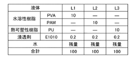
図12は、液体L1〜L3の組成を示す表である。表中の数字の単位は、質量%である。残量として水を加えて、合計100質量%とした。表中、「PVA」は、ポリビニルアルコールであり、クラレ社製のPVA117を用いた。「PAM」は、ポリアクリルアミドであり、星光PMC社製のDS4352を用いた。「PU」は、ポリウレタンであり、第一工業製薬社製のスーパーフレックス460を用いた。「E1010」は、日信化学社製のオルフィンE1010である。 FIG. 12 is a table showing compositions of the liquids L1 to L3. The unit of the numbers in the table is% by mass. Water was added as the remaining amount to make 100% by mass in total. In the table, "PVA" is polyvinyl alcohol, and PVA117 manufactured by Kuraray Co., Ltd. was used. “PAM” is polyacrylamide, and DS4352 manufactured by Seikou PMC Ltd. was used. “PU” is polyurethane, and Superflex 460 manufactured by Dai-ichi Kogyo Seiyaku Co., Ltd. was used. “E1010” is Olfin E1010 manufactured by Nissin Chemical Co., Ltd.
実施例1〜8では、加圧部82の圧力を変化させて、液体L1〜L3が塗布されるウェブのかさ密度を変化させた。比較例1では、加圧部によってウェブに圧力を加えなかったこと以外は、実施例1と同じである。実施例1〜8および比較例1のシートに対して、層間剥離試験および引張り試験を行った。
In Examples 1 to 8, the pressure of the pressurizing
層間剥離試験では、リョービ社製の枚葉オフセット印刷機「3200CCD」を用いて、成形されたシートに対して、A4横目通紙で6000枚/時の速度でモノクロ印刷を行い、200枚印刷したときの層間剥離枚数をカウントした。評価基準は、以下のとおりである。 In the delamination test, a sheet-fed offset printing machine “3200CCD” manufactured by Ryobi Co., Ltd. was used to perform monochrome printing on the formed sheets with A4 grain crossing paper at a speed of 6000 sheets/hour to print 200 sheets. The number of delaminated sheets at that time was counted. The evaluation criteria are as follows.
A:層間剥離枚数が10枚未満
B:層間剥離枚数が10枚以上20枚未満
C:層間剥離枚数が20枚以上30枚未満
D:層間剥離枚数が30枚以上
A: The number of delaminated layers is less than 10 B: The number of delaminated layers is 10 or more and less than 20 C: The number of delaminated layers is 20 or more and less than 30 D: The number of delaminated layers is 30 or more
引張り試験では、島津製作所社製の引張り試験機「AGS−X 500N」を用いて、成形されたシートを幅20mmに裁断したサンプルに対して、「JIS P8113:2006」に記載された方法で、引張り強度を測定した。評価基準は、以下のとおりである。 In the tensile test, using a tensile tester “AGS-X 500N” manufactured by Shimadzu Corporation, a sample obtained by cutting the molded sheet into a width of 20 mm was subjected to the method described in “JIS P8113:2006”. The tensile strength was measured. The evaluation criteria are as follows.
A:引張り強さが50N以上
B:引張り強さが35N以上50N未満
C:引張り強さが20N以上35N未満
D:引張り強さが20N未満
A: Tensile strength is 50N or more B: Tensile strength is 35N or more and less than 50N C: Tensile strength is 20N or more and less than 35N D: Tensile strength is less than 20N
なお、ウェブのかさ密度は、「JIS P 8118」に記載された方法に基づいて、下記式で求めた。 The bulk density of the web was calculated by the following formula based on the method described in "JIS P 8118".
かさ密度(g/cm3)=坪量(g/cm2)/厚さ(nm)×1000 Bulk density (g/cm 3 )=grammage (g/cm 2 )/thickness (nm)×1000
図13は、実施例1〜8および比較例1の層間剥離試験および引張り試験の評価結果を示す表である。 FIG. 13 is a table showing the evaluation results of the delamination test and the tensile test of Examples 1 to 8 and Comparative Example 1.
図13に示すように、実施例1〜8は、比較例1に比べて、層間剥離試験および引張り試験の評価が良好だった。これは、実施例1〜8は、加圧部82によってウェブに圧力をかけてウェブのかさ密度を0.09g/cm3以上にしたため、比較例1に比べて毛細管現象が発現し易く、液体L1〜L3がウェブの内部にまで浸透したためである。さらに、ウェブのかさ密度を、0.09g/cm3以上0.80g/cm3以下、好ましくは0.20g/cm3以上0.70g/cm3以下とすることにより、層間剥離試験および引張り試験の評価が、より良好となることがわかった。実施例6は、かさ密度が大きすぎて、実施例5の場合に比べて毛細管現象が発現し難く、液体L1がウェブの内部にまで浸透し難くなったために、実施例5よりも評価結果が悪かったと考えられる。
As shown in FIG. 13, Examples 1 to 8 were better in evaluation of the delamination test and the tensile test than Comparative Example 1. In Examples 1 to 8, the pressure was applied to the web by the pressurizing
4.2. 実施例9〜16および比較例2
実施例9〜16として、図9に示す繊維体成形装置150に対応する繊維体成形装置を用いて、シートを成形した。液体塗布装置としてスプレーを用いて、液体L1〜L3をウェブの両面に塗布した。液体L1〜L3の塗布量は、ウェブの片面に対して40g/m2とし、ウェブの両面の塗布量総量で80g/m2とした。加熱部の温度および原料は、実施例1と同じである。
4.2. Examples 9 to 16 and Comparative Example 2
As Examples 9 to 16, sheets were molded using a fiber body molding device corresponding to the fiber
実施例9〜16では、加圧部82の圧力を変化させて、液体L1〜L3が塗布されるウェブのかさ密度を変化させた。比較例2では、加圧部82によってウェブに圧力を加えなかったこと以外は、実施例9と同様である。実施例9〜16および比較例2のシートに対して、実施例1〜8および比較例1と同様に、層間剥離試験および引張り試験を行った。
In Examples 9 to 16, the pressure of the pressurizing
図14は、実施例9〜16および比較例2の層間剥離試験および引張り試験の評価結果を示す表である。 FIG. 14 is a table showing the evaluation results of the delamination test and the tensile test of Examples 9 to 16 and Comparative Example 2.
図14に示すように、実施例9〜16は、比較例2に比べて、層間剥離試験および引張り試験の評価が良好であり、図13と基本的に同様の傾向であった。 As shown in FIG. 14, Examples 9 to 16 were better in evaluation of the delamination test and the tensile test than Comparative Example 2, and had basically the same tendency as in FIG. 13.
4.3. 実施例17〜24および比較例3
実施例17〜24では、図6に示す繊維体成形装置120に対応する繊維体成形装置を用いて、シートを成形した。繊維体成形装置は、液体L1〜L3を塗布する前にウェブを加圧する加圧部82(以下、「第1加圧部」ともいう)と、液体L1〜L3を塗布した後にウェブを加圧する加圧部122(以下、「第2加圧部」ともいう)と、を有している。第2加圧部122の圧力を、500kg/cm2とした。液体塗布装置としてインクジェットヘッドを用いて、液体L1〜L3をウェブの両面に塗布した。液体L1〜L3の塗布量は、ウェブの片面に対して8g/m2とし、ウェブの両面の塗布量総量で16g/m2とした。加熱部の温度および原料は、実施例1と同じである。
4.3. Examples 17-24 and Comparative Example 3
In Examples 17 to 24, sheets were molded using a fiber body molding device corresponding to the fiber
実施例17〜24では、第1加圧部82の圧力を変化させて、液体L1〜L3が塗布されるウェブのかさ密度を変化させた。比較例3では、第1加圧部82によってウェブに圧力を加えなかったこと以外は、実施例17と同様である。実施例17〜24および比較例3のシートに対して、実施例1〜8および比較例1と同様に、層間剥離試験および引張り試験を行った。
In Examples 17 to 24, the pressure of the
図15は、実施例17〜24および比較例3の層間剥離試験および引張り試験の評価結果を示す表である。なお、表中の「圧力」は、第1加圧部82の圧力である。
FIG. 15 is a table showing the evaluation results of the delamination test and the tensile test of Examples 17 to 24 and Comparative Example 3. The “pressure” in the table is the pressure of the
図15に示すように、実施例17〜24は、比較例3に比べて、層間剥離試験および引張り試験の評価が良好であり、図13と基本的に同様の傾向であった。 As shown in FIG. 15, in Examples 17 to 24, the evaluations of the delamination test and the tensile test were better than those of Comparative Example 3, and basically the same tendency as in FIG.
本発明は、本願に記載の特徴や効果を有する範囲で一部の構成を省略したり、各実施形態や変形例を組み合わせたりしてもよい。 The present invention may omit some of the configurations or combine the embodiments and modifications within the scope of the features and effects described in the present application.
本発明は、上述した実施形態に限定されるものではなく、さらに種々の変形が可能である。例えば、本発明は、実施形態で説明した構成と実質的に同一の構成を含む。実質的に同一の構成とは、例えば、機能、方法、および結果が同一の構成、あるいは目的および効果が同一の構成である。また、本発明は、実施形態で説明した構成の本質的でない部分を置き換えた構成を含む。また、本発明は、実施形態で説明した構成と同一の作用効果を奏する構成または同一の目的を達成することができる構成を含む。また、本発明は、実施形態で説明した構成に公知技術を付加した構成を含む。 The present invention is not limited to the above-described embodiment, and various modifications can be made. For example, the invention includes configurations that are substantially the same as the configurations described in the embodiments. The substantially same structure is, for example, a structure having the same function, method, and result, or a structure having the same object and effect. Further, the invention includes configurations in which non-essential parts of the configurations described in the embodiments are replaced. Further, the invention includes a configuration that achieves the same effect as the configuration described in the embodiment or a configuration that can achieve the same object. Further, the invention includes configurations in which known techniques are added to the configurations described in the embodiments.
2,3,7,8…管、8…管、9…シュート、10…供給部、12…粗砕部、14…粗砕刃、20…解繊部、22…導入口、23…管、24…排出口、26…解繊ブロアー、27…集塵部、28…捕集ブロアー、29…管、40…選別部、41…ドラム部、42…導入口、43…ハウジング部、44…排出口、45…第1ウェブ形成部、46…メッシュベルト、47…ローラー、48…吸引部、49…回転体、54…管、56…ブロアー、60…堆積部、61…ドラム部、62…導入口、63…ハウジング部、70…第2ウェブ形成部、72…メッシュベルト、74…ローラー、76…サクション機構、77…サクションブロアー、79…搬送部、79a…メッシュベルト、79b…ローラー、79c…サクション機構、80…シート形成部、82…加圧部、84…加熱部、85…カレンダーローラー
、86…加熱ローラー、90…切断部、92…第1切断部、94…第2切断部、96…排出部、100…繊維体成形装置、102…液体塗布装置、120…繊維体成形装置、122…加圧部、123…カレンダーローラー、130…繊維体成形装置、132…加圧部、133…カレンダーローラー、134…加圧部、135…カレンダーローラー、140,150,160…繊維体成形装置、162…搬送ローラー、202,204,206,208,210,212…加湿部、1084…加熱部、1086…加熱ローラー、1102…液体塗布装置
2, 3, 7, 8... Tube, 8... Tube, 9... Shoot, 10... Supply section, 12... Coarse crushing section, 14... Coarse crushing blade, 20... Disentanglement section, 22... Inlet port, 23... Tube, 24... Discharge port, 26... Disentanglement blower, 27... Dust collection part, 28... Collection blower, 29... Pipe, 40... Sorting part, 41... Drum part, 42... Inlet port, 43... Housing part, 44... Discharge Outlet, 45... First web forming section, 46... Mesh belt, 47... Roller, 48... Suction section, 49... Rotating body, 54... Tube, 56... Blower, 60... Accumulation section, 61... Drum section, 62... Introduction Mouth, 63... Housing part, 70... Second web forming part, 72... Mesh belt, 74... Roller, 76... Suction mechanism, 77... Suction blower, 79... Conveying part, 79a... Mesh belt, 79b... Roller, 79c... Suction mechanism, 80... Sheet forming section, 82... Pressing section, 84... Heating section, 85... Calender roller, 86... Heating roller, 90... Cutting section, 92... First cutting section, 94... Second cutting section, 96 ... Discharging section, 100... Fibrous body molding apparatus, 102... Liquid application apparatus, 120... Fibrous body molding apparatus, 122... Pressing section, 123... Calender roller, 130... Fibrous body molding apparatus, 132... Pressing section, 133... Calender roller, 134... Pressurizing section, 135... Calender roller, 140, 150, 160... Fibrous body molding device, 162... Conveying roller, 202, 204, 206, 208, 210, 212... Humidifying section, 1084... Heating section, 1086...
Claims (18)
前記ウェブに、複数の前記繊維を結着させるバインダーを含む液体を塗布する工程と、を含む、繊維体成形方法。 Preparing a web containing a plurality of fibers and having a bulk density of 0.09 g/cm 3 or more;
A step of applying a liquid containing a binder for binding the plurality of fibers to the web, the method for forming a fiber body.
前記ウェブを加圧する工程と、
加圧された前記ウェブに、複数の前記繊維を結着させるバインダーを含む液体を塗布する工程と、
を含む、繊維体成形方法。 Preparing a web containing a plurality of fibers,
Pressurizing the web,
Applying a liquid containing a binder for binding the plurality of fibers to the pressed web;
A method for molding a fibrous body, comprising:
前記バインダーは、熱可塑性樹脂または熱硬化性樹脂である、繊維体成形方法。 In claim 1 or 2,
The fibrous body molding method, wherein the binder is a thermoplastic resin or a thermosetting resin.
前記バインダーは、水溶性樹脂である、繊維体成形方法。 In claim 1 or 2,
The fibrous body molding method, wherein the binder is a water-soluble resin.
前記液体が塗布された前記ウェブを加熱する工程を含む、繊維体成形方法。 In any one of Claim 1 thru|or 4,
A method for molding a fibrous body, comprising the step of heating the web coated with the liquid.
前記液体が塗布された前記ウェブを加圧する工程を含む、繊維体成形方法。 In any one of Claim 1 thru|or 5,
A method for molding a fibrous body, comprising the step of pressurizing the web coated with the liquid.
前記液体を塗布する工程では、
インクジェット方式で前記液体を塗布する、繊維体成形方法。 In any one of Claims 1 thru|or 6,
In the step of applying the liquid,
A fibrous body molding method, wherein the liquid is applied by an inkjet method.
前記液体を塗布する工程では、
かさ密度が0.80g/cm3以下の前記ウェブに前記液体を塗布する、繊維体成形方法。 In any one of Claims 1 thru|or 7,
In the step of applying the liquid,
A fibrous body molding method, wherein the liquid is applied to the web having a bulk density of 0.80 g/cm 3 or less.
前記液体を塗布する工程では、
かさ密度が0.20g/cm3以上0.70g/cm3以下の前記ウェブに前記液体を塗布する、繊維体成形方法。 In any one of Claim 1 thru|or 8,
In the step of applying the liquid,
A fibrous body molding method, wherein the liquid is applied to the web having a bulk density of 0.20 g/cm 3 or more and 0.70 g/cm 3 or less.
前記加圧部で加圧された前記ウェブに、複数の前記繊維を結着させるバインダーを含む液体を塗布する液体塗布装置と、
を含む、繊維体成形装置。 A pressing unit for pressing a web containing a plurality of fibers,
A liquid application device that applies a liquid containing a binder that binds the plurality of fibers to the web pressed by the pressing unit,
A fibrous body molding apparatus including:
前記バインダーは、熱可塑性樹脂または熱硬化性樹脂である、繊維体成形装置。 In Claim 10 or 11,
The fibrous body molding apparatus, wherein the binder is a thermoplastic resin or a thermosetting resin.
前記バインダーは、水溶性樹脂である、繊維体成形装置。 In Claim 10 or 11,
The fibrous body molding apparatus, wherein the binder is a water-soluble resin.
前記液体塗布装置によって前記液体が塗布された前記ウェブを加熱する加熱部を含む、繊維体成形装置。 In any one of Claims 10 thru|or 13,
A fibrous body molding apparatus including a heating unit that heats the web coated with the liquid by the liquid coating apparatus.
前記液体塗布装置によって前記液体が塗布された前記ウェブを加圧する加圧部を含む、繊維体成形装置。 In any one of Claim 10 thru|or 14,
A fibrous body forming apparatus including a pressurizing unit for pressurizing the web coated with the liquid by the liquid coating apparatus.
前記液体塗布装置は、インクジェットヘッドである、繊維体成形装置。 In any one of Claim 10 thru|or 15,
The fibrous body molding apparatus, wherein the liquid application apparatus is an inkjet head.
前記液体塗布装置は、かさ密度が0.80g/cm3以下の前記ウェブに、前記液体を塗布する、繊維体成形装置。 In any one of Claim 10 thru|or 16,
The liquid application device is a fibrous body molding device that applies the liquid to the web having a bulk density of 0.80 g/cm 3 or less.
前記液体塗布装置は、かさ密度が0.20g/cm3以上0.70g/cm3以下の前記ウェブに、前記液体を塗布する、繊維体成形装置。 In any one of Claim 10 thru|or 17,
The liquid application device is a fibrous body forming device that applies the liquid to the web having a bulk density of 0.20 g/cm 3 or more and 0.70 g/cm 3 or less.
Priority Applications (5)
| Application Number | Priority Date | Filing Date | Title |
|---|---|---|---|
| CN201911166454.5A CN111218829A (en) | 2018-11-27 | 2019-11-25 | Method and apparatus for forming fibrous body |
| US16/695,261 US11346054B2 (en) | 2018-11-27 | 2019-11-26 | Fiber body forming method and fiber body forming apparatus |
| EP19211782.8A EP3660212B1 (en) | 2018-11-27 | 2019-11-27 | Fiber body forming method |
| EP22170360.6A EP4071299A1 (en) | 2018-11-27 | 2019-11-27 | Fiber body forming method and fiber body forming apparatus |
| US17/733,236 US11680372B2 (en) | 2018-11-27 | 2022-04-29 | Fiber body forming method and fiber body forming apparatus |
Applications Claiming Priority (4)
| Application Number | Priority Date | Filing Date | Title |
|---|---|---|---|
| JP2018221158 | 2018-11-27 | ||
| JP2018221157 | 2018-11-27 | ||
| JP2018221157 | 2018-11-27 | ||
| JP2018221158 | 2018-11-27 |
Publications (1)
| Publication Number | Publication Date |
|---|---|
| JP2020090765A true JP2020090765A (en) | 2020-06-11 |
Family
ID=71012469
Family Applications (2)
| Application Number | Title | Priority Date | Filing Date |
|---|---|---|---|
| JP2019031639A Withdrawn JP2020090765A (en) | 2018-11-27 | 2019-02-25 | Fiber assembly forming method and fiber assembly forming device |
| JP2019031638A Active JP7279405B2 (en) | 2018-11-27 | 2019-02-25 | Fiber body molding method and fiber body molding apparatus |
Family Applications After (1)
| Application Number | Title | Priority Date | Filing Date |
|---|---|---|---|
| JP2019031638A Active JP7279405B2 (en) | 2018-11-27 | 2019-02-25 | Fiber body molding method and fiber body molding apparatus |
Country Status (1)
| Country | Link |
|---|---|
| JP (2) | JP2020090765A (en) |
Citations (7)
| Publication number | Priority date | Publication date | Assignee | Title |
|---|---|---|---|---|
| WO1993014264A1 (en) * | 1992-01-13 | 1993-07-22 | Weyerhaeuser Company | Method and apparatus for crosslinking individualized cellulose fibers |
| JPH08510796A (en) * | 1993-06-02 | 1996-11-12 | ミネソタ マイニング アンド マニュファクチャリング カンパニー | Non-woven fabric product and manufacturing method thereof |
| JPH11514049A (en) * | 1996-05-22 | 1999-11-30 | ザ、プロクター、エンド、ギャンブル、カンパニー | Tissue paper creping method |
| WO2002012619A1 (en) * | 2000-08-04 | 2002-02-14 | Teijin Limited | Heat-resistant fibrous paper |
| JP2015091640A (en) * | 2013-10-02 | 2015-05-14 | セイコーエプソン株式会社 | Recording method |
| JP2015137437A (en) * | 2014-01-23 | 2015-07-30 | セイコーエプソン株式会社 | Sheet production apparatus and sheet production method |
| JP2016188448A (en) * | 2015-03-30 | 2016-11-04 | セイコーエプソン株式会社 | Apparatus and method for manufacturing sheet, and sheet |
Family Cites Families (9)
| Publication number | Priority date | Publication date | Assignee | Title |
|---|---|---|---|---|
| US3200005A (en) * | 1962-05-28 | 1965-08-10 | Cellu Kote Inc | Paper products coated with vinyl resin and wax |
| CA977221A (en) * | 1972-12-20 | 1975-11-04 | John R. Hitchmough | Production of coated paper |
| US3978179A (en) | 1973-09-04 | 1976-08-31 | Reprocess Textile Associates | Production of non-woven fabrics |
| JPH07238451A (en) * | 1994-02-22 | 1995-09-12 | Nippon Zeon Co Ltd | Binder composition for nonwoven fabric and production of nonwoven fabric |
| US5514758A (en) * | 1994-09-30 | 1996-05-07 | The Goodyear Tire & Rubber Company | Process for making latex for high performance masking tape |
| US6162327A (en) | 1999-09-17 | 2000-12-19 | The Procter & Gamble Company | Multifunctional tissue paper product |
| US20060086472A1 (en) | 2004-10-27 | 2006-04-27 | Kimberly-Clark Worldwide, Inc. | Soft durable paper product |
| JP5664027B2 (en) | 2010-08-31 | 2015-02-04 | セイコーエプソン株式会社 | Inkjet recording method, inkjet recording apparatus, and recorded matter |
| JP6756092B2 (en) | 2015-05-15 | 2020-09-16 | セイコーエプソン株式会社 | Ink Composition for Ink |
-
2019
- 2019-02-25 JP JP2019031639A patent/JP2020090765A/en not_active Withdrawn
- 2019-02-25 JP JP2019031638A patent/JP7279405B2/en active Active
Patent Citations (7)
| Publication number | Priority date | Publication date | Assignee | Title |
|---|---|---|---|---|
| WO1993014264A1 (en) * | 1992-01-13 | 1993-07-22 | Weyerhaeuser Company | Method and apparatus for crosslinking individualized cellulose fibers |
| JPH08510796A (en) * | 1993-06-02 | 1996-11-12 | ミネソタ マイニング アンド マニュファクチャリング カンパニー | Non-woven fabric product and manufacturing method thereof |
| JPH11514049A (en) * | 1996-05-22 | 1999-11-30 | ザ、プロクター、エンド、ギャンブル、カンパニー | Tissue paper creping method |
| WO2002012619A1 (en) * | 2000-08-04 | 2002-02-14 | Teijin Limited | Heat-resistant fibrous paper |
| JP2015091640A (en) * | 2013-10-02 | 2015-05-14 | セイコーエプソン株式会社 | Recording method |
| JP2015137437A (en) * | 2014-01-23 | 2015-07-30 | セイコーエプソン株式会社 | Sheet production apparatus and sheet production method |
| JP2016188448A (en) * | 2015-03-30 | 2016-11-04 | セイコーエプソン株式会社 | Apparatus and method for manufacturing sheet, and sheet |
Also Published As
| Publication number | Publication date |
|---|---|
| JP2020090764A (en) | 2020-06-11 |
| JP7279405B2 (en) | 2023-05-23 |
Similar Documents
| Publication | Publication Date | Title |
|---|---|---|
| CN107428024B (en) | Sheet manufacturing apparatus and sheet manufacturing method | |
| CN106012629B (en) | Sheet manufacturing apparatus, sheet manufacturing method, and sheet | |
| WO2018043034A1 (en) | Sheet manufacturing device, and control method of sheet manufacturing device | |
| JP7003422B2 (en) | Sheets, sheet manufacturing equipment, and sheet manufacturing methods | |
| JP7188035B2 (en) | Fibration method, fibrillation device, sheet manufacturing method, and sheet manufacturing device | |
| US11680372B2 (en) | Fiber body forming method and fiber body forming apparatus | |
| WO2016072063A1 (en) | Sheet manufacturing apparatus and method for manufacturing sheet | |
| JP7338286B2 (en) | Fiber structure, method for manufacturing fiber structure | |
| WO2018092626A1 (en) | Vaporization-type humidification unit, vaporization-type humidification unit control method, and sheet manufacture device | |
| US20200164668A1 (en) | Sheet processing device and sheet processing method | |
| JP2020090765A (en) | Fiber assembly forming method and fiber assembly forming device | |
| US20200165781A1 (en) | Fiber body forming method and fiber body forming apparatus | |
| JP2020090762A (en) | Sheet processing device and sheet processing method | |
| WO2018043176A1 (en) | Sheet manufacturing device | |
| US11624015B2 (en) | Fiber body forming method and fiber binding liquid | |
| JP7234661B2 (en) | Used paper recycling device and used paper recycling method | |
| WO2018163669A1 (en) | Sheet | |
| WO2018163652A1 (en) | Sheet | |
| US11040560B2 (en) | Waste paper recycling apparatus and waste paper recycling method | |
| JP6946673B2 (en) | Seat | |
| JP2021063311A (en) | Fiber body production apparatus and fiber body production method | |
| JP2021080583A (en) | Apparatus for manufacturing fiber body | |
| JP2021080584A (en) | Method for manufacturing fiber body | |
| JP2016065339A (en) | Sheet manufacturing device and sheet manufacturing method |
Legal Events
| Date | Code | Title | Description |
|---|---|---|---|
| A621 | Written request for application examination |
Free format text: JAPANESE INTERMEDIATE CODE: A621 Effective date: 20211228 |
|
| A977 | Report on retrieval |
Free format text: JAPANESE INTERMEDIATE CODE: A971007 Effective date: 20230112 |
|
| A131 | Notification of reasons for refusal |
Free format text: JAPANESE INTERMEDIATE CODE: A131 Effective date: 20230117 |
|
| A761 | Written withdrawal of application |
Free format text: JAPANESE INTERMEDIATE CODE: A761 Effective date: 20230317 |