JP2020081694A - Game machine - Google Patents
Game machine Download PDFInfo
- Publication number
- JP2020081694A JP2020081694A JP2018224538A JP2018224538A JP2020081694A JP 2020081694 A JP2020081694 A JP 2020081694A JP 2018224538 A JP2018224538 A JP 2018224538A JP 2018224538 A JP2018224538 A JP 2018224538A JP 2020081694 A JP2020081694 A JP 2020081694A
- Authority
- JP
- Japan
- Prior art keywords
- special
- game
- effect
- variation
- display
- Prior art date
- Legal status (The legal status is an assumption and is not a legal conclusion. Google has not performed a legal analysis and makes no representation as to the accuracy of the status listed.)
- Pending
Links
- 230000000694 effects Effects 0.000 claims description 972
- 230000002708 enhancing effect Effects 0.000 abstract 1
- 238000000034 method Methods 0.000 description 400
- 230000008569 process Effects 0.000 description 393
- 238000012545 processing Methods 0.000 description 214
- 238000004519 manufacturing process Methods 0.000 description 138
- 230000015654 memory Effects 0.000 description 94
- 238000005034 decoration Methods 0.000 description 73
- 230000001755 vocal effect Effects 0.000 description 72
- 238000012544 monitoring process Methods 0.000 description 64
- 230000008859 change Effects 0.000 description 54
- 230000005856 abnormality Effects 0.000 description 38
- 238000001514 detection method Methods 0.000 description 32
- 238000011038 discontinuous diafiltration by volume reduction Methods 0.000 description 32
- 238000003860 storage Methods 0.000 description 32
- 230000002844 continuous effect Effects 0.000 description 28
- 230000007423 decrease Effects 0.000 description 23
- 238000004458 analytical method Methods 0.000 description 22
- 238000012360 testing method Methods 0.000 description 22
- 239000011521 glass Substances 0.000 description 21
- 230000002159 abnormal effect Effects 0.000 description 16
- 238000012790 confirmation Methods 0.000 description 16
- OMFRMAHOUUJSGP-IRHGGOMRSA-N bifenthrin Chemical compound C1=CC=C(C=2C=CC=CC=2)C(C)=C1COC(=O)[C@@H]1[C@H](\C=C(/Cl)C(F)(F)F)C1(C)C OMFRMAHOUUJSGP-IRHGGOMRSA-N 0.000 description 15
- 238000007689 inspection Methods 0.000 description 15
- 230000003247 decreasing effect Effects 0.000 description 14
- 238000010924 continuous production Methods 0.000 description 12
- 238000010304 firing Methods 0.000 description 12
- 230000002829 reductive effect Effects 0.000 description 12
- 238000006243 chemical reaction Methods 0.000 description 10
- 230000004044 response Effects 0.000 description 10
- 101150064138 MAP1 gene Proteins 0.000 description 9
- 230000009471 action Effects 0.000 description 9
- 230000004397 blinking Effects 0.000 description 9
- 238000004891 communication Methods 0.000 description 8
- 238000013461 design Methods 0.000 description 8
- 230000006870 function Effects 0.000 description 8
- 238000007726 management method Methods 0.000 description 7
- 238000011084 recovery Methods 0.000 description 7
- 101100495835 Oryza sativa subsp. japonica Cht1 gene Proteins 0.000 description 6
- 230000005540 biological transmission Effects 0.000 description 6
- 238000010586 diagram Methods 0.000 description 6
- 230000007704 transition Effects 0.000 description 6
- 238000007599 discharging Methods 0.000 description 5
- 230000007274 generation of a signal involved in cell-cell signaling Effects 0.000 description 5
- 239000004973 liquid crystal related substance Substances 0.000 description 5
- 230000001743 silencing effect Effects 0.000 description 5
- 238000004364 calculation method Methods 0.000 description 4
- 210000005069 ears Anatomy 0.000 description 4
- 230000002401 inhibitory effect Effects 0.000 description 4
- 230000001788 irregular Effects 0.000 description 4
- 230000010355 oscillation Effects 0.000 description 4
- 230000017105 transposition Effects 0.000 description 4
- 101100400452 Caenorhabditis elegans map-2 gene Proteins 0.000 description 3
- 230000003213 activating effect Effects 0.000 description 3
- 230000004913 activation Effects 0.000 description 3
- 230000002730 additional effect Effects 0.000 description 3
- FFBHFFJDDLITSX-UHFFFAOYSA-N benzyl N-[2-hydroxy-4-(3-oxomorpholin-4-yl)phenyl]carbamate Chemical compound OC1=C(NC(=O)OCC2=CC=CC=C2)C=CC(=C1)N1CCOCC1=O FFBHFFJDDLITSX-UHFFFAOYSA-N 0.000 description 3
- 238000009826 distribution Methods 0.000 description 3
- 238000003825 pressing Methods 0.000 description 3
- 230000000717 retained effect Effects 0.000 description 3
- 238000005096 rolling process Methods 0.000 description 3
- 238000004904 shortening Methods 0.000 description 3
- 238000013459 approach Methods 0.000 description 2
- 239000003990 capacitor Substances 0.000 description 2
- 238000001816 cooling Methods 0.000 description 2
- 239000013078 crystal Substances 0.000 description 2
- 230000001934 delay Effects 0.000 description 2
- 230000029087 digestion Effects 0.000 description 2
- 239000000284 extract Substances 0.000 description 2
- WABPQHHGFIMREM-UHFFFAOYSA-N lead(0) Chemical compound [Pb] WABPQHHGFIMREM-UHFFFAOYSA-N 0.000 description 2
- 230000007257 malfunction Effects 0.000 description 2
- 230000001151 other effect Effects 0.000 description 2
- 230000002093 peripheral effect Effects 0.000 description 2
- 238000010248 power generation Methods 0.000 description 2
- 239000007858 starting material Substances 0.000 description 2
- 239000000725 suspension Substances 0.000 description 2
- 230000008685 targeting Effects 0.000 description 2
- 241000282376 Panthera tigris Species 0.000 description 1
- 241000287127 Passeridae Species 0.000 description 1
- 230000008901 benefit Effects 0.000 description 1
- 239000006059 cover glass Substances 0.000 description 1
- 238000013500 data storage Methods 0.000 description 1
- 230000007547 defect Effects 0.000 description 1
- 230000003111 delayed effect Effects 0.000 description 1
- 230000000881 depressing effect Effects 0.000 description 1
- 238000009795 derivation Methods 0.000 description 1
- 230000008034 disappearance Effects 0.000 description 1
- 238000007667 floating Methods 0.000 description 1
- 230000000873 masking effect Effects 0.000 description 1
- 239000002184 metal Substances 0.000 description 1
- 238000002156 mixing Methods 0.000 description 1
- 239000000203 mixture Substances 0.000 description 1
- 238000012986 modification Methods 0.000 description 1
- 230000004048 modification Effects 0.000 description 1
- 238000005192 partition Methods 0.000 description 1
- 230000000737 periodic effect Effects 0.000 description 1
- 238000002360 preparation method Methods 0.000 description 1
- MCSOAHVAIJXNDN-ZTFGCOKTSA-N ram-322 Chemical compound C1C(=O)CC[C@@]2(O)[C@H]3CC4=CC=C(OC)C(O)=C4[C@]21CCN3C MCSOAHVAIJXNDN-ZTFGCOKTSA-N 0.000 description 1
- 230000009467 reduction Effects 0.000 description 1
- 229920005989 resin Polymers 0.000 description 1
- 239000011347 resin Substances 0.000 description 1
- 230000000630 rising effect Effects 0.000 description 1
- 230000008054 signal transmission Effects 0.000 description 1
- 239000000758 substrate Substances 0.000 description 1
- 230000001360 synchronised effect Effects 0.000 description 1
- 229920003002 synthetic resin Polymers 0.000 description 1
- 239000000057 synthetic resin Substances 0.000 description 1
- 239000002023 wood Substances 0.000 description 1
Images


Landscapes
- Pinball Game Machines (AREA)
- Display Devices Of Pinball Game Machines (AREA)
Abstract
Description
本発明は、遊技演出に関連する画像を表示可能な表示手段と、遊技演出の関連する音を出力可能な音出力手段と、前記表示手段及び前記音出力手段を制御する演出制御手段と、を備える遊技機に関する。 The present invention includes a display unit capable of displaying an image related to a game effect, a sound output unit capable of outputting a sound related to the game effect, and an effect control unit for controlling the display unit and the sound output unit. A gaming machine provided.
表示手段に複数の図柄を変動表示させて停止させる変動表示ゲームの演出を行うとともに、報音手段にて音の演出を行う遊技機が知られている(例えば特許文献1参照)。
2. Description of the Related Art There is known a gaming machine that produces a variable display game in which a plurality of symbols are variably displayed on a display unit and is stopped, and produces a sound by a sounding unit (see
しかしながら、従来の遊技機で実行される音の演出は、興趣が高いとは言えなかった。
本発明の目的は、音の演出の興趣を高めることである。
However, it cannot be said that the sound production performed by the conventional game machine is interesting.
An object of the present invention is to enhance the enjoyment of sound production.
以上の課題を解決するため、請求項1に記載の発明は、
遊技演出に関連する画像を表示可能な表示手段と、遊技演出の関連する音を出力可能な音出力手段と、前記表示手段及び前記音出力手段を制御する演出制御手段と、を備える遊技機において、
遊技者が操作可能な操作手段を備え、
前記演出制御手段は、
前記操作手段の操作に基づいて前記音出力手段から出力される音の音量調節と、特定音を出力しない特定演出と、を実行可能であり、
前記音量調節の実行中に音量調節画像と、前記特定演出の実行中に前記特定音が出力されていないことを報知する報知画像と、を前記表示手段に表示可能であることを特徴とする。
In order to solve the above problems, the invention described in
A gaming machine comprising: display means capable of displaying an image related to a game effect; sound output means capable of outputting a sound related to the game effect; and effect control means for controlling the display means and the sound output means. ,
Equipped with operation means that can be operated by the player,
The effect control means,
It is possible to perform volume adjustment of a sound output from the sound output unit based on an operation of the operation unit, and a specific effect that does not output a specific sound,
It is characterized in that a volume adjustment image can be displayed on the display means during the volume adjustment, and a notification image for notifying that the specific sound is not output during the execution of the specific effect.
本発明によれば、音の演出の興趣を高めることができる。 According to the present invention, it is possible to enhance the interest of sound production.
<第1実施形態>
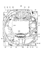
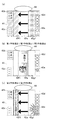
図1に示すように本実施形態の遊技機10は前面枠12を備え、該前面枠12は外枠(支持枠)11に開閉回動可能に組み付けられている。遊技盤30(図2参照)は前面枠12の表側に形成された収納部(図示省略)に収納されている。また、前面枠(本体枠)12には、遊技盤30の前面を覆うカバーガラス(透明部材)14を備えたガラス枠15(透明板保持枠)が取り付けられている。
<First Embodiment>
As shown in FIG. 1, the
また、ガラス枠15の左右には内部にランプやLED等を内蔵し装飾や演出、および異常発生時の報知(例えば、払出異常が発生した場合はランプやLED等を異常報知色(例えば、赤色)で点灯(点滅)させる)のための発光をする枠装飾装置18や、音響(例えば、効果音)を発するスピーカ(上スピーカ)19aが設けられている。さらに、前面枠12の下部にもスピーカ(下スピーカ)19bが設けられている。また、異常発生時はスピーカ(上スピーカ)19a、スピーカ(下スピーカ)19bから音声で異常内容が報知されるようになっている。なお、ガラス枠15の所定部位に払出異常報知用のランプを設けるようにしても良い。
Further, on the left and right sides of the
また、前面枠12の下部には、図示しない打球発射装置に遊技球を供給する上皿21(貯留皿)、遊技機10の裏面側に設けられている払出ユニットから払い出された遊技球が流出する上皿球出口22、上皿21が一杯になった状態で払い出された遊技球を貯留する下皿(受皿)23及び打球発射装置の操作部24等が設けられている。さらに、上皿21の上縁部には、遊技者からの押圧操作入力を受け付けるための演出ボタンスイッチ25aを内蔵した演出ボタン25が設けられている。また、演出ボタン25の上面(押圧面)には、遊技者からの接触操作入力を受け付けるためのタッチパネル29が設けられている。さらに、前面枠12の下部右側には、前面枠12やガラス枠15を開放したり施錠したりする鍵を挿入するための鍵穴26が設けられている。
なお、本実施形態ではタッチパネル29を演出ボタン25と一体的に設けたが、タッチパネル29は、演出ボタン25と別体であってもよく、例えば、演出ボタン25の近傍にサブ表示装置を設け、そのサブ表示装置の表示面にタッチパネル29を設けてもよい。
Further, in the lower part of the
Although the
また、演出ボタン25の右方には、遊技者が隣接する球貸機から球貸しを受ける場合に操作する球貸ボタン27、球貸機のカードユニットからプリペイドカードを排出させるために操作する排出ボタン28、プリペイドカードの残高を表示する残高表示部(図示省略)等が設けられている。この実施形態の遊技機10においては、遊技者が操作部24を回動操作することによって、打球発射装置が上皿21から供給される遊技球を遊技盤30前面の遊技領域32に向かって発射する。また、遊技者が演出ボタン25やタッチパネル29を操作することによって、表示装置41(図2参照)における変動表示ゲーム(飾り特図変動表示ゲーム)において、遊技者の操作を介入させた演出等を行うことができる。
Further, to the right of the
次に、図2を用いて遊技盤30の一例について説明する。図2は、本実施形態の遊技盤30の正面図である。
図2に示すように、遊技盤30は、各種部材の取付ベースとなる平板状の遊技盤本体80を備える。遊技盤本体80は木製又は合成樹脂製であって、当該遊技盤本体80の前面には、遊技盤30の四隅に各々設けられた樹脂製のサイドケース33及び外周壁(ガイドレール)31で囲まれた遊技領域32が設けられている。遊技機10は、外周壁31で囲まれた遊技領域32内に打球発射装置から遊技球を発射して遊技を行うように構成されている。遊技領域32には遊技球の流下方向を変換する部材として風車や障害釘などが配設されており、発射された遊技球はこれら部材により転動方向を変えながら遊技領域32を流下する。
Next, an example of the
As shown in FIG. 2, the
遊技領域32の略中央には、変動表示ゲームの表示領域となる窓部を形成するセンターケース40が取り付けられている。センターケース40に形成された窓部の後方には、複数の識別情報を変動表示する演出表示装置(変動表示装置)としての表示装置41が配置されている。
A
表示装置41(変動表示装置)は、例えば、LCD(液晶表示器)、CRT(ブラウン管)等の表示画面を有する装置で構成されている。表示画面の画像を表示可能な領域(表示領域)には、演出画像として静止画や動画を表示可能であり、例えば、複数の識別情報(特別図柄)や特図変動表示ゲームを演出するキャラクタや演出効果を高める背景画像等の遊技に関する情報が表示される。表示装置41の表示画面においては、識別情報として割り当てられた複数の特別図柄が変動表示(可変表示)されて、特図変動表示ゲームに対応した飾り特図変動表示ゲームが行われる。また、表示画面には遊技の進行に基づく演出のための画像(例えば、大当り表示画像、ファンファーレ表示画像、エンディング表示画像等)が表示される。
The display device 41 (variable display device) is configured by a device having a display screen such as an LCD (liquid crystal display) and a CRT (CRT). In the area where the image on the display screen can be displayed (display area), a still image or a moving image can be displayed as an effect image. For example, a plurality of identification information (special symbols) or a character that directs a special figure variable display game, Information about the game such as a background image that enhances the effect is displayed. On the display screen of the
センターケース40には、遊技領域32を流下する遊技球をセンターケース40の内側に導くためのワープ流路を形成するワープ流路形成部材614と、当該ワープ流路を通過した遊技球が転動可能なステージ部620とが設けられている。センターケース40のステージ部620は、始動入賞口36の上方に配置されているため、ステージ部620上で転動した遊技球は始動入賞口36に入賞し易くなっている。
また、センターケース40の上部には、動作することによって遊技の演出を行う盤演出装置44が備えられている。この盤演出装置44は、図2に示す状態から表示装置41の中央へ向けて動作可能となっている。
In the
Further, on the upper part of the
センターケース40の右方の遊技領域32には、普通図柄始動ゲート(普図始動ゲート)34が設けられている。普図始動ゲート34の内部には、当該普図始動ゲート34を通過した遊技球を検出するためのゲートスイッチ34a(図3参照)が設けられている。遊技領域32内に打ち込まれた遊技球が普図始動ゲート34を通過すると、普図変動表示ゲームが実行される。
In the
センターケース40の左下方の遊技領域32には、二つの一般入賞口35が配置されており、センターケース40の右下方の遊技領域32には、一つの一般入賞口35が配置されている。これら一般入賞口35への遊技球の入賞は、一般入賞口35に備えられた入賞口スイッチ35a(図3参照)によって検出される。
In the lower
センターケース40の下方の遊技領域32には、特図1変動表示ゲーム(第1特図変動表示ゲーム)の開始条件を与える始動入賞口36(第1始動入賞領域)が設けられている。始動入賞口36に入賞した遊技球は、始動口1スイッチ36a(図3参照)によって検出される。
In the
センターケース40の右部には、特図2変動表示ゲーム(第2特図変動表示ゲーム)の開始条件を与える普通変動入賞装置37(第2始動入賞領域)が設けられている。普通変動入賞装置37に入賞した遊技球は、始動口2スイッチ37a(図3参照)によって検出される。
普通変動入賞装置37は、可動部材(図示省略)を備えており、この可動部材は、常時は遊技球が流入できない閉じた閉状態(遊技者にとって不利な状態)を保持している。そして、普図変動表示ゲームの結果が所定結果となった場合には、駆動装置としての普電ソレノイド37c(図3参照)によって、普通変動入賞装置37に遊技球が流入し易い開状態(遊技者にとって有利な状態)に変化させられるようになっている。
On the right part of the
The normal
なお、本実施形態において、普通変動入賞装置37の可動部材は、普電ソレノイド37cによって前後方向に進退(スライド)することで開閉する所謂ベロ型の普通電動役物であるが、普通変動入賞装置37の可動部材は、これに限定されない。普通変動入賞装置37の可動部材は、例えば、普電ソレノイド37cによって上端側が手前側に倒れる方向に回動することで開放するアタッカ形式の普通電動役物であっても良いし、普電ソレノイド37cによって逆「ハ」の字状に開放するチューリップ型の普通電動役物であっても良い。
また、普通変動入賞装置37は、可動部材が閉状態でも遊技球の入賞を可能とし、閉状態では開状態よりも遊技球が入賞しにくい状態としても良い。
In addition, in the present embodiment, the movable member of the normal
In addition, the normal
センターケース40の右方の遊技領域32のうち、普図始動ゲート34と普通変動入賞装置37との間には、特図変動表示ゲームの結果によって遊技球を受け入れない状態と受け入れ易い状態とに変換可能な第1特別変動入賞装置(上大入賞口)38が設けられている。第1特別変動入賞装置38は、開閉部材(図示省略)が前後方向に進退(スライド)することで、上大入賞口を遊技球が流入可能な状態に変換する。第1特別変動入賞装置38は、特図変動表示ゲームの結果によって、上大入賞口を閉じた閉状態から開状態に変換し、上大入賞口内への遊技球の流入を容易にさせることで、遊技者に所定の遊技価値(賞球)を付与するようになっている。第1特別変動入賞装置38に入賞した遊技球は、大入賞口スイッチ(カウントスイッチ)38a(図3参照)によって検出される。
In the
上大入賞口の内部(入賞領域)には、遊技球が流入可能な特定領域が設けられているとともに、当該特定領域への遊技球の流入確率を変化させるようにレバーソレノイド38f(図3参照)により動作するレバー部材が設けられている。特定領域には遊技球の流入を検出可能な特定領域スイッチ38d(図3参照)が設けられており、当該特定領域スイッチ38dで遊技球を検出したことに基づいて、遊技者にとって有利な状態が発生する(本実施形態では、特別遊技状態の終了後に高確率状態が発生する)ようになっている。特定領域に流入した遊技球は第1特別変動入賞装置38の外部へ排出される。
Inside the upper special winning opening (winning area), a specific area into which the game ball can flow is provided, and the
また、上大入賞口の内部には、特定領域に流入せずに第1特別変動入賞装置38の外部へ排出される遊技球を検出する残存球排出口スイッチ38e(図3参照)が設けられている。上大入賞口の内部に設けられた大入賞口スイッチ38aで検出された遊技球数(上大入賞口に流入した遊技球数)と、特定領域スイッチ38d及び残存球排出口スイッチ38eで検出された遊技球数(上大入賞口から排出される遊技球数)とが一致することにより上大入賞口内の遊技球が全て排出されたことを確認でき、基本的にはこの確認が終了するまでは新たな上大入賞口の開放が行われないようになっている。
Further, inside the upper special winning opening, there is provided a remaining
センターケース40の下方の遊技領域32のうち、始動入賞口36の右方には、特図変動表示ゲームの結果によって遊技球を受け入れない状態と受け入れ易い状態とに変換可能な第2特別変動入賞装置(下大入賞口)39が設けられている。第2特別変動入賞装置39は、開閉部材(図示省略)が前後方向に進退(スライド)することで、下大入賞口を遊技球が流入可能な状態に変換する。第2特別変動入賞装置39は、特図変動表示ゲームの結果によって、下大入賞口を閉じた閉状態から開状態に変換し、下大入賞口内への遊技球の流入を容易にさせることで、遊技者に所定の遊技価値(賞球)を付与するようになっている。第2特別変動入賞装置39に入賞した遊技球は、大入賞口スイッチ(カウントスイッチ)39a(図3参照)によって検出される。
In the
始動入賞口36の下方の遊技領域32には、入賞口等に入賞しなかった遊技球を回収するアウト口30aが設けられている。また、遊技領域32の外側であって遊技盤本体80の右下角部には、特図変動表示ゲーム(特図1変動表示ゲーム、特図2変動表示ゲーム)及び普図変動表示ゲームを実行する一括表示装置50が設けられている。
In the
一括表示装置50は、7セグメント型の表示器(LEDランプ)等で構成された特図1変動表示ゲーム用の特図1表示器(第1特図変動表示部)51及び特図2変動表示ゲーム用の特図2表示器(第2特図変動表示部)52と、LEDランプで構成された特図1変動表示ゲームの始動記憶数報知用の第1記憶表示部53と、LEDランプで構成された特図2変動表示ゲームの始動記憶数報知用の第2記憶表示部54とを備える。
The
また、一括表示装置50には、大当り時のラウンド数(特別変動入賞装置38,39の開閉回数)を表示するラウンド表示部55、左打ち(通常打ち)と右打ちのうち遊技者に有利な打ち方(遊技状態に対応した打ち方)を報知する第1遊技状態表示部56、特図変動表示ゲームの確率状態(高確率状態又は低確率状態)を報知する確率表示部57が設けられている。なお、一括表示装置50には、遊技機10の電源投入時に大当りの確率状態が高確率状態となっていることを表示する確率状態表示部、大当りが発生すると点灯して大当り発生を報知する表示部(表示器)等が設けられていてもよい。
更に、普図変動表示ゲームを表示する普図表示部58や、普図変動表示ゲームの始動記憶数報知用の記憶表示部59、時短状態が発生すると点灯して時短状態発生を報知する時短状態報知部60等が設けられている。
In addition, the
Further, the public figure display unit 58 for displaying the general figure variable display game, the memory display unit 59 for informing the number of starting memories of the general figure variable display game, and the time saving state which lights up when the time saving state occurs and notifies the occurrence of the time saving state. A
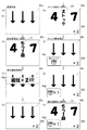
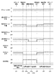
特図1表示器51と特図2表示器52における特図変動表示ゲームは、例えば変動表示ゲームの実行中、すなわち、表示装置41において飾り特図変動表示ゲームを行っている間は、中央のセグメントを点滅駆動させて変動中であることを表示する。点滅周期は、例えば100m秒に設定されている。なお、本実施形態の場合、特図1表示器51における特図1変動表示ゲームにおいては、中央のセグメントに加えて7セグの右方下側に設けられた8番目のセグメントも点滅駆動させて変動中であることを表示するようにし、特図1と特図2との区別が可能なように構成されている。そして、ゲームの結果が「はずれ」のときは、はずれの結果態様として例えば中央のセグメント(特図1であれば加えて右方下側の8番目のセグメント)を点灯状態にし、ゲームの結果が「当り」のときは、当りの結果態様(特別結果態様)としてはずれの結果態様以外の結果態様(例えば数字や記号)を点灯状態にしてゲーム結果を表示する。
The special figure variation display game on the special figure 1
第1記憶表示部53は、特図1表示器51の変動開始条件となる始動入賞口36への入賞球数のうち未消化の球数(始動記憶数=保留数)を複数のLEDの消灯、点灯(点滅)により表示する。
第2記憶表示部54は、特図2表示器52の変動開始条件となる普通変動入賞装置37への入賞球数のうち未消化の球数(始動記憶数=保留数)を複数のLEDの消灯、点灯(点滅)により表示する。
ラウンド表示部55はLEDランプ等で構成され、特別遊技状態中でない場合には全てのLEDを消灯状態にし、特別遊技状態中には特別結果に応じて選択されたラウンド数に対応してLEDを点灯状態にする。なお、ラウンド表示部55は7セグメント型の表示器で構成してもよい。
The first
The second memory display unit 54 displays the number of undigested balls (starting memory number=holding number) among the plurality of LEDs among the number of winning balls to the normal
The round display unit 55 is composed of LED lamps and the like, and turns off all the LEDs when not in the special game state, and turns on the LEDs corresponding to the number of rounds selected according to the special result during the special game state. Turn it on. The round display unit 55 may be configured by a 7-segment type display.
第1遊技状態表示部56はLEDランプ等で構成され、例えば右打ちよりも左打ちの方が遊技者にとって有利な遊技状態の場合(通常打ち時)には全てのLEDを消灯状態にし、左打ちよりも右打ちの方が遊技者にとって有利な遊技状態の場合(右打ち時)には全てのLEDを点灯状態にする。
確率表示部57はLEDランプ等で構成され、例えば大当りの確率状態が低確率状態(通常確率状態)の場合には全てのLEDを消灯状態にし、大当りの確率状態が高確率状態(確変状態)の場合には全てのLEDを点灯状態にする。
The first gaming state display unit 56 is composed of LED lamps and the like. For example, when the player is in a gaming state in which the left hitting is more advantageous to the player than the right hitting (normal hitting), all LEDs are turned off and left. When the right hitting is more advantageous for the player than the hitting (in the right hitting), all the LEDs are turned on.
The probability display unit 57 is composed of an LED lamp or the like. For example, when the probability state of a big hit is a low probability state (normal probability state), all the LEDs are turned off, and the probability state of a big hit is a high probability state (probability change state). In the case of, all the LEDs are turned on.
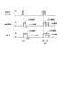
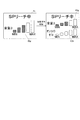
図3は、本実施形態のパチンコ遊技機10の制御システムのブロック図である。
遊技機10は遊技制御装置100を備え、遊技制御装置100は、遊技を統括的に制御する主制御装置(主基板)であって、遊技用マイクロコンピュータ(以下、遊技用マイコンと称する)111を有するCPU部110と、入力ポートを有する入力部120と、出力ポートやドライバなどを有する出力部130と、CPU部110と入力部120と出力部130との間を接続するデータバス140などからなる。
FIG. 3 is a block diagram of a control system of the
The
CPU部110は、アミューズメントチップ(IC)と呼ばれる遊技用マイコン(CPU)111と、水晶振動子のような発振子を備え、CPUの動作クロックやタイマ割込み、乱数生成回路の基準となるクロックを生成する発振回路(水晶発振器)113などを有する。遊技制御装置100及び該遊技制御装置100によって駆動されるソレノイドやモータなどの電子部品には、電源装置400で生成されたDC32V,DC12V,DC5Vなど所定のレベルの直流電圧が供給されて動作可能にされる。
The
電源装置400は、24Vの交流電源からDC32Vの直流電圧を生成するAC−DCコンバータやDC32Vの電圧からDC12V,DC5Vなどのより低いレベルの直流電圧を生成するDC−DCコンバータなどを有する通常電源部410と、遊技用マイコン111の内部のRAMに対して停電時に電源電圧を供給するバックアップ電源部420と、停電監視回路を有し、遊技制御装置100に停電の発生、回復を知らせる停電監視信号やリセット信号などの制御信号を生成して出力する制御信号生成部430などを備える。
The
この実施形態では、電源装置400は、遊技制御装置100と別個に構成されているが、バックアップ電源部420及び制御信号生成部430は、別個の基板上あるいは遊技制御装置100と一体、すなわち、主基板上に設けるように構成してもよい。遊技盤30及び遊技制御装置100は機種変更の際に交換の対象となるので、本実施形態のように、電源装置400若しくは主基板とは別の基板にバックアップ電源部420及び制御信号生成部430を設けることにより、交換の対象から外しコストダウンを図ることができる。
In this embodiment, the
バックアップ電源部420は、電解コンデンサのような大容量のコンデンサ1つで構成することができる。バックアップ電源は、遊技制御装置100の遊技用マイコン111(特に内蔵RAM)に供給され、停電中あるいは電源遮断後もRAMに記憶されたデータが保持されるようになっている。すなわち、遊技制御装置100が、停電が発生し当該遊技機への電源供給が停止しても遊技に関する情報を記憶保持可能であるとともに、停電復旧後には記憶保持された情報に基づき遊技を再開可能とする遊技情報記憶保持手段をなす。制御信号生成部430は、例えば通常電源部410で生成された32Vの電圧を監視してそれが例えば17V以下に下がると停電発生を検出して停電監視信号を変化させるとともに、所定時間後にリセット信号を出力する。また、電源投入時や停電回復時にもその時点から所定時間経過後にリセット信号を出力する。
The backup
また、遊技制御装置100にはRAM初期化スイッチ112が設けられている。このRAM初期化スイッチ112が操作されると初期化スイッチ信号が生成され、これに基づき遊技用マイコン111内のRAM111C及び払出制御装置200内のRAMに記憶されている情報を強制的に初期化する処理が行われる。特に限定されるわけではないが初期化スイッチ信号は電源投入時に読み込まれ、停電監視信号は遊技用マイコン111が実行するメインプログラムのメインループの中で繰り返し読み込まれる。リセット信号は強制割込み信号の一種であり、制御システム全体をリセットさせる。
Further, the
遊技用マイコン111は、CPU(中央処理ユニット:マイクロプロセッサ)111A、読出し専用のROM(リードオンリメモリ)111B及び随時読出し書込み可能なRAM(ランダムアクセスメモリ)111Cを備える。
The
ROM111Bは、遊技制御のための不変の情報(プログラム、固定データ、各種乱数の判定値等)を不揮発的に記憶し、RAM111Cは、遊技制御時にCPU111Aの作業領域や各種信号や乱数値の記憶領域として利用される。ROM111B又はRAM111Cとして、EEPROMのような電気的に書換え可能な不揮発性メモリを用いてもよい。
The
また、ROM111Bは、例えば、特図変動表示ゲームの実行時間、演出内容、リーチ状態の発生の有無などを規定する変動パターン(変動態様)を決定するための変動パターンテーブルを記憶している。変動パターンテーブルとは、始動記憶として記憶されている変動パターン乱数1〜3をCPU111Aが参照して変動パターンを決定するためのテーブルである。また、変動パターンテーブルには、結果がはずれとなる場合に選択されるはずれ変動パターンテーブル、結果が大当りとなる場合に選択される大当り変動パターンテーブル等が含まれる。さらに、これらのパターンテーブルには、リーチ状態となった後の変動パターンである後半変動パターンを決定するためのテーブル(後半変動グループテーブルや後半変動パターン選択テーブル等)、リーチ状態となる前の変動パターンである前半変動パターンを決定するためのテーブル(前半変動グループテーブルや前半変動パターン選択テーブル等)が含まれている。
Further, the
ここでリーチ(リーチ状態)とは、表示状態が変化可能な表示装置を有し、該表示装置が時期を異ならせて複数の表示結果を導出表示し、該複数の表示結果が予め定められた特別結果態様となった場合に、遊技状態が遊技者にとって有利な遊技状態(特別遊技状態)となる遊技機10において、複数の表示結果の一部がまだ導出表示されていない段階で、既に導出表示されている表示結果が特別結果態様となる条件を満たしている表示状態をいう。また、別の表現をすれば、リーチ状態とは、表示装置の変動表示制御が進行して表示結果が導出表示される前段階にまで達した時点でも、特別結果態様となる表示条件からはずれていない表示態様をいう。そして、例えば、特別結果態様が揃った状態を維持しながら複数の変動表示領域による変動表示を行う状態(いわゆる全回転リーチ)もリーチ状態に含まれる。また、リーチ状態とは、表示装置の表示制御が進行して表示結果が導出表示される前段階にまで達した時点での表示状態であって、表示結果が導出表示される以前に決定されている複数の変動表示領域の表示結果の少なくとも一部が特別結果態様となる条件を満たしている場合の表示状態をいう。
Here, the reach (reach state) has a display device whose display state can be changed, the display device derives and displays a plurality of display results at different times, and the plurality of display results are predetermined. In the
よって、例えば、特図変動表示ゲームに対応して表示装置に表示される飾り特図変動表示ゲームが、表示装置における左、中、右の変動表示領域の各々で所定時間複数の識別情報を変動表示した後、左、右、中の順で変動表示を停止して結果態様を表示するものである場合、左、右の変動表示領域で、特別結果態様となる条件を満たした状態(例えば、同一の識別情報)で変動表示が停止した状態がリーチ状態となる。またこの他に、すべての変動表示領域の変動表示を一旦停止した時点で、左、中、右のうち何れか二つの変動表示領域で特別結果態様となる条件を満たした状態(例えば、同一の識別情報となった状態、ただし特別結果態様は除く)をリーチ状態とし、このリーチ状態から残りの一つの変動表示領域を変動表示するようにしても良い。 Therefore, for example, the decorative special figure variation display game displayed on the display device corresponding to the special figure variation display game varies a plurality of identification information for a predetermined time in each of the left, middle and right variation display areas of the display device. After displaying, in the case of displaying the result form by stopping the variable display in the order of left, right, and middle, in the left and right variable display areas, the condition that satisfies the special result form (for example, The state where the variable display is stopped by the same identification information) is the reach state. In addition to this, at the time when the variable display of all the variable display areas is temporarily stopped, the condition that the special result mode is satisfied in any two variable display areas of left, middle, and right (for example, the same The state that has become the identification information, but excluding the special result mode) may be set as the reach state, and the remaining one variable display area may be variably displayed from this reach state.
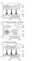
そして、このリーチ状態には複数のリーチ演出が含まれ、特別結果態様が導出される可能性が異なる(期待値が異なる)リーチ演出として、ノーマルリーチ(Nリーチ)、スペシャル1リーチ(SP1リーチ)、スペシャル2リーチ(SP2リーチ)、スペシャル3リーチ(SP3リーチ)、プレミアリーチが設定されている。なお、期待値は、リーチなし<ノーマルリーチ<スペシャル1リーチ<スペシャル2リーチ<スペシャル3リーチ<プレミアリーチの順に高くなるようになっている。また、このリーチ状態は、少なくとも特図変動表示ゲームで特別結果態様が導出される場合(大当りとなる場合)における変動表示態様に含まれるようになっている。すなわち、特図変動表示ゲームで特別結果態様が導出されないと判定する場合(はずれとなる場合)における変動表示態様に含まれることもある。よって、リーチ状態が発生した状態は、リーチ状態が発生しない場合に比べて大当りとなる可能性の高い状態である。
Then, this reach state includes a plurality of reach effects, and normal reach (N reach), special 1 reach (SP1 reach), as reach effects with different possibility of deriving the special result mode (expected value is different),
CPU111Aは、ROM111B内の遊技制御用プログラムを実行して、払出制御装置200や演出制御装置300に対する制御信号(コマンド)を生成したりソレノイドや表示装置の駆動信号を生成して出力して遊技機10全体の制御を行う。また、図示しないが、遊技用マイコン111は、特図変動表示ゲームの当りを判定するための大当り乱数や大当りの図柄を決定するための大当り図柄乱数、特図変動表示ゲームでの変動パターン(各種リーチやリーチ無しの変動表示における変動表示ゲームの実行時間等を含む)を決定するための変動パターン乱数、普図変動表示ゲームの当りを判定するための当り乱数等を生成するための乱数生成回路と、発振回路113からの発振信号(原クロック信号)に基づいてCPU111Aに対する所定周期(例えば、4ミリ秒)のタイマ割込み信号や乱数生成回路の更新タイミングを与えるクロックを生成するクロックジェネレータを備えている。
The CPU 111A executes the game control program in the
また、CPU111Aは、特図変動表示ゲームに関する処理において、ROM111Bに記憶されている複数の変動パターンテーブルの中から、何れか一の変動パターンテーブルを取得する。具体的には、CPU111Aは、特図変動表示ゲームの遊技結果(大当り、小当り又ははずれ)や、現在の遊技状態としての特図変動表示ゲームの確率状態(低確率状態或いは高確率状態)、始動記憶数などに基づいて、複数の変動パターンテーブルの中から、何れか一の変動パターンテーブルを選択して取得する。ここで、CPU111Aは、特図変動表示ゲームを実行する場合に、ROM111Bに記憶された複数の変動パターンテーブルのうち、何れか一の変動パターンテーブルを取得する変動振り分け情報取得手段をなす。
Further, the CPU 111A acquires any one of the fluctuation pattern tables stored in the
払出制御装置200は、CPU、ROM、RAM、入力インタフェース、出力インタフェース等を備え、遊技制御装置100からの賞球払出し指令(コマンドやデータ)に従って、払出ユニットの払出モータを駆動させ、賞球を払い出させるための制御を行う。また、払出制御装置200は、カードユニットからの貸球要求信号に基づいて払出ユニットの払出モータを駆動させ、貸球を払い出させるための制御を行う。
The
遊技用マイコン111の入力部120には、遊技機に対する電波の発射を検出する盤電波センサ62、始動入賞口36内の始動口1スイッチ36a、普通変動入賞装置37内の始動口2スイッチ37a、一般入賞口35内の入賞口スイッチ35a、第1特別変動入賞装置38内の大入賞口スイッチ38a、第2特別変動入賞装置39内の大入賞口スイッチ39a、普図始動ゲート34内のゲートスイッチ34a、第1特別変動入賞装置38内に配設される特定領域スイッチ38d及び残存球排出口スイッチ38e、遊技領域32に発射されて遊技を終えた全ての遊技球を検出するアウト球検出スイッチ32aに接続され、これらのスイッチから供給されるハイレベルが11Vでロウレベルが7Vのような負論理の信号が入力され、0V−5Vの正論理の信号に変換するインタフェースチップ(近接I/F)121が設けられている。近接I/F121は、入力の範囲が7V−11Vとされることで、センサや近接スイッチのリード線が不正にショートされたり、センサやスイッチがコネクタから外されたり、リード線が切断されてフローティングになったような異常な状態を検出することができ、異常検知信号を出力するように構成されている。
In the input unit 120 of the
近接I/F121の出力は、第2入力ポート123、第3入力ポート124又は第4入力ポート126へ供給されデータバス140を介して遊技用マイコン111に読み込まれる。なお、近接I/F121の出力のうち、始動口1スイッチ36a、始動口2スイッチ37a、入賞口スイッチ35a、大入賞口スイッチ38a,39a及びゲートスイッチ34aの検出信号は第2入力ポート123へ入力される。また、近接I/F121の出力のうち、特定領域スイッチ38d、残存球排出スイッチ38e及びアウト球検出スイッチ32aの検出信号は第4入力ポート126へ入力される。また、近接I/F121の出力のうち、盤電波センサ62の検出信号及びセンサやスイッチの異常を検出した際に出力される異常検知信号は第3入力ポート124に入力される。
The output of the proximity I/
また、第3入力ポート124には、遊技機10の前面枠12等に設けられた不正検出用の磁気センサ61の検出信号、遊技機10の振動を検出する振動センサ65の検出信号、遊技機10のガラス枠15等に設けられたガラス枠開放検出スイッチ63の検出信号、遊技機10の前面枠(本体枠)12等に設けられた本体枠開放検出スイッチ64の検出信号も入力されるようになっている。
Further, the
さらに、第3入力ポート124には、設定キー操作部の操作を検出する設定キースイッチ152からの信号が入力される。設定キー操作部は、設定キーを差し込む鍵穴を備え、対応する設定キーを差し込んだ場合にのみ第1位置から第2位置(所定状態)へ当該設定キーを回すことができるように構成されている。設定キースイッチ152は、第2位置へ回した状態となっていることを検出可能なセンサであり、第2位置に回した状態である場合にオン状態となり、第2位置に回していない状態である場合にオフ状態となる。
Further, a signal from the setting
RAM初期化スイッチ112及び設定キー操作部は、特図変動表示ゲームで特別結果となる確率値が割り当てられた確率設定値を複数から選択するための操作部であり、これらの操作部を操作することで、特図変動表示ゲームで特別結果となる確率値が割り当てられた確率設定値を選択することができ、選択された確率設定値に対応する確率値が遊技で使用されるようになっている。ここでは確率設定値として“設定1”〜“設定6”の6つが用意されている。
The
確率設定値を選択する際には、設定キー操作部の設定キーを第2位置に回した状態でRAM初期化スイッチ112を操作(押下)しながら遊技機の電源を投入することで確率設定値を変更可能な確率設定値変更モードとなり、確率設定値変更モード中にRAM初期化スイッチ112を操作(押下)することで確率設定値を変更することができるようになっている。選択されている確率設定値は、算出されたベース値や役物比率を表示するための性能表示装置153に表示される。具体的には、性能表示装置153には、確率設定値に関する操作をしている間(確率設定値変更モードや確率設定値確認モードである間)は確率設定値の情報が表示され、それ以外では算出されたベース値や役物比率が表示されるようになっている。
When selecting the probability setting value, the probability setting value is set by turning on the power of the gaming machine while operating (depressing) the
また、設定キー操作部の設定キーを第2位置に回した状態(RAM初期化スイッチ112は操作しない)で遊技機の電源を投入することで、現在選択されている確率設定値が性能表示装置153に表示されるが確率設定値の変更はできない確率設定値確認モードとなる。なお、RAM初期化スイッチ112及び設定キー操作部は、前面枠12を開状態としなければ操作できないようにされている。
性能表示装置153は7セグメント式のディスプレイであり、確率設定値を1〜6の数字で表示するようになっている。もちろん表示態様はこれに限られず、確率設定値を認識できる表示態様であれば良い。また、液晶表示装置など他の形式の表示装置でも良いし、一又は複数のLEDの点灯態様や発光色等により確率設定値を示すものであっても良い。
In addition, by turning on the power of the gaming machine with the setting key of the setting key operation unit turned to the second position (the
The
また、近接I/F121の出力のうち、第2入力ポート123への出力及び第4入力ポート126への出力(アウト球検出スイッチ32aの検出信号は除く)は、主基板100から中継基板70を介して図示しない試射試験装置へも供給されるようになっている。さらに、近接I/F121の出力のうち始動口1スイッチ36a及び始動口2スイッチ37aの検出信号は、第2入力ポート123の他、遊技用マイコン111へ入力されるように構成されている。
Of the outputs of the proximity I/
上記のように近接I/F121は、信号のレベル変換機能を有する。このようなレベル変換機能を可能にするため、近接I/F121には、電源装置400から通常のICの動作に必要な例えば5Vのような電圧の他に、12Vの電圧が供給されるようになっている。
As described above, the proximity I/
第2入力ポート123が保持しているデータは、遊技用マイコン111が第2入力ポート123に割り当てられているアドレスをデコードすることによってイネーブル信号CE2をアサート(有効レベルに変化)することよって、読み出すことができる。第3入力ポート124や第4入力ポート126や後述の第1入力ポート122も同様である。
The data held by the second input port 123 is read by the
また、入力部120には、払出制御装置200からの枠電波不正信号(前面枠12に設けられた枠電波センサが電波を検出することに基づき出力される信号)、払出ビジー信号(払出制御装置200がコマンドを受付可能な状態か否かを示す信号)、払出異常ステータス信号(払出異常を示すステータス信号)、シュート球切れスイッチ信号(払出し前の遊技球の不足を示す信号)、オーバーフロースイッチ信号(下皿23に遊技球が所定量以上貯留されていること(満杯になったこと)を検出したときに出力される信号)、タッチスイッチ信号(操作部24に設けられたタッチスイッチの入力に基づく信号)を取り込んでデータバス140を介して遊技用マイコン111に供給する第1入力ポート122が設けられている。
Further, to the input unit 120, a frame radio wave incorrect signal from the payout control device 200 (a signal output based on a radio wave detected by a frame radio wave sensor provided on the front frame 12), a payout busy signal (payout control device). 200 is a signal indicating whether or not a command can be accepted), a payout abnormality status signal (a status signal indicating a payout abnormality), a shoot ball out switch signal (a signal indicating a shortage of gaming balls before payout), an overflow switch signal (Signal output when it is detected that the game balls are stored in the
また、入力部120には、電源装置400からの停電監視信号やリセット信号などの信号を遊技用マイコン111等に入力するためのシュミットバッファ125が設けられており、シュミットバッファ125はこれらの入力信号からノイズを除去する機能を有する。電源装置400からの停電監視信号や、RAM初期化スイッチ112からの初期化スイッチ信号は、一旦第1入力ポート122に入力され、データバス140を介して遊技用マイコン111に取り込まれる。つまり、前述の各種スイッチからの信号と同等の信号として扱われる。遊技用マイコン111に設けられている外部からの信号を受ける端子の数には制約があるためである。
Further, the input section 120 is provided with a
一方、シュミットバッファ125によりノイズ除去されたリセット信号RESETは、遊技用マイコン111に設けられているリセット端子に直接入力されるとともに、出力部130の各ポートに供給される。また、リセット信号RESETは出力部130を介さずに直接中継基板70に出力することで、試射試験装置へ出力するために中継基板70のポート(図示省略)に保持される試射試験信号をオフするように構成されている。また、リセット信号RESETを中継基板70を介して試射試験装置へ出力可能に構成するようにしてもよい。なお、リセット信号RESETは入力部120の各ポート122,123,124,126には供給されない。リセット信号RESETが入る直前に遊技用マイコン111によって出力部130の各ポートに設定されたデータはシステムの誤動作を防止するためリセットする必要があるが、リセット信号RESETが入る直前に入力部120の各ポートから遊技用マイコン111が読み込んだデータは、遊技用マイコン111のリセットによって廃棄されるためである。
On the other hand, the reset signal RESET from which noise has been removed by the
出力部130には、遊技用マイコン111から演出制御装置300への通信経路及び遊技用マイコン111から払出制御装置200への通信経路に配されるシュミットバッファ132が設けられている。遊技制御装置100から演出制御装置300及び払出制御装置200へは、シリアル通信でデータが送信される。なお、演出制御装置300の側から遊技制御装置100へ信号を入力できないようにした片方向通信とされている。
The
さらに、出力部130には、データバス140に接続され図示しない認定機関の試射試験装置へ変動表示ゲームの特図図柄情報を知らせるデータや大当りの確率状態を示す信号などを中継基板70を介して出力するバッファ133が実装可能に構成されている。このバッファ133は遊技店に設置される実機(量産販売品)としてのパチンコ遊技機の遊技制御装置(主基板)には実装されない部品である。なお、近接I/F121から出力される始動口スイッチなど加工の必要のないスイッチの検出信号は、バッファ133を通さずに中継基板70を介して試射試験装置へ供給される。
Further, the
一方、磁気センサ61や盤電波センサ62や振動センサ65のようにそのままでは試射試験装置へ供給できない検出信号は、一旦遊技用マイコン111に取り込まれて他の信号若しくは情報に加工されて、例えば遊技機が遊技制御できない状態であることを示すエラー信号としてデータバス140からバッファ133、中継基板70を介して試射試験装置へ供給される。なお、中継基板70には、バッファ133から出力された信号を取り込んで試射試験装置へ供給するポートや、バッファを介さないスイッチの検出信号の信号線を中継して伝達するコネクタなどが設けられている。中継基板70上のポートには、遊技用マイコン111から出力されるチップイネーブル信号CEも供給され、該信号CEにより選択制御されたポートの信号が試射試験装置へ供給されるようになっている。
On the other hand, detection signals such as the
また、出力部130には、データバス140に接続された第2出力ポート134が設けられている。第2出力ポート134は、第1特別変動入賞装置38を開成させる第1大入賞口ソレノイド(大入賞口ソレノイド1)38b、第2特別変動入賞装置39を開成させる第2大入賞口ソレノイド(大入賞口ソレノイド2)39b、第1特別変動入賞装置38内のレバー部材を動作させるレバーソレノイド38f及び普通変動入賞装置37を開成させる普電ソレノイド37cの動作データを出力するとともに、現在選択されている確率設定値を表示する性能表示装置153の表示データを出力するためのポートである。
また、出力部130には、一括表示装置50に表示する内容に応じてLEDのアノード端子が接続されているセグメント線のオン/オフデータを出力するための第3出力ポート135、一括表示装置50のLEDのカソード端子が接続されているデジット線のオン/オフデータを出力するための第4出力ポート136が設けられている。
The
In addition, the
また、出力部130には、大当り情報など遊技機10に関する情報を外部情報端子板71へ出力するための第5出力ポート137が設けられている。外部情報端子板71にはフォトリレーが備えられ、例えば遊技店に設置された外部装置(情報収集端末や遊技場内部管理装置(ホールコンピュータ)など)に接続可能であり、遊技機10に関する情報を外部装置に供給することができるようになっている。また、第5出力ポート137からはシュミットバッファ132を介して払出制御装置200に発射許可信号も出力される。
Further, the
さらに、出力部130には、第2出力ポート134から出力される大入賞口ソレノイド38b,39bやレバーソレノイド38fや普電ソレノイド37cの動作データ信号を受けてソレノイド駆動信号を生成し出力する第1ドライバ(駆動回路)138a、第3出力ポート135から出力される一括表示装置50の電流供給側のセグメント線のオン/オフ駆動信号を出力する第2ドライバ138b、第4出力ポート136から出力される一括表示装置50の電流引き込み側のデジット線のオン/オフ駆動信号を出力する第3ドライバ138c、第5出力ポート137から管理装置等の外部装置へ供給する外部情報信号を外部情報端子板71へ出力する第4ドライバ138d、第2出力ポート134から出力される性能表示装置153の表示データ信号を受けて駆動信号を生成し出力する第5ドライバ138eが設けられている。なお、第2出力ポート134から第5ドライバ138eへは、シリアル通信でデータが送信される。
Further, the
第1ドライバ138aには、32Vで動作するソレノイドを駆動できるようにするため、電源電圧としてDC32Vが電源装置400から供給される。第5ドライバ138eには、5Vで動作する性能表示装置153を駆動できるようにするため、電源電圧としてDC5Vが電源装置400から供給される。
また、一括表示装置50のセグメント線を駆動する第2ドライバ138bには、DC12Vが供給される。デジット線を駆動する第3ドライバ138cは、表示データに応じたデジット線を電流で引き抜くためのものであるため、電源電圧は12V又は5Vのいずれであってもよい。
The
Further,
12Vを出力する第2ドライバ138bによりセグメント線を介してLEDのアノード端子に電流を流し込み、接地電位を出力する第3ドライバ138cによりカソード端子よりセグメント線を介して電流を引き抜くことで、ダイナミック駆動方式で順次選択されたLEDに電源電圧が流れて点灯される。
外部情報信号を外部情報端子板71へ出力する第4ドライバ138dは、外部情報信号に12Vのレベルを与えるため、DC12Vが供給される。
なお、バッファ133や第2出力ポート134、第1ドライバ138a等は、遊技制御装置100の出力部130、すなわち、主基板ではなく、中継基板70側に設けるようにしてもよい。
The
The
The
さらに、出力部130には、外部の検査装置500へ各遊技機の識別コードやプログラムなどの情報を送信するためのフォトカプラ139が設けられている。フォトカプラ139は、遊技用マイコン111が検査装置500との間でシリアル通信によってデータの送受信を行えるように双方通信可能に構成されている。なお、かかるデータの送受信は、通常の汎用マイクロプロセッサと同様に遊技用マイコン111が有するシリアル通信端子を利用して行われるため、入力ポート122,123,124,126のようなポートは設けられていない。
Further, the
なお、特に限定されるわけではないが、始動入賞口36内の始動口1スイッチ36a、普通変動入賞装置37内の始動口2スイッチ37a、入賞口スイッチ35a、大入賞口スイッチ38a,39a、ゲートスイッチ34aには、磁気検出用のコイルを備え該コイルに金属が近接すると磁界が変化する現象を利用して遊技球を検出する非接触型の磁気近接センサ(以下、近接スイッチと称する)が使用されている。また、遊技機10のガラス枠15等に設けられたガラス枠開放検出スイッチ63や前面枠(本体枠)12等に設けられた本体枠開放検出スイッチ64には、機械的な接点を有するマイクロスイッチを用いることができる。
Although not particularly limited, the starting
次に、図4を用いて、演出制御装置300の構成について説明する。
演出制御装置300は、遊技用マイコン111と同様にアミューズメントチップ(IC)からなる主制御用マイコン(CPU)311と、主制御用マイコン311からのコマンドやデータに従って表示装置41への映像表示のための画像処理を行うグラフィックプロセッサとしてのVDP(Video Display Processor)312と、各種のメロディや効果音などをスピーカ19a,19bから再生させるため音の出力を制御する音源LSI314を備えている。
Next, the configuration of the
The
主制御用マイコン311には、CPUが実行するプログラムや各種データを格納したPROM(プログラマブルリードオンリメモリ)からなるプログラムROM321、作業領域を提供するRAM322、停電時に電力が供給されなくとも記憶内容を保持可能なFeRAM323、現在の日時(年月日や曜日、時刻など)を示す情報を生成する計時手段をなすRTC(リアルタイムクロック)338が接続されている。なお、主制御用マイコン311の内部にも作業領域を提供するRAMが設けられている。また、主制御用マイコン311にはWDT(ウォッチドッグ・タイマ)回路324が接続されている。主制御用マイコン311は、遊技用マイコン111からのコマンドを解析し、演出内容を決定してVDP312へ出力映像の内容を指示したり、音源LSI314への再生音の指示、装飾ランプの点灯、モータやソレノイドの駆動制御、演出時間の管理などの処理を実行する。
In the
VDP312には、作業領域を提供するRAM312aや、画像を拡大、縮小処理するためのスケーラ312bが設けられている。また、VDP312にはキャラクタ画像や映像データが記憶された画像ROM325や、画像ROM325から読み出されたキャラクタなどの画像データを展開したり加工したりするのに使用される超高速なVRAM(ビデオRAM)326が接続されている。
The
特に限定されるわけではないが、主制御用マイコン311とVDP312との間は、パラレル方式でデータの送受信が行われるように構成されている。パラレル方式でデータを送受信することで、シリアルの場合よりも短時間にコマンドやデータを送信することができる。
Although not particularly limited, data is transmitted and received between the
VDP312から主制御用マイコン311へは、表示装置41の映像とガラス枠15や遊技盤30に設けられている装飾ランプの点灯を同期させるための垂直同期信号VSYNC、データの送信タイミングを与える同期信号STSが入力される。なお、VDP312から主制御用マイコン311へは、VRAMへの描画の終了等処理状況を知らせるため割込み信号INT0〜n及び主制御用マイコン311からのコマンドやデータの受信待ちの状態にあることを知らせるためのウェイト信号WAITなども入力される。
From the
演出制御装置300には、LVDS(小振幅信号伝送)方式で表示装置41へ送信する映像信号を生成する信号変換回路313が設けられている。VDP312から信号変換回路313へは、映像データ、水平同期信号HSYNC及び垂直同期信号VSYNCが入力されるようになっており、VDP312で生成された映像は、信号変換回路313を介して表示装置41に表示される。
The
音源LSI314には音声データが記憶された音声ROM327が接続されている。主制御用マイコン311と音源LSI314は、アドレス/データバス340を介して接続されている。また、音源LSI314から主制御用マイコン311へは割込み信号INTが入力されるようになっている。演出制御装置に300には、ガラス枠15に設けられた上スピーカ19a及び前面枠12に設けられた下スピーカ19bを駆動するオーディオパワーアンプなどからなるアンプ回路337が設けられており、音源LSI314で生成された音声はアンプ回路337を介して上スピーカ19a及び下スピーカ19bから出力される。
A
また、演出制御装置300には、遊技制御装置100から送信されてくるコマンドを受信するインタフェースチップ(コマンドI/F)331が設けられている。このコマンドI/F331を介して、遊技制御装置100から演出制御装置300へ送信された飾り特図保留数コマンド、飾り特図コマンド、変動コマンド、停止情報コマンド等を、演出制御指令信号(演出コマンド)として受信する。遊技制御装置100の遊技用マイコン111はDC5Vで動作し、演出制御装置300の主制御用マイコン311はDC3.3Vで動作するため、コマンドI/F331には信号のレベル変換の機能が設けられている。
Further, the
また、演出制御装置300には、遊技盤30(センターケース40を含む)に設けられているLED(発光ダイオード)を有する盤装飾装置46を駆動制御する盤装飾LED制御回路332、ガラス枠15に設けられているLED(発光ダイオード)を有する枠装飾装置(例えば枠装飾装置18等)を駆動制御する枠装飾LED制御回路333、遊技盤30(センターケース40を含む)に設けられている盤演出装置44(例えば表示装置41における演出表示と協働して演出効果を高める可動役物等)を駆動制御する盤演出可動体制御回路334が設けられている。ランプやモータ及びソレノイドなどを駆動制御するこれらの制御回路332〜334は、アドレス/データバス340を介して主制御用マイコン311と接続されている。なお、ガラス枠15にモータ(例えば演出用の装置を動作させるモータ)等の駆動源を備えた枠演出装置を設け、この枠演出装置を駆動制御する枠演出可動体制御回路を備えていても良い。
In addition, in the
さらに、演出制御装置300には、ガラス枠15に設けられた演出ボタン25に内蔵されている演出ボタンスイッチ25a、ガラス枠15に設けられたタッチパネル29、盤演出装置44内のモータの初期位置等を検出する演出役物スイッチ47(演出モータスイッチ)のオン/オフ状態を検出して主制御用マイコン311へ検出信号を入力する機能や、演出制御装置300に設けられた音量調節スイッチ335の状態を検出して主制御用マイコン311へ検出信号を入力する機能を有するスイッチ入力回路336が設けられている。
Further, in the
電源装置400の通常電源部410は、上記のような構成を有する演出制御装置300やそれによって制御される電子部品に対して所望のレベルの直流電圧を供給するため、モータやソレノイドを駆動するためのDC32V、液晶パネルからなる表示装置41、モータやLEDを駆動するためのDC12V、コマンドI/F331の電源電圧となるDC5Vの他に、モータやLED、スピーカを駆動するためのDC15Vの電圧を生成するように構成されている。さらに、主制御用マイコン311として、3.3Vあるいは1.2Vのような低電圧で動作するLSIを使用する場合には、DC5Vに基づいてDC3.3VやDC1.2Vを生成するためのDC−DCコンバータが演出制御装置300に設けられる。なお、DC−DCコンバータは通常電源部410に設けるようにしてもよい。
The normal
電源装置400の制御信号生成部430により生成されたリセット信号は、主制御用マイコン311に供給され、当該デバイスをリセット状態にする。また、主制御用マイコン311から出力される形で、VDP312(VDPRESET信号)、音源LSI314、スピーカを駆動するアンプ回路337(SNDRESET信号)、ランプやモータなどを駆動制御する制御回路332〜334(IORESET信号)に供給され、これらをリセット状態にする。また、演出制御装置300には遊技機10の各所を冷却する冷却FAN45が接続され、演出制御装置300の電源が投入された状態では冷却FAN45が駆動するようにされている。
The reset signal generated by the control
本実施形態の遊技機10では、図示しない打球発射装置から遊技領域32に向けて遊技球(パチンコ球)が打ち出されることによって遊技が行われる。打ち出された遊技球は、遊技領域32内の各所に配置された障害釘や風車等の方向転換部材によって転動方向を変えながら遊技領域32を流下し、普図始動ゲート34、一般入賞口35、始動入賞口36、普通変動入賞装置37、第1特別変動入賞装置38又は第2特別変動入賞装置39に入賞するか、遊技領域32の最下部に設けられたアウト口30aへ流入し遊技領域32から排出される。そして、一般入賞口35、始動入賞口36、普通変動入賞装置37、第1特別変動入賞装置38又は第2特別変動入賞装置39に遊技球が入賞すると、入賞した入賞口の種類に応じた数の賞球が、払出制御装置200(図3参照)によって制御される払出ユニットから、ガラス枠15の上皿21又は下皿23に排出される。
In the
本実施形態の遊技機10においては、遊技者が発射勢を調節して左側遊技領域へ遊技球を発射(いわゆる左打ち)することで始動入賞口36や、当該始動入賞口36の左方に配設された一般入賞口35への入賞を狙うことができ、右側遊技領域へ遊技球を発射(いわゆる右打ち)することで普図始動ゲート34や普通変動入賞装置37、第1特別変動入賞装置38、第2特別変動入賞装置39、当該第2特別変動入賞装置39の右方に配設された一般入賞口35への入賞を狙うことができるようになっている。
In the
普図始動ゲート34内には、該普図始動ゲート34を通過した遊技球を検出するための非接触型のスイッチなどからなるゲートスイッチ34aが設けられており、遊技領域32内に打ち込まれた遊技球が普図始動ゲート34内を通過すると、ゲートスイッチ34aにより検出される。遊技制御装置100の遊技用マイコン111のCPU111Aでは、普図始動ゲート34に備えられたゲートスイッチ34aからの遊技球の検出信号の入力に基づき、普図始動記憶数が上限数(例えば、4個)未満ならば普図始動記憶数を加算(+1)してROM111Bに普図始動記憶を1つ記憶する。この普図始動入賞の記憶数は、一括表示装置50の普図保留表示器56に表示される。また、普図始動記憶には、ゲートスイッチ34aからの遊技球の検出信号の入力に基づき抽出された普図変動表示ゲームの結果を決定するための当り判定用乱数値(当り乱数値)が記憶されるようになっている。
Inside the universal
そして、普図始動記憶があり普図変動表示ゲームを開始可能な場合、すなわち、普図変動表示ゲームの実行中でなく、普図変動表示ゲームが当って普通変動入賞装置37を開状態に変換する当り状態でもない場合は、最先に記憶された普図始動記憶に記憶された当り判定用乱数値とROM111Bに記憶されている判定値と比較し、普図変動表示ゲームの当りはずれを判定し、普図変動表示ゲームを開始する処理を行う。この当り判定用乱数値が判定値と一致した場合に、当該普図変動表示ゲームが当りとなって特定の結果態様(普図特定結果)が導出されることとなる。
Then, if there is a general figure starting memory and the general figure variable display game can be started, that is, the general figure variable display game is not running, the general figure variable display game hits and the normal variable
また、遊技制御装置100は普図変動表示ゲームを実行する処理として、一括表示装置50に設けられた普図表示部58に、所定の変動時間に亘り予め定められた複数の点灯パターンを予め定められた順序で繰り返し表示する普図変動中表示を行った後、結果に応じた点灯パターン(結果態様)を停止表示する普図変動表示ゲームを表示する処理を行う。なお、普図表示部58を表示装置41で構成し、普通識別情報として例えば数字、記号、キャラクタ図柄などを用い、これを所定時間変動表示させた後、停止表示させて結果を表示するように構成しても良い。
Further, the
普図変動表示ゲームの結果が当りの場合は、普図表示部58に特別の結果態様となる点灯パターンを停止表示するとともに、普電ソレノイド37cを動作させ、普通変動入賞装置37の可動部材を所定時間(例えば、0.5秒間又は1.7秒間)開放する制御を行う。すなわち、遊技制御装置100が、変換部材(可動部材)の変換制御を行う変換制御実行手段をなす。なお、普図変動表示ゲームの結果がはずれの場合は、普図表示部58にはずれの結果態様となる点灯パターンを表示する制御を行う。
When the result of the universal figure variation display game is a hit, the universal
また、始動入賞口36への入賞球及び普通変動入賞装置37への入賞球は、それぞれ内部に設けられた始動口1スイッチ36aと始動口2スイッチ37aによって検出される。遊技制御装置100の遊技用マイコン111のCPU111Aでは、始動入賞口36への入賞に基づき始動記憶(特図始動記憶)をなす第1始動記憶を所定の上限数(例えば、4個)を限度に記憶するとともに、普通変動入賞装置37への入賞に基づき始動記憶(特図始動記憶)をなす第2始動記憶を所定の上限数(例えば、4個)を限度に記憶する。始動入賞口36や普通変動入賞装置37への入賞に基づき、それぞれ始動記憶情報として大当り乱数値や大当り図柄乱数値、並びに各変動パターン乱数値が抽出されるようになっており、抽出された乱数値は、第1始動記憶や第2始動記憶としてRAM111Bに記憶される。そして、この始動記憶の記憶数は、一括表示装置50の始動入賞数報知用の第1記憶表示部53(特図1保留表示器)や第2記憶表示部54(特図2保留表示器)に表示されるとともに、センターケース40の表示装置41においても飾り特図始動記憶表示として表示される。
The winning ball to the
遊技制御装置100は、第1始動記憶に基づいて特図1表示器51(第1変動表示装置)で特図1変動表示ゲームを行い、第2始動記憶に基づいて特図2表示器52(第2変動表示装置)で特図2変動表示ゲームを行う。特図1変動表示ゲームと特図2変動表示ゲームは同時に実行可能であるが、一方の特図変動表示ゲームの実行中に、他方の特図変動表示ゲームが第1特別結果(大当り)となった場合には、当該一方の特図変動表示ゲームを特別結果以外の結果(はずれ結果)として終了させるようにしている。また、一方の特図変動表示ゲームの実行中に、他方の特図変動表示ゲームが第2特別結果(小当り)となった場合には、当該小当りに基づく特別遊技状態の終了まで当該一方の特図変動表示ゲームを中断するようにしている。
The
すなわち、遊技制御装置(遊技制御手段)100は、始動入賞口36(第1始動入賞領域)への遊技球の入賞に基づいて特図1変動表示ゲーム(第1特図変動表示ゲーム)の実行制御を行う第1実行制御手段をなす。また、遊技制御装置(遊技制御手段)100は、普通変動入賞装置37(第2始動入賞領域)への遊技球の入賞に基づいて特図2変動表示ゲーム(第2特図変動表示ゲーム)の実行制御を行う第2実行制御手段をなす。 That is, the game control device (game control means) 100 executes the special figure 1 variable display game (first special figure variable display game) based on the winning of the game ball to the starting winning opening 36 (first starting winning area). It constitutes a first execution control means for controlling. In addition, the game control device (game control means) 100 of the special figure 2 variable display game (second special figure variable display game) based on the winning of the game ball to the normal variable prize device 37 (second start prize area). It constitutes second execution control means for performing execution control.
特図1表示器51及び特図2表示器52では、変動表示を行った後、所定の結果態様を停止表示する。そして、特図変動表示ゲームの結果が大当りである場合は、特図1表示器51若しくは特図2表示器52の表示態様が第1特別結果に対応する特別結果態様(大当り結果態様)となって大当りとなり、第1特別遊技状態(いわゆる大当り状態)となる。また、特図変動表示ゲームの結果が小当りである場合は、特図1表示器51若しくは特図2表示器52の表示態様が第2特別結果に対応する特別結果態様(小当り結果態様)となって小当りとなり、第2特別遊技状態(いわゆる小当り状態)となる。すなわち、特図1表示器51が、始動入賞口36への遊技球の入賞に基づく第1変動表示ゲーム(特図1変動表示ゲーム)を表示可能な第1変動表示手段をなす。また、特図2表示器52が、普通変動入賞装置37への遊技球の入賞に基づく第2変動表示ゲーム(特図2変動表示ゲーム)を表示可能な第2変動表示手段をなす。
In the special figure 1
また、遊技制御装置(遊技制御手段)100は、大当り遊技状態(第1特別遊技状態)の終了後、通常遊技状態よりも遊技者に有利な状況(当り確率が高確率であることや普電サポートがあること)で遊技を進行可能な遊技状態(特定遊技状態)を発生させる制御を行うことが可能である。すなわち、遊技制御装置(遊技制御手段)100が特定遊技状態発生手段をなす。 In addition, the game control device (game control means) 100, after the end of the big hit game state (first special game state), is in a situation that is more advantageous to the player than the normal game state (the probability of hit is high probability or normal power). It is possible to perform control to generate a game state (specific game state) in which the game can be progressed by having support). That is, the game control device (game control means) 100 constitutes a specific game state generation means.
また、特図1変動表示ゲームや特図2変動表示ゲームの実行に対応して、表示装置41にて複数種類の飾り識別情報(数字、記号、キャラクタ図柄等)を変動表示させる飾り特図変動表示ゲームが実行されるようになっている。表示装置41での飾り特図変動表示ゲームには、特図1変動表示ゲームに対応する飾り特図1変動表示ゲームと、特図2変動表示ゲームに対応する飾り特図2変動表示ゲームとがあり、これらは別々の表示領域に表示される。そして、対応する特図変動表示ゲームの変動に伴い変動表示が行われ、対応する特図変動表示ゲームでの結果態様の導出に伴い結果に対応した表示が行われる。
In addition, in response to the execution of the special figure 1 variable display game and the special figure 2 variable display game, a decoration special figure variation in which a plurality of types of decorative identification information (numbers, symbols, character designs, etc.) is variably displayed on the
すなわち、表示装置41が、第1変動表示ゲーム(特図1変動表示ゲーム)及び第2変動表示ゲーム(特図2変動表示ゲーム)に対応して飾り識別情報を変動表示する飾り変動表示ゲーム(飾り特図変動表示ゲーム)を表示可能な飾り変動表示手段をなす。なお、飾り特図1変動表示ゲームと飾り特図2変動表示ゲームで別々の表示装置を使用するとしても良いし、一方の飾り特図変動表示ゲームのみを表示するとしても良い。また、遊技機10に特図1表示器51及び特図2表示器52を備えずに、表示装置41のみで特図変動表示ゲームを実行するようにしても良い。
That is, the display variation display game in which the
本実施形態の遊技機では特図2変動表示ゲームの方が小当りの確率が高い(特図1変動表示ゲームの小当りの確率が0である)が、通常遊技状態である場合には特図2変動表示ゲームの変動パターンとして変動時間が非常に長い(約10分)長変動が選択される。これにより、通常遊技状態では特図2変動表示ゲームの実行が時間的に非効率的となり、通常遊技状態における小当りの獲得を狙った特図2変動表示ゲームの実行を遊技者が選択しないようにしている。よって、通常遊技状態では、左打ちを行って始動入賞口36を狙い、特図1変動表示ゲームを行う方が遊技者にとって有利となる。
なお、長変動の時間は約10分としたがこれより長くても良いし、短くても良い(5分、50分、10時間など)。また、特図2変動表示ゲームの結果に応じて長変動の時間を異ならせても良い。具体的には、例えば、特図2変動表示ゲームの結果がはずれ又は小当りである場合には、当該特図2変動表示ゲームの変動パターンとして変動時間が約10分の長変動が選択され、特図2変動表示ゲームの結果が大当りである場合には、当該特図2変動表示ゲームの変動パターンとして変動時間が約5分の長変動が選択されるようにしても良い。
In the gaming machine of the present embodiment, the probability of the small hit in the special figure 2 variable display game is higher (the probability of the small hit in the special figure 1 variable display game is 0), but it is special in the normal gaming state. FIG. 2 As the variation pattern of the variation display game, a long variation having a very long variation time (about 10 minutes) is selected. As a result, the execution of the special figure 2 variable display game becomes inefficient in time in the normal game state, and the player does not select the execution of the special figure 2 variable display game aiming to win the small hit in the normal game state. I have to. Therefore, in the normal game state, it is more advantageous for the player to hit the left and hit the
The time for long fluctuation is set to about 10 minutes, but it may be longer or shorter (5 minutes, 50 minutes, 10 hours, etc.). Further, the time of long fluctuation may be changed according to the result of the special figure 2 variable display game. Specifically, for example, when the result of the special figure 2 variable display game is a miss or a small hit, a long variation of about 10 minutes is selected as the variation pattern of the special figure 2 variable display game, When the result of the special figure 2 variable display game is a big hit, a long variation of about 5 minutes may be selected as the variation pattern of the special figure 2 variable display game.
以下、このような遊技を行う遊技機の制御について説明する。まず、遊技制御装置100の遊技用マイクロコンピュータ(遊技用マイコン)111によって実行される制御について説明する。遊技用マイコン111による制御処理は、主に図5及び図6に示すメイン処理と、所定時間周期(例えば4m秒)で行われる図7に示すタイマ割込み処理とからなる。
Hereinafter, control of a gaming machine that performs such a game will be described. First, the control executed by the gaming microcomputer (gaming microcomputer) 111 of the
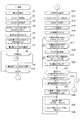
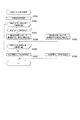
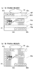
〔メイン処理〕
まず、メイン処理について説明する。メイン処理は、電源が投入されることで開始される。このメイン処理においては、図5に示すように、まず、割込みを禁止する処理(ステップX1)を行ってから、割込みが発生したときにレジスタ等の値を退避する領域の先頭アドレスであるスタックポインタを設定するスタックポインタ設定処理(ステップX2)を行う。次に、レジスタバンク0を指定し(ステップX3)、所定のレジスタ(例えばDレジスタ)にRAM先頭アドレスの上位アドレスをセットする(ステップX4)。本実施形態の場合、RAMのアドレスの範囲は0000h〜01FFhで、上位としては00hか01hをとり、ステップX4では先頭の00hをセットする。次に、発射停止の信号を出力して発射許可信号を禁止状態に設定する(ステップX5)。発射許可信号は遊技制御装置100と払出制御装置200の少なくとも一方が発射停止の信号を出力している場合に禁止状態に設定され、遊技球の発射が禁止されるようになっている。
[Main processing]
First, the main process will be described. The main process is started when the power is turned on. In this main process, as shown in FIG. 5, first, a process of inhibiting an interrupt (step X1) is performed, and then a stack pointer which is a top address of an area for saving a value of a register or the like when the interrupt occurs. A stack pointer setting process (step X2) for setting is performed. Next, the
その後、RAM初期化スイッチ112と設定キースイッチ152の状態を読み込み(ステップX6)、電源投入ディレイタイマを設定する処理(ステップX7)を行う。ステップX7の処理では所定の初期値を設定することにより、主制御手段をなす遊技制御装置100からの指示に従い種々の制御を行う従制御手段(例えば、払出制御装置200や演出制御装置300)のプログラムが正常に起動するのを待つための待機時間(例えば3秒)が設定される。これにより、電源投入の際に仮に遊技制御装置100が先に立ち上がって従制御装置(例えば払出制御装置200や演出制御装置300)が立ち上がる前にコマンドを従制御装置へ送ってしまい、従制御装置がコマンドを取りこぼすのを回避することができる。すなわち、遊技制御装置100が、電源投入時において、主制御手段(遊技制御装置100)の起動を遅らせて従制御装置(払出制御装置200、演出制御装置300等)の起動を待つための所定の待機時間を設定する待機手段をなす。
After that, the states of the
また、電源投入ディレイタイマの計時は、RAMの正当性判定(チェックサム算出)の対象とならない記憶領域(正当性判定対象外のRAM領域又はレジスタ等)を用いて行われる。これにより、RAM領域のチェックサム等のチェックデータを算出する際に、一部のRAM領域を除外して算出する必要がないため電源投入時の制御が複雑になることを防止することができる。 In addition, the power-on delay timer counts time using a storage area (RAM area or register, etc. that is not the target of validity determination) that is not the target of validity determination (checksum calculation) of RAM. As a result, when calculating check data such as the checksum of the RAM area, it is not necessary to exclude a part of the RAM area for calculation, and thus it is possible to prevent the control at power-on from becoming complicated.
電源投入ディレイタイマを設定する処理(ステップX7)を行った後、停電が発生しているか判定し(ステップX8)、停電が発生している場合(ステップX8;Y)には、遊技機の電源が遮断されるのを待つ。
具体的には、ステップX8では、例えば、電源装置400から入力されている停電監視信号をポート及びデータバスを介して読み込んでチェックする回数(例えば2回)を設定し、停電監視信号がオンであるかの判定を行う。そして、停電監視信号がオンである場合は、設定したチェック回数分停電監視信号のオン状態が継続しているか判定する。そして、チェック回数分停電監視信号のオン状態が継続していない場合は、停電監視信号がオンであるかの判定に戻る。また、チェック回数分停電監視信号のオン状態が継続している場合には、停電が発生していると判定する。後述するステップX34,X54においても同様である。このように、所定期間に亘り停電監視信号を受信し続けた場合に停電が発生したと判定することで、ノイズなどにより停電を誤検知することを防止でき、電源投入時における不具合に適切に対処することができる。
After performing the process of setting the power-on delay timer (step X7), it is determined whether a power failure has occurred (step X8). If a power failure has occurred (step X8; Y), the power supply of the gaming machine is determined. Wait for the cutoff.
Specifically, in step X8, for example, the number of times (for example, twice) the power failure monitoring signal input from the
すなわち、遊技制御装置100が、所定の待機時間において停電の発生を監視する停電監視手段をなす。これにより、主制御手段をなす遊技制御装置100の起動を遅らせている期間において発生した停電に対応することが可能となり、電源投入時における不具合に適切に対処することができる。なお、待機時間の終了まではRAMへのアクセスが許可されておらず、前回の電源遮断時の記憶内容が保持されたままとなっているため、ここでの停電発生時にはバックアップの処理等は行う必要がない。このため、待機時間中に停電が発生してもRAMのバックアップを取る必要がなく、制御の負担を軽減することができる。
That is, the
一方、停電が発生していない場合(ステップX8;N)には、電源投入ディレイタイマを−1更新し(ステップX9)、タイマの値が0であるか判定する(ステップX10)。タイマの値が0でない場合(ステップX10;N)、すなわち、待機時間が終了していない場合には、停電が発生しているか判定する処理(ステップX8)に戻る。また、タイマの値が0である場合(ステップX10;Y)、すなわち、待機時間が終了した場合には、RAMやEEPROM等の読出し書込み可能なRWM(リードライトメモリ)のアクセス許可をし(ステップX11)、全出力ポートにオフデータを出力(出力が無い状態に設定)する(ステップX12)。 On the other hand, if no power failure has occurred (step X8; N), the power-on delay timer is updated by -1 (step X9), and it is determined whether the timer value is 0 (step X10). When the value of the timer is not 0 (step X10; N), that is, when the standby time has not ended, the process returns to the process (step X8) of determining whether a power failure has occurred. When the value of the timer is 0 (step X10; Y), that is, when the waiting time is over, access is permitted to the read/write memory (RWM) such as RAM and EEPROM (step S10). X11), OFF data is output to all output ports (set to no output) (step X12).
次に、シリアルポート(遊技用マイコン111に予め搭載されているポートで、本実施形態では、演出制御装置300や払出制御装置200との通信に使用)を設定し(ステップX13)、遊技用マイコン111(クロックジェネレータ)内のタイマ割込み信号及び乱数更新トリガ信号(CTC)を発生するCTC(Counter/Timer Circuit)回路を起動する処理(ステップX14)を行う。なお、CTC回路は、遊技用マイコン111内のクロックジェネレータに設けられている。クロックジェネレータは、発振回路113からの発振信号(原クロック信号)を分周する分周回路と、分周された信号に基づいてCPU111Aに対して所定周期(例えば、4ミリ秒)のタイマ割込み信号及び乱数生成回路へ供給する乱数更新のトリガを与える信号CTCを発生するCTC回路とを備えている。
次いで、RAM異常フラグをセットする(ステップX15)。ここでは、RAMに異常があるか否かにかかわらずRAMに異常があることを前提として、一旦、RAM異常フラグを所定のレジスタにセットする。
Next, a serial port (a port that is pre-installed in the
Then, the RAM abnormality flag is set (step X15). Here, the RAM abnormality flag is temporarily set in a predetermined register on the assumption that the RAM has abnormality regardless of whether the RAM has abnormality.
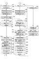
次いで、RWM内の停電検査領域1の値が正常な停電検査領域チェックデータ1(例えば5Ah)であるか判定し(ステップX16)、正常であれば(ステップX16;Y)、RWM内の停電検査領域2の値が正常な停電検査領域チェックデータ2(例えばA5h)であるか判定する(ステップX17)。そして、停電検査領域2の値が正常であれば(ステップX17;Y)、RWM内の所定領域のチェックサムを算出するチェックサム算出処理(ステップX18)を行い、算出したチェックサムと電源断時のチェックサムが一致するか判定する(ステップX19)。チェックサムが一致する場合(ステップX19;Y)には、RAMに異常がないためRAM異常フラグをクリアして(ステップX20)、ステップX21へ移行する。
Next, it is judged whether the value of the power
また、停電検査領域のチェックデータが正常なデータでないと判定された場合(ステップX16;NもしくはステップX17;N)、チェックサムが一致しないと判定された場合(ステップX19;N)には、ステップX6で読み込んだ状態に基づいて設定キースイッチ152とRAM初期化スイッチ112の両方がオン状態であるか判定する(ステップX21)。そして、設定キースイッチ152とRAM初期化スイッチ112の少なくとも一方がオフ状態である場合(ステップX21;N)には、RAM異常フラグがセットされているか判定する(ステップX22)。RAM異常フラグがセットされている場合(ステップX22;Y)には、RAMに異常があるため、遊技制御装置100が異常であることを報知するメイン異常エラー報知のコマンドを演出制御基板(演出制御装置300)に送信する(ステップX24)。
If it is determined that the check data in the power failure inspection area is not normal data (step X16;N or step X17;N), or if the checksums do not match (step X19;N), the step is performed. Based on the state read in X6, it is determined whether both the setting
一方、RAM異常フラグがセットされていない場合(ステップX22;N)には、確率設定変更中フラグがセットされているか判定する(ステップX23)。そして、確率設定変更中フラグがセットされている場合(ステップX23;Y)には、メイン異常エラー報知のコマンドを演出制御基板(演出制御装置300)に送信する(ステップX24)。ここでセットされている確率設定中フラグは、停電発生前にセットされた確率設定中フラグである。すなわち、確率設定値の変更中に遊技機の電源が遮断して再起動した場合には、遊技制御装置100の動作が停止するのでステップX24の処理を行う。
次いで、遊技停止時の7セグ表示データを、第2出力ポート134を介して第5ドライバ138eに出力する(ステップX25)。これにより、性能表示装置153において、遊技停止時の表示が行われる。その後、セキュリティ信号のオンデータを出力するとともにセキュリティ信号以外の信号のオフデータを出力して(ステップX26)、ステップX25に戻る。
On the other hand, when the RAM abnormality flag is not set (step X22; N), it is determined whether the probability setting changing flag is set (step X23). Then, when the probability setting changing flag is set (step X23; Y), the main abnormality error notification command is transmitted to the effect control board (effect control device 300) (step X24). The probability setting flag set here is a probability setting flag set before the occurrence of a power failure. That is, when the power supply of the game machine is cut off and restarted during the change of the probability setting value, the operation of the
Next, the 7-segment display data when the game is stopped is output to the fifth driver 138e via the second output port 134 (step X25). As a result, the
また、設定キースイッチ152とRAM初期化スイッチ112の両方がオン状態である場合(ステップX21;Y)には、RAM異常フラグがセットされているか判定する(ステップX27)。そして、RAM異常フラグがセットされていない場合(ステップX27;N)には、確率設定変更中フラグをセットする(ステップX29)。これにより確率設定値変更モードに移行する。その後、確率設定変更中のコマンドを演出制御基板(演出制御装置300)に送信して(ステップX30)、ステップX31へ移行する。演出制御装置300では、確率設定変更中のコマンドを受信することに基づき、表示装置41の表示、枠装飾装置18や盤装飾装置46のLEDの発光、盤演出装置44の動作、スピーカ19a,19bによる音声の出力などにより、確率設定値の変更中である旨を示す報知を行う。
一方、RAM異常フラグがセットされている場合(ステップX27;Y)には、確率設定値をクリアする処理(ステップX28)を行う。これにより、RWM内の確率設定値用の領域に0がセットされて、確率設定値が“設定1”となる。その後、ステップX29,X30の処理を行って、ステップX31へ移行する。
If both the setting
On the other hand, when the RAM abnormality flag is set (step X27; Y), the probability setting value is cleared (step X28). As a result, 0 is set in the area for the probability setting value in the RWM, and the probability setting value becomes “setting 1”. After that, the processes of steps X29 and X30 are performed, and the process proceeds to step X31.
また、設定キースイッチ152とRAM初期化スイッチ112の少なくとも一方がオフ状態であり(ステップX21;N)、RAM異常フラグも確率設定変更中フラグもセットされていない場合(テップX22;N及びステップX23;N)には、ステップX6で読み込んだ状態に基づいて設定キースイッチ152がオン状態であるか判定する(ステップX35)。そして、設定キースイッチ152がオン状態でない場合(ステップX35;N)には、ステップX6で読み込んだ状態に基づいてRAM初期化スイッチ112がオン状態であるか判定する(ステップX43)。
Further, when at least one of the setting
RAM初期化スイッチ112がオン状態でないと判定した場合(ステップX43;N)、すなわち設定キースイッチ152とRAM初期化スイッチ112の両方がオフ状態である場合には、ステップX41へ移行して停電から正常に復旧した場合の処理を行う。
一方、RAM初期化スイッチ112がオン状態であると判定した場合(ステップX43;Y)には、ステップX44へ移行して初期化の処理を行う。すなわち、RAM初期化スイッチ112が外部からの操作が可能な初期化操作部をなし、遊技制御装置100が、初期化操作部が操作されたことに基づきRAMに記憶されたデータを初期化する初期化手段をなす。
When it is determined that the
On the other hand, when it is determined that the
また、設定キースイッチ152がオン状態である場合(ステップX35;Y)には、確率設定確認中フラグをセットする(ステップX36)。これにより確率設定値確認モードに移行する。その後、確率設定確認中のコマンドを演出制御基板(演出制御装置300)に送信する(ステップX37)。演出制御装置300では、確率設定確認中のコマンドを受信することに基づき、表示装置41の表示、枠装飾装置18や盤装飾装置46のLEDの発光、盤演出装置44の動作、スピーカ19a,19bによる音声の出力などにより、確率設定値の確認中である旨の報知を行う。
If the setting
そして、50m秒間以上のセキュリティ信号の出力を保証するために、セキュリティ信号制御タイマ領域に128m秒に対応する値をセーブする(ステップX31)。セキュリティ信号は、確率設定値変更モードや確率設定値確認モードである場合にはタイマ割込み処理の確率設定変更/確認処理(ステップX122)で出力され、それ以外の場合はタイマ割込み処理の外部情報編集処理(ステップX120)で出力される。したがって、128m秒間未満で確率設定値変更モードや確率設定値確認モードが終了する場合には、タイマ割込み処理の外部情報編集処理(ステップX120)によってセキュリティ信号が継続して出力される。すなわち、128m秒間未満で確率設定値変更モードや確率設定値確認モードが終了する場合であっても、確率設定値変更モードや確率設定値確認モードに移行してから128m秒間はセキュリティ信号が出力される。なお、ステップX31においてセキュリティ信号制御タイマ領域にセーブする値は128m秒に対応する値に限定されない。ただし、確率設定値変更モードや確率設定値確認モードに移行してから少なくとも50m秒間はセキュリティ信号を出力する必要があるため、50m秒以上に対応する値をセーブする必要がある。 Then, in order to guarantee the output of the security signal for 50 msec or more, the value corresponding to 128 msec is saved in the security signal control timer area (step X31). The security signal is output in the probability setting change/confirmation process (step X122) of the timer interrupt process in the probability set value change mode or the probability set value confirmation mode, and in other cases, the external information of the timer interrupt process is edited. It is output in the process (step X120). Therefore, when the probability setting value changing mode or the probability setting value confirming mode ends in less than 128 msec, the security signal is continuously output by the external information editing processing (step X120) of the timer interrupt processing. That is, even if the probability setting value change mode or the probability setting value confirmation mode ends in less than 128 msec, the security signal is output for 128 msec after the mode is changed to the probability setting value change mode or the probability setting value confirmation mode. It The value saved in the security signal control timer area in step X31 is not limited to the value corresponding to 128 msec. However, since it is necessary to output the security signal for at least 50 msec after shifting to the probability set value change mode or the probability set value confirmation mode, it is necessary to save the value corresponding to 50 msec or more.
そして、割込みを許可し(ステップX32)、設定キースイッチ152がオフ状態であるか判定する(ステップX33)。ステップX33では、ステップX6で読み込んだ状態(電源投入時の状態)に基づいて判定するのではなく、タイマ割込み処理(図7)の入力処理(ステップX103)で読み込んだ状態(現時点の状態)に基づいて判定する。ステップX33で設定キースイッチ152がオフ状態である判定された場合に、確率設定値が確定される。
設定キースイッチ152がオフ状態でない場合(ステップX33;N)には、停電が発生しているか判定し(ステップX34)、停電が発生していない場合(ステップX34;N)には、ステップX33に戻り、停電が発生している場合(ステップX34;Y)には、ステップX55へ移行する。確率設定変更中フラグがセットされている状態でステップX34にて停電が発生していると判定された場合に、当該停電から復旧した後のメイン処理(図5及び図6)のステップX23において、確率設定変更中フラグがセットされていると判定される。
Then, interruption is permitted (step X32), and it is determined whether the setting
If the setting
一方、設定キースイッチ152がオフ状態である場合(ステップX33;Y)には、割込みを禁止する処理(ステップX38)を行う。割込みを許可する処理(ステップX32)を行ってから割込みを禁止する処理(ステップX38,X55)を行うまでの間は、タイマ割込み処理(図7)が所定時間周期(例えば4m秒)で行われる。当該タイマ割込み処理では、確率設定値に関する処理である確率設定変更/確認処理(ステップX122)が行われる。すなわち、確率設定値の変更や確認が終了するまで(あるいは停電が発生するまで)の間、メイン処理は待機していることとなる。
次いで、報知終了のコマンドを演出制御基板(演出制御装置300)に送信する(ステップX39)。演出制御装置300では、報知終了のコマンドを受信することに基づき、実行中の報知(確率設定値の変更中である旨を示す報知又は確率設定値の確認中である旨の報知)を終了する。
On the other hand, when the setting
Next, a command to end the notification is transmitted to the effect control board (effect control device 300) (step X39). The
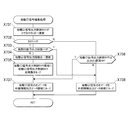
次いで、確率設定変更中フラグがセットされているか判定し(ステップX40)、確率設定変更中フラグがセットされていない場合(ステップX40;N)、すなわち確率設定確認中フラグがセットされている場合には、初期化すべき領域(例えば、停電検査領域、チェックサム領域及びエラー不正監視に係る領域)に停電復旧時の初期値をセーブする処理等を行う停電復旧処理(ステップX41)を行う。確率設定確認中フラグは、このステップX41でクリアされる。
その後、特図ゲーム処理番号に対応する停電復旧時のコマンドを演出制御基板(演出制御装置300)へ送信し(ステップX42)、ステップX47へ移行する。本実施形態の場合、ステップX42では、機種指定コマンド、確率設定情報コマンド、特図1保留数コマンド、特図2保留数コマンド、確率情報コマンド、演出回数情報コマンド、画面指定のコマンド等の複数のコマンドを送信する。画面指定のコマンドとしては、特図1及び特図2について何れも後述する普段処理中である場合、すなわち特図変動表示ゲームの実行中でもなく特別遊技状態中でもない場合である客待ち中であれば客待ちデモ画面のコマンドを送信し、それ以外であれば復旧画面のコマンドを送信する。また、機種によっては、これらのコマンドに加えて、高確率回数情報コマンド等も送信する。
Next, it is determined whether the probability setting changing flag is set (step X40), and when the probability setting changing flag is not set (step X40; N), that is, when the probability setting confirming flag is set. Performs a power failure recovery process (step X41) that performs a process of saving the initial value at the time of power recovery in an area to be initialized (for example, a power failure inspection area, a checksum area, and an area related to error fraud monitoring). The probability setting confirmation flag is cleared in step X41.
After that, the command for power failure recovery corresponding to the special figure game processing number is transmitted to the effect control board (effect control device 300) (step X42), and the process proceeds to step X47. In the case of the present embodiment, in step X42, a plurality of model designation commands, probability setting information commands, special figure 1 hold number commands, special figure 2 hold number commands, probability information commands, performance number information commands, screen designation commands, etc. Send a command. As the command for screen designation, if both the special figure 1 and the special figure 2 are in the normal processing described later, that is, if the special figure change display game is not being executed and the special game state is not being waited for, Send the command on the customer waiting demo screen, otherwise send the command on the recovery screen. In addition to these commands, depending on the model, a high-probability-number-of-times information command or the like is also transmitted.
一方、確率設定変更中フラグがセットされている場合(ステップX40;Y)には、確率設定値以外のRAM領域を0クリアする(ステップX44)。ステップX44では、確率設定値用のRAM領域(ワーク領域(確率設定値の1バイト領域))と性能表示(ベース値や役物比率の表示)用のRAM領域(ワーク領域とスタック領域)はクリアせず、遊技制御用のRAM領域(ワーク領域とスタック領域)を0クリアする。したがって、確率設定変更中フラグは、このステップX44でクリアされる。なお、ステップX44では、スタック領域や未使用領域をクリアしてもしなくても良い。 On the other hand, when the probability setting changing flag is set (step X40; Y), the RAM areas other than the probability setting value are cleared to 0 (step X44). At step X44, the RAM area for the probability setting value (work area (1 byte area of the probability setting value)) and the RAM area for displaying performance (displaying the base value and accessory ratio) (work area and stack area) are cleared. Instead, the RAM area for the game control (work area and stack area) is cleared to 0. Therefore, the probability setting changing flag is cleared in step X44. In step X44, the stack area and the unused area may or may not be cleared.
そして、初期化すべき領域にRAM初期化時の初期値をセーブする(ステップX45)。ここでの初期化すべき領域とは、客待ちデモ領域及び演出モードの設定に係る領域である。そして、RAM初期化時のコマンドを演出制御基板(演出制御装置300)へ送信する(ステップX46)。本実施形態の場合、ステップX46では、機種指定コマンド、確率設定情報コマンド、特図1保留数コマンド、特図2保留数コマンド、確率情報コマンド、演出回数情報コマンド、RAM初期化のコマンド(客待ちデモ画面を表示させるとともに、所定時間(例えば30秒間)光と音でRAM初期化の報知を行わせるためのコマンド)等の複数のコマンドを送信する。また、機種によっては、これらのコマンドに加えて、演出回数情報コマンドや普電サポートありとした特図変動表示ゲームの実行回数の情報であるサポート回数情報コマンド等も送信する。 Then, the initial value at the time of RAM initialization is saved in the area to be initialized (step X45). The area to be initialized here is the customer waiting demonstration area and the area related to the setting of the effect mode. Then, the command for RAM initialization is transmitted to the effect control board (effect control device 300) (step X46). In the case of the present embodiment, in step X46, a model designation command, a probability setting information command, a special figure 1 hold number command, a special figure 2 hold number command, a probability information command, an effect number information command, a RAM initialization command (waiting for customers) While displaying the demo screen, a plurality of commands such as a command to notify the RAM initialization by light and sound for a predetermined time (for example, 30 seconds) are transmitted. Also, depending on the model, in addition to these commands, a support number information command, a support number information command that is information on the number of times the special figure variation display game with normal electric power support is executed, and the like are also transmitted.
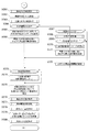
次いで、乱数生成回路を起動設定する処理を行う(ステップX47)。具体的には、乱数生成回路内の所定のレジスタ(CTC更新許可レジスタ)へ乱数生成回路を起動させるためのコード(指定値)の設定などがCPU111Aによって行われる。また、乱数生成回路のハードウェアで生成されるハード乱数(ここでは大当り乱数)のビット転置パターンの設定も行われる。ビット転置パターンとは、抽出した乱数のビット配置(上段のビット転置前の配置)を、予め定められた順で入れ替えて異なるビット配置(下段のビット転置後の配置)として格納する際の入れ替え方を定めるパターンである。このビット転置パターンに従い乱数のビットを入れ替えることで、乱数の規則性を崩すことができるとともに、乱数の秘匿性を高めることができる。なお、ビット転置パターンは、固定された単一のパターンであっても良いし、予め用意された複数のパターンから選択するようにしても良い。また、ユーザーが任意に設定できるようにしても良い。 Next, a process for activating and setting the random number generation circuit is performed (step X47). Specifically, the CPU 111A sets a code (specified value) for activating the random number generation circuit in a predetermined register (CTC update permission register) in the random number generation circuit. Also, a bit transposed pattern of hard random numbers (here, big hit random numbers) generated by the hardware of the random number generation circuit is set. The bit transposition pattern is the method of exchanging the bit arrangement of the extracted random numbers (arrangement before bit transposition in the upper row) in a predetermined order and storing as a different bit arrangement (arrangement after bit transposition in the lower row). Is a pattern that determines. By exchanging the bits of the random number in accordance with this bit transposed pattern, the regularity of the random number can be broken and the confidentiality of the random number can be improved. The bit transposition pattern may be a fixed single pattern or may be selected from a plurality of patterns prepared in advance. Further, the user may set it arbitrarily.
その後、電源投入時の乱数生成回路内の所定のレジスタ(ソフト乱数レジスタ1〜n)の値を抽出し、対応する各種初期値乱数(本実施形態の場合、特図の当り図柄を決定する乱数(大当り図柄乱数、小当り図柄乱数)、普図の当りを決定する乱数(当り乱数)、転落抽選に当選か否かを決定する乱数(転落抽選乱数))の初期値(スタート値)としてRWMの所定領域にセーブしてから(ステップX48)、割込みを許可する(ステップX49)。本実施形態で使用するCPU111A内の乱数生成回路においては、電源投入毎にソフト乱数レジスタの初期値が変わるように構成されているため、この値を各種初期値乱数の初期値(スタート値)とすることで、ソフトウェアで生成される乱数の規則性を崩すことができ、遊技者による不正な乱数の取得を困難にすることができる。 After that, the values of predetermined registers (soft random number registers 1 to n) in the random number generation circuit at the time of power-on are extracted, and various corresponding initial value random numbers (in the case of the present embodiment, random numbers for determining the winning symbol of the special drawing). (Big hit symbol random number, Small hit symbol random number), Random number that determines the hit of a general figure (hit number), RWM as the initial value (start value) of the random number that determines whether to win the falling lottery (falling lottery random number) After saving the data in the predetermined area (step X48), the interrupt is permitted (step X49). Since the random number generation circuit in the CPU 111A used in the present embodiment is configured so that the initial value of the soft random number register changes each time the power is turned on, this value is used as the initial value (start value) of various initial value random numbers. By doing so, it is possible to break the regularity of the random numbers generated by the software and make it difficult for the player to obtain an illegal random number.
続いて、各種初期値乱数の値を更新して乱数の規則性を崩すための初期値乱数更新処理(ステップX50)を行う。なお、特に限定されるわけではないが、本実施形態においては、大当り乱数、大当り図柄乱数、小当り図柄乱数、当り乱数、転落抽選乱数は乱数生成回路において生成される乱数を使用して生成するように構成されている。ただし、大当り乱数はCPUの動作クロックと同等以上の速度のクロックを基にして更新される所謂「高速カウンタ」であり、大当り図柄乱数、小当り図柄乱数、当り乱数、転落抽選乱数はプログラムの処理単位であるタイマ割込み処理と同周期となるCTC出力(タイマ割込み処理のCTC(CTC0)とは別のCTC(CTC2))を基にして更新される「低速カウンタ」である。また、大当り図柄乱数、小当り図柄乱数、当り乱数、転落抽選乱数においては、乱数が一巡する毎に各々の初期値乱数(ソフトウェアで生成)を用いてスタート値を変更する所謂「初期値変更方式」を採用している。なお、前記各乱数は、+1或いは−1によるカウンタ式更新でもよいし、一巡するまで範囲内の全ての値が重複なくバラバラに出現するランダム式更新でもよい。つまり、大当り乱数はハードウェアのみで更新される乱数であり、大当り図柄乱数、小当り図柄乱数、当り乱数、転落抽選乱数はハードウェア及びソフトウェアで更新される乱数である。
なお、本実施形態では、普図の当り図柄を決定する乱数(当り図柄乱数)を設けていないため、普図の当り図柄は1種類しかないが、当り図柄乱数を設けて普図の当り図柄を複数種類の中から選択するようにしても良い。
Subsequently, an initial value random number updating process (step X50) for updating the values of various initial value random numbers and breaking the regularity of the random numbers is performed. Although not particularly limited, in the present embodiment, the big hit random number, the big hit symbol random number, the small hit symbol random number, the hit random number, and the falling lottery random number are generated by using the random numbers generated in the random number generation circuit. Is configured. However, the big hit random number is a so-called "high-speed counter" that is updated based on a clock having a speed equal to or higher than the operation clock of the CPU, and the big hit symbol random number, the small hit symbol random number, the hit random number, and the falling lottery random number are processed by the program. It is a "low-speed counter" that is updated based on the CTC output (CTC (CTC2) different from CTC (CTC0) of timer interrupt processing) that has the same cycle as the unit of timer interrupt processing. In addition, in the big hit design random number, the small hit design random number, the hit random number, the falling lottery random number, the so-called "initial value change method" that changes the start value using each initial value random number (generated by software) every time the random number makes a round Is adopted. Each of the random numbers may be a counter-type update by +1 or -1, or may be a random-type update in which all values within the range appear separately without duplication until one cycle. That is, the big hit random number is a random number that is updated only by hardware, and the big hit symbol random number, the small hit symbol random number, the hit random number, and the falling lottery random number are random numbers that are updated by hardware and software.
In addition, in the present embodiment, since there is no random number (hit symbol random number) for determining the hit symbol of the universal symbol, there is only one type of hit symbol of the universal symbol, but the hit symbol of the universal symbol is provided by providing the hit symbol random number. May be selected from a plurality of types.
ステップX50の初期値乱数更新処理の後、割込みを禁止する処理(ステップX51)を行って、性能表示編集処理(ステップX52)を行う。そして、割込みを許可する処理(ステップX53)を行った後、停電が発生しているか判定し(ステップX54)、停電が発生していない場合(ステップX54;N)には、初期値乱数更新処理(ステップX50)に戻る。すなわち、停電が発生していない場合には、初期値乱数更新処理と性能表示編集処理と停電監視を繰り返し行う。初期値乱数更新処理(ステップX50)の前に割込みを許可する(ステップX49)ことによって、初期値乱数更新処理中にタイマ割込みが発生すると割込み処理が優先して実行されるようになり、タイマ割込みが初期値乱数更新処理によって待たされることで割込み処理が圧迫されるのを回避することができる。 After the initial value random number updating process of step X50, a process of inhibiting interruption (step X51) is performed, and a performance display editing process (step X52) is performed. Then, after performing the process of permitting the interrupt (step X53), it is determined whether or not a power failure has occurred (step X54). If no power failure has occurred (step X54; N), an initial value random number updating process Return to (Step X50). That is, when the power failure has not occurred, the initial value random number updating processing, the performance display editing processing, and the power failure monitoring are repeated. By permitting the interrupt (step X49) before the initial value random number updating process (step X50), when a timer interrupt occurs during the initial value random number updating process, the interrupt process is preferentially executed. It is possible to avoid pressure on the interrupt process by waiting for the initial value random number update process.
なお、ステップX50での初期値乱数更新処理は、メイン処理のほか、タイマ割込み処理の中においても初期値乱数更新処理を行う方法もあり、そのような方法を採用した場合には両方で初期値乱数更新処理が実行されるのを回避するため、メイン処理で初期値乱数更新処理を行う場合には割込みを禁止してから更新して割込みを解除する必要があるが、本実施形態のようにタイマ割込み処理の中での初期値乱数更新処理はせず、メイン処理内のみにした場合には初期値乱数更新処理の前に割込みを解除しても何ら問題はなく、それによってメイン処理が簡素化されるという利点がある。 In addition to the main process, the initial value random number updating process in step X50 includes a method of performing the initial value random number updating process in the timer interrupt process as well. In order to prevent the random number update process from being executed, when performing the initial value random number update process in the main process, it is necessary to disable the interrupt and then update the interrupt to cancel the interrupt. If the initial value random number update processing is not performed in the timer interrupt processing and only within the main processing, there is no problem even if the interrupt is released before the initial value random number update processing, which simplifies the main processing. The advantage is that
一方、停電が発生している場合(ステップX54;Y)には、一旦割込みを禁止する処理(ステップX55)、全出力ポートにオフデータを出力する処理(ステップX56)を行う。
その後、停電検査領域1に停電検査領域チェックデータ1をセーブし(ステップX57)、停電検査領域2に停電検査領域チェックデータ2をセーブする(ステップX58)。さらに、RWMの電源遮断時のチェックサムを算出するチェックサム算出処理(ステップX59)、算出したチェックサムをセーブする処理(ステップX60)を行った後、RWMへのアクセスを禁止する処理(ステップX61)を行ってから、遊技機の電源が遮断されるのを待つ。このように、停電検査領域にチェックデータをセーブするとともに、電源遮断時のチェックサムを算出することで、電源の遮断の前にRWMに記憶されていた情報が正しくバックアップされているか否かを電源再投入時に判断することができる。
On the other hand, when a power failure has occurred (step X54; Y), a process of temporarily interrupting (step X55) and a process of outputting off data to all output ports (step X56) are performed.
After that, the power failure inspection
以上のことから、遊技を統括的に制御する主制御手段(遊技制御装置100)と、該主制御手段からの指示に従い種々の制御を行う従制御手段(払出制御装置200、演出制御装置300等)と、を備える遊技機において、主制御手段は、電源投入時において、当該主制御手段の起動を遅らせて従制御装置の起動を待つための所定の待機時間を設定する待機手段(遊技制御装置100)と、当該所定の待機時間において停電の発生を監視する停電監視手段(遊技制御装置100)と、を備えていることとなる。
また、各種装置に電力を供給する電源装置400を備え、当該電源装置400は、停電の発生を検出した際に停電監視信号を出力するように構成され、停電監視手段(遊技制御装置100)は、所定期間に亘り停電監視信号を受信し続けた場合に停電が発生したと判定するようにしていることとなる。
From the above, the main control means (game control device 100) for controlling the game in an integrated manner, and the secondary control means (
Further, a
また、主制御手段(遊技制御装置100)は、データを記憶可能なRAM111Cと、外部からの操作が可能な初期化操作部(RAM初期化スイッチ112)と、初期化操作部が操作されたことに基づきRAM111Cに記憶されたデータを初期化する初期化手段(遊技制御装置100)と、を備え、当該初期化手段の操作状態を待機時間の開始前に読み込むようにしていることとなる。
また、主制御手段(遊技制御装置100)は、待機時間の経過後にRAM111Cへのアクセスを許可するようにしていることとなる。
Further, the main control means (game control device 100), RAM111C capable of storing data, an initialization operation unit (RAM initialization switch 112) that can be operated from the outside, and the initialization operation unit are operated. It is provided with an initialization means (game control device 100) for initializing the data stored in the
Further, the main control means (game control device 100) allows access to the
〔タイマ割込み処理〕
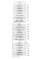
次に、タイマ割込み処理について説明する。タイマ割込み処理はクロックジェネレータ内のCTC回路で生成される周期的なタイマ割込み信号がCPU111Aに入力されることで開始される。すなわち、所定周期で開始される割込みルーチンである。遊技用マイコン111においてタイマ割込みが発生すると、自動的に割込み禁止状態になって、図7のタイマ割込み処理が開始される。
[Timer interrupt processing]
Next, the timer interrupt process will be described. The timer interrupt processing is started when a periodic timer interrupt signal generated by the CTC circuit in the clock generator is input to the CPU 111A. That is, it is an interrupt routine started at a predetermined cycle. When a timer interrupt is generated in the
タイマ割込み処理が開始されると、まず、レジスタバンク1を指定する(ステップX101)。レジスタバンク1に切り替えたことで、所定のレジスタ(例えばメイン処理で使っているレジスタ)に保持されている値をRWMに移すレジスタ退避の処理を行ったのと同等になる。次に、所定のレジスタ(例えばDレジスタ)にRAM先頭アドレスの上位アドレスをセットする(ステップX102)。ステップX102では、メイン処理におけるステップX4と同じ処理を行っているが、レジスタバンクが異なる。次に、各種センサやスイッチからの入力や、信号の取込み、すなわち、各入力ポートの状態を読み込む入力処理(ステップX103)を行う。
When the timer interrupt process is started, first, the
次いで、確率設定変更中フラグ又は確率設定確認中フラグがセットされているか判定し(ステップX104)、確率設定変更中フラグ又は確率設定確認中フラグがセットされている場合(ステップX104;Y)には、確率設定変更/確認処理(ステップX122)を行って、タイマ割込み処理を終了する。
一方、確率設定変更中フラグと確率設定確認中フラグの両方がセットされていない場合(ステップX104;N)には、各種処理でセットされた出力データに基づき、ソレノイド(大入賞口ソレノイド38b,39b、レバーソレノイド38f、普電ソレノイド37c)等のアクチュエータの駆動制御などを行うための出力処理(ステップX105)を行う。なお、メイン処理におけるステップX5で発射停止の信号を出力すると、この出力処理が行われることで発射許可の信号が出力され、発射許可信号を許可状態に設定可能な状態とされる。この発射許可信号は払出制御装置を経由して発射制御装置に出力される。その際、信号の加工等は行われない。また、当該発射許可信号は遊技制御装置から見た発射許可の状態を示す第1の信号であり、払出制御装置から見た発射許可の状態を示す第2の信号(発射許可信号)も払出制御装置内で生成され、発射制御装置に出力される。つまり、2つの発射許可信号が発射制御装置に出力されており、両者が共に発射許可となっている場合に、遊技球が発射可能な状態となるよう構成されている。
Then, it is determined whether the probability setting changing flag or the probability setting confirming flag is set (step X104), and when the probability setting changing flag or the probability setting confirming flag is set (step X104; Y). , Probability setting change/confirmation processing (step X122) is performed, and the timer interrupt processing ends.
On the other hand, when neither the probability setting changing flag nor the probability setting confirming flag is set (step X104; N), the solenoids (special winning
次に、各種処理で送信バッファにセットされたコマンドを払出制御装置200に出力する払出コマンド送信処理(ステップX106)、乱数更新処理1(ステップX107)、乱数更新処理2(ステップX108)を行う。その後、始動口1スイッチ36a、始動口2スイッチ37a、入賞口スイッチ35a、大入賞口スイッチ38a,39aから正常な信号の入力があるか否かの監視や、賞球の設定、前面枠やガラス枠の開放や、普通変動入賞装置37、特別変動入賞装置38,39への不正入賞などのエラーの監視を行う入賞口スイッチ/状態監視処理(ステップX109)を行う。
Next, a payout command transmission process (step X106) of outputting the command set in the transmission buffer to the
次に、異常排出発生中であるか判定する(ステップX110)。異常排出とは、第1特別変動入賞装置38において、第1特別変動入賞装置38から排出される遊技球数(特定領域スイッチ38d及び残存球排出口スイッチ38eで検出された遊技球数)が、第1特別変動入賞装置38に流入した遊技球数(大入賞口スイッチ38aで検出された遊技球数)を上回ることである。なお、異常排出発生中である場合には異常排出フラグがセットされている。そして、異常排出発生中である場合(ステップX110;Y)には、ステップX116へ移行する。すなわち、遊技が進行しないようにする。
Next, it is determined whether abnormal discharge is occurring (step X110). Abnormal discharge means that in the first special
一方、異常排出発生中でない場合(ステップX110;N)には、始動口1スイッチ36a及び始動口2スイッチ37aの入賞を監視する始動口スイッチ監視処理(ステップX111)を行う。始動口スイッチ監視処理では、始動入賞口36や普通変動入賞装置37への遊技球の入賞に基づき、各種乱数(大当り乱数など)の抽出を行う。そして、特図1変動表示ゲームに関する処理を行う特図1ゲーム処理(ステップX112)、特図2変動表示ゲームに関する処理を行う特図2ゲーム処理(ステップX113)、普図変動表示ゲームに関する処理を行う普図ゲーム処理(ステップX114)を行って、遊技機10に設けられ、特図変動表示ゲームの表示や遊技に関する各種情報を表示するセグメントLEDを所望の内容を表示するように駆動するセグメントLED編集処理(ステップX115)を行う。
On the other hand, when the abnormal discharge is not occurring (step X110; N), the starting port switch monitoring process (step X111) for monitoring the winning of the starting
次いで、磁気センサ61からの検出信号をチェックして異常がないか判定する処理を行う磁石不正監視処理(ステップX116)、盤電波センサ62からの検出信号をチェックして異常がないか判定する処理を行う盤電波不正監視処理(ステップX117)、振動センサ65からの検出信号をチェックして異常がないか判定する処理を行う振動不正監視処理(ステップX118)、異常排出が発生していないか判定する処理を行う異常排出監視処理(ステップX119)を行う。さらに、外部の各種装置に出力する信号を出力バッファにセットする外部情報編集処理(ステップX120)、性能表示モニタ153の制御に関する性能表示モニタ制御処理(ステップX121)を行って、タイマ割込み処理を終了する。
Next, a magnet irregularity monitoring process (step X116) for checking the detection signal from the
ここで、本実施形態では、割込み禁止状態を復元する処理(すなわち、割込みを許可する処理)や、レジスタバンクの指定を復元する処理(すなわち、レジスタバンク0を指定する処理)は、割込みリターンの際(タイマ割込み処理の終了時)に自動的に行う。なお、使用するCPUによっては、割込み禁止状態を復元する処理やレジスタバンクの指定を復元する処理の実行を命令する必要がある遊技機もある。 Here, in this embodiment, the process of restoring the interrupt disabled state (that is, the process of permitting the interrupt) and the process of restoring the designation of the register bank (that is, the process of designating the register bank 0) are performed by interrupt return. At this time (at the end of timer interrupt processing), it is automatically performed. Depending on the CPU to be used, there is a gaming machine in which it is necessary to instruct execution of a process of restoring the interrupt prohibited state or a process of restoring the designation of the register bank.
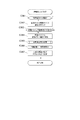
〔始動口スイッチ監視処理〕
図8には、上述のタイマ割込み処理における始動口スイッチ監視処理(ステップX111)を示した。この始動口スイッチ監視処理では、まず、始動口1(始動入賞口36)入賞監視テーブルを準備し(ステップX491)、ハード乱数取得処理(ステップX492)を行う。そして、当該ハード乱数取得処理で始動入賞口36への入賞に基づき大当り乱数を取得した場合に設定される始動口入賞あり情報があるか判定する(ステップX493)。
[Starting switch monitoring process]
FIG. 8 shows the starting opening switch monitoring process (step X111) in the above-mentioned timer interrupt process. In the starting opening switch monitoring processing, first, the starting opening 1 (starting winning opening 36) winning award monitoring table is prepared (step X491), and the hard random number acquisition processing (step X492) is performed. Then, it is determined whether or not there is the information regarding the winning of the starting opening set when the jackpot random number is acquired based on the winning of the
始動入賞口36への入賞に基づき始動口入賞あり情報が設定されていない場合(ステップX493;N)には、ステップX499へ移行する。なお、この場合は始動口入賞なし情報が設定されている。
一方、始動入賞口36への入賞に基づき始動口入賞あり情報が設定されている場合(ステップX493;Y)には、特図低確率&時短なし中(通常遊技状態中)であるか判定する(ステップX494)。そして、特図低確率&時短なし中である場合(ステップX494;Y)には、ステップX497へ移行する。また、特図低確率&時短なし中でない場合(ステップX494;N)には、右打ち指示報知コマンドを準備し(ステップX495)、演出コマンド設定処理(ステップX496)を行う。
When the information regarding the existence of the starting opening winning combination is not set based on the winning of the starting winning opening 36 (step X493; N), the process proceeds to step X499. It should be noted that in this case, the information on no starting mouth winning is set.
On the other hand, when the information about the winning of the starting opening is set based on the winning of the starting winning opening 36 (step X493; Y), it is determined whether the special figure low probability & no time saving (during normal game state). (Step X494). Then, when the special figure low probability & time saving is not in progress (step X494; Y), the process proceeds to step X497. If the special figure low probability & time saving is not in progress (step X494; N), a right-handing instruction notification command is prepared (step X495), and effect command setting processing (step X496) is performed.
演出制御装置300では、右打ち指示報知コマンドを受信することに基づき、表示や音声等により遊技者に対して右打ちをするように指示する右打ち指示報知を行う。特定遊技状態中や特別遊技状態中である場合は右打ちの方が遊技者にとって有利であり、左打ちでなければ入賞しないようになっている始動入賞口36で特定遊技状態中や特別遊技状態中において入賞を検出した場合に右打ち指示報知を行うようにしている。
Based on the reception of the right-handing instruction notification command, the
そして、始動口1による保留の情報を設定するテーブルを準備し(ステップX497)、特図始動口スイッチ共通処理(ステップX498)を行う。次いで、始動口2(普通変動入賞装置37)入賞監視テーブルを準備し(ステップX499)、ハード乱数取得処理(ステップX500)を行って、普通変動入賞装置37への入賞に基づき大当り乱数を取得した場合に設定される始動口入賞あり情報があるか判定する(ステップX501)。
Then, a table for setting information on the hold by the starting
普通変動入賞装置37への入賞に基づき始動口入賞あり情報が設定されていない場合(ステップX501;N)には、始動口スイッチ監視処理を終了する。なお、この場合は始動口入賞なし情報が設定されている。
一方、普通変動入賞装置37への入賞に基づき始動口入賞あり情報が設定されている場合(ステップX501;Y)には、普電(普通変動入賞装置37)が作動中であるか、すなわち普通変動入賞装置37が作動して遊技球の入賞が可能な開状態となっているか否か判定し(ステップX502)、普電が作動中である場合(ステップX502;Y)には、ステップX504へ移行する。一方、普電が作動中でない場合(ステップX502;N)には、普電不正発生中であるか判定する(ステップX503)。
When the information regarding the presence of the starting opening winning combination is not set based on the winning of the normal variation winning device 37 (step X501; N), the starting opening switch monitoring processing is ended. It should be noted that in this case, the information on no starting mouth winning is set.
On the other hand, when the information with the start mouth winning is set based on the winning of the normal variable winning device 37 (step X501; Y), whether the electric power (normal variable winning device 37) is operating, that is, the normal It is determined whether or not the variable winning
普電不正発生中であるかの判定では、普通変動入賞装置37への不正入賞数が不正発生判定個数(例えば5個)以上である場合に不正発生中であると判定する。普通変動入賞装置37は、閉状態では遊技球が入賞不可能であり、開状態でのみ遊技球が入賞可能である。よって、閉状態で遊技球が入賞した場合は何らかの異常や不正が発生した場合であり、このような閉状態で入賞した遊技球があった場合はその数を不正入賞数として計数する。そして、このように計数された不正入賞数が所定の不正発生判定個数(上限値)以上である場合に不正発生中と判定する。
In the determination as to whether or not there is a fraudulent fraud, it is determined that fraud has occurred if the number of fraudulent prizes awarded to the normal
普電不正発生中である場合(ステップX503;Y)には、始動口スイッチ監視処理を終了する。すなわち、第2始動記憶をそれ以上発生させないようにする。また、普電不正発生中でない場合(ステップX503;N)には、始動口2による保留の情報を設定するテーブルを準備し(ステップX504)、特図始動口スイッチ共通処理(ステップX505)を行って、始動口スイッチ監視処理を終了する。
When the illegal power generation is occurring (step X503; Y), the starting opening switch monitoring process is ended. That is, the second starting memory is not generated any more. In addition, when the illegal call is not occurring (step X503; N), a table for setting information on the hold by the starting
〔特図始動口スイッチ共通処理〕
図9には、上述の始動口スイッチ監視処理における特図始動口スイッチ共通処理(ステップX498,X505)を示した。特図始動口スイッチ共通処理は、始動口1スイッチ36aや始動口2スイッチ37aの入力があった場合に、各々の入力について共通して行われる処理である。
[Common processing for special drawing start switch]
FIG. 9 shows the special figure starting port switch common process (steps X498, X505) in the starting port switch monitoring process described above. The special figure starting port switch common process is a process commonly performed for each input when the starting
この特図始動口スイッチ共通処理では、まず、始動口1スイッチ36a及び始動口2スイッチ37aのうち、監視対象の始動口スイッチへの入賞の回数に関する情報を遊技機10の外部の管理装置に対して出力する回数である始動口信号出力回数をロードし(ステップX521)、ロードした値を+1更新して(ステップX522)、出力回数がオーバーフローするか判定する(ステップX523)。
出力回数がオーバーフローしない場合(ステップX523;N)には、更新後の値をRWMの始動口信号出力回数領域にセーブし(ステップX524)、監視対象の始動口スイッチに対応する特図保留(始動記憶)数、すなわち更新対象の特図保留(始動記憶)数が上限値(ここでは4)未満か判定する(ステップX525)。一方、出力回数がオーバーフローする場合(ステップX523;Y)には、ステップX525へ移行する。ここでは出力回数を255まで記憶できるが、上限まで記憶している場合には+1更新によりループして0となってしまうため、更新後の値のセーブを行わない。
In this special figure starting port switch common processing, first, information regarding the number of winnings to the starting port switch to be monitored among the starting
If the number of outputs does not overflow (step X523; N), the updated value is saved in the starting port signal output number area of the RWM (step X524), and the special figure holding (starting) corresponding to the starting port switch to be monitored is started. It is determined whether or not the number of stored), that is, the number of special figure suspension (starting storage) to be updated is less than the upper limit value (here, 4) (step X525). On the other hand, when the output count overflows (step X523; Y), the process proceeds to step X525. Here, the number of output times can be stored up to 255. However, when the upper limit is stored, the value is not saved after updating because it loops to 0 by updating +1.
そして、更新対象の特図保留数が上限値未満でない場合(ステップX525;N)には、特図始動口スイッチ共通処理を終了する。一方、更新対象の特図保留数が上限値未満である場合(ステップX525;Y)には、更新対象の特図保留数(特図1保留数又は特図2保留数)を+1更新して(ステップX526)、対象の始動口入賞フラグをセーブする(ステップX527)。次に、監視対象の始動口スイッチ及び特図保留数に対応する乱数格納領域のアドレスを算出して(ステップX528)、ハード乱数取得処理で準備した大当り乱数をRWMの大当り乱数格納領域にセーブする(ステップX529)。
If the number of reserved special figure to be updated is not less than the upper limit value (step X525; N), the special figure starting port switch common processing ends. On the other hand, if the number of reserved special maps to be updated is less than the upper limit value (step X525; Y), the number of reserved special maps to be updated (
その後、監視対象の始動口スイッチの大当り図柄乱数を抽出して準備し(ステップX530)、RWMの大当り図柄乱数格納領域にセーブする(ステップX531)。次に、監視対象の始動口スイッチの転落抽選乱数を抽出して準備し(ステップX532)、RWMの転落抽選乱数格納領域にセーブする(ステップX533)。
次いで、始動口2(普通変動入賞装置37)への入賞であるか判定し(ステップX534)、始動口2への入賞でない場合(ステップX534;N)には、ステップX537へ移行する。一方、始動口2への入賞である場合(ステップX534;Y)には、小当り図柄乱数を抽出して準備し(ステップX535)、RWMの小当り図柄乱数格納領域にセーブする(ステップX536)。
After that, the big hit symbol random number of the starting mouth switch of the object of monitoring is extracted and prepared (step X530), and saved in the big hit symbol random number storage area of the RWM (step X531). Next, the falling lottery random number of the starting port switch to be monitored is extracted and prepared (step X532) and saved in the falling lottery random number storage area of the RWM (step X533).
Next, it is determined whether or not the winning is to the starting opening 2 (ordinary variable winning device 37) (step X534), and when the winning is not to the starting opening 2 (step X534; N), the process proceeds to step X537. On the other hand, in the case of winning the start opening 2 (step X534; Y), a small hit symbol random number is extracted and prepared (step X535), and saved in the small hit symbol random number storage area of the RWM (step X536). ..
そして、変動パターン乱数1から3を対応するRWMの変動パターン乱数格納領域にセーブし(ステップX537)、先読み処理である特図保留情報判定処理(ステップX538)を行う。次いで、監視対象の始動口スイッチ及び特図保留数に対応する飾り特図保留数コマンドを準備し(ステップX539)、演出コマンド設定処理(ステップX540)を行って、特図始動口スイッチ共通処理を終了する。
すなわち、遊技制御装置100(RAM111C)が、始動入賞口36への遊技球の入賞に基づき所定の乱数を抽出し、該所定の乱数を第1始動記憶として所定の上限数まで記憶可能な第1始動記憶手段をなす。また、遊技制御装置100(RAM111C)が、普通変動入賞装置37への遊技球の入賞に基づき所定の乱数を抽出し、該所定の乱数を第2始動記憶として所定の上限数まで記憶可能な第2始動記憶手段をなす。
Then, the fluctuation pattern
That is, the game control device 100 (RAM111C) extracts a predetermined random number based on the winning of the game ball into the
〔特図保留情報判定処理〕
図10及び図11には、上述の特図始動口スイッチ共通処理における特図保留情報判定処理(ステップX538)を示した。特図保留情報判定処理は、対応する始動記憶に基づく特図変動表示ゲームの開始タイミングより前に当該始動記憶に対応した結果関連情報の判定を行う先読み処理である。
[Special map reservation information determination process]
10 and 11 show the special figure reservation information determination process (step X538) in the above-mentioned special figure starting port switch common process. The special figure hold information determination process is a prefetch process that determines the result related information corresponding to the start memory before the start timing of the special figure variation display game based on the corresponding start memory.
この特図保留情報判定処理では、まず、大当り中(第1特別遊技状態中)であるか判定し(ステップX541)、大当り中である場合(ステップX541;Y)には、特図保留情報判定処理を終了する。一方、大当り中でない場合(ステップX541;N)には、特図始動口スイッチ共通処理のステップX527にてセーブした始動口入賞フラグをチェックして、始動口1(始動入賞口36)への入賞であるか判定する(ステップX542)。 In this special figure reservation information determination processing, first, it is determined whether or not it is a big hit (during the first special game state) (step X541), and if it is a big hit (step X541; Y), the special figure hold information determination. The process ends. On the other hand, if it is not a big hit (step X541; N), the start opening winning flag saved in step X527 of the special figure starting opening switch common processing is checked, and the winning on the starting opening 1 (start winning opening 36) is won. Is determined (step X542).
始動口1への入賞である場合(ステップX542;Y)には、ステップX544へ移行して先読みを行う。一方、始動口1への入賞でない場合(ステップX542;N)には、特図低確率&時短なし中(通常遊技状態中)であるか判定する(ステップX543)。そして、特図低確率&時短なし中である場合(ステップX543;Y)には、特図保留情報判定処理を終了する。すなわち、通常遊技状態である場合には特図2変動表示ゲームの変動パターンとして変動時間が非常に長い(約10分)長変動が選択されるが、この場合には先読みを行わない。一方、特図低確率&時短なし中でない場合(ステップX543;N)には、特図高確率中であるか判定する(ステップX544)。 In the case of winning the start opening 1 (step X542; Y), the process proceeds to step X544 and prefetching is performed. On the other hand, if the winning is not in the starting opening 1 (step X542; N), it is determined whether or not the special figure low probability & no time saving (during normal game state) is in progress (step X543). Then, when the special map low probability & no time saving is in progress (step X543; Y), the special map pending information determination processing is ended. That is, in the normal game state, long variation is selected as the variation pattern of the special figure 2 variation display game, which has a very long variation time (about 10 minutes), but in this case, prefetching is not performed. On the other hand, when it is not during the special figure low probability & no time saving (step X543; N), it is determined whether the special figure high probability is in progress (step X544).
特図高確率中でない場合(ステップX544;N)には、ステップX548へ移行する。一方、特図高確率中である場合(ステップX544;Y)には、特図始動口スイッチ共通処理のステップX532にて準備した転落抽選乱数の値は転落当選の判定値の範囲内であるか判定する(ステップX545)。次いで、判定結果に対応する先読み転落抽選情報コマンドを準備し(ステップX546)、演出コマンド設定処理(ステップX547)を行って、低確率判定フラグを準備する(ステップX548)。 When the special figure high probability is not in progress (step X544; N), the process proceeds to step X548. On the other hand, when it is during the special figure high probability (step X544; Y), is the value of the falling lottery random number prepared in step X532 of the common drawing starting port switch common processing within the range of the judgment value of the falling win? The determination is made (step X545). Next, a look-ahead falling lottery information command corresponding to the determination result is prepared (step X546), an effect command setting process (step X547) is performed, and a low probability determination flag is prepared (step X548).
そして、大当り乱数値が大当り判定値(大当り低確率判定値)と一致するか否かにより大当りであるか判定する先読み大当り判定処理(ステップX549)を行う。判定結果が大当りである場合(ステップX550;Y)には、対象の始動口スイッチに対応する大当り図柄乱数チェックテーブルを設定し(ステップX551)、特図始動口スイッチ共通処理のステップX530にて準備した大当り図柄乱数に対応する停止図柄情報を取得して(ステップX552)、ステップX559へ移行する。一方、判定結果が大当りでない場合(ステップX550;N)には、特図始動口スイッチ共通処理のステップX527にてセーブした始動口入賞フラグをチェックして、始動口2(普通変動入賞装置37)への入賞であるか判定する(ステップX553)。 Then, a pre-reading big hit judging process (step X549) for judging whether or not it is a big hit is carried out by whether or not the big hit random number value matches the big hit judgment value (big hit low probability judgment value). If the determination result is a big hit (step X550; Y), a big hit symbol random number check table corresponding to the target starting port switch is set (step X551), and prepared at step X530 of the special figure starting port switch common processing. The stop symbol information corresponding to the hit big symbol random number is acquired (step X552), and the process proceeds to step X559. On the other hand, if the determination result is not a big hit (step X550; N), the starting opening winning flag saved in step X527 of the special drawing starting opening switch common processing is checked, and the starting opening 2 (normal variation winning device 37) It is determined whether or not there is a prize (step X553).
始動口2への入賞でない場合(ステップX553;N)には、はずれの停止図柄情報を設定して(ステップX558)、ステップX559へ移行する。一方、始動口2への入賞である場合(ステップX553;Y)には、大当り乱数値が小当り判定値と一致するか否かにより小当りであるか判定する小当り判定処理(ステップX554)を行う。そして、判定結果が小当りである場合(ステップX555;Y)には、小当り図柄乱数チェックテーブルを設定し(ステップX556)、特図始動口スイッチ共通処理のステップX535にて準備した小当り図柄乱数に対応する停止図柄情報を取得して(ステップX557)、ステップX559へ移行する。一方、判定結果が小当りでない場合(ステップX555;N)には、はずれの停止図柄情報を設定して(ステップX558)、ステップX552又はX557にて取得した停止図柄情報、あるいはステップX558にて設定した停止図柄情報を図柄情報領域にセーブする(ステップX559)。 If it is not a winning in the starting opening 2 (step X553; N), the stop symbol information of the outset is set (step X558), and the process proceeds to step X559. On the other hand, in the case of winning the start opening 2 (step X553; Y), a small hit determination process (step X554) for determining whether or not the big hit random number value matches the small hit determination value. I do. Then, if the determination result is a small hit (step X555; Y), a small hit symbol random number check table is set (step X556), and the small hit symbol prepared in step X535 of the special figure starting port switch common processing. The stop symbol information corresponding to the random number is acquired (step X557), and the process proceeds to step X559. On the other hand, if the determination result is not a small hit (step X555; N), the stop symbol information of the out is set (step X558), the stop symbol information acquired in step X552 or X557, or set in step X558. The stopped symbol information is saved in the symbol information area (step X559).
その後、対象の始動口スイッチ及び停止図柄情報に対応する先読み停止図柄コマンド(低確率)を準備して(ステップX560)、演出コマンド設定処理(ステップX561)を行う。
次いで、高確率判定フラグを準備して(ステップX562)、大当り乱数値が大当り判定値(大当り高確率判定値)と一致するか否かにより大当りであるか判定する先読み大当り判定処理(ステップX563)を行う。そして、判定結果が大当りである場合(ステップX564;Y)には、対象の始動口スイッチに対応する大当り図柄乱数チェックテーブルを設定し(ステップX565)、特図始動口スイッチ共通処理のステップX530にて準備した大当り図柄乱数に対応する停止図柄情報を取得して(ステップX566)、ステップX573へ移行する。一方、判定結果が大当りでない場合(ステップX564;N)には、特図始動口スイッチ共通処理のステップX527にてセーブした始動口入賞フラグをチェックして、始動口2(普通変動入賞装置37)への入賞であるか判定する(ステップX567)。
After that, a read-ahead stop symbol command (low probability) corresponding to the target starting opening switch and stop symbol information is prepared (step X560), and effect command setting processing (step X561) is performed.
Next, the high-probability determination flag is prepared (step X562), and the pre-reading big-hit determination process (step X563) for determining whether or not the big-hit random number value matches the big-hit judgment value (big-hit high probability judgment value) is a big hit. I do. When the determination result is a big hit (step X564; Y), a big hit symbol random number check table corresponding to the target starting mouth switch is set (step X565), and the special figure starting mouth switch common processing is performed at step X530. The stop symbol information corresponding to the jackpot symbol random number thus prepared is acquired (step X566), and the process proceeds to step X573. On the other hand, if the determination result is not a big hit (step X564; N), the start opening winning flag saved in step X527 of the special figure starting opening switch common processing is checked, and the starting opening 2 (normal variation winning device 37). It is determined whether or not there is a prize (step X567).
始動口2への入賞でない場合(ステップX567;N)には、はずれの停止図柄情報を設定して(ステップX572)、ステップX573へ移行する。一方、始動口2への入賞である場合(ステップX567;Y)には、大当り乱数値が小当り判定値と一致するか否かにより小当りであるか判定する小当り判定処理(ステップX568)を行う。そして、判定結果が小当りである場合(ステップX569;Y)には、小当り図柄乱数チェックテーブルを設定し(ステップX570)、特図始動口スイッチ共通処理のステップX535にて準備した小当り図柄乱数に対応する停止図柄情報を取得して(ステップX571)、ステップX573へ移行する。一方、判定結果が小当りでない場合(ステップX569;N)には、はずれの停止図柄情報を設定して(ステップX572)、特図高確率中であるか判定する(ステップX573)。 When it is not a winning in the starting opening 2 (step X567; N), the stop symbol information of the outset is set (step X572), and the process proceeds to step X573. On the other hand, in the case of a win to the starting opening 2 (step X567; Y), a small hit determination process (step X568) for determining whether or not the big hit random number value matches the small hit determination value is a small hit. I do. Then, if the determination result is a small hit (step X569; Y), the small hit symbol random number check table is set (step X570), and the small hit symbol prepared in step X535 of the special figure starting port switch common processing. The stop symbol information corresponding to the random number is acquired (step X571), and the process proceeds to step X573. On the other hand, when the determination result is not a small hit (step X569; N), the stop symbol information of the outlier is set (step X572), and it is determined whether or not there is a special figure high probability (step X573).
そして特図高確率中でない場合(ステップX573;N)には、ステップX575へ移行する。一方、特図高確率中である場合(ステップX573;Y)には、ステップX559にて停止図柄情報をセーブした図柄情報領域に、ステップX566又はX571にて取得した停止図柄情報、あるいはステップX572にて設定した停止図柄情報を上書きしてセーブする(ステップX574)。なお、図柄情報領域にセーブされる停止図柄情報は、変動パターンの先読み等で使用される。 If it is not within the special figure high probability (step X573; N), the process proceeds to step X575. On the other hand, if the special symbol is in high probability (step X573; Y), in the symbol information area in which the stop symbol information is saved in step X559, the stop symbol information acquired in step X566 or X571, or in step X572. The stop symbol information set by the above is overwritten and saved (step X574). The stop symbol information saved in the symbol information area is used for pre-reading of the variation pattern.
次いで、対象の始動口スイッチ及び停止図柄情報に対応する先読み停止図柄コマンド(高確率)を準備して(ステップX575)、演出コマンド設定処理(ステップX576)を行う。このように、本実施形態では、特図保留情報判定処理を実行する度に、大当り低確率判定値で判定した結果と、大当り高確率判定値で判定した結果とが、演出制御装置300に送信される。
次に、変動パターンを設定するためのパラメータである特図情報を設定する特図情報設定処理(ステップX577)を行い、特図変動表示ゲームの変動態様を設定する変動パターン設定処理(ステップX578)を行う。
そして、特図変動表示ゲームの変動態様における変動パターンを示す変動パターン番号に対応する先読み変動パターンコマンドを準備し(ステップX579)、演出コマンド設定処理(ステップX580)を行って、特図保留情報判定処理を終了する。なお、ステップX577における特図情報設定処理、ステップX578における変動パターン設定処理は、特図普段処理で特図変動表示ゲームの開始時に実行される処理と同様である。
Next, a read-ahead stop symbol command (high probability) corresponding to the target starting opening switch and stop symbol information is prepared (step X575), and effect command setting processing (step X576) is performed. As described above, in this embodiment, every time the special figure hold information determination process is executed, the result determined by the big hit low probability determination value and the result determined by the big hit high probability determination value are transmitted to the
Next, a special figure information setting process (step X577) for setting special figure information which is a parameter for setting the variation pattern is performed, and a variation pattern setting process for setting a variation mode of the special figure variation display game (step X578). I do.
Then, the look-ahead variation pattern command corresponding to the variation pattern number indicating the variation pattern in the variation mode of the special figure variation display game is prepared (step X579), and the effect command setting process (step X580) is performed to determine the special figure hold information. The process ends. The special figure information setting process in step X577 and the variation pattern setting process in step X578 are the same as the processes executed at the start of the special figure variation display game in the special figure normal process.
以上の処理により、先読み対象の始動記憶に基づく特図変動表示ゲームに対する転落抽選の抽選結果を含む先読み転落抽選情報コマンドと、先読み対象の始動記憶に基づく特図変動表示ゲームの結果を含む先読み停止図柄コマンドと、当該始動記憶に基づく特図変動表示ゲームでの変動パターンの情報を含む先読み変動パターンコマンドが準備され、演出制御装置300に送信される。これにより、始動記憶に対応した結果関連情報(転落するか(大当りの確率状態が高確率状態から低確率状態(通常確率状態)へ移行するか)否かや、大当り又は小当りか否かや、変動パターンの種類)の判定結果(先読み結果)を、対応する始動記憶に基づく特図変動表示ゲームの開始タイミングより前に演出制御装置300に対して知らせることができ、特に表示装置41に表示される飾り特図始動記憶表示を変化させるなどして、その特図変動表示ゲームの開始タイミングより前に遊技者に結果関連情報を報知することが可能となる。
By the above processing, the prefetch fall lottery information command including the lottery result of the fall lottery for the special figure variation display game based on the start memory of the prefetch target, and the prefetch stop including the result of the special figure variation display game based on the start memory of the prefetch target The pattern command and the look-ahead variation pattern command including the variation pattern information in the special figure variation display game based on the starting memory are prepared and transmitted to the
すなわち、遊技制御装置100が、始動記憶手段に記憶された始動記憶に基づき、変動表示ゲームの結果及び変動態様情報を当該変動表示ゲームの開始以前に決定することが可能な決定手段をなす。また、遊技制御装置100が、始動記憶手段に始動記憶として記憶される乱数を、当該始動記憶に基づく変動表示ゲームの実行前に判定する(例えば、特別結果となるか否か等を判定する)事前判定手段をなす。なお、始動記憶に対応して記憶された乱数値を事前に判定する時期は、当該始動記憶が発生した始動入賞時だけではなく、当該始動記憶に基づく変動表示ゲームが行われる前であればいつでもよい。
That is, the
〔先読み大当り判定処理〕
図12には、上述の特図保留情報判定処理における先読み大当り判定処理(ステップX549,X563)を示した。この先読み大当り判定処理では、まず、大当り判定値の下限判定値を設定し(ステップX581)、対象の大当り乱数の値が下限判定値未満か判定する(ステップX582)。なお、大当りであるとは大当り乱数が大当り判定値と一致することである。大当り判定値は連続する複数の値であり、大当り乱数が、大当り判定値の下限の値である下限判定値以上で、かつ、大当り判定値の上限の値である上限判定値以下である場合に、大当りであると判定される。
[Pre-reading big hit judgment processing]
FIG. 12 shows the prefetching big hit determination processing (steps X549, X563) in the above-mentioned special figure reservation information determination processing. In this pre-reading big hit determination process, first, the lower limit judgment value of the big hit judgment value is set (step X581), and it is judged whether the value of the target big hit random number is less than the lower limit judgment value (step X582). The big hit means that the big hit random number matches the big hit determination value. The big hit judgment value is a plurality of consecutive values, and when the big hit random number is greater than or equal to the lower limit judgment value, which is the lower limit value of the big hit judgment value, and less than or equal to the upper limit judgment value, which is the upper limit value of the big hit judgment value. , Determined to be a big hit.
大当り乱数の値が下限判定値未満である場合(ステップX582;Y)、すなわち大当りでない場合には、判定結果としてはずれを設定し(ステップX587)、先読み大当り判定処理を終了する。なお、判定結果としてのはずれとは、大当りの抽選にはずれたことを示すものである。
一方、大当り乱数の値が下限判定値未満でない場合(ステップX582;N)には、判定フラグが高確率判定フラグであるか判定する(ステップX583)。判定フラグが高確率判定フラグである場合(ステップX583;Y)には、現在の確率設定値に対応する高確率中の上限判定値を設定し(ステップX584)、対象の大当り乱数の値が上限判定値より大きいか判定する(ステップX586)。一方、判定フラグが高確率判定フラグでない場合(ステップX583;N)、すなわち低確率判定フラグである場合には、現在の確率設定値に対応する低確率中の上限判定値を設定し(ステップX585)、対象の大当り乱数の値が上限判定値より大きいか判定する(ステップX586)。
If the value of the big hit random number is less than the lower limit judgment value (step X582; Y), that is, if it is not the big hit, a deviation is set as the judgment result (step X587), and the prefetch big hit judgment processing is ended. It should be noted that the deviation as the determination result means that the big hit lottery has been missed.
On the other hand, when the value of the big hit random number is not less than the lower limit judgment value (step X582; N), it is judged whether the judgment flag is the high probability judgment flag (step X583). When the determination flag is the high probability determination flag (step X583; Y), the upper limit determination value in the high probability corresponding to the current probability setting value is set (step X584), and the value of the target jackpot random number is the upper limit. It is determined whether it is larger than the determination value (step X586). On the other hand, when the determination flag is not the high probability determination flag (step X583; N), that is, when it is the low probability determination flag, the upper limit determination value in the low probability corresponding to the current probability setting value is set (step X585). ), it is determined whether the value of the target jackpot random number is larger than the upper limit determination value (step X586).
大当り乱数の値が上限判定値より大きい場合(ステップX586;Y)、すなわち大当りでない場合には、判定結果としてはずれを設定し(ステップX587)、先読み大当り判定処理を終了する。一方、大当り乱数の値が上限判定値より大きくない場合(ステップX586;N)、すなわち大当りである場合には、判定結果として大当りを設定し(ステップX588)、先読み大当り判定処理を終了する。 When the value of the big hit random number is larger than the upper limit judgment value (step X586; Y), that is, when it is not the big hit, deviation is set as the judgment result (step X587), and the pre-reading big hit judgment processing is ended. On the other hand, when the value of the big hit random number is not larger than the upper limit judgment value (step X586; N), that is, when it is a big hit, the big hit is set as the judgment result (step X588), and the prefetch big hit judgment processing is ended.
〔特図1ゲーム処理〕
図13には、上述のタイマ割込み処理における特図1ゲーム処理(ステップX112)を示した。特図1ゲーム処理では、特図1変動表示ゲームに関する処理全体の制御、特図1の表示の設定を行う。この特図1ゲーム処理では、まず、特図1変動表示ゲームが中断されている場合にセットされる特図1中断フラグがセットされているか判定する(ステップY100)。特図1変動表示ゲームは、当該特図1変動表示ゲームの実行中に特図2変動表示ゲームの結果が第2特別結果(小当り)となって第2特別遊技状態が実行される場合に、当該第2特別遊技状態の実行中において中断される。
[Special Figure 1 Game Processing]
FIG. 13 shows the special figure 1 game process (step X112) in the above timer interrupt process. In the special figure 1 game process, control of the entire process relating to the special figure 1 variable display game and setting of the display of special figure 1 are performed. In the special figure 1 game process, first, it is determined whether the special figure 1 interruption flag which is set when the special figure 1 variable display game is interrupted is set (step Y100). In the special figure 1 variable display game, when the result of the special figure 2 variable display game becomes the second special result (small hit) during execution of the special figure 1 variable display game, and the second special game state is executed. , Is interrupted during execution of the second special game state.
特図1中断フラグがセットされていない場合(ステップY100;N)、すなわち特図1変動表示ゲームの中断が行われていない場合には、ステップY101へ移行して、以降の特図1変動表示ゲームに関する処理を行う。一方、特図1中断フラグがセットされている場合(ステップY100;Y)、すなわち特図1変動表示ゲームが中断されている場合には、ステップY101〜Y115の特図1変動表示ゲームに関する処理を行わず、ステップY116へ移行する。これにより、特図1変動表示ゲームの中断中は特図1変動表示ゲームが進行せず(特図1ゲーム処理タイマの更新が行われず)、変動表示のみが継続するようになる。 If the special figure 1 interruption flag is not set (step Y100; N), that is, if the special figure 1 variable display game is not interrupted, the process moves to step Y101, and the subsequent special figure 1 variable display is performed. Performs processing related to the game. On the other hand, if the special figure 1 interruption flag is set (step Y100; Y), that is, if the special figure 1 variable display game is interrupted, the processing relating to the special figure 1 variable display game in steps Y101 to Y115 is performed. No, the process proceeds to step Y116. As a result, during the suspension of the special figure 1 variable display game, the special figure 1 variable display game does not proceed (the special figure 1 game processing timer is not updated), and only the variable display continues.
特図1変動表示ゲームに関する処理では、まず、特図2の大当り/小当り中であるか、すなわち特図2変動表示ゲームの結果が大当り又は小当りになることに基づき実行される特別遊技状態中であるか判定する(ステップY101)。そして、特図2の大当り/小当り中である場合(ステップY101;Y)には、ステップY104へ移行する。一方、特図2の大当り/小当り中でない場合(ステップY101;N)には、大入賞口スイッチ監視処理(ステップY102)を行い、特定領域スイッチ監視処理(ステップY103)を行う。 In the processing relating to the special figure 1 variable display game, first, a special game state executed based on whether the big hit/small hit of the special figure 2 is in effect, that is, the result of the special figure 2 variable display game is a big hit or a small hit. It is determined whether it is in progress (step Y101). Then, in the case of the big hit/small hit in the special figure 2 (step Y101; Y), the process proceeds to step Y104. On the other hand, when it is not in the big hit/small hit of special figure 2 (step Y101; N), the special winning opening switch monitoring process (step Y102) is performed, and the specific region switch monitoring process (step Y103) is performed.
大入賞口スイッチ監視処理では、第1特別変動入賞装置38内に設けられた大入賞口スイッチ38a及び第2特別変動入賞装置39内に設けられた大入賞口スイッチ39aでの遊技球の検出を監視し、大入賞口への入賞に基づいて演出制御装置300に送信する大入賞口カウントコマンドを設定する処理や、大入賞口へ規定数の入賞があった場合に大入賞口を閉鎖するための処理を行う。特図1ゲーム処理では、特図1変動表示ゲームの結果が大当りになることに基づき実行される特別遊技状態について大入賞口スイッチ監視処理を行うようにしており、特図2変動表示ゲームの結果が大当り又は小当りになることに基づき実行される特別遊技状態については後述する特図2ゲーム処理において大入賞口スイッチ監視処理を行う。
特定領域スイッチ監視処理では、第1特別変動入賞装置38内に設けられた特定領域スイッチ38dでの遊技球の検出を監視し、特定領域(確率作動領域)への遊技球の流入に基づいて特定領域通過フラグをセットする処理を行う。この特定領域通過フラグがセットされていることに基づき特別遊技状態を発生させる処理が行われることとなる。
In the special winning opening switch monitoring process, the game balls are detected by the special winning
In the specific area switch monitoring process, the detection of the game ball is monitored by the
次いで、特図1ゲーム処理タイマが0でなければ−1更新し(ステップY104)、特図1ゲーム処理タイマの値が0であるか判定する(ステップY105)。そして、特図1ゲーム処理タイマの値が0でない場合(ステップY105;N)、すなわちタイムアップしていない場合には、ステップY116へ移行する。また、特図1ゲーム処理タイマの値が0である場合(ステップY105;Y)、すなわちタイムアップした又はすでにタイムアップしていた場合には、特図1ゲーム処理番号に対応する処理に分岐させるために参照する特図1ゲームシーケンス分岐テーブルをレジスタに設定する(ステップY106)。そして、当該テーブルを用いて特図1ゲーム処理番号に対応する処理の分岐先アドレスを取得し(ステップY107)、特図1ゲーム処理番号によるサブルーチンコールを行う(ステップY108)。 Next, if the special figure 1 game processing timer is not 0, -1 is updated (step Y104), and it is determined whether the value of the special figure 1 game processing timer is 0 (step Y105). Then, when the value of the special figure 1 game processing timer is not 0 (step Y105; N), that is, when the time is not up, the process proceeds to step Y116. When the value of the special figure 1 game process timer is 0 (step Y105; Y), that is, when the time has expired or has already expired, the process branches to the process corresponding to the special figure 1 game process number. The special figure 1 game sequence branch table to be referred to for this purpose is set in a register (step Y106). Then, the branch destination address of the process corresponding to the special figure 1 game process number is obtained using the table (step Y107), and the subroutine call by the special figure 1 game process number is performed (step Y108).
ステップY108にて、特図1ゲーム処理番号が「0」の場合は、特図1変動表示ゲームの変動開始を監視し、特図1変動表示ゲームの変動開始の設定や演出の設定や、特図1変動中処理を行うために必要な情報の設定等を行う特図1普段処理(ステップY109)を行う。
ステップY108にて、特図1ゲーム処理番号が「1」の場合は、特図1の停止表示時間の設定や、特図1表示中処理を行うために必要な情報の設定等を行う特図1変動中処理(ステップY110)を行う。
ステップY108にて、特図1ゲーム処理番号が「2」の場合は、特図1変動表示ゲームの遊技結果が大当りであれば、大当りの種類に応じたファンファーレコマンドの設定や、各大当り種類の大入賞口開放パターンに応じたファンファーレ時間の設定や、ファンファーレ/インターバル中処理を行うために必要な情報の設定等を行う特図1表示中処理(ステップY111)を行う。
In step Y108, if the special figure 1 game processing number is “0”, the fluctuation start of the special figure 1 variable display game is monitored, and the fluctuation start setting and effect setting of the special figure 1 variable display game and the special effect are monitored. Fig. 1 Special figure 1 normal process (step Y109) for setting information necessary for performing the changing process is performed.
In step Y108, if the special figure 1 game process number is "1", the special display for setting the stop display time of special figure 1 and the information necessary for performing the processing during the special figure 1
In step Y108, if the special figure 1 game processing number is "2", if the game result of the special figure 1 variable display game is a big hit, setting of a fanfare command according to the kind of big hit, and each big hit type The special figure 1 display processing (step Y111) is performed to set the fanfare time according to the special winning opening opening pattern and the information necessary for performing the fanfare/interval processing.
ステップY108にて、特図1ゲーム処理番号が「3」の場合は、大入賞口の開放時間の設定や開放回数の更新、大入賞口開放中処理を行うために必要な情報の設定等を行うファンファーレ/インターバル中処理(ステップY112)を行う。
ステップY108にて、特図1ゲーム処理番号が「4」の場合は、大当りラウンドが最終ラウンドでなければインターバルコマンドを設定する一方で最終ラウンドであればエンディングコマンドを設定する処理や、大入賞口残存球処理を行うために必要な情報の設定等を行う大入賞口開放中処理(ステップY113)を行う。
In step Y108, when the special figure 1 game processing number is "3", setting of the opening time of the special winning opening, update of the number of times of opening, setting of information necessary for performing the processing during opening of the special winning opening, etc. Perform fanfare/interval processing (step Y112).
In step Y108, when the special figure 1 game process number is "4", the interval command is set if the big hit round is not the final round, while the ending command is set if the big hit round is the final round, or the special winning opening The special winning opening opening process (step Y113) for setting the information necessary for performing the remaining ball process is performed.
ステップY108にて、特図1ゲーム処理番号が「5」の場合は、大当りラウンドが最終ラウンドであれば大入賞口内にある残存球が排出されるための時間を設定する処理や、特図1大当り終了処理を行うために必要な情報の設定等を行う大入賞口残存球処理(ステップY114)を行う。
ステップY108にて、特図1ゲーム処理番号が「6」の場合は、特図1普段処理(ステップY109)を行うために必要な情報の設定等を行う特図1大当り終了処理(ステップY115)を行う。
In step Y108, when the special figure 1 game process number is "5", if the big hit round is the final round, the process for setting the time for discharging the remaining balls in the special winning opening, and the special figure 1 The special winning opening remaining ball process (step Y114) is performed to set the information necessary for the big hit ending process.
If the special figure 1 game process number is "6" in step Y108, the special figure 1 jackpot end process (step Y115) that sets the information necessary for performing the special figure 1 normal process (step Y109) I do.
その後、特図1表示器51の変動を制御するための特図1変動制御テーブルを準備し(ステップY116)、特図1表示器51に係る図柄変動制御処理(ステップY117)を行い、レバーソレノイド38fの動作を制御するレバーソレノイド制御処理(ステップY118)を行って、特図1ゲーム処理を終了する。この特図1ゲーム処理が第1変動表示ゲーム(特図1変動表示ゲーム)に関する一連の実行制御を行う処理をなす。
After that, the special figure 1 fluctuation control table for controlling the fluctuation of the special figure 1
〔特図2ゲーム処理〕
図14及び図15には、上述のタイマ割込み処理における特図2ゲーム処理(ステップX113)を示した。特図2ゲーム処理では、特図2変動表示ゲームに関する処理全体の制御、特図2の表示の設定を行う。特図2ゲーム処理は、基本的には上述の特図1ゲーム処理と同様の処理を特図2について行うものである。
[Special Figure 2 game processing]
14 and 15 show the special figure 2 game process (step X113) in the above-mentioned timer interrupt process. In the special figure 2 game process, the control of the entire process relating to the special figure 2 variable display game and the setting of the special figure 2 display are performed. The special figure 2 game process basically performs the same process as the special figure 1 game process described above for the special figure 2.
この特図2ゲーム処理では、まず、特図1の大当り中であるか、すなわち特図1変動表示ゲームの結果が大当りになることに基づき実行される特別遊技状態中であるか判定する(ステップY131)。そして、特図1の大当り中である場合(ステップY131;Y)には、ステップY134へ移行する。また、特図1の大当り中でない場合(ステップY131;N)には、大入賞口スイッチ監視処理(ステップY132)を行い、特定領域スイッチ監視処理(ステップY133)を行う。 In the special figure 2 game processing, first, it is determined whether the big hit of the special figure 1 is in progress, that is, whether the special game state is executed based on the result of the special figure 1 variable display game being a big hit (step). Y131). Then, when the big hit of special figure 1 is in progress (step Y131; Y), the process proceeds to step Y134. When the big hit in special figure 1 is not in progress (step Y131; N), the special winning opening switch monitoring process (step Y132) is performed, and the specific region switch monitoring process (step Y133) is performed.
大入賞口スイッチ監視処理では、第1特別変動入賞装置38内に設けられた大入賞口スイッチ38a及び第2特別変動入賞装置39内に設けられた大入賞口スイッチ39aでの遊技球の検出を監視し、大入賞口への入賞に基づいて演出制御装置300に送信する大入賞口カウントコマンドを設定する処理や、大入賞口へ規定数の入賞があった場合に大入賞口を閉鎖するための処理を行う。特図2ゲーム処理では、特図2変動表示ゲームの結果が大当り又は小当りになることに基づき実行される特別遊技状態について大入賞口スイッチ監視処理を行うようにしており、特図1変動表示ゲームの結果が大当りになることに基づき実行される特別遊技状態については上述した特図1ゲーム処理において大入賞口スイッチ監視処理を行う。
特定領域スイッチ監視処理では、第1特別変動入賞装置38内に設けられた特定領域スイッチ38dでの遊技球の検出を監視し、特定領域(確率作動領域)への遊技球の流入に基づいて特定領域通過フラグをセットする処理を行う。この特定領域通過フラグがセットされていることに基づき特別遊技状態を発生させる処理が行われることとなる。
In the special winning opening switch monitoring process, the game balls are detected by the special winning
In the specific area switch monitoring process, the detection of the game ball is monitored by the
次いで、特図2ゲーム処理タイマが0でなければ−1更新し(ステップY134)、特図2ゲーム処理タイマの値が0であるか判定する(ステップY135)。そして、特図2ゲーム処理タイマの値が0でない場合(ステップY135;N)、すなわちタイムアップしていない場合には、ステップY153へ移行する。また、特図2ゲーム処理タイマの値が0である場合(ステップY135;Y)、すなわちタイムアップした又はすでにタイムアップしていた場合には、特図2ゲーム処理タイマの繰り返し回数が0であるか判定する(ステップY136)。 Next, if the special figure 2 game processing timer is not 0, -1 is updated (step Y134), and it is determined whether the value of the special figure 2 game processing timer is 0 (step Y135). When the value of the special figure 2 game processing timer is not 0 (step Y135; N), that is, when the time is not up, the process proceeds to step Y153. When the value of the special figure 2 game processing timer is 0 (step Y135; Y), that is, when the time has expired or has already expired, the number of repetitions of the special figure 2 game processing timer is 0. It is determined whether or not (step Y136).
特図2ゲーム処理タイマの繰り返し回数が0でない場合(ステップY136;N)には、特図2ゲーム処理タイマの繰り返し回数を−1更新し(ステップY137)、特図2ゲーム処理タイマ領域に長変動用タイマ値(例えば60000m秒)をセーブして(ステップY138)、ステップY153へ移行する。
小当りの発生確率が高い特図2変動表示ゲームを通常遊技状態で遊技者が意図的に実行することを防止するため、通常遊技状態における特図2変動表示ゲームの変動時間は非常に長い時間(例えば10分)とされている。しかし、特図2ゲーム処理タイマとして利用できる領域は限られているため、タイマ初期値として上限値を設定しても変動時間を一度で計時することは困難である。そこで、規定時間(例えば60000m秒)の計時を行う回数である繰り返し回数を用いて複数回の計時により変動時間を計時するようにしている。
When the number of repetitions of the special figure 2 game processing timer is not 0 (step Y136; N), the number of repetitions of the special figure 2 game processing timer is updated by -1 (step Y137), and the special figure 2 game processing timer area is extended. The fluctuation timer value (for example, 60000 msec) is saved (step Y138), and the process proceeds to step Y153.
In order to prevent the player from intentionally executing the special figure 2 variable display game with a high probability of small hits in the normal game state, the change time of the special figure 2 variable display game in the normal game state is a very long time. (For example, 10 minutes). However, since the area that can be used as the special figure 2 game processing timer is limited, it is difficult to measure the variable time at once even if the upper limit value is set as the timer initial value. Therefore, the variable time is measured by a plurality of times using the number of times of repetition, which is the number of times of measuring the specified time (for example, 60000 msec).
特図2ゲーム処理タイマの繰り返し回数が0である場合(ステップY136;Y)には、特図2ゲーム処理番号に対応する処理に分岐させるために参照する特図2ゲームシーケンス分岐テーブルをレジスタに設定する(ステップY139)。そして、当該テーブルを用いて特図2ゲーム処理番号に対応する処理の分岐先アドレスを取得し(ステップY140)、特図2ゲーム処理番号によるサブルーチンコールを行う(ステップY141)。 When the number of repetitions of the special figure 2 game processing timer is 0 (step Y136; Y), the special figure 2 game sequence branch table referred to in order to branch to the process corresponding to the special figure 2 game process number is registered in a register. It is set (step Y139). Then, the branch destination address of the process corresponding to the special figure 2 game process number is obtained using the table (step Y140), and the subroutine call by the special figure 2 game process number is performed (step Y141).
ステップY141にて、特図2ゲーム処理番号が「0」の場合は、特図2変動表示ゲームの変動開始を監視し、特図2変動表示ゲームの変動開始の設定や演出の設定や、特図2変動中処理を行うために必要な情報の設定等を行う特図2普段処理(ステップY142)を行う。
ステップY141にて、特図2ゲーム処理番号が「1」の場合は、特図2の停止表示時間の設定や、特図2表示中処理を行うために必要な情報の設定等を行う特図2変動中処理(ステップY143)を行う。
ステップY141にて、特図2ゲーム処理番号が「2」の場合は、特図2変動表示ゲームの遊技結果が大当りであれば、大当りの種類に応じたファンファーレコマンドの設定や、各大当り種類の大入賞口開放パターンに応じたファンファーレ時間の設定や、ファンファーレ/インターバル中処理を行うために必要な情報の設定等を行う特図2表示中処理(ステップY144)を行う。
In step Y141, if the special figure 2 game process number is “0”, the change start of the special figure 2 variable display game is monitored, and the change start setting and the effect setting of the special figure 2 variable display game and the special effect are monitored. FIG. 2 Special figure 2 normal processing (step Y142) for setting the information necessary for performing the changing process is performed.
If the special figure 2 game process number is "1" in step Y141, the special figure for setting the stop display time of special figure 2 and the information necessary for performing the special figure 2 displaying process, etc. 2 The changing process (step Y143) is performed.
At step Y141, if the special figure 2 game processing number is "2", if the game result of the special figure 2 variable display game is a big hit, setting of fanfare commands according to the kind of big hit, and of each big hit type The special figure 2 displaying process (step Y144) for setting the fanfare time according to the special winning opening opening pattern and the information necessary for performing the fanfare/interval processing is performed.
ステップY141にて、特図2ゲーム処理番号が「3」の場合は、大入賞口の開放時間の設定や開放回数の更新、大入賞口開放中処理を行うために必要な情報の設定等を行うファンファーレ/インターバル中処理(ステップY145)を行う。
ステップY141にて、特図2ゲーム処理番号が「4」の場合は、大当りラウンドが最終ラウンドでなければインターバルコマンドを設定する一方で最終ラウンドであればエンディングコマンドを設定する処理や、大入賞口残存球処理を行うために必要な情報の設定等を行う大入賞口開放中処理(ステップY146)を行う。
In step Y141, when the special figure 2 game process number is "3", setting of the opening time of the special winning opening, updating of the number of times of opening, setting of information necessary for performing the special winning opening opening process, etc. Perform fanfare/interval processing (step Y145).
In step Y141, when the special figure 2 game process number is "4", the interval command is set if the big hit round is not the final round, while the ending command is set if it is the final round, and the special winning opening A special winning opening opening process (step Y146) for setting information necessary for performing the remaining ball process is performed.
ステップY141にて、特図2ゲーム処理番号が「5」の場合は、大当りラウンドが最終ラウンドであれば大入賞口内にある残存球が排出されるための時間を設定する処理や、特図2大当り終了処理を行うために必要な情報の設定等を行う大入賞口残存球処理(ステップY147)を行う。
ステップY141にて、特図2ゲーム処理番号が「6」の場合は、特図2普段処理(ステップY108)を行うために必要な情報の設定等を行う特図2大当り終了処理(ステップY148)を行う。
In step Y141, if the special figure 2 game process number is "5", the process for setting the time for discharging the remaining balls in the special winning opening if the big hit round is the final round, and the special figure 2 The special winning opening remaining ball process (step Y147) for setting the information necessary for performing the big hit ending process is performed.
When the special figure 2 game process number is "6" in step Y141, the special figure 2 jackpot end process (step Y148) for setting the information necessary for performing the special figure 2 normal process (step Y108) I do.
ステップY141にて、特図2ゲーム処理番号が「7」の場合は、小当りが発生した際の大入賞口の開放時間・開放パターンの設定、ファンファーレコマンドの設定、小当り中処理を行うために必要な情報の設定等を行う小当りファンファーレ中処理(ステップY149)を行う。
ステップY141にて、特図2ゲーム処理番号が「8」の場合は、エンディングコマンドの設定や小当り残存球処理を行うために必要な情報の設定等を行う小当り中処理(ステップY150)を行う。
In step Y141, if the special figure 2 game processing number is "7", the opening time and opening pattern of the special winning opening when a small hit occurs, the fanfare command setting, and the processing during the small hit are performed. The small hit fanfare middle processing (step Y149) for setting the information necessary for the above is performed.
When the special figure 2 game process number is "8" in step Y141, a small hit mid-range process (step Y150) for setting an ending command and information necessary for performing the small hit remaining ball process, etc. is executed. To do.
ステップY141にて、特図2ゲーム処理番号が「9」の場合は、小当り中処理の際に大入賞口内に入賞した残存球が排出されるための時間を設定する処理や、小当り終了処理を行うために必要な情報の設定等を行う小当り残存球処理(ステップY151)を行う。
ステップY141にて、特図2ゲーム処理番号が「10」の場合は、特図2普段処理を行うために必要な情報の設定等を行う特図2小当り終了処理(ステップY152)を行う。
In step Y141, when the special figure 2 game process number is "9", a process for setting the time for discharging the remaining balls winning in the special winning opening during the process of small hit, and the end of small hit The small hit remaining ball process (step Y151) for setting the information necessary for the process is performed.
When the special figure 2 game process number is "10" in step Y141, the special figure 2 small hit end process (step Y152) for setting the information necessary for performing the special figure 2 normal process is performed.
その後、特図2表示器52の変動を制御するための特図2変動制御テーブルを準備し(ステップY153)、特図2表示器52に係る図柄変動制御処理(ステップY154)を行い、レバーソレノイド38fの動作を制御するレバーソレノイド制御処理(ステップY155)を行って、特図2ゲーム処理を終了する。この特図2ゲーム処理が第2変動表示ゲーム(特図2変動表示ゲーム)に関する一連の実行制御を行う処理をなす。以上の特図2ゲーム処理は、基本的には上述の特図1ゲーム処理と同様の処理を特図2について行うものであり、以降の説明では特図1ゲーム処理と特図2ゲーム処理とで対応する処理を並行して説明する。
After that, a special figure 2 fluctuation control table for controlling the fluctuation of the special figure 2
〔特図1普段処理〕
図16には、上述の特図1ゲーム処理における特図1普段処理(ステップY109)を示した。この特図1普段処理では、まず、特図1が変動開始可能であるか判定する(ステップY201)。この判定における特図1が変動開始可能である状態とは、大当り又は小当りとなる特図2変動表示ゲームの変動停止から特別遊技状態の終了までの間でないことである。なお、特図1変動表示ゲームの実行中や特図1変動表示ゲームに基づく特別遊技状態中も変動開始できない状態ではあるが、その場合は特図1普段処理が実行されていない状態であるため、ここではこれについては判定しなくても良い。
[Special Figure 1 Normal processing]
FIG. 16 shows the special figure 1 normal process (step Y109) in the special figure 1 game process described above. In this special figure 1 normal process, it is first determined whether or not the special figure 1 can start changing (step Y201). The state in which the special figure 1 can start changing in this determination is not from the stop of the change in the special figure 2 changing display game in which the big hit or the small hit occurs until the end of the special game state. It should be noted that the variation cannot be started even during execution of the special figure 1 variable display game or the special game state based on the special figure 1 variable display game, but in that case, the special figure 1 normal processing is not executed. However, it is not necessary to judge this here.
特図1が変動開始可能でない場合(ステップY201;N)には、特図1ゲーム処理番号として「0」を設定し(ステップY216)、特図1ゲーム処理番号領域に処理番号をセーブして(ステップY217)、特図1普段処理を終了する。また、特図1が変動開始可能である場合(ステップY201;Y)には、左打ち指示報知済みであるか、すなわち左打ち指示報知フラグがセットされているか判定する(ステップY202)。
左打ち指示報知済みである場合(ステップY202;Y)には、ステップY206へ移行する。また、左打ち指示報知済みでない場合(ステップY202;N)には、左打ち指示報知コマンドを準備し(ステップY203)、演出コマンド設定処理(ステップY204)を行って、左打ち指示報知フラグをセットする(ステップY205)。左打ち指示報知フラグは、特定遊技状態が終了する際にクリアされるようになっており、これにより通常遊技状態に移行する際に左打ち指示報知が行われることとなる。
When the special figure 1 cannot start changing (step Y201; N), "0" is set as the special figure 1 game process number (step Y216), and the process number is saved in the special figure 1 game process number area. (Step Y217), the
When the left-handing instruction has been notified (step Y202; Y), the process proceeds to step Y206. If the left-handing instruction notification has not been made (step Y202; N), a left-handing instruction notification command is prepared (step Y203), effect command setting processing (step Y204) is performed, and a left-handing instruction notification flag is set. Yes (step Y205). The left-handing instruction notification flag is set to be cleared when the specific game state ends, whereby the left-handing instruction notification is given when the game state shifts to the normal game state.
次いで、特図1保留数が0であるか判定し(ステップY206)、特図1保留数が0である場合(ステップY206;Y)には、ステップY216へ移行する。また、特図1保留数が0でない場合(ステップY206;N)には、現在の確率状態に対応する変動開始確率情報コマンドを準備し(ステップY207)、演出コマンド設定処理(ステップY208)を行う。その後、特図1変動表示ゲームに関する情報の設定等を行う特図1変動開始処理(ステップY209)を行い、特図1保留数に対応する飾り特図1保留数コマンドを準備して(ステップY210)、演出コマンド設定処理(ステップY211)を行う。なお、飾り特図保留数コマンドを準備する処理(ステップY210)を行う時点では特図1変動表示ゲームの開始に基づく特図1保留数の減算は行われておらず、現在の特図1保留数から−1した特図1保留数に対応する保留数コマンドを準備している。その後、時間短縮変動回数に対応する残り遊技回数コマンドを準備して(ステップY212)、演出コマンド設定処理(ステップY213)を行う。 Next, it is determined whether the special figure 1 reservation number is 0 (step Y206), and when the special figure 1 reservation number is 0 (step Y206; Y), the process proceeds to step Y216. In addition, when the special figure 1 reservation number is not 0 (step Y206; N), the fluctuation start probability information command corresponding to the current probability state is prepared (step Y207), and the effect command setting process (step Y208) is performed. . After that, special figure 1 variation start processing (step Y209) for setting information regarding the special figure 1 variation display game is performed, and a decorative special figure 1 pending number command corresponding to the special figure 1 pending number is prepared (step Y210). ) And effect command setting processing (step Y211). In addition, at the time of performing the process (step Y210) of preparing the decoration special figure reservation number command, the subtraction of the special figure 1 reservation number based on the start of the special figure 1 variable display game is not performed, and the current special figure 1 reservation is held. The reserved number command corresponding to the special figure 1 reserved number subtracted from the number is prepared. After that, the remaining game number command corresponding to the time shortening variation number is prepared (step Y212), and the effect command setting process (step Y213) is performed.
次に、特図ステータス領域に特図1変動中をセット(情報加算)する(ステップY214)。ここで特図ステータスとは、特図変動表示ゲームの状態を示すものであり、0〜5の何れかがセットされる。特図ステータス0は特図1変動表示ゲームと特図2変動表示ゲームの何れも実行されていない状態を示し、特図ステータス1は特図1変動表示ゲームのみが実行されている状態を示し、特図ステータス2は特図2変動表示ゲームのみが実行されている状態を示す。また、特図ステータス3は特図1変動表示ゲームと特図2変動表示ゲームの両方が実行されている状態を示し、特図ステータス4は大当りに基づく特別遊技状態である第1特別遊技状態であることを示し、特図ステータス5は小当りに基づく特別遊技状態である第2特別遊技状態であることを示す。ここでは特図1変動表示ゲームが開始されるので、特図ステータスとして1又は3がセットされる。その後、特図1変動中処理移行設定処理(ステップY215)を行って、特図1普段処理を終了する。
Next, the change of special figure 1 is set (information addition) in the special figure status area (step Y214). Here, the special figure status indicates the state of the special figure variable display game, and any one of 0 to 5 is set.
〔特図2普段処理〕
図17には、上述の特図2ゲーム処理における特図2普段処理(ステップY142)を示した。この特図2普段処理では、まず、特図2が変動開始可能であるか判定する(ステップY221)。この判定における特図2が変動開始可能である状態とは、大当りとなる特図1変動表示ゲームの変動停止から特別遊技状態の終了までの間でないことである。なお、特図2変動表示ゲームの実行中や特図2変動表示ゲームに基づく特別遊技状態中も変動開始できない状態ではあるが、その場合は特図2普段処理が実行されていない状態であるため、ここではこれについては判定しなくても良い。
[Special figure 2 daily processing]
FIG. 17 shows the special figure 2 normal process (step Y142) in the special figure 2 game process described above. In this special figure 2 normal process, it is first determined whether or not the special figure 2 can start changing (step Y221). The state in which the special figure 2 can start changing in this determination is not from the stop of the change in the special figure 1 changing display game which is a big hit until the end of the special game state. It is to be noted that the fluctuation cannot be started even during the execution of the special figure 2 variable display game or the special game state based on the special figure 2 variable display game, but in that case, the special figure 2 normal processing is not executed. However, it is not necessary to determine this here.
特図2が変動開始可能でない場合(ステップY221;N)には、特図2ゲーム処理番号として「0」を設定し(ステップY238)、特図2ゲーム処理番号領域に処理番号をセーブして(ステップY239)、特図2普段処理を終了する。また、特図2が変動開始可能である場合(ステップY221;Y)には、特図2保留数が0であるか判定する(ステップY222)。 If the special figure 2 cannot start changing (step Y221; N), "0" is set as the special figure 2 game process number (step Y238), and the process number is saved in the special figure 2 game process number area. (Step Y239), the special figure 2 normal processing is ended. In addition, when the special figure 2 can start changing (step Y221; Y), it is determined whether the number of special figure 2 reservations is 0 (step Y222).
そして、特図2保留数が0でない場合(ステップY222;N)には、現在の確率状態に対応する変動開始確率情報コマンドを準備し(ステップY223)、演出コマンド設定処理(ステップY224)を行う。その後、特図2変動表示ゲームに関する情報の設定等を行う特図2変動開始処理(ステップY225)を行い、特図2保留数に対応する飾り特図2保留数コマンドを準備して(ステップY226)、演出コマンド設定処理(ステップY227)を行う。なお、飾り特図保留数コマンドを準備する処理(ステップY226)を行う時点では特図2変動表示ゲームの開始に基づく特図2保留数の減算は行われておらず、現在の特図2保留数から−1した特図2保留数に対応する保留数コマンドを準備している。その後、時間短縮変動回数に対応する残り遊技回数コマンドを準備して(ステップY228)、演出コマンド設定処理(ステップY229)を行う。 Then, when the special figure 2 reservation number is not 0 (step Y222; N), a fluctuation start probability information command corresponding to the current probability state is prepared (step Y223), and effect command setting processing (step Y224) is performed. . After that, the special figure 2 variation start processing (step Y225) for setting information about the special figure 2 variable display game and the like is performed to prepare a decorative special figure 2 hold number command corresponding to the special figure 2 hold number (step Y226). ) And effect command setting processing (step Y227). At the time of performing the process (step Y226) of preparing the decoration special figure reservation number command, the special figure 2 reservation number is not decremented based on the start of the special figure 2 variable display game, and the current special figure 2 reservation is held. The reserved number command corresponding to the special figure 2 reserved number subtracted from the number is prepared. After that, the remaining game number command corresponding to the time shortening variation number is prepared (step Y228), and the effect command setting process (step Y229) is performed.
次に、特図ステータス領域に特図2変動中をセット(情報加算)する(ステップY230)。ここでは特図2変動表示ゲームが開始されるので、特図ステータスとして2又は3がセットされる。その後、特図2変動中処理移行設定処理(ステップY231)を行って、特図2普段処理を終了する。 Next, in the special figure status area, the change of special figure 2 is set (information addition) (step Y230). Since the special figure 2 variable display game is started here, 2 or 3 is set as the special figure status. After that, the special figure 2 changing process transition setting process (step Y231) is performed, and the special figure 2 normal process is ended.
一方、特図2保留数が0である場合(ステップY222;Y)には、特図1保留数が0であるか判定する(ステップY232)。そして、特図1保留数が0である場合(ステップY232;Y)には、特図1が変動中であるか判定する(ステップY233)。そして、特図1が変動中でない場合(ステップY233;N)には、客待ちデモが開始済みであるか判定し(ステップY234)、開始済みでない場合(ステップY234;N)には、客待ち状態の設定に関する処理を行う。また、特図1保留数が0でない場合(ステップY232;N)、特図1が変動中である場合(ステップY233;Y)又は客待ちデモが開始済みである場合(ステップY234;Y)には、ステップY238へ移行する。
On the other hand, when the special figure 2 reservation number is 0 (step Y222; Y), it is determined whether the special figure 1 reservation number is 0 (step Y232). Then, when the number of reserved
客待ち状態の設定に関する処理では、まず、客待ちデモフラグ領域に客待ちデモ中フラグをセットし(ステップY235)、現在の確率状態に対応する客待ちデモコマンドを準備して(ステップY236)、演出コマンド設定処理(ステップY237)を行い、ステップY238へ移行する。客待ちデモコマンドを現在の確率状態に対応するものとすることで、確率状態に応じて異なる客待ち画面を表示することが可能となる。 In the process for setting the customer waiting state, first, the customer waiting demonstration flag is set in the customer waiting demo flag area (step Y235), and the customer waiting demo command corresponding to the current probability state is prepared (step Y236), and the effect is produced. Command setting processing (step Y237) is performed, and the process proceeds to step Y238. By making the customer waiting demo command correspond to the current probability state, it becomes possible to display different customer waiting screens depending on the probability state.
また、何らかの原因により演出制御装置300が再起動した場合、バックアップ機能を備えない演出制御装置300は遊技状態の情報を喪失してしまうため、適切な演出を行うことができなくなってしまうが、客待ちデモコマンドを現在の確率状態に対応するものとすることで、このコマンドの受信からは遊技状態に応じた演出を行うことができ、遊技状態の変更に基づく確率情報コマンドが送信されるのを待つよりも早く遊技状態に応じた演出に復帰できるようになる。
Also, when the
また、本実施形態の遊技機では、特図1変動表示ゲームと特図2変動表示ゲームとが同時に実行可能であり、特図1変動表示ゲームについての処理によって確率状態が変化することも考えられるので、特図変動表示ゲームの開始ごとに変動開始確率情報コマンドを送信するようにしている(ステップY207,Y223)。これにより、演出制御装置300において遊技状態に応じた適切な演出を行うことが可能となる。
In the gaming machine of the present embodiment, the special figure 1 variable display game and the special figure 2 variable display game can be executed at the same time, and the probability state may change due to the processing for the special figure 1 variable display game. Therefore, the variation start probability information command is transmitted every time the special figure variation display game is started (steps Y207 and Y223). As a result, it becomes possible for the
また、変動開始確率情報コマンドを特図変動表示ゲームの開始ごとに送信するようにしたことで、演出制御装置300が再起動した場合でもこのコマンドの受信からは遊技状態に応じた演出を行うことができ、遊技状態の変更に基づく確率情報コマンドが送信されるのを待つよりも早く遊技状態に応じた演出に復帰できるようになる。なお、客待ちデモコマンドや変動開始確率情報コマンドに、演出制御装置300が再起動した場合に遊技状態に応じた演出に復帰できるようにするためのその他の情報を含ませるようにしても良い。
Further, by transmitting the variation start probability information command every time the special figure variation display game is started, even if the
〔特図1変動開始処理〕
図18(a)には、上述の特図1普段処理における特図1変動開始処理(ステップY209)を示した。特図1変動開始処理は、特図1変動表示ゲームの開始時に行う処理である。この特図1変動開始処理では、まず、特図保留情報判定処理において変動パターンの振り分けに用いる特図1情報設定フラグをセットする(ステップY241)。次いで、RWMの特図1転落抽選乱数格納領域(保留数1用)から乱数をロードして準備し(ステップY242)、特図1転落抽選乱数格納領域(保留数1用)を0クリアして(ステップY243)、高確率状態から低確率状態への移行を抽選する転落抽選処理(ステップY244)を行う。なお、保留数1用とは、消化順序が最先(ここでは特図1のうちで最先)の特図始動記憶についての情報(乱数等)を格納する領域である。
[
FIG. 18A shows the special figure 1 variation start process (step Y209) in the above-mentioned special figure 1 normal process. The special figure 1 variation start process is a process performed at the start of the special figure 1 variation display game. In the special figure 1 variation start processing, first, the special figure 1 information setting flag used for distribution of variation patterns in the special figure pending information determination processing is set (step Y241). Next, a random number is loaded from the special figure 1 falling lottery random number storage area (for holding number 1) to prepare (step Y242), and the
次に、特図1変動表示ゲームの結果情報としてはずれ情報又は大当り情報を設定する大当りフラグ1設定処理(ステップY245)を行い、特図1停止図柄(図柄情報)の設定に係る特図1停止図柄設定処理(ステップY246)を行う。そして、変動パターンを設定するためのパラメータである特図情報を設定する特図1情報設定処理(ステップY247)を行い、特図1変動表示ゲームの変動パターンの設定に関する種々の情報を参照するための情報が設定されたテーブルである特図1変動パターン設定情報テーブルを準備する(ステップY248)。
Next, the
その後、特図1変動表示ゲームにおける変動態様である変動パターンを設定する特図1変動パターン設定処理(ステップY249)を行い、特図1変動表示ゲームの変動開始の情報を設定する変動開始情報設定処理(ステップY250)を行って、時間短縮変動回数更新処理(ステップY251)を行う。次いで、処理番号として特図1変動中処理にかかる「1」を設定し(ステップY252)、特図ゲーム処理番号領域に処理番号をセーブする(ステップY253)。 After that, a special figure 1 fluctuation pattern setting process (step Y249) for setting a fluctuation pattern that is a variation mode in the special figure 1 variable display game is performed, and fluctuation start information setting for setting the fluctuation start information of the special figure 1 variable display game The process (step Y250) is performed, and the time shortening variation number update process (step Y251) is performed. Next, as the process number, "1" related to the process during fluctuation of special figure 1 is set (step Y252), and the process number is saved in the special figure game process number area (step Y253).
次に、客待ちデモフラグ領域をクリアし(ステップY254)、特図1の変動開始に関する信号(例えば、特別図柄1変動中信号をON)を試験信号出力データ領域にセーブする(ステップY255)。その後、特図1変動制御フラグ領域に変動中フラグをセーブし(ステップY256)、特図1点滅制御タイマ領域に点滅制御タイマ(特図1表示器51の点滅の周期のタイマ)の初期値(ここでは100m秒)をセーブし(ステップY257)、特図1変動中図柄番号領域に初期値(ここではブランク図柄を示す「0」)をセーブして(ステップY258)、特図1変動開始処理を終了する。
Next, the customer waiting demo flag area is cleared (step Y254), and a signal related to fluctuation start of special figure 1 (for example, a
〔特図2変動開始処理〕
図18(b)には、上述の特図2普段処理における特図2変動開始処理(ステップY225)を示した。特図2変動開始処理は、特図2変動表示ゲームの開始時に行う処理である。この特図2変動開始処理では、まず、特図保留情報判定処理において変動パターンの振り分けに用いる特図2情報設定フラグをセットする(ステップY261)。次いで、RWMの特図2転落抽選乱数格納領域(保留数1用)から乱数をロードして準備し(ステップY262)、特図2転落抽選乱数格納領域(保留数1用)を0クリアして(ステップY263)、高確率状態から低確率状態への移行を抽選する転落抽選処理(ステップY264)を行う。なお、保留数1用とは、消化順序が最先(ここでは特図2のうちで最先)の特図始動記憶についての情報(乱数等)を格納する領域である。
[Special figure 2 fluctuation start processing]
FIG. 18B shows the special figure 2 fluctuation start process (step Y225) in the special figure 2 normal process described above. The special figure 2 variation start process is a process performed at the start of the special figure 2 variation display game. In the special figure 2 variation start processing, first, the special figure 2 information setting flag used for sorting the variation patterns in the special figure pending information determination processing is set (step Y261). Next, a random number is loaded from the special figure 2 falling lottery random number storage area (for holding number 1) to prepare (step Y262), and the
次に、特図2変動表示ゲームの結果情報としてはずれ情報、大当り情報又は小当り情報を設定する大当りフラグ2設定処理(ステップY265)を行い、特図2停止図柄(図柄情報)の設定に係る特図2停止図柄設定処理(ステップY266)を行う。そして、変動パターンを設定するためのパラメータである特図情報を設定する特図2情報設定処理(ステップY267)を行い、特図2変動表示ゲームの変動パターンの設定に関する種々の情報を参照するための情報が設定されたテーブルである特図2変動パターン設定情報テーブルを準備する(ステップY268)。
Next, as the result information of the special figure 2 variable display game, the
その後、特図2変動表示ゲームにおける変動態様である変動パターンを設定する特図2変動パターン設定処理(ステップY269)を行い、特図2変動表示ゲームの変動開始の情報を設定する変動開始情報設定処理(ステップY270)を行って、時間短縮変動開始更新処理(ステップY271)を行う。次いで、処理番号として特図2変動中処理にかかる「1」を設定し(ステップY272)、特図ゲーム処理番号領域に処理番号をセーブする(ステップY273)。 After that, a special figure 2 fluctuation pattern setting process (step Y269) for setting a fluctuation pattern, which is a variation mode in the special figure 2 variable display game, is performed, and fluctuation start information setting for setting the fluctuation start information of the special figure 2 variable display game. The process (step Y270) is performed, and the time reduction fluctuation start update process (step Y271) is performed. Next, as the process number, "1" relating to the process during fluctuation of special figure 2 is set (step Y272), and the process number is saved in the special figure game process number area (step Y273).
次に、客待ちデモフラグ領域をクリアし(ステップY274)、特図2の変動開始に関する信号(例えば、特別図柄2変動中信号をON)を試験信号出力データ領域にセーブする(ステップY275)。その後、特図2変動制御フラグ領域に変動中フラグをセーブし(ステップY276)、特図2点滅制御タイマ領域に点滅制御タイマ(特図2表示器52の点滅の周期のタイマ)の初期値(ここでは100m秒)をセーブし(ステップY277)、特図2変動中図柄番号領域に初期値(ここではブランク図柄を示す「0」)をセーブして(ステップY278)、特図2変動開始処理を終了する。
Next, the customer waiting demonstration flag area is cleared (step Y274), and a signal related to the fluctuation start of the special figure 2 (for example, the
なお、上述の特図1変動開始処理や特図2変動開始処理において特図変動表示ゲームの変動パターンを選択する際に、設定されている確率設定値の情報を参照するようにしても良い。これにより、確率設定値に応じた変動パターンを選択することや、確率設定値に応じて変動パターンの選択確率を異ならせるなど、確率設定値を示唆又は報知する演出を実行可能となる。 In addition, when selecting the variation pattern of the special figure variation display game in the above-described special figure 1 variation start processing or special figure 2 variation start processing, information of the set probability setting value may be referred to. As a result, it is possible to execute an effect that suggests or informs the probability setting value, such as selecting a variation pattern according to the probability setting value or changing the selection probability of the variation pattern according to the probability setting value.
〔外部情報編集処理〕
図19及び図20には、上述のタイマ割込み処理における外部情報編集処理(ステップX120)を示した。外部情報編集処理では、払出コマンド送信処理(ステップX106)、入賞口スイッチ/状態監視処理(ステップX109)、磁石不正監視処理(ステップX116)、盤電波不正監視処理(ステップX117)、振動不正監視処理(ステップX118)、異常排出監視処理(ステップX119)などでの監視結果に基づいて、情報収集端末や遊技場内部管理装置等の外部装置や試射試験装置に出力する情報を作成して出力バッファにセットする処理等を行う。
[External information editing process]
19 and 20 show the external information editing process (step X120) in the above-mentioned timer interrupt process. In the external information editing processing, payout command transmission processing (step X106), winning opening switch/state monitoring processing (step X109), magnet fraud monitoring processing (step X116), board radio fraud monitoring processing (step X117), vibration fraud monitoring processing (Step X118), based on the monitoring result in the abnormal discharge monitoring process (Step X119) and the like, information to be output to an external device such as an information collecting terminal, an amusement hall internal management device, or a test shooting test device is created and stored in an output buffer. Perform processing such as setting.
この外部情報編集処理では、まず、ガラス枠開放エラーの発生中であるかを判定し(ステップX701)、ガラス枠開放エラーの発生中でない場合(ステップX701;N)は、本体枠(前面枠12)開放エラーの発生中であるかを判定する(ステップX702)。そして、本体枠開放エラーの発生中でない場合(ステップX702;N)は、扉・枠開放信号のオフデータを外部情報出力データ領域にセーブして(ステップX703)、セキュリティ信号のオフデータを外部情報出力データ領域にセーブし(ステップX704)、ステップX707に移行する。 In this external information editing process, it is first determined whether a glass frame opening error is occurring (step X701). If no glass frame opening error is occurring (step X701; N), the main body frame (front frame 12) is determined. ) It is determined whether a release error is occurring (step X702). When the main frame opening error is not occurring (step X702; N), the OFF data of the door/frame opening signal is saved in the external information output data area (step X703), and the OFF data of the security signal is set to the external information. The data is saved in the output data area (step X704) and the process proceeds to step X707.
一方、ガラス枠開放エラーの発生中である場合(ステップX701;Y)や、本体枠(前面枠12)開放エラーの発生中である場合(ステップX702;Y)には、扉・枠開放信号のオンデータを外部情報出力データ領域にセーブして(ステップX705)、遊技機エラー状態信号のオンデータを試験信号出力データ領域にセーブし(ステップX706)、ステップX707に移行する。すなわち、ガラス枠14や前面枠12が開放されている情報が外部情報として出力される。
On the other hand, when the glass frame opening error is occurring (step X701; Y) or when the main body frame (front frame 12) opening error is occurring (step X702; Y), the door/frame opening signal The on-data is saved in the external information output data area (step X705), the on-data of the gaming machine error status signal is saved in the test signal output data area (step X706), and the process proceeds to step X707. That is, the information that the
次に、初期化スイッチの操作等によりRAMに記憶されたデータの初期化が行われた時から所定時間(例えば256m秒)を計時するセキュリティ信号制御タイマが0でなければ−1更新する(ステップX707)。なお、セキュリティ信号制御タイマの最小値は0に設定されている。
そして、セキュリティ信号制御タイマの値が0でない場合(ステップX708;N)、すなわちタイムアップしていない場合は、セキュリティ信号のオンデータを外部情報出力データ領域にセーブし(ステップX709)、ステップX710に移行する。これにより、RAMに記憶されたデータの初期化が行われたことが外部情報として出力される。また、セキュリティ信号制御タイマの値が0である場合(ステップX708;Y)は、ステップX710に移行する。
Next, if the security signal control timer that measures a predetermined time (for example, 256 msec) from the time when the data stored in the RAM is initialized by operating the initialization switch or the like is not 0, it is updated by -1 (step X707). The minimum value of the security signal control timer is set to 0.
If the value of the security signal control timer is not 0 (step X708; N), that is, if the time has not expired, the ON data of the security signal is saved in the external information output data area (step X709), and step X710 is executed. Transition. As a result, the fact that the data stored in the RAM has been initialized is output as external information. If the value of the security signal control timer is 0 (step X708; Y), the process proceeds to step X710.
そして、磁石不正発生中(ステップX710;Y)、盤電波不正発生中(ステップX711;Y)、枠電波不正発生中(ステップX712;Y)、大入賞口不正発生中(ステップX713;Y)、普電不正発生中(ステップX714;Y)、振動不正発生中(ステップX715;Y)、異常排出エラー発生中(ステップX716;Y)、V通過エラー発生中(ステップX717;Y)、残存球エラー発生中(ステップX718;Y)の少なくとも一つに該当する場合は、セキュリティ信号のオンデータを外部情報出力データ領域にセーブし(ステップX721)、遊技機エラー状態信号のオンデータを試験信号出力データ領域にセーブして(ステップX722)、ステップX723に移行する。すなわち、エラーの発生が外部情報として出力される。 Then, the illegal magnet is being generated (step X710; Y), the board electric wave is being generated (step X711; Y), the frame electric wave is being generated (step X712; Y), the special winning opening is being generated (step X713; Y), Unauthorized normal power generation (step X714; Y), illegal vibration (step X715; Y), abnormal discharge error (step X716; Y), V passage error (step X717; Y), residual ball error If it corresponds to at least one of the occurrence (step X718; Y), the ON data of the security signal is saved in the external information output data area (step X721), and the ON data of the gaming machine error status signal is changed to the test signal output data. Save in the area (step X722) and move to step X723. That is, the occurrence of an error is output as external information.
また、ステップX710〜X718の何れのエラーも発生していない場合は、スイッチのコネクタ抜けなどのスイッチ異常エラーの発生中であるかを判定する(ステップX719)。そして、スイッチ異常エラーの発生中でない場合(ステップX719;N)は、遊技機エラー状態信号のオフデータを試験信号出力データ領域にセーブして(ステップX720)、ステップX723に移行する。また、スイッチ異常エラーの発生中である場合(ステップX719;Y)は、遊技機エラー状態信号のオンデータを試験信号出力データ領域にセーブして(ステップX722)、ステップX723に移行する。 If none of the errors in steps X710 to X718 has occurred, it is determined whether a switch abnormality error such as disconnection of the switch connector is occurring (step X719). When the switch abnormality error is not occurring (step X719; N), the off data of the gaming machine error state signal is saved in the test signal output data area (step X720), and the process proceeds to step X723. If a switch abnormality error is occurring (step X719; Y), the ON data of the gaming machine error status signal is saved in the test signal output data area (step X722), and the process proceeds to step X723.
そして、第1始動入賞口36への入賞信号や第2始動入賞口37への入賞信号を編集する始動口信号編集処理(ステップX723)を行う。次に、払出予定の賞球数に関する情報を設定するメイン賞球信号編集処理(ステップX724)を行い、特図変動表示ゲームの実行回数に係る情報の設定を行う図柄確定回数信号編集処理を行って(ステップX725)、外部情報編集処理を終了する。
Then, a starting opening signal editing process (step X723) for editing the winning signal to the first
〔始動口信号編集処理〕
図21には、上述の外部情報編集処理における始動口信号編集処理(ステップX723)を示した。この始動口信号編集処理では、まず、始動口信号出力制御タイマが0でなければ−1更新する(ステップX731)。なお、始動口信号出力制御タイマの最小値は0に設定されている。そして、始動口信号出力制御タイマの値が0であるかを判定する(ステップX732)。始動口信号出力制御タイマの値が0である場合(ステップX732;Y)は、始動口信号出力回数が0であるかを判定する(ステップX733)。
[Starting gate signal editing process]
FIG. 21 shows the starting opening signal editing process (step X723) in the above-mentioned external information editing process. In this starting port signal editing process, first, if the starting port signal output control timer is not 0, -1 is updated (step X731). The minimum value of the starting port signal output control timer is set to 0. Then, it is determined whether the value of the starting opening signal output control timer is 0 (step X732). When the value of the starting opening signal output control timer is 0 (step X732; Y), it is determined whether the starting opening signal output frequency is 0 (step X733).
そして、始動口信号出力回数が0でない場合(ステップX733;N)は、始動口信号出力回数を−1更新し(ステップX734)、始動口信号出力制御タイマ領域に始動口信号出力制御タイマ初期値(例えば128m秒)をセーブする(ステップX735)。その後、始動口信号をオン状態にするオンデータをRWMの外部情報出力データ領域にセーブして(ステップX737)、始動口信号編集処理を終了する。また、始動口信号出力回数が0である場合(ステップX733;Y)は、始動口信号をオフ状態にするオフデータをRWMの外部情報出力データ領域にセーブして(ステップX738)、始動口信号編集処理を終了する。 Then, if the number of times of starting port signal output is not 0 (step X733; N), the number of times of starting port signal output is updated by -1 (step X734), and the starting port signal output control timer initial value is set in the starting port signal output control timer area. (For example, 128 msec) is saved (step X735). Then, the ON data for turning on the starting opening signal is saved in the external information output data area of the RWM (step X737), and the starting opening signal editing process is ended. If the number of times the starting port signal is output is 0 (step X733; Y), OFF data for turning the starting port signal to the OFF state is saved in the external information output data area of the RWM (step X738), and the starting port signal is output. The editing process ends.
一方、始動口信号出力制御タイマの値が0でない場合(ステップX732;N)は、始動口信号出力制御タイマが出力オン区間中であるかを判定する(ステップX736)。なお、始動口信号出力制御タイマが出力オン区間中であるとは、始動口信号出力制御タイマの値が所定時間(例えば64ms)以上であることである。始動口信号出力制御タイマが出力オン区間中である場合(ステップX736;Y)は、ステップX737に移行する。また、始動口信号出力制御タイマが出力オン区間中でない場合(ステップX736;N)は、ステップX738に移行する。 On the other hand, when the value of the starting opening signal output control timer is not 0 (step X732; N), it is determined whether the starting opening signal output control timer is in the output on section (step X736). The fact that the start-port signal output control timer is in the output-on section means that the value of the start-port signal output control timer is equal to or longer than a predetermined time (for example, 64 ms). When the start-port signal output control timer is in the output-on section (step X736; Y), the process proceeds to step X737. If the start-port signal output control timer is not in the output-on section (step X736; N), the process proceeds to step X738.
次に演出制御装置300での制御について説明する。演出制御装置300の主制御用マイコン(CPU)311では、図22に示すメイン処理と、図示しないタイマ割込み処理を行う。
Next, the control by the
〔メイン処理〕
図22に示すようにメイン処理では、はじめにプログラム開始時の処理を行う。このプログラム開始時の処理では、まず、割込みを禁止し(ステップC1)、CPUの初期設定を行う(ステップC2)。次に、VDP312の初期設定を行って(ステップC3)、割込みを許可する(ステップC4)。次いで、表示用データの生成を許可して(ステップC5)、乱数シードを設定し(ステップC6)、初期化すべき領域に電源投入時の初期値をセーブする(ステップC7)。これにより、停電発生検出済みフラグ等がクリアされる。
[Main processing]
As shown in FIG. 22, in the main process, the process at the start of the program is first performed. In the processing at the start of the program, first, interrupts are prohibited (step C1), and the CPU is initialized (step C2). Next, the
ステップC1からC7のプログラム開始時の処理を行った後、メインループ処理としてループの処理を行う。このループ処理では、まず、WDT(watchdog timer)をクリアする(ステップC8)。次いで、演出ボタン25やタッチパネル29の操作に基づく入力信号(立ち上がりエッジ)から入力情報を作成する演出ボタン入力処理(ステップC9)を行う。演出ボタン25やタッチパネル29からの入力の読み込みはタイマ割込み処理内で行い、この演出ボタン入力処理では演出ボタン25やタッチパネル29からの入力があった時に、演出内容を変更する処理等を行う。
After performing the processing at the start of the program in steps C1 to C7, the loop processing is performed as the main loop processing. In this loop processing, first, the WDT (watchdog timer) is cleared (step C8). Next, effect button input processing (step C9) of creating input information from an input signal (rising edge) based on the operation of the
そして、LEDや液晶の輝度、音量などの変更可能範囲の設定や、遊技者によるLEDや液晶の輝度、音量の変更などの操作を受け付けるホール・遊技者設定モード処理を行う(ステップC10)。次に、飾り特図変動表示ゲームの変動態様の詳細を決定する乱数を更新する乱数更新処理(ステップC11)を行う。 Then, a hall/player setting mode process is performed in which a changeable range of the brightness and volume of the LEDs and the liquid crystal is set, and operations such as the brightness and volume of the LED and the liquid crystal are changed by the player (step C10). Next, a random number update process (step C11) of updating a random number that determines the details of the variation mode of the decorative special figure variation display game is performed.
次いで、遊技制御装置100からのコマンドを解析して対応を行う受信コマンドチェック処理(ステップC12)を行い、演出の進行を制御するための設定や描画コマンドの編集を行う演出表示編集処理(ステップC13)を行って、描画コマンドの準備終了を設定する(ステップC14)。これらの処理では、描画する内容に合わせ各種データの更新を行う等して、最終的に描画データをフレームバッファに設定するところまで行う。1/30秒(約33.3m秒)以内に描画する画面の描画データを準備できていれば問題なく画像更新できる。
Next, a received command check process (step C12) that analyzes and responds to the command from the
そして、フレーム切替タイミングであるか否かを判定する(ステップC15)。本実施形態では、システム周期(1フレーム1/30秒)を作るため、Vブランク割込(1/60秒)が2回入るとフレーム切替タイミングであると判定する。なお、フレーム切替タイミングは適宜任意に変更可能であり、例えば、1/60秒で画像の更新(フレームの切り替え)を行ってもよいし、1/60秒よりも遅いタイミングで画像の更新(フレームの切り替え)を行ってもよい。ステップC15で、フレーム切替タイミングでないと判定した場合(ステップC15;N)には、ステップC15の処理を繰り返して行う。一方、ステップC15で、フレーム切替タイミングであると判定した場合(ステップC15;Y)には、画面描画を指示する(ステップC16)。
Then, it is determined whether or not it is the frame switching timing (step C15). In this embodiment, since the system cycle (1
その後、スピーカ(上スピーカ19a、下スピーカ19b)からの音声の出力に関する制御を行うサウンド制御処理(ステップC17)、盤装飾装置46や枠装飾装置18などのLEDの制御を行う装飾制御処理(ステップC18)、盤演出装置44のモータやソレノイドの制御を行う可動体制御処理(ステップC19)を行い、センターケース40に設けられた報知部などによる演出を制御する盤演出設定処理(ステップC20)を行って、WDTをクリアする処理(ステップC8)に戻る。
After that, a sound control process (step C17) for controlling output of sound from the speakers (
〔受信コマンドチェック処理〕
図23には、上述のメイン処理における受信コマンドチェック処理を示した。この受信コマンドチェック処理では、まず、1フレーム(1/30秒間)の間に何個のコマンドを受信したかをカウントするコマンド受信カウンタの値をコマンド受信数としてロードし(ステップC201)、コマンド受信数が0でないか否かを判定する(ステップC202)。そして、コマンド受信数が0であると判定した場合(ステップC202;N)は、受信コマンドチェック処理を終了する。また、受信コマンド数が0でないと判定した場合(ステップC202;Y)には、コマンド受信カウンタ領域の内容をコマンド受信数分減算する(ステップC203)。
[Reception command check processing]
FIG. 23 shows the received command check processing in the main processing described above. In this reception command check processing, first, the value of the command reception counter that counts how many commands are received during one frame (1/30 second) is loaded as the command reception number (step C201), and the command reception is performed. It is determined whether the number is not 0 (step C202). Then, when it is determined that the number of received commands is 0 (step C202; N), the received command check processing ends. If it is determined that the number of received commands is not 0 (step C202; Y), the content of the command reception counter area is subtracted by the number of received commands (step C203).
次いで、受信コマンドバッファの内容をコマンド領域にコピーして(ステップC204)、コマンド読出インデックスを0〜31の範囲で+1更新し(ステップC205)、コマンド受信数分のコマンドのコピーが完了したか否かを判定する(ステップC206)。このように、本実施形態では、受信コマンドバッファ内で直接コマンドの解析を行わず、受信コマンドバッファの内容をコマンド領域(解析用のRAM領域)にコピーし、コマンド領域でコマンドの解析作業を行うよう構成されている。これにより、コマンドの解析中に遊技制御装置100からコマンドが送信されてくる場合に備えて、コマンド(データ)を移動して空きを作っておくことができる。また、コマンドの解析をメイン処理一巡単位でまとめて行うことができる。
Next, the contents of the received command buffer are copied to the command area (step C204), the command read index is updated by +1 in the range of 0 to 31 (step C205), and whether or not the command copy for the number of received commands is completed is completed. It is determined (step C206). As described above, in the present embodiment, the command is not directly analyzed in the received command buffer, but the contents of the received command buffer are copied to the command area (RAM area for analysis), and the command is analyzed in the command area. It is configured as follows. As a result, the command (data) can be moved to make a vacant space in case the command is transmitted from the
ステップC206で、コマンド受信数分のコマンドのコピーが完了していないと判定した場合(ステップC206;N)には、ステップC204の処理に戻る。また、コマンド受信数分のコマンドのコピーが完了したと判定した場合(ステップC206;Y)には、コマンド領域の内容をロードして(ステップC207)、受信コマンド解析処理(ステップC208)を行う。 When it is determined in step C206 that the copying of the commands for the number of received commands has not been completed (step C206; N), the processing returns to step C204. If it is determined that the copying of the commands for the number of received commands is completed (step C206; Y), the contents of the command area are loaded (step C207) and the received command analysis process (step C208) is performed.
次いで、コマンド領域のアドレスを更新し(ステップC209)、コマンド受信数分のコマンドの解析が完了したか否か判定する(ステップC210)。そして、コマンド受信数分のコマンドの解析が完了していないと判定した場合(ステップC210;N)には、ステップC207の処理に戻る。また、コマンド受信数分のコマンドの解析が完了したと判定した場合(ステップC210;Y)には、受信コマンドチェック処理を終了する。このように、受信コマンドチェック処理では、1フレーム(1/30秒間)の間に受信したコマンドをまとめて解析する。なお、本実施形態では、コマンドを32個分まで保存できる構成としている。 Next, the address of the command area is updated (step C209), and it is determined whether the analysis of the commands for the number of received commands is completed (step C210). Then, when it is determined that the analysis of the command for the number of received commands is not completed (step C210; N), the process returns to the step C207. Further, when it is determined that the analysis of the commands for the number of received commands is completed (step C210; Y), the received command check processing is ended. In this way, in the received command check processing, the commands received during one frame (1/30 seconds) are analyzed together. In this embodiment, up to 32 commands can be stored.
〔受信コマンド解析処理〕
図24には、上述の受信コマンドチェック処理における受信コマンド解析処理を示した。この受信コマンド解析処理では、まず、コマンド上位バイトをMODE、下位バイトをACT(ACTION)として分離し(ステップC231)、MODE及びACTは正常範囲であるか否かを判定する(ステップC232、ステップC233)。MODE及びACTは正常範囲であると判定した場合(ステップC232;Y、ステップC233;Y)には、MODEに対するACTは正しい組合せであるか否かを判定する(ステップC234)。
[Reception command analysis processing]
FIG. 24 shows the received command analysis process in the received command check process described above. In this received command analysis processing, first, the command upper byte is separated as MODE and the lower byte is separated as ACT (ACTION) (step C231), and it is determined whether MODE and ACT are in the normal range (step C232, step C233). ). When it is determined that MODE and ACT are in the normal range (step C232; Y, step C233; Y), it is determined whether ACT for MODE is a correct combination (step C234).
また、ステップC232、ステップC233で、MODE又はACTは正常範囲でないと判定した場合(ステップC232;N、ステップC233;N)、あるいは、ステップC234でMODEに対するACTは正しい組合せでないと判定した場合(ステップC234;N)には、受信コマンド解析処理を終了する。 When it is determined in step C232 or step C233 that MODE or ACT is not within the normal range (step C232; N, step C233; N), or when it is determined in step C234 that the ACT for MODE is not a correct combination (step In C234; N), the received command analysis processing is ended.
ステップC234で、MODEに対するACTは正しい組合せであると判定した場合(ステップC234;Y)には、MODEは変動系コマンドの範囲であるか否かを判定する(ステップC235)。変動系コマンドは、特図の変動パターンを指令するコマンドである。そして、MODEは変動系コマンドの範囲であると判定した場合(ステップC235;Y)には、変動系コマンド処理(ステップC236)を行って、受信コマンド解析処理を終了する。 When it is determined in step C234 that the ACT for MODE is a correct combination (step C234; Y), it is determined whether MODE is within the range of the variable system command (step C235). The variation system command is a command for instructing a variation pattern of a special figure. When it is determined that MODE is within the range of the variable system command (step C235; Y), the variable system command process (step C236) is performed, and the received command analysis process is ended.
また、ステップC235で、MODEは変動系コマンドの範囲でないと判定した場合(ステップC235;N)には、MODEは大当り系コマンドの範囲であるか否かを判定する(ステップC237)。大当り系コマンドは、大当り中演出に関する動作(ファンファーレ画面やラウンド画面の表示など)を指令するコマンドや、小当り中演出に関する動作(ファンファーレ画面や終了画面の表示など)を指令するコマンドである。そして、MODEは大当り系コマンドの範囲であると判定した場合(ステップC237;Y)には、大当り系コマンド処理(ステップC238)を行って、受信コマンド解析処理を終了する。 Further, when it is determined in step C235 that MODE is not within the range of the variable system command (step C235; N), it is determined whether MODE is within the range of the big hit system command (step C237). The big hit type command is a command for instructing an operation related to a big hit mid-stage production (display of a fanfare screen or a round screen) or a command related to small win mid-stage production (display of a fanfare screen or an end screen). When it is determined that MODE is within the range of the big hit type command (step C237; Y), the big hit type command process (step C238) is performed, and the received command analysis process is ended.
また、ステップC237で、MODEは大当り系コマンドの範囲でないと判定した場合(ステップC237;N)には、MODEは図柄系コマンドの範囲であるか否かを判定する(ステップC239)。図柄系コマンドは、特図の図柄に関する情報(例えば、特図の停止図柄を何にするかなど)を指令するコマンドである。そして、MODEは図柄系コマンドの範囲であると判定した場合(ステップC239;Y)には、図柄系コマンド処理(ステップC240)を行って、受信コマンド解析処理を終了する。 When it is determined in step C237 that MODE is not within the range of the big hit type command (step C237; N), it is determined whether MODE is within the range of the symbol type command (step C239). The symbol-based command is a command for instructing information related to the symbol of the special symbol (for example, what to do with the stop symbol of the special symbol). When MODE is determined to be in the range of the symbol type command (step C239; Y), the symbol type command process (step C240) is performed, and the received command analysis process is ended.
また、ステップC239で、MODEは図柄系コマンドの範囲でないと判定した場合(ステップC239;N)には、MODEは保留数コマンドやエラーコマンドなどの単発系コマンドの範囲であるか否かを判定する(ステップC241)。単発系コマンドは、図柄コマンドと変動系コマンドのように組合せで意味をなすコマンドと違い、単独で成立するコマンドである。この単発系コマンドには、客待ちデモコマンド、保留数コマンド、図柄停止コマンド、確率情報系コマンド、エラー/不正系コマンド、機種指定コマンドなどがある。そして、MODEは単発系コマンドの範囲であると判定した場合(ステップC241;Y)には、単発系コマンド処理(ステップC242)を行って、受信コマンド解析処理を終了する。 If it is determined in step C239 that MODE is not within the range of symbol commands (step C239; N), it is determined whether MODE is within the range of single-shot commands such as the hold number command and error command. (Step C241). The single-shot command is a command that stands alone, unlike a command that makes sense by combination like a pattern command and a variable command. This single-shot system command includes a customer waiting demo command, a hold number command, a symbol stop command, a probability information system command, an error/illegal system command, and a model designation command. If it is determined that MODE is within the range of the single-shot system command (step C241; Y), the single-shot system command process (step C242) is performed, and the received command analysis process is terminated.
また、ステップC241で、MODEは単発系コマンドの範囲でないと判定した場合(ステップC241;N)には、MODEは先読み図柄系コマンドの範囲であるか否かを判定する(ステップC243)。そして、MODEは先読み図柄系コマンドの範囲であると判定した場合(ステップC243;Y)には、先読み図柄系コマンド処理(ステップC244)を行って、受信コマンド解析処理を終了する。 In addition, when it is determined in step C241 that MODE is not within the range of single-shot type commands (step C241; N), it is determined whether MODE is within the range of prefetch symbol type commands (step C243). When MODE is determined to be in the range of the prefetch symbol system command (step C243; Y), the prefetch symbol system command process (step C244) is performed, and the received command analysis process is ended.
また、ステップC243で、MODEは先読み図柄系コマンドの範囲でないと判定した場合(ステップC243;N)には、MODEは先読み変動系コマンドの範囲であるか否かを判定する(ステップC245)。そして、MODEは先読み変動系コマンドの範囲であると判定した場合(ステップC245;Y)には、先読み変動系コマンド処理(ステップC246)を行って、受信コマンド解析処理を終了する。また、ステップC245で、MODEは先読み変動系コマンドの範囲でないと判定した場合(ステップC245;N)には、受信コマンド解析処理を終了する。 If it is determined in step C243 that MODE is not within the range of the prefetch symbol system command (step C243; N), it is determined whether MODE is within the range of the prefetch variable system command (step C245). When it is determined that the MODE is within the range of the prefetching variable system command (step C245; Y), the prefetching variable system command process (step C246) is performed, and the received command analysis process is ended. If it is determined in step C245 that MODE is not within the range of the prefetch variation type command (step C245; N), the received command analysis processing ends.
なお、先読み変動系コマンド及び先読み図柄系コマンドは、先読み演出を実行するために必要な情報を含むコマンドである。先読み演出(先読み予告、あるいは先読み予告演出ともいう)とは、特図変動表示ゲームが未実行の始動記憶(保留)に対応する特図変動表示ゲームがその後実行された時に大当りになるか否か(あるいはどんな変動パターンになるか)を、所定の信頼度で遊技者に事前報知すべく、表示装置41に表示する飾り特図始動記憶表示等を通常と異なる態様で行うことや、表示装置41に演出表示を行うなどの演出である。そして、先読み系コマンド(先読み変動系コマンド及び先読み図柄系コマンド)は、先読み演出の対象となる始動記憶に対応する変動パターンや停止図柄を事前に知らせるコマンドであり、始動入賞時に遊技制御装置100から演出制御装置300に送信される。なお、先読みでない通常の変動系コマンドや図柄系コマンドは、変動表示開始時に遊技制御装置100から演出制御装置300に送信される。
The read-ahead variation system command and the read-ahead symbol system command are commands including information necessary for executing the read-ahead effect. The pre-reading effect (also referred to as the pre-reading notice or the pre-reading notice effect) is whether or not the special figure variation display game corresponding to the starting memory (holding) for which the special figure variation display game is not executed is a big hit when it is subsequently executed. In order to inform the player in advance (or what kind of variation pattern) with a predetermined reliability, the decoration special figure starting memory display or the like displayed on the
〔変動系コマンド処理〕
図25には、上述の受信コマンド解析処理における変動系コマンド処理(ステップC236)を示した。この変動系コマンド処理では、まず、特図種別が未確定であるかを判定する(ステップC361)。特図種別とは、特図の種別が特図1か特図2かを示す情報であり、上述の図柄系コマンド処理のステップC251で設定される情報である。
[Variable command processing]
FIG. 25 shows the variable system command processing (step C236) in the received command analysis processing described above. In this variable system command processing, it is first determined whether the special figure classification is undetermined (step C361). The special figure type is information indicating whether the type of the special figure is the special figure 1 or the special figure 2, and is the information set in step C251 of the symbol system command processing described above.
この特図種別が未確定である場合(ステップC361;Y)は、変動系コマンド処理を終了する。また、特図種別が未確定でない場合(ステップC361;N)、すなわち特図種別が設定されている場合は、変動コマンドと図柄コマンドの組み合わせをチェックし(ステップC362)、変動コマンドと図柄種別が不整合であるかを判定する(ステップC363)。 If this special map type is not determined (step C361; Y), the variable system command processing is ended. If the special figure type is not undetermined (step C361; N), that is, if the special figure type is set, the combination of the variable command and the symbol command is checked (step C362), and the variable command and the symbol type are It is determined whether there is a mismatch (step C363).
変動コマンドと図柄種別が不整合である場合(ステップC363;Y)は、変動系コマンド処理を終了する。また、変動コマンドと図柄種別が不整合でない場合(ステップC363;N)は、変動コマンドから変動パターン種別を判別する(ステップC364)。図柄種別とは図柄のカテゴリを意味し、図柄種別には例えば、はずれ図柄、16R大当り図柄、10R大当り図柄、小当り図柄などがある。変動コマンドと図柄種別が不整合である場合とは、はずれの変動コマンド(変動パターンコマンド)を受信したのに、16R大当り図柄の図柄コマンドを受信していた時のような、演出を行う上で矛盾してしまう組み合わせ(変動コマンドと図柄種別の組み合わせ)であることを意味する。 If the variable command and the symbol type are not compatible (step C363; Y), the variable command processing is ended. If the variation command and the symbol type are not inconsistent (step C363; N), the variation pattern type is determined from the variation command (step C364). The symbol type means a category of symbols, and the symbol types include, for example, outlying symbols, 16R jackpot symbols, 10R jackpot symbols, and small hit symbols. When the variation command and the symbol type are inconsistent, when a variation command (variation pattern command) that is out of line is received, as in the case where the symbol command of the 16R big hit symbol is received, on the effect It means that the combination is inconsistent (combination of variable command and symbol type).
変動コマンドから変動パターン種別を判別する処理(ステップC364)では、受信したコマンドに応じて、特図の変動表示演出の大まかな分類である変動パターン種別を判別する。そして、変動コマンドに応じた演出を行うための情報を設定する変動演出設定処理を行う(ステップC365)。 In the process of determining the variation pattern type from the variation command (step C364), the variation pattern type, which is a rough classification of the variation display effect of the special figure, is determined according to the received command. Then, a variation effect setting process for setting information for performing an effect according to the variation command is performed (step C365).
次に、P機状態(パチンコ機の状態)として特図変動中を設定する(ステップC366)。ここで、特図変動中とは、特図の変動中(客待ちデモ中や大当り中、或いはファンファーレ中等でないこと)を表している。さらに、先読み演出回数(先読み実行回数)がゼロでなければ先読み演出回数を−1更新(先読み演出回数を1だけ減らす処理)し(ステップC367)、変動系コマンド処理を終了する。 Next, the special figure changing state is set as the P machine state (state of the pachinko machine) (step C366). Here, the state of changing the special map means that the special map is changing (not during a customer waiting demonstration, a big hit, or a fanfare). Furthermore, if the number of pre-reading effects (the number of pre-reading executions) is not zero, the number of pre-reading effects is updated by -1 (a process of reducing the number of pre-reading effects by 1) (step C367), and the variable system command process ends.
〔単発系コマンド処理〕
図26には、上述の受信コマンド解析処理における単発系コマンド処理(ステップC242)を示した。この単発系コマンド処理では、まず、MODEは客待ちデモであるかを判定する(ステップC121)。
[Single-shot command processing]
FIG. 26 shows the single-shot system command process (step C242) in the received command analysis process described above. In this single-shot command processing, it is first determined whether MODE is a customer waiting demo (step C121).
MODEは客待ちデモであると判定した場合(ステップC121;Y)は、P機状態が客待ちデモ中に設定されているかを判定し(ステップC122)、すでに客待ちデモ中に設定されている場合(ステップC122;Y)は、単発系コマンド処理を終了する。また、客待ちデモ中に設定されていない場合(ステップC122;N)は、客待ち状態での演出を設定するための客待ちシナリオデータ設定処理を行う(ステップC123)。さらに、P機状態として客待ちAを設定し(ステップC124)、単発系コマンド処理を終了する。 When MODE is determined to be a customer waiting demo (step C121; Y), it is determined whether the P machine state is set to the customer waiting demo (step C122), and it is already set to the customer waiting demo. In the case (step C122; Y), the single-shot system command processing ends. If the customer waiting demonstration is not set (step C122; N), customer waiting scenario data setting processing for setting the effect in the customer waiting state is performed (step C123). Furthermore, the customer waiting A is set as the P machine state (step C124), and the single command system command processing is ended.
ステップC121において、MODEは客待ちデモでないと判定した場合(ステップC121;N)は、MODEは特図1保留系の範囲であるか、すなわち受信したコマンドが特図1始動記憶に対応する飾り特図保留数コマンドであるかを判定する(ステップC125)。MODEは特図1保留系の範囲であると判定した場合(ステップC125;Y)は、特図1の保留に関する情報の記憶などを行う特図1保留情報設定処理(ステップC126)を行って、単発系コマンド処理を終了する。また、MODEは特図1保留系の範囲でないと判定した場合(ステップC125;N)は、MODEは特図2保留系の範囲であるか、すなわち受信したコマンドが特図2始動記憶に対応する飾り特図保留数コマンドであるかを判定する(ステップC127)。 If it is determined in step C121 that the MODE is not a customer waiting demo (step C121; N), the MODE is within the range of the special figure 1 holding system, that is, the received command corresponds to the special figure 1 starting memory. It is determined whether the command is the command for holding number of figures (step C125). When MODE is determined to be within the range of the special figure 1 holding system (step C125; Y), the special figure 1 holding information setting process (step C126) of storing information about holding of the special figure 1 is performed, Terminates single-shot command processing. When it is determined that the MODE is not within the range of the special figure 1 holding system (step C125; N), the MODE is within the range of the special figure 2 holding system, that is, the received command corresponds to the special figure 2 starting memory. It is determined whether the command is the decorative special figure reservation number command (step C127).
MODEは特図2保留系の範囲であると判定した場合(ステップC127;Y)は、特図2の保留に関する情報の記憶などを行う特図2保留情報設定処理(ステップC128)を行って、単発系コマンド処理を終了する。また、MODEは特図2保留系の範囲でないと判定した場合(ステップC127;N)は、MODEは図柄停止系の範囲であるかを判定する(ステップC129)。 When it is determined that the MODE is within the range of the special figure 2 holding system (step C127; Y), the special figure 2 holding information setting process (step C128) of storing information about holding of the special figure 2 is performed, Terminates single-shot command processing. Further, when it is determined that MODE is not within the special figure 2 holding system range (step C127; N), it is determined whether MODE is within the symbol stop system range (step C129).
MODEは図柄停止系の範囲であると判定した場合(ステップC129;Y)は、図柄を停止する際の演出を設定する図柄停止用シナリオデータ設定処理を行い(ステップC130)、P機状態として通常を設定し(ステップC131)、単発系コマンド処理を終了する。また、MODEは図柄停止系の範囲でないと判定した場合(ステップC129;N)には、RAM初期化、停電復旧、エラー/不正、演出モード、確率情報など図示を省略する他のMODEについての処理を行う。 When MODE is determined to be in the range of the symbol stop system (step C129; Y), the scenario stop scenario data setting process for setting the effect when stopping the symbol is performed (step C130), and is normally set as the P machine state. Is set (step C131), and the single-shot system command processing ends. In addition, when it is determined that the MODE is not within the range of the symbol stop system (step C129; N), processing for other MODEs such as RAM initialization, power failure recovery, error/incorrectness, staging information, probability information, etc., which are not shown I do.
〔特図1保留情報設定処理〕
図27には、上述の単発系コマンド処理における特図1保留情報設定処理(ステップC126)を示した。この特図1保留情報設定処理では、まず、特図1保留数をロードして前保留数とし(ステップC141)、特図1保留数にコマンドの値を設定して新保留数とし(ステップC142)、新保留数と前保留数とが一致するかを判定する(ステップC143)。
[
FIG. 27 shows the special figure 1 hold information setting process (step C126) in the above-described single-shot command process. In this special figure 1 hold information setting process, first, the special figure 1 hold number is loaded as the previous hold number (step C141), and the command value is set to the special figure 1 hold number as the new hold number (step C142). ), it is determined whether the new pending number and the previous pending number match (step C143).
新保留数と前保留数とが一致する場合(ステップC143;Y)は、特図1保留情報設定処理を終了する。また、新保留数と前保留数とが一致しない場合(ステップC143;N)は、特定演出の実行中であるかを判定する(ステップC144)。特定演出とは、待機中保留表示部42dが非表示とされる演出である。
When the new pending number and the previous pending number match (step C143; Y), the special figure 1 pending information setting process ends. If the new pending number and the previous pending number do not match (step C143; N), it is determined whether the specific effect is being executed (step C144). The specific effect is an effect in which the standby
この特定演出の実行中でない場合(ステップC144;N)は、ステップC146に移行する。また、特定演出の実行中である場合(ステップC144;Y)は、非表示中情報を設定し(ステップC145)、新保留数に対応する保留用モーション制御テーブルのインデックスを算出してセーブする(ステップC146)。そして、シナリオレイヤー番号5を準備し(ステップC147)、特図1保留シナリオ用データテーブル(保留X個)のアドレスを準備して(ステップC148)、シナリオデータ設定処理を行う(ステップC149)。
If the specific effect is not being executed (step C144; N), the process proceeds to step C146. Further, when the specific effect is being executed (step C144; Y), the non-display information is set (step C145), and the index of the hold motion control table corresponding to the new hold number is calculated and saved ( Step C146). Then, the
これにより、待機中保留表示部42dの表示の更新が設定される。待機中保留表示部42dについては、非表示中情報の有無により表示を更新するタイミングを異ならせるようにしており、表示中である場合は即座に表示を更新するシナリオを設定し、非表示中である場合には表示が再開されるタイミングで更新されるシナリオを設定する。表示が再開されるタイミングは、現在実行中である演出のシナリオの進行状況から特定演出の終了までの時間を取得することで可能である。このようなシナリオを設定することで待機中保留表示部42dに表示が再開された際に待機中保留表示部42dの表示を更新することが可能となる。
As a result, the display update of the standby
その後、非表示中情報をクリアし(ステップC150)、保留数が増加したかを判定する(ステップC151)。保留数が増加した場合(ステップC151;Y)は、新保留数に対応する色情報領域に保留通常点灯の表示パターンを設定する(ステップC152)。色情報領域は先読み結果を示唆する飾り始動記憶表示の表示態様の情報を記憶する領域であり、ここでは新たに発生した始動記憶に対応する飾り始動記憶表示の表示態様として通常の表示態様を設定する。なお、当該始動記憶についての先読み結果に基づく飾り始動記憶表示の表示態様の変化は、後の先読み変動系コマンド処理により行われる。 Then, the non-display information is cleared (step C150), and it is determined whether the number of reservations has increased (step C151). When the number of reservations has increased (step C151; Y), the display pattern of the reservation normal lighting is set in the color information area corresponding to the new number of reservations (step C152). The color information area is an area for storing information on the display mode of the decorative starting memory display which indicates the look-ahead result. Here, a normal display mode is set as the display mode of the decorative starting memory display corresponding to the newly generated starting memory. To do. The display mode of the decorative starting memory display based on the pre-reading result of the starting memory is changed by the subsequent pre-reading variable system command processing.
そして、P機状態が大当り中(特別遊技状態中)であるかを判定(ステップC153)、P機状態が大当り中である場合(ステップC153;Y)は、特図1保留情報設定処理を終了する。また、P機状態が大当り中でない場合(ステップC153;N)は、始動口入賞音を出力要求し(ステップC154)、特図1保留情報設定処理を終了する。一方、保留数が増加していない場合(ステップC151;N)、すなわち減少した場合は、特図1先読み情報領域をシフトし(ステップC155)、色情報領域をシフトして(ステップC156)、特図1保留情報設定処理を終了する。
Then, it is determined whether or not the P machine state is in the big hit (during special game state) (step C153), and when the P machine state is in the big hit (step C153; Y), the special figure 1 hold information setting process is ended. To do. If the state of the P machine is not a big hit (step C153; N), the output request of the starting opening winning sound is made (step C154), and the special figure 1 holding information setting process is ended. On the other hand, if the number of holdings has not increased (step C151; N), that is, if the number has decreased, the
なお、単発系コマンド処理における特図2保留情報設定処理(ステップC128)では、上述の特図1保留情報設定処理と同様の処理を特図2始動記憶について行う。以上の特図1保留情報設定処理や特図2保留情報設定処理により、発生した保留に対応する情報が所定のタイミングで待機中保留表示部42dに表示される。すなわち、演出制御装置300が、始動記憶手段に記憶された始動記憶に関する情報を示す保留表示(飾り特図始動記憶表示)を表示装置41に表示可能な始動記憶表示手段をなす。
In the special figure 2 hold information setting process (step C128) in the single-shot system command process, the same process as the above-mentioned special figure 1 hold information setting process is performed for the special figure 2 starting storage. By the above special figure 1 hold information setting process and special figure 2 hold information setting process, the information corresponding to the generated hold is displayed on the waiting
〔先読み変動系コマンド処理〕
図28には、上述の受信コマンド解析処理における先読み変動系コマンド処理(ステップC65)を示した。この先読み変動系コマンド処理では、まず、先読み変動パターンコマンド受信待ち中であるかを判定する(ステップC311)。ここでは、上述の先読み図柄系コマンド処理で設定される先読み変動パターンコマンド受信待ちフラグがある場合に受信待ち中と判定するようになっている。先読み変動パターンコマンド受信待ち中でない場合(ステップC311;N)は、先読み変動系コマンド処理を終了する。一方、先読み変動パターンコマンド受信待ち中である場合(ステップC311;Y)は、先読み変動パターンコマンド受信待ちフラグをクリアする(ステップC312)。
[Prefetch variable system command processing]
FIG. 28 shows the look-ahead variable system command processing (step C65) in the received command analysis processing described above. In this prefetching variable system command processing, first, it is determined whether or not the prefetching variable pattern command is waiting to be received (step C311). Here, when there is a read-ahead variation pattern command reception waiting flag set in the above-described read-ahead symbol system command processing, it is determined that the reception is waiting. When the prefetch variation pattern command reception is not waiting (step C311; N), the prefetch variation system command processing is ended. On the other hand, when the prefetch variation pattern command reception is waiting (step C311; Y), the prefetch variation pattern command reception waiting flag is cleared (step C312).
その後、コマンドを保留数合計に対応する先読み変動コマンド領域にセーブし(ステップC313)、MODEとACTの組合せ(コマンド組合せ)が正常であるかを判定する先読みコマンド整合チェック処理(ステップC314)を行う。コマンド組合せが正常でない場合(ステップC315;N)、すなわち無効コマンド情報の値が返された場合は、先読み変動系コマンド処理を終了する。なお、この場合に正常でない先読み変動パターンコマンドの情報を格納領域からクリアしても良い。また、該当する格納領域に正常でない旨の情報(NG情報)をセーブするようにしても良い。一方、コマンド組合せが正常である場合(ステップC315;Y)、すなわち有効コマンド情報の値が返された場合は、特定演出の実行中であるかを判定する(ステップC316)。特定演出とは、待機中保留表示部42dが非表示とされる演出である。
After that, the command is saved in the read-ahead variable command area corresponding to the total pending number (step C313), and the read-ahead command consistency check process (step C314) for determining whether the combination of MODE and ACT (command combination) is normal is performed. . When the command combination is not normal (step C315; N), that is, when the value of the invalid command information is returned, the read-ahead variable system command processing is ended. In this case, the information of the abnormal prefetch variation pattern command may be cleared from the storage area. Further, information (NG information) indicating that it is not normal may be saved in the corresponding storage area. On the other hand, when the command combination is normal (step C315; Y), that is, when the value of the valid command information is returned, it is determined whether the specific effect is being executed (step C316). The specific effect is an effect in which the standby
この特定演出の実行中でない場合(ステップC316;N)は、ステップC318に移行する。また、特定演出の実行中である場合(ステップC316;Y)は、非表示中情報を設定し(ステップC317)、先読み予告演出の実行を抽選する先読み抽選処理(ステップC318)を行い、先読み予告演出を発生するかを判定する(ステップC319)。 If the specific effect is not being executed (step C316; N), the process proceeds to step C318. When the specific effect is being executed (step C316; Y), the non-display information is set (step C317), and the prefetching lottery process (step C318) for randomly selecting the execution of the prefetching notice effect is performed and the prefetching notice is given. It is determined whether an effect is generated (step C319).
そして、先読み予告演出を発生しない場合(ステップC319;N)は、先読み変動系コマンド処理を終了する。一方、先読み予告演出を発生する場合(ステップC319;Y)は、当該発生する先読み予告演出(すなわち、先読み抽選処理(ステップC318)で選出された先読み予告演出)が、直ちに開始する演出であるかを判定する(ステップC320)。直ちに開始する演出とは、例えば、表示装置41に表示されている待機中保留表示部42dにおける飾り特図始動記憶表示の表示態様を現時点から変更する保留変化予告である。
Then, when the prefetching notice effect is not generated (step C319; N), the prefetching variable system command processing is ended. On the other hand, when the prefetching notice effect is generated (step C319; Y), is the generated prefetching notice effect (that is, the prefetching notice effect selected in the prefetch lottery process (step C318)) immediately starting? Is determined (step C320). The effect to be started immediately is, for example, a reservation change notice for changing the display mode of the decorative special figure starting memory display on the
また、直ちに開始しない演出とは、表示装置41に表示される飾り特図始動記憶表示の表示態様を後の所定タイミングから変更する保留変化予告であり、例えば、待機中保留表示部42dが非表示である場合に表示が再開されたタイミングで開始する保留変化予告である。この他に特図変動表示ゲームの実行中に行う先読み予告演出であって、複数の特図変動表示ゲームに亘り連続で特定の演出やリーチ状態を発生させる演出や、変動表示中に登場するキャラクタによって予告を行う演出なども含まれる。このような直ちに開始しない演出の実行を開始するタイミングには、特図変動表示ゲームの実行中であればその特図変動表示ゲームが終了し、次の特図変動表示ゲームの実行が開始されるタイミングなどが含まれる。
In addition, the effect that does not start immediately is a notice of a pending change that changes the display mode of the decorative special figure starting memory display displayed on the
直ちに開始する演出である場合(ステップC320;Y)は、選出された先読み予告演出の描画を設定し(ステップC321)、非表示中情報をクリアして(ステップC323)、先読み変動系コマンド処理を終了する。一方、直ちに開始する演出でない場合(ステップC320;N)は、選出された先読み予告演出の描画予約設定をし(ステップC322)、非表示中情報をクリアして(ステップC323)、先読み変動系コマンド処理を終了する。 If the effect is to start immediately (step C320; Y), the drawing of the selected look-ahead notice effect is set (step C321), the non-display information is cleared (step C323), and the look-ahead variable system command processing is executed. finish. On the other hand, if it is not the effect to start immediately (step C320; N), the drawing reservation setting of the selected prefetching notice effect is set (step C322), the non-display information is cleared (step C323), and the prefetching variation system command is set. The process ends.
選出された先読み予告演出の描画予約設定をする処理(ステップC322)では、例えば、待機中保留表示部42dが非表示である場合に表示が再開されたタイミングで保留変化予告を開始するように設定する。これにより、待機中保留表示部42dの表示が再開されたタイミングで保留変化予告が開始されるようになる。表示が再開されるタイミングは、現在実行中である演出のシナリオの進行状況から特定演出の終了までの時間を取得することで可能である。
In the process of setting the drawing reservation of the selected look-ahead notice effect (step C322), for example, when the standby
<再変動演出>
演出制御装置300は、特図変動表示ゲームの実行に対応して、表示装置41にて複数種類の飾り識別情報(数字、記号、キャラクタ図柄等)を変動表示させる飾り特図変動表示ゲームを実行可能である。さらに、演出制御装置300は、特図変動表示ゲームの途中で、飾り識別情報の変動表示を仮停止した後に再度変動表示を開始する再変動演出を実行可能である。
本実施形態においては、再変動演出として、ストック擬似連変動演出と通常擬似連変動演出とを実行する。ストック擬似連変動演出は、変動表示を再開するごとに遊技ポイント(例えば味方キャラクタ)をストックする付加演出を伴う擬似連変動演出であり、以下、ストック擬似連変動演出を「ストック演出」と称する。また、通常擬似連変動演出は、付加演出を伴わない擬似連変動演出であり、以下、通常擬似連変動演出を「擬似連演出」と称する。
<Re-change production>
The
In the present embodiment, as the re-variation effect, the stock pseudo-relational fluctuation effect and the normal pseudo-reciprocal fluctuation effect are executed. The stock pseudo continuous variable effect is a pseudo continuous variable effect accompanied by an additional effect of stocking a game point (for example, an ally character) every time the variable display is restarted, and hereinafter, the stock pseudo continuous variable effect is referred to as "stock effect". In addition, the normal pseudo continuous variation effect is a pseudo continuous variation effect that is not accompanied by an additional effect, and hereinafter, the normal pseudo continuous variation effect is referred to as a “pseudo continuous effect”.
ここで、本実施形態の遊技機10においては、特図1変動表示ゲームと特図2変動表示ゲームとを同時に実行可能である。
また、本実施形態の遊技機10においては、左打ちすることで始動入賞口36(第1始動入賞領域)への入賞を狙うことができ、右打ちすることで普通変動入賞装置37(第2始動入賞領域)への入賞を狙うことができる。すなわち、遊技者の意思によって狙う始動領域を選択可能となっている。そして、遊技状態には、右打ちよりも左打ちの方が遊技者にとって有利な遊技状態と、左打ちよりも右打ちの方が遊技者にとって有利な遊技状態とがある。すなわち、各遊技状態では、特図1変動表示ゲームと特図2変動表示ゲームのうち、いずれか一方を主として遊技を進行することを想定して設計されており、この設計に従い遊技者が遊技を進行するように、設計上で主とすると定めた一方の特図変動表示ゲームを主として遊技を進行した方が遊技者にとって有利となるように構成されている。なお、以下の説明では、各遊技状態で主とすると定めた一方の特図変動表示ゲームを「メイン変動」と称し、他方の特図変動表示ゲームを「イレギュラー変動」と称することがある。
Here, in the
Further, in the
図29〜図30に、本実施形態の再変動演出の一例を示す。
例えば図29(a)に示すように、表示装置41の表示領域の中央部には、メイン変動に対応する飾り特図変動表示ゲームを表示する飾り特図ゲーム表示部42aが設けられる。なお、本実施形態では、イレギュラー変動に対応する飾り特図変動表示ゲームは表示しないが、表示するようにしても良い。
演出制御装置300は、メイン変動が開始されると、例えば図29(a)に示すように、飾り特図ゲーム表示部42aにおいて飾り識別情報の変動表示を開始し、その後、例えば図29(b)に示すように、擬似連演出を開始する。擬似連演出では、まず、例えば図29(b)に示すように、飾り特図ゲーム表示部42aにおける左、中、右の変動表示領域の各々で飾り識別情報の仮停止表示(例えば、定位置で揺動表示)が行われ、次に、例えば図29(c)に示すように、飾り特図ゲーム表示部42aにおける左、中、右の変動表示領域の各々で飾り識別情報の変動表示が再開される。
29 to 30 show an example of the re-variation effect of the present embodiment.
For example, as shown in FIG. 29A, a decoration special figure
When the main fluctuation is started, the
次いで、演出制御装置300は、擬似連演出の実行を報知する擬似連報知演出を行う。擬似連報知演出では、例えば図29(c)に示すように、擬似連演出の実行を報知する擬似連実行報知画像43a(例えば「擬似×2!!!」という文字画像)が表示される。なお、本実施形態において、擬似連実行報知画像43aは、全部が飾り特図ゲーム表示部42aに表示されているが、これに限定されず、擬似連実行報知画像43aは、一部が飾り特図ゲーム表示部42aに表示されて残りが飾り特図ゲーム表示部42a以外に表示されるものであっても良いし、全部が飾り特図ゲーム表示部42a以外に表示されるものであっても良い。
Next, the
次いで、演出制御装置300は、例えば図29(d)に示すように、表示装置41の表示領域の隅部(例えば右下部)に設けた第1報知用表示部に、擬似連演出の実行回数を報知する擬似連実行回数報知画像43b(例えば「×2」という文字画像)を表示する。具体的には、擬似連実行回数報知画像43bは、擬似変動(擬似的な変動表示)の実行回数を示す。
飾り特図変動表示ゲームの開始から1回目の仮停止までの間に行われた変動(例えば図29(a))が1回目の擬似変動に相当し、1回目の擬似連演出による再変動(例えば図29(c)〜(d))が2回目の擬似変動に相当し、2回目の擬似連演出による再変動(例えば図30(a)〜(b))が3回目の擬似変動に相当する。したがって、「擬似連演出1回」は「擬似変動2回」とも言える。また、「擬似連演出2回」は「擬似変動3回」とも言える。すなわち、擬似連実行回数報知画像43bが示す数を「n」とした場合、擬似連演出の実行回数は「n−1」となるため、遊技者は、擬似連実行回数報知画像43bが示す数に基づいて擬似連演出の実行回数を算出し把握することができる。擬似連実行回数報知画像43bが示す数は、特図変動表示ゲームの終了(あるいは、特図変動表示ゲームの開始)に伴ってリセットされる。すなわち、擬似連実行回数報知画像43bが示す数は、一の特図変動表示ゲーム内での擬似変動の実行回数である。
Next, for example, as shown in FIG. 29D, the
The variation (for example, FIG. 29A) performed from the start of the decorative special figure variation display game to the first temporary stop corresponds to the first pseudo variation, and the revariation by the first pseudo continuous production ( For example, FIGS. 29(c) to 29(d) correspond to the second pseudo variation, and the second re-variation due to the second pseudo-reproduction (for example, FIGS. 30(a) to 30(b)) corresponds to the third pseudo variation. To do. Therefore, it can be said that “one pseudo-reproduction” is “two pseudo-variations”. Further, it can be said that “two pseudo-reproductions” is “three pseudo variations”. That is, when the number indicated by the pseudo continuous execution
次いで、演出制御装置300は、例えば図29(e)に示すように、ストック演出を開始する。ストック演出では、まず、例えば図29(e)に示すように、飾り特図ゲーム表示部42aにおける左、中、右の変動表示領域の各々で飾り識別情報の仮停止表示(例えば、定位置で揺動表示)が行われ、次に、例えば図29(f)に示すように、飾り特図ゲーム表示部42aにおける左、中、右の変動表示領域の各々で飾り識別情報の変動表示が再開される。
次いで、演出制御装置300は、ストック演出の実行を報知するストック報知演出を行う。ストック報知演出では、例えば図29(f)に示すように、表示装置41の表示領域の隅部(例えば左下部)に設けられた第2報知用表示部に、ストック演出の実行を報知するストック実行報知画像43c(例えば「虎Aストック!!!」という文字画像とキャラクタ画像)が表示される。
Next, the
Next, the
次いで、演出制御装置300は、例えば図29(g)に示すように、第2報知用表示部に、ストック演出の実行回数を報知するストック実行回数報知画像43d(例えばキャラクタ画像と「×1」という文字画像)を表示する。具体的には、ストック実行回数報知画像43dは、味方キャラクタのストック数を示す。
本実施形態においては、ストック演出を1回実行するごとに味方キャラクタのストック数が+1更新されるようになっている。すなわち、ストック実行回数報知画像43dが示す数を「m」とした場合、ストック演出の実行回数は「m」となる。ストック実行回数報知画像43dが示す数は、特図変動表示ゲームの終了(あるいは、特図変動表示ゲームの開始)に伴ってリセットされる。すなわち、ストック実行回数報知画像43dが示す数は、一の特図変動表示ゲーム内でのストック演出の実行回数である。
Next, the
In this embodiment, the stock number of the teammate character is updated by +1 each time the stock effect is executed. That is, when the number indicated by the stock execution
さらに、例えば図29(h)〜図30(a)に示すように、擬似連演出が実行されると、例えば図30(a)に示すように、擬似連報知演出が実行されて、例えば図30(b)に示すように、擬似連実行回数報知画像43bの示す数が+1更新される。
また、例えば図30(c)〜(d)に示すように、ストック演出が実行されると、例えば図30(d)に示すように、ストック報知演出が実行されて、例えば図30(e)に示すように、ストック実行回数報知画像43dの示す数が+1更新される。
Further, for example, as shown in FIGS. 29(h) to 30(a), when the pseudo-relationship effect is executed, the pseudo-relationship notification effect is executed as shown in, for example, FIG. As shown in 30(b), the number indicated by the pseudo-repeated execution
Further, for example, when the stock effect is executed as shown in FIGS. 30(c) to (d), the stock notification effect is executed as shown in FIG. 30(d), for example, as shown in FIG. 30(e). As shown in, the number indicated by the stock execution
次いで、例えば図30(f)に示すように、飾り識別情報をリーチ状態で変動表示するリーチ変動演出が実行され、その後、リーチ演出として、ストックされている味方キャラクタに応じた演出が実行される。本実施形態では、例えば図30(g)に示すように、リーチ演出として、ストックされている味方キャラクタが敵キャラクタと戦うバトル演出を実行する。図29〜図30に示す例では、味方キャラクタの最終的なストック数(ストック実行回数報知画像43dが示す最終的な数)が「2」であるため、バトル演出では味方キャラクタが2つ表示されている。
なお、バトル演出では、例えば、味方キャラクタの最終的なストック数が多いほど、味方キャラクタが勝利する可能性が高くなるように設定しても良い。すなわち、最終的な遊技ポイントが多いほど、遊技者にとって有利な状態が発生する可能性が高くなるように設定しても良い。
Next, as shown in FIG. 30(f), for example, a reach variation effect is displayed in which the decoration identification information is variably displayed in the reach state, and thereafter, as the reach effect, an effect corresponding to the stocked ally character is executed. . In the present embodiment, for example, as shown in FIG. 30(g), as a reach effect, a battle effect in which a stocked ally character fights an enemy character is executed. In the examples shown in FIGS. 29 to 30, since the final stock number of the teammate character (the final number shown by the stock execution
In the battle production, for example, as the final stock number of the teammate character increases, the teammate character may be more likely to win. That is, it may be set such that the more the final game points are, the higher the possibility that a state advantageous to the player will occur.
ここで、飾り特図ゲーム表示部42aに表示される識別情報(飾り識別情報)には、一般図柄(図柄1〜9)や特殊図柄(例えば、擬似連演出用特殊図柄Z1、ストック演出用特殊図柄Z2)などがある。擬似連演出では、例えば図29(b)や図29(h)に示すように、一般図柄と擬似連演出用特殊図柄Z1とが仮停止表示され、ストック演出では、例えば図29(e)や図30(c)に示すように、一般図柄とストック演出用特殊図柄Z2とが仮停止表示される。すなわち、本実施形態では、擬似連演出の仮停止態様と、ストック演出の仮停止態様とが異なっている。
Here, in the identification information (decoration identification information) displayed on the decoration special figure
なお、擬似連演出用特殊図柄Z1は、「もう一回」という文字図柄に限定されず適宜変更可能である。また、擬似連演出の度に、複数の擬似連演出用特殊図柄Z1の中から、出現させる擬似連演出用特殊図柄Z1(仮停止表示する擬似連演出用特殊図柄Z1)を選択するようにしても良い。また、擬似連演出の仮停止では、擬似連演出用特殊図柄Z1を出現させなくても良い。すなわち、擬似連演出の仮停止は、一般図柄のみが仮停止表示されるものであっても良い。
また、ストック演出用特殊図柄Z2は、「ストック」という文字図柄に限定されず適宜変更可能である。また、ストック演出の度に、複数のストック演出用特殊図柄Z2の中から、出現させるストック演出用特殊図柄Z2(仮停止表示するストック演出用特殊図柄Z2)を選択するようにしても良い。また、ストック演出の仮停止では、ストック演出用特殊図柄Z2を出現させなくても良い。すなわち、ストック演出の仮停止は、一般図柄のみが仮停止表示されるものであっても良い。
In addition, the special symbol Z1 for the pseudo continuous effect is not limited to the character symbol "again" and can be changed as appropriate. In addition, each time the pseudo-relational effect, the special symbol Z1 for the pseudo-relational effect to be made to appear (the special symbol Z1 for the pseudo-relational effect to be temporarily stopped) is selected from among the plurality of special symbols for the pseudo-relational effect Z1. Is also good. In addition, in the temporary stop of the pseudo continuous effect, the special symbol Z1 for pseudo continuous effect does not have to appear. That is, the temporary stop of the pseudo continuous effect may be such that only the general symbol is temporarily stopped and displayed.
Further, the stock effect special symbol Z2 is not limited to the character symbol "stock" and can be changed as appropriate. In addition, each time the stock effect is produced, the stock effect special symbol Z2 to be made to appear (the stock effect special symbol Z2 to be temporarily stopped) may be selected from the plurality of stock effect special symbols Z2. In the temporary stop of the stock effect, the stock effect special symbol Z2 does not have to appear. That is, the temporary stop of the stock production may be such that only the general symbols are temporarily stopped and displayed.
図31(a)に、再変動演出振分テーブルの一例を示す。
本実施形態において、変動パターンには、再変動演出を実行しない変動パターンと、再変動演出を1回実行する変動パターンと、再変動演出を2回実行する変動パターンと、再変動演出を3回実行する変動パターンと、再変動演出を4回実行する変動パターンと、再変動演出を5回実行する変動パターンとがある。
演出制御装置300は、再変動演出を実行する変動パターンに関する情報を含む変動コマンドを受信した場合には、再変動演出振分テーブルを参照して再変動演出のパターンを決定する再変動演出パターン抽選を行う。この再変動演出パターン抽選は、例えば、変動系コマンド処理(図25)のステップC365において実行される。すなわち、特図変動表示ゲームの開始時に、当該特図変動表示ゲームを対象として再変動演出パターン抽選が実行される。
ここで、擬似連演出の実行回数とストック演出の実行回数との和が、再変動演出の実行回数となる。
FIG. 31A shows an example of the re-variation effect distribution table.
In the present embodiment, the variation patterns include a variation pattern in which the re-variation effect is not executed, a variation pattern in which the re-variation effect is executed once, a variation pattern in which the re-variation effect is executed twice, and a re-variation effect is performed three times. There are a variation pattern to be executed, a variation pattern to execute the
When the
Here, the sum of the number of executions of the pseudo continuous production and the number of executions of the stock production is the number of executions of the re-variation production.
例えば図31(a)に示すように、開始する特図変動表示ゲームで再変動演出を3回実行する場合(再変動演出を3回実行する変動パターンに関する情報を含む変動コマンドを受信した場合)であって、開始する特図変動表示ゲームの結果が大当りである場合には、3回の擬似連演出を実行するパターン、2回の擬似連演出及び1回のストック演出を実行するパターン、1回の擬似連演出及び2回のストック演出を実行するパターン、3回のストック演出を実行するパターン、の4つのパターンのうちいずれか一つが選択される。
また、開始する特図変動表示ゲームで再変動演出を3回実行する場合(再変動演出を3回実行する変動パターンに関する情報を含む変動コマンドを受信した場合)であって、開始する特図変動表示ゲームの結果が大当り以外(はずれ又は小当り)である場合には、2回の擬似連演出及び1回のストック演出を実行するパターン、1回の擬似連演出及び2回のストック演出を実行するパターン、3回のストック演出を実行するパターン、の3つのパターンのうちいずれか一つが選択される。
For example, as shown in FIG. 31A, when the re-variation effect is executed three times in the special figure variation display game to be started (when a variation command including information about a variation pattern for executing the re-variation effect three times is received). In the case where the result of the special figure variation display game to be started is a big hit, a pattern for executing three pseudo-reproductions, a pattern for executing two pseudo-reproductions, and a pattern for executing one stock production, 1 Any one of the four patterns of the pattern of executing the pseudo continuous effect and the stock effect of two times and the pattern of executing the stock effect of three times is selected.
Further, when the re-variation effect is executed three times in the special figure variation display game to be started (when a variation command including information about a variation pattern for executing the re-variation effect three times is received), the special figure variation to be started When the result of the display game is other than a big hit (defect or small hit), a pattern for executing two pseudo-reproductions and one stock production is executed, one pseudo-reproduction and two stock productions. One of the three patterns, that is, the pattern to perform and the pattern to execute the stock production three times is selected.
そして、演出制御装置300は、再変動演出のパターンを決定した後、再変動演出の実行順序を決定する再変動演出実行順序抽選を行う。この再変動演出実行順序抽選は、例えば、変動系コマンド処理(図25)のステップC365において実行される。すなわち、特図変動表示ゲームの開始時に、当該特図変動表示ゲームを対象として再変動演出実行順序抽選が実行される。
図29〜図30には、再変動演出パターン抽選で2回の擬似連演出及び2回のストック演出を実行するパターンが選択された場合であって、再変動演出実行順序抽選で擬似連演出→ストック演出→擬似連演出→ストック演出という順序が選択された場合における表示装置41での表示の一例を示している。
Then, the
FIGS. 29 to 30 show a case where a pattern for executing two pseudo continuous effects and two stock effects is selected in the re-variation effect pattern lottery, and the pseudo variable effect is performed in the re-variation effect execution order lottery. An example of the display on the
本実施形態では、例えば図31(a)に示すように、3回の擬似連演出を実行するパターンと、3回の擬似連演出及び1回のストック演出を実行するパターンと、3回の擬似連演出及び2回のストック演出を実行するパターンは、特図変動表示ゲームの結果が大当り以外である場合には選択されないようになっている。すなわち、一の特図変動表示ゲームの実行中に擬似連演出を3回(擬似変動を4回)行うことで、当該特図変動表示ゲームの結果が大当りとなることを示唆できるようになっている。
また、本実施形態では、例えば図31(a)に示すように、5回のストック演出を実行するパターンは、特図変動表示ゲームの結果が大当り以外である場合には選択されないようになっている。すなわち、一の特図変動表示ゲームの実行中にストック演出を5回行う(味方キャラクタを5つストックする)ことで、当該特図変動表示ゲームの結果が大当りとなることを示唆できるようになっている。
In the present embodiment, for example, as shown in FIG. 31( a ), a pattern for performing three pseudo continuous effects, a pattern for performing three pseudo continuous effects and one stock effect, and three pseudo effects. The pattern for executing the continuous effect and the two-time stock effect is not selected when the result of the special figure variation display game is other than the big hit. That is, it is possible to suggest that the result of the special figure change display game will be a big hit by performing the pseudo continuous effect three times (four pseudo changes) during the execution of one special figure change display game. There is.
Further, in the present embodiment, for example, as shown in FIG. 31A, the pattern for executing the stock effect five times is not selected when the result of the special figure variation display game is other than the big hit. There is. That is, it is possible to suggest that by performing
なお、本実施形態では、結果が大当り以外の場合には、擬似連演出を所定回数(本実施形態の場合、3回)実行するパターンを選択できないようにしたが、これに限定されず、結果が大当り以外の場合にも、擬似連演出を所定回数実行するパターンを選択できるようにしても良い。
また、本実施形態では、結果が大当り以外の場合には、ストック演出を所定回数(本実施形態の場合、5回)実行するパターンを選択できないようにしたが、これに限定されず、結果が大当り以外の場合にも、ストック演出を所定回数実行するパターンを選択できるようにしても良い。
In addition, in the present embodiment, when the result is other than the big hit, the pattern in which the pseudo continuous effect is executed a predetermined number of times (three times in the case of the present embodiment) cannot be selected, but the present invention is not limited to this, and the result Even when is not a big hit, a pattern may be selected in which the pseudo linked effect is executed a predetermined number of times.
Further, in the present embodiment, when the result is other than the big hit, the pattern for executing the stock effect a predetermined number of times (five times in the present embodiment) cannot be selected, but the present invention is not limited to this, and the result is It is also possible to select a pattern in which the stock effect is executed a predetermined number of times even in the case other than the big hit.
また、本実施形態では、再変動演出の実行回数の上限を5回としたが、これに限定されず、再変動演出の実行回数の上限は適宜変更可能である。
また、本実施形態では、擬似連演出の実行回数の上限を3回(擬似変動の実行回数の上限を4回)としたが、これに限定されず、擬似連演出の実行回数の上限(擬似変動の実行回数の上限)は適宜変更可能である。
Further, in the present embodiment, the upper limit of the number of executions of the re-variation effect is set to 5, but the present invention is not limited to this, and the upper limit of the number of executions of the re-variation effect can be appropriately changed.
In addition, in the present embodiment, the upper limit of the number of executions of the pseudo continuous effect is set to 3 (the upper limit of the number of executions of the pseudo variation is set to 4), but the present invention is not limited to this. The upper limit of the number of times of execution of fluctuation) can be appropriately changed.
また、本実施形態では、再変動演出パターン抽選において各パターンの当選確率を同一としたが、これに限定されず、各パターンの当選確率は適宜変更可能である。
具体的には、開始する特図変動表示ゲームで再変動演出を1回実行する場合(再変動演出を1回実行する変動パターンに関する情報を含む変動コマンドを受信した場合)には、1回の擬似連演出を実行するパターン又は1回のストック演出を実行するパターンが選択されるが、例えば図31(b)に示すように、開始する特図変動表示ゲームの結果が大当りである場合には、1回のストック演出を実行するパターンに当選する確率を、1回の擬似連演出を実行するパターンに当選する確率よりも高くし、開始する特図変動表示ゲームの結果が大当り以外である場合には、1回のストック演出を実行するパターンに当選する確率を、1回の擬似連演出を実行するパターンに当選する確率よりも低くしても良い。これにより、再変動演出が1回実行される特図変動表示ゲームにおいて、1回の擬似連演出を実行するパターンが出現した場合よりも、1回のストック演出を実行するパターンが出現した場合の方が、大当りの期待度が高いことを示唆することが可能となる。すなわち、各パターンの当選確率を異ならせた場合には、一の特図変動表示ゲーム内での擬似連演出の実行回数とストック演出の実行回数の組合せによって期待度を示唆することが可能となる。
Further, in the present embodiment, the winning probability of each pattern is the same in the re-variation effect pattern lottery, but the present invention is not limited to this, and the winning probability of each pattern can be appropriately changed.
Specifically, when the re-variation effect is executed once in the special figure variation display game to be started (when a variation command including information about a variation pattern for executing the re-variation effect once is received), A pattern for executing the pseudo continuous effect or a pattern for executing one stock effect is selected, but, for example, as shown in FIG. 31B, when the result of the special figure variation display game to be started is a big hit. When the probability of winning the pattern for executing one stock effect is set higher than the probability of winning for the pattern for executing one pseudo continuous effect, and the result of the special figure variation display game to be started is other than the jackpot. In the above, the probability of winning the pattern for executing the stock effect once may be set lower than the probability of winning the pattern for executing the pseudo continuous effect once. As a result, in the special figure variation display game in which the re-variation effect is executed once, the pattern in which the stock effect is executed once appears more than in the case where the pattern that executes the pseudo continuous effect appears once. It is possible to suggest that the expectation of a big hit is higher. That is, when the winning probabilities of the respective patterns are made different, it is possible to suggest the degree of expectation by a combination of the number of times of execution of the pseudo continuous production and the number of execution of stock production in one special figure variation display game. .
また、本実施形態では、ストック演出を1回実行するごとに味方キャラクタのストック数が+1ずつ更新されるようにしたが、これに限定されず、味方キャラクタのストック数の増加の仕方は適宜変更可能である。すなわち、本実施形態では、加算値を1としたが、例えば図32(a)に示すように、加算値は2以上であっても良い。また、本実施形態では、2回目以降のストック数の更新において、前回の加算値と同じ値を加算するようにしたが、例えば図32(b)に示すように、前回の加算値と異なる値を加算するようにしても良い。
また、本実施形態では、味方キャラクタのストック数を数値で示すようにしたが、これに限定されず、例えば図33(a)に示すように、アイコン(例えばキャラクタ画像)の数で示すようにしても良い。図33(a)に示す例では、ストック実行回数報知画像43dに含まれるアイコンが3つであるので、味方キャラクタのストック数が「3」であることが分かる。
Further, in the present embodiment, the stock number of the teammate character is updated by +1 each time the stock effect is executed once, but the present invention is not limited to this, and the method of increasing the stock number of the teammate character is appropriately changed. It is possible. That is, although the added value is set to 1 in the present embodiment, the added value may be 2 or more as shown in, for example, FIG. Further, in the present embodiment, the same value as the previous addition value is added in the second and subsequent stock number updates, but as shown in FIG. 32B, for example, a value different from the previous addition value is added. May be added.
Further, in the present embodiment, the number of stocks of the teammate character is indicated by a numerical value, but the present invention is not limited to this, and may be indicated by the number of icons (for example, character images) as shown in FIG. May be. In the example shown in FIG. 33A, since the stock execution
また、本実施形態では、擬似連報知演出として、擬似連実行報知画像43aを出現させる演出(図29(c)や図30(a))を実行したが、これに限定されず、擬似連報知演出は適宜変更可能である。例えば、擬似連報知演出は、擬似連演出用特殊図柄Z1を仮停止表示する演出(図29(b)や図29(h))であっても良く、この場合、擬似連実行報知画像43aを出現させる演出は省略して良い。また、擬似連報知演出は、擬似連実行回数報知画像43bを出現させる演出(図29(d))や擬似連実行回数報知画像43bを更新する演出(図30(b))であっても良く、この場合も、擬似連実行報知画像43aを出現させる演出は省略して良い。
Further, in the present embodiment, an effect of causing the pseudo-relationship
また、本実施形態では、ストック報知演出として、ストック実行報知画像43cを出現させる演出(図29(f)や図30(d))を実行したが、これに限定されず、ストック報知演出は適宜変更可能である。例えば、ストック報知演出は、ストック演出用特殊図柄Z2を仮停止表示する演出(図29(e)や図30(c))であっても良く、この場合、ストック実行報知画像43cを出現させる演出は省略して良い。また、ストック報知演出は、ストック実行回数報知画像43dを出現させる演出(図29(g))やストック実行回数報知画像43dを更新する演出(図30(e))であっても良く、この場合も、ストック実行報知画像43cを出現させる演出は省略して良い。
Further, in the present embodiment, as the stock notification effect, the effect of causing the stock
また、本実施形態では、ストック実行報知画像43cとストック実行回数報知画像43dとを同一の表示部(第2報知用表示部)に表示することとしたが、これに限定されず、例えば図33(b)に示すように、ストック実行報知画像43cとストック実行回数報知画像43dとを異なる表示部に表示するようにしても良い。この場合、ストック実行報知画像43cは、全部が飾り特図ゲーム表示部42aに表示されるものであっても良いし、一部が飾り特図ゲーム表示部42aに表示されて残りが飾り特図ゲーム表示部42a以外に表示されるものであっても良いし、例えば図33(b)に示すように全部が飾り特図ゲーム表示部42a以外に表示されるものであっても良い。
Further, in the present embodiment, the stock
以上のことから、本実施形態の遊技機10は、識別情報(飾り識別情報)を変動表示する変動表示ゲーム(飾り特図変動表示ゲーム)を表示可能な表示装置41を備え、当該変動表示ゲームの結果が特別結果となった場合に遊技者に有利な特別遊技状態を発生可能な遊技機であって、表示装置41を制御する演出制御手段(演出制御装置300)を備え、演出制御手段は、識別情報の変動表示を繰り返す再変動演出として複数種類の再変動演出を実行可能であり、一の変動表示ゲームにおいて複数種類の再変動演出のうちの2種類以上を実行する場合に、再変動演出の実行回数を種類ごとに報知可能であるよう構成されている。
具体的には、本実施形態の場合、再変動演出として、擬似連演出及びストック演出の2種類の再変動演出を実行可能であり、擬似連実行回数報知画像43bによって擬似連演出の実行回数を報知するとともに、擬似連実行回数報知画像43bとは別の画像(ストック実行回数報知画像43d)によってストック演出の実行回数を報知することが可能である(図29〜図30参照)。
From the above, the
Specifically, in the case of the present embodiment, it is possible to execute two types of re-variation productions, that is, a pseudo-reproduction production and a stock production, as the re-variation productions. In addition to the notification, it is possible to notify the number of executions of the stock production by an image (stock execution
したがって、一の変動表示ゲームにおいて複数種類の再変動演出を実行可能であるため、再変動演出の興趣を高めることができる。
また、一の変動表示ゲームにおいて複数種類の再変動演出を実行する場合には、各種類の実行回数を別々に報知可能であるため、遊技者が実行回数を混同してしまう不都合を回避することができる。特に、本実施形態では、擬似連演出の繰り返し実行の途中でストック演出を実行可能であり、ストック演出の繰り返し実行の途中で擬似連演出を実行可能である。すなわち、一の種類の再変動演出の繰り返し実行の途中で他の種類の再変動演出を実行可能であるため、一の種類の再変動演出の繰り返し実行が完結した後でなければ他の種類の再変動演出を実行できない場合に比べて、遊技者が各種類の実行回数を混同してしまう可能性が高い。そのため、本実施形態では、各種類の実行回数を別々に報知するようにしている。これにより、今回のカウントアップが擬似連演出に基づくカウントアップであるのかストック演出に基づくカウントアップであるのかが明確になるため、遊技者に不信感や違和感を与えてしまうことがない。
なお、再変動演出は、識別情報の変動表示を仮停止した後に再度変動表示を開始する演出に限定されず、例えば、仮停止せずに変動表示を繰り返す演出であっても良い。具体的には、擬似変動と次の擬似変動の間に仮停止画面(飾り識別情報が仮停止表示されている画面)を挟むのではなく、擬似変動と次の擬似変動の間に仮停止画面以外の画面(暗転画面や、所定の画像(例えば「NEXT」という文字画像)が表示された画面など)を挟んでも良い。
Therefore, since it is possible to execute a plurality of types of re-variation effects in one variation display game, it is possible to enhance the interest of the re-variation effects.
Further, when a plurality of types of re-variation effects are executed in one variation display game, the number of executions of each type can be notified separately, so avoiding the inconvenience that the player confuses the number of executions. You can Particularly, in the present embodiment, the stock production can be executed during the repeated execution of the pseudo production, and the pseudo production can be executed during the execution of the repeated stock production. In other words, since it is possible to execute another type of re-variation effect in the middle of the repeated execution of one type of re-variation effect, it is possible to execute another type of re-variation effect only after the repeated execution of one type of re-variation effect The player is more likely to confuse the number of times of execution of each type, as compared with the case where the re-variation effect cannot be executed. Therefore, in this embodiment, the number of executions of each type is notified separately. As a result, it is clear whether the current count-up is a count-up based on the pseudo continuous production or a count-up based on the stock production, so that the player does not feel distrust or discomfort.
Note that the re-variation effect is not limited to an effect in which the variable display of the identification information is temporarily stopped and then the variable display is started again, and may be, for example, an effect in which the variable display is repeated without being temporarily stopped. Specifically, instead of sandwiching the temporary stop screen (the screen in which the ornament identification information is temporarily displayed) between the pseudo fluctuation and the next pseudo fluctuation, the temporary stop screen is displayed between the pseudo fluctuation and the next pseudo fluctuation. Other screens (such as a dark screen or a screen on which a predetermined image (for example, a character image “NEXT”) is displayed may be sandwiched.
また、本実施形態の遊技機10において、演出制御手段(演出制御装置300)は、一の変動表示ゲームにおいて複数種類の再変動演出のうちの第1種類の再変動演出(擬似連演出)を所定回数(例えば3回)実行することによって、当該変動表示ゲームの結果が特別結果(大当り結果)となることを示唆可能であるよう構成することができる(図31(a)参照)。
このように構成することで、第1種類の再変動演出の実行回数が所定回数に近づくにつれて遊技者の期待感を高めることが可能となるため、再変動演出の興趣を高めることができる。
Further, in the
With this configuration, it is possible to increase the player's sense of expectation as the number of times of execution of the first-type re-variation effect approaches a predetermined number of times, so that the interest of the re-variation effect can be increased.
また、このように構成した場合に、遊技者が、第1種類の再変動演出の実行回数と他の種類の再変動演出の実行回数とを混同してしまうと、第1種類の再変動演出の実行回数が所定回数に達した(すなわち、変動表示ゲームの結果が特別結果になる)と勘違いして、実際には特別結果とならず、興趣が低下してしまうおそれがあるが、本実施形態では、各種類の実行回数を別々に報知可能であるため、遊技者が、第1種類の再変動演出の実行回数と、他の種類の再変動演出の実行回数とを混同してしまう不都合を回避することができる。 Further, in the case of such a configuration, if the player confuses the number of times of execution of the first type of re-variation effect with the number of times of execution of another type of re-variation effect, the first type of re-variation effect is generated. The number of executions of has reached a predetermined number (that is, the result of the variable display game will be a special result), and the actual result will not be a special result, which may reduce the fun. In the form, since it is possible to separately notify the number of times of execution of each type, the player confuses the number of times of execution of the re-fluctuation effect of the first type with the number of times of execution of re-fluctuation effect of another type. Can be avoided.
なお、再変動演出の実行回数を種類ごとに報知可能であれば、各種類の実行回数を同時に報知しても良いし、同時に報知しなくても良い。すなわち、本実施形態では、擬似連演出の実行回数とストック演出の実行回数を同時に報知するようにしたが(図29(g),(h)、図30(a),(b),(c),(e),(f)参照)、これに限定されず、擬似連演出の実行回数及びストック演出の実行回数の一方のみを報知するようにしても良い。具体的には、例えば、擬似連演出が開始されてからストック演出が開始されるまでの間は、ストック実行回数報知画像43dは表示せずに擬似連実行回数報知画像43bを表示して擬似連演出の実行回数のみを報知し、ストック演出が開始されてから擬似連演出が開始されるまでの間は、擬似連実行回数報知画像43bは表示せずにストック実行回数報知画像43dを表示してストック演出の実行回数のみを報知するようにしても良い。
また、第1種類の再変動演出は、擬似連演出に限定されず、例えばストック演出であっても良い。
If the number of executions of re-variation effect can be notified for each type, the number of executions of each type may be notified at the same time or may not be notified at the same time. That is, in the present embodiment, the number of executions of the pseudo continuous production and the number of executions of the stock production are simultaneously notified (FIGS. 29G, 29H, 30A, 30B, and 30C). ), (e), (f)), but not limited to this, only one of the number of times of execution of the pseudo continuous production and the number of execution of stock production may be notified. Specifically, for example, during the period from the start of the pseudo continuous production to the start of the stock production, the stock continuous execution
Further, the first-type re-variation effect is not limited to the pseudo continuous effect, and may be, for example, a stock effect.
また、本実施形態の遊技機10は、識別情報(飾り識別情報)を変動表示する変動表示ゲーム(飾り特図変動表示ゲーム)を表示可能な表示装置41を備え、当該変動表示ゲームの結果が特別結果となった場合に遊技者に有利な特別遊技状態を発生可能な遊技機であって、表示装置41を制御する演出制御手段(演出制御装置300)を備え、演出制御手段は、識別情報を仮停止態様で表示した後に再度変動表示を開始する再変動演出として、仮停止態様が互いに異なる複数種類の再変動演出を実行可能であるよう構成されている。
Further, the
具体的には、本実施形態の場合、再変動演出として、擬似連演出及びストック演出の2種類の再変動演出を実行可能であり、擬似連演出の仮停止態様(図29(b),(h)参照)と、ストック演出の仮停止態様(図29(e)、図30(c)参照)とが異なっている。
したがって、再変動演出として複数種類の再変動演出を実行可能であるため、再変動演出の興趣を高めることができる。また、仮停止態様が種類ごとに異なるため、仮停止態様によって再変動演出の種類を把握することが可能となる。
Specifically, in the case of the present embodiment, it is possible to execute two types of re-variation productions, that is, a pseudo-reproduction production and a stock production, as a re-variation production, and a temporary stop mode of the pseudo-reproduction production (FIG. 29(b), ( h)) and the temporary stop mode of the stock effect (see FIGS. 29E and 30C) are different.
Therefore, since it is possible to execute a plurality of types of re-variation effects as the re-variation effects, it is possible to enhance the interest of the re-variation effects. Further, since the temporary stop mode is different for each type, it is possible to grasp the type of re-fluctuation effect by the temporary stop mode.
また、本実施形態の遊技機10において、演出制御手段(演出制御装置300)は、複数種類の再変動演出のうちの第1種類の再変動演出(擬似連演出)の実行を報知する第1報知演出(擬似連報知演出)と、複数種類の再変動演出のうちの第2種類の再変動演出(ストック演出)の実行を報知する第2報知演出(ストック報知演出)と、を実行可能であり、第1報知演出は、表示装置41の表示領域に設けた表示部のうち、変動表示ゲームが表示される表示部(飾り特図ゲーム表示部42a)で実行され(図29(c)、図30(a)参照)、第2報知演出は、表示装置41の表示領域に設けた表示部のうち、変動表示ゲームが表示される表示部(飾り特図ゲーム表示部42a)とは別の表示部で実行される(図29(f)、図30(d)、図33(b)参照)よう構成することができる。
このように構成することで、報知演出が実行される領域の位置によって、再変動演出の種類を把握することが可能となる。
Further, in the
With this configuration, it is possible to grasp the type of re-variation effect depending on the position of the area where the notification effect is executed.
なお、再変動演出は、擬似連演出とストック演出の2種類に限定されず、3種類以上であっても良い。
例えば、擬似連演出及びストック演出に加えて(あるいは、擬似連演出及びストック演出のうち少なくとも一方に替えて)、ランクアップ演出やカウントダウン演出などを実行しても良い。
It should be noted that the re-variation effect is not limited to the two types of the pseudo effect and the stock effect, and may be three or more kinds.
For example, in addition to the pseudo continuous effect and the stock effect (or at least one of the pseudo continuous effect and the stock effect), a rank-up effect or a countdown effect may be executed.
ここでのランクアップ演出は、例えば、変動表示を再開するごとに期待度のより高い態様に変化する付加演出を伴う擬似連変動演出である。
具体的には、例えば図34(a)に示すように、表示装置41の表示領域の隅部(例えば左上部)に設けた表示部に現在のランクを示す案内画像43eを表示し、ランクアップ演出が実行されると、案内画像43eが示すランクが期待度のより高いランクに変化する演出を実行しても良い。
あるいは、例えば、ランクアップ演出が実行されると、ストック実行回数報知画像43dに含まれるアイコンが期待度のより高いアイコン(例えば、バトル演出に勝利する可能性がより高い味方キャラクタのキャラクタ画像)に変化する演出を実行しても良い。
The rank-up effect here is, for example, a pseudo-continuous variation effect accompanied by an additional effect that changes to a mode with a higher expectation degree each time the variable display is restarted.
Specifically, as shown in FIG. 34A, for example, a
Alternatively, for example, when the rank-up effect is executed, the icon included in the stock execution
あるいは、例えば、表示装置41の表示領域に、現在実行中の特図変動表示ゲームの始動記憶に対応する飾り特図始動記憶表示を表示する実行中保留表示部42eを設け、ランクアップ演出が実行されると、実行中保留表示部42eに表示されている飾り特図始動記憶表示の表示態様が期待度のより高い表示態様に変化する演出を実行しても良い。
さらに、ランクアップ演出の実行を報知するランクアップ報知演出を実行しても良い。
Alternatively, for example, in the display area of the
Further, a rank-up notification effect for notifying the execution of the rank-up effect may be executed.
また、ここでのカウントダウン演出は、例えば、変動表示を再開するごとに表示装置41(あるいは他の表示器であっても良い)に表示されている数が減少する擬似連変動演出である。
具体的には、例えば図34(b)に示すように、表示装置41の表示領域の隅部(例えば下中央部)に設けた表示部に、敵キャラクタのストック数を報知する敵ストック数報知画像43fを表示し、カウントダウン演出が実行されると、敵ストック数報知画像43fの示す数が減少する演出を実行しても良い。そして、その後に実行されるバトル演出では、例えば、敵キャラクタの最終的なストック数(敵ストック数報知画像43fが示す最終的な数)が少ないほど、敵キャラクタが勝利する可能性が低くなる。
In addition, the countdown effect here is, for example, a pseudo continuous variation effect in which the number displayed on the display device 41 (or another display device) may be reduced each time the variation display is restarted.
Specifically, as shown in FIG. 34( b ), for example, the display unit provided at the corner (for example, the lower center) of the display area of the
なお、ランクアップ演出において仮停止表示される特殊図柄であるランクアップ演出用特殊図柄Z3は、「アップ」という文字図柄に限定されず適宜変更可能である。また、ランクアップ演出の度に、複数のランクアップ演出用特殊図柄Z3の中から、出現させるランクアップ演出用特殊図柄Z3(仮停止表示するランクアップ演出用特殊図柄Z3)を選択するようにしても良い。また、ランクアップ演出の仮停止では、ランクアップ演出用特殊図柄Z3を出現させなくても良い。すなわち、ランクアップ演出の仮停止は、一般図柄のみが仮停止表示されるものであっても良い。
また、カウントダウン演出において仮停止表示される特殊図柄であるカウントダウン演出用特殊図柄Z4は、「ダウン」という文字図柄に限定されず適宜変更可能である。また、カウントダウン演出の度に、複数のカウントダウン演出用特殊図柄Z4の中から、出現させるカウントダウン演出用特殊図柄Z4(仮停止表示するカウントダウン演出用特殊図柄Z4)を選択するようにしても良い。また、カウントダウン演出の仮停止では、カウントダウン演出用特殊図柄Z4を出現させなくても良い。すなわち、カウントダウン演出の仮停止は、一般図柄のみが仮停止表示されるものであっても良い。
In addition, the rank-up effect special symbol Z3, which is a special symbol temporarily displayed in the rank-up effect, is not limited to the character symbol "up" and can be changed as appropriate. Further, every time the rank-up effect is made, the rank-up effect special symbol Z3 to be made to appear (the rank-up effect special symbol Z3 to be temporarily stopped) is selected from the plurality of rank-up effect special symbols Z3. Is also good. In the temporary stop of the rank-up effect, the special symbol Z3 for rank-up effect does not have to appear. That is, the temporary stop of the rank-up effect may be one in which only the general symbols are temporarily stopped and displayed.
In addition, the countdown effect special symbol Z4, which is a special symbol temporarily stopped in the countdown effect, is not limited to the character symbol "down" and can be changed as appropriate. In addition, each time the countdown effect is produced, from among the plurality of countdown effect special symbols Z4, the countdown effect special symbol Z4 to be caused to appear (temporarily stopped countdown effect special symbol Z4) may be selected. In the temporary stop of the countdown effect, the special symbol Z4 for the countdown effect does not have to appear. That is, the temporary stop of the countdown effect may be a temporary stop display of only the general symbol.
本実施形態のストック演出は、変動表示を再開するごとに表示装置41に表示されている数(数値やアイコン数など)が増加する擬似連変動演出であるから、カウントアップ演出とも言える。
また、本実施形態の擬似連演出は、変動表示を再開するごとに表示装置41に表示されている数(数値)が増加する擬似連変動演出であるから、カウントアップ演出とも言える。
なお、擬似連演出及びストック演出に加えて(あるいは、擬似連演出及びストック演出のうち少なくとも一方に替えて)、擬似連演出やストック演出とは異なるカウントアップ演出(変動表示を再開するごとに表示装置41(あるいは他の表示器であっても良い)に表示されている数が増加する擬似連変動演出)を実行しても良い。
The stock effect of the present embodiment is a pseudo-continuous change effect in which the number (numerical value, the number of icons, etc.) displayed on the
Further, since the pseudo continuous effect of the present embodiment is a pseudo continuous variable effect in which the number (numerical value) displayed on the
In addition to the pseudo-relational production and the stock production (or at least one of the pseudo-reproduction and the stock production), a count-up production different from the pseudo-reproduction and the stock production (displayed every time the variable display is restarted It is also possible to execute a pseudo continuous variation effect in which the number displayed on the device 41 (or another display device) may increase.
<エラー音声、案内音声>
図35(a)に、演出制御装置300を構成する音源LSI(サウンドIC)314の内部構成を示す機能ブロック図の一例を示す。
例えば図4に示すように、音源LSI(サウンドIC)314には、圧縮された音声データや音声再生処理に必要なシーケンス、簡易アクセスのためのコマンド列などが記憶された音声ROM327が接続されている。
<Error voice, guidance voice>
FIG. 35A shows an example of a functional block diagram showing an internal configuration of a sound source LSI (sound IC) 314 included in the
For example, as shown in FIG. 4, a sound source LSI (sound IC) 314 is connected to a
例えば図35(a)に示すように、音源LSI(サウンドIC)314は、演出制御装置300全体を制御する主制御用マイコン(CPU)311との間でコマンドなどの送受信を行うCPUインタフェース341と、主制御用マイコン(CPU)311が遊技制御装置100から受信したコマンドに応じて音声の再生や音量の設定、パン(各チャンネルの音の混合比率や出力比率等)の設定などの処理を音声ROM327に格納されているシーケスに従って順次実行するシーケンサ342と、遊技制御装置100から送信された簡易アクセスコマンドを受信したことに応じて音声ROM327から当該コマンドに対応したコマンド列を読み出して実行する簡易アクセス回路343と、音声ROM327から読み出された圧縮音声データを伸長するデコーダ344とを備える。
For example, as shown in FIG. 35A, the sound source LSI (sound IC) 314 and a
さらに、音源LSI(サウンドIC)314は、当該LSIに設けられている32チャンネルの単位音源のそれぞれについて音量を設定するチャンネルボリューム回路345と、任意のチャンネルの音源同士を混合するチャンネルミックス回路346と、各チャンネルの音源もしくは混合された合成音にエフェクト(音響効果)を与えるエフェクト回路347と、32チャンネル全体での音量を調節するトータルボリューム回路348と、調節された音源データをアナログ信号に変換して指定された出力端子へスピーカ駆動信号として出力する出力インタフェース349とを備える。出力インタフェース349から出力されるスピーカ駆動信号は、本実施形態では、左側の上スピーカ19a用の駆動信号上Lと、右側の上スピーカ19a用の駆動信号上Rと、左側の下スピーカ19b用の駆動信号下Lと、右側の下スピーカ19b用の駆動信号下Rとである。
Further, the sound source LSI (sound IC) 314 includes a channel volume circuit 345 that sets the volume of each of the unit sound sources of 32 channels provided in the LSI, and a
なお、本実施形態においては、上スピーカ19a用の16チャンネルと、下スピーカ19b用の16チャンネルと、の合わせて32チャンネルが音源LSI314に設けられていることとするが、音源LSI314に設けられているチャンネル数はこれに限定されず、適宜変更可能である。また、上スピーカ19a用のチャンネルは左右で共通のチャンネルではなく、左右で異なるチャンネルを使用しても良い。また、下スピーカ19b用のチャンネルは左右で共通のチャンネルではなく、左右で異なるチャンネルを使用しても良い。
In the present embodiment, it is assumed that the
本実施形態の音源LSI(サウンドIC)314のトータルボリューム回路348には、遊技店に設置された外部装置(情報収集端末や遊技場内部管理装置(ホールコンピュータ)など)からの音量規制信号又は当該音量規制信号に応じて主制御用マイコン(CPU)311から供給されるミュート信号MUTEが入力され、当該信号に応じて最小音量(無音)のスピーカ駆動信号を出力するようになっている。なお、音量規制信号が入力された場合に、主制御用マイコン(CPU)311から音源LSI314へミュート信号MUTEでなく最小レベルの音量(例えば音量レベル「1」に相当する音量)を指定する信号を供給するようにしても良い。
In the
本実施形態においては、遊技者が入力操作手段(演出ボタン25やタッチパネル29、あるいはその他の操作部)を操作することで、スピーカ19a,19bから発せられる音量を調節できるようになっている。また、遊技機10の裏面側に多段階の音量調節スイッチ335(図4参照)が設けられており、この音量調節スイッチ335の設定状態に応じてスピーカ19a,19bから発せられる音量を調節できるようにも構成されている。すなわち、遊技機10の前面と裏面の両方に音量設定手段が設けられている。
In the present embodiment, the player operates the input operation means (the
従来、所定のキャラクタの声で所定の楽曲を歌う歌唱演出を実行可能な遊技機が知られている。また、このような歌唱演出の実行中にエラー音声(例えば所定のキャラクタの声によるエラー報知音)を出力する際には、エラー音声を聞き取りやすくするために、ダッキング処理を行って楽曲の音量を下げる遊技機も知られている。
しかし、楽曲の音量を下げるためにダッキング処理を行うと、音量低下の際にフェードタイムが発生するため、エラー音声を即座に出力できないという問題がある。また、例えば遊技者が楽曲を熱心に聴いている際に楽曲の音量が低下すると、遊技者が気分を害してしまって遊技の興趣が低下するおそれがある。
そこで、本実施形態では、歌を含む楽曲のカラオケ音の音量とボーカル音の音量とを別々に調節可能とするために、歌を含む楽曲の音声データを当該楽曲のカラオケ音のデータと当該楽曲のボーカル音のデータとに分けて音声ROM327に記憶し、カラオケ音とボーカル音とをそれぞれ異なるチャンネルから出力することとする。
2. Description of the Related Art Conventionally, there is known a gaming machine capable of performing a singing effect of singing a predetermined music with a voice of a predetermined character. In addition, when an error sound (for example, an error notification sound by a voice of a predetermined character) is output during the execution of such a singing effect, a ducking process is performed to adjust the volume of the music in order to make the error sound easy to hear. A game machine for lowering is also known.
However, if the ducking process is performed to reduce the volume of the music, a fade time occurs when the volume is reduced, and thus there is a problem that the error sound cannot be immediately output. Further, for example, if the volume of the music decreases while the player listens to the music enthusiastically, the player may be offended and the interest of the game may decrease.
Therefore, in the present embodiment, in order to separately adjust the volume of the karaoke sound of the song including the song and the volume of the vocal sound, the audio data of the song including the song is changed to the data of the karaoke sound of the song and the song. The vocal sound data is separately stored in the
図35(b)に、遊技機10が有するチャンネル(音源LSI314に設けられているチャンネル)の一例を示す。
遊技機10は、上スピーカ19a用のCH1〜CH16の16つのチャンネル(音出力チャンネル)と、下スピーカ19b用のCH1〜CH16の16つのチャンネル(音出力チャンネル)とを有し、それぞれのチャンネルから出力する出力内容と出力態様とを制御することで、所望の音を出力する。
「CH1」は「エラー効果音」を担当するチャンネルであり、「CH2」は「エラー音声」を担当するチャンネルである。エラー効果音は、エラーの発生を報知する効果音であり、例えば“ブー”や“ピンポーン”などの効果音である。また、エラー音声は、エラーの発生を報知する台詞音であり、例えば“扉が開いています”や“球を抜いてください”などの台詞音である。エラーには、例えば図19に示すように、ガラス枠開放エラー、本体枠開放エラー、磁石不正エラー、盤電波不正エラー、枠電波不正エラー、大入賞口不正エラー、普電不正エラー、振動不正エラー、異常排出エラー、V通過エラー、残存球エラー、スイッチ異常エラー等がある。さらに、シュート球切れエラー、オーバーフローエラー、払出異常エラー等もある。
FIG. 35B shows an example of channels (channels provided in the sound source LSI 314) of the
The
“CH1” is a channel in charge of “error sound effect”, and “CH2” is a channel in charge of “error voice”. The error sound effect is a sound effect that notifies the occurrence of an error, and is, for example, a sound effect such as “boo” or “ping pawn”. The error voice is a speech sound that notifies the occurrence of an error, for example, a speech sound such as "door is open" or "please pull out the ball". As the error, for example, as shown in FIG. 19, a glass frame opening error, a main body frame opening error, a magnet illegal error, a board electric wave illegal error, a frame electric wave illegal error, a special winning opening illegal error, a universal telephone illegal error, a vibration illegal error , Abnormal discharge error, V passage error, remaining ball error, switch error error, etc. Further, there are shot ball out error, overflow error, payout abnormality error and the like.
「CH3」は「案内音声」を担当するチャンネルである。案内音声は、遊技に関して案内する台詞音であり、例えば、“右打ちしてください”等の打ち方を案内する台詞音や、“〇〇モード開始”等の遊技状態を案内する台詞音などである。
「CH4」は「枠効果音」を担当するチャンネルである。枠効果音は、球貸し、カード受け入れ、カード排出、音量調節等の遊技枠で行われる各種操作に関連して出力される効果音である。
「CH5」は「盤効果音」を担当するチャンネルである。盤効果音は、入賞、変動、大当り、ファンファーレ、保留発生、操作演出等の演出に関連して出力される効果音である。
「CH6」は「BGM」を担当するチャンネルである。BGMは、遊技演出等にあわせて流れる音である。
"CH3" is a channel in charge of "guidance voice". The guidance voice is a dialogue sound that guides the player about the game. For example, a dialogue sound that guides how to hit, such as "please right-hand," or a dialogue sound that guides the game state, such as "start XX mode". is there.
“CH4” is a channel in charge of “frame effect sound”. The frame sound effect is a sound effect output in connection with various operations performed in the game frame such as lending a ball, accepting a card, ejecting a card, and adjusting the volume.
"CH5" is a channel in charge of "board effect sound". The board sound effect is a sound effect that is output in connection with effects such as winning, fluctuation, big hit, fanfare, occurrence of holding, and operation effect.
“CH6” is a channel in charge of “BGM”. BGM is a sound that flows in accordance with game effects and the like.
「CH15」は「カラオケ音」を担当するチャンネルであり、「CH16」は「ボーカル音」を担当するチャンネルである。カラオケ音は、歌を含む楽曲のうちの伴奏音(演奏音、メロディー音)であり、ボーカル音は、歌を含む楽曲のうちの歌唱音である。歌を含む楽曲を出力する際には「CH15」及び「CH16」が使用される一方、歌を含まない楽曲を出力する際には「CH6」又は「CH15」が使用される。すなわち、「CH15」は「BGM」を担当するチャンネルとして使用することもできる。このように本実施形態の遊技機10は、BGMを複数チャンネル(CH6とCH15)で出力することができるため、1チャンネルで出力する場合に比べBGMに広がりを持たせることができる。
“CH15” is a channel in charge of “karaoke sound”, and “CH16” is a channel in charge of “vocal sound”. The karaoke sound is an accompaniment sound (performance sound, melody sound) of a music piece including a song, and the vocal sound is a singing sound of a music piece including a song. "CH15" and "CH16" are used when outputting a song containing a song, while "CH6" or "CH15" is used when outputting a song not containing a song. That is, "CH15" can also be used as a channel in charge of "BGM". As described above, the
「エラー音声」と「案内音声」と「ボーカル音」は、言葉を発する点で同系統の音であり、「エラー効果音」と「枠効果音」と「盤効果音」と「BGM」と「カラオケ音」は、言葉を発しない点で同系統の音である。
また、「エラー音声」と「案内音声」と「ボーカル音」は、その音域が、人声の音域(例えば100Hz〜2kHz)に収まる点で同系統の音であり、「エラー効果音」と「枠効果音」と「盤効果音」と「BGM」と「カラオケ音」は、その音域が、人声の音域に収まらない場合がある点で同系統の音である。
"Error voice", "guidance voice", and "vocal sound" are sounds of the same system in terms of uttering words, and are "error sound effect", "frame sound effect", "board sound effect", and "BGM". "Karaoke sound" is a sound of the same system in that it does not utter a word.
Further, the “error voice”, the “guidance voice”, and the “vocal sound” are sounds of the same system in that their range falls within the range of human voice (for example, 100 Hz to 2 kHz), and they are “error sound effect” and “error sound”. The “frame effect sound”, the “board effect sound”, the “BGM”, and the “karaoke sound” are sounds of the same system in that the range thereof may not be within the range of the human voice.
次に、歌を含む楽曲の出力中にエラー音声や案内音声を出力する場合に、演出制御装置300によって実行される制御の一例について、図36のタイミングチャートを用いて説明する。
なお、以下の説明において、エラーは遊技制御装置100又は演出制御装置300のいずれによって検出されたものであっても良い。遊技制御装置100においてエラーが検出された場合には、コマンドによって演出制御装置300へ知らせるように構成することができる。また、「ボリュームSW」は、遊技機10の前面側に設けられている入力操作手段(演出ボタン25やタッチパネル29、あるいはその他の操作部)又は遊技機10の裏面側に設けられている音量調節スイッチ335のいずれによって設定されたものであってもよい。
Next, an example of the control executed by the
In the following description, the error may be detected by either the
例えば図36に示すように、「ボリュームSW」が5段階レベル(「0」を除く「1」〜「5」)のうちの第4レベルに設定されている状態において、歌を含む楽曲のうちの楽曲Aを出力する演出を実行するタイミングになったとする(t11)。すると、音源LSI314へ楽曲Aの開始を指示するコマンドが送信される。これにより、音源LSI314は、音声ROM327に記憶されている音声データのうち楽曲Aのカラオケ音の音声データを、カラオケ音が割り当てられたチャンネルであるカラオケ音チャンネル(例えばCH15)で再生するとともに、音声ROM327に記憶されている音声データのうち楽曲Aのボーカル音の音声データを、ボーカル音が割り当てられたチャンネルであるボーカル音チャンネル(例えばCH16)で再生して、楽曲Aをスピーカ19a,19bより出力させる。
For example, as shown in FIG. 36, in the state in which the “volume SW” is set to the fourth level among the five levels (“1” to “5” excluding “0”), among the songs including songs, It is assumed that it is time to execute the effect of outputting the song A (t11). Then, a command for instructing the start of the music A is transmitted to the
楽曲Aの出力中にエラーが発生し、当該エラーがエラー音声のうちのエラー音声Bによって報知されるエラーであったとする(t12)。すると、音源LSI314へエラー音声Bの開始を指示するコマンドが送信される。これにより、音源LSI314は、ボーカル音チャンネル以外のチャンネルの音量レベルは「4」に保ったまま、ボーカル音チャンネルの音量レベルを「0」に下げ、音声ROM327に記憶されている音声データのうちエラー音声Bの音声データを、エラー音声が割り当てられたチャンネルであるエラー音声チャンネル(例えばCH2)で再生して、楽曲Aのカラオケ音とエラー音声Bとをスピーカ19a,19bより出力させる。
It is assumed that an error occurs during the output of the music A, and the error is an error notified by the error sound B of the error sounds (t12). Then, a command instructing the start of the error voice B is transmitted to the
その後、当該エラーが解消したとする(t13)。すると、音源LSI314へエラー音声Bの終了を指示するコマンドが送信される。これにより、音源LSI314は、エラー音声チャンネルの再生を停止して、ボーカル音チャンネルの音量レベルをエラー発生前のレベルである「4」に戻す。なお、エラーが解消してから所定時間が経過した後に、ボーカル音チャンネルの音量レベルを戻すよう構成することも可能である。このように構成することで、エラー音声の出力が終了して(エラーが解消して)、ボーカル音の出力が再開したことが明確になる。
Then, it is assumed that the error is resolved (t13). Then, a command instructing the termination of the error voice B is transmitted to the
また、楽曲Aの出力中に、案内音声のうちの案内音声Cを出力する演出を実行するタイミングになったとする(t14)。すると、音源LSI314へ案内音声Cの開始を指示するコマンドが送信される。これにより、音源LSI314は、ボーカル音チャンネル以外のチャンネルの音量レベルは「4」に保ったまま、ボーカル音チャンネルの音量レベルを「2」に下げ、音声ROM327に記憶されている音声データのうち案内音声Cの音声データを、案内音声が割り当てられたチャンネルである案内音声チャンネル(例えばCH3)で再生して、楽曲Aのカラオケ音と案内音声Cとをスピーカ19a,19bより出力させる。
Further, it is assumed that it is time to execute the effect of outputting the guidance voice C of the guidance voice while the music A is being output (t14). Then, a command for instructing the start of the guidance voice C is transmitted to the
その後、案内音声Cを出力する演出の実行時間が経過したとする(t15)。すると、音源LSI314へ案内音声Cの終了を指示するコマンドが送信される。これにより、音源LSI314は、案内音声チャンネルの再生を停止して、ボーカル音チャンネルの音量レベルをエラー発生前のレベルである「4」に戻す。なお、案内音声が終了してから所定時間が経過した後に、ボーカル音チャンネルの音量レベルを戻すよう構成することも可能である。このように構成することで、案内音声の出力が終了して、ボーカル音の出力が再開したことが明確になる。
また、楽曲Aを出力する演出の実行時間が経過したとする(t16)。すると、音源LSI314へ楽曲Aの終了を指示するコマンドが送信される。これにより、音源LSI314は、カラオケ音チャンネル及びボーカル音チャンネルの再生を停止する。
After that, it is assumed that the execution time of the effect of outputting the guidance voice C has elapsed (t15). Then, the command for instructing the termination of the guidance voice C is transmitted to the
Further, it is assumed that the execution time of the effect of outputting the music A has elapsed (t16). Then, a command instructing the end of the music A is transmitted to the
このように、本実施形態では、例えば図37(a)に示すように、ボリュームSWによって設定されている音量レベルを「N」とした場合、エラー音声の出力時には上スピーカ19a及び下スピーカ19bから出力されるボーカル音の音量が「0」となり、案内音声の出力時には上スピーカ19a及び下スピーカ19bから出力されるボーカル音の音量が「N−2(ただし、N−2<0のときは0)」となるように構成されている。
すなわち、エラー音声の出力開始時には、上スピーカ19a用のボーカル音チャンネル及び下スピーカ19b用のボーカル音チャンネルに対して、音量レベルを「N」から「0」へと下げる第1音量低下制御が行われ、案内音声の出力開始時には、上スピーカ19a用のボーカル音チャンネル及び下スピーカ19b用のボーカル音チャンネルに対して、音量レベルを「N」から「N−2」へと下げる第2音量低下制御が行われるように構成されている。そして、エラー音声や案内音声の出力終了時には、上スピーカ19a用のボーカル音チャンネル及び下スピーカ19b用のボーカル音チャンネルに対して、音量レベルを「N」へ戻す音量復帰制御が行われる。
As described above, in the present embodiment, for example, as shown in FIG. 37A, when the volume level set by the volume SW is set to “N”, the
That is, at the start of the output of the error sound, the first sound volume reduction control for decreasing the sound volume level from “N” to “0” is performed for the vocal sound channel for the
したがって、図36に示す例では、ボリュームSWによって設定されている音量レベルが「4」であるため、エラー音声の出力時にボーカル音の音量が「0」となり、案内音声の出力時にボーカル音の音量が「2(=4−2)」となっている。
なお、歌を含む楽曲の出力中に表示装置41にその歌詞が表示される場合には、第1音量低下制御や第2音量低下制御によってボーカル音の音量が「0」になっても、表示装置41に歌詞を表示し続けても良い。
また、エラー音声の出力時に第1音量低下制御を行うか否かや、案内音声の出力時に第2音量低下制御を行うか否かを、遊技者が入力操作手段(演出ボタン25やタッチパネル29、あるいはその他の操作部)を操作して選択できるようにしても良い。
また、案内音声の出力とエラー音声の出力とが重複する場合には、案内音声チャンネルに対して第1音量低下制御又は第2音量低下制御を行っても良い。
Therefore, in the example shown in FIG. 36, since the volume level set by the volume SW is “4”, the volume of the vocal sound becomes “0” at the time of outputting the error voice, and the volume of the vocal sound at the time of outputting the guide voice. Is “2 (=4-2)”.
In addition, when the lyrics are displayed on the
In addition, the player determines whether to perform the first volume reduction control at the time of outputting the error voice, and whether to perform the second volume reduction control at the time of outputting the guidance voice, by the input operation means (
Further, when the output of the guidance voice and the output of the error voice overlap, the first volume reduction control or the second volume reduction control may be performed on the guidance voice channel.
また、エラー音声出力時のボーカル音の音量(ボーカル音チャンネルの音量レベル)は「0」に限定されず、適宜変更可能である。例えば、エラー音声出力時のボーカル音の音量は「N−3(ただし、N−3<0のときは0)」などであっても良い。
また、案内音声出力時のボーカル音の音量(ボーカル音チャンネルの音量レベル)は「N−2(ただし、N−2<0のときは0)」に限定されず、適宜変更可能である。例えば、案内音声出力時のボーカル音の音量は、ボリュームSWによって設定されている音量レベルにかかわらず「1」や「0」などであっても良い。
Further, the volume of the vocal sound (volume level of the vocal sound channel) at the time of outputting the error sound is not limited to “0”, and can be changed appropriately. For example, the volume of the vocal sound at the time of outputting the error sound may be “N-3 (however, 0 when N-3<0)”.
Further, the volume of the vocal sound (volume level of the vocal sound channel) at the time of outputting the guide voice is not limited to “N−2 (however, 0 when N−2<0)” and can be changed as appropriate. For example, the volume of the vocal sound at the time of outputting the guidance voice may be "1" or "0" regardless of the volume level set by the volume SW.
また、本実施形態では、エラー音声チャンネルの音量レベルをボリュームSWによって設定されている音量レベルと同一にしたが、これに限定されない。例えば、ボリュームSWによって設定されている音量レベルにかかわらず、エラー音声チャンネルの音量レベルは最大レベル(本実施形態の場合「5」)であっても良い。
また、本実施形態では、案内音声チャンネルの音量レベルをボリュームSWによって設定されている音量レベルと同一にしたが、これに限定されない。例えば、ボリュームSWによって設定されている音量レベルにかかわらず、案内音声チャンネルの音量レベルは最大レベル(本実施形態の場合「5」)であっても良い。
Further, in the present embodiment, the volume level of the error audio channel is set to be the same as the volume level set by the volume SW, but it is not limited to this. For example, the volume level of the error audio channel may be the maximum level (“5” in this embodiment) regardless of the volume level set by the volume SW.
Further, in the present embodiment, the volume level of the guide voice channel is set to be the same as the volume level set by the volume SW, but the present invention is not limited to this. For example, the volume level of the guidance voice channel may be the maximum level (“5” in this embodiment) regardless of the volume level set by the volume SW.
また、本実施形態では、エラー音声の出力開始時に、上スピーカ19a用のボーカル音チャンネル及び下スピーカ19b用のボーカル音チャンネルに対して第1音量低下制御を行うこととしたが、これに限定されない。例えば図37(b)に示すように、上スピーカ19a用のボーカル音チャンネルに対してのみ第1音量低下制御を行い、下スピーカ19b用のボーカル音チャンネルに対しては音量低下制御を行わないよう構成することも可能である。上スピーカ19aは下スピーカ19bよりも遊技者の耳に近いため、少なくとも上スピーカ19a用のボーカル音チャンネルに対して第1音量低下制御を行うことで、ボーカル音に邪魔されることなく、異常(エラー)の発生に関する報知を確実に行うことが可能となる。
In the present embodiment, the first volume reduction control is performed on the vocal sound channel for the
また、本実施形態では、案内音声の出力開始時に、上スピーカ19a用のボーカル音チャンネル及び下スピーカ19b用のボーカル音チャンネルに対して第2音量低下制御を行うこととしたが、これに限定されない。例えば図37(b)に示すように、上スピーカ19a用のボーカル音チャンネルに対してのみ第2音量低下制御を行い、下スピーカ19b用のボーカル音チャンネルに対しては音量低下制御を行わないよう構成することも可能である。上スピーカ19aは下スピーカ19bよりも遊技者の耳に近いため、少なくとも上スピーカ19a用のボーカル音チャンネルに対して第2音量低下制御を行うことで、ボーカル音に邪魔されることなく、遊技に関する案内を確実に行うことが可能となる。
Further, in the present embodiment, the second volume reduction control is performed on the vocal sound channel for the
また、例えば図38に示すように、エラー効果音の出力開始時には、上スピーカ19a用のカラオケ音チャンネル及び下スピーカ19b用のカラオケ音チャンネル(上スピーカ19a用のカラオケ音チャンネルのみであっても良い)に対して第1音量低下制御を行っても良い。すなわち、カラオケ音と同系統のエラー報知音であるエラー効果音を出力するときには、カラオケ音チャンネルに対して音量低下制御を行い、ボーカル音と同系統のエラー報知音であるエラー音声を出力するときには、ボーカル音チャンネルに対して音量低下制御を行うよう構成しても良い。これにより、同系統の音に邪魔されることなく、異常(エラー)の発生に関する報知を確実に行うことが可能となる。
Further, for example, as shown in FIG. 38, when the output of the error sound effect is started, the karaoke sound channel for the
また、人声の音域を「中音域」、中音域よりも低い音域を「低音域」、中音域よりも高い音域を「高音域」と定義した場合、エラー音声や案内音声の音域は中音域に含まれる。したがって、エラー音声や案内音声の出力時に楽曲の中音域の音量を下げるよう構成しても良い。このように構成することで、エラー音声や案内音声の出力時に楽曲のボーカル音の音量を下げる構成と同様、音声によって異常(エラー)の発生に関する報知や遊技に関する案内を確実に行うことが可能となる。 When the human voice range is defined as "mid range", the range lower than the middle range is defined as "low range", and the range higher than the middle range is defined as "high range", the range of error voice and guidance voice is the middle range. include. Therefore, the volume of the middle range of the music may be reduced when the error voice or the guide voice is output. With this configuration, it is possible to reliably notify the occurrence of an abnormality (error) or provide guidance regarding a game by voice, as in the case of the configuration in which the volume of the vocal sound of the music is lowered when the error voice or the guide voice is output. Become.
すなわち、歌を含む楽曲(歌を含まない楽曲であっても良い)の中音域の音量と高・低音域(高音域及び低音域)の音量とを別々に調節可能とするために、楽曲の音声データを当該楽曲の中音域のデータと当該楽曲の高・低音域のデータとに分けて音声ROM327に記憶し、中音域と高・低音域とをそれぞれ異なるチャンネルから出力するよう構成する。そして、例えば図39(a)に示すように、エラー音声の出力開始時には、楽曲の中音域が割り当てられたチャンネルである楽曲中音域チャンネル(例えばCH15)に対して音量低下制御(例えば第1音量低下制御)を行い、案内音声の出力開始時には、楽曲中音域チャンネルに対して音量低下制御(例えば第2音量低下制御)を行うようにしても良い。
That is, in order to be able to separately adjust the volume of the middle range and the volume of the high and low ranges (the high range and the low range) including the song (the song may not include the song), The audio data is stored in the
さらに、例えば図39(b)に示すように、中音域のエラー効果音の出力開始時には、楽曲中音域チャンネルに対して音量低下制御(例えば第1音量低下制御)を行い、高音域又は低音域のエラー効果音の出力開始時には、楽曲の高・低音域が割り当てられたチャンネルである楽曲高・低音域チャンネル(例えばCH16)に対して音量低下制御(例えば第1音量低下制御)を行うようにしても良い。 Further, as shown in FIG. 39(b), for example, at the start of output of the error sound effect in the middle range, volume reduction control (for example, first volume reduction control) is performed on the music middle range channel, and high range or low range is performed. When the output of the error sound effect is started, the volume reduction control (for example, the first volume reduction control) is performed on the music high/low range channel (for example, CH16) which is the channel to which the high and low range of the music is assigned. May be.
以上のことから、本実施形態の遊技機10は、音を出力可能な音出力手段(スピーカ19a,19b)と、音出力手段を制御する演出制御手段(演出制御装置300)と、を備える遊技機であって、楽曲のデータと、エラー音声のデータと、を記憶する記憶手段(音声ROM327)を備え、楽曲(歌を含む楽曲)のデータは、当該楽曲の伴奏音(カラオケ音)のデータと、当該楽曲の歌唱音声(ボーカル音)のデータと、に分けて記憶手段に記憶されており、演出制御手段は、音出力手段に出力するためのチャンネルを複数有し、チャンネルごとに異なるデータを再生することによって同時に出力可能であり、楽曲の出力中は、伴奏音が割り当てられた第1のチャンネル(カラオケ音チャンネル)で当該楽曲の伴奏音のデータを再生するとともに、歌唱音声が割り当てられた第2のチャンネル(ボーカル音チャンネル)で当該楽曲の歌唱音声のデータを再生し、楽曲の出力中にエラーが発生した場合には、エラー音声が割り当てられた第3のチャンネル(エラー音声チャンネル)で当該発生したエラーに対応するエラー音声のデータを再生するとともに、第1のチャンネルの音量を低下させずに第2のチャンネルの音量を低下させるよう構成されている(図36、図37(a)参照)。
From the above, the
したがって、楽曲(歌を含む楽曲)の出力中にエラー音声を出力する際には、エラー音声と同系統の音である歌唱音声(ボーカル音)の音量が低下するため、エラー発生を確実に認識させることが可能となる。さらに、楽曲の出力中にエラー音声を出力する際には、当該楽曲の歌唱音声の音量は低下するが、当該楽曲の伴奏音(カラオケ音)の音量は低下しないため、例えば遊技者が楽曲を熱心に聴いている場合であっても、遊技の興趣の低下を抑制することが可能となる。 Therefore, when outputting an error sound while outputting a music piece (a music piece including a song), the volume of the singing voice (vocal sound), which is a sound of the same system as the error sound, decreases, so that the error occurrence can be reliably recognized. It becomes possible. Furthermore, when the error sound is output during the output of the music, the volume of the singing voice of the music decreases, but the volume of the accompaniment sound (karaoke sound) of the music does not decrease. Even if the user listens enthusiastically, it is possible to prevent a decrease in the interest of the game.
また、本実施形態の遊技機10は、音を出力可能な音出力手段(スピーカ19a,19b)と、音出力手段を制御する演出制御手段(演出制御装置300)と、を備える遊技機であって、楽曲のデータと、エラー音声のデータと、を記憶する記憶手段(音声ROM327)を備え、楽曲のデータは、当該楽曲の第1音域(高・低音域)のデータと、当該楽曲の第2音域(中音域)のデータと、に分けて記憶手段に記憶されており、第1音域は、第2音域よりも高い音域及び第2音域よりも低い音域であり、エラー音声の音域は、第2音域に含まれ、演出制御手段は、音出力手段に出力するためのチャンネルを複数有し、チャンネルごとに異なるデータを再生することによって同時に出力可能であり、楽曲の出力中は、第1音域が割り当てられた第1のチャンネル(楽曲高・低音域チャンネル)で当該楽曲の第1音域のデータを再生するとともに、第2音域が割り当てられた第2のチャンネル(楽曲中音域チャンネル)で当該楽曲の第2音域のデータを再生し、楽曲の出力中にエラーが発生した場合には、エラー音声が割り当てられた第3のチャンネル(エラー音声チャンネル)で当該発生したエラーに対応するエラー音声のデータを再生するとともに、第1のチャンネルの音量を低下させずに第2のチャンネルの音量を低下させるよう構成することができる(図39(a),(b)参照)。
Further, the
このように構成することで、楽曲の出力中にエラー音声を出力する際には、エラー音声の音域が含まれる第2音域(中音域)の音量が低下するため、異常(エラー)の発生を確実に認識させることが可能となる。さらに、楽曲の出力中にエラー音声を出力する際には、当該楽曲の第2音域の音量は低下するが、当該楽曲の第1音域(高・低音域)の音量は低下しないため、例えば遊技者が楽曲を熱心に聴いている場合であっても、遊技の興趣の低下を抑制することが可能となる。 With this configuration, when the error sound is output during the output of the music, the volume of the second sound range (medium sound range) including the sound sound range of the error sound is lowered, so that the abnormality (error) is not generated. It is possible to make sure recognition. Furthermore, when the error sound is output during the output of the music, the volume of the second range of the music decreases, but the volume of the first range (high/low range) of the music does not decrease. Even if the person listens to the music enthusiastically, it is possible to prevent the interest in the game from decreasing.
また、本実施形態の遊技機10は、音を出力可能な音出力手段(スピーカ19a,19b)と、音出力手段を制御する演出制御手段(演出制御装置300)と、を備える遊技機であって、楽曲のデータと、案内音声のデータと、を記憶する記憶手段(音声ROM327)を備え、楽曲(歌を含む楽曲)のデータは、当該楽曲の伴奏音(カラオケ音)のデータと、当該楽曲の歌唱音声(ボーカル音)のデータと、に分けて記憶手段に記憶されており、演出制御手段は、音出力手段に出力するためのチャンネルを複数有し、チャンネルごとに異なるデータを再生することによって同時に出力可能であり、楽曲の出力中は、伴奏音が割り当てられた第1のチャンネル(カラオケ音チャンネル)において当該楽曲の伴奏音のデータを第1音量(「N(NはボリュームSWによって設定されている音量)」)で再生するとともに、歌唱音声が割り当てられた第2のチャンネル(ボーカル音チャンネル)において当該楽曲の歌唱音声のデータを第1音量で再生し、楽曲の出力中に所定の案内音声を出力する場合には、案内音声が割り当てられた第4のチャンネル(案内音声チャンネル)において当該所定の案内音声のデータを再生するとともに、第1のチャンネルの音量を低下させずに第2のチャンネルの音量を第1音量よりも小さい第2音量(例えば「N−2」)とするよう構成されている(図36、図37(a)参照)。
Further, the
したがって、楽曲(歌を含む楽曲)の出力中に案内音声を出力する際には、案内音声と同系統の音である歌唱音声(ボーカル音)の音量が低下するため、遊技案内を確実に認識させることが可能となる。さらに、楽曲の出力中に案内音声を出力する際には、当該楽曲の歌唱音声の音量は低下するが、当該楽曲の伴奏音(カラオケ音)の音量は低下しないため、例えば遊技者が楽曲を熱心に聴いている場合であっても、遊技の興趣の低下を抑制することが可能となる。 Therefore, when the guidance voice is output during the output of the music (the music including the song), the volume of the singing voice (vocal sound), which is a sound of the same system as the guidance voice, decreases, so that the game guidance is surely recognized. It becomes possible. Furthermore, when outputting the guide voice during the output of the music, the volume of the singing voice of the music decreases, but the volume of the accompaniment sound (karaoke sound) of the music does not decrease, so that, for example, the player plays the music. Even if the user listens enthusiastically, it is possible to prevent a decrease in the interest of the game.
また、本実施形態の遊技機10において、記憶手段(音声ROM327)は、更に、エラー音声のデータを記憶し、演出制御手段(演出制御装置300)は、楽曲の出力中に所定のエラー音声を出力する場合には、エラー音声が割り当てられた第3のチャンネル(エラー音声チャンネル)において当該所定のエラー音声のデータを再生するとともに、第1のチャンネルの音量を低下させずに第2のチャンネルの音量を第2音量(例えば「N−2」)よりも小さい第3音量(例えば「0」)とするよう構成することができる(図36、図37(a)参照)。
Further, in the
このように構成することで、楽曲(歌を含む楽曲)の出力中にエラー音声を出力する際には、エラー音声と同系統の音である歌唱音声(ボーカル音)の音量が低下するため、エラー発生を確実に認識させることが可能となる。さらに、楽曲の出力中にエラー音声を出力する際には、当該楽曲の歌唱音声の音量は低下するが、当該楽曲の伴奏音(カラオケ音)の音量は低下しないため、例えば遊技者が楽曲を熱心に聴いている場合であっても、遊技の興趣の低下を抑制することが可能となる。 With this configuration, when the error sound is output during the output of the music (the music including the song), the volume of the singing sound (vocal sound) that is a sound of the same system as the error sound is reduced. It is possible to surely recognize the occurrence of an error. Furthermore, when the error sound is output during the output of the music, the volume of the singing voice of the music decreases, but the volume of the accompaniment sound (karaoke sound) of the music does not decrease. Even if the user listens enthusiastically, it is possible to prevent a decrease in the interest of the game.
なお、楽曲の出力中にエラー音声及び案内音声以外の音声(例えば演出音声)を出力する場合には、第2のチャンネル(ボーカル音チャンネル)の音量を第2音量(例えば「N−2」)としても良い。すなわち、楽曲の出力中(楽曲の出力中であってエラー音声及び案内音声を出力しない場合)は、伴奏音が割り当てられた第1のチャンネル(カラオケ音チャンネル)において当該楽曲の伴奏音のデータを第1音量(「N」)で再生するとともに、歌唱音声が割り当てられた第2のチャンネル(ボーカル音チャンネル)において当該楽曲の歌唱音声のデータを第1音量(「N」(エラー音声及び案内音声以外の音声を出力しないとき))又は第1音量よりも小さい第2音量(「N−2」(エラー音声及び案内音声以外の音声を出力するとき))で再生するようにしても良い。 In addition, when outputting a sound other than the error sound and the guide sound (for example, a production sound) during the output of the music, the volume of the second channel (vocal sound channel) is set to the second volume (for example, "N-2"). Also good. That is, during output of the music (when the error sound and the guide sound are not output while the music is being output), the data of the accompaniment sound of the music is displayed on the first channel (Karaoke sound channel) to which the accompaniment sound is assigned. The data of the singing voice of the music is reproduced at the first volume (“N”) and the second channel (vocal sound channel) to which the singing voice is assigned has the first volume (“N” (error voice and guide voice). Other sound) is output) or a second sound volume (“N-2” (when sound other than error sound and guide sound is output)) lower than the first sound volume may be reproduced.
また、表示装置41や枠装飾装置18や盤装飾装置46を用いてエラー装飾を実行するようにしても良い。具体的には、例えば、エラーが発生してから当該エラーが解消するまでの間(t12〜t13)、表示装置41に所定のエラー報知画像を表示するようにしても良い。また、例えば、エラーが発生してから当該エラーが解消するまでの間(t12〜t13)、枠装飾装置18や盤装飾装置46のLED等を所定のエラー報知態様で発光させるようにしても良い。また、エラー装飾の終了タイミングは、エラーが解消した時点(t13)に限定されず、例えば、エラーが解消してから所定時間が経過した後にエラー装飾を終了しても良い。
Further, the error decoration may be executed using the
また、不正やエラーの優先順位に応じて音量レベルを「N」から「0」へと下げる第1音量低下制御を行うチャンネルを選択するようにしても良い。具体的には、例えば、発生したエラーが優先順位の比較的低い弱エラー(例えば、遊技者が解除可能なエラーや遊技が継続可能なエラー)である場合には、ボーカル音チャンネルに対して第1音量低下制御を行い、発生したエラーが優先順位の比較的高い強エラー(例えば、遊技者が解除不可能なエラーや遊技が継続不可能なエラー)である場合には、エラー音声チャンネル以外のチャンネルに対して第1音量低下制御を行うとともに、エラー音声チャンネルの音量を最大音量に変更する制御を行うようにしても良い。 Further, it is possible to select a channel for which the first volume reduction control is performed to reduce the volume level from “N” to “0” according to the priority order of fraud or error. Specifically, for example, when the generated error is a weak error having a relatively low priority (for example, an error that can be canceled by the player or an error that allows the player to continue playing), the first error for the vocal sound channel is set. 1 If the volume reduction control is performed and the generated error is a relatively high-priority strong error (for example, an error that cannot be canceled by the player or an error that the game cannot be continued), the error voice channel other than The first volume reduction control may be performed on the channel and the volume of the error audio channel may be changed to the maximum volume.
また、楽曲の出力中に所定の演出音声(演出に関連する台詞音)を出力する場合には、演出音声が割り当てられたチャンネル(例えば盤効果音チャンネル)で当該所定の演出音声のデータを再生するとともに、カラオケ音チャンネルの音量を低下させずにボーカル音チャンネルの音量を第2音量(例えば「N−2(NはボリュームSWによって設定されている音量)」)よりも高い第3音量(例えば「N−1」)となるように低下させるよう構成しても良い。
さらに、出力する演出音声の信頼度の高さによってボーカル音チャンネルの音量を決定しても良い。具体的には、例えば、楽曲の出力中に所定の演出音声を出力する場合であって、当該所定の演出音声の信頼度が第1信頼度である場合には、ボーカル音チャンネルの音量を第2音量(例えば「N−2(NはボリュームSWによって設定されている音量)」)となるように低下させ、楽曲の出力中に所定の演出音声を出力する場合であって、当該所定の演出音声の信頼度が第1信頼度よりも低い第2信頼度である場合には、ボーカル音チャンネルの音量を当該第2音量よりも高い第3音量(例えば「N−1」)となるように低下させるよう構成しても良い。
Further, when outputting a predetermined effect sound (speech sound related to the effect) while outputting the music, the data of the predetermined effect sound is reproduced on the channel (for example, the board effect sound channel) to which the effect sound is assigned. In addition, the volume of the vocal sound channel is set to a third volume (for example, “N−2 (N is a volume set by the volume SW)”) higher than the second volume without decreasing the volume of the karaoke sound channel (for example, “N-2”). "N-1") may be set.
Furthermore, the volume of the vocal sound channel may be determined depending on the reliability of the effect sound to be output. Specifically, for example, when a predetermined effect sound is output during the output of music, and when the reliability of the predetermined effect sound is the first reliability, the volume of the vocal sound channel is set to the first level. In the case where the volume is reduced to 2 volumes (for example, “N−2 (N is the volume set by the volume SW)”) and a predetermined effect sound is output during the output of the music, the predetermined effect is generated. When the reliability of the voice is the second reliability lower than the first reliability, the volume of the vocal sound channel is set to the third volume higher than the second volume (for example, “N−1”). You may comprise so that it may reduce.
また、出力する演出音声の声質によってボーカル音チャンネルの音量を決定しても良い。具体的には、例えば、ボーカル音が女性の声である楽曲の出力中に所定の演出音声を出力する場合であって、当該所定の演出音声が女性の声である場合には、ボーカル音チャンネルの音量を第2音量(例えば「N−2(NはボリュームSWによって設定されている音量)」)となるように低下させ、ボーカル音が女性の声である楽曲の出力中に所定の演出音声を出力する場合であって、当該所定の演出音声が男性の声である場合には、ボーカル音チャンネルの音量を当該第2音量よりも高い第3音量(例えば「N−1」)となるように低下させるよう構成しても良い。 Further, the volume of the vocal sound channel may be determined according to the voice quality of the effect sound to be output. Specifically, for example, when a predetermined effect sound is output during the output of a song whose vocal sound is a female voice, and the predetermined effect sound is a female voice, the vocal sound channel Volume is reduced to a second volume (for example, "N-2 (N is the volume set by the volume SW)"), and a predetermined effect voice is output during the output of the music in which the vocal sound is a female voice. When the predetermined effect sound is a male voice, the volume of the vocal sound channel is set to the third volume (for example, “N−1”) higher than the second volume. It may be configured to lower the
<高音域の効果音>
確定音など、高音域の効果音を耳障りに感じる遊技者がいる。そこで、例えば図40(a)に示すように、所定音域よりも高い音域の効果音(例えば盤効果音)を出力する際には、上スピーカ19aの音量をボリュームSWによって設定されている音量よりも下げるようにしても良い。上スピーカ19aは下スピーカ19bよりも遊技者の耳に近いため、高音域の効果音を出力する際に上スピーカ19aの音量を下げることで、高音域の効果音を耳障りと感じないようにすることが可能となる。
<Sound effects in the high range>
Some players find the high-frequency sound effects such as the confirmation sound offensive. Therefore, for example, as shown in FIG. 40A, when outputting a sound effect in a sound range higher than a predetermined sound range (for example, a board sound effect), the sound volume of the
あるいは、所定音域よりも高い音域の効果音を出力する際には、下スピーカ19bから出力される効果音が、上スピーカ19aから出力される効果音をマスキングするように音源LSI314等を制御するようにしても良い。上スピーカ19aは下スピーカ19bよりも遊技者の耳に近いため、高音域の効果音を出力する際に上スピーカ19aからの効果音をマスキングすることで、高音域の効果音を耳障りと感じないようにすることが可能となる。
Alternatively, when outputting a sound effect in a sound range higher than the predetermined sound range, the
一方で、高音域の効果音を耳障りに感じにくい遊技者もいる。そこで、例えば図40(b)に示すように、所定音域よりも高い音域の効果音(例えば盤効果音)を出力する際には、上スピーカ19aの音量をボリュームSWによって設定されている音量よりも上げて、下スピーカ19bの音量をボリュームSWによって設定されている音量よりも下げるようにしても良い。上スピーカ19aからの音は下スピーカ19bからの音よりも遠くまで伝わりやすいため、高音域の効果音(例えば確定音)を出力する際に上スピーカ19aの音量を上げることで、より広範囲にアピール(例えば大当りの発生をアピール)することが可能となる。
On the other hand, some players find it difficult to hear the high-range sound effects. Therefore, for example, as shown in FIG. 40(b), when outputting a sound effect in a sound range higher than a predetermined sound range (for example, a board sound effect), the volume of the
さらに、例えば図40(b)に示すように、所定音域よりも低い音域の効果音(例えば盤効果音)を出力する際には、下スピーカ19bの音量をボリュームSWによって設定されている音量よりも上げて、上スピーカ19aの音量をボリュームSWによって設定されている音量よりも下げるようにしても良い。下スピーカ19bは上スピーカ19aよりも遊技者の身体に近いため、低音域の効果音(例えば激熱音)を出力する際に下スピーカ19bの音量を上げることで、振動によって遊技者に所定のイベント(例えば激熱演出)の発生を訴えかけて、遊技者の期待感を煽ることが可能となる。
Further, for example, as shown in FIG. 40B, when outputting a sound effect in a sound range lower than a predetermined sound range (for example, a board sound effect), the volume of the
<入賞音>
始動口入賞ありの場合には(ステップX493;Y、ステップX501;Y)、特図始動口スイッチ共通処理(図9)のステップX522において始動口信号出力回数が+1更新される。そして、始動口信号編集処理(図21)において始動口信号出力回数が0でない場合には(ステップX733;N)、始動口信号をオン状態にするオンデータが外部情報出力データ領域にセーブされる(ステップX737)。すなわち、例えば図41に示すように、始動入賞口36に遊技球が入賞した場合や普通変動入賞装置37に遊技球が入賞した場合には(t21)、外部情報(始動口信号)が遊技店に設置された外部装置(情報収集端末や遊技場内部管理装置(ホールコンピュータ)など)に出力される。
<Prize winning sound>
When there is a winning opening winning (step X493; Y, step X501; Y), the number of times the starting opening signal is output is incremented by 1 in step X522 of the special figure starting opening switch common processing (FIG. 9). Then, when the number of times the starting port signal is output is not 0 in the starting port signal editing process (FIG. 21) (step X733; N), ON data for turning on the starting port signal is saved in the external information output data area. (Step X737). That is, for example, as shown in FIG. 41, when a game ball is won in the
また、始動口入賞ありの場合には(ステップX493;Y、ステップX501;Y)、特図始動口スイッチ共通処理(図9)のステップX539で準備された飾り特図保留数コマンドが演出制御装置300に送信される。そして、演出制御装置300は、飾り特図保留数コマンドを受信すると、単発系コマンド処理(図26)の特図1保留情報設定処理(ステップC126)や特図2保留情報設定処理(ステップC128)において始動口入賞音を出力要求する(図27のステップC154参照)。すなわち、例えば図41に示すように、始動入賞口36に遊技球が入賞した場合や普通変動入賞装置37に遊技球が入賞した場合には(t21)、入賞音(始動口入賞音)がスピーカ19a,19bから出力される。
When there is a winning opening winning prize (step X493; Y, step X501; Y), the special decoration holding number command prepared in step X539 of the special drawing starting switch common processing (FIG. 9) is the effect control device. Sent to 300. Then, when the
入賞音の出力は、所定のON期間とOFF期間で1セットとなっている。入賞音にOFF期間(無音期間)を設けることで区切りがつくため、対象の始動記憶を分かりやすくすることができる。
また、外部情報の出力も、所定のON期間とOFF期間で1セットとなっている。外部情報は一定の周波数で出力されるため、外部情報にOFF期間を設けずに複数の外部情報を重複して出力すると、外部装置が複数の外部情報を受信したことを認識できない。よって、外部情報にOFF期間を設けることで、外部装置の誤認を防ぐことができる。したがって、外部情報の場合、始動口入賞が続けて発生して1回目の始動口入賞に対応するON期間が終了する前に2回目の始動口入賞があった際には(t22、t23)、1回目の始動口入賞に対応するON期間(出力オン区間)が終了してOFF期間を経た後に、2回目の始動口入賞に対応するON期間が開始する(t24)。
The output of the winning sound is one set in a predetermined ON period and OFF period. Since the winning period is divided by providing the OFF period (silent period), the starting memory of the target can be easily understood.
The output of external information is also one set in a predetermined ON period and OFF period. Since the external information is output at a constant frequency, if the external information is output in duplicate without providing an OFF period in the external information, it cannot be recognized that the external device has received the external information. Therefore, it is possible to prevent the external device from being erroneously recognized by providing the OFF period for the external information. Therefore, in the case of the external information, when the second winning opening winning occurs before the ON period corresponding to the first winning opening winning continues and the first winning opening winning occurs (t22, t23), After the ON period (output ON section) corresponding to the first winning opening winning is finished and the OFF period has passed, the ON period corresponding to the second winning opening winning starts (t24).
その一方で、入賞音は一定の周波数で出力されないため、入賞音にOFF期間を設けずに複数の入賞音を重複して出力しても、遊技者は複数の入賞音が出力されたことを認識できる。したがって、入賞音の場合、始動口入賞が続けて発生して1回目の始動口入賞に対応するON期間が終了する前に2回目の始動口入賞があった際には(t22、t23)、1回目の始動口入賞に対応するON期間が終了していなくても、2回目の始動口入賞があった時点、すなわち2回目の始動口入賞に対応する飾り特図保留数コマンドを受信した時点で、2回目の始動口入賞に対応するON期間が開始する(t23)。これにより、リアルタイムに演出(始動口入賞を報知する演出)を行うことができるため、遊技の興趣が向上する。 On the other hand, since the winning sound is not output at a constant frequency, even if a plurality of winning sounds are output in duplicate without providing an OFF period for the winning sound, the player still outputs a plurality of winning sounds. Can be recognized. Therefore, in the case of the winning sound, when the second winning opening winning occurs before the ON period corresponding to the first winning opening winning and the first winning opening winning ends (t22, t23), Even when the ON period corresponding to the first start opening prize has not ended, the time when the second start opening prize is received, that is, the time when the decorative special figure hold number command corresponding to the second starting entrance winning is received. Then, the ON period corresponding to the second winning opening prize starts (t23). As a result, an effect (an effect for informing the winning of the starting mouth) can be performed in real time, which enhances the enjoyment of the game.
<消音演出>
演出制御装置300は、スピーカ19a,19bから出力される複数種類の音のうち特定の種類の音(特定音)を消音状態にする消音演出を実行可能である。
本実施形態においては、期待度の高いSPリーチ(例えばSP3リーチ)の発生中に消音演出を実行する。具体的には、演出制御装置300は、期待度の高いSPリーチ(例えばSP3リーチ)を実行する変動パターンに関する情報を含む変動コマンドを受信した場合に、消音演出を実行するか否かを決定する消音演出抽選を行う。この消音演出抽選は、例えば、変動系コマンド処理(図25)のステップC365において実行される。消音演出を実行して特定音を消音状態にすることで、遊技者に「他のSPリーチ(例えばSP1リーチやSP2リーチ)の演出と違う」等の違和感を与えることができるため、消音演出は、遊技者の期待感を高める演出であると言える。
<Silent production>
The
In the present embodiment, the mute effect is executed while the SP reach (for example, SP3 reach) with high expectation is being generated. Specifically, the
また、本実施形態においては、BGMを特定音にする。したがって、例えば図42(a)に示すように、消音演出の実行時には、BGMが割り当てられたチャンネルであるBGMチャンネル(例えばCH6)の音量レベルが「0」になる。具体的には、ボリュームSW(入力操作手段や音量調節スイッチ335)によって設定されている音量レベルを「N」とした場合、消音演出の実行開始時には、上スピーカ19a用のBGMチャンネル及び下スピーカ19b用のBGMチャンネルに対して、音量レベルを「N」から「0」へと下げる第1音量低下制御が行われ、消音演出の実行終了時には、上スピーカ19a用のBGMチャンネル及び下スピーカ19b用のBGMチャンネルに対して、音量レベルを「N」へ戻す音量復帰制御が行われる。
Further, in the present embodiment, the BGM is a specific sound. Therefore, for example, as shown in FIG. 42(a), when the muffling effect is executed, the volume level of the BGM channel (for example, CH6), which is the channel to which BGM is assigned, becomes “0”. Specifically, when the volume level set by the volume SW (input operation means or volume adjustment switch 335) is set to “N”, the BGM channel for the
前述したように、本実施形態においては、遊技者が入力操作手段(演出ボタン25やタッチパネル29、あるいはその他の操作部)を操作することによって、スピーカ19a,19bから発せられる音量を調節できるように構成されている。
具体的には、例えば、タッチパネル29を用いて表示装置41に表示させた各種機能の中から音量調節機能を選択して、図42(b)に示すような音量調節画像43gを表示させる。そして、音量調節画像43gが表示されている状態において、タッチパネル29を操作することで音量レベルを選択する。本実施形態の場合、タッチパネル29の右領域にタッチする操作を行うことで音量レベルが増加し、タッチパネル29の左領域にタッチする操作を行うことで音量レベルが減少するようになっている。その後、音量調節画像43gの表示時間が経過することで、音量レベルが確定されて、音量調節画像43gが消去される。なお、客待ち中である場合には、演出ボタン25を演出に使用しないので、演出ボタン25の操作によって音量レベルを確定(音量調節画像43gを消去)するようにしても良い。すなわち、客待ち中である場合には、音量調節画像43gの表示時間が経過することで音量レベルを確定することに加えて、音量調節画像43gの表示時間が経過する前に演出ボタン25を操作することで音量レベルを確定するようにしても良いし、音量調節画像43gの表示時間が経過することで音量レベルを確定することに替えて、演出ボタン25を操作することで音量レベルを確定するようにしても良い。
As described above, in the present embodiment, the player can adjust the volume emitted from the
Specifically, for example, the volume control function is selected from the various functions displayed on the
消音演出の実行中は、例えば図42(c)に示すように、特定音が消音状態であることを報知する報知画像43hが表示装置41に表示される。報知画像43hは音量調節画像43g(具体的には、スピーカ19a,19bの音量が「0」のときの音量調節画像43g)と一部が異なっている。本実施形態の場合、音量調節画像43gが「音量」と漢字で表記された文字画像を含むのに対し、報知画像43hが「オンリョウ」とカタカナで表記された文字画像を含む点で異なる。また、音量調節画像43gも報知画像43hも長さが異なる複数(例えば5つ)の長方形が長さ順に並んだメータ画像を含むが、音量調節画像43gでは長方形の各角が直角であるのに対し、報知画像43hでは長方形の各角が丸い点で異なる。
During execution of the muffling effect, a
次に、消音演出を実行する場合に、演出制御装置300によって実行される制御の一例について、図43(a)のタイミングチャートを用いて説明する。
例えば図43(a)に示すように、「ボリュームSW」が5段階レベル(「0」を除く「1」〜「5」)のうちの第3レベルに設定されている状態において、SPリーチのうちの消音演出を実行するSPリーチが発生して(t31)、消音演出を実行するタイミングになったとする(t32)。すると、表示装置41に報知画像43hが出現し、音源LSI314へ消音演出の開始を指示するコマンドが送信される。これにより、音源LSI314は、BGMチャンネル以外のチャンネルの音量レベルは「3」に保ったまま、BGMチャンネルの音量レベルを「0」に下げて、BGMを消音状態にさせる。
Next, an example of the control executed by the
For example, as shown in FIG. 43(a), in the state in which the "volume SW" is set to the third level among the five levels ("1" to "5" excluding "0"), the SP reach It is assumed that the SP reach for executing the silencing effect has occurred (t31), and the timing for executing the silencing effect has come (t32). Then, the
その後、消音演出の実行時間が経過したとする(t34)。すると、報知画像43hが消去されて、音源LSI314へ消音演出の終了を指示するコマンドが送信される。これにより、音源LSI314は、BGMチャンネルの音量レベルを消音演出実行前のレベルである「3」に戻して、BGMを出音状態へ復帰させる。
本実施形態においては、例えば図43(a)に示すように、消音演出を実行していないときに遊技者による音量調節操作があった場合には(t35)、スピーカ19a,19bの音量(ボリュームSWによって設定されている音量レベル)が変更されるのに対し、消音演出を実行しているときに遊技者による音量調節操作があった場合には(t33)、スピーカ19a,19bの音量(ボリュームSWによって設定されている音量レベル)が変更されない。すなわち、演出制御装置300は、消音演出の実行中に、スピーカ19a,19bの音量を変更しない音量調節不可能期間を設定するようになっている。
After that, it is assumed that the execution time of the mute effect has elapsed (t34). Then, the
In the present embodiment, for example, as shown in FIG. 43(a), when there is a volume adjustment operation by the player when the mute effect is not being executed (t35), the volume of the
したがって、音量調節画像43gの表示中に消音演出が開始される場合には、消音演出の開始時に、音量調節画像43gに替えて報知画像43hが表示され、音量調節可能期間(遊技者による音量調節操作に応答して音量を変更することが可能な期間)が終了して、音量調節不可能期間(遊技者による音量調節操作に応答して音量を変更することが不可能な期間)が開始する。そして、消音演出が終了することで、音量調節不可能期間が終了して音量調節可能期間が再開するとともに、音量調節画像43gが消音演出実行前の状態に戻る(すなわち音量調節画像43gの表示が再開される)こととなる。
Therefore, when the muffling effect is started while the
なお、音量調節画像43gの表示中に消音演出が開始される場合には、音量調節画像43gを表示したまま、当該音量調節画像43gよりも優先して報知画像43hを表示するよう構成しても良い。具体的には、例えば、消音演出実行中は音量調節画像43gの手前側に報知画像43hを表示して、音量調節画像43gの一部(あるいは全部)が報知画像43hによって隠蔽される状態(すなわち音量調節画像43gの一部(あるいは全部)が視認不可能な状態)となるようにし、消音演出が終了して報知画像43hが消えることで、音量調節画像43gが消音演出実行前の状態に戻る(すなわち音量調節画像43gの全部が視認可能な状態に戻る)ようにしても良い。
In addition, when the mute effect is started while the
また、消音演出実行中も音量調節画像43gの表示時間をカウントするよう構成しても良い。その際、消音演出実行中に音量調節画像43gの表示時間が経過した場合には、消音演出が終了しても音量調節画像43gは消音演出実行前の状態に戻らない。すなわち、消音演出実行中に音量調節画像43gの表示時間が経過した場合には、消音演出が終了することで、報知画像43h及び音量調節画像43g以外の画像(例えばSPリーチに対応する画像)が表示装置41に表示されることとなる。
また、音量調節画像43gの表示中に消音演出が開始される場合には、消音演出実行中に音量調節画像43gと報知画像43hとを交互に切り替えて表示するよう構成しても良い。このように構成することで、音量調節画像43gによって現在の音量を報知できるとともに、報知画像43hによってBGMが消音状態であることを報知できるため、興趣が向上する。音量調節画像43gと報知画像43fを交互表示する構成であって、消音演出実行中も音量調節画像43gの表示時間をカウントする構成の場合には、消音演出実行中に音量調節画像43gの表示時間が経過したら交互表示ではなく、消音演出が終了するまで報知画像43hが表示され続けることとなる。
Further, the display time of the
Further, when the sound deadening effect is started while the sound
報知画像43hは音量調節画像43gと略同一であるため、遊技者は、報知画像43hの表示中(すなわち音量調節不可能期間中)に音量調節操作を行う可能性がある。そこで、報知画像43hの表示中に遊技者による音量調節操作(音量増加操作(例えばタッチパネル29の右領域をタッチする操作)や音量減少操作(例えばタッチパネル29の左領域をタッチする操作))が実行された場合には、特典として特別演出を実行するよう構成することも可能である。このように構成することで、遊技者による音量調節操作が無駄にならないため、興趣が向上する。
特別演出は、例えば図43(b)に示すように、報知画像43hを用いて大当りの期待度を示唆する演出である。図43(b)に示す例では、遊技者による音量調節操作(音量増加操作や音量減少操作)に応じて報知画像43hに含まれるメータ画像の目盛が「4」になっているため、期待度が80%であることを示唆している。
あるいは、特別演出は、遊技者による音量調節操作(音量増加操作や音量減少操作)が実行される度に、報知画像43hの表示態様を徐々に変化させる演出であっても良い。具体的には、例えば、報知画像43hのメータ画像の形状が徐々に変化する演出、報知画像43hの「オンリョウ」という文字画像やMIN/MAXという文字画像が徐々に漢字に変化する演出であっても良い。
Since the
The special effect is, for example, as shown in FIG. 43(b), an effect that suggests the degree of expectation of a big hit using a
Alternatively, the special effect may be an effect in which the display mode of the
あるいは、特別演出は、例えば図44(a)に示すように、遊技者による音量調節操作(音量増加操作)が実行される度に、BGM(特定音)の音量を徐々に上昇させる演出であっても良い。ただし、消音演出の実行中(すなわち報知画像43hの表示中)に複数回の音量調節操作(音量増加操作)が実行された場合には、ボリュームSWによって設定されている音量を超えない範囲でBGM(特定音)の音量を上昇させることとする。したがって、図44(a)に示す例では、消音演出の実行中に音量調節操作(音量増加操作)が4回行われているが、ボリュームSWによって設定されている音量が「3」であるため、1回目の音量調節操作(t33a)、2回目の音量調節操作(t33b)、及び3回目の音量調節操作(t33c)に応答してBGMの音量が上昇しているのに対し、4回目の音量調節操作(t33d)には応答していない。なお、図44(a)に示す例では、特別演出において特定音の音量が1ずつ上昇しているが、これに限定されず、特別演出において特定音の音量は、2ずつ上昇しても良いし、ボリュームSWによって設定されている音量まで一気に上昇しても良い。また、報知画像43hの表示中に実行された遊技者による音量調節操作が音量減少操作である場合には、当該音量減少操作に応じてBGM(特定音)の音量を上昇させる特定演出を行っても良いし、当該音量減少操作に応じてBGM(特定音)の音量を低下させる特定演出を行っても良い。
Alternatively, the special effect is, for example, as shown in FIG. 44A, an effect in which the volume of BGM (specific sound) is gradually increased each time a volume adjustment operation (volume increase operation) is performed by the player. May be. However, if a plurality of volume adjustment operations (volume increase operations) are executed during execution of the sound deadening effect (that is, while the
また、特別演出として、遊技者による音量調節操作が実行される度に特定音の音量を変化させる演出に加えて、特定音の音量変化に同期して報知画像43hに含まれるメータ画像の目盛を変化させる演出を行っても良い。すなわち、例えば図44(b)に示すように、報知画像43hを用いて特定音の現在の音量を報知する演出を行っても良い。
あるいは、消音演出の開始時にBGM(特定音)の音量を一気に「0」へ低下させるのではなく、報知画像43hの表示中に遊技者による音量調節操作(音量増加操作や音量減少操作)が実行された場合に、BGM(特定音)の音量を徐々に(あるいは一気に)低下させても良い。その際、特別演出として、特定音の音量低下に同期して報知画像43hに含まれるメータ画像の目盛を減少させる演出を行っても良い。
Further, as a special effect, in addition to the effect of changing the volume of the specific sound each time the player performs a volume adjusting operation, the scale of the meter image included in the
Alternatively, the volume control operation (volume increase operation or volume decrease operation) by the player is executed while the
あるいは、特別演出は、例えば図45に示すように、遊技者による音量調節操作(音量増加操作や音量減少操作)が実行される度に、消音状態にする音の種類を徐々に増加させる演出であっても良い。
前述したように、盤効果音は演出に関連して出力される効果音である。図45に示す例では、盤効果音を担当するチャンネルを複数設け、消音演出の実行中に行われた1回目の音量調節操作(t33a)に応答して「盤効果音1(例えば入賞音)」の音量が「0」になり、消音演出の実行中に行われた2回目の音量調節操作(t33b)に応答して「盤効果音2(例えば変動音)」の音量が「0」になっている。
また、特別演出として、遊技者による音量調節操作が実行される度に消音状態にする音の種類を徐々に増加させる演出に加えて、消音状態にする音の種類を報知(例えば、消音状態である音の種類を表示装置41に表示)する演出を行っても良い。
あるいは、消音演出の開始時に複数種類の音を消音状態にして、遊技者による音量調節操作(音量増加操作や音量減少操作)が実行される度に、出音状態にする音の種類を徐々に増加させる特別演出を行っても良い。その際、特別演出として、遊技者による音量調節操作が実行される度に出音状態にする音の種類を徐々に増加させる演出に加えて、消音状態である音の種類を報知(例えば、消音状態である音の種類を表示装置41に表示)する演出を行っても良い。
Alternatively, the special effect is, for example, as shown in FIG. 45, an effect of gradually increasing the types of sounds to be muted each time a volume adjustment operation (volume increase operation or volume decrease operation) is performed by the player. It may be.
As described above, the board sound effect is a sound effect output in relation to the effect. In the example shown in FIG. 45, a plurality of channels that are in charge of the board sound effect are provided, and in response to the first volume adjustment operation (t33a) performed during execution of the muffling effect, “board sound effect 1 (for example, winning sound)” is given. Becomes "0", and in response to the second volume adjustment operation (t33b) performed during execution of the mute effect, the volume of "Bonus effect sound 2 (for example, fluctuation sound)" becomes "0". Has become.
Further, as a special effect, in addition to the effect of gradually increasing the type of sound to be muted each time the player performs a volume control operation, the type of sound to be muted is notified (for example, An effect of displaying a certain sound type on the display device 41) may be performed.
Alternatively, a plurality of types of sounds are muted at the start of the mute effect, and each time the player performs a volume adjustment operation (volume increase operation or volume decrease operation), the type of sound to be output is gradually changed. You may perform special production to increase. At that time, as a special effect, in addition to the effect of gradually increasing the type of sound to be put into the sound output state each time the player performs the volume adjustment operation, the type of the sound in the mute state is notified (for example, mute An effect may be performed in which the type of sound that is in a state is displayed on the display device 41).
なお、本実施形態では、消音演出の開始時にBGM(特定音)の音量を一気に「0」へ低下させるよう構成したが、これに限定されない。例えば図46(a)に示すように、消音演出の開始時にBGM(特定音)の音量を徐々に「0」へと低下させるよう構成することも可能である。
また、消音演出の開始時に特定音の音量を徐々に「0」へと低下させる構成の場合には、特定音の音量低下に同期して報知画像43hに含まれるメータ画像の目盛を徐々に減少させる演出を行っても良い。すなわち、例えば図46(b)に示すように、報知画像43hを用いて特定音の現在の音量を報知する演出を行っても良い。
In this embodiment, the volume of BGM (specific sound) is reduced to "0" at once at the start of the muffling effect, but the present invention is not limited to this. For example, as shown in FIG. 46(a), it is possible to gradually reduce the volume of BGM (specific sound) to "0" at the start of the muffling effect.
When the volume of the specific sound is gradually reduced to "0" at the start of the mute effect, the scale of the meter image included in the
また、本実施形態では、消音演出の終了時にBGM(特定音)の音量を一気に「N(ボリュームSWによって設定されている音量)」へ上昇させるよう構成したが、これに限定されず、例えば、消音演出の終了時にBGM(特定音)の音量を徐々に「N」へと上昇させるよう構成することも可能である。
また、消音演出の終了時に特定音の音量を徐々に「N」へと上昇させる構成の場合には、特定音の音量上昇に同期して報知画像43hに含まれるメータ画像の目盛を徐々に増加させる演出を行っても良い。
Further, in the present embodiment, the volume of the BGM (specific sound) is increased at once to “N (volume set by the volume SW)” at the end of the silencing effect, but the present invention is not limited to this, and for example, It is also possible to gradually increase the volume of BGM (specific sound) to "N" at the end of the mute effect.
When the volume of the specific sound is gradually increased to “N” at the end of the mute effect, the scale of the meter image included in the
また、本実施形態では、音量調節画像43gの表示中に消音演出が開始される場合には、消音演出の開始時に、音量調節画像43gに替えて報知画像43hを表示する(音量調節画像43gを消去して報知画像43hを出現させる)よう構成したが、これに限定されない。例えば図47に示すように、音量調節画像43gの表示中に消音演出が開始される場合には、音量調節画像43gを表示した状態のまま報知画像43hを出現させるよう構成することも可能である。
報知画像43hの表示中(消音演出の実行中)は音量調節不可能期間であるため、遊技者による音量調節操作があってもスピーカ19a,19bの音量は変化しない。したがって、報知画像43hとともに表示される音量調節画像43gにおいては、遊技者による音量調節操作があっても変化(例えばメータ画像の目盛が増減)しない。なお、遊技者による音量調節操作があった場合に、報知画像43hとともに表示されている音量調節画像43gを変化させても良い。この場合、スピーカ19a,19bの音量は変化しないため、実際の音量と、音量調節画像43gが報知している音量とが異なることとなる。よって、この場合には、消音演出の終了(報知画像43hの消去)に伴って音量調節画像43gを消音演出実行前の状態に戻す(実際の音量を示す状態に戻す)必要がある。
Further, in the present embodiment, when the muffling effect is started while the
Since the volume adjustment is not possible during the display of the
以上のことから、本実施形態の遊技機10は、遊技演出に関連する画像を表示可能な表示手段(表示装置41)と、遊技演出の関連する音を出力可能な音出力手段(スピーカ19a,19b)と、表示手段及び音出力手段を制御する演出制御手段(演出制御装置300)と、を備える遊技機であって、遊技者が操作可能な操作手段(演出ボタン25、タッチパネル29)を備え、演出制御手段は、操作手段の操作に基づいて音出力手段から出力される音の音量調節と、特定音(例えばBGM)を出力しない特定演出(消音演出)と、を実行可能であり、音量調節の実行中に音量調節画像43gと、特定演出の実行中に特定音が出力されていないことを報知する報知画像43hと、を表示手段に表示可能であるよう構成されている(図42(b),(c)参照)。
From the above, the
したがって、音の演出として、特定音を出力しない特定演出(特定音を消音状態にする消音演出)を実行可能であり、特定演出の実行中は、報知画像43hによって特定音が出力されていないことが報知可能であるため、特定音が出力されなくなったタイミング(特定音が消音状態になったタイミング)が明確となる。すなわち、音の演出として、遊技者にとって分かりやすい演出(十分に堪能できる演出)が実行されるため、音の演出の興趣を高めることができる。
Therefore, as the sound effect, it is possible to execute a specific effect that does not output the specific sound (silence effect that makes the specific sound mute state), and the specific sound is not output by the
なお、特定音は、BGMに限定されず、適宜変更可能である。すなわち、特定演出(消音演出)は、BGMを出力しない演出に限定されず、適宜変更可能である。例えば、リーチ状態となるときに出力される盤効果音(例えば「リーチ」や「チャンス」や「激熱」などの音声)を出力しない演出であっても良いし、飾り特図始動記憶表示の表示態様が変化するときに出力される盤効果音(保留変化音)を出力しない演出であっても良いし、再変動演出において仮停止するときに出力される盤効果音(変動終了音)や再度変動表示を開始するときに出力される盤効果音(変動開始音)を出力しない演出であっても良い。 The specific sound is not limited to BGM and can be changed as appropriate. That is, the specific effect (silence effect) is not limited to the effect that does not output BGM, and can be changed as appropriate. For example, it may be a production in which the board effect sound (for example, the sound such as "reach", "chance", or "heat") output when the reach state is reached is not output, or the decoration special figure start memory display The effect that does not output the board effect sound (holding change sound) that is output when the display mode changes, or the board effect sound (variation end sound) that is output when temporarily stopping in the re-fluctuation effect, The effect may be such that the board effect sound (variation start sound) that is output when the variable display is started again is not output.
また、本実施形態では、期待度の高いSPリーチ(例えばSP3リーチ)の発生中に特定演出(消音演出)を実行するようにしたが、特定演出の実行タイミングは、期待度の高いSPリーチの発生中に限定されず適宜変更可能である。例えば、期待度の高いSPリーチ(例えばSP3リーチ)の発生中だけでなく、その他のリーチの発生中にも特定演出を実行しても良いし、保留変化演出(保留変化予告)中に特定演出を実行しても良いし、擬似連演出(再変動演出)中に特定演出を実行しても良い。
また、本実施形態では、特定演出(消音演出)の実行中に、特定音が割り当てられたチャンネルの音量を「0」にすることによって、特定音を出力しない(特定音を発しない)ようにしたが、これに限定されない。例えば、特定演出専用の音声データ(特定音がない音声データ)を音声ROM327に記憶しておき、特定演出の実行中は特定演出専用の音声データを再生するよう構成することも可能である。この構成の場合、特定演出の実行中に特定音が割り当てられたチャンネルの音量を「0」にしなくても、特定音が出力されない(特定音が発せられない)ため、特定音が割り当てられたチャンネルの音量を「0」にする必要がない。
Further, in the present embodiment, the specific effect (silence effect) is executed during the occurrence of the SP reach having a high expectation (for example, SP3 reach), but the execution timing of the specific effect is the SP reach having a high expectation. It is not limited during the occurrence and can be changed appropriately. For example, the specific effect may be executed not only during the occurrence of the SP reach with a high degree of expectation (for example, SP3 reach), but also during the occurrence of other reach, or the specific effect during the hold change effect (hold change change notice). May be executed, or the specific effect may be executed during the pseudo continuous effect (re-fluctuation effect).
Further, in the present embodiment, the specific sound is not output (the specific sound is not emitted) by setting the volume of the channel to which the specific sound is assigned to “0” during the execution of the specific effect (silence effect). However, it is not limited to this. For example, it is possible to store audio data dedicated to a specific effect (audio data having no specific sound) in the
また、本実施形態の遊技機10において、報知画像43hは、音量調節画像43gと一部異なる(図42(b),(c)参照)よう構成することができる。
このように構成することで、特定演出の実行中は、音量調節画像43gと略同一の報知画像43hによって特定音が出力されていないことが報知することが可能となる。
なお、報知画像43hは、音量調節画像43gと一部異なるものに限定されず、適宜変更可能であり、例えば、音量調節画像43gと全部異なるものであっても良い。
Further, in the
With this configuration, it is possible to notify that the specific sound is not output by the
Note that the
また、本実施形態の遊技機10において、演出制御手段(演出制御装置300)は、特定演出(消音演出)の実行中に、音量調節の実行を禁止する期間(音量調節不可能期間)を設定するよう構成することができる。
このように構成することで、特定演出(消音演出)の実行中における操作(音量調整操作)よって、音出力手段(スピーカ19a,19b)の音量が遊技者の意図しない音量となってしまう不都合を回避することが可能となる。すなわち、特定演出の実行中は特定音が聞こえないため、特定音の音量を大きくしようとして、遊技者が音量調節操作を何度も行って、音出力手段の音量が遊技者の意図しない音量となってしまう不都合が生じる可能性がある。これに対し、特定演出の実行中に音量調節不可能期間を設定することで、特定演出の実行中に遊技者が音量調節操作を連発しても音出力手段の音量が変化しないため、音出力手段の音量が遊技者の意図しない音量となってしまう不都合を回避することが可能となる。
Further, in the
With this configuration, there is an inconvenience that the volume of the sound output means (
なお、特定音は、特定演出(消音演出)の開始前から終了後まで出力される音に限定されず、特定演出の実行中に出力される音であれば良い。すなわち、特定音の再生開始タイミングは、特定演出の開始前であっても良いし、特定演出の実行中であっても良い。また、特定音の再生終了タイミングは、特定演出の実行中であっても良いし、特定演出の終了後であっても良い。 The specific sound is not limited to the sound output from before the start of the specific effect (silence effect) to after the end thereof, and may be any sound output during the execution of the specific effect. That is, the reproduction start timing of the specific sound may be before the start of the specific effect or during the execution of the specific effect. Further, the reproduction end timing of the specific sound may be during execution of the specific effect or after the end of the specific effect.
また、特定演出(消音演出)が実行される表示領域とは異なる領域で別の演出を実行する場合であって、当該別の演出でも特定音を出力する場合には、当該別の演出での特定音は特定演出の実行中であっても出力しても良い。具体的には、例えば、特定演出が実行される第1表示領域でSPリーチ変動演出を実行し、第1表示領域とは異なる第2表示領域で別の演出としてSPリーチの期待度を示唆するルーレット演出を実行する場合であって、第1表示領域での演出(カットイン演出やチャンスアップ演出)のときに出力される盤効果音を特定音とし、第2表示領域においても同じ盤効果音を出力する場合(例えばルーレットが停止するときにカットイン演出やチャンスアップ演出のときと同じ音が出力される場合)には、特定演出(消音演出)の実行中は、第2表示領域での演出に対応する盤効果音は消音状態とせずに、第1表示領域での演出に対応する盤効果音だけを消音状態としても良い。すなわち、第1表示領域での演出に対応する音(例えば盤効果音)の音量と第2表示領域での演出に対応する音(例えば盤効果音)の音量とを別々に調節可能とするために、第1表示領域での演出に対応する音のデータと第2表示領域での演出に対応する音のデータとを分けて音声ROM327に記憶し、第1表示領域での演出に対応する音と第2表示領域での演出に対応する音とをそれぞれ異なるチャンネルから出力するよう構成しても良い。
Further, when another effect is executed in an area different from the display area in which the specific effect (silence effect) is executed, and when the specific sound is output also in the other effect, in the other effect, The specific sound may be output even during execution of the specific effect. Specifically, for example, the SP reach variation effect is executed in the first display area in which the specific effect is executed, and the SP reach expectation degree is suggested as another effect in the second display area different from the first display area. In the case of executing the roulette effect, the board effect sound output at the time of the effect (cut-in effect or chance up effect) in the first display area is the specific sound, and the same board effect sound is also applied in the second display area. Is output (for example, when the same sound is output when the cut-in effect or the chance up effect is output when the roulette is stopped), the second display area is displayed while the specific effect (silence effect) is being executed. The board effect sound corresponding to the effect may not be muted, but only the board effect sound corresponding to the effect in the first display area may be muted. That is, the volume of the sound (for example, the board effect sound) corresponding to the effect in the first display area and the volume of the sound (for example, the board effect sound) corresponding to the effect in the second display area can be adjusted separately. In addition, the sound data corresponding to the effect in the first display area and the sound data corresponding to the effect in the second display area are separately stored in the
<予告演出>
演出制御装置300は、実行中の特図変動表示ゲームに関する予告演出として、第1〜第3予告演出を実行可能である。
前述したように、本実施形態の遊技機10においては、特図1変動表示ゲームと特図2変動表示ゲームとを同時に実行可能である。
また、前述したように、本実施形態の遊技機10においては、左打ちすることで始動入賞口36(第1始動入賞領域)への入賞を狙うことができ、右打ちすることで普通変動入賞装置37(第2始動入賞領域)への入賞を狙うことができる。すなわち、遊技者の意思によって狙う始動領域を選択可能となっている。そして、遊技状態には、右打ちよりも左打ちの方が遊技者にとって有利な遊技状態と、左打ちよりも右打ちの方が遊技者にとって有利な遊技状態とがある。なお、以下の説明では、各遊技状態で主とすると定めた一方の特図変動表示ゲームを「メイン変動」と称し、他方の特図変動表示ゲームを「イレギュラー変動」と称することがある。
<Preliminary performance>
The
As described above, the
Further, as described above, in the
図48〜図49に、本実施形態の第1予告演出、第2予告演出及び第3予告演出の一例を示す。
例えば図48(a)に示すように、表示装置41の表示領域の中央部には、メイン変動に対応する飾り特図変動表示ゲームを表示する飾り特図ゲーム表示部42aが設けられる。なお、本実施形態では、イレギュラー変動に対応する飾り特図変動表示ゲームは表示しないが、表示するようにしても良い。演出制御装置300は、例えば変動系コマンド処理(図25)のステップC365において、第1予告演出を実行するか否かを決定する第1予告演出抽選を行い、第1予告演出抽選に当選した場合に、飾り特図ゲーム表示部42aで第1予告演出を実行する。
第1予告演出は、表示したキャラクタによって実行中の特図変動表示ゲームの結果が大当りとなる期待度(あるいは、実行中の特図変動表示ゲームの変動パターンが特定の変動パターンとなる期待度)を示唆する演出である。本実施形態では、例えば図48(b)に示すように、飾り特図ゲーム表示部42aにキャラクタが表示されている状態を、第1予告演出の実行中とする。
48 to 49 show examples of the first notice effect, the second notice effect, and the third notice effect of the present embodiment.
For example, as shown in FIG. 48A, a decoration special figure
The first notice effect is the degree of expectation that the result of the special figure variation display game being executed is a big hit depending on the displayed character (or the degree of expectation that the variation pattern of the special figure variation display game being executed is a specific variation pattern). It is a production that suggests. In the present embodiment, for example, as shown in FIG. 48(b), the state in which the character is displayed on the decorative special figure
また、例えば図48(a)に示すように、表示装置41の表示領域の上部には、演出上の日付を表示する日付表示部42bが設けられる。演出制御装置300は、例えば変動系コマンド処理(図25)のステップC365において、第2予告演出を実行するか否かを決定する第2予告演出抽選を行い、第2予告演出抽選に当選した場合に、日付表示部42bで第2予告演出を実行する。
第2予告演出は、表示した日付によって実行中の特図変動表示ゲームの結果が大当りとなる期待度(あるいは、実行中の特図変動表示ゲームの変動パターンが特定の変動パターンとなる期待度)を示唆する演出である。本実施形態では、例えば図48(b)に示すように、日付表示部42bにキャラクタの誕生日などの特定の日付(例えば〇年〇月〇日)が表示されている状態を、第2予告演出の実行中とする。
なお、図面では便宜上、日付表示部42bを一点鎖線で囲っているが、実際の日付表示部42bは、線などで囲まれていても良いし、囲まれていなくても良い。
Further, for example, as shown in FIG. 48A, a
The second notice production is the degree of expectation that the result of the special figure variation display game being executed becomes a big hit depending on the displayed date (or the degree of expectation that the variation pattern of the special figure variation display game being executed is a specific variation pattern). It is a production that suggests. In the present embodiment, for example, as shown in FIG. 48B, a state in which a specific date such as the birthday of the character (for example, ∘∘∘∘∘) is displayed in the
Note that, in the drawings, the
また、例えば図48(a)に示すように、表示装置41の表示領域の上部には、飾り特図ゲーム表示部42aにて変動表示される飾り識別情報よりも相対的に小さい小図柄を変動表示する小図柄変動表示部42cが設けられる。
演出制御装置300は、小図柄変動表示部42cで現在の確率設定値を示唆する演出を実行可能である。具体的には、小図柄変動表示部42cに表示した停止図柄によって現在の確率設定値を示唆することが可能である。
なお、図面では便宜上、小図柄変動表示部42cを二点鎖線で囲っているが、実際の小図柄変動表示部42cは、線などで囲まれていても良いし、囲まれていなくても良い。
In addition, as shown in FIG. 48A, for example, in the upper part of the display area of the
The
In the drawings, the small symbol
また、例えば図48(a)に示すように、表示装置41の表示領域の下部には、未消化の始動記憶のうちメイン変動の始動記憶に対応する飾り特図始動記憶表示を表示する待機中保留表示部42dが設けられる。待機中保留表示部42dに表示される飾り特図始動記憶表示は、メイン変動の始動記憶と一対一に対応し、記憶順に並んで表示されている。待機中保留表示部42dに表示される飾り特図始動記憶表示のうち、左端の飾り特図始動記憶表示が最先に記憶されたメイン変動の始動記憶に対応する飾り特図始動記憶表示であり、消化されるごとに左へ移動するようになっている。以下の説明では、未消化の始動記憶に対応する飾り特図始動記憶表示を「待機中保留」と称することがある。
Further, as shown in FIG. 48A, for example, in the lower part of the display area of the
演出制御装置300は、待機中保留表示部42dで先読み演出を実行可能である。具体的には、待機中保留の表示態様によって、対応する特図変動表示ゲームの結果が大当りとなる期待度(あるいは、対応する特図変動表示ゲームの変動パターンが特定の変動パターンとなる期待度)を示唆することが可能である。
なお、図面では便宜上、待機中保留表示部42dを一点鎖線で囲っているが、実際の待機中保留表示部42dは、線などで囲まれていても良いし、囲まれていなくても良い。
The
Note that, in the drawing, the standby pending
また、例えば図48(a)に示すように、表示装置41の表示領域の下部であって、待機中保留表示部42dの左方には、現在実行中の特図変動表示ゲームに対応する始動記憶に関する情報を表示する実行中保留表示部42eが設けられる。この実行中保留表示部42eには、メイン変動の開始時に、待機中保留表示部42dに表示されている飾り特図始動記憶表示のうち、左端にある飾り特図始動記憶表示が移動するようになっている。以下の説明では、現在実行中の特図変動表示ゲームの始動記憶に対応する飾り特図始動記憶表示を「実行中保留」と称することがある。
Further, for example, as shown in FIG. 48A, at the lower part of the display area of the
演出制御装置300は、例えば変動系コマンド処理(図25)のステップC365において、第3予告演出を実行するか否かを決定する第3予告演出抽選を行い、第3予告演出抽選に当選した場合に、実行中保留表示部42eで第3予告演出を実行する。
第3予告演出は、実行中保留の表示態様によって実行中の特図変動表示ゲームの結果が大当りとなる期待度(あるいは、実行中の特図変動表示ゲームの変動パターンが特定の変動パターンとなる期待度)を示唆する演出である。本実施形態では、例えば図48(b)に示すように、実行中保留が通常表示態様とは異なる表示態様で表示されている状態を、第3予告演出の実行中とする。
なお、図面では便宜上、実行中保留表示部42eを二点鎖線で囲っているが、実際の実行中保留表示部42eは、線などで囲まれていても良いし、囲まれていなくても良い。
When the
In the third notice effect, the degree of expectation that the result of the special figure variation display game being executed is a big hit due to the display mode of the pending execution (or the variation pattern of the special figure variation display game being executed becomes a specific variation pattern). It is a performance that suggests the degree of expectation. In the present embodiment, as shown in, for example, FIG. 48B, a state in which the pending execution is displayed in a display mode different from the normal display mode is set to the execution of the third notice effect.
Note that, in the drawing, the execution-in-
また、例えば図48(a)に示すように、表示装置41の表示領域の上部には、上側表示部42fが設けられる。上側表示部42fは、図48(a)において斜線ハッチングを付した部分であり、飾り特図ゲーム表示部42aと日付表示部42bとの隙間(以下「第1隙間部42f1」という)を含むが、日付表示部42bや小図柄変動表示部42cを含まない。
演出制御装置300は、例えば図48(c)や図49(a)に示すように、上側表示部42f(少なくとも第1隙間部42f1)で報知演出や案内演出などの所定の演出を実行可能である。以下、上側表示部42f(少なくとも第1隙間部42f1)で実行する所定の演出を「第1隙間部演出」と称する。図48(c)や図49(a)に示す例では、第1隙間部演出として、盤演出装置44が動作したことを報知するエフェクト画像を表示する演出が実行されている。
なお、図面では便宜上、第1隙間部42f1を破線で囲っているが、実際の第1隙間部42f1は、線などで囲まれていても良いし、囲まれていなくても良い。
Further, as shown in FIG. 48A, for example, an
As shown in, for example, FIG. 48(c) or FIG. 49(a), the
Note that, in the drawings, the first gap portion 42f1 is surrounded by a broken line for the sake of convenience, but the actual first gap portion 42f1 may or may not be surrounded by a line or the like.
本実施形態においては、例えば図48(b)や図49(b)に示すように、第1予告演出及び第2予告演出の両方が実行されているときは、第1隙間部演出を実行しないように構成されている。すなわち、演出制御装置300は、飾り特図ゲーム表示部42aでの演出(キャラクタを表示する第1予告演出)と、日付表示部42bでの演出(特定の日付を表示する第2予告演出)との両方が実行される期間を、第1隙間部演出の実行を禁止する第1隙間部演出禁止期間として設定する。これにより、第1予告演出を実行する表示部(飾り特図ゲーム表示部42a)と第2予告演出を実行する表示部(日付表示部42b)とを第1隙間部42f1によって明確に区切ることができるため、個々の演出が分かりやすくなる。
In the present embodiment, for example, as shown in FIG. 48(b) or FIG. 49(b), when both the first notice effect and the second notice effect are being executed, the first gap effect is not executed. Is configured. That is, the
なお、第1隙間部演出は、遊技者に報知(示唆、予告)するための報知画像を表示する報知演出や、遊技者に案内(説明)するための案内画像を表示する案内演出である。したがって、報知画像や案内画像以外の画像(例えば背景画像や装飾画像など)であれば、第1隙間部演出禁止期間中であるか否かにかかわらず、上側表示部42f(少なくとも第1隙間部42f1)に表示することは可能である。すなわち、第1隙間部演出禁止期間中は、上側表示部42f(少なくとも第1隙間部42f1)への報知画像や案内画像の表示は禁止されているのに対し、上側表示部42f(少なくとも第1隙間部42f1)へのそれ以外の画像(報知画像や案内画像以外の画像)の表示は禁止されていない。
The first gap effect is a notification effect for displaying a notification image for notifying (indicating or notifying) the player or a guide effect for displaying a guide image for guiding (explaining) the player. Therefore, as long as it is an image other than the notification image or the guide image (for example, a background image or a decoration image), the
一方、第1予告演出及び第2予告演出の少なくとも一方が実行されていないときは、第1隙間部演出を実行することが可能である。具体的には、例えば図48(c)に示すように、第2予告演出は実行されているが第1予告演出は実行されていないときに、第1隙間部演出が実行可能となる。また、例えば図49(a)に示すように、第1予告演出は実行されているが第2予告演出は実行されていないときに、第1隙間部演出が実行可能となる。また、第1予告演出も第2予告演出も実行されていないときに、第1隙間部演出が実行可能となる。
第1隙間部42f1は、第1予告演出と第2予告演出とを仕切るために設けられているので、第1予告演出及び第2予告演出の少なくとも一方が実行されていないときには、第1予告演出と第2予告演出とを仕切る必要がない。したがって、第1予告演出及び第2予告演出の少なくとも一方が実行されていないときは、第1隙間部演出禁止期間を設定しない。これにより、飾り特図ゲーム表示部42a及び日付表示部42bの少なくとも一方で演出が実行されていないときに、飾り特図ゲーム表示部42aと日付表示部42bとの隙間(第1隙間部42f1)で演出を実行することが可能となるため、表示装置41の表示スペースを有効利用することができる。
On the other hand, when at least one of the first notice effect and the second notice effect is not executed, the first gap effect can be executed. Specifically, as shown in FIG. 48C, for example, when the second notice effect is being executed but the first notice effect is not being executed, the first gap effect can be executed. Further, for example, as shown in FIG. 49A, when the first notice effect is being executed but the second notice effect is not being executed, the first gap effect can be executed. Further, when neither the first notice effect nor the second notice effect is executed, the first gap effect can be executed.
Since the first gap portion 42f1 is provided to partition the first notice effect and the second notice effect, when at least one of the first notice effect and the second notice effect is not executed, the first notice effect is generated. There is no need to separate the second notice production. Therefore, when at least one of the first notice effect and the second notice effect is not executed, the first gap effect prohibition period is not set. As a result, when the effect is not executed on at least one of the decorative special figure
なお、第1隙間部演出は、盤演出装置44が動作したことを報知する報知演出に限定されず、遊技者に報知(示唆、予告)するための報知画像を表示する報知演出や、遊技者に案内(説明)するための案内画像を表示する案内演出であれば、適宜変更可能である。例えば、第1隙間部演出は、日付表示部42bを強調するエフェクト画像を表示する演出、すなわち第2予告演出が実行されていることを報知する演出であっても良い。
また、図48(c)や図49(a)に示す例では、第1隙間部42f1を含む上側表示部42fで第1隙間部演出を実行しているが、これに限定されず、第1隙間部42f1のみで第1隙間部演出を実行しても良い。
In addition, the first gap portion effect is not limited to the notification effect for notifying that the
Further, in the example shown in FIG. 48(c) and FIG. 49(a), the first gap portion effect is executed by the
第1隙間部42f1は、飾り特図ゲーム表示部42aと小図柄変動表示部42cとの間にも設けられている。したがって、飾り特図ゲーム表示部42aでの演出(キャラクタを表示する第1予告演出)と、日付表示部42bでの演出(特定の日付を表示する第2予告演出)との両方が実行される期間に加えて、飾り特図ゲーム表示部42aでの演出(キャラクタを表示する第1予告演出)と、小図柄変動表示部42cでの演出(停止図柄によって現在の確率設定値を示唆する演出)との両方が実行される期間を、第1隙間部演出禁止期間として設定するよう構成することも可能である。このように構成することで、飾り特図ゲーム表示部42aでの演出と小図柄変動表示部42cでの演出とを第1隙間部42f1によって明確に仕切ることができるため、個々の演出が分かりやすくなる。
The first gap 42f1 is also provided between the decorative special
また、例えば図48(a)に示すように、表示装置41の表示領域の下部には、下側表示部42gが設けられる。下側表示部42gは、図48(a)においてドットハッチングを付した部分であり、飾り特図ゲーム表示部42aと実行中保留表示部42eとの隙間(以下「第2隙間部42g1」という)を含むが、待機中保留表示部42dや実行中保留表示部42eを含まない。
演出制御装置300は、例えば図48(c)や図49(b)に示すように、下側表示部42g(少なくとも第2隙間部42g1)で報知演出や案内演出などの所定の演出を実行可能である。以下、下側表示部42g(少なくとも第2隙間部42g1)で実行する所定の演出を「第2隙間部演出」と称する。図48(c)や図49(b)に示す例では、第2隙間部演出として、SPリーチになると大当りの期待度が高いことを案内するテロップ画像を表示する演出が実行されている。
なお、図面では便宜上、第2隙間部42g1を破線で囲っているが、実際の第2隙間部42g1は、線などで囲まれていても良いし、囲まれていなくても良い。
Further, as shown in FIG. 48A, for example, a
As shown in FIG. 48(c) or FIG. 49(b), for example, the
Note that, in the drawing, the second gap portion 42g1 is surrounded by a broken line for the sake of convenience, but the actual second gap portion 42g1 may or may not be surrounded by a line or the like.
本実施形態においては、例えば図48(b)や図49(a)に示すように、第1予告演出及び第3予告演出の両方が実行されているときは、第2隙間部演出を実行しないように構成されている。すなわち、演出制御装置300は、飾り特図ゲーム表示部42aでの演出(キャラクタを表示する第1予告演出)と、実行中保留表示部42eでの演出(通常とは異なる表示態様の実行中保留を表示する第3予告演出)との両方が実行される期間を、第2隙間部演出の実行を禁止する第2隙間部演出禁止期間として設定する。これにより、第1予告演出を実行する表示部(飾り特図ゲーム表示部42a)と第3予告演出を実行する表示部(実行中保留表示部42e)とを第2隙間部42g1によって明確に区切ることができるため、個々の演出が分かりやすくなる。
In the present embodiment, as shown in, for example, FIG. 48(b) or FIG. 49(a), when both the first notice effect and the third notice effect are being executed, the second gap effect is not executed. Is configured. That is, the
なお、第2隙間部演出は、遊技者に報知(示唆、予告)するための報知画像を表示する報知演出や、遊技者に案内(説明)するための案内画像を表示する案内演出である。したがって、報知画像や案内画像以外の画像(例えば背景画像や装飾画像など)であれば、第2隙間部演出禁止期間中であるか否かにかかわらず、下側表示部42g(少なくとも第2隙間部42g1)に表示することは可能である。すなわち、第2隙間部演出禁止期間中は、下側表示部42g(少なくとも第2隙間部42g1)への報知画像や案内画像の表示は禁止されているのに対し、下側表示部42g(少なくとも第2隙間部42g1)へのそれ以外の画像(報知画像や案内画像以外の画像)の表示は禁止されていない。
The second gap effect is a notification effect for displaying a notification image for notifying (indicating or notifying) the player and a guide effect for displaying a guide image for guiding (explaining) the player. Therefore, as long as it is an image other than the notification image or the guide image (for example, a background image or a decoration image), the
一方、第1予告演出及び第3予告演出の少なくとも一方が実行されていないときは、第2隙間部演出を実行することが可能である。具体的には、例えば図48(c)に示すように、第3予告演出は実行されているが第1予告演出は実行されていないときに、第2隙間部演出が実行可能となる。また、例えば図49(b)に示すように、第1予告演出は実行されているが第3予告演出は実行されていないときに、第2隙間部演出が実行可能となる。また、第1予告演出も第3予告演出も実行されていないときに、第2隙間部演出が実行可能となる。
第2隙間部42g1は、第1予告演出と第3予告演出とを仕切るために設けられているので、第1予告演出及び第3予告演出の少なくとも一方が実行されていないときには、第1予告演出と第3予告演出とを仕切る必要がない。したがって、第1予告演出及び第3予告演出の少なくとも一方が実行されていないときは、第2隙間部演出禁止期間を設定しない。これにより、飾り特図ゲーム表示部42a及び実行中保留表示部42eの少なくとも一方で演出が実行されていないときに、飾り特図ゲーム表示部42aと実行中保留表示部42eとの隙間(第2隙間部42g1)で演出を実行することが可能となるため、表示装置41の表示スペースを有効利用することができる。
On the other hand, when at least one of the first notice effect and the third notice effect is not executed, the second gap effect can be executed. Specifically, for example, as shown in FIG. 48(c), the second gap effect can be executed when the third notice effect is being executed but the first notice effect is not being executed. Further, for example, as shown in FIG. 49B, when the first notice effect is being executed but the third notice effect is not being executed, the second gap effect can be executed. Further, when neither the first notice effect nor the third notice effect is being executed, the second gap effect can be executed.
Since the second gap portion 42g1 is provided to separate the first notice effect and the third notice effect, when at least one of the first notice effect and the third notice effect is not executed, the first notice effect is performed. There is no need to separate the third notice production. Therefore, when at least one of the first notice effect and the third notice effect is not executed, the second gap effect prohibition period is not set. As a result, when the effect is not executed in at least one of the decorative special figure
なお、第2隙間部演出は、SPリーチになると大当りの期待度が高いことを案内する案内演出に限定されず、遊技者に報知(示唆、予告)するための報知画像を表示する報知演出や、遊技者に案内(説明)するための案内画像を表示する案内演出であれば、適宜変更可能である。例えば、第2隙間部演出は、実行中保留表示部42eを強調するエフェクト画像を表示する演出、すなわち第3予告演出が実行されていることを報知する演出であっても良い。
また、図48(c)や図49(b)に示す例では、第2隙間部42gのみで第2隙間部演出を実行しているが、これに限定されず、第2隙間部42g1を含む下側表示部42gで第2隙間部演出を実行しても良い。
It should be noted that the second gap portion effect is not limited to a guide effect that guides that the expectation of a big hit is high when SP reach is reached, and a notification effect that displays a notification image for notifying (indicating, notifying) the player or As long as it is a guide effect that displays a guide image for guiding (explaining) to the player, it can be appropriately changed. For example, the second gap effect may be an effect that displays an effect image that emphasizes the currently-executed
Further, in the example shown in FIG. 48(c) and FIG. 49(b), the second gap effect is executed only by the
第2隙間部42g1は、飾り特図ゲーム表示部42aと待機中保留表示部42dとの間にも設けられている。したがって、飾り特図ゲーム表示部42aでの演出(キャラクタを表示する第1予告演出)と、実行中保留表示部42eでの演出(通常とは異なる表示態様の実行中保留を表示する第3予告演出)との両方が実行される期間に加えて、飾り特図ゲーム表示部42aでの演出(キャラクタを表示する第1予告演出)と、待機中保留表示部42dでの演出(待機中保留の表示態様によって期待度を示唆する演出)との両方が実行される期間を、第2隙間部演出禁止期間として設定するよう構成することも可能である。このように構成することで、飾り特図ゲーム表示部42aでの演出と待機中保留表示部42dでの演出とを第2隙間部42g1によって明確に仕切ることができるため、個々の演出が分かりやすくなる。
The second gap portion 42g1 is also provided between the decorative special figure
さらに、演出制御装置300は、例えば図49(c)に示すように、第1予告演出が実行されていないときに、第1隙間部42f1と飾り特図ゲーム表示部42aと第2隙間部42g1とに跨る演出(以下「多表示部演出」という)を実行可能である。
本実施形態において、演出制御装置300は、第1予告演出抽選に落選した場合であって、第2予告演出抽選及び第3予告演出抽選に当選した場合に、多表示部演出を実行するか否かを決定する多表示部演出抽選を行う。この多表示部演出抽選は、例えば、変動系コマンド処理(図25)のステップC365において実行される。そして、多表示部演出抽選に当選した場合に、第1隙間部42f1と飾り特図ゲーム表示部42aと第2隙間部42g1とを少なくとも含む領域で多表示部演出を実行する。
Further, the
In the present embodiment, if the
図49(c)に示す例では、第2予告演出が実行(日付表示部42bに特定の日付が表示)された後に、日付表示部42bから実行中保留表示部42eへ向かうエフェクト画像を表示する多表示部演出が実行され、このエフェクト画像の作用によって実行中保留の表示態様が通常とは異なる表示態様に変化して第3予告演出が実行されている。
なお、多表示部演出は、第1隙間部42f1と飾り特図ゲーム表示部42aと第2隙間部42g1とを少なくとも含む領域に一の画像(例えば日付表示部42bから実行中保留表示部42eへ向かう一のエフェクト画像)を表示する演出に限定されず、適宜変更可能である。例えば、多表示部演出は、第1隙間部42f1と飾り特図ゲーム表示部42aと第2隙間部42g1とを少なくとも含む領域に複数の画像(例えば日付表示部42bから実行中保留表示部42eへ向かう複数の画像)を表示する演出であっても良い。
In the example shown in FIG. 49(c), after the second notice effect is executed (a specific date is displayed on the
The multi-display effect is one image in an area including at least the first gap 42f1, the decoration special
また、演出制御装置300は、第2予告演出抽選及び第3予告演出抽選に落選した場合であって、第1予告演出抽選に当選した場合に、飾り特図ゲーム表示部42aを拡大するか否かを決定する拡大抽選を行う。
そして、拡大抽選に落選した場合には、例えば図50(a)に示すように、第1隙間部42f1(上側表示部42f)及び第2隙間部42g1(下側表示部42g)を設ける。すなわち、日付表示部42b(及び小図柄変動表示部42c)にも実行中保留表示部42e(及び待機中保留表示部42d)にも接しない通常サイズの飾り特図ゲーム表示部42aで、第1予告演出を実行する。
Further, the
Then, in the case of losing in the expanded lottery, as shown in FIG. 50A, for example, a first gap portion 42f1 (
一方、拡大抽選に当選した場合には、例えば図50(b)に示すように、第1隙間部42f1(上側表示部42f)及び第2隙間部42g1(下側表示部42g)を設けない。すなわち、日付表示部42b(及び小図柄変動表示部42c)にも実行中保留表示部42e(及び待機中保留表示部42d)にも接する拡大サイズ(通常サイズよりも大きいサイズ)の飾り特図ゲーム表示部42aで、第1予告演出を実行する。
拡大抽選は、例えば、変動系コマンド処理(図25)のステップC365において実行される。すなわち、特図変動表示ゲームの開始時に、当該特図変動表示ゲームを対象とした拡大抽選が実行される。
On the other hand, when the expanded lottery is won, the first gap portion 42f1 (
The expanded lottery is executed, for example, in step C365 of the variable system command process (FIG. 25). That is, at the start of the special figure variation display game, an enlarged lottery for the special figure variation display game is executed.
本実施形態においては、結果が大当りとなる特図変動表示ゲームやSPリーチが発生する特図変動表示ゲームを対象とした拡大抽選は、それ以外の特図変動表示ゲームを対象とした拡大抽選よりも当選する確率が高く、結果が大当り以外(はずれ又は小当り)となる特図変動表示ゲームやSPリーチが発生しない特図変動表示ゲームを対象とした拡大抽選は、それ以外の特図変動表示ゲーム(結果が大当りとなる特図変動表示ゲームやSPリーチが発生する特図変動表示ゲーム)よりも落選する確率が高くなるように設定されている。したがって、本実施形態においては、通常サイズよりも大きい拡大サイズの飾り特図ゲーム表示部42aで第1予告演出を実行することによって、すなわち第1隙間部42g1及び第2隙間部42g1を設けないことによって、大当りの期待度やSPリーチが発生する期待度が高いことを示唆することができる。
In the present embodiment, the expanded lottery targeting the special map change display game in which the result is a big hit or the special map change display game in which SP reach occurs is larger than the expanded lottery targeting other special map change display games. The probability of winning is also high, and the special lottery variation display game in which the result is something other than a big hit (departure or small hit) or the special figure variation display game in which SP reach does not occur The probability of losing is set to be higher than that of a game (a special figure changing display game in which the result is a big hit or a special figure changing display game in which SP reach occurs). Therefore, in the present embodiment, the first notice effect is executed on the decorative special drawing
以上のことから、本実施形態の遊技機10は、遊技演出に関連する画像を表示可能な表示手段(表示装置41)と、表示手段を制御する演出制御手段(演出制御装置300)と、を備える遊技機であって、演出制御手段は、表示手段の表示領域に設けた第1表示部(飾り特図ゲーム表示部42a)で第1演出(第1予告演出)を実行可能であり、表示手段の表示領域のうち第1表示部の一側(例えば上側)に当該第1表示部に離間して設けた第2表示部(日付表示部42b)で第2演出(第2予告演出)を実行可能であり、表示手段の表示領域のうち第1表示部の他側(例えば下側)に当該第1表示部に離間して設けた第3表示部(実行中保留表示部42e)で第3演出(第3予告演出)を実行可能であり、第1演出及び第2演出の少なくとも一方を実行していないときに、表示手段の表示領域のうち第1表示部の一側(例えば上側)に当該第1表示部及び第2表示部の両方に隣接して設けた第4表示部(第1隙間部42f1(あるいは上側表示部42f))で第4演出(第1隙間部演出)を実行可能であり(図48(c)、図49(a)参照)、第1演出及び第3演出の少なくとも一方を実行していないときに、表示手段の表示領域のうち第1表示部の他側(例えば下側)に当該第1表示部及び第3表示部の両方に隣接して設けた第5表示部(第2隙間部42g1(あるいは下側表示部42g))で第5演出(第2隙間部演出)を実行可能である(図48(c)、図49(b)参照)よう構成されている。
From the above, the
すなわち、第1演出(第1予告演出)及び第2演出(第2予告演出)の両方を実行しているときには第4演出(第1隙間部演出)が実行されないため、第1演出を実行する第1表示部(飾り特図ゲーム表示部42a)と第2演出を実行する第2表示部(日付表示部42b)とを第4表示部(第1隙間部42f1)によって明確に区切ることができる。また、第1演出(第1予告演出)及び第3演出(第3予告演出)の両方を実行しているときには第5演出(第2隙間部演出)が実行されないため、第1演出を実行する第1表示部(飾り特図ゲーム表示部42a)と第3演出を実行する第3表示部(実行中保留表示部42e)とを第5表示部(第2隙間部42g1)によって明確に区切ることができる。したがって、個々の演出が分かりやすくなるため、表示手段(表示装置41)の表示領域全体において興趣の高い演出を実行することができる。
That is, when both the first effect (first notice effect) and the second effect (second notice effect) are being executed, the fourth effect (first gap effect) is not executed, so the first effect is executed. The first display portion (decorative special figure
また、本実施形態の遊技機10において、演出制御手段(演出制御装置300)は、第1演出(第1予告演出)を実行していないときに、第2演出(第2予告演出)及び第3演出(第3予告演出)に関連する演出(多表示部演出)を、第4表示部(第1隙間部42f1(あるいは上側表示部42f))と第1表示部(飾り特図ゲーム表示部42a)と第5表示部(第2隙間部42g1(あるいは下側表示部42g))とに跨って実行可能であるよう構成することができる(図49(c)参照)。
このように構成することで、複数の表示部に亘るダイナミックな演出を行うことが可能となるため、遊技の興趣が向上する。
Further, in the
With such a configuration, it is possible to perform a dynamic effect over a plurality of display portions, and thus the interest of the game is improved.
なお、第1演出は、キャラクタを表示する第1予告演出に限定されず、適宜変更可能であり、例えば、リーチ変動演出(リーチ態様での変動表示)や再変動演出などであっても良い。また、第1表示部は、飾り特図ゲーム表示部42aに限定されず、適宜変更可能である。
第2演出は、特定の日付を表示する第2予告演出に限定されず、適宜変更可能である。また、第2表示部は、日付表示部42bに限定されず、適宜変更可能であり、例えば小図柄変動表示部42cであっても良い。
第3演出は、通常とは異なる表示態様の実行中保留を表示する第3予告演出に限定されず、適宜変更可能である。また、第3表示部は、実行中保留表示部42eに限定されず、適宜変更可能であり、例えば待機中保留表示部42dであっても良い。
第4演出は、盤演出装置44が動作したことを報知する報知演出に限定されず、適宜変更可能である。
第5演出は、SPリーチになると大当りの期待度が高いことを案内する案内演出に限定されず、適宜変更可能である。
The first effect is not limited to the first notice effect for displaying the character and can be changed as appropriate, and may be, for example, reach variation effect (variable display in the reach mode) or re-variation effect. The first display section is not limited to the decorative special figure
The second effect is not limited to the second notice effect displaying a specific date, and can be changed as appropriate. The second display unit is not limited to the
The third effect is not limited to the third notice effect that displays the pending execution in a display mode different from the normal display mode, and can be changed as appropriate. Further, the third display unit is not limited to the execution-in-
The fourth effect is not limited to the notification effect that notifies that the
The fifth effect is not limited to the guide effect that guides that the expectation of a big hit is high when SP reach is reached, and can be appropriately changed.
また、第1表示部の一側は、第1表示部の上下方向一側(本実施形態の場合、上側)に限定されない。第1表示部の一側は、例えば図51(a)〜(c)に示すように、第1表示部(飾り特図ゲーム表示部42a)の左右方向一側(図51に示す例では左側)であっても良い。
また、第1表示部の他側は、第1表示部の上下方向他側(本実施形態の場合、下側)に限定されない。第1表示部の他側は、例えば図51(a)〜(c)に示すように、第1表示部(飾り特図ゲーム表示部42a)の左右方向他側(図51に示す例では右側)であっても良い。図51(c)に示す例では、飾り特図ゲーム表示部42aでの演出(第1予告演出)が実行されていないため、飾り特図ゲーム表示部42aと日付表示部42bとの間の第1隙間部42f1で演出(ここでは、SPリーチになると大当りの期待度が高いことを案内する案内演出)が実行されている。また、図51(c)に示す例では、飾り特図ゲーム表示部42aでの演出(第1予告演出)が実行されていないため、飾り特図ゲーム表示部42aと実行中保留表示部42eとの間の第2隙間部42g1で演出(ここでは、実行中保留表示部42eを強調するエフェクト画像を表示する演出、すなわち第3予告演出が実行されていることを報知する報知演出)が実行されている。
Further, one side of the first display unit is not limited to one side in the vertical direction of the first display unit (upper side in the present embodiment). One side of the first display section is, for example, as shown in FIGS. 51A to 51C, one side in the left-right direction (the left side in the example shown in FIG. 51) of the first display section (decorative special figure
Further, the other side of the first display unit is not limited to the other side in the vertical direction of the first display unit (lower side in the present embodiment). The other side of the first display section is, for example, as shown in FIGS. 51A to 51C, the other side in the left-right direction of the first display section (decorative special figure
また、本実施形態の遊技機10は、識別情報(飾り識別情報)を変動表示するゲーム(飾り特図変動表示ゲーム)を表示可能な表示手段(表示装置41)を備え、当該ゲームの結果が特別結果となった場合に遊技者に有利な特別遊技状態を発生可能な遊技機であって、表示手段を制御する演出制御手段(演出制御装置300)を備え、演出制御手段は、表示手段の表示領域に、互いに異なる演出を実行する複数の表示部(飾り特図ゲーム表示部42a、日付表示部42b、小図柄変動表示部42c、待機中保留表示部42d、実行中保留表示部42e、第1隙間部42f1(あるいは上側表示部42f)、第2隙間部42g1(あるいは下側表示部42g))を設けることが可能であり、表示領域に設ける表示部の数を、ゲームの結果が特別結果となる期待度に応じて異ならせることが可能であるよう構成されている(図50(a),(b)参照)。
Further, the
したがって、同時に複数の演出を実行できるだけでなく、表示手段(表示装置41)の表示領域に設ける表示部の数によってゲームの結果が特別結果となる期待度を報知することができるので、表示領域全体において興趣の高い演出を実行することができる。
なお、表示手段(表示装置41)の表示領域に設けることが可能な表示部は、飾り特図ゲーム表示部42a、日付表示部42b、小図柄変動表示部42c、待機中保留表示部42d、実行中保留表示部42e、第1隙間部42f1(あるいは上側表示部42f)、第2隙間部42g1(あるいは下側表示部42g)に限定されず、適宜変更可能である。
Therefore, not only can a plurality of effects be executed at the same time, but also the degree of expectation that the result of the game will be a special result can be notified by the number of display units provided in the display area of the display means (display device 41). It is possible to execute an interesting production in.
The display unit that can be provided in the display area of the display means (display device 41) includes a decoration special figure
また、本実施形態の遊技機10において、演出制御手段(演出制御装置300)は、表示手段(表示装置41)の表示領域に、第1表示部(飾り特図ゲーム表示部42a)と、第2表示部(日付表示部42b)と、第1表示部と第2表示部とを隔てる第3表示部(第1隙間部42f1(あるいは上側表示部42f))と、を設けることが可能であり、期待度が第1期待度である場合に、第1表示部と第2表示部とが隣接しないように第3表示部を設け(図50(a)参照)、期待度が第1期待度よりも高い第2期待度である場合に、第1表示部と第2表示部とが隣接するように第3表示部を設けない(図50(b)参照)よう構成することができる。
Further, in the
このように構成することで、第1表示部と第2表示部とが隣接しているか否かによって、ゲームの結果が特別結果となる期待度を報知することができるため、表示手段(表示装置41)の表示領域全体において興趣の高い演出を実行することができる。
なお、本実施形態では、表示手段(表示装置41)の表示領域に設ける表示部の数が少ないほど、ゲームの結果が特別結果となる期待度が高くなるよう構成したが、これに限定されない。例えば、表示手段(表示装置41)の表示領域に設ける表示部の数が多いほど、ゲームの結果が特別結果となる期待度が高くなるよう構成することも可能である。
また、第1表示部は、飾り特図ゲーム表示部42aに限定されず、適宜変更可能である。
また、第2表示部は、日付表示部42bに限定されず、適宜変更可能である。
また、第3表示部は、第1隙間部42f1(あるいは上側表示部42f)に限定されず、適宜変更可能であり、例えば第2隙間部42g1(あるいは下側表示部42g)であっても良い。
With this configuration, it is possible to notify the degree of expectation that the game result will be a special result, depending on whether or not the first display unit and the second display unit are adjacent to each other. It is possible to execute a highly entertaining effect in the entire display area of 41).
In the present embodiment, the smaller the number of display units provided in the display area of the display unit (display device 41), the higher the expectation that the game result will be a special result. However, the present invention is not limited to this. For example, as the number of display units provided in the display area of the display unit (display device 41) increases, the expectation that the game result will be a special result can be increased.
The first display section is not limited to the decorative special figure
The second display unit is not limited to the
Further, the third display portion is not limited to the first gap portion 42f1 (or the
第1予告演出(飾り特図ゲーム表示部42aでの演出)として実行中保留の表示態様が変化することを示唆する演出を実行し、当該第1予告演出が実行された後に、飾り特図ゲーム表示部42aから実行中保留表示部42eへ向かうエフェクト画像を表示する演出が実行され、このエフェクト画像の作用によって実行中保留の表示態様が通常とは異なる表示態様に変化して第3予告演出が実行されるよう構成しても良い。その場合、第2隙間部42g1には当該エフェクト画像の一部が表示されるため、当該エフェクト画像の表示中は当該エフェクト画像以外の画像を第2隙間部42g1に表示しないことがことが好ましい。すなわち、飾り特図ゲーム表示部42aと第2隙間部42g1と実行中保留表示部42eとに跨る演出(例えば、飾り特図ゲーム表示部42aと第2隙間部42g1と実行中保留表示部42eとに亘って所定の画像(飾り特図ゲーム表示部42aでの演出に関連する画像や、実行中保留表示部42eでの演出に関連する画像)を表示する演出)を実行しても良い。この場合、少なくとも第2隙間部42g1を線などで囲むことによって、各表示部(飾り特図ゲーム表示部42aと第2隙間部42g1と実行中保留表示部42e)を明確に区切ることができる。
As the first notice effect (the effect on the decoration special map
また、飾り特図ゲーム表示部42aと第1隙間部42f1と日付表示部42bとに跨る演出を実行しても良い。具体的には、例えば、飾り特図ゲーム表示部42aと第1隙間部42f1と日付表示部42bとに亘って所定の画像(飾り特図ゲーム表示部42aでの演出に関連する画像(例えば、大当り期待度が高いことを示唆する「チャンス」という文字画像)や、日付表示部42bでの演出に関連する画像(例えば、日付に注目するよう促す「日付に注目」という文字画像))を表示する演出を実行しても良い。この場合、少なくとも第1隙間部42f1を線などで囲むことによって、各表示部(飾り特図ゲーム表示部42aと第1隙間部42f1と日付表示部42b)を明確に区切ることができる。
Moreover, you may perform the effect which straddles the decoration special figure
また、日付表示部42bでの演出は実行されず、飾り特図ゲーム表示部42aでの演出と実行中保留表示部42eでの演出との両方が実行されている状態において、上側表示部42f(少なくとも第1隙間部42f1)で、実行中の演出に関連する演出(実行中保留の表示態様が何回変化するかや、実行中保留がどのような表示態様に変化するかなどを示唆する画像を表示する演出)を実行しても良い。
また、実行中保留表示部42eでの演出は実行されず、飾り特図ゲーム表示部42aでの演出と日付表示部42bでの演出との両方が実行されている状態において、下側表示部42g(少なくとも第2隙間部42g1)で、実行中の演出に関連する演出(日付表示部42bに特定の日付がいつ表示されるのかを示唆する画像を表示する演出)を実行しても良い。
Further, in the state where the effect on the
Further, in the state in which both the effect on the decorative special figure
また、各表示部での演出の向き(例えば、画像が動作する向き、画像が流れる向き)が、隣接する表示部とは異なる向きとなるように構成しても良い。このように構成することで、個々の演出が更に分かりやすくなるため、表示手段(表示装置41)の表示領域全体において興趣の高い演出を実行することができる。具体的には、例えば、飾り特図ゲーム表示部42aでの演出の向きを右から左、日付表示部42bと小図柄変動表示部42cと実行中保留表示部42eと待機中保留表示部42dでの演出の向きを上から下、第1隙間部42f1と第2隙間部42g1での演出の向きを左から右、にすることで違いをはっきりさせることが可能となる。さらに、その他の表示部(例えば、上側表示部42fのうち第1隙間部42f1以外の部分、下側表示部42gのうち第2隙間部42g1以外の部分)での演出の向きを上記と異なる向き(例えば、左上から右下、右上から左下)にすることで更に分かり易い演出となる。
Further, the direction of the effect on each display unit (for example, the direction in which the image operates, the direction in which the image flows) may be different from that of the adjacent display unit. With such a configuration, the individual effects can be more easily understood, and therefore, highly entertaining effects can be executed in the entire display area of the display unit (display device 41). Specifically, for example, the direction of the effect on the decorative special figure
なお、本発明の遊技機は、遊技機として、前記実施の形態に示されるようなパチンコ遊技機に限られるものではなく、例えば、その他のパチンコ遊技機、アレンジボール遊技機、雀球遊技機などの遊技球を使用する全ての遊技機に適用可能である。また、本発明をスロットマシンに適用することも可能である。このスロットマシンとしてはメダルを使用するスロットマシンに限られるものではなく、例えば、遊技球を使用するスロットマシンなどの全てのスロットマシンが含まれる。 Note that the gaming machine of the present invention is not limited to the pachinko gaming machine as shown in the above embodiment as a gaming machine, and other gaming machines such as other pachinko gaming machines, arrange ball gaming machines, sparrow ball gaming machines, etc. It can be applied to all gaming machines that use the game balls. Further, the present invention can be applied to a slot machine. This slot machine is not limited to a slot machine that uses medals, but includes, for example, all slot machines such as slot machines that use game balls.
また、今回開示された実施の形態はすべての点で例示であって制限的なものではないと考えられるべきである。本発明の範囲は上記した説明ではなくて特許請求の範囲によって示され、特許請求の範囲と均等の意味および範囲内でのすべての変更が含まれることが意図される。また、上述の各実施形態や各変形例の構成は適宜組み合わせて適用することが可能である。 Further, it should be considered that the embodiments disclosed this time are exemplifications in all points and not restrictive. The scope of the present invention is shown not by the above description but by the claims, and is intended to include meanings equivalent to the claims and all modifications within the scope. Further, the configurations of the above-described embodiments and modified examples can be appropriately combined and applied.
10 遊技機
19a 上スピーカ(音出力手段)
19b 下スピーカ(音出力手段)
25 演出ボタン(操作手段)
29 タッチパネル(操作手段)
41 表示装置(表示手段)
42a 飾り特図ゲーム表示部(第1表示部)
42b 日付表示部(第2表示部)
42e 実行中保留表示部(第3表示部)
42f1 第1隙間部(第4表示部、第3表示部)
42g1 第2隙間部(第5表示部)
43g 音量調節画像
43h 報知画像
300 演出制御装置(演出制御手段)
327 音声ROM(記憶手段)
10 Speaker on
19b Lower speaker (sound output means)
25 Production button (operation means)
29 Touch panel (operation means)
41 display device (display means)
42a Decorative special drawing game display section (first display section)
42b Date display section (second display section)
42e Execution pending display section (third display section)
42f1 1st gap part (4th display part, 3rd display part)
42g1 2nd gap part (5th display part)
43g
327 Voice ROM (storage means)
Claims (2)
遊技者が操作可能な操作手段を備え、
前記演出制御手段は、
前記操作手段の操作に基づいて前記音出力手段から出力される音の音量調節と、特定音を出力しない特定演出と、を実行可能であり、
前記音量調節の実行中に音量調節画像と、前記特定演出の実行中に前記特定音が出力されていないことを報知する報知画像と、を前記表示手段に表示可能であることを特徴とする遊技機。 A gaming machine comprising: display means capable of displaying an image related to a game effect; sound output means capable of outputting a sound related to the game effect; and effect control means for controlling the display means and the sound output means. ,
Equipped with operation means that can be operated by the player,
The effect control means,
It is possible to perform volume adjustment of a sound output from the sound output unit based on an operation of the operation unit, and a specific effect that does not output a specific sound,
A game characterized by being able to display a volume control image during execution of the volume control and a notification image for notifying that the specific sound is not output during execution of the specific effect on the display means. Machine.
前記演出制御手段は、前記特定演出の実行中に、前記音量調節の実行を禁止する期間を設定することを特徴とする請求項1に記載の遊技機。 The notification image is partially different from the volume adjustment image,
The game machine according to claim 1, wherein the effect control means sets a period during which execution of the volume adjustment is prohibited during execution of the specific effect.
Priority Applications (1)
| Application Number | Priority Date | Filing Date | Title |
|---|---|---|---|
| JP2018224538A JP2020081694A (en) | 2018-11-30 | 2018-11-30 | Game machine |
Applications Claiming Priority (1)
| Application Number | Priority Date | Filing Date | Title |
|---|---|---|---|
| JP2018224538A JP2020081694A (en) | 2018-11-30 | 2018-11-30 | Game machine |
Publications (2)
| Publication Number | Publication Date |
|---|---|
| JP2020081694A true JP2020081694A (en) | 2020-06-04 |
| JP2020081694A5 JP2020081694A5 (en) | 2021-12-02 |
Family
ID=70905143
Family Applications (1)
| Application Number | Title | Priority Date | Filing Date |
|---|---|---|---|
| JP2018224538A Pending JP2020081694A (en) | 2018-11-30 | 2018-11-30 | Game machine |
Country Status (1)
| Country | Link |
|---|---|
| JP (1) | JP2020081694A (en) |
Citations (10)
| Publication number | Priority date | Publication date | Assignee | Title |
|---|---|---|---|---|
| JP2004195185A (en) * | 2002-10-21 | 2004-07-15 | Aruze Corp | Game machine, and simulation game program |
| JP2013042833A (en) * | 2011-08-23 | 2013-03-04 | Sophia Co Ltd | Game machine |
| JP2014100290A (en) * | 2012-11-20 | 2014-06-05 | Newgin Co Ltd | Game machine |
| JP2014108348A (en) * | 2013-07-12 | 2014-06-12 | Heiwa Corp | Game machine |
| JP2016077353A (en) * | 2014-10-10 | 2016-05-16 | 株式会社三共 | Game machine |
| JP2016150005A (en) * | 2015-02-16 | 2016-08-22 | 株式会社平和 | Game machine |
| JP2016202302A (en) * | 2015-04-16 | 2016-12-08 | 京楽産業.株式会社 | Game machine |
| JP2016214305A (en) * | 2015-05-14 | 2016-12-22 | 京楽産業.株式会社 | Game machine |
| JP2018019735A (en) * | 2016-07-31 | 2018-02-08 | 株式会社大都技研 | Game machine |
| JP2019107296A (en) * | 2017-12-19 | 2019-07-04 | 京楽産業.株式会社 | Game machine |
-
2018
- 2018-11-30 JP JP2018224538A patent/JP2020081694A/en active Pending
Patent Citations (10)
| Publication number | Priority date | Publication date | Assignee | Title |
|---|---|---|---|---|
| JP2004195185A (en) * | 2002-10-21 | 2004-07-15 | Aruze Corp | Game machine, and simulation game program |
| JP2013042833A (en) * | 2011-08-23 | 2013-03-04 | Sophia Co Ltd | Game machine |
| JP2014100290A (en) * | 2012-11-20 | 2014-06-05 | Newgin Co Ltd | Game machine |
| JP2014108348A (en) * | 2013-07-12 | 2014-06-12 | Heiwa Corp | Game machine |
| JP2016077353A (en) * | 2014-10-10 | 2016-05-16 | 株式会社三共 | Game machine |
| JP2016150005A (en) * | 2015-02-16 | 2016-08-22 | 株式会社平和 | Game machine |
| JP2016202302A (en) * | 2015-04-16 | 2016-12-08 | 京楽産業.株式会社 | Game machine |
| JP2016214305A (en) * | 2015-05-14 | 2016-12-22 | 京楽産業.株式会社 | Game machine |
| JP2018019735A (en) * | 2016-07-31 | 2018-02-08 | 株式会社大都技研 | Game machine |
| JP2019107296A (en) * | 2017-12-19 | 2019-07-04 | 京楽産業.株式会社 | Game machine |
Similar Documents
| Publication | Publication Date | Title |
|---|---|---|
| JP2021191522A (en) | Game machine | |
| JP2022002776A (en) | Game machine | |
| JP2020120758A (en) | Game machine | |
| JP7011838B2 (en) | Pachinko machine | |
| JP6915884B2 (en) | Pachinko machine | |
| JP2020103555A (en) | Game machine | |
| JP2020103551A (en) | Game machine | |
| JP7093111B2 (en) | Pachinko machine | |
| JP6850023B2 (en) | Game machine | |
| JP2020103558A (en) | Game machine | |
| JP2020103533A (en) | Game machine | |
| JP6934193B2 (en) | Pachinko machine | |
| JP6784412B2 (en) | Game machine | |
| JP2020081694A (en) | Game machine | |
| JP2020081704A (en) | Game machine | |
| JP2022075851A (en) | Game machine | |
| JP7089281B2 (en) | Pachinko machine | |
| JP2020120821A (en) | Game machine | |
| JP2020120823A (en) | Game machine | |
| JP2020120824A (en) | Game machine | |
| JP6908934B2 (en) | Pachinko machine | |
| JP2020103541A (en) | Game machine | |
| JP2020103557A (en) | Game machine | |
| JP2020103538A (en) | Game machine | |
| JP2020103554A (en) | Game machine |
Legal Events
| Date | Code | Title | Description |
|---|---|---|---|
| A521 | Request for written amendment filed |
Free format text: JAPANESE INTERMEDIATE CODE: A523 Effective date: 20211019 |
|
| A621 | Written request for application examination |
Free format text: JAPANESE INTERMEDIATE CODE: A621 Effective date: 20211019 |
|
| A977 | Report on retrieval |
Free format text: JAPANESE INTERMEDIATE CODE: A971007 Effective date: 20220916 |
|
| A131 | Notification of reasons for refusal |
Free format text: JAPANESE INTERMEDIATE CODE: A131 Effective date: 20221004 |
|
| A521 | Request for written amendment filed |
Free format text: JAPANESE INTERMEDIATE CODE: A523 Effective date: 20221125 |
|
| A131 | Notification of reasons for refusal |
Free format text: JAPANESE INTERMEDIATE CODE: A131 Effective date: 20230104 |
|
| A521 | Request for written amendment filed |
Free format text: JAPANESE INTERMEDIATE CODE: A523 Effective date: 20230217 |
|
| A02 | Decision of refusal |
Free format text: JAPANESE INTERMEDIATE CODE: A02 Effective date: 20230314 |