JP2020081255A - Game machine - Google Patents
Game machine Download PDFInfo
- Publication number
- JP2020081255A JP2020081255A JP2018218764A JP2018218764A JP2020081255A JP 2020081255 A JP2020081255 A JP 2020081255A JP 2018218764 A JP2018218764 A JP 2018218764A JP 2018218764 A JP2018218764 A JP 2018218764A JP 2020081255 A JP2020081255 A JP 2020081255A
- Authority
- JP
- Japan
- Prior art keywords
- game
- information
- main
- predetermined
- display
- Prior art date
- Legal status (The legal status is an assumption and is not a legal conclusion. Google has not performed a legal analysis and makes no representation as to the accuracy of the status listed.)
- Pending
Links
Images


Classifications
-
- Y—GENERAL TAGGING OF NEW TECHNOLOGICAL DEVELOPMENTS; GENERAL TAGGING OF CROSS-SECTIONAL TECHNOLOGIES SPANNING OVER SEVERAL SECTIONS OF THE IPC; TECHNICAL SUBJECTS COVERED BY FORMER USPC CROSS-REFERENCE ART COLLECTIONS [XRACs] AND DIGESTS
- Y02—TECHNOLOGIES OR APPLICATIONS FOR MITIGATION OR ADAPTATION AGAINST CLIMATE CHANGE
- Y02E—REDUCTION OF GREENHOUSE GAS [GHG] EMISSIONS, RELATED TO ENERGY GENERATION, TRANSMISSION OR DISTRIBUTION
- Y02E60/00—Enabling technologies; Technologies with a potential or indirect contribution to GHG emissions mitigation
- Y02E60/10—Energy storage using batteries
Abstract
Description
本発明は、遊技機に関するものである。 The present invention relates to a gaming machine.
遊技機としてパチンコ機やスロットマシンが知られている。例えば、パチンコ機では、遊技者に付与された遊技球を貯留する皿貯留部を遊技機前面部に備えており、当該皿貯留部に貯留された遊技球が遊技球発射装置に案内されて、遊技者の発射操作に応じて遊技領域に向けて発射される。そして、例えば遊技領域に設けられた入球部に遊技球が入球した場合に、例えば払出装置から皿貯留部に遊技球が払い出される。また、パチンコ機においては、皿貯留部として上側皿貯留部と下側皿貯留部とを備えた構成も知られており、この場合、上側皿貯留部に貯留された遊技球が遊技球発射装置に案内され、当該上側皿貯留部にて余剰となった遊技球が下側皿貯留部に排出される(例えば特許文献1参照)。 Pachinko machines and slot machines are known as game machines. For example, in a pachinko machine, a dish storage unit for storing the game balls given to the player is provided in the game machine front face portion, and the game balls stored in the dish storage unit are guided to the game ball launching device, It is fired toward the game area according to the firing operation of the player. Then, for example, when the game ball enters the ball entering portion provided in the game area, for example, the game ball is paid out from the payout device to the dish storage part. Further, in the pachinko machine, a configuration including an upper plate storage part and a lower plate storage part as a plate storage part is also known, and in this case, the game balls stored in the upper plate storage part are game ball launching devices. The game balls that have been surplus in the upper dish storage section are discharged to the lower dish storage section (for example, refer to Patent Document 1).
また、スロットマシンでは、メダルがベットされている状況でスタートレバーが操作されて新たなゲームが開始される場合に制御手段にて抽選処理が実行される。また、抽選処理が実行された場合には制御手段にて回転開始制御が実行されることによりリールの回転が開始され、当該リールの回転中にストップボタンが操作された場合には制御手段にて回転停止制御が実行されることによりリールの回転が停止される。そして、リールの回転停止後の停止結果が抽選処理の当選役に対応したものである場合には、当該当選役に対応した特典が遊技者に付与される。 Further, in the slot machine, the lottery process is executed by the control means when the start lever is operated and a new game is started while the medals are bet. When the lottery process is executed, the rotation start control is executed by the control means to start the rotation of the reel, and when the stop button is operated during the rotation of the reel, the control means is executed. The rotation of the reel is stopped by executing the rotation stop control. Then, when the stop result after the reel rotation is stopped corresponds to the winning combination of the lottery process, the privilege corresponding to the winning combination is given to the player.
ここで、上記例示等のような遊技機においては、遊技機の管理が好適に行われる必要があり、この点について未だ改良の余地がある。 Here, in the gaming machine as exemplified above, it is necessary to manage the gaming machine appropriately, and there is still room for improvement in this respect.
本発明は、上記例示した事情等に鑑みてなされたものであり、遊技機の管理を好適に行うことが可能な遊技機を提供することを目的とするものである。 The present invention has been made in view of the above-exemplified circumstances, and an object thereof is to provide a gaming machine capable of suitably managing the gaming machine.
上記課題を解決すべく請求項1記載の発明は、遊技媒体を利用して遊技が行われる遊技機において、
遊技が行われることで利益付与事象が発生したことに基づいて利益を付与する利益付与手段と、
所定期間において利用された前記遊技媒体の合計数に対する当該所定期間において付与された前記利益の合計量の割合に対応する所定割合情報を算出する所定算出手段と、
を備えていることを特徴とする。
In order to solve the above problems, the invention according to
A profit giving means for giving a profit based on the occurrence of a profit giving event due to a game being played,
Predetermined calculation means for calculating predetermined ratio information corresponding to a ratio of the total amount of the profit given in the predetermined period to the total number of the game media used in the predetermined period,
It is characterized by having.
本発明によれば、遊技機の管理を好適に行うことが可能となる。 According to the present invention, it is possible to preferably manage the gaming machine.
<第1の実施形態>
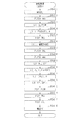
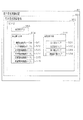
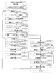
以下、遊技機の一種であるパチンコ機10の第1の実施形態を、図面に基づいて詳細に説明する。図1はパチンコ機10の斜視図、図2はパチンコ機10の主要な構成を分解して示す斜視図である。なお、図2では便宜上パチンコ機10の遊技領域PA内の構成を省略している。
<First Embodiment>
Hereinafter, a first embodiment of a
パチンコ機10は、図1に示すように、当該パチンコ機10の外殻を形成する外枠11と、この外枠11に対して前方に回動可能に取り付けられた遊技機本体12と、を有する。外枠11は木製の板材を四辺に連結し構成されるものであって矩形枠状をなしている。パチンコ機10は、外枠11を島設備に取り付け固定することにより、遊技ホールに設置される。なお、パチンコ機10において外枠11は必須の構成ではなく、遊技ホールの島設備に外枠11が備え付けられた構成としてもよい。
As shown in FIG. 1, the
遊技機本体12は図2に示すように、内枠13と、その内枠13の前方に配置される前扉枠14と、内枠13の後方に配置される裏パックユニット15と、を備えている。遊技機本体12のうち内枠13が外枠11に回動可能に支持されている。詳細には、正面視で左側を回動基端側とし右側を回動先端側として内枠13が前方へ回動可能とされている。
As shown in FIG. 2, the
内枠13には、前扉枠14が回動可能に支持されており、正面視で左側を回動基端側とし右側を回動先端側として前方へ回動可能とされている。また、内枠13には、裏パックユニット15が回動可能に支持されており、正面視で左側を回動基端側とし右側を回動先端側として後方へ回動可能とされている。
A
なお、遊技機本体12には、その回動先端部に施錠装置が設けられており、遊技機本体12を外枠11に対して開放不能に施錠状態とする機能を有しているとともに、前扉枠14を内枠13に対して開放不能に施錠状態とする機能を有している。これらの各施錠状態は、パチンコ機10前面にて露出させて設けられたシリンダ錠17に解錠キーを用いて解錠操作を行うことにより、それぞれ解除される。
In addition, the gaming machine
次に、遊技機本体12の前面側の構成について説明する。
Next, the configuration on the front side of the
内枠13は、外形が外枠11とほぼ同一形状をなす樹脂ベース21を主体に構成されている。樹脂ベース21の中央部には略楕円形状の窓孔23が形成されている。樹脂ベース21には遊技盤24が着脱可能に取り付けられている。遊技盤24は合板よりなり、遊技盤24の前面に形成された遊技領域PAが樹脂ベース21の窓孔23を通じて内枠13の前面側に露出した状態となっている。
The
ここで、遊技盤24の構成を図3に基づいて説明する。図3は遊技盤24の正面図である。
Here, the configuration of the
遊技盤24には、遊技領域PAの外縁の一部を区画するようにして内レール部25と外レール部26とが取り付けられており、これら内レール部25と外レール部26とにより誘導手段としての誘導レールが構成されている。樹脂ベース21において窓孔23の下方に取り付けられた遊技球発射機構27(図2参照)から発射された遊技球は誘導レールにより遊技領域PAの上部に案内されるようになっている。
An
ちなみに、遊技球発射機構27は、誘導レールに向けて延びる発射レール27aと、後述する上皿55aに貯留されている遊技球を発射レール27a上に供給する球送り装置27bと、発射レール27a上に供給された遊技球を誘導レールに向けて発射させる電動アクチュエータであるソレノイド27cと、を備えている。前扉枠14に設けられた発射操作装置(又は操作ハンドル)28が回動操作されることによりソレノイド27cが駆動制御され、遊技球が発射される。
By the way, the game
遊技盤24には、前後方向に貫通する大小複数の開口部が形成されている。各開口部には一般入賞口31、特電入賞装置32、第1作動口33、第2作動口34、スルーゲート35、可変表示ユニット36、特図ユニット37及び普図ユニット38等がそれぞれ設けられている。一般入賞口31は合計で4個設けられており、それ以外はそれぞれ1個ずつ設けられている。
The
スルーゲート35への入球が発生したとしても遊技球の払い出しは実行されない。一方、一般入賞口31、特電入賞装置32、第1作動口33及び第2作動口34への入球が発生すると、所定数の遊技球の払い出しが実行される。当該賞球個数について具体的には、第1作動口33への1個の遊技球の入球が発生した場合又は第2作動口34への1個の遊技球の入球が発生した場合には、1個の賞球の払い出しが実行され、一般入賞口31への1個の遊技球の入球が発生した場合には、10個の賞球の払い出しが実行され、特電入賞装置32への1個の遊技球の入球が発生した場合には、15個の賞球の払い出しが実行される。
Even if a ball enters the through
なお、上記賞球個数は任意であり、例えば、第2作動口34の方が第1作動口33よりも賞球個数が少ない構成としてもよく、第2作動口34の方が第1作動口33よりも賞球個数が多い構成としてもよい。
The number of prize balls is arbitrary, and for example, the number of prize balls may be smaller in the
その他に、遊技盤24の最下部にはアウト口24aが設けられており、各種入賞口等に入らなかった遊技球はアウト口24aを通って遊技領域PAから排出される。また、遊技盤24には、遊技球の落下方向を適宜分散、調整等するために多数の釘24bが植設されているとともに、風車等の各種部材が配設されている。
In addition, an out port 24a is provided at the bottom of the
ここで、入球とは所定の開口部を遊技球が通過することを意味し、開口部を通過した後に遊技領域PAから排出される態様だけではなく、開口部を通過した後に遊技領域PAから排出されることなく遊技領域PAの流下を継続する態様も含まれる。但し、以下の説明では、アウト口24aへの遊技球の入球と明確に区別するために、一般入賞口31、特電入賞装置32、第1作動口33、第2作動口34及びスルーゲート35への遊技球の入球を、入賞とも表現する。
Here, the entry ball means that the game ball passes through a predetermined opening, and not only the mode in which the game ball is discharged from the game area PA after passing through the opening, but also the game area PA after passing through the opening. A mode in which the flow of the game area PA is continued without being discharged is also included. However, in the following description, in order to be clearly distinguished from the game ball entering the out port 24a, a
第1作動口33及び第2作動口34は、作動口装置としてユニット化されて遊技盤24に設置されている。第1作動口33及び第2作動口34は共に上向きに開放されている。また、第1作動口33が上方となるようにして両作動口33,34は鉛直方向に並んでいる。第2作動口34には、左右一対の可動片よりなるガイド片としての普電役物34aが設けられている。普電役物34aの閉鎖状態では遊技球が第2作動口34に入賞できず、普電役物34aが開放状態となることで第2作動口34への入賞が可能となる。
The
第2作動口34よりも遊技球の流下方向の上流側に、スルーゲート35が設けられている。スルーゲート35は縦方向に貫通した図示しない貫通孔を有しており、スルーゲート35に入賞した遊技球は入賞後に遊技領域PAを流下する。これにより、スルーゲート35に入賞した遊技球が第2作動口34へ入賞することが可能となっている。
A through
スルーゲート35への入賞に基づき第2作動口34の普電役物34aが閉鎖状態から開放状態に切り換えられる。具体的には、スルーゲート35への入賞をトリガとして内部抽選が行われるとともに、遊技領域PAにおいて遊技球が通過しない領域である右下の隅部に設けられた普図ユニット38の普図表示部38aにて絵柄の変動表示が行われる。そして、内部抽選の結果が電役開放当選であり当該結果に対応した停止結果が表示されて普図表示部38aの変動表示が終了された場合に普電開放状態へ移行する。普電開放状態では、普電役物34aが所定の態様で開放状態となる。
Based on the winning of the through-gate 35, the general electric accessory 34a of the
なお、普図表示部38aは、LEDによる複数の表示用セグメントが所定の態様で配列されてなるセグメント表示器により構成されているが、これに限定されることはなく、液晶表示装置、有機EL表示装置、CRT又はドットマトリックス表示器等その他のタイプの表示装置によって構成されていてもよい。また、普図表示部38aにて変動表示される絵柄としては、複数種の文字が変動表示される構成、複数種の記号が変動表示される構成、複数種のキャラクタが変動表示される構成又は複数種の色が切り換え表示される構成などが考えられる。 The general-purpose display section 38a is composed of a segment display in which a plurality of display segments by LEDs are arranged in a predetermined manner, but the display section 38a is not limited to this, and a liquid crystal display device, an organic EL device or the like. It may be constituted by another type of display device such as a display device, a CRT or a dot matrix display. Further, as the pattern variably displayed on the universal figure display unit 38a, a configuration in which a plurality of types of characters are variably displayed, a configuration in which a plurality of types of symbols are variably displayed, a configuration in which a plurality of types of characters are variably displayed, or A configuration in which a plurality of types of colors are switched and displayed can be considered.
普図ユニット38において、普図表示部38aに隣接した位置には、普図保留表示部38bが設けられている。遊技球がスルーゲート35に入賞した個数は最大4個まで保留され、普図保留表示部38bの点灯によってその保留個数が表示されるようになっている。
In the
第1作動口33又は第2作動口34への入賞をトリガとして当たり抽選が行われる。そして、当該抽選結果は特図ユニット37及び可変表示ユニット36の図柄表示装置41における表示演出を通じて明示される。
A winning lottery is carried out with the winning of the first working
特図ユニット37について詳細には、特図ユニット37には特図表示部37aが設けられている。特図表示部37aの表示領域は図柄表示装置41の表示面41aよりも狭い。特図表示部37aでは、第1作動口33への入賞又は第2作動口34への入賞をトリガとして当たり抽選が行われることで絵柄の変動表示又は所定の表示が行われる。そして、抽選結果に対応した結果が表示される。なお、特図表示部37aは、LEDによる複数の表示用セグメントが所定の態様で配列されてなるセグメント表示器により構成されているが、これに限定されることはなく、液晶表示装置、有機EL表示装置、CRT又はドットマトリックス表示器等その他のタイプの表示装置によって構成されていてもよい。また、特図表示部37aにて表示される絵柄としては、複数種の文字が表示される構成、複数種の記号が表示される構成、複数種のキャラクタが表示される構成又は複数種の色が表示される構成などが考えられる。
More specifically, the
特図ユニット37において、特図表示部37aに隣接した位置には、特図保留表示部37bが設けられている。遊技球が第1作動口33又は第2作動口34に入賞した個数は最大4個まで保留され、特図保留表示部37bの点灯によってその保留個数が表示されるようになっている。
In the
図柄表示装置41について詳細には、図柄表示装置41は、液晶ディスプレイを備えた液晶表示装置として構成されており、後述する表示制御装置により表示内容が制御される。なお、図柄表示装置41は、液晶表示装置に限定されることはなく、プラズマディスプレイ装置、有機EL表示装置又はCRTといった表示画面を有する他の表示装置であってもよく、ドットマトリクス表示器であってもよい。
In detail about the
図柄表示装置41では、第1作動口33への入賞又は第2作動口34への入賞に基づき特図表示部37aにて絵柄の変動表示又は所定の表示が行われる場合にそれに合わせて図柄の変動表示又は所定の表示が行われる。例えば、図柄表示装置41の表示面41aには、複数の表示領域として上段・中段・下段の3つの図柄列が設定され、各図柄列において「1」〜「9」の数字が付された主図柄が昇順又は降順で配列された状態でスクロール表示される。このスクロール表示においては、最初に全図柄列におけるスクロール表示が開始され、上図柄列→下図柄列→中図柄列の順にスクロール表示から待機表示に切り換えられ、最終的に各図柄列にて所定の図柄を静止表示した状態で終了される。そして、遊技結果が大当たり結果となる遊技回では、図柄表示装置41の表示面41aにおいて予め設定されている有効ライン上に所定の図柄の組み合わせが停止表示される。具体的には、後述する最有利大当たり結果となる場合には同一の奇数図柄の組み合わせが停止表示され、後述する低確大当たり結果となる場合には同一の偶数図柄の組み合わせが停止表示され、後述する低入賞高確大当たり結果となる場合には同一の図柄の組み合わせではないものの低入賞高確大当たり結果ではない場合には停止表示されない図柄の組み合わせが停止表示される。
In the
なお、図柄表示装置41では、第1作動口33又は第2作動口34への入賞をトリガとした表示演出だけではなく、当たり当選となった後に移行する開閉実行モード中の表示演出などが行われる。また、いずれかの作動口33,34への入賞に基づいて、特図表示部37a及び図柄表示装置41にて表示が開始され、所定の結果を表示して終了されるまでが遊技回の1回に相当する。また、図柄表示装置41における図柄の変動表示の態様は上記のものに限定されることはなく任意であり、図柄列の数、図柄列における図柄の変動表示の方向、各図柄列の図柄数などは適宜変更可能である。また、図柄表示装置41にて変動表示される絵柄は上記のような図柄に限定されることはなく、例えば絵柄として数字のみが変動表示される構成としてもよい。
In addition, in the
第1作動口33への入賞又は第2作動口34への入賞に基づく当たり抽選にて大当たり当選となった場合には、特電入賞装置32への入賞が可能となる開閉実行モードへ移行する。特電入賞装置32は、遊技盤24の背面側へと通じる図示しない大入賞口を備えているとともに、当該大入賞口を開閉する開閉扉32aを備えている。開閉扉32aは、閉鎖状態及び開放状態のいずれかに配置される。具体的には、開閉扉32aは、通常は遊技球が入賞できない閉鎖状態になっており、内部抽選において開閉実行モードへの移行に当選した場合に遊技球が入賞可能な開放状態に切り換えられるようになっている。ちなみに、開閉実行モードとは、当たり結果となった場合に移行することとなるモードである。なお、閉鎖状態では入賞が不可ではないが開放状態よりも入賞が発生しづらい状態となる構成としてもよい。
When a big hit is won in the winning lottery based on the winning of the first working
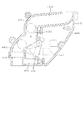
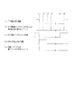
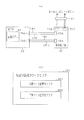
図4は、遊技領域PAを流下した遊技球の排出に関する構成を説明するための説明図である。 FIG. 4 is an explanatory diagram for explaining a configuration related to the discharge of the game balls flowing down the game area PA.
既に説明したとおり、一般入賞口31、特電入賞装置32、第1作動口33、第2作動口34及びアウト口24aのいずれかに入球した遊技球は遊技領域PAから排出される。換言すれば、遊技球発射機構27から発射されて遊技領域PAに流入した遊技球は一般入賞口31、特電入賞装置32、第1作動口33、第2作動口34及びアウト口24aのいずれかに入球することにより遊技領域PAから排出されることとなる。一般入賞口31、特電入賞装置32、第1作動口33、第2作動口34及びアウト口24aのいずれかに入球した遊技球は遊技盤24の背面側に導かれる。
As described above, the game balls that enter the general winning
遊技盤24の背面には、一般入賞口31、特電入賞装置32、第1作動口33、第2作動口34及びアウト口24aのそれぞれに対応させて排出通路部42〜48が形成されている。排出通路部42〜48に流入した遊技球はその流入した排出通路部42〜48を流下することにより、遊技盤24の背面側において遊技盤24の下端部に導かれ図示しない排出球回収部にて回収される。そして、排出球回収部にて回収された遊技球は、遊技ホールにおいてパチンコ機10が設置された島設備の球循環装置に排出される。
On the back surface of the
各排出通路部42〜48には遊技球を検知するための各種検知センサ42a〜48aが設けられている。これら排出通路部42〜48及び検知センサ42a〜48aについて以下に説明する。一般入賞口31は既に説明したとおり4個設けられているため、それら4個のそれぞれに対応させて排出通路部42〜44が存在している。この場合、最も左の一般入賞口31に対応する第1排出通路部42及びその右隣りの一般入賞口31に対応する第2排出通路部43のそれぞれに対しては1個ずつ検知センサ42a,43aが設けられている。具体的には、第1排出通路部42の途中位置に検知範囲が存在するようにして第1入賞口検知センサ42aが設けられているとともに、第2排出通路部43の途中位置に検知範囲が存在するように第2入賞口検知センサ43aが設けられている。最も左の一般入賞口31に入球した遊技球は第1排出通路部42を通過する途中で第1入賞口検知センサ42aにて検知され、その右隣りの一般入賞口31に入球した遊技球は第2排出通路部43を通過する途中で第2入賞口検知センサ43aにて検知される。また、右側2個の一般入賞口31に対しては途中位置で合流するように形成された第3排出通路部44が設けられている。当該第3排出通路部44は、2個の一般入賞口31のそれぞれに対応する入口側領域を有しているとともに、それら入口側領域が途中で合流することで1個の出口側領域を有している。第3排出通路部44における出口側領域の途中位置に検知範囲が存在するように第3入賞口検知センサ44aが設けられている。右側2個のいずれかの一般入賞口31に入球した遊技球は第3排出通路部44を通過する途中で第3入賞口検知センサ44aにて検知される。
特電入賞装置32に対応させて第4排出通路部45が存在している。第4排出通路部45の途中位置に検知範囲が存在するようにして特電検知センサ45aが設けられており、特電入賞装置32に入球した遊技球は第4排出通路部45を通過する途中で特電検知センサ45aにて検知される。第1作動口33に対応させて第5排出通路部46が存在している。第5排出通路部46の途中位置に検知範囲が存在するようにして第1作動口検知センサ46aが設けられており、第1作動口33に入球した遊技球は第5排出通路部46を通過する途中で第1作動口検知センサ46aにて検知される。第2作動口34に対応させて第6排出通路部47が存在している。第6排出通路部47の途中位置に検知範囲が存在するようにして第2作動口検知センサ47aが設けられており、第2作動口34に入球した遊技球は第6排出通路部47を通過する途中で第2作動口検知センサ47aにて検知される。アウト口24aに対応させて第7排出通路部48が存在している。第7排出通路部48の途中位置に検知範囲が存在するようにしてアウト口検知センサ48aが設けられており、アウト口24aに入球した遊技球は第7排出通路部48を通過する途中でアウト口検知センサ48aにて検知される。
The fourth
なお、各種検知センサ42a〜48aのうちいずれか1個の検知センサ42a〜48aにて検知対象となった遊技球は他の検知センサ42a〜48aの検知対象となることはない。また、スルーゲート35に対してもゲート検知センサ49aが設けられており、遊技領域PAを流下する途中でスルーゲート35を通過する遊技球はゲート検知センサ49aにて検知される。
It should be noted that the game ball detected by any one of the
各種検知センサ42a〜49aとしては、いずれも電磁誘導型の近接センサが用いられているが、遊技球を個別に検知できるのであれば使用するセンサは任意である。また、各種検知センサ42a〜49aは後述する主制御装置60と電気的に接続されており、各種検知センサ42a〜49aの検知結果は主制御装置60に出力される。具体的には、各種検知センサ42a〜49aは、遊技球を検知していない状況ではLOWレベル信号を出力し、遊技球を検知している状況ではHIレベル信号を出力する。なお、これに限定されることはなくHI及びLOWの関係が逆であってもよい。
An electromagnetic induction type proximity sensor is used as each of the
図2に示すように、上記構成の遊技盤24が樹脂ベース21に取り付けられてなる内枠13の前面側全体を覆うようにして前扉枠14が設けられている。前扉枠14には、図1に示すように、遊技領域PAのほぼ全域を前方から視認することができるようにした窓部51が形成されている。窓部51は、略楕円形状をなし、窓パネル52が嵌め込まれている。窓パネル52は、ガラスによって無色透明に形成されているが、これに限定されることはなく合成樹脂によって無色透明に形成されていてもよく、パチンコ機10前方から窓パネル52を通じて遊技領域PAを視認可能であれば有色透明に形成されていてもよい。
As shown in FIG. 2, the
窓部51の上方には表示発光部53が設けられている。また、遊技状態に応じた効果音などが出力される左右一対のスピーカ部54が設けられている。また、窓部51の下方には、手前側へ膨出した上側膨出部55と下側膨出部56とが上下に並設されている。上側膨出部55内側には上方に開口した上皿55aが設けられており、下側膨出部56内側には同じく上方に開口した下皿56aが設けられている。上皿55aは、後述する払出装置より払い出された遊技球を一旦貯留し、一列に整列させながら遊技球発射機構27側へ導くための機能を有する。また、下皿56aは、上皿55a内にて余剰となった遊技球を貯留する機能を有する。
A display
次に、遊技機本体12の背面側の構成について説明する。
Next, the configuration of the back side of the
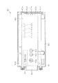
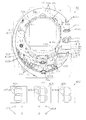
図2に示すように、内枠13(具体的には、遊技盤24)の背面には、遊技の主たる制御を司る主制御装置60が搭載されている。図5は主制御装置60の正面図である。
As shown in FIG. 2, on the back surface of the inner frame 13 (specifically, the game board 24), a
主制御装置60は、図5に示すように、主制御基板61が基板ボックス60aに収容されてなる。主制御基板61の一方の板面である素子搭載面には、MPU62が搭載されている。基板ボックス60aは当該基板ボックス60aの外部から当該基板ボックス60a内に収容されたMPU62を目視することが可能となるように透明に形成されている。なお、基板ボックス60aは無色透明に形成されているが、基板ボックス60aの外部から当該基板ボックス60a内に収容されたMPU62を目視することが可能であれば有色透明に形成されていてもよい。主制御装置60は基板ボックス60aにおいて主制御基板61の素子搭載面と対向する対向壁部60bがパチンコ機10後方を向くようにして樹脂ベース21の背面に搭載されている。したがって、遊技機本体12を外枠11に対してパチンコ機10前方に開放させて樹脂ベース21の背面を露出させることにより、基板ボックス60aの対向壁部60bを目視することが可能となるとともに当該対向壁部60bを通じてMPU62を目視することが可能となる。
As shown in FIG. 5, the
基板ボックス60aは複数のケース体60cを前後に組合せることにより形成されているが、これら複数のケース体60cには、これらケース体60cの分離を阻止するとともにこれらケース体60cの分離に際してその痕跡を残すための結合部60eが設けられている。結合部60eは、略直方体形状の基板ボックス60aにおける一辺に複数並設されている。これにより、一部の結合部60eを利用してケース体60cの分離を阻止している状態において当該一部の結合部60eを破壊してケース体60cを分離したとしても、その後に別の結合部60eを結合状態とすることでケース体60cの分離を再度阻止することが可能となる。また、ケース体60cの分離に際して結合部60eが破壊されてその痕跡が残ることにより、結合部60eを目視確認することでケース体60cの分離が不正に行われているか否かを把握することが可能となる。また、基板ボックス60aにおいて結合部60eが並設された一辺とは逆の一辺にはケース体60c間の境界を跨ぐようにして封印シール60fが貼り付けられている。封印シール60fはその引き剥がしに際して粘着層がケース体60cに残る。これにより、ケース体60cの分離に際して封印シール60fが剥がされた場合にはその痕跡を残すことが可能となる。
The
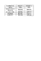
上記構成の主制御装置60において主制御基板61には、パチンコ機10の設定状態を「設定1」から「設定6」の範囲で変更する契機を生じさせるために遊技ホールの管理者が所有する設定キーが挿入されてON操作される設定キー挿入部68aと、設定キー挿入部68aに対するON操作後においてパチンコ機10の設定状態を順次変更させるために操作される更新ボタン68bと、主制御装置60のMPU62に設けられた後述する主側RAM65のデータをクリアするために操作されるリセットボタン68cと、遊技履歴の管理結果を報知するための第1〜第3報知用表示装置69a〜69cと、が設けられている。また、主制御基板61に搭載されたMPU62には、遊技履歴の管理結果又は主側ROM64に記憶された情報(プログラム及びデータ)を外部装置にて読み取るために当該外部装置の接続端子を接続するための読み取り用端子68dが設けられている。なお、パチンコ機10の設定状態は「設定1」〜「設定6」の6段階に限定されることはなく複数段階であれば任意である。
In the
これら設定キー挿入部68a、更新ボタン68b、リセットボタン68c、読み取り用端子68d(すなわちMPU62)及び第1〜第3報知用表示装置69a〜69cはいずれも主制御基板61の素子搭載面に設けられている。また、主制御基板61の素子搭載面は既に説明したとおり基板ボックス60aの対向壁部60bと対向しているが、設定キー挿入部68a、更新ボタン68b、リセットボタン68c及び読み取り用端子68dは対向壁部60bにより覆われていない。つまり、対向壁部60bには設定キー挿入部68a、更新ボタン68b、リセットボタン68c及び読み取り用端子68dのそれぞれと対向する領域が個別の開口部とされている。これにより、基板ボックス60aの開放を要することなく、設定キー挿入部68aに設定キーを挿入することが可能であり、更新ボタン68bを押圧操作することが可能であり、リセットボタン68cを押圧操作することが可能であり、読み取り用端子68dに外部装置の接続端子を接続することが可能である。
The setting
設定キー挿入部68aに設定キーを挿入して所定方向に回転操作することにより設定キー挿入部68aがON操作された状態となる。その状態でパチンコ機10への動作電力の供給を開始させることで(すなわち主制御装置60のMPU62への動作電力の供給を開始させることで)、パチンコ機10の設定状態を変更することが可能な変更可能状態となる。そして、この状態において更新ボタン68bを1回押圧操作する度にパチンコ機10の設定状態が「設定1」〜「設定6」の範囲において昇順で1段階ずつ変更される。なお、「設定6」の状態で更新ボタン68bが操作された場合には「設定1」に更新される。また、設定キー挿入部68aに挿入している設定キーをON操作の位置から所定方向とは反対方向に回転操作して初期位置に復帰させることにより設定キー挿入部68aがOFF操作された状態となる。設定キー挿入部68aがOFF操作された状態となることで上記変更可能状態が終了し、その時点における設定値の状態で遊技を行うことが可能な状態となる。つまり、変更可能状態が終了した後に更新ボタン68bを操作しても設定値を変更することはできない。
By inserting the setting key into the setting
設定キー挿入部68aに対するON操作はパチンコ機10への動作電力の供給開始時(すなわち主制御装置60のMPU62への動作電力の供給開始時)のみ有効とされる。したがって、主制御装置60のMPU62において動作電力の供給開始時の処理が終了した後に設定キー挿入部68aに対するON操作を行ったとしても設定値を変更することはできない。
The ON operation to the setting
パチンコ機10の設定状態は当該パチンコ機10における単位時間当たりの有利度を定めるものであり、「設定n」(nは「1」〜「6」の整数)のnが大きい値ほど(すなわち設定値が高いほど)有利度が高くなる。詳細は後述するが大当たり結果の当選確率を決定する当否抽選モードとして相対的に当選確率が低くなる低確率モードと相対的に当選確率が高くなる高確率モードとが存在しており、設定値が高いほど低確率モードにおける大当たり結果の当選確率が高くなるように設定されている。一方、いずれの設定値であっても高確率モードにおける大当たり結果の当選確率は一定となっている。
The setting state of the
リセットボタン68cは上記のとおり主側RAM65のデータをクリアするために操作されるが、当該データのクリアを発生させるためにはリセットボタン68cを押圧操作した状態でパチンコ機10への動作電力の供給を開始させる必要がある(すなわち主制御装置60のMPU62への動作電力の供給を開始させる必要がある)。リセットボタン68cに対するON操作はパチンコ機10への動作電力の供給開始時(すなわち主制御装置60のMPU62への動作電力の供給開始時)のみ有効とされる。したがって、主制御装置60のMPU62において動作電力の供給開始時の処理が終了した後にリセットボタン68cを押圧操作したとしても主側RAM65のデータのクリアを行うことはできない。
The
読み取り用端子68dは既に説明したとおり遊技履歴の管理結果又は主側ROM64に記憶された情報(プログラム及びデータ)を外部装置にて読み取るために当該外部装置の接続端子が接続されるが、外部装置への外部出力を行うためには読み取り用端子68dに外部装置の接続端子を接続した状態でパチンコ機10への動作電力の供給を開始させる必要がある(すなわち主制御装置60のMPU62への動作電力の供給を開始させる必要がある)。読み取り用端子68dに対する外部装置の接続はパチンコ機10への動作電力の供給開始時(すなわち主制御装置60のMPU62への動作電力の供給開始時)のみ有効とされる。したがって、主制御装置60のMPU62において動作電力の供給開始時の処理が終了した後に読み取り用端子68dに外部装置を接続したとしても当該外部装置への外部出力は行われない。
As described above, the reading
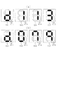
第1〜第3報知用表示装置69a〜69cはいずれも、LEDによる表示用セグメントが7個配列されたセグメント表示器であるが、これに限定されることはなく多色発光タイプの単一の発光体であってもよく、液晶表示装置であってもよく、有機ELディスプレイであってもよい。第1〜第3報知用表示装置69a〜69cはいずれもその表示面が主制御基板61の素子搭載面が向く方向を向くようにして設置されているとともに、基板ボックス60aの対向壁部60bにより覆われている。この場合に、基板ボックス60aが透明に形成されていることにより、基板ボックス60aの外部から当該基板ボックス60a内に収容された第1〜第3報知用表示装置69a〜69cの表示面を目視することが可能となる。また、既に説明したとおり主制御装置60は基板ボックス60aにおいて主制御基板61の素子搭載面と対向する対向壁部60bがパチンコ機10後方を向くようにして樹脂ベース21の背面に搭載されているため、遊技機本体12を外枠11に対してパチンコ機10前方に開放させて樹脂ベース21の背面をパチンコ機10前方に露出させた場合には、対向壁部60bを通じて第1〜第3報知用表示装置69a〜69cの表示面を目視することが可能となる。
Each of the first to third
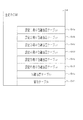
第1報知用表示装置69aの表示面においては「0」〜「9」の数字だけではなく、アルファベット文字を含めた各種文字が表示される。一方、第2報知用表示装置69b及び第3報知用表示装置69cにおいては「0」〜「9」の数字が表示される。第1〜第3報知用表示装置69a〜69cを利用して遊技履歴の管理結果が報知されるが、この報知内容については後に詳細に説明する。また、パチンコ機10の設定状態を変更することが可能な変更可能状態においては現状の設定値に対応する値が第3報知用表示装置69cにて表示される。なお、当該設定値に対応する値が第1報知用表示装置69aにて表示される構成としてもよく、第2報知用表示装置69bにて表示される構成としてもよい。また、変更可能状態となる前における設定値が第1〜第3報知用表示装置69a〜69cのうちの一の報知用表示装置にて表示されるとともに現状の設定値が第1〜第3報知用表示装置69a〜69cのうちの他の一の報知用表示装置にて表示される構成としてもよい。
On the display surface of the first
図2に示すように、主制御装置60を含めて内枠13の背面側を覆うようにして裏パックユニット15が設置されている。裏パックユニット15は、透明性を有する合成樹脂により形成された裏パック72を備えており、当該裏パック72に払出機構部73及び制御装置集合ユニット74が取り付けられている。
As shown in FIG. 2, the
払出機構部73は、遊技ホールの島設備から供給される遊技球が逐次補給されるタンク75と、当該タンク75に貯留された遊技球を払い出すための払出装置76と、を備えている。払出装置76より払い出された遊技球は、当該払出装置76の下流側に設けられた払出通路を通じて、上皿55a又は下皿56aに排出される。なお、払出機構部73には、例えば交流24ボルトの主電源が供給されるとともに、電源のON操作及びOFF操作を行うための電源スイッチを有する裏パック基板が搭載されている。
The
制御装置集合ユニット74は、払出装置76を制御する機能を有する払出制御装置77と、各種制御装置等で要する所定の電力が生成されて出力されるとともに遊技者による発射操作装置28の操作に伴う遊技球の打ち出しの制御が行われる電源・発射制御装置78と、を備えている。これら払出制御装置77と電源・発射制御装置78とは、払出制御装置77がパチンコ機10後方となるように前後に重ねて配置されている。
The control
<パチンコ機10の電気的構成>
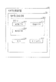
図6は、パチンコ機10の電気的構成を示すブロック図である。
<Electrical structure of the
FIG. 6 is a block diagram showing an electrical configuration of the
主制御装置60は、遊技の主たる制御を司る主制御基板61と、電源を監視する停電監視基板67と、を具備している。主制御基板61には、MPU62が搭載されている。MPU62には、制御部及び演算部を含む演算処理装置である主側CPU63の他に、主側ROM64、主側RAM65及び管理用IC66が内蔵されている。なお、MPU62には、上記素子以外に、割込回路、タイマ回路、データ入出力回路、乱数発生器としての各種カウンタ回路などが内蔵されている。
The
主側ROM64は、NOR型フラッシュメモリ及びNAND型フラッシュメモリなどの記憶保持に外部からの電力供給が不要なメモリ(すなわち、不揮発性記憶手段)であり、読み出し専用として利用される。主側ROM64は、主側CPU63により実行される各種の制御プログラムや固定値データを記憶している。
The main-
主側RAM65は、SRAM及びDRAMなどの記憶保持に外部からの電力供給が必要なメモリ(すなわち、揮発性記憶手段)であり、読み書き両用として利用される。主側RAM65は、ランダムアクセスが可能であるとともに、同一のデータ容量で比較した場合に主側ROM64よりも読み出しに要する時間が早いものとなっている。主側RAM65は、主側ROM64内に記憶されている制御プログラムの実行に対して各種のデータなどを一時的に記憶する。
The
管理用IC66は、主側CPU63から供給された情報に基づいて遊技履歴を管理する管理装置である。詳細は後述するが、管理用IC66にて一般入賞口31、特電入賞装置32、第1作動口33、第2作動口34及びアウト口24aへの遊技球の入球履歴が把握されるとともに、その把握された入球履歴に応じて一般入賞口31、特電入賞装置32、第1作動口33及び第2作動口34への入球頻度が把握される。また、管理用IC66にて後述する開閉実行モード及び高頻度サポートモードの発生頻度が把握される。
The
MPU62には、入力ポート及び出力ポートがそれぞれ設けられている。MPU62の入力側には主制御装置60に設けられた停電監視基板67及び払出制御装置77が接続されている。停電監視基板67には動作電力を供給する機能を有する電源・発射制御装置78が接続されており、MPU62には停電監視基板67を介して動作電力が供給される。
The
MPU62の入力側には、各入球検知センサ42a〜49aといった各種センサが接続されている。各入球検知センサ42a〜49aには、既に説明したとおり、第1入賞口検知センサ42a、第2入賞口検知センサ43a、第3入賞口検知センサ44a、特電検知センサ45a、第1作動口検知センサ46a、第2作動口検知センサ47a、アウト口検知センサ48a及びゲート検知センサ49aが含まれる。これら入球検知センサ42a〜49aの検知結果に基づいて、主側CPU63にて各入球部への入球判定が行われる。また、主側CPU63では第1作動口33への入賞に基づいて各種抽選が実行されるとともに第2作動口34への入賞に基づいて各種抽選が実行される。
Various sensors such as the
MPU62の入力側には、主制御基板61に設けられた設定キー挿入部68a、更新ボタン68b及びリセットボタン68cが設けられている。設定キー挿入部68aには図示しないセンサが設けられており、当該センサにより当該設定キー挿入部68aがON操作の位置及びOFF操作の位置のいずれに配置されているのかが検知される。そして、主側CPU63はそのセンサからの検知結果に基づいて設定キー挿入部68aがON操作の位置及びOFF操作の位置のいずれに配置されているのかを特定する。更新ボタン68bには図示しないセンサが設けられており、当該センサにより更新ボタン68bが押圧操作されているか否かが検知される。そして、主側CPU63はそのセンサからの検知結果に基づいて更新ボタン68bが押圧操作されているか否かを特定する。リセットボタン68cには図示しないセンサが設けられており、当該センサによりリセットボタン68cが押圧操作されているか否かが検知される。そして、主側CPU63はそのセンサからの検知結果に基づいてリセットボタン68cが押圧操作されているか否かを特定する。
On the input side of the
MPU62の出力側には、停電監視基板67、払出制御装置77及び音声発光制御装置81が接続されている。払出制御装置77には、例えば、上記入球部のうち入球の発生が遊技球の払い出しに対応する賞球対応入球部に遊技球が入球したことに基づいて賞球コマンドが出力される。音声発光制御装置81には、変動用コマンド、種別コマンド及びオープニングコマンドなどの各種コマンドが出力される。
A power
MPU62の出力側には、特電入賞装置32の開閉扉32aを開閉動作させる特電用の駆動部32b、第2作動口34の普電役物34aを開閉動作させる普電用の駆動部34b、特図ユニット37及び普図ユニット38が接続されている。ちなみに、特図ユニット37には、特図表示部37a及び特図保留表示部37bが設けられているが、これらの全てがMPU62の出力側に接続されている。同様に、普図ユニット38には、普図表示部38a及び普図保留表示部38bが設けられているが、これらの全てがMPU62の出力側に接続されている。主制御基板61には各種ドライバ回路が設けられており、当該ドライバ回路を通じてMPU62は各種駆動部及び各種表示部の駆動制御を実行する。
On the output side of the
つまり、開閉実行モードにおいては特電入賞装置32が開閉されるように、主側CPU63において特電用の駆動部32bの駆動制御が実行される。また、普電役物34aの開放状態当選となった場合には、普電役物34aが開閉されるように、主側CPU63において普電用の駆動部34bの駆動制御が実行される。また、各遊技回に際しては、主側CPU63において特図表示部37aの表示制御が実行される。また、普電役物34aを開放状態とするか否かの抽選結果を明示する場合に、主側CPU63において普図表示部38aの表示制御が実行される。また、第1作動口33若しくは第2作動口34への入賞が発生した場合、又は特図表示部37aにおいて変動表示が開始される場合に、主側CPU63において特図保留表示部37bの表示制御が実行され、スルーゲート35への入賞が発生した場合、又は普図表示部38aにおいて変動表示が開始される場合に、主側CPU63において普図保留表示部38bの表示制御が実行される。
That is, in the opening/closing execution mode, the
MPU62の出力側には第1〜第3報知用表示装置69a〜69cが接続されている。また、管理用IC66における遊技履歴の管理結果が第1〜第3報知用表示装置69a〜69cにおける表示を通じて報知される。また、パチンコ機10の設定状態の変更に際しては第3報知用表示装置69cにて現状の設定値が表示される。この場合、第1報知用表示装置69a及び第2報知用表示装置69bは管理用IC66により表示制御され主側CPU63により表示制御されないのに対して、第3報知用表示装置69cは主側CPU63により表示制御されるとともに管理用IC66により表示制御される。第3報知用表示装置69cの表示は管理用IC66による表示制御よりも主側CPU63による表示制御が優先される。
First to third
但し、これに限定されることはなく第3報知用表示装置69cについても管理用IC66により表示制御され主側CPU63により表示制御されない構成としてもよい。この場合、パチンコ機10の設定状態の変更に際して第3報知用表示装置69cにて現状の設定値を表示する場合には主側CPU63から管理用IC66に設定値の表示指示が行われる構成とするとよい。
However, the present invention is not limited to this, and the third
MPU62には読み取り用端子68dが設けられている。読み取り用端子68dには図示しないセンサが設けられており、当該センサにより読み取り用端子68dに外部装置の接続端子が接続されているか否かが検知される。そして、主側CPU63はそのセンサからの検知結果に基づいて読み取り用端子68dに外部装置の接続端子が接続されているか否かを特定する。また、読み取り用端子68dに外部装置が接続されている場合、管理用IC66における遊技履歴の管理結果又は主側ROM64に記憶された情報(プログラム及びデータ)が当該外部装置に外部出力される。
The
停電監視基板67は、主制御基板61と電源・発射制御装置78とを中継し、電源・発射制御装置78から出力される最大電圧である直流安定24ボルトの電圧を監視する。払出制御装置77は、主制御装置60から受信した賞球コマンドに基づいて、払出装置76により賞球や貸し球の払出制御を行うものである。
The power
電源・発射制御装置78は、例えば、遊技ホール等における商用電源(外部電源)に接続されている。そして、その商用電源から供給される外部電力に基づいて主制御基板61や払出制御装置77等に対して各々に必要な動作電力を生成するとともに、その生成した動作電力を供給する。ちなみに、電源・発射制御装置78にはバックアップ用コンデンサなどの電断時用電源部が設けられており、パチンコ機10の電源がOFF状態の場合であっても当該電断時用電源部から主制御装置60の主側RAM65及び払出制御装置77に記憶保持用の電力が供給される。また、電源・発射制御装置78は遊技球発射機構27の発射制御を担うものであり、遊技球発射機構27は所定の発射条件が整っている場合に駆動される。また、払出機構部73には既に説明したとおり電源スイッチが設けられており、電源スイッチがON操作されることによりパチンコ機10への動作電力の供給が開始され、電源スイッチがOFF操作されることによりパチンコ機10への動作電力の供給が停止される。
The power supply/
音声発光制御装置81は、主制御装置60から受信した各種コマンドに基づいて、前扉枠14に設けられた表示発光部53及びスピーカ部54を駆動制御するとともに、表示制御装置82を制御するものである。表示制御装置82は、音声発光制御装置81から受信したコマンドに基づいて、図柄表示装置41の表示制御を実行する。
The sound
<主側CPU63にて各種抽選を行うための電気的構成>
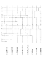
次に、主側CPU63にて各種抽選を行うための電気的な構成について図7を用いて説明する。
<Electrical structure for performing various lottery in the
Next, an electrical configuration for the
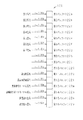
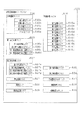
主側CPU63は遊技に際し各種カウンタ情報を用いて、大当たり発生抽選、特図表示部37aの表示の設定、図柄表示装置41の図柄表示の設定、普図表示部38aの表示の設定などを行うこととしており、具体的には、図7に示すように、当たり発生の抽選に使用する当たり乱数カウンタC1と、大当たり種別を判定する際に使用する大当たり種別カウンタC2と、図柄表示装置41が外れ変動する際のリーチ発生抽選に使用するリーチ乱数カウンタC3と、当たり乱数カウンタC1の初期値設定に使用する乱数初期値カウンタCINIと、特図表示部37a及び図柄表示装置41における表示継続時間を決定する変動種別カウンタCSと、を用いることとしている。さらに、第2作動口34の普電役物34aを普電開放状態とするか否かの抽選に使用する普電役物開放カウンタC4を用いることとしている。なお、上記各カウンタC1〜C3,CINI,CS,C4は、主側RAM65の各種カウンタエリア65bに設けられている。
The main side CPU63 uses the various counter information at the time of the game, and performs the jackpot occurrence lottery, the setting of the display of the special
各カウンタC1〜C3,CINI,CS,C4は、その更新の都度前回値に1が加算され、最大値に達した後に「0」に戻るループカウンタとなっている。各カウンタは短時間間隔で更新される。当たり乱数カウンタC1、大当たり種別カウンタC2及びリーチ乱数カウンタC3に対応した情報は、第1作動口33又は第2作動口34への入賞が発生した場合に、主側RAM65に取得情報記憶手段として設けられた保留格納エリア65aに格納される。
Each of the counters C1 to C3, CINI, CS and C4 is a loop counter in which 1 is added to the previous value each time it is updated, and after reaching the maximum value, it returns to "0". Each counter is updated at short time intervals. The information corresponding to the winning random number counter C1, the jackpot type counter C2, and the reach random number counter C3 is provided as acquisition information storage means in the
保留格納エリア65aは、保留用エリアREと、実行エリアAEとを備えている。保留用エリアREは、第1保留エリアRE1、第2保留エリアRE2、第3保留エリアRE3及び第4保留エリアRE4を備えており、第1作動口33又は第2作動口34への入賞履歴に合わせて、当たり乱数カウンタC1、大当たり種別カウンタC2及びリーチ乱数カウンタC3の各数値情報の組合せが保留情報として、いずれかの保留エリアRE1〜RE4に格納される。
The hold storage area 65a includes a hold area RE and an execution area AE. The holding area RE includes a first holding area RE1, a second holding area RE2, a third holding area RE3, and a fourth holding area RE4, and the winning history of the first working
この場合、第1保留エリアRE1〜第4保留エリアRE4には、第1作動口33又は第2作動口34への入賞が複数回連続して発生した場合に、第1保留エリアRE1→第2保留エリアRE2→第3保留エリアRE3→第4保留エリアRE4の順に各数値情報が時系列的に格納されていく。このように4つの保留エリアRE1〜RE4が設けられていることにより、第1作動口33又は第2作動口34への遊技球の入賞履歴が最大4個まで保留記憶されるようになっている。
In this case, in the first holding area RE1 to the fourth holding area RE4, when the winning of the first working
なお、保留記憶可能な数は、4個に限定されることはなく任意であり、2個、3個又は5個以上といったように他の複数であってもよく、単数であってもよい。 Note that the number that can be reserved and stored is not limited to four, and may be any number, and may be another number such as two, three, or five or more, or may be a single number.
実行エリアAEは、特図表示部37aの変動表示を開始する際に、保留用エリアREの第1保留エリアRE1に格納された各数値情報を移動させるためのエリアであり、1遊技回の開始に際しては実行エリアAEに記憶されている各種数値情報に基づいて、当否判定などが行われる。
The execution area AE is an area for moving each numerical value information stored in the first holding area RE1 of the holding area RE when starting the variable display of the special
上記各カウンタについて詳細に説明する。 Each of the above counters will be described in detail.
まず、普電役物開放カウンタC4について説明する。普電役物開放カウンタC4は、例えば、0〜250の範囲内で順に1ずつ加算され、最大値に達した後に「0」に戻る構成となっている。普電役物開放カウンタC4は定期的に更新され、スルーゲート35に遊技球が入賞したタイミングで主側RAM65の普電保留エリア65cに格納される。そして、所定のタイミングにおいて、その格納された普電役物開放カウンタC4の値によって普電役物34aを開放状態に制御するか否かの抽選が行われる。
First, the general electric accessory release counter C4 will be described. For example, the ordinary electric accessory release counter C4 is configured to be sequentially incremented by 1 in the range of 0 to 250, and returned to "0" after reaching the maximum value. The ordinary electric accessory release counter C4 is regularly updated and is stored in the ordinary electric
本パチンコ機10では、普電役物34aによるサポートの態様が相互に異なるように複数種類のサポートモードが設定されている。詳細には、サポートモードには、遊技領域PAに同様の態様で遊技球の発射が継続されている状況で比較した場合に、第2作動口34の普電役物34aが単位時間当たりに開放状態となる頻度が相対的に高低となるように、高頻度サポートモードと低頻度サポートモードとが設定されている。
In the
高頻度サポートモードと低頻度サポートモードとでは、普電役物開放カウンタC4を用いた普電開放抽選における普電開放状態当選となる確率は同一(例えば、共に4/5)となっているが、高頻度サポートモードでは低頻度サポートモードよりも、普電開放状態当選となった際に普電役物34aが開放状態となる回数が多く設定されており、さらに1回の開放時間が長く設定されている。この場合、高頻度サポートモードにおいて普電開放状態当選となり普電役物34aの開放状態が複数回発生する場合において、1回の開放状態が終了してから次の開放状態が開始されるまでの閉鎖時間は、1回の開放時間よりも短く設定されている。さらにまた、高頻度サポートモードでは低頻度サポートモードよりも、1回の普電開放抽選が行われてから次の普電開放抽選が行われる上で最低限確保される確保時間(すなわち、普図表示部38aにおける1回の表示継続時間)が短く設定されている。 In the high-frequency support mode and the low-frequency support mode, the probability of winning the ordinary electric open state in the ordinary electric lottery using the ordinary electric outlet release counter C4 is the same (for example, both are 4/5). In the high frequency support mode, the number of times that the general electric accessory 34a is in the open state when the general electric open state is won is set to a larger number than in the low frequency support mode, and the opening time of one time is set longer. Has been done. In this case, in the high-frequency support mode, when the general electric open state is elected and the general electric auditors a thing 34a is opened a plurality of times, from the end of one open state to the start of the next open state. The closing time is set shorter than one opening time. Furthermore, in the high-frequency support mode, the minimum securing time (that is, in the general map The one-time display duration on the display section 38a is set to be short.
上記のとおり、高頻度サポートモードでは、低頻度サポートモードよりも第2作動口34への入賞が発生する確率が高くなる。換言すれば、低頻度サポートモードでは、第2作動口34よりも第1作動口33への入賞が発生する確率が高くなるが、高頻度サポートモードでは、第1作動口33よりも第2作動口34への入賞が発生する確率が高くなる。そして、第2作動口34への入賞が発生した場合には、所定個数の遊技球の払出が実行されるため、高頻度サポートモードでは、遊技者は持ち球をあまり減らさないようにしながら遊技を行うことができる。
As described above, in the high frequency support mode, the probability of winning the
なお、高頻度サポートモードを低頻度サポートモードよりも単位時間当たりに普電開放状態となる頻度を高くする上での構成は、上記のものに限定されることはなく、例えば普電開放抽選における普電開放状態当選となる確率を高くする構成としてもよい。また、1回の普電開放抽選が行われてから次の普電開放抽選が行われる上で確保される確保時間(例えば、スルーゲート35への入賞に基づき普図表示部38aにて実行される変動表示の時間)が複数種類用意されている構成においては、高頻度サポートモードでは低頻度サポートモードよりも、短い確保時間が選択され易い又は平均の確保時間が短くなるように設定されていてもよい。さらには、開放回数を多くする、開放時間を長くする、1回の普電開放抽選が行われてから次の普電開放抽選が行われる上で確保される確保時間を短くする、係る確保時間の平均時間を短くする及び当選確率を高くするのうち、いずれか1条件又は任意の組合せの条件を適用することで、低頻度サポートモードに対する高頻度サポートモードの有利性を高めてもよい。 Note that the configuration for increasing the frequency of the high frequency support mode to be in the general electric open state per unit time more than the low frequency support mode is not limited to the above, and for example, in the general electric open lottery. It may be configured to increase the probability of winning the ordinary electric open state. In addition, a securing time that is ensured when the next ordinary electric train open lottery is performed after one ordinary electric train open lottery is performed (for example, it is executed in the universal map display portion 38a based on the winning of the through gate 35). In the configuration where multiple types of variable display time) are prepared, the high-frequency support mode is set so that a shorter securing time can be selected more easily or the average securing time is shorter than in the low-frequency support mode. Good. Furthermore, the number of times of opening is increased, the time of opening is lengthened, and the securing time that is secured when the next ordinary electric train opening lottery is performed after one ordinary electric train opening lottery is shortened. The advantage of the high frequency support mode over the low frequency support mode may be increased by applying any one condition or a condition of any combination of shortening the averaging time and increasing the winning probability.
ここで、既に説明したとおりパチンコ機10には「設定1」〜「設定6」の設定状態が存在しているが、低頻度サポートモードにおける普電役物34aの開放頻度及び開放態様はいずれの設定値であっても同一であるとともに、高頻度サポートモードにおける普電役物34aの開放頻度及び開放態様もいずれの設定値であっても同一となっている。但し、これに限定されることはなく、低頻度サポートモード及び高頻度サポートモードの少なくとも一方について普電役物34aの開放頻度及び開放態様の少なくとも一方がパチンコ機10の設定状態に応じて変動する構成としてもよい。例えば設定値が高いほど、低頻度サポートモードにおいて普電役物34aの開放頻度が高くなる構成としてもよく、低頻度サポートモードにおいて普電役物34aが1回開放状態となる場合における第2作動口34への遊技球の入球確率が高くなる構成としてもよい。また、設定値が高いほど、高頻度サポートモードにおいて普電役物34aの開放頻度が高くなる構成としてもよく、高頻度サポートモードにおいて普電役物34aが1回開放状態となる場合における第2作動口34への遊技球の入球確率が高くなる構成としてもよい。
Here, although the setting states of “setting 1” to “setting 6” exist in the
次に、当たり乱数カウンタC1について説明する。当たり乱数カウンタC1は、例えば0〜599の範囲内で順に1ずつ加算され、最大値に達した後に「0」に戻る構成となっている。特に当たり乱数カウンタC1が1周した場合、その時点の乱数初期値カウンタCINIの値が当該当たり乱数カウンタC1の初期値として読み込まれる。なお、乱数初期値カウンタCINIは、当たり乱数カウンタC1と同様のループカウンタである(値=0〜599)。当たり乱数カウンタC1は定期的に更新され、遊技球が第1作動口33又は第2作動口34に入賞したタイミングで主側RAM65の保留格納エリア65aに格納される。
Next, the winning random number counter C1 will be described. The hit random number counter C1 is configured to be incremented by 1 in order within a range of 0 to 599, for example, and returns to "0" after reaching the maximum value. In particular, when the hit random number counter C1 makes one round, the value of the random number initial value counter CINI at that time is read as the initial value of the hit random number counter C1. The random number initial value counter CINI is a loop counter similar to the random number counter C1 (value=0 to 599). The hit random number counter C1 is regularly updated and is stored in the reserved storage area 65a of the
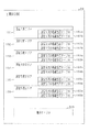
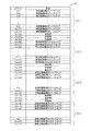
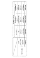
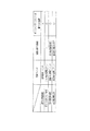
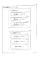
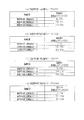
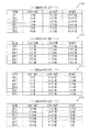
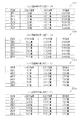
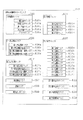
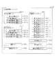
大当たり当選となる乱数の値は、主側ROM64に当否テーブルとして記憶されている。図8は主側ROM64に記憶されている各種テーブルを説明するための説明図である。当否テーブルとして、低確率モード用の低確当否テーブル64a〜64fと、高確率モード用の高確当否テーブル64gとが記憶されている。
The value of the random number that wins the jackpot is stored in the
低確当否テーブル64a〜64fは、「設定1」〜「設定6」の設定状態に1対1で対応させて設けられている。つまり、パチンコ機10の設定状態が「設定1」である場合に参照される設定1用の低確当否テーブル64aと、パチンコ機10の設定状態が「設定2」である場合に参照される設定2用の低確当否テーブル64bと、パチンコ機10の設定状態が「設定3」である場合に参照される設定3用の低確当否テーブル64cと、パチンコ機10の設定状態が「設定4」である場合に参照される設定4用の低確当否テーブル64dと、パチンコ機10の設定状態が「設定5」である場合に参照される設定5用の低確当否テーブル64eと、パチンコ機10の設定状態が「設定6」である場合に参照される設定6用の低確当否テーブル64fと、が存在している。
The low probability hit/miss tables 64a to 64f are provided in one-to-one correspondence with the setting states of "setting 1" to "setting 6". That is, the low probability table 64a for setting 1 referred to when the setting state of the
これら低確当否テーブル64a〜64fは高い設定値ほど大当たり結果の当選確率が高くなるように設定されている。具体的には、設定1用の低確当否テーブル64aが参照された場合には約1/320で大当たり結果となり、設定2用の低確当否テーブル64bが参照された場合には約1/310で大当たり結果となり、設定3用の低確当否テーブル64cが参照された場合には約1/300で大当たり結果となり、設定4用の低確当否テーブル64dが参照された場合には約1/290で大当たり結果となり、設定5用の低確当否テーブル64eが参照された場合には約1/280で大当たり結果となり、設定6用の低確当否テーブル64fが参照された場合には約1/270で大当たり結果となる。これにより、パチンコ機10の設定状態が高い設定値である方が低確率モードにおいて大当たり結果が発生し易くなり、遊技者にとって有利となる。
These low certainty win/loss tables 64a to 64f are set such that the higher the set value, the higher the winning probability of the jackpot result. Specifically, when the low probability hit table 64a for setting 1 is referred to, a big hit result is obtained at about 1/320, and when the low probability hit table 64b for setting 2 is referred to, about 1/310. Results in a big hit, and when the low probability table 64c for setting 3 is referred to, the result is about 1/300. When the low probability table 64d for setting 4 is referenced, the result is approximately 1/290. Results in a big hit, about 1/280 when the low probability table 64e for setting 5 is referred to, and about 1/270 when a low accuracy table 64f for setting 6 is referred to. The result is a big hit. As a result, when the set state of the
一方、高確当否テーブル64gは、「設定1」〜「設定6」のいずれの設定状態であっても共通となるように1種類のみ設けられている。高確当否テーブル64gは「設定1」〜「設定6」のいずれの設定状態であっても低確当否テーブル64a〜64fよりも大当たり結果の当選確率が高くなるように設定されている。具体的には、高確当否テーブル64gが参照された場合には約1/30で大当たり結果となる。これにより、パチンコ機10の設定状態に関係なく高確率モードを低確率モードよりも有利な状態とすることが可能となる。また、最も低い設定状態である「設定1」であっても高確率モードとなることで最も高い設定状態である「設定6」の低確率モードよりも大当たり結果となる確率を高くすることが可能となる。また、高確率モードについてはパチンコ機10の設定状態による有利又は不利が生じないようにすることが可能となるとともに、高確当否テーブル64gを主側ROM64にて予め記憶するための記憶容量を抑えることが可能となる。
On the other hand, the high-probability/non-probability table 64g is provided in only one type so as to be common regardless of the setting states of “setting 1” to “setting 6”. The high-probability win/loss table 64g is set so that the winning probability of the jackpot result is higher than that of the low-probability win/loss tables 64a to 64f in any of the setting states of "setting 1" to "setting 6". Specifically, when the highly accurate hit/miss table 64g is referred to, the result of the big hit is about 1/30. As a result, it is possible to make the high-probability mode more advantageous than the low-probability mode regardless of the setting state of the
大当たり種別カウンタC2は、0〜29の範囲内で順に1ずつ加算され、最大値に達した後に「0」に戻る構成となっている。大当たり種別カウンタC2は定期的に更新され、遊技球が第1作動口33又は第2作動口34に入賞したタイミングで保留格納エリア65aに格納される。
The jackpot type counter C2 is configured to be sequentially incremented by 1 within the range of 0 to 29, and returned to "0" after reaching the maximum value. The jackpot type counter C2 is regularly updated and is stored in the reserved storage area 65a at the timing when the game ball wins the
本パチンコ機10では、複数の大当たり結果が設定されている。これら複数の大当たり結果は、(1)開閉実行モードにおける特電入賞装置32の開閉制御の態様、(2)開閉実行モード終了後の当否抽選手段における抽選モード、(3)開閉実行モード終了後の第2作動口34の普電役物34aにおけるサポートモード、という3つの条件に差異を設けることにより、複数の大当たり結果が設定されている。
In this
開閉実行モードにおける特電入賞装置32の開閉制御の態様としては、開閉実行モードが開始されてから終了するまでの間における特電入賞装置32への入賞の発生頻度が相対的に高低となるように高頻度入賞モードと低頻度入賞モードとが設定されている。具体的には、高頻度入賞モード及び低頻度入賞モードのいずれであっても、予め定められた回数のラウンド遊技を上限として実行される。
As an aspect of the opening/closing control of the special electric
ラウンド遊技とは、予め定められた上限継続期間が経過すること、及び予め定められた上限個数の遊技球が特電入賞装置32に入賞することのいずれか一方の条件が満たされるまで継続する遊技のことである。また、大当たり結果が契機となった開閉実行モードにおけるラウンド遊技の回数は、その移行の契機となった大当たり結果の種類がいずれであっても固定ラウンド回数で同一となっている。具体的には、いずれの大当たり結果となった場合であっても、ラウンド遊技の上限回数は15ラウンドに設定されている。
A round game is a game that continues until a predetermined upper limit duration period elapses, or a predetermined upper limit number of game balls are won in the special electric
また、本パチンコ機10では、特電入賞装置32の1回の開放態様が、特電入賞装置32が開放されてから閉鎖されるまでの開放継続時間を相違させて、複数種類設定されている。詳細には、開放継続時間が長時間である29秒に設定された長時間態様と、開放継続時間が上記長時間よりも短い短時間である0.06秒に設定された短時間態様と、が設定されている。
In addition, in the
本パチンコ機10では、発射操作装置28が遊技者により操作されている状況では、0.6秒に1個の遊技球が遊技領域PAに向けて発射されるように遊技球発射機構27が駆動制御される。また、ラウンド遊技は終了条件の上限個数が9個に設定されている。そうすると、上記開放態様のうち長時間態様では、遊技球の発射周期と1回のラウンド遊技との積よりも長い時間の開放継続時間が設定されていることとなる。一方、短時間態様では、遊技球の発射周期と1回のラウンド遊技との積よりも短い時間、より詳細には、遊技球の発射周期よりも短い時間の開放継続時間が設定されている。したがって、長時間態様で1回の開放が行われた場合には、特電入賞装置32に対して、1回のラウンド遊技における上限個数分の入賞が発生することが期待され、短時間態様で1回の開放が行われた場合には、特電入賞装置32への入賞が発生しないこと又は入賞が発生するとしても1個程度となることが期待される。
In the
高頻度入賞モードでは、各ラウンド遊技において長時間態様による特電入賞装置32の開放が1回行われる。一方、低頻度入賞モードでは、各ラウンド遊技において短時間態様による特電入賞装置32の開放が1回行われる。
In the high frequency winning mode, the special
なお、高頻度入賞モード及び低頻度入賞モードにおける特電入賞装置32の開閉回数、ラウンド遊技の回数、1回の開放に対する開放継続時間及び1回のラウンド遊技における上限個数は、高頻度入賞モードの方が低頻度入賞モードよりも、開閉実行モードが開始されてから終了するまでの間における特電入賞装置32への入賞の発生頻度が高くなるのであれば、上記の値に限定されることはなく任意である。
In addition, the number of times of opening and closing the special electric
大当たり種別カウンタC2に対する大当たり結果の振分先は、図8に示すように主側ROM64に振分テーブル64hとして記憶されている。そして、振分テーブル64hにおいては大当たり結果となった場合における大当たり結果の振分先として、低確大当たり結果と、低入賞高確大当たり結果と、最有利大当たり結果とが設定されている。
The distribution destination of the big hit result to the big hit type counter C2 is stored in the
低確大当たり結果は、開閉実行モードが高頻度入賞モードとなり、さらに開閉実行モードの終了後には、当否抽選モードが低確率モードとなるとともに、サポートモードが高頻度サポートモードとなる大当たり結果である。但し、この高頻度サポートモードは、移行後において遊技回数が終了基準回数(具体的には、100回)に達した場合に低頻度サポートモードに移行する。 The low-probability jackpot result is a jackpot result in which the opening/closing execution mode becomes the high-frequency winning mode, and after the opening/closing execution mode ends, the winning/winning lottery mode becomes the low-probability mode and the support mode becomes the high-frequency support mode. However, the high frequency support mode shifts to the low frequency support mode when the number of games reaches the end reference number (specifically, 100 times) after the shift.
低入賞高確大当たり結果は、開閉実行モードが低頻度入賞モードとなり、さらに開閉実行モードの終了後には、当否抽選モードが高確率モードとなるとともに、サポートモードが高頻度サポートモードとなる大当たり結果である。これら高確率モード及び高頻度サポートモードは、当否抽選における抽選結果が大当たり状態当選となり、それによる大当たり状態に移行するまで継続する。 The low winning high-accuracy jackpot result is a big hit result in which the opening/closing execution mode becomes the low frequency winning mode, and after the opening/closing execution mode ends, the win/loss lottery mode becomes the high probability mode and the support mode becomes the high frequency support mode. is there. These high-probability mode and high-frequency support mode are continued until the lottery result in the winning/winning lottery is a big hit state winning and the big hit state is brought about.
最有利大当たり結果は、開閉実行モードが高頻度入賞モードとなり、さらに開閉実行モードの終了後には、当否抽選モードが高確率モードとなるとともに、サポートモードが高頻度サポートモードとなる大当たり結果である。これら高確率モード及び高頻度サポートモードは、当否抽選における抽選結果が大当たり状態当選となり、それによる大当たり状態に移行するまで継続する。 The most advantageous jackpot result is a jackpot result in which the opening/closing execution mode becomes the high-frequency winning mode, and after the opening/closing execution mode ends, the winning/winning lottery mode becomes the high-probability mode and the support mode becomes the high-frequency support mode. These high-probability mode and high-frequency support mode are continued until the lottery result in the winning/winning lottery is a big hit state winning and the big hit state is brought about.
なお、上記各遊技状態との関係で通常遊技状態とは、開閉実行モードではなく、さらに当否抽選モードが低確率モードであり、サポートモードが低頻度サポートモードである状態をいう。また、遊技結果として、低入賞高確大当たり結果が設定されていない構成としてもよい。また、低入賞高確大当たり結果における開閉実行モードでは、ラウンド遊技の回数が低確大当たり結果及び最有利大当たり結果の場合よりも少ない回数である構成としてもよい。 Note that the normal game state in relation to each of the above-mentioned game states means not the open/close execution mode but the winning/winning lottery mode is the low probability mode and the support mode is the low frequency support mode. In addition, as a game result, a low winning high probability jackpot result may not be set. Further, in the opening/closing execution mode in the low winning high-probability jackpot result, the number of round games may be smaller than that in the low-probability jackpot result and the most advantageous jackpot result.
振分テーブル64hでは、「0〜29」の大当たり種別カウンタC2の値のうち、「0〜9」が低確大当たり結果に対応しており、「10〜14」が低入賞高確大当たり結果に対応しており、「15〜29」が最有利大当たり結果に対応している。 In the distribution table 64h, of the values of the jackpot type counter C2 of "0 to 29", "0 to 9" correspond to the low-probability jackpot result, and "10 to 14" correspond to the low winning high-probability jackpot result. Corresponding, "15-29" corresponds to the most advantageous jackpot results.
振分テーブル64hは、「設定1」〜「設定6」のいずれの設定状態であっても共通となるように1種類のみ設けられている。これにより、大当たり結果の振分態様についてパチンコ機10の設定状態による有利又は不利が生じないようにすることが可能となるとともに、振分テーブル64hを主側ROM64にて予め記憶するための記憶容量を抑えることが可能となる。
Only one kind of distribution table 64h is provided so as to be common in any of the setting states of “setting 1” to “setting 6”. This makes it possible to prevent an advantage or disadvantage due to the setting state of the
なお、パチンコ機10の設定状態に応じて大当たり結果の振分態様が相違する構成としてもよい。例えば、高い設定値ほど最有利大当たり結果に振り分けられる確率を高くする構成としてもよく、高い設定値ほど最有利大当たり結果又は低入賞高確大当たり結果に振り分けられる確率を高くする構成としてもよい。この場合、高い設定値ほど大当たり結果となった後に高確率モードとなる確率を高くすることが可能となる。また、高い設定値ほど低入賞高確大当たり結果に振り分けられる確率を低くする構成としてもよく、高い設定値では低入賞高確大当たり結果に振り分けられないのに対して低い設定値では低入賞高確大当たり結果に振り分けられ得る構成としてもよい。この場合、高い設定値ほど高頻度入賞モードの開閉実行モードが発生する確率を高くすることが可能となる。
The distribution mode of the jackpot results may be different depending on the setting state of the
次に、リーチ乱数カウンタC3について説明する。リーチ乱数カウンタC3は、例えば0〜238の範囲内で順に1ずつ加算され、最大値に達した後に「0」に戻る構成となっている。本パチンコ機10には、図柄表示装置41における表示演出の一種として期待演出が設定されている。期待演出とは、図柄の変動表示を行うことが可能な図柄表示装置41を備え、所定の大当たり結果となる遊技回では最終的な停止結果が付与対応結果となる遊技機において、図柄表示装置41における図柄の変動表示が開始されてから停止結果が導出表示される前段階で、前記付与対応結果となり易い変動表示状態であると遊技者に思わせるための表示状態をいう。なお、付与対応結果について具体的には、いずれかの有効ライン上に同一の数字が付された図柄の組合せが停止表示される。
Next, the reach random number counter C3 will be described. The reach random number counter C3 is configured to be sequentially incremented by 1 within a range of 0 to 238, for example, and returned to "0" after reaching the maximum value. Expected effects are set in the
期待演出には、リーチ表示と、リーチ表示が発生する前段階などにおいてリーチ表示の発生や付与対応結果の発生を期待させるための予告表示との2種類が設定されている。 Two types of expected display are set: a reach display and a notice display for expecting the occurrence of the reach display or the result of the assignment response in a stage before the reach display occurs.
リーチ表示には、図柄表示装置41の表示面41aに表示される複数の図柄列のうち一部の図柄列について図柄を停止表示させることで、リーチ図柄の組合せを表示し、その状態で残りの図柄列において図柄の変動表示を行う表示状態が含まれる。また、上記のようにリーチ図柄の組合せを表示した状態で、残りの図柄列において図柄の変動表示を行うとともに、その背景画面において所定のキャラクタなどを動画として表示することによりリーチ演出を行うものや、リーチ図柄の組合せを縮小表示させる又は非表示とした上で、表示面41aの略全体において所定のキャラクタなどを動画として表示することによりリーチ演出を行うものが含まれる。
In the reach display, the symbols are stopped and displayed for some of the plurality of symbol columns displayed on the display surface 41a of the
予告表示には、図柄表示装置41の表示面41aにおいて図柄の変動表示が開始されてから、全ての図柄列にて図柄が変動表示されている状況において、又は一部の図柄列であって複数の図柄列にて図柄が変動表示されている状況において、図柄列上の図柄とは別にキャラクタを表示させる態様が含まれる。また、背景画面をそれまでの態様とは異なる所定の態様とするものや、図柄列上の図柄をそれまでの態様とは異なる所定の態様とするものも含まれる。かかる予告表示は、リーチ表示が行われる場合及びリーチ表示が行われない場合のいずれの遊技回においても発生し得るが、リーチ表示が行われる場合の方がリーチ表示が行われない場合よりも高確率で発生するように設定されている。
In the notice display, after the variable display of the symbols is started on the display surface 41a of the
リーチ表示は、最終的に同一の図柄の組合せが停止表示される遊技回では、リーチ乱数カウンタC3の値に関係なく実行される。また、同一の図柄の組合せが停止表示されない大当たり結果に対応した遊技回では、リーチ乱数カウンタC3の値に関係なく実行されない。また、外れ結果に対応した遊技回では、主側ROM64に記憶されたリーチ用テーブルを参照して所定のタイミングで取得したリーチ乱数カウンタC3がリーチ表示の発生に対応している場合に実行される。
Reach display is executed irrespective of the value of the reach random number counter C3 at the game time when the same symbol combination is finally stopped and displayed. Further, in the game times corresponding to the jackpot result in which the same symbol combination is not stopped and displayed, it is not executed regardless of the value of the reach random number counter C3. Further, in the game times corresponding to the deviation result, it is executed when the reach random number counter C3 acquired at a predetermined timing by referring to the reach table stored in the
一方、予告表示を行うか否かの決定は、主制御装置60において行うのではなく、音声発光制御装置81において行われる。この場合、音声発光制御装置81は、いずれかの大当たり結果に対応した遊技回の方が、外れ結果に対応した遊技回に比べ、予告表示が発生し易いこと、及び出現率の低い予告表示が発生し易いことの少なくとも一方の条件を満たすように、予告表示用の抽選処理を実行する。ちなみに、この抽選結果は、図柄表示装置41にて遊技回用の演出が実行される場合に反映される。
On the other hand, the decision as to whether or not to display the advance notice is made in the sound
ここで、外れ結果となる遊技回においてリーチ表示の発生となる確率は「設定1」〜「設定6」のいずれの設定状態であっても同一である。これにより、外れ結果となる遊技回においてリーチ表示が発生する確率に関してパチンコ機10の設定状態による有利又は不利が生じないようにすることが可能となる。但し、これに限定されることはなく、高い設定値ほど外れ結果となる遊技回においてリーチ表示が発生する確率が高くなる構成としてもよい。
Here, the probability that the reach display is generated in the game times that result in the deviation is the same in any of the setting states of "setting 1" to "setting 6". As a result, it is possible to prevent an advantage or a disadvantage due to the setting state of the
次に、変動種別カウンタCSについて説明する。変動種別カウンタCSは、例えば0〜198の範囲内で順に1ずつ加算され、最大値に達した後に「0」に戻る構成となっている。変動種別カウンタCSは、特図表示部37aにおける表示継続時間と、図柄表示装置41における図柄の表示継続時間とを主側CPU63において決定する上で用いられる。変動種別カウンタCSは、後述するタイマ割込み処理が1回実行される毎に1回更新され、次回のタイマ割込み処理が実行されるまでの残余時間内でも繰り返し更新される。そして、特図表示部37aにおける変動表示の開始時及び図柄表示装置41による図柄の変動開始時における変動パターン決定に際して変動種別カウンタCSのバッファ値が取得される。
Next, the fluctuation type counter CS will be described. The variation type counter CS is configured to be incremented by 1 in the range of 0 to 198, for example, and return to "0" after reaching the maximum value. The fluctuation type counter CS is used when the
<主側CPU63の処理構成について>
次に、主側CPU63にて遊技を進行させるために実行される各処理を説明する。かかる主側CPU63の処理としては大別して、電源投入に伴い起動されるメイン処理と、定期的に(本実施の形態では4ミリ秒周期で)起動されるタイマ割込み処理とがある。
<Regarding the processing configuration of the
Next, each process executed by the
<メイン処理>
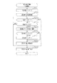
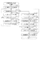
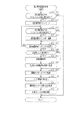
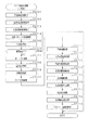
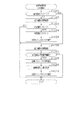
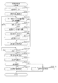
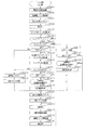
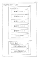
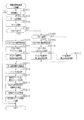
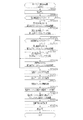
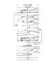
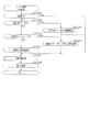
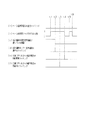
まず、図9のフローチャートを参照しながらメイン処理を説明する。
<Main processing>
First, the main processing will be described with reference to the flowchart of FIG.
まず電源投入ウエイト処理を実行する(ステップS101)。当該電源投入ウエイト処理では、例えばメイン処理が起動されてからウエイト用の所定時間(具体的には1秒)が経過するまで次の処理に進行することなく待機する。かかる電源投入ウエイト処理の実行期間において図柄表示装置41の動作開始及び初期設定が完了することとなる。その後、主側RAM65のアクセスを許可する(ステップS102)。
First, power-on wait processing is executed (step S101). In the power-on wait process, for example, the main process is started and waits for a predetermined time for waiting (specifically, 1 second) without proceeding to the next process. During the execution period of the power-on weight process, the operation start and initial setting of the
その後、設定キー挿入部68aがON操作されているか否かを判定する(ステップS103)。設定キー挿入部68aがON操作されていない場合(ステップS103:NO)、リセットボタン68cが押圧操作されているか否かを判定する(ステップS104)。リセットボタン68cが押圧操作されている場合(ステップS104:YES)、主側RAM65においてパチンコ機10の設定状態を示す設定値の情報が設定されたエリアを除いて、主側RAM65の各エリアを「0」クリアするとともにその「0」クリアしたエリアに対して初期設定を行う(ステップS105)。つまり、設定キー挿入部68aのON操作を伴わずにリセットボタン68cを押圧操作しながらパチンコ機10への動作電力の供給が開始された場合には設定値の情報についてはパチンコ機10への動作電力の供給が停止される前の状態に維持したまま主側RAM65のクリア処理が実行されるとともにそのクリア処理が実行された記憶エリアに対して初期設定が行われる。これにより、設定値の変更を要することなく主側RAM65の他のエリアを初期化させることが可能となる。なお、ステップS105では主側CPU63の各種レジスタも「0」クリアした後に初期設定を行う。
Then, it is determined whether or not the setting
リセットボタン68cが押圧操作されていない場合(ステップS104:NO)、停電フラグに「1」がセットされているか否かを判定する(ステップS106)。停電フラグは主側RAM65に設けられており、主側CPU63への動作電力の供給が停止される場合において予め定められた停電時処理が正常に実行された場合には当該停電フラグに「1」がセットされることとなる。停電フラグに「1」がセットされている場合には、チェックサムの算出結果が電源遮断時に保存したチェックサムと一致するか否かすなわち記憶保持されたデータの有効性を判定する(ステップS107)。ステップS105の処理を実行した場合、又はステップS107にて肯定判定をした場合、主側RAM65を確認することでパチンコ機10の設定値が正常か否かを判定する(ステップS108)。具体的には、設定値が「設定1」〜「設定6」のいずれかである場合に正常であると判定し、「0」又は7以上である場合に異常であると判定する。
When the
ステップS106〜ステップS108のいずれかで否定判定をした場合には動作禁止処理を実行する。動作禁止処理では、ホール管理者等にエラーの発生を報知するためのエラー報知処理を実行した後に(ステップS109)、無限ループとなる。当該動作禁止処理は、後述する全部クリア処理(ステップS117)が実行されることにより解除される。 When a negative determination is made in any of steps S106 to S108, the operation prohibition process is executed. In the operation prohibition process, an infinite loop is performed after executing the error notification process for notifying the hall manager or the like of the occurrence of the error (step S109). The operation prohibition process is canceled by executing the all clear process (step S117) described later.
ステップS106〜ステップS108の全てにおいて肯定判定をした場合には電源投入設定処理を実行する(ステップS110)。電源投入設定処理では、停電フラグの初期化といった主側RAM65の所定のエリアを初期値に設定するとともに、現状の遊技状態に対応したコマンドを音声発光制御装置81に送信する。また、ステップS110の処理を実行した後は、管理用IC66に各種情報を認識させるための認識用処理(ステップS111)、及びMPU62の読み取り用端子68dに接続された外部装置に各種データを出力するためのデータ出力用処理を実行する(ステップS112)。これら認識用処理及びデータ出力用処理の詳細については後に説明する。
When a positive determination is made in all of steps S106 to S108, power-on setting processing is executed (step S110). In the power-on setting process, a predetermined area of the
なお、主側CPU63はタイマ割込み処理を定期的に実行する構成であるが、メイン処理が開始された段階においてはタイマ割込み処理の発生が禁止されている。このタイマ割込み処理の発生が禁止された状態はステップS112の処理が完了してステップS113の処理が実行される前のタイミングで解除され、タイマ割込み処理の実行が許可される。これにより、主側CPU63への動作電力の供給が開始された場合にはステップS112のデータ出力用処理が終了して、ステップS113の処理が開始される前の段階までタイマ割込み処理は実行されない。よって、当該状況となるまでは主側CPU63にて遊技を進行させるための処理が開始されないこととなる。
Although the
その後、ステップS113〜ステップS116の残余処理に進む。つまり、主側CPU63はタイマ割込み処理を定期的に実行する構成であるが、1のタイマ割込み処理と次のタイマ割込み処理との間に残余時間が生じることとなる。この残余時間は各タイマ割込み処理の処理完了時間に応じて変動することとなるが、かかる不規則な時間を利用してステップS113〜ステップS116の残余処理を繰り返し実行する。この点、当該ステップS113〜ステップS116の残余処理は非定期的に実行される非定期処理であると言える。
After that, the process proceeds to the residual process of steps S113 to S116. That is, the
残余処理では、まずステップS113にて、タイマ割込み処理の発生を禁止するために割込み禁止の設定を行う。続くステップS114では、乱数初期値カウンタCINIの更新を行う乱数初期値更新処理を実行するとともに、ステップS115にて変動種別カウンタCSの更新を行う変動用カウンタ更新処理を実行する。これらの更新処理では、主側RAM65の対応するカウンタから現状の数値情報を読み出し、その読み出した数値情報を1加算する処理を実行した後に、読み出し元のカウンタに上書きする処理を実行する。この場合、カウンタ値が最大値を超えた際にそれぞれ「0」にクリアする。その後、ステップS116にて、タイマ割込み処理の発生を禁止している状態から許可する状態へ切り換える割込み許可の設定を行う。ステップS116の処理を実行した場合、ステップS113に戻り、ステップS113〜ステップS116の処理を繰り返す。
In the residual processing, first, in step S113, interrupt prohibition is set in order to prohibit the occurrence of timer interrupt processing. In a succeeding step S114, a random number initial value updating process for updating the random number initial value counter CINI is executed, and at the same time, a fluctuation counter updating process for updating the fluctuation type counter CS is executed in step S115. In these updating processes, the current numerical value information is read from the corresponding counter of the
一方、設定キー挿入部68aがON操作されている場合(ステップS103:YES)、主側RAM65においてパチンコ機10の設定状態を示す設定値の情報が設定されたエリアも含めて、主側RAM65の全てのエリアを「0」クリアするとともにその「0」クリアしたエリアに対して初期設定を行う(ステップS117)。つまり、パチンコ機10の設定状態を変更するための操作が行われている場合にはリセットボタン68cが押圧操作されていなくても主側RAM65の全てのエリアが「0」クリアされるとともにそのクリア処理が実行された記憶エリアに対して初期設定が行われる。また、ステップS117では主側CPU63の各種レジスタも「0」クリアした後に初期設定を行う。なお、これに限定されることはなく、パチンコ機10の設定状態を変更するための操作が行われている場合であってもリセットボタン68cが押圧操作されていない場合には主側RAM65の全部クリア処理が実行されずに、パチンコ機10の設定状態を変更するための操作が行われているとともにリセットボタン68cが押圧操作されている場合に全部クリア処理が実行される構成としてもよい。
On the other hand, when the setting
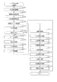
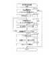
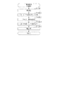
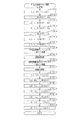
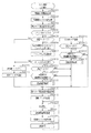
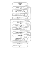
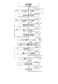
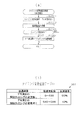
その後、ステップS118にて設定値更新処理を実行し、ステップS119にて設定値更新信号の出力処理を実行した後に、ステップS110の処理に移行する。以下、設定値更新処理について説明する。なお、設定値更新信号の出力処理については後に詳細に説明する。図10は設定値更新処理を示すフローチャートである。 After that, the set value update processing is executed in step S118, the set value update signal output processing is executed in step S119, and then the process proceeds to step S110. The setting value update process will be described below. The output process of the set value update signal will be described in detail later. FIG. 10 is a flowchart showing the set value updating process.
まず主側RAM65に設けられた設定値カウンタに「1」をセットする(ステップS201)。設定値カウンタはパチンコ機10の設定状態がいずれの設定値であるのかを主側CPU63にて特定するためのカウンタである。設定値カウンタに「1」がセットされることにより、設定値更新処理が実行される場合にはそれまでの設定値に関係なく設定値が「設定1」となる。
First, "1" is set to the set value counter provided in the main RAM 65 (step S201). The set value counter is a counter for the
その後、設定値の表示開始処理を実行する(ステップS202)。設定値の表示開始処理では、「設定1」に対応する「1」の数字が表示されるように第3報知用表示装置69cを表示制御する。遊技ホールの管理者は設定値の変更に際しては第3報知用表示装置69cを確認することでパチンコ機10の現状の設定状態を把握することが可能となる。
Then, the display start processing of the set value is executed (step S202). In the setting value display start processing, the display of the third
その後、設定キー挿入部68aがOFF操作されていないことを条件として(ステップS203:NO)、更新ボタン68bが1回押圧操作されたか否かを判定する(ステップS204)。具体的には更新ボタン68bの押圧操作を検知するセンサからの信号がLOWレベルからHIレベルに切り換わったか否かを判定する。ステップS204にて否定判定をした場合、ステップS203の処理に戻り、設定キー挿入部68aがOFF操作されているか否かを判定する。
After that, on condition that the setting
更新ボタン68bが1回押圧操作されている場合(ステップS204:YES)、主側RAM65の設定値カウンタの値を1加算する(ステップS205)。また、1加算後における設定値カウンタの値が「6」を超えた場合(ステップS206:YES)、設定値カウンタに「1」をセットする(ステップS207)。これにより、更新ボタン68bが1回押圧操作される度に1段階上の設定値に更新され、「設定6」の状況で更新ボタン68bが1回押圧操作された場合には「設定1」に戻ることになる。
When the
ステップS206にて否定判定をした場合、又はステップS207の処理を実行した場合、設定値の表示更新処理を実行する(ステップS208)。設定値の表示更新処理では、主側RAM65の設定値カウンタの値に対応する数字が表示されるように第3報知用表示装置69cを表示制御する。遊技ホールの管理者は第3報知用表示装置69cを確認することで更新ボタン68bを押圧操作した後のパチンコ機10の設定状態を把握することが可能となる。
When a negative determination is made in step S206, or when the process of step S207 is executed, the display update process of the set value is executed (step S208). In the display update process of the set value, the display of the third
ステップS208の処理を実行した後はステップS203に戻り、設定キー挿入部68aがOFF操作されているか否かを判定する。OFF操作されていない場合(ステップS203:NO)、ステップS204以降の処理を再度実行する。OFF操作されている場合(ステップS203:YES)、設定値の表示終了処理を実行する(ステップS209)。設定値の表示終了処理では、第3報知用表示装置69cにおける設定値の表示を終了させる。
After executing the process of step S208, the process returns to step S203, and it is determined whether or not the setting
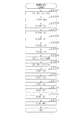
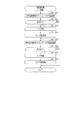
<タイマ割込み処理>
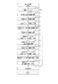
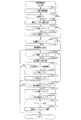
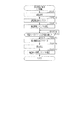
次に、図11のフローチャートを参照しながらタイマ割込み処理を説明する。タイマ割込み処理は定期的(例えば4ミリ秒周期)に実行される。
<Timer interrupt processing>
Next, the timer interrupt processing will be described with reference to the flowchart of FIG. The timer interrupt process is executed periodically (for example, every 4 milliseconds).
まず停電情報記憶処理を実行する(ステップS301)。停電情報記憶処理では、停電監視基板67から電源遮断の発生に対応した停電信号を受信しているか否かを監視し、停電の発生を特定した場合には停電時処理を実行した後に無限ループとなる。停電時処理では、主側RAM65の停電フラグに「1」をセットするとともに、チェックサムを算出しその算出したチェックサムを保存する。
First, power failure information storage processing is executed (step S301). In the power failure information storage processing, it is monitored whether or not a power failure signal corresponding to the occurrence of the power cutoff is received from the power
その後、抽選用乱数更新処理を実行する(ステップS302)。抽選用乱数更新処理では、当たり乱数カウンタC1、大当たり種別カウンタC2、リーチ乱数カウンタC3及び普電役物開放カウンタC4の更新を実行する。具体的には、当たり乱数カウンタC1、大当たり種別カウンタC2、リーチ乱数カウンタC3及び普電役物開放カウンタC4から現状の数値情報を順次読み出し、それら読み出した数値情報をそれぞれ1加算する処理を実行した後に、読み出し元のカウンタに上書きする処理を実行する。この場合、カウンタ値が最大値を超えた際にそれぞれ「0」にクリアする。その後、ステップS303ではステップS114と同様に乱数初期値更新処理を実行するとともに、ステップS304にてステップS115と同様に変動用カウンタ更新処理を実行する。 After that, random number update processing for lottery is executed (step S302). In the lottery random number updating process, the winning random number counter C1, the big hit type counter C2, the reach random number counter C3, and the general electric utility article release counter C4 are updated. Specifically, the present numerical value information is sequentially read from the hit random number counter C1, the big hit type counter C2, the reach random number counter C3, and the general electric utility open counter C4, and the process of adding 1 to each of the read numerical value information is executed. After that, a process of overwriting the counter of the reading source is executed. In this case, when the counter value exceeds the maximum value, each is cleared to "0". After that, in step S303, the random number initial value updating process is executed as in step S114, and at the same time, the fluctuation counter updating process is executed in step S304 as in step S115.
その後、不正用の監視対象として設定されている所定の事象が発生しているか否かを監視する不正検知処理を実行する(ステップS305)。当該不正検知処理では、複数種類の事象の発生を監視し、所定の事象が発生していることを確認することで、主側RAM65に設けられた遊技停止フラグに「1」をセットする。続くステップS306では、上記遊技停止フラグに「1」がセットされているか否かを判定することで、遊技の進行を停止している状態であるか否かを判定する。ステップS306にて否定判定をした場合に、ステップS307以降の処理を実行する。
Then, the fraud detection process of monitoring whether or not a predetermined event set as a fraudulent monitoring target has occurred is executed (step S305). In the fraud detection process, the occurrence of a plurality of types of events is monitored, and by confirming that a predetermined event has occurred, the game stop flag provided in the
ステップS307では、ポート出力処理を実行する。ポート出力処理では、前回のタイマ割込み処理において出力情報の設定が行われている場合に、その出力情報に対応した出力を各種駆動部32b,34bに行うための処理を実行する。例えば、特電入賞装置32を開放状態に切り換えるべき情報が設定されている場合には特電用の駆動部32bへの駆動信号の出力を開始させ、閉鎖状態に切り換えるべき情報が設定されている場合には当該駆動信号の出力を停止させる。また、第2作動口34の普電役物34aを開放状態に切り換えるべき情報が設定されている場合には普電用の駆動部34bへの駆動信号の出力を開始させ、閉鎖状態に切り換えるべき情報が設定されている場合には当該駆動信号の出力を停止させる。
In step S307, port output processing is executed. In the port output process, when the output information is set in the previous timer interrupt process, a process for outputting the various drive units 32b and 34b corresponding to the output information is executed. For example, when the information to switch the special electric
その後、読み込み処理を実行する(ステップS308)。読み込み処理では、停電信号及び入賞信号以外の信号の読み込みを実行し、その読み込んだ情報を今後の処理にて利用するために記憶する。 Then, the reading process is executed (step S308). In the reading process, signals other than the power failure signal and the winning signal are read, and the read information is stored for use in future processes.
その後、入球検知処理を実行する(ステップS309)。当該入球検知処理では、各入球検知センサ42a〜49aから受信している信号を読み込み、その読み込み結果に基づいて、アウト口24a、一般入賞口31、特電入賞装置32、第1作動口33、第2作動口34及びスルーゲート35への入球の有無を特定する。なお、入球検知処理の詳細については後に説明する。
After that, a ball detection process is executed (step S309). In the entrance detection process, signals received from the
その後、主側RAM65に設けられている複数種類のタイマカウンタの数値情報をまとめて更新するためのタイマ更新処理を実行する(ステップS310)。この場合、記憶されている数値情報が減算されて更新されるタイマカウンタを集約して扱う構成であるが、減算式のタイマカウンタの更新及び加算式のタイマカウンタの更新の両方を集約して行う構成としてもよい。
After that, a timer updating process for collectively updating the numerical information of a plurality of types of timer counters provided in the
その後、遊技球の発射制御を行うための発射制御処理を実行する(ステップS311)。発射操作装置28への発射操作が継続されている状況では、所定の発射周期である0.6秒に1個の遊技球が発射される。続くステップS312では、入力状態監視処理として、ステップS308の読み込み処理にて読み込んだ情報に基づいて、各入球検知センサ42a〜49aの断線確認や、遊技機本体12や前扉枠14の開放確認を行う。
After that, the firing control process for controlling the firing of the game ball is executed (step S311). In the situation where the firing operation to the
その後、遊技回の実行制御及び開閉実行モードの実行制御を行うための特図特電制御処理を実行する(ステップS313)。特図特電制御処理については後に詳細に説明する。 After that, the special figure special electric power control processing for executing the game time execution control and the execution control of the opening/closing execution mode is executed (step S313). The special figure special power control processing will be described in detail later.
その後、普図普電制御処理を実行する(ステップS314)。普図普電制御処理では、スルーゲート35への入賞が発生している場合に普図側の保留情報を取得するための処理を実行するとともに、普図側の保留情報が記憶されている場合にその保留情報について開放判定を行い、さらにその開放判定を契機として普図用の演出を行うための処理を実行する。また、開放判定の結果に基づいて、第2作動口34の普電役物34aを開閉させる処理を実行する。この場合、サポートモードが低頻度サポートモードであればそれに対応する処理が実行され、サポートモードが高頻度サポートモードであればそれに対応する処理が実行される。また、開閉実行モードである場合にはその直前のサポートモードが高頻度サポートモードであったとしても低頻度サポートモードとなる。
After that, the general/universal/universal electric vehicle control process is executed (step S314). In the general/universal/universal electric power control process, a process for obtaining the general/universal-university-side pending information is executed when a prize is paid to the through
続くステップS315では、直前のステップS313及びステップS314の処理結果に基づいて、特図表示部37aに係る保留情報の増減個数を特図保留表示部37bに反映させるための出力情報の設定を行うとともに、普図表示部38aに係る保留情報の増減個数を普図保留表示部38bに反映させるための出力情報の設定を行う。また、ステップS315では、直前のステップS313及びステップS314の処理結果に基づいて、特図表示部37aの表示内容を更新させるための出力情報の設定を行うとともに、普図表示部38aの表示内容を更新させるための出力情報の設定を行う。
In the following step S315, based on the processing results of the immediately preceding steps S313 and S314, the output information for reflecting the increased/decreased number of the hold information related to the special
その後、払出制御装置77から受信したコマンド及び信号の内容を確認し、その確認結果に対応した処理を行うための払出状態受信処理を実行する(ステップS316)。また、賞球コマンドを出力対象として設定するための払出出力処理を実行する(ステップS317)。また、今回のタイマ割込み処理にて実行された各種処理の処理結果に応じた外部信号の出力の開始及び終了を制御するための外部情報設定処理を実行する(ステップS318)。その後、遊技領域PAにおける遊技球の入球結果に対応する情報を管理用IC66に出力するための管理用出力処理を実行する(ステップS319)。管理用出力処理の詳細については後に説明する。
After that, the contents of the command and the signal received from the
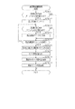
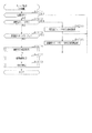
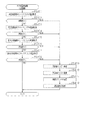
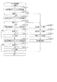
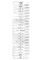
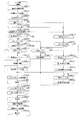
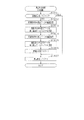
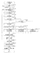
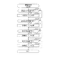
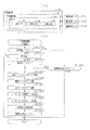
次に、ステップS313の特図特電制御処理について、図12のフローチャートを参照しながら説明する。 Next, the special figure special power control processing of step S313 will be described with reference to the flowchart of FIG.
まず保留情報の取得処理を実行する(ステップS401)。保留情報の取得処理では、第1作動口33又は第2作動口34への入賞が発生しているか否かを判定し、入賞が発生している場合には保留格納エリア65aにおける保留数が上限値(本実施の形態では「4」)未満であるか否かを判定する。保留数が上限値未満である場合には、保留数を1加算するとともに、前回のステップS302にて更新した当たり乱数カウンタC1、大当たり種別カウンタC2及びリーチ乱数カウンタC3の各数値情報を、保留用エリアREの空き保留エリアRE1〜RE4のうち最初の保留エリアに格納する。なお、第1作動口33及び第2作動口34への入賞が同時に発生している場合には、保留情報の取得処理を1回実行する範囲内において、上記保留情報を取得するための処理を複数回実行する。また、保留情報の新たな取得が行われた場合にはそれに対応する取得時コマンドを音声発光制御装置81に送信する。音声発光制御装置81は当該コマンドを受信した場合、図柄表示装置41における保留情報の個数を示す画像の表示を保留情報の増加に対応する表示内容に更新させる。
First, a process of acquiring pending information is executed (step S401). In the process of acquiring the hold information, it is determined whether or not a prize has been paid to the first working
その後、主側RAM65に設けられた特図特電カウンタの情報を読み出すとともに(ステップS402)、主側ROM64に設けられた特図特電アドレステーブルを読み出す(ステップS403)。そして、特図特電アドレステーブルから特図特電カウンタの情報に対応した開始アドレスを取得し(ステップS404)、ステップS406〜ステップS412の処理のうちその取得した開始アドレスが示す処理にジャンプする(ステップS405)。特図特電カウンタは、ステップS406〜ステップS412の各種処理のうちいずれを実行すべきであるかを主側CPU63にて把握するためのカウンタであり、特図特電アドレステーブルは、特図特電カウンタの数値情報に対応させて、ステップS406〜ステップS412の処理を実行するためのプログラムの開始アドレスが設定されている。
Then, the information of the special figure special power counter provided in the
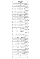
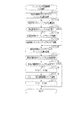
ステップS406では特図変動開始処理を実行する。図13は特図変動開始処理を示すフローチャートである。 In step S406, special figure variation start processing is executed. FIG. 13 is a flowchart showing the special figure variation start processing.
特図変動開始処理では保留用エリアREに格納されている保留情報の個数が1以上であることを条件として(ステップS501:YES)、データ設定処理を実行する(ステップS502)。データ設定処理では、まず保留数を1減算するとともに、保留用エリアREの第1保留エリアRE1に格納されたデータを実行エリアAEに移動する。その後、保留用エリアREの各保留エリアRE1〜RE4に格納されたデータをシフトさせる処理を実行する。このデータシフト処理は、第1保留エリアRE1〜第4保留エリアRE4に格納されているデータを下位エリア側に順にシフトさせる処理であり、詳細には、第2保留エリアRE2→第1保留エリアRE1、第3保留エリアRE3→第2保留エリアRE2、第4保留エリアRE4→第3保留エリアRE3といった具合に各エリア内のデータをシフトさせた後に第4保留エリアRE4を「0」クリアする。この際、保留エリアのデータのシフトが行われたことを認識させるためのシフト時コマンドを音声発光制御装置81に送信する。音声発光制御装置81は当該コマンドを受信した場合、図柄表示装置41における保留情報の個数を示す画像の表示を保留情報の減少に対応する表示内容に更新させる。
In the special figure variation start processing, the data setting processing is executed (step S502) on condition that the number of pieces of holding information stored in the holding area RE is 1 or more (step S501: YES). In the data setting process, first, the number of reservations is decremented by 1, and the data stored in the first reservation area RE1 of the reservation area RE is moved to the execution area AE. Then, the process of shifting the data stored in each of the holding areas RE1 to RE4 of the holding area RE is executed. This data shift process is a process of sequentially shifting the data stored in the first holding area RE1 to the fourth holding area RE4 to the lower area side, specifically, the second holding area RE2→the first holding area RE1. , The third reservation area RE3→the second reservation area RE2, the fourth reservation area RE4→the third reservation area RE3, and the like, and then the fourth reservation area RE4 is cleared to “0”. At this time, a shift command for recognizing that the data in the holding area has been shifted is transmitted to the voice
データ設定処理を実行した後は当否テーブルを主側ROM64から読み出す(ステップS503)。具体的には、まず主側RAM65の当否抽選モードを示す情報を読み出すことにより現状の当否抽選モードを把握する。高確率モードである場合には主側ROM64から高確当否テーブル64gを読み出す。一方、低確率モードである場合には主側RAM65の設定値カウンタの値を読み出すことによりパチンコ機10の設定状態を把握する。そして、その把握した設定値に対応する低確当否テーブル64a〜64fを主側ROM64から読み出す。
After executing the data setting process, the win/fail table is read from the main ROM 64 (step S503). Specifically, the current winning/unwinning lottery mode is grasped by reading information indicating the winning/unwinning lottery mode in the
その後、ステップS503にて読み出した当否テーブル64a〜64gを参照して当否判定処理を実行する(ステップS504)。当否判定処理では、実行エリアAEに格納された情報のうち当否判定用の情報、すなわち当たり乱数カウンタC1に係る数値情報が、ステップS503にて読み出した当否テーブル64a〜64gに設定された大当たり数値情報と一致しているか否かを判定する。 After that, the win/loss determination process is executed by referring to the win/loss tables 64a to 64g read in step S503 (step S504). In the hit determination processing, the information for hit determination of the information stored in the execution area AE, that is, the numerical value information related to the hit random number counter C1, is the jackpot numerical value information set in the hit/miss tables 64a to 64g read in step S503. It is determined whether or not
当否判定処理の結果が大当たり当選結果である場合には(ステップS505:YES)、振分判定処理を実行する(ステップS506)。振分判定処理では、実行エリアAEに格納された情報のうち振分判定用の情報、すなわち大当たり種別カウンタC2に係る数値情報を読み出す。そして、主側ROM64に設けられた振分テーブル64hを参照して、上記読み出した大当たり種別カウンタC2に係る数値情報がいずれの大当たり結果に対応しているのかを特定する。具体的には、低確大当たり結果、低入賞高確大当たり結果及び最有利大当たり結果のうちいずれの大当たり結果に対応しているのかを特定する。
When the result of the win/loss determination process is the jackpot win result (step S505: YES), the distribution determination process is executed (step S506). In the distribution determination process, information for distribution determination, that is, numerical information related to the jackpot type counter C2 is read out from the information stored in the execution area AE. Then, by referring to the distribution table 64h provided in the
その後、大当たり結果用の停止結果設定処理を実行する(ステップS507)。具体的には、今回の変動開始に係る遊技回において特図表示部37aに最終的に停止表示させる絵柄の態様の情報を、主側ROM64に予め記憶されている大当たり結果用の停止結果テーブルから特定し、その特定した情報を主側RAM65に書き込む。この大当たり結果用の停止結果テーブルには、特図表示部37aに停止表示される絵柄の態様の情報が、大当たり結果の種類毎に相違させて設定されている。
After that, the stop result setting process for the jackpot result is executed (step S507). Specifically, in the game time related to the start of the variation this time, the information of the aspect of the pattern to be finally stopped and displayed on the special
その後、振分判定結果に対応したフラグセット処理を実行する(ステップS508)。具体的には、主側RAM65には各大当たり結果の種類に対応したフラグが設けられており、ステップS508では、それら各大当たり結果の種類に対応したフラグのうち、ステップS506の振分判定処理の結果に対応したフラグに「1」をセットする。
After that, a flag setting process corresponding to the distribution determination result is executed (step S508). Specifically, the
一方、ステップS505にて大当たり当選結果ではないと判定した場合には、外れ結果用の停止結果設定処理を実行する(ステップS509)。具体的には、今回の変動開始に係る遊技回において特図表示部37aに最終的に停止表示させる絵柄の態様の情報を、主側ROM64に予め記憶されている外れ結果用の停止結果テーブルから特定し、その特定した情報を主側RAM65に書き込む。この場合に選択される絵柄の態様の情報は、大当たり結果の場合に選択される絵柄の態様の情報とは異なっている。
On the other hand, if it is determined in step S505 that the result is not the jackpot, the stop result setting process for the result of deviation is executed (step S509). Specifically, in the game time relating to the current variation start, the information of the mode of the picture finally stopped and displayed on the special
ステップS508及びステップS509のいずれかの処理を実行した後は、遊技回の継続期間の把握処理を実行する(ステップS510)。かかる処理では、変動種別カウンタCSの数値情報を取得する。また、今回の遊技回において図柄表示装置41にてリーチ表示が発生するか否かを判定する。具体的には、今回の変動開始に係る遊技回が低確大当たり結果又は最有利大当たり結果である場合には、リーチ表示が発生すると判定する。また、いずれの大当たり結果でもなく、さらに実行エリアAEに格納されているリーチ乱数カウンタC3に係る数値情報がリーチ発生に対応した数値情報である場合には、リーチ表示が発生すると判定する。
After performing the process of either step S508 or step S509, the process of grasping the duration of the game is performed (step S510). In this process, the numerical information of the fluctuation type counter CS is acquired. In addition, it is determined whether or not the reach display is generated on the
リーチ表示が発生すると判定した場合には、主側ROM64に記憶されているリーチ発生用継続期間テーブルを参照して、今回の変動種別カウンタCSの数値情報に対応した遊技回の継続期間を取得する。一方、リーチ表示が発生しないと判定した場合には、主側ROM64に記憶されているリーチ非発生用継続期間テーブルを参照して、今回の変動種別カウンタCSの数値情報に対応した遊技回の継続期間を取得する。ちなみに、リーチ非発生用継続期間テーブルを参照して取得され得る遊技回の継続期間は、リーチ発生用継続期間テーブルを参照して取得され得る遊技回の継続期間と異なっている。
When it is determined that the reach display is generated, the reach generation continuation period table stored in the
なお、リーチ非発生時における遊技回の継続期間は、保留用エリアREに格納されている保留情報の数が多いほど遊技回の継続期間が短くなるように設定されている。また、サポートモードが高頻度サポートモードである状況においては低頻度サポートモードである状況よりも、保留情報の数が同一である場合で比較して、短い遊技回の継続期間が選択されるようにリーチ非発生用継続期間テーブルが設定されている。但し、これに限定されることはなく、保留情報の数やサポートモードに応じて遊技回の継続期間が変動しない構成としてもよく、上記の関係とは逆であってもよい。さらには、リーチ発生時における遊技回の継続期間に対して、上記構成を適用してもよい。また、各種大当たり結果の場合、外れリーチ時の場合及びリーチ非発生の外れ結果の場合のそれぞれに対して個別に継続期間テーブルが設定されていてもよい。この場合、各遊技結果に応じた遊技回の継続期間の振分が行われることとなる。 The duration of the game times when the reach is not generated is set so that the duration of the game times becomes shorter as the number of pieces of holding information stored in the holding area RE increases. In addition, in the situation where the support mode is the high frequency support mode, compared to the case where the number of holding information is the same as in the situation where the support mode is the low frequency support mode, a shorter duration of game times is selected. A reach non-occurrence duration table is set. However, the present invention is not limited to this, and the duration of the game times may not change in accordance with the number of pieces of hold information and the support mode, and the above relationship may be reversed. Furthermore, the above configuration may be applied to the duration of the game times when the reach occurs. Further, the duration table may be set individually for each of the various jackpot results, the case of the missed reach, and the case of the missed result of the non-reach occurrence. In this case, the duration of the game times is distributed according to each game result.
その後、ステップS510にて取得した遊技回の継続期間の情報を、主側RAM65に設けられた特図特電タイマカウンタにセットする(ステップS511)。特図特電タイマカウンタにセットされた数値情報の更新は、タイマ更新処理(ステップS310)にて実行される。ちなみに、遊技回用の演出として、特図表示部37aにおける絵柄の変動表示と図柄表示装置41における図柄の変動表示とが行われるが、これらの各変動表示が終了される場合にはその遊技回の停止結果が表示された状態(図柄表示装置41では有効ライン上に所定の図柄の組合せが待機された状態)で最終停止期間(例えば0.5秒)に亘って最終停止表示される。この場合に、ステップS510にて取得される遊技回の継続期間は1遊技回分のトータル時間となっている。
After that, the information on the duration of the game times acquired in step S510 is set in the special figure special power timer counter provided in the main side RAM 65 (step S511). The updating of the numerical information set in the special figure special electric timer counter is executed in the timer updating process (step S310). By the way, as the effect for the game use, the variable display of the symbol on the special
その後、変動用コマンド及び種別コマンドを音声発光制御装置81に送信する(ステップS512)。変動用コマンドには、遊技回の継続期間の情報が含まれる。ここで、上記のとおりリーチ非発生用継続期間テーブルを参照して取得される遊技回の継続期間は、リーチ発生用継続期間テーブルを参照して取得される遊技回の継続期間と異なっているため、変動用コマンドにリーチ発生の有無の情報が含まれていなかったとしても、音声発光制御装置81では遊技回の継続期間の情報からリーチ発生の有無を特定することは可能である。この点、変動用コマンドには、リーチ発生の有無を示す情報が含まれているとも言える。なお、変動用コマンドにリーチ発生の有無を直接示す情報が含まれていてもよい。また、種別コマンドには、遊技結果の情報が含まれる。
After that, the variation command and the type command are transmitted to the voice emission control device 81 (step S512). The variation command includes information on the duration of the game game. Here, as described above, the duration of the game times obtained by referring to the reach non-occurrence duration table is different from the duration of the game times obtained by referring to the reach occurrence duration table. Even if the variation command does not include the information about the presence or absence of the reach occurrence, the voice
音声発光制御装置81は変動用コマンド及び種別コマンドを主側CPU63から受信した場合、表示発光部53、スピーカ部54及び図柄表示装置41において遊技回用の演出が実行されるようにする。この場合、当該遊技回用の演出は変動用コマンド及び種別コマンドの内容に対応する態様で行われる。また、図柄表示装置41では遊技回用の演出として図柄の変動表示が行われ、当該遊技回用の演出が終了する場合には当否判定処理及び振分判定処理の結果に対応する図柄の組み合わせが停止表示される。
When the voice light
その後、特図表示部37aにおける絵柄の変動表示を開始させる(ステップS513)。そして、特図特電カウンタを1加算する(ステップS514)。この場合、特図変動開始処理が実行される場合における特図特電カウンタの数値情報は「0」であるため特図特電カウンタの数値情報は「1」となる。その後、主側RAM65に設けられた第11出力フラグに「1」をセットする(ステップS515)。第11出力フラグは、遊技回が開始されたことを示す情報出力を管理用IC66に対して実行すべきことを主側CPU63にて特定するためのフラグである。
After that, the variable display of the pattern on the special
特図特電制御処理(図52)の説明に戻り、ステップS407では特図変動中処理を実行する。特図変動中処理では、遊技回の継続時間中であって最終停止表示前のタイミングであるか否かを判定し、最終停止表示前であれば特図表示部37aにおける絵柄の表示態様を規則的に変化させるための処理を実行する。最終停止表示させるタイミングとなった場合には、特図特電カウンタの数値情報を1加算することで、当該カウンタの数値情報を特図変動中処理に対応したものから特図確定中処理に対応したものに更新する。なお、本実施形態においては主側CPU63から音声発光制御装置81に最終停止コマンドは送信されない。
Returning to the description of the special figure special power control process (FIG. 52 ), the special figure changing process is executed in step S407. In the special figure changing process, it is determined whether it is the timing before the final stop display during the duration of the game time, and if it is before the final stop display, the display mode of the pattern in the special
ステップS408では特図確定中処理を実行する。特図確定中処理では、特図表示部37aにおける絵柄の表示態様を今回の遊技回の抽選結果に対応した表示態様とする。また、特図確定中処理では、最終停止期間が経過したか否かを判定し、当該期間が経過している場合には開閉実行モードへの移行が発生するか否かの判定を行う。開閉実行モードへの移行が発生しない場合には特図特電カウンタの数値情報を「0」クリアする。開閉実行モードへの移行が発生する場合には特図特電カウンタの数値情報を1加算することで、当該カウンタの数値情報を特図確定中処理に対応したものから特電開始処理に対応したものに更新する。
In step S408, the processing for confirming the special figure is executed. In the special figure finalizing process, the display mode of the pattern on the special
ステップS409では特電開始処理を実行する。特電開始処理では今回の開閉実行モードにおけるオープニング期間を開始させるための処理を未だ実行していない場合、オープニング期間のセット処理を実行する。また、オープニングコマンドを音声発光制御装置81に送信する。音声発光制御装置81はオープニングコマンドを受信することにより、表示発光部53、スピーカ部54及び図柄表示装置41にてオープニング演出が実行されるようにする。オープニング期間が経過している場合、最初のラウンド遊技を開始させるための開始用処理を実行する。当該開始用処理では、特電入賞装置32を開放状態とするとともにラウンド遊技の終了条件を設定する。この終了条件の設定に際しては、今回の最初のラウンド遊技において特電入賞装置32を開放状態に継続させる場合の上限継続期間をセットするとともに、今回の最初のラウンド遊技において特電入賞装置32に入賞可能な遊技球の上限個数を主側RAM65に設けられた入賞個数カウンタにセットする。
In step S409, special electric power start processing is executed. In the special electric power start process, if the process for starting the opening period in the current open/close execution mode has not been executed yet, the opening period setting process is executed. Further, the opening command is transmitted to the voice
ステップS410では特電開放中処理を実行する。特電開放中処理ではラウンド遊技の終了条件が成立したか否かを判定する。終了条件が成立している場合には特電入賞装置32を閉鎖状態とする。そして、今回終了したラウンド遊技が最後の実行回のラウンド遊技でなければ特図特電カウンタの数値情報を1加算することで当該カウンタの数値情報を特電開放中処理に対応したものから特電閉鎖中処理に対応したものに更新し、今回終了したラウンド遊技が最後の実行回のラウンド遊技であれば特図特電カウンタの数値情報を2加算することで当該カウンタの数値情報を特電開放中処理に対応したものから特電終了処理に対応したものに更新する。
In step S410, the special electric power releasing processing is executed. In the special electric open processing, it is determined whether or not the ending condition of the round game is satisfied. When the ending condition is satisfied, the special
ステップS411では特電閉鎖中処理を実行する。特電閉鎖中処理では、ラウンド遊技間のインターバル期間が経過したか否かを判定する。インターバル期間は前回のラウンド遊技が終了する場合に設定される。インターバル期間が経過した場合には、特電入賞装置32を開放状態とするとともにラウンド遊技の終了条件を設定する。そして、特図特電カウンタの数値情報を1減算することで、当該カウンタの数値情報を特電閉鎖中処理に対応したものから特電開放中処理に対応したものに更新する。
In step S411, a special electric power closing process is executed. In the special electric closed processing, it is determined whether or not the interval period between round games has passed. The interval period is set when the previous round game ends. When the interval period has elapsed, the special electric
ステップS412では特電終了処理を実行する。特電終了処理では、今回の開閉実行モードにおけるエンディング期間を開始させるための処理を未だ実行していない場合、エンディング期間(例えば5秒)をセットするとともに、エンディングコマンドを音声発光制御装置81に送信する。音声発光制御装置81はエンディングコマンドを受信することにより、表示発光部53、スピーカ部54及び図柄表示装置41にてエンディング演出が実行されるようにする。エンディング期間が経過した場合には、開閉実行モードの終了後における当否抽選モード及びサポートモードのそれぞれを、今回の開閉実行モードの開始契機となった大当たり結果に対応するモードに設定する。
In step S412, special electric power termination processing is executed. In the special power termination process, if the process for starting the ending period in the opening/closing execution mode this time is not yet executed, the ending period (for example, 5 seconds) is set and the ending command is transmitted to the sound
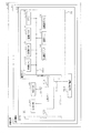
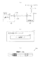
次に、主側CPU63にて、各入球検知センサ42a〜49aの検知結果に基づき、アウト口24a、一般入賞口31、特電入賞装置32、第1作動口33、第2作動口34及びスルーゲート35への遊技球の入球の有無を特定するための構成について説明する。図14は主側CPU63に入球検知センサ42a〜49aの検知結果が入力されるようにする構成を説明するための説明図である。
Next, in the
主側CPU63には入力ポート63aが設けられている。入力ポート63aは、8種類の信号を同時に扱うことができるように8ビットのパラレルインターフェースとして構成されている。そして、各信号の電圧に応じて「0」又は「1」の情報が格納されるエリアが、各端子に1対1で対応させて設けられている。つまり、当該エリアとして、第0ビットD0〜第7ビットD7を備えている。また、入力ポート63aには8種類を超える信号が入力されることとなるが、同時に入力される対象を8種類に制限するために、入力ポート63aへの入力対象となる信号群はドライバICによる切換制御を通じて切り換えられる。
The
タイマ割込み処理(図11)の入球検知処理(ステップS309)では、入力ポート63aへの入力対象となる信号群が各入球検知センサ42a〜49aからの信号群に設定される。かかる設定がなされた状況では、第0ビットD0は第1入賞口検知センサ42aからの検知信号に対応した情報が格納され、第1ビットD1は第2入賞口検知センサ43aからの検知信号に対応した情報が格納され、第2ビットD2は第3入賞口検知センサ44aからの検知信号に対応した情報が格納され、第3ビットD3は特電検知センサ45aからの検知信号に対応した情報が格納され、第4ビットD4は第1作動口検知センサ46aからの検知信号に対応した情報が格納され、第5ビットD5は第2作動口検知センサ47aからの検知信号に対応した情報が格納され、第6ビットD6はアウト口検知センサ48aからの検知信号に対応した情報が格納され、第7ビットD7はゲート検知センサ49aからの検知信号に対応した情報が格納される。
In the incoming ball detection process (step S309) of the timer interrupt process (FIG. 11), the signal group to be input to the input port 63a is set to the signal group from each of the incoming
上記各入球検知センサ42a〜49aは、遊技球の通過を検知していない場合には検知信号として非検知中であることを示すLOWレベル信号を出力し、遊技球の通過を検知している場合には検知信号として検知中であることを示すHIレベル信号を出力する。そして、入力ポート63aではLOWレベル信号を受信している場合に該当するビットに対して「0」の情報を格納し、HIレベル信号を受信している場合に該当するビットに対して「1」の情報を格納する。つまり、入球検知センサ42a〜49aにおいて遊技球の通過が検知されていない状況では該当するビットに対して非検知中を示す情報に対応した「0」の情報が格納され、遊技球の通過が検知されている状況では該当するビットに対して検知中を示す情報に対応した「1」の情報が格納される。
When the passage of the game ball is not detected, each of the
図15はタイマ割込み処理(図11)のステップS309にて実行される入球検知処理を示すフローチャートである。 FIG. 15 is a flow chart showing the incoming ball detection process executed in step S309 of the timer interrupt process (FIG. 11).
第0ビットD0に「0」の情報が格納されている状況から「1」の情報が格納されている状況に切り換わったことを確認した場合、第1入賞口検知センサ42aにて1個の遊技球が検知されたと判定する(ステップS601:YES)。この場合、主側RAM65に設けられた第1出力フラグに「1」をセットするとともに(ステップS602)、主側RAM65に設けられた10個賞球用カウンタの値を1加算する(ステップS603)。第1出力フラグは、第1入賞口検知センサ42aにて1個の遊技球が検知されたことを示す情報出力を管理用IC66に対して実行すべきことを主側CPU63にて特定するためのフラグである。10個賞球用カウンタは、10個の遊技球の払い出しを実行すべき回数を主側CPU63にて特定するためのカウンタである。10個賞球用カウンタの値が1以上である場合、タイマ割込み処理(図11)におけるステップS317の払出出力処理にて10個賞球コマンドを払出制御装置77に出力するとともに、10個賞球コマンドを1回出力した場合には10個賞球用カウンタの値を1減算する。払出制御装置77は10個賞球コマンドを受信した場合、10個の遊技球が払い出されるように払出装置76を駆動制御する。
When it is confirmed that the state in which the information of “0” is stored in the 0th bit D0 is switched to the state in which the information of “1” is stored, one piece is detected by the first winning
第1ビットD1に「0」の情報が格納されている状況から「1」の情報が格納されている状況に切り換わったことを確認した場合、第2入賞口検知センサ43aにて1個の遊技球が検知されたと判定する(ステップS604:YES)。この場合、主側RAM65に設けられた第2出力フラグに「1」をセットするとともに(ステップS605)、主側RAM65に設けられた10個賞球用カウンタの値を1加算する(ステップS606)。第2出力フラグは、第2入賞口検知センサ43aにて1個の遊技球が検知されたことを示す情報出力を管理用IC66に対して実行すべきことを主側CPU63にて特定するためのフラグである。
When it is confirmed that the state in which the information of "0" is stored in the first bit D1 is switched to the state in which the information of "1" is stored, one piece is detected by the second winning
第2ビットD2に「0」の情報が格納されている状況から「1」の情報が格納されている状況に切り換わったことを確認した場合、第3入賞口検知センサ44aにて1個の遊技球が検知されたと判定する(ステップS607:YES)。この場合、主側RAM65に設けられた第3出力フラグに「1」をセットするとともに(ステップS608)、主側RAM65に設けられた10個賞球用カウンタの値を1加算する(ステップS609)。第3出力フラグは、第3入賞口検知センサ44aにて1個の遊技球が検知されたことを示す情報出力を管理用IC66に対して実行すべきことを主側CPU63にて特定するためのフラグである。
When it is confirmed that the state in which the information of "0" is stored in the second bit D2 is switched to the state in which the information of "1" is stored, the third winning
第3ビットD3に「0」の情報が格納されている状況から「1」の情報が格納されている状況に切り換わったことを確認した場合、特電検知センサ45aにて1個の遊技球が検知されたと判定する(ステップS610:YES)。この場合、主側RAM65に設けられた特電入賞フラグに「1」をセットするとともに(ステップS611)、主側RAM65に設けられた第4出力フラグに「1」をセットし(ステップS612)、さらに主側RAM65に設けられた15個賞球用カウンタの値を1加算する(ステップS613)。特電入賞フラグは開閉実行モードのラウンド遊技において特電入賞装置32に1個の遊技球が入球したことを主側CPU63にて特定するためのフラグである。タイマ割込み処理(図11)の特図特電制御処理(ステップS313)では特電入賞フラグに「1」がセットされていることを確認することで、特電入賞装置32への1個の遊技球の入球が発生したことを特定し、ラウンド遊技における特電入賞装置32への残りの入球可能個数を1減算する。かかる入球可能個数を1減算する処理を実行した場合に特電入賞フラグを「0」クリアする。第4出力フラグは、特電検知センサ45aにて1個の遊技球が検知されたことを示す情報出力を管理用IC66に対して実行すべきことを主側CPU63にて特定するためのフラグである。15個賞球用カウンタは、15個の遊技球の払い出しを実行すべき回数を主側CPU63にて特定するためのカウンタである。15個賞球用カウンタの値が1以上である場合、タイマ割込み処理(図11)におけるステップS317の払出出力処理にて15個賞球コマンドを払出制御装置77に出力するとともに、15個賞球コマンドを1回出力した場合には15個賞球用カウンタの値を1減算する。払出制御装置77は15個賞球コマンドを受信した場合、15個の遊技球が払い出されるように払出装置76を駆動制御する。
When it is confirmed that the state in which the information of "0" is stored in the third bit D3 is switched to the state in which the information of "1" is stored, one game ball is detected by the special
第4ビットD4に「0」の情報が格納されている状況から「1」の情報が格納されている状況に切り換わったことを確認した場合、第1作動口検知センサ46aにて1個の遊技球が検知されたと判定する(ステップS614:YES)。この場合、主側RAM65に設けられた第1作動入賞フラグに「1」をセットするとともに(ステップS615)、主側RAM65に設けられた第5出力フラグに「1」をセットし(ステップS616)、さらに主側RAM65に設けられた1個賞球用カウンタの値を1加算する(ステップS617)。第1作動入賞フラグは第1作動口33に1個の遊技球が入球したことを主側CPU63にて特定するためのフラグである。タイマ割込み処理(図11)の特図特電制御処理(ステップS313)では第1作動入賞フラグに「1」がセットされていることを確認することで、保留格納エリア65aの保留用エリアREに格納されている保留情報の個数が上限数である4個未満であることを条件として、保留情報を新たに格納する処理を実行する。特電特電制御処理(ステップS313)にて第1作動入賞フラグに「1」がセットされていることを確認し、その確認に対応する処理を実行した場合に第1作動入賞フラグを「0」クリアする。第5出力フラグは、第1作動口検知センサ46aにて1個の遊技球が検知されたことを示す情報出力を管理用IC66に対して実行すべきことを主側CPU63にて特定するためのフラグである。1個賞球用カウンタは、1個の遊技球の払い出しを実行すべき回数を主側CPU63にて特定するためのカウンタである。1個賞球用カウンタの値が1以上である場合、タイマ割込み処理(図11)におけるステップS317の払出出力処理にて1個賞球コマンドを払出制御装置77に出力するとともに、1個賞球コマンドを1回出力した場合には1個賞球用カウンタの値を1減算する。払出制御装置77は1個賞球コマンドを受信した場合、1個の遊技球が払い出されるように払出装置76を駆動制御する。
When it is confirmed that the state in which the information of “0” is stored in the fourth bit D4 is switched to the state in which the information of “1” is stored, the first operating
第5ビットD5に「0」の情報が格納されている状況から「1」の情報が格納されている状況に切り換わったことを確認した場合、第2作動口検知センサ47aにて1個の遊技球が検知されたと判定する(ステップS618:YES)。この場合、主側RAM65に設けられた第2作動入賞フラグに「1」をセットするとともに(ステップS619)、主側RAM65に設けられた第6出力フラグに「1」をセットし(ステップS620)、さらに主側RAM65に設けられた1個賞球用カウンタの値を1加算する(ステップS621)。第2作動入賞フラグは第2作動口34に1個の遊技球が入球したことを主側CPU63にて特定するためのフラグである。タイマ割込み処理(図11)の特図特電制御処理(ステップS313)では第2作動入賞フラグに「1」がセットされていることを確認することで、保留格納エリア65aの保留用エリアREに格納されている保留情報の個数が上限数である4個未満であることを条件として、保留情報を新たに格納する処理を実行する。特電特電制御処理(ステップS313)にて第2作動入賞フラグに「1」がセットされていることを確認し、その確認に対応する処理を実行した場合に第2作動入賞フラグを「0」クリアする。第6出力フラグは、第2作動口検知センサ47aにて1個の遊技球が検知されたことを示す情報出力を管理用IC66に対して実行すべきことを主側CPU63にて特定するためのフラグである。
When it is confirmed that the state in which the information of “0” is stored in the fifth bit D5 is switched to the state in which the information of “1” is stored, one is detected by the second working
第6ビットD6に「0」の情報が格納されている状況から「1」の情報が格納されている状況に切り換わったことを確認した場合、アウト口検知センサ48aにて1個の遊技球が検知されたと判定する(ステップS622:YES)。この場合、主側RAM65に設けられた第7出力フラグに「1」をセットする(ステップS623)。第7出力フラグは、アウト口検知センサ48aにて1個の遊技球が検知されたことを示す情報出力を管理用IC66に対して実行すべきことを主側CPU63にて特定するためのフラグである。
When it is confirmed that the state in which the information of "0" is stored in the sixth bit D6 is switched to the state in which the information of "1" is stored, one game ball is detected by the out-
第7ビットD7に「0」の情報が格納されている状況から「1」の情報が格納されている状況に切り換わったことを確認した場合、ゲート検知センサ49aにて1個の遊技球が検知されたと判定する(ステップS624:YES)。この場合、主側RAM65に設けられたゲート入賞フラグに「1」をセットする(ステップS625)。ゲート入賞フラグはスルーゲート35に1個の遊技球が入球したことを主側CPU63にて特定するためのフラグである。タイマ割込み処理(図11)の普図普電制御処理(ステップS314)ではゲート入賞フラグに「1」がセットされていることを確認することで、普電保留エリア65cに格納されている普図側の保留情報の個数が上限数である4個未満であることを条件として、現状の普電役物開放カウンタC4の数値情報を普図側の保留情報として普電保留エリア65cに格納する処理を実行する。普図普電制御処理(ステップS314)にてゲート入賞フラグに「1」がセットされていることを確認し、その確認に対応する処理を実行した場合にゲート入賞フラグを「0」クリアする。
When it is confirmed that the situation in which the information of "0" is stored in the seventh bit D7 is switched to the situation in which the information of "1" is stored, one game ball is detected by the gate detection sensor 49a. It is determined that it has been detected (step S624: YES). In this case, the gate winning flag provided in the
なお、タイマ割込み処理(図11)は既に説明したとおり4ミリ秒周期で起動されるため、1個の入球検知センサ42a〜49aにて1個の遊技球の検知が開始された場合、当該入球検知センサ42a〜49aにてその1個の遊技球の検知を継続している状況において当該入球検知センサ42a〜49aにて1個の遊技球が検知されたことの特定が主側CPU63にて行われる。したがって、第1〜第7出力フラグはそれぞれ1個ずつ設けられていれば十分である。
Note that the timer interrupt process (FIG. 11) is activated in a cycle of 4 milliseconds as already described, and therefore, when detection of one game ball is started by one of the
次に、払出制御装置77にて実行される処理内容について説明する。まず払出制御装置77及び当該払出制御装置77との間で通信を行う各種装置の電気的構成について、図16のブロック図を参照しながら説明する。
Next, the content of processing executed by the
払出制御装置77はMPU91を備えている。MPU91には、制御部及び演算部を含む演算処理装置である払出側CPU92の他に、払出側ROM93、払出側RAM94、割込回路、タイマ回路、データ入出力回路などが内蔵されている。
The
払出側ROM93は、NOR型フラッシュメモリ及びNAND型フラッシュメモリなどの記憶保持に外部からの電力供給が不要なメモリ(すなわち、不揮発性記憶手段)であり、読み出し専用として利用される。払出側ROM93は、払出側CPU92により実行される各種の制御プログラムや固定値データを記憶している。
The payout-
払出側RAM94は、SRAM及びDRAMなどの記憶保持に外部からの電力供給が必要なメモリ(すなわち、揮発性記憶手段)であり、読み書き両用として利用される。払出側RAM94は、ランダムアクセスが可能であるとともに、同一のデータ容量で比較した場合に払出側ROM93よりも読み出しに要する時間が早いものとなっている。払出側RAM94は、払出側ROM93内に記憶されている制御プログラムの実行に対して各種のデータなどを一時的に記憶する。
The
払出側CPU92は、主側CPU63と双方向通信を行うことが可能となっている。払出側CPU92は主側CPU63から賞球コマンドを受信することにより、その賞球コマンドに対応する個数の遊技球が払い出されるように払出装置76を駆動制御する。また、払出側CPU92は、遊技球の払い出しを正常に行うことが可能な状態であるか否かを監視し、正常に行うことが可能ではない状態であると特定した場合には払出側RAM94に未払出の賞球個数情報が記憶されている状況であっても払出装置76を停止させる。また、払出側CPU92は、このように正常に払い出しを行うことが可能ではない状態であることを示す払出制限コマンドを主側CPU63に送信する。主側CPU63は当該払出制限コマンドを受信した場合、遊技球の払い出しを正常に行うことが可能ではない状態であることを示す報知が図柄表示装置41、表示発光部53及びスピーカ部54にて実行されるように音声発光制御装置81に報知用コマンドを送信する。遊技球の払い出しを正常に行うことが可能ではない状態として、下皿56aが遊技球で満タンとなる満タン状態と、タンク75に遊技球が補充されていない球無状態と、払出装置76が正常に動作しない払出異常状態と、遊技機本体12が外枠11から開放された本体開放状態と、前扉枠14が内枠13から開放された前扉開放状態と、が存在している。
The
払出装置76から下皿56aへと通じる遊技球通路の途中位置には図示しない満タン検知センサが設けられており、当該満タン検知センサの検知結果は払出側CPU92に入力される。払出側CPU92は、満タン検知センサにおいて遊技球が継続して検知された場合に満タン状態であると特定し、満タン検知センサにて遊技球が継続して検知される状態が解除された場合に満タン状態が解除されたと特定する。
An unillustrated full tank detection sensor is provided at an intermediate position of the game ball passage leading from the
タンク75から払出装置76へと通じる遊技球通路の途中位置に図示しない球無検知センサが設けられており、当該球無検知センサの検知結果は払出側CPU92に入力される。払出側CPU92は、球無検知センサにおいて遊技球が継続して検知されない場合に球無状態であると特定し、球無検知センサにて遊技球が継続して検知されない状態が解除された場合に球無状態が解除されたと特定する。
A ball non-detection sensor (not shown) is provided at an intermediate position of the game ball passage leading from the
払出装置76には当該払出装置76から払い出される遊技球を検知するための図示しない払出検知センサが設けられており、当該払出検知センサの検知結果は払出側CPU92に入力される。払出側CPU92は、払出検知センサにて遊技球が検知された場合に払出装置76から1個の遊技球が払い出されたと特定する。また、払出側CPU92は、遊技球が払い出されるように払出装置76を駆動制御しているにも関わらず払出検知センサにて遊技球が継続して検知されない場合に払出異常状態であると特定し、払出検知センサにて遊技球が継続して検知されない状態が解除された場合に払出異常状態が解除されたと特定する。
The
内枠13の前面部には前扉開放センサ95が設けられており(図2参照)、当該前扉開放センサ95の検知結果は払出側CPU92に入力される。この場合、内枠13に対して前扉枠14が閉鎖状態である場合に前扉開放センサ95は閉鎖検知信号を払出側CPU92に送信し、内枠13に対して前扉枠14が開放状態である場合に前扉開放センサ95は開放検知信号を払出側CPU92に送信する。払出側CPU92は、前扉開放センサ95から閉鎖検知信号を受信している場合に前扉枠14が閉鎖状態であると特定し、前扉開放センサ95から開放検知信号を受信している場合に前扉枠14が開放状態であると特定する。また、払出側CPU92は、前扉枠14が閉鎖状態から開放状態となったと特定したタイミングで主側CPU63に前扉開放コマンドを送信し、前扉枠14が開放状態から閉鎖状態となったと特定したタイミングで主側CPU63に前扉閉鎖コマンドを送信する。主側CPU63は、前扉開放コマンドを受信した場合に前扉枠14が開放状態となったと特定し、前扉閉鎖コマンドを受信した場合に前扉枠14が閉鎖状態となったと特定する。
A front
裏パックユニット15の前面部には本体開放センサ96が設けられており(図2参照)、当該本体開放センサ96の検知結果は払出側CPU92に入力される。この場合、外枠11に対して遊技機本体12が閉鎖状態である場合に本体開放センサ96は閉鎖検知信号を払出側CPU92に送信し、外枠11に対して遊技機本体12が開放状態である場合に本体開放センサ96は開放検知信号を払出側CPU92に送信する。払出側CPU92は、本体開放センサ96から閉鎖検知信号を受信している場合に遊技機本体12が閉鎖状態であると特定し、本体開放センサ96から開放検知信号を受信している場合に遊技機本体12が開放状態であると特定する。また、払出側CPU92は、遊技機本体12が閉鎖状態から開放状態となったと特定したタイミングで主側CPU63に本体開放コマンドを送信し、遊技機本体12が開放状態から閉鎖状態となったと特定したタイミングで主側CPU63に本体閉鎖コマンドを送信する。主側CPU63は、本体開放コマンドを受信した場合に遊技機本体12が開放状態となったと特定し、本体閉鎖コマンドを受信した場合に遊技機本体12が閉鎖状態となったと特定する。
A main
図17のフローチャートを参照しながら、払出側CPU92にて実行されるタイマ割込み処理について説明する。タイマ割込み処理は、予め定められた周期(例えば2ミリ秒)で繰り返し起動されるものである。
The timer interrupt process executed by the
まず満タン用処理を実行する(ステップS701)。満タン用処理では、既に説明したとおり満タン検知センサの検知結果に基づいて満タン状態であるか否かを特定し、満タン状態である場合には遊技球の払い出しを停止させるための処理を実行するとともに、満タン状態であることを示すコマンドを主側CPU63に送信する。また、満タン状態が解除された場合には遊技球の払い出しを可能とさせるための処理を実行するとともに、満タン状態が解除されたことを示すコマンドを主側CPU63に送信する。
First, a full tank process is executed (step S701). In the full tank process, as described above, it is determined whether the tank is full based on the detection result of the full tank detection sensor, and when the tank is full, the process for stopping the payout of gaming balls. And sends a command indicating that the tank is full to the
その後、球無用処理を実行する(ステップS702)。球無用処理では、既に説明したとおり球無検知センサの検知結果に基づいて球無状態であるか否かを特定し、球無状態である場合には遊技球の払い出しを停止させるための処理を実行するとともに、球無状態であることを示すコマンドを主側CPU63に送信する。また、球無状態が解除された場合には遊技球の払い出しを可能とさせるための処理を実行するとともに、球無状態が解除されたことを示すコマンドを主側CPU63に送信する。
After that, the ball non-use process is executed (step S702). In the ball non-use processing, as described above, it is determined whether or not there is no ball based on the detection result of the ball non-detection sensor, and in the case of no ball, the processing for stopping the payout of the game ball Along with the execution, a command indicating that there is no ball is transmitted to the
その後、払出異常監視処理を実行する(ステップS703)。払出異常監視処理では、既に説明したとおり払出検知センサの検知結果に基づいて払出異常状態であるか否かを特定し、払出異常状態である場合には遊技球の払い出しを停止させる処理を実行するとともに、払出異常状態であることを示すコマンドを主側CPU63に送信する。また、払出異常状態が解除された場合には遊技球の払い出しを可能とさせる処理を実行するとともに、払出異常状態が解除されたことを示すコマンドを主側CPU63に送信する。
After that, the payout abnormality monitoring processing is executed (step S703). In the payout abnormality monitoring process, as described above, it is determined whether or not the payout state is abnormal based on the detection result of the payout detection sensor, and when the payout state is abnormal, the process of stopping the payout of the game ball is executed. At the same time, a command indicating that the payout is in an abnormal state is transmitted to the
その後、前扉開放監視処理を実行する(ステップS704)。前扉開放監視処理では、既に説明したとおり前扉開放センサ95の検知結果に基づいて前扉枠14が開放状態であるか否かを特定し、前扉枠14が開放状態である場合には遊技球の払い出しを停止させる処理を実行するとともに、前扉開放コマンドを主側CPU63に送信する。また、前扉枠14が閉鎖された場合には遊技球の払い出しを可能とさせる処理を実行するとともに、前扉閉鎖コマンドを主側CPU63に送信する。
Then, the front door opening monitoring process is executed (step S704). In the front door opening monitoring process, as described above, it is specified whether or not the
その後、本体開放監視処理を実行する(ステップS705)。本体開放監視処理では、既に説明したとおり本体開放センサ96の検知結果に基づいて遊技機本体12が開放状態であるか否かを特定し、遊技機本体12が開放状態である場合には遊技球の払い出しを停止させる処理を実行するとともに、本体開放コマンドを主側CPU63に送信する。また、遊技機本体12が閉鎖された場合には遊技球の払い出しを可能とさせる処理を実行するとともに、本体閉鎖コマンドを主側CPU63に送信する。
Then, the main body opening monitoring process is executed (step S705). In the main body opening monitoring process, as described above, it is determined whether or not the game machine
その後、コマンド読込処理を実行する(ステップS706)。当該コマンド読込処理では、主側CPU63が送信した賞球コマンドを読み込む処理を実行し、その賞球コマンドを払出側RAM94に格納する。そして、その受信した賞球コマンドに対応する個数を払出側RAM94における未払出の賞球個数情報に加算するための賞球設定処理を実行した後に(ステップS707)、払出装置76による遊技球の払い出しの実行制御を行うための払出制御処理を実行する(ステップS708)。払出制御処理では、払出側RAM94に記憶されている未払出の賞球個数情報が1以上の値である場合に払出装置76の駆動制御を行い、払出検知センサにて1個の遊技球を検知した場合に賞球個数情報の値を1減算する。そして、賞球個数情報の値が「0」となった場合には払出装置76の駆動制御を停止する。その後、今回のタイマ割込み処理にて実行された各種処理の処理結果に応じた外部信号の出力の開始及び終了を制御するための外部情報設定処理を実行する(ステップS709)。
Then, the command reading process is executed (step S706). In the command reading process, a process of reading the prize ball command transmitted from the
次に、遊技ホールに設けられたホールコンピュータHCにパチンコ機10から情報を外部出力するための構成について説明する。
Next, a configuration for externally outputting information from the
図2に示すように、裏パックユニット15には外部端子板97が設けられている。外部端子板97には多数の外部端子が設けられており、一部の外部端子であって複数の外部端子が主側CPU63と電気的に接続されているとともに、一部の外部端子であって複数の外部端子が払出側CPU92と電気的に接続されている。このように主側CPU63及び払出側CPU92のそれぞれが外部端子板97と電気的に接続されていることにより、図16に示すように、主側CPU63及び払出側CPU92はホールコンピュータHCに情報を外部出力することが可能である。
As shown in FIG. 2, the
外部端子板97の1個の外部端子は前扉開放センサ95と電気的に接続されているとともに、外部端子板97の1個の外部端子は本体開放センサ96と電気的に接続されている。この電気的な接続の構成について詳細には、前扉開放センサ95から払出側CPU92に向けた信号経路の途中位置には信号中継基板98が設けられている。当該信号中継基板98には、前扉開放センサ95から払出側CPU92に向けた信号経路SL1から分岐させて分岐経路SL2が設けられている。そして、当該分岐経路SL2は外部端子板97における前扉開放用の外部端子に接続されている。したがって、前扉開放センサ95における検知結果に対応した電気信号は、払出側CPU92に入力されるだけでなく、外部端子板97における前扉開放用の外部端子にも入力される。これにより、払出側CPU92による制御を介することなく、前扉枠14が開放状態であるか否かを示す信号をホールコンピュータHCに外部出力することが可能となる。
One external terminal of the external
本体開放センサ96について詳細には、信号中継基板98には、本体開放センサ96から払出側CPU92に向けた信号経路SL3から分岐させて分岐経路SL4が設けられている。そして、当該分岐経路SL4は外部端子板97における本体開放用の外部端子に接続されている。したがって、本体開放センサ96における検知結果に対応した電気信号は、払出側CPU92に入力されるだけでなく、外部端子板97における本体開放用の外部端子にも入力される。これにより、払出側CPU92による制御を介することなく、遊技機本体12が開放状態であるか否かを示す信号をホールコンピュータHCに外部出力することが可能となる。
For details of the main
次に、主側CPU63及び払出側CPU92からホールコンピュータHCに外部出力される情報の内容について説明する。まず主側CPU63からホールコンピュータHCに外部出力される情報の内容について説明する。
Next, the content of the information externally output from the
主側CPU63はタイマ割込み処理(図11)における外部情報設定処理(ステップS318)にて、外部端子板97において主側CPU63に割り当てられている各外部端子への情報の出力設定を行う。主側CPU63から外部端子板97に出力される情報として、開閉実行モード中であることを示す情報と、サポートモードが高頻度サポートモード中であることを示す情報と、一の遊技回が終了したことを示す情報と、所定個数(例えば100個)の遊技球がアウト口24a、一般入賞口31、特電入賞装置32、第1作動口33及び第2作動口34のいずれかを通じて遊技領域PAから排出されたことを示す情報と、第1作動口33に遊技球が入球したことを示す情報と、第2作動口34に遊技球が入球したことを示す情報と、が含まれている。
In the external information setting process (step S318) in the timer interrupt process (FIG. 11), the
払出側CPU92はタイマ割込み処理(図17)における外部情報設定処理(ステップS709)にて、外部端子板97において払出側CPU92に割り当てられている各外部端子への情報の出力設定を行う。払出側CPU92から外部端子板97に出力される情報として、10個の遊技球の払い出しが行われたことを示す情報が含まれている。
In the external information setting process (step S709) in the timer interrupt process (FIG. 17), the
ホールコンピュータHCでは外部端子板97を通じてパチンコ機10から受信する各種情報に応じて、当該パチンコ機10における遊技球の払い出しの実行態様などを把握することが可能である。例えば、
・パチンコ機10の遊技領域PAから100個の遊技球が排出されるまでに発生した遊技球の払出個数の割合である出玉率
・開閉実行モード及び高頻度サポートモードではない通常遊技状態における出玉率(以下、この出玉率を「B」とする)
・開閉実行モードにおける出玉率
・高頻度サポートモードにおける出玉率
・パチンコ機10の遊技領域PAから100個の遊技球が排出されるまでに実行された遊技回の回数(以下、この割合を「S」とする)
・B−S×「第1作動口33及び第2作動口34への入賞に対する賞球個数」
・パチンコ機10の遊技領域PAから100個の遊技球が排出されるまでに発生した第1作動口33への遊技球の入球個数(以下、この割合を「S1」とする)
・パチンコ機10の遊技領域PAから100個の遊技球が排出されるまでに発生した第2作動口34への遊技球の入球個数(以下、この割合を「S2」とする)
・B−(S1×「第1作動口33への入賞に対する賞球個数」+S2×「第2作動口34への入賞に対する賞球個数」)
・単位遊技回当たりにおける開閉実行モードの発生確率
・単位遊技回当たりにおける高頻度サポートモードの発生確率
などが算出される。これにより、ホールコンピュータHCにおいてパチンコ機10の遊技領域PAにおける遊技球の入球態様を管理することが可能となる。なお、賞球個数とは対応する入球部に1個の遊技球が入球した場合に払い出される遊技球の個数のことである。
In the hall computer HC, according to various information received from the
・The payout rate, which is the ratio of the number of payouts of the game balls generated until 100 game balls are discharged from the game area PA of the pachinko machine ・The output in the normal game state that is not the opening/closing execution mode or the high frequency support mode Ball rate (hereinafter, this ball output rate is referred to as "B")
-Ball output rate in open/close execution mode-ball output rate in high-frequency support mode-number of game times executed until 100 game balls are discharged from the game area PA of the pachinko machine 10 (hereinafter, this ratio is "S")
B-S x "the number of prize balls for winning in the first working
-The number of game balls entering the
-The number of game balls entering the
B-(S1 x "the number of prize balls for winning in the
The probability of occurrence of the open/close execution mode per unit game time, the probability of occurrence of the high frequency support mode per unit game time, etc. are calculated. As a result, it becomes possible to manage the entry mode of the game ball in the game area PA of the
<遊技球の入賞態様を管理するための構成>
次に、管理用IC66を利用して遊技履歴を管理するための構成について説明する。まず図18のブロック図を参照しながら、管理用IC66の電気的構成について説明する。
<Structure for managing the winning mode of the game ball>
Next, a configuration for managing the game history using the
既に説明したとおり主制御装置60のMPU62は、主側CPU63、主側ROM64、主側RAM65、及び管理用IC66を備えている。また、MPU62は、これら以外にもI/F101を備えているとともに、既に説明した読み取り用端子68dを備えている。
As described above, the
I/F101は、MPU62の外部の機器との間で信号を送受信するためのインターフェースである。I/F101は、内部バス103を介して主側CPU63と電気的に接続されている。I/F101の入力ポートを通じて各入球検知センサ42a〜49aなどのセンサからの検知結果、及び払出側CPU92からのコマンドなどがMPU62に入力され、その入力された検知結果及びコマンドの内容に基づいて既に説明したとおり主側CPU63にて各種処理が実行される。また、主側CPU63にて各種処理が実行された結果、特電用の駆動部32bなどの機器へ信号出力が行われる場合には当該信号出力はI/F101の出力ポートを通じて行われるとともに、主側CPU63にて各種処理が実行された結果、払出側CPU92及び音声発光制御装置81へコマンド出力が行われる場合には当該コマンド出力はI/F101の出力ポートを通じて行われる。
The I/
管理用IC66は、管理側I/F111と、管理側CPU112と、管理側ROM113と、管理側RAM114と、RTC115と、対応関係用メモリ116と、履歴用メモリ117と、演算結果用メモリ131と、を備えている。これら各装置は管理用IC66に設けられた内部バス66aを通じて双方向通信可能に接続されている。
The
管理側I/F111は、MPU62に内蔵された単方向通信用の信号経路群118を介して主側CPU63から各種信号を受信するとともに、MPU62に内蔵された単方向通信用の信号経路群119を介して読み取り用端子68dに各種信号を送信するためのインターフェースである。主側CPU63からの各種信号は管理側I/F111の入力ポートに入力され、読み取り用端子68dへの各種信号は管理側I/F111の出力ポートから出力される。なお、主側CPU63はMPU62に内蔵された双方向通信用の信号経路群120を介して読み取り用端子68dと電気的に接続されている。
The management-side I/F 111 receives various signals from the
管理側CPU112は、制御部及び演算部を含む演算処理装置である。管理側ROM113は、NOR型フラッシュメモリ及びNAND型フラッシュメモリなどの記憶保持に外部からの電力供給が不要なメモリ(すなわち、不揮発性記憶手段)であり、読み出し専用として利用される。管理側ROM113は、管理側CPU112により実行される各種の制御プログラムや固定値データを記憶している。管理側RAM114は、SRAM及びDRAMなどの記憶保持に外部からの電力供給が必要なメモリ(すなわち、揮発性記憶手段)であり、読み書き両用として利用される。管理側RAM114は、ランダムアクセスが可能であるとともに、同一のデータ容量で比較した場合に管理側ROM113よりも読み出しに要する時間が早いものとなっている。管理側RAM114は管理側ROM113内に記憶されている制御プログラムの実行に対して各種のデータなどを一時的に記憶する。
The
RTC115はリアルタイムクロックであり、年月日情報及び時刻情報を常時計測し、管理側CPU112からの指示に従い、その計測している年月日情報及び時刻情報(以下、日時情報ともいう)を出力することが可能な構成である。なお、RTC115にはバックアップ電源が設けられており、パチンコ機10の電源遮断中においても年月日情報及び時刻情報を計測することが可能となっている。
The
対応関係用メモリ116は、SRAM及びDRAMなどの記憶保持に外部からの電力供給が必要なメモリ(すなわち、揮発性記憶手段)であり、読み書き両用として利用される。対応関係用メモリ116は、管理側I/F111の入力ポート121に設けられた各バッファ122a〜122pとそれらバッファ122a〜122pに入力される信号の種類との対応関係の情報を記憶しておくために利用される。対応関係用メモリ116の内容の詳細については後に説明する。
The
履歴用メモリ117は、NOR型フラッシュメモリ及びNAND型フラッシュメモリなどの記憶保持に外部からの電力供給が不要なメモリ(すなわち、不揮発性記憶手段)であり、読み書き両用として利用される。履歴用メモリ117は、管理側I/F111を通じて主側CPU63から受信した遊技履歴に関する情報を記憶しておくために利用される。履歴用メモリ117の内容の詳細については後に説明する。
The
演算結果用メモリ131は、NOR型フラッシュメモリ及びNAND型フラッシュメモリなどの記憶保持に外部からの電力供給が不要なメモリ(すなわち、不揮発性記憶手段)であり、読み書き両用として利用される。演算結果用メモリ131は、履歴用メモリ117に格納されている履歴情報を利用して管理側CPU112にて演算された各種パラメータを順次記憶するために利用される。演算結果用メモリ131に記憶された各種パラメータの内容は、第1〜第3報知用表示装置69a〜69cにて順次表示されるとともに、読み取り用端子68dに接続された外部装置に出力される。
The
次に、管理側I/F111に設けられた入力ポート121の構成について説明する。図19は管理側I/F111の入力ポート121の構成を説明するための説明図である。
Next, the configuration of the
入力ポート121には複数のバッファ122a〜122pが設けられている。具体的には第1〜第16バッファ122a〜122pが設けられている。第1〜第16バッファ122a〜122pのそれぞれには信号経路118a〜118pを通じて1種類の信号を入力可能となっており、第1〜第16バッファ122a〜122pのそれぞれは入力対象となっている信号がLOWレベルである場合に第1データとして「0」の情報が格納され、入力対象となっている信号がHIレベルである場合に第2データとして「1」の情報が格納される。なお、これらLOW及びHIと第1データ及び第2データとの関係が逆であってもよい。
The
第1バッファ122aには第1入賞口検知センサ42aの検知結果に対応する第1信号が入力される。この場合、主側CPU63は第1入賞口検知センサ42aにて新たな遊技球が検知されていない状況ではLOWレベルの第1信号を出力し、第1入賞口検知センサ42aにて1個の遊技球が検知された場合に特定期間に亘ってHIレベルの第1信号を出力する。この特定期間は、第1バッファ122aにHIレベルの第1信号が入力されていることを管理側CPU112にて特定するのに十分な期間となっている。
The first signal corresponding to the detection result of the first winning
第2バッファ122bには第2入賞口検知センサ43aの検知結果に対応する第2信号が入力される。この場合、主側CPU63は第2入賞口検知センサ43aにて新たな遊技球が検知されていない状況ではLOWレベルの第2信号を出力し、第2入賞口検知センサ43aにて1個の遊技球が検知された場合に特定期間に亘ってHIレベルの第2信号を出力する。この特定期間は、第2バッファ122bにHIレベルの第2信号が入力されていることを管理側CPU112にて特定するのに十分な期間となっている。
The second signal corresponding to the detection result of the second winning
第3バッファ122cには第3入賞口検知センサ44aの検知結果に対応する第3信号が入力される。この場合、主側CPU63は第3入賞口検知センサ44aにて新たな遊技球が検知されていない状況ではLOWレベルの第3信号を出力し、第3入賞口検知センサ44aにて1個の遊技球が検知された場合に特定期間に亘ってHIレベルの第3信号を出力する。この特定期間は、第3バッファ122cにHIレベルの第3信号が入力されていることを管理側CPU112にて特定するのに十分な期間となっている。
The third signal corresponding to the detection result of the third winning
第4バッファ122dには特電検知センサ45aの検知結果に対応する第4信号が入力される。この場合、主側CPU63は特電検知センサ45aにて新たな遊技球が検知されていない状況ではLOWレベルの第4信号を出力し、特電検知センサ45aにて1個の遊技球が検知された場合に特定期間に亘ってHIレベルの第4信号を出力する。この特定期間は、第4バッファ122dにHIレベルの第4信号が入力されていることを管理側CPU112にて特定するのに十分な期間となっている。
The fourth signal corresponding to the detection result of the special
第5バッファ122eには第1作動口検知センサ46aの検知結果に対応する第5信号が入力される。この場合、主側CPU63は第1作動口検知センサ46aにて新たな遊技球が検知されていない状況ではLOWレベルの第5信号を出力し、第1作動口検知センサ46aにて1個の遊技球が検知された場合に特定期間に亘ってHIレベルの第5信号を出力する。この特定期間は、第5バッファ122eにHIレベルの第5信号が入力されていることを管理側CPU112にて特定するのに十分な期間となっている。
The fifth signal corresponding to the detection result of the first working
第6バッファ122fには第2作動口検知センサ47aの検知結果に対応する第6信号が入力される。この場合、主側CPU63は第2作動口検知センサ47aにて新たな遊技球が検知されていない状況ではLOWレベルの第6信号を出力し、第2作動口検知センサ47aにて1個の遊技球が検知された場合に特定期間に亘ってHIレベルの第6信号を出力する。この特定期間は、第6バッファ122fにHIレベルの第6信号が入力されていることを管理側CPU112にて特定するのに十分な期間となっている。
The sixth signal corresponding to the detection result of the second working
第7バッファ122gにはアウト口検知センサ48aの検知結果に対応する第7信号が入力される。この場合、主側CPU63はアウト口検知センサ48aにて新たな遊技球が検知されていない状況ではLOWレベルの第7信号を出力し、アウト口検知センサ48aにて1個の遊技球が検知された場合に特定期間に亘ってHIレベルの第7信号を出力する。この特定期間は、第7バッファ122gにHIレベルの第7信号が入力されていることを管理側CPU112にて特定するのに十分な期間となっている。
The seventh signal corresponding to the detection result of the
第8バッファ122hには開閉実行モードの期間中であるか否かに対応する第8信号が入力される。この場合、主側CPU63は開閉実行モードではない状況ではLOWレベルの第8信号を継続して出力し、開閉実行モードである状況ではHIレベルの第8信号を継続して出力する。
An eighth signal corresponding to whether the open/close execution mode is in operation is input to the eighth buffer 122h. In this case, the
第9バッファ122iには高頻度サポートモードの期間中であるか否かに対応する第9信号が入力される。この場合、主側CPU63は高頻度サポートモードではない状況ではLOWレベルの第9信号を継続して出力し、高頻度サポートモードである状況ではHIレベルの第9信号を継続して出力する。
The ninth signal corresponding to whether or not the high frequency support mode is in operation is input to the ninth buffer 122i. In this case, the
第10バッファ122jには前扉枠14が開放されている期間中であるか否かに対応する第10信号が入力される。この場合、主側CPU63は前扉枠14が閉鎖状態である状況ではLOWレベルの第10信号を継続して出力し、前扉枠14が開放状態である状況ではHIレベルの第10信号を継続して出力する。
A tenth signal corresponding to whether or not the
第11バッファ122kには遊技回が開始されたか否かに対応する第11信号が入力される。この場合、主側CPU63は遊技回が開始される前まではLOWレベルの第11信号を継続して出力し、遊技回が開始された場合に特定期間に亘ってHIレベルの第11信号を出力する。この特定期間は、第11バッファ122kにHIレベルの第11信号が入力されていることを管理側CPU112にて特定するのに十分な期間となっている。
The eleventh signal corresponding to whether or not the game time has started is input to the
第15バッファ122oには主側CPU63にてパチンコ機10の設定状態の新たな設定が行われたことを管理側CPU112に認識させるための設定値更新信号が入力される。この場合、主側CPU63はパチンコ機10の設定状態の新たな設定が行われていない状況ではLOWレベルの設定値更新信号を出力し、パチンコ機10の設定状態の新たな設定が行われた場合にHIレベルの設定値更新信号が特定期間に亘って維持されるパルス信号をその新たに設定された設定値に対応する数分出力する。この特定期間は、第15バッファ122oにHIレベルの設定値更新信号が入力されていることを管理側CPU112にて特定するのに十分な期間となっている。
A set value update signal is input to the fifteenth buffer 122o to cause the
第16バッファ122pには履歴用メモリ117に格納された履歴情報及び演算結果用メモリ131に記憶された各種パラメータを読み取り用端子68dに出力する契機を管理側CPU112に認識させるための出力指示信号が入力される。この場合、主側CPU63は履歴情報を出力する必要がない状況ではLOWレベルの出力指示信号を出力し、履歴情報を出力する必要がある場合に特定期間に亘ってHIレベルの出力指示信号を出力する。この特定期間は、第16バッファ122pにHIレベルの出力指示信号が入力されていることを管理側CPU112にて特定するのに十分な期間となっている。
The 16th buffer 122p includes an output instruction signal for causing the management-
第12バッファ122l、第13バッファ122m及び第14バッファ122nは、主側CPU63からの信号を入力可能ではあるものの、本パチンコ機10では通常の信号が入力されないブランクとなっている。このように管理側I/F111の入力ポート121として本パチンコ機10において主側CPU63から管理用IC66に出力される信号の種類よりも多くの数のバッファ122a〜122pが設けられていることにより、管理用IC66を本パチンコ機10とは異なる機種にも流用することが可能となる。これにより、管理用IC66の汎用性を高めることが可能となる。ちなみに、主側CPU63と第1〜第16バッファ122a〜122pのそれぞれとの間には第1〜第16バッファ122a〜122pに1対1で対応するように信号経路118a〜118pが形成されているが、これに限定されることはなく、ブランク対象となるバッファ122l〜122nとの間には信号経路118l〜118nが形成されていない構成としてもよい。
Although the twelfth buffer 122l, the thirteenth buffer 122m, and the fourteenth buffer 122n can input signals from the
第15バッファ122oに設定値更新信号が入力されること及び第16バッファ122pに出力指示信号が入力されることは管理用IC66の設計段階において決定されており、主側CPU63からの指示を受けることなく、管理側CPU112は第15バッファ122oに設定値更新信号が入力されることび第16バッファ122pに出力指示信号が入力されることを特定可能となっている。一方、第1〜第14バッファ122a〜122nにどのような種類の信号が入力されるのかは管理用IC66の設計段階において決定されておらず、これら信号の種類は主側CPU63からの指示を受けることで管理側CPU112にて特定される。管理側CPU112におけるこれら信号の種類の特定は、詳細は後述するが、MPU62への動作電力の供給開始に伴い主側CPU63及び管理側CPU112において制御が開始された場合に主側CPU63から管理側CPU112に種類識別コマンドが送信されることにより行われる。この場合、種類識別コマンドにより提供された各種信号の種類の情報は対応関係用メモリ116に記憶され、動作電力が供給されている状況において各種信号の種類を管理側CPU112にて特定する場合には対応関係用メモリ116に記憶された情報が参照される。
Whether the set value update signal is input to the fifteenth buffer 122o and the output instruction signal is input to the sixteenth buffer 122p are determined at the design stage of the
図20は対応関係用メモリ116の構成を説明するための説明図である。対応関係用メモリ116には、管理側I/F111の入力ポート121に設けられた第1〜第14バッファ122a〜122nに1対1で対応させて第1〜第14対応関係エリア123a〜123nが設けられている。
FIG. 20 is an explanatory diagram for explaining the configuration of the
第1対応関係エリア123aには第1バッファ122aに入力される信号の種類を管理側CPU112にて特定するための情報として、一般入賞口31であることを示す情報が格納される。また、第1対応関係エリア123aには一般入賞口31であることを示す情報とともに一般入賞口31に1個の遊技球が入球した場合に払い出される遊技球の個数の情報(10個)も格納される。第2対応関係エリア123bには第2バッファ122bに入力される信号の種類を管理側CPU112にて特定するための情報として、一般入賞口31であることを示す情報が格納される。また、第2対応関係エリア123bには一般入賞口31であることを示す情報とともに一般入賞口31に1個の遊技球が入球した場合に払い出される遊技球の個数の情報(10個)も格納される。第3対応関係エリア123cには第3バッファ122cに入力される信号の種類を管理側CPU112にて特定するための情報として、一般入賞口31であることを示す情報が格納される。また、第3対応関係エリア123cには一般入賞口31であることを示す情報とともに一般入賞口31に1個の遊技球が入球した場合に払い出される遊技球の個数の情報(10個)も格納される。
In the
第4対応関係エリア123dには第4バッファ122dに入力される信号の種類を管理側CPU112にて特定するための情報として、特電入賞装置32であることを示す情報が格納される。また、第4対応関係エリア123dには特電入賞装置32であることを示す情報とともに特電入賞装置32に1個の遊技球が入球した場合に払い出される遊技球の個数の情報(15個)も格納される。第5対応関係エリア123eには第5バッファ122eに入力される信号の種類を管理側CPU112にて特定するための情報として、第1作動口33であることを示す情報が格納される。また、第5対応関係エリア123eには第1作動口33であることを示す情報とともに第1作動口33に1個の遊技球が入球した場合に払い出される遊技球の個数の情報(1個)も格納される。第6対応関係エリア123fには第6バッファ122fに入力される信号の種類を管理側CPU112にて特定するための情報として、第2作動口34であることを示す情報が格納される。また、第6対応関係エリア123fには第2作動口34であることを示す情報とともに第2作動口34に1個の遊技球が入球した場合に払い出される遊技球の個数の情報(1個)も格納される。第7対応関係エリア123gには第7バッファ122gに入力される信号の種類を管理側CPU112にて特定するための情報として、アウト口24aであることを示す情報が格納される。
In the
第8対応関係エリア123hには第8バッファ122hに入力される信号の種類を管理側CPU112にて特定するための情報として、開閉実行モードであることを示す情報が格納される。第9対応関係エリア123iには第9バッファ122iに入力される信号の種類を管理側CPU112にて特定するための情報として、高頻度サポートモードであることを示す情報が格納される。第10対応関係エリア123jには第10バッファ122jに入力される信号の種類を管理側CPU112にて特定するための情報として、前扉枠14であることを示す情報が格納される。第11対応関係エリア123kには第11バッファ122kに入力される信号の種類を管理側CPU112にて特定するための情報として、遊技回の開始であることを示す情報が格納される。
In the
第12対応関係エリア123lには第12バッファ122lに入力される信号の種類を管理側CPU112にて特定するための情報として、いずれにも対応しないブランクであることを示す情報が格納される。第13対応関係エリア123mには第13バッファ122mに入力される信号の種類を管理側CPU112にて特定するための情報として、いずれにも対応しないブランクであることを示す情報が格納される。第14対応関係エリア123nには第14バッファ122nに入力される信号の種類を管理側CPU112にて特定するための情報として、いずれにも対応しないブランクであることを示す情報が格納される。
In the twelfth correspondence area 123l, as information for specifying the type of signal input to the twelfth buffer 122l by the management-
上記のように第1〜第14バッファ122a〜122nにどのような種類の信号が入力されるのかが、主側CPU63からの指示を受けることで管理側CPU112にて特定される構成とすることで、管理用IC66を本パチンコ機10とは異なる機種にも流用することが可能となる。これにより、管理用IC66の汎用性を高めることが可能となる。
As described above, what kind of signal is input to the first to
また、第1〜第14バッファ122a〜122nに履歴情報の記憶に対応する信号出力を行う度にその信号の種類を認識させるための情報を出力するのではなく、事前に信号の種類を認識させるための情報を出力するとともにその出力された情報に基づき第1〜第14バッファ122a〜122nに入力される信号の種類を管理側CPU112にて特定するための情報が対応関係用メモリ116に格納される構成である。これにより、第1〜第14バッファ122a〜122nに履歴情報の記憶に対応する信号出力を行う度にその信号の種類を認識させるための情報が出力される構成に比べ、都度の信号出力に際して主側CPU63から管理側CPU112に出力される情報量を抑えることが可能となる。
Also, instead of outputting the information for recognizing the type of the signal each time the signal output corresponding to the storage of the history information is output to the first to
また、第1〜第14バッファ122a〜122nに入力される信号の種類を管理側CPU112にて特定するための情報の出力は、動作電力の供給開始時に行われる。これにより、本パチンコ機10にて遊技が開始される状況においては、第1〜第14バッファ122a〜122nに入力される信号の種類を管理側CPU112にて特定することが可能となる。
In addition, the output of information for specifying the type of signal input to the first to
また、第15バッファ122oに設定値更新信号が入力されることの情報設定及び第16バッファ122pに出力指示信号が入力されることの情報設定が管理用IC66の設計段階において行われている。これにより、本パチンコ機10に限らず管理用IC66を利用する他の機種のパチンコ機であっても確実に使用する設定値更新信号及び出力指示信号については、第15バッファ122o及び第16バッファ122pに入力される信号の種類を特定するための処理を省略することが可能となる。よって、かかる信号の種類を特定するための処理の処理負荷を抑えることが可能となる。
Further, information setting that the setting value update signal is input to the fifteenth buffer 122o and information setting that the output instruction signal is input to the sixteenth buffer 122p are performed in the design stage of the
次に、管理用IC66の履歴用メモリ117について説明する。図21は履歴用メモリ117の構成を説明するための説明図である。
Next, the
履歴用メモリ117には、履歴情報を順次記憶するための履歴用エリア124が設けられている。履歴用エリア124には、複数のポインタ情報が連番で設定されているとともに、各ポインタ情報に1対1で対応させて履歴情報格納エリア125が設定されている。履歴情報格納エリア125には、RTC情報と対応関係情報との組合せを格納可能となっている。この場合、各履歴情報格納エリア125は2バイトのデータ容量となっており、RTC情報を格納するためのエリアとして1バイトのデータ容量が割り当てられており、対応関係情報を格納するためのエリアとして1バイトのデータ容量が割り当てられている。第1〜第14バッファ122a〜122n(本パチンコ機10の場合は実際には第1〜第11バッファ122a〜122k)に入力されている信号に応じて対応関係情報を格納する必要が生じた場合には、まず現状の書き込み対象となっているポインタ情報に対応する履歴情報格納エリア125のRTC情報を格納するためのエリアに、現状のRTC115において計測されている日時情報を格納する。その後、今回の情報格納契機となったバッファ122a〜122nに対応する対応関係情報を対応関係用メモリ116における当該バッファ122a〜122nに対応する対応関係エリア123a〜123nから読み出し、その読み出した対応関係情報を現状の書き込み対象となっているポインタ情報に対応する履歴情報格納エリア125の対応関係情報を格納するためのエリアに格納する。
The
履歴情報格納エリア125に格納される対応関係情報について具体的には、第1〜第7バッファ122a〜122gは既に説明したとおり入球検知センサ42a〜48aの検知結果に対応する信号が入力されるため、対応関係用メモリ116における第1〜第7対応関係エリア123a〜123gには入球検知センサ42a〜48aの種類に対応する情報が格納されている。より詳細には、入球検知センサ42a〜48aのそれぞれに対応する入球部の種類に対応する情報が、第1〜第7対応関係エリア123a〜123gに格納されている。本パチンコ機10では既に説明したとおり第1〜第3入賞口検知センサ42a〜44aはいずれも一般入賞口31に入球した遊技球を検知するものであるため、これら第1〜第3入賞口検知センサ42a〜44aに対応する第1〜第3対応関係エリア123a〜123cにはいずれも一般入賞口31であることを示す情報が格納されている。また、第4対応関係エリア123dには特電入賞装置32であることを示す情報が格納されており、第5対応関係エリア123eには第1作動口33であることを示す情報が格納されており、第6対応関係エリア123fには第2作動口34であることを示す情報が格納されており、第7対応関係エリア123gにはアウト口24aであることを示す情報が格納されている。今回の情報格納契機となったバッファ122a〜122nが第1〜第7バッファ122a〜122gのいずれかである場合には、そのバッファ122a〜122gに対応する入球部の種類の情報が第1〜第7対応関係エリア123a〜123gのいずれかから読み出され、その読み出された入球部の種類の情報が履歴情報格納エリア125の対応関係情報を格納するためのエリアにそのまま格納される。
Regarding the correspondence information stored in the history
一方、第8バッファ122hは開閉実行モード中であるか否かを示す信号が入力され、第9バッファ122iは高頻度サポートモード中であるか否かを示す信号が入力され、第10バッファ122jは前扉枠14が開放中であるか否かを示す信号が入力され、第11バッファ122kは遊技回が開始されたか否かを示す信号が入力される。したがって、第8対応関係エリア123hには開閉実行モードであることを示す情報が格納され、第9対応関係エリア123iには高頻度サポートモードであることを示す情報が格納され、第10対応関係エリア123jには前扉枠14であることを示す情報が格納され、第11対応関係エリア123kには遊技回であることを示す情報が格納される。
On the other hand, a signal indicating whether the eighth buffer 122h is in the open/close execution mode is input, a signal indicating whether the ninth buffer 122i is in the high frequency support mode is input, and the tenth buffer 122j is A signal indicating whether or not the
主側CPU63は既に説明したとおり開閉実行モードではない状況ではLOWレベルの第8信号を継続して出力し、開閉実行モードである状況ではHIレベルの第8信号を継続して出力するため、管理側CPU112は第8信号がLOWレベルからHIレベルに変化した場合に開閉実行モードが開始されたと特定し、第8信号がHIレベルからLOWレベルに変化した場合に開閉実行モードが終了したと特定することが可能となる。そして、第8信号がLOWレベルからHIレベルに変化した場合、及びHIレベルからLOWレベルに変化した場合のいずれにおいても、管理側CPU112は履歴情報格納エリア125への対応関係情報の格納契機が発生したと特定する。つまり、第8信号がLOWレベルからHIレベルに変化した場合には、第8対応関係エリア123hから読み出した開閉実行モードであることを示す情報だけではなく開始情報も一緒に、履歴情報格納エリア125の対応関係情報を格納するためのエリアに格納する。また、第8信号がHIレベルからLOWレベルに変化した場合には、第8対応関係エリア123hから読み出した開閉実行モードであることを示す情報だけではなく終了情報も一緒に、履歴情報格納エリア125の対応関係情報を格納するためのエリアに格納する。
As described above, the
主側CPU63は既に説明したとおり高頻度サポートモードではない状況ではLOWレベルの第9信号を継続して出力し、高頻度サポートモードである状況ではHIレベルの第9信号を継続して出力するため、管理側CPU112は第9信号がLOWレベルからHIレベルに変化した場合に高頻度サポートモードが開始されたと特定し、第9信号がHIレベルからLOWレベルに変化した場合に高頻度サポートモードが終了したと特定することが可能となる。そして、第9信号がLOWレベルからHIレベルに変化した場合、及びHIレベルからLOWレベルに変化した場合のいずれにおいても、管理側CPU112は履歴情報格納エリア125への対応関係情報の格納契機が発生したと特定する。つまり、第9信号がLOWレベルからHIレベルに変化した場合には、第9対応関係エリア123iから読み出した高頻度サポートモードであることを示す情報だけではなく開始情報も一緒に、履歴情報格納エリア125の対応関係情報を格納するためのエリアに格納する。また、第9信号がHIレベルからLOWレベルに変化した場合には、第9対応関係エリア123iから読み出した高頻度サポートモードであることを示す情報だけではなく終了情報も一緒に、履歴情報格納エリア125の対応関係情報を格納するためのエリアに格納する。
As described above, the
主側CPU63は既に説明したとおり前扉枠14が閉鎖状態である状況ではLOWレベルの第10信号を継続して出力し、前扉枠14が開放状態である状況ではHIレベルの第10信号を継続して出力するため、管理側CPU112は第10信号がLOWレベルからHIレベルに変化した場合に前扉枠14が開放されたと特定し、第10信号がHIレベルからLOWレベルに変化した場合にが前扉枠14が閉鎖されたと特定することが可能となる。そして、第10信号がLOWレベルからHIレベルに変化した場合、及びHIレベルからLOWレベルに変化した場合のいずれにおいても、管理側CPU112は履歴情報格納エリア125への対応関係情報の格納契機が発生したと特定する。つまり、第10信号がLOWレベルからHIレベルに変化した場合には、第10対応関係エリア123jから読み出した前扉枠14であることを示す情報だけではなく開放開始情報も一緒に、履歴情報格納エリア125の対応関係情報を格納するためのエリアに格納する。また、第10信号がHIレベルからLOWレベルに変化した場合には、第10対応関係エリア123jから読み出した前扉枠14であることを示す情報だけではなく開放終了情報も一緒に、履歴情報格納エリア125の対応関係情報を格納するためのエリアに格納する。
As described above, the
主側CPU63は既に説明したとおり遊技回の開始タイミングとなるまではLOWレベルの第11信号を継続して出力し、遊技回の開始タイミングとなった場合に特定期間に亘ってHIレベルの第11信号を出力する。したがって、管理側CPU112は第11信号がLOWレベルからHIレベルに変化した場合に遊技回が開始されたと特定する。つまり、第11信号がLOWレベルからHIレベルに変化した場合には、第11対応関係エリア123kから読み出した遊技回であることを示す情報を、履歴情報格納エリア125の対応関係情報を格納するためのエリアに格納する。
As described above, the
履歴情報格納エリア125は、仮に開店から閉店まで本パチンコ機10における遊技球の発射が継続される営業日が10日間連続したとしてもその間に発生した各履歴情報を全て記憶しておくことを可能とする数分設けられている。例えば1日に履歴情報が60000回発生するとした場合、600000個以上の履歴情報格納エリア125が設けられている。これにより、少なくとも10日間は全ての履歴情報を履歴用メモリ117において記憶保持することが可能である。
The history
履歴用メモリ117には履歴用エリア124とは別にポインタ用エリア126が設けられている。ポインタ用エリア126には、履歴用メモリ117において現状の書き込み対象となっているポインタ情報を管理側CPU112にて特定するための情報が格納されている。具体的には、パチンコ機10の出荷段階ではポインタ用エリア126には「0」のポインタ情報を書き込み対象に指定する情報が設定されている。そして、1個の履歴情報が履歴情報格納エリア125に新たに格納される度に、書き込み対象となるポインタ情報の値が1加算されるようにポインタ用エリア126の情報が更新される。最後の順番のポインタ情報が書き込み対象となり当該最後の順番のポインタ情報に対応する履歴情報格納エリア125に履歴情報が格納された場合には、「0」のポインタ情報が書き込み対象となるようにポインタ用エリア126の情報が更新される。これにより、格納可能な履歴情報の個数を超えて履歴情報の格納契機が発生した場合には、古い履歴情報が格納されている履歴情報格納エリア125から順に新しい履歴情報に上書きされていくこととなる。
The
また、外部装置による履歴用メモリ117からの履歴情報の読み取りが発生した場合には、履歴情報格納エリア125が全て「0」クリアされるとともに、「0」のポインタ情報が書き込み対象となるようにポインタ用エリア126の情報が更新される。これにより、一旦読み取り対象となった履歴情報が再度読み取り対象となってしまうことを阻止することが可能となる。
Further, when the history information is read from the
次に、管理用IC66を利用して遊技履歴を管理するための具体的な処理構成について説明する。まず管理側I/F111の入力ポート121に設けられた第1〜第14バッファ122a〜122nと信号の種類との対応関係の情報を対応関係用メモリ116に格納するための処理構成について説明する。図22は主側CPU63にて実行される認識用処理を示すフローチャートである。なお、認識用処理はメイン処理(図9)におけるステップS111にて実行される。
Next, a specific processing configuration for managing the game history using the
まず主側RAM65に設けられた認識用出力カウンタに「14」をセットする(ステップS801)。認識用出力カウンタは、管理側I/F111における入力ポート121の第1〜第14バッファ122a〜122nがいずれの種類の信号に対応しているのかを管理側CPU112に認識させるための情報出力の残りの必要回数を主側CPU63にて特定するためのカウンタである。既に説明したとおり第1〜第14バッファ122a〜122nの14個が信号の種類の認識対象となるため、認識用出力カウンタには「14」をセットする。
First, "14" is set to the recognition output counter provided in the main RAM 65 (step S801). The output counter for recognition recognizes which type of signal the first to
その後、識別開始コマンドの出力処理を実行する(ステップS802)。主側CPU63は、第1〜第14バッファ122a〜122nがいずれの種類の信号に対応しているのかを管理側CPU112に認識させるために当該管理側CPU112に各種コマンドを出力する。このコマンド出力に際しては第1〜第8バッファ122a〜122hに入力される第1〜第8信号が利用される。つまり、履歴情報の格納契機を管理側CPU112に指示するために利用される第1〜第8信号(すなわち第1〜第8信号経路118a〜118h)を利用して、第1〜第14バッファ122a〜122nがいずれの種類の信号に対応しているのかを管理側CPU112に認識させるためのコマンド出力が行われる。これにより、当該コマンド出力を行うための信号経路を、第1〜第16バッファ122a〜122pに信号出力するための信号経路118a〜118pとは別に設ける構成に比べて、信号経路の数を減らすことが可能となり構成を簡素化させることが可能となる。識別開始コマンドは8ビットのデータ容量となっており各ビットのデータがそれぞれ第1〜第8信号として第1〜第8バッファ122a〜122hに入力される。また、識別開始コマンドの出力処理では、新たなコマンドを送信したことを管理側CPU112に認識させるために、識別開始コマンドの出力を開始するタイミングで第9信号の出力状態をHIレベルに切り換える。また、識別開始コマンドの出力期間及び第9信号の出力状態をHIレベルに維持する期間は、これら識別開始コマンド及び第9信号の出力状態を管理側CPU112にて認識するのに十分な期間に設定されている。識別開始コマンドを受信することにより、管理側CPU112は第1〜第14バッファ122a〜122nと信号の種類との対応関係の情報を対応関係用メモリ116に格納するための処理を開始すべきことを特定する。
Then, the output process of the identification start command is executed (step S802). The
その後、主側RAM65の認識用出力カウンタの現状の値に対応する種類識別コマンドを主側ROM64から読み出す(ステップS803)。この場合、第1バッファ122aが最初に信号種類の設定対象となり、その後は第nバッファの次に第n+1バッファが信号種類の設定対象となるように、第1〜第14バッファ122a〜122nに対応する信号種類の認識設定が行われる。したがって、認識用出力カウンタが「14」〜「12」であれば一般入賞口31であること及びその賞球個数を示す種類識別コマンドを読み出し、認識用出力カウンタが「11」であれば特電入賞装置32であること及びその賞球個数を示す種類識別コマンドを読み出し、認識用出力カウンタが「10」であれば第1作動口33であること及びその賞球個数を示す種類識別コマンドを読み出し、認識用出力カウンタが「9」であれば第2作動口34であること及びその賞球個数を示す種類識別コマンドを読み出し、認識用出力カウンタが「8」であればアウト口24aであることを示す種類識別コマンドを読み出し、認識用出力カウンタが「7」であれば開閉実行モードであることを示す種類識別コマンドを読み出し、認識用出力カウンタが「6」であれば高頻度サポートモードであることを示す種類識別コマンドを読み出し、認識用出力カウンタが「5」であれば前扉枠14であることを示す種類識別コマンドを読み出し、認識用出力カウンタが「4」であれば遊技回であることを示す種類識別コマンドを読み出し、認識用出力カウンタが「3」〜「1」であればブランクであることを示す種類識別コマンドを読み出す。
After that, the type identification command corresponding to the current value of the recognition output counter of the
その後、読み出した種類識別コマンドの出力処理を実行する(ステップS804)。種類識別コマンドは、識別開始コマンドと同様に8ビットのデータ容量となっており、各ビットのデータがそれぞれ第1〜第8信号として第1〜第8バッファ122a〜122hに入力される。また、識別種類コマンドの出力処理では、新たなコマンドを送信したことを管理側CPU112に認識させるために、識別種類コマンドの出力を開始するタイミングで第9信号の出力状態をHIレベルに切り換える。また、識別種類コマンドの出力期間及び第9信号の出力状態をHIレベルに維持する期間は、これら識別種類コマンド及び第9信号の出力状態を管理側CPU112にて認識するのに十分な期間に設定されている。識別種類コマンドを受信することにより、管理側CPU112は第1〜第14バッファ122a〜122nのうち今回の設定対象となっているバッファに対応する対応関係エリア123a〜123nに、その識別種類コマンドに対応する情報を格納する。
After that, the output process of the read type identification command is executed (step S804). The type identification command has an 8-bit data capacity similarly to the identification start command, and the data of each bit is input to the first to
その後、主側RAM65の認識用出力カウンタの値を1減算し(ステップS805)、その1減算後における認識用出力カウンタの値が「0」であるか否かを判定する(ステップS806)。認識用出力カウンタの値が1以上である場合には(ステップS806:NO)、1減算後における認識用出力カウンタの値に対応する種類識別コマンドを出力するための処理を実行する(ステップS803及びステップS804)。
Thereafter, the value of the recognition output counter of the
一方、認識用出力カウンタの値が「0」である場合には(ステップS806:YES)、識別終了コマンドの出力処理を実行する(ステップS807)。識別終了コマンドは8ビットのデータ容量となっており、各ビットのデータがそれぞれ第1〜第8信号として第1〜第8バッファ122a〜122hに入力される。また、識別終了コマンドの出力処理では、新たなコマンドを送信したことを管理側CPU112に認識させるために、識別終了コマンドの出力を開始するタイミングで第9信号の出力状態をHIレベルに切り換える。また、識別終了コマンドの出力期間及び第9信号の出力状態をHIレベルに維持する期間は、これら識別終了コマンド及び第9信号の出力状態を管理側CPU112にて認識するのに十分な期間に設定されている。識別終了コマンドを受信することにより、管理側CPU112は第1〜第14バッファ122a〜122nと信号の種類との対応関係の情報を対応関係用メモリ116に格納するための処理が完了したことを特定する。
On the other hand, when the value of the recognition output counter is "0" (step S806: YES), the identification end command output process is executed (step S807). The identification end command has an 8-bit data capacity, and the data of each bit is input to the first to
次に、管理側CPU112にて実行される管理処理について、図23のフローチャートを参照しながら説明する。管理処理は、管理側CPU112への動作電力の供給が開始された場合に開始される。なお、管理側CPU112の処理速度は主側CPU63の処理速度よりも速い構成であり、主側CPU63において1回のタイマ割込み処理(図11)が開始されてから次回のタイマ割込み処理(図11)が開始されるまでに、管理処理におけるステップS908以降の処理の組合せが16回以上実行される。
Next, the management processing executed by the
まず主側CPU63から識別開始コマンドを受信したか否かを判定する(ステップS901)。識別開始コマンドを受信していない場合(ステップS901:NO)、設定更新認識用処理を実行した後に(ステップS902)、ステップS901に戻る。設定更新認識用処理では、詳細は後述するが主側CPU63にてパチンコ機10の設定状態の新たな設定が行われた場合にそれに対応する処理を実行する。
First, it is determined whether an identification start command has been received from the main CPU 63 (step S901). When the identification start command has not been received (step S901: NO), the setting update recognition process is executed (step S902), and the process returns to step S901. Although details will be described later, in the setting update recognition process, when the
主側CPU63から識別開始コマンドを受信した場合(ステップS901:YES)、管理側RAM114に設けられた設定対象カウンタの値を「0」クリアする(ステップS903)。設定対象カウンタは、信号の種類の設定対象となっているバッファ122a〜122nの種類を管理側CPU112にて特定するためのカウンタである。第1バッファ122aが最初に信号種類の設定対象となり、その後は第nバッファの次に第n+1バッファが信号種類の設定対象となる。
When the identification start command is received from the main CPU 63 (step S901: YES), the value of the setting target counter provided in the
その後、主側CPU63から種類識別コマンドを受信していることを条件として(ステップS904:YES)、対応関係設定処理を実行する(ステップS905)。対応関係設定処理では、対応関係用メモリ116の第1〜第14対応関係エリア123a〜123nのうち、管理側RAM114の設定対象カウンタにおける現状の値に対応する対応関係エリアに、今回受信した種類識別コマンドに設定されている信号種類の情報を格納する。その後、管理側RAM114の設定対象カウンタの値を1加算する(ステップS906)。
After that, on condition that the type identification command is received from the main CPU 63 (step S904: YES), the correspondence relationship setting process is executed (step S905). In the correspondence relation setting process, of the first to fourteenth
ステップS904にて否定判定をした場合、又はステップS906の処理を実行した場合、主側CPU63から識別終了コマンドを受信したか否かを判定する(ステップS907)。識別終了コマンドを受信していない場合(ステップS907:NO)、ステップS904に戻り、主側CPU63から種類識別コマンドを新たに受信することを条件として(ステップS904:YES)、ステップS905及びステップS906の処理を再度実行する。 If a negative determination is made in step S904, or if the processing of step S906 is executed, it is determined whether or not an identification end command has been received from the main CPU 63 (step S907). When the identification end command has not been received (step S907: NO), the process returns to step S904, and on condition that the type identification command is newly received from the main CPU 63 (step S904: YES), steps S905 and S906 are executed. Execute the process again.
主側CPU63から識別終了コマンドを受信している場合(ステップS907:YES)、ステップS908〜ステップS910の処理を繰り返し実行する。ステップS908では詳細は後述するが、主側CPU63から受信した信号の種類に対応する履歴情報を履歴用メモリ117に格納するための履歴設定処理を実行する。ステップS909では、詳細は後述するが、履歴用メモリ117に格納された履歴情報を利用して各種パラメータを演算するとともにその演算結果を第1〜第3報知用表示装置69a〜69cにて報知するための表示出力処理を実行する。ステップS910では、詳細は後述するが、履歴用メモリ117に格納された履歴情報及び演算結果用メモリ131に記憶された各種パラメータを読み取り用端子68dに出力するための外部出力用処理を実行する。
When the identification end command is received from the main CPU 63 (step S907: YES), the processes of steps S908 to S910 are repeatedly executed. Although details will be described later, in step S908, history setting processing for storing history information corresponding to the type of signal received from the
図24は第1〜第14バッファ122a〜122nとこれらバッファ122a〜122nに入力される信号の種類との対応関係の情報が対応関係用メモリ116に格納される様子を示すタイムチャートである。図24(a)は第1〜第8信号(すなわち第1〜第8信号経路118a〜118h)を利用して主側CPU63から管理側CPU112にコマンドが出力されている期間を示し、図24(b)は第9信号の出力状態がHIレベルとなっている期間を示し、図24(c)は第1〜第14バッファ122a〜122nとこれらバッファ122a〜122nに入力される信号の種類との対応関係を識別するための処理が実行される識別状態の実行期間を示し、図24(d)は管理側CPU112にて対応関係設定処理(ステップS905)が実行されるタイミングを示す。
FIG. 24 is a time chart showing a state in which information on the correspondence between the first to
主側CPU63及び管理側CPU112への動作電力の供給が開始されることで、t1のタイミングで図24(a)に示すように第1〜第8信号を利用した識別開始コマンドの出力が開始される。また、当該t1のタイミングで図24(b)に示すように第9信号の出力状態がLOWレベルからHIレベルに変更される。その後、識別開始コマンドの出力が継続されている状況であるt2のタイミングで、図24(b)に示すように第9信号の出力状態がHIレベルからLOWレベルに変更される。管理側CPU112は第9信号の出力状態がHIレベルからLOWレベルに変更されたことを確認することで主側CPU63からコマンドが送信されていることを特定し、第1〜第8バッファ122a〜122hの情報を確認することで主側CPU63から受信しているコマンドの内容を把握する。この場合、識別開始コマンドを受信しているため、管理側CPU112は管理処理(図23)のステップS901にて肯定判定をすることで識別状態となる。その後、t3のタイミングで図24(a)に示すように識別開始コマンドの出力が停止される。
When the supply of the operating power to the
その後、t4のタイミングで図24(a)に示すように第1〜第8信号を利用した1個目の種類識別コマンドの出力が開始される。また、当該t4のタイミングで図24(b)に示すように第9信号の出力状態がLOWレベルからHIレベルに変更される。その後、種類識別コマンドの出力が継続されている状況であるt5のタイミングで、図24(b)に示すように第9信号の出力状態がHIレベルからLOWレベルに変更される。管理側CPU112は第9信号の出力状態がHIレベルからLOWレベルに変更されたことを確認することで主側CPU63からコマンドが送信されたことを特定し、第1〜第8バッファ122a〜122hの情報を確認することで主側CPU63から受信しているコマンドの内容を把握する。この場合、1個目の種類識別コマンドを受信しているため、管理側CPU112はt5のタイミングで図24(d)に示すように対応関係設定処理を実行する。当該対応関係設定処理では、対応関係用メモリ116の第1対応関係エリア123aに一般入賞口31であることを示す情報及びその賞球個数の情報を格納する。その後、t6のタイミングで図24(a)に示すように種類識別コマンドの出力が停止される。
Then, at timing t4, as shown in FIG. 24A, the output of the first type identification command using the first to eighth signals is started. Further, at the timing of t4, the output state of the ninth signal is changed from the LOW level to the HI level as shown in FIG. 24(b). After that, at the timing of t5 in which the output of the type identification command is continued, as shown in FIG. 24B, the output state of the ninth signal is changed from the HI level to the LOW level. The management-
その後、t7のタイミング〜t9のタイミング、t10のタイミング〜t12のタイミング、t13のタイミング〜t15のタイミング、及びt16のタイミング〜t18のタイミングのそれぞれにおいて、t4のタイミング〜t6のタイミングと同様に、主側CPU63から出力された種類識別コマンドに対応する対応関係設定処理が管理側CPU112にて実行される。この場合、t16のタイミング〜t18のタイミングにおいて14個目の種類識別コマンドに対応する対応関係設定処理が完了する。
Thereafter, at each of the timing from t7 to t9, the timing from t10 to the timing from t12, the timing from t13 to the timing from t15, and the timing from t16 to the timing at t18, similar to the timing from t4 to t6, Correspondence relationship setting processing corresponding to the type identification command output from the
その後、t19のタイミングで図24(a)に示すように第1〜第8信号を利用した識別終了コマンドの出力が開始される。また、当該t19のタイミングで図24(b)に示すように第9信号の出力状態がLOWレベルからHIレベルに変更される。その後、識別終了コマンドの出力が継続されている状況であるt20のタイミングで、図24(b)に示すように第9信号の出力状態がHIレベルからLOWレベルに変更される。管理側CPU112は第9信号の出力状態がHIレベルからLOWレベルに変更されたことを確認することで主側CPU63からコマンドが送信されたことを特定し、第1〜第8バッファ122a〜122hの情報を確認することで主側CPU63から受信しているコマンドの内容を把握する。この場合、識別終了コマンドを受信しているため、t20のタイミングで図24(c)に示すように管理側CPU112の識別状態が終了する。その後、t21のタイミングで図24(a)に示すように識別終了コマンドの出力が停止される。
After that, at the timing of t19, as shown in FIG. 24A, the output of the identification end command using the first to eighth signals is started. Further, at the timing of t19, the output state of the ninth signal is changed from the LOW level to the HI level as shown in FIG. After that, at the timing of t20 in which the output of the identification end command is continued, the output state of the ninth signal is changed from the HI level to the LOW level as shown in FIG. The management-
上記のように第9信号を利用してコマンドが出力されている状況であるか否かを管理側CPU112に認識させる構成であることにより、履歴情報の格納契機を管理側CPU112に指示するために利用される第1〜第8信号(すなわち第1〜第8信号経路)を利用してコマンド出力が行われる構成であってもコマンドが出力されている状況であることを管理側CPU112に明確に認識させることが可能となる。
In order to instruct the management-
次に、履歴情報を履歴用メモリ117に格納させるための処理構成について説明する。図25は主側CPU63にて実行される管理用出力処理を示すフローチャートである。なお、管理用出力処理はタイマ割込み処理(図11)におけるステップS319にて実行される。
Next, a processing configuration for storing history information in the
まず主側RAM65に設けられた管理対象カウンタに「11」をセットする(ステップS1001)。管理対象カウンタは、今回の管理用出力処理において管理側CPU112への信号出力状態を変更すべきか否かの特定対象となっていない管理対象が存在しているか否かを主側CPU63にて特定するとともに、いずれの管理対象について管理側CPU112への信号出力状態を変更すべきか否かを主側CPU63にて特定するためのカウンタである。1回の管理用出力処理にて、管理側CPU112への信号出力状態を変更すべきか否かを主側CPU63にて特定する対象となる管理対象は、7個の入球検知センサ42a〜48a、開閉実行モードの実行の有無、高頻度サポートモードの実行の有無、前扉枠14の開閉の有無、及び遊技回の開始の有無の合計11個である。したがって、最初に管理対象カウンタに「11」をセットする。
First, "11" is set to the managed counter provided in the main RAM 65 (step S1001). The management target counter specifies, by the
その後、現状の管理対象カウンタの値に対応する管理対象についての管理側CPU112への信号の出力状態がHIレベルであるか否かを判定する(ステップS1002)。HIレベルではない場合(ステップS1002:NO)、管理対象カウンタの値が5以上であるか否かを判定することで、管理対象カウンタの値に対応する管理対象が7個の入球検知センサ42a〜48aのいずれかであるかを特定する(ステップS1003)。
After that, it is determined whether the output state of the signal to the management-
ステップS1003にて肯定判定をした場合、管理対象カウンタの値に対応する主側RAM65の出力フラグに「1」がセットされているか否かを判定する(ステップS1004)。具体的には、管理対象カウンタの値が「11」であり第1入賞口検知センサ42aに対応している場合には第1出力フラグに「1」がセットされているか否かを判定し、管理対象カウンタの値が「10」であり第2入賞口検知センサ43aに対応している場合には第2出力フラグに「1」がセットされているか否かを判定し、管理対象カウンタの値が「9」であり第3入賞口検知センサ44aに対応している場合には第3出力フラグに「1」がセットされているか否かを判定し、管理対象カウンタの値が「8」であり特電検知センサ45aに対応している場合には第4出力フラグに「1」がセットされているか否かを判定し、管理対象カウンタの値が「7」であり第1作動口検知センサ46aに対応している場合には第5出力フラグに「1」がセットされているか否かを判定し、管理対象カウンタの値が「6」であり第2作動口検知センサ47aに対応している場合には第6出力フラグに「1」がセットされているか否かを判定し、管理対象カウンタの値が「5」でありアウト口24aに対応している場合には第7出力フラグに「1」がセットされているか否かを判定する。なお、これら第1〜第7出力フラグには既に説明したとおり、入球検知処理(図15)にて「1」がセットされる。
When an affirmative determination is made in step S1003, it is determined whether or not the output flag of the
管理対象カウンタの値に対応する出力フラグに「1」がセットされている場合(ステップS1004:YES)、第1〜第7信号のうち管理対象カウンタの値に対応する信号の出力状態をHIレベルに設定する(ステップS1005)。その後、管理対象カウンタの値に対応する出力フラグを「0」クリアする(ステップS1006)。 When "1" is set in the output flag corresponding to the value of the managed counter (step S1004: YES), the output state of the signal corresponding to the value of the managed counter among the first to seventh signals is set to the HI level. Is set (step S1005). Then, the output flag corresponding to the value of the managed counter is cleared to "0" (step S1006).
ステップS1003にて否定判定をした場合、管理対象カウンタの値に対応する信号の出力状態をHIレベルに切り換える契機が発生したか否かを判定する(ステップS1007)。具体的には、管理対象カウンタの値が「4」である場合には開閉実行モードへの移行が発生したか否かを判定し、管理対象カウンタの値が「3」である場合には高頻度サポートモードへの移行が発生したか否かを判定し、管理対象カウンタの値が「2」である場合には前扉枠14が開放状態となったか否かを判定し、管理対象カウンタの値が「1」である場合には第11出力フラグに「1」がセットされているか否かを判定することで遊技回が開始されたか否かを判定する。ステップS1007にて肯定判定をした場合には、管理対象カウンタの値に対応する信号の出力状態をHIレベルに設定する(ステップS1008)。なお、管理対象カウンタの値が「1」である場合にステップS1008の処理を実行した場合、第11出力フラグを「0」クリアする。
When a negative determination is made in step S1003, it is determined whether a trigger for switching the output state of the signal corresponding to the value of the managed counter to the HI level has occurred (step S1007). Specifically, when the value of the managed counter is “4”, it is determined whether or not the transition to the open/close execution mode has occurred, and when the value of the managed counter is “3”, it is high. It is determined whether or not the transition to the frequency support mode has occurred, and if the value of the managed counter is “2”, it is determined whether the
ステップS1002にて肯定判定をした場合、管理対象カウンタの値に対応する信号の出力状態をLOWレベルに切り換える契機が発生したか否かを判定する(ステップS1009)。具体的には管理対象カウンタの値が5以上又は「1」であり現状の管理対象がいずれかの入球検知センサ42a〜48a又は遊技回の開始である場合には、第1〜第7信号及び第11信号のうち管理対象カウンタの値に対応する信号の出力状態をLOWレベルからHIレベルに切り換えてからHI出力継続期間(具体的には10ミリ秒)が経過したか否かを判定する。このHI出力継続期間は管理側CPU112において管理処理(図23)の履歴設定処理(ステップS908)の最長処理間隔よりも長い期間に設定されており、LOWレベルからHIレベルに切り換わった信号の出力状態を管理側CPU112にて確実に特定することが可能な期間となっている。また、管理対象カウンタの値が「4」であり現状の管理対象が開閉実行モードである場合には開閉実行モードが終了したか否かを判定し、管理対象カウンタの値が「3」であり現状の管理対象が高頻度サポートモードである場合には高頻度サポートモードが終了したか否かを判定し、管理対象カウンタの値が「2」であり現状の管理対象が前扉枠14である場合には前扉枠14が閉鎖状態であるか否かを判定する。管理対象カウンタの値に対応する信号の出力状態をLOWレベルに切り換える契機が発生している場合(ステップS1009:YES)、管理対象カウンタの値に対応する信号の出力状態をLOWレベルに設定する(ステップS1010)。
When an affirmative determination is made in step S1002, it is determined whether or not a trigger for switching the output state of the signal corresponding to the value of the managed counter to the LOW level has occurred (step S1009). Specifically, when the value of the management target counter is 5 or more or "1" and the current management target is any of the
ステップS1004にて否定判定をした場合、ステップS1006の処理を実行した場合、ステップS1007にて否定判定をした場合、ステップS1008の処理を実行した場合、ステップS1009にて否定判定をした場合、又はステップS1010の処理を実行した場合、主側RAM65の管理対象カウンタの値を1減算する(ステップS1011)。そして、その1減算後における管理対象カウンタの値が「0」であるか否かを判定する(ステップS1012)。管理対象カウンタの値が1以上である場合には(ステップS1012:NO)、新たな管理対象カウンタの値に対応する管理対象について、ステップS1002以降の処理を実行する。
If a negative determination is made in step S1004, the process of step S1006 is executed, a negative determination is made in step S1007, the process of step S1008 is executed, a negative determination is made in step S1009, or When the process of S1010 is executed, the value of the managed counter of the
次に、管理側CPU112にて実行される履歴設定処理について図26のフローチャートを参照しながら説明する。履歴設定処理は、管理処理(図23)のステップS908にて実行される。
Next, the history setting process executed by the management-
まず管理側RAM114に設けられた確認対象カウンタに、第1〜第14バッファ122a〜122nのうち管理側CPU112において確認対象となるバッファの数をセットする(ステップS1101)。具体的には、対応関係用メモリ116における第1〜第14対応関係エリア123a〜123nのうちブランクであることを示す情報以外の情報が格納されている対応関係エリアの数を特定し、その特定した数の情報を確認対象カウンタにセットする。本パチンコ機10では既に説明したとおり第1〜第11対応関係エリア123a〜123kにブランクであることを示す情報以外の情報が格納されているため、ステップS1101では確認対象カウンタに「11」をセットする。
First, the number of buffers to be confirmed in the
その後、第1〜第14バッファ122a〜122nのうち現状の確認対象カウンタの値に対応するバッファに格納されている数値情報が、「0」から「1」に変更されたか否かを確認することで、当該バッファへの主側CPU63からの入力信号の出力状態がLOWレベルからHIレベルに切り換えられたか否かを判定する(ステップS1102)。なお、確認対象カウンタの値が「n」である場合には第nバッファ122a〜122nが数値情報の確認対象となる。例えば、確認対象カウンタの値が「11」であれば第11バッファ122kが数値情報の確認対象となり、確認対象カウンタの値が「5」であれば第5バッファ122eが数値情報の確認対象となる。
Then, confirm whether or not the numerical value information stored in the buffer corresponding to the current value of the check target counter among the first to
ステップS1102にて肯定判定をした場合には、RTC115から年月日情報及び時刻情報であるRTC情報を読み出す(ステップS1103)。そして、履歴用メモリ117への書き込み処理を実行する(ステップS1104)。当該書き込み処理では、履歴用メモリ117のポインタ用エリア126を参照することで現状の書き込み対象となっている履歴用エリア124のポインタ情報を特定し、その書き込み対象となっているポインタ情報に対応する履歴用エリア124の履歴情報格納エリア125に、ステップS1103にて読み出したRTC情報を書き込む。また、現状の確認対象カウンタの値に対応する対応関係エリア123a〜123nから対応関係情報を読み出し、その対応関係情報を上記書き込み対象となっているポインタ情報に対応する履歴情報格納エリア125に書き込む。また、対応関係情報が、開閉実行モードであることを示す情報、高頻度サポートモードであることを示す情報、及び前扉枠14であることを示す情報のうちいずれかである場合には、上記書き込み対象となっているポインタ情報に対応する履歴情報格納エリア125に対応関係情報だけではなく開始情報を書き込む。なお、確認対象カウンタの値が「n」である場合には第n対応関係エリア123a〜123nが対応関係情報の読み出し対象となる。例えば、確認対象カウンタの値が「11」であれば第11対応関係エリア123kが対応関係情報の読み出し対象となり、確認対象カウンタの値が「5」であれば第5対応関係エリア123eが対応関係情報の読み出し対象となる。
If an affirmative decision is made in step S1102, the RTC information, which is date information and time information, is read from the RTC 115 (step S1103). Then, the writing process to the
上記のように書き込み処理が実行されることにより、確認対象カウンタの値がアウト口24a、一般入賞口31、特電入賞装置32、第1作動口33、第2作動口34及び遊技回のいずれかである場合には、書き込み対象となっているポインタ情報に対応する履歴情報格納エリア125に、RTC情報と、アウト口24a、一般入賞口31、特電入賞装置32、第1作動口33、第2作動口34及び遊技回のいずれかであることを示す対応関係情報と、の組合せが履歴情報として記憶された状態となる。また、確認対象カウンタの値が開閉実行モード、高頻度サポートモード及び前扉枠14のいずれかである場合には、書き込み対象となっているポインタ情報に対応する履歴情報格納エリア125に、RTC情報と、開閉実行モード、高頻度サポートモード及び前扉枠14のうちいずれかであることを示す対応関係情報と、開始情報と、の組合せが履歴情報として記憶された状態となる。
By performing the writing process as described above, the value of the check target counter is any one of the outlet 24a, the general winning
その後、対象ポインタの更新処理を実行する(ステップS1105)。当該更新処理では、履歴用メモリ117のポインタ用エリア126に格納されている数値情報を読み出し1加算する。その1加算後におけるポインタ情報が履歴用エリア124におけるポインタ情報の最大値を超えたか否かを判定する。最大値を超えていない場合には1加算後におけるポインタ情報を新たな書き込み対象のポインタ情報としてポインタ用エリア126に上書きする。最大値を超えている場合には書き込み対象のポインタ情報が最初のポインタ情報となるようにポインタ用エリア126を「0」クリアする。
After that, the target pointer is updated (step S1105). In the updating process, the numerical value information stored in the
ステップS1102にて否定判定をした場合、又はステップS1105の処理を実行した場合、現状の確認対象カウンタの値に対応する対応関係エリア123a〜123nに、信号出力がLOWレベルに切り換えられたか否かを確認すべき対象となる対応関係情報が格納されているか否かを判定する(ステップS1106)。具体的には、現状の確認対象カウンタの値が「8」〜「10」である場合には対応する対応関係エリア123h〜123jに、開閉実行モードであることを示す情報、高頻度サポートモードであることを示す情報、及び前扉枠14であることを示す情報のいずれかが格納されているため、ステップS1106にて肯定判定をする。
If a negative determination is made in step S1102, or if the processing of step S1105 is executed, it is determined whether or not the signal output has been switched to the LOW level in the
ステップS1106にて肯定判定をした場合、第1〜第14バッファ122a〜122nのうち現状の確認対象カウンタの値に対応するバッファに格納されている数値情報が「1」から「0」に変更されたか否かを確認することで、当該バッファへの主側CPU63からの入力信号の出力状態がHIレベルからLOWレベルに切り換えられたか否かを判定する(ステップS1107)。ステップS1107にて肯定判定をした場合には、ステップS1103と同様にRTC情報を読み出し(ステップS1108)、さらに履歴用メモリ117への書き込み処理を実行する(ステップS1109)。当該書き込み処理では、書き込み対象となっているポインタ情報に対応する履歴用エリア124の履歴情報格納エリア125に、ステップS1108にて読み出したRTC情報を書き込む。また、現状の確認対象カウンタの値に対応する対応関係エリア123a〜123nから対応関係情報を読み出し、その対応関係情報を上記書き込み対象となっているポインタ情報に対応する履歴情報格納エリア125に書き込む。また、上記書き込み対象となっているポインタ情報に対応する履歴情報格納エリア125に対応関係情報だけではなく終了情報を書き込む。このように書き込み処理が実行されることにより、確認対象カウンタの値が開閉実行モード、高頻度サポートモード及び前扉枠14のいずれかである場合には、書き込み対象となっているポインタ情報に対応する履歴情報格納エリア125に、RTC情報と、開閉実行モード、高頻度サポートモード及び前扉枠14のうちいずれかであることを示す対応関係情報と、終了情報と、の組合せが履歴情報として記憶された状態となる。その後、ステップS1105と同様に対象ポインタの更新処理を実行する(ステップS1110)。
When an affirmative determination is made in step S1106, the numerical value information stored in the buffer corresponding to the current value of the check target counter among the first to
ステップS1106にて否定判定をした場合、ステップS1107にて否定判定をした場合、又はステップS1110の処理を実行した場合、管理側RAM114の確認対象カウンタの値を1減算する(ステップS1111)。そして、その1減算後における確認対象カウンタの値が「0」であるか否かを判定する(ステップS1112)。確認対象カウンタの値が1以上である場合には(ステップS1112:NO)、新たな確認対象カウンタの値に対応する確認対象について、ステップS1102以降の処理を実行する。
When a negative determination is made in step S1106, a negative determination is made in step S1107, or when the processing of step S1110 is executed, the value of the check target counter of the
次に、履歴用メモリ117に履歴情報が格納されていく様子について、図27のタイムチャートを参照しながら説明する。図27(a)は第1〜第7,第11バッファ122a〜122g,122kのいずれかにHIレベルの信号が入力されている期間を示し、図27(b)は第8バッファ122hにHIレベルの信号が入力されている期間を示し、図27(c)は第9バッファ122iにHIレベルの信号が入力されている期間を示し、図27(d)は第10バッファ122jにHIレベルの信号が入力されている期間を示し、図27(e)は履歴用メモリ117への履歴情報の書き込みタイミングを示す。
Next, how the history information is stored in the
t1のタイミングで、図27(a)に示すように第1〜第7,第11バッファ122a〜122g,122kのいずれかに入力されている信号の出力状態がLOWレベルからHIレベルに切り換えられる。したがって、当該t1のタイミングで図27(e)に示すように履歴用メモリ117に履歴情報が書き込まれる。その後、t2のタイミングで、図27(a)に示すようにt1のタイミングでHIレベルに切り換えられた信号がLOWレベルに切り換えられる。しかしながら、当該信号は第1〜第7,第11バッファ122a〜122g,122kのいずれかに入力されている信号であり、LOWレベルの切り換えが履歴情報の格納対象となっていないため、当該t2のタイミングでは図27(e)に示すように履歴情報の書き込みは実行されない。
At the timing of t1, the output state of the signal input to any of the first to seventh and
その後、t3のタイミング、t5のタイミング、t6のタイミング、t9のタイミング、t10のタイミング、t13のタイミング及びt14のタイミングのそれぞれにおいて、図27(a)に示すように、第1〜第7,第11バッファ122a〜122g,122kのいずれかに入力されている信号の出力状態がLOWレベルからHIレベルに切り換えられる。したがって、これら各タイミングにおいて図27(e)に示すように履歴情報が書き込まれる。
Then, at each of the timing of t3, the timing of t5, the timing of t6, the timing of t9, the timing of t10, the timing of t13, and the timing of t14, as shown in FIG. The output state of the signal input to any of the 11
図27(b)に示すようにt4のタイミング〜t7のタイミングに亘って、第8バッファ122hに入力されている信号の出力状態がHIレベルとなる。この第8バッファ122hは開閉実行モードの発生の有無に対応している。したがって、図27(e)に示すように第8バッファ122hに入力されている信号の出力状態がHIレベルに切り換わるタイミングであるt4のタイミング、及び当該信号の出力状態がLOWレベルに切り換わるタイミングであるt7のタイミングのそれぞれにおいて、履歴情報が書き込まれる。この場合、t4のタイミングで書き込まれる履歴情報には開始情報が含まれ、t7のタイミングで書き込まれる履歴情報には終了情報が含まれる。これにより、履歴用メモリ117の履歴情報を確認することで開閉実行モードの実行期間を把握することが可能となる。
As shown in FIG. 27B, the output state of the signal input to the eighth buffer 122h becomes the HI level from the timing of t4 to the timing of t7. The eighth buffer 122h corresponds to the presence/absence of the open/close execution mode. Therefore, as shown in FIG. 27E, the timing of t4, which is the timing when the output state of the signal input to the eighth buffer 122h switches to the HI level, and the timing when the output state of the signal switches to the LOW level. The history information is written at each timing t7. In this case, the history information written at the timing of t4 includes start information, and the history information written at the timing of t7 includes end information. As a result, by checking the history information in the
また、履歴用メモリ117には履歴情報が時間の経過の順に従って書き込まれる。したがって、アウト口24a、一般入賞口31、特電入賞装置32、第1作動口33及び第2作動口34のいずれかへの入球が発生したことを示す履歴情報が開閉実行モード中のものか否かを区別することが可能となる。また、履歴情報にはRTC情報が含まれるため、当該RTC情報を対比することによっても、アウト口24a、一般入賞口31、特電入賞装置32、第1作動口33及び第2作動口34のいずれかへの入球が発生したことを示す履歴情報が開閉実行モード中のものか否かを区別することが可能となる。
Further, history information is written in the
図27(c)に示すようにt8のタイミング〜t11のタイミングに亘って、第9バッファ122iに入力されている信号の出力状態がHIレベルとなる。この第9バッファ122iは高頻度サポートモードの発生の有無に対応している。したがって、図27(e)に示すように第9バッファ122iに入力されている信号の出力状態がHIレベルに切り換わるタイミングであるt8のタイミング、及び当該信号の出力状態がLOWレベルに切り換わるタイミングであるt11のタイミングのそれぞれにおいて、履歴情報が書き込まれる。この場合、t8のタイミングで書き込まれる履歴情報には開始情報が含まれ、t11のタイミングで書き込まれる履歴情報には終了情報が含まれる。これにより、履歴用メモリ117の履歴情報を確認することで高頻度サポートモードの実行期間を把握することが可能となる。
As shown in FIG. 27C, the output state of the signal input to the ninth buffer 122i becomes the HI level from the timing t8 to the timing t11. The ninth buffer 122i corresponds to the presence/absence of occurrence of the high frequency support mode. Therefore, as shown in FIG. 27E, the timing of t8 when the output state of the signal input to the ninth buffer 122i switches to the HI level, and the timing when the output state of the signal switches to the LOW level. The history information is written at each timing t11. In this case, the history information written at the timing of t8 includes start information, and the history information written at the timing of t11 includes end information. As a result, by checking the history information in the
また、履歴用メモリ117には履歴情報が時間の経過の順に従って書き込まれる。したがって、アウト口24a、一般入賞口31、特電入賞装置32、第1作動口33及び第2作動口34のいずれかへの入球が発生したことを示す履歴情報が高頻度サポートモード中のものか否かを区別することが可能となる。また、履歴情報にはRTC情報が含まれるため、当該RTC情報を対比することによっても、アウト口24a、一般入賞口31、特電入賞装置32、第1作動口33及び第2作動口34のいずれかへの入球が発生したことを示す履歴情報が高頻度サポートモード中のものか否かを区別することが可能となる。
Further, history information is written in the
図27(d)に示すようにt12のタイミング〜t15のタイミングに亘って、第10バッファ122jに入力されている信号の出力状態がHIレベルとなる。この第10バッファ122jは前扉枠14の開放の有無に対応している。したがって、図27(e)に示すように第10バッファ122jに入力されている信号の出力状態がHIレベルに切り換わるタイミングであるt12のタイミング、及び当該信号の出力状態がLOWレベルに切り換わるタイミングであるt15のタイミングのそれぞれにおいて、履歴情報が書き込まれる。この場合、t12のタイミングで書き込まれる履歴情報には開始情報が含まれ、t15のタイミングで書き込まれる履歴情報には終了情報が含まれる。これにより、履歴用メモリ117の履歴情報を確認することで前扉枠14が開放状態となっている期間を把握することが可能となる。
As shown in FIG. 27D, the output state of the signal input to the tenth buffer 122j becomes the HI level from the timing of t12 to the timing of t15. The tenth buffer 122j corresponds to whether or not the
また、履歴用メモリ117には履歴情報が時間の経過の順に従って書き込まれる。したがって、アウト口24a、一般入賞口31、特電入賞装置32、第1作動口33及び第2作動口34のいずれかへの入球が発生したことを示す履歴情報が前扉枠14の開放中のものか否かを区別することが可能となる。また、履歴情報にはRTC情報が含まれるため、当該RTC情報を対比することによっても、アウト口24a、一般入賞口31、特電入賞装置32、第1作動口33及び第2作動口34のいずれかへの入球が発生したことを示す履歴情報が前扉枠14の開放中のものか否かを区別することが可能となる。
Further, history information is written in the
次に、主側CPU63にてパチンコ機10の設定状態の設定が行われた場合に実行される設定値更新信号の出力処理について説明する。図28は主側CPU63にて実行される設定値更新信号の出力処理を示すフローチャートである。なお、設定値更新信号の出力処理はメイン処理(図9)におけるステップS119にて実行される。
Next, the output process of the setting value update signal executed when the setting state of the
主側RAM65に設けられたパルス個数カウンタに今回設定されたパチンコ機10の設定値に対応する値を設定する(ステップS1201)。具体的には、主側RAM65の設定値カウンタの値をパルス個数カウンタに設定する。その後、管理側CPU112に向けた設定値更新信号がHIレベルとなっているか否かを判定する(ステップS1202)。既に説明したとおり、設定値更新信号は管理用IC66における入力ポート121の第15バッファ122oに入力されている。ここで、設定値更新信号の出力処理は、メイン処理(図9)において入力ポート121の第1〜第14バッファ122a〜122nに入力される信号の種類を管理側CPU112に特定させるための処理である認識用処理よりも前のタイミングで実行される。これに対して、第15バッファ122oに設定値更新信号が入力されることはパチンコ機10の設計段階において管理用IC66に設定されているため、認識用処理よりも前に設定値更新信号の出力処理が実行されたとしても、管理側CPU112において第15バッファ122oに入力されている信号が設定値更新信号であることを特定することが可能となる。
A value corresponding to the set value of the
ステップS1202にて否定判定をした場合、主側RAM65に設けられたLOWレベルカウンタの値を1減算し(ステップS1203)、その1減算後におけるLOWレベルカウンタの値が「0」となっているか否かを判定する(ステップS1204)。LOWレベルカウンタは設定値更新信号がHIレベルとなるパルスを複数出力する間において当該設定値更新信号をLOWレベルに所定期間に亘って維持したか否かを主側CPU63にて特定するためのカウンタである。LOWレベルカウンタの値が「0」となっている場合(ステップS1204:YES)、設定値更新信号をHIレベルに設定するタイミングとなっていることを意味するため、設定値更新信号をHIレベルに設定する(ステップS1205)。
When a negative determination is made in step S1202, the value of the LOW level counter provided in the
その後、主側RAM65に設けられたHIレベルカウンタに「20」を設定する(ステップS1206)。HIレベルカウンタは設定値更新信号をHIレベルに維持する期間を主側CPU63にて特定するためのカウンタである。HIレベルカウンタに設定された値は約10マイクロ秒周期で1減算されるため、1パルスの出力に際して設定値更新信号は200マイクロ秒に亘ってHIレベルに維持される。このHIレベルの維持期間は管理側CPU112において設定値更新信号がLOWレベルからHIレベルに変更されたことを特定するのに十分な期間となっている。
Then, "20" is set to the HI level counter provided in the main RAM 65 (step S1206). The HI level counter is a counter for the
設定値更新信号がHIレベルである場合(ステップS1202:YES)、主側RAM65のHIレベルカウンタの値を1減算し(ステップS1207)、その1減算後におけるHIレベルカウンタの値が「0」となっているか否かを判定する(ステップS1208)。HIレベルカウンタの値が「0」となっている場合(ステップS1208:YES)、設定値更新信号をLOWレベルに設定するタイミングとなっていることを意味するため、設定値更新信号をLOWレベルに設定する(ステップS1209)。
When the set value update signal is at the HI level (step S1202: YES), the value of the HI level counter in the
その後、主側RAM65のパルス個数カウンタの値を1減算し(ステップS1210)、その1減算後におけるパルス個数カウンタの値が「0」となっているか否かを判定する(ステップS1211)。パルス個数カウンタの値が「0」となっていない場合(ステップS1211:NO)、今回設定されたパチンコ機10の設定値に対応する数分の設定値更新信号によるパルス信号の出力が完了していないことを意味するため、主側RAM65のLOWレベルカウンタに「20」を設定する(ステップS1212)。LOWレベルカウンタに設定された値は約10マイクロ秒周期で1減算されるため、設定値更新信号による複数のパルス出力間において200マイクロ秒に亘ってLOWレベルに維持される。このLOWレベルの維持期間は管理側CPU112において設定値更新信号がHIレベルからLOWレベルに変更されたことを特定するのに十分な期間となっている。
Thereafter, the value of the pulse number counter of the
パルス個数カウンタの値が「0」となっている場合(ステップS1211:YES)、今回設定されたパチンコ機10の設定値に対応する数分の設定値更新信号によるパルス信号の出力が完了したことを意味するため、設定値識別終了コマンドの出力処理を実行する(ステップS1213)。設定値識別終了コマンドは、今回設定されたパチンコ機10の設定値を管理側CPU112に認識させるための設定値更新信号の出力が完了したことを管理側CPU112に認識させるためのコマンドである。設定値識別終了コマンドの出力に際しては識別開始コマンド、種類識別コマンド及び識別終了コマンドと同様に第1〜第8バッファ122a〜122hに入力される第1〜第8信号が利用される。但し、設定値識別終了コマンドの信号パターンは識別開始コマンド、種類識別コマンド及び識別終了コマンドとは異なっている。
When the value of the pulse number counter is "0" (step S1211: YES), it means that the output of the pulse signal by the set value update signals for the number corresponding to the set value of the
上記のとおり設定値更新信号の出力処理では、今回の動作電力の供給開始時に設定されたパチンコ機10の設定値の値に対応する数分の設定値更新信号によるパルス信号を管理用IC66に出力する。管理側CPU112は設定更新認識用処理を実行することにより、当該設定値更新信号によるパルス信号の数を把握して、それに基づき今回設定されたパチンコ機10の設定値を把握する。
As described above, in the output process of the set value update signal, the pulse signals of the set value update signals for the number corresponding to the set value of the
図29は管理側CPU112にて実行される設定更新認識用処理を示すフローチャートである。なお、設定更新認識用処理は、管理処理(図23)のステップS902にて実行される。
FIG. 29 is a flowchart showing the setting update recognition process executed by the
入力ポート121の第15バッファ122oに入力されている設定値更新信号がLOWレベルからHIレベルに切り換わったか否かを判定する(ステップS1301)。ステップS1301にて肯定判定をした場合、管理側RAM114に設けられた設定値把握カウンタの値を「1」に設定する(ステップS1302)。設定値把握カウンタはパチンコ機10の設定値を管理側CPU112にて特定するためのカウンタであり、例えば設定値把握カウンタの値が「1」であれば「設定1」であることを意味し、設定値把握カウンタの値が「6」であれば「設定6」であることを意味する。
It is determined whether or not the set value update signal input to the fifteenth buffer 122o of the
その後、入力ポート121の第15バッファ122oに入力されている設定値更新信号が再度LOWレベルからHIレベルに切り換わったか否かを判定する(ステップS1303)。ステップS1303にて肯定判定をした場合、管理側RAM114の設定値把握カウンタの値を1加算する(ステップS1304)。これにより、管理側CPU112において特定しているパチンコ機10の設定値が1段階上昇することとなる。
After that, it is determined whether or not the set value update signal input to the fifteenth buffer 122o of the
ステップS1303にて否定判定をした場合、又はステップS1304の処理を実行した場合、入力ポート121の第1〜第8バッファ122a〜122hに入力されている第1〜第8信号の入力状態に基づいて、主側CPU63から設定値識別終了コマンドを受信したか否かを判定する(ステップS1305)。ステップS1305にて否定判定をした場合、ステップS1303の処理に戻る。
If a negative determination is made in step S1303, or if the process of step S1304 is executed, based on the input state of the first to eighth signals input to the first to
ステップS1305にて肯定判定をした場合、RTC115から年月日情報及び時刻情報であるRTC情報を読み出す(ステップS1306)。そして、履歴用メモリ117への書き込み処理を実行する(ステップS1307)。当該書き込み処理では、履歴用メモリ117のポインタ用エリア126を参照することで現状の書き込み対象となっている履歴用エリア124のポインタ情報を特定し、その書き込み対象となっているポインタ情報に対応する履歴用エリア124の履歴情報格納エリア125に、ステップS1306にて読み出したRTC情報を書き込む。また、設定値であることを識別するための情報及び設定値把握カウンタの値の情報の両方を上記書き込み対象となっているポインタ情報に対応する履歴情報格納エリア125に書き込む。これにより、パチンコ機10の設定状態が新たに設定されたことを示す情報と、当該設定が行われた日時に対応するRTC情報と、当該設定が行われた場合の設定値の情報と、の組合せが履歴情報として記憶された状態となる。
When an affirmative determination is made in step S1305, the RTC information that is the date information and the time information is read from the RTC 115 (step S1306). Then, the writing process to the
その後、対象ポインタの更新処理を実行する(ステップS1308)。当該更新処理では、履歴用メモリ117のポインタ用エリア126に格納されている数値情報を読み出し1加算する。その1加算後におけるポインタ情報が履歴用エリア124におけるポインタ情報の最大値を超えたか否かを判定する。最大値を超えていない場合には1加算後におけるポインタ情報を新たな書き込み対象のポインタ情報としてポインタ用エリア126に上書きする。最大値を超えている場合には書き込み対象のポインタ情報が最初のポインタ情報となるようにポインタ用エリア126を「0」クリアする。
After that, the target pointer is updated (step S1308). In the updating process, the numerical value information stored in the
上記のように設定更新認識用処理が実行されることにより、パチンコ機10の設定状態が新たに設定された場合には、当該設定が行われたこと、当該設定が行われた日時、及び当該設定が行われた場合の設定値の組合せが履歴情報として履歴用エリア124に格納される。これにより、読み取り用端子68dに接続した外部装置を利用して履歴用メモリ117に格納された情報を読み出して解析することにより、パチンコ機10の設定状態が新たに設定された日時及び当該設定が行われた場合の設定値の内容を把握することが可能となる。
When the setting state of the
ここで、パチンコ機10の設定状態が新たに設定されたとしても履歴用メモリ117に記憶されている情報はそのまま維持される。これにより、パチンコ機10の設定状態が新たに設定されたとしても履歴用メモリ117の履歴情報が消去されないようにすることが可能となるとともに後述する各種パラメータはパチンコ機10の設定状態の変更タイミングの前後を跨いで存在する履歴情報を利用して算出される。この場合に、上記のとおりパチンコ機10の設定状態が新たに設定された日時は履歴用メモリ117に記憶されるため、読み取り用端子68dに外部装置を接続して履歴用メモリ117に格納された情報を読み取ることで、パチンコ機10の設定状態が新たに設定されたタイミング以後であって当該設定状態が維持されている期間における各種パラメータを演算することが可能となる。
Here, even if the setting state of the
次に、管理側CPU112にて実行される表示出力処理について、図30のフローチャートを参照しながら説明する。なお、表示出力処理は、管理処理(図23)のステップS909にて実行される。
Next, the display output processing executed by the
まず演算タイミングであるか否かを判定する(ステップS1401)。管理側CPU112への動作電力の供給が開始されてから51秒が経過した場合、又は前回ステップS1401にて肯定判定をしてから51秒が経過した場合、ステップS1401にて肯定判定をする。ステップS1401にて肯定判定をした場合、通常時の各種入球個数を演算する(ステップS1402)。具体的には、まず履歴用メモリ117の履歴用エリア124においてアウト口24aであることを示す対応関係情報が格納されている履歴情報格納エリア125の数をカウントすることで、アウト口24aへの入球個数を演算する。また、履歴用メモリ117の履歴用エリア124において一般入賞口31であることを示す対応関係情報が格納されている履歴情報格納エリア125の数をカウントすることで、一般入賞口31への入球個数を演算する。また、履歴用メモリ117の履歴用エリア124において特電入賞装置32であることを示す対応関係情報が格納されている履歴情報格納エリア125の数をカウントすることで、特電入賞装置32への入球個数を演算する。また、履歴用メモリ117の履歴用エリア124において第1作動口33であることを示す対応関係情報が格納されている履歴情報格納エリア125の数をカウントすることで、第1作動口33への入球個数を演算する。また、履歴用メモリ117の履歴用エリア124において第2作動口34であることを示す対応関係情報が格納されている履歴情報格納エリア125の数をカウントすることで、第2作動口34への入球個数を演算する。
First, it is determined whether it is the calculation timing (step S1401). If 51 seconds have passed since the start of the supply of operating power to the
その後、履歴用メモリ117の履歴用エリア124において前扉枠14であることを示す対応関係情報及び開始情報が格納されている履歴情報格納エリア125と、前扉枠14であることを示す対応関係情報及び終了情報が格納されている履歴情報格納エリア125との間の期間に存在している履歴情報格納エリア125を参照することで、前扉枠14が開放状態である状況で発生したアウト口24a、一般入賞口31、特電入賞装置32、第1作動口33及び第2作動口34のそれぞれへの入球個数を演算する(ステップS1403)。履歴用メモリ117の履歴用エリア124において前扉枠14であることを示す対応関係情報及び開始情報が格納されている履歴情報格納エリア125と、前扉枠14であることを示す対応関係情報及び終了情報が格納されている履歴情報格納エリア125との間の期間は、これら履歴情報格納エリア125に格納されているRTC情報から算出される。また、連番となるポインタ情報の全体において、前扉枠14であることを示す対応関係情報及び開始情報が格納されている履歴情報格納エリア125と、前扉枠14であることを示す対応関係情報及び終了情報が格納されている履歴情報格納エリア125との区間が複数存在している場合にはその区間の合計分の各入球個数を演算する。また、前扉枠14であることを示す対応関係情報及び開始情報が格納されている履歴情報格納エリア125が存在しているものの、当該履歴情報格納エリア125よりも後の時間に対応するRTC情報が格納されている履歴情報格納エリア125に前扉枠14であることを示す対応関係情報及び終了情報が格納されていない場合、前扉枠14であることを示す対応関係情報及び開始情報が格納されている履歴情報格納エリア125よりも後の時間に対応するRTC情報が格納されている履歴情報格納エリア125の履歴情報はいずれも前扉枠14が開放状態におけるものとして扱う。
Thereafter, in the
その後、ステップS1402及びステップS1403の演算結果を利用して各種パラメータを演算する(ステップS1404)。具体的には、まずステップS1402で算出した各入球個数から、ステップS1403にて算出した前扉枠14が開放中に発生した各入球個数を減算する。そして、その減算後における各入球個数を利用して以下の第1〜第8パラメータを演算する。なお、ステップS1402にて算出したアウト口24aの入球個数に対するステップS1403にて算出したアウト口24aの入球個数の差を入球個数K1とし、ステップS1402にて算出した一般入賞口31の入球個数に対するステップS1403にて算出した一般入賞口31の入球個数の差を入球個数K2とし、ステップS1402にて算出した特電入賞装置32の入球個数に対するステップS1403にて算出した特電入賞装置32の入球個数の差を入球個数K3とし、ステップS1402にて算出した第1作動口33の入球個数に対するステップS1403にて算出した第1作動口33の入球個数の差を入球個数K4とし、ステップS1402にて算出した第2作動口34の入球個数に対するステップS1403にて算出した第2作動口34の入球個数の差を入球個数K5とする。
・第1パラメータ:遊技球の合計払出個数(K2×「一般入賞口31への入賞に対する賞球個数」+K3×「特電入賞装置32への入賞に対する賞球個数」+K4×「第1作動口33への入賞に対する賞球個数」+K5×「第2作動口34への入賞に対する賞球個数」)/遊技領域PAから排出された遊技球の合計個数(K1+K2+K3+K4+K5)の割合(以下、この割合を「D1」とする)
・第2パラメータ:一般入賞口31への遊技球の合計入球個数K2/遊技領域PAから排出された遊技球の合計個数(K1+K2+K3+K4+K5)の割合
・第3パラメータ:特電入賞装置32への遊技球の合計入球個数K3/遊技領域PAから排出された遊技球の合計個数(K1+K2+K3+K4+K5)の割合
・第4パラメータ:第1作動口33への遊技球の合計入球個数K4/遊技領域PAから排出された遊技球の合計個数(K1+K2+K3+K4+K5)の割合(以下、この割合を「D2」とする)
・第5パラメータ:第2作動口34への遊技球の合計入球個数K5/遊技領域PAから排出された遊技球の合計個数(K1+K2+K3+K4+K5)の割合(以下、この割合を「D3」とする)
・第6パラメータ:D1−(D2×「第1作動口33への入賞に対する賞球個数」+D3×「第2作動口34への入賞に対する賞球個数」)
・第7パラメータ:(K3×「特電入賞装置32への入賞に対する賞球個数」+K5×「第2作動口34への入賞に対する賞球個数」)/遊技球の合計払出個数(K2×「一般入賞口31への入賞に対する賞球個数」+K3×「特電入賞装置32への入賞に対する賞球個数」+K4×「第1作動口33への入賞に対する賞球個数」+K5×「第2作動口34への入賞に対する賞球個数」)の割合
・第8パラメータ:K3×「特電入賞装置32への入賞に対する賞球個数」/遊技球の合計払出個数(K2×「一般入賞口31への入賞に対する賞球個数」+K3×「特電入賞装置32への入賞に対する賞球個数」+K4×「第1作動口33への入賞に対する賞球個数」+K5×「第2作動口34への入賞に対する賞球個数」)の割合
ステップS1404では演算結果である上記第1〜第8パラメータを演算結果用メモリ131における通常時用記憶エリアに記憶させる。当該通常時用記憶エリアに記憶された上記第1〜第8パラメータは次回のステップS1404が実行されるまで記憶保持される。つまり、次回のステップS1404が実行されて上記第1〜第8パラメータが演算された場合、その新たに演算された上記第1〜第8パラメータが通常時用記憶エリアに記憶されることで、それまで通常時用記憶エリアに記憶されていた前回の第1〜第8パラメータの演算結果が上書きされる。
Then, various parameters are calculated using the calculation results of steps S1402 and S1403 (step S1404). Specifically, first, the number of incoming balls generated during the opening of the
First parameter: total payout number of game balls (K2 x "number of prize balls for winning in
-Second parameter: ratio of the total number of game balls K2 into the general winning
・Fifth parameter: ratio of total number of game balls K5 entering
-Sixth parameter: D1-(D2 x "number of prize balls for winning in first working
-Seventh parameter: (K3 x "number of prize balls for winning in special electric
その後、履歴用メモリ117の履歴用エリア124において開閉実行モードであることを示す対応関係情報及び開始情報が格納されている履歴情報格納エリア125と、開閉実行モードであることを示す対応関係情報及び終了情報が格納されている履歴情報格納エリア125との間の期間に存在している履歴情報格納エリア125を参照することで、開閉実行モードである状況で発生したアウト口24a、一般入賞口31、特電入賞装置32、第1作動口33及び第2作動口34のそれぞれへの入球個数を演算する(ステップS1405)。履歴用メモリ117の履歴用エリア124において開閉実行モードであることを示す対応関係情報及び開始情報が格納されている履歴情報格納エリア125と、開閉実行モードであることを示す対応関係情報及び終了情報が格納されている履歴情報格納エリア125との間の期間は、これら履歴情報格納エリア125に格納されているRTC情報から算出される。また、連番となるポインタ情報の全体において、開閉実行モードであることを示す対応関係情報及び開始情報が格納されている履歴情報格納エリア125と、開閉実行モードであることを示す対応関係情報及び終了情報が格納されている履歴情報格納エリア125との区間が複数存在している場合にはその区間の合計分の各入球個数を演算する。また、開閉実行モードであることを示す対応関係情報及び開始情報が格納されている履歴情報格納エリア125が存在しているものの、当該履歴情報格納エリア125よりも後の時間に対応するRTC情報が格納されている履歴情報格納エリア125に開閉実行モードであることを示す対応関係情報及び終了情報が格納されていない場合、開閉実行モードであることを示す対応関係情報及び開始情報が格納されている履歴情報格納エリア125よりも後の時間に対応するRTC情報が格納されている履歴情報格納エリア125の履歴情報はいずれも開閉実行モードにおけるものとして扱う。
After that, in the
その後、ステップS1405にて特定した開閉実行モードである期間のうち、前扉枠14が開放状態である状況で発生したアウト口24a、一般入賞口31、特電入賞装置32、第1作動口33及び第2作動口34のそれぞれへの入球個数を演算する(ステップS1406)。これら入球個数の演算の方法は、ステップS1405にて特定した開閉実行モードである期間を前提とする点を除き、ステップS1403の場合と同様である。
After that, during the period of the opening/closing execution mode specified in step S1405, the outlet 24a, the general winning
その後、ステップS1405及びステップS1406の演算結果を利用して各種パラメータを演算する(ステップS1407)。具体的には、まずステップS1405にて算出した各入球個数から、ステップS1406にて算出した前扉枠14が開放中に発生した各入球個数を減算する。そして、その減算後における各入球個数を利用して以下の第11〜第18パラメータを演算する。なお、ステップS1405にて算出したアウト口24aの入球個数に対するステップS1406にて算出したアウト口24aの入球個数の差を入球個数K11とし、ステップS1405にて算出した一般入賞口31の入球個数に対するステップS1406にて算出した一般入賞口31の入球個数の差を入球個数K12とし、ステップS1405にて算出した特電入賞装置32の入球個数に対するステップS1406にて算出した特電入賞装置32の入球個数の差を入球個数K13とし、ステップS1405にて算出した第1作動口33の入球個数に対するステップS1406にて算出した第1作動口33の入球個数の差を入球個数K14とし、ステップS1405にて算出した第2作動口34の入球個数に対するステップS1406にて算出した第2作動口34の入球個数の差を入球個数K15とする。
・第11パラメータ:遊技球の合計払出個数(K12×「一般入賞口31への入賞に対する賞球個数」+K13×「特電入賞装置32への入賞に対する賞球個数」+K14×「第1作動口33への入賞に対する賞球個数」+K15×「第2作動口34への入賞に対する賞球個数」)/遊技領域PAから排出された遊技球の合計個数(K11+K12+K13+K14+K15)の割合(以下、この割合を「D11」とする)
・第12パラメータ:一般入賞口31への遊技球の合計入球個数K12/遊技領域PAから排出された遊技球の合計個数(K11+K12+K13+K14+K15)の割合
・第13パラメータ:特電入賞装置32への遊技球の合計入球個数K13/遊技領域PAから排出された遊技球の合計個数(K11+K12+K13+K14+K15)の割合
・第14パラメータ:第1作動口33への遊技球の合計入球個数K14/遊技領域PAから排出された遊技球の合計個数(K11+K12+K13+K14+K15)の割合(以下、この割合を「D12」とする)
・第15パラメータ:第2作動口34への遊技球の合計入球個数K15/遊技領域PAから排出された遊技球の合計個数(K11+K12+K13+K14+K15)の割合(以下、この割合を「D13」とする)
・第16パラメータ:D11−(D12×「第1作動口33への入賞に対する賞球個数」+D13×「第2作動口34への入賞に対する賞球個数」)
・第17パラメータ:(K13×「特電入賞装置32への入賞に対する賞球個数」+K15×「第2作動口34への入賞に対する賞球個数」)/遊技球の合計払出個数(K12×「一般入賞口31への入賞に対する賞球個数」+K13×「特電入賞装置32への入賞に対する賞球個数」+K14×「第1作動口33への入賞に対する賞球個数」+K15×「第2作動口34への入賞に対する賞球個数」)の割合
・第18パラメータ:K13×「特電入賞装置32への入賞に対する賞球個数」/遊技球の合計払出個数(K12×「一般入賞口31への入賞に対する賞球個数」+K13×「特電入賞装置32への入賞に対する賞球個数」+K14×「第1作動口33への入賞に対する賞球個数」+K15×「第2作動口34への入賞に対する賞球個数」)の割合
ステップS1407では演算結果である上記第11〜第18パラメータを演算結果用メモリ131における開閉実行モード時用記憶エリアに記憶させる。当該開閉実行モード時用記憶エリアに記憶された上記第11〜第18パラメータは次回のステップS1407が実行されるまで記憶保持される。つまり、次回のステップS1407が実行されて上記第11〜第18パラメータが演算された場合、その新たに演算された上記第11〜第18パラメータが開閉実行モード時用記憶エリアに記憶されることで、それまで開閉実行モード時用記憶エリアに記憶されていた前回の第11〜第18パラメータの演算結果が上書きされる。
Then, various parameters are calculated using the calculation results of step S1405 and step S1406 (step S1407). Specifically, first, the number of incoming balls generated during the opening of the
Eleventh parameter: total payout number of game balls (K12 x "number of prize balls for winning in
・Twelfth parameter: ratio of total number of game balls K12 to the general winning
Fifteenth parameter: ratio of the total number of game balls K15 entering the
-Sixteenth parameter: D11-(D12 x "number of prize balls for winning in
Seventeenth parameter: (K13 x "number of prize balls for winning in special electric
その後、履歴用メモリ117の履歴用エリア124において高頻度サポートモードであることを示す対応関係情報及び開始情報が格納されている履歴情報格納エリア125と、高頻度サポートモードであることを示す対応関係情報及び終了情報が格納されている履歴情報格納エリア125との間の期間に存在している履歴情報格納エリア125を参照することで、高頻度サポートモードである状況で発生したアウト口24a、一般入賞口31、特電入賞装置32、第1作動口33及び第2作動口34のそれぞれへの入球個数を演算する(ステップS1408)。履歴用メモリ117の履歴用エリア124において高頻度サポートモードであることを示す対応関係情報及び開始情報が格納されている履歴情報格納エリア125と、高頻度サポートモードであることを示す対応関係情報及び終了情報が格納されている履歴情報格納エリア125との間の期間は、これら履歴情報格納エリア125に格納されているRTC情報から算出される。また、連番となるポインタ情報の全体において、高頻度サポートモードであることを示す対応関係情報及び開始情報が格納されている履歴情報格納エリア125と、高頻度サポートモードであることを示す対応関係情報及び終了情報が格納されている履歴情報格納エリア125との区間が複数存在している場合にはその区間の合計分の各入球個数を演算する。また、高頻度サポートモードであることを示す対応関係情報及び開始情報が格納されている履歴情報格納エリア125が存在しているものの、当該履歴情報格納エリア125よりも後の時間に対応するRTC情報が格納されている履歴情報格納エリア125に高頻度サポートモードであることを示す対応関係情報及び終了情報が格納されていない場合、高頻度サポートモードであることを示す対応関係情報及び開始情報が格納されている履歴情報格納エリア125よりも後の時間に対応するRTC情報が格納されている履歴情報格納エリア125の履歴情報はいずれも高頻度サポートモードにおけるものとして扱う。
After that, in the
その後、ステップS1408にて特定した高頻度サポートモードである期間のうち、前扉枠14が開放状態である状況で発生したアウト口24a、一般入賞口31、特電入賞装置32、第1作動口33及び第2作動口34のそれぞれへの入球個数を演算する(ステップS1409)。これら入球個数の演算の方法は、ステップS1408にて特定した高頻度サポートモードである期間を前提とする点を除き、ステップS1403の場合と同様である。
After that, during the period of the high-frequency support mode specified in step S1408, the outlet 24a, the general winning
その後、ステップS1408及びステップS1409の演算結果を利用して各種パラメータを演算する(ステップS1410)。具体的には、まずステップS1408にて算出した各入球個数から、ステップS1409にて算出した前扉枠14が開放中に発生した各入球個数を減算する。そして、その減算後における各入球個数を利用して以下の第21〜第26パラメータを演算する。なお、ステップS1408にて算出したアウト口24aの入球個数に対するステップS1409にて算出したアウト口24aの入球個数の差を入球個数K21とし、ステップS1408にて算出した一般入賞口31の入球個数に対するステップS1409にて算出した一般入賞口31の入球個数の差を入球個数K22とし、ステップS1408にて算出した特電入賞装置32の入球個数に対するステップS1409にて算出した特電入賞装置32の入球個数の差を入球個数K23とし、ステップS1408にて算出した第1作動口33の入球個数に対するステップS1409にて算出した第1作動口33の入球個数の差を入球個数K24とし、ステップS1408にて算出した第2作動口34の入球個数に対するステップS1409にて算出した第2作動口34の入球個数の差を入球個数K25とする。
・第21パラメータ:遊技球の合計払出個数(K22×「一般入賞口31への入賞に対する賞球個数」+K23×「特電入賞装置32への入賞に対する賞球個数」+K24×「第1作動口33への入賞に対する賞球個数」+K25×「第2作動口34への入賞に対する賞球個数」)/遊技領域PAから排出された遊技球の合計個数(K21+K22+K23+K24+K25)の割合(以下、この割合を「D11」とする)
・第22パラメータ:一般入賞口31への遊技球の合計入球個数K22/遊技領域PAから排出された遊技球の合計個数(K21+K22+K23+K24+K25)の割合
・第23パラメータ:特電入賞装置32への遊技球の合計入球個数K23/遊技領域PAから排出された遊技球の合計個数(K21+K22+K23+K24+K25)の割合
・第24パラメータ:第1作動口33への遊技球の合計入球個数K24/遊技領域PAから排出された遊技球の合計個数(K21+K22+K23+K24+K25)の割合(以下、この割合を「D22」とする)
・第25パラメータ:第2作動口34への遊技球の合計入球個数K25/遊技領域PAから排出された遊技球の合計個数(K21+K22+K23+K24+K25)の割合(以下、この割合を「D23」とする)
・第26パラメータ:D21−(D22×「第1作動口33への入賞に対する賞球個数」+D23×「第2作動口34への入賞に対する賞球個数」)
ステップS1410では演算結果である上記第21〜第26パラメータを演算結果用メモリ131における高頻度サポートモード時用記憶エリアに記憶させる。当該高頻度サポートモード時用記憶エリアに記憶された上記第21〜第26パラメータは次回のステップS1410が実行されるまで記憶保持される。つまり、次回のステップS1410が実行されて上記第21〜第26パラメータが演算された場合、その新たに演算された上記第21〜第26パラメータが高頻度サポートモード時用記憶エリアに記憶されることで、それまで高頻度サポートモード時用記憶エリアに記憶されていた前回の第21〜第26パラメータの演算結果が上書きされる。
Then, various parameters are calculated using the calculation results of steps S1408 and S1409 (step S1410). Specifically, first, the number of incoming balls generated during the opening of the
21st parameter: total payout number of game balls (K22 x "number of prize balls for winning in
-Twenty-second parameter: ratio of total number of game balls K22 to the general winning
Twenty-fifth parameter: ratio of the total number of game balls K25 entering the
-Twenty-sixth parameter: D21-(D22 x "number of prize balls for winning in
In step S1410, the 21st to 26th parameters, which are the calculation results, are stored in the high-frequency support mode storage area of the
その後、開閉実行モードの発生頻度を演算して記憶する(ステップS1411)。具体的には、履歴用メモリ117の履歴用エリア124において開閉実行モードであることを示す対応関係情報及び開始情報が格納されている履歴情報格納エリア125の数をカウントすることで、開閉実行モードの発生回数を演算する。また、履歴用メモリ117の履歴用エリア124において遊技回の開始であることを示す対応関係情報が格納されている履歴情報格納エリア125の数をカウントすることで、遊技回の発生回数を演算する。そして、単位遊技回当たりの開閉実行モードの発生回数を演算する。なお、開閉実行モードの発生回数を発生回数K31とし、遊技回の発生回数を発生回数K32とする。
・第31パラメータ:K31/K32
ステップS1411では演算結果である上記第31パラメータを演算結果用メモリ131における開閉実行モード頻度用記憶エリアに記憶させる。当該開閉実行モード頻度用記憶エリアに記憶された上記第31パラメータは次回のステップS1411が実行されるまで記憶保持される。つまり、次回のステップS1411が実行されて上記第31パラメータが演算された場合、その新たに演算された上記第31パラメータが開閉実行モード頻度用記憶エリアに記憶されることで、それまで開閉実行モード頻度用記憶エリアに記憶されていた前回の第31パラメータの演算結果が上書きされる。
After that, the frequency of occurrence of the open/close execution mode is calculated and stored (step S1411). Specifically, in the
・Thirty-first parameter: K31/K32
In step S1411, the 31st parameter, which is the calculation result, is stored in the storage area for opening/closing execution mode frequency in the
その後、高頻度サポートモードの発生頻度を演算して記憶する(ステップS1412)。具体的には、履歴用メモリ117の履歴用エリア124において高頻度サポートモードであることを示す対応関係情報及び開始情報が格納されている履歴情報格納エリア125の数をカウントすることで、高頻度サポートモードの発生回数を演算する。また、履歴用メモリ117の履歴用エリア124において遊技回の開始であることを示す対応関係情報が格納されている履歴情報格納エリア125の数をカウントすることで、遊技回の発生回数を演算する。そして、単位遊技回当たりの高頻度サポートモードの発生回数、及び開閉実行モードの発生回数に対する高頻度サポートモードの発生回数の割合を演算する。なお、高頻度サポートモードの発生回数を発生回数K41とし、遊技回の発生回数を発生回数K42とし、ステップS1411にて演算された開閉実行モードの発生回数を発生回数K43とする。
・第41パラメータ:K41/K42
・第42パラメータ:K41/K43
ステップS1412では演算結果である上記第41〜第42パラメータを演算結果用メモリ131における高頻度サポートモード頻度用記憶エリアに記憶させる。当該高頻度サポートモード頻度用記憶エリアに記憶された上記第41〜第42パラメータは次回のステップS1412が実行されるまで記憶保持される。つまり、次回のステップS1412が実行されて上記第41〜第42パラメータが演算された場合、その新たに演算された上記第41〜第42パラメータが高頻度サポートモード頻度用記憶エリアに記憶されることで、それまで高頻度サポートモード頻度用記憶エリアに記憶されていた前回の第41〜第42パラメータの演算結果が上書きされる。
Then, the frequency of occurrence of the high frequency support mode is calculated and stored (step S1412). Specifically, in the
41st parameter: K41/K42
42nd parameter: K41/K43
In step S1412, the 41st to 42nd parameters, which are the calculation results, are stored in the storage area for high frequency support mode frequency in the
ステップS1401にて否定判定をした場合、又はステップS1412の処理を実行した場合、表示用処理を実行する(ステップS1413)。図31は表示用処理を示すフローチャートである。 If a negative determination is made in step S1401, or if the process of step S1412 has been executed, the display process is executed (step S1413). FIG. 31 is a flowchart showing the display processing.
まず管理側RAM114に設けられた更新タイミングカウンタの値を1減算する(ステップS1501)。更新タイミングカウンタは第1〜第3報知用表示装置69a〜69cにおける遊技履歴の管理結果の表示内容を更新するタイミングであることを管理側CPU112にて特定するためのカウンタである。管理側CPU112は第1〜第3報知用表示装置69a〜69cを表示制御することにより、上記第1〜第8パラメータ、上記第11〜第18パラメータ、上記第21〜第26パラメータ、上記第31パラメータ及び上記第41〜第42パラメータの演算結果を報知する。この場合、第1報知用表示装置69aでは報知対象となっているパラメータの種類に対応する情報が表示される。また、報知対象となっているパラメータを100倍した値のうち、10の位に対応する数字が第2報知用表示装置69bにて表示され、1の位に対応する数字が第3報知用表示装置69cにて表示される。そして、第1〜第3報知用表示装置69a〜69cにおいては、上記第1〜第8パラメータ、上記第11〜第18パラメータ、上記第21〜第26パラメータ、上記第31パラメータ及び上記第41〜第42パラメータの演算結果に対応する表示が予め定められた順序に従って順次切り換えられ、最後の順番の表示対象である第42パラメータの演算結果が表示された後は最初の順番の表示対象である第1パラメータの演算結果が表示される。この場合、一のパラメータの演算結果が継続して表示される期間は2秒となっている。
First, the value of the update timing counter provided in the
ここで、管理側CPU112における上記各種パラメータの演算周期は51秒となっている。これに対して、各種パラメータの数は25個となっているとともに、一のパラメータの演算結果が継続して表示される期間は2秒となっている。したがって、管理側CPU112にて演算された各種パラメータは少なくとも1回は第1〜第3報知用表示装置69a〜69cにおける表示対象となる。
Here, the calculation cycle of the various parameters in the
ステップS1501の処理を実行した場合、1減算後における更新タイミングカウンタの値が「0」となっているか否かを判定することで第1〜第3報知用表示装置69a〜69cの表示内容を更新するタイミングとなったか否かを判定する(ステップS1502)。ステップS1502にて肯定判定をした場合、管理側RAM114に設けられている表示対象カウンタの値を1加算する(ステップS1503)。そして、1加算後における表示対象カウンタの値が最大値である「24」を超えた場合(ステップS1504:YES)、表示対象カウンタの値を「0」クリアする(ステップS1505)。
When the process of step S1501 is executed, the display contents of the first to third
表示対象カウンタは第1〜第3報知用表示装置69a〜69cにおける表示対象となっているパラメータの種類を管理側CPU112にて特定するためのカウンタである。上記第1〜第8パラメータ、上記第11〜第18パラメータ、上記第21〜第26パラメータ、上記第31パラメータ及び上記第41〜第42パラメータと、「0」〜「24」の表示対象カウンタの取り得る値とは1対1で対応している。例えば表示対象カウンタの値が「0」である場合、最初の表示対象である第1パラメータが第1〜第3報知用表示装置69a〜69cの表示対象となり、表示対象カウンタの値が「24」である場合、最後の表示対象である第42パラメータが第1〜第3報知用表示装置69a〜69cの表示対象となる。
The display target counter is a counter for the management-
ステップS1504にて否定判定をした場合、又はステップS1505の処理を実行した場合、表示対象カウンタの値に対応するパラメータの種類に対応する情報が表示されるように第1報知用表示装置69aを表示制御する(ステップS1506)。また、表示対象カウンタの値に対応するパラメータを演算結果用メモリ131から読み出すとともに、その読み出したパラメータを100倍し、10の位に対応する数字が第2報知用表示装置69bにて表示され、1の位に対応する数字が第3報知用表示装置69cにて表示されるようにする(ステップS1507)。ステップS1506及びステップS1507により第1〜第3報知用表示装置69a〜69cにて表示された内容は次回の更新タイミングとなるまで、又は管理側CPU112への動作電力の供給が停止されるまで継続される。その後、管理側RAM114の更新タイミングカウンタに次回の更新タイミングに対応する値として2秒に対応する値を設定する(ステップS1508)。
If a negative determination is made in step S1504, or if the process of step S1505 is executed, the first
上記のように表示用処理が実行されることにより、管理側CPU112に動作電力の供給が開始されている場合、第1〜第3報知用表示装置69a〜69cにて遊技履歴の管理結果が表示される。当該遊技履歴の管理結果の表示は遊技が継続されているか否かに関係なく行われるとともに、遊技機本体12が外枠11に対して開放操作されて主制御装置60がパチンコ機10の前方から視認可能となっているか否かに関係なく行われる。このように遊技の状況やパチンコ機10の状態に関係なく第1〜第3報知用表示装置69a〜69cの表示制御が実行されるようにすることにより、第1〜第3報知用表示装置69a〜69cを表示制御するための処理構成を簡素化することが可能となる。
When the supply of operating power to the management-
第1〜第3報知用表示装置69a〜69cにおける遊技履歴の管理結果の表示は管理側CPU112への動作電力の供給が開始された後であって主側CPU63から識別終了コマンドを受信した後に開始される。この場合、演算結果用メモリ131に記憶されている情報は履歴用メモリ117に記憶されている情報と同様に、パチンコ機10への動作電力の供給が停止されている場合であっても記憶保持されるため、管理側CPU112への動作電力の供給が開始された場合には当該管理側CPU112への動作電力の供給が停止される前に算出された遊技履歴の管理結果が表示される。
The display of the management result of the game history on the first to
主側CPU63への動作電力の供給が開始された場合にパチンコ機10の設定状態の設定が行われる場合、変更途中の設定値に対応する情報が第3報知用表示装置69cにて表示されることとなるが、当該設定値に対応する情報の表示は主側CPU63から識別終了コマンドが送信される前に行われるのに対して、第1〜第3報知用表示装置69a〜69cにおける遊技履歴の管理結果の表示は主側CPU63から識別終了コマンドが送信された後に開始される。これにより、第3報知用表示装置69cが設定値に対応する情報の表示と遊技履歴の管理結果の表示とを行うための表示装置として兼用されている構成であっても、これらの表示の表示期間が重複してしまわないようにすることが可能となる。
When the setting state of the
また、設定値に対応する情報の表示が行われる場合には第1報知用表示装置69a及び第2報知用表示装置69bが非表示とされる。これに対して、遊技履歴の管理結果の表示が行われている場合、第1報知用表示装置69a及び第2報知用表示装置69bが非表示とならない。これにより、第3報知用表示装置69cにおいて設定値に対応する情報の表示及び遊技履歴の管理結果の表示のうちいずれが行われているのかを識別することが可能となる。
When the information corresponding to the set value is displayed, the first
次に、MPU62の読み取り用端子68dに電気的に接続された外部装置に、履歴用メモリ117に記憶された履歴情報及び演算結果用メモリ131に記憶された各種パラメータを出力するための処理構成について説明する。図32(a)は主側CPU63にて実行されるデータ出力用処理を示すフローチャートである。なお、データ出力用処理はメイン処理(図9)におけるステップS112にて実行される。
Next, regarding a processing configuration for outputting the history information stored in the
データ出力用処理では、まず読み取り用端子68dに外部装置が電気的に接続されていることを示す接続信号を、読み取り用端子68dから受信しているか否かを判定する(ステップS1601)。ステップS1601にて否定判定をした場合にはそのまま本データ出力用処理を終了する。この場合、データ出力用処理が実行されるようにするためには主側CPU63への動作電力の供給が再度開始されるようにする必要がある。これにより、履歴情報及び各種パラメータの外部出力が行われるようにするためには、読み取り用端子68dに外部装置を電気的に接続した状態で主側CPU63への動作電力の供給が開始されるようにする必要がある。主側CPU63への動作電力の供給の停止操作及び開始操作を行うための電源スイッチは裏パックユニット15の背面に搭載された払出機構部73に設けられているため、これら停止操作及び開始操作を行うためには外枠11に対して遊技機本体12を開放させて裏パックユニット15の背面を露出させる必要がある。このような事情において、履歴情報及び各種パラメータの外部出力が行われるようにするためには読み取り用端子68dに外部装置を電気的に接続した状態で主側CPU63への動作電力の供給が開始されるようにする必要がある構成とすることで、履歴情報及び各種パラメータを読み取る操作を遊技ホールの管理者以外が行おうとしても、それを行いづらくさせることが可能となる。
In the data output process, first, it is determined whether or not the connection signal indicating that the external device is electrically connected to the
ステップS1601にて肯定判定をした場合、読み取り用端子68dから制御情報確認用の信号を受信しているか否かを判定することで、読み取り用端子68dへの外部装置の今回の接続が主側ROM64の制御情報(プログラム及びデータ)の確認に対応しているか否かを判定する(ステップS1602)。外部装置は制御情報の確認と、履歴情報及び各種パラメータの確認との両方を行うことが可能な構成であり、外部装置に対する手動操作により制御情報の確認が選択されている場合には外部装置から制御情報確認用の信号が送信され、外部装置に対する手動操作により履歴情報及び各種パラメータの確認が選択されている場合には外部装置から履歴確認用の信号が送信される。なお、これに限定されることはなく、制御情報確認用の外部装置と履歴確認用の外部装置とが別である構成としてもよい。この場合、読み取り用端子68dに制御情報確認用の外部装置が電気的に接続されている場合には当該外部装置から制御情報確認用の信号が送信され、読み取り用端子68dに履歴確認用の外部装置が電気的に接続されている場合には当該外部装置から履歴確認用の信号が送信される。
If an affirmative decision is made in step S1601, it is decided whether or not a control information confirmation signal has been received from the reading
ステップS1602にて肯定判定をした場合には、制御情報確認用の出力処理を実行する(ステップS1603)。当該出力処理では、主側ROM64から制御情報としてプログラム及びデータを読み出し、その読み出した制御情報を読み取り用端子68dに出力する。これにより、当該読み取り用端子68dに電気的に接続されている外部装置において制御情報を読み取ることが可能となり、制御情報が正規のものであるか否か又は正常なものであるか否かの確認を行うことが可能となる。
If an affirmative decision is made in step S1602, an output process for confirming control information is executed (step S1603). In the output process, a program and data are read as control information from the
ステップS1602にて否定判定をした場合には、管理側CPU112に出力指示信号を送信する(ステップS1604)。具体的には、出力指示信号の出力状態をLOWレベルからHIレベルに切り換える。このHIレベルの出力状態は特定期間に亘って継続される。この特定期間は、第16バッファ122pにHIレベルの出力指示信号が入力されていることを管理側CPU112にて特定するのに十分な期間となっている。出力指示信号の出力状態がHIレベルに切り換えられることにより、管理側CPU112において履歴情報を出力するための処理が実行される。
When a negative determination is made in step S1602, an output instruction signal is transmitted to the management side CPU 112 (step S1604). Specifically, the output state of the output instruction signal is switched from LOW level to HI level. This HI level output state continues for a specific period. This specific period is a period sufficient for the
具体的には、図32(b)のフローチャートに示すように管理側CPU112は入力ポート121の第16バッファ122pに入力されている出力指示信号の出力状態がLOWレベルからHIレベルに切り換わった場合(ステップS1701:YES)、履歴用メモリ117に記憶されている履歴情報及び演算結果用メモリ131に記憶されている各種パラメータを読み出し、その読み出した履歴情報及び各種パラメータを読み取り用端子68dに出力する(ステップS1702)。これにより、当該読み取り用端子68dに電気的に接続されている外部装置において履歴情報及び各種パラメータを読み取ることが可能となり、遊技履歴の管理結果の情報を解析することが可能となる。また、管理側CPU112は履歴情報を読み取り用端子68dに出力した場合、履歴用メモリ117を「0」クリアする(ステップS1703)。履歴用メモリ117の履歴情報は外部装置にて履歴情報の読み取りが行われた場合にのみ消去される。
Specifically, when the management-
データ出力用処理(図32(a))の説明に戻り、ステップS1603の処理を実行した場合、又はステップS1604の処理を実行した場合、読み取り用端子68dへの外部装置の電気的な接続が継続されているか否かを判定する(ステップS1605)。継続されている場合には(ステップS1605:YES)、そのままステップS1605にて待機する。これにより、読み取り用端子68dに対する外部装置の接続が解除されるまでは、データ出力用処理よりも後の実行順序に設定されている処理が実行されないようにすることが可能となる。読み取り用端子68dへの外部装置の接続が解除された場合(ステップS1605:NO)、本データ出力用処理を終了する。
Returning to the description of the data output process (FIG. 32A), when the process of step S1603 is executed or the process of step S1604 is executed, the electrical connection of the external device to the
以上詳述した本実施形態によれば、以下の優れた効果を奏する。 According to this embodiment described in detail above, the following excellent effects are exhibited.
一般入賞口31、特電入賞装置32、第1作動口33及び第2作動口34のいずれかに遊技球が入球した場合に遊技球が払い出されるため、遊技者はこれら入球部のいずれかに遊技球が入球することを期待しながら遊技を行うこととなる。当該構成において、アウト口24a、一般入賞口31、特電入賞装置32、第1作動口33及び第2作動口34(以下、履歴対象入球部ともいう)のいずれかへの遊技球の入球が発生した場合にはそれに対応する履歴情報が管理用IC66の履歴用メモリ117にて記憶されることとなる。これにより、各履歴対象入球部への遊技球の入球個数又は入球頻度を管理するための情報をパチンコ機10にて記憶保持することが可能となり、この管理されている情報を利用することで各履歴対象入球部への遊技球の入球態様の管理を適切に行うことが可能となる。また、履歴情報がパチンコ機10自身にて記憶保持されることにより、履歴情報への不正なアクセスや不正な改変を阻止することが可能となる。
Since the game ball is paid out when the game ball enters any of the general winning
遊技領域PAから遊技球を排出させる全ての入球部が、履歴情報の記憶処理の実行対象となるとともに履歴情報を利用した管理の対象となる。これにより、任意の履歴対象入球部についての入球頻度を、履歴情報を利用して管理することが可能となる。また、遊技領域PAから排出される遊技球の個数に対する各履歴対象入球部への遊技球の入球個数の割合を、履歴情報を利用して管理することが可能となる。 All of the ball-in units that discharge the game balls from the game area PA are targets for execution of the history information storage processing and targets for management using the history information. As a result, it becomes possible to manage the ball entry frequency for any history-target ball entry section by using the history information. Further, it is possible to manage the ratio of the number of game balls entering each history target ball portion to the number of game balls discharged from the game area PA using history information.
履歴情報には当該履歴情報を記憶させる契機となった履歴対象入球部に遊技球が入球したタイミングに対応する情報であるRTC情報が含まれている。これにより、履歴情報を利用することで、履歴対象入球部への遊技球の入球履歴を詳細に把握することが可能となる。 The history information includes RTC information, which is information corresponding to the timing at which the game ball enters the history-targeted ball entering portion that has caused the history information to be stored. Thereby, by using the history information, it becomes possible to grasp the entry history of the game ball into the history-target entry portion in detail.
履歴用メモリ117には、履歴対象入球部に遊技球が入球したことに対応する履歴情報だけではなく、開閉実行モード中であるか否かを示す履歴情報、高頻度サポートモード中であるか否かを示す履歴情報、及び前扉枠14が開放中であるか否かを示す履歴情報が記憶される。これにより、これら各状況であるか否かを区別して、履歴対象入球部への遊技球の入球態様を管理することが可能となる。
In the
履歴用メモリ117に格納された履歴情報を、パチンコ機10外部の装置である外部装置に出力することが可能である。これにより、外部装置にて履歴情報を読み取り、その読み取った履歴情報を利用して履歴対象入球部への遊技球の入球態様を分析することが可能となる。
It is possible to output the history information stored in the
MPU62には読み取り用端子68dが設けられており、当該読み取り用端子68dに電気的に接続された外部装置により主側ROM64からプログラムを読み出すことが可能である。これにより、プログラムが正常なものであるか否かを確認することが可能となる。当該構成において、プログラムを外部出力するための読み取り用端子68dを利用して、履歴用メモリ117に記憶された履歴情報が外部出力される。これにより、構成が複雑化してしまうことを阻止しながら、履歴情報を外部出力することが可能となる。
The
読み取り用端子68dから出力すべき情報がプログラム及び履歴情報のうちいずれであるかを特定し、その特定結果に対応する側の情報が読み取り用端子68dを通じて外部出力される。これにより、プログラムを外部出力するための読み取り用端子68dを利用して履歴情報が外部出力される構成において、外部出力の対象となる情報がプログラム及び履歴情報のうちいずれであるのかがパチンコ機10側にて特定され、その特定された情報が外部出力される。よって、読み取り用端子68dが兼用される構成であっても必要な情報のみを読み出すことが可能となる。
The information to be output from the reading
読み取り用端子68dに電気的に接続された外部装置から受信する情報に基づき、当該読み取り用端子68dから出力すべき情報がプログラム及び履歴情報のうちいずれの情報であるのかが特定される。これにより、外部出力の対象となる情報の選択に関する構成が複雑化してしまわないようにすることが可能となる。
Based on the information received from the external device electrically connected to the
プログラムを予め記憶する主側ROM64を有するMPU62が、管理用IC66及び読み取り用端子68dを有する。これにより、読み取り用端子68dに対する信号経路をMPU62内に集約することが可能となる。よって、読み取り用端子68dへの信号経路に対する不正なアクセスを行いづらくさせながら、既に説明したような優れた効果を奏することが可能となる。
An
一般入賞口31、特電入賞装置32、第1作動口33及び第2作動口34のいずれかへの遊技球の入球に基づき遊技球が払い出されるようにするための処理を実行する主側CPU63とは別に管理側CPU112が設けられており、当該管理側CPU112にて履歴用メモリ117に履歴情報が記憶されるようにするための処理が実行される。これにより、主側CPU63の処理負荷が極端に増加してしまわないようにしながら、各履歴対象入球部への遊技球の入球態様を管理することが可能となる。
A
主側CPU63と管理側CPU112とがMPU62として同一のチップに設けられている。これにより、これら主側CPU63と管理側CPU112との間の通信経路への不正なアクセスを阻止することが可能となる。
The
主側CPU63は各入球検知センサ42a〜48aの検知結果に対応する情報を、入球検知センサ42a〜48aのそれぞれに対応する信号経路を利用して、管理用IC66の入力ポート121の各バッファ122a〜122gに送信する。これにより、主側CPU63から送信される情報の種類と各バッファ122a〜122g(すなわち各信号経路)とが対応することとなり、管理側CPU112にて各情報の種類を区別するための構成を簡素化することが可能となる。
The
主側CPU63は開閉実行モード中であるか否かに対応する情報、高頻度サポートモード中であるか否かに対応する情報、前扉枠14が開放中であるか否かに対応する情報、及び遊技回が開始されたことに対応する情報を、これら各状況のそれぞれに対応する信号経路を利用して、管理用IC66の入力ポート121の各バッファ122h〜122kに送信する。これにより、これら各状況に対応する情報の種類と各バッファ122h〜122k(すなわち各信号経路)とが対応することとなり、管理側CPU112にて各情報の種類を区別するための構成を簡素化することが可能となる。
The
主側CPU63は、各バッファ122a〜122k(すなわち各信号経路118a〜118k)がいずれの種類の情報に対応しているのかを示す対応関係情報を管理側CPU112に送信する。これにより、当該対応関係情報を管理用IC66において予め記憶しておく必要が生じない。よって、管理用IC66の汎用性を高めることが可能となる。
The
主側CPU63への動作電力の供給が開始された場合に当該主側CPU63から管理用IC66に対応関係情報が送信される。これにより、履歴対象入球部への遊技球の入球が発生し得る状況においては、主側CPU63から送信される情報と履歴対象入球部との対応関係を管理用IC66にて特定可能となるようにすることが可能となる。
When the supply of operating power to the
履歴対象入球部への遊技球の入球の有無を示す情報を送信するための信号経路118a〜118gを利用して、対応関係情報が主側CPU63から管理用IC66に送信される。これにより、対応関係情報を送信するための専用の信号経路を設ける構成に比べて通信に関する構成を簡素化することが可能となる。
Correspondence relationship information is transmitted from the
管理用IC66には対応関係用メモリ116が設けられており、主側CPU63から管理用IC66に送信された対応関係情報は対応関係用メモリ116にて記憶される。これにより、送信対象の情報に対応する履歴対象入球部を管理用IC66にて特定可能とする情報を、主側CPU63から各入球検知センサ42a〜48aの検知結果の情報を送信する度に提供する必要がなくなる。よって、主側CPU63から送信される各入球検知センサ42a〜48aの検知結果の情報の情報量を抑えることが可能となる。
The
主側CPU63から管理用IC66に出力されている出力指示信号の出力状態がLOWレベルからHIレベルに切り換わることにより、管理用IC66から読み取り用端子68dへの情報出力が行われる。この場合に、第16バッファ122pに対応する信号経路が出力指示信号に対応していることは、主側CPU63からの対応関係情報を受信しなくても管理側CPU112にて特定可能となっている。これにより、対応関係情報の送信に関する構成が極端に複雑化してしまわないようにすることが可能となる。
Information is output from the
管理用IC66には、主側CPU63からの情報を受信することが可能なバッファ122a〜122pとして、主側CPU63から管理用IC66に送信する必要がある情報の種類数よりも多い数のバッファが設けられている。これにより、パチンコ機10の機種に応じて当該情報の種類数が増減する場合であってもバッファ122a〜122pに関する構成を変更することなく対応することが可能となる。よって、管理用IC66の汎用性を高めることが可能となる。
The
管理用IC66から履歴情報が読み取り用端子68dに送信される場合、当該履歴情報に対応する履歴対象入球部の種類を示す対応関係情報が各履歴情報に含まれている。これにより、読み取った履歴情報を利用して、各履歴対象入球部への遊技球の入球態様を特定することが可能となる。
When the history information is transmitted from the
管理用IC66において、履歴用メモリ117に記憶された履歴情報を利用することにより、所定の期間における遊技領域PAの遊技球の入球態様に対応する各種パラメータ(第1〜第8パラメータ、第11〜第18パラメータ、第21〜第26パラメータ、第31パラメータ、第41〜第42パラメータ)が演算される。そして、これら演算された結果の各種パラメータが第1〜第3報知用表示装置69a〜69cにて順次表示される。これにより、履歴情報を利用して演算した結果である各種パラメータをパチンコ機10にて報知することが可能となる。
By using the history information stored in the
前扉枠14が開放中である状況に対応する履歴情報を除外した状態で各種パラメータが演算される。これにより、前扉枠14が閉鎖状態である正常な状況における各種パラメータを導き出すことが可能となる。また、開閉実行モードである状況及び高頻度サポートモードである状況のそれぞれに対応した各種パラメータが演算される。これにより、各状況に応じた遊技球の入球態様を遊技ホールの管理者などが把握することが可能となる。
Various parameters are calculated with the history information corresponding to the situation where the
履歴用メモリ117の履歴情報が外部装置に出力された場合、履歴用メモリ117のクリア処理が実行されることにより当該履歴用メモリ117が初期化される。これにより、履歴用メモリ117の記憶容量を超えてしまうほどの履歴情報が履歴用メモリ117への記憶対象となってしまい、本来なら記憶保持されるべき履歴情報が上書きによって消去されてしまうという事象を発生しづらくさせることが可能となる。
When the history information of the
第1作動口33や第2作動口34への遊技球の入球が発生した場合にそれに対応する外部出力が外部端子板97を通じて行われる構成において、履歴情報が履歴用メモリ117に記憶される。これにより、外部端子板97を通じて外部出力される情報を利用することで第1作動口33や第2作動口34への遊技球の入球個数及び入球頻度を簡易的に把握しながら、履歴用メモリ117に記憶された履歴情報を利用することで履歴対象入球部への遊技球の入球個数及び入球頻度を正確に把握することが可能となる。
When the game ball enters the
低確率モードにおいて大当たり結果となる確率が「設定1」〜「設定6」のパチンコ機10の設定状態に応じて変動する。これにより、単一のパチンコ機10であっても低確率モードにおいて大当たり結果となる確率について有利又は不利となる状況を生じさせることが可能となる。よって、遊技の興趣向上を図ることが可能となる。
The probability of a jackpot result in the low-probability mode varies depending on the setting state of the
低確率モードにおいて大当たり結果となる確率については「設定1」〜「設定6」のパチンコ機10の設定状態に応じて変動する一方、高確率モードにおいて大当たり結果となる確率についてはパチンコ機10の設定状態に応じて変動しない。これにより、大当たり結果となる確率に対するパチンコ機10の設定状態の影響を低確率モードにおける状況に制限することが可能となる。また、高確率モードにおいて参照される高確当否テーブル64gをパチンコ機10の設定状態のいずれであっても共通のものとすることが可能となるため、主側ROM64において当否テーブル64a〜64gを予め記憶するための記憶容量の増大化を抑制することが可能となる。
The probability of a jackpot result in the low-probability mode varies depending on the setting state of the
低確率モードにおいて大当たり結果となる確率については「設定1」〜「設定6」のパチンコ機10の設定状態に応じて変動する一方、大当たり結果の種類の振分態様はパチンコ機10の設定状態に応じて変動しない。これにより、パチンコ機10の設定状態の影響を低確率モードにおける状況に制限することが可能となる。また、大当たり結果の種類を振り分ける場合に参照される振分テーブル64hをパチンコ機10の設定状態のいずれであっても共通のものとすることが可能となるため、主側ROM64において振分テーブル64hを予め記憶するための記憶容量の増大化を抑制することが可能となる。
The probability of a jackpot result in the low-probability mode varies according to the setting state of the
パチンコ機10の設定状態の新たな設定が行われたとしても履歴用メモリ117に記憶されている履歴情報が消去されずに記憶保持される。これにより、パチンコ機10の設定状態の新たな設定が行われたとしてもそれまでの履歴情報を履歴用メモリ117に継続して記憶させておくことが可能となり、長期間に亘って履歴用メモリ117に累積された履歴情報を利用して遊技履歴の管理結果を特定することが可能となる。
Even if a new setting state of the
パチンコ機10の設定状態の新たな設定が行われたとしても履歴用メモリ117に記憶されている履歴情報が消去されずに記憶保持されている構成において、パチンコ機10の設定状態の新たな設定が行われた場合にはそれに対応する履歴情報が履歴用メモリ117に記憶される。これにより、パチンコ機10の設定状態の新たな設定が行われる前の履歴情報と行われた後の履歴情報とを区別することが可能となる。
Even if the setting state of the
パチンコ機10の設定状態の新たな設定が行われることで履歴用メモリ117にそれに対応する履歴情報が記憶される場合、その設定値に対応する情報が当該履歴情報に含まれる。これにより、履歴情報を参照することにより過去に設定された設定値の内容を特定することが可能となる。
When history information corresponding to the history information is stored in the
設定値更新処理(図10)が開始された場合、予め定められた開始対応の設定値から設定値の変更が行われる。これにより、設定値更新処理(図10)が開始される前における使用対象の設定値に関係なく、設定値更新処理(図10)においては一定の開始対応の設定値から当該設定値の変更操作を行うことが可能となる。よって、設定値の変更操作の作業内容が作業者にとって分かり易いものとなる。 When the set value update process (FIG. 10) is started, the set value is changed from the set value corresponding to the start that is set in advance. As a result, regardless of the set value to be used before the set value update process (FIG. 10) is started, in the set value update process (FIG. 10), a change operation of the set value corresponding to a certain start is performed. It becomes possible to do. Therefore, it becomes easy for the operator to understand the work content of the operation of changing the set value.
上記開始対応の設定値は具体的には有利度が最も低い「設定1」となっている。したがって、設定値更新処理(図10)が開始された場合には有利度が最も低い「設定1」から設定値の変更が行われる。これにより、遊技ホールの管理者が設定値更新処理(図10)の開始直後に意図せずに当該設定値更新処理(図10)を終了させてしまったとしても有利度が最も低い設定値となるため、このような状況において遊技ホールに意図しない不利益が生じてしまわないようにすることが可能となる。 Specifically, the setting value corresponding to the start is “setting 1” having the lowest advantage. Therefore, when the setting value updating process (FIG. 10) is started, the setting value is changed from “setting 1” having the lowest advantage. As a result, even if the manager of the game hall unintentionally terminates the set value update processing (FIG. 10) immediately after the start of the set value update processing (FIG. 10), the setting value with the lowest advantage is set. Therefore, in such a situation, it is possible to prevent an unintended disadvantage from occurring in the game hall.
なお、演算タイミングとなることで各種パラメータを演算する場合、履歴用メモリ117においてパチンコ機10の設定状態の新たな設定に対応する履歴情報を基準として、それよりも後に記憶された履歴情報を利用して各種パラメータを演算する構成としてもよい。この場合、パチンコ機10の設定状態の新たな設定が行われた後のタイミングにおける遊技履歴の管理結果を各種パラメータとして導出することが可能となる。
When various parameters are calculated at the calculation timing, the history information corresponding to the new setting of the setting state of the
また、演算タイミングとなることで各種パラメータを演算する場合、履歴用メモリ117においてパチンコ機10の設定状態の新たな設定に対応する履歴情報であって設定値の変更に対応する履歴情報を基準として、それよりも後に記憶された履歴情報を利用して各種パラメータを演算する構成としてもよい。この場合、パチンコ機10の設定状態が変更された後のタイミングにおける遊技履歴の管理結果を各種パラメータとして導出することが可能となる。
Further, when various parameters are calculated at the calculation timing, history information corresponding to a new setting of the setting state of the
また、主制御装置60の基板ボックス60aに読み取り用端子68dを露出させるための開口部が設けられている構成としたが、当該開口部が設けられておらず読み取り用端子69dが対向壁部60bにより覆われている構成としてもよい。この場合、読み取り用端子68dに外部装置を接続するためには基板ボックス60aを開放させる必要が生じる。
Although the
<第2の実施形態>
本実施形態ではパチンコ機10の設定状態に対応する当否テーブルの内容が上記第1の実施形態と相違している。以下、上記第1の実施形態と相違している構成について説明する。なお、上記第1の実施形態と同一の構成については基本的にその説明を省略する。
<Second Embodiment>
In the present embodiment, the contents of the hit/miss table corresponding to the setting state of the
図33は本実施形態における主側ROM64に記憶されている各種テーブルを説明するための説明図である。
FIG. 33 is an explanatory diagram for explaining various tables stored in the
図33に示すように主側ROM64には設定1用エリア161と、設定2用エリア162と、設定3用エリア163と、設定4用エリア164と、設定5用エリア165と、設定6用エリア166と、が設けられている。設定1用エリア161には、パチンコ機10の設定状態が「設定1」であって当否抽選モードが低確率モードである場合に参照される設定1用の低確当否テーブル161aと、パチンコ機10の設定状態が「設定1」であって当否抽選モードが高確率モードである場合に参照される設定1用の高確当否テーブル161bと、が記憶されている。設定2用エリア162には、パチンコ機10の設定状態が「設定2」であって当否抽選モードが低確率モードである場合に参照される設定2用の低確当否テーブル162aと、パチンコ機10の設定状態が「設定2」であって当否抽選モードが高確率モードである場合に参照される設定2用の高確当否テーブル162bと、が記憶されている。設定3用エリア163には、パチンコ機10の設定状態が「設定3」であって当否抽選モードが低確率モードである場合に参照される設定3用の低確当否テーブル163aと、パチンコ機10の設定状態が「設定3」であって当否抽選モードが高確率モードである場合に参照される設定3用の高確当否テーブル163bと、が記憶されている。
As shown in FIG. 33, in the
設定4用エリア164には、パチンコ機10の設定状態が「設定4」であって当否抽選モードが低確率モードである場合に参照される設定4用の低確当否テーブル164aと、パチンコ機10の設定状態が「設定4」であって当否抽選モードが高確率モードである場合に参照される設定4用の高確当否テーブル164bと、が記憶されている。設定5用エリア165には、パチンコ機10の設定状態が「設定5」であって当否抽選モードが低確率モードである場合に参照される設定5用の低確当否テーブル165aと、パチンコ機10の設定状態が「設定5」であって当否抽選モードが高確率モードである場合に参照される設定5用の高確当否テーブル165bと、が記憶されている。設定6用エリア166には、パチンコ機10の設定状態が「設定6」であって当否抽選モードが低確率モードである場合に参照される設定6用の低確当否テーブル166aと、パチンコ機10の設定状態が「設定6」であって当否抽選モードが高確率モードである場合に参照される設定6用の高確当否テーブル166bと、が記憶されている。
In the setting 4
低確当否テーブル161a〜166aのそれぞれに設定されている大当たり結果の当選確率は相互に異なっている。具体的には、設定1用の低確当否テーブル161aが参照された場合には約1/320で大当たり結果となり、設定2用の低確当否テーブル162aが参照された場合には約1/310で大当たり結果となり、設定3用の低確当否テーブル163aが参照された場合には約1/300で大当たり結果となり、設定4用の低確当否テーブル164aが参照された場合には約1/290で大当たり結果となり、設定5用の低確当否テーブル165aが参照された場合には約1/280で大当たり結果となり、設定6用の低確当否テーブル166aが参照された場合には約1/270で大当たり結果となる。これにより、パチンコ機10の設定状態が高い設定値である方が低確率モードにおいて大当たり結果が発生し易くなり、遊技者にとって有利となる。
The winning probabilities of the jackpot results set in each of the low certainty win/loss tables 161a to 166a are different from each other. Specifically, when the low-probability/probability table 161a for setting 1 is referred to, the jackpot result is about 1/320, and when the low-probability/probability table 162a for setting 2 is referred to, about 1/310. Results in a big hit, about 1/300 when the low probability table 163a for setting 3 is referred to, and about 1/290 when a low probability table 164a for setting 4 is referenced. Results in a big hit, about 1/280 when the low probability table 165a for setting 5 is referred to, and about 1/270 when a low accuracy table 166a for setting 6 is referred to. The result is a big hit. As a result, when the set state of the
高確当否テーブル161b〜166bのそれぞれに設定されている大当たり結果の当選確率は相互に異なっている。具体的には、設定1用の高確当否テーブル161bが参照された場合には約1/45で大当たり結果となり、設定2用の高確当否テーブル162bが参照された場合には約1/40で大当たり結果となり、設定3用の高確当否テーブル163bが参照された場合には約1/35で大当たり結果となり、設定4用の高確当否テーブル164bが参照された場合には約1/30で大当たり結果となり、設定5用の高確当否テーブル165bが参照された場合には約1/25で大当たり結果となり、設定6用の高確当否テーブル166bが参照された場合には約1/20で大当たり結果となる。これにより、パチンコ機10の設定状態が高い設定値である方が高確率モードにおいて大当たり結果が発生し易くなり、遊技者にとって有利となる。
The winning probability of the jackpot result set in each of the high-probability winning/losing tables 161b to 166b is different from each other. Specifically, when the high-probability/probability table 161b for setting 1 is referenced, the jackpot result is about 1/45, and when the high-probability/probability table 162b for setting 2 is referenced, it is about 1/40. Results in a jackpot, and when the high-accuracy hit/miss table 163b for setting 3 is referenced, the jackpot results are obtained at about 1/35. When the high-accuracy hit/miss table 164b for setting 4 is referred to, approximately 1/30 Results in a jackpot, and when the high-accuracy hit/miss table 165b for setting 5 is referred to, the jackpot result is about 1/25, and when the high-accuracy hit/miss table 166b for setting 6 is referred to, approximately 1/20. The result is a big hit. As a result, when the set state of the
つまり、上記第1の実施形態では低確率モードにおける大当たり結果の当選確率はパチンコ機10の設定状態が高い設定値であるほど高くなる一方、高確率モードにおける大当たり結果の当選確率は「設定1」〜「設定6」のいずれの設定状態であっても共通となる構成としたが、本実施形態では低確率モードにおける大当たり結果の当選確率及び高確率モードにおける大当たり結果の当選確率の両方が、パチンコ機10の設定状態が高い設定値であるほど高くなる構成となっている。これにより、高い設定値が設定されていることに対する遊技者の有利度を高めることが可能となる。
That is, in the first embodiment, the winning probability of the jackpot result in the low-probability mode becomes higher as the setting state of the
また、最も高い設定状態である「設定6」の場合における低確率モードの大当たり結果の当選確率であっても、最も低い設定状態である「設定1」の場合における高確率モードの大当たり結果の当選確率よりも低く設定されている。これにより、パチンコ機10の設定状態が「設定1」である場合の遊技者の有利度が極端に低くなってしまわないようにすることが可能となるとともに、パチンコ機10の設定状態が「設定6」である場合の遊技者の有利度が極端に高くなってしまわないようにすることが可能となる。
In addition, even if the winning probability of the jackpot result in the low probability mode in the case of the highest setting state "setting 6", the winning of the jackpot result in the high probability mode in the case of the lowest setting state "setting 1" It is set lower than the probability. This makes it possible to prevent the advantage of the player from becoming extremely low when the setting state of the
一方、振分テーブル64hは上記第1の実施形態と同様に、「設定1」〜「設定6」のいずれの設定状態であっても共通となるように1種類のみ設けられている。これにより、大当たり結果の振分態様についてパチンコ機10の設定状態による有利又は不利が生じないようにすることが可能となるとともに、振分テーブル64hを主側ROM64にて予め記憶するための記憶容量を抑えることが可能となる。
On the other hand, as in the first embodiment, only one sort table 64h is provided so as to be common regardless of the setting states of “setting 1” to “setting 6”. This makes it possible to prevent an advantage or disadvantage due to the setting state of the
なお、低確率モードにおける大当たり結果の当選確率についてはパチンコ機10の設定状態が高い設定値である方が高くなる一方、高確率モードにおける大当たり結果の当選確率についてはパチンコ機10の設定状態が高い設定値である方が低くなる構成としてもよい。この場合、低確率モードにおいてはパチンコ機10の設定状態が高い設定値ほど遊技者にとって有利となり、高確率モードにおいてはパチンコ機10の設定状態が低い設定値ほど遊技者にとって有利となるようにすることが可能となる。
The winning probability of the jackpot result in the low-probability mode is higher when the setting state of the
また、高確率モードにおける大当たり結果の当選確率についてはパチンコ機10の設定状態が高い設定値である方が高くなる一方、低確率モードにおける大当たり結果の当選確率については「設定1」〜「設定6」の設定状態において一定である構成としてもよい。この場合、高確率モードにおいてはパチンコ機10の設定状態が高い設定値ほど遊技者にとって有利となり、低確率モードにおいてはパチンコ機10の設定状態による有利又は不利が生じないようにすることが可能となる。
The winning probability of the jackpot result in the high-probability mode is higher when the setting state of the
<第3の実施形態>
本実施形態ではパチンコ機10の設定状態が新たに設定された場合における遊技履歴の管理結果の扱いが上記第1の実施形態と相違している。以下、上記第1の実施形態と相違している構成について説明する。なお、上記第1の実施形態と同一の構成については基本的にその説明を省略する。
<Third Embodiment>
In this embodiment, the management result of the game history when the setting state of the
管理用IC66には情報を記憶するためのメモリとして上記第1の実施形態における各メモリに加えて別保存用メモリ171が設けられている。図34は別保存用メモリ171を説明するための説明図である。別保存用メモリ171は、NOR型フラッシュメモリ及びNAND型フラッシュメモリなどの記憶保持に外部からの電力供給が不要なメモリ(すなわち、不揮発性記憶手段)であり、読み書き両用として利用される。
The
別保存用メモリ171には第1別保存エリア172、第2別保存エリア173、第3別保存エリア174、第4別保存エリア175及び第5別保存エリア176が設けられている。これら第1〜第5別保存エリア172〜176にはパチンコ機10の設定状態が新たに設定された場合に算出された遊技履歴の管理結果の情報、より具体的には上記第1の実施形態で説明した各種パラメータ(第1〜第8パラメータ、第11〜第18パラメータ、第21〜第26パラメータ、第31パラメータ、第41〜第42パラメータ)が順次記憶される。この場合、パチンコ機10の設定状態が新たに設定された場合、まず第1別保存エリア172に各種パラメータが記憶され、その後はパチンコ機10の設定状態が新たに設定される毎に第n別保存エリア172〜176→第n+1別保存エリア172〜176となるように記憶対象となるエリアが切り換えられる。そして、第5別保存エリア176に各種パラメータが記憶された後にパチンコ機10の設定状態が新たに設定された場合には第1別保存エリア172に各種パラメータが再度記憶される。この際、既に第1別保存エリア172に記憶されていた各種パラメータは消去される。これにより、パチンコ機10の設定状態の新たな設定が5回実行されるまでにおける各種パラメータが別保存用メモリ171に記憶されることとなり、5回を超える分については最も古い各種パラメータを消去することで記憶される。
The
第1〜第5別保存エリア172〜176に記憶された各種パラメータは、読み取り用端子68dに外部装置を接続することにより当該外部装置にて読み取ることが可能である。これにより、パチンコ機10において設定状態の新たな設定が行われる前における遊技履歴の管理結果を把握することが可能となる。
The various parameters stored in the first to fifth
次に、管理側CPU112にて実行される本実施形態における設定更新認識用処理について図35のフローチャートを参照しながら説明する。
Next, the setting update recognition process executed by the
入力ポート121の第15バッファ122oに入力されている設定値更新信号がLOWレベルからHIレベルに切り換わった場合(ステップS1801:YES)、管理側RAM114の設定値把握カウンタの値を「1」に設定する(ステップS1802)。設定値把握カウンタはパチンコ機10の設定値を管理側CPU112にて特定するためのカウンタであり、例えば設定値把握カウンタの値が「1」であれば「設定1」であることを意味し、設定値把握カウンタの値が「6」であれば「設定6」であることを意味する。
When the set value update signal input to the fifteenth buffer 122o of the
その後、入力ポート121の第15バッファ122oに入力されている設定値更新信号が再度LOWレベルからHIレベルに切り換わったか否かを判定する(ステップS1803)。ステップS1803にて肯定判定をした場合、管理側RAM114の設定値把握カウンタの値を1加算する(ステップS1804)。これにより、管理側CPU112において特定しているパチンコ機10の設定値が1段階上昇することとなる。
Then, it is determined whether or not the set value update signal input to the fifteenth buffer 122o of the
ステップS1803にて否定判定をした場合、又はステップS1804の処理を実行した場合、入力ポート121の第1〜第8バッファ122a〜122hに入力されている第1〜第8信号の入力状態に基づいて、主側CPU63から設定値識別終了コマンドを受信したか否かを判定する(ステップS1805)。ステップS1805にて否定判定をした場合、ステップS1803の処理に戻る。
If a negative determination is made in step S1803, or if the process of step S1804 is executed, based on the input states of the first to eighth signals input to the first to
ステップS1805にて肯定判定をした場合、繰り返し変更の監視処理を実行する(ステップS1806)。繰り返し変更の監視処理では詳細は後述するが、パチンコ機10の設定状態の新たな設定が短期間で繰り返し発生した場合にそれを報知するための処理を実行する。パチンコ機10の設定状態の新たな設定が行われる度に各種パラメータが別保存用メモリ171に記憶される構成においては、所定期間に亘って遊技が行われた場合における遊技履歴の管理結果を意図的に消去させるべくパチンコ機10の設定状態の新たな設定が短期間で繰り返し行われることが想定される。これに対して、繰り返し変更の監視処理が実行されることで、このような行為が行われた場合にはそれに対応する報知が実行されることとなる。
If an affirmative decision is made in step S1805, repeated change monitoring processing is executed (step S1806). Although details of the repeated change monitoring process will be described later, when a new setting of the setting state of the
その後、各種演算処理を実行する(ステップS1807)。各種演算処理では上記第1の実施形態における表示出力処理(図30)のステップS1402〜ステップS1412の処理を実行する。これにより、その時点における履歴用メモリ117に記憶された履歴情報を利用して各種パラメータ(第1〜第8パラメータ、第11〜第18パラメータ、第21〜第26パラメータ、第31パラメータ及び第41〜第42パラメータ)が算出される。
After that, various arithmetic processes are executed (step S1807). In various calculation processes, the processes of steps S1402 to S1412 of the display output process (FIG. 30) in the first embodiment are executed. As a result, various parameters (first to eighth parameters, eleventh to eighteenth parameters, twenty-first to twenty-sixth parameters, thirty-first parameters and fourteenth parameters) are utilized by utilizing the history information stored in the
その後、ステップS1807にて算出した各種パラメータを別保存用メモリ171の第1〜第5別保存エリア172〜176のうち今回の記憶対象となっているエリアに記憶させる(ステップS1808)。別保存用メモリ171には第1〜第5別保存エリア172〜176のうち記憶対象となるエリアを管理側CPU112にて特定可能とするためのポインタ情報エリアが設定されている。当該ポインタ情報エリアの情報は、第1〜第5別保存エリア172〜176のうち記憶対象となっているエリアに各種パラメータが記憶された場合に次の順番のエリアに記憶対象が変更されるように更新される。ステップS1808の処理が実行されることにより、今回のパチンコ機10の設定状態の新たな設定に対してその時点における各種パラメータが別保存用メモリ171に記憶されることとなる。
After that, the various parameters calculated in step S1807 are stored in the areas to be stored this time among the first to fifth
その後、履歴用メモリ117を「0」クリアする(ステップS1809)。つまり、本実施形態では読み取り用端子68dに接続された外部装置にて履歴情報の読み取りが行われた場合だけではなく、パチンコ機10の設定状態が新たに設定された場合にも、履歴用メモリ117の履歴情報が消去される。
After that, the
その後、RTC115から年月日情報及び時刻情報であるRTC情報を読み出す(ステップS1810)。そして、履歴用メモリ117への書き込み処理を実行する(ステップS1811)。当該書き込み処理では、履歴用メモリ117のポインタ用エリア126を参照することで現状の書き込み対象となっている履歴用エリア124のポインタ情報を特定し、その書き込み対象となっているポインタ情報に対応する履歴用エリア124の履歴情報格納エリア125に、ステップS1810にて読み出したRTC情報を書き込む。また、設定値であることを識別するための情報及び設定値把握カウンタの値の情報の両方を上記書き込み対象となっているポインタ情報に対応する履歴情報格納エリア125に書き込む。これにより、パチンコ機10の設定状態が新たに設定されたことを示す情報と、当該設定が行われた日時に対応するRTC情報と、当該設定が行われた場合の設定値の情報と、の組合せが履歴情報として記憶された状態となる。
After that, the RTC information which is the date information and the time information is read from the RTC 115 (step S1810). Then, the writing process to the
その後、対象ポインタの更新処理を実行する(ステップS1812)。当該更新処理では、履歴用メモリ117のポインタ用エリア126に格納されている数値情報を読み出し1加算する。その1加算後におけるポインタ情報が履歴用エリア124におけるポインタ情報の最大値を超えたか否かを判定する。最大値を超えていない場合には1加算後におけるポインタ情報を新たな書き込み対象のポインタ情報としてポインタ用エリア126に上書きする。最大値を超えている場合には書き込み対象のポインタ情報が最初のポインタ情報となるようにポインタ用エリア126を「0」クリアする。
After that, the target pointer is updated (step S1812). In the updating process, the numerical value information stored in the
次に、ステップS1806にて実行される繰り返し変更の監視処理について、図36のフローチャートを参照しながら説明する。 Next, the repeated change monitoring process executed in step S1806 will be described with reference to the flowchart in FIG.
まずパチンコ機10の設定状態が前回設定されてから実行された遊技回の回数が基準回数(具体的には100回)以内であるか否かを判定する(ステップS1901)。具体的には、履歴用メモリ117の履歴用エリア124において遊技回の開始であることを示す対応関係情報が格納されている履歴情報格納エリア125の数をカウントすることで、パチンコ機10の設定状態が前回設定されてから実行された遊技回の回数を把握し、さらにその把握した遊技回の回数が基準回数(具体的には100回)以内であるか否かを判定する。
First, it is determined whether or not the number of game times executed since the setting state of the
ステップS1901にて肯定判定をした場合、別保存用メモリ171に設けられた繰り返し変更カウンタの値を1加算する(ステップS1902)。別保存用メモリ171は既に説明したとおり記憶保持に外部からの電力供給が不要なメモリであるため、繰り返し変更カウンタの値についても記憶保持に外部からの電力供給が不要となっている。
If an affirmative decision is made in step S1901, the value of the repeat change counter provided in the
その後、1加算後における繰り返し変更カウンタの値が報知基準値である「5」を超えているか否かを判定する(ステップS1903)。報知基準値は別保存用メモリ171に設けられた第1〜第5別保存エリア172〜176の数に対応している。したがって、ステップS1903では、基準回数を超える遊技回の実行を間に挟むことなくパチンコ機10の設定状態の新たな設定が繰り返された回数が第1〜第5別保存エリア172〜176の数を超えたか否かを判定している。
Then, it is determined whether or not the value of the repeat change counter after adding 1 exceeds the notification reference value "5" (step S1903). The notification reference value corresponds to the number of the first to fifth
ステップS1903にて肯定判定をした場合、繰り返し変更の表示処理を実行する(ステップS1904)。繰り返し変更の表示処理では第1〜第3報知用表示装置69a〜69cの表示内容を、パチンコ機10の設定状態の新たな設定が短期間において報知基準値を超える回数繰り返されたことに対応する繰り返し変更の表示内容とする。当該繰り返し変更の表示内容は、第1〜第3報知用表示装置69a〜69cの全てにおいて「E」を表示する表示内容となっており、この表示内容は他の状況においては発生しない。また、第1〜第3報知用表示装置69a〜69cにおいて繰り返し変更の表示内容が表示された状態は、別保存用メモリ171に設けられた繰り返し変更フラグが「0」クリアされるまで継続される。繰り返し変更フラグは第1〜第3報知用表示装置69a〜69cにおいて繰り返し変更の表示内容を表示させるべき状況であることを管理側CPU112にて特定するためのフラグである。また、繰り返し変更フラグに「1」がセットされており第1〜第3報知用表示装置69a〜69cにて繰り返し変更の表示内容が表示されている場合、上記第1の実施形態における表示用処理(図31)は実行されない。その後、別保存用メモリ171の繰り返し変更フラグに「1」をセットする(ステップS1905)。
When an affirmative determination is made in step S1903, display processing of repeated changes is executed (step S1904). In the display process of the repeated change, the display contents of the first to third
ステップS1901にて否定判定をした場合、別保存用メモリ171の繰り返し変更カウンタの値を「0」クリアする(ステップS1906)。その後、別保存用メモリ171の繰り返し変更フラグに「1」がセットされていることを条件として(ステップS1907:YES)、第1〜第3報知用表示装置69a〜69cにおける繰り返し変更の表示内容の表示を終了させ(ステップS1908)、繰り返し変更フラグを「0」クリアする(ステップS1909)。
When a negative determination is made in step S1901, the value of the repeat change counter of the
以上詳述した本実施形態によれば、以下の優れた効果を奏する。 According to this embodiment described in detail above, the following excellent effects are exhibited.
パチンコ機10の設定状態の新たな設定が行われた場合には履歴用メモリ117に記憶されている履歴情報が消去される。これにより、パチンコ機10の設定状態の新たな設定が行われた後に実行された遊技による履歴情報を履歴用メモリ117に残すことが可能となる。
When a new setting of the setting state of the
パチンコ機10の設定状態の新たな設定が行われた場合にはその時点における履歴用メモリ117の履歴情報を利用して遊技履歴の管理結果として各種パラメータが算出される。これにより、パチンコ機10において設定状態の新たな設定が行われる前の状況における遊技履歴の管理結果を把握することが可能となる。また、パチンコ機10の設定状態の新たな設定が行われた場合に履歴用メモリ117の履歴情報が消去されるとしても、当該消去対象となる履歴情報による遊技履歴の管理結果を把握することが可能となる。
When the setting state of the
パチンコ機10において設定状態の新たな設定が行われた場合にその時点における履歴用メモリ117の履歴情報を利用して各種パラメータが算出される構成において、この算出された各種パラメータは別保存用メモリ171に記憶される。これにより、パチンコ機10において設定状態の新たな設定が行われたとしても、その後の任意のタイミングで当該設定が行われる前の状況における遊技履歴の管理結果を把握することが可能となる。
In a configuration in which various parameters are calculated using the history information of the
別保存用メモリ171に複数の別保存エリア172〜176が設けられていることにより、複数回分の設定状態の設定タイミングに対応する各種パラメータを記憶することが可能となる。これにより、設定状態の新たな設定が行われたタイミングを基準として、複数の期間における遊技履歴の管理結果を把握することが可能となる。また、遊技が行われない状況下においてパチンコ機10の設定状態の新たな設定が繰り返されたとしても、実質的に遊技が行われている状況の履歴情報を利用して算出された各種パラメータが別保存用メモリ171に残っている可能性を高めることが可能となる。
Since the plurality of
第1〜第5別保存エリア172〜176に記憶された各種パラメータは、読み取り用端子68dに外部装置を接続することにより当該外部装置にて読み取ることが可能である。これにより、パチンコ機10において設定状態の新たな設定が行われる前における遊技履歴の管理結果を把握することが可能となる。
The various parameters stored in the first to fifth
パチンコ機10の設定状態の新たな設定が行われる度に各種パラメータが別保存用メモリ171に記憶される構成においては、所定期間に亘って遊技が行われた場合における遊技履歴の管理結果を意図的に消去させるべくパチンコ機10の設定状態の新たな設定が短期間で繰り返し行われることが想定される。これに対して、繰り返し変更の監視処理が実行されることで、このような行為が行われた場合にはそれに対応する報知が実行されることとなる。これにより、パチンコ機10の設定状態の新たな設定が短期間で繰り返し行われたことを管理者などに報知することが可能となる。
In a configuration in which various parameters are stored in the
パチンコ機10の設定状態の新たな設定が短期間で繰り返し行われたことの報知は第1〜第3報知用表示装置69a〜69cにて行われる。これにより、遊技履歴の管理結果を報知するための第1〜第3報知用表示装置69a〜69cを利用して、パチンコ機10の設定状態の新たな設定が短期間で繰り返し行われたことの報知を行うことが可能となる。
The notification that the new setting of the setting state of the
パチンコ機10の設定状態の新たな設定が短期間で繰り返し行われたことの報知を行うべき状況においては、第1〜第3報知用表示装置69a〜69cでは繰り返し変更の表示内容が表示され続け、通常時の遊技履歴の管理結果の報知は第1〜第3報知用表示装置69a〜69cにて行われない。これにより、パチンコ機10の設定状態の新たな設定が短期間で繰り返し行われたことの報知を強調することが可能となる。
In a situation in which it is necessary to notify that the new setting of the setting state of the
なお、パチンコ機10の設定状態の新たな設定が行われてから実行された遊技回の回数が基準回数以内である状況で当該新たな設定が行われる事象が報知基準値を超えて連続した場合にそれに対応する報知が実行される構成としたが、これに限定されることはなく、パチンコ機10の設定状態の新たな設定が行われてから遊技領域PAから排出された遊技球の総排出個数が基準個数以内である状況で当該新たな設定が行われる事象が報知基準値を超えて連続した場合にそれに対応する報知が実行される構成としてもよい。また、パチンコ機10の設定状態の新たな設定が行われてから所定の入球部(例えばアウト口24a、一般入賞口31、第1作動口33及び第2作動口34のいずれか又は所定の組合せ)に入球した遊技球の総排出個数が基準個数以内である状況で当該新たな設定が行われる事象が報知基準値を超えて連続した場合にそれに対応する報知が実行される構成としてもよい。また、パチンコ機10の設定状態の新たな設定が行われてから履歴用メモリ117に新たに記憶された履歴情報の合計個数が基準個数以内である状況で当該新たな設定が行われる事象が報知基準値を超えて連続した場合にそれに対応する報知が実行される構成としてもよい。
In addition, when the number of game times executed after the new setting of the setting state of the
また、パチンコ機10の設定状態の新たな設定が監視基準期間(例えば600秒)内に報知基準値を超えて実行された場合に、それに対応する報知が実行される構成としてもよい。
In addition, when a new setting of the setting state of the
また、パチンコ機10の設定状態の新たな設定が行われてから実行された遊技回の回数が基準回数以内である状況で当該新たな設定が行われる事象が報知基準値を超えて連続した場合にそれに対応する報知が実行される構成としたが、パチンコ機10の設定状態の新たな設定が行われてから実行された遊技回の回数が基準回数以内である状況で設定値が変更された事象が報知基準値を超えて連続した場合にそれに対応する報知が実行される構成としてもよい。
In addition, when the number of game times executed after the new setting of the setting state of the
また、パチンコ機10の設定状態の新たな設定が行われてから実行された遊技回の回数が基準回数以内である状況で当該新たな設定が行われる事象が報知基準値を超えて連続した場合にそれに対応する報知が実行される構成としたが、パチンコ機10の設定状態の新たな設定が行われてから実行された遊技回の回数が基準回数以内である状況で当該新たな設定を契機とした各種パラメータが演算される事象が報知基準値を超えて連続した場合にそれに対応する報知が実行される構成としてもよい。
In addition, when the number of game times executed after the new setting of the setting state of the
また、パチンコ機10の設定状態の新たな設定が行われてから実行された遊技回の回数が基準回数以内である状況で当該新たな設定が行われる事象が報知基準値を超えて連続した場合にそれに対応する報知が実行される構成としたが、それに加えて又は代えて、遊技の進行が所定期間(例えば1時間)に亘って制限される構成としてもよい。
Further, when the number of game times executed after the new setting of the setting state of the
<第4の実施形態>
本実施形態では繰り返し変更の監視処理が主側CPU63にて実行される点で上記第3の実施形態と相違している。以下、上記第3の実施形態と相違している構成について説明する。なお、上記第3の実施形態と同一の構成については基本的にその説明を省略する。
<Fourth Embodiment>
The present embodiment is different from the third embodiment in that the monitoring process of repeated changes is executed by the
図37は主側CPU63にて実行される繰り返し変更の監視処理を示すフローチャートである。なお、繰り返し変更の監視処理はメイン処理(図9)において設定値更新処理(ステップS118)が実行された場合に実行される。つまり、パチンコ機10の設定状態が新たに設定された場合に繰り返し変更の監視処理が実行される。但し、これに限定されることはなく設定値が変更された場合に繰り返し変更の監視処理が実行される構成としてもよい。
FIG. 37 is a flowchart showing the repeated change monitoring process executed by the
まずパチンコ機10の設定状態が前回設定されてから実行された遊技回の回数が基準回数(具体的には100回)以内であるか否かを判定する(ステップS2001)。主側RAM65にはパチンコ機10の設定状態が新たに設定されてから実行された遊技回の回数を計測するための遊技回数カウンタが設けられており、主側CPU63は遊技回が新たに実行される度に遊技回数カウンタの値を1加算する。当該遊技回数カウンタは主側RAM65のクリア処理(ステップS105、ステップS117)が実行される場合であっても「0」クリアの対象から除外されている。
First, it is determined whether or not the number of game times executed since the setting state of the
ステップS2001にて肯定判定をした場合、主側RAM65に設けられた繰り返し変更カウンタの値を1加算する(ステップS2002)。当該繰り返し変更カウンタは主側RAM65のクリア処理(ステップS105、ステップS117)が実行される場合であっても「0」クリアの対象から除外されている。
When an affirmative determination is made in step S2001, the value of the repeat change counter provided in the
その後、1加算後における繰り返し変更カウンタの値が報知基準値である「5」を超えているか否かを判定する(ステップS2003)。報知基準値は別保存用メモリ171に設けられた第1〜第5別保存エリア172〜176の数に対応している。したがって、ステップS2003では、基準回数を超える遊技回の実行を間に挟むことなくパチンコ機10の設定状態の新たな設定が繰り返された回数が第1〜第5別保存エリア172〜176の数を超えたか否かを判定している。
Then, it is determined whether or not the value of the repeat change counter after adding 1 exceeds the notification reference value "5" (step S2003). The notification reference value corresponds to the number of the first to fifth
ステップS2003にて肯定判定をした場合、主側RAM65に設けられた繰り返し変更フラグに「1」をセットする(ステップS2004)。繰り返し変更フラグは繰り返し変更の報知を行うべき状況であることを主側CPU63にて特定するためのフラグである。当該繰り返し変更フラグは主側RAM65のクリア処理(ステップS105、ステップS117)が実行される場合であっても「0」クリアの対象から除外されている。
When an affirmative determination is made in step S2003, "1" is set to the repeat change flag provided in the main RAM 65 (step S2004). The repetitive change flag is a flag for the
ステップS2001にて否定判定をした場合、主側RAM65の繰り返し変更カウンタの値を「0」クリアする(ステップS2005)。その後、主側RAM65の繰り返し変更フラグに「1」がセットされていることを条件として(ステップS2006:YES)、繰り返し変更フラグを「0」クリアする(ステップS2007)。
When a negative determination is made in step S2001, the value of the repeat change counter of the
繰り返し変更の監視処理では、主側RAM65の繰り返し変更フラグに「1」がセットされている場合(ステップS2008:YES)、繰り返し変更の報知コマンドを音声発光制御装置81に送信する(ステップS2009)。音声発光制御装置81は繰り返し変更の報知コマンドを受信した場合、図柄表示装置41、表示発光部53及びスピーカ部54において繰り返し変更の報知が行われるようにする。当該繰り返し変更の報知は音声発光制御装置81への動作電力の供給が停止されるまで継続される。
In the repeated change monitoring process, when "1" is set in the repeated change flag of the main RAM 65 (step S2008: YES), the repeated change notification command is transmitted to the sound emission control device 81 (step S2009). When the sound
上記構成によれば、パチンコ機10の設定状態の新たな設定が短期間で繰り返し行われたことの報知を主側CPU63による制御に基づき行うことが可能となる。また、当該報知が図柄表示装置41、表示発光部53及びスピーカ部54にて行われるため、外枠11に対して遊技機本体12を前方に開放させなくても、パチンコ機10の設定状態の新たな設定が短期間で繰り返し行われたことを管理者に認識させることが可能となる。
According to the above configuration, it is possible to notify that new setting of the setting state of the
なお、パチンコ機10の設定状態の新たな設定が短期間で繰り返し行われた場合には繰り返し変更の報知コマンドが主側CPU63から音声発光制御装置81に送信される構成に加えて又は代えて、それに対応する外部出力が行われる構成としてもよい。
When a new setting of the setting state of the
また、主側CPU63において本実施形態における繰り返し変更の監視処理が実行されるとともに、管理側CPU112において上記第3の実施形態における繰り返し変更の監視処理が実行される構成としてもよい。これにより、パチンコ機10の設定状態の新たな設定が短期間で繰り返し行われるか否かの監視を厳重に行うことが可能となる。
Further, the
<第5の実施形態>
本実施形態では管理側CPU112における設定更新認識用処理の処理構成が上記第3の実施形態と相違している。以下、上記第3の実施形態と相違している構成について説明する。なお、上記第3の実施形態と同一の構成については基本的にその説明を省略する。
<Fifth Embodiment>
In this embodiment, the processing configuration of the setting update recognition processing in the
図38は管理側CPU112にて実行される本実施形態における設定更新認識用処理を示すフローチャートである。
FIG. 38 is a flowchart showing the processing for setting update recognition in this embodiment executed by the
入力ポート121の第15バッファ122oに入力されている設定値更新信号がLOWレベルからHIレベルに切り換わった場合(ステップS2101:YES)、管理側RAM114の設定値把握カウンタの値を「1」に設定する(ステップS2102)。設定値把握カウンタはパチンコ機10の設定値を管理側CPU112にて特定するためのカウンタであり、例えば設定値把握カウンタの値が「1」であれば「設定1」であることを意味し、設定値把握カウンタの値が「6」であれば「設定6」であることを意味する。
When the set value update signal input to the fifteenth buffer 122o of the
その後、入力ポート121の第15バッファ122oに入力されている設定値更新信号が再度LOWレベルからHIレベルに切り換わったか否かを判定する(ステップS2103)。ステップS2103にて肯定判定をした場合、管理側RAM114の設定値把握カウンタの値を1加算する(ステップS2104)。これにより、管理側CPU112において特定しているパチンコ機10の設定値が1段階上昇することとなる。
After that, it is determined whether or not the set value update signal input to the fifteenth buffer 122o of the
ステップS2103にて否定判定をした場合、又はステップS2104の処理を実行した場合、入力ポート121の第1〜第8バッファ122a〜122hに入力されている第1〜第8信号の入力状態に基づいて、主側CPU63から設定値識別終了コマンドを受信したか否かを判定する(ステップS2105)。ステップS2105にて否定判定をした場合、ステップS2103の処理に戻る。
When a negative determination is made in step S2103, or when the processing of step S2104 is executed, based on the input states of the first to eighth signals input to the first to
ステップS2105にて肯定判定をした場合、履歴用メモリ117に所定数以上の所定の履歴情報が存在しているか否かを判定する(ステップS2106)。具体的には、履歴用メモリ117の履歴用エリア124において遊技回の開始であることを示す対応関係情報が格納されている履歴情報格納エリア125の数をカウントすることで、パチンコ機10の設定状態が前回設定されてから実行された遊技回の回数を把握し、さらにその把握した遊技回の回数が基準回数(具体的には100回)を超えているか否かを判定する。但し、これに限定されることはなく、遊技領域PAから遊技球が排出されたことを示す対応関係情報が格納されている履歴情報格納エリア125の数が基準数(具体的には1000個)を超えているか否かをステップS2106にて判定する構成としてもよい。また、所定の入球部(例えばアウト口24a、一般入賞口31、第1作動口33及び第2作動口34のいずれか又は所定の組合せ)に遊技球が入球したことを示す対応関係情報が格納されている履歴情報格納エリア125の数が基準数(具体的には1000個)を超えているか否かをステップS2106にて判定する構成としてもよい。また、履歴用メモリ117に記憶されている履歴情報の総数基準数(具体的には1000個)を超えているか否かをステップS2106にて判定する構成としてもよい。
When an affirmative determination is made in step S2105, it is determined whether or not there is a predetermined number or more of predetermined history information in the history memory 117 (step S2106). Specifically, the setting of the
なお、パチンコ機10の設定状態の新たな設定が行われてから実行された遊技回の回数が基準回数以内である状況で当該新たな設定が行われる事象が報知基準値を超えて連続した場合にそれに対応する報知が実行される構成としたが、これに限定されることはなく、パチンコ機10の設定状態の新たな設定が行われてから遊技領域PAから排出された遊技球の総排出個数が基準個数以内である状況で当該新たな設定が行われる事象が報知基準値を超えて連続した場合にそれに対応する報知が実行される構成としてもよい。また、パチンコ機10の設定状態の新たな設定が行われてから所定の入球部(例えばアウト口24a、一般入賞口31、第1作動口33及び第2作動口34のいずれか又は所定の組合せ)に入球した遊技球の総排出個数が基準個数以内である状況で当該新たな設定が行われる事象が報知基準値を超えて連続した場合にそれに対応する報知が実行される構成としてもよい。また、パチンコ機10の設定状態の新たな設定が行われてから履歴用メモリ117に新たに記憶された履歴情報の合計個数が基準個数以内である状況で当該新たな設定が行われる事象が報知基準値を超えて連続した場合にそれに対応する報知が実行される構成としてもよい。
In addition, when the number of game times executed after the new setting of the setting state of the
ステップS2106にて肯定判定をした場合、各種演算処理を実行する(ステップS2107)。各種演算処理では上記第1の実施形態における表示出力処理(図30)のステップS1402〜ステップS1412の処理を実行する。これにより、その時点における履歴用メモリ117に記憶された履歴情報を利用して各種パラメータ(第1〜第8パラメータ、第11〜第18パラメータ、第21〜第26パラメータ、第31パラメータ及び第41〜第42パラメータ)が算出される。
When an affirmative determination is made in step S2106, various arithmetic processes are executed (step S2107). In various calculation processes, the processes of steps S1402 to S1412 of the display output process (FIG. 30) in the first embodiment are executed. As a result, various parameters (first to eighth parameters, eleventh to eighteenth parameters, twenty-first to twenty-sixth parameters, thirty-first parameters and fourteenth parameters) are utilized by utilizing the history information stored in the
その後、ステップS2107にて算出した各種パラメータを別保存用メモリ171の第1〜第5別保存エリア172〜176のうち今回の記憶対象となっているエリアに記憶させる(ステップS2108)。別保存用メモリ171には第1〜第5別保存エリア172〜176のうち記憶対象となるエリアを管理側CPU112にて特定可能とするためのポインタ情報エリアが設定されている。当該ポインタ情報エリアの情報は、第1〜第5別保存エリア172〜176のうち記憶対象となっているエリアに各種パラメータが記憶された場合に次の順番のエリアに記憶対象が変更されるように更新される。ステップS2108の処理が実行されることにより、今回のパチンコ機10の設定状態の新たな設定に対してその時点における各種パラメータが別保存用メモリ171に記憶されることとなる。
After that, the various parameters calculated in step S2107 are stored in the areas to be stored this time among the first to fifth
ステップS2106にて否定判定をした場合、又はステップS2108の処理を実行した場合、履歴用メモリ117を「0」クリアする(ステップS2109)。つまり、本実施形態では読み取り用端子68dに接続された外部装置にて履歴情報の読み取りが行われた場合だけではなく、パチンコ機10の設定状態が新たに設定された場合にも、履歴用メモリ117の履歴情報が消去される。
If a negative determination is made in step S2106, or if the process of step S2108 is executed, the
その後、RTC115から年月日情報及び時刻情報であるRTC情報を読み出す(ステップS2110)。そして、履歴用メモリ117への書き込み処理を実行する(ステップS2111)。当該書き込み処理では、履歴用メモリ117のポインタ用エリア126を参照することで現状の書き込み対象となっている履歴用エリア124のポインタ情報を特定し、その書き込み対象となっているポインタ情報に対応する履歴用エリア124の履歴情報格納エリア125に、ステップS2110にて読み出したRTC情報を書き込む。また、設定値であることを識別するための情報及び設定値把握カウンタの値の情報の両方を上記書き込み対象となっているポインタ情報に対応する履歴情報格納エリア125に書き込む。これにより、パチンコ機10の設定状態が新たに設定されたことを示す情報と、当該設定が行われた日時に対応するRTC情報と、当該設定が行われた場合の設定値の情報と、の組合せが履歴情報として記憶された状態となる。
After that, the RTC information which is the date information and the time information is read from the RTC 115 (step S2110). Then, the writing process to the
その後、対象ポインタの更新処理を実行する(ステップS2112)。当該更新処理では、履歴用メモリ117のポインタ用エリア126に格納されている数値情報を読み出し1加算する。その1加算後におけるポインタ情報が履歴用エリア124におけるポインタ情報の最大値を超えたか否かを判定する。最大値を超えていない場合には1加算後におけるポインタ情報を新たな書き込み対象のポインタ情報としてポインタ用エリア126に上書きする。最大値を超えている場合には書き込み対象のポインタ情報が最初のポインタ情報となるようにポインタ用エリア126を「0」クリアする。
Then, the target pointer update process is executed (step S2112). In the updating process, the numerical value information stored in the
上記構成によれば、パチンコ機10の設定状態が新たに設定された場合、履歴用メモリ117に所定数以上の履歴情報が記憶されていることを条件として、当該履歴用メモリ117に記憶された履歴情報を利用して各種パラメータが算出されるとともに当該各種パラメータが別保存用メモリ171に記憶される。これにより、パチンコ機10の設定状態の新たな設定が短期間で繰り返し行われたとしても、別保存用メモリ171には実質的に遊技が行われた結果としての遊技履歴の管理結果の情報が格納されるようにすることが可能となる。
According to the above configuration, when the setting state of the
なお、ステップS2109の処理がステップS2107及びステップS2108の処理が実行されたことを条件として実行される構成としてもよい。つまり、履歴用メモリ117に所定数以上の履歴情報が記憶されていることを条件として、履歴用メモリ117に記憶された履歴情報が消去される。これにより、パチンコ機10の設定状態の新たな設定が短期間で繰り返し行われたとしても、履歴用メモリ117の履歴情報が消去されてしまわないようにすることが可能となる。
Note that the process of step S2109 may be executed on condition that the processes of steps S2107 and S2108 are executed. That is, the history information stored in the
<第6の実施形態>
本実施形態では履歴用メモリ117の構成が上記第1の実施形態と相違している。以下、上記第1の実施形態と相違している構成について説明する。なお、上記第1の実施形態と同一の構成については基本的にその説明を省略する。
<Sixth Embodiment>
In this embodiment, the structure of the
図39は本実施形態における履歴用メモリ117の構成を説明するための説明図である。
FIG. 39 is an explanatory diagram for explaining the configuration of the
履歴用メモリ117には、合計用エリア141と、第1状態用エリア142と、第2状態用エリア143と、第3状態用エリア144と、が設けられている。これら各エリア141〜144のそれぞれには、第1〜第14カウンタ141a〜141n,142a〜142n,143a〜143n,144a〜144nが設けられている。各エリア141〜144の第1カウンタ141a〜144aには第1バッファ122aに入力される第1信号の出力状態がLOWレベルからHIレベルに変更された回数の情報が記憶される。各エリア141〜144の第2カウンタ141b〜144bには第2バッファ122bに入力される第2信号の出力状態がLOWレベルからHIレベルに変更された回数の情報が記憶される。各エリア141〜144の第3カウンタ141c〜144cには第3バッファ122cに入力される第3信号の出力状態がLOWレベルからHIレベルに変更された回数の情報が記憶される。各エリア141〜144の第4カウンタ141d〜144dには第4バッファ122dに入力される第4信号の出力状態がLOWレベルからHIレベルに変更された回数の情報が記憶される。各エリア141〜144の第5カウンタ141e〜144eには第5バッファ122eに入力される第5信号の出力状態がLOWレベルからHIレベルに変更された回数の情報が記憶される。各エリア141〜144の第6カウンタ141f〜144fには第6バッファ122fに入力される第6信号の出力状態がLOWレベルからHIレベルに変更された回数の情報が記憶される。各エリア141〜144の第7カウンタ141g〜144gには第7バッファ122gに入力される第7信号の出力状態がLOWレベルからHIレベルに変更された回数の情報が記憶される。各エリア141〜144の第8カウンタ141h〜144hには第8バッファ122hに入力される第8信号の出力状態がLOWレベルからHIレベルに変更された回数の情報が記憶される。各エリア141〜144の第9カウンタ141i〜144iには第9バッファ122iに入力される第9信号の出力状態がLOWレベルからHIレベルに変更された回数の情報が記憶される。各エリア141〜144の第10カウンタ141j〜144jには第10バッファ122jに入力される第10信号の出力状態がLOWレベルからHIレベルに変更された回数の情報が記憶される。各エリア141〜144の第11カウンタ141k〜144kには第11バッファ122kに入力される第11信号の出力状態がLOWレベルからHIレベルに変更された回数の情報が記憶される。各エリア141〜144の第12カウンタ141l〜144lには第12バッファ122lに入力される第12信号の出力状態がLOWレベルからHIレベルに変更された回数の情報が記憶される。各エリア141〜144の第13カウンタ141m〜144mには第13バッファ122mに入力される第13信号の出力状態がLOWレベルからHIレベルに変更された回数の情報が記憶される。各エリア141〜144の第14カウンタ141n〜144nには第14バッファ122nに入力される第14信号の出力状態がLOWレベルからHIレベルに変更された回数の情報が記憶される。
The
図40は管理側CPU112にて実行される本実施形態における履歴設定処理を示すフローチャートである。
FIG. 40 is a flowchart showing the history setting process executed by the
まず管理側RAM114の確認対象カウンタに、第1〜第14バッファ122a〜122nのうち管理側CPU112において確認対象となるバッファの数をセットする(ステップS2201)。具体的には、対応関係用メモリ116における第1〜第14対応関係エリア123a〜123nのうちブランクであることを示す情報以外の情報が格納されている対応関係エリアの数を特定し、その特定した数の情報を確認対象カウンタにセットする。本パチンコ機10では第1〜第11対応関係エリア123a〜123kにブランクであることを示す情報以外の情報が格納されているため、ステップS2201では確認対象カウンタに「11」をセットする。
First, the number of buffers to be confirmed in the
その後、現状の確認対象カウンタに対応するバッファ122a〜122nが状態情報の信号が入力されるバッファであるか否かを判定する(ステップS2202)。具体的には、現状の確認対象カウンタの値に対応する対応関係エリア123a〜123nに、対応関係情報として、開閉実行モードであることを示す情報、高頻度サポートモードであることを示す情報、及び前扉枠14であることを示す情報のいずれかが格納されているか否かを判定する。
Then, it is determined whether or not the
ステップS2202にて肯定判定をした場合、状態情報の設定処理を実行する(ステップS2203)。当該設定処理では、開閉実行モード中か否かを示す第8信号の出力状態がLOWレベルからHIレベルに切り換わった場合には開閉実行モード中であることを示す第1状態の情報を管理側RAM114に記憶し、当該第8信号の出力状態がHIレベルからLOWレベルに切り換わった場合には第1状態の情報を管理側RAM114から消去する。また、高頻度サポートモード中か否かを示す第9信号の出力状態がLOWレベルからHIレベルに切り換わった場合には高頻度サポートモード中であることを示す第2状態の情報を管理側RAM114に記憶し、当該第9信号の出力状態がHIレベルからLOWレベルに切り換わった場合には第2状態の情報を管理側RAM114から消去する。また、前扉枠14が開放中か否かを示す第10信号の出力状態がLOWレベルからHIレベルに切り換わった場合には前扉枠14が開放中であることを示す第3状態の情報を管理側RAM114に記憶し、当該第10信号の出力状態がHIレベルからLOWレベルに切り換わった場合には第3状態の情報を管理側RAM114から消去する。
When a positive determination is made in step S2202, state information setting processing is executed (step S2203). In the setting process, when the output state of the eighth signal indicating whether or not the open/close execution mode is switched from the LOW level to the HI level, the information of the first state indicating that the open/close execution mode is set is displayed on the management side. When the output state of the eighth signal is switched from the HI level to the LOW level, the information of the first state is stored in the
ステップS2202にて否定判定をした場合、又はステップS2203の処理を実行した場合、第1〜第14バッファ122a〜122nのうち現状の確認対象カウンタの値に対応するバッファに格納されている数値情報が、「0」から「1」に変更されたか否かを確認することで、当該バッファへの主側CPU63からの入力信号の出力状態がLOWレベルからHIレベルに切り換えられたか否かを判定する(ステップS2204)。なお、現状の確認対象カウンタの値が第8バッファ122hに対応する値である状況において第8バッファ122hに格納されている数値情報が「0」から「1」に変更された場合、ステップS2203にて第1状態の情報が管理側RAM114に記憶されるとともに、ステップS2204にて肯定判定をする。また、現状の確認対象カウンタの値が第9バッファ122iに対応する値である状況において第9バッファ122iに格納されている数値情報が「0」から「1」に変更された場合、ステップS2203にて第2状態の情報が管理側RAM114に記憶されるとともに、ステップS2204にて肯定判定をする。また、現状の確認対象カウンタの値が第10バッファ122jに対応する値である状況において第10バッファ122jに格納されている数値情報が「0」から「1」に変更された場合、ステップS2203にて第3状態の情報が管理側RAM114に記憶されるとともに、ステップS2204にて肯定判定をする。
When a negative determination is made in step S2202, or when the process of step S2203 is executed, the numerical value information stored in the buffer corresponding to the current value of the check target counter among the first to
ステップS2204にて肯定判定をした場合、対応する合計用のカウンタの加算処理を実行する(ステップS2205)。当該加算処理では、履歴用メモリ117の合計用エリア141における合計用の第1〜第14カウンタ141a〜141nのうち現状の確認対象カウンタの値に対応するカウンタの値を1加算する。例えば、確認対象カウンタの値が「11」であれば合計用の第11カウンタ141kが加算対象となり、確認対象カウンタの値が「5」であれば合計用の第5カウンタ141eが加算対象となり、確認対象カウンタの値が「1」であれば合計用の第1カウンタ141aが加算対象となる。
When an affirmative determination is made in step S2204, the corresponding summing counter addition processing is executed (step S2205). In the addition processing, the value of the counter corresponding to the current value of the check target counter among the first to fourteenth counters 141a to 141n for summing in the summing
その後、管理側RAM114の状態情報を参照することで第1状態であるか否か、すなわち開閉実行モード中であるか否かを判定する(ステップS2206)。第1状態である場合には(ステップS2206:YES)、対応する第1状態用のカウンタの加算処理を実行する(ステップS2207)。当該加算処理では、履歴用メモリ117の第1状態用エリア142における第1状態用の第1〜第14カウンタ142a〜142nのうち現状の確認対象カウンタの値に対応するカウンタの値を1加算する。例えば、確認対象カウンタの値が「11」であれば第1状態用の第11カウンタ142kが加算対象となり、確認対象カウンタの値が「5」であれば第1状態用の第5カウンタ142eが加算対象となり、確認対象カウンタの値が「1」であれば第1状態用の第1カウンタ142aが加算対象となる。
Thereafter, by referring to the state information of the
その後、管理側RAM114の状態情報を参照することで第2状態であるか否か、すなわち高頻度サポートモード中であるか否かを判定する(ステップS2208)。第2状態である場合には(ステップS2208:YES)、対応する第2状態用のカウンタの加算処理を実行する(ステップS2209)。当該加算処理では、履歴用メモリ117の第2状態用エリア143における第2状態用の第1〜第14カウンタ143a〜143nのうち現状の確認対象カウンタの値に対応するカウンタの値を1加算する。例えば、確認対象カウンタの値が「11」であれば第2状態用の第11カウンタ143kが加算対象となり、確認対象カウンタの値が「5」であれば第2状態用の第5カウンタ143eが加算対象となり、確認対象カウンタの値が「1」であれば第2状態用の第1カウンタ143aが加算対象となる。
Thereafter, by referring to the state information of the
その後、管理側RAM114の状態情報を参照することで第3状態であるか否か、すなわち前扉枠14が開放中であるか否かを判定する(ステップS2210)。第3状態である場合には(ステップS2210:YES)、対応する第3状態用のカウンタの加算処理を実行する(ステップS2211)。当該加算処理では、履歴用メモリ117の第3状態用エリア144における第3状態用の第1〜第14カウンタ144a〜144nのうち現状の確認対象カウンタの値に対応するカウンタの値を1加算する。例えば、確認対象カウンタの値が「11」であれば第3状態用の第11カウンタ144kが加算対象となり、確認対象カウンタの値が「5」であれば第3状態用の第5カウンタ144eが加算対象となり、確認対象カウンタの値が「1」であれば第3状態用の第1カウンタ144aが加算対象となる。
After that, by referring to the state information of the
ステップS2204にて否定判定をした場合、ステップS2210にて否定判定をした場合、又はステップS2211の処理を実行した場合、管理側RAM114の確認対象カウンタの値を1減算する(ステップS2212)。そして、その1減算後における確認対象カウンタの値が「0」であるか否かを判定する(ステップS2213)。確認対象カウンタの値が1以上である場合には(ステップS2213:NO)、新たな確認対象カウンタの値に対応する確認対象について、ステップS2202以降の処理を実行する。
When a negative determination is made in step S2204, a negative determination is made in step S2210, or when the processing of step S2211 is executed, the value of the check target counter of the
上記のように履歴設定処理が実行されることにより、アウト口24a、一般入賞口31、特電入賞装置32、第1作動口33及び第2作動口34への遊技球の入球回数、開閉実行モードの発生回数、高頻度サポートモードの発生回数、及び遊技回の発生回数が、上記第1の実施形態のような履歴情報として記憶されるのではなく回数情報として記憶される。これにより、各履歴情報を個別に記憶していく構成に比べて、履歴用メモリ117において必要な記憶容量を抑えることが可能となる。
By executing the history setting process as described above, the number of game balls entered into the outlet 24a, the general winning
このように履歴情報ではなく回数情報として記憶される構成であることにより、各種パラメータの演算に際して履歴情報から回数情報を導出する処理を実行する必要が生じない。これにより、各種パラメータを演算するための処理負荷を軽減することが可能となる。 Since the number of pieces of information is stored as the number-of-times information instead of the history information, it is not necessary to perform the process of deriving the number-of-times information from the history information when calculating various parameters. This makes it possible to reduce the processing load for calculating various parameters.
次に、管理側CPU112にて実行される本実施形態における設定更新認識用処理について、図41のフローチャートを参照しながら説明する。
Next, the setting update recognition process executed by the
入力ポート121の第15バッファ122oに入力されている設定値更新信号がLOWレベルからHIレベルに切り換わった場合(ステップS2301:YES)、管理側RAM114の設定値把握カウンタの値を「1」に設定する(ステップS2302)。設定値把握カウンタはパチンコ機10の設定値を管理側CPU112にて特定するためのカウンタであり、例えば設定値把握カウンタの値が「1」であれば「設定1」であることを意味し、設定値把握カウンタの値が「6」であれば「設定6」であることを意味する。
When the set value update signal input to the fifteenth buffer 122o of the
その後、入力ポート121の第15バッファ122oに入力されている設定値更新信号が再度LOWレベルからHIレベルに切り換わったか否かを判定する(ステップS2303)。ステップS2303にて肯定判定をした場合、管理側RAM114の設定値把握カウンタの値を1加算する(ステップS2304)。これにより、管理側CPU112において特定しているパチンコ機10の設定値が1段階上昇することとなる。
Then, it is determined whether or not the set value update signal input to the fifteenth buffer 122o of the
ステップS2303にて否定判定をした場合、又はステップS2304の処理を実行した場合、入力ポート121の第1〜第8バッファ122a〜122hに入力されている第1〜第8信号の入力状態に基づいて、主側CPU63から設定値識別終了コマンドを受信したか否かを判定する(ステップS2305)。ステップS2305にて否定判定をした場合、ステップS2303の処理に戻る。
If a negative determination is made in step S2303, or if the process of step S2304 is executed, based on the input state of the first to eighth signals input to the first to
ステップS2305にて肯定判定をした場合、履歴用メモリ117における合計用エリア141において遊技回の実行回数を計測している合計用の第11カウンタ141k、履歴用メモリ117における合計用エリア141において開閉実行モードの発生回数を計測している合計用の第8カウンタ141h、及び履歴用メモリ117における合計用エリア141において高頻度サポートモードの発生回数を計測している合計用の第9カウンタ141iのそれぞれを「0」クリアする(ステップS2306〜ステップS2308)。これにより、遊技回の実行回数、開閉実行モードの発生回数及び高頻度サポートモードの発生回数の各回数情報はパチンコ機10の設定状態の新たな設定が行われたことを契機として「0」クリアされる。したがって、単位遊技回当たりの開閉実行モードの発生回数を示す第31パラメータ、単位遊技回当たりの高頻度サポートモードの発生回数を示す第41パラメータ、及び開閉実行モードの発生回数に対する高頻度サポートモードの発生回数の割合を示す第42パラメータの演算結果は、パチンコ機10の設定状態の新たな設定が行われた後の遊技内容に対応したものとなる。パチンコ機10の設定値が変更された場合には大当たり結果の当選確率が変更される構成において、上記のように第31パラメータ、第41パラメータ及び第42パラメータの演算結果がパチンコ機10の設定状態の新たな設定が行われた後の遊技内容に対応したものとなるようにすることで、現状の設定値を基準としてそれら第31パラメータ、第41パラメータ及び第42パラメータの演算結果が適切であるか否かを判断することが可能となる。
If an affirmative decision is made in step S2305, the total eleventh counter 141k for measuring the number of times the game times are executed in the
その一方、パチンコ機10の設定状態の新たな設定が行われたとしても、履歴用メモリ117において合計用の第8カウンタ141h、合計用の第9カウンタ141i及び第11カウンタ141k以外のカウンタは「0」クリアされない。これにより、各履歴対象入球部への遊技球の入球個数又は入球頻度の管理については、パチンコ機10の設定状態の新たな設定に影響されることなく長期の遊技履歴に基づいて行うことが可能となる。
On the other hand, even if the setting state of the
上記構成によれば、アウト口24a、一般入賞口31、特電入賞装置32、第1作動口33及び第2作動口34への遊技球の入球回数、開閉実行モードの発生回数、高頻度サポートモードの発生回数、及び遊技回の発生回数が、上記第1の実施形態のような履歴情報として記憶されるのではなく回数情報として記憶される。これにより、各履歴情報を個別に記憶していく構成に比べて、履歴用メモリ117において必要な記憶容量を抑えることが可能となる。
According to the above configuration, the number of game balls entered into the outlet 24a, the
また、このように履歴情報ではなく回数情報として記憶される構成であることにより、各種パラメータの演算に際して履歴情報から回数情報を導出する処理を実行する必要が生じない。これにより、各種パラメータを演算するための処理負荷を軽減することが可能となる。 In addition, since the number of pieces of information is stored as the number-of-times information instead of the history information, it is not necessary to perform the process of deriving the number-of-times information from the history information when calculating various parameters. This makes it possible to reduce the processing load for calculating various parameters.
遊技回の実行回数、開閉実行モードの発生回数及び高頻度サポートモードの発生回数の各回数情報はパチンコ機10の設定状態の新たな設定が行われたことを契機として「0」クリアされる。したがって、単位遊技回当たりの開閉実行モードの発生回数を示す第31パラメータ、単位遊技回当たりの高頻度サポートモードの発生回数を示す第41パラメータ、及び開閉実行モードの発生回数に対する高頻度サポートモードの発生回数の割合を示す第42パラメータの演算結果は、パチンコ機10の設定状態の新たな設定が行われた後の遊技内容に対応したものとなる。パチンコ機10の設定値が変更された場合には大当たり結果の当選確率が変更される構成において、上記のように第31パラメータ、第41パラメータ及び第42パラメータの演算結果がパチンコ機10の設定状態の新たな設定が行われた後の遊技内容に対応したものとなるようにすることで、現状の設定値を基準としてそれら第31パラメータ、第41パラメータ及び第42パラメータの演算結果が適切であるか否かを判断することが可能となる。
Each piece of information on the number of times the game has been executed, the number of times the open/close execution mode has occurred, and the number of times the high-frequency support mode has occurred is cleared to "0" when a new setting of the setting state of the
その一方、パチンコ機10の設定状態の新たな設定が行われたとしても、履歴用メモリ117において合計用の第8カウンタ141h、合計用の第9カウンタ141i及び第11カウンタ141k以外のカウンタは「0」クリアされない。これにより、各履歴対象入球部への遊技球の入球個数又は入球頻度の管理については、パチンコ機10の設定状態の新たな設定に影響されることなく長期の遊技履歴に基づいて行うことが可能となる。
On the other hand, even if the setting state of the
なお、本実施形態のような履歴用メモリ117の構成を上記第1〜第5の実施形態や本実施形態以降に記載されている実施形態に対して適用してもよい。例えば上記第1の実施形態に適用した場合、パチンコ機10の設定状態の新たな設定が行われたとしても履歴用メモリ117の情報はそのまま維持される。また、第3の実施形態に適用した場合、パチンコ機10の設定状態の新たな設定が行われた場合には履歴用メモリ117の全体が「0」クリアされる。
Note that the configuration of the
また、パチンコ機10の設定値が変更された場合に設定更新認識用処理(図41)においてステップS2306〜ステップS2308の処理が実行される構成としてもよい。これにより、パチンコ機10の設定状態の新たな設定が行われたとしてもその前後で設定値が変更されない場合には遊技回の実行回数の情報、開閉実行モードの発生回数の情報及び高頻度サポートモードの発生回数の情報が「0」クリアされることはなく、パチンコ機10の設定値が変更された場合に遊技回の実行回数の情報、開閉実行モードの発生回数の情報及び高頻度サポートモードの発生回数の情報が「0」クリアされるようにすることが可能となる。
Further, the processing of step S2306 to step S2308 may be executed in the setting update recognition processing (FIG. 41) when the setting value of the
また、設定更新認識用処理(図41)においてステップS2306〜ステップS2308の処理が実行される前に履歴用メモリ117の各カウンタ141〜144を利用して各種パラメータが演算されるとともにその演算された各種パラメータが演算結果用メモリ131に記憶される構成としてもよい。
In addition, in the setting update recognition process (FIG. 41), various parameters are calculated using the
<第7の実施形態>
本実施形態では履歴用メモリ117の構成が上記第1の実施形態と相違している。以下、上記第1の実施形態と相違している構成について説明する。なお、上記第1の実施形態と同一の構成については基本的にその説明を省略する。
<Seventh Embodiment>
In this embodiment, the structure of the
図42は本実施形態における履歴用メモリ117の構成を説明するための説明図である。
FIG. 42 is an explanatory diagram for explaining the configuration of the
履歴用メモリ117として、パチンコ機10の設定状態である「設定1」〜「設定6」のそれぞれに対応する履歴用メモリ181〜186が設けられている。具体的には、「設定1」に対応させて設定1用の履歴用メモリ181が設けられており、「設定2」に対応させて設定2用の履歴用メモリ182が設けられており、「設定3」に対応させて設定3用の履歴用メモリ183が設けられており、「設定4」に対応させて設定4用の履歴用メモリ184が設けられており、「設定5」に対応させて設定5用の履歴用メモリ185が設けられており、「設定6」に対応させて設定6用の履歴用メモリ186が設けられている。
As the
設定1〜6用の履歴用メモリ181〜186のそれぞれには、上記第1の実施形態における履歴用メモリ117の履歴用エリア124及びポインタ用エリア126の組わせが設けられている。これにより、「設定1」〜「設定6」のパチンコ機10の設定状態のそれぞれに対応させて履歴情報を記憶していくことが可能となる。この場合、パチンコ機10の設定状態の新たな設定が行われた場合には、その新たな設定が行われた設定値に対応する履歴用メモリ181〜186が履歴情報の記憶対象とされるため、パチンコ機10の設定状態の新たな設定に際して履歴情報の消去を行わなくても設定値ごとに区別して履歴情報を記憶することが可能となる。また、現状設定されているパチンコ機10の設定状態に対応する履歴情報を利用して各種パラメータが算出されるため、各設定値に対応する各種パラメータを適切に導出することが可能となる。
Each of the
なお、設定1〜6用の履歴用メモリ181〜186のそれぞれに、上記第6の実施形態における合計用エリア141、第1状態用エリア142、第2状態用エリア143及び第3状態用エリア144の組合せが設定されている構成としてもよい。
In addition, in each of the
次に、管理側CPU112にて実行される本実施形態における設定更新認識用処理について、図43のフローチャートを参照しながら説明する。
Next, the setting update recognition process executed by the
入力ポート121の第15バッファ122oに入力されている設定値更新信号がLOWレベルからHIレベルに切り換わった場合(ステップS2401:YES)、演算結果用メモリ131に設けられた設定値把握カウンタの値を「1」に設定する(ステップS2402)。設定値把握カウンタはパチンコ機10の設定値を管理側CPU112にて特定するためのカウンタであり、例えば設定値把握カウンタの値が「1」であれば「設定1」であることを意味し、設定値把握カウンタの値が「6」であれば「設定6」であることを意味する。また、本実施形態では記憶保持に外部からの電力供給が不要なメモリである演算結果用メモリ131に設定値把握カウンタが設けられているため管理用IC66への動作電力の供給が停止されたとしても設定値把握カウンタに記憶された値は記憶保持される。
When the set value update signal input to the fifteenth buffer 122o of the
その後、入力ポート121の第15バッファ122oに入力されている設定値更新信号が再度LOWレベルからHIレベルに切り換わったか否かを判定する(ステップS2403)。ステップS2403にて肯定判定をした場合、演算結果用メモリ131の設定値把握カウンタの値を1加算する(ステップS2404)。これにより、管理側CPU112において特定しているパチンコ機10の設定値が1段階上昇することとなる。
After that, it is determined whether or not the set value update signal input to the fifteenth buffer 122o of the
ステップS2403にて否定判定をした場合、又はステップS2404の処理を実行した場合、入力ポート121の第1〜第8バッファ122a〜122hに入力されている第1〜第8信号の入力状態に基づいて、主側CPU63から設定値識別終了コマンドを受信したか否かを判定する(ステップS2405)。ステップS2405にて否定判定をした場合、ステップS2403の処理に戻る。
When a negative determination is made in step S2403 or when the processing of step S2404 is executed, based on the input states of the first to eighth signals input to the first to
ステップS2405にて肯定判定をした場合、演算結果用メモリ131の設定値把握カウンタの値に対応する履歴用メモリ181〜186を履歴情報の記憶対象及び各種パラメータの演算時における参照対象として設定する(ステップS2406)。具体的には、設定値把握カウンタの値が「1」であれば「設定1」に設定されたことを意味するため、設定1用の履歴用メモリ181を履歴情報の記憶対象及び各種パラメータの演算時における参照対象として設定する。また、設定値把握カウンタの値が「2」であれば「設定2」に設定されたことを意味するため、設定2用の履歴用メモリ182を履歴情報の記憶対象及び各種パラメータの演算時における参照対象として設定する。また、設定値把握カウンタの値が「3」であれば「設定3」に設定されたことを意味するため、設定3用の履歴用メモリ183を履歴情報の記憶対象及び各種パラメータの演算時における参照対象として設定する。また、設定値把握カウンタの値が「4」であれば「設定4」に設定されたことを意味するため、設定4用の履歴用メモリ184を履歴情報の記憶対象及び各種パラメータの演算時における参照対象として設定する。また、設定値把握カウンタの値が「5」であれば「設定5」に設定されたことを意味するため、設定5用の履歴用メモリ185を履歴情報の記憶対象及び各種パラメータの演算時における参照対象として設定する。また、設定値把握カウンタの値が「6」であれば「設定6」に設定されたことを意味するため、設定6用の履歴用メモリ186を履歴情報の記憶対象及び各種パラメータの演算時における参照対象として設定する。
When an affirmative determination is made in step S2405, the
その後、RTC115から年月日情報及び時刻情報であるRTC情報を読み出す(ステップS2407)。そして、履歴用メモリ117への書き込み処理を実行する(ステップS2408)。当該書き込み処理では、設定1〜6用の履歴用メモリ181〜186のうちステップS2406にて履歴情報の記憶対象として設定された履歴用メモリ181〜186を選択する。そして、その記憶対象となっている履歴用メモリ181〜186においてポインタ用エリア126を参照することで現状の書き込み対象となっている履歴用エリア124のポインタ情報を特定し、その書き込み対象となっているポインタ情報に対応する履歴用エリア124の履歴情報格納エリア125に、ステップS2407にて読み出したRTC情報を書き込む。また、設定値であることを識別するための情報を上記書き込み対象となっているポインタ情報に対応する履歴情報格納エリア125に書き込む。これにより、パチンコ機10の設定状態が新たに設定されたことを示す情報と、当該設定が行われた日時に対応するRTC情報と、の組合せが履歴情報として記憶された状態となる。
After that, the RTC information which is the date information and the time information is read from the RTC 115 (step S2407). Then, the writing process to the
その後、対象ポインタの更新処理を実行する(ステップS2409)。当該更新処理では、設定1〜6用の履歴用メモリ181〜186のうちステップS2406にて履歴情報の記憶対象として設定された履歴用メモリ181〜186を選択し、その履歴用メモリ181〜186のポインタ用エリア126に格納されている数値情報を読み出し1加算する。その1加算後におけるポインタ情報が履歴用エリア124におけるポインタ情報の最大値を超えたか否かを判定する。最大値を超えていない場合には1加算後におけるポインタ情報を新たな書き込み対象のポインタ情報としてポインタ用エリア126に上書きする。最大値を超えている場合には書き込み対象のポインタ情報が最初のポインタ情報となるようにポインタ用エリア126を「0」クリアする。
After that, the target pointer update process is executed (step S2409). In the update process, the
上記構成によれば、履歴用メモリ117として、「設定1」〜「設定6」のそれぞれに対応するように設定1〜6用の履歴用メモリ181〜186が設けられている。これにより、「設定1」〜「設定6」のパチンコ機10の設定状態のそれぞれに対応させて遊技履歴を記憶していくことが可能となる。この場合、パチンコ機10の設定状態の新たな設定が行われた場合には、その新たな設定が行われた設定値に対応する履歴用メモリ181〜186が履歴情報の記憶対象とされるため、パチンコ機10の設定状態の新たな設定に際して履歴情報の消去を行わなくても設定値ごとに区別して履歴情報を記憶することが可能となる。また、現状設定されているパチンコ機10の設定状態に対応する履歴情報を利用して各種パラメータが算出されるため、各設定値に対応する各種パラメータを適切に導出することが可能となる。
According to the above configuration, as the
なお、履歴用メモリ117として、設定1〜6用の履歴用メモリ181〜186の6個のメモリが設けられている構成に限定されることはなく、1個のメモリに対して、設定1用の履歴用メモリ181に対応するエリアと、設定2用の履歴用メモリ182に対応するエリアと、設定3用の履歴用メモリ183に対応するエリアと、設定4用の履歴用メモリ184に対応するエリアと、設定5用の履歴用メモリ185に対応するエリアと、設定6用の履歴用メモリ186に対応するエリアとが設定されている構成としてもよい。
It should be noted that the
<第8の実施形態>
本実施形態では履歴用メモリ117の構成が上記第1の実施形態と相違している。以下、上記第1の実施形態と相違している構成について説明する。なお、上記第1の実施形態と同一の構成については基本的にその説明を省略する。
<Eighth Embodiment>
In this embodiment, the structure of the
図44は本実施形態における履歴用メモリ117の構成を説明するための説明図である。
FIG. 44 is an explanatory diagram for explaining the configuration of the
履歴用メモリ117として、第1履歴用メモリ191と第2履歴用メモリ192とが設けられている。第1履歴用メモリ191及び第2履歴用メモリ192のそれぞれには、上記第1の実施形態における履歴用メモリ117の履歴用エリア124及びポインタ用エリア126の組合せが設けられている。この場合、第1履歴用メモリ191及び第2履歴用メモリ192のうち一方の履歴用メモリ191,192を利用して履歴情報の記憶を行っている状況においてパチンコ機10の設定状態の新たな設定が行われた場合には、その後に所定数以上の履歴情報が他方の履歴用メモリ191,192に記憶されるまでは上記一方の履歴用メモリ191,192の履歴情報を消去することなく残すことが可能となるとともに、上記他方の履歴用メモリ191,192に所定数以上の履歴情報が記憶されるまでは両方の履歴用メモリ191,192において履歴情報を新たに記憶しておくことが可能となる。
As the
次に、管理側CPU112にて実行される本実施形態における設定更新認識用処理について、図45のフローチャートを参照しながら説明する。
Next, the setting update recognition process executed by the
入力ポート121の第15バッファ122oに入力されている設定値更新信号がLOWレベルからHIレベルに切り換わった場合(ステップS2501:YES)、管理側RAM114に設けられた設定値把握カウンタの値を「1」に設定する(ステップS2502)。設定値把握カウンタはパチンコ機10の設定値を管理側CPU112にて特定するためのカウンタであり、例えば設定値把握カウンタの値が「1」であれば「設定1」であることを意味し、設定値把握カウンタの値が「6」であれば「設定6」であることを意味する。
When the set value update signal input to the fifteenth buffer 122o of the
その後、入力ポート121の第15バッファ122oに入力されている設定値更新信号が再度LOWレベルからHIレベルに切り換わったか否かを判定する(ステップS2503)。ステップS2503にて肯定判定をした場合、管理側RAM114の設定値把握カウンタの値を1加算する(ステップS2504)。これにより、管理側CPU112において特定しているパチンコ機10の設定値が1段階上昇することとなる。
Then, it is determined whether or not the set value update signal input to the fifteenth buffer 122o of the
ステップS2503にて否定判定をした場合、又はステップS2504の処理を実行した場合、入力ポート121の第1〜第8バッファ122a〜122hに入力されている第1〜第8信号の入力状態に基づいて、主側CPU63から設定値識別終了コマンドを受信したか否かを判定する(ステップS2505)。ステップS2505にて否定判定をした場合、ステップS2503の処理に戻る。
When a negative determination is made in step S2503 or when the processing of step S2504 is executed, based on the input states of the first to eighth signals input to the first to
ステップS2505にて肯定判定をした場合、演算結果用メモリ131に設けられた設定変更発生フラグに「1」をセットする(ステップS2506)。設定変更発生フラグは、パチンコ機10の設定状態の新たな設定が行われた後において、第1履歴用メモリ191及び第2履歴用メモリ192のうちそれまで履歴情報の記憶対象と設定されていた履歴用メモリ191,192だけではなくもう一方の履歴用メモリ191,192も履歴情報の記憶対象とする状況であるか否かを管理側CPU112にて特定するためのフラグである。また、記憶保持に外部からの電力供給が不要なメモリである演算結果用メモリ131に設定変更発生フラグが設けられているため管理用IC66への動作電力の供給が停止されたとしても設定変更発生フラグに記憶された値は記憶保持される。
When a positive determination is made in step S2505, "1" is set to the setting change occurrence flag provided in the calculation result memory 131 (step S2506). The setting change occurrence flag has been set as a storage target of history information until then in the
その後、RTC115から年月日情報及び時刻情報であるRTC情報を読み出す(ステップS2507)。そして、各履歴用メモリ191,192への書き込み処理を実行する(ステップS2508)。当該書き込み処理では、まず第1履歴用メモリ191のポインタ用エリア126を参照することで現状の書き込み対象となっている履歴用エリア124のポインタ情報を特定し、その書き込み対象となっているポインタ情報に対応する履歴用エリア124の履歴情報格納エリア125に、ステップS2507にて読み出したRTC情報を書き込む。また、設定値であることを識別するための情報及び設定値把握カウンタの値の情報の両方を上記書き込み対象となっているポインタ情報に対応する履歴情報格納エリア125に書き込む。これにより、パチンコ機10の設定状態が新たに設定されたことを示す情報と、当該設定が行われた日時に対応するRTC情報と、当該設定が行われた場合の設定値の情報と、の組合せが履歴情報として第1履歴用メモリ191に記憶された状態となる。また、当該書き込み処理では、第2履歴用メモリ192のポインタ用エリア126を参照することで現状の書き込み対象となっている履歴用エリア124のポインタ情報を特定し、その書き込み対象となっているポインタ情報に対応する履歴用エリア124の履歴情報格納エリア125に、ステップS2507にて読み出したRTC情報を書き込む。また、設定値であることを識別するための情報及び設定値把握カウンタの値の情報の両方を上記書き込み対象となっているポインタ情報に対応する履歴情報格納エリア125に書き込む。これにより、パチンコ機10の設定状態が新たに設定されたことを示す情報と、当該設定が行われた日時に対応するRTC情報と、当該設定が行われた場合の設定値の情報と、の組合せが履歴情報として第2履歴用メモリ192に記憶された状態となる。
After that, the RTC information which is the date information and the time information is read from the RTC 115 (step S2507). Then, the writing process to the
その後、各対象ポインタの更新処理を実行する(ステップS2509)。当該更新処理では、まず第1履歴用メモリ191のポインタ用エリア126に格納されている数値情報を読み出し1加算する。その1加算後におけるポインタ情報が履歴用エリア124におけるポインタ情報の最大値を超えたか否かを判定する。最大値を超えていない場合には1加算後におけるポインタ情報を新たな書き込み対象のポインタ情報としてポインタ用エリア126に上書きする。最大値を超えている場合には書き込み対象のポインタ情報が最初のポインタ情報となるようにポインタ用エリア126を「0」クリアする。また、当該更新処理では、第2履歴用メモリ192のポインタ用エリア126に格納されている数値情報を読み出し1加算する。その1加算後におけるポインタ情報が履歴用エリア124におけるポインタ情報の最大値を超えたか否かを判定する。最大値を超えていない場合には1加算後におけるポインタ情報を新たな書き込み対象のポインタ情報としてポインタ用エリア126に上書きする。最大値を超えている場合には書き込み対象のポインタ情報が最初のポインタ情報となるようにポインタ用エリア126を「0」クリアする。
After that, update processing of each target pointer is executed (step S2509). In the update process, first, the numerical information stored in the
次に、管理側CPU112にて実行される本実施形態における履歴設定処理について、図46のフローチャートを参照しながら説明する。
Next, the history setting process in this embodiment executed by the
演算結果用メモリ131の設定変更発生フラグに「1」がセットされていない場合(ステップS2601:NO)、第1履歴用メモリ191及び第2履歴用メモリ192のうち記憶対象となっている側にのみ履歴情報を記憶させるべき状況であることを意味する。この場合、まず現状の記憶対象となっている履歴用メモリ191,192を把握する(ステップS2602)。演算結果用メモリ131には記憶対象フラグが設けられており、記憶対象フラグの値が「0」である場合には第1履歴用メモリ191が記憶対象となり、記憶対象フラグの値が「1」である場合には第2履歴用メモリ192が記憶対象となる。なお、記憶対象フラグは記憶保持に外部からの電力供給が不要なメモリである演算結果用メモリ131に設けられているため、管理用IC66への動作電力の供給が停止されたとしても記憶対象フラグの値は記憶保持される。
When “1” is not set in the setting change occurrence flag of the calculation result memory 131 (step S2601: NO), the side of the
その後、記憶対象となっている履歴用メモリ191,192に対して履歴設定の実行処理を実行する(ステップS2603)。具体的には、記憶対象となっている一方の履歴用メモリ191,192に対して上記第1の実施形態における履歴設定処理(図26)のステップS1101〜ステップS1112の処理を実行する。これにより、記憶対象となっている一方の履歴用メモリ191,192に履歴情報が記憶される。
After that, the history setting execution processing is executed for the
一方、演算結果用メモリ131の設定変更発生フラグに「1」がセットされている場合(ステップS2601:YES)、第1履歴用メモリ191及び第2履歴用メモリ192のうち記憶対象となっている側だけではなく他方にも履歴情報を記憶させるべき状況であることを意味する。この場合、両方の履歴用メモリ191,192に対して履歴設定の実行処理を実行する(ステップS2604)。具体的には、まず第1履歴用メモリ191に対して上記第1の実施形態における履歴設定処理(図26)のステップS1101〜ステップS1112の処理を実行する。これにより、第1履歴用メモリ191に履歴情報が記憶される。その後に、第2履歴用メモリ192に対して上記第1の実施形態における履歴設定処理(図26)のステップS1101〜ステップS1112の処理を実行する。これにより、第2履歴用メモリ192に履歴情報が記憶される。
On the other hand, when “1” is set in the setting change occurrence flag of the calculation result memory 131 (step S2601: YES), it is the storage target of the
ステップS2603の処理を実行した場合、又はステップS2604の処理を実行した場合、演算結果用メモリ131の設定変更発生フラグに「1」がセットされているか否かを判定する(ステップS2605)。ステップS2605にて肯定判定をした場合、非記憶対象の履歴用メモリ191,192において所定数以上の球排出履歴が存在しているか否かを判定する(ステップS2606)。具体的には、演算結果用メモリ131の記憶対象フラグの値が「0」である場合には第1履歴用メモリ191が記憶対象となっているため、第2履歴用メモリ192に遊技領域PAから遊技球が排出されたことを示す履歴情報が所定数(具体的には「1000」)以上記憶されているか否かを判定する。また、演算結果用メモリ131の記憶対象フラグの値が「1」である場合には第2履歴用メモリ192が記憶対象となっているため、第1履歴用メモリ191に遊技領域PAから遊技球が排出されたことを示す履歴情報が所定数(具体的には「1000」)以上記憶されているか否かを判定する。なお、遊技領域PAから遊技球が排出されたことを示す履歴情報が所定数(具体的には「1000」)以上記憶されているか否かを判定するのではなく、遊技回が実行されたことを示す履歴情報が所定数(具体的には「100」)以上記憶されているか否かを判定する構成としてもよい。
When the process of step S2603 is executed or the process of step S2604 is executed, it is determined whether "1" is set in the setting change occurrence flag of the operation result memory 131 (step S2605). When an affirmative determination is made in step S2605, it is determined whether or not there is a predetermined number or more of ball discharge histories in the
ステップS2606にて肯定判定をした場合、記憶対象の変更処理を実行する(ステップS2607)。記憶対象の変更処理では、演算結果用メモリ131の記憶対象フラグの値を2値の間で現状の値とは異なる値に設定することで第1履歴用メモリ191及び第2履歴用メモリ192のうち記憶対象となる側を変更する。具体的には、記憶対象フラグの値が「0」であれば記憶対象フラグに「1」をセットすることで記憶対象を第1履歴用メモリ191から第2履歴用メモリ192に変更する。また、記憶対象フラグの値が「1」であれば記憶対象フラグを「0」クリアすることで記憶対象を第2履歴用メモリ192から第1履歴用メモリ191に変更する。これにより、パチンコ機10の設定状態の新たな設定が行われた後において実行された遊技による履歴情報のみが記憶された履歴用メモリ191,192が記憶対象として設定される。そして、この新たに記憶対象となった履歴用メモリ191,192の履歴情報を利用して各種パラメータが算出されることにより、パチンコ機10の設定状態の新たな設定が行われた後において実行された遊技による各種パラメータを導出することが可能となる。
When an affirmative determination is made in step S2606, a storage target change process is executed (step S2607). In the change processing of the storage object, the value of the storage object flag of the
その後、第1履歴用メモリ191及び第2履歴用メモリ192のうちそれまで記憶対象となっていた側のクリア処理を実行する(ステップS2608)。具体的には、記憶対象フラグの値が「0」であれば第2履歴用メモリ192を「0」クリアし、記憶対象フラグの値が「1」であれば第1履歴用メモリ191を「0」クリアする。その後、演算結果用メモリ131の設定変更発生フラグを「0」クリアする(ステップS2609)。
After that, the clear process is executed on the side of the
次に、管理側CPU112にて実行される本実施形態における表示出力処理について、図47のフローチャートを参照しながら説明する。
Next, the display output processing in this embodiment executed by the
演算タイミングである場合(ステップS2701:YES)、第1履歴用メモリ191及び第2履歴用メモリ192のうち記憶対象となっている側を把握する(ステップS2702)。具体的には、演算結果用メモリ131の記憶対象フラグの値が「0」であれば第1履歴用メモリ191を記憶対象として把握し、記憶対象フラグの値が「1」であれば第2履歴用メモリ192を記憶対象として把握する。その後、ステップS2702にて把握した記憶対象の履歴用メモリ191,192に記憶された履歴情報を利用して上記第1の実施形態における表示出力処理(図30)のステップS1402〜ステップS1412を実行することで、各種パラメータ(第1〜第8パラメータ、第11〜第18パラメータ、第21〜第26パラメータ、第31パラメータ、第41〜第42パラメータ)を算出するとともに、その算出した各種パラメータを演算結果用メモリ131に記憶させる(ステップS2703)。この場合、演算結果用メモリ131の設定変更発生フラグに「1」がセットされていることにより第1履歴用メモリ191及び第2履歴用メモリ192の両方に対して履歴情報が記憶される状況であったとしても、記憶対象となっている一方の履歴用メモリ191,192を利用して各種パラメータが算出される。
If it is the calculation timing (step S2701: YES), the storage target side of the
ステップS2701にて否定判定をした場合、又はステップS2703の処理を実行した場合、表示用処理を実行する(ステップS2704)。表示用処理の処理内容は上記第1の実施形態における表示用処理(図31)と同一である。 If a negative determination is made in step S2701, or if the process of step S2703 has been executed, the display process is executed (step S2704). The processing content of the display processing is the same as the display processing (FIG. 31) in the first embodiment.
上記構成によれば、履歴用メモリ117として第1履歴用メモリ191と第2履歴用メモリ192とが設けられており、パチンコ機10の設定状態の新たな設定が行われた場合にはそれまで記憶対象となっていた履歴用メモリ191,192がそのまま記憶対象とされながら、記憶対象となっていない側の履歴用メモリ191,192にも履歴情報が記憶される。そして、記憶対象となっていない側の履歴用メモリ191,192に遊技領域PAから遊技球が排出されたことに対応する履歴情報が所定数以上記憶された場合に、その記憶対象となっていない側の履歴用メモリ191,192がそのまま記憶対象とされ、それまで記憶対象となっていた側の履歴用メモリ191,192は「0」クリアされる。これにより、パチンコ機10の設定状態の新たな設定が行われた場合にはその新たに設定された設定値において行われた遊技の履歴情報のみを利用して各種パラメータを算出することが可能となる。
According to the above configuration, the
その一方、上記構成によれば、各種パラメータの算出を適切に行わせないようにすべくパチンコ機10の設定状態の新たな設定が短期間で繰り返し行われたとしても、記憶対象となる履歴用メモリ191,192は変更されることなく維持される。これにより、パチンコ機10の設定状態の新たな設定が短期間で繰り返し行われたとしても、それまでの遊技履歴の管理結果を適切に導出することが可能となる。
On the other hand, according to the above configuration, even if a new setting of the setting state of the
なお、履歴用メモリ117として、第1履歴用メモリ191及び第2履歴用メモリ192の2個のメモリが設けられている構成に限定されることはなく、1個のメモリに対して第1履歴用メモリ191に対応する第1履歴用エリアと第2履歴用メモリ192に対応する第2履歴用エリアとが設定されている構成としてもよい。
It should be noted that the
また、1個の履歴用メモリ117のみが設けられた構成としてもよい。この場合、パチンコ機10の設定状態の新たな設定が行われてから遊技領域PAからの遊技球の総排出個数が所定個数以上となった場合にパチンコ機10の設定状態の新たな設定が行われたタイミングよりも前の履歴情報が消去され、当該設定が行われたタイミング以降の履歴情報は消去されることなく記憶保持される構成としてもよい。これにより、パチンコ機10の設定状態の新たな設定が行われてから所定数以上の履歴情報が貯まったタイミングで、パチンコ機10の設定状態の新たな設定が行われたタイミングよりも前の履歴情報が消去されるようにすることが可能となる。また、パチンコ機10の設定状態の新たな設定が行われたタイミングでそれに対応する履歴情報が履歴用メモリ117に記憶されるようにすることで、履歴用メモリ117において上記設定状態の新たな設定が行われたタイミングよりも前の履歴情報と後の履歴情報とを区別することが可能となる。
Alternatively, only one
また、履歴情報を消去するタイミングは、パチンコ機10の設定状態の新たな設定が行われてから遊技領域PAからの遊技球の総排出個数が所定個数以上となった場合に限定されることはなく、パチンコ機10の設定状態の新たな設定が行われてから実行された遊技回の回数が所定回数以上となった場合としてもよい。
Further, the timing of deleting the history information is not limited to the case where the total number of discharged game balls from the game area PA becomes equal to or more than a predetermined number after the new setting of the setting state of the
また、パチンコ機10の設定状態の新たな設定が行われたとしてもその前後で設定値が変更されていない場合には上記のような記憶対象の履歴用メモリ191,192の変更及び履歴情報の消去は行われないようにし、パチンコ機10の設定状態の新たな設定が行われた場合であってその前後で設定値が変更された場合に上記のような記憶対象の履歴用メモリ191,192の変更及び履歴情報の消去が行われる構成としてもよい。
Further, even if a new setting of the setting state of the
<第9の実施形態>
本実施形態では、管理側I/F111における入力ポート121の第1〜第16バッファ122a〜122pのうち、入力される信号の種類が管理用IC66の設計段階において決定されているバッファの種類が上記第1の実施形態と相違している。また、入力される信号の種類を管理側CPU112に特定させるために主側CPU63にて実行される処理構成が上記第1の実施形態と相違している。以下、上記第1の実施形態と相違している構成について説明する。なお、上記第1の実施形態と同一の構成については基本的にその説明を省略する。
<Ninth Embodiment>
In the present embodiment, among the first to sixteenth
図48は本実施形態における管理側I/F111の入力ポート121の構成を説明するための説明図である。
FIG. 48 is an explanatory diagram for explaining the configuration of the
第1〜第7バッファ122a〜122g及び第16バッファ122pには、上記第1の実施形態と同一の種類の信号が入力される。詳細には、第1バッファ122aには第1入賞口検知センサ42aの検知結果に対応する第1信号が入力され、第2バッファ122bには第2入賞口検知センサ43aの検知結果に対応する第2信号が入力され、第3バッファ122cには第3入賞口検知センサ44aの検知結果に対応する第3信号が入力され、第4バッファ122dには特電検知センサ45aの検知結果に対応する第4信号が入力され、第5バッファ122eには第1作動口検知センサ46aの検知結果に対応する第5信号が入力され、第6バッファ122fには第2作動口検知センサ47aの検知結果に対応する第6信号が入力され、第7バッファ122gにはアウト口検知センサ48aの検知結果に対応する第7信号が入力され、第16バッファ122pには出力指示信号が入力される。
The same kind of signal as that of the first embodiment is input to the first to
一方、上記第1の実施形態では開閉実行モードに対応する信号が第8信号として第8バッファ122hに入力され、高頻度サポートモードに対応する信号が第9信号として第9バッファ122iに入力され、前扉枠14に対応する信号が第10信号として第10バッファ122jに入力され、遊技回の開始に対応する信号が第11信号として第11バッファ122kに入力され、設定値更新信号が第15バッファ122oに入力される構成としたが、本実施形態ではこれら信号の入力対象となるバッファが異なっている。具体的には遊技回の開始に対応する信号は遊技回信号として第11バッファ122kに入力され、設定値更新信号は第12バッファ122lに入力され、開閉実行モードに対応する信号は開閉実行モード中信号として第13バッファ122mに入力され、高頻度サポートモードに対応する信号は高頻度サポートモード中信号として第14バッファ122nに入力され、前扉枠14に対応する信号は扉開放中信号として第15バッファ122oに入力される。
On the other hand, in the first embodiment, the signal corresponding to the open/close execution mode is input to the eighth buffer 122h as the eighth signal, and the signal corresponding to the high frequency support mode is input to the ninth buffer 122i as the ninth signal. A signal corresponding to the
第11バッファ122kに遊技回信号が入力されること、第12バッファ122lに設定値更新信号が入力されること、第13バッファ122mに開閉実行モード中信号が入力されること、第14バッファ122nに高頻度サポートモード中信号が入力されること、第15バッファ122oに扉開放中信号が入力されること、及び第16バッファ122pに出力指示信号が入力されることは管理用IC66の設計段階において決定されており、主側CPU63からの指示を受けることなく、管理側CPU112はこれら第11〜第16バッファ122k〜122pにそれぞれに対応する上記各信号が入力されることを特定可能となっている。一方、第1〜第10バッファ122a〜122jにどのような種類の信号が入力されるのかは管理用IC66の設計段階において決定されておらず、これら信号の種類は主側CPU63からの指示を受けることで管理側CPU112にて特定される。この信号の種類を特定するための処理は、上記第1の実施形態と同様に、主側CPU63及び管理側CPU112に動作電力の供給が開始された場合に実行される。
The game time signal is input to the
図49は主側CPU63にて実行される本実施形態の認識用処理を示すフローチャートである。なお、認識用処理は上記第1の実施形態と同様にメイン処理(図9)におけるステップS111にて実行される。
FIG. 49 is a flowchart showing the recognition process of this embodiment executed by the
まず主側RAM65の認識用出力カウンタに、信号の種類の認識対象となる第1〜第10バッファ122a〜122jの数である「10」をセットする(ステップS2801)。その後、識別開始信号の出力処理を実行する(ステップS2802)。当該出力処理では、第1バッファ122aに入力される第1信号、第13バッファ122mに入力される開閉実行モード中信号、第14バッファ122nに入力される高頻度サポートモード中信号のそれぞれの出力状態をHIレベルに設定することで、識別開始信号の出力を開始する。これら信号をHIレベルに維持する期間は、これら信号の出力状態を管理側CPU112にて認識するのに十分な期間に設定されている。
First, "10", which is the number of the first to
その後、主側RAM65の認識用出力カウンタの現状の値に対応する出力回数の情報を主側ROM64から読み出し、その読み出した出力回数の情報を主側RAM65に設けられた出力回数カウンタにセットする(ステップS2803)。出力回数カウンタは、種類識別用信号の出力回数を主側CPU63にて特定するためのカウンタである。
After that, the information on the output count corresponding to the current value of the recognition output counter of the
本実施形態では、第1バッファ122a〜第10バッファ122jに入力される信号の種類を管理側CPU112に認識させる場合、その信号の種類に対応する入球部に対して設定されている賞球個数と同一回数、種類識別用信号を出力する。管理側CPU112は第1バッファ122a〜第10バッファ122jのそれぞれについて種類識別用信号を受信した回数に対応する情報を、対応関係用メモリ116の第1〜第10対応関係エリア123a〜123jに格納する。つまり、第1バッファ122a〜第10バッファ122jに入力される信号の種類が、その信号の種類に対応する入球部に対して設定されている賞球個数として把握される。
In the present embodiment, when making the management-
ステップS2803では、認識用出力カウンタの値が「10」、「9」及び「8」のいずれかである場合、一般入賞口31の賞球個数に対応する「10」を出力回数カウンタにセットする。また、認識用出力カウンタの値が「7」である場合、特電入賞装置32の賞球個数に対応する「15」を出力回数カウンタにセットする。また、認識用出力カウンタの値が「6」である場合、第1作動口33の賞球個数に対応する「1」を出力回数カウンタにセットする。また、認識用出力カウンタの値が「5」である場合、第2作動口34の賞球個数に対応する「1」を出力回数カウンタにセットする。また、認識用出力カウンタの値が「4」である場合、アウト口24aに対応しているものの当該アウト口24aに遊技球が入球したとしても遊技球の払い出しは実行されないため、出力回数カウンタに「0」をセットする。また、認識用出力カウンタの値が「3」〜「1」のいずれかである場合、対応する入球部が存在しておらずブランクであるため、出力回数カウンタに「0」をセットする。
In step S2803, if the value of the output counter for recognition is any of "10", "9", and "8", "10" corresponding to the number of prize balls of the general winning
その後、開始契機信号の出力処理を実行する(ステップS2804)。当該出力処理では、第1バッファ122aに入力される第1信号の出力状態をHIレベルに設定することで、開始契機信号の出力を開始する。第1信号をHIレベルに維持する期間は、第1信号の出力状態を管理側CPU112にて認識するのに十分な期間に設定されている。
After that, the output processing of the start trigger signal is executed (step S2804). In the output process, the output of the start trigger signal is started by setting the output state of the first signal input to the
その後、主側RAM65の出力回数カウンタの値が「0」ではないことを条件として(ステップS2805:YES)、すなわちステップS2803にて1以上の値が出力回数カウンタにセットされたことを条件として、ステップS2806に進む。ステップS2806では、種類識別用信号の出力処理を実行する。当該出力処理では、第2バッファ122bに入力される第2信号の出力状態をHIレベルに設定することで、種類識別信号の出力を開始する。第2信号をHIレベルに維持する期間は、第2信号の出力状態を管理側CPU112にて認識するのに十分な期間に設定されている。
After that, on the condition that the value of the output counter of the
その後、主側RAM65の出力回数カウンタの値を1減算し(ステップS2807)、その1減算後における出力回数カウンタの値が「0」であるか否かを判定する(ステップS2808)。出力回数カウンタの値が1以上である場合には(ステップS2808:NO)、ステップS2806に戻る。
After that, the value of the output counter of the
ステップS2805にて肯定判定をした場合、又はステップS2808にて肯定判定をした場合、終了契機信号の出力処理を実行する(ステップS2809)。当該出力処理では、第3バッファ122cに入力される第3信号の出力状態をHIレベルに設定することで、終了契機信号の出力を開始する。第3信号をHIレベルに維持する期間は、第3信号の出力状態を管理側CPU112にて認識するのに十分な期間に設定されている。
If an affirmative decision is made in step S2805, or if an affirmative decision is made in step S2808, output processing of the termination trigger signal is executed (step S2809). In the output process, the output of the termination trigger signal is started by setting the output state of the third signal input to the third buffer 122c to the HI level. The period in which the third signal is maintained at the HI level is set to a period sufficient for the management-
その後、主側RAM65の認識用出力カウンタの値を1減算し(ステップS2810)、その1減算後における認識用出力カウンタの値が「0」であるか否かを判定する(ステップS2811)。認識用出力カウンタの値が1以上である場合には(ステップS2811:NO)、ステップS2803に戻り、1減算後における認識用出力カウンタの値に対応する信号の種類を認識させるための処理を実行する。
Thereafter, the value of the recognition output counter of the
一方、認識用出力カウンタの値が「0」である場合には(ステップS2811:YES)、識別終了信号の出力処理を実行する(ステップS2812)。当該出力処理では、第3バッファ122cに入力される第3信号、第13バッファ122mに入力される開閉実行モード中信号、第14バッファ122nに入力される高頻度サポートモード中信号のそれぞれの出力状態をHIレベルに設定することで、識別終了信号の出力を開始する。これら信号をHIレベルに維持する期間は、これら信号の出力状態を管理側CPU112にて認識するのに十分な期間に設定されている。
On the other hand, when the value of the recognition output counter is "0" (step S2811: YES), the identification end signal output process is executed (step S2812). In the output process, the output states of the third signal input to the third buffer 122c, the open/close execution mode signal input to the thirteenth buffer 122m, and the high-frequency support mode input signal input to the fourteenth buffer 122n. Is set to the HI level, the output of the identification end signal is started. The period in which these signals are maintained at the HI level is set to a period sufficient for the management-
次に、管理側CPU112にて実行される本実施形態における管理処理について、図50のフローチャートを参照しながら説明する。管理処理は、上記第1の実施形態と同様に管理側CPU112への動作電力の供給が開始された場合に開始される。
Next, the management processing executed by the management-
まず主側CPU63からの識別開始信号の受信を終了したか否かを判定する(ステップS2901)。識別開始信号を受信していない場合、ステップS2902にて設定更新認識用処理を実行した後にステップS2901の処理を再度実行する。設定更新認識用処理の処理内容は上記第1の実施形態と同一である。
First, it is determined whether the reception of the identification start signal from the
主側CPU63からの識別開始信号の受信が終了した場合(ステップS2901:YES)、管理側RAM114の設定対象カウンタの値を「0」クリアする(ステップS2903)。その後、主側CPU63から開始契機信号を受信していることを条件として(ステップS2904:YES)、ステップS2905に進む。ステップS2905では、主側CPU63から種類識別用信号を受信しているか否かを判定する。種類識別用信号を受信している場合(ステップS2905:YES)、管理側RAM114に設けられた受信回数カウンタの値を1加算する(ステップS2906)。受信回数カウンタは、主側CPU63から種類識別用信号を受信した回数を管理側CPU112にて特定するためのカウンタである。なお、受信回数カウンタの値はステップS2904にて肯定判定をした場合に「0」クリアされる。
When the reception of the identification start signal from the
ステップS2905にて否定判定をした場合、又はステップS2906の処理を実行した場合、主側CPU63から終了契機信号を受信しているか否かを判定する(ステップS2907)。終了契機信号を受信していない場合(ステップS2907:NO)、ステップS2905に戻り、終了契機信号を受信している場合(ステップS2907:YES)、対応関係設定処理を実行する(ステップS2908)。対応関係設定処理では、対応関係用メモリ116の第1〜第10対応関係エリア123a〜123jのうち、管理側RAM114の設定対象カウンタにおける現状の値に対応する対応関係エリアに、受信回数カウンタにセットされている値を格納する。この場合、第1対応関係エリア123a、第2対応関係エリア123b及び第3対応関係エリア123cには一般入賞口31の賞球個数に対応する「10」がセットされ、第4対応関係エリア123dには特電入賞装置32の賞球個数に対応する「15」がセットされ、第5対応関係エリア123eには第1作動口33の賞球個数に対応する「1」がセットされ、第6対応関係エリア123fには第2作動口34の賞球個数に対応する「1」がセットされる。また、第7〜第12対応関係エリア123g〜123lには「0」がセットされる。その後、管理側RAM114の設定対象カウンタの値を1加算する(ステップS2909)。
When a negative determination is made in step S2905 or when the processing of step S2906 is executed, it is determined whether or not an end trigger signal is received from the main CPU 63 (step S2907). If the termination trigger signal has not been received (step S2907: NO), the process returns to step S2905, and if the termination trigger signal has been received (step S2907: YES), the correspondence relationship setting process is executed (step S2908). In the correspondence relation setting process, among the first to tenth
ステップS2904にて否定判定をした場合、又はステップS2909の処理を実行した場合、主側CPU63からの識別終了信号の受信が終了したか否かを判定する(ステップS2910)。識別終了信号の受信が終了していない場合(ステップS2910:NO)、ステップS2904に戻り、主側CPU63から開始契機信号を受信することを条件として(ステップS2904:YES)、ステップS2905以降の処理を実行する。主側CPU63からの識別終了信号の受信が終了している場合(ステップS2910:YES)、ステップS2911の履歴設定処理、ステップS2912の表示出力処理及びステップS2913の外部出力用処理を繰り返し実行する。
When a negative determination is made in step S2904 or when the processing of step S2909 is executed, it is determined whether the reception of the identification end signal from the
図51は第1〜第10バッファ122a〜122jとこれらバッファ122a〜122jに入力される信号の種類との対応関係の情報が対応関係用メモリ116に格納される様子を示すタイムチャートである。図51(a)は第1信号の出力状態がHIレベルとなっている期間を示し、図51(b)は第2信号の出力状態がHIレベルとなっている期間を示し、図51(c)は第3信号の出力状態がHIレベルとなっている期間を示し、図51(d)は開閉実行モード中信号の出力状態がHIレベルとなっている期間を示し、図51(e)は高頻度サポートモード中信号の出力状態がHIレベルとなっている期間を示し、図51(f)は第1〜第10バッファ122a〜122jとこれらバッファ122a〜122jに入力される信号の種類との対応関係を識別するための処理が実行される識別状態の実行期間を示し、図51(g)は管理側RAM114の受信回数カウンタの値が1加算されるタイミングを示し、図51(h)は管理側CPU112にて対応関係設定処理(ステップS2908)が実行されるタイミングを示す。
FIG. 51 is a time chart showing a state in which information on the correspondence relationship between the first to
主側CPU63及び管理側CPU112への動作電力の供給が開始されることで、t1のタイミングで、図51(a)、図51(d)及び図51(e)に示すように、第1信号、開閉実行モード中信号及び高頻度サポートモード中信号の出力状態がLOWレベルからHIレベルに変更される。これにより、主側CPU63から管理側CPU112への識別開始信号の出力が開始される。その後、t2のタイミングで、第1信号、開閉実行モード中信号及び高頻度サポートモード中信号の出力状態がHIレベルからLOWベルに変更される。これにより、主側CPU63から管理側CPU112への識別開始信号の出力が停止される。当該t2のタイミングで、管理側CPU112は管理処理(図50)のステップS2901にて肯定判定をすることで、図51(f)に示すように識別状態となる。
As the supply of the operating power to the
その後、t3のタイミング〜t4のタイミングに亘って図51(a)に示すように第1信号の出力状態がHIレベルに維持される。これにより、管理側CPU112に開始契機信号が出力された状態となる。そして、t5のタイミング〜t7のタイミングに亘って図51(b)に示すように第2信号の出力状態がHIレベルに維持される。これにより、管理側CPU112に種類識別用信号が1回出力された状態となる。この場合、t6のタイミングで、図51(g)に示すように管理側RAM114の受信回数カウンタの値が1加算される。
After that, the output state of the first signal is maintained at the HI level as shown in FIG. 51A from the timing of t3 to the timing of t4. As a result, the start trigger signal is output to the management-
その後、t8のタイミング〜t10のタイミングに亘って図51(c)に示すように第3信号の出力状態がHIレベルに維持される。これにより、管理側CPU112に終了契機信号が出力された状態となる。この場合、t9のタイミングで、図51(h)に示すように管理側CPU112にて対応関係設定処理が実行される。当該対応関係設定処理が実行されるタイミングでは受信回数カウンタの値が「1」となっているため、対応関係用メモリ116における今回の設定対象の対応関係エリア123a〜123jに対応関係情報として「1」の情報を格納する。
After that, the output state of the third signal is maintained at the HI level from timing t8 to timing t10 as shown in FIG. 51(c). As a result, the termination trigger signal is output to the management-
その後、t11のタイミング〜t12のタイミングに亘って図51(a)に示すように第1信号の出力状態がHIレベルに維持される。これにより、管理側CPU112に開始契機信号が出力された状態となる。そして、t13のタイミング〜t15のタイミング、t16のタイミング〜t18のタイミング、t19のタイミング〜t21のタイミング、及びt22のタイミング〜t24のタイミングのそれぞれに亘って図51(b)に示すように第2信号の出力状態がHIレベルに維持される。これにより、管理側CPU112に種類識別用信号がそれぞれ1回出力された状態となる。この場合、t14のタイミング、t17のタイミング、t20のタイミング、t23のタイミングのそれぞれで、図51(g)に示すように管理側RAM114の受信回数カウンタの値が1加算される。
After that, the output state of the first signal is maintained at the HI level from timing t11 to timing t12 as shown in FIG. As a result, the start trigger signal is output to the management-
その後、t25のタイミング〜t27のタイミングに亘って図51(c)に示すように第3信号の出力状態がHIレベルに維持される。これにより、管理側CPU112に終了契機信号が出力された状態となる。この場合、t26のタイミングで、図51(h)に示すように管理側CPU112にて対応関係設定処理が実行される。当該対応関係設定処理が実行されるタイミングでは受信回数カウンタの値が「10」となっているため、対応関係用メモリ116における今回の設定対象の対応関係エリア123a〜123jに対応関係情報として「10」の情報を格納する。
After that, from the timing of t25 to the timing of t27, the output state of the third signal is maintained at the HI level as shown in FIG. 51(c). As a result, the termination trigger signal is output to the management-
その後、t28のタイミングで、図51(c)、図51(d)及び図51(e)に示すように、第3信号、開閉実行モード中信号及び高頻度サポートモード中信号の出力状態がLOWレベルからHIレベルに変更される。これにより、主側CPU63から管理側CPU112への識別終了信号の出力が開始される。その後、t29のタイミングで、第3信号、開閉実行モード中信号及び高頻度サポートモード中信号の出力状態がHIレベルからLOWベルに変更される。これにより、主側CPU63から管理側CPU112への識別終了信号の出力が停止される。当該t29のタイミングで、管理側CPU112は管理処理(図50)のステップS2910にて肯定判定をすることで、図51(f)に示すように識別状態が解除される。
After that, at the timing of t28, the output states of the third signal, the open/close execution mode signal, and the high-frequency support mode signal are LOW, as shown in FIGS. 51(c), 51(d), and 51(e). Level is changed to HI level. As a result, the
なお、本実施形態では対応関係情報として賞球個数の情報が格納されるため、履歴用メモリ117に格納される履歴情報にはその履歴情報の格納契機となった入球部に対応する賞球個数の情報が対応関係情報として含まれる。当該構成においては、賞球個数が同一である入球部が複数種類存在している場合、履歴情報においてそれら入球部を区別することができない。具体的には、第1作動口33と第2作動口34とは賞球個数がいずれも1個であるため、履歴情報において第1作動口33と第2作動口34とを区別することができない。このような事情において第1作動口33と第2作動口34との賞球個数を異ならせてもよい。これにより、本実施形態のような履歴情報が格納される構成であっても、履歴情報において第1作動口33と第2作動口34とを区別することが可能となる。
Note that, in the present embodiment, since the information on the number of prize balls is stored as the correspondence information, the history information stored in the
以上詳述した本実施形態によれば、設定値更新信号及び出力指示信号だけではなく、遊技回が開始されたか否かに対応する情報、開閉実行モード中であるか否かに対応する情報、高頻度サポートモード中であるか否かに対応する情報、及び前扉枠14が開放中であるか否かに対応する情報についても、これら情報に対応する信号経路であることを主側CPU63からの対応関係情報を受信しなくても管理側CPU112にて特定可能となっている。この場合、各入球検知センサ42a〜48aの検知結果に対応する情報のみが、各情報と各信号経路118a〜118jとの対応関係を主側CPU63から管理側CPU112に認識させる必要がある情報となる。そして、対応関係情報を管理側CPU112に認識させる場合、各入球検知センサ42a〜48aに対応する賞球個数と同一の数のパルス信号が第2信号を利用して主側CPU63から管理側CPU112に出力される。これにより、対応関係情報の送信に関する構成を簡素化することが可能となる。
According to the present embodiment described in detail above, not only the set value update signal and the output instruction signal, but also information corresponding to whether or not the game time is started, information corresponding to whether or not in the opening and closing execution mode, Regarding the information corresponding to whether or not the high frequency support mode is in progress and the information corresponding to whether or not the
<第10の実施形態>
本実施形態では、各入球結果の情報を管理用IC66に提供するための構成が上記第1の実施形態と相違している。以下、上記第1の実施形態と相違している構成について説明する。なお、上記第1の実施形態と同一の構成については基本的にその説明を省略する。
<Tenth Embodiment>
The present embodiment is different from the first embodiment in the configuration for providing the information of each entrance result to the
図52は各入球検知センサ42a〜48aの検知結果が主側CPU63及び管理用IC66に入力されるようにするための信号経路の構成を説明するための説明図である。
FIG. 52 is an explanatory diagram for explaining the configuration of a signal path for allowing the detection results of the respective
第1入賞口検知センサ42aの検知結果は第1信号経路SL11を通じて主側CPU63に入力される。また、第2入賞口検知センサ43aの検知結果は第2信号経路SL12を通じて主側CPU63に入力される。また、第3入賞口検知センサ44aの検知結果は第3信号経路SL13を通じて主側CPU63に入力される。また、特電検知センサ45aの検知結果は第4信号経路SL14を通じて主側CPU63に入力される。また、第1作動口検知センサ46aの検知結果は第5信号経路SL15を通じて主側CPU63に入力される。また、第2作動口検知センサ47aの検知結果は第6信号経路SL16を通じて主側CPU63に入力される。また、アウト口検知センサ48aの検知結果は第7信号経路SL17を通じて主側CPU63に入力される。
The detection result of the first winning
第1信号経路SL11の途中位置から分岐させるようにして第1分岐経路SL21が形成されており、当該第1分岐経路SL21は管理用IC66と電気的に接続されている。また、第2信号経路SL12の途中位置から分岐させるようにして第2分岐経路SL22が形成されており、当該第2分岐経路SL22は管理用IC66と電気的に接続されている。また、第3信号経路SL13の途中位置から分岐させるようにして第3分岐経路SL23が形成されており、当該第3分岐経路SL23は管理用IC66と電気的に接続されている。また、第4信号経路SL14の途中位置から分岐させるようにして第4分岐経路SL24が形成されており、当該第4分岐経路SL24は管理用IC66と電気的に接続されている。また、第5信号経路SL15の途中位置から分岐させるようにして第5分岐経路SL25が形成されており、当該第5分岐経路SL25は管理用IC66と電気的に接続されている。また、第6信号経路SL16の途中位置から分岐させるようにして第6分岐経路SL26が形成されており、当該第6分岐経路SL26は管理用IC66と電気的に接続されている。また、第7信号経路SL17の途中位置から分岐させるようにして第7分岐経路SL27が形成されており、当該第7分岐経路SL27は管理用IC66と電気的に接続されている。
A first branch path SL21 is formed so as to branch from an intermediate position of the first signal path SL11, and the first branch path SL21 is electrically connected to the
上記構成であることにより、各入球検知センサ42a〜48aの検知結果は主側CPU63による処理を介在させることなく管理用IC66に入力される。これにより、アウト口24a、一般入賞口31、特電入賞装置32、第1作動口33及び第2作動口34の各入球結果を管理側CPU112に認識させるための処理を主側CPU63にて実行する必要がなくなるため、主側CPU63の処理負荷の軽減を図ることが可能となる。
With the above configuration, the detection results of the respective
また、各信号経路SL11〜SL17からの各分岐経路SL21〜SL27の分岐箇所はMPU62内に存在している。これにより、当該分岐箇所及び各分岐経路SL21〜SL27に対する外部からのアクセスを行いづらくさせることが可能となり、管理用IC66にのみ異常な入球結果を入力させる不正行為を阻止することが可能となる。
Further, branch points of the branch paths SL21 to SL27 from the signal paths SL11 to SL17 are present in the
<第11の実施形態>
本実施形態では遊技履歴の管理結果を表示するための表示装置の構成が上記第1の実施形態と相違している。以下、上記第1の実施形態と相違している構成について説明する。なお、上記第1の実施形態と同一の構成については基本的にその説明を省略する。
<Eleventh Embodiment>
In the present embodiment, the configuration of the display device for displaying the management result of the game history is different from that of the first embodiment. The configuration different from that of the first embodiment will be described below. The description of the same configuration as that of the first embodiment is basically omitted.
図53は本実施形態における主制御装置60の正面図である。
FIG. 53 is a front view of
上記第1の実施形態では主制御装置60に第1報知用表示装置69a、第2報知用表示装置69b及び第3報知用表示装置69cが設けられていたが、本実施形態では第1報知用表示装置201、第2報知用表示装置202、第3報知用表示装置203及び第4報知用表示装置204が設けられている。これら第1〜第4報知用表示装置201〜204は主制御基板61の素子搭載面において横並びで設けられている。
In the first embodiment, the
第1〜第4報知用表示装置201〜204はいずれも、LEDによる表示用セグメントが7個配列されたセグメント表示器であるが、これに限定されることはなく多色発光タイプの単一の発光体であってもよく、液晶表示装置であってもよく、有機ELディスプレイであってもよい。第1〜第4報知用表示装置201〜204はいずれもその表示面が主制御基板61の素子搭載面が向く方向を向くようにして設置されているとともに、基板ボックス60aの対向壁部60bにより覆われている。この場合に、基板ボックス60aが透明に形成されていることにより、基板ボックス60aの外部から当該基板ボックス60a内に収容された第1〜第4報知用表示装置201〜204の表示面を目視することが可能となる。また、主制御装置60は基板ボックス60aにおいて主制御基板61の素子搭載面と対向する対向壁部60bがパチンコ機10後方を向くようにして樹脂ベース21の背面に搭載されているため、遊技機本体12を外枠11に対してパチンコ機10前方に開放させて樹脂ベース21の背面をパチンコ機10前方に露出させた場合には、対向壁部60bを通じて第1〜第4報知用表示装置201〜204の表示面を目視することが可能となる。
Each of the first to fourth
第1報知用表示装置201の表示面においては「A」、「E」、「H」、「L」、「O」といったアルファベットが表示される。一方、第2報知用表示装置202、第3報知用表示装置203及び第4報知用表示装置204においては「0」〜「9」の範囲で数字が表示される。第1〜第4報知用表示装置201〜204を利用して遊技履歴の管理結果が報知される。この場合、第1報知用表示装置201及び第2報知用表示装置202では報知対象となっている遊技履歴の管理結果(上記第1の実施形態における第1〜第8パラメータ、第11〜第18パラメータ、第21〜第26パラメータ、第31パラメータ、第41〜第42パラメータ)の種類に対応する表示が行われ、第3報知用表示装置203及び第4報知用表示装置204では報知対象となっている種類の遊技履歴の管理結果の内容に対応する表示が行われる。
Alphabets such as “A”, “E”, “H”, “L”, and “O” are displayed on the display surface of the first
詳細には、遊技履歴の管理結果の種類として上記第1の実施形態における第1〜第8パラメータ、第11〜第18パラメータ、第21〜第26パラメータ、第31パラメータ及び第41〜第42パラメータが存在している。第1報知用表示装置201では報知対象となっているパラメータ群の種類に対応する表示が行われる。具体的には、第1〜第8パラメータのいずれかが報知対象となっている場合には第1報知用表示装置201にて「A」が表示され、第11〜第18パラメータのいずれかが報知対象となっている場合には第1報知用表示装置201にて「E」が表示され、第21〜第26パラメータのいずれかが報知対象となっている場合には第1報知用表示装置201にて「H」が表示され、第31パラメータのいずれかが報知対象となっている場合には第1報知用表示装置201にて「L」が表示され、第41〜第42パラメータが報知対象となっている場合には第1報知用表示装置201にて「O」が表示される。
Specifically, as the type of game history management result, the first to eighth parameters, the eleventh to eighteenth parameters, the twenty-first to twenty-sixth parameters, the thirty-first parameters, and the fourteenth to 42nd parameters in the first embodiment are described. Exists. On the first
第2報知用表示装置202では報知対象となっているパラメータ群における遊技履歴の管理結果の配列順序のうち報知対象となっている遊技履歴の管理結果の種類に対応する順序の表示が行われる。第1〜第8パラメータのパラメータ群を例に挙げて説明すると、第1パラメータが報知対象となっている場合には第2報知用表示装置202にて「1」が表示され、第2パラメータが報知対象となっている場合には第2報知用表示装置202にて「2」が表示され、第3パラメータが報知対象となっている場合には第2報知用表示装置202にて「3」が表示され、第4パラメータが報知対象となっている場合には第2報知用表示装置202にて「4」が表示され、第5パラメータが報知対象となっている場合には第2報知用表示装置202にて「5」が表示され、第6パラメータが報知対象となっている場合には第2報知用表示装置202にて「6」が表示され、第7パラメータが報知対象となっている場合には第2報知用表示装置202にて「7」が表示され、第8パラメータが報知対象となっている場合には第2報知用表示装置202にて「8」が表示される。また、第21〜第26パラメータのパラメータ群を例に挙げて説明すると、第21パラメータが報知対象となっている場合には第2報知用表示装置202にて「1」が表示され、第22パラメータが報知対象となっている場合には第2報知用表示装置202にて「2」が表示され、第23パラメータが報知対象となっている場合には第2報知用表示装置202にて「3」が表示され、第24パラメータが報知対象となっている場合には第2報知用表示装置202にて「4」が表示され、第25パラメータが報知対象となっている場合には第2報知用表示装置202にて「5」が表示され、第26パラメータが報知対象となっている場合には第2報知用表示装置202にて「6」が表示される。
The second
第3報知用表示装置203及び第4報知用表示装置204の表示内容について詳細には、報知対象となっているパラメータを100倍した値のうち、10の位に対応する数字が第3報知用表示装置203にて表示され、1の位に対応する数字が第4報知用表示装置204にて表示される。
For details of the display contents of the third
第1〜第4報知用表示装置201〜204においては、上記第1〜第8パラメータ、上記第11〜第18パラメータ、上記第21〜第26パラメータ、上記第31パラメータ及び上記第41〜第42パラメータの演算結果に対応する表示が予め定められた順序に従って順次切り換えられ、最後の順番の表示対象である第42パラメータの演算結果が表示された後は最初の順番の表示対象である第1パラメータの演算結果が表示される。この場合、一のパラメータの演算結果が継続して表示される期間は2秒となっている。これに対して、管理側CPU112における上記各種パラメータの演算周期は51秒となっているとともに、各種パラメータの数は25個となっている。したがって、管理側CPU112にて演算された各種パラメータは少なくとも1回は第1〜第4報知用表示装置201〜202における報知対象となる。
In the 1st-4th notification display devices 201-204, the said 1st-8th parameters, the said 11th-18th parameters, the said 21st-26th parameters, the said 31st parameters, and the said 41st-42nd. The display corresponding to the calculation result of the parameter is sequentially switched according to a predetermined order, and after the calculation result of the 42nd parameter, which is the display object in the last order, is displayed, the first parameter that is the display object in the first order is displayed. The calculation result of is displayed. In this case, the period during which the calculation result of one parameter is continuously displayed is 2 seconds. On the other hand, the calculation cycle of the various parameters in the
第1〜第4報知用表示装置201〜204においては上記第1の実施形態と同様に遊技履歴の管理結果の報知だけではなく、パチンコ機10の設定状態を変更することが可能な変更可能状態においては現状の設定値に対応する値が表示される。具体的には、当該変更可能状態においては第1〜第3報知用表示装置201〜203が消灯状態とされるのに対して、横並びの第1〜第4報知用表示装置204において右端に存在している第4報知用表示装置204にて現状の設定値に対応する値が表示される。つまり、変更可能状態において「設定1」が選択されている場合には第4報知用表示装置204にて「1」が表示され、変更可能状態において「設定2」が選択されている場合には第4報知用表示装置204にて「2」が表示され、変更可能状態において「設定3」が選択されている場合には第4報知用表示装置204にて「3」が表示され、変更可能状態において「設定4」が選択されている場合には第4報知用表示装置204にて「4」が表示され、変更可能状態において「設定5」が選択されている場合には第4報知用表示装置204にて「5」が表示され、変更可能状態において「設定6」が選択されている場合には第4報知用表示装置204にて「6」が表示される。
In the first to fourth
次に、MPU62の制御に基づき第1〜第4報知用表示装置201〜204において各種表示を行うための電気的な構成について説明する。図54はMPU62の制御に基づき第1〜第4報知用表示装置201〜204において各種表示を行うための電気的な構成を説明するためのブロック図である。
Next, an electrical configuration for performing various displays on the first to fourth
既に説明したとおり主制御基板61にはMPU62及び第1〜第4報知用表示装置201〜204が設けられている。また、主制御基板61には第1表示IC205、第2表示IC206、第3表示IC207及び第4表示IC208が設けられている。
As described above, the
第1表示IC205は第1報知用表示装置201に対応させて設けられており、信号経路SL31によりMPU62と電気的に接続されているとともに信号経路SL32により第1報知用表示装置201と電気的に接続されている。第1表示IC205にはMPU62から受信した表示データを記憶するための記憶バッファが設けられており、当該記憶バッファに記憶されている表示データに従って第1報知用表示装置201の表示制御、すなわち各表示用セグメントの発光制御を行う。第1表示IC205は動作電力が供給されている場合には記憶バッファに記憶された表示データを記憶保持可能であり、その記憶保持している表示データに対応する表示内容を第1報知用表示装置201に継続して表示させる。そして、表示データがMPU62により変更されることにより、その変更された表示データに対応する表示内容に第1報知用表示装置201の表示が変更される。また、第1表示IC205への動作電力の供給が開始された後であってMPU62による表示データの設定が行われていない状況においては表示データがオール「0」のデータとなるが、この場合には第1報知用表示装置201は非表示状態、すなわち消灯状態となる。
The
但し、当該構成に限定されることはなく第1表示IC205にバックアップ電力が供給されることでパチンコ機10への動作電力の供給が停止されている状況であっても第1表示IC205にて表示データを記憶保持可能な構成としてもよい。この場合、パチンコ機10への動作電力の供給が開始された場合には、パチンコ機10の動作電力の供給が停止される直前に第1報知用表示装置201にて行われていた表示が当該第1報知用表示装置201にて開始されることとなる。
However, the configuration is not limited to this, and the
第2表示IC206は第2報知用表示装置202に対応させて設けられており、信号経路SL33によりMPU62と電気的に接続されているとともに信号経路SL34により第2報知用表示装置202と電気的に接続されている。第2表示IC206にはMPU62から受信した表示データを記憶するための記憶バッファが設けられており、当該記憶バッファに記憶されている表示データに従って第2報知用表示装置202の表示制御、すなわち各表示用セグメントの発光制御を行う。第2表示IC206は動作電力が供給されている場合には記憶バッファに記憶された表示データを記憶保持可能であり、その記憶保持している表示データに対応する表示内容を第2報知用表示装置202に継続して表示させる。そして、表示データがMPU62により変更されることにより、その変更された表示データに対応する表示内容に第2報知用表示装置202の表示が変更される。また、第2表示IC206への動作電力の供給が開始された後であってMPU62による表示データの設定が行われていない状況においては表示データがオール「0」のデータとなるが、この場合には第2報知用表示装置202は非表示状態、すなわち消灯状態となる。
The
但し、当該構成に限定されることはなく第2表示IC206にバックアップ電力が供給されることでパチンコ機10への動作電力の供給が停止されている状況であっても第2表示IC206にて表示データを記憶保持可能な構成としてもよい。この場合、パチンコ機10への動作電力の供給が開始された場合には、パチンコ機10の動作電力の供給が停止される直前に第2報知用表示装置202にて行われていた表示が当該第2報知用表示装置202にて開始されることとなる。
However, the present invention is not limited to this configuration, and the
第3表示IC207は第3報知用表示装置203に対応させて設けられており、信号経路SL35によりMPU62と電気的に接続されているとともに信号経路SL36により第3報知用表示装置203と電気的に接続されている。第3表示IC207にはMPU62から受信した表示データを記憶するための記憶バッファが設けられており、当該記憶バッファに記憶されている表示データに従って第3報知用表示装置203の表示制御、すなわち各表示用セグメントの発光制御を行う。第3表示IC207は動作電力が供給されている場合には記憶バッファに記憶された表示データを記憶保持可能であり、その記憶保持している表示データに対応する表示内容を第3報知用表示装置203に継続して表示させる。そして、表示データがMPU62により変更されることにより、その変更された表示データに対応する表示内容に第3報知用表示装置203の表示が変更される。また、第3表示IC207への動作電力の供給が開始された後であってMPU62による表示データの設定が行われていない状況においては表示データがオール「0」のデータとなるが、この場合には第3報知用表示装置203は非表示状態、すなわち消灯状態となる。
The
但し、当該構成に限定されることはなく第3表示IC207にバックアップ電力が供給されることでパチンコ機10への動作電力の供給が停止されている状況であっても第3表示IC207にて表示データを記憶保持可能な構成としてもよい。この場合、パチンコ機10への動作電力の供給が開始された場合には、パチンコ機10の動作電力の供給が停止される直前に第3報知用表示装置203にて行われていた表示が当該第3報知用表示装置203にて開始されることとなる。
However, the present invention is not limited to this configuration, and even if the supply of operating power to the
第4表示IC208は第4報知用表示装置204に対応させて設けられており、信号経路SL37によりMPU62と電気的に接続されているとともに信号経路SL38により第4報知用表示装置204と電気的に接続されている。第4表示IC208にはMPU62から受信した表示データを記憶するための記憶バッファが設けられており、当該記憶バッファに記憶されている表示データに従って第4報知用表示装置204の表示制御、すなわち各表示用セグメントの発光制御を行う。第4表示IC208は動作電力が供給されている場合には記憶バッファに記憶された表示データを記憶保持可能であり、その記憶保持している表示データに対応する表示内容を第4報知用表示装置204に継続して表示させる。そして、表示データがMPU62により変更されることにより、その変更された表示データに対応する表示内容に第4報知用表示装置204の表示が変更される。また、第4表示IC208への動作電力の供給が開始された後であってMPU62による表示データの設定が行われていない状況においては表示データがオール「0」のデータとなるが、この場合には第4報知用表示装置204は非表示状態、すなわち消灯状態となる。
The fourth display IC 208 is provided so as to correspond to the fourth
但し、当該構成に限定されることはなく第4表示IC208にバックアップ電力が供給されることでパチンコ機10への動作電力の供給が停止されている状況であっても第4表示IC208にて表示データを記憶保持可能な構成としてもよい。この場合、パチンコ機10への動作電力の供給が開始された場合には、パチンコ機10の動作電力の供給が停止される直前に第4報知用表示装置204にて行われていた表示が当該第4報知用表示装置204にて開始されることとなる。
However, the present invention is not limited to this configuration, and the fourth display IC 208 displays even if the supply of operating power to the
第1〜第4表示IC205〜208への表示データの出力はMPU62により行われるが、当該表示データの出力設定は主側CPU63及び管理側CPU112のそれぞれにて行われる。つまり、主側CPU63において第1〜第4報知用表示装置201〜204の表示制御が実行されるとともに管理側CPU112において第1〜第4報知用表示装置201〜204の表示制御が実行される。この場合、主側CPU63及び管理側CPU112において同時期に表示データの出力設定が行われないように、それぞれにおいて表示データの出力設定が行われる期間が調整されている。具体的には、MPU62への動作電力の供給が開始された後においてパチンコ機10の設定状態を変更することが可能である変更可能状態においては主側CPU63による表示データの出力設定が行われるのに対して管理側CPU112による表示データの出力設定は行われない。一方、設定値の変更可能状態ではない状態においては管理側CPU112による表示データの出力設定が行われるのに対して主側CPU63による表示データの出力設定は行われない。
The output of the display data to the first to
なお、仮に主側CPU63による表示データの出力設定と管理側CPU112による表示データの出力設定とが同期時に行われた場合には主側CPU63による表示データの出力設定が優先される。但し、これに限定されることはなく管理側CPU112による表示データの出力設定が優先される構成としてもよい。
If the display data output setting by the
次に、管理側CPU112にて実行される本実施形態における表示用処理について、図55のフローチャートを参照しながら説明する。
Next, the display processing in this embodiment executed by the
まず管理側RAM114の更新タイミングカウンタの値を1減算する(ステップS3001)。更新タイミングカウンタは第1〜第4報知用表示装置201〜204における遊技履歴の管理結果の表示内容を更新するタイミングであることを管理側CPU112にて特定するためのカウンタである。その後、1減算後における更新タイミングカウンタの値が「0」となっているか否かを判定することで第1〜第4報知用表示装置201〜204の表示内容を更新するタイミングとなったか否かを判定する(ステップS3002)。
First, the value of the update timing counter of the
ステップS3002にて肯定判定をした場合、管理側RAM114の表示対象カウンタの値を1加算する(ステップS3003)。そして、1加算後における表示対象カウンタの値が最大値である「24」を超えた場合(ステップS3004:YES)、表示対象カウンタの値を「0」クリアする(ステップS3005)。表示対象カウンタは第1〜第4報知用表示装置201〜204における表示対象となっているパラメータの種類を管理側CPU112にて特定するためのカウンタである。上記第1〜第8パラメータ、上記第11〜第18パラメータ、上記第21〜第26パラメータ、上記第31パラメータ及び上記第41〜第42パラメータと、「0」〜「24」の表示対象カウンタの取り得る値とは1対1で対応している。例えば表示対象カウンタの値が「0」である場合、最初の表示対象である第1パラメータが第1〜第4報知用表示装置201〜204の表示対象となり、表示対象カウンタの値が「24」である場合、最後の表示対象である第42パラメータが第1〜第4報知用表示装置201〜204の表示対象となる。
When a positive determination is made in step S3002, the value of the display target counter of the
ステップS3004にて否定判定をした場合、又はステップS3005の処理を実行した場合、表示対象カウンタの値に対応するパラメータの種類に対応する表示データを管理側ROM113から読み出す(ステップS3006)。そして、第1報知用表示装置201に対応する表示データの設定処理を実行するとともに(ステップS3007)、第2報知用表示装置202に対応する表示データの設定処理を実行する(ステップS3008)。例えば表示対象カウンタの値が「0」であり第1パラメータが表示対象となっているのであれば、第1報知用表示装置201に「A」を表示するための表示データを第1表示IC205に出力するとともに、第2報知用表示装置202に「1」を表示するための表示データを第2表示IC206に出力する。また、例えば表示対象カウンタの値が「24」であり第42パラメータが表示対象となっているのであれば、第1報知用表示装置201に「O」を表示するための表示データを第1表示IC205に出力するとともに、第2報知用表示装置202に「2」を表示するための表示データを第2表示IC206に出力する。
If a negative determination is made in step S3004, or if the process of step S3005 is executed, display data corresponding to the type of parameter corresponding to the value of the display target counter is read from the management side ROM 113 (step S3006). Then, the display data setting process corresponding to the first
その後、表示対象カウンタの値に対応するパラメータを演算結果用メモリ131から読み出すとともに、その読み出したパラメータを100倍した結果の10の位に対応する表示データと1の位に対応する表示データとを管理側ROM113から読み出す(ステップS3009)。そして、その結果の10の位に対応する数字が表示されるように第3報知用表示装置203を表示制御するとともに(ステップS3010)、1の位に対応する数字が表示されるように第4報知用表示装置204を表示制御する(ステップS3011)。例えば100倍した結果が「53」である場合には第3報知用表示装置203に「5」を表示するための表示データを第3表示IC207に出力するとともに、第4報知用表示装置204に「3」を表示するための表示データを第4表示IC208に出力する。
After that, the parameter corresponding to the value of the display target counter is read from the
その後、管理側RAM114の更新タイミングカウンタに次回の更新タイミングに対応する値として2秒に対応する値を設定する(ステップS3012)。 After that, a value corresponding to 2 seconds is set as a value corresponding to the next update timing in the update timing counter of the management side RAM 114 (step S3012).
上記のように表示用処理が実行されることにより、第1〜第4報知用表示装置201〜204にて遊技履歴の管理結果が表示される。当該遊技履歴の管理結果の表示は遊技が継続されているか否かに関係なく行われるとともに、遊技機本体12が外枠11に対して開放操作されて主制御装置60がパチンコ機10の前方から視認可能となっているか否かに関係なく行われる。このように遊技の状況やパチンコ機10の状態に関係なく第1〜第4報知用表示装置201〜204の表示制御が実行されるようにすることにより、第1〜第4報知用表示装置201〜204を表示制御するための処理構成を簡素化することが可能となる。
By executing the display process as described above, the game history management result is displayed on the first to fourth
第1〜第4報知用表示装置201〜204における遊技履歴の管理結果の表示は管理側CPU112への動作電力の供給が開始された後であって主側CPU63から識別終了コマンドを受信した後に開始される。この場合、演算結果用メモリ131に記憶されている情報は履歴用メモリ117に記憶されている情報と同様に、パチンコ機10への動作電力の供給が停止されている場合であっても記憶保持されるため、管理側CPU112への動作電力の供給が開始された場合には当該管理側CPU112への動作電力の供給が停止される前に算出された遊技履歴の管理結果が表示される。
The display of the management result of the game history on the first to fourth
第1〜第4表示IC205〜208は動作電力が供給されている間はMPU62から出力された表示データを記憶保持するとともに、その表示データに従って対応する第1〜第4報知用表示装置201〜204を表示制御する。したがって、遊技履歴の管理結果の表示が開始された後は第1〜第4報知用表示装置201〜204は消灯状態(すなわち非表示状態)となることはなく、何らかの表示に対応する点灯状態(すなわち表示状態)となっている。
The first to
次に、主側CPU63にて実行される本実施形態における設定値更新処理について、図56のフローチャートを参照しながら説明する。
Next, the setting value update processing in this embodiment executed by the
まず第1〜第3報知用表示装置201〜203の消灯処理を実行する(ステップS3101)。具体的には、第1〜第3表示IC205〜207に対してオール「0」となる表示データを出力する。これにより、第1〜第3報知用表示装置201〜203の表示用セグメントは全て消灯状態となり、第1〜第3報知用表示装置201〜203は非表示状態となる。なお、パチンコ機10への動作電力の供給が開始された直後においては第1〜第4報知用表示装置201〜204の表示用セグメントは全て消灯状態であり第1〜第4報知用表示装置201〜204は非表示状態である。したがって、ステップS3101は、第1〜第3報知用表示装置201〜203を非表示状態に維持させる処理であるとともに、仮に何らかの影響で第1〜第3報知用表示装置201〜203のいずれかが表示状態となっていた場合にはそれを非表示状態とする処理である。
First, the extinguishing process of the first to third
その後、主側RAM65の設定値カウンタに「1」をセットする(ステップS3102)。設定値カウンタはパチンコ機10の設定状態がいずれの設定値であるのかを主側CPU63にて特定するためのカウンタである。設定値カウンタに「1」がセットされることにより、設定値更新処理が実行される場合にはそれまでの設定値に関係なく設定値が「設定1」となる。
After that, "1" is set to the set value counter of the main RAM 65 (step S3102). The set value counter is a counter for the
その後、第4報知用表示装置204における設定値の表示開始処理を実行する(ステップS3103)。設定値の表示開始処理では、「1」を表示するための表示データを第4表示IC208に出力する。これにより、「設定1」に対応する「1」の数字が第4報知用表示装置204にて表示される。
Then, the display start processing of the set value on the fourth
その後、設定キー挿入部68aがOFF操作されていないことを条件として(ステップS3104:NO)、更新ボタン68bが1回押圧操作されたか否かを判定する(ステップS3105)。具体的には更新ボタン68bの押圧操作を検知するセンサからの信号がLOWレベルからHIレベルに切り換わったか否かを判定する。ステップS3105にて否定判定をした場合、ステップS3104の処理に戻り、設定キー挿入部68aがOFF操作されているか否かを判定する。
After that, on condition that the setting
更新ボタン68bが1回押圧操作されている場合(ステップS3105:YES)、主側RAM65の設定値カウンタの値を1加算する(ステップS3106)。また、1加算後における設定値カウンタの値が「6」を超えた場合(ステップS3107:YES)、設定値カウンタに「1」をセットする(ステップS3108)。これにより、更新ボタン68bが1回押圧操作される度に1段階上の設定値に更新され、「設定6」の状況で更新ボタン68bが1回押圧操作された場合には「設定1」に戻ることになる。
When the
ステップS3107にて否定判定をした場合、又はステップS3108の処理を実行した場合、第4報知用表示装置204における設定値の表示更新処理を実行する(ステップS3109)。設定値の表示更新処理では、主側RAM65の設定値カウンタの値に対応する数字を表示するための表示データを第4表示IC208に出力する。これにより、現状の設定値に対応する数字が第4報知用表示装置204にて表示される。遊技ホールの管理者は第4報知用表示装置204を確認することで更新ボタン68bを押圧操作した後のパチンコ機10の設定状態を把握することが可能となる。
If a negative determination is made in step S3107, or if the process of step S3108 is executed, the display update process of the set value on the fourth
ステップS3109の処理を実行した後はステップS3104に戻り、設定キー挿入部68aがOFF操作されているか否かを判定する。OFF操作されていない場合(ステップS3104:NO)、ステップS3105以降の処理を再度実行する。OFF操作されている場合(ステップS3104:YES)、第1〜第4報知用表示装置201〜204における管理結果の表示開始処理を実行する(ステップS3110)。
After executing the process of step S3109, the process returns to step S3104, and it is determined whether or not the setting
当該表示開始処理では主側CPU63から管理側CPU112に管理結果の表示開始コマンドが送信される。当該管理結果の表示開始コマンドを受信した管理側CPU112は演算結果用メモリ131に記憶されている各種パラメータのうち第1パラメータを表示するための処理を実行する。この場合の処理内容は表示用処理(図55)におけるステップS3006〜ステップS3012と同様である。これにより、パチンコ機10の動作電力が前回停止される直前に演算された第1パラメータに対応する表示が第1〜第4報知用表示装置201〜204にて行われる。
In the display start process, a display start command of the management result is transmitted from the
次に、遊技履歴の管理結果が表示される場合及びパチンコ機10の設定状態が更新される場合のそれぞれにおける第1〜第4報知用表示装置201〜204の表示態様について説明する。図57(a)は遊技履歴の管理結果が表示される場合における第1〜第4報知用表示装置201〜204の表示態様を説明するための説明図であり、図57(b)はパチンコ機10の設定状態が変更される場合における第1〜第4報知用表示装置201〜204の表示態様を説明するための説明図である。
Next, the display modes of the first to fourth
遊技履歴の管理結果が表示される場合、図57(a)に示すように第1〜第4報知用表示装置201〜204のそれぞれにおいて少なくとも1個の表示用セグメントが発光状態となる。つまり、第1〜第4報知用表示装置201〜204のそれぞれが表示状態となる。そして、これは第1〜第8パラメータ、第11〜第18パラメータ、第21〜第26パラメータ、第31パラメータ及び第41〜第42パラメータのいずれが報知対象となる場合であっても同様である。これにより、遊技ホールの管理者は第1〜第4報知用表示装置201〜204の全てが表示状態となっていることを目視することで、第1〜第4報知用表示装置201〜204において遊技履歴の管理結果が表示されていることを把握することが可能となる。
When the management result of the game history is displayed, at least one display segment is in a light emitting state in each of the first to fourth
一方、パチンコ機10の設定状態が変更される場合、図57(b)に示すように第1〜第3報知用表示装置201〜203のそれぞれにおいて全ての表示用セグメントが消灯状態となる。つまり、第1〜第3報知用表示装置201〜203のそれぞれが非表示状態となる。また、第4報知用表示装置204において「1」〜「6」のいずれかの表示が行われる。このように第4報知用表示装置204において「1」〜「6」のいずれかの表示が行われるとともに第1〜第3報知用表示装置201〜203のそれぞれが非表示状態となることにより、遊技ホールの管理者は第1〜第4報知用表示装置201〜204において設定値に対応する表示が行われていることを把握することが可能となるとともに、現状の設定値を明確に把握することが可能となる。
On the other hand, when the setting state of the
次に、図58(a)〜図58(h)のタイムチャートを参照しながら第1〜第4報知用表示装置201〜204が表示状態となる様子について説明する。図58(a)はパチンコ機10の設定状態を変更することが可能な変更可能状態の期間を示し、図58(b)は第1〜第4報知用表示装置201〜204における設定表示の更新タイミングを示し、図58(c)は遊技履歴の管理結果を第1〜第4報知用表示装置201〜204に表示する期間を示し、図58(d)は第1〜第4報知用表示装置201〜204における遊技履歴の管理結果に対応する表示の更新タイミングを示し、図58(e)は第1報知用表示装置201が表示状態となっている期間を示し、図58(f)は第2報知用表示装置202が表示状態となっている期間を示し、図58(g)は第3報知用表示装置203が表示状態となっている期間を示し、図58(h)は第4報知用表示装置204が表示状態となっている期間を示す。
Next, the manner in which the first to fourth
設定キー挿入部68aがON操作された状態でパチンコ機10への動作電力の供給が開始されることで図58(a)に示すようにt1のタイミングでパチンコ機10の設定状態を変更することが可能な変更可能状態となる。当該t1のタイミングで図58(b)に示すように設定表示の更新タイミングとなり図58(h)に示すように第4報知用表示装置204が表示状態となりその表示状態が継続される。この場合、「設定1」が選択されているため、第4報知用表示装置204では「1」が表示される。一方、t1のタイミングでは図58(e)〜図58(g)に示すように第1〜第3報知用表示装置201〜203は非表示状態、すなわち全ての表示用セグメントが消灯された状態に維持される。
By changing the setting state of the
その後、t2のタイミング、t3のタイミング、t4のタイミング及びt5のタイミングのそれぞれで更新ボタン68bの操作により設定値を変更する操作が行われることにより、図58(b)に示すようにこれら各タイミングで設定値表示の更新タイミングとなる。この場合、図58(h)に示すように第4報知用表示装置204ではそれら各タイミングにおいて、変更後における設定値に対応する数字に表示内容が切り換えられることとなるが、この表示内容の切り換えが行われる各タイミングを含めて第4報知用表示装置204は表示状態に維持される。一方、図58(e)〜図58(g)に示すようにこれら設定値表示の更新タイミングのそれぞれにおいても第1〜第3報知用表示装置201〜203は非表示状態、すなわち全ての表示用セグメントが消灯された状態に維持される。
Thereafter, an operation for changing the set value is performed by operating the
その後、t6のタイミングで設定キー挿入部68aがOFF操作されることで図58(a)に示すように変更可能状態が終了される。この場合、当該t6のタイミングで図58(c)に示すように遊技履歴の管理結果の表示期間が開始される。具体的には、演算結果用メモリ131に記憶されている第1パラメータの表示が開始される。したがって、当該t6のタイミングで図58(e)〜図58(g)に示すように第1〜第3報知用表示装置201〜203が非表示状態から表示状態に切り換えられるとともに第4報知用表示装置204が表示内容は変更されるものの表示状態に維持される。
Thereafter, the setting
その後、t7のタイミング、t8のタイミング、t9のタイミング、t10のタイミング、t11のタイミング及びt12のタイミングのそれぞれで図58(d)に示すように遊技履歴の管理結果の表示の更新タイミングとなる。この場合、図58(e)〜図58(h)に示すように第1〜第4報知用表示装置201〜204ではそれら各タイミングにおいて、更新後における遊技履歴の管理結果に対応する表示内容に切り換えられることとなるが、この表示内容の切り換えが行われる各タイミングを含めて第1〜第4報知用表示装置201〜204はいずれも表示状態に維持される。
After that, at each of the timing of t7, the timing of t8, the timing of t9, the timing of t10, the timing of t11, and the timing of t12, as shown in FIG. 58(d), the display timing of the management result of the game history is updated. In this case, as shown in FIG. 58(e) to FIG. 58(h), the display contents corresponding to the management result of the game history after the update are displayed on the respective timings of the first to fourth
以上詳述した本実施形態によれば、以下の優れた効果を奏する。 According to this embodiment described in detail above, the following excellent effects are exhibited.
遊技履歴の管理結果が第1〜第4報知用表示装置201〜204にて表示される構成において、パチンコ機10の設定状態を変更することが可能である変更可能状態においてはそれに対応する表示が第1〜第4報知用表示装置201〜204にて行われる。これにより、第1〜第4報知用表示装置201〜204を遊技履歴の管理結果を表示するためだけではなく変更可能状態においてそれに対応する表示を行うための表示装置として兼用することが可能となる。
In the configuration in which the management result of the game history is displayed on the first to fourth
第1〜第4報知用表示装置201〜204において遊技履歴の管理結果が表示される期間と、第1〜第4報知用表示装置201〜204において設定値の変更可能状態であることに対応する表示が行われる期間とは区別されている。これにより、第1〜第4報知用表示装置201〜204において表示が行われている状況を把握することで、当該第1〜第4報知用表示装置201〜204においていずれの表示が行われているのかを特定することが可能となる。
It corresponds to the period in which the game history management result is displayed on the first to fourth
設定値の変更可能状態に対応する表示が行われる場合、遊技履歴の管理結果が表示される場合における表示態様とは異なる表示態様となるように第1〜第4報知用表示装置201〜204が表示制御される。これにより、第1〜第4報知用表示装置201〜204の表示態様を把握することで、当該第1〜第4報知用表示装置201〜204においていずれの表示が行われているのかを特定することが可能となる。
When the display corresponding to the changeable state of the set value is performed, the first to fourth
複数の報知用表示装置201〜204が設けられている。これにより、遊技履歴の管理結果に対応する表示として多種多様な表示を行うことが可能となる。また、複数の報知用表示装置201〜204が存在していることにより、遊技履歴の管理結果が表示される場合と設定値の変更可能状態に対応する表示が行われる場合とで表示態様を大きく相違させることが可能となる。
A plurality of
設定値の変更可能状態に対応する表示が行われる場合、遊技履歴の管理結果を表示する場合に非表示状態とならない第1〜第3報知用表示装置201〜203が非表示状態となる。これにより、第1〜第3報知用表示装置201〜203が非表示状態となっているか否かを確認するだけで、遊技履歴の管理結果の表示及び設定値の変更可能状態に対応する表示のうちいずれが第1〜第4報知用表示装置201〜204にて行われているのかを明確に特定することが可能となる。
When the display corresponding to the changeable state of the set value is performed, the first to third
設定値の変更可能状態に対応する表示が行われる場合、第4報知用表示装置204が表示状態となるとともに、その表示内容は遊技履歴の管理結果を表示する場合において第4報知用表示装置204にて表示され得る表示内容である。このように第4報知用表示装置204における表示内容が重複し得るようにすることにより、遊技履歴の管理結果が表示される場合及び設定値の変更可能状態に対応する表示が行われる場合のそれぞれの表示内容に制約を与えないようにすることが可能となる。また、このように第4報知用表示装置204における表示内容が重複し得る構成であっても、設定値の変更可能状態に対応する表示が行われる場合には第1〜第3報知用表示装置201〜203が非表示状態とされるため、第1〜第4報知用表示装置201〜204においていずれの表示が行われているのかを特定することができる。
When the display corresponding to the changeable state of the set value is performed, the fourth
遊技履歴の管理結果が表示される場合、第1〜第4報知用表示装置201〜204のそれぞれが表示状態となる。これにより、遊技履歴の管理結果が表示される場合と設定値の変更可能状態に対応する表示が行われる場合とで第1〜第4報知用表示装置201〜204の表示態様を明確に相違させることが可能となる。
When the management result of the game history is displayed, each of the first to fourth
遊技履歴の管理結果が表示される場合、表示対象となる遊技履歴の管理結果の種類が変更される場合であっても第1〜第4報知用表示装置201〜204は非表示状態に維持されない。これにより、遊技履歴の管理結果が表示されている状況における第1〜第4報知用表示装置201〜204を確認したタイミングに関係なく、遊技履歴の管理結果を特定することが可能となる。また、第1〜第4報知用表示装置201〜204を確認したタイミングに関係なく、第1〜第4報知用表示装置201〜204において遊技履歴の管理結果の表示及び設定値の変更可能状態に対応する表示のうちいずれが行われているのかを特定することが可能となる。
When the management result of the game history is displayed, the first to fourth
設定値の変更可能状態に対応する表示が行われる場合、第4報知用表示装置204の1個のみが表示状態となる。これにより、設定値の変更可能状態に対応する表示が行われているか否かを把握し易くなる。
When the display corresponding to the changeable state of the set value is performed, only one of the fourth
第1〜第4報知用表示装置201〜204が横方向に配列されている構成において右端に配置された第4報知用表示装置204のみを利用して設定値の変更可能状態に対応する表示が行われる。これにより、設定値の変更可能状態に対応する表示が行われているか否かを把握し易くなる。
In the configuration in which the first to fourth
遊技履歴の管理結果が表示される場合には第1報知用表示装置201及び第2報知用表示装置202を利用して表示対象となる遊技履歴の管理結果の種類に対応する表示が行われるとともに第3報知用表示装置203及び第4報知用表示装置204を利用して遊技履歴の管理結果の内容に対応する表示が行われる。これにより、遊技履歴の管理結果を把握し易くなる。この場合に、設定値の変更可能状態においては遊技履歴の管理結果の種類が表示される第1報知用表示装置201及び第2報知用表示装置202がいずれも非表示状態となる。これにより、種類を表示するための第1,第2報知用表示装置201,202が非表示の状態が設定値の変更可能状態に対応していることとなり、設定値の変更可能状態に対応する表示が行われていることを把握し易くなる。
When the management result of the game history is displayed, a display corresponding to the type of the management result of the game history to be displayed is performed using the first
また、設定値の変更可能状態に対応する表示が行われる場合には、遊技履歴の管理結果の種類が表示される第1報知用表示装置201及び第2報知用表示装置202だけではなく、遊技履歴の管理結果の内容が表示される第3報知用表示装置203も非表示状態となる。これにより、設定値の変更可能状態に対応する表示が行われていることを把握し易くなる。
Further, when the display corresponding to the changeable state of the set value is performed, not only the first
MPU62から第1〜第4表示IC205〜208に表示データが出力され、第1〜第4表示IC205〜208はその表示データに従って第1〜第4報知用表示装置201〜204に所定の表示を行わせる構成において、第1〜第4表示IC205〜208にて表示データが記憶保持される。これにより、例えば電波検知異常や振動検知異常が発生したことで主側CPU63において遊技を進行させるための処理の実行が停止された場合であっても(ステップS306にて肯定判定をする場合)、第1〜第4報知用表示装置201〜204における遊技履歴の管理結果の表示を維持させることが可能となる。
Display data is output from the
なお、第1〜第4報知用表示装置201〜204のうちパチンコ機10の設定状態を変更することが可能である変更可能状態において非表示状態(全消灯状態)となる対象は、第1〜第3報知用表示装置201〜203に限定されることはなく第1,第2報知用表示装置201,202としてもよい。この場合、第3報知用表示装置203にて現状の設定値の内容とは異なる所定の表示(例えば「5」の表示)が行われるとともに、第4報知用表示装置204にて現状の設定値に対応する数字が表示される構成としてもよく、第4報知用表示装置204にて現状の設定値の内容とは異なる所定の表示(例えば「5」の表示)が行われるとともに、第3報知用表示装置203にて現状の設定値に対応する数字が表示される構成としてもよい。また、第1報知用表示装置201と第3報知用表示装置203とが非表示状態(全消灯状態)となり第2報知用表示装置202と第4報知用表示装置204とが表示状態となる構成としてもよく、第1報知用表示装置201と第4報知用表示装置204とが非表示状態(全消灯状態)となり第2報知用表示装置202と第3報知用表示装置203とが表示状態となる構成としてもよく、第2報知用表示装置202と第3報知用表示装置203とが非表示状態(全消灯状態)となり第1報知用表示装置201と第4報知用表示装置204とが表示状態となる構成としてもよく、第2報知用表示装置202と第4報知用表示装置204とが非表示状態(全消灯状態)となり第1報知用表示装置201と第3報知用表示装置203とが表示状態となる構成としてもよい。
In addition, in the changeable state in which the setting state of the
また、パチンコ機10の設定状態を変更することが可能である変更可能状態においては、第1報知用表示装置201のみが非表示状態(全消灯状態)となる構成としてもよく、第2報知用表示装置202のみが非表示状態(全消灯状態)となる構成としてもよく、第3報知用表示装置203のみが非表示状態(全消灯状態)となる構成としてもよく、第4報知用表示装置204のみが非表示状態(全消灯状態)となる構成としてもよい。
Further, in the changeable state in which the setting state of the
また、パチンコ機10の設定状態を変更することが可能である変更可能状態においては、第1報知用表示装置201のみが表示状態となる構成としてもよく、第2報知用表示装置202のみが表示状態となる構成としてもよく、第3報知用表示装置203のみが表示状態となる構成としてもよい。
In the changeable state in which the setting state of the
<第12の実施形態>
本実施形態では、設定値の変更可能状態における第1報知用表示装置201及び第2報知用表示装置202の表示内容が上記第11の実施形態と相違している。以下、上記第11の実施形態と相違している構成について説明する。なお、上記第11の実施形態と同一の構成については基本的にその説明を省略する。
<Twelfth Embodiment>
In the present embodiment, the display contents of the first
図59(a)は第1報知用表示装置201の構成を説明するための説明図であり、図59(b)は第2報知用表示装置202の構成を説明するための説明図である。
59A is an explanatory diagram for explaining the configuration of the first
図59(a)に示すように第1報知用表示装置201は7個の第1〜第7表示用セグメント201a〜201gを備えている。第1〜第7表示用セグメント201a〜201gはいずれも棒状に形成されており、内部にLEDなどの発光体を有している。これら7個の第1〜第7表示用セグメント201a〜201gは第1報知用表示装置201が所謂7セグメントディスプレイとなるように配列されている。
As shown in FIG. 59(a), the first
図59(b)に示すように第2報知用表示装置202は7個の第1〜第7表示用セグメント202a〜202gを備えている。第1〜第7表示用セグメント202a〜202gはいずれも棒状に形成されており、内部にLEDなどの発光体を有している。これら7個の第1〜第7表示用セグメント202a〜202gは第2報知用表示装置202が所謂7セグメントディスプレイとなるように配列されている。
As shown in FIG. 59B, the second
図60は第1〜第4報知用表示装置201〜204にて遊技履歴の管理結果を表示する場合及びパチンコ機10の設定状態を変更することが可能な変更可能状態であることを表示する場合における第1報知用表示装置201及び第2報知用表示装置202の表示内容を説明するための説明図である。
FIG. 60 shows a case where the game history management result is displayed on the first to fourth
遊技履歴の管理結果を表示する場合における第1報知用表示装置201及び第2報知用表示装置202の表示内容は上記第11の実施形態と同様である。したがって、第1報知用表示装置201では「A」、「E」、「H」、「L」、「O」のいずれかが表示され、第2報知用表示装置202では「1」〜「8」のいずれかが表示される。
The display contents of the first
この場合、第1報知用表示装置201の第1〜第7表示用セグメント201a〜201gのそれぞれは、第1報知用表示装置201における「A」、「E」、「H」、「L」、「O」の表示のうち少なくとも1種類の表示において発光対象となる。つまり、第1報知用表示装置201において「A」、「E」、「H」、「L」、「O」のいずれを表示する場合であっても発光対象とならない表示用セグメント201a〜201gは存在していない。
In this case, each of the first to seventh display segments 201a to 201g of the first
第2報知用表示装置202についても同様に、第2報知用表示装置202の第1〜第7表示用セグメント202a〜202gのそれぞれは、第2報知用表示装置202における「1」〜「8」の表示のうち少なくとも1種類の表示において発光対象となる。つまり、第2報知用表示装置202において「1」〜「8」のいずれを表示する場合であっても発光対象とならない表示用セグメント202a〜202gは存在していない。
Similarly for the second
パチンコ機10の設定状態を変更することが可能な変更可能状態においては第1報知用表示装置201では第2表示用セグメント201bと第5表示用セグメント201eとが発光状態となる。これら第2表示用セグメント201b及び第5表示用セグメント201eは既に説明したとおり第1報知用表示装置201にて遊技履歴の管理結果を表示する場合において発光状態となり得る。さらに言うと第1報知用表示装置201にて遊技履歴の管理結果を表示する場合のいずれにおいても第2表示用セグメント201b及び第5表示用セグメント201eは発光状態となる。その一方、第1〜第7表示用セグメント201a〜201gのうち第2表示用セグメント201b及び第5表示用セグメント201eのみが発光状態となる第1報知用表示装置201の表示内容は遊技履歴の管理結果を表示する場合において存在していない。これにより、設定値の変更可能状態において、遊技履歴の管理結果を表示する場合に発光状態となり得る表示用セグメント201b,201eを利用しながら、遊技履歴の管理結果を表示する場合には表示されない表示態様を第1報知用表示装置201に表示させることが可能となる。よって、遊技履歴の管理結果を表示する場合に利用される表示用セグメント201a〜201gを兼用しながら、設定値の変更可能状態に対応する表示を第1報知用表示装置201にて行わせることが可能となる。
In the changeable state in which the setting state of the
設定値の変更可能状態においては第2報知用表示装置202では第3表示用セグメント202cが発光状態となる。第3表示用セグメント202cは既に説明したとおり第2報知用表示装置202にて遊技履歴の管理結果を表示する場合において発光状態となり得る。その一方、第1〜第7表示用セグメント202a〜202gのうち第3表示用セグメント202cのみが発光状態となる第2報知用表示装置202の表示内容は遊技履歴の管理結果を表示する場合において存在していない。これにより、設定値の変更可能状態において、遊技履歴の管理結果を表示する場合に発光状態となり得る表示用セグメント202cを利用しながら、遊技履歴の管理結果を表示する場合には表示されない表示態様を第2報知用表示装置202に表示させることが可能となる。よって、遊技履歴の管理結果を表示する場合に利用される表示用セグメント202a〜202gを兼用しながら、設定値の変更可能状態に対応する表示を第2報知用表示装置202にて行わせることが可能となる。
In the state in which the set value can be changed, the
次に、主側CPU63にて実行される本実施形態における設定値更新処理について、図61のフローチャートを参照しながら説明する。
Next, the setting value update processing in this embodiment executed by the
まず第1〜第2報知用表示装置201,202における設定値表示の開始処理を実行する(ステップS3201)。具体的には、第1報知用表示装置201については第2表示用セグメント201b及び第5表示用セグメント201eが発光状態となりそれ以外の表示用セグメント201a,201c,201d,201f,201gが消灯状態となる表示データを第1表示IC205に出力する。また、第2報知用表示装置202については第3表示用セグメント202cが発光状態となりそれ以外の表示用セグメント202a,202b,202d〜202gが消灯状態となる表示データを第2表示IC206に出力する。これにより、パチンコ機10の設定状態を変更することが可能な変更可能状態であることを報知するための表示が第1報知用表示装置201及び第2報知用表示装置202にて開始される。
First, the start processing of displaying the set values on the first to second
その後、第3報知用表示装置203の消灯処理を実行する(ステップS3202)。具体的には、第3表示IC207に対してオール「0」となる表示データを出力する。これにより、第3報知用表示装置203は全ての表示用セグメントが消灯状態となり、第3報知用表示装置203は非表示の状態となる。
Then, the extinguishing process of the third
その後、主側RAM65の設定値カウンタに「1」をセットする(ステップS3203)。設定値カウンタはパチンコ機10の設定状態がいずれの設定値であるのかを主側CPU63にて特定するためのカウンタである。設定値カウンタに「1」がセットされることにより、設定値更新処理が実行される場合にはそれまでの設定値に関係なく設定値が「設定1」となる。
After that, "1" is set to the set value counter of the main RAM 65 (step S3203). The set value counter is a counter for the
その後、第4報知用表示装置204における設定値の表示開始処理を実行する(ステップS3204)。設定値の表示開始処理では、「1」を表示するための表示データを第4表示IC208に出力する。これにより、「設定1」に対応する「1」の数字が第4報知用表示装置204にて表示される。
After that, display start processing of the set value on the fourth
その後、設定キー挿入部68aがOFF操作されていないことを条件として(ステップS3205:NO)、更新ボタン68bが1回押圧操作されたか否かを判定する(ステップS3206)。具体的には更新ボタン68bの押圧操作を検知するセンサからの信号がLOWレベルからHIレベルに切り換わったか否かを判定する。ステップS3206にて否定判定をした場合、ステップS3205の処理に戻り、設定キー挿入部68aがOFF操作されているか否かを判定する。
After that, on condition that the setting
更新ボタン68bが1回押圧操作されている場合(ステップS3206:YES)、主側RAM65の設定値カウンタの値を1加算する(ステップS3207)。また、1加算後における設定値カウンタの値が「6」を超えた場合(ステップS3208:YES)、設定値カウンタに「1」をセットする(ステップS3209)。これにより、更新ボタン68bが1回押圧操作される度に1段階上の設定値に更新され、「設定6」の状況で更新ボタン68bが1回押圧操作された場合には「設定1」に戻ることになる。
When the
ステップS3208にて否定判定をした場合、又はステップS3209の処理を実行した場合、第4報知用表示装置204における設定値の表示更新処理を実行する(ステップS3210)。設定値の表示更新処理では、主側RAM65の設定値カウンタの値に対応する数字を表示するための表示データを第4表示IC208に出力する。これにより、現状の設定値に対応する数字が第4報知用表示装置204にて表示される。遊技ホールの管理者は第4報知用表示装置204を確認することで更新ボタン68bを押圧操作した後のパチンコ機10の設定状態を把握することが可能となる。
If a negative determination is made in step S3208, or if the process of step S3209 is executed, the display update process of the set value in the fourth
ステップS3210の処理を実行した後はステップS3205に戻り、設定キー挿入部68aがOFF操作されているか否かを判定する。OFF操作されていない場合(ステップS3205:NO)、ステップS3206以降の処理を再度実行する。OFF操作されている場合(ステップS3205:YES)、第1〜第4報知用表示装置201〜204における管理結果の表示開始処理を実行する(ステップS3211)。
After executing the process of step S3210, the process returns to step S3205, and it is determined whether or not the setting
当該表示開始処理では主側CPU63から管理側CPU112に管理結果の表示開始コマンドが送信される。当該管理結果の表示開始コマンドを受信した管理側CPU112は演算結果用メモリ131に記憶されている各種パラメータのうち第1パラメータを表示するための処理を実行する。この場合の処理内容は表示用処理(図55)におけるステップS3006〜ステップS3012と同様である。これにより、パチンコ機10の動作電力が前回停止される直前に演算された第1パラメータに対応する表示が第1〜第4報知用表示装置201〜204にて行われる。
In the display start process, a display start command of the management result is transmitted from the
以上詳述した本実施形態によれば、以下の優れた効果を奏する。 According to this embodiment described in detail above, the following excellent effects are exhibited.
遊技履歴の管理結果が表示される場合に発光状態となり得る第1,第2報知用表示装置201,202の表示用セグメント201a〜201g,202a〜202gを発光状態とすることにより設定値の変更可能状態に対応する表示が行われる。これにより、遊技履歴の管理結果の表示の多様化を図る上で遊技履歴の管理結果に対応する表示の内容に極力制約を与えないようにすることが可能となる。その一方、第1報知用表示装置201及び第2報知用表示装置202のそれぞれについて、設定値の変更可能状態に対応する表示が行われる場合に発光状態となる表示用セグメント201a〜201g,202a〜202gの組合せが、遊技履歴の管理結果が表示される場合には存在しない組合せとなっている。これにより、第1報知用表示装置201及び第2報知用表示装置202のそれぞれについて発光状態となる表示用セグメント201a〜201g,202a〜202gの組合せを把握することにより、遊技履歴の管理結果の表示及び設定値の変更可能状態に対応する表示のうちいずれが行われているのかを把握することが可能となる。
The set value can be changed by setting the display segments 201a to 201g, 202a to 202g of the first and second
第1報知用表示装置201及び第2報知用表示装置202のそれぞれについて、遊技履歴の管理結果の表示が全パターン行われたとしても発光状態とならない表示用セグメント201a〜201g,202a〜202gは存在していない。これにより、遊技履歴の管理結果に対応する表示の多様化を図る上で遊技履歴の管理結果の表示内容に極力制約を与えないようにすることが可能となる。
For each of the first
設定値の変更可能状態に対応する表示が行われる場合、遊技履歴の管理結果を表示する場合に非表示状態とならない第3報知用表示装置203が非表示状態となる。これにより、第1報知用表示装置201及び第2報知用表示装置202の表示内容だけではなく、第3報知用表示装置203が非表示状態となっているか否かを確認することで、遊技履歴の管理結果の表示及び設定値の変更可能状態に対応する表示のうちいずれが第1〜第4報知用表示装置201〜204にて行われているのかを明確に特定することが可能となる。
When the display corresponding to the changeable state of the set value is performed, the third
なお、第1,第2報知用表示装置201,202におけるパチンコ機10の設定状態を変更することが可能である変更可能状態に対応する表示内容の種類が1種類のみ設定されている構成に限定されることはなく、複数種類設定されている構成としてもよい。この場合、当該複数種類の表示内容は表示順序が予め定められており、変更可能状態が新たに実行される度にその表示順序に従って表示対象となる表示内容が変更される構成としてもよい。このように設定値の変更可能状態に対応する表示内容が複数種類存在している場合であっても、それら表示内容は、遊技履歴の管理結果を表示する場合に発光状態となる表示用セグメント201a〜201g,202a〜202gを利用して表示されるとともに、遊技履歴の管理結果を表示する場合には表示されない表示内容となっている。
Note that it is possible to change the setting state of the
また、遊技履歴の管理結果を表示する場合及びパチンコ機10の設定状態を変更することが可能である変更可能状態に対応する表示を行う場合のうち一方においては第1,第2報知用表示装置201,202において点滅表示が行われ、他方においては点灯を維持する表示が行われる構成としてもよい。この場合、点滅表示及び点灯表示のいずれであるかによって遊技履歴の管理結果の表示及び変更可能状態に対応する表示のうちいずれであるかを遊技ホールの管理者が特定することができるため、変更可能状態に対応する表示において発光状態とされる表示用セグメント201a〜201g,202a〜202gの組合せが、遊技履歴の管理結果を表示する場合に利用される組合せであってもよく、遊技履歴の管理結果を表示する場合に利用されない組合せであってもよい。また、点滅表示における点灯期間と消灯期間とが、第1報知用表示装置201と第2報知用表示装置202とで相互に一致している構成としてもよく、完全にずれている構成としてもよく、一部だけ重複する構成としてもよい。
Further, in one of the case of displaying the management result of the game history and the case of displaying corresponding to the changeable state in which the setting state of the
<第13の実施形態>
本実施形態ではパチンコ機10に異常状態が発生した場合にそれに対応する表示が第1〜第4報知用表示装置201〜204を利用して行われることが上記第11の実施形態と相違している。以下、上記第11の実施形態と相違している構成について説明する。なお、上記第11の実施形態と同一の構成については基本的にその説明を省略する。
<Thirteenth Embodiment>
In the present embodiment, when an abnormal state occurs in the
図62は主側RAM65に設けられた異常表示エリア211の構成を説明するための説明図である。
FIG. 62 is an explanatory diagram for explaining the configuration of the
異常表示エリア211は、第1〜第4報知用表示装置201〜204にて表示すべき異常状態の情報を記憶するためのエリアである。異常表示エリア211には、複数の単位エリア211a〜211dが設けられている。具体的には、第1単位エリア211a、第2単位エリア211b、第3単位エリア211c及び第4単位エリア211dが設けられている。これら第1〜第4単位エリア211a〜211dのそれぞれには1個ずつパチンコ機10の異常状態の情報を格納することが可能である。つまり、異常表示エリア211においてはパチンコ機10の異常状態の情報を最大で4個記憶保持可能である。
The
ここで、本実施形態ではパチンコ機10において発生する異常状態の全ての情報が主側CPU63にて特定される。例えば、遊技球の払い出しに関する異常(例えば、下皿56aの満タン、タンク75の球無し、払出装置76による払出異常)が発生した場合には、その発生した異常に対応するコマンドが払出側CPU92から主側CPU63に送信される。また、パチンコ機10には図示しない電波検知センサ及び振動検知センサが設けられており、不正な電波を電波検知センサが検知した場合にはそれに対応する異常信号が主側CPU63に送信され、異常な振動を振動検知センサが検知した場合にはそれに対応する異常信号が主側CPU63に送信される。また、各入球検知センサ42a〜49aから正常な信号の送信が行われなくなることを特定することに基づいて、これら入球検知センサ42a〜49aの断線異常の発生を特定する。
Here, in this embodiment, the
主側CPU63にて特定される異常状態の種類は、異常表示エリア211において記憶可能な異常状態の情報の最大数よりも多い数となっている。そうすると、多数の異常状態が同時に発生した場合には異常表示エリア211に既に最大数の異常状態の情報が記憶されているにも関わらず新たな異常情報が発生することが想定される。これに対して、異常状態の情報に対してはパチンコ機10の設定段階において記憶優先度が設定されており、異常表示エリア211に既に最大数の異常状態の情報が記憶されている状況において新たに異常状態が発生した場合には記憶優先度が高い異常状態の情報が異常表示エリア211に残されることとなる。これにより、記憶優先度が高い異常状態の報知を優先して実行することが可能となる。
The type of abnormal state specified by the
次に、主側CPU63にて実行される異常設定処理について、図63のフローチャートを参照しながら説明する。なお、異常設定処理はタイマ割込み処理(図11)の最初の処理として実行される。
Next, the abnormality setting process executed by the
まず異常表示対象が発生しているか否かを判定する(ステップS3301)。異常表示対象の種類は、下皿56aの満タン、タンク75の球無し、払出装置76による払出異常、電波検知異常、振動検知異常、各入球検知センサ42a〜49aの断線異常が含まれる。この異常表示対象の種類の数は異常表示エリア211に設けられた第1〜第4単位エリア211a〜211dの数よりも多い数となっている。
First, it is determined whether or not an abnormality display target has occurred (step S3301). The types of abnormal display objects include full filling of the lower plate 56a, no ball in the
ステップS3301にて肯定判定をした場合、今回発生した異常表示対象に対応する異常状態の情報が異常表示エリア211の第1〜第4単位エリア211a〜211dのいずれかに既に記憶されているか否かを判定する(ステップS3302)。既に記憶されている場合には今回発生した異常表示対象に対応する異常状態の情報は異常表示エリア211に記憶されない。これにより、同一種類の異常状態の情報が異常表示エリア211に重複して記憶されてしまわないようにすることが可能となる。
If an affirmative decision is made in step S3301, whether or not information on the abnormal state corresponding to the abnormal display target that has occurred this time has already been stored in any of the first to fourth unit areas 211a to 211d of the
ステップS3302にて否定判定をした場合、主側RAM65に設けられた異常対象カウンタの値が最大値(具体的には「4」)であるか否かを判定する(ステップS3303)。異常対象カウンタは、異常表示エリア211における第1〜第4単位エリア211a〜211dのうち異常状態の情報が格納されているエリアの数を主側CPU63にて特定するためのカウンタである。
When a negative determination is made in step S3302, it is determined whether the value of the abnormality target counter provided in the
異常対象カウンタの値が最大値である場合(ステップS3303:YES)、優先度の比較処理を実行する(ステップS3304)。優先度の比較処理では、まず異常表示エリア211の第1〜第4単位エリア211a〜211dに記憶されている異常状態の情報のうち最も記憶優先度が低い異常状態の情報を特定する。記憶優先度はパチンコ機10の設計段階において予め定められており、具体的には下皿56aの満タン→タンク75の球無し→振動検知異常→払出装置76による払出異常→入球検知センサ42a〜49aの断線異常→電波検知異常の順序で記憶優先度が高くなる。優先度の比較処理では、第1〜第4単位エリア211a〜211dに記憶されている最も記憶優先度が低い異常状態の情報と、今回発生した異常表示対象とのうちいずれの記憶優先度が高いのかを比較判定する。
When the value of the abnormality target counter is the maximum value (step S3303: YES), priority comparison processing is executed (step S3304). In the priority comparison process, first, the abnormal state information having the lowest storage priority is specified among the abnormal state information stored in the first to fourth unit areas 211a to 211d of the
今回発生した異常表示対象の記憶優先度の方が低い場合には(ステップS3305:NO)、今回発生した異常表示対象に対応する異常状態の情報を異常表示エリア211に記憶しない。これにより、異常表示対象の種類の数が異常表示エリア211に設けられた第1〜第4単位エリア211a〜211dの数よりも多い数である構成において、記憶優先度が高い異常状態の情報を異常表示エリア211に残すことが可能となる。
When the storage priority of the abnormality display target that has occurred this time is lower (step S3305: NO), the
今回発生した異常表示対象の記憶優先度の方が高い場合には(ステップS3305:YES)、異常表示エリア211の設定処理を実行する(ステップS3306)。ステップS3305にて肯定判定をした場合に実行される異常表示エリア211の設定処理では、記憶優先度が最も低い異常状態の情報が記憶されていると特定された単位エリア211a〜211dに、今回発生した異常表示対象に対応する異常状態の情報を上書きする。
When the storage priority of the abnormality display target that has occurred this time is higher (step S3305: YES), the setting processing of the
一方、主側RAM65の異常対象カウンタの値が最大値に達していない場合には(ステップS3303:NO)、異常対象カウンタの値を1加算した後に(ステップS3307)、異常表示エリア211の設定処理を実行する(ステップS3306)。当該設定処理では、異常表示エリア211において異常状態の情報が格納されていない単位エリア211a〜211dの中から一のエリアを選択し、その選択したエリアに今回発生した異常表示対象に対応する異常状態の情報を格納する。
On the other hand, when the value of the abnormality target counter of the
なお、ステップS3306では、異常表示エリア211に記憶されている異常状態の情報が1個のみである場合にはその異常状態の情報は第1単位エリア211aに格納されるようにし、異常表示エリア211に記憶されている異常状態の情報が複数個である場合には第n単位エリア211a〜211bの「n」の値が小さいエリアから順に異常状態の情報が格納されるようにする。
In step S3306, if only one piece of abnormal state information is stored in the
異常設定処理では、異常表示対象の解除事象が発生したか否かを判定する(ステップS3308)。例えば下皿56aの満タンが解除されたこと、タンク75の球無しが解除されたこと、又は払出装置76による払出異常が解除されたことを示すコマンドを払出側CPU92から受信したか否かを判定する。また、電波検知異常の発生に対する異常解除操作が行われたか否か、振動検知異常の発生に対する異常解除操作が行われたか否か、又は断線異常の発生に対する異常解除操作が行われたか否かを判定する。
In the abnormality setting process, it is determined whether or not an abnormal display target release event has occurred (step S3308). For example, it is determined whether or not a command indicating that the lower plate 56a is full, that the
ステップS3308にて肯定判定をした場合、異常表示エリア211の消去処理を実行する(ステップS3309)。当該消去処理では、今回解除対象となった異常表示対象に対応する異常状態の情報が異常表示エリア211の第1〜第4単位エリア211a〜211dのいずれかに格納されているか否かを特定し、格納されている場合にはその格納されているエリアを「0」クリアすることでその異常状態の情報を消去する。この場合、消去後において異常表示エリア211に記憶されている異常状態の情報が1個のみである場合にはその異常状態の情報は第1単位エリア211aに格納されるようにし、消去後において異常表示エリア211に記憶されている異常状態の情報が複数個である場合には第n単位エリア211a〜211bの「n」の値が小さいエリアから順に異常状態の情報が格納されるようにする。また、主側RAM65の異常対象カウンタの値を1減算する(ステップS3310)。
If an affirmative decision is made in step S3308, an erasing process of the
異常設定処理では、異常表示の開始操作が発生したか否かを判定する(ステップS3311)。異常表示の開始操作は、パチンコ機10の設定状態を変更することが可能な変更可能状態ではない状況において外枠11に対して遊技機本体12を前方に開放させた状態で更新ボタン68bを押圧操作することにより行われる。
In the abnormality setting process, it is determined whether or not an operation to start the abnormality display has occurred (step S3311). The start operation of the abnormality display is such that the setting state of the
ステップS3311にて肯定判定をした場合、異常表示エリア211に1個以上の異常状態の情報が記憶されているか否かを判定する(ステップS3312)。異常状態の情報が記憶されていない場合には第1〜第4報知用表示装置201〜204における異常表示が開始されない。これにより、報知すべき異常状態の情報が存在していないにも関わらず異常表示が開始されてしまわないようにすることが可能となる。
When an affirmative determination is made in step S3311, it is determined whether or not information on one or more abnormal states is stored in the abnormal display area 211 (step S3312). If the information on the abnormal state is not stored, the abnormal display on the first to fourth
ステップS3312にて肯定判定をした場合、主側RAM65に設けられた異常表示中フラグに「1」をセットする(ステップS3313)。異常表示中フラグは、遊技履歴の管理結果に対応する表示を中止して、異常表示エリア211に格納されている異常状態の情報に対応する表示を第1〜第4報知用表示装置201〜204にて行うべき状況であることを主側CPU63にて特定するためのフラグである。なお、既に異常表示中フラグに「1」がセットされている状況で異常表示の開始操作が行われたとしてもステップS3311にて否定判定をする。
When an affirmative determination is made in step S3312, "1" is set to the abnormality display flag provided in the main RAM 65 (step S3313). The abnormal display flag stops the display corresponding to the management result of the game history, and displays the display corresponding to the abnormal state information stored in the
その後、管理結果の表示の中止設定処理を実行する(ステップS3314)。当該中止設定処理では、管理側CPU112に対して表示中止コマンドを送信することで、第1〜第4報知用表示装置201〜204における遊技履歴の管理結果の表示の更新を一旦中止させる。管理側CPU112は当該表示中止コマンドを受信することで、表示用処理(図55)の実行を中止する。但し、管理側CPU112は表示中止コマンドを受信したとしても第1〜第4表示IC205〜208にオール「0」のデータとなる表示データを設定しない。したがって、主側CPU63から第1〜第4表示IC205〜208に表示データが送信されるまではその時点における遊技履歴の管理結果の表示が第1〜第4報知用表示装置201〜204において継続される。
After that, the management result display stop setting process is executed (step S3314). In the cancellation setting process, a display cancellation command is transmitted to the management-
異常設定処理では、異常表示の終了操作が発生したか否かを判定する(ステップS3315)。異常表示の終了操作は、パチンコ機10の設定状態を変更することが可能な変更可能状態ではない状況において外枠11に対して遊技機本体12を前方に開放させた状態でリセットボタン68cを押圧操作することにより行われる。ステップS3315にて肯定判定をした場合、主側RAM65の異常表示中フラグを「0」クリアする(ステップS3316)。なお、既に異常表示中フラグの値が「0」である状況で異常表示の終了操作が行われたとしてもステップS3315にて否定判定をする。
In the abnormality setting process, it is determined whether or not an operation for ending the abnormality display has occurred (step S3315). The operation of ending the abnormal display is performed by pressing the
その後、管理結果の表示の中止解除処理を実行する(ステップS3317)。当該中止解除処理では、管理側CPU112に対して中止解除コマンドを送信することで、第1〜第4報知用表示装置201〜204における遊技履歴の管理結果の表示の更新が中止されている状態を解除する。管理側CPU112は当該中止解除コマンドを受信することで、表示用処理(図55)の実行を再開する。但し、管理側CPU112は中止解除コマンドを受信したとしても第1〜第4表示IC205〜208にオール「0」のデータとなる表示データを設定しない。したがって、管理側CPU112から第1〜第4表示IC205〜208に表示データが送信されるまではその時点における異常表示が第1〜第4報知用表示装置201〜204において継続される。また、管理側CPU112は遊技履歴の管理結果の表示の更新が中止されている状況であっても履歴情報の記憶及び各種パラメータの演算を継続しており、各種パラメータの演算を行った結果は演算結果用メモリ131に記憶されている。したがって、遊技履歴の管理結果の表示の更新が中止された状態が解除された場合には、直近の遊技履歴の管理結果についての表示が第1〜第4報知用表示装置201〜204において即座に再開されることとなる。
After that, the cancellation release process of displaying the management result is executed (step S3317). In the cancellation canceling process, the cancellation cancellation command is transmitted to the management-
異常設定処理では、主側RAM65の異常表示中フラグに「1」がセットされている場合(ステップS3318:YES)、異常表示用処理を実行する(ステップS3319)。図64は異常表示用処理を示すフローチャートである。 In the abnormality setting process, if "1" is set in the abnormality display flag of the main RAM 65 (step S3318: YES), the abnormality display process is executed (step S3319). FIG. 64 is a flowchart showing the abnormality display processing.
まず第1,第2報知用表示装置201,202の消灯処理を実行する(ステップS3401)。具体的には、第1,第2表示IC205,206に対してオール「0」となる表示データを出力する。これにより、第1,第2報知用表示装置201,202はいずれも全ての表示用セグメントが消灯状態となり、第1,第2報知用表示装置201,202は非表示の状態となる。
First, the extinguishing process of the first and second
その後、主側RAM65に設けられた更新タイミングカウンタの値を1減算する(ステップS3402)。更新タイミングカウンタは第1〜第4報知用表示装置201〜204における異常表示の表示内容を更新するタイミングであることを主側CPU63にて特定するためのカウンタである。なお、既に更新タイミングカウンタの値が「0」となっている場合にはその状態を維持する。その後、更新タイミングカウンタの値が「0」となっているか否かを判定することで第1〜第4報知用表示装置201〜204の表示内容を更新するタイミングとなったか否かを判定する(ステップS3403)。
Thereafter, the value of the update timing counter provided in the
ステップS3403にて肯定判定をした場合、主側RAM65に設けられた表示対象カウンタの更新処理を実行する(ステップS3404)。当該更新処理では、今回が主側RAM65の異常表示中フラグに「1」がセットされてから最初の異常表示処理の処理回である場合には表示対象カウンタに「0」をセットする。表示対象カウンタの値は異常表示エリア211の第1〜第4単位エリア211a〜211dに対応しており、具体的には表示対象カウンタの「0」の値は第1単位エリア211aに対応しており、表示対象カウンタの「1」の値は第2単位エリア211bに対応しており、表示対象カウンタの「2」の値は第3単位エリア211cに対応しており、表示対象カウンタの「3」の値は第4単位エリア211dに対応している。更新処理では、今回が主側RAM65の異常表示中フラグに「1」がセットされてから最初の異常表示処理の処理回ではない場合には表示対象カウンタの値を1加算する。
If an affirmative decision is made in step S3403, update processing of the display target counter provided in the
その後、第1〜第4単位エリア211a〜211dのうち表示対象カウンタの現状の値に対応するエリアに異常状態の情報が格納されているか否かを判定する(ステップS3405)。ここで、既に説明したとおり異常状態の情報が1個のみ記憶されている場合にはその異常状態の情報は第1単位エリア211aに記憶されており、異常状態の情報が複数個記憶されている場合には第n単位エリア211a〜211bの「n」の値が小さいエリアから順に異常状態の情報が格納されている。したがって、表示対象カウンタの現状の値に対応するエリアに異常状態の情報が格納されていない場合には当該表示対象カウンタの値よりも大きい値に対応するエリアにも異常状態の情報が格納されていないことになる。また、1加算後における表示対象カウンタの値が最大値である「3」を超えている場合にはそもそも対応するエリアが存在していないため、異常状態の情報は格納されていないものとして扱われる。 After that, it is determined whether the information of the abnormal state is stored in the area corresponding to the current value of the display target counter among the first to fourth unit areas 211a to 211d (step S3405). Here, as described above, when only one piece of abnormal state information is stored, the abnormal state information is stored in the first unit area 211a, and a plurality of abnormal state information is stored. In this case, the abnormal state information is stored in order from the area having the smallest “n” value in the nth unit areas 211a to 211b. Therefore, when the abnormal state information is not stored in the area corresponding to the current value of the display target counter, the abnormal state information is also stored in the area corresponding to a value larger than the value of the display target counter. There will be no. In addition, when the value of the display target counter after adding 1 exceeds the maximum value “3”, there is no corresponding area in the first place, and the information of the abnormal state is treated as not stored. .
ステップS3405にて肯定判定をした場合、主側RAM65の表示対象カウンタの値を「0」クリアする(ステップS3406)。ここで、異常表示が行われている状況において異常表示の対象となっている異常状態の全てが解除されることが想定される。この場合、異常表示用処理が実行される状況であっても異常表示エリア211に異常状態の情報が記憶されていない状況となる。このような状況においては、第3,第4報知用表示装置203,204にて異常状態の情報が記憶されていないことを示す表示が行われる。
If an affirmative decision is made in step S3405, the value of the display target counter of the
ステップS3405にて否定判定をした場合、又はステップS3406の処理を実行した場合、主側RAM65の表示対象カウンタの値に対応する表示対象の表示データを主側ROM64から読み出す(ステップS3407)。具体的には、異常表示エリア211の第1〜第4単位エリア211a〜211dのうち主側RAM65の表示対象カウンタの値に対応するエリアに記憶されている情報を読み出す。そして、その情報に対応する表示データを主側ROM64から読み出す。表示データは異常状態の情報に対して1対1で対応させて設定されており、その表示データによる第3,第4報知用表示装置203,204の表示内容は異常状態の情報の種類毎に相違している。また、異常状態の情報が存在していないことに対応する表示データも存在しており、この表示データは異常状態の情報に対応する表示データと相違している。したがって、異常状態の情報が存在していない場合には、第3,第4報知用表示装置203,204の表示内容は異常状態の情報が存在している場合とは異なる表示内容となる。
If a negative determination is made in step S3405, or if the process of step S3406 is executed, display data of the display target corresponding to the value of the display target counter of the
一方、第3,第4報知用表示装置203,204における異常状態の情報に対応する表示の表示内容及び異常状態の情報が存在していないことに対応する表示の表示内容は、第3,第4報知用表示装置203,204にて遊技履歴の管理結果を表示する場合の表示内容及び第4報知用表示装置204における設定値の表示内容と重複している。これに対して、遊技履歴の管理結果を表示する場合には第1〜第4報知用表示装置201〜204の全てが表示状態となり、パチンコ機10の設定状態を変更することが可能な変更可能状態においては第1〜第3報知用表示装置201〜203が非表示状態となるとともに第4報知用表示装置204が表示状態となり、異常表示を行う場合には第1,第2報知用表示装置201,202が非表示状態となるとともに第3,第4報知用表示装置203,204が表示状態となるため、上記のように表示内容が重複しているとしてもいずれの状況に対応している表示であるのかを遊技ホールの管理者が把握することが可能となる。
On the other hand, the display content of the display corresponding to the information of the abnormal state in the third and fourth
その後、ステップS3407にて読み出した表示データに従って第3報知用表示装置203を表示制御するとともに(ステップS3408)、第4報知用表示装置204を表示制御する(ステップS3409)。この場合、異常状態の情報に対応する表示を行う場合及び異常状態の情報が存在していないことに対応する表示を行う場合のいずれであっても第3報知用表示装置203及び第4報知用表示装置204はいずれも非表示状態となることはなく(すなわち全消灯状態となることはなく)、何らかの表示状態となっている。
After that, the display of the third
その後、主側RAM65の更新タイミングカウンタに次回の更新タイミングに対応する値として2秒に対応する値を設定する(ステップS3410)。 After that, a value corresponding to 2 seconds is set as a value corresponding to the next update timing in the update timing counter of the main RAM 65 (step S3410).
以上詳述した本実施形態によれば、以下の優れた効果を奏する。 According to this embodiment described in detail above, the following excellent effects are exhibited.
遊技履歴の管理結果が第1〜第4報知用表示装置201〜204にて表示される構成において、パチンコ機10の異常状態に対応する表示が第1〜第4報知用表示装置201〜204にて行われる。これにより、第1〜第4報知用表示装置201〜204を遊技履歴の管理結果を表示するためだけではなく異常状態に対応する表示を行うための表示装置として兼用することが可能となる。
In the configuration in which the management result of the game history is displayed on the first to fourth
パチンコ機10に異常状態が発生していない場合において異常状態に対応する表示を第1〜第4報知用表示装置201〜204に行わせる場合、第1〜第4報知用表示装置201〜204では異常状態が発生していないことに対応する表示が行われる。これにより、第1〜第4報知用表示装置201〜204を確認することでパチンコ機10に異常状態が発生しているか否かを明確に特定することが可能となる。
When the first to fourth
第1〜第4報知用表示装置201〜204において遊技履歴の管理結果が表示される期間と、第1〜第4報知用表示装置201〜204においてパチンコ機10の異常状態に対応する表示が行われる期間とは区別されている。これにより、第1〜第4報知用表示装置201〜204において表示が行われている状況を把握することで、当該第1〜第4報知用表示装置201〜204においていずれの表示が行われているのかを特定することが可能となる。
A period corresponding to the period in which the game history management result is displayed on the first to fourth
パチンコ機10の異常状態に対応する表示が行われる場合、遊技履歴の管理結果が表示される場合における表示態様とは異なる表示態様となるように第1〜第4報知用表示装置201〜204が表示制御される。これにより、第1〜第4報知用表示装置201〜204の表示態様を把握することで、当該第1〜第4報知用表示装置201〜204においていずれの表示が行われているのかを特定することが可能となる。
When the display corresponding to the abnormal state of the
複数の報知用表示装置201〜204が設けられている。これにより、遊技履歴の管理結果に対応する表示として多種多様な表示を行うことが可能となる。また、複数の報知用表示装置201〜204が存在していることにより、遊技履歴の管理結果が表示される場合とパチンコ機10の異常状態に対応する表示が行われる場合とで表示態様を大きく相違させることが可能となる。
A plurality of
パチンコ機10の異常状態に対応する表示が行われる場合、遊技履歴の管理結果を表示する場合に非表示状態とならない第1,第2報知用表示装置201,202が非表示状態となる。これにより、第1,第2報知用表示装置201,202が非表示状態となっているか否かを確認するだけで、遊技履歴の管理結果の表示及びパチンコ機10の異常状態に対応する表示のうちいずれが第1〜第4報知用表示装置201〜204にて行われているのかを明確に特定することが可能となる。
When the display corresponding to the abnormal state of the
パチンコ機10の異常状態に対応する表示が行われる場合、第3,第4報知用表示装置203,204が表示状態となるとともに、その表示内容は遊技履歴の管理結果を表示する場合において第3,第4報知用表示装置203,204にて表示され得る表示内容である。このように第3,第4報知用表示装置203,204における表示内容が重複し得るようにすることにより、遊技履歴の管理結果が表示される場合及びパチンコ機10の異常状態に対応する表示が行われる場合のそれぞれの表示内容に制約を与えないようにすることが可能となる。また、このように第3,第4報知用表示装置203,204における表示内容が重複し得る構成であっても、パチンコ機10の異常状態に対応する表示が行われる場合には第1,第2報知用表示装置201,202が非表示状態とされるため、第1〜第4報知用表示装置201〜204においていずれの表示が行われているのかを特定することができる。
When the display corresponding to the abnormal state of the
なお、異常表示エリア211に異常状態の情報が記憶されていない状況において異常表示の開始操作が行われた場合、その時点で第1〜第4報知用表示装置201〜204にて異常状態の情報が記憶されていないことに対応する表示が行われる構成としてもよい。
In addition, when an abnormal display start operation is performed in a situation where the
<第14の実施形態>
本実施形態では主側CPU63にて実行される管理用出力処理の処理構成が上記第1の実施形態と相違している。以下、上記第1の実施形態と相違している構成について説明する。なお、上記第1の実施形態と同一の構成については基本的にその説明を省略する。
<Fourteenth Embodiment>
In this embodiment, the processing configuration of the management output processing executed by the
図65は主側CPU63にて実行される本実施形態における管理用出力処理を示すフローチャートである。
FIG. 65 is a flowchart showing the management output process executed by the
まず主側RAM65に設けられた管理開始フラグに「1」がセットされているか否かを判定する(ステップS3501)。管理開始フラグは、履歴用メモリ117に履歴情報を記憶させるべき状況であるか否かを主側CPU63にて特定するためのフラグである。本実施形態ではパチンコ機10への動作電力の供給が開始された後(すなわちMPU62への動作電力の供給が開始された後)において遊技領域PAから排出された遊技球の合計個数が管理開始基準値に対応する個数以上となるまでは履歴用メモリ117に履歴情報を記憶させることなく、遊技領域PAから排出された遊技球の合計個数が管理開始基準値に対応する個数以上となった場合に履歴用メモリ117への履歴情報の記憶を開始させる。パチンコ機10の出荷段階などにおいては出荷前にパチンコ機10の動作チェックが行われることがあり、その際には各入球部に遊技球を手入れしてその後の動作がチェックされる。これに対して、パチンコ機10への動作電力の供給開始後において遊技領域PAから排出された遊技球の合計個数が管理開始基準値以上となるまでは履歴用メモリ117に履歴情報を記憶させないようにすることにより、上記のような動作チェック時における入球結果などが履歴情報として記憶されてしまわないようにすることが可能となる。
First, it is determined whether "1" is set in the management start flag provided in the main RAM 65 (step S3501). The management start flag is a flag for the
ステップS3501にて否定判定をした場合、主側RAM65に設けられた開始時管理カウンタに「7」をセットする(ステップS3502)。開始時管理カウンタは、管理開始フラグに「1」がセットされていない状況において7個の入球検知センサ42a〜48aのうちいずれのセンサについて遊技球の検知状態の特定を行う状況であるのかを主側CPU63にて特定するためのカウンタである。
When a negative determination is made in step S3501, "7" is set to the start time management counter provided in the main RAM 65 (step S3502). The start-time management counter indicates which of the seven ball-
その後、開始時管理カウンタの値に対応する主側RAM65の出力フラグに「1」がセットされているか否かを判定する(ステップS3503)。具体的には、開始時管理カウンタの値が「7」であり第1入賞口検知センサ42aに対応している場合には第1出力フラグに「1」がセットされているか否かを判定し、開始時管理カウンタの値が「6」であり第2入賞口検知センサ43aに対応している場合には第2出力フラグに「1」がセットされているか否かを判定し、開始時管理カウンタの値が「5」であり第3入賞口検知センサ44aに対応している場合には第3出力フラグに「1」がセットされているか否かを判定し、開始時管理カウンタの値が「4」であり特電検知センサ45aに対応している場合には第4出力フラグに「1」がセットされているか否かを判定し、開始時管理カウンタの値が「3」であり第1作動口検知センサ46aに対応している場合には第5出力フラグに「1」がセットされているか否かを判定し、開始時管理カウンタの値が「2」であり第2作動口検知センサ47aに対応している場合には第6出力フラグに「1」がセットされているか否かを判定し、開始時管理カウンタの値が「1」でありアウト口24aに対応している場合には第7出力フラグに「1」がセットされているか否かを判定する。なお、これら第1〜第7出力フラグには既に説明したとおり、入球検知処理(図15)にて「1」がセットされる。
Then, it is determined whether or not the output flag of the
ステップS3503にて肯定判定をした場合、開始時管理カウンタの値に対応する出力フラグを「0」クリアする(ステップS3504)。その後、主側RAM65に設けられた排出個数カウンタの値を1加算する(ステップS3505)。排出個数カウンタは、主側RAM65の管理開始フラグに「1」がセットされていない状況において遊技領域PAから排出された遊技球の合計個数を主側CPU63にて特定するためのカウンタである。
If an affirmative decision is made in step S3503, the output flag corresponding to the value of the start-time management counter is cleared to "0" (step S3504). After that, the value of the discharge number counter provided in the
その後、排出個数カウンタの値が管理開始基準値以上となっているか否かを判定する(ステップS3506)。管理開始基準値は「300」に設定されているが、これに限定されることはなく「300」よりも少ない数である構成としてもよく、「300」よりも多い数である構成としてもよい。 After that, it is determined whether or not the value of the discharged number counter is equal to or larger than the management start reference value (step S3506). Although the management start reference value is set to “300”, the present invention is not limited to this, and the number may be smaller than “300” or may be larger than “300”. .
ステップS3503にて否定判定をした場合、又はステップS3506にて否定判定をした場合、主側RAM65の開始時管理カウンタの値を1減算する(ステップS3507)。そして、その1減算後における開始時管理カウンタの値が「0」であるか否かを判定する(ステップS3508)。ステップS3508にて否定判定をした場合にはステップS3503に戻り、ステップS3508にて肯定判定をした場合にはそのまま本管理用出力処理を終了する。
When a negative determination is made in step S3503 or when a negative determination is made in step S3506, the value of the start time management counter of the
一方、主側RAM65の排出個数カウンタの値が管理開始基準値以上である場合(ステップS3506:YES)、主側RAM65の管理開始フラグに「1」をセットする(ステップS3509)。その後、管理用処理を実行する(ステップS3510)。また、管理開始フラグに「1」がセットされておりステップS3501にて肯定判定をした場合にも管理用処理を実行する(ステップS3510)。管理用処理の処理内容は上記第1の実施形態における管理用出力処理(図25)のステップS1001〜ステップS1012と同一である。
On the other hand, if the value of the discharge number counter of the
上記構成によれば、パチンコ機10への動作電力の供給が開始された後(すなわちMPU62への動作電力の供給が開始された後)において遊技領域PAから排出された遊技球の合計個数が管理開始基準値に対応する個数以上となるまでは履歴用メモリ117に履歴情報を記憶させることなく、遊技領域PAから排出された遊技球の合計個数が管理開始基準値に対応する個数以上となった場合に履歴用メモリ117への履歴情報の記憶を開始させる。パチンコ機10の出荷段階などにおいては出荷前にパチンコ機10の動作チェックが行われることがあり、その際には各入球部に遊技球を手入れしてその後の動作がチェックされる。これに対して、パチンコ機10への動作電力の供給開始後において遊技領域PAから排出された遊技球の合計個数が管理開始基準値以上となるまでは履歴用メモリ117に履歴情報を記憶させないようにすることにより、上記のような動作チェック時における入球結果などが履歴情報として記憶されてしまわないようにすることが可能となる。
According to the above configuration, the total number of game balls discharged from the game area PA after the supply of the operating power to the
ここで、上記のようにパチンコ機10への動作電力の供給が開始された後において遊技領域PAから排出された遊技球の合計個数が管理開始基準値に対応する個数以上となるまでは履歴用メモリ117に履歴情報が記憶されない構成においては、その間の遊技履歴の管理結果を算出することができない。そこでこのような状況においては第1〜第4報知用表示装置201〜204において当該状況に対応する表示が行われる構成としてもよい。例えば第1〜第4報知用表示装置201〜204のそれぞれにおいて全ての表示用セグメントを発光状態とする構成としてもよい。当該表示内容は、遊技履歴の管理結果を表示する場合及びパチンコ機10の設定状態を変更することが可能である変更可能状態であることを表示する場合のいずれであっても表示されないため、第1〜第4報知用表示装置201〜204を確認することで上記のように履歴情報が記憶されない状況であるか否かを特定することが可能となる。
Here, for history until the total number of game balls discharged from the game area PA after the supply of the operating power to the
なお、パチンコ機10への動作電力の供給開始後においてパチンコ機10の設定状態を変更することが可能な変更可能状態となったか否かにより主側RAM65の管理開始フラグの情報の設定態様が相違する構成としてもよい。図66は主側CPU63にて実行される当該別形態におけるメイン処理を示すフローチャートである。ステップS3601〜ステップS3609では上記第1の実施形態におけるメイン処理(図9)のステップS101〜ステップS109と同一の処理を実行し、ステップS3611〜ステップS3620では上記第1の実施形態におけるメイン処理(図9)のステップS110〜ステップS119と同一の処理を実行する。一方、本別形態ではステップS3608にて肯定判定をした場合には主側RAM65の管理開始フラグを「0」クリアし(ステップS3610)、ステップS3620の処理を実行した後に主側RAM65の管理開始フラグに「1」をセットする(ステップS3621)。当該構成によれば、パチンコ機10の設定状態を新たに設定するための処理が実行されない場合にはパチンコ機10への動作電力の供給開始後において遊技領域PAから排出された遊技球の合計個数が管理開始基準値以上となるまでは履歴用メモリ117に履歴情報を記憶させないようにされ、パチンコ機10の設定状態を新たに設定するための処理が実行された場合にはパチンコ機10への動作電力の供給開始後における遊技球の排出個数に関係なく履歴用メモリ117に履歴情報が記憶される。これにより、パチンコ機10の出荷段階における動作チェックに該当しない可能性が高い状況においてはパチンコ機10への動作電力の供給開始直後から遊技履歴の管理を行うことが可能となる。
Note that the setting mode of the information of the management start flag of the
また、パチンコ機10への動作電力の供給が開始されてから遊技領域PAから排出された遊技球の合計個数が管理開始基準値以上となるまで履歴用メモリ117への履歴情報の格納が行われない構成に代えて、履歴用メモリ117とは別に、遊技球の合計個数が管理開始基準値以上となるまで履歴情報を格納するためのエリアを設ける構成としてもよい。これにより、当該状況における遊技履歴の管理結果を特定することが可能となる。
Further, the history information is stored in the
また、パチンコ機10への動作電力の供給が開始されてから遊技領域PAから排出された遊技球の合計個数が管理開始基準値以上となるまで履歴用メモリ117への履歴情報の格納が行われない状況が発生する条件として、履歴用メモリ117に履歴情報が格納されていない状況においてパチンコ機10への動作電力の供給が開始された場合という条件が追加されている構成としてもよい。この場合、履歴用メモリ117に履歴情報が既に格納されている状況においてパチンコ機10への動作電力の供給が開始された場合には遊技領域PAから排出された遊技球の合計個数が管理開始基準値以上となるか否かに関係なく当初から履歴用メモリ117への履歴情報の格納が行われることとなる。
Further, the history information is stored in the
また、パチンコ機10への動作電力の供給が開始されてから遊技領域PAから排出された遊技球の合計個数が管理開始基準値以上となるまで履歴用メモリ117への履歴情報の格納が行われない構成に加えて又は代えて、電波検知異常や振動検知異常といった異常状態となった場合には当該異常状態が解除されるまで履歴用メモリ117に履歴情報が格納されないようにしてもよい。これにより、異常状態である状況において発生した事象に対して履歴情報が格納されてしまわないようにすることが可能となる。
Further, the history information is stored in the
また、パチンコ機10への動作電力の供給が開始されてから遊技領域PAから排出された遊技球の合計個数が管理開始基準値以上となるまで履歴用メモリ117への履歴情報の格納が行われない構成に加えて又は代えて、遊技機本体12又は前扉枠14が開放されている状況においては履歴用メモリ117に履歴情報が格納されないようにしてもよい。これにより、遊技機本体12又は前扉枠14が開放されている状況において発生した事象に対して履歴情報が格納されてしまわないようにすることが可能となる。
Further, history information is stored in the
<第15の実施形態>
本実施形態では遊技履歴を管理する処理の実行主体が上記第1の実施形態と相違している。以下、上記第1の実施形態と相違している構成について説明する。なお、上記第1の実施形態と同一の構成については基本的にその説明を省略する。
<Fifteenth Embodiment>
In this embodiment, the execution subject of the process for managing the game history is different from that in the first embodiment. The configuration different from that of the first embodiment will be described below. The description of the same configuration as that of the first embodiment is basically omitted.
上記第1の実施形態ではMPU62に管理用IC66が設けられている構成としたが、本実施形態ではMPU62に管理用IC66が設けられていない。管理用IC66が設けられていない代わりに、本実施形態では遊技履歴を管理するための処理が主側CPU63にて実行される。また、本実施形態では主側CPU63は特定制御と非特定制御とに区別して各種制御を実行する。具体的には、遊技履歴の管理に関する制御が非特定制御とされ、遊技者による遊技操作に基づき遊技を進行させるための制御を含めて非特定制御以外の制御が特定制御とされている。
Although the
特定制御について詳細には、主側CPU63への動作電力の供給が開始された場合に実行されるメイン処理(図9)による制御は全て特定制御に含まれている。なお、本実施形態では上記第1の実施形態におけるメイン処理(図9)のうち認識用処理(ステップS111)、データ出力用処理(ステップS112)及び設定値更新信号の出力処理(ステップS119)は実行されない。また、本実施形態であってもメイン処理(図9)におけるステップS113〜ステップS116の処理に割り込むようにしてタイマ割込み処理が定期的に実行されることとなるが、当該タイマ割込み処理の各種処理のうち後述する管理用処理以外の処理はいずれも特定制御に含まれる。また、管理用処理についても一部は特定制御に含まれる。
More specifically, the specific control includes all the control by the main process (FIG. 9) executed when the supply of the operating power to the
図67は主側ROM64におけるプログラム及びデータの設定態様を説明するための説明図である。主側CPU63にて実行される制御が特定制御と非特定制御とで区別されていることに対応させて、図67に示すように、主側ROM64においても特定制御用のプログラム及び特定制御用のデータと、非特定制御用のプログラム及び非特定制御用のデータとが記憶されているエリアのアドレスが明確に区別されている。
FIG. 67 is an explanatory diagram for explaining a setting mode of programs and data in the
具体的には、アドレスX(1)〜X(k+2)の範囲内における連続する各アドレスのエリアに特定制御用のプログラムが集約して記憶されている。また、アドレスX(1)〜X(k+2)に連続するアドレスX(k+3)〜X(k+5)はデータが記憶されていない未使用のエリアのアドレスとなっており、その後に続けてアドレスX(k+6)〜X(m+2)の範囲内における連続する各アドレスのエリアに特定制御用のデータが集約して記憶されている。また、アドレスX(k+6)〜X(m+2)に連続するアドレスX(m+3)〜X(m+5)はデータが記憶されていない未使用のエリアのアドレスとなっており、その後に続けてアドレスX(m+6)〜X(n+2)の範囲内における連続する各アドレスのエリアに非特定制御用のプログラムが集約して記憶されている。また、アドレスX(m+6)〜X(n+2)に連続するアドレスX(n+3)〜X(n+5)はデータが記憶されていない未使用のエリアのアドレスとなっており、その後に続けてアドレスX(n+6)〜X(p+2)の範囲内における連続する各アドレスのエリアに非特定制御用のデータが集約して記憶されている。なお、上記のようなプログラム及びデータとアドレスとの関係は、主側ROM64における物理アドレス及び主側CPU63において認識されるメモリマップ上の論理アドレスの両方において設定されている。
Specifically, the programs for specific control are collectively stored in the area of each continuous address within the range of addresses X(1) to X(k+2). Further, addresses X(k+3) to X(k+5) consecutive to the addresses X(1) to X(k+2) are addresses of an unused area in which no data is stored, and the address X( Data for specific control is collectively stored in the area of each continuous address within the range of k+6) to X(m+2). Further, addresses X(m+3) to X(m+5) consecutive to the addresses X(k+6) to X(m+2) are addresses of an unused area in which no data is stored, and the address X( Programs for non-specific control are collectively stored in the area of each continuous address within the range of m+6) to X(n+2). Further, the addresses X(n+3) to X(n+5), which are consecutive to the addresses X(m+6) to X(n+2), are addresses of unused areas in which no data is stored, and the address X( Data for non-specific control are collectively stored in the area of each continuous address in the range of (n+6) to X(p+2). The relationship between the program and data and the address as described above is set in both the physical address in the
上記のように特定制御用のプログラム及び特定制御用のデータと、非特定制御用のプログラム及び非特定制御用のデータとが、対応する制御を実行するための処理の実行順序とは関係なく、異なる範囲のアドレスのエリアに記憶されていることにより、例えば特定制御用のプログラム及び特定制御用のデータのみをチェックする場合にはこれら特定制御用のプログラム及び特定制御用のデータが記憶されたアドレス範囲のエリアのみをチェックすればよく、例えば非特定制御用のプログラム及び非特定制御用のデータのみをチェックする場合にはこれら非特定制御用のプログラム及び非特定制御用のデータが記憶されたアドレス範囲のエリアのみをチェックすればよい。よって、プログラム及びデータを特定制御と非特定制御とで区別してチェックする場合の作業を効率的に行うことが可能となる。また、それに伴ってプログラム及びデータを特定制御と非特定制御とで区別して修正する場合の作業を効率的に行うことが可能となる。 As described above, the program for specific control and the data for specific control, the program for non-specific control and the data for non-specific control, regardless of the execution order of the process for executing the corresponding control, Since the addresses are stored in different address areas, for example, when checking only the program for specific control and the data for specific control, the address where the program for specific control and the data for specific control are stored Only the area of the range needs to be checked. For example, when checking only the program for non-specific control and the data for non-specific control, the address where the program for non-specific control and the data for non-specific control are stored. You only have to check the area of the range. Therefore, it is possible to efficiently perform the work for checking the program and the data by distinguishing between the specific control and the non-specific control. Further, along with this, it is possible to efficiently perform the work when the program and the data are modified by distinguishing between the specific control and the non-specific control.
特定制御用のプログラム及び特定制御用のデータが記憶されたエリアのアドレス範囲と、非特定制御用のプログラム及び非特定制御用のデータが記憶されたエリアのアドレス範囲との間に何らデータが記憶されていない未使用のエリアのアドレス範囲が設定されていることにより、特定制御用のアドレス範囲と非特定制御用のアドレス範囲との境界をチェック作業に際して把握し易くなる。 No data is stored between the address range of the area where the specific control program and the data for the specific control are stored and the address range of the area where the non-specific control program and the data for the non-specific control are stored. By setting the address range of the unused area which is not set, the boundary between the address range for specific control and the address range for non-specific control can be easily grasped at the time of checking work.
特定制御用のアドレス範囲及び非特定制御用のアドレス範囲のそれぞれにおいて、プログラムとデータとが、対応する制御を実行するための処理の実行順序とは関係なく、異なる範囲のアドレスのエリアに記憶されていることにより、プログラムとデータとで区別してチェックする場合の作業を効率的に行うことが可能となる。また、プログラムが記憶されたエリアのアドレス範囲と、データが記憶されたエリアのアドレス範囲との間に何らデータが記憶されていない未使用のエリアのアドレス範囲が設定されていることにより、プログラムのアドレス範囲とデータのアドレス範囲との境界をチェック作業に際して把握し易くなる。 In each of the address range for specific control and the address range for non-specific control, programs and data are stored in areas with different range of addresses, regardless of the execution order of the processing for executing the corresponding control. By doing so, it becomes possible to efficiently perform the work for checking the program and the data separately. In addition, since the address range of the unused area where no data is stored is set between the address range of the area where the program is stored and the address range of the area where the data is stored, It becomes easy to understand the boundary between the address range and the address range of the data when checking.
図68は主側RAM65における各エリアの設定態様を説明するための説明図である。主側CPU63にて実行される制御が特定制御と非特定制御とで区別されていることに対応させて、図68に示すように、主側RAM65においても特定制御用のワークエリア221及び特定制御用のスタックエリア222のアドレス範囲と、非特定制御用のワークエリア223及び非特定制御用のスタックエリア224のアドレス範囲とが明確に区別されている。
FIG. 68 is an explanatory diagram for explaining a setting mode of each area in the
具体的には、アドレスY(1)〜Y(r+2)の範囲内における連続する各アドレスのエリアが特定制御用のワークエリア221として設定されている。また、アドレスY(1)〜Y(r+2)に連続するアドレスY(r+3)〜Y(r+5)は未使用のエリアのアドレスとなっており、その後に続けてアドレスY(r+6)〜Y(s+2)の範囲内における連続する各アドレスのエリアが特定制御用のスタックエリア222として設定されている。また、アドレスY(r+6)〜Y(s+2)に連続するアドレスY(s+3)〜Y(s+5)は未使用のエリアのアドレスとなっており、その後に続けてアドレスY(s+6)〜Y(t+2)の範囲内における連続する各アドレスのエリアが非特定制御用のワークエリア223として設定されている。また、アドレスY(s+6)〜Y(t+2)に連続するアドレスY(t+3)〜Y(t+5)は未使用のエリアのアドレスとなっており、その後に続けてアドレスY(t+6)〜Y(u+2)の範囲内における連続する各アドレスのエリアが非特定制御用のスタックエリア224として設定されている。なお、上記のような各エリアとアドレスとの関係は、主側RAM65における物理アドレス及び主側CPU63において認識されるメモリマップ上の論理アドレスの両方において設定されている。
Specifically, the area of each successive address within the range of addresses Y(1) to Y(r+2) is set as the
上記のように特定制御用のワークエリア221と、非特定制御用のワークエリア223とが区別して設定されていることにより、主側CPU63において特定制御を実行する場合と非特定制御を実行する場合とで、各種演算などを実行する場合において主側RAM65の異なるエリアが使用されることとなる。これにより、特定制御及び非特定制御のうち一方を実行する場合に他方において必要な主側RAM65の情報が消去されてしまうといった事象を発生しづらくさせることが可能となる。ちなみに、各ワークエリア221,223への情報の書き込み及び各ワークエリア221,223からの情報の読み出しに際しては主側CPU63にてロード命令が行われる。
When the
特定制御用のスタックエリア222と、非特定制御用のスタックエリア224とが区別して設定されていることにより、主側CPU63において特定制御を実行する場合と非特定制御を実行する場合とで、主側CPU63のレジスタに記憶された情報を退避する場合及びプログラム上の戻り番地の情報を記憶する場合において主側RAM65の異なるエリアが使用されることとなる。これにより、特定制御及び非特定制御のうち一方を実行している状況において主側CPU63のレジスタに記憶された情報を退避する場合及びプログラム上の戻り番地の情報を記憶する場合に、他方において使用される情報が消去されてしまうといった事象を発生しづらくさせることが可能となる。ちなみに、各スタックエリア222,224への情報の書き込みに際しては主側CPU63にてプッシュ命令が行われ、各スタックエリア222,224からの情報の読み出しに際しては主側CPU63にてポップ命令が行われる。また、各スタックエリア222,224からの情報の読み出しに際しては当該スタックエリア222,224への書き込み順序が後の情報から先に読み出し対象となる。
Since the
ここで、主側CPU63において特定制御に対応する処理を実行する場合には、主側CPU63は特定制御用のワークエリア221及び特定制御用のスタックエリア222への情報の書き込みが可能であるとともに、特定制御用のワークエリア221及び特定制御用のスタックエリア222からの情報の読み出しが可能である。一方、主側CPU63において特定制御に対応する処理を実行する場合には、主側CPU63は非特定制御用のワークエリア223及び非特定制御用のスタックエリア224からの情報の読み出しは可能であるものの、非特定制御用のワークエリア223及び非特定制御用のスタックエリア224への情報の書き込みは不可である。これにより、特定制御に対応する処理が実行されている状況において、非特定制御に対応する処理にて利用される情報を誤って消去してしまわないようにすることが可能となる。
Here, when the
また、主側CPU63において非特定制御に対応する処理を実行する場合には、主側CPU63は非特定制御用のワークエリア223及び非特定制御用のスタックエリア224への情報の書き込みが可能であるとともに、非特定制御用のワークエリア223及び非特定制御用のスタックエリア224からの情報の読み出しが可能である。一方、主側CPU63において非特定制御に対応する処理を実行する場合には、主側CPU63は特定制御用のワークエリア221及び特定制御用のスタックエリア222からの情報の読み出しは可能であるものの、特定制御用のワークエリア221及び特定制御用のスタックエリア222への情報の書き込みは不可である。これにより、非特定制御に対応する処理が実行されている状況において、特定制御に対応する処理にて利用される情報を誤って消去してしまわないようにすることが可能となる。
When the
なお、主側RAM65にはパチンコ機10の電源遮断後においてもバックアップ電力が供給されることとなるが、当該バックアップ電力は特定制御用のワークエリア221、特定制御用のスタックエリア222、非特定制御用のワークエリア223及び非特定制御用のスタックエリア224の全てに供給される。これにより、これら特定制御用のワークエリア221、特定制御用のスタックエリア222、非特定制御用のワークエリア223及び非特定制御用のスタックエリア224に記憶された情報は、パチンコ機10の電源遮断後においてもバックアップ電力が供給されている間は記憶保持される。
Although the backup power is supplied to the
次に、主側CPU63にて実行される本実施形態におけるタイマ割込み処理について、図69のフローチャートを参照しながら説明する。タイマ割込み処理は、上記第1の実施形態と同様にメイン処理(図9)においてステップS113〜ステップS116の処理が実行されている状況で定期的(例えば4ミリ秒周期)に実行される。なお、タイマ割込み処理に対応するプログラムは特定制御用のプログラムに設定されている。
Next, the timer interrupt processing in this embodiment executed by the
ステップS3701〜ステップS3718では上記第1の実施形態におけるタイマ割込み処理(図11)のステップS301〜ステップS318と同一の処理を実行する。これらの処理は、主側CPU63において特定制御用のプログラム及び特定制御用のデータを利用して実行される。タイマ割込み処理におけるステップS3719では管理用処理を実行する。管理用処理の実行に際しては、特定制御用のプログラムに設定されている管理用処理に対応するサブルーチンのプログラムが実行されることとなるが、当該サブルーチンのプログラムの実行に際しては管理用処理の実行後におけるタイマ割込み処理の戻り番地を特定するための情報がプッシュ命令により特定制御用のスタックエリア222に書き込まれる。そして、管理用処理が終了した場合にはポップ命令によりその戻り番地を特定するための情報が読み出され、当該戻り番地が示すタイマ割込み処理のプログラムに復帰する。
In steps S3701 to S3718, the same processing as steps S301 to S318 of the timer interrupt processing (FIG. 11) in the first embodiment is executed. These processes are executed by the
図70は管理用処理を示すフローチャートである。なお、管理用処理におけるステップS3801〜ステップS3805の処理は、主側CPU63において特定制御用のプログラム及び特定制御用のデータを利用して実行される。
FIG. 70 is a flowchart showing the management process. The processes of steps S3801 to S3805 in the management process are executed by the
まずタイマ割込み処理(図69)の発生を禁止するために割込み禁止の設定を行う(ステップS3801)。これにより、非特定制御に対応する処理である後述する管理実行処理の途中の状況において、特定制御に対応する処理であるタイマ割込み処理(図69)が割り込んで起動されてしまわないようにすることが可能となる。 First, interrupt prohibition is set in order to prohibit the occurrence of timer interrupt processing (FIG. 69) (step S3801). This prevents the timer interrupt process (FIG. 69), which is the process corresponding to the specific control, from being interrupted and started in the middle of the management execution process, which will be described later, which is the process corresponding to the non-specific control. Is possible.
その後、「PUSH PSW」として、プッシュ命令により、主側CPU63のフラグレジスタの情報を特定制御用のスタックエリア222に退避させる(ステップS3802)。フラグレジスタにはキャリフラグ、ゼロフラグ、P/Vフラグ、サインフラグ及びハーフキャリフラグなどを含み、演算命令、ローテート命令及び入出力命令などの実行結果によってフラグレジスタの情報は変化することとなる。このようなフラグレジスタの情報を管理実行処理に対応するサブルーチンのプログラムが開始される前に退避させることにより、当該サブルーチンのコールや当該サブルーチンの開始後において変化する前の状態のフラグレジスタの情報を特定制御用のスタックエリア222に退避させておくことが可能となる。なお、フラグレジスタの情報量は1バイトとなっている。
After that, the information of the flag register of the
その後、非特定制御用のプログラムに設定されている管理実行処理に対応するサブルーチンのプログラムを読み出すことにより、当該管理実行処理を開始する(ステップS3803)。この場合、当該管理実行処理の実行後における管理用処理の戻り番地を特定するための情報がプッシュ命令により特定制御用のスタックエリア222に書き込まれる。そして、管理実行処理が終了した場合にはポップ命令によりその戻り番地を特定するための情報が読み出され、当該戻り番地が示す管理用処理のプログラムに復帰する。
After that, the management execution process is started by reading the program of the subroutine corresponding to the management execution process set in the non-specific control program (step S3803). In this case, the information for specifying the return address of the management process after the execution of the management execution process is written to the
管理実行処理の実行後において管理用処理のプログラムに復帰した場合、「POP PSW」として、ポップ命令により、ステップS3802にて特定制御用のスタックエリア222に退避させたフラグレジスタの情報を主側CPU63のフラグレジスタに復帰させる(ステップS3804)。これにより、主側CPU63のフラグレジスタの情報が、ステップS3802が実行された時点の情報に復帰することとなる。つまり、主側CPU63のフラグレジスタの情報が特定制御を実行するための情報に復帰することとなる。
When returning to the management processing program after execution of the management execution processing, the information of the flag register saved in the
その後、タイマ割込み処理(図69)の発生を禁止している状態から許可する状態へ切り換えるために割込み許可の設定を行う(ステップS3805)。これにより、タイマ割込み処理の新たな実行が可能となる。 Thereafter, in order to switch from the state in which the generation of the timer interrupt process (FIG. 69) is prohibited to the state in which the timer interrupt processing is permitted, the interrupt permission is set (step S3805). This enables new execution of timer interrupt processing.
図71は管理実行処理を示すフローチャートである。なお、管理実行処理におけるステップS3901〜ステップS3915の処理は、主側CPU63において非特定制御用のプログラム及び非特定制御用のデータを利用して実行される。
FIG. 71 is a flowchart showing the management execution process. The processes of steps S3901 to S3915 in the management execution process are executed by the
まず「LD SP,Y(u+2)」として、ロード命令により、主側CPU63のスタックポインタに非特定制御の開始時における固定アドレスとしてY(u+2)を設定する(ステップS3901)。スタックポインタは、スタックエリア222,224においてプッシュ命令による情報の書き込み対象となる記憶エリアを主側CPU63にて特定するためのアドレスの情報が設定されるエリアである。プッシュ命令が行われる度にスタックポインタの情報が、次の順番の書き込み対象となる記憶エリアのアドレスの情報に更新され、ポップ命令が行われる度にスタックポインタの情報が、前の順番の書き込み対象となる記憶エリアのアドレスの情報に更新される。また、非特定制御用のスタックエリア224を使用する場合、記憶対象となる情報は非特定制御用のスタックエリア224における最後のアドレスの記憶エリアから記憶され、記憶対象となる情報が追加される度に非特定制御用のスタックエリア224における最初のアドレス側に向けて記憶先の記憶エリアが変更される。したがって、ステップS3901では、非特定制御用のスタックエリア224における最後のアドレスの情報をスタックポインタに設定する。このように最後のアドレスの記憶エリアから最初のアドレスの記憶エリアに向けて情報が記憶されることは、特定制御用のスタックエリア222についても同様である。
First, as "LDSP, Y(u+2)", a load instruction sets Y(u+2) as a fixed address at the start of non-specific control in the stack pointer of the main CPU 63 (step S3901). The stack pointer is an area in which information of an address for specifying the storage area in the
ちなみに、特定制御用のスタックエリア222及び非特定制御用のスタックエリア224のいずれについても、全ての記憶エリアに情報が設定されているにも関わらず追加でプッシュ命令が実行された場合には、記憶処理に関して異常が発生したものとして主側RAM65の全エリアが「0」クリアされる。これにより、記憶処理に関して異常が発生しているにも関わらずそのまま遊技が進行してしまわないようにすることが可能となる。
By the way, regarding both the
その後、「LD (_WABUF),WA」として、ロード命令により、主側CPU63のWAレジスタの情報を非特定制御用のワークエリア223に設定されたWAバッファに退避させる(ステップS3902)。また、「LD (_BCBUF),BC」として、ロード命令により、主側CPU63のBCレジスタの情報を非特定制御用のワークエリア223に設定されたBCバッファに退避させる(ステップS3903)。また、「LD
(_DEBUF),DE」として、ロード命令により、主側CPU63のDEレジスタの情報を非特定制御用のワークエリア223に設定されたDEバッファに退避させる(ステップS3904)。また、「LD (_HLBUF),HL」として、ロード命令により、主側CPU63のHLレジスタの情報を非特定制御用のワークエリア223に設定されたHLバッファに退避させる(ステップS3905)。また、「LD (_IXBUF),IX」として、ロード命令により、主側CPU63のIXレジスタの情報を非特定制御用のワークエリア223に設定されたIXバッファに退避させる(ステップS3906)。また、「LD (_IYBUF),IY」として、ロード命令により、主側CPU63のIYレジスタの情報を非特定制御用のワークエリア223に設定されたIYバッファに退避させる(ステップS3907)。
After that, as "LD (_WABUF), WA", the information of the WA register of the
(_DEBUF), DE”, the load instruction saves the information in the DE register of the
主側CPU63のレジスタには、既に説明したフラグレジスタ以外にも、各種の汎用レジスタ、補助レジスタ及びインデックスレジスタが存在している。この場合に、ステップS3902〜ステップS3907では、これら各種の汎用レジスタ、補助レジスタ及びインデックスレジスタのうち一部のレジスタであるWAレジスタ、BCレジスタ、DEレジスタ、HLレジスタ、IXレジスタ及びIYレジスタの各情報を、非特定制御用のワークエリア223における対応するバッファに退避させている。なお、WAレジスタ、BCレジスタ、DEレジスタ、HLレジスタ、IXレジスタ及びIYレジスタの情報量はいずれも2バイトとなっている。
In the registers of the
これらWAレジスタ、BCレジスタ、DEレジスタ、HLレジスタ、IXレジスタ及びIYレジスタは非特定制御に対応する処理であるチェック処理(ステップS3908)にて利用されるレジスタである。そのようなレジスタに設定されている情報をチェック処理(ステップS3908)の実行に先立ち非特定制御用のワークエリア223に退避させることにより、特定制御に際して利用されていたこれらレジスタの情報を非特定制御が開始される前に退避させることが可能となる。よって、非特定制御に際してこれらレジスタが上書きされたとしても、非特定制御を終了する場合には非特定制御用のワークエリア223に退避させた情報をこれらレジスタに復帰させることで、これらレジスタの状態を非特定制御が実行される前における特定制御に対応する状態に復帰させることが可能となる。
The WA register, BC register, DE register, HL register, IX register, and IY register are registers used in the check process (step S3908) corresponding to the non-specific control. By saving the information set in such registers in the
また、各種の汎用レジスタ、補助レジスタ及びインデックスレジスタの全ての情報を非特定制御用のワークエリア223に退避させるのではなく、非特定制御に対応する処理であるチェック処理にて利用対象となるWAレジスタ、BCレジスタ、DEレジスタ、HLレジスタ、IXレジスタ及びIYレジスタの情報を選択的に非特定制御用のワークエリア223に退避させることにより、非特定制御用のワークエリア223においてレジスタの情報を退避させるために確保する容量を抑えることが可能となる。よって、チェック処理に際して利用可能となる非特定制御用のワークエリア223の容量を大きく確保しながら、上記のようなレジスタの情報の退避を行うことが可能となる。なお、当然のことながら主側CPU63における各種の汎用レジスタ、補助レジスタ及びインデックスレジスタのうちWAレジスタ、BCレジスタ、DEレジスタ、HLレジスタ、IXレジスタ及びIYレジスタ以外のレジスタについては、非特定制御に対応する処理が開始される前に設定された情報が当該非特定制御に対応する処理が終了して特定制御に対応する処理が再開されるまで記憶保持される。
Further, instead of saving all information of various general-purpose registers, auxiliary registers, and index registers in the
また、レジスタの情報を非特定制御用のスタックエリア224に退避させるのではなく非特定制御用のワークエリア223に退避させることにより、それだけ非特定制御用のスタックエリア224の容量を小さく抑えることが可能となる。また、非特定制御用のスタックエリア224を利用する場合、既に説明したとおり情報の書き込み順序が後の情報から先に読み出されることとなるため、仮に何らかのノイズなどの原因で情報の読み出し順序がずれてしまうとそれ以降の読み出し順序の情報が全て異なるレジスタに復帰されることとなってしまう。このような事象の発生確率は非特定制御用のスタックエリア224に退避させる情報量が多くなるほど高くなってしまう。これに対して、レジスタの情報を非特定制御用のワークエリア223に退避させることにより退避対象となる情報が多い場合であっても上記のような事象が発生しないようにすることが可能となる。
Further, the capacity of the non-specific
ステップS3902〜ステップS3907の処理を実行した後は、チェック処理を実行する(ステップS3908)。チェック処理の実行に際しては、非特定制御用のプログラムに設定されているチェック処理に対応するサブルーチンのプログラムが実行されることとなるが、当該サブルーチンのプログラムの実行に際してはチェック処理の実行後における管理実行処理の戻り番地を特定するための情報がプッシュ命令により非特定制御用のスタックエリア224に書き込まれる。そして、チェック処理が終了した場合にはポップ命令によりその戻り番地を特定するための情報が読み出され、当該戻り番地が示す管理実行処理のプログラムに復帰する。チェック処理の詳細については後に説明する。
After executing the processes of steps S3902 to S3907, the check process is executed (step S3908). When executing the check process, the program of the subroutine corresponding to the check process set in the non-specific control program is executed. However, when executing the program of the subroutine, management after the execution of the check process is performed. Information for specifying the return address of the execution process is written in the
チェック処理を実行した後は、「LD SP,Y(r+α)」として、ロード命令により、主側CPU63のスタックポインタに特定制御への復帰時における固定アドレスとしてY(r+α)を設定する(ステップS3909)。Y(r+α)のアドレスは、特定制御用のスタックエリア222におけるY(r+8)とY(s)との間のアドレスとして設定されている。
After the check processing is executed, Y(r+α) is set to the stack pointer of the
管理用処理(図70)のステップS3803にて管理実行処理のサブルーチンが実行される直前において特定制御用のスタックエリア222に記憶されている情報量は常に一定であり、それに伴って当該タイミングにおける主側CPU63のスタックポインタの情報(すなわちスタックポインタの値)は一定である。この場合に特定制御用のスタックエリア222に記憶されている情報としては、例えば管理実行処理(図71)が終了した後における管理用処理(図70)の戻り番地の情報、及び管理用処理(図70)が終了した後におけるタイマ割込み処理(図69)の戻り番地の情報が挙げられる。スタックポインタの上記一定の情報がY(r+α)となっている。したがって、非特定制御に対応する処理であるチェック処理が終了して特定制御に対応する処理に復帰する場合には、その一定の情報であるY(r+α)を主側CPU63のスタックポインタに設定することで、当該スタックポインタの情報を非特定制御に対応する処理が開始される直前の情報に復帰させることが可能となる。このように固定の情報をスタックポインタに設定することによって当該スタックポインタの情報を非特定制御に対応する処理が開始される直前の情報に復帰させる構成とすることで、非特定制御に対応する処理を開始する前に特定制御に対応する主側CPU63のスタックポインタの情報を主側RAM65に退避させる必要がなくなる。よって、処理負荷を軽減させることが可能となるとともに当該退避させるための領域を主側RAM65において確保する必要がなくなる。
The amount of information stored in the
その後、「LD WA,(_WABUF)」として、ロード命令により、非特定制御用のワークエリア223のWAバッファに退避された情報を主側CPU63のWAレジスタに上書きする(ステップS3910)。また「LD BC,(_BCBUF)」として、ロード命令により、非特定制御用のワークエリア223のBCバッファに退避された情報を主側CPU63のBCレジスタに上書きする(ステップS3911)。また「LD DE,(_DEBUF)」として、ロード命令により、非特定制御用のワークエリア223のDEバッファに退避された情報を主側CPU63のDEレジスタに上書きする(ステップS3912)。また「LD HL,(_HLBUF)」として、ロード命令により、非特定制御用のワークエリア223のHLバッファに退避された情報を主側CPU63のHLレジスタに上書きする(ステップS3913)。また「LD IX,(_IXBUF)」として、ロード命令により、非特定制御用のワークエリア223のIXバッファに退避された情報を主側CPU63のIXレジスタに上書きする(ステップS3914)。また「LD IY,(_IYBUF)」として、ロード命令により、非特定制御用のワークエリア223のIYバッファに退避された情報を主側CPU63のIYレジスタに上書きする(ステップS3915)。ステップS3910〜ステップS3915の処理が実行されることにより、主側CPU63のWAレジスタ、BCレジスタ、DEレジスタ、HLレジスタ、IXレジスタ及びIYレジスタの各情報を、非特定制御に対応する処理が開始される直前における特定制御に対応する情報に復帰させることが可能となる。
After that, the information saved in the WA buffer of the
ここで、非特定制御に対応する処理が実行された場合に主側CPU63のフラグレジスタ及び各種レジスタに記憶された情報は、特定制御に対応する処理が再開される場合に主側RAM65に退避されない。これにより、特定制御用のワークエリア221及び特定制御用のスタックエリア222において上記情報を退避させるための記憶エリアを確保する必要が生じない。
Here, the information stored in the flag register and various registers of the
また、非特定制御に対応する処理が実行された場合に主側CPU63のフラグレジスタ及び各種レジスタに記憶された情報は、特定制御に対応する処理への復帰後において非特定制御に対応する処理が再度開始された場合に利用されない情報である。つまり、特定制御に対応する処理を間に挟んで実行される非特定制御に対応する処理の複数回の処理回において必要な情報は非特定制御用のワークエリア223又は非特定制御用のスタックエリア224に記憶されており、主側CPU63のフラグレジスタ及び各種レジスタには記憶されていない。したがって、非特定制御に対応する処理が実行された場合に主側CPU63のフラグレジスタ及び各種レジスタに記憶された情報が主側RAM65に退避されないとしても、非特定制御に対応する処理を実行する上で問題が生じない。
Further, when the process corresponding to the non-specific control is executed, the information stored in the flag register and the various registers of the
次に、ステップS3908にてサブルーチンのプログラムが呼び出されることにより実行されるチェック処理について説明する。当該チェック処理では遊技履歴の情報を収集するための処理、遊技履歴の管理結果を導出するための処理及びその管理結果を報知するための処理を実行する。つまり、遊技履歴の情報を収集するための処理、遊技履歴の管理結果を導出するための処理及びその管理結果を報知するための処理は、非特定制御に対応する処理として実行される。 Next, the check processing executed by calling the program of the subroutine in step S3908 will be described. In the check process, a process for collecting information on the game history, a process for deriving a game history management result, and a process for notifying the management result are executed. That is, the processing for collecting information on the game history, the processing for deriving the management result of the game history, and the processing for notifying the management result are executed as processing corresponding to the non-specific control.
チェック処理の説明に先立ち、遊技履歴を管理するために使用される非特定制御用のワークエリア223の各種エリア231〜234の内容について説明する。図72は遊技履歴を管理するために使用される非特定制御用のワークエリア223の各種エリア231〜234を説明するための説明図である。
Prior to the description of the check processing, the contents of
非特定制御用のワークエリア223には、通常用カウンタエリア231、開閉実行モード用カウンタエリア232及び高頻度サポートモード用カウンタエリア233が設けられている。これら各エリア231〜233のそれぞれには、一般入賞カウンタ231a,232a,233a、特電入賞カウンタ231b,232b,233b、第1作動カウンタ231c,232c,233c、第2作動カウンタ231d,232d,233d、及びアウトカウンタ231e,232e,233eが設けられている。一般入賞カウンタ231a,232a,233aは所定の計測開始契機からの一般入賞口31への遊技球の入球個数を計測するためのカウンタである。特電入賞カウンタ231b,232b,233bは所定の計測開始契機からの特電入賞装置32への遊技球の入球個数を計測するためのカウンタである。第1作動カウンタ231c,232c,233cは所定の計測開始契機からの第1作動口33への遊技球の入球個数を計測するためのカウンタである。第2作動カウンタ231d,232d,233dは所定の計測開始契機からの第2作動口34への遊技球の入球個数を計測するためのカウンタである。アウトカウンタ231e,232e,233eは所定の計測開始契機からのアウト口24aへの遊技球の入球個数を計測するためのカウンタである。
The
通常用カウンタエリア231の各カウンタ231a〜231eは、前扉枠14が閉鎖状態となっている状況であって開閉実行モード及び高頻度サポートモードのいずれでもない状況において対象となる入球部24a,31〜34に入球した遊技球の個数を計測するために利用される。開閉実行モード用カウンタエリア232の各カウンタ232a〜232eは、前扉枠14が閉鎖状態となっている状況であって開閉実行モードである状況において対象となる入球部24a,31〜34に入球した遊技球の個数を計測するために利用される。高頻度サポートモード用カウンタエリア233の各カウンタ233a〜233eは、前扉枠14が閉鎖状態となっている状況であって高頻度サポートモードである状況において対象となる入球部24a,31〜34に入球した遊技球の個数を計測するために利用される。
Each of the counters 231a to 231e in the
なお、前扉枠14が開放状態となっている状況が計測対象外となっているのは、前扉枠14を開放した状態で入球部24a,31〜34に手入れで遊技球が入球された場合の入球個数を計測対象から除外するためである。但し、これに限定されることはなく前扉枠14が開放状態となっている状況も前扉枠14が閉鎖状態となっている状況と同様に計測対象とする構成としてもよい。
In addition, the situation where the
非特定制御用のワークエリア223には、通常用カウンタエリア231、開閉実行モード用カウンタエリア232及び高頻度サポートモード用カウンタエリア233以外にも演算結果記憶エリア234が設けられている。演算結果記憶エリア234は、通常用カウンタエリア231、開閉実行モード用カウンタエリア232及び高頻度サポートモード用カウンタエリア233を利用して算出した遊技履歴の管理結果の情報を記憶するためのエリアである。演算結果記憶エリア234に記憶された遊技履歴の管理結果の情報は、遊技履歴の管理結果の情報が新たに算出されることで当該新たに算出された情報が上書きされるまで記憶保持される。
In the
図73はステップS3908にてサブルーチンのプログラムが呼び出されることにより実行されるチェック処理を示すフローチャートである。なお、チェック処理におけるステップS4001〜ステップS4008の処理はサブルーチンの処理も含めて、主側CPU63において非特定制御用のプログラム及び非特定制御用のデータを利用して実行される。また、サブルーチンの処理を実行する場合には当該サブルーチンの処理の実行後における戻り番地の情報を非特定制御用のスタックエリア224において主側CPU63の現状のスタックポインタの値に対応する記憶エリアに書き込むとともに、当該スタックポインタの値を次の順番の記憶対象となる記憶エリアのアドレスの情報に更新する。また、サブルーチンの処理が完了した場合には主側CPU63の現状のスタックポインタの値に対して手前の順番の値に対応する記憶エリアから戻り番地の情報を読み出してその戻り番地の情報に対応するプログラムに復帰するとともに、当該スタックポインタの値をその戻り番地の情報の読み出し元となった記憶エリアのアドレスの情報に更新する。
FIG. 73 is a flowchart showing the check processing executed by calling the program of the subroutine in step S3908. The processes of steps S4001 to S4008 in the check process, including the process of the subroutine, are executed in the
チェック処理では、前扉枠14が開放状態である場合には(ステップS4001:YES)、通常の入球管理処理(ステップS4004)、開閉実行モード中の入球管理処理(ステップS4005)及び高頻度サポートモード中の入球管理処理(ステップS4006)のいずれも実行することなく、後述する結果演算処理(ステップS4007)及び表示用処理(ステップS4008)を実行する。前扉枠14に設けられた窓パネル52の裏面と遊技盤24の前面によって前後に区画された空間によって遊技領域PAが形成されているため、前扉枠14が開放状態となった場合には遊技領域PAが前方に向けて開放された状態となりその状況で遊技領域PAに向けて遊技球が発射されたとしてもその遊技球は遊技領域PAを正常に流下することはできない。また、前扉枠14が開放状態である状況で入球部24a,31〜34への遊技球の入球が発生する場合というのは、メンテナンスや不具合の解消のために遊技ホールの管理者により前扉枠14が開放状態とされて手入れなどにより遊技球の入球が発生する場合である。このような遊技球の入球は正規の遊技の実行状況における遊技球の入球ではないため、そのような遊技球の入球を管理対象とする必要がない。したがって、チェック処理では上記のとおり前扉枠14が開放状態である場合にはステップS4004〜ステップS4006のいずれの処理も実行しない。
In the check process, when the
前扉枠14が閉鎖状態であって開閉実行モード及び高頻度サポートモードのいずれでもない場合(ステップS4001〜ステップS4003:NO)、通常の入球管理処理を実行する(ステップS4004)。また、前扉枠14が閉鎖状態であって開閉実行モードである場合(ステップS4001:NO、ステップS4002:YES)、開閉実行モード中の入球管理処理を実行する(ステップS4005)。また、前扉枠14が閉鎖状態であって高頻度サポートモードである場合(ステップS4001:NO、ステップS4003:YES)、高頻度サポートモード中の入球管理処理を実行する(ステップS4006)。
When the
図74は、ステップS4004における通常の入球管理処理を示すフローチャートである。 FIG. 74 is a flowchart showing the normal entrance management process in step S4004.
第1入賞口検知センサ42aにて1個の遊技球が検知されたと判定した場合(ステップS4101:YES)、すなわち第1入賞口検知センサ42aから受信している信号がLOWレベルからHIレベルに切り換わったことを確認した場合、第2入賞口検知センサ43aにて1個の遊技球が検知されたと判定した場合(ステップS4103:YES)、すなわち第2入賞口検知センサ43aから受信している信号がLOWレベルからHIレベルに切り換わったことを確認した場合、又は第3入賞口検知センサ44aにて1個の遊技球が検知されたと判定した場合(ステップS4105:YES)、すなわち第3入賞口検知センサ44aから受信している信号がLOWレベルからHIレベルに切り換わったことを確認した場合、通常用の一般入賞カウンタ231aの値を1加算する(ステップS4102、ステップS4104、ステップS4106)。
When it is determined that one gaming ball is detected by the first winning
なお、開閉実行モード中の入球管理処理であればステップS4102、ステップS4104及びステップS4106に対応する処理として開閉実行モード用の一般入賞カウンタ232aの値を1加算し、高頻度サポートモード中の入球管理処理であればステップS4102、ステップS4104及びステップS4106に対応する処理として高頻度サポートモード用の一般入賞カウンタ233aの値を1加算する。また、特定制御に対応する処理として実行されるタイマ割込み処理(図69)の入球検知処理(ステップS3709)においても第1〜第3入賞口検知センサ42a〜44aの検知結果が監視され、第1〜第3入賞口検知センサ42a〜44aのいずれかにて1個の遊技球が検知されたと判定した場合には一般入賞口31に対応する個数の遊技球が払い出されるようにするための処理を実行する。
In the case of the entrance management process in the opening/closing execution mode, the value of the general winning counter 232a for the opening/closing execution mode is incremented by 1 as the process corresponding to steps S4102, S4104 and S4106, and the winning in the high frequency support mode is performed. If it is a ball management process, the value of the general winning counter 233a for high frequency support mode is incremented by 1 as the process corresponding to steps S4102, S4104 and S4106. Further, in the ball detection process (step S3709) of the timer interrupt process (FIG. 69) executed as the process corresponding to the specific control, the detection results of the first to third winning
特電検知センサ45aにて1個の遊技球が検知されたと判定した場合(ステップS4107:YES)、すなわち特電検知センサ45aから受信している信号がLOWレベルからHIレベルに切り換わったことを確認した場合、通常用の特電入賞カウンタ231bの値を1加算する(ステップS4108)。
When it is determined that one game ball is detected by the special
なお、開閉実行モード中の入球管理処理であればステップS4108に対応する処理として開閉実行モード用の特電入賞カウンタ232bの値を1加算し、高頻度サポートモード中の入球管理処理であればステップS4108に対応する処理として高頻度サポートモード用の特電入賞カウンタ233bの値を1加算する。また、特定制御に対応する処理として実行されるタイマ割込み処理(図69)の入球検知処理(ステップS3709)においても特電検知センサ45aの検知結果が監視され、特電検知センサ45aにて1個の遊技球が検知されたと判定した場合には特電入賞装置32に対応する個数の遊技球が払い出されるようにするための処理を実行するとともにラウンド遊技の終了契機を特定するための処理を実行する。
If it is a ball entry management process in the high frequency support mode, the value of the special
第1作動口検知センサ46aにて1個の遊技球が検知されたと判定した場合(ステップS4109:YES)、すなわち第1作動口検知センサ46aから受信している信号がLOWレベルからHIレベルに切り換わったことを確認した場合、通常用の第1作動カウンタ231cの値を1加算する(ステップS4110)。
When it is determined that one gaming ball is detected by the first working
なお、開閉実行モード中の入球管理処理であればステップS4110に対応する処理として開閉実行モード用の第1作動カウンタ232cの値を1加算し、高頻度サポートモード中の入球管理処理であればステップS4110に対応する処理として高頻度サポートモード用の第1作動カウンタ233cの値を1加算する。また、特定制御に対応する処理として実行されるタイマ割込み処理(図69)の入球検知処理(ステップS3709)においても第1作動口検知センサ46aの検知結果が監視され、第1作動口検知センサ46aにて1個の遊技球が検知されたと判定した場合には第1作動口33に対応する個数の遊技球が払い出されるようにするための処理を実行するとともに特図用の保留情報の取得契機を特定するための処理を実行する。
In the case of the entrance management process in the opening/closing execution mode, the value of the
第2作動口検知センサ47aにて1個の遊技球が検知されたと判定した場合(ステップS4111:YES)、すなわち第2作動口検知センサ47aから受信している信号がLOWレベルからHIレベルに切り換わったことを確認した場合、通常用の第2作動カウンタ231dの値を1加算する(ステップS4112)。
When it is determined that one game ball is detected by the second working opening
なお、開閉実行モード中の入球管理処理であればステップS4112に対応する処理として開閉実行モード用の第2作動カウンタ232dの値を1加算し、高頻度サポートモード中の入球管理処理であればステップS4112に対応する処理として高頻度サポートモード用の第2作動カウンタ233dの値を1加算する。また、特定制御に対応する処理として実行されるタイマ割込み処理(図69)の入球検知処理(ステップS3709)においても第2作動口検知センサ47aの検知結果が監視され、第2作動口検知センサ47aにて1個の遊技球が検知されたと判定した場合には第2作動口34に対応する個数の遊技球が払い出されるようにするための処理を実行するとともに特図用の保留情報の取得契機を特定するための処理を実行する。
In the case of the entrance management process in the open/close execution mode, as the process corresponding to step S4112, the value of the
アウト口検知センサ48aにて1個の遊技球が検知されたと判定した場合(ステップS4113:YES)、すなわちアウト口検知センサ48aから受信している信号がLOWレベルからHIレベルに切り換わったことを確認した場合、通常用のアウトカウンタ231eの値を1加算する(ステップS4114)。
When it is determined that one gaming ball is detected by the out-
なお、開閉実行モード中の入球管理処理であればステップS4114に対応する処理として開閉実行モード用のアウトカウンタ232eの値を1加算し、高頻度サポートモード中の入球管理処理であればステップS4114に対応する処理として高頻度サポートモード用のアウトカウンタ233eの値を1加算する。また、特定制御に対応する処理として実行されるタイマ割込み処理(図69)の入球検知処理(ステップS3709)においてはアウト口検知センサ48aの検知結果は監視されない。
In the case of the entrance management process in the opening/closing execution mode, 1 is added to the value of the out counter 232e for the opening/closing execution mode as the process corresponding to step S4114, and in the case of the entrance management process in the high frequency support mode, the step is performed. As the process corresponding to S4114, 1 is added to the value of the
以上のようにステップS4004〜ステップS4006の処理が実行されることにより、一般入賞口31への遊技球の入球個数が一般入賞カウンタ231a,232a,233aを利用して計測され、特電入賞装置32への遊技球の入球個数が特電入賞カウンタ231b,232b,233bを利用して計測され、第1作動口33への遊技球の入球個数が第1作動カウンタ231c,232c,233cを利用して計測され、第2作動口34への遊技球の入球個数が第2作動カウンタ231d,232d,233dを利用して計測され、アウト口24aへの遊技球の入球個数がアウトカウンタ231e,232e,233eを利用して計測される。これにより、各入球部24a,31〜34への入球履歴を主側CPU63にて把握することが可能となる。また、通常用カウンタエリア231、開閉実行モード用カウンタエリア232及び高頻度サポートモード用カウンタエリア233のそれぞれが区別して設けられていることにより、開閉実行モード及び高頻度サポートモードのいずれでもない状況と、開閉実行モードである状況と、高頻度サポートモードである状況とのそれぞれを区別して各入球部24a,31〜34への入球履歴を主側CPU63にて把握することが可能となる。
By performing the processing of step S4004 to step S4006 as described above, the number of game balls entered into the general winning
チェック処理(図73)の説明に戻り、ステップS4001にて肯定判定をした場合、ステップS4004の処理を実行した場合、ステップS4005の処理を実行した場合、又はステップS4006の処理を実行した場合、ステップS4007にて結果演算処理を実行し、ステップS4008にて表示用処理を実行する。 Returning to the explanation of the check process (FIG. 73 ), if an affirmative judgment is made in step S4001, the process of step S4004 is executed, the process of step S4005 is executed, or the process of step S4006 is executed, A result calculation process is executed in step S4007, and a display process is executed in step S4008.
図75はステップS4007の結果演算処理を示すフローチャートである。 FIG. 75 is a flowchart showing the result calculation process of step S4007.
まず非特定制御用のワークエリア223に設けられた管理開始フラグに「1」がセットされているか否かを判定する(ステップS4201)。管理開始フラグは、遊技履歴の管理結果を算出するための遊技履歴の収集を実行すべき状況であるか否かを主側CPU63にて特定するためのフラグである。本実施形態ではパチンコ機10の製造後に初めて当該パチンコ機10への動作電力の供給が開始された場合(すなわちMPU62への動作電力の供給が開始された場合)、遊技領域PAから排出された遊技球の合計個数が管理開始基準値に対応する個数以上となるまでは遊技履歴の管理結果を算出するための遊技履歴の収集を実行することなく、遊技領域PAから排出された遊技球の合計個数が管理開始基準値に対応する個数以上となった場合に遊技履歴の管理結果を算出するための遊技履歴の収集を実行する。パチンコ機10の出荷段階などにおいては出荷前にパチンコ機10の動作チェックが行われることがあり、その際には各入球部に遊技球を手入れしてその後の動作がチェックされる。これに対して、パチンコ機10への動作電力の供給開始後において遊技領域PAから排出された遊技球の合計個数が管理開始基準値以上となるまでは遊技履歴の管理結果を算出するための遊技履歴の収集を実行させないようにすることにより、上記のような動作チェック時における入球結果などが遊技履歴の管理結果を算出するための遊技履歴として収集されてしまわないようにすることが可能となる。
First, it is determined whether or not "1" is set in the management start flag provided in the
ここで、パチンコ機10の製造後に初めて当該パチンコ機10への動作電力の供給が開始された場合(すなわちMPU62への動作電力の供給が開始された場合)、管理開始フラグの値は「0」となっている。この場合、通常用カウンタエリア231の各カウンタ231a〜231eの値、開閉実行モード用カウンタエリア232の各カウンタ232a〜232eの値、及び高頻度サポートモード用カウンタエリア233の各カウンタ233a〜233eの値も「0」となっている。一方、管理開始フラグの値が「1」である状況においてパチンコ機10への動作電力の供給が停止され、その後に主側RAM65にバックアップ電力が供給されている状況においてパチンコ機10への動作電力の供給が開始された場合には管理開始フラグの値が「1」のままとなる。この場合、通常用カウンタエリア231の各カウンタ231a〜231eの値、開閉実行モード用カウンタエリア232の各カウンタ232a〜232eの値、及び高頻度サポートモード用カウンタエリア233の各カウンタ233a〜233eの値もパチンコ機10への動作電力の供給が停止される前の状態に維持される。上記構成であることにより管理開始フラグの値が「0」である場合には通常用カウンタエリア231の各カウンタ231a〜231eの値、開閉実行モード用カウンタエリア232の各カウンタ232a〜232eの値、及び高頻度サポートモード用カウンタエリア233の各カウンタ233a〜233eの値も「0」となる。
Here, when the supply of the operating power to the
ちなみに、メイン処理(図9)におけるステップS105又はステップS117にて主側RAM65のクリア処理が実行される場合、そのクリア処理の対象となるのは特定制御用のワークエリア221及び特定制御用のスタックエリア222であり、非特定制御用のワークエリア223及び非特定制御用のスタックエリア224はクリア処理の対象から除外される。これにより、遊技ホールの管理者が意図的に非特定制御用のワークエリア223及び非特定制御用のスタックエリア224を「0」クリアすることができない構成となっている。
Incidentally, when the
また、主側CPU63は後述するタイマ割込み処理(図69)において非特定制御用のワークエリア223及び非特定制御用のスタックエリア224に異常が発生していないか否かを確認し、異常の発生を確認した場合には非特定制御用のワークエリア223及び非特定制御用のスタックエリア224が「0」クリアされる構成としてもよい。これにより、非特定制御用のワークエリア223及び非特定制御用のスタックエリア224に異常が発生した場合には初期化することが可能となる。また、当該構成において非特定制御用のワークエリア223に異常が発生した場合には非特定制御用のスタックエリア224を「0」クリアすることなく非特定制御用のワークエリア223を「0」クリアし、非特定制御用のスタックエリア224に異常が発生した場合には非特定制御用のワークエリア223を「0」クリアすることなく非特定制御用のスタックエリア224を「0」クリアする構成としてもよい。また、非特定制御用のワークエリア223及び非特定制御用のスタックエリア224に異常が発生したとしても演算結果記憶エリア234は「0」クリアの対象から除外される構成としてもよい。
Further, the
ステップS4201にて否定判定をした場合、通常用カウンタエリア231の各カウンタ231a〜231eの値、開閉実行モード用カウンタエリア232の各カウンタ232a〜232eの値、及び高頻度サポートモード用カウンタエリア233の各カウンタ233a〜233eの値を全て合計することで合計個数を算出する(ステップS4202)。そして、その算出した合計個数が管理開始基準値である「300」よりも多い個数となっているか否かを判定する(ステップS4203)。
When a negative determination is made in step S4201, the values of the counters 231a to 231e in the
ステップS4203にて肯定判定をした場合、非特定制御用のワークエリア223の管理開始フラグに「1」をセットする(ステップS4204)。また、通常用カウンタエリア231の各カウンタ231a〜231e、開閉実行モード用カウンタエリア232の各カウンタ232a〜232e、及び高頻度サポートモード用カウンタエリア233の各カウンタ233a〜233eを全て「0」クリアする(ステップS4205)。これにより、パチンコ機10への動作電力の供給が開始された後(すなわちMPU62への動作電力の供給が開始された後)において遊技領域PAから排出された遊技球の合計個数が管理開始基準値に対応する個数以上となるまでに収集された遊技履歴の情報が全て消去されることとなる。よって、パチンコ機10への動作電力の供給開始後において遊技領域PAから排出された遊技球の合計個数が管理開始基準値以上となるまでは遊技履歴の管理結果を算出するための遊技履歴の収集を実行させないようにすることが可能となる。
If a positive determination is made in step S4203, the management start flag of the
ステップS4201にて肯定判定をした場合、ステップS4202と同様に合計個数の演算処理を実行する(ステップS4206)。つまり、通常用カウンタエリア231の各カウンタ231a〜231eの値、開閉実行モード用カウンタエリア232の各カウンタ232a〜232eの値、及び高頻度サポートモード用カウンタエリア233の各カウンタ233a〜233eの値を全て合計することで合計個数を算出する。そして、その算出した合計個数が演算基準個数である「6000」以上の個数となっているか否かを判定する(ステップS4207)。
If an affirmative decision is made in step S4201, the calculation processing of the total number is executed as in step S4202 (step S4206). In other words, the values of the counters 231a to 231e in the
ステップS4207にて肯定判定をした場合、各種パラメータの演算処理を実行する(ステップS4208)。具体的には、通常用カウンタエリア231の各種カウンタ231a〜231eの値をK61〜K65とし、開閉実行モード用カウンタエリア232の各種カウンタ232a〜232eの値をK71〜K75とし、高頻度サポートモード用カウンタエリア233の各種カウンタ233a〜233eの値をK81〜K85とした場合において以下の第61パラメータ〜第68パラメータを算出する。
・第61パラメータ:遊技球の合計払出個数(「K61+K71+K81」×「一般入賞口31への入賞に対する賞球個数」+「K62+K72+K82」×「特電入賞装置32への入賞に対する賞球個数」+「K63+K73+K83」×「第1作動口33への入賞に対する賞球個数」+「K64+K74+K84」×「第2作動口34への入賞に対する賞球個数」)/遊技領域PAから排出された遊技球の合計個数(K61+K62+K63+K64+K65+K71+K72+K73+K74+K75+K81+K82+K83+K84+K85)の割合
・第62パラメータ:通常時における遊技球の合計払出個数(K61×「一般入賞口31への入賞に対する賞球個数」+K62×「特電入賞装置32への入賞に対する賞球個数」+K63×「第1作動口33への入賞に対する賞球個数」+K64×「第2作動口34への入賞に対する賞球個数」)/通常時における遊技領域PAから排出された遊技球の合計個数(K61+K62+K63+K64+K65)の割合
・第63パラメータ:開閉実行モード時における遊技球の合計払出個数(K71×「一般入賞口31への入賞に対する賞球個数」+K72×「特電入賞装置32への入賞に対する賞球個数」+K73×「第1作動口33への入賞に対する賞球個数」+K74×「第2作動口34への入賞に対する賞球個数」)/開閉実行モード時における遊技領域PAから排出された遊技球の合計個数(K71+K72+K73+K74+K75)の割合
・第64パラメータ:高頻度サポートモード時における遊技球の合計払出個数(K81×「一般入賞口31への入賞に対する賞球個数」+K82×「特電入賞装置32への入賞に対する賞球個数」+K83×「第1作動口33への入賞に対する賞球個数」+K84×「第2作動口34への入賞に対する賞球個数」)/高頻度サポートモード時における遊技領域PAから排出された遊技球の合計個数(K81+K82+K83+K84+K85)の割合
・第65パラメータ:一般入賞口31への遊技球の合計入球個数(K61+K71+K81)/遊技領域PAから排出された遊技球の合計個数(K61+K62+K63+K64+K65+K71+K72+K73+K74+K75+K81+K82+K83+K84+K85)の割合
・第66パラメータ:第1作動口33への遊技球の合計入球個数(K63+K73+K83)/遊技領域PAから排出された遊技球の合計個数(K61+K62+K63+K64+K65+K71+K72+K73+K74+K75+K81+K82+K83+K84+K85)の割合
・第67パラメータ:(「K62+K72+K82」×「特電入賞装置32への入賞に対する賞球個数」+「K64+K74+K84」×「第2作動口34への入賞に対する賞球個数」)/遊技球の合計払出個数(「K61+K71+K81」×「一般入賞口31への入賞に対する賞球個数」+「K62+K72+K82」×「特電入賞装置32への入賞に対する賞球個数」+「K63+K73+K83」×「第1作動口33への入賞に対する賞球個数」+「K64+K74+K84」×「第2作動口34への入賞に対する賞球個数」)の割合
・第68パラメータ:「K62+K72+K82」×「特電入賞装置32への入賞に対する賞球個数」/遊技球の合計払出個数(「K61+K71+K81」×「一般入賞口31への入賞に対する賞球個数」+「K62+K72+K82」×「特電入賞装置32への入賞に対する賞球個数」+「K63+K73+K83」×「第1作動口33への入賞に対する賞球個数」+「K64+K74+K84」×「第2作動口34への入賞に対する賞球個数」)の割合
その後、ステップS4208にて算出した第61〜第68パラメータを演算結果記憶エリア234に上書きする(ステップS4209)。この場合、演算結果記憶エリア234に既に記憶されていた前回の処理回における演算結果の第61〜第68パラメータは消去される。なお、パチンコ機10への動作電力の供給が停止されている状況であっても主側RAM65にはバックアップ電力が供給されるため、当該バックアップ電力が供給されている状況であればパチンコ機10への動作電力の供給開始直後であっても演算結果記憶エリア234にはパチンコ機10への動作電力の供給が停止される前に算出された第61〜第68パラメータの情報が記憶されている。
If an affirmative decision is made in step S4207, arithmetic processing of various parameters is executed (step S4208). Specifically, the values of the various counters 231a to 231e in the
61st parameter: total payout number of game balls (“K61+K71+K81”דnumber of prize balls for winning in the general winning
その後、通常用カウンタエリア231の各カウンタ231a〜231e、開閉実行モード用カウンタエリア232の各カウンタ232a〜232e、及び高頻度サポートモード用カウンタエリア233の各カウンタ233a〜233eを全て「0」クリアする(ステップS4210)。これにより、第61〜第68パラメータが演算されたことを契機として、その時点で遊技履歴の情報を一旦消去することが可能となる。
After that, all the counters 231a to 231e in the
なお、管理開始フラグに「1」がセットされた直後においては遊技領域PAから排出された遊技球の合計個数が演算基準個数から管理開始基準値を減算した値以上となった場合にステップS4208〜ステップS4210の処理を実行し、その後は遊技領域PAから排出された遊技球の合計個数が演算基準個数以上となった場合にステップS4208〜ステップS4210の処理を実行する構成としてもよい。 Immediately after the management start flag is set to "1", when the total number of game balls discharged from the game area PA is equal to or more than the value obtained by subtracting the management start reference value from the calculation reference number, steps S4208 to The processing of step S4210 may be executed, and thereafter, the processing of steps S4208 to S4210 may be executed when the total number of game balls discharged from the game area PA becomes equal to or larger than the calculation reference number.
図76はチェック処理(図73)におけるステップS4008の表示用処理を示すフローチャートである。 FIG. 76 is a flowchart showing the display processing of step S4008 in the check processing (FIG. 73).
まず非特定制御用のワークエリア223に設けられた更新タイミングカウンタの値を1減算する(ステップS4301)。更新タイミングカウンタは第1〜第3報知用表示装置69a〜69cにおける遊技履歴の管理結果の表示内容を更新するタイミングであることを主側CPU63にて特定するためのカウンタである。主側CPU63は第1〜第3報知用表示装置69a〜69cを表示制御することにより、上記第61〜第68パラメータの演算結果を報知する。この場合、第1報知用表示装置69aでは報知対象となっているパラメータの種類に対応する情報が表示される。また、報知対象となっているパラメータを100倍した値のうち、10の位に対応する数字が第2報知用表示装置69bにて表示され、1の位に対応する数字が第3報知用表示装置69cにて表示される。そして、第1〜第3報知用表示装置69a〜69cにおいては、上記第61〜第68パラメータの演算結果に対応する表示が予め定められた順序に従って順次切り換えられ、最後の順番の表示対象である第68パラメータの演算結果が表示された後は最初の順番の表示対象である第61パラメータの演算結果が表示される。この場合、一のパラメータの演算結果が継続して表示される期間は10秒となっている。
First, the value of the update timing counter provided in the
ここで、主側CPU63における上記第61〜第68パラメータの演算周期は最短で60分となっている。これに対して、第61〜第68パラメータの数は8個となっているとともに、一のパラメータの演算結果が継続して表示される期間は10秒となっている。したがって、主側CPU63にて演算された第61〜第68パラメータは少なくとも1回は第1〜第3報知用表示装置69a〜69cにおける表示対象となる。
Here, the calculation cycle of the 61st to 68th parameters in the
ステップS4301の処理を実行した場合、1減算後における更新タイミングカウンタの値が「0」となっているか否かを判定することで第1〜第3報知用表示装置69a〜69cの表示内容を更新するタイミングとなったか否かを判定する(ステップS4302)。ステップS4302にて肯定判定をした場合、非特定制御用のワークエリア223に設けられた表示対象カウンタの値を1加算する(ステップS4303)。そして、1加算後における表示対象カウンタの値が最大値である「7」を超えた場合(ステップS4304:YES)、表示対象カウンタの値を「0」クリアする(ステップS4305)。
When the process of step S4301 is executed, the display contents of the first to third
表示対象カウンタは第1〜第3報知用表示装置69a〜69cにおける表示対象となっているパラメータの種類を主側CPU63にて特定するためのカウンタである。上記第61〜第68パラメータと、「0」〜「7」の表示対象カウンタの取り得る値とは1対1で対応している。例えば表示対象カウンタの値が「0」である場合、最初の表示対象である第61パラメータが第1〜第3報知用表示装置69a〜69cの表示対象となり、表示対象カウンタの値が「7」である場合、最後の表示対象である第68パラメータが第1〜第3報知用表示装置69a〜69cの表示対象となる。
The display target counter is a counter for the
ステップS4304にて否定判定をした場合、又はステップS4305の処理を実行した場合、表示対象カウンタの値に対応するパラメータの種類に対応する情報が表示されるように第1報知用表示装置69aを表示制御する(ステップS4306)。また、表示対象カウンタの値に対応するパラメータを演算結果記憶エリア234から読み出すとともに、その読み出したパラメータを100倍し、10の位に対応する数字が第2報知用表示装置69bにて表示され、1の位に対応する数字が第3報知用表示装置69cにて表示されるようにする(ステップS4307)。
If a negative determination is made in step S4304, or if the processing of step S4305 is executed, the first
ここで、第1〜第3報知用表示装置69a〜69cのそれぞれに対応させて表示ICが設けられている。ステップS4306では主側CPU63は第1報知用表示装置69aに対応する表示ICに表示データを出力し、ステップS4307では主側CPU63は第2報知用表示装置69bに対応する表示IC、及び第3報知用表示装置69cに対応する表示ICのそれぞれに表示データを出力する。これら表示ICは動作電力が供給されている場合には表示データを記憶保持可能であり、その記憶保持している表示データに対応する表示内容を対応する報知用表示装置69a〜69cに継続して表示させる。そして、表示データが主側CPU63により変更されることにより、その変更された表示データに対応する表示内容に報知用表示装置69a〜69cの表示が変更される。これにより、非特定制御に対応する処理である管理実行処理(図71)が終了して特定制御に対応する処理に復帰した後においても、非特定制御に対応する処理の実行状況において設定された表示データに対応する表示が第1〜第3報知用表示装置69a〜69cにて継続されることとなる。
Here, a display IC is provided corresponding to each of the first to third
その後、非特定制御用のワークエリア223の更新タイミングカウンタに次回の更新タイミングに対応する値として10秒に対応する値を設定する(ステップS4308)。
After that, a value corresponding to 10 seconds is set as a value corresponding to the next update timing in the update timing counter of the
上記のように表示用処理が実行されることにより、主側CPU63に動作電力の供給が開始されている場合、第1〜第3報知用表示装置69a〜69cにて遊技履歴の管理結果が表示される。当該遊技履歴の管理結果の表示は遊技が継続されているか否かに関係なく行われるとともに、遊技機本体12が外枠11に対して開放操作されて主制御装置60がパチンコ機10の前方から視認可能となっているか否かに関係なく行われる。このように遊技の状況やパチンコ機10の状態に関係なく第1〜第3報知用表示装置69a〜69cの表示制御が実行されるようにすることにより、第1〜第3報知用表示装置69a〜69cを表示制御するための処理構成を簡素化することが可能となる。
When the supply of operating power to the
以上詳述した本実施形態によれば、以下の優れた効果を奏する。 According to this embodiment described in detail above, the following excellent effects are exhibited.
主側RAM65には、特定制御用のワークエリア221及び特定制御用のスタックエリア222と、非特定制御用のワークエリア223及び非特定制御用のスタックエリア224とが設けられている。そして、特定制御用のワークエリア221及び特定制御用のスタックエリア222は、特定制御用のプログラム及び特定制御用のデータを利用して特定制御に対応する処理が主側CPU63にて実行される場合に情報の記憶及び情報の読み出しが可能であるのに対して、非特定制御用のプログラム及び非特定制御用のデータを利用して非特定制御に対応する処理が主側CPU63にて実行される場合には情報の読み出しは可能ではあるものの情報の記憶が不可である。また、非特定制御用のワークエリア223及び非特定制御用のスタックエリア224は、非特定制御に対応する処理が主側CPU63にて実行される場合に情報の記憶及び情報の読み出しが可能であるのに対して、特定制御に対応する処理が主側CPU63にて実行される場合には情報の読み出しは可能ではあるものの情報の記憶が不可である。これにより、特定制御用のワークエリア221及び特定制御用のスタックエリア222を特定制御に対応する処理の専用の記憶領域として扱うとともに、非特定制御用のワークエリア223及び非特定制御用のスタックエリア224を非特定制御に対応する処理の専用の記憶領域として扱うことが可能となる。したがって、特定制御に対応する処理と非特定制御に対応する処理とで主側RAM65における情報の記憶先を明確に相違させることが可能となる。よって、特定制御に対応する処理及び非特定制御に対応する処理のうち一方の処理の実行に際して他方の処理において利用される情報が消去されてしまわないようにすることが可能となる。
The
特定制御に対応する処理には遊技の進行を制御するための処理が含まれ、非特定制御に対応する処理には遊技履歴を管理するための処理が含まれる。そして、上記のとおり特定制御用のワークエリア221及び特定制御用のスタックエリア222は特定制御に対応する処理の専用の記憶領域として扱われるとともに、非特定制御用のワークエリア223及び非特定制御用のスタックエリア224は非特定制御に対応する処理の専用の記憶領域として扱われる。これにより、遊技の進行を制御するための処理の実行に際して、遊技履歴を管理するための処理にて利用される情報、例えば通常用カウンタエリア231、開閉実行モード用カウンタエリア232、高頻度サポートモード用カウンタエリア233及び演算結果記憶エリア234に記憶された情報が書き換えられてしまわないようにすることが可能となる。
The process corresponding to the specific control includes a process for controlling the progress of the game, and the process corresponding to the non-specific control includes a process for managing the game history. As described above, the
遊技履歴を管理するための情報が記憶される通常用カウンタエリア231、開閉実行モード用カウンタエリア232、高頻度サポートモード用カウンタエリア233及び演算結果記憶エリア234が主側RAM65に設けられている。これにより、主側CPU63にて遊技履歴を管理するための処理を完結することが可能となる。また、遊技履歴の情報及び当該遊技履歴の情報を利用して算出された各種パラメータの情報への不正なアクセスや不正な改変を阻止することができる。
A
特定制御に対応する処理を実行している状況から非特定制御に対応する処理を実行する状況となる場合又は非特定制御に対応する処理を実行する状況となった場合には主側CPU63の各種レジスタの情報が主側RAM65に退避される。これにより、非特定制御に対応する処理が実行される場合に、特定制御に対応する処理の実行に際して主側CPU63の各種レジスタに記憶された情報が書き換えられてしまわないようにすることが可能となる。また、非特定制御に対応する処理を終了する場合又は終了した後に、主側RAM65に退避された情報が主側CPU63の各種レジスタに復帰される。これにより、非特定制御に対応する処理が終了した場合には当該非特定制御に対応する処理の実行前における主側CPU63の各種レジスタの状態から特定制御に対応する処理を実行することが可能となる。
When the process corresponding to the non-specific control is executed from the condition in which the process corresponding to the specific control is executed, or when the process corresponding to the non-specific control is executed, various types of
特定制御に対応する処理を実行している状況から非特定制御に対応する処理を実行する状況となる場合又は非特定制御に対応する処理を実行する状況となった場合、主側CPU63の各種レジスタのうち一部のレジスタの情報が主側RAM65に退避される。これにより、主側RAM65において主側CPU63のレジスタの情報を退避させるために必要な記憶容量を抑えることが可能となる。
Various registers of the
特定制御に対応する処理を実行している状況から非特定制御に対応する処理を実行する状況となる場合又は非特定制御に対応する処理を実行する状況となった場合、主側CPU63の各種レジスタのうち非特定制御に対応する処理にて情報の記憶対象となるレジスタの情報が主側RAM65に退避される。これにより、非特定制御に対応する処理が終了した場合には当該非特定制御に対応する処理の実行前における主側CPU63のレジスタの状態から特定制御に対応する処理を再開することを可能としながら、主側RAM65において主側CPU63のレジスタの情報を退避させるために必要な記憶容量を抑えることが可能となる。
Various registers of the main-
非特定制御に対応する処理が開始される場合、主側CPU63のフラグレジスタの情報が特定制御に対応する処理において特定制御用のスタックエリア222に退避され、主側CPU63のWAレジスタ、BCレジスタ、DEレジスタ、HLレジスタ、IXレジスタ及びIYレジスタの各情報が非特定制御に対応する処理において非特定制御用のワークエリア223に退避される。これにより、主側CPU63の各種レジスタに記憶された各情報にとって好ましいタイミングで退避を行うことが可能となるとともに、情報を退避させるための処理を特定制御に対応する処理と非特定制御に対応する処理とで分散させて実行することが可能となる。
When the process corresponding to the non-specific control is started, the information in the flag register of the
フラグレジスタにはキャリフラグ、ゼロフラグ、P/Vフラグ、サインフラグ及びハーフキャリフラグなどを含み、演算命令、ローテート命令及び入出力命令などの実行結果によってフラグレジスタの情報は変化することとなる。この場合に、フラグレジスタの情報は非特定制御に対応する処理が開始される前において特定制御に対応する処理にて、特定制御用のスタックエリア222に退避される。これにより、非特定制御に対応するサブルーチンのコールや当該サブルーチンの開始後において変化する前の状態のフラグレジスタの情報を特定制御用のスタックエリア222に退避させておくことが可能となる。
The flag register includes a carry flag, a zero flag, a P/V flag, a sine flag, a half carry flag, and the like, and the information in the flag register changes depending on the execution result of an arithmetic instruction, a rotate instruction, an input/output instruction, and the like. In this case, the information in the flag register is saved in the
WAレジスタ、BCレジスタ、DEレジスタ、HLレジスタ、IXレジスタ及びIYレジスタの情報を非特定制御用のスタックエリア224に退避させるのではなく非特定制御用のワークエリア223に退避させることにより、それだけ非特定制御用のスタックエリア224の容量を小さく抑えることが可能となる。また、非特定制御用のスタックエリア224を利用する場合、情報の書き込み順序が後の情報から先に読み出されることとなるため、仮に何らかのノイズなどの原因で情報の読み出し順序がずれてしまうとそれ以降の読み出し順序の情報が全て異なるレジスタに復帰されることとなってしまう。このような事象の発生確率は非特定制御用のスタックエリア224に退避させる情報量が多くなるほど高くなってしまう。これに対して、レジスタの情報を非特定制御用のワークエリア223に退避させることにより退避対象となる情報が多い場合であっても上記のような事象が発生しないようにすることが可能となる。
The information of the WA register, BC register, DE register, HL register, IX register, and IY register is not saved in the
特定制御に対応する処理を実行している状況から非特定制御に対応する処理を実行する状況となる場合又は非特定制御に対応する処理を実行する状況となった場合に主側CPU63のスタックポインタの情報は固定の情報となる構成であり、当該スタックポインタの情報は非特定制御に対応する処理の開始に際して主側RAM65に退避されない。これにより、主側RAM65においてスタックポインタの情報を退避させるための容量を確保する必要がないため、主側RAM65の記憶容量をそれだけ抑えることが可能となる。また、このようにスタックポインタの情報が退避されない構成であっても、特定制御に対応する処理を実行している状況から非特定制御に対応する処理を実行する状況となる場合又は非特定制御に対応する処理を実行する状況となった場合において主側CPU63のスタックポインタの情報は固定の情報となるため、上記のようにスタックポインタの情報を退避させなくても非特定制御に対応する処理が終了した場合には当該非特定制御に対応する処理が開始される前におけるスタックポインタの情報に復帰させることが可能である。
The stack pointer of the
なお、非特定制御に対応する処理が実行される場合に主側CPU63のフラグレジスタの情報が特定制御に対応する処理において主側RAM65に退避される構成としたが、これに限定されることはなく、当該フラグレジスタの情報が非特定制御に対応する処理において主側RAM65に退避される構成としてもよい。また、非特定制御に対応する処理が終了した後において主側CPU63のフラグレジスタへの情報の復帰が特定制御に対応する処理において行われる構成としたが、これに限定されることはなく、当該フラグレジスタへの情報の復帰が非特定制御に対応する処理において行われる構成としてもよい。
Although the information in the flag register of the
また、主側CPU63のWAレジスタ、BCレジスタ、DEレジスタ、HLレジスタ、IXレジスタ及びIYレジスタの情報が非特定制御に対応する処理が開始された後において当該非特定制御に対応する処理にて主側RAM65に退避される構成としたが、これに限定されることはなく、これらレジスタの情報が特定制御に対応する処理において主側RAM65に退避される構成としてもよい。また、非特定制御に対応する処理が終了する場合において上記各レジスタへの情報の復帰が非特定制御に対応する処理にて行われる構成としたが、これに限定されることはなく、上記各レジスタへの情報の復帰が非特定制御に対応する処理が終了した後における特定制御に対応する処理にて行われる構成としてもよい。
Also, after the processing corresponding to the non-specific control is started for the information of the WA register, BC register, DE register, HL register, IX register, and IY register of the
<第16の実施形態>
本実施形態では管理用処理の処理構成が上記第15の実施形態と相違している。以下、上記第15の実施形態と相違している構成について説明する。なお、上記第15の実施形態と同一の構成については基本的にその説明を省略する。
<Sixteenth Embodiment>
In this embodiment, the processing configuration of the management processing is different from that of the fifteenth embodiment. The configuration different from that of the fifteenth embodiment will be described below. The description of the same configuration as the fifteenth embodiment is basically omitted.
図77は主側CPU63にて実行される本実施形態における管理用処理を示すフローチャートである。なお、管理用処理におけるステップS4401〜ステップS4405の処理は、主側CPU63において特定制御用のプログラム及び特定制御用のデータを利用して実行される。
FIG. 77 is a flowchart showing the management processing executed by the
まずタイマ割込み処理(図69)の発生を禁止するために割込み禁止の設定を行う(ステップS4401)。これにより、非特定制御に対応する処理である後述する管理実行処理の途中の状況において、特定制御に対応する処理であるタイマ割込み処理(図69)が割り込んで起動されてしまわないようにすることが可能となる。 First, in order to prohibit the occurrence of the timer interrupt process (FIG. 69), interrupt prohibition is set (step S4401). This prevents the timer interrupt process (FIG. 69), which is the process corresponding to the specific control, from being interrupted and started in the middle of the management execution process, which will be described later, which is the process corresponding to the non-specific control. Is possible.
その後、「LD (_PSWBUF),PSW」として、ロード命令により、主側CPU63のフラグレジスタの情報を特定制御用のワークエリア221に設定されたPSWバッファに退避させる(ステップS4402)。フラグレジスタにはキャリフラグ、ゼロフラグ、P/Vフラグ、サインフラグ及びハーフキャリフラグなどを含み、演算命令、ローテート命令及び入出力命令などの実行結果によってフラグレジスタの情報は変化することとなる。このようなフラグレジスタの情報を管理実行処理に対応するサブルーチンのプログラムが開始される前に退避させることにより、当該サブルーチンのコールや当該サブルーチンの開始後において変化してしまう前の状態のフラグレジスタの情報を特定制御用のワークエリア221に退避させておくことが可能となる。
After that, as "LD (_PSWBUF), PSW", the information of the flag register of the
その後、非特定制御用のプログラムに設定されている管理実行処理に対応するサブルーチンのプログラムを読み出すことにより、当該管理実行処理を開始する(ステップS4403)。この場合、当該管理実行処理の実行後における管理用処理の戻り番地を特定するための情報がプッシュ命令により特定制御用のスタックエリア222に書き込まれる。そして、管理実行処理が終了した場合にはポップ命令によりその戻り番地を特定するための情報が読み出され、当該戻り番地が示す管理用処理のプログラムに復帰する。
After that, the management execution process is started by reading the program of the subroutine corresponding to the management execution process set in the non-specific control program (step S4403). In this case, the information for specifying the return address of the management process after the execution of the management execution process is written to the
管理実行処理の実行後において管理用処理のプログラムに復帰した場合には、「LD PSW,(_PSWBUF)」として、ロード命令により、ステップS4402にて特定制御用のワークエリア221におけるPSWバッファに退避させたフラグレジスタの情報を主側CPU63のフラグレジスタに復帰させる(ステップS4404)。これにより、主側CPU63のフラグレジスタの情報が、ステップS4402が前回実行された時点の情報に復帰することとなる。つまり、主側CPU63のフラグレジスタの情報が特定制御を実行するための情報に復帰することとなる。
After returning to the management processing program after execution of the management execution processing, a load instruction as “LD PSW, (_PSWBUF)” is executed to save it in the PSW buffer in the
その後、タイマ割込み処理(図69)の発生を禁止している状態から許可する状態へ切り換えるために割込み許可の設定を行う(ステップS4405)。これにより、タイマ割込み処理の新たな実行が可能となる。 After that, the interrupt permission is set to switch from the state in which the generation of the timer interrupt process (FIG. 69) is prohibited to the state in which it is permitted (step S4405). This enables new execution of timer interrupt processing.
上記構成によれば特定制御から非特定制御に切り換わる直前における主側CPU63のフラグレジスタの情報が特定制御用のスタックエリア222ではなく特定制御用のワークエリア221に退避される。これにより、特定制御用のスタックエリア222の容量を抑えながらフラグレジスタの情報を退避させることが可能となる。
According to the above configuration, the information in the flag register of the
なお、特定制御用のワークエリア221におけるPSWバッファは専用エリアとして確保されているがこれに限定されることはなく、他の情報も書き込まれ得る兼用エリアである構成としてもよい。つまり、管理用処理が実行されない状況においては特定制御に対応する主側CPU63のフラグレジスタの情報を退避させる必要がないため、管理用処理が実行されない状況における特定制御に対応する処理にて所定の演算処理を実行する場合などにPSWバッファとしても利用される兼用エリアを利用する構成としてもよい。この場合、当該兼用エリアは管理用処理の実行に際してフラグレジスタの情報を退避させるために確実に利用されることとなるため、フラグレジスタの情報以外の情報として、管理用処理が実行される前に不要となる情報が兼用エリアに書き込まれる構成とする必要がある。
Although the PSW buffer in the
<第17の実施形態>
本実施形態では管理実行処理の処理構成が上記第15の実施形態と相違している。以下、上記第15の実施形態と相違している構成について説明する。なお、上記第15の実施形態と同一の構成については基本的にその説明を省略する。
<17th Embodiment>
In this embodiment, the processing configuration of the management execution processing is different from that of the fifteenth embodiment. The configuration different from that of the fifteenth embodiment will be described below. The description of the same configuration as the fifteenth embodiment is basically omitted.
図78は主側CPU63にて実行される本実施形態における管理実行処理を示すフローチャートである。なお、管理実行処理におけるステップS4501〜ステップS4515の処理は、主側CPU63において非特定制御用のプログラム及び非特定制御用のデータを利用して実行される。
FIG. 78 is a flowchart showing the management execution process in this embodiment executed by the
まず、上記第15の実施形態における管理実行処理(図71)のステップS3901と同様に「LD SP,Y(u+2)」として、ロード命令により、主側CPU63のスタックポインタに非特定制御の開始時における固定アドレスとしてY(u+2)を設定する(ステップS4501)。
First, as in step S3901 of the management execution process (FIG. 71) in the fifteenth embodiment, when the non-specific control is started in the stack pointer of the
その後、「PUSH WA」として、プッシュ命令により、主側CPU63のWAレジスタの情報を非特定制御用のスタックエリア224における主側CPU63の現状のスタックポインタの情報に対応する記憶エリアに退避させる(ステップS4502)。この場合、ステップS4501にて主側CPU63のスタックポインタに設定した固定アドレスに対応する記憶エリアにWAレジスタの情報を退避させる。また、主側CPU63のスタックポインタの情報を次の順番の書き込み対象となる記憶エリアのアドレスの情報に更新する。
Thereafter, as "PUSH WA", a push instruction saves the information in the WA register of the
その後、「PUSH BC」として、プッシュ命令により、主側CPU63のBCレジスタの情報を非特定制御用のスタックエリア224における主側CPU63の現状のスタックポインタの情報に対応する記憶エリアに退避させる(ステップS4503)。また、主側CPU63のスタックポインタの情報を次の順番の書き込み対象となる記憶エリアのアドレスの情報に更新する。
After that, as "PUSH BC", a push instruction saves the information of the BC register of the
その後、「PUSH DE」として、プッシュ命令により、主側CPU63のDEレジスタの情報を非特定制御用のスタックエリア224における主側CPU63の現状のスタックポインタの情報に対応する記憶エリアに退避させる(ステップS4504)。また、主側CPU63のスタックポインタの情報を次の順番の書き込み対象となる記憶エリアのアドレスの情報に更新する。
After that, as "PUSH DE", the push instruction saves the information in the DE register of the
その後、「PUSH HL」として、プッシュ命令により、主側CPU63のHLレジスタの情報を非特定制御用のスタックエリア224における主側CPU63の現状のスタックポインタの情報に対応する記憶エリアに退避させる(ステップS4505)。また、主側CPU63のスタックポインタの情報を次の順番の書き込み対象となる記憶エリアのアドレスの情報に更新する。
After that, as "PUSH HL", a push instruction saves the information in the HL register of the
その後、「PUSH IX」として、プッシュ命令により、主側CPU63のIXレジスタの情報を非特定制御用のスタックエリア224における主側CPU63の現状のスタックポインタの情報に対応する記憶エリアに退避させる(ステップS4506)。また、主側CPU63のスタックポインタの情報を次の順番の書き込み対象となる記憶エリアのアドレスの情報に更新する。
After that, as "PUSH IX", the push instruction saves the information of the IX register of the
その後、「PUSH IY」として、プッシュ命令により、主側CPU63のIYレジスタの情報を非特定制御用のスタックエリア224における主側CPU63の現状のスタックポインタの情報に対応する記憶エリアに退避させる(ステップS4507)。また、主側CPU63のスタックポインタの情報を次の順番の書き込み対象となる記憶エリアのアドレスの情報に更新する。
Then, as "PUSH IY", a push instruction saves the information of the IY register of the
ステップS4502〜ステップS4507の処理を実行した後は、チェック処理を実行する(ステップS4508)。チェック処理の実行に際しては、非特定制御用のプログラムに設定されているチェック処理に対応するサブルーチンのプログラムが実行されることとなる。当該サブルーチンのプログラムの実行に際してはチェック処理の実行後における管理実行処理の戻り番地を特定するための情報を、プッシュ命令により、非特定制御用のスタックエリア224における主側CPU63の現状のスタックポインタの情報に対応する記憶エリアに書き込む。そして、チェック処理が終了した場合にはポップ命令によりその戻り番地を特定するための情報を読み出し、当該戻り番地が示す管理実行処理のプログラムに復帰する。チェック処理の内容は上記第15の実施形態と同一である。
After performing the processes of steps S4502 to S4507, the check process is performed (step S4508). When the check process is executed, the subroutine program corresponding to the check process set in the non-specific control program is executed. At the time of executing the program of the subroutine, information for specifying the return address of the management execution process after the execution of the check process is provided by the push command to the current stack pointer of the
その後、上記第15の実施形態における管理実行処理(図71)のステップS3909と同様に「LD SP,Y(r+α)」として、ロード命令により、主側CPU63のスタックポインタに特定制御への復帰時における固定アドレスとしてY(r+α)を設定する(ステップS4509)。Y(r+α)のアドレスは、特定制御用のスタックエリア222におけるY(r+8)とY(s)との間のアドレスとして設定されている。
After that, as in step S3909 of the management execution process (FIG. 71) in the fifteenth embodiment, when the load pointer is set to “LD SP, Y(r+α)”, the stack pointer of the
その後、「POP IY」として、ポップ命令により、非特定制御用のスタックエリア224における主側CPU63の現状のスタックポインタの情報に対して前の順番の情報に対応する記憶エリアに退避された情報を主側CPU63のIYレジスタに上書きする(ステップS4510)。また、主側CPU63のスタックポインタの情報を前の順番の書き込み対象となる記憶エリアのアドレスの情報に更新する。
After that, as the "POP IY", the information saved in the storage area corresponding to the information in the previous order with respect to the information of the current stack pointer of the
その後、「POP IX」として、ポップ命令により、非特定制御用のスタックエリア224における主側CPU63の現状のスタックポインタの情報に対して前の順番の情報に対応する記憶エリアに退避された情報を主側CPU63のIXレジスタに上書きする(ステップS4511)。また、主側CPU63のスタックポインタの情報を前の順番の書き込み対象となる記憶エリアのアドレスの情報に更新する。
Thereafter, as "POP IX", the information saved in the storage area corresponding to the information in the previous order with respect to the information of the current stack pointer of the
その後、「POP HL」として、ポップ命令により、非特定制御用のスタックエリア224における主側CPU63の現状のスタックポインタの情報に対して前の順番の情報に対応する記憶エリアに退避された情報を主側CPU63のHLレジスタに上書きする(ステップS4512)。また、主側CPU63のスタックポインタの情報を前の順番の書き込み対象となる記憶エリアのアドレスの情報に更新する。
After that, as "POP HL", the information saved in the storage area corresponding to the information in the previous order with respect to the information of the current stack pointer of the
その後、「POP DE」として、ポップ命令により、非特定制御用のスタックエリア224における主側CPU63の現状のスタックポインタの情報に対して前の順番の情報に対応する記憶エリアに退避された情報を主側CPU63のDEレジスタに上書きする(ステップS4513)。また、主側CPU63のスタックポインタの情報を前の順番の書き込み対象となる記憶エリアのアドレスの情報に更新する。
After that, as "POP DE", the information saved in the storage area corresponding to the information in the previous order with respect to the information of the current stack pointer of the
その後、「POP BC」として、ポップ命令により、非特定制御用のスタックエリア224における主側CPU63の現状のスタックポインタの情報に対して前の順番の情報に対応する記憶エリアに退避された情報を主側CPU63のBCレジスタに上書きする(ステップS4514)。また、主側CPU63のスタックポインタの情報を前の順番の書き込み対象となる記憶エリアのアドレスの情報に更新する。
After that, as "POP BC", the information saved in the storage area corresponding to the information in the previous order with respect to the information of the current stack pointer of the
その後、「POP WA」として、ポップ命令により、非特定制御用のスタックエリア224における主側CPU63の現状のスタックポインタの情報に対して前の順番の情報に対応する記憶エリアに退避された情報を主側CPU63のWAレジスタに上書きする(ステップS4515)。また、主側CPU63のスタックポインタの情報を前の順番の書き込み対象となる記憶エリアのアドレスの情報に更新する。
After that, as "POP WA", the information saved in the storage area corresponding to the information in the previous order with respect to the information of the current stack pointer of the
ステップS4510〜ステップS4515の処理が実行されることにより、主側CPU63のWAレジスタ、BCレジスタ、DEレジスタ、HLレジスタ、IXレジスタ及びIYレジスタの各情報を、非特定制御に対応する処理が開始される直前における特定制御に対応する情報に復帰させることが可能となる。
By executing the processing of steps S4510 to S4515, processing corresponding to non-specific control is started for each information of the WA register, BC register, DE register, HL register, IX register, and IY register of the
主側CPU63のレジスタには、フラグレジスタ以外にも、各種の汎用レジスタ、補助レジスタ及びインデックスレジスタが存在している。この場合に、ステップS4502〜ステップS4507では、これら各種の汎用レジスタ、補助レジスタ及びインデックスレジスタのうち一部のレジスタであるWAレジスタ、BCレジスタ、DEレジスタ、HLレジスタ、IXレジスタ及びIYレジスタの各情報を、非特定制御用のスタックエリア224に退避させている。これらWAレジスタ、BCレジスタ、DEレジスタ、HLレジスタ、IXレジスタ及びIYレジスタは非特定制御に対応する処理であるチェック処理(ステップS4508)にて利用されるレジスタである。そのようなレジスタに設定されている情報をチェック処理(ステップS4508)の実行に先立ち非特定制御用のスタックエリア224に退避させることにより、特定制御に際して利用されていたこれらレジスタの情報を非特定制御が開始される前に退避させることが可能となる。よって、非特定制御に際してこれらレジスタが上書きされたとしても、非特定制御を終了する場合には非特定制御用のスタックエリア224に退避させた情報をこれらレジスタに復帰させることで、これらレジスタの状態を非特定制御が実行される前における特定制御に対応する状態に復帰させることが可能となる。
The registers of the
また、各種の汎用レジスタ、補助レジスタ及びインデックスレジスタの全ての情報を非特定制御用のスタックエリア224に退避させるのではなく、非特定制御に対応する処理であるチェック処理にて利用対象となるWAレジスタ、BCレジスタ、DEレジスタ、HLレジスタ、IXレジスタ及びIYレジスタの情報を選択的に非特定制御用のスタックエリア224に退避させることにより、非特定制御用のスタックエリア224においてレジスタの情報を退避させるために確保する容量を抑えることが可能となる。よって、チェック処理に際して利用可能となる非特定制御用のスタックエリア224の容量を大きく確保しながら、上記のようなレジスタの情報の退避を行うことが可能となる。
Further, instead of saving all the information of various general-purpose registers, auxiliary registers, and index registers in the
<第18の実施形態>
本実施形態では管理実行処理の処理構成が上記第15の実施形態と相違している。以下、上記第15の実施形態と相違している構成について説明する。なお、上記第15の実施形態と同一の構成については基本的にその説明を省略する。
<Eighteenth embodiment>
In this embodiment, the processing configuration of the management execution processing is different from that of the fifteenth embodiment. The configuration different from that of the fifteenth embodiment will be described below. The description of the same configuration as the fifteenth embodiment is basically omitted.
図79は主側CPU63にて実行される本実施形態における管理実行処理を示すフローチャートである。なお、管理実行処理におけるステップS4601〜ステップS4605の処理は、主側CPU63において非特定制御用のプログラム及び非特定制御用のデータを利用して実行される。
FIG. 79 is a flowchart showing the management execution processing in this embodiment executed by the
まず、上記第15の実施形態における管理実行処理(図71)のステップS3901と同様に「LD SP,Y(u+2)」として、ロード命令により、主側CPU63のスタックポインタに非特定制御の開始時における固定アドレスとしてY(u+2)を設定する(ステップS4601)。
First, as in step S3901 of the management execution process (FIG. 71) in the fifteenth embodiment, when the non-specific control is started in the stack pointer of the
その後、「LD (_ALLBUF),ALL」として、ロード命令により、主側CPU63の全レジスタの情報を非特定制御用のワークエリア223に設定されたALLバッファに退避させる(ステップS4602)。これにより、非特定制御に対応する処理であるチェック処理にて利用されるWAレジスタ、BCレジスタ、DEレジスタ、HLレジスタ、IXレジスタ及びIYレジスタだけではなく、それ以外のレジスタも含めて、全てのレジスタの情報がまとめて非特定制御用のワークエリア223のALLバッファに退避されることとなる。このように主側CPU63の全レジスタを非特定制御用のワークエリア223に退避させることにより、主側CPU63のレジスタの情報を選択的に退避させる必要が生じない。
After that, as "LD (_ALLBUF), ALL", the information of all the registers of the
ここで、退避対象となるレジスタにはフラグレジスタも含まれる。フラグレジスタの情報は管理用処理(図70)のステップS3802にて特定制御用のスタックエリア222に退避されているが、ステップS4602においてはフラグレジスタの情報が非特定制御用のワークエリア223に退避される。これにより、フラグレジスタの情報も含めて、主側CPU63のレジスタの情報の選択的な退避を行う必要が生じない。また、このようにフラグレジスタの情報が重複させて退避されるとしても、当該管理実行処理の終了後において管理用処理(図70)のステップS3804にて特制御用のスタックエリア222から主側CPU63のフラグレジスタへの情報の復帰が行われるため、特定制御に対応する処理に復帰する場合には主側CPU63のフラグレジスタの情報を管理実行処理が実行される直前の状態に復帰させることが可能となる。
Here, the registers to be saved include a flag register. The information in the flag register is saved in the
その後、チェック処理を実行する(ステップS4603)。チェック処理の実行に際しては、非特定制御用のプログラムに設定されているチェック処理に対応するサブルーチンのプログラムが実行されることとなる。当該サブルーチンのプログラムの実行に際してはチェック処理の実行後における管理実行処理の戻り番地を特定するための情報を、プッシュ命令により、非特定制御用のスタックエリア224における主側CPU63の現状のスタックポインタの情報に対応する記憶エリアに書き込む。そして、チェック処理が終了した場合にはポップ命令によりその戻り番地を特定するための情報を読み出し、当該戻り番地が示す管理実行処理のプログラムに復帰する。チェック処理の内容は上記第15の実施形態と同一である。
After that, a check process is executed (step S4603). When the check process is executed, the subroutine program corresponding to the check process set in the non-specific control program is executed. At the time of executing the program of the subroutine, information for specifying the return address of the management execution process after the execution of the check process is provided by the push command to the current stack pointer of the
その後、上記第15の実施形態における管理実行処理(図71)のステップS3909と同様に「LD SP,Y(r+α)」として、ロード命令により、主側CPU63のスタックポインタに特定制御への復帰時における固定アドレスとしてY(r+α)を設定する(ステップS4604)。Y(r+α)のアドレスは、特定制御用のスタックエリア222におけるY(r+8)とY(s)との間のアドレスとして設定されている。
After that, as in step S3909 of the management execution process (FIG. 71) in the fifteenth embodiment, when the load pointer is set to “LD SP, Y(r+α)”, the stack pointer of the
その後、「LD ALL,(_ALLBUF)」として、ロード命令により、非特定制御用のワークエリア223のALLバッファに退避された情報を主側CPU63のそれぞれに対応するレジスタに上書きする(ステップS4605)。これにより、主側CPU63の全レジスタの各情報を、非特定制御に対応する処理が開始される直前における特定制御に対応する情報に復帰させることが可能となる。
After that, as "LD ALL, (_ALLBUF)", the information saved in the ALL buffer of the
上記構成によれば、主側CPU63のレジスタの情報を非特定制御用のスタックエリア224に退避させるのではなく非特定制御用のワークエリア223に退避させることにより、それだけ非特定制御用のスタックエリア224の容量を小さく抑えることが可能となる。また、非特定制御用のスタックエリア224を利用する場合、情報の書き込み順序が後の情報から先に読み出されることとなるため、仮に何らかのノイズなどの原因で情報の読み出し順序がずれてしまうとそれ以降の読み出し順序の情報が全て異なるレジスタに復帰されることとなってしまう。このような事象の発生確率は非特定制御用のスタックエリア224に退避させる情報量が多くなるほど高くなってしまう。これに対して、レジスタの情報を非特定制御用のワークエリア223に退避させることにより退避対象となる情報が多い場合であっても上記のような事象が発生しないようにすることが可能となる。
According to the above configuration, the information of the register of the
また、主側CPU63のレジスタの情報を非特定制御用のワークエリア223に退避させる場合、非特定制御に対応する処理であるチェック処理にて利用されるWAレジスタ、BCレジスタ、DEレジスタ、HLレジスタ、IXレジスタ及びIYレジスタだけではなく、それ以外のレジスタも含めて、全てのレジスタの情報がまとめて非特定制御用のワークエリア223のALLバッファに退避されることとなる。このように主側CPU63の全レジスタを非特定制御用のワークエリア223に退避させることにより、主側CPU63のレジスタの情報を選択的に退避させる必要が生じない。
Further, when the information of the register of the
なお、主側CPU63の全レジスタの情報が非特定制御に対応する処理が開始された後において当該非特定制御に対応する処理にて主側RAM65に退避される構成としたが、これに限定されることはなく、全レジスタの情報が特定制御に対応する処理において主側RAM65に退避される構成としてもよい。また、非特定制御に対応する処理が終了する場合において全レジスタへの情報の復帰が非特定制御に対応する処理にて行われる構成としたが、これに限定されることはなく、全レジスタへの情報の復帰が非特定制御に対応する処理が終了した後における特定制御に対応する処理にて行われる構成としてもよい。
Although the information of all the registers of the
<第19の実施形態>
本実施形態では管理実行処理の処理構成が上記第15の実施形態と相違している。以下、上記第15の実施形態と相違している構成について説明する。なお、上記第15の実施形態と同一の構成については基本的にその説明を省略する。
<19th Embodiment>
In this embodiment, the processing configuration of the management execution processing is different from that of the fifteenth embodiment. The configuration different from that of the fifteenth embodiment will be described below. The description of the same configuration as the fifteenth embodiment is basically omitted.
図80は主側CPU63にて実行される本実施形態における管理実行処理を示すフローチャートである。なお、管理実行処理におけるステップS4701〜ステップS4706の処理は、主側CPU63において非特定制御用のプログラム及び非特定制御用のデータを利用して実行される。
FIG. 80 is a flowchart showing the management execution process in this embodiment executed by the
まず「LD (_SPBUF),SP」として、ロード命令により、主側CPU63のスタックポインタの情報を非特定制御用のワークエリア223に設定されたSPバッファに退避させる(ステップS4701)。これにより、非特定制御に対応する処理が開始される直前の特定制御に対応するスタックポインタの情報が非特定制御用のワークエリア223に退避されることとなる。
First, as "LD (_SPBUF), SP", the load instruction saves the information of the stack pointer of the
その後、上記第15の実施形態における管理実行処理(図71)のステップS3901と同様に「LD SP,Y(u+2)」として、ロード命令により、主側CPU63のスタックポインタに非特定制御の開始時における固定アドレスとしてY(u+2)を設定する(ステップS4702)。
After that, similarly to step S3901 of the management execution process (FIG. 71) in the fifteenth embodiment, when the non-specific control is started to the stack pointer of the
その後、「PUSH ALL」として、プッシュ命令により、主側CPU63の全レジスタの情報を非特定制御用のスタックエリア224における主側CPU63の現状のスタックポインタの情報に対応する記憶エリア及び当該記憶エリアから連続する記憶エリアに退避させる(ステップS4703)。この場合、主側CPU63の全レジスタの情報を非特定制御用のスタックエリア224における一の記憶エリアに記憶させることができないため、上記のとおり非特定制御用のスタックエリア224における主側CPU63の現状のスタックポインタの情報に対応する記憶エリア及び当該記憶エリアから連続する記憶エリアをレジスタの情報の退避先とする。また、主側CPU63のスタックポインタの情報を全レジスタの情報の退避に際して最後の情報を記憶させた記憶エリアに対して次の順番の書き込み対象となる記憶エリアのアドレスの情報に更新する。
After that, as a "PUSH ALL", the information of all the registers of the
その後、チェック処理を実行する(ステップS4704)。チェック処理の実行に際しては、非特定制御用のプログラムに設定されているチェック処理に対応するサブルーチンのプログラムが実行されることとなる。当該サブルーチンのプログラムの実行に際してはチェック処理の実行後における管理実行処理の戻り番地を特定するための情報を、プッシュ命令により、非特定制御用のスタックエリア224における主側CPU63の現状のスタックポインタの情報に対応する記憶エリアに書き込む。そして、チェック処理が終了した場合にはポップ命令によりその戻り番地を特定するための情報を読み出し、当該戻り番地が示す管理実行処理のプログラムに復帰する。チェック処理の内容は上記第15の実施形態と同一である。
After that, a check process is executed (step S4704). When the check process is executed, the subroutine program corresponding to the check process set in the non-specific control program is executed. At the time of executing the program of the subroutine, information for specifying the return address of the management execution process after the execution of the check process is provided by the push command to the current stack pointer of the
その後、「POP ALL」として、ポップ命令により、非特定制御用のスタックエリア224における主側CPU63の現状のスタックポインタの情報に対応する記憶エリア及び当該記憶エリアから連続する記憶エリアに退避された情報を主側CPU63のそれぞれに対応するレジスタに上書きする(ステップS4705)。これにより、主側CPU63の全レジスタの情報を、非特定制御に対応する処理が開始される直前における特定制御に対応する情報に復帰させることが可能となる。
After that, as a "POP ALL", the information saved in the storage area corresponding to the information of the current stack pointer of the
その後、「LD SP,(_SPBUF)」として、ロード命令により、非特定制御用のワークエリア223のSPバッファに退避された情報を主側CPU63のスタックポインタに上書きする(ステップS4706)。これにより、主側CPU63のスタックポインタの情報が非特定制御に対応する処理が開始される直前の特定制御に対応する情報に復帰することとなる。
After that, the information saved in the SP buffer of the
上記構成によれば、主側CPU63のレジスタの情報を非特定制御用のスタックエリア224に退避させる場合、非特定制御に対応する処理であるチェック処理にて利用されるWAレジスタ、BCレジスタ、DEレジスタ、HLレジスタ、IXレジスタ及びIYレジスタだけではなく、それ以外のレジスタも含めて、全てのレジスタの情報がまとめて非特定制御用のスタックエリア224に退避されることとなる。このように主側CPU63の全レジスタを非特定制御用のスタックエリア224に退避させることにより、主側CPU63のレジスタの情報を選択的に退避させる必要が生じない。
According to the above configuration, when the information in the register of the
非特定制御に対応する処理が開始される直前の特定制御に対応するスタックポインタの情報が非特定制御用のワークエリア223に退避される。これにより、非特定制御に対応する処理が開始される直前における特定制御に対応するスタックポインタの情報が変動し得る構成であったとしても、非特定制御に対応する処理が終了して特定制御に対応する処理に復帰する場合には、主側CPU63のスタックポインタの情報を非特定制御に対応する処理が開始される直前の特定制御に対応する情報に復帰させることが可能となる。
The information of the stack pointer corresponding to the specific control immediately before the processing corresponding to the non-specific control is started is saved in the
なお、主側CPU63の全レジスタの情報が非特定制御に対応する処理が開始された後において当該非特定制御に対応する処理にて主側RAM65に退避される構成としたが、これに限定されることはなく、全レジスタの情報が特定制御に対応する処理において主側RAM65に退避される構成としてもよい。また、非特定制御に対応する処理が終了する場合において全レジスタへの情報の復帰が非特定制御に対応する処理にて行われる構成としたが、これに限定されることはなく、全レジスタへの情報の復帰が非特定制御に対応する処理が終了した後における特定制御に対応する処理にて行われる構成としてもよい。
Although the information of all the registers of the
<第20の実施形態>
本実施形態では管理用処理及び管理実行処理の処理構成が上記第15の実施形態と相違している。以下、上記第15の実施形態と相違している構成について説明する。なお、上記第15の実施形態と同一の構成については基本的にその説明を省略する。
<Twentieth Embodiment>
In this embodiment, the processing configurations of the management process and the management execution process are different from those of the fifteenth embodiment. The configuration different from that of the fifteenth embodiment will be described below. The description of the same configuration as the fifteenth embodiment is basically omitted.
図81は主側CPU63にて実行される本実施形態における管理用処理を示すフローチャートである。なお、管理用処理におけるステップS4801〜ステップS4811の処理は、主側CPU63において特定制御用のプログラム及び特定制御用のデータを利用して実行される。
FIG. 81 is a flowchart showing the management process executed by the
まずタイマ割込み処理(図69)の発生を禁止するために割込み禁止の設定を行う(ステップS4801)。これにより、非特定制御に対応する処理である後述する管理実行処理の途中の状況において、特定制御に対応する処理であるタイマ割込み処理(図69)が割り込んで起動されてしまわないようにすることが可能となる。 First, interrupt prohibition is set in order to prohibit the occurrence of timer interrupt processing (FIG. 69) (step S4801). This prevents the timer interrupt process (FIG. 69), which is the process corresponding to the specific control, from being interrupted and started in the middle of the management execution process, which will be described later, which is the process corresponding to the non-specific control. Is possible.
その後、「PUSH PSW」として、プッシュ命令により、主側CPU63のフラグレジスタの情報を特定制御用のスタックエリア222に退避させる(ステップS4802)。フラグレジスタにはキャリフラグ、ゼロフラグ、P/Vフラグ、サインフラグ及びハーフキャリフラグなどを含み、演算命令、ローテート命令及び入出力命令などの実行結果によってフラグレジスタの情報は変化することとなる。このようなフラグレジスタの情報を管理実行処理に対応するサブルーチンのプログラムが開始される前に退避させることにより、当該サブルーチンのコールや当該サブルーチンの開始後において変化してしまう前の状態のフラグレジスタの情報を特定制御用のスタックエリア222に退避させておくことが可能となる。
After that, the information of the flag register of the
その後、「LD WA,0」として、ロード命令により、主側CPU63のWAレジスタを「0」クリアする(ステップS4803)。また、「LD BC,0」として、ロード命令により、主側CPU63のBCレジスタを「0」クリアする(ステップS4804)。また、「LD DE,0」として、ロード命令により、主側CPU63のDEレジスタを「0」クリアする(ステップS4805)。また、「LD HL,0」として、ロード命令により、主側CPU63のHLレジスタを「0」クリアする(ステップS4806)。また、「LD IX,0」として、ロード命令により、主側CPU63のIXレジスタを「0」クリアする(ステップS4807)。また、「LD IY,0」として、ロード命令により、主側CPU63のIYレジスタを「0」クリアする(ステップS4808)。
Thereafter, as "LD WA, 0", the WA register of the
主側CPU63のレジスタには、フラグレジスタ以外にも、各種の汎用レジスタ、補助レジスタ及びインデックスレジスタが存在している。この場合に、ステップS4803〜ステップS4808では、これら各種の汎用レジスタ、補助レジスタ及びインデックスレジスタのうち一部のレジスタであるWAレジスタ、BCレジスタ、DEレジスタ、HLレジスタ、IXレジスタ及びIYレジスタのそれぞれを「0」クリアする。これらWAレジスタ、BCレジスタ、DEレジスタ、HLレジスタ、IXレジスタ及びIYレジスタは非特定制御に対応する処理であるチェック処理(ステップS4902)にて利用されるレジスタである。そのようなレジスタを非特定制御に対応する処理である管理実行処理(ステップS4809)の実行に先立ち「0」クリアすることにより、これらレジスタの状態を非特定制御に対応する処理が開始される前に、主側CPU63への動作電力の供給が開始された直後の状態とすることが可能となる。
The registers of the
また、非特定制御に対応する処理が開始される前におけるWAレジスタ、BCレジスタ、DEレジスタ、HLレジスタ、IXレジスタ及びIYレジスタの各情報は、当該非特定制御に対応する処理が終了した後における特定制御に対応する処理において不要な情報である。よって、これらレジスタの情報が退避されることなく「0」クリアされたとしても、非特定制御に対応する処理が終了した後に復帰した特定制御に対応する処理において問題が生じない。 The information of the WA register, the BC register, the DE register, the HL register, the IX register, and the IY register before the processing corresponding to the non-specific control starts after the processing corresponding to the non-specific control ends. This is unnecessary information in the process corresponding to the specific control. Therefore, even if the information in these registers is cleared to "0" without being saved, no problem occurs in the processing corresponding to the specific control that is restored after the processing corresponding to the non-specific control is completed.
ステップS4803〜ステップS4808の処理を実行した後は、非特定制御用のプログラムに設定されている管理実行処理に対応するサブルーチンのプログラムを読み出すことにより、当該管理実行処理を開始する(ステップS4809)。この場合、当該管理実行処理の実行後における管理用処理の戻り番地を特定するための情報がプッシュ命令により特定制御用のスタックエリア222に書き込まれる。そして、管理実行処理が終了した場合にはポップ命令によりその戻り番地を特定するための情報が読み出され、当該戻り番地が示す管理用処理のプログラムに復帰する。
After performing the processes of steps S4803 to S4808, the management execution process is started by reading the program of the subroutine corresponding to the management execution process set in the non-specific control program (step S4809). In this case, the information for specifying the return address of the management process after the execution of the management execution process is written to the
管理実行処理の実行後において管理用処理のプログラムに復帰した場合、「POP PSW」として、ポップ命令により、ステップS4802にて特定制御用のスタックエリア222に退避させたフラグレジスタの情報を主側CPU63のフラグレジスタに復帰させる(ステップS4810)。これにより、主側CPU63のフラグレジスタの情報が、ステップS4802が前回実行された時点の情報に復帰することとなる。つまり、主側CPU63のフラグレジスタの情報が特定制御を実行するための情報に復帰することとなる。
When returning to the management processing program after the execution of the management execution processing, the information of the flag register saved in the
その後、タイマ割込み処理(図69)の発生を禁止している状態から許可する状態へ切り換えるために割込み許可の設定を行う(ステップS4811)。これにより、タイマ割込み処理の新たな実行が可能となる。 After that, interrupt permission is set to switch from the state in which the generation of the timer interrupt process (FIG. 69) is prohibited to the state in which it is permitted (step S4811). This enables new execution of timer interrupt processing.
図82は主側CPU63にて実行される本実施形態における管理実行処理を示すフローチャートである。なお、管理実行処理におけるステップS4901〜ステップS4909の処理は、主側CPU63において非特定制御用のプログラム及び非特定制御用のデータを利用して実行される。
FIG. 82 is a flowchart showing the management execution process executed by the
まず上記第15の実施形態における管理実行処理(図71)のステップS3901と同様に「LD SP,Y(u+2)」として、ロード命令により、主側CPU63のスタックポインタに非特定制御の開始時における固定アドレスとしてY(u+2)を設定する(ステップS4901)。
First, as in step S3901 of the management execution process (FIG. 71) in the fifteenth embodiment, “LD SP,Y(u+2)” is set to the stack pointer of the
その後、チェック処理を実行する(ステップS4902)。チェック処理の実行に際しては、非特定制御用のプログラムに設定されているチェック処理に対応するサブルーチンのプログラムが実行されることとなるが、当該サブルーチンのプログラムの実行に際してはチェック処理の実行後における管理実行処理の戻り番地を特定するための情報がプッシュ命令により非特定制御用のスタックエリア224に書き込まれる。そして、チェック処理が終了した場合にはポップ命令によりその戻り番地を特定するための情報が読み出され、当該戻り番地が示す管理実行処理のプログラムに復帰する。チェック処理の内容は上記第15の実施形態と同一である。
After that, a check process is executed (step S4902). When executing the check process, the program of the subroutine corresponding to the check process set in the non-specific control program is executed. However, when executing the program of the subroutine, management after the execution of the check process is performed. Information for specifying the return address of the execution process is written in the
その後、「LD WA,0」として、ロード命令により、主側CPU63のWAレジスタを「0」クリアする(ステップS4903)。また、「LD BC,0」として、ロード命令により、主側CPU63のBCレジスタを「0」クリアする(ステップS4904)。また、「LD DE,0」として、ロード命令により、主側CPU63のDEレジスタを「0」クリアする(ステップS4905)。また、「LD HL,0」として、ロード命令により、主側CPU63のHLレジスタを「0」クリアする(ステップS4906)。また、「LD IX,0」として、ロード命令により、主側CPU63のIXレジスタを「0」クリアする(ステップS4907)。また、「LD IY,0」として、ロード命令により、主側CPU63のIYレジスタを「0」クリアする(ステップS4908)。
Thereafter, as "LD WA, 0", the WA register of the
これらWAレジスタ、BCレジスタ、DEレジスタ、HLレジスタ、IXレジスタ及びIYレジスタは既に説明したとおり非特定制御に対応する処理であるチェック処理(ステップS4902)にて利用されるレジスタである。そのようなレジスタを非特定制御に対応する処理から特定制御に対応する処理への復帰に先立ち「0」クリアすることにより、これらレジスタの状態を特定制御に対応する処理への復帰前に、主側CPU63への動作電力の供給が開始された直後の状態とすることが可能となる。
The WA register, BC register, DE register, HL register, IX register, and IY register are registers used in the check process (step S4902) corresponding to the non-specific control as described above. By clearing such registers to "0" prior to the return from the processing corresponding to the non-specific control to the processing corresponding to the specific control, the states of these registers can be The state immediately after the supply of the operating power to the
また、特定制御に対応する処理が開始される前におけるWAレジスタ、BCレジスタ、DEレジスタ、HLレジスタ、IXレジスタ及びIYレジスタの各情報は、当該特定制御に対応する処理が終了した後における非特定制御に対応する処理において不要な情報である。よって、これらレジスタの情報が退避されることなく「0」クリアされたとしても、特定制御に対応する処理が終了した後に復帰した非特定制御に対応する処理において問題が生じない。 Further, the information of the WA register, BC register, DE register, HL register, IX register, and IY register before the process corresponding to the specific control is not specified after the process corresponding to the specific control is completed. This is unnecessary information in the processing corresponding to the control. Therefore, even if the information in these registers is cleared to "0" without being saved, no problem occurs in the processing corresponding to the non-specific control that is restored after the processing corresponding to the specific control ends.
その後、上記第15の実施形態における管理実行処理(図71)のステップS3909と同様に「LD SP,Y(r+α)」として、ロード命令により、主側CPU63のスタックポインタに特定制御への復帰時における固定アドレスとしてY(r+α)を設定する(ステップS4909)。Y(r+α)のアドレスは、特定制御用のスタックエリア222におけるY(r+8)とY(s)との間のアドレスとして設定されている。
After that, as in step S3909 of the management execution process (FIG. 71) in the fifteenth embodiment, when the load pointer is set to “LD SP, Y(r+α)”, the stack pointer of the
上記構成によれば、特定制御に対応する処理が実行されている状況から非特定制御に対応する処理が開始される場合に主側CPU63のWAレジスタ、BCレジスタ、DEレジスタ、HLレジスタ、IXレジスタ及びIYレジスタを「0」クリアする構成である。これにより、れら各レジスタの情報を主側RAM65に退避させる必要が生じない。よって、これら各情報を退避させるための容量を確保する必要が生じない。
According to the above configuration, when the process corresponding to the non-specific control is started from the situation where the process corresponding to the specific control is being executed, the WA register, BC register, DE register, HL register, IX register of the
また、非特定制御に対応する処理が実行されている状況から特定制御に対応する処理に復帰させる場合にも主側CPU63のWAレジスタ、BCレジスタ、DEレジスタ、HLレジスタ、IXレジスタ及びIYレジスタを「0」クリアする構成である。これにより、特定制御に対応する処理に復帰させる場合には、これら各レジスタの状態を非特定制御に対応する処理が開始される直前の状態に復帰させることが可能となる。
Also, when returning to the process corresponding to the specific control from the situation where the process corresponding to the non-specific control is executed, the WA register, BC register, DE register, HL register, IX register and IY register of the
上記各レジスタが「0」クリアされた状態は、主側CPU63への動作電力の供給が開始された場合の状態である。これにより、非特定制御に対応する処理を開始する場合及び特定制御に対応する処理に復帰する場合において上記各レジスタを所定状態に設定するための処理構成を簡素なものとすることが可能となる。
The state in which each of the registers is cleared to "0" is the state when the supply of the operating power to the
非特定制御に対応する処理を開始する場合及び特定制御に対応する処理に復帰する場合において「0」クリアの実行対象となるレジスタは主側CPU63の各種レジスタのうち一部のレジスタである。これにより、非特定制御に対応する処理を開始する場合及び特定制御に対応する処理に復帰する場合において上記各レジスタを所定状態に設定するための処理負荷を軽減することが可能となる。
When starting the process corresponding to the non-specific control and returning to the process corresponding to the specific control, the registers for which the “0” is cleared are some of the various registers of the
非特定制御に対応する処理を開始する場合及び特定制御に対応する処理に復帰する場合にWAレジスタ、BCレジスタ、DEレジスタ、HLレジスタ、IXレジスタ及びIYレジスタを「0」クリアする構成において、それ以外のレジスタは「0」クリアしない。これにより、特定制御に対応する処理において必要な情報を非特定制御に対応する処理の開始に際して消去してしまわないようにすることが可能となる。 In the configuration in which the WA register, the BC register, the DE register, the HL register, the IX register, and the IY register are cleared to “0” when starting the process corresponding to the non-specific control and returning to the process corresponding to the specific control, Registers other than "0" are not cleared. This makes it possible to prevent the information required in the process corresponding to the specific control from being erased at the start of the process corresponding to the non-specific control.
また、WAレジスタ、BCレジスタ、DEレジスタ、HLレジスタ、IXレジスタ及びIYレジスタ以外のレジスタの情報は非特定制御に対応する処理の開始に際して主側RAM65に退避されない。これにより、これら情報を退避させるための領域を主側RAM65において確保する必要が生じない。
Information of registers other than the WA register, the BC register, the DE register, the HL register, the IX register, and the IY register is not saved in the
非特定制御に対応する処理が開始される前における主側CPU63のWAレジスタ、BCレジスタ、DEレジスタ、HLレジスタ、IXレジスタ及びIYレジスタの情報は、非特定制御に対応する処理が終了した後における特定制御に対応する処理にて利用されない情報である。これにより、非特定制御に対応する処理が開始される場合に上記各レジスタが「0」クリアされる構成であったとしても、非特定制御に対応する処理が終了した後における特定制御に対応する処理に影響を与えないようにすることが可能となる。
The information of the WA register, BC register, DE register, HL register, IX register, and IY register of the
なお、管理用処理(図81)におけるステップS4803〜ステップS4808にて主側CPU63のWAレジスタ、BCレジスタ、DEレジスタ、HLレジスタ、IXレジスタ及びIYレジスタを「0」クリアする構成に代えて、これらレジスタを初期化する構成としてもよい。つまり、主側CPU63への動作電力の供給が開始された場合、これら主側CPU63の各レジスタは一旦「0」クリアされた後に、初期状態となるように各レジスタの情報設定が行われるが、ステップS4803〜ステップS4808ではこの初期状態となるように各レジスタの設定を行う構成としてもよい。この場合、ステップS4903〜ステップS4908においても上記初期状態となるように各レジスタの設定が行われる構成とすることで、特定制御に対応する処理に復帰させる場合にはこれら各レジスタの状態を非特定制御に対応する処理が開始される直前の状態に復帰させることが可能となる。
It should be noted that instead of the configuration of clearing the WA register, BC register, DE register, HL register, IX register and IY register of the
また、管理用処理(図81)におけるステップS4803〜ステップS4808にて主側CPU63のWAレジスタ、BCレジスタ、DEレジスタ、HLレジスタ、IXレジスタ及びIYレジスタを「0」クリアする構成に代えて、これらレジスタの全てに「1」を設定する構成としてもよい。この場合、ステップS4903〜ステップS4908においても上記各レジスタの全てに「1」を設定することで、特定制御に対応する処理に復帰させる場合にはこれら各レジスタの状態を非特定制御に対応する処理が開始される直前の状態に復帰させることが可能となる。
Also, instead of the configuration of clearing the WA register, BC register, DE register, HL register, IX register and IY register of the
また、非特定制御に対応する処理が実行される場合に主側CPU63のフラグレジスタの情報が特定制御に対応する処理において主側RAM65に退避される構成としたが、これに限定されることはなく、当該フラグレジスタの情報が非特定制御に対応する処理において主側RAM65に退避される構成としてもよい。また、非特定制御に対応する処理が終了した後において主側CPU63のフラグレジスタへの情報の復帰が特定制御に対応する処理において行われる構成としたが、これに限定されることはなく、当該フラグレジスタへの情報の復帰が非特定制御に対応する処理において行われる構成としてもよい。
Further, when the processing corresponding to the non-specific control is executed, the information in the flag register of the
また、主側CPU63のWAレジスタ、BCレジスタ、DEレジスタ、HLレジスタ、IXレジスタ及びIYレジスタを「0」クリアする処理が非特定制御に対応する処理が開始される前において特定制御に対応する処理にて実行される構成としたが、これに限定されることはなく、これらレジスタを「0」クリアする処理が非特定制御に対応する処理にて実行される構成としてもよい。また、非特定制御に対応する処理が終了する場合において上記各レジスタを「0」クリアする処理が非特定制御に対応する処理にて行われる構成としたが、これに限定されることはなく、上記各レジスタを「0」クリアする処理が非特定制御に対応する処理が終了した後における特定制御に対応する処理にて行われる構成としてもよい。
Further, the process of clearing the WA register, BC register, DE register, HL register, IX register, and IY register of the
また、管理用処理(図81)においてステップS4802における「PUSH PSW」の処理がステップS4803〜ステップS4808にて各レジスタに「0」を設定する前に実行される構成としたが、これに代えて、ステップS4802における「PUSH PSW」の処理がステップS4803〜ステップS4808にて各レジスタに「0」を設定した後であってステップS4809にて管理実行処理に対応するサブルーチンのプログラムが読み出される前に実行される構成としてもよい。これにより、ステップS4803〜ステップS4808のロード命令により変化した後におけるフラグレジスタの情報を特定制御用のスタックエリア222に退避させることが可能となる。
Further, in the management process (FIG. 81), the process of "PUSH PSW" in step S4802 is executed before setting "0" to each register in steps S4803 to S4808, but instead of this, , "PUSH PSW" processing in step S4802 is executed after "0" is set in each register in steps S4803 to S4808 and before the subroutine program corresponding to the management execution processing is read in step S4809. It may be configured to be. This makes it possible to save the information in the flag register, which has been changed by the load instruction in steps S4803 to S4808, in the
<第21の実施形態>
本実施形態では遊技履歴の情報を収集するための構成が上記第15の実施形態と相違している。以下、上記第15の実施形態と相違している構成について説明する。なお、上記第15の実施形態と同一の構成については基本的にその説明を省略する。
<Twenty-first embodiment>
In this embodiment, the configuration for collecting information on the game history is different from that of the fifteenth embodiment. The configuration different from that of the fifteenth embodiment will be described below. The description of the same configuration as the fifteenth embodiment is basically omitted.
図83は本実施形態における電気的構成を説明するための説明図である。 FIG. 83 is an explanatory diagram for explaining the electrical configuration of this embodiment.
MPU62には上記第15の実施形態と同様に主側CPU63、主側ROM64及び主側RAM65が設けられている。また、MPU62には上記第15の実施形態と異なり、MPU62に管理用RAM241が電気的に接続されている。つまり、MPU62に内蔵されている主側RAM65とは別に管理用RAM241が設けられており、当該管理用RAM241はMPU62に外付けされている。
The
主側RAM65には上記第15の実施形態と同様に特定制御用のワークエリア221、特定制御用のスタックエリア222、非特定制御用のワークエリア223及び非特定制御用のスタックエリア224が設けられている。したがって、主側CPU63にて主側ROM64における特定制御用のプログラム及び特定制御用のデータを利用して特定制御に対応する処理を実行する場合には主側RAM65における特定制御用のワークエリア221及び特定制御用のスタックエリア222を利用し、主側CPU63にて主側ROM64における非特定制御用のプログラム及び非特定制御用のデータを利用して非特定制御に対応する処理を実行する場合には主側RAM65における非特定制御用のワークエリア223及び非特定制御用のスタックエリア224を利用する。
The
管理用RAM241には通常用カウンタエリア231、開閉実行モード用カウンタエリア232、高頻度サポートモード用カウンタエリア233及び演算結果記憶エリア234が設けられている。これら各エリア231〜234の内容は上記第15の実施形態と同一である。本実施形態においても主側CPU63における非特定制御に対応する処理としてチェック処理を含む管理実行処理が実行される。そして、当該チェック処理において上記第15の実施形態と同様に通常用カウンタエリア231、開閉実行モード用カウンタエリア232及び高頻度サポートモード用カウンタエリア233の更新を通じて遊技履歴の収集が行われるとともに、その収集された遊技履歴を利用して算出された第61〜第68パラメータは演算結果記憶エリア234に書き込まれる。つまり、管理用RAM241は主側CPU63において非特定制御に対応する処理を実行する場合に利用されることとなるため、管理用RAM241は非特定制御用のワークエリアとして利用されることとなる。
The
また、遊技履歴の収集やその収集された履歴情報を利用して第61〜第68パラメータを算出する場合に主側RAM65の非特定制御用のワークエリア223及び非特定制御用のスタックエリア224が適宜利用される。
In addition, when the 61st to 68th parameters are calculated by collecting the game history and using the collected history information, the non-specific
上記構成によれば、通常用カウンタエリア231、開閉実行モード用カウンタエリア232、高頻度サポートモード用カウンタエリア233及び演算結果記憶エリア234がMPU62に外付けされた管理用RAM241に設けられている。これにより、主側RAM65における非特定制御用のワークエリア223において必要な記憶容量を増加させないようにしながら、収集した遊技履歴の情報を記憶することが可能となるとともに、当該遊技履歴を利用して算出された第61〜第68パラメータを記憶することが可能となる。また、汎用的なMPU62を利用しながら、遊技履歴の情報を記憶するための記憶容量を増大化させることが可能となる。
According to the above configuration, the
遊技履歴の収集やその収集された履歴情報を利用して第61〜第68パラメータを算出する場合に主側RAM65の非特定制御用のワークエリア223及び非特定制御用のスタックエリア224が適宜利用される。これにより、履歴情報に関する処理を実行する場合における処理速度が極端に低下してしまわないようにすることが可能となる。
The non-specific
なお、管理用RAM241に通常用カウンタエリア231、開閉実行モード用カウンタエリア232、高頻度サポートモード用カウンタエリア233及び演算結果記憶エリア234が設けられる構成に加えて又は代えて、上記第1の実施形態などにおける履歴用メモリ117に対応する記憶エリアが設定されている構成としてもよい。この場合、履歴情報を記憶するために必要な記憶容量を増大化させる必要があるが、MPU62に外付けされた管理用RAM241が当該履歴情報を記憶するための記憶手段として利用される構成であるため、記憶容量の増大化に柔軟に対応することが可能となる。
In addition to or instead of the configuration in which the normal
<第22の実施形態>
本実施形態では主側CPU63にて実行される処理構成が上記第15の実施形態と相違している。以下、上記第15の実施形態と相違している構成について説明する。なお、上記第15の実施形態と同一の構成については基本的にその説明を省略する。
<Twenty-second Embodiment>
In the present embodiment, the processing configuration executed by the
図84は主側CPU63にて実行される本実施形態におけるメイン処理を示すフローチャートである。なお、メイン処理におけるステップS5001〜ステップS5019の処理は、主側CPU63において特定制御用のプログラム及び特定制御用のデータを利用して実行される。
FIG. 84 is a flowchart showing the main processing executed by the
まず電源投入ウエイト処理を実行する(ステップS5001)。当該電源投入ウエイト処理では、例えばメイン処理が起動されてからウエイト用の所定時間(具体的には1秒)が経過するまで次の処理に進行することなく待機する。かかる電源投入ウエイト処理の実行期間において図柄表示装置41の動作開始及び初期設定が完了することとなる。その後、主側RAM65のアクセスを許可する(ステップS5002)。
First, power-on wait processing is executed (step S5001). In the power-on wait process, for example, the main process is started and waits for a predetermined time for waiting (specifically, 1 second) without proceeding to the next process. During the execution period of the power-on weight process, the operation start and initial setting of the
その後、リセットボタン68cが押圧操作されているか否かを判定し(ステップS5003)、設定キー挿入部68aが設定キーを利用してON操作されているか否かを判定し(ステップS5004)、内枠13に対して前扉枠14が開放状態であるか否かを判定し(ステップS5005)、外枠11に対して遊技機本体12が開放状態であるか否かを判定する(ステップS5006)。
Then, it is determined whether or not the
本実施形態では内枠13に対して前扉枠14が開放状態となっているか否かを検知するための前扉開放センサ95が主側CPU63と電気的に接続されており、前扉開放センサ95の検知結果は主側CPU63に入力される。この場合、内枠13に対して前扉枠14が閉鎖状態である場合に前扉開放センサ95は閉鎖検知信号を主側CPU63に送信し、内枠13に対して前扉枠14が開放状態である場合に前扉開放センサ95は開放検知信号を主側CPU63に送信する。主側CPU63は、前扉開放センサ95から閉鎖検知信号を受信している場合に前扉枠14が閉鎖状態であると特定し、前扉開放センサ95から開放検知信号を受信している場合に前扉枠14が開放状態であると特定する。
In the present embodiment, a front
また、本実施形態では外枠11に対して遊技機本体12が開放状態となっているか否かを検知するための本体開放センサ96が主側CPU63と電気的に接続されており、本体開放センサ96の検知結果は主側CPU63に入力される。この場合、外枠11に対して遊技機本体12が閉鎖状態である場合に本体開放センサ96は閉鎖検知信号を主側CPU63に送信し、外枠11に対して遊技機本体12が開放状態である場合に本体開放センサ96は開放検知信号を主側CPU63に送信する。主側CPU63は、本体開放センサ96から閉鎖検知信号を受信している場合に遊技機本体12が閉鎖状態であると特定し、本体開放センサ96から開放検知信号を受信している場合に遊技機本体12が開放状態であると特定する。
Further, in the present embodiment, a main
リセットボタン68cが押圧操作されている場合であって(ステップS5003:YES)、ステップS5004〜ステップS5006のいずれかにて否定判定をした場合、非設定更新時のクリア処理を実行する(ステップS5007)。非設定更新時のクリア処理では、特定制御用のワークエリア221においてパチンコ機10の設定状態を示す設定値の情報が設定されたエリア(具体的には設定値カウンタ)を除いて、当該特定制御用のワークエリア221を「0」クリアするとともにその「0」クリアしたエリアに対して初期設定を行う。これにより、当否抽選モードが高確率モードであるか否かを示すエリアが「0」クリアされるため、パチンコ機10への動作電力の供給が停止される直前における当否抽選モードに関係なく当否抽選モードは低確率モードとなる。また、遊技回が実行されていない状況となるとともに開閉実行モードが実行されていない状況となり、さらに普図表示部38aが変動表示されていない状況であって普電役物34aが閉鎖状態である状況となる。また、特定制御用のワークエリア221に設けられた保留格納エリア65a及び普電保留エリア65cも「0」クリアされるため、特図表示部37a用の保留情報が消去されるとともに普図表示部38a用の保留情報が消去される。また、非設定更新時のクリア処理では特定制御用のスタックエリア222を「0」クリアする。また、非設定更新時のクリア処理では主側CPU63の各種レジスタも「0」クリアした後に初期設定を行う。
When the
非設定更新時のクリア処理では非特定制御用のワークエリア223及び非特定制御用のスタックエリア224を「0」クリアしない。これにより、リセットボタン68cを押圧操作した状態でパチンコ機10への動作電力の供給を開始したとしても、非特定制御用のワークエリア223及び非特定制御用のスタックエリア224が「0」クリアされないようにすることが可能となる。
In the clear processing at the time of non-setting update, the
リセットボタン68cが押圧操作されていない場合(ステップS5003:NO)、停電フラグに「1」がセットされているか否かを判定する(ステップS5008)。停電フラグは特定制御用のワークエリア221に設けられており、主側CPU63への動作電力の供給が停止される場合において予め定められた停電時処理が正常に実行された場合には当該停電フラグに「1」がセットされることとなる。停電フラグに「1」がセットされている場合には、チェックサムの算出結果が電源遮断時に保存したチェックサムと一致するか否かすなわち記憶保持されたデータの有効性を判定する(ステップS5009)。ステップS5007にて非設定更新時のクリア処理を実行した場合、又はステップS5009にて肯定判定をした場合、特定制御用のワークエリア221における設定値カウンタの値を確認することでパチンコ機10の設定値が正常か否かを判定する(ステップS5010)。具体的には、設定値カウンタに設定された設定値が「設定1」〜「設定6」のいずれかである場合に正常であると判定し、「0」又は7以上である場合に異常であると判定する。
When the
ステップS5008〜ステップS5010のいずれかで否定判定をした場合には動作禁止処理を実行する。動作禁止処理では、ホール管理者等にエラーの発生を報知するためのエラー報知処理を実行した後に(ステップS5011)、無限ループとなる。当該動作禁止処理は、後述する設定更新時のクリア処理(ステップS5018)が実行されることにより解除される。 If a negative determination is made in any of steps S5008 to S5010, operation prohibition processing is executed. In the operation prohibition process, an infinite loop is performed after executing the error notification process for notifying the hall manager or the like of the occurrence of the error (step S5011). The operation prohibition process is canceled by executing a clearing process (step S5018) at the time of updating the setting, which will be described later.
ステップS5008〜ステップS5010の全てにおいて肯定判定をした場合には電源投入設定処理を実行する(ステップS5012)。電源投入設定処理では、停電フラグの初期化といった特定制御用のワークエリア221の所定のエリアを初期値に設定するとともに、現状の遊技状態に対応したコマンドを音声発光制御装置81に送信する。
When a positive determination is made in all of steps S5008 to S5010, power-on setting processing is executed (step S5012). In the power-on setting process, a predetermined area of the
なお、主側CPU63はタイマ割込み処理を定期的に実行する構成であるが、メイン処理が開始された段階においてはタイマ割込み処理の発生が禁止されている。このタイマ割込み処理の発生が禁止された状態はステップS5012の処理が完了してステップS5013の処理が実行される前のタイミングで解除され、タイマ割込み処理の実行が許可される。これにより、主側CPU63への動作電力の供給が開始された場合にはステップS5012の電源投入設定処理が終了して、ステップS5013の処理が開始される前の段階までタイマ割込み処理は実行されない。よって、当該状況となるまでは主側CPU63にて遊技を進行させるための処理が開始されないこととなる。
Although the
その後、ステップS5013〜ステップS5016の残余処理に進む。つまり、主側CPU63はタイマ割込み処理を定期的に実行する構成であるが、1のタイマ割込み処理と次のタイマ割込み処理との間に残余時間が生じることとなる。この残余時間は各タイマ割込み処理の処理完了時間に応じて変動することとなるが、かかる不規則な時間を利用してステップS5013〜ステップS5016の残余処理を繰り返し実行する。この点、当該ステップS5013〜ステップS5016の残余処理は非定期的に実行される非定期処理であると言える。ステップS5013〜ステップS5016では、上記第1の実施形態におけるメイン処理(図9)のステップS113〜ステップS116と同一の処理を実行する。
After that, the process proceeds to the residual process of steps S5013 to S5016. That is, the
一方、リセットボタン68cが押圧操作されている場合であって(ステップS5003:YES)、ステップS5004〜ステップS5006の全てで肯定判定をした場合、設定値を更新するための処理を実行する。具体的には、まず設定値のコピー処理を実行する(ステップS5017)。当該コピー処理では、特定制御用のワークエリア221においてパチンコ機10の設定値を特定するために利用される設定値カウンタの情報を、特定制御用のワークエリア221に設けられたコピー領域に記憶させる。これにより、この後に実行される設定更新時のクリア処理(ステップS5018)にて設定値カウンタの情報が「0」クリアされたとしても、当該設定値更新時のクリア処理が実行される前における本パチンコ機10の設定値(すなわちパチンコ機10への動作電力の供給が停止される前における当該パチンコ機10の設定値)を把握することが可能となる。
On the other hand, if the
その後、設定更新時のクリア処理を実行する(ステップS5018)。設定更新時のクリア処理では、特定制御用のワークエリア221における当否抽選モードが高確率モードであるか否かを示すエリア及び上記コピー領域を除いて、当該特定制御用のワークエリア221を「0」クリアするとともにその「0」クリアしたエリアに対して初期設定を行う。これにより、遊技回が実行されていない状況となるとともに開閉実行モードが実行されていない状況となり、さらに普図表示部38aが変動表示されていない状況であって普電役物34aが閉鎖状態である状況となる。また、特定制御用のワークエリア221に設けられた保留格納エリア65a及び普電保留エリア65cも「0」クリアされるため、特図表示部37a用の保留情報が消去されるとともに普図表示部38a用の保留情報が消去される。また、設定更新時のクリア処理では特定制御用のスタックエリア222を「0」クリアするとともにその「0」クリアしたエリアに対して初期設定を行う。また、設定更新時のクリア処理ではパチンコ機10の設定値を特定するために利用される設定値カウンタを「0」クリアする。また、設定更新時のクリア処理では主側CPU63の各種レジスタも「0」クリアした後に初期設定を行う。
After that, a clear process at the time of updating the setting is executed (step S5018). In the clearing process at the time of updating the settings, the
その一方、設定更新時のクリア処理では当否抽選モードが高確率モードであるか否かを示すエリアを「0」クリアしないため、設定値更新処理(ステップS5019)が実行されたとしても当否抽選モードをパチンコ機10への動作電力の供給が停止される前におけるモードに維持させることが可能となる。また、設定更新時のクリア処理ではコピー領域を「0」クリアしないため、設定更新時のクリア処理が実行される前に設定されていた設定値をその後に特定することが可能となる。
On the other hand, in the clearing process at the time of updating the settings, the area indicating whether the win/win lottery mode is the high-probability mode is not cleared to “0”, so that the win/win lottery mode is executed even if the setting value update process (step S5019) is executed. Can be maintained in the mode before the supply of the operating power to the
設定更新時のクリア処理では非特定制御用のワークエリア223及び非特定制御用のスタックエリア224を「0」クリアしない。これにより、パチンコ機10の設定値を変更することが可能な設定値更新処理が実行されたとしても、非特定制御用のワークエリア223及び非特定制御用のスタックエリア224が「0」クリアされないようにすることが可能となる。
In the clear processing at the time of updating the settings, the
その後、ステップS5019にて設定値更新処理を実行した後に、ステップS5012の処理に移行する。以下、設定値更新処理について説明する。図85は設定値更新処理を示すフローチャートである。なお、設定値更新処理におけるステップS5101〜ステップS5114の処理は、主側CPU63において特定制御用のプログラム及び特定制御用のデータを利用して実行される。
After that, after executing the setting value updating process in step S5019, the process proceeds to step S5012. The setting value update process will be described below. FIG. 85 is a flowchart showing the set value updating process. The processes of steps S5101 to S5114 in the setting value update process are executed by the
まず特定制御用のワークエリア221に設けられた設定値カウンタに「1」をセットする(ステップS5101)。設定値カウンタはパチンコ機10の設定状態がいずれの設定値であるのかを主側CPU63にて特定するためのカウンタである。設定値カウンタに「1」がセットされることにより、設定値更新処理が実行される場合にはそれまでの設定値に関係なく設定値が「設定1」となる。
First, "1" is set to the set value counter provided in the
その後、設定値の表示開始処理を実行する(ステップS5102)。設定値の表示開始処理では、「設定1」に対応する「1」の数字が表示されるように第3報知用表示装置69cを表示制御する。遊技ホールの管理者は設定値の変更に際しては第3報知用表示装置69cを確認することでパチンコ機10の現状の設定状態を把握することが可能となる。
After that, the display start processing of the set value is executed (step S5102). In the setting value display start processing, the display of the third
その後、アウト口検知センサ48aにて1個の遊技球が検知されたか否かを判定する(ステップS5103)。具体的にはアウト口検知センサ48aから受信している信号がLOWレベルからHIレベルに切り換わったか否かを判定する。ステップS5103にて否定判定をした場合、更新ボタン68bが1回押圧操作されたか否かを判定する(ステップS5104)。具体的には更新ボタン68bの押圧操作を検知するセンサからの信号がLOWレベルからHIレベルに切り換わったか否かを判定する。ステップS5104にて否定判定をした場合、ステップS5103の処理に戻り、アウト口検知センサ48aにて1個の遊技球を検知したか否かを判定する。
After that, it is determined whether or not one gaming ball is detected by the out
更新ボタン68bが1回押圧操作されている場合(ステップS5104:YES)、特定制御用のワークエリア221における設定値カウンタの値を1加算する(ステップS5105)。また、1加算後における設定値カウンタの値が「6」を超えた場合(ステップS5106:YES)、設定値カウンタに「1」をセットする(ステップS5107)。これにより、更新ボタン68bが1回押圧操作される度に1段階上の設定値に更新され、「設定6」の状況で更新ボタン68bが1回押圧操作された場合には「設定1」に戻ることになる。
When the
ステップS5106にて否定判定をした場合、又はステップS5107の処理を実行した場合、設定値の表示更新処理を実行する(ステップS5108)。設定値の表示更新処理では、特定制御用のワークエリア221における設定値カウンタの値に対応する数字が表示されるように第3報知用表示装置69cを表示制御する。遊技ホールの管理者は第3報知用表示装置69cを確認することで更新ボタン68bを押圧操作した後のパチンコ機10の設定状態を把握することが可能となる。
If a negative determination is made in step S5106, or if the processing of step S5107 is executed, display update processing of the set value is executed (step S5108). In the display update process of the set value, the display control of the third
ステップS5108の処理を実行した後はステップS5103に戻り、アウト口検知センサ48aにて1個の遊技球が検知されたか否かを判定する。アウト口検知センサ48aにて1個の遊技球を検知していない場合(ステップS5103:NO)、ステップS5104以降の処理を再度実行する。アウト口検知センサ48aにて1個の遊技球を検知している場合(ステップS5103:YES)、設定キー挿入部68aがON状態からOFF状態に切り換わったか否かを判定する(ステップS5109)。この場合、設定キー挿入部68aがOFF状態であるか否かが特定されるのではなく、ON状態からOFF状態への切り換わりが発生したか否かが特定され、当該切り換わりが発生したと特定された場合にステップS5109にて肯定判定をする。
After executing the process of step S5108, the process returns to step S5103, and it is determined whether or not one gaming ball is detected by the out-
OFF状態に切り換わっていない場合(ステップS5109:NO)、ステップS5109の処理を再度実行する。これにより、設定キー挿入部68aがOFF操作されるまで処理の進行を待機することとなる。OFF状態に切り換わった場合(ステップS5109:YES)、設定値の表示終了処理を実行する(ステップS5110)。設定値の表示終了処理では、第3報知用表示装置69cにおける設定値の表示を終了させる。この場合、非特定制御用のワークエリア223に設けられた演算結果記憶エリア234に記憶された各種パラメータの情報の表示が第1〜第3報知用表示装置69a〜69cにて開始される。
If it has not been switched to the OFF state (step S5109: NO), the process of step S5109 is executed again. As a result, the process is on standby until the setting
その後、設定値の比較処理を実行する(ステップS5111)。設定値の比較処理では特定制御用のワークエリア221における設定値カウンタの情報が、特定制御用のワークエリア221におけるコピー領域に記憶された情報と一致しているか否かを判定する。つまり、パチンコ機10への動作電力の供給が停止される前に設定されていた設定値と、今回の設定値更新処理にて設定された設定値とが同一であるか否かを判定する。
After that, a comparison process of set values is executed (step S5111). In the setting value comparison processing, it is determined whether or not the information of the setting value counter in the specific
パチンコ機10への動作電力の供給が停止される前に設定されていた設定値と、今回の設定値更新処理にて設定された設定値とが同一である場合(ステップS5112:NO)、非変更時の報知用処理を実行する(ステップS5113)。非変更時の報知用処理では設定値が変更されなかったことを示す設定維持コマンドを音声発光制御装置81に送信する。音声発光制御装置81は当該設定維持コマンドを受信することにより、表示発光部53を設定維持に対応する態様で発光させるとともに、スピーカ部54から「設定維持です。」という音声を出力させる。また、図柄表示装置41にて「設定維持です。」という文字画像が表示されるようにする。
If the set value set before the supply of the operating power to the
これら報知は設定維持コマンドが送信されてから報知実行期間(例えば10秒)が経過するまでは維持され、報知実行期間が経過した場合に終了される。但し、これに限定されることはなく報知終了操作が遊技ホールの管理者により行われた場合に上記報知が終了される構成としてもよい。報知終了操作としては例えば更新ボタン68bが押圧操作されることとしてもよく、リセットボタン68cが押圧操作されることとしてもよい。上記報知を確認することにより遊技ホールの管理者は設定値が維持されたことを把握することが可能となる。なお、非変更時の報知用処理では、第1〜第3報知用表示装置69a〜69cの少なくとも一の表示装置における表示内容を設定維持に対応する表示内容とすることで設定値が維持されたことを報知する構成としてもよく、設定値が維持されたことを示す外部出力を行う構成としてもよい。
These notifications are maintained until the notification execution period (for example, 10 seconds) elapses after the setting maintenance command is transmitted, and is terminated when the notification execution period elapses. However, the present invention is not limited to this, and the notification may be ended when the notification end operation is performed by the game hall manager. As the notification end operation, for example, the
パチンコ機10への動作電力の供給が停止される前に設定されていた設定値と、今回の設定値更新処理にて設定された設定値とが同一ではない場合(ステップS5112:YES)、変更時の報知用処理を実行する(ステップS5114)。変更時の報知用処理では設定値が変更されたことを示す設定変更コマンドを音声発光制御装置81に送信する。音声発光制御装置81は当該設定変更コマンドを受信することにより、表示発光部53を設定変更に対応する態様で発光させるとともに、スピーカ部54から「設定変更です。」という音声を出力させる。また、図柄表示装置41にて「設定変更です。」という文字画像が表示されるようにする。
If the set value that was set before the supply of operating power to the
これら報知は設定変更コマンドが送信されてから報知実行期間(例えば10秒)が経過するまでは維持され、報知実行期間が経過した場合に終了される。但し、これに限定されることはなく報知終了操作が遊技ホールの管理者により行われた場合に上記報知が終了される構成としてもよい。報知終了操作としては例えば更新ボタン68bが押圧操作されることとしてもよく、リセットボタン68cが押圧操作されることとしてもよい。上記報知を確認することにより遊技ホールの管理者は設定値が変更されたことを把握することが可能となる。なお、変更時の報知用処理では、第1〜第3報知用表示装置69a〜69cの少なくとも一の表示装置における表示内容を設定変更に対応する表示内容とすることで設定値が変更されたことを報知する構成としてもよく、設定値が変更されたことを示す外部出力を行う構成としてもよい。
These notifications are maintained until the notification execution period (for example, 10 seconds) elapses after the setting change command is transmitted, and is terminated when the notification execution period elapses. However, the present invention is not limited to this, and the notification may be ended when the notification end operation is performed by the game hall manager. As the notification end operation, for example, the
上記のとおり本実施形態では設定値更新処理が実行されるためには、設定キー挿入部68aがON操作されるだけではなく、リセットボタン68cが押圧操作されており、前扉枠14が開放状態とされており、遊技機本体12が開放状態とされている必要がある。これにより、設定値更新処理を不正に実行させようとしてもそれを行いづらくさせることが可能となる。
As described above, in the present embodiment, in order to execute the set value updating process, not only the setting
また、設定値更新処理が実行されるためには前扉枠14及び遊技機本体12が開放状態である必要がある。これにより、設定値更新処理を不正に実行させようとしたとしても、前扉枠14及び遊技機本体12が開放状態となっているため当該不正行為が目立つこととなり、遊技ホールの管理者は当該不正行為を発見し易くなる。
Further, the
特に、設定値更新処理が実行されるためには、主制御装置60を露出させるために必要な遊技機本体12の開放操作だけではなく、前扉枠14の開放操作も必要とすることにより、上記不正行為の作業を煩雑なものとすることが可能となるとともに、上記不正行為を目立たせることが可能となる。
In particular, in order to execute the set value update processing, not only the opening operation of the gaming machine
また、設定値更新処理が完了しない場合には遊技を進行させるための処理に復帰しない構成において、設定値更新処理において選択した設定値を確定させて当該設定値更新処理を終了させるためには、アウト口24aに遊技球を入球させてアウト口検知センサ48aに遊技球を検知させ、その後に設定キー挿入部68aをOFF操作する必要がある。これにより、設定値更新処理を不正に実行させたとしても、その後に設定値更新処理を終了させて遊技を進行させるための処理に復帰させるための操作を行いづらくさせることが可能となる。
Further, in the configuration that does not return to the process for advancing the game when the set value update process is not completed, in order to confirm the set value selected in the set value update process and end the set value update process, It is necessary to insert a game ball into the outlet 24a and cause the
また、パチンコ機10への動作電力の供給が停止される前に設定されていた設定値と、設定値更新処理にて選択された設定値とが比較され、両設定値が同一であるか否かに対応する報知が実行される。これにより、遊技ホールの管理者は設定値更新処理によって設定値を変更させることができたか否かを容易に把握することが可能となる。
Further, the set value set before the supply of the operating power to the
図86は主側CPU63にて実行される本実施形態におけるタイマ割込み処理を示すフローチャートである。タイマ割込み処理は、メイン処理(図84)においてステップS5013〜ステップS5016の処理が実行されている状況で定期的(例えば4ミリ秒周期)に実行される。なお、タイマ割込み処理に対応するプログラムは特定制御用のプログラムに設定されている。
FIG. 86 is a flowchart showing the timer interrupt processing executed in the
ステップS5201〜ステップS5205では上記第1の実施形態におけるタイマ割込み処理(図11)のステップS301〜ステップS305と同一の処理を実行する。これらの処理は、主側CPU63において特定制御用のプログラム及び特定制御用のデータを利用して実行される。
In steps S5201 to S5205, the same processes as steps S301 to S305 of the timer interrupt process (FIG. 11) in the first embodiment are executed. These processes are executed by the
その後、設定確認用処理を実行する(ステップS5206)。設定確認用処理の実行に際しては、特定制御用のプログラムに設定されている設定確認用処理に対応するサブルーチンのプログラムが実行されることとなるが、当該サブルーチンのプログラムの実行に際しては設定確認用処理の実行後におけるタイマ割込み処理の戻り番地を特定するための情報がプッシュ命令により特定制御用のスタックエリア222に書き込まれる。そして、設定確認用処理が終了した場合にはポップ命令によりその戻り番地を特定するための情報が読み出され、当該戻り番地が示すタイマ割込み処理のプログラムに復帰する。
After that, a setting confirmation process is executed (step S5206). When the setting confirmation process is executed, the subroutine program corresponding to the setting confirmation process set in the specific control program is executed. However, when the subroutine program is executed, the setting confirmation process is executed. Information for specifying the return address of the timer interrupt processing after execution of is written into the
図87は設定確認用処理を示すフローチャートである。なお、設定確認用処理におけるステップS5301〜ステップS5312の処理は、主側CPU63において特定制御用のプログラム及び特定制御用のデータを利用して実行される。
FIG. 87 is a flowchart showing the setting confirmation processing. The processes of steps S5301 to S5312 in the setting confirmation process are executed by the
まず第3報知用表示装置69cにて特定制御用のワークエリア221における設定値カウンタの情報に対応する設定値の表示が行われているか否かを判定する(ステップS5301)。ステップS5301にて否定判定をした場合、遊技回及び開閉実行モードのいずれでもないか否かを判定し(ステップS5302)、普図表示部38aにおける絵柄の変動表示回及び普電役物34aが開放状態となり得る普電開放状態のいずれでもないか否かを判定し(ステップS5303)、内枠13に対して前扉枠14が開放状態であるか否かを判定し(ステップS5304)、外枠11に対して遊技機本体12が開放状態であるか否かを判定し(ステップS5305)、設定キー挿入部68aがON操作されているか否かを判定する(ステップS5306)。前扉枠14が開放状態であるか否かの判定はメイン処理(図84)におけるステップS5005と同様に前扉開放センサ95の検知結果に基づき行い、遊技機本体12が開放状態であるか否かの判定はメイン処理(図84)におけるステップS5006と同様に本体開放センサ96の検知結果に基づき行う。
First, it is determined whether or not the set value corresponding to the set value counter information in the specific
ステップS5302〜ステップS5306のいずれかにて否定判定をした場合、ステップS5307〜ステップS5309の処理を実行することなく本設定確認用処理を終了する。ステップS5302〜ステップS5306の全てにて肯定判定をした場合、設定値の表示開始処理を実行する(ステップS5307)。設定値の表示開始処理では、特定制御用のワークエリア221における設定値カウンタの情報に対応する設定値の数字が表示されるように第3報知用表示装置69cを表示制御する。遊技ホールの管理者は設定値の確認に際しては第3報知用表示装置69cを目視することでパチンコ機10の現状の設定状態を把握することが可能となる。
When a negative determination is made in any of steps S5302 to S5306, this setting confirmation process is terminated without executing the processes of steps S5307 to S5309. When a positive determination is made in all of step S5302 to step S5306, setting value display start processing is executed (step S5307). In the display start processing of the set value, the third
その後、特定制御用のワークエリア221に設けられた遊技停止フラグに「1」をセットする(ステップS5308)。遊技停止フラグは、タイマ割込み処理(図86)においてステップS5207にて肯定判定をしてステップS5208〜ステップS5221の処理を実行しない状況、すなわち遊技を進行させるための処理の実行を停止すべき状況であるか否かを主側CPU63にて特定するためのフラグである。遊技停止フラグに「1」がセットされることにより、タイマ割込み処理(図86)のステップS5207にて肯定判定をすることでステップS5208〜ステップS5221の処理が実行されない状況となる。これにより、遊技を進行させるための処理の実行が停止されている状況において設定値の確認が行われることとなる。但し、遊技停止フラグに「1」がセットされている状況であってもタイマ割込み処理(図86)におけるステップS5201〜ステップS5205の処理が実行されるため、設定値の確認が行われている状況であっても停電監視が実行されるとともに、当たり乱数カウンタC1、大当たり種別カウンタC2、リーチ乱数カウンタC3及び乱数初期値カウンタCINIの更新が実行され、さらに不正の検知が実行される。
Then, "1" is set to the game stop flag provided in the
その後、確認報知開始コマンドを音声発光制御装置81に送信する(ステップS5309)。音声発光制御装置81は当該確認報知開始コマンドを受信することにより、表示発光部53を設定確認中に対応する態様で発光させるとともに、スピーカ部54から「設定確認中です。」という音声を出力させる。また、図柄表示装置41にて「設定確認中です。」という文字画像が表示されるようにする。これら報知は主側CPU63から確認報知終了コマンドを受信するまで継続される。なお、設定値の確認中であることを示す外部出力を行う構成としてもよい。
After that, the confirmation notification start command is transmitted to the voice emission control device 81 (step S5309). Upon receiving the confirmation notification start command, the voice
上記のとおり遊技回及び開閉実行モードのいずれでもなく、さらに普図表示部38aにおける絵柄の変動表示回及び普電役物34aが開放状態となり得る普電開放状態のいずれでもないことを条件として、設定値を確認するための表示が第3報知用表示装置69cにて行われるようにすることにより、遊技が行われている状況において設定値の確認作業が行われてしまわないようにすることが可能となる。
As described above, on condition that it is neither the game times nor the opening/closing execution mode, and further, neither the variable display times of the picture in the universal figure display section 38a nor the universal electric open state in which the general electric accessory 34a can be in an open state, By making the display for confirming the set value displayed on the third
また、設定値を確認するための表示が第3報知用表示装置69cにて行われるようにするためには、設定キー挿入部68aがON操作されるだけではなく、前扉枠14が開放状態とされており、遊技機本体12が開放状態とされている必要がある。これにより、設定値の確認用の表示を不正に行わせようとしてもそれを行いづらくさせることが可能となる。
Further, in order to display the confirmation of the set value on the third
また、設定値を確認するための表示が第3報知用表示装置69cにて行われるようにするためには、前扉枠14及び遊技機本体12が開放状態である必要がある。これにより、設定値の確認用の表示を不正に行わせようとしたとしても、前扉枠14及び遊技機本体12が開放状態となっているため当該不正行為が目立つこととなり、遊技ホールの管理者は当該不正行為を発見し易くなる。
Further, in order for the display for confirming the set value to be displayed on the third
特に、設定値を確認するための表示が第3報知用表示装置69cにて行われるようにするためには、主制御装置60を露出させるために必要な遊技機本体12の開放操作だけではなく、前扉枠14の開放操作も必要とすることにより、上記不正行為の作業を煩雑なものとすることが可能となるとともに、上記不正行為を目立たせることが可能となる。
In particular, in order for the display for confirming the set value to be displayed on the third
ステップS5301にて肯定判定をした場合、設定キー挿入部68aがOFF操作されているか否かを判定する(ステップS5310)。OFF操作されている場合(ステップS5310:YES)、特定制御用のワークエリア221における遊技停止フラグを「0」クリアする(ステップS5311)。これにより、タイマ割込み処理(図86)のステップS5207にて否定判定をすることでステップS5208〜ステップS5221の処理が実行される状況となる。これにより、遊技を進行させるための処理の実行が停止されている状態が解除される。
When an affirmative determination is made in step S5301, it is determined whether or not the setting
その後、確認報知終了コマンドを音声発光制御装置81に送信する(ステップS5312)。音声発光制御装置81は当該確認報知終了コマンドを受信することにより、図柄表示装置41、表示発光部53及びスピーカ部54における設定値の確認中であることを示す報知を終了させる。
After that, the confirmation notification end command is transmitted to the voice emission control device 81 (step S5312). By receiving the confirmation notification end command, the voice
タイマ割込み処理(図86)の説明に戻り、ステップS5206の設定確認用処理を終了した後は、遊技停止中か否かを判定する(ステップS5207)。この場合、ステップS5206の設定確認用処理にて特定制御用のワークエリア221における遊技停止フラグに「1」がセットされている場合にはステップS5207にて肯定判定をしてステップS5208〜ステップS5221の処理を実行しない。また、ステップS5205の不正検知処理にて不正の発生を検知している場合にもステップS5207にて肯定判定をしてステップS5208〜ステップS5221の処理を実行しない。
Returning to the explanation of the timer interrupt processing (FIG. 86), after the setting confirmation processing of step S5206 is completed, it is determined whether or not the game is stopped (step S5207). In this case, if "1" is set to the game stop flag in the
ステップS5208〜ステップS5219では上記第1の実施形態におけるタイマ割込み処理(図11)のステップS307〜ステップS318と同一の処理を実行する。これらの処理は、主側CPU63において特定制御用のプログラム及び特定制御用のデータを利用して実行される。また、ステップS5221では上記第15の実施形態におけるタイマ割込み処理(図69)のステップS3719と同一の処理を実行する。
In steps S5208 to S5219, the same processes as steps S307 to S318 of the timer interrupt process (FIG. 11) in the first embodiment are executed. These processes are executed by the
一方、ステップS5220ではRAM監視処理を実行する。RAM監視処理の実行に際しては、特定制御用のプログラムに設定されているRAM監視処理に対応するサブルーチンのプログラムが実行されることとなるが、当該サブルーチンのプログラムの実行に際してはRAM監視処理の実行後におけるタイマ割込み処理の戻り番地を特定するための情報がプッシュ命令により特定制御用のスタックエリア222に書き込まれる。そして、RAM監視処理が終了した場合にはポップ命令によりその戻り番地を特定するための情報が読み出され、当該戻り番地が示すタイマ割込み処理のプログラムに復帰する。
On the other hand, in step S5220, RAM monitoring processing is executed. When executing the RAM monitoring process, the program of the subroutine corresponding to the RAM monitoring process set in the program for specific control is executed. The information for specifying the return address of the timer interrupt process in is written in the
図88はRAM監視処理を示すフローチャートである。なお、RAM監視処理におけるステップS5401〜ステップS5412の処理は、主側CPU63において特定制御用のプログラム及び特定制御用のデータを利用して実行される。
FIG. 88 is a flowchart showing the RAM monitoring process. The processes of steps S5401 to S5412 in the RAM monitoring process are executed by the
まず特定制御用のワークエリア221の監視処理を実行する(ステップS5401)。当該監視処理ではノイズなどの原因で特定制御用のワークエリア221に記憶されている情報に異常が発生しているか否かを監視する。この監視方法は任意であるが、例えば特定制御用のワークエリア221において主側CPU63における各種制御にて情報の書き込みが行われない記憶エリアの状態が初期状態とは異なる状態となっているか否かを監視し、初期状態とは異なる状態となっている場合に異常発生と判定する方法が挙げられる。この場合、記憶エリアの初期状態が「0」の値である状態とした場合には当該記憶エリアに「1」が記憶されている場合に異常発生と判定し、記憶エリアの初期状態が「1」の値である状態とした場合には当該記憶エリアが「0」の値となっている場合に異常発生と判定する。また、上記監視方法以外にも所定のバイトの値が正常な状態において設定され得る値とは異なる値となっている場合に異常発生と判定する構成としてもよい。
First, the monitoring processing of the
ステップS5401にて異常有りと判定した場合(ステップS5402:YES)、ステップS5409〜ステップS5412の処理を実行する。ステップS5401にて異常有りと判定しなかった場合(ステップS5402:NO)、ステップS5403に進む。 When it is determined that there is an abnormality in step S5401 (step S5402: YES), the processes of steps S5409 to S5412 are executed. If it is not determined that there is an abnormality in step S5401 (step S5402: NO), the process proceeds to step S5403.
ステップS5403では、特定制御用のスタックエリア222の監視処理を実行する。当該監視処理ではノイズなどの原因で特定制御用のスタックエリア222に記憶されている情報に異常が発生しているか否かを監視する。この監視方法は任意であるが、例えば特定制御用のスタックエリア222において主側CPU63における各種制御にて情報の書き込みが行われない記憶エリアの状態が初期状態とは異なる状態となっているか否かを監視し、初期状態とは異なる状態となっている場合に異常発生と判定する方法が挙げられる。この場合、記憶エリアの初期状態が「0」の値である状態とした場合には当該記憶エリアに「1」が記憶されている場合に異常発生と判定し、記憶エリアの初期状態が「1」の値である状態とした場合には当該記憶エリアが「0」の値となっている場合に異常発生と判定する。また、上記監視方法以外にも所定のバイトの値が正常な状態において設定され得る値とは異なる値となっている場合に異常発生と判定する構成としてもよい。
In step S5403, monitoring processing of the
ステップS5403にて異常有りと判定した場合(ステップS5404:YES)、ステップS5409〜ステップS5412の処理を実行する。ステップS5403にて異常有りと判定しなかった場合(ステップS5404:NO)、ステップS5405に進む。 When it is determined that there is an abnormality in step S5403 (step S5404: YES), the processes of steps S5409 to S5412 are executed. If it is not determined that there is an abnormality in step S5403 (step S5404: NO), the process proceeds to step S5405.
ステップS5405では、非特定制御用のワークエリア223の監視処理を実行する。当該監視処理ではノイズなどの原因で非特定制御用のワークエリア223に記憶されている情報に異常が発生しているか否かを監視する。この監視方法は任意であるが、例えば非特定制御用のワークエリア223において主側CPU63における各種制御にて情報の書き込みが行われない記憶エリアの状態が初期状態とは異なる状態となっているか否かを監視し、初期状態とは異なる状態となっている場合に異常発生と判定する方法が挙げられる。この場合、記憶エリアの初期状態が「0」の値である状態とした場合には当該記憶エリアに「1」が記憶されている場合に異常発生と判定し、記憶エリアの初期状態が「1」の値である状態とした場合には当該記憶エリアが「0」の値となっている場合に異常発生と判定する。また、上記監視方法以外にも所定のバイトの値が正常な状態において設定され得る値とは異なる値となっている場合に異常発生と判定する構成としてもよい。
In step S5405, monitoring processing of the
ステップS5405にて異常有りと判定した場合(ステップS5406:YES)、ステップS5409〜ステップS5412の処理を実行する。ステップS5405にて異常有りと判定しなかった場合(ステップS5406:NO)、ステップS5407に進む。 When it is determined that there is an abnormality in step S5405 (step S5406: YES), the processes of steps S5409 to S5412 are executed. If it is not determined that there is an abnormality in step S5405 (step S5406: NO), the process proceeds to step S5407.
ステップS5407では、非特定制御用のスタックエリア224の監視処理を実行する。当該監視処理ではノイズなどの原因で非特定制御用のスタックエリア224に記憶されている情報に異常が発生しているか否かを監視する。この監視方法は任意であるが、例えば非特定制御用のスタックエリア224において主側CPU63における各種制御にて情報の書き込みが行われない記憶エリアの状態が初期状態とは異なる状態となっているか否かを監視し、初期状態とは異なる状態となっている場合に異常発生と判定する方法が挙げられる。この場合、記憶エリアの初期状態が「0」の値である状態とした場合には当該記憶エリアに「1」が記憶されている場合に異常発生と判定し、記憶エリアの初期状態が「1」の値である状態とした場合には当該記憶エリアが「0」の値となっている場合に異常発生と判定する。また、上記監視方法以外にも所定のバイトの値が正常な状態において設定され得る値とは異なる値となっている場合に異常発生と判定する構成としてもよい。
In step S5407, monitoring processing of the
ステップS5407にて異常有りと判定した場合(ステップS5408:YES)、ステップS5409〜ステップS5412の処理を実行する。具体的には、まず設定値のコピー処理を実行する(ステップS5409)。当該コピー処理では、特定制御用のワークエリア221においてパチンコ機10の設定値を特定するために利用される設定値カウンタの情報を、特定制御用のワークエリア221に設けられたコピー領域に記憶させる。これにより、この後に実行される異常時のクリア処理(ステップS5410)にて設定値カウンタの情報が「0」クリアされたとしても、当該異常時のクリア処理が実行される前における本パチンコ機10の設定値を把握することが可能となる。
When it is determined that there is an abnormality in step S5407 (step S5408: YES), the processes of steps S5409 to S5412 are executed. Specifically, first, a setting value copy process is executed (step S5409). In the copy processing, information on a setting value counter used to specify the setting value of the
その後、異常時のクリア処理を実行する(ステップS5410)。異常時のクリア処理では、コピー領域を除いて特定制御用のワークエリア221を「0」クリアするとともに、特定制御用のスタックエリア222、非特定制御用のワークエリア223及び非特定制御用のスタックエリア224を「0」クリアする。また、「0」クリアした後に初期設定を行う。つまり、RAM監視処理では、特定制御用のワークエリア221、特定制御用のスタックエリア222、非特定制御用のワークエリア223及び非特定制御用のスタックエリア224のいずれか1つでも異常が発生していると特定した場合には、コピー領域を除いて特定制御用のワークエリア221を「0」クリアするとともに、特定制御用のスタックエリア222、非特定制御用のワークエリア223及び非特定制御用のスタックエリア224を「0」クリアする。これにより、主側RAM65において何らかの情報異常が発生している可能性がある場合には、そのままの状態で特定制御に対応する処理及び非特定制御に対応する処理のいずれもが実行されてしまわないようにすることが可能となる。
After that, the clear processing at the time of abnormality is executed (step S5410). In the clear processing at the time of abnormality, the
なお、特定制御用のスタックエリア222が「0」クリアされた場合、RAM監視処理の実行後における戻り番地の情報も消去されてしまう。そこで、特定制御用のスタックエリア222が「0」クリアされた場合にはステップS5412の処理を終了した後に、所定のプログラムに一義的に復帰する。具体的には、メイン処理(図22)におけるステップS5013の処理に一義的に復帰する構成とする。但し、一義的に復帰するプログラムはステップS5013に限定されることはなく、タイマ割込み処理(図86)におけるステップS5221であってもよい。また、特定制御用のスタックエリア222が「0」クリアされた場合には主側CPU63のスタックポインタも特定制御用のスタックエリア222における記憶順序が最初の記憶エリアのアドレスに設定される。
When the
その後、異常時のクリア処理が発生したことを示す異常コマンドを音声発光制御装置81に送信する(ステップS5411)。音声発光制御装置81は当該異常コマンドを受信することにより、表示発光部53を強制クリアに対応する態様で発光させるとともに、スピーカ部54から「強制クリアされました。」という音声を出力させる。また、図柄表示装置41にて「強制クリアされました。」という文字画像が表示されるようにする。これら報知はパチンコ機10への動作電力の供給が停止されるまでは維持され、パチンコ機10への動作電力の供給が停止された場合に終了される。但し、これに限定されることはなく報知終了操作が遊技ホールの管理者により行われた場合に上記報知が終了される構成としてもよい。報知終了操作としては例えば更新ボタン68bが押圧操作されることとしてもよく、リセットボタン68cが押圧操作されることとしてもよい。上記報知を確認することにより遊技ホールの管理者は主側RAM65が強制クリアされたことを把握することが可能となる。
After that, an abnormal command indicating that the clear processing at the abnormal time has occurred is transmitted to the sound emission control device 81 (step S5411). Upon receiving the abnormal command, the voice
その後、設定値更新処理を実行する(ステップS5412)。つまり、異常時のクリア処理が発生した場合には特定制御用のワークエリア221における設定値カウンタを含めて「0」クリアが実行されることとなるため、パチンコ機10の設定値の再設定を行うために設定値更新処理を実行する。設定値更新処理の処理内容はメイン処理(図84)のステップS5019と同一である。したがって、更新ボタン68bが1回押圧操作される度に設定値が1段階ずつ更新され、アウト口検知センサ48aにて遊技球を検知することで選択中の設定値が確定される。更新途中の設定値及び確定した設定値は第3報知用表示装置69cにて表示される。その後、設定キー挿入部68aのON状態からOFF状態への切り換わりが発生した場合に設定値更新処理の終了条件が成立したと判定する。
After that, the setting value updating process is executed (step S5412). That is, when the clear processing at the time of abnormality occurs, "0" is cleared including the set value counter in the
ここで、設定キー挿入部68aがOFF状態となっているだけでは終了条件が成立したと判定されることはなく、設定キー挿入部68aがON状態からOFF状態に切り換わった場合に終了条件が成立したと判定する。RAM監視処理(図88)にて設定値更新処理が実行される場合、当該設定値更新処理の開始時には設定キー挿入部68aがOFF状態となっているため、当該設定値更新処理の終了条件を成立させるためには設定キー挿入部68aに設定キーを挿入して一旦ON操作を行った後にOFF操作を行う必要がある。これにより、遊技ホールの管理者による正規の操作が行われていないにも関わらず設定値更新処理が終了してしまわないようにすることが可能となる。
Here, it is not determined that the end condition is satisfied only when the setting
設定キー挿入部68aのON状態からOFF状態への切り換わりが発生して設定値更新処理の終了条件が成立した場合には、設定値更新処理(図85)におけるステップS5111を実行することで、特定制御用のワークエリア221におけるコピー領域に記憶された設定値と、特定制御用のワークエリア221における設定値カウンタに今回設定された設定値とが同一であるか否かを比較する。つまり、異常時のクリア処理(ステップS5410)が実行される前に設定されていた設定値と、今回の設定値更新処理にて設定された設定値とが同一であるか否かを判定する。両設定値が同一である場合(ステップS5112:NO)、非変更時の報知用処理(ステップS5113)を実行することで、既に説明した設定維持報知が行われるようにする。一方、両設定値が異なる場合(ステップS5112:YES)、変更時の報知用処理(ステップS5114)を実行することで、既に説明した設定変更報知が行われるようにする。
When the setting
以上詳述した本実施形態によれば、以下の優れた効果を奏する。 According to this embodiment described in detail above, the following excellent effects are exhibited.
パチンコ機10への動作電力の供給が開始された場合に設定値更新処理が実行されるためには、設定キー挿入部68aがON操作されるだけではなく、リセットボタン68cが押圧操作されており、前扉枠14が開放状態とされており、遊技機本体12が開放状態とされている必要がある。これにより、設定値更新処理を不正に実行させようとしてもそれを行いづらくさせることが可能となる。
In order to execute the set value updating process when the supply of the operating power to the
設定値更新処理が実行されるためには前扉枠14及び遊技機本体12が開放状態である必要がある。これにより、設定値更新処理を不正に実行させようとしたとしても、前扉枠14及び遊技機本体12が開放状態となっているため当該不正行為が目立つこととなり、遊技ホールの管理者は当該不正行為を発見し易くなる。
In order to execute the set value updating process, the
特に、設定値更新処理が実行されるためには、主制御装置60を露出させるために必要な遊技機本体12の開放操作だけではなく、前扉枠14の開放操作も必要とすることにより、上記不正行為の作業を煩雑なものとすることが可能となるとともに、上記不正行為を目立たせることが可能となる。
In particular, in order to execute the set value update processing, not only the opening operation of the gaming machine
設定値更新処理が完了しない場合には遊技を進行させるための処理に復帰しない構成において、設定値更新処理において選択した設定値を確定させて当該設定値更新処理を終了させるためには、アウト口24aに遊技球を入球させてアウト口検知センサ48aに遊技球を検知させ、その後に設定キー挿入部68aをOFF操作する必要がある。これにより、設定値更新処理を不正に実行させたとしても、その後に設定値更新処理を終了させて遊技を進行させるための処理に復帰させるための操作を行いづらくさせることが可能となる。
If the setting value update process is not completed and the process is not returned to the process for advancing the game, the set value selected in the setting value update process is confirmed and the setting value update process is ended. It is necessary to insert a game ball into 24a and have the
パチンコ機10への動作電力の供給が停止される前に設定されていた設定値と、設定値更新処理にて選択された設定値とが比較され、両設定値が同一であるか否かに対応する報知が実行される。これにより、遊技ホールの管理者は設定値更新処理によって設定値を変更させることができたか否かを容易に把握することが可能となる。
The set value set before the supply of the operating power to the
遊技回及び開閉実行モードのいずれでもなく、さらに普図表示部38aにおける絵柄の変動表示回及び普電役物34aが開放状態となり得る普電開放状態のいずれでもないことを条件として、設定値を確認するための表示が第3報知用表示装置69cにて行われるようにすることにより、遊技が行われている状況において設定値の確認作業が行われてしまわないようにすることが可能となる。
The set value is set on the condition that neither the game time nor the opening/closing execution mode is set, and further, the variable display time of the picture in the universal figure display unit 38a and the universal electric open state in which the general electric accessory 34a can be opened. By making the display for confirmation displayed on the third
設定値を確認するための表示が第3報知用表示装置69cにて行われるようにするためには、設定キー挿入部68aがON操作されるだけではなく、前扉枠14が開放状態とされており、遊技機本体12が開放状態とされている必要がある。これにより、設定値の確認用の表示を不正に行わせようとしてもそれを行いづらくさせることが可能となる。
In order for the display for confirming the set value to be displayed on the third
設定値を確認するための表示が第3報知用表示装置69cにて行われるようにするためには、前扉枠14及び遊技機本体12が開放状態である必要がある。これにより、設定値の確認用の表示を不正に行わせようとしたとしても、前扉枠14及び遊技機本体12が開放状態となっているため当該不正行為が目立つこととなり、遊技ホールの管理者は当該不正行為を発見し易くなる。
In order for the display for confirming the set value to be displayed on the third
特に、設定値を確認するための表示が第3報知用表示装置69cにて行われるようにするためには、主制御装置60を露出させるために必要な遊技機本体12の開放操作だけではなく、前扉枠14の開放操作も必要とすることにより、上記不正行為の作業を煩雑なものとすることが可能となるとともに、上記不正行為を目立たせることが可能となる。
In particular, in order for the display for confirming the set value to be displayed on the third
特定制御用のワークエリア221、特定制御用のスタックエリア222、非特定制御用のワークエリア223及び非特定制御用のスタックエリア224のいずれか1つでも異常が発生していると特定した場合には、コピー領域を除いて特定制御用のワークエリア221を「0」クリアするとともに、特定制御用のスタックエリア222、非特定制御用のワークエリア223及び非特定制御用のスタックエリア224を「0」クリアする。これにより、主側RAM65に対して何らかの情報異常が発生している可能性がある場合には、そのままの状態で特定制御に対応する処理及び非特定制御に対応する処理のいずれもが実行されてしまわないようにすることが可能となる。
When it is specified that an abnormality has occurred in any one of the specific
特定制御に対応する処理にて、特定制御用のワークエリア221及び特定制御用のスタックエリア222だけではなく、非特定制御用のワークエリア223及び非特定制御用のスタックエリア224に情報異常が発生しているか否かが監視される。これにより、特定制御に対応する処理と非特定制御に対応する処理とで分けて情報異常が発生しているか否かを監視する構成に比べて処理構成を簡素化させることが可能となる。
In the process corresponding to the specific control, information abnormality occurs not only in the specific
特定制御用のワークエリア221、特定制御用のスタックエリア222、非特定制御用のワークエリア223及び非特定制御用のスタックエリア224のいずれか1つでも異常が発生していると特定した場合には、特定制御に対応する処理にて、特定制御用のワークエリア221及び特定制御用のスタックエリア222だけではなく、非特定制御用のワークエリア223及び非特定制御用のスタックエリア224が「0」クリアされる。これにより、特定制御に対応する処理と非特定制御に対応する処理とで分けて「0」クリアを行う構成に比べて処理構成を簡素化させることが可能となる。
When it is specified that an abnormality has occurred in any one of the specific
情報異常が発生していることにより異常時のクリア処理が実行された場合には設定値更新処理が実行される。これにより、設定値が設定されていないにも関わらず遊技が進行してしまわないようにすることが可能となる。この場合に、異常時のクリア処理が実行される前に設定されていた設定値と、異常時のクリア処理の実行後における設定値更新処理にて設定された設定値とが同一である場合には設定維持報知が行われる。これにより、異常時のクリア処理が実行されたとしてもその前の状況において設定されていた設定値を再設定することで設定維持報知が行われることとなり、異常時のクリア処理が実行されたとしても設定値が変化していないことを遊技者に明示することが可能となる。ちなみに、遊技ホールにおいては設置された各パチンコ機10の設定値を記録するのが一般的であるため、その記録された設定値となるように異常時のクリア処理の実行後における設定値更新処理を実行することが可能である。
When the clear processing at the time of abnormality is executed due to the occurrence of the information abnormality, the set value update processing is executed. This makes it possible to prevent the game from proceeding even though the set value is not set. In this case, if the set value that was set before the clear processing at the time of abnormality is the same as the set value that was set by the setting value update processing after the execution of the clear processing at the time of abnormality Is notified of the setting maintenance. As a result, even if the clear processing at the time of abnormality is executed, the setting maintenance notification will be performed by resetting the set value that was set in the previous situation, and the clear processing at the time of abnormality will be executed. Also, it becomes possible to clearly indicate to the player that the set value has not changed. By the way, since it is common to record the set value of each
なお、パチンコ機10への動作電力の供給が開始された場合に設定値更新処理が実行されるための条件を上記実施形態とは異なる条件としてもよい。図89は別形態となるメイン処理を示すフローチャートである。当該メイン処理ではステップS5501〜ステップS5506及びステップS5508〜ステップS5520にて上記実施形態におけるメイン処理(図84)のステップS5001〜ステップS5019と同一の処理を実行する。一方、当該メイン処理ではステップS5507にて遊技領域PAに遊技球を発射させるために操作される発射操作装置28の操作ハンドルが初期回転位置から回動操作されているか否かを判定する。そして、リセットボタン68cが押圧操作されており(ステップS5503:YES)、設定キー挿入部68aがON操作されており(ステップS5504:YES)、内枠13に対して前扉枠14が開放状態とされており(ステップS5505:YES)、外枠11に対して遊技機本体12が開放状態とされており(ステップS5506:YES)、発射操作装置28の操作ハンドルが初期回転位置から回動操作されている場合に(ステップS5507:YES)、設定値更新処理(ステップS5520)が実行される。これにより、パチンコ機10への動作電力の供給が開始された場合に設定値更新処理が実行されるためには設定キー挿入部68aに設定キーを挿入してON操作を行うだけではなく、発射操作装置28の操作ハンドルを回動操作した状態でパチンコ機10への動作電力の供給が開始されるようにする必要が生じる。よって、設定値を不正に変更しようとする行為を行いづらくさせることが可能となる。なお、ステップS5507にて発射操作装置28の操作ハンドルが初期回転位置から回動操作されているか否かを判定するのではなく、発射操作装置28が遊技者により触れられているか否かを判定する構成としてもよい。
It should be noted that the condition for executing the set value updating process when the supply of the operating power to the
また、パチンコ機10への動作電力の供給が開始された場合に設定値更新処理が実行されるための条件として、内枠13に対して前扉枠14が開放状態となっていること及び外枠11に対して遊技機本体12が開放状態となっていることという両方の条件が設定されている構成としたが、これら条件のうち一方のみが設定されている構成としてもよい。
Further, as a condition for executing the set value updating process when the supply of the operating power to the
また、パチンコ機10への動作電力の供給が開始された場合に設定値更新処理が実行されるための条件として、リセットボタン68cが押圧操作されていることという条件が設定されている構成としたが、当該条件が設定されていない構成としてもよい。
Further, the condition that the
また、パチンコ機10への動作電力の供給が開始された場合に設定値更新処理が実行されるための条件として、ゲート検知センサ49aにおいて遊技球が検知されている状況でパチンコ機10への動作電力の供給が開始されたことという条件が設定されている構成としてもい。これにより、パチンコ機10への動作電力の供給が開始された場合に設定値更新処理が実行されるためには設定キー挿入部68aに設定キーを挿入してON操作を行うだけではなく、スルーゲート35に遊技球を滞留させた状態でパチンコ機10への動作電力の供給が開始されるようにする必要が生じる。よって、設定値を不正に変更しようとする行為を行いづらくさせることが可能となる。
Further, as a condition for executing the set value updating process when the supply of the operating power to the
また、設定値更新処理において設定値を確定させるための操作の内容を上記実施形態とは異なる内容としてもよい。図90は別形態となる設定値更新処理を示すフローチャートである。当該設定値更新処理ではステップS5601〜ステップS5602及びステップS5604〜ステップS5614にて上記実施形態における設定値更新処理(図85)のステップS5101〜ステップS5102及びステップS5104〜ステップS5114と同一の処理を実行する。一方、当該設定値更新処理ではステップS5603にて、アウト口検知センサ48aにて遊技球を検知したか否かを判定するのではなく、ゲート検知センサ49aからON信号が継続して出力されているON継続期間が終了基準期間(具体的には5秒)以上となっているか否かを判定する。そして、ステップS5603にて肯定判定をした場合に選択中の設定値を確定させてステップS5609に進む。当該構成によれば、選択中の設定値を確定させるためにはスルーゲート35に遊技球を終了基準期間以上に亘って意図的に滞留させる必要がある。スルーゲート35に遊技球が終了基準期間以上に亘って滞留することは通常の遊技が行われている状況においては発生しない。これにより、選択中の設定値を確定させるための条件が通常の遊技が行われている状況においては成立しない又は成立しづらくなるようにすることが可能となる。また、不正により設定値更新処理が開始されたとしても、当該設定値更新処理にて選択中の設定値を確定させるための操作を行いづらくさせることが可能となる。
Further, the content of the operation for confirming the set value in the set value update processing may be different from that of the above-described embodiment. FIG. 90 is a flowchart showing a setting value update process which is another form. In the set value update processing, the same processing as step S5101 to step S5102 and step S5104 to step S5114 of the set value update processing (FIG. 85) in the above embodiment is executed in step S5601 to step S5602 and step S5604 to step S5614. .. On the other hand, in the setting value updating process, in step S5603, the ON signal is continuously output from the gate detection sensor 49a, instead of determining whether or not the game ball is detected by the out-
また、設定値更新処理において、発射操作装置28の操作ハンドルが初期回転位置から回動操作された場合に選択中の設定値が確定される構成としてもよく、発射操作装置28が遊技者により触れられた場合に選択中の設定値が確定される構成としてもよい。
Further, in the set value updating process, the selected set value may be determined when the operation handle of the
また、設定値更新処理において、開閉部材が設けられた特電入賞装置32に遊技球が入球したことが特電検知センサ45aにて検知された場合に選択中の設定値が確定される構成としてもよく、開閉部材が設けられた第2作動口34に遊技球が入球したことが第2作動口検知センサ47aにて検知された場合に選択中の設定値が確定される構成としてもよい。この場合、選択中の設定値を確定させるためには対象となる入球部を手動で開放状態とした後に遊技球を手入れする必要が生じるため、不正に設定値を変更する行為を行いづらくさせることが可能となる。
Further, in the set value update processing, the set value being selected may be fixed when the special electric
また、設定値更新処理において、第1の入球部に遊技球が入球したことが検知された後に第2の入球部に遊技球が入球したことが検知されたことに基づいて選択中の設定値が確定される構成としてもよい。この場合、選択中の設定値を確定させるためには所定の順序に従って複数の入球部に手入れにより遊技球を入球させる必要が生じるため、不正に設定値を変更する行為を行いづらくさせることが可能となる。この場合、第1の入球部及び第2の入球部をいずれも開閉部材が設けられていない入球部とすることで、正規の作業の作業性が極端に低下してしまわないようにすることが可能となる。 In addition, in the set value update processing, selection is made based on the fact that the game ball has entered the second ball entrance part after it has been detected that the game ball has entered the first ball entrance part. The set value may be fixed. In this case, in order to confirm the set value being selected, it is necessary to enter the game balls into the plurality of ball entry parts by maintenance in a predetermined order, so it is difficult to illegally change the set value. Is possible. In this case, the workability of the regular work is not extremely reduced by making the first ball entry part and the second ball entry part both ball entry parts without the opening/closing member. It becomes possible to do.
また、設定値更新処理では設定キー挿入部68aをON状態からOFF状態に切り換えることで、選択中の設定値が確定されるとともに設定値更新処理の終了条件が成立する構成としてもよい。
Further, in the setting value updating process, the setting
また、設定値更新処理において設定値を1段階更新させるための操作が更新ボタン68bの押圧操作である構成に限定されることはなく、リセットボタン68cが押圧操作されることで設定値が1段階更新される構成としてもよい。
Further, the operation for updating the setting value by one step in the setting value update processing is not limited to the configuration in which the
また、リセットボタン68cが押圧操作されている状況であって設定キー挿入部68aが設定キーによりON操作されている状況においてパチンコ機10への動作電力の供給が開始された場合であって、内枠13に対して前扉枠14が開放状態ではない場合又は外枠11に対して遊技機本体12が開放状態ではない場合、非設定更新時のクリア処理(ステップS5007)が実行される構成に限定されることはなく、非設定更新時のクリア処理が実行されない構成としてもよい。これにより、遊技ホールの管理者の意思に反して非設定更新時のクリア処理が実行されてしまわないようにすることが可能となる。
In the case where the
また、リセットボタン68cが押圧操作されている状況であって設定キー挿入部68aが設定キーによりON操作されていない状況においてパチンコ機10への動作電力の供給が開始された場合であって、内枠13に対して前扉枠14が開放状態ではない場合又は外枠11に対して遊技機本体12が開放状態ではない場合、非設定更新時のクリア処理(ステップS5007)が実行される構成に限定されることはなく、非設定更新時のクリア処理が実行されない構成としてもよい。これにより、不正に非設定更新時のクリア処理を実行させようとしてもそれを行いづらくさせることが可能となる。
In addition, in a case where the
<第23の実施形態>
本実施形態ではメイン処理の処理構成が上記第22の実施形態と相違している。以下、上記第22の実施形態と相違している構成について説明する。なお、上記第22の実施形態と同一の構成については基本的にその説明を省略する。
<Twenty-third embodiment>
In this embodiment, the processing configuration of the main processing is different from that of the 22nd embodiment. The configuration different from that of the 22nd embodiment will be described below. Note that the description of the same configuration as the twenty-second embodiment is basically omitted.
図91は主側CPU63にて実行される本実施形態におけるメイン処理を示すフローチャートである。なお、メイン処理におけるステップS5701〜ステップS5720の処理は、主側CPU63において特定制御用のプログラム及び特定制御用のデータを利用して実行される。
FIG. 91 is a flowchart showing the main processing executed in the
まず電源投入ウエイト処理を実行する(ステップS5701)。当該電源投入ウエイト処理では、例えばメイン処理が起動されてからウエイト用の所定時間(具体的には1秒)が経過するまで次の処理に進行することなく待機する。かかる電源投入ウエイト処理の実行期間において図柄表示装置41の動作開始及び初期設定が完了することとなる。その後、主側RAM65のアクセスを許可する(ステップS5702)。
First, power-on wait processing is executed (step S5701). In the power-on wait process, for example, the main process is started and waits for a predetermined time for waiting (specifically, 1 second) without proceeding to the next process. During the execution period of the power-on weight process, the operation start and initial setting of the
その後、前扉開放センサ95の検知結果に基づき内枠13に対して前扉枠14が開放状態であるか否かを判定し(ステップS5703)、本体開放センサ96の検知結果に基づき外枠11に対して遊技機本体12が開放状態であるか否かを判定し(ステップS5704)、リセットボタン68cが押圧操作されているか否かを判定する(ステップS5705)。ステップS5703〜ステップS5705のいずれかにて否定判定をした場合、ステップS5706〜ステップS5714の処理を実行する。これらステップS5706〜ステップS5714の処理は上記第22の実施形態におけるメイン処理(図84)のステップS5008〜ステップS5016と同一である。
Thereafter, based on the detection result of the front
ステップS5703〜ステップS5705の全てにて肯定判定をした場合、選択用処理を実行する(ステップS5715)。選択用処理では、非設定更新時のクリア処理を実行し設定値更新処理を実行しない状況、及び設定更新時のクリア処理を実行するとともに設定値更新処理を実行する状況のうちいずれの状況とするのかを遊技ホールの管理者による選択操作に基づき決定する処理を実行する。具体的には、更新ボタン68bが1回押圧操作される度に上記各状況のうち一方の状況が選択されている状態から他方の状況が選択されている状態に切り換わるようにする。なお、当該選択操作がリセットボタン68cの操作により行われる構成としてもよく、他の操作部の操作により行われる構成としてもよい。また、非設定更新時のクリア処理を実行し設定値更新処理を実行しない状況を選択している場合には第1報知用表示装置69aにおいて「O」を表示するとともに第2報知用表示装置69b及び第3報知用表示装置69cを消灯状態とし、設定更新時のクリア処理を実行するとともに設定値更新処理を実行する状況を選択している場合には第2報知用表示装置69bにおいて「O」を表示するとともに第1報知用表示装置69a及び第3報知用表示装置69cを消灯状態とする。また、リセットボタン68cが確定選択期間(具体的には10秒)以上に亘って継続して押圧操作された場合に、上記各状況のうち選択されている側の状況を今回の選択対象として確定する。
When a positive determination is made in all of steps S5703 to S5705, selection processing is executed (step S5715). In the selection process, the status can be either the status where the clear processing at the time of non-setting update is executed and the setting value updating processing is not executed, or the status where the clear processing at the time of setting updating is executed and the setting value updating processing is executed. A process of deciding whether to be based on the selection operation by the manager of the game hall is executed. Specifically, each time the
なお、更新ボタン68bが確定選択期間(具体的には10秒)以上に亘って継続して押圧操作された場合に上記各状況のうち選択されている側の状況を今回の選択対象として確定する構成としてもよく、他の操作部が確定選択期間(具体的には10秒)以上に亘って継続して押圧操作された場合に上記各状況のうち選択されている側の状況を今回の選択対象として確定する構成としてもよい。また、発射操作装置28の操作ハンドルが回動操作されることにより上記各状況のうち選択されている側の状況を今回の選択対象として確定する構成としてもよい。
When the
選択用処理において、非設定更新時のクリア処理を実行し設定値更新処理を実行しない状況が今回の選択対象として確定された場合(ステップS5716:NO)、非設定更新時のクリア処理を実行する(ステップS5717)。非設定更新時のクリア処理の処理内容は、上記第22の実施形態におけるメイン処理(図84)のステップS5007と同一である。 In the process for selection, when the situation where the clear process at the time of non-setting update is executed and the setting value update process is not executed is confirmed as the current selection target (step S5716: NO), the clear process at the time of non-setting update is executed. (Step S5717). The processing content of the clear processing at the time of non-setting update is the same as step S5007 of the main processing (FIG. 84) in the twenty-second embodiment.
選択用処理において、設定更新時のクリア処理を実行するとともに設定値更新処理を実行する状況が今回の選択対象として確定された場合(ステップS5716:YES)、設定値のコピー処理を実行し(ステップS5718)、設定更新時のクリア処理を実行し(ステップS5719)、設定値更新処理を実行する(ステップS5720)。これらステップS5718〜ステップS5720の処理内容は上記第22の実施形態におけるメイン処理(図84)のステップS5017〜ステップS5019と同一である。 In the process for selection, when the status of executing the clear process at the time of updating the setting and executing the setting value updating process is confirmed as the current selection target (step S5716: YES), the copying process of the setting value is executed (step S5716). In step S5718, a clear process at the time of setting update is executed (step S5719), and a set value update process is executed (step S5720). The processing contents of these steps S5718 to S5720 are the same as the steps S5017 to S5019 of the main processing (FIG. 84) in the twenty-second embodiment.
上記構成によれば、設定キー挿入部68aが設けられていない構成であっても、非設定更新時のクリア処理を実行し設定値更新処理を実行しない状況、及び設定更新時のクリア処理を実行するとともに設定値更新処理を実行する状況のうちいずれの状況とするのかを遊技ホールの管理者が選択することが可能となる。
According to the above configuration, even if the setting
また、設定値更新処理を実行する場合だけではなく非設定更新時のクリア処理を実行する場合であっても、リセットボタン68cが押圧操作されている状況でパチンコ機10への動作電力の供給を開始するだけではなく、内枠13に対して前扉枠14を開放状態とするとともに外枠11に対して遊技機本体12を開放状態とする必要がある。これにより、不正に非設定更新時のクリア処理を実行させようとしてもそれを行いづらくさせることが可能となる。
Further, not only when the setting value updating process is executed but also when the clearing process at the time of non-setting updating is executed, the operating power is supplied to the
なお、パチンコ機10への動作電力の供給が開始された場合に選択用処理が実行されるための条件として、内枠13に対して前扉枠14が開放状態となっていること及び外枠11に対して遊技機本体12が開放状態となっていることの両方の条件が設定されている構成としたが、これら条件のうち一方のみが設定されている構成としてもよい。
In addition, as conditions for executing the selection process when the supply of the operating power to the
また、パチンコ機10への動作電力の供給が開始された場合に選択用処理が実行されるための条件として、発射操作装置28の発射ハンドルが回動操作されていることという条件が追加されている構成としてもよく、発射操作装置28が触れられていることという条件が追加されている構成としてもよく、ゲート検知センサ49aにおいて遊技球を検知していることという条件が追加されている構成としてもよい。
Further, as a condition for executing the selection process when the supply of the operating power to the
<第24の実施形態>
本実施形態ではRAM監視処理の処理構成が上記第22の実施形態と相違している。以下、上記第22の実施形態と相違している構成について説明する。なお、上記第22の実施形態と同一の構成については基本的にその説明を省略する。
<Twenty-fourth Embodiment>
In this embodiment, the processing configuration of the RAM monitoring processing is different from that of the 22nd embodiment. The configuration different from that of the 22nd embodiment will be described below. Note that the description of the same configuration as the twenty-second embodiment is basically omitted.
図92は主側CPU63にて実行される本実施形態におけるRAM監視処理を示すフローチャートである。なお、RAM監視処理におけるステップS5801〜ステップS5814の処理は、主側CPU63において特定制御用のプログラム及び特定制御用のデータを利用して実行される。
FIG. 92 is a flowchart showing the RAM monitoring process executed by the
まず特定制御用のワークエリア221の監視処理を実行する(ステップS5801)。当該監視処理の内容は上記第22の実施形態におけるRAM監視処理(図88)のステップS5401と同一である。ステップS5801にて異常有りと判定した場合(ステップS5802:YES)、ステップS5805〜ステップS5808の処理を実行する。
First, the monitoring process of the
ステップS5801にて異常有りと判定しなかった場合(ステップS5802:NO)、特定制御用のスタックエリア222の監視処理を実行する(ステップS5803)。当該監視処理の内容は上記第22の実施形態におけるRAM監視処理(図88)のステップS5403と同一である。ステップS5803にて異常有りと判定した場合(ステップS5804:YES)、ステップS5805〜ステップS5808の処理を実行する。
If it is not determined that there is an abnormality in step S5801 (step S5802: NO), the monitoring process of the
ステップS5805〜ステップS5808の処理について詳細には、まず設定値のコピー処理を実行する(ステップS5805)。当該コピー処理では、特定制御用のワークエリア221においてパチンコ機10の設定値を特定するために利用される設定値カウンタの情報を、特定制御用のワークエリア221に設けられたコピー領域に記憶させる。これにより、この後に実行される異常時のクリア処理(ステップS5806)にて設定値カウンタの情報が「0」クリアされたとしても、当該異常時のクリア処理が実行される前における本パチンコ機10の設定値を把握することが可能となる。
For details of the processing in steps S5805 to S5808, first, a setting value copy processing is executed (step S5805). In the copy processing, information on a setting value counter used to specify the setting value of the
その後、異常時のクリア処理を実行する(ステップS5806)。異常時のクリア処理では、コピー領域を除いて特定制御用のワークエリア221を「0」クリアするとともに、特定制御用のスタックエリア222を「0」クリアする。また、「0」クリアした後に初期設定を行う。一方、非特定制御用のワークエリア223及び非特定制御用のスタックエリア224の「0」クリアは実行しない。つまり、本実施形態におけるRAM監視処理では、特定制御用のワークエリア221及び特定制御用のスタックエリア222のいずれかで異常が発生していると特定した場合には、コピー領域を除いて特定制御用のワークエリア221を「0」クリアするとともに、特定制御用のスタックエリア222を「0」クリアする。これにより、特定制御用のワークエリア221又は特定制御用のスタックエリア222に対して何らかの情報異常が発生している可能性がある場合には、そのままの状態で特定制御に対応する処理が実行されてしまわないようにすることが可能となる。また、特定制御用のワークエリア221又は特定制御用のスタックエリア222に情報異常が発生していたとしても、非特定制御用のワークエリア223及び非特定制御用のスタックエリア224は「0」クリアされないことにより、特定制御用のワークエリア221又は特定制御用のスタックエリア222における情報異常を契機として非特定制御用のワークエリア223及び非特定制御用のスタックエリア224が「0」クリアされてしまわないようにすることが可能となる。
After that, the clear processing at the time of abnormality is executed (step S5806). In the abnormal clear processing, the
なお、特定制御用のスタックエリア222が「0」クリアされた場合、RAM監視処理の実行後における戻り番地の情報も消去されてしまう。そこで、特定制御用のスタックエリア222が「0」クリアされた場合にはステップS5808の処理を終了した後に、所定のプログラムに一義的に復帰する。具体的には、メイン処理(図22)におけるステップS5013の処理に一義的に復帰する構成とする。但し、一義的に復帰するプログラムはステップS5013に限定されることはなく、タイマ割込み処理(図86)におけるステップS5221であってもよい。また、特定制御用のスタックエリア222が「0」クリアされた場合には主側CPU63のスタックポインタも特定制御用のスタックエリア222における記憶順序が最初の記憶エリアのアドレスに設定される。
When the
その後、異常時のクリア処理が発生したことを示す異常コマンドを音声発光制御装置81に送信する(ステップS5807)。音声発光制御装置81は当該異常コマンドを受信することにより、表示発光部53を強制クリアに対応する態様で発光させるとともに、スピーカ部54から「強制クリアされました。」という音声を出力させる。また、図柄表示装置41にて「強制クリアされました。」という文字画像が表示されるようにする。これら報知はパチンコ機10への動作電力の供給が停止されるまでは維持され、パチンコ機10への動作電力の供給が停止された場合に終了される。但し、これに限定されることはなく報知終了操作が遊技ホールの管理者により行われた場合に上記報知が終了される構成としてもよい。報知終了操作としては例えば更新ボタン68bが押圧操作されることとしてもよく、リセットボタン68cが押圧操作されることとしてもよい。上記報知を確認することにより遊技ホールの管理者は特定制御用のワークエリア221及び特定制御用のスタックエリア222が強制クリアされたことを把握することが可能となる。
After that, an abnormal command indicating that the clear processing at the abnormal time has occurred is transmitted to the sound emission control device 81 (step S5807). Upon receiving the abnormal command, the voice
その後、設定値更新処理を実行する(ステップS5808)。設定値更新処理の処理内容は上記第22の実施形態におけるRAM監視処理(図88)におけるステップS5412と同一である。 After that, the setting value update processing is executed (step S5808). The processing contents of the setting value update processing are the same as step S5412 in the RAM monitoring processing (FIG. 88) in the twenty-second embodiment.
ステップS5801及びステップS5803の両方にて異常有りと判定しなかった場合(ステップS5802及びステップS5804:NO)、非特定制御用のワークエリア223の監視処理を実行する(ステップS5809)。当該監視処理の内容は上記第22の実施形態におけるRAM監視処理(図88)のステップS5405と同一である。ステップS5809にて異常有りと判定した場合(ステップS5810:YES)、非特定制御用のワークエリア223を「0」クリアするとともに初期設定を行う(ステップS5811)。この場合、通常用カウンタエリア231、開閉実行モード用カウンタエリア232、高頻度サポートモード用カウンタエリア233、演算結果記憶エリア234及び管理開始フラグの全てが「0」クリアされる。これにより、非特定制御用のワークエリア223における情報異常を解消することが可能となる。
When it is not determined that there is an abnormality in both step S5801 and step S5803 (step S5802 and step S5804: NO), the monitoring process of the
その一方、ステップS5811では、特定制御用のワークエリア221、特定制御用のスタックエリア222及び非特定制御用のスタックエリア224は「0」クリアされない。これにより、非特定制御用のワークエリア223に情報異常が発生したとしても、それを理由に特定制御用のワークエリア221、特定制御用のスタックエリア222及び非特定制御用のスタックエリア224が「0」クリアされないようにすることが可能となる。
On the other hand, in step S5811, the
なお、ステップS5811では、通常用カウンタエリア231、開閉実行モード用カウンタエリア232、高頻度サポートモード用カウンタエリア233及び演算結果記憶エリア234を「0」クリアするものの管理開始フラグは「0」クリアしない構成としてもよい。また、ステップS5811では、通常用カウンタエリア231、開閉実行モード用カウンタエリア232、高頻度サポートモード用カウンタエリア233及び管理開始フラグを「0」クリアするものの演算結果記憶エリア234は「0」クリアしない構成としてもよい。また、ステップS5811では、通常用カウンタエリア231、開閉実行モード用カウンタエリア232及び高頻度サポートモード用カウンタエリア233を「0」クリアするものの演算結果記憶エリア234及び管理開始フラグは「0」クリアしない構成としてもよい。
In step S5811, the
ステップS5810にて否定判定をした場合又はステップS5811の処理を実行した場合、非特定制御用のスタックエリア224の監視処理を実行する(ステップS5812)。当該監視処理の内容は上記第22の実施形態におけるRAM監視処理(図88)のステップS5407と同一である。ステップS5812にて異常有りと判定した場合(ステップS5813:YES)、非特定制御用のスタックエリア224を「0」クリアするとともに初期設定を行う(ステップS5814)。これにより、非特定制御用のスタックエリア224における情報異常を解消することが可能となる。
When a negative determination is made in step S5810 or when the processing of step S5811 is executed, the monitoring processing of the
その一方、ステップS5814では、特定制御用のワークエリア221、特定制御用のスタックエリア222及び非特定制御用のワークエリア223は「0」クリアされない。これにより、非特定制御用のスタックエリア224に情報異常が発生したとしても、それを理由に特定制御用のワークエリア221、特定制御用のスタックエリア222及び非特定制御用のワークエリア223が「0」クリアされないようにすることが可能となる。
On the other hand, in step S5814, the
上記構成によれば、特定制御用のワークエリア221及び特定制御用のスタックエリア222のいずれかで異常が発生していると特定した場合には、コピー領域を除いて特定制御用のワークエリア221を「0」クリアするとともに、特定制御用のスタックエリア222を「0」クリアする。これにより、特定制御用のワークエリア221又は特定制御用のスタックエリア222に対して何らかの情報異常が発生している可能性がある場合には、そのままの状態で特定制御に対応する処理が実行されてしまわないようにすることが可能となる。
According to the above configuration, when it is specified that an abnormality has occurred in either the specific
特定制御用のワークエリア221又は特定制御用のスタックエリア222に情報異常が発生していたとしても、非特定制御用のワークエリア223及び非特定制御用のスタックエリア224は「0」クリアされない。これにより、特定制御用のワークエリア221又は特定制御用のスタックエリア222における情報異常を契機として非特定制御用のワークエリア223及び非特定制御用のスタックエリア224が「0」クリアされてしまわないようにすることが可能となる。
Even if the information abnormality occurs in the
非特定制御用のワークエリア223に情報異常が発生していたとしても、特定制御用のワークエリア221、特定制御用のスタックエリア222及び非特定制御用のスタックエリア224は「0」クリアされない。これにより、非特定制御用のワークエリア223における情報異常を契機として特定制御用のワークエリア221、特定制御用のスタックエリア222及び非特定制御用のスタックエリア224が「0」クリアされないようにすることが可能となる。
Even if the information abnormality occurs in the
非特定制御用のスタックエリア224に情報異常が発生していたとしても、特定制御用のワークエリア221、特定制御用のスタックエリア222及び非特定制御用のワークエリア223は「0」クリアされない。これにより、非特定制御用のスタックエリア224における情報異常を契機として特定制御用のワークエリア221、特定制御用のスタックエリア222及び非特定制御用のワークエリア223が「0」クリアされないようにすることが可能となる。
Even if the information abnormality occurs in the non-specific
なお、特定制御用のワークエリア221に情報異常が発生していた場合にはコピー領域を除いて特定制御用のワークエリア221が「0」クリアされる一方、特定制御用のスタックエリア222が「0」クリアされない構成としてもよい。
When an information error occurs in the specific
また、特定制御用のスタックエリア222に情報異常が発生している場合には特定制御用のスタックエリア222が「0」クリアされる一方、特定制御用のワークエリア221が「0」クリアされない構成としてもよい。この場合、特定制御用のスタックエリア222が「0」クリアされたとしてもステップS5805〜ステップS5808の処理を実行しない構成としてもよい。
Further, when an information abnormality has occurred in the
<第25の実施形態>
本実施形態では主側RAM65の各エリア221〜224に情報異常が発生しているか否かを監視するための処理構成が上記第22の実施形態と相違している。以下、上記第22の実施形態と相違している構成について説明する。なお、上記第22の実施形態と同一の構成については基本的にその説明を省略する。
<Twenty-fifth embodiment>
In this embodiment, the processing configuration for monitoring whether or not an information abnormality has occurred in each of the
図93は主側CPU63にて実行される本実施形態におけるRAM監視処理を示すフローチャートである。なお、RAM監視処理におけるステップS5901〜ステップS5908の処理は、主側CPU63において特定制御用のプログラム及び特定制御用のデータを利用して実行される。
FIG. 93 is a flowchart showing the RAM monitoring process executed by the
まず特定制御用のワークエリア221の監視処理を実行する(ステップS5901)。当該監視処理の内容は上記第22の実施形態におけるRAM監視処理(図88)のステップS5401と同一である。ステップS5901にて異常有りと判定した場合(ステップS5902:YES)、ステップS5905〜ステップS5908の処理を実行する。
First, the monitoring process of the
ステップS5901にて異常有りと判定しなかった場合(ステップS5902:NO)、特定制御用のスタックエリア222の監視処理を実行する(ステップS5903)。当該監視処理の内容は上記第22の実施形態におけるRAM監視処理(図88)のステップS5403と同一である。ステップS5903にて異常有りと判定した場合(ステップS5904:YES)、ステップS5905〜ステップS5908の処理を実行する。
If it is not determined that there is an abnormality in step S5901 (step S5902: NO), monitoring processing of the
ステップS5905〜ステップS5908の処理について詳細には、まず設定値のコピー処理を実行する(ステップS5905)。当該コピー処理では、特定制御用のワークエリア221においてパチンコ機10の設定値を特定するために利用される設定値カウンタの情報を、特定制御用のワークエリア221に設けられたコピー領域に記憶させる。これにより、この後に実行される異常時のクリア処理(ステップS5906)にて設定値カウンタの情報が「0」クリアされたとしても、当該異常時のクリア処理が実行される前における本パチンコ機10の設定値を把握することが可能となる。
For details of the processing in steps S5905 to S5908, first, a setting value copy processing is executed (step S5905). In the copy processing, information on a setting value counter used to specify the setting value of the
その後、異常時のクリア処理を実行する(ステップS5906)。異常時のクリア処理では、コピー領域を除いて特定制御用のワークエリア221を「0」クリアするとともに、特定制御用のスタックエリア222を「0」クリアする。また、「0」クリアした後に初期設定を行う。一方、非特定制御用のワークエリア223及び非特定制御用のスタックエリア224の「0」クリアは実行しない。つまり、本実施形態におけるRAM監視処理では、特定制御用のワークエリア221及び特定制御用のスタックエリア222のいずれかで異常が発生していると特定した場合には、コピー領域を除いて特定制御用のワークエリア221を「0」クリアするとともに、特定制御用のスタックエリア222を「0」クリアする。これにより、特定制御用のワークエリア221又は特定制御用のスタックエリア222に対して何らかの情報異常が発生している可能性がある場合には、そのままの状態で特定制御に対応する処理が実行されてしまわないようにすることが可能となる。また、特定制御用のワークエリア221又は特定制御用のスタックエリア222に情報異常が発生していたとしても、非特定制御用のワークエリア223及び非特定制御用のスタックエリア224は「0」クリアされないことにより、特定制御用のワークエリア221又は特定制御用のスタックエリア222における情報異常を契機として非特定制御用のワークエリア223及び非特定制御用のスタックエリア224が「0」クリアされてしまわないようにすることが可能となる。
After that, the clear processing at the time of abnormality is executed (step S5906). In the abnormal clear processing, the
その後、異常時のクリア処理が発生したことを示す異常コマンドを音声発光制御装置81に送信する(ステップS5907)。音声発光制御装置81は当該異常コマンドを受信することにより、表示発光部53を特定制御用のワークエリア221及び特定制御用のスタックエリア222の強制クリアに対応する態様で発光させるとともに、スピーカ部54から「特定制御に関して強制クリアが実行されました。」という音声を出力させる。また、図柄表示装置41にて「特定制御に関して強制クリアが実行されました。」という文字画像が表示されるようにする。これら報知はパチンコ機10への動作電力の供給が停止されるまでは維持され、パチンコ機10への動作電力の供給が停止された場合に終了される。但し、これに限定されることはなく報知終了操作が遊技ホールの管理者により行われた場合に上記報知が終了される構成としてもよい。報知終了操作としては例えば更新ボタン68bが押圧操作されることとしてもよく、リセットボタン68cが押圧操作されることとしてもよい。上記報知を確認することにより遊技ホールの管理者は特定制御用のワークエリア221及び特定制御用のスタックエリア222が強制クリアされたことを把握することが可能となる。
After that, an abnormal command indicating that the clear processing at the abnormal time has occurred is transmitted to the voice emission control device 81 (step S5907). Upon receiving the abnormal command, the sound
その後、設定値更新処理を実行する(ステップS5908)。設定値更新処理の処理内容は上記第22の実施形態におけるRAM監視処理(図88)におけるステップS5412と同一である。 After that, the setting value updating process is executed (step S5908). The processing contents of the setting value update processing are the same as step S5412 in the RAM monitoring processing (FIG. 88) in the twenty-second embodiment.
上記のとおり特定制御用のプログラム及び特定制御用のデータを利用して実行されるRAM監視処理では、特定制御用のワークエリア221及び特定制御用のスタックエリア222について情報異常の監視が実行されるものの、非特定制御用のワークエリア223及び非特定制御用のスタックエリア224について情報異常の監視は実行されない。これら非特定制御用のワークエリア223及び非特定制御用のスタックエリア224についての情報異常の監視は非特定制御用のプログラム及び非特定制御用のデータが利用される非特定制御に対応する処理にて実行される。
As described above, in the RAM monitoring process executed by using the specific control program and the specific control data, information abnormality monitoring is performed on the specific
図94は主側CPU63にて実行される本実施形態における管理実行処理を示すフローチャートである。なお、管理実行処理は上記第15の実施形態と同様に管理用処理(図70)にてサブルーチンのプログラムが読み出されることにより実行される。また、管理実行処理におけるステップS6001〜ステップS6016の処理は、主側CPU63において非特定制御用のプログラム及び非特定制御用のデータを利用して実行される。
FIG. 94 is a flowchart showing the management execution process executed by the
ステップS6001〜ステップS6008及びステップS6010〜ステップS6016では上記第15の実施形態における管理実行処理(図71)のステップS3901〜ステップS3915と同一の処理を実行する。また、ステップS6009では別監視処理を実行する。別監視処理の実行に際しては、非特定制御用のプログラムに設定されている別監視処理に対応するサブルーチンのプログラムが実行されることとなるが、当該サブルーチンのプログラムの実行に際しては別監視処理の実行後における管理実行処理の戻り番地を特定するための情報がプッシュ命令により非特定制御用のスタックエリア224に書き込まれる。そして、別監視処理が終了した場合にはポップ命令によりその戻り番地を特定するための情報が読み出され、当該戻り番地が示す管理実行処理のプログラムに復帰する。
In steps S6001 to S6008 and steps S6010 to S6016, the same processes as steps S3901 to S3915 of the management execution process (FIG. 71) in the fifteenth embodiment are executed. In step S6009, another monitoring process is executed. When the separate monitoring process is executed, the subroutine program corresponding to the separate monitoring process set in the non-specific control program is executed. However, when executing the subroutine program, the separate monitoring process is executed. Information for specifying the return address of the later management execution processing is written in the
図95は別監視処理を示すフローチャートである。なお、別監視処理におけるステップS6101〜ステップS6108の処理は、主側CPU63において非特定制御用のプログラム及び非特定制御用のデータを利用して実行される。
FIG. 95 is a flowchart showing another monitoring process. The processes of steps S6101 to S6108 in the separate monitoring process are executed by the
まず非特定制御用のワークエリア223の監視処理を実行する(ステップS6101)。当該監視処理の内容は上記第22の実施形態におけるRAM監視処理(図88)のステップS5405と同一である。ステップS6101にて異常有りと判定した場合(ステップS6102:YES)、非特定制御用のワークエリア223を「0」クリアするとともに初期設定を行う(ステップS6103)。この場合、通常用カウンタエリア231、開閉実行モード用カウンタエリア232、高頻度サポートモード用カウンタエリア233、演算結果記憶エリア234及び管理開始フラグの全てが「0」クリアされる。これにより、非特定制御用のワークエリア223における情報異常を解消することが可能となる。
First, the monitoring process of the
その一方、ステップS6103では、特定制御用のワークエリア221、特定制御用のスタックエリア222及び非特定制御用のスタックエリア224は「0」クリアされない。これにより、非特定制御用のワークエリア223に情報異常が発生したとしても、それを理由に特定制御用のワークエリア221、特定制御用のスタックエリア222及び非特定制御用のスタックエリア224が「0」クリアされないようにすることが可能となる。
On the other hand, in step S6103, the
なお、ステップS6103では、通常用カウンタエリア231、開閉実行モード用カウンタエリア232、高頻度サポートモード用カウンタエリア233及び演算結果記憶エリア234を「0」クリアするものの管理開始フラグは「0」クリアしない構成としてもよい。また、ステップS6103では、通常用カウンタエリア231、開閉実行モード用カウンタエリア232、高頻度サポートモード用カウンタエリア233及び管理開始フラグを「0」クリアするものの演算結果記憶エリア234は「0」クリアしない構成としてもよい。また、ステップS6103では、通常用カウンタエリア231、開閉実行モード用カウンタエリア232及び高頻度サポートモード用カウンタエリア233を「0」クリアするものの演算結果記憶エリア234及び管理開始フラグは「0」クリアしない構成としてもよい。
In step S6103, the
その後、クリア報知処理を実行する(ステップS6104)。クリア報知処理では非特定制御用のワークエリア223が「0」クリアされたことを示すコマンドを音声発光制御装置81に送信する。音声発光制御装置81は当該コマンドを受信することにより、表示発光部53を非特定制御用のワークエリア223の強制クリアに対応する態様で発光させるとともに、スピーカ部54から「履歴情報が強制クリアされました。」という音声を出力させる。また、図柄表示装置41にて「履歴情報が強制クリアされました。」という文字画像が表示されるようにする。これら報知はパチンコ機10への動作電力の供給が停止されるまでは維持され、パチンコ機10への動作電力の供給が停止された場合に終了される。但し、これに限定されることはなく報知終了操作が遊技ホールの管理者により行われた場合に上記報知が終了される構成としてもよい。報知終了操作としては例えば更新ボタン68bが押圧操作されることとしてもよく、リセットボタン68cが押圧操作されることとしてもよい。上記報知を確認することにより遊技ホールの管理者は非特定制御用のワークエリア223が強制クリアされたことを把握することが可能となる。
After that, a clear notification process is executed (step S6104). In the clear notification process, a command indicating that the
ステップS6102にて否定判定をした場合又はステップS6104の処理を実行した場合、非特定制御用のスタックエリア224の監視処理を実行する(ステップS6105)。当該監視処理の内容は上記第22の実施形態におけるRAM監視処理(図88)のステップS5407と同一である。ステップS6105にて異常有りと判定した場合(ステップS6106:YES)、非特定制御用のスタックエリア224を「0」クリアするとともに初期設定を行う(ステップS6107)。これにより、非特定制御用のスタックエリア224における情報異常を解消することが可能となる。
When a negative determination is made in step S6102 or when the processing of step S6104 is executed, the monitoring processing of the
その一方、ステップS6107では、特定制御用のワークエリア221、特定制御用のスタックエリア222及び非特定制御用のワークエリア223は「0」クリアされない。これにより、非特定制御用のスタックエリア224に情報異常が発生したとしても、それを理由に特定制御用のワークエリア221、特定制御用のスタックエリア222及び非特定制御用のワークエリア223が「0」クリアされないようにすることが可能となる。
On the other hand, in step S6107, the
その後、クリア報知処理を実行する(ステップS6108)。クリア報知処理では非特定制御用のスタックエリア224が「0」クリアされたことを示すコマンドを音声発光制御装置81に送信する。音声発光制御装置81は当該コマンドを受信することにより、表示発光部53を非特定制御用のスタックエリア224の強制クリアに対応する態様で発光させるとともに、スピーカ部54から「非特定制御のスタックが強制クリアされました。」という音声を出力させる。また、図柄表示装置41にて「非特定制御のスタックが強制クリアされました。」という文字画像が表示されるようにする。これら報知はパチンコ機10への動作電力の供給が停止されるまでは維持され、パチンコ機10への動作電力の供給が停止された場合に終了される。但し、これに限定されることはなく報知終了操作が遊技ホールの管理者により行われた場合に上記報知が終了される構成としてもよい。報知終了操作としては例えば更新ボタン68bが押圧操作されることとしてもよく、リセットボタン68cが押圧操作されることとしてもよい。上記報知を確認することにより遊技ホールの管理者は非特定制御用のスタックエリア224が強制クリアされたことを把握することが可能となる。
After that, a clear notification process is executed (step S6108). In the clear notification process, a command indicating that the
なお、非特定制御用のスタックエリア224が強制クリアされた場合、別監視処理の実行後における戻り番地の情報として管理実行処理(図94)におけるステップS6010のプログラムのアドレスが一義的に設定される。これにより、非特定制御用のスタックエリア224が強制クリアされたとしても、管理実行処理において本来復帰すべきプログラムに復帰することが可能となる。また、非特定制御用のスタックエリア224が強制クリアされた場合には主側CPU63のスタックポインタも非特定制御用のスタックエリア224における記憶順序が最初の記憶エリアのアドレスに設定される。
When the
上記構成によれば、特定制御用のワークエリア221及び特定制御用のスタックエリア222に情報異常が発生しているか否かの監視が主側CPU63における特定制御に対応する処理にて実行され、非特定制御用のワークエリア223及び非特定制御用のスタックエリア224に情報異常が発生しているか否かの監視が主側CPU63における非特定制御に対応する処理にて実行される。これにより、特定制御に対応する処理と非特定制御に対応する処理とで、利用対象となる主側RAM65のエリア221〜224を明確に区別するだけではなく、監視対象となる主側RAM65のエリア221〜224も明確に区別することが可能となる。
According to the above configuration, monitoring whether or not an information abnormality has occurred in the specific
なお、非特定制御用のワークエリア223が「0」クリアされた場合、特定制御に対応する処理にて利用される主側CPU63の各種レジスタの情報であって非特定制御用のワークエリア223に退避された情報も「0」クリアされる。この場合、非特定制御に対応する処理が終了して特定制御に対応する処理に復帰したとしても非特定制御に対応する処理が開始される前の状態に復帰することができないおそれがある。したがって、非特定制御用のワークエリア223が「0」クリアされた場合には特定制御用のワークエリア221及び特定制御用のスタックエリア222も「0」クリアされる構成としてもよい。また、当該構成においては特定制御用のワークエリア221における設定値カウンタも「0」クリアされてしまうため、非特定制御に対応する処理から特定制御に対応する処理に復帰した場合には特定制御に対応する処理として設定値更新処理が最初に実行される構成としてもよい。
When the
<第26の実施形態>
本実施形態では管理用処理の処理構成が上記第20の実施形態と相違している。以下、上記第20の実施形態と相違している構成について説明する。なお、上記第20の実施形態と同一の構成については基本的にその説明を省略する。
<Twenty-sixth Embodiment>
In this embodiment, the processing configuration of the management process is different from that of the twentieth embodiment. Hereinafter, a configuration different from that of the twentieth embodiment will be described. The description of the same configuration as that of the twentieth embodiment is basically omitted.
図96は主側CPU63にて実行される本実施形態における管理用処理を示すフローチャートである。なお、管理用処理におけるステップS6201〜ステップS6219の処理は、主側CPU63において特定制御用のプログラム及び特定制御用のデータを利用して実行される。
FIG. 96 is a flowchart showing the management processing executed by the
まずタイマ割込み処理(図69)の発生を禁止するために割込み禁止の設定を行う(ステップS6201)。これにより、非特定制御に対応する処理である後述する管理実行処理の途中の状況において、特定制御に対応する処理であるタイマ割込み処理(図69)が割り込んで起動されてしまわないようにすることが可能となる。 First, in order to prohibit the occurrence of the timer interrupt process (FIG. 69), interrupt prohibition is set (step S6201). This prevents the timer interrupt process (FIG. 69), which is the process corresponding to the specific control, from being interrupted and started in the middle of the management execution process, which will be described later, which is the process corresponding to the non-specific control. Is possible.
その後、「LD HL,SP」として、ロード命令により、主側CPU63のスタックポインタの情報を主側CPU63のHLレジスタに上書きする(ステップS6202)。この場合、スタックポインタの情報量は16ビットとなっているとともにHレジスタ及びLレジスタのそれぞれの情報量は8ビットとなっているため、スタックポインタの上位側から連続する8ビットの情報がHレジスタに上書きされ、スタックポインタの下位側から連続する8ビットの情報がLレジスタに上書きされる。
After that, the information of the stack pointer of the
その後、「LD (HL),0」として、ロード命令により、特定制御用のスタックエリア222における主側CPU63のHLレジスタに記憶されたスタックポインタの情報に対応する1バイトの記憶エリアを「0」クリアする(ステップS6203)。なお、主側CPU63のHLレジスタにはステップS6202にて主側CPU63のスタックポインタの情報が上書きされているとともに、ステップS6203の処理が実行されるまでに主側CPU63のスタックポインタは情報の更新が行われていないため、ステップS6203では特定制御用のスタックエリア222における主側CPU63のスタックポインタの情報に対応する1バイトの記憶エリアを「0」クリアしたことになる。
After that, as “LD (HL), 0”, a 1-byte storage area corresponding to the information of the stack pointer stored in the HL register of the
その後、「LD SP,SP−1」として、ロード命令により、主側CPU63のスタックポインタの情報を特定制御用のスタックエリア222における次の順番の書き込み対象となる記憶エリアのアドレスの情報に更新する(ステップS6204)。特定制御用のスタックエリア222を使用する場合、記憶対象となる情報は特定制御用のスタックエリア222における最後のアドレスの記憶エリアから記憶され、記憶対象となる情報が追加される度に特定制御用のスタックエリア222における最初のアドレス側に向けて記憶先の記憶エリアが変更される。したがって、ステップS6204では、主側CPU63のスタックポインタの情報を特定制御用のスタックエリア222における1個分アドレスが小さい側の記憶エリアに対応するアドレスの情報に更新している。ステップS6204の処理を実行することにより、ステップS6203にて「0」クリアした記憶エリアに対して次の順番の記憶エリアが次回のプッシュ命令による情報の記憶対象として設定されるとともに、ステップS6203にて「0」クリアした記憶エリアが次回のポップ命令による情報の読み出し対象として設定される。
After that, as "LDSP, SP-1," the load instruction updates the stack pointer information of the
その後、「LD WA,0」として、ロード命令により、主側CPU63のWAレジスタを「0」クリアする(ステップS6205)。また、「LD BC,0」として、ロード命令により、主側CPU63のBCレジスタを「0」クリアする(ステップS6206)。また、「LD DE,0」として、ロード命令により、主側CPU63のDEレジスタを「0」クリアする(ステップS6207)。また、「LD HL,0」として、ロード命令により、主側CPU63のHLレジスタを「0」クリアする(ステップS6208)。また、「LD IX,0」として、ロード命令により、主側CPU63のIXレジスタを「0」クリアする(ステップS6209)。また、「LD IY,0」として、ロード命令により、主側CPU63のIYレジスタを「0」クリアする(ステップS6210)。
After that, as "LD WA, 0", the WA register of the
主側CPU63のレジスタには、フラグレジスタ以外にも、各種の汎用レジスタ、補助レジスタ及びインデックスレジスタが存在している。この場合に、ステップS6205〜ステップS6210では、これら各種の汎用レジスタ、補助レジスタ及びインデックスレジスタのうち一部のレジスタであるWAレジスタ、BCレジスタ、DEレジスタ、HLレジスタ、IXレジスタ及びIYレジスタのそれぞれを「0」クリアする。これらWAレジスタ、BCレジスタ、DEレジスタ、HLレジスタ、IXレジスタ及びIYレジスタは非特定制御に対応する処理である管理実行処理(ステップS6212)にて利用されるレジスタである。そのようなレジスタを非特定制御に対応する処理である管理実行処理(ステップS6212)の実行に先立ち「0」クリアすることにより、これらレジスタの状態を非特定制御に対応する処理が開始される前に、主側CPU63への動作電力の供給が開始された直後の状態とすることが可能となる。
The registers of the
また、非特定制御に対応する処理が開始される前におけるWAレジスタ、BCレジスタ、DEレジスタ、HLレジスタ、IXレジスタ及びIYレジスタの各情報は、当該非特定制御に対応する処理が終了した後における特定制御に対応する処理において不要な情報である。よって、これらレジスタの情報が退避されることなく「0」クリアされたとしても、非特定制御に対応する処理が終了した後に復帰した特定制御に対応する処理において問題が生じない。 The information of the WA register, the BC register, the DE register, the HL register, the IX register, and the IY register before the processing corresponding to the non-specific control starts after the processing corresponding to the non-specific control ends. This is unnecessary information in the process corresponding to the specific control. Therefore, even if the information in these registers is cleared to "0" without being saved, no problem occurs in the processing corresponding to the specific control that is restored after the processing corresponding to the non-specific control is completed.
その後、「POP PSW」として、ポップ命令により、特定制御用のスタックエリア222における主側CPU63のスタックポインタの情報に対応する記憶エリアに対して1個前の書き込み順序の記憶エリアから情報を読み出し、その読み出した情報を主側CPU63のフラグレジスタに上書きする(ステップS6211)。ステップS6211のポップ命令が実行される直前における主側CPU63のスタックポインタの情報は、ステップS6203にて「0」クリアした特定制御用のスタックエリア222における記憶エリアに対して次の書き込み順序の記憶エリアに対応する情報となっている。したがって、特定制御用のスタックエリア222における主側CPU63のスタックポインタの情報に対応する記憶エリアに対して1個前の書き込み順序の記憶エリアは、ステップS6203にて「0」クリアした記憶エリアとなる。そして、この記憶エリアから読み出した情報を主側CPU63のフラグレジスタに上書きすることにより、当該フラグレジスタが「0」クリアされた状態となる。なお、特定制御用のスタックエリア222における1個の記憶エリアは8ビット(1バイト)の情報量となっているとともに主側CPU63のフラグレジスタも8ビット(1バイト)の情報量となっている。フラグレジスタを非特定制御に対応する処理である管理実行処理(ステップS6212)の実行に先立ち「0」クリアすることにより、フラグレジスタの状態を非特定制御に対応する処理が開始される前に、主側CPU63への動作電力の供給が開始された直後の状態とすることが可能となる。
After that, as a "POP PSW", a pop instruction is used to read information from the storage area in the writing order immediately before the storage area corresponding to the information of the stack pointer of the
その後、非特定制御用のプログラムに設定されている管理実行処理に対応するサブルーチンのプログラムを読み出すことにより、当該管理実行処理を開始する(ステップS6212)。この場合、当該管理実行処理の実行後における管理用処理の戻り番地を特定するための情報がプッシュ命令により特定制御用のスタックエリア222に書き込まれる。そして、管理実行処理が終了した場合にはポップ命令によりその戻り番地を特定するための情報が読み出され、当該戻り番地が示す管理用処理のプログラムに復帰する。
After that, the program of the subroutine corresponding to the management execution process set in the non-specific control program is read to start the management execution process (step S6212). In this case, the information for specifying the return address of the management process after the execution of the management execution process is written to the
なお、管理実行処理の処理内容は上記第20の実施形態における管理実行処理(図82)と同一である。したがって、管理実行処理においてチェック処理が終了した後は、WAレジスタ、BCレジスタ、DEレジスタ、HLレジスタ、IXレジスタ及びIYレジスタは「0」クリアされる。これにより、非特定制御に対応する処理から特定制御に対応する処理への復帰に先立ちこれらレジスタが「0」クリアされることとなり、これらレジスタの状態を特定制御に対応する処理への復帰前に主側CPU63への動作電力の供給が開始された直後の状態とすることが可能となる。
The content of the management execution process is the same as the management execution process (FIG. 82) in the twentieth embodiment. Therefore, after the check processing is completed in the management execution processing, the WA register, BC register, DE register, HL register, IX register, and IY register are cleared to "0". As a result, these registers are cleared to "0" before returning from the process corresponding to the non-specific control to the process corresponding to the specific control. The state immediately after the supply of the operating power to the
管理実行処理の実行後において管理用処理のプログラムに復帰した場合、主側CPU63のフラグレジスタを「0」クリアするための処理を実行する。詳細には、まず「PUSH HL」として、プッシュ命令により、主側CPU63のHLレジスタの情報を特定制御用のスタックエリア222に退避させる(ステップS6213)。当該プッシュ命令の実行後には主側CPU63のスタックポインタの情報は、特定制御用のスタックエリア222においてHLレジスタの情報が退避された記憶エリアに対して次の書き込み順序の記憶エリアに対応する情報となる。
After returning to the management processing program after executing the management execution processing, processing for clearing the flag register of the
その後、「LD HL,SP」として、ロード命令により、主側CPU63のスタックポインタの情報を主側CPU63のHLレジスタに上書きする(ステップS6214)。この場合、スタックポインタの情報量は16ビットとなっているとともにHレジスタ及びLレジスタのそれぞれの情報量は8ビットとなっているため、スタックポインタの上位側から連続する8ビットの情報がHレジスタに上書きされ、スタックポインタの下位側から連続する8ビットの情報がLレジスタに上書きされる。
After that, the information of the stack pointer of the
その後、「LD (HL),0」として、ロード命令により、特定制御用のスタックエリア222における主側CPU63のHLレジスタに記憶されたスタックポインタの情報に対応する1バイトの記憶エリアを「0」クリアする(ステップS6215)。なお、主側CPU63のHLレジスタにはステップS6214にて主側CPU63のスタックポインタの情報が上書きされているとともに、ステップS6215の処理が実行されるまでに主側CPU63のスタックポインタは情報の更新が行われていないため、ステップS6215では特定制御用のスタックエリア222における主側CPU63のスタックポインタの情報に対応する1バイトの記憶エリアを「0」クリアしたことになる。
After that, as “LD (HL), 0”, a 1-byte storage area corresponding to the information of the stack pointer stored in the HL register of the
その後、「LD SP,SP−1」として、ロード命令により、主側CPU63のスタックポインタの情報を特定制御用のスタックエリア222における次の順番の書き込み対象となる記憶エリアのアドレスの情報に更新する(ステップS6216)。特定制御用のスタックエリア222を使用する場合、記憶対象となる情報は特定制御用のスタックエリア222における最後のアドレスの記憶エリアから記憶され、記憶対象となる情報が追加される度に特定制御用のスタックエリア222における最初のアドレス側に向けて記憶先の記憶エリアが変更される。したがって、ステップS6216では、主側CPU63のスタックポインタの情報を特定制御用のスタックエリア222における1個分アドレスが小さい側の記憶エリアに対応するアドレスの情報に更新している。ステップS6216の処理を実行することにより、ステップS6215にて「0」クリアした記憶エリアに対して次の順番の記憶エリアが次回のプッシュ命令による情報の記憶対象として設定されるとともに、ステップS6215にて「0」クリアした記憶エリアが次回のポップ命令による情報の読み出し対象として設定される。
After that, as "LDSP, SP-1," the load instruction updates the stack pointer information of the
その後、「POP PSW」として、ポップ命令により、特定制御用のスタックエリア222における主側CPU63のスタックポインタの情報に対応する記憶エリアに対して1個前の書き込み順序の記憶エリアから情報を読み出し、その読み出した情報を主側CPU63のフラグレジスタに上書きする(ステップS6217)。ステップS6217のポップ命令が実行される直前における主側CPU63のスタックポインタの情報は、ステップS6215にて「0」クリアした特定制御用のスタックエリア222における記憶エリアに対して次の書き込み順序の記憶エリアに対応する情報となっている。したがって、特定制御用のスタックエリア222における主側CPU63のスタックポインタの情報に対応する記憶エリアに対して1個前の書き込み順序の記憶エリアは、ステップS6215にて「0」クリアした特定制御用のスタックエリア222における記憶エリアとなる。そして、この記憶エリアから読み出した情報を主側CPU63のフラグレジスタに上書きすることにより、当該フラグレジスタが「0」クリアされた状態となる。なお、特定制御用のスタックエリア222における1個の記憶エリアは8ビット(1バイト)の情報量となっているとともに主側CPU63のフラグレジスタも8ビット(1バイト)の情報量となっている。フラグレジスタを非特定制御に対応する処理である管理実行処理(ステップS6212)の実行後に「0」クリアすることにより、フラグレジスタの状態を非特定制御に対応する処理が終了した後に、主側CPU63への動作電力の供給が開始された直後の状態とすることが可能となる。また、上記ポップ命令が実行された場合、主側CPU63のスタックポインタの情報は特定制御用のスタックエリア222における書き込み順序が1個前の記憶エリアに対応する情報に更新される。
After that, as a "POP PSW", a pop instruction is used to read information from the storage area in the write order immediately before the storage area corresponding to the information of the stack pointer of the
その後、「POP HL」として、ポップ命令により、ステップS6213にて特定制御用のスタックエリア222に退避させたHLレジスタの情報を主側CPU63のHLレジスタに復帰させる(ステップS6218)。なお、HLレジスタは管理実行処理(ステップS6212)が終了する直前において「0」クリアされているため、ステップS6213ではその「0」クリアされた情報が特定制御用のスタックエリア222に退避されているとともに、ステップS6218ではその「0」クリアされた情報が主側CPU63のHLレジスタに復帰されるため、結果的に主側CPU63のHLレジスタが「0」クリアされた状態となる。また、上記ポップ命令が実行された場合、主側CPU63のスタックポインタの情報は特定制御用のスタックエリア222における書き込み順序が2個前の記憶エリアに対応する情報に更新される。
Then, as "POP HL", the pop instruction is used to restore the information of the HL register saved in the
その後、タイマ割込み処理(図69)の発生を禁止している状態から許可する状態へ切り換えるために割込み許可の設定を行う(ステップS6219)。これにより、タイマ割込み処理の新たな実行が可能となる。 After that, in order to switch from the state in which the generation of the timer interrupt processing (FIG. 69) is prohibited to the state in which the timer interrupt processing is permitted, the interrupt permission is set (step S6219). This enables new execution of timer interrupt processing.
上記構成によれば上記第20の実施形態にて説明した効果に加え以下の効果を奏することが可能である。 According to the above structure, the following effects can be obtained in addition to the effects described in the twentieth embodiment.
特定制御に対応する処理が実行されている状況から非特定制御に対応する処理が開始される場合に主側CPU63のフラグレジスタを「0」クリアする構成である。これにより、非特定制御に対応する処理が実行されている状況において特定制御に対応する処理にて利用されるフラグレジスタの情報を主側RAM65に退避させておく必要が生じない。よって、当該情報を退避させるための容量を確保する必要が生じない。
The configuration is such that the flag register of the
また、非特定制御に対応する処理が実行されている状況から特定制御に対応する処理に復帰させた場合にも主側CPU63のフラグレジスタを「0」クリアする構成である。これにより、特定制御に対応する処理に復帰させる場合には、フラグレジスタの状態を非特定制御に対応する処理が開始される直前の状態に復帰させることが可能となる。
The flag register of the
フラグレジスタが「0」クリアされた状態は、主側CPU63への動作電力の供給が開始された場合の状態である。これにより、非特定制御に対応する処理を開始する場合及び特定制御に対応する処理に復帰する場合においてフラグレジスタを所定状態に設定するための処理構成を簡素なものとすることが可能となる。
The state in which the flag register is cleared to “0” is the state when the supply of operating power to the
非特定制御に対応する処理が開始される前における主側CPU63のフラグレジスタの情報は、非特定制御に対応する処理が終了した後における特定制御に対応する処理にて利用されない情報である。これにより、非特定制御に対応する処理が開始される場合にフラグレジスタが「0」クリアされる構成であったとしても非特定制御に対応する処理が終了した後における特定制御に対応する処理に影響を与えないようにすることが可能となる。
The information in the flag register of the
特定制御用のスタックエリア222の所定の記憶エリアを「0」クリアし、その「0」クリアした記憶エリアの情報をポップ命令によりフラグレジスタに上書きすることにより、当該フラグレジスタを「0」クリアする構成である。これにより、フラグレジスタに対する「0」クリアをロード命令により直接的に行うことが規制されている構成であっても、当該フラグレジスタを「0」クリアすることが可能となる。
The predetermined storage area of the
なお、フラグレジスタを「0」クリアする構成に代えて、フラグレジスタを初期化する構成としてもよい。つまり、主側CPU63への動作電力の供給が開始された場合、主側CPU63のフラグレジスタは一旦「0」クリアされた後に、初期状態となるように情報設定が行われるが、ステップS6202〜ステップS6204及びステップS6211ではこの初期状態となるようにフラグレジスタの設定を行う構成としてもよい。この場合、ステップS6213〜ステップS6218においても上記初期状態となるようにフラグレジスタの設定が行われる構成とすることで、特定制御に対応する処理に復帰させる場合にはフラグレジスタの状態を非特定制御に対応する処理が開始される直前の状態に復帰させることが可能となる。
Note that the flag register may be initialized instead of being cleared to "0". That is, when the supply of the operating power to the
また、ステップS6202〜ステップS6204及びステップS6211では主側CPU63のフラグレジスタを「0」クリアする構成に代えて、フラグレジスタの全てに「1」を設定する構成としてもよい。この場合、ステップS6213〜ステップS6218においてもフラグレジスタの全てに「1」を設定することで、特定制御に対応する処理に復帰させる場合にはフラグレジスタの状態を非特定制御に対応する処理が開始される直前の状態に復帰させることが可能となる。
Further, in steps S6202 to S6204 and step S6211, instead of the configuration in which the flag register of the
また、ステップS6202〜ステップS6204及びステップS6211の処理に代えて、「LD PSW,0」として、ロード命令により、主側CPU63のフラグレジスタを直接的に「0」クリアする構成としてもよい。また、ステップS6213〜ステップS6218の処理に代えて、「LD PSW,0」として、ロード命令により、主側CPU63のフラグレジスタを直接的に「0」クリアする構成としてもよい。
Further, instead of the processing of steps S6202 to S6204 and step S6211, "LD PSW,0" may be configured to directly clear the flag register of the
また、ステップS6213及びステップS6218の処理を実行する構成に代えて、「LD HL,0」としてロード命令によりHLレジスタを「0」クリアする構成としてもよい。この場合であっても、HLレジスタの状態を非特定制御に対応する処理である管理実行処理が実行される直前の状態に復帰させることが可能となる。 Further, instead of the configuration of executing the processing of steps S6213 and S6218, the configuration may be such that "LD HL,0" clears the HL register by "0" by a load instruction. Even in this case, it is possible to return the state of the HL register to the state immediately before the management execution process corresponding to the non-specific control is executed.
また、フラグレジスタを「0」クリアする処理が特定制御に対応する処理にて実行される構成に代えて、非特定制御に対応する処理にて実行される構成としてもよい。 Further, instead of the configuration in which the process of clearing the flag register to “0” is performed in the process corresponding to the specific control, the configuration may be performed in the process corresponding to the non-specific control.
<第27の実施形態>
本実施形態では管理用処理の処理構成が上記第20の実施形態と相違している。以下、上記第20の実施形態と相違している構成について説明する。なお、上記第20の実施形態と同一の構成については基本的にその説明を省略する。
<Twenty-seventh embodiment>
In this embodiment, the processing configuration of the management process is different from that of the twentieth embodiment. Hereinafter, a configuration different from that of the twentieth embodiment will be described. The description of the same configuration as that of the twentieth embodiment is basically omitted.
図97は主側CPU63にて実行される本実施形態における管理用処理を示すフローチャートである。なお、管理用処理におけるステップS6301〜ステップS6323の処理は、主側CPU63において特定制御用のプログラム及び特定制御用のデータを利用して実行される。
FIG. 97 is a flowchart showing the management process executed by the
まずタイマ割込み処理(図69)の発生を禁止するために割込み禁止の設定を行う(ステップS6301)。これにより、非特定制御に対応する処理である後述する管理実行処理の途中の状況において、特定制御に対応する処理であるタイマ割込み処理(図69)が割り込んで起動されてしまわないようにすることが可能となる。 First, in order to prohibit the occurrence of the timer interrupt processing (FIG. 69), interrupt prohibition is set (step S6301). This prevents the timer interrupt process (FIG. 69), which is the process corresponding to the specific control, from being interrupted and started in the middle of the management execution process, which will be described later, which is the process corresponding to the non-specific control. Is possible.
その後、「PUSH AF」として、プッシュ命令により、主側CPU63のAレジスタの情報及びフラグレジスタの情報のそれぞれを特定制御用のスタックエリア222における主側CPU63の現状のスタックポインタの情報に対応する記憶エリア及び当該記憶エリアに対して次の書き込み順序の記憶エリアのそれぞれに退避させる(ステップS6302)。主側CPU63のAレジスタ及びフラグレジスタはそれぞれ8ビット(1バイト)の情報量となっているため、Aレジスタの情報及びフラグレジスタの情報はアドレスが連続する2個の記憶エリアに対して個別に退避される。なお、上記プッシュ命令が実行された場合、主側CPU63のスタックポインタの情報は特定制御用のスタックエリア222における書き込み順序が2個後の記憶エリアに対応する情報に更新される。
After that, as "PUSH AF", a push instruction stores each of the information of the A register of the
その後、「POP HL」として、ポップ命令により、ステップS6302にて特定制御用のスタックエリア222に退避させたAレジスタの情報及びフラグレジスタの情報を主側CPU63のHLレジスタに上書きする(ステップS6303)。この場合、特定制御用のスタックエリア222に退避されたAレジスタの情報が主側CPU63のHレジスタに上書きされ、特定制御用のスタックエリア222に退避されたフラグレジスタの情報が主側CPU63のLレジスタに上書きされる。主側CPU63のHレジスタ及びLレジスタはそれぞれ8ビット(1バイト)の情報量となっている。なお、上記ポップ命令が実行された場合、主側CPU63のスタックポインタの情報は特定制御用のスタックエリア222における書き込み順序が2個前の記憶エリアに対応する情報に更新される。
After that, as “POP HL”, the pop instruction overwrites the HL register of the
その後、「LD A,0」として、ロード命令により、主側CPU63のAレジスタを「0」クリアする(ステップS6304)。そして、「LD L,A」として、ロード命令により、主側CPU63のAレジスタの情報を主側CPU63のLレジスタに上書きするとともに(ステップS6305)、「LD H,A」として、ロード命令により、主側CPU63のAレジスタの情報を主側CPU63のHレジスタに上書きする(ステップS6306)。AレジスタはステップS6304にて「0」クリアされているため、そのAレジスタの情報をLレジスタ及びHレジスタのそれぞれに上書きすることでこれらLレジスタ及びHレジスタのそれぞれが「0」クリアされた状態となる。
After that, as "LD A,0", the A register of the
その後、「PUSH HL」として、プッシュ命令により、主側CPU63のHLレジスタ(すなわちHレジスタ及びLレジスタ)の情報を特定制御用のスタックエリア222における主側CPU63の現状のスタックポインタの情報に対応する記憶エリア及び当該記憶エリアに対して次の書き込み順序の記憶エリアのそれぞれに退避させる(ステップS6307)。主側CPU63のHレジスタ及びLレジスタはそれぞれ8ビット(1バイト)の情報量となっているため、Hレジスタの情報及びLレジスタの情報はアドレスが連続する2個の記憶エリアに対して個別に退避される。なお、上記プッシュ命令が実行された場合、主側CPU63のスタックポインタの情報は特定制御用のスタックエリア222における書き込み順序が2個後の記憶エリアに対応する情報に更新される。
After that, as “PUSH HL”, the push instruction causes the information of the HL register (that is, the H register and the L register) of the
その後、「LD BC,0」として、ロード命令により、主側CPU63のBCレジスタを「0」クリアする(ステップS6308)。また、「LD DE,0」として、ロード命令により、主側CPU63のDEレジスタを「0」クリアする(ステップS6309)。また、「LD IX,0」として、ロード命令により、主側CPU63のIXレジスタを「0」クリアする(ステップS6310)。また、「LD IY,0」として、ロード命令により、主側CPU63のIYレジスタを「0」クリアする(ステップS6311)。
After that, as "LD BC, 0", the BC register of the
主側CPU63のレジスタには、フラグレジスタ以外にも、各種の汎用レジスタ、補助レジスタ及びインデックスレジスタが存在している。この場合に、ステップS6308〜ステップS6311では、これら各種の汎用レジスタ、補助レジスタ及びインデックスレジスタのうち一部のレジスタであるBCレジスタ、DEレジスタ、IXレジスタ及びIYレジスタのそれぞれを「0」クリアする。また、ステップS6305及びステップS6306にてHLレジスタが「0」クリアされている。これらBCレジスタ、DEレジスタ、HLレジスタ、IXレジスタ及びIYレジスタは非特定制御に対応する処理である管理実行処理(ステップS6313)にて利用されるレジスタである。そのようなレジスタを非特定制御に対応する処理である管理実行処理(ステップS6313)の実行に先立ち「0」クリアすることにより、これらレジスタの状態を非特定制御に対応する処理が開始される前に、主側CPU63への動作電力の供給が開始された直後の状態とすることが可能となる。
The registers of the
また、非特定制御に対応する処理が開始される前におけるBCレジスタ、DEレジスタ、HLレジスタ、IXレジスタ及びIYレジスタの各情報は、当該非特定制御に対応する処理が終了した後における特定制御に対応する処理において不要な情報である。よって、これらレジスタの情報が退避されることなく「0」クリアされたとしても、非特定制御に対応する処理が終了した後に復帰した特定制御に対応する処理において問題が生じない。 Further, each information of the BC register, the DE register, the HL register, the IX register, and the IY register before the processing corresponding to the non-specific control is changed to the specific control after the processing corresponding to the non-specific control is finished. This is unnecessary information in the corresponding processing. Therefore, even if the information in these registers is cleared to "0" without being saved, no problem occurs in the processing corresponding to the specific control that is restored after the processing corresponding to the non-specific control is completed.
その後、「POP AF」として、ポップ命令により、ステップS6307にて特定制御用のスタックエリア222に退避させたHレジスタの情報及びLレジスタの情報を主側CPU63のAレジスタ及びフラグレジスタに上書きする(ステップS6312)。この場合、特定制御用のスタックエリア222に退避されたHレジスタの情報が主側CPU63のAレジスタに上書きされ、特定制御用のスタックエリア222に退避されたLレジスタの情報が主側CPU63のフラグレジスタに上書きされる。特定制御用のスタックエリア222に退避されたHレジスタの情報及びLレジスタの情報はいずれもオール「0」の情報であるため、ステップS6312の処理が実行されることにより主側CPU63のAレジスタが「0」クリアされた状態となるとともに主側CPU63のフラグレジスタが「0」クリアされた状態となる。これにより、フラグレジスタの状態を非特定制御に対応する処理が開始される前に、主側CPU63への動作電力の供給が開始された直後の状態とすることが可能となる。なお、上記ポップ命令が実行された場合、主側CPU63のスタックポインタの情報は特定制御用のスタックエリア222における書き込み順序が2個前の記憶エリアに対応する情報に更新される。
Thereafter, as "POP AF", a pop instruction overwrites the A register and the flag register of the
その後、非特定制御用のプログラムに設定されている管理実行処理に対応するサブルーチンのプログラムを読み出すことにより、当該管理実行処理を開始する(ステップS6313)。この場合、当該管理実行処理の実行後における管理用処理の戻り番地を特定するための情報がプッシュ命令により特定制御用のスタックエリア222に書き込まれる。そして、管理実行処理が終了した場合にはポップ命令によりその戻り番地を特定するための情報が読み出され、当該戻り番地が示す管理用処理のプログラムに復帰する。
After that, the management execution process is started by reading the program of the subroutine corresponding to the management execution process set in the non-specific control program (step S6313). In this case, the information for specifying the return address of the management process after the execution of the management execution process is written to the
なお、管理実行処理においてチェック処理が終了した後は、BCレジスタ、DEレジスタ、HLレジスタ、IXレジスタ及びIYレジスタは「0」クリアされる。これにより、非特定制御に対応する処理から特定制御に対応する処理への復帰に先立ちこれらレジスタが「0」クリアされることとなり、これらレジスタの状態を特定制御に対応する処理への復帰前に主側CPU63への動作電力の供給が開始された直後の状態とすることが可能となる。
It should be noted that after the check processing is completed in the management execution processing, the BC register, the DE register, the HL register, the IX register, and the IY register are cleared to “0”. As a result, these registers are cleared to "0" before returning from the process corresponding to the non-specific control to the process corresponding to the specific control. The state immediately after the supply of the operating power to the
管理実行処理の実行後において管理用処理のプログラムに復帰した場合、主側CPU63のフラグレジスタを「0」クリアするための処理を実行する。詳細には、まず「PUSH HL」として、プッシュ命令により、主側CPU63のHLレジスタの情報を特定制御用のスタックエリア222に退避させる(ステップS6314)。当該プッシュ命令の実行後には主側CPU63のスタックポインタの情報は、特定制御用のスタックエリア222においてHLレジスタの情報が退避された記憶エリアに対して次の書き込み順序の記憶エリアに対応する情報となる。
After returning to the management processing program after executing the management execution processing, processing for clearing the flag register of the
その後、「PUSH AF」として、プッシュ命令により、主側CPU63のAレジスタの情報及びフラグレジスタの情報のそれぞれを特定制御用のスタックエリア222における主側CPU63の現状のスタックポインタの情報に対応する記憶エリア及び当該記憶エリアに対して次の書き込み順序の記憶エリアのそれぞれに退避させる(ステップS6315)。主側CPU63のAレジスタ及びフラグレジスタはそれぞれ8ビット(1バイト)の情報量となっているため、Aレジスタの情報及びフラグレジスタの情報はアドレスが連続する2個の記憶エリアに対して個別に退避される。なお、上記プッシュ命令が実行された場合、主側CPU63のスタックポインタの情報は特定制御用のスタックエリア222における書き込み順序が2個後の記憶エリアに対応する情報に更新される。
After that, as "PUSH AF", a push instruction stores each of the information of the A register of the
その後、「POP HL」として、ポップ命令により、ステップS6315にて特定制御用のスタックエリア222に退避させたAレジスタの情報及びフラグレジスタの情報を主側CPU63のHLレジスタに上書きする(ステップS6316)。この場合、特定制御用のスタックエリア222に退避されたAレジスタの情報が主側CPU63のHレジスタに上書きされ、特定制御用のスタックエリア222に退避されたフラグレジスタの情報が主側CPU63のLレジスタに上書きされる。主側CPU63のHレジスタ及びLレジスタはそれぞれ8ビット(1バイト)の情報量となっている。なお、上記ポップ命令が実行された場合、主側CPU63のスタックポインタの情報は特定制御用のスタックエリア222における書き込み順序が2個前の記憶エリアに対応する情報に更新される。
After that, as "POP HL", the pop instruction overwrites the HL register of the
その後、「LD A,0」として、ロード命令により、主側CPU63のAレジスタを「0」クリアする(ステップS6317)。そして、「LD L,A」として、ロード命令により、主側CPU63のAレジスタの情報を主側CPU63のLレジスタに上書きするとともに(ステップS6318)、「LD H,A」として、ロード命令により、主側CPU63のAレジスタの情報を主側CPU63のHレジスタに上書きする(ステップS6319)。AレジスタはステップS6317にて「0」クリアされているため、そのAレジスタの情報をLレジスタ及びHレジスタのそれぞれに上書きすることでこれらLレジスタ及びHレジスタのそれぞれが「0」クリアされた状態となる。
After that, as "LD A, 0", the A register of the
その後、「PUSH HL」として、プッシュ命令により、主側CPU63のHLレジスタ(すなわちHレジスタ及びLレジスタ)の情報を特定制御用のスタックエリア222における主側CPU63の現状のスタックポインタの情報に対応する記憶エリア及び当該記憶エリアに対して次の書き込み順序の記憶エリアのそれぞれに退避させる(ステップS6320)。主側CPU63のHレジスタ及びLレジスタはそれぞれ8ビット(1バイト)の情報量となっているため、Hレジスタの情報及びLレジスタの情報はアドレスが連続する2個の記憶エリアに対して個別に退避される。なお、上記プッシュ命令が実行された場合、主側CPU63のスタックポインタの情報は特定制御用のスタックエリア222における書き込み順序が2個後の記憶エリアに対応する情報に更新される。
After that, as “PUSH HL”, the push instruction causes the information of the HL register (that is, the H register and the L register) of the
その後、「POP AF」として、ポップ命令により、ステップS6320にて特定制御用のスタックエリア222に退避させたHレジスタの情報及びLレジスタの情報を主側CPU63のAレジスタ及びフラグレジスタに上書きする(ステップS6321)。この場合、特定制御用のスタックエリア222に退避されたHレジスタの情報が主側CPU63のAレジスタに上書きされ、特定制御用のスタックエリア222に退避されたLレジスタの情報が主側CPU63のフラグレジスタに上書きされる。特定制御用のスタックエリア222に退避されたHレジスタの情報及びLレジスタの情報はいずれもオール「0」の情報であるため、ステップS6321の処理が実行されることにより主側CPU63のAレジスタが「0」クリアされた状態となるとともに主側CPU63のフラグレジスタが「0」クリアされた状態となる。フラグレジスタを非特定制御に対応する処理である管理実行処理(ステップS6313)の実行後に「0」クリアすることにより、フラグレジスタの状態を非特定制御に対応する処理が終了した後に、主側CPU63への動作電力の供給が開始された直後の状態とすることが可能となる。なお、上記ポップ命令が実行された場合、主側CPU63のスタックポインタの情報は特定制御用のスタックエリア222における書き込み順序が2個前の記憶エリアに対応する情報に更新される。
After that, as "POP AF", by a pop instruction, the information of the H register and the information of the L register saved in the
その後、「POP HL」として、ポップ命令により、ステップS6314にて特定制御用のスタックエリア222に退避させたHLレジスタの情報を主側CPU63のHLレジスタに復帰させる(ステップS6322)。なお、HLレジスタは管理実行処理(ステップS6313)が終了する直前において「0」クリアされているため、ステップS6314ではその「0」クリアされた情報が特定制御用のスタックエリア222に退避されているとともに、ステップS6322ではその「0」クリアされた情報が主側CPU63のHLレジスタに復帰されるため、結果的に主側CPU63のHLレジスタが「0」クリアされた状態となる。また、上記ポップ命令が実行された場合、主側CPU63のスタックポインタの情報は特定制御用のスタックエリア222における書き込み順序が2個前の記憶エリアに対応する情報に更新される。
After that, as "POP HL", the information of the HL register saved in the
その後、タイマ割込み処理(図69)の発生を禁止している状態から許可する状態へ切り換えるために割込み許可の設定を行う(ステップS6323)。これにより、タイマ割込み処理の新たな実行が可能となる。 After that, in order to switch from the state in which the generation of the timer interrupt processing (FIG. 69) is prohibited to the state in which the timer interrupt processing is permitted, the interrupt permission is set (step S6323). This enables new execution of timer interrupt processing.
上記構成によれば、特定制御用のスタックエリア222における所定の記憶エリアをロード命令により「0」クリアするという処理を実行することなく、主側CPU63のフラグレジスタを「0」クリアすることが可能となる。これにより、特定制御用のスタックエリア222における所定の記憶エリアに対する「0」クリアをロード命令により行うことが規制されている構成であっても、主側CPU63のフラグレジスタを「0」クリアすることが可能となる。
According to the above configuration, it is possible to clear the flag register of the
なお、フラグレジスタを「0」クリアする構成に代えて、フラグレジスタを初期化する構成としてもよい。つまり、主側CPU63への動作電力の供給が開始された場合、主側CPU63のフラグレジスタは一旦「0」クリアされた後に、初期状態となるように情報設定が行われるが、ステップS6302〜ステップS6307及びステップS6312ではこの初期状態となるようにフラグレジスタの設定を行う構成としてもよい。この場合、ステップS6314〜ステップS6322においても上記初期状態となるようにフラグレジスタの設定が行われる構成とすることで、特定制御に対応する処理に復帰させる場合にはフラグレジスタの状態を非特定制御に対応する処理が開始される直前の状態に復帰させることが可能となる。
Note that the flag register may be initialized instead of being cleared to "0". That is, when the supply of the operating power to the
また、ステップS6302〜ステップS6307及びステップS6312では主側CPU63のフラグレジスタを「0」クリアする構成に代えて、フラグレジスタの全てに「1」を設定する構成としてもよい。この場合、ステップS6314〜ステップS6322においてもフラグレジスタの全てに「1」を設定することで、特定制御に対応する処理に復帰させる場合にはフラグレジスタの状態を非特定制御に対応する処理が開始される直前の状態に復帰させることが可能となる。
Further, in steps S6302 to S6307 and step S6312, instead of the configuration in which the flag registers of the
また、ステップS6302及びステップS6303の処理が実行されない構成としてもよい。この場合、処理構成を簡素化することが可能となる。 Further, the processing of steps S6302 and S6303 may not be executed. In this case, the processing configuration can be simplified.
また、ステップS6315及びステップS6316の処理が実行されない構成としてもよい。この場合、処理構成を簡素化することが可能となる。 Further, the processing of steps S6315 and S6316 may not be executed. In this case, the processing configuration can be simplified.
また、ステップS6302〜ステップS6306の処理を実行する構成に代えて、「LD HL,0」として、ロード命令により、HLレジスタを「0」クリアした後に、その「0」クリアしたHLレジスタをプッシュ命令により特定制御用のスタックエリア222に退避させた後にポップ命令によりその退避させた情報をAFレジスタに復帰させることで、主側CPU63のフラグレジスタを「0」クリアする構成としてもよい。
Further, instead of the configuration for executing the processes of steps S6302 to S6306, as "LD HL,0", the load instruction clears the HL register to "0", and then the HL register cleared to "0" is pushed. The flag register of the
また、フラグレジスタを「0」クリアする処理が特定制御に対応する処理にて実行される構成に代えて、非特定制御に対応する処理にて実行される構成としてもよい。 Further, instead of the configuration in which the process of clearing the flag register to “0” is performed in the process corresponding to the specific control, the configuration may be performed in the process corresponding to the non-specific control.
<第28の実施形態>
本実施形態では管理用処理の処理構成が上記第15の実施形態と相違している。以下、上記第15の実施形態と相違している構成について説明する。なお、上記第15の実施形態と同一の構成については基本的にその説明を省略する。
<Twenty-eighth embodiment>
In this embodiment, the processing configuration of the management processing is different from that of the fifteenth embodiment. The configuration different from that of the fifteenth embodiment will be described below. The description of the same configuration as the fifteenth embodiment is basically omitted.
図98は主側CPU63にて実行される本実施形態における管理用処理を示すフローチャートである。なお、管理用処理におけるステップS6401〜ステップS6416の処理は、主側CPU63において特定制御用のプログラム及び特定制御用のデータを利用して実行される。
FIG. 98 is a flowchart showing the management processing executed by the
まずタイマ割込み処理(図69)の発生を禁止するために割込み禁止の設定を行う(ステップS6401)。これにより、非特定制御に対応する処理である後述する管理実行処理の途中の状況において、特定制御に対応する処理であるタイマ割込み処理(図69)が割り込んで起動されてしまわないようにすることが可能となる。 First, in order to prohibit the occurrence of the timer interrupt process (FIG. 69), interrupt prohibition is set (step S6401). This prevents the timer interrupt process (FIG. 69), which is the process corresponding to the specific control, from being interrupted and started in the middle of the management execution process, which will be described later, which is the process corresponding to the non-specific control. Is possible.
その後、「PUSH WA」として、プッシュ命令により、主側CPU63のWAレジスタ(すなわちWレジスタ及びAレジスタ)の情報を特定制御用のスタックエリア222における主側CPU63の現状のスタックポインタの情報に対応する記憶エリア及び当該記憶エリアに対して次の書き込み順序の記憶エリアのそれぞれに退避させる(ステップS6402)。主側CPU63のWレジスタ及びAレジスタはそれぞれ8ビット(1バイト)の情報量となっているため、Wレジスタ及びAレジスタの情報はアドレスが連続する2個の記憶エリアに対して個別に退避される。なお、上記プッシュ命令が実行された場合、主側CPU63のスタックポインタの情報は特定制御用のスタックエリア222における書き込み順序が2個後の記憶エリアに対応する情報に更新される。
After that, as "PUSH WA", a push instruction causes the information in the WA register (that is, the W register and the A register) of the
その後、「LD A,PSW」として、ロード命令により、主側CPU63のフラグレジスタの情報を主側CPU63のAレジスタに上書きする(ステップS6403)。この場合、フラグレジスタ及びAレジスタはいずれも情報量が8ビット(1バイト)となっている。そして、「LD (_FGBUF),A」として、ロード命令により、主側CPU63のAレジスタの情報を特定制御用のワークエリア221に設定されたFGバッファに退避させる(ステップS6404)。AレジスタにはステップS6403にてフラグレジスタの情報が上書きされているため、ステップS6404が実行されることによりフラグレジスタの情報が特定制御用のワークエリア221に退避された状態となる。
After that, the information of the flag register of the
その後、「POP WA」として、ポップ命令により、ステップS6402にて特定制御用のスタックエリア222に退避させたWAレジスタの情報を主側CPU63のWAレジスタに復帰させる(ステップS6405)。これにより、フラグレジスタの情報を特定制御用のワークエリア221に退避させるためにAレジスタが利用されたとしても、当該Aレジスタの状態を当該退避が行われる前の状態に復帰させることが可能となる。なお、上記ポップ命令が実行された場合、主側CPU63のスタックポインタの情報は特定制御用のスタックエリア222における書き込み順序が2個前の記憶エリアに対応する情報に更新される。
After that, as the "POP WA", the information of the WA register saved in the
その後、非特定制御用のプログラムに設定されている管理実行処理に対応するサブルーチンのプログラムを読み出すことにより、当該管理実行処理を開始する(ステップS6406)。この場合、当該管理実行処理の実行後における管理用処理の戻り番地を特定するための情報がプッシュ命令により特定制御用のスタックエリア222に書き込まれる。そして、管理実行処理が終了した場合にはポップ命令によりその戻り番地を特定するための情報が読み出され、当該戻り番地が示す管理用処理のプログラムに復帰する。
After that, the management execution process is started by reading the program of the subroutine corresponding to the management execution process set in the non-specific control program (step S6406). In this case, the information for specifying the return address of the management process after the execution of the management execution process is written to the
なお、管理実行処理の処理内容は上記第15の実施形態における管理実行処理(図71)と同一である。したがって、管理実行処理においてチェック処理が開始される前に主側CPU63のWAレジスタ、BCレジスタ、DEレジスタ、HLレジスタ、IXレジスタ及びIYレジスタの各情報が非特定制御用のワークエリア223に退避されるとともに、管理実行処理においてチェック処理が終了した後にその非特定制御用のワークエリア223に退避された各情報が主側CPU63のWAレジスタ、BCレジスタ、DEレジスタ、HLレジスタ、IXレジスタ及びIYレジスタに復帰される。これにより、チェック処理の前後で主側CPU63のWAレジスタ、BCレジスタ、DEレジスタ、HLレジスタ、IXレジスタ及びIYレジスタの状態を同一の状態とすることが可能となる。
The content of the management execution process is the same as the management execution process (FIG. 71) in the fifteenth embodiment. Therefore, before the check process is started in the management execution process, each information of the WA register, BC register, DE register, HL register, IX register, and IY register of the
但し、これに限定されることはなく管理実行処理の処理内容が上記第17の実施形態における管理実行処理(図78)と同一である構成としてもよく、上記第18の実施形態における管理実行処理(図79)と同一である構成としてもよく、上記第19の実施形態における管理実行処理(図80)と同一である構成としてもよい。 However, the present invention is not limited to this, and the processing content of the management execution processing may be the same as the management execution processing (FIG. 78) in the seventeenth embodiment, and the management execution processing in the eighteenth embodiment. The configuration may be the same as that of (FIG. 79) or the configuration of the management execution process (FIG. 80) of the nineteenth embodiment.
管理実行処理の実行後において管理用処理のプログラムに復帰した場合、主側CPU63のフラグレジスタの情報を管理実行処理が実行される前の状態に復帰させるための処理を実行する。詳細にはまず「PUSH HL」として、プッシュ命令により、主側CPU63のHLレジスタの情報を特定制御用のスタックエリア222に退避させる(ステップS6407)。当該プッシュ命令の実行後には主側CPU63のスタックポインタの情報は、特定制御用のスタックエリア222においてHLレジスタの情報が退避された記憶エリアに対して次の書き込み順序の記憶エリアに対応する情報となる。
After returning to the management processing program after the execution of the management execution processing, processing for returning the information in the flag register of the
その後、「PUSH WA」として、プッシュ命令により、主側CPU63のWAレジスタの情報を特定制御用のスタックエリア222に退避させる(ステップS6408)。当該プッシュ命令の実行後には主側CPU63のスタックポインタの情報は、特定制御用のスタックエリア222においてWAレジスタの情報が退避された記憶エリアに対して次の書き込み順序の記憶エリアに対応する情報となる。
After that, the information of the WA register of the
その後、「LD HL,SP」として、ロード命令により、主側CPU63のスタックポインタの情報を主側CPU63のHLレジスタに上書きする(ステップS6409)。この場合、スタックポインタの情報量は16ビットとなっているとともにHレジスタ及びLレジスタのそれぞれの情報量は8ビットとなっているため、スタックポインタの上位側から連続する8ビットの情報がHレジスタに上書きされ、スタックポインタの下位側から連続する8ビットの情報がLレジスタに上書きされる。
After that, the information of the stack pointer of the
その後、「LD A,(_FGBUF)」として、ロード命令により、ステップS6406にて特定制御用のワークエリア221におけるFGバッファに退避させたフラグレジスタの情報を主側CPU63のAレジスタに上書きする(ステップS6410)。そして、「LD (HL),A」として、ロード命令により、特定制御用のスタックエリア222における主側CPU63のHLレジスタに記憶されたスタックポインタの情報に対応する1バイトの記憶エリアに、主側CPU63のAレジスタの情報を記憶させる(ステップS6411)。これにより、ステップS6404にて特定制御用のワークエリア221におけるFGバッファに退避させたフラグレジスタの情報が特定制御用のスタックエリア222に退避された状態となる。
After that, the information of the flag register saved in the FG buffer in the
その後、「LD SP,SP−1」として、ロード命令により、主側CPU63のスタックポインタの情報を特定制御用のスタックエリア222における次の順番の書き込み対象となる記憶エリアのアドレスの情報に更新する(ステップS6412)。特定制御用のスタックエリア222を使用する場合、記憶対象となる情報は特定制御用のスタックエリア222における最後のアドレスの記憶エリアから記憶され、記憶対象となる情報が追加される度に特定制御用のスタックエリア222における最初のアドレス側に向けて記憶先の記憶エリアが変更される。したがって、ステップS6412では、主側CPU63のスタックポインタの情報を特定制御用のスタックエリア222における1個分アドレスが小さい側の記憶エリアに対応するアドレスの情報に更新している。ステップS6412の処理を実行することにより、ステップS6411にてAレジスタの情報を退避させた記憶エリアに対して次の順番の記憶エリアが次回のプッシュ命令による情報の記憶対象として設定されるとともに、ステップS6411にてAレジスタの情報を退避させた記憶エリアが次回のポップ命令による情報の読み出し対象として設定される。
After that, as "LDSP, SP-1," the load instruction updates the stack pointer information of the
その後、「POP PSW」として、ポップ命令により、特定制御用のスタックエリア222における主側CPU63のスタックポインタの情報に対応する記憶エリアに対して1個前の書き込み順序の記憶エリアから情報を読み出し、その読み出した情報を主側CPU63のフラグレジスタに上書きする(ステップS6413)。ステップS6413のポップ命令が実行される直前における主側CPU63のスタックポインタの情報は、ステップS6411にてAレジスタの情報を退避させた記憶エリアに対して次の書き込み順序の記憶エリアに対応する情報となっている。したがって、特定制御用のスタックエリア222における主側CPU63のスタックポインタの情報に対応する記憶エリアに対して1個前の書き込み順序の記憶エリアは、ステップS6411にてAレジスタの情報を退避させた記憶エリアとなる。そして、この記憶エリアから読み出した情報を主側CPU63のフラグレジスタに上書きすることにより、ステップS6404にて特定制御用のワークエリア221におけるFGバッファに退避させたフラグレジスタの情報が主側CPU63のフラグレジスタに復帰されることとなる。なお、上記ポップ命令が実行された場合、主側CPU63のスタックポインタの情報は特定制御用のスタックエリア222における書き込み順序が1個前の記憶エリアに対応する情報に更新される。
After that, as a "POP PSW", a pop instruction is used to read information from the storage area in the writing order immediately before the storage area corresponding to the information of the stack pointer of the
その後、「POP WA」として、ポップ命令により、ステップS6408にて特定制御用のスタックエリア222に退避させたWAレジスタの情報を主側CPU63のWAレジスタに復帰させる(ステップS6414)。なお、上記ポップ命令が実行された場合、主側CPU63のスタックポインタの情報は特定制御用のスタックエリア222における書き込み順序が2個前の記憶エリアに対応する情報に更新される。また、「POP HL」として、ポップ命令により、ステップS6407にて特定制御用のスタックエリア222に退避させたHLレジスタの情報を主側CPU63のHLレジスタに復帰させる(ステップS6415)。なお、上記ポップ命令が実行された場合、主側CPU63のスタックポインタの情報は特定制御用のスタックエリア222における書き込み順序が2個前の記憶エリアに対応する情報に更新される。
After that, as the "POP WA", the information of the WA register saved in the
その後、タイマ割込み処理(図69)の発生を禁止している状態から許可する状態へ切り換えるために割込み許可の設定を行う(ステップS6416)。これにより、タイマ割込み処理の新たな実行が可能となる。 After that, interrupt permission is set to switch from the state in which the generation of the timer interrupt process (FIG. 69) is prohibited to the state in which it is permitted (step S6416). This enables new execution of timer interrupt processing.
上記構成によれば、特定制御に対応する処理が実行されている状況から非特定制御に対応する処理が開始される場合に主側CPU63のフラグレジスタの情報を特定制御用のスタックエリア222ではなく特定制御用のワークエリア221に退避させることが可能となる。そして、非特定制御に対応する処理が実行されている状況から特定制御に対応する処理に復帰させた場合には特定制御用のワークエリア221に退避されたフラグレジスタの情報が主側CPU63のフラグレジスタに復帰される。これにより、主側CPU63のスタックポインタの情報を参照することなくプログラム上において指定された特定制御用のワークエリア221の記憶エリアから主側CPU63のフラグレジスタに情報を復帰させればよいため、主側CPU63のスタックポインタの情報がノイズなどの原因で書き換えられてしまった場合であっても主側CPU63のフラグレジスタに情報を復帰させることが可能となる。
According to the above configuration, when the process corresponding to the non-specific control is started from the situation in which the process corresponding to the specific control is being executed, the information in the flag register of the
また、フラグレジスタの情報を主側RAM65に退避させる処理が特定制御に対応する処理にて実行される構成に代えて、非特定制御に対応する処理にて実行される構成としてもよい。また、主側RAM65に退避させたフラグレジスタの情報を主側CPU63のフラグレジスタに復帰させる処理が特定制御に対応する処理にて実行される構成に代えて、非特定制御に対応する処理にて実行される構成としてもよい。
Further, instead of the configuration in which the process of saving the flag register information in the
<第29の実施形態>
本実施形態では管理用処理の処理構成が上記第15の実施形態と相違している。以下、上記第15の実施形態と相違している構成について説明する。なお、上記第15の実施形態と同一の構成については基本的にその説明を省略する。
<Twenty-ninth embodiment>
In this embodiment, the processing configuration of the management processing is different from that of the fifteenth embodiment. The configuration different from that of the fifteenth embodiment will be described below. The description of the same configuration as the fifteenth embodiment is basically omitted.
図99は主側CPU63にて実行される本実施形態における管理用処理を示すフローチャートである。なお、管理用処理におけるステップS6501〜ステップS6519の処理は、主側CPU63において特定制御用のプログラム及び特定制御用のデータを利用して実行される。
FIG. 99 is a flowchart showing the management process executed by the
まずタイマ割込み処理(図69)の発生を禁止するために割込み禁止の設定を行う(ステップS6501)。これにより、非特定制御に対応する処理である後述する管理実行処理の途中の状況において、特定制御に対応する処理であるタイマ割込み処理(図69)が割り込んで起動されてしまわないようにすることが可能となる。 First, in order to prohibit the occurrence of the timer interrupt process (FIG. 69), interrupt prohibition is set (step S6501). This prevents the timer interrupt process (FIG. 69), which is the process corresponding to the specific control, from being interrupted and started in the middle of the management execution process, which will be described later, which is the process corresponding to the non-specific control. Is possible.
その後、「PUSH HL」として、プッシュ命令により、主側CPU63のHLレジスタ(すなわちHレジスタ及びLレジスタ)の情報を特定制御用のスタックエリア222における主側CPU63の現状のスタックポインタの情報に対応する記憶エリア及び当該記憶エリアに対して次の書き込み順序の記憶エリアのそれぞれに退避させる(ステップS6502)。主側CPU63のHレジスタ及びLレジスタはそれぞれ8ビット(1バイト)の情報量となっているため、Hレジスタ及びLレジスタの情報はアドレスが連続する2個の記憶エリアに対して個別に退避される。なお、上記プッシュ命令が実行された場合、主側CPU63のスタックポインタの情報は特定制御用のスタックエリア222における書き込み順序が2個後の記憶エリアに対応する情報に更新される。
After that, as “PUSH HL”, the push instruction causes the information of the HL register (that is, the H register and the L register) of the
その後、「PUSH AF」として、プッシュ命令により、主側CPU63のAレジスタの情報及びフラグレジスタの情報のそれぞれを特定制御用のスタックエリア222における主側CPU63の現状のスタックポインタの情報に対応する記憶エリア及び当該記憶エリアに対して次の書き込み順序の記憶エリアのそれぞれに退避させる(ステップS6503)。主側CPU63のAレジスタ及びフラグレジスタはそれぞれ8ビット(1バイト)の情報量となっているため、Aレジスタの情報及びフラグレジスタの情報はアドレスが連続する2個の記憶エリアに対して個別に退避される。なお、上記プッシュ命令が実行された場合、主側CPU63のスタックポインタの情報は特定制御用のスタックエリア222における書き込み順序が2個後の記憶エリアに対応する情報に更新される。
Then, as "PUSH AF", a push instruction stores each of the information of the A register of the
その後、「POP HL」として、ポップ命令により、ステップS6503にて特定制御用のスタックエリア222に退避させたAレジスタの情報及びフラグレジスタの情報を主側CPU63のHLレジスタに上書きする(ステップS6504)。この場合、特定制御用のスタックエリア222に退避されたAレジスタの情報が主側CPU63のHレジスタに上書きされ、特定制御用のスタックエリア222に退避されたフラグレジスタの情報が主側CPU63のLレジスタに上書きされる。なお、上記ポップ命令が実行された場合、主側CPU63のスタックポインタの情報は特定制御用のスタックエリア222における書き込み順序が2個前の記憶エリアに対応する情報に更新される。
After that, as “POP HL”, the pop instruction overwrites the HL register of the
その後、「LD A,L」として、ロード命令により、主側CPU63のLレジスタの情報を主側CPU63のAレジスタに上書きする(ステップS6505)。LレジスタにはステップS6504にて主側CPU63のフラグレジスタの情報が上書きされているため、そのLレジスタの情報をAレジスタに上書きすることで当該Aレジスタにフラグレジスタの情報が上書きされた状態となる。そして、「LD (_FGBUF),A」として、ロード命令により、主側CPU63のAレジスタの情報を特定制御用のワークエリア221に設定されたFGバッファに退避させる(ステップS6506)。AレジスタにはステップS6505にてフラグレジスタの情報が上書きされているため、ステップS6506が実行されることによりフラグレジスタの情報が特定制御用のワークエリア221に退避された状態となる。
After that, as “LD A,L”, the information of the L register of the
その後、「PUSH HL」として、プッシュ命令により、主側CPU63のHLレジスタ(すなわちHレジスタ及びLレジスタ)の情報を特定制御用のスタックエリア222における主側CPU63の現状のスタックポインタの情報に対応する記憶エリア及び当該記憶エリアに対して次の書き込み順序の記憶エリアのそれぞれに退避させる(ステップS6507)。この場合、HLレジスタにはステップS6504にてAレジスタの情報及びフラグレジスタの情報が上書きされているため、ステップS6507ではそのAレジスタの情報及びフラグレジスタの情報を特定制御用のスタックエリア222に退避させたことになる。なお、上記プッシュ命令が実行された場合、主側CPU63のスタックポインタの情報は特定制御用のスタックエリア222における書き込み順序が2個後の記憶エリアに対応する情報に更新される。
After that, as “PUSH HL”, the push instruction causes the information of the HL register (that is, the H register and the L register) of the
その後、「POP AF」として、ポップ命令により、ステップS6507にて特定制御用のスタックエリア222に退避させたHレジスタの情報及びLレジスタの情報を主側CPU63のAレジスタ及びフラグレジスタに上書きする(ステップS6508)。この場合、特定制御用のスタックエリア222に退避されたHレジスタの情報が主側CPU63のAレジスタに上書きされ、特定制御用のスタックエリア222に退避されたLレジスタの情報が主側CPU63のフラグレジスタに上書きされる。特定制御用のスタックエリア222に退避されたHレジスタの情報はステップS6503の時点におけるAレジスタの情報であり、特定制御用のスタックエリア222に退避されたLレジスタの情報はステップS6503の時点におけるフラグレジスタの情報である。したがって、ステップS6508の処理が実行されることにより、主側CPU63のAレジスタ及びフラグレジスタの状態がステップS6503の時点における状態に復帰することとなる。なお、上記ポップ命令が実行された場合、主側CPU63のスタックポインタの情報は特定制御用のスタックエリア222における書き込み順序が2個前の記憶エリアに対応する情報に更新される。
After that, as "POP AF", by a pop instruction, the information of the H register and the information of the L register saved in the
その後、「POP HL」として、ポップ命令により、ステップS6502にて特定制御用のスタックエリア222に退避させたHLレジスタの情報を主側CPU63のHLレジスタに復帰させる(ステップS6509)。これにより、主側CPU63のHLレジスタの状態がステップS6502の時点における状態に復帰することとなる。なお、上記ポップ命令が実行された場合、主側CPU63のスタックポインタの情報は特定制御用のスタックエリア222における書き込み順序が2個前の記憶エリアに対応する情報に更新される。
After that, as "POP HL", the information of the HL register saved in the
その後、非特定制御用のプログラムに設定されている管理実行処理に対応するサブルーチンのプログラムを読み出すことにより、当該管理実行処理を開始する(ステップS6510)。この場合、当該管理実行処理の実行後における管理用処理の戻り番地を特定するための情報がプッシュ命令により特定制御用のスタックエリア222に書き込まれる。そして、管理実行処理が終了した場合にはポップ命令によりその戻り番地を特定するための情報が読み出され、当該戻り番地が示す管理用処理のプログラムに復帰する。
After that, the management execution process is started by reading the program of the subroutine corresponding to the management execution process set in the non-specific control program (step S6510). In this case, the information for specifying the return address of the management process after the execution of the management execution process is written to the
なお、管理実行処理ではチェック処理が開始される前に主側CPU63のBCレジスタ、DEレジスタ、HLレジスタ、IXレジスタ及びIYレジスタの各情報が非特定制御用のワークエリア223に退避されるとともに、管理実行処理においてチェック処理が終了した後にその非特定制御用のワークエリア223に退避された各情報が主側CPU63のBCレジスタ、DEレジスタ、HLレジスタ、IXレジスタ及びIYレジスタに復帰される。これにより、チェック処理の前後で主側CPU63のBCレジスタ、DEレジスタ、HLレジスタ、IXレジスタ及びIYレジスタの状態を同一の状態とすることが可能となる。
In the management execution process, the information of the BC register, the DE register, the HL register, the IX register, and the IY register of the
但し、これに限定されることはなく管理実行処理の処理内容が上記第17の実施形態における管理実行処理(図78)と同一である構成としてもよく、上記第18の実施形態における管理実行処理(図79)と同一である構成としてもよく、上記第19の実施形態における管理実行処理(図80)と同一である構成としてもよい。 However, the present invention is not limited to this, and the processing content of the management execution processing may be the same as the management execution processing (FIG. 78) in the seventeenth embodiment, and the management execution processing in the eighteenth embodiment. The configuration may be the same as that of (FIG. 79) or the configuration of the management execution process (FIG. 80) of the nineteenth embodiment.
管理実行処理の実行後において管理用処理のプログラムに復帰した場合、主側CPU63のフラグレジスタの情報を管理実行処理が実行される前の状態に復帰させるための処理を実行する。詳細にはまず「PUSH HL」として、プッシュ命令により、主側CPU63のHLレジスタの情報を特定制御用のスタックエリア222に退避させる(ステップS6511)。当該プッシュ命令の実行後には主側CPU63のスタックポインタの情報は、特定制御用のスタックエリア222においてHLレジスタの情報が退避された記憶エリアに対して次の書き込み順序の記憶エリアに対応する情報となる。
After returning to the management processing program after the execution of the management execution processing, processing for returning the information in the flag register of the
その後、「PUSH AF」として、プッシュ命令により、主側CPU63のAレジスタの情報及びフラグレジスタの情報のそれぞれを特定制御用のスタックエリア222における主側CPU63の現状のスタックポインタの情報に対応する記憶エリア及び当該記憶エリアに対して次の書き込み順序の記憶エリアのそれぞれに退避させる(ステップS6512)。主側CPU63のAレジスタ及びフラグレジスタはそれぞれ8ビット(1バイト)の情報量となっているため、Aレジスタの情報及びフラグレジスタの情報はアドレスが連続する2個の記憶エリアに対して個別に退避される。なお、上記プッシュ命令が実行された場合、主側CPU63のスタックポインタの情報は特定制御用のスタックエリア222における書き込み順序が2個後の記憶エリアに対応する情報に更新される。
After that, as "PUSH AF", a push instruction stores each of the information of the A register of the
その後、「POP HL」として、ポップ命令により、ステップS6512にて特定制御用のスタックエリア222に退避させたAレジスタの情報及びフラグレジスタの情報を主側CPU63のHLレジスタに上書きする(ステップS6513)。この場合、特定制御用のスタックエリア222に退避されたAレジスタの情報が主側CPU63のHレジスタに上書きされ、特定制御用のスタックエリア222に退避されたフラグレジスタの情報が主側CPU63のLレジスタに上書きされる。なお、上記ポップ命令が実行された場合、主側CPU63のスタックポインタの情報は特定制御用のスタックエリア222における書き込み順序が2個前の記憶エリアに対応する情報に更新される。
Thereafter, as "POP HL", a pop instruction overwrites the HL register of the
その後、「LD A,(_FGBUF)」として、ロード命令により、ステップS6506にて特定制御用のワークエリア221におけるFGバッファに退避させたステップS6503の時点におけるフラグレジスタの情報を主側CPU63のAレジスタに上書きする(ステップS6514)。そして、「LD L,A」として、ロード命令により、主側CPU63のAレジスタの情報を主側CPU63のLレジスタに上書きする(ステップS6515)。AレジスタにはステップS6514にてステップS6503の時点における主側CPU63のフラグレジスタの情報が復帰されているため、そのAレジスタの情報をLレジスタに上書きすることで当該LレジスタにステップS6503の時点におけるフラグレジスタの情報が上書きされた状態となる。
Thereafter, the information of the flag register at the time of step S6503 saved in the FG buffer in the
その後、「PUSH HL」として、プッシュ命令により、主側CPU63のHLレジスタ(すなわちHレジスタ及びLレジスタ)の情報を特定制御用のスタックエリア222における主側CPU63の現状のスタックポインタの情報に対応する記憶エリア及び当該記憶エリアに対して次の書き込み順序の記憶エリアのそれぞれに退避させる(ステップS6516)。この場合、HレジスタにはステップS6513にて当該ステップS6512の時点におけるAレジスタの情報が上書きされているため、ステップS6516ではそのAレジスタの情報を特定制御用のスタックエリア222に退避させたことになる。また、LレジスタにはステップS6515にてステップS6503の時点におけるフラグレジスタの情報が上書きされているため、ステップS6516ではそのフラグレジスタの情報を特定制御用のスタックエリア222に退避させたことになる。
After that, as “PUSH HL”, the push instruction causes the information of the HL register (that is, the H register and the L register) of the
その後、「POP AF」として、ポップ命令により、ステップS6516にて特定制御用のスタックエリア222に退避させたHレジスタの情報及びLレジスタの情報を主側CPU63のAレジスタ及びフラグレジスタに上書きする(ステップS6517)。この場合、特定制御用のスタックエリア222に退避されたHレジスタの情報が主側CPU63のAレジスタに上書きされ、特定制御用のスタックエリア222に退避されたLレジスタの情報が主側CPU63のフラグレジスタに上書きされる。特定制御用のスタックエリア222に退避されたHレジスタの情報はステップS6512の時点におけるAレジスタの情報であり、特定制御用のスタックエリア222に退避されたLレジスタの情報はステップS6503の時点におけるフラグレジスタの情報である。したがって、ステップS6517の処理が実行されることにより、主側CPU63のAレジスタの状態がステップS6512の状態に復帰するとともに、フラグレジスタの状態がステップS6503の時点における状態に復帰することとなる。
After that, as "POP AF", by a pop command, the information of the H register and the information of the L register saved in the
ちなみに、管理実行処理においては主側CPU63のAレジスタは利用されない。したがって、ステップS6512の時点におけるAレジスタの状態はステップS6508の時点におけるAレジスタの状態であり、ステップS6508の時点におけるAレジスタの状態はステップS6503の時点におけるAレジスタの状態である。したがって、ステップS6517の処理が実行されることにより、主側CPU63のAレジスタ及びフラグレジスタの状態がステップS6503の時点における状態に復帰することとなる。なお、上記ポップ命令が実行された場合、主側CPU63のスタックポインタの情報は特定制御用のスタックエリア222における書き込み順序が2個前の記憶エリアに対応する情報に更新される。
Incidentally, the A register of the
その後、「POP HL」として、ポップ命令により、ステップS6511にて特定制御用のスタックエリア222に退避させたHLレジスタの情報を主側CPU63のHLレジスタに復帰させる(ステップS6518)。これにより、主側CPU63のHLレジスタの状態がステップS6511の時点における状態に復帰することとなる。なお、上記ポップ命令が実行された場合、主側CPU63のスタックポインタの情報は特定制御用のスタックエリア222における書き込み順序が2個前の記憶エリアに対応する情報に更新される。
After that, as "POP HL", the information of the HL register saved in the
その後、タイマ割込み処理(図69)の発生を禁止している状態から許可する状態へ切り換えるために割込み許可の設定を行う(ステップS6519)。これにより、タイマ割込み処理の新たな実行が可能となる。 After that, the interrupt permission is set to switch from the state in which the generation of the timer interrupt process (FIG. 69) is prohibited to the state in which the generation is permitted (step S6519). This enables new execution of timer interrupt processing.
上記構成によれば、ロード命令により、主側CPU63のフラグレジスタから当該主側CPU63の他のレジスタに当該フラグレジスタの情報を直接上書きする処理を実行することなく、主側CPU63のフラグレジスタの情報を特定制御用のワークエリア221に退避させることが可能となる。
According to the above configuration, the information of the flag register of the
なお、ステップS6505〜ステップS6508の処理を実行することなく、その代わりに、ステップS6504の処理を実行した後に、「LD (_FGBUF),L」として、ロード命令により、フラグレジスタの情報が上書きされたLレジスタの情報をFGバッファに退避させることにより、フラグレジスタの情報を特定制御用のワークエリア221に退避させる構成としてもよい。
Note that the information in the flag register is overwritten by the load instruction as "LD (_FGBUF), L" after performing the process in step S6504 instead of performing the process in steps S6505 to S6508. The configuration may be such that the information in the flag register is saved in the
また、ステップSステップS6514及びステップS6515の処理を実行することなく、その代わりに、ステップS6513の処理を実行した後に、「LD L,(_FGBUF)」として、ロード命令により、特定制御用のワークエリア221に退避されたフラグレジスタの情報をLレジスタに上書きする構成としてもよい。 Also, without performing the processing of step S6514 and step S6515, instead of performing the processing of step S6513, as a "LDL, (_FGBUF)", by the load instruction, the work area for specific control. The configuration may be such that the information of the flag register saved in 221 is overwritten in the L register.
また、フラグレジスタの情報を主側RAM65に退避させる処理が特定制御に対応する処理にて実行される構成に代えて、非特定制御に対応する処理にて実行される構成としてもよい。また、主側RAM65に退避させたフラグレジスタの情報を主側CPU63のフラグレジスタに復帰させる処理が特定制御に対応する処理にて実行される構成に代えて、非特定制御に対応する処理にて実行される構成としてもよい。
Further, instead of the configuration in which the process of saving the flag register information in the
<第30の実施形態>
本実施形態では主側CPU63にて実行される処理構成が上記第15の実施形態と相違している。以下、上記第15の実施形態と相違している構成について説明する。なお、上記第15の実施形態と同一の構成については基本的にその説明を省略する。
<Thirtieth Embodiment>
In the present embodiment, the processing configuration executed by the
図100は主側CPU63にて実行される本実施形態におけるメイン処理を示すフローチャートである。なお、メイン処理におけるステップS6601〜ステップS6621の処理は、主側CPU63における特定制御用のプログラム及び特定制御用のデータを利用して実行される。
FIG. 100 is a flowchart showing the main processing executed in the
まず電源投入ウエイト処理を実行する(ステップS6601)。当該電源投入ウエイト処理では、例えばメイン処理が起動されてからウエイト用の所定時間(具体的には1秒)が経過するまで次の処理に進行することなく待機する。かかる電源投入ウエイト処理の実行期間において図柄表示装置41の動作開始及び初期設定が完了することとなる。その後、主側RAM65のアクセスを許可する(ステップS6602)。
First, power-on wait processing is executed (step S6601). In the power-on wait process, for example, the main process is started and waits for a predetermined time for waiting (specifically, 1 second) without proceeding to the next process. During the execution period of the power-on weight process, the operation start and initial setting of the
その後、主側RAM65における特定制御用のワークエリア221に設けられた停電フラグに「1」がセットされているか否かを判定する(ステップS6603)。停電フラグに「1」がセットされている場合(ステップS6603:YES)、特定制御用のワークエリア221及び特定制御用のスタックエリア222についてチェックサムを算出する(ステップS6604)。
After that, it is determined whether or not "1" is set in the power failure flag provided in the specific
チェックサムの算出方法は任意であるが、例えばチェックサムの演算対象となる記憶エリアの全ての数値を加算する算出方法が挙げられる。このチェックサムの算出方法は後述する停電時処理におけるチェックサムの算出方法と同一の算出方法となっている。後述する停電時処理において算出されたチェックサムは特定制御用のワークエリア221に記憶されることとなるが、このチェックサムが記憶される特定制御用のワークエリア221の記憶エリアはチェックサムの算出に際して演算対象となる記憶エリアから除外される。
Although the checksum calculation method is arbitrary, for example, there is a calculation method of adding all the numerical values in the storage area subject to the checksum calculation. The method of calculating the checksum is the same as the method of calculating the checksum in the power failure process described later. The checksum calculated in the power failure process to be described later is stored in the specific
つまり、チェックサムの算出に際しては特定制御用のワークエリア221及び特定制御用のスタックエリア222において一部の記憶エリアが演算対象となる。この演算対象となる記憶エリアは、MPU62への動作電力の供給が停止される場合における停電時処理においてチェックサムを算出してからMPU62への動作電力の供給が再開されてステップS6604の処理が実行されるまで、特定制御用のワークエリア221及び特定制御用のスタックエリア222へのバックアップ電力といった電力供給が継続された場合には基本的には情報の書き換えが行われない記憶エリアである。したがって、MPU62への動作電力の供給が停止されてから当該MPU62への動作電力の供給が再開されるまでに特定制御用のワークエリア221及び特定制御用のスタックエリア222の情報が変更されていない場合には、特定制御用のワークエリア221及び特定制御用のスタックエリア222についてのチェックサムはMPU62への動作電力の供給が停止される直前と同一である。なお、このチェックサムの算出に際して演算対象となる記憶エリアには、特定制御用のワークエリア221においてパチンコ機10の設定状態を示す設定値の情報が設定されたエリア(具体的には設定値カウンタ)が含まれている。
That is, when calculating the checksum, some of the storage areas in the
その後、MPU62への動作電力の供給が停止される直前に実行された停電時処理において算出されて特定制御用のワークエリア221に保存された特定制御用のワークエリア221及び特定制御用のスタックエリア222についてのチェックサムを特定制御用のワークエリア221から読み出すとともに、その読み出したチェックサムを、ステップS6604にて算出したチェックサムと比較する(ステップS6605)。そして、それらチェックサムが一致しているか否かを判定する(ステップS6606)。
Thereafter, the
ここで、図101のフローチャートを参照しながら主側CPU63にて実行される停電情報記憶処理について説明する。なお、停電情報記憶処理は後述するタイマ割込み処理(図103)におけるステップS6801にて実行される。
Here, the power failure information storage processing executed by the
停電情報記憶処理では、まず特定制御用のワークエリア221に設けられた繰り返しカウンタに停電信号用の繰り返し回数情報である「10」の情報をセットするとともに(ステップS6701)、特定制御用のワークエリア221に設けられた停電検知カウンタを「0」クリアする(ステップS6702)。
In the power failure information storage process, first, the repeat counter provided in the
その後、MPU62の入力ポートに受信している停電信号の情報を読み込む処理を実行する(ステップS6703)。この場合、電源遮断が発生していないことに対応した停電信号(LOWレベルの停電信号)を受信している場合には入力ポートに非電断情報として「0」の情報が格納されており、電源遮断が発生していることに対応した停電信号(HIレベルの停電信号)を受信している場合には入力ポートに電断発生情報として「1」の情報が格納されている。ステップS6703では、かかる停電信号の情報を主側CPU63のレジスタに読み込む処理を実行する。
After that, a process of reading the information of the power failure signal received in the input port of the
ステップS6703にて読み込んだ停電信号の情報が停電の発生(電断の発生)に対応したものである場合(ステップS6704:YES)、停電検知カウンタの数値情報を1加算する(ステップS6705)。ステップS6704にて否定判定をした場合又はステップS6705の処理を実行した場合、繰り返しカウンタの数値情報を1減算する(ステップS6706)。そして、その1減算後における繰り返しカウンタの数値情報が「0」であるか否かを判定する(ステップS6707)。ステップS6707にて否定判定をした場合には、ステップS6703に戻りステップS6703〜ステップS6706の処理を繰り返す。一方、ステップS6707にて肯定判定をした場合には、ステップS6708に進む。 When the information of the power failure signal read in step S6703 corresponds to the occurrence of power failure (power failure) (step S6704: YES), the numerical information of the power failure detection counter is incremented by 1 (step S6705). When a negative determination is made in step S6704 or when the process of step S6705 is executed, the numerical value information of the repetition counter is decremented by 1 (step S6706). Then, it is determined whether or not the numerical information of the repetition counter after the subtraction of 1 is "0" (step S6707). If a negative determination is made in step S6707, the process returns to step S6703 and the processes of steps S6703 to S6706 are repeated. On the other hand, if an affirmative decision is made in step S6707, the operation proceeds to step S6708.
ステップS6708では、停電検知カウンタの現状の数値情報が、停電発生に対応した契機基準回数以上となっているか否かを判定する。契機基準回数未満である場合には、そのまま本停電情報記憶処理を終了する。一方、契機基準回数以上である場合には、ステップS6709〜ステップS6712の停電時処理を実行する。 In step S6708, it is determined whether or not the current numerical information of the power failure detection counter is equal to or greater than the trigger reference number of times corresponding to the occurrence of the power failure. If it is less than the trigger reference number of times, this power failure information storage processing is ended as it is. On the other hand, if the number of times is equal to or greater than the trigger reference number, the power outage process of steps S6709 to S6712 is executed.
具体的には、まず特定制御用のワークエリア221に設けられた停電フラグに「1」をセットする(ステップS6709)。これにより、正常に停電時処理が実行されるとともに主側RAM65における情報の記憶保持が正常に行われた場合には、主側CPU63への動作電力の供給が再度開始された場合に特定制御用のワークエリア221の停電フラグに「1」がセットされていることとなる。
Specifically, first, "1" is set to the power failure flag provided in the
その後、特定制御用のワークエリア221及び特定制御用のスタックエリア222についてチェックサムを算出する(ステップS6710)。この場合、チェックサムの算出に際して演算対象となる特定制御用のワークエリア221及び特定制御用のスタックエリア222における記憶エリアは、メイン処理(図100)のステップS6604にてチェックサムの演算対象となる特定制御用のワークエリア221及び特定制御用のスタックエリア222における記憶エリアと同一である。また、このチェックサムの算出に際して演算対象となる記憶エリアには、特定制御用のワークエリア221においてパチンコ機10の設定状態を示す設定値の情報が設定されたエリア(具体的には設定値カウンタ)が含まれている。そして、その算出したチェックサムを特定制御用のワークエリア221における当該チェックサムを記憶するための記憶エリアであってチェックサムの算出対象から除外されている記憶エリアに記憶させる。
After that, checksums are calculated for the
その後、主側CPU63のレジスタにおける出力ポートの情報を全て「0」にセットするとともに(ステップS6711)、主側RAM65へのアクセスを禁止する(ステップS6712)。そして、電源が完全に遮断して処理が実行できなくなるまで無限ループを継続する。
After that, all the output port information in the register of the
なお、タイマ割込み処理の最初の処理として停電情報記憶処理を実行するようにしたことにより、復電後にタイマ割込み処理の途中から実行する必要がなくなる。これにより、停電発生時に実行していた処理のアドレスをスタック情報として主側RAM65に記憶する必要がなくなり、停電発生時の処理の処理負荷を軽減することが可能となる。
Since the power failure information storage process is executed as the first process of the timer interrupt process, it is not necessary to execute the timer interrupt process in the middle of power recovery. As a result, it is not necessary to store the address of the process being executed at the time of the power failure in the
メイン処理(図100)の説明に戻り、ステップS6603又はステップS6606にて否定判定をした場合、非設定更新時のクリア処理を実行する(ステップS6607)。非設定更新時のクリア処理では、特定制御用のワークエリア221においてパチンコ機10の設定状態を示す設定値の情報が設定されたエリア(具体的には設定値カウンタ)を除いて、当該特定制御用のワークエリア221を「0」クリアするとともに初期設定を実行する。これにより、当否抽選モードが高確率モードであるか否かを示すエリアが「0」クリアされるため、パチンコ機10への動作電力の供給が停止される直前における当否抽選モードに関係なく当否抽選モードは低確率モードとなる。また、遊技回が実行されていない状況となるとともに開閉実行モードが実行されていない状況となり、さらに普図表示部38aが変動表示されていない状況であって普電役物34aが閉鎖状態である状況となる。また、特定制御用のワークエリア221に設けられた保留格納エリア65a及び普電保留エリア65cも「0」クリアされるため、特図表示部37a用の保留情報が消去されるとともに普図表示部38a用の保留情報が消去される。また、非設定更新時のクリア処理では特定制御用のスタックエリア222を「0」クリアするとともに初期設定を実行する。また、非設定更新時のクリア処理では主側CPU63の各種レジスタも「0」クリアした後に初期設定を実行する。
Returning to the description of the main process (FIG. 100), if a negative determination is made in step S6603 or step S6606, a clear process at the time of non-setting update is executed (step S6607). In the clear processing at the time of non-setting update, the specific control is performed except for the area (specifically, the set value counter) in the
一方、非設定更新時のクリア処理では非特定制御用のワークエリア223及び非特定制御用のスタックエリア224を「0」クリアしない。これにより、停電時処理が正常に実行されなかったことで停電フラグに「1」がセットされていなかったとしても非特定制御用のワークエリア223及び非特定制御用のスタックエリア224が「0」クリアされないようにすることが可能となる。また、特定制御用のワークエリア221及び特定制御用のスタックエリア222についてのチェックサムに関して異常が発生したとしても非特定制御用のワークエリア223及び非特定制御用のスタックエリア224が「0」クリアされないようにすることが可能となる。
On the other hand, in the clear processing at the time of non-setting update, the
ステップS6603又はステップS6606にて否定判定をした場合においてステップS6607にて非設定更新時のクリア処理を実行した後は、特定制御用のワークエリア221における設定値カウンタの値を確認することでパチンコ機10の設定値が正常か否かを判定する(ステップS6608)。具体的には、設定値カウンタに設定された設定値が「設定1」〜「設定6」のいずれかである場合に正常であると判定し、「0」又は7以上である場合に異常であると判定する。設定値が異常である場合(ステップS6608:NO)、後述する設定値を新たに設定するための処理(ステップS6619〜ステップS6621)を実行する。これにより、ステップS6603又はステップS6606にて否定判定をして非設定更新時のクリア処理(ステップS6607)が実行される場合であっても設定値が正常であるか否かを監視することが可能となるとともに、設定値が異常である場合には設定値の再設定を行うようにすることが可能となる。
When a negative determination is made in step S6603 or step S6606, after the clear processing at the time of non-setting update is executed in step S6607, the value of the set value counter in the
設定値が正常である場合(ステップS6608:YES)、電源投入設定処理を実行する(ステップS6609)。電源投入設定処理では、停電フラグの初期化といった特定制御用のワークエリア221の所定のエリアを初期値に設定するとともに、現状の遊技状態に対応したコマンドを音声発光制御装置81に送信する。
When the set value is normal (step S6608: YES), power-on setting processing is executed (step S6609). In the power-on setting process, a predetermined area of the
なお、主側CPU63はタイマ割込み処理を定期的に実行する構成であるが、メイン処理が開始された段階においてはタイマ割込み処理の発生が禁止されている。このタイマ割込み処理の発生が禁止された状態はステップS6609の処理が完了してステップS6610の処理が実行される前のタイミングで解除され、タイマ割込み処理の実行が許可される。これにより、主側CPU63への動作電力の供給が開始された場合にはステップS6609の電源投入設定処理が終了して、ステップS6610の処理が開始される前の段階までタイマ割込み処理は実行されない。よって、当該状況となるまでは主側CPU63にて遊技を進行させるための処理が開始されないこととなる。
Although the
その後、ステップS6610〜ステップS6613の残余処理に進む。つまり、主側CPU63はタイマ割込み処理を定期的に実行する構成であるが、1のタイマ割込み処理と次のタイマ割込み処理との間に残余時間が生じることとなる。この残余時間は各タイマ割込み処理の処理完了時間に応じて変動することとなるが、かかる不規則な時間を利用してステップS6610〜ステップS6613の残余処理を繰り返し実行する。この点、当該ステップS6610〜ステップS6613の残余処理は非定期的に実行される非定期処理であると言える。ステップS6610〜ステップS6613では、上記第1の実施形態におけるメイン処理(図9)のステップS113〜ステップS116と同一の処理を実行する。
After that, the process proceeds to the residual process of steps S6610 to S6613. That is, the
上記のとおり本実施形態では主側CPU63への動作電力の供給が開始された場合において、特定制御用のワークエリア221の停電フラグに「1」がセットされていない場合、又はチェックサムが一致しない場合、非設定更新時のクリア処理を実行した後に、設定値が正常であれば(ステップS6608:YES)、遊技を進行させるための処理に移行する。これにより、停電時処理が正常に実行されなかったことで停電フラグに「1」がセットされていなかったとしても、主側CPU63への動作電力の供給が開始された後に再度の電源のON・OFF操作をする必要がない。また、特定制御用のワークエリア221及び特定制御用のスタックエリア222についてのチェックサムに関して異常が発生したとしても、主側CPU63への動作電力の供給が開始された後に再度の電源のON・OFF操作をする必要がない。
As described above, in the present embodiment, when the supply of operating power to the
ステップS6603及びステップS6606の両方にて肯定判定をした場合、特定制御用のワークエリア221における設定値カウンタの値を確認することでパチンコ機10の設定値が正常か否かを判定する(ステップS6614)。具体的には、設定値カウンタに設定された設定値が「設定1」〜「設定6」のいずれかである場合に正常であると判定し、「0」又は7以上である場合に異常であると判定する。設定値が異常である場合(ステップS6614:NO)、後述する設定値を新たに設定するための処理(ステップS6619〜ステップS6621)を実行する。
When a positive determination is made in both step S6603 and step S6606, it is determined whether or not the set value of the
設定値が正常である場合(ステップS6614:YES)、リセットボタン68cが押圧操作されているか否かを判定し(ステップS6615)、設定キー挿入部68aが設定キーを利用してON操作されているか否かを判定し(ステップS6616)、内枠13に対して前扉枠14が開放状態であるか否かを判定し(ステップS6617)、外枠11に対して遊技機本体12が開放状態であるか否かを判定する(ステップS6618)。
When the set value is normal (step S6614: YES), it is determined whether or not the
本実施形態では内枠13に対して前扉枠14が開放状態となっているか否かを検知するための前扉開放センサ95が主側CPU63と電気的に接続されており、前扉開放センサ95の検知結果は主側CPU63に入力される。この場合、内枠13に対して前扉枠14が閉鎖状態である場合に前扉開放センサ95は閉鎖検知信号を主側CPU63に送信し、内枠13に対して前扉枠14が開放状態である場合に前扉開放センサ95は開放検知信号を主側CPU63に送信する。主側CPU63は、前扉開放センサ95から閉鎖検知信号を受信している場合に前扉枠14が閉鎖状態であると特定し、前扉開放センサ95から開放検知信号を受信している場合に前扉枠14が開放状態であると特定する。
In the present embodiment, a front
また、本実施形態では外枠11に対して遊技機本体12が開放状態となっているか否かを検知するための本体開放センサ96が主側CPU63と電気的に接続されており、本体開放センサ96の検知結果は主側CPU63に入力される。この場合、外枠11に対して遊技機本体12が閉鎖状態である場合に本体開放センサ96は閉鎖検知信号を主側CPU63に送信し、外枠11に対して遊技機本体12が開放状態である場合に本体開放センサ96は開放検知信号を主側CPU63に送信する。主側CPU63は、本体開放センサ96から閉鎖検知信号を受信している場合に遊技機本体12が閉鎖状態であると特定し、本体開放センサ96から開放検知信号を受信している場合に遊技機本体12が開放状態であると特定する。
Further, in the present embodiment, a main
リセットボタン68cが押圧操作されていない場合(ステップS6615:NO)、ステップS6609にて電源投入設定処理を実行した後に、ステップS6610〜ステップS6613の残余処理を繰り返す。つまり、リセットボタン68cが押圧操作されていない場合には特定制御用のワークエリア221及び特定制御用のスタックエリア222のクリア処理を実行することなく、遊技の進行を制御するための処理に移行する。
If the
リセットボタン68cが押圧操作されている場合であって(ステップS6615:YES)、ステップS6616〜ステップS6618のいずれかにて否定判定をした場合、非設定更新時のクリア処理を実行した後に(ステップS6607)、設定値が正常であることを条件として(ステップS6608:YES)、ステップS6609以降における遊技の進行を制御するための処理に移行する。非設定更新時のクリア処理の処理内容は既に説明したとおりである。
When the
リセットボタン68cが押圧操作されている場合であって(ステップS6615:YES)、ステップS6616〜ステップS6618の全てで肯定判定をした場合、設定値を更新するための処理を実行する。また、ステップS6608又はステップS6614にて設定値が異常であると判定した場合にも、設定値を更新するための処理を実行する。
When the
具体的には、まず設定値のコピー処理を実行する(ステップS6619)。当該コピー処理では、特定制御用のワークエリア221においてパチンコ機10の設定値を特定するために利用される設定値カウンタの情報を、特定制御用のワークエリア221に設けられたコピー領域に記憶させる。これにより、この後に実行される設定更新時のクリア処理(ステップS6620)にて設定値カウンタの情報が「0」クリアされたとしても、当該設定値更新時のクリア処理が実行される前における本パチンコ機10の設定値(すなわちパチンコ機10への動作電力の供給が停止される前における当該パチンコ機10の設定値)を把握することが可能となる。
Specifically, first, a setting value copy process is executed (step S6619). In the copy processing, information on a setting value counter used to specify the setting value of the
その後、設定更新時のクリア処理を実行する(ステップS6620)。設定更新時のクリア処理では、特定制御用のワークエリア221における当否抽選モードが高確率モードであるか否かを示すエリア及び上記コピー領域を除いて、当該特定制御用のワークエリア221を「0」クリアするとともに初期設定を実行する。これにより、遊技回が実行されていない状況となるとともに開閉実行モードが実行されていない状況となり、さらに普図表示部38aが変動表示されていない状況であって普電役物34aが閉鎖状態である状況となる。また、特定制御用のワークエリア221に設けられた保留格納エリア65a及び普電保留エリア65cも「0」クリアされるため、特図表示部37a用の保留情報が消去されるとともに普図表示部38a用の保留情報が消去される。また、設定更新時のクリア処理では特定制御用のスタックエリア222を「0」クリアするとともに初期設定を実行する。また、設定更新時のクリア処理ではパチンコ機10の設定値を特定するために利用される設定値カウンタを「0」クリアする。また、設定更新時のクリア処理では主側CPU63の各種レジスタも「0」クリアした後に初期設定を実行する。
After that, a clear process at the time of updating the setting is executed (step S6620). In the clear processing at the time of updating the setting, the
その一方、設定更新時のクリア処理では当否抽選モードが高確率モードであるか否かを示すエリアを「0」クリアしないため、設定値更新処理(ステップS6621)が実行されたとしても当否抽選モードをパチンコ機10への動作電力の供給が停止される前におけるモードに維持させることが可能となる。また、設定更新時のクリア処理ではコピー領域を「0」クリアしないため、設定更新時のクリア処理が実行される前に設定されていた設定値をその後に特定することが可能となる。なお、上記構成に限定されることはなく設定更新時のクリア処理ではパチンコ機10の設定値を特定するために利用される設定値カウンタを「0」クリアしない構成としてもよく、設定更新時のクリア処理では当否抽選モードが高確率モードであるか否かを示すエリアを「0」クリアする構成としてもよい。
On the other hand, in the clearing process at the time of updating the setting, the area indicating whether the win/win lottery mode is the high-probability mode is not cleared to "0". Can be maintained in the mode before the supply of the operating power to the
設定更新時のクリア処理では非特定制御用のワークエリア223及び非特定制御用のスタックエリア224を「0」クリアしない。これにより、パチンコ機10の設定値を変更することが可能な設定値更新処理が実行されたとしても、非特定制御用のワークエリア223及び非特定制御用のスタックエリア224が「0」クリアされないようにすることが可能となる。
In the clear processing at the time of updating the settings, the
その後、ステップS6621にて設定値更新処理を実行する。設定値更新処理の処理内容は上記第22の実施形態における設定値更新処理(図85)と同一である。設定値更新処理を実行した後は、ステップS6609以降の遊技の進行を制御するための処理に移行する。 After that, a set value updating process is executed in step S6621. The processing content of the setting value updating processing is the same as the setting value updating processing (FIG. 85) in the twenty-second embodiment. After executing the setting value update process, the process proceeds to the process for controlling the progress of the game after step S6609.
上記構成によれば設定値が異常であった場合、遊技ホールの管理者による特別な操作を要することなく設定値更新処理が開始される。そして、設定値更新処理が完了した場合には遊技の進行を制御するための処理に移行する。これにより、正常な設定値に設定された状況において遊技が行われるようにすることが可能となる。その一方、設定値更新処理を完了させるためには設定キー挿入部68aに対する設定キーによるOFF操作などを要するため、遊技ホールの管理者以外の者により設定値が勝手に設定されて遊技が開始されてしまうという事象の発生を阻止することが可能となる。
According to the above configuration, when the setting value is abnormal, the setting value updating process is started without requiring a special operation by the game hall manager. Then, when the set value updating process is completed, the process proceeds to a process for controlling the progress of the game. As a result, it becomes possible to play the game in the situation where the normal set value is set. On the other hand, in order to complete the set value updating process, an OFF operation or the like by the set key to the set
次に、主側CPU63にて各種処理を正常に行うことができない状況となった場合に遊技の進行を強制的に停止させるための構成について説明する。図102(a)はMPU62の構成を説明するためのブロック図である。
Next, a configuration for forcibly stopping the progress of the game when the
図102(a)に示すようにMPU62には主側CPU63、主側ROM64及び主側RAM65が設けられているとともに、リセット信号出力部251及びプログラム監視部252が設けられている。リセット信号出力部251は主側CPU63にリセット信号を出力する機能を有している。具体的には、リセット信号出力部251は、電源・発射制御装置78から動作電力が供給されている場合であって出力不可条件が成立していない場合にHIレベルの信号としてリセット信号を主側CPU63に出力し、電源・発射制御装置78から動作電力が供給されていない場合又は動作電力が供給されている場合であっても出力不可条件が成立している場合にはリセット信号を主側CPU63に出力しない。主側CPU63は電源・発射制御装置78から動作電力が供給されている場合であってリセット信号出力部251からリセット信号を受信している場合に各種処理を実行し、電源・発射制御装置78から動作電力が供給されている場合であってもリセット信号出力部251からリセット信号を受信していない場合には各種処理を実行しない。また、主側CPU63は電源・発射制御装置78から動作電力が供給されている場合においてリセット信号出力部251からリセット信号を受信していない状況からリセット信号を受信している状況に切り換わった場合にメイン処理(図100)を開始する。
As shown in FIG. 102A, the
プログラム監視部252は主側CPU63にて各種処理を正常に行うことができる状況であるか否かを監視する機能を有している。具体的には、プログラム監視部252は、主側CPU63に設けられたプログラムカウンタの値が異常な値であるか否かを監視する。プログラムカウンタは主側CPU63において実行すべき命令が格納されているアドレスを記憶するためのものである。プログラムカウンタは取り得る値が定められており、プログラム監視部252はプログラムカウンタの値が取り得る値以外の値となっているか否かを監視する。また、プログラム監視部252は、ロード命令により情報を特定制御用のワークエリア221に書き込む場合にその書き込み先のエリアとして指定されたアドレスが異常なアドレスか否かを監視する。なお、プログラム監視部252は、ロード命令により情報を特定制御用のワークエリア221から読み出す場合にその読み出し対象のエリアとして指定されたアドレスが異常なアドレスか否かを監視する構成としてもよい。
The
プログラム監視部252は、プログラムカウンタの値が異常な値であると判断した場合、又はロード命令により情報を書き込む場合に指定されたアドレスが異常なアドレスであると判断した場合、リセット信号出力部251に監視異常信号を出力する。リセット信号出力部251はプログラム監視部252から監視異常信号を受信した場合には電源・発射制御装置78から動作電力が供給されている場合であってもリセット信号の出力を一旦停止させ、停止継続期間に亘ってリセット信号の出力を停止させた後にリセット信号の出力を再開させる。停止継続期間はリセット信号の出力が停止されていることを主側CPU63にて特定するのに十分な期間となっている。これにより、プログラムカウンタの値が異常な値となった場合、又はロード命令により情報を書き込む場合に指定されたアドレスが異常なアドレスとなった場合には、リセット信号のOFF・ONを通じて主側CPU63にてメイン処理が実行されることとなる。
If the
図102(b)はリセット信号出力部251によるリセット信号の出力の様子を示すタイムチャートである。図102(b1)は電源・発射制御装置78から動作電力が供給されている期間を示し、図102(b2)はリセット信号出力部251からリセット信号が出力されている期間を示し、図102(b3)はプログラム監視部252から監視異常信号が出力されるタイミングを示す。
FIG. 102B is a time chart showing how the reset
まずプログラム監視部252から監視異常信号が出力されない場合について説明すると、t1のタイミングで図102(b1)に示すように電源・発射制御装置78からMPU62への動作電力の供給が開始されることで、t2のタイミングで図102(b)に示すようにリセット信号出力部251からのリセット信号の出力が開始される。その後、t3のタイミングで図102(b1)に示すように電源・発射制御装置78からMPU62への動作電力の供給が停止されることで、t4のタイミングで図102(b2)に示すようにリセット信号出力部251からのリセット信号の出力が停止される。
First, the case where the monitoring abnormality signal is not output from the
次にプログラム監視部252から監視異常信号が出力される場合について説明すると、t5のタイミングで図102(b1)に示すように電源・発射制御装置78からMPU62への動作電力の供給が開始されることで、t6のタイミングで図102(b)に示すようにリセット信号出力部251からのリセット信号の出力が開始される。その後、t7のタイミングで、プログラムカウンタの値が異常な値となる又はロード命令により情報を書き込む場合に指定されたアドレスが異常なアドレスとなることにより、図102(b3)に示すようにプログラム監視部252からリセット信号出力部251に監視異常信号が出力される。これにより、図102(b2)に示すようにリセット信号出力部251からのリセット信号の出力がt7のタイミングで一旦停止され、その後のt8のタイミングで再開される。
Next, the case where the monitoring abnormality signal is output from the
この場合、主側CPU63はt7のタイミングで各種処理の実行を停止し、リセット信号の立ち上がりを確認したタイミングであるt8のタイミングでメイン処理(図100)を開始する。但し、主側CPU63の各種処理の実行の停止に際して停電時処理は実行されていないため、特定制御用のワークエリア221における停電フラグに「1」がセットされていない状況でメイン処理(図100)が開始されるとともに、特定制御用のワークエリア221及び特定制御用のスタックエリア222についてのチェックサムが保存されることなくメイン処理(図100)が開始される。したがって、メイン処理(図100)ではステップS6603又はステップS6606にて否定判定をすることとなり、非設定更新時のクリア処理(ステップS6607)を実行する。これにより、プログラムカウンタの値が異常な値となる又はロード命令により情報を書き込む場合に指定されたアドレスが異常なアドレスとなることによりプログラム監視部252から監視異常信号が出力された場合には、特定制御用のワークエリア221及び特定制御用のスタックエリア222のうち所定の記憶エリアが「0」クリアされることとなる非設定更新時のクリア処理が実行されるようにすることが可能となる。
In this case, the
但し、非設定更新時のクリア処理では非特定制御用のワークエリア223及び非特定制御用のスタックエリア224を「0」クリアしない。これにより、プログラムカウンタの値が異常な値となる又はロード命令により情報を書き込む場合に指定されたアドレスが異常なアドレスとなることによりプログラム監視部252から監視異常信号が出力されたとしても、非特定制御用のワークエリア223及び非特定制御用のスタックエリア224が「0」クリアされないようにすることが可能となる。
However, in the clear processing at the time of non-setting update, the
図102(b)の説明に戻り、その後、t9のタイミングで図102(b1)に示すように電源・発射制御装置78からMPU62への動作電力の供給が停止されることで、t10のタイミングで図102(b2)に示すようにリセット信号出力部251からのリセット信号の出力が停止される。
Returning to the explanation of FIG. 102(b), after that, at the timing of t9, as shown in FIG. 102(b1), the supply of the operating power from the power supply/
次に、主側CPU63にて実行される本実施形態におけるタイマ割込み処理について、図103のフローチャートを参照しながら説明する。タイマ割込み処理は、メイン処理(図100)においてステップS6610〜ステップS6613の処理が実行されている状況で定期的(例えば4ミリ秒周期)に実行される。なお、タイマ割込み処理に対応するプログラムは特定制御用のプログラムに設定されている。
Next, the timer interrupt processing in this embodiment executed by the
ステップS6801〜ステップS6819では上記第22の実施形態におけるタイマ割込み処理(図86)のステップS5201〜ステップS5219と同一の処理を実行する。これらの処理は、主側CPU63において特定制御用のプログラム及び特定制御用のデータを利用して実行される。その後、設定監視処理を実行する(ステップS6820)。図104は設定監視処理を示すフローチャートである。
In steps S6801 to S6819, the same processes as steps S5201 to S5219 of the timer interrupt process (FIG. 86) in the twenty-second embodiment are executed. These processes are executed by the
特定制御用のワークエリア221における設定値カウンタの値を確認することでパチンコ機10の設定値が正常か否かを判定する(ステップS6901)。具体的には、設定値カウンタに設定された設定値が「設定1」〜「設定6」のいずれかである場合に正常であると判定し、「0」又は7以上である場合に異常であると判定する。
By checking the value of the set value counter in the
設定値が異常である場合(ステップS6901:NO)、まず設定値のコピー処理を実行する(ステップS6902)。当該コピー処理では、特定制御用のワークエリア221においてパチンコ機10の設定値を特定するために利用される設定値カウンタの情報を、特定制御用のワークエリア221に設けられたコピー領域に記憶させる。これにより、この後に実行される設定値更新処理の実行前における本パチンコ機10の設定値を把握することが可能となる。
When the set value is abnormal (step S6901: NO), first, the set value copy process is executed (step S6902). In the copy processing, information on a setting value counter used to specify the setting value of the
その後、設定値の異常が発生したことを示す異常コマンドを音声発光制御装置81に送信する(ステップS6903)。音声発光制御装置81は当該異常コマンドを受信することにより、表示発光部53を設定値異常に対応する態様で発光させるとともに、スピーカ部54から「設定値の異常を検出しました。」という音声を出力させる。また、図柄表示装置41にて「設定値の異常を検出しました。」という文字画像が表示されるようにする。これら報知はパチンコ機10への動作電力の供給が停止されるまでは維持され、パチンコ機10への動作電力の供給が停止された場合に終了される。但し、これに限定されることはなく報知終了操作が遊技ホールの管理者により行われた場合に上記報知が終了される構成としてもよい。報知終了操作としては例えば更新ボタン68bが押圧操作されることとしてもよく、リセットボタン68cが押圧操作されることとしてもよい。上記報知を確認することにより遊技ホールの管理者は設定値異常が発生したことを把握することが可能となる。
After that, an abnormality command indicating that the abnormality of the set value has occurred is transmitted to the sound emission control device 81 (step S6903). Upon receiving the abnormality command, the sound
その後、設定値更新処理を実行する(ステップS6904)。つまり、タイマ割込み処理(図103)が実行される度に設定値に異常が発生しているか否かが監視され、設定値異常の発生を特定した場合にはパチンコ機10の設定値の再設定を行うために設定値更新処理を実行する。設定値更新処理の処理内容は上記第22の実施形態における設定値更新処理(図85)と同一である。したがって、更新ボタン68bが1回押圧操作される度に設定値が1段階ずつ更新され、アウト口検知センサ48aにて遊技球を検知することで選択中の設定値が確定される。更新途中の設定値及び確定した設定値は第3報知用表示装置69cにて表示される。その後、設定キー挿入部68aのON状態からOFF状態への切り換わりが発生した場合に設定値更新処理の終了条件が成立したと判定する。設定値更新処理を実行した後は、タイマ割込み処理(図103)に復帰する。
After that, the set value updating process is executed (step S6904). That is, every time the timer interrupt process (FIG. 103) is executed, it is monitored whether or not an abnormality has occurred in the set value, and when the occurrence of the set value abnormality is identified, the set value of the
ここで、設定値更新処理では、設定キー挿入部68aがOFF状態となっているだけでは終了条件が成立したと判定されることはなく、設定キー挿入部68aがON状態からOFF状態に切り換わった場合に終了条件が成立したと判定する。設定監視処理にて設定値更新処理が実行される場合、当該設定値更新処理の開始時には設定キー挿入部68aがOFF状態となっているため、当該設定値更新処理の終了条件を成立させるためには設定キー挿入部68aに設定キーを挿入して一旦ON操作を行った後にOFF操作を行う必要がある。これにより、遊技ホールの管理者による正規の操作が行われていないにも関わらず設定値更新処理が終了してしまわないようにすることが可能となる。
Here, in the set value updating process, it is not determined that the termination condition is satisfied only by the setting
設定キー挿入部68aのON状態からOFF状態への切り換わりが発生して設定値更新処理の終了条件が成立した場合には、設定値更新処理(図85)におけるステップS5111を実行することで、特定制御用のワークエリア221におけるコピー領域に記憶された設定値と、特定制御用のワークエリア221における設定値カウンタに今回設定された設定値とが同一であるか否かを比較する。つまり、設定値更新処理(ステップS6904)が実行される前に設定されていた設定値と、今回の設定値更新処理にて設定された設定値とが同一であるか否かを判定する。両設定値が同一である場合(ステップS5112:NO)、非変更時の報知用処理(ステップS5113)を実行することで、既に説明した設定維持報知が行われるようにする。一方、両設定値が異なる場合(ステップS5112:YES)、変更時の報知用処理(ステップS5114)を実行することで、既に説明した設定変更報知が行われるようにする。
When the setting
設定値異常が発生している場合には設定値更新処理が実行される構成において、当該設定値更新処理が実行される前に設定されていた設定値と、当該設定値更新処理にて設定された設定値とが同一である場合には設定維持報知が行われる。これにより、設定値異常により設定値更新処理が実行されたとしてもその前の状況において設定されていた設定値を再設定することで設定維持報知が行われることとなり、設定値異常による設定値更新処理が実行されたとしても設定値が変化していないことを遊技者に明示することが可能となる。ちなみに、遊技ホールにおいては設置された各パチンコ機10の設定値を記録するのが一般的であるため、その記録された設定値となるように設定値異常による設定値更新処理を実行することが可能である。
In the configuration where the setting value update process is executed when a setting value abnormality occurs, the setting value that was set before the setting value update process was executed and the setting value that was set in the setting value update process If the set value is the same, the setting maintenance notification is given. As a result, even if the setting value update processing is executed due to a setting value error, the setting maintenance notification will be performed by resetting the setting value that was set in the previous situation, and the setting value update due to the setting value error Even if the processing is executed, it is possible to clearly indicate to the player that the set value has not changed. By the way, since it is common to record the set value of each
タイマ割込み処理(図103)の説明に戻り、ステップS6820にて設定監視処理を実行した後は、ステップS6821にて管理用処理を実行する。管理用処理の実行に際しては、特定制御用のプログラムに設定されている管理用処理に対応するサブルーチンのプログラムが実行されることとなるが、当該サブルーチンのプログラムの実行に際しては管理用処理の実行後におけるタイマ割込み処理の戻り番地を特定するための情報がプッシュ命令により特定制御用のスタックエリア222に書き込まれる。そして、管理用処理が終了した場合にはポップ命令によりその戻り番地を特定するための情報が読み出され、当該戻り番地が示すタイマ割込み処理のプログラムに復帰する。
Returning to the explanation of the timer interrupt processing (FIG. 103), after executing the setting monitoring processing in step S6820, the management processing is executed in step S6821. When the management process is executed, the subroutine program corresponding to the management process set in the specific control program is executed. The information for specifying the return address of the timer interrupt process in is written in the
図105は主側CPU63にて実行される本実施形態における管理用処理を示すフローチャートである。なお、管理用処理におけるステップS7001〜ステップS7005の処理は、主側CPU63において特定制御用のプログラム及び特定制御用のデータを利用して実行される。
FIG. 105 is a flowchart showing the management process executed by the
まずタイマ割込み処理(図103)の発生を禁止するために割込み禁止の設定を行う(ステップS7001)。これにより、非特定制御に対応する処理である後述する管理実行処理の途中の状況において、特定制御に対応する処理であるタイマ割込み処理(図103)が割り込んで起動されてしまわないようにすることが可能となる。 First, in order to prohibit the occurrence of the timer interrupt process (FIG. 103), interrupt prohibition is set (step S7001). This prevents the timer interrupt process (FIG. 103), which is the process corresponding to the specific control, from being interrupted and activated in the middle of the later-described management execution process which is the process corresponding to the non-specific control. Is possible.
その後、「LD (_PSWBUF),PSW」として、ロード命令により、主側CPU63のフラグレジスタの情報を特定制御用のワークエリア221に設定されたPSWバッファに退避させる(ステップS7002)。フラグレジスタにはキャリフラグ、ゼロフラグ、P/Vフラグ、サインフラグ及びハーフキャリフラグなどを含み、演算命令、ローテート命令及び入出力命令などの実行結果によってフラグレジスタの情報は変化することとなる。このようなフラグレジスタの情報を管理実行処理に対応するサブルーチンのプログラムが開始される前に退避させることにより、当該サブルーチンのコールや当該サブルーチンの開始後において変化してしまう前の状態のフラグレジスタの情報を特定制御用のワークエリア221に退避させておくことが可能となる。
After that, as "LD (_PSWBUF), PSW", the information of the flag register of the
その後、非特定制御用のプログラムに設定されている管理実行処理に対応するサブルーチンのプログラムを読み出すことにより、当該管理実行処理を開始する(ステップS7003)。この場合、当該管理実行処理の実行後における管理用処理の戻り番地を特定するための情報がプッシュ命令により特定制御用のスタックエリア222に書き込まれる。そして、管理実行処理が終了した場合にはポップ命令によりその戻り番地を特定するための情報が読み出され、当該戻り番地が示す管理用処理のプログラムに復帰する。
After that, the management execution process is started by reading the program of the subroutine corresponding to the management execution process set in the non-specific control program (step S7003). In this case, the information for specifying the return address of the management process after the execution of the management execution process is written to the
管理実行処理の実行後において管理用処理のプログラムに復帰した場合には「LD PSW,(_PSWBUF)」として、ロード命令により、ステップS7002にて特定制御用のワークエリア221におけるPSWバッファに退避させたフラグレジスタの情報を主側CPU63のフラグレジスタに復帰させる(ステップS7004)。これにより、主側CPU63のフラグレジスタの情報が、ステップS7002が前回実行された時点の情報に復帰することとなる。つまり、主側CPU63のフラグレジスタの情報が特定制御を実行するための情報に復帰することとなる。
After returning to the management processing program after execution of the management execution processing, "LD PSW, (_PSWBUF)" is saved to the PSW buffer in the
その後、タイマ割込み処理(図103)の発生を禁止している状態から許可する状態へ切り換えるために割込み許可の設定を行う(ステップS7005)。これにより、タイマ割込み処理の新たな実行が可能となる。 After that, the interrupt permission is set to switch from the state in which the generation of the timer interrupt process (FIG. 103) is prohibited to the state in which it is permitted (step S7005). This enables new execution of timer interrupt processing.
図106は主側CPU63にて実行される本実施形態における管理実行処理を示すフローチャートである。なお、管理実行処理におけるステップS7101〜ステップS7116の処理は、主側CPU63において非特定制御用のプログラム及び非特定制御用のデータを利用して実行される。
FIG. 106 is a flowchart showing the management execution process in this embodiment executed by the
ステップS7101〜ステップS7108及びステップS7110〜ステップS7116では上記第17の実施形態における管理実行処理(図78)のステップS4501〜ステップS4515と同一の処理を実行する。また、ステップS7109では別監視処理を実行する。別監視処理の実行に際しては非特定制御用のプログラムに設定されている別監視処理に対応するサブルーチンのプログラムが実行されることとなるが、当該サブルーチンのプログラムの実行に際しては別監視処理の実行後における管理実行処理の戻り番地を特定するための情報がプッシュ命令により非特定制御用のスタックエリア224に書き込まれる。そして、別監視処理が終了した場合にはポップ命令によりその戻り番地を特定するための情報が読み出され、当該戻り番地が示す管理実行処理のプログラムに復帰する。
In steps S7101 to S7108 and steps S710 to S7116, the same processing as steps S4501 to S4515 of the management execution processing (FIG. 78) in the seventeenth embodiment is executed. Further, in step S7109, another monitoring process is executed. When the separate monitoring process is executed, the subroutine program corresponding to the separate monitoring process set in the non-specific control program is executed. However, when executing the subroutine program, after executing the separate monitoring process. The information for specifying the return address of the management execution process in (1) is written in the
図107は別監視処理を示すフローチャートである。なお、別監視処理におけるステップS7201〜ステップS7206の処理は、主側CPU63において非特定制御用のプログラム及び非特定制御用のデータを利用して実行される。
FIG. 107 is a flowchart showing another monitoring process. The processes of steps S7201 to S7206 in the separate monitoring process are executed by the
別監視処理では、非特定制御用のプログラムにおいて実行している処理の処理位置を示すポインタの値が正常な数値範囲を超えた値となっているか否かを判定する(ステップS7201)。また、非特定制御用のワークエリア223に設けられた通常用カウンタエリア231、開閉実行モード用カウンタエリア232及び高頻度サポートモード用カウンタエリア233に記憶されている情報が明らかに異常な情報となっているか否かを判定する(ステップS7202)。例えば通常用カウンタエリア231において通常用のアウトカウンタ231eの値が「0」であるにも関わらず通常用の一般入賞カウンタ231aの値が1000以上となっている場合には異常と判定する。また、非特定制御用のワークエリア223に設けられた演算結果記憶エリア234に記憶されている情報が明らかに異常な情報となっているか否かを判定する(ステップS7203)。例えば第61パラメータが「0」であるにも関わらず第62〜第64パラメータのいずれかが「0」ではない場合には異常と判定する。
In the separate monitoring process, it is determined whether or not the value of the pointer indicating the processing position of the process being executed in the non-specific control program exceeds the normal numerical range (step S7201). Further, the information stored in the
ステップS7201〜ステップS7203のいずれかにて肯定判定をした場合、非特定制御用のワークエリア223について情報異常が発生しているとして、非特定制御用のワークエリア223の一部クリア処理を実行する(ステップS7204)。当該一部クリア処理では非特定制御用のワークエリア223において管理開始フラグ以外の記憶エリアを「0」クリアする。この場合、通常用カウンタエリア231、開閉実行モード用カウンタエリア232、高頻度サポートモード用カウンタエリア233及び演算結果記憶エリア234の全てが「0」クリアされる。これにより、非特定制御用のワークエリア223における情報異常を解消することが可能となる。
When an affirmative determination is made in any of steps S7201 to S7203, it is determined that an information abnormality has occurred in the
また、管理開始フラグを「0」クリアしないようにすることにより管理開始フラグに既に「1」がセットされている状態を維持させることが可能となり、既にパチンコ機10が遊技ホールにて継続して使用されているにも関わらず履歴情報の収集に関してパチンコ機10の出荷段階の規制を生じさせてしまわないようにすることが可能となる。但し、これに限定されることはなくステップS7204では管理開始フラグを含めて非特定制御用のワークエリア223の全体を「0」クリアする構成としてもよい。
Also, by not clearing the management start flag to "0", it is possible to maintain the state in which the management start flag is already set to "1", and the
また、ステップS7204では非特定制御用のスタックエリア224を「0」クリアしない。非特定制御用のスタックエリア224には管理実行処理(図106)におけるステップS7102〜ステップS7107にて特定制御に対応する処理にて利用される各種レジスタの情報が退避されている。この場合に、非特定制御用のスタックエリア224を「0」クリアしないようにすることにより、この特定制御に対応する処理にて利用される各種レジスタの情報であって非特定制御用のスタックエリア224に退避されている情報を消去してしまわないようにすることが可能となる。また、非特定制御用のスタックエリア224には別監視処理が終了した後における管理実行処理(図106)の戻り番地の情報が格納されているが、非特定制御用のスタックエリア224を「0」クリアしないようにすることにより、この戻り番地の情報が消去されてしまわないようにすることが可能となる。
Also, in step S7204, the
その後、初期設定処理を実行する(ステップS7205)。初期設定処理では、非特定制御用のワークエリア223においてステップS7204にて「0」クリアの対象となった記憶エリアに対して初期設定を行う。
After that, initialization processing is executed (step S7205). In the initial setting process, the initial setting is performed for the storage area for which “0” is cleared in the
その後、クリア報知処理を実行する(ステップS7206)。クリア報知処理では非特定制御用のワークエリア223が「0」クリアされたことを示すコマンドを音声発光制御装置81に送信する。音声発光制御装置81は当該コマンドを受信することにより、表示発光部53を非特定制御用のワークエリア223の強制クリアに対応する態様で発光させるとともに、スピーカ部54から「履歴情報が強制クリアされました。」という音声を出力させる。また、図柄表示装置41にて「履歴情報が強制クリアされました。」という文字画像が表示されるようにする。これら報知はパチンコ機10への動作電力の供給が停止されるまでは維持され、パチンコ機10への動作電力の供給が停止された場合に終了される。但し、これに限定されることはなく報知終了操作が遊技ホールの管理者により行われた場合に上記報知が終了される構成としてもよい。報知終了操作としては例えば更新ボタン68bが押圧操作されることとしてもよく、リセットボタン68cが押圧操作されることとしてもよい。上記報知を確認することにより遊技ホールの管理者は非特定制御用のワークエリア223が強制クリアされたことを把握することが可能となる。
After that, clear notification processing is executed (step S7206). In the clear notification process, a command indicating that the
ステップS7201〜ステップS7203の全てにて否定判定をした場合、又はステップS7206の処理を実行した場合、別監視処理を終了して監視実行処理(図106)に復帰する。 When a negative determination is made in all of steps S7201 to S7203 or when the process of step S7206 is executed, another monitoring process is ended and the process returns to the monitoring execution process (FIG. 106).
以上詳述した本実施形態によれば、以下の優れた効果を奏する。 According to this embodiment described in detail above, the following excellent effects are exhibited.
プログラム監視部252においてロード命令により情報を書き込む場合に指定されたアドレスが異常なアドレスであることが特定された場合、リセット信号出力部251によりリセット信号のOFF→ONが行われることにより主側CPU63では動作電力の供給が新たに開始された場合と同様にメイン処理(図100)が実行される。そして、リセット信号のOFF→ONが行われた場合には特定制御用のワークエリア221における停電フラグに「1」がセットされていないとともに停電時におけるチェックサムが特定制御用のワークエリア221に記憶されていないため、強制的に非設定更新時のクリア処理(ステップS6607)が実行される。非設定更新時のクリア処理では、特定制御用のワークエリア221においてパチンコ機10の設定値が記憶された記憶エリア以外の記憶エリアが「0」クリアされるとともに特定制御用のスタックエリア222が「0」クリアされ、さらにこれらエリアの初期設定処理が実行される。これにより、特定制御用のワークエリア221又は特定制御用のスタックエリア222に関して情報異常が発生している可能性がある場合には、特定制御用のワークエリア221及び特定制御用のスタックエリア222に対して「0」クリア処理と初期設定処理とを実行することで当該情報異常が解消されるようにすることが可能となる。
When the
プログラム監視部252において主側CPU63のプログラムカウンタの値が異常な値であることが特定された場合、リセット信号出力部251によりリセット信号のOFF→ONが行われることにより主側CPU63では動作電力の供給が新たに開始された場合と同様にメイン処理(図100)が実行される。そして、リセット信号のOFF→ONが行われた場合には特定制御用のワークエリア221における停電フラグに「1」がセットされていないとともに停電時におけるチェックサムが特定制御用のワークエリア221に記憶されていないため、強制的に非設定更新時のクリア処理(ステップS6607)が実行される。非設定更新時のクリア処理では、各種レジスタを含めた主側CPU63の内部記憶エリアが「0」クリアされるとともに初期設定処理が実行される。これにより、主側CPU63の内部記憶エリアに関して情報異常が発生している可能性がある場合には、主側CPU63の内部記憶エリアに対して「0」クリア及び初期設定処理を実行することで当該情報異常が解消されるようにすることが可能となる。
When the
一方、非設定更新時のクリア処理では非特定制御用のワークエリア223及び非特定制御用のスタックエリア224を「0」クリアしない。これにより、上記のようにプログラム監視部252において情報異常が特定されたことで主側CPU63の内部記憶エリア、特定制御用のワークエリア221及び特定制御用のスタックエリア222に対して「0」クリアと初期設定処理とが実行される場合であっても、遊技履歴の情報が消去されてしまわないようにすることが可能となるとともに、遊技履歴の管理結果の情報が消去されてしまわないようにすることが可能となる。
On the other hand, in the clear processing at the time of non-setting update, the
主側CPU63への動作電力の供給が開始された場合のメイン処理(図100)にて停電フラグに「1」がセットされていない場合又はチェックサムが一致しない場合には非設定更新時のクリア処理(ステップS6607)が実行される構成において、プログラム監視部252にて情報異常の発生が特定された場合にはリセット信号のOFF→ONを行うことで停電フラグに「1」がセットされていないとともにチェックサムが記憶されていない状況にてメイン処理(図100)が実行されるようにする。これにより、動作電力の供給開始時において情報異常を解消するための構成を利用して、プログラム監視部252にて特定された情報異常を解消することが可能となる。
If the power failure flag is not set to "1" in the main process (Fig. 100) when the supply of operating power to the
主側CPU63への動作電力の供給が開始された場合のメイン処理(図100)にてチェックサムが正常であるか否かが監視される構成において、当該チェックサムの算出対象には特定制御用のワークエリア221及び特定制御用のスタックエリア222が含まれ、非特定制御用のワークエリア223及び非特定制御用のスタックエリア224は含まれない。これにより、主側RAM65において特定制御に対応する記憶エリアのみについて情報異常が発生しているか否かを特定することが可能となる。
In the configuration in which whether or not the checksum is normal is monitored in the main process (FIG. 100) when the supply of operating power to the
主側CPU63への動作電力の供給が開始された場合のメイン処理(図100)にてチェックサムが異常であることが特定された場合には非設定更新時のクリア処理(ステップS6607)が実行されることとなるが、当該非設定更新時のクリア処理では特定制御用のワークエリア221及び特定制御用のスタックエリア222には「0」クリアする処理と初期設定処理とが実行されるのに対して、非特定制御用のワークエリア223及び非特定制御用のスタックエリア224には「0」クリアする処理が実行されない。これにより、特定制御用のワークエリア221及び特定制御用のスタックエリア222に情報異常が発生しているにも関わらずそのままの状態で特定制御に対応する処理が継続して実行されてしまわないようにすることが可能となるとともに、特定制御用のワークエリア221及び特定制御用のスタックエリア222の情報異常を契機として主側RAM65の非特定制御に対応する記憶エリアまで「0」クリアされてしまわないようにすることが可能となる。
When it is determined that the checksum is abnormal in the main process (FIG. 100) when the supply of the operating power to the
停電情報記憶処理(図101)の停電時処理(ステップS6709〜ステップS6712)では特定制御用のワークエリア221及び特定制御用のスタックエリア222についてチェックサムが算出されるのに対して、主側RAM65の非特定制御に対応する記憶エリアについてはチェックサムが算出されない。これにより、停電時処理を完了するまでに要する処理期間が過剰に長くなってしまわないようにすることが可能となる。
In the power failure information storage processing (FIG. 101) during power failure (steps S6709 to S6712), checksums are calculated for the specific
非特定制御に対応する処理にて実行される別監視処理(図107)にて非特定制御用のワークエリア223に記憶された情報について異常の発生を特定した場合には、非特定制御に対応する処理である当該別監視処理(図107)にて非特定制御用のワークエリア223を「0」クリアするとともに初期設定処理を実行する。これにより、非特定制御用のワークエリア223に何らかの異常が発生しているにも関わらず非特定制御用のワークエリア223の情報がそのまま保持された状態で非特定制御に対応する処理が実行されてしまわないようにすることが可能となる。また、非特定制御用のワークエリア223を「0」クリアする処理及び初期設定する処理は非特定制御に対応する処理にて実行されるため、非特定制御用のワークエリア223の情報の更新に関して特定制御に対応する処理が介在してしまわないようにすることが可能となる。
When the occurrence of an abnormality is specified in the information stored in the
非特定制御に対応する処理である別監視処理(図107)において非特定制御用のワークエリア223に異常が発生しているか否かの監視が実行されるとともに、異常が発生している場合には当該非特定制御用のワークエリア223を「0」クリアする処理と初期設定する処理とが実行される。これにより、非特定制御用のワークエリア223に異常が発生しているか否かの監視と当該非特定制御用のワークエリア223の初期化の実行とを非特定制御に対応する処理における一連の処理として実行することが可能となる。
In another monitoring process (FIG. 107) that is a process corresponding to the non-specific control, whether or not an abnormality has occurred in the
非特定制御に対応する処理にて実行される別監視処理(図107)にて非特定制御用のワークエリア223に記憶された情報について異常の発生を特定した場合には、非特定制御用のワークエリア223に対して「0」クリアする処理及び初期設定する処理を実行するものの、非特定制御用のスタックエリア224に対しては「0」クリアする処理及び初期設定する処理を実行しない。これにより、非特定制御用のワークエリア223における情報異常を解消可能としながら、非特定制御用のスタックエリア224に退避された特定制御に対応する処理にて利用される各種レジスタの情報及び別管理処理が終了した後における戻り番地の情報が消去されてしまわないようにすることが可能となる。
When the occurrence of an abnormality is specified in the information stored in the
特定制御用のワークエリア221及び特定制御用のスタックエリア222を「0」クリアするとともに初期設定する処理は特定制御に対応する処理にて実行され、非特定制御用のワークエリア223を「0」クリアするとともに初期設定する処理は非特定制御に対応する処理にて実行される。これにより、このような初期化の処理に関しても、特定制御用のワークエリア221及び特定制御用のスタックエリア222が特定制御に対応する処理の専用の記憶エリアとして扱われるとともに、非特定制御用のワークエリア223が非特定制御に対応する処理の専用の記憶エリアとして扱われるようにすることが可能となる。
The process of clearing the
なお、メイン処理(図100)ではステップS6608及びステップS6614にて設定値が正常であるか否かの監視を実行する構成としたが、これら設定値が正常であるか否かを監視する処理が実行されない構成としてもよい。これにより、主側CPU63への動作電力の供給が開始された場合に実行される動作電力の供給開始時の処理の処理負荷を軽減することが可能となる。また、このように動作電力の供給開始時の処理では設定値が正常であるか否かの監視が行われないとしても、当該動作電力の供給開始時の処理が終了した後に実行されるタイマ割込み処理(図103)の設定監視処理(ステップS6820)にて設定値が正常であるか否かの監視が行われるため、設定値が異常である場合にはそれに対処することが可能となる。
In the main process (FIG. 100), it is configured to monitor whether the set values are normal in steps S6608 and S6614. However, the process of monitoring whether these set values are normal is performed. The configuration may not be executed. This makes it possible to reduce the processing load of the process at the start of the supply of the operating power, which is executed when the supply of the operating power to the
また、設定監視処理(ステップS6820)がタイマ割込み処理(図103)が起動される度に実行される構成に限定されることはなく、例えばタイマ割込み処理(図103)が複数として定められた契機回数(例えば10000回)実行される度に設定監視処理(ステップS6820)が実行される構成としてもよい。この場合、設定値が正常であるか否かの監視を定期的に行うようにしながらも、当該監視の実行頻度を抑えることが可能となる。 Further, the setting monitoring process (step S6820) is not limited to the configuration executed every time the timer interrupt process (FIG. 103) is activated. For example, when the timer interrupt process (FIG. 103) is defined as a plurality of triggers. The configuration may be configured such that the setting monitoring process (step S6820) is performed every time the process is performed a number of times (for example, 10,000 times). In this case, it is possible to suppress the execution frequency of the monitoring while regularly monitoring whether the set value is normal or not.
また、設定監視処理(ステップS6820)がメイン処理(図100)における残余処理(ステップS6610〜ステップS6613)にて実行される構成としてもよい。この場合、タイマ割込み処理が実行されていない状況における空き時間を利用して設定値が正常であるか否かの監視を行うことが可能となる。 Further, the setting monitoring process (step S6820) may be configured to be executed by the residual process (steps S6610 to S6613) in the main process (FIG. 100). In this case, it is possible to monitor whether or not the set value is normal by utilizing the free time in the situation where the timer interrupt process is not executed.
また、遊技回が新たに開始される場合に設定監視処理(ステップS6820)が実行される構成としてもよい。より具体的には遊技回が新たに開始される場合において当否判定処理が実行される前に設定監視処理(ステップS6820)が実行される構成としてもよい。これにより、設定値が異常な状況で当否判定処理が実行されてしまわないようにすることが可能となる。 Further, the setting monitoring process (step S6820) may be executed when the game time is newly started. More specifically, the setting monitoring process (step S6820) may be executed before the win/fail judgment process is executed when the game time is newly started. As a result, it is possible to prevent the success/failure determination process from being executed when the set value is abnormal.
また、設定監視処理(ステップS6820)において設定値が異常であることを特定した場合には、設定値更新処理(ステップS6904)に移行する構成に代えて、特定制御用のワークエリア221に設けられた遊技停止フラグに「1」をセットする構成としてもよい。この場合、タイマ割込み処理(図103)においてステップS6807にて肯定判定をすることでステップS6808〜ステップS6821の処理が実行されないため、設定値が異常である場合には遊技の進行が停止されることとなる。但し、ステップS6801〜ステップS6806の処理は実行されるため、停電監視が実行されるとともに、当たり乱数カウンタC1、大当たり種別カウンタC2、リーチ乱数カウンタC3及び乱数初期値カウンタCINIの更新が実行され、さらに不正の検知が実行される。また、遊技停止フラグに「1」をセットした場合には設定値を更新すべきことを示す報知が実行されるようにすることで、設定値更新処理の実行を促すようにしてもよい。この場合、当該報知を確認した遊技ホールの管理者が、電源OFF操作を行った後に、設定値更新処理が実行される態様で電源のON操作を行うことで、遊技停止フラグが「0」クリアされて遊技の進行が停止された状態が解除されるとともに、設定値更新処理が実行されて正常な設定値が設定されることとなる。
Further, when it is specified that the set value is abnormal in the setting monitoring process (step S6820), the work is provided in the
また、設定監視処理(ステップS6820)において設定値が異常であることを特定した場合には、特定制御用のワークエリア221に設けられた設定異常フラグに「1」をセットした状態でメイン処理(図100)を開始する構成としてもよく、当該設定異常フラグに「1」をセットした状態で遊技の進行を停止させるとともに当該遊技の進行が停止された状態を解除するためには電源のOFF→ONが必要である構成としてもよい。この場合、メイン処理(図100)では設定値更新処理が実行されるようにするための操作が行われないとしても、設定異常フラグに「1」がセットされている場合には強制的に設定値更新処理が実行されるようにすることで、メイン処理(図100)に設定された設定値更新処理を利用して設定値の新たな設定を強制的に行わせることが可能となる。
When it is determined that the setting value is abnormal in the setting monitoring process (step S6820), the main process (1) is set in the setting abnormality flag provided in the
また、プログラム監視部252にて情報異常の発生が特定されてリセット信号が強制的にOFF→ONされた場合には、特定制御用のワークエリア221に対して初期化処理が実行されることで、パチンコ機10の設定値が「設定1」となる構成としてもよい。また、プログラム監視部252にて情報異常の発生が特定されてリセット信号が強制的にOFF→ONされた場合には、特定制御用のワークエリア221に対して初期化処理が実行された後に設定値更新処理が実行される構成としてもよい。
Further, when the
また、プログラム監視部252にて情報異常の発生が特定された場合にはリセット信号が強制的にOFF→ONされることなく、非設定更新時のクリア処理(ステップS6607)が実行される構成としてもよく、設定更新時のクリア処理(ステップS6620)及び設定値更新処理(ステップS6621)が実行される構成としてもよい。
Further, when the
また、非設定更新時のクリア処理(ステップS6607)では特定制御用のワークエリア221において設定値の情報を記憶する記憶エリアを初期化することでパチンコ機10の設定値が「設定1」となる構成としてもよく、「設定1」以外の予め定められた設定値となる構成としてもよい。これにより、非設定更新時のクリア処理が実行された場合には予め定められた設定値とすることが可能となる。
Further, in the clearing process at the time of non-setting update (step S6607), the setting value of the
また、非設定更新時のクリア処理(ステップS6607)では非特定制御用のワークエリア223及び非特定制御用のスタックエリア224が「0」クリアされない構成としたが「0」クリアされる構成としてもよい。
In addition, in the clear processing at the time of non-setting update (step S6607), the
また、別監視処理(図107)におけるステップS7204では管理開始フラグを「0」クリアしない構成としたが、管理開始フラグを「0」クリアする構成としてもよい。また、別監視処理(図107)におけるステップS7204では通常用カウンタエリア231、開閉実行モード用カウンタエリア232及び高頻度サポートモード用カウンタエリア233を「0」クリアしない構成としてもよく、演算結果記憶エリア234を「0」クリアしない構成としてもよい。
Although the management start flag is not cleared to "0" in step S7204 in the separate monitoring process (Fig. 107), the management start flag may be cleared to "0". Further, in step S7204 of the separate monitoring process (FIG. 107), the
また、別監視処理(図107)におけるステップS7204では非特定制御用のワークエリア223だけではなく非特定制御用のスタックエリア224に対しても「0」クリアの処理と初期設定処理とを実行する構成としてもよい。この場合、非特定制御用のスタックエリア224において別監視処理の終了後における管理実行処理の戻り番地の情報及び非特定制御用のスタックエリア224に退避された特定制御に対応する処理にて利用される各種レジスタの情報は消去しないようにすることが好ましい。
Further, in step S7204 of the separate monitoring process (FIG. 107), not only the
また、別監視処理(図107)では非特定制御用のスタックエリア224に異常が発生しているか否かを監視し、異常が発生していることが特定された場合には非特定制御用のスタックエリア224に対して「0」クリアの処理と初期設定処理とを実行する構成としてもよい。この場合、非特定制御用のスタックエリア224において別監視処理の終了後における管理実行処理の戻り番地の情報は消去しないようにすることが好ましい。
In another monitoring process (FIG. 107), whether or not an abnormality has occurred in the non-specific
また、特定制御用のワークエリア221及び特定制御用のスタックエリア222の両方がチェックサムの算出対象である構成に限定されることはなく、特定制御用のワークエリア221のみがチェックサムの算出対象である構成としてもよく、特定制御用のスタックエリア222のみがチェックサムの算出対象である構成としてもよい。
Further, both the specific
<第31の実施形態>
本実施形態では主側CPU63にて実行されるメイン処理の処理構成が上記第30の実施形態と相違している。以下、上記第30の実施形態と相違している構成について説明する。なお、上記第30の実施形態と同一の構成については基本的にその説明を省略する。
<Thirty-first embodiment>
In this embodiment, the processing configuration of the main processing executed by the
図108は主側CPU63にて実行される本実施形態におけるメイン処理を示すフローチャートである。なお、メイン処理におけるステップS7301〜ステップS7322の処理は、主側CPU63における特定制御用のプログラム及び特定制御用のデータを利用して実行される。
FIG. 108 is a flowchart showing the main processing executed in the
まず電源投入ウエイト処理を実行する(ステップS7301)。当該電源投入ウエイト処理では、例えばメイン処理が起動されてからウエイト用の所定時間(具体的には1秒)が経過するまで次の処理に進行することなく待機する。かかる電源投入ウエイト処理の実行期間において図柄表示装置41の動作開始及び初期設定が完了することとなる。その後、主側RAM65のアクセスを許可する(ステップS7302)。
First, power-on wait processing is executed (step S7301). In the power-on wait process, for example, the main process is started and waits for a predetermined time for waiting (specifically, 1 second) without proceeding to the next process. During the execution period of the power-on weight process, the operation start and initial setting of the
その後、主側RAM65における特定制御用のワークエリア221に設けられた停電フラグに「1」がセットされているか否かを判定する(ステップS7303)。停電フラグに「1」がセットされている場合(ステップS7303:YES)、特定制御用のワークエリア221及び特定制御用のスタックエリア222についてチェックサムを算出する(ステップS7304)。チェックサムの算出方法は上記第30の実施形態におけるメイン処理(図100)のステップS6604と同一である。
After that, it is determined whether or not "1" is set in the power failure flag provided in the
その後、主側CPU63への動作電力の供給が停止される直前に実行された停電時処理において算出されて特定制御用のワークエリア221に保存された特定制御用のワークエリア221及び特定制御用のスタックエリア222についてのチェックサムを特定制御用のワークエリア221から読み出すとともに、その読み出したチェックサムを、ステップS7304にて算出したチェックサムと比較する(ステップS7305)。そして、それらチェックサムが一致しているか否かを判定する(ステップS7306)。
After that, the specific
ステップS7306にて肯定判定をした場合、ステップS7307〜ステップS7320の処理を実行する。この場合、ステップS7307〜ステップS7314の処理内容は上記第30の実施形態におけるメイン処理(図100)のステップS6614〜ステップS6621と同一であり、ステップS7316〜ステップS7320は上記第30の実施形態におけるメイン処理(図100)のステップS6609〜ステップS6613と同一である。 If an affirmative decision is made in step S7306, the processing of steps S7307 to S7320 is executed. In this case, the processing contents of steps S7307 to S7314 are the same as steps S6614 to S6621 of the main processing (FIG. 100) in the thirtieth embodiment, and steps S7316 to S7320 are the main processing in the thirtieth embodiment. This is the same as steps S6609 to S6613 of the processing (FIG. 100).
また、リセットボタン68cが押圧操作されているのに対して(ステップS7308:YES)、ステップS7309〜ステップS7311のいずれかにて否定判定をした場合、非設定更新時のクリア処理を実行する(ステップS7315)。非設定更新時のクリア処理の処理内容は上記第30の実施形態におけるメイン処理(図100)のステップS6607と同一である。但し、本実施形態では非設定更新時のクリア処理を実行した後は設定値が正常であるか否かの判定を行うことなくステップS7316〜ステップS7320の処理に進む。ステップS7309〜ステップS7311のいずれかにて否定判定をした場合にのみ非設定更新時のクリア処理(ステップS7315)が実行されることとなるが、ステップS7309〜ステップS7311の処理が実行される前にステップS7307にて設定値が正常であるか否かの判定を行っているため、非設定更新時のクリア処理を実行した後に設定値が正常であるか否かの判定を行う必要がない。
Further, when the
ステップS7303又はステップS7306にて否定判定をした場合、すなわち特定制御用のワークエリア221における停電フラグに「1」がセットされていない場合又はチェックサム異常が発生した場合、異常時のクリア処理を実行する(ステップS7321)。図109は異常時のクリア処理を示すフローチャートである。なお、異常時のクリア処理におけるステップS7401〜ステップS7405の処理は、主側CPU63において特定制御用のプログラム及び特定制御用のデータを利用して実行される。
If a negative determination is made in step S7303 or step S7306, that is, if the power failure flag in the specific
まず特定制御用のワークエリア221のクリア処理を実行する(ステップS7401)。当該クリア処理では、特定制御用のワークエリア221においてパチンコ機10の設定状態を示す設定値の情報が設定されたエリア(具体的には設定値カウンタ)を除いて、当該特定制御用のワークエリア221を「0」クリアするとともにその「0」クリアしたエリアに対して初期設定を行う。これにより、当否抽選モードが高確率モードであるか否かを示すエリアが「0」クリアされるため、パチンコ機10への動作電力の供給が停止される直前における当否抽選モードに関係なく当否抽選モードは低確率モードとなる。また、遊技回が実行されていない状況となるとともに開閉実行モードが実行されていない状況となり、さらに普図表示部38aが変動表示されていない状況であって普電役物34aが閉鎖状態である状況となる。また、特定制御用のワークエリア221に設けられた保留格納エリア65a及び普電保留エリア65cも「0」クリアされるため、特図表示部37a用の保留情報が消去されるとともに普図表示部38a用の保留情報が消去される。
First, the clear processing of the
その後、特定制御用のスタックエリア222のクリア処理を実行する(ステップS7402)。当該クリア処理では、特定制御用のスタックエリア222を「0」クリアするとともに初期設定を行う。
After that, a clearing process of the
その後、「PUSH PSW」として、プッシュ命令により、主側CPU63のフラグレジスタの情報を特定制御用のスタックエリア222に退避させる(ステップS7403)。フラグレジスタにはキャリフラグ、ゼロフラグ、P/Vフラグ、サインフラグ及びハーフキャリフラグなどを含み、演算命令、ローテート命令及び入出力命令などの実行結果によってフラグレジスタの情報は変化することとなる。このようなフラグレジスタの情報を非特定制御用のクリア処理に対応するサブルーチンのプログラムが開始される前に退避させることにより、当該サブルーチンのコールや当該サブルーチンの開始後において変化する前の状態のフラグレジスタの情報を特定制御用のスタックエリア222に退避させておくことが可能となる。なお、フラグレジスタの情報量は1バイトとなっている。
After that, as "PUSH PSW", the information of the flag register of the
その後、非特定制御用のプログラムに設定されている非特定制御用のクリア処理に対応するサブルーチンのプログラムを読み出すことにより、当該非特定制御用のクリア処理を開始する(ステップS7404)。この場合、当該非特定制御用のクリア処理の実行後における異常時のクリア処理の戻り番地を特定するための情報がプッシュ命令により特定制御用のスタックエリア222に書き込まれる。そして、非特定制御用のクリア処理が終了した場合にはポップ命令によりその戻り番地を特定するための情報が読み出され、当該戻り番地が示す異常時のクリア処理のプログラムに復帰する。
After that, the non-specific control clear processing is started by reading the program of the subroutine corresponding to the non-specific control clear processing set in the non-specific control program (step S7404). In this case, the information for specifying the return address of the clear processing at the time of abnormality after the execution of the clear processing for non-specific control is written in the
非特定制御用のクリア処理の実行後において異常時のクリア処理のプログラムに復帰した場合、「POP PSW」として、ポップ命令により、ステップS7402にて特定制御用のスタックエリア222に退避させたフラグレジスタの情報を主側CPU63のフラグレジスタに復帰させる(ステップS7405)。これにより、主側CPU63のフラグレジスタの情報が、ステップS7402が実行された時点の情報に復帰することとなる。つまり、主側CPU63のフラグレジスタの情報が特定制御を実行するための情報に復帰することとなる。
When returning to the program of the clear processing at the time of abnormality after executing the clear processing for non-specific control, the flag register saved in the
図110は非特定制御用のクリア処理を示すフローチャートである。なお、非特定制御用のクリア処理におけるステップS7501〜ステップS7516の処理は主側CPU63において非特定制御用のプログラム及び非特定制御用のデータを利用して実行される。
FIG. 110 is a flowchart showing the clear processing for non-specific control. The processes of steps S7501 to S7516 in the non-specific control clearing process are executed by the
まず「LD SP,Y(u+2)」として、ロード命令により、主側CPU63のスタックポインタに非特定制御の開始時における固定アドレスとしてY(u+2)を設定する(ステップS7501)。この場合、上記第15の実施形態における管理実行処理(図71)のステップS3901と同様に、非特定制御用のスタックエリア224における最後のアドレスの情報をスタックポインタに設定する。
First, as "LDSP, Y(u+2)", a load instruction sets Y(u+2) as a fixed address at the start of non-specific control in the stack pointer of the main CPU 63 (step S7501). In this case, similarly to step S3901 of the management execution process (FIG. 71) in the fifteenth embodiment, information on the last address in the
その後、「LD (_WABUF),WA」として、ロード命令により、主側CPU63のWAレジスタの情報を非特定制御用のワークエリア223に設定されたWAバッファに退避させる(ステップS7502)。また、「LD (_BCBUF),BC」として、ロード命令により、主側CPU63のBCレジスタの情報を非特定制御用のワークエリア223に設定されたBCバッファに退避させる(ステップS7503)。また、「LD
(_DEBUF),DE」として、ロード命令により、主側CPU63のDEレジスタの情報を非特定制御用のワークエリア223に設定されたDEバッファに退避させる(ステップS7504)。また、「LD (_HLBUF),HL」として、ロード命令により、主側CPU63のHLレジスタの情報を非特定制御用のワークエリア223に設定されたHLバッファに退避させる(ステップS7505)。また、「LD (_IXBUF),IX」として、ロード命令により、主側CPU63のIXレジスタの情報を非特定制御用のワークエリア223に設定されたIXバッファに退避させる(ステップS7506)。また、「LD (_IYBUF),IY」として、ロード命令により、主側CPU63のIYレジスタの情報を非特定制御用のワークエリア223に設定されたIYバッファに退避させる(ステップS7507)。
After that, as "LD (_WABUF), WA", the information of the WA register of the
(_DEBUF), DE”, the load instruction saves the information in the DE register of the
主側CPU63のレジスタには、既に説明したフラグレジスタ以外にも、各種の汎用レジスタ、補助レジスタ及びインデックスレジスタが存在している。この場合に、ステップS7502〜ステップS7507では、これら各種の汎用レジスタ、補助レジスタ及びインデックスレジスタのうち一部のレジスタであるWAレジスタ、BCレジスタ、DEレジスタ、HLレジスタ、IXレジスタ及びIYレジスタの各情報を、非特定制御用のワークエリア223における対応するバッファに退避させている。なお、WAレジスタ、BCレジスタ、DEレジスタ、HLレジスタ、IXレジスタ及びIYレジスタの情報量はいずれも2バイトとなっている。
In the registers of the
これらWAレジスタ、BCレジスタ、DEレジスタ、HLレジスタ、IXレジスタ及びIYレジスタは非特定制御に対応する処理である非特定制御用のワークエリア223の一部クリア処理(ステップS7508)及び初期設定処理(ステップS7509)にて利用されるレジスタである。そのようなレジスタに設定されている情報を非特定制御用のワークエリア223の一部クリア処理(ステップS7508)及び初期設定処理(ステップS7509)の実行に先立ち非特定制御用のワークエリア223に退避させることにより、特定制御に際して利用されていたこれらレジスタの情報を非特定制御が開始される前に退避させることが可能となる。よって、非特定制御に際してこれらレジスタが上書きされたとしても、非特定制御を終了する場合には非特定制御用のワークエリア223に退避させた情報をこれらレジスタに復帰させることで、これらレジスタの状態を非特定制御が実行される前における特定制御に対応する状態に復帰させることが可能となる。
These WA register, BC register, DE register, HL register, IX register, and IY register are processes corresponding to non-specific control, partly clearing the
また、各種の汎用レジスタ、補助レジスタ及びインデックスレジスタの全ての情報を非特定制御用のワークエリア223に退避させるのではなく、非特定制御に対応する処理である非特定制御用のワークエリア223の一部クリア処理(ステップS7508)及び初期設定処理(ステップS7509)にて利用対象となるWAレジスタ、BCレジスタ、DEレジスタ、HLレジスタ、IXレジスタ及びIYレジスタの情報を選択的に非特定制御用のワークエリア223に退避させることにより、非特定制御用のワークエリア223においてレジスタの情報を退避させるために確保する容量を抑えることが可能となる。よって、非特定制御用のワークエリア223の一部クリア処理(ステップS7508)及び初期設定処理(ステップS7509)に際して利用可能となる非特定制御用のワークエリア223の容量を大きく確保しながら、上記のようなレジスタの情報の退避を行うことが可能となる。なお、当然のことながら主側CPU63における各種の汎用レジスタ、補助レジスタ及びインデックスレジスタのうちWAレジスタ、BCレジスタ、DEレジスタ、HLレジスタ、IXレジスタ及びIYレジスタ以外のレジスタについては、非特定制御に対応する処理が開始される前に設定された情報が当該非特定制御に対応する処理が終了して特定制御に対応する処理が再開されるまで記憶保持される。
Further, instead of saving all information of various general-purpose registers, auxiliary registers, and index registers in the
また、レジスタの情報を非特定制御用のスタックエリア224に退避させるのではなく非特定制御用のワークエリア223に退避させることにより、それだけ非特定制御用のスタックエリア224の容量を小さく抑えることが可能となる。また、非特定制御用のスタックエリア224を利用する場合、既に説明したとおり情報の書き込み順序が後の情報から先に読み出されることとなるため、仮に何らかのノイズなどの原因で情報の読み出し順序がずれてしまうとそれ以降の読み出し順序の情報が全て異なるレジスタに復帰されることとなってしまう。このような事象の発生確率は非特定制御用のスタックエリア224に退避させる情報量が多くなるほど高くなってしまう。これに対して、レジスタの情報を非特定制御用のワークエリア223に退避させることにより退避対象となる情報が多い場合であっても上記のような事象が発生しないようにすることが可能となる。
Further, the capacity of the non-specific
ステップS7502〜ステップS7507の処理を実行した後は、非特定制御用のワークエリア223の一部クリア処理を実行する(ステップS7508)。当該一部クリア処理では非特定制御用のワークエリア223の各記憶エリアのうち、特定制御に対応する処理にて利用される主側CPU63の各種レジスタの情報が退避された記憶エリア以外の記憶エリアを「0」クリアする。具体的には、非特定制御用のワークエリア223の各記憶エリアのうちWAバッファ、BCバッファ、DEバッファ、HLバッファ、IXバッファ及びIYバッファは「0」クリアしない一方、これら各種バッファ以外の記憶エリアを「0」クリアする。
After performing the processes of steps S7502 to S7507, a process of partially clearing the
この場合、通常用カウンタエリア231、開閉実行モード用カウンタエリア232、高頻度サポートモード用カウンタエリア233、演算結果記憶エリア234及び管理開始フラグの全てが「0」クリアされる。これにより、非特定制御用のワークエリア223における情報異常を解消することが可能となる。また、特定制御に対応する処理にて利用される主側CPU63の各種レジスタの情報が退避された記憶エリアを「0」クリアしないようにすることにより、非特定制御に対応する処理が終了して特定制御に対応する処理に復帰する場合には主側CPU63の各種レジスタに特定制御に対応する処理にて利用される情報を復帰させることが可能となる。
In this case, all of the
また、ステップS7508では非特定制御用のスタックエリア224を「0」クリアしない。非特定制御用のスタックエリア224には非特定制御用のクリア処理が終了した後における異常時のクリア処理(図109)の戻り番地の情報が格納されているが、非特定制御用のスタックエリア224を「0」クリアしないようにすることにより、この戻り番地の情報が消去されてしまわないようにすることが可能となる。
Also, in step S7508, the
その後、初期設定処理を実行する(ステップS7509)。初期設定処理では、非特定制御用のワークエリア223においてステップS7508にて「0」クリアの対象となった記憶エリアに対して初期設定を行う。
After that, initialization processing is executed (step S7509). In the initial setting process, the initial setting is performed for the storage area for which “0” is cleared in the
その後、「LD SP,Y(r+α)」として、ロード命令により、上記第15の実施形態における管理実行処理(図71)のステップS3909と同様に、主側CPU63のスタックポインタに特定制御への復帰時における固定アドレスとしてY(r+α)を設定する(ステップS7510)。Y(r+α)のアドレスは、特定制御用のスタックエリア222におけるY(r+8)とY(s)との間のアドレスとして設定されている。
After that, as “LD SP, Y(r+α)”, a load instruction causes the stack pointer of the
その後、「LD WA,(_WABUF)」として、ロード命令により、非特定制御用のワークエリア223のWAバッファに退避された情報を主側CPU63のWAレジスタに上書きする(ステップS7511)。また「LD BC,(_BCBUF)」として、ロード命令により、非特定制御用のワークエリア223のBCバッファに退避された情報を主側CPU63のBCレジスタに上書きする(ステップS7512)。また「LD DE,(_DEBUF)」として、ロード命令により、非特定制御用のワークエリア223のDEバッファに退避された情報を主側CPU63のDEレジスタに上書きする(ステップS7513)。また「LD HL,(_HLBUF)」として、ロード命令により、非特定制御用のワークエリア223のHLバッファに退避された情報を主側CPU63のHLレジスタに上書きする(ステップS7514)。また「LD IX,(_IXBUF)」として、ロード命令により、非特定制御用のワークエリア223のIXバッファに退避された情報を主側CPU63のIXレジスタに上書きする(ステップS7515)。また「LD IY,(_IYBUF)」として、ロード命令により、非特定制御用のワークエリア223のIYバッファに退避された情報を主側CPU63のIYレジスタに上書きする(ステップS7516)。ステップS7511〜ステップS7516の処理が実行されることにより、主側CPU63のWAレジスタ、BCレジスタ、DEレジスタ、HLレジスタ、IXレジスタ及びIYレジスタの各情報を、非特定制御に対応する処理が開始される直前における特定制御に対応する情報に復帰させることが可能となる。
After that, the information saved in the WA buffer of the
上記構成によれば、主側CPU63への動作電力の供給が開始された場合に実行されるメイン処理(図108)にて停電フラグに「1」がセットされていない場合又はチェックサムが異常である場合には、異常時のクリア処理(ステップS7321)が実行されることにより、特定制御用のワークエリア221及び特定制御用のスタックエリア222だけではなく非特定制御用のワークエリア223も「0」クリアされるとともに初期設定される。特定制御用のワークエリア221について情報異常が発生している場合には非特定制御用のワークエリア223も情報異常が発生している可能性があるが、異常時のクリア処理において非特定制御用のワークエリア223も初期化されることにより非特定制御用のワークエリア223に情報異常が発生しているにも関わらずそのままの状態で非特定制御に対応する処理が実行されてしまわないようにすることが可能となる。
According to the above configuration, when the power failure flag is not set to "1" in the main process (FIG. 108) executed when the supply of the operating power to the
異常時のクリア処理(ステップS7321)において非特定制御用のワークエリア223に対して「0」クリアする処理及び初期設定する処理が実行される場合であっても、当該非特定制御用のワークエリア223に退避された特定制御に対応する処理にて利用される各種レジスタの情報は「0」クリアされない。これにより、非特定制御に対応する処理が終了した後に特定制御に対応する処理にて利用される情報を消去しないようにしながら、非特定制御用のワークエリア223に対して「0」クリアする処理及び初期設定する処理を実行することが可能となる。
Even when the process of clearing "0" and the process of initializing the
異常時のクリア処理(ステップS7321)において非特定制御用のワークエリア223に対して「0」クリアする処理及び初期設定する処理が実行される場合であっても、非特定制御用のスタックエリア224に対しては「0」クリアする処理及び初期設定する処理は実行されない。これにより、非特定制御用のクリア処理(図110)が終了した後における戻り番地の情報が消去されてしまわないようにすることが可能となる。
Even when the process of clearing “0” and the process of initializing the
特定制御用のワークエリア221及び特定制御用のスタックエリア222を「0」クリアする処理と初期設定する処理とは特定制御に対応する処理にて実行され、非特定制御用のワークエリア223を「0」クリアする処理と初期設定する処理とは非特定制御に対応する処理にて実行される。これにより、「0」クリアする処理及び初期設定する処理に関しても、特定制御用のワークエリア221及び特定制御用のスタックエリア222が特定制御に対応する処理の専用の記憶エリアとして扱われるとともに、非特定制御用のワークエリア223が非特定制御に対応する処理の専用の記憶エリアとして扱われるようにすることが可能となる。
The process of clearing “0” and the process of initializing the
なお、特定制御用のワークエリア221及び特定制御用のスタックエリア222の両方がチェックサムの算出対象である構成に限定されることはなく、特定制御用のワークエリア221のみがチェックサムの算出対象である構成としてもよく、特定制御用のスタックエリア222のみがチェックサムの算出対象である構成としてもよい。
Note that both the specific
また、非特定制御用のワークエリア223がチェックサムの算出対象である構成としてもよい。この場合、特定制御用のワークエリア221及び非特定制御用のワークエリア223がチェックサムの算出対象である構成としてもよく、特定制御用のスタックエリア222及び非特定制御用のワークエリア223がチェックサムの算出対象である構成としてもよく、特定制御用のワークエリア221、特定制御用のスタックエリア222及び非特定制御用のワークエリア223がチェックサムの算出対象である構成としてもよい。
Alternatively, the
また、非特定制御用のスタックエリア224がチェックサムの算出対象である構成としてもよい。この場合、特定制御用のワークエリア221及び非特定制御用のスタックエリア224がチェックサムの算出対象である構成としてもよく、特定制御用のスタックエリア222及び非特定制御用のスタックエリア224がチェックサムの算出対象である構成としてもよく、特定制御用のワークエリア221、特定制御用のスタックエリア222及び非特定制御用のスタックエリア224がチェックサムの算出対象である構成としてもよい。
Also, the
また、非特定制御用のワークエリア223及び非特定制御用のスタックエリア224がチェックサムの算出対象である構成としてもよい。この場合、特定制御用のワークエリア221、非特定制御用のワークエリア223及び非特定制御用のスタックエリア224がチェックサムの算出対象である構成としてもよく、特定制御用のスタックエリア222、非特定制御用のワークエリア223及び非特定制御用のスタックエリア224がチェックサムの算出対象である構成としてもよく、特定制御用のワークエリア221、特定制御用のスタックエリア222、非特定制御用のワークエリア223及び非特定制御用のスタックエリア224がチェックサムの算出対象である構成としてもよい。
Further, the
また、非特定制御用のクリア処理(図110)におけるステップS7508及びステップS7509では非特定制御用のワークエリア223だけではなく非特定制御用のスタックエリア224に対しても「0」クリアの処理と初期設定処理とを実行する構成としてもよい。この場合、非特定制御用のクリア処理の終了後における異常時のクリア処理の戻り番地の情報は消去しないようにすることが好ましい。
Further, in step S7508 and step S7509 in the clear processing for non-specific control (FIG. 110), “0” clear processing is performed not only for the
また、非特定制御用のクリア処理(図110)におけるステップS7508では管理開始フラグを「0」クリアする構成としたが、管理開始フラグを「0」クリアしない構成としてもよい。また、非特定制御用のクリア処理(図110)におけるステップS7508では通常用カウンタエリア231、開閉実行モード用カウンタエリア232及び高頻度サポートモード用カウンタエリア233を「0」クリアしない構成としてもよく、演算結果記憶エリア234を「0」クリアしない構成としてもよい。
Further, in step S7508 in the clear process for non-specific control (FIG. 110), the management start flag is cleared to “0”, but the management start flag may not be cleared to “0”. Further, in step S7508 in the clear processing for non-specific control (FIG. 110), the
<第32の実施形態>
本実施形態ではチェックサムを利用した主側RAM65の情報異常の監視に関する処理構成が上記第30の実施形態と相違している。以下、上記第30の実施形態と相違している構成について説明する。なお、上記第30の実施形態と同一の構成については基本的にその説明を省略する。
<Thirty-second embodiment>
The present embodiment is different from the thirtieth embodiment in the processing configuration relating to the information abnormality monitoring of the
図111は主側CPU63にて実行される本実施形態における停電情報記憶処理を示すフローチャートである。なお、停電情報記憶処理はタイマ割込み処理(図103)におけるステップS6801にて実行される。また、停電情報記憶処理におけるステップS7601〜ステップS7613の処理は、主側CPU63において特定制御用のプログラム及び特定制御用のデータを利用して実行される。
FIG. 111 is a flowchart showing a power failure information storage process in the present embodiment executed by the
停電情報記憶処理におけるステップS7601〜ステップS7608では上記第30の実施形態における停電情報記憶処理(図101)のステップS6701〜ステップS6708と同一の処理を実行する。停電の発生を特定した場合、ステップS7608にて肯定判定をしてステップS7609〜ステップS7613の停電時処理を実行する。 In steps S7601 to S7608 in the power failure information storage processing, the same processing as steps S6701 to S6708 of the power failure information storage processing (FIG. 101) in the thirtieth embodiment is executed. When the occurrence of a power failure is specified, an affirmative decision is made in step S7608 and the processing during a power failure in steps S7609 to S7613 is executed.
具体的には、まず特定制御用のワークエリア221に設けられた停電フラグに「1」をセットする(ステップS7609)。これにより、正常に停電時処理が実行されるとともに主側RAM65における情報の記憶保持が正常に行われた場合には、主側CPU63への動作電力の供給が再度開始された場合に特定制御用のワークエリア221の停電フラグに「1」がセットされていることとなる。
Specifically, first, "1" is set to the power failure flag provided in the
その後、特定制御用のワークエリア221及び特定制御用のスタックエリア222についてチェックサムを算出する(ステップS7610)。この場合、特定制御用のチェックサムの算出に際して演算対象となる特定制御用のワークエリア221及び特定制御用のスタックエリア222における記憶エリアは、後述するチェックサムの監視処理(図112)のステップS7701にて特定制御用のチェックサムの演算対象となる特定制御用のワークエリア221及び特定制御用のスタックエリア222における記憶エリアと同一である。また、この特定制御用のチェックサムの算出に際して演算対象となる記憶エリアには、特定制御用のワークエリア221においてパチンコ機10の設定状態を示す設定値の情報が設定されたエリア(具体的には設定値カウンタ)が含まれている。そして、その算出した特定制御用のチェックサムを特定制御用のワークエリア221における当該特定制御用のチェックサムを記憶するための記憶エリアであって特定制御用のチェックサムの算出対象から除外されている記憶エリアに記憶させる。
After that, checksums are calculated for the specific
その後、非特定制御用のワークエリア223及び非特定制御用のスタックエリア224についてチェックサムを算出する(ステップS7611)。この場合、非特定制御用のチェックサムの算出に際して演算対象となる非特定制御用のワークエリア223及び非特定制御用のスタックエリア224における記憶エリアは、後述するチェックサムの監視処理(図112)のステップS7706にて非特定制御用のチェックサムの演算対象となる非特定制御用のワークエリア223及び非特定制御用のスタックエリア224における記憶エリアと同一である。そして、その算出した非特定制御用のチェックサムを特定制御用のワークエリア221における当該非特定制御用のチェックサムを記憶するための記憶エリアであって特定制御用のチェックサムの算出対象から除外されている記憶エリアに記憶させる。
After that, checksums are calculated for the
その後、主側CPU63のレジスタにおける出力ポートの情報を全て「0」にセットするとともに(ステップS7612)、主側RAM65へのアクセスを禁止する(ステップS7613)。そして、電源が完全に遮断して処理が実行できなくなるまで無限ループを継続する。
After that, all the output port information in the register of the
次に、図112のフローチャートを参照しながら主側CPU63にて実行されるチェックサムの監視処理について説明する。なお、チェックサムの監視処理はメイン処理(図100)においてステップS6604〜ステップS6606の代わりに実行される。また、チェックサムの監視処理におけるステップS7701〜ステップS7711の処理は、主側CPU63において特定制御用のプログラム及び特定制御用のデータを利用して実行される。
Next, the checksum monitoring process executed by the
まず特定制御用のワークエリア221及び特定制御用のスタックエリア222について特定制御用のチェックサムを算出する(ステップS7701)。当該特定制御用のチェックサムの算出方法は停電情報記憶処理(図111)におけるステップS7610と同一である。その後、主側CPU63への動作電力の供給が停止される直前に実行された停電時処理のステップS7610にて算出されて特定制御用のワークエリア221に保存された特定制御用のチェックサムを特定制御用のワークエリア221から読み出すとともに、その読み出した特定制御用のチェックサムを、ステップS7701にて算出した特定制御用のチェックサムと比較する(ステップS7702)。そして、それら特定制御用のチェックサムが一致しているか否かを判定する(ステップS7703)。
First, a checksum for specific control is calculated for the specific
特定制御用のチェックサムが一致していない場合(ステップS7703:NO)。特定制御用のワークエリア221のクリア処理を実行する(ステップS7704)。当該クリア処理では、特定制御用のワークエリア221においてパチンコ機10の設定状態を示す設定値の情報が設定されたエリア(具体的には設定値カウンタ)を除いて、当該特定制御用のワークエリア221を「0」クリアするとともに初期設定を実行する。これにより、当否抽選モードが高確率モードであるか否かを示すエリアが「0」クリアされるため、パチンコ機10への動作電力の供給が停止される直前における当否抽選モードに関係なく当否抽選モードは低確率モードとなる。また、遊技回が実行されていない状況となるとともに開閉実行モードが実行されていない状況となり、さらに普図表示部38aが変動表示されていない状況であって普電役物34aが閉鎖状態である状況となる。また、特定制御用のワークエリア221に設けられた保留格納エリア65a及び普電保留エリア65cも「0」クリアされるため、特図表示部37a用の保留情報が消去されるとともに普図表示部38a用の保留情報が消去される。また、当該クリア処理では主側CPU63の各種レジスタも「0」クリアした後に初期設定を実行する。また、特定制御用のスタックエリア222を「0」クリアするとともに初期設定を実行する(ステップS7705)。
If the checksums for specific control do not match (step S7703: NO). A clear process of the
ステップS7703にて肯定判定をした場合、又はステップS7705の処理を実行した場合、非特定制御用のワークエリア223及び非特定制御用のスタックエリア224について非特定制御用のチェックサムを算出する(ステップS7706)。当該非特定制御用のチェックサムの算出方法は停電情報記憶処理(図111)におけるステップS7611と同一である。その後、主側CPU63への動作電力の供給が停止される直前に実行された停電時処理のステップS7611にて算出されて特定制御用のワークエリア221に保存された非特定制御用のチェックサムを特定制御用のワークエリア221から読み出すとともに、その読み出した非特定制御用のチェックサムを、ステップS7706にて算出した非特定制御用のチェックサムと比較する(ステップS7707)。そして、それら非特定制御用のチェックサムが一致しているか否かを判定する(ステップS7708)。
If an affirmative decision is made in step S7703, or if the processing of step S7705 is executed, a checksum for non-specific control is calculated for the
非特定制御用のチェックサムが一致していない場合(ステップS7708:NO)、「PUSH PSW」として、プッシュ命令により、主側CPU63のフラグレジスタの情報を特定制御用のスタックエリア222に退避させる(ステップS7709)。フラグレジスタにはキャリフラグ、ゼロフラグ、P/Vフラグ、サインフラグ及びハーフキャリフラグなどを含み、演算命令、ローテート命令及び入出力命令などの実行結果によってフラグレジスタの情報は変化することとなる。このようなフラグレジスタの情報を非特定制御用のクリア処理に対応するサブルーチンのプログラムが開始される前に退避させることにより、当該サブルーチンのコールや当該サブルーチンの開始後において変化する前の状態のフラグレジスタの情報を特定制御用のスタックエリア222に退避させておくことが可能となる。なお、フラグレジスタの情報量は1バイトとなっている。
When the checksums for non-specific control do not match (step S7708: NO), the information of the flag register of the
その後、非特定制御用のプログラムに設定されている非特定制御用のクリア処理に対応するサブルーチンのプログラムを読み出すことにより、当該非特定制御用のクリア処理を開始する(ステップS7710)。この場合、当該非特定制御用のクリア処理の実行後におけるチェックサムの監視処理の戻り番地を特定するための情報がプッシュ命令により特定制御用のスタックエリア222に書き込まれる。そして、非特定制御用のクリア処理が終了した場合にはポップ命令によりその戻り番地を特定するための情報が読み出され、当該戻り番地が示すチェックサムの監視処理のプログラムに復帰する。
After that, by reading the program of the subroutine corresponding to the clear processing for non-specific control set in the program for non-specific control, the clear processing for non-specific control is started (step S7710). In this case, the information for specifying the return address of the checksum monitoring process after the execution of the non-specific control clearing process is written to the specific
非特定制御用のクリア処理の実行後において異常時のクリア処理のプログラムに復帰した場合、「POP PSW」として、ポップ命令により、ステップS7709にて特定制御用のスタックエリア222に退避させたフラグレジスタの情報を主側CPU63のフラグレジスタに復帰させる(ステップS7711)。これにより、主側CPU63のフラグレジスタの情報が、ステップS7709が実行された時点の情報に復帰することとなる。つまり、主側CPU63のフラグレジスタの情報が特定制御を実行するための情報に復帰することとなる。
When the program returns to the clearing process at the time of abnormality after executing the clearing process for non-specific control, the flag register saved in the
図113は非特定制御用のクリア処理を示すフローチャートである。なお、非特定制御用のクリア処理におけるステップS7801〜ステップS7818の処理は主側CPU63において非特定制御用のプログラム及び非特定制御用のデータを利用して実行される。
FIG. 113 is a flowchart showing the clearing process for non-specific control. The processes of steps S7801 to S7818 in the non-specific control clearing process are executed by the
非特定制御用のクリア処理におけるステップS7801〜ステップS7807では上記第31の実施形態における非特定制御用のクリア処理(図110)におけるステップS7501〜ステップS7507と同一の処理を実行する。 In steps S7801 to S7807 in the non-specific control clear processing, the same processing as steps S7501 to S7507 in the non-specific control clear processing (FIG. 110) in the thirty-first embodiment is executed.
その後、非特定制御用のワークエリア223の一部クリア処理を実行する(ステップS7808)。当該一部クリア処理では非特定制御用のワークエリア223の各記憶エリアのうち、特定制御に対応する処理にて利用される主側CPU63の各種レジスタの情報が退避された記憶エリア以外の記憶エリアを「0」クリアする。具体的には、非特定制御用のワークエリア223の各記憶エリアのうちWAバッファ、BCバッファ、DEバッファ、HLバッファ、IXバッファ及びIYバッファは「0」クリアしない一方、これら各種バッファ以外の記憶エリアを「0」クリアする。
After that, a part of the
この場合、通常用カウンタエリア231、開閉実行モード用カウンタエリア232、高頻度サポートモード用カウンタエリア233、演算結果記憶エリア234及び管理開始フラグの全てが「0」クリアされる。これにより、非特定制御用のワークエリア223における情報異常を解消することが可能となる。また、特定制御に対応する処理にて利用される主側CPU63の各種レジスタの情報が退避された記憶エリアを「0」クリアしないようにすることにより、非特定制御に対応する処理が終了して特定制御に対応する処理に復帰する場合には主側CPU63の各種レジスタに特定制御に対応する処理にて利用される情報を復帰させることが可能となる。
In this case, all of the
その後、初期設定処理を実行する(ステップS7809)。初期設定処理では、非特定制御用のワークエリア223においてステップS7808にて「0」クリアの対象となった記憶エリアに対して初期設定を行う。
After that, initialization processing is executed (step S7809). In the initial setting process, the initial setting is performed for the storage area for which “0” is cleared in step S7808 in the
その後、非特定制御用のスタックエリア224の一部クリア処理を実行する(ステップS7810)。当該一部クリア処理では非特定制御用のスタックエリア224の各記憶エリアのうち、非特定制御用のクリア処理が終了した後におけるチェックサムの監視処理(図112)の戻り番地の情報が格納された記憶エリア以外の記憶エリアを「0」クリアする。これにより、非特定制御用のクリア処理が終了した後におけるチェックサムの監視処理(図112)の戻り番地の情報が消去されてしまわないようにしながら、非特定制御用のスタックエリア224の情報異常を解消することが可能となる。
After that, a process for partially clearing the
その後、初期設定処理を実行する(ステップS7811)。初期設定処理では、非特定制御用のスタックエリア224においてステップS7810にて「0」クリアの対象となった記憶エリアに対して初期設定を行う。
After that, initialization processing is executed (step S7811). In the initial setting process, the initial setting is performed for the storage area for which the “0” is cleared in step S7810 in the
その後、ステップS7812〜ステップS7818の処理を実行する。これらステップS7812〜ステップS7818の処理は上記第31の実施形態における非特定制御用のクリア処理(図110)におけるステップS7510〜ステップS7516と同一の処理を実行する。 Then, the processes of steps S7812 to S7818 are executed. The processing of these steps S7812 to S7818 is the same as the processing of steps S7510 to S7516 in the non-specific control clear processing (FIG. 110) in the 31st embodiment.
上記構成によれば、特定制御用のワークエリア221及び特定制御用のスタックエリア222についてのチェックサムと、非特定制御用のワークエリア223及び非特定制御用のスタックエリア224についてのチェックサムとが個別に算出される。これにより、主側RAM65における特定制御に対応する記憶エリアと、主側RAM65における非特定制御に対応する記憶エリアとのそれぞれについて個別に情報異常を特定することが可能となる。
According to the above configuration, the checksum for the
特定制御用のチェックサムに異常がある場合には特定制御用のワークエリア221及び特定制御用のスタックエリア222に対して「0」クリアの処理と初期設定処理とを実行し、非特定制御用のチェックサムに異常がある場合には非特定制御用のワークエリア223及び非特定制御用のスタックエリア224に対して「0」クリアの処理と初期設定処理とを実行する。これにより、「0」クリアの処理及び初期設定処理を実行する対象を、チェックサムの異常が特定されたエリアに絞ることが可能となる。
When the checksum for specific control has an abnormality, the processing for clearing "0" and the initial setting processing are executed for the
特定制御用のワークエリア221及び特定制御用のスタックエリア222を「0」クリアする処理と初期設定する処理とは特定制御に対応する処理にて実行され、非特定制御用のワークエリア223を「0」クリアする処理と初期設定する処理とは非特定制御に対応する処理にて実行される。これにより、「0」クリアする処理及び初期設定処理に関しても、特定制御用のワークエリア221及び特定制御用のスタックエリア222が特定制御に対応する処理の専用の記憶エリアとして扱われるとともに、非特定制御用のワークエリア223が非特定制御に対応する処理の専用の記憶エリアとして扱われるようにすることが可能となる。
The process of clearing “0” and the process of initializing the
なお、非特定制御用のクリア処理(図113)におけるステップS7808では管理開始フラグを「0」クリアする構成としたが、管理開始フラグを「0」クリアしない構成としてもよい。また、非特定制御用のクリア処理(図113)におけるステップS7808では通常用カウンタエリア231、開閉実行モード用カウンタエリア232及び高頻度サポートモード用カウンタエリア233を「0」クリアしない構成としてもよく、演算結果記憶エリア234を「0」クリアしない構成としてもよい。
Although the management start flag is cleared to "0" in step S7808 in the clear processing for non-specific control (FIG. 113), the management start flag may not be cleared to "0". Further, in step S7808 in the clear processing for non-specific control (FIG. 113), the
<第33の実施形態>
本実施形態では主側CPU63にて実行される処理構成が上記第15の実施形態と相違している。以下、上記第15の実施形態と相違している構成について説明する。なお、上記第15の実施形態と同一の構成については基本的にその説明を省略する。
<Thirty-third embodiment>
In the present embodiment, the processing configuration executed by the
図114は主側CPU63にて実行される本実施形態におけるメイン処理を示すフローチャートである。なお、メイン処理におけるステップS7901〜ステップS7924の処理は、主側CPU63における特定制御用のプログラム及び特定制御用のデータを利用して実行される。
FIG. 114 is a flowchart showing the main processing executed by the
まず電源投入初期設定処理を実行する(ステップS7901)。電源投入初期設定処理では、例えばメイン処理が起動されてからウエイト用の所定時間(具体的には1秒)が経過するまで次の処理に進行することなく待機する。このウエイト用の所定期間において図柄表示装置41の動作開始及び初期設定が完了することとなる。また、主側RAM65のアクセスを許可する。
First, power-on initialization processing is executed (step S7901). In the power-on initialization process, for example, a predetermined time for waiting (specifically, 1 second) has elapsed from the start of the main process and waits without proceeding to the next process. The operation start and initial setting of the
その後、内部機能レジスタ設定処理を実行する(ステップS7902)。内部機能レジスタ設定処理では、当該メイン処理に対して定期的に割り込んで起動される処理である第1タイマ割込み処理(図117)の割込み周期を第1割込み周期(具体的には4ミリ秒)に設定するとともに、当該メイン処理に対して定期的に割り込んで起動される処理である第2タイマ割込み処理(図123)の割込み周期を上記第1割込み周期よりも短い周期である第2割込み周期(具体的には2ミリ秒)に設定する。 After that, an internal function register setting process is executed (step S7902). In the internal function register setting process, the interrupt period of the first timer interrupt process (FIG. 117), which is a process that is periodically interrupted and activated with respect to the main process, is set to the first interrupt period (specifically, 4 milliseconds). And the second timer interrupt process (FIG. 123), which is a process that is activated by periodically interrupting the main process, is set to a second interrupt period that is shorter than the first interrupt period. (Specifically, it is set to 2 milliseconds).
つまり、本実施形態ではタイマ割込み処理として割込み周期が相対的に長短となるように第1タイマ割込み処理と第2タイマ割込み処理とが存在している。第1タイマ割込み処理及び第2タイマ割込み処理はいずれもメイン処理に対して割り込んで起動される。また、第2タイマ割込み処理は第1タイマ割込み処理に対して割り込んで起動される。一方、第1タイマ割込み処理は第2タイマ割込み処理に対して割り込んで起動されない。また、第1タイマ割込み処理及び第2タイマ割込み処理の両方が実行されていない状況において第1割込み周期及び第2割込み周期の両方が経過している場合、それら周期の経過順序に関係なく第2タイマ割込み処理から先に起動される。この点、第2タイマ割込み処理は第1タイマ割込み処理よりも優先して起動される処理であると言える。 That is, in the present embodiment, the timer interrupt process includes the first timer interrupt process and the second timer interrupt process so that the interrupt cycle becomes relatively long and short. Both the first timer interrupt process and the second timer interrupt process are activated by interrupting the main process. Also, the second timer interrupt process is activated by interrupting the first timer interrupt process. On the other hand, the first timer interrupt process does not start by interrupting the second timer interrupt process. In addition, when both the first interrupt cycle and the second interrupt cycle have passed in a situation where both the first timer interrupt processing and the second timer interrupt processing are not executed, the second interrupt is executed regardless of the order of the cycles. The timer interrupt process is started first. In this respect, it can be said that the second timer interrupt process is a process activated prior to the first timer interrupt process.
内部機能レジスタ設定処理では、第1タイマ割込み処理の第1割込み周期を主側CPU63の所定のレジスタに設定するとともに、第2タイマ割込み処理の第2割込み周期を主側CPU63の特定のレジスタに設定する。また、内部機能レジスタ設定処理では上記第1,第2割込み周期の設定以外にも例えば当たり乱数カウンタC1の数値範囲といった各種カウンタの数値範囲の設定処理などを実行する。
In the internal function register setting process, the first interrupt cycle of the first timer interrupt process is set in a predetermined register of the
その後、特定制御用のワークエリア221に設けられた立ち上げ処理中フラグに「1」をセットする(ステップS7903)。立ち上げ処理中フラグは、第1タイマ割込み処理が起動されたとしても当該第1タイマ割込み処理に設定されている各種処理を実行することなく当該第1タイマ割込み処理を終了すべき状況であることを主側CPU63にて特定するためのフラグである。立ち上げ処理中フラグに「1」がセットされることにより、第1タイマ割込み処理が起動されたとしても当該第1タイマ割込み処理に設定されている各種処理は実行されることはなく当該第1タイマ割込み処理が終了されることとなる。
After that, "1" is set to the in-start-up processing flag provided in the
その後、割込み許可の設定を行う(ステップS7904)。これにより、第1タイマ割込み処理(図117)が第1割込み周期で割り込んで起動されるとともに、第2タイマ割込み処理(図123)が第2割込み周期で割り込んで起動される。但し、ステップS7903にて立ち上げ処理中フラグに「1」がセットされているため、第1タイマ割込み処理が起動されたとしても当該第1タイマ割込み処理に設定されている各種処理が実行されることなく当該第1タイマ割込み処理が終了される。 After that, interrupt permission is set (step S7904). As a result, the first timer interrupt process (FIG. 117) is activated in the first interrupt cycle, and the second timer interrupt process (FIG. 123) is activated in the second interrupt cycle. However, since "1" is set in the startup processing flag in step S7903, even if the first timer interrupt processing is activated, various processing set in the first timer interrupt processing is executed. Without this, the first timer interrupt processing is ended.
その後、リセットボタン68cが押圧操作されているか否かを判定する(ステップS7905)。つまり、リセットボタン68cが押圧操作されている状態においてパチンコ機10の電源ON操作が行われて主側CPU63への動作電力の供給が開始されたか否かを判定する。ここで、本実施形態では主制御装置60に設定キー挿入部68a及びリセットボタン68cが設けられているものの更新ボタン68bは設けられていない。また、主制御装置60には第1〜第3報知用表示装置69a〜69cではなく第11の実施形態と同様に第1〜第4報知用表示装置201〜204が設けられている。
After that, it is determined whether or not the
リセットボタン68cが押圧操作されていない場合(ステップS7905:NO)、特定制御用のワークエリア221に設けられた停電フラグに「1」がセットされているか否かを判定する(ステップS7906)。後述する第1タイマ割込み処理(図117)の停電情報記憶処理(ステップS8202)にて停電時処理が実行された場合に停電フラグに「1」がセットされる。停電フラグは、前回の電源遮断時において停電時処理が適切に行われたか否かを主側CPU63にて特定するためのフラグである。
When the
停電フラグに「1」がセットされている場合(ステップS7906:YES)、特定制御用のワークエリア221及び特定制御用のスタックエリア222についてチェックサムを算出する(ステップS7907)。チェックサムの算出方法は任意であるが、後述する第1タイマ割込み処理(図117)の停電情報記憶処理(ステップS8202)における停電時処理においてチェックサムが算出される場合の算出方法と同一の算出方法となっている。当該停電時処理において算出されたチェックサムは特定制御用のワークエリア221に記憶されることとなるが、このチェックサムが記憶される特定制御用のワークエリア221の記憶エリアはチェックサムの算出に際して演算対象となる記憶エリアから除外される。
When "1" is set in the power failure flag (step S7906: YES), checksums are calculated for the specific
つまり、チェックサムの算出に際しては特定制御用のワークエリア221及び特定制御用のスタックエリア222において一部の記憶エリアである演算対象となる記憶エリアが演算対象となる。この演算対象となる記憶エリアは、MPU62への動作電力の供給が停止される場合における停電時処理においてチェックサムを算出してからMPU62への動作電力の供給が再開されてステップS7907の処理が実行されるまで、特定制御用のワークエリア221及び特定制御用のスタックエリア222へのバックアップ電力といった電力供給が継続された場合には基本的には情報の書き換えが行われない記憶エリアである。したがって、MPU62への動作電力の供給が停止されてから当該MPU62への動作電力の供給が再開されるまでに特定制御用のワークエリア221及び特定制御用のスタックエリア222の情報が変更されていない場合には、特定制御用のワークエリア221及び特定制御用のスタックエリア222についてのチェックサムはMPU62への動作電力の供給が停止される直前と同一である。また、このチェックサムの算出に際して演算対象となる記憶エリアには、特定制御用のワークエリア221においてパチンコ機10の設定状態を示す設定値の情報が設定されたエリア(具体的には設定値カウンタ)が含まれている。なお、上記チェックサムの演算対象には非特定制御用のワークエリア223及び非特定制御用のスタックエリア224は含まれていない。
That is, when the checksum is calculated, the storage areas to be calculated, which are some storage areas in the specific
その後、主側CPU63への動作電力の供給が停止される直前に実行された停電時処理において算出されて特定制御用のワークエリア221に保存された特定制御用のワークエリア221及び特定制御用のスタックエリア222についてのチェックサムを特定制御用のワークエリア221から読み出すとともに、その読み出したチェックサムを、ステップS7907にて算出したチェックサムと比較する(ステップS7908)。そして、それらチェックサムが一致しているか否かを判定する(ステップS7909)。
After that, the specific
ステップS7906又はステップS7909にて否定判定をした場合、すなわち停電フラグに「1」がセットされていない場合又はチェックサムが一致しなかった場合、特定制御用のワークエリア221に設けられた遊技停止フラグに「1」をセットする(ステップS7910)。遊技停止フラグは、後述する第1タイマ割込み処理(図117)においてステップS8207にて肯定判定をしてステップS8208〜ステップS8221の処理を実行しない状況、すなわち遊技を進行させるための処理の実行を停止すべき状況であるか否かを主側CPU63にて特定するためのフラグである。遊技停止フラグに「1」がセットされることにより、後述する第1タイマ割込み処理(図117)のステップS8207にて肯定判定をすることでステップS8208〜ステップS8221の処理が実行されない状況となる。これにより、前回の電源遮断時において停電時処理が適切に行われなかったことで停電フラグに「1」がセットされていない場合には遊技の進行が停止された状態となるとともに、特定制御用のワークエリア221及び特定制御用のスタックエリア222の少なくとも一方について前回の電源遮断時から情報の記憶状態が変化していることに起因してチェックサムが一致しない場合には遊技の進行が停止された状態となる。
If a negative determination is made in step S7906 or step S7909, that is, if the power failure flag is not set to "1" or the checksums do not match, the game stop flag provided in the
この場合に、チェックサムの算出に際して演算対象となる記憶エリアには上記のとおり特定制御用のワークエリア221においてパチンコ機10の設定状態を示す設定値の情報が設定されたエリア(具体的には設定値カウンタ)が含まれている。したがって、前回の電源遮断時の後において設定値異常が発生している場合にはチェックサムが一致しないこととなり、遊技の進行が停止された状態となる。
In this case, in the storage area to be calculated when the checksum is calculated, the area (specifically, the information of the set value indicating the setting state of the
その一方、遊技停止フラグに「1」がセットされている状況であっても第1タイマ割込み処理(図117)におけるステップS8202〜ステップS8206の処理が実行される。したがって、遊技の進行が停止されている状況であっても停電監視が実行されるとともに、当たり乱数カウンタC1、大当たり種別カウンタC2、リーチ乱数カウンタC3及び乱数初期値カウンタCINIの更新が実行され、さらに不正の検知が実行される。 On the other hand, even when the game stop flag is set to "1", the processing of steps S8202 to S8206 in the first timer interrupt processing (FIG. 117) is executed. Therefore, even when the progress of the game is stopped, power failure monitoring is executed, and the winning random number counter C1, the big hit type counter C2, the reach random number counter C3, and the random number initial value counter CINI are updated, and Fraud detection is performed.
その後、動作電力の供給開始時において停電フラグ又はチェックサムに関して異常が発生したことを示す異常コマンドを音声発光制御装置81に送信する(ステップS7911)。音声発光制御装置81は当該異常コマンドを受信することにより、表示発光部53を動作電力の供給開始時における情報異常に対応する態様で発光させるとともに、スピーカ部54から「設定変更をして下さい。」という音声を出力させる。また、図柄表示装置41にて「設定変更をして下さい。」という文字画像が表示されるようにする。これら報知はパチンコ機10への動作電力の供給が停止されるまでは維持され、パチンコ機10への動作電力の供給が停止された場合に終了される。但し、パチンコ機10への動作電力の供給が一旦停止されたとしても設定値更新処理(ステップS7918)が実行されるまではパチンコ機10への動作電力の供給が再開された場合に上記報知が継続される構成としてもよい。
After that, an abnormality command indicating that an abnormality has occurred with respect to the power failure flag or the checksum at the start of supplying the operating power is transmitted to the sound emission control device 81 (step S7911). Upon receipt of the abnormality command, the sound
遊技の進行が停止されている状況において上記報知を確認した遊技ホールの管理者は、パチンコ機10への動作電力の供給を一旦停止させて、その後にパチンコ機10への動作電力の供給を再開させる場合に設定値更新処理(ステップS7918)が実行されるようにするための操作を行うこととなる。これにより、動作電力の供給開始時において停電フラグ又はチェックサムに関して異常が発生した場合には設定値更新処理(ステップS7918)にて設定値の新たな設定が行われるようにすることが可能となる。
The manager of the game hall, who has confirmed the above notification in the situation where the progress of the game is stopped, temporarily stops the supply of the operating power to the
特に、チェックサムの算出に際して演算対象となる記憶エリアには上記のとおり特定制御用のワークエリア221においてパチンコ機10の設定状態を示す設定値の情報が設定されたエリア(具体的には設定値カウンタ)が含まれているため、チェックサムに異常が発生している場合には設定値に異常が発生している可能性がある。これに対して、上記のようにチェックサムに関して異常が発生した場合には設定値更新処理(ステップS7918)の実行が促されることにより、異常な設定値のまま遊技が行われてしまわないようにすることが可能となる。
In particular, in the storage area that is the calculation target when calculating the checksum, as described above, an area (specifically, the set value) in which the setting value information indicating the setting state of the
停電フラグに「1」がセットされているとともにチェックサムが正常である場合(ステップS7906及びステップS7909:YES)、設定キー挿入部68aが設定キーを利用してON操作されているか否かを判定し(ステップS7912)、内枠13に対して前扉枠14が開放状態であるとともに外枠11に対して遊技機本体12が開放状態であるか否かを判定する(ステップS7913)。内枠13に対して前扉枠14が開放状態であるか否かの検知は上記第30の実施形態と同様に前扉開放センサ95が利用され、外枠11に対して遊技機本体12が開放状態であるか否かの検知は上記第30の実施形態と同様に本体開放センサ96が利用される。設定キー挿入部68aが設定キーを利用してON操作されており(ステップS7912:YES)、さらに内枠13に対して前扉枠14が開放状態であるとともに外枠11に対して遊技機本体12が開放状態である場合(ステップS7913:YES)、設定確認用処理を実行する(ステップS7914)。設定確認用処理では、遊技履歴の管理結果である各種パラメータを表示するために利用される第1〜第4報知用表示装置201〜204にて、パチンコ機10の現状の設定値を確認している状況であることを示す表示及びパチンコ機10の現状の設定値を示す表示を行うための処理を実行する。
When the power failure flag is set to "1" and the checksum is normal (step S7906 and step S7909: YES), it is determined whether the setting
図115は設定確認用処理を示すフローチャートである。なお、設定確認用処理におけるステップS8001〜ステップS8003の処理は、主側CPU63における特定制御用のプログラム及び特定制御用のデータを利用して実行される。
FIG. 115 is a flowchart showing the setting confirmation processing. The processes of steps S8001 to S8003 in the setting confirmation process are executed using the specific control program and the specific control data in the
まず特定制御用のワークエリア221に設けられた設定確認表示フラグに「1」をセットする(ステップS8001)。設定確認表示フラグは、パチンコ機10の現状の設定値を確認している状況であることを主側CPU63にて特定するためのフラグである。設定確認表示フラグに「1」がセットされることにより、後述する第2タイマ割込み処理(図123)にてそれに対応する表示制御が第1〜第4報知用表示装置201〜204に対して行われる。これにより、第1〜第4報知用表示装置201〜204にて、パチンコ機10の現状の設定値を確認している状況であることを示す表示及びパチンコ機10の現状の設定値を示す表示が行われる。
First, "1" is set to the setting confirmation display flag provided in the
その後、設定キー挿入部68aが設定キーを利用してOFF操作されているか否かを判定する(ステップS8002)。この場合、設定キー挿入部68aがON状態からOFF状態に切り換わったか否かを判定する構成としてもよく、設定キー挿入部68aがOFF状態であるか否かを判定する構成としてもよい。設定キー挿入部68aがOFF操作されていない場合(ステップS8002:NO)、そのままステップS8002の処理を繰り返す。
Then, it is determined whether or not the setting
設定キー挿入部68aがOFF操作されている場合(ステップS8002:YES)、特定制御用のワークエリア221における設定確認表示フラグを「0」クリアする(ステップS8003)。これにより、第1〜第4報知用表示装置201〜204にて、パチンコ機10の現状の設定値を確認している状況であることを示す表示及びパチンコ機10の現状の設定値を示す表示が行われる状態が解除される。この場合、第1〜第4報知用表示装置201〜204では遊技履歴の管理結果を示す表示が開始されることとなる。
When the setting
上記のとおり本実施形態ではリセットボタン68cを押圧操作することなく設定キー挿入部68aを設定キーによりON操作した状態でパチンコ機10の電源ON操作が行われることにより、主側CPU63への動作電力の供給が開始されてメイン処理が開始された状況においてリセットボタン68cが押圧操作されていないとともに設定キー挿入部68aがON操作された状態となり、メイン処理にて遊技の進行を可能とする処理が実行される前の状況である動作電力の供給開始時の処理が実行されている状況において設定確認用処理が実行される。これにより、遊技が行われていない状況下において設定値の確認を行うことが可能となる。
As described above, in the present embodiment, the power of the
遊技の進行が継続される状況において設定値の確認が行われる場合を想定すると、例えば遊技回の実行途中において設定値の確認が行われた場合には、設定値の確認が行われている途中で開閉実行モードへの移行が発生してしまうおそれがある。この場合、開閉実行モードが開始されているにも関わらず特電入賞装置32に向けて遊技球を発射することができないおそれがある。また、開閉実行モードの実行途中において設定値の確認が行われた場合、設定値の確認が行われている状況下において開閉実行モードが進行することとなるため、この場合にも特電入賞装置32に向けて遊技球を発射することができないおそれがある。
Assuming that the setting value is confirmed in the situation where the game progresses, for example, if the setting value is confirmed during the execution of the game times, the setting value is being confirmed. Therefore, there is a possibility that the switching to the open/close execution mode may occur. In this case, there is a possibility that the game ball cannot be fired toward the special electric
設定値の確認が行われる場合には遊技の進行が停止される場合を想定すると、遊技が行われている状況において設定値の確認が開始された場合には、遊技の進行を途中で停止させるための処理が複雑化してしまうおそれがある。例えば遊技回の実行途中において設定値の確認が開始されて遊技の進行を途中で停止させようとすると、遊技回を途中で停止させるための処理が必要となる。この場合、設定値の確認が開始された場合に図柄表示装置41における図柄の変動表示を途中で停止させて、設定値の確認が終了した場合に図柄表示装置41における図柄の変動表示を再開させようとすると、それだけ複雑な処理を要することとなる。また、例えば開閉実行モードの実行途中において設定値の確認が開始されて遊技の進行を途中で停止させようとすると、開閉実行モードを途中で停止させるための処理が必要となる。また、普図表示部38aにおける絵柄の変動表示の実行途中において設定値の確認が開始されて遊技の進行を途中で停止させようとすると、当該絵柄の変動表示を途中で停止させるための処理が必要となる。また、普電役物34aの開放実行状態の実行途中において設定値の確認が開始されて遊技の進行を途中で停止させようとすると、当該開放実行状態を途中で停止させるための処理が必要となる。その一方、全ての遊技が終了するまで待って設定値の確認が行われる構成も考えられるが、この場合、遊技回、開閉実行モード、普図表示部38aにおける絵柄の変動表示、及び普電役物34aの開放実行状態のいずれもが実行されない状況まで待つ必要が生じ、設定値の確認を開始させるまでの待ち時間が長くなってしまうおそれがある。
Assuming that the progress of the game is stopped when the setting value is confirmed, if the confirmation of the setting value is started in the situation where the game is being performed, the progress of the game is stopped midway. Processing may be complicated. For example, if the confirmation of the set value is started during the execution of the game time and the progress of the game is to be stopped midway, a process for stopping the game time is required. In this case, when the confirmation of the set value is started, the variable display of the symbol on the
これに対して、主側CPU63への動作電力の供給が開始された場合に実行されるメイン処理において遊技の進行を可能とする処理が実行される前の状況である動作電力の供給開始時の処理が実行されている状況で設定確認用処理が実行されるため、遊技の進行が既に停止されている状況において設定値の確認が行われることとなる。これにより、遊技が進行している状況で設定値の確認が行われないようにすることが可能となるとともに、設定値の確認に際して遊技の進行を途中で停止させたり、遊技の進行が停止されるまで設定値の確認を待つ必要が生じない。よって、設定値の確認を適切に行うことが可能となる。
On the other hand, in the main process executed when the supply of the operating power to the
メイン処理(図114)の説明に戻り、リセットボタン68cが押圧操作されている場合(ステップS7905:YES)、RAMクリア処理を実行する(ステップS7915)。RAMクリア処理では、特定制御用のワークエリア221においてパチンコ機10の設定状態を示す設定値の情報が設定されたエリア(具体的には設定値カウンタ)を除いて、当該特定制御用のワークエリア221を「0」クリアするとともに初期設定を実行する。これにより、当否抽選モードが高確率モードであるか否かを示すエリアが「0」クリアされるため、パチンコ機10への動作電力の供給が停止される直前における当否抽選モードに関係なく当否抽選モードは低確率モードとなる。また、遊技回が実行されていない状況となるとともに開閉実行モードが実行されていない状況となり、さらに普図表示部38aが変動表示されていない状況であって普電役物34aが閉鎖状態である状況となる。また、特定制御用のワークエリア221に設けられた保留格納エリア65a及び普電保留エリア65cも「0」クリアされるため、特図表示部37a用の保留情報が消去されるとともに普図表示部38a用の保留情報が消去される。また、RAMクリア処理では特定制御用のスタックエリア222を「0」クリアするとともに初期設定を実行する。また、RAMクリア処理では主側CPU63の各種レジスタも「0」クリアした後に初期設定を実行する。この初期設定ではステップS7902の内部機能レジスタ設定処理(ステップS7902)と同様の処理を実行する。
Returning to the explanation of the main processing (FIG. 114), when the
一方、RAMクリア処理では非特定制御用のワークエリア223及び非特定制御用のスタックエリア224を「0」クリアしない。これにより、遊技ホールの管理者によるクリア操作によっては非特定制御用のワークエリア223及び非特定制御用のスタックエリア224が「0」クリアされないようにすることが可能となる。
On the other hand, in the RAM clear processing, the
その後、設定キー挿入部68aが設定キーを利用してON操作されているか否かを判定し(ステップS7916)、内枠13に対して前扉枠14が開放状態であるとともに外枠11に対して遊技機本体12が開放状態であるか否かを判定する(ステップS7917)。内枠13に対して前扉枠14が開放状態であるか否かの検知は上記第30の実施形態と同様に前扉開放センサ95が利用され、外枠11に対して遊技機本体12が開放状態であるか否かの検知は上記第30の実施形態と同様に本体開放センサ96が利用される。設定キー挿入部68aが設定キーを利用してON操作されており(ステップS7916:YES)、さらに内枠13に対して前扉枠14が開放状態であるとともに外枠11に対して遊技機本体12が開放状態である場合(ステップS7917:YES)、設定値更新処理を実行する(ステップS7918)。
Then, it is determined whether or not the setting
図116は設定値更新処理を示すフローチャートである。なお、設定値更新処理におけるステップS8101〜ステップS8107の処理は、主側CPU63における特定制御用のプログラム及び特定制御用のデータを利用して実行される。
FIG. 116 is a flowchart showing the setting value update processing. The processing of steps S8101 to S8107 in the setting value update processing is executed using the specific control program and specific control data in the
まず特定制御用のワークエリア221に設けられた設定更新表示フラグに「1」をセットする(ステップS8101)。設定更新表示フラグは、パチンコ機10の設定値を更新している状況であることを主側CPU63にて特定するためのフラグである。設定更新表示フラグに「1」がセットされることにより、後述する第2タイマ割込み処理(図123)にてそれに対応する表示制御が第1〜第4報知用表示装置201〜204に対して行われる。これにより、第1〜第4報知用表示装置201〜204にて、パチンコ機10の設定値を更新している状況であることを示す表示及びパチンコ機10の現状の設定値を示す表示が行われる。
First, "1" is set to the setting update display flag provided in the specific control work area 221 (step S8101). The setting update display flag is a flag for the
その後、特定制御用のワークエリア221に設けられた設定値カウンタの値が「設定1」に対応する1以上であって「設定6」に対応する6以下であるか否かを判定する(ステップS8102)。設定値カウンタの値が「0」である場合又は7以上である場合、ステップS8102にて否定判定をして、設定値カウンタに「1」をセットする(ステップS8103)。これにより、パチンコ機10の設定値が「設定1」となる。
Then, it is determined whether or not the value of the set value counter provided in the
ステップS8102にて肯定判定をした場合又はステップS8103の処理を実行した場合、設定キー挿入部68aが設定キーを利用してOFF操作されているか否かを判定する(ステップS8104)。この場合、設定キー挿入部68aがON状態からOFF状態に切り換わったか否かを判定する構成としてもよく、設定キー挿入部68aがOFF状態であるか否かを判定する構成としてもよい。
If an affirmative decision is made in step S8102, or if the processing of step S8103 is executed, it is decided whether or not the setting
設定キー挿入部68aがOFF操作されていない場合(ステップS8104:NO)、リセットボタン68cが押圧操作されていることを条件として(ステップS8105:YES)、特定制御用のワークエリア221における設定値カウンタの値を1加算する(ステップS8106)。これにより、リセットボタン68cが1回押圧操作される度に1段階上の設定値に更新される。また、リセットボタン68cが押圧操作されていない場合(ステップS8105:NO)又は設定値カウンタの値を1加算した場合にはステップS8102の処理に戻ることとなるが、ステップS8102にて設定値カウンタの値が7以上であると判定されると、ステップS8103にて設定値カウンタに「1」がセットされる。これにより、「設定6」の状況でリセットボタン68cが1回押圧操作された場合には「設定1」に戻ることになる。
When the setting
設定キー挿入部68aがOFF操作されている場合(ステップS8104:YES)、特定制御用のワークエリア221における設定更新表示フラグを「0」クリアする(ステップS8107)。これにより、第1〜第4報知用表示装置201〜204にて、パチンコ機10の設定値を更新している状況であることを示す表示及びパチンコ機10の現状の設定値を示す表示が行われる状態が解除される。この場合、第1〜第4報知用表示装置201〜204では遊技履歴の管理結果を示す表示が開始されることとなる。
When the setting
上記のとおり本実施形態ではリセットボタン68cを押圧操作しながらパチンコ機10の電源ON操作が行われることにより、主側CPU63への動作電力の供給が開始されてメイン処理が開始された状況においてリセットボタン68cが押圧操作された状態となり、設定キー挿入部68aがON操作されているか否かに関係なくRAMクリア処理(ステップS7915)が実行される。これにより、リセットボタン68cを押圧操作しながらパチンコ機10の電源ON操作を行うという操作内容が、RAMクリア処理(ステップS7915)の実行に一義的に結びつくこととなり、RAMクリア処理(ステップS7915)を発生させるための操作内容を遊技ホールの管理者にとって分かり易いものとすることが可能となる。
As described above, in this embodiment, when the power of the
RAMクリア処理(ステップS7915)が実行されたとしても特定制御用のワークエリア221における設定値カウンタは「0」クリアされないとともに設定値カウンタの情報は変更されない。これにより、RAMクリア処理(ステップS7915)が実行されたとしても設定値が変更されてしまわないようにすることが可能となる。
Even if the RAM clearing process (step S7915) is executed, the set value counter in the specific
リセットボタン68cを押圧操作しながらパチンコ機10の電源ON操作を行うだけではなくさらに設定キー挿入部68aを設定キーによりON操作しながらパチンコ機10の電源ON操作を行うことに基づき、RAMクリア処理(ステップS7915)だけではなく設定値更新処理(ステップS7918)が実行される。また、既に説明したとおりリセットボタン68cを押圧操作することなく設定キー挿入部68aを設定キーによりON操作しながらパチンコ機10の電源ON操作を行うことに基づき、設定確認用処理(ステップS7914)が実行される。これにより、設定値に関する処理が実行されるための操作として、設定キー挿入部68aに対するON操作を共通させることが可能となる。よって、設定値に関する処理を発生させるための操作内容を遊技ホールの管理者にとって分かり易いものとすることが可能となる。
The RAM clear process is performed based on not only performing the power ON operation of the
また、設定キー挿入部68aを設定キーによりON操作しながらパチンコ機10の電源ON操作を行う場合であって、リセットボタン68cの押圧操作を付加しない場合には設定確認用処理が実行され、リセットボタン68cの押圧操作を付加する場合には設定値更新処理が実行される。これにより、リセットボタン68cの押圧操作の有無によって設定確認用処理及び設定値更新処理のうち実行対象の処理を相違させることが可能となる。よって、設定確認用処理及び設定値更新処理のうち所望の処理を実行させるための操作内容を遊技ホールの管理者にとって分かり易いものとすることが可能となる。また、設定確認用処理よりも設定値更新処理を実行させるための操作内容を多くすることにより、設定値更新処理を不正に行わせる行為を特に行いづらくさせることが可能となる。
Further, when the power of the
メイン処理(図114)の説明に戻り、ステップS7911の処理を実行した場合、ステップS7912若しくはステップS7913にて否定判定をした場合、ステップS7914の処理を実行した場合、ステップS7916若しくはステップS7917にて否定判定をした場合、又はステップS7918の処理を実行した場合、特定制御用のワークエリア221における立ち上げ処理中フラグを「0」クリアする(ステップS7919)。立ち上げ処理中フラグが「0」クリアされることにより、第1タイマ割込み処理が起動されたとしても当該第1タイマ割込み処理に設定されている各種処理が実行されない状態が解除される。なお、ステップS7919では特定制御用のワークエリア221における停電フラグも「0」クリアする。
Returning to the description of the main process (FIG. 114 ), when the process of step S7911 is executed, when the negative determination is made in step S7912 or step S7913, when the process of step S7914 is executed, and negative in step S7916 or step S7917. When the determination is made or when the processing of step S7918 is executed, the startup processing flag in the
その後、復帰コマンドを音声発光制御装置81に送信する(ステップS7920)。復帰コマンドには、特図表示部37a用の保留情報の数を示す情報、現状の当否抽選モードを示す情報、現状のサポートモードを示す情報、開閉実行モードの実行途中であるか否かを示す情報、及び遊技回の実行途中であるか否かを示す情報が含まれている。これら情報は特定制御用のワークエリア221に記憶された情報に基づき設定される。音声発光制御装置81は復帰コマンドを受信することにより、図柄表示装置41の表示内容、表示発光部53の発光内容及びスピーカ部54の音出力内容を、復帰コマンドに設定されている各種情報に対応する内容とする。
After that, a return command is transmitted to the voice emission control device 81 (step S7920). The return command indicates information indicating the number of hold information for the special
ここで、パチンコ機10の設定値の確認を行う場合、設定キー挿入部68aを設定キーによりON操作しながらパチンコ機10の電源ON操作を行う必要がある。そうすると、例えば遊技回の実行途中に設定値を確認する必要が生じた場合には、遊技回の実行途中でパチンコ機10の電源OFF操作が行われ、その後に設定キー挿入部68aを設定キーによりON操作しながらパチンコ機10の電源ON操作が行われることとなる。この場合に、音声発光制御装置81に設けられたRAMにはバックアップ電力が供給されないため、パチンコ機10の電源OFF操作が行われた段階で、音声発光制御装置81のRAMにおける遊技回用の演出を制御するための情報は消去されてしまう。これに対して、主側RAM65にはバックアップ電力が供給されるとともに設定値の確認に際しては主側RAM65のクリア処理は実行されないため、遊技回の実行途中でパチンコ機10の電源OFF操作が行われ、その後に設定キー挿入部68aを設定キーによりON操作しながらパチンコ機10の電源ON操作が行われた場合には、設定確認用処理の実行後には特図表示部37aにて絵柄の変動表示が再開されることとなる。そうすると特図表示部37aでは絵柄の変動表示が行われているにも関わらず、図柄表示装置41では図柄の変動表示が行われない状況が発生してしまう。
Here, when confirming the set value of the
これに対して、設定確認用処理が終了した後に復帰コマンドが音声発光制御装置81に送信されるとともに当該復帰コマンドには遊技回の実行途中であるか否かを示す情報が含まれている。そして、音声発光制御装置81は復帰コマンドを受信した場合には図柄表示装置41において図柄の変動表示を開始させる。これにより、特図表示部37aでは絵柄の変動表示が行われているにも関わらず図柄表示装置41では図柄の変動表示が行われない状況が発生してしまわないようにすることが可能となる。この図柄の変動表示は変動表示中の各図柄が遊技者にとって識別不可又は識別しづらくなるように相対的に速い速度で行われる。また、復帰コマンドには再開対象となる遊技回の当否判定処理の結果及び振分判定処理の結果が含まれていないとともに再開対象となる遊技回の終了タイミングを示す情報も含まれていない。したがって、音声発光制御装置81は復帰コマンドに基づき図柄表示装置41における図柄の変動表示を開始させた場合、再開対象の遊技回が外れ結果に対応しているのであれば次の遊技回の開始を示すコマンド又はデモ表示を図柄表示装置41にて開始すべきコマンドを受信した場合に復帰コマンドに基づく図柄の変動表示を終了させてその新たに受信したコマンドに対応する表示を開始させ、再開対象の遊技回が大当たり結果に対応しているのであれば開閉実行モードの開始を示すオープニングコマンドを受信した場合に復帰コマンドに基づく図柄の変動表示を終了させてオープニング演出を開始させる。
On the other hand, after the setting confirmation process is completed, a return command is transmitted to the voice
また、復帰コマンドに開閉実行モードの実行途中であることを示す情報が含まれている場合には、音声発光制御装置81は開閉実行モードであることを示す表示演出が図柄表示装置41にて開始されるようにする。これにより、開閉実行モードが実行されていることを遊技者に認識させることが可能となる。
Further, when the return command includes information indicating that the opening/closing execution mode is being executed, the sound
その後、ステップS7921〜ステップS7924の残余処理に進む。つまり、主側CPU63は第1タイマ割込み処理(図117)及び第2タイマ割込み処理(図123)を定期的に実行する構成であるが、1のタイマ割込み処理と次のタイマ割込み処理との間に残余時間が生じることとなる。この残余時間は各タイマ割込み処理の処理完了時間に応じて変動することとなるが、かかる不規則な時間を利用してステップS7921〜ステップS7924の残余処理を繰り返し実行する。この点、当該ステップS7921〜ステップS7924の残余処理は非定期的に実行される非定期処理であると言える。ステップS7921〜ステップS7924では、上記第1の実施形態におけるメイン処理(図9)のステップS113〜ステップS116と同一の処理を実行する。
After that, the process proceeds to the residual process of steps S7921 to S7924. That is, the
次に、主側CPU63にて実行される第1タイマ割込み処理について、図117のフローチャートを参照しながら説明する。なお、第1タイマ割込み処理は既に説明したとおり第1割込み周期である4ミリ秒周期で定期的に起動される。また、第1タイマ割込み処理に対応するプログラムは特定制御用のプログラムに設定されている。
Next, the first timer interrupt process executed by the
まず特定制御用のワークエリア221における立ち上げ処理中フラグに「1」がセットされているか否かを判定する(ステップS8201)。既に説明したとおり立ち上げ処理中フラグにはメイン処理(図114)のステップS7903にて「1」がセットされる。そして、立ち上げ処理中フラグに「1」がセットされている場合(ステップS8201:YES)、ステップS8202〜ステップS8221の各種処理を実行することなく第1タイマ割込み処理を終了する。これにより、パチンコ機10への動作電力の供給が開始されてメイン処理(図114)が開始された場合には早期に第1タイマ割込み処理及び第2タイマ割込み処理の実行が許可される構成であっても、動作電力の供給開始時の処理が終了して遊技の進行を制御するための処理の実行が許可されるまでは第1タイマ割込み処理において遊技の進行を制御するための各種処理が実行されないようにすることが可能となる。
First, it is determined whether or not "1" is set in the startup processing flag in the
既に説明したとおり立ち上げ処理中フラグは、メイン処理(図114)において動作電力の供給開始時の処理が終了した場合にステップS7919にて「0」クリアされる。第1タイマ割込み処理では立ち上げ処理中フラグに「1」がセットされていない場合(ステップS8201:NO)、ステップS8202以降の処理を実行する。 As described above, the startup processing flag is cleared to “0” in step S7919 when the processing at the start of supplying the operating power is completed in the main processing (FIG. 114). In the first timer interrupt process, when “1” is not set in the startup process flag (step S8201: NO), the processes of step S8202 and thereafter are executed.
ステップS8202〜ステップS8219及びステップS8221では上記第15の実施形態におけるタイマ割込み処理(図69)のステップS3701〜ステップS3719と同一の処理を実行する。これらの処理は、主側CPU63において特定制御用のプログラム及び特定制御用のデータを利用して実行される。この場合に、既に説明したとおりメイン処理(図114)において停電フラグに「1」がセットされていないと判定した場合(ステップS7906:NO)又はチェックサムが一致していないと判定した場合(ステップS7909:NO)、特定制御用のワークエリア221における遊技停止フラグに「1」をセットする(ステップS7910)。遊技停止フラグに「1」がセットされている場合、第1タイマ割込み処理ではステップS8201〜ステップS8206の処理は実行するものの、ステップS8207にて肯定判定をすることでステップS8208〜ステップS8221の処理を実行しない。これにより、前回の電源遮断時において停電時処理が適切に行われなかったことで停電フラグに「1」がセットされていない場合には遊技の進行が停止された状態となるとともに、特定制御用のワークエリア221及び特定制御用のスタックエリア222の少なくとも一方について前回の電源遮断時から情報の記憶状態が変化していることに起因してチェックサムが一致しない場合には遊技の進行が停止された状態となる。例えばステップS8212の処理が実行されないことで遊技球の発射が禁止される。また、ステップS8214の処理が実行されないことで遊技回及び開閉実行モードの実行が禁止される。また、ステップS8218の処理が実行されないことで遊技球の払い出しが禁止される。
In steps S8202 to S8219 and step S8221, the same process as steps S3701 to S3719 of the timer interrupt process (FIG. 69) in the fifteenth embodiment is executed. These processes are executed by the
その一方、このように遊技の進行が停止されている状況であってもステップS8202による停電監視が実行されるとともに、ステップS8203及びステップS8204による当たり乱数カウンタC1、大当たり種別カウンタC2、リーチ乱数カウンタC3及び乱数初期値カウンタCINIの更新が実行され、さらにステップS8206による不正の検知が実行される。 On the other hand, even in the situation where the progress of the game is stopped in this way, power failure monitoring is executed in step S8202, and the winning random number counter C1, the jackpot type counter C2, and the reach random number counter C3 in steps S8203 and S8204. Then, the random number initial value counter CINI is updated, and further fraud detection is executed in step S8206.
第1タイマ割込み処理ではステップS8220にて設定監視処理を実行する。図118は設定監視処理を示すフローチャートである。なお、設定監視処理におけるステップS8301〜ステップS8303の処理は、主側CPU63における特定制御用のプログラム及び特定制御用のデータを利用して実行される。
In the first timer interrupt processing, the setting monitoring processing is executed in step S8220. FIG. 118 is a flowchart showing the setting monitoring process. The processes of steps S8301 to S8303 in the setting monitoring process are executed by using the specific control program and the specific control data in the
特定制御用のワークエリア221における設定値カウンタの値を確認することでパチンコ機10の設定値が正常か否かを判定する(ステップS8301)。具体的には、設定値カウンタに設定された設定値が「設定1」〜「設定6」のいずれかである場合に正常であると判定し、「0」又は7以上である場合に異常であると判定する。
By checking the value of the set value counter in the
設定値が異常である場合(ステップS8301:NO)、メイン処理(図114)におけるステップS7910と同様に、特定制御用のワークエリア221における遊技停止フラグに「1」をセットする(ステップS8302)。遊技停止フラグに「1」がセットされることにより、第1タイマ割込み処理(図117)のステップS8207にて肯定判定をすることでステップS8208〜ステップS8221の処理が実行されない状況となる。これにより、設定値が異常であることが特定された場合には遊技の進行が停止された状態となる。その一方、遊技停止フラグに「1」がセットされている状況であっても第1タイマ割込み処理(図117)におけるステップS8202〜ステップS8206の処理が実行されるため、遊技の進行が停止されている状況であっても停電監視が実行されるとともに、当たり乱数カウンタC1、大当たり種別カウンタC2、リーチ乱数カウンタC3及び乱数初期値カウンタCINIの更新が実行され、さらに不正の検知が実行される。
When the set value is abnormal (step S8301: NO), “1” is set to the game stop flag in the specific
その後、設定値が異常であることを示す異常コマンドを音声発光制御装置81に送信する(ステップS8303)。音声発光制御装置81は当該異常コマンドを受信することにより、表示発光部53を設定値異常に対応する態様で発光させるとともに、スピーカ部54から「設定変更をして下さい。」という音声を出力させる。また、図柄表示装置41にて「設定変更をして下さい。」という文字画像が表示されるようにする。これら報知はパチンコ機10への動作電力の供給が停止されるまでは維持され、パチンコ機10への動作電力の供給が停止された場合に終了される。但し、パチンコ機10への動作電力の供給が一旦停止されたとしてもメイン処理(図114)の設定値更新処理(ステップS7918)が実行されるまではパチンコ機10への動作電力の供給が再開された場合に上記報知が継続される構成としてもよい。
After that, an abnormal command indicating that the set value is abnormal is transmitted to the voice emission control device 81 (step S8303). Upon receiving the abnormal command, the voice
遊技の進行が停止されている状況において上記報知を確認した遊技ホールの管理者は、パチンコ機10への動作電力の供給を一旦停止させて、その後にパチンコ機10への動作電力の供給を再開させる場合に設定値更新処理(ステップS7918)が実行されるようにするための操作を行うこととなる。これにより、設定値異常が発生した場合には設定値更新処理(ステップS7918)にて設定値の新たな設定が行われるようにすることが可能となる。
The manager of the game hall, who has confirmed the above notification in the situation where the progress of the game is stopped, temporarily stops the supply of the operating power to the
ここで、設定値が異常であるか否かの監視処理が定期的に起動される第1タイマ割込み処理(図117)にて実行される。これにより、設定値が異常であるか否かの監視を遊技が行われている状況であっても行うことが可能となる。よって、設定値が異常であるにも関わらず遊技が継続されてしまわないようにすることが可能となる。また、設定値が異常であるか否かの監視は監視契機が発生する度に実行される。これにより、設定値が異常であるか否かを監視する頻度を高めることが可能となる。 Here, the monitoring process of whether or not the set value is abnormal is executed by the first timer interrupt process (FIG. 117) that is regularly activated. This makes it possible to monitor whether or not the set value is abnormal even in a situation where a game is being played. Therefore, it is possible to prevent the game from being continued even though the set value is abnormal. Further, the monitoring of whether or not the set value is abnormal is executed every time a monitoring trigger occurs. As a result, it is possible to increase the frequency of monitoring whether the set value is abnormal.
メイン処理(図114)には設定値が正常であるか否かを監視するための処理は設定されていない。メイン処理(図114)における動作電力の供給開始時の処理において設定値が正常であるか否かを監視するための処理が設定されていると、動作電力の供給開始時において停電フラグ及びチェックサムの監視を行うだけではなく設定値が正常であるか否かの監視を行う必要が生じ、監視負荷が高くなってしまう。さらに動作電力の供給開始時において設定値が異常であることを特定した場合にはRAMクリア処理(ステップS7915)及び設定値更新処理(ステップS7918)が実行されるようにしようとすると、それだけ処理構成が複雑化してしまう。これに対して、メイン処理(図114)には設定値が正常であるか否かを監視するための処理が設定されていないことにより、動作電力の供給開始時の処理の処理構成を好適なものとすることが可能となる。また、このように動作電力の供給開始時の処理において設定値が正常であるか否かを監視するための処理が設定されていないとしても、上記のとおり第1タイマ割込み処理(図117)にて設定監視処理(ステップS8220)を実行する構成であるため、設定値が異常である場合にはそれに対処することが可能となる。 In the main process (FIG. 114), the process for monitoring whether or not the set value is normal is not set. When the process for monitoring whether or not the set value is normal is set in the process at the start of the supply of the operating power in the main process (FIG. 114), the power failure flag and the checksum are set at the start of the supply of the operating power. It becomes necessary to monitor whether or not the set value is normal, in addition to the above-mentioned monitoring, which increases the monitoring load. Further, when it is determined that the set value is abnormal at the start of the supply of the operating power, the RAM clear process (step S7915) and the set value update process (step S7918) are executed, and the processing configuration is that much. Becomes complicated. On the other hand, since the process for monitoring whether or not the set value is normal is not set in the main process (FIG. 114), the processing configuration of the process at the start of supplying the operating power is preferable. It becomes possible. Even if the process for monitoring whether or not the set value is normal is not set in the process at the start of supplying the operating power, the first timer interrupt process (FIG. 117) is performed as described above. Since the setting monitoring process (step S8220) is executed by the above, if the set value is abnormal, it can be dealt with.
第1タイマ割込み処理が上記のように実行される構成において、本実施形態では既に説明したとおりタイマ割込み処理として第1タイマ割込み処理(図117)とは別に第2タイマ割込み処理(図123)が存在しているとともに、当該第2タイマ割込み処理は第1タイマ割込み処理の実行途中であっても当該第1タイマ割込み処理に対して割り込んで起動される。この場合に、第1タイマ割込み処理では図示は省略するが、ステップS8201〜ステップS8221の各処理の前後においてタイマ割込み処理の禁止とタイマ割込み処理の許可とを行っている。例えば、抽選用乱数更新処理(ステップS8203)を実行する前にタイマ割込み処理を禁止し、抽選用乱数更新処理(ステップS8203)を実行した後にタイマ割込み処理を許可する。これにより、抽選用乱数更新処理が実行されている途中で第2タイマ割込み処理が割り込んで起動されてしまわないようにすることが可能となる。また、特図特電制御処理(ステップS8214)を実行する前にタイマ割込み処理を禁止し、特図特電制御処理(ステップS8214)を実行した後にタイマ割込み処理を許可する。これにより、特図特電制御処理が実行されている途中で第2タイマ割込み処理が割り込んで起動されてしまわないようにすることが可能となる。 In the configuration in which the first timer interrupt process is executed as described above, the second timer interrupt process (FIG. 123) is provided separately from the first timer interrupt process (FIG. 117) as the timer interrupt process in the present embodiment as already described. While existing, the second timer interrupt process is activated by interrupting the first timer interrupt process even during execution of the first timer interrupt process. In this case, although not shown in the first timer interrupt process, the timer interrupt process is prohibited and the timer interrupt process is permitted before and after each process of steps S8201 to S8221. For example, the timer interrupt process is prohibited before executing the lottery random number updating process (step S8203), and the timer interrupt process is permitted after executing the lottery random number updating process (step S8203). As a result, it is possible to prevent the second timer interrupt process from being interrupted and activated during the execution of the lottery random number updating process. Further, the timer interrupt process is prohibited before the special figure special power control process (step S8214) is executed, and the timer interrupt process is permitted after the special figure special power control process (step S8214) is executed. As a result, it is possible to prevent the second timer interrupt process from being interrupted and started during the execution of the special figure special power control process.
次に、主側CPU63にて各種表示部を表示制御するための構成について説明する。図119は主側CPU63にて各種表示部を表示制御するための構成を説明するためのブロック図である。
Next, a configuration for controlling the display of various display units by the
主側CPU63にて表示制御が行われる対象として、特図表示部37a、特図保留表示部37b、普図表示部38a、普図保留表示部38b及び第1〜第4報知用表示装置201〜204が存在している。これらはいずれもLEDによる表示用セグメントが複数配列されたセグメント表示部として設けられている。これらセグメント表示部は、発光状態に対応するデータ(例えば2値データのうち一方である「1」のデータ)が設定されることにより発光状態となり、消灯状態に対応するデータ(例えば2値データのうち他方である「0」のデータ)が設定されることにより消灯状態となる。
Targets of which display control is performed by the
主制御基板61には、特図表示部37aに対応させて第1表示回路261が設けられており、特図保留表示部37bに対応させて第2表示回路262が設けられており、普図表示部38aに対応させて第3表示回路263が設けられており、普図保留表示部38bに対応させて第4表示回路264が設けられており、第1〜第4報知用表示装置201〜204に対応させて第5表示回路265が設けられている。なお、上記第11の実施形態では主制御基板61に第1〜第4報知用表示装置201〜204に1対1で対応させて第1〜第4表示IC205〜208が設けられている構成としたが、本実施形態ではこれら第1〜第4表示IC205〜208は設けられていない。
The
第1表示回路261は供給された表示データに対応するデータを特図表示部37aの複数の表示用セグメントのそれぞれに提供する。これにより、第1表示回路261に提供された表示データに対応する態様で特図表示部37aの各表示用セグメントが発光状態又は消灯状態となる。この場合に、第1表示回路261は提供された表示データを所定期間(例えば16ミリ秒)に亘って記憶保持することが可能であるものの所定期間が経過すると表示データは徐々にオール「0」の状態に近付くこととなる。したがって、第1表示回路261に提供された表示データによって発光状態となっている特図表示部37aの表示用セグメントは新たな表示データが第1表示回路261に提供されることなく所定期間が経過することで徐々に消灯状態となる。また、このような構成であることにより特図表示部37aの表示内容が変更される場合だけではなく特図表示部37aの表示内容が変更されない場合であっても、前回の表示データの出力処理回と同一の表示データが第1表示回路261に供給される。
The
特図表示部37aに設けられた表示用セグメントの数は8個である。したがって、特図表示部37aを表示制御するための表示データとして8ビットのデータが第1表示回路261に提供される。
The number of display segments provided in the special
第2表示回路262は供給された表示データに対応するデータを特図保留表示部37bの複数の表示用セグメントのそれぞれに提供する。これにより、第2表示回路262に提供された表示データに対応する態様で特図保留表示部37bの各表示用セグメントが発光状態又は消灯状態となる。この場合に、第2表示回路262は提供された表示データを所定期間(例えば16ミリ秒)に亘って記憶保持することが可能であるものの所定期間が経過すると表示データは徐々にオール「0」の状態に近付くこととなる。したがって、第2表示回路262に提供された表示データによって発光状態となっている特図保留表示部37bの表示用セグメントは新たな表示データが第2表示回路262に提供されることなく所定期間が経過することで徐々に消灯状態となる。また、このような構成であることにより特図保留表示部37bの表示内容が変更される場合だけではなく特図保留表示部37bの表示内容が変更されない場合であっても、前回の表示データの出力処理回と同一の表示データが第2表示回路262に供給される。
The
特図保留表示部37bに設けられた表示用セグメントの数は4個である。したがって、特図保留表示部37bを表示制御するための表示データとして4ビットのデータが第2表示回路262に提供される。但し、表示データの提供は8ビット単位で行われるため、第2表示回路262に表示データが提供される場合にも8ビットのデータが提供されるが、そのうちの4ビットが特図保留表示部37bを表示制御するための表示データとして利用される。
The number of display segments provided in the special figure
第3表示回路263は供給された表示データに対応するデータを普図表示部38aの複数の表示用セグメントのそれぞれに提供する。これにより、第3表示回路263に提供された表示データに対応する態様で普図表示部38aの各表示用セグメントが発光状態又は消灯状態となる。この場合に、第3表示回路263は提供された表示データを所定期間(例えば16ミリ秒)に亘って記憶保持することが可能であるものの所定期間が経過すると表示データは徐々にオール「0」の状態に近付くこととなる。したがって、第3表示回路263に提供された表示データによって発光状態となっている普図表示部38aの表示用セグメントは新たな表示データが第3表示回路263に提供されることなく所定期間が経過することで徐々に消灯状態となる。また、このような構成であることにより普図表示部38aの表示内容が変更される場合だけではなく普図表示部38aの表示内容が変更されない場合であっても、前回の表示データの出力処理回と同一の表示データが第3表示回路263に供給される。
The
普図表示部38aに設けられた表示用セグメントの数は8個である。したがって、普図表示部38aを表示制御するための表示データとして8ビットのデータが第3表示回路263に提供される。
The number of display segments provided on the general-picture display section 38a is eight. Therefore, 8-bit data is provided to the
第4表示回路264は供給された表示データに対応するデータを普図保留表示部38bの複数の表示用セグメントのそれぞれに提供する。これにより、第4表示回路264に提供された表示データに対応する態様で普図保留表示部38bの各表示用セグメントが発光状態又は消灯状態となる。この場合に、第4表示回路264は提供された表示データを所定期間(例えば16ミリ秒)に亘って記憶保持することが可能であるものの所定期間が経過すると表示データは徐々にオール「0」の状態に近付くこととなる。したがって、第4表示回路264に提供された表示データによって発光状態となっている普図保留表示部38bの表示用セグメントは新たな表示データが第4表示回路264に提供されることなく所定期間が経過することで徐々に消灯状態となる。また、このような構成であることにより普図保留表示部38bの表示内容が変更される場合だけではなく普図保留表示部38bの表示内容が変更されない場合であっても、前回の表示データの出力処理回と同一の表示データが第4表示回路264に供給される。
The
普図保留表示部38bに設けられた表示用セグメントの数は4個である。したがって、普図保留表示部38bを表示制御するための表示データとして4ビットのデータが第4表示回路264に提供される。但し、表示データの提供は8ビット単位で行われるため、第4表示回路264に表示データが提供される場合にも8ビットのデータが提供されるが、そのうちの4ビットが普図保留表示部38bを表示制御するための表示データとして利用される。
The number of display segments provided in the universal figure
第5表示回路265は供給された表示データに対応するデータを第1〜第4報知用表示装置201〜204のそれぞれに設けられた複数の表示用セグメントのそれぞれに提供する。これにより、第5表示回路265に提供された表示データに対応する態様で第1〜第4報知用表示装置201〜204の各表示用セグメントが発光状態又は消灯状態となる。この場合に、第5表示回路265は提供された表示データを所定期間(例えば16ミリ秒)に亘って記憶保持することが可能であるものの所定期間が経過すると表示データは徐々にオール「0」の状態に近付くこととなる。したがって、第5表示回路265に提供された表示データによって発光状態となっている第1〜第4報知用表示装置201〜204の表示用セグメントは新たな表示データが第5表示回路265に提供されることなく所定期間が経過することで徐々に消灯状態となる。また、このような構成であることにより第1〜第4報知用表示装置201〜204の表示内容が変更される場合だけではなく第1〜第4報知用表示装置201〜204の表示内容が変更されない場合であっても、前回の表示データの出力処理回と同一の表示データが第5表示回路265に供給される。
The
第1〜第4報知用表示装置201〜204のそれぞれには表示用セグメントが7個設けられている。これに対して、表示データの提供は8ビット単位で行われる。第1〜第4報知用表示装置201〜204の表示データが第5表示回路265に提供される場合、第1報知用表示装置201に対応する7ビットの表示データが8ビット単位のデータとして提供され、その後に第2報知用表示装置202に対応する7ビットの表示データが8ビット単位のデータとして提供され、その後に第3報知用表示装置203に対応する7ビットの表示データが8ビット単位のデータとして提供され、最後に第4報知用表示装置204に対応する7ビットの表示データが8ビット単位のデータとして提供される。
Each of the first to fourth
上記のように第1〜第5表示回路261〜265が設けられた構成において、主側CPU63は表示IC266に対して表示データを供給する。つまり、第1〜第5表示回路261〜265に1対1で表示IC266が設けられているのではなく、第1〜第5表示回路261〜265の全てに対して共通となるように1個の表示IC266が設けられている。そして、主側CPU63は表示IC266に表示データを供給する場合、その表示データが第1〜第5表示回路261〜265のいずれに対応しているのかを示す種別データも表示IC266に供給する。
In the configuration in which the first to
主側CPU63と表示IC266との電気的な接続について詳細には、主側CPU63と表示IC266とは、種別データ信号線LN1と、種別クロック信号線LN2と、表示データ信号線LN3と、表示クロック信号線LN4とを利用して電気的に接続されている。これら信号線LN1〜LN4はいずれも主側CPU63から表示IC266に一方向通信で信号を送信するための信号線である。
For details of the electrical connection between the
種別データ信号線LN1を利用して主側CPU63から表示IC266に種別データがシリアル通信で送信される。この場合、シリアル通信による種別データの各1ビットの区切りが、種別クロック信号線LN2を利用して主側CPU63から表示IC266に送信される種別クロック信号により示される。種別データは送信対象となっている表示データが第1〜第5表示回路261〜265のいずれに対応しているのかを示すデータである。種別データは第1ビット〜第5ビットによる5ビットのデータとして送信される。表示データが第1表示回路261に対応している場合には第1ビットがHIレベルとなるとともに他のビットはLOWレベルとなる。表示データが第2表示回路262に対応している場合には第2ビットがHIレベルとなるとともに他のビットはLOWレベルとなる。表示データが第3表示回路263に対応している場合には第3ビットがHIレベルとなるとともに他のビットはLOWレベルとなる。表示データが第4表示回路264に対応している場合には第4ビットがHIレベルとなるとともに他のビットはLOWレベルとなる。表示データが第5表示回路265に対応している場合には第5ビットがHIレベルとなるとともに他のビットはLOWレベルとなる。
The type data is transmitted from the
表示データ信号線LN3を利用して主側CPU63から表示IC266に表示データがシリアル通信で送信される。この場合、シリアル通信による表示データの各1ビットの区切りが、表示クロック信号線LN4を利用して主側CPU63から表示IC266に送信される表示クロック信号により示される。表示データは第1〜第8ビットによる8ビット単位で送信される。
Display data is transmitted by serial communication from the
主側CPU63は後述する第2タイマ割込み処理(図123)にて、第1〜第5表示回路261〜265のそれぞれに対応する表示データを表示IC266に送信する。この場合、第2タイマ割込み処理の1回の処理回では第1〜第5表示回路261〜265のうち1個の表示回路に対して表示データを送信するとともに、第n表示回路→第n+1表示回路となる順序に従って第2タイマ割込み処理の新たな処理回が発生する度に表示データの送信対象となる表示回路261〜265が1個ずつ変更される。また、当該順序において最後の順番となる第5表示回路265に対応する表示データを送信した処理回の次の処理回における第2タイマ割込み処理では上記順序において最初の順番となる第1表示回路261に対応する表示データを送信する。なお、第1〜第4表示回路261〜264のいずれかに表示データを送信する第2タイマ割込み処理の処理回では8ビット単位の表示データが1個のみ送信されるが、第5表示回路265に表示データを送信する第2タイマ割込み処理の処理回では8ビット単位の表示データが第1〜第4報知用表示装置201〜204の数に対応させて4個送信される。
The
上記のように主側CPU63が表示データを送信する構成において特定制御用のワークエリア221及び非特定制御用のワークエリア223には表示データを送信するために主側CPU63により参照される各種記憶エリアが設定されている。図120(a)は特定制御用のワークエリア221に設けられた各種バッファ271〜275を説明するための説明図であり、図120(b)は非特定制御用のワークエリア223に設けられた各種記憶エリア234,276を説明するための説明図である。
In the configuration in which the
図120(a)に示すように特定制御用のワークエリア221には第1表示データバッファ271と、第2表示データバッファ272と、第3表示データバッファ273と、第4表示データバッファ274と、第5表示データバッファ275とが設けられている。
As shown in FIG. 120(a), in the
第1表示データバッファ271には第1表示回路261に供給するための表示データが格納される。第1表示回路261は既に説明したとおり特図表示部37aに対応させて設けられているため、第1表示データバッファ271には特図表示部37aに所定の表示を行わせるための表示データが格納されることになる。この場合、第1表示データバッファ271に対する表示データの格納は第1タイマ割込み処理(図117)における特図特電制御処理(ステップS8214)の内容を踏まえて表示制御処理(ステップS8216)にて行われる。また、第1表示回路261に表示データを送信する第2タイマ割込み処理(図123)の処理回となった場合には、第1表示データバッファ271に格納された表示データが変更された場合だけではなく、当該表示データが変更されていない場合であっても、第1表示データバッファ271に格納された表示データが表示IC266に送信される。
Display data to be supplied to the
第2表示データバッファ272には第2表示回路262に供給するための表示データが格納される。第2表示回路262は既に説明したとおり特図保留表示部37bに対応させて設けられているため、第2表示データバッファ272には特図保留表示部37bに所定の表示を行わせるための表示データが格納されることになる。この場合、第2表示データバッファ272に対する表示データの格納は第1タイマ割込み処理(図117)における特図特電制御処理(ステップS8214)の内容を踏まえて表示制御処理(ステップS8216)にて行われる。また、第2表示回路262に表示データを送信する第2タイマ割込み処理(図123)の処理回となった場合には、第2表示データバッファ272に格納された表示データが変更された場合だけではなく、当該表示データが変更されていない場合であっても、第2表示データバッファ272に格納された表示データが表示IC266に送信される。
The display data to be supplied to the
第3表示データバッファ273には第3表示回路263に供給するための表示データが格納される。第3表示回路263は既に説明したとおり普図表示部38aに対応させて設けられているため、第3表示データバッファ273には普図表示部38aに所定の表示を行わせるための表示データが格納されることになる。この場合、第3表示データバッファ273に対する表示データの格納は第1タイマ割込み処理(図117)における普図普電制御処理(ステップS8215)の内容を踏まえて表示制御処理(ステップS8216)にて行われる。また、第3表示回路263に表示データを送信する第2タイマ割込み処理(図123)の処理回となった場合には、第3表示データバッファ273に格納された表示データが変更された場合だけではなく、当該表示データが変更されていない場合であっても、第3表示データバッファ273に格納された表示データが表示IC266に送信される。
The display data to be supplied to the
第4表示データバッファ274には第4表示回路264に供給するための表示データが格納される。第4表示回路264は既に説明したとおり普図保留表示部38bに対応させて設けられているため、第4表示データバッファ274には普図保留表示部38bに所定の表示を行わせるための表示データが格納されることになる。この場合、第4表示データバッファ274に対する表示データの格納は第1タイマ割込み処理(図117)における普図普電制御処理(ステップS8215)の内容を踏まえて表示制御処理(ステップS8216)にて行われる。また、第4表示回路264に表示データを送信する第2タイマ割込み処理(図123)の処理回となった場合には、第4表示データバッファ274に格納された表示データが変更された場合だけではなく、当該表示データが変更されていない場合であっても、第4表示データバッファ274に格納された表示データが表示IC266に送信される。
The display data to be supplied to the
第5表示データバッファ275には第5表示回路265に供給するための表示データが格納される。第5表示回路265は既に説明したとおり第1〜第4報知用表示装置201〜204に対応させて設けられているため、第5表示データバッファ275には第1〜第4報知用表示装置201〜204に所定の表示を行わせるための表示データが格納されることになる。第5表示回路265に表示データを送信する第2タイマ割込み処理の処理回となった場合には、第5表示データバッファ275に格納された表示データが変更された場合だけではなく、当該表示データが変更されていない場合であっても、第5表示データバッファ275に格納された表示データが表示IC266に送信される。
The fifth display data buffer 275 stores the display data to be supplied to the
ここで、第1〜第4報知用表示装置201〜204では遊技履歴の管理結果に対応する表示が行われるとともに、設定確認用処理(図115)又は設定値更新処理(図116)が実行される場合には現状の設定値に対応する表示が行われる。この場合に、第5表示データバッファ275は特定制御用のワークエリア221に設けられているため、第5表示データバッファ275に表示データを格納する処理は特定制御に対応する処理として行われる。一方、遊技履歴の管理結果を導出するための処理は非特定制御に対応する処理として行われるとともに、遊技履歴の管理結果である第61パラメータ〜第68パラメータは第1〜第4報知用表示装置201〜204において順次表示対象となる。
Here, the display corresponding to the management result of the game history is performed on the first to fourth
そこで、図120(b)に示すように非特定制御用のワークエリア223には第61パラメータ〜第68パラメータを格納するための演算結果記憶エリア234だけではなく、それら第61パラメータ〜第68パラメータのうち第1〜第4報知用表示装置201〜204への表示対象となるパラメータを格納するための表示対象設定エリア276が設けられている。本実施形態であっても上記第15の実施形態と同様に一のパラメータの演算結果が継続して表示される期間は10秒となっているため、非特定制御に対応する処理にて、10秒が経過する毎に予め定められた表示順序に従って表示対象となるパラメータの演算結果が演算結果記憶エリア234から読み出され、その読み出されたパラメータの演算結果が表示対象設定エリア276に格納される。そして、第1〜第4報知用表示装置201〜204にて遊技履歴の管理結果を表示する状況である場合には、特定制御に対応する処理である第2タイマ割込み処理(図123)にて、表示対象設定エリア276に格納された表示データが読み出され、その読み出された表示データが第5表示データバッファ275に格納される。
Therefore, as shown in FIG. 120(b), not only the calculation
一方、設定確認用処理(図115)が実行されている状況である場合には、特定制御に対応する処理である第2タイマ割込み処理(図123)にて、第1〜第4報知用表示装置201〜204においてパチンコ機10の現状の設定値を確認している状況であることを示す表示及びパチンコ機10の現状の設定値を示す表示が行われるようにするための表示データが第5表示データバッファ275に格納される。また、設定値更新処理(図116)が実行されている状況である場合には、特定制御に対応する処理である第2タイマ割込み処理(図123)にて、第1〜第4報知用表示装置201〜204においてパチンコ機10の設定値を更新している状況であることを示す表示及びパチンコ機10の現状の設定値を示す表示が行われるようにするための表示データが第5表示データバッファ275に格納される。
On the other hand, when the setting confirmation process (FIG. 115) is being executed, the first to fourth notification displays are displayed in the second timer interrupt process (FIG. 123) which is a process corresponding to the specific control. The display data for displaying the current setting values of the
上記のように第1〜第5表示データバッファ271〜275が設けられた構成において、主側CPU63は第2タイマ割込み処理(図123)の各処理回にて、その処理回に対応する表示データバッファ271〜275から表示データを読み出し、その読み出した表示データを表示IC266に送信するとともに、その表示データが第1〜第5表示回路261〜265のいずれに対応しているのかを示す種別データを表示IC266に送信する。図121は表示IC266の電気的な構成を説明するための説明図である。
In the configuration in which the first to fifth display data buffers 271 to 275 are provided as described above, the
表示IC266は図121に示すように、種別データバッファ281と、選択信号出力部282と、表示データバッファ283と、表示データ出力部284と、を備えている。表示データバッファ283には主側CPU63から受信した表示データが格納される。表示データ出力部284は表示データバッファ283に格納された表示データを第1〜第5表示回路261〜265に送信する。種別データバッファ281には主側CPU63から受信した種別データが格納される。選択信号出力部282は第1〜第5表示回路261〜265のうち種別データバッファ281に格納されている種別データに対応する表示回路261〜265を表示データの受信先として指定するための選択信号を出力する。
As shown in FIG. 121, the
詳細には図119に示すように、表示IC266と第1表示回路261とは表示用信号群291を利用して電気的に接続されている。表示用信号群291は8ビットの表示データを一度に送信することを可能とするように設けられており、8ビット単位の表示データはパラレル通信で表示IC266から送信される。また、表示用信号群291から分岐させて分岐信号群292が設けられており、当該分岐信号群292は第2表示回路262、第3表示回路263、第4表示回路264及び第5表示回路265のそれぞれと電気的に接続されている。分岐信号群292は表示用信号群291と同様に8ビットの表示データを一度に送信することを可能とするように設けられており、8ビット単位の表示データはパラレル通信で表示IC266から送信される。
In detail, as shown in FIG. 119, the
上記のように表示用信号群291及び分岐信号群292が設けられていることにより、表示データバッファ283に格納された表示データが表示データ出力部284により送信された場合、その表示データは第1〜第5表示回路261〜265の全てに供給される。この場合に、その供給された表示データを受信して利用すべき表示回路261〜265を指定するために第1〜第5選択信号線301〜305が設けられている。
Since the
第1選択信号線301は表示IC266と第1表示回路261とを電気的に接続するように設けられている。種別データバッファ281に第1表示回路261に対応する種別データが格納されている場合には、表示データ出力部284から供給している表示データを第1表示回路261に受信させて利用させるために、表示IC266の選択信号出力部282は第1選択信号線301を通じて第1表示回路261に第1選択信号を送信する。これにより、表示用信号群291及び分岐信号群292を通じて第1〜第5表示回路261〜265の全てに供給されている表示データが、第1表示回路261のみにおいて受信されて利用される。
The first selection signal line 301 is provided so as to electrically connect the
第2選択信号線302は表示IC266と第2表示回路262とを電気的に接続するように設けられている。種別データバッファ281に第2表示回路262に対応する種別データが格納されている場合には、表示データ出力部284から供給している表示データを第2表示回路262に受信させて利用させるために、表示IC266の選択信号出力部282は第2選択信号線302を通じて第2表示回路262に第2選択信号を送信する。これにより、表示用信号群291及び分岐信号群292を通じて第1〜第5表示回路261〜265の全てに供給されている表示データが、第2表示回路262のみにおいて受信されて利用される。
The second
第3選択信号線303は表示IC266と第3表示回路263とを電気的に接続するように設けられている。種別データバッファ281に第3表示回路263に対応する種別データが格納されている場合には、表示データ出力部284から供給している表示データを第3表示回路263に受信させて利用させるために、表示IC266の選択信号出力部282は第3選択信号線303を通じて第3表示回路263に第3選択信号を送信する。これにより、表示用信号群291及び分岐信号群292を通じて第1〜第5表示回路261〜265の全てに供給されている表示データが、第3表示回路263のみにおいて受信されて利用される。
The third
第4選択信号線304は表示IC266と第4表示回路264とを電気的に接続するように設けられている。種別データバッファ281に第4表示回路264に対応する種別データが格納されている場合には、表示データ出力部284から供給している表示データを第4表示回路264に受信させて利用させるために、表示IC266の選択信号出力部282は第4選択信号線304を通じて第4表示回路264に第4選択信号を送信する。これにより、表示用信号群291及び分岐信号群292を通じて第1〜第5表示回路261〜265の全てに供給されている表示データが、第4表示回路264のみにおいて受信されて利用される。
The fourth
第5選択信号線305は表示IC266と第5表示回路265とを電気的に接続するように設けられている。種別データバッファ281に第5表示回路265に対応する種別データが格納されている場合には、表示データ出力部284から供給している表示データを第5表示回路265に受信させて利用させるために、表示IC266の選択信号出力部282は第5選択信号線305を通じて第5表示回路265に第5選択信号を送信する。これにより、表示用信号群291及び分岐信号群292を通じて第1〜第5表示回路261〜265の全てに供給されている表示データが、第5表示回路265のみにおいて受信されて利用される。
The fifth
図122は、主側CPU63から表示IC266に種別データ及び表示データが送信されるとともに、表示IC266から送信された表示データが第1表示回路261又は第2表示回路262にて受信される様子を示すタイムチャートである。図122(a)は主側CPU63から表示IC266への種別データ信号の送信期間を示し、図122(b)は主側CPU63から表示IC266への種別クロック信号の送信期間を示し、図122(c)は主側CPU63から表示IC266への表示データ信号の送信期間を示し、図122(d)は主側CPU63から表示IC266への表示クロック信号の送信期間を示し、図122(e)は表示IC266から第1表示回路261への第1選択信号の送信期間を示し、図122(f)は表示IC266から第2表示回路262への第2選択信号の送信期間を示し、図122(g)は表示IC266から第1〜第5表示回路261〜265への表示データの送信期間を示す。なお、第3〜第5表示回路263〜265において表示データが受信される場合についても同様である。
FIG. 122 shows how the
主側CPU63、表示IC266及び第1〜第5表示回路261〜265を含めてパチンコ機10への動作電力の供給が開始された後におけるt1のタイミングで、主側CPU63から表示IC266への種別データ及び表示データの送信が開始される。具体的には、図122(b)に示すようにt1のタイミング、t2のタイミング、t3のタイミング、t4のタイミング及びt5のタイミングのそれぞれでパルス状の種別クロック信号が送信されるとともに、図122(a)に示すようにt1のタイミングにおけるパルス状の種別クロック信号の送信に対応させてパルス状の種別データ信号が送信される。これにより、表示IC266の種別データバッファ281には第1表示回路261に対応する情報が格納される。
Type data from the
また、図122(d)に示すようにt1のタイミング、t2のタイミング、t3のタイミング、t4のタイミング、t5のタイミング、t6のタイミング、t7のタイミング及びt8のタイミングのそれぞれでパルス状の表示クロック信号が送信されるとともに、図122(c)に示すようにt2のタイミング、t3のタイミング、t5のタイミング及びt7のタイミングにおけるパルス状の表示クロック信号の送信に対応させてパルス状の表示データ信号が送信される。これにより、表示IC266の表示データバッファ283には上記情報形態に対応する表示データが格納される。
Further, as shown in FIG. 122(d), a pulse-shaped display clock is generated at each of the timing t1, the timing t2, the timing t3, the timing t4, the timing t5, the timing t6, the timing t7, and the timing t8. A signal is transmitted, and as shown in FIG. 122(c), a pulsed display data signal corresponding to the transmission of the pulsed display clock signal at the timing of t2, the timing of t3, the timing of t5, and the timing of t7. Will be sent. As a result, the
そして、t9のタイミングで図122(d)に示すように8ビット目の表示クロック信号の送信が完了することで、当該t9のタイミングで図122(e)に示すように、種別データバッファ281に格納された種別データに対応する第1表示回路261に向けて表示IC266の選択信号出力部282により第1選択信号の送信が開始されるとともに、当該t9のタイミングで図122(g)に示すように表示IC266の表示データ出力部284により表示データバッファ283に格納された表示データの送信が開始される。これにより、第1表示回路261にて表示データが受信されて利用される。
Then, at the timing of t9, the transmission of the display clock signal of the 8th bit is completed as shown in FIG. 122(d), so that at the timing of t9, as shown in FIG. The selection
その後、t10のタイミングで、図122(a)〜図122(d)に示すように、主側CPU63から表示IC266への種別データ及び表示データの送信が新たに開始される。この場合、当該t10のタイミングで、図122(e)及び図122(g)に示すように表示IC266から第1表示回路261に向けた第1選択信号の送信が停止されるとともに、表示IC266から第1〜第5表示回路261〜265に向けた表示データの送信が停止される。
Then, at the timing of t10, as shown in FIGS. 122A to 122D, transmission of the type data and the display data from the
種別データ及び表示データの新たな送信について詳細には、図122(b)に示すようにt10のタイミング、t11のタイミング、t12のタイミング、t13のタイミング及びt14のタイミングのそれぞれでパルス状の種別クロック信号が送信されるとともに、図122(a)に示すようにt11のタイミングにおけるパルス状の種別クロック信号の送信に対応させてパルス状の種別データ信号が送信される。これにより、表示IC266の種別データバッファ281には第2表示回路262に対応する情報が格納される。
For details on the new transmission of the type data and the display data, as shown in FIG. 122(b), the pulse-type type clocks at the timing t10, the timing t11, the timing t12, the timing t13, and the timing t14, respectively. The signal is transmitted, and as shown in FIG. 122(a), the pulsed type data signal is transmitted corresponding to the transmission of the pulsed type clock signal at the timing of t11. As a result, the information corresponding to the
また、図122(d)に示すようにt10のタイミング、t11のタイミング、t12のタイミング、t13のタイミング、t14のタイミング、t15のタイミング、t16のタイミング及びt17のタイミングのそれぞれでパルス状の表示クロック信号が送信されるとともに、図122(c)に示すようにt10のタイミング、t11のタイミング、t12のタイミング、t15のタイミング、t16のタイミング及びt17のタイミングにおけるパルス状の表示クロック信号の送信に対応させてパルス状の表示データ信号が送信される。これにより、表示IC266の表示データバッファ283には上記情報形態に対応する表示データが格納される。
Further, as shown in FIG. 122(d), a pulse-shaped display clock is generated at each of the timing t10, the timing t11, the timing t12, the timing t13, the timing t14, the timing t15, the timing t16, and the timing t17. The signal is transmitted, and as shown in FIG. 122(c), it corresponds to the transmission of the pulsed display clock signal at the timing of t10, the timing of t11, the timing of t12, the timing of t15, the timing of t16, and the timing of t17. Then, the pulse-shaped display data signal is transmitted. As a result, the
そして、t18のタイミングで図122(d)に示すように8ビット目の表示クロック信号の送信が完了することで、当該t18のタイミングで図122(f)に示すように種別データバッファ281に格納された種別データに対応する第2表示回路262に向けて表示IC266の選択信号出力部282により第2選択信号の送信が開始されるとともに、当該t18のタイミングで図122(g)に示すように表示IC266の表示データ出力部284により表示データバッファ283に格納された表示データの送信が開始される。これにより、第2表示回路262にて表示データが受信されて利用される。
When the transmission of the display clock signal of the 8th bit is completed at the timing of t18 as shown in FIG. 122(d), it is stored in the
なお、第1〜第4表示回路261〜264については表示データの送信対象となる第2タイマ割込み処理(図123)において1個の表示データのみが送信されるが、第5表示回路265については表示データの送信対象となる第2タイマ割込み処理(図123)において第1〜第4報知用表示装置201〜204の数に対応させて4個の表示データが送信される。第2タイマ割込み処理(図123)は既に説明したとおり第2割込み周期(具体的には2ミリ秒)で起動されることとなるが、4個の表示データを送信する処理回であっても第2割込み周期未満で1処理回が終了するように各処理時間が設定されている。
Regarding the first to fourth display circuits 261-264, only one display data is transmitted in the second timer interrupt process (FIG. 123) which is the transmission target of the display data, but regarding the
上記構成であることにより1個の表示IC266を利用して複数の表示回路261〜265に表示データを送信することが可能となる。ここで、既に説明したとおり第1〜第5表示回路261〜265のそれぞれは提供された表示データを所定期間(例えば16ミリ秒)に亘って記憶保持することが可能であるものの所定期間が経過すると表示データは徐々にオール「0」の状態に近付くこととなる。この場合において各表示回路261〜265における表示データの受信が所定期間を超えてしまうと、特図表示部37a、特図保留表示部37b、普図表示部38a、普図保留表示部38b及び第1〜第4報知用表示装置201〜204において表示内容が変更されていない状況であっても発光状態である表示用セグメントが一時的に消灯状態に近付くこととなり、結果的に表示用セグメントにおける光の点滅が生じてしまうおそれがある。これに対して、本実施形態では第1割込み周期(具体的には4ミリ秒)で起動される第1タイマ割込み処理(図117)とは別に、当該第1割込み周期よりも短い第2割込み周期(具体的には2ミリ秒)で起動される第2タイマ割込み処理(図123)が設定されており、当該第2タイマ割込み処理において表示IC266への表示データの送信が集約して行われる。
With the above structure, it is possible to transmit display data to the plurality of
以下、第2タイマ割込み処理について図123のフローチャートを参照しながら説明する。なお、第2タイマ割込み処理におけるステップS8401〜ステップS8413の処理は、主側CPU63における特定制御用のプログラム及び特定制御用のデータを利用して実行される。
The second timer interrupt process will be described below with reference to the flowchart of FIG. 123. The processes of steps S8401 to S8413 in the second timer interrupt process are executed using the specific control program and the specific control data in the
まず第1タイマ割込み処理(図117)及び第2タイマ割込み処理(図123)の発生を禁止するために割込み禁止の設定を行う(ステップS8401)。第1タイマ割込み処理(図117)の発生が禁止されることにより、第1割込み周期が経過したとしても第2タイマ割込み処理(図123)に対して第1タイマ割込み処理(図117)が割り込んで起動されてしまわないようにすることが可能となる。また、第2タイマ割込み処理(図123)の発生が禁止されることにより、第2タイマ割込み処理(図123)の実行途中において仮に第2割込み周期が経過してしまったとしても第2タイマ割込み処理(図123)が重複して起動されてしまわないようにすることが可能となる。 First, in order to prohibit the occurrence of the first timer interrupt process (FIG. 117) and the second timer interrupt process (FIG. 123), interrupt prohibition is set (step S8401). By prohibiting the generation of the first timer interrupt process (FIG. 117), the first timer interrupt process (FIG. 117) interrupts the second timer interrupt process (FIG. 123) even if the first interrupt cycle has elapsed. It is possible to prevent it from being started with. Further, since the generation of the second timer interrupt process (FIG. 123) is prohibited, even if the second interrupt period elapses during the execution of the second timer interrupt process (FIG. 123), the second timer interrupt process It is possible to prevent the processing (FIG. 123) from being repeatedly activated.
その後、特定制御用のワークエリア221における設定更新表示フラグに「1」がセットされているか否かを判定する(ステップS8402)。設定更新表示フラグは主側CPU63にて設定値更新処理(図116)を実行している状況であるか否かを主側CPU63にて特定するためのフラグである。既に説明したとおり設定値更新処理(図116)は主側CPU63への動作電力の供給が開始された場合におけるメイン処理(図114)において動作電力の供給開始時の処理が実行されている状況で実行されることとなるが、第2タイマ割込み処理(図123)は当該動作電力の供給開始時の処理が実行されている状況であっても割り込んで起動されるため、主側CPU63にて設定値更新処理(図116)が実行されている状況であっても第2タイマ割込み処理(図123)は割り込んで起動される。
After that, it is determined whether or not "1" is set in the setting update display flag in the specific control work area 221 (step S8402). The setting update display flag is a flag for the
設定更新表示フラグに「1」がセットされている状況とは、第2タイマ割込み処理(図123)の今回の処理回が主側CPU63にて設定値更新処理(図116)が実行されている状況で割り込んで起動された処理回であることを意味する。ステップS8402にて肯定判定をした場合、設定更新中における第5表示データバッファ275への設定処理を実行する(ステップS8403)。当該設定処理では、第1〜第4報知用表示装置201〜204にてパチンコ機10の設定値を更新している状況であることを示す表示及びパチンコ機10の現状の設定値を示す表示を行わせるための表示データを第5表示データバッファ275に格納する。
The situation where the setting update display flag is set to "1" means that the
第5表示データバッファ275に格納された当該表示データが表示IC266を介して第5表示回路265に送信された場合、第1〜第4報知用表示装置201〜204では図124(a)の説明図に示す表示が行われる。具体的には、第1〜第4報知用表示装置201〜204において設定値を更新している状況であることを示す表示が行われる場合、第1〜第4報知用表示装置201〜204のそれぞれにおいて少なくとも1個の表示用セグメントが発光状態となる。つまり、第1〜第4報知用表示装置201〜204のそれぞれが表示状態となる。これにより、設定値を更新している状況であることを示す表示が行われている場合であっても、第1〜第4報知用表示装置201〜204が故障していないことを遊技ホールの管理者は把握することが可能となる。なお、遊技履歴の管理結果が表示される場合であっても第1〜第4報知用表示装置201〜204のそれぞれにおいて少なくとも1個の表示用セグメントが発光状態となり、第1〜第4報知用表示装置201〜204のそれぞれが表示状態となる。
When the display data stored in the fifth
第1〜第4報知用表示装置201〜204のそれぞれの表示内容について詳細には、第1報知用表示装置201では中央の1個の表示用セグメントが発光状態となり残りの表示用セグメントが消灯状態となる。遊技履歴の管理結果が第1〜第4報知用表示装置201〜204において表示される場合であっても第1報知用表示装置201における中央の1個の表示用セグメントが発光状態となり得るが、遊技履歴の管理結果が表示される場合における第1報知用表示装置201の表示内容には中央の1個の表示用セグメントが発光状態となり残りの表示用セグメントが消灯状態となる表示内容は含まれていない。これにより、遊技履歴の管理結果が表示される場合にも発光状態となり得る表示用セグメントを利用しながらも、設定値を更新している状況における第1報知用表示装置201の表示内容を遊技履歴の管理結果において表示されない表示内容とすることが可能となる。
For details of the display contents of each of the first to fourth
第2報知用表示装置202では第1報知用表示装置201と同様に、中央の1個の表示用セグメントが発光状態となり残りの表示用セグメントが消灯状態となる。遊技履歴の管理結果が第1〜第4報知用表示装置201〜204において表示される場合であっても第2報知用表示装置202における中央の1個の表示用セグメントが発光状態となり得るが、遊技履歴の管理結果が表示される場合における第2報知用表示装置202の表示内容には中央の1個の表示用セグメントが発光状態となり残りの表示用セグメントが消灯状態となる表示内容は含まれていない。これにより、遊技履歴の管理結果が表示される場合にも発光状態となり得る表示用セグメントを利用しながらも、設定値を更新している状況における第2報知用表示装置202の表示内容を遊技履歴の管理結果において表示されない表示内容とすることが可能となる。
In the second
第3報知用表示装置203では「H」の文字が表示されるように一部の表示用セグメントが発光状態となり残りの表示用セグメントが消灯状態となる。この場合に発光状態となる表示用セグメントは遊技履歴の管理結果が第1〜第4報知用表示装置201〜204において表示される場合であっても発光状態となり得るが、遊技履歴の管理結果が表示される場合における第3報知用表示装置203の表示内容には「H」の文字が表示される表示内容は含まれていない。これにより、遊技履歴の管理結果が表示される場合にも発光状態となり得る表示用セグメントを利用しながらも、設定値を更新している状況における第3報知用表示装置203の表示内容を遊技履歴の管理結果において表示されない表示内容とすることが可能となる。また、設定値を確認している状況における第3報知用表示装置203の表示内容にも「H」の文字が表示される表示内容は含まれていない。これにより、第3報知用表示装置203において「H」を表示することにより、設定値を更新している状況であることを遊技ホールの管理者に報知することが可能となる。
On the third
第4報知用表示装置204では現状の設定値に対応する表示が行われるように一部の表示用セグメントが発光状態となり残りの表示用セグメントが消灯状態となる。図124(a)の場合においては現状の設定値が「設定2」であるため、第4報知用表示装置204においては「設定2」に対応する「2」が表示されている。第4報知用表示装置204を確認することで、遊技ホールの管理者は現状の設定値を把握することが可能となる。なお、設定値を更新している状況における第4報知用表示装置204の表示内容は遊技履歴の管理結果が表示される状況及び設定値を確認している状況のいずれにおいても表示され得る。
In the fourth
第2タイマ割込み処理(図123)の説明に戻り、ステップS8402にて否定判定をした場合、特定制御用のワークエリア221における設定確認表示フラグに「1」がセットされているか否かを判定する(ステップS8404)。設定確認表示フラグは主側CPU63にて設定確認用処理(図115)を実行している状況であるか否かを主側CPU63にて特定するためのフラグである。既に説明したとおり設定確認用処理(図115)は主側CPU63への動作電力の供給が開始された場合におけるメイン処理(図114)において動作電力の供給開始時の処理が実行されている状況で実行されることとなるが、第2タイマ割込み処理(図123)は当該動作電力の供給開始時の処理が実行されている状況であっても割り込んで起動されるため、主側CPU63にて設定確認用処理(図115)が実行されている状況であっても第2タイマ割込み処理(図123)は割り込んで起動される。
Returning to the explanation of the second timer interrupt process (FIG. 123 ), if a negative decision is made in step S8402, it is decided whether or not “1” is set in the setting confirmation display flag in the
設定確認表示フラグに「1」がセットされている状況とは、第2タイマ割込み処理(図123)の今回の処理回が主側CPU63にて設定確認用処理(図115)が実行されている状況で割り込んで起動された処理回であることを意味する。ステップS8404にて肯定判定をした場合、設定確認中における第5表示データバッファ275への設定処理を実行する(ステップS8405)。当該設定処理では、第1〜第4報知用表示装置201〜204にてパチンコ機10の設定値を確認している状況であることを示す表示及びパチンコ機10の現状の設定値を示す表示を行わせるための表示データを第5表示データバッファ275に格納する。
The situation in which the setting confirmation display flag is set to "1" means that the
第5表示データバッファ275に格納された当該表示データが表示IC266を介して第5表示回路265に送信された場合、第1〜第4報知用表示装置201〜204では図124(b)の説明図に示す表示が行われる。具体的には、第1〜第4報知用表示装置201〜204において設定値を更新している状況であることを示す表示が行われる場合、第1〜第4報知用表示装置201〜204のそれぞれにおいて少なくとも1個の表示用セグメントが発光状態となる。つまり、第1〜第4報知用表示装置201〜204のそれぞれが表示状態となる。これにより、設定値を確認している状況であることを示す表示が行われている場合であっても、第1〜第4報知用表示装置201〜204が故障していないことを遊技ホールの管理者は把握することが可能となる。
When the display data stored in the fifth
第1〜第4報知用表示装置201〜204のそれぞれの表示内容について詳細には、第1報知用表示装置201では中央の1個の表示用セグメントが発光状態となり残りの表示用セグメントが消灯状態となる。遊技履歴の管理結果が第1〜第4報知用表示装置201〜204において表示される場合であっても第1報知用表示装置201における中央の1個の表示用セグメントが発光状態となり得るが、遊技履歴の管理結果が表示される場合における第1報知用表示装置201の表示内容には中央の1個の表示用セグメントが発光状態となり残りの表示用セグメントが消灯状態となる表示内容は含まれていない。これにより、遊技履歴の管理結果が表示される場合にも発光状態となり得る表示用セグメントを利用しながらも、設定値を確認している状況における第1報知用表示装置201の表示内容を遊技履歴の管理結果において表示されない表示内容とすることが可能となる。
For details of the display contents of each of the first to fourth
第2報知用表示装置202では第1報知用表示装置201と同様に、中央の1個の表示用セグメントが発光状態となり残りの表示用セグメントが消灯状態となる。遊技履歴の管理結果が第1〜第4報知用表示装置201〜204において表示される場合であっても第2報知用表示装置202における中央の1個の表示用セグメントが発光状態となり得るが、遊技履歴の管理結果が表示される場合における第2報知用表示装置202の表示内容には中央の1個の表示用セグメントが発光状態となり残りの表示用セグメントが消灯状態となる表示内容は含まれていない。これにより、遊技履歴の管理結果が表示される場合にも発光状態となり得る表示用セグメントを利用しながらも、設定値を確認している状況における第2報知用表示装置202の表示内容を遊技履歴の管理結果において表示されない表示内容とすることが可能となる。
In the second
ここで、第1報知用表示装置201及び第2報知用表示装置202における表示内容は設定値を更新している状況及び設定値を確認している状況のいずれであっても同一となる。これにより、第1〜第4報知用表示装置201〜204における表示対象が遊技履歴の管理結果ではなく設定値に関するものであることを、第1報知用表示装置201及び第2報知用表示装置202の表示により遊技ホールの管理者に明確に報知することが可能となる。
Here, the display contents on the first
第3報知用表示装置203では「k」の文字が表示されるように一部の表示用セグメントが発光状態となり残りの表示用セグメントが消灯状態となる。この場合に発光状態となる表示用セグメントは遊技履歴の管理結果が第1〜第4報知用表示装置201〜204において表示される場合であっても発光状態となり得るが、遊技履歴の管理結果が表示される場合における第3報知用表示装置203の表示内容には「k」の文字が表示される表示内容は含まれていない。これにより、遊技履歴の管理結果が表示される場合にも発光状態となり得る表示用セグメントを利用しながらも、設定値を確認している状況における第3報知用表示装置203の表示内容を遊技履歴の管理結果において表示されない表示内容とすることが可能となる。また、設定値を更新している状況では第3報知用表示装置203に「H」が表示されるのに対して、設定値を確認している状況では第3報知用表示装置203に「k」が表示される。これにより、第3報知用表示装置203の表示内容を確認することにより、設定値を更新している状況及び設定値を確認している状況のいずれであるのかを遊技ホールの管理者に報知することが可能となる。
In the third
第4報知用表示装置204では現状の設定値に対応する表示が行われるように一部の表示用セグメントが発光状態となり残りの表示用セグメントが消灯状態となる。図124(b)の場合においては現状の設定値が「設定2」であるため、第4報知用表示装置204においては「設定2」に対応する「2」が表示されている。第4報知用表示装置204を確認することで、遊技ホールの管理者は現状の設定値を把握することが可能となる。なお、設定値を確認している状況における第4報知用表示装置204の表示内容は遊技履歴の管理結果が表示される状況及び設定値を更新している状況のいずれにおいても表示され得る。
In the fourth
第2タイマ割込み処理(図123)の説明に戻り、ステップS8404にて否定判定をした場合、通常時における第5表示データバッファ275への設定処理を実行する(ステップS8406)。この場合、非特定制御用のワークエリア223における表示対象設定エリア276から情報を読み出し、その読み出した情報に対応するパラメータの表示を第1〜第4報知用表示装置201〜204に行わせるための表示データを第5表示データバッファ275に格納する。当該表示データが表示IC266を介して第5表示回路265に送信されることで、第1〜第4報知用表示装置201〜204では第61〜第68パラメータのうち現状の表示対象のパラメータの演算結果が表示される。
Returning to the explanation of the second timer interrupt process (FIG. 123), if a negative decision is made in step S8404, the setting process to the fifth
ステップS8403、ステップS8405又はステップS8406の処理を実行した場合、種別データ信号線LN1及び種別クロック信号線LN2を通じた信号の送信状態をOFF状態とするとともに(ステップS8407)、表示データ信号線LN3及び表示クロック信号線LN4を通じた信号の送信状態をOFF状態とする(ステップS8408)。その後、特定制御用のワークエリア221に設けられた種別カウンタの更新処理を実行する(ステップS8409)。
When the process of step S8403, step S8405 or step S8406 is executed, the signal transmission state through the type data signal line LN1 and the type clock signal line LN2 is set to the OFF state (step S8407), and the display data signal line LN3 and the display are displayed. The transmission state of the signal through the clock signal line LN4 is turned off (step S8408). After that, update processing of the type counter provided in the
種別カウンタは、第2タイマ割込み処理の今回の処理回において第1〜第5表示データバッファ271〜275のうち表示データの送信対象を主側CPU63にて特定するためのカウンタである。種別カウンタの値が「1」である場合、第1表示データバッファ271の表示データが送信対象となり、種別カウンタの値が「2」である場合、第2表示データバッファ272の表示データが送信対象となり、種別カウンタの値が「3」である場合、第3表示データバッファ273の表示データが送信対象となり、種別カウンタの値が「4」である場合、第4表示データバッファ274の表示データが送信対象となり、種別カウンタの値が「5」である場合、第5表示データバッファ275の表示データが送信対象となる。種別カウンタの更新処理では種別カウンタの値を1加算するとともに、その1加算後における種別カウンタの値が上限値である「5」を超えた場合には種別カウンタの値を「1」に設定する。これにより、第2タイマ割込み処理の各処理回ごとに第1〜第5表示データバッファ271〜275において表示データの送信対象が順次変更される。
The type counter is a counter for the
その後、種別カウンタの値に対応する種別データを主側ROM64から読み出す(ステップS8410)。具体的には、種別カウンタの値が「1」である場合には第1表示回路261に対応する種別データを主側ROM64から読み出し、種別カウンタの値が「2」である場合には第2表示回路262に対応する種別データを主側ROM64から読み出し、種別カウンタの値が「3」である場合には第3表示回路263に対応する種別データを主側ROM64から読み出し、種別カウンタの値が「4」である場合には第4表示回路264に対応する種別データを主側ROM64から読み出し、種別カウンタの値が「5」である場合には第5表示回路265に対応する種別データを主側ROM64から読み出す。
Then, the type data corresponding to the value of the type counter is read from the main ROM 64 (step S8410). Specifically, when the value of the type counter is “1”, the type data corresponding to the
その後、種別カウンタの値に対応する表示データバッファ271〜275から表示データを読み出す(ステップS8411)。具体的には、種別カウンタの値が「1」である場合には第1表示データバッファ271から表示データを読み出し、種別カウンタの値が「2」である場合には第2表示データバッファ272から表示データを読み出し、種別カウンタの値が「3」である場合には第3表示データバッファ273から表示データを読み出し、種別カウンタの値が「4」である場合には第4表示データバッファ274から表示データを読み出し、種別カウンタの値が「5」である場合には第5表示データバッファ275から表示データを読み出す。
After that, the display data is read from the display data buffers 271 to 275 corresponding to the value of the type counter (step S8411). Specifically, when the value of the type counter is “1”, the display data is read from the first
その後、各種信号の送信処理を実行する(ステップS8412)。当該送信処理では、ステップS8410にて読み出した種別データが表示IC266に送信されるように、種別データ信号線LN1及び種別クロック信号線LN2に対する信号出力を行う。また、当該送信処理では、ステップS8411にて読み出した表示データが表示IC266に送信されるように、表示データ信号線LN3及び表示クロック信号線LN4に対する信号出力を行う。
After that, transmission processing of various signals is executed (step S8412). In the transmission process, signals are output to the type data signal line LN1 and the type clock signal line LN2 so that the type data read in step S8410 is transmitted to the
その後、第1タイマ割込み処理(図117)及び第2タイマ割込み処理(図123)の発生を許可するために割込み許可の設定を行う(ステップS8413)。 After that, in order to permit the occurrence of the first timer interrupt process (FIG. 117) and the second timer interrupt process (FIG. 123), the interrupt permission is set (step S8413).
以上詳述した本実施形態によれば、以下の優れた効果を奏する。 According to this embodiment described in detail above, the following excellent effects are exhibited.
リセットボタン68cを押圧操作することなく設定キー挿入部68aを設定キーによりON操作した状態でパチンコ機10の電源のON操作が行われることにより、主側CPU63への動作電力の供給が開始されてメイン処理(図114)が開始された状況においてリセットボタン68cが押圧操作されていないとともに設定キー挿入部68aがON操作された状態となり、メイン処理にて遊技の進行を可能とする処理が実行される前の状況である動作電力の供給開始時の処理が実行されている状況において設定確認用処理が実行される。これにより、設定値を不正に確認しようとする行為を行いづらくさせることが可能となる。
When the power of the
遊技の進行が継続される状況において設定値の確認が行われる場合を想定すると、例えば遊技回の実行途中において設定値の確認が行われた場合には、設定値の確認が行われている途中で開閉実行モードへの移行が発生してしまうおそれがある。この場合、開閉実行モードが開始されているにも関わらず特電入賞装置32に向けて遊技球を発射することができないおそれがある。また、開閉実行モードの実行途中において設定値の確認が行われた場合、設定値の確認が行われている状況下において開閉実行モードが進行することとなるため、この場合にも特電入賞装置32に向けて遊技球を発射することができないおそれがある。
Assuming that the setting value is confirmed in the situation where the game progresses, for example, if the setting value is confirmed during the execution of the game times, the setting value is being confirmed. Therefore, there is a possibility that the switching to the open/close execution mode may occur. In this case, there is a possibility that the game ball cannot be fired toward the special electric
設定値の確認が行われる場合には遊技の進行が停止される場合を想定すると、遊技が行われている状況において設定値の確認が開始された場合には、遊技の進行を途中で停止させるための処理が複雑化してしまうおそれがある。例えば遊技回の実行途中において設定値の確認が開始されて遊技の進行を途中で停止させようとすると、遊技回を途中で停止させるための処理が必要となる。この場合、設定値の確認が開始された場合に図柄表示装置41における図柄の変動表示を途中で停止させて、設定値の確認が終了した場合に図柄表示装置41における図柄の変動表示を再開させようとすると、それだけ複雑な処理を要することとなる。また、例えば開閉実行モードの実行途中において設定値の確認が開始されて遊技の進行を途中で停止させようとすると、開閉実行モードを途中で停止させるための処理が必要となる。また、普図表示部38aにおける絵柄の変動表示の実行途中において設定値の確認が開始されて遊技の進行を途中で停止させようとすると、当該絵柄の変動表示を途中で停止させるための処理が必要となる。また、普電役物34aの開放実行状態の実行途中において設定値の確認が開始されて遊技の進行を途中で停止させようとすると、当該開放実行状態を途中で停止させるための処理が必要となる。その一方、全ての遊技が終了するまで待って設定値の確認が行われる構成も考えられるが、この場合、遊技回、開閉実行モード、普図表示部38aにおける絵柄の変動表示、及び普電役物34aの開放実行状態のいずれもが実行されない状況まで待つ必要が生じ、設定値の確認を開始させるまでの待ち時間が長くなってしまうおそれがある。
Assuming that the progress of the game is stopped when the setting value is confirmed, if the confirmation of the setting value is started in the situation where the game is being performed, the progress of the game is stopped midway. Processing may be complicated. For example, if the confirmation of the set value is started during the execution of the game time and the progress of the game is to be stopped midway, a process for stopping the game time is required. In this case, when the confirmation of the set value is started, the variable display of the symbol on the
これに対して、主側CPU63への動作電力の供給が開始された場合に実行されるメイン処理において遊技の進行を可能とする処理が実行される前の状況である動作電力の供給開始時の処理が実行されている状況で設定確認用処理が実行されるため、遊技の進行が既に停止されている状況において設定値の確認が行われることとなる。これにより、遊技が進行している状況で設定値の確認が行われないようにすることが可能となるとともに、設定値の確認に際して遊技の進行を途中で停止させたり、遊技の進行が停止されるまで設定値の確認を待つ必要が生じない。よって、設定値の確認を適切に行うことが可能となる。
On the other hand, in the main process executed when the supply of the operating power to the
リセットボタン68cを押圧操作しながらパチンコ機10の電源のON操作が行われることにより、主側CPU63への動作電力の供給が開始されてメイン処理(図114)が開始された状況においてリセットボタン68cが押圧操作された状態となり、設定キー挿入部68aがON操作されているか否かに関係なくRAMクリア処理(ステップS7915)が実行される。これにより、リセットボタン68cを押圧操作しながらパチンコ機10の電源のON操作を行うという操作内容が、RAMクリア処理(ステップS7915)の実行に一義的に結びつくこととなり、RAMクリア処理(ステップS7915)を発生させるための操作内容を遊技ホールの管理者にとって分かり易いものとすることが可能となる。
When the power of the
RAMクリア処理(ステップS7915)が実行されたとしても特定制御用のワークエリア221における設定値カウンタは「0」クリアされないとともに設定値カウンタの情報は変更されない。これにより、RAMクリア処理(ステップS7915)が実行されたとしても設定値が変更されてしまわないようにすることが可能となる。
Even if the RAM clearing process (step S7915) is executed, the set value counter in the specific
リセットボタン68cを押圧操作しながらパチンコ機10の電源のON操作を行うだけではなくさらに設定キー挿入部68aを設定キーによりON操作しながらパチンコ機10の電源のON操作を行うことに基づき、RAMクリア処理(ステップS7915)だけではなく設定値更新処理(ステップS7918)が実行される。また、既に説明したとおりリセットボタン68cを押圧操作することなく設定キー挿入部68aを設定キーによりON操作しながらパチンコ機10の電源のON操作を行うことに基づき、設定確認用処理(ステップS7914)が実行される。これにより、設定値に関する処理が実行されるための操作として、設定キー挿入部68aに対するON操作を共通させることが可能となる。よって、設定値に関する処理を発生させるための操作内容を遊技ホールの管理者にとって分かり易いものとすることが可能となる。
Based on not only turning on the power of the
設定キー挿入部68aを設定キーによりON操作しながらパチンコ機10の電源のON操作を行う場合であって、リセットボタン68cの押圧操作を付加しない場合には設定確認用処理が実行され、リセットボタン68cの押圧操作を付加する場合には設定値更新処理が実行される。これにより、リセットボタン68cの押圧操作の有無によって設定確認用処理及び設定値更新処理のうち実行対象の処理を相違させることが可能となる。よって、設定確認用処理及び設定値更新処理のうち所望の処理を実行させるための操作内容を遊技ホールの管理者にとって分かり易いものとすることが可能となる。また、設定確認用処理よりも設定値更新処理を実行させるための操作内容を多くすることにより、設定値更新処理を不正に行わせる行為を特に行いづらくさせることが可能となる。
When the power of the
設定値が異常であるか否かの監視処理が定期的に起動される第1タイマ割込み処理(図117)にて実行される。これにより、設定値が異常であるか否かの監視を遊技が行われている状況であっても行うことが可能となる。よって、設定値が異常であるにも関わらず遊技が継続されてしまわないようにすることが可能となる。 The monitoring process for determining whether or not the set value is abnormal is executed by the first timer interrupt process (FIG. 117) that is regularly activated. This makes it possible to monitor whether or not the set value is abnormal even in a situation where a game is being played. Therefore, it is possible to prevent the game from being continued even though the set value is abnormal.
設定値が異常であるか否かの監視は監視契機が発生する度に実行される。より詳細には第1タイマ割込み処理(図117)が起動される度に実行される。これにより、設定値が異常であるか否かを監視する頻度を高めることが可能となる。 The monitoring of whether or not the set value is abnormal is executed every time a monitoring trigger occurs. More specifically, it is executed every time the first timer interrupt process (FIG. 117) is started. As a result, it is possible to increase the frequency of monitoring whether the set value is abnormal.
メイン処理(図114)には設定値が正常であるか否かを監視するための処理は設定されていない。メイン処理(図114)における動作電力の供給開始時の処理において設定値が正常であるか否かを監視するための処理が設定されていると、動作電力の供給開始時において停電フラグ及びチェックサムの監視を行うだけではなく設定値が正常であるか否かの監視を行う必要が生じ、監視負荷が高くなってしまう。さらに動作電力の供給開始時において設定値が異常であることを特定した場合にはRAMクリア処理(ステップS7915)及び設定値更新処理(ステップS7918)が実行されるようにしようとすると、それだけ処理構成が複雑化してしまう。これに対して、メイン処理(図114)には設定値が正常であるか否かを監視するための処理が設定されていないことにより、動作電力の供給開始時の処理の処理構成を好適なものとすることが可能となる。また、このように動作電力の供給開始時の処理において設定値が正常であるか否かを監視するための処理が設定されていないとしても、第1タイマ割込み処理(図117)にて設定監視処理(ステップS8220)を実行する構成であるため、設定値が異常である場合にはそれに対処することが可能となる。 In the main process (FIG. 114), the process for monitoring whether or not the set value is normal is not set. When the process for monitoring whether or not the set value is normal is set in the process at the start of the supply of the operating power in the main process (FIG. 114), the power failure flag and the checksum are set at the start of the supply of the operating power. It becomes necessary to monitor whether or not the set value is normal, in addition to the above-mentioned monitoring, which increases the monitoring load. Further, when it is determined that the set value is abnormal at the start of the supply of the operating power, the RAM clear process (step S7915) and the set value update process (step S7918) are executed, and the processing configuration is that much. Becomes complicated. On the other hand, since the process for monitoring whether or not the set value is normal is not set in the main process (FIG. 114), the processing configuration of the process at the start of supplying the operating power is preferable. It becomes possible. Even if the process for monitoring whether or not the set value is normal is not set in the process at the time of starting the supply of the operating power as described above, the setting monitoring is performed by the first timer interrupt process (FIG. 117). Since the processing (step S8220) is executed, if the set value is abnormal, it can be dealt with.
主側CPU63から送信された表示データに従って表示IC266にて第1〜第5表示回路261〜265に対する表示設定が行われることで、当該表示データに対応する表示内容となるように特図表示部37a、特図保留表示部37b、普図表示部38a、普図保留表示部38b及び第1〜第4報知用表示装置201〜204が表示制御される。これにより、主側CPU63の処理負荷を軽減することが可能となる。この場合に、特図表示部37a、特図保留表示部37b、普図表示部38a、普図保留表示部38b及び第1〜第4報知用表示装置201〜204といったように複数の表示部が設けられた構成においてそれら複数の表示部に1対1で対応させて表示IC266が設けられているのではなく、複数の表示部に対して1個の表示IC266が兼用されている。これにより、表示IC266の数の増加を抑えながら表示制御対象となる表示部の数を増加させることが可能となる。また、主側CPU63から表示IC266への表示データの送信間隔は、各表示部において表示データに対応する表示を維持することができなくなる前に、各表示部に対応する表示回路261〜265に対して表示IC266による表示設定が行われることとなる送信間隔に設定されている。これにより、複数の表示部に対して1個の表示IC266が兼用される構成であっても、各表示部において表示データに対応する表示を適切に行わせることが可能となる。
According to the display data transmitted from the
主側CPU63は表示データを表示IC266に送信する場合、その表示データの設定対象となる表示回路261〜265の種類を特定可能とする種別データを表示IC266に送信する。これにより、表示IC266は、主側CPU63から表示データが送信された場合には主側CPU63から送信されている種別データに対応する表示回路261〜265に対してその表示データを設定すればよい。よって、複数の表示部に対して1個の表示IC266が兼用される構成であっても、表示IC266の構成を簡素なものとすることが可能となる。
When transmitting the display data to the
主側CPU63は、複数の表示部が予め定められた順序で1回ずつ表示データの設定対象となることを更新周回の1回とした場合に、当該更新周回が繰り返されるように表示データの送信を行う。これにより、主側CPU63は予め定められた順序に従って表示データの送信対象となる表示部を変更すればよいため、主側CPU63の処理構成を簡素なものとすることが可能となる。
The
主側CPU63は、一の表示部に対する表示データの内容が当該表示部を送信対象として前回送信した場合における表示データの内容と同一であったとしても、当該表示部が送信対象となった場合にはその表示データを送信する。これにより、複数の表示部に対して1個の表示IC266が兼用される構成であっても、所定の表示部にて同一の表示を継続させることが可能となる。
Even when the content of the display data for one display unit is the same as the content of the display data when the display unit was previously transmitted with the display unit as the transmission target, the
主側CPU63は第2割込み周期となった場合に他の処理に割り込んで起動される第2タイマ割込み処理(図123)にて表示IC266に表示データを送信するための処理を実行する。これにより、各表示部に表示データが設定される周期を所定の周期とすることが可能となる。よって、複数の表示部に対して1個の表示IC266が兼用される構成であっても、各表示部において表示データに対応する表示を維持することができなくなる前に、各表示部に対して表示IC266による表示データの設定が行われるようにすることが可能となる。
The
表示IC266により表示設定の対象となる第1〜第5表示回路261〜265に対して表示データを送信するための処理は、第2タイマ割込み処理(図123)に集約されている。これにより、第1〜第5表示回路261〜265に表示データが設定される周期を同一の周期とすることが可能となる。
The processing for transmitting the display data to the first to
主側CPU63は第1割込み周期となった場合に他の処理に割り込んで第1タイマ割込み処理(図117)を実行する。この場合に、第2タイマ割込み処理(図123)の第2割込み周期は第1タイマ割込み処理(図117)の第1割込み周期よりも短い周期に設定されている。これにより、第1タイマ割込み処理(図117)にて表示IC266に表示データを送信する処理が実行される構成に比べて短い周期で表示データを送信することが可能となる。
When the first interrupt cycle comes, the
また、遊技を進行させるための処理が設定されている第1タイマ割込み処理(図117)よりも割込み周期が短い第2タイマ割込み処理(図123)に表示IC266に表示データを送信する処理が設定されている。これにより、遊技を進行させるための処理を実行する上で適切な周期で第1タイマ割込み処理(図117)が起動されるようにしながら、既に説明したような優れた効果を奏することが可能となる。
In addition, the process of transmitting the display data to the
第2タイマ割込み処理(図123)は第1タイマ割込み処理(図117)が実行されている状況であっても割り込んで起動される。これにより、表示データの送信周期を所定の周期とすることが可能となる。 The second timer interrupt process (FIG. 123) is activated by interrupting even when the first timer interrupt process (FIG. 117) is being executed. As a result, the display data transmission cycle can be set to a predetermined cycle.
第2タイマ割込み処理(図123)が開始される場合に第1タイマ割込み処理(図117)の割込みが禁止され、第2タイマ割込み処理(図123)が終了される場合に第1タイマ割込み処理(図117)の割込みが許可される。これにより、第2タイマ割込み処理(図123)が実行されている状況において第1タイマ割込み処理(図117)が割り込んで実行されてしまわないようにすることが可能となる。よって、表示データを送信するための処理を優先させることが可能となる。 When the second timer interrupt process (FIG. 123) is started, the interrupt of the first timer interrupt process (FIG. 117) is prohibited, and when the second timer interrupt process (FIG. 123) is ended, the first timer interrupt process The interrupt of FIG. 117 is enabled. As a result, it is possible to prevent the first timer interrupt process (FIG. 117) from being interrupted and executed while the second timer interrupt process (FIG. 123) is being executed. Therefore, it becomes possible to prioritize the process for transmitting the display data.
第2タイマ割込み処理(図123)はメイン処理(図114)において動作電力の供給開始時の処理(ステップS7901〜ステップS7918)が実行されている状況であっても割り込んで起動される。これにより、動作電力の供給開始時の処理が実行されている状況であっても複数の表示部を表示制御することが可能となる。また、動作電力の供給開始時の処理に対して第2タイマ割込み処理(図123)が割り込んで起動される構成であるため、動作電力の供給開始時の処理の処理構成を複雑化させなくても、動作電力の供給開始時の処理が実行されている状況において複数の表示部を表示制御することが可能となる。 The second timer interrupt process (FIG. 123) is activated even if the process at the start of supply of operating power (steps S7901 to S7918) is being executed in the main process (FIG. 114). This makes it possible to control the display of a plurality of display units even in the situation where the process at the start of supplying the operating power is being executed. Further, since the second timer interrupt process (FIG. 123) is activated by interrupting the process at the start of the supply of the operating power, the process configuration at the start of the supply of the operating power is not complicated. Also, it becomes possible to display-control the plurality of display units in a situation where the process at the start of supplying the operating power is being executed.
メイン処理(図114)にて設定値更新処理(ステップS7918)が実行されている状況においても第2タイマ割込み処理(図123)が割り込んで起動されるとともに、当該状況においては第2タイマ割込み処理(図123)にて現状の設定値を第4報知用表示装置204に表示させるための表示データが送信される。これにより、メイン処理(図114)の処理構成を複雑化させなくても、設定値更新処理(ステップS7918)が実行されている状況において現状の設定値が第4報知用表示装置204にて表示されるようにすることが可能となる。
The second timer interrupt process (FIG. 123) is also interrupted and activated even in the situation where the setting value update process (step S7918) is being executed in the main process (FIG. 114), and in that situation, the second timer interrupt process is performed. In (FIG. 123), the display data for displaying the current set value on the fourth
メイン処理(図114)にて動作電力の供給開始時の処理が実行された後であっても第2割込み周期が経過する度に第2タイマ割込み処理(図123)が割り込んで起動される。これにより、第2タイマ割込み処理(図123)を利用することで、動作電力の供給開始時の処理が実行されている状況及び当該動作電力の供給開始時の処理が終了した後の状況のいずれにおいても複数の表示部を表示制御することが可能となる。 Even after the process at the start of supplying the operating power is executed in the main process (FIG. 114 ), the second timer interrupt process (FIG. 123) is activated every time the second interrupt period elapses. As a result, by using the second timer interrupt process (FIG. 123), whether the process at the start of the supply of the operating power is being executed or the condition after the process at the start of the supply of the operating power is finished. Also in this case, it is possible to control the display of a plurality of display units.
なお、上記第1の実施形態と同様に更新ボタン68bが設けられており、設定値更新処理(図116)においてはリセットボタン68cが押圧操作される度に設定値が1段階更新されるのではなく更新ボタン68bが押圧操作される度に設定値が1段階更新される構成としてもよい。また、設定キー挿入部68aに設定キーを挿入して回動操作をした場合における回動操作位置として「設定1」〜「設定6」のそれぞれに対応する位置が設定されており、設定キー挿入部68aの回動操作位置に対応する設定値が設定される構成としてもよい。また、設定キー挿入部68aをON位置よりもさらに回動操作することが可能な構成とし、ON位置を超えた回動操作が行われる度に更新途中の設定値が次の順番の設定値に更新される構成としてもよい。
An
また、設定値更新処理(図116)では設定キー挿入部68aをOFF操作することで選択中の設定値が確定されるとともに、さらにリセットボタン68cが押圧操作されることにより設定値更新処理が終了される構成としてもよい。また、更新ボタン68bが設けられた構成においては、設定値更新処理(図116)では設定キー挿入部68aをOFF操作することで選択中の設定値が確定されるとともに、さらに更新ボタン68bが押圧操作されることにより設定値更新処理が終了される構成としてもよい。
Further, in the set value update process (FIG. 116), the set value being selected is confirmed by turning off the set
また、設定値更新処理(図116)が実行されるための条件として、遊技機本体12が開放状態であることという条件が設定されていない構成としてもよく、前扉枠14が開放状態であることという条件が設定されていない構成としてもよく、遊技機本体12が開放状態であることという条件及び前扉枠14が開放状態であることという条件の両方が設定されていない構成としてもよい。
Further, as a condition for executing the set value updating process (FIG. 116), the condition that the gaming machine
また、設定確認用処理(図115)が実行されるための条件として、遊技機本体12が開放状態であることという条件が設定されていない構成としてもよく、前扉枠14が開放状態であることという条件が設定されていない構成としてもよく、遊技機本体12が開放状態であることという条件及び前扉枠14が開放状態であることという条件の両方が設定されていない構成としてもよい。
Further, as the condition for executing the setting confirmation process (FIG. 115), the condition that the gaming machine
また、主側CPU63への動作電力の供給が開始された場合に実行されるメイン処理(図114)において停電フラグに「1」がセットされていないこと又はチェックサムが異常であることが特定された場合には、RAMクリア処理(ステップS7915)が実行される構成としてもよい。この場合、RAMクリア処理(ステップS7915)が実行された後は、設定値更新処理(ステップS7918)が実行される構成としてもよく、設定値更新処理(ステップS7918)を実行すべきことを示す報知を実行するとともに遊技の進行を停止させる構成としてもよく、遊技の進行を制御するための処理が開始される構成としてもよい。
Further, it is specified that "1" is not set in the power failure flag or the checksum is abnormal in the main process (FIG. 114) executed when the supply of the operating power to the
また、メイン処理(図114)において設定確認用処理(ステップS7914)が停電フラグに「1」がセットされているか否かの判定処理及びチェックサムの比較処理よりも後に実行される構成に代えて、これら処理よりも前に実行される構成としてもよい。この場合、設定値を確認させるための処理を優先させることが可能となる。 Further, instead of the configuration in which the setting confirmation process (step S7914) in the main process (FIG. 114) is executed after the determination process of whether or not the power failure flag is set to “1” and the checksum comparison process. The configuration may be executed before these processes. In this case, it is possible to give priority to the processing for confirming the set value.
また、設定監視処理(ステップS8220)が第1タイマ割込み処理(図117)が起動される度に実行される構成に限定されることはなく、例えば第1タイマ割込み処理(図117)が複数として定められた契機回数(例えば10000回)実行される度に設定監視処理(ステップS8220)が実行される構成としてもよい。この場合、設定値が正常であるか否かの監視を定期的に行うようにしながらも、当該監視の実行頻度を抑えることが可能となる。 Further, the setting monitoring process (step S8220) is not limited to the configuration executed every time the first timer interrupt process (FIG. 117) is activated. The configuration may be configured such that the setting monitoring process (step S8220) is executed every time the predetermined number of triggers (for example, 10,000) is executed. In this case, it is possible to suppress the execution frequency of the monitoring while regularly monitoring whether the set value is normal or not.
また、設定監視処理(ステップS8220)がメイン処理(図114)における残余処理(ステップS7921〜ステップS7924)にて実行される構成としてもよい。この場合、第1タイマ割込み処理(図117)及び第2タイマ割込み処理(図123)が実行されていない状況における空き時間を利用して設定値が正常であるか否かの監視を行うことが可能となる。 Further, the configuration monitoring process (step S8220) may be executed by the residual process (steps S7921 to S7924) in the main process (FIG. 114). In this case, it is possible to monitor whether or not the set value is normal by utilizing the free time in the situation where the first timer interrupt process (FIG. 117) and the second timer interrupt process (FIG. 123) are not executed. It will be possible.
また、遊技回が新たに開始される場合に設定監視処理(ステップS8220)が実行される構成としてもよい。より具体的には遊技回が新たに開始される場合において当否判定処理が実行される前に設定監視処理(ステップS8220)が実行される構成としてもよい。これにより、設定値が異常な状況で当否判定処理が実行されてしまわないようにすることが可能となる。 Further, the setting monitoring process (step S8220) may be executed when the game time is newly started. More specifically, the setting monitoring process (step S8220) may be executed before the hit determination process is executed when the game time is newly started. As a result, it is possible to prevent the success/failure determination process from being executed when the set value is abnormal.
また、設定監視処理(ステップS8220)において設定値が異常であることを特定した場合には、設定値更新処理(ステップS7918)に移行する構成としてもよい。 Further, when it is specified that the set value is abnormal in the setting monitoring process (step S8220), the process may shift to the set value updating process (step S7918).
また、設定監視処理(ステップS8220)において設定値が異常であることを特定した場合には、特定制御用のワークエリア221に設けられた設定異常フラグに「1」をセットした状態でメイン処理(図114)を開始する構成としてもよく、当該設定異常フラグに「1」をセットした状態で遊技の進行を停止させるとともに当該遊技の進行が停止された状態を解除するためには電源のOFF→ONが必要である構成としてもよい。この場合、メイン処理(図114)では設定値更新処理が実行されるようにするための操作が行われないとしても、設定異常フラグに「1」がセットされている場合には強制的に設定値更新処理が実行されるようにすることで、メイン処理(図114)に設定された設定値更新処理を利用して設定値の新たな設定を強制的に行わせることが可能となる。
When it is determined that the setting value is abnormal in the setting monitoring process (step S8220), the main process (1) is set in the setting abnormality flag provided in the
また、第1作動口33に遊技球が入球した場合に取得される保留情報と第2作動口34に遊技球が入球した場合に取得される保留情報とが区別して記憶されるとともに、特図表示部37aとしてそれら保留情報に対応させて第1特図表示部と第2特図表示部とが設けられている構成としてもよい。この場合、第1特図表示部における絵柄の変動表示と第2特図表示部における絵柄の変動表示とが重複して実行され得るとともに、所定の遊技状態となった場合にはいずれか一方の特図表示部における絵柄の変動表示の継続期間が極端に長くなる構成としてもよい。当該構成においては遊技が行われていない状況となるまで設定値の確認を待機しようとすると、その待機時間が長くなってしまう。これに対して、主側CPU63における動作電力の供給開始時の処理にて設定確認用処理(ステップS7914)が実行されるようにすることで、上記のような待機時間を生じさせることなく設定値を確認することが可能となる。
In addition, the hold information acquired when the game ball enters the
また、低頻度サポートモードにおいては普図表示部38aにおける絵柄の変動表示の継続期間が極端に長くなる構成としてもよい。当該構成においては遊技が行われていない状況となるまで設定値の確認を待機しようとすると、その待機時間が長くなってしまう。これに対して、主側CPU63における動作電力の供給開始時の処理にて設定確認用処理(ステップS7914)が実行されるようにすることで、上記のような待機時間を生じさせることなく設定値を確認することが可能となる。
Further, in the low frequency support mode, the duration of variable display of the picture on the general figure display section 38a may be extremely long. In this configuration, if the player waits for confirmation of the set value until the game is not played, the waiting time becomes long. On the other hand, by performing the setting confirmation process (step S7914) in the process at the time of starting the supply of the operating power in the
また、設定確認用処理(図115)が実行される場合における第1〜第4報知用表示装置201〜204の表示内容は上記実施形態における表示内容に限定されることはなく、例えば第3報知用表示装置203において「k」の文字が表示されるのではなく第1報知用表示装置201及び第2報知用表示装置202と同様に中央の表示用セグメントのみが発光状態となる構成としてもよい。また、第1〜第3報知用表示装置201〜203は消灯状態となり第4報知用表示装置204において現状の設定値に対応する表示が行われる構成としてもよい。
Further, the display contents of the first to fourth
また、設定値更新処理(図116)が実行される場合における第1〜第4報知用表示装置201〜204の表示内容は上記実施形態における表示内容に限定されることはなく、例えば第3報知用表示装置203において「H」の文字が表示されるのではなく第1報知用表示装置201及び第2報知用表示装置202と同様に中央の表示用セグメントのみが発光状態となる構成としてもよい。また、第1〜第3報知用表示装置201〜203は消灯状態となり第4報知用表示装置204において現状の設定値に対応する表示が行われる構成としてもよい。
Further, the display contents of the first to fourth
また、主側CPU63は表示IC266に対して種別データと表示データとを同時に送信する構成に代えて、種別データの送信を開始した後に表示データの送信を開始する構成としてもよい。この場合、種別データの送信途中において表示データの送信が開始される構成としてもよく、種別データの送信が完了した後に表示データの送信が開始される構成としてもよい。また、表示データの送信を開始した後に種別データの送信を開始する構成としてもよい。この場合、表示データの送信途中において種別データの送信が開始される構成としてもよく、表示データの送信が完了した後に種別データの送信が開始される構成としてもよい。
Further, the
また、表示IC266は第1〜第5表示回路261〜265に対して共通となるように1個のみ設けられている構成に限定されることはなく、第1〜第5表示回路261〜265のそれぞれに1対1で対応させて設けられている構成としてもよい。当該構成において、第1〜第5表示回路261〜265に1対1で対応させて設けられた各表示ICにて表示データを記憶保持する期間が短い場合には各表示ICへの表示データの提供周期によっては各表示部にて意図しない点滅が発生してしまうおそれがある。これに対して、上記実施形態と同様に相対的に割込み周期が短い第2タイマ割込み処理(図123)に表示データを送信するための処理を集約させることにより、各表示ICへの表示データの提供周期を短くすることが可能となり、各表示部にて意図しない点滅が発生してしまわないようにすることが可能となる。
Further, the
また、当たり乱数カウンタC1が主側RAM65に設けられている構成に代えて、当否判定処理にて取得される乱数を更新するための乱数回路が設けられている構成としてもよい。この場合、メイン処理(図114)における内部機能レジスタ設定処理において当該乱数回路の乱数を当否判定処理にて取得される乱数として対応付けるための設定が行われることとなる。
Further, instead of the configuration in which the winning random number counter C1 is provided in the
また、第1タイマ割込み処理(図117)ではステップS8201〜ステップS8221の各処理の前後においてタイマ割込み処理の禁止とタイマ割込み処理の許可とを行う構成としたがこれを変更してもよい。例えば、第1タイマ割込み処理(図117)の一部の処理についてはその前後においてタイマ割込み処理の禁止とタイマ割込み処理の許可とを行う一方、第1タイマ割込み処理(図117)のその他の処理についてはその前後においてタイマ割込み処理の禁止とタイマ割込み処理の許可とを行わない構成としてもよい。また、第1タイマ割込み処理(図117)に含まれる複数の処理を間に挟むようにして、タイマ割込み処理の禁止とタイマ割込み処理の許可とが設定されている構成としてもよい。 In the first timer interrupt process (FIG. 117), the timer interrupt process is prohibited and the timer interrupt process is permitted before and after the processes of steps S8201 to S8221, but this may be changed. For example, for some processes of the first timer interrupt process (FIG. 117), the timer interrupt process is prohibited and the timer interrupt process is permitted before and after the process, while other processes of the first timer interrupt process (FIG. 117) are performed. With respect to the above, before and after that, the timer interrupt processing may not be prohibited and the timer interrupt processing may not be permitted. Further, it may be configured such that a plurality of processes included in the first timer interrupt process (FIG. 117) are sandwiched between the prohibition of the timer interrupt process and the permission of the timer interrupt process.
また、第1タイマ割込み処理(図117)では第2タイマ割込み処理(図123)の割込みを禁止する設定が行われない構成としてもよい。この場合、第1タイマ割込み処理(図117)よりも第2タイマ割込み処理(図123)が優先して実行されることとなるため、複数の表示部の表示制御を優先させることが可能となる。また、当該構成において第1タイマ割込み処理(図117)では第1タイマ割込み処理(図117)が重複して起動されることを阻止するために第1タイマ割込み処理(図117)の割込みは禁止される一方、第2タイマ割込み処理(図123)の割込みは禁止されない構成としてもよい。 Further, in the first timer interrupt process (FIG. 117), the setting for prohibiting the interrupt of the second timer interrupt process (FIG. 123) may not be performed. In this case, since the second timer interrupt process (FIG. 123) is executed with priority over the first timer interrupt process (FIG. 117), it is possible to give priority to the display control of the plurality of display units. . Further, in the configuration, in the first timer interrupt process (FIG. 117), the interrupt of the first timer interrupt process (FIG. 117) is prohibited in order to prevent the first timer interrupt process (FIG. 117) from being activated in duplicate. On the other hand, the interrupt of the second timer interrupt process (FIG. 123) may not be prohibited.
また、第1タイマ割込み処理(図117)及び第2タイマ割込み処理(図123)の両方の割込み契機が発生した場合、第2タイマ割込み処理(図123)の実行が第1タイマ割込み処理(図117)の実行よりも優先される構成に代えて、第1タイマ割込み処理(図117)の実行が第2タイマ割込み処理(図123)の実行よりも優先される構成としてもよく、割込み契機が発生した順序が早い方のタイマ割込み処理から先に開始される構成としてもよい。 When both the first timer interrupt process (FIG. 117) and the second timer interrupt process (FIG. 123) are triggered, the second timer interrupt process (FIG. 123) is executed as the first timer interrupt process (FIG. 123). 117), the first timer interrupt process (FIG. 117) may be prioritized over the second timer interrupt process (FIG. 123) instead of the prioritized process. It is also possible to have a configuration in which the timer interrupt processing that occurs earlier is started first.
また、第2タイマ割込み処理(図123)が実行されている状況においては第1タイマ割込み処理(図117)の実行が禁止される構成に代えて、第2タイマ割込み処理(図123)が実行されている状況であっても第1タイマ割込み処理(図117)が割り込んで起動される構成としてもよい。これにより、複数の表示部の表示制御よりも遊技を進行させるための処理の実行を優先させることが可能となる。 Further, in the situation where the second timer interrupt process (FIG. 123) is being executed, the second timer interrupt process (FIG. 123) is executed instead of the configuration in which the execution of the first timer interrupt process (FIG. 117) is prohibited. Even in the situation where the first timer interrupt process (FIG. 117) is interrupted and activated. This makes it possible to give priority to execution of processing for advancing a game over display control of a plurality of display units.
また、第2タイマ割込み処理(図123)が設定されておらず、当該第2タイマ割込み処理(図123)の各種処理がメイン処理(図114)及び第1タイマ割込み処理(図117)のそれぞれにおいて分散して実行される構成としてもよい。例えば、メイン処理(図114)における設定確認用処理(ステップS7914)に、設定確認中であることを示す表示及び現状の設定値に対応する表示を第1〜第4報知用表示装置201〜204にて行わせるための処理が設定されている構成としてもよい。また、メイン処理(図114)における設定値更新処理(ステップS7918)に、設定更新中であることを示す表示及び現状の設定値に対応する表示を第1〜第4報知用表示装置201〜204にて行わせるための処理が設定されている構成としてもよい。また、第1タイマ割込み処理(図117)に、特図表示部37a、特図保留表示部37b、普図表示部38a、普図保留表示部38b及び第1〜第4報知用表示装置201〜204を表示制御するための処理が設定されている構成としてもよい。
Also, the second timer interrupt process (FIG. 123) is not set, and various processes of the second timer interrupt process (FIG. 123) are the main process (FIG. 114) and the first timer interrupt process (FIG. 117), respectively. It may be configured to be distributed and executed in. For example, in the setting confirmation process (step S7914) in the main process (FIG. 114), a display indicating that the setting is being confirmed and a display corresponding to the current setting value are displayed in the first to fourth
また、第2タイマ割込み処理(図123)では複数の表示部を表示制御するための処理のみが実行される構成に限定されることはなく、複数の表示部を表示制御するための処理に加えて又は代えて、複数の表示部を表示制御するための処理とは異なる処理が実行される構成としてもよい。例えば、遊技を進行させるための処理の一部が第1タイマ割込み処理(図117)にて実行され、残りが第2タイマ割込み処理(図123)にて実行される構成としてもよい。この場合、実行周期が相対的に短い方が好ましい処理を割込み周期が相対的に短い第2タイマ割込み処理(図123)にて実行し、実行周期が相対的に長くても問題が生じない処理を割込み周期が相対的に長い第1タイマ割込み処理(図117)にて実行する構成とすることが好ましい。また、上記実施形態の第1タイマ割込み処理(図117)におけるステップS8202〜ステップS8221の処理のうち、停電情報記憶処理(ステップS8202)が第2タイマ割込み処理(図123)にて実行され、それ以外の処理が第1タイマ割込み処理(図117)にて実行される構成としてもよい。この場合、停電監視を相対的に短い周期で繰り返し実行することが可能となる。また、当該構成に加えて又は代えて、不正検知処理(ステップS8206)が第2タイマ割込み処理(図123)にて実行され、それ以外の処理が第1タイマ割込み処理(図117)にて実行される構成としてもよい。この場合、不正監視を相対的に短い周期で繰り返し実行することが可能となる。 Further, the second timer interrupt process (FIG. 123) is not limited to the configuration in which only the process for controlling the display of the plurality of display units is executed, and in addition to the process for controlling the display of the plurality of display units, Alternatively, or alternatively, a process different from the process for controlling the display of the plurality of display units may be executed. For example, a part of the process for advancing the game may be executed by the first timer interrupt process (FIG. 117), and the rest may be executed by the second timer interrupt process (FIG. 123). In this case, the processing in which the execution cycle is preferably shorter is executed by the second timer interrupt processing (FIG. 123) in which the interrupt cycle is relatively shorter, and the processing does not cause a problem even if the execution cycle is relatively long. Is preferably executed by the first timer interrupt process (FIG. 117) having a relatively long interrupt cycle. Further, of the processes of steps S8202 to S8221 in the first timer interrupt process (FIG. 117) of the above embodiment, the power failure information storage process (step S8202) is executed by the second timer interrupt process (FIG. 123), and A process other than the above may be executed in the first timer interrupt process (FIG. 117). In this case, it is possible to repeatedly execute power failure monitoring with a relatively short cycle. In addition to or in place of the configuration, the fraud detection process (step S8206) is executed by the second timer interrupt process (FIG. 123), and the other processes are executed by the first timer interrupt process (FIG. 117). It may be configured to be. In this case, fraud monitoring can be repeatedly executed at relatively short intervals.
また、表示IC266により表示データの表示設定が行われる対象となる表示回路261〜265の数は5個に限定されることはなく、2個、3個、4個又は6個以上である構成としてもよい。また、第5表示回路265に対して第1〜第4報知用表示装置201〜204が対応付けられている構成に限定されることはなく、第1〜第4報知用表示装置201〜204に1対1で対応させて表示回路が設けられている構成としてもよい。
Further, the number of the
<第34の実施形態>
本実施形態では主側CPU63にて実行される設定値更新処理の処理構成が上記第33の実施形態と相違している。以下、上記第33の実施形態と相違している構成について説明する。なお、上記第33の実施形態と同一の構成については基本的にその説明を省略する。また、本実施形態では主制御基板61に上記第1の実施形態と同様に更新ボタン68bが設けられている。
<34th Embodiment>
In this embodiment, the processing configuration of the setting value update processing executed by the
図125は主側CPU63にて実行される本実施形態における設定値更新処理を示すフローチャートである。なお、設定値更新処理におけるステップS8501〜ステップS8508の処理は、主側CPU63における特定制御用のプログラム及び特定制御用のデータを利用して実行される。
FIG. 125 is a flowchart showing the setting value update processing executed in the
まず特定制御用のワークエリア221に設けられた設定更新表示フラグに「1」をセットする(ステップS8501)。その後、特定制御用のワークエリア221に設けられた設定値カウンタの値が「設定1」に対応する1以上であって「設定6」に対応する6以下であるか否かを判定する(ステップS8502)。設定値カウンタの値が「0」である場合又は7以上である場合、ステップS8502にて否定判定をして、設定値カウンタに「1」をセットする(ステップS8503)。これにより、パチンコ機10の設定値が「設定1」となる。
First, "1" is set to the setting update display flag provided in the
ステップS8502にて肯定判定をした場合又はステップS8503の処理を実行した場合、リセットボタン68cが押圧操作されているか否かを判定する(ステップS8504)。リセットボタン68cが押圧操作されていない場合(ステップS8504:NO)、更新ボタン68bが押圧操作されていることを条件として(ステップS8505:YES)、特定制御用のワークエリア221における設定値カウンタの値を1加算する(ステップS8506)。これにより、更新ボタン68bが1回押圧操作される度に1段階上の設定値に更新される。また、更新ボタン68bが押圧操作されていない場合(ステップS8505:NO)又は設定値カウンタの値を1加算した場合にはステップS8502の処理に戻ることとなるが、ステップS8502にて設定値カウンタの値が7以上であると判定されると、ステップS8503にて設定値カウンタに「1」がセットされる。これにより、「設定6」の状況で更新ボタン68bが1回押圧操作された場合には「設定1」に戻ることになる。
When an affirmative determination is made in step S8502 or the processing of step S8503 is executed, it is determined whether or not the
リセットボタン68cが押圧操作されている場合(ステップS8504:YES)、現状の設定値を確定させてステップS8507に進む。ステップS8507では、設定キー挿入部68aが設定キーを利用してOFF操作されているか否かを判定する。この場合、設定キー挿入部68aがON状態からOFF状態に切り換わったか否かを判定する構成としてもよく、設定キー挿入部68aがOFF状態であるか否かを判定する構成としてもよい。設定キー挿入部68aがOFF操作されていない場合(ステップS8507:NO)、ステップS8507の処理を再度実行する。
When the
設定キー挿入部68aがOFF操作されている場合(ステップS8507:YES)、特定制御用のワークエリア221における設定更新表示フラグを「0」クリアする(ステップS8508)。
When the setting
上記構成によれば、更新ボタン68bが押圧操作されることにより設定値が更新される構成においてリセットボタン68cが押圧操作されることにより設定値が確定され、設定キー挿入部68aがOFF操作されることにより設定値更新処理が終了される。つまり、設定値更新処理において設定値を更新させた後に当該設定値更新処理を終了させるためには、設定キー挿入部68aをOFF操作するだけではなくリセットボタン68cを押圧操作する必要がある。これにより、不正に設定値を更新させた後にその設定値にて遊技を行おうとする行為を行いづらくさせることが可能となる。
According to the above configuration, in the configuration in which the
<第35の実施形態>
本実施形態では主側CPU63にて実行される第1〜第4報知用表示装置201〜204の表示制御に関する処理構成が上記第33の実施形態と相違している。以下、上記第33の実施形態と相違している構成について説明する。なお、上記第33の実施形態と同一の構成については基本的にその説明を省略する。
<35th Embodiment>
In this embodiment, the processing configuration relating to the display control of the first to fourth
図126は非特定制御用のワークエリア223に設けられた演算結果記憶エリア234の電気的構成を説明するための説明図である。
FIG. 126 is an explanatory diagram for explaining the electrical configuration of the calculation
演算結果記憶エリア234には、主側CPU63により算出されるベース値の情報が記憶される。ベース値とは、大当たり結果による開閉実行モード及び高頻度サポートモードのいずれでもない状況における遊技領域PAから排出された遊技球の合計個数(すなわち遊技領域PAに供給された遊技球の合計個数)に対する遊技球の合計払出個数の割合のことである。
The calculation
ベース値の算出に関して詳細には、本実施形態では非特定制御用のワークエリア223に通常用カウンタエリア231は設けられているものの、開閉実行モード用カウンタエリア232及び高頻度サポートモード用カウンタエリア233は設けられていない。通常用カウンタエリア231には上記第15の実施形態と同様に通常用の一般入賞カウンタ231a、通常用の特電入賞カウンタ231b、通常用の第1作動カウンタ231c、通常用の第2作動カウンタ231d及び通常用のアウトカウンタ231eが設けられている。大当たり結果による開閉実行モード及び高頻度サポートモードのいずれでもない状況において、一般入賞口31に1個の遊技球が入球した場合には通常用の一般入賞カウンタ231aの値が1加算され、特電入賞装置32に1個の遊技球が入球した場合には通常用の特電入賞カウンタ231bの値が1加算され、第1作動口33に1個の遊技球が入球した場合には通常用の第1作動カウンタ231cの値が1加算され、第2作動口34に1個の遊技球が入球した場合には通常用の第2作動カウンタ231dの値が1加算され、アウト口24aに1個の遊技球が入球した場合には通常用のアウトカウンタ231eの値が1加算される。そして、大当たり結果による開閉実行モード及び高頻度サポートモードのいずれでもない状況における通常用カウンタエリア231の各種カウンタ231a〜231eの値をK91〜K95とした場合にベース値は以下のものとなる。
・ベース値:遊技球の合計払出個数(K91×「一般入賞口31への入賞に対する賞球個数」+K92×「特電入賞装置32への入賞に対する賞球個数」+K93×「第1作動口33への入賞に対する賞球個数」+K94×「第2作動口34への入賞に対する賞球個数」)/遊技領域PAから排出された遊技球の合計個数(K91+K92+K93+K94+K95)の割合。
In detail regarding the calculation of the base value, although the
Base value: total payout number of game balls (K91 x "number of prize balls for winning in
ベース値の算出は、後述する第1タイマ割込み処理(図133)の管理用処理(ステップS8920)にて後述する結果演算処理(図130)が実行される度に行われるが、通常用カウンタエリア231の各種カウンタ231a〜231eの値は、非特定制御用のワークエリア223に設けられた管理開始フラグに「1」がセットされていない状況であって大当たり結果による開閉実行モード及び高頻度サポートモードのいずれでもない状況において遊技領域PAから排出された遊技球の合計個数(すなわち遊技領域PAに供給された遊技球の合計個数)が管理開始基準個数となることで「0」クリアされるとともに、管理開始フラグに「1」がセットされている状況であって大当たり結果による開閉実行モード及び高頻度サポートモードのいずれでもない状況において遊技領域PAから排出された遊技球の合計個数(すなわち遊技領域PAに供給された遊技球の合計個数)がシフト基準個数となることで「0」クリアされる。
The calculation of the base value is performed every time the result calculation process (FIG. 130) described later is executed in the management process (step S8920) of the first timer interrupt process (FIG. 133) described later, but the normal counter area The values of the various counters 231a to 231e of H.231 are in a situation where "1" is not set in the management start flag provided in the
管理開始基準個数は、上記第15の実施形態と同様にシフト基準個数よりも少ない個数である300個に設定されている。パチンコ機10の出荷段階などにおいては出荷前にパチンコ機10の動作チェックが行われることがあり、その際には各入球部に遊技球を手入れしてその後の動作がチェックされる。このような状況下におけるベース値は通常の遊技が行われる状況とは異なる値となり得る。したがって、管理開始フラグに「1」がセットされていない状況であって大当たり結果による開閉実行モード及び高頻度サポートモードのいずれでもない状況において遊技領域PAから排出された遊技球の合計個数(すなわち遊技領域PAに供給された遊技球の合計個数)がシフト基準個数よりも少ない個数である管理開始基準個数となった段階で一旦、通常用カウンタエリア231の各種カウンタ231a〜231eを「0」クリアすることで、パチンコ機10の出荷後において通常の遊技が行われている状況におけるベース値に対する上記動作チェックの影響を低減することが可能となる。なお、管理開始基準個数は300個に限定されることはなく複数個数であれば任意であり、300個よりも少ない個数に設定されていてもよく、300個よりも多い個数に設定されていてもよい。
The management start reference number is set to 300, which is smaller than the shift reference number, as in the fifteenth embodiment. When the
シフト基準個数は、60000個に設定されている。パチンコ機10では1分間に最大で100個の遊技球の発射が行われるため、60000個は10時間における最大の発射個数となる。この場合に遊技ホールにおける一般的な営業時間は13時間程度であり、そのうち大当たり結果による開閉実行モード及び高頻度サポートモードのいずれでもない状況において遊技が行われる時間は10時間程度となる。したがって、シフト基準個数は概ね1営業日における遊技球の最大発射個数を想定して設定されている。シフト基準個数となる度に通常用カウンタエリア231の各種カウンタ231a〜231eを「0」クリアすることで、シフト基準個数の範囲においてベース値を算出することが可能となる。なお、シフト基準個数は60000個に限定されることはなく複数個数であれば任意であり、60000個よりも少ない個数に設定されていてもよく、60000個よりも多い個数に設定されていてもよい。
The shift reference number is set to 60,000. In the
演算結果記憶エリア234には上記ベース値の情報を格納するための記憶エリアとして、現状エリア311と、第1履歴エリア312と、第2履歴エリア313と、第3履歴エリア314とが設けられている。これら各種エリア311〜314はいずれも同一の記憶容量となっており、具体的にはベース値の情報を格納可能とするように1バイトの容量となっている。
The calculation
現状エリア311には直近の結果演算処理(図130)にて算出されたベース値が格納される。つまり、現状エリア311には直近のベース値が格納されることとなる。
The
第1履歴エリア312には1回前の算出期間における最終的なベース値が格納される。この場合、1回前の算出期間が管理開始フラグに「1」がセットされた後である状況であれば、第1履歴エリア312には、1回前の算出期間において大当たり結果による開閉実行モード及び高頻度サポートモードのいずれでもない状況で遊技領域PAから排出された遊技球の合計個数(すなわち遊技領域PAに供給された遊技球の合計個数)がシフト基準個数となったタイミングにおけるベース値が格納される。また、1回前の算出期間が経過することで管理開始フラグに「1」がセットされたのであれば、第1履歴エリア312には、1回前の算出期間において大当たり結果による開閉実行モード及び高頻度サポートモードのいずれでもない状況で遊技領域PAから排出された遊技球の合計個数(すなわち遊技領域PAに供給された遊技球の合計個数)が管理開始基準個数となったタイミングにおけるベース値が格納される。
The
第2履歴エリア313には2回前の算出期間における最終的なベース値が格納される。この場合、2回前の算出期間が管理開始フラグに「1」がセットされた後である状況であれば、第2履歴エリア313には、2回前の算出期間において大当たり結果による開閉実行モード及び高頻度サポートモードのいずれでもない状況で遊技領域PAから排出された遊技球の合計個数(すなわち遊技領域PAに供給された遊技球の合計個数)がシフト基準個数となったタイミングにおけるベース値が格納される。また、2回前の算出期間が経過することで管理開始フラグに「1」がセットされたのであれば、第2履歴エリア313には、2回前の算出期間において大当たり結果による開閉実行モード及び高頻度サポートモードのいずれでもない状況で遊技領域PAから排出された遊技球の合計個数(すなわち遊技領域PAに供給された遊技球の合計個数)が管理開始基準個数となったタイミングにおけるベース値が格納される。
In the
第3履歴エリア314には3回前の算出期間における最終的なベース値が格納される。この場合、3回前の算出期間が管理開始フラグに「1」がセットされた後である状況であれば、第3履歴エリア314には、3回前の算出期間において大当たり結果による開閉実行モード及び高頻度サポートモードのいずれでもない状況で遊技領域PAから排出された遊技球の合計個数(すなわち遊技領域PAに供給された遊技球の合計個数)がシフト基準個数となったタイミングにおけるベース値が格納される。また、3回前の算出期間が経過することで管理開始フラグに「1」がセットされたのであれば、第3履歴エリア314には、3回前の算出期間において大当たり結果による開閉実行モード及び高頻度サポートモードのいずれでもない状況で遊技領域PAから排出された遊技球の合計個数(すなわち遊技領域PAに供給された遊技球の合計個数)が管理開始基準個数となったタイミングにおけるベース値が格納される。
The final base value in the calculation period three times before is stored in the
現状エリア311、第1履歴エリア312、第2履歴エリア313及び第3履歴エリア314に格納されたベース値は、第1〜第4報知用表示装置201〜204にて順次報知される。具体的には、表示継続期間(具体的には5秒)が経過する度に、現状エリア311→第1履歴エリア312→第2履歴エリア313→第3履歴エリア314という予め定められた順序で報知対象となるベース値が切り換えられるとともに、当該予め定められた順序による報知対象となるベース値の切り換えが繰り返される。
The base values stored in the
図127(a)〜図127(d)は管理開始フラグに「1」がセットされている状況において各種エリア311〜314に格納されたベース値が報知される場合における第1〜第4報知用表示装置201〜204の表示内容を説明するための説明図である。図127(a)は現状エリア311に格納されたベース値が報知される場合における第1〜第4報知用表示装置201〜204の表示内容の一例を示し、図127(b)は第1履歴エリア312に格納されたベース値が報知される場合における第1〜第4報知用表示装置201〜204の表示内容の一例を示し、図127(c)は第2履歴エリア313に格納されたベース値が報知される場合における第1〜第4報知用表示装置201〜204の表示内容の一例を示し、図127(d)は第3履歴エリア314に格納されたベース値が報知される場合における第1〜第4報知用表示装置201〜204の表示内容の一例を示す。
127(a) to 127(d) are for first to fourth notifications when the base values stored in the
図127(a)〜図127(d)に示すように第1〜第4報知用表示装置201〜204はいずれも8個の表示用セグメント321〜324を有している。8個の表示用セグメント321〜324のうち7個の表示用セグメント321〜324はいずれも同一形状及び同一サイズとなる棒状の発光領域となっており、「8」の字を生じさせるように配列されている。一方、1個の表示用セグメント321〜324は円形状の発光領域となっており、「8」の字状に配列されている7個の表示用セグメント321〜324に対して右下の位置に設けられている。各種エリア311〜314のいずれのベース値を報知する場合であっても、第1〜第4報知用表示装置201〜204のそれぞれにおいて少なくとも1個の表示用セグメント321〜324が発光状態となる。
As shown in FIGS. 127A to 127D, each of the first to fourth
第1報知用表示装置201では、第1〜第4報知用表示装置201〜204においてベース値を報知している状況であることを示す表示が行われる。具体的には、各種エリア311〜314のいずれのベース値を報知する場合であっても第1報知用表示装置201には「b」の文字が表示される。第1〜第4報知用表示装置201〜204においてベース値以外の情報が報知される場合には第1報知用表示装置201にて「b」の文字が表示されることはない。これにより、第1報知用表示装置201にて「b」の文字が表示されていることを確認することで、遊技ホールの管理者は第1〜第4報知用表示装置201〜204にてベース値が報知されていることを把握することが可能となる。
On the first
第2報知用表示装置202では、各種エリア311〜314のうちいずれのベース値を報知している状況であるのかを示す表示が行われる。具体的には、現状エリア311のベース値が報知されている状況においては図127(a)に示すように第2報知用表示装置202にて「L.」の文字が表示される。第1履歴エリア312のベース値が報知されている状況においては図127(b)に示すように第2報知用表示装置202にて「1.」の文字が表示される。第2履歴エリア313のベース値が報知されている状況においては図127(c)に示すように第2報知用表示装置202にて「2.」の文字が表示される。第3履歴エリア314のベース値が報知されている状況においては図127(d)に示すように第2報知用表示装置202にて「3.」の文字が表示される。これにより、第2報知用表示装置202に表示されている文字を確認することで、遊技ホールの管理者は第1〜第4報知用表示装置201〜204にて報知されているベース値がいずれの算出期間におけるものであるのかを把握することが可能となる。
On the second
第2報知用表示装置202では各種エリア311〜314のうちいずれのベース値を報知している状況であっても円形状の表示用セグメント321〜324が発光状態となる。後述するように第3報知用表示装置203及び第4報知用表示装置204ではベース値に対応する表示として「0」〜「9」のいずれかの数字が表示されることとなる。この場合に、第2報知用表示装置202にて「1」〜「3」のいずれかの数字が表示されると、第2〜第4報知用表示装置202〜204にて3個の数字が並ぶこととなり、ベース値を把握しづらくなってしまう。これに対して、第2報知用表示装置202の右下に設けられた円形状の表示用セグメント321〜324が発光状態となることにより、第2報知用表示装置202にて「1」〜「3」のいずれかの数字が表示される場合であっても、その第2報知用表示装置202に表示される数字と第3報知用表示装置203及び第4報知用表示装置204に表示される数字とを区別して把握することが可能となる。
In the second
第3報知用表示装置203及び第4報知用表示装置204では、報知対象となっているベース値の数字が表示される。ベース値は小数点第2位までの少数として算出されることとなるが、当該ベース値のうち小数点第1位の数字が第3報知用表示装置203にて表示され、当該ベース値のうち小数点第2位の数字が第4報知用表示装置204にて表示される。ここで、ベース値が「1.00」の場合には第3報知用表示装置203及び第4報知用表示装置204のそれぞれにて「0」の数字が表示される。一方、報知対象となっているエリア311〜314にベース値が未だ格納されていない場合には、図128(a)の説明図に示すように第3報知用表示装置203及び第4報知用表示装置204のそれぞれにて「−」の文字が表示される。これにより、第3報知用表示装置203及び第4報知用表示装置204の2個の表示装置にて小数点第2位までの少数として算出されるベース値を報知する場合であっても、ベース値が「1.00」の場合と、報知対象となっているエリア311〜314にベース値が未だ格納されていない場合とで表示内容を区別することが可能となる。
On the third
なお、ベース値が「1.00」の場合とベース値が「0.00」の場合とでは第3報知用表示装置203及び第4報知用表示装置204の組合せの表示内容が同一となる。これに対して、両者を区別するために前者及び後者のうち一方では「00」の表示の発光状態が維持され、他方では「00」の表示が点滅状態とされる構成としてもよい。
The display contents of the combination of the third
次に、図129のタイムチャートを参照しながら管理開始フラグに「1」がセットされている状況において第1〜第4報知用表示装置201〜204にて各種エリア311〜314のベース値が報知される様子を説明する。図129(a)は現状エリア311に格納されたベース値が第1〜第4報知用表示装置201〜204にて報知される期間を示し、図129(b)は第1履歴エリア312に格納されたベース値が第1〜第4報知用表示装置201〜204にて報知される期間を示し、図129(c)は第2履歴エリア313に格納されたベース値が第1〜第4報知用表示装置201〜204にて報知される期間を示し、図129(d)は第3履歴エリア314に格納されたベース値が第1〜第4報知用表示装置201〜204にて報知される期間を示し、図129(e)はベース値の算出期間が新たに開始されてから大当たり結果による開閉実行モード及び高頻度サポートモードのいずれでもない状況で遊技領域PAから排出された遊技球の合計個数(すなわち遊技領域PAに供給された遊技球の合計個数)が初期基準個数(具体的には6000個)に達するまでの期間を示す。
Next, referring to the time chart of FIG. 129, in the situation where the management start flag is set to “1”, the base values of the
t1のタイミングで図129(a)に示すように現状エリア311に格納されたベース値の報知が第1〜第4報知用表示装置201〜204にて開始される。この報知に際しては図127(a)に示すように第1報知用表示装置201ではベース値が報知対象であることを示す表示が行われ、第2報知用表示装置202では現状エリア311に格納されたベース値が報知対象であることを示す表示が行われ、第3報知用表示装置203及び第4報知用表示装置204では現状エリア311に格納されたベース値に対応する表示が行われる。
At the timing of t1, as shown in FIG. 129(a), the notification of the base value stored in the
ここで、図129(e)に示すようにt1のタイミング〜t2のタイミングに亘って演算初期表示が行われる。具体的には、ベース値の算出期間が新たに開始されてから大当たり結果による開閉実行モード及び高頻度サポートモードのいずれでもない状況で遊技領域PAから排出された遊技球の合計個数(すなわち遊技領域PAに供給された遊技球の合計個数)が初期基準個数(具体的には6000個)に達するまでの期間において、第1報知用表示装置201及び第2報知用表示装置202において表示対象となる文字の点灯を継続させるのではなく、演算初期表示として当該表示対象となる文字が点滅表示される。算出期間が開始された直後においてはベース値を算出するための遊技履歴の情報が少ないため、ベース値の実測値がベース値の理論値範囲から大きく外れた値となり得る。これに対して、このように算出期間が開始された直後においては演算初期表示を行わせることで、算出期間が開始された直後であることを遊技ホールの管理者に認識させることが可能となる。
Here, as shown in FIG. 129(e), the calculation initial display is performed from the timing of t1 to the timing of t2. Specifically, since the base value calculation period was newly started, the total number of game balls discharged from the game area PA in a situation where neither the open/close execution mode due to the big hit result nor the high frequency support mode (that is, the game area) During the period until the total number of game balls supplied to the PA reaches the initial reference number (specifically, 6000), the first
また、演算初期表示ではベース値に対応する数字が表示される第3報知用表示装置203及び第4報知用表示装置204では当該数字の点灯を継続させるのに対して、第1報知用表示装置201及び第2報知用表示装置202において表示対象となる文字が点滅表示される。これにより、ベース値の視認性を低下させないようにしながら、算出期間が開始された直後であることを報知することが可能となる。なお、これに限定されることはなく演算初期表示であっても第3報知用表示装置203及び第4報知用表示装置204の少なくとも一方において点滅表示が行われる構成としてもよく、これら両方において点滅表示が行われる構成としてもよく、第1報知用表示装置201及び第2報知用表示装置202の一方のみにおいて点滅表示が行われる構成としてもよい。また、初期基準個数は6000個に限定されることはなく複数個数であれば任意であり、6000個よりも少ない個数に設定されていてもよく、6000個よりも多い個数に設定されていてもよい。
Further, in the third
t2のタイミングで、t1のタイミングから大当たり結果による開閉実行モード及び高頻度サポートモードのいずれでもない状況で遊技領域PAから排出された遊技球の合計個数(すなわち遊技領域PAに供給された遊技球の合計個数)が初期基準個数(具体的には6000個)に達することで、図129(e)に示すように演算初期表示が終了される。これにより、第3報知用表示装置203及び第4報知用表示装置204だけではなく第1報知用表示装置201及び第2報知用表示装置202においても点灯表示が開始される。
At the timing of t2, from the timing of t1, the total number of game balls discharged from the game area PA in a situation where neither the open/close execution mode due to the big hit result nor the high-frequency support mode (that is, the number of game balls supplied to the game area PA). When the total number reaches the initial reference number (specifically, 6000), the calculation initial display is ended as shown in FIG. 129(e). As a result, lighting display is started not only on the third
その後、t3のタイミングでt1のタイミングから表示継続期間が経過することで、図129(a)に示すように現状エリア311に格納されたベース値の報知が終了されて、図129(b)に示すように第1履歴エリア312に格納されたベース値の報知が開始される。この場合、第1履歴エリア312に格納されたベース値は1回前の算出期間における最終的なベース値の算出結果であるため演算初期表示は行われない。
After that, when the display continuation period elapses from the timing of t1 at the timing of t3, the notification of the base value stored in the
その後、t4のタイミングでt3のタイミングから表示継続期間が経過することで、図129(b)に示すように第1履歴エリア312に格納されたベース値の報知が終了されて、図129(c)に示すように第2履歴エリア313に格納されたベース値の報知が開始される。この場合、第2履歴エリア313に格納されたベース値は2回前の算出期間における最終的なベース値の算出結果であるため演算初期表示は行われない。
After that, when the display continuation period elapses from the timing of t3 at the timing of t4, the notification of the base value stored in the
その後、t5のタイミングでt4のタイミングから表示継続期間が経過することで、図129(c)に示すように第2履歴エリア313に格納されたベース値の報知が終了されて、図129(d)に示すように第3履歴エリア314に格納されたベース値の報知が開始される。この場合、第3履歴エリア314に格納されたベース値は3回前の算出期間における最終的なベース値の算出結果であるため演算初期表示は行われない。
After that, when the display continuation period elapses from the timing of t4 at the timing of t5, the notification of the base value stored in the
その後、t6のタイミングでt5のタイミングから表示継続期間が経過することで、図129(d)に示すように第3履歴エリア314に格納されたベース値の報知が終了されて、図129(a)に示すように現状エリア311に格納されたベース値の報知が開始される。この場合、ベース値の算出期間が新たに開始されてから大当たり結果による開閉実行モード及び高頻度サポートモードのいずれでもない状況で遊技領域PAから排出された遊技球の合計個数(すなわち遊技領域PAに供給された遊技球の合計個数)が初期基準個数(具体的には6000個)に達するまでの期間であることを報知するために、t6のタイミング〜t7のタイミングに亘って図129(e)に示すように演算初期表示が行われる。
After that, when the display continuation period elapses from the timing of t5 at the timing of t6, the notification of the base value stored in the
その後、t8のタイミングでt6のタイミングから表示継続期間が経過することで、図129(a)に示すように現状エリア311に格納されたベース値の報知が終了されて、図129(b)に示すように第1履歴エリア312に格納されたベース値の報知が開始される。この場合、第1履歴エリア312に格納されたベース値は1回前の算出期間における最終的なベース値の算出結果であるため演算初期表示は行われない。
After that, when the display continuation period elapses from the timing of t6 at the timing of t8, the notification of the base value stored in the
次に、上記のようなベース値の報知を可能とするための処理構成について説明する。 Next, a processing configuration for enabling notification of the base value as described above will be described.
後述する第1タイマ割込み処理(図133)における管理用処理(ステップS8920)では上記第15の実施形態における管理用処理(図70)と同様にステップS3803にて非特定制御に対応する処理である管理実行処理のプログラムを読み出す。そして、この管理実行処理(図71)では上記第15の実施形態と同様にステップS3908にてチェック処理を実行する。 The management process (step S8920) in the first timer interrupt process (FIG. 133) described later is a process corresponding to the non-specific control in step S3803, like the management process (FIG. 70) in the fifteenth embodiment. Read the program for management execution processing. Then, in this management execution process (FIG. 71), the check process is executed in step S3908 as in the fifteenth embodiment.
チェック処理では、大当たり結果による開閉実行モード及び高頻度サポートモードのいずれでもない状況において、一般入賞口31への1個の遊技球の入球を特定した場合には通常用の一般入賞カウンタ231aの値を1加算し、特電入賞装置32への1個の遊技球の入球を特定した場合には通常用の特電入賞カウンタ231bの値を1加算し、第1作動口33への1個の遊技球の入球を特定した場合には通常用の第1作動カウンタ231cの値を1加算し、第2作動口34への1個の遊技球の入球を特定した場合には通常用の第2作動カウンタ231dの値を1加算し、アウト口24aへの1個の遊技球の入球を特定した場合には通常用のアウトカウンタ231eの値を1加算する。また、チェック用処理では、結果演算処理及び表示用処理を実行する。
In the check processing, in a situation where neither the open/close execution mode by the jackpot result nor the high frequency support mode is specified, when the entry of one game ball into the general winning
図130は結果演算処理を示すフローチャートである。なお、結果演算処理におけるステップS8601〜ステップS8615の処理は、主側CPU63における非特定制御用のプログラム及び非特定制御用のデータを利用して実行される。
FIG. 130 is a flowchart showing the result calculation process. The processes of steps S8601 to S8615 in the result calculation process are executed using the non-specific control program and the non-specific control data in the
まずベース値の演算処理を実行する(ステップS8601)。当該演算処理では、通常用カウンタエリア231の各種カウンタ231a〜231eの値を利用してベース値を算出する。ベース値の演算方法は既に説明したとおりである。そして、その算出したベース値を現状エリア311に上書きする(ステップS8602)。
First, a base value calculation process is executed (step S8601). In the calculation process, the base value is calculated by using the values of the various counters 231a to 231e in the
その後、非特定制御用のワークエリア223に設けられた管理開始フラグに「1」がセットされているか否かを判定する(ステップS8603)。管理開始フラグは、パチンコ機10の製造後に初めて当該パチンコ機10への動作電力の供給が開始された場合において「0」の値となっている。また、非特定制御用のワークエリア223が管理開始フラグを含めて「0」クリアされて初期化された場合にも管理開始フラグの値は「0」となる。管理開始フラグが「0」の値である状況であって大当たり結果による開閉実行モード及び高頻度サポートモードのいずれでもない状況において遊技領域PAから排出された遊技球の合計個数(すなわち遊技領域PAに供給された遊技球の合計個数)が管理開始基準個数となることで管理開始フラグに「1」がセットされる。また、管理開始フラグに「1」がセットされる場合に、通常用カウンタエリア231の各種カウンタ231a〜231eの値が「0」クリアされて新たな算出期間が開始される。これにより、パチンコ機10の出荷段階における動作チェックの影響が、パチンコ機10の出荷後において通常の遊技が行われている状況におけるベース値に対して及びづらくさせることが可能となる。
After that, it is determined whether or not "1" is set in the management start flag provided in the
ステップS8603にて否定判定をした場合、通常用カウンタエリア231の各種カウンタ231a〜231eの値を全て合計することで合計個数を算出する(ステップS8604)。そして、その算出した合計個数が管理開始基準個数である300個よりも多い個数であるか否かを判定する(ステップS8605)。 When a negative determination is made in step S8603, the total number is calculated by summing the values of the various counters 231a to 231e in the normal counter area 231 (step S8604). Then, it is determined whether the calculated total number is greater than the management start reference number of 300 (step S8605).
ステップS8605にて肯定判定をした場合、管理開始フラグに「1」をセットする(ステップS8606)。その後、データシフト処理を実行する(ステップS8607)。データシフト処理では、演算結果記憶エリア234における現状エリア311、第1履歴エリア312、第2履歴エリア313及び第3履歴エリア314に記憶された情報を、第2履歴エリア313→第3履歴エリア314、第1履歴エリア312→第2履歴エリア313、現状エリア311→第1履歴エリア312の順序でシフトする。これにより、2回前の算出期間における最終的なベース値が3回前の算出期間における最終的なベース値として第3履歴エリア314に記憶され、1回前の算出期間における最終的なベース値が2回前の算出期間における最終的なベース値として第2履歴エリア313に記憶され、現状の算出期間において最後に算出されたベース値が1回前の算出期間における最終的なベース値として第1履歴エリア312に記憶される。データシフト処理では、上記のような情報のシフトを行う場合、LDIR命令を利用する。LDIR命令では、情報の記憶元のエリアのアドレスと情報の記憶先のエリアのアドレスとを指定することで、記憶元のエリアに記憶された情報が記憶先のエリアにシフト(コピー)されることとなる。
When a positive determination is made in step S8605, the management start flag is set to "1" (step S8606). After that, a data shift process is executed (step S8607). In the data shift process, the information stored in the
但し、管理開始フラグに「1」がセットされていない状況においては基本的に第1〜第3履歴エリア312〜314にベース値の情報が記憶されていないため、ステップS8607では実質的に、管理開始フラグに「1」がセットされていない状況における算出期間の最終的なベース値の第1履歴エリア312へのシフトのみが行われる。その後、通常用カウンタエリア231の各カウンタ231a〜231eを全て「0」クリアする(ステップS8608)。
However, in the situation where the management start flag is not set to "1", the base value information is not basically stored in the first to
ステップS8603にて肯定判定をした場合、通常用カウンタエリア231の各種カウンタ231a〜231eの値を全て合計することで合計個数を算出する(ステップS8609)。そして、その算出した合計個数が初期基準個数である6000個よりも多い個数であるか否かを判定する(ステップS8610)。ステップS8610にて否定判定をした場合には非特定制御用のワークエリア223に設けられた演算初期フラグに「1」をセットし(ステップS8611)、ステップS8610にて肯定判定をした場合には当該演算初期フラグを「0」クリアする(ステップS8612)。演算初期フラグは、ベース値の算出期間が新たに開始されてから大当たり結果による開閉実行モード及び高頻度サポートモードのいずれでもない状況で遊技領域PAから排出された遊技球の合計個数(すなわち遊技領域PAに供給された遊技球の合計個数)が初期基準個数に達しているか否かを主側CPU63にて特定するためのフラグである。
If an affirmative decision is made in step S8603, the total number is calculated by summing the values of the various counters 231a to 231e in the normal counter area 231 (step S8609). Then, it is determined whether or not the calculated total number is greater than the initial reference number of 6000 (step S8610). When a negative determination is made in step S8610, "1" is set to the calculation initial flag provided in the
ステップS8611又はステップS8612の処理を実行した場合、ステップS8609にて算出した合計個数がシフト基準個数である60000個以上であるか否かを判定する(ステップS8613)。ステップS8613にて肯定判定をした場合、データシフト処理を実行する(ステップS8614)。データシフト処理ではステップS8607と同様に演算結果記憶エリア234における現状エリア311、第1履歴エリア312、第2履歴エリア313及び第3履歴エリア314に記憶された情報を、第2履歴エリア313→第3履歴エリア314、第1履歴エリア312→第2履歴エリア313、現状エリア311→第1履歴エリア312の順序でシフトする。これにより、2回前の算出期間における最終的なベース値が3回前の算出期間における最終的なベース値として第3履歴エリア314に記憶され、1回前の算出期間における最終的なベース値が2回前の算出期間における最終的なベース値として第2履歴エリア313に記憶され、現状の算出期間において最後に算出されたベース値が1回前の算出期間における最終的なベース値として第1履歴エリア312に記憶される。データシフト処理では、上記のような情報のシフトを行う場合、LDIR命令を利用する。LDIR命令では、情報の記憶元のエリアのアドレスと情報の記憶先のエリアのアドレスとを指定することで、記憶元のエリアに記憶された情報が記憶先のエリアにシフト(コピー)されることとなる。その後、通常用カウンタエリア231の各カウンタ231a〜231eを全て「0」クリアする(ステップS8615)。
When the process of step S8611 or step S8612 is executed, it is determined whether the total number calculated in step S8609 is the shift reference number of 60,000 or more (step S8613). If a positive determination is made in step S8613, data shift processing is executed (step S8614). In the data shift process, the information stored in the
図131は表示用処理を示すフローチャートである。なお、表示用処理におけるステップS8701〜ステップS8714の処理は、主側CPU63における非特定制御用のプログラム及び非特定制御用のデータを利用して実行される。
FIG. 131 is a flowchart showing the display process. The processes of steps S8701 to S8714 in the display process are executed using the non-specific control program and non-specific control data in the
まず非特定制御用のワークエリア223に設けられた管理開始フラグに「1」がセットされているか否かを判定する(ステップS8701)。ステップS8701にて肯定判定をした場合、非特定制御用のワークエリア223に設けられた切換タイミングカウンタの値を1減算する(ステップS8702)。切換タイミングカウンタは、演算結果記憶エリア234の現状エリア311、第1履歴エリア312、第2履歴エリア313及び第3履歴エリア314のそれぞれに記憶されたベース値のうち第1〜第4報知用表示装置201〜204における報知対象となるベース値を切り換えるタイミングであることを主側CPU63にて特定するためのカウンタである。既に説明したとおり表示継続期間(具体的には5秒)が経過する度に、現状エリア311→第1履歴エリア312→第2履歴エリア313→第3履歴エリア314という予め定められた順序で報知対象となるベース値が切り換えられるとともに、当該予め定められた順序による報知対象となるベース値の切り換えが繰り返される。
First, it is determined whether or not "1" is set in the management start flag provided in the
ステップS8702の処理を実行した場合、1減算後における切換タイミングカウンタの値が「0」となっているか否かを判定することで、現状の報知対象となっているベース値が報知対象となってから表示継続期間が経過したか否かを判定する(ステップS8703)。ステップS8703にて肯定判定をした場合、非特定制御用のワークエリア223に設けられた表示対象カウンタの値を1加算する(ステップS8704)。そして、1加算後における表示対象カウンタの値が最大値である「3」を超えた場合(ステップS8705:YES)、表示対象カウンタの値を「0」クリアする(ステップS8706)。
When the process of step S8702 is executed, by determining whether or not the value of the switching timing counter after subtracting 1 is “0”, the base value which is the current notification target becomes the notification target. It is determined whether or not the display continuation period has elapsed since (step S8703). When a positive determination is made in step S8703, the value of the display target counter provided in the
表示対象カウンタは、演算結果記憶エリア234における現状エリア311、第1履歴エリア312、第2履歴エリア313及び第3履歴エリア314のそれぞれに記憶されたベース値のうち第1〜第4報知用表示装置201〜204における報知対象となるベース値を主側CPU63にて特定するためのカウンタである。具体的には表示対象カウンタの値が「0」である場合には現状エリア311に記憶されたベース値が報知対象となり、表示対象カウンタの値が「1」である場合には第1履歴エリア312に記憶されたベース値が報知対象となり、表示対象カウンタの値が「2」である場合には第2履歴エリア313に記憶されたベース値が報知対象となり、表示対象カウンタの値が「3」である場合には第3履歴エリア314に記憶されたベース値が報知対象となる。
The display target counter is a display for first to fourth notification among the base values stored in each of the
ステップS8705にて否定判定をした場合、又はステップS8706の処理を実行した場合、非特定制御用のワークエリア223の切換タイミングカウンタに次回の報知対象の切換タイミングに対応する値として表示継続期間(具体的には5秒)に対応する値を設定する(ステップS8707)。
When a negative determination is made in step S8705, or when the processing of step S8706 is executed, the switching timing counter of the
ステップS8703にて否定判定をした場合、又はステップS8707の処理を実行した場合、非特定制御用のワークエリア223に設けられた表示対象設定エリア276に今回の報知対象となっているベース値に対応する表示データを設定するための処理を実行する。具体的には、まず表示対象カウンタの値に対応する表示種別データを表示対象設定エリア276に設定する(ステップS8708)。表示種別データは、第1〜第4報知用表示装置201〜204の報知対象がベース値であることを示す表示を第1報知用表示装置201に行わせるための表示データと、報知対象のベース値が演算結果記憶エリア234における現状エリア311、第1履歴エリア312、第2履歴エリア313及び第3履歴エリア314のうちいずれに対応しているのかを示す表示を第2報知用表示装置202に行わせるための表示データとを含む。
If a negative determination is made in step S8703, or if the processing of step S8707 is executed, the display
その後、演算結果記憶エリア234における現状エリア311、第1履歴エリア312、第2履歴エリア313及び第3履歴エリア314のうち表示対象カウンタの値に対応するエリアからベース値を読み出し、その読み出したベース値における少数点第1位の数字及び少数点第2位の数字に対応する演算結果データを表示対象設定エリア276に設定する(ステップS8709)。演算結果データは、報知対象のベース値における小数点第1位の数字に対応する表示を第3報知用表示装置203に行わせるための表示データと、報知対象のベース値における小数点第2位の数字に対応する表示を第4報知用表示装置204に行わせるための表示データとを含む。
After that, the base value is read from the
上記のように表示対象設定エリア276に表示種別データと演算結果データとからなる表示データが設定される。後述する第2タイマ割込み処理(図134)にて当該表示データが表示IC266に送信されることにより、第1〜第4報知用表示装置201〜204にて当該表示データに対応する表示が行われる。
As described above, the display data including the display type data and the calculation result data is set in the display
また、ステップS8709の処理は報知対象のベース値の切換タイミングとは関係なく表示用処理(図131)が実行される度に実行される。既に説明したとおり演算結果記憶処理(図130)が実行される度に通常用カウンタエリア231の各カウンタ231a〜231eにおける現状の値を利用してベース値が算出され、その算出されたベース値が演算結果記憶エリア234の現状エリア311に記憶される。この場合に、上記のとおり演算結果データを表示対象設定エリア276に設定するためのステップS8709の処理が報知対象のベース値の切換タイミングとは関係なく表示用処理(図131)が実行される度に実行されることにより、現状エリア311のベース値が報知対象となっている状況において当該ベース値が変更された場合にはその変更されたベース値を報知することが可能となる。
Further, the process of step S8709 is executed every time the display process (FIG. 131) is executed regardless of the switching timing of the base value to be notified. As described above, every time the calculation result storing process (FIG. 130) is executed, the base value is calculated using the current value in each of the counters 231a to 231e in the
その後、表示対象カウンタの値に基づき現状エリア311のベース値が報知対象となっているか否かを判定するとともに(ステップS8710)、非特定制御用のワークエリア223に設けられた演算初期フラグに「1」がセットされているか否かを判定する(ステップS8711)。演算初期フラグは既に説明した通り、ベース値の算出期間が新たに開始されてから大当たり結果による開閉実行モード及び高頻度サポートモードのいずれでもない状況で遊技領域PAから排出された遊技球の合計個数(すなわち遊技領域PAに供給された遊技球の合計個数)が初期基準個数に達しているか否かを主側CPU63にて特定するためのフラグである。ステップS8710及びステップS8711の両方にて肯定判定をした場合、非特定制御用のワークエリア223に設けられた初期表示フラグに「1」をセットし(ステップS8712)、ステップS8710及びステップS8711のいずれかにて否定判定をした場合、初期表示フラグを「0」クリアする(ステップS8713)。
Then, based on the value of the display target counter, it is determined whether or not the base value of the
初期表示フラグは、現状エリア311のベース値が報知対象となっている状況において当該ベース値が算出期間の開始後における演算初期のベース値であることを報知するために第1報知用表示装置201及び第2報知用表示装置202を点滅表示させるべき状況であることを主側CPU63にて特定するためのフラグである。後述する第2タイマ割込み処理(図134)にて初期表示フラグに「1」がセットされていることを特定した場合、表示対象設定エリア276に記憶された表示データを表示IC266に送信するだけではなく、当該表示データに対応する表示を第1〜第4報知用表示装置201〜204にて行わせる場合に第1報知用表示装置201及び第2報知用表示装置202を点滅表示させるとともに第3報知用表示装置203及び第4報知用表示装置204を点灯表示させる。なお、後述する第2タイマ割込み処理(図134)にて初期表示フラグに「1」がセットされていないことを特定した場合、表示対象設定エリア276に記憶された表示データに対応する表示を第1〜第4報知用表示装置201〜204にて行わせる場合に第1〜4報知用表示装置201〜204の全てを点灯表示させる。
The initial display flag is used to notify that the base value is the initial calculation base value after the start of the calculation period in the situation where the base value of the
一方、非特定制御用のワークエリア223に設けられた管理開始フラグに「1」がセットされておらずステップS8701にて否定判定をした場合、表示対象カウンタの値に関係なく、現状エリア311からベース値を読み出し、その読み出したベース値における小数点第1位の数字及び小数点第2位の数字に対応する演算結果データを表示対象設定エリア276に設定する(ステップS8714)。当該演算結果データに対応する表示データが表示IC266に送信されることにより、現状エリア311のベース値における小数点第1位の数字が第3報知用表示装置203にて表示され、現状エリア311のベース値における小数点第2位の数字が第4報知用表示装置204にて表示される。上記構成であることにより、管理開始フラグに「1」がセットされていない状況においては過去の算出期間におけるベース値は報知されることなく、現状の算出期間において算出されているベース値のみが報知される。
On the other hand, if "1" is not set in the management start flag provided in the
管理開始フラグに「1」がセットされていない状況においては表示対象設定エリア276に演算結果データは設定されるものの表示種別データは設定されない。詳細は後述するが管理開始フラグに「1」がセットされていない状況においてベース値の報知が行われる場合には第1報知用表示装置201及び第2報知用表示装置202の表示内容が、管理開始フラグに「1」がセットされている状況においてベース値の報知が行われる場合とは異なる表示内容となる。
When the management start flag is not set to "1", the calculation result data is set in the display
次に、主側CPU63にて実行される本実施形態におけるメイン処理について、図132のフローチャートを参照しながら説明する。なお、メイン処理におけるステップS8801〜ステップS8825の処理は、主側CPU63における特定制御用のプログラム及び特定制御用のデータを利用して実行される。
Next, the main processing in this embodiment executed by the
まず電源投入初期設定処理を実行する(ステップS8801)。電源投入初期設定処理では、例えばメイン処理が起動されてからウエイト用の所定時間(具体的には1秒)が経過するまで次の処理に進行することなく待機する。このウエイト用の所定期間において図柄表示装置41の動作開始及び初期設定が完了することとなる。また、主側RAM65のアクセスを許可する。
First, power-on initialization processing is executed (step S8801). In the power-on initialization process, for example, a predetermined time for waiting (specifically, 1 second) has elapsed from the start of the main process and waits without proceeding to the next process. The operation start and initial setting of the
その後、内部機能レジスタ設定処理を実行する(ステップS8802)。内部機能レジスタ設定処理では、当該メイン処理に対して定期的に割り込んで起動される処理である第1タイマ割込み処理(図133)の割込み周期を第1割込み周期(具体的には4ミリ秒)に設定するとともに、当該メイン処理に対して定期的に割り込んで起動される処理である第2タイマ割込み処理(図134)の割込み周期を上記第1割込み周期よりも短い周期である第2割込み周期(具体的には2ミリ秒)に設定する。 Then, an internal function register setting process is executed (step S8802). In the internal function register setting process, the interrupt period of the first timer interrupt process (FIG. 133), which is a process that is periodically interrupted and activated for the main process, is the first interrupt period (specifically, 4 milliseconds). And the interrupt period of the second timer interrupt process (FIG. 134), which is a process that is activated by periodically interrupting the main process, is set to a second interrupt period that is shorter than the first interrupt period. (Specifically, it is set to 2 milliseconds).
つまり、本実施形態では上記第33の実施形態と同様に、タイマ割込み処理として割込み周期が相対的に長短となるように第1タイマ割込み処理と第2タイマ割込み処理とが存在している。第1タイマ割込み処理及び第2タイマ割込み処理はいずれもメイン処理に対して割り込んで起動される。また、第2タイマ割込み処理は第1タイマ割込み処理に対して割り込んで起動される。一方、第1タイマ割込み処理は第2タイマ割込み処理に対して割り込んで起動されない。また、第1タイマ割込み処理及び第2タイマ割込み処理の両方が実行されていない状況において第1割込み周期及び第2割込み周期の両方が経過している場合、それら周期の経過順序に関係なく第2タイマ割込み処理から先に起動される。この点、第2タイマ割込み処理は第1タイマ割込み処理よりも優先して起動される処理であると言える。但し、これに限定されることはなく第1タイマ割込み処理が第2タイマ割込み処理よりも優先して起動される構成としてもよい。 That is, in the present embodiment, as in the 33rd embodiment, the timer interrupt processing includes the first timer interrupt processing and the second timer interrupt processing so that the interrupt cycle becomes relatively long and short. Both the first timer interrupt process and the second timer interrupt process are activated by interrupting the main process. Also, the second timer interrupt process is activated by interrupting the first timer interrupt process. On the other hand, the first timer interrupt process does not start by interrupting the second timer interrupt process. In addition, when both the first interrupt cycle and the second interrupt cycle have passed in a situation where both the first timer interrupt processing and the second timer interrupt processing are not executed, the second interrupt is executed regardless of the order of the cycles. The timer interrupt process is started first. In this respect, it can be said that the second timer interrupt process is a process activated prior to the first timer interrupt process. However, the configuration is not limited to this, and the first timer interrupt process may be activated prior to the second timer interrupt process.
内部機能レジスタ設定処理では、第1タイマ割込み処理の第1割込み周期を主側CPU63の所定のレジスタに設定するとともに、第2タイマ割込み処理の第2割込み周期を主側CPU63の特定のレジスタに設定する。また、内部機能レジスタ設定処理では上記第1,第2割込み周期の設定以外にも例えば当たり乱数カウンタC1の数値範囲といった各種カウンタの数値範囲の設定処理などを実行する。
In the internal function register setting process, the first interrupt cycle of the first timer interrupt process is set in a predetermined register of the
その後、特定制御用のワークエリア221に設けられた立ち上げ処理中フラグに「1」をセットする(ステップS8803)。立ち上げ処理中フラグは、第1タイマ割込み処理が起動されたとしても当該第1タイマ割込み処理に設定されている各種処理のうち停電監視、各種カウンタの更新及び不正監視を行うための処理は実行する一方、遊技を進行させるための処理を実行することなく当該第1タイマ割込み処理を終了すべき状況であることを主側CPU63にて特定するためのフラグである。
After that, "1" is set to the startup processing flag provided in the specific control work area 221 (step S8803). Even if the first timer interrupt process is activated, the startup process in progress flag executes the process for power failure monitoring, updating various counters, and illegal monitoring among the various processes set in the first timer interrupt process. On the other hand, it is a flag for the
図133は主側CPU63にて実行される本実施形態における第1タイマ割込み処理を示すフローチャートである。なお、第1タイマ割込み処理は既に説明したとおり第1割込み周期である4ミリ秒周期で定期的に起動される。また、第1タイマ割込み処理に対応するプログラムは特定制御用のプログラムに設定されている。
FIG. 133 is a flowchart showing the first timer interrupt processing in this embodiment executed by the
ステップS8901〜ステップS8905では上記第1の実施形態におけるタイマ割込み処理(図11)のステップS301〜ステップS305と同一の処理を実行する。すなわち、ステップS8901にて停電情報記憶処理を実行することで停電監視を実行する。具体的には、上記第30の実施形態における停電情報記憶処理(図101)と同様に、停電監視基板67から電源遮断の発生に対応した停電信号を受信しているか否かを監視し、停電の発生を特定した場合には停電時処理を実行した後に無限ループとなる。停電時処理では、特定制御用のワークエリア221に設けられた停電フラグに「1」をセットするとともに、チェックサムを算出しその算出したチェックサムを特定制御用のワークエリア221に保存する。また、ステップS8902にて抽選用乱数更新処理を実行することで当たり乱数カウンタC1、大当たり種別カウンタC2、リーチ乱数カウンタC3及び普電役物開放カウンタC4の各数値情報を更新し、ステップS8903にて乱数初期値更新処理を実行することで乱数初期値カウンタCINIの数値情報を更新し、ステップS8904にて変動用カウンタ更新処理を実行することで変動種別カウンタCSの数値情報を更新する。また、ステップS8905にて不正検知処理を実行することで不正用の監視対象として設定されている事象が発生しているか否かを監視する。当該不正検知処理では、複数種類の事象の発生を監視し、これら複数種類の事象のうちいずれかが発生していることを確認することで、特定制御用のワークエリア221に設けられた遊技停止フラグに「1」をセットする。
In steps S8901 to S8905, the same processes as steps S301 to S305 of the timer interrupt process (FIG. 11) in the first embodiment are executed. That is, power failure monitoring is performed by executing power failure information storage processing in step S8901. Specifically, similarly to the power failure information storage processing (FIG. 101) in the thirtieth embodiment, it is monitored whether or not a power failure signal corresponding to the occurrence of power interruption is received from the power
ステップS8901〜ステップS8905の処理を実行した後は、特定制御用のワークエリア221に設けられた遊技停止フラグ及び立ち上げ処理中フラグのいずれかに「1」がセットされているか否かを判定する(ステップS8906)。遊技停止フラグ及び立ち上げ処理中フラグのいずれにも「1」がセットされていない場合(ステップS8906:NO)、ステップS8907〜ステップS8920の処理を実行する。ステップS8907〜ステップS8919では上記第33の実施形態における第1タイマ割込み処理(図117)のステップS8208〜ステップS8220と同一の処理を実行する。また、ステップS8920では上記第33の実施形態における第1タイマ割込み処理(図117)のステップS8221と同様に管理用処理を実行するものの、当該管理用処理において呼び出される管理実行処理のチェック処理の内容は既に説明した内容となっている。当該チェック処理にて通常用カウンタエリア231の各カウンタ231a〜231eの更新処理が実行されるとともに、結果演算処理(図130)及び表示用処理(図131)が実行される。
After executing the processes of steps S8901 to S8905, it is determined whether or not "1" is set to either the game stop flag or the in-progress process flag provided in the
一方、遊技停止フラグ及び立ち上げ処理中フラグの少なくとも一方に「1」がセットされている場合(ステップS8906:YES)、ステップS8907〜ステップS8920の処理を実行することなく本第1タイマ割込み処理を終了する。つまり、遊技停止フラグに「1」がセットされている状況だけではなく立ち上げ処理中フラグに「1」がセットされている場合にも、第1タイマ割込み処理においてステップS8901〜ステップS8905の処理を実行する一方、ステップS8907〜ステップS8920の処理を実行しない。 On the other hand, if "1" is set in at least one of the game stop flag and the startup processing flag (step S8906: YES), the first timer interrupt processing is performed without executing the processing of steps S8907 to S8920. finish. That is, not only when the game stop flag is set to "1" but also when the startup processing flag is set to "1", the processing of steps S8901 to S8905 in the first timer interrupt processing is performed. While executing, the processes of steps S8907 to S8920 are not executed.
立ち上げ処理中フラグは、上記第33の実施形態と同様にメイン処理(図132)において動作電力の供給開始時の処理(ステップS8801〜ステップS8819)が開始されて割込許可(ステップS8805)を行う前に「1」がセットされ、動作電力の供給開始時の処理が終了して残余処理(ステップS8822〜ステップS8825)が開始される前に「0」クリアされる。この場合に、上記のとおり第1タイマ割込み処理では立ち上げ処理中フラグに「1」がセットされている場合にはステップS8907〜ステップS8920の処理を実行しないようにすることにより、動作電力の供給開始時の処理(ステップS8801〜ステップS8819)が実行されている状況において遊技を進行させるための処理が実行されないようにすることが可能となる。その一方、上記のとおり第1タイマ割込み処理では立ち上げ処理中フラグに「1」がセットされている場合であってもステップS8901〜ステップS8905の処理を実行することで、動作電力の供給開始時の処理(ステップS8801〜ステップS8819)が実行されている状況であっても停電監視が実行されるとともに、当たり乱数カウンタC1、大当たり種別カウンタC2、リーチ乱数カウンタC3及び乱数初期値カウンタCINIの更新が実行され、さらに不正の検知が実行される。 As for the start-up processing in progress flag, the processing at the start of the supply of the operating power (steps S8801 to S8819) is started and the interruption permission (step S8805) is started in the main processing (FIG. 132) as in the 33rd embodiment. "1" is set before the operation is performed, and "0" is cleared before the processing at the start of supplying the operating power is finished and the residual processing (steps S8822 to S8825) is started. In this case, as described above, in the first timer interrupt processing, when the start-up processing flag is set to "1", the processing of steps S8907 to S8920 is not executed, thereby supplying the operating power. It is possible to prevent the processing for advancing the game from being executed in the situation where the processing at the start (steps S8801 to S8819) is being executed. On the other hand, as described above, in the first timer interrupt processing, even when the start-up processing flag is set to "1", the processing of steps S8901 to S8905 is executed to start the supply of the operating power. Even when the process (steps S8801 to S8819) is being executed, power failure monitoring is performed, and the winning random number counter C1, the jackpot type counter C2, the reach random number counter C3, and the random number initial value counter CINI are updated. It is executed, and further fraud detection is executed.
特に、立ち上げ処理中フラグに「1」がセットされている状況であっても停電情報記憶処理(ステップS8901)が実行されることにより、動作電力の供給開始時の処理(ステップS8801〜ステップS8819)が実行されている状況において停電が発生したとしてもそれに対して停電時処理を実行することが可能となる。停電時処理では既に説明したとおり、特定制御用のワークエリア221に設けられた停電フラグに「1」をセットするとともに、チェックサムを算出しその算出したチェックサムを特定制御用のワークエリア221に保存するため、動作電力の供給が再度開始された場合には主側RAM65の異常発生と特定されないようにすることが可能となる。これにより、設定値更新処理(ステップS8819)の途中で停電が発生した場合であってもその時点で選択されている設定値を現状のパチンコ機10の設定値として記憶保持することが可能となる。よって、設定値更新処理の実行途中で停電が発生したとしても、動作電力の供給が再度開始された場合に設定値更新処理を再度実行する必要がなくなる。
In particular, even when the start-up processing flag is set to "1", the power failure information storage processing (step S8901) is executed, so that the operation power supply start processing (steps S8801 to S8819) is started. Even if a power failure occurs in the situation where () is being executed, it is possible to execute the power failure process for the power failure. In the power failure process, as already described, the power failure flag provided in the specific
ちなみに、設定値更新処理が実行されている状況では、第1タイマ割込み処理(図133)及び第2タイマ割込み処理(図134)のいずれについても割込みが禁止されることはなく任意のタイミングで割込み可能となっている。この場合、設定値更新処理を含めてメイン処理(図132)において第1タイマ割込み処理(図133)又は第2タイマ割込み処理(図134)が割り込んで起動される場合には、その起動対象となったタイマ割込み処理が終了した後に復帰するためのメイン処理(図132)の戻り番地の情報が特定制御用のスタックエリア222に退避されるとともに、当該タイマ割込み処理が起動される直前における主側CPU63の各種レジスタの情報が特定制御用のスタックエリア222に退避される。そして、起動対象となったタイマ割込み処理が終了した場合には特定制御用のスタックエリア222に退避された戻り番地の情報に対応するメイン処理(図132)の処理に復帰することとなるとともに、特定制御用のスタックエリア222に退避された情報が主側CPU63の各種レジスタに復帰される。
By the way, in the situation where the set value updating process is executed, the interrupt is not prohibited in both the first timer interrupt process (FIG. 133) and the second timer interrupt process (FIG. 134), and the interrupt occurs at an arbitrary timing. It is possible. In this case, if the first timer interrupt process (FIG. 133) or the second timer interrupt process (FIG. 134) is activated in the main process (FIG. 132) including the setting value update process, the target is to be activated. The information of the return address of the main process (FIG. 132) for returning after the end of the interrupted timer interrupt process is saved in the
メイン処理(図132)の説明に戻り、ステップS8803にて立ち上げ処理中フラグに「1」をセットした後は、特定制御用のワークエリア221に設けられたチェック中カウンタに初期チェック期間(具体的には5秒)に対応する値をセットする(ステップS8804)。本実施形態では主側CPU63への動作電力の供給が開始された場合、第1〜第4報知用表示装置201〜204に設けられた各表示用セグメント321〜324が正常に発光状態となり得るかどうかを遊技ホールの管理者に確認させるために、ステップS8804の処理が開始されてから初期チェック期間が経過するまで、第1〜第4報知用表示装置201〜204にてチェック用表示が行われる。当該チェック用表示として具体的には、図128(b)の説明図に示すように第1〜第4報知用表示装置201〜204の全ての表示用セグメント321〜324が発光状態に維持される。ステップS8804では、この初期チェック期間に対応する情報をチェック中カウンタに設定する。
Returning to the explanation of the main processing (FIG. 132 ), after setting the start-up processing flag to “1” in step S8803, the initial check period (specific The value corresponding to 5 seconds) is set (step S8804). In the present embodiment, when the supply of the operating power to the
なお、初期チェック期間は、メイン処理において後述するステップS8811、ステップS8812、ステップS8815及びステップS8819のいずれの処理も実行されなかった場合に遊技の進行を制御するための処理が開始されるまでに要する最長時間よりも長い時間に設定されている。したがって、第1〜第4報知用表示装置201〜204にてチェック用表示が行われている状況において遊技が開始されることがある。
It should be noted that the initial check period is required until the processing for controlling the progress of the game is started when none of the processing of step S8811, step S8812, step S8815, and step S8819 described below is executed in the main processing. It is set longer than the longest time. Therefore, the game may be started in a situation where the check display is being performed on the first to fourth
その後、割込み許可の設定を行う(ステップS8805)。これにより、第1タイマ割込み処理(図133)が第1割込み周期で割り込んで起動されるとともに、第2タイマ割込み処理(図134)が第2割込み周期で割り込んで起動される。但し、ステップS8803にて立ち上げ処理中フラグに「1」がセットされているため、第1タイマ割込み処理が起動されたとしても当該第1タイマ割込み処理の各種処理のうち停電監視、各種カウンタの更新及び不正監視を行うための処理は実行される一方、遊技を進行させるための処理が実行されることなく当該第1タイマ割込み処理が終了される。 After that, interrupt permission is set (step S8805). As a result, the first timer interrupt process (FIG. 133) is interrupted and activated in the first interrupt cycle, and the second timer interrupt process (FIG. 134) is interrupted and activated in the second interrupt period. However, since "1" is set in the start-up processing flag in step S8803, even if the first timer interrupt processing is activated, power failure monitoring and counters of various counters among various processing of the first timer interrupt processing are performed. While the processing for performing update and fraud monitoring is executed, the first timer interrupt processing is ended without executing the processing for advancing the game.
その後、ステップS8806〜ステップS8825では上記第33の実施形態におけるメイン処理(図114)のステップS7905〜ステップS7924と同様の処理を実行する。具体的には、ステップS8806にてリセットボタン68cが押圧操作されているか否かを判定する。つまり、リセットボタン68cが押圧操作されている状態においてパチンコ機10の電源ON操作が行われて主側CPU63への動作電力の供給が開始されたか否かを判定する。ここで、本実施形態では上記第33の実施形態と同様に、主制御装置60に設定キー挿入部68a及びリセットボタン68cが設けられているものの更新ボタン68bは設けられていない。また、主制御装置60には第1〜第3報知用表示装置69a〜69cではなく第11の実施形態と同様に第1〜第4報知用表示装置201〜204が設けられている。
Then, in steps S8806 to S8825, the same processing as steps S7905 to S7924 of the main processing (FIG. 114) in the thirty-third embodiment is executed. Specifically, in step S8806, it is determined whether the
リセットボタン68cが押圧操作されていない場合(ステップS8806:NO)、特定制御用のワークエリア221に設けられた停電フラグに「1」がセットされているか否かを判定する(ステップS8807)。第1タイマ割込み処理(図133)の停電情報記憶処理(ステップS8901)にて停電時処理が実行された場合に停電フラグに「1」がセットされる。停電フラグは、前回の電源遮断時において停電時処理が適切に行われたか否かを主側CPU63にて特定するためのフラグである。
If the
停電フラグに「1」がセットされている場合(ステップS8807:YES)、特定制御用のワークエリア221及び特定制御用のスタックエリア222についてチェックサムを算出する(ステップS8808)。チェックサムの算出方法は上記第33の実施形態と同一である。その後、主側CPU63への動作電力の供給が停止される直前に実行された停電時処理において算出されて特定制御用のワークエリア221に保存された特定制御用のワークエリア221及び特定制御用のスタックエリア222についてのチェックサムを特定制御用のワークエリア221から読み出すとともに、その読み出したチェックサムを、ステップS8808にて算出したチェックサムと比較する(ステップS8809)。そして、それらチェックサムが一致しているか否かを判定する(ステップS8810)。
When "1" is set in the power failure flag (step S8807: YES), checksums are calculated for the specific
ステップS8807又はステップS8810にて否定判定をした場合、すなわち停電フラグに「1」がセットされていない場合又はチェックサムが一致しなかった場合、特定制御用のワークエリア221に設けられた遊技停止フラグに「1」をセットする(ステップS8811)。遊技停止フラグに「1」がセットされることにより、第1タイマ割込み処理(図133)においてステップS8901〜ステップS8905の処理を実行する一方、ステップS8906にて肯定判定をすることでステップS8907〜ステップS8920の処理を実行しない。これにより、前回の電源遮断時において停電時処理が適切に行われなかったことで停電フラグに「1」がセットされていない場合、又は特定制御用のワークエリア221及び特定制御用のスタックエリア222の少なくとも一方について前回の電源遮断時から情報の記憶状態が変化していることに起因してチェックサムが一致しない場合には、停電監視、各種カウンタの更新及び不正監視を行うための処理は実行される一方、遊技を進行させるための処理が実行されないことになる。
If a negative determination is made in step S8807 or step S8810, that is, if the power failure flag is not set to "1" or the checksums do not match, the game stop flag provided in the
その後、動作電力の供給開始時において停電フラグ又はチェックサムに関して異常が発生したことを示す異常コマンドを音声発光制御装置81に送信する(ステップS8812)。音声発光制御装置81は当該異常コマンドを受信することにより、表示発光部53を動作電力の供給開始時における情報異常に対応する態様で発光させるとともに、スピーカ部54から「設定変更をして下さい。」という音声を出力させる。また、図柄表示装置41にて「設定変更をして下さい。」という文字画像が表示されるようにする。これら報知はパチンコ機10への動作電力の供給が停止されるまでは維持され、パチンコ機10への動作電力の供給が停止された場合に終了される。但し、パチンコ機10への動作電力の供給が一旦停止されたとしても設定値更新処理(ステップS8819)が実行されるまではパチンコ機10への動作電力の供給が再開された場合に上記報知が継続される構成としてもよい。
After that, an abnormal command indicating that an abnormality has occurred with respect to the power failure flag or the checksum at the start of supplying the operating power is transmitted to the voice light emission control device 81 (step S8812). Upon receipt of the abnormality command, the sound
停電フラグに「1」がセットされているとともにチェックサムが正常である場合(ステップS8807及びステップS8810:YES)、設定キー挿入部68aが設定キーを利用してON操作されているか否かを判定し(ステップS8813)、内枠13に対して前扉枠14が開放状態であるとともに外枠11に対して遊技機本体12が開放状態であるか否かを判定する(ステップS8814)。内枠13に対して前扉枠14が開放状態であるか否かの検知は上記第30の実施形態と同様に前扉開放センサ95が利用され、外枠11に対して遊技機本体12が開放状態であるか否かの検知は上記第30の実施形態と同様に本体開放センサ96が利用される。設定キー挿入部68aが設定キーを利用してON操作されており(ステップS8813:YES)、さらに内枠13に対して前扉枠14が開放状態であるとともに外枠11に対して遊技機本体12が開放状態である場合(ステップS8814:YES)、設定確認用処理を実行する(ステップS8815)。設定確認用処理の詳細については後に説明する。
When the power failure flag is set to "1" and the checksum is normal (step S8807 and step S8810: YES), it is determined whether the setting
リセットボタン68cが押圧操作されている場合(ステップS8806:YES)、RAMクリア処理を実行する(ステップS8816)。RAMクリア処理の内容は上記第33の実施形態におけるメイン処理(図114)のステップS7915と同一である。その後、設定キー挿入部68aが設定キーを利用してON操作されており(ステップS8817:YES)、さらに内枠13に対して前扉枠14が開放状態であるとともに外枠11に対して遊技機本体12が開放状態である場合(ステップS8818:YES)、設定値更新処理を実行する(ステップS8819)。設定値更新処理の詳細については後に説明する。
If the
ステップS8812の処理を実行した場合、ステップS8813若しくはステップS8814にて否定判定をした場合、ステップS8815の処理を実行した場合、ステップS8817若しくはステップS8818にて否定判定をした場合、又はステップS8819の処理を実行した場合、特定制御用のワークエリア221における立ち上げ処理中フラグを「0」クリアする(ステップS8820)。立ち上げ処理中フラグが「0」クリアされることにより、第1タイマ割込み処理が起動されたとしても遊技を進行させるための処理が実行されない状態が解除される。なお、ステップS8820では特定制御用のワークエリア221における停電フラグも「0」クリアする。
When the process of step S8812 is executed, when the negative determination is made in step S8813 or step S8814, when the process of step S8815 is executed, when the negative determination is made in step S8817 or step S8818, or the process of step S8819 is executed. When executed, the start-up processing flag in the
その後、復帰コマンドを音声発光制御装置81に送信する(ステップS8821)。復帰コマンドに含まれている情報の内容及び復帰コマンドを受信した場合における音声発光制御装置81の処理内容は、上記第33の実施形態におけるメイン処理(図114)のステップS7920の場合と同一である。
Then, the return command is transmitted to the voice emission control device 81 (step S8821). The content of the information included in the return command and the processing content of the voice
その後、ステップS8822〜ステップS8825の残余処理に進む。つまり、主側CPU63は第1タイマ割込み処理(図133)及び第2タイマ割込み処理(図134)を定期的に実行する構成であるが、1のタイマ割込み処理と次のタイマ割込み処理との間に残余時間が生じることとなる。この残余時間は各タイマ割込み処理の処理完了時間に応じて変動することとなるが、かかる不規則な時間を利用してステップS8822〜ステップS8825の残余処理を繰り返し実行する。この点、当該ステップS8822〜ステップS8825の残余処理は非定期的に実行される非定期処理であると言える。ステップS8822〜ステップS8825では、上記第1の実施形態におけるメイン処理(図9)のステップS113〜ステップS116と同一の処理を実行する。
After that, the process proceeds to the residual process of steps S8822 to S8825. That is, the
次に、主側CPU63にて実行される本実施形態における第2タイマ割込み処理について、図134のフローチャートを参照しながら説明する。なお、第2タイマ割込み処理におけるステップS9001〜ステップS9014の処理は主側CPU63において特定制御用のプログラム及び特定制御用のデータを利用して実行される。
Next, the second timer interrupt processing in this embodiment executed by the
まず第1タイマ割込み処理(図133)及び第2タイマ割込み処理(図134)の発生を禁止するために割込み禁止の設定を行う(ステップS9001)。第1タイマ割込み処理(図133)の発生が禁止されることにより、第1割込み周期が経過したとしても第2タイマ割込み処理(図134)に対して第1タイマ割込み処理(図133)が割り込んで起動されてしまわないようにすることが可能となる。また、第2タイマ割込み処理(図134)の発生が禁止されることにより、第2タイマ割込み処理(図134)の実行途中において仮に第2割込み周期が経過してしまったとしても第2タイマ割込み処理(図134)が重複して起動されてしまわないようにすることが可能となる。 First, in order to prohibit the occurrence of the first timer interrupt process (FIG. 133) and the second timer interrupt process (FIG. 134), interrupt prohibition is set (step S9001). Since the generation of the first timer interrupt process (FIG. 133) is prohibited, the first timer interrupt process (FIG. 133) interrupts the second timer interrupt process (FIG. 134) even if the first interrupt cycle has elapsed. It is possible to prevent it from being started with. Further, since the generation of the second timer interrupt process (FIG. 134) is prohibited, even if the second interrupt period elapses during the execution of the second timer interrupt process (FIG. 134), the second timer interrupt process It is possible to prevent the processing (FIG. 134) from being activated in duplicate.
その後、チェック中カウンタの更新処理を実行する(ステップS9002)。チェック中カウンタの更新処理では、特定制御用のワークエリア221に設けられたチェック中カウンタの値が1以上である場合に当該チェック中カウンタの値を1減算する。これにより、チェック中カウンタを利用して初期チェック期間を計測している状況である場合、当該チェック中カウンタの値が第2タイマ割込み処理(図134)が起動される度に定期的に減算されることとなる。
After that, update processing of the checking counter is executed (step S9002). In the updating process of the checking counter, when the value of the checking counter provided in the
その後、特定制御用のワークエリア221における設定更新表示フラグに「1」がセットされているか否かを判定する(ステップS9003)。設定更新表示フラグは主側CPU63にて設定値更新処理(図137)を実行している状況であるか否かを主側CPU63にて特定するためのフラグである。既に説明したとおり設定値更新処理(図137)は主側CPU63への動作電力の供給が開始された場合におけるメイン処理(図132)において動作電力の供給開始時の処理が実行されている状況で実行されることとなるが、第2タイマ割込み処理(図134)は当該動作電力の供給開始時の処理が実行されている状況であっても割り込んで起動されるため、主側CPU63にて設定値更新処理(図137)が実行されている状況であっても第2タイマ割込み処理(図134)は割り込んで起動される。
Then, it is determined whether or not "1" is set in the setting update display flag in the
設定更新表示フラグに「1」がセットされている状況とは、第2タイマ割込み処理(図134)の今回の処理回が主側CPU63にて設定値更新処理(図137)が実行されている状況で割り込んで起動された処理回であることを意味する。ステップS9003にて肯定判定をした場合、設定更新中における第5表示データバッファ275への設定処理を実行する(ステップS9004)。当該設定処理では、上記第33の実施形態における第2タイマ割込み処理(図123)のステップS8403と同様に、第1〜第4報知用表示装置201〜204にてパチンコ機10の設定値を更新している状況であることを示す表示及びパチンコ機10の現状の設定値を示す表示を行わせるための表示データを第5表示データバッファ275に格納する。これにより、上記第33の実施形態と同様に、第1〜第4報知用表示装置201〜204にて、設定値を更新している状況であることを示す表示及び現状の設定値を示す表示が行われる。
The situation where the setting update display flag is set to "1" means that the
ステップS9003にて否定判定をした場合、特定制御用のワークエリア221における設定確認表示フラグに「1」がセットされているか否かを判定する(ステップS9005)。設定確認表示フラグは主側CPU63にて設定確認用処理(図136)を実行している状況であるか否かを主側CPU63にて特定するためのフラグである。既に説明したとおり設定確認用処理(図136)は主側CPU63への動作電力の供給が開始された場合におけるメイン処理(図132)において動作電力の供給開始時の処理が実行されている状況で実行されることとなるが、第2タイマ割込み処理(図134)は当該動作電力の供給開始時の処理が実行されている状況であっても割り込んで起動されるため、主側CPU63にて設定確認用処理(図136)が実行されている状況であっても第2タイマ割込み処理(図134)は割り込んで起動される。
When a negative determination is made in step S9003, it is determined whether the setting confirmation display flag in the specific
設定確認表示フラグに「1」がセットされている状況とは、第2タイマ割込み処理(図134)の今回の処理回が主側CPU63にて設定確認用処理(図137)が実行されている状況で割り込んで起動された処理回であることを意味する。ステップS9005にて肯定判定をした場合、設定確認中における第5表示データバッファ275への設定処理を実行する(ステップS9006)。当該設定処理では、上記第33の実施形態における第2タイマ割込み処理(図123)のステップS8405と同様に、第1〜第4報知用表示装置201〜204にてパチンコ機10の設定値を確認している状況であることを示す表示及びパチンコ機10の現状の設定値を示す表示を行わせるための表示データを第5表示データバッファ275に格納する。これにより、上記第33の実施形態と同様に、第1〜第4報知用表示装置201〜204にて、設定値を確認している状況であることを示す表示及び現状の設定値を示す表示が行われる。
The situation in which the setting confirmation display flag is set to "1" means that the
ステップS9005にて否定判定をした場合、通常時の設定処理を実行する(ステップS9007)。通常時の設定処理については後に詳細に説明する。 When a negative determination is made in step S9005, normal setting processing is executed (step S9007). The normal setting process will be described later in detail.
ステップS9004、ステップS9006又はステップS9007の処理を実行した場合、ステップS9008〜ステップS9014の処理を実行する。これらステップS9008〜ステップS9014の処理内容は上記第33の実施形態における第2タイマ割込み処理(図123)のステップS8407〜ステップS8413と同一である。 When the processing of step S9004, step S9006, or step S9007 is executed, the processing of steps S9008 to S9014 is executed. The processing contents of these steps S9008 to S9014 are the same as the steps S8407 to S8413 of the second timer interrupt processing (FIG. 123) in the 33rd embodiment.
具体的には、まず種別データ信号線LN1及び種別クロック信号線LN2を通じた信号の送信状態をOFF状態とするとともに(ステップS9008)、表示データ信号線LN3及び表示クロック信号線LN4を通じた信号の送信状態をOFF状態とする(ステップS9009)。その後、特定制御用のワークエリア221に設けられた種別カウンタの更新処理を実行する(ステップS9010)。
Specifically, first, the signal transmission state through the type data signal line LN1 and the type clock signal line LN2 is set to the OFF state (step S9008), and the signal is transmitted through the display data signal line LN3 and the display clock signal line LN4. The state is turned off (step S9009). After that, the type counter provided in the specific
種別カウンタは、第2タイマ割込み処理の今回の処理回において第1〜第5表示データバッファ271〜275のうち表示データの送信対象を主側CPU63にて特定するためのカウンタである。種別カウンタの値が「1」である場合、第1表示データバッファ271の表示データが送信対象となり、種別カウンタの値が「2」である場合、第2表示データバッファ272の表示データが送信対象となり、種別カウンタの値が「3」である場合、第3表示データバッファ273の表示データが送信対象となり、種別カウンタの値が「4」である場合、第4表示データバッファ274の表示データが送信対象となり、種別カウンタの値が「5」である場合、第5表示データバッファ275の表示データが送信対象となる。種別カウンタの更新処理では種別カウンタの値を1加算するとともに、その1加算後における種別カウンタの値が上限値である「5」を超えた場合には種別カウンタの値を「1」に設定する。これにより、第2タイマ割込み処理の各処理回ごとに第1〜第5表示データバッファ271〜275において表示データの送信対象が順次変更される。
The type counter is a counter for the
その後、種別カウンタの値に対応する種別データを主側ROM64から読み出す(ステップS9011)。具体的には、種別カウンタの値が「1」である場合には第1表示回路261に対応する種別データを主側ROM64から読み出し、種別カウンタの値が「2」である場合には第2表示回路262に対応する種別データを主側ROM64から読み出し、種別カウンタの値が「3」である場合には第3表示回路263に対応する種別データを主側ROM64から読み出し、種別カウンタの値が「4」である場合には第4表示回路264に対応する種別データを主側ROM64から読み出し、種別カウンタの値が「5」である場合には第5表示回路265に対応する種別データを主側ROM64から読み出す。
Then, the type data corresponding to the value of the type counter is read from the main ROM 64 (step S9011). Specifically, when the value of the type counter is “1”, the type data corresponding to the
その後、種別カウンタの値に対応する表示データバッファ271〜275から表示データを読み出す(ステップS9012)。具体的には、種別カウンタの値が「1」である場合には第1表示データバッファ271から表示データを読み出し、種別カウンタの値が「2」である場合には第2表示データバッファ272から表示データを読み出し、種別カウンタの値が「3」である場合には第3表示データバッファ273から表示データを読み出し、種別カウンタの値が「4」である場合には第4表示データバッファ274から表示データを読み出し、種別カウンタの値が「5」である場合には第5表示データバッファ275から表示データを読み出す。
Then, the display data is read from the display data buffers 271-275 corresponding to the value of the type counter (step S9012). Specifically, when the value of the type counter is “1”, the display data is read from the first
その後、各種信号の送信処理を実行する(ステップS9013)。当該送信処理では、ステップS9011にて読み出した種別データが表示IC266に送信されるように、種別データ信号線LN1及び種別クロック信号線LN2に対する信号出力を行う。また、当該送信処理では、ステップS9012にて読み出した表示データが表示IC266に送信されるように、表示データ信号線LN3及び表示クロック信号線LN4に対する信号出力を行う。
After that, transmission processing of various signals is executed (step S9013). In the transmission processing, signals are output to the type data signal line LN1 and the type clock signal line LN2 so that the type data read in step S9011 is transmitted to the
その後、第1タイマ割込み処理(図133)及び第2タイマ割込み処理(図134)の発生を許可するために割込み許可の設定を行う(ステップS9014)。 After that, the interrupt permission is set to permit the generation of the first timer interrupt process (FIG. 133) and the second timer interrupt process (FIG. 134) (step S9014).
図135は第2タイマ割込み処理(図134)のステップS9007における通常時の設定処理を示すフローチャートである。なお、通常時の設定処理におけるステップS9101〜ステップS9109の処理は主側CPU63において特定制御用のプログラム及び特定制御用のデータを利用して実行される。
FIG. 135 is a flowchart showing the normal setting processing in step S9007 of the second timer interrupt processing (FIG. 134). The processes of steps S9101 to S9109 in the normal setting process are executed by the
まず特定制御用のワークエリア221に設けられたチェック中カウンタの値が1以上であるか否かを判定する(ステップS9101)。チェック中カウンタの値が1以上である場合(ステップS9101:YES)、初期チェック期間であることを意味する。この場合、チェック用表示のデータを特定制御用のワークエリア221における第5表示データバッファ275に設定する(ステップS9102)。第5表示データバッファ275に設定された表示データは既に説明したとおり第1〜第4報知用表示装置201〜204を表示制御するための表示データである。また、チェック用表示のデータは、第1〜第4報知用表示装置201〜204にてチェック用表示を行わせるための表示データ、すなわち第1〜第4報知用表示装置201〜204のそれぞれにおいて全ての表示用セグメント321〜324を発光状態とするための表示データである。当該チェック用表示のデータが表示IC266に供給されることにより、図128(b)の説明図に示すように、チェック用表示として、第1〜第4報知用表示装置201〜204のそれぞれにおいて全ての表示用セグメント321〜324が発光状態となる。これにより、遊技ホールの管理者は第1〜第4報知用表示装置201〜204の各表示用セグメント321〜324が正常に発光状態となり得るか否かを把握することが可能となる。
First, it is determined whether the value of the checking counter provided in the specific
ここで、初期チェック期間は設定確認又は設定値更新に際してキャンセル可能な構成となっている。かかるキャンセル可能な構成について説明する。図136はメイン処理(図132)のステップS8815にて実行される設定確認用処理を示すフローチャートである。なお、設定確認用処理におけるステップS9201〜ステップS9206の処理は、主側CPU63における特定制御用のプログラム及び特定制御用のデータを利用して実行される。
Here, the initial check period can be canceled when confirming the setting or updating the set value. The cancelable configuration will be described. FIG. 136 is a flowchart showing the setting confirmation process executed in step S8815 of the main process (FIG. 132). The processing of steps S9201 to S9206 in the setting confirmation processing is executed by using the specific control program and the specific control data in the
まず操作指示コマンドを音声発光制御装置81に送信する(ステップS9201)。音声発光制御装置81は当該操作指示コマンドを受信することにより、スピーカ部54から「リセットボタン68cを操作して下さい。」という音声を出力させる。当該報知はリセットボタン68cが押圧操作されるまで継続される。
First, the operation instruction command is transmitted to the voice emission control device 81 (step S9201). Upon receiving the operation instruction command, the voice
その後、リセットボタン68cが押圧操作されたか否かを判定する(ステップS9202)。リセットボタン68cが押圧操作されていない場合にはステップS9202にて待機する。リセットボタン68cが押圧操作された場合(ステップS9202:YES)、特定制御用のワークエリア221に設けられたチェック中カウンタを「0」クリアする(ステップS9203)。これにより、初期チェック期間がキャンセルされる。
After that, it is determined whether or not the
その後、特定制御用のワークエリア221に設けられた設定確認表示フラグに「1」をセットする(ステップS9204)。設定確認表示フラグに「1」がセットされることで、第2タイマ割込み処理(図134)では既に説明したとおりステップS9005にて肯定判定をして、第1〜第4報知用表示装置201〜204にてパチンコ機10の設定値を確認している状況であることを示す表示及びパチンコ機10の現状の設定値を示す表示を行わせるための表示データを第5表示データバッファ275に格納する(ステップS9006)。これにより、上記第33の実施形態と同様に、第1〜第4報知用表示装置201〜204にて、設定値を確認している状況であることを示す表示及び現状の設定値を示す表示が行われる。
After that, "1" is set to the setting confirmation display flag provided in the
その後、設定キー挿入部68aがOFF操作されていることを条件として(ステップS9205:YES)、特定制御用のワークエリア221における設定確認表示フラグを「0」クリアする(ステップS9206)。これにより、第1〜第4報知用表示装置201〜204にて、パチンコ機10の現状の設定値を確認している状況であることを示す表示及びパチンコ機10の現状の設定値を示す表示が行われる状態が解除される。この場合、第1〜第4報知用表示装置201〜204ではベース値を示す表示が開始されることとなる。
After that, on condition that the setting
上記のとおり設定確認用処理が開始された場合、リセットボタン68cが押圧操作されたことを条件として、初期チェック期間が途中で解除されて第1〜第4報知用表示装置201〜204にて現状の設定値が報知される。これにより、主側CPU63への動作電力の供給が開始されて当該主側CPU63にてメイン処理(図132)が開始された場合には、当該メイン処理における動作電力の供給開始時の処理が実行されている状況において初期チェック期間が開始されて第1〜第4報知用表示装置201〜204にてチェック用表示が行われる構成であったとしても、動作電力の供給開始時の処理が実行されている状況において設定値を確認する場合には初期チェック期間をキャンセルして第1〜第4報知用表示装置201〜204に現状の設定値を表示させることが可能となる。よって、初期チェック期間が経過するのを待つことなく設定値を確認することが可能となる。
When the setting confirmation process is started as described above, the initial check period is canceled halfway on condition that the
また、メイン処理(図132)において設定確認用処理(図136)が実行される場合であっても初期チェック期間が先に開始されるため、第1〜第4報知用表示装置201〜204のそれぞれにおける各表示用セグメント321〜324が正常に発光状態となり得るかどうかを確認した後に設定値を確認することが可能となる。これにより、設定値の確認を正確に行うことが可能となる。
Further, even when the setting confirmation process (FIG. 136) is executed in the main process (FIG. 132 ), the initial check period is started first, so that the first to fourth
図137はメイン処理(図132)のステップS8819にて実行される設定値更新処理を示すフローチャートである。なお、設定値更新処理におけるステップS9301〜ステップS9310の処理は、主側CPU63における特定制御用のプログラム及び特定制御用のデータを利用して実行される。
FIG. 137 is a flowchart showing the setting value updating process executed in step S8819 of the main process (FIG. 132). The processing of steps S9301 to S9310 in the setting value update processing is executed by using the specific control program and specific control data in the
まず更新開始コマンドを音声発光制御装置81に送信する(ステップS9301)。音声発光制御装置81は当該更新開始コマンドを受信することにより、スピーカ部54から「設定変更中です。」という音声を出力させる。当該報知は本設定値更新処理が終了されるまで継続される。
First, an update start command is transmitted to the voice emission control device 81 (step S9301). Upon receiving the update start command, the voice
その後、特定制御用のワークエリア221に設けられた設定値カウンタの値が「設定1」に対応する1以上であって「設定6」に対応する6以下であるか否かを判定する(ステップS9302)。設定値カウンタの値が「0」である場合又は7以上である場合、ステップS9302にて否定判定をして、設定値カウンタに「1」をセットする(ステップS9303)。これにより、パチンコ機10の設定値が「設定1」となる。
Then, it is determined whether or not the value of the set value counter provided in the
ステップS9302にて肯定判定をした場合又はステップS9303の処理を実行した場合、設定キー挿入部68aが設定キーを利用してOFF操作されているか否かを判定する(ステップS9304)。この場合、設定キー挿入部68aがON状態からOFF状態に切り換わったか否かを判定する構成としてもよく、設定キー挿入部68aがOFF状態であるか否かを判定する構成としてもよい。
If an affirmative decision is made in step S9302 or if the processing of step S9303 is executed, it is decided whether or not the setting
設定キー挿入部68aがOFF操作されていない場合(ステップS9304:NO)、リセットボタン68cが押圧操作されているか否かを判定する(ステップS9305)。リセットボタン68cが押圧操作されている場合(ステップS9305:YES)、特定制御用のワークエリア221に設けられた設定更新表示フラグに「1」がセットされていないことを条件として(ステップS9306:NO)、当該設定更新表示フラグに「1」をセットするとともに(ステップS9307)、特定制御用のワークエリア221に設けられたチェック中カウンタを「0」クリアする(ステップS9308)。
If the setting
チェック中カウンタが「0」クリアされることで、初期チェック期間がキャンセルされる。また、設定更新表示フラグに「1」がセットされることで、第2タイマ割込み処理(図134)では既に説明したとおりステップS9003にて肯定判定をして、第1〜第4報知用表示装置201〜204にてパチンコ機10の設定値を更新している状況であることを示す表示及びパチンコ機10の現状の設定値を示す表示を行わせるための表示データを第5表示データバッファ275に格納する(ステップS9004)。これにより、上記第33の実施形態と同様に、第1〜第4報知用表示装置201〜204にて、設定値を更新している状況であることを示す表示及び現状の設定値を示す表示が行われる。
The initial checking period is canceled by clearing the checking counter to “0”. In addition, since the setting update display flag is set to "1", in the second timer interrupt processing (FIG. 134), a positive determination is made in step S9003 as already described, and the first to fourth notification display devices are provided. In the fifth
ステップS9306にて肯定判定をした場合、又はステップS9308の処理を実行した場合、特定制御用のワークエリア221における設定値カウンタの値を1加算する(ステップS9309)。これにより、リセットボタン68cが1回押圧操作される度に1段階上の設定値に更新される。また、リセットボタン68cが押圧操作されていない場合(ステップS9305:NO)又は設定値カウンタの値を1加算した場合にはステップS9302の処理に戻ることとなるが、ステップS9302にて設定値カウンタの値が7以上であると判定されると、ステップS9303にて設定値カウンタに「1」がセットされる。これにより、「設定6」の状況でリセットボタン68cが1回押圧操作された場合には「設定1」に戻ることになる。
If an affirmative decision is made in step S9306, or if the processing of step S9308 is executed, the value of the set value counter in the
設定キー挿入部68aがOFF操作されている場合(ステップ9304:YES)、特定制御用のワークエリア221における設定更新表示フラグを「0」クリアする(ステップS9310)。これにより、第1〜第4報知用表示装置201〜204にて、パチンコ機10の設定値を更新している状況であることを示す表示及びパチンコ機10の現状の設定値を示す表示が行われる状態が解除される。この場合、第1〜第4報知用表示装置201〜204ではベース値を示す表示が開始されることとなる。
When the setting
上記のとおり設定値更新処理が実行された場合、リセットボタン68cが押圧操作されたことを条件として、初期チェック期間が途中で解除されて第1〜第4報知用表示装置201〜204にて現状の設定値が報知される。これにより、主側CPU63への動作電力の供給が開始されて当該主側CPU63にてメイン処理(図132)が開始された場合には、当該メイン処理における動作電力の供給開始時の処理が実行されている状況において初期チェック期間が開始されて第1〜第4報知用表示装置201〜204にてチェック用表示が行われる構成であったとしても、動作電力の供給開始時の処理が実行されている状況において設定値を更新する場合には初期チェック期間をキャンセルして第1〜第4報知用表示装置201〜204に現状の設定値を表示させることが可能となる。よって、初期チェック期間が経過するのを待つことなく、現状の設定値を確認しながら設定値を更新することが可能となる。
When the set value update process is executed as described above, the initial check period is canceled halfway and the first to fourth
また、メイン処理(図132)において設定値更新処理(図137)が実行される場合であっても初期チェック期間が先に開始されるため、第1〜第4報知用表示装置201〜204のそれぞれにおける各表示用セグメント321〜324が正常に発光状態となり得るかどうかを確認した後に設定値を更新することが可能となる。これにより、設定値の更新を正確に行うことが可能となる。
Further, even when the setting value update process (FIG. 137) is executed in the main process (FIG. 132), the initial check period is started first, so that the first to fourth
また、設定値更新処理(図137)において設定値を更新させるためにリセットボタン68cが押圧操作された場合に初期チェック期間がキャンセルされる。これにより、設定値を更新するためにリセットボタン68cを押圧操作した場合にはそれに伴って初期チェック期間がキャンセルされることとなり、初期チェック期間をキャンセルするための操作性を向上させることが可能となる。
The initial check period is canceled when the
通常時の設定処理(図135)の説明に戻り、チェック中カウンタの値が「0」であり初期チェック期間ではない場合(ステップS9101:NO)、非特定制御用のワークエリア223に設けられた管理開始フラグに「1」がセットされているか否かを判定する(ステップS9103)。管理開始フラグに「1」がセットされていない場合(ステップS9103:NO)、第1,第2報知用表示装置201,202について管理開始前表示の設定処理を実行する(ステップS9104)。当該設定処理では、第1,第2報知用表示装置201,202のそれぞれにおいて全ての表示用セグメント321,322を発光状態とするための表示データを第5表示データバッファ275に設定する。なお、第1,第2報知用表示装置201,202のそれぞれにおいて全ての表示用セグメント321,322を発光状態とする構成に限定されることはなく、第1,第2報知用表示装置201,202のそれぞれにおいて全ての表示用セグメント321,322にて点滅表示が行われるようにする構成としてもよい。
Returning to the description of the setting process in normal times (FIG. 135 ), when the value of the checking counter is “0” and it is not the initial check period (step S9101: NO), the
その後、非特定制御用のワークエリア223における表示対象設定エリア276に設定された演算結果データを読み出し(ステップS9105)、その読み出した演算結果データを第3,第4報知用表示装置203,204に適用する表示データとして第5表示データバッファ275に設定する(ステップS9106)。既に説明したとおり表示用処理(図131)では管理開始フラグに「1」がセットされていない場合(ステップS8701:NO)、現状エリア311からベース値を読み出し、その読み出したベース値における小数点第1位の数字及び小数点第2位の数字に対応する演算結果データを表示対象設定エリア276に設定する(ステップS8714)。ステップS9106ではこの演算結果データを第3,第4報知用表示装置203,204に適用する表示データとして第5表示データバッファ275に設定する。
After that, the calculation result data set in the display
ステップS9104及びステップS9106にて第5表示データバッファ275に設定された表示データが表示IC266に供給されることにより、図128(c)の説明図に示すように、第1,第2報知用表示装置201,202のそれぞれにおいて全ての表示用セグメント321,322が発光状態となっている状況において、第3報知用表示装置203にて現状の算出期間において算出されているベース値の小数点第1位の数字が表示されるとともに、第4報知用表示装置204にて現状の算出期間において算出されているベース値の小数点第2位の数字が表示される。第1,第2報知用表示装置201,202のそれぞれにおいて全ての表示用セグメント321,322を発光状態としながら第3,第4報知用表示装置203,204にてベース値に対応する数字を表示することにより、現状報知されているベース値が管理開始フラグに「1」がセットされていない状況におけるベース値であることを遊技ホールの管理者に認識させることが可能となる。
By supplying the display data set in the fifth
また、管理開始フラグに「1」がセットされている状況においては、既に説明したとおり表示継続期間(具体的には5秒)が経過する度に、現状エリア311→第1履歴エリア312→第2履歴エリア313→第3履歴エリア314という予め定められた順序で第1〜第4報知用表示装置201〜204にて報知対象となるベース値が切り換えられるのに対して、管理開始フラグに「1」がセットされていない状況においては現状エリア311のベース値が報知対象として維持される。これにより、パチンコ機10の出荷段階においてパチンコ機10の動作チェックが行われる場合には、現状のベース値を任意のタイミングで確認することが可能となる。
Further, in the situation where the management start flag is set to “1”, as described above, every time the display continuation period (specifically, 5 seconds) elapses, the
管理開始フラグに「1」がセットされている場合(ステップS9103:YES)、非特定制御用のワークエリア223における表示対象設定エリア276に設定された表示データを読み出し、その読み出した表示データを第5表示データバッファ275に設定する(ステップS9107)。当該表示データが表示IC266に供給されることにより、現状エリア311のベース値が報知対象となっているのであれば図127(a)の説明図に示すような表示が第1〜第4報知用表示装置201〜204にて行われ、第1履歴エリア312のベース値が報知対象となっているのであれば図127(b)の説明図に示すような表示が第1〜第4報知用表示装置201〜204にて行われ、第2履歴エリア313のベース値が報知対象となっているのであれば図127(c)の説明図に示すような表示が第1〜第4報知用表示装置201〜204にて行われ、第3履歴エリア314のベース値が報知対象となっているのであれば図127(d)の説明図に示すような表示が第1〜第4報知用表示装置201〜204にて行われる。
When the management start flag is set to "1" (step S9103: YES), the display data set in the display
その後、非特定制御用のワークエリア223に設けられた初期表示フラグに「1」がセットされているか否かを判定する(ステップS9108)。初期表示フラグは、既に説明したとおり現状エリア311のベース値が報知対象となっている状況において当該ベース値が算出期間の開始後における演算初期のベース値であることを報知するために第1報知用表示装置201及び第2報知用表示装置202を点滅表示させるべき状況であることを主側CPU63にて特定するためのフラグである。初期表示フラグに「1」がセットされている場合(ステップS9108:YES)、第1,第2報知用表示装置201,202について点滅設定処理を実行する(ステップS9109)。
After that, it is determined whether or not "1" is set to the initial display flag provided in the
当該点滅設定処理では、第5表示データバッファ275に現状設定されている表示データに対応する表示が第1,第2報知用表示装置201,202にて行われる場合に、当該表示が点滅表示されるようにするための設定を行う。点滅表示されるようにするための設定として、具体的には第1,第2報知用表示装置201,202に対する表示データの送信については第5表示データバッファ275に現状設定されている表示データに対応するデータを所定点灯期間(例えば0.5秒)が経過するまでは表示IC266に送信し、その後に第1,第2報知用表示装置201,202の全ての表示用セグメント321,322を消灯状態とするデータを所定消灯期間(例えば0.5秒)が経過するまでは表示IC266に送信し、その後はこれら所定点灯期間と所定消灯期間とが交互に繰り返されるようにする。これにより、ベース値の新たな算出期間が開始された直後において現状エリア311のベース値が報知対象となった場合には第1,第2報知用表示装置201,202にて演算初期表示が行われることとなり、第1〜第4報知用表示装置201〜204にて報知されている現状のベース値が新たな算出期間の開始直後のものであることを遊技ホールの管理者に把握させることが可能となる。
In the blink setting process, when the display corresponding to the display data currently set in the fifth
次に、主側CPU63への動作電力の供給が開始された場合における第1〜第4報知用表示装置201〜204の表示内容について、図138のタイムチャートを参照しながら説明する。図138(a)は初期チェック期間を示し、図138(b)は管理開始フラグに「1」がセットされていない状況において第1〜第4報知用表示装置201〜204にてベース値が報知される管理開始前表示期間を示し、図138(c)は演算結果記憶エリア234の各種エリア311〜314に記憶されたベース値が第1〜第4報知用表示装置201〜204にて順次報知される通常表示期間を示し、図138(d)はパチンコ機10の設定値を更新している状況であることを示す表示及びパチンコ機10の現状の設定値を示す表示が第1〜第4報知用表示装置201〜204にて行われる設定更新中表示期間を示し、図138(e)はパチンコ機10の設定値を確認している状況であることを示す表示及びパチンコ機10の現状の設定値を示す表示が第1〜第4報知用表示装置201〜204にて行われる設定確認中表示期間を示し、図138(f)はリセットボタン68cが押圧操作されたタイミングを示す。
Next, the display contents of the first to fourth
まず管理開始フラグに「1」がセットされていない状況で主側CPU63への動作電力の供給が開始された場合であって動作電力の供給開始時の処理において設定確認用処理(図136)及び設定値更新処理(図137)が実行されない場合について説明する。
First, when the supply of the operating power to the
t1のタイミングで図138(a)に示すように初期チェック期間が開始される。これにより、図128(b)の説明図に示すように第1〜第4報知用表示装置201〜204にてチェック用表示が開始される。
At the timing of t1, the initial check period is started as shown in FIG. 138(a). As a result, the check display is started on the first to fourth
その後、t2のタイミングで図138(a)に示すように初期チェック期間が途中でキャンセルされることなく終了する。この場合、当該t2のタイミングで図138(b)に示すように管理開始前表示期間が開始される。管理開始前表示期間では、図128(c)の説明図に示すように第1報知用表示装置201及び第2報知用表示装置202においては全ての表示用セグメント321,322が発光状態となり、第3報知用表示装置203及び第4報知用表示装置204においては現状のベース値に対応する数字が表示される。
After that, at the timing of t2, as shown in FIG. 138(a), the initial check period ends without being canceled midway. In this case, the pre-management start display period is started at the timing of t2 as shown in FIG. 138(b). In the display period before the start of management, all the
その後、t3のタイミングで、管理開始フラグに「1」がセットされていない状況であって大当たり結果による開閉実行モード及び高頻度サポートモードのいずれでもない状況において遊技領域PAから排出された遊技球の合計個数(すなわち遊技領域PAに供給された遊技球の合計個数)がシフト基準個数よりも少ない個数である管理開始基準個数に達する。これにより、管理開始フラグに「1」がセットされることで、図138(b)に示すように管理開始前表示期間が終了する。この場合、当該t3のタイミングで図138(c)に示すように通常表示期間が開始される。通常表示期間では、図127(a)〜図127(d)に示すように演算結果記憶エリア234における各種エリア311〜314に記憶されたベース値が第1〜第4報知用表示装置201〜204にて順次報知される。
After that, at the timing of t3, in the situation where "1" is not set in the management start flag and neither the open/close execution mode due to the jackpot result nor the high frequency support mode, the game balls discharged from the game area PA The total number (that is, the total number of game balls supplied to the game area PA) reaches the management start reference number, which is smaller than the shift reference number. As a result, the management start flag is set to "1", and the pre-management start display period ends as shown in FIG. 138(b). In this case, the normal display period is started at the timing of t3 as shown in FIG. 138(c). In the normal display period, as shown in FIGS. 127(a) to 127(d), the base values stored in the
次に、管理開始フラグに「1」がセットされている状況において主側CPU63への動作電力の供給が開始された場合であって動作電力の供給開始時の処理において設定確認用処理(図136)及び設定値更新処理(図137)が実行されない場合について説明する。
Next, when the supply of the operating power to the
t4のタイミングで図138(a)に示すように初期チェック期間が開始される。これにより、図128(b)の説明図に示すように第1〜第4報知用表示装置201〜204にてチェック用表示が開始される。
At the timing of t4, the initial check period is started as shown in FIG. 138(a). As a result, the check display is started on the first to fourth
その後、t5のタイミングで図138(a)に示すように初期チェック期間が途中でキャンセルされることなく終了する。この場合、当該t5のタイミングで図138(c)に示すように通常表示期間が開始される。通常表示期間では、図127(a)〜図127(d)に示すように演算結果記憶エリア234における各種エリア311〜314に記憶されたベース値が第1〜第4報知用表示装置201〜204にて順次報知される。
Then, at the timing of t5, as shown in FIG. 138(a), the initial check period ends without being canceled midway. In this case, the normal display period is started at the timing of t5 as shown in FIG. 138(c). In the normal display period, as shown in FIGS. 127(a) to 127(d), the base values stored in the
次に、管理開始フラグに「1」がセットされている状況において主側CPU63への動作電力の供給が開始された場合であって動作電力の供給開始時の処理において設定値更新処理(図137)が実行される場合について説明する。
Next, when the supply of the operating power to the
t6のタイミングで図138(a)に示すように初期チェック期間が開始される。これにより、図128(b)の説明図に示すように第1〜第4報知用表示装置201〜204にてチェック用表示が開始される。
At the timing of t6, the initial check period is started as shown in FIG. 138(a). As a result, the check display is started on the first to fourth
その後、初期チェック期間の途中において設定値更新処理(図137)が開始されて、t7のタイミングで図138(f)に示すようにリセットボタン68cが押圧操作される。これにより、当該t7のタイミングで図138(a)に示すように初期チェック期間が途中で終了されるとともに、当該t7のタイミングで図138(d)に示すように設定更新中表示期間が開始される。
After that, the set value updating process (FIG. 137) is started in the middle of the initial check period, and the
その後、t8のタイミングで図138(d)に示すように設定更新中表示期間が終了する。この場合、当該t8のタイミングで図138(c)に示すように通常表示期間が開始される。通常表示期間では、図127(a)〜図127(d)に示すように演算結果記憶エリア234における各種エリア311〜314に記憶されたベース値が第1〜第4報知用表示装置201〜204にて順次報知される。
Then, at the timing of t8, the setting updating display period ends as shown in FIG. 138(d). In this case, the normal display period is started at the timing of t8 as shown in FIG. 138(c). In the normal display period, as shown in FIGS. 127(a) to 127(d), the base values stored in the
次に、管理開始フラグに「1」がセットされている状況において主側CPU63への動作電力の供給が開始された場合であって動作電力の供給開始時の処理において設定確認用処理(図136)が実行される場合について説明する。
Next, when the supply of the operating power to the
t9のタイミングで図138(a)に示すように初期チェック期間が開始される。これにより、図128(b)の説明図に示すように第1〜第4報知用表示装置201〜204にてチェック用表示が開始される。
At the timing of t9, the initial check period starts as shown in FIG. 138(a). As a result, the check display is started on the first to fourth
その後、初期チェック期間の途中において設定確認用処理(図136)が開始されて、t10のタイミングで図138(f)に示すようにリセットボタン68cが押圧操作される。これにより、当該t10のタイミングで図138(a)に示すように初期チェック期間が途中で終了されるとともに、当該t10のタイミングで図138(e)に示すように設定確認中表示期間が開始される。
After that, the setting confirmation process (FIG. 136) is started in the middle of the initial check period, and the
その後、t11のタイミングで図138(e)に示すように設定確認中表示期間が終了する。この場合、当該t11のタイミングで図138(c)に示すように通常表示期間が開始される。通常表示期間では、図127(a)〜図127(d)に示すように演算結果記憶エリア234における各種エリア311〜314に記憶されたベース値が第1〜第4報知用表示装置201〜204にて順次報知される。
Then, at the timing of t11, the setting confirming display period ends as shown in FIG. 138(e). In this case, the normal display period is started at the timing of t11 as shown in FIG. 138(c). In the normal display period, as shown in FIGS. 127(a) to 127(d), the base values stored in the
なお、管理開始フラグに「1」がセットされていない状況において主側CPU63への動作電力の供給が開始された場合であって動作電力の供給開始時の処理において設定確認用処理(図136)又は設定値更新処理(図137)が実行されて初期チェック期間が途中でキャンセルされた場合、設定更新中表示期間又は設定確認中表示期間が終了された後に、管理開始前表示期間が開始されることとなる。
It should be noted that when the supply of the operating power to the
以上詳述した本実施形態によれば、以下の優れた効果を奏する。 According to this embodiment described in detail above, the following excellent effects are exhibited.
チェック用表示として第1〜第4報知用表示装置201〜204のそれぞれにおける各表示用セグメント321〜324が発光状態となる初期チェック期間が発生し得る。これにより、各表示用セグメント321〜324のそれぞれについて発光状態となるか否かの確認を行うことが可能となり、第1〜第4報知用表示装置201〜204が正常であるか否かを確認することが可能となる。
As a check display, an initial check period may occur in which each of the
主側CPU63への動作電力の供給が開始された場合に第1〜第4報知用表示装置201〜204の初期チェック期間が開始される。これにより、動作電力の供給が開始された場合には第1〜第4報知用表示装置201〜204が正常であるか否かの確認を早期に行うことが可能となる。
When the supply of operating power to the
主側CPU63への動作電力の供給が開始される度に第1〜第4報知用表示装置201〜204の初期チェック期間が開始される。これにより、動作電力の供給が開始される度に第1〜第4報知用表示装置201〜204が正常であるか否かを確認することが可能となる。
Each time the supply of operating power to the
主側CPU63への動作電力の供給が開始された場合、特別な操作を要することなく第1〜第4報知用表示装置201〜204の初期チェック期間が開始される。これにより、第1〜第4報知用表示装置201〜204が正常であるか否かの確認作業を容易なものとすることが可能となる。
When the supply of the operating power to the
初期チェック期間が経過していなくてもキャンセル契機が発生した場合に、第1〜第4報知用表示装置201〜204における上記チェック用表示が途中で終了される。これにより、初期チェック期間の途中であっても上記チェック用表示を終了させて第1〜第4報知用表示装置201〜204にて他の表示を行わせることが可能となる。
Even if the initial check period has not elapsed, if the cancellation trigger occurs, the check display on the first to fourth
主側CPU63への動作電力の供給が開始された場合であって遊技の進行を制御するための処理が実行される前に初期チェック期間が開始されて第1〜第4報知用表示装置201〜204にて上記チェック用表示が開始される。これにより、遊技が開始される前に、第1〜第4報知用表示装置201〜204が正常であるか否かの確認を行うことが可能となる。
When the supply of operating power to the
動作電力の供給開始時の処理が実行されている状況において設定確認用処理(図136)及び設定値更新処理(図137)といった所定の設定関連処理が実行される構成において、動作電力の供給開始時の処理が実行されている状況において初期チェック期間が開始される。これにより、動作電力の供給開始時の処理に対して、所定の設定関連処理だけではなく初期チェック期間を開始させるための処理を集約させることが可能となる。 Start of supply of operating power in a configuration in which predetermined setting-related processing such as setting confirmation processing (FIG. 136) and setting value update processing (FIG. 137) is executed in a situation where processing at the start of supplying operating power is being executed The initial check period is started in the situation where the hour process is being executed. This makes it possible to aggregate not only the predetermined setting-related processing but also the processing for starting the initial check period with respect to the processing when the supply of the operating power is started.
設定確認用処理(図136)及び設定値更新処理(図137)では第1〜第4報知用表示装置201〜204にて現状の設定値に対応する表示が行われる構成において、これら所定の設定関連処理が実行される前に初期チェック期間が開始されて第1〜第4報知用表示装置201〜204にて上記チェック用表示が開始される。これにより、第1〜第4報知用表示装置201〜204が正常であるか否かを確認した後に、当該第1〜第4報知用表示装置201〜204を利用して現状の設定値を確認することが可能となる。よって、設定値の確認を正確に行うことが可能となる。
In the setting confirmation process (FIG. 136) and the set value update process (FIG. 137), in the configuration in which the display corresponding to the current set value is performed on the first to fourth
初期チェック期間である状況において設定確認用処理(図136)又は設定値更新処理(図137)が実行されたことに基づいて当該初期チェック期間が経過していなくても第1〜第4報知用表示装置201〜204における上記チェック用表示が途中で終了される。これにより、設定確認用処理(図136)又は設定値更新処理(図137)が実行された場合には初期チェック期間が経過することを待たなくても第1〜第4報知用表示装置201〜204における上記チェック用処理を終了させて第1〜第4報知用表示装置201〜204にて現状の設定値を表示させることが可能となる。よって、現状の設定値の確認を早期に行うことが可能となる。
Based on the fact that the setting confirmation process (FIG. 136) or the set value update process (FIG. 137) has been executed in the situation of the initial check period, even if the initial check period has not elapsed, the first to fourth notifications The display for checking on the
初期チェック期間である状況において設定確認用処理(図136)又は設定値更新処理(図137)が実行された場合であってリセットボタン68cが押圧操作された場合に当該初期チェック期間が経過していなくても第1〜第4報知用表示装置201〜204における上記チェック用表示が途中で終了される。これにより、設定確認用処理(図136)又は設定値更新処理(図137)が開始された後の任意のタイミングで初期チェック期間を終了させることが可能となる。例えば設定確認用処理(図136)又は設定値更新処理(図137)が開始された場合に、第1〜第4報知用表示装置201〜204が正常であることを遊技ホールの管理者が十分に確認した後に、当該第1〜第4報知用表示装置201〜204において上記チェック用表示を終了させて現状の設定値の表示を開始させることが可能となる。
When the setting confirmation process (FIG. 136) or the set value update process (FIG. 137) is executed in the initial check period and the
また、設定値更新処理(図137)においてはリセットボタン68cが押圧操作されることで選択対象の設定値が更新される。この場合に、上記のとおりリセットボタン68cが押圧操作された場合に第1〜第4報知用表示装置201〜204にて上記チェック用表示が終了されて現状の設定値の表示が開始されるようにすることで、チェック用表示を終了させて現状の設定値の表示を開始させるための専用の操作が必要なくなる。よって、設定値を更新するための作業の作業性を向上させることが可能となる。
Further, in the set value update process (FIG. 137), the set value to be selected is updated by pressing the
演算結果記憶エリア234には、異なる期間における通常用カウンタエリア231の情報を利用して導出された複数のベース値が記憶される。これにより、複数の期間におけるベース値を把握することが可能となるため、遊技領域PAに供給された遊技球の個数に対する賞球個数の割合を正確に把握することが可能となる。
The calculation
演算結果記憶エリア234には、直近のベース値が記憶される現状エリア311と、それよりも前に導出されたベース値が記憶される第1〜第3履歴エリア312〜314とが設けられている。これにより、遊技領域PAに供給された遊技球の個数に対する賞球個数の割合を直近のものだけではなく過去のものも把握することが可能となる。
The calculation
一の算出期間が経過する前において比較的短い周期で繰り返し算出されるベース値は現状エリア311に記憶されるとともに、一の算出期間が経過した場合に算出されたベース値が第1〜第3履歴エリア312〜314に記憶される。これにより、遊技領域PAに供給された遊技球の個数に対する賞球個数の割合について直近のものを把握することが可能となるとともに、一の算出期間の単位での過去の上記割合を把握することが可能となる。また、第1〜第3履歴エリア312〜314には一の算出期間の単位でのベース値が記憶されるため、第1〜第3履歴エリア312〜314に記憶されるベース値の数を抑えることが可能となる。
The base value that is repeatedly calculated in a relatively short cycle before the one calculation period elapses is stored in the
一の算出期間が経過したことに基づいて通常用カウンタエリア231の各種カウンタ231a〜231eが「0」クリアされる。これにより、通常用カウンタエリア231において必要な記憶容量を抑えることが可能となる。また、このように通常用カウンタエリア231の各種カウンタ231a〜231eが「0」クリアされる構成であったとしても、一の算出期間が経過した場合に算出されたベース値が第1〜第3履歴エリア312〜314に記憶されるため、過去の算出期間における遊技領域PAに供給された遊技球の個数に対する賞球個数の割合を後から把握することが可能となる。
Based on the elapse of one calculation period, the various counters 231a to 231e in the
過去のベース値を記憶するためのエリアとして複数の履歴エリア312〜314が設けられている。これにより、過去の複数の算出期間におけるベース値を比較することが可能となる。
A plurality of
現状エリア311、第1履歴エリア312、第2履歴エリア313及び第3履歴エリア314のそれぞれに記憶されたベース値は、第1〜第4報知用表示装置201〜204にて順次表示される。これにより、報知用表示装置201〜204の数を抑えながら、複数の算出期間におけるベース値を個別に把握することが可能となる。
The base values stored in each of the
動作電力の供給開始時の処理が実行されている状況であっても停電情報記憶処理(ステップS8901)が実行されることで停電の発生が監視されるとともに停電の発生が特定された場合には停電時処理が実行される。これにより、動作電力の供給開始時の処理が実行されている状況において停電が発生した場合にはそれに対して適切に対処することが可能となる。 Even when the process at the start of supplying the operating power is being executed, the occurrence of the power outage is monitored and the occurrence of the power outage is identified by executing the power outage information storage process (step S8901). The power outage process is executed. As a result, when a power outage occurs in a situation where the process at the start of supplying the operating power is being executed, it is possible to appropriately cope with the power outage.
第1タイマ割込み処理(図133)に停電情報記憶処理(ステップS8901)が含まれている構成において、動作電力の供給開始時の処理が実行されている状況であっても第1タイマ割込み処理が割り込んで起動される。これにより、動作電力の供給開始時の処理が実行されている状況であっても停電の発生の監視を定期的に行うことが可能となる。 In the configuration in which the power outage information storage process (step S8901) is included in the first timer interrupt process (FIG. 133), the first timer interrupt process is executed even if the process at the start of supplying the operating power is being executed. It starts by interrupting. As a result, it is possible to regularly monitor the occurrence of a power failure even in the situation where the process at the start of supplying the operating power is being executed.
第1タイマ割込み処理(図133)は動作電力の供給開始時の処理が終了した後において残余処理が実行されている状況であっても割り込んで起動される。これにより、残余処理に割り込んで起動される第1タイマ割込み処理を利用して、動作電力の供給開始時の処理が実行されている状況において停電の発生の監視を定期的に行うことが可能となる。 The first timer interrupt process (FIG. 133) is interrupted and activated even in a situation where the residual process is executed after the process at the start of supplying the operating power is completed. As a result, it is possible to regularly monitor the occurrence of a power failure in the situation where the process at the start of supplying the operating power is being executed by using the first timer interrupt process that is activated by interrupting the residual process. Become.
動作電力の供給開始時の処理が実行されている状況において第1タイマ割込み処理(図133)が割り込んで起動された場合、特定制御用のワークエリア221に設けられた立ち上げ処理中フラグに「1」がセットされていることで遊技を進行させるための処理は実行されない。これにより、動作電力の供給開始時の処理が実行されている状況であっても第1タイマ割込み処理が割り込んで起動されることで停電の発生の監視を定期的に行う構成において、動作電力の供給開始時の処理が実行されている状況において遊技を進行させるための処理が実行されてしまわないようにすることが可能となる。
When the first timer interrupt process (FIG. 133) is started by interruption in the situation where the process at the time of starting the supply of the operating power is being executed, the start-up process in progress flag provided in the
動作電力の供給開始時の処理が実行されている状況において設定値更新処理(図137)が実行される構成において、動作電力の供給開始時の処理が実行されている状況であっても停電情報記憶処理(ステップS8901)が実行される。これにより、使用対象となる設定値の設定を行っている途中で停電が発生したとしてもそれに対して適切に対処することが可能となる。 In the configuration in which the setting value update processing (FIG. 137) is executed in the situation where the processing at the time of starting the supply of the operating power is executed, the power failure information Storage processing (step S8901) is executed. As a result, even if a power failure occurs in the middle of setting the setting value to be used, it is possible to appropriately cope with it.
なお、第1〜第4報知用表示装置201〜204のチェック用表示が、初期チェック期間が経過した場合に終了される構成に限定されることはなく、当該チェック用表示を終了させるための操作が行われるまでは当該チェック用表示が継続される構成としてもよい。当該終了させるための操作としては、例えば設定確認用処理(図136)及び設定値更新処理(図137)のいずれかが実行されているか否かに関係なくリセットボタン68cが操作されることとしてもよく、リセットボタン68c以外の操作部が操作されることとしてもよい。この場合、第1〜第4報知用表示装置201〜204にてベース値又は設定値を確認するタイミングとなるまで第1〜第4報知用表示装置201〜204においてチェック用表示が継続されることとなるため、第1〜第4報知用表示装置201〜204が正常であるか否かを確認した後にベース値又は設定値を確認することが可能となる。また、操作部の操作に基づきチェック用表示が終了されるため、所望のタイミングでチェック用表示を終了させることが可能となる。
The check display of the first to fourth
また、動作電力の供給が開始された場合かどうかに関係なく更新ボタン68bやリセットボタン68cといった所定の操作部が操作された場合に、第1〜第4報知用表示装置201〜204のチェック用表示が開始される構成としてもよい。この場合、ベース値又は設定値を確認する場合における所望のタイミングでチェック用表示を開始させることが可能となる。また、当該構成において所定期間(例えば5秒)が経過した場合にチェック用表示が終了される構成としてもよく、チェック用表示を開始させるために操作された上記所定の操作部又はそれとは別の操作部が操作された場合にチェック用表示が終了される構成としてもよい。
In addition, regardless of whether or not the supply of operating power is started, when a predetermined operation unit such as the
また、更新ボタン68bといったリセットボタン68c以外の特定の操作部が操作された状態で主側CPU63への動作電力の供給が開始された場合には第1〜第4報知用表示装置201〜204のチェック用表示が開始され、当該特定の操作部が操作されることなく主側CPU63への動作電力の供給が開始された場合にはチェック用表示が開始されない構成としてもよい。この場合、動作電力の供給が開始されたことを契機としてチェック用表示が行われる構成において、遊技ホールの管理者の操作によりチェック用表示を開始させるか否かを選択することが可能となる。
Further, when supply of operating power to the
また、遊技機本体12が開放状態であるか否かに関係なく第1〜第4報知用表示装置201〜204にてベース値が表示される構成に限定されることはなく、遊技機本体12が開放状態となっていることが本体開放センサ96の検知結果に基づき特定されている場合に第1〜第4報知用表示装置201〜204にてベース値が表示される構成としてもよい。この場合、遊技機本体12が開放状態となった場合にはまず第1〜第4報知用表示装置201〜204のチェック用表示が開始され、その後に第1〜第4報知用表示装置201〜204にてベース値が表示される構成としてもよい。これにより、ベース値を確認する場合にはその前に第1〜第4報知用表示装置201〜204が正常であるか否かを確認することが可能となる。また、当該構成において所定期間(例えば5秒)が経過した場合にチェック用表示が終了される構成としてもよく、チェック用表示を開始させるために操作された上記所定の操作部又はそれとは別の操作部が操作された場合にチェック用表示が終了される構成としてもよい。
Further, the base value is not limited to the configuration in which the base value is displayed on the first to fourth
また、設定確認用処理(図136)が実行される条件を満たした状態でメイン処理(図132)が開始された場合には第1〜第4報知用表示装置201〜204のチェック用表示が開始されずに、設定確認用処理が実行される条件を満たさない状態でメイン処理が開始された場合にはチェック用表示が開始される構成としてもよい。この場合、設定値の確認が行われることが確定している場合にはチェック用表示が行われないようにすることが可能となる。
Further, when the main process (FIG. 132) is started in a state where the condition for executing the setting confirmation process (FIG. 136) is satisfied, the check display of the first to fourth
また、設定値更新処理(図137)が実行される条件を満たした状態でメイン処理(図132)が開始された場合には第1〜第4報知用表示装置201〜204のチェック用表示が開始されずに、設定値更新処理が実行される条件を満たさない状態でメイン処理が開始された場合にはチェック用表示が開始される構成としてもよい。この場合、設定値の更新が行われることが確定している場合にはチェック用表示が行われないようにすることが可能となる。
Further, when the main process (FIG. 132) is started in a state where the condition for executing the set value update process (FIG. 137) is satisfied, the check display of the first to fourth
また、設定確認用処理(図136)が実行される条件及び設定値更新処理(図137)が実行される条件のいずれかを満たした状態でメイン処理(図132)が開始された場合には第1〜第4報知用表示装置201〜204のチェック用表示が開始されずに、設定確認用処理が実行される条件及び設定値更新処理が実行される条件の両方を満たさない状態でメイン処理が開始された場合にはチェック用表示が開始される構成としてもよい。この場合、設定値の確認又は設定値の更新が行われることが確定している場合にはチェック用表示が行われないようにすることが可能となる。
When the main process (FIG. 132) is started in a state in which either the condition for executing the setting confirmation process (FIG. 136) or the condition for executing the setting value update process (FIG. 137) is satisfied, The main processing is performed in a state where both the condition for executing the setting confirmation process and the condition for executing the setting value updating process are not satisfied without the check display of the first to fourth
また、チェック用表示では第1〜第4報知用表示装置201〜204のそれぞれにおける各表示用セグメント321〜324が発光状態に維持される構成に限定されることはなく、第1〜第4報知用表示装置201〜204のそれぞれにおける各表示用セグメント321〜324が点滅状態とされる構成としてもよい。また、チェック用表示では、第1〜第4報知用表示装置201〜204のそれぞれにおいて各表示用セグメント321〜324が1個ずつ又は一部の複数個ずつ順次発光状態となり、初期チェック期間の範囲内で各表示用セグメント321〜324が少なくとも1回は発光状態となる構成としてもよい。
In addition, the check display is not limited to the configuration in which the
また、第1〜第4報知用表示装置201〜204にてチェック用表示を行わせる処理が特定制御に対応する処理として実行される構成に限定されることはなく、非特定制御に対応する処理として実行される構成としてもよい。
Further, the processing for causing the first to fourth
また、演算結果記憶エリア234の第1〜第3履歴エリア312〜314のいずれかにベース値が記憶されていない場合には、その履歴エリア312〜314は第1〜第4報知用表示装置201〜204にて報知対象とならない構成としてもよい。この場合、例えば現状エリア311及び第1履歴エリア312にベース値が記憶されている一方、第2履歴エリア313及び第3履歴エリア314にはベース値が記憶されていない場合には、表示継続期間が経過する度に、現状エリア311と第1履歴エリア312との間で第1〜第4報知用表示装置201〜204における報知対象が切り換えられ、第2履歴エリア313及び第3履歴エリア314は報知対象とならないことになる。
When the base value is not stored in any of the first to
また、演算結果記憶エリア234の現状エリア311、第1履歴エリア312、第2履歴エリア313及び第3履歴エリア314には、少数点第2位までの少数として表されるベース値が記憶される構成としたが、これに限定されることはなく、当該ベース値のうち小数点第1位の数字と少数点第2位の数字との組合せの情報が記憶される構成としてもよく、ベース値を算出することを可能とするための遊技球の合計払出個数(K91×「一般入賞口31への入賞に対する賞球個数」+K92×「特電入賞装置32への入賞に対する賞球個数」+K93×「第1作動口33への入賞に対する賞球個数」+K94×「第2作動口34への入賞に対する賞球個数」)と、遊技領域PAから排出された遊技球の合計個数(K91+K92+K93+K94+K95)との組合せの情報が記憶される構成としてもよい。前者の場合には各種エリア311〜314の情報をそのまま表示対象設定エリア276に設定することが可能となり、後者の場合には各種エリア311〜314の情報を利用してベース値を算出した後に当該ベース値から抽出した小数点第1位の数字と小数点第2位の数字との情報を表示対象設定エリア276に設定することとなる。
In addition, the
また、演算結果記憶エリア234にはベース値を記憶するためのエリアとして、現状エリア311及び第1履歴エリア312のみが設けられている構成としてもよく、現状エリア311、第1履歴エリア312及び第2履歴エリア313のみが設けられている構成としてもよい。また、過去のベース値の情報を記憶するための履歴エリアとして4個以上のエリアが設けられている構成としてもよい。
Further, the calculation
また、演算結果記憶エリア234は各種エリア311〜314がアドレス上固定されており、必要に応じてベース値がそれら各種エリア311〜314においてシフトされる構成に限定されることはなく、各種エリア311〜314がリングバッファとして設けられている構成としてもよい。
Further, the
また、態様情報としてベース値が算出される構成に代えて、上記第15の実施形態のように第61パラメータ〜第68パラメータが算出される構成としてもよい。この場合、演算結果記憶エリア234の現状エリア311、第1履歴エリア312、第2履歴エリア313及び第3履歴エリア314のそれぞれには第61〜第68パラメータの全てが記憶される構成としてもよく、現状エリア311には第61〜第68パラメータが記憶されるものの第1〜第3履歴エリア312〜314には第61パラメータのみといったように一部のパラメータが記憶される構成としてもよい。
Further, instead of the configuration in which the base value is calculated as the aspect information, a configuration in which the 61st to 68th parameters are calculated as in the fifteenth embodiment may be adopted. In this case, all of the 61st to 68th parameters may be stored in each of the
また、態様情報としてベース値に加えて又は代えて、大当たり結果の発生確率が算出されて記憶される構成としてもよく、高頻度サポートモードの発生確率が算出されて記憶される構成としてもよい。 Further, in addition to or instead of the base value as the form information, the probability of occurrence of the jackpot result may be calculated and stored, or the probability of occurrence of the high frequency support mode may be calculated and stored.
また、演算結果記憶エリア234における各種エリア311〜314においてベース値のシフトが行われる契機は、遊技領域PAから排出された遊技球の合計個数がシフト基準個数以上となった場合に限定されることはなく、所定期間(例えば8時間)が経過した場合にシフトが行われる構成としてもよく、主側CPU63への動作電力の供給が停止される場合にシフトが行われる構成としてもよく、主側CPU63への動作電力の供給が開始された場合にシフトが行われる構成としてもよく、パチンコ機10の設定値が変更された場合にシフトが行われる構成としてもよい。またシフトが行われる契機が複数種類存在している構成としてもよい。
Further, the trigger for shifting the base value in the
また、非特定制御用のワークエリア223に設けられた管理開始フラグに「1」がセットされるまでは、第1,第2報知用表示装置202のそれぞれにおける表示用セグメント321,322が発光状態に維持される構成に限定されることはなく、第1,第2報知用表示装置202のそれぞれにおける表示用セグメント321,322が点滅状態とされる構成としてもよい。また、管理開始フラグに「1」がセットされるまでは、第1〜第4報知用表示装置201〜204において「bL.−−」→「b1.−−」→「b2.−−」→「b3.−−」という表示が繰り返される構成としてもよい。
Until the management start flag provided in the non-specific
また、非特定制御用のワークエリア223に設けられた管理開始フラグに「1」がセットされるまでは、第1〜第4報知用表示装置201〜204のそれぞれにおける表示用セグメント321〜324が発光状態となるチェック用表示が行われずに、第1,第2報知用表示装置201,202のそれぞれにおける各表示用セグメント321,322が発光状態又は点滅状態となるとともに、第3,第4報知用表示装置203,204にて現状のベース値に対応する表示が行われるといったように、管理開始フラグに「1」がセットされていないことに対応する表示が行われる構成としてもよい。
In addition, until the management start flag provided in the
また、停電フラグに「1」がセットされていない又はチェックサムが一致しないことにより遊技停止フラグに「1」がセットされて遊技の進行が停止される場合には、第1〜第4報知用表示装置201〜204においてチェック用表示と同様に各表示用セグメント321〜324が発光状態となる構成としてもよく、各表示用セグメント321〜324が点滅状態となる構成としてもよい。
Also, if the game stop flag is set to "1" because the power failure flag is not set to "1" or the checksums do not match, the progress of the game is stopped. In the
また、第1〜第4報知用表示装置201〜204の表示制御が主側CPU63により行われる構成に限定されることはなく、専用の制御手段により行われる構成としてもよく、音声発光制御装置81により行われる構成としてもよく、表示制御装置82により行われる構成としてもよい。この場合、第1〜第4報知用表示装置201〜204においてベース値を表示する場合には報知対象となるベース値が主側CPU63から制御主体となる制御手段に送信されることとなり、第1〜第4報知用表示装置201〜204において設定値を表示する場合には報知対象となる設定値が主側CPU63から制御主体となる制御手段に送信されることとなる。また、主側CPU63において動作電力の供給開始時の処理が実行される場合には当該動作電力の供給開始時の処理が実行されている状況において第1〜第4報知用表示装置201〜204にてチェック用表示が開始されるように、チェック用表示の開始に対応する情報が主側CPU63から制御主体となる制御手段に送信されることとなる。
In addition, the display control of the first to fourth
<第36の実施形態>
本実施形態では主側CPU63にて実行されるメイン処理の処理構成が上記第35の実施形態と相違している。以下、上記第35の実施形態と相違している構成について説明する。なお、上記第35の実施形態と同一の構成については基本的にその説明を省略する。
<36th Embodiment>
In this embodiment, the processing configuration of the main processing executed by the
図139は主側CPU63にて実行される本実施形態におけるメイン処理を示すフローチャートである。なお、メイン処理におけるステップS9401〜ステップS9426の処理は、主側CPU63における特定制御用のプログラム及び特定制御用のデータを利用して実行される。
FIG. 139 is a flowchart showing the main processing executed in the
ステップS9401〜ステップS9403では上記第35の実施形態におけるメイン処理(図132)のステップS8801〜ステップS8803と同一の処理を実行する。その後、割込み許可の設定を行う(ステップS9404)。これにより、第1タイマ割込み処理(図133)が第1割込み周期で割り込んで起動されるとともに、第2タイマ割込み処理(図134)が第2割込み周期で割り込んで起動される。但し、ステップS9403にて立ち上げ処理中フラグに「1」がセットされているため、第1タイマ割込み処理が起動されたとしても当該第1タイマ割込み処理の各種処理のうち停電監視、各種カウンタの更新及び不正監視を行うための処理は実行される一方、遊技を進行させるための処理が実行されることなく当該第1タイマ割込み処理が終了される。 In steps S9401 to S9403, the same processing as steps S8801 to S8803 of the main processing (FIG. 132) in the 35th embodiment is executed. After that, interrupt permission is set (step S9404). As a result, the first timer interrupt process (FIG. 133) is interrupted and activated in the first interrupt cycle, and the second timer interrupt process (FIG. 134) is interrupted and activated in the second interrupt period. However, since "1" is set in the start-up processing flag in step S9403, even if the first timer interrupt processing is activated, power failure monitoring and counters of various counters among various processing of the first timer interrupt processing are performed. While the processing for performing update and fraud monitoring is executed, the first timer interrupt processing is ended without executing the processing for advancing the game.
その後、特定制御用のワークエリア221に設けられたチェック中カウンタに初期チェック期間(具体的には5秒)に対応する情報をセットする(ステップS9405)。チェック中カウンタにセットされた値は上記第35の実施形態と同様に第2タイマ割込み処理(図134)が起動される度に1減算される。チェック中カウンタに1以上の値が設定されている場合、上記第35の実施形態と同様に第1〜第4報知用表示装置201〜204にてチェック用表示が行われる。
After that, information corresponding to the initial check period (specifically, 5 seconds) is set in the checking counter provided in the
その後、チェック中カウンタの値が「0」となっているか否かを判定する(ステップS9406)。そして、チェック中カウンタの値が「0」となるまで、ステップS9406にて待機する。これにより、ステップS9405にてセットされた初期チェック期間が経過するまでは、第1〜第4報知用表示装置201〜204におけるチェック用表示が継続される。
After that, it is determined whether or not the value of the checking counter is “0” (step S9406). Then, the process waits in step S9406 until the value of the checking counter becomes "0". As a result, the check display on the first to fourth
その後、ステップS9407〜ステップS9426の処理を実行する。これらステップS9407〜ステップS9426の処理内容は、上記第35の実施形態におけるメイン処理(図132)のステップS8806〜ステップS8825と同一である。 After that, the processes of steps S9407 to S9426 are executed. The processing contents of these steps S9407 to S9426 are the same as the steps S8806 to S8825 of the main processing (FIG. 132) in the 35th embodiment.
上記構成によれば主側CPU63への動作電力の供給が開始されて当該主側CPU63において動作電力の供給開始時の処理が開始された場合、第1〜第4報知用表示装置201〜204にてチェック用表示が行われるとともにその状況で初期チェック期間が経過するまで動作電力の供給開始時の処理の進行が停止される。これにより、初期チェック期間の途中で設定確認及び設定値更新が実行されないようにすることが可能となり、処理負荷の増加を抑えることが可能となる。また、初期チェック期間の途中で遊技が開始されてしまわないようにすることが可能となる。
According to the above configuration, when the supply of the operating power to the
<第37の実施形態>
本実施形態では主側CPU63にて実行されるメイン処理の処理構成が上記第35の実施形態と相違している。以下、上記第35の実施形態と相違している構成について説明する。なお、上記第35の実施形態と同一の構成については基本的にその説明を省略する。
<Thirty-seventh embodiment>
In this embodiment, the processing configuration of the main processing executed by the
図140は主側CPU63にて実行される本実施形態におけるメイン処理を示すフローチャートである。なお、メイン処理におけるステップS9501〜ステップS9525の処理は、主側CPU63における特定制御用のプログラム及び特定制御用のデータを利用して実行される。
FIG. 140 is a flowchart showing the main processing executed in the
ステップS9501〜ステップS9518では上記第33の実施形態におけるメイン処理(図114)のステップS7901〜ステップS7918と同一の処理を実行する。その後、特定制御用のワークエリア221に設けられたチェック中カウンタに初期チェック期間(具体的には5秒)に対応する情報をセットする(ステップS9519)。チェック中カウンタにセットされた値は上記第35の実施形態と同様に第2タイマ割込み処理(図134)が起動される度に1減算される。チェック中カウンタに1以上の値が設定されている場合、上記第35の実施形態と同様に第1〜第4報知用表示装置201〜204にてチェック用表示が継続される。
In steps S9501 to S9518, the same processes as steps S7901 to S7918 of the main process (FIG. 114) in the thirty-third embodiment are executed. After that, information corresponding to the initial check period (specifically, 5 seconds) is set in the checking counter provided in the
その後、ステップS9520以降の処理を実行する。ステップS9520〜ステップS9525の処理内容は上記第33の実施形態におけるメイン処理(図114)のステップS7919〜ステップS7924と同一である。 After that, the processing from step S9520 is executed. The processing contents of steps S9520 to S9525 are the same as steps S7919 to S7924 of the main processing (FIG. 114) in the 33rd embodiment.
上記構成によれば主側CPU63への動作電力の供給が開始された場合、当該主側CPU63にて動作電力の供給開始時の処理(ステップS9501〜ステップS9518)が終了した後であって残余処理(ステップS9522〜ステップS9525)が開始される前に、初期チェック期間が開始される。これにより、動作電力の供給開始時の処理が実行されている状況において初期チェック期間を制御する必要がないため、当該動作電力の供給開始時の処理が実行されている状況における処理負荷を軽減することが可能となる。
According to the above configuration, when the supply of the operating power to the
設定確認用処理(ステップS9514)及び設定値更新処理(ステップS9518)は動作電力の供給開始時の処理として実行されるのに対して、初期チェック期間は動作電力の供給開始時の処理が終了した後に開始される。これにより、初期チェック期間において第1〜第4報知用表示装置201〜204にてチェック用表示が行われるとしても、第1〜第4報知用表示装置201〜204を利用した設定値の表示に影響を与えないようにすることが可能となる。
The setting confirmation process (step S9514) and the set value update process (step S9518) are executed as the process at the start of the supply of the operating power, while the process at the start of the supply of the operating power is completed during the initial check period. It will be started later. Accordingly, even if the check display is performed on the first to fourth
主側CPU63への動作電力の供給が開始された場合には、設定確認用処理(ステップS9514)及び設定値更新処理(ステップS9518)のいずれかが実行される場合、並びに設定確認用処理(ステップS9514)及び設定値更新処理(ステップS9518)のいずれもが実行されない場合のいずれであっても、第1〜第4報知用表示装置201〜204にてチェック用表示が行われる。これにより、主側CPU63への動作電力の供給が開始された場合における状況に関係なく第1〜第4報知用表示装置201〜204が正常であるか否かを確認することが可能となる。
When the supply of operating power to the
主側CPU63のメイン処理(図140)には、設定確認用処理(ステップS9514)及び設定値更新処理(ステップS9518)のいずれかが実行される場合、並びに設定確認用処理(ステップS9514)及び設定値更新処理(ステップS9518)のいずれもが実行されない場合のいずれであっても共通して実行される処理であって、設定確認用処理(ステップS9514)及び設定値更新処理(ステップS9518)のいずれかが実行される場合にはこれら設定確認用処理(ステップS9514)及び設定値更新処理(ステップS9518)よりも実行順序が後の処理として、第1〜第4報知用表示装置201〜204にチェック用表示を開始させる処理が設定されている。このように第1〜第4報知用表示装置201〜204にチェック用表示を開始させるための処理が共通処理として設定されていることにより、処理構成の簡素化を図りながら既に説明したような優れた効果を奏することが可能となる。
In the main process (FIG. 140) of the
第1〜第4報知用表示装置201〜204にてチェック用表示が実行されている状況であっても主側CPU63にて遊技を進行させるための処理が開始され得る。これにより、設定確認用処理(ステップS9514)又は設定値更新処理(ステップS9518)の実行後に第1〜第4報知用表示装置201〜204にてチェック用表示が行われる構成であっても遊技を進行させるための処理の開始タイミングが遅れてしまわないようにすることが可能となる。
Even when the check display is being executed on the first to fourth
なお、初期チェック期間が経過するまでステップS9520以降の処理が開始されない構成としてもよい。この場合、第1〜第4報知用表示装置201〜204にてチェック用表示が行われている状況で遊技が開始されてしまわないようにすることが可能となる。
Note that the processing after step S9520 may not be started until the initial check period elapses. In this case, it is possible to prevent the game from being started in the situation where the check display is being performed on the first to fourth
<第38の実施形態>
本実施形態では主側CPU63にて実行される通常時の設定処理の処理構成が上記第35の実施形態と相違している。以下、上記第35の実施形態と相違している構成について説明する。なお、上記第35の実施形態と同一の構成については基本的にその説明を省略する。
<38th Embodiment>
In the present embodiment, the processing configuration of the normal setting processing executed by the
図141は主側CPU63にて実行される本実施形態における通常時の設定処理を示すフローチャートである。なお、通常時の設定処理におけるステップS9601〜ステップS9605の処理は、主側CPU63における特定制御用のプログラム及び特定制御用のデータを利用して実行される。
FIG. 141 is a flow chart showing the setting processing in normal time in this embodiment executed by the
まず非特定制御用のワークエリア223に設けられた管理開始フラグに「1」がセットされているか否かを判定する(ステップS9601)。管理開始フラグに「1」がセットされていない場合(ステップS9601:NO)、チェック用表示のデータを特定制御用のワークエリア221における第5表示データバッファ275に設定する(ステップS9602)。当該チェック用表示のデータが表示IC266に供給されることにより、第1〜第4報知用表示装置201〜204にてチェック用表示が開始される。具体的には、第1〜第4報知用表示装置201〜204のそれぞれにおいて全ての表示用セグメント321〜324が発光状態となる。これにより、遊技ホールの管理者は第1〜第4報知用表示装置201〜204の各表示用セグメント321〜324が正常に発光状態となり得るか否かを把握することが可能となる。
First, it is determined whether or not "1" is set in the management start flag provided in the
管理開始フラグに「1」がセットされている場合(ステップS9601:YES)、ステップS9603〜ステップS9605の処理を実行する。ステップS9603〜ステップS9605の処理内容は上記第35の実施形態における通常時の設定処理(図135)におけるステップS9107〜ステップS9109と同一である。ステップS9603〜ステップS9605の処理が実行されることにより、演算結果記憶エリア234の各種エリア311〜314に記憶されたベース値が第1〜第4報知用表示装置201〜204にて順次報知されるとともに、新たな算出期間の開始直後において現状エリア311のベース値が報知される場合には第1,第2報知用表示装置201,202にて演算初期表示が行われる。
When "1" is set in the management start flag (step S9601: YES), the processes of steps S9603 to S9605 are executed. The processing contents of steps S9603 to S9605 are the same as those of steps S9107 to S9109 in the normal setting process (FIG. 135) in the thirty-fifth embodiment. By executing the processing in steps S9603 to S9605, the base values stored in the
上記構成によれば管理開始フラグに「1」がセットされていない場合に、第1〜第4報知用表示装置201〜204にてチェック用表示が行われる初期チェック期間となる。これにより、主側CPU63への動作電力の供給が開始された場合に初期チェック期間となる状況をパチンコ機10の出荷段階などにおいて管理開始フラグに「1」がセットされていない状況に制限することが可能となる。
According to the above configuration, when "1" is not set in the management start flag, the check period is displayed on the first to fourth
<第39の実施形態>
本実施形態では設定値に関する構成が上記第33の実施形態と相違している。以下、上記第33の実施形態と相違している構成について説明する。なお、上記第33の実施形態と同一の構成については基本的にその説明を省略する。
<39th Embodiment>
In this embodiment, the configuration related to set values is different from that of the 33rd embodiment. The configuration different from that of the 33rd embodiment will be described below. The description of the same configuration as the thirty-third embodiment is basically omitted.
図142(a)〜図142(d)は主側ROM64に設けられた設定対応記憶エリア325を説明するための説明図である。
142(a) to 142(d) are explanatory views for explaining the setting
設定対応記憶エリア325には、パチンコ機10の設定値に対応させて低確率モードの当否テーブル、高確率モードの当否テーブル、並びに設定確認用処理(図115)及び設定値更新処理(図116)において第1〜第4報知用表示装置201〜204に現状の設定値を表示させるために利用される設定値の表示データが設定されている。より詳細には、設定対応記憶エリア325には第1設定情報記憶エリア325a、第2設定情報記憶エリア325b、第3設定情報記憶エリア325c、第4設定情報記憶エリア325d、第5設定情報記憶エリア325e及び第6設定情報記憶エリア325fが設けられている。
In the setting
第1〜第6設定情報記憶エリア325a〜325fのそれぞれには、当否抽選モードが低確率モードである場合に参照される低確率モードの当否テーブルを記憶するための記憶エリアと、当否抽選モードが高確率モードである場合に参照される高確率モードの当否テーブルを記憶するための記憶エリアと、設定確認用処理(図115)及び設定値更新処理(図116)において第1〜第4報知用表示装置201〜204に現状の設定値を表示させるために利用される設定値の表示データを記憶するための記憶エリアとが設けられている。第1〜第6設定情報記憶エリア325a〜325fのそれぞれにおいて、低確率モードの当否テーブルを記憶するための記憶エリアとして所定の複数バイトのエリアが確保されており、高確率モードの当否テーブルを記憶するための記憶エリアとして所定の複数バイトのエリアが確保されており、設定値の表示データを記憶するための記憶エリアとして1バイトのエリアが確保されている。したがって、第1〜第6設定情報記憶エリア325a〜325fのそれぞれは複数バイトの記憶容量となっている。この場合、第1設定情報記憶エリア325aの開始アドレスはA(1)となっており、第2設定情報記憶エリア325bの開始アドレスはA(2)となっており、第3設定情報記憶エリア325cの開始アドレスはA(3)となっており、第4設定情報記憶エリア325dの開始アドレスはA(4)となっており、第5設定情報記憶エリア325eの開始アドレスはA(5)となっており、第6設定情報記憶エリア325fの開始アドレスはA(6)となっている。
In each of the first to sixth setting
上記構成において本実施形態における第1形態のパチンコ機10では、当該パチンコ機10の設定値として上記33の実施形態と同様に「設定1」〜「設定6」の6段階の設定値が設定されている。この場合、「設定1」〜「設定6」のそれぞれで低確率モードにおいて大当たり結果となる確率は相違する一方、高確率モードにおいて大当たり結果となる確率は相互に同一となっている。したがって、図142(a)に示すように第1設定情報記憶エリア325aには、低確率モードの当否テーブルを記憶するための記憶エリアに「設定1」に対応する第1低確当否テーブルLT(1)が記憶されており、高確率モードの当否テーブルを記憶するための記憶エリアに「設定1」〜「設定6」で共通となる共通高確当否テーブルHTが記憶されており、設定値の表示データを記憶するための記憶エリアに「1」を表示するための表示データが記憶されている。第2設定情報記憶エリア325bには、低確率モードの当否テーブルを記憶するための記憶エリアに「設定2」に対応する第2低確当否テーブルLT(2)が記憶されており、高確率モードの当否テーブルを記憶するための記憶エリアに「設定1」〜「設定6」で共通となる共通高確当否テーブルHTが記憶されており、設定値の表示データを記憶するための記憶エリアに「2」を表示するための表示データが記憶されている。
In the above configuration, in the
第3設定情報記憶エリア325cには、低確率モードの当否テーブルを記憶するための記憶エリアに「設定3」に対応する第3低確当否テーブルLT(3)が記憶されており、高確率モードの当否テーブルを記憶するための記憶エリアに「設定1」〜「設定6」で共通となる共通高確当否テーブルHTが記憶されており、設定値の表示データを記憶するための記憶エリアに「3」を表示するための表示データが記憶されている。第4設定情報記憶エリア325dには、低確率モードの当否テーブルを記憶するための記憶エリアに「設定4」に対応する第4低確当否テーブルLT(4)が記憶されており、高確率モードの当否テーブルを記憶するための記憶エリアに「設定1」〜「設定6」で共通となる共通高確当否テーブルHTが記憶されており、設定値の表示データを記憶するための記憶エリアに「4」を表示するための表示データが記憶されている。
The third setting
第5設定情報記憶エリア325eには、低確率モードの当否テーブルを記憶するための記憶エリアに「設定5」に対応する第5低確当否テーブルLT(5)が記憶されており、高確率モードの当否テーブルを記憶するための記憶エリアに「設定1」〜「設定6」で共通となる共通高確当否テーブルHTが記憶されており、設定値の表示データを記憶するための記憶エリアに「5」を表示するための表示データが記憶されている。第6設定情報記憶エリア325fには、低確率モードの当否テーブルを記憶するための記憶エリアに「設定6」に対応する第6低確当否テーブルLT(6)が記憶されており、高確率モードの当否テーブルを記憶するための記憶エリアに「設定1」〜「設定6」で共通となる共通高確当否テーブルHTが記憶されており、設定値の表示データを記憶するための記憶エリアに「6」を表示するための表示データが記憶されている。
The fifth setting
上記第1形態の構成の場合、低確率モードにおいて大当たり結果となる確率は大きい設定値ほど高くなる。その一方、高確率モードにおいて大当たり結果となる確率はいずれの設定値であっても同一となる。なお、高確率モードにおいて大当たり結果となる確率は1/30であるため、「設定1」であっても高確率モードにおいて大当たり結果となる確率は「設定6」における低確率モードの大当たり確率よりも高い確率となる。
In the case of the configuration of the first mode, the larger the set value is, the higher the probability that the jackpot result will be in the low probability mode. On the other hand, the probability of a jackpot result in the high-probability mode is the same regardless of the set value. Since the probability of a jackpot result in the high-probability mode is 1/30, the probability of a jackpot result in the high-probability mode is higher than that in the low-probability mode in “setting 6” even in “
設定値として「設定1」〜「設定6」が設定された第1形態において、特図変動開始処理(図13)のステップS504にて当否判定処理を実行するために、ステップS503にて実行される当否テーブルの読み出し処理について説明する。図143は当否テーブルの読み出し処理を示すフローチャートである。なお、当否テーブルの読み出し処理におけるステップS9701〜ステップS9705の処理は、主側CPU63における特定制御用のプログラム及び特定制御用のデータを利用して実行される。
In the first mode in which "setting 1" to "setting 6" are set as the setting values, the process is executed in step S503 to execute the success/failure determination process in step S504 of the special figure variation start process (FIG. 13). The process of reading the hit/miss table will be described. FIG. 143 is a flowchart showing the read/write process of the win/fail table. Note that the processing of steps S9701 to S9705 in the read/write processing of the hit/miss table is executed using the program for specific control and the data for specific control in the
まず主側RAM65における特定制御用のワークエリア221に設けられた設定値カウンタの値を読み出す(ステップS9701)。設定値カウンタは、当否テーブルを読み出す場合及び設定値の表示データを読み出す場合のそれぞれにおいて設定対応記憶エリア325における第1〜第6設定情報記憶エリア325a〜325fのうちいずれを参照すべきであるのかを主側CPU63にて特定するためのカウンタである。
First, the value of the set value counter provided in the
その後、設定対応記憶エリア325における第1〜第6設定情報記憶エリア325a〜325fのうち、ステップS9701にて読み出した設定値カウンタの値に対応する記憶エリアを選択する(ステップS9702)。設定値カウンタは上記第33の実施形態と同様に「1」〜「6」のいずれかの値を取るように構成されており、設定値カウンタの値が「1」である場合には第1設定情報記憶エリア325aを選択し、設定値カウンタの値が「2」である場合には第2設定情報記憶エリア325bを選択し、設定値カウンタの値が「3」である場合には第3設定情報記憶エリア325cを選択し、設定値カウンタの値が「4」である場合には第4設定情報記憶エリア325dを選択し、設定値カウンタの値が「5」である場合には第5設定情報記憶エリア325eを選択し、設定値カウンタの値が「6」である場合には第6設定情報記憶エリア325fを選択する。
After that, among the first to sixth setting
この選択に際しては主側ROM64に予め記憶された対応テーブルが参照される。当該対応テーブルには設定値カウンタの値と第1〜第6設定情報記憶エリア325a〜325fの開始アドレスとの対応関係が定められている。詳細には、設定値カウンタの「1」の値に対応させて第1設定情報記憶エリア325aの開始アドレスであるA(1)が設定されており、設定値カウンタの「2」の値に対応させて第2設定情報記憶エリア325bの開始アドレスであるA(2)が設定されており、設定値カウンタの「3」の値に対応させて第3設定情報記憶エリア325cの開始アドレスであるA(3)が設定されており、設定値カウンタの「4」の値に対応させて第4設定情報記憶エリア325dの開始アドレスであるA(4)が設定されており、設定値カウンタの「5」の値に対応させて第5設定情報記憶エリア325eの開始アドレスであるA(5)が設定されており、設定値カウンタの「6」の値に対応させて第6設定情報記憶エリア325fの開始アドレスであるA(6)が設定されている。
At the time of this selection, the correspondence table previously stored in the
その後、現状の当否抽選モードが低確率モードであれば(ステップS9703:NO)、ステップS9702にて選択した設定情報記憶エリア325a〜325fから低確率モードの当否テーブルを読み出す(ステップS9704)。一方、現状の当否抽選モードが高確率モードであれば(ステップS9703:YES)、ステップS9702にて選択した設定情報記憶エリア325a〜325fから高確率モードの当否テーブルを読み出す(ステップS9705)。
Then, if the current winning/discarding lottery mode is the low probability mode (step S9703: NO), the winning/discarding table of the low probability mode is read from the setting
上記のように当否テーブルの読み出し処理が実行されることにより、設定値カウンタの値に対応する設定情報記憶エリア325a〜325fから、現状の当否抽選モードに対応する当否テーブルが読み出される。そして、特図変動開始処理(図13)の当否判定処理(ステップS504)では、その読み出した当否テーブルを利用して、今回の遊技回が大当たり結果に対応しているか否かを判定する。
By executing the win/loss table reading process as described above, the win/loss table corresponding to the present win/loss lottery mode is read from the setting
次に、主側CPU63におけるメイン処理(図114)にて設定値更新処理(ステップS7918)が実行されている状況で第2タイマ割込み処理(図123)が割り込んで起動された場合における処理について説明する。この場合、第2タイマ割込み処理(図123)では設定値更新中における第5表示データバッファ275への設定処理を実行する(ステップS8403)。図144は設定更新中における第5表示データバッファ275への設定処理を示すフローチャートである。なお、当該設定処理におけるステップS9801〜ステップS9805の処理は、主側CPU63における特定制御用のプログラム及び特定制御用のデータを利用して実行される。
Next, a description will be given of the processing in the case where the second timer interrupt processing (FIG. 123) is activated by interruption while the setting value updating processing (step S7918) is being executed in the main processing (FIG. 114) in the
まず主側RAM65における特定制御用のワークエリア221に設けられた設定値カウンタの値を読み出す(ステップS9801)。その後、設定対応記憶エリア325における第1〜第6設定情報記憶エリア325a〜325fのうち、ステップS9801にて読み出した設定値カウンタの値に対応する記憶エリアを選択する(ステップS9802)。設定値カウンタは上記第33の実施形態と同様に「1」〜「6」のいずれかの値を取るように構成されており、設定値カウンタの値が「1」である場合には第1設定情報記憶エリア325aを選択し、設定値カウンタの値が「2」である場合には第2設定情報記憶エリア325bを選択し、設定値カウンタの値が「3」である場合には第3設定情報記憶エリア325cを選択し、設定値カウンタの値が「4」である場合には第4設定情報記憶エリア325dを選択し、設定値カウンタの値が「5」である場合には第5設定情報記憶エリア325eを選択し、設定値カウンタの値が「6」である場合には第6設定情報記憶エリア325fを選択する。この選択に際しては当否テーブルの読み出し処理(図143)と同様に主側ROM64に予め記憶された対応テーブルが参照される。
First, the value of the set value counter provided in the
その後、ステップS9802にて選択した設定情報記憶エリア325a〜325fから設定値の表示データを読み出す(ステップS9803)。そして、その読み出した設定値の表示データを第4報知用表示装置204に適用するための表示データとして特定制御用のワークエリア221における第5表示データバッファ275に設定する(ステップS9804)。また、パチンコ機10の設定値を更新している状況であることを示す表示を第1〜第3報知用表示装置201〜203に表示させるための表示データを第5表示データバッファ275に設定する(ステップS9805)。
After that, the display data of the setting value is read from the setting
上記のように設定更新中における第5表示データバッファ275への設定処理が実行されることにより、ステップS9805にて第5表示データバッファ275に設定された表示データに対応する表示が第1〜第3報知用表示装置201〜203にて行われるとともに、ステップS9804にて第5表示データバッファ275に設定された表示データに対応する表示が第4報知用表示装置204にて行われる。これにより、例えば図124(a)の説明図に示すように、パチンコ機10の設定値を更新している状況であることを示す表示及びパチンコ機10の現状の設定値を示す表示が第1〜第4報知用表示装置201〜204にて行われる。
By performing the setting process for the fifth
なお、主側CPU63におけるメイン処理(図114)にて設定確認用処理(ステップS7914)が実行されている状況で第2タイマ割込み処理(図123)が割り込んで起動された場合に実行される設定確認中における第5表示データバッファ275への設定処理(ステップS8405)においても、設定値の表示データの設定に関して、上記設定更新中における第5表示データバッファ275への設定処理(図144)と同様の処理が実行される。
The setting executed when the second timer interrupt process (FIG. 123) is activated by interruption while the setting confirmation process (step S7914) is being executed in the main process (FIG. 114) in the
ここで、第1形態のパチンコ機10においては当該パチンコ機10の設定値として「設定1」〜「設定6」の6段階の設定値が設定されていたが、パチンコ機10の機種や型式によっては6段階よりも少ない設定値が利用される場合がある。具体的には、図142(b)の説明図に示す第2形態のパチンコ機10では「設定1」、「設定3」及び「設定6」の3段階の設定値が設定されており、図142(c)の説明図に示す第3形態のパチンコ機10では「設定1」、「設定2」、「設定3」及び「設定4」の4段階の設定値が設定されており、図142(d)の説明図に示す第4形態のパチンコ機10では「設定1」の1段階の設定値のみが設定されている。この場合に、第2〜第4形態のいずれのパチンコ機10であっても第1形態のパチンコ機10と同様に、6段階の設定値の設定を可能とする第1〜第6設定情報記憶エリア325a〜325fを有する設定対応記憶エリア325が利用される。
Here, in the
第2形態のパチンコ機10において設定対応記憶エリア325が利用される場合について詳細には、図142(b)の説明図に示すように、第1設定情報記憶エリア325a及び第4設定情報記憶エリア325dには「設定1」に対応する各種情報が記憶されている。つまり、第1設定情報記憶エリア325a及び第4設定情報記憶エリア325dには、低確率モードの当否テーブルを記憶するための記憶エリアに「設定1」に対応する第1低確当否テーブルLT(1)が記憶されており、高確率モードの当否テーブルを記憶するための記憶エリアに「設定1」に対応する第1高確当否テーブルHT(1)が記憶されており、設定値の表示データを記憶するための記憶エリアに「1」を表示するための表示データが記憶されている。
When the setting-corresponding
第2設定情報記憶エリア325b及び第5設定情報記憶エリア325eには「設定3」に対応する各種情報が記憶されている。つまり、第2設定情報記憶エリア325b及び第5設定情報記憶エリア325eには、低確率モードの当否テーブルを記憶するための記憶エリアに「設定3」に対応する第3低確当否テーブルLT(3)が記憶されており、高確率モードの当否テーブルを記憶するための記憶エリアに「設定3」に対応する第3高確当否テーブルHT(3)が記憶されており、設定値の表示データを記憶するための記憶エリアに「3」を表示するための表示データが記憶されている。
Various information corresponding to “setting 3” is stored in the second setting
第3設定情報記憶エリア325c及び第6設定情報記憶エリア325fには「設定6」に対応する各種情報が記憶されている。つまり、第3設定情報記憶エリア325c及び第6設定情報記憶エリア325fには、低確率モードの当否テーブルを記憶するための記憶エリアに「設定6」に対応する第6低確当否テーブルLT(6)が記憶されており、高確率モードの当否テーブルを記憶するための記憶エリアに「設定6」に対応する第6高確当否テーブルHT(6)が記憶されており、設定値の表示データを記憶するための記憶エリアに「6」を表示するための表示データが記憶されている。
Various information corresponding to “setting 6” is stored in the third setting
上記第2形態の構成の場合、第1〜第6設定情報記憶エリア325a〜325fを有する設定対応記憶エリア325が利用される構成であっても、これら第1〜6設定情報記憶エリア325a〜325fの数である6個よりも少ない段階数の設定値が設定されている。そして、低確率モードにおいて大当たり結果となる確率は大きい設定値ほど高くなり、高確率モードにおいて大当たり結果となる確率も大きい設定値ほど高くなる。なお、「設定1」における高確率モードの大当たり確率は、「設定6」における低確率モードの大当たり確率よりも高い確率である。
In the case of the configuration of the second mode, even if the setting
上記第2形態の構成の場合、当否テーブルの読み出し処理(図143)では、設定値カウンタの値が「1」の場合及び「4」の場合のいずれであっても「設定1」に対応する当否テーブルが読み出され、設定値カウンタの値が「2」の場合及び「5」の場合のいずれであっても「設定3」に対応する当否テーブルが読み出され、設定値カウンタの値が「3」の場合及び「6」の場合のいずれであっても「設定6」に対応する当否テーブルが読み出される。 In the case of the configuration of the second mode, in the read/write table (FIG. 143), the setting value counter corresponds to “setting 1” regardless of whether the value is “1” or “4”. The win/loss table is read, and the win/loss table corresponding to “setting 3” is read regardless of whether the value of the set value counter is “2” or “5”, and the value of the set value counter is In either case of "3" or "6", the win/loss table corresponding to "setting 6" is read.
当否テーブルの読み出し処理(図143)では、設定値の段階数がいずれであったとしても設定値カウンタの値に対応する設定情報記憶エリア325から当否テーブルを読み出す構成である。これにより、3段階の設定値が設定されている場合であっても、当否テーブルの読み出し処理(図143)の処理構成を6段階の設定値が設定されている場合と同一の処理構成とすることが可能となる。
The win/loss table read process (FIG. 143) is configured to read the win/loss table from the setting
上記第2形態の構成の場合、6段階の設定値を設定可能である設定対応記憶エリア325が利用される場合において3段階の設定値が設定されているため、設定対応記憶エリア325において設定可能な設定値の段階数を、使用対象となる設定値の段階数で割り切ることが可能である。つまり、使用対象となる設定値の段階数は、設定対応記憶エリア325において設定可能な設定値の最大の段階数の約数であって、当該最大の段階数とは異なる数となっている。この場合に、使用対象となる設定値のそれぞれに対して同一数の設定情報記憶エリア325a〜325fが割り当てられているとともに、3段階の設定値が昇順で1個ずつ配列された態様を1グループとした場合にそのグループが繰り返されるように第1〜第6設定情報記憶エリア325a〜325fに対する設定値の割り当てが行われている。これにより、設定値更新処理(図116)において設定値カウンタの値が「1」である状況からリセットボタン68cが繰り返し操作された場合には、第1〜第4報知用表示装置201〜204にて表示される設定値は、「1」→「3」→「6」→「1」→「3」→「6」→「1」→・・・の順で変更されることとなる。つまり、リセットボタン68cの1回の操作に対して異なる設定値の表示に変更されるとともに、設定可能な設定値が1回ずつ表示される場合を1表示周回とした場合に一定の態様の表示周回が繰り返されることとなる。よって、設定値の更新操作を行い易くなる。
In the case of the configuration of the second embodiment, when the setting
設定更新中における第5表示データバッファ275への設定処理(図144)では、設定値の段階数がいずれであったとしても設定値カウンタの値に対応する設定情報記憶エリア325から設定値の表示データを読み出す構成である。これにより、3段階の設定値が設定されている場合であっても、当該設定処理(図144)の処理構成を6段階の設定値が設定されている場合と同一の処理構成とすることが可能となる。
In the setting process (FIG. 144) for the fifth
なお、第2形態のパチンコ機10において第1設定情報記憶エリア325a及び第2設定情報記憶エリア325bに「設定1」に対応する各種情報が記憶されており、第3設定情報記憶エリア325c及び第4設定情報記憶エリア325dに「設定3」に対応する各種情報が記憶されており、第5設定情報記憶エリア325e及び第6設定情報記憶エリア325fに「設定6」に対応する各種情報が記憶されている構成としてもよい。つまり、使用対象となる設定値のそれぞれに対して同一数の設定情報記憶エリア325a〜325fが割り当てられているとともに、同一の設定値が設定値カウンタの値との関係で連続する設定情報記憶エリア325a〜325fに設定されている構成としてもよい。この場合、設定値更新処理(図116)において設定値カウンタの値が「1」である状況からリセットボタン68cが繰り返し操作された場合には、第1〜第4報知用表示装置201〜204にて表示される設定値は、「1」→「1」→「3」→「3」→「6」→「6」→「1」→・・・の順で変更されることとなる。
In the
第3形態のパチンコ機10において設定対応記憶エリア325が利用される場合について詳細には、図142(c)の説明図に示すように、第1設定情報記憶エリア325a及び第2設定情報記憶エリア325bには「設定1」に対応する各種情報が記憶されている。つまり、第1設定情報記憶エリア325a及び第2設定情報記憶エリア325bには、低確率モードの当否テーブルを記憶するための記憶エリアに「設定1」に対応する第1低確当否テーブルLT(1)が記憶されており、高確率モードの当否テーブルを記憶するための記憶エリアに「設定1」〜「設定6」で共通となる共通高確当否テーブルHTが記憶されており、設定値の表示データを記憶するための記憶エリアに「1」を表示するための表示データが記憶されている。
When the setting-corresponding
第3設定情報記憶エリア325c及び第4設定情報記憶エリア325dには「設定2」に対応する各種情報が記憶されている。つまり、第3設定情報記憶エリア325c及び第4設定情報記憶エリア325dには、低確率モードの当否テーブルを記憶するための記憶エリアに「設定2」に対応する第2低確当否テーブルLT(2)が記憶されており、高確率モードの当否テーブルを記憶するための記憶エリアに「設定1」〜「設定6」で共通となる共通高確当否テーブルHTが記憶されており、設定値の表示データを記憶するための記憶エリアに「2」を表示するための表示データが記憶されている。
Various information corresponding to “setting 2” is stored in the third setting
第5設定情報記憶エリア325eには「設定3」に対応する各種情報が記憶されている。つまり、第5設定情報記憶エリア325eには、低確率モードの当否テーブルを記憶するための記憶エリアに「設定3」に対応する第3低確当否テーブルLT(3)が記憶されており、高確率モードの当否テーブルを記憶するための記憶エリアに「設定1」〜「設定6」で共通となる共通高確当否テーブルHTが記憶されており、設定値の表示データを記憶するための記憶エリアに「3」を表示するための表示データが記憶されている。
Various information corresponding to “setting 3” is stored in the fifth setting
第6設定情報記憶エリア325fには「設定4」に対応する各種情報が記憶されている。つまり、第6設定情報記憶エリア325fには、低確率モードの当否テーブルを記憶するための記憶エリアに「設定4」に対応する第4低確当否テーブルLT(4)が記憶されており、高確率モードの当否テーブルを記憶するための記憶エリアに「設定1」〜「設定6」で共通となる共通高確当否テーブルHTが記憶されており、設定値の表示データを記憶するための記憶エリアに「4」を表示するための表示データが記憶されている。
Various information corresponding to "setting 4" is stored in the sixth setting
上記第3形態の構成の場合、第1〜第6設定情報記憶エリア325a〜325fを有する設定対応記憶エリア325が利用される構成であっても、これら第1〜6設定情報記憶エリア325a〜325fの数である6個よりも少ない段階数の設定値が設定されている。そして、低確率モードにおいて大当たり結果となる確率は大きい設定値ほど高くなり、高確率モードにおいて大当たり結果となる確率はいずれの設定値であっても同一となる。なお、高確率モードにおいて大当たり結果となる確率は1/30であるため、「設定1」であっても高確率モードにおいて大当たり結果となる確率は「設定4」における低確率モードの大当たり確率よりも高い確率となる。
In the case of the configuration of the third mode, even if the configuration corresponding
上記第3形態の構成の場合、当否テーブルの読み出し処理(図143)では、設定値カウンタの値が「1」の場合及び「2」の場合のいずれであっても「設定1」に対応する当否テーブルが読み出され、設定値カウンタの値が「3」の場合及び「4」の場合のいずれであっても「設定2」に対応する当否テーブルが読み出され、設定値カウンタの値が「5」の場合には「設定3」に対応する当否テーブルが読み出され、設定値カウンタの値が「6」の場合には「設定4」に対応する当否テーブルが読み出される。 In the case of the configuration of the third embodiment, in the read/write table (FIG. 143), the setting value counter corresponds to “setting 1” regardless of whether the value is “1” or “2”. The win/loss table is read, and the win/loss table corresponding to “setting 2” is read regardless of whether the value of the set value counter is “3” or “4”, and the value of the set value counter is In the case of "5", the win/loss table corresponding to "setting 3" is read, and in the case of the value of the set value counter being "6", the win/loss table corresponding to "setting 4" is read.
当否テーブルの読み出し処理(図143)では、設定値の段階数がいずれであったとしても設定値カウンタの値に対応する設定情報記憶エリア325から当否テーブルを読み出す構成である。これにより、4段階の設定値が設定されている場合であっても、当否テーブルの読み出し処理(図143)の処理構成を6段階の設定値が設定されている場合と同一の処理構成とすることが可能となる。
The win/loss table read process (FIG. 143) is configured to read the win/loss table from the setting
上記第3形態の構成の場合、6段階の設定値を設定可能である設定対応記憶エリア325が利用される場合において4段階の設定値が設定されているため、設定対応記憶エリア325において設定可能な設定値の段階数を、使用対象となる設定値の段階数で割り切ることができない。この場合に、「設定1」及び「設定2」のそれぞれについては設定値カウンタの値との関係で連続する2個の設定情報記憶エリア325a〜325dが割り当てられているとともに、「設定3」及び「設定4」のそれぞれについては1個の設定情報記憶エリア325e,325fが割り当てられている。これにより、設定値更新処理(図116)において設定値カウンタの値が「1」である状況からリセットボタン68cが繰り返し操作された場合には、第1〜第4報知用表示装置201〜204にて表示される設定値は、「1」→「1」→「2」→「2」→「3」→「4」→「1」→・・・の順で変更されることとなる。
In the case of the configuration of the third embodiment, when the setting
設定更新中における第5表示データバッファ275への設定処理(図144)では、設定値の段階数がいずれであったとしても設定値カウンタの値に対応する設定情報記憶エリア325から設定値の表示データを読み出す構成である。これにより、4段階の設定値が設定されている場合であっても、当該設定処理(図144)の処理構成を6段階の設定値が設定されている場合と同一の処理構成とすることが可能となる。
In the setting process (FIG. 144) for the fifth
なお、設定値更新処理(図116)においてリセットボタン68cの1回の操作に対して、第1〜第4報知用表示装置201〜204における設定値の表示が変更されるようにする上では、設定値カウンタの値との関係で連続する設定情報記憶エリア325a〜325fに同一の設定値に対応する各種情報が設定されてないようにすることが好ましい。例えば、第1設定情報記憶エリア325aに「設定1」に対応する各種情報を設定し、第2設定情報記憶エリア325bに「設定2」に対応する各種情報を設定し、第3設定情報記憶エリア325cに「設定3」に対応する各種情報を設定し、第4設定情報記憶エリア325dに「設定4」に対応する各種情報を設定し、第5設定情報記憶エリア325eに「設定1」に対応する各種情報を設定し、第6設定情報記憶エリア325fに「設定2」に対応する各種情報を設定する構成が考えられる。この場合、設定値更新処理(図116)において設定値カウンタの値が「1」である状況からリセットボタン68cが繰り返し操作された場合には、第1〜第4報知用表示装置201〜204にて表示される設定値は、「1」→「2」→「3」→「4」→「1」→「2」→「1」→・・・の順で変更されることとなる。
In addition, in the setting value updating process (FIG. 116), in order to change the display of the setting values on the first to fourth
第4形態のパチンコ機10において設定対応記憶エリア325が利用される場合について詳細には、図142(d)の説明図に示すように、第1〜第6設定情報記憶エリア325a〜325fの全てに「設定1」に対応する各種情報が記憶されている。つまり、第1〜第6設定情報記憶エリア325a〜325fには、低確率モードの当否テーブルを記憶するための記憶エリアに「設定1」に対応する第1低確当否テーブルLT(1)が記憶されており、高確率モードの当否テーブルを記憶するための記憶エリアに「設定1」〜「設定6」で共通となる共通高確当否テーブルHTが記憶されており、設定値の表示データを記憶するための記憶エリアに「1」を表示するための表示データが記憶されている。
For details about the case where the setting
上記第4形態の構成の場合、第1〜第6設定情報記憶エリア325a〜325fを有する設定対応記憶エリア325が利用される構成であっても、1種類の設定値のみが設定されている。このように1種類の設定値のみが設定されている構成であっても、当否テーブルの読み出し処理(図143)では設定値カウンタの値に対応する設定情報記憶エリア325から当否テーブルを読み出す構成である。これにより、1種類の設定値のみが設定されている場合であっても、当否テーブルの読み出し処理(図143)の処理構成を6段階の設定値が設定されている場合と同一の処理構成とすることが可能となる。
In the case of the configuration of the fourth mode, only one type of setting value is set even in the configuration in which the setting
上記第4形態の構成の場合、設定値を設定する必要がないため基本的には設定値更新処理(図116)を実行する必要がないが、設定値の異常が発生した場合には設定値更新処理(図116)が実行され得る。この場合、第1〜第6設定情報記憶エリア325a〜325fの全てに対して「設定1」が割り当てられている。したがって、設定値更新処理(図116)において設定値カウンタの値が「1」である状況からリセットボタン68cが繰り返し操作された場合には、第1〜第4報知用表示装置201〜204にて表示される設定値は、「1」→「1」→「1」→「1」→「1」→「1」→「1」→・・・というように「1」の表示が継続されることとなる。
In the case of the configuration of the fourth embodiment, it is not basically necessary to execute the set value update processing (FIG. 116) because it is not necessary to set the set value, but if an abnormality occurs in the set value, The update process (FIG. 116) may be executed. In this case, “setting 1” is assigned to all of the first to sixth setting
設定更新中における第5表示データバッファ275への設定処理(図144)では、設定値の段階数がいずれであったとしても設定値カウンタの値に対応する設定情報記憶エリア325から設定値の表示データを読み出す構成である。これにより、1種類の設定値のみが設定されている場合であっても、当該設定処理(図144)の処理構成を6段階の設定値が設定されている場合と同一の処理構成とすることが可能となる。
In the setting process (FIG. 144) for the fifth
以上詳述した本実施形態によれば、以下の優れた効果を奏する。 According to this embodiment described in detail above, the following excellent effects are exhibited.
遊技者の有利度に対応する複数段階の設定値の中から使用対象となる設定値が設定される構成であるため、遊技者はより有利な設定値が使用対象となっていることを期待することとなる。この場合に、第2形態〜第4形態のパチンコ機10では、設定値に対応する当否テーブルを記憶するための設定情報記憶エリア325a〜325fが第1所定数(具体的には6個)設けられている構成において使用対象となる設定値の種類数は第1所定数よりも少ない数となっている。これにより、使用対象となる設定値の種類数が第1所定数である第1形態のパチンコ機10と設定対応記憶エリア325に関する構成を共通化させることが可能となり、設定値の種類数を変更する場合におけるパチンコ機10の設計作業を簡易的に行うことが可能となる。
Since the setting value to be used is set from the setting values of a plurality of stages corresponding to the advantage of the player, the player expects that a more advantageous setting value is to be used. It will be. In this case, in the
設定値更新処理(ステップS7918)ではリセットボタン68cが操作される度に特定制御用のワークエリア221に設けられた設定値カウンタの数値情報が変更されることで使用対象となる設定値が変更され、その変更された数値情報に対応する設定情報記憶エリア325a〜325fの当否テーブルが当否判定処理にて利用されることで使用対象の設定値に対応する態様で当否判定処理が実行されることとなる。この場合に、設定され得る設定値の各当否テーブルは少なくとも1個の設定情報記憶エリア325a〜325fに記憶されている構成であって、第1所定数の一部であって複数の設定情報記憶エリア325a〜325fには同一の当否テーブルが記憶されている構成であることにより、第1所定数の設定情報記憶エリア325a〜325fの全てに当否テーブルが記憶されている。これにより、第1所定数の設定情報記憶エリア325a〜325fをそのまま利用するとともに設定値カウンタを利用して使用対象となる設定値を決定する構成をそのまま利用しながら、使用対象となる設定値の種類数を第1所定数よりも少ない数とすることが可能となる。
In the set value update processing (step S7918), the set value to be used is changed by changing the numerical information of the set value counter provided in the
設定値カウンタの数値情報に対応する設定情報記憶エリア325a〜325fから当否テーブルを読み出し、その読み出した当否テーブルを利用して当否判定処理を実行する構成である。これにより、使用対象となる設定値の種類数が第1所定数よりも少ない数である構成であったとしても、当否判定処理の実行に際して当否テーブルを読み出す構成をそのまま利用することが可能となる。
The configuration is such that the win/loss table is read from the setting
設定値更新処理(ステップS7918)が実行される状況においては、設定値カウンタの数値情報に対応する設定情報記憶エリア325a〜325fから設定値の表示データを読み出し、その読み出した設定値の表示データに対応する表示を第4報知用表示装置204にて行わせる構成である。これにより、使用対象となる設定値の種類数が第1所定数よりも少ない数である構成であったとしても、設定値に対応する表示の実行に際して設定値の表示データを読み出す構成をそのまま利用することが可能となる。
In the situation where the set value update process (step S7918) is executed, the display data of the set value is read from the set
使用対象となる設定値の段階数は、設定対応記憶エリア325において設定可能な設定値の最大の段階数の約数であって、当該最大の段階数とは異なる数となっている。この場合に、使用対象となる設定値のそれぞれに対して同一数の設定情報記憶エリア325a〜325fが割り当てられているとともに、3段階の設定値が昇順で1個ずつ配列された態様を1グループとした場合にそのグループが繰り返されるように第1〜第6設定情報記憶エリア325a〜325fに対する設定値の割り当てが行われている。これにより、設定値更新処理(図116)において設定値カウンタの値が「1」である状況からリセットボタン68cが繰り返し操作された場合には、第1〜第4報知用表示装置201〜204にて表示される設定値は、「1」→「3」→「6」→「1」→「3」→「6」→「1」→・・・の順で変更されることとなる。つまり、リセットボタン68cの1回の操作に対して異なる設定値の表示に変更されるとともに、設定可能な設定値が1回ずつ表示される場合を1表示周回とした場合に一定の態様の表示周回が繰り返されることとなる。よって、設定値の更新操作を行い易くなる。
The number of steps of the setting value to be used is a divisor of the maximum number of steps of the setting value that can be set in the setting
なお、高確率モードの当否テーブルが設定値に応じて変化しない構成においては、高確率モードの当否テーブルが、設定対応記憶エリア325の第1〜第6設定情報記憶エリア325a〜325fに記憶されているのではなく、主側ROM64における設定対応記憶エリア325とは異なる記憶エリアに記憶されている構成としてもよい。
In a configuration in which the high probability mode win/loss table does not change according to the set value, the high probability mode win/loss table is stored in the first to sixth setting
また、使用対象となる設定値が1個のみである場合にはその設定値に対応する当否テーブルが1個の設定情報記憶エリア325a〜325fのみに設定されるとともに残りの設定情報記憶エリア325a〜325fには当否テーブルが設定されない構成としてもよい。また、使用対象となる設定値が複数段階ではあるもののその段階数が第1〜第6設定情報記憶エリア325a〜325fの数よりも少ない場合には、それら各設定値に対応する当否テーブルはそれぞれ対応する1個の設定情報記憶エリア325a〜325fのみに設定されるとともに残りの設定情報記憶エリア325a〜325fには当否テーブルが設定されない構成としてもよい。当該構成においては当否テーブルが設定されていない設定情報記憶エリア325a〜325fに対応する数値情報が設定値カウンタにおいて選択され得ない数値情報とすることで、当否テーブルが設定されていない設定情報記憶エリア325a〜325fが、当否テーブルの読み出しや設定値の表示データの読み出しに際して選択されてしまわないようにすることが可能となる。
When there is only one set value to be used, the win/loss table corresponding to the set value is set in only one set
<第40の実施形態>
上記第39の実施形態では6段階の設定値を設定することが可能な設定対応記憶エリア325を利用する構成としたが、本実施形態では3段階の設定値を設定することが可能な設定対応記憶エリア326を利用する。
<40th Embodiment>
In the thirty-ninth embodiment, the setting
図145(a)〜図145(c)は主側ROM64に予め記憶されている設定対応記憶エリア326を説明するための説明図である。
145(a) to 145(c) are explanatory views for explaining the setting
設定対応記憶エリア326には、第1設定情報記憶エリア326a、第2設定情報記憶エリア326b及び第3設定情報記憶エリア326cが設けられている。図145(a)に示す第1形態のパチンコ機10では第1設定情報記憶エリア326aに「設定1」に対応する各種情報が設定されており、第2設定情報記憶エリア326bに「設定2」に対応する各種情報が設定されており、第3設定情報記憶エリア326cに「設定3」に対応する各種情報が設定されている。つまり、第1形態のパチンコ機10では設定対応記憶エリア326において設定可能な最大数分の設定値が設定されている。
The setting
図145(b)に示す第2形態のパチンコ機10では第1〜第3設定情報記憶エリア326a〜326cの全てに「設定1」に対応する各種情報が設定されている。つまり、第2形態のパチンコ機10では3段階の設定値を設定可能な設定対応記憶エリア326を利用して、1種類の設定値のみが設定されている。
In the
図145(c)に示す第3形態のパチンコ機10では、第1設定情報記憶エリア326a及び第2設定情報記憶エリア326bに「設定1」に対応する各種情報が設定されており、第3設定情報記憶エリア326cに「設定3」に対応する各種情報が設定されている。つまり、第3形態のパチンコ機10では3段階の設定値を設定可能な設定対応記憶エリア326を利用して、2段階の設定値が設定されている。
In the
上記構成によれば3段階の設定値を設定することが可能な設定対応記憶エリア326を、3段階の設定値よりも少ない段階数の設定値が使用対象となる第2形態及び第3形態のパチンコ機10に対してそのまま流用することが可能となる。また、上記第39の実施形態と同様に、当否テーブルの読み出し処理(図143)の処理構成及び設定更新中における第5表示データバッファ275への設定処理(図144)の処理構成を、第1〜第3形態のパチンコ機10において共通して利用することが可能となる。
According to the above-described configuration, the setting
<第41の実施形態>
本実施形態では主側CPU63におけるメイン処理(図114)にて設定確認用処理(ステップS7914)又は設定値更新処理(ステップS7918)が実行されている場合に、パチンコ機10の前面側から視認可能となる表示部にて所定の報知が実行される点で上記第33の実施形態と相違している。以下、上記第33の実施形態と相違している構成について説明する。なお、上記第33の実施形態と同一の構成については基本的にその説明を省略する。
<Forty-first embodiment>
In the present embodiment, it is visible from the front side of the
図146(a)は、パチンコ機10の前面を生じさせる窓パネル52を通じてパチンコ機10前方から視認可能となる領域に設けられた各種表示部を説明するための説明図である。
FIG. 146( a) is an explanatory diagram for explaining various display units provided in a region visible from the front of the
各種表示部として、特図表示部37aと、特図保留表示部37bと、普図表示部38aと、普図保留表示部38bとが設けられている。これらの機能は上記第1の実施形態と同一である。特図表示部37a及び普図表示部38aは横並びとなるように設けられているが、これら特図表示部37a及び普図表示部38aに対して横並びとなるようにしてラウンド表示部330が設けられている。
As various display units, a special
ラウンド表示部330は、特図表示部37a及び普図表示部38aと同様に、7個の表示用セグメント331〜337を有している。7個の表示用セグメント331〜337はいずれも同一形状及び同一サイズとなる棒状の発光領域となっており、「8」の字を生じさせるように配列されている。7個の表示用セグメント331〜337は個別に発光制御される。
The
ラウンド表示部330では、大当たり結果となったことを契機とした開閉実行モードにて発生するラウンド遊技の回数が報知される。本実施形態では当否判定処理にて大当たり当選となった場合に選択され得る大当たり結果として、ラウンド遊技の実行回数が相対的に少ない開閉実行モードへの移行契機となる第1大当たり結果と、ラウンド遊技の実行回数が相対的に多い開閉実行モードへの移行契機となる第2大当たり結果とが存在している。具体的には、第1大当たり結果を契機とした開閉実行モードではラウンド遊技が2回実行され、第2大当たり結果を契機とした開閉実行モードではラウンド遊技が16回実行される。
In the
なお、第1大当たり結果には、開閉実行モードの終了後に当否抽選モードが低確率モードとなるとともにサポートモードが低頻度サポートモードとなる大当たり結果と、開閉実行モードの終了後に当否抽選モードが高確率モードとなるとともにサポートモードが高頻度サポートモードとなる大当たり結果とが存在している。また、第2大当たり結果には、開閉実行モードの終了後に当否抽選モードが低確率モードとなるとともにサポートモードが低頻度サポートモードとなる大当たり結果と、開閉実行モードの終了後に当否抽選モードが高確率モードとなるとともにサポートモードが高頻度サポートモードとなる大当たり結果とが存在している。 The first jackpot result is a jackpot result in which the win/loss lottery mode becomes the low-probability mode and the support mode becomes the low-frequency support mode after the end of the opening/closing execution mode, and the win/loss lottery mode has a high probability in the end/opening/closing execution mode. There is a big hit result that the support mode becomes the high frequency support mode as well as the mode. In addition, the second jackpot result is a jackpot result in which the win/loss lottery mode becomes the low-probability mode and the support mode becomes the low-frequency support mode after the opening/closing execution mode ends, and the win/loss lottery mode has a high probability in the support mode becoming low-frequency support mode. There is a big hit result that the support mode becomes the high frequency support mode as well as the mode.
図146(b)はラウンド表示部330の表示内容を説明するための説明図である。
FIG. 146( b) is an explanatory diagram for explaining the display content of the
ラウンド表示部330は、いずれかの大当たり結果を契機とした開閉実行モードが開始される場合に、全ての表示用セグメント331〜337が消灯状態となった非表示状態から、少なくとも一部の表示用セグメント331〜337が発光状態となる表示状態となる。開閉実行モードが継続している状況においては当該開閉実行モードの開始時にラウンド表示部330に表示された表示内容が維持される。そして、開閉実行モードが終了する場合にラウンド表示部330が表示状態から非表示状態となる。
The
2回のラウンド遊技が実行されることとなる開閉実行モードにおいては図146(b)に示すように、ラウンド表示部330の第1〜第4表示用セグメント331〜334が消灯状態となり、第5〜第7表示用セグメント335〜337が点灯状態となる。16回のラウンド遊技が実行されることとなる開閉実行モードにおいては図146(b)に示すように、ラウンド表示部330の第1〜第4表示用セグメント331〜334が点灯状態となり、第5〜第7表示用セグメント335〜337が消灯状態となる。これにより、遊技ホールの管理者はパチンコ機10にて開閉実行モードが実行されている場合にはラウンド表示部330を確認することで、その開閉実行モードがいずれの種類の開閉実行モードに対応しているのかを把握することが可能となる。
In the open/close execution mode in which the round game is executed twice, as shown in FIG. 146(b), the first to
主側CPU63におけるメイン処理(図114)にて設定値更新処理(ステップS7918)が実行されている場合にはラウンド表示部330にてそれに対応する表示が行われる。具体的には、設定値更新処理(ステップS7918)が実行されている場合には図146(b)に示すように、ラウンド表示部330の第1表示用セグメント331、第3表示用セグメント333、第5表示用セグメント335及び第7表示用セグメント337が消灯状態となり、第2表示用セグメント332、第4表示用セグメント334及び第6表示用セグメント336が点灯状態となる。
When the set value update process (step S7918) is being executed in the main process (FIG. 114) in the
設定値更新処理(ステップS7918)に対応するラウンド表示部330における表示は、設定値更新処理(ステップS7918)が開始された場合に開始され、設定値更新処理(ステップS7918)が終了された場合に終了される。この表示内容は、開閉実行モードが実行される場合にラウンド表示部330に表示される表示内容とは異なっており、さらに後述する設定確認用処理(ステップS7914)が実行される場合にラウンド表示部330に表示される表示内容とも異なっている。これにより、遊技ホールの管理者はラウンド表示部330を確認することで設定値更新処理(ステップS7918)が実行されている状況であるか否かを容易に把握することが可能となる。また、このような把握を、ラウンド表示部330を利用して行うことが可能となる。
The display in the
主側CPU63におけるメイン処理(図114)にて設定確認用処理(ステップS7914)が実行されている場合にはラウンド表示部330にてそれに対応する表示が行われる。具体的には、設定確認用処理(ステップS7914)が実行されている場合には図146(b)に示すように、ラウンド表示部330の第1表示用セグメント331、第3表示用セグメント333、第5表示用セグメント335及び第7表示用セグメント337が点灯状態となり、第2表示用セグメント332、第4表示用セグメント334及び第6表示用セグメント336が消灯状態となる。
When the setting confirmation process (step S7914) is executed in the main process (FIG. 114) in the
設定確認用処理(ステップS7914)に対応するラウンド表示部330における表示は、設定確認用処理(ステップS7914)が開始された場合に開始され、設定確認用処理(ステップS7914)が終了された場合に終了される。この表示内容は、開閉実行モードが実行される場合にラウンド表示部330に表示される表示内容とは異なっており、さらに設定値更新処理(ステップS7918)が実行される場合にラウンド表示部330に表示される表示内容とも異なっている。これにより、遊技ホールの管理者はラウンド表示部330を確認することで設定確認用処理(ステップS7914)が実行されている状況であるか否かを容易に把握することが可能となる。また、このような把握を、ラウンド表示部330を利用して行うことが可能となる。
The display on the
メイン処理(図114)において設定確認用処理(ステップS7914)及び設定値更新処理(ステップS7918)が実行される状況では、遊技を進行させるための処理は実行されない。したがって、開閉実行モードが実行されている状況において設定確認用処理(ステップS7914)及び設定値更新処理(ステップS7918)が実行されることはない。また、設定確認用処理(ステップS7914)及び設定値更新処理(ステップS7918)のうち一方が実行されている状況において他方が実行されることもない。したがって、ラウンド表示部330をそれぞれの表示を行うための表示部として兼用したとしても、各表示を行うべき状況が重複して発生してしまうことはない。
In the situation where the setting confirmation process (step S7914) and the setting value update process (step S7918) are executed in the main process (FIG. 114), the process for advancing the game is not executed. Therefore, the setting confirmation process (step S7914) and the set value update process (step S7918) are not executed in the situation where the open/close execution mode is executed. Further, in the situation where one of the setting confirmation process (step S7914) and the setting value update process (step S7918) is being executed, the other is not executed. Therefore, even if the
なお、ラウンド表示部330の表示内容は上記の表示内容に限定されることはなく、それぞれの状況であることをラウンド表示部330の表示内容から区別することが可能であれば任意であり、例えば設定確認用処理(ステップS7914)に対応する表示及び設定値更新処理(ステップS7918)のうち一方は第1〜第7表示用セグメント331〜337の全てが点灯状態となる構成としてもよい。また、設定確認用処理(ステップS7914)に対応する表示及び設定値更新処理(ステップS7918)のうち一方は第1〜第7表示用セグメント331〜337の全てが点灯状態となるとともにその状態が維持され、他方は第1〜第7表示用セグメント331〜337の全てが点滅状態となる構成としてもよい。
The display contents of the
また、ラウンド表示部330にて設定確認用処理に対応する表示及び設定値更新処理に対応する表示が行われる構成に代えて、特図表示部37aにてこれら表示が行われる構成としてもよく、普図表示部38aにてこれら表示が行われる構成としてもよい。また、特図表示部37a、普図表示部38a及びラウンド表示部330のいずれか1個の表示部にて設定確認用処理に対応する表示が行われ、他の1個の表示部にて設定値更新処理に対応する表示が行われる構成としてもよい。
Further, in place of the configuration in which the display corresponding to the setting confirmation process and the display corresponding to the setting value update process are performed in the
また、第1作動口33への遊技球の入球に基づき取得された保留情報と第2作動口34への遊技球の入球に基づき取得された保留情報とが区別して記憶されるとともに、特図表示部37aとして、第1作動口33に対応する保留情報を契機とした遊技回が実行される第1特図表示部と、第2作動口34に対応する保留情報を契機とした遊技回が実行される第2特図表示部とが設けられた構成においては、第1特図表示部にて設定確認用処理に対応する表示及び設定値更新処理に対応する表示が行われる構成としてもよく、第2特図表示部にて設定確認用処理に対応する表示及び設定値更新処理に対応する表示が行われる構成としてもよく、第1特図表示部にて設定確認用処理に対応する表示が行われるとともに第2特図表示部にて設定値更新処理に対応する表示が行われる構成としてもよい。
In addition, the hold information acquired based on the entry of the game ball into the first operation opening 33 and the hold information acquired based on the entry of the game ball into the
また、設定確認用処理が実行されている状況であることを表示するための専用の表示部が設けられている構成としてもよく、設定値更新処理が実行されている状況であることを表示するための専用の表示部が設けられている構成としてもよく、設定確認用処理が実行されている状況であること又は設定値更新処理が実行されている状況であることを表示するための専用の表示部が設けられている構成としてもよい。この場合、当該専用の表示部が主側CPU63により表示制御される構成としてもよく、音声発光制御装置81又は表示制御装置82により表示制御される構成としてもよい。
Further, a configuration may be provided in which a dedicated display unit for displaying that the setting confirmation process is being executed is provided, and it is displayed that the setting value update process is being executed. May be provided with a dedicated display unit for displaying the setting confirmation process or the setting value update process. The display unit may be provided. In this case, the dedicated display unit may be display-controlled by the
<第42の実施形態>
本実施形態ではメイン処理及び第1タイマ割込み処理の処理構成が上記第33の実施形態と相違している。以下、上記第33の実施形態と相違している構成について説明する。なお、上記第33の実施形態と同一の構成については基本的にその説明を省略する。
<42nd Embodiment>
In this embodiment, the processing configurations of the main process and the first timer interrupt process are different from those of the 33rd embodiment. The configuration different from that of the 33rd embodiment will be described below. The description of the same configuration as the thirty-third embodiment is basically omitted.
図147は主側CPU63にて実行される本実施形態におけるメイン処理を示すフローチャートである。なお、メイン処理におけるステップS9901〜ステップS9923の処理は、主側CPU63における特定制御用のプログラム及び特定制御用のデータを利用して実行される。
FIG. 147 is a flowchart showing the main processing in this embodiment executed by the
まず電源投入初期設定処理を実行する(ステップS9901)。電源投入初期設定処理では、例えばメイン処理が起動されてからウエイト用の所定時間(具体的には1秒)が経過するまで次の処理に進行することなく待機する。このウエイト用の所定期間において図柄表示装置41の動作開始及び初期設定が完了することとなる。また、主側RAM65のアクセスを許可する。
First, power-on initialization processing is executed (step S9901). In the power-on initialization process, for example, a predetermined time for waiting (specifically, 1 second) has elapsed from the start of the main process and waits without proceeding to the next process. The operation start and initial setting of the
その後、内部機能レジスタ設定処理を実行する(ステップS9902)。内部機能レジスタ設定処理では、上記第33の実施形態におけるメイン処理(図114)のステップS7902と同様に、当該メイン処理に対して定期的に割り込んで起動される処理である第1タイマ割込み処理(図148)の割込み周期を第1割込み周期(具体的には4ミリ秒)に設定するとともに、当該メイン処理に対して定期的に割り込んで起動される処理である第2タイマ割込み処理(図123)の割込み周期を上記第1割込み周期よりも短い周期である第2割込み周期(具体的には2ミリ秒)に設定する。 After that, the internal function register setting process is executed (step S9902). In the internal function register setting process, similarly to step S7902 of the main process (FIG. 114) in the thirty-third embodiment, the first timer interrupt process (process that is activated by periodically interrupting the main process ( The interrupt period of FIG. 148) is set to the first interrupt period (specifically 4 milliseconds), and the second timer interrupt process (FIG. 123) is a process that is activated by periodically interrupting the main process. ) Is set to the second interrupt cycle (specifically, 2 milliseconds) which is shorter than the first interrupt cycle.
その後、第2タイマ割込み処理(図123)について割込み許可の設定を行う(ステップS9903)。これにより、第2タイマ割込み処理(図123)が第2割込み周期で割り込んで起動される。一方、第1タイマ割込み処理(図148)については割込み許可の設定が行われない。これにより、第1タイマ割込み処理(図148)は依然として割込みが禁止された状態に維持される。 After that, the interruption permission is set for the second timer interruption processing (FIG. 123) (step S9903). As a result, the second timer interrupt process (FIG. 123) is activated at the second interrupt cycle. On the other hand, in the first timer interrupt process (FIG. 148), the interrupt permission is not set. As a result, the first timer interrupt processing (FIG. 148) is still maintained in the interrupt disabled state.
その後、ステップS9904〜ステップS9917の処理を実行する。これらステップS9904〜ステップS9917の処理内容は上記第33の実施形態におけるメイン処理(図114)のステップS7905〜ステップS7918と同一である。 Then, the processes of steps S9904 to S9917 are executed. The processing contents of these steps S9904 to S9917 are the same as the steps S7905 to S7918 of the main processing (FIG. 114) in the thirty-third embodiment.
ステップS9904〜ステップS9917の処理を終了した後は、第1タイマ割込み処理(図148)について割込み許可の設定を行う(ステップS9918)。これにより、第1タイマ割込み処理(図148)が第1割込み周期で割り込んで起動される。つまり、第1タイマ割込み処理(図117)が第1割込み周期で割り込んで起動されるとともに、第2タイマ割込み処理(図123)が第2割込み周期で割り込んで起動される。その後、ステップS9919〜ステップS9923では上記第33の実施形態におけるメイン処理(図114)のステップS7920〜ステップS7924と同一の処理を実行する。 After the processes of steps S9904 to S9917 are completed, the interrupt permission is set for the first timer interrupt process (FIG. 148) (step S9918). As a result, the first timer interrupt process (FIG. 148) is started by interrupting at the first interrupt cycle. That is, the first timer interrupt process (FIG. 117) is activated by interrupting at the first interrupt cycle, and the second timer interrupt process (FIG. 123) is activated by interrupting at the second interrupt period. After that, in steps S9919 to S9923, the same processes as steps S7920 to S7924 of the main process (FIG. 114) in the thirty-third embodiment are executed.
図148は主側CPU63にて実行される本実施形態における第1タイマ割込み処理を示すフローチャートである。なお、第1タイマ割込み処理は既に説明したとおり第1割込み周期である4ミリ秒周期で定期的に起動される。また、第1タイマ割込み処理に対応するプログラムは特定制御用のプログラムに設定されている。
FIG. 148 is a flowchart showing the first timer interrupt processing in this embodiment executed by the
まず第1タイマ割込み処理(図148)及び第2タイマ割込み処理(図123)の発生を禁止するために割込み禁止の設定を行う(ステップSA101)。第1タイマ割込み処理(図148)の発生が禁止されることにより、第1タイマ割込み処理(図148)の発生が禁止されることにより、第1タイマ割込み処理(図148)の実行途中において仮に第1割込み周期が経過してしまったとしても第1タイマ割込み処理(図148)が重複して起動されてしまわないようにすることが可能となる。また、第2タイマ割込み処理(図123)の発生が禁止されることにより、第2割込み周期が経過したとしても第1タイマ割込み処理(図148)に対して第2タイマ割込み処理(図123)が割り込んで起動されてしまわないようにすることが可能となる。 First, in order to prohibit the occurrence of the first timer interrupt process (FIG. 148) and the second timer interrupt process (FIG. 123), interrupt prohibition is set (step SA101). Since the generation of the first timer interrupt processing (FIG. 148) is prohibited and the generation of the first timer interrupt processing (FIG. 148) is prohibited, it is assumed that the first timer interrupt processing (FIG. 148) is being executed. Even if the first interrupt cycle has elapsed, it is possible to prevent the first timer interrupt processing (FIG. 148) from being redundantly activated. Further, since the generation of the second timer interrupt process (FIG. 123) is prohibited, the second timer interrupt process (FIG. 123) is different from the first timer interrupt process (FIG. 148) even if the second interrupt cycle elapses. It is possible to prevent it from being interrupted and started.
その後、ステップSA102〜ステップSA121では上記第33の実施形態における第1タイマ割込み処理(図117)のステップS8202〜ステップS8221と同一の処理を実行する。ステップSA107にて肯定判定をした場合、又はステップSA121の処理を実行した場合、第1タイマ割込み処理(図148)及び第2タイマ割込み処理(図123)の発生を許可するために割込み許可の設定を行う(ステップSA122)。 After that, in steps SA102 to SA121, the same processing as steps S8202 to S8221 of the first timer interrupt processing (FIG. 117) in the thirty-third embodiment is executed. If the determination in step SA107 is affirmative, or if the process in step SA121 is executed, the interrupt permission setting is set to permit the occurrence of the first timer interrupt process (FIG. 148) and the second timer interrupt process (FIG. 123). Is performed (step SA122).
上記構成によればメイン処理(図147)において動作電力の供給開始時の処理が実行されている状況においては第2タイマ割込み処理(図123)の割込みは許可される一方、第1タイマ割込み処理(図148)の割込みは許可されない。これにより、動作電力の供給開始時の処理が実行されている状況であっても第2タイマ割込み処理(図123)による第1〜第4報知用表示装置201〜204の表示制御の実行は可能とする一方、第1タイマ割込み処理(図148)による遊技の進行を制御するための処理は実行されないようにすることが可能となる。
According to the above configuration, while the processing at the start of supply of operating power is being executed in the main processing (FIG. 147), the interrupt of the second timer interrupt processing (FIG. 123) is permitted, while the first timer interrupt processing Interrupts (Fig. 148) are not allowed. As a result, it is possible to execute the display control of the first to fourth
また、第1タイマ割込み処理(図148)は第2タイマ割込み処理(図123)に対して割り込んで起動されないとともに、第2タイマ割込み処理(図123)は第1タイマ割込み処理(図148)に対して割り込んで起動されない。これにより、タイマ割込み処理が重複して起動されないようにすることが可能となる。 Further, the first timer interrupt process (FIG. 148) does not start by interrupting the second timer interrupt process (FIG. 123), and the second timer interrupt process (FIG. 123) becomes the first timer interrupt process (FIG. 148). It does not start by interrupting it. This makes it possible to prevent the timer interrupt processing from being activated again.
<第43の実施形態>
本実施形態では第1〜第4報知用表示装置201〜204にてベース値を表示するための構成が上記第35の実施形態と相違している。以下、上記第35の実施形態と相違している構成について説明する。なお、上記第35の実施形態と同一の構成については基本的にその説明を省略する。
<Forty-third embodiment>
In this embodiment, the configuration for displaying the base value on the first to fourth
本実施形態であっても上記第35の実施形態と同様に、非特定制御用のワークエリア223には通常用カウンタエリア231が設けられている。通常用カウンタエリア231には上記第15の実施形態と同様に通常用の一般入賞カウンタ231a、通常用の特電入賞カウンタ231b、通常用の第1作動カウンタ231c、通常用の第2作動カウンタ231d及び通常用のアウトカウンタ231eが設けられている。大当たり結果による開閉実行モード及び高頻度サポートモードのいずれでもない状況において、一般入賞口31に1個の遊技球が入球した場合には通常用の一般入賞カウンタ231aの値が1加算され、特電入賞装置32に1個の遊技球が入球した場合には通常用の特電入賞カウンタ231bの値が1加算され、第1作動口33に1個の遊技球が入球した場合には通常用の第1作動カウンタ231cの値が1加算され、第2作動口34に1個の遊技球が入球した場合には通常用の第2作動カウンタ231dの値が1加算され、アウト口24aに1個の遊技球が入球した場合には通常用のアウトカウンタ231eの値が1加算される。そして、大当たり結果による開閉実行モード及び高頻度サポートモードのいずれでもない状況における通常用カウンタエリア231の各種カウンタ231a〜231eの値をK91〜K95とした場合にベース値は以下のものとなる。
・ベース値:遊技球の合計払出個数(K91×「一般入賞口31への入賞に対する賞球個数」+K92×「特電入賞装置32への入賞に対する賞球個数」+K93×「第1作動口33への入賞に対する賞球個数」+K94×「第2作動口34への入賞に対する賞球個数」)/遊技領域PAから排出された遊技球の合計個数(K91+K92+K93+K94+K95)の割合。
In the present embodiment as well, as in the thirty-fifth embodiment, the
Base value: total payout number of game balls (K91 x "number of prize balls for winning in
非特定制御用のワークエリア223には通常用カウンタエリア231以外にも演算結果記憶エリア234が設けられている。演算結果記憶エリア234には上記第35の実施形態と同様に、ベース値の情報を格納するための記憶エリアとして、現状エリア311と、第1履歴エリア312と、第2履歴エリア313と、第3履歴エリア314とが設けられている(図126参照)。現状エリア311には結果演算処理(図149)にて算出された直近のベース値が格納される。第1履歴エリア312には1回前の算出期間における最終的なベース値が格納される。第2履歴エリア313には2回前の算出期間における最終的なベース値が格納される。第3履歴エリア314には3回前の算出期間における最終的なベース値が格納される。
In the
図149は主側CPU63にて実行される本実施形態における結果演算処理を示すフローチャートである。なお、第1タイマ割込み処理(図133)における管理用処理(ステップS8920)では上記第15の実施形態における管理用処理(図70)と同様にステップS3803にて非特定制御に対応する処理である管理実行処理のプログラムを読み出す。そして、この管理実行処理(図71)では上記第15の実施形態と同様にステップS3908にてチェック処理を実行する。このチェック処理において結果演算処理を実行するとともに後述する表示用処理(図150)を実行する。また、結果演算処理におけるステップSA201〜ステップSA217の処理は、主側CPU63における非特定制御用のプログラム及び非特定制御用のデータを利用して実行される。
FIG. 149 is a flowchart showing the result calculation processing executed in the
まずベース値の演算処理を実行する(ステップSA201)。当該演算処理では、上記第35の実施形態と同様に通常用カウンタエリア231の各種カウンタ231a〜231eの値を利用してベース値を算出する。ここで、本実施形態ではベース値の演算が結果演算処理の1回の処理回で完了するのではなく、結果演算処理の処理回が所定の複数回実行されることにより完了する。
First, a base value calculation process is executed (step SA201). In the arithmetic processing, the base value is calculated using the values of the various counters 231a to 231e in the
具体的には、新たにベース値の演算が開始されることとなる結果演算処理の所定の処理回ではステップSA201にて、通常用カウンタエリア231の各種カウンタ231a〜231eの値をK91〜K95とした場合に、K91×「一般入賞口31への入賞に対する賞球個数」と、K92×「特電入賞装置32への入賞に対する賞球個数」と、K93×「第1作動口33への入賞に対する賞球個数」と、K94×「第2作動口34への入賞に対する賞球個数」と、遊技領域PAから排出された遊技球の合計個数(K91+K92+K93+K94+K95)と、を演算して、それら各演算結果を非特定制御用のワークエリア223に設けられた演算中記憶エリアに記憶させる。その後、上記所定の処理回に対して1回後の処理回の結果演算処理のステップSA201において、上記演算中記憶エリアに記憶された各種情報を利用して、遊技球の合計払出個数(K91×「一般入賞口31への入賞に対する賞球個数」+K92×「特電入賞装置32への入賞に対する賞球個数」+K93×「第1作動口33への入賞に対する賞球個数」+K94×「第2作動口34への入賞に対する賞球個数」)を演算して、その演算結果を上記演算中記憶エリアに記憶させる。その後、上記所定の処理回に対して2回後の処理回の結果演算処理のステップSA201において、上記演算中記憶エリアに記憶された各種情報を利用して、上記ベース値を演算する。
Specifically, in a predetermined number of times of the result calculation process in which the calculation of the base value is newly started, in step SA201, the values of the various counters 231a to 231e in the
つまり、本実施形態では一のベース値を算出するために結果演算処理を3回実行する必要がある。この場合に、結果演算処理は第1タイマ割込み処理(図133)にて呼び出されて実行されるため、第1割込み周期(具体的には4ミリ秒)が経過する度に実行されることとなる。したがって、一のベース値は約12ミリ秒周期で算出されることとなる。但し、これに限定されることはなく一のベース値が算出される周期は12ミリ秒周期よりも短い周期としてもよく、12ミリ秒周期よりも長い周期としてもよい。 That is, in the present embodiment, it is necessary to execute the result calculation processing three times in order to calculate one base value. In this case, since the result calculation process is called and executed in the first timer interrupt process (FIG. 133), it is executed every time the first interrupt period (specifically, 4 milliseconds) elapses. Become. Therefore, one base value is calculated in a cycle of about 12 milliseconds. However, the present invention is not limited to this, and the cycle in which one base value is calculated may be a cycle shorter than the 12-millisecond cycle or a cycle longer than the 12-millisecond cycle.
上記のように結果演算処理の処理回を複数回実行することで一のベース値を算出する構成とすることにより、ベース値を算出するための処理負荷を軽減することが可能となる。特に、結果演算処理は非特定制御に対応する処理として実行されるため、結果演算処理を実行するためには非特定制御用のプログラム及び非特定制御用のデータを読み出す処理だけではなく、特定制御に対応する処理において利用された主側CPU63の各種レジスタの情報を退避させる必要がある。この場合に、ベース値を算出するための処理負荷を軽減することで、結果演算処理の処理負荷を軽減することが可能となり、結果的に非特定制御に対応する処理を実行するための処理負荷を軽減することが可能となる。
As described above, by adopting a configuration in which one base value is calculated by executing the result operation processing a plurality of times, it is possible to reduce the processing load for calculating the base value. In particular, since the result calculation process is executed as a process corresponding to the non-specific control, in order to execute the result calculation process, not only the process of reading the program for the non-specific control and the data for the non-specific control but also the specific control It is necessary to save the information of the various registers of the
一のベース値を算出するために結果演算処理の処理回が複数回実行される構成であっても、結果演算処理の各処理回におけるベース値の算出途中の各情報は非特定制御用のワークエリア223に書き込まれる。これにより、結果演算処理の一の処理回と次の処理回との間で特定制御に対応する処理が実行されることに伴って、非特定制御に対応する処理において利用された主側CPU63の各種レジスタの情報が消去されるとしても、ベース値の算出途中の各情報を記憶保持することが可能となる。
Even if the result calculation process is executed multiple times to calculate one base value, each piece of information during the calculation of the base value in each process of the result calculation process is a work for non-specific control. Written in
一のベース値を算出するために結果演算処理の処理回が複数回実行される構成であっても、新たなベース値を算出するための結果演算処理の最初の処理回において通常用カウンタエリア231の各種カウンタ231a〜231eの値が全て抽出され、その抽出された値を利用してその算出回のベース値が算出される。これにより、一のベース値を算出している途中で通常用カウンタエリア231の各種カウンタ231a〜231eの値が変更されたとしても、その値の変更の影響を受けないようにしながら一のベース値を算出することが可能となる。
Even if the result calculation process is performed a plurality of times to calculate one base value, the
ステップSA201にてベース値の演算処理を実行した後は、今回の処理回の結果演算処理にて一のベース値の算出が完了したか否かを判定する(ステップSA202)。一のベース値の算出が完了していない場合(ステップSA202:NO)、ステップSA203〜SA205の処理を実行しないことにより演算結果記憶エリア234の現状エリア311へのベース値の上書きを実行しない。
After the base value calculation processing is executed in step SA201, it is determined whether or not the calculation of one base value is completed in the result calculation processing of this processing time (step SA202). If the calculation of one base value has not been completed (step SA202: NO), the base value is not overwritten in the
一のベース値の算出が完了している場合(ステップSA202:YES)、その算出が完了したベース値を現状エリア311に上書きする(ステップSA203)。その後、非特定制御用のワークエリア223に設けられたシフト契機フラグに「1」がセットされているか否かを判定する(ステップSA204)。本実施形態では、大当たり結果による開閉実行モード及び高頻度サポートモードのいずれでもない状況で遊技領域PAから排出された遊技球の合計個数(すなわち遊技領域PAに供給された遊技球の合計個数)がシフト基準個数(具体的には60000個)となった後に新たなベース値の算出が完了した場合に、演算結果記憶エリア234におけるデータシフト処理(ステップSA216)が実行される。このデータシフト処理では、演算結果記憶エリア234における現状エリア311、第1履歴エリア312、第2履歴エリア313及び第3履歴エリア314に記憶された情報を、第2履歴エリア313→第3履歴エリア314、第1履歴エリア312→第2履歴エリア313、現状エリア311→第1履歴エリア312の順序でシフトした後に、現状エリア311を「0」クリアする。シフト契機フラグは、上記遊技球の合計個数がシフト基準個数に達した後であってデータシフト処理を実行する前の状況であることを主側CPU63にて特定するためのフラグである。
When the calculation of one base value is completed (step SA202: YES), the calculated base value is overwritten in the current area 311 (step SA203). Then, it is determined whether or not "1" is set in the shift trigger flag provided in the
シフト契機フラグに「1」がセットされている場合(ステップSA204:YES)、非特定制御用のワークエリア223に設けられたシフト時の演算完了フラグに「1」をセットする(ステップSA205)。シフト時の演算完了フラグは、上記遊技球の合計個数がシフト基準個数に達した後において一のベース値の算出が完了したことを主側CPU63にて特定するためのフラグである。
When "1" is set in the shift opportunity flag (step SA204: YES), "1" is set in the calculation completion flag at the time of shift provided in the
ステップSA202にて否定判定をした場合、ステップSA204にて否定判定をした場合、又はステップSA205の処理を実行した場合、非特定制御用のワークエリア223に設けられた管理開始フラグに「1」がセットされているか否かを判定する(ステップSA206)。管理開始フラグに「1」がセットされていない場合(ステップSA206:NO)、管理開始前用処理を実行する(ステップSA207)。管理開始前用処理では、上記第35の実施形態における結果演算処理(図130)のステップS8604〜ステップS8608の処理を実行する。
If a negative determination is made in step SA202, a negative determination is made in step SA204, or if the process of step SA205 is executed, "1" is set in the management start flag provided in the
管理開始フラグに「1」がセットされている場合(ステップSA206:YES)、非特定制御用のワークエリア223におけるシフト契機フラグに「1」がセットされているか否かを判定する(ステップSA208)。シフト契機フラグに「1」がセットされていない場合(ステップSA208:NO)、通常用カウンタエリア231の各種カウンタ231a〜231eの値を全て合計することで合計個数を算出する(ステップSA209)。そして、その算出した合計個数がシフト基準個数である60000個以上であるか否かを判定する(ステップSA210)。
When the management start flag is set to "1" (step SA206: YES), it is determined whether the shift trigger flag in the
ステップSA210にて肯定判定をした場合、非特定制御用のワークエリア223におけるシフト契機フラグに「1」をセットする(ステップSA211)。また、非特定制御用のワークエリア223に設けられたシフト前表示フラグに「1」をセットする(ステップSA212)。シフト前表示フラグは、上記遊技球の合計個数がシフト基準個数に達したことに対応するシフト前表示を第1〜第4報知用表示装置201〜204にて開始すべき状況であることを主側CPU63にて特定するためのフラグである。
When a positive determination is made in step SA210, "1" is set to the shift trigger flag in the
シフト契機フラグに「1」がセットされておりステップSA208にて肯定判定をした場合、非特定制御用のワークエリア223におけるシフト時の演算完了フラグに「1」がセットされているか否かを判定する(ステップSA213)。シフト時の演算完了フラグは、既に説明したとおり上記遊技球の合計個数がシフト基準個数に達した後において一のベース値の算出が完了した場合に「1」がセットされる。ステップSA213にて肯定判定をした場合、非特定制御用のワークエリア223におけるシフト契機フラグを「0」クリアする(ステップSA214)。また、非特定制御用のワークエリア223におけるシフト時の演算完了フラグを「0」クリアする(ステップSA215)。
When "1" is set in the shift trigger flag and a positive determination is made in step SA208, it is determined whether or not the calculation completion flag at the time of shift in the
その後、データシフト処理を実行する(ステップSA216)。データシフト処理では、演算結果記憶エリア234における現状エリア311、第1履歴エリア312、第2履歴エリア313及び第3履歴エリア314に記憶された情報を、第2履歴エリア313→第3履歴エリア314、第1履歴エリア312→第2履歴エリア313、現状エリア311→第1履歴エリア312の順序でシフトした後に、現状エリア311を「0」クリアする。これにより、2回前の算出期間における最終的なベース値が3回前の算出期間における最終的なベース値として第3履歴エリア314に記憶され、1回前の算出期間における最終的なベース値が2回前の算出期間における最終的なベース値として第2履歴エリア313に記憶され、現状の算出期間において上記遊技球の合計個数がシフト基準個数に達した後に算出されたベース値が1回前の算出期間における最終的なベース値として第1履歴エリア312に記憶される。また、現状エリア311はベース値が何ら記憶されていない状態となる。なお、データシフト処理では上記のような情報のシフトを行う場合、LDIR命令を利用する。LDIR命令では、情報の記憶元のエリアのアドレスと情報の記憶先のエリアのアドレスとを指定することで、記憶元のエリアに記憶された情報が記憶先のエリアにシフト(コピー)されることとなる。その後、通常用カウンタエリア231の各カウンタ231a〜231eを全て「0」クリアする(ステップSA217)。
Then, the data shift process is executed (step SA216). In the data shift process, the information stored in the
図150は主側CPU63にて実行される本実施形態における表示用処理を示すフローチャートである。なお、表示用処理におけるステップSA301〜ステップSA320の処理は、主側CPU63における非特定制御用のプログラム及び非特定制御用のデータを利用して実行される。
FIG. 150 is a flowchart showing the display processing in this embodiment executed by the
まず非特定制御用のワークエリア223における管理開始フラグに「1」がセットされているか否かを判定する(ステップSA301)。ステップSA301にて否定判定をした場合、上記第35の実施形態における表示用処理(図131)のステップS8714と同様に、現状エリア311からベース値を読み出し、その読み出したベース値における小数点第1位の数字及び小数点第2位の数字に対応する演算結果データを表示対象設定エリア276に設定する(ステップSA302)。当該演算結果データに対応する表示データが表示IC266に送信されることにより、現状エリア311のベース値における小数点第1位の数字が第3報知用表示装置203にて表示され、現状エリア311のベース値における小数点第2位の数字が第4報知用表示装置204にて表示される。上記構成であることにより、管理開始フラグに「1」がセットされていない状況においては過去の算出期間におけるベース値は報知されることなく、現状の算出期間において算出されているベース値のみが報知される。なお、管理開始フラグに「1」がセットされていない状況においてベース値が報知される場合における第1〜第4報知用表示装置201〜204の表示内容は上記第35の実施形態と同様である。
First, it is determined whether or not "1" is set in the management start flag in the
ステップSA301にて肯定判定をした場合、非特定制御用のワークエリア223に設けられた切換タイミングカウンタの値を1減算する(ステップSA303)。切換タイミングカウンタは、第1〜第4報知用表示装置201〜204にてベース値に関する表示を行う状況において当該第1〜第4報知用表示装置201〜204の表示内容を切り換えるタイミングを主側CPU63にて特定するためのカウンタである。
When a positive determination is made in step SA301, the value of the switching timing counter provided in the
本実施形態では、大当たり結果による開閉実行モード及び高頻度サポートモードのいずれでもない状況で遊技領域PAから排出された遊技球の合計個数(すなわち遊技領域PAに供給された遊技球の合計個数)がシフト基準個数に達していない状況においては、現状エリア311、第1履歴エリア312、第2履歴エリア313及び第3履歴エリア314のそれぞれに記憶されたベース値の報知が表示継続期間(具体的には5秒)に亘って実行されるとともに、それらベース値の報知の間において報知対象となるベース値の切り換えが発生することを報知するためにインターバル用非表示がインターバル期間(具体的には1秒)に亘って実行される。インターバル用非表示として具体的に、第1〜第4報知用表示装置201〜204のそれぞれにおいて全ての表示用セグメント321〜324が消灯状態となることで第1〜第4報知用表示装置201〜204が非表示状態となる。現状エリア311→第1履歴エリア312→第2履歴エリア313→第3履歴エリア314という予め定められた順序で報知対象となるベース値が切り換えられる前にインターバル用非表示が行われることにより、報知対象となるベース値が切り換えられることを遊技ホールの管理者に明確に認識させることが可能となる。
In the present embodiment, the total number of game balls discharged from the game area PA in a situation that is neither the open/close execution mode due to the jackpot result nor the high frequency support mode (that is, the total number of game balls supplied to the game area PA) is In a situation where the shift reference number has not been reached, the notification of the base value stored in each of the
上記遊技球の合計個数がシフト基準個数に達した状況においては第1〜第4報知用表示装置201〜204にてそれに対応するシフト前表示が行われる。シフト前表示として具体的には、第1〜第4報知用表示装置201〜204のそれぞれにおいて「A.」の表示が行われる。「A.」の表示内容はベース値に対応する表示の表示継続期間及びインターバル用非表示となるインターバル期間のいずれにおいても第1〜第4報知用表示装置201〜204にて表示されない表示内容である。これにより、シフト前表示が行われる状況における第1〜第4報知用表示装置201〜204の全体の表示内容を、ベース値に対応する表示の表示継続期間及びインターバル用非表示となるインターバル期間とは異なる表示内容とすることが可能となる。よって、第1〜第4報知用表示装置201〜204にてシフト前表示が行われていることを遊技ホールの管理者が確認することで、上記遊技球の合計個数がシフト基準個数に達したことでベース値のシフトが行われる状況であることを把握することが可能となる。
When the total number of game balls has reached the shift reference number, the corresponding pre-shift display is performed on the first to fourth
シフト前表示の表示内容は、チェック用表示が行われている状況における第1〜第4報知用表示装置201〜204の表示内容、管理開始前フラグに「1」がセットされていない状況における第1〜第4報知用表示装置201〜204の表示内容、設定確認用処理(図136)が実行されている状況における第1〜第4報知用表示装置201〜204の表示内容、及び設定値更新処理(図137)が実行されている状況における第1〜第4報知用表示装置201〜204の表示内容とも異なっている。この点からも、第1〜第4報知用表示装置201〜204にてシフト前表示が行われていることを遊技ホールの管理者が確認することで、上記遊技球の合計個数がシフト基準個数に達したことでベース値のシフトが行われる状況であることを把握することが可能となる。
The display contents of the pre-shift display are the display contents of the first to fourth
シフト前表示の実行期間はインターバル用非表示が行われるインターバル期間(具体的には1秒)よりも長い期間に設定されている。また、シフト前表示の実行期間はベース値に対応する表示の表示継続期間(具体的には5秒)よりも長い期間に設定されている。具体的には、シフト前表示の実行期間は8秒に設定されている。なお、これに限定されることはなくシフト前表示の実行期間が、インターバル期間よりも長くベース値に対応する表示の表示継続期間以下である構成としてもよく、インターバル期間以下である構成としてもよい。但し、シフト前表示が行われていることを遊技ホールの管理者に明確に認識させるためには、シフト前表示の実行期間がインターバル期間よりも長い期間に設定されていることが好ましい。 The execution period of the pre-shift display is set to be longer than the interval period (specifically, 1 second) in which the interval non-display is performed. The execution period of the pre-shift display is set to be longer than the display continuation period (specifically, 5 seconds) of the display corresponding to the base value. Specifically, the execution period of the pre-shift display is set to 8 seconds. The present invention is not limited to this, and the execution period of the pre-shift display may be longer than the interval period and may be the display continuation period of the display corresponding to the base value or less, or may be the configuration of the interval period or less. . However, in order for the game hall manager to clearly recognize that the pre-shift display is being performed, it is preferable that the execution period of the pre-shift display is set to be longer than the interval period.
既に説明したとおり一のベース値の算出が完了するためには結果演算処理(図149)の処理回が複数回実行される必要があり、具体的には一のベース値が算出される周期は12ミリ秒周期となっている。また、上記遊技球の合計個数がシフト基準個数に達することで演算結果記憶エリア234の各種エリア311〜314間でベース値の情報がシフトされるデータシフト処理(ステップSA216)は、シフト基準個数に達した後において一のベース値が新たに算出された後に実行される。この場合に、シフト前表示の実行期間は、上記遊技球の合計個数がシフト基準個数に達したことを契機としてデータシフト処理(ステップSA216)が完了するまでに要する最長の期間よりも長い期間に設定されている。これにより、第1〜第4報知用表示装置201〜204にてシフト前表示が行われている状況において一のベース値の新たな算出及びベース値のデータシフト処理(ステップSA216)を完了させることが可能となる。
As already described, in order to complete the calculation of one base value, the result operation processing (FIG. 149) needs to be executed a plurality of times. Specifically, the cycle of calculating one base value is It has a cycle of 12 milliseconds. In addition, the data shift processing (step SA216) in which the information of the base value is shifted among the
表示用処理(図150)の説明に戻り、ステップSA303の処理を実行した場合、1減算後における切換タイミングカウンタの値が「0」となっているか否かを判定することで、ベース値の表示継続期間、インターバル用非表示が行われるインターバル期間及びシフト前表示の実行期間のうち現状の計測対象の期間が経過したか否かを判定する(ステップSA304)。ステップSA304にて肯定判定をした場合、非特定制御用のワークエリア223におけるシフト前表示フラグに「1」がセットされているか否かを判定することで、シフト前表示を開始すべき状況であるか否かを判定する(ステップSA305)。ステップSA305にて否定判定をした場合、非特定制御用のワークエリア223に設けられたインターバルフラグに「1」がセットされているか否かを判定する(ステップSA306)。インターバルフラグはインターバル用非表示を開始すべき状況であるか否かを主側CPU63にて特定するためのフラグである。
Returning to the description of the display process (FIG. 150), when the process of step SA303 is executed, the base value is displayed by determining whether the value of the switching timing counter after subtracting 1 is “0”. It is determined whether or not the current measurement target period has elapsed from the continuation period, the interval period in which the interval non-display is performed, and the pre-shift display execution period (step SA304). When an affirmative determination is made in step SA304, it is a situation in which pre-shift display should be started by determining whether or not "1" is set in the pre-shift display flag in the
ステップSA306にて否定判定をした場合、第1〜第4報知用表示装置201〜204にて今回の切換タイミングを契機として報知を開始すべき対象がベース値であることを意味する。この場合、非特定制御用のワークエリア223に設けられた表示対象カウンタの値を1加算する(ステップSA307)。そして、1加算後における表示対象カウンタの値が最大値である「3」を超えた場合(ステップSA308:YES)、表示対象カウンタの値を「0」クリアする(ステップSA309)。
When a negative determination is made in step SA306, it means that the target of which the notification should be started on the first to fourth
表示対象カウンタは、演算結果記憶エリア234における現状エリア311、第1履歴エリア312、第2履歴エリア313及び第3履歴エリア314のそれぞれに記憶されたベース値のうち第1〜第4報知用表示装置201〜204における報知対象となるベース値を主側CPU63にて特定するためのカウンタである。具体的には表示対象カウンタの値が「0」である場合には現状エリア311に記憶されたベース値が報知対象となり、表示対象カウンタの値が「1」である場合には第1履歴エリア312に記憶されたベース値が報知対象となり、表示対象カウンタの値が「2」である場合には第2履歴エリア313に記憶されたベース値が報知対象となり、表示対象カウンタの値が「3」である場合には第3履歴エリア314に記憶されたベース値が報知対象となる。
The display target counter is a display for first to fourth notification among the base values stored in each of the
ステップSA308にて否定判定をした場合、又はステップSA309の処理を実行した場合、非特定制御用のワークエリア223の切換タイミングカウンタに次回の切換タイミングに対応する値として、ベース値を表示するための表示継続期間(具体的には5秒)に対応する値を設定する(ステップSA310)。その後、非特定制御用のワークエリア223におけるインターバルフラグに「1」をセットする(ステップSA311)。これにより、次回の切換タイミングとなるまでに非特定制御用のワークエリア223におけるシフト前表示フラグに「1」がセットされていない場合には、次回の切換タイミングとなった場合にはインターバル用非表示が行われることとなる。
When a negative determination is made in step SA308 or when the process of step SA309 is executed, the base timing is displayed on the switching timing counter of the
その後、非特定制御用のワークエリア223に設けられた表示対象設定エリア276に今回の報知対象となっているベース値に対応する表示データを設定するための処理を実行する。具体的には、上記第35の実施形態における表示用処理(図131)のステップS8708と同様に、表示対象カウンタの値に対応する表示種別データを表示対象設定エリア276に設定する(ステップSA312)。表示種別データは、第1〜第4報知用表示装置201〜204の報知対象がベース値であることを示す表示を第1報知用表示装置201に行わせるための表示データと、報知対象のベース値が演算結果記憶エリア234における現状エリア311、第1履歴エリア312、第2履歴エリア313及び第3履歴エリア314のうちいずれに対応しているのかを示す表示を第2報知用表示装置202に行わせるための表示データとを含む。
After that, the processing for setting the display data corresponding to the base value that is the current notification target in the display
その後、上記第35の実施形態における表示用処理(図131)のステップS8709と同様に、演算結果記憶エリア234における現状エリア311、第1履歴エリア312、第2履歴エリア313及び第3履歴エリア314のうち表示対象カウンタの値に対応するエリアからベース値を読み出し、その読み出したベース値における少数点第1位の数字及び少数点第2位の数字に対応する演算結果データを表示対象設定エリア276に設定する(ステップSA313)。演算結果データは、報知対象のベース値における小数点第1位の数字に対応する表示を第3報知用表示装置203に行わせるための表示データと、報知対象のベース値における小数点第2位の数字に対応する表示を第4報知用表示装置204に行わせるための表示データとを含む。
After that, as in step S8709 of the display process (FIG. 131) in the thirty-fifth embodiment, the
表示種別データ及び演算結果データからなる表示データが表示対象設定エリア276に設定されることにより、上記第35の実施形態と同様に第2タイマ割込み処理(図134)にて当該表示データが表示IC266に送信され、第1〜第4報知用表示装置201〜204にて当該表示データに対応する表示が行われる。つまり、現状エリア311のベース値が報知対象となっている場合には一例として図127(a)に示すような表示が第1〜第4報知用表示装置201〜204にて行われ、第1履歴エリア312のベース値が報知対象となっている場合には一例として図127(b)に示すような表示が第1〜第4報知用表示装置201〜204にて行われ、第2履歴エリア313のベース値が報知対象となっている場合には一例として図127(c)に示すような表示が第1〜第4報知用表示装置201〜204にて行われ、第3履歴エリア314のベース値が報知対象となっている場合には一例として図127(d)に示すような表示が第1〜第4報知用表示装置201〜204にて行われる。
By setting the display data including the display type data and the calculation result data in the display
非特定制御用のワークエリア223におけるインターバルフラグに「1」がセットされていることでステップSA306にて肯定判定をした場合、第1〜第4報知用表示装置201〜204にて今回の切換タイミングを契機として報知を開始すべき対象がインターバル用非表示であることを意味する。この場合、インターバルの設定処理を実行する(ステップSA314)。当該設定処理では、非特定制御用のワークエリア223の切換タイミングカウンタに次回の切換タイミングに対応する値として、インターバル期間(具体的には1秒)に対応する値を設定する。その後、非特定制御用のワークエリア223におけるインターバルフラグを「0」クリアする(ステップSA315)。これにより、次回の切換タイミングとなるまでに非特定制御用のワークエリア223におけるシフト前表示フラグに「1」がセットされていない場合には、次回の切換タイミングとなった場合にはベース値の表示が行われることとなる。
When an affirmative determination is made in step SA306 because the interval flag in the
その後、非特定制御用のワークエリア223に設けられた表示対象設定エリア276にインターバルデータを設定する(ステップSA316)。インターバルデータは第1〜第4報知用表示装置201〜204にインターバル用非表示を行わせるためのデータであり、具体的には第1〜第4報知用表示装置201〜204のそれぞれにおいて全ての表示用セグメント321〜324を消灯状態とするためのデータである。表示データとしてインターバルデータが表示対象設定エリア276に設定されることにより、第2タイマ割込み処理(図134)にて当該インターバルデータが表示IC266に送信され、第1〜第4報知用表示装置201〜204はいずれも非表示状態となる。第1〜第4報知用表示装置201〜204が非表示状態となっていることを確認した遊技ホールの管理者は、インターバル期間であることを把握することが可能となる。
After that, the interval data is set in the display
非特定制御用のワークエリア223におけるシフト前表示フラグに「1」がセットされていることでステップSA305にて肯定判定をした場合、第1〜第4報知用表示装置201〜204にて今回の切換タイミングを契機として報知を開始すべき対象がシフト前表示であることを意味する。この場合、シフト前表示期間の設定処理を実行する(ステップSA317)。当該設定処理では、非特定制御用のワークエリア223の切換タイミングカウンタに次回の切換タイミングに対応する値として、シフト前表示の実行期間(具体的には8秒)に対応する値を設定する。
When a positive determination is made in step SA305 because the pre-shift display flag in the
その後、非特定制御用のワークエリア223におけるインターバルフラグを「0」クリアするとともに非特定制御用のワークエリア223におけるシフト前表示フラグを「0」クリアし(ステップSA318)、さらに非特定制御用のワークエリア223における表示対象カウンタに最大値である「3」をセットする(ステップSA319)。インターバルフラグを「0」クリアすることでシフト前表示の実行期間が経過した場合には次の報知対象がベース値となる。そして、表示対象カウンタに最大値をセットすることで、ベース値を報知すべくステップSA306にて否定判定をした場合にはステップSA307にて表示対象カウンタの値を1加算した後における当該表示対象カウンタの値が最大値を超えることとなり、ステップSA308にて肯定判定をして表示対象カウンタの値を「0」クリアする。これにより、シフト前表示の実行期間が経過した場合には次の報知対象がベース値となるとともに、そのベース値は演算結果記憶エリア234の現状エリア311のベース値となる。
After that, the interval flag in the
つまり、シフト前表示が行われた場合には、そのシフト前表示が行われる前における報知対象がベース値及びインターバル用非表示のいずれであたっとしてもベース値の報知から開始される。これにより、シフト前表示が終了した場合にはインターバル期間の経過を待たずにベース値の確認を行うことが可能となる。また、シフト前表示が行われる前において最後に報知対象となったベース値が演算結果記憶エリア234の現状エリア311、第1履歴エリア312、第2履歴エリア313及び第3履歴エリア314のいずれであったとしても、シフト前表示が終了した場合には現状エリア311のベース値から報知が開始される。これにより、現状エリア311、第1履歴エリア312、第2履歴エリア313及び第3履歴エリア314におけるベース値の報知順序を最初の報知順序に戻すことが可能となり、ベース値のシフトが発生した直後であることを遊技ホールの管理者に認識させ易くすることが可能となる。
In other words, when the pre-shift display is performed, the base value is notified regardless of whether the notification target before the pre-shift display is the base value or the interval non-display. As a result, when the pre-shift display is completed, it is possible to confirm the base value without waiting for the interval period to elapse. In addition, before the pre-shift display is performed, the last base value to be notified is in any of the
その後、非特定制御用のワークエリア223に設けられた表示対象設定エリア276にシフト前表示データを設定する(ステップSA320)。シフト前表示データは第1〜第4報知用表示装置201〜204にシフト前表示を行わせるためのデータであり、具体的には第1〜第4報知用表示装置201〜204のそれぞれにおいて「A.」の表示を行わせるためのデータである。表示データとしてシフト前表示データが表示対象設定エリア276に設定されることにより、第2タイマ割込み処理(図134)にて当該シフト前表示データが表示IC266に送信され、第1〜第4報知用表示装置201〜204のそれぞれにおいて「A.」が表示される。第1〜第4報知用表示装置201〜204にてシフト前表示が行われていることを確認した遊技ホールの管理者は、シフト前表示の実行期間であることを把握することが可能となる。
After that, the pre-shift display data is set in the display
次に、図151のタイムチャートを参照しながら管理開始フラグに「1」がセットされている状況において第1〜第4報知用表示装置201〜204にて各種エリア311〜314のベース値が報知される様子を説明する。図151(a)は現状エリア311に格納されたベース値が第1〜第4報知用表示装置201〜204にて報知される期間を示し、図151(b)は第1履歴エリア312に格納されたベース値が第1〜第4報知用表示装置201〜204にて報知される期間を示し、図151(c)は第2履歴エリア313に格納されたベース値が第1〜第4報知用表示装置201〜204にて報知される期間を示し、図151(d)は第3履歴エリア314に格納されたベース値が第1〜第4報知用表示装置201〜204にて報知される期間を示し、図151(e)は第1〜第4報知用表示装置201〜204にてインターバル用非表示が行われる期間を示し、図151(f)は第1〜第4報知用表示装置201〜204にてシフト前表示が行われる期間を示し、図151(g)はベース値の算出期間が新たに開始されてから大当たり結果による開閉実行モード及び高頻度サポートモードのいずれでもない状況で遊技領域PAから排出された遊技球の合計個数(すなわち遊技領域PAに供給された遊技球の合計個数)がシフト基準個数(具体的には60000個)に達したタイミングを示す。
Next, referring to the time chart of FIG. 151, in a situation where the management start flag is set to “1”, the base values of the
t1のタイミングで図151(a)に示すように現状エリア311に格納されたベース値の報知が第1〜第4報知用表示装置201〜204にて開始される。この報知に際しては図127(a)に示すように第1報知用表示装置201ではベース値が報知対象であることを示す表示が行われ、第2報知用表示装置202では現状エリア311に格納されたベース値が報知対象であることを示す表示が行われ、第3報知用表示装置203及び第4報知用表示装置204では現状エリア311に格納されたベース値に対応する表示が行われる。
At a timing of t1, as shown in FIG. 151(a), the notification of the base value stored in the
その後、t2のタイミングでt1のタイミングから表示継続期間が経過することで、図151(a)に示すように現状エリア311に格納されたベース値の報知が終了され、図151(e)に示すようにインターバル用非表示が第1〜第4報知用表示装置201〜204にて開始される。このインターバル用非表示はt2のタイミングからインターバル期間が経過したタイミングであるt3のタイミングで図151(e)に示すように終了される。
After that, when the display continuation period elapses from the timing of t1 at the timing of t2, the notification of the base value stored in the
t3のタイミングで図151(b)に示すように第1履歴エリア312に格納されたベース値の報知が第1〜第4報知用表示装置201〜204にて開始される。この報知に際しては図127(b)に示すように第1報知用表示装置201ではベース値が報知対象であることを示す表示が行われ、第2報知用表示装置202では第1履歴エリア312に格納されたベース値が報知対象であることを示す表示が行われ、第3報知用表示装置203及び第4報知用表示装置204では第1履歴エリア312に格納されたベース値に対応する表示が行われる。
At the timing of t3, as shown in FIG. 151(b), the notification of the base value stored in the
その後、t4のタイミングでt3のタイミングから表示継続期間が経過することで、図151(b)に示すように第1履歴エリア312に格納されたベース値の報知が終了され、図151(e)に示すようにインターバル用非表示が第1〜第4報知用表示装置201〜204にて開始される。このインターバル用非表示はt4のタイミングからインターバル期間が経過したタイミングであるt5のタイミングで図151(e)に示すように終了される。
After that, when the display continuation period elapses from the timing of t3 at the timing of t4, the notification of the base value stored in the
t5のタイミングで図151(c)に示すように第2履歴エリア313に格納されたベース値の報知が第1〜第4報知用表示装置201〜204にて開始される。この報知に際しては図127(c)に示すように第1報知用表示装置201ではベース値が報知対象であることを示す表示が行われ、第2報知用表示装置202では第2履歴エリア313に格納されたベース値が報知対象であることを示す表示が行われ、第3報知用表示装置203及び第4報知用表示装置204では第2履歴エリア313に格納されたベース値に対応する表示が行われる。
At the timing of t5, the notification of the base value stored in the
その後、t6のタイミングでt5のタイミングから表示継続期間が経過することで、図151(c)に示すように第2履歴エリア313に格納されたベース値の報知が終了され、図151(e)に示すようにインターバル用非表示が第1〜第4報知用表示装置201〜204にて開始される。このインターバル用非表示はt6のタイミングからインターバル期間が経過したタイミングであるt7のタイミングで図151(e)に示すように終了される。
After that, when the display continuation period elapses from the timing of t5 at the timing of t6, the notification of the base value stored in the
t7のタイミングで図151(d)に示すように第3履歴エリア314に格納されたベース値の報知が第1〜第4報知用表示装置201〜204にて開始される。この報知に際しては図127(d)に示すように第1報知用表示装置201ではベース値が報知対象であることを示す表示が行われ、第2報知用表示装置202では第3履歴エリア314に格納されたベース値が報知対象であることを示す表示が行われ、第3報知用表示装置203及び第4報知用表示装置204では第3履歴エリア314に格納されたベース値に対応する表示が行われる。
At the timing of t7, as shown in FIG. 151(d), the notification of the base value stored in the
その後、t8のタイミングでt7のタイミングから表示継続期間が経過することで、図151(d)に示すように第3履歴エリア314に格納されたベース値の報知が終了され、図151(e)に示すようにインターバル用非表示が第1〜第4報知用表示装置201〜204にて開始される。このインターバル用非表示はt8のタイミングからインターバル期間が経過したタイミングであるt9のタイミングで図151(e)に示すように終了される。
After that, when the display continuation period elapses from the timing of t7 at the timing of t8, the notification of the base value stored in the
その後、t9のタイミング〜t10のタイミングに亘ってt1のタイミング〜t2のタイミングと同様に、図151(a)に示すように現状エリア311に格納されたベース値に対応する表示が第1〜第4報知用表示装置201〜204にて行われ、さらにt10のタイミング〜t11のタイミングに亘ってt2のタイミング〜t3のタイミングと同様に、図151(e)に示すようにインターバル用非表示が第1〜第4報知用表示装置201〜204にて行われる。そして、t11のタイミングでt3のタイミングと同様に、図151(b)に示すように第1履歴エリア312に格納されたベース値に対応する表示が第1〜第4報知用表示装置201〜204にて開始される。
After that, similarly to the timing of t1 to the timing of t2 from the timing of t9 to the timing of t10, the display corresponding to the base value stored in the
その後、第1履歴エリア312に格納されたベース値に対応する表示が行われている途中のタイミングであるt12のタイミングで、図151(g)に示すように、ベース値の算出期間が新たに開始されてから大当たり結果による開閉実行モード及び高頻度サポートモードのいずれでもない状況で遊技領域PAから排出された遊技球の合計個数(すなわち遊技領域PAに供給された遊技球の合計個数)がシフト基準個数(具体的には60000個)に達する。但し、当該t12のタイミングでは、t11のタイミングにて第1履歴エリア312のベース値に対応する表示が開始されてから表示継続期間が経過していないため、図151(b)に示すように第1履歴エリア312のベース値に対応する表示が継続される。これにより、上記遊技球の合計個数がシフト基準個数に達するタイミングが任意である構成であったとしても、第1〜第4報知用表示装置201〜204における現状の報知対象の表示を予定通りの期間に亘って行った後に当該第1〜第4報知用表示装置201〜204にてシフト前表示を開始することが可能となる。
After that, at the timing t12 which is the timing during which the display corresponding to the base value stored in the
その後、t13のタイミングでt11のタイミングから表示継続期間が経過することで、図151(b)に示すように第1履歴エリア312に格納されたベース値の報知が終了され、図151(f)に示すようにシフト前表示が第1〜第4報知用表示装置201〜204にて開始される。なお、他のベース値の報知が行われている途中で上記遊技球の合計個数がシフト基準個数に達した場合であってもそのベース値の報知についての表示継続継続が経過した場合にシフト前表示が第1〜第4報知用表示装置201〜204にて開始される。また、インターバル用非表示が行われている途中で上記遊技球の合計個数がシフト基準個数に達した場合であってもそのインターバル用非表示についてのインターバル期間が経過した場合にシフト前表示が第1〜第4報知用表示装置201〜204にて開始される。
After that, when the display continuation period elapses from the timing of t11 at the timing of t13, the notification of the base value stored in the
その後、t14のタイミングでt13のタイミングからシフト前表示の実行期間が経過することで、図151(f)に示すようにシフト前表示が終了され、図151(a)に示すように現状エリア311に格納されたベース値の報知が第1〜第4報知用表示装置201〜204にて開始される。つまり、シフト前表示が開始される場合における報知対象が第1履歴エリア312のベース値であったとしても、シフト前表示が終了した場合にはベース値の報知順序における最初の報知順序に対応する現状エリア311のベース値から報知が開始される。
Thereafter, at the timing of t14, the execution period of the pre-shift display elapses from the timing of t13, so that the pre-shift display is ended as shown in FIG. 151(f), and the
その後、t15のタイミングでt14のタイミングから表示継続期間が経過することで、図151(a)に示すように現状エリア311に格納されたベース値の報知が終了され、図151(e)に示すようにインターバル用非表示が第1〜第4報知用表示装置201〜204にて開始される。このインターバル用非表示はt15のタイミングからインターバル期間が経過したタイミングであるt16のタイミングで図151(e)に示すように終了され、図151(b)に示すように第1履歴エリア312のベース値に対応する表示が第1〜第4報知用表示装置201〜204にて開始される。
After that, when the display continuation period elapses from the timing of t14 at the timing of t15, the notification of the base value stored in the
以上詳述した本実施形態によれば、以下の優れた効果を奏する。 According to this embodiment described in detail above, the following excellent effects are exhibited.
演算結果記憶エリア234の現状エリア311、第1履歴エリア312、第2履歴エリア313及び第3履歴エリア314に記憶されたベース値が第1〜第4報知用表示装置201〜204にて順次表示される。これにより、第1〜第4報知用表示装置201〜204の数を抑えながらも、異なる期間に対応するそれぞれのベース値を個別に報知することが可能となる。また、予め定められた順序に従って各ベース値が表示されるため、表示対象となっているベース値の種類を遊技ホールの管理者が把握し易くなる。
The base values stored in the
演算結果記憶エリア234における現状エリア311、第1履歴エリア312、第2履歴エリア313及び第3履歴エリア314のそれぞれに対応付けてベース値の表示順序が定められている。これにより、ベース値の表示を新たに開始する場合において表示対象となるベース値の種類を特定するための処理構成を簡素なものとすることが可能となる。
The display order of the base values is set in association with each of the
一のベース値が表示されている状況から次のベース値が表示される状況となる前に、第1〜第4報知用表示装置201〜204はインターバル用非表示の状態となる。これにより、表示対象となっているベース値の種類が切り換わったことを遊技ホールの管理者が明確に把握することが可能となる。
Before the situation in which one base value is displayed is changed to the situation in which the next base value is displayed, the first to fourth
第1〜第4報知用表示装置201〜204にてベース値が順次表示される構成において、ベース値の算出期間が新たに開始されてから大当たり結果による開閉実行モード及び高頻度サポートモードのいずれでもない状況で遊技領域PAから排出された遊技球の合計個数(すなわち遊技領域PAに供給された遊技球の合計個数)がシフト基準個数(具体的には60000個)に達した場合には第1〜第4報知用表示装置201〜204にてシフト前表示が行われる。これにより、第1〜第4報知用表示装置201〜204を利用して、上記遊技球の合計個数がシフト基準個数に達したことを報知することが可能となる。
In the configuration in which the base values are sequentially displayed on the first to fourth
上記遊技球の合計個数がシフト基準個数に達した場合には演算結果記憶エリア234において現状エリア311、第1履歴エリア312、第2履歴エリア313及び第3履歴エリア314に記憶されているベース値が記憶順序の後側の記憶エリアにシフトされるとともに、通常用カウンタエリア231の各種カウンタ231a〜231eが「0」クリアされて新たな算出期間のベース値の算出が開始される。したがって、上記遊技球の合計個数がシフト基準個数に達したことを契機として第1〜第4報知用表示装置201〜204におけるベース値の報知内容が変更されることとなる。この場合に、上記遊技球の合計個数がシフト基準個数に達した場合にはシフト前表示が行われた後にベース値の報知が再開されるため、上記遊技球の合計個数がシフト基準個数に達したことを契機としてベース値の報知内容が変更されることを遊技ホールの管理者に認識させることが可能となる。
When the total number of game balls has reached the shift reference number, the base value stored in the
ベース値が表示されている途中で上記遊技球の合計個数がシフト基準個数に達した場合、そのベース値の表示の表示継続期間が経過した後にシフト前表示が開始される。これにより、既に行われているベース値の表示を邪魔しないようにしながら、シフト前表示を開始することが可能となる。 When the total number of game balls reaches the shift reference number while the base value is being displayed, the pre-shift display is started after the display continuation period of the display of the base value has elapsed. This makes it possible to start the pre-shift display while not disturbing the already-displayed base value.
演算結果記憶エリア234に記憶された複数のベース値が所定表示順序に従って順次表示される構成において、シフト前表示が行われた後は、所定表示順序における最初の順番のベース値から表示される。これにより、上記遊技球の合計個数がシフト基準個数に達した場合には、所定表示順序における最初の順番のベース値から改めて確認することが可能となる。
In the configuration in which the plurality of base values stored in the calculation
結果演算処理(図149)にてベース値を算出する構成において、一のベース値の算出を開始してから当該ベース値の算出が完了するまでに結果演算処理が複数回実行される。これにより、1回の結果演算処理にてベース値の算出を完了させる構成に比べて、結果演算処理を実行するための処理負荷を軽減することが可能となる。 In the configuration for calculating the base value in the result calculation process (FIG. 149), the result calculation process is executed a plurality of times from the start of calculation of one base value until the calculation of the base value is completed. This makes it possible to reduce the processing load for executing the result calculation process, as compared with the configuration in which the calculation of the base value is completed in one result calculation process.
上記遊技球の合計個数がシフト基準個数に達した場合には当該シフト基準個数に達したタイミングにおいてベース値が新たに導出された後にベース値のデータシフト処理(ステップSA216)が実行される構成において、上記遊技球の合計個数がシフト基準個数に達した場合には第1〜第4報知用表示装置201〜204にてシフト前表示が行われる。これにより、ベース値が新たに導出されてベース値のデータシフト処理が行われている状況においては第1〜第4報知用表示装置201〜204にてシフト前表示を行うことが可能となり、シフト基準個数に達したにも関わらずそれ以前のベース値の表示がそのまま継続されてしまわないようにすることが可能となる。
When the total number of the game balls reaches the shift reference number, the base value data shift process (step SA216) is executed after the base value is newly derived at the timing when the shift reference number is reached. When the total number of the game balls has reached the shift reference number, the pre-shift display is performed on the first to fourth
なお、ベース値の算出期間が開始されてから大当たり結果による開閉実行モード及び高頻度サポートモードのいずれでもない状況で遊技領域PAから排出された遊技球の合計個数(すなわち遊技領域PAに供給された遊技球の合計個数)が初期基準個数(具体的には6000個)に達するまでは上記第35の実施形態と同様に、現状エリア311のベース値が表示される場合には第1〜第4報知用表示装置201〜204にて演算初期表示が行われる構成としてもよい。
In addition, since the base value calculation period is started, the total number of game balls discharged from the game area PA (that is, supplied to the game area PA in neither the open/close execution mode due to the jackpot result nor the high-frequency support mode). Until the total number of game balls reaches the initial reference number (specifically, 6000), as in the 35th embodiment, if the base value of the
また、第1〜第4報知用表示装置201〜204がインターバル用非表示である状態において上記遊技球の合計個数がシフト基準個数(具体的には60000個)に達した場合には即座にシフト前表示が開始され、第1〜第4報知用表示装置201〜204にてベース値が表示されている状況において上記遊技球の合計個数がシフト基準個数(具体的には60000個)に達した場合にはそのベース値の表示の表示継続期間が経過した場合にシフト前表示が開始される構成としてもよい。これにより、既に行われているベース値の表示が途中で終了されてしまわないようにしながら、シフト前表示を早期に開始させることが可能となる。
In addition, when the total number of the game balls reaches the shift reference number (specifically, 60000) in the state where the first to fourth
また、シフト前表示の表示内容は上記のものに限定されることはなく、第1〜第4報知用表示装置201〜204の少なくとも一部における表示内容は他の状況においても表示され得る表示内容ではあるものの、第1〜第4報知用表示装置201〜204の全体の表示内容は他の状況においては表示されない表示内容である構成としてもよい。また、シフト前表示が行われる場合には第1〜第4報知用表示装置201〜204のそれぞれにおいて少なくとも1個の表示用セグメント321〜324が点灯状態となる構成としたが、第1〜第4報知用表示装置201〜204の一部については全ての表示用セグメント321〜324が消灯状態となる構成としてもよい。また、シフト前表示が行われる場合には当該シフト前表示の表示内容がシフト前表示の実行期間に亘って維持される構成に限定されることはなく、シフト前表示の表示内容がシフト前表示の実行期間に亘って点滅される構成としてもよい。
The display contents of the pre-shift display are not limited to those described above, and the display contents of at least a part of the first to fourth
また、シフト前表示の実行期間が固定である構成に限定されることはなく、例えば上記遊技球の合計個数がシフト基準個数(具体的には60000個)に達してから新たなベース値が算出されてベース値のデータシフト処理が完了するまでに要した期間に応じて、シフト前表示の実行期間が変動する構成としてもよい。 Further, the execution period of the pre-shift display is not limited to a fixed configuration. For example, a new base value is calculated after the total number of game balls reaches the shift reference number (specifically, 60000). The execution period of the pre-shift display may be changed according to the period required to complete the data shift process of the base value.
また、上記遊技球の合計個数がシフト基準個数に達した場合には、その時点で第1〜第4報知用表示装置201〜204にて行われている各ベース値の表示周回のうち最後の順番のベース値(すなわち第3履歴エリア314に格納されたベース値)の表示が完了した後にシフト前表示が開始される構成としてもよい。これにより、各ベース値の表示周回が完了した後にシフト前表示を経由して新たな各ベース値の表示周回を開始させることが可能となる。
In addition, when the total number of game balls reaches the shift reference number, the last one of the display laps of each base value being performed on the first to fourth
また、上記遊技球の合計個数がシフト基準個数に達した場合にはその時点における通常用カウンタエリア231の各種カウンタ231a〜231eを利用してベース値の算出が開始され、そのベース値の算出が完了した場合にデータシフト処理(ステップSA216)が行われる構成としてもよい。この場合、上記遊技球の合計個数がシフト基準個数に達したタイミングにおけるベース値を正確に算出することが可能となる。
When the total number of game balls reaches the shift reference number, the calculation of the base value is started using the various counters 231a to 231e in the
また、インターバル期間においてはインターバル用非表示が行われることに代えて、第1〜第4報知用表示装置201〜204の少なくとも一部では所定の表示が行われるとともに第1〜第4報知用表示装置201〜204の全体の表示としてはベース値が報知される状況において発生し得る表示内容とは異なる表示内容となるインターバル用表示が行われる構成としてもよい。例えば、第1〜第4報知用表示装置201〜204のそれぞれにおいて中央の表示用セグメント321〜324のみが点灯状態となることで「−」の表示が行われる構成としてもよく、第1〜第4報知用表示装置201〜204の一部の表示装置において「−」の表示が行われるとともに残りの表示装置は非表示状態となる構成としてもよい。
Further, in the interval period, instead of performing the non-display for the interval, at least a part of the first to fourth
また、インターバル期間が設定されていない構成としてもよい。この場合、一のベース値について表示継続期間が経過した場合には、次の順番の表示対象となるベース値の表示が第1〜第4報知用表示装置201〜204にて開始されることとなる。
Alternatively, the interval period may not be set. In this case, when the display continuation period has elapsed for one base value, the display of the base value to be displayed in the next order is started on the first to fourth
<第44の実施形態>
本実施形態ではシフト前表示の開始タイミングが上記第43の実施形態と相違している。以下、上記第43の実施形態と相違している構成について説明する。なお、上記第43の実施形態と同一の構成については基本的にその説明を省略する。
<44th Embodiment>
In this embodiment, the start timing of the pre-shift display is different from that in the 43rd embodiment. Hereinafter, the configuration different from that of the forty-third embodiment will be described. The description of the same configuration as that of the forty-third embodiment is basically omitted.
本実施形態におけるシフト前表示の開始タイミングについて図152のタイムチャートを参照しながら説明する。図152(a)は現状エリア311に格納されたベース値が第1〜第4報知用表示装置201〜204にて報知される期間を示し、図152(b)は第1履歴エリア312に格納されたベース値が第1〜第4報知用表示装置201〜204にて報知される期間を示し、図152(c)は第2履歴エリア313に格納されたベース値が第1〜第4報知用表示装置201〜204にて報知される期間を示し、図152(d)は第3履歴エリア314に格納されたベース値が第1〜第4報知用表示装置201〜204にて報知される期間を示し、図152(e)は第1〜第4報知用表示装置201〜204にてインターバル用非表示が行われる期間を示し、図152(f)は第1〜第4報知用表示装置201〜204にてシフト前表示が行われる期間を示し、図152(g)はベース値の算出期間が新たに開始されてから大当たり結果による開閉実行モード及び高頻度サポートモードのいずれでもない状況で遊技領域PAから排出された遊技球の合計個数(すなわち遊技領域PAに供給された遊技球の合計個数)がシフト基準個数(具体的には60000個)に達したタイミングを示す。
The start timing of the pre-shift display in this embodiment will be described with reference to the time chart of FIG. FIG. 152(a) shows a period during which the base value stored in the
t1〜t11のタイミングでは、上記第43の実施形態における図151(a)〜図151(g)のタイムチャートと同様に、第1〜第4報知用表示装置201〜204にて、表示継続期間に亘るベース値に対応する表示と、インターバル期間におけるインターバル用非表示の実行とが繰り返されるとともに、ベース値に対応する表示は演算結果記憶エリア234の現状エリア311→第1履歴エリア312→第2履歴エリア313→第3履歴エリア314の順序で繰り返される。そして、t11のタイミングで図152(b)に示すように第1履歴エリア312に格納されたベース値に対応する表示が第1〜第4報知用表示装置201〜204にて開始される。
At the timing of t1 to t11, the display continuation period is displayed on the first to fourth
その後、第1履歴エリア312に格納されたベース値に対応する表示が行われている途中のタイミングであるt12のタイミングで、図152(g)に示すように、ベース値の算出期間が新たに開始されてから大当たり結果による開閉実行モード及び高頻度サポートモードのいずれでもない状況で遊技領域PAから排出された遊技球の合計個数(すなわち遊技領域PAに供給された遊技球の合計個数)がシフト基準個数(具体的には60000個)に達する。この場合、当該t12のタイミングでは、t11のタイミングにて第1履歴エリア312のベース値に対応する表示が開始されてから表示継続期間が経過していないものの、図152(b)に示すように第1履歴エリア312に格納されたベース値の報知が終了され、図152(f)に示すようにシフト前表示が第1〜第4報知用表示装置201〜204にて開始される。
After that, as shown in FIG. 152(g), the base value calculation period is newly added at the timing t12 which is the timing during which the display corresponding to the base value stored in the
なお、他のベース値の報知が行われている途中で上記遊技球の合計個数がシフト基準個数に達した場合であってもそのタイミングでシフト前表示が第1〜第4報知用表示装置201〜204にて開始される。また、インターバル用非表示が行われている途中で上記遊技球の合計個数がシフト基準個数に達した場合であってもそのタイミングでシフト前表示が第1〜第4報知用表示装置201〜204にて開始される。
Even if the total number of the game balls reaches the shift reference number while the other base values are being notified, the pre-shift display is the first to fourth
その後、t13のタイミングでt12のタイミングからシフト前表示の実行期間が経過することで、図152(f)に示すようにシフト前表示が終了され、図152(a)に示すように現状エリア311に格納されたベース値の報知が第1〜第4報知用表示装置201〜204にて開始される。つまり、シフト前表示が開始される場合における報知対象が第1履歴エリア312のベース値であったとしても、シフト前表示が終了した場合にはベース値の報知順序における最初の報知順序に対応する現状エリア311のベース値から報知が開始される。
After that, at the timing of t13, the execution period of the pre-shift display elapses from the timing of t12, the pre-shift display is ended as shown in FIG. 152(f), and the
その後、t14のタイミングでt13のタイミングから表示継続期間が経過することで、図152(a)に示すように現状エリア311に格納されたベース値の報知が終了され、図152(e)に示すようにインターバル用非表示が第1〜第4報知用表示装置201〜204にて開始される。このインターバル用非表示はt14のタイミングからインターバル期間が経過したタイミングであるt15のタイミングで図152(e)に示すように終了され、図152(b)に示すように第1履歴エリア312のベース値に対応する表示が第1〜第4報知用表示装置201〜204にて開始される。
After that, when the display continuation period elapses from the timing of t13 at the timing of t14, the notification of the base value stored in the
上記構成によれば、ベース値の算出期間が新たに開始されてから大当たり結果による開閉実行モード及び高頻度サポートモードのいずれでもない状況で遊技領域PAから排出された遊技球の合計個数(すなわち遊技領域PAに供給された遊技球の合計個数)がシフト基準個数(具体的には60000個)に達した場合には、そのタイミングで第1〜第4報知用表示装置201〜204にてシフト前表示が開始される。これにより、シフト前表示を早期に開始することが可能となり、上記遊技球の合計個数がシフト基準個数に達したことを早期に報知することが可能となる。
According to the above configuration, since the base value calculation period is newly started, the total number of game balls discharged from the game area PA (that is, a game in a situation where neither the open/close execution mode by the jackpot result nor the high frequency support mode is present). When the total number of game balls supplied to the area PA has reached the shift reference number (specifically, 60000), before the shift on the first to fourth
<第45の実施形態>
本実施形態では主側CPU63にて実行されるメイン処理の処理構成が上記第35の実施形態と相違している。以下、上記第35の実施形態と相違している構成について説明する。なお、上記第35の実施形態と同一の構成については基本的にその説明を省略する。
<45th Embodiment>
In this embodiment, the processing configuration of the main processing executed by the
図153は主側CPU63にて実行される本実施形態におけるメイン処理を示すフローチャートである。なお、メイン処理におけるステップSA401〜ステップSA425の処理は、主側CPU63における特定制御用のプログラム及び特定制御用のデータを利用して実行される。
FIG. 153 is a flowchart showing the main processing executed in the
まず電源投入初期設定処理を実行する(ステップSA401)。電源投入初期設定処理では、例えばメイン処理が起動されてからウエイト用の所定時間(具体的には1秒)が経過するまで次の処理に進行することなく待機する。このウエイト用の所定期間において図柄表示装置41の動作開始及び初期設定が完了することとなる。また、主側RAM65のアクセスを許可する。
First, power-on initialization processing is executed (step SA401). In the power-on initialization process, for example, a predetermined time for waiting (specifically, 1 second) has elapsed from the start of the main process and waits without proceeding to the next process. The operation start and initial setting of the
その後、内部機能レジスタ設定処理を実行する(ステップSA402)。内部機能レジスタ設定処理では上記第35の実施形態と同様に、当該メイン処理に対して定期的に割り込んで起動される処理である第1タイマ割込み処理(図133)の割込み周期を第1割込み周期(具体的には4ミリ秒)に設定するとともに、当該メイン処理に対して定期的に割り込んで起動される処理である第2タイマ割込み処理(図134)の割込み周期を上記第1割込み周期よりも短い周期である第2割込み周期(具体的には2ミリ秒)に設定する。 Then, the internal function register setting process is executed (step SA402). In the internal function register setting process, as in the 35th embodiment, the interrupt period of the first timer interrupt process (FIG. 133), which is a process that is periodically interrupted and activated with respect to the main process, is set to the first interrupt period. (Specifically, 4 milliseconds), and the interrupt period of the second timer interrupt process (FIG. 134), which is a process that is activated by periodically interrupting the main process, is set to be greater than the first interrupt period. Is set to the second interrupt cycle (specifically, 2 milliseconds) which is a short cycle.
つまり、本実施形態では上記第35の実施形態と同様に、タイマ割込み処理として割込み周期が相対的に長短となるように第1タイマ割込み処理(図133)と第2タイマ割込み処理(図134)とが存在している。第1タイマ割込み処理(図133)及び第2タイマ割込み処理(図134)はいずれもメイン処理に対して割り込んで起動される。また、第2タイマ割込み処理(図134)は第1タイマ割込み処理(図133)に対して割り込んで起動される。一方、第1タイマ割込み処理(図133)は第2タイマ割込み処理(図134)に対して割り込んで起動されない。また、第1タイマ割込み処理(図133)及び第2タイマ割込み処理(図134)の両方が実行されていない状況において第1割込み周期及び第2割込み周期の両方が経過している場合、それら周期の経過順序に関係なく第2タイマ割込み処理(図134)から先に起動される。この点、第2タイマ割込み処理(図134)は第1タイマ割込み処理(図133)よりも優先して起動される処理であると言える。但し、これに限定されることはなく第1タイマ割込み処理(図133)が第2タイマ割込み処理(図134)よりも優先して起動される構成としてもよい。 That is, in the present embodiment, as in the 35th embodiment, the first timer interrupt processing (FIG. 133) and the second timer interrupt processing (FIG. 134) are performed so that the interrupt cycle becomes relatively long and short as the timer interrupt processing. And exist. Both the first timer interrupt process (FIG. 133) and the second timer interrupt process (FIG. 134) are activated by interrupting the main process. The second timer interrupt process (FIG. 134) is activated by interrupting the first timer interrupt process (FIG. 133). On the other hand, the first timer interrupt process (FIG. 133) does not start by interrupting the second timer interrupt process (FIG. 134). In addition, when both the first interrupt cycle and the second interrupt cycle have passed in a situation in which both the first timer interrupt processing (FIG. 133) and the second timer interrupt processing (FIG. 134) are not executed, those cycles The second timer interrupt process (FIG. 134) is activated first regardless of the lapsed order of. In this respect, it can be said that the second timer interrupt process (FIG. 134) is a process activated prior to the first timer interrupt process (FIG. 133). However, the present invention is not limited to this, and the first timer interrupt process (FIG. 133) may be activated prior to the second timer interrupt process (FIG. 134).
内部機能レジスタ設定処理では、第1タイマ割込み処理(図133)の第1割込み周期を主側CPU63の所定のレジスタに設定するとともに、第2タイマ割込み処理(図134)の第2割込み周期を主側CPU63の特定のレジスタに設定する。また、内部機能レジスタ設定処理では上記第1,第2割込み周期の設定以外にも例えば当たり乱数カウンタC1の数値範囲といった各種カウンタの数値範囲の設定処理などを実行する。
In the internal function register setting process, the first interrupt cycle of the first timer interrupt process (FIG. 133) is set in a predetermined register of the
その後、特定制御用のワークエリア221に設けられた立ち上げ処理中フラグに「1」をセットする(ステップSA403)。立ち上げ処理中フラグは上記第35の実施形態と同様に、第1タイマ割込み処理(図133)が起動されたとしても当該第1タイマ割込み処理(図133)に設定されている各種処理のうち停電監視、各種カウンタの更新及び不正監視を行うための処理は実行する一方、遊技を進行させるための処理を実行することなく当該第1タイマ割込み処理(図133)を終了すべき状況であることを主側CPU63にて特定するためのフラグである。
Then, "1" is set to the in-start-up processing flag provided in the
立ち上げ処理中フラグは、上記第35の実施形態と同様にメイン処理(図153)において動作電力の供給開始時の処理(ステップSA401〜ステップSA418)が開始されて割込許可(ステップSA404)を行う前に「1」がセットされ、動作電力の供給開始時の処理が終了して残余処理(ステップSA422〜ステップSA425)が開始される前に「0」クリアされる。この場合に、上記第35の実施形態と同様に第1タイマ割込み処理(図133)では立ち上げ処理中フラグに「1」がセットされている場合にはステップS8907〜ステップS8920の処理を実行しないようにすることにより、動作電力の供給開始時の処理(ステップSA401〜ステップSA418)が実行されている状況において遊技を進行させるための処理が実行されないようにすることが可能となる。その一方、上記のとおり第1タイマ割込み処理(図133)では立ち上げ処理中フラグに「1」がセットされている場合であってもステップS8901〜ステップS8905の処理を実行することで、動作電力の供給開始時の処理(ステップSA401〜ステップSA418)が実行されている状況であっても停電監視が実行されるとともに、当たり乱数カウンタC1、大当たり種別カウンタC2、リーチ乱数カウンタC3及び乱数初期値カウンタCINIの更新が実行され、さらに不正の検知が実行される。 The start-up processing flag is the same as in the thirty-fifth embodiment, and the processing (step SA401 to step SA418) at the time of starting the supply of the operating power is started in the main processing (FIG. 153) to permit the interruption permission (step SA404). "1" is set before the operation is performed, and "0" is cleared before the process at the start of supplying the operating power is finished and the residual process (step SA422 to step SA425) is started. In this case, as in the 35th embodiment, in the first timer interrupt process (FIG. 133), when the start-up processing flag is set to "1", the processes of steps S8907 to S8920 are not executed. By doing so, it becomes possible to prevent the process for advancing the game from being executed in the situation where the process at the start of supplying the operating power (step SA401 to step SA418) is being executed. On the other hand, as described above, in the first timer interrupt processing (FIG. 133), even if the start-up processing flag is set to "1", by executing the processing of steps S8901 to S8905, the operating power is reduced. Power supply monitoring is executed even in the situation where the process (step SA401 to step SA418) at the start of supply of is executed, and the winning random number counter C1, the jackpot type counter C2, the reach random number counter C3, and the random number initial value counter Update of CINI is executed, and further fraud detection is executed.
特に、立ち上げ処理中フラグに「1」がセットされている状況であっても停電情報記憶処理(ステップS8901)が実行されることにより、動作電力の供給開始時の処理(ステップSA401〜ステップSA418)が実行されている状況において停電が発生したとしてもそれに対して停電時処理を実行することが可能となる。停電時処理では上記第35の実施形態と同様に、特定制御用のワークエリア221に設けられた停電フラグに「1」をセットするとともに、チェックサムを算出しその算出したチェックサムを特定制御用のワークエリア221に保存するため、動作電力の供給が再度開始された場合には主側RAM65の異常発生と特定されないようにすることが可能となる。これにより、設定確認用処理(ステップSA415)又は設定値更新処理(ステップSA418)の途中で停電が発生した場合には、これら設定関連処理の途中で停電が発生したことを次回の動作電力の供給開始時に特定することが可能となる。
Particularly, even when the start-up processing flag is set to "1", the power failure information storage processing (step S8901) is executed, so that the processing at the start of supplying the operating power (steps SA401 to SA418) Even if a power failure occurs in the situation where () is being executed, it is possible to execute the power failure process for the power failure. In the power failure process, as in the thirty-fifth embodiment, the power failure flag provided in the specific
ちなみに、設定確認用処理(ステップSA415)又は設定値更新処理(ステップSA418)が実行されている状況では、第1タイマ割込み処理(図133)及び第2タイマ割込み処理(図134)のいずれについても割込みが禁止されることはなく任意のタイミングで割込み可能となっている。この場合、設定確認用処理(ステップSA415)及び設定値更新処理(ステップSA418)を含めてメイン処理(図153)において第1タイマ割込み処理(図133)又は第2タイマ割込み処理(図134)が割り込んで起動される場合には、その起動対象となったタイマ割込み処理が終了した後に復帰するためのメイン処理(図153)の戻り番地の情報が特定制御用のスタックエリア222に退避されるとともに、当該タイマ割込み処理が起動される直前における主側CPU63の各種レジスタの情報が特定制御用のスタックエリア222に退避される。そして、起動対象となったタイマ割込み処理が終了した場合には特定制御用のスタックエリア222に退避された戻り番地の情報に対応するメイン処理(図153)の処理に復帰することとなるとともに、特定制御用のスタックエリア222に退避された情報が主側CPU63の各種レジスタに復帰される。
By the way, in the situation where the setting confirmation process (step SA415) or the set value update process (step SA418) is executed, both the first timer interrupt process (FIG. 133) and the second timer interrupt process (FIG. 134) are performed. Interrupts are not prohibited and can be interrupted at any timing. In this case, the first timer interrupt process (FIG. 133) or the second timer interrupt process (FIG. 134) is executed in the main process (FIG. 153) including the setting confirmation process (step SA415) and the set value update process (step SA418). In the case of being activated by interruption, information on the return address of the main process (FIG. 153) for returning after the timer interrupt process which is the activation target is completed is saved in the
ステップSA403にて立ち上げ処理中フラグに「1」をセットした後は、割込み許可の設定を行う(ステップSA404)。これにより、第1タイマ割込み処理(図133)が第1割込み周期で割り込んで起動されるとともに、第2タイマ割込み処理(図134)が第2割込み周期で割り込んで起動される。但し、ステップSA403にて立ち上げ処理中フラグに「1」がセットされているため、第1タイマ割込み処理(図133)が起動されたとしても当該第1タイマ割込み処理(図133)の各種処理のうち停電監視、各種カウンタの更新及び不正監視を行うための処理は実行される一方、遊技を進行させるための処理が実行されることなく当該第1タイマ割込み処理(図133)が終了される。 After setting the start-up processing flag to "1" in step SA403, interrupt permission is set (step SA404). As a result, the first timer interrupt process (FIG. 133) is interrupted and activated in the first interrupt cycle, and the second timer interrupt process (FIG. 134) is interrupted and activated in the second interrupt period. However, since "1" is set in the start-up processing flag in step SA403, even if the first timer interrupt processing (FIG. 133) is activated, various processing of the first timer interrupt processing (FIG. 133) is performed. Of these, the processing for performing power failure monitoring, updating various counters, and fraud monitoring is executed, while the processing for advancing the game is not executed, and the first timer interrupt processing (FIG. 133) is ended. .
その後、リセットボタン68cが押圧操作されているか否かを判定する(ステップSA405)。つまり、リセットボタン68cが押圧操作されている状態においてパチンコ機10の電源ON操作が行われて主側CPU63への動作電力の供給が開始されたか否かを判定する。ここで、本実施形態では上記第35の実施形態と同様に、主制御装置60に設定キー挿入部68a及びリセットボタン68cが設けられているものの更新ボタン68bは設けられていない。また、主制御装置60には第1〜第3報知用表示装置69a〜69cではなく第11の実施形態と同様に第1〜第4報知用表示装置201〜204が設けられている。
Then, it is determined whether or not the
リセットボタン68cが押圧操作されていない場合(ステップSA405:NO)、特定制御用のワークエリア221に設けられた停電フラグに「1」がセットされているか否かを判定する(ステップSA406)。第1タイマ割込み処理(図133)の停電情報記憶処理(ステップS8901)にて停電時処理が実行された場合に停電フラグに「1」がセットされる。停電フラグは、前回の電源遮断時において停電時処理が適切に行われたか否かを主側CPU63にて特定するためのフラグである。
When the
停電フラグに「1」がセットされている場合(ステップSA406:YES)、特定制御用のワークエリア221及び特定制御用のスタックエリア222についてチェックサムを算出する(ステップSA407)。チェックサムの算出方法は上記第33の実施形態と同一である。その後、主側CPU63への動作電力の供給が停止される直前に実行された停電時処理において算出されて特定制御用のワークエリア221に保存された特定制御用のワークエリア221及び特定制御用のスタックエリア222についてのチェックサムを読み出すとともに、その読み出したチェックサムを、ステップSA407にて算出したチェックサムと比較する(ステップSA408)。そして、それらチェックサムが一致しているか否かを判定する(ステップSA409)。
When "1" is set in the power failure flag (step SA406: YES), checksums are calculated for the specific
ステップSA406又はステップSA409にて否定判定をした場合、すなわち停電フラグに「1」がセットされていない場合又はチェックサムが一致しなかった場合、特定制御用のワークエリア221に設けられた遊技停止フラグに「1」をセットする(ステップSA410)。遊技停止フラグに「1」がセットされることにより、第1タイマ割込み処理(図133)においてステップS8901〜ステップS8905の処理を実行する一方、ステップS8906にて肯定判定をすることでステップS8907〜ステップS8920の処理を実行しない。これにより、前回の電源遮断時において停電時処理が適切に行われなかったことで停電フラグに「1」がセットされていない場合、又は特定制御用のワークエリア221及び特定制御用のスタックエリア222の少なくとも一方について前回の電源遮断時から情報の記憶状態が変化していることに起因してチェックサムが一致しない場合には、停電監視、各種カウンタの更新及び不正監視を行うための処理は実行される一方、遊技を進行させるための処理が実行されないことになる。
If a negative determination is made in step SA406 or step SA409, that is, if the power failure flag is not set to "1" or the checksums do not match, the game stop flag provided in the
その後、動作電力の供給開始時において停電フラグ又はチェックサムに関して異常が発生したことを示す異常コマンドを音声発光制御装置81に送信する(ステップSA411)。音声発光制御装置81は当該異常コマンドを受信することにより、表示発光部53を動作電力の供給開始時における情報異常に対応する態様で発光させるとともに、スピーカ部54から「設定変更をして下さい。」という音声を出力させる。また、図柄表示装置41にて「設定変更をして下さい。」という文字画像が表示されるようにする。これら報知はパチンコ機10への動作電力の供給が停止されるまでは維持され、パチンコ機10への動作電力の供給が停止された場合に終了される。但し、パチンコ機10への動作電力の供給が一旦停止されたとしても設定値更新処理(ステップSA418)が実行されるまではパチンコ機10への動作電力の供給が再開された場合に上記報知が継続される構成としてもよい。
After that, an abnormal command indicating that an abnormality has occurred with respect to the power failure flag or the checksum at the start of supplying the operating power is transmitted to the voice light emission control device 81 (step SA411). Upon receipt of the abnormality command, the sound
停電フラグに「1」がセットされているとともにチェックサムが正常である場合(ステップSA406及びステップSA409:YES)、特定制御用のワークエリア221に設けられた設定更新表示フラグに「1」がセットされているか否かを判定する(ステップSA412)。設定更新表示フラグは上記第35の実施形態と同様に設定値更新処理(ステップSA418)が実行されていることを主側CPU63にて特定するためのフラグであり、設定更新表示フラグに「1」がセットされている場合には第1〜第4報知用表示装置201〜204にて、設定値を更新している状況であることを示す表示及び更新途中の設定値を示す表示が行われる。設定更新表示フラグは、設定値更新処理(ステップSA418)が開始された場合に「1」がセットされ設定値更新処理(ステップSA418)が終了される場合に「0」クリアされるフラグであるため、設定値更新処理(ステップSA418)が実行されていない状況においては基本的に設定更新表示フラグに「1」がセットされた状態とはならない。しかしながら、設定値更新処理(ステップSA418)が実行されている状況において主側CPU63への動作電力の供給が停止された場合には、その後に主側CPU63への動作電力の供給が開始された場合において設定更新表示フラグに「1」がセットされた状態となる。この設定更新表示フラグに「1」がセットされた状態はRAMクリア処理(ステップSA416)が実行されるか、又は設定値更新処理(ステップSA418)において設定更新表示フラグを「0」クリアする処理が実行されるまでは維持される。
When the power failure flag is set to "1" and the checksum is normal (step SA406 and step SA409: YES), "1" is set to the setting update display flag provided in the
設定更新表示フラグに「1」がセットされていないことでステップSA412にて否定判定をした場合、設定キー挿入部68aが設定キーを利用してON操作されているか否かを判定する(ステップSA413)。設定キー挿入部68aが設定キーを利用してON操作されている場合(ステップSA413:YES)、設定確認用処理を実行する(ステップSA415)。また、設定キー挿入部68aが設定キーを利用してON操作されていない場合であっても(ステップSA413:NO)、特定制御用のワークエリア221に設けられた設定確認表示フラグに「1」がセットされている場合(ステップSA414:YES)、設定確認用処理を実行する(ステップSA415)。設定確認用処理については後に説明する。
When a negative determination is made in step SA412 because "1" is not set in the setting update display flag, it is determined whether the setting
設定確認表示フラグは上記第35の実施形態と同様に設定確認用処理(ステップSA415)が実行されていることを主側CPU63にて特定するためのフラグであり、設定確認表示フラグに「1」がセットされている場合には第1〜第4報知用表示装置201〜204にて、設定値を確認している状況であることを示す表示及び現状設定されている設定値を示す表示が行われる。設定確認表示フラグは、設定確認用処理(ステップSA415)が開始された場合に「1」がセットされ設定確認用処理(ステップSA415)が終了される場合に「0」クリアされるフラグであるため、設定確認用処理(ステップSA415)が実行されていない状況においては基本的に設定確認表示フラグに「1」がセットされた状態とはならない。しかしながら、設定確認用処理(ステップSA415)が実行されている状況において主側CPU63への動作電力の供給が停止された場合には、その後に主側CPU63への動作電力の供給が開始された場合において設定確認表示フラグに「1」がセットされた状態となる。この設定確認表示フラグに「1」がセットされた状態はRAMクリア処理(ステップSA416)が実行されるか、又は設定確認用処理(ステップSA415)において設定確認表示フラグを「0」クリアする処理が実行されるまでは維持される。
The setting confirmation display flag is a flag for the
リセットボタン68cが押圧操作されている場合(ステップSA405:YES)、RAMクリア処理を実行する(ステップSA416)。RAMクリア処理では、特定制御用のワークエリア221においてパチンコ機10の設定状態を示す設定値の情報が設定されたエリア(具体的には後述する設定参照用エリア341)を除いて、当該特定制御用のワークエリア221を「0」クリアするとともに初期設定を実行する。これにより、当否抽選モードが高確率モードであるか否かを示すエリアが「0」クリアされるため、パチンコ機10への動作電力の供給が停止される直前における当否抽選モードに関係なく当否抽選モードは低確率モードとなる。また、遊技回が実行されていない状況となるとともに開閉実行モードが実行されていない状況となり、さらに普図表示部38aが変動表示されていない状況であって普電役物34aが閉鎖状態である状況となる。また、特定制御用のワークエリア221に設けられた保留格納エリア65a及び普電保留エリア65cも「0」クリアされるため、特図表示部37a用の保留情報が消去されるとともに普図表示部38a用の保留情報が消去される。また、特定制御用のワークエリア221に設けられた設定更新表示フラグ及び設定確認表示フラグを「0」クリアする。また、特定制御用のワークエリア221に設けられた後述する設定更新用エリア342を「0」クリアする。また、RAMクリア処理では特定制御用のスタックエリア222を「0」クリアするとともに初期設定を実行する。また、RAMクリア処理では主側CPU63の各種レジスタも「0」クリアした後に初期設定を実行する。この初期設定ではステップSA402の内部機能レジスタ設定処理と同様の処理を実行する。なお、非特定制御用のワークエリア223及び非特定制御用のスタックエリア224については「0」クリアするための処理及び初期設定を行うための処理は実行しない。
When the
その後、設定キー挿入部68aが設定キーを利用してON操作されているか否かを判定する(ステップSA417)。ON操作されている場合(ステップSA417:YES)、設定値更新処理を実行する(ステップSA418)。設定値更新処理については後に説明する。
Then, it is determined whether or not the setting
ステップSA411の処理を実行した場合、ステップSA414にて否定判定をした場合、ステップSA415の処理を実行した場合、ステップSA417にて否定判定をした場合、又はステップSA418の処理を実行した場合、特定制御用のワークエリア221に設けられたチェック中カウンタに初期チェック期間(具体的には5秒)に対応する情報をセットする(ステップSA419)。チェック中カウンタにセットされた値は上記第35の実施形態と同様に第2タイマ割込み処理(図134)が起動される度に1減算される。チェック中カウンタに1以上の値が設定されている場合、上記第35の実施形態と同様に第1〜第4報知用表示装置201〜204にてチェック用表示が継続される。
When the process of step SA411 is executed, a negative determination is made in step SA414, the process of step SA415 is executed, a negative determination is made in step SA417, or the process of step SA418 is executed, specific control Information corresponding to the initial check period (specifically, 5 seconds) is set in the checking counter provided in the work area 221 (step SA419). The value set in the checking counter is decremented by 1 each time the second timer interrupt process (FIG. 134) is activated, as in the 35th embodiment. When the value of 1 or more is set in the checking counter, the check display is continued on the first to fourth
上記構成によれば主側CPU63への動作電力の供給が開始された場合、当該主側CPU63にて動作電力の供給開始時の処理(ステップSA401〜ステップSA418)が終了した後であって残余処理(ステップSA422〜ステップSA425)が開始される前に、初期チェック期間が開始される。これにより、動作電力の供給開始時の処理が実行されている状況において初期チェック期間を制御する必要がないため、当該動作電力の供給開始時の処理が実行されている状況における処理負荷を軽減することが可能となる。
According to the above configuration, when the supply of the operating power to the
また、設定確認用処理(ステップSA415)及び設定値更新処理(ステップSA418)は動作電力の供給開始時の処理として実行されるのに対して、初期チェック期間は動作電力の供給開始時の処理が終了した後に開始される。これにより、初期チェック期間において第1〜第4報知用表示装置201〜204にてチェック用表示が行われるとしても、第1〜第4報知用表示装置201〜204を利用した設定値の表示に影響を与えないようにすることが可能となる。
Further, while the setting confirmation process (step SA415) and the set value update process (step SA418) are executed as the process at the start of supplying the operating power, the process at the start of supplying the operating power is performed during the initial check period. It will be started after finishing. Accordingly, even if the check display is performed on the first to fourth
その後、特定制御用のワークエリア221における立ち上げ処理中フラグを「0」クリアする(ステップSA420)。立ち上げ処理中フラグが「0」クリアされることにより、第1タイマ割込み処理(図133)が起動された場合にステップS8906にて否定判定をすることでステップS8901〜ステップS8905の処理だけではなくステップS8907〜ステップS8920の処理を実行することとなり、遊技を進行させるための処理が実行されない状態が解除される。なお、ステップSA420では特定制御用のワークエリア221における停電フラグも「0」クリアする。
After that, the start-up processing flag in the specific
その後、復帰コマンドを音声発光制御装置81に送信する(ステップSA421)。復帰コマンドに含まれている情報の内容及び復帰コマンドを受信した場合における音声発光制御装置81の処理内容は、上記第33の実施形態におけるメイン処理(図114)のステップS7920の場合と同一である。
Then, the return command is transmitted to the voice emission control device 81 (step SA421). The content of the information included in the return command and the processing content of the voice
その後、ステップSA422〜ステップSA425の残余処理に進む。つまり、主側CPU63は第1タイマ割込み処理(図133)及び第2タイマ割込み処理(図134)を定期的に実行する構成であるが、1のタイマ割込み処理と次のタイマ割込み処理との間に残余時間が生じることとなる。この残余時間は各タイマ割込み処理の処理完了時間に応じて変動することとなるが、かかる不規則な時間を利用してステップSA422〜ステップSA425の残余処理を繰り返し実行する。この点、当該ステップSA422〜ステップSA425の残余処理は非定期的に実行される非定期処理であると言える。ステップSA422〜ステップSA425では、上記第1の実施形態におけるメイン処理(図9)のステップS113〜ステップS116と同一の処理を実行する。
After that, the process proceeds to the residual process of steps SA422 to SA425. That is, the
次に、本実施形態における設定値に関する構成について説明する。図154は特定制御用のワークエリア221に設けられた設定値に関する記憶エリアの内容を説明するための説明図である。
Next, the configuration related to the set values in this embodiment will be described. FIG. 154 is an explanatory diagram for explaining the contents of a storage area for setting values provided in the specific
図154に示すように特定制御用のワークエリア221には設定参照用エリア341と設定更新用エリア342とが設けられている。設定参照用エリア341は現状のパチンコ機10の設定値を主側CPU63にて特定するための情報が格納される記憶エリアである。特図変動開始処理(図13)におけるステップS503では設定参照用エリア341に格納されている情報によりパチンコ機10の現状の設定値を特定し、その特定した設定値に対応する当否テーブルを読み出す。そして、ステップS504ではその読み出した当否テーブルを利用して当否判定処理を実行する。また、特定制御用のワークエリア221における設定確認表示フラグに「1」がセットされている状況においては設定参照用エリア341に格納されている情報に対応する設定値の表示が第4報知用表示装置204にて行われる。
As shown in FIG. 154, the
設定参照用エリア341には設定値の情報として数値情報が格納される。具体的には、設定参照用エリア341に「1」の数値情報が格納されている場合には現状のパチンコ機10の設定値は「設定1」となる。設定参照用エリア341に「2」の数値情報が格納されている場合には現状のパチンコ機10の設定値は「設定2」となる。設定参照用エリア341に「3」の数値情報が格納されている場合には現状のパチンコ機10の設定値は「設定3」となる。設定参照用エリア341に「4」の数値情報が格納されている場合には現状のパチンコ機10の設定値は「設定4」となる。設定参照用エリア341に「5」の数値情報が格納されている場合には現状のパチンコ機10の設定値は「設定5」となる。設定参照用エリア341に「6」の数値情報が格納されている場合には現状のパチンコ機10の設定値は「設定6」となる。
Numerical information is stored in the setting
設定更新用エリア342は設定値更新処理(ステップSA418)において更新途中の設定値の情報が格納される。つまり、設定値更新処理(ステップSA418)ではリセットボタン68cが押圧操作される度に選択対象の設定値の情報を更新することとなるが、この更新に際しては設定参照用エリア341に格納された設定値の情報は変更されることなく、設定更新用エリア342に格納された設定値の情報が変更される。これにより、設定値更新処理(ステップSA418)が開始される前に設定されていた設定値の情報を記憶保持しながら、設定値の更新を行うことが可能となる。設定値更新処理(ステップSA418)が終了される場合にその時点における設定更新用エリア342に格納された設定値の情報が設定参照用エリア341に上書きされる。これにより、設定値更新処理(ステップSA418)にて更新された結果の設定値が、現状のパチンコ機10の設定値として設定されることとなる。また、特定制御用のワークエリア221における設定更新表示フラグに「1」がセットされている状況においては設定更新用エリア342に格納されている情報に対応する設定値の表示が第4報知用表示装置204にて行われる。
The setting
設定更新用エリア342には設定値の情報として数値情報が格納される。具体的には、設定更新用エリア342に「1」の数値情報が格納されている場合には更新対象(選択対象又は変更対象)の設定値は「設定1」となる。設定更新用エリア342に「2」の数値情報が格納されている場合には更新対象の設定値は「設定2」となる。設定更新用エリア342に「3」の数値情報が格納されている場合には更新対象の設定値は「設定3」となる。設定更新用エリア342に「4」の数値情報が格納されている場合には更新対象の設定値は「設定4」となる。設定更新用エリア342に「5」の数値情報が格納されている場合には更新対象の設定値は「設定5」となる。設定更新用エリア342に「6」の数値情報が格納されている場合には更新対象の設定値は「設定6」となる。
Numerical information is stored in the setting
図155はメイン処理(図153)のステップSA415にて実行される設定確認用処理を示すフローチャートである。なお、設定確認用処理におけるステップSA501〜ステップSA504の処理は、主側CPU63における特定制御用のプログラム及び特定制御用のデータを利用して実行される。
FIG. 155 is a flowchart showing the setting confirmation process executed in step SA415 of the main process (FIG. 153). Note that the processing of steps SA501 to SA504 in the setting confirmation processing is executed using the specific control program and specific control data in the
特定制御用のワークエリア221に設けられた設定確認表示フラグに「1」がセットされていないことを条件として(ステップSA501:NO)、設定確認表示フラグに「1」をセットする(ステップSA502)。設定確認表示フラグに「1」がセットされることにより、第2タイマ割込み処理(図134)のステップS9005にて肯定判定をすることで、設定確認中における第5表示データバッファ275への設定処理(ステップS9006)を実行する。
On the condition that the setting confirmation display flag provided in the
図156は設定確認中における第5表示データバッファ275への設定処理を示すフローチャートである。なお、当該設定処理におけるステップSA601〜ステップSA603の処理は、主側CPU63における特定制御用のプログラム及び特定制御用のデータを利用して実行される。
FIG. 156 is a flowchart showing the setting process for the fifth
まず特定制御用のワークエリア221の設定参照用エリア341に格納された設定値の情報に対応する設定値の表示データを読み出す(ステップSA601)。そして、その読み出した設定値の表示データを第4報知用表示装置204に適用するための表示データとして特定制御用のワークエリア221における第5表示データバッファ275に設定する(ステップSA602)。また、パチンコ機10の設定値を確認している状況であることを示す表示を第1〜第3報知用表示装置201〜203に行わせるための表示データを第5表示データバッファ275に設定する(ステップSA603)。
First, the display data of the setting value corresponding to the setting value information stored in the setting
上記のように設定確認中における第5表示データバッファ275への設定処理が実行されることにより、ステップSA603にて第5表示データバッファ275に設定された表示データに対応する表示が第1〜第3報知用表示装置201〜203にて行われるとともに、ステップSA602にて第5表示データバッファ275に設定された表示データに対応する表示が第4報知用表示装置204にて行われる。これにより、例えば図124(b)の説明図に示すように、パチンコ機10の設定値を確認している状況であることを示す表示及びパチンコ機10の現状の設定値を示す表示が第1〜第4報知用表示装置201〜204にて行われる。
By performing the setting process for the fifth
設定確認用処理(図155)の説明に戻り、ステップSA501にて肯定判定をした場合又はステップSA502の処理を実行した場合、設定キー挿入部68aが設定キーを利用してON状態からOFF状態に切り換わったか否かを判定する(ステップSA503)。具体的には、設定キー挿入部68aの状態を検知する検知センサから受信している信号の受信状態が、ON状態に対応する受信状態からOFF状態に対応する受信状態となったか否かを判定する。したがって、設定キー挿入部68aがON状態に維持されている場合だけではなく、設定キー挿入部68aがOFF状態である状況で設定確認用処理が開始された場合においてそのOFF状態が維持されている場合にもステップSA503にて否定判定をする。設定キー挿入部68aがON状態からOFF状態に切り換わったことを特定していない場合(ステップSA503:NO)、ステップSA503の処理を繰り返す。
Returning to the description of the setting confirmation process (FIG. 155), if the determination in step SA501 is affirmative or if the process in step SA502 is executed, the setting
設定キー挿入部68aがON状態からOFF状態に切り換わったことを特定した場合(ステップSA503:YES)、特定制御用のワークエリア221における設定確認表示フラグを「0」クリアする(ステップSA504)。これにより、第2タイマ割込み処理(図134)のステップS9005にて否定判定をすることで、設定確認中における第5表示データバッファ275への設定処理(ステップS9006)が実行されない状況となる。したがって、第1〜第4報知用表示装置201〜204にて、パチンコ機10の現状の設定値を確認している状況であることを示す表示及びパチンコ機10の現状の設定値を示す表示が行われる状態が解除される。
When it is specified that the setting
上記のとおりリセットボタン68cを押圧操作することなく設定キー挿入部68aを設定キーによりON操作した状態でパチンコ機10の電源ON操作が行われることにより、主側CPU63への動作電力の供給が開始されてメイン処理(図153)が開始された状況においてリセットボタン68cが押圧操作されていないとともに設定キー挿入部68aがON操作された状態となり、メイン処理(図153)にて遊技の進行を可能とする処理が実行される前の状況である動作電力の供給開始時の処理が実行されている状況において設定確認用処理(図155)が実行される。これにより、遊技が行われていない状況下において設定値の確認を行うことが可能となる。
As described above, when the power of the
図157はメイン処理(図153)のステップSA418にて実行される設定値更新処理を示すフローチャートである。なお、設定値更新処理におけるステップSA701〜ステップSA710の処理は、主側CPU63における特定制御用のプログラム及び特定制御用のデータを利用して実行される。
FIG. 157 is a flowchart showing the setting value update processing executed in step SA418 of the main processing (FIG. 153). Note that the processing of step SA701 to step SA710 in the setting value update processing is executed using the specific control program and specific control data in the
まず特定制御用のワークエリア221に設けられた設定更新表示フラグに「1」がセットされているか否かを判定する(ステップSA701)。設定更新表示フラグに「1」がセットされていない場合(ステップSA701:NO)、設定更新表示フラグに「1」をセットする(ステップSA702)。その後、特定制御用のワークエリア221における設定参照用エリア341に格納された設定値の情報を特定制御用のワークエリア221における設定更新用エリア342に上書きする(ステップSA703)。これにより、動作電力の供給が前回停止された場合に設定されていた設定値の情報が設定更新用エリア342に設定された状態となる。
First, it is determined whether the setting update display flag provided in the specific
一方、設定値更新処理が実行されている途中で動作電力の供給が停止された後において動作電力の供給が再開されてメイン処理(図153)のRAMクリア処理(ステップSA416)が実行されることなく設定値更新処理が開始されたことにより設定更新表示フラグに既に「1」がセットされている場合(ステップSA701:YES)、ステップSA703の処理は実行されない。この場合、動作電力の供給が停止される前における設定値更新処理において設定更新用エリア342に設定されていた設定値の情報がそのまま維持された状態で、ステップSA704以降の処理を実行することとなる。
On the other hand, after the supply of the operating power is stopped while the set value updating process is being executed, the supply of the operating power is restarted and the RAM clearing process (step SA416) of the main process (FIG. 153) is executed. If the setting update display flag is already set to "1" due to the start of the setting value updating process (step SA701: YES), the process of step SA703 is not executed. In this case, the processing of step SA704 and the subsequent steps is executed while the setting value information set in the
設定更新表示フラグに「1」がセットされている場合、第2タイマ割込み処理(図134)のステップS9003にて肯定判定をすることで、設定更新中における第5表示データバッファ275への設定処理(ステップS9004)を実行する。
If the setting update display flag is set to "1", a positive determination is made in step S9003 of the second timer interrupt process (FIG. 134), and the setting process for the fifth
図158は設定更新中における第5表示データバッファ275への設定処理を示すフローチャートである。なお、当該設定処理におけるステップSA801〜ステップSA803の処理は、主側CPU63における特定制御用のプログラム及び特定制御用のデータを利用して実行される。
FIG. 158 is a flowchart showing the setting processing for the fifth
まず特定制御用のワークエリア221の設定更新用エリア342に格納された設定値の情報に対応する設定値の表示データを読み出す(ステップSA801)。そして、その読み出した設定値の表示データを第4報知用表示装置204に適用するための表示データとして特定制御用のワークエリア221における第5表示データバッファ275に設定する(ステップSA802)。また、パチンコ機10の設定値を更新している状況であることを示す表示を第1〜第3報知用表示装置201〜203に行わせるための表示データを第5表示データバッファ275に設定する(ステップSA803)。
First, the display data of the set value corresponding to the set value information stored in the setting
上記のように設定更新中における第5表示データバッファ275への設定処理が実行されることにより、ステップSA803にて第5表示データバッファ275に設定された表示データに対応する表示が第1〜第3報知用表示装置201〜203にて行われるとともに、ステップSA802にて第5表示データバッファ275に設定された表示データに対応する表示が第4報知用表示装置204にて行われる。これにより、例えば図124(a)の説明図に示すように、パチンコ機10の設定値を更新している状況であることを示す表示及びパチンコ機10の更新対象として選択されている設定値の表示が第1〜第4報知用表示装置201〜204にて行われる。
By executing the setting process for the fifth
設定値更新処理(図157)の説明に戻り、ステップSA701にて肯定判定をした場合又はステップSA703の処理を実行した場合、設定更新用エリア342に格納された設定値の情報が「1」〜「6」のいずれかであるか否かを判定する(ステップSA704)。「1」〜「6」のいずれかではない場合(ステップSA704:NO)、設定更新用エリア342に「1」を設定する(ステップSA705)。これにより、更新対象の設定値が「設定1」となる。
Returning to the description of the setting value update processing (FIG. 157), when the positive determination is made in step SA701 or the processing of step SA703 is executed, the setting value information stored in the setting
ステップSA704にて肯定判定をした場合又はステップSA705の処理を実行した場合、設定キー挿入部68aが設定キーを利用してON状態からOFF状態に切り換わったか否かを判定する(ステップSA706)。具体的には、設定キー挿入部68aの状態を検知する検知センサから受信している信号の受信状態が、ON状態に対応する受信状態からOFF状態に対応する受信状態となったか否かを判定する。したがって、設定キー挿入部68aがON状態に維持されている場合だけではなく、設定キー挿入部68aがOFF状態である状況で設定値更新処理が開始された場合においてそのOFF状態が維持されている場合にもステップSA706にて否定判定をする。
When an affirmative determination is made in step SA704 or the processing of step SA705 is executed, it is determined whether or not the setting
ステップSA706にて否定判定をした場合、リセットボタン68cが押圧操作されていることを条件として(ステップSA707:YES)、設定更新用エリア342の値を1加算する(ステップSA708)。これにより、リセットボタン68cが1回押圧操作される度に1段階上の設定値に更新される。また、リセットボタン68cが押圧操作されていない場合(ステップSA707:NO)又は設定更新用エリア342の値を1加算した場合にはステップSA704の処理に戻ることとなるが、ステップSA704にて設定更新用エリア342の値が7以上であると判定されると、ステップSA705にて設定更新用エリア342に「1」がセットされる。これにより、「設定6」の状況でリセットボタン68cが1回押圧操作された場合には「設定1」に戻ることになる。
When a negative determination is made in step SA706, the value of the setting
設定キー挿入部68aがON状態からOFF状態に切り換わったことを特定した場合(ステップSA706:YES)、設定更新用エリア342に格納された設定値の情報を設定参照用エリア341に上書きする(ステップSA709)。これにより、今回の設定値更新処理にて更新された結果の設定値の情報が設定参照用エリア341に設定された状態となり、その設定された情報に対応する設定値が現状のパチンコ機10の設定値となる。
When it is specified that the setting
その後、特定制御用のワークエリア221における設定更新表示フラグを「0」クリアする(ステップSA710)。これにより、第2タイマ割込み処理(図134)のステップS9003にて否定判定をすることで、設定更新中における第5表示データバッファ275への設定処理(ステップS9004)が実行されない状況となる。したがって、第1〜第4報知用表示装置201〜204にて、パチンコ機10の現状の設定値を更新している状況であることを示す表示及びパチンコ機10の更新対象として選択されている設定値の表示が行われる状態が解除される。
After that, the setting update display flag in the specific
上記のとおりリセットボタン68cを押圧操作しながらパチンコ機10の電源ON操作を行うだけではなくさらに設定キー挿入部68aを設定キーによりON操作しながらパチンコ機10の電源ON操作を行うことに基づき、RAMクリア処理(ステップSA416)だけではなく設定値更新処理(図157)が実行される。また、既に説明したとおりリセットボタン68cを押圧操作することなく設定キー挿入部68aを設定キーによりON操作しながらパチンコ機10の電源ON操作を行うことに基づき、設定確認用処理(図155)が実行される。これにより、設定値に関する設定関連処理が実行されるための操作として、設定キー挿入部68aに対するON操作を共通させることが可能となる。よって、設定関連処理を発生させるための操作内容を遊技ホールの管理者にとって分かり易いものとすることが可能となる。
Based on not only performing the power ON operation of the
また、設定キー挿入部68aを設定キーによりON操作しながらパチンコ機10の電源ON操作を行う場合であって、リセットボタン68cの押圧操作を付加しない場合には設定確認用処理が実行され、リセットボタン68cの押圧操作を付加する場合には設定値更新処理が実行される。これにより、リセットボタン68cの押圧操作の有無によって設定確認用処理及び設定値更新処理のうち実行対象の処理を相違させることが可能となる。よって、設定確認用処理及び設定値更新処理のうち所望の処理を実行させるための操作内容を遊技ホールの管理者にとって分かり易いものとすることが可能となる。また、設定確認用処理よりも設定値更新処理を実行させるための操作内容を多くすることにより、設定値更新処理を不正に行わせる行為を特に行いづらくさせることが可能となる。
Further, when the power of the
次に、設定値更新処理(図157)又は設定確認用処理(図155)が実行されている状況において停電時処理が実行された場合に、その後の動作電力の供給の再開に際してメイン処理(図153)にて実行される処理の内容について図159の説明図を参照しながら説明する。 Next, when the power outage process is executed in the situation where the set value update process (FIG. 157) or the setting confirmation process (FIG. 155) is being executed, the main process (Fig. The contents of the processing executed in 153) will be described with reference to the explanatory diagram of FIG. 159.
まず設定値更新処理(図157)及び設定確認用処理(図155)のいずれもが実行されていない状況において停電時処理が実行された場合に、その後の動作電力の供給の再開に際してメイン処理(図153)にて実行される処理の内容について説明する。 First, when the power outage process is executed in a situation in which neither the set value update process (FIG. 157) nor the setting confirmation process (FIG. 155) is executed, the main process ( The contents of the processing executed in FIG. 153) will be described.
設定キー挿入部68aがON操作されることなくさらにリセットボタン68cが押圧操作されることなく動作電力の供給が再開された場合(すなわち「操作無し」の場合)、メイン処理(図153)ではRAMクリア処理(ステップSA416)、設定値更新処理(ステップSA418)及び設定確認用処理(ステップSA415)のいずれも実行されない。設定キー挿入部68aがON操作されないのに対してリセットボタン68cが押圧操作されながら動作電力の供給が再開された場合(すなわち「RAMクリア操作」が行われた場合)、メイン処理(図153)ではRAMクリア処理(ステップSA416)が実行される一方、設定値更新処理(ステップSA418)及び設定確認用処理(ステップSA415)は実行されない。設定キー挿入部68aがON操作されるとともにリセットボタン68cが押圧操作されながら動作電力の供給が再開された場合(すなわち「設定変更操作」が行われた場合)、メイン処理(図153)ではRAMクリア処理(ステップSA416)が実行されるとともに設定値更新処理(ステップSA418)が実行される一方、設定確認用処理(ステップSA415)は実行されない。設定キー挿入部68aがON操作されるもののリセットボタン68cが押圧操作されることなく動作電力の供給が再開された場合(すなわち「設定確認操作」が行われた場合)、設定確認用処理(ステップSA415)が実行される一方、RAMクリア処理(ステップSA416)及び設定値更新処理(ステップSA418)は実行されない。
When the supply of operating power is resumed without the setting
次に、設定値更新処理(ステップSA418)が実行されている状況(すなわち設定更新表示フラグに「1」がセットされた状況)において停電時処理が実行された場合に、その後の動作電力の供給の再開に際してメイン処理(図153)にて実行される処理の内容について説明する。 Next, when the power failure process is executed in the situation where the setting value update process (step SA418) is being executed (that is, the condition where the setting update display flag is set to "1"), the subsequent supply of operating power The contents of the process executed in the main process (FIG. 153) when the process is restarted will be described.
「RAMクリア操作」が行われた状況で動作電力の供給が再開された場合、メイン処理(図153)ではRAMクリア処理(ステップSA416)が実行される一方、設定値更新処理(ステップSA418)及び設定確認用処理(ステップSA415)は実行されない。つまり、設定値更新処理(ステップSA418)が実行されている状況において停電時処理が実行されたとしても、その後の動作電力の供給の再開に際して「RAMクリア操作」が行われた場合には設定値更新処理(ステップSA418)の再開及び新たな実行を行うことなく、RAMクリア処理(ステップSA416)を実行する。これにより、「RAMクリア操作」に対するRAMクリア処理(ステップSA416)のみの実行を優先させることが可能となる。この場合、設定値更新処理(ステップSA418)においてステップSA709の処理が実行される前に停電時処理が実行されたのであれば、当該設定値更新処理(ステップSA418)において更新された設定値(すなわち変更された設定値)の情報は設定参照用エリア341に設定されていないため、当該設定値更新処理(ステップSA418)が開始される前に設定されていた設定値が、動作電力の供給の再開後においても使用対象となる。なお、RAMクリア処理(ステップSA416)が実行されることで設定更新表示フラグは「0」クリアされる。
When the supply of operating power is restarted in the state where the “RAM clear operation” is performed, the RAM clear process (step SA416) is executed in the main process (FIG. 153) while the set value update process (step SA418) and The setting confirmation process (step SA415) is not executed. That is, even if the power outage process is executed in the situation where the set value update process (step SA418) is being executed, if the "RAM clear operation" is performed when the supply of the operating power is resumed after that, the set value is set. The RAM clearing process (step SA416) is executed without restarting the updating process (step SA418) and newly executing it. This makes it possible to prioritize the execution of only the RAM clear processing (step SA416) for the “RAM clear operation”. In this case, if the power outage process was executed before the process of step SA709 was executed in the set value update process (step SA418), the set value updated in the set value update process (step SA418) (that is, Since the information of the changed setting value) is not set in the setting
「設定変更操作」が行われた状況で動作電力の供給が再開された場合、メイン処理(図153)ではRAMクリア処理(ステップSA416)が実行されるとともに設定値更新処理(ステップSA418)が実行される一方、設定確認用処理(ステップSA415)は実行されない。つまり、設定値更新処理(ステップSA418)が実行されている状況において停電時処理が実行されたとしても、その後の動作電力の供給の再開に際して「設定変更操作」が行われた場合にはRAMクリア処理(ステップSA416)が実行された後に設定値更新処理(ステップSA418)が新たに開始される。 When the supply of operating power is restarted in the state where the “setting change operation” is performed, the RAM clearing process (step SA416) is executed and the setting value updating process (step SA418) is executed in the main process (FIG. 153). On the other hand, the setting confirmation process (step SA415) is not executed. That is, even if the power outage process is executed in the situation where the set value update process (step SA418) is being executed, the RAM is cleared when the “setting change operation” is performed when the supply of the operating power is resumed thereafter. After the processing (step SA416) is executed, the set value update processing (step SA418) is newly started.
RAMクリア処理(ステップSA416)が実行された場合には既に説明したとおり特定制御用のワークエリア221における設定更新表示フラグが「0」クリアされるため、設定値更新処理(図157)ではステップSA701にて否定判定をすることで、設定参照用エリア341に格納された設定値の情報を設定更新用エリア342に上書きする。したがって、動作電力の供給が停止される前における設定値更新処理(ステップSA418)においてステップSA709の処理が実行される前に停電時処理が実行されたのであれば、当該設定値更新処理(ステップSA418)において更新された設定値の情報は設定参照用エリア341に設定されていないため無効化される。この場合、動作電力の供給の再開後における設定値更新処理(ステップSA418)では、動作電力の供給が停止される前における設定値更新処理(ステップSA418)が開始される前に設定されていた設定値から当該設定値の更新が行われることとなる。
When the RAM clearing process (step SA416) is executed, the setting update display flag in the specific
「操作無し」の状況で動作電力の供給が再開された場合、又は「設定確認操作」が行われた状況で動作電力の供給が再開された場合、メイン処理(図153)では停電フラグ及びチェックサムに関して異常が発生していないことを条件としてステップSA412にて肯定判定をすることで、RAMクリア処理(ステップSA416)が実行されることなく設定値更新処理(ステップSA418)が実行される。RAMクリア処理(ステップSA416)が実行されない場合には特定制御用のワークエリア221における設定更新表示フラグに「1」がセットされた状態が維持されるため、設定値更新処理(図157)ではステップSA701にて肯定判定をすることで設定更新用エリア342の設定値の情報がそのまま維持される。したがって、動作電力の供給が停止される前における設定値更新処理(ステップSA418)にて更新途中となっている設定値から当該設定値の更新が再開されることとなる。これにより、設定値更新処理(ステップSA418)の途中で停電時処理が実行された場合であってその後の動作電力の供給の再開に際して「RAMクリア操作」が行われなかった場合には、「設定変更操作」が行われなかったとしても設定値更新処理(ステップSA418)を再開させることが可能となる。
If the supply of operating power is restarted in the situation of "no operation" or if the supply of operating power is restarted in the situation of "setting confirmation operation", the power failure flag and check are performed in the main process (Fig. 153). By making an affirmative decision in step SA412 on condition that no abnormality has occurred with respect to the thumb, the set value update processing (step SA418) is executed without executing the RAM clear processing (step SA416). If the RAM clearing process (step SA416) is not executed, the state in which the setting update display flag in the
特に、設定値更新処理(ステップSA418)を実行している途中において間違ってパチンコ機10の電源のOFF操作を行ってしまうことが想定され、この場合には即座にパチンコ機10の電源のON操作が行われることが考えられる。この場合、設定キー挿入部68aがON操作された状態のままリセットボタン68cを押圧操作することなくパチンコ機10の電源のON操作が行われることが想定され、そうすると「設定確認操作」が行われた状況で動作電力の供給が再開されることとなる。このような状況において上記のとおり設定値更新処理(ステップSA418)が実行されるとともに、当該設定値更新処理(ステップSA418)において動作電力の供給が停止される前における設定値更新処理(ステップSA418)にて更新途中となっている設定値から当該設定値の更新が再開される。これにより、上記のような事象が発生したとしても、問題なく設定値の更新を再開させることが可能となる。
In particular, it is assumed that the
次に、設定確認用処理(ステップSA415)が実行されている状況(すなわち設定確認表示フラグに「1」がセットされた状況)において停電時処理が実行された場合に、その後の動作電力の供給の再開に際してメイン処理(図153)にて実行される処理の内容について説明する。 Next, when the power failure process is executed in the situation where the setting confirmation process (step SA415) is being executed (that is, the setting confirmation display flag is set to "1"), the subsequent supply of operating power The contents of the process executed in the main process (FIG. 153) when the process is restarted will be described.
「RAMクリア操作」が行われた状況で動作電力の供給が再開された場合、メイン処理(図153)ではRAMクリア処理(ステップSA416)が実行される一方、設定値更新処理(ステップSA418)及び設定確認用処理(ステップSA415)は実行されない。つまり、設定確認用処理(ステップSA415)が実行されている状況において停電時処理が実行されたとしても、その後の動作電力の供給の再開に際して「RAMクリア操作」が行われた場合には設定確認用処理(ステップSA415)を新たに実行することなく、RAMクリア処理(ステップSA416)を実行する。これにより、「RAMクリア操作」に対するRAMクリア処理(ステップSA416)のみの実行を優先させることが可能となる。なお、RAMクリア処理(ステップSA416)が実行されることで設定確認表示フラグは「0」クリアされる。 When the supply of operating power is restarted in the state where the “RAM clear operation” is performed, the RAM clear process (step SA416) is executed in the main process (FIG. 153) while the set value update process (step SA418) and The setting confirmation process (step SA415) is not executed. That is, even if the power failure process is executed in the situation where the setting confirmation process (step SA415) is being executed, the setting confirmation is performed when the "RAM clear operation" is performed when the supply of the operating power is resumed thereafter. The RAM clear process (step SA416) is executed without newly executing the use process (step SA415). This makes it possible to prioritize the execution of only the RAM clear processing (step SA416) for the “RAM clear operation”. The setting confirmation display flag is cleared to "0" by executing the RAM clearing process (step SA416).
「設定変更操作」が行われた状況で動作電力の供給が再開された場合、メイン処理(図153)ではRAMクリア処理(ステップSA416)が実行されるとともに設定値更新処理(ステップSA418)が実行される一方、設定確認用処理(ステップSA415)は実行されない。つまり、設定確認用処理(ステップSA415)が実行されている状況において停電時処理が実行されたとしても、その後の動作電力の供給の再開に際して「設定変更操作」が行われた場合には設定確認用処理(ステップSA415)を新たに実行することなく、RAMクリア処理(ステップSA416)の実行後に設定値更新処理(ステップSA418)を実行する。これにより、「設定変更操作」に対するRAMクリア処理(ステップSA416)及び設定値更新処理(ステップSA418)の実行を優先させることが可能となる。また、このように設定確認用処理(ステップSA415)が実行されなかったとしても、設定値更新処理(ステップSA418)が実行されることで更新対象の設定値が第4報知用表示装置204にて表示されるとともに設定値更新処理(ステップSA418)の終了に際してその時点で更新対象となっている設定値の情報が設定参照用エリア341に設定されるため、遊技ホールの管理者は現状のパチンコ機10の設定値を確認することができる。なお、RAMクリア処理(ステップSA416)が実行されることで設定確認表示フラグは「0」クリアされる。
When the supply of operating power is restarted in the state where the “setting change operation” is performed, the RAM clearing process (step SA416) is executed and the setting value updating process (step SA418) is executed in the main process (FIG. 153). On the other hand, the setting confirmation process (step SA415) is not executed. That is, even if the power outage process is executed in the situation where the setting confirmation process (step SA415) is executed, the setting confirmation is performed when the "setting change operation" is performed when the supply of the operating power is resumed thereafter. The setting value updating process (step SA418) is executed after the RAM clearing process (step SA416) is executed without newly executing the process (step SA415). This makes it possible to prioritize the execution of the RAM clearing process (step SA416) and the setting value updating process (step SA418) for the "setting change operation". Even if the setting confirmation process (step SA415) is not executed in this way, the setting value to be updated is displayed on the fourth
「設定確認操作」が行われた状況で動作電力の供給が再開された場合、メイン処理(図153)では停電フラグ及びチェックサムに関して異常が発生していないことを条件として設定確認用処理(ステップSA415)を実行する。これにより、設定確認用処理(ステップSA415)の途中で停電時処理が実行されたとしても、動作電力の供給の再開に際して「設定確認操作」を行うことで設定値の確認を再開することが可能となる。 When the supply of operating power is restarted in the situation where the "setting confirmation operation" is performed, the setting confirmation process (step SA 415) is executed. As a result, even if the power failure process is executed in the middle of the setting confirmation process (step SA415), it is possible to restart the confirmation of the setting value by performing the "setting confirmation operation" when the supply of the operating power is restarted. Becomes
「操作無し」の状況で動作電力の供給が再開された場合、メイン処理(図153)では停電フラグ及びチェックサムに関して異常が発生していないことを条件としてステップSA414にて肯定判定をすることで、設定キー挿入部68aがON操作されていなくても設定確認用処理(ステップSA415)が実行される。これにより、設定確認用処理(ステップSA415)の途中で停電時処理が実行された場合であってその後の動作電力の供給の再開に際して「操作無し」の状況であったとしても設定値の確認を再開させることが可能となる。
When the supply of operating power is restarted in the “no operation” situation, a positive determination is made in step SA414 on condition that no abnormality has occurred in the power failure flag and checksum in the main process (FIG. 153). The setting confirmation process (step SA415) is executed even if the setting
次に、設定値更新処理(図157)及び設定確認用処理(図155)の設定キー挿入部68aの操作状態との関係での終了タイミングについて、図160のタイムチャートを参照しながら説明する。図160(a)はパチンコ機10の電源がON状態となっている期間を示し、図160(b)は設定キー挿入部68aがON操作されている期間を示し、図160(c)は設定値更新処理(図157)が実行されている期間を示し、図160(d)は設定確認用処理(図155)が実行されている期間を示し、図160(e)は停電時処理が実行されている期間を示す。
Next, the end timing of the setting value update processing (FIG. 157) and the setting confirmation processing (FIG. 155) in relation to the operation state of the setting
まず通常の流れで設定値更新処理(図157)及び設定確認用処理(図155)のそれぞれが実行される場合について説明する。 First, a case where each of the setting value update processing (FIG. 157) and the setting confirmation processing (FIG. 155) is executed in the normal flow will be described.
t1のタイミングで図160(b)に示すように設定キー挿入部68aが設定キーを用いてON操作され、その後のt2のタイミングで図160(a)に示すようにパチンコ機10の電源のON操作が行われる。この場合、リセットボタン68cの押圧操作も行われている。したがって、t3のタイミングで図160(c)に示すように設定値更新処理(図157)が開始される。その後に、t4のタイミングで図160(b)に示すように設定キー挿入部68aがON操作されている状態からOFF操作された状態となる。これにより、図160(c)に示すように設定値更新処理(図157)が終了する。
At the timing of t1, the setting
また、t5のタイミングで図160(b)に示すように設定キー挿入部68aが設定キーを用いてON操作され、その後のt6のタイミングで図160(a)に示すようにパチンコ機10の電源のON操作が行われる。この場合、リセットボタン68cの押圧操作が行われていない。したがって、t7のタイミングで図160(d)に示すように設定確認用処理(図155)が開始される。その後に、t8のタイミングで図160(b)に示すように設定キー挿入部68aがON操作されている状態からOFF操作された状態となる。これにより、図160(d)に示すように設定確認用処理(図155)が終了する。
Further, at the timing of t5, the setting
次に、設定値更新処理(図157)の実行途中で停電時処理が実行された場合であってその後の動作電力の供給の再開時に「操作無し」の状況であった場合について説明する。 Next, a case will be described in which the power failure process is executed during the execution of the set value updating process (FIG. 157) and the “no operation” is performed when the supply of the operating power is resumed thereafter.
t9のタイミングで図160(b)に示すように設定キー挿入部68aが設定キーを用いてON操作され、その後のt10のタイミングで図160(a)に示すようにパチンコ機10の電源のON操作が行われる。この場合、リセットボタン68cの押圧操作も行われている。したがって、t11のタイミングで図160(c)に示すように設定値更新処理(図157)が開始される。そして、当該設定値更新処理(図157)の実行途中であるt12のタイミングでパチンコ機10の電源OFF操作又は商用電源の突然の停電の発生などにより図160(a)に示すように電源がOFF状態となることで、図160(e)に示すように停電時処理が開始される。この場合、当該t12のタイミングで図160(c)に示すように設定値更新処理(図157)が終了し、t13のタイミングで図160(e)に示すように停電時処理が終了する。
At the timing of t9, the setting
その後、t14のタイミングで図160(b)に示すように設定キー挿入部68aがOFF操作された状態となり、その状態でt15のタイミングで図160(a)に示すようにパチンコ機10の電源のON操作が行われる。この場合、リセットボタン68cの押圧操作は行われていない。つまり、「操作無し」の状況でパチンコ機10の電源ON操作が行われている。但し、前回のパチンコ機10の電源OFF時には設定値更新処理(図157)の途中で停電時処理が実行されている。したがって、t16のタイミングで図160(c)に示すように設定値更新処理(図157)が開始される。この場合、設定値更新処理(図157)は設定キー挿入部68aがON操作された状態からOFF操作された状態に切り換わったことを特定した場合に終了されるため、設定値更新処理(図157)の開始タイミングから設定キー挿入部68aがOFF操作された状態に維持されているとしても設定値更新処理(図157)の終了条件が成立したことにならない。
After that, at the timing of t14, the setting
その後、設定値更新処理(図157)が実行されている途中であるt17のタイミングで図160(b)に示すように設定キー挿入部68aが設定キーを用いてON操作され、その後のt18のタイミングで図160(b)に示すように設定キー挿入部68aがON操作されている状態からOFF操作された状態となる。これにより、図160(c)に示すように設定値更新処理(図157)が終了する。
After that, as shown in FIG. 160(b), the setting
次に、設定確認用処理(図155)の実行途中で停電時処理が実行された場合であってその後の動作電力の供給の再開時に「操作無し」の状況であった場合について説明する。 Next, a case will be described in which the power failure process is performed during the setting confirmation process (FIG. 155) and the operation is not performed at the time of restarting the supply of the operating power.
t19のタイミングで図160(b)に示すように設定キー挿入部68aが設定キーを用いてON操作され、その後のt20のタイミングで図160(a)に示すようにパチンコ機10の電源のON操作が行われる。この場合、リセットボタン68cの押圧操作は行われていない。したがって、t21のタイミングで図160(d)に示すように設定確認用処理(図155)が開始される。そして、当該設定確認用処理(図155)の実行途中であるt22のタイミングでパチンコ機10の電源OFF操作又は商用電源の突然の停電の発生などにより図160(a)に示すように電源がOFF状態となることで、図160(e)に示すように停電時処理が開始される。この場合、当該t22のタイミングで図160(d)に示すように設定確認用処理(図155)が終了し、t23のタイミングで図160(e)に示すように停電時処理が終了する。
At time t19, the setting
その後、t24のタイミングで図160(b)に示すように設定キー挿入部68aがOFF操作された状態となり、その状態でt25のタイミングで図160(a)に示すようにパチンコ機10の電源のON操作が行われる。この場合、リセットボタン68cの押圧操作は行われていない。つまり、「操作無し」の状況でパチンコ機10の電源ON操作が行われている。但し、前回のパチンコ機10の電源OFF時には設定確認用処理(図155)の途中で停電時処理が実行されている。したがって、t26のタイミングで図160(d)に示すように設定確認用処理(図155)が開始される。この場合、設定確認用処理(図155)は設定キー挿入部68aがON操作された状態からOFF操作された状態に切り換わったことを特定した場合に終了されるため、設定確認用処理(図155)の開始タイミングから設定キー挿入部68aがOFF操作された状態に維持されているとしても設定確認用処理(図155)の終了条件が成立したことにならない。
After that, at the timing of t24, the setting
その後、設定確認用処理(図155)が実行されている途中であるt27のタイミングで図160(b)に示すように設定キー挿入部68aが設定キーを用いてON操作され、その後のt28のタイミングで図160(b)に示すように設定キー挿入部68aがON操作されている状態からOFF操作された状態となる。これにより、図160(d)に示すように設定確認用処理(図155)が終了する。
After that, at the timing of t27 in the middle of the setting confirmation process (FIG. 155) being executed, the setting
以上詳述した本実施形態によれば、以下の優れた効果を奏する。 According to this embodiment described in detail above, the following excellent effects are exhibited.
設定値更新処理(図157)が実行されるようにするためには動作電力の供給が開始される場合に、設定キー挿入部68aをON操作するとともにリセットボタン68cを押圧操作することで「設定変更操作」を行う必要がある。これにより、設定値を不正に変更しようとする行為を行いづらくさせることが可能となる。この場合に、設定値更新処理(図157)が実行されている状況で動作電力の供給が停止された場合には動作電力の供給が再開される場合に「設定変更操作」が行われていなくても設定値更新処理(図157)が実行され得る。これにより、設定値更新処理(図157)の実行を優先させることが可能となる。
In order to execute the set value update process (FIG. 157), when the supply of operating power is started, the setting
設定値更新処理(図157)が実行されている状況で動作電力の供給が停止された場合において動作電力の供給が再開される場合に設定値を確認するための「設定確認操作」が行われた場合、設定確認用処理(図155)が実行されるのではなく設定値更新処理(図157)が実行される。これにより、設定値の確認よりも設定値の変更を優先させることが可能となり、使用対象の設定値の変更が実際には完了していないにも関わらず遊技が開始されてしまわないようにすることが可能となる。 When the supply of operating power is stopped while the setting value updating process (Fig. 157) is being executed, a "setting confirmation operation" is performed to confirm the set value when the supply of operating power is resumed. In this case, the setting confirmation process (FIG. 155) is not executed, but the setting value update process (FIG. 157) is executed. As a result, it becomes possible to give priority to the change of the set value rather than the confirmation of the set value, so that the game is not started even though the change of the set value to be used is not actually completed. It becomes possible.
設定値更新処理(図157)が実行されている状況においては第1〜第4報知用表示装置201〜204にて更新対象として選択されている設定値が表示される。これにより、更新対象として選択されている設定値を把握しながら設定値の変更作業を行うことが可能となる。また、このように更新対象として選択されている設定値が表示されることにより、動作電力の供給が再開される場合に「設定確認操作」が行われたにも関わらず設定値更新処理(図157)が優先される構成であっても、実質的に設定値の確認も行うことが可能となる。
In the situation where the set value update process (FIG. 157) is being executed, the set value selected as the update target is displayed on the first to fourth
設定値更新処理(図157)が実行されている状況においては第1〜第4報知用表示装置201〜204にて更新対象として選択されている設定値に対応する表示だけではなく設定値更新処理(図157)が実行されている状況に対応する表示も行われる。これにより、動作電力の供給が再開される場合に「設定確認操作」を行ったにも関わらず設定値更新処理(図157)が開始されたとしても、当該設定値更新処理(図157)が開始されたことを遊技ホールの管理者が把握し易くなる。
In the situation where the set value update process (FIG. 157) is being executed, not only the display corresponding to the set value selected as the update target on the first to fourth
設定値更新処理(図157)が実行されている状況で動作電力の供給が停止された場合においてその後に動作電力の供給が再開される場合に「操作無し」であった場合又は「設定確認操作」が行われた場合、動作電力の供給が停止される前に選択されていた設定値から当該設定値の変更が行われる。これにより、動作電力の供給が停止される前に選択されていた設定値から当該設定値の変更を継続することが可能となる。 When the operation power supply is stopped while the setting value update process (FIG. 157) is being executed, and when the operation power supply is then restarted, “no operation” or “setting confirmation operation” Is performed, the set value is changed from the set value that was selected before the supply of the operating power was stopped. This makes it possible to continue changing the set value from the set value that was selected before the supply of the operating power was stopped.
設定値更新処理(図157)が実行されている状況で動作電力の供給が停止された場合においてその後に動作電力の供給が再開される場合に「設定変更操作」が行われた場合、現状の使用対象となっている設定値から当該設定値の変更が行われる。これにより、設定値の変更を開始する場合における初期の設定値を、動作電力の供給が再開される場合における操作内容に応じて異ならせることが可能となる。 If the "setting change operation" is performed when the supply of the operating power is resumed after the supply of the operating power is stopped while the setting value updating process (Fig. 157) is being executed, The setting value is changed from the setting value that is the target of use. This makes it possible to make the initial set value when changing the set value different depending on the operation content when the supply of the operating power is restarted.
設定値更新処理(図157)が実行されている状況で動作電力の供給が停止された場合であっても動作電力の供給が再開される場合に「RAMクリア操作」が行われた場合には設定値更新処理(図157)が実行されない。これにより、設定値更新処理(図157)が実行されている状況で動作電力の供給が停止された場合であってもその後に設定値更新処理(図157)を実行する必要がない場合には、動作電力の供給が開始される場合に「RAMクリア操作」を行うことで設定値更新処理(図157)が実行されてしまわないようにすることが可能となる。 If the "RAM clear operation" is performed when the supply of the operating power is resumed even when the supply of the operating power is stopped in the situation where the set value updating process (Fig. 157) is being executed. The set value update process (FIG. 157) is not executed. As a result, even when the supply of operating power is stopped in the situation where the set value update process (FIG. 157) is being executed, it is not necessary to execute the set value update process (FIG. 157) after that. By performing the "RAM clear operation" when the supply of the operating power is started, it becomes possible to prevent the set value updating process (Fig. 157) from being executed.
設定確認用処理(図155)が実行されるようにするためには動作電力の供給が開始される場合に、設定キー挿入部68aをON操作することで「設定確認操作」を行う必要がある。これにより、設定値を不正に確認しようとする行為を行いづらくさせることが可能となる。この場合に、設定確認用処理(図155)が実行されている状況で動作電力の供給が停止された場合には動作電力の供給が再開される場合に「設定確認操作」が行われていなくても設定確認用処理(図155)が実行され得る。これにより、設定確認用処理(図155)の実行を優先させることが可能となる。
In order to execute the setting confirmation process (FIG. 155), it is necessary to perform a “setting confirmation operation” by turning on the setting
設定確認用処理(図155)が実行されている状況で動作電力の供給が停止された場合であっても動作電力の供給が再開される場合に「設定変更操作」が行われた場合には設定確認用処理(図155)が実行されることなく設定値更新処理(図157)が実行される。これにより設定値の確認作業よりも設定値の変更作業を優先させることが可能となる。 When the “setting change operation” is performed when the supply of the operating power is resumed even when the supply of the operating power is stopped while the setting confirmation process (FIG. 155) is being executed, The setting value update processing (FIG. 157) is executed without executing the setting confirmation processing (FIG. 155). This makes it possible to prioritize the work of changing the set value over the work of confirming the set value.
特定制御用のワークエリア221には設定参照用エリア341と設定更新用エリア342とが設けられており、使用対象の設定値に対応する情報は設定参照用エリア341に記憶され、設定値更新処理(図157)が実行されている状況における変更途中の設定値に対応する情報は設定更新用エリア342に記憶される。これにより、設定値更新処理(図157)が開始される前に設定されていた設定値の情報を設定参照用エリア341にて記憶保持しながら、設定値更新処理(図157)において更新対象の設定値を変更することが可能となる。
The
設定値更新処理(図157)が実行されている途中で動作電力の供給が停止された場合、その後の動作電力の供給の再開に際して「操作無し」の場合又は「設定確認操作」が行われた場合には設定更新用エリア342に記憶されている情報に対応する設定値から当該設定値の変更を開始させ、その後の動作電力の供給の再開に際して「設定変更操作」が行われた場合には設定参照用エリア341に記憶されている情報に対応する設定値から当該設定値の変更を開始させればよい。これにより、これら各状況を適切に生じさせることが可能となる。
When the supply of operating power is stopped while the set value updating process (FIG. 157) is being executed, when there is no operation when restarting the supply of operating power thereafter, or a “setting confirmation operation” has been performed. In this case, if the setting value is changed from the setting value corresponding to the information stored in the setting
設定値更新処理(図157)を開始させるためには設定キーを利用して設定キー挿入部68aをON操作する必要があるため、設定値更新処理(図157)を不正に開始させようとする行為を行いづらくさせることが可能となる。この場合に、設定値更新処理(図157)は設定キー挿入部68aがOFF操作されているだけでは終了されることはなく設定キー挿入部68aがON操作されている状態からOFF操作された場合に終了される。これにより、設定値更新処理(図157)が実行されている状況で動作電力の供給が停止された場合であってその後の動作電力の供給の再開に際して「操作無し」であることにより設定キー挿入部68aがOFF状態である状況で設定値更新処理(図157)が開始されたとしても、即座に設定値更新処理(図157)が終了されることはなく、設定キー挿入部68aを一旦ON操作した後に更にOFF操作することで設定値更新処理(図157)が終了されるため、遊技ホールの管理者にとって好ましいタイミングで設定値更新処理(図157)を終了させることが可能となる。
In order to start the set value updating process (FIG. 157), it is necessary to turn on the setting
設定確認用処理(図155)を開始させるためには設定キーを利用して設定キー挿入部68aをON操作する必要があるため、設定確認用処理(図155)を不正に開始させようとする行為を行いづらくさせることが可能となる。この場合に、設定確認用処理(図155)は設定キー挿入部68aがOFF操作されているだけでは終了されることはなく設定キー挿入部68aがON操作されている状態からOFF操作された場合に終了される。これにより、設定確認用処理(図155)が実行されている状況で動作電力の供給が停止された場合であってその後の動作電力の供給の再開に際して「操作無し」であることにより設定キー挿入部68aがOFF状態である状況で設定確認用処理(図155)が開始されたとしても、即座に設定確認用処理(図155)が終了されることはなく、設定キー挿入部68aを一旦ON操作した後に更にOFF操作することで設定確認用処理(図155)が終了されるため、遊技ホールの管理者にとって好ましいタイミングで設定確認用処理(図155)を終了させることが可能となる。
In order to start the setting confirmation process (FIG. 155), it is necessary to turn on the setting
主側CPU63への動作電力の供給が開始された場合、当該主側CPU63にて動作電力の供給開始時の処理(ステップSA401〜ステップSA418)が終了した後であって残余処理(ステップSA422〜ステップSA425)が開始される前に、初期チェック期間が開始される。これにより、動作電力の供給開始時の処理が実行されている状況において初期チェック期間を制御する必要がないため、当該動作電力の供給開始時の処理が実行されている状況における処理負荷を軽減することが可能となる。
When the supply of the operating power to the
設定確認用処理(図155)及び設定値更新処理(図157)は動作電力の供給開始時の処理として実行されるのに対して、初期チェック期間は動作電力の供給開始時の処理が終了した後に開始される。これにより、初期チェック期間において第1〜第4報知用表示装置201〜204にてチェック用表示が行われるとしても、第1〜第4報知用表示装置201〜204を利用した設定値の表示に影響を与えないようにすることが可能となる。
The setting confirmation process (FIG. 155) and the set value update process (FIG. 157) are executed as the process at the start of the supply of the operating power, while the process at the start of the supply of the operating power is completed during the initial check period. It will be started later. Accordingly, even if the check display is performed on the first to fourth
主側CPU63への動作電力の供給が開始された場合には、設定確認用処理(図155)及び設定値更新処理(図157)のいずれかが実行される場合、並びに設定確認用処理(図155)及び設定値更新処理(図157)のいずれもが実行されない場合のいずれであっても、第1〜第4報知用表示装置201〜204にてチェック用表示が行われる。これにより、主側CPU63への動作電力の供給が開始された場合における状況に関係なく第1〜第4報知用表示装置201〜204が正常であるか否かを確認することが可能となる。
When the supply of operating power to the
主側CPU63のメイン処理(図153)には、設定確認用処理(図155)及び設定値更新処理(図157)のいずれかが実行される場合、並びに設定確認用処理(図155)及び設定値更新処理(図157)のいずれもが実行されない場合のいずれであっても共通して実行される処理であって、設定確認用処理(図155)及び設定値更新処理(図157)のいずれかが実行される場合にはこれら設定確認用処理(図155)及び設定値更新処理(図157)よりも実行順序が後の処理として、第1〜第4報知用表示装置201〜204にチェック用表示を開始させる処理が設定されている。このように第1〜第4報知用表示装置201〜204にチェック用表示を開始させるための処理が共通処理として設定されていることにより、処理構成の簡素化を図りながら既に説明したような優れた効果を奏することが可能となる。
In the main process (FIG. 153) of the
第1〜第4報知用表示装置201〜204にてチェック用表示が実行されている状況であっても主側CPU63にて遊技を進行させるための処理が開始され得る。これにより、設定確認用処理(図155)又は設定値更新処理(図157)の実行後に第1〜第4報知用表示装置201〜204にてチェック用表示が行われる構成であっても遊技を進行させるための処理の開始タイミングが遅れてしまわないようにすることが可能となる。
Even when the check display is being executed on the first to fourth
なお、設定値更新処理(図157)が実行されている状況で動作電力の供給が停止された場合において動作電力の供給が再開された場合に「操作無し」の場合には、設定値更新処理(図157)が動作電力の供給が停止される前における変更途中の設定値から開始される構成に限定されることはなく設定参照用エリア341に記憶されている現状の使用対象の設定値から開始される構成としてもよい。また、設定値更新処理(図157)が実行されている状況で動作電力の供給が停止された場合において動作電力の供給が再開された場合に「操作無し」の場合には、RAMクリア処理(ステップSA416)が実行された後に設定値更新処理(図157)が実行される構成としてもよく、設定値更新処理(図157)が実行された後にRAMクリア処理(ステップSA416)が実行される構成としてもよい。
In the case where the operation power supply is stopped while the set value update processing (FIG. 157) is being executed and the operation power supply is resumed, “no operation” is performed, the set value update processing is performed. (FIG. 157) is not limited to the configuration started from the setting value being changed before the supply of the operating power is stopped, and the setting value of the current use target stored in the setting
また、設定値更新処理(図157)が実行されている状況で動作電力の供給が停止された場合において動作電力の供給が再開された場合に「操作無し」の場合には設定値更新処理(図157)が実行されない構成としてもよい。この場合、次回の設定値更新処理(図157)の開始に際して設定参照用エリア341に記憶されている設定値の情報が設定更新用エリア342に上書きされる構成としてもよい。
Further, when the supply of the operating power is stopped while the setting value updating process (FIG. 157) is being executed, the setting value updating process ( 157) may not be executed. In this case, the setting value information stored in the setting
また、設定確認用処理(図155)が実行されている状況で動作電力の供給が停止された場合において動作電力の供給が再開された場合に「操作無し」の場合には設定確認用処理(図155)が実行されない構成としてもよい。 Further, when the operation power supply is stopped while the setting check processing (FIG. 155) is being executed, the setting check processing ( 155) may not be executed.
また、設定値更新処理(図157)が実行されている状況で動作電力の供給が停止された場合において動作電力の供給が再開された場合に「RAMクリア操作」が行われた場合には、RAMクリア処理(ステップSA416)が実行された後に設定値更新処理(図157)が実行される構成としてもよい。この場合、設定値更新処理(図157)が動作電力の供給が停止される前における変更途中の設定値から開始される構成としてもよく、設定参照用エリア341に記憶されている現状の使用対象の設定値から開始される構成としてもよい。
Further, if the "RAM clear operation" is performed when the supply of the operating power is resumed when the supply of the operating power is stopped while the setting value updating process (FIG. 157) is being executed, The configuration may be configured such that the RAM clearing process (step SA416) is executed and then the setting value updating process (FIG. 157) is executed. In this case, the setting value updating process (FIG. 157) may be started from the setting value which is being changed before the supply of the operating power is stopped, and the current use target stored in the setting
また、設定値更新処理(図157)が実行されている状況で動作電力の供給が停止された場合において動作電力の供給が再開された場合に「RAMクリア操作」が行われた場合には、RAMクリア処理(ステップSA416)が実行されることなく設定値更新処理(図157)が実行される構成としてもよく、設定値更新処理(図157)が実行された後にRAMクリア処理(ステップSA416)が実行される構成としてもよい。この場合、設定値更新処理(図157)が動作電力の供給が停止される前における変更途中の設定値から開始される構成としてもよく、設定参照用エリア341に記憶されている現状の使用対象の設定値から開始される構成としてもよい。
Further, if the "RAM clear operation" is performed when the supply of the operating power is resumed when the supply of the operating power is stopped while the setting value updating process (FIG. 157) is being executed, The setting value updating process (FIG. 157) may be executed without executing the RAM clearing process (step SA416), and the RAM clearing process (step SA416) may be performed after the setting value updating process (FIG. 157) is executed. May be configured to be executed. In this case, the setting value updating process (FIG. 157) may be started from the setting value which is being changed before the supply of the operating power is stopped, and the current use target stored in the setting
また、設定確認用処理(図155)が実行されている状況で動作電力の供給が停止された場合において動作電力の供給が再開された場合に「RAMクリア操作」が行われた場合には、RAMクリア処理(ステップSA416)が実行された後に設定確認用処理(図155)が実行される構成としてもよく、RAMクリア処理(ステップSA416)が実行されることなく設定確認用処理(図155)が実行される構成としてもよく、設定確認用処理(図155)が実行された後にRAMクリア処理(ステップSA416)が実行される構成としてもよい。 Further, in the case where the supply of the operating power is stopped in the situation where the setting confirmation process (FIG. 155) is being executed and the “RAM clear operation” is performed when the supply of the operating power is resumed, The configuration confirmation process (FIG. 155) may be executed after the RAM clear process (step SA416) is executed, and the configuration confirmation process (FIG. 155) may be executed without executing the RAM clear process (step SA416). May be executed, or the RAM clearing process (step SA416) may be executed after the setting confirmation process (FIG. 155) is executed.
また、設定値更新処理(図157)が実行されている状況で動作電力の供給が停止された場合において動作電力の供給が再開された場合に「設定変更操作」が行われた場合には、設定値更新処理(図157)が設定参照用エリア341に記憶されている現状の使用対象の設定値から開始される構成としたが、設定値更新処理(図157)が動作電力の供給が停止される前における変更途中の設定値から開始される構成としてもよい。
Further, if the setting change operation is performed when the supply of the operating power is resumed when the supply of the operating power is stopped while the setting value updating process (FIG. 157) is being executed, Although the setting value update process (FIG. 157) is configured to start from the setting value of the current use target stored in the setting
また、設定値更新処理(図157)が実行されている状況で動作電力の供給が停止された場合において動作電力の供給が再開された場合に「設定変更操作」が行われた場合には、RAMクリア処理(ステップSA416)が実行されることなく設定値更新処理(図157)が実行される構成としてもよく、設定値更新処理(図157)が実行された後にRAMクリア処理(ステップSA416)が実行される構成としてもよい。この場合、設定値更新処理(図157)が動作電力の供給が停止される前における変更途中の設定値から開始される構成としてもよく、設定参照用エリア341に記憶されている現状の使用対象の設定値から開始される構成としてもよい。
Further, if the setting change operation is performed when the supply of the operating power is resumed when the supply of the operating power is stopped while the setting value updating process (FIG. 157) is being executed, The setting value updating process (FIG. 157) may be executed without executing the RAM clearing process (step SA416), and the RAM clearing process (step SA416) may be performed after the setting value updating process (FIG. 157) is executed. May be configured to be executed. In this case, the setting value updating process (FIG. 157) may be started from the setting value which is being changed before the supply of the operating power is stopped, and the current use target stored in the setting
また、設定確認用処理(図155)が実行されている状況で動作電力の供給が停止された場合において動作電力の供給が再開された場合に「設定変更操作」が行われた場合には、設定値更新処理(図157)が設定参照用エリア341に記憶されている現状の使用対象の設定値から開始される構成としたが、設定値更新処理(図157)が動作電力の供給が停止される前における変更途中の設定値から開始される構成としてもよい。
Further, if the setting change operation is performed when the supply of the operating power is resumed when the supply of the operating power is stopped while the setting confirmation process (FIG. 155) is being executed, Although the setting value update process (FIG. 157) is configured to start from the setting value of the current use target stored in the setting
また、設定確認用処理(図155)が実行されている状況で動作電力の供給が停止された場合において動作電力の供給が再開された場合に「設定変更操作」が行われた場合には、RAMクリア処理(ステップSA416)が実行されることなく設定値更新処理(図157)が実行される構成としてもよく、設定値更新処理(図157)が実行された後にRAMクリア処理(ステップSA416)が実行される構成としてもよい。 Further, if the setting change operation is performed when the supply of the operating power is resumed when the supply of the operating power is stopped while the setting confirmation process (FIG. 155) is being executed, The setting value updating process (FIG. 157) may be executed without executing the RAM clearing process (step SA416), and the RAM clearing process (step SA416) may be performed after the setting value updating process (FIG. 157) is executed. May be executed.
また、設定確認用処理(図155)が実行されている状況で動作電力の供給が停止された場合において動作電力の供給が再開された場合に「設定変更操作」が行われた場合には、設定確認用処理(図155)が実行されて設定値更新処理(図157)が実行されない構成としてもよく、設定確認用処理(図155)が実行された後に設定値更新処理(図157)が実行される構成としてもよく、設定値更新処理(図157)が実行された後に設定確認用処理(図155)が実行される構成としてもよい。また、設定確認用処理(図155)が実行されている状況で動作電力の供給が停止された場合において動作電力の供給が再開された場合に「設定変更操作」が行われた場合には、設定確認用処理(図155)及び設定値更新処理(図157)の両方が実行されない構成としてもよい。 Further, if the setting change operation is performed when the supply of the operating power is resumed when the supply of the operating power is stopped while the setting confirmation process (FIG. 155) is being executed, The configuration may be configured such that the setting confirmation process (FIG. 155) is executed and the setting value update process (FIG. 157) is not executed, and the setting value update process (FIG. 157) is executed after the setting confirmation process (FIG. 155) is executed. The configuration may be executed, or the setting confirmation process (FIG. 155) may be executed after the setting value update process (FIG. 157) is executed. Further, in the case where the supply of operating power is stopped in the situation where the setting confirmation process (FIG. 155) is being executed and the “setting change operation” is performed when the supply of operating power is resumed, Both the setting confirmation process (FIG. 155) and the setting value update process (FIG. 157) may not be executed.
また、設定値更新処理(図157)が実行されている状況で動作電力の供給が停止された場合において動作電力の供給が再開された場合に「設定確認操作」が行われた場合には、設定値更新処理(図157)が動作電力の供給が停止される前における変更途中の設定値から開始される構成に限定されることはなく、設定値更新処理(図157)が設定参照用エリア341に記憶されている現状の使用対象の設定値から開始される構成としてもよい。 Further, in the case where the supply of operating power is stopped while the setting value updating process (FIG. 157) is being executed, and the “setting confirmation operation” is performed when the supply of operating power is resumed, The set value update process (FIG. 157) is not limited to the configuration started from the set value being changed before the supply of the operating power is stopped, and the set value update process (FIG. 157) is performed in the setting reference area. The configuration may be started from the setting value of the current use target stored in 341.
また、設定値更新処理(図157)が実行されている状況で動作電力の供給が停止された場合において動作電力の供給が再開された場合に「設定確認操作」が行われた場合には、RAMクリア処理(ステップSA416)が実行された後に設定値更新処理(図157)が実行される構成としてもよく、設定値更新処理(図157)が実行された後にRAMクリア処理(ステップSA416)が実行される構成としてもよい。 Further, in the case where the supply of operating power is stopped while the setting value updating process (FIG. 157) is being executed, and the “setting confirmation operation” is performed when the supply of operating power is resumed, The configuration clearing process (FIG. 157) may be performed after the RAM clearing process (step SA416) is performed, and the RAM clearing process (step SA416) may be performed after the setting value updating process (FIG. 157) is performed. It may be configured to be executed.
また、設定値更新処理(図157)が実行されている状況で動作電力の供給が停止された場合において動作電力の供給が再開された場合に「設定確認操作」が行われた場合には設定値更新処理(図157)が実行されることなく設定確認用処理(図155)が実行される構成としてもよい。この場合、次回の設定値更新処理(図157)の開始に際して設定参照用エリア341に記憶されている設定値の情報が設定更新用エリア342に上書きされる構成としてもよい。
In addition, when the supply of the operating power is stopped while the setting value update process (FIG. 157) is being executed, the setting is confirmed when the “setting confirmation operation” is performed when the supply of the operating power is resumed. The configuration confirmation process (FIG. 155) may be executed without executing the value update process (FIG. 157). In this case, the setting value information stored in the setting
また、設定値更新処理(図157)が実行されている状況で動作電力の供給が停止された場合において動作電力の供給が再開された場合に「設定確認操作」が行われた場合には、設定確認用処理(図155)が実行された後に設定値更新処理(図157)が実行される構成としてもよく、設定値更新処理(図157)が実行された後に設定確認用処理(図155)が実行される構成としてもよい。また、設定値更新処理(図157)が実行されている状況で動作電力の供給が停止された場合において動作電力の供給が再開された場合に「設定確認操作」が行われた場合には、設定確認用処理(図155)及び設定値更新処理(図157)の両方が実行されない構成としてもよい。 Further, in the case where the supply of operating power is stopped in the situation where the setting value update process (FIG. 157) is being executed and the “setting confirmation operation” is performed when the supply of operating power is resumed, The configuration may be configured such that the setting value update process (FIG. 157) is executed after the setting confirmation process (FIG. 155) is executed, and the setting confirmation process (FIG. 155) is executed after the setting value update process (FIG. 157) is executed. ) May be configured to be executed. Further, in the case where the supply of operating power is stopped in the situation where the setting value update process (FIG. 157) is being executed and the “setting confirmation operation” is performed when the supply of operating power is resumed, Both the setting confirmation process (FIG. 155) and the setting value update process (FIG. 157) may not be executed.
また、特定制御用のワークエリア221における設定更新表示フラグに「1」がセットされている状況で動作電力の供給が開始された場合には電源投入初期設定処理(ステップSA401)にてウエイト用の所定時間が経過した後において第2タイマ割込み処理(図134)の割込みが許可されることで、設定値を更新している状況であることを示す表示及び設定更新用エリア342に記憶されている情報に対応する設定値を示す表示が第1〜第4報知用表示装置201〜204にて開始される構成に限定されることはなく、上記ウエイト用の所定時間の経過を待つことなくこれらの表示が開始される構成としてもよい。また、設定更新表示フラグに「1」がセットされていたとしても設定値更新処理(図157)が実行されている状況であることを条件として、設定値を更新している状況であることを示す表示及び設定更新用エリア342に記憶されている情報に対応する設定値を示す表示が第1〜第4報知用表示装置201〜204にて行われる構成としてもよい。この場合、設定値更新処理(図157)が実行されていない状況においてこれらの表示が行われてしまわないようにすることが可能となる。
Further, when the supply of the operating power is started in the situation where the setting update display flag in the
また、特定制御用のワークエリア221における設定確認表示フラグに「1」がセットされている状況で動作電力の供給が開始された場合には電源投入初期設定処理(ステップSA401)にてウエイト用の所定時間が経過した後において第2タイマ割込み処理(図134)の割込みが許可されることで、設定値を確認している状況であることを示す表示及び設定参照用エリア341に記憶されている情報に対応する設定値を示す表示が第1〜第4報知用表示装置201〜204にて開始される構成に限定されることはなく、上記ウエイト用の所定時間の経過を待つことなくこれらの表示が開始される構成としてもよい。また、設定確認表示フラグに「1」がセットされていたとしても設定確認用処理(図155)が実行されている状況であることを条件として、設定値を確認している状況であることを示す表示及び設定更新用エリア342に記憶されている情報に対応する設定値を示す表示が第1〜第4報知用表示装置201〜204にて行われる構成としてもよい。この場合、設定確認用処理(図155)が実行されていない状況においてこれらの表示が行われてしまわないようにすることが可能となる。
Further, when the supply of the operating power is started in the situation where the setting confirmation display flag in the
また、設定値更新処理(図157)が実行されている状況においては、図柄表示装置41にて設定値を更新している状況であることを示す画像が表示される構成としてもよく、当該表示に加えて又は代えて、設定値を更新するための操作手順を示す画像が表示される構成としてもよく、表示発光部53又はスピーカ部54にて設定値を更新している状況であることを示す報知が行われる構成としてもよい。この場合、設定値更新処理(図157)が実行されている状況であることを遊技ホールの管理者に明確に認識させることが可能となる。
Further, in the situation where the setting value updating process (FIG. 157) is being executed, the image indicating that the setting value is being updated may be displayed on the
また、設定確認用処理(図155)が実行されている状況においては、図柄表示装置41にて設定値を確認している状況であることを示す画像が表示される構成としてもよく、当該表示に加えて又は代えて、設定値を確認するための操作手順を示す画像が表示される構成としてもよく、表示発光部53又はスピーカ部54にて設定値を確認している状況であることを示す報知が行われる構成としてもよい。この場合、設定確認用処理(図155)が実行されている状況であることを遊技ホールの管理者に明確に認識させることが可能となる。
Further, in the situation where the setting confirmation process (FIG. 155) is being executed, an image indicating that the setting value is being confirmed is displayed on the
また、設定値更新処理(図157)にて設定値を更新させるために操作される操作部はリセットボタン68cに限定されることはなく、更新ボタン68bといった専用の操作部であってもよく、異常状態を解除するために主制御装置60に設けられた操作部であってもよい。また、設定キー挿入部68aに設定キーを挿入して回動操作をした場合における回動操作位置として「設定1」〜「設定6」のそれぞれに対応する位置が設定されており、設定キー挿入部68aの回動操作位置に対応する設定値が設定される構成としてもよい。また、設定キー挿入部68aをON位置よりもさらに回動操作することが可能な構成とし、ON位置を超えた回動操作が行われる度に更新途中の設定値が次の順番の設定値に更新される構成としてもよい。
Further, the operation unit operated to update the set value in the set value update process (FIG. 157) is not limited to the
また、設定値更新処理(図157)が実行される場合にはパチンコ機10から遊技ホールの管理コンピュータにそれに対応する信号が外部出力される構成としてもよい。この場合、当該信号出力が予め定められた所定期間(例えば100ミリ秒)に亘って行われる構成としてもよく、設定値更新処理(図157)が実行されている間は当該信号出力が継続される構成としてもい。これにより、パチンコ機10にて設定値更新処理(図157)が実行されたことを遊技ホールの管理コンピュータにて把握することが可能となる。
In addition, when the set value update process (FIG. 157) is executed, the
また、設定確認用処理(図155)が実行される場合にはパチンコ機10から遊技ホールの管理コンピュータにそれに対応する信号が外部出力される構成としてもよい。この場合、当該信号出力が予め定められた所定期間(例えば100ミリ秒)に亘って行われる構成としてもよく、設定確認用処理(図155)が実行されている間は当該信号出力が継続される構成としてもい。これにより、パチンコ機10にて設定確認用処理(図155)が実行されたことを遊技ホールの管理コンピュータにて把握することが可能となる。
Further, when the setting confirmation process (FIG. 155) is executed, the
また、キー挿入部がON状態からOFF状態に変更されたことを契機として処理を終了させる構成を、設定確認用処理(図155)及び設定値更新処理(図157)以外の処理に適用してもよい。例えば、ベース値を第1〜第4報知用表示装置201〜204に表示させるためには所定のキー挿入部がON位置に操作される必要がある構成とするとともに、所定のキー挿入部がON状態からOFF状態に変更されたことを特定した場合に当該表示が終了される構成としてもよい。
In addition, the configuration in which the processing is terminated when the key insertion unit is changed from the ON state to the OFF state is applied to processing other than the setting confirmation processing (FIG. 155) and the setting value update processing (FIG. 157). Good. For example, in order to display the base value on the first to fourth
また、設定値更新処理(図157)が開始される条件として遊技機本体12及び前扉枠14のうち少なくとも一方である開放対象が開放操作されているという条件が設定されている構成としてもよい。当該構成においては、設定値更新処理(図157)が実行されている状況において動作電力の供給が停止された場合であって動作電力の供給の再開に際して「操作無し」の場合又は「設定確認操作」が行われた場合には、上記開放対象が開放操作されていなくても設定値更新処理(図157)が開始される構成としてもよい。
Further, as a condition for starting the set value updating process (FIG. 157), a condition may be set such that at least one of the
また、設定確認用処理(図155)が開始される条件として遊技機本体12及び前扉枠14のうち少なくとも一方である開放対象が開放操作されているという条件が設定されている構成としてもよい。当該構成においては、設定確認用処理(図155)が実行されている状況において動作電力の供給が停止された場合であって動作電力の供給の再開に際して「操作無し」の場合には、上記開放対象が開放操作されていなくても設定確認用処理(図155)が開始される構成としてもよい。
Further, as a condition for starting the setting confirmation process (FIG. 155), a condition that at least one of the gaming machine
また、設定値更新処理(図157)が実行される前に実行されるRAMクリア処理と、設定値更新処理が実行されることなく実行されるRAMクリア処理とで、主側RAM65において初期化の対象となるエリアが異なっている構成としてもよい。
Further, the
また、設定更新表示フラグに「1」がセットされていない状況で設定値更新処理(図157)が開始された場合には、設定参照用エリア341に記憶されている情報に対応する設定値から当該設定値の変更が行われるようにする構成に限定されることはなく、予め定められた初期値の設定値から当該設定値の変更が行われるようにする構成としてもよい。当該初期値としては例えば「設定1」としてもよく、「設定6」としてもよく、これら以外の設定値としてもよい。
Further, when the setting value update processing (FIG. 157) is started in the situation where “1” is not set in the setting update display flag, the setting value corresponding to the information stored in the setting
また、設定値更新処理(図157)が動作電力の供給開始時の処理として実行される構成に加えて又は代えて、動作電力の供給開始時の処理が終了した後の状況において「設定変更操作」が行われたことに基づいて設定値更新処理(図157)が実行される構成としてもよい。当該構成であっても通常の終了契機が発生する前に設定値更新処理(図157)が終了した場合には「設定変更操作」が行われていなくても設定値更新処理(図157)が実行される構成とすることで設定値の変更作業を優先させることが可能となる。 Further, in addition to or instead of the configuration in which the setting value update process (FIG. 157) is executed as the process at the start of the supply of the operating power, in the situation after the process at the start of the supply of the operating power is completed, the “setting change operation” is performed. The setting value update process (FIG. 157) may be executed based on the fact that "." Even with this configuration, if the setting value update process (FIG. 157) ends before the normal termination trigger occurs, the setting value update process (FIG. 157) will be executed even if the “setting change operation” is not performed. With the configuration that is executed, it is possible to give priority to the work of changing the set value.
また、設定確認用処理(図155)が動作電力の供給開始時の処理として実行される構成に加えて又は代えて、動作電力の供給開始時の処理が終了した後の状況において「設定確認操作」が行われたことに基づいて設定確認用処理(図155)が実行される構成としてもよい。当該構成であっても通常の終了契機が発生する前に設定確認用処理(図155)が終了した場合には「設定確認操作」が行われていなくても設定確認用処理(図155)が実行される構成とすることで設定値の確認作業を優先させることが可能となる。 Further, in addition to or instead of the configuration in which the setting confirmation process (FIG. 155) is executed as the process at the time of starting the supply of the operating power, in the situation after the process at the start of supplying the operating power is completed, the “setting confirmation operation” is performed. The configuration confirmation process (FIG. 155) may be executed based on the fact that "." Even with this configuration, if the setting confirmation process (FIG. 155) is completed before the normal termination trigger occurs, the setting confirmation process (FIG. 155) is executed even if the “setting confirmation operation” is not performed. With the configuration that is executed, it is possible to give priority to the confirmation work of the set value.
<第46の実施形態>
本実施形態では主側CPU63にて実行されるメイン処理の処理構成が上記第45の実施形態と相違している。以下、上記第45の実施形態と相違している構成について説明する。なお、上記第45の実施形態と同一の構成については基本的にその説明を省略する。
<46th Embodiment>
In this embodiment, the processing configuration of the main processing executed by the
図161は主側CPU63にて実行される本実施形態におけるメイン処理を示すフローチャートである。なお、メイン処理におけるステップSA901〜ステップSA925の処理は、主側CPU63における特定制御用のプログラム及び特定制御用のデータを利用して実行される。
FIG. 161 is a flowchart showing the main processing executed by the
ステップSA901〜ステップSA904では上記第45の実施形態におけるメイン処理(図153)のステップSA401〜ステップSA404と同一の処理を実行する。その後、特定制御用のワークエリア221に設けられた設定更新表示フラグに「1」がセットされているか否かを判定する(ステップSA905)。設定値更新処理(ステップSA918)を実行している状況において動作電力の供給が停止された後に動作電力の供給が再開された場合には、設定更新表示フラグに「1」がセットされている状況においてメイン処理が開始されることとなる。 In steps SA901 to SA904, the same processing as steps SA401 to SA404 of the main processing (FIG. 153) in the forty-fifth embodiment is executed. Then, it is determined whether or not "1" is set in the setting update display flag provided in the specific control work area 221 (step SA905). When the supply of operating power is resumed after the supply of operating power is stopped in the situation where the setting value update processing (step SA918) is being executed, the setting update display flag is set to "1". In, the main process is started.
ステップSA905にて否定判定をした場合、リセットボタン68cが押圧操作されているか否かを判定する(ステップSA906)。つまり、リセットボタン68cが押圧操作されている状態においてパチンコ機10の電源ON操作が行われて主側CPU63への動作電力の供給が開始されたか否かを判定する。
When a negative determination is made in step SA905, it is determined whether or not the
リセットボタン68cが押圧操作されていない場合(ステップSA906:NO)、特定制御用のワークエリア221に設けられた停電フラグに「1」がセットされているか否かを判定する(ステップSA907)。第1タイマ割込み処理(図133)の停電情報記憶処理(ステップS8901)にて停電時処理が実行された場合に停電フラグに「1」がセットされる。停電フラグは、前回の電源遮断時において停電時処理が適切に行われたか否かを主側CPU63にて特定するためのフラグである。
When the
停電フラグに「1」がセットされている場合(ステップSA907:YES)、特定制御用のワークエリア221及び特定制御用のスタックエリア222についてチェックサムを算出する(ステップSA908)。チェックサムの算出方法は上記第33の実施形態と同一である。その後、主側CPU63への動作電力の供給が停止される直前に実行された停電時処理において算出されて特定制御用のワークエリア221に保存された特定制御用のワークエリア221及び特定制御用のスタックエリア222についてのチェックサムを読み出すとともに、その読み出したチェックサムを、ステップSA908にて算出したチェックサムと比較する(ステップSA909)。そして、それらチェックサムが一致しているか否かを判定する(ステップSA910)。
When "1" is set in the power failure flag (step SA907: YES), checksums are calculated for the specific
ステップSA907又はステップSA910にて否定判定をした場合、すなわち停電フラグに「1」がセットされていない場合又はチェックサムが一致しなかった場合、特定制御用のワークエリア221に設けられた遊技停止フラグに「1」をセットする(ステップSA911)。また、動作電力の供給開始時において停電フラグ又はチェックサムに関して異常が発生したことを示す異常コマンドを音声発光制御装置81に送信する(ステップSA912)。これらステップSA911及びステップSA912の処理内容は上記第45の実施形態におけるメイン処理(図153)のステップSA410及びステップSA411と同一である。
If a negative determination is made in step SA907 or step SA910, that is, if the power failure flag is not set to "1" or the checksums do not match, the game stop flag provided in the
停電フラグに「1」がセットされているとともにチェックサムが正常である場合(ステップSA907及びステップSA910:YES)、設定キー挿入部68aが設定キーを利用してON操作されているか否かを判定する(ステップSA913)。設定キー挿入部68aが設定キーを利用してON操作されている場合(ステップSA913:YES)、設定確認用処理を実行する(ステップSA914)。設定確認用処理の処理内容は上記第45の実施形態と同一である。つまり、本実施形態では特定制御用のワークエリア221に設けられた設定確認表示フラグに「1」がセットされていたとしても設定キー挿入部68aがON操作されていない限り設定確認用処理は実行されない。したがって、設定確認用処理が実行されている状況で動作電力の供給が停止されたとしても、「設定確認操作」を行った状況で動作電力の供給が再開されない限り設定確認用処理は実行されない。
When the power failure flag is set to "1" and the checksum is normal (step SA907 and step SA910: YES), it is determined whether or not the setting
設定更新表示フラグに「1」がセットされている場合(ステップSA905:YES)、又はリセットボタン68cが押圧操作されている場合(ステップSA906:YES)、RAMクリア処理を実行する(ステップSA915)。RAMクリア処理の処理内容は上記第45の実施形態におけるメイン処理(図153)のRAMクリア処理(ステップSA416)と同一である。
When "1" is set in the setting update display flag (step SA905: YES) or when the
その後、設定更新表示フラグに「1」がセットされている場合には(ステップSA916:YES)、設定キー挿入部68aがON操作されているか否かに関係なく設定値更新処理を実行する(ステップSA918)。一方、設定更新表示フラグに「1」がセットされていない場合には(ステップSA916:NO)、設定キー挿入部68aがON操作されていることを条件として(ステップSA917:YES)、設定値更新処理を実行する(ステップSA918)。つまり、設定値更新処理が実行されている状況で動作電力の供給が停止された場合には、その後の動作電力の供給の再開に際しての操作内容がいずれであったとしても、RAMクリア処理(ステップSA915)が実行された後に設定値更新処理(ステップSA918)が新たに開始される。
After that, when the setting update display flag is set to "1" (step SA916: YES), the setting value update processing is executed regardless of whether the setting
ステップSA912の処理を実行した場合、ステップSA913にて否定判定をした場合、ステップSA914の処理を実行した場合、ステップSA917にて否定判定をした場合、又はステップSA918の処理を実行した場合、ステップSA919〜ステップSA925の処理を実行する。ステップSA919〜ステップSA925の処理内容は上記第45の実施形態におけるメイン処理(図153)のステップSA419〜ステップSA425と同一である。 When the process of step SA912 is executed, the negative determination is made in step SA913, the process of step SA914 is executed, the negative determination is made in step SA917, or the process of step SA918 is executed, the step SA919 is executed. ~ The process of step SA925 is executed. The processing contents of steps SA919 to SA925 are the same as those of steps SA419 to SA425 of the main processing (FIG. 153) in the 45th embodiment.
図162は、設定値更新処理(ステップSA918)又は設定確認用処理(ステップSA914)が実行されている状況において停電時処理が実行された場合に、その後の動作電力の供給の再開に際してメイン処理(図161)にて実行される処理の内容を説明するための説明図である。 FIG. 162 shows a main process when resuming the supply of operating power after the power failure process is executed in the situation where the setting value update process (step SA918) or the setting confirmation process (step SA914) is executed. It is explanatory drawing for demonstrating the content of the process performed in FIG. 161).
設定値更新処理(ステップSA918)及び設定確認用処理(ステップSA914)のいずれもが実行されていない状況において停電時処理が実行された場合においてその後の動作電力の供給の再開に際してメイン処理(図161)にて実行される処理の内容は上記第45の実施形態と同様である。つまり、「操作無し」の状況で動作電力の供給が再開された場合にはメイン処理(図161)ではRAMクリア処理(ステップSA915)、設定値更新処理(ステップSA918)及び設定確認用処理(ステップSA914)のいずれも実行されない。また、「RAMクリア操作」が行われた状況で動作電力の供給が再開された場合にはメイン処理(図161)ではRAMクリア処理(ステップSA915)が実行される一方、設定値更新処理(ステップSA918)及び設定確認用処理(ステップSA914)は実行されない。「設定変更操作」が行われた状況で動作電力の供給が再開された場合にはメイン処理(図161)ではRAMクリア処理(ステップSA915)が実行されるとともに設定値更新処理(ステップSA918)が実行される一方、設定確認用処理(ステップSA914)は実行されない。「設定確認操作」が行われた状況で動作電力の供給が再開された場合にはメイン処理(図161)では設定確認用処理(ステップSA914)が実行される一方、RAMクリア処理(ステップSA915)及び設定値更新処理(ステップSA918)は実行されない。 When neither the set value update process (step SA918) nor the setting confirmation process (step SA914) is performed and the power failure process is performed, the main process (Fig. The content of the processing executed in () is the same as that in the 45th embodiment. That is, when the supply of operating power is restarted in the "no operation" state, the RAM clearing process (step SA915), the set value updating process (step SA918), and the setting confirming process (step) in the main process (FIG. 161). Neither SA 914) is executed. Further, when the supply of operating power is restarted in the state where the “RAM clear operation” is performed, the RAM clear process (step SA915) is executed in the main process (FIG. 161), while the set value update process (step SA915) is executed. SA918) and the setting confirmation process (step SA914) are not executed. When the supply of operating power is restarted in the state where the “setting change operation” is performed, the RAM clearing process (step SA915) is executed in the main process (FIG. 161) and the setting value updating process (step SA918) is executed. While being executed, the setting confirmation process (step SA914) is not executed. When the supply of operating power is restarted in the situation where the “setting confirmation operation” is performed, the setting confirmation process (step SA914) is executed in the main process (FIG. 161), while the RAM clear process (step SA915). Also, the set value updating process (step SA918) is not executed.
次に、設定値更新処理(ステップSA918)が実行されている状況(すなわち設定更新表示フラグに「1」がセットされた状況)において停電時処理が実行された場合に、その後の動作電力の供給の再開に際してメイン処理(図161)にて実行される処理の内容について説明する。 Next, when the power failure process is executed in the situation where the set value update processing (step SA918) is being executed (that is, the situation where the setting update display flag is set to “1”), the subsequent supply of operating power The contents of the processing executed in the main processing (FIG. 161) at the time of resuming will be described.
「操作無し」の状況で動作電力の供給が再開された場合、「RAMクリア操作」が行われた状況で動作電力の供給が再開された場合、「設定変更操作」が行われた状況で動作電力の供給が再開された場合、及び「設定確認操作」が行われた状況で動作電力の供給が再開された場合のいずれであっても、メイン処理(図161)ではRAMクリア処理(ステップSA915)が実行されるとともに設定値更新処理(ステップSA918)が実行される一方、設定確認用処理(ステップSA914)は実行されない。つまり、設定値更新処理(ステップSA918)が実行されている状況において停電時処理が実行された場合には、その後の動作電力の供給の再開に際しての操作内容がいずれであったとしても、RAMクリア処理(ステップSA915)が実行された後に設定値更新処理(ステップSA918)が新たに開始される。 When the operating power supply is restarted in the "no operation" situation, when the operating power supply is restarted in the "RAM clear operation" situation, the "setting change operation" is performed The RAM clear process (step SA915) is executed in the main process (FIG. 161) regardless of whether the supply of power is restarted or the supply of operating power is restarted in the state where the “setting confirmation operation” is performed. ) Is executed and the setting value updating process (step SA918) is executed, while the setting confirmation process (step SA914) is not executed. That is, when the power failure process is executed in the situation where the set value update process (step SA918) is being executed, the RAM clearing is performed regardless of the operation content at the time of restarting the supply of operating power thereafter. After the process (step SA915) is executed, the set value update process (step SA918) is newly started.
上記構成であることにより、設定値更新処理(ステップSA918)の途中で動作電力の供給が停止された場合には動作電力の供給の再開に際しては、パチンコ機10の電源ON時における設定キー挿入部68a及びリセットボタン68cへの操作内容に関係なく、RAMクリア処理(ステップSA915)が実行された後に設定値更新処理(ステップSA918)が新たに開始されるようにすることが可能となる。これにより、設定値の更新途中で動作電力の供給が停止された場合には、その後に動作電力の供給が再開された場合には設定値の更新を行った後に完了させる機会を確実に生じさせることが可能となる。よって、設定値の更新途中で動作電力の供給が停止されたにも関わらず、その後に動作電力の供給が再開された場合に前回の設定値更新処理(ステップSA918)が開始される前における設定値のまま遊技が開始されてしまわないようにすることが可能となる。
With the above configuration, when the supply of the operating power is stopped in the middle of the set value updating process (step SA918), when restarting the supply of the operating power, the setting key insertion portion when the power of the
また、設定値更新処理(ステップSA918)の途中で動作電力の供給が停止された場合には動作電力の供給の再開に際しての操作内容に関係なく一義的に、RAMクリア処理(ステップSA915)が実行された後に設定値更新処理(ステップSA918)が実行されるようにすることで、各操作内容に応じて実行される処理内容を変更させる構成に比べて処理構成を簡素化しながら上記のような優れた効果を奏することが可能となる。 Further, when the supply of the operating power is stopped in the middle of the set value updating process (step SA918), the RAM clearing process (step SA915) is uniquely executed irrespective of the operation content when the supply of the operating power is restarted. By performing the set value updating process (step SA918) after the above, the process configuration is simplified as compared with the configuration in which the process content executed according to each operation content is changed, and the above-described advantages are obtained. It is possible to achieve the effect.
次に、設定確認用処理(ステップSA914)が実行されている状況(すなわち設定確認表示フラグに「1」がセットされた状況)において停電時処理が実行された場合に、その後の動作電力の供給の再開に際してメイン処理(図161)にて実行される処理の内容について説明する。 Next, when the power failure process is executed in the situation where the setting confirmation process (step SA914) is being executed (that is, the setting confirmation display flag is set to "1"), the subsequent supply of operating power The contents of the process executed in the main process (FIG. 161) when the process is restarted will be described.
設定確認用処理(ステップSA914)が実行されている状況(すなわち設定確認表示フラグに「1」がセットされた状況)において停電時処理が実行された場合にその後の動作電力の供給の再開に際してメイン処理(図161)にて実行される処理の内容は、設定値更新処理(図157)及び設定確認用処理(図155)のいずれもが実行されていない状況において停電時処理が実行された場合においてその後の動作電力の供給の再開に際してメイン処理(図161)にて実行される処理の内容と同一である。つまり、設定確認用処理(ステップSA914)が実行されている状況において動作電力の供給が停止されたとしても、その後に動作電力の供給が再開された場合にはパチンコ機10の電源ON操作に際しての操作内容に対応する処理が実行される。
When the power failure process is executed in the situation where the setting confirmation process (step SA914) is being executed (that is, the condition where the setting confirmation display flag is set to "1"), main The content of the processing executed in the processing (FIG. 161) is that the processing at the time of power failure is executed in a situation where neither the setting value update processing (FIG. 157) nor the setting confirmation processing (FIG. 155) is executed. At the time of resuming the supply of operating power thereafter, the contents are the same as the contents of the main process (FIG. 161). That is, even if the supply of the operating power is stopped in the situation where the setting confirmation process (step SA914) is executed, if the supply of the operating power is resumed after that, the power of the
設定値の確認は設定値の変更と異なり、途中で終了されてそのまま再開されなかったとしても遊技への影響はない。したがって、設定値の確認の実行途中で動作電力の供給が停止されたとしてもパチンコ機10の電源ON操作に際しての操作内容に対応する処理が実行されるようにすることで、遊技ホールの管理者による電源ON操作に際しての操作内容を優先させることが可能となる。
Unlike the change of the set value, the confirmation of the set value does not affect the game even if it is ended midway and not restarted. Therefore, even if the supply of the operating power is stopped during the execution of the confirmation of the set value, the process corresponding to the operation content at the time of turning on the power of the
<第47の実施形態>
本実施形態では、設定値更新処理(ステップSA918)又は設定確認用処理(ステップSA914)が実行されている状況において停電時処理が実行された場合にその後の動作電力の供給の再開に際してメイン処理(図161)にて実行される処理の内容が上記第45の実施形態と相違している。以下、上記第45の実施形態と相違している構成について説明する。なお、上記第45の実施形態と同一の構成については基本的にその説明を省略する。
<Forty-seventh Embodiment>
In the present embodiment, when the power outage process is executed in the situation where the setting value update process (step SA918) or the setting confirmation process (step SA914) is executed, the main process ( The contents of the processing executed in FIG. 161) are different from those in the 45th embodiment. The configuration different from that of the 45th embodiment will be described below. Note that the description of the same configuration as the 45th embodiment is basically omitted.
図163は、設定値更新処理(図157)又は設定確認用処理(図155)が実行されている状況において停電時処理が実行された場合に、その後の動作電力の供給の再開に際してメイン処理(図153)にて実行される処理の内容を説明するための説明図である。 FIG. 163 shows the main process () when restarting the supply of operating power when the power failure process is executed in the situation where the setting value update process (FIG. 157) or the setting confirmation process (FIG. 155) is being executed. FIG. 153 is an explanatory diagram for explaining the content of the processing executed in FIG. 153).
設定値更新処理(図157)及び設定確認用処理(図155)のいずれもが実行されていない状況において停電時処理が実行された場合においてその後の動作電力の供給の再開に際してメイン処理(図153)にて実行される処理の内容は上記第45の実施形態と同様である。また、設定確認用処理(ステップ図155)が実行されている状況(すなわち設定確認表示フラグに「1」がセットされた状況)において停電時処理が実行された場合に、その後の動作電力の供給の再開に際してメイン処理(図153)にて実行される処理の内容は上記第46の実施形態と同様である。 When neither the set value update process (FIG. 157) nor the setting confirmation process (FIG. 155) is executed, the main process (FIG. 153) is performed when the supply of operating power is resumed when the process during a power failure is executed. The contents of the process executed in () are the same as those in the 45th embodiment. Further, when the power failure process is executed in the situation where the setting confirmation process (step 155) is being executed (that is, the state where the setting confirmation display flag is set to “1”), the subsequent supply of operating power is performed. The contents of the process executed in the main process (FIG. 153) when the process is restarted are the same as those in the 46th embodiment.
設定値更新処理(図157)が実行されている状況(すなわち設定更新表示フラグに「1」がセットされた状況)において停電時処理が実行された場合にその後の動作電力の供給の再開に際してメイン処理(図153)にて実行される処理の内容は、「操作無し」の場合及び「設定確認操作」の場合は上記第45の実施形態と同様に、設定値更新処理(図157)の再開である。また、「RAMクリア操作」及び「設定変更操作」の場合は、RAMクリア処理(ステップSA416)が実行された後に、設定値更新処理(図157)の再開である。この場合、RAMクリア処理(ステップSA416)では特定制御用のワークエリア221に設けられた設定参照用エリア341だけではなく、特定制御用のワークエリア221に設けられた設定更新表示フラグ及び設定更新用エリア342が初期化の対象から除外されている。したがって、設定更新表示フラグに「1」がセットされている状況でRAMクリア処理(ステップSA416)が実行されたとしても、その後の設定値更新処理(図157)の開始に際しては設定更新表示フラグに「1」がセットされた状態となり、設定更新用エリア342にその時点で記憶されている設定値の情報から設定値の更新が開始される。
When the power outage process is executed in the situation where the setting value update process (FIG. 157) is being executed (that is, the condition where the setting update display flag is set to “1”), the main operation is performed when the supply of the operating power is resumed. As for the contents of the processing executed in the processing (FIG. 153), in the case of “no operation” and in the case of “setting confirmation operation”, the setting value update processing (FIG. 157) is restarted as in the 45th embodiment. Is. In the case of “RAM clear operation” and “setting change operation”, the set value update processing (FIG. 157) is restarted after the RAM clear processing (step SA416) is executed. In this case, in the RAM clear processing (step SA416), not only the setting
上記構成であることにより、設定値の更新途中で動作電力の供給が停止された場合にはその後の動作電力の供給の再開に際して設定値更新処理(図157)が確実に実行されるだけではなく、動作電力の供給が停止される直前における更新途中の設定値から当該設定値の更新を再開させることが可能となる。これにより、設定値の変更作業をそのまま継続させることが可能となる。 With the above configuration, when the supply of the operating power is stopped during the updating of the set value, the set value updating process (FIG. 157) is not only surely executed when the supply of the operating power is resumed thereafter. It is possible to restart the update of the set value from the set value that is being updated just before the supply of the operating power is stopped. This makes it possible to continue the work of changing the set value.
<第48の実施形態>
本実施形態では、設定値更新処理(ステップSA918)又は設定確認用処理(ステップSA914)が実行されている状況において停電時処理が実行された場合にその後の動作電力の供給の再開に際してメイン処理(図161)にて実行される処理の内容が上記第45の実施形態と相違している。以下、上記第45の実施形態と相違している構成について説明する。なお、上記第45の実施形態と同一の構成については基本的にその説明を省略する。
<48th Embodiment>
In the present embodiment, when the power outage process is executed in the situation where the setting value update process (step SA918) or the setting confirmation process (step SA914) is executed, the main process ( The contents of the processing executed in FIG. 161) are different from those in the 45th embodiment. The configuration different from that of the 45th embodiment will be described below. Note that the description of the same configuration as the 45th embodiment is basically omitted.
図164は、設定値更新処理(図157)又は設定確認用処理(図155)が実行されている状況において停電時処理が実行された場合に、その後の動作電力の供給の再開に際してメイン処理(図153)にて実行される処理の内容を説明するための説明図である。 FIG. 164 shows the main process when restarting the supply of operating power after the power failure process is executed in the situation where the setting value update process (FIG. 157) or the setting confirmation process (FIG. 155) is executed. FIG. 153 is an explanatory diagram for explaining the content of the process executed in FIG. 153).
設定値更新処理(図157)及び設定確認用処理(図155)のいずれもが実行されていない状況において停電時処理が実行された場合においてその後の動作電力の供給の再開に際してメイン処理(図153)にて実行される処理の内容は上記第45の実施形態と同様である。また、設定確認用処理(ステップ図155)が実行されている状況(すなわち設定確認表示フラグに「1」がセットされた状況)において停電時処理が実行された場合に、その後の動作電力の供給の再開に際してメイン処理(図153)にて実行される処理の内容は上記第46の実施形態と同様である。 When neither the set value update process (FIG. 157) nor the setting confirmation process (FIG. 155) is executed, the main process (FIG. 153) is performed when the supply of operating power is resumed when the process during a power failure is executed. The contents of the process executed in () are the same as those in the 45th embodiment. Further, when the power failure process is executed in the situation where the setting confirmation process (step 155) is being executed (that is, the state where the setting confirmation display flag is set to “1”), the subsequent supply of operating power is performed. The contents of the process executed in the main process (FIG. 153) when the process is restarted are the same as those in the 46th embodiment.
設定値更新処理(図157)が実行されている状況(すなわち設定更新表示フラグに「1」がセットされた状況)において停電時処理が実行された場合にその後の動作電力の供給の再開に際してメイン処理(図153)にて実行される処理の内容は、「操作無し」の場合、「RAMクリア操作」の場合及び「設定確認操作」の場合には設定値更新処理(図157)及び設定確認用処理(図155)のいずれもが実行されていない状況において停電時処理が実行された場合においてその後の動作電力の供給の再開に際してメイン処理(図153)にて実行される処理の内容と同一である。つまり、「操作無し」の場合にはRAMクリア処理(ステップSA416)、設定値更新処理(図157)及び設定確認用処理(図155)はいずれも実行されることはなく、「RAMクリア操作」の場合にはRAMクリア処理(ステップSA416)が実行されるものの設定値更新処理(図157)及び設定確認用処理(図155)は実行されることはなく、「設定確認操作」の場合には設定確認用処理(図155)が実行されるもののRAMクリア処理(ステップSA416)及び設定値更新処理(図157)は実行されない。 When the power outage process is executed in the situation where the setting value update process (FIG. 157) is being executed (that is, the condition where the setting update display flag is set to “1”), the main operation is performed when the supply of the operating power is resumed. The contents of the processing executed in the processing (FIG. 153) are the setting value update processing (FIG. 157) and the setting confirmation in the case of “no operation”, “RAM clear operation” and “setting confirmation operation”. In the case where the power failure process is executed in a situation where none of the power processing (FIG. 155) is being executed, the same content as the process executed in the main process (FIG. 153) when the supply of operating power is resumed after that Is. That is, in the case of "no operation", the RAM clear processing (step SA416), the set value update processing (Fig. 157), and the setting confirmation processing (Fig. 155) are not executed, and the "RAM clear operation" is performed. In the case of, the RAM clearing process (step SA416) is executed, but the set value updating process (FIG. 157) and the setting confirmation process (FIG. 155) are not executed. Although the setting confirmation process (FIG. 155) is executed, the RAM clear process (step SA416) and the set value update process (FIG. 157) are not executed.
これに対して、「設定変更操作」の場合にはRAMクリア処理(ステップSA416)が実行された後に設定値更新処理(図157)が再開される。この場合、RAMクリア処理(ステップSA416)では特定制御用のワークエリア221に設けられた設定参照用エリア341だけではなく、特定制御用のワークエリア221に設けられた設定更新表示フラグ及び設定更新用エリア342が初期化の対象から除外されている。したがって、設定更新表示フラグに「1」がセットされている状況でRAMクリア処理(ステップSA416)が実行されたとしても、その後の設定値更新処理(図157)の開始に際しては設定更新表示フラグに「1」がセットされた状態となり、設定更新用エリア342にその時点で記憶されている設定値の情報から設定値の更新が開始される。
On the other hand, in the case of the “setting change operation”, the RAM clearing process (step SA416) is executed and then the setting value updating process (FIG. 157) is restarted. In this case, in the RAM clear processing (step SA416), not only the setting
上記構成であることにより、設定値の更新が行われている途中で動作電力の供給が停止されたとしても、その後の動作電力の供給の再開に際しての遊技ホールの管理者による操作内容に対応する処理の実行を優先させることが可能となる。 With the above configuration, even if the supply of the operating power is stopped while the set value is being updated, it corresponds to the operation content by the manager of the game hall when the supply of the operating power is resumed thereafter. It is possible to give priority to the execution of processing.
また、設定値の更新が行われている途中で動作電力の供給が停止された場合において「設定変更操作」が行われた状況で動作電力の供給が再開された場合には、動作電力の供給が停止される直前における更新途中の設定値から当該設定値の更新を再開させることが可能となる。これにより、設定値の変更作業をそのまま継続させることが可能となる。 In addition, if the supply of operating power is stopped while the set value is being updated and the supply of operating power is restarted in the situation where the “setting change operation” was performed, the supply of operating power It is possible to restart the update of the set value from the set value that is being updated immediately before the stop. This makes it possible to continue the work of changing the set value.
<第49の実施形態>
本実施形態では主側CPU63にて実行されるメイン処理の処理構成が上記第45の実施形態と相違している。以下、上記第45の実施形態と相違している構成について説明する。なお、上記第45の実施形態と同一の構成については基本的にその説明を省略する。
<49th Embodiment>
In this embodiment, the processing configuration of the main processing executed by the
図165は主側CPU63にて実行される本実施形態におけるメイン処理を示すフローチャートである。なお、メイン処理におけるステップSB101〜ステップSB128の処理は、主側CPU63における特定制御用のプログラム及び特定制御用のデータを利用して実行される。
FIG. 165 is a flowchart showing the main processing executed by the
まず電源投入初期設定処理を実行する(ステップSB101)。電源投入初期設定処理では、例えばメイン処理が起動されてからウエイト用の所定時間(具体的には1秒)が経過するまで次の処理に進行することなく待機する。このウエイト用の所定期間において図柄表示装置41の動作開始及び初期設定が完了することとなる。また、主側RAM65のアクセスを許可する。
First, power-on initialization processing is executed (step SB101). In the power-on initialization process, for example, a predetermined time for waiting (specifically, 1 second) has elapsed from the start of the main process and waits without proceeding to the next process. The operation start and initial setting of the
その後、内部機能レジスタ設定処理を実行する(ステップSB102)。内部機能レジスタ設定処理では上記第35の実施形態と同様に、当該メイン処理に対して定期的に割り込んで起動される処理である第1タイマ割込み処理(図133)の割込み周期を第1割込み周期(具体的には4ミリ秒)に設定するとともに、当該メイン処理に対して定期的に割り込んで起動される処理である第2タイマ割込み処理(図134)の割込み周期を上記第1割込み周期よりも短い周期である第2割込み周期(具体的には2ミリ秒)に設定する。 Then, the internal function register setting process is executed (step SB102). In the internal function register setting process, as in the 35th embodiment, the interrupt period of the first timer interrupt process (FIG. 133), which is a process that is periodically interrupted and activated with respect to the main process, is set to the first interrupt period. (Specifically, 4 milliseconds), and the interrupt period of the second timer interrupt process (FIG. 134), which is a process that is activated by periodically interrupting the main process, is set to be greater than the first interrupt period. Is set to the second interrupt cycle (specifically, 2 milliseconds) which is a short cycle.
つまり、本実施形態では上記第35の実施形態と同様に、タイマ割込み処理として割込み周期が相対的に長短となるように第1タイマ割込み処理(図133)と第2タイマ割込み処理(図134)とが存在している。第1タイマ割込み処理(図133)及び第2タイマ割込み処理(図134)はいずれもメイン処理に対して割り込んで起動される。また、第2タイマ割込み処理(図134)は第1タイマ割込み処理(図133)に対して割り込んで起動される。一方、第1タイマ割込み処理(図133)は第2タイマ割込み処理(図134)に対して割り込んで起動されない。また、第1タイマ割込み処理(図133)及び第2タイマ割込み処理(図134)の両方が実行されていない状況において第1割込み周期及び第2割込み周期の両方が経過している場合、それら周期の経過順序に関係なく第2タイマ割込み処理(図134)から先に起動される。この点、第2タイマ割込み処理(図134)は第1タイマ割込み処理(図133)よりも優先して起動される処理であると言える。但し、これに限定されることはなく第1タイマ割込み処理(図133)が第2タイマ割込み処理(図134)よりも優先して起動される構成としてもよい。 That is, in the present embodiment, as in the 35th embodiment, the first timer interrupt processing (FIG. 133) and the second timer interrupt processing (FIG. 134) are performed so that the interrupt cycle becomes relatively long and short as the timer interrupt processing. And exist. Both the first timer interrupt process (FIG. 133) and the second timer interrupt process (FIG. 134) are activated by interrupting the main process. The second timer interrupt process (FIG. 134) is activated by interrupting the first timer interrupt process (FIG. 133). On the other hand, the first timer interrupt process (FIG. 133) does not start by interrupting the second timer interrupt process (FIG. 134). In addition, when both the first interrupt cycle and the second interrupt cycle have passed in a situation in which both the first timer interrupt processing (FIG. 133) and the second timer interrupt processing (FIG. 134) are not executed, those cycles The second timer interrupt process (FIG. 134) is activated first regardless of the lapsed order of. In this respect, it can be said that the second timer interrupt process (FIG. 134) is a process activated prior to the first timer interrupt process (FIG. 133). However, the present invention is not limited to this, and the first timer interrupt process (FIG. 133) may be activated prior to the second timer interrupt process (FIG. 134).
内部機能レジスタ設定処理では、第1タイマ割込み処理(図133)の第1割込み周期を主側CPU63の所定のレジスタに設定するとともに、第2タイマ割込み処理(図134)の第2割込み周期を主側CPU63の特定のレジスタに設定する。また、内部機能レジスタ設定処理では上記第1,第2割込み周期の設定以外にも例えば当たり乱数カウンタC1の数値範囲といった各種カウンタの数値範囲の設定処理などを実行する。
In the internal function register setting process, the first interrupt cycle of the first timer interrupt process (FIG. 133) is set in a predetermined register of the
その後、特定制御用のワークエリア221に設けられた立ち上げ処理中フラグに「1」をセットする(ステップSB103)。立ち上げ処理中フラグは上記第35の実施形態と同様に、第1タイマ割込み処理(図133)が起動されたとしても当該第1タイマ割込み処理(図133)に設定されている各種処理のうち停電監視、各種カウンタの更新及び不正監視を行うための処理は実行する一方、遊技を進行させるための処理を実行することなく当該第1タイマ割込み処理(図133)を終了すべき状況であることを主側CPU63にて特定するためのフラグである。
After that, "1" is set to the in-start-up processing flag provided in the
立ち上げ処理中フラグは、メイン処理(図165)において動作電力の供給開始時の処理(ステップSB101〜ステップSB122)が開始された場合に「1」がセットされ、動作電力の供給開始時の処理(ステップSB101〜ステップSB122)が終了して残余処理(ステップSB125〜ステップSB128)が開始される前に「0」クリアされる。上記第35の実施形態と同様に第1タイマ割込み処理(図133)では立ち上げ処理中フラグに「1」がセットされている場合にはステップS8907〜ステップS8920の処理を実行しないようにすることにより、動作電力の供給開始時の処理(ステップSB101〜ステップSB122)のうち後述する設定確認用処理(図166)又は設定値更新処理(図167)が実行されている状況において遊技を進行させるための処理が実行されないようにすることが可能となる。その一方、上記のとおり第1タイマ割込み処理(図133)では立ち上げ処理中フラグに「1」がセットされている場合であってもステップS8901〜ステップS8905の処理を実行することで、動作電力の供給開始時の処理(ステップSB101〜ステップSB122)のうち後述する設定確認用処理(図166)又は設定値更新処理(図167)が実行されている状況であっても停電監視が実行されるとともに、当たり乱数カウンタC1、大当たり種別カウンタC2、リーチ乱数カウンタC3及び乱数初期値カウンタCINIの更新が実行され、さらに不正の検知が実行される。 The start-up processing flag is set to "1" when the processing at the start of supplying the operating power (steps SB101 to SB122) is started in the main processing (FIG. 165), and the processing at the start of supplying the operating power is started. It is cleared to "0" before the end of (step SB101 to step SB122) and the start of the residual processing (step SB125 to step SB128). As in the 35th embodiment, in the first timer interrupt process (FIG. 133), if "1" is set in the startup process flag, the processes of steps S8907 to S8920 should not be executed. Therefore, in order to advance the game in the situation where the setting confirmation processing (FIG. 166) or the setting value update processing (FIG. 167) described later among the processing (step SB101 to step SB122) at the time of starting the supply of the operating power is executed. It is possible to prevent the processing of (1) from being executed. On the other hand, as described above, in the first timer interrupt processing (FIG. 133), even if the start-up processing flag is set to "1", the processing in steps S8901 to S8905 is executed, thereby reducing the operating power. The power failure monitoring is performed even in the situation where the setting confirmation process (FIG. 166) or the set value update process (FIG. 167) described later among the processes at the start of supply (steps SB101 to SB122) is being executed. At the same time, the hit random number counter C1, the big hit type counter C2, the reach random number counter C3, and the random number initial value counter CINI are updated, and further fraud detection is executed.
特に、立ち上げ処理中フラグに「1」がセットされている状況であっても停電情報記憶処理(ステップS8901)が実行されることにより、動作電力の供給開始時の処理(ステップSB101〜ステップSB122)のうち後述する設定確認用処理(図166)又は設定値更新処理(図167)が実行されている状況において停電が発生したとしてもそれに対して停電時処理を実行することが可能となる。停電時処理では上記第35の実施形態と同様に、特定制御用のワークエリア221に設けられた停電フラグに「1」をセットするとともに、チェックサムを算出しその算出したチェックサムを特定制御用のワークエリア221に保存するため、動作電力の供給が再度開始された場合には主側RAM65の異常発生と特定されないようにすることが可能となる。これにより、設定確認用処理(図166)又は設定値更新処理(図167)の途中で停電が発生した場合には、これら設定関連処理の途中で停電が発生したことを次回の動作電力の供給開始時に特定することが可能となる。
In particular, even when "1" is set in the startup processing flag, the power failure information storage processing (step S8901) is executed, so that the processing at the start of supplying the operating power (steps SB101 to SB122) Even if a power outage occurs in the situation where the setting confirmation process (FIG. 166) or the set value update process (FIG. 167) described later is executed, it is possible to execute the power outage process for the power outage. In the power failure process, as in the thirty-fifth embodiment, the power failure flag provided in the specific
ちなみに、設定確認用処理(図166)又は設定値更新処理(図167)が実行されている状況では、第1タイマ割込み処理(図133)及び第2タイマ割込み処理(図134)のいずれについても割込みが禁止されることはなく任意のタイミングで割込み可能となっている。この場合、設定確認用処理(図166)又は設定値更新処理(図167)において第1タイマ割込み処理(図133)又は第2タイマ割込み処理(図134)が割り込んで起動される場合には、その起動対象となったタイマ割込み処理が終了した後に復帰するためのメイン処理(図165)の戻り番地の情報が特定制御用のスタックエリア222に退避されるとともに、当該タイマ割込み処理が起動される直前における主側CPU63の各種レジスタの情報が特定制御用のスタックエリア222に退避される。そして、起動対象となったタイマ割込み処理が終了した場合には特定制御用のスタックエリア222に退避された戻り番地の情報に対応するメイン処理(図165)の処理に復帰することとなるとともに、特定制御用のスタックエリア222に退避された情報が主側CPU63の各種レジスタに復帰される。
Incidentally, in the situation where the setting confirmation process (FIG. 166) or the setting value update process (FIG. 167) is being executed, both the first timer interrupt process (FIG. 133) and the second timer interrupt process (FIG. 134) are performed. Interrupts are not prohibited and can be interrupted at any timing. In this case, when the first timer interrupt process (FIG. 133) or the second timer interrupt process (FIG. 134) is activated in the setting confirmation process (FIG. 166) or the setting value update process (FIG. 167), The information of the return address of the main process (FIG. 165) for returning after the timer interrupt process that is the target of activation is saved in the
ステップSB103にて立ち上げ処理中フラグに「1」をセットした後は、特定制御用のワークエリア221に設けられた停電フラグに「1」がセットされているか否かを判定する(ステップSB104)。第1タイマ割込み処理(図133)の停電情報記憶処理(ステップS8901)にて停電時処理が実行された場合に停電フラグに「1」がセットされる。停電フラグは、前回の電源遮断時において停電時処理が適切に行われたか否かを主側CPU63にて特定するためのフラグである。
After setting the start-up processing flag to "1" in step SB103, it is determined whether the power failure flag provided in the
停電フラグに「1」がセットされている場合(ステップSB104:YES)、チェックサムが正常であるか否かを判定する(ステップSB105)。具体的には、まず特定制御用のワークエリア221及び特定制御用のスタックエリア222についてチェックサムを算出する。チェックサムの算出方法は上記第33の実施形態と同一である。その後、主側CPU63への動作電力の供給が停止される直前に実行された停電時処理において算出されて特定制御用のワークエリア221に保存された特定制御用のワークエリア221及び特定制御用のスタックエリア222についてのチェックサムを読み出すとともに、その読み出したチェックサムを、今回のメイン処理にて上記のように算出したチェックサムと比較する。そして、それらチェックサムが一致しているか否かを判定する。
When "1" is set in the power failure flag (step SB104: YES), it is determined whether the checksum is normal (step SB105). Specifically, first, checksums are calculated for the specific
チェックサムが一致している場合(ステップSB105:YES)、特定制御用のワークエリア221における設定参照用エリア341(図154参照)に格納された情報に対応する設定値が正常な範囲であるか否かを判定する(ステップSB106)。設定参照用エリア341は上記第45の実施形態と同様に現状のパチンコ機10の設定値を主側CPU63にて特定するための情報が格納される記憶エリアである。設定参照用エリア341に「1」の数値情報が格納されている場合には現状のパチンコ機10の設定値は「設定1」となる。設定参照用エリア341に「2」の数値情報が格納されている場合には現状のパチンコ機10の設定値は「設定2」となる。設定参照用エリア341に「3」の数値情報が格納されている場合には現状のパチンコ機10の設定値は「設定3」となる。設定参照用エリア341に「4」の数値情報が格納されている場合には現状のパチンコ機10の設定値は「設定4」となる。設定参照用エリア341に「5」の数値情報が格納されている場合には現状のパチンコ機10の設定値は「設定5」となる。設定参照用エリア341に「6」の数値情報が格納されている場合には現状のパチンコ機10の設定値は「設定6」となる。ステップSB106では設定参照用エリア341に格納された設定値の情報が「1」〜「6」のいずれかであるか否かを判定する。
If the checksums match (step SB105: YES), is the setting value corresponding to the information stored in the setting reference area 341 (see FIG. 154) in the specific
ステップSB104〜ステップSB106の全てで肯定判定をした場合、特定制御用のワークエリア221に設けられた設定更新表示フラグに「1」がセットされているか否かを判定する(ステップSB107)。設定更新表示フラグは上記第35の実施形態と同様に設定値更新処理(図167)が実行されていることを主側CPU63にて特定するためのフラグであり、設定更新表示フラグに「1」がセットされている場合には第1〜第4報知用表示装置201〜204にて、設定値を更新している状況であることを示す表示及び更新途中の設定値を示す表示が行われる。設定更新表示フラグは、設定値更新処理(図167)が開始された場合に「1」がセットされ設定値更新処理(図167)が終了される場合に「0」クリアされるフラグであるため、設定値更新処理(図167)が実行されていない状況においては基本的に設定更新表示フラグに「1」がセットされた状態とはならない。しかしながら、設定値更新処理(図167)が実行されている状況において主側CPU63への動作電力の供給が停止された場合には、その後に主側CPU63への動作電力の供給が開始された場合において設定更新表示フラグに「1」がセットされた状態となる。この設定更新表示フラグに「1」がセットされた状態は設定値更新処理(図167)において設定更新表示フラグを「0」クリアする処理が実行されるまでは維持される。
When a positive determination is made in all of steps SB104 to SB106, it is determined whether "1" is set in the setting update display flag provided in the specific control work area 221 (step SB107). The setting update display flag is a flag for the
設定更新表示フラグに「1」がセットされていないことでステップSB107にて否定判定をした場合、リセットボタン68cが押圧操作されているか否かを判定する(ステップSB108)。つまり、リセットボタン68cが押圧操作されている状態においてパチンコ機10の電源ON操作が行われて主側CPU63への動作電力の供給が開始されたか否かを判定する。ここで、本実施形態では上記第35の実施形態と同様に、主制御装置60に設定キー挿入部68a及びリセットボタン68cが設けられているものの更新ボタン68bは設けられていない。また、主制御装置60には第1〜第3報知用表示装置69a〜69cではなく第11の実施形態と同様に第1〜第4報知用表示装置201〜204が設けられている。
When a negative determination is made in step SB107 because the setting update display flag is not set to "1", it is determined whether the
リセットボタン68cが押圧操作されていない場合(ステップSB108:NO)、特定制御用のワークエリア221における遊技停止フラグに「1」がセットされているか否かを判定する(ステップSB109)。遊技停止フラグは、停電フラグに「1」がセットされていない場合、チェックサムが一致しなかった場合又は設定値が異常であった場合に「1」がセットされるフラグである。遊技停止フラグに「1」がセットされることにより、第1タイマ割込み処理(図133)においてステップS8901〜ステップS8905の処理を実行する一方、ステップS8906にて肯定判定をすることでステップS8907〜ステップS8920の処理を実行しない。これにより、前回の電源遮断時において停電時処理が適切に行われなかったことで停電フラグに「1」がセットされていない場合、特定制御用のワークエリア221及び特定制御用のスタックエリア222の少なくとも一方について前回の電源遮断時から情報の記憶状態が変化していることに起因してチェックサムが一致しない場合、又は設定値が異常である場合には、停電監視、各種カウンタの更新及び不正監視を行うための処理は実行される一方、遊技を進行させるための処理が実行されないことになる。ステップSB109にて肯定判定をした場合、後述するステップSB121及びステップSB122の処理を実行する。
When the
ステップSB109にて否定判定をした場合、設定キー挿入部68aが設定キーを利用してON操作されているか否かを判定する(ステップSB110)。設定キー挿入部68aが設定キーを利用してON操作されている場合(ステップSB110:YES)、設定確認用処理を実行する(ステップSB112)。また、設定キー挿入部68aが設定キーを利用してON操作されていない場合であっても(ステップSB110:NO)、特定制御用のワークエリア221に設けられた設定確認表示フラグに「1」がセットされている場合(ステップSB111:YES)、設定確認用処理を実行する(ステップSB112)。
When a negative determination is made in step SB109, it is determined whether or not the setting
設定確認表示フラグは上記第35の実施形態と同様に設定確認用処理(図166)が実行されていることを主側CPU63にて特定するためのフラグであり、設定確認表示フラグに「1」がセットされている場合には第1〜第4報知用表示装置201〜204にて、設定値を確認している状況であることを示す表示及び現状設定されている設定値を示す表示が行われる。設定確認表示フラグは、設定確認用処理(図166)が開始された場合に「1」がセットされ設定確認用処理(図166)が終了される場合に「0」クリアされるフラグであるため、設定確認用処理(図166)が実行されていない状況においては基本的に設定確認表示フラグに「1」がセットされた状態とはならない。しかしながら、設定確認用処理(図166)が実行されている状況において主側CPU63への動作電力の供給が停止された場合には、その後に主側CPU63への動作電力の供給が開始された場合において設定確認表示フラグに「1」がセットされた状態となる。この設定確認表示フラグに「1」がセットされた状態は後述する第1RAMクリア処理(ステップSB117)が実行されるか、後述する設定値更新処理(図167)が実行されるか、又は設定確認用処理(図166)において設定確認表示フラグを「0」クリアする処理が実行されるまでは維持される。
The setting confirmation display flag is a flag for the
上記のようにリセットボタン68cが押圧操作されていない状況であって設定キー挿入部68aがON操作されている場合(すなわち「設定確認操作」が行われた場合)だけではなく、リセットボタン68cが押圧操作されていない状況であって設定確認表示フラグに「1」がセットされている場合にも設定確認用処理(図166)が実行されることにより、設定確認用処理(図166)が実行されている状況において停電時処理が実行された場合には、その後の動作電力の供給の再開に際して「設定確認操作」が行われなかったとしても設定確認用処理(図166)が実行される。これにより、パチンコ機10の現状の設定値の確認を引き続き行わせることが可能となる。一方、設定確認用処理(図166)が実行されている状況において停電時処理が実行された場合であってもその後の動作電力の供給の再開に際してリセットボタン68cが押圧操作された場合には、設定確認用処理(図166)が実行されることなく第1RAMクリア処理(ステップSB117)及び設定値更新処理(図167)のうち動作電力の供給の再開に際して行われた操作に対応する処理が実行される。これにより、設定確認用処理(図166)よりも第1RAMクリア処理(ステップSB117)又は設定値更新処理(図167)の実行を優先させることが可能となる。
Not only when the
ここで、ステップSB112にて実行される設定確認用処理について説明する。図166は設定確認用処理を示すフローチャートである。なお、設定確認用処理におけるステップSB201〜ステップSB207の処理は、主側CPU63における特定制御用のプログラム及び特定制御用のデータを利用して実行される。
Here, the setting confirmation process executed in step SB112 will be described. FIG. 166 is a flowchart showing the setting confirmation process. The processing of steps SB201 to SB207 in the setting confirmation processing is executed by using the specific control program and specific control data in the
まず割込み許可の設定を行う(ステップSB201)。これにより、第1タイマ割込み処理(図133)が第1割込み周期で割り込んで起動されるとともに、第2タイマ割込み処理(図134)が第2割込み周期で割り込んで起動される。 First, interrupt permission is set (step SB201). As a result, the first timer interrupt process (FIG. 133) is interrupted and activated in the first interrupt cycle, and the second timer interrupt process (FIG. 134) is interrupted and activated in the second interrupt period.
本実施形態においては動作電力の供給開始時の処理(ステップSB101〜ステップSB122)では基本的に第1タイマ割込み処理(図133)及び第2タイマ割込み処理(図134)の割込みが禁止されており、設定確認用処理(図166)及び設定値更新処理(図167)において割込みが許可される。したがって、動作電力の供給開始時の処理(ステップSB101〜ステップSB122)において設定確認用処理(図166)及び設定値更新処理(図167)が実行されていない状況においては第1タイマ割込み処理(図133)及び第2タイマ割込み処理(図134)の実行が禁止され、設定確認用処理(図166)又は設定値更新処理(図167)が実行されている状況において第1タイマ割込み処理(図133)及び第2タイマ割込み処理(図134)の実行が許可される。但し、設定確認用処理(図166)又は設定値更新処理(図167)が実行されている状況においては立ち上げ処理中フラグに「1」がセットされているため、第1タイマ割込み処理(図133)が起動されたとしても当該第1タイマ割込み処理(図133)の各種処理のうち停電監視、各種カウンタの更新及び不正監視を行うための処理は実行される一方、遊技を進行させるための処理が実行されることなく当該第1タイマ割込み処理(図133)が終了される。 In the present embodiment, the interrupts of the first timer interrupt process (FIG. 133) and the second timer interrupt process (FIG. 134) are basically prohibited in the process (step SB101 to step SB122) at the start of supply of operating power. In the setting confirmation process (FIG. 166) and the setting value update process (FIG. 167), interruption is permitted. Therefore, in the situation where the setting confirmation process (FIG. 166) and the set value update process (FIG. 167) are not executed in the process (step SB101 to step SB122) at the start of supplying the operating power, the first timer interrupt process (FIG. 133) and the second timer interrupt process (FIG. 134) are prohibited, and the first timer interrupt process (FIG. 133) is executed in the situation where the setting confirmation process (FIG. 166) or the set value update process (FIG. 167) is being executed. ) And the execution of the second timer interrupt process (FIG. 134) are permitted. However, in the situation where the setting confirmation process (FIG. 166) or the setting value update process (FIG. 167) is being executed, since the start-up processing flag is set to “1”, the first timer interrupt process (FIG. Even if 133) is activated, among the various processes of the first timer interrupt process (FIG. 133), the processes for power failure monitoring, updating various counters, and fraudulent monitoring are executed, while the game progresses. The first timer interrupt process (FIG. 133) is terminated without executing the process.
その後、特定制御用のワークエリア221に設けられた設定確認表示フラグに「1」がセットされていないことを条件として、設定確認表示フラグに「1」をセットする(ステップSB202)。設定確認表示フラグに「1」がセットされることにより、第2タイマ割込み処理(図134)のステップS9005にて肯定判定をすることで、設定確認中における第5表示データバッファ275への設定処理(ステップS9006)を実行する。当該設定確認中における第5表示データバッファ275への設定処理の処理内容は上記第45の実施形態と同一である。当該処理が実行されることにより、例えば図124(b)の説明図に示すように、パチンコ機10の設定値を確認している状況であることを示す表示及びパチンコ機10の現状の設定値を示す表示が第1〜第4報知用表示装置201〜204にて行われる。
Then, "1" is set to the setting confirmation display flag on condition that "1" is not set to the setting confirmation display flag provided in the
その後、確認開始コマンドを音声発光制御装置81に送信する(ステップSB203)。音声発光制御装置81は確認開始コマンドを受信することにより、設定確認用処理(図166)が実行されていることを示す画像及び設定確認用処理(図166)を終了させるための操作内容を認識可能とさせるための画像が図柄表示装置41にて表示されるように表示制御装置82を表示制御する。これにより、パチンコ機10の現状の設定値を確認している状況であることを遊技ホールの管理者が認識することが可能となるとともに、設定確認用処理(図166)を終了させるために必要な操作内容を遊技ホールの管理者が認識することが可能となる。なお、上記報知が図柄表示装置41にて実行されることに加えて又は代えて、表示発光部53及びスピーカ部54のうち少なくとも一方にて行われる構成としてもよい。また、設定確認用処理(図166)が実行されていることを示す外部出力が例えば遊技ホールの管理コンピュータといったパチンコ機10外部の装置に対して行われる構成としてもよい。
After that, the confirmation start command is transmitted to the voice emission control device 81 (step SB203). Upon receiving the confirmation start command, the sound
その後、設定キー挿入部68aが設定キーを利用してON状態からOFF状態に切り換わったか否かを判定する(ステップSB204)。具体的には、上記第45の実施形態における設定確認用処理(図155)と同様に、設定キー挿入部68aの状態を検知する検知センサから受信している信号の受信状態がON状態に対応する受信状態からOFF状態に対応する受信状態となったか否かを判定する。したがって、設定キー挿入部68aがON状態に維持されている場合だけではなく、設定キー挿入部68aがOFF状態である状況で設定確認用処理(図166)が開始された場合においてそのOFF状態が維持されている場合にもステップSB204にて否定判定をする。設定キー挿入部68aがON状態からOFF状態に切り換わったことを特定していない場合(ステップSB204:NO)、ステップSB204の処理を繰り返す。
After that, the setting
設定キー挿入部68aがON状態からOFF状態に切り換わったことを特定した場合(ステップSB204:YES)、特定制御用のワークエリア221における設定確認表示フラグを「0」クリアする(ステップSB205)。これにより、第2タイマ割込み処理(図134)のステップS9005にて否定判定をすることで、設定確認中における第5表示データバッファ275への設定処理(ステップS9006)が実行されない状況となる。したがって、第1〜第4報知用表示装置201〜204にて、パチンコ機10の現状の設定値を確認している状況であることを示す表示及びパチンコ機10の現状の設定値を示す表示が行われる状態が解除される。
When it is specified that the setting
その後、割込み禁止の設定を行う(ステップSB206)。これにより、設定確認用処理(図166)を終了してメイン処理(図165)における動作電力の供給開始時の処理(ステップSB101〜ステップSB122)に復帰する場合には第1タイマ割込み処理(図133)及び第2タイマ割込み処理(図134)の割込みが禁止される。 After that, the interruption is prohibited (step SB206). As a result, when the setting confirmation process (FIG. 166) is terminated and the process returns to the process (step SB101 to step SB122) at the time of starting the supply of the operating power in the main process (FIG. 165), the first timer interrupt process (FIG. 133) and the interrupt of the second timer interrupt processing (FIG. 134) are prohibited.
その後、確認時の復帰コマンドを音声発光制御装置81に送信する(ステップSB207)。音声発光制御装置81は確認時の復帰コマンドを受信することにより、主側CPU63において動作電力の供給開始時の処理(ステップSB101〜ステップSB122)が終了したことを特定するとともに、今回の動作電力の供給開始時の処理(ステップSB101〜ステップSB122)にて設定確認用処理(図166)が実行されたことを特定する。そして、確認時の復帰コマンドを受信したことに対応する処理を実行する。当該処理の内容については後に説明する。
After that, a return command for confirmation is transmitted to the voice emission control device 81 (step SB207). By receiving the return command at the time of confirmation, the sound
上記のとおりリセットボタン68cを押圧操作することなく設定キー挿入部68aを設定キーによりON操作した状態でパチンコ機10の電源ON操作が行われることにより、主側CPU63への動作電力の供給が開始されてメイン処理(図165)が開始された状況においてリセットボタン68cが押圧操作されていないとともに設定キー挿入部68aがON操作された状態となり、メイン処理(図165)にて遊技を進行させるための処理が実行される前の状況である動作電力の供給開始時の処理が実行されている状況において設定確認用処理(図166)が実行される。これにより、遊技が行われていない状況下において設定値の確認を行うことが可能となる。
As described above, when the power of the
メイン処理(図165)の説明に戻り、設定キー挿入部68aが設定キーを利用してON操作されていない場合であって設定確認表示フラグに「1」がセットされていない場合(ステップSB110及びステップSB111:NO)、通常復帰コマンドを音声発光制御装置81に送信する(ステップSB113)。音声発光制御装置81は通常復帰コマンドを受信することにより、主側CPU63において動作電力の供給開始時の処理(ステップSB101〜ステップSB122)が終了したことを特定するとともに、今回の動作電力の供給開始時の処理(ステップSB101〜ステップSB122)にて第1RAMクリア処理(ステップSB117)、設定確認用処理(図166)及び設定値更新処理(図167)のいずれもが実行されていないことを特定する。そして、通常復帰コマンドを受信したことに対応する処理を実行する。当該処理の内容については後に説明する。
Returning to the explanation of the main processing (FIG. 165), when the setting
一方、ステップSB108にてリセットボタン68cが押圧操作されていると判定した場合であって、設定キー挿入部68aが設定キーを利用してON操作されていると判定した場合(ステップSB108及びステップSB114:YES)、又はステップSB107にて設定更新表示フラグに「1」がセットされていると判定した場合、設定値更新処理を実行する(ステップSB115)。上記のようにリセットボタン68cが押圧操作されている場合であって設定キー挿入部68aがON操作されている場合(すなわち「設定変更操作」が行われた場合)だけではなく、リセットボタン68cの押圧操作及び設定キー挿入部68aのON操作の有無に関係なく設定更新表示フラグに「1」がセットされている場合にも設定値更新処理(図167)が実行されることにより、設定値更新処理(図167)が実行されている状況において停電時処理が実行された場合には、その後の動作電力の供給の開始に際しての操作内容が「操作無し」、「RAMクリア操作」、「設定変更操作」及び「設定確認操作」のいずれであったとしても設定値更新処理(図167)が実行される。これにより、設定値更新処理(図167)の実行を優先させることが可能となる。
On the other hand, when it is determined in step SB108 that the
ここで、ステップSB115にて実行される設定値更新処理について説明する。図167は設定値更新処理を示すフローチャートである。なお、設定値更新処理におけるステップSB301〜ステップSB314の処理は、主側CPU63における特定制御用のプログラム及び特定制御用のデータを利用して実行される。
Here, the setting value update processing executed in step SB115 will be described. FIG. 167 is a flowchart showing the set value updating process. The processing of steps SB301 to SB314 in the setting value update processing is executed by using the specific control program and specific control data in the
まず割込み許可の設定を行う(ステップSB301)。これにより、第1タイマ割込み処理(図133)が第1割込み周期で割り込んで起動されるとともに、第2タイマ割込み処理(図134)が第2割込み周期で割り込んで起動される。 First, interrupt permission is set (step SB301). As a result, the first timer interrupt process (FIG. 133) is interrupted and activated in the first interrupt cycle, and the second timer interrupt process (FIG. 134) is interrupted and activated in the second interrupt period.
本実施形態においては動作電力の供給開始時の処理(ステップSB101〜ステップSB122)では基本的に第1タイマ割込み処理(図133)及び第2タイマ割込み処理(図134)の割込みが禁止されており、設定確認用処理(図166)及び設定値更新処理(図167)において割込みが許可される。したがって、動作電力の供給開始時の処理(ステップSB101〜ステップSB122)において設定確認用処理(図166)及び設定値更新処理(図167)が実行されていない状況においては第1タイマ割込み処理(図133)及び第2タイマ割込み処理(図134)の実行が禁止され、設定確認用処理(図166)又は設定値更新処理(図167)が実行されている状況において第1タイマ割込み処理(図133)及び第2タイマ割込み処理(図134)の実行が許可される。但し、設定確認用処理(図166)又は設定値更新処理(図167)が実行されている状況においては立ち上げ処理中フラグに「1」がセットされているため、第1タイマ割込み処理(図133)が起動されたとしても当該第1タイマ割込み処理(図133)の各種処理のうち停電監視、各種カウンタの更新及び不正監視を行うための処理は実行される一方、遊技を進行させるための処理が実行されることなく当該第1タイマ割込み処理(図133)が終了される。 In the present embodiment, the interrupts of the first timer interrupt process (FIG. 133) and the second timer interrupt process (FIG. 134) are basically prohibited in the process (step SB101 to step SB122) at the start of supply of operating power. In the setting confirmation process (FIG. 166) and the setting value update process (FIG. 167), interruption is permitted. Therefore, in the situation where the setting confirmation process (FIG. 166) and the set value update process (FIG. 167) are not executed in the process (step SB101 to step SB122) at the start of supplying the operating power, the first timer interrupt process (FIG. 133) and the second timer interrupt process (FIG. 134) are prohibited, and the first timer interrupt process (FIG. 133) is executed in the situation where the setting confirmation process (FIG. 166) or the set value update process (FIG. 167) is being executed. ) And the execution of the second timer interrupt process (FIG. 134) are permitted. However, in the situation where the setting confirmation process (FIG. 166) or the setting value update process (FIG. 167) is being executed, since the start-up processing flag is set to “1”, the first timer interrupt process (FIG. Even if 133) is activated, among the various processes of the first timer interrupt process (FIG. 133), the processes for power failure monitoring, updating various counters, and fraudulent monitoring are executed, while the game progresses. The first timer interrupt process (FIG. 133) is terminated without executing the process.
その後、特定制御用のワークエリア221に設けられた設定更新表示フラグに「1」がセットされていないことを条件として、設定更新表示フラグに「1」をセットする(ステップSB302)。設定更新表示フラグに「1」がセットされることにより、第2タイマ割込み処理(図134)のステップS9003にて肯定判定をすることで、設定更新中における第5表示データバッファ275への設定処理(ステップS9004)を実行する。当該設定更新中における第5表示データバッファ275への設定処理の処理内容は上記第45の実施形態と同一である。当該処理が実行されることにより、例えば図124(a)の説明図に示すように、パチンコ機10の設定値を更新している状況であることを示す表示及びパチンコ機10の更新対象として選択されている設定値の表示が第1〜第4報知用表示装置201〜204にて行われる。
After that, "1" is set to the setting update display flag on condition that "1" is not set to the setting update display flag provided in the
その後、開始時の初期設定を行う(ステップSB303)。当該初期設定では、特定制御用のワークエリア221に設けられた遊技停止フラグを「0」クリアする。遊技停止フラグは、前回の電源遮断時において停電時処理が適切に行われなかったことで停電フラグに「1」がセットされていない場合(ステップSB104:NO)、特定制御用のワークエリア221及び特定制御用のスタックエリア222の少なくとも一方について前回の電源遮断時から情報の記憶状態が変化していることに起因してチェックサムが一致しない場合(ステップSB105:NO)、又は設定参照用エリア341に格納された情報に対応する設定値が正常な範囲ではない場合に(ステップSB106:NO)、メイン処理(図165)のステップSB119にて「1」がセットされるフラグである。遊技停止フラグに「1」がセットされることにより、第1タイマ割込み処理(図133)においてステップS8901〜ステップS8905の処理を実行する一方、ステップS8906にて肯定判定をすることでステップS8907〜ステップS8920の処理を実行しない。これにより、上記のような主側RAM65の情報異常が発生した場合には、停電監視、各種カウンタの更新及び不正監視を行うための処理は実行される一方、遊技を進行させるための処理が実行されないことになる。ステップSB303の処理にて遊技停止フラグを「0」クリアすることで、主側RAM65の情報異常の発生が特定されている状態を設定値更新処理(図167)が実行された場合に解除することが可能となる。
After that, initial setting at the time of start is performed (step SB303). In the initial setting, the game stop flag provided in the
その後、特定制御用のワークエリア221における設定更新用エリア342(図154参照)に「1」を設定する(ステップSB304)。設定更新用エリア342は上記第45の実施形態と同様に設定値更新処理(図167)において更新途中の設定値の情報が格納される記憶エリアである。設定更新用エリア342に「1」の数値情報が格納されている場合には更新対象(選択対象又は変更対象)の設定値は「設定1」となる。設定更新用エリア342に「2」の数値情報が格納されている場合には更新対象の設定値は「設定2」となる。設定更新用エリア342に「3」の数値情報が格納されている場合には更新対象の設定値は「設定3」となる。設定更新用エリア342に「4」の数値情報が格納されている場合には更新対象の設定値は「設定4」となる。設定更新用エリア342に「5」の数値情報が格納されている場合には更新対象の設定値は「設定5」となる。設定更新用エリア342に「6」の数値情報が格納されている場合には更新対象の設定値は「設定6」となる。
After that, "1" is set in the setting update area 342 (see FIG. 154) in the specific control work area 221 (step SB304). The setting
ステップSB304にて設定更新用エリア342に「1」を設定することで、更新対象の設定値が「設定1」となる。つまり、本実施形態ではパチンコ機10の現状の設定値がいずれであったとしても設定値更新処理(図167)が開始された場合には更新対象の設定値は「設定1」となる。
By setting "1" in the setting
その後、更新開始コマンドを音声発光制御装置81に送信する(ステップSB305)。音声発光制御装置81は更新開始コマンドを受信することにより、設定値更新処理(図167)が実行されていることを示す画像、設定値を変更するための操作内容を認識可能とさせるための画像、及び設定値更新処理(図167)を終了させるための操作内容を認識可能とさせるための画像が図柄表示装置41にて表示されるように表示制御装置82を表示制御する。これにより、設定値を変更している状況であることを遊技ホールの管理者が認識することが可能となるとともに、設定値を変更させるために必要な操作内容及び設定値更新処理(図167)を終了させるために必要な操作内容を遊技ホールの管理者が認識することが可能となる。なお、上記報知が図柄表示装置41にて実行されることに加えて又は代えて、表示発光部53及びスピーカ部54のうち少なくとも一方にて行われる構成としてもよい。また、設定値更新処理(図167)が実行されていることを示す外部出力が例えば遊技ホールの管理コンピュータといったパチンコ機10外部の装置に対して行われる構成としてもよい。
Then, the update start command is transmitted to the voice emission control device 81 (step SB305). Upon receiving the update start command, the sound
その後、設定更新用エリア342に格納された設定値の情報が「1」〜「6」のいずれかであるか否かを判定する(ステップSB306)。「1」〜「6」のいずれかではない場合(ステップSB306:NO)、設定更新用エリア342に「1」を設定する(ステップSB307)。これにより、更新対象の設定値が「設定1」となる。
After that, it is determined whether or not the setting value information stored in the setting
ステップSB306にて肯定判定をした場合又はステップSB307の処理を実行した場合、設定キー挿入部68aが設定キーを利用してON状態からOFF状態に切り換わったか否かを判定する(ステップSB308)。具体的には、設定キー挿入部68aの状態を検知する検知センサから受信している信号の受信状態が、ON状態に対応する受信状態からOFF状態に対応する受信状態となったか否かを判定する。したがって、設定キー挿入部68aがON状態に維持されている場合だけではなく、設定キー挿入部68aがOFF状態である状況で設定値更新処理が開始された場合においてそのOFF状態が維持されている場合にもステップSB308にて否定判定をする。
When an affirmative determination is made in step SB306 or the processing of step SB307 is executed, it is determined whether or not the setting
ステップSB308にて否定判定をした場合、リセットボタン68cが押圧操作されていることを条件として(ステップSB309:YES)、設定更新用エリア342の値を1加算する(ステップSB310)。これにより、リセットボタン68cが1回押圧操作される度に1段階上の設定値に更新される。また、リセットボタン68cが押圧操作されていない場合(ステップSB309:NO)又は設定更新用エリア342の値を1加算した場合にはステップSB306の処理に戻ることとなるが、ステップSB306にて設定更新用エリア342の値が7以上であると判定されると、ステップSB307にて設定更新用エリア342に「1」がセットされる。これにより、「設定6」の状況でリセットボタン68cが1回押圧操作された場合には「設定1」に戻ることになる。
When a negative determination is made in step SB308, the value of the setting
設定キー挿入部68aがON状態からOFF状態に切り換わったことを特定した場合(ステップSB308:YES)、設定更新用エリア342に格納された設定値の情報を設定参照用エリア341に上書きする(ステップSB311)。これにより、今回の設定値更新処理(図167)にて更新された結果の設定値の情報が設定参照用エリア341に設定された状態となり、その設定された情報に対応する設定値が現状のパチンコ機10の設定値となる。
When it is specified that the setting
その後、割込み禁止の設定を行う(ステップSB312)。これにより、設定値更新処理(図167)を終了してメイン処理(図165)における動作電力の供給開始時の処理(ステップSB101〜ステップSB122)に復帰する場合には第1タイマ割込み処理(図133)及び第2タイマ割込み処理(図134)の割込みが禁止される。 After that, the interruption is prohibited (step SB312). As a result, when the set value updating process (FIG. 167) is ended and the process returns to the process (step SB101 to step SB122) at the start of supplying the operating power in the main process (FIG. 165), the first timer interrupt process (FIG. 133) and the interrupt of the second timer interrupt processing (FIG. 134) are prohibited.
その後、第2RAMクリア処理を実行する(ステップSB313)。第2RAMクリア処理では、上記第45の実施形態におけるRAMクリア処理(ステップSA416)と同様に、特定制御用のワークエリア221においてパチンコ機10の設定状態を示す設定値の情報が設定されたエリア(すなわち設定参照用エリア341)を除いて、当該特定制御用のワークエリア221を「0」クリアするとともに初期設定を実行する。これにより、当否抽選モードが高確率モードであるか否かを示すエリアが「0」クリアされるため、パチンコ機10への動作電力の供給が停止される直前における当否抽選モードに関係なく当否抽選モードは低確率モードとなる。また、遊技回が実行されていない状況となるとともに開閉実行モードが実行されていない状況となり、さらに普図表示部38aが変動表示されていない状況であって普電役物34aが閉鎖状態である状況となる。また、特定制御用のワークエリア221に設けられた保留格納エリア65a及び普電保留エリア65cも「0」クリアされるため、特図表示部37a用の保留情報が消去されるとともに普図表示部38a用の保留情報が消去される。また、特定制御用のワークエリア221に設けられた設定更新表示フラグ及び設定確認表示フラグを「0」クリアする。また、特定制御用のワークエリア221に設けられた設定更新用エリア342を「0」クリアする。また、特定制御用のワークエリア221に設けられた遊技停止フラグを「0」クリアする。また、第2RAMクリア処理では特定制御用のスタックエリア222を「0」クリアするとともに初期設定を実行する。また、第2RAMクリア処理では主側CPU63の各種レジスタも「0」クリアした後に初期設定を実行する。この初期設定ではステップSB102の内部機能レジスタ設定処理と同様の処理を実行する。なお、非特定制御用のワークエリア223及び非特定制御用のスタックエリア224については「0」クリアするための処理及び初期設定を行うための処理は実行しない。
After that, the second RAM clearing process is executed (step SB313). In the second RAM clearing process, as in the RAM clearing process (step SA416) in the forty-fifth embodiment, an area in which the setting value information indicating the setting state of the
その後、更新時の復帰コマンドを音声発光制御装置81に送信する(ステップSB314)。音声発光制御装置81は更新時の復帰コマンドを受信することにより、主側CPU63において動作電力の供給開始時の処理(ステップSB101〜ステップSB122)が終了したことを特定するとともに、今回の動作電力の供給開始時の処理(ステップSB101〜ステップSB122)にて設定値更新処理(図167)が実行されたことを特定する。そして、更新時の復帰コマンドを受信したことに対応する処理を実行する。当該処理の内容については後に説明する。
After that, a return command for updating is transmitted to the voice emission control device 81 (step SB314). The voice
上記のとおりリセットボタン68cを押圧操作しながらパチンコ機10の電源ON操作を行うだけではなくさらに設定キー挿入部68aを設定キーによりON操作しながらパチンコ機10の電源ON操作を行うことに基づき、設定値更新処理(図167)が実行される。また、既に説明したとおりリセットボタン68cを押圧操作することなく設定キー挿入部68aを設定キーによりON操作しながらパチンコ機10の電源ON操作を行うことに基づき、設定確認用処理(図166)が実行される。これにより、設定値に関する設定関連処理が実行されるための操作として、設定キー挿入部68aに対するON操作を共通させることが可能となる。よって、設定関連処理を発生させるための操作内容を遊技ホールの管理者にとって分かり易いものとすることが可能となる。
Based on not only performing the power ON operation of the
また、設定キー挿入部68aを設定キーによりON操作しながらパチンコ機10の電源ON操作を行う場合であって、リセットボタン68cの押圧操作を付加しない場合には設定確認用処理(図166)が実行され、リセットボタン68cの押圧操作を付加する場合には設定値更新処理(図167)が実行される。これにより、リセットボタン68cの押圧操作の有無によって設定確認用処理(図166)及び設定値更新処理(図167)のうち実行対象の処理を相違させることが可能となる。よって、設定確認用処理(図166)及び設定値更新処理(図167)のうち所望の処理を実行させるための操作内容を遊技ホールの管理者にとって分かり易いものとすることが可能となる。また、設定確認用処理(図166)よりも設定値更新処理(図167)を実行させるための操作内容を多くすることにより、設定値更新処理(図167)を不正に行わせる行為を特に行いづらくさせることが可能となる。
When the power of the
メイン処理(図165)の説明に戻り、ステップSB108にてリセットボタン68cが押圧操作されていると判定した場合であって、設定キー挿入部68aが設定キーを利用してON操作されていないと判定した場合(ステップSB114:NO)、特定制御用のワークエリア221における遊技停止フラグに「1」がセットされているか否かを判定する(ステップSB116)。遊技停止フラグは、停電フラグに「1」がセットされていない場合、チェックサムが一致しなかった場合又は設定値が異常であった場合に「1」がセットされるフラグである。遊技停止フラグに「1」がセットされることにより、第1タイマ割込み処理(図133)においてステップS8901〜ステップS8905の処理を実行する一方、ステップS8906にて肯定判定をすることでステップS8907〜ステップS8920の処理を実行しない。これにより、前回の電源遮断時において停電時処理が適切に行われなかったことで停電フラグに「1」がセットされていない場合、特定制御用のワークエリア221及び特定制御用のスタックエリア222の少なくとも一方について前回の電源遮断時から情報の記憶状態が変化していることに起因してチェックサムが一致しない場合、又は設定値が異常である場合には、停電監視、各種カウンタの更新及び不正監視を行うための処理は実行される一方、遊技を進行させるための処理が実行されないことになる。
Returning to the explanation of the main processing (FIG. 165), when it is determined in step SB108 that the
遊技停止フラグに「1」がセットされていない場合(ステップSB116:NO)、第1RAMクリア処理を実行する(ステップSB117)。第1RAMクリア処理では、上記第45の実施形態におけるRAMクリア処理(ステップSA416)と同様に、特定制御用のワークエリア221においてパチンコ機10の設定状態を示す設定値の情報が設定されたエリア(すなわち設定参照用エリア341)を除いて、当該特定制御用のワークエリア221を「0」クリアするとともに初期設定を実行する。これにより、当否抽選モードが高確率モードであるか否かを示すエリアが「0」クリアされるため、パチンコ機10への動作電力の供給が停止される直前における当否抽選モードに関係なく当否抽選モードは低確率モードとなる。また、遊技回が実行されていない状況となるとともに開閉実行モードが実行されていない状況となり、さらに普図表示部38aが変動表示されていない状況であって普電役物34aが閉鎖状態である状況となる。また、特定制御用のワークエリア221に設けられた保留格納エリア65a及び普電保留エリア65cも「0」クリアされるため、特図表示部37a用の保留情報が消去されるとともに普図表示部38a用の保留情報が消去される。また、特定制御用のワークエリア221に設けられた設定更新表示フラグ及び設定確認表示フラグを「0」クリアする。また、特定制御用のワークエリア221に設けられた設定更新用エリア342を「0」クリアする。また、第1RAMクリア処理では特定制御用のスタックエリア222を「0」クリアするとともに初期設定を実行する。また、第1RAMクリア処理では主側CPU63の各種レジスタも「0」クリアした後に初期設定を実行する。この初期設定ではステップSB102の内部機能レジスタ設定処理と同様の処理を実行する。
When "1" is not set in the game stop flag (step SB116: NO), the first RAM clearing process is executed (step SB117). In the first RAM clearing process, similarly to the RAM clearing process (step SA416) in the forty-fifth embodiment, an area in which the setting value information indicating the setting state of the
なお、非特定制御用のワークエリア223及び非特定制御用のスタックエリア224については「0」クリアするための処理及び初期設定を行うための処理は実行しない。また、第1RAMクリア処理(ステップSB117)の処理内容は設定値更新処理(図167)における第2RAMクリア処理(ステップSB313)の処理内容と同一であるが、これら処理内容の一部が相違している構成としてもよい。例えば、第1RAMクリア処理(ステップSB117)では「0」クリア及び初期設定の対象となるエリアが第2RAMクリア処理(ステップSB313)では「0」クリア及び初期設定の対象とはならない構成としてもよく、第2RAMクリア処理(ステップSB313)では「0」クリア及び初期設定の対象となるエリアが第1RAMクリア処理(ステップSB117)では「0」クリア及び初期設定の対象とはならない構成としてもよい。
Note that the processing for clearing “0” and the processing for initial setting are not executed for the
その後、クリア時の復帰コマンドを音声発光制御装置81に送信する(ステップSB118)。音声発光制御装置81はクリア時の復帰コマンドを受信することにより、主側CPU63において動作電力の供給開始時の処理(ステップSB101〜ステップSB122)が終了したことを特定するとともに、今回の動作電力の供給開始時の処理(ステップSB101〜ステップSB122)にて第1RAMクリア処理(ステップSB117)が実行されたことを特定する。そして、クリア時の復帰コマンドを受信したことに対応する処理を実行する。当該処理の内容については後に説明する。
After that, the clear return command is transmitted to the voice emission control device 81 (step SB118). By receiving the return command at the time of clearing, the sound
メイン処理(図165)においてステップSB104〜ステップSB106のいずれかにて否定判定をした場合、すなわち停電フラグに「1」がセットされていない場合、チェックサムが一致しなかった場合又は設定値が異常であった場合、特定制御用のワークエリア221における遊技停止フラグに「1」をセットする(ステップSB119)。既に説明したとおり遊技停止フラグに「1」がセットされることにより、第1タイマ割込み処理(図133)においてステップS8901〜ステップS8905の処理を実行する一方、ステップS8906にて肯定判定をすることでステップS8907〜ステップS8920の処理を実行しない。これにより、前回の電源遮断時において停電時処理が適切に行われなかったことで停電フラグに「1」がセットされていない場合、特定制御用のワークエリア221及び特定制御用のスタックエリア222の少なくとも一方について前回の電源遮断時から情報の記憶状態が変化していることに起因してチェックサムが一致しない場合、又は設定値が異常である場合には、停電監視、各種カウンタの更新及び不正監視を行うための処理は実行される一方、遊技を進行させるための処理が実行されないことになる。
In the main process (FIG. 165), when a negative determination is made in any of steps SB104 to SB106, that is, when the power failure flag is not set to "1", the checksums do not match, or the set value is abnormal. If it is, the game stop flag in the specific
その後、リセットボタン68cが押圧操作されているか否かを判定する(ステップSB120)。リセットボタン68cが押圧操作されていない場合(ステップSB120:NO)、動作電力の供給開始時において停電フラグ、チェックサム又は設定値に関して異常が発生したことを示す異常コマンドを音声発光制御装置81に送信する(ステップSB121)。音声発光制御装置81は当該異常コマンドを受信することにより、表示発光部53を動作電力の供給開始時における情報異常に対応する態様で発光させるとともに、スピーカ部54から「設定変更をして下さい。」という音声を出力させる。また、図柄表示装置41にて「設定変更をして下さい。」という文字画像が表示されるようにする。これら報知はパチンコ機10への動作電力の供給が停止されるまでは維持され、パチンコ機10への動作電力の供給が停止された場合に終了される。但し、パチンコ機10への動作電力の供給が一旦停止されたとしても設定値更新処理(図167)が実行されるまではパチンコ機10への動作電力の供給が再開された場合に上記報知が再度開始されることとなる。
Then, it is determined whether or not the
その後、異常時の外部出力処理を実行する(ステップSB122)。異常時の外部出力処理では、遊技ホールの管理コンピュータに向けて異常信号を外部出力するための処理を実行する。この場合、異常信号の信号出力が予め定められた所定期間(例えば100ミリ秒)に亘って行われる。但し、これに限定されることはなく遊技停止フラグに「1」がセットされている状況下においては異常信号の信号出力が継続され、遊技停止フラグが「0」クリアされることで異常信号の信号出力が停止される構成としてもよい。また、異常信号は、停電フラグ、チェックサム及び設定値に関する異常とは異なる異常が発生した場合にも出力され得る。例えば、第1タイマ割込み処理(図133)の不正検知処理(ステップS8905)において監視対象の不正(不正な電波の検知や不正の磁気の検知)が発生したことを特定した場合にも異常信号が外部出力される。但し、このように異常信号が兼用される構成に限定されることはなく、停電フラグ、チェックサム又は設定値に関する異常に対して専用となる異常信号が外部出力される構成としてもよく、停電フラグに関する異常、チェックサムに関する異常及び設定値に関する異常のそれぞれに対応する異常信号が外部出力される構成としてもよい。 Then, the external output process at the time of abnormality is executed (step SB122). In the external output process at the time of abnormality, a process for externally outputting the abnormality signal to the management computer of the game hall is executed. In this case, the signal output of the abnormal signal is performed for a predetermined period (for example, 100 milliseconds). However, the present invention is not limited to this, and under the situation where the game stop flag is set to "1", the signal output of the abnormal signal is continued, and the game stop flag is cleared to "0", thereby the abnormal signal The signal output may be stopped. The abnormality signal can also be output when an abnormality different from the abnormality regarding the power failure flag, the checksum, and the set value occurs. For example, in the fraud detection process (step S8905) of the first timer interrupt process (FIG. 133), when the fraud of the monitoring target (detection of fraudulent radio wave or detection of fraudulent magnetism) occurs, the abnormal signal is also output. It is output externally. However, the configuration is not limited to such a configuration in which the abnormality signal is also used, and a configuration in which a dedicated abnormality signal for an abnormality related to a power failure flag, checksum, or set value is externally output may be used. It is also possible to have a configuration in which an abnormality signal corresponding to each of the abnormality relating to, the abnormality relating to the checksum, and the abnormality relating to the set value is externally output.
リセットボタン68cが押圧操作されている場合(ステップSB120:YES)、設定キー挿入部68aが設定キーを利用してON操作されているか否かを判定する(ステップSB114)。リセットボタン68cが押圧操作されているとともに設定キー挿入部68aが設定キーを利用してON操作されている場合(ステップSB114及びステップSB120:YES)、設定値更新処理を実行する(ステップSB115)。設定値更新処理の処理内容は既に説明したとおりである。つまり、「設定変更操作」が行われている状況で主側CPU63への動作電力が供給された場合、主側RAM65について異常が発生していることでステップSB104〜ステップSB106のいずれかにて否定判定をした場合であっても設定値更新処理(図167)が実行される。これにより、設定値の変更を優先させることが可能となる。また、設定値更新処理(図167)では既に説明したとおりステップSB303にて開始時の初期設定が実行されることで遊技停止フラグが「0」クリアされる。これにより、設定値更新処理(図167)が実行された場合には、設定値の更新が完了した後に、主側RAM65について異常が発生している状態を解消させることが可能となる。
When the
一方、リセットボタン68cが押圧操作されているものの設定キー挿入部68aがON操作されていない場合(ステップSB120:YES、ステップSB114:NO)、特定制御用のワークエリア221における遊技停止フラグに「1」がセットされているか否かを判定する(ステップSB116)。ステップSB119にて遊技停止フラグに「1」がセットされた後におけるステップSB116の処理では当然のことながら遊技停止フラグに「1」がセットされているため、ステップSB116にて肯定判定をする。この場合、ステップSB121にて音声発光制御装置81に異常コマンドを送信するとともに、ステップSB122にて異常信号を外部出力する。
On the other hand, when the
つまり、停電フラグ、チェックサム及び設定値に関する異常が発生してステップSB104〜ステップSB106のいずれかにて否定判定をした場合、「RAMクリア操作」が行われている状況で主側CPU63への動作電力の供給が開始されたとしても第1RAMクリア処理(ステップSB117)は実行されない。また、遊技停止フラグに「1」がセットされている状況であって「RAMクリア操作」が行われている状況で主側CPU63への動作電力の供給が開始された場合にも第1RAMクリア処理(ステップSB117)は実行されない。これにより、「RAMクリア操作」が行われている状況で主側CPU63への動作電力の供給が開始されたとしても遊技停止フラグに「1」がセットされた状態が解消されないようにすることが可能となる。これに対して、「設定変更操作」が行われている場合には遊技停止フラグに「1」がセットされているか否かに関係なく設定値更新処理(図167)が実行されるとともに当該設定値更新処理(図167)の開始時の初期設定(ステップSB303)にて遊技停止フラグが「0」クリアされる。これにより、遊技停止フラグに「1」がセットされた状態を解消するためには設定値更新処理(図167)を実行する必要が生じることとなる。よって、特定制御用のワークエリア221の情報異常の発生に際しては当該特定制御用のワークエリア221を初期化するための処理だけではなく、設定値の再設定を要するようにすることが可能となる。
That is, when an abnormality related to the power failure flag, the checksum, and the set value occurs and a negative determination is made in any of steps SB104 to SB106, the operation to the
また、遊技停止フラグに「1」がセットされている状況において主側CPU63への動作電力の供給が開始された場合には、「設定変更操作」が行われていない場合、すなわち「操作無し」の場合又は「RAMクリア操作」若しくは「設定確認操作」が行われた場合、ステップSB109又はステップSB116にて肯定判定をすることで、ステップSB121にて異常コマンドを送信するとともにステップSB122にて異常時の外部出力処理を実行する。これにより、遊技停止フラグに「1」がセットされた場合には、その後のメイン処理におけるステップSB104〜ステップSB106の処理結果に関係なく、設定値更新処理(図167)が実行されない限り、主側CPU63への動作電力の供給が開始される度にパチンコ機10における異常報知及びパチンコ機10の外部への異常時の外部出力が行われる。よって、遊技ホールの管理者に設定値を変更すべきことを認識させることが可能となる。
Further, when the supply of operating power to the
ステップSB112の処理を実行した場合、ステップSB113の処理を実行した場合、ステップSB115の処理を実行した場合、ステップSB118の処理を実行した場合、又はステップSB122の処理を実行した場合、特定制御用のワークエリア221に設けられたチェック中カウンタに初期チェック期間(具体的には5秒)に対応する情報をセットする(ステップSB123)。チェック中カウンタにセットされた値は上記第35の実施形態と同様に第2タイマ割込み処理(図134)が起動される度に1減算される。チェック中カウンタに1以上の値が設定されている場合、上記第35の実施形態と同様に第1〜第4報知用表示装置201〜204にてチェック用表示が継続される。
When the process of step SB112 is executed, the process of step SB113 is executed, the process of step SB115 is executed, the process of step SB118 is executed, or the process of step SB122 is executed, Information corresponding to the initial check period (specifically, 5 seconds) is set in the checking counter provided in the work area 221 (step SB123). The value set in the checking counter is decremented by 1 each time the second timer interrupt process (FIG. 134) is activated, as in the 35th embodiment. When the value of 1 or more is set in the checking counter, the check display is continued on the first to fourth
上記構成によれば主側CPU63への動作電力の供給が開始された場合、当該主側CPU63にて動作電力の供給開始時の処理(ステップSB101〜ステップSB122)が終了した後であって残余処理(ステップSB125〜ステップSB128)が開始される前に、初期チェック期間が開始される。これにより、動作電力の供給開始時の処理が実行されている状況において初期チェック期間を制御する必要がないため、当該動作電力の供給開始時の処理が実行されている状況における処理負荷を軽減することが可能となる。
According to the above configuration, when the supply of the operating power to the
また、設定確認用処理(図166)及び設定値更新処理(図167)は動作電力の供給開始時の処理(ステップSB101〜ステップSB122)として実行されるのに対して、初期チェック期間は動作電力の供給開始時の処理が終了した後に開始される。これにより、初期チェック期間において第1〜第4報知用表示装置201〜204にてチェック用表示が行われるとしても、第1〜第4報知用表示装置201〜204を利用した設定値の表示に影響を与えないようにすることが可能となる。
Further, while the setting confirmation process (FIG. 166) and the setting value update process (FIG. 167) are executed as the process at the start of the supply of the operating power (step SB101 to step SB122), the initial check period is the operating power. The process is started after the process at the start of the supply of is completed. Accordingly, even if the check display is performed on the first to fourth
その後、特定制御用のワークエリア221における立ち上げ処理中フラグを「0」クリアする(ステップSB124)。立ち上げ処理中フラグが「0」クリアされることにより、第1タイマ割込み処理(図133)が起動された場合にステップS8906にて否定判定をすることでステップS8901〜ステップS8905の処理だけではなくステップS8907〜ステップS8920の処理を実行することとなり、遊技を進行させるための処理が実行されない状態が解除される。なお、ステップSB124では特定制御用のワークエリア221における停電フラグも「0」クリアする。
After that, the start-up processing flag in the specific
その後、ステップSB125〜ステップSB128の残余処理に進む。つまり、主側CPU63は第1タイマ割込み処理(図133)及び第2タイマ割込み処理(図134)を定期的に実行する構成であるが、1のタイマ割込み処理と次のタイマ割込み処理との間に残余時間が生じることとなる。この残余時間は各タイマ割込み処理の処理完了時間に応じて変動することとなるが、かかる不規則な時間を利用してステップSB125〜ステップSB128の残余処理を繰り返し実行する。この点、当該ステップSB125〜ステップSB128の残余処理は非定期的に実行される非定期処理であると言える。ステップSB125〜ステップSB128では、上記第1の実施形態におけるメイン処理(図9)のステップS113〜ステップS116と同一の処理を実行する。
After that, the process proceeds to the residual processing of steps SB125 to SB128. That is, the
次に、動作電力の供給開始時の処理(ステップSB101〜ステップSB122)が実行されている状況において第1タイマ割込み処理(図133)及び第2タイマ割込み処理(図134)の割込みが許可される様子について図168のタイムチャートを参照しながら説明する。図168(a)はパチンコ機10の電源がON状態となっている期間を示し、図168(b)は動作電力の供給開始時の処理(ステップSB101〜ステップSB122)が実行されている期間を示し、図168(c)は特定制御用のワークエリア221における立ち上げ処理中フラグに「1」がセットされている期間を示し、図168(d)は残余処理(ステップSB125〜ステップSB128)が実行されている期間を示し、図168(e)は割込みが許可されている期間を示し、図168(f)は第1タイマ割込み処理(図133)又は第2タイマ割込み処理(図134)が実行されている期間を示し、図168(g)は設定値更新処理(図167)が実行されている期間を示し、図168(h)は設定確認用処理(図166)が実行されている期間を示す。
Next, the interrupts of the first timer interrupt process (FIG. 133) and the second timer interrupt process (FIG. 134) are permitted in the situation where the process at the start of supplying the operating power (step SB101 to step SB122) is being executed. The situation will be described with reference to the time chart of FIG. 168. FIG. 168(a) shows a period in which the power of the
まず動作電力の供給開始時の処理(ステップSB101〜ステップSB122)において設定確認用処理(図166)及び設定値更新処理(図167)の両方が実行されない場合について説明する。 First, a case will be described in which both the setting confirmation process (FIG. 166) and the set value update process (FIG. 167) are not executed in the process (steps SB101 to SB122) at the start of supply of operating power.
t1のタイミングで図168(a)に示すようにパチンコ機10の電源のON操作が行われる。この場合、「RAMクリア操作」、「設定変更操作」及び「設定確認操作」のいずれもが行われない「操作無し」の状況でパチンコ機10の電源のON操作が行われている。当該t1のタイミングで、図168(b)に示すように主側CPU63にて動作電力の供給開始時の処理(ステップSB101〜ステップSB122)が開始される。また、図168(c)に示すように特定制御用のワークエリア221における立ち上げ処理中フラグに「1」がセットされた状態となる。
At the timing of t1, the power of the
その後、t2のタイミングで、図168(b)に示すように動作電力の供給開始時の処理(ステップSB101〜ステップSB122)が終了して、図168(d)に示すように残余処理(ステップSB125〜ステップSB128)が開始される。また、当該t2のタイミングで図168(c)に示すように特定制御用のワークエリア221における立ち上げ処理中フラグが「0」クリアされる。なお、残余処理(ステップSB125〜ステップSB128)が開始されたタイミングでは図168(e)に示すように割込みは許可されない。
After that, at the timing of t2, the process at the start of supplying the operating power (steps SB101 to SB122) ends as shown in FIG. 168(b), and the residual process (step SB125 as shown in FIG. 168(d). ~Step SB128) is started. Further, at the timing of t2, the startup processing flag in the
その後、t3のタイミングで、図168(d)に示すように残余処理(ステップSB125〜ステップSB128)が終了するとともに図168(e)に示すように割込みが許可される。これにより、図168(f)に示すようにタイマ割込み処理が開始される。この場合、第2タイマ割込み処理(図134)が先に実行され当該第2タイマ割込み処理(図134)が終了した場合に第1タイマ割込み処理(図133)が実行される。但し、これに限定されることはなく、第1タイマ割込み処理(図133)が先に実行され当該第1タイマ割込み処理(図133)が終了した場合に第2タイマ割込み処理(図134)が実行される構成としてもよい。 After that, at the timing of t3, the residual processing (step SB125 to step SB128) is completed as shown in FIG. 168(d), and the interrupt is permitted as shown in FIG. 168(e). This starts the timer interrupt processing as shown in FIG. 168(f). In this case, the second timer interrupt process (FIG. 134) is executed first, and when the second timer interrupt process (FIG. 134) is completed, the first timer interrupt process (FIG. 133) is executed. However, the present invention is not limited to this, and when the first timer interrupt process (FIG. 133) is executed first and the first timer interrupt process (FIG. 133) ends, the second timer interrupt process (FIG. 134) is executed. It may be configured to be executed.
次に、動作電力の供給開始時の処理(ステップSB101〜ステップSB122)において設定値更新処理(図167)が実行される場合について説明する。 Next, a case where the set value update process (FIG. 167) is executed in the process (step SB101 to step SB122) at the time of starting the supply of the operating power will be described.
t4のタイミングで図168(a)に示すようにパチンコ機10の電源のON操作が行われる。この場合、「設定変更操作」が行われた状況でパチンコ機10の電源のON操作が行われている。当該t4のタイミングで、図168(b)に示すように主側CPU63にて動作電力の供給開始時の処理(ステップSB101〜ステップSB122)が開始される。また、図168(c)に示すように特定制御用のワークエリア221における立ち上げ処理中フラグに「1」がセットされた状態となる。
At the timing of t4, the power of the
その後、t5のタイミングで図168(g)に示すように設定値更新処理(図167)が開始される。この場合、当該t5のタイミングで図168(e)に示すように割込みが許可される。割込みが許可されることでt6のタイミングで図168(f)に示すようにタイマ割込み処理が開始される。この場合、第2タイマ割込み処理(図134)が先に実行され当該第2タイマ割込み処理(図134)が終了した場合に第1タイマ割込み処理(図133)が実行される。但し、これに限定されることはなく、第1タイマ割込み処理(図133)が先に実行され当該第1タイマ割込み処理(図133)が終了した場合に第2タイマ割込み処理(図134)が実行される構成としてもよい。また、第1タイマ割込み処理(図133)が実行されたとしても図168(c)に示すように立ち上げ処理中フラグに「1」がセットされているため、停電監視、各種カウンタの更新及び不正監視を行うための処理は実行される一方、遊技を進行させるための処理は実行されない。 After that, at the timing of t5, the set value update processing (FIG. 167) is started as shown in FIG. 168(g). In this case, the interrupt is permitted at the timing of t5 as shown in FIG. 168(e). When the interrupt is permitted, the timer interrupt process is started at the timing of t6 as shown in FIG. 168(f). In this case, the second timer interrupt process (FIG. 134) is executed first, and when the second timer interrupt process (FIG. 134) is completed, the first timer interrupt process (FIG. 133) is executed. However, the present invention is not limited to this, and when the first timer interrupt process (FIG. 133) is executed first and the first timer interrupt process (FIG. 133) ends, the second timer interrupt process (FIG. 134) is executed. It may be configured to be executed. Even if the first timer interrupt process (FIG. 133) is executed, since the start-up processing flag is set to “1” as shown in FIG. 168(c), power failure monitoring, updating of various counters, and While processing for performing fraud monitoring is executed, processing for advancing the game is not executed.
タイマ割込み処理は図168(f)に示すようにt7のタイミングで終了し、その後、t8のタイミングで図168(g)に示すように設定値更新処理(図167)が終了する。そして、当該t8のタイミングで図168(b)に示すように動作電力の供給開始時の処理(ステップSB101〜ステップSB122)が終了するとともに図168(c)に示すように立ち上げ処理中フラグが「0」クリアされる。また、当該t8のタイミングで図168(d)に示すように残余処理(ステップSB125〜ステップSB128)が開始される。 The timer interrupt process ends at the timing of t7 as shown in FIG. 168(f), and then the set value updating process (FIG. 167) as shown in FIG. 168(g) ends at the timing of t8. Then, at the timing of t8, as shown in FIG. 168(b), the process at the start of supplying the operating power (steps SB101 to SB122) is completed, and as shown in FIG. 168(c), the start-up processing flag is set. "0" is cleared. Further, at the timing of t8, the residual processing (step SB125 to step SB128) is started as shown in FIG. 168(d).
次に、動作電力の供給開始時の処理(ステップSB101〜ステップSB122)において設定確認用処理(図166)が実行される場合について説明する。 Next, a case where the setting confirmation process (FIG. 166) is executed in the process (step SB101 to step SB122) at the start of supplying the operating power will be described.
t9のタイミングで図168(a)に示すようにパチンコ機10の電源のON操作が行われる。この場合、「設定確認操作」が行われた状況でパチンコ機10の電源のON操作が行われている。当該t9のタイミングで、図168(b)に示すように主側CPU63にて動作電力の供給開始時の処理(ステップSB101〜ステップSB122)が開始される。また、図168(c)に示すように特定制御用のワークエリア221における立ち上げ処理中フラグに「1」がセットされた状態となる。
At timing t9, the
その後、t10のタイミングで図168(h)に示すように設定確認用処理(図166)が開始される。この場合、当該t10のタイミングで図168(e)に示すように割込みが許可される。割込みが許可されることでt11のタイミングで図168(f)に示すようにタイマ割込み処理が開始される。この場合、第2タイマ割込み処理(図134)が先に実行され当該第2タイマ割込み処理(図134)が終了した場合に第1タイマ割込み処理(図133)が実行される。但し、これに限定されることはなく、第1タイマ割込み処理(図133)が先に実行され当該第1タイマ割込み処理(図133)が終了した場合に第2タイマ割込み処理(図134)が実行される構成としてもよい。また、第1タイマ割込み処理(図133)が実行されたとしても図168(c)に示すように立ち上げ処理中フラグに「1」がセットされているため、停電監視、各種カウンタの更新及び不正監視を行うための処理は実行される一方、遊技を進行させるための処理は実行されない。 After that, at the timing of t10, the setting confirmation process (FIG. 166) is started as shown in FIG. 168(h). In this case, the interrupt is permitted at the timing of t10 as shown in FIG. 168(e). When the interrupt is permitted, the timer interrupt process is started at the timing t11 as shown in FIG. 168(f). In this case, the second timer interrupt process (FIG. 134) is executed first, and when the second timer interrupt process (FIG. 134) is completed, the first timer interrupt process (FIG. 133) is executed. However, the present invention is not limited to this, and when the first timer interrupt process (FIG. 133) is executed first and the first timer interrupt process (FIG. 133) ends, the second timer interrupt process (FIG. 134) is executed. It may be configured to be executed. Even if the first timer interrupt process (FIG. 133) is executed, since the start-up processing flag is set to “1” as shown in FIG. 168(c), power failure monitoring, updating of various counters, and While processing for performing fraud monitoring is executed, processing for advancing the game is not executed.
タイマ割込み処理は図168(f)に示すようにt12のタイミングで終了し、その後、t13のタイミングで図168(h)に示すように設定確認用処理(図166)が終了する。そして、当該t13のタイミングで図168(b)に示すように動作電力の供給開始時の処理(ステップSB101〜ステップSB122)が終了するとともに図168(c)に示すように立ち上げ処理中フラグが「0」クリアされる。また、当該t13のタイミングで図168(d)に示すように残余処理(ステップSB125〜ステップSB128)が開始される。 The timer interrupt process ends at timing t12 as shown in FIG. 168(f), and then the setting confirmation process (FIG. 166) as shown in FIG. 168(h) ends at timing t13. Then, at the timing of t13, as shown in FIG. 168(b), the process at the start of supplying the operating power (steps SB101 to SB122) is completed, and the start-up processing flag is set as shown in FIG. 168(c). "0" is cleared. Further, at the timing of t13, the residual process (step SB125 to step SB128) is started as shown in FIG. 168(d).
上記のとおり動作電力の供給開始時の処理(ステップSB101〜ステップSB122)において設定確認用処理(図166)及び設定値更新処理(図167)が実行されていない状況においては第1タイマ割込み処理(図133)及び第2タイマ割込み処理(図134)の実行が禁止され、設定確認用処理(図166)又は設定値更新処理(図167)が実行されている状況において第1タイマ割込み処理(図133)及び第2タイマ割込み処理(図134)の実行が許可される。設定確認用処理(図166)及び設定値更新処理(図167)が実行されない場合には動作電力の供給開始時の処理(ステップSB101〜ステップSB122)の途中でタイマ割込み処理が割り込んで起動されないようにすることで、動作電力の供給開始時の処理(ステップSB101〜ステップSB122)を早期に完了させることが可能となる。 As described above, the first timer interrupt process (in the situation where the setting confirmation process (FIG. 166) and the set value update process (FIG. 167) are not executed in the process (step SB101 to step SB122) at the start of supplying the operating power 133) and the execution of the second timer interrupt process (FIG. 134) are prohibited, and the setting confirmation process (FIG. 166) or the set value update process (FIG. 167) is being executed, the first timer interrupt process (FIG. 133) and the execution of the second timer interrupt processing (FIG. 134) are permitted. If the setting confirmation process (FIG. 166) and the set value update process (FIG. 167) are not executed, the timer interrupt process is not interrupted and activated during the process (step SB101 to step SB122) at the start of the supply of the operating power. By doing so, it becomes possible to complete the processing (step SB101 to step SB122) at the start of supplying the operating power at an early stage.
その一方、設定確認用処理(図166)及び設定値更新処理(図167)が実行される場合には遊技ホールの管理者の操作に応じた処理が実行されるため、これら処理に滞在する期間が長くなる。この場合に設定確認用処理(図166)及び設定値更新処理(図167)が実行されている状況であってもタイマ割込み処理の割込みが禁止されたままであるとすると、タイマ割込み処理の実行開始タイミングが極端に遅くなってしまう。これに対して、設定確認用処理(図166)又は設定値更新処理(図167)が実行される場合にはタイマ割込み処理の割込みが許可される。これにより、タイマ割込み処理の実行開始タイミングが極端に遅くなってしまわないようにすることが可能となる。また、設定確認用処理(図166)及び設定値更新処理(図167)が実行されている状況において、第1〜第4報知用表示装置201〜204を表示制御するための処理が実行される第2タイマ割込み処理(図134)が割り込んで実行されることにより、第2タイマ割込み処理(図134)を利用して第1〜第4報知用表示装置201〜204にて設定値に関する表示を行わせることが可能となる。
On the other hand, when the setting confirmation process (FIG. 166) and the setting value update process (FIG. 167) are executed, the process according to the operation of the manager of the game hall is executed. Becomes longer. In this case, even if the setting confirmation process (FIG. 166) and the set value update process (FIG. 167) are being executed, assuming that the interrupt of the timer interrupt process remains disabled, the execution of the timer interrupt process starts. The timing is extremely late. On the other hand, when the setting confirmation process (FIG. 166) or the set value update process (FIG. 167) is executed, the interrupt of the timer interrupt process is permitted. This makes it possible to prevent the execution start timing of the timer interrupt processing from being extremely delayed. Further, in the situation where the setting confirmation process (FIG. 166) and the setting value update process (FIG. 167) are being executed, the process for display control of the first to fourth
また、設定確認用処理(図166)又は設定値更新処理(図167)が実行されている状況においては立ち上げ処理中フラグに「1」がセットされている。したがって、設定確認用処理(図166)又は設定値更新処理(図167)が実行されている状況において第1タイマ割込み処理(図133)が起動されたとしても、当該第1タイマ割込み処理(図133)の各種処理のうち停電監視、各種カウンタの更新及び不正監視を行うための処理は実行される一方、遊技を進行させるための処理が実行されないようにすることが可能となる。 Further, in the situation where the setting confirmation process (FIG. 166) or the setting value update process (FIG. 167) is being executed, “1” is set in the startup processing flag. Therefore, even if the first timer interrupt process (FIG. 133) is activated in the situation where the setting confirmation process (FIG. 166) or the setting value update process (FIG. 167) is being executed, the first timer interrupt process (FIG. It is possible to prevent the processing for performing a game from being executed while the processing for performing power failure monitoring, updating various counters, and fraudulent monitoring among various processing of 133) is executed.
次に、停電フラグ、チェックサム又は設定値に関する異常が発生した場合における処理の進行態様について図169のタイムチャートを参照しながら説明する。図169(a)はパチンコ機10の電源がON状態となっている期間を示し、図169(b)は動作電力の供給開始時の処理(ステップSB101〜ステップSB122)が実行されている期間を示し、図169(c)は残余処理(ステップSB125〜ステップSB128)が実行されている期間を示し、図169(d)は第1タイマ割込み処理(図133)又は第2タイマ割込み処理(図134)が実行されている期間を示し、図169(e)は特定制御用のワークエリア221における遊技停止フラグに「1」がセットされている期間を示し、図169(f)は異常信号が外部出力されている期間を示し、図169(g)は設定値更新処理(図167)が実行されている期間を示す。
Next, a mode of progress of the processing when an abnormality regarding the power failure flag, the checksum, or the set value occurs will be described with reference to the time chart of FIG. 169. FIG. 169(a) shows a period during which the power of the
t1のタイミングで図169(a)に示すようにパチンコ機10の電源のON操作が行われる。この場合、「RAMクリア操作」、「設定変更操作」及び「設定確認操作」のいずれもが行われない「操作無し」の状況でパチンコ機10の電源のON操作が行われている。当該t1のタイミングで、図168(b)に示すように主側CPU63にて動作電力の供給開始時の処理(ステップSB101〜ステップSB122)が開始される。
At a timing of t1, the
その後、t2のタイミングで停電フラグ、チェックサム及び設定値のいずれかに関する異常の発生が特定されることにより、図169(e)に示すように特定制御用のワークエリア221における遊技停止フラグに「1」がセットされた状態となる。また、当該t2のタイミングで図169(f)に示すように異常信号の外部出力が開始される。これにより、パチンコ機10において停電フラグ、チェックサム及び設定値のいずれかに関する異常が発生したことを遊技ホールの管理コンピュータにおいて特定することが可能となる。
After that, at the timing of t2, the occurrence of an abnormality related to any of the power failure flag, the checksum, and the set value is specified, so that the game stop flag in the
その後、t3のタイミングで図169(b)に示すように動作電力の供給開始時の処理(ステップSB101〜ステップSB122)が終了するとともに図169(c)に示すように残余処理(ステップSB125〜ステップSB128)が開始される。また、t4のタイミングで図169(f)に示すように異常信号の外部出力が終了される。t2のタイミング〜t4のタイミングの所定期間(例えば100ミリ秒)に亘って異常信号の外部出力が継続されることにより、パチンコ機10において停電フラグ、チェックサム及び設定値のいずれかに関する異常が発生したことを遊技ホールの管理コンピュータにおいて正確に特定することが可能となる。また、異常信号の外部出力が継続される期間が所定期間で一定となっていることにより、当該異常信号の外部出力を行うための処理構成を簡素化することが可能となる。なお、異常信号の外部出力だけではなく、図柄表示装置41、表示発光部53及びスピーカ部54における異常報知も実行される。
After that, at the timing of t3, the process at the start of the supply of the operating power (steps SB101 to SB122) ends as shown in FIG. 169(b), and the residual process (step SB125 to step SB125 to step SB125 as shown in FIG. 169(c). SB128) is started. Further, at the timing of t4, the external output of the abnormal signal is ended as shown in FIG. 169(f). The external output of the abnormal signal is continued for a predetermined period (for example, 100 milliseconds) from the timing of t2 to the timing of t4, so that the
その後、t5のタイミングで図169(c)に示すように残余処理(ステップSB125〜ステップSB128)が終了する。そして、t5のタイミング〜t6のタイミングに亘って図169(d)に示すようにタイマ割込み処理が実行され、t6のタイミング〜t7のタイミングに亘って図169(c)に示すように残余処理(ステップSB125〜ステップSB128)が実行され、t7のタイミング〜t8のタイミングに亘って図169(d)に示すようにタイマ割込み処理が実行される。但し、図169(e)に示すように遊技停止フラグに「1」がセットされているため、第1タイマ割込み処理(図133)が実行されたとしても、停電監視、各種カウンタの更新及び不正監視を行うための処理は実行されるものの、遊技を進行させるための処理は実行されない。t8のタイミングで第1タイマ割込み処理(図133)にて停電時処理が実行され、図169(a)に示すようにパチンコ機10の電源がOFF状態となる。
After that, at the timing of t5, the residual process (step SB125 to step SB128) ends as shown in FIG. 169(c). Then, the timer interrupt processing is executed as shown in FIG. 169(d) from the timing of t5 to the timing of t6, and the residual processing (shown in FIG. 169(c) from the timing of t6 to the timing of t7). Steps SB125 to SB128) are executed, and the timer interrupt processing is executed from timing t7 to timing t8 as shown in FIG. 169(d). However, since "1" is set in the game stop flag as shown in FIG. 169(e), even if the first timer interrupt process (FIG. 133) is executed, power failure monitoring, updating of various counters, and illegality are performed. Although the process for monitoring is executed, the process for advancing the game is not executed. At the timing of t8, the power failure process is executed by the first timer interrupt process (FIG. 133), and the power of the
その後、t9のタイミングで、図169(a)に示すようにパチンコ機10の電源が再度ON状態となり、図169(b)に示すように動作電力の供給開始時の処理(ステップSB101〜ステップSB122)が開始される。この場合、図169(e)に示すように特定制御用のワークエリア221における遊技停止フラグに「1」がセットされている。したがって、t10のタイミング〜t12のタイミングに亘って図169(f)に示すように異常信号の外部出力が行われる。これにより、パチンコ機10において停電フラグ、チェックサム及び設定値のいずれかに関する異常が発生していることを遊技ホールの管理コンピュータに再度認識させることが可能となる。なお、異常信号の外部出力だけではなく、図柄表示装置41、表示発光部53及びスピーカ部54における異常報知も実行される。
After that, at the timing of t9, the power of the
また、図169(b)に示すように動作電力の供給開始時の処理(ステップSB101〜ステップSB122)はt11のタイミングで終了し、当該t11のタイミング〜t13のタイミングに亘って図169(c)に示すように残余処理(ステップSB125〜ステップSB128)が実行される。そして、図169(d)に示すようにt13のタイミングでタイマ割込み処理が実行される。但し、図169(e)に示すように遊技停止フラグに「1」がセットされているため、第1タイマ割込み処理(図133)が実行されたとしても、停電監視、各種カウンタの更新及び不正監視を行うための処理は実行されるものの、遊技を進行させるための処理は実行されない。t14のタイミングで第1タイマ割込み処理(図133)にて停電時処理が実行され、図169(a)に示すようにパチンコ機10の電源がOFF状態となる。
Further, as shown in FIG. 169(b), the process at the start of supplying the operating power (steps SB101 to SB122) ends at the timing of t11, and the processing from the timing of t11 to the timing of t13 is performed as shown in FIG. 169(c). The residual process (step SB125 to step SB128) is executed as shown in FIG. Then, as shown in FIG. 169(d), the timer interrupt process is executed at the timing of t13. However, since "1" is set in the game stop flag as shown in FIG. 169(e), even if the first timer interrupt process (FIG. 133) is executed, power failure monitoring, updating of various counters, and illegality are performed. Although the process for monitoring is executed, the process for advancing the game is not executed. At the timing of t14, the power failure process is executed by the first timer interrupt process (FIG. 133), and the power of the
その後、t15のタイミングで、図169(a)に示すようにパチンコ機10の電源が再度ON状態となり、図169(b)に示すように動作電力の供給開始時の処理(ステップSB101〜ステップSB122)が開始される。そして、図169(g)に示すようにt16のタイミング〜t17のタイミングに亘って設定値更新処理(図167)が実行される。設定値更新処理(図167)が実行されることにより設定値が変更されるだけではなく、図169(e)に示すように特定制御用のワークエリア221における遊技停止フラグが「0」クリアされる。これにより、特定制御用のワークエリア221の情報異常の発生に起因して遊技を進行させるための処理の実行が阻止された状態が解消される。その後、t17のタイミング〜t18のタイミングに亘って図169(c)に示すように残余処理(ステップSB125〜ステップSB128)が実行され、t18のタイミングで図169(d)に示すようにタイマ割込み処理が開始される。
After that, at the timing of t15, the power of the
上記のとおり停電フラグ、チェックサム及び設定値に関する異常が発生してメイン処理(図165)におけるステップSB104〜ステップSB106のいずれかにて否定判定をした場合には特定制御用のワークエリア221における遊技停止フラグに「1」がセットされることで、遊技を進行させるための処理が実行されない状況となる。これにより、特定制御用のワークエリア221の情報異常が発生しているにも関わらず遊技が行われてしまわないようにすることが可能となる。
As described above, when an abnormality related to the power failure flag, the checksum, and the set value occurs and a negative determination is made in any of steps SB104 to SB106 in the main processing (FIG. 165), a game in the
また、遊技停止フラグに「1」がセットされた状態は設定値更新処理(図167)が実行されない限り解消されない。これにより、遊技停止フラグに「1」がセットされた状態を解消するためには設定値更新処理(図167)を実行する必要が生じることとなり、特定制御用のワークエリア221の情報異常の発生に際しては当該特定制御用のワークエリア221を初期化するための処理だけではなく設定値の再設定を要するようにすることが可能となる。
Also, the state in which the game stop flag is set to "1" cannot be resolved unless the set value update process (FIG. 167) is executed. As a result, it becomes necessary to execute the set value updating process (FIG. 167) in order to cancel the state in which the game stop flag is set to "1", and the information abnormality in the
次に、主側CPU63への動作電力の供給が開始された場合における第1〜第4報知用表示装置201〜204の表示内容について、図170のタイムチャートを参照しながら説明する。図170(a)は動作電力の供給開始時の処理(ステップSB101〜ステップSB122)が実行されている期間を示し、図170(b)は動作電力の供給開始時の処理(ステップSB101〜ステップSB122)が終了した後の処理が実行されている期間を示し、図170(c)は初期チェック期間を示し、図170(d)は設定値更新処理(図167)が実行されている期間を示し、図170(e)はパチンコ機10の設定値を更新している状況であることを示す表示及びパチンコ機10の現状の設定値を示す表示が第1〜第4報知用表示装置201〜204にて行われる設定更新中表示期間を示し、図170(f)は設定確認用処理(図166)が実行されている期間を示し、図170(g)はパチンコ機10の設定値を確認している状況であることを示す表示及びパチンコ機10の現状の設定値を示す表示が第1〜第4報知用表示装置201〜204にて行われる設定確認中表示期間を示す。
Next, the display contents of the first to fourth
まず動作電力の供給開始時の処理(ステップSB101〜ステップSB122)において設定確認用処理(図166)及び設定値更新処理(図167)の両方が実行されない場合について説明する。 First, a case will be described in which both the setting confirmation process (FIG. 166) and the set value update process (FIG. 167) are not executed in the process (steps SB101 to SB122) at the start of supply of operating power.
t1のタイミング〜t2のタイミングに亘って図170(a)に示すように動作電力の供給開始時の処理(ステップSB101〜ステップSB122)が実行される。そして、t2のタイミングで図170(b)に示すように動作電力の供給開始時の処理(ステップSB101〜ステップSB122)が終了した後の処理が開始される。この場合、当該t2のタイミングでメイン処理(図165)におけるステップSB122にてチェック中カウンタの設定処理が実行されることで初期チェック期間が開始される。これにより、第1〜第4報知用表示装置201〜204にてチェック用表示が開始される(図128(b)参照)。当該初期チェック期間であっても遊技を進行させるための処理は実行されるため、第1〜第4報知用表示装置201〜204にてチェック用表示が行われている状況において遊技が行われ得る。その後、t3のタイミングで図170(c)に示すように初期チェック期間が終了する。これにより、第1〜第4報知用表示装置201〜204ではベース値の表示が開始される。
As shown in FIG. 170(a), the processing at the start of supplying the operating power (steps SB101 to SB122) is executed from the timing t1 to the timing t2. Then, at the timing of t2, as shown in FIG. 170(b), the process after the process at the start of supplying the operating power (steps SB101 to SB122) is finished is started. In this case, the initial check period is started by executing the setting process of the checking counter in step SB122 in the main process (FIG. 165) at the timing of t2. As a result, the check display is started on the first to fourth
次に、動作電力の供給開始時の処理(ステップSB101〜ステップSB122)において設定値更新処理(図167)が実行される場合について説明する。 Next, a case where the set value update process (FIG. 167) is executed in the process (step SB101 to step SB122) at the time of starting the supply of the operating power will be described.
t4のタイミングで図170(a)に示すように動作電力の供給開始時の処理(ステップSB101〜ステップSB122)が開始される。そして、t5のタイミング〜t6のタイミングに亘って図170(d)に示すように設定値更新処理(図167)が実行される。この場合、図170(e)に示すようにt5のタイミング〜t6のタイミングに亘って設定更新中表示期間となる。 At the timing of t4, as shown in FIG. 170(a), the process at the start of supplying the operating power (steps SB101 to SB122) is started. Then, the set value updating process (FIG. 167) is executed from the timing t5 to the timing t6 as shown in FIG. 170(d). In this case, as shown in FIG. 170(e), the setting update display period is provided from the timing t5 to the timing t6.
その後、t6のタイミングで図170(b)に示すように動作電力の供給開始時の処理(ステップSB101〜ステップSB122)が終了した後の処理が開始される。この場合、当該t6のタイミングでメイン処理(図165)におけるステップSB122にてチェック中カウンタの設定処理が実行されることで初期チェック期間が開始される。これにより、第1〜第4報知用表示装置201〜204にてチェック用表示が開始される(図128(b)参照)。当該初期チェック期間であっても遊技を進行させるための処理は実行されるため、第1〜第4報知用表示装置201〜204にてチェック用表示が行われている状況において遊技が行われ得る。その後、t7のタイミングで図170(c)に示すように初期チェック期間が終了する。これにより、第1〜第4報知用表示装置201〜204ではベース値の表示が開始される。
After that, at the timing of t6, as shown in FIG. 170(b), the process after the process at the start of supplying the operating power (steps SB101 to SB122) is finished is started. In this case, the initial check period is started by executing the setting process of the checking counter in step SB122 in the main process (FIG. 165) at the timing of t6. As a result, the check display is started on the first to fourth
次に、動作電力の供給開始時の処理(ステップSB101〜ステップSB122)において設定確認用処理(図166)が実行される場合について説明する。 Next, a case where the setting confirmation process (FIG. 166) is executed in the process (step SB101 to step SB122) at the start of supplying the operating power will be described.
t8のタイミングで図170(a)に示すように動作電力の供給開始時の処理(ステップSB101〜ステップSB122)が開始される。そして、t9のタイミング〜t10のタイミングに亘って図170(f)に示すように設定確認用処理(図166)が実行される。この場合、図170(g)に示すようにt9のタイミング〜t10のタイミングに亘って設定確認中表示期間となる。 At the timing of t8, the process (step SB101 to step SB122) at the start of supplying the operating power is started as shown in FIG. 170(a). Then, the setting confirmation process (FIG. 166) is executed from timing t9 to timing t10 as shown in FIG. 170(f). In this case, as shown in FIG. 170(g), the setting confirming display period extends from the timing t9 to the timing t10.
その後、t10のタイミングで図170(b)に示すように動作電力の供給開始時の処理(ステップSB101〜ステップSB122)が終了した後の処理が開始される。この場合、当該t10のタイミングでメイン処理(図165)におけるステップSB122にてチェック中カウンタの設定処理が実行されることで初期チェック期間が開始される。これにより、第1〜第4報知用表示装置201〜204にてチェック用表示が開始される(図128(b)参照)。当該初期チェック期間であっても遊技を進行させるための処理は実行されるため、第1〜第4報知用表示装置201〜204にてチェック用表示が行われている状況において遊技が行われ得る。その後、t11のタイミングで図170(c)に示すように初期チェック期間が終了する。これにより、第1〜第4報知用表示装置201〜204ではベース値の表示が開始される。
After that, at the timing of t10, as shown in FIG. 170(b), the process after the process at the start of supplying the operating power (steps SB101 to SB122) is finished is started. In this case, the initial check period is started by executing the setting process of the checking counter in step SB122 in the main process (FIG. 165) at the timing of t10. As a result, the check display is started on the first to fourth
上記構成によれば主側CPU63への動作電力の供給が開始された場合、当該主側CPU63にて動作電力の供給開始時の処理(ステップSB101〜ステップSB122)が終了した後であって残余処理(ステップSB125〜ステップSB128)が開始される前に、初期チェック期間が開始される。これにより、動作電力の供給開始時の処理が実行されている状況において初期チェック期間を制御する必要がないため、当該動作電力の供給開始時の処理が実行されている状況における処理負荷を軽減することが可能となる。
According to the above configuration, when the supply of the operating power to the
また、設定確認用処理(図166)及び設定値更新処理(図167)は動作電力の供給開始時の処理(ステップSB101〜ステップSB122)として実行されるのに対して、初期チェック期間は動作電力の供給開始時の処理が終了した後に開始される。これにより、初期チェック期間において第1〜第4報知用表示装置201〜204にてチェック用表示が行われるとしても、第1〜第4報知用表示装置201〜204を利用した設定値の表示に影響を与えないようにすることが可能となる。
Further, while the setting confirmation process (FIG. 166) and the setting value update process (FIG. 167) are executed as the process at the start of the supply of the operating power (step SB101 to step SB122), the initial check period is the operating power. The process is started after the process at the start of the supply of is completed. Accordingly, even if the check display is performed on the first to fourth
次に、設定値更新処理(図167)又は設定確認用処理(図166)が実行されている状況において停電時処理が実行された場合に、その後の動作電力の供給の再開に際してメイン処理(図165)にて実行される処理の内容について図171の説明図を参照しながら説明する。 Next, when the power outage process is executed in the situation where the set value update process (FIG. 167) or the setting confirmation process (FIG. 166) is executed, the main process (Fig. The contents of the processing executed in (165) will be described with reference to the explanatory diagram of FIG.
設定値更新処理(図167)及び設定確認用処理(図166)のいずれもが実行されていない状況において停電時処理が実行された場合においてその後の動作電力の供給の再開に際してメイン処理(図165)にて実行される処理の内容をまず説明する。 When neither the set value update process (FIG. 167) nor the setting confirmation process (FIG. 166) is executed, the main process (FIG. 165) is executed when the operation power supply is resumed when the power failure process is executed. The contents of the processing executed in () will be described first.
「操作無し」の状況で動作電力の供給が再開された場合にはメイン処理(図165)では第1RAMクリア処理(ステップSB117)、設定値更新処理(図167)及び設定確認用処理(図166)のいずれも実行されない。また、「RAMクリア操作」が行われた状況で動作電力の供給が再開された場合にはメイン処理(図165)では第1RAMクリア処理(ステップSB117)が実行される一方、設定値更新処理(図167)及び設定確認用処理(図166)は実行されない。「設定変更操作」が行われた状況で動作電力の供給が再開された場合にはメイン処理(図165)では設定値更新処理(図167)が実行される一方、第1RAMクリア処理(ステップSB117)及び設定確認用処理(図166)は実行されない。「設定確認操作」が行われた状況で動作電力の供給が再開された場合にはメイン処理(図165)では設定確認用処理(図166)が実行される一方、第1RAMクリア処理(ステップSB117)及び設定値更新処理(図167)は実行されない。 When the supply of operating power is restarted in the "no operation" situation, the first RAM clearing process (step SB117), the setting value updating process (FIG. 167) and the setting confirmation process (FIG. 166) are executed in the main process (FIG. 165). ) Is not executed. Further, when the supply of operating power is restarted in the state where the “RAM clear operation” is performed, the first RAM clear process (step SB117) is executed in the main process (FIG. 165), while the set value update process ( 167) and the setting confirmation process (FIG. 166) are not executed. When the supply of operating power is restarted in the situation where the “setting change operation” is performed, the setting value updating process (FIG. 167) is executed in the main process (FIG. 165) while the first RAM clearing process (step SB117). ) And the setting confirmation process (FIG. 166) are not executed. When the supply of the operating power is restarted in the situation where the “setting confirmation operation” is performed, the main processing (FIG. 165) executes the setting confirmation processing (FIG. 166) while the first RAM clear processing (step SB117). ) And the set value update process (FIG. 167) are not executed.
次に、設定値更新処理(図167)が実行されている状況(すなわち設定更新表示フラグに「1」がセットされた状況)において停電時処理が実行された場合に、その後の動作電力の供給の再開に際してメイン処理(図165)にて実行される処理の内容について説明する。 Next, when the power failure process is executed in the situation where the set value update processing (FIG. 167) is being executed (that is, the situation where the setting update display flag is set to “1”), the subsequent supply of operating power is performed. The contents of the process executed in the main process (FIG. 165) when the process is restarted will be described.
「操作無し」の状況で動作電力の供給が再開された場合、「RAMクリア操作」が行われた状況で動作電力の供給が再開された場合、「設定変更操作」が行われた状況で動作電力の供給が再開された場合、及び「設定確認操作」が行われた状況で動作電力の供給が再開された場合のいずれであっても、メイン処理(図165)では設定値更新処理(図167)が実行される一方、設定確認用処理(図166)は実行されない。つまり、設定値更新処理(図167)が実行されている状況において停電時処理が実行された場合には、その後の動作電力の供給の再開に際しての操作内容がいずれであったとしても設定値更新処理(図167)が新たに開始される。 When the operating power supply is restarted in the "no operation" situation, when the operating power supply is restarted in the "RAM clear operation" situation, the "setting change operation" is performed Whether the power supply is restarted or the operating power supply is restarted in the situation where the “setting confirmation operation” is performed, the main process (FIG. 165) performs the set value update process (FIG. 165). 167) is executed, but the setting confirmation process (FIG. 166) is not executed. That is, when the power outage process is executed in the situation where the set value update process (FIG. 167) is being executed, the set value update is performed regardless of the operation content at the time of restarting the supply of the operating power thereafter. The process (FIG. 167) is newly started.
上記構成であることにより、設定値更新処理(図167)の途中で動作電力の供給が停止された場合には動作電力の供給の再開に際しては、パチンコ機10の電源ON時における設定キー挿入部68a及びリセットボタン68cへの操作内容に関係なく設定値更新処理(図167)が新たに開始されるようにすることが可能となる。これにより、設定値の更新を完了させる機会を確実に生じさせることが可能となる。よって、設定値の更新が完了していないにも関わらず遊技が開始されてしまわないようにすることが可能となる。
With the above configuration, when the supply of the operating power is stopped during the set value updating process (FIG. 167), when the supply of the operating power is restarted, the setting key insertion portion when the power of the
また、設定値更新処理(図167)の途中で動作電力の供給が停止された場合には動作電力の供給の再開に際しての操作内容に関係なく一義的に設定値更新処理(図167)が実行されるようにすることで、各操作内容に応じて実行される処理内容を変更させる構成に比べて処理構成を簡素化しながら上記のような優れた効果を奏することが可能となる。 Further, when the supply of the operating power is stopped in the middle of the setting value updating process (FIG. 167), the setting value updating process (FIG. 167) is uniquely executed irrespective of the operation contents when the supply of the operating power is restarted. By doing so, it is possible to achieve the above-mentioned excellent effects while simplifying the processing configuration as compared with the configuration in which the processing content executed according to each operation content is changed.
次に、設定確認用処理(図166)が実行されている状況(すなわち設定確認表示フラグに「1」がセットされた状況)において停電時処理が実行された場合に、その後の動作電力の供給の再開に際してメイン処理(図165)にて実行される処理の内容について説明する。 Next, when the power failure process is executed in the situation where the setting confirmation process (FIG. 166) is being executed (that is, the setting confirmation display flag is set to “1”), the subsequent supply of operating power is performed. The contents of the process executed in the main process (FIG. 165) when the process is restarted will be described.
「RAMクリア操作」が行われた状況で動作電力の供給が再開された場合、メイン処理(図165)では第1RAMクリア処理(ステップSB117)が実行される一方、設定値更新処理(図167)及び設定確認用処理(図166)は実行されない。つまり、設定確認用処理(図166)が実行されている状況において停電時処理が実行されたとしても、その後の動作電力の供給の再開に際して「RAMクリア操作」が行われた場合には設定確認用処理(図166)を新たに実行することなく、第1RAMクリア処理(ステップSB117)を実行する。これにより、「RAMクリア操作」に対する第1RAMクリア処理(ステップSB117)の実行を優先させることが可能となる。なお、第1RAMクリア処理(ステップSB117)が実行されることで設定確認表示フラグは「0」クリアされる。 When the supply of operating power is restarted in the situation where the "RAM clear operation" is performed, the main process (FIG. 165) executes the first RAM clear process (step SB117) while the set value update process (FIG. 167) is executed. The setting confirmation process (FIG. 166) is not executed. That is, even if the power failure process is executed in the situation where the setting confirmation process (FIG. 166) is being executed, the setting confirmation is performed when the “RAM clear operation” is performed when the supply of the operating power is resumed thereafter. The first RAM clearing process (step SB117) is executed without newly executing the use process (FIG. 166). This makes it possible to prioritize the execution of the first RAM clear process (step SB117) for the “RAM clear operation”. The setting confirmation display flag is cleared to "0" by executing the first RAM clearing process (step SB117).
「設定変更操作」が行われた状況で動作電力の供給が再開された場合、メイン処理(図165)では設定値更新処理(図167)が実行される一方、設定確認用処理(図166)は実行されない。つまり、設定確認用処理(図166)が実行されている状況において停電時処理が実行されたとしても、その後の動作電力の供給の再開に際して「設定変更操作」が行われた場合には設定確認用処理(図166)を新たに実行することなく、設定値更新処理(図167)を実行する。これにより、「設定変更操作」に対する設定値更新処理(図167)の実行を優先させることが可能となる。また、このように設定確認用処理(図166)が実行されなかったとしても、設定値更新処理(図167)が実行されることで更新対象の設定値が第4報知用表示装置204にて表示されるとともに設定値更新処理(図167)の終了に際してその時点で更新対象となっている設定値の情報が設定参照用エリア341に設定されるため、遊技ホールの管理者は現状のパチンコ機10の設定値を確認することができる。なお、設定値更新処理(図167)において第2RAMクリア処理(ステップSB313)が実行されることで設定確認表示フラグは「0」クリアされる。
When the supply of the operating power is restarted in the situation where the “setting change operation” is performed, the setting value updating process (FIG. 167) is executed in the main process (FIG. 165) while the setting confirmation process (FIG. 166) is executed. Is not executed. That is, even if the power failure process is executed in the situation where the setting confirmation process (FIG. 166) is being executed, the setting confirmation is performed when the “setting change operation” is performed when the supply of the operating power is resumed thereafter. The setting value update process (FIG. 167) is executed without newly executing the use process (FIG. 166). As a result, it becomes possible to give priority to the execution of the setting value update processing (FIG. 167) for the “setting change operation”. Even if the setting confirmation process (FIG. 166) is not executed as described above, the setting value to be updated is displayed on the fourth
「設定確認操作」が行われた状況で動作電力の供給が再開された場合、メイン処理(図165)では停電フラグ、チェックサム及び設定値に関して異常が発生していないことを条件として設定確認用処理(図166)を実行する。これにより、設定確認用処理(図166)の途中で停電時処理が実行されたとしても、動作電力の供給の再開に際して「設定確認操作」を行うことで設定値の確認を再開することが可能となる。 When the supply of operating power is restarted in the situation where the "setting confirmation operation" is performed, the main processing (Fig. 165) is for confirming the setting on condition that no abnormality has occurred with respect to the power failure flag, the checksum, and the set value. The process (FIG. 166) is executed. As a result, even if the power failure process is executed in the middle of the setting confirmation process (FIG. 166), it is possible to restart the setting value confirmation by performing the “setting confirmation operation” when the supply of the operating power is restarted. Becomes
「操作無し」の状況で動作電力の供給が再開された場合、メイン処理(図165)では停電フラグ、チェックサム及び設定値に関して異常が発生していないことを条件として、設定キー挿入部68aがON操作されていなくても設定確認用処理(図166)が実行される。これにより、設定確認用処理(図166)の途中で停電時処理が実行された場合であってその後の動作電力の供給の再開に際して「操作無し」の状況であったとしても設定値の確認を再開させることが可能となる。
When the supply of operating power is restarted in the “no operation” situation, the setting
次に、音声発光制御装置81にて実行される処理について説明する。当該処理の説明に先立ち音声発光制御装置81の電気的構成について図172の説明図を参照しながら説明する。
Next, the processing executed by the sound
音声発光制御装置81は音声発光制御基板351を備えている。音声発光制御基板351には音光側MPU352が搭載されている。音光側MPU352には、制御部及び演算部を含む演算処理装置である音光側CPU353の他に、音光側ROM354及び音光側RAM355が内蔵されている。また、音光側MPU352には、上記素子以外に、割込回路、タイマ回路、データ入出力回路、乱数発生器としての各種カウンタ回路などが内蔵されている。
The voice
音光側ROM354は、NOR型フラッシュメモリ及びNAND型フラッシュメモリなどの記憶保持に外部からの電力供給が不要なメモリ(すなわち、不揮発性記憶手段)であり、読み出し専用として利用される。音光側ROM354は、音光側CPU353により実行される各種の制御プログラムや固定値データを記憶している。
The sound-light-
音光側RAM355は、SRAM及びDRAMなどの記憶保持に外部からの電力供給が必要なメモリ(すなわち、揮発性記憶手段)であり、読み書き両用として利用される。音光側RAM355は、ランダムアクセスが可能であるとともに、同一のデータ容量で比較した場合に音光側ROM354よりも読み出しに要する時間が早いものとなっている。音光側RAM355は、音光側ROM354内に記憶されている制御プログラムの実行に対して各種のデータなどを一時的に記憶する。
The sound-light-
音声発光制御基板351には音光側MPU352以外にもRTC356及びRTC用メモリ357が搭載されている。RTC356はリアルタイムクロックであり、年月日情報及び時刻情報を常時計測し、音光側CPU353からの指示に従い、その計測している年月日情報及び時刻情報(以下、日時情報ともいう)を出力することが可能な構成である。なお、RTC356にはバックアップ電源が設けられており、パチンコ機10の電源遮断中においても年月日情報及び時刻情報を計測することが可能となっている。また、RTC356において日時情報が計測される構成に限定されることはなく、時刻情報のみが計測される構成としてもよい。
In addition to the sound-
RTC用メモリ357はSRAM及びDRAMなどの記憶保持に外部からの電力供給が必要なメモリ(すなわち、揮発性記憶手段)であり、読み書き両用として利用される。RTC用メモリ357には音光側CPU353からの指示に従いRTC356の日時情報が格納される。また、RTC用メモリ357に格納された日時情報は必要に応じて音光側CPU353にて読み出される。音光側CPU353はRTC用メモリ357に格納された日時情報に基づき基準時間を把握するとともに、その基準時間を基準として所定時間(例えば1時間)が経過する毎に時間対応演出が実行されるようにするための処理を実行する。なお、RTC用メモリ357にはRTC356に対して設けられたバックアップ電源からバックアップ電力が供給される構成となっており、パチンコ機10の電源遮断中においても日時情報が記憶保持される。但し、これに限定されることはなくRTC用メモリ357が情報の記憶保持に外部からの電力供給を必要としないEEPROMなどであってもよい。
The
次に、音光側CPU353にて実行される演出制御処理について図173のフローチャートを参照しながら説明する。なお、演出制御処理は音光側CPU353への動作電力の供給が開始された場合に実行される。
Next, the effect control process executed by the sound-
主側CPU63から更新開始コマンドを受信している場合(ステップSB401:YES)、更新時報知の設定処理を実行する(ステップSB402)。更新開始コマンドは既に説明したとおり主側CPU63にて設定値更新処理(図167)が開始された場合に音光側CPU353に送信される。更新時報知の設定処理では、設定値更新処理(図167)が実行されていることを示す画像、設定値を変更するための操作内容を認識可能とさせるための画像、及び設定値更新処理(図167)を終了させるための操作内容を認識可能とさせるための画像が図柄表示装置41にて表示されるように表示制御装置82を表示制御する。これにより、設定値を変更している状況であることを遊技ホールの管理者が認識することが可能となるとともに、設定値を変更させるために必要な操作内容及び設定値更新処理(図167)を終了させるために必要な操作内容を遊技ホールの管理者が認識することが可能となる。なお、上記報知が図柄表示装置41にて実行されることに加えて又は代えて、表示発光部53及びスピーカ部54のうち少なくとも一方にて行われる構成としてもよい。
When the update start command is received from the main CPU 63 (step SB401: YES), the update notification setting process is executed (step SB402). As described above, the update start command is transmitted to the sound/
主側CPU63から確認開始コマンドを受信している場合(ステップSB403:YES)、確認時報知の設定処理を実行する(ステップSB404)。確認開始コマンドは既に説明したとおり主側CPU63にて設定確認用処理(図166)が開始される場合に音光側CPU353に送信される。確認時報知の設定処理では、設定確認用処理(図166)が実行されていることを示す画像及び設定確認用処理(図166)を終了させるための操作内容を認識可能とさせるための画像が図柄表示装置41にて表示されるように表示制御装置82を表示制御する。これにより、パチンコ機10の現状の設定値を確認している状況であることを遊技ホールの管理者が認識することが可能となるとともに、設定確認用処理(図166)を終了させるために必要な操作内容を遊技ホールの管理者が認識することが可能となる。なお、上記報知が図柄表示装置41にて実行されることに加えて又は代えて、表示発光部53及びスピーカ部54のうち少なくとも一方にて行われる構成としてもよい。
When the confirmation start command is received from the main CPU 63 (step SB403: YES), the confirmation notification setting process is executed (step SB404). As described above, the confirmation start command is transmitted to the sound/
ステップSB401〜ステップSB404の処理を実行した場合、主側CPU63から通常復帰コマンド、クリア時の復帰コマンド、確認時の復帰コマンド及び更新時の復帰コマンドのいずれかを受信したか否かを判定する(ステップSB405)。通常復帰コマンドは第1RAMクリア処理(ステップSB117)、設定確認用処理(図166)及び設定値更新処理(図167)のいずれもが実行されることなく動作電力の供給開始時の処理(ステップSB101〜ステップSB122)が終了した場合に送信される。クリア時の復帰コマンドは第1RAMクリア処理(ステップSB117)が実行されて動作電力の供給開始時の処理(ステップSB101〜ステップSB122)が終了した場合に送信される。確認時の復帰コマンドは設定確認用処理(図166)が実行されて動作電力の供給開始時の処理(ステップSB101〜ステップSB122)が終了した場合に送信される。更新時の復帰コマンドは設定値更新処理(図167)が実行されて動作電力の供給開始時の処理(ステップSB101〜ステップSB122)が終了した場合に送信される。 When the processes of steps SB401 to SB404 are executed, it is determined whether any of the normal restoration command, the clear restoration command, the confirmation restoration command, and the update restoration command are received from the main CPU 63 ( Step SB405). The normal return command is a process at the start of supply of operating power (step SB101) without executing the first RAM clear process (step SB117), the setting confirmation process (FIG. 166), and the set value update process (FIG. 167). ~ Sent when step SB122) is completed. The return command at the time of clear is transmitted when the first RAM clear process (step SB117) is executed and the process at the start of supplying the operating power (steps SB101 to SB122) is completed. The return command at the time of confirmation is transmitted when the process for confirming the setting (FIG. 166) is executed and the process at the start of supplying the operating power (steps SB101 to SB122) is completed. The update return command is transmitted when the set value update process (FIG. 167) is executed and the process at the start of supplying the operating power (steps SB101 to SB122) is completed.
これら復帰コマンドを受信していない場合(ステップSB405:NO)、ステップSB401の処理に戻る。主側CPU63は動作電力の供給開始時の処理(ステップSB101〜ステップSB122)が終了する場合にいずれかの復帰コマンドを音光側CPU353に送信する。この場合に上記のとおり音光側CPU353はいずれかの復帰コマンドを主側CPU63から受信するまではステップSB406以降の処理を実行しない。これにより、主側CPU63にて動作電力の供給開始時の処理(ステップSB101〜ステップSB122)が実行されている間は音光側CPU353にて通常の演出の実行制御が開始されないようにすることが可能となる。
If these return commands have not been received (step SB405: NO), the process returns to step SB401. The main-
また、いずれの復帰コマンドも受信していない状況においては主側CPU63から更新開始コマンド又は確認開始コマンドを受信する可能性があり、更新開始コマンドを受信した場合には既に説明したとおり設定値更新処理(図167)が実行されることに対応する報知が行われるようにする必要があり、確認開始コマンドを受信した場合には既に説明したとおり設定確認用処理(図166)が実行されることに対応する報知が行われるようにする必要がある。この場合に、音光側CPU353はいずれかの復帰コマンドを主側CPU63から受信するまではステップSB406以降の処理を実行しないことにより、更新開始コマンド又は確認開始コマンドを受信した場合にそれに対応する報知を好適に開始させることが可能となる。
Further, in a situation where no return command is received, there is a possibility that an update start command or a confirmation start command may be received from the
主側CPU63からいずれかの復帰コマンドを受信した場合(ステップSB405:YES)、その受信した復帰コマンドが通常復帰コマンドであるか否かを判定する(ステップSB406)。通常復帰コマンドは既に説明したとおり、第1RAMクリア処理(ステップSB117)、設定確認用処理(図166)及び設定値更新処理(図167)のいずれもが実行されることなく動作電力の供給開始時の処理(ステップSB101〜ステップSB122)が終了した場合に送信される。通常復帰コマンドを受信した場合(ステップSB406:YES)、RTC356の現状の日時情報を読み出し、その読み出した日時情報をRTC用メモリ357に格納させる(ステップSB407)。これにより、時間対応演出を実行するタイミングを特定する場合に基準となる日時情報がRTC用メモリ357に格納された状態となる。
When any return command is received from the main CPU 63 (step SB405: YES), it is determined whether the received return command is a normal return command (step SB406). As described above, the normal return command does not execute the first RAM clear process (step SB117), the setting confirmation process (FIG. 166), and the set value update process (FIG. 167), and when the supply of operating power is started. This is transmitted when the process (step SB101 to step SB122) is completed. When the normal recovery command is received (step SB406: YES), the current date and time information of the
今回受信した復帰コマンドが通常復帰コマンドではなく(ステップSB406:NO)、更新時の復帰コマンドである場合(ステップSB408:YES)、更新時報知の終了処理を実行する(ステップSB409)。更新時の復帰コマンドは既に説明したとおり主側CPU63にて設定値更新処理(図167)が終了される場合に音光側CPU353に送信される。更新時報知の終了処理では、ステップSB402にて開始した設定値更新処理(図167)に対応する報知を終了させる。
When the return command received this time is not the normal return command (step SB406: NO) but the update return command (step SB408: YES), the update notification end processing is executed (step SB409). As described above, the return command at the time of updating is transmitted to the sound/
今回受信した復帰コマンドが更新時の復帰コマンドではなく(ステップSB408:NO)、確認時の復帰コマンドである場合(ステップSB410:YES)、確認時報知の終了処理を実行する(ステップSB411)。確認時の復帰コマンドは既に説明したとおり主側CPU63にて設定確認用処理(図166)が終了される場合に音光側CPU353に送信される。確認時報知の終了処理では、ステップSB404にて開始した設定確認用処理(図166)に対応する報知を終了させる。
If the return command received this time is not the update return command (step SB408: NO) but the confirmation return command (step SB410: YES), the confirmation notification end process is executed (step SB411). As described above, the return command for confirmation is transmitted to the sound/
ステップSB407の処理を実行した場合、ステップSB409の処理を実行した場合、ステップSB410にて否定判定をした場合、又はステップSB411の処理を実行した場合、通常の演出の実行制御を行うための処理を実行する。具体的には、まず時間対応演出の開始タイミングであるか否かを判定する(ステップSB412)。 When the process of step SB407 is executed, the process of step SB409 is executed, the negative determination is made in step SB410, or the process of step SB411 is executed, a process for executing execution control of a normal effect is performed. Run. Specifically, first, it is determined whether or not it is the start timing of the time-based production (step SB412).
時間対応演出とは、RTC用メモリ357に格納された日時情報に対応する基準時間を基準として所定時間(例えば1時間)が経過する度に実行される演出である。時間対応演出では、表示発光部53において時間対応演出に対応する発光演出が行われ、スピーカ部54において時間対応演出に対応する音出力演出が行われ、図柄表示装置41において時間対応演出に対応する表示演出が行われる。
The time-corresponding effect is an effect that is executed every time a predetermined time (for example, 1 hour) elapses with reference to the reference time corresponding to the date and time information stored in the
なお、遊技回用の演出が実行されている状況において時間対応演出が開始された場合には表示発光部53及びスピーカ部54では遊技回用の演出よりも時間対応演出が優先して実行される一方、図柄表示装置41では遊技回用の演出に対応する画像表示が図柄表示装置41の表示面の一部に縮小表示された状態で時間対応演出に対応する画像表示が行われる。また、開閉実行モード用の演出が実行されている状況において時間対応演出が開始された場合には表示発光部53及びスピーカ部54では開閉実行モード用の演出よりも時間対応演出が優先して実行される一方、図柄表示装置41では開閉実行モード用の演出に対応する画像表示が図柄表示装置41の表示面の一部に縮小表示された状態で時間対応演出に対応する画像表示が行われる。
When the time corresponding effect is started in a situation where the game turning effect is being executed, the display
RTC用メモリ357に格納された日時情報に対応する基準時間を基準として所定時間(例えば1時間)が経過する度に時間対応演出が実行される構成であることにより、遊技ホールにおいて隣接する複数のパチンコ機10の基準時間が一致しているのであればそれら複数のパチンコ機10にて時間対応演出を同時に開始させることが可能となる。なお、遊技ホールにおいては複数のパチンコ機10の電源が同時にON状態とされるため、基本的にはそれら複数のパチンコ機10の基準時間は一致することとなる。
With the configuration in which the time-corresponding effect is executed every time a predetermined time (for example, one hour) elapses with reference to the reference time corresponding to the date and time information stored in the
ステップSB412では、RTC用メモリ357に格納された日時情報に基づき基準時間を把握する。また、RTC356の現状の日時情報を読み出す。そして、RTC356から読み出した現状の日時情報に対応する時間に対する基準時間の差分の時間が所定時間の整数倍となっているか否かを判定する。ステップSB412にて肯定判定をした場合、時間対応演出の設定処理を実行する(ステップSB413)。時間対応演出の設定処理では、表示発光部53及びスピーカ部54にて時間対応演出を実行させるための設定を行うとともに、図柄表示装置41にて時間対応演出を実行させるためのコマンドを表示制御装置82に送信する。なお、RTC用メモリ357に格納された日時情報に対応する基準時間を基準とした場合における時間対応演出の実行回数に応じて当該時間対応演出の実行内容が異なる構成としてもよい。
In step SB412, the reference time is grasped based on the date and time information stored in the
ステップSB412にて否定判定をした場合又はステップSB413の処理を実行した場合、その他の処理を実行する(ステップSB414)。その他の処理では、遊技回用の演出を開始させるべきコマンドを主側CPU63から受信した場合には図柄表示装置41、表示発光部53及びスピーカ部54にて遊技回用の演出を開始させるための設定を行い、遊技回用の演出を進行させるべき状況である場合には図柄表示装置41、表示発光部53及びスピーカ部54にて遊技回用の演出を進行させるための設定を行い、遊技回用の演出を終了させるべき状況である場合には図柄表示装置41、表示発光部53及びスピーカ部54にて遊技回用の演出を終了させるための設定を行う。また、その他の処理では、開閉実行モード用の演出を開始させるべきコマンドを主側CPU63から受信した場合には図柄表示装置41、表示発光部53及びスピーカ部54にて開閉実行モード用の演出を開始させるための設定を行い、開閉実行モード用の演出を進行させるべき状況である場合には図柄表示装置41、表示発光部53及びスピーカ部54にて開閉実行モード用の演出を進行させるための設定を行い、開閉実行モード用の演出を終了させるべき状況である場合には図柄表示装置41、表示発光部53及びスピーカ部54にて開閉実行モード用の演出を終了させるための設定を行う。
If a negative determination is made in step SB412 or the process of step SB413 is executed, other processes are executed (step SB414). In other processing, when the command to start the game use effect is received from the
次に、主側CPU63における動作電力の供給開始時の処理(ステップSB101〜ステップSB122)にて実行された処理の内容に対応する作用について、図174の説明図を参照しながら説明する。
Next, the action corresponding to the content of the process executed in the process (step SB101 to step SB122) at the time of starting the supply of the operating power in the
主側CPU63における動作電力の供給開始時の処理(ステップSB101〜ステップSB122)にて第1RAMクリア処理(ステップSB117)、設定確認用処理(図166)及び設定値更新処理(図167)のいずれもが実行されなかった場合、動作電力の供給開始時の処理(ステップSB101〜ステップSB122)が終了する場合に主側CPU63は音光側CPU353に通常復帰コマンドを送信する。音光側CPU353は通常復帰コマンドを受信した場合、それに対して報知に関する制御は実行しない。一方、音光側CPU353は通常復帰コマンドを受信した場合、RTC356において計測されている現状の日時情報をRTC用メモリ357に格納する。これにより、時間対応演出の実行契機を特定するために参照される基準時間に対応する情報がRTC用メモリ357に新たに格納されることとなる。
All of the first RAM clearing process (step SB117), the setting confirmation process (FIG. 166) and the setting value updating process (FIG. 167) in the process (step SB101 to step SB122) at the time of starting the supply of the operating power in the
主側CPU63における動作電力の供給開始時の処理(ステップSB101〜ステップSB122)にて第1RAMクリア処理(ステップSB117)が実行された場合、動作電力の供給開始時の処理(ステップSB101〜ステップSB122)が終了する場合に主側CPU63は音光側CPU353にクリア時の復帰コマンドを送信する。音光側CPU353はクリア時の復帰コマンドを受信した場合、それに対して報知に関する制御は実行しない。また、音光側CPU353はクリア時の復帰コマンドを受信したとしても、RTC356において計測されている現状の日時情報をRTC用メモリ357に格納しない。RTC用メモリ357にはバックアップ用の電力が供給されるため、RTC用メモリ357への日時情報の新たな格納が発生しなかった場合にはパチンコ機10の電源がOFFされる前にRTC用メモリ357に格納されていた日時情報がそのまま記憶保持される。
When the first RAM clear process (step SB117) is executed in the process (step SB101 to step SB122) at the start of supplying the operating power in the
主側CPU63における動作電力の供給開始時の処理(ステップSB101〜ステップSB122)にて設定値更新処理(図167)が実行された場合、動作電力の供給開始時の処理(ステップSB101〜ステップSB122)が終了する場合に主側CPU63は音光側CPU353に更新時の復帰コマンドを送信する。音光側CPU353は更新時の復帰コマンドを受信した場合、設定値更新処理(図167)が実行されることに対応する報知を終了させる。また、音光側CPU353は更新時の復帰コマンドを受信したとしても、RTC356において計測されている現状の日時情報をRTC用メモリ357に格納しない。RTC用メモリ357にはバックアップ用の電力が供給されるため、RTC用メモリ357への日時情報の新たな格納が発生しなかった場合にはパチンコ機10の電源がOFFされる前にRTC用メモリ357に格納されていた日時情報がそのまま記憶保持される。
When the setting value update process (FIG. 167) is executed in the process (step SB101 to step SB122) at the start of supplying the operating power in the
主側CPU63における動作電力の供給開始時の処理(ステップSB101〜ステップSB122)にて設定確認用処理(図166)が実行された場合、動作電力の供給開始時の処理(ステップSB101〜ステップSB122)が終了する場合に主側CPU63は音光側CPU353に確認時の復帰コマンドを送信する。音光側CPU353は確認時の復帰コマンドを受信した場合、設定確認用処理(図166)が実行されることに対応する報知を終了させる。また、音光側CPU353は確認時の復帰コマンドを受信したとしても、RTC356において計測されている現状の日時情報をRTC用メモリ357に格納しない。RTC用メモリ357にはバックアップ用の電力が供給されるため、RTC用メモリ357への日時情報の新たな格納が発生しなかった場合にはパチンコ機10の電源がOFFされる前にRTC用メモリ357に格納されていた日時情報がそのまま記憶保持される。
When the setting confirmation process (FIG. 166) is executed in the process (step SB101 to step SB122) at the start of supplying the operating power in the
以上詳述した本実施形態によれば、以下の優れた効果を奏する。 According to this embodiment described in detail above, the following excellent effects are exhibited.
設定値更新処理(図167)が開始された場合、予め定められた開始対応の設定値から設定値の変更が行われる。これにより、設定値更新処理(図167)が開始される前における使用対象の設定値に関係なく、設定値更新処理(図167)においては一定の開始対応の設定値から当該設定値の変更操作を行うことが可能となる。よって、設定値の変更操作の作業内容が作業者にとって分かり易いものとなる。 When the set value update process (FIG. 167) is started, the set value is changed from the set value corresponding to the start that is set in advance. As a result, regardless of the setting value to be used before the setting value updating process (FIG. 167) is started, in the setting value updating process (FIG. 167), an operation of changing the setting value from a certain start corresponding setting value is performed. It becomes possible to do. Therefore, it becomes easy for the operator to understand the work content of the operation of changing the set value.
上記開始対応の設定値は具体的には有利度が最も低い「設定1」となっている。したがって、設定値更新処理(図167)が開始された場合には有利度が最も低い「設定1」から設定値の変更が行われる。これにより、遊技ホールの管理者が設定値更新処理(図167)の開始直後に意図せずに当該設定値更新処理(図167)を終了させてしまったとしても有利度が最も低い設定値となるため、このような状況において遊技が開始されたとしても遊技ホールに意図しない不利益が生じてしまわないようにすることが可能となる。 Specifically, the setting value corresponding to the start is “setting 1” having the lowest advantage. Therefore, when the setting value update process (FIG. 167) is started, the setting value is changed from “setting 1” having the lowest advantage. As a result, even if the manager of the game hall unintentionally terminates the set value update processing (FIG. 167) immediately after the start of the set value update processing (FIG. 167), the setting value with the lowest advantage is set. Therefore, even if the game is started in such a situation, it is possible to prevent an unintended disadvantage from occurring in the game hall.
特定制御用のワークエリア221には設定参照用エリア341と設定更新用エリア342とが設けられており、使用対象の設定値に対応する情報は設定参照用エリア341に記憶され、設定値更新処理(図167)が実行されている状況における変更途中の設定値に対応する情報は設定更新用エリア342に記憶される。これにより、設定値更新処理(図167)が開始される前に設定されていた設定値の情報を設定参照用エリア341にて記憶保持しながら、設定値更新処理(図167)において更新対象の設定値を変更することが可能となる。
The
主側CPU63は動作電力の供給が開始された場合において、第1RAMクリア処理(ステップSB117)を実行した場合にクリア時の復帰コマンドを送信し、設定値更新処理(図167)を実行した場合に更新時の復帰コマンドを送信し、設定確認用処理(図166)を実行した場合に確認時の復帰コマンドを送信し、これら第1RAMクリア処理(ステップSB117)、設定値更新処理(図167)及び設定確認用処理(図166)のいずれも実行しなかった場合に通常復帰コマンドを送信する。これにより、動作電力の供給が開始された場合における開始状況の種類に対応する制御が主側CPU63だけではなく音光側CPU353にて行われるようにすることが可能となる。
When the
音光側CPU353は通常復帰コマンド、クリア時の復帰コマンド、更新時の復帰コマンド及び確認時の復帰コマンドのいずれを受信した場合であっても演出制御処理(図173)のステップSB405にて肯定判定をしてステップSB412〜ステップSB414の処理を実行する状態となる。その一方、通常復帰コマンドを受信した場合にはRTC用メモリ357への書き込み処理(ステップSB407)を実行し、更新時の復帰コマンドを受信した場合には更新時報知の終了処理(ステップSB409)を実行し、確認時の復帰コマンドを受信した場合には確認時報知の終了処理(ステップSB411)を実行し、クリア時の復帰コマンドを受信した場合には専用の処理を実行しない。これにより、各復帰コマンドのうちいずれか一の復帰コマンドの受信を契機として音光側CPU353にて遊技の進行に対応する処理が開始されるようにしながら、各復帰コマンドに対応する制御が音光側CPU353にて実行されるようにすることが可能となる。
The sound-
主側CPU63はいずれかの復帰コマンドを送信した後に動作電力の供給開始時の処理(ステップSB101〜ステップSB122)を終了して遊技の進行を制御するための処理(ステップS8907〜ステップS8920)を開始し、音光側CPU353はいずれかの復帰コマンドを受信した場合に遊技の進行内容に対応する演出の実行制御を行う。これにより、主側CPU63にて遊技の進行を制御するための処理が実行される状況となった後に音光側CPU353にて遊技の進行内容に対応する演出の実行制御が行われるようにすることが可能となる。この場合に、音光側CPU353は各復帰コマンドに対応する処理を実行する。これにより、音光側CPU353における動作電力の供給開始時の処理の実行内容を相違させる複数の復帰コマンドを利用して、遊技の進行内容に対応する演出の実行制御の開始契機を音光側CPU353に認識させることが可能となる。
After transmitting one of the return commands, the
RTC用メモリ357に記憶されている日時情報を基準として時間対応演出の実行タイミングとなった場合に時間対応演出が実行されるため、所定の時刻となったタイミングで時間対応演出が実行されるようにすることが可能となる。この場合に、主側CPU63への動作電力の供給が開始された場合において第1RAMクリア処理(ステップSB117)、設定値更新処理(図167)又は設定確認用処理(図166)が実行された場合にはRTC用メモリ357への日時情報の新たな格納が発生しない一方、第1RAMクリア処理(ステップSB117)、設定値更新処理(図167)及び設定確認用処理(図166)のいずれもが実行されなかった場合にRTC356において計測されている現状の日時情報がRTC用メモリ357に格納される。これにより、主側CPU63への動作電力の供給が開始された場合に主側CPU63にて実行される処理内容に応じて、RTC用メモリ357に日時情報が新たに記憶される状況と、RTC用メモリ357に日時情報が新たに記憶されない状況とを生じさせることが可能となる。
Since the time-corresponding effect is executed when the execution timing of the time-corresponding effect is based on the date and time information stored in the
主側CPU63への動作電力の供給が開始された場合において「RAMクリア操作」が行われた場合には第1RAMクリア処理(ステップSB117)が実行され、「設定変更操作」が行われた場合には設定値更新処理(図167)が実行され、「設定確認操作」が行われた場合には設定確認用処理(図166)が実行される。一方、「操作無し」の状況で主側CPU63への動作電力の供給が開始された場合には第1RAMクリア処理(ステップSB117)、設定値更新処理(図167)及び設定確認用処理(図166)のいずれもが実行されない。この場合に、上記のとおり主側CPU63への動作電力の供給が開始された場合において第1RAMクリア処理(ステップSB117)、設定値更新処理(図167)又は設定確認用処理(図166)が実行された場合にはRTC用メモリ357への日時情報の新たな格納が発生しない一方、第1RAMクリア処理(ステップSB117)、設定値更新処理(図167)及び設定確認用処理(図166)のいずれもが実行されなかった場合にRTC356において計測されている現状の日時情報がRTC用メモリ357に格納される。これにより、パチンコ機10の電源のON操作を行う場合に、RTC用メモリ357に日時情報が新たに記憶される状況とするのか、RTC用メモリ357に日時情報が新たに記憶されない状況とするのかを遊技ホールの管理者が選択することが可能となる。
When the “RAM clear operation” is performed when the supply of the operating power to the
主側CPU63への動作電力の供給が開始された場合、当該主側CPU63にて動作電力の供給開始時の処理(ステップSB101〜ステップSB122)が終了した後であって残余処理(ステップSB125〜ステップSB128)が開始される前に、初期チェック期間が開始される。これにより、動作電力の供給開始時の処理が実行されている状況において初期チェック期間を制御する必要がないため、当該動作電力の供給開始時の処理が実行されている状況における処理負荷を軽減することが可能となる。
When the supply of the operating power to the
設定確認用処理(図166)及び設定値更新処理(図167)は動作電力の供給開始時の処理(ステップSB101〜ステップSB122)として実行されるのに対して、初期チェック期間は動作電力の供給開始時の処理が終了した後に開始される。これにより、初期チェック期間において第1〜第4報知用表示装置201〜204にてチェック用表示が行われるとしても、第1〜第4報知用表示装置201〜204を利用した設定値の表示に影響を与えないようにすることが可能となる。
The setting confirmation process (FIG. 166) and the setting value update process (FIG. 167) are executed as the process at the start of the supply of the operating power (steps SB101 to SB122), while the initial check period supplies the operating power. It is started after the processing at the start is completed. Accordingly, even if the check display is performed on the first to fourth
主側CPU63への動作電力の供給が開始された場合には、設定確認用処理(図166)及び設定値更新処理(図167)のいずれかが実行される場合、並びに設定確認用処理(図166)及び設定値更新処理(図167)のいずれもが実行されない場合のいずれであっても、第1〜第4報知用表示装置201〜204にてチェック用表示が行われる。これにより、主側CPU63への動作電力の供給が開始された場合における状況に関係なく第1〜第4報知用表示装置201〜204が正常であるか否かを確認することが可能となる。
When the supply of operating power to the
主側CPU63のメイン処理(図165)には、設定確認用処理(図166)及び設定値更新処理(図167)のいずれかが実行される場合、並びに設定確認用処理(図166)及び設定値更新処理(図167)のいずれもが実行されない場合のいずれであっても共通して実行される処理であって、設定確認用処理(図166)及び設定値更新処理(図167)のいずれかが実行される場合にはこれら設定確認用処理(図166)及び設定値更新処理(図167)よりも実行順序が後の処理として、第1〜第4報知用表示装置201〜204にチェック用表示を開始させる処理が設定されている。このように第1〜第4報知用表示装置201〜204にチェック用表示を開始させるための処理が共通処理として設定されていることにより、処理構成の簡素化を図りながら既に説明したような優れた効果を奏することが可能となる。
In the main processing (FIG. 165) of the
第1〜第4報知用表示装置201〜204にてチェック用表示が実行されている状況であっても主側CPU63にて遊技を進行させるための処理が開始され得る。これにより、設定確認用処理(図166)又は設定値更新処理(図167)の実行後に第1〜第4報知用表示装置201〜204にてチェック用表示が行われる構成であっても遊技を進行させるための処理の開始タイミングが遅れてしまわないようにすることが可能となる。
Even when the check display is being executed on the first to fourth
主側CPU63において動作電力の供給が開始された場合に実行される動作電力の供給開始時の処理(ステップSB101〜ステップSB122)にて、使用対象の設定値が正常な範囲であるか否かを監視するための処理が実行される。そして、使用対象の設定値が異常である場合には遊技を進行させるための処理が開始されない規制状態となる。これにより、使用対象の設定値が異常であるにも関わらず遊技を進行させるための処理が開始されてしまわないようにすることが可能となる。
In the process at the start of the supply of the operating power (step SB101 to step SB122) that is executed when the supply of the operating power is started in the
使用対象の設定値が正常な範囲であるか否かを監視するための処理は動作電力の供給開始時の処理(ステップSB101〜ステップSB122)が終了した後においても第1タイマ割込み処理(図133)のステップS8919にて実行される。これにより、遊技が進行していく過程で使用対象の設定値が異常なものとなってしまったとしても、それに対処することが可能となる。 The process for monitoring whether or not the set value of the usage target is within the normal range is the first timer interrupt process (FIG. 133) even after the process at the start of supplying the operating power (step SB101 to step SB122) is completed. ) Is executed in step S8919. As a result, even if the set value to be used becomes abnormal in the course of the game, it is possible to deal with it.
主側CPU63において動作電力の供給が開始された場合に実行される動作電力の供給開始時の処理(ステップSB101〜ステップSB122)にて、使用対象の設定値が正常な範囲であるか否かの監視だけではなく、特定制御用のワークエリア221における停電フラグに「1」がセットされているか否かの監視が実行されるとともに特定制御用のワークエリア221及び特定制御用のスタックエリア222のチェックサムが正常か否かの監視が実行される。そして、停電フラグに「1」がセットされていない場合又はチェックサムが異常である場合には遊技を進行させるための処理が開始されない規制状態となる。これにより、主側RAM65に関して情報異常が発生しているにも関わらず遊技を進行させるための処理が開始されてしまわないようにすることが可能となる。
Whether or not the setting value to be used is within the normal range in the process (step SB101 to step SB122) at the start of the supply of the operating power, which is executed when the supply of the operating power is started in the
上記規制状態は動作電力の供給が停止されたとしても動作電力の供給が再開された場合に再開される。これにより、主側RAM65に関して情報異常が発生していることで遊技を進行させるための処理の実行が規制された状態は動作電力の供給を停止させただけでは解除されないようにすることが可能となる。
The regulation state is resumed when the supply of the operating power is resumed even if the supply of the operating power is stopped. As a result, it is possible to prevent the state in which the execution of the processing for advancing the game is restricted due to the occurrence of the information abnormality in the
上記規制状態は設定値更新処理(図167)が実行されることで解除される。これにより、主側RAM65に関して情報異常が発生していることで遊技の進行が規制された状態の解除に際して、使用対象の設定値の新たな設定を行わせることが可能となる。
The restricted state is canceled by executing the set value updating process (FIG. 167). As a result, when the state where the progress of the game is restricted due to the occurrence of the information abnormality with respect to the
上記規制状態であっても停電監視や各種カウンタの更新処理が実行される。これにより、上記のように遊技の進行が規制された状態であっても必要な処理の実行を担保することが可能となる。特に、停電監視が実行されることにより、遊技の進行が規制された状態であっても停電が発生した場合にはそれに対して適切に対処することが可能となる。 Even in the regulated state, power failure monitoring and updating of various counters are executed. As a result, it becomes possible to ensure the execution of the necessary processing even when the progress of the game is restricted as described above. In particular, by executing the power outage monitoring, it is possible to appropriately cope with the power outage even if the progress of the game is restricted.
上記規制状態となった場合には使用対象の設定値を変更すべきことが報知される。これにより、主側RAM65に関して情報異常が発生した場合にはそれを解消するように遊技ホールの管理者に促すことが可能となる。
When the regulated state is reached, it is notified that the setting value of the usage target should be changed. This makes it possible to prompt the manager of the game hall to eliminate the abnormal information generated in the
主側RAM65に関して情報異常が発生している場合には遊技ホールの管理コンピュータに向けて異常信号が外部出力される。これにより、主側RAM65に関して情報異常が発生した場合にはそれを解消するように遊技ホールの管理者に促すことが可能となる。
When the information abnormality occurs in the
主側RAM65に関して情報異常が発生している場合とは異なる異常の発生時にも遊技ホールの管理コンピュータに向けて異常信号が外部出力される。これにより、外部出力を行うための構成を兼用することが可能となる。
An abnormal signal is externally output to the management computer of the game hall even when an abnormality different from the information abnormality of the
主側RAM65に関して情報異常が発生していることで遊技の進行が規制された規制状態において主側CPU63への動作電力の供給が停止されたとしても動作電力の供給が再開された場合において未だに規制状態が解除されない場合には異常信号の外部出力が再度行われる。これにより、規制状態においては動作電力の供給が再開される度に異常信号が外部出力されることとなる。よって、主側RAM65に関して情報異常が発生していることを遊技ホールの管理者に認識させ易くなる。
Even if the supply of the operating power to the
動作電力の供給開始時の処理(ステップSB101〜ステップSB122)において設定確認用処理(図166)及び設定値更新処理(図167)が実行されていない状況においては第1タイマ割込み処理(図133)及び第2タイマ割込み処理(図134)の実行が禁止され、設定確認用処理(図166)又は設定値更新処理(図167)が実行されている状況において第1タイマ割込み処理(図133)及び第2タイマ割込み処理(図134)の実行が許可される。設定確認用処理(図166)及び設定値更新処理(図167)が実行されない場合には動作電力の供給開始時の処理(ステップSB101〜ステップSB122)の途中でタイマ割込み処理が割り込んで起動されないようにすることで、動作電力の供給開始時の処理(ステップSB101〜ステップSB122)を早期に完了させることが可能となる。 The first timer interrupt process (FIG. 133) when the setting confirmation process (FIG. 166) and the set value update process (FIG. 167) are not executed in the process (step SB101 to step SB122) at the time of starting the supply of the operating power. And execution of the second timer interrupt process (FIG. 134) is prohibited, and the setting check process (FIG. 166) or the set value update process (FIG. 167) is being executed, the first timer interrupt process (FIG. 133) and Execution of the second timer interrupt process (FIG. 134) is permitted. If the setting confirmation process (FIG. 166) and the set value update process (FIG. 167) are not executed, the timer interrupt process is not interrupted and activated during the process (step SB101 to step SB122) at the start of the supply of the operating power. By doing so, it becomes possible to complete the processing (step SB101 to step SB122) at the start of supplying the operating power at an early stage.
その一方、設定確認用処理(図166)及び設定値更新処理(図167)が実行される場合には遊技ホールの管理者の操作に応じた処理が実行されるため、これら処理に滞在する期間が長くなる。この場合に設定確認用処理(図166)及び設定値更新処理(図167)が実行されている状況であってもタイマ割込み処理の割込みが禁止されたままであるとすると、タイマ割込み処理の実行開始タイミングが極端に遅くなってしまう。これに対して、設定確認用処理(図166)又は設定値更新処理(図167)が実行される場合にはタイマ割込み処理の割込みが許可される。これにより、タイマ割込み処理の実行開始タイミングが極端に遅くなってしまわないようにすることが可能となる。また、設定確認用処理(図166)及び設定値更新処理(図167)が実行されている状況において、第1〜第4報知用表示装置201〜204を表示制御するための処理が実行される第2タイマ割込み処理(図134)が割り込んで実行されることにより、第2タイマ割込み処理(図134)を利用して第1〜第4報知用表示装置201〜204にて設定値に関する表示を行わせることが可能となる。
On the other hand, when the setting confirmation process (FIG. 166) and the setting value update process (FIG. 167) are executed, the process according to the operation of the manager of the game hall is executed. Becomes longer. In this case, even if the setting confirmation process (FIG. 166) and the set value update process (FIG. 167) are being executed, assuming that the interrupt of the timer interrupt process remains disabled, the execution of the timer interrupt process starts. The timing is extremely late. On the other hand, when the setting confirmation process (FIG. 166) or the set value update process (FIG. 167) is executed, the interrupt of the timer interrupt process is permitted. This makes it possible to prevent the execution start timing of the timer interrupt processing from being extremely delayed. Further, in the situation where the setting confirmation process (FIG. 166) and the setting value update process (FIG. 167) are being executed, the process for display control of the first to fourth
また、設定確認用処理(図166)又は設定値更新処理(図167)が実行されている状況においては立ち上げ処理中フラグに「1」がセットされている。したがって、設定確認用処理(図166)又は設定値更新処理(図167)が実行されている状況において第1タイマ割込み処理(図133)が起動されたとしても、当該第1タイマ割込み処理(図133)の各種処理のうち停電監視、各種カウンタの更新及び不正監視を行うための処理は実行される一方、遊技を進行させるための処理が実行されないようにすることが可能となる。 Further, in the situation where the setting confirmation process (FIG. 166) or the setting value update process (FIG. 167) is being executed, “1” is set in the startup processing flag. Therefore, even if the first timer interrupt process (FIG. 133) is activated in the situation where the setting confirmation process (FIG. 166) or the setting value update process (FIG. 167) is being executed, the first timer interrupt process (FIG. It is possible to prevent the processing for performing a game from being executed while the processing for performing power failure monitoring, updating various counters, and fraudulent monitoring among various processing of 133) is executed.
なお、第1RAMクリア処理(ステップSB117)、設定値更新処理(図167)及び設定確認用処理(図166)のいずれもが実行されない場合にRTC用メモリ357への日時情報の新たな格納が発生し、第1RAMクリア処理(ステップSB117)、設定値更新処理(図167)及び設定確認用処理(図166)のいずれかが実行された場合にRTC用メモリ357への日時情報の新たな格納が発生しない構成に限定されない。例えば、第1RAMクリア処理(ステップSB117)、設定値更新処理(図167)及び設定確認用処理(図166)のいずれもが実行されない場合、又は第1RAMクリア処理(ステップSB117)が実行された場合にRTC用メモリ357への日時情報の新たな格納が発生する構成としてもよい。また、第1RAMクリア処理(ステップSB117)、設定値更新処理(図167)及び設定確認用処理(図166)のいずれもが実行されない場合、又は設定値更新処理(図167)が実行された場合にRTC用メモリ357への日時情報の新たな格納が発生する構成としてもよい。また、第1RAMクリア処理(ステップSB117)、設定値更新処理(図167)及び設定確認用処理(図166)のいずれもが実行されない場合、又は設定確認用処理(図166)が実行された場合にRTC用メモリ357への日時情報の新たな格納が発生する構成としてもよい。
When neither the first RAM clear process (step SB117), the set value update process (FIG. 167) nor the setting confirmation process (FIG. 166) is executed, new storage of date and time information in the
また、第1RAMクリア処理(ステップSB117)、設定値更新処理(図167)及び設定確認用処理(図166)のいずれもが実行されない場合、設定値更新処理(図167)が実行された場合、又は設定確認用処理(図166)が実行された場合にRTC用メモリ357への日時情報の新たな格納が発生する構成としてもよい。また、第1RAMクリア処理(ステップSB117)、設定値更新処理(図167)及び設定確認用処理(図166)のいずれもが実行されない場合、第1RAMクリア処理(ステップSB117)が実行された場合、又は設定確認用処理(図166)が実行された場合にRTC用メモリ357への日時情報の新たな格納が発生する構成としてもよい。また、第1RAMクリア処理(ステップSB117)、設定値更新処理(図167)及び設定確認用処理(図166)のいずれもが実行されない場合、第1RAMクリア処理(ステップSB117)が実行された場合、又は設定値更新処理(図167)が実行された場合にRTC用メモリ357への日時情報の新たな格納が発生する構成としてもよい。
When neither the first RAM clear process (step SB117), the set value update process (FIG. 167) nor the setting confirmation process (FIG. 166) is executed, or the set value update process (FIG. 167) is executed, Alternatively, the configuration may be such that new storage of date and time information in the
また、第1RAMクリア処理(ステップSB117)が実行された場合にはRTC用メモリ357への日時情報の新たな格納が発生し、それ以外の場合にはRTC用メモリ357への日時情報の新たな格納が発生しない構成としてもよい。また、設定値更新処理(図167)が実行された場合にはRTC用メモリ357への日時情報の新たな格納が発生し、それ以外の場合にはRTC用メモリ357への日時情報の新たな格納が発生しない構成としてもよい。また、設定確認用処理(図166)が実行された場合にはRTC用メモリ357への日時情報の新たな格納が発生し、それ以外の場合にはRTC用メモリ357への日時情報の新たな格納が発生しない構成としてもよい。また、第1RAMクリア処理(ステップSB117)又は設定値更新処理(図167)が実行された場合にはRTC用メモリ357への日時情報の新たな格納が発生し、それ以外の場合にはRTC用メモリ357への日時情報の新たな格納が発生しない構成としてもよい。第1RAMクリア処理(ステップSB117)又は設定確認用処理(図166)が実行された場合にはRTC用メモリ357への日時情報の新たな格納が発生し、それ以外の場合にはRTC用メモリ357への日時情報の新たな格納が発生しない構成としてもよい。また、設定値更新処理(図167)又は設定確認用処理(図166)が実行された場合にはRTC用メモリ357への日時情報の新たな格納が発生し、それ以外の場合にはRTC用メモリ357への日時情報の新たな格納が発生しない構成としてもよい。
When the first RAM clear process (step SB117) is executed, new storage of date and time information in the
また、設定値更新処理(図167)が実行された場合には開始時の初期設定(ステップSB303)において設定参照用エリア341及び設定更新用エリア342を含めた特定制御用のワークエリア221の全エリアを「0」クリアするとともに初期化を実行する構成としてもよい。この場合、設定値更新処理(図167)において第2RAMクリア処理(ステップSB313)が実行されない構成としてもよい。
In addition, when the setting value update process (FIG. 167) is executed, the
また、設定値更新処理(図167)が開始された場合には「設定1」以外の予め定められた設定値から設定値の変更が開始される構成としてもよい。例えば、「設定2」から設定値の変更が開始される構成としてもよく、「設定3」から設定値の変更が開始される構成としてもよく、「設定4」から設定値の変更が開始される構成としてもよく、「設定5」から設定値の変更が開始される構成としてもよく、「設定6」から設定値の変更が開始される構成としてもよい。 Further, when the setting value update processing (FIG. 167) is started, the setting value may be changed from a predetermined setting value other than “setting 1”. For example, the configuration may be changed from "setting 2", the setting may be changed from "setting 3", or the setting may be changed from "setting 4". The configuration may be changed, the setting value may be changed from "setting 5", or the setting value may be changed from "setting 6".
また、設定値更新処理(図167)が開始された場合には上記第45の実施形態と同様に設定参照用エリア341に記憶されている設定値の情報が設定更新用エリア342に上書きされることで、それまで使用対象として設定されていた設定値から設定値の変更が開始される構成としてもよい。
When the setting value update process (FIG. 167) is started, the setting value information stored in the setting
また、メイン処理(図165)において各種復帰コマンドを送信するための処理が、残余処理(ステップSB125〜ステップSB128)が開始される前の処理として設定されている構成としてもよい。この場合、第1RAMクリア処理(ステップSB117)、設定値更新処理(図167)及び設定確認用処理(図166)のいずれかの処理が実行された場合にはそれに対応するフラグをセットし、上記各種復帰コマンドを送信するための処理ではそのフラグの状態に対応する復帰コマンドを音光側CPU353に送信する構成としてもよい。
Further, the process for transmitting various return commands in the main process (FIG. 165) may be set as a process before the residual process (step SB125 to step SB128) is started. In this case, when any one of the first RAM clearing process (step SB117), the set value updating process (FIG. 167) and the setting confirmation process (FIG. 166) is executed, a flag corresponding to the process is set, and In the process for transmitting various return commands, the return command corresponding to the state of the flag may be transmitted to the sound-
また、RTC用メモリ357に格納された日時情報を基準として所定の時間が経過する度に時間対応演出が実行される構成に加えて又は代えて、RTC用メモリ357に格納された日時情報を基準として所定の時間が経過する度に所定の異常が発生しているか否かの監視が行われる構成としてもよく、RTC用メモリ357に格納された日時情報を基準として所定の時間が経過する度にベース値の報知が行われる構成としてもよい。この場合、RTC356及びRTC用メモリ357が主制御基板61に設けられており、主側CPU63にて上記異常監視又は上記ベース値の報知が行われる構成としてもよい。遊技ホールに設置された複数のパチンコ機10にて同時に異常監視が実行されてその結果が例えば図柄表示装置41などにて報知されることにより、所定の異常が発生しているか否かの定期的な監視を複数のパチンコ機10に対してまとめて行うことが可能となる。また、遊技ホールに設定された複数のパチンコ機10にて図柄表示装置41などにて同時にベース値の報知が行われることにより、ベース値の定期的な監視を複数のパチンコ機10に対してまとめて行うことが可能となる。なお、上記各種報知はパチンコ機10自身にて行われる構成に限定されることはなく、遊技ホールの管理コンピュータへの外部出力により行われる構成としてもよい。
In addition to or instead of the configuration in which the time-corresponding effect is executed every time a predetermined time elapses with reference to the date/time information stored in the
また、メイン処理(図165)において停電フラグに「1」がセットされていないと判定した場合、チェックサムが異常であると判定した場合、又は設定参照用エリア341の設定値が異常であると判定した場合には、「設定変更操作」が行われているか否かに関係なく設定値更新処理(図165)が強制的に実行される構成としてもよい。これにより、主側RAM65に関して情報異常が発生している場合には即座に設定値を変更させることが可能となる。
Further, in the main process (FIG. 165), it is determined that the power failure flag is not set to "1", the checksum is determined to be abnormal, or the setting value of the setting
<第50の実施形態>
本実施形態では音光側CPU353にて実行される演出制御処理の処理構成が上記第49の実施形態と相違している。以下、上記第49の実施形態と相違している構成について説明する。なお、上記第49の実施形態と同一の構成については基本的にその説明を省略する。
<50th Embodiment>
In this embodiment, the processing configuration of the effect control processing executed by the sound-
図175は音光側CPU353にて実行される本実施形態における演出制御処理を示すフローチャートである。
FIG. 175 is a flowchart showing an effect control process in the present embodiment, which is executed by the sound-
ステップSB501〜ステップSB505では上記第49の実施形態における演出制御処理(図173)のステップSB401〜ステップSB405と同一の処理を実行する。主側CPU63から通常復帰コマンド、クリア時の復帰コマンド、確認時の復帰コマンド及び更新時の復帰コマンドのいずれかを受信した場合(ステップSB505:YES)、今回受信した復帰コマンドが通常復帰コマンド以外の復帰コマンドであるか否かを判定する(ステップSB506)。 In Steps SB501 to SB505, the same processing as Steps SB401 to SB405 of the effect control processing (FIG. 173) in the forty-ninth embodiment is executed. When any of the normal return command, the clear return command, the check return command, and the update return command are received from the main CPU 63 (step SB505: YES), the return command received this time is other than the normal return command. It is determined whether the command is a return command (step SB506).
今回受信した復帰コマンドがクリア時の復帰コマンド、確認時の復帰コマンド及び更新時の復帰コマンドのいずれかである場合(ステップSB506:YES)、上記第49の実施形態における演出制御処理(図173)のステップSB407と同様に、RTC356の現状の日時情報を読み出し、その読み出した日時情報をRTC用メモリ357に格納させる(ステップSB407)。これにより、時間対応演出を実行するタイミングを特定する場合に基準となる日時情報がRTC用メモリ357に格納された状態となる。
When the return command received this time is any of the return command for clear, the return command for confirmation, and the return command for update (step SB506: YES), the effect control process in the forty-ninth embodiment (FIG. 173). Similar to step SB407 in step S407, the current date and time information of the
ステップSB508〜ステップSB514では上記第49の実施形態における演出制御処理(図173)のステップSB408〜ステップSB414と同一の処理を実行する。 In Steps SB508 to SB514, the same processing as Steps SB408 to SB414 of the effect control processing (FIG. 173) in the forty-ninth embodiment is executed.
図176は、主側CPU63における動作電力の供給開始時の処理(ステップSB101〜ステップSB122)にて実行された処理の内容に対応する作用を説明するための説明図である。
FIG. 176 is an explanatory diagram for describing an action corresponding to the content of the process executed in the process (step SB101 to step SB122) at the time of starting the supply of the operating power in the
上記第49の実施形態と同様に、主側CPU63における動作電力の供給開始時の処理(ステップSB101〜ステップSB122)にて、第1RAMクリア処理(ステップSB117)、設定確認用処理(図166)及び設定値更新処理(図167)のいずれもが実行されなかった場合には主側CPU63は音光側CPU353に通常復帰コマンドを送信し、第1RAMクリア処理(ステップSB117)が実行された場合には主側CPU63は音光側CPU353にクリア時の復帰コマンドを送信し、設定値更新処理(図167)が実行された場合には主側CPU63は音光側CPU353に更新時の復帰コマンドを送信し、設定確認用処理(図166)が実行された場合には主側CPU63は音光側CPU353に確認時の復帰コマンドを送信する。
Similar to the forty-ninth embodiment, the first CPU clearing process (step SB117), the setting confirmation process (FIG. 166), and the setting confirmation process (FIG. 166) in the process (step SB101 to step SB122) at the start of supplying the operating power in the
音光側CPU353は上記第49の実施形態と同様に、更新時の復帰コマンドを受信した場合には設定値更新処理(図167)が実行されることに対応する報知を終了させるとともに、確認時の復帰コマンドを受信した場合には設定確認用処理(図166)が実行されることに対応する報知を終了させる。また、音光側CPU353は上記第49の実施形態と同様に、通常復帰コマンド及びクリア時の復帰コマンドを受信したとしてもそれに対して報知に関する制御は実行しない。
Similarly to the forty-ninth embodiment, the sound-
音光側CPU353は、クリア時の復帰コマンド、更新時の復帰コマンド及び確認時の復帰コマンドのいずれかを受信した場合、RTC356において計測されている現状の日時情報をRTC用メモリ357に格納する。これにより、時間対応演出の実行契機を特定するために参照される基準時間に対応する情報がRTC用メモリ357に新たに格納されることとなる。一方、音光側CPU353は、通常復帰コマンドを受信したとしても、RTC356において計測されている現状の日時情報をRTC用メモリ357に格納しない。RTC用メモリ357にはバックアップ用の電力が供給されるため、RTC用メモリ357への日時情報の新たな格納が発生しなかった場合にはパチンコ機10の電源がOFF操作される前にRTC用メモリ357に格納されていた日時情報がそのまま記憶保持される。
The sound/light-
上記構成によれば動作電力の供給開始時の処理(ステップSB101〜ステップSB122)において第1RAMクリア処理(ステップSB117)、設定値更新処理(図167)及び設定確認用処理(図166)のいずれかが実行された場合には、RTC用メモリ357に格納されている日時情報がRTC356において計測されている現状の日時情報に書き換えられるのに対して、動作電力の供給開始時の処理(ステップSB101〜ステップSB122)において第1RAMクリア処理(ステップSB117)、設定値更新処理(図167)及び設定確認用処理(図166)のいずれも実行されなかった場合には、RTC用メモリ357に格納されている日時情報が書き換えられない。これにより、遊技ホールの営業中においてパチンコ機10のメンテナンスや動作チェックのためにパチンコ機10の電源が一旦OFF操作されたとしても、その後の動作電力の供給の再開に際して「操作無し」の状況でパチンコ機10の電源のON操作を行うことで、RTC用メモリ357に格納されている日時情報が書き換えられないようにすることが可能となる。よって、遊技ホールの営業中にパチンコ機10の電源を一旦OFF操作した後に動作電力の供給を再開させる場合において、遊技ホールにおける周囲のパチンコ機10との間で時間対応演出の基準時間を同一としながら当該パチンコ機10への動作電力の供給を再開させるための操作性を高めることが可能となる。
According to the above configuration, any one of the first RAM clearing process (step SB117), the set value updating process (FIG. 167) and the setting confirmation process (FIG. 166) in the process (step SB101 to step SB122) at the start of supplying the operating power. Is executed, the date and time information stored in the
また、「操作無し」の状況でパチンコ機10の電源のON操作を行うことでRTC用メモリ357に格納されている日時情報が書き換えられないことにより、RTC用メモリ357に格納されている日時情報が書き換えられないようにパチンコ機10の電源のON操作を行った場合に、第1RAMクリア処理(ステップSB117)、設定値更新処理(図167)及び設定確認用処理(図166)といった目的外の処理が実行されてしまわないようにすることが可能となる。
In addition, the date and time information stored in the
<第51の実施形態>
本実施形態では主側CPU63にて実行されるメイン処理の処理構成が上記第49の実施形態と相違している。以下、上記第49の実施形態と相違している構成について説明する。なお、上記第49の実施形態と同一の構成については基本的にその説明を省略する。
<51st Embodiment>
In this embodiment, the processing configuration of the main processing executed by the
図177は主側CPU63にて実行される本実施形態におけるメイン処理を示すフローチャートである。なお、メイン処理におけるステップSB601〜ステップSB630の処理は、主側CPU63における特定制御用のプログラム及び特定制御用のデータを利用して実行される。
FIG. 177 is a flow chart showing the main processing in this embodiment executed by the
ステップSB601〜ステップSB622は上記第49の実施形態におけるメイン処理(図165)のステップSB101〜ステップSB122と同一の処理を実行する。 Steps SB601 to SB622 execute the same processes as steps SB101 to SB122 of the main process (FIG. 165) in the forty-ninth embodiment.
ステップSB612の処理を実行した場合、ステップSB613の処理を実行した場合、ステップSB615の処理を実行した場合、ステップSB618の処理を実行した場合、又はステップSB622の処理を実行した場合、特定制御用のワークエリア221に設けられたチェック中カウンタに初期チェック期間(具体的には5秒)に対応する情報をセットする(ステップSB623)。チェック中カウンタにセットされた値は上記第35の実施形態と同様に第2タイマ割込み処理(図134)が起動される度に1減算される。チェック中カウンタに1以上の値が設定されている場合、上記第35の実施形態と同様に第1〜第4報知用表示装置201〜204にてチェック用表示が継続される。
When the process of step SB612 is executed, the process of step SB613 is executed, the process of step SB615 is executed, the process of step SB618 is executed, or the process of step SB622 is executed, Information corresponding to the initial check period (specifically, 5 seconds) is set in the checking counter provided in the work area 221 (step SB623). The value set in the checking counter is decremented by 1 each time the second timer interrupt process (FIG. 134) is activated, as in the 35th embodiment. When the value of 1 or more is set in the checking counter, the check display is continued on the first to fourth
上記構成によれば主側CPU63への動作電力の供給が開始された場合、当該主側CPU63にて動作電力の供給開始時の処理(ステップSB601〜ステップSB622)が終了した後であって残余処理(ステップSB627〜ステップSB630)が開始される前に、初期チェック期間が開始される。これにより、動作電力の供給開始時の処理が実行されている状況において初期チェック期間を制御する必要がないため、当該動作電力の供給開始時の処理が実行されている状況における処理負荷を軽減することが可能となる。
According to the above configuration, when the supply of the operating power to the
また、設定確認用処理(図166)及び設定値更新処理(図167)は動作電力の供給開始時の処理(ステップSB601〜ステップSB622)として実行されるのに対して、初期チェック期間は動作電力の供給開始時の処理が終了した後に開始される。これにより、初期チェック期間において第1〜第4報知用表示装置201〜204にてチェック用表示が行われるとしても、第1〜第4報知用表示装置201〜204を利用した設定値の表示に影響を与えないようにすることが可能となる。
Further, while the setting confirmation process (FIG. 166) and the set value update process (FIG. 167) are executed as the process (step SB601 to step SB622) at the start of the supply of the operating power, the initial check period is the operating power. The process is started after the process at the start of the supply of is completed. Accordingly, even if the check display is performed on the first to fourth
その後、割込み許可の設定を行う(ステップSB624)。これにより、第1タイマ割込み処理(図133)が第1割込み周期で割り込んで起動されるとともに、第2タイマ割込み処理(図134)が第2割込み周期で割り込んで起動される。第2タイマ割込み処理(図134)が割り込んで起動された場合、チェック中カウンタに1以上の値が設定されている状況においてはチェック用表示が行われるように第1〜第4報知用表示装置201〜204が表示制御される。 After that, interrupt permission is set (step SB624). As a result, the first timer interrupt process (FIG. 133) is interrupted and activated in the first interrupt cycle, and the second timer interrupt process (FIG. 134) is interrupted and activated in the second interrupt period. When the second timer interrupt process (FIG. 134) is activated by interruption, the first to fourth notification display devices are displayed so that the check display is performed in the situation where the check counter is set to a value of 1 or more. Display control of 201 to 204 is performed.
その後、特定制御用のワークエリア221におけるチェック中カウンタの値が「0」となっているか否かを判定する(ステップSB625)。そして、チェック中カウンタの値が「0」となるまで、ステップSB625にて待機する。この場合、特定制御用のワークエリア221における立ち上げ処理中フラグに「1」がセットされた状態が維持されているため、第1タイマ割込み処理(図133)が割り込んで起動されたとしても、当該第1タイマ割込み処理(図133)の各種処理のうち停電監視、各種カウンタの更新及び不正監視を行うための処理は実行される一方、遊技を進行させるための処理が実行されることなく当該第1タイマ割込み処理(図133)が終了される。したがって、ステップSB623にてセットされた初期チェック期間が経過するまでは、遊技を進行させるための処理の実行が阻止された状況において第1〜第4報知用表示装置201〜204にてチェック用表示が継続される。
After that, it is determined whether or not the value of the checking counter in the specific
その後、特定制御用のワークエリア221における立ち上げ処理中フラグを「0」クリアする(ステップSB626)。立ち上げ処理中フラグが「0」クリアされることにより、第1タイマ割込み処理(図133)が起動された場合にステップS8906にて否定判定をすることでステップS8901〜ステップS8905の処理だけではなくステップS8907〜ステップS8920の処理を実行することとなり、遊技を進行させるための処理が実行されない状態が解除される。なお、ステップSB626では特定制御用のワークエリア221における停電フラグも「0」クリアする。
After that, the start-up processing flag in the
その後、ステップSB627〜ステップSB630の残余処理に進む。つまり、主側CPU63は第1タイマ割込み処理(図133)及び第2タイマ割込み処理(図134)を定期的に実行する構成であるが、1のタイマ割込み処理と次のタイマ割込み処理との間に残余時間が生じることとなる。この残余時間は各タイマ割込み処理の処理完了時間に応じて変動することとなるが、かかる不規則な時間を利用してステップSB627〜ステップSB630の残余処理を繰り返し実行する。この点、当該ステップSB627〜ステップSB630の残余処理は非定期的に実行される非定期処理であると言える。ステップSB627〜ステップSB630では、上記第1の実施形態におけるメイン処理(図9)のステップS113〜ステップS116と同一の処理を実行する。
After that, the process proceeds to the residual processing of steps SB627 to SB630. That is, the
上記構成によれば、遊技を進行させるための処理の実行が阻止された状況において第1〜第4報知用表示装置201〜204にてチェック用表示が行われる。これにより、遊技が行われない状況下において第1〜第4報知用表示装置201〜204が正常であるか否かのチェックを行うことが可能となる。
According to the above configuration, the check display is performed on the first to fourth
<第52の実施形態>
本実施形態では主側CPU63にて実行されるメイン処理の処理構成が上記第49の実施形態と相違している。以下、上記第49の実施形態と相違している構成について説明する。なお、上記第49の実施形態と同一の構成については基本的にその説明を省略する。
<Fifty-second Embodiment>
In this embodiment, the processing configuration of the main processing executed by the
図178は主側CPU63にて実行される本実施形態におけるメイン処理を示すフローチャートである。なお、メイン処理におけるステップSB701〜ステップSB734の処理は、主側CPU63における特定制御用のプログラム及び特定制御用のデータを利用して実行される。
FIG. 178 is a flowchart showing the main processing executed in the
本実施形態のメイン処理では上記第49の実施形態と異なり電源投入初期設定処理を実行しない。したがって、メイン処理が起動された場合にはウエイト用の所定時間が経過することを待つことなくステップSB701以降の処理を開始する。なお、電源投入初期設定処理は実行しないが、メイン処理を開始した場合に主側RAM65のアクセスを許可する。
Unlike the forty-ninth embodiment, the main processing of this embodiment does not execute the power-on initialization processing. Therefore, when the main processing is started, the processing of step SB701 and thereafter is started without waiting for the predetermined time for waiting to elapse. Although the power-on initialization process is not executed, the
メイン処理ではまず上記第49の実施形態におけるメイン処理(図165)のステップSB102と同様に内部機能レジスタ設定処理を実行するとともに(ステップSB701)、上記第49の実施形態におけるメイン処理(図165)のステップSB103と同様に特定制御用のワークエリア221における立ち上げ処理中フラグに「1」をセットする(ステップSB702)。その後、停電フラグに「1」がセットされており、チェックサムが正常であり、設定値が正常であり、さらに特定制御用のワークエリア221における設定更新表示フラグに「1」がセットされていないことを条件として(ステップSB703〜ステップSB705:YES、ステップSB706:NO)、リセットボタン68cが押圧操作されているか否かを判定する(ステップSB707)。
In the main process, first, the internal function register setting process is executed similarly to step SB102 of the main process (FIG. 165) in the forty-ninth embodiment (step SB701), and the main process in the forty-ninth embodiment (FIG. 165). Similarly to step SB103 of
リセットボタン68cが押圧操作されていない場合(ステップSB707:NO)、特定制御用のワークエリア221における遊技停止フラグに「1」がセットされているか否かを判定する(ステップSB708)。遊技停止フラグに「1」がセットされていない場合であって設定キー挿入部68aが設定キーを利用してON操作されている場合(ステップSB708:NO、ステップSB709:YES)、又は遊技停止フラグに「1」がセットされておらずさらに設定キー挿入部68aが設定キーを利用してON操作されていない場合であって特定制御用のワークエリア221における設定確認表示フラグに「1」がセットされている場合(ステップSB708及びステップSB709:NO、ステップSB710:YES)、設定確認用処理を実行する(ステップSB711)。設定確認用処理では上記第49の実施形態における設定確認用処理(図166)においてステップSB201〜ステップSB202及びステップSB204〜ステップSB207の処理を実行する。
When the
つまり、本実施形態の設定確認用処理では確認開始コマンドを音光側CPU353に送信しない。したがって、本実施形態では設定確認用処理が実行されたとしても、設定確認用処理に対応する報知が図柄表示装置41、表示発光部53及びスピーカ部54にて実行されない。本実施形態では既に説明したとおりメイン処理が起動された場合にはウエイト用の所定時間が経過することを待つことなくステップSB701以降の処理を開始するため設定確認用処理が開始されたタイミングにおいて図柄表示装置41の動作開始及び初期設定が完了していない可能性がある。これに対して、上記のとおり設定確認用処理に対応する報知が図柄表示装置41にて実行されないようにすることにより、初期設定が完了していない状況において図柄表示装置41の表示制御が開始されてしまわないようにすることが可能となる。なお、設定確認用処理に対応する報知が表示発光部53及びスピーカ部54にて行われるものの図柄表示装置41にて行われない構成としてもよい。
That is, in the setting confirmation process of this embodiment, the confirmation start command is not transmitted to the sound-
設定確認用処理を実行した後は、特定制御用のワークエリア221に設けられたチェック中カウンタに初期チェック期間(具体的には5秒)に対応する情報をセットする(ステップSB712)。チェック中カウンタにセットされた値は上記第35の実施形態と同様に第2タイマ割込み処理(図134)が起動される度に1減算される。チェック中カウンタに1以上の値が設定されている場合、上記第35の実施形態と同様に第1〜第4報知用表示装置201〜204にてチェック用表示が継続される。つまり、動作電力の供給開始時の処理(ステップSB701〜ステップSB729)にて設定確認用処理が実行される場合には、設定確認用処理が終了した後に第1〜第4報知用表示装置201〜204にてチェック用表示が開始されるとともに、当該チェック用表示は処理の進行が待機されていない状況で行われる。
After the setting confirmation process is executed, information corresponding to the initial check period (specifically, 5 seconds) is set in the checking counter provided in the specific control work area 221 (step SB712). The value set in the checking counter is decremented by 1 each time the second timer interrupt process (FIG. 134) is activated, as in the 35th embodiment. When the value of 1 or more is set in the checking counter, the check display is continued on the first to fourth
リセットボタン68cが押圧操作されていないとともに遊技停止フラグに「1」がセットされておらずさらに設定キー挿入部68aが設定キーを利用してON操作されていない場合であって特定制御用のワークエリア221における設定確認表示フラグに「1」がセットされていない場合(ステップSB707〜ステップSB710:NO)、特定制御用のワークエリア221に設けられたチェック中カウンタに初期チェック期間(具体的には5秒)に対応する情報をセットする(ステップSB713)。チェック中カウンタにセットされた値は上記第35の実施形態と同様に第2タイマ割込み処理(図134)が起動される度に1減算される。チェック中カウンタに1以上の値が設定されている場合、上記第35の実施形態と同様に第1〜第4報知用表示装置201〜204にてチェック用表示が継続される。
When the
その後、割込み許可の設定を行う(ステップSB714)。これにより、第1タイマ割込み処理(図133)が第1割込み周期で割り込んで起動されるとともに、第2タイマ割込み処理(図134)が第2割込み周期で割り込んで起動される。第2タイマ割込み処理(図134)が割り込んで起動された場合、チェック中カウンタに1以上の値が設定されている状況においてはチェック用表示が行われるように第1〜第4報知用表示装置201〜204が表示制御される。 After that, the interruption permission is set (step SB714). As a result, the first timer interrupt process (FIG. 133) is interrupted and activated in the first interrupt cycle, and the second timer interrupt process (FIG. 134) is interrupted and activated in the second interrupt period. When the second timer interrupt process (FIG. 134) is activated by interruption, the first to fourth notification display devices are displayed so that the check display is performed in the situation where the check counter is set to a value of 1 or more. Display control of 201 to 204 is performed.
その後、ウエイト用処理を実行する(ステップSB715)。ウエイト用処理では、特定制御用のワークエリア221におけるチェック中カウンタの値が「0」となるまで待機する。この場合、特定制御用のワークエリア221における立ち上げ処理中フラグに「1」がセットされた状態が維持されているため、第1タイマ割込み処理(図133)が割り込んで起動されたとしても、当該第1タイマ割込み処理(図133)の各種処理のうち停電監視、各種カウンタの更新及び不正監視を行うための処理は実行される一方、遊技を進行させるための処理が実行されることなく当該第1タイマ割込み処理(図133)が終了される。したがって、ステップSB713にてセットされた初期チェック期間が経過するまでは、遊技を進行させるための処理の実行が阻止された状況において第1〜第4報知用表示装置201〜204にてチェック用表示が継続される。また、ウエイト用処理にて待機している時間において図柄表示装置41の動作開始及び初期設定が完了することとなる。つまり、図柄表示装置41の動作開始及び初期設定が完了するまで遊技を進行させるための処理の実行を阻止するためのウエイト期間を利用して、第1〜第4報知用表示装置201〜204にてチェック用表示を行わせることが可能となる。ウエイト用処理(ステップSB715)が終了した後は、上記第49の実施形態におけるメイン処理(図165)のステップSB113と同様に通常復帰コマンドを音光側CPU353に送信する(ステップSB716)。
After that, the processing for weight is executed (step SB715). In the wait process, the process waits until the value of the checking counter in the specific
リセットボタン68cが押圧操作されているとともに設定キー挿入部68aが設定キーを利用してON操作されている場合(ステップSB707及びステップSB717:YES)、設定値更新処理を実行する(ステップSB718)。また、上記のような「設定変更操作」が行われているか否かに関係なく特定制御用のワークエリア221における設定更新表示フラグに「1」がセットされている場合にも(ステップSB706:YES)、設定値更新処理を実行する(ステップSB717)。設定値更新処理では上記第49の実施形態における設定値更新処理(図167)においてステップSB301〜ステップSB304及びステップSB306〜ステップSB314の処理を実行する。
When the
つまり、本実施形態の設定値更新処理では更新開始コマンドを音光側CPU353に送信しない。したがって、本実施形態では設定値更新処理が実行されたとしても、設定値更新処理に対応する報知が図柄表示装置41、表示発光部53及びスピーカ部54にて実行されない。本実施形態では既に説明したとおりメイン処理が起動された場合にはウエイト用の所定時間が経過することを待つことなくステップSB701以降の処理を開始するため設定値更新処理が開始されたタイミングにおいて図柄表示装置41の動作開始及び初期設定が完了していない可能性がある。これに対して、上記のとおり設定値更新処理に対応する報知が図柄表示装置41にて実行されないようにすることにより、初期設定が完了していない状況において図柄表示装置41の表示制御が開始されてしまわないようにすることが可能となる。なお、設定値更新処理に対応する報知が表示発光部53及びスピーカ部54にて行われるものの図柄表示装置41にて行われない構成としてもよい。
That is, the update start command is not transmitted to the sound-
設定値更新処理を実行した後は、特定制御用のワークエリア221に設けられたチェック中カウンタに初期チェック期間(具体的には5秒)に対応する情報をセットする(ステップSB719)。チェック中カウンタにセットされた値は上記第35の実施形態と同様に第2タイマ割込み処理(図134)が起動される度に1減算される。チェック中カウンタに1以上の値が設定されている場合、上記第35の実施形態と同様に第1〜第4報知用表示装置201〜204にてチェック用表示が継続される。つまり、動作電力の供給開始時の処理(ステップSB701〜ステップSB729)にて設定値更新処理が実行される場合には、設定値更新処理が終了した後に第1〜第4報知用表示装置201〜204にてチェック用表示が開始されるとともに、当該チェック用表示は処理の進行が待機されていない状況で行われる。
After executing the set value updating process, information corresponding to the initial check period (specifically, 5 seconds) is set in the checking counter provided in the
リセットボタン68cが押圧操作されている一方、設定キー挿入部68aがON操作されていない場合(ステップSB707:YES、ステップSB717:NO)、特定制御用のワークエリア221における遊技停止フラグに「1」がセットされていないことを条件として(ステップSB720:NO)、第1RAMクリア処理を実行する(ステップSB721)。第1RAMクリア処理の処理内容は上記第49の実施形態におけるメイン処理(図165)の第1RAMクリア処理(ステップSB117)と同一である。
When the
その後、特定制御用のワークエリア221に設けられたチェック中カウンタに初期チェック期間(具体的には5秒)に対応する情報をセットする(ステップSB722)。チェック中カウンタにセットされた値は上記第35の実施形態と同様に第2タイマ割込み処理(図134)が起動される度に1減算される。チェック中カウンタに1以上の値が設定されている場合、上記第35の実施形態と同様に第1〜第4報知用表示装置201〜204にてチェック用表示が継続される。
After that, information corresponding to the initial check period (specifically, 5 seconds) is set in the checking counter provided in the
その後、割込み許可の設定を行う(ステップSB723)。これにより、第1タイマ割込み処理(図133)が第1割込み周期で割り込んで起動されるとともに、第2タイマ割込み処理(図134)が第2割込み周期で割り込んで起動される。第2タイマ割込み処理(図134)が割り込んで起動された場合、チェック中カウンタに1以上の値が設定されている状況においてはチェック用表示が行われるように第1〜第4報知用表示装置201〜204が表示制御される。 Then, the interrupt permission is set (step SB723). As a result, the first timer interrupt process (FIG. 133) is interrupted and activated in the first interrupt cycle, and the second timer interrupt process (FIG. 134) is interrupted and activated in the second interrupt period. When the second timer interrupt process (FIG. 134) is activated by interruption, the first to fourth notification display devices are displayed so that the check display is performed in the situation where the check counter is set to a value of 1 or more. Display control of 201 to 204 is performed.
その後、ウエイト用処理を実行する(ステップSB724)。ウエイト用処理では、特定制御用のワークエリア221におけるチェック中カウンタの値が「0」となるまで待機する。この場合、特定制御用のワークエリア221における立ち上げ処理中フラグに「1」がセットされた状態が維持されているため、第1タイマ割込み処理(図133)が割り込んで起動されたとしても、当該第1タイマ割込み処理(図133)の各種処理のうち停電監視、各種カウンタの更新及び不正監視を行うための処理は実行される一方、遊技を進行させるための処理が実行されることなく当該第1タイマ割込み処理(図133)が終了される。したがって、ステップSB722にてセットされた初期チェック期間が経過するまでは、遊技を進行させるための処理の実行が阻止された状況において第1〜第4報知用表示装置201〜204にてチェック用表示が継続される。また、ウエイト用処理にて待機している時間において図柄表示装置41の動作開始及び初期設定が完了することとなる。つまり、図柄表示装置41の動作開始及び初期設定が完了するまで遊技を進行させるための処理の実行を阻止するためのウエイト期間を利用して、第1〜第4報知用表示装置201〜204にてチェック用表示を行わせることが可能となる。ウエイト用処理(ステップSB724)が終了した後は、上記第49の実施形態におけるメイン処理(図165)のステップSB118と同様にクリア時の復帰コマンドを音光側CPU353に送信する(ステップSB725)。
After that, the processing for weight is executed (step SB724). In the wait process, the process waits until the value of the checking counter in the specific
ステップSB703〜ステップSB705のいずれかにて否定判定をした場合、特定制御用のワークエリア221における遊技停止フラグに「1」をセットした後に(ステップSB726)、リセットボタン68cが押圧操作されているか否かを判定する(ステップSB727)。リセットボタン68cが押圧操作されている場合であって設定キー挿入部68aが設定キーを利用してON操作されている場合(ステップSB717及びステップSB727:YES)、ステップSB718にて設定値更新処理を実行するとともにステップSB719にてチェック中カウンタの設定処理を実行する。これら処理の内容は既に説明したとおりである。
When a negative determination is made in any of steps SB703 to SB705, after setting the game stop flag in the
リセットボタン68cが押圧操作されていない場合(ステップSB727:NO)、ステップSB720にて遊技停止フラグに「1」がセットされていると判定した場合、又はステップSB708にて遊技停止フラグに「1」がセットされていると判定した場合、ステップSB728及びステップSB729の処理を実行する。これらステップSB728及びステップSB729の処理内容は上記第49の実施形態におけるメイン処理(図165)のステップSB121及びステップSB122と同一である。
If the
ステップSB712の処理を実行した場合、ステップSB716の処理を実行した場合、ステップSB719の処理を実行した場合、ステップSB725の処理を実行した場合、又はステップSB729の処理を実行した場合、特定制御用のワークエリア221における立ち上げ処理中フラグを「0」クリアする(ステップSB730)。立ち上げ処理中フラグが「0」クリアされることにより、第1タイマ割込み処理(図133)が起動された場合にステップS8906にて否定判定をすることでステップS8901〜ステップS8905の処理だけではなくステップS8907〜ステップS8920の処理を実行することとなり、遊技を進行させるための処理が実行されない状態が解除される。なお、ステップSB730では特定制御用のワークエリア221における停電フラグも「0」クリアする。
When the process of step SB712 is executed, the process of step SB716 is executed, the process of step SB719 is executed, the process of step SB725 is executed, or the process of step SB729 is executed, The start-up processing flag in the
その後、ステップSB731〜ステップSB734の残余処理に進む。つまり、主側CPU63は第1タイマ割込み処理(図133)及び第2タイマ割込み処理(図134)を定期的に実行する構成であるが、1のタイマ割込み処理と次のタイマ割込み処理との間に残余時間が生じることとなる。この残余時間は各タイマ割込み処理の処理完了時間に応じて変動することとなるが、かかる不規則な時間を利用してステップSB731〜ステップSB734の残余処理を繰り返し実行する。この点、当該ステップSB731〜ステップSB734の残余処理は非定期的に実行される非定期処理であると言える。ステップSB731〜ステップSB734では、上記第1の実施形態におけるメイン処理(図9)のステップS113〜ステップS116と同一の処理を実行する。
After that, the process proceeds to the residual process of steps SB731 to SB734. That is, the
上記構成によれば、動作電力の供給開始時の処理(ステップSB701〜ステップSB729)にて設定確認用処理(ステップSB711)及び設定値更新処理(ステップSB718)が実行されない場合には、ウエイト用処理にて処理の進行を待機している状況において第1〜第4報知用表示装置201〜204にてチェック用表示が継続される。これにより、図柄表示装置41の動作開始及び初期設定が完了するまで遊技を進行させるための処理の実行を阻止するためのウエイト期間を利用して、第1〜第4報知用表示装置201〜204にてチェック用表示を行わせることが可能となる。また、遊技を進行させるための処理が開始される前に、第1〜第4報知用表示装置201〜204におけるチェック用表示を確認する機会を担保することが可能となる。
According to the above configuration, when the setting confirmation process (step SB711) and the set value update process (step SB718) are not executed in the process (step SB701 to step SB729) at the time of starting the supply of the operating power, the weight process is performed. The check display is continued on the first to fourth
一方、設定確認用処理(ステップSB711)又は設定値更新処理(ステップSB718)は少なくとも遊技ホールの管理者により設定キー挿入部68aがOFF操作されないと終了しないため、これら設定確認用処理(ステップSB711)又は設定値更新処理(ステップSB718)が終了されるまでに、図柄表示装置41の動作開始及び初期設定が完了するまでに要する時間以上の時間が経過していることとなる。この場合に、設定確認用処理(ステップSB711)又は設定値更新処理(ステップSB718)が実行される場合にはウエイト用処理が実行されないようにすることにより、設定確認用処理(ステップSB711)又は設定値更新処理(ステップSB718)が実行された場合において遊技を進行させるための処理が開始されるまでに要する時間が過剰に長くなってしまわないようにすることが可能となる。
On the other hand, the setting confirmation process (step SB711) or the set value update process (step SB718) is not completed unless the setting
また、設定確認用処理(ステップSB711)又は設定値更新処理(ステップSB718)が実行される場合、設定確認用処理(ステップSB711)又は設定値更新処理(ステップSB718)が終了した後に第1〜第4報知用表示装置201〜204にてチェック用表示が行われる。これにより、第1〜第4報知用表示装置201〜204を利用した設定値の表示に影響を与えないようにしながら、第1〜第4報知用表示装置201〜204にてチェック用表示を行うことが可能となる。
When the setting confirmation process (step SB711) or the setting value update process (step SB718) is executed, the first to the first after the setting confirmation process (step SB711) or the setting value update process (step SB718) are completed. 4 The check display is performed on the
<第53の実施形態>
本実施形態では主側CPU63にて実行されるメイン処理の処理構成が上記第49の実施形態と相違している。以下、上記第49の実施形態と相違している構成について説明する。なお、上記第49の実施形態と同一の構成については基本的にその説明を省略する。
<53rd Embodiment>
In this embodiment, the processing configuration of the main processing executed by the
図179は主側CPU63にて実行される本実施形態におけるメイン処理を示すフローチャートである。なお、メイン処理におけるステップSB801〜ステップSB826の処理は、主側CPU63における特定制御用のプログラム及び特定制御用のデータを利用して実行される。
FIG. 179 is a flowchart showing the main processing executed by the
まず電源投入初期設定処理を実行する(ステップSB801)。電源投入初期設定処理では、例えばメイン処理が起動されてからウエイト用の所定時間(具体的には1秒)が経過するまで次の処理に進行することなく待機する。このウエイト用の所定期間において図柄表示装置41の動作開始及び初期設定が完了することとなる。また、主側RAM65のアクセスを許可する。
First, power-on initialization processing is executed (step SB801). In the power-on initialization process, for example, a predetermined time for waiting (specifically, 1 second) has elapsed from the start of the main process and waits without proceeding to the next process. The operation start and initial setting of the
その後、内部機能レジスタ設定処理を実行する(ステップSB802)。内部機能レジスタ設定処理では上記第35の実施形態と同様に、当該メイン処理に対して定期的に割り込んで起動される処理である第1タイマ割込み処理(図133)の割込み周期を第1割込み周期(具体的には4ミリ秒)に設定するとともに、当該メイン処理に対して定期的に割り込んで起動される処理である第2タイマ割込み処理(図134)の割込み周期を上記第1割込み周期よりも短い周期である第2割込み周期(具体的には2ミリ秒)に設定する。 After that, the internal function register setting process is executed (step SB802). In the internal function register setting process, as in the 35th embodiment, the interrupt period of the first timer interrupt process (FIG. 133), which is a process that is periodically interrupted and activated with respect to the main process, is set to the first interrupt period. (Specifically, 4 milliseconds), and the interrupt period of the second timer interrupt process (FIG. 134), which is a process that is activated by periodically interrupting the main process, is set to be greater than the first interrupt period. Is set to the second interrupt cycle (specifically, 2 milliseconds) which is a short cycle.
つまり、本実施形態では上記第35の実施形態と同様に、タイマ割込み処理として割込み周期が相対的に長短となるように第1タイマ割込み処理(図133)と第2タイマ割込み処理(図134)とが存在している。第1タイマ割込み処理(図133)及び第2タイマ割込み処理(図134)はいずれもメイン処理に対して割り込んで起動される。また、第2タイマ割込み処理(図134)は第1タイマ割込み処理(図133)に対して割り込んで起動される。一方、第1タイマ割込み処理(図133)は第2タイマ割込み処理(図134)に対して割り込んで起動されない。また、第1タイマ割込み処理(図133)及び第2タイマ割込み処理(図134)の両方が実行されていない状況において第1割込み周期及び第2割込み周期の両方が経過している場合、それら周期の経過順序に関係なく第2タイマ割込み処理(図134)から先に起動される。この点、第2タイマ割込み処理(図134)は第1タイマ割込み処理(図133)よりも優先して起動される処理であると言える。但し、これに限定されることはなく第1タイマ割込み処理(図133)が第2タイマ割込み処理(図134)よりも優先して起動される構成としてもよい。 That is, in the present embodiment, as in the 35th embodiment, the first timer interrupt processing (FIG. 133) and the second timer interrupt processing (FIG. 134) are performed so that the interrupt cycle becomes relatively long and short as the timer interrupt processing. And exist. Both the first timer interrupt process (FIG. 133) and the second timer interrupt process (FIG. 134) are activated by interrupting the main process. The second timer interrupt process (FIG. 134) is activated by interrupting the first timer interrupt process (FIG. 133). On the other hand, the first timer interrupt process (FIG. 133) does not start by interrupting the second timer interrupt process (FIG. 134). In addition, when both the first interrupt cycle and the second interrupt cycle have passed in a situation in which both the first timer interrupt processing (FIG. 133) and the second timer interrupt processing (FIG. 134) are not executed, those cycles The second timer interrupt process (FIG. 134) is activated first regardless of the lapsed order of. In this respect, it can be said that the second timer interrupt process (FIG. 134) is a process activated prior to the first timer interrupt process (FIG. 133). However, the present invention is not limited to this, and the first timer interrupt process (FIG. 133) may be activated prior to the second timer interrupt process (FIG. 134).
内部機能レジスタ設定処理では、第1タイマ割込み処理(図133)の第1割込み周期を主側CPU63の所定のレジスタに設定するとともに、第2タイマ割込み処理(図134)の第2割込み周期を主側CPU63の特定のレジスタに設定する。また、内部機能レジスタ設定処理では上記第1,第2割込み周期の設定以外にも例えば当たり乱数カウンタC1の数値範囲といった各種カウンタの数値範囲の設定処理などを実行する。
In the internal function register setting process, the first interrupt cycle of the first timer interrupt process (FIG. 133) is set in a predetermined register of the
その後、特定制御用のワークエリア221に設けられた立ち上げ処理中フラグに「1」をセットする(ステップSB803)。立ち上げ処理中フラグは上記第35の実施形態と同様に、第1タイマ割込み処理(図133)が起動されたとしても当該第1タイマ割込み処理(図133)に設定されている各種処理のうち停電監視、各種カウンタの更新及び不正監視を行うための処理は実行する一方、遊技を進行させるための処理を実行することなく当該第1タイマ割込み処理(図133)を終了すべき状況であることを主側CPU63にて特定するためのフラグである。
After that, "1" is set to the startup processing flag provided in the
立ち上げ処理中フラグは、メイン処理(図165)において動作電力の供給開始時の処理(ステップSB801〜ステップSB818、ステップSB823〜ステップSB826)が開始された場合に「1」がセットされ、動作電力の供給開始時の処理が終了して残余処理(ステップSB819〜ステップSB822)が開始される前に「0」クリアされる。上記第35の実施形態と同様に第1タイマ割込み処理(図133)では立ち上げ処理中フラグに「1」がセットされている場合にはステップS8907〜ステップS8920の処理を実行しないようにすることにより、動作電力の供給開始時の処理(ステップSB801〜ステップSB818、ステップSB823〜ステップSB826)のうち後述する設定確認用処理(ステップSB810)又は設定値更新処理(図181)が実行されている状況において遊技を進行させるための処理が実行されないようにすることが可能となる。その一方、上記のとおり第1タイマ割込み処理(図133)では立ち上げ処理中フラグに「1」がセットされている場合であってもステップS8901〜ステップS8905の処理を実行することで、動作電力の供給開始時の処理(ステップSB801〜ステップSB818、ステップSB823〜ステップSB826)のうち後述する設定確認用処理(ステップSB810)又は設定値更新処理(図181)が実行されている状況であっても停電監視が実行されるとともに、当たり乱数カウンタC1、大当たり種別カウンタC2、リーチ乱数カウンタC3及び乱数初期値カウンタCINIの更新が実行され、さらに不正の検知が実行される。 The start-up processing flag is set to "1" when the processing (step SB801 to step SB818, step SB823 to step SB826) at the start of supplying the operating power is started in the main processing (FIG. 165), and the operating power is set. Is cleared before the remaining processing (steps SB819 to SB822) is started and the processing at the start of the supply of is finished. As in the 35th embodiment, in the first timer interrupt process (FIG. 133), if "1" is set in the startup process flag, the processes of steps S8907 to S8920 should not be executed. As a result, a setting confirmation process (step SB810) or a set value update process (FIG. 181), which will be described later, among the processes at the start of supply of operating power (steps SB801 to SB818, step SB823 to step SB826) are executed. In, it is possible to prevent the processing for advancing the game from being executed. On the other hand, as described above, in the first timer interrupt processing (FIG. 133), even if the start-up processing flag is set to "1", by executing the processing of steps S8901 to S8905, the operating power is reduced. Even if the setting confirmation process (step SB810) or the set value update process (FIG. 181) to be described later among the processes at the start of supply (steps SB801 to SB818, step SB823 to step SB826) is being executed. The power failure monitoring is executed, the hit random number counter C1, the big hit type counter C2, the reach random number counter C3, and the random number initial value counter CINI are updated, and further fraud detection is executed.
特に、立ち上げ処理中フラグに「1」がセットされている状況であっても停電情報記憶処理(ステップS8901)が実行されることにより、動作電力の供給開始時の処理(ステップSB801〜ステップSB818、ステップSB823〜ステップSB826)のうち後述する設定確認用処理(ステップSB810)又は設定値更新処理(図181)が実行されている状況において停電が発生したとしてもそれに対して停電時処理を実行することが可能となる。停電時処理では上記第35の実施形態と同様に、特定制御用のワークエリア221に設けられた停電フラグに「1」をセットするとともに、チェックサムを算出しその算出したチェックサムを特定制御用のワークエリア221に保存するため、動作電力の供給が再度開始された場合には主側RAM65の異常発生と特定されないようにすることが可能となる。これにより、設定確認用処理(ステップSB810)又は設定値更新処理(図181)の途中で停電が発生した場合には、これら設定関連処理の途中で停電が発生したことを次回の動作電力の供給開始時に特定することが可能となる。
In particular, even when the start-up processing in progress flag is set to "1", the power failure information storage processing (step S8901) is executed, so that the operation power supply start processing (steps SB801 to SB818) is started. , Steps SB823 to SB826), even if a power failure occurs in the situation where the setting confirmation processing (Step SB810) or the set value update processing (FIG. 181) described later is being executed, the power failure processing is executed for it. It becomes possible. In the power failure process, as in the thirty-fifth embodiment, the power failure flag provided in the specific
ちなみに、設定確認用処理(ステップSB810)又は設定値更新処理(図181)が実行されている状況では、第1タイマ割込み処理(図133)及び第2タイマ割込み処理(図134)のいずれについても割込みが禁止されることはなく任意のタイミングで割込み可能となっている。この場合、設定確認用処理(ステップSB810)又は設定値更新処理(図181)において第1タイマ割込み処理(図133)又は第2タイマ割込み処理(図134)が割り込んで起動される場合には、その起動対象となったタイマ割込み処理が終了した後に復帰するためのメイン処理(図179)の戻り番地の情報が特定制御用のスタックエリア222に退避されるとともに、当該タイマ割込み処理が起動される直前における主側CPU63の各種レジスタの情報が特定制御用のスタックエリア222に退避される。そして、起動対象となったタイマ割込み処理が終了した場合には特定制御用のスタックエリア222に退避された戻り番地の情報に対応するメイン処理(図179)の処理に復帰することとなるとともに、特定制御用のスタックエリア222に退避された情報が主側CPU63の各種レジスタに復帰される。
Incidentally, in the situation where the setting confirmation process (step SB810) or the setting value update process (FIG. 181) is being executed, both the first timer interrupt process (FIG. 133) and the second timer interrupt process (FIG. 134) are performed. Interrupts are not prohibited and can be interrupted at any timing. In this case, when the first timer interrupt process (FIG. 133) or the second timer interrupt process (FIG. 134) is activated in the setting confirmation process (step SB810) or the set value update process (FIG. 181), The information of the return address of the main process (FIG. 179) for returning after the timer interrupt process that is the activation target is saved is saved in the
ステップSB803にて立ち上げ処理中フラグに「1」をセットした後は、特定制御用のワークエリア221に設けられた停電フラグに「1」がセットされているか否かを判定する(ステップSB804)。第1タイマ割込み処理(図133)の停電情報記憶処理(ステップS8901)にて停電時処理が実行された場合に停電フラグに「1」がセットされる。停電フラグは、前回の電源遮断時において停電時処理が適切に行われたか否かを主側CPU63にて特定するためのフラグである。
After setting the start-up processing flag to "1" in step SB803, it is determined whether the power failure flag provided in the
停電フラグに「1」がセットされている場合(ステップSB804:YES)、チェックサムが正常であるか否かを判定する(ステップSB805)。具体的には、まず特定制御用のワークエリア221及び特定制御用のスタックエリア222についてチェックサムを算出する。チェックサムの算出方法は上記第33の実施形態と同一である。その後、主側CPU63への動作電力の供給が停止される直前に実行された停電時処理において算出されて特定制御用のワークエリア221に保存された特定制御用のワークエリア221及び特定制御用のスタックエリア222についてのチェックサムを読み出すとともに、その読み出したチェックサムを、今回のメイン処理にて上記のように算出したチェックサムと比較する。そして、それらチェックサムが一致しているか否かを判定する。
When the power failure flag is set to "1" (step SB804: YES), it is determined whether the checksum is normal (step SB805). Specifically, first, checksums are calculated for the specific
チェックサムが一致している場合(ステップSB805:YES)、特定制御用のワークエリア221における設定参照用エリア341(図154参照)に格納された情報に対応する設定値が正常な範囲であるか否かを判定する(ステップSB806)。設定参照用エリア341は上記第45の実施形態と同様に現状のパチンコ機10の設定値を主側CPU63にて特定するための情報が格納される記憶エリアである。設定参照用エリア341に「1」の数値情報が格納されている場合には現状のパチンコ機10の設定値は「設定1」となる。設定参照用エリア341に「2」の数値情報が格納されている場合には現状のパチンコ機10の設定値は「設定2」となる。設定参照用エリア341に「3」の数値情報が格納されている場合には現状のパチンコ機10の設定値は「設定3」となる。設定参照用エリア341に「4」の数値情報が格納されている場合には現状のパチンコ機10の設定値は「設定4」となる。設定参照用エリア341に「5」の数値情報が格納されている場合には現状のパチンコ機10の設定値は「設定5」となる。設定参照用エリア341に「6」の数値情報が格納されている場合には現状のパチンコ機10の設定値は「設定6」となる。ステップSB806では設定参照用エリア341に格納された設定値の情報が「1」〜「6」のいずれかであるか否かを判定する。
If the checksums match (step SB805: YES), is the setting value corresponding to the information stored in the setting reference area 341 (see FIG. 154) in the specific
ステップSB804〜ステップSB806の全てで肯定判定をした場合、リセットボタン68cが押圧操作されているか否かを判定する(ステップSB807)。つまり、リセットボタン68cが押圧操作されている状態においてパチンコ機10の電源ON操作が行われて主側CPU63への動作電力の供給が開始されたか否かを判定する。ここで、本実施形態では上記第35の実施形態と同様に、主制御装置60に設定キー挿入部68a及びリセットボタン68cが設けられているものの更新ボタン68bは設けられていない。また、主制御装置60には第1〜第3報知用表示装置69a〜69cではなく第11の実施形態と同様に第1〜第4報知用表示装置201〜204が設けられている。
When a positive determination is made in all of steps SB804 to SB806, it is determined whether or not the
リセットボタン68cが押圧操作されていない場合(ステップSB807:NO)、特定制御用のワークエリア221に設けられた遊技停止フラグ又は設定更新表示フラグに「1」がセットされているか否かを判定する(ステップSB808)。
When the
遊技停止フラグは、停電フラグに「1」がセットされていない場合、チェックサムが一致しなかった場合又は設定値が異常であった場合に「1」がセットされるフラグである。遊技停止フラグに「1」がセットされることにより、第1タイマ割込み処理(図133)においてステップS8901〜ステップS8905の処理を実行する一方、ステップS8906にて肯定判定をすることでステップS8907〜ステップS8920の処理を実行しない。これにより、前回の電源遮断時において停電時処理が適切に行われなかったことで停電フラグに「1」がセットされていない場合、特定制御用のワークエリア221及び特定制御用のスタックエリア222の少なくとも一方について前回の電源遮断時から情報の記憶状態が変化していることに起因してチェックサムが一致しない場合、又は設定値が異常である場合には、停電監視、各種カウンタの更新及び不正監視を行うための処理は実行される一方、遊技を進行させるための処理が実行されないことになる。
The game stop flag is a flag that is set to "1" when "1" is not set in the power failure flag, when the checksums do not match, or when the set value is abnormal. When the game stop flag is set to "1", the processes of steps S8901 to S8905 are executed in the first timer interrupt process (FIG. 133), while the affirmative determination is made in step S8906 to steps S8907 to step. The process of S8920 is not executed. As a result, when the power failure flag is not set to "1" because the power failure process was not properly performed at the previous power shutdown, the
設定更新表示フラグは上記第35の実施形態と同様に設定値更新処理(図181)が実行されていることを主側CPU63にて特定するためのフラグであり、設定更新表示フラグに「1」がセットされている場合には第1〜第4報知用表示装置201〜204にて、設定値を更新している状況であることを示す表示及び更新途中の設定値を示す表示が行われる。設定更新表示フラグは、設定値更新処理(図181)が開始された場合に「1」がセットされ設定値更新処理(図181)が終了される場合に「0」クリアされるフラグであるため、設定値更新処理(図181)が実行されていない状況においては基本的に設定更新表示フラグに「1」がセットされた状態とはならない。しかしながら、設定値更新処理(図181)が実行されている状況において主側CPU63への動作電力の供給が停止された場合には、その後に主側CPU63への動作電力の供給が開始された場合において設定更新表示フラグに「1」がセットされた状態となる。この設定更新表示フラグに「1」がセットされた状態は設定値更新処理(図181)において設定更新表示フラグを「0」クリアする処理が実行されるまでは維持される。
The setting update display flag is a flag for the
遊技停止フラグ及び設定更新表示フラグに「1」がセットされていないことでステップSB808にて否定判定をした場合、設定キー挿入部68aが設定キーを利用してON操作されているか否かを判定する(ステップSB809)。設定キー挿入部68aが設定キーを利用してON操作されている場合(ステップSB809:YES)、設定確認用処理を実行する(ステップSB810)。設定確認用処理の処理内容は上記第49の実施形態における設定確認用処理(図166)と同一である。なお、本実施形態では設定確認用処理を実行している途中で動作電力の供給が停止されたとしても、動作電力の供給が再開される場合に「設定確認操作」が行われない限り設定確認用処理は実行されない。
When a negative determination is made in step SB808 because "1" is not set in the game stop flag and the setting update display flag, it is determined whether the setting
設定キー挿入部68aが設定キーを利用してON操作されていない場合(ステップSB809:NO)、通常復帰コマンドを音声発光制御装置81に送信する(ステップSB811)。通常復帰コマンドを受信した場合に音声発光制御装置81にて実行される処理内容は上記第49の実施形態と同一である。
When the setting
一方、ステップSB807にてリセットボタン68cが押圧操作されていると判定した場合であって、設定キー挿入部68aが設定キーを利用してON操作されていると判定した場合(ステップSB807及びステップSB812:YES)、設定値更新処理を実行する(ステップSB813)。つまり、本実施形態では特定制御用のワークエリア221における設定更新表示フラグに「1」がセットされていたとしても、主側CPU63への動作電力の供給開始時に「設定変更操作」が行われない限り設定値更新処理は実行されない。設定値更新処理の詳細については後に説明する。
On the other hand, when it is determined in step SB807 that the
ステップSB807にてリセットボタン68cが押圧操作されていると判定した場合であって、設定キー挿入部68aが設定キーを利用してON操作されていないと判定した場合(ステップSB812:NO)、特定制御用のワークエリア221における遊技停止フラグ又は設定更新表示フラグに「1」がセットされているか否かを判定する(ステップSB814)。
If it is determined in step SB807 that the
遊技停止フラグ及び設定更新表示フラグの両方に「1」がセットされていない場合(ステップSB814:NO)、第1RAMクリア処理を実行する(ステップSB815)。第1RAMクリア処理では、上記第45の実施形態におけるRAMクリア処理(ステップSA416)と同様に、特定制御用のワークエリア221においてパチンコ機10の設定状態を示す設定値の情報が設定されたエリア(すなわち設定参照用エリア341)を除いて、当該特定制御用のワークエリア221を「0」クリアするとともに初期設定を実行する。これにより、当否抽選モードが高確率モードであるか否かを示すエリアが「0」クリアされるため、パチンコ機10への動作電力の供給が停止される直前における当否抽選モードに関係なく当否抽選モードは低確率モードとなる。また、遊技回が実行されていない状況となるとともに開閉実行モードが実行されていない状況となり、さらに普図表示部38aが変動表示されていない状況であって普電役物34aが閉鎖状態である状況となる。また、特定制御用のワークエリア221に設けられた保留格納エリア65a及び普電保留エリア65cも「0」クリアされるため、特図表示部37a用の保留情報が消去されるとともに普図表示部38a用の保留情報が消去される。また、特定制御用のワークエリア221に設けられた設定更新表示フラグ及び設定確認表示フラグを「0」クリアする。また、特定制御用のワークエリア221に設けられた設定更新用エリア342を「0」クリアする。また、第1RAMクリア処理では特定制御用のスタックエリア222を「0」クリアするとともに初期設定を実行する。また、第1RAMクリア処理では主側CPU63の各種レジスタも「0」クリアした後に初期設定を実行する。この初期設定ではステップSB802の内部機能レジスタ設定処理と同様の処理を実行する。なお、非特定制御用のワークエリア223及び非特定制御用のスタックエリア224については「0」クリアするための処理及び初期設定を行うための処理は実行しない。
When "1" is not set in both the game stop flag and the setting update display flag (step SB814: NO), the first RAM clearing process is executed (step SB815). In the first RAM clearing process, similarly to the RAM clearing process (step SA416) in the forty-fifth embodiment, an area in which the setting value information indicating the setting state of the
その後、クリア時の復帰コマンドを音声発光制御装置81に送信する(ステップSB816)。クリア時の復帰コマンドを受信した場合に音声発光制御装置81にて実行される処理内容は上記第49の実施形態と同一である。
After that, a return command at the time of clear is transmitted to the sound emission control device 81 (step SB816). The contents of the processing executed by the voice
ステップSB810の処理を実行した場合、ステップSB811の処理を実行した場合、ステップSB813の処理を実行した場合、又はステップSB816の処理を実行した場合、特定制御用のワークエリア221に設けられたチェック中カウンタに初期チェック期間(具体的には5秒)に対応する情報をセットする(ステップSB817)。チェック中カウンタにセットされた値は上記第35の実施形態と同様に第2タイマ割込み処理(図134)が起動される度に1減算される。チェック中カウンタに1以上の値が設定されている場合、上記第35の実施形態と同様に第1〜第4報知用表示装置201〜204にてチェック用表示が継続される。
When the process of step SB810 is executed, the process of step SB811 is executed, the process of step SB813 is executed, or the process of step SB816 is executed, the check area provided in the
上記構成によれば主側CPU63への動作電力の供給が開始された場合、当該主側CPU63にて動作電力の供給開始時の処理(ステップSB801〜ステップSB818、ステップSB823〜ステップSB826)が終了した後であって残余処理(ステップSB819〜ステップSB822)が開始される前に、初期チェック期間が開始される。これにより、動作電力の供給開始時の処理が実行されている状況において初期チェック期間を制御する必要がないため、当該動作電力の供給開始時の処理が実行されている状況における処理負荷を軽減することが可能となる。
According to the above configuration, when the supply of the operating power to the
また、設定確認用処理(ステップSB810)及び設定値更新処理(図181)は動作電力の供給開始時の処理(ステップSB801〜ステップSB818、ステップSB823〜ステップSB826)として実行されるのに対して、初期チェック期間は動作電力の供給開始時の処理が終了した後に開始される。これにより、初期チェック期間において第1〜第4報知用表示装置201〜204にてチェック用表示が行われるとしても、第1〜第4報知用表示装置201〜204を利用した設定値の表示に影響を与えないようにすることが可能となる。
Further, while the setting confirmation process (step SB810) and the setting value update process (FIG. 181) are executed as the process (step SB801 to step SB818, step SB823 to step SB826) at the start of supply of operating power, The initial check period starts after the process at the start of supplying the operating power is completed. Accordingly, even if the check display is performed on the first to fourth
その後、特定制御用のワークエリア221における立ち上げ処理中フラグを「0」クリアする(ステップSB818)。立ち上げ処理中フラグが「0」クリアされることにより、第1タイマ割込み処理(図133)が起動された場合にステップS8906にて否定判定をすることでステップS8901〜ステップS8905の処理だけではなくステップS8907〜ステップS8920の処理を実行することとなり、遊技を進行させるための処理が実行されない状態が解除される。なお、ステップSB818では特定制御用のワークエリア221における停電フラグも「0」クリアする。
Then, the start-up processing flag in the
その後、ステップSB819〜ステップSB822の残余処理に進む。つまり、主側CPU63は第1タイマ割込み処理(図133)及び第2タイマ割込み処理(図134)を定期的に実行する構成であるが、1のタイマ割込み処理と次のタイマ割込み処理との間に残余時間が生じることとなる。この残余時間は各タイマ割込み処理の処理完了時間に応じて変動することとなるが、かかる不規則な時間を利用してステップSB819〜ステップSB822の残余処理を繰り返し実行する。この点、当該ステップSB819〜ステップSB822の残余処理は非定期的に実行される非定期処理であると言える。ステップSB819〜ステップSB822では、上記第1の実施形態におけるメイン処理(図9)のステップS113〜ステップS116と同一の処理を実行する。
After that, the process proceeds to the residual processing of steps SB819 to SB822. That is, the
メイン処理(図179)においてステップSB804〜ステップSB806のいずれかにて否定判定をした場合、すなわち停電フラグに「1」がセットされていない場合、チェックサムが一致しなかった場合又は設定値が異常であった場合、特定制御用のワークエリア221における遊技停止フラグに「1」をセットする(ステップSB823)。既に説明したとおり遊技停止フラグに「1」がセットされることにより、第1タイマ割込み処理(図133)においてステップS8901〜ステップS8905の処理を実行する一方、ステップS8906にて肯定判定をすることでステップS8907〜ステップS8920の処理を実行しない。これにより、前回の電源遮断時において停電時処理が適切に行われなかったことで停電フラグに「1」がセットされていない場合、特定制御用のワークエリア221及び特定制御用のスタックエリア222の少なくとも一方について前回の電源遮断時から情報の記憶状態が変化していることに起因してチェックサムが一致しない場合、又は設定値が異常である場合には、停電監視、各種カウンタの更新及び不正監視を行うための処理は実行される一方、遊技を進行させるための処理が実行されないことになる。
In the main process (FIG. 179), when a negative determination is made in any of steps SB804 to SB806, that is, when the power failure flag is not set to "1", the checksums do not match, or the set value is abnormal. If it is, the game stop flag in the specific
その後、リセットボタン68cが押圧操作されているか否かを判定する(ステップSB824)。リセットボタン68cが押圧操作されていない場合(ステップSB824:NO)、動作電力の供給開始時において停電フラグ、チェックサム又は設定値に関して異常が発生したことを示す異常コマンドを音声発光制御装置81に送信する(ステップSB825)。音声発光制御装置81は当該異常コマンドを受信することにより、表示発光部53を動作電力の供給開始時における情報異常に対応する態様で発光させるとともに、スピーカ部54から「設定変更をして下さい。」という音声を出力させる。また、図柄表示装置41にて「設定変更をして下さい。」という文字画像が表示されるようにする。これら報知はパチンコ機10への動作電力の供給が停止されるまでは維持され、パチンコ機10への動作電力の供給が停止された場合に終了される。但し、パチンコ機10への動作電力の供給が一旦停止されたとしても設定値更新処理(図181)が実行されるまではパチンコ機10への動作電力の供給が再開された場合に上記報知が再開されることとなる。
Then, it is determined whether or not the
その後、異常時の外部出力処理を実行する(ステップSB826)。異常時の外部出力処理では、遊技ホールの管理コンピュータに向けて異常信号を外部出力するための処理を実行する。この場合、異常信号の信号出力が予め定められた所定期間(例えば100ミリ秒)に亘って行われる。但し、これに限定されることはなくステップSB826の処理の実行契機となる事象が発生している状況においては異常信号の信号出力が継続され、ステップSB826の処理の実行契機となる事象が発生していない状況となることで異常信号の信号出力が停止される構成としてもよい。また、異常信号は、ステップSB826においてのみ出力されるのではなく、他の処理によっても出力され得る。例えば、第1タイマ割込み処理(図133)の不正検知処理(ステップS8905)において監視対象の不正(不正な電波の検知や不正の磁気の検知)が発生したことを特定した場合にも異常信号が外部出力される。但し、このように異常信号が兼用される構成に限定されることはなく、ステップSB826の専用となる異常信号が外部出力される構成としてもよい。 After that, the external output processing at the time of abnormality is executed (step SB826). In the external output process at the time of abnormality, a process for externally outputting the abnormality signal to the management computer of the game hall is executed. In this case, the signal output of the abnormal signal is performed for a predetermined period (for example, 100 milliseconds). However, the present invention is not limited to this, and in a situation in which an event that triggers the execution of the process of step SB826 occurs, the abnormal signal continues to be output and an event that triggers the execution of the process of step SB826 occurs. The configuration may be such that the signal output of the abnormal signal is stopped when the situation is not met. Further, the abnormality signal may be output not only in step SB826 but also by other processing. For example, in the fraud detection process (step S8905) of the first timer interrupt process (FIG. 133), when the fraud of the monitoring target (detection of fraudulent radio wave or detection of fraudulent magnetism) occurs, the abnormal signal is also output. It is output externally. However, the configuration is not limited to the configuration in which the abnormality signal is also used as described above, and the abnormality signal dedicated to step SB826 may be externally output.
リセットボタン68cが押圧操作されている場合(ステップSB824:YES)、設定キー挿入部68aが設定キーを利用してON操作されているか否かを判定する(ステップSB812)。リセットボタン68cが押圧操作されているとともに設定キー挿入部68aが設定キーを利用してON操作されている場合(ステップSB812及びステップSB824:YES)、設定値更新処理を実行する(ステップSB813)。つまり、「設定変更操作」が行われている状況で主側CPU63への動作電力が供給された場合、主側RAM65について異常が発生していることでステップSB804〜ステップSB806のいずれかにて否定判定をした場合であっても設定値更新処理(図181)が実行される。これにより、設定値の変更を優先させることが可能となる。
When the
一方、リセットボタン68cが押圧操作されているものの設定キー挿入部68aがON操作されていない場合(ステップSB824:YES、ステップSB812:NO)、特定制御用のワークエリア221における遊技停止フラグ又は設定更新表示フラグに「1」がセットされているか否かを判定する(ステップSB814)。ステップSB823にて遊技停止フラグに「1」がセットされた後におけるステップSB814の処理では当然のことながら遊技停止フラグに「1」がセットされているため、ステップSB814にて肯定判定をする。この場合、ステップSB825にて音声発光制御装置81に異常コマンドを送信するとともに、ステップSB826にて異常信号を外部出力する。その後、ステップSB817及びステップSB818の処理を実行することなく、ステップSB819〜ステップSB822の残余処理に移行する。
On the other hand, when the
つまり、停電フラグ、チェックサム及び設定値に関する異常が発生してステップSB804〜ステップSB806のいずれかにて否定判定をした場合、「RAMクリア操作」が行われている状況で主側CPU63への動作電力の供給が開始されたとしても第1RAMクリア処理(ステップSB815)は実行されない。また、遊技停止フラグに「1」がセットされている状況であって「RAMクリア操作」が行われている状況で主側CPU63への動作電力の供給が開始された場合にも第1RAMクリア処理(ステップSB815)は実行されない。これにより、「RAMクリア操作」が行われている状況で主側CPU63への動作電力の供給が開始されたとしても遊技停止フラグに「1」がセットされた状態が解消されないようにすることが可能となる。これに対して、「設定変更操作」が行われている場合には遊技停止フラグに「1」がセットされているか否かに関係なく設定値更新処理(図181)が実行されるとともに詳細は後述するが当該設定値更新処理(図181)の開始時の初期設定にて遊技停止フラグが「0」クリアされる。これにより、遊技停止フラグに「1」がセットされた状態を解消するためには設定値更新処理(図181)を実行する必要が生じることとなる。よって、特定制御用のワークエリア221の情報異常の発生に際しては当該特定制御用のワークエリア221を初期化するための処理だけではなく、設定値の再設定を要するようにすることが可能となる。
That is, when an abnormality relating to the power failure flag, the checksum, and the set value occurs and a negative determination is made in any of steps SB804 to SB806, the operation to the
ここで、ステップSB807にてリセットボタン68cが押圧操作されていないと判定した場合においてステップSB808にて特定制御用のワークエリア221における遊技停止フラグ又は設定更新表示フラグに「1」がセットされていると判定した場合、ステップSB825にて音声発光制御装置81に異常コマンドを送信するとともに、ステップSB826にて異常信号を外部出力する。そして、これらの処理を実行した後は、ステップSB817及びステップSB818の処理を実行することなく、ステップSB819〜ステップSB822の残余処理に移行する。また、ステップSB807にてリセットボタン68cが押圧操作されていると判定するとともにステップSB812にて設定キー挿入部68aがON操作されていないと判定した場合(すなわち「RAMクリア操作」が行われた場合)であっても、特定制御用のワークエリア221における遊技停止フラグ又は設定更新表示フラグに「1」がセットされている場合にはステップSB814にて肯定判定をして、ステップSB825にて音声発光制御装置81に異常コマンドを送信するとともに、ステップSB826にて異常信号を外部出力する。そして、これらの処理を実行した後は、ステップSB817及びステップSB818の処理を実行することなく、ステップSB819〜ステップSB822の残余処理に移行する。
Here, when it is determined in step SB807 that the
次に、設定値更新処理(図181)が実行されている状況において主側CPU63への動作電力の供給が停止された場合におけるその後の処理の様子について図180のタイムチャートを参照しながら説明する。図180(a)はパチンコ機10の電源がON状態となっている期間を示し、図180(b)は動作電力の供給開始時の処理(ステップSB801〜ステップSB818、ステップSB823〜ステップSB826)が実行されている期間を示し、図180(c)は動作電力の供給開始時の処理(ステップSB801〜ステップSB818、ステップSB823〜ステップSB826)が終了した後の処理が実行されている期間を示し、図180(d)は設定値更新処理(図181)が実行されている期間を示し、図180(e)は特定制御用のワークエリア221における設定更新表示フラグに「1」がセットされている期間を示し、図180(f)は特定制御用のワークエリア221における立ち上げ処理中フラグに「1」がセットされている期間を示し、図180(g)は異常信号が外部出力されている期間を示す。
Next, with reference to the time chart of FIG. 180, a description will be given of the state of the subsequent processing when the supply of operating power to the
t1のタイミングで図180(a)に示すようにパチンコ機10の電源のON操作が行われる。この場合、「設定変更操作」が行われた状況でパチンコ機10の電源のON操作が行われている。当該t1のタイミングで図180(b)に示すように主側CPU63にて動作電力の供給開始時の処理(ステップSB801〜ステップSB818、ステップSB823〜ステップSB826)が開始されるとともに、図180(f)に示すように特定制御用のワークエリア221における立ち上げ処理中フラグに「1」がセットされる。
At timing t1, the
その後、t2のタイミングで図180(d)に示すように設定値更新処理(図181)が開始される。この場合、当該t2のタイミングで図180(e)に示すように特定制御用のワークエリア221における設定更新表示フラグに「1」がセットされる。
Then, at the timing of t2, the set value updating process (FIG. 181) is started as shown in FIG. 180(d). In this case, at the timing of t2, "1" is set to the setting update display flag in the
その後、図180(d)に示すように設定値更新処理(図181)が実行されている途中の状況であるt3のタイミングでパチンコ機10の電源のOFF操作が行われることで主側CPU63への動作電力の供給が停止される。したがって、図180(b)に示すように動作電力の供給開始時の処理(ステップSB801〜ステップSB818、ステップSB823〜ステップSB826)が終了するとともに図180(d)に示すように設定値更新処理(図181)が終了する。
After that, as shown in FIG. 180(d), the power of the
その後、t4のタイミングで図180(a)に示すようにパチンコ機10の電源のON操作が再度行われる。この場合、「RAMクリア操作」が行われた状況でパチンコ機10の電源のON操作が行われている。当該t4のタイミングで図180(b)に示すように主側CPU63にて動作電力の供給開始時の処理(ステップSB801〜ステップSB818、ステップSB823〜ステップSB826)が開始される。また、図180(e)及び図180(f)に示すように前回の動作電力の供給停止前から引き続き特定制御用のワークエリア221における設定更新表示フラグ及び立ち上げ処理中フラグの両方に「1」がセットされている。
Then, at timing t4, the
今回は設定更新表示フラグに「1」がセットされている状況において「RAMクリア操作」が行われた状況でパチンコ機10の電源のON操作が行われているため、第1RAMクリア処理(ステップSB815)が実行されることなく、図180(g)に示すようにt5のタイミング〜t7のタイミングの所定期間(例えば100ミリ秒)に亘って異常信号の外部出力が行われる。また、t5のタイミングで異常コマンドの送信に基づく異常報知が開始される。
This time, since the power-on operation of the
図180(b)に示すようにt4のタイミングで開始された動作電力の供給開始時の処理(ステップSB801〜ステップSB818、ステップSB823〜ステップSB826)はt6のタイミングで終了する。そして、当該t6のタイミングで動作電力の供給開始時の処理(ステップSB801〜ステップSB818、ステップSB823〜ステップSB826)が終了した後の処理が開始される。 As shown in FIG. 180(b), the processing at the start of supply of the operating power (steps SB801 to SB818, step SB823 to step SB826) started at the timing of t4 ends at the timing of t6. Then, at the timing of t6, the process after the process (step SB801 to step SB818, step SB823 to step SB826) at the time of starting the supply of the operating power is finished is started.
この場合、図180(f)に示すように特定制御用のワークエリア221における立ち上げ処理中フラグに「1」がセットされているため、第1タイマ割込み処理(図133)が起動されたとしても停電監視、各種カウンタの更新及び不正監視を行うための処理は実行される一方、遊技を進行させるための処理は実行されない。その後、t8のタイミングで図180(a)に示すようにパチンコ機10の電源のOFF操作が行われることで主側CPU63への動作電力の供給が停止される。また、当該t8のタイミングで図180(c)に示すように供給後の処理が終了する。
In this case, since the start-up processing flag in the
その後、t9のタイミングで図180(a)に示すようにパチンコ機10の電源のON操作が再度行われる。この場合、「設定変更操作」が行われた状況でパチンコ機10の電源のON操作が行われている。当該t9のタイミングで図180(b)に示すように主側CPU63にて動作電力の供給開始時の処理(ステップSB801〜ステップSB818、ステップSB823〜ステップSB826)が開始される。また、図180(e)及び図180(f)に示すように前回の動作電力の供給停止前から引き続き特定制御用のワークエリア221における設定更新表示フラグ及び立ち上げ処理中フラグの両方に「1」がセットされている。
After that, at the timing of t9, the power-on operation of the
その後、t10のタイミング〜t11のタイミングに亘って図180(d)に示すように設定値更新処理(図181)が実行される。この場合、当該設定値更新処理(図181)は正常に終了する。そして、この終了したタイミングであるt11のタイミングで、図180(e)に示すように設定更新表示フラグが「0」クリアされる。また、当該t11のタイミングで図180(b)に示すように動作電力の供給開始時の処理(ステップSB801〜ステップSB818、ステップSB823〜ステップSB826)が終了する。これにより、当該t11のタイミングで、図180(f)に示すように立ち上げ処理中フラグが「0」クリアされる。そして、当該t11のタイミングで図180(c)に示すように動作電力の供給開始時の処理(ステップSB801〜ステップSB818、ステップSB823〜ステップSB826)が終了した後の処理が開始される。この場合、立ち上げ処理中フラグは既に「0」クリアされているため、第1タイマ割込み処理(図133)が起動された場合には停電監視、各種カウンタの更新及び不正監視を行うための処理だけではなく、遊技を進行させるための処理が実行される。 After that, the set value updating process (FIG. 181) is executed from the timing t10 to the timing t11 as shown in FIG. 180(d). In this case, the setting value update process (FIG. 181) ends normally. The setting update display flag is cleared to "0" as shown in FIG. 180(e) at the timing t11 which is the end timing. Further, at the timing of t11, the process at the start of supplying the operating power (steps SB801 to SB818, step SB823 to step SB826) is finished as shown in FIG. 180(b). As a result, at the timing of t11, the startup processing flag is cleared to "0" as shown in FIG. 180(f). Then, at the timing of t11, as shown in FIG. 180(c), the process after the process at the start of the supply of the operating power (steps SB801 to SB818, step SB823 to step SB826) is finished is started. In this case, since the start-up processing flag has already been cleared to "0", when the first timer interrupt processing (FIG. 133) is activated, processing for performing power failure monitoring, updating various counters, and illegal monitoring Not only that, processing for advancing the game is executed.
上記のとおり設定値更新処理(図181)が実行されている状況において主側CPU63への動作電力の供給が停止された場合には、主側CPU63への動作電力の供給が再開される場合に「設定変更操作」が行われない限り、動作電力の供給開始時の処理(ステップSB801〜ステップSB818、ステップSB823〜ステップSB826)では音声発光制御装置81への異常コマンドの送信及び異常信号の外部出力が実行され、仮に「RAMクリア操作」が行われていたとしても第1RAMクリア処理(ステップSB815)が実行されることはなく、「設定確認操作」が行われていたとしても設定確認用処理(ステップSB810)が実行されることはない。さらにまた、音声発光制御装置81への異常コマンドの送信及び異常信号の外部出力が実行された場合には、特定制御用のワークエリア221における立ち上げ処理中フラグを「0」クリアする処理(ステップSB818)が実行されることなく残余処理(ステップSB819〜ステップSB822)が実行されるため、第1タイマ割込み処理(図133)が起動されたとしても停電監視、各種カウンタの更新及び不正監視を行うための処理は実行される一方、遊技を進行させるための処理は実行されない。これにより、設定値更新処理(図181)が実行されている状況において主側CPU63への動作電力の供給が停止された場合には、「設定変更操作」を行った状況で主側CPU63への動作電力の供給を再開させて設定値更新処理(図181)を実行させる必要が生じる。よって、設定値の変更を確実に行わせることが可能となる。
When the supply of operating power to the
次に、メイン処理(図179)のステップSB813にて実行される本実施形態における設定値更新処理について、図181のフローチャートを参照しながら説明する。なお、設定値更新処理におけるステップSB901〜ステップSB918の処理は、主側CPU63における特定制御用のプログラム及び特定制御用のデータを利用して実行される。
Next, the setting value update processing in this embodiment executed in step SB813 of the main processing (FIG. 179) will be described with reference to the flowchart in FIG. The processing of steps SB901 to SB918 in the setting value update processing is executed using the specific control program and specific control data in the
まずOFF確認フラグ361に「1」をセットする(ステップSB901)。OFF確認フラグ361は図182の説明図に示すように特定制御用のワークエリア221に設けられている。本実施形態であっても設定値更新処理(図181)ではリセットボタン68cが押圧操作される度に特定制御用のワークエリア221の設定更新用エリア342の値、すなわち更新対象の設定値が1加算される。この場合に、リセットボタン68cの1回の押圧操作に対して更新対象の設定値が「1」のみ加算されるようにすべく、リセットボタン68cが非操作状態から操作状態となった場合、すなわちリセットボタン68cの操作を検知する検知センサからの検知信号が操作非検知の状態から操作検知の状態に切り換わった場合に、設定更新用エリア342の値を1加算することで更新対象の設定値を1加算する構成となっている。
First, the
当該構成においてOFF確認フラグ361は設定値更新処理(図181)にてリセットボタン68cが押圧操作されたか否かを確認する場合においてリセットボタン68cの押圧操作が開始されたタイミングであるか否かを確認するためのフラグである。設定値更新処理(図181)にてリセットボタン68cが押圧操作されているか否かの判定処理(ステップSB910)を実行した後において、リセットボタン68cが押圧操作されていると判定した場合に「1」がセットされ又は「1」のセット状態が維持され、リセットボタン68cが押圧操作されていないと判定した場合に「0」クリアされる又は「0」の状態が維持される。
In the configuration, the
ここで、設定値更新処理(図181)は既に説明したとおりメイン処理(図179)のステップSB807又はステップSB824にてリセットボタン68cが押圧操作されていると判定したことを条件として実行される。これらステップSB807又はステップSB824では主側CPU63はリセットボタン68cの押圧操作の有無を検知する検知センサからの検知信号が入力される入力ポートを直接監視することでリセットボタン68cが押圧操作されているか否かを判定する。この場合、リセットボタン68cの押圧操作の開始タイミングや終了タイミングを確認するのではなく、リセットボタン68cが押圧操作されている状態となっているか否かを確認する。したがって、ステップSB807又はステップSB824ではOFF確認フラグ361を確認することなく、リセットボタン68cが押圧操作されていることに対応する信号が入力ポートに入力されている場合には肯定判定をする。
Here, the set value update process (FIG. 181) is executed on condition that it is determined in step SB807 or step SB824 of the main process (FIG. 179) that the
但し、当該構成においては設定値更新処理(図181)を開始させるためのパチンコ機10の電源ON時におけるリセットボタン68cの押圧操作の終了タイミングと設定値更新処理(図181)の開始タイミングとの関係によっては、当該押圧操作が更新対象の設定値を1加算する契機となる場合と当該契機とならない場合とが発生することとなる。そうすると、パチンコ機10の電源ON時におけるリセットボタン68cの押圧操作の終了タイミングに応じて更新対象の設定値の更新態様が変化することとなってしまい操作性が低下してしまう。これに対して、OFF確認フラグ361に「0」がセットされている状況においてリセットボタン68cが押圧操作されていると判定した場合に更新対象の設定値を1加算する構成において、設定値更新処理(図181)が開始された場合にはリセットボタン68cが押圧操作されているか否かを判定する処理よりも先に実行されるステップSB901にてOFF確認フラグ361に「1」をセットする構成とすることにより、パチンコ機10の電源ON時におけるリセットボタン68cの押圧操作に起因して更新対象の設定値が1加算されてしまわないようにすることが可能となる。
However, in the configuration, the end timing of the pressing operation of the
ステップSB901の処理を実行した後は、割込み許可の設定を行う(ステップSB902)。これにより、第1タイマ割込み処理(図133)が第1割込み周期で割り込んで起動されるとともに、第2タイマ割込み処理(図134)が第2割込み周期で割り込んで起動される。本実施形態においては上記第49の実施形態と同様に動作電力の供給開始時の処理(ステップSB801〜ステップSB818、ステップSB823〜ステップSB826)では基本的に第1タイマ割込み処理(図133)及び第2タイマ割込み処理(図134)の割込みが禁止されており、設定確認用処理(ステップSB810)及び設定値更新処理(図181)において割込みが許可される。したがって、動作電力の供給開始時の処理(ステップSB801〜ステップSB818、ステップSB823〜ステップSB826)において設定確認用処理(ステップSB810)及び設定値更新処理(図181)が実行されていない状況においては第1タイマ割込み処理(図133)及び第2タイマ割込み処理(図134)の実行が禁止され、設定確認用処理(ステップSB810)又は設定値更新処理(図181)が実行されている状況において第1タイマ割込み処理(図133)及び第2タイマ割込み処理(図134)の実行が許可される。但し、設定確認用処理(ステップSB810)又は設定値更新処理(図181)が実行されている状況においては立ち上げ処理中フラグに「1」がセットされているため、第1タイマ割込み処理(図133)が起動されたとしても当該第1タイマ割込み処理(図133)の各種処理のうち停電監視、各種カウンタの更新及び不正監視を行うための処理は実行される一方、遊技を進行させるための処理が実行されることなく当該第1タイマ割込み処理(図133)が終了される。 After the process of step SB901 is executed, the interrupt permission is set (step SB902). As a result, the first timer interrupt process (FIG. 133) is interrupted and activated in the first interrupt cycle, and the second timer interrupt process (FIG. 134) is interrupted and activated in the second interrupt period. In this embodiment, similar to the forty-ninth embodiment, the processing at the start of supply of operating power (step SB801 to step SB818, step SB823 to step SB826) is basically the first timer interrupt processing (FIG. 133) and the first timer interrupt processing. The interrupt of the 2-timer interrupt process (FIG. 134) is prohibited, and the interrupt is permitted in the setting confirmation process (step SB810) and the set value update process (FIG. 181). Therefore, in the situation where the setting confirmation process (step SB810) and the set value update process (FIG. 181) are not executed in the process (step SB801 to step SB818, step SB823 to step SB826) at the start of supplying the operating power, Execution of the first timer interrupt process (FIG. 133) and the second timer interrupt process (FIG. 134) is prohibited, and the setting confirmation process (step SB810) or the set value update process (FIG. 181) is executed first. Execution of the timer interrupt process (FIG. 133) and the second timer interrupt process (FIG. 134) is permitted. However, in the situation where the setting confirmation process (step SB810) or the set value update process (FIG. 181) is being executed, since the startup flag is set to “1”, the first timer interrupt process (FIG. Even if 133) is activated, among the various processes of the first timer interrupt process (FIG. 133), the processes for power failure monitoring, updating various counters, and fraudulent monitoring are executed, while the game progresses. The first timer interrupt process (FIG. 133) is terminated without executing the process.
その後、特定制御用のワークエリア221に設けられた設定更新表示フラグに「1」がセットされていないことを条件として、設定更新表示フラグに「1」をセットする(ステップSB903)。設定更新表示フラグに「1」がセットされることにより、第2タイマ割込み処理(図134)のステップS9003にて肯定判定をすることで、設定更新中における第5表示データバッファ275への設定処理(ステップS9004)を実行する。当該設定更新中における第5表示データバッファ275への設定処理の処理内容は上記第45の実施形態と同一である。当該処理が実行されることにより、例えば図124(a)の説明図に示すように、パチンコ機10の設定値を更新している状況であることを示す表示及びパチンコ機10の更新対象として選択されている設定値の表示が第1〜第4報知用表示装置201〜204にて行われる。
After that, "1" is set to the setting update display flag on condition that "1" is not set to the setting update display flag provided in the
その後、開始時の初期設定を行う(ステップSB904)。当該初期設定では、特定制御用のワークエリア221に設けられた遊技停止フラグを「0」クリアする。遊技停止フラグは、前回の電源遮断時において停電時処理が適切に行われなかったことで停電フラグに「1」がセットされていない場合(ステップSB804:NO)、特定制御用のワークエリア221及び特定制御用のスタックエリア222の少なくとも一方について前回の電源遮断時から情報の記憶状態が変化していることに起因してチェックサムが一致しない場合(ステップSB805:NO)、又は設定参照用エリア341に格納された情報に対応する設定値が正常な範囲ではない場合に(ステップSB806:NO)、メイン処理(図179)のステップSB823にて「1」がセットされるフラグである。遊技停止フラグに「1」がセットされることにより、第1タイマ割込み処理(図133)においてステップS8901〜ステップS8905の処理を実行する一方、ステップS8906にて肯定判定をすることでステップS8907〜ステップS8920の処理を実行しない。これにより、上記のような主側RAM65の情報異常が発生した場合には、停電監視、各種カウンタの更新及び不正監視を行うための処理は実行される一方、遊技を進行させるための処理が実行されないことになる。ステップSB904の処理にて遊技停止フラグを「0」クリアすることで、主側RAM65の情報異常の発生が特定されている状態を設定値更新処理(図181)が実行された場合に解除することが可能となる。
After that, initial setting at the start is performed (step SB904). In the initial setting, the game stop flag provided in the
その後、特定制御用のワークエリア221における設定更新用エリア342(図154参照)に「1」を設定する(ステップSB905)。設定更新用エリア342は上記第45の実施形態と同様に設定値更新処理(図181)において更新途中の設定値の情報が格納される記憶エリアである。設定更新用エリア342に「1」の数値情報が格納されている場合には更新対象(選択対象又は変更対象)の設定値は「設定1」となる。設定更新用エリア342に「2」の数値情報が格納されている場合には更新対象の設定値は「設定2」となる。設定更新用エリア342に「3」の数値情報が格納されている場合には更新対象の設定値は「設定3」となる。設定更新用エリア342に「4」の数値情報が格納されている場合には更新対象の設定値は「設定4」となる。設定更新用エリア342に「5」の数値情報が格納されている場合には更新対象の設定値は「設定5」となる。設定更新用エリア342に「6」の数値情報が格納されている場合には更新対象の設定値は「設定6」となる。
After that, "1" is set in the setting update area 342 (see FIG. 154) in the specific control work area 221 (step SB905). The setting
ステップSB905にて設定更新用エリア342に「1」を設定することで、更新対象の設定値が「設定1」となる。つまり、本実施形態ではパチンコ機10の現状の設定値がいずれであったとしても設定値更新処理(図181)が開始された場合には更新対象の設定値は「設定1」となる。
By setting "1" in the setting
その後、更新開始コマンドを音声発光制御装置81に送信する(ステップSB906)。音声発光制御装置81は更新開始コマンドを受信することにより、設定値更新処理(図181)が実行されていることを示す画像、設定値を変更するための操作内容を認識可能とさせるための画像、及び設定値更新処理(図181)を終了させるための操作内容を認識可能とさせるための画像が図柄表示装置41にて表示されるように表示制御装置82を表示制御する。これにより、設定値を変更している状況であることを遊技ホールの管理者が認識することが可能となるとともに、設定値を変更させるために必要な操作内容及び設定値更新処理(図181)を終了させるために必要な操作内容を遊技ホールの管理者が認識することが可能となる。なお、上記報知が図柄表示装置41にて実行されることに加えて又は代えて、表示発光部53及びスピーカ部54のうち少なくとも一方にて行われる構成としてもよい。また、設定値更新処理(図181)が実行されていることを示す外部出力が例えば遊技ホールの管理コンピュータといったパチンコ機10外部の装置に対して行われる構成としてもよい。
After that, the update start command is transmitted to the voice emission control device 81 (step SB906). Upon receiving the update start command, the sound
その後、設定更新用エリア342に格納された設定値の情報が「1」〜「6」のいずれかであるか否かを判定する(ステップSB907)。「1」〜「6」のいずれかではない場合(ステップSB907:NO)、設定更新用エリア342に「1」を設定する(ステップSB908)。これにより、更新対象の設定値が「設定1」となる。
After that, it is determined whether the setting value information stored in the setting
ステップSB907にて肯定判定をした場合又はステップSB908の処理を実行した場合、設定キー挿入部68aが設定キーを利用してON状態からOFF状態に切り換わったか否かを判定する(ステップSB909)。具体的には、設定キー挿入部68aの状態を検知する検知センサから受信している信号の受信状態が、ON状態に対応する受信状態からOFF状態に対応する受信状態となったか否かを判定する。
When an affirmative determination is made in step SB907 or the processing of step SB908 is executed, it is determined whether or not the setting
ステップSB909にて否定判定をした場合、リセットボタン68cが押圧操作されているか否かを判定する(ステップSB910)。具体的には、リセットボタン68cの押圧操作の有無を検知する検知センサからの検知信号が入力される入力ポートを直接監視することでリセットボタン68cが押圧操作されているか否かを判定する。リセットボタン68cが押圧操作されていない場合(ステップSB910:NO)、特定制御用のワークエリア221におけるOFF確認フラグ361を「0」クリアした後に(ステップSB911)、ステップSB907の処理に戻る。
When a negative determination is made in step SB909, it is determined whether or not the
リセットボタン68cが押圧操作されている場合(ステップSB910:YES)、特定制御用のワークエリア221におけるOFF確認フラグ361の値が「0」であるか否かを判定する(ステップSB912)。OFF確認フラグ361に「1」がセットされている場合には(ステップSB912:NO)、今回の確認タイミングがリセットボタン68cの押圧操作の開始タイミングではなく、リセットボタン68cの押圧操作が継続されている状況であることを意味するため、更新対象の設定値を1加算することなくステップSB907の処理に戻る。
When the
OFF確認フラグ361の値が「0」である場合(ステップSB912:YES)、今回の確認タイミングがリセットボタン68cの押圧操作の開始タイミングであることを意味する。この場合、OFF確認フラグ361に「1」をセットした後に(ステップSB913)、設定更新用エリア342の値を1加算する(ステップSB914)。これにより、リセットボタン68cが1回押圧操作される度に1段階上の設定値に更新される。また、リセットボタン68cが押圧操作されていない場合(ステップSB910:NO)、OFF確認フラグ361に「1」がセットされている場合(ステップSB912:NO)、又は設定更新用エリア342の値を1加算した場合(ステップSB914)にはステップSB907の処理に戻ることとなるが、ステップSB907にて設定更新用エリア342の値が7以上であると判定されると、ステップSB908にて設定更新用エリア342に「1」がセットされる。これにより、「設定6」の状況でリセットボタン68cが1回押圧操作された場合には「設定1」に戻ることになる。
When the value of the
設定キー挿入部68aがON状態からOFF状態に切り換わったことを特定した場合(ステップSB909:YES)、設定更新用エリア342に格納された設定値の情報を設定参照用エリア341に上書きする(ステップSB915)。これにより、今回の設定値更新処理(図181)にて更新された結果の設定値の情報が設定参照用エリア341に設定された状態となり、その設定された情報に対応する設定値が現状のパチンコ機10の設定値となる。
When it is specified that the setting
その後、割込み禁止の設定を行う(ステップSB916)。これにより、設定値更新処理(図181)を終了してメイン処理(図179)における動作電力の供給開始時の処理(ステップSB801〜ステップSB818、ステップSB823〜ステップSB826)に復帰する場合には第1タイマ割込み処理(図133)及び第2タイマ割込み処理(図134)の割込みが禁止される。 After that, the interruption is prohibited (step SB916). As a result, in the case of ending the set value updating process (FIG. 181) and returning to the process (step SB801 to step SB818, step SB823 to step SB826) at the time of starting the supply of the operating power in the main process (FIG. 179), Interrupts of the 1-timer interrupt processing (FIG. 133) and the 2nd timer interrupt processing (FIG. 134) are prohibited.
その後、第2RAMクリア処理を実行する(ステップSB917)。第2RAMクリア処理では、上記第45の実施形態におけるRAMクリア処理(ステップSA416)と同様に、特定制御用のワークエリア221においてパチンコ機10の設定状態を示す設定値の情報が設定されたエリア(すなわち設定参照用エリア341)を除いて、当該特定制御用のワークエリア221を「0」クリアするとともに初期設定を実行する。これにより、当否抽選モードが高確率モードであるか否かを示すエリアが「0」クリアされるため、パチンコ機10への動作電力の供給が停止される直前における当否抽選モードに関係なく当否抽選モードは低確率モードとなる。また、遊技回が実行されていない状況となるとともに開閉実行モードが実行されていない状況となり、さらに普図表示部38aが変動表示されていない状況であって普電役物34aが閉鎖状態である状況となる。また、特定制御用のワークエリア221に設けられた保留格納エリア65a及び普電保留エリア65cも「0」クリアされるため、特図表示部37a用の保留情報が消去されるとともに普図表示部38a用の保留情報が消去される。また、特定制御用のワークエリア221に設けられた設定更新表示フラグ及び設定確認表示フラグを「0」クリアする。また、特定制御用のワークエリア221に設けられた設定更新用エリア342を「0」クリアする。また、特定制御用のワークエリア221に設けられた遊技停止フラグを「0」クリアする。また、第2RAMクリア処理では特定制御用のスタックエリア222を「0」クリアするとともに初期設定を実行する。また、第2RAMクリア処理では主側CPU63の各種レジスタも「0」クリアした後に初期設定を実行する。この初期設定ではステップSB802の内部機能レジスタ設定処理と同様の処理を実行する。なお、非特定制御用のワークエリア223及び非特定制御用のスタックエリア224については「0」クリアするための処理及び初期設定を行うための処理は実行しない。
After that, the second RAM clearing process is executed (step SB917). In the second RAM clearing process, as in the RAM clearing process (step SA416) in the forty-fifth embodiment, an area in which the setting value information indicating the setting state of the
その後、更新時の復帰コマンドを音声発光制御装置81に送信する(ステップSB918)。更新時の復帰コマンドを受信した場合に音声発光制御装置81にて実行される処理内容は上記第49の実施形態と同一である。
Then, the update return command is transmitted to the voice emission control device 81 (step SB918). The contents of the process executed by the voice
次に、更新対象の設定値が更新される様子について図183のタイムチャートを参照しながら説明する。図183(a)はパチンコ機10の電源がON状態となっている期間を示し、図183(b)は設定キー挿入部68aの操作状況を示し、図183(c)はリセットボタン68cの操作状況を示し、図183(d)は設定値更新処理(図181)が実行されている期間を示し、図183(e)はOFF確認フラグ361の設定状況を示し、図183(f)は設定値の更新タイミングを示す。
Next, how the set value to be updated is updated will be described with reference to the time chart in FIG. 183. FIG. 183(a) shows a period during which the power of the
まず設定値更新処理(図181)が開始された場合にOFF確認フラグ361に「1」がセットされない比較例について説明する。
First, a comparative example in which the
t1のタイミングで図183(b)に示すように設定キー挿入部68aが設定キーを利用してON操作されるとともに図183(c)に示すようにリセットボタン68cが押圧操作される。そして、設定キー挿入部68aのON操作及びリセットボタン68cの押圧操作が継続されている状況であるt2のタイミングで図183(a)に示すようにパチンコ機10の電源のON操作が行われる。この場合、「設定変更操作」が行われた状況でパチンコ機10の電源のON操作が行われていることになるため、t3のタイミングで図183(d)に示すように設定値更新処理(図181)が開始される。
At the timing of t1, the setting
当該比較例では設定値更新処理(図181)が開始された場合にOFF確認フラグ361に「1」がセットされないため、図183(e)に示すようにt3のタイミングではOFF確認フラグ361の値は「0」となっている。その後、電源のON操作時におけるリセットボタン68cの押圧操作が継続されている状況であるt4のタイミングで、OFF確認フラグ361の値が「0」である状況でリセットボタン68cが押圧操作されていることが特定されることで図183(f)に示すように更新対象の設定値が1加算される。また、当該t4のタイミングで図183(e)に示すようにOFF確認フラグ361に「1」がセットされる。
In the comparative example, since the
つまり、上記比較例では電源のON操作時におけるリセットボタン68cの押圧操作が設定値更新処理(図181)の開始後も継続されることで、当該押圧操作を契機として更新対象の設定値が1加算されることとなる。この場合、遊技ホールの管理者は更新対象の設定値を更新する意図がないにも関わらず、更新対象の設定値が更新されることとなってしまう。
That is, in the above comparative example, the pressing operation of the
次に、設定値更新処理(図181)が開始された場合にOFF確認フラグ361に「1」がセットされる本実施形態について説明する。
Next, a description will be given of the present embodiment in which the
t5のタイミングで図183(b)に示すように設定キー挿入部68aが設定キーを利用してON操作されるとともに図183(c)に示すようにリセットボタン68cが押圧操作される。そして、設定キー挿入部68aのON操作及びリセットボタン68cの押圧操作が継続されている状況であるt6のタイミングで図183(a)に示すようにパチンコ機10の電源のON操作が行われる。この場合、「設定変更操作」が行われた状況でパチンコ機10の電源のON操作が行われていることになるため、t7のタイミングで図183(d)に示すように設定値更新処理(図181)が開始される。設定値更新処理(図181)が開始された場合にはステップSB901にてOFF確認フラグ361に「1」をセットする処理が実行される。したがって、t7のタイミングで図183(e)に示すようにOFF確認フラグ361に「1」がセットされた状態となる。このOFF確認フラグ361に「1」をセットするタイミングは設定値更新処理(図181)においてリセットボタン68cが押圧操作されたか否かを判定するタイミングよりも前のタイミングであるため、図183(f)に示すように電源のON操作時におけるリセットボタン68cの押圧操作が継続されているとしても更新対象の設定値は1加算されない。その後、t8のタイミングで図183(c)に示すようにリセットボタン68cの押圧操作が終了されることで図183(e)に示すようにOFF確認フラグ361は「0」クリアされる。
At the timing of t5, the setting
その後、図183(c)に示すようにt9のタイミング〜t10のタイミング、t11のタイミング〜t12のタイミング、及びt13のタイミング〜t14のタイミングのそれぞれにおいてリセットボタン68cの押圧操作が行われる。この場合、t9のタイミング、t11のタイミング及びt13のタイミングのそれぞれにおいてOFF確認フラグ361の値が「0」である状況でリセットボタン68cが押圧操作されることとなるため、図183(f)に示すようにこれらの各タイミングにおいて更新対象の設定値が1加算される。
After that, as shown in FIG. 183(c), the
その後、t15のタイミングで図183(b)に示すように設定キー挿入部68aがOFF操作される、これにより、当該t15のタイミングで図183(d)に示すように設定値更新処理(図181)が終了する。
After that, the setting
上記のとおりOFF確認フラグ361に「0」がセットされている状況においてリセットボタン68cが押圧操作されていると判定した場合に更新対象の設定値を1加算する構成において、設定値更新処理(図181)が開始された場合にはリセットボタン68cが押圧操作されているか否かを判定する処理よりも先に実行されるステップSB901にてOFF確認フラグ361に「1」をセットする構成である。これにより、パチンコ機10の電源ON時におけるリセットボタン68cの押圧操作に起因して更新対象の設定値が1加算されてしまわないようにすることが可能となる。
As described above, in the configuration in which the set value to be updated is incremented by 1 when it is determined that the
以上詳述した本実施形態によれば、以下の優れた効果を奏する。 According to this embodiment described in detail above, the following excellent effects are exhibited.
設定値更新処理(図181)が開始された場合、予め定められた開始対応の設定値から設定値の変更が行われる。これにより、設定値更新処理(図181)が開始される前における使用対象の設定値に関係なく、設定値更新処理(図181)においては一定の開始対応の設定値から当該設定値の変更操作を行うことが可能となる。よって、設定値の変更操作の作業内容が作業者にとって分かり易いものとなる。 When the set value update processing (FIG. 181) is started, the set value is changed from the set value corresponding to the start that is set in advance. As a result, regardless of the setting value to be used before the setting value updating process (FIG. 181) is started, in the setting value updating process (FIG. 181), a change operation for changing the setting value from a certain start corresponding setting value is performed. Will be possible. Therefore, it becomes easy for the operator to understand the work content of the operation of changing the set value.
上記開始対応の設定値は具体的には有利度が最も低い「設定1」となっている。したがって、設定値更新処理(図181)が開始された場合には有利度が最も低い「設定1」から設定値の変更が行われる。これにより、遊技ホールの管理者が設定値更新処理(図181)の開始直後に意図せずに当該設定値更新処理(図181)を終了させてしまったとしても有利度が最も低い設定値となるため、このような状況において遊技が開始されたとしても遊技ホールに意図しない不利益が生じてしまわないようにすることが可能となる。 Specifically, the setting value corresponding to the start is “setting 1” having the lowest advantage. Therefore, when the setting value update process (FIG. 181) is started, the setting value is changed from “setting 1” having the lowest advantage. As a result, even if the manager of the game hall unintentionally terminates the set value update process (FIG. 181) immediately after the start of the set value update process (FIG. 181), the set value with the lowest advantage is obtained. Therefore, even if the game is started in such a situation, it is possible to prevent an unintended disadvantage from occurring in the game hall.
特定制御用のワークエリア221には設定参照用エリア341と設定更新用エリア342とが設けられており、使用対象の設定値に対応する情報は設定参照用エリア341に記憶され、設定値更新処理(図181)が実行されている状況における変更途中の設定値に対応する情報は設定更新用エリア342に記憶される。これにより、設定値更新処理(図181)が開始される前に設定されていた設定値の情報を設定参照用エリア341にて記憶保持しながら、設定値更新処理(図181)において更新対象の設定値を変更することが可能となる。
The
設定値更新処理(図181)が実行されている状況において主側CPU63への動作電力の供給が停止された場合には、その後に主側CPU63への動作電力の供給が再開された場合に遊技を進行させるための処理が開始されない規制状態となる。これにより、設定値更新処理(図181)が完了していないにも関わらず遊技を進行させるための処理が開始されてしまわないようにすることが可能となる。
When the supply of the operating power to the
設定値更新処理(図181)が実行されている状況において主側CPU63への動作電力の供給が停止された場合であっても、その後に主側CPU63への動作電力の供給が再開される場合に「設定変更操作」が行われた場合には上記規制状態とならない。これにより、設定値の変更が行われる場合にまで遊技を進行させるための処理の実行が規制されてしまわないようにすることが可能となる。
Even when the supply of the operating power to the
上記規制状態であっても停電監視や各種カウンタの更新処理が実行される。これにより、上記のように遊技の進行が規制された状態であっても必要な処理の実行を担保することが可能となる。特に、停電監視が実行されることにより、遊技の進行が規制された状態であっても停電が発生した場合にはそれに対して適切に対処することが可能となる。 Even in the regulated state, power failure monitoring and updating of various counters are executed. As a result, it becomes possible to ensure the execution of the necessary processing even when the progress of the game is restricted as described above. In particular, by executing the power outage monitoring, it is possible to appropriately cope with the power outage even if the progress of the game is restricted.
上記規制状態は動作電力の供給が停止されたとしても動作電力の供給が再開された場合に再開される。これにより、設定値更新処理(図181)が実行されている状況において主側CPU63への動作電力の供給が停止されることで遊技を進行させるための処理の実行が規制された状態は動作電力の供給を停止させただけでは解除されないようにすることが可能となる。
The regulation state is resumed when the supply of the operating power is resumed even if the supply of the operating power is stopped. As a result, in the state where the setting value update process (FIG. 181) is being executed, the supply of the operating power to the
特定制御用のワークエリア221におけるOFF確認フラグ361に「0」がセットされている状況でリセットボタン68cが押圧操作されていると判定した場合に更新対象の設定値を1加算する構成において、設定値更新処理(図181)が開始された場合にはリセットボタン68cが押圧操作されているか否かを判定する処理よりも先に実行されるステップSB901にてOFF確認フラグ361に「1」をセットする構成である。これにより、パチンコ機10の電源ON時におけるリセットボタン68cの押圧操作に起因して更新対象の設定値が1加算されてしまわないようにすることが可能となる。
In a configuration in which the set value to be updated is incremented by 1 when it is determined that the
なお、設定値更新処理(図181)の途中で主側CPU63への動作電力の供給が停止された場合であって、その後の主側CPU63への動作電力の供給の再開に際して設定確認用処理(ステップSB810)が実行される場合には設定更新表示フラグが「0」クリアされて遊技を進行させるための処理の実行が規制されない構成としてもよい。設定確認用処理(ステップSB810)が実行されることで現状の使用対象の設定値が報知されるため、遊技ホールの管理者が使用対象の設定値を把握することが可能である。このような場合には遊技を進行させるための処理の実行を規制しなくても、遊技ホールの管理者が想定していない設定値のまま遊技が進行されてしまうことがない。
Note that if the supply of operating power to the
また、設定値更新処理(図181)の途中で主側CPU63への動作電力の供給が停止された場合にはその後の動作電力の供給の再開に際して「設定変更操作」が行われているか否かに関係なく設定値更新処理(図181)が強制的に実行される構成としてもよい。これにより、強制的に設定値を変更させることが可能となる。
Further, if the supply of the operating power to the
また、設定確認用処理(ステップSB810)の途中で主側CPU63への動作電力の供給が停止された場合にはその後の動作電力の供給の再開に際して遊技を進行させるための処理の実行が規制される規制状態となる構成としてもよい。この場合、動作電力の供給の再開に際して設定確認用処理(ステップSB810)が実行される場合には上記規制状態とならない構成としてよく、当該構成に加えて又は代えて、動作電力の供給の再開に際して設定値更新処理(図181)が実行される場合には上記規制状態とならない構成としてもよい。
If the supply of operating power to the
また、設定確認用処理(ステップSB810)の途中で主側CPU63への動作電力の供給が停止された場合にはその後の動作電力の供給の再開に際して「設定確認操作」が行われているか否かに関係なく設定確認用処理(ステップSB810)が強制的に実行される構成としてもよい。これにより、強制的に設定値を確認させることが可能となる。
Further, if the supply of the operating power to the
また、設定値更新処理(図181)では連続する2回の処理回において前側の処理回にてリセットボタン68cが押圧操作されていないことが特定されて後側の処理回にてリセットボタン68cが押圧操作されていることが特定された場合に選択対象の設定値が変更される構成としたが、これに限定されることはなく、過去の連続する複数の処理回のそれぞれにてリセットボタン68cが押圧操作されていないことが特定されて、その状況においてリセットボタン68cが押圧操作されていることが1処理回又は連続する複数の処理回にて特定された場合に選択対象の設定値が変更される構成としてもよい。この場合であっても設定値更新処理(図181)が開始された場合には過去の連続する複数の処理回におけるリセットボタン68cの押圧操作の確認履歴に関する情報をリセットボタン68cが押圧操作されていることに対応する情報に書き換えることで、設定値更新処理(図181)を開始させるためのリセットボタン68cの押圧操作によって設定値更新処理(図181)において選択対象の設定値が変更されてしまわないようにすることが可能となる。
Further, in the set value update process (FIG. 181), it is specified that the
<第54の実施形態>
本実施形態では主側CPU63にて実行されるメイン処理の処理構成が上記第53の実施形態と相違している。以下、上記第53の実施形態と相違している構成について説明する。なお、上記第53の実施形態と同一の構成については基本的にその説明を省略する。
<Fifty-fourth embodiment>
In this embodiment, the processing configuration of the main processing executed by the
図184は主側CPU63にて実行される本実施形態におけるメイン処理を示すフローチャートである。なお、メイン処理におけるステップSC101〜ステップSC128の処理は、主側CPU63における特定制御用のプログラム及び特定制御用のデータを利用して実行される。
FIG. 184 is a flowchart showing the main processing executed in the
ステップSC101〜ステップSC106では上記第53の実施形態におけるメイン処理(図179)のステップSB801〜ステップSB806と同一の処理を実行する。ステップSC104〜ステップSC106の全てにて肯定判定をした場合、リセットボタン68cが押圧操作されているか否かを判定する(ステップSC107)。また、リセットボタン68cが押圧操作されていない場合には(ステップSC107:NO)、特定制御用のワークエリア221における設定更新表示フラグに「1」がセットされているか否かを判定する(ステップSC108)。リセットボタン68cが押圧操作されておらず、さらに設定更新表示フラグに「1」がセットされていない場合(ステップSC107及びステップSC108:NO)、特定制御用のワークエリア221における遊技停止フラグに「1」がセットされているか否かを判定する(ステップSC109)。遊技停止フラグに「1」がセットされている場合、ステップSC127にて異常コマンドを送信するとともにステップSC128にて異常時の外部出力処理を実行する。
In Step SC101 to Step SC106, the same processing as Step SB801 to Step SB806 of the main processing (FIG. 179) in the 53rd embodiment is executed. When a positive determination is made in all of steps SC104 to SC106, it is determined whether or not the
遊技停止フラグに「1」がセットされていない場合(ステップSC109:NO)、ステップSC110に進む。ステップSC110〜ステップSC112では上記第53の実施形態におけるメイン処理(図179)のステップSB809〜ステップSB811と同一の処理を実行する。 When "1" is not set in the game stop flag (step SC109: NO), the process proceeds to step SC110. In steps SC110 to SC112, the same processing as steps SB809 to SB811 of the main processing (FIG. 179) in the 53rd embodiment is executed.
ステップSC107にてリセットボタン68cが押圧操作されていると判定した場合、又はステップSC108にて設定更新表示フラグに「1」がセットされていると判定した場合、ステップSC113にて設定キー挿入部68aが設定キーを利用してON操作されているか否かを判定する。そして、設定キー挿入部68aがON操作されていると判定した場合(ステップSC113:YES)、特定制御用のワークエリア221におけるOFF確認フラグ361に「1」をセットした後に(ステップSC114)、設定値更新処理を実行する(ステップSC115)。なお、ステップSC116〜ステップSC128では上記第53の実施形態におけるメイン処理(図179)のステップSB114〜ステップSB826と同一の処理を実行する。
If it is determined in step SC107 that the
つまり、本実施形態では設定値更新処理(ステップSC115)の実行途中で主側CPU63への動作電力の供給が停止された場合、「操作無し」である状況又は「RAMクリア操作」が行われた状況で主側CPU63への動作電力の供給が再開された場合には上記第53の実施形態と同様に遊技を進行させるための処理が阻止された状況が継続される一方、「設定変更操作」が行われた状況で主側CPU63への動作電力の供給が再開された場合だけではなく「設定確認操作」が行われた状況で主側CPU63への動作電力の供給が再開された場合にも設定値更新処理(ステップSC115)が実行される。これにより、設定値更新処理(ステップSC115)の実行途中で主側CPU63への動作電力の供給が停止された後において主側CPU63への動作電力の供給が再開された場合に設定値更新処理(ステップSC115)が実行され易くなる。
That is, in the present embodiment, when the supply of the operating power to the
特に、「設定変更操作」に際しては設定キーを利用して設定キー挿入部68aをON操作するとともにリセットボタン68cを押圧操作する必要があるとともに「設定確認操作」に際しては設定キーを利用して設定キー挿入部68aをON操作する必要がある構成において、設定更新表示フラグに「1」がセットされている場合にはリセットボタン68cが押圧操作されていなくても設定キー挿入部68aがON操作されていることで設定値更新処理(ステップSC115)が実行される。これにより、「設定変更操作」を行った状況でパチンコ機10の電源のON操作を行うことで設定値更新処理(ステップSC115)を開始させたもののその途中で例えば電源のOFF操作を誤って行った場合に、その後に急いで電源のON状態に復帰させるために、設定キー挿入部68aがON操作された状態を維持する一方、リセットボタン68cを押圧操作しなかった場合であっても、設定値更新処理(ステップSC115)が実行されるようにすることが可能となる。
In particular, in the "setting change operation", it is necessary to turn on the setting
また、本実施形態ではステップSC112にて設定キー挿入部68aがON操作されていると判定した場合、設定値更新処理(ステップSC115)が開始される前に、ステップSC114にて特定制御用のワークエリア221におけるOFF確認フラグ361に「1」をセットする。これにより、設定値更新処理(ステップSC115)が開始された場合にOFF確認フラグ361に「1」をセットする処理を行わなくても、電源のON操作時におけるリセットボタン68cの押圧操作を契機として更新対象の設定値が1加算されてしまわないようにすることが可能となる。ちなみに、本実施形態における設定値更新処理(ステップSC115)では上記第53の実施形態における設定値更新処理(図181)のうちステップSB901の処理は実行されることなくステップSB902〜ステップSB918の処理が実行される。
Further, in the present embodiment, when it is determined in step SC112 that the setting
なお、設定値更新処理(ステップSC115)では連続する2回の処理回において前側の処理回にてリセットボタン68cが押圧操作されていないことが特定されて後側の処理回にてリセットボタン68cが押圧操作されていることが特定された場合に選択対象の設定値が変更される構成としたが、これに限定されることはなく、過去の連続する複数の処理回のそれぞれにてリセットボタン68cが押圧操作されていないことが特定されて、その状況においてリセットボタン68cが押圧操作されていることが1処理回又は連続する複数の処理回にて特定された場合に選択対象の設定値が変更される構成としてもよい。この場合であっても設定値更新処理(ステップSC115)が開始される場合には過去の連続する複数の処理回におけるリセットボタン68cの押圧操作の確認履歴に関する情報をリセットボタン68cが押圧操作されていることに対応する情報に書き換えることで、設定値更新処理(図181)を開始させるためのリセットボタン68cの押圧操作によって設定値更新処理(図181)において選択対象の設定値が変更されてしまわないようにすることが可能となる。
In the set value updating process (step SC115), it is specified that the
<第55の実施形態>
本実施形態では主側CPU63にて実行されるメイン処理の処理構成が上記第49の実施形態と相違している。以下、上記第49の実施形態と相違している構成について説明する。なお、上記第49の実施形態と同一の構成については基本的にその説明を省略する。
<55th Embodiment>
In this embodiment, the processing configuration of the main processing executed by the
図185は主側CPU63にて実行される本実施形態におけるメイン処理を示すフローチャートである。なお、メイン処理におけるステップSC201〜ステップSC230の処理は、主側CPU63における特定制御用のプログラム及び特定制御用のデータを利用して実行される。
FIG. 185 is a flowchart showing the main processing executed by the
まず電源投入初期設定処理を実行する(ステップSC201)。電源投入初期設定処理では、例えばメイン処理が起動されてからウエイト用の所定時間(具体的には1秒)が経過するまで次の処理に進行することなく待機する。このウエイト用の所定期間において図柄表示装置41の動作開始及び初期設定が完了することとなる。また、主側RAM65のアクセスを許可する。
First, power-on initialization processing is executed (step SC201). In the power-on initialization process, for example, a predetermined time for waiting (specifically, 1 second) has elapsed from the start of the main process and waits without proceeding to the next process. The operation start and initial setting of the
その後、内部機能レジスタ設定処理を実行する(ステップSC202)。内部機能レジスタ設定処理では上記第35の実施形態と同様に、当該メイン処理に対して定期的に割り込んで起動される処理である第1タイマ割込み処理(図133)の割込み周期を第1割込み周期(具体的には4ミリ秒)に設定するとともに、当該メイン処理に対して定期的に割り込んで起動される処理である第2タイマ割込み処理(図188)の割込み周期を上記第1割込み周期よりも短い周期である第2割込み周期(具体的には2ミリ秒)に設定する。 Then, the internal function register setting process is executed (step SC202). In the internal function register setting process, as in the 35th embodiment, the interrupt period of the first timer interrupt process (FIG. 133), which is a process that is periodically interrupted and activated with respect to the main process, is set to the first interrupt period. (Specifically 4 milliseconds), and the interrupt period of the second timer interrupt process (FIG. 188), which is a process that is periodically interrupted and activated with respect to the main process, is set from the first interrupt period. Is set to the second interrupt cycle (specifically, 2 milliseconds) which is a short cycle.
つまり、本実施形態では上記第35の実施形態と同様に、タイマ割込み処理として割込み周期が相対的に長短となるように第1タイマ割込み処理(図133)と第2タイマ割込み処理(図188)とが存在している。第1タイマ割込み処理(図133)及び第2タイマ割込み処理(図188)はいずれもメイン処理に対して割り込んで起動される。また、第2タイマ割込み処理(図188)は第1タイマ割込み処理(図133)に対して割り込んで起動される。一方、第1タイマ割込み処理(図133)は第2タイマ割込み処理(図188)に対して割り込んで起動されない。また、第1タイマ割込み処理(図133)及び第2タイマ割込み処理(図188)の両方が実行されていない状況において第1割込み周期及び第2割込み周期の両方が経過している場合、それら周期の経過順序に関係なく第2タイマ割込み処理(図188)から先に起動される。この点、第2タイマ割込み処理(図188)は第1タイマ割込み処理(図133)よりも優先して起動される処理であると言える。但し、これに限定されることはなく第1タイマ割込み処理(図133)が第2タイマ割込み処理(図188)よりも優先して起動される構成としてもよい。 That is, in the present embodiment, as in the 35th embodiment, the first timer interrupt processing (FIG. 133) and the second timer interrupt processing (FIG. 188) are performed so that the interrupt cycle becomes relatively long and short as the timer interrupt processing. And exist. Both the first timer interrupt process (FIG. 133) and the second timer interrupt process (FIG. 188) are activated by interrupting the main process. The second timer interrupt process (FIG. 188) is activated by interrupting the first timer interrupt process (FIG. 133). On the other hand, the first timer interrupt process (FIG. 133) does not start by interrupting the second timer interrupt process (FIG. 188). Further, if both the first interrupt cycle and the second interrupt cycle have elapsed in a situation where both the first timer interrupt processing (FIG. 133) and the second timer interrupt processing (FIG. 188) are not executed, those cycles The second timer interrupt processing (FIG. 188) is started first regardless of the lapsed order of. In this respect, it can be said that the second timer interrupt process (FIG. 188) is a process activated prior to the first timer interrupt process (FIG. 133). However, the configuration is not limited to this, and the first timer interrupt process (FIG. 133) may be activated prior to the second timer interrupt process (FIG. 188).
内部機能レジスタ設定処理では、第1タイマ割込み処理(図133)の第1割込み周期を主側CPU63の所定のレジスタに設定するとともに、第2タイマ割込み処理(図188)の第2割込み周期を主側CPU63の特定のレジスタに設定する。また、内部機能レジスタ設定処理では上記第1,第2割込み周期の設定以外にも例えば当たり乱数カウンタC1の数値範囲といった各種カウンタの数値範囲の設定処理などを実行する。
In the internal function register setting process, the first interrupt period of the first timer interrupt process (FIG. 133) is set in a predetermined register of the
その後、特定制御用のワークエリア221に設けられた立ち上げ処理中フラグに「1」をセットする(ステップSC203)。立ち上げ処理中フラグは上記第35の実施形態と同様に、第1タイマ割込み処理(図133)が起動されたとしても当該第1タイマ割込み処理(図133)に設定されている各種処理のうち停電監視、各種カウンタの更新及び不正監視を行うための処理は実行する一方、遊技を進行させるための処理を実行することなく当該第1タイマ割込み処理(図133)を終了すべき状況であることを主側CPU63にて特定するためのフラグである。
Then, "1" is set to the in-start-up processing flag provided in the
立ち上げ処理中フラグは、メイン処理(図185)において動作電力の供給開始時の処理(ステップSC201〜ステップSC223)が開始された場合に「1」がセットされ、動作電力の供給開始時の処理(ステップSC201〜ステップSC223)が終了して残余処理(ステップSC227〜ステップSC230)が開始される前に「0」クリアされる。上記第35の実施形態と同様に第1タイマ割込み処理(図133)では立ち上げ処理中フラグに「1」がセットされている場合にはステップS8907〜ステップS8920の処理を実行しないようにすることにより、動作電力の供給開始時の処理(ステップSC201〜ステップSC223)のうち設定確認用処理(ステップSC213)又は設定値更新処理(ステップSC216)が実行されている状況において遊技を進行させるための処理が実行されないようにすることが可能となる。その一方、上記のとおり第1タイマ割込み処理(図133)では立ち上げ処理中フラグに「1」がセットされている場合であってもステップS8901〜ステップS8905の処理を実行することで、動作電力の供給開始時の処理(ステップSC201〜ステップSC223)のうち設定確認用処理(ステップSC213)又は設定値更新処理(ステップSC216)が実行されている状況であっても停電監視が実行されるとともに、当たり乱数カウンタC1、大当たり種別カウンタC2、リーチ乱数カウンタC3及び乱数初期値カウンタCINIの更新が実行され、さらに不正の検知が実行される。 The start-up processing flag is set to "1" when the processing (step SC201 to step SC223) at the start of supplying the operating power is started in the main processing (FIG. 185), and the processing at the start of supplying the operating power. “0” is cleared before (step SC201 to step SC223) and the residual process (step SC227 to step SC230) are started. As in the 35th embodiment, in the first timer interrupt process (FIG. 133), if "1" is set in the startup process flag, the processes of steps S8907 to S8920 should not be executed. Thus, the process for advancing the game in a situation where the process for confirming the setting (step SC213) or the process for updating the setting value (step SC216) in the process at the start of supplying the operating power (steps SC201 to SC223) is executed. Can be prevented from being executed. On the other hand, as described above, in the first timer interrupt processing (FIG. 133), even if the start-up processing flag is set to "1", by executing the processing of steps S8901 to S8905, the operating power is reduced. In the situation where the setting confirmation process (step SC213) or the set value update process (step SC216) among the processes at the start of supply (step SC201 to step SC223) is being executed, the power failure monitoring is executed, The hit random number counter C1, the big hit type counter C2, the reach random number counter C3, and the random number initial value counter CINI are updated, and further fraud detection is executed.
特に、立ち上げ処理中フラグに「1」がセットされている状況であっても停電情報記憶処理(ステップS8901)が実行されることにより、動作電力の供給開始時の処理(ステップSC201〜ステップSC223)のうち設定確認用処理(ステップSC213)又は設定値更新処理(ステップSC216)が実行されている状況において停電が発生したとしてもそれに対して停電時処理を実行することが可能となる。停電時処理では上記第35の実施形態と同様に、特定制御用のワークエリア221に設けられた停電フラグに「1」をセットするとともに、チェックサムを算出しその算出したチェックサムを特定制御用のワークエリア221に保存するため、動作電力の供給が再度開始された場合には主側RAM65の異常発生と特定されないようにすることが可能となる。これにより、設定確認用処理(ステップSC213)又は設定値更新処理(ステップSC216)の途中で停電が発生した場合には、これら設定関連処理の途中で停電が発生したことを次回の動作電力の供給開始時に特定することが可能となる。
Particularly, even when the start-up processing flag is set to "1", the power failure information storage processing (step S8901) is executed, so that the operation power supply start processing (step SC201 to step SC223) is started. Even if a power outage occurs in the situation where the setting confirmation process (step SC213) or the setting value update process (step SC216) is executed, the power failure process can be executed. In the power failure process, as in the thirty-fifth embodiment, the power failure flag provided in the specific
ちなみに、設定確認用処理(ステップSC213)又は設定値更新処理(ステップSC216)が実行されている状況では、第1タイマ割込み処理(図133)及び第2タイマ割込み処理(図188)のいずれについても割込みが禁止されることはなく任意のタイミングで割込み可能となっている。この場合、設定確認用処理(ステップSC213)又は設定値更新処理(ステップSC216)において第1タイマ割込み処理(図133)又は第2タイマ割込み処理(図188)が割り込んで起動される場合には、その起動対象となったタイマ割込み処理が終了した後に復帰するためのメイン処理(図185)の戻り番地の情報が特定制御用のスタックエリア222に退避されるとともに、当該タイマ割込み処理が起動される直前における主側CPU63の各種レジスタの情報が特定制御用のスタックエリア222に退避される。そして、起動対象となったタイマ割込み処理が終了した場合には特定制御用のスタックエリア222に退避された戻り番地の情報に対応するメイン処理(図185)の処理に復帰することとなるとともに、特定制御用のスタックエリア222に退避された情報が主側CPU63の各種レジスタに復帰される。
Incidentally, in the situation where the setting confirmation process (step SC213) or the setting value update process (step SC216) is being executed, both the first timer interrupt process (FIG. 133) and the second timer interrupt process (FIG. 188) are performed. Interrupts are not prohibited and can be interrupted at any timing. In this case, when the first timer interrupt process (FIG. 133) or the second timer interrupt process (FIG. 188) is activated in the setting confirmation process (step SC213) or the setting value update process (step SC216), The information on the return address of the main process (FIG. 185) for returning after the timer interrupt process that is the target of activation is saved in the
その後、特定制御用のワークエリア221に設けられた表示開始フラグを「0」クリアする(ステップSC204)。表示開始フラグは、主側CPU63への動作電力の供給が開始された後において特図表示部37a及び普図表示部38aの表示制御を開始すべき状況であることを主側CPU63にて特定するためのフラグである。
After that, the display start flag provided in the
その後、ステップSC205〜ステップSC225にて上記第49の実施形態におけるメイン処理(図165)のステップSB104〜ステップSB124と同一の処理を実行する。この場合、前回の動作電力の供給停止時における状況と今回の動作電力の供給開始時における操作内容との組合せの関係でメイン処理(図185)にて実行される処理内容は、上記第49の実施形態と同様に図171の説明図に示す処理内容となる。例えば、設定確認用処理(ステップSC213)及び設定値更新処理(ステップSC216)のいずれもが実行されていない状況で停電時処理が実行された場合、又は設定確認用処理(ステップSC213)が実行されている状況で停電時処理が実行された場合において、その後の動作電力の供給の再開に際して「RAMクリア操作」が行われた場合には、メイン処理(図185)にて第1RAMクリア処理(ステップSC218)が実行される。また、設定値更新処理(ステップSC216)が実行されている状況で停電時処理が実行された場合にはその後の動作電力の供給の再開に際していずれの操作が行われたとしても設定値更新処理(ステップSC216)にて第2RAMクリア処理(第49の実施形態における図167のステップSB313)が実行されるとともに、設定値更新処理(ステップSC216)が実行されていない状況で停電時処理が実行された場合であってもその後の動作電力の供給の再開に際して「設定変更操作」が行われた場合には設定値更新処理(ステップSC216)にて第2RAMクリア処理(第49の実施形態における図49のステップSB313)が実行される。 After that, in Step SC205 to Step SC225, the same processing as Step SB104 to Step SB124 of the main processing (FIG. 165) in the forty-ninth embodiment is executed. In this case, the processing content executed in the main processing (FIG. 185) is the 49th operation described above due to the combination of the situation when the supply of the operating power last time and the operation content when the supply of the operating power this time is started. Similar to the embodiment, the processing content shown in the explanatory diagram of FIG. 171 is obtained. For example, when the power failure process is executed in a situation where neither the setting confirmation process (step SC213) nor the set value update process (step SC216) is executed, or the setting confirmation process (step SC213) is executed. If the "RAM clear operation" is performed when the supply of the operating power is resumed after the power failure process is executed under the above condition, the first RAM clear process (step 185) is performed in the main process (FIG. 185). SC218) is executed. Further, when the power outage process is executed while the set value update process (step SC216) is being executed, the set value update process ( In step SC216), the second RAM clearing process (step SB313 in FIG. 167 in the forty-ninth embodiment) is executed, and the power outage process is executed in the situation where the set value updating process (step SC216) is not executed. Even in such a case, if the "setting change operation" is performed when the supply of the operating power is subsequently resumed, the second RAM clearing process (see FIG. 49 in the forty-ninth embodiment in the setting value updating process (step SC216)) is performed. Step SB313) is executed.
第1RAMクリア処理及び第2RAMクリア処理では、特定制御用のワークエリア221におけるクリア対象エリア371を「0」クリアするとともに初期設定を実行する一方、特定制御用のワークエリア221におけるクリア対象外エリア372に対しては「0」クリア及び初期設定を実行しない。図186は特定制御用のワークエリア221に設けられたクリア対象エリア371及びクリア対象外エリア372を説明するための説明図である。
In the first RAM clearing process and the second RAM clearing process, the
本実施形態においても上記第1の実施形態と同様にパチンコ機10の電源がOFF状態であることで主側CPU63への動作電力の供給が停止されている状況であっても、電源・発射制御装置78に設けられた電断時用電源部から主側RAM65に記憶保持用の電力としてバックアップ電力が供給される。このように主側RAM65にバックアップ電力が供給されることで、特定制御用のワークエリア221、特定制御用のスタックエリア222、非特定制御用のワークエリア223及び非特定制御用のスタックエリア224にもバックアップ電力が供給される。そして、特定制御用のワークエリア221にバックアップ電力が供給されることでクリア対象エリア371及びクリア対象外エリア372にバックアップ電力が供給される。これにより、パチンコ機10の電源がOFF状態であることで主側CPU63への動作電力の供給が停止されている状況であってもクリア対象エリア371及びクリア対象外エリア372にバックアップ電力が供給され、これらクリア対象エリア371及びクリア対象外エリア372において情報の記憶保持が行われる。
Also in the present embodiment, similarly to the first embodiment, even when the supply of operating power to the
クリア対象エリア371には、第2表示データバッファ272、第4表示データバッファ274及び第5表示データバッファ275が含まれる。第2表示データバッファ272は上記第33の実施形態と同様に特図保留表示部37bに所定の表示を行わせるための表示データが設定されるエリアである。特図特電制御処理(図12)における保留情報の取得処理(ステップS401)にて特図表示部37a用の保留情報が保留格納エリア65aに新たに格納された場合には、第1タイマ割込み処理(図133)における表示制御手段(ステップS8915)にて当該格納後において保留格納エリア65aに格納されている特図表示部37a用の保留情報の数に対応する表示データが第2表示データバッファ272に設定される。また、特図変動開始処理(図13)におけるデータ設定処理(ステップS502)にて特図表示部37a用の保留情報が遊技回の実行契機として消化された場合には、第1タイマ割込み処理(図133)における表示制御手段(ステップS8915)にて当該消化後において保留格納エリア65aに格納されている特図表示部37a用の保留情報の数に対応する表示データが第2表示データバッファ272に設定される。
The
第4表示データバッファ274は上記第33の実施形態と同様に普図保留表示部38bに所定の表示を行わせるための表示データが格納されるエリアである。第1タイマ割込み処理(図133)における普図普電制御処理(ステップS8914)にて普図表示部38a用の保留情報が普電保留エリア65cに新たに格納された場合には、第1タイマ割込み処理(図133)における表示制御手段(ステップS8915)にて当該格納後において普電保留エリア65cに格納されている普図表示部38a用の保留情報の数に対応する表示データが第4表示データバッファ274に設定される。また、第1タイマ割込み処理(図133)における普図普電制御処理(ステップS8914)にて普図表示部38a用の保留情報が普図表示部38aの変動表示回の実行契機として消化された場合には、第1タイマ割込み処理(図133)における表示制御手段(ステップS8915)にて当該消化後において普電保留エリア65cに格納されている普図表示部38a用の保留情報の数に対応する表示データが第4表示データバッファ274に設定される。
The fourth
第5表示データバッファ275は上記第33の実施形態と同様に第1〜第4報知用表示装置201〜204に所定の表示を行わせるための表示データが設定されるエリアである。当該第5表示データバッファ275への表示データの設定は後述する第2タイマ割込み処理(図188)におけるステップSC403、ステップSC405及びステップSC406にて実行される。
The fifth
クリア対象エリア371には上記第2表示データバッファ272、第4表示データバッファ274及び第5表示データバッファ275以外にも、特図表示部37a用の保留情報が格納される保留格納エリア65a及び普図表示部38a用の保留情報が格納される普電保留エリア65cが含まれている。したがって、第1RAMクリア処理又は第2RAMクリア処理が実行された場合には特図表示部37a用の保留情報及び普図表示部38a用の保留情報が消去される。この場合に上記のとおりクリア対象エリア371に第2表示データバッファ272及び第4表示データバッファ274が含まれている。これにより、保留格納エリア65aが初期化されることで特図表示部37a用の保留情報が0個となった場合には特図保留表示部37bの表示内容も特図表示部37a用の保留情報が0個である表示内容とすることが可能となるとともに、普電保留エリア65cが初期化されることで普図表示部38a用の保留情報が0個となった場合には普図保留表示部38bの表示内容も普図表示部38a用の保留情報が0個である表示内容とすることが可能となる。
In addition to the second
また、第1〜第4報知用表示装置201〜204では上記第49の実施形態などと同様に動作電力の供給開始時の処理(ステップSC201〜ステップSC223)が終了した後においては基本的にベース値の情報が表示されることとなるが、動作電力の供給開始時の処理(ステップSC201〜ステップSC223)においては設定確認用処理(ステップSC213)が実行されるのであれば現状のパチンコ機10の設定値が表示されるとともに設定値更新処理(ステップSC216)が実行されるのであれば更新途中の設定値が表示され、さらに動作電力の供給開始時の処理(ステップSC201〜ステップSC223)が終了した場合にはチェック用表示が行われる。つまり、第1〜第4報知用表示装置201〜204では、動作電力の供給が再開された場合には動作電力の供給が停止される前に表示されていたベース値の情報とは異なる情報が表示されることとなる。したがって、第1RAMクリア処理又は第2RAMクリア処理が実行された場合に第5表示データバッファ275が初期化されたとしても第1〜第4報知用表示装置201〜204の表示内容として問題が生じない。
In addition, in the first to fourth
クリア対象エリア371には、上記各エリア以外にも特図特電制御用のエリア及び普図普電制御用のエリアが含まれている。したがって、第1RAMクリア処理又は第2RAMクリア処理が実行された場合には、パチンコ機10への動作電力の供給が停止される直前における当否抽選モードに関係なく当否抽選モードは低確率モードとなる。また、遊技回が実行されていない状況となるとともに開閉実行モードが実行されていない状況となり、さらに普図表示部38aが変動表示されていない状況であって普電役物34aが閉鎖状態である状況となる。また、特定制御用のワークエリア221に設けられた設定更新表示フラグ及び設定確認表示フラグが「0」クリアされ、特定制御用のワークエリア221に設けられた設定更新用エリア342が「0」クリアされる。また、特定制御用のスタックエリア222が「0」クリアされるとともに初期設定が実行される。また、主側CPU63の各種レジスタも「0」クリアされた後に初期設定が実行される。この初期設定ではステップSC202の内部機能レジスタ設定処理と同様の処理を実行する。
In addition to the above areas, the
なお、第1RAMクリア処理の処理内容は設定値更新処理における第2RAMクリア処理の処理内容と同一であるが、これら処理内容の一部が相違している構成としてもよい。例えば、第1RAMクリア処理では「0」クリア及び初期設定の対象となるエリアが第2RAMクリア処理では「0」クリア及び初期設定の対象とはならない構成としてもよく、第2RAMクリア処理では「0」クリア及び初期設定の対象となるエリアが第1RAMクリア処理では「0」クリア及び初期設定の対象とはならない構成としてもよい。 The processing contents of the first RAM clearing process are the same as the processing contents of the second RAM clearing process in the setting value updating process, but a part of these processing contents may be different. For example, in the first RAM clear processing, the area targeted for “0” clear and initial setting may not be the target for “0” clear and initial setting in the second RAM clear processing, and may be “0” in the second RAM clear processing. The area targeted for clearing and initial setting may not be the target for clearing and initializing “0” in the first RAM clear processing.
クリア対象外エリア372には、第1表示データバッファ271、第3表示データバッファ273及び初期表示済みフラグ373が含まれる。第1表示データバッファ271は上記第33の実施形態と同様に特図表示部37aに所定の表示を行わせるための表示データが格納されるエリアである。特図変動開始処理(図13)におけるステップS513にて特図表示部37aにおいて絵柄の変動表示を開始させるための処理が実行されることで第1タイマ割込み処理(図133)における表示制御手段(ステップS8915)にて特図表示部37aの変動開始時の表示に対応する表示データが第1表示データバッファ271に設定される。また、特図特電制御処理(図12)における特図変動中処理(ステップS407)にて特図表示部37aの表示内容を更新させるための処理が実行されることで第1タイマ割込み処理(図133)における表示制御手段(ステップS8915)にて特図表示部37aの絵柄の変動表示を進行させるための表示データが第1表示データバッファ271に設定される。また、特図特電制御処理(図12)における特図確定中処理(ステップS408)にて特図表示部37aの表示内容を今回の遊技回における当否判定処理(ステップS504)及び振分判定処理(ステップS506)の処理結果に対応する表示内容とするための処理が実行されることで第1タイマ割込み処理(図133)における表示制御手段(ステップS8915)にて特図表示部37aに今回の遊技回の結果に対応する表示を行わせるための表示データが第1表示データバッファ271に設定される。この場合に設定される表示データは今回の遊技回の開始時において特図変動開始処理(図13)のステップS507又はステップS509にて選択された表示データとなる。また、この場合に設定された表示データは特図表示部37aにて新たな遊技回を開始させる状況となるまで第1表示データバッファ271に記憶保持される。
The
第3表示データバッファ273は上記第33の実施形態と同様に普図表示部38aに所定の表示を行わせるための表示データが格納されるエリアである。第1タイマ割込み処理(図133)における普図普電制御処理(ステップS8914)にて普図表示部38aにおいて絵柄の変動表示を開始させるための処理が実行されることで第1タイマ割込み処理(図133)における表示制御手段(ステップS8915)にて普図表示部38aの変動開始時の表示に対応する表示データが第3表示データバッファ273に設定される。また、第1タイマ割込み処理(図133)における普図普電制御処理(ステップS8914)にて普図表示部38aの表示内容を更新させるための処理が実行されることで第1タイマ割込み処理(図133)における表示制御手段(ステップS8915)にて普図表示部38aの絵柄の変動表示を進行させるための表示データが第3表示データバッファ273に設定される。また、第1タイマ割込み処理(図133)における普図普電制御処理(ステップS8914)にて普図表示部38aの表示内容を今回の変動表示回における普電開放抽選の結果に対応する表示内容とするための処理が実行されることで第1タイマ割込み処理(図133)における表示制御手段(ステップS8915)にて普図表示部38aに今回の変動表示回の結果に対応する表示を行わせるための表示データが第3表示データバッファ273に設定される。この場合に設定された表示データは普図表示部38aにて新たな変動表示回を開始させる状況となるまで第3表示データバッファ273に記憶保持される。
The third
初期表示済みフラグ373は工場の出荷段階における特図表示部37a及び普図表示部38aの初期表示を完了した後における状況であるか否かを主側CPU63にて特定するためのフラグである。クリア対象外エリア372に初期表示済みフラグ373が含まれていることにより、工場の出荷段階における特図表示部37a及び普図表示部38aの初期表示を一旦確認した後は、その後の動作電力の供給の再開に際して当該初期表示が行われないようにすることが可能となる。
The initial display completed
クリア対象外エリア372に第1表示データバッファ271及び第3表示データバッファ273が含まれていることにより、第1RAMクリア処理又は第2RAMクリア処理が実行されたとしても、動作電力の供給が再開された後において特図表示部37a及び普図表示部38aの表示が開始された場合におけるこれら特図表示部37a及び普図表示部38aの表示内容を動作電力の供給が停止される前における表示内容に復帰させることが可能となる。これにより、動作電力の供給が再開された後に遊技者が特図表示部37a及び普図表示部38aを確認したとしても、第1RAMクリア処理又は第2RAMクリア処理が実行されたか否かを特定することができなくなる。
Since the
特に、第2RAMクリア処理はパチンコ機10の設定値を変更することを可能とする設定値更新処理(ステップSC216)にて実行されるため、第2RAMクリア処理が実行された場合に特図表示部37a及び普図表示部38aの少なくとも一方の表示内容が第2RAMクリア処理の実行に対応する表示内容となったり、動作電力の供給が停止される前における表示内容から変更されたりすると、その表示内容となる特図表示部37a又は普図表示部38aを確認することでパチンコ機10の設定値の変更の有無を予測することができてしまう。これに対して、第2RAMクリア処理が実行されたとしても動作電力の供給が開始された後において特図表示部37a及び普図表示部38aの表示が開始された場合におけるこれら特図表示部37a及び普図表示部38aの表示内容が動作電力の供給が停止される前における表示内容に復帰することとなる。これにより、特図表示部37a及び普図表示部38aを確認したとしても設定値更新処理(ステップSC216)が実行されたか否かを特定することができないようにすることが可能となる。
In particular, the second RAM clearing process is executed by the set value updating process (step SC216) that enables the setting value of the
なお、クリア対象外エリア372には上記各エリア以外にも、パチンコ機10の設定状態を示す設定値の情報が設定されたエリア(すなわち設定参照用エリア341)が含まれる。これにより、第1RAMクリア処理又は第2RAMクリア処理が実行されたとしてもパチンコ機10の設定状態を示す設定値の情報はそのまま維持される。また、クリア対象外エリア372には非特定制御用のワークエリア223及び非特定制御用のスタックエリア224も含まれる。
In addition to the above areas, the
ちなみに、音声発光制御装置81及び表示制御装置82のRAMにはバックアップ電力が供給されないため、パチンコ機10の電源がOFF操作されて音声発光制御装置81及び表示制御装置82への動作電力の供給が停止された場合にはこれら音声発光制御装置81及び表示制御装置82のRAMに記憶されている情報は消去される。但し、動作電力の供給が開始された場合において第1RAMクリア処理及び第2RAMクリア処理が実行されなかった場合には主側CPU63から音声発光制御装置81に演出の実行状態を動作電力の供給が停止される直前の状態に復帰させるためのコマンドが送信されることで、音声発光制御装置81及び表示制御装置82における演出の実行制御の内容が動作電力の供給が停止される直前の状態に復帰することとなる。
By the way, since backup power is not supplied to the RAM of the sound
メイン処理(図185)の説明に戻り、ステップSC225の処理を実行した後は、表示開始処理を実行する(ステップSC226)。その後、ステップSC227〜ステップSC230にて残余処理を実行する。これらステップSC227〜ステップSC230の処理内容は上記第49の実施形態におけるメイン処理(図165)のステップSB125〜ステップSB128と同一である。 Returning to the explanation of the main process (FIG. 185), after the process of step SC225 is executed, the display start process is executed (step SC226). After that, the residual processing is executed in steps SC227 to SC230. The processing contents of these steps SC227 to SC230 are the same as steps SB125 to SB128 of the main processing (FIG. 165) in the forty-ninth embodiment.
次に、メイン処理(図185)のステップSC226にて実行される表示開始処理について、図187のフローチャートを参照しながら説明する。なお、表示開始処理におけるステップSC301〜ステップSC305の処理は、主側CPU63における特定制御用のプログラム及び特定制御用のデータを利用して実行される。
Next, the display start processing executed in step SC226 of the main processing (FIG. 185) will be described with reference to the flowchart in FIG. 187. The processing of step SC301 to step SC305 in the display start processing is executed using the program for specific control and the data for specific control in the
初期表示済みフラグ373に「1」がセットされていない場合(ステップSC301:NO)、特図用の初期表示データを第1表示データバッファ271に設定するとともに(ステップSC302)、普図用の初期表示データを第3表示データバッファ273に設定する(ステップSC303)。そして、初期表示済みフラグ373に「1」をセットする(ステップSC304)。 When "1" is not set in the initial display completed flag 373 (step SC301: NO), the initial display data for special drawing is set in the first display data buffer 271 (step SC302), and the initial for general drawing is set. The display data is set in the third display data buffer 273 (step SC303). Then, "1" is set to the initially displayed flag 373 (step SC304).
第1表示データバッファ271に格納された特図用の初期表示データを利用して特図表示部37aが表示制御されることにより、当該特図表示部37aにおいて初期表示が行われる。特図表示部37aにおける初期表示の表示内容は任意であるが、例えば特図表示部37aに設けられた複数の発光部の全てが発光状態となる構成としてもよく、特図表示部37aに設けられた複数の発光部の一部の発光部が発光状態となる構成としてもよい。一部の発光部が発光状態となる場合、発光状態となる発光部と消灯状態に維持される発光部とが配列順序において交互となる構成としてもよい。また、第3表示データバッファ273に格納された普図用の初期表示データを利用して普図表示部38aが表示制御されることにより、当該普図表示部38aにおいて初期表示が行われる。普図表示部38aにおける初期表示の表示内容は任意であるが、例えば普図表示部38aに設けられた複数の発光部の全てが発光状態となる構成としてもよく、普図表示部38aに設けられた複数の発光部の一部の発光部が発光状態となる構成としてもよい。一部の発光部が発光状態となる場合、発光状態となる発光部と消灯状態に維持される発光部とが配列順序において交互となる構成としてもよい。
By controlling the display of the special
一方、初期表示済みフラグ373に「1」がセットされている場合(ステップSC301:YES)、ステップSC302及びステップSC303の処理を実行しない。したがって、第1表示データバッファ271は動作電力の供給が停止される直前に格納された表示データがそのまま格納された状態となるとともに、第3表示データバッファ273は動作電力の供給が停止される直前に格納された表示データがそのまま格納された状態となる。また、既に説明したとおり第1表示データバッファ271及び第3表示データバッファ273はクリア対象外エリア372に設けられているため、メイン処理(図185)にて第1RAMクリア処理及び第2RAMクリア処理のいずれかが実行されたとしても、第1表示データバッファ271は動作電力の供給が停止される直前に格納された表示データがそのまま格納された状態となるとともに、第3表示データバッファ273は動作電力の供給が停止される直前に格納された表示データがそのまま格納された状態となる。
On the other hand, when "1" is set to the initial display completed flag 373 (step SC301: YES), the processes of step SC302 and step SC303 are not executed. Therefore, the first
ステップSC301にて肯定判定をした場合、又はステップSC304の処理を実行した場合、特定制御用のワークエリア221のクリア対象エリア371に設けられた表示開始フラグに「1」をセットする(ステップSC305)。表示開始フラグは、特図表示部37a、特図保留表示部37b、普図表示部38a及び普図保留表示部38bの表示制御を開始すべきか否かを主側CPU63にて特定するためのフラグである。表示開始フラグの値が「0」である場合には主側CPU63は特図表示部37a、特図保留表示部37b、普図表示部38a及び普図保留表示部38bの表示制御を行わずに、表示開始フラグに「1」がセットされた場合に主側CPU63は特図表示部37a、特図保留表示部37b、普図表示部38a及び普図保留表示部38bの表示制御を開始する。
If an affirmative decision is made in step SC301, or if the processing of step SC304 is executed, "1" is set to the display start flag provided in the
既に説明したとおりメイン処理(図185)のステップSC204にて表示開始フラグを「0」クリアする。この処理タイミングは主側CPU63への動作電力の供給が開始された後において特図表示部37a、特図保留表示部37b、普図表示部38a、普図保留表示部38b及び第1〜第4報知用表示装置201〜204の表示制御を実行するための第2タイマ割込み処理(図188)が最初に実行されるタイミングよりも前のタイミングとなっている。そして、既に説明したとおり動作電力の供給開始時の処理(ステップSC201〜ステップSC223)が終了した後に実行される表示開始処理(図187)にて表示開始フラグに「1」がセットされる。これにより、動作電力の供給が再開された直後においては特図表示部37a、特図保留表示部37b、普図表示部38a及び普図保留表示部38bは消灯状態が維持され、動作電力の供給開始時の処理(ステップSC201〜ステップSC223)が終了した後に特図表示部37a、特図保留表示部37b、普図表示部38a及び普図保留表示部38bの表示制御が開始される。
As described above, the display start flag is cleared to "0" in step SC204 of the main process (FIG. 185). The processing timing is after the supply of the operating power to the
次に、主側CPU63にて実行される本実施形態における第2タイマ割込み処理について、図188のフローチャートを参照しながら説明する。なお、第2タイマ割込み処理におけるステップSC401〜ステップSC415の処理は、主側CPU63における特定制御用のプログラム及び特定制御用のデータを利用して実行される。また、第2タイマ割込み処理は設定確認用処理(ステップSC213)が開始される場合に割込みが許可されるとともに設定確認用処理(ステップSC213)が終了される場合に割込みが禁止される。また、第2タイマ割込み処理は設定値更新処理(ステップSC216)が開始される場合に割込みが許可されるとともに設定値更新処理(ステップSC216)が終了される場合に割込みが禁止される。また、第2割込み処理はメイン処理(図185)のステップSC230にて割込許可の設定が行われてからメイン処理(図185)のステップSC227にて割込禁止の設定が行われるまで割込みが許可される。これらは第1タイマ割込み処理(図133)も同様である。
Next, the second timer interrupt processing in this embodiment executed by the
ステップSC401〜ステップSC409では上記第33の実施形態における第2タイマ割込み処理(図123)のステップS8401〜ステップS8409と同一の処理を実行する。その後、種別カウンタの値が「5」であるか否かを判定する(ステップSC410)。上記第33の実施形態と同様に、種別カウンタは、第2タイマ割込み処理の今回の処理回において第1〜第5表示データバッファ271〜275のうち表示データの送信対象を主側CPU63にて特定するためのカウンタである。種別カウンタの値が「1」である場合、第1表示データバッファ271の表示データが送信対象となり、種別カウンタの値が「2」である場合、第2表示データバッファ272の表示データが送信対象となり、種別カウンタの値が「3」である場合、第3表示データバッファ273の表示データが送信対象となり、種別カウンタの値が「4」である場合、第4表示データバッファ274の表示データが送信対象となり、種別カウンタの値が「5」である場合、第5表示データバッファ275の表示データが送信対象となる。
In steps SC401 to SC409, the same processing as steps S8401 to S8409 of the second timer interrupt processing (FIG. 123) in the thirty-third embodiment is executed. Then, it is determined whether the value of the type counter is "5" (step SC410). Similar to the 33rd embodiment, the type counter identifies the transmission target of the display data among the first to fifth display data buffers 271 to 275 in the
種別カウンタの値が「1」〜「4」のいずれかである場合、すなわち特図表示部37a、特図保留表示部37b、普図表示部38a及び普図保留表示部38bのいずれかを表示制御する状況である場合(ステップSC410:NO)、特定制御用のワークエリア221の表示開始フラグに「1」がセットされているか否かを判定する(ステップSC411)。種別カウンタの値が「5」である場合(ステップSC410:YES)、又は種別カウンタの値が「1」〜「4」のいずれかであって表示開始フラグに「1」がセットされている場合(ステップSC410:NO、ステップSC411:YES)、ステップSC412〜ステップSC414の処理を実行する。
When the value of the type counter is one of "1" to "4", that is, one of the special
ステップSC412〜ステップSC414の処理では、まず種別カウンタの値に対応する種別データを主側ROM64から読み出す(ステップSC412)。具体的には、種別カウンタの値が「1」である場合には第1表示回路261に対応する種別データを主側ROM64から読み出し、種別カウンタの値が「2」である場合には第2表示回路262に対応する種別データを主側ROM64から読み出し、種別カウンタの値が「3」である場合には第3表示回路263に対応する種別データを主側ROM64から読み出し、種別カウンタの値が「4」である場合には第4表示回路264に対応する種別データを主側ROM64から読み出し、種別カウンタの値が「5」である場合には第5表示回路265に対応する種別データを主側ROM64から読み出す。
In the processing of steps SC412 to SC414, the type data corresponding to the value of the type counter is first read from the main ROM 64 (step SC412). Specifically, when the value of the type counter is “1”, the type data corresponding to the
その後、種別カウンタの値に対応する表示データバッファ271〜275から表示データを読み出す(ステップSC413)。具体的には、種別カウンタの値が「1」である場合には第1表示データバッファ271から表示データを読み出し、種別カウンタの値が「2」である場合には第2表示データバッファ272から表示データを読み出し、種別カウンタの値が「3」である場合には第3表示データバッファ273から表示データを読み出し、種別カウンタの値が「4」である場合には第4表示データバッファ274から表示データを読み出し、種別カウンタの値が「5」である場合には第5表示データバッファ275から表示データを読み出す。
Then, the display data is read from the display data buffers 271-275 corresponding to the value of the type counter (step SC413). Specifically, when the value of the type counter is “1”, the display data is read from the first
その後、各種信号の送信処理を実行する(ステップSC414)。当該送信処理では、ステップSC412にて読み出した種別データが表示IC266に送信されるように、種別データ信号線LN1及び種別クロック信号線LN2に対する信号出力を行う。また、当該送信処理では、ステップSC413にて読み出した表示データが表示IC266に送信されるように、表示データ信号線LN3及び表示クロック信号線LN4に対する信号出力を行う。
After that, the transmission processing of various signals is executed (step SC414). In the transmission process, signals are output to the type data signal line LN1 and the type clock signal line LN2 so that the type data read in step SC412 is transmitted to the
一方、種別カウンタの値が「1」〜「4」のいずれかであって表示開始フラグに「1」がセットされていない場合(ステップSC410及びステップSC411:NO)、ステップSC412〜ステップSC414の処理を実行しない。これにより、主側CPU63への動作電力の供給が開始されたとしても表示開始フラグに「1」がセットされるまでは、特図表示部37a、特図保留表示部37b、普図表示部38a及び普図保留表示部38bの表示制御が開始されることなく、特図表示部37a、特図保留表示部37b、普図表示部38a及び普図保留表示部38bが消灯状態に維持される。
On the other hand, when the value of the type counter is any of "1" to "4" and the display start flag is not set to "1" (step SC410 and step SC411: NO), the processing of steps SC412 to SC414 Do not run. As a result, even if the supply of operating power to the
ステップSC411にて否定判定をした場合、又はステップSC414の処理を実行した場合、第1タイマ割込み処理及び第2タイマ割込み処理の発生を許可するために割込み許可の設定を行う(ステップSC415)。 If a negative determination is made in step SC411, or if the process of step SC414 is executed, interrupt permission is set to permit the generation of the first timer interrupt process and the second timer interrupt process (step SC415).
次に、動作電力の供給開始時の状況に対応する特図表示部37a及び普図表示部38aの表示内容について説明する。図189は動作電力の供給開始時の状況に対応する特図表示部37a及び普図表示部38aの表示内容を説明するための説明図である。
Next, the display contents of the special
工場の出荷段階においては初期表示済みフラグ373に未だ「1」がセットされていないため、主側CPU63への動作電力の供給が開始されて特図表示部37a及び普図表示部38aの表示が開始される場合、これら特図表示部37a及び普図表示部38aにおいて初期表示が開始される。特図表示部37aにおける初期表示は、第1作動口33又は第2作動口34への遊技球の入球が発生して遊技回の開始条件が成立することで特図表示部37aにて絵柄の変動表示が開始されるまで継続される。普図表示部38aにおける初期表示は、スルーゲート35への遊技球の入球が発生して普図表示部38aにおける絵柄の変動表示が開始されるまで継続される。
At the factory shipping stage, since "1" has not been set in the initial display completed
工場の出荷段階ではない場合、すなわち初期表示済みフラグ373に既に「1」がセットされている場合には、動作電力の供給開始時の処理(ステップSC201〜ステップSC223)にて第1RAMクリア処理が実行された場合、設定値更新処理が実行された場合、設定確認用処理が実行された場合、及びこれらの処理が実行されなかった場合のいずれであっても、動作電力の供給が停止される直前における表示内容となるようにこれら特図表示部37a及び普図表示部38aが表示制御される。これにより、特図表示部37a及び普図表示部38aを確認したとしても設定値更新処理(ステップSC216)が実行されたか否かを特定することができないようにすることが可能となる。
If it is not at the factory shipping stage, that is, if the initial
特に、特図表示部37a及び普図表示部38aの表示が開始される場合における表示内容と、動作電力の供給が停止される直前における特図表示部37a及び普図表示部38aが表示内容とが同一である。これにより、動作電力の供給が停止される直前における特図表示部37a及び普図表示部38aの表示内容を確認して覚えた上で動作電力の供給開始後において特図表示部37a及び普図表示部38aにて最初に表示される表示内容を確認したとしても、設定値更新処理(ステップSC216)が実行されたか否かを特定することができないようにすることが可能となる。
In particular, the display contents when the display of the special
また、特定制御用のワークエリア221において第1RAMクリア処理及び第2RAMクリア処理の実行対象外となるクリア対象外エリア372に第1表示データバッファ271及び第3表示データバッファ273を設定することで、特図表示部37a及び普図表示部38aの表示が開始される場合における表示内容を、動作電力の供給が停止される直前における特図表示部37a及び普図表示部38aが表示内容と同一とする構成である。つまり、特図表示部37a及び普図表示部38aを確認したとしても設定値更新処理(ステップSC216)が実行されたか否かを特定することができないようにするために特別な処理を必要としない。よって、処理負荷の増加を抑制しながら既に説明したような優れた効果を奏することが可能となる。
Further, by setting the first
なお、クリア対象外エリア372に第1表示データバッファ271及び第3表示データバッファ273の両方が設けられている構成に限定されることはなく、第1表示データバッファ271はクリア対象外エリア372に設けられているが、第3表示データバッファ273はクリア対象エリア371に設けられている構成としてもよい。この場合、動作電力の供給が開始された場合において第1RAMクリア処理又は第2RAMクリア処理が実行された場合には特図表示部37aにおいては動作電力の供給が停止される前における表示内容から表示が開始されることとなるが、普図表示部38aにおいては初期表示が行われることとなる。また、これに代えて、第3表示データバッファ273はクリア対象外エリア372に設けられているが、第1表示データバッファ271はクリア対象エリア371に設けられている構成としてもよい。この場合、動作電力の供給が開始された場合において第1RAMクリア処理又は第2RAMクリア処理が実行された場合には普図表示部38aにおいては動作電力の供給が停止される前における表示内容から表示が開始されることとなるが、特図表示部37aにおいては初期表示が行われることとなる。
The area not to be cleared 372 is not limited to the configuration in which both the first
また、主側CPU63により表示制御される表示部として、大当たり結果となったことを契機とした開閉実行モードにて発生するラウンド遊技の回数を報知するためのラウンド表示部が設けられている構成においては、当該ラウンド表示部に表示を行わせるための表示データが記憶されるエリアがクリア対象外エリア372に設けられている構成としてもよい。この場合、ラウンド表示部において所定の表示が行われている状況で動作電力の供給が停止された場合において動作電力の供給が開始された場合に第1RAMクリア処理又は第2RAMクリア処理が実行されたとしてもラウンド表示部において所定の表示が再開されることとなる。
Further, in the configuration in which a round display unit for notifying the number of round games that occur in the opening/closing execution mode triggered by the jackpot result is provided as a display unit whose display is controlled by the
また、特図表示部37a、特図保留表示部37b、普図表示部38a及び普図保留表示部38bを含めて主側CPU63により直接的に表示制御される表示部は全て、表示を行うための表示データが記憶されるエリアが第1RAMクリア処理及び第2RAMクリア処理により初期化されない構成としてもよい。この場合、主側CPU63により直接的に表示制御される表示部はいずれも、動作電力の供給が開始された場合に第1RAMクリア処理又は第2RAMクリア処理が実行されたとしても、動作電力の供給が停止される前における表示内容による表示が行われることとなる。なお、当該構成においては特図保留表示部37b及び普図保留表示部38bにて動作電力の供給が停止される前における表示内容による表示が一旦開始されるものの、その後に対応する保留情報が0個であることに対応する表示内容に切り換わる構成としてもよい。
In addition, all the display units including the special
また、特図保留表示部37b及び普図保留表示部38bにて表示を行わせるための表示データが記憶されるエリアは第1RAMクリア処理又は第2RAMクリア処理が実行された場合に初期化されるものの、対応する保留情報の個数が遊技者にとって分かりづらい態様で特図保留表示部37b及び普図保留表示部38bの表示が行われる構成としてもよい。この場合、第1RAMクリア処理又は第2RAMクリア処理が実行されることで特図保留表示部37b及び普図保留表示部38bのそれぞれにて対応する保留情報が0個であることを示す表示が行われたとしても、遊技者にとっては保留情報が0個であることを示す表示が行われていることが分かりづらいものとなるため、特図保留表示部37b及び普図保留表示部38bを確認したとしても第1RAMクリア処理又は第2RAMクリア処理が実行されたことを特定しづらくなる。
Further, the area in which the display data for displaying on the special figure
<第56の実施形態>
本実施形態では主側CPU63への動作電力の供給が再開された場合における特図表示部37a及び普図表示部38aの表示内容が上記第55の実施形態と相違している。以下、上記第55の実施形態と相違している構成について説明する。なお、上記第55の実施形態と同一の構成については基本的にその説明を省略する。
<56th Embodiment>
In the present embodiment, the display contents of the special
図190は特定制御用のワークエリア221のクリア対象エリア371に設けられた各エリアを説明するための説明図である。
FIG. 190 is an explanatory diagram for explaining each area provided in the
クリア対象エリア371には、特図保留表示部37bに所定の表示を行わせるための表示データが格納される第2表示データバッファ272、普図保留表示部38bに所定の表示を行わせるための表示データが格納される第4表示データバッファ274、及び第1〜第4報知用表示装置201〜204に所定の表示を行わせるための表示データが格納される第5表示データバッファ275だけではなく、特図表示部37aに所定の表示を行わせるための表示データが格納される第1表示データバッファ271、及び普図表示部38aに所定の表示を行わせるための表示データが格納される第3表示データバッファ273が設けられている。したがって、メイン処理(図185)にて第1RAMクリア処理(ステップSC218)が実行された場合又は設定値更新処理(ステップSC216)の第2RAMクリア処理が実行された場合には、動作電力の供給が停止される直前における特図表示部37a及び普図表示部38aの表示内容に対応する表示データは消去されることとなる。
In the
クリア対象エリア371には第1〜第5表示データバッファ271〜275以外にも初期表示用フラグ375が設けられている。初期表示用フラグ375は特図表示部37a及び普図表示部38aにて初期表示を行う必要がある状況であるか否かを主側CPU63にて特定するためのフラグである。初期表示用フラグ375がクリア対象エリア371に設けられていることにより、メイン処理(図185)にて第1RAMクリア処理又は第2RAMクリア処理が実行された場合には初期表示用フラグ375は「0」クリアされることとなる。したがって、メイン処理(図185)にて第1RAMクリア処理又は第2RAMクリア処理が実行された場合には動作電力の供給開始時の処理(ステップSC201〜ステップSC223)が実行された後において特図表示部37a及び普図表示部38aの表示が開始される場合にはこれら特図表示部37a及び普図表示部38aにて初期表示が行われることとなる。
The
図191は主側CPU63にて実行される本実施形態における表示開始処理を示すフローチャートである。なお、表示開始処理におけるステップSC501〜ステップSC511の処理は、主側CPU63における特定制御用のプログラム及び特定制御用のデータを利用して実行される。
FIG. 191 is a flowchart showing the display start processing in this embodiment executed by the
初期表示用フラグ375に「1」がセットされていない場合(ステップSC501:NO)、特図用の初期表示データを第1表示データバッファ271に設定するとともに(ステップSC502)、普図用の初期表示データを第3表示データバッファ273に設定する(ステップSC503)。そして、初期表示用フラグ375に「1」をセットする(ステップSC504)。 When "1" is not set in the initial display flag 375 (step SC501: NO), the initial display data for special drawing is set in the first display data buffer 271 (step SC502), and the initial for general drawing is set. The display data is set in the third display data buffer 273 (step SC503). Then, "1" is set to the initial display flag 375 (step SC504).
第1表示データバッファ271に格納された特図用の初期表示データを利用して特図表示部37aが表示制御されることにより、当該特図表示部37aにおいて初期表示が行われる。特図表示部37aにおける初期表示の表示内容は任意であるが、例えば特図表示部37aに設けられた複数の発光部の全てが発光状態となる構成としてもよく、特図表示部37aに設けられた複数の発光部の一部の発光部が発光状態となる構成としてもよい。一部の発光部が発光状態となる場合、発光状態となる発光部と消灯状態に維持される発光部とが配列順序において交互となる構成としてもよい。また、特図表示部37aにおける初期表示の表示内容は特図表示部37aにて遊技回の遊技結果を報知するために停止表示される表示内容とは異なる表示内容となっている。また、特図表示部37aにおける初期表示の表示内容は特図表示部37aにて絵柄の変動表示が行われている状況において表示される表示内容とは異なる表示内容となっている。これにより、特図表示部37aにて初期表示が行われていることを明確に特定することが可能となる。
By controlling the display of the special
第3表示データバッファ273に格納された普図用の初期表示データを利用して普図表示部38aが表示制御されることにより、当該普図表示部38aにおいて初期表示が行われる。普図表示部38aにおける初期表示の表示内容は任意であるが、例えば普図表示部38aに設けられた複数の発光部の全てが発光状態となる構成としてもよく、普図表示部38aに設けられた複数の発光部の一部の発光部が発光状態となる構成としてもよい。一部の発光部が発光状態となる場合、発光状態となる発光部と消灯状態に維持される発光部とが配列順序において交互となる構成としてもよい。また、普図表示部38aにおける初期表示の表示内容は普図表示部38aにて変動表示回における振電開放抽選の結果を報知するために停止表示される表示内容とは異なる表示内容となっている。また、普図表示部38aにおける初期表示の表示内容は普図表示部38aにて絵柄の変動表示が行われている状況において表示される表示内容とは異なる表示内容となっている。これにより、普図表示部38aにて初期表示が行われていることを明確に特定することが可能となる。
Display control of the general figure display unit 38a is performed using the initial display data for general figure stored in the third
ステップSC501にて肯定判定をした場合、特定制御用のワークエリア221のクリア対象エリア371における遊技回の実行中であるか否かを示す情報が記憶される記憶エリアを参照することで、遊技回の実行中において動作電力の供給が停止された後に動作電力の供給が再開された状況であるか否かを判定する(ステップSC505)。当該記憶エリアには遊技回が開始される場合に遊技回の実行中であることを示す情報が格納され、遊技回が終了される場合に遊技回の実行中であることを示す情報が当該記憶エリアから消去される。当該記憶エリアの情報は、主側CPU63への動作電力の供給が停止されたとしても特定制御用のワークエリア221にバックアップ電力が供給されている場合には記憶保持され、主側CPU63への動作電力の供給が再開された場合に第1RAMクリア処理及び第2RAMクリア処理が実行されなかった場合にも記憶保持される。
If an affirmative decision is made in step SC501, the game time is referred by referring to the storage area in which information indicating whether or not the game time is being executed in the
また、特定制御用のワークエリア221のクリア対象エリア371における開閉実行モードの実行中であるか否かを示す情報が記憶される記憶エリアを参照することで、開閉実行モードの実行中において動作電力の供給が停止された後に動作電力の供給が再開された状況であるか否かを判定する(ステップSC506)。当該記憶エリアには開閉実行モードが開始される場合に開閉実行モードの実行中であることを示す情報が格納され、開閉実行モードが終了される場合に開閉実行モードの実行中であることを示す情報が当該記憶エリアから消去される。当該記憶エリアの情報は、主側CPU63への動作電力の供給が停止されたとしても特定制御用のワークエリア221にバックアップ電力が供給されている場合には記憶保持され、主側CPU63への動作電力の供給が再開された場合に第1RAMクリア処理及び第2RAMクリア処理が実行されなかった場合にも記憶保持される。
Further, by referring to a storage area in the
前回の動作電力の供給の停止時が遊技回の実行中及び開閉実行モードの実行中のいずれでもなかった場合(ステップSC505及びステップSC506:NO)、特図用の初期表示データを第1表示データバッファ271に設定する(ステップSC507)。第1表示データバッファ271に格納された特図用の初期表示データを利用して特図表示部37aが表示制御されることにより、当該特図表示部37aにおいて既に説明した初期表示が行われる。一方、前回の動作電力の供給の停止時が遊技回の実行中及び開閉実行モードの実行中のいずれかであった場合(ステップSC505又はステップSC506:YES)、特図用の初期表示データが第1表示データバッファ271に設定されないため、動作電力の供給が停止される前に格納されていた表示データがそのまま第1表示データバッファ271に格納された状態となる。したがって、特図表示部37aにおける表示が開始される場合には動作電力の供給が停止される直前における特図表示部37aの表示内容がそのまま再開されることとなる。
If the last time the supply of operating power was stopped was neither during the game times nor during the opening/closing execution mode (step SC505 and step SC506: NO), the initial display data for special maps is the first display data. It is set in the buffer 271 (step SC507). By performing the display control of the special
ステップSC505にて肯定判定をした場合、ステップSC506にて肯定判定をした場合、又はステップSC507の処理を実行した場合、特定制御用のワークエリア221のクリア対象エリア371における普図表示部38aの変動表示中であるか否かを示す情報が記憶される記憶エリアを参照することで、普図表示部38aにおける絵柄の変動表示中において動作電力の供給が停止された後に動作電力の供給が再開された状況であるか否かを判定する(ステップSC508)。当該記憶エリアには普図表示部38aにて絵柄の変動表示が開始される場合に普図表示部38aにて絵柄の変動表示の実行中あることを示す情報が格納され、普図表示部38aにて絵柄の変動表示が終了される場合に普図表示部38aにて絵柄の変動表示の実行中であることを示す情報が当該記憶エリアから消去される。当該記憶エリアの情報は、主側CPU63への動作電力の供給が停止されたとしても特定制御用のワークエリア221にバックアップ電力が供給されている場合には記憶保持され、主側CPU63への動作電力の供給が再開された場合に第1RAMクリア処理及び第2RAMクリア処理が実行されなかった場合にも記憶保持される。
If an affirmative decision is made in step SC505, an affirmative decision is made in step SC506, or if the process of step SC507 is executed, the fluctuation of the general figure display portion 38a in the
また、特定制御用のワークエリア221のクリア対象エリア371における普電開放状態の実行中であるか否かを示す情報が記憶される記憶エリアを参照することで、普電開放状態の実行中において動作電力の供給が停止された後に動作電力の供給が再開された状況であるか否かを判定する(ステップSC509)。当該記憶エリアには普電開放状態が開始される場合に普電開放状態の実行中であることを示す情報が格納され、普電開放状態が終了される場合に普電開放状態の実行中であることを示す情報が当該記憶エリアから消去される。当該記憶エリアの情報は、主側CPU63への動作電力の供給が停止されたとしても特定制御用のワークエリア221にバックアップ電力が供給されている場合には記憶保持され、主側CPU63への動作電力の供給が再開された場合に第1RAMクリア処理及び第2RAMクリア処理が実行されなかった場合にも記憶保持される。
In addition, by referring to the storage area in the
前回の動作電力の供給の停止時が普図表示部38aにおける絵柄の変動表示の実行中及び普電開放状態の実行中のいずれでもなかった場合(ステップSC508及びステップSC509:NO)、普図用の初期表示データを第3表示データバッファ273に設定する(ステップSC510)。第3表示データバッファ273に格納された普図用の初期表示データを利用して普図表示部38aが表示制御されることにより、当該普図表示部38aにおいて既に説明した初期表示が行われる。一方、前回の動作電力の供給の停止時が普図表示部38aにおける絵柄の変動表示の実行中及び普電開放状態の実行中のいずれかであった場合(ステップSC508又はステップSC509:YES)、普図用の初期表示データが第3表示データバッファ273に設定されないため、動作電力の供給が停止される前に格納されていた表示データがそのまま第3表示データバッファ273に格納された状態となる。したがって、普図表示部38aにおける表示が開始される場合には動作電力の供給が停止される直前における普図表示部38aの表示内容がそのまま再開されることとなる。
If the last time the supply of operating power was stopped was neither during the variable display of the picture on the universal figure display portion 38a nor during the open state of the regular electricity (step SC508 and step SC509: NO) The initial display data of is set in the third display data buffer 273 (step SC510). By controlling the display of the general figure display unit 38a using the initial display data for general figure stored in the third
ステップSC504の処理を実行した場合、ステップSC508にて肯定判定をした場合、ステップSC509にて肯定判定をした場合、又はステップSC510の処理を実行した場合、特定制御用のワークエリア221のクリア対象エリア371に設けられた表示開始フラグに「1」をセットする(ステップSC511)。表示開始フラグは上記第55の実施形態と同様に、特図表示部37a、特図保留表示部37b、普図表示部38a及び普図保留表示部38bの表示制御を開始すべきか否かを主側CPU63にて特定するためのフラグである。表示開始フラグの値が「0」である場合には主側CPU63は特図表示部37a、特図保留表示部37b、普図表示部38a及び普図保留表示部38bの表示制御を行わずに、表示開始フラグに「1」がセットされた場合に主側CPU63は特図表示部37a、特図保留表示部37b、普図表示部38a及び普図保留表示部38bの表示制御を開始する。
When the process of step SC504 is executed, the affirmative judgment is made in step SC508, the affirmative judgment is made in step SC509, or the process of step SC510 is executed, the clear target area of the
上記第55の実施形態と同様にメイン処理(図185)のステップSC204にて表示開始フラグを「0」クリアする。この処理タイミングは主側CPU63への動作電力の供給が開始された後において特図表示部37a、特図保留表示部37b、普図表示部38a、普図保留表示部38b及び第1〜第4報知用表示装置201〜204の表示制御を実行するための第2タイマ割込み処理(図188)が最初に実行されるタイミングよりも前のタイミングとなっている。そして、動作電力の供給開始時の処理(ステップSC201〜ステップSC223)が終了した後に実行される表示開始処理(図191)にて表示開始フラグに「1」がセットされる。これにより、動作電力の供給が再開された直後においては特図表示部37a、特図保留表示部37b、普図表示部38a及び普図保留表示部38bは消灯状態が維持され、動作電力の供給開始時の処理(ステップSC201〜ステップSC223)が終了した後に特図表示部37a、特図保留表示部37b、普図表示部38a及び普図保留表示部38bの表示制御が開始される。
Similar to the 55th embodiment, the display start flag is cleared to "0" in step SC204 of the main process (FIG. 185). The processing timing is after the supply of the operating power to the
特に、表示開始処理(図191)では既に説明したとおりメイン処理(図185)にて第1RAMクリア処理及び第2RAMクリア処理の両方が実行されていない状況であっても第1表示データバッファ271に特図用の初期表示データを設定するとともに第3表示データバッファ273に普図用の初期表示データを設定することがある。この場合に、主側CPU63への動作電力の供給が開始された直後に特図表示部37a及び普図表示部38aの表示制御が開始されるとすると、特図表示部37a及び普図表示部38aにて動作電力の供給が停止される直前における表示内容が表示された直後に初期表示が開始されることとなってしまう。そうすると、このような表示内容の変化を目視した遊技者は第1RAMクリア処理及び第2RAMクリア処理の両方が実行されていない状況において特図表示部37a及び普図表示部38aにて初期表示が開始されたことを把握することができてしまう。これに対して、表示開始処理(図191)において第1表示データバッファ271及び第3表示データバッファ273に表示データが設定される場合には当該表示データを設定する処理が終了した後に表示開始フラグに「1」がセットされて特図表示部37a及び普図表示部38aの表示が開始される。これにより、上記のような表示内容の変化が生じてしまわないようにすることが可能となる。
In particular, in the display start process (FIG. 191), even if the first RAM clear process and the second RAM clear process are not both executed in the main process (FIG. 185) as already described, the first
次に、動作電力の供給開始時の状況に対応する特図表示部37a及び普図表示部38aの表示内容について説明する。図192は動作電力の供給開始時の状況に対応する特図表示部37a及び普図表示部38aの表示内容を説明するための説明図である。
Next, the display contents of the special
動作電力の供給開始時の処理(ステップSC201〜ステップSC223)にて第1RAMクリア処理が実行された場合又は設定値更新処理の第2RAMクリア処理が実行された場合、初期表示用フラグ375に「1」がセットされていないため、主側CPU63への動作電力の供給が開始されて特図表示部37a及び普図表示部38aの表示が開始される場合、これら特図表示部37a及び普図表示部38aにおいて初期表示が開始される。特図表示部37aにおける初期表示は、第1作動口33又は第2作動口34への遊技球の入球が発生して遊技回の開始条件が成立することで特図表示部37aにて絵柄の変動表示が開始されるまで継続される。普図表示部38aにおける初期表示は、スルーゲート35への遊技球の入球が発生して普図表示部38aにおける絵柄の変動表示が開始されるまで継続される。なお、工場の出荷段階においても初期表示用フラグ375に「1」がセットされていないため特図表示部37a及び普図表示部38aにて初期表示が開始されることとなる。
When the first RAM clearing process is executed in the process at the start of supplying the operating power (step SC201 to step SC223) or the second RAM clearing process of the set value updating process is executed, the
上記のように「RAMクリア操作」に基づき第1RAMクリア処理が実行された場合、及び「設定変更操作」に基づき設定値更新処理の第2RAMクリア処理が実行された場合のいずれであっても、特図表示部37a及び普図表示部38aの表示が開始される場合にこれら特図表示部37a及び普図表示部38aにて初期表示が行われることにより、動作電力の供給が開始されて特図表示部37a及び普図表示部38aにて表示が開始される場合におけるこれら表示部37a,38aの表示内容を確認したとしても第1RAMクリア処理及び設定値更新処理のいずれが実行されたのかを把握することができない。これにより、動作電力の供給が開始された場合における特図表示部37a及び普図表示部38aの表示内容を確認したとしても設定値更新処理が実行されたか否かを特定することができないようにすることが可能となる。
Whether the first RAM clear process is executed based on the “RAM clear operation” as described above or the second RAM clear process of the set value update process is executed based on the “setting change operation”, When the special
動作電力の供給開始時の処理(ステップSC201〜ステップSC223)にて第1RAMクリア処理及び設定値更新処理の第2RAMクリア処理が実行されなかったとしても、動作電力の供給が停止された状況が遊技回の実行中及び開閉実行モードの実行中のいずれでもない状況であった場合には特図表示部37aにて表示が開始される場合に特図表示部37aにて初期表示が開始される。また、動作電力の供給開始時の処理(ステップSC201〜ステップSC223)にて第1RAMクリア処理及び設定値更新処理の第2RAMクリア処理が実行されなかったとしても、動作電力の供給が停止された状況が普図表示部38aにおける絵柄の変動表示の実行中及び普電開放状態の実行中のいずれでもない状況であった場合には普図表示部38aにて表示が開始される場合に普図表示部38aにて初期表示が開始される。そして、既に説明したとおり動作電力の供給開始時の処理(ステップSC201〜ステップSC223)にて第1RAMクリア処理又は設定値更新処理の第2RAMクリア処理が実行された場合にも特図表示部37a及び普図表示部38aにて初期表示が行われる。これにより、動作電力の供給が開始された場合に特図表示部37a及び普図表示部38aにて初期表示が行われていることを確認したとしても、第1RAMクリア処理及び第2RAMクリア処理のいずれかが実行されたことを特定することができないようにすることが可能となる。
Even if the first RAM clearing process and the second RAM clearing process of the set value updating process are not executed in the process (step SC201 to step SC223) at the start of supplying the operating power, the situation in which the supply of the operating power is stopped is a game. If the special
その一方、動作電力の供給が停止された状況が遊技回の実行中及び開閉実行モードの実行中のいずれかであって動作電力の供給開始時の処理(ステップSC201〜ステップSC223)にて第1RAMクリア処理及び第2RAMクリア処理が実行されなかった場合には、特図表示部37aにて表示が開始される場合に動作電力の供給が停止される直前における表示内容となるように特図表示部37aが表示制御される。また、動作電力の供給が停止された状況が普図表示部38aにおける絵柄の変動表示の実行中及び普電開放状態の実行中のいずれかであって動作電力の供給開始時の処理(ステップSC201〜ステップSC223)にて第1RAMクリア処理及び第2RAMクリア処理が実行されなかった場合には、普図表示部38aにて表示が開始される場合に動作電力の供給が停止される直前における表示内容となるように普図表示部38aが表示制御される。これにより、動作電力の供給が再開された場合に動作電力の供給が停止される直前における遊技状況が再開される場合には、その遊技状況の再開に対応する態様で特図表示部37a及び普図表示部38aの表示を開始することが可能となる。
On the other hand, the situation in which the supply of operating power is stopped is either during execution of the game times or during execution of the open/close execution mode, and the first RAM in the process (step SC201 to step SC223) at the time of starting the supply of operating power. When the clearing process and the second RAM clearing process are not executed, when the display is started on the special
なお、動作電力の供給が開始された場合において第1RAMクリア処理が実行された場合と第2RAMクリア処理が実行された場合とで特図表示部37aに表示される初期表示の内容が相違している構成としてもよい。また、動作電力の供給が開始された場合において第1RAMクリア処理が実行された場合と第2RAMクリア処理が実行された場合とで普図表示部38aに表示される初期表示の内容が相違している構成としてもよい。
The contents of the initial display displayed on the special
また、動作電力の供給が開始された場合において第1RAMクリア処理又は第2RAMクリア処理が実行された場合には、特図表示部37aにて初期表示が行われるのに対して普図表示部38aでは動作電力の供給が停止される前の表示内容が表示される構成としてもよい。また、動作電力の供給が開始された場合において第1RAMクリア処理又は第2RAMクリア処理が実行された場合には、普図表示部38aにて初期表示が行われるのに対して特図表示部37aでは動作電力の供給が停止される前の表示内容が表示される構成としてもよい。
Further, when the first RAM clearing process or the second RAM clearing process is executed when the supply of the operating power is started, the general-purpose display unit 38a displays the initial display on the special
また、特図表示部37aの初期表示が複数種類存在しており、動作電力の供給が開始された場合において当該特図表示部37aにて初期表示が行われる場合には抽選にて選択された初期表示が特図表示部37aにて行われる構成としてもよい。また、普図表示部38aの初期表示が複数種類存在しており、動作電力の供給が開始された場合において当該普図表示部38aにて初期表示が行われる場合には抽選にて選択された初期表示が普図表示部38aにて行われる構成としてもよい。
In addition, there are a plurality of types of initial display on the special
また、主側CPU63により表示制御される表示部として、大当たり結果となったことを契機とした開閉実行モードにて発生するラウンド遊技の回数を報知するためのラウンド表示部が設けられている構成においては、動作電力の供給が開始された場合において第1RAMクリア処理及び第2RAMクリア処理のいずれかが実行された場合並びに第1RAMクリア処理及び第2RAMクリア処理の両方が実行されなかった場合のいずれであってもラウンド表示部にて初期表示が行われる構成としてもよい。これにより、ラウンド表示部を確認したとしても第1RAMクリア処理又は第2RAMクリア処理が実行されたか否かを特定することができない。
Further, in the configuration in which a round display unit for notifying the number of round games that occur in the opening/closing execution mode triggered by the jackpot result is provided as a display unit whose display is controlled by the
また、特図表示部37a、特図保留表示部37b、普図表示部38a及び普図保留表示部38bを含めて主側CPU63により直接的に表示制御される表示部は全て、動作電力の供給が開始された場合において第1RAMクリア処理及び第2RAMクリア処理のいずれかが実行された場合並びに第1RAMクリア処理及び第2RAMクリア処理の両方が実行されなかった場合のいずれであっても初期表示が行われる構成としてもよい。なお、当該構成においては特図保留表示部37b及び普図保留表示部38bにて初期表示が一旦開始されるものの、その後に対応する保留情報が0個であることに対応する表示内容に切り換わる構成としてもよい。
In addition, all the display sections including the special
また、動作電力の供給が開始された場合において第1RAMクリア処理が実行された場合には表示開始処理(図191)のステップSC502〜ステップSC503が実行される一方、第2RAMクリア処理が実行された場合には表示開始処理(図191)のステップSC502〜ステップSC503が実行されない構成としてもよい。また、動作電力の供給が開始された場合において第2RAMクリア処理が実行された場合には表示開始処理(図191)のステップSC502〜ステップSC503が実行される一方、第1RAMクリア処理が実行された場合には表示開始処理(図191)のステップSC502〜ステップSC503が実行されない構成としてもよい。 Further, when the first RAM clearing process is executed when the supply of the operating power is started, steps SC502 to SC503 of the display starting process (FIG. 191) are executed, while the second RAM clearing process is executed. In this case, the display start process (FIG. 191) may be configured such that steps SC502 to SC503 are not executed. When the second RAM clearing process is executed when the supply of the operating power is started, steps SC502 to SC503 of the display starting process (FIG. 191) are executed, while the first RAM clearing process is executed. In this case, the display start process (FIG. 191) may be configured such that steps SC502 to SC503 are not executed.
<第57の実施形態>
本実施形態では主側CPU63への動作電力の供給が再開された場合における特図表示部37a及び普図表示部38aの表示内容が上記第56の実施形態と相違している。以下、上記第56の実施形態と相違している構成について説明する。なお、上記第56の実施形態と同一の構成については基本的にその説明を省略する。
<57th Embodiment>
In this embodiment, the display contents of the special
図193は主側CPU63にて実行される本実施形態における表示開始処理を示すフローチャートである。なお、表示開始処理におけるステップSC601〜ステップSC605の処理は、主側CPU63における特定制御用のプログラム及び特定制御用のデータを利用して実行される。また、特定制御用のワークエリア221におけるクリア対象エリア371に第1〜第5表示データバッファ271〜275及び初期表示用フラグ375が設けられている。
FIG. 193 is a flowchart showing the display start processing in this embodiment executed by the
初期表示用フラグ375に「1」がセットされていない場合(ステップSC601:NO)、特図用の外れ表示データを第1表示データバッファ271に設定するとともに(ステップSC602)、普図用の外れ表示データを第3表示データバッファ273に設定する(ステップSC603)。そして、初期表示用フラグ375に「1」をセットする(ステップSC604)。 If "1" is not set in the initial display flag 375 (step SC601: NO), the special display deviation display data is set in the first display data buffer 271 (step SC602), and the general drawing deviation is performed. The display data is set in the third display data buffer 273 (step SC603). Then, "1" is set to the initial display flag 375 (step SC604).
特図用の外れ表示データは特図変動開始処理(図13)の当否判定処理(ステップS504)の結果が外れ結果であった場合に外れ結果用の停止結果設定処理(ステップS509)にて選択される表示データである。つまり、特図用の外れ表示データは、当否判定処理の結果が外れ結果である遊技回において特図表示部37aにて最終的に外れ表示を行わせるための表示データである。特図用の外れ表示データは1種類のみ設定されているため、特図表示部37aにおける外れ表示の種類も1種類となっている。また、当否判定処理の結果が当たり結果である遊技回において特図表示部37aに最終的に表示される当たり表示は複数種類設定されているが、外れ表示はこれら複数種類の当たり表示とは異なる表示内容となっている。
The deviation display data for the special figure is selected by the stop result setting processing (step S509) for the deviation result when the result of the success/failure determination processing (step S504) of the special figure fluctuation start processing (FIG. 13) is the deviation result. This is the display data to be displayed. That is, the special display deviation display data is display data for finally causing the special
第1表示データバッファ271に格納された特図用の外れ表示データを利用して特図表示部37aが表示制御されることにより、当該特図表示部37aにおいて外れ表示が行われる。外れ表示の表示内容は任意であるが、例えば特図表示部37aに設けられた複数の発光部のうち1個の発光部のみが発光状態となる構成としてもよく、複数個の発光部が発光状態となる構成としてもよい。
By performing the display control of the special
普図用の外れ表示データは第1タイマ割込み処理(図133)の普図普電制御処理(ステップS8914)における普電開放抽選の結果が外れ結果であった場合に当該普電開放抽選の実行に対応する普図表示部38aの変動表示回において当該普図表示部38aに最終的に外れ表示を行わせるための表示データである。普図用の外れ表示データは1種類のみ設定されているため、普図表示部38aにおける外れ表示の種類も1種類となっている。また、普電開放抽選の結果が当たり結果である普図表示部38aの変動表示回において普図表示部38aに最終的に表示される当たり表示は1種類のみ設定されているが、外れ表示は当該当たり表示とは異なる表示内容となっている。 The disengagement display data for the universal figure is the execution of the ordinary electricity open lottery when the result of the universal electricity open lottery in the universal figure universal electricity control processing (step S8914) of the first timer interrupt processing (FIG. 133) is the result of loss. It is the display data for finally causing the general figure display section 38a to display the deviation in the variable display times of the general figure display section 38a corresponding to. Since only one type of deviation display data for a general figure is set, there is also one kind of deviation display on the general figure display unit 38a. In addition, only one type of hit display finally set on the public figure display part 38a is set in the variable display times of the public figure display part 38a where the result of the general electric open lottery is a win result. The display content is different from the hit display.
第3表示データバッファ273に格納された普図用の外れ表示データを利用して普図表示部38aが表示制御されることにより、当該普図表示部38aにおいて外れ表示が行われる。外れ表示の表示内容は任意であるが、例えば普図表示部38aに設けられた複数の発光部のうち1個の発光部のみが発光状態となる構成としてもよく、複数個の発光部が発光状態となる構成としてもよい。
By performing the display control of the general figure display unit 38a by using the general figure deviation display data stored in the third
ステップSC601にて肯定判定をした場合、又はステップSC604の処理を実行した場合、特定制御用のワークエリア221のクリア対象エリア371に設けられた表示開始フラグに「1」をセットする(ステップSC605)。表示開始フラグは上記第55の実施形態と同様に、特図表示部37a、特図保留表示部37b、普図表示部38a及び普図保留表示部38bの表示制御を開始すべきか否かを主側CPU63にて特定するためのフラグである。表示開始フラグの値が「0」である場合には主側CPU63は特図表示部37a、特図保留表示部37b、普図表示部38a及び普図保留表示部38bの表示制御を行わずに、表示開始フラグに「1」がセットされた場合に主側CPU63は特図表示部37a、特図保留表示部37b、普図表示部38a及び普図保留表示部38bの表示制御を開始する。
If an affirmative decision is made in step SC601, or if the processing of step SC604 is executed, "1" is set to the display start flag provided in the
上記第55の実施形態と同様にメイン処理(図185)のステップSC204にて表示開始フラグを「0」クリアする。この処理タイミングは主側CPU63への動作電力の供給が開始された後において特図表示部37a、特図保留表示部37b、普図表示部38a、普図保留表示部38b及び第1〜第4報知用表示装置201〜204の表示制御を実行するための第2タイマ割込み処理(図188)が最初に実行されるタイミングよりも前のタイミングとなっている。そして、動作電力の供給開始時の処理(ステップSC201〜ステップSC223)が終了した後に実行される表示開始処理(図193)にて表示開始フラグに「1」がセットされる。これにより、動作電力の供給が再開された直後においては特図表示部37a、特図保留表示部37b、普図表示部38a及び普図保留表示部38bは消灯状態が維持され、動作電力の供給開始時の処理(ステップSC201〜ステップSC223)が終了した後に特図表示部37a、特図保留表示部37b、普図表示部38a及び普図保留表示部38bの表示制御が開始される。
Similar to the 55th embodiment, the display start flag is cleared to "0" in step SC204 of the main process (FIG. 185). The processing timing is after the supply of the operating power to the
特に、表示開始処理(図193)では既に説明したとおりメイン処理(図185)にて第1RAMクリア処理及び第2RAMクリア処理のいずれかが実行された場合には第1表示データバッファ271に特図用の外れ表示データを設定するとともに第3表示データバッファ273に普図用の外れ表示データを設定する。この場合に、主側CPU63への動作電力の供給が開始された直後に特図表示部37a及び普図表示部38aの表示制御が開始されるとすると、特図表示部37a及び普図表示部38aにて動作電力の供給が停止される直前における表示内容が表示された直後に外れ表示が開始されることとなってしまう。そうすると、このような表示内容の変化を目視した遊技者は第1RAMクリア処理及び第2RAMクリア処理のいずれかが実行された状況において特図表示部37a及び普図表示部38aにて外れ表示が開始されたことを把握することができてしまう。これに対して、表示開始処理(図191)において第1表示データバッファ271及び第3表示データバッファ273に表示データが設定される場合には当該表示データを設定する処理が終了した後に表示開始フラグに「1」がセットされて特図表示部37a及び普図表示部38aの表示が開始される。これにより、上記のような表示内容の変化が生じてしまわないようにすることが可能となる。
In particular, in the display start process (FIG. 193), when either the first RAM clear process or the second RAM clear process is executed in the main process (FIG. 185) as already described, the special display in the first
一方、初期表示用フラグ375に「1」がセットされている場合(ステップSC601:YES)、ステップSC602及びステップSC603の処理を実行しない。したがって、第1表示データバッファ271は動作電力の供給が停止される直前に格納された表示データがそのまま格納された状態となるとともに、第3表示データバッファ273は動作電力の供給が停止される直前に格納された表示データがそのまま格納された状態となる。この場合、表示開始フラグに「1」がセットされて特図表示部37aの表示が開始される場合には動作電力の供給が停止される直前に第1表示データバッファ271に格納された表示データに対応する表示が特図表示部37aにて行われる。また、表示開始フラグに「1」がセットされて普図表示部38aの表示が開始される場合には動作電力の供給が停止される直前に第3表示データバッファ273に格納された表示データに対応する表示が普図表示部38aにて行われる。
On the other hand, when "1" is set in the initial display flag 375 (step SC601: YES), the processes of step SC602 and step SC603 are not executed. Therefore, the first
次に、動作電力の供給開始時の状況に対応する特図表示部37a及び普図表示部38aの表示内容について説明する。図194は動作電力の供給開始時の状況に対応する特図表示部37a及び普図表示部38aの表示内容を説明するための説明図である。
Next, the display contents of the special
動作電力の供給開始時の処理(ステップSC201〜ステップSC223)にて第1RAMクリア処理が実行された場合又は設定値更新処理の第2RAMクリア処理が実行された場合、初期表示用フラグ375に「1」がセットされていないため、主側CPU63への動作電力の供給が開始されて特図表示部37a及び普図表示部38aの表示が開始される場合にはこれら特図表示部37a及び普図表示部38aにおいて外れ表示が開始される。特図表示部37aにおける外れ表示は、第1作動口33又は第2作動口34への遊技球の入球が発生して遊技回の開始条件が成立することで特図表示部37aにて絵柄の変動表示が開始されるまで継続される。普図表示部38aにおける外れ表示は、スルーゲート35への遊技球の入球が発生して普図表示部38aにおける絵柄の変動表示が開始されるまで継続される。なお、工場の出荷段階においても初期表示用フラグ375に「1」がセットされていないため特図表示部37a及び普図表示部38aにて外れ表示が開始されることとなる。
When the first RAM clearing process is executed in the process at the start of supplying the operating power (step SC201 to step SC223) or the second RAM clearing process of the set value updating process is executed, the
上記のように第1RAMクリア処理が実行された場合及び設定値更新処理の第2RAMクリア処理が実行された場合のいずれであっても、特図表示部37a及び普図表示部38aの表示が開始される場合にこれら特図表示部37a及び普図表示部38aにて外れ表示が行われることにより、動作電力の供給が開始されて特図表示部37a及び普図表示部38aにて表示が開始される場合におけるこれら表示部37a,38aの表示内容を確認したとしても第1RAMクリア処理及び設定値更新処理のいずれが実行されたのかを把握することができない。これにより、動作電力の供給が開始された場合における特図表示部37a及び普図表示部38aの表示内容を確認したとしても設定値更新処理が実行されたか否かを特定することができないようにすることが可能となる。
Whether the first RAM clearing process is executed or the second RAM clearing process of the set value updating process is executed as described above, the display of the special
動作電力の供給開始時の処理(ステップSC201〜ステップSC223)にて第1RAMクリア処理及び設定値更新処理の第2RAMクリア処理が実行されなかった場合、特図表示部37aにて表示が開始される場合には動作電力の供給が停止される直前における表示内容で特図表示部37aにおける表示が開始されるとともに、普図表示部38aにて表示が開始される場合には動作電力の供給が停止される直前における表示内容で普図表示部38aにおける表示が開始される。ここで、遊技ホールの営業終了時間においては遊技回及び開閉実行モードのいずれもが実行されていない状況でパチンコ機10の電源が遮断されることがほとんどであり、さらには普図表示部38aの変動表示回及び普電開放状態のいずれもが実行されていない状況でパチンコ機10の電源が遮断されることがほとんどである。つまり、動作電力の供給が停止される直前における特図表示部37a及び普図表示部38aの表示内容は基本的に外れ表示である。そして、既に説明したとおり動作電力の供給開始時の処理(ステップSC201〜ステップSC223)にて第1RAMクリア処理又は設定値更新処理の第2RAMクリア処理が実行された場合にも特図表示部37a及び普図表示部38aにて外れ表示が行われる。これにより、動作電力の供給が開始された場合に特図表示部37a及び普図表示部38aにて外れ表示が行われていることを確認したとしても、第1RAMクリア処理及び第2RAMクリア処理のいずれかが実行されたことを特定することができないようにすることが可能となる。
If the first RAM clearing process and the second RAM clearing process of the set value updating process are not executed in the process (step SC201 to step SC223) at the start of supplying the operating power, the special
なお、特図表示部37aの外れ表示が複数種類存在している構成において、動作電力の供給が開始された場合に第1RAMクリア処理又は第2RAMクリア処理が実行された場合にはそれら複数種類の外れ表示のうち予め定められた1種類の外れ表示が特図表示部37aにて行われる構成としてもよい。また、普図表示部38aの外れ表示が複数種類存在している構成において、動作電力の供給が開始された場合に第1RAMクリア処理又は第2RAMクリア処理が実行された場合にはそれら複数種類の外れ表示のうち予め定められた1種類の外れ表示が普図表示部38aにて行われる構成としてもよい。
In addition, in the configuration in which there are a plurality of types of the off-display of the special
また、動作電力の供給が開始された場合において第1RAMクリア処理が実行された場合には表示開始処理(図193)のステップSC602〜ステップSC603が実行される一方、第2RAMクリア処理が実行された場合には表示開始処理(図193)のステップSC602〜ステップSC603が実行されない構成としてもよい。また、動作電力の供給が開始された場合において第2RAMクリア処理が実行された場合には表示開始処理(図193)のステップSC602〜ステップSC603が実行される一方、第1RAMクリア処理が実行された場合には表示開始処理(図193)のステップSC602〜ステップSC603が実行されない構成としてもよい。 Further, when the first RAM clearing process is executed when the supply of the operating power is started, steps SC602 to SC603 of the display starting process (FIG. 193) are executed, while the second RAM clearing process is executed. In this case, the display start process (FIG. 193) may be configured such that steps SC602 to SC603 are not executed. Further, when the second RAM clearing process is executed when the supply of the operating power is started, steps SC602 to SC603 of the display starting process (FIG. 193) are executed, while the first RAM clearing process is executed. In this case, the display start process (FIG. 193) may be configured such that steps SC602 to SC603 are not executed.
<第58の実施形態>
本実施形態では主側CPU63への動作電力の供給が再開された場合における特図表示部37a及び普図表示部38aの表示内容が上記第55の実施形態と相違している。以下、上記第55の実施形態と相違している構成について説明する。なお、上記第55の実施形態と同一の構成については基本的にその説明を省略する。
<58th Embodiment>
In the present embodiment, the display contents of the special
図195は特定制御用のワークエリア221のクリア対象エリア371及びクリア対象外エリア372に設けられた各エリアを説明するための説明図である。
FIG. 195 is an explanatory diagram for explaining each area provided in the
クリア対象エリア371には、特図保留表示部37bに所定の表示を行わせるための表示データが格納される第2表示データバッファ272、普図保留表示部38bに所定の表示を行わせるための表示データが格納される第4表示データバッファ274、及び第1〜第4報知用表示装置201〜204に所定の表示を行わせるための表示データが格納される第5表示データバッファ275だけではなく、特図表示部37aに所定の表示を行わせるための表示データが格納される第1表示データバッファ271、及び普図表示部38aに所定の表示を行わせるための表示データが格納される第3表示データバッファ273が設けられている。したがって、メイン処理(図185)にて第1RAMクリア処理(ステップSC218)が実行された場合又は設定値更新処理(ステップSC216)の第2RAMクリア処理が実行された場合には、動作電力の供給が停止される直前における特図表示部37a及び普図表示部38aの表示内容に対応する表示データは消去されることとなる。
In the
クリア対象エリア371には第1〜第5表示データバッファ271〜275以外にも初期表示用フラグ375が設けられている。初期表示用フラグ375は特図表示部37a及び普図表示部38aにて初期表示として外れ表示を行う必要がある状況であるか否かを主側CPU63にて特定するためのフラグである。初期表示用フラグ375がクリア対象エリア371に設けられていることにより、メイン処理(図185)にて第1RAMクリア処理又は第2RAMクリア処理が実行された場合には初期表示用フラグ375は「0」クリアされることとなる。したがって、メイン処理(図185)にて第1RAMクリア処理又は第2RAMクリア処理が実行された場合には動作電力の供給開始時の処理(ステップSC201〜ステップSC223)が実行された後において特図表示部37a及び普図表示部38aにて初期表示として外れ表示が行われることとなる。
The
クリア対象外エリア372には特図用の初期表示カウンタ381及び普図用の初期表示カウンタ382が設けられている。特図用の初期表示カウンタ381は特図表示部37aの表示が開始される場合に当該特図表示部37aにて初期表示として外れ表示を行わせる場合に、複数種類存在している特図用の外れ表示のうちいずれの種類の特図用の外れ表示を行わせるのかを抽選により決定するためのカウンタである。特図用の初期表示カウンタ381がとり得る数値範囲は「0〜59」となっているがこれに限定されることはなく任意である。
The
普図用の初期表示カウンタ382は普図表示部38aの表示が開始される場合に当該普図表示部38aにて初期表示として外れ表示を行わせる場合に、複数種類存在している普図用の外れ表示のうちいずれの種類の普図用の外れ表示を行わせるのかを抽選により決定するためのカウンタである。普図用の初期表示カウンタ382がとり得る数値範囲は「0〜59」となっているがこれに限定されることはなく任意である。
The general-purpose
特図用の初期表示カウンタ381及び普図用の初期表示カウンタ382は上記のとおりクリア対象外エリア372に設けられている。これにより、主側CPU63への動作電力の供給が停止されている状況において主側RAM65へのバックアップ電力の供給が継続されるのであれば、メイン処理(図185)にて第1RAMクリア処理又は第2RAMクリア処理が実行されたとしても特図用の初期表示カウンタ381及び普図用の初期表示カウンタ382は初期化されることなく動作電力の供給が停止される直前における数値情報が記憶された状態が維持される。
The
特図用の初期表示カウンタ381の数値情報及び普図用の初期表示カウンタ382の数値情報は第1タイマ割込み処理の起動が許可されている状況において当該第1タイマ割込み処理にて定期的に更新される。図196は主側CPU63にて実行される本実施形態における第1タイマ割込み処理を示すフローチャートである。なお、第1タイマ割込み処理におけるステップSC701〜ステップSC722の処理は、主側CPU63における特定制御用のプログラム及び特定制御用のデータを利用して実行される。
The numerical information of the
ステップSC705〜ステップSC705では上記第35の実施形態における第1タイマ割込み処理(図133)のステップS8901〜ステップS8905と同一の処理を実行する。その後、特図用の初期表示カウンタ更新処理を実行する(ステップSC706)。当該更新処理では、特図用の初期表示カウンタ381から現状の数値情報を読み出し、その読み出した数値情報を1加算した後に、その1加算後における数値情報を特図用の初期表示カウンタ381に上書きする。この場合、カウンタ値が最大値(具体的には「59」)を超えた際に「0」にクリアする。
In Step SC705 to Step SC705, the same processing as Step S8901 to Step S8905 of the first timer interrupt processing (FIG. 133) in the 35th embodiment is executed. After that, the initial display counter updating process for special drawings is executed (step SC706). In the update process, the current numerical value information is read from the special display
その後、ステップSC707では特定制御用のワークエリア221における遊技停止フラグ及び立ち上げ処理中フラグのいずれかに「1」がセットされているか否かを判定する。いずれかのフラグに「1」がセットされている場合には(ステップSC707:YES)、ステップSC708〜ステップSC722の処理を実行することなく本第1タイマ割込み処理を終了する。いずれのフラグにも「1」がセットされていない場合(ステップSC707:NO)、普図用の初期表示カウンタ更新処理を実行する(ステップSC708)。当該更新処理では、普図用の初期表示カウンタ382から現状の数値情報を読み出し、その読み出した数値情報を1加算した後に、その1加算後における数値情報を普図用の初期表示カウンタ382に上書きする。この場合、カウンタ値が最大値(具体的には「59」)を超えた際に「0」にクリアする。ステップSC709〜ステップSC722では上記第35の実施形態における第1タイマ割込み処理(図133)のステップS8907〜ステップS8920と同一の処理を実行する。
After that, in step SC707, it is determined whether or not "1" is set to either the game stop flag or the startup processing flag in the
ここで、特図用の初期表示カウンタ更新処理(ステップSC706)は遊技停止フラグ又は立ち上げ処理中フラグに「1」がセットされているか否かに関係なく実行される処理として設定されているのに対して、普図用の初期表示カウンタ更新処理(ステップSC708)は遊技停止フラグ又は立ち上げ処理中フラグに「1」がセットされている場合に実行されない処理として設定されている。これにより、特図用の初期表示カウンタ381と普図用の初期表示カウンタ382とで更新頻度を異ならせることが可能となり、特図用の初期表示カウンタ381と普図用の初期表示カウンタ382とが同期してしまわないようにすることが可能となる。
Here, the initial display counter updating process for special figures (step SC706) is set as a process to be executed regardless of whether "1" is set to the game stop flag or the in-progress process flag. On the other hand, the initial display counter updating process for normal figures (step SC708) is set as a process that is not executed when "1" is set in the game stop flag or the in-progress process flag. As a result, the update frequency can be made different between the special display
図197は主側CPU63にて実行される本実施形態における表示開始処理を示すフローチャートである。なお、表示開始処理におけるステップSC801〜ステップSC807の処理は、主側CPU63における特定制御用のプログラム及び特定制御用のデータを利用して実行される。
FIG. 197 is a flowchart showing the display start processing in this embodiment executed by the
初期表示用フラグ375に「1」がセットされていない場合(ステップSC801:NO)、特図用の外れ表示データの抽選処理を実行する(ステップSC802)。特図用の外れ表示データの抽選処理では、主側ROM64に予め記憶された特図用の外れ表示抽選テーブル383を参照する。図198(a)は特図用の外れ表示抽選テーブル383を説明するための説明図である。図198(a)に示すように特図用の外れ表示データとして、特図用の第1外れ表示データ、特図用の第2外れ表示データ及び特図用の第3外れ表示データが存在している。
When "1" is not set in the initial display flag 375 (step SC801: NO), a lottery process for out-of-specification display data is executed (step SC802). In the lottery process for the special figure deviation display data, the special figure deviation display lottery table 383 stored in advance in the
特図用の第1外れ表示データ、特図用の第2外れ表示データ及び特図用の第3外れ表示データは特図変動開始処理(図13)の当否判定処理(ステップS504)の結果が外れ結果であった場合に外れ結果用の停止結果設定処理(ステップS509)にて抽選により選択され得る表示データである。つまり、特図用の第1〜第3外れ表示データは、当否判定処理の結果が外れ結果である遊技回において特図表示部37aにて最終的に外れ表示を行わせるための表示データである。特図用の第1外れ表示データは特図用の第1外れ表示を特図表示部37aに表示させるためのデータであり、特図用の第2外れ表示データは特図用の第2外れ表示を特図表示部37aに表示させるためのデータであり、特図用の第3外れ表示データは特図用の第3外れ表示を特図表示部37aに表示させるためのデータである。これら特図用の第1外れ表示、特図用の第2外れ表示及び特図用の第3外れ表示の表示内容は相互に異なっている。また、当否判定処理の結果が当たり結果である遊技回において特図表示部37aに最終的に表示される当たり表示は複数種類設定されているが、特図用の第1〜第3外れ表示はこれら複数種類の当たり表示とは異なる表示内容となっている。なお、外れ結果用の停止結果設定処理(ステップS509)においても特図用の初期表示カウンタ381及び特図用の外れ表示抽選テーブル383を利用して、特図表示部37aに表示させる外れ表示の種類を特図用の第1〜第3外れ表示の中から選択する。
The first deviation display data for special maps, the second deviation display data for special maps, and the third deviation display data for special maps have the result of the success/failure determination processing (step S504) of the special drawing variation start processing (FIG. 13). This is display data that can be selected by lottery in the stop result setting process (step S509) for the disengagement result when the result is the disengagement result. That is, the first to third deviation display data for special maps are display data for finally performing the deviation display on the special
特図用の外れ表示抽選テーブル383には、特図用の第1〜第3外れ表示データのそれぞれに対して特図用の初期表示カウンタ381の数値範囲が設定されている。具体的には、特図用の第1外れ表示データに対して「0〜19」の特図用の初期表示カウンタ381の数値範囲が設定されており、特図用の第2外れ表示データに対して「20〜39」の特図用の初期表示カウンタ381の数値範囲が設定されており、特図用の第3外れ表示データに対して「40〜59」の特図用の初期表示カウンタ381の数値範囲が設定されている。つまり、特図用の外れ表示データの抽選処理における特図用の第1外れ表示データ、特図用の第2外れ表示データ及び特図用の第3外れ表示データの選択確率は「1/3」で同一となっている。
In the special figure deviation display lottery table 383, the numerical range of the
特図用の外れ表示データの抽選処理では特図用の外れ表示抽選テーブル383を読み出した後に、特定制御用のワークエリア221におけるクリア対象外エリア372に設けられた特図用の初期表示カウンタ381の現状の数値情報を取得する。そして、その取得した数値情報を特図用の外れ表示抽選テーブル383に対して照合することで、今回の表示対象とする表示データを特図用の第1外れ表示データ、特図用の第2外れ表示データ及び特図用の第3外れ表示データの中から選択する。
In the lottery processing of the special display deviation display data, after reading the special figure deviation display lottery table 383, the special display
特図用の外れ表示データの抽選処理にて選択した表示データを第1表示データバッファ271に設定する(ステップSC803)。第1表示データバッファ271に格納された表示データを利用して特図表示部37aが表示制御されることにより、当該特図表示部37aにおいてその表示データに対応する外れ表示が行われる。つまり、第1表示データバッファ271に特図用の第1外れ表示データが設定された場合には特図表示部37aにて特図用の第1外れ表示が行われ、第1表示データバッファ271に特図用の第2外れ表示データが設定された場合には特図表示部37aにて特図用の第2外れ表示が行われ、第1表示データバッファ271に特図用の第3外れ表示データが設定された場合には特図表示部37aにて特図用の第3外れ表示が行われる。
The display data selected in the lottery process for the special display deviation display data is set in the first display data buffer 271 (step SC803). By controlling the display of the special
その後、普図用の外れ表示データの抽選処理を実行する(ステップSC804)。普図用の外れ表示データの抽選処理では、主側ROM64に予め記憶された普図用の外れ表示抽選テーブル384を参照する。図198(b)は普図用の外れ表示抽選テーブル384を説明するための説明図である。図198(b)に示すように普図用の外れ表示データとして、普図用の第1外れ表示データ、普図用の第2外れ表示データ及び普図用の第3外れ表示データが存在している。
Then, the lottery process for the out-of-place display data for ordinary figures is executed (step SC804). In the lottery process for the general-purpose image non-display display data, the general-purpose non-display display lottery table 384 stored in advance in the
普図用の第1外れ表示データ、普図用の第2外れ表示データ及び普図用の第3外れ表示データは、第1タイマ割込み処理(図196)における普図普電制御処理(ステップSC716)において普電役物34aを開放状態とするか否かを決定するために普電役物開放カウンタC4を利用して実行された普電開放抽選の結果が外れ結果であった場合に、普図表示部38aの変動表示回において当該普図表示部38aに最終的に普図用の外れ表示を行わせるための表示データである。普図用の第1外れ表示データは普図用の第1外れ表示を普図表示部38aに表示させるためのデータであり、普図用の第2外れ表示データは普図用の第2外れ表示を普図表示部38aに表示させるためのデータであり、普図用の第3外れ表示データは普図用の第3外れ表示を普図表示部38aに表示させるためのデータである。これら普図用の第1外れ表示、普図用の第2外れ表示及び普図用の第3外れ表示の表示内容は相互に異なっている。また、普電開放抽選の結果が当たり結果である変動表示回において普図表示部38aに最終的に表示される当たり表示は複数種類設定されているが、普図用の第1〜第3外れ表示はこれら複数種類の当たり表示とは異なる表示内容となっている。なお、普図普電制御処理(ステップSC716)においても普図用の初期表示カウンタ382及び普図用の外れ表示抽選テーブル384を利用して、普図表示部38aに表示させる外れ表示の種類を普図用の第1〜第3外れ表示の中から選択する。
The first deviation display data for general purpose drawing, the second deviation display data for general purpose drawing, and the third deviation display data for general purpose drawing are the general purpose picture electric power control processing (step SC716) in the first timer interrupt processing (FIG. 196). ), in the case where the result of the general electric open lottery executed by using the general electric utility object opening counter C4 to determine whether or not to open the general electric officer object 34a is a failure result, This is display data for finally causing the general figure display section 38a to perform the deviation display for the general figure in the variable display time of the figure display section 38a. The first deviation display data for general drawings is data for displaying the first deviation display for general drawings on the general drawing display unit 38a, and the second deviation display data for general drawings is the second deviation for general drawings. This is data for displaying the display on the public figure display unit 38a, and the third out-of-display display data for general figure is data for displaying the third off-display for general figure on the public figure display unit 38a. The display contents of the first out-of-print display for the general drawing, the second out-of-print display for the general drawing, and the third out-of-display display for the general drawing are different from each other. In addition, in the variable display times in which the result of the ordinary electric open lottery is the winning result, a plurality of types of hit displays finally displayed on the ordinary figure display portion 38a are set, but the first to third deviations for the ordinary figure are set. The display has different display contents from those of the multiple types of hit displays. In the general/university/university control process (step SC716) as well, by using the general/universal/universal/universal figure
普図用の外れ表示抽選テーブル384には、普図用の第1〜第3外れ表示データのそれぞれに対して普図用の初期表示カウンタ382の数値範囲が設定されている。具体的には、普図用の第1外れ表示データに対して「0〜19」の普図用の初期表示カウンタ382の数値範囲が設定されており、普図用の第2外れ表示データに対して「20〜39」の普図用の初期表示カウンタ382の数値範囲が設定されており、普図用の第3外れ表示データに対して「40〜59」の普図用の初期表示カウンタ382の数値範囲が設定されている。つまり、普図用の外れ表示データの抽選処理における普図用の第1外れ表示データ、普図用の第2外れ表示データ及び普図用の第3外れ表示データの選択確率は「1/3」で同一となっている。
In the out-of-drawing display lottery table 384 for a general figure, the numerical range of the
普図用の外れ表示データの抽選処理では普図用の外れ表示抽選テーブル384を読み出した後に、特定制御用のワークエリア221におけるクリア対象外エリア372に設けられた普図用の初期表示カウンタ382の現状の数値情報を取得する。そして、その取得した数値情報を普図用の外れ表示抽選テーブル384に対して照合することで、今回の表示対象とする表示データを普図用の第1外れ表示データ、普図用の第2外れ表示データ及び普図用の第3外れ表示データの中から選択する。
In the lottery processing of the out-of-drawing display data for a general figure, after reading out the out-of-drawing display lottery table 384 for a general figure, the
普図用の外れ表示データの抽選処理にて選択した表示データを第3表示データバッファ273に設定する(ステップSC805)。第3表示データバッファ273に格納された表示データを利用して普図表示部38aが表示制御されることにより、当該普図表示部38aにおいてその表示データに対応する外れ表示が行われる。つまり、第3表示データバッファ273に普図用の第1外れ表示データが設定された場合には普図表示部38aにて普図用の第1外れ表示が行われ、第3表示データバッファ273に普図用の第2外れ表示データが設定された場合には普図表示部38aにて普図用の第2外れ表示が行われ、第3表示データバッファ273に普図用の第3外れ表示データが設定された場合には普図表示部38aにて普図用の第3外れ表示が行われる。
The display data selected in the lottery process for the out-of-display display data for general drawings is set in the third display data buffer 273 (step SC805). By controlling the display of the general figure display unit 38a by using the display data stored in the third
ステップSC802〜ステップSC805の処理を実行した後は、特定制御用のワークエリア221におけるクリア対象エリア371に設けられた初期表示用フラグ375に「1」をセットする(ステップSC806)。
After executing the processing of steps SC802 to SC805, "1" is set to the
ステップSC801にて肯定判定をした場合、又はステップSC806の処理を実行した場合、特定制御用のワークエリア221のクリア対象エリア371に設けられた表示開始フラグに「1」をセットする(ステップSC807)。表示開始フラグは上記第55の実施形態と同様に、特図表示部37a、特図保留表示部37b、普図表示部38a及び普図保留表示部38bの表示制御を開始すべきか否かを主側CPU63にて特定するためのフラグである。表示開始フラグの値が「0」である場合には主側CPU63は特図表示部37a、特図保留表示部37b、普図表示部38a及び普図保留表示部38bの表示制御を行わずに、表示開始フラグに「1」がセットされた場合に主側CPU63は特図表示部37a、特図保留表示部37b、普図表示部38a及び普図保留表示部38bの表示制御を開始する。
If an affirmative judgment is made in step SC801 or if the processing of step SC806 is executed, "1" is set to the display start flag provided in the
上記第55の実施形態と同様にメイン処理(図185)のステップSC204にて表示開始フラグを「0」クリアする。この処理タイミングは主側CPU63への動作電力の供給が開始された後において特図表示部37a、特図保留表示部37b、普図表示部38a、普図保留表示部38b及び第1〜第4報知用表示装置201〜204の表示制御を実行するための第2タイマ割込み処理(図188)が最初に実行されるタイミングよりも前のタイミングとなっている。そして、動作電力の供給開始時の処理(ステップSC201〜ステップSC223)が終了した後に実行される表示開始処理(図197)にて表示開始フラグに「1」がセットされる。これにより、動作電力の供給が再開された直後においては特図表示部37a、特図保留表示部37b、普図表示部38a及び普図保留表示部38bは消灯状態が維持され、動作電力の供給開始時の処理(ステップSC201〜ステップSC223)が終了した後に特図表示部37a、特図保留表示部37b、普図表示部38a及び普図保留表示部38bの表示制御が開始される。
Similar to the 55th embodiment, the display start flag is cleared to "0" in step SC204 of the main process (FIG. 185). The processing timing is after the supply of the operating power to the
特に、表示開始処理(図197)では既に説明したとおりメイン処理(図185)にて第1RAMクリア処理及び第2RAMクリア処理のいずれかが実行された場合には第1表示データバッファ271に特図用の第1〜第3外れ表示データのいずれかを設定するとともに第3表示データバッファ273に普図用の第1〜第3外れ表示データのいずれかを設定する。この場合に、主側CPU63への動作電力の供給が開始された直後に特図表示部37a及び普図表示部38aの表示制御が開始されるとすると、特図表示部37a及び普図表示部38aにて動作電力の供給が停止される直前における表示内容が表示された直後に外れ表示が開始されることとなってしまう。そうすると、このような表示内容の変化を目視した遊技者は第1RAMクリア処理及び第2RAMクリア処理のいずれかが実行された状況において特図表示部37a及び普図表示部38aにて外れ表示が開始されたことを把握することができてしまう。これに対して、表示開始処理(図197)において第1表示データバッファ271及び第3表示データバッファ273に表示データが設定される場合には当該表示データを設定する処理が終了した後に表示開始フラグに「1」がセットされて特図表示部37a及び普図表示部38aの表示が開始される。これにより、上記のような表示内容の変化が生じてしまわないようにすることが可能となる。
In particular, in the display start processing (FIG. 197), as described above, when either the first RAM clear processing or the second RAM clear processing is executed in the main processing (FIG. 185), the special display is added to the first
一方、初期表示用フラグ375に「1」がセットされている場合(ステップSC801:YES)、ステップSC802〜ステップSC805の処理を実行しない。したがって、第1表示データバッファ271は動作電力の供給が停止される直前に格納された表示データがそのまま格納された状態となるとともに、第3表示データバッファ273は動作電力の供給が停止される直前に格納された表示データがそのまま格納された状態となる。この場合、表示開始フラグに「1」がセットされて特図表示部37aの表示が開始される場合には動作電力の供給が停止される直前に第1表示データバッファ271に格納された表示データに対応する表示が特図表示部37aにて行われる。また、表示開始フラグに「1」がセットされて普図表示部38aの表示が開始される場合には動作電力の供給が停止される直前に第3表示データバッファ273に格納された表示データに対応する表示が普図表示部38aにて行われる。
On the other hand, when "1" is set in the initial display flag 375 (step SC801: YES), the processes of steps SC802 to SC805 are not executed. Therefore, the first
以上詳述したように、動作電力の供給開始時の処理(ステップSC201〜ステップSC223)にて第1RAMクリア処理が実行された場合又は設定値更新処理の第2RAMクリア処理が実行された場合、初期表示用フラグ375に「1」がセットされていないため、主側CPU63への動作電力の供給が開始されて特図表示部37a及び普図表示部38aの表示が開始される場合にはこれら特図表示部37a及び普図表示部38aにおいて外れ表示が開始される。特図表示部37aにおける外れ表示は、第1作動口33又は第2作動口34への遊技球の入球が発生して遊技回の開始条件が成立することで特図表示部37aにて絵柄の変動表示が開始されるまで継続される。普図表示部38aにおける外れ表示は、スルーゲート35への遊技球の入球が発生して普図表示部38aにおける絵柄の変動表示が開始されるまで継続される。なお、工場の出荷段階においても初期表示用フラグ375に「1」がセットされていないため特図表示部37a及び普図表示部38aにて外れ表示が開始されることとなる。
As described above in detail, when the first RAM clearing process is executed in the process (step SC201 to step SC223) at the start of supplying the operating power or when the second RAM clearing process of the set value updating process is executed, Since "1" is not set in the
上記のように第1RAMクリア処理が実行された場合、及び設定値更新処理の第2RAMクリア処理が実行された場合のいずれであっても、特図表示部37a及び普図表示部38aの表示が開始される場合にこれら特図表示部37a及び普図表示部38aにて外れ表示が行われることにより、動作電力の供給が開始されて特図表示部37a及び普図表示部38aにて表示が開始される場合におけるこれら表示部37a,38aの表示内容を確認したとしても第1RAMクリア処理及び設定値更新処理のいずれが実行されたのかを把握することができない。これにより、動作電力の供給が開始された場合における特図表示部37a及び普図表示部38aの表示内容を確認したとしても設定値更新処理が実行されたか否かを特定することができないようにすることが可能となる。
Whether the first RAM clearing process is executed or the second RAM clearing process of the set value updating process is executed as described above, the display on the special
動作電力の供給開始時の処理(ステップSC201〜ステップSC223)にて第1RAMクリア処理及び設定値更新処理の第2RAMクリア処理が実行されなかった場合、特図表示部37aにて表示が開始される場合には動作電力の供給が停止される直前における表示内容で特図表示部37aにおける表示が開始されるとともに、普図表示部38aにて表示が開始される場合には動作電力の供給が停止される直前における表示内容で普図表示部38aにおける表示が開始される。ここで、遊技ホールの営業終了時間においては遊技回及び開閉実行モードのいずれもが実行されていない状況でパチンコ機10の電源が遮断されることがほとんどであり、さらには普図表示部38aの変動表示回及び普電開放状態のいずれもが実行されていない状況でパチンコ機10の電源が遮断されることがほとんどである。つまり、動作電力の供給が停止される直前における特図表示部37a及び普図表示部38aの表示内容は基本的に外れ表示である。そして、既に説明したとおり動作電力の供給開始時の処理(ステップSC201〜ステップSC223)にて第1RAMクリア処理又は設定値更新処理の第2RAMクリア処理が実行された場合にも特図表示部37a及び普図表示部38aにて外れ表示が行われる。これにより、動作電力の供給が開始された場合に特図表示部37a及び普図表示部38aにて外れ表示が行われていることを確認したとしても、第1RAMクリア処理及び第2RAMクリア処理のいずれかが実行されたことを特定することができないようにすることが可能となる。
If the first RAM clearing process and the second RAM clearing process of the set value updating process are not executed in the process (step SC201 to step SC223) at the start of supplying the operating power, the special
特に、特図用の外れ表示が複数種類存在している構成において第1RAMクリア処理又は設定値更新処理の第2RAMクリア処理が実行された場合にはそれら複数種類の外れ表示の中から抽選により選択された種類の外れ表示が特図表示部37aにて行われる。これにより、動作電力の供給が開始された場合において特図表示部37aに最初に表示される外れ表示の種類から第1RAMクリア処理及び設定値更新処理の第2RAMクリア処理のいずれかの実行の有無を特定しようとしてもそれを行いづらくさせることが可能となる。
In particular, when the first RAM clearing process or the second RAM clearing process of the set value updating process is executed in a configuration in which there are a plurality of out-of-displays for special drawings, a selection is made by lottery from the plurality of out-of-displays. The deviation display of the selected type is performed on the special
同様に普図用の外れ表示が複数種類存在している構成において第1RAMクリア処理又は設定値更新処理の第2RAMクリア処理が実行された場合にはそれら複数種類の外れ表示の中から抽選により選択された種類の外れ表示が普図表示部38aにて行われる。これにより、動作電力の供給が開始された場合において普図表示部38aに最初に表示される外れ表示の種類から第1RAMクリア処理及び設定値更新処理の第2RAMクリア処理のいずれかの実行の有無を特定しようとしてもそれを行いづらくさせることが可能となる。 Similarly, when the first RAM clearing process or the second RAM clearing process of the set value updating process is executed in a configuration in which there are a plurality of out-of-range displays for general drawings, a selection is made by lottery from the plurality of out-of-place displays. The dislocation display of the selected type is performed on the public figure display unit 38a. As a result, whether or not any of the first RAM clear processing and the second RAM clear processing of the set value update processing is executed from the type of the deviation display first displayed on the universal graphic display unit 38a when the supply of the operating power is started. It is possible to make it difficult to do so even if you try to identify.
なお、表示開始処理(図197)にて実行される特図用の外れ表示データの抽選処理(ステップSC802)における特図用の第1外れ表示データ、特図用の第2外れ表示データ及び特図用の第3外れ表示データのそれぞれの選択確率が同一である構成に限定されることはなく、若干相違するものの略同一である構成としてもよく、大きく異なる選択確率である構成としてもよい。 The first deviation display data for the special drawing, the second deviation display data for the special drawing, and the special character in the lottery processing (step SC802) for the special display deviation display data executed in the display start processing (FIG. 197). The selection probabilities of the third outlier display data for the drawings are not limited to the same configurations, and the configurations may be substantially the same although they are slightly different, and the configurations may have selection probabilities that are greatly different.
また、表示開始処理(図197)にて実行される特図用の外れ表示データの抽選処理(ステップSC802)における特図用の第1外れ表示データ、特図用の第2外れ表示データ及び特図用の第3外れ表示データのそれぞれの選択確率が、外れ結果となる遊技回における特図用の第1外れ表示データ、特図用の第2外れ表示データ及び特図用の第3外れ表示データのそれぞれの選択確率と同一である構成としたが、これに限定されることはなく、若干相違するものの略同一である構成としてもよく、大きく異なる選択確率である構成としてもよい。 Further, the first deviation display data for special drawings, the second deviation display data for special drawings and the special characteristics in the lottery processing (step SC802) for the special display deviation display data executed in the display start processing (FIG. 197). The respective selection probabilities of the third deviation display data for figures are the first deviation display data for special figures, the second deviation display data for special figures, and the third deviation display for special figures in the game times that result in deviation. Although the configurations are the same as the selection probabilities of the respective data, the configurations are not limited to this, and the configurations may be substantially the same although they are slightly different, or the configurations may be selection probabilities that are greatly different.
また、表示開始処理(図197)にて実行される普図用の外れ表示データの抽選処理(ステップSC804)における普図用の第1外れ表示データ、普図用の第2外れ表示データ及び普図用の第3外れ表示データのそれぞれの選択確率が同一である構成に限定されることはなく、若干相違するものの略同一である構成としてもよく、相互に大きく異なる選択確率である構成としてもよい。 In addition, the first deviation display data for general drawings, the second deviation display data for general drawings, and the general deviation in the drawing display data for general drawings executed in the display start processing (FIG. 197) in the lottery processing (step SC804). The selection probabilities of the third outlier display data for the drawings are not limited to the same configurations, and the configurations may be substantially the same although they are slightly different, or the selection probabilities may be significantly different from each other. Good.
また、表示開始処理(図197)にて実行される普図用の外れ表示データの抽選処理(ステップSC804)における普図用の第1外れ表示データ、普図用の第2外れ表示データ及び普図用の第3外れ表示データのそれぞれの選択確率が、外れ結果となる変動表示回における普図用の第1外れ表示データ、普図用の第2外れ表示データ及び普図用の第3外れ表示データのそれぞれの選択確率と同一である構成としたが、これに限定されることはなく、若干相違するものの略同一である構成としてもよく、大きく異なる選択確率である構成としてもよい。 In addition, the first deviation display data for general drawings, the second deviation display data for general drawings, and the general deviation in the drawing display data for general drawings executed in the display start processing (FIG. 197) in the lottery processing (step SC804). The respective selection probabilities of the third outlier display data for figures are the first outlier display data for ordinary figures, the second outlier display data for ordinary figures, and the third outlier for ordinary figures in the variable display times that result in outliers. Although the configuration is the same as the selection probability of each of the display data, the present invention is not limited to this, and the configuration may be substantially the same although it is slightly different, or the configuration may have a significantly different selection probability.
また、動作電力の供給が開始された場合において第1RAMクリア処理が実行された場合には表示開始処理(図197)のステップSC802〜ステップSC805が実行される一方、第2RAMクリア処理が実行された場合には表示開始処理(図197)のステップSC802〜ステップSC805が実行されない構成としてもよい。また、動作電力の供給が開始された場合において第2RAMクリア処理が実行された場合には表示開始処理(図197)のステップSC802〜ステップSC805が実行される一方、第1RAMクリア処理が実行された場合には表示開始処理(図197)のステップSC802〜ステップSC805が実行されない構成としてもよい。 Further, when the first RAM clearing process is executed when the supply of the operating power is started, steps SC802 to SC805 of the display starting process (FIG. 197) are executed, while the second RAM clearing process is executed. In this case, the display start process (FIG. 197) may be configured such that steps SC802 to SC805 are not executed. When the second RAM clearing process is executed when the supply of the operating power is started, steps SC802 to SC805 of the display starting process (FIG. 197) are executed, while the first RAM clearing process is executed. In this case, the display start process (FIG. 197) may be configured such that steps SC802 to SC805 are not executed.
また、動作電力の供給が開始された場合において第1RAMクリア処理又は第2RAMクリア処理が実行された場合には表示開始処理(図197)のステップSC802にて特図用の第1〜第3外れ表示データが抽選により選択される構成に限定されることはなく、動作電力の供給が開始された場合においてステップSC802の処理が実行される度に特図用の第1外れ表示データ→特図用の第2外れ表示データ→特図用の第3外れ表示データ→特図用の第1外れ表示データ→・・・といったように選択対象となる特図用の外れ表示データが予め定められた順序で順次変更される構成としてもよい。 Further, when the first RAM clear processing or the second RAM clear processing is executed when the supply of the operating power is started, the first to third deviations for special drawings are made in step SC802 of the display start processing (FIG. 197). The display data is not limited to the configuration selected by lottery, and when the supply of the operating power is started, every time the process of step SC802 is executed, the first deviation display data for special drawing → for special drawing Second deviation display data→special deviation third deviation display data→special drawing first deviation display data→... The special deviation deviation display data to be selected is in a predetermined order. The configuration may be changed in sequence.
また、動作電力の供給が開始された場合において第1RAMクリア処理又は第2RAMクリア処理が実行された場合には表示開始処理(図197)のステップSC804にて普図用の第1〜第3外れ表示データが抽選により選択される構成に限定されることはなく、動作電力の供給が開始された場合においてステップSC804の処理が実行される度に普図用の第1外れ表示データ→普図用の第2外れ表示データ→普図用の第3外れ表示データ→普図用の第1外れ表示データ→・・・といったように選択対象となる普図用の外れ表示データが予め定められた順序で順次変更される構成としてもよい。 Further, when the first RAM clearing process or the second RAM clearing process is executed when the supply of the operating power is started, the first to third deviations for general figures are made in step SC804 of the display starting process (FIG. 197). The display data is not limited to the configuration selected by lottery, and when the supply of operating power is started, every time the process of step SC804 is executed, the first deviation display data for a general figure → for a general figure Second deviation display data -> third deviation display data for general purpose drawing -> first deviation display data for general purpose drawing -> ... and so on. The configuration may be changed in sequence.
<第59の実施形態>
本実施形態では主側CPU63への動作電力の供給が再開された場合における特図表示部37a及び普図表示部38aの表示内容が上記第58の実施形態と相違している。以下、上記第58の実施形態と相違している構成について説明する。なお、上記第58の実施形態と同一の構成については基本的にその説明を省略する。
<59th Embodiment>
In the present embodiment, the display contents of the special
図199は主側CPU63にて実行される本実施形態における表示開始処理を示すフローチャートである。なお、表示開始処理におけるステップSC901〜ステップSC907の処理は、主側CPU63における特定制御用のプログラム及び特定制御用のデータを利用して実行される。
FIG. 199 is a flowchart showing the display start processing in this embodiment executed by the
初期表示用フラグ375に「1」がセットされていない場合(ステップSC901:NO)、特図用の初期表示データの抽選処理を実行する(ステップSC902)。特図用の初期表示データの抽選処理では、主側ROM64に予め記憶された特図用の初期表示抽選テーブル385を参照する。図200(a)は特図用の初期表示抽選テーブル385を説明するための説明図である。図200(a)に示すように特図用の初期表示データとして、特図用の第1外れ表示データ、特図用の第2外れ表示データ、特図用の第3外れ表示データ、特図用の第1当たり表示データ、特図用の第2当たり表示データ及び特図用の第3当たり表示データが存在している。
When "1" is not set in the initial display flag 375 (step SC901: NO), a lottery process of initial display data for special drawing is executed (step SC902). In the lottery process for initial display data for special figures, the initial display lottery table 385 for special figures stored in the
特図用の第1外れ表示データ、特図用の第2外れ表示データ及び特図用の第3外れ表示データは特図変動開始処理(図13)の当否判定処理(ステップS504)の結果が外れ結果であった場合に外れ結果用の停止結果設定処理(ステップS509)にて抽選により選択され得る表示データである。また、特図用の第1当たり表示データ、特図用の第2当たり表示データ及び特図用の第3当たり表示データは特図変動開始処理(図13)の当否判定処理(ステップS504)の結果が当たり結果であった場合に大当たり結果用の停止結果設定処理(ステップS507)にて抽選により選択され得る表示データである。つまり、特図用の第1〜第3外れ表示データは当否判定処理の結果が外れ結果である遊技回において特図表示部37aにて最終的に外れ表示を行わせるための表示データであり、特図用の第1〜第3当たり表示データは当否判定処理の結果が当たり結果である遊技回において特図表示部37aにて最終的に当たり表示を行わせるための表示データである。
The first deviation display data for special maps, the second deviation display data for special maps, and the third deviation display data for special maps have the result of the success/failure determination processing (step S504) of the special drawing variation start processing (FIG. 13). This is display data that can be selected by lottery in the stop result setting process (step S509) for the disengagement result when the result is the disengagement result. Further, the first hit display data for the special figure, the second hit display data for the special figure, and the third hit display data for the special figure are determined by the success/failure determination process (step S504) of the special figure variation start process (FIG. 13). This is display data that can be selected by lottery in the big hit result stop result setting process (step S507) when the result is a win result. That is, the first to third deviation display data for special maps are display data for finally performing the deviation display on the special
特図用の第1外れ表示データは特図用の第1外れ表示を特図表示部37aに表示させるためのデータであり、特図用の第2外れ表示データは特図用の第2外れ表示を特図表示部37aに表示させるためのデータであり、特図用の第3外れ表示データは特図用の第3外れ表示を特図表示部37aに表示させるためのデータである。また、特図用の第1当たり表示データは特図用の第1当たり表示を特図表示部37aに表示させるためのデータであり、特図用の第2当たり表示データは特図用の第2当たり表示を特図表示部37aに表示させるためのデータであり、特図用の第3当たり表示データは特図用の第3当たり表示を特図表示部37aに表示させるためのデータである。特図用の第1当たり表示は特図変動開始処理(図13)の当否判定処理(ステップS504)の結果が当たり結果であって振分判定処理(ステップS506)の結果が低確大当たり結果である遊技回において特図表示部37aに最終的に表示される。また、特図用の第2当たり表示は特図変動開始処理(図13)の当否判定処理(ステップS504)の結果が当たり結果であって振分判定処理(ステップS506)の結果が低入賞高確大当たり結果である遊技回において特図表示部37aに最終的に表示される。また、特図用の第3当たり表示は特図変動開始処理(図13)の当否判定処理(ステップS504)の結果が当たり結果であって振分判定処理(ステップS506)の結果が最有利大当たり結果である遊技回において特図表示部37aに最終的に表示される。これら特図用の第1外れ表示、特図用の第2外れ表示、特図用の第3外れ表示、特図用の第1当たり表示、特図用の第2当たり表示及び特図用の第3当たり表示の表示内容は相互に異なっている。
The first deviation display data for special drawings is data for displaying the first deviation display for special drawings on the special
特図用の初期表示抽選テーブル385には、特図用の第1〜第3外れ表示データ及び特図用の第1〜第3当たり表示データのそれぞれに対して特図用の初期表示カウンタ381の数値範囲が設定されている。具体的には、特図用の第1外れ表示データに対して「0〜9」の特図用の初期表示カウンタ381の数値範囲が設定されており、特図用の第2外れ表示データに対して「10〜19」の特図用の初期表示カウンタ381の数値範囲が設定されており、特図用の第3外れ表示データに対して「20〜29」の特図用の初期表示カウンタ381の数値範囲が設定されており、特図用の第1当たり表示データに対して「30〜39」の特図用の初期表示カウンタ381の数値範囲が設定されており、特図用の第2当たり表示データに対して「40〜49」の特図用の初期表示カウンタ381の数値範囲が設定されており、特図用の第3当たり表示データに対して「50〜59」の特図用の初期表示カウンタ381の数値範囲が設定されている。つまり、特図用の初期表示データの抽選処理における特図用の第1外れ表示データ、特図用の第2外れ表示データ、特図用の第3外れ表示データ、特図用の第1当たり表示データ、特図用の第2当たり表示データ及び特図用の第3当たり表示データの選択確率は「1/6」で同一となっている。
In the special display initial display lottery table 385, the special display
特図用の初期表示データの抽選処理では特図用の初期表示抽選テーブル385を読み出した後に、特定制御用のワークエリア221におけるクリア対象外エリア372に設けられた特図用の初期表示カウンタ381の現状の数値情報を取得する。そして、その取得した数値情報を特図用の初期表示抽選テーブル385に対して照合することで、今回の表示対象とする表示データを特図用の第1外れ表示データ、特図用の第2外れ表示データ、特図用の第3外れ表示データ、特図用の第1当たり表示データ、特図用の第2当たり表示データ及び特図用の第3当たり表示データの中から選択する。
In the lottery process of initial display data for special maps, after reading the initial display lottery table 385 for special maps, the
特図用の初期表示データの抽選処理にて選択した表示データを第1表示データバッファ271に設定する(ステップSC903)。第1表示データバッファ271に格納された表示データを利用して特図表示部37aが表示制御されることにより、当該特図表示部37aにおいてその表示データに対応する外れ表示又は当たり表示が行われる。つまり、第1表示データバッファ271に特図用の第1外れ表示データが設定された場合には特図表示部37aにて特図用の第1外れ表示が行われ、第1表示データバッファ271に特図用の第2外れ表示データが設定された場合には特図表示部37aにて特図用の第2外れ表示が行われ、第1表示データバッファ271に特図用の第3外れ表示データが設定された場合には特図表示部37aにて特図用の第3外れ表示が行われる。また、第1表示データバッファ271に特図用の第1当たり表示データが設定された場合には特図表示部37aにて特図用の第1当たり表示が行われ、第1表示データバッファ271に特図用の第2当たり表示データが設定された場合には特図表示部37aにて特図用の第2当たり表示が行われ、第1表示データバッファ271に特図用の第3当たり表示データが設定された場合には特図表示部37aにて特図用の第3当たり表示が行われる。
The display data selected by the lottery process of the initial display data for special figures is set in the first display data buffer 271 (step SC903). By controlling the display of the special
その後、普図用の初期表示データの抽選処理を実行する(ステップSC904)。普図用の初期表示データの抽選処理では、主側ROM64に予め記憶された普図用の初期表示抽選テーブル386を参照する。図200(b)は普図用の初期表示抽選テーブル386を説明するための説明図である。図200(b)に示すように普図用の初期表示データとして、普図用の第1外れ表示データ、普図用の第2外れ表示データ、普図用の第3外れ表示データ及び普図用の当たり表示データが存在している。
After that, the lottery process of the initial display data for general drawings is executed (step SC904). In the lottery process for initial display data for general drawings, the initial display lottery table 386 for general drawings stored in advance in the
普図用の第1外れ表示データ、普図用の第2外れ表示データ及び普図用の第3外れ表示データは、第1タイマ割込み処理(図196)における普図普電制御処理(ステップSC716)において普電役物34aを開放状態とするか否かを決定するために普電役物開放カウンタC4を利用して実行された普電開放抽選の結果が外れ結果であった場合に、普図表示部38aの変動表示回において当該普図表示部38aに最終的に普図用の外れ表示を行わせるための表示データである。また、普図用の当たり表示データは、上記普電開放抽選の結果が当たり結果であった場合に、普図表示部38aの変動表示回において当該普図表示部38aに最終的に普図用の当たり表示を行わせるための表示データである。 The first deviation display data for general purpose drawing, the second deviation display data for general purpose drawing, and the third deviation display data for general purpose drawing are the general purpose picture electric power control processing (step SC716) in the first timer interrupt processing (FIG. 196). ), in the case where the result of the general electric open lottery executed by using the general electric utility object opening counter C4 to determine whether or not to open the general electric officer object 34a is a failure result, This is display data for finally causing the general figure display section 38a to perform the deviation display for the general figure in the variable display time of the figure display section 38a. In addition, the hit display data for a general figure is finally displayed on the general figure display section 38a in the variable display time of the general figure display section 38a when the result of the above-mentioned general electric open lottery is a winning result. It is the display data for displaying the hit display.
普図用の第1外れ表示データは普図用の第1外れ表示を普図表示部38aに表示させるためのデータであり、普図用の第2外れ表示データは普図用の第2外れ表示を普図表示部38aに表示させるためのデータであり、普図用の第3外れ表示データは普図用の第3外れ表示を普図表示部38aに表示させるためのデータである。また、普図用の当たり表示データは普図用の当たり表示を普図表示部38aに表示させるためのデータである。これら普図用の第1外れ表示、普図用の第2外れ表示、普図用の第3外れ表示及び普図用の当たり表示の表示内容は相互に異なっている。 The first deviation display data for general drawings is data for displaying the first deviation display for general drawings on the general drawing display unit 38a, and the second deviation display data for general drawings is the second deviation for general drawings. This is data for displaying the display on the public figure display unit 38a, and the third out-of-display display data for general figure is data for displaying the third off-display for general figure on the public figure display unit 38a. In addition, the hit display data for the general figure is data for displaying the hit display for the general figure on the general figure display unit 38a. The display contents of the first deviation display for general drawings, the second deviation display for general drawings, the third deviation display for general drawings, and the hit display for general drawings are different from each other.
普図用の初期表示抽選テーブル386には、普図用の第1〜第3外れ表示データ及び普図用の当たり表示データのそれぞれに対して普図用の初期表示カウンタ382の数値範囲が設定されている。具体的には、普図用の第1外れ表示データに対して「0〜14」の普図用の初期表示カウンタ382の数値範囲が設定されており、普図用の第2外れ表示データに対して「15〜29」の普図用の初期表示カウンタ382の数値範囲が設定されており、普図用の第3外れ表示データに対して「30〜44」の普図用の初期表示カウンタ382の数値範囲が設定されており、普図用の当たり表示データに対して「45〜59」の普図用の初期表示カウンタ382の数値範囲が設定されている。つまり、普図用の初期表示データの抽選処理における普図用の第1外れ表示データ、普図用の第2外れ表示データ、普図用の第3外れ表示データ及び普図用の当たり表示データの選択確率は「1/4」で同一となっている。
In the general-purpose initial display lottery table 386, the numerical range of the general-purpose
普図用の初期表示データの抽選処理では普図用の初期表示抽選テーブル386を読み出した後に、特定制御用のワークエリア221におけるクリア対象外エリア372に設けられた普図用の初期表示カウンタ382の現状の数値情報を取得する。そして、その取得した数値情報を普図用の初期表示抽選テーブル386に対して照合することで、今回の表示対象とする表示データを普図用の第1外れ表示データ、普図用の第2外れ表示データ、普図用の第3外れ表示データ及び普図用の当たり表示データの中から選択する。
In the lottery processing of initial display data for general drawings, after reading the initial display lottery table 386 for general drawings, the
普図用の初期表示データの抽選処理にて選択した表示データを第3表示データバッファ273に設定する(ステップSC905)。第3表示データバッファ273に格納された表示データを利用して普図表示部38aが表示制御されることにより、当該普図表示部38aにおいてその表示データに対応する外れ表示又は当たり表示が行われる。つまり、第3表示データバッファ273に普図用の第1外れ表示データが設定された場合には普図表示部38aにて普図用の第1外れ表示が行われ、第3表示データバッファ273に普図用の第2外れ表示データが設定された場合には普図表示部38aにて普図用の第2外れ表示が行われ、第3表示データバッファ273に普図用の第3外れ表示データが設定された場合には普図表示部38aにて普図用の第3外れ表示が行われ、第3表示データバッファ273に普図用の当たり表示データが設定された場合には普図表示部38aにて普図用の当たり表示が行われる。
The display data selected in the lottery process of the initial display data for general drawings is set in the third display data buffer 273 (step SC905). By controlling the display of the general figure display unit 38a by using the display data stored in the third
ステップSC902〜ステップSC905の処理を実行した後は、特定制御用のワークエリア221におけるクリア対象エリア371に設けられた初期表示用フラグ375に「1」をセットする(ステップSC906)。
After executing the processing of steps SC902 to SC905, "1" is set to the
ステップSC901にて肯定判定をした場合、又はステップSC906の処理を実行した場合、特定制御用のワークエリア221のクリア対象エリア371に設けられた表示開始フラグに「1」をセットする(ステップSC907)。表示開始フラグは上記第55の実施形態と同様に、特図表示部37a、特図保留表示部37b、普図表示部38a及び普図保留表示部38bの表示制御を開始すべきか否かを主側CPU63にて特定するためのフラグである。表示開始フラグの値が「0」である場合には主側CPU63は特図表示部37a、特図保留表示部37b、普図表示部38a及び普図保留表示部38bの表示制御を行わずに、表示開始フラグに「1」がセットされた場合に主側CPU63は特図表示部37a、特図保留表示部37b、普図表示部38a及び普図保留表示部38bの表示制御を開始する。
If an affirmative decision is made in step SC901, or if the processing of step SC906 is executed, then "1" is set to the display start flag provided in the
上記第55の実施形態と同様にメイン処理(図185)のステップSC204にて表示開始フラグを「0」クリアする。この処理タイミングは主側CPU63への動作電力の供給が開始された後において特図表示部37a、特図保留表示部37b、普図表示部38a、普図保留表示部38b及び第1〜第4報知用表示装置201〜204の表示制御を実行するための第2タイマ割込み処理(図188)が最初に実行されるタイミングよりも前のタイミングとなっている。そして、動作電力の供給開始時の処理(ステップSC201〜ステップSC223)が終了した後に実行される表示開始処理(図199)にて表示開始フラグに「1」がセットされる。これにより、動作電力の供給が再開された直後においては特図表示部37a、特図保留表示部37b、普図表示部38a及び普図保留表示部38bは消灯状態が維持され、動作電力の供給開始時の処理(ステップSC201〜ステップSC223)が終了した後に特図表示部37a、特図保留表示部37b、普図表示部38a及び普図保留表示部38bの表示制御が開始される。
Similar to the 55th embodiment, the display start flag is cleared to "0" in step SC204 of the main process (FIG. 185). The processing timing is after the supply of the operating power to the
特に、表示開始処理(図199)では既に説明したとおりメイン処理(図185)にて第1RAMクリア処理及び第2RAMクリア処理のいずれかが実行された場合には第1表示データバッファ271に特図用の第1〜第3外れ表示データ及び特図用の第1〜第3当たり表示データのいずれかを設定するとともに第3表示データバッファ273に普図用の第1〜第3外れ表示データ及び普図用の当たり表示データのいずれかを設定する。この場合に、主側CPU63への動作電力の供給が開始された直後に特図表示部37a及び普図表示部38aの表示制御が開始されるとすると、特図表示部37a及び普図表示部38aにて動作電力の供給が停止される直前における表示内容が表示された直後に外れ表示又は当たり表示が開始されることとなってしまう。そうすると、このような表示内容の変化を目視した遊技者は第1RAMクリア処理及び第2RAMクリア処理のいずれかが実行された状況において特図表示部37a及び普図表示部38aにて外れ表示又は当たり表示が開始されたことを把握することができてしまう。これに対して、表示開始処理(図199)において第1表示データバッファ271及び第3表示データバッファ273に表示データが設定される場合には当該表示データを設定する処理が終了した後に表示開始フラグに「1」がセットされて特図表示部37a及び普図表示部38aの表示が開始される。これにより、上記のような表示内容の変化が生じてしまわないようにすることが可能となる。
In particular, in the display start process (FIG. 199), as already described, when either the first RAM clear process or the second RAM clear process is executed in the main process (FIG. 185), the special display in the first
一方、初期表示用フラグ375に「1」がセットされている場合(ステップSC901:YES)、ステップSC902〜ステップSC905の処理を実行しない。したがって、第1表示データバッファ271は動作電力の供給が停止される直前に格納された表示データがそのまま格納された状態となるとともに、第3表示データバッファ273は動作電力の供給が停止される直前に格納された表示データがそのまま格納された状態となる。この場合、表示開始フラグに「1」がセットされて特図表示部37aの表示が開始される場合には動作電力の供給が停止される直前に第1表示データバッファ271に格納された表示データに対応する表示が特図表示部37aにて行われる。また、表示開始フラグに「1」がセットされて普図表示部38aの表示が開始される場合には動作電力の供給が停止される直前に第3表示データバッファ273に格納された表示データに対応する表示が普図表示部38aにて行われる。
On the other hand, when "1" is set in the initial display flag 375 (step SC901: YES), the processes of steps SC902 to SC905 are not executed. Therefore, the first
次に、動作電力の供給開始時の状況に対応する特図表示部37a及び普図表示部38aの表示内容について説明する。図201は動作電力の供給開始時の状況に対応する特図表示部37a及び普図表示部38aの表示内容を説明するための説明図である。
Next, the display contents of the special
動作電力の供給開始時の処理(ステップSC201〜ステップSC223)にて第1RAMクリア処理が実行された場合又は設定値更新処理の第2RAMクリア処理が実行された場合、初期表示用フラグ375に「1」がセットされていないため、主側CPU63への動作電力の供給が開始されて特図表示部37a及び普図表示部38aの表示が開始される場合にはこれら特図表示部37a及び普図表示部38aにおいて外れ表示又は当たり表示が開始される。特図表示部37aにおける外れ表示又は当たり表示は、第1作動口33又は第2作動口34への遊技球の入球が発生して遊技回の開始条件が成立することで特図表示部37aにて絵柄の変動表示が開始されるまで継続される。普図表示部38aにおける外れ表示又は当たり表示は、スルーゲート35への遊技球の入球が発生して普図表示部38aにおける絵柄の変動表示が開始されるまで継続される。なお、工場の出荷段階においても初期表示用フラグ375に「1」がセットされていないため特図表示部37a及び普図表示部38aにて外れ表示又は当たり表示が開始されることとなる。
When the first RAM clearing process is executed in the process at the start of supplying the operating power (step SC201 to step SC223) or the second RAM clearing process of the set value updating process is executed, the
上記のように第1RAMクリア処理が実行された場合、及び設定値更新処理の第2RAMクリア処理が実行された場合のいずれであっても、特図表示部37a及び普図表示部38aの表示が開始される場合にこれら特図表示部37a及び普図表示部38aにて外れ表示又は当たり表示が行われることにより、動作電力の供給が開始されて特図表示部37a及び普図表示部38aにて表示が開始される場合におけるこれら表示部37a,38aの表示内容を確認したとしても第1RAMクリア処理及び設定値更新処理のいずれが実行されたのかを把握することができない。これにより、動作電力の供給が開始された場合における特図表示部37a及び普図表示部38aの表示内容を確認したとしても設定値更新処理が実行されたか否かを特定することができないようにすることが可能となる。
Whether the first RAM clearing process is executed or the second RAM clearing process of the set value updating process is executed as described above, the display on the special
動作電力の供給開始時の処理(ステップSC201〜ステップSC223)にて第1RAMクリア処理及び設定値更新処理の第2RAMクリア処理が実行されなかった場合、特図表示部37aにて表示が開始される場合には動作電力の供給が停止される直前における表示内容で特図表示部37aにおける表示が開始されるとともに、普図表示部38aにて表示が開始される場合には動作電力の供給が停止される直前における表示内容で普図表示部38aにおける表示が開始される。つまり、動作電力の供給開始時の処理(ステップSC201〜ステップSC223)にて第1RAMクリア処理及び設定値更新処理の第2RAMクリア処理が実行されなかった場合には、特図表示部37a及び普図表示部38aの表示内容は動作電力の供給が停止されたタイミングにおける状況に依存することとなり、表示内容は多様なものとなる。これに対して、動作電力の供給開始時の処理(ステップSC201〜ステップSC223)にて第1RAMクリア処理又は設定値更新処理の第2RAMクリア処理が実行された場合には特図表示部37a及び普図表示部38aにて外れ表示又は当たり表示が抽選により決定されて表示される。これにより、動作電力の供給開始時の処理(ステップSC201〜ステップSC223)にて第1RAMクリア処理又は設定値更新処理の第2RAMクリア処理が実行された場合であっても、動作電力の供給開始時の処理(ステップSC201〜ステップSC223)にて第1RAMクリア処理及び設定値更新処理の第2RAMクリア処理が実行されなかった場合と同様に、特図表示部37a及び普図表示部38aの表示内容を多様化させることが可能となる。よって、動作電力の供給が開始されて特図表示部37a及び普図表示部38aの表示が開始された場合にその表示を確認したとしても、第1RAMクリア処理及び第2RAMクリア処理のいずれかが実行されたことを特定しづらくさせることが可能となる。
If the first RAM clearing process and the second RAM clearing process of the set value updating process are not executed in the process (step SC201 to step SC223) at the start of supplying the operating power, the special
また、動作電力の供給開始時の処理(ステップSC201〜ステップSC223)にて第1RAMクリア処理又は設定値更新処理の第2RAMクリア処理が実行された場合に選択され得る特図表示部37a及び普図表示部38aの表示データは、通常の遊技に際して選択され得る表示データである。これにより、特図表示部37a及び普図表示部38aの表示データのデータ容量を増大化させないようにしながら、動作電力の供給開始時の処理(ステップSC201〜ステップSC223)にて第1RAMクリア処理又は設定値更新処理の第2RAMクリア処理が実行された場合における特図表示部37a及び普図表示部38aの表示内容を多様化させることが可能となる。
In addition, the special
なお、表示開始処理(図199)にて実行される特図用の初期表示データの抽選処理(ステップSC902)における特図用の第1外れ表示データ、特図用の第2外れ表示データ、特図用の第3外れ表示データ、特図用の第1当たり表示データ、特図用の第2当たり表示データ及び特図用の第3当たり表示データのそれぞれの選択確率が同一である構成に限定されることはなく、若干相違するものの略同一である構成としてもよく、大きく異なる選択確率である構成としてもよい。大きく異なる選択確率である構成としては、例えば特図用の第1〜第3外れ表示データの合計の選択確率が特図用の第1〜第3当たり表示データの合計の選択確率よりも高い構成としてもよく、低い構成としてもよい。 The first deviation display data for special drawing, the second deviation display data for special drawing, and the special deviation data for special drawing in the lottery processing (step SC902) for initial display data for special drawing executed in the display start processing (FIG. 199). Limited to configurations in which the selection probability of each of the third deviation display data for drawing, the first hit display data for special drawing, the second hit display data for special drawing, and the third hit display data for special drawing is the same. However, the configurations may be slightly different but substantially the same, or the configurations may have significantly different selection probabilities. As a configuration having significantly different selection probabilities, for example, a configuration in which the total selection probability of the first to third outlier display data for special maps is higher than the total selection probability of the first to third per display data for special maps Or a low configuration.
また、表示開始処理(図199)にて実行される普図用の初期表示データの抽選処理(ステップSC904)における普図用の第1外れ表示データ、普図用の第2外れ表示データ、普図用の第3外れ表示データ及び普図用の当たり表示データのそれぞれの選択確率が同一である構成に限定されることはなく、若干相違するものの略同一である構成としてもよく、大きく異なる選択確率である構成としてもよい。 Further, the first deviation display data for general drawings, the second deviation display data for general drawings, the general deviation display data for general drawings in the lottery processing (step SC904) for initial display data for general drawings executed in the display start processing (FIG. 199). The selection probabilities of the third deviation display data for drawings and the hit display data for general drawings are not limited to the same configurations, and the configurations may be slightly different but substantially the same, and selections that are substantially different. The configuration may be a probability.
また、表示開始処理(図199)にて実行される特図用の初期表示データの抽選処理(ステップSC902)において選択される表示データとして、遊技回の停止結果に含まれない表示を行わせるための表示データが含まれている構成としてもよい。また、表示開始処理(図199)にて実行される普図用の初期表示データの抽選処理(ステップSC904)において選択される表示データとして、変動表示回の停止結果に含まれない表示を行わせるための表示データが含まれている構成としてもよい。 In addition, as display data selected in the lottery process (step SC902) for initial display data for special figures executed in the display start process (FIG. 199), a display not included in the game game stop result is performed. The display data may be included. Further, as the display data selected in the lottery process (step SC904) for initial display data for general drawings executed in the display start process (FIG. 199), a display not included in the stop result of the variable display times is performed. The display data may be included.
また、動作電力の供給が開始された場合において第1RAMクリア処理が実行された場合には表示開始処理(図199)のステップSC902〜ステップSC905が実行される一方、第2RAMクリア処理が実行された場合には表示開始処理(図199)のステップSC902〜ステップSC905が実行されない構成としてもよい。また、動作電力の供給が開始された場合において第2RAMクリア処理が実行された場合には表示開始処理(図199)のステップSC902〜ステップSC905が実行される一方、第1RAMクリア処理が実行された場合には表示開始処理(図199)のステップSC902〜ステップSC905が実行されない構成としてもよい。 Further, when the first RAM clearing process is executed when the supply of the operating power is started, the step SC902 to the step SC905 of the display starting process (FIG. 199) are executed, while the second RAM clearing process is executed. In this case, the display start process (FIG. 199) may be configured such that steps SC902 to SC905 are not executed. When the second RAM clearing process is executed when the supply of the operating power is started, steps SC902 to SC905 of the display starting process (FIG. 199) are executed, while the first RAM clearing process is executed. In this case, the display start process (FIG. 199) may be configured such that steps SC902 to SC905 are not executed.
また、動作電力の供給が開始された場合において第1RAMクリア処理又は第2RAMクリア処理が実行された場合には表示開始処理(図199)のステップSC902にて特図用の第1〜第3外れ表示データ及び特図用の第1〜第3当たり表示データが抽選により選択される構成に限定されることはなく、動作電力の供給が開始された場合においてステップSC902の処理が実行される度に特図用の第1外れ表示データ→特図用の第2外れ表示データ→特図用の第3外れ表示データ→特図用の第1当たり表示データ→特図用の第2当たり表示データ→特図用の第3当たり表示データ→特図用の第1外れ表示データ→・・・といったように選択対象となる表示データが予め定められた順序で順次変更される構成としてもよい。 Further, when the first RAM clearing process or the second RAM clearing process is executed when the supply of the operating power is started, the first to third deviations for special drawings are made in step SC902 of the display starting process (FIG. 199). The display data and the first to third hit display data for special drawings are not limited to the configuration selected by lottery, and each time the process of step SC902 is executed when the supply of operating power is started. 1st deviation display data for special drawing → 2nd deviation display data for special drawing → 3rd deviation display data for special drawing → 1st hit display data for special drawing → 2nd hit display data for special drawing → The configuration may be such that the display data to be selected is sequentially changed in a predetermined order such as the third hit display data for special figure→the first deviation display data for special figure→.
また、動作電力の供給が開始された場合において第1RAMクリア処理又は第2RAMクリア処理が実行された場合には表示開始処理(図199)のステップSC904にて普図用の第1〜第3外れ表示データ及び普図用の第1〜第3当たり表示データが抽選により選択される構成に限定されることはなく、動作電力の供給が開始された場合においてステップSC904の処理が実行される度に普図用の第1外れ表示データ→普図用の第2外れ表示データ→普図用の第3外れ表示データ→普図用の当たり表示データ→普図用の第1外れ表示データ→・・・といったように選択対象となる表示データが予め定められた順序で順次変更される構成としてもよい。 Further, when the first RAM clearing process or the second RAM clearing process is executed when the supply of the operating power is started, the first to third deviations for general figures are removed in step SC904 of the display starting process (FIG. 199). It is not limited to the configuration in which the display data and the first to third display data for general drawings are selected by lottery, and each time the process of step SC904 is executed when the supply of operating power is started. First deviation display data for general drawings → Second deviation display data for general drawings → Third deviation display data for general drawings → Hit display data for general drawings → First deviation display data for general drawings → ・・The display data to be selected may be sequentially changed in a predetermined order such as.
<第60の実施形態>
本実施形態では主側CPU63への動作電力の供給が再開された場合における特図表示部37a及び普図表示部38aの表示内容が上記第59の実施形態と相違している。以下、上記第59の実施形態と相違している構成について説明する。なお、上記第59の実施形態と同一の構成については基本的にその説明を省略する。
<60th Embodiment>
In this embodiment, the display contents of the special
図202は主側CPU63にて実行される本実施形態における表示開始処理を示すフローチャートである。なお、表示開始処理におけるステップSD101〜ステップSD115の処理は、主側CPU63における特定制御用のプログラム及び特定制御用のデータを利用して実行される。
FIG. 202 is a flowchart showing the display start processing in this embodiment executed by the
初期表示用フラグ375に「1」がセットされていない場合(ステップSD101:NO)、ステップSD102〜ステップSD106の処理を実行する。ステップSD102〜ステップSD106の処理内容は上記第59の実施形態における表示開始処理(図199)のステップSC901〜ステップSC906と同一である。これにより、第1RAMクリア処理又は設定値更新処理の第2RAMクリア処理が実行された場合には上記第59の実施形態と同様に、特図表示部37a及び普図表示部38aの表示が開始される場合において外れ表示又は当たり表示が行われる。
When "1" is not set in the initial display flag 375 (step SD101: NO), the processes of steps SD102 to SD106 are executed. The processing contents of step SD102 to step SD106 are the same as step SC901 to step SC906 of the display start processing (FIG. 199) in the 59th embodiment. Accordingly, when the first RAM clearing process or the second RAM clearing process of the set value updating process is executed, the display of the special
初期表示用フラグ375に「1」がセットされている場合(ステップSD101:YES)、特定制御用のワークエリア221のクリア対象エリア371における遊技回の実行中であるか否かを示す情報が記憶される記憶エリアを参照することで、遊技回の実行中において動作電力の供給が停止された後に動作電力の供給が再開された状況であるか否かを判定する(ステップSD107)。当該記憶エリアには遊技回が開始される場合に遊技回の実行中であることを示す情報が格納され、遊技回が終了される場合に遊技回の実行中であることを示す情報が当該記憶エリアから消去される。当該記憶エリアの情報は、主側CPU63への動作電力の供給が停止されたとしても特定制御用のワークエリア221にバックアップ電力が供給されている場合には記憶保持され、主側CPU63への動作電力の供給が再開された場合に第1RAMクリア処理及び第2RAMクリア処理が実行されなかった場合には記憶保持される。
When "1" is set in the initial display flag 375 (step SD101: YES), information indicating whether or not the game game is being executed in the
また、特定制御用のワークエリア221のクリア対象エリア371における開閉実行モードの実行中であるか否かを示す情報が記憶される記憶エリアを参照することで、開閉実行モードの実行中において動作電力の供給が停止された後に動作電力の供給が再開された状況であるか否かを判定する(ステップSD108)。当該記憶エリアには開閉実行モードが開始される場合に開閉実行モードの実行中であることを示す情報が格納され、開閉実行モードが終了される場合に開閉実行モードの実行中であることを示す情報が当該記憶エリアから消去される。当該記憶エリアの情報は、主側CPU63への動作電力の供給が停止されたとしても特定制御用のワークエリア221にバックアップ電力が供給されている場合には記憶保持され、主側CPU63への動作電力の供給が再開された場合に第1RAMクリア処理及び第2RAMクリア処理が実行されなかった場合には記憶保持される。
Further, by referring to a storage area in the
前回の動作電力の供給の停止時が遊技回の実行中及び開閉実行モードの実行中のいずれでもなかった場合(ステップSD107及びステップSD108:NO)、特図用の初期表示データの抽選処理を実行する(ステップSD109)。特図用の初期表示データの抽選処理の処理内容はステップSD102と同一であり、さらに言うと上記第59の実施形態における表示開始処理(図199)のステップSC902と同一である。これにより、特図表示部37aの表示を開始する場合に当該特図表示部37aに外れ表示又は当たり表示を行わせるための表示データとして、特図用の第1外れ表示データ、特図用の第2外れ表示データ、特図用の第3外れ表示データ、特図用の第1当たり表示データ、特図用の第2当たり表示データ及び特図用の第3当たり表示データのいずれかが選択される。
If the last stop of the supply of operating power is neither during the game times nor during the open/close execution mode (step SD107 and step SD108: NO), the initial display data lottery process for special maps is executed. Yes (step SD109). The processing content of the lottery processing of the initial display data for special figures is the same as that of step SD102, and further, it is the same as the step SC902 of the display start processing (FIG. 199) in the above fifty-ninth embodiment. As a result, when the display of the special
特図用の初期表示データの抽選処理にて選択した表示データを第1表示データバッファ271に設定する(ステップSD110)。第1表示データバッファ271に格納された表示データを利用して特図表示部37aが表示制御されることにより、当該特図表示部37aにおいてその表示データに対応する外れ表示又は当たり表示が行われる。つまり、第1表示データバッファ271に特図用の第1外れ表示データが設定された場合には特図表示部37aにて特図用の第1外れ表示が行われ、第1表示データバッファ271に特図用の第2外れ表示データが設定された場合には特図表示部37aにて特図用の第2外れ表示が行われ、第1表示データバッファ271に特図用の第3外れ表示データが設定された場合には特図表示部37aにて特図用の第3外れ表示が行われる。また、第1表示データバッファ271に特図用の第1当たり表示データが設定された場合には特図表示部37aにて特図用の第1当たり表示が行われ、第1表示データバッファ271に特図用の第2当たり表示データが設定された場合には特図表示部37aにて特図用の第2当たり表示が行われ、第1表示データバッファ271に特図用の第3当たり表示データが設定された場合には特図表示部37aにて特図用の第3当たり表示が行われる。
The display data selected in the lottery process of the initial display data for special figures is set in the first display data buffer 271 (step SD110). By controlling the display of the special
一方、前回の動作電力の供給の停止時が遊技回の実行中及び開閉実行モードの実行中のいずれかであった場合(ステップSD107又はステップSD108:YES)、特図用の初期表示データが第1表示データバッファ271に設定されないため、動作電力の供給が停止される前に格納されていた表示データがそのまま第1表示データバッファ271に格納された状態となる。したがって、特図表示部37aにおける表示が開始される場合には動作電力の供給が停止される直前における特図表示部37aの表示内容がそのまま再開されることとなる。
On the other hand, if the previous stop of the supply of operating power was either during the game times or during the opening/closing execution mode (step SD107 or step SD108: YES), the initial display data for special maps is Since it is not set in the first
ステップSD107にて肯定判定をした場合、ステップSD108にて肯定判定をした場合、又はステップSD110の処理を実行した場合、特定制御用のワークエリア221のクリア対象エリア371における普図表示部38aの変動表示中であるか否かを示す情報が記憶される記憶エリアを参照することで、普図表示部38aにおける絵柄の変動表示中において動作電力の供給が停止された後に動作電力の供給が再開された状況であるか否かを判定する(ステップSD111)。当該記憶エリアには普図表示部38aにて絵柄の変動表示が開始される場合に普図表示部38aにて絵柄の変動表示の実行中あることを示す情報が格納され、普図表示部38aにて絵柄の変動表示が終了される場合に普図表示部38aにて絵柄の変動表示の実行中であることを示す情報が当該記憶エリアから消去される。当該記憶エリアの情報は、主側CPU63への動作電力の供給が停止されたとしても特定制御用のワークエリア221にバックアップ電力が供給されている場合には記憶保持され、主側CPU63への動作電力の供給が再開された場合に第1RAMクリア処理及び第2RAMクリア処理が実行されなかった場合には記憶保持される。
If the affirmative judgment is made in step SD107, the affirmative judgment is made in step SD108, or the process of step SD110 is executed, the change of the general figure display portion 38a in the
また、特定制御用のワークエリア221のクリア対象エリア371における普電開放状態の実行中であるか否かを示す情報が記憶される記憶エリアを参照することで、普電開放状態の実行中において動作電力の供給が停止された後に動作電力の供給が再開された状況であるか否かを判定する(ステップSD112)。当該記憶エリアには普電開放状態が開始される場合に普電開放状態の実行中であることを示す情報が格納され、普電開放状態が終了される場合に普電開放状態の実行中であることを示す情報が当該記憶エリアから消去される。当該記憶エリアの情報は、主側CPU63への動作電力の供給が停止されたとしても特定制御用のワークエリア221にバックアップ電力が供給されている場合には記憶保持され、主側CPU63への動作電力の供給が再開された場合に第1RAMクリア処理及び第2RAMクリア処理が実行されなかった場合には記憶保持される。
In addition, by referring to the storage area in the
前回の動作電力の供給の停止時が普図表示部38aにおける絵柄の変動表示の実行中及び普電開放状態の実行中のいずれでもなかった場合(ステップSD111及びステップSD112:NO)、普図用の初期表示データの抽選処理を実行する(ステップSD113)。普図用の初期表示データの抽選処理の処理内容はステップSD104と同一であり、さらに言うと上記第59の実施形態における表示開始処理(図199)のステップSC904と同一である。これにより、普図表示部38aの表示を開始する場合に当該普図表示部38aに外れ表示又は当たり表示を行わせるための表示データとして、普図用の第1外れ表示データ、普図用の第2外れ表示データ、普図用の第3外れ表示データ及び普図用の当たり表示データのいずれかが選択される。 If the last time the supply of operating power was stopped was neither during the variable display of the picture on the universal figure display section 38a nor during the open state of the regular electricity (step SD111 and step SD112: NO), for the regular figure The initial display data lottery process is executed (step SD113). The contents of the lottery process for initial display data for general drawings are the same as in step SD104, and more specifically, they are the same as step SC904 in the display starting process (FIG. 199) in the 59th embodiment. As a result, when the display of the general figure display unit 38a is started, as the display data for causing the general figure display unit 38a to perform the deviation display or the hit display, the first deviation display data for the general figure and the general deviation display data for the general figure are displayed. One of the second deviation display data, the third deviation display data for general drawings, and the hit display data for general drawings is selected.
普図用の初期表示データの抽選処理にて選択した表示データを第3表示データバッファ273に設定する(ステップSD114)。第3表示データバッファ273に格納された表示データを利用して普図表示部38aが表示制御されることにより、当該普図表示部38aにおいてその表示データに対応する外れ表示又は当たり表示が行われる。つまり、第3表示データバッファ273に普図用の第1外れ表示データが設定された場合には普図表示部38aにて普図用の第1外れ表示が行われ、第3表示データバッファ273に普図用の第2外れ表示データが設定された場合には普図表示部38aにて普図用の第2外れ表示が行われ、第3表示データバッファ273に普図用の第3外れ表示データが設定された場合には普図表示部38aにて普図用の第3外れ表示が行われ、第3表示データバッファ273に普図用の当たり表示データが設定された場合には普図表示部38aにて普図用の当たり表示が行われる。
The display data selected in the lottery process of the initial display data for general drawings is set in the third display data buffer 273 (step SD114). By controlling the display of the general figure display unit 38a by using the display data stored in the third
一方、前回の動作電力の供給の停止時が普図表示部38aにおける絵柄の変動表示の実行中及び普電開放状態の実行中のいずれかであった場合(ステップSD111又はステップSD112:YES)、普図用の初期表示データが第3表示データバッファ273に設定されないため、動作電力の供給が停止される前に格納されていた表示データがそのまま第3表示データバッファ273に格納された状態となる。したがって、普図表示部38aにおける表示が開始される場合には動作電力の供給が停止される直前における普図表示部38aの表示内容がそのまま再開されることとなる。
On the other hand, if the previous stoppage of the supply of operating power was either the execution of the variable display of the picture on the universal graphic display unit 38a or the execution of the universal power open state (step SD111 or step SD112: YES), Since the initial display data for general use is not set in the third
ステップSD106の処理を実行した場合、ステップSD111にて肯定判定をした場合、ステップSD112にて肯定判定をした場合、又はステップSD114の処理を実行した場合、特定制御用のワークエリア221のクリア対象エリア371に設けられた表示開始フラグに「1」をセットする(ステップSD115)。表示開始フラグは上記第55の実施形態と同様に、特図表示部37a、特図保留表示部37b、普図表示部38a及び普図保留表示部38bの表示制御を開始すべきか否かを主側CPU63にて特定するためのフラグである。表示開始フラグの値が「0」である場合には主側CPU63は特図表示部37a、特図保留表示部37b、普図表示部38a及び普図保留表示部38bの表示制御を行わずに、表示開始フラグに「1」がセットされた場合に主側CPU63は特図表示部37a、特図保留表示部37b、普図表示部38a及び普図保留表示部38bの表示制御を開始する。
When the process of step SD106 is executed, the affirmative judgment is made in step SD111, the affirmative judgment is made in step SD112, or the process of step SD114 is executed, the clear target area of the
上記第55の実施形態と同様にメイン処理(図185)のステップSC204にて表示開始フラグを「0」クリアする。この処理タイミングは主側CPU63への動作電力の供給が開始された後において特図表示部37a、特図保留表示部37b、普図表示部38a、普図保留表示部38b及び第1〜第4報知用表示装置201〜204の表示制御を実行するための第2タイマ割込み処理(図188)が最初に実行されるタイミングよりも前のタイミングとなっている。そして、動作電力の供給開始時の処理(ステップSC201〜ステップSC223)が終了した後に実行される表示開始処理(図202)にて表示開始フラグに「1」がセットされる。これにより、動作電力の供給が再開された直後においては特図表示部37a、特図保留表示部37b、普図表示部38a及び普図保留表示部38bは消灯状態が維持され、動作電力の供給開始時の処理(ステップSC201〜ステップSC223)が終了した後に特図表示部37a、特図保留表示部37b、普図表示部38a及び普図保留表示部38bの表示制御が開始される。
Similar to the 55th embodiment, the display start flag is cleared to "0" in step SC204 of the main process (FIG. 185). The processing timing is after the supply of the operating power to the
特に、表示開始処理(図202)では既に説明したとおりメイン処理(図185)にて第1RAMクリア処理及び第2RAMクリア処理の両方が実行されていない状況であっても第1表示データバッファ271に特図用の初期表示データを設定するとともに第3表示データバッファ273に普図用の初期表示データを設定することがある。この場合に、主側CPU63への動作電力の供給が開始された直後に特図表示部37a及び普図表示部38aの表示制御が開始されるとすると、特図表示部37a及び普図表示部38aにて動作電力の供給が停止される直前における表示内容が表示された直後に初期表示が開始されることとなってしまう。そうすると、このような表示内容の変化を目視した遊技者は第1RAMクリア処理及び第2RAMクリア処理の両方が実行されていない状況において特図表示部37a及び普図表示部38aにて初期表示が開始されたことを把握することができてしまう。これに対して、表示開始処理(図202)において第1表示データバッファ271及び第3表示データバッファ273に表示データが設定される場合には当該表示データを設定する処理が終了した後に表示開始フラグに「1」がセットされて特図表示部37a及び普図表示部38aの表示が開始される。これにより、上記のような表示内容の変化が生じてしまわないようにすることが可能となる。
In particular, in the display start process (FIG. 202), as already described, even in the situation where neither the first RAM clear process nor the second RAM clear process is executed in the main process (FIG. 185), the first
次に、動作電力の供給開始時の状況に対応する特図表示部37a及び普図表示部38aの表示内容について説明する。図203は動作電力の供給開始時の状況に対応する特図表示部37a及び普図表示部38aの表示内容を説明するための説明図である。
Next, the display contents of the special
動作電力の供給開始時の処理(ステップSC201〜ステップSC223)にて第1RAMクリア処理が実行された場合又は設定値更新処理の第2RAMクリア処理が実行された場合、初期表示用フラグ375に「1」がセットされていないため、主側CPU63への動作電力の供給が開始されて特図表示部37a及び普図表示部38aの表示が開始される場合にはこれら特図表示部37a及び普図表示部38aにおいて外れ表示又は当たり表示が開始される。特図表示部37aにおける外れ表示又は当たり表示は、第1作動口33又は第2作動口34への遊技球の入球が発生して遊技回の開始条件が成立することで特図表示部37aにて絵柄の変動表示が開始されるまで継続される。普図表示部38aにおける外れ表示又は当たり表示は、スルーゲート35への遊技球の入球が発生して普図表示部38aにおける絵柄の変動表示が開始されるまで継続される。なお、工場の出荷段階においても初期表示用フラグ375に「1」がセットされていないため特図表示部37a及び普図表示部38aにて外れ表示又は当たり表示が開始されることとなる。
When the first RAM clearing process is executed in the process at the start of supplying the operating power (step SC201 to step SC223) or the second RAM clearing process of the set value updating process is executed, the
上記のように第1RAMクリア処理が実行された場合、及び設定値更新処理の第2RAMクリア処理が実行された場合のいずれであっても、特図表示部37a及び普図表示部38aの表示が開始される場合にこれら特図表示部37a及び普図表示部38aにて外れ表示又は当たり表示が行われることにより、動作電力の供給が開始されて特図表示部37a及び普図表示部38aにて表示が開始される場合におけるこれら表示部37a,38aの表示内容を確認したとしても第1RAMクリア処理及び設定値更新処理のいずれが実行されたのかを把握することができない。これにより、動作電力の供給が開始された場合における特図表示部37a及び普図表示部38aの表示内容を確認したとしても設定値更新処理が実行されたか否かを特定することができないようにすることが可能となる。
Whether the first RAM clearing process is executed or the second RAM clearing process of the set value updating process is executed as described above, the display on the special
動作電力の供給開始時の処理(ステップSC201〜ステップSC223)にて第1RAMクリア処理及び設定値更新処理の第2RAMクリア処理が実行されなかったとしても、動作電力の供給が停止された状況が遊技回の実行中及び開閉実行モードの実行中のいずれでもない状況であった場合には特図表示部37aにて表示が開始される場合に特図表示部37aにて外れ表示又は当たり表示が開始される。また、動作電力の供給開始時の処理(ステップSC201〜ステップSC223)にて第1RAMクリア処理及び設定値更新処理の第2RAMクリア処理が実行されなかったとしても、動作電力の供給が停止された状況が普図表示部38aにおける絵柄の変動表示の実行中及び普電開放状態の実行中のいずれでもない状況であった場合には普図表示部38aにて表示が開始される場合に普図表示部38aにて外れ表示又は当たり表示が開始される。そして、既に説明したとおり動作電力の供給開始時の処理(ステップSC201〜ステップSC223)にて第1RAMクリア処理又は設定値更新処理の第2RAMクリア処理が実行された場合にも特図表示部37a及び普図表示部38aにて外れ表示又は当たり表示が行われる。これにより、動作電力の供給が開始された場合に特図表示部37a及び普図表示部38aにて外れ表示又は当たり表示が行われていることを確認したとしても、第1RAMクリア処理及び第2RAMクリア処理のいずれかが実行されたことを特定することができないようにすることが可能となる。
Even if the first RAM clearing process and the second RAM clearing process of the set value updating process are not executed in the process (step SC201 to step SC223) when the supply of the operating power is started, the situation where the supply of the operating power is stopped is a game. If the special
その一方、動作電力の供給が停止された状況が遊技回の実行中及び開閉実行モードの実行中のいずれかであって動作電力の供給開始時の処理(ステップSC201〜ステップSC223)にて第1RAMクリア処理及び第2RAMクリア処理が実行されなかった場合には、特図表示部37aにて表示が開始される場合に動作電力の供給が停止される直前における表示内容となるように特図表示部37aが表示制御される。また、動作電力の供給が停止された状況が普図表示部38aにおける絵柄の変動表示の実行中及び普電開放状態の実行中のいずれかであって動作電力の供給開始時の処理(ステップSC201〜ステップSC223)にて第1RAMクリア処理及び第2RAMクリア処理が実行されなかった場合には、普図表示部38aにて表示が開始される場合に動作電力の供給が停止される直前における表示内容となるように普図表示部38aが表示制御される。これにより、動作電力の供給が再開された場合に動作電力の供給が停止される直前における遊技状況が再開される場合には、その遊技状況の再開に対応する態様で特図表示部37a及び普図表示部38aの表示を開始することが可能となる。
On the other hand, the situation in which the supply of operating power is stopped is either during execution of the game times or during execution of the open/close execution mode, and the first RAM in the process (step SC201 to step SC223) at the time of starting the supply of operating power. When the clearing process and the second RAM clearing process are not executed, when the display is started on the special
なお、表示開始処理(図202)にて実行される特図用の初期表示データの抽選処理(ステップSD102、ステップSD109)における特図用の第1外れ表示データ、特図用の第2外れ表示データ、特図用の第3外れ表示データ、特図用の第1当たり表示データ、特図用の第2当たり表示データ及び特図用の第3当たり表示データのそれぞれの選択確率が同一である構成に限定されることはなく、若干相違するものの略同一である構成としてもよく、大きく異なる選択確率である構成としてもよい。大きく異なる選択確率である構成としては、例えば特図用の第1〜第3外れ表示データの合計の選択確率が特図用の第1〜第3当たり表示データの合計の選択確率よりも高い構成としてもよく、低い構成としてもよい。 The first deviation display data for special drawings and the second deviation display for special drawings in the lottery processing (step SD102, step SD109) for initial display data for special drawings executed in the display start processing (FIG. 202). The selection probabilities of the data, the third deviation display data for the special figure, the first hit display data for the special figure, the second hit display data for the special figure, and the third hit display data for the special figure are the same. The configuration is not limited, and the configurations may be slightly different but substantially the same, or the configurations may have significantly different selection probabilities. As a configuration having significantly different selection probabilities, for example, a configuration in which the total selection probability of the first to third outlier display data for special maps is higher than the total selection probability of the first to third per display data for special maps Or a low configuration.
また、表示開始処理(図202)にて実行される普図用の初期表示データの抽選処理(ステップSD104、ステップSD113)における普図用の第1外れ表示データ、普図用の第2外れ表示データ、普図用の第3外れ表示データ及び普図用の当たり表示データのそれぞれの選択確率が同一である構成に限定されることはなく、若干相違するものの略同一である構成としてもよく、大きく異なる選択確率である構成としてもよい。 In addition, the first deviation display data for the general figure and the second deviation display for the general figure in the lottery process (step SD104, step SD113) of the initial display data for the general figure executed in the display start process (FIG. 202). The selection probabilities of the data, the third outlier display data for general drawings, and the hit display data for general drawings are not limited to the same configurations, and the configurations may be slightly different but substantially the same. The selection probabilities may differ greatly.
また、表示開始処理(図202)にて実行される特図用の初期表示データの抽選処理(ステップSD102、ステップSD109)において選択される表示データとして、遊技回の停止結果に含まれない表示を行わせるための表示データが含まれている構成としてもよい。また、表示開始処理(図202)にて実行される普図用の初期表示データの抽選処理(ステップSD104、ステップSD113)において選択される表示データとして、変動表示回の停止結果に含まれない表示を行わせるための表示データが含まれている構成としてもよい。 Further, as the display data selected in the lottery process (step SD102, step SD109) for initial display data for special figure executed in the display start process (FIG. 202), a display not included in the result of stopping the game is displayed. It may be configured to include display data for performing the process. Further, as display data selected in the lottery process (step SD104, step SD113) for initial display data for universal figure executed in the display start process (FIG. 202), the display not included in the stop result of the variable display times. It may be configured to include display data for performing the above.
また、動作電力の供給が開始された場合において第1RAMクリア処理が実行された場合には表示開始処理(図202)のステップSD102〜ステップSD105が実行される一方、第2RAMクリア処理が実行された場合には表示開始処理(図202)のステップSD102〜ステップSD105が実行されない構成としてもよい。また、動作電力の供給が開始された場合において第2RAMクリア処理が実行された場合には表示開始処理(図202)のステップSD102〜ステップSD105が実行される一方、第1RAMクリア処理が実行された場合には表示開始処理(図202)のステップSD102〜ステップSD105が実行されない構成としてもよい。 When the first RAM clearing process is executed when the supply of the operating power is started, steps SD102 to SD105 of the display starting process (FIG. 202) are executed, while the second RAM clearing process is executed. In this case, the display start process (FIG. 202) may be configured such that steps SD102 to SD105 are not executed. If the second RAM clearing process is executed when the supply of the operating power is started, the display starting process (FIG. 202), steps SD102 to SD105, is executed, while the first RAM clearing process is executed. In this case, the display start process (FIG. 202) may be configured such that steps SD102 to SD105 are not executed.
<第61の実施形態>
本実施形態では主側CPU63への動作電力の供給が再開された場合における特図表示部37a及び普図表示部38aの表示内容が上記第56の実施形態と相違している。以下、上記第56の実施形態と相違している構成について説明する。なお、上記第56の実施形態と同一の構成については基本的にその説明を省略する。
<61st Embodiment>
In this embodiment, the display contents of the special
図204は主側CPU63にて実行される本実施形態における表示開始処理を示すフローチャートである。なお、表示開始処理におけるステップSD201〜ステップSD219の処理は、主側CPU63における特定制御用のプログラム及び特定制御用のデータを利用して実行される。
FIG. 204 is a flowchart showing the display start processing in this embodiment executed by the
初期表示用フラグ375に「1」がセットされていない場合(ステップSD201:NO)、特定制御用のワークエリア221におけるクリア対象エリア371に設けられた抽選対象カウンタに、特図表示部37aに設けられた発光部の数に相当する「7」をセットする(ステップSD202)。抽選対象カウンタはステップSD203〜ステップSD207の処理又はステップSD211〜ステップSD215の処理を実行する必要があるか否かを主側CPU63にて特定するためのカウンタである。
When "1" is not set in the initial display flag 375 (step SD201: NO), the special
その後、抽選対象カウンタの値に対応する特図用乱数回路から乱数値を取得する(ステップSD203)。本実施形態では主制御基板61に特図表示部37aに設けられた発光部の数に対応する数の特図用乱数回路が設けられている。具体的には、特図表示部37aには7個の発光部が設けられているため7個の特図用乱数回路が設けられている。これら7個の特図用乱数回路は主側CPU63への動作電力の供給が開始された場合に比較的短期間周期(例えば1マイクロ秒〜7マイクロ秒)であってそれぞれ異なる周期で自身が保持する乱数値を更新する構成であり、さらに主側CPU63への動作電力の供給が停止されている状況であってもバックアップ電力が供給されることにより主側CPU63への動作電力の供給が停止される直前における乱数値を記憶保持することが可能な構成である。
After that, a random number value is acquired from the special figure random number circuit corresponding to the value of the lottery target counter (step SD203). In the present embodiment, the
特図表示部37aの7個の発光部を第1〜第7発光部とするとともに7個の特図用乱数回路を第1〜第7特図用乱数回路とした場合に、第1特図用乱数回路が第1発光部に対応しており、第2特図用乱数回路が第2発光部に対応しており、第3特図用乱数回路が第3発光部に対応しており、第4特図用乱数回路が第4発光部に対応しており、第5特図用乱数回路が第5発光部に対応しており、第6特図用乱数回路が第6発光部に対応しており、第7特図用乱数回路が第7発光部に対応している。また、抽選対象カウンタの値が「7」である場合には第1発光部及び第1特図用乱数回路に対応しており、抽選対象カウンタの値が「6」である場合には第2発光部及び第2特図用乱数回路に対応しており、抽選対象カウンタの値が「5」である場合には第3発光部及び第3特図用乱数回路に対応しており、抽選対象カウンタの値が「4」である場合には第4発光部及び第4特図用乱数回路に対応しており、抽選対象カウンタの値が「3」である場合には第5発光部及び第5特図用乱数回路に対応しており、抽選対象カウンタの値が「2」である場合には第6発光部及び第6特図用乱数回路に対応しており、抽選対象カウンタの値が「1」である場合には第7発光部及び第7特図用乱数回路に対応している。なお、第1〜第7特図用乱数回路はいずれも乱数の数値範囲が同一となっている(例えば「0〜255」)。
When the seven light emitting units of the special
その後、特図用の点灯抽選処理を実行する(ステップSD204)。特図用の点灯抽選処理では主側ROM64から特図用の点灯抽選テーブルを読み出す。特図用の点灯抽選テーブルには第1〜第7特図用乱数回路において取り得る乱数値のうち半分の乱数値が当選乱数値として設定されている。そして、ステップSD203にて取得した乱数値を特図用の点灯抽選テーブルに対して照合する。
Then, the special drawing lighting lottery process is executed (step SD204). In the special drawing lighting lottery process, the special drawing lighting lottery table is read from the
特図用の点灯抽選処理の結果が点灯当選である場合(ステップSD205:YES)、特定制御用のワークエリア221におけるクリア対象エリア371のうち現状の抽選対象カウンタの値に対応するエリアに点灯情報を記憶させる(ステップSD206)。なお、抽選対象カウンタに対応させて設けられた各エリアはステップSD202の処理を実行した場合に「0」クリアされる。
If the result of the special drawing lighting lottery process is a lighting win (step SD205: YES), the lighting information is output to the area corresponding to the current value of the lottery target counter in the
その後、抽選対象カウンタの値を1減算し(ステップSD207)、その1減算後における抽選対象カウンタの値が「0」となっているか否かを判定する(ステップSD208)。ステップSD208にて否定判定をした場合、ステップSD203〜ステップSD207の処理を再度実行する。 After that, the value of the lottery target counter is decremented by 1 (step SD207), and it is determined whether or not the value of the lottery target counter after the decrement by 1 is "0" (step SD208). When a negative determination is made in step SD208, the processes of steps SD203 to SD207 are executed again.
ステップSD208にて肯定判定をした場合、特図用の初期表示データを第1表示データバッファ271に設定する(ステップSD209)。特図用の初期表示データは、抽選対象カウンタの値が「1」〜「7」のそれぞれに対応する点灯情報の有無によって定められる。例えば抽選対象カウンタの値が「7」、「5」及び「1」の場合に対応する点灯情報が記憶されている一方、抽選対象カウンタのそれ以外の値に対応する点灯情報が記憶されていない場合には、特図表示部37aの第1発光部、第3発光部及び第7発光部が発光状態となるとともに第2発光部、第4発光部、第5発光部及び第6発光部が消灯状態となる特図用の初期表示を可能とする特図用の初期表示データを第1表示データバッファ271に設定する。
When a positive determination is made in step SD208, the initial display data for special figure is set in the first display data buffer 271 (step SD209). The special display initial display data is determined by the presence or absence of lighting information corresponding to each of the lottery target counter values “1” to “7”. For example, while the lighting information corresponding to the values of the lottery target counter being "7", "5", and "1" is stored, the lighting information corresponding to the other values of the lottery target counter is not stored. In this case, the first light emitting portion, the third light emitting portion and the seventh light emitting portion of the special
第1表示データバッファ271に格納された表示データを利用して特図表示部37aが表示制御されることにより、当該特図表示部37aにおいてその表示データに対応する初期表示が行われる。初期表示として特図表示部37aに表示され得る表示内容には、通常の遊技において特図表示部37aに表示され得る表示内容が含まれるとともに、通常の遊技において特図表示部37aに表示されない表示内容も含まれる。また、初期表示として特図表示部37aに表示され得る表示内容であって通常の遊技において特図表示部37aに表示され得る表示内容として、外れ結果の遊技回において特図表示部37aに最終的に表示される特図用の外れ表示及び当たり結果の遊技回において特図表示部37aに最終的に表示される特図用の当たり表示が含まれる。
By controlling the display of the special
その後、特定制御用のワークエリア221におけるクリア対象エリア371に設けられた抽選対象カウンタに、普図表示部38aに設けられた発光部の数に相当する「7」をセットする(ステップSD210)。
After that, the lottery target counter provided in the
その後、抽選対象カウンタの値に対応する普図用乱数回路から乱数値を取得する(ステップSD211)。本実施形態では主制御基板61に普図表示部38aに設けられた発光部の数に対応する数の普図用乱数回路が設けられている。具体的には、普図表示部38aには7個の発光部が設けられているため7個の普図用乱数回路が設けられている。これら7個の普図用乱数回路は主側CPU63への動作電力の供給が開始された場合に比較的短期間周期(例えば1マイクロ秒〜7マイクロ秒)であってそれぞれ異なる周期で自身が保持する乱数値を更新する構成であり、さらに主側CPU63への動作電力の供給が停止されている状況であってもバックアップ電力が供給されることにより主側CPU63への動作電力の供給が停止される直前における乱数値を記憶保持することが可能な構成である。
After that, a random number value is acquired from the universal figure random number circuit corresponding to the value of the lottery target counter (step SD211). In the present embodiment, the
普図表示部38aの7個の発光部を第1〜第7発光部とするとともに7個の普図用乱数回路を第1〜第7普図用乱数回路とした場合に、第1普図用乱数回路が第1発光部に対応しており、第2普図用乱数回路が第2発光部に対応しており、第3普図用乱数回路が第3発光部に対応しており、第4普図用乱数回路が第4発光部に対応しており、第5普図用乱数回路が第5発光部に対応しており、第6普図用乱数回路が第6発光部に対応しており、第7普図用乱数回路が第7発光部に対応している。また、抽選対象カウンタの値が「7」である場合には第1発光部及び第1普図用乱数回路に対応しており、抽選対象カウンタの値が「6」である場合には第2発光部及び第2普図用乱数回路に対応しており、抽選対象カウンタの値が「5」である場合には第3発光部及び第3普図用乱数回路に対応しており、抽選対象カウンタの値が「4」である場合には第4発光部及び第4普図用乱数回路に対応しており、抽選対象カウンタの値が「3」である場合には第5発光部及び第5普図用乱数回路に対応しており、抽選対象カウンタの値が「2」である場合には第6発光部及び第6普図用乱数回路に対応しており、抽選対象カウンタの値が「1」である場合には第7発光部及び第7普図用乱数回路に対応している。なお、第1〜第7普図用乱数回路はいずれも乱数の数値範囲が同一となっている(例えば「0〜255」)。 When the seven light emitting units of the universal figure display unit 38a are the first to seventh light emitting units and the seven random number circuits for universal figure are the first to seventh random number circuits for universal figure, The random number circuit for use corresponds to the first light emitting portion, the second random number circuit for universal figure corresponds to the second light emitting portion, the third random number circuit for universal figure corresponds to the third light emitting portion, The fourth universal figure random number circuit corresponds to the fourth light emitting section, the fifth universal figure random number circuit corresponds to the fifth light emitting section, and the sixth universal figure random number circuit corresponds to the sixth light emitting section. The random number circuit for the seventh universal figure corresponds to the seventh light emitting unit. Further, when the value of the lottery target counter is “7”, it corresponds to the first light emitting unit and the first random number circuit for universal figures, and when the value of the lottery target counter is “6”, it is the second. It corresponds to the light emitting unit and the second random number circuit for public figures, and when the value of the lottery target counter is "5", it corresponds to the third light emitting unit and the third random number circuit for general figures, and the lottery target When the value of the counter is "4", it corresponds to the fourth light emitting unit and the fourth random number circuit for universal figure, and when the value of the lottery target counter is "3", the fifth light emitting unit and the fourth light emitting unit. 5 If the value of the lottery target counter is “2”, it corresponds to the sixth light emitting unit and the sixth universal figure random number circuit, and the value of the lottery target counter is When the value is "1", it corresponds to the seventh light emitting unit and the seventh random number circuit for universal figure. It should be noted that the random number circuits for the first to seventh universal figures have the same numerical value range of random numbers (for example, "0 to 255").
その後、普図用の点灯抽選処理を実行する(ステップSD212)。普図用の点灯抽選処理では主側ROM64から普図用の点灯抽選テーブルを読み出す。普図用の点灯抽選テーブルには第1〜第7普図用乱数回路において取り得る乱数値のうち半分の乱数値が当選乱数値として設定されている。そして、ステップSD211にて取得した乱数値を普図用の点灯抽選テーブルに対して照合する。
After that, the lighting lottery process for the universal figure is executed (step SD212). In the general drawing lighting lottery process, the general drawing lighting lottery table is read from the
普図用の点灯抽選処理の結果が点灯当選である場合(ステップSD213:YES)、特定制御用のワークエリア221におけるクリア対象エリア371のうち現状の抽選対象カウンタの値に対応するエリアに点灯情報を記憶させる(ステップSD214)。なお、抽選対象カウンタに対応させて設けられた各エリアはステップSD210の処理を実行した場合に「0」クリアされる。
If the result of the lighting lottery process for general drawings is a lighting win (step SD213: YES), the lighting information is displayed in an area corresponding to the current value of the lottery target counter in the
その後、抽選対象カウンタの値を1減算し(ステップSD215)、その1減算後における抽選対象カウンタの値が「0」となっているか否かを判定する(ステップSD216)。ステップSD216にて否定判定をした場合、ステップSD211〜ステップSD215の処理を再度実行する。 After that, the value of the lottery target counter is decremented by 1 (step SD215), and it is determined whether the value of the lottery target counter after the decrement by 1 is "0" (step SD216). When a negative determination is made in step SD216, the processes of steps SD211 to SD215 are executed again.
ステップSD216にて肯定判定をした場合、普図用の初期表示データを第3表示データバッファ273に設定する(ステップSD217)。普図用の初期表示データは、抽選対象カウンタの値が「1」〜「7」のそれぞれに対応する点灯情報の有無によって定められる。例えば抽選対象カウンタの値が「7」、「5」及び「1」の場合に対応する点灯情報が記憶されている一方、抽選対象カウンタのそれ以外の値に対応する点灯情報が記憶されていない場合には、普図表示部38aの第1発光部、第3発光部及び第7発光部が発光状態となるとともに第2発光部、第4発光部、第5発光部及び第6発光部が消灯状態となる普図用の初期表示の実行を可能とする普図用の初期表示データを第3表示データバッファ273に設定する。
If an affirmative decision is made in step SD216, the initial display data for universal graphics is set in the third display data buffer 273 (step SD217). The initial display data for general drawings is determined by the presence or absence of lighting information corresponding to each of the values of the lottery target counters "1" to "7". For example, while the lighting information corresponding to the values of the lottery target counter being "7", "5", and "1" is stored, the lighting information corresponding to the other values of the lottery target counter is not stored. In this case, the first light emitting portion, the third light emitting portion and the seventh light emitting portion of the universal figure display portion 38a are in the light emitting state, and the second light emitting portion, the fourth light emitting portion, the fifth light emitting portion and the sixth light emitting portion are Initial display data for a general figure that enables execution of an initial display for a general figure that is turned off is set in the third
第3表示データバッファ273に格納された表示データを利用して普図表示部38aが表示制御されることにより、当該普図表示部38aにおいてその表示データに対応する初期表示が行われる。初期表示として普図表示部38aに表示され得る表示内容には、通常の遊技において普図表示部38aに表示され得る表示内容が含まれるとともに、通常の遊技において普図表示部38aに表示されない表示内容も含まれる。また、初期表示として普図表示部38aに表示され得る表示内容であって通常の遊技において普図表示部38aに表示され得る表示内容として、外れ結果の変動表示回において普図表示部38aに最終的に表示される普図用の外れ表示及び当たり結果の変動表示回において普図表示部38aに最終的に表示される普図用の当たり表示が含まれる。
By controlling the display of the general figure display unit 38a using the display data stored in the third
ステップSD202〜ステップSD217の処理を実行した後は、特定制御用のワークエリア221におけるクリア対象エリア371に設けられた初期表示用フラグ375に「1」をセットする(ステップSD218)。
After executing the processing of steps SD202 to SD217, "1" is set to the
ステップSD201にて肯定判定をした場合、又はステップSD218の処理を実行した場合、特定制御用のワークエリア221のクリア対象エリア371に設けられた表示開始フラグに「1」をセットする(ステップSD219)。表示開始フラグは上記第55の実施形態と同様に、特図表示部37a、特図保留表示部37b、普図表示部38a及び普図保留表示部38bの表示制御を開始すべきか否かを主側CPU63にて特定するためのフラグである。表示開始フラグの値が「0」である場合には主側CPU63は特図表示部37a、特図保留表示部37b、普図表示部38a及び普図保留表示部38bの表示制御を行わずに、表示開始フラグに「1」がセットされた場合に主側CPU63は特図表示部37a、特図保留表示部37b、普図表示部38a及び普図保留表示部38bの表示制御を開始する。
If an affirmative decision is made in step SD201, or if the processing of step SD218 is executed, "1" is set to the display start flag provided in the
上記第55の実施形態と同様にメイン処理(図185)のステップSC204にて表示開始フラグを「0」クリアする。この処理タイミングは主側CPU63への動作電力の供給が開始された後において特図表示部37a、特図保留表示部37b、普図表示部38a、普図保留表示部38b及び第1〜第4報知用表示装置201〜204の表示制御を実行するための第2タイマ割込み処理(図188)が最初に実行されるタイミングよりも前のタイミングとなっている。そして、動作電力の供給開始時の処理(ステップSC201〜ステップSC223)が終了した後に実行される表示開始処理(図204)にて表示開始フラグに「1」がセットされる。これにより、動作電力の供給が再開された直後においては特図表示部37a、特図保留表示部37b、普図表示部38a及び普図保留表示部38bは消灯状態が維持され、動作電力の供給開始時の処理(ステップSC201〜ステップSC223)が終了した後に特図表示部37a、特図保留表示部37b、普図表示部38a及び普図保留表示部38bの表示制御が開始される。
Similar to the 55th embodiment, the display start flag is cleared to "0" in step SC204 of the main process (FIG. 185). The processing timing is after the supply of the operating power to the
特に、表示開始処理(図204)では既に説明したとおりメイン処理(図185)にて第1RAMクリア処理及び第2RAMクリア処理のいずれかが実行された場合には第1表示データバッファ271に特図用の初期表示データを設定するとともに第3表示データバッファ273に普図用の初期表示データを設定する。この場合に、主側CPU63への動作電力の供給が開始された直後に特図表示部37a及び普図表示部38aの表示制御が開始されるとすると、特図表示部37a及び普図表示部38aにて動作電力の供給が停止される直前における表示内容が表示された直後に初期表示が開始されることとなってしまう。そうすると、このような表示内容の変化を目視した遊技者は第1RAMクリア処理及び第2RAMクリア処理のいずれかが実行された状況において特図表示部37a及び普図表示部38aにて初期表示が開始されたことを把握することができてしまう。これに対して、表示開始処理(図204)において第1表示データバッファ271及び第3表示データバッファ273に表示データが設定される場合には当該表示データを設定する処理が終了した後に表示開始フラグに「1」がセットされて特図表示部37a及び普図表示部38aの表示が開始される。これにより、上記のような表示内容の変化が生じてしまわないようにすることが可能となる。
In particular, in the display start process (FIG. 204), as described above, when either the first RAM clear process or the second RAM clear process is executed in the main process (FIG. 185), the special display in the first
一方、初期表示用フラグ375に「1」がセットされている場合(ステップSD201:YES)、ステップSD202〜ステップSD218の処理を実行しない。したがって、第1表示データバッファ271は動作電力の供給が停止される直前に格納された表示データがそのまま格納された状態となるとともに、第3表示データバッファ273は動作電力の供給が停止される直前に格納された表示データがそのまま格納された状態となる。この場合、表示開始フラグに「1」がセットされて特図表示部37aの表示が開始される場合には動作電力の供給が停止される直前に第1表示データバッファ271に格納された表示データに対応する表示が特図表示部37aにて行われる。また、表示開始フラグに「1」がセットされて普図表示部38aの表示が開始される場合には動作電力の供給が停止される直前に第3表示データバッファ273に格納された表示データに対応する表示が普図表示部38aにて行われる。
On the other hand, when "1" is set in the initial display flag 375 (step SD201: YES), the processes of steps SD202 to SD218 are not executed. Therefore, the first
以上詳述したように、動作電力の供給開始時の処理(ステップSC201〜ステップSC223)にて第1RAMクリア処理が実行された場合又は設定値更新処理の第2RAMクリア処理が実行された場合、初期表示用フラグ375に「1」がセットされていないため、主側CPU63への動作電力の供給が開始されて特図表示部37a及び普図表示部38aの表示が開始される場合にはこれら特図表示部37a及び普図表示部38aにおいて初期表示が開始される。特図表示部37aにおける初期表示は、第1作動口33又は第2作動口34への遊技球の入球が発生して遊技回の開始条件が成立することで特図表示部37aにて絵柄の変動表示が開始されるまで継続される。普図表示部38aにおける初期表示は、スルーゲート35への遊技球の入球が発生して普図表示部38aにおける絵柄の変動表示が開始されるまで継続される。なお、工場の出荷段階においても初期表示用フラグ375に「1」がセットされていないため特図表示部37a及び普図表示部38aにて外れ表示が開始されることとなる。
As described above in detail, when the first RAM clear process is executed in the process (step SC201 to step SC223) at the time of starting the supply of the operating power or the second RAM clear process of the set value update process is executed, the initial state is set. Since "1" is not set in the
上記のように第1RAMクリア処理が実行された場合、及び設定値更新処理の第2RAMクリア処理が実行された場合のいずれであっても、特図表示部37a及び普図表示部38aの表示が開始される場合にこれら特図表示部37a及び普図表示部38aにて初期表示が行われることにより、動作電力の供給が開始されて特図表示部37a及び普図表示部38aにて表示が開始される場合におけるこれら表示部37a,38aの表示内容を確認したとしても第1RAMクリア処理及び設定値更新処理のいずれが実行されたのかを把握することができない。これにより、動作電力の供給が開始された場合における特図表示部37a及び普図表示部38aの表示内容を確認したとしても設定値更新処理が実行されたか否かを特定することができないようにすることが可能となる。
Whether the first RAM clearing process is executed or the second RAM clearing process of the set value updating process is executed as described above, the display on the special
動作電力の供給開始時の処理(ステップSC201〜ステップSC223)にて第1RAMクリア処理及び設定値更新処理の第2RAMクリア処理が実行されなかった場合、特図表示部37aにて表示が開始される場合には動作電力の供給が停止される直前における表示内容で特図表示部37aにおける表示が開始されるとともに、普図表示部38aにて表示が開始される場合には動作電力の供給が停止される直前における表示内容で普図表示部38aにおける表示が開始される。つまり、動作電力の供給開始時の処理(ステップSC201〜ステップSC223)にて第1RAMクリア処理及び設定値更新処理の第2RAMクリア処理が実行されなかった場合には、特図表示部37a及び普図表示部38aの表示内容は動作電力の供給が停止されたタイミングにおける状況に依存することとなり、表示内容は多様なものとなる。これに対して、動作電力の供給開始時の処理(ステップSC201〜ステップSC223)にて第1RAMクリア処理又は設定値更新処理の第2RAMクリア処理が実行された場合には特図表示部37a及び普図表示部38aにて初期表示が抽選により決定されて表示される。これにより、動作電力の供給開始時の処理(ステップSC201〜ステップSC223)にて第1RAMクリア処理又は設定値更新処理の第2RAMクリア処理が実行された場合であっても、動作電力の供給開始時の処理(ステップSC201〜ステップSC223)にて第1RAMクリア処理及び設定値更新処理の第2RAMクリア処理が実行されなかった場合と同様に、特図表示部37a及び普図表示部38aの表示内容を多様化させることが可能となる。よって、動作電力の供給が開始されて特図表示部37a及び普図表示部38aの表示が開始された場合にその表示を確認したとしても、第1RAMクリア処理及び第2RAMクリア処理のいずれかが実行されたことを特定しづらくさせることが可能となる。
If the first RAM clearing process and the second RAM clearing process of the set value updating process are not executed in the process (step SC201 to step SC223) at the start of supplying the operating power, the special
特に、初期表示の表示内容の決定に際しては特図表示部37a及び普図表示部38aのそれぞれについて各発光部の単位で点灯抽選処理が実行される構成である。これにより、初期表示として選択され得る表示内容を多様化させることが可能となる。
In particular, when the display content of the initial display is determined, the lighting lottery process is executed for each light emitting unit for each of the special
なお、動作電力の供給が開始された場合に第1RAMクリア処理及び第2RAMクリア処理が実行されなかった場合にも表示開始処理(図204)のステップSD202〜ステップSD218の処理が実行される構成としてもよい。この場合、動作電力の供給が開始された場合に特図表示部37a及び普図表示部38aを確認したとしても、動作電力の供給が開始された場合において第1RAMクリア処理及び第2RAMクリア処理のいずれかが実行されたか否かを特定することができないようにすることが可能となる。また、当該構成において動作電力の供給が停止される直前において特図表示部37aにて絵柄の変動表示が実行されている途中であった場合又は開閉実行モードの途中であった場合には表示開始処理(図204)のステップSD202〜ステップSD209の処理を実行しないようにすることで動作電力の供給が停止される前における表示内容の表示が特図表示部37aにて再開される構成としてもよい。また、動作電力の供給が停止される直前において普図表示部38aにて絵柄の変動表示が実行されている途中であった場合又は普電開放状態の途中であった場合には表示開始処理(図204)のステップSD210〜ステップSD217の処理を実行しないようにすることで動作電力の供給が停止される前における表示内容の表示が特図表示部37aにて再開される構成としてもよい。
It should be noted that the processing of steps SD202 to SD218 of the display start processing (FIG. 204) is executed even when the first RAM clear processing and the second RAM clear processing are not executed when the supply of the operating power is started. Good. In this case, even if the special
また、表示開始処理(図204)の特図用の点灯抽選処理(ステップSD204)では特図表示部37aの各発光部のそれぞれに対して個別に点灯させるか否かの抽選を行うのではなく、2個又は3個といった所定の複数個の単位で点灯させるか否かの抽選を行う構成としてもよい。また、表示開始処理(図204)の普図用の点灯抽選処理(ステップSD212)では普図表示部38aの各発光部のそれぞれに対して個別に点灯させるか否かの抽選を行うのではなく、2個又は3個といった所定の複数個の単位で点灯させるか否かの抽選を行う構成としてもよい。
Further, in the special drawing lighting lottery process (step SD204) of the display start process (FIG. 204), a lottery of whether or not to individually light each of the light emitting units of the special
また、動作電力の供給が開始された場合において第1RAMクリア処理が実行された場合には表示開始処理(図204)のステップSD202〜ステップSD217が実行される一方、第2RAMクリア処理が実行された場合には表示開始処理(図204)のステップSD202〜ステップSD217が実行されない構成としてもよい。また、動作電力の供給が開始された場合において第2RAMクリア処理が実行された場合には表示開始処理(図204)のステップSD202〜ステップSD217が実行される一方、第1RAMクリア処理が実行された場合には表示開始処理(図204)のステップSD202〜ステップSD217が実行されない構成としてもよい。 Further, when the first RAM clearing process is executed when the supply of the operating power is started, the steps SD202 to SD217 of the display starting process (FIG. 204) are executed, while the second RAM clearing process is executed. In this case, the display start process (FIG. 204) may be configured such that steps SD202 to SD217 are not executed. Further, when the second RAM clearing process is executed when the supply of the operating power is started, the steps SD202 to SD217 of the display starting process (FIG. 204) are executed, while the first RAM clearing process is executed. In this case, the display start process (FIG. 204) may be configured such that steps SD202 to SD217 are not executed.
<第62の実施形態>
本実施形態では主側CPU63への動作電力の供給が開始された場合における特図表示部37a及び普図表示部38aの表示内容が上記第58の実施形態と相違している。以下、上記第58の実施形態と相違している構成について説明する。なお、上記第58の実施形態と同一の構成については基本的にその説明を省略する。
<62nd Embodiment>
In the present embodiment, the display contents of the special
図205は主側CPU63のメイン処理(図185)におけるステップSC216にて実行される本実施形態における設定値更新処理を示すフローチャートである。なお、設定値更新処理におけるステップSD301〜ステップSD316の処理は、主側CPU63における特定制御用のプログラム及び特定制御用のデータを利用して実行される。
FIG. 205 is a flowchart showing the setting value update processing in this embodiment executed in step SC216 in the main processing (FIG. 185) of the
まず割込み許可の設定を行う(ステップSD301)。これにより、第1タイマ割込み処理(図196)が第1割込み周期で割り込んで起動されるとともに、第2タイマ割込み処理(図188)が第2割込み周期で割り込んで起動される。 First, interrupt permission is set (step SD301). As a result, the first timer interrupt process (FIG. 196) is activated in the first interrupt cycle, and the second timer interrupt process (FIG. 188) is activated in the second interrupt cycle.
本実施形態においては動作電力の供給開始時の処理(ステップSC201〜ステップSC223)では基本的に第1タイマ割込み処理(図196)及び第2タイマ割込み処理(図188)の割込みが禁止されており、設定確認用処理(ステップSC213)及び設定値更新処理(図205)において割込みが許可される。したがって、動作電力の供給開始時の処理(ステップSC201〜ステップSC223)において設定確認用処理(ステップSC213)及び設定値更新処理(図205)が実行されていない状況においては第1タイマ割込み処理(図196)及び第2タイマ割込み処理(図188)の実行が禁止され、設定確認用処理(ステップSC213)又は設定値更新処理(図205)が実行されている状況において第1タイマ割込み処理(図196)及び第2タイマ割込み処理(図188)の実行が許可される。但し、設定確認用処理(ステップSC213)又は設定値更新処理(図205)が実行されている状況においては立ち上げ処理中フラグに「1」がセットされているため、第1タイマ割込み処理(図196)が起動されたとしても当該第1タイマ割込み処理(図196)の各種処理のうち停電監視、各種カウンタの更新及び不正監視を行うための処理は実行される一方、遊技を進行させるための処理が実行されることなく当該第1タイマ割込み処理(図196)が終了される。 In the present embodiment, the interrupts of the first timer interrupt process (FIG. 196) and the second timer interrupt process (FIG. 188) are basically prohibited in the process (step SC201 to step SC223) at the start of supplying the operating power. In the setting confirmation process (step SC213) and the set value update process (FIG. 205), interruption is permitted. Therefore, in the situation where the setting confirmation process (step SC213) and the set value update process (FIG. 205) are not executed in the process (step SC201 to step SC223) at the time of starting the supply of the operating power, the first timer interrupt process (FIG. 196) and the execution of the second timer interrupt process (FIG. 188) are prohibited, and the setting confirmation process (step SC213) or the set value update process (FIG. 205) is being executed, the first timer interrupt process (FIG. 196). ) And execution of the second timer interrupt process (FIG. 188) are permitted. However, in the situation where the setting confirmation process (step SC213) or the set value update process (FIG. 205) is being executed, since the startup flag is set to “1”, the first timer interrupt process (FIG. Even if 196) is started, among the various processes of the first timer interrupt process (FIG. 196), the processes for power failure monitoring, updating various counters, and fraudulent monitoring are executed, while the game progresses. The first timer interrupt process (FIG. 196) is terminated without executing the process.
その後、特定制御用のワークエリア221に設けられた設定更新表示フラグに「1」がセットされていないことを条件として、設定更新表示フラグに「1」をセットする(ステップSD302)。設定更新表示フラグに「1」がセットされることにより、第2タイマ割込み処理(図188)のステップSC402にて肯定判定をすることで、設定更新中における第5表示データバッファ275への設定処理(ステップSC403)を実行する。当該設定更新中における第5表示データバッファ275への設定処理の処理内容は上記第45の実施形態と同一である。当該処理が実行されることにより、例えば図124(a)の説明図に示すように、パチンコ機10の設定値を更新している状況であることを示す表示及びパチンコ機10の更新対象として選択されている設定値の表示が第1〜第4報知用表示装置201〜204にて行われる。
Thereafter, the setting update display flag is set to "1" on condition that the setting update display flag provided in the specific
その後、開始時の初期設定を行う(ステップSD303)。当該初期設定では、特定制御用のワークエリア221に設けられた遊技停止フラグを「0」クリアする。遊技停止フラグは、前回の電源遮断時において停電時処理が適切に行われなかったことで停電フラグに「1」がセットされていない場合(ステップSC205:NO)、特定制御用のワークエリア221及び特定制御用のスタックエリア222の少なくとも一方について前回の電源遮断時から情報の記憶状態が変化していることに起因してチェックサムが一致しない場合(ステップSC206:NO)、又は設定参照用エリア341に格納された情報に対応する設定値が正常な範囲ではない場合に(ステップSC207:NO)、メイン処理(図185)のステップSC220にて「1」がセットされるフラグである。遊技停止フラグに「1」がセットされることにより、第1タイマ割込み処理(図196)においてステップSC701〜ステップSC706の処理を実行する一方、ステップSC707にて肯定判定をすることでステップSC708〜ステップSC722の処理を実行しない。これにより、上記のような主側RAM65の情報異常が発生した場合には、停電監視、各種カウンタの更新及び不正監視を行うための処理は実行される一方、遊技を進行させるための処理が実行されないことになる。ステップSD303の処理にて遊技停止フラグを「0」クリアすることで、主側RAM65の情報異常の発生が特定されている状態を設定値更新処理(図205)が実行された場合に解除することが可能となる。
After that, initial setting at the start is performed (step SD303). In the initial setting, the game stop flag provided in the
その後、特定制御用のワークエリア221における設定更新用エリア342(図154参照)に「1」を設定する(ステップSD304)。設定更新用エリア342は上記第45の実施形態と同様に設定値更新処理(図205)において更新途中の設定値の情報が格納される記憶エリアである。設定更新用エリア342に「1」の数値情報が格納されている場合には更新対象(選択対象又は変更対象)の設定値は「設定1」となる。設定更新用エリア342に「2」の数値情報が格納されている場合には更新対象の設定値は「設定2」となる。設定更新用エリア342に「3」の数値情報が格納されている場合には更新対象の設定値は「設定3」となる。設定更新用エリア342に「4」の数値情報が格納されている場合には更新対象の設定値は「設定4」となる。設定更新用エリア342に「5」の数値情報が格納されている場合には更新対象の設定値は「設定5」となる。設定更新用エリア342に「6」の数値情報が格納されている場合には更新対象の設定値は「設定6」となる。
Then, “1” is set in the setting update area 342 (see FIG. 154) in the specific control work area 221 (step SD304). The setting
ステップSD304にて設定更新用エリア342に「1」を設定することで、更新対象の設定値が「設定1」となる。つまり、本実施形態ではパチンコ機10の現状の設定値がいずれであったとしても設定値更新処理(図205)が開始された場合には更新対象の設定値は「設定1」となる。
By setting "1" in the setting
その後、更新開始コマンドを音声発光制御装置81に送信する(ステップSD305)。音声発光制御装置81は更新開始コマンドを受信することにより、設定値更新処理(図205)が実行されていることを示す画像、設定値を変更するための操作内容を認識可能とさせるための画像、及び設定値更新処理(図205)を終了させるための操作内容を認識可能とさせるための画像が図柄表示装置41にて表示されるように表示制御装置82を表示制御する。これにより、設定値を変更している状況であることを遊技ホールの管理者が認識することが可能となるとともに、設定値を変更させるために必要な操作内容及び設定値更新処理(図205)を終了させるために必要な操作内容を遊技ホールの管理者が認識することが可能となる。なお、上記報知が図柄表示装置41にて実行されることに加えて又は代えて、表示発光部53及びスピーカ部54のうち少なくとも一方にて行われる構成としてもよい。また、設定値更新処理(図205)が実行されていることを示す外部出力が例えば遊技ホールの管理コンピュータといったパチンコ機10外部の装置に対して行われる構成としてもよい。
After that, the update start command is transmitted to the voice emission control device 81 (step SD305). Upon receiving the update start command, the sound
その後、設定更新用エリア342に格納された設定値の情報が「1」〜「6」のいずれかであるか否かを判定する(ステップSD306)。「1」〜「6」のいずれかではない場合(ステップSD306:NO)、設定更新用エリア342に「1」を設定する(ステップSD307)。これにより、更新対象の設定値が「設定1」となる。
Then, it is determined whether or not the setting value information stored in the setting
ステップSD306にて肯定判定をした場合又はステップSD307の処理を実行した場合、設定キー挿入部68aが設定キーを利用してON状態からOFF状態に切り換わったか否かを判定する(ステップSD308)。具体的には、設定キー挿入部68aの状態を検知する検知センサから受信している信号の受信状態が、ON状態に対応する受信状態からOFF状態に対応する受信状態となったか否かを判定する。したがって、設定キー挿入部68aがON状態に維持されている場合だけではなく、設定キー挿入部68aがOFF状態である状況で設定値更新処理が開始された場合においてそのOFF状態が維持されている場合にもステップSD308にて否定判定をする。
When an affirmative determination is made in step SD306 or the processing of step SD307 is executed, it is determined whether or not the setting
ステップSD308にて否定判定をした場合、リセットボタン68cが押圧操作されていることを条件として(ステップSD309:YES)、設定更新用エリア342の値を1加算する(ステップSD310)。これにより、リセットボタン68cが1回押圧操作される度に1段階上の設定値に更新される。また、リセットボタン68cが押圧操作されていない場合(ステップSD309:NO)又は設定更新用エリア342の値を1加算した場合にはステップSD306の処理に戻ることとなるが、ステップSD306にて設定更新用エリア342の値が7以上であると判定されると、ステップSD307にて設定更新用エリア342に「1」がセットされる。これにより、「設定6」の状況でリセットボタン68cが1回押圧操作された場合には「設定1」に戻ることになる。
When a negative determination is made in step SD308, the value of the setting
設定キー挿入部68aがON状態からOFF状態に切り換わったことを特定した場合(ステップSD308:YES)、設定更新用エリア342に格納された情報に対応する設定値が設定参照用エリア341に格納された情報に対応する設定値以上であるか否かを判定することで、今回の設定値更新処理(図205)が開始される前に選択されていた設定値の有利度以上の設定値が今回の設定値更新処理(図205)にて選択されたか否かを判定する(ステップSD311)。ステップSD311にて肯定判定をした場合、特定制御用のワークエリア221におけるクリア対象エリア371に設けられた上昇期待フラグに「1」をセットする(ステップSD312)。上昇期待フラグは、今回の動作電力の供給開始時の処理(ステップSC201〜ステップSC223)にてそれまでに選択されていた設定値の有利度以上となる設定値が設定されたか否かを主側CPU63にて特定するためのフラグである。
When it is specified that the setting
ステップSD311にて否定判定をした場合、又はステップSD312の処理を実行した場合、設定更新用エリア342に格納された設定値の情報を設定参照用エリア341に上書きする(ステップSD313)。これにより、今回の設定値更新処理(図205)にて更新された結果の設定値の情報が設定参照用エリア341に設定された状態となり、その設定された情報に対応する設定値が現状のパチンコ機10の設定値となる。
When a negative determination is made in step SD311 or the processing of step SD312 is executed, the setting
その後、割込み禁止の設定を行う(ステップSD314)。これにより、設定値更新処理(図205)を終了してメイン処理(図185)における動作電力の供給開始時の処理(ステップSC201〜ステップSC223)に復帰する場合には第1タイマ割込み処理(図196)及び第2タイマ割込み処理(図188)の割込みが禁止される。 After that, the interruption is prohibited (step SD314). As a result, when the set value updating process (FIG. 205) is terminated and the process returns to the process (step SC201 to step SC223) at the time of starting the supply of the operating power in the main process (FIG. 185), the first timer interrupt process (FIG. 196) and the interrupt of the second timer interrupt processing (FIG. 188) are prohibited.
その後、第2RAMクリア処理を実行する(ステップSD315)。第2RAMクリア処理では、メイン処理(図185)の第1RAMクリア処理(ステップSC218)と同様に、特定制御用のワークエリア221におけるクリア対象エリア371に設けられたエリアを「0」クリアするとともに初期設定を実行する。なお、パチンコ機10の設定状態を示す設定値の情報が設定されたエリア(すなわち設定参照用エリア341)はクリア対象エリア371ではなくクリア対象外エリア372に設けられている。
Then, the second RAM clearing process is executed (step SD315). In the second RAM clearing process, as in the first RAM clearing process (step SC218) of the main process (FIG. 185), the area provided in the
その後、更新時の復帰コマンドを音声発光制御装置81に送信する(ステップSD316)。音声発光制御装置81は更新時の復帰コマンドを受信することにより、主側CPU63において動作電力の供給開始時の処理(ステップSC201〜ステップSC223)が終了したことを特定するとともに、今回の動作電力の供給開始時の処理(ステップSC201〜ステップSC223)にて設定値更新処理(図205)が実行されたことを特定する。そして、上記第49の実施形態と同様に更新時の復帰コマンドを受信したことに対応する処理を実行する。
After that, a return command for updating is transmitted to the voice emission control device 81 (step SD316). The voice
図206は主側CPU63にて実行される本実施形態における表示開始処理を示すフローチャートである。なお、表示開始処理におけるステップSD401〜ステップSD413の処理は、主側CPU63における特定制御用のプログラム及び特定制御用のデータを利用して実行される。
FIG. 206 is a flowchart showing the display start processing in this embodiment executed by the
初期表示用フラグ375に「1」がセットされていない場合(ステップSD401:NO)、特定制御用のワークエリア221におけるクリア対象エリア371の上昇期待フラグに「1」がセットされているか否かを判定する(ステップSD402)。上昇期待フラグに「1」がセットされていない場合(ステップSD402:NO)、主側ROM64に設けられた特図用の第1表示振分テーブル391を読み出し(ステップSD403)、上昇期待フラグに「1」がセットされている場合(ステップSD402:YES)、主側ROM64に設けられた特図用の第2表示振分テーブル392を読み出す(ステップSD404)。
When "1" is not set in the initial display flag 375 (step SD401: NO), it is determined whether or not "1" is set in the rising expectation flag of the
図207(a)は特図用の第1表示振分テーブル391を説明するための説明図であり、図207(b)は特図用の第2表示振分テーブル392を説明するための説明図である。特図用の第1表示振分テーブル391及び特図用の第2表示振分テーブル392のいずれにも特図用の初期表示データとして、特図用の第1初期表示データ、特図用の第2初期表示データ及び特図用の第3初期表示データが存在している。 207(a) is an explanatory diagram for explaining the first display allocation table 391 for special drawings, and FIG. 207(b) is an explanatory diagram for explaining the second display allocation table 392 for special drawings. It is a figure. In both the first display distribution table 391 for special maps and the second display distribution table 392 for special maps, the first initial display data for special maps and the initial display data for special maps are used as initial display data for special maps. The second initial display data and the third initial display data for special drawings are present.
特図用の第1初期表示データは特図用の第1初期表示を特図表示部37aに表示させるためのデータであり、特図用の第2初期表示データは特図用の第2初期表示を特図表示部37aに表示させるためのデータであり、特図用の第3初期表示データは特図用の第3初期表示を特図表示部37aに表示させるためのデータである。これら特図用の第1初期表示、特図用の第2初期表示及び特図用の第3初期表示の表示内容は相互に異なっている。
The first initial display data for the special figure is data for displaying the first initial display for the special figure on the special
特図用の第1初期表示データ、特図用の第2初期表示データ及び特図用の第3初期表示データは特図変動開始処理(図13)における大当たり結果用の停止結果設定処理(ステップS507)及び外れ結果用の停止結果設定処理(ステップS509)のいずれにおいても選択されない表示データである。したがって、特図用の第1初期表示、特図用の第2初期表示及び特図用の第3初期表示は遊技回において特図表示部37aに最終的に停止表示され得る表示内容とは異なっている。さらにまた特図用の第1初期表示、特図用の第2初期表示及び特図用の第3初期表示は遊技回において特図表示部37aにて絵柄の変動表示が行われる場合に表示対象として選択されない表示内容である。これにより、主側CPU63への動作電力の供給が開始されて特図表示部37aにおける表示の開始に際して特図用の第1初期表示、特図用の第2初期表示及び特図用の第3初期表示のいずれかが行われた場合には、今回の動作電力の供給開始時の処理(ステップSC201〜ステップSC223)にて第1RAMクリア処理及び設定値更新処理の第2RAMクリア処理のいずれかが実行されたことを把握することが可能となる。
The first initial display data for the special figure, the second initial display data for the special figure, and the third initial display data for the special figure are the stop result setting process (step) for the jackpot result in the special figure variation start process (FIG. 13). This is the display data that is not selected in either the step S507) or the stop result setting process for the disconnection result (step S509). Therefore, the first initial display for special maps, the second initial display for special maps, and the third initial display for special maps are different from the display contents that can be finally stopped and displayed on the special
特図用の第1表示振分テーブル391及び特図用の第2表示振分テーブル392のそれぞれには、図207(a)及び図207(b)に示すように、特図用の第1〜第3初期表示データのそれぞれに対して特図用の初期表示カウンタ381の数値範囲が設定されている。特図用の初期表示カウンタ381は上記第58の実施形態と同様にクリア対象外エリア372に設けられているため、主側CPU63への動作電力の供給が停止されている状況において主側RAM65へのバックアップ電力の供給が継続されるのであれば、第1RAMクリア処理又は設定値更新処理の第2RAMクリア処理が実行されたとしても初期化されることなく動作電力の供給が停止される直前における数値情報が記憶された状態が維持される。また、特図用の初期表示カウンタ381の数値情報は上記第58の実施形態と同様に第1タイマ割込み処理(図196)におけるステップSC706にて更新される。
As shown in FIGS. 207(a) and 207(b), the first display allocation table 391 for special maps and the second display allocation table 392 for special maps respectively include the first display allocation table 391 for special drawings. The numerical range of the
特図用の第1表示振分テーブル391においては図207(a)に示すように、特図用の第1初期表示データに対して「0〜39」の特図用の初期表示カウンタ381の数値範囲が設定されており、特図用の第2初期表示データに対して「40〜54」の特図用の初期表示カウンタ381の数値範囲が設定されており、特図用の第3初期表示データに対して「55〜59」の特図用の初期表示カウンタ381の数値範囲が設定されている。つまり、特図用の第1表示振分テーブル391においては、特図用の第1初期表示データの選択確率が2/3であることで最も選択確率が高く、特図用の第2初期表示データの選択確率が1/4であることで2番目に選択確率が高く、特図用の第3初期表示データの選択確率が1/12であることで最も選択確率が低い。
In the special display first display allocation table 391, as shown in FIG. 207(a), the special display
特図用の第2表示振分テーブル392においては図207(b)に示すように、特図用の第1初期表示データに対して「0〜9」の特図用の初期表示カウンタ381の数値範囲が設定されており、特図用の第2初期表示データに対して「10〜39」の特図用の初期表示カウンタ381の数値範囲が設定されており、特図用の第3初期表示データに対して「40〜59」の特図用の初期表示カウンタ381の数値範囲が設定されている。つまり、特図用の第2表示振分テーブル392においては、特図用の第2初期表示データの選択確率が1/2であることで最も選択確率が高く、特図用の第3初期表示データの選択確率が1/3であることで2番目に選択確率が高く、特図用の第1初期表示データの選択確率が1/6であることで最も選択確率が低い。
In the special display second display allocation table 392, as shown in FIG. 207(b), the special display
表示開始処理(図206)の説明に戻り、ステップSD403の処理又はステップSD404の処理を実行した後は特図用の初期表示データの抽選処理を実行する(ステップSD405)。特図用の初期表示データの抽選処理では、特図用の初期表示カウンタ381の現状の数値情報を取得する。そして、その取得した数値情報をステップSD403にて主側ROM64から読み出した特図用の第1表示振分テーブル391又はステップSD404にて主側ROM64から読み出した特図用の第2表示振分テーブル392に対して照合することで、今回の表示対象とする表示データを特図用の第1初期表示データ、特図用の第2初期表示データ及び特図用の第3初期表示データの中から選択する。
Returning to the explanation of the display start process (FIG. 206), after the process of step SD403 or the process of step SD404 is executed, the lottery process of the initial display data for special figures is executed (step SD405). In the lottery process for initial display data for special maps, the current numerical value information of the
特図用の初期表示データの抽選処理にて選択した表示データを第1表示データバッファ271に設定する(ステップSD406)。第1表示データバッファ271に格納された表示データを利用して特図表示部37aが表示制御されることにより、当該特図表示部37aにおいてその表示データに対応する初期表示が行われる。つまり、第1表示データバッファ271に特図用の第1初期表示データが設定された場合には特図表示部37aにて特図用の第1初期表示が行われ、第1表示データバッファ271に特図用の第2初期表示データが設定された場合には特図表示部37aにて特図用の第2初期表示が行われ、第1表示データバッファ271に特図用の第3初期表示データが設定された場合には特図表示部37aにて特図用の第3初期表示が行われる。
The display data selected in the lottery process of the initial display data for special maps is set in the first display data buffer 271 (step SD406). By controlling the display of the special
その後、特定制御用のワークエリア221におけるクリア対象エリア371の上昇期待フラグに「1」がセットされているか否かを判定する(ステップSD407)。当該上昇期待フラグに「1」がセットされていない場合(ステップSD407:NO)、主側ROM64に設けられた普図用の第1表示振分テーブル393を読み出し(ステップSD408)、上昇期待フラグに「1」がセットされている場合(ステップSD407:YES)、主側ROM64に設けられた普図用の第2表示振分テーブル394を読み出す(ステップSD409)。
Then, it is determined whether or not "1" is set in the rising expectation flag of the
図207(c)は普図用の第1表示振分テーブル393を説明するための説明図であり、図207(d)は普図用の第2表示振分テーブル394を説明するための説明図である。普図用の第1表示振分テーブル393及び普図用の第2表示振分テーブル394のいずれにも普図用の初期表示データとして、普図用の第1初期表示データ、普図用の第2初期表示データ及び普図用の第3初期表示データが存在している。 207(c) is an explanatory diagram for explaining the first display distribution table 393 for general drawings, and FIG. 207(d) is an explanation for explaining the second display distribution table 394 for general drawings. It is a figure. In both the first display sorting table 393 for general drawings and the second display sorting table 394 for general drawings, the first initial display data for general drawings and the first initial display data for general drawings are used as initial display data for general drawings. There is the second initial display data and the third initial display data for general drawings.
普図用の第1初期表示データは普図用の第1初期表示を普図表示部38aに表示させるためのデータであり、普図用の第2初期表示データは普図用の第2初期表示を普図表示部38aに表示させるためのデータであり、普図用の第3初期表示データは普図用の第3初期表示を普図表示部38aに表示させるためのデータである。これら普図用の第1初期表示、普図用の第2初期表示及び普図用の第3初期表示の表示内容は相互に異なっている。 The first initial display data for general drawings is data for displaying the first initial display for general drawings on the general drawing display portion 38a, and the second initial display data for general drawings is the second initial display data for general drawings. The display is data for displaying on the public figure display unit 38a, and the third initial display data for public figure is data for displaying the third initial display for general figure on the public figure display unit 38a. The display contents of the first initial display for general drawings, the second initial display for general drawings, and the third initial display for general drawings are different from each other.
普図用の第1初期表示データ、普図用の第2初期表示データ及び普図用の第3初期表示データは、第1タイマ割込み処理(図196)における普図普電制御処理(ステップSC716)において普電役物34aを開放状態とするか否かを決定するために普電役物開放カウンタC4を利用して実行された普電開放抽選の結果が外れ結果であった場合及び当たり結果であった場合のいずれにおいても選択されない表示データである。したがって、普図用の第1初期表示、普図用の第2初期表示及び普図用の第3初期表示は変動表示回において普図表示部38aに最終的に停止表示され得る表示内容とは異なっている。さらにまた普図用の第1初期表示、普図用の第2初期表示及び普図用の第3初期表示は変動表示回において普図表示部38aにて絵柄の変動表示が行われる場合に表示対象として選択されない表示内容である。これにより、主側CPU63への動作電力の供給が開始されて普図表示部38aにおける表示の開始に際して普図用の第1初期表示、普図用の第2初期表示及び普図用の第3初期表示のいずれかが行われた場合には、今回の動作電力の供給開始時の処理(ステップSC201〜ステップSC223)にて第1RAMクリア処理及び設定値更新処理の第2RAMクリア処理のいずれかが実行されたことを把握することが可能となる。
The first initial display data for the universal figure, the second initial display data for the universal figure, and the third initial display data for the universal figure are the universal figure universal communication control process (step SC716) in the first timer interrupt process (FIG. 196). ) In the case where the result of the general electric open lottery executed by using the general electric utility object opening counter C4 to determine whether or not to open the general electric officer object 34a is a miss result, and the winning result The display data is not selected in any of the cases. Therefore, the first initial display for public figures, the second initial display for general figures, and the third initial display for general figures are the display contents that can be finally stopped and displayed on the general figure display unit 38a in the variable display time. Different. Furthermore, the first initial display for public figures, the second initial display for general figures, and the third initial display for general figures are displayed when the variable display of the patterns is performed on the general figure display unit 38a in the variable display times. It is the display content that is not selected as the target. As a result, the supply of operating power to the
普図用の第1表示振分テーブル393及び普図用の第2表示振分テーブル394のそれぞれには、図207(c)及び図207(d)に示すように、普図用の第1〜第3初期表示データのそれぞれに対して普図用の初期表示カウンタ382の数値範囲が設定されている。普図用の初期表示カウンタ382は上記第58の実施形態と同様にクリア対象外エリア372に設けられているため、主側CPU63への動作電力の供給が停止されている状況において主側RAM65へのバックアップ電力の供給が継続されるのであれば、第1RAMクリア処理又は設定値更新処理の第2RAMクリア処理が実行されたとしても初期化されることなく動作電力の供給が停止される直前における数値情報が記憶された状態が維持される。また、普図用の初期表示カウンタ382の数値情報は上記第58の実施形態と同様に第1タイマ割込み処理(図196)におけるステップSC708にて更新される。
As shown in FIGS. 207(c) and 207(d), the first display sorting table 393 for general drawings and the second display sorting table 394 for general drawings each have a first display sorting table for general drawings. The numerical range of the general-purpose
普図用の第1表示振分テーブル393においては図207(c)に示すように、普図用の第1初期表示データに対して「0〜29」の普図用の初期表示カウンタ382の数値範囲が設定されており、普図用の第2初期表示データに対して「30〜49」の普図用の初期表示カウンタ382の数値範囲が設定されており、普図用の第3初期表示データに対して「50〜59」の普図用の初期表示カウンタ382の数値範囲が設定されている。つまり、普図用の第1表示振分テーブル393においては、普図用の第1初期表示データの選択確率が1/2であることで最も選択確率が高く、普図用の第2初期表示データの選択確率が1/3であることで2番目に選択確率が高く、普図用の第3初期表示データの選択確率が1/6であることで最も選択確率が低い。
In the general-purpose first display distribution table 393, as shown in FIG. 207(c), the general-purpose
普図用の第2表示振分テーブル394においては図207(d)に示すように、普図用の第1初期表示データに対して「0〜19」の普図用の初期表示カウンタ382の数値範囲が設定されており、普図用の第2初期表示データに対して「20〜29」の普図用の初期表示カウンタ382の数値範囲が設定されており、普図用の第3初期表示データに対して「30〜59」の普図用の初期表示カウンタ382の数値範囲が設定されている。つまり、普図用の第2表示振分テーブル394においては、普図用の第3初期表示データの選択確率が1/2であることで最も選択確率が高く、普図用の第1初期表示データの選択確率が1/3であることで2番目に選択確率が高く、普図用の第2初期表示データの選択確率が1/6であることで最も選択確率が低い。
In the second display distribution table 394 for a general figure, as shown in FIG. 207(d), the
表示開始処理(図206)の説明に戻り、ステップSD408の処理又はステップSD409の処理を実行した後は普図用の初期表示データの抽選処理を実行する(ステップSD410)。普図用の初期表示データの抽選処理では、普図用の初期表示カウンタ382の現状の数値情報を取得する。そして、その取得した数値情報をステップSD408にて主側ROM64から読み出した普図用の第1表示振分テーブル393又はステップSD409にて主側ROM64から読み出した普図用の第2表示振分テーブル394に対して照合することで、今回の表示対象とする表示データを普図用の第1初期表示データ、普図用の第2初期表示データ及び普図用の第3初期表示データの中から選択する。
Returning to the description of the display start process (FIG. 206 ), after the process of step SD 408 or the process of step SD 409 is executed, the lottery process of initial display data for general drawings is executed (step SD 410 ). In the lottery process for initial display data for general drawings, the current numerical value information of the
普図用の初期表示データの抽選処理にて選択した表示データを第3表示データバッファ273に設定する(ステップSD411)。第3表示データバッファ273に格納された表示データを利用して普図表示部38aが表示制御されることにより、当該普図表示部38aにおいてその表示データに対応する初期表示が行われる。つまり、第3表示データバッファ273に普図用の第1初期表示データが設定された場合には普図表示部38aにて普図用の第1初期表示が行われ、第3表示データバッファ273に普図用の第2初期表示データが設定された場合には普図表示部38aにて普図用の第2初期表示が行われ、第3表示データバッファ273に普図用の第3初期表示データが設定された場合には普図表示部38aにて普図用の第3初期表示が行われる。
The display data selected in the lottery process of the initial display data for general drawings is set in the third display data buffer 273 (step SD411). By controlling the display of the general figure display unit 38a using the display data stored in the third
ステップSD402〜ステップSD411の処理を実行した後は、特定制御用のワークエリア221におけるクリア対象エリア371に設けられた初期表示用フラグ375に「1」をセットする(ステップSD412)。
After executing the processing of steps SD402 to SD411, "1" is set to the
ステップSD401にて肯定判定をした場合、又はステップSD412の処理を実行した場合、特定制御用のワークエリア221のクリア対象エリア371に設けられた表示開始フラグに「1」をセットする(ステップSD413)。表示開始フラグは上記第55の実施形態と同様に、特図表示部37a、特図保留表示部37b、普図表示部38a及び普図保留表示部38bの表示制御を開始すべきか否かを主側CPU63にて特定するためのフラグである。表示開始フラグの値が「0」である場合には主側CPU63は特図表示部37a、特図保留表示部37b、普図表示部38a及び普図保留表示部38bの表示制御を行わずに、表示開始フラグに「1」がセットされた場合に主側CPU63は特図表示部37a、特図保留表示部37b、普図表示部38a及び普図保留表示部38bの表示制御を開始する。
If a positive determination is made in step SD401, or if the processing of step SD412 is executed, "1" is set to the display start flag provided in the
上記第55の実施形態と同様にメイン処理(図185)のステップSC204にて表示開始フラグを「0」クリアする。この処理タイミングは主側CPU63への動作電力の供給が開始された後において特図表示部37a、特図保留表示部37b、普図表示部38a、普図保留表示部38b及び第1〜第4報知用表示装置201〜204の表示制御を実行するための第2タイマ割込み処理(図188)が最初に実行されるタイミングよりも前のタイミングとなっている。そして、動作電力の供給開始時の処理(ステップSC201〜ステップSC223)が終了した後に実行される表示開始処理(図206)にて表示開始フラグに「1」がセットされる。これにより、動作電力の供給が再開された直後においては特図表示部37a、特図保留表示部37b、普図表示部38a及び普図保留表示部38bは消灯状態が維持され、動作電力の供給開始時の処理(ステップSC201〜ステップSC223)が終了した後に特図表示部37a、特図保留表示部37b、普図表示部38a及び普図保留表示部38bの表示制御が開始される。
Similar to the 55th embodiment, the display start flag is cleared to "0" in step SC204 of the main process (FIG. 185). The processing timing is after the supply of the operating power to the
特に、表示開始処理(図206)では既に説明したとおりメイン処理(図185)にて第1RAMクリア処理及び第2RAMクリア処理のいずれかが実行された場合には第1表示データバッファ271に特図用の第1〜第3初期表示データのいずれかを設定するとともに第3表示データバッファ273に普図用の第1〜第3初期表示データのいずれかを設定する。この場合に、主側CPU63への動作電力の供給が開始された直後に特図表示部37a及び普図表示部38aの表示制御が開始されるとすると、特図表示部37a及び普図表示部38aにて動作電力の供給が停止される直前における表示内容が表示された直後に初期表示が開始されることとなってしまう。これに対して、表示開始処理(図206)において第1表示データバッファ271及び第3表示データバッファ273に表示データが設定される場合には当該表示データを設定する処理が終了した後に表示開始フラグに「1」がセットされて特図表示部37a及び普図表示部38aの表示が開始される。これにより、上記のような表示内容の変化が生じてしまわないようにすることが可能となる。
In particular, in the display start processing (FIG. 206), as described above, when either the first RAM clear processing or the second RAM clear processing is executed in the main processing (FIG. 185), the special display in the first
一方、初期表示用フラグ375に「1」がセットされている場合(ステップSD401:YES)、ステップSD402〜ステップSD412の処理を実行しない。したがって、第1表示データバッファ271は動作電力の供給が停止される直前に格納された表示データがそのまま格納された状態となるとともに、第3表示データバッファ273は動作電力の供給が停止される直前に格納された表示データがそのまま格納された状態となる。この場合、表示開始フラグに「1」がセットされて特図表示部37aの表示が開始される場合には動作電力の供給が停止される直前に第1表示データバッファ271に格納された表示データに対応する表示が特図表示部37aにて行われる。また、表示開始フラグに「1」がセットされて普図表示部38aの表示が開始される場合には動作電力の供給が停止される直前に第3表示データバッファ273に格納された表示データに対応する表示が普図表示部38aにて行われる。
On the other hand, when "1" is set in the initial display flag 375 (step SD401: YES), the processes of steps SD402 to SD412 are not executed. Therefore, the first
以上詳述したように、動作電力の供給開始時の処理(ステップSC201〜ステップSC223)にて第1RAMクリア処理が実行された場合又は設定値更新処理の第2RAMクリア処理が実行された場合、初期表示用フラグ375に「1」がセットされていないため、主側CPU63への動作電力の供給が開始されて特図表示部37a及び普図表示部38aの表示が開始される場合にはこれら特図表示部37a及び普図表示部38aにおいて初期表示が開始される。特図表示部37aにおける初期表示は、第1作動口33又は第2作動口34への遊技球の入球が発生して遊技回の開始条件が成立することで特図表示部37aにて絵柄の変動表示が開始されるまで継続される。普図表示部38aにおける初期表示は、スルーゲート35への遊技球の入球が発生して普図表示部38aにおける絵柄の変動表示が開始されるまで継続される。なお、工場の出荷段階においても初期表示用フラグ375に「1」がセットされていないため特図表示部37a及び普図表示部38aにて初期表示が開始されることとなる。
As described above in detail, when the first RAM clear process is executed in the process (step SC201 to step SC223) at the time of starting the supply of the operating power or the second RAM clear process of the set value update process is executed, the initial state is set. Since "1" is not set in the
上記のように第1RAMクリア処理が実行された場合、及び設定値更新処理の第2RAMクリア処理が実行された場合のいずれであっても、特図表示部37a及び普図表示部38aの表示が開始される場合にこれら特図表示部37a及び普図表示部38aにて初期表示が行われることにより、動作電力の供給が開始されて特図表示部37a及び普図表示部38aにて表示が開始される場合におけるこれら表示部37a,38aの表示内容を確認したとしても第1RAMクリア処理及び設定値更新処理のいずれが実行されたのかを把握することができない。これにより、動作電力の供給が開始された場合における特図表示部37a及び普図表示部38aの表示内容を確認したとしても設定値更新処理が実行されたか否かを特定することができないようにすることが可能となる。
Whether the first RAM clearing process is executed or the second RAM clearing process of the set value updating process is executed as described above, the display on the special
一方、設定値更新処理(図205)が実行されるとともに当該設定値更新処理(図205)にてそれまでの設定値の有利度以上の設定値が選択された場合には特図表示部37aに行わせる初期表示を決定するためのテーブルとして特図用の第2表示振分テーブル392が選択されるのに対して、設定値更新処理(図205)が実行されなかった場合又は設定値更新処理(図205)にてそれまでの設定値の有利度以上の設定値が選択されなかった場合には特図表示部37aに行わせる初期表示を決定するためのテーブルとして特図用の第1表示振分テーブル391が選択される。そして、これら特図用の第1表示振分テーブル391と特図用の第2表示振分テーブル392とで初期表示の選択態様が異なっている。これにより、動作電力の供給が開始されて特図表示部37aの表示が開始される場合における初期表示の内容を確認することで、それまでの設定値の有利度以上の設定値が新たに設定されたか否かを予測することが可能となる。
On the other hand, when the set value update process (FIG. 205) is executed and a set value that is equal to or higher than the advantage of the set values so far is selected in the set value update process (FIG. 205), the special
また、同様に、設定値更新処理(図205)が実行されるとともに当該設定値更新処理(図205)にてそれまでの設定値の有利度以上の設定値が選択された場合には普図表示部38aに行わせる初期表示を決定するためのテーブルとして普図用の第2表示振分テーブル394が選択されるのに対して、設定値更新処理(図205)が実行されなかった場合又は設定値更新処理(図205)にてそれまでの設定値の有利度以上の設定値が選択されなかった場合には普図表示部38aに行わせる初期表示を決定するためのテーブルとして普図用の第1表示振分テーブル393が選択される。そして、これら普図用の第1表示振分テーブル393と普図用の第2表示振分テーブル394とで初期表示の選択態様が異なっている。これにより、動作電力の供給が開始されて普図表示部38aの表示が開始される場合における初期表示の内容を確認することで、それまでの設定値の有利度以上の設定値が新たに設定されたか否かを予測することが可能となる。 Similarly, when the set value update process (FIG. 205) is executed and a set value that is equal to or higher than the advantage of the set values up to then is selected in the set value update process (FIG. 205), the general setting is performed. The second display allocation table 394 for general drawings is selected as the table for determining the initial display to be performed on the display unit 38a, while the set value update processing (FIG. 205) is not executed, or As a table for determining an initial display to be displayed on the figure display unit 38a when a set value equal to or higher than the advantage of the set values is not selected in the set value update process (FIG. 205) The first display allocation table 393 is selected. The first display allocation table 393 for general figures and the second display allocation table 394 for general figures have different initial display selection modes. With this, by confirming the contents of the initial display when the supply of the operating power is started and the display of the general-purpose display unit 38a is started, the set value more than the advantage of the set values up to that time is newly set. It is possible to predict whether or not it has been done.
また、上記のとおり動作電力の供給が開始されて表示が開始される場合における初期表示の内容によってそれまでの設定値の有利度以上の設定値が新たに設定されたか否かを予測することを可能とする表示部として、特図表示部37a及び普図表示部38aという複数の表示部が存在している。これにより、それまでの設定値の有利度以上の設定値が新たに設定されたか否かを予測する上での判断材料が多くなるため、遊技者による当該予測の精度を高めることが可能となる。
In addition, as described above, it is possible to predict whether or not a set value that is equal to or higher than the advantage of the set values up to that time is newly set according to the contents of the initial display when the supply of the operating power is started and the display is started. There are a plurality of display parts, that is, a special
なお、設定値更新処理(図205)においてそれまでの設定値の有利度以上の設定値が設定された場合に上昇期待フラグに「1」がセットされて初期表示データの抽選に際して特図用の第2表示振分テーブル392又は普図用の第2表示振分テーブル394が参照される構成に限定されることはなく、設定値更新処理(図205)においてそれまでの設定値よりも有利な設定値が設定された場合に上昇期待フラグに「1」がセットされて初期表示データの抽選に際して特図用の第2表示振分テーブル392又は普図用の第2表示振分テーブル394が参照される構成としてもよく、設定値更新処理(図205)が実行された場合にはいずれの設定値が新たに設定されたとしても上昇期待フラグに「1」がセットされて初期表示データの抽選に際して特図用の第2表示振分テーブル392又は普図用の第2表示振分テーブル394が参照される構成としてもよい。 In addition, in the set value update process (FIG. 205), when the set value which is equal to or higher than the advantage of the set value is set, the rising expectation flag is set to "1", and the special display is used in the initial display data lottery. The configuration is not limited to the configuration in which the second display distribution table 392 or the second display distribution table 394 for general figures is referred to, and is more advantageous in the set value update processing (FIG. 205) than the set values up to that point. When the set value is set, the rising expectation flag is set to "1", and the second display distribution table 392 for special drawings or the second display distribution table 394 for general drawings is referred to when the initial display data is selected. When the setting value update process (FIG. 205) is executed, the rising expectation flag is set to "1" regardless of which setting value is newly set, and the initial display data is selected by lottery. At that time, the second display allocation table 392 for special drawings or the second display allocation table 394 for general drawings may be referred to.
また、特図用の第1表示振分テーブル391を参照した場合に選択され得る特図用の初期表示データと特図用の第2表示振分テーブル392を参照した場合に選択され得る特図用の初期表示データとが完全に一致している構成に限定されることはなく、特図用の第1表示振分テーブル391に設定されている特図用の初期表示データと特図用の第2表示振分テーブル392に設定されている特図用の初期表示データとが完全に一致していない構成としてもよい。この場合、設定値更新処理(図205)にて上昇期待フラグに「1」がセットされたか否かによって特図表示部37aの表示内容が明確に相違することとなる。よって、動作電力の供給が開始された場合における特図表示部37aの表示内容を確認することで、それまでの設定値の有利度以上の設定値が設定されたか否かを明確に特定することが可能となる。
Further, initial display data for special maps that can be selected when the first display allocation table 391 for special maps is referred to, and special characters that can be selected when the second display allocation table 392 for special maps is referenced. The initial display data for special images is not limited to the configuration in which the initial display data for special images completely match, and the initial display data for special images and the special display for special images set in the first display distribution table 391 for special images The configuration may be such that the initial display data for special maps set in the second display distribution table 392 does not completely match. In this case, the display content of the special
また、特図用の第1表示振分テーブル391及び特図用の第2表示振分テーブル392のそれぞれに対して共通となる特図用の初期表示データが設定されているものの、特図用の第1表示振分テーブル391及び特図用の第2表示振分テーブル392の一方に設定されており他方に設定されていない特図用の初期表示データが存在している構成としてもよい。この場合、特図用の第1表示振分テーブル391にのみ設定されている特図用の初期表示データに対応する初期表示が特図表示部37aにて実行された場合にはそれまでの設定値の有利度以上の設定値が設定されなかったことを特定することが可能となる。その一方、特図用の第2表示振分テーブル392にのみ設定されている特図用の初期表示データに対応する初期表示が特図表示部37aにて実行された場合にはそれまでの設定値の有利度以上の設定値が設定されたことを特定することが可能となる。
In addition, although the initial display data for special maps, which is common to the first display distribution table 391 for special maps and the second display distribution table 392 for special maps, is set, The first display allocation table 391 and the special display second display allocation table 392 may be configured to have initial display data for special maps which is set in one of the two and is not set in the other. In this case, when the initial display corresponding to the initial display data for special maps which is set only in the first display allocation table 391 for special maps is executed by the special
また、普図用の第1表示振分テーブル393を参照した場合に選択され得る普図用の初期表示データと普図用の第2表示振分テーブル394を参照した場合に選択され得る普図用の初期表示データとが完全に一致している構成に限定されることはなく、普図用の第1表示振分テーブル393に設定されている普図用の初期表示データと普図用の第2表示振分テーブル394に設定されている普図用の初期表示データとが完全に一致していない構成としてもよい。この場合、設定値更新処理(図205)にて上昇期待フラグに「1」がセットされたか否かによって普図表示部38aの表示内容が明確に相違することとなる。よって、動作電力の供給が開始された場合における普図表示部38aの表示内容を確認することで、それまでの設定値の有利度以上の設定値が設定されたか否かを明確に特定することが可能となる。 In addition, initial display data for a public figure that can be selected when referring to the first display sorting table 393 for a public figure and public drawings that can be selected when referring to a second display sorting table 394 for a public figure It is not limited to the configuration in which the initial display data for a normal picture completely matches, and the initial display data for a general picture set for the first display sorting table 393 for a general picture and the normal display data for a general picture are set. The configuration may be such that the general display initial display data set in the second display distribution table 394 does not completely match. In this case, the display content of the general figure display unit 38a is clearly different depending on whether or not "1" is set to the rising expectation flag in the set value update processing (FIG. 205). Therefore, by confirming the display content of the universal figure display unit 38a when the supply of the operating power is started, it is possible to clearly specify whether or not the set value equal to or higher than the advantage of the set values up to that time is set. Is possible.
また、普図用の第1表示振分テーブル393及び普図用の第2表示振分テーブル394のそれぞれに対して共通となる普図用の初期表示データが設定されているものの、普図用の第1表示振分テーブル393及び普図用の第2表示振分テーブル394の一方に設定されており他方に設定されていない普図用の初期表示データが存在している構成としてもよい。この場合、普図用の第1表示振分テーブル393にのみ設定されている普図用の初期表示データに対応する初期表示が普図表示部38aにて実行された場合にはそれまでの設定値の有利度以上の設定値が設定されなかったことを特定することが可能となる。その一方、普図用の第2表示振分テーブル394にのみ設定されている普図用の初期表示データに対応する初期表示が普図表示部38aにて実行された場合にはそれまでの設定値の有利度以上の設定値が設定されたことを特定することが可能となる。 In addition, although common initial display data for general drawings is set for the first display allocation table 393 for general drawings and the second display allocation table 394 for general drawings, The first display allocation table 393 and the general display second display allocation table 394 may be configured to have the initial display data for general purpose, which is set in one and not set in the other. In this case, if the initial display corresponding to the initial display data for the general figure set only in the first display distribution table 393 for the general figure is executed by the general figure display unit 38a, the settings up to that time are performed. It is possible to specify that the set value equal to or higher than the value advantage is not set. On the other hand, when an initial display corresponding to the initial display data for a general figure set only in the second display sorting table 394 for a general figure is executed on the general figure display unit 38a, the setting up to that time is performed. It is possible to specify that the set value equal to or higher than the value advantage is set.
また、特図用の初期表示データが抽選により決定される構成に限定されることはなく、上昇期待フラグに「1」がセットされている場合に選択される特図用の初期表示データが1種類のみであるとともに、上昇期待フラグに「1」がセットされていない場合に選択される特図用の初期表示データが1種類のみであり、さらにそれら各特図用の初期表示データが相違している構成としてもよい。この場合、それまでの設定値の有利度以上の設定値が設定されたか否かによって特図表示部37aの表示内容が相違することとなる。
The initial display data for special maps is not limited to the configuration determined by lottery, and the initial display data for special maps selected when the rising expectation flag is set to "1" is 1 There is only one type of initial display data for special maps that is selected when "1" is not set in the rising expectation flag, and the initial display data for each special map is different. It may be configured to have. In this case, the display content of the special
また、普図用の初期表示データが抽選により決定される構成に限定されることはなく、上昇期待フラグに「1」がセットされている場合に選択される普図用の初期表示データが1種類のみであるとともに、上昇期待フラグに「1」がセットされていない場合に選択される普図用の初期表示データが1種類のみであり、さらにそれら各普図用の初期表示データが相違している構成としてもよい。この場合、それまでの設定値の有利度以上の設定値が設定されたか否かによって普図表示部38aの表示内容が相違することとなる。 Further, the initial display data for the general figure is not limited to the configuration determined by the lottery, and the initial display data for the general figure that is selected when the rising expectation flag is set to 1 is 1 There is only one type of initial display data for general drawings that is selected when "1" is not set in the rising expectation flag, and the initial display data for each general drawing is different. It may be configured to have. In this case, the display content of the general figure display portion 38a differs depending on whether or not the set value that is equal to or higher than the advantage of the set values up to that time is set.
<第63の実施形態>
本実施形態では主側CPU63への動作電力の供給が再開された場合における特図表示部37a及び普図表示部38aの表示内容が上記第62の実施形態と相違している。以下、上記第62の実施形態と相違している構成について説明する。なお、上記第62の実施形態と同一の構成については基本的にその説明を省略する。
<63rd Embodiment>
In the present embodiment, the display contents of the special
図208は主側CPU63にて実行される本実施形態における表示開始処理を示すフローチャートである。なお、表示開始処理におけるステップSD501〜ステップSD514の処理は、主側CPU63における特定制御用のプログラム及び特定制御用のデータを利用して実行される。
FIG. 208 is a flowchart showing the display start processing in this embodiment executed by the
初期表示用フラグ375に「1」がセットされていない場合(ステップSD501:NO)、初期表示用の抽選処理を実行する(ステップSD502)。初期表示用の抽選処理では、上記第62の実施形態における表示開始処理(図206)のステップSD402〜ステップSD411と同一の処理を実行する。これにより、第1RAMクリア処理又は設定値更新処理の第2RAMクリア処理が実行された場合には上記第62の実施形態と同様に特図表示部37a及び普図表示部38aの表示が開始される場合において初期表示が行われる。その後、初期表示用フラグ375に「1」をセットする(ステップSD503)。
If "1" is not set in the initial display flag 375 (step SD501: NO), the lottery process for initial display is executed (step SD502). In the lottery process for initial display, the same process as step SD402 to step SD411 of the display start process (FIG. 206) in the 62nd embodiment is executed. Accordingly, when the first RAM clearing process or the second RAM clearing process of the set value updating process is executed, the display of the special
初期表示用フラグ375に「1」がセットされている場合(ステップSD501:YES)、特定制御用のワークエリア221のクリア対象エリア371における遊技回の実行中であるか否かを示す情報が記憶される記憶エリアを参照することで、遊技回の実行中において動作電力の供給が停止された後に動作電力の供給が再開された状況であるか否かを判定する(ステップSD504)。当該記憶エリアには遊技回が開始される場合に遊技回の実行中であることを示す情報が格納され、遊技回が終了される場合に遊技回の実行中であることを示す情報が当該記憶エリアから消去される。当該記憶エリアの情報は、主側CPU63への動作電力の供給が停止されたとしても特定制御用のワークエリア221にバックアップ電力が供給されている場合には記憶保持され、主側CPU63への動作電力の供給が再開された場合に第1RAMクリア処理及び第2RAMクリア処理が実行されなかった場合には記憶保持される。
When "1" is set to the initial display flag 375 (step SD501: YES), information indicating whether or not the game game is being executed in the
また、特定制御用のワークエリア221のクリア対象エリア371における開閉実行モードの実行中であるか否かを示す情報が記憶される記憶エリアを参照することで、開閉実行モードの実行中において動作電力の供給が停止された後に動作電力の供給が再開された状況であるか否かを判定する(ステップSD505)。当該記憶エリアには開閉実行モードが開始される場合に開閉実行モードの実行中であることを示す情報が格納され、開閉実行モードが終了される場合に開閉実行モードの実行中であることを示す情報が当該記憶エリアから消去される。当該記憶エリアの情報は、主側CPU63への動作電力の供給が停止されたとしても特定制御用のワークエリア221にバックアップ電力が供給されている場合には記憶保持され、主側CPU63への動作電力の供給が再開された場合に第1RAMクリア処理及び第2RAMクリア処理が実行されなかった場合には記憶保持される。
Further, by referring to a storage area in the
前回の動作電力の供給の停止時が遊技回の実行中及び開閉実行モードの実行中のいずれでもなかった場合(ステップSD504及びステップSD505:NO)、主側ROM64から特図用の第1表示振分テーブル391を読み出す(ステップSD506)。そして、特図用の初期表示データの抽選処理を実行する(ステップSD507)。特図用の初期表示データの抽選処理では、特図用の初期表示カウンタ381の現状の数値情報を取得する。そして、その取得した数値情報をステップSD506にて主側ROM64から読み出した特図用の第1表示振分テーブル391に対して照合することで、今回の表示対象とする表示データを特図用の第1初期表示データ、特図用の第2初期表示データ及び特図用の第3初期表示データの中から選択する。
If the last stop of the supply of operating power was neither during the game times nor during the open/close execution mode (step SD504 and step SD505: NO), the first display shake for special drawing from the
特図用の初期表示データの抽選処理にて選択した表示データを第1表示データバッファ271に設定する(ステップSD508)。第1表示データバッファ271に格納された表示データを利用して特図表示部37aが表示制御されることにより、当該特図表示部37aにおいてその表示データに対応する初期表示が行われる。つまり、第1表示データバッファ271に特図用の第1初期表示データが設定された場合には特図表示部37aにて特図用の第1初期表示が行われ、第1表示データバッファ271に特図用の第2初期表示データが設定された場合には特図表示部37aにて特図用の第2初期表示が行われ、第1表示データバッファ271に特図用の第3初期表示データが設定された場合には特図表示部37aにて特図用の第3初期表示が行われる。
The display data selected in the lottery process of the initial display data for special figures is set in the first display data buffer 271 (step SD508). By controlling the display of the special
一方、前回の動作電力の供給の停止時が遊技回の実行中及び開閉実行モードの実行中のいずれかであった場合(ステップSD504又はステップSD505:YES)、特図用の初期表示データが第1表示データバッファ271に設定されないため、動作電力の供給が停止される前に格納されていた表示データがそのまま第1表示データバッファ271に格納された状態となる。したがって、特図表示部37aにおける表示が開始される場合には動作電力の供給が停止される直前における特図表示部37aの表示内容がそのまま再開されることとなる。
On the other hand, if the last time the supply of operating power was stopped was during execution of the game game or during execution of the opening/closing execution mode (step SD504 or step SD505: YES), the initial display data for special maps is Since it is not set in the 1
ステップSD504にて肯定判定をした場合、ステップSD505にて肯定判定をした場合、又はステップSD508の処理を実行した場合、特定制御用のワークエリア221のクリア対象エリア371における普図表示部38aの変動表示中であるか否かを示す情報が記憶される記憶エリアを参照することで、普図表示部38aにおける絵柄の変動表示中において動作電力の供給が停止された後に動作電力の供給が再開された状況であるか否かを判定する(ステップSD509)。当該記憶エリアには普図表示部38aにて絵柄の変動表示が開始される場合に普図表示部38aにて絵柄の変動表示の実行中あることを示す情報が格納され、普図表示部38aにて絵柄の変動表示が終了される場合に普図表示部38aにて絵柄の変動表示の実行中であることを示す情報が当該記憶エリアから消去される。当該記憶エリアの情報は、主側CPU63への動作電力の供給が停止されたとしても特定制御用のワークエリア221にバックアップ電力が供給されている場合には記憶保持され、主側CPU63への動作電力の供給が再開された場合に第1RAMクリア処理及び第2RAMクリア処理が実行されなかった場合には記憶保持される。
If the affirmative judgment is made in step SD504, the affirmative judgment is made in step SD505, or the process of step SD508 is executed, the fluctuation of the general figure display portion 38a in the
また、特定制御用のワークエリア221のクリア対象エリア371における普電開放状態の実行中であるか否かを示す情報が記憶される記憶エリアを参照することで、普電開放状態の実行中において動作電力の供給が停止された後に動作電力の供給が再開された状況であるか否かを判定する(ステップSD510)。当該記憶エリアには普電開放状態が開始される場合に普電開放状態の実行中であることを示す情報が格納され、普電開放状態が終了される場合に普電開放状態の実行中であることを示す情報が当該記憶エリアから消去される。当該記憶エリアの情報は、主側CPU63への動作電力の供給が停止されたとしても特定制御用のワークエリア221にバックアップ電力が供給されている場合には記憶保持され、主側CPU63への動作電力の供給が再開された場合に第1RAMクリア処理及び第2RAMクリア処理が実行されなかった場合には記憶保持される。
In addition, by referring to the storage area in the
前回の動作電力の供給の停止時が普図表示部38aにおける絵柄の変動表示の実行中及び普電開放状態の実行中のいずれでもなかった場合(ステップSD509及びステップSD510:NO)、主側ROM64から普図用の第1表示振分テーブル393を読み出す(ステップSD511)。そして、普図用の初期表示データの抽選処理を実行する(ステップSD512)。普図用の初期表示データの抽選処理では、普図用の初期表示カウンタ382の現状の数値情報を取得する。そして、その取得した数値情報をステップSD511にて主側ROM64から読み出した普図用の第1表示振分テーブル393に対して照合することで、今回の表示対象とする表示データを普図用の第1初期表示データ、普図用の第2初期表示データ及び普図用の第3初期表示データの中から選択する。
If the previous stoppage of the supply of operating power was neither during the variable display of the pattern on the universal graphic display section 38a nor during the universal power open state (step SD509 and step SD510: NO), the
普図用の初期表示データの抽選処理にて選択した表示データを第3表示データバッファ273に設定する(ステップSD513)。第3表示データバッファ273に格納された表示データを利用して普図表示部38aが表示制御されることにより、当該普図表示部38aにおいてその表示データに対応する初期表示が行われる。つまり、第3表示データバッファ273に普図用の第1初期表示データが設定された場合には普図表示部38aにて普図用の第1初期表示が行われ、第3表示データバッファ273に普図用の第2初期表示データが設定された場合には普図表示部38aにて普図用の第2初期表示が行われ、第3表示データバッファ273に普図用の第3初期表示データが設定された場合には普図表示部38aにて普図用の第3初期表示が行われる。
The display data selected in the lottery process of the initial display data for general drawings is set in the third display data buffer 273 (step SD513). By controlling the display of the general figure display unit 38a using the display data stored in the third
一方、前回の動作電力の供給の停止時が普図表示部38aにおける絵柄の変動表示の実行中及び普電開放状態の実行中のいずれかであった場合(ステップSD509又はステップSD510:YES)、普図用の初期表示データが第3表示データバッファ273に設定されないため、動作電力の供給が停止される前に格納されていた表示データがそのまま第3表示データバッファ273に格納された状態となる。したがって、普図表示部38aにおける表示が開始される場合には動作電力の供給が停止される直前における普図表示部38aの表示内容がそのまま再開されることとなる。
On the other hand, if the last time the supply of operating power was stopped was during execution of variable display of the pattern on the universal graphic display unit 38a or during execution of the universal power open state (step SD509 or step SD510: YES), Since the initial display data for general use is not set in the third
ステップSD503の処理を実行した場合、ステップSD509にて肯定判定をした場合、ステップSD510にて肯定判定をした場合、又はステップSD513の処理を実行した場合、特定制御用のワークエリア221のクリア対象エリア371に設けられた表示開始フラグに「1」をセットする(ステップSD514)。表示開始フラグは上記第55の実施形態と同様に、特図表示部37a、特図保留表示部37b、普図表示部38a及び普図保留表示部38bの表示制御を開始すべきか否かを主側CPU63にて特定するためのフラグである。表示開始フラグの値が「0」である場合には主側CPU63は特図表示部37a、特図保留表示部37b、普図表示部38a及び普図保留表示部38bの表示制御を行わずに、表示開始フラグに「1」がセットされた場合に主側CPU63は特図表示部37a、特図保留表示部37b、普図表示部38a及び普図保留表示部38bの表示制御を開始する。
If the process of step SD503 is executed, the affirmative judgment is made in step SD509, the affirmative judgment is made in step SD510, or the process of step SD513 is executed, the clear target area of the
上記第55の実施形態と同様にメイン処理(図185)のステップSC204にて表示開始フラグを「0」クリアする。この処理タイミングは主側CPU63への動作電力の供給が開始された後において特図表示部37a、特図保留表示部37b、普図表示部38a、普図保留表示部38b及び第1〜第4報知用表示装置201〜204の表示制御を実行するための第2タイマ割込み処理(図188)が最初に実行されるタイミングよりも前のタイミングとなっている。そして、動作電力の供給開始時の処理(ステップSC201〜ステップSC223)が終了した後に実行される表示開始処理(図202)にて表示開始フラグに「1」がセットされる。これにより、動作電力の供給が再開された直後においては特図表示部37a、特図保留表示部37b、普図表示部38a及び普図保留表示部38bは消灯状態が維持され、動作電力の供給開始時の処理(ステップSC201〜ステップSC223)が終了した後に特図表示部37a、特図保留表示部37b、普図表示部38a及び普図保留表示部38bの表示制御が開始される。
Similar to the 55th embodiment, the display start flag is cleared to "0" in step SC204 of the main process (FIG. 185). The processing timing is after the supply of the operating power to the
特に、表示開始処理(図202)では既に説明したとおりメイン処理(図185)にて第1RAMクリア処理及び第2RAMクリア処理の両方が実行されていない状況であっても第1表示データバッファ271に特図用の初期表示データを設定するとともに第3表示データバッファ273に普図用の初期表示データを設定することがある。この場合に、主側CPU63への動作電力の供給が開始された直後に特図表示部37a及び普図表示部38aの表示制御が開始されるとすると、特図表示部37a及び普図表示部38aにて動作電力の供給が停止される直前における表示内容が表示された直後に初期表示が開始されることとなってしまう。これに対して、表示開始処理(図208)において第1表示データバッファ271及び第3表示データバッファ273に表示データが設定される場合には当該表示データを設定する処理が終了した後に表示開始フラグに「1」がセットされて特図表示部37a及び普図表示部38aの表示が開始される。これにより、上記のような表示内容の変化が生じてしまわないようにすることが可能となる。
In particular, in the display start process (FIG. 202), as already described, even in the situation where neither the first RAM clear process nor the second RAM clear process is executed in the main process (FIG. 185), the first
上記構成によれば、動作電力の供給開始時の処理(ステップSC201〜ステップSC223)にて第1RAMクリア処理及び設定値更新処理の第2RAMクリア処理が実行されなかったとしても、動作電力の供給が停止された状況が遊技回の実行中及び開閉実行モードの実行中のいずれでもない状況であった場合には特図表示部37aにて表示が開始される場合に特図表示部37aにて初期表示が開始される。また、動作電力の供給開始時の処理(ステップSC201〜ステップSC223)にて第1RAMクリア処理及び設定値更新処理の第2RAMクリア処理が実行されなかったとしても、動作電力の供給が停止された状況が普図表示部38aにおける絵柄の変動表示の実行中及び普電開放状態の実行中のいずれでもない状況であった場合には普図表示部38aにて表示が開始される場合に普図表示部38aにて初期表示が開始される。そして、既に説明したとおり動作電力の供給開始時の処理(ステップSC201〜ステップSC223)にて第1RAMクリア処理又は設定値更新処理の第2RAMクリア処理が実行された場合にも特図表示部37a及び普図表示部38aにて初期表示が行われる。これにより、動作電力の供給が開始された場合に特図表示部37a及び普図表示部38aにて初期表示が行われていることを確認したとしても、第1RAMクリア処理及び第2RAMクリア処理のいずれかが実行されたことを特定することができないようにすることが可能となる。
According to the above configuration, even if the first RAM clearing process and the second RAM clearing process of the set value updating process are not executed in the process (step SC201 to step SC223) at the start of supplying the operating power, the operating power is supplied. In the case where the stopped situation is a situation where neither the game times are being executed nor the opening/closing execution mode is being executed, when the display is started on the special
また、第1RAMクリア処理及び設定値更新処理の第2RAMクリア処理が実行されない場合において特図表示部37a及び普図表示部38aにて初期表示が行われる場合、初期表示データの抽選処理に際して特図用の第1表示振分テーブル391及び普図用の第1表示振分テーブル393が参照される。これにより、設定値更新処理(図205)が実行された場合であってそれまでの設定値の有利度以上の設定値が新たに設定された場合にのみ初期表示データの抽選処理に際して特図用の第2表示振分テーブル392及び普図用の第2表示振分テーブル394が参照されるようにすることが可能となる。よって、上記のように第1RAMクリア処理及び第2RAMクリア処理のいずれかが実行されたことを特定することができないようにした構成であっても、動作電力の供給が開始されて特図表示部37a及び普図表示部38aの表示が開始される場合における初期表示の内容を確認することで、それまでの設定値の有利度以上の設定値が新たに設定されたか否かを遊技者に予測させることが可能となる。
In addition, when the initial display is performed on the special
その一方、動作電力の供給が停止された状況が遊技回の実行中及び開閉実行モードの実行中のいずれかであって動作電力の供給開始時の処理(ステップSC201〜ステップSC223)にて第1RAMクリア処理及び第2RAMクリア処理が実行されなかった場合には、特図表示部37aにて表示が開始される場合に動作電力の供給が停止される直前における表示内容となるように特図表示部37aが表示制御される。また、動作電力の供給が停止された状況が普図表示部38aにおける絵柄の変動表示の実行中及び普電開放状態の実行中のいずれかであって動作電力の供給開始時の処理(ステップSC201〜ステップSC223)にて第1RAMクリア処理及び第2RAMクリア処理が実行されなかった場合には、普図表示部38aにて表示が開始される場合に動作電力の供給が停止される直前における表示内容となるように普図表示部38aが表示制御される。これにより、動作電力の供給が再開された場合に動作電力の供給が停止される直前における遊技状況が再開される場合には、その遊技状況の再開に対応する態様で特図表示部37a及び普図表示部38aの表示を開始することが可能となる。
On the other hand, the situation in which the supply of operating power is stopped is either during execution of the game times or during execution of the open/close execution mode, and the first RAM in the process (step SC201 to step SC223) at the time of starting the supply of operating power. When the clearing process and the second RAM clearing process are not executed, when the display is started on the special
<第64の実施形態>
本実施形態では遊技の実行内容が上記第56の実施形態と相違している。以下、上記第56の実施形態と相違している構成について説明する。なお、上記第56の実施形態と同一の構成については基本的にその説明を省略する。
<64th Embodiment>
In this embodiment, the contents of the game executed are different from those in the 56th embodiment. The configuration different from that of the 56th embodiment will be described below. Note that the description of the same configuration as the 56th embodiment is basically omitted.
図209は本実施形態における遊技盤24の正面図である。
FIG. 209 is a front view of the
遊技盤24には、遊技領域PAの外縁の一部を区画するようにして内レール部401と外レール部402とが取り付けられており、これら内レール部401と外レール部402とにより誘導手段としての誘導レールが構成されている。遊技球発射機構27(図2参照)から発射された遊技球は誘導レールにより遊技領域PAの上部に案内されるようになっている。
An
遊技盤24には、前後方向に貫通する大小複数の開口部が形成されている。各開口部には一般入賞部411、第1作動部412、第2作動部413、スルー入賞部414、振分入賞装置415、特電入賞装置416、可変表示ユニット421、特図ユニット422及び普図ユニット423等がそれぞれ設けられている。一般入賞部411は合計で4個設けられており、それ以外はそれぞれ1個ずつ設けられている。
The
スルー入賞部414への遊技球の入球が発生したとしても遊技球の払い出しは実行されない。一方、一般入賞部411、第1作動部412、第2作動部413、振分入賞装置415及び特電入賞装置416のいずれかへの遊技球の入球が発生した場合、遊技者が使用可能な遊技媒体数を増加させるべく所定数の遊技球の払い出しが実行される。当該賞球個数について具体的には、一般入賞部411への遊技球の入球が発生した場合には10個の遊技球の払い出しが実行され、第1作動部412への遊技球の入球が発生した場合には3個の遊技球の払い出しが実行され、第2作動部413への遊技球の入球が発生した場合には1個の遊技球の払い出しが実行され、振分入賞装置415への遊技球の入球が発生した場合には15個の遊技球の払い出しが実行され、特電入賞装置416への遊技球の入球が発生した場合には振分入賞装置415への入球が発生した場合と同一の15個の遊技球の払い出しが実行される。
Even if a game ball enters the through winning
なお、振分入賞装置415には後述するように排出通路領域445bとV入賞通路領域445cとが設けられており、振分入賞装置415に入球した遊技球は排出通路領域445b及びV入賞通路領域445cのいずれかを通過することとなるが、排出通路領域445b及びV入賞通路領域445cのいずれを遊技球が通過したとしても同一個数(具体的には15個)の遊技球の払い出しが実行される。また、上記賞球個数は任意であり、例えば第1作動部412及び第2作動部413の賞球個数が同一である構成としてもよく、振分入賞装置415の賞球個数の方が特電入賞装置416の賞球個数よりも多い構成としてもよく少ない構成としてもよい。
As will be described later, the
その他に、遊技盤24の最下部にはアウト口24aが設けられており、各種入賞口等に入らなかった遊技球はアウト口24aを通って遊技領域PAから排出される。また、遊技盤24には、遊技球の落下方向を適宜分散、調整等するために多数の釘24bが設けられているとともに、風車等の各種部材が設けられている。
In addition, an out port 24a is provided at the bottom of the
遊技領域PAの中央部を含むようにして可変表示ユニット421が設けられている。当該可変表示ユニット421の周縁部が遊技盤24の表面よりもパチンコ機10前方に突出していることに起因して、遊技領域PAに発射された遊技球が流下可能な領域が区画されている。具体的には、遊技領域PAにおいて可変表示ユニット421の所定の高さ位置よりも上方の領域である上側領域PA1と、当該上側領域PA1に対してその下方にて連続し可変表示ユニット421よりも左方の領域である左側領域PA2と、上側領域PA1に対してその下方にて連続し可変表示ユニット421よりも右方の領域である右側領域PA3と、左側領域PA2及び右側領域PA3のそれぞれに対してその下方にて連続し可変表示ユニット421よりも下方の領域である下側領域PA4と、に区画されている。
The
遊技者が第1発射操作として基準回動量未満である第1範囲の回動量で発射操作装置28の操作を行うことで、上側領域PA1において横方向の中央位置よりも左方にて遊技球が流下し出す。この場合、上側領域PA1→左側領域PA2→下側領域PA4の順で遊技球が流下することとなる。その一方、遊技者が第2発射操作として基準回動量以上である第2範囲の回動量で発射操作装置28の操作を行うことで、上側領域PA1において横方向の中央位置よりも右方にて遊技球が流下し出す。この場合、上側領域PA1→右側領域PA3→下側領域PA4の順で遊技球が流下することとなる。つまり、遊技者は発射操作装置28の回動操作量を調整することで、左側領域PA2及び右側領域PA3のうち左側領域PA2を遊技球が流下するように遊技を行うことができるとともに、右側領域PA3を遊技球が流下するように遊技を行うことができる。ちなみに、最大回動量で発射操作装置28の操作が行われた場合、上側領域PA1→右側領域PA3→下側領域PA4の順で遊技球が流下することとなる。
As the player operates the
第1作動部412は、下側領域PA4に設置されている。第1作動部412は上向きに開放されており、第1作動部412への遊技球の入球を阻止するための開閉部材といった部材は設けられていない。そして、同一の態様で遊技球が発射されている状況では遊技状態に依存することなく第1作動部412への入賞確率は一定となっている。換言すれば、第1作動部412は、遊技領域PAを当該第1作動部412に向けて流下する遊技球が常時入球可能となっている。また、第1作動部412は可変表示ユニット421に形成されたステージ421aの真下に配置されており、可変表示ユニット421に形成された誘導通路を介してステージ421a上に流入した遊技球であってステージ421aの横方向の中央から可変表示ユニット421外に排出される遊技球は第1作動部412に入賞し易くなっている。第1作動部412には検知センサ412aが設けられており、当該検知センサ412aにより第1作動部412に入賞した遊技球が検知される。検知センサ412aは主制御装置60のMPU62と電気的に接続されており、検知センサ412aの検知結果に基づき主側CPU63にて第1作動部412への入賞の有無が特定される。
The
上記のように第1作動部412は下側領域PA4に設けられているが、第1作動部412に対して右側領域PA3に向けた上流側には当該右側領域PA3を流下した遊技球が第1作動部412に到達することを不可とするように規制釘24cが設けられている。また、ステージ421aへの誘導通路の入口が左側領域PA2に対して設けられており、右側領域PA3に対して設けられていない。これらの構成により、左側領域PA2を遊技球が流下するように発射操作装置28が操作されている場合には第1作動部412への入賞は可能であるが、右側領域PA3を遊技球が流下するように発射操作装置28が操作されている場合には第1作動部412への入賞が不可となる。但し、これに限定されることはなく、規制釘24cが設けられていない又はステージ421aへの誘導通路の入口が右側領域PA3に設けられていることにより、右側領域PA3を遊技球が流下するように発射操作装置28が操作されている場合であっても第1作動部412への入賞が可能である構成としてもよい。
As described above, the
第2作動部413は、右側領域PA3に設置されている。つまり、第2作動部413は左側領域PA2を遊技球が流下するように発射操作装置28が操作されている場合には入賞が不可であり、右側領域PA3を遊技球が流下するように発射操作装置28が操作されている場合には入賞が可能である。
The
第2作動部413の構成について図210(a)を参照しながら説明する。図210(a)は非誘導状態である場合における第2作動部413の縦断面図である。第2作動部413は、遊技領域PAから流入した遊技球を遊技盤24の後方に排出するための排出通路433が形成されたベースユニット431と、遊技領域PAを流下する遊技球を排出通路433に誘導するための誘導ユニット432とを備えている。排出通路433の入口部433aは、遊技球1個分以上の開口面積を有しており、パチンコ機10前方に向けて開放されている。排出通路433の出口部433b側には検知センサ434が設けられており、当該検知センサ434により第2作動部413に入賞した遊技球が検知される。検知センサ434は主制御装置60のMPU62と電気的に接続されており、検知センサ434の検知結果に基づき主側CPU63にて第2作動部413への入賞の有無が特定される。
The configuration of the
誘導ユニット432は、遊技領域PAにおける入口部433aの前方領域を流下する遊技球を下方から受け、その受けた遊技球を排出通路433内に誘導するためのガイド部材435と、排出通路433内への遊技球の誘導を不可とする初期位置と当該誘導を可能とする誘導位置との間でガイド部材435を変位させるためのガイド駆動部436と、ガイド部材435が初期位置に配置されている状況において排出通路433への遊技球の流入を阻止する阻止位置に配置されガイド部材435が誘導位置に配置されている状況において排出通路433への遊技球の流入を阻止しない非阻止位置に配置される阻止部材437とを備えている。ガイド部材435及び阻止部材437はガイド部材435が下方となるようにして縦方向に所定の間隔を置いて対向配置されている。これらガイド部材435及び阻止部材437にガイド駆動部436の駆動力を伝達するように伝達ユニット438が設けられている。
The
ガイド駆動部436が非駆動状態である場合には図示しないバネなどといった付勢手段の付勢力によってガイド部材435は初期位置に配置され、阻止部材437は阻止位置に配置される。この場合、ガイド部材435及び阻止部材437はその全体が排出通路433内に埋没しており遊技領域PA内に突出していない。これにより、遊技領域PAにおける排出通路433の入口部433aの前方領域を流下する遊技球がガイド部材435及び阻止部材437によって排出通路433内に誘導されることはなく、つまり当該遊技球が第2作動部413に入球することなく遊技領域PAを下方へと流下する。また、阻止部材437が阻止位置に配置されていることにより、排出通路433の入口部433aの実質的な開口面積が遊技球1個分未満となる。これにより、ガイド部材435が初期位置に配置されている状況においては第2作動部413への遊技球の入球を確実に阻止することが可能となる。
When the
ガイド駆動部436が駆動状態となることにより、ガイド部材435及び阻止部材437が上記付勢手段の付勢力に抗して変位し、ガイド部材435が誘導位置に配置されるとともに阻止部材437が非阻止位置に配置される。図210(b)は誘導状態である場合における第2作動部413の縦断面図である。
When the
ガイド部材435が誘導位置に配置されている場合、当該ガイド部材435の先端側が排出通路433の入口部433aから遊技領域PA側に突出する。この突出量は遊技領域PAにおける入口部433aの前方領域を流下する遊技球を下方から受けることが可能な程度となっている。そして、このガイド部材435の先端側は上面が排出通路433の入口部433aに向けて下り傾斜となっていることにより、ガイド部材435の先端側において下方から受けられた遊技球はガイド部材435の上面を転がって排出通路433内に誘導されることとなる。また、阻止部材437が非阻止位置に配置されている場合、当該阻止部材437はその先端部が阻止位置よりも上方の位置となるように変位されているため、ガイド部材435の上面を転がる遊技球は阻止部材437に干渉することなく排出通路433内に流入する。これにより、ガイド駆動部436が駆動状態となることにより、遊技領域PAにおける入口部433aの前方領域を流下する遊技球が第2作動部413に入球することとなる。以下、説明の便宜上、ガイド駆動部436が非駆動状態でありガイド部材435が初期位置に配置され阻止部材437が阻止位置に配置されている状態を誘導ユニット432の非誘導状態又は第2作動部413の閉鎖状態といい、ガイド駆動部436が駆動状態でありガイド部材435が誘導位置に配置され阻止部材437が非阻止位置に配置されている状態を誘導ユニット432の誘導状態又は第2作動部413の開放状態という。
When the
第2作動部413は、排出通路433の入口部433aに対してパチンコ機10前方から対向するようにして設けられたカバー部材439を備えている。カバー部材439は、遊技領域PAにおける入口部433aの前方領域において鉛直方向の通路部439aを形成するようにゲート状に形成されており、当該入口部433aの前方領域を同時に通過する遊技球を1個に制限するとともに当該遊技球のパチンコ機10前方への移動及び横方向への移動を規制するように設けられている。これにより、第2作動部413の誘導ユニット432が誘導状態となった場合に複数の遊技球が同時に第2作動部413の排出通路433内に誘導されてしまうことが阻止されているとともに、当該誘導状態において入口部433aの前方領域を通過する遊技球を排出通路433内に確実に誘導することが可能となる。なお、ガイド駆動部436は主制御装置60のMPU62と電気的に接続されており、主側CPU63にてガイド駆動部436の駆動制御が実行される。
The
図209に示すように、右側領域PA3において第2作動部413の上方にはスルー入賞部414が設けられている。つまり、スルー入賞部414は左側領域PA2を遊技球が流下するように発射操作装置28が操作されている場合には入賞が不可であり、右側領域PA3を遊技球が流下するように発射操作装置28が操作されている場合には入賞が可能である。スルー入賞部414は縦方向に貫通した貫通孔を有している。また、スルー入賞部414の鉛直下方の位置には第2作動部413が設けられており、さらには右側領域PA3において第2作動部413よりも下流側には特電入賞装置416及び振分入賞装置415が設けられている。したがって、スルー入賞部414に入賞した遊技球が、第2作動部413、特電入賞装置416又は振分入賞装置415へ入賞することが可能となっている。
As shown in FIG. 209, a through winning
第2作動部413及びスルー入賞部414が集約配置された右側領域PA3は、左方が可変表示ユニット421において遊技盤24の盤面よりもパチンコ機10前方に膨出している側壁421bにより規定されているとともに、右方が内枠13の樹脂ベース21に設けられ遊技盤24の盤面よりもパチンコ機10前方に突出した規制壁により規定されている。当該右側領域PA3は、下側領域PA4よりも横方向の寸法が狭く設定されており、その横方向の寸法は遊技球の入球装置を同じ高さ位置において横方向に並べることが不可な程度となっている。これにより、右側領域PA3を流下する遊技球の流下軌道を所定の範囲に制限することが可能となり、第2作動部413及びスルー入賞部414への遊技球の入球が発生し易くなっている。
The right side area PA3 where the
右側領域PA3においてスルー入賞部414よりも上流側における複数の釘24bの配列態様が、右側領域PA3を流下する遊技球をスルー入賞部414に誘導するように設定されている。これにより、右側領域PA3を流下する遊技球がスルー入賞部414に入球し易くなっており、スルー入賞部414に入球し易いことに伴って第2作動部413に入球し易くなっている。スルー入賞部414には検知センサ414aが設けられており、当該検知センサ414aによりスルー入賞部414に入賞した遊技球が検知される。検知センサ414aは主制御装置60のMPU62と電気的に接続されており、検知センサ414aの検知結果に基づき主側CPU63にてスルー入賞部414への入賞の有無が特定される。
The arrangement mode of the plurality of
スルー入賞部414への入賞に基づき第2作動部413の誘導ユニット432が非誘導状態から誘導状態に切り換えられる。具体的にはスルー入賞部414への入賞をトリガとして内部抽選が行われるとともに、遊技領域PAにおいて遊技球が通過しない領域である左下の隅部に設けられた普図ユニット423の普図表示部423aにて絵柄の変動表示が行われる。そして、内部抽選の結果が誘導実行状態の当選であり当該結果に対応した停止結果が表示されて普図表示部423aにおける絵柄の変動表示が終了された場合に誘導実行状態へ移行する。誘導実行状態では、誘導ユニット432が所定の態様で誘導状態となる。
Based on the winning of the through winning
普図表示部423aは、複数のセグメント発光部が所定の態様で配列されてなるセグメント表示器により構成されている。この場合、普図表示部423aにおいて図柄表示装置424のような複雑な表示を行うことは不可であるが、普図表示部423aを表示制御するための処理負荷を軽減することが可能となる。但し、これに限定されることはなく、液晶表示装置、有機EL表示装置、CRT又はドットマトリックス表示器等その他のタイプの表示装置によって構成されていてもよい。また、普図表示部423aにて表示される絵柄としては、複数種の文字が表示される構成、複数種の記号が表示される構成、複数種のキャラクタが表示される構成又は複数種の色が表示される構成などが考えられる。
The universal
普図ユニット423において、普図表示部423aに隣接した位置には、普図保留表示部423bが設けられている。遊技球がスルー入賞部414に入賞した個数は最大4個まで保留され、普図保留表示部423bの点灯によってその保留個数が表示されるようになっている。普図表示部423a及び普図保留表示部423bは主制御装置60のMPU62と電気的に接続されており、主側CPU63にて普図表示部423a及び普図保留表示部423bの表示制御が実行される。
In the
ちなみに、普図表示部423aの表示範囲は図柄表示装置424の表示面よりも狭い範囲となっている。さらには、普図表示部423aと普図保留表示部423bとの両方分の表示範囲も、図柄表示装置424の表示面よりも狭い範囲となっている。これにより、普図表示部423a及び普図保留表示部423bよりも図柄表示装置424への遊技者の注目度を高めることが可能となる。
By the way, the display range of the universal
本パチンコ機10では、誘導ユニット432の誘導状態の発生頻度が相違するようにサポートモードとして複数種類のモードが設定されている。詳細には、サポートモードには、遊技領域PAに対して同様の態様で遊技球の発射が継続されている状況で比較した場合に、誘導ユニット432が単位時間当たりに誘導状態となる頻度が相対的に高低となるように、高頻度サポートモードと低頻度サポートモードとが設定されている。
In the
高頻度サポートモードと低頻度サポートモードとは、スルー入賞部414への遊技球の入球に基づく誘導状態抽選にて誘導状態当選となる確率は同一(具体的には4/5)となっているが、高頻度サポートモードは低頻度サポートモードよりも、誘導状態当選となった際に誘導ユニット432が誘導状態となる回数が多く設定されており、さらに1回の誘導制御の実行回において誘導ユニット432が誘導状態に維持される上限誘導期間が長く設定されている。この場合、高頻度サポートモードにて誘導状態当選となり誘導ユニット432の誘導状態が複数回発生する場合において、1回の誘導状態が終了してから次の誘導状態が開始されるまでの閉鎖期間は、1回の上限誘導期間よりも短く設定されている。さらにまた、高頻度サポートモードは低頻度サポートモードよりも、1回の誘導状態抽選が行われてから次の誘導状態抽選が行われる上で最低限確保される確保時間(すなわち、普図表示部423aにおける1回の絵柄の変動表示の表示継続時間)が短く設定されている。
The high-frequency support mode and the low-frequency support mode have the same probability (specifically, 4/5) that they will be in the guided state in the guided state lottery based on the entry of the game ball into the through winning
上記のとおり高頻度サポートモードでは、低頻度サポートモードよりも第2作動部413への入賞が発生する確率が高くなる。換言すれば、低頻度サポートモードでは、第2作動部413よりも第1作動部412への入賞が発生する確率が高くなるが、高頻度サポートモードでは、第1作動部412よりも第2作動部413への入賞が発生する確率が高くなる。そして、第2作動部413への入賞が発生した場合には所定個数の遊技球の払出が実行されるため、高頻度サポートモードでは遊技者は持ち球をあまり減らさないようにしながら遊技を行うことができる。
As described above, in the high frequency support mode, the probability of winning the
なお、高頻度サポートモードを低頻度サポートモードよりも単位時間当たりに誘導状態となる頻度を高くする上での構成は、上記のものに限定されることはなく、例えば誘導状態抽選における誘導状態当選となる確率を高くする構成としてもよい。また、1回の誘導状態抽選が行われてから次の誘導状態抽選が行われる上で確保される確保時間(例えば、スルー入賞部414への入賞に基づき普図表示部423aにて実行される変動表示の時間)が複数種類用意されている構成においては、高頻度サポートモードでは低頻度サポートモードよりも、短い確保時間が選択され易い又は平均の確保時間が短くなるように設定されていてもよい。さらには、誘導状態の実行回数を多くする、上限誘導期間を長くする、1回の誘導状態抽選が行われてから次の誘導状態抽選が行われる上で確保される確保時間を短くする、この確保時間の平均時間を短くする及び当選確率を高くすることのうち、いずれか1条件又は任意の組合せの条件を適用することで、低頻度サポートモードに対する高頻度サポートモードの有利性を高めてもよい。
The configuration for increasing the frequency of the high-frequency support mode being in the guiding state per unit time higher than that of the low-frequency support mode is not limited to the above, and for example, the guiding state winning in the guiding state lottery. It may be configured to increase the probability that In addition, a securing time that is secured when one guidance state lottery is performed and the next guidance state lottery is performed (for example, is executed in the universal
第1作動部412又は第2作動部413への入賞が発生したことに基づいて当たり抽選が行われる。当たり抽選が行われた場合には特図ユニット422において絵柄の変動表示が行われ、最終的にその当たり抽選の結果に対応した結果が表示される。
A winning lottery is performed based on the occurrence of a prize in the
特図ユニット422は遊技領域PAの右下側の隅部であって前方を遊技球が流下しない位置に設けられている。また、特図ユニット422は前扉枠14が閉鎖位置に配置されている状況であっても窓パネル52を通じてパチンコ機10前方から視認可能な位置に設けられている。したがって、遊技ホールの管理者は遊技機本体12の開放操作及び前扉枠14の開放操作を要することなく特図ユニット422に設けられた各種表示部425〜429の表示内容を目視することが可能となる。
The
図209(b)は特図ユニット422を説明するための説明図である。特図ユニット422について詳細には、特図ユニット422には第1特図表示部425及び第2特図表示部426が設けられている。第1特図表示部425では、第1作動部412への入賞が発生したことに基づいて当たり抽選が行われることで絵柄の変動表示が行われ、最終的に抽選結果に対応した結果が表示される。また、第2特図表示部426では、第2作動部413への入賞が発生したことに基づいて当たり抽選が行われることで絵柄の変動表示が行われ、最終的に抽選結果に対応した結果が表示される。第1特図表示部425及び第2特図表示部426のいずれかにて絵柄の変動表示が開始され、その絵柄の変動表示が所定の結果を表示して終了されるまでが遊技回の1回に相当する。
FIG. 209( b) is an explanatory diagram for explaining the
第1特図表示部425は7個の表示用セグメント425aを備えている。これら表示用セグメント425aはいずれも棒状に形成されており、内部にLEDなどの発光体を有している。これら7個の表示用セグメント425aは第1特図表示部425が所謂7セグメントディスプレイとなるように配列されている。第1特図表示部425は主制御装置60のMPU62と電気的に接続されており、主側CPU63により各表示用セグメント425aの点灯及び消灯が個別に制御される。第1特図表示部425において図柄表示装置424のような複雑な表示を行うことは不可であるが、第1特図表示部425を表示制御するための処理負荷を軽減することが可能となる。
The first special
なお、表示用セグメント425aが円形状に形成されており、これら表示用セグメント425aが直線状又は円形状に配列されている構成としてもよい。また、第1特図表示部425が液晶表示装置、有機EL表示装置、CRT又はドットマトリックス表示器等その他のタイプの表示装置によって構成されていてもよい。また、第1特図表示部425にて表示される絵柄としては、複数種の文字が表示される構成、複数種の記号が表示される構成、複数種のキャラクタが表示される構成又は複数種の色が表示される構成などが考えられる。
The display segments 425a may be formed in a circular shape, and the display segments 425a may be arranged in a linear shape or a circular shape. In addition, the first special
第2特図表示部426は7個の表示用セグメント426aを備えている。これら表示用セグメント426aはいずれも棒状に形成されており、内部にLEDなどの発光体を有している。これら7個の表示用セグメント426aは第2特図表示部426が所謂7セグメントディスプレイとなるように配列されている。第2特図表示部426は主制御装置60のMPU62と電気的に接続されており、主側CPU63により各表示用セグメント426aの点灯及び消灯が個別に制御される。第2特図表示部426において図柄表示装置424のような複雑な表示を行うことは不可であるが、第2特図表示部426を表示制御するための処理負荷を軽減することが可能となる。
The second special
なお、表示用セグメント426aが円形状に形成されており、これら表示用セグメント426aが直線状又は円形状に配列されている構成としてもよい。また、第2特図表示部426が液晶表示装置、有機EL表示装置、CRT又はドットマトリックス表示器等その他のタイプの表示装置によって構成されていてもよい。また、第2特図表示部426にて表示される絵柄としては、複数種の文字が表示される構成、複数種の記号が表示される構成、複数種のキャラクタが表示される構成又は複数種の色が表示される構成などが考えられる。
The display segments 426a may be formed in a circular shape, and the display segments 426a may be arranged in a linear shape or a circular shape. In addition, the second special
特図ユニット422において、第1特図表示部425に隣接した位置には第1特図保留表示部427が設けられている。遊技球が第1作動部412に入賞した個数は最大4個まで保留され、第1特図保留表示部427の点灯によってその保留個数が表示されるようになっている。また、第2特図表示部426に隣接した位置には第2特図保留表示部428が設けられている。遊技球が第2作動部413に入賞した個数は最大4個まで保留され、第2特図保留表示部428の点灯によってその保留個数が表示されるようになっている。第1特図保留表示部427及び第2特図保留表示部428は主制御装置60のMPU62と電気的に接続されており、主側CPU63により第1特図保留表示部427及び第2特図保留表示部428の表示制御が実行される。
In the
特図ユニット422において、第2特図表示部426に隣接した位置には特別表示部429が設けられている。特電入賞装置416が開放状態となる開閉実行モードが開始される場合に所定の表示状態となるように特別表示部429が表示制御され、当該開閉実行モードが終了して新たな遊技回が開始される場合にその所定の表示状態が終了して消灯状態となるように特別表示部429が表示制御される。
In the
特別表示部429は7個の表示用セグメント429aを備えている。これら表示用セグメント429aはいずれも棒状に形成されており、内部にLEDなどの発光体を有している。これら7個の表示用セグメント429aは特別表示部429が所謂7セグメントディスプレイとなるように配列されている。特別表示部429は主制御装置60のMPU62と電気的に接続されており、主側CPU63により各表示用セグメント429aの点灯及び消灯が個別に制御される。特別表示部429において図柄表示装置424のような複雑な表示を行うことは不可であるが、特別表示部429を表示制御するための処理負荷を軽減することが可能となる。
The
なお、表示用セグメント429aが円形状に形成されており、これら表示用セグメント429aが直線状又は円形状に配列されている構成としてもよい。また、特別表示部429が液晶表示装置、有機EL表示装置、CRT又はドットマトリックス表示器等その他のタイプの表示装置によって構成されていてもよい。また、特別表示部429にて表示される内容としては、複数種の文字が表示される構成、複数種の記号が表示される構成、複数種のキャラクタが表示される構成又は複数種の色が表示される構成などが考えられる。
The display segments 429a may be formed in a circular shape, and the display segments 429a may be arranged in a linear shape or a circular shape. Further, the
第1特図表示部425及び第2特図表示部426の表示範囲は図柄表示装置424の表示面よりも狭い範囲となっている。また、第1特図表示部425、第2特図表示部426、第1特図保留表示部427、第2特図保留表示部428及び特別表示部429の全体分の表示範囲も、図柄表示装置424の表示面よりも狭い範囲となっている。これにより、第1特図表示部425、第2特図表示部426、第1特図保留表示部427、第2特図保留表示部428及び特別表示部429よりも図柄表示装置424への遊技者の注目度を高めることが可能となる。
The display range of the first special
第1特図表示部425又は第2特図表示部426において絵柄の変動表示が行われる場合、すなわち遊技回が実行されている場合、可変表示ユニット421に設けられた図柄表示装置424においてそれに合わせて表示演出が行われる。また、図柄表示装置424では、第1作動部412又は第2作動部413への入賞をトリガとした表示演出だけでなく、大当たり結果となった後などに移行する開閉実行モード中の表示演出及び小当たり結果となった後に移行する振分実行モード中の表示演出などが行われる。また、開閉実行モード、振分実行モード及び高頻度サポートモードにおいては右側領域PA3を狙って遊技球の発射を行うべきことを報知するための右打ち報知画像が図柄表示装置424にて表示される。
When the variable display of the pattern is performed on the first special
図柄表示装置424は、液晶ディスプレイを備えた液晶表示装置として構成されており、表示制御装置82により表示内容が制御される。なお、図柄表示装置424は、液晶表示装置に限定されることはなく、プラズマディスプレイ装置、有機EL表示装置又はCRTといった表示面を有する他の表示装置であってもよく、ドットマトリクス表示器であってもよい。
The
遊技回の実行中に図柄表示装置424にて行われる表示演出の内容について図211を参照しながら説明する。図211は遊技回が実行される場合における図柄表示装置424の表示内容を説明するための説明図である。
The contents of the display effect performed on the
図211(a)に示すように、図柄表示装置424の表示面には、複数の表示領域として上段・中段・下段の3つの図柄列Z1,Z2,Z3が設定されている。各図柄列Z1〜Z3は主図柄と副図柄が所定の順序で配列されて構成されている。つまり、遊技回が実行される場合、図柄表示装置424の表示面の全体を利用して図柄の変動表示が行われる。
As shown in FIG. 211(a), on the display surface of the
図212は各図柄列Z1〜Z3にて変動表示される主図柄及び副図柄を説明するための説明図である。図212(a)〜図212(j)に示すように、絵柄の一種である図柄は、「1」〜「9」の数字が各々付された9種類の主図柄と、貝形状の絵図柄からなる副図柄とにより構成されている。より詳しくは、タコ等の9種類のキャラクタ図柄に「1」〜「9」の数字がそれぞれ付されて主図柄が構成されている。 FIG. 212 is an explanatory diagram for explaining main symbols and sub symbols that are variably displayed in each of the symbol columns Z1 to Z3. As shown in FIGS. 212(a) to 212(j), the symbols, which are a kind of symbols, are nine types of main symbols to which the numbers “1” to “9” are respectively attached, and shell-shaped symbols. And a sub-pattern consisting of. More specifically, the numbers of "1" to "9" are respectively added to nine types of character designs such as octopus to constitute the main design.
図211(b)に示すように、上図柄列Z1には、「1」〜「9」の9種類の主図柄が数字の降順に配列されるとともに、各主図柄の間に副図柄が1つずつ配されている。下図柄列Z3には、「1」〜「9」の9種類の主図柄が数字の昇順に配列されるとともに各主図柄の間に副図柄が1つずつ配されている。つまり、上図柄列Z1と下図柄列Z3は18個の図柄により構成されている。これに対し、中図柄列Z2には、数字の昇順に「1」〜「9」の9種類の主図柄が配列された上で「9」の主図柄と「1」の主図柄との間に「4」の主図柄が付加的に配列され、これら各主図柄の間に副図柄が1つずつ配されている。つまり、中図柄列Z2に限っては、10個の主図柄が配されて20個の図柄により構成されている。そして、表示面では、これら各図柄列Z1〜Z3の図柄が周期性をもって所定の向きにスクロールするように変動表示される。図柄表示装置424は、図柄列Z1〜Z3毎に3個の図柄が停止表示されるようになっており、結果として3×3の計9個の図柄が停止表示されるようになっている。また、図柄表示装置424には図211(a)に示すように、5つの有効ライン、すなわち左ラインL1、中ラインL2、右ラインL3、右下がりラインL4、右上がりラインL5が設定されている。
As shown in FIG. 211(b), in the upper symbol row Z1, nine types of main symbols “1” to “9” are arranged in descending numerical order, and a sub symbol is 1 between each main symbol. They are arranged one by one. In the lower symbol row Z3, nine types of main symbols “1” to “9” are arranged in ascending order of the numbers and one sub symbol is arranged between each main symbol. That is, the upper symbol row Z1 and the lower symbol row Z3 are composed of 18 symbols. On the other hand, in the middle symbol column Z2, nine kinds of main symbols "1" to "9" are arranged in ascending order of numbers, and then between the main symbol "9" and the main symbol "1". The main symbols of "4" are additionally arranged, and one sub symbol is arranged between each of the main symbols. That is, only in the middle symbol row Z2, 10 main symbols are arranged and configured by 20 symbols. Then, on the display surface, the symbols of these symbol columns Z1 to Z3 are variably displayed so as to scroll in a predetermined direction with periodicity. The
第1作動部412又は第2作動部413への入賞に基づいて表示面において図柄の変動表示が行われる場合には、各図柄列Z1〜Z3の図柄が周期性をもって所定の向きにスクロールするように変動表示が開始される。そして、基本的には上図柄列Z1→下図柄列Z3→中図柄列Z2の順に変動表示から待機表示に切り換えられ、最終的に各図柄列Z1〜Z3にて所定の図柄を静止表示した状態で終了される。また、図柄の変動表示が終了する場合、内部抽選の結果が後述する15R大当たり結果であった場合にはいずれかの有効ライン上に「7」図柄の組合せが形成され、内部抽選の結果が後述する6R大当たり結果であった場合にはいずれかの有効ライン上に「7」図柄以外の同一の奇数図柄の組合せが形成され、内部抽選の結果が後述する第1〜第3小当たり結果のいずれかであった場合にはいずれかの有効ライン上に同一の偶数図柄の組合せが形成される。
When the variable display of the symbols is performed on the display surface based on the winning of the
上記のように各図柄列Z1〜Z3にて図柄の変動表示が行われる構成において、遊技回が実行される場合における図柄表示装置424の表示演出として期待演出が設定されている。期待演出とは、図柄表示装置424における図柄の変動表示が開始されてから停止結果が導出表示される前段階で、大当たり結果となり易い変動表示状態であると遊技者に思わせるための表示状態をいう。期待演出には、リーチ表示と、リーチ表示が発生する前段階などにおいてリーチ表示の発生や大当たり結果の発生を期待させるための予告表示との2種類が設定されている。
In the configuration in which the variable display of symbols is performed in each of the symbol columns Z1 to Z3 as described above, the expected effect is set as the display effect of the
リーチ表示には、複数の図柄列Z1〜Z3のうち上図柄列Z1及び下図柄列Z3について同一の種類の図柄を停止表示させることでリーチ図柄の組合せを表示し、その状態で残りの中図柄列Z2において図柄の変動表示を行う表示状態が含まれる。また、上記のようにリーチ図柄の組合せを表示した状態で、残りの図柄列において図柄の変動表示を行うとともに、その背景画面において所定のキャラクタなどを動画として表示することによりリーチ演出を行うものや、リーチ図柄の組合せを縮小表示させる又は非表示とした上で、表示面の略全体において所定のキャラクタなどを動画として表示することによりリーチ演出を行うものが含まれる。大当たり結果又は小当たり結果となる遊技回であればリーチ図柄の組合せを形成している図柄と同一の種類の図柄が中図柄列Z2におけるリーチライン上に停止表示され、大当たり結果及び小当たり結果のいずれにもならない遊技回であればリーチ図柄の組合せを形成している図柄とは異なる種類の図柄が中図柄列Z2におけるリーチライン上に停止表示される。 In the reach display, a combination of reach symbols is displayed by stopping and displaying the same type of symbols for the upper symbol column Z1 and the lower symbol column Z3 among the plurality of symbol columns Z1 to Z3, and the remaining middle symbols in that state. A display state in which variable display of symbols is performed is included in the column Z2. In addition, while displaying the combination of reach symbols as described above, while performing variable display of the symbols in the remaining symbol columns, and performing a reach effect by displaying a predetermined character or the like as a moving image on the background screen, , Which includes a reduction effect or a non-display of a combination of reach symbols, and a predetermined character or the like is displayed as a moving image on almost the entire display surface to provide a reach effect. If it is a game time that is a big hit result or a small hit result, a symbol of the same type as the symbol forming the combination of reach symbols is stopped and displayed on the reach line in the middle symbol row Z2, and the jackpot result and the small hit result are displayed. If it is a game time that does not become any, a symbol different from the symbol forming the combination of reach symbols is stopped and displayed on the reach line in the middle symbol row Z2.
予告表示には、各図柄列Z1〜Z3にて図柄の変動表示が開始されてから、全ての図柄列Z1〜Z3にて図柄が変動表示されている状況において、又は一部の図柄列Z1〜Z3であって複数の図柄列Z1〜Z3にて図柄が変動表示されている状況において、図柄列Z1〜Z3上の図柄とは別にキャラクタを表示させる態様が含まれる。また、背景画面をそれまでの態様とは異なる所定の態様とするものや、図柄列Z1〜Z3上の図柄をそれまでの態様とは異なる所定の態様とするものも含まれる。かかる予告表示は、リーチ表示が行われる場合及びリーチ表示が行われない場合のいずれの遊技回においても発生し得るが、リーチ表示が行われる場合の方がリーチ表示が行われない場合よりも高確率で発生するように設定されている。 In the notice display, after the variable display of the symbols is started in each of the symbol columns Z1 to Z3, the symbols are variably displayed in all the symbol columns Z1 to Z3, or a part of the symbol columns Z1 to Z3. In a situation in which the symbols are variably displayed in Z3 and the plurality of symbol columns Z1 to Z3, a mode in which the character is displayed separately from the symbols on the symbol columns Z1 to Z3 is included. Further, the background screen may be a predetermined mode different from the previous modes, and the symbols on the symbol rows Z1 to Z3 may be predetermined modes different from the previous modes. Such advance notice display can occur at both game times when the reach display is performed and when the reach display is not performed, but the reach display is higher than the case where the reach display is not performed. It is set to occur with a probability.
第1作動部412又は第2作動部413への入賞に基づき実行された内部抽選にて6R大当たり結果及び15R大当たり結果のいずれかが選択された場合、当該大当たり結果に対応する遊技回が終了した後に開閉実行モードに移行する。開閉実行モードにおいては特電入賞装置416への入賞が可能となる。図209に示すように、特電入賞装置416は、右側領域PA3において第2作動部413の下方であって振分入賞装置415よりも上方の位置に設けられている。つまり、特電入賞装置416は左側領域PA2を遊技球が流下するように発射操作装置28が操作されている場合には入賞が不可であり、右側領域PA3を遊技球が流下するように発射操作装置28が操作されている場合には入賞が可能である。
When either the 6R jackpot result or the 15R jackpot result is selected in the internal lottery executed based on the winning of the
特電入賞装置416は、図209に示すように、遊技球が通過可能な大きさに形成された大入賞口416aを備えているとともに、当該大入賞口416aを遊技球が通過不可である閉鎖状態と遊技球が通過可能である開放状態とに切り換える特電側開閉部材416bを備えている。特電側開閉部材416bは特電用の駆動部416cにより図示しないリンク機構を通じて駆動されることで開放状態となる。特電入賞装置416は大入賞口416aが入口部分となるようにして遊技球通路を備えており、大入賞口416aを通じて遊技球通路に流入した遊技球は遊技球通路に設けられた特電入賞検知センサ416dにより検知された後に、遊技盤24の後方に排出される。特電入賞検知センサ416dは主制御装置60のMPU62と電気的に接続されており、特電入賞検知センサ416dの検知結果に基づき主側CPU63にて特電入賞装置416への入賞の有無が特定される。また、特電用の駆動部416cは主制御装置60のMPU62と電気的に接続されており、主側CPU63により特電用の駆動部416cの駆動制御が実行される。
As shown in FIG. 209, the special
開閉実行モードでは複数回数(具体的には5回、6回、8回、14回又は16回)のラウンド遊技が実行される。ラウンド遊技とは、特電入賞装置416の開閉回数が上限回数となること、及び予め定められた上限入賞個数の遊技球が特電入賞装置416に入賞することのいずれか一方の条件が満たされるまで継続する遊技のことである。本実施形態では1回のラウンド遊技において特電入賞装置416の開閉が1回行われるとともに、各ラウンド遊技における開放継続期間が29秒に設定されている。また、特電入賞装置416への上限入賞個数は10個に設定されている。発射操作装置28が遊技者により操作されている状況では0.6秒に1個の遊技球が遊技領域PAに向けて発射されるように遊技球発射機構27が駆動制御されるため、ラウンド遊技の開放継続期間は遊技球の発射周期と1回のラウンド遊技の上限入賞個数との積よりも長い時間に設定されていることとなる。よって、各ラウンド遊技において特電入賞装置416に上限入賞個数以上の遊技球が入賞することを期待することができる。
In the opening/closing execution mode, a plurality of times (specifically, 5 times, 6 times, 8 times, 14 times or 16 times) of the round game is executed. The round game is continued until either one of the conditions that the number of times of opening and closing the special electric
第2作動部413への入賞に基づき実行された内部抽選にて第1小当たり結果〜第3小当たり結果のいずれかが選択された場合、当該小当たり結果に対応する遊技回が終了した後に振分実行モードに移行する。振分実行モードにおいては振分入賞装置415への入賞が可能となる。
When any of the first small hit result to the third small hit result is selected in the internal lottery executed based on the winning of the
振分入賞装置415は、図209に示すように、右側領域PA3において特電入賞装置416よりも下方の位置に設けられている。つまり、振分入賞装置415は左側領域PA2を遊技球が流下するように発射操作装置28が操作されている場合には入賞が不可であり、右側領域PA3を遊技球が流下するように発射操作装置28が操作されている場合には入賞が可能である。
As shown in FIG. 209, the
振分入賞装置415の構成について図209に加えて図213を参照しながら説明する。図213は振分入賞装置415の内部構成を説明するための縦断面図である。
The configuration of the
振分入賞装置415は、図209に示すように、遊技球が通過可能な大きさの振分入口441を備えているとともに、当該振分入口441を遊技球が通過不可である閉鎖状態と遊技球が通過可能である開放状態とに切り換える振分側開閉部材442を備えている。振分側開閉部材442は振分入口用の駆動部443により図示しないリンク機構を通じて駆動されることで開放状態となる。振分入口用の駆動部443は主制御装置60のMPU62と電気的に接続されており、主側CPU63にて振分入口用の駆動部443の駆動制御が実行される。
As shown in FIG. 209, the
振分入口441に入賞した遊技球は、図213に示すように、振分入賞装置415のベース体444に形成された分岐通路445に導出される。分岐通路445は、分岐通路445の入口部分から当該分岐通路445の途中位置に亘って通路方向が横方向に下り傾斜となるように設定された上流通路領域445aと、当該上流通路領域445aの下流側端部に連続し通路方向が鉛直下方となるように設定された排出通路領域445bと、当該排出通路領域445bの途中位置から分岐させて設けられ排出通路領域445bとは異なる側に遊技球を導くためのV入賞通路領域445cとを備えている。この場合、上流通路領域445aは通路方向に対して直交する方向の寸法が遊技球1個分以上であって遊技球2個分未満となっているため、通路方向に対して直交する方向に複数の遊技球が並んだ状態で上流通路領域445aを遊技球が通過することが阻止される。よって、排出通路領域445bにおけるV入賞通路領域445cへの分岐位置に複数の遊技球が同時に到達することが阻止される。
As shown in FIG. 213, the game balls that have won the
排出通路領域445bにおけるV入賞通路領域445cへの分岐箇所には、排出通路領域445bに流入した遊技球をV入賞通路領域445cに誘導するための切換片446が設けられている。切換片446は、ベース体444における排出通路領域445bを基準としてV入賞通路領域445c側とは逆側の領域に回動可能に支持されており、排出通路領域445bの外部に全体が退避した退避位置と、排出通路領域445b内に突出したV誘導位置との間で変位可能となっている。切換片446には図示しない伝達ユニットを通じて切換用駆動部447の駆動力が伝達される。切換片446は、切換用駆動部447が非駆動状態である場合には図示しないバネなどの付勢手段の付勢力によって退避位置に配置され、切換用駆動部447が駆動状態となることでその付勢力に抗して切換片446が変位してV誘導位置に配置される。切換用駆動部447は主制御装置60のMPU62と電気的に接続されており、主側CPU63にて切換用駆動部447の駆動制御が実行される。
A
切換片446が退避位置に配置されている場合には、分岐通路445に流入した遊技球はV入賞通路領域445cに誘導されることなく排出通路領域445bを流下する。そして、その遊技球は、排出通路領域445bにおいて切換片446による分岐位置よりも下流に設けられたカウント検知センサ448により検知された後に遊技盤24の後方に排出される。カウント検知センサ448は主制御装置60のMPU62と電気的に接続されており、カウント検知センサ448の検知結果に基づき主側CPU63にてカウント検知センサ448における遊技球の検知の有無が特定される。
When the
一方、切換片446がV誘導位置に配置されている場合には、分岐通路445に流入した遊技球は切換片446により下方から受けられる。V誘導位置に配置されている状態における切換片446の上面は、V入賞通路領域445cに向けて下り傾斜となっている。これにより、切換片446により下方から受けられた遊技球は自重により、V入賞通路領域445cに流入し、当該V入賞通路領域445cを流下する。そして、その遊技球は、V入賞通路領域445cに設けられたV入賞検知センサ449により検知された後に、遊技盤24の後方に排出される。V入賞検知センサ449は主制御装置60のMPU62と電気的に接続されており、V入賞検知センサ449の検知結果に基づき主側CPU63にてV入賞通路領域445cの遊技球の通過の有無が特定される。
On the other hand, when the
振分側開閉部材442が開放状態となる場合、当該開放状態に維持される期間は遊技球の発射周期よりも長い期間である10秒で一定となっているとともに、振分実行モードにおいて振分入賞装置415に入球可能な遊技球の上限入賞個数は10個で一定となっている。また、発射操作装置28が遊技者により操作されている状況では、0.6secに1個の遊技球が遊技領域PAに向けて発射されるように遊技球発射機構27が駆動制御される。また、右側領域PA3を流下する遊技球は途中で第2作動部413又は特電入賞装置416に入球しない限り振分側開閉部材442の位置に到達する。そうすると、振分側開閉部材442が開放状態となった場合には振分入賞装置415に向けて遊技球が流下するように遊技球の発射を継続するのであれば当該振分入賞装置415に上限入賞個数以上の遊技球を入賞させることが可能となる。
When the distribution-side opening/closing
これに対して、切換片446は振分側開閉部材442が開放状態となったタイミングから2秒経過したタイミングで退避位置からV誘導位置に配置され、その後、12秒間に亘ってV誘導位置に保持される。そして、12秒が経過した場合にV誘導位置から退避位置に復帰する。この場合、上記のとおり発射操作装置28が遊技者により操作されている状況では、0.6secに1個の遊技球が遊技領域PAに向けて発射されるように遊技球発射機構27が駆動制御されるため、切換片446がV誘導位置に配置されたタイミングにおいては未だ振分入賞装置415への入賞個数が振分実行モードの上限入賞個数に到達しておらず振分側開閉部材442の開放状態が維持される。また、上記のとおり右側領域PA3を流下する遊技球は途中で第2作動部413又は特電入賞装置416に入球しない限り振分側開閉部材442の位置に到達する。したがって、振分側開閉部材442が開放状態となった場合には振分入賞装置415に向けて遊技球が流下するように遊技球の発射を継続するのであれば、振分側開閉部材442が開放状態となってから2秒経過後に振分入賞装置415に入賞した遊技球が切換片446の位置に到達したタイミングにおいて当該切換片446がV誘導位置に配置されていることとなる。よって、振分実行モードにおいては基本的にV入賞検知センサ449にて遊技球が検知されることとなる。
On the other hand, the
カウント検知センサ448により遊技球が検知された場合及びV入賞検知センサ449により遊技球が検知された場合のいずれであっても、振分入賞装置415に対応する同一個数の賞球の払い出しが実行される。また、振分実行モードにおいてV入賞検知センサ449にて遊技球が検知された場合には、当該振分実行モード後に開閉実行モードが発生する。一方、V入賞検知センサ449にて遊技球が検知されることなく振分実行モードが終了した場合には開閉実行モードが発生しない。
Whether the game ball is detected by the
次に、主側CPU63にて各種抽選を行うための電気的な構成について図214を用いて説明する。
Next, an electrical configuration for the
主側CPU63は遊技に際し各種カウンタ情報を用いて、当たり発生抽選、特図表示部425,426の表示の設定、図柄表示装置424の図柄表示の設定、普図表示部423aの表示の設定などを行うこととしており、具体的には、図214に示すように、当たり発生の抽選に使用する当たり乱数カウンタC1と、大当たり種別及び小当たり種別を判定する際に使用する種別カウンタC2と、図柄表示装置424が外れ変動する際のリーチ発生抽選に使用するリーチ乱数カウンタC3と、当たり乱数カウンタC1の初期値設定に使用する乱数初期値カウンタCINIと、特図表示部425,426及び図柄表示装置424における遊技回の表示継続期間を決定する変動種別カウンタCSとを用いることとしている。さらに、第2作動部413の誘導ユニット432を誘導実行状態とするか否かの抽選に使用する普電役物開放カウンタC4を用いることとしている。なお、上記各カウンタC1〜C3,CINI,CS,C4は、主側RAM65の各種カウンタエリア65bに設けられている。
The
各カウンタC1〜C3,CINI,CS,C4は、その更新の都度前回値に1が加算され、最大値に達した後に「0」に戻るループカウンタとなっている。各カウンタは短時間間隔で更新される。当たり乱数カウンタC1、種別カウンタC2及びリーチ乱数カウンタC3に対応した情報は、第1作動部412又は第2作動部413への入賞が発生した場合に、主側RAM65に設けられた特図保留エリア451に格納される。特図保留エリア451は、第1特図保留エリア452と、第2特図保留エリア453と、特図用の実行エリア454とを備えている。
Each of the counters C1 to C3, CINI, CS and C4 is a loop counter in which 1 is added to the previous value each time it is updated, and after reaching the maximum value, it returns to "0". Each counter is updated at short time intervals. The information corresponding to the hit random number counter C1, the type counter C2, and the reach random number counter C3 is the special figure holding area provided in the
第1特図保留エリア452は第1エリア452a、第2エリア452b、第3エリア452c及び第4エリア452dを備えており、第1作動部412への入賞履歴に合わせて、当たり乱数カウンタC1、種別カウンタC2及びリーチ乱数カウンタC3の各数値情報が特図側の保留情報として、いずれかのエリア452a〜452dに格納される。この場合、第1エリア452a〜第4エリア452dには、第1作動部412への入賞が複数回連続して発生した場合に、第1エリア452a→第2エリア452b→第3エリア452c→第4エリア452dの順に各数値情報が時系列的に格納されていく。このように4つのエリア452a〜452dが設けられていることにより、第1作動部412への遊技球の入賞履歴が最大4個まで保留記憶されるようになっている。なお、第1特図保留エリア452において保留記憶可能な数は、4個に限定されることはなく任意であり、2個、3個又は5個以上といったように他の複数であってもよく、単数であってもよい。
The first special
第2特図保留エリア453は第1エリア453a、第2エリア453b、第3エリア453c及び第4エリア453dを備えており、第2作動部413への入賞履歴に合わせて、当たり乱数カウンタC1、種別カウンタC2及びリーチ乱数カウンタC3の各数値情報が特図側の保留情報として、いずれかのエリア453a〜453dに格納される。この場合、第1エリア453a〜第4エリア453dには、第2作動部413への入賞が複数回連続して発生した場合に、第1エリア453a→第2エリア453b→第3エリア453c→第4エリア453dの順に各数値情報が時系列的に格納されていく。このように4つのエリア453a〜453dが設けられていることにより、第2作動部413への遊技球の入賞履歴が最大4個まで保留記憶されるようになっている。なお、第2特図保留エリア453において保留記憶可能な数は、4個に限定されることはなく任意であり、2個、3個又は5個以上といったように他の複数であってもよく、単数であってもよい。
The second special
特図用の実行エリア454は、いずれかの特図表示部425,426にて変動表示を開始する際に、特図用の当否判定や種別判定などを行う対象の保留情報が格納されるエリアである。具体的には、第1特図表示部425の変動表示を開始する際には、第1特図保留エリア452の第1エリア452aに格納された保留情報が特図用の実行エリア454に移動される。一方、第2特図表示部426の変動表示を開始する際には、第2特図保留エリア453の第1エリア453aに格納された保留情報が特図用の実行エリア454に移動される。なお、以下の説明では第1特図保留エリア452に格納された保留情報及び当該第1特図保留エリア452から特図用の実行エリア454に移動された保留情報を第1特図側の保留情報といい、第2特図保留エリア453に格納された保留情報及び当該第2特図保留エリア453から特図用の実行エリア454に移動された保留情報を第2特図側の保留情報という。
The special
普電役物開放カウンタC4に対応した情報は、スルー入賞部414への入賞が発生した場合に、主側RAM65に設けられた普図保留エリア455に格納される。普図保留エリア455は、第1エリア455a、第2エリア455b、第3エリア455c及び第4エリア455dを備えており、スルー入賞部414への入賞履歴に合わせて、普電役物開放カウンタC4の数値情報が普図側の保留情報として、いずれかのエリア455a〜455dに格納される。この場合、第1エリア455a〜第4エリア455dには、スルー入賞部414への入賞が複数回連続して発生した場合に、第1エリア455a→第2エリア455b→第3エリア455c→第4エリア455dの順に数値情報が時系列的に格納されていく。このように4つのエリア455a〜455dが設けられていることにより、スルー入賞部414への遊技球の入賞履歴が最大4個まで保留記憶されるようになっている。なお、普図保留エリア455において保留記憶可能な数は、4個に限定されることはなく任意であり、2個、3個又は5個以上といったように他の複数であってもよく、単数であってもよい。
The information corresponding to the universal electric accessory release counter C4 is stored in the universal
普図保留エリア455には普図用の実行エリア456が設けられている。普図用の実行エリア456は、普図表示部423aにて変動表示を開始する際に、誘導ユニット432を誘導状態とするか否かを決定するための誘導状態抽選を行う対象の保留情報が格納されるエリアである。具体的には、普図表示部423aの変動表示を開始する際には、普図保留エリア455の第1エリア455aに格納された保留情報が普図用の実行エリア456に移動される。
An
上記各カウンタC1〜C3,CINI,CS,C4について詳細に説明する。 The counters C1 to C3, CINI, CS and C4 will be described in detail.
まず、普電役物開放カウンタC4について説明する。普電役物開放カウンタC4は、0〜250の範囲内で順に1ずつ加算され、最大値に達した後に「0」に戻る構成となっている。普電役物開放カウンタC4は定期的に更新され、スルー入賞部414に遊技球が入賞したタイミングで主側RAM65の普図保留エリア455に格納される。そして、所定のタイミングにおいて、その格納された普電役物開放カウンタC4の値によって誘導ユニット432を誘導状態に制御するか否かを決定するための誘導状態抽選が行われる。既に説明したとおり誘導ユニット432のサポートモード(すなわち第2作動部413のサポートモード)として高頻度サポートモードと低頻度サポートモードとが設定されており、誘導ユニット432の誘導状態(第2作動部413の開放状態)の制御はその時点におけるサポートモードの種類に対応する態様で行われる。
First, the general electric accessory release counter C4 will be described. The ordinary electric accessory release counter C4 is configured to be incremented by 1 in the range of 0 to 250, and then returned to "0" after reaching the maximum value. The ordinary electric accessory release counter C4 is regularly updated, and is stored in the universal
次に、当たり乱数カウンタC1について説明する。当たり乱数カウンタC1は、0〜9999の範囲内で順に1ずつ加算され、最大値に達した後に「0」に戻る構成となっている。特に当たり乱数カウンタC1が1周した場合、その時点の乱数初期値カウンタCINIの値が当該当たり乱数カウンタC1の初期値として読み込まれる。なお、乱数初期値カウンタCINIは、当たり乱数カウンタC1と同様のループカウンタである(値=0〜9999)。当たり乱数カウンタC1は定期的に更新され、遊技球が第1作動部412又は第2作動部413に入賞したタイミングで主側RAM65の特図保留エリア451に格納される。そして、この格納された当たり乱数カウンタC1の値を利用して当否判定処理が行われる。
Next, the winning random number counter C1 will be described. The hit random number counter C1 is configured to be incremented by 1 in the range of 0 to 9999, and returns to "0" after reaching the maximum value. In particular, when the hit random number counter C1 makes one round, the value of the random number initial value counter CINI at that time is read as the initial value of the hit random number counter C1. The random number initial value counter CINI is a loop counter similar to the random number counter C1 (value=0 to 9999). The hit random number counter C1 is regularly updated, and is stored in the special
当否判定処理に際して当選となる乱数の値は、主側ROM64に当否テーブルとして記憶されている。当否テーブルとして、第1特図側の保留情報に対応させて第1特図の当否テーブル461が設けられているとともに、第2特図側の保留情報に対応させて第2特図の当否テーブル462が設けられている。また、本実施形態では当否抽選モードとして、大当たり結果となる確率を相違させる複数種類のモードが存在しているのではなく、同一の設定値であれば大当たり結果となる確率が一定となるように1種類のモードが設定されている。
The value of the random number that is won in the win/win determination process is stored as a win/loss table in the
図215(a)は第1特図の当否テーブル461を説明するための説明図であり、図215(b)は第2特図の当否テーブル462を説明するための説明図である。 FIG. 215(a) is an explanatory diagram for explaining the win/loss table 461 of the first special figure, and FIG. 215(b) is an explanatory diagram for explaining the win/loss table 462 of the second special figure.
図215(a)及び図215(b)に示すように当否判定処理の当否結果として、大当たり結果と、小当たり結果と、外れ結果とが存在している。大当たり結果は、特電入賞装置416が開閉制御される開閉実行モードへの移行契機となるとともに、サポートモードの移行契機となり得る当否結果である。小当たり結果は、振分入賞装置415が開閉制御される振分実行モードへの移行契機となり、当該振分実行モードにおいてV入賞が発生した場合には開閉実行モード及びサポートモードの移行契機となる一方、当該振分実行モードにおいてV入賞が発生しなかった場合には開閉実行モード及びサポートモードの移行契機とならない当否結果である。外れ結果は、開閉実行モード及び振分実行モードへの移行契機とならずに、さらにサポートモードについても移行契機とならない当否結果である。
As shown in FIGS. 215(a) and 215(b), there are a big hit result, a small hit result, and a misplacement result as the hit/no hit results of the hit/miss judgment process. The jackpot result is a win/fail result that can be a trigger to shift to the opening/closing execution mode in which the special
図215(a)に示すように第1特図の当否テーブル461には当否判定処理の判定結果として、大当たり結果及び外れ結果は設定されているが小当たり結果は設定されていない。また、パチンコ機10には「設定1」〜「設定6」の設定状態が存在しているが、高い設定値ほど大当たり結果となる確率が高く、高い設定値ほど外れ結果となる確率が低くなるように設定されている。
As shown in FIG. 215(a), in the hit/miss table 461 of the first special figure, the jackpot result and the miss result are set as the judgment results of the hit/miss judgment processing, but the small hit result is not set. Further, although the
具体的には、最も低い設定値である「設定1」には大当たり結果となる当たり乱数カウンタC1の数値情報の数として50個が設定されているとともに外れ結果となる当たり乱数カウンタC1の数値情報の数として9950個が設定されている。また、「設定1」よりも1段階高い設定値である「設定2」には大当たり結果となる当たり乱数カウンタC1の数値情報の数として52個が設定されているとともに外れ結果となる当たり乱数カウンタC1の数値情報の数として9948個が設定されている。また、「設定2」よりも1段階高い設定値である「設定3」には大当たり結果となる当たり乱数カウンタC1の数値情報の数として54個が設定されているとともに外れ結果となる当たり乱数カウンタC1の数値情報の数として9946個が設定されている。また、「設定3」よりも1段階高い設定値である「設定4」には大当たり結果となる当たり乱数カウンタC1の数値情報の数として56個が設定されているとともに外れ結果となる当たり乱数カウンタC1の数値情報の数として9944個が設定されている。また、「設定4」よりも1段階高い設定値である「設定5」には大当たり結果となる当たり乱数カウンタC1の数値情報の数として58個が設定されているとともに外れ結果となる当たり乱数カウンタC1の数値情報の数として9942個が設定されている。また、最も高い設定値である「設定6」には大当たり結果となる当たり乱数カウンタC1の数値情報の数として60個が設定されているとともに外れ結果となる当たり乱数カウンタC1の数値情報の数として9940個が設定されている。
Specifically, the lowest setting value “setting 1” is set to 50 as the number information of the hit random number counter C1 which is a big hit result, and the numeric value information of the hit random number counter C1 which is a deviation result. Is set to 9950. Further, in "
つまり、「設定1」において第1特図側の保留情報を契機として大当たり結果となる確率は1/200である。「設定2」において第1特図側の保留情報を契機として大当たり結果となる確率は約1/192である。「設定3」において第1特図側の保留情報を契機として大当たり結果となる確率は約1/185である。「設定4」において第1特図側の保留情報を契機として大当たり結果となる確率は約1/179である。「設定5」において第1特図側の保留情報を契機として大当たり結果となる確率は約1/172である。「設定6」において第1特図側の保留情報を契機として大当たり結果となる確率は約1/167である。なお、大当たり結果となる当たり乱数カウンタC1の数値情報は連番となるように集約して設定されている構成としてもよく、少なくとも一部又は全部が連番とならないように分散させて設定されている構成としてもよい。
That is, the probability that a jackpot result will be 1/200 triggered by the hold information on the side of the first special figure in “
図215(b)に示すように第2特図の当否テーブル462には当否判定処理の判定結果として、大当たり結果、小当たり結果及び外れ結果が設定されている。また、パチンコ機10には「設定1」〜「設定6」の設定状態が存在しているが、高い設定値ほど大当たり結果となる確率が高く、高い設定値ほど外れ結果となる確率が低くなるように設定されている。一方、小当たり結果となる確率は「設定1」〜「設定6」のいずれであっても同一となるように設定されている。
As shown in FIG. 215(b), the jackpot result, the jackpot result, and the miss result are set in the hit/miss table 462 of the second special figure as the judgment results of the hit/miss determination processing. Further, although the
具体的には、最も低い設定値である「設定1」には大当たり結果となる当たり乱数カウンタC1の数値情報の数として50個が設定されており、小当たり結果となる当たり乱数カウンタC1の数値情報の数として2000個が設定されており、外れ結果となる当たり乱数カウンタC1の数値情報の数として7950個が設定されている。また、「設定1」よりも1段階高い設定値である「設定2」には大当たり結果となる当たり乱数カウンタC1の数値情報の数として52個が設定されており、小当たり結果となる当たり乱数カウンタC1の数値情報の数として2000個が設定されており、外れ結果となる当たり乱数カウンタC1の数値情報の数として7948個が設定されている。また、「設定2」よりも1段階高い設定値である「設定3」には大当たり結果となる当たり乱数カウンタC1の数値情報の数として54個が設定されており、小当たり結果となる当たり乱数カウンタC1の数値情報の数として2000個が設定されており、外れ結果となる当たり乱数カウンタC1の数値情報の数として7946個が設定されている。また、「設定3」よりも1段階高い設定値である「設定4」には大当たり結果となる当たり乱数カウンタC1の数値情報の数として56個が設定されており、小当たり結果となる当たり乱数カウンタC1の数値情報の数として2000個が設定されており、外れ結果となる当たり乱数カウンタC1の数値情報の数として7944個が設定されている。また、「設定4」よりも1段階高い設定値である「設定5」には大当たり結果となる当たり乱数カウンタC1の数値情報の数として58個が設定されており、小当たり結果となる当たり乱数カウンタC1の数値情報の数として2000個が設定されており、外れ結果となる当たり乱数カウンタC1の数値情報の数として7942個が設定されている。また、最も高い設定値である「設定6」には大当たり結果となる当たり乱数カウンタC1の数値情報の数として60個が設定されており、小当たり結果となる当たり乱数カウンタC1の数値情報の数として2000個が設定されており、外れ結果となる当たり乱数カウンタC1の数値情報の数として7940個が設定されている。
Specifically, 50 is set as the number of pieces of numerical value information of the hit random number counter C1 which is a big hit result in the "setting 1" which is the lowest set value, and the numerical value of the hit random number counter C1 which is a small hit result. 2000 is set as the number of pieces of information, and 7950 pieces is set as the number of pieces of numerical value information of the random number counter C1 which is a deviation result. In addition, in the "setting 2" which is a setting value one step higher than the "setting 1", 52 pieces are set as the number of pieces of numerical information of the hit random number counter C1 which is a big hit result, and the hit random number which is a small hit result. The number of pieces of numerical information of the counter C1 is set to 2000, and the number of pieces of numerical information of the random number counter C1 which is a deviation result is set to 7948. In addition, 54 pieces are set as the number of pieces of numerical value information of the hit random number counter C1 which is a big hit result, in the "setting 3" which is a setting value one step higher than that of the "set 2". 2000 is set as the number of numerical information of the counter C1, and 7946 is set as the number of numerical information of the random number counter C1 which is a deviation result. Further, in "
つまり、「設定1」において第2特図側の保留情報を契機として大当たり結果となる確率は第1特図側の保留情報を契機として大当たり結果となる確率と同一となる1/200である。「設定2」において第2特図側の保留情報を契機として大当たり結果となる確率は第1特図側の保留情報を契機として大当たり結果となる確率と同一となる約1/192である。「設定3」において第2特図側の保留情報を契機として大当たり結果となる確率は第1特図側の保留情報を契機として大当たり結果となる確率と同一となる約1/185である。「設定4」において第2特図側の保留情報を契機として大当たり結果となる確率は第1特図側の保留情報を契機として大当たり結果となる確率と同一となる約1/179である。「設定5」において第2特図側の保留情報を契機として大当たり結果となる確率は第1特図側の保留情報を契機として大当たり結果となる確率と同一となる約1/172である。「設定6」において第2特図側の保留情報を契機として大当たり結果となる確率は第1特図側の保留情報を契機として大当たり結果となる確率と同一となる約1/167である。
That is, in “
第2特図側の保留情報を契機として小当たり結果となる確率は「設定1」〜「設定6」のいずれであっても同一となる1/5である。この小当たり結果となる確率は「設定1」〜「設定6」のいずれであっても大当たり結果となる確率よりも高い確率となっている。なお、大当たり結果となる当たり乱数カウンタC1の数値情報は連番となるように集約して設定されている構成としてもよく、少なくとも一部又は全部が連番とならないように分散させて設定されている構成としてもよい。また、小当たり結果となる当たり乱数カウンタC1の数値情報は連番となるように集約して設定されている構成としてもよく、少なくとも一部又は全部が連番とならないように分散させて設定されている構成としてもよい。
The probability of a small hit result triggered by the hold information on the side of the second special map is ⅕, which is the same for any of “setting 1” to “setting 6”. The probability of a small hit result is higher than the probability of a big hit result in any of "Setting 1" to "
上記のとおり第1特図側の保留情報を契機とした場合及び第2特図側の保留情報を契機とした場合のいずれであっても高い設定値ほど大当たり結果となる確率が高くなるように設定されていることにより高い設定値ほど遊技者にとって有利となる。また、開閉実行モードは単位時間当たりにおける遊技者の持ち球の増加量が最も多くなる期間であり、当該開閉実行モードの移行契機となる大当たり結果の確率が設定値に応じて変動することにより、設定値に対する遊技者の注目度を高めることが可能となる。 As described above, regardless of whether the holding information on the first special map side is the trigger or the holding information on the second special map side is the trigger, the higher the set value, the higher the probability of a jackpot result. The higher the set value, the more advantageous it is for the player. Further, the opening and closing execution mode is a period in which the increase amount of the player's ball per unit time is the largest, and the probability of the jackpot result that triggers the transition of the opening and closing execution mode changes according to the set value, It is possible to increase the player's attention to the set value.
このように大当たり結果となる確率が設定値に応じて変動する構成において、小当たり結果となる確率は「設定1」〜「設定6」のいずれであっても同一となっている。これにより、遊技者が設定値を推測するために注目する対象を大当たり結果に限定させることが可能となり、設定値の推測をしづらくさせることが可能となる。
In such a configuration in which the probability of a big hit result fluctuates according to the set value, the probability of a small hit result is the same regardless of "Setting 1" to "
また、第2特図の当否テーブル462においてはいずれの設定値であっても小当たり結果に割り当てられている当たり乱数カウンタC1の数値情報の数よりも外れ結果に割り当てられている当たり乱数カウンタC1の数値情報の数の方が多い構成において、大当たり結果に割り当てられている当たり乱数カウンタC1の数値情報の数の設定値による変動分が、外れ結果に割り当てられている当たり乱数カウンタC1の数値情報の数の変動によって吸収されている。この点からも設定値の推測をしづらくさせることが可能となる。 Further, in the hit/miss table 462 of the second special figure, any set value deviates from the number of pieces of numerical value information of the hit random number counter C1 assigned to the small hit result, and the hit random number counter C1 assigned to the result. In a configuration in which the number of numerical information items is larger than the numerical value information of the random number counter C1 assigned to the jackpot result, the fluctuation amount due to the set value of the numerical information of the hit random number counter C1 assigned to the jackpot result is numerical information of the hit random number counter C1 assigned to the outlier result. Absorbed by fluctuations in the number of. From this point as well, it becomes possible to make it difficult to guess the set value.
次に、種別カウンタC2について説明する。種別カウンタC2は、0〜29の範囲内で順に1ずつ加算され、最大値に達した後に「0」に戻る構成となっている。種別カウンタC2は定期的に更新され、遊技球が第1作動部412又は第2作動部413に入賞したタイミングで主側RAM65の特図保留エリア451に格納される。そして、この格納された種別カウンタC2の値を利用して種別判定処理が行われる。
Next, the type counter C2 will be described. The type counter C2 is configured to be sequentially incremented by 1 within the range of 0 to 29, and returned to "0" after reaching the maximum value. The type counter C2 is periodically updated and is stored in the special
種別カウンタC2を利用した種別判定処理は、当否判定処理において大当たり結果となった場合及び小当たり結果となった場合のそれぞれにおいて行われる。つまり、本実施形態では大当たり結果が複数種類設定されているとともに小当たり結果が複数種類設定されている。そして、当否判定処理において大当たり結果が選択された場合には、主側ROM64に予め記憶された大当たり用の種別テーブル463及び種別カウンタC2を利用して大当たり結果の種類が選択される。また、当否判定処理において小当たり結果が選択された場合には、主側ROM64に予め記憶された小当たり用の種別テーブル464及び種別カウンタC2を利用して小当たり結果の種類が選択される。以下、大当たり結果の種類及び小当たり結果の種類について説明する。
The type determination process using the type counter C2 is performed in each of the case of a big hit result and the case of a small hit result in the hit determination process. That is, in the present embodiment, a plurality of types of big hit results are set and a plurality of types of small hit results are set. When the jackpot result is selected in the hit/miss determination process, the jackpot result type is selected using the jackpot type table 463 and the type counter C2 stored in advance in the
図216(a)は第1特図側の保留情報又は第2特図側の保留情報を契機とした当否判定処理において大当たり結果が選択された場合に大当たり結果の種類を振り分けるために参照される大当たり用の種別テーブル463を説明するための説明図である。また、図216(b)は複数種類の大当たり結果のそれぞれの内容について説明するための説明図である。 FIG. 216(a) is referred to in order to sort the types of jackpot results when the jackpot result is selected in the hit/miss determination process triggered by the hold information on the first special figure side or the hold information on the second special figure side. It is explanatory drawing for demonstrating the classification table 463 for big hits. In addition, FIG. 216(b) is an explanatory diagram for explaining the respective contents of a plurality of types of jackpot results.
大当たり用の種別テーブル463は第1特図用の保留情報を契機とした当否判定処理において大当たり結果が選択された場合に参照されるとともに、第2特図用の保留情報を契機とした当否判定処理において大当たり結果が選択された場合に参照される。つまり、第1特図用の保留情報を契機とした当否判定処理において大当たり結果が選択された場合及び第2特図用の保留情報を契機とした当否判定処理において大当たり結果が選択された場合のいずれであっても、同一の大当たり用の種別テーブル463が参照される。 The jackpot type table 463 is referred to when the jackpot result is selected in the hit determination process triggered by the holding information for the first special figure, and the hit determination is triggered by the holding information for the second special figure. Referenced when the jackpot result is selected in the processing. That is, when the jackpot result is selected in the hit determination process triggered by the hold information for the first special figure, and when the jackpot result is selected in the hit determination process triggered by the hold information for the second special figure. In either case, the same jackpot type table 463 is referred to.
大当たり用の種別テーブル463には図216(a)に示すように、大当たり結果の種類として、6R大当たり結果と15R大当たり結果とが設定されている。そして、「0〜26」の種別カウンタC2の数値情報が6R大当たり結果に対応しており、「27〜29」の種別カウンタC2の数値情報が15R大当たり結果に対応している。つまり、当否判定処理において大当たり結果が選択された場合には、9/10の確率で6R大当たり結果が選択され、1/10の確率で15R大当たり結果が選択される。 In the jackpot type table 463, as shown in FIG. 216(a), 6R jackpot results and 15R jackpot results are set as the jackpot result types. The numerical information of the type counter C2 of "0 to 26" corresponds to the 6R jackpot result, and the numerical information of the type counter C2 of "27 to 29" corresponds to the 15R jackpot result. That is, when the jackpot result is selected in the hit determination processing, the 6R jackpot result is selected with a probability of 9/10, and the 15R jackpot result is selected with a probability of 1/10.
6R大当たり結果となった場合、図216(b)に示すようにその後の開閉実行モードではラウンド遊技が6回発生する。また、開閉実行モードが終了した後は当該開閉実行モードの開始前におけるサポートモードに関係なく高頻度サポートモードとなる。この高頻度サポートモードは、6R大当たり結果の発生の契機となった保留情報が第1特図側の保留情報であった場合には、第2特図側の保留情報を契機とした遊技回が1回実行された場合には終了して低頻度サポートモードに移行する。既に説明したとおり第2特図保留エリア453には第1〜第4エリア453a〜453dが設けられており第2特図側の保留情報を4個保留記憶することが可能となっている。したがって、開閉実行モードが終了した後に第2特図側の保留情報を契機とした最初の遊技回が実行されている状況において高頻度サポートモードの態様で制御される第2作動部413に4個の遊技球を入球させることで、開閉実行モードが終了した後に第2特図側の保留情報を契機とした遊技回を5回実行させることが可能となる。
When the 6R jackpot result is obtained, the round game occurs 6 times in the subsequent opening/closing execution mode as shown in FIG. 216(b). After the opening/closing execution mode is completed, the high-frequency support mode is set regardless of the support mode before the opening/closing execution mode is started. In this high-frequency support mode, if the hold information that triggered the occurrence of the 6R jackpot result is the hold information on the first special map side, the game time is triggered by the hold information on the second special map side. When it is executed once, the process ends and shifts to the low frequency support mode. As described above, the first to
一方、6R大当たり結果の発生の契機となった保留情報が第2特図側の保留情報であった場合には、第2特図側の保留情報を契機とした遊技回が5回実行された場合には終了して低頻度サポートモードに移行する。既に説明したとおり第2特図保留エリア453には第1〜第4エリア453a〜453dが設けられており第2特図側の保留情報を4個保留記憶することが可能となっている。したがって、開閉実行モードが終了した後に第2特図側の保留情報を契機とした5回目の遊技回が実行されている状況において高頻度サポートモードの態様で制御される第2作動部413に4個の遊技球を入球させることで、開閉実行モードが終了した後に第2特図側の保留情報を契機とした遊技回を9回実行させることが可能となる。
On the other hand, when the hold information that triggered the occurrence of the 6R jackpot result was the hold information on the second special map side, the game times were triggered five times triggered by the hold information on the second special map side. In this case, the process ends and the low frequency support mode is entered. As described above, the first to
15R大当たり結果となった場合、図216(b)に示すようにその後の開閉実行モードではラウンド遊技が15回発生する。したがって、少なくともラウンド遊技の実行回数という点で15R大当たり結果は6R大当たり結果よりも有利となっている。また、開閉実行モードが終了した後は当該開閉実行モードの開始前におけるサポートモードに関係なく高頻度サポートモードとなる。この高頻度サポートモードは、15R大当たり結果の発生の契機となった保留情報が第1特図側の保留情報及び第2特図側の保留情報のいずれであったとしても第2特図側の保留情報を契機とした遊技回が5回実行された場合には終了して低頻度サポートモードに移行する。既に説明したとおり第2特図保留エリア453には第1〜第4エリア453a〜453dが設けられており第2特図側の保留情報を4個保留記憶することが可能となっている。したがって、開閉実行モードが終了した後に第2特図側の保留情報を契機とした5回目の遊技回が実行されている状況において高頻度サポートモードの態様で制御される第2作動部413に4個の遊技球を入球させることで、開閉実行モードが終了した後に第2特図側の保留情報を契機とした遊技回を9回実行させることが可能となる。
When the 15R jackpot result is obtained, a round game occurs 15 times in the subsequent opening/closing execution mode as shown in FIG. 216(b). Therefore, the 15R jackpot result is more advantageous than the 6R jackpot result at least in terms of the number of round game executions. After the opening/closing execution mode is completed, the high-frequency support mode is set regardless of the support mode before the opening/closing execution mode is started. In this high-frequency support mode, even if the holding information that triggered the 15R jackpot result is the holding information on the first special drawing side or the holding information on the second special drawing side, When the game times triggered by the hold information are executed five times, the game ends and the mode shifts to the low frequency support mode. As described above, the first to
図216(c)は第2特図側の保留情報を契機とした当否判定処理において小当たり結果が選択された場合に小当たり結果の種類を振り分けるために参照される小当たり用の種別テーブル464を説明するための説明図である。また、図216(d)は複数種類の小当たり結果のそれぞれの内容について説明するための説明図である。なお、既に説明したとおり第1特図側の保留情報を契機とした当否判定処理において小当たり結果が選択されることはないため、第1特図側の保留情報を契機とした遊技回において小当たり用の種別テーブル464が参照されることはない。 FIG. 216(c) shows a type table 464 for small hits, which is referred to when the small hit result is selected in the hit determination process triggered by the hold information on the second special map side, to sort the type of the small hit result. It is an explanatory view for explaining. In addition, FIG. 216(d) is an explanatory diagram for explaining each content of a plurality of types of small hit results. As described above, since the small hit result is not selected in the hit determination process triggered by the hold information on the first special map side, the small hit is set in the game times triggered by the hold information on the first special map side. The hit type table 464 is not referred to.
小当たり用の種別テーブル464には図216(c)に示すように、小当たり結果の種類として、第1小当たり結果と第2小当たり結果と第3小当たり結果とが設定されている。そして、「0〜9」の種別カウンタC2の数値情報が第1小当たり結果に対応しており、「10〜19」の種別カウンタC2の数値情報が第2小当たり結果に対応しており、「20〜29」の種別カウンタC2の数値情報が第3小当たり結果に対応している。つまり、当否判定処理において小当たり結果が選択された場合には、1/3の確率で第1小当たり結果が選択され、1/3の確率で第2小当たり結果が選択され、1/3の確率で第3小当たり結果が選択される。 As shown in FIG. 216(c), in the small hit type table 464, the first small hit result, the second small hit result, and the third small hit result are set as the small hit result types. Then, the numerical information of the type counter C2 of "0 to 9" corresponds to the first small hit result, and the numerical information of the type counter C2 of "10 to 19" corresponds to the second small hit result, The numerical information of the type counter C2 of "20 to 29" corresponds to the third small hit result. That is, when the small hit result is selected in the hit/miss determination process, the first small hit result is selected with a probability of 1/3, the second small hit result is selected with a probability of 1/3, and is reduced to 1/3. The third small hit result is selected with a probability of.
第1小当たり結果、第2小当たり結果及び第3小当たり結果のいずれであっても、図216(d)に示すように最初に振分実行モードが開始される。この振分実行モードでは振分入賞装置415が1回開閉される。振分入賞装置415の開放状態は、既に説明したとおり開放継続期間である10秒が経過した場合、及び振分入賞装置415に入球した遊技球の個数が上限入賞個数である10個に到達した場合のいずれか一方の条件が成立するまで継続される。そして、振分入賞装置415の開放状態が継続されている状況において当該振分入賞装置415に向けて遊技球が流下するように発射操作を継続することで、振分入賞装置415に入球した遊技球がV入賞検知センサ449にて検知されるV入賞が発生することとなる。なお、1回の振分実行モードにおいてV入賞検知センサ449にて複数個の遊技球が検知されたとしても、V入賞の発生回数は1回として扱われる。
Whether the result is the first small hit, the second small hit, or the third small hit, the distribution execution mode is first started as shown in FIG. 216(d). In this distribution execution mode, the
V入賞が発生することでその後に開閉実行モードが発生する。この場合、第1小当たり結果を契機とした振分実行モードの後であれば5回のラウンド遊技が実行される開閉実行モードとなり、第2小当たり結果を契機とした振分実行モードであれば8回のラウンド遊技が実行される開閉実行モードとなり、第3小当たり結果を契機とした振分実行モードであれば14回のラウンド遊技が実行される開閉実行モードとなる。したがって、少なくともラウンド遊技の実行回数という点で第1小当たり結果よりも第2小当たり結果の方が有利であり、第2小当たり結果よりも第3小当たり結果の方が有利である。 When the V prize is generated, the opening/closing execution mode is generated thereafter. In this case, if it is after the distribution execution mode triggered by the first small hit result, it becomes the open/close execution mode in which five round games are executed, and if it is the distribution execution mode triggered by the second small hit result. For example, it becomes an opening/closing execution mode in which a round game is executed eight times, and becomes an opening/closing execution mode in which a round game is executed 14 times if the distribution execution mode is triggered by the third small hit result. Therefore, the second small hit result is more advantageous than the first small hit result, and the third small hit result is more advantageous than the second small hit result, at least in terms of the number of round games executed.
第1小当たり結果、第2小当たり結果及び第3小当たり結果のいずれかとなり更に振分実行モードにおいてV入賞が発生して開閉実行モードが発生した場合には、当該開閉実行モードが終了した後に振分実行モードの開始前におけるサポートモードに関係なく高頻度サポートモードとなる。この高頻度サポートモードは、第1小当たり結果、第2小当たり結果及び第3小当たり結果のいずれを契機としている場合であっても、第2特図側の保留情報を契機とした遊技回が5回実行された場合には終了して低頻度サポートモードに移行する。既に説明したとおり第2特図保留エリア453には第1〜第4エリア453a〜453dが設けられており第2特図側の保留情報を4個保留記憶することが可能となっている。したがって、開閉実行モードが終了した後に第2特図側の保留情報を契機とした5回目の遊技回が実行されている状況において高頻度サポートモードの態様で制御される第2作動部413に4個の遊技球を入球させることで、開閉実行モードが終了した後に第2特図側の保留情報を契機とした遊技回を9回実行させることが可能となる。なお、第1小当たり結果、第2小当たり結果及び第3小当たり結果のいずれかとなったことを契機とした振分実行モードにおいてV入賞が発生しなかった場合には、振分実行モードが終了した後に開閉実行モードが発生することはなく、さらに振分実行モードの開始前におけるサポートモードが維持される。
If one of the first small hit result, the second small hit result, and the third small hit result becomes a V winning and the open/close execution mode occurs in the distribution execution mode, the open/close execution mode ends. After that, the high-frequency support mode is set regardless of the support mode before the start of the distribution execution mode. This high-frequency support mode, regardless of which one of the first small hit result, the second small hit result and the third small hit result, is the game time triggered by the hold information on the second special map side. If is executed five times, the process ends and shifts to the low frequency support mode. As described above, the first to
以上のように当否テーブル461,462及び種別テーブル463,464が設定されていることによる遊技の流れについて説明する。遊技ホールの営業開始時には基本的にサポートモードが低頻度サポートモードとなる。低頻度サポートモードにおいては第1作動部412への入賞を狙って発射操作が行われ、第1作動部412への入賞が発生することで第1特図表示部425にて絵柄の変動表示が実行されるとともに図柄表示装置424にて図柄の変動表示が行われる遊技回が実行される。この遊技回の開始時に実行された当否判定処理において大当たり結果が選択されることで当該遊技回の終了後に開閉実行モードが発生する。この開閉実行モードは、6R大当たり結果が発生契機であればラウンド遊技が6回実行され、15R大当たり結果が発生契機であればラウンド遊技が15回実行される。
The flow of the game when the win/loss tables 461 and 462 and the type tables 463 and 464 are set as described above will be described. At the beginning of the game hall business, the support mode is basically the low frequency support mode. In the low-frequency support mode, a firing operation is performed aiming at a winning of the
開閉実行モードが終了した後は高頻度サポートモードとなる。この場合に当該高頻度サポートモードは、開閉実行モードの発生の契機となった大当たり結果が6R大当たり結果であれば第2特図表示部426における遊技回が1回実行された場合に終了され、開閉実行モードの発生の契機となった大当たり結果が15R大当たり結果であれば第2特図表示部426における遊技回が5回実行された場合に終了される。第2特図表示部426における遊技回が1回実行された場合に高頻度サポートモードが終了される場合は第2特図側の保留情報を契機とした遊技回を5回実行させることが可能となり、第2特図表示部426における遊技回が5回実行された場合に高頻度サポートモードが終了される場合は第2特図側の保留情報を契機とした遊技回を9回実行させることが可能となる。
After the opening/closing execution mode ends, the high-frequency support mode is set. In this case, the high-frequency support mode is ended when the game round in the second special
高頻度サポートモードにおいては第2作動部413への入賞を狙って発射操作が行われ、第2作動部413への入賞が発生することで第2特図表示部426にて絵柄の変動表示が実行されるとともに図柄表示装置424にて図柄の変動表示が行われる遊技回が実行される。第2特図側の保留情報を契機とした遊技回では1/5という高い確率で小当たり結果となる。小当たり結果となった場合には振分実行モードとなり当該振分実行モードでは振分入賞装置415への入賞を狙って発射操作が継続されることで基本的にV入賞が発生する。V入賞が発生した場合にはその後に開閉実行モードが発生する。この開閉実行モードは、第1小当たり結果が発生契機であればラウンド遊技が5回実行され、第2小当たり結果が発生契機であればラウンド遊技が8回実行され、第3小当たり結果が発生契機であればラウンド遊技が14回実行される。そして、開閉実行モードが終了した後は発生契機が第1小当たり結果、第2小当たり結果及び第3小当たり結果のいずれであったとしても高頻度サポートモードとなるとともに当該高頻度サポートモードは第2特図表示部426における遊技回が5回実行された場合に終了される。この場合、第2特図側の保留情報を契機とした遊技回を9回実行させることが可能となる。
In the high-frequency support mode, a shooting operation is performed aiming at winning in the
つまり、高頻度サポートモードへの移行が発生した場合には第2特図側の保留情報を契機とした遊技回にて小当たり結果が発生することで、振分実行モード及び開閉実行モードを発生させることが可能となるとともに、その後に第2特図側の保留情報を契機とした遊技回を9回実行させることが可能となる。これにより、遊技者は高頻度サポートモードへの移行が発生することを期待するとともに、高頻度サポートモードへの移行が発生した場合には第2特図側の保留情報を契機とした遊技回にて小当たり結果となることを期待することとなる。よって、遊技の興趣向上を図ることが可能となる。なお、第2特図側の保留情報を契機とした遊技回においても大当たり結果が発生し得るとともに大当たり結果が発生した場合には開閉実行モードが発生する。また、開閉実行モードの終了後には発生契機となった大当たり結果の種類に関係なく、高頻度サポートモードとなるとともに当該高頻度サポートモードは第2特図表示部426における遊技回が5回実行された場合に終了される。
In other words, when the transition to the high-frequency support mode occurs, the small hit result occurs in the game time triggered by the hold information on the second special map side, and the distribution execution mode and the open/close execution mode are generated. It becomes possible to perform, and after that, it becomes possible to execute nine game times triggered by the hold information on the second special figure side. As a result, the player expects that a shift to the high frequency support mode will occur, and when the shift to the high frequency support mode occurs, the game will be triggered by the hold information on the second special map side. It is expected that the result will be a small hit. Therefore, it becomes possible to improve the interest of the game. It should be noted that the jackpot result may occur also in the game times triggered by the hold information on the second special map side, and when the jackpot result occurs, the opening/closing execution mode occurs. Further, after the opening/closing execution mode ends, regardless of the kind of the jackpot result that has triggered the occurrence, the high frequency support mode is set and the high frequency support mode is executed five times in the second special
次に、リーチ乱数カウンタC3について説明する。リーチ乱数カウンタC3は、例えば0〜238の範囲内で順に1ずつ加算され、最大値に達した後に「0」に戻る構成となっている。リーチ乱数カウンタC3は定期的に更新され、遊技球が第1作動部412又は第2作動部413に入賞したタイミングで主側RAM65の特図保留エリア451に格納される。そして、この格納されたリーチ乱数カウンタC3の値を利用して外れ結果となる遊技回においてリーチ表示を発生させるか否かが決定される。
Next, the reach random number counter C3 will be described. The reach random number counter C3 is configured to be sequentially incremented by 1 within a range of 0 to 238, for example, and returned to "0" after reaching the maximum value. The reach random number counter C3 is periodically updated and is stored in the special
ここで、本パチンコ機10には、図柄表示装置424における表示演出の一種として期待演出が設定されている。期待演出とは、図柄の変動表示を行うことが可能な図柄表示装置424を備え、大当たり結果又は小当たり結果となる遊技回では最終的な停止結果が付与対応結果となる遊技機において、図柄表示装置424における図柄の変動表示が開始されてから停止結果が導出表示される前段階で、前記付与対応結果となり易い変動表示状態であると遊技者に思わせるための表示状態をいう。なお、付与対応結果について具体的には、いずれかの有効ライン上に同一の数字が付された図柄の組合せが停止表示される。
Here, in the
期待演出には、リーチ表示と、リーチ表示が発生する前段階などにおいてリーチ表示の発生や付与対応結果の発生を期待させるための予告表示との2種類が設定されている。 Two types of expected display are set: a reach display and a notice display for expecting the occurrence of the reach display or the result of the assignment response in a stage before the reach display occurs.
リーチ表示には、図柄表示装置424の表示面に表示される複数の図柄列のうち一部の図柄列について図柄を停止表示させることで、リーチ図柄の組合せを表示し、その状態で残りの図柄列において図柄の変動表示を行う表示状態が含まれる。また、上記のようにリーチ図柄の組合せを表示した状態で、残りの図柄列において図柄の変動表示を行うとともに、その背景画面において所定のキャラクタなどを動画として表示することによりリーチ演出を行うものや、リーチ図柄の組合せを縮小表示させる又は非表示とした上で、表示面の略全体において所定のキャラクタなどを動画として表示することによりリーチ演出を行うものが含まれる。
In the reach display, the symbols are stopped and displayed for some of the plurality of symbol strings displayed on the display surface of the
予告表示には、図柄表示装置424の表示面において図柄の変動表示が開始されてから、全ての図柄列にて図柄が変動表示されている状況において、又は一部の図柄列であって複数の図柄列にて図柄が変動表示されている状況において、図柄列上の図柄とは別にキャラクタを表示させる態様が含まれる。また、背景画面をそれまでの態様とは異なる所定の態様とするものや、図柄列上の図柄をそれまでの態様とは異なる所定の態様とするものも含まれる。かかる予告表示は、リーチ表示が行われる場合及びリーチ表示が行われない場合のいずれの遊技回においても発生し得るが、リーチ表示が行われる場合の方がリーチ表示が行われない場合よりも高確率で発生するように設定されている。
In the notice display, after the variable display of the symbols is started on the display surface of the
リーチ表示は、最終的に同一の図柄の組合せが停止表示される遊技回、すなわち大当たり結果又は小当たり結果に対応する遊技回では、リーチ乱数カウンタC3の値に関係なく実行される。また、外れ結果に対応した遊技回では、主側ROM64に記憶されたリーチ用テーブルを参照して所定のタイミングで取得したリーチ乱数カウンタC3がリーチ表示の発生に対応している場合に実行される。
The reach display is executed regardless of the value of the reach random number counter C3 in the game times in which the same symbol combination is finally stopped and displayed, that is, in the game times corresponding to the big hit result or the small hit result. Further, in the game times corresponding to the deviation result, it is executed when the reach random number counter C3 acquired at a predetermined timing by referring to the reach table stored in the
一方、予告表示を行うか否かの決定は、主制御装置60において行うのではなく、音声発光制御装置81において行われる。この場合、音声発光制御装置81は、いずれかの大当たり結果又は小当たり結果に対応した遊技回の方が、外れ結果に対応した遊技回に比べ、予告表示が発生し易いこと、及び出現率の低い予告表示が発生し易いことの少なくとも一方の条件を満たすように、予告表示用の抽選処理を実行する。ちなみに、この抽選結果は、図柄表示装置424にて遊技回用の演出が実行される場合に反映される。
On the other hand, the decision as to whether or not to display the advance notice is made in the sound
次に、変動種別カウンタCSについて説明する。変動種別カウンタCSは、例えば0〜198の範囲内で順に1ずつ加算され、最大値に達した後に「0」に戻る構成となっている。変動種別カウンタCSは、特図表示部425,426における絵柄の変動表示の表示継続期間と、図柄表示装置424における図柄の変動表示の表示継続期間とを主側CPU63において決定する上で用いられる。変動種別カウンタCSは繰り返し更新され、特図表示部425,426における絵柄の変動開始時及び図柄表示装置424による図柄の変動開始時における変動パターン決定に際して取得される。
Next, the fluctuation type counter CS will be described. The variation type counter CS is configured to be incremented by 1 in the range of 0 to 198, for example, and return to "0" after reaching the maximum value. The fluctuation type counter CS is used by the
<普図普電制御処理>
次に、主側CPU63にて実行される各種処理について説明する。図217は主側CPU63にて実行される普図普電制御処理を示すフローチャートである。なお、普図普電制御処理は第1タイマ割込み処理(図133)におけるステップS8914にて実行される。また、普図普電制御処理におけるステップSD601〜ステップSD610の処理は、主側CPU63における特定制御用のプログラム及び特定制御用のデータを利用して実行される。
<Universal control system processing>
Next, various processes executed by the
まず普図側の保留情報の取得処理を実行する(ステップSD601)。当該取得処理では、スルー入賞部414への入賞が発生しており、さらに普図保留エリア455に上限個数分の普図側の保留情報が取得されていない場合に、普電役物開放カウンタC4の数値情報を普図保留エリア455に格納する。この場合、第1エリア455a→第2エリア455b→第3エリア455c→第4エリア455dの順序で普図側の保留情報が格納されるようにする。
First, the process of acquiring the reservation information on the universal figure side is executed (step SD601). In the acquisition processing, when a prize has been awarded to the through winning
その後、主側RAM65に設けられた普図普電カウンタの数値情報を読み出すとともに(ステップSD602)、主側ROM64に設けられた普図普電アドレステーブルを読み出す(ステップSD603)。そして、普図普電アドレステーブルから普図普電カウンタの数値情報に対応した開始アドレスを取得し(ステップSD604)、その取得した開始アドレスの示す処理にジャンプする(ステップSD605)。
After that, the numerical information of the universal figure universal communication counter provided in the
普図普電カウンタは、普図普電制御処理におけるステップSD606〜ステップSD610の各処理のうちいずれを実行すべきであるかを主側CPU63にて把握するためのカウンタであり、普図普電アドレステーブルには、普図普電カウンタの数値情報に対応させて、ステップSD606〜ステップSD610の各処理を実行するためのプログラムにおける開始アドレスが設定されている。普図普電カウンタの値が「0」である場合にはステップSD606の普図変動開始処理にジャンプし、普図普電カウンタの値が「1」である場合にはステップSD607の普図変動中処理にジャンプし、普図普電カウンタの値が「2」である場合にはステップSD608の普図確定中処理にジャンプし、普図普電カウンタの値が「3」である場合にはステップSD609の普電開放中処理にジャンプし、普図普電カウンタの値が「4」である場合にはステップSD610の普電閉鎖中処理にジャンプする。
The universal figure/universal counter is a counter for the
ステップSD606の普図変動開始処理では、普図保留エリア455に普図側の保留情報が保留記憶されていることを条件に、普図保留エリア455に保留記憶されている普図側の保留情報をシフトする処理を実行する。具体的には、普図保留エリア455の第1エリア455aに格納されている普図側の保留情報を普図用の実行エリア456にシフトし、その後に第2エリア455b→第1エリア455a、第3エリア455c→第2エリア455b、及び第4エリア455d→第3エリア455cとなるように普図側の保留情報をシフトする。そして、普図用の実行エリア456に新たににシフトされた普図側の保留情報を抽選値として誘導状態抽選処理を実行する。本実施形態では既に説明したとおりサポートモードとして低頻度サポートモードと高頻度サポートモードとが存在している。但し、誘導状態抽選処理にて誘導状態当選となる確率は低頻度サポートモードと高頻度サポートモードとで同一となっている(具体的には4/5)。
In the universal figure fluctuation start process in step SD606, the universal figure pending information stored in the universal
普図変動開始処理では誘導状態抽選処理を実行した場合、普図表示部423aにおける絵柄の変動表示を開始させる処理を実行する。この場合に、普図表示部423aにて絵柄を変動表示させる表示継続期間の情報を主側RAM65に設けられた普図普電タイマカウンタにセットする。当該普図普電タイマカウンタにセットされた値は第1タイマ割込み処理(図133)のタイマ更新処理(ステップS8910)が実行される度に1減算される。この場合に、当該表示継続期間は高頻度サポートモードの方が低頻度サポートモードよりも短くなっている。具体的には、高頻度サポートモードであれば当該表示継続期間は1秒であり、低頻度サポートモードであれば当該表示継続期間は10秒である。その後、普図表示部423aにおける絵柄の変動表示を開始させた後に、普図普電カウンタの値を「0」から「1」に更新する。これにより、普図普電制御処理の次回の処理回における実行対象の処理が普図変動中処理となる。
When the guidance state lottery process is executed in the universal figure fluctuation start process, a process for starting variable display of the pattern on the universal
ステップSD607の普図変動中処理では、普図表示部423aにおける絵柄の表示を更新させるための処理を実行する。また、普図変動開始処理にて主側RAM65の普図普電タイマカウンタにセットした値が「0」となっている場合には、普図側の確定期間の情報を主側RAM65の普図普電タイマカウンタにセットするとともに、普図表示部423aにおける今回の絵柄の変動表示回の実行契機となった誘導状態抽選処理の結果に対応する絵柄を普図表示部423aに停止表示させるための処理を実行する。そして、普図普電カウンタの値を「1」から「2」に更新する。これにより、普図普電制御処理の次回の処理回における実行対象の処理が普図確定中処理となる。
In the routine figure changing process of step SD607, a process for updating the display of the pattern on the figure
ステップSD608の普図確定中処理では、普図普電タイマカウンタの値が「0」となっている場合に、今回の絵柄の変動表示回の実行契機となった誘導状態抽選処理の結果が誘導状態当選であるか否かを判定する。誘導状態当選ではない場合、普図普電カウンタの値を「0」クリアする。これにより、普図普電制御処理の次回の処理回における実行対象の処理が普図変動開始処理となる。 In the universal figure finalizing process of step SD608, when the value of the universal figure universal electric timer counter is “0”, the result of the guidance state lottery process that triggers the execution of the variable display time of the current pattern is guided. It is determined whether or not the state is won. If the guidance state is not elected, the value of the universal figure/universal counter is cleared to “0”. As a result, the process to be executed in the next processing time of the universal figure/universal control process becomes the universal figure variation start process.
誘導状態当選である場合、第2作動部413の誘導ユニット432を誘導状態とするための処理を実行する。この場合、高頻度サポートモードであれば誘導ユニット432が誘導状態となる回数として3回を設定するとともに各誘導状態の実行回における上限誘導期間を2秒に設定する。一方、低頻度サポートモードであれば誘導ユニット432が誘導状態となる回数として1回を設定するとともに当該誘導状態の実行回における上限誘導期間を0.6秒に設定する。誘導状態の実行回数の情報は主側RAM65に設けられた普電開放回数カウンタにセットし、上限誘導期間の情報は普図普電タイマカウンタにセットする。また、高頻度サポートモード及び低頻度サポートモードのいずれであっても誘導状態当選となった場合における第2作動部413への遊技球の上限入賞個数は10個となっている。上限入賞個数の情報は主側RAM65に設けられた普電入賞カウンタにセットする。普電入賞カウンタの値が「0」となった場合には今回の誘導状態当選を契機とした誘導状態の実行を終了させる。また、ガイド駆動部436への駆動信号の出力を開始することにより誘導ユニット432を非誘導状態から誘導状態に切り換える。上記のような誘導状態の実行を可能とするための設定を行った後は、普図普電カウンタの値を「2」から「3」に更新する。これにより、普図普電制御処理の次回の処理回における実行対象の処理が普電開放中処理となる。
In the case of the guided state winning, the process for bringing the guiding
ステップSD609の普電開放中処理では、第2作動部413への入賞が発生している場合にその入賞個数に対応する値を主側RAM65の普電入賞カウンタの値から減算する。そして、普電入賞カウンタの値が「0」である場合には、ガイド駆動部436への駆動信号の出力を停止することで誘導ユニット432を誘導状態から非誘導状態に切り換えた後に、普図普電カウンタの値を「0」クリアする。これにより、普図普電制御処理の次回の処理回における実行対象の処理が普図変動開始処理となる。また、普電入賞カウンタの値が「0」ではない場合であっても普図普電タイマカウンタの値が「0」である場合には、ガイド駆動部436への駆動信号の出力を停止することで誘導ユニット432を誘導状態から非誘導状態に切り換えるとともに普電開放回数カウンタの値を1減算する。そして、普電開放回数カウンタの値が「0」ではない場合には誘導ユニット432の非誘導継続期間の情報を普図普電タイマカウンタにセットした後に普図普電カウンタの値を「3」から「4」に更新する。これにより、普図普電制御処理の次回の処理回における実行対象の処理が普電閉鎖中処理となる。普電開放回数カウンタの値が「0」である場合には普図普電カウンタの値を「0」クリアする。これにより、普図普電制御処理の次回の処理回における実行対象の処理が普図変動開始処理となる。
In the normal electric power open process of step SD609, when a prize is generated in the
ステップSD610の普電閉鎖中処理では、普図普電タイマカウンタの値が「0」となっていることを条件として、ガイド駆動部436への駆動信号の出力を開始することで誘導ユニット432を非誘導状態から誘導状態に切り換えるとともに上限誘導期間の情報を普図普電タイマカウンタにセットする。そして、普図普電カウンタの値を「4」から「3」に更新する。これにより、普図普電制御処理の次回の処理回における実行対象の処理が普電開放中処理となる。
In the normal electric power closing process of step SD610, the
以上のように普電普電制御処理が実行されることにより、スルー入賞部414への入賞が発生することを契機として普図表示部423aにおいて絵柄の変動表示が行われる。そして、誘導状態抽選処理において誘導状態当選となった場合には第2作動部413の誘導ユニット432が誘導状態となる。第2作動部413が誘導状態となることで当該第2作動部413への遊技球の入賞が可能となり、第2作動部413に遊技球が入賞することで第2特図側の保留情報が第2特図保留エリア453に格納される。
As a result of the normal/general electric power control process being executed as described above, the variable display of the pattern is performed on the normal
<特図特電制御処理>
図218は主側CPU63にて実行される特図特電制御処理を示すフローチャートである。なお、特図特電制御処理は第1タイマ割込み処理(図133)におけるステップS8913にて実行される。また、特図特電制御処理におけるステップSD701〜ステップSD713の処理は、主側CPU63における特定制御用のプログラム及び特定制御用のデータを利用して実行される。
<Special map special electric control processing>
FIG. 218 is a flowchart showing a special figure special power control process executed by the
まず保留情報の取得処理を実行する(ステップSD701)。保留情報の取得処理では第1作動部412への入賞が発生している場合、第1特図保留エリア452に記憶されている第1特図側の保留情報の数が上限記憶数(具体的には4個)未満であることを条件として、第1特図側の保留情報の格納処理を実行する。当該格納処理では、当たり乱数カウンタC1、種別カウンタC2及びリーチ乱数カウンタC3の各数値情報を第1特図側の保留情報として、第1特図保留エリア452の第1エリア452a〜第4エリア452dにおける第1特図側の保留情報が記憶されていないエリアのうち消化順序が早い側のエリアに格納する。なお、第1特図側の保留情報を取得した場合には、第1特図側の保留情報の個数が今回増加したことに合わせて第1特図保留表示部427の表示内容が更新されるようにするためのデータ設定を行う。また、第1特図側の保留情報を取得した場合には、保留増加コマンドを音声発光制御装置81に送信する。これにより、図柄表示装置424における第1特図側の保留情報の保留記憶数を報知するための画像が第1特図側の保留情報の新たな取得に対応させて更新される。
First, a process of acquiring pending information is executed (step SD701). In the process of acquiring the reservation information, when a winning is generated in the
第2作動部413への入賞が発生している場合、第2特図保留エリア453に記憶されている第2特図側の保留情報の数が上限記憶数(具体的には4個)未満であることを条件として、第2特図側の保留情報の格納処理を実行する。当該格納処理では、当たり乱数カウンタC1、種別カウンタC2及びリーチ乱数カウンタC3の各数値情報を第2特図側の保留情報として、第2特図保留エリア453の第1エリア453a〜第4エリア453dにおける第2特図側の保留情報が記憶されていないエリアのうち消化順序が早い側のエリアに格納する。なお、第2特図側の保留情報を取得した場合には、第2特図側の保留情報の個数が今回増加したことに合わせて第2特図保留表示部428の表示内容が更新されるようにするためのデータ設定を行う。また、第2特図側の保留情報を取得した場合には、保留増加コマンドを音声発光制御装置81に送信する。これにより、図柄表示装置424における第2特図側の保留情報の保留記憶数を報知するための画像が第2特図側の保留情報の新たな取得に対応させて更新される。
When a prize has been awarded to the
保留情報の取得処理を実行した後は、主側ROM64に記憶されている特図特電アドレステーブルを読み出す(ステップSD702)。そして、特図特電アドレステーブルから特図特電カウンタの数値情報に対応した開始アドレスを取得し(ステップSD703)、その取得した開始アドレスの示す処理にジャンプする(ステップSD704)。
After executing the acquisition processing of the reservation information, the special figure special electric address table stored in the
特図特電カウンタは、特図特電制御処理におけるステップSD705〜ステップSD713の各処理のうちいずれを実行すべきであるかを主側CPU63にて把握するためのカウンタであり、特図特電アドレステーブルには、特図特電カウンタの数値情報に対応させて、ステップSD705〜ステップSD713の各処理を実行するためのプログラムにおける開始アドレスが設定されている。特図特電カウンタの値が「0」である場合にはステップSD705の特図変動開始処理にジャンプし、特図特電カウンタの値が「1」である場合にはステップSD706の特図変動中処理にジャンプし、特図特電カウンタの値が「2」である場合にはステップSD707の特図確定中処理にジャンプし、特図特電カウンタの値が「3」である場合にはステップSD708の振分開始用処理にジャンプし、特図特電カウンタの値が「4」である場合にはステップSD709の振分用処理にジャンプし、特図特電カウンタの値が「5」である場合にはステップSD710の特電開始処理にジャンプし、特図特電カウンタの値が「6」である場合にはステップSD711の特電開放中処理にジャンプし、特図特電カウンタの値が「7」である場合にはステップSD712の特電閉鎖中処理にジャンプし、特図特電カウンタの値が「8」である場合にはステップSD713の特電終了処理にジャンプする。以下、ステップSD705〜ステップSD713の各処理について個別に説明する。
The special figure special telephone counter is a counter for the
<特図変動開始処理>
まずステップSD705の特図変動開始処理について、図219のフローチャートを参照しながら説明する。なお、特図変動開始処理におけるステップSD801〜ステップSD818の処理は、主側CPU63における特定制御用のプログラム及び特定制御用のデータを利用して実行される。
<Special map fluctuation start processing>
First, the special figure variation start processing in step SD705 will be described with reference to the flowchart in FIG. 219. Note that the processes of steps SD801 to SD818 in the special figure variation start process are executed using the specific control program and the specific control data in the
特図変動開始処理では、第1特図側の保留情報又は第2特図側の保留情報が記憶されていることを条件として(ステップSD801:YES)、データ設定処理を実行する(ステップSD802)。データ設定処理では、第2特図保留エリア453に第2特図側の保留情報が記憶されている場合、第1特図保留エリア452に当該第2特図側の保留情報よりも先に取得された第1特図側の保留情報が取得されているか否かに関係なく、第2特図保留エリア453の第1エリア453aに記憶されている第2特図側の保留情報を遊技回の実行対象とすべく特図用の実行エリア454に移動させる。これにより、第2特図側の保留情報を第1特図側の保留情報よりも当否判定処理の実行契機として優先させることが可能となるとともに、遊技回の実行契機として優先させることが可能となる。
In the special figure fluctuation start process, the data setting process is executed (step SD801: YES) on condition that the pending information on the first special figure side or the pending information on the second special figure side is stored (step SD801: YES). .. In the data setting process, when the second special
第2特図保留エリア453の第1エリア453aに記憶されている第2特図側の保留情報を特図用の実行エリア454に移動させた場合、その後に第2特図保留エリア453に格納された第2特図側の保留情報をシフトさせる処理を実行する。このデータシフト処理は、第1〜第4エリア453a〜453dに格納されているデータを下位エリア側に順にシフトさせる。具体的には、第2エリア453b→第1エリア453a、第3エリア453c→第2エリア453b、第4エリア453d→第3エリア453cといった具合に各エリア内のデータをシフトするとともに第4エリア453dを「0」クリアする。また、データ設定処理では、第2特図側の保留情報の個数が今回減少したことに合わせて第2特図保留表示部428の表示内容が更新されるようにするためのデータ設定を行う。また、データ設定処理では、保留減少コマンドを音声発光制御装置81に送信する。これにより、図柄表示装置424における第2特図側の保留情報の保留記憶数を報知するための画像が第2特図側の保留情報の減少に対応させて更新される。
When the holding information on the second special figure side stored in the
一方、データ設定処理では、第2特図保留エリア453に第2特図側の保留情報が記憶されていない場合、第1特図保留エリア452の第1エリア452aに格納されたデータを特図用の実行エリア454に移動する。その後、第1特図保留エリア452に格納されたデータをシフトさせる処理を実行する。このデータシフト処理は、第1〜第4エリア452a〜452dに格納されているデータを下位エリア側に順にシフトさせる。具体的には、第2エリア452b→第1エリア452a、第3エリア452c→第2エリア452b、第4エリア452d→第3エリア452cといった具合に各エリア内のデータをシフトするとともに第4エリア452dを「0」クリアする。また、データ設定処理では、第1特図側の保留情報の個数が今回減少したことに合わせて第1特図保留表示部427の表示内容が更新されるようにするためのデータ設定を行う。また、データ設定処理では、保留減少コマンドを音声発光制御装置81に送信する。これにより、図柄表示装置424における第1特図側の保留情報の保留記憶数を報知するための画像が第1特図側の保留情報の減少に対応させて更新される。
On the other hand, in the data setting process, if the second special
データ設定処理を実行した後は当否判定処理を実行する(ステップSD803)。当否判定処理では、特図用の実行エリア454に第1特図側の保留情報が格納されており今回の遊技回が第1特図側の保留情報を契機としている場合には、現状のパチンコ機10の設定値に対応する第1特図の当否テーブル461(図215(a)参照)を主側ROM64から読み出す。そして、今回の遊技回の開始契機となった第1特図側の保留情報のうち当たり乱数カウンタC1についての数値情報を読み出し、その読み出した数値情報を上記第1特図の当否テーブル461に対して照合することで今回の当否判定処理の結果が大当たり結果及び外れ結果のいずれであるのかを特定する。
After the data setting process is executed, the hit/miss judgment process is executed (step SD803). In the winning/disapproval determination processing, when the holding information of the first special drawing side is stored in the
一方、当否判定処理では、特図用の実行エリア454に第2特図側の保留情報が格納されており今回の遊技回が第2特図側の保留情報を契機としている場合には、現状のパチンコ機10の設定値に対応する第2特図の当否テーブル462(図215(b)参照)を主側ROM64から読み出す。そして、今回の遊技回の開始契機となった第2特図側の保留情報のうち当たり乱数カウンタC1についての数値情報を読み出し、その読み出した数値情報を上記第2特図の当否テーブル462に対して照合することで今回の当否判定処理の結果が大当たり結果、小当たり結果及び外れ結果のいずれであるのかを特定する。
On the other hand, in the hit/miss determination process, when the special special
当否判定処理の結果が大当たり結果である場合(ステップSD804:YES)、大当たり時の種別判定処理を実行する(ステップSD805)。大当たり時の種別判定処理では、図216(a)に示す大当たり用の種別テーブル463を主側ROM64から読み出す。また、第1特図側の保留情報が今回の遊技回の契機である場合には当該第1特図側の保留情報のうち種別カウンタC2についての数値情報を読み出し、第2特図側の保留情報が今回の遊技回の契機である場合には当該第2特図側の保留情報のうち種別カウンタC2についての数値情報を読み出す。そして、その読み出した種別カウンタC2についての数値情報が上記大当たり用の種別テーブル463において設定されている6R大当たり結果及び15R大当たり結果のうちいずれの種類の大当たり結果の数値範囲に対応しているのかを特定する。
When the result of the hit determination processing is the jackpot result (step SD804: YES), the jackpot type determination processing is executed (step SD805). In the jackpot type determination process, the jackpot type table 463 shown in FIG. 216(a) is read from the
大当たり時の種別判定処理を実行した後は、当該種別判定処理にて特定した大当たり結果の種類に対応する主側RAM65のフラグに「1」をセットする(ステップSD806)。この「1」がセットされたフラグの状態は、開閉実行モードが終了する場合に「0」クリアされる。
After executing the jackpot type determination process, "1" is set to the flag of the
その後、大当たり結果用の停止結果設定処理を実行する(ステップSD807)。具体的には、第1特図表示部425及び第2特図表示部426のうち遊技回の実行対象となっている側に今回の遊技回において最終的に停止表示させる絵柄の停止態様の情報を、主側ROM64に予め記憶されている大当たり結果用の停止結果テーブルから特定し、その特定した情報を主側RAM65に記憶する。この大当たり結果用の停止結果テーブルには、第1特図表示部425又は第2特図表示部426に停止表示される絵柄の停止態様の種類が、大当たり結果の種類毎に相違させて設定されており、ステップSD807では、ステップSD805にて特定した大当たり結果の種類に応じた絵柄の停止態様の情報を主側RAM65に記憶する。なお、各大当たり結果に1対1で対応させて絵柄の停止態様が設定されていてもよく、少なくとも一部の大当たり結果に対して複数種類の絵柄の停止態様が設定されていてもよい。複数種類の絵柄の停止態様が設定されている大当たり結果について停止結果を選択する方法は任意であるが、例えば種別カウンタC2の値に応じて停止結果が選択される構成としてもよい。
After that, the stop result setting process for the jackpot result is executed (step SD807). Specifically, information on the stop mode of the pattern to be finally stopped and displayed in the current game game on the side of the first special
当否判定処理の結果が小当たり結果である場合(ステップSD808:YES)、小当たり時の種別判定処理を実行する(ステップSD809)。なお、既に説明したとおり第1特図側の保留情報に対して当否判定処理が実行された場合には小当たり結果が選択されることはなく、第2特図側の保留情報に対して当否判定処理が実行された場合に小当たり結果が選択され得る。小当たり時の種別判定処理では、図216(c)に示す小当たり用の種別テーブル464を主側ROM64から読み出す。また、今回の遊技回の契機となっている第2特図側の保留情報のうち種別カウンタC2についての数値情報を読み出す。そして、その読み出した種別カウンタC2についての数値情報が上記小当たり用の種別テーブル464において設定されている第1小当たり結果、第2小当たり結果及び第3小当たり結果のうちいずれの種類の小当たり結果の数値範囲に対応しているのかを特定する。
When the result of the hit determination processing is the small hit result (step SD808: YES), the type determination processing at the time of small hit is executed (step SD809). In addition, as described above, when the hit/disapproval determination process is executed for the hold information on the first special map side, the small hit result is not selected, and the hit information on the hold information on the second special map side is not selected. The small hit result can be selected when the determination process is executed. In the small hit type determination process, the small hit type table 464 shown in FIG. 216(c) is read from the
小当たり時の種別判定処理を実行した後は、当該種別判定処理にて特定した小当たり結果の種類に対応する主側RAM65のフラグに「1」をセットする(ステップSD810)。この「1」がセットされたフラグの状態は、振分実行モードの終了後に開閉実行モードが発生しない場合には振分実行モードが終了する場合に「0」クリアされ、振分実行モードの終了後に開閉実行モードが発生する場合には開閉実行モードが終了する場合に「0」クリアされる。
After the small hit type determination process is executed, "1" is set to the flag of the
その後、小当たり結果用の停止結果設定処理を実行する(ステップSD811)。具体的には、第2特図表示部426に今回の遊技回において最終的に停止表示させる絵柄の停止態様の情報を、主側ROM64に予め記憶されている小当たり結果用の停止結果テーブルから特定し、その特定した情報を主側RAM65に記憶する。この小当たり結果用の停止結果テーブルには、第2特図表示部426に停止表示される絵柄の停止態様の種類が、小当たり結果の種類毎に相違させて設定されており、ステップSD811では、ステップSD809にて特定した小当たり結果の種類に応じた絵柄の停止態様の情報を主側RAM65に記憶する。この場合に選択される絵柄の態様の情報は、大当たり結果の場合に選択される絵柄の態様の情報とは異なっている。なお、各小当たり結果に1対1で対応させて絵柄の停止態様が設定されていてもよく、少なくとも一部の小当たり結果に対して複数種類の絵柄の停止態様が設定されていてもよい。複数種類の絵柄の停止態様が設定されている小当たり結果について停止結果を選択する方法は任意であるが、例えば種別カウンタC2の値に応じて停止結果が選択される構成としてもよい。
After that, the stop result setting process for the small hit result is executed (step SD811). Specifically, the stop result table for the small hit result stored in advance in the
当否判定処理の結果が大当たり結果及び小当たり結果のいずれでもない場合(ステップSD804及びステップSD808:NO)、外れ結果用の停止結果設定処理を実行する(ステップSD812)。具体的には、第1特図表示部425及び第2特図表示部426のうち遊技回の実行対象となっている側に今回の遊技回において最終的に停止表示させる絵柄の停止態様の情報を、主側ROM64に予め記憶されている外れ結果用の停止結果テーブルから特定し、その特定した情報を主側RAM65に記憶する。この場合に選択される絵柄の態様の情報は、大当たり結果の場合に選択される絵柄の態様の情報及び小当たり結果の場合に選択される絵柄の態様の情報とは異なっている。
When the result of the hit/miss determination process is neither the big hit result nor the small hit result (step SD804 and step SD808: NO), the stop result setting process for the deviation result is executed (step SD812). Specifically, information on the stop mode of the pattern to be finally stopped and displayed in the current game game on the side of the first special
いずれかの停止結果設定処理を実行した後は、表示継続期間の把握処理を実行する(ステップSD813)。かかる処理では、変動種別カウンタCSの数値情報を取得する。また、今回の遊技回において図柄表示装置424にてリーチ表示が発生するか否かを判定する。具体的には、今回の変動開始に係る遊技回がいずれかの大当たり結果又はいずれかの小当たり結果である場合には、リーチ表示が発生すると判定する。また、いずれの大当たり結果及びいずれの小当たり結果でもない場合であっても、特図用の実行エリア454に格納されているリーチ乱数カウンタC3に係る数値情報がリーチ発生に対応した数値情報である場合には、リーチ表示が発生すると判定する。
After executing any of the stop result setting processes, a display continuation period grasping process is executed (step SD813). In this process, the numerical information of the fluctuation type counter CS is acquired. In addition, it is determined whether or not reach display is generated on the
リーチ表示が発生すると判定した場合には、主側ROM64に記憶されているリーチ発生用継続期間テーブルを参照して、今回の変動種別カウンタCSの数値情報に対応した遊技回の表示継続期間を取得する。一方、リーチ表示が発生しないと判定した場合には、主側ROM64に記憶されているリーチ非発生用継続期間テーブルを参照して、今回の変動種別カウンタCSの数値情報に対応した遊技回の表示継続期間を取得する。ちなみに、リーチ非発生用継続期間テーブルを参照して取得され得る遊技回の表示継続期間は、リーチ発生用継続期間テーブルを参照して取得され得る遊技回の表示継続期間と異なっている。
When it is determined that the reach display occurs, the reach generation continuation period table stored in the
その後、今回の当否判定処理及び種別判定処理の結果、現状のサポートモードの種類、並びにステップSD813の処理結果に対応する変動用コマンド及び種別コマンドを主側ROM64から選択する(ステップSD814)。そして、その選択した変動用コマンド及び種別コマンドを音声発光制御装置81に送信する(ステップSD815)。音声発光制御装置81は、受信した変動用コマンド及び種別コマンドに対応する遊技回用の演出が実行されるようにするための制御を実行する。
After that, a variation command and a type command corresponding to the result of the present success/failure determination processing and the type determination processing, the type of the current support mode, and the processing result of step SD813 are selected from the main ROM 64 (step SD814). Then, the selected variation command and type command are transmitted to the voice emission control device 81 (step SD815). The voice
その後、第1特図表示部425及び第2特図表示部426のうち今回の遊技回の実行対象となっている側における絵柄の変動表示を開始させる(ステップSD816)。第1特図表示部425又は第2特図表示部426にて絵柄の変動表示を行わせる場合に主側CPU63に参照されるテーブルとして、第1特図表示部425及び第2特図表示部426に対して共通となる特図用の変動表示テーブルが主側ROM64に予め記憶されている。第1特図表示部425又は第2特図表示部426において絵柄の変動表示が実行される場合には、当否判定処理の結果及び種別判定処理の結果に関係なく同一の変動表示テーブルが使用される。第1特図表示部425又は第2特図表示部426において絵柄の変動表示が行われる場合、所定のパターンによる絵柄の変動表示が繰り返されることとなるが、特図用の変動表示テーブルにはその所定のパターンによる絵柄の変動表示における1周分の制御データが設定されている。したがって、第1特図表示部425又は第2特図表示部426において絵柄の変動表示が行われる場合、ステップSD813にて決定した遊技回の表示継続期間が経過するまで特図用の変動表示テーブルが繰り返し使用されることとなる。
After that, the variable display of the pattern is started on the side of the first special
なお、第1特図表示部425及び第2特図表示部426における絵柄の変動表示の内容は任意であり、例えば全ての表示用セグメント425a,426aが所定の順序で発光状態となることで絵柄の変動表示が行われる構成としてもよく、2個又は3個といったように一部の表示用セグメント425a,426aが所定の順序で発光状態となることで絵柄の変動表示が行われる構成としてもよく、全ての表示用セグメント425a,426aが点滅することで絵柄の変動表示が行われる構成としてもよく、1個又は2個といった一部の表示用セグメント425a,426aが点滅することで絵柄の変動表示が行われる構成としてもよい。
The contents of the variable display of the patterns on the first special
その後、特別表示部429の消灯処理を実行する(ステップSD817)。特別表示部429においては、開閉実行モードが発生した場合に当該開閉実行モードにおいて発生するラウンド遊技の回数に対応する情報が表示される。つまり、6R大当たり結果となったことを契機として開閉実行モードが発生する場合には当該開閉実行モードが開始される場合に特別表示部429にて6回のラウンド遊技に対応する表示が行われる。また、15R大当たり結果となったことを契機として開閉実行モードが発生する場合には当該開閉実行モードが開始される場合に特別表示部429にて15回のラウンド遊技に対応する表示が行われる。また、第1小当たり結果を契機とした振分実行モードにてV入賞が発生したことで開閉実行モードが発生する場合には当該開閉実行モードが開始される場合に特別表示部429にて5回のラウンド遊技に対応する表示が行われる。また、第2小当たり結果を契機とした振分実行モードにてV入賞が発生したことで開閉実行モードが発生する場合には当該開閉実行モードが開始される場合に特別表示部429にて8回のラウンド遊技に対応する表示が行われる。また、第3小当たり結果を契機とした振分実行モードにてV入賞が発生したことで開閉実行モードが発生する場合には当該開閉実行モードが開始される場合に特別表示部429にて14回のラウンド遊技に対応する表示が行われる。上記構成において特図変動開始処理のステップSD817にて特別表示部429の消灯処理が実行されることにより、開閉実行モードが開始される場合に開始された特別表示部429におけるラウンド遊技の回数に対応する表示は当該開閉実行モードが終了した後において新たな遊技回が開始される場合に終了される。そして、特別表示部429は開閉実行モードが新たに発生するまで消灯状態に維持される。
After that, the
その後、特図特電カウンタの値を1加算する(ステップSD818)。特図変動開始処理が実行される場合における特図特電カウンタの値は「0」であるため、1加算されることでその加算対象となった特図特電カウンタの値は特図変動中処理(ステップSD706)に対応する「1」となる。 After that, the value of the special figure special power counter is incremented by 1 (step SD818). Since the value of the special figure special power counter when the special figure fluctuation start process is executed is “0”, the value of the special figure special power counter that is the addition target by adding 1 is It becomes "1" corresponding to step SD706).
<特図変動中処理>
次に、特図特電制御処理(図218)のステップSD706にて実行される特図変動中処理について説明する。
<Processing during special map change>
Next, the special figure changing process executed in step SD706 of the special figure special power control process (FIG. 218) will be described.
今回の遊技回の表示継続期間が経過していない場合であって、今回の遊技回の実行対象となっている特図表示部425,426の表示内容の更新タイミングである場合、特図用の変動表示テーブルを参照することにより特図表示部425,426の表示内容を更新するためのデータ設定を行う。これにより、今回の遊技回の実行対象となっている特図表示部425,426における絵柄の表示内容が次の順番の表示内容に更新される。なお、主側RAM65には第1特図表示部425において絵柄の更新タイミングとなった場合に絵柄の表示内容を特図用の変動表示テーブルから導出するために参照される第1表示順序カウンタが設けられている。また、主側RAM65には第2特図表示部426において絵柄の更新タイミングとなった場合に絵柄の表示内容を特図用の変動表示テーブルから導出するために参照される第2表示順序カウンタが設けられている。
In the case where the display continuation period of the current game time has not elapsed, and when it is the update timing of the display content of the special
特図表示部425,426における絵柄の変動表示の開始時の態様、及び絵柄の変動表示の更新態様は、当否判定処理の結果及び種別判定処理の結果に関係なく一定の態様で行われるとともに、図柄表示装置424における遊技回用の演出の内容に関係なく一定の態様で行われる。例えば、所定の複数回の更新タイミングが発生することで絵柄の表示内容が1周するとともに表示順序が一定の順序である表示パターンが繰り返し行われ、遊技回の表示継続期間が経過した場合には当該表示パターンのいずれの順序の表示が行われている状況であっても、その遊技回の開始時に決定された停止結果が表示される。これにより、特図表示部425,426を表示制御するための処理構成の簡素化を図ることが可能となる。
The mode at the start of the variable display of the patterns on the special
一方、遊技回の表示継続期間が経過している場合、遊技回の開始時に主側RAM65に記憶された特図表示部425,426の絵柄の停止態様の情報を読み出すとともにその絵柄の停止態様となるように今回の遊技回の実行対象となっている特図表示部425,426を表示制御する。これにより、今回の遊技回の実行対象となっている特図表示部425,426において今回の遊技回の当否判定処理の結果及び種別判定処理の結果に対応する絵柄が表示された状態で絵柄の変動表示が停止される。特図表示部425,426において停止表示された絵柄の態様は、振分実行モード及び開閉実行モードであるか否かに関係なく、その特図表示部425,426における次回の絵柄の変動表示が開始されるまで維持される。また、主側RAM65のタイマカウンタに最終停止期間(例えば0.5sec)の情報をセットする。これにより、最終停止期間の計測が開始される。
On the other hand, when the display continuation period of the game time has elapsed, the information on the stop mode of the picture of the special
その後、最終停止コマンドを音声発光制御装置81に送信する。音声発光制御装置81は、主側CPU63から最終停止コマンドを受信した場合、表示制御装置82に最終停止コマンドを送信する。表示制御装置82は、音声発光制御装置81から最終停止コマンドを受信した場合、今回の遊技回における停止図柄の組合せを最終停止期間に亘って停止表示させるための表示パターンテーブルを読み出す。これにより、図柄表示装置424において今回の遊技回に対応する停止図柄の組合せが最終停止期間に亘って停止表示されることとなる。
After that, the final stop command is transmitted to the voice
その後、特図特電カウンタの値を1加算する。特図変動中処理が実行される場合における特図特電カウンタの値は「1」であるため、1加算されることで特図特電カウンタの値は特図確定中処理(ステップSD707)に対応する「2」となる。 After that, 1 is added to the value of the special figure special power counter. Since the value of the special figure special power counter is "1" when the special figure changing process is executed, the value of the special figure special power counter corresponds to the special figure fixing process (step SD707) by adding 1. It becomes "2".
<特図確定中処理>
次に、特図特電制御処理(図218)のステップSD707にて実行される特図確定中処理について、図220のフローチャートを参照しながら説明する。なお、特図確定中処理におけるステップSD901〜ステップSD915の処理は、主側CPU63における特定制御用のプログラム及び特定制御用のデータを利用して実行される。
<Processing during special map confirmation>
Next, the special figure special electric power control processing (FIG. 218), which is executed during step SD707, will be described with reference to the flowchart of FIG. 220. The process from step SD901 to step SD915 in the special figure finalizing process is executed by using the specific control program and the specific control data in the
最終停止期間が経過している場合であって今回の遊技回が大当たり結果に対応している場合(ステップSD901及びステップSD902:YES)、特別表示部429の表示開始処理を実行する(ステップSD903)。特別表示部429の表示開始処理では、今回の大当たり結果が6R大当たり結果である場合には6回のラウンド遊技に対応する表示が開始されるように特別表示部429を表示制御するためのデータ設定を行う。また、特別表示部429の表示開始処理では、今回の大当たり結果が15R大当たり結果である場合には15回のラウンド遊技に対応する表示が開始されるように特別表示部429を表示制御するためのデータ設定を行う。その後、特図特電カウンタの値を3加算する(ステップSD904)。特図確定中処理が実行される場合における特図特電カウンタの値が「2」であるため、3加算されることでその加算対象となった特図特電カウンタの値は特電開始処理(ステップSD710)に対応する「5」となる。
If the final stop period has elapsed and the current game count corresponds to the jackpot result (step SD901 and step SD902: YES), display start processing of the
最終停止期間が経過している場合であって今回の遊技回が大当たり結果に対応していない場合(ステップSD901:YES、ステップSD902:NO)、主側RAM65に設けられたサポートフラグに「1」がセットされているか否かを判定する(ステップSD905)。サポートフラグは高頻度サポートモードである場合に「1」がセットされ、低頻度サポートモードである場合に「0」となるフラグである。したがって、ステップSD905ではサポートモードが高頻度サポートモードであるか否かを判定していることになる。
When the final stop period has elapsed and the current game time does not correspond to the jackpot result (step SD901: YES, step SD902: NO), the support flag provided in the
高頻度サポートモードでありサポートフラグに「1」がセットされている場合(ステップSD905:YES)、今回終了した遊技回が第2特図側の保留情報を契機とした遊技回であるか否かを判定する(ステップSD906)。今回終了した遊技回が第2特図側の保留情報を契機とした遊技回である場合(ステップSD906:YES)、主側RAM65に設けられた第2特図用カウンタの値を1減算するとともに(ステップSD907)、主側RAM65に設けられた合計用カウンタの値を1減算する(ステップSD908)。一方、今回終了した遊技回が第1特図側の保留情報を契機とした遊技回である場合(ステップSD906:NO)、主側RAM65に設けられた第1特図用カウンタの値を1減算するとともに(ステップSD909)、主側RAM65の合計用カウンタの値を1減算する(ステップSD910)。ステップSD908又はステップSD910の処理を実行した後は、第1特図用カウンタ、第2特図用カウンタ及び合計用カウンタのいずれかの値が「0」となっているか否かを判定する(ステップSD911)。ステップSD911にて肯定判定をした場合、主側RAM65のサポートフラグを「0」クリアする(ステップSD912)。これにより、サポートモードが高頻度サポートモードから低頻度サポートモードに移行する。
When the high-frequency support mode is set and the support flag is set to "1" (step SD905: YES), whether or not the game time ended this time is a game time triggered by the hold information on the second special map side. Is determined (step SD906). When the game time ended this time is a game time triggered by the hold information on the second special figure side (step SD906: YES), the value of the second special figure counter provided in the
既に説明したとおり開閉実行モードが終了した場合にはサポートモードが高頻度サポートモードとなる。この高頻度サポートモードは開閉実行モードが終了した後における遊技回の実行回数が終了基準回数となった場合に終了し低頻度サポートモードに移行する。第1特図用カウンタ、第2特図用カウンタ及び合計用カウンタはいずれも上記終了基準回数を主側CPU63にて特定するためのカウンタである。第1特図用カウンタは開閉実行モードが終了した後における第1特図側の保留情報を契機とした遊技回の実行回数を計測するためのカウンタであり、第2特図用カウンタは開閉実行モードが終了した後における第2特図側の保留情報を契機とした遊技回の実行回数を計測するためのカウンタであり、合計用カウンタは開閉実行モードが終了した後における第1特図側の保留情報を契機とした遊技回及び第2特図側の保留情報を契機とした遊技回の合計の実行回数を計測するためのカウンタである。開閉実行モードの発生契機となった大当たり結果又は小当たり結果がいずれの種類であったとしても、第1特図用カウンタ及び合計用カウンタには開閉実行モードが終了する場合に「100」がセットされる。一方、第2特図用カウンタには、第1特図側の保留情報による6R大当たり結果を契機とした開閉実行モードである場合には「1」がセットされ、それ以外を契機とした開閉実行モードである場合には「5」がセットされる。
As described above, when the open/close execution mode ends, the support mode becomes the high frequency support mode. The high frequency support mode ends and shifts to the low frequency support mode when the number of executions of the game times after the end of the opening/closing execution mode becomes the end reference number. The first special figure counter, the second special figure counter, and the total counter are all counters for the
上記のとおり第1特図側の保留情報を契機とした遊技回が実行された場合には第1特図用カウンタ及び合計用カウンタの値がそれぞれ1減算され、第2特図側の保留情報を契機とした遊技回が実行された場合には第2特図用カウンタ及び合計用カウンタの値がそれぞれ1減算される。そして、第1特図用カウンタ、第2特図用カウンタ及び合計用カウンタのいずれかの値が「0」となった場合には、高頻度サポートモードから低頻度サポートモードに移行する。したがって、高頻度サポートモードは、開閉実行モードが終了した後における第2特図側の保留情報を契機とした遊技回の実行回数が1回若しくは5回となった場合、開閉実行モードが終了した後における第1特図側の保留情報を契機とした遊技回の実行回数が100回となった場合、又は開閉実行モードが終了した後における第1特図側の保留情報を契機とした遊技回及び第2特図側の保留情報を契機とした遊技回の合計回数が100回となった場合に終了する。 As described above, when the game times triggered by the hold information on the first special map side are executed, the values of the first special map counter and the total counter are decremented by 1, respectively, and the second special map side reserved information. When the game time is triggered by, the values of the second special figure counter and the total counter are each decremented by 1. Then, when the value of any of the first special figure counter, the second special figure counter, and the total counter becomes “0”, the high frequency support mode is shifted to the low frequency support mode. Therefore, in the high-frequency support mode, the opening/closing execution mode is ended when the number of game times executed after the ending of the opening/closing execution mode is triggered by the holding information on the second special map side is 1 or 5 times. When the number of executions of the game times triggered by the holding information on the first special map side becomes 100 times later, or the game times triggered by the holding information on the first special map side after the opening/closing execution mode ends And when the total number of game times triggered by the hold information on the second special map side is 100, the process ends.
但し、高頻度サポートモードにおいては基本的に右側領域PA3を遊技球が流下するように発射操作が行われる。したがって、高頻度サポートモードは基本的に、開閉実行モードが終了した後における第2特図側の保留情報を契機とした遊技回の実行回数が1回又は5回となった場合に終了することとなる。なお、開閉実行モードが終了した後における第2特図側の保留情報を契機とした遊技回の実行回数が1回となった場合に終了するとは、開閉実行モードが終了した後における最初の第2特図側の保留情報を契機とした遊技回が終了した場合に高頻度サポートモードが終了することである。また、開閉実行モードが終了した後における第2特図側の保留情報を契機とした遊技回の実行回数が5回となった場合に終了するとは、開閉実行モードが終了した後における5回目の第2特図側の保留情報を契機とした遊技回が終了した場合に高頻度サポートモードが終了することである。 However, in the high frequency support mode, the firing operation is basically performed so that the game ball flows down the right side area PA3. Therefore, the high-frequency support mode basically ends when the number of executions of the game times triggered by the hold information on the second special map side after the end of the opening/closing execution mode becomes 1 or 5 times. Becomes In addition, when the number of executions of the game times triggered by the hold information on the second special map side after the end of the opening/closing execution mode is one, the ending is the first number after the end of the opening/closing execution mode. 2 The high-frequency support mode ends when the game times triggered by the hold information on the special map side end. In addition, when the number of times the game times are executed triggered by the holding information on the second special map side after the end of the opening/closing execution mode is 5 times, the ending is the fifth time after the end of the opening/closing execution mode. The high-frequency support mode ends when the game time triggered by the hold information on the second special map side ends.
ステップSD905にて否定判定をした場合、ステップSD911にて否定判定をした場合、又はステップSD912の処理を実行した場合、今回の遊技回が小当たり結果に対応しているか否かを判定する(ステップSD913)。今回の遊技回が小当たり結果に対応していない場合(ステップSD913:NO)、特図特電カウンタの値を「0」クリアする(ステップSD914)。これにより、特図特電カウンタの値は特図変動開始処理(ステップSD705)に対応する「0」となる。一方、今回の遊技回が小当たり結果に対応している場合(ステップSD913:YES)、特図特電カウンタの値を1加算する(ステップSD915)。特図確定中処理が実行される場合における特図特電カウンタの値が「2」であるため、1加算されることでその加算対象となった特図特電カウンタの値は振分開始用処理(ステップSD708)に対応する「3」となる。 If a negative determination is made in step SD905, a negative determination is made in step SD911, or if the processing of step SD912 is executed, it is determined whether or not the current game time corresponds to the small hit result (step SD913). When the current game number does not correspond to the small hit result (step SD913: NO), the value of the special figure special power counter is cleared to "0" (step SD914). As a result, the value of the special figure special power counter becomes "0" corresponding to the special figure variation start process (step SD705). On the other hand, when the game number of this time corresponds to the small hit result (step SD913: YES), the value of the special figure special power counter is incremented by 1 (step SD915). Since the value of the special figure special electric counter when the special figure finalizing process is executed is “2”, the value of the special figure special electric counter which is the addition target by adding 1 is the distribution start processing ( It becomes "3" corresponding to step SD708).
<振分開始用処理>
次に、特図特電制御処理(図218)のステップSD708にて実行される振分開始用処理について説明する。
<Process for starting sorting>
Next, the distribution start processing executed in step SD708 of the special figure special power control processing (FIG. 218) will be described.
まず振分開始コマンドを音声発光制御装置81に送信する。音声発光制御装置81は、主側CPU63から振分開始コマンドを受信した場合、振分実行モード中であることを示す演出が実行されるように表示発光部53の発光制御及びスピーカ部54の音出力制御を実行する。また、音声発光制御装置81は表示制御装置82に振分開始コマンドを送信する。表示制御装置82は音声発光制御装置81から振分開始コマンドを受信した場合、振分実行モードが開始されたことを示す表示演出が実行された後に、振分実行モード中であることを示す表示演出が実行されるように図柄表示装置424を表示制御する。
First, a distribution start command is transmitted to the voice
その後、主側RAM65に設けられた振分入賞カウンタに「10」をセットする。振分入賞カウンタは、振分実行モードにおいて開放状態となっている振分入賞装置415に入球した遊技球の個数との関係で当該振分入賞装置415を開放状態から閉鎖状態に切り換える契機を主側CPU63にて特定するためのカウンタである。また、振分開放期間のセット処理を実行する。振分開放期間のセット処理では、振分入賞装置415が開放状態に維持される期間が振分開放期間である10秒となるように当該10秒に対応する情報を主側RAM65のタイマカウンタにセットする。そして、振分入賞装置415を開放状態とするために振分入口用の駆動部443への駆動信号の出力を開始する。
After that, "10" is set to the distribution prize counter provided in the
その後、特図特電カウンタの値を1加算する。振分開始用処理が実行される場合における特図特電カウンタの値は「3」であるため、1加算されることで特図特電カウンタの値は振分用処理(ステップSD709)に対応する「4」となる。 After that, 1 is added to the value of the special figure special power counter. When the distribution start process is executed, the value of the special map special power counter is “3”, so that the value of the special map special power counter corresponds to the distribution process (step SD709) by adding 1. 4”.
<振分用処理>
次に、特図特電制御処理(図218)のステップSD709にて実行される振分用処理について、図221のフローチャートを参照しながら説明する。なお、振分用処理におけるステップSE101〜ステップSE118の処理は、主側CPU63における特定制御用のプログラム及び特定制御用のデータを利用して実行される。
<Distribution processing>
Next, the distribution process executed in step SD709 of the special figure special power control process (FIG. 218) will be described with reference to the flowchart of FIG. 221. Note that the processing of steps SE101 to SE118 in the distribution processing is executed using the specific control program and specific control data in the
まず振分入賞装置415の切換片446を退避位置からV誘導位置に切り換えるタイミングとなったか否かを判定する(ステップSE101)。振分入賞装置415が開放状態となってから2秒経過した場合にステップSE101にて肯定判定をする。ステップSE101にて肯定判定をした場合、切換片446が退避位置からV誘導位置に移動するように切換用駆動部447に駆動信号を出力する(ステップSE102)。これにより、切換片446がV誘導位置に配置され、その後に切換片446の位置に到達した遊技球は切換片446によってV入賞通路領域445cに誘導されてV入賞検知センサ449にて検知される。
First, it is determined whether or not it is time to switch the
振分入賞装置415のV入賞検知センサ449にて遊技球が検知されている場合(ステップSE103:YES)、主側RAM65に設けられたV入賞フラグに「1」をセットする(ステップSE104)。V入賞フラグは、V入賞検知センサ449にて遊技球が検知されたことを主側CPU63にて特定するためのフラグである。また、V入賞コマンドを音声発光制御装置81に送信する(ステップSE105)。音声発光制御装置81は主側CPU63からV入賞コマンドを受信した場合、V入賞検知センサ449にて遊技球が検知されたことに対応する演出が実行されるように表示発光部53の発光制御及びスピーカ部54の音出力制御を実行する。また、音声発光制御装置81は表示制御装置82にV入賞コマンドを送信する。表示制御装置82は、音声発光制御装置81からV入賞コマンドを受信した場合、V入賞検知センサ449にて遊技球が検知されたことを示す表示演出が実行されるように図柄表示装置424を表示制御する。
When the game ball is detected by the V winning
振分入賞装置415が開放状態である状況において、主側RAM65のタイマカウンタを利用して計測している振分開放期間が経過したか否かを判定する(ステップSE106)。振分開放期間が経過していない場合(ステップSE106:NO)、振分入賞装置415のカウント検知センサ448又はV入賞検知センサ449にて遊技球が検知されたか否かを判定することで振分入賞装置415への入賞が発生したか否かを判定する(ステップSE107)。振分入賞装置415への入賞が発生している場合(ステップSE107:YES)、主側RAM65の振分入賞カウンタの値を1減算する(ステップSE108)。そして、その1減算後における振分入賞カウンタの値が「0」であるか否かを判定する(ステップSE109)。
In a situation where the
ステップSE106にて肯定判定をした場合、又はステップSE109にて肯定判定をした場合、振分入賞装置415の閉鎖条件が成立しているため、振分入口用の駆動部443への駆動信号の出力を停止することで振分入賞装置415を閉鎖状態とする(ステップSE110)。その後、振分入賞装置415内に確実に遊技球が存在しなくなるまで振分実行モードの終了を待機するために、主側RAM65のタイマカウンタに待機期間に対応する情報をセットする(ステップSE111)。待機期間は、振分入賞装置415に入球した遊技球がカウント検知センサ448及びV入賞検知センサ449のいずれかに検知されるまでに要する最長期間よりも長い期間として設定されている。具体的には4秒に設定されている。このように待機期間が経過するまで振分実行モードの終了を待機することで、振分入賞装置415を閉鎖状態とする直前に当該振分入賞装置415に入球した遊技球が仮にV入賞検知センサ449にて検知された場合にそれを有効なものとして扱うことが可能となる。
If an affirmative judgment is made in step SE106 or if an affirmative judgment is made in step SE109, the closing condition of the distribution-winning
主側RAM65のタイマカウンタにて計測している待機期間が経過している場合(ステップSE112:YES)、切換片446がV誘導位置から退避位置に復帰するように切換用駆動部447への駆動信号の出力を停止する(ステップSE113)。これにより、切換片446が退避位置に復帰する。
When the waiting period measured by the timer counter of the
その後、主側RAM65のV入賞フラグに「1」がセットされているか否かを判定することで、今回の振分実行モードにおいてV入賞検知センサ449にて遊技球が検知されたか否かを判定する(ステップSE114)。V入賞フラグに「1」がセットされている場合(ステップSE114:YES)、特別表示部429の表示開始処理を実行する(ステップSE115)。特別表示部429の表示開始処理では、今回の振分実行モードが第1小当たり結果を契機としている場合には5回のラウンド遊技に対応する表示が開始されるように特別表示部429を表示制御するためのデータ設定を行う。また、特別表示部429の表示開始処理では、今回の振分実行モードが第2小当たり結果を契機としている場合には8回のラウンド遊技に対応する表示が開始されるように特別表示部429を表示制御するためのデータ設定を行う。また、特別表示部429の表示開始処理では、今回の振分実行モードが第3小当たり結果を契機としている場合には14回のラウンド遊技に対応する表示が開始されるように特別表示部429を表示制御するためのデータ設定を行う。その後、特図特電カウンタの値を1加算する(ステップSE116)。振分用処理が実行される場合における特図特電カウンタの値が「4」であるため、1加算されることでその加算対象となった特図特電カウンタの値は特電開始処理(ステップSD710)に対応する「5」となる。なお、ステップSE114にて肯定判定をした場合にはV入賞フラグを「0」クリアする。
After that, by determining whether or not the V winning flag of the
V入賞フラグに「1」がセットされていない場合(ステップSE114:NO)、フラグクリア処理を実行する(ステップSE117)。フラグクリア処理では、小当たり結果の種類を特定するためのフラグなどを「0」クリアする。その後、特図特電カウンタの値を「0」クリアする(ステップSE118)。これにより、特図特電カウンタの値は特図変動開始処理(ステップSD705)に対応する「0」となる。 When "1" is not set in the V winning flag (step SE114: NO), a flag clearing process is executed (step SE117). In the flag clearing process, a flag or the like for specifying the type of the small hit result is cleared to "0". After that, the value of the special map special electric counter is cleared to "0" (step SE118). As a result, the value of the special figure special power counter becomes "0" corresponding to the special figure variation start process (step SD705).
<特電開始処理>
次に、特図特電制御処理(図218)のステップSD710にて実行される特電開始処理について説明する。
<Special train start processing>
Next, the special electric power start processing executed in step SD710 of the special electric power control processing (FIG. 218) will be described.
特電開始処理では、オープニング期間の開始前であればオープニング期間(例えば4秒)の計測を開始するとともにオープニングコマンドを音声発光制御装置81に送信する。音声発光制御装置81はオープニングコマンドを受信した場合、オープニング演出が実行されるように表示発光部53の発光制御及びスピーカ部54の音出力制御を実行する。また、音声発光制御装置81はオープニングコマンドを表示制御装置82に送信する。表示制御装置82はオープニングコマンドを受信した場合、オープニング演出が実行されるように図柄表示装置424の表示制御を実行する。
In the special power start process, before the start of the opening period, the measurement of the opening period (for example, 4 seconds) is started, and the opening command is transmitted to the voice
特電開始処理では、オープニング期間が経過した場合、主側RAM65に設けられたラウンドカウンタに今回の開閉実行モードのラウンド遊技の実行回数に対応する情報をセットする。ラウンドカウンタは、開閉実行モードにおいて残りのラウンド遊技の回数を主側CPU63にて特定するためのカウンタであり、ラウンド遊技が1回実行される度にラウンドカウンタの値が1減算される。また、主側RAM65のタイマカウンタにラウンド遊技の開放継続期間の情報(具体的には29秒)をセットするとともに、主側RAM65に設けられた入賞カウンタに1回のラウンド遊技における特電入賞装置416への上限入賞個数に対応する情報(具体的には「10」)をセットする。そして、特電用の開放設定処理を実行する。当該開放設定処理では、特電入賞装置416が開放状態となるように特電用の駆動部416cへの駆動信号の出力を開始する。その後、特図特電カウンタの値を1加算する。これにより、特図特電カウンタの値は特電開放中処理(ステップSD711)に対応する「6」となる。
In the special electric power starting process, when the opening period has elapsed, information corresponding to the number of times the round game has been executed in the current open/close execution mode is set in the round counter provided in the
<特電開放中処理>
次に、特図特電制御処理(図218)のステップSD711にて実行される特電開放中処理について説明する。
<Processing during opening of special train>
Next, the special electric power releasing control processing executed in step SD711 of the special electric power control processing (FIG. 218) will be described.
特電開放中処理では、特電入賞装置416の開放継続期間が経過している場合又は特電入賞装置416に上限入賞個数の遊技球の入賞が発生している場合、閉鎖設定処理を実行する。当該閉鎖設定処理では、特電入賞装置416が閉鎖状態となるように特電用の駆動部416cへの駆動信号の出力を停止する。その後、主側RAM65のラウンドカウンタの値を1減算する。
In the special electric open process, the closing setting process is executed when the opening continuation period of the special electric
1減算後におけるラウンドカウンタの値が「0」ではない場合、閉鎖継続期間に対応する情報(具体的には2秒)を主側RAM65のタイマカウンタにセットする。その後、特図特電カウンタの値を1加算する。これにより、特図特電カウンタの値は特電閉鎖中処理(ステップSD712)に対応する「7」となる。
When the value of the round counter after subtracting 1 is not "0", information (specifically, 2 seconds) corresponding to the closing duration is set in the timer counter of the
1減算後におけるラウンドカウンタの値が「0」である場合、エンディング期間に対応する情報(具体的には10秒)を主側RAM65のタイマカウンタにセットする。また、エンディングコマンドを音声発光制御装置81に送信する。音声発光制御装置81はエンディングコマンドを受信した場合、エンディング演出が実行されるように表示発光部53の発光制御及びスピーカ部54の音出力制御を実行する。また、音声発光制御装置81はエンディングコマンドを表示制御装置82に送信する。表示制御装置82はエンディングコマンドを受信した場合、エンディング演出が実行されるように図柄表示装置424の表示制御を実行する。その後、特図特電カウンタの値を2加算する。これにより、特図特電カウンタの値は特電終了処理(ステップSD713)に対応する「8」となる。
When the value of the round counter after subtracting 1 is “0”, information (specifically, 10 seconds) corresponding to the ending period is set in the timer counter of the
<特電閉鎖中処理>
次に、特図特電制御処理(図218)のステップSD712にて実行される特電閉鎖中処理について説明する。
<Processing during special electric line closure>
Next, the special electric power closing control process executed in step SD712 of the special electric power control process (FIG. 218) will be described.
閉鎖継続期間が経過している場合、主側RAM65のタイマカウンタにラウンド遊技の開放継続期間の情報(具体的には29秒)をセットするとともに、主側RAM65の入賞カウンタに1回のラウンド遊技における特電入賞装置416への上限入賞個数に対応する情報(具体的には「10」)をセットする。そして、特電用の開放設定処理を実行することで特電入賞装置416を開放状態とする。その後、特図特電カウンタの値を1減算する。これにより、特図特電カウンタの値は特電開放中処理(ステップSD711)に対応する「6」となる。
When the closing duration has passed, the timer counter of the
<特電終了処理>
次に、特図特電制御処理(図218)のステップSD713にて実行される特電終了処理について、図222のフローチャートを参照しながら説明する。なお、特電終了処理におけるステップSE201〜ステップSE209の処理は、主側CPU63における特定制御用のプログラム及び特定制御用のデータを利用して実行される。
<Tokuden termination processing>
Next, the special electric power ending processing executed in step SD713 of the special electric power control processing (FIG. 218) will be described with reference to the flowchart in FIG. 222. In addition, the processing of step SE201 to step SE209 in the special electric power ending processing is executed using the program for specific control and the data for specific control in the
エンディング期間が経過している場合(ステップSE201:YES)、主側RAM65の合計用カウンタに「100」をセットするとともに(ステップSE202)、主側RAM65の第1特図用カウンタに「100」をセットする(ステップSE203)。その後、今回の開閉実行モードが第2特図側の保留情報を契機としているか否かを判定する(ステップSE204)。また、今回の開閉実行モードが第1特図側の保留情報を契機としている場合には(ステップSE204:NO)、今回の開閉実行モードが15R大当たり結果を契機としているか否かを判定する(ステップSE205)。ステップSE204又はステップSE205にて肯定判定をした場合には主側RAM65の第2特図用カウンタに「5」をセットし(ステップSE206)、ステップSE204及びステップSE205の両方にて否定判定をした場合には主側RAM65の第2特図用カウンタに「1」をセットする(ステップSE207)。上記ステップSE202〜ステップSE207の処理により開閉実行モードが終了した後における高頻度サポートモードの終了条件が設定される。
When the ending period has elapsed (step SE201: YES), "100" is set to the total counter of the main RAM 65 (step SE202), and "100" is set to the first special figure counter of the
ステップSE206又はステップSE207の処理を実行した場合、主側RAM65のサポートフラグに「1」をセットする(ステップSE208)。これにより、開閉実行モードが終了した後のサポートモードが高頻度サポートモードとなる。その後、特図特電カウンタの値を「0」クリアする(ステップSE209)。これにより、特図特電カウンタの値は特図変動開始処理(ステップSD705)に対応する「0」となる。
When the process of step SE206 or step SE207 is executed, the support flag of the
<設定関連処理の実行中であることの報知>
次に、主側CPU63への動作電力の供給が開始された場合に起動されるメイン処理(図185)にて設定確認用処理(ステップSC213)又は設定値更新処理(ステップSC216)が実行されている状況であることを報知するための構成について説明する。
<Notification that setting-related processing is being executed>
Next, the setting confirmation process (step SC213) or the set value update process (step SC216) is executed in the main process (FIG. 185) started when the supply of the operating power to the
図223は特定制御用のワークエリア221のクリア対象エリア371に設けられた各エリアを説明するための説明図である。
FIG. 223 is an explanatory diagram for explaining each area provided in the
クリア対象エリア371には上記第56の実施形態と同様に、第1表示データバッファ271、第2表示データバッファ272、第3表示データバッファ273、第4表示データバッファ274及び第5表示データバッファ275が設けられている。また、クリア対象エリア371には第1〜第5表示データバッファ271〜275以外にも、第6表示データバッファ471、第7表示データバッファ472及び第8表示データバッファ473が設けられている。
In the
第1表示データバッファ271には第1特図表示部425に所定の表示を行わせるための表示データが格納される。特図変動開始処理(図219)におけるステップSD816にて第1特図表示部425において絵柄の変動表示を開始させるための処理が実行されることで第1タイマ割込み処理(図133)における表示制御手段(ステップS8915)にて第1特図表示部425の変動開始時の表示に対応する表示データが第1表示データバッファ271に設定される。また、特図特電制御処理(図218)における特図変動中処理(ステップSD706)にて第1特図表示部425の表示内容を更新させるための処理が実行されることで第1タイマ割込み処理(図133)における表示制御手段(ステップS8915)にて第1特図表示部425の絵柄の変動表示を進行させるための表示データが第1表示データバッファ271に設定される。また、特図特電制御処理(図218)における特図変動中処理(ステップSD706)にて第1特図表示部425の表示内容を今回の遊技回における当否判定処理(ステップSD803)及び大当たり時の種別判定処理(ステップSD805)の処理結果に対応する表示内容とするための処理が実行されることで第1タイマ割込み処理(図133)における表示制御手段(ステップS8915)にて第1特図表示部425に今回の遊技回の結果に対応する表示を行わせるための表示データが第1表示データバッファ271に設定される。この場合に設定される表示データは今回の遊技回の開始時において特図変動開始処理(図219)のステップSD807又はステップSD812にて選択された表示データとなる。また、この場合に設定された表示データは第1特図表示部425にて新たな遊技回を開始させる状況となるまで第1表示データバッファ271に記憶保持される。なお、第1特図表示部425に対応させて第1表示回路261が設けられており、第1表示データバッファ271に格納された表示データが第1表示回路261に供給されることにより当該表示データに対応する表示が第1特図表示部425にて行われる。
Display data for causing the first special
第2表示データバッファ272には第1特図保留表示部427に所定の表示を行わせるための表示データが格納される。特図特電制御処理(図218)における保留情報の取得処理(ステップSD701)にて第1特図側の保留情報が第1特図保留エリア452に新たに格納された場合には、第1タイマ割込み処理(図133)における表示制御手段(ステップS8915)にて当該格納後において第1特図保留エリア452に格納されている第1特図側の保留情報の数に対応する表示データが第2表示データバッファ272に設定される。また、特図変動開始処理(図219)におけるデータ設定処理(ステップSD802)にて第1特図側の保留情報が遊技回の実行契機として消化された場合には、第1タイマ割込み処理(図133)における表示制御手段(ステップS8915)にて当該消化後において第1特図保留エリア452に格納されている第1特図側の保留情報の数に対応する表示データが第2表示データバッファ272に設定される。なお、第1特図保留表示部427に対応させて第2表示回路262が設けられており、第2表示データバッファ272に格納された表示データが第2表示回路262に供給されることにより当該表示データに対応する表示が第1特図保留表示部427にて行われる。
The second display data buffer 272 stores display data for causing the first special figure
第3表示データバッファ273には普図表示部423aに所定の表示を行わせるための表示データが格納される。普図普電制御処理(図217)の普図変動開始処理(ステップSD606)にて普図表示部423aにおける絵柄の変動表示を開始させるための処理が実行されることで第1タイマ割込み処理(図133)における表示制御手段(ステップS8915)にて普図表示部423aの変動開始時の表示に対応する表示データが第3表示データバッファ273に設定される。また、普図普電制御処理(図217)の普図変動中処理(ステップSD607)にて普図表示部423aの表示内容を更新させるための処理が実行されることで第1タイマ割込み処理(図133)における表示制御手段(ステップS8915)にて普図表示部423aの絵柄の変動表示を進行させるための表示データが第3表示データバッファ273に設定される。また、普図普電制御処理(図217)の普図変動中処理(ステップSD607)にて普図表示部423aの表示内容を今回の変動表示回における誘導状態抽選の結果に対応する表示内容とするための処理が実行されることで第1タイマ割込み処理(図133)における表示制御手段(ステップS8915)にて普図表示部423aに今回の変動表示回の結果に対応する表示を行わせるための表示データが第3表示データバッファ273に設定される。この場合に設定された表示データは普図表示部423aにて新たな変動表示回を開始させる状況となるまで第3表示データバッファ273に記憶保持される。なお、普図表示部423aに対応させて第3表示回路263が設けられており、第3表示データバッファ273に格納された表示データが第3表示回路263に供給されることにより当該表示データに対応する表示が普図表示部423aにて行われる。
The third display data buffer 273 stores display data for causing the universal
第4表示データバッファ274には普図保留表示部423bに所定の表示を行わせるための表示データが格納される。普図普電制御処理(図217)の普図側の保留情報の取得処理(ステップSD601)にて普図側の保留情報が普図保留エリア455に新たに格納された場合には、第1タイマ割込み処理(図133)における表示制御手段(ステップS8915)にて当該格納後において普図保留エリア455に格納されている普図側の保留情報の数に対応する表示データが第4表示データバッファ274に設定される。また、普図普電制御処理(図217)の普図変動開始処理(ステップSD606)にて普図側の保留情報が普図表示部423aの変動表示回の実行契機として消化された場合には、第1タイマ割込み処理(図133)における表示制御手段(ステップS8915)にて当該消化後において普図保留エリア455に格納されている普図側の保留情報の数に対応する表示データが第4表示データバッファ274に設定される。なお、普図保留表示部423bに対応させて第4表示回路264が設けられており、第4表示データバッファ274に格納された表示データが第4表示回路264に供給されることにより当該表示データに対応する表示が普図保留表示部423bにて行われる。
The fourth display data buffer 274 stores display data for causing the universal figure
第5表示データバッファ275には第1〜第4報知用表示装置201〜204に所定の表示を行わせるための表示データが格納される。当該第5表示データバッファ275への表示データの設定は後述する第2タイマ割込み処理(図224)におけるステップSE303、ステップSE307及びステップSE310にて実行される。なお、第1〜第4報知用表示装置201〜204に対応させて第5表示回路265が設けられており、第5表示データバッファ275に格納された表示データが第5表示回路265に供給されることにより当該表示データに対応する表示が第1〜第4報知用表示装置201〜204にて行われる。
The fifth display data buffer 275 stores display data for causing the first to fourth
第6表示データバッファ471には第2特図表示部426に所定の表示を行わせるための表示データが格納される。特図変動開始処理(図219)におけるステップSD816にて第2特図表示部426において絵柄の変動表示を開始させるための処理が実行されることで第1タイマ割込み処理(図133)における表示制御手段(ステップS8915)にて第2特図表示部426の変動開始時の表示に対応する表示データが第6表示データバッファ471に設定される。また、特図特電制御処理(図218)における特図変動中処理(ステップSD706)にて第2特図表示部426の表示内容を更新させるための処理が実行されることで第1タイマ割込み処理(図133)における表示制御手段(ステップS8915)にて第2特図表示部426の絵柄の変動表示を進行させるための表示データが第6表示データバッファ471に設定される。また、特図特電制御処理(図218)における特図変動中処理(ステップSD706)にて第2特図表示部426の表示内容を今回の遊技回における当否判定処理(ステップSD803)、大当たり時の種別判定処理(ステップSD805)及び小当たり時の種別判定処理(ステップSD809)の処理結果に対応する表示内容とするための処理が実行されることで第1タイマ割込み処理(図133)における表示制御手段(ステップS8915)にて第2特図表示部426に今回の遊技回の結果に対応する表示を行わせるための表示データが第6表示データバッファ471に設定される。この場合に設定される表示データは今回の遊技回の開始時において特図変動開始処理(図219)のステップSD807、ステップSD811又はステップSD812にて選択された表示データとなる。また、この場合に設定された表示データは第2特図表示部426にて新たな遊技回を開始させる状況となるまで第6表示データバッファ471に記憶保持される。なお、第2特図表示部426に対応させて第6表示回路が設けられており、第6表示データバッファ471に格納された表示データが第6表示回路に供給されることにより当該表示データに対応する表示が第2特図表示部426にて行われる。
The sixth display data buffer 471 stores display data for causing the second special
第7表示データバッファ472には第2特図保留表示部428に所定の表示を行わせるための表示データが格納される。特図特電制御処理(図218)における保留情報の取得処理(ステップSD701)にて第2特図側の保留情報が第2特図保留エリア453に新たに格納された場合には、第1タイマ割込み処理(図133)における表示制御手段(ステップS8915)にて当該格納後において第2特図保留エリア453に格納されている第2特図側の保留情報の数に対応する表示データが第7表示データバッファ472に設定される。また、特図変動開始処理(図219)におけるデータ設定処理(ステップSD802)にて第2特図側の保留情報が遊技回の実行契機として消化された場合には、第1タイマ割込み処理(図133)における表示制御手段(ステップS8915)にて当該消化後において第2特図保留エリア453に格納されている第2特図側の保留情報の数に対応する表示データが第7表示データバッファ472に設定される。なお、第2特図保留表示部428に対応させて第7表示回路が設けられており、第7表示データバッファ472に格納された表示データが第7表示回路に供給されることにより当該表示データに対応する表示が第2特図保留表示部428にて行われる。
The seventh
第8表示データバッファ473には特別表示部429に所定の表示を行わせるための表示データが格納される。大当たり結果に対応する遊技回において特図確定中処理(図220)における特別表示部429の表示開始処理(ステップSD903)にてラウンド遊技の回数の情報が設定された場合には、第1タイマ割込み処理(図133)における表示制御手段(ステップS8915)にてそのラウンド遊技の回数の情報に対応する表示データが第8表示データバッファ473に格納される。また、振分実行モードとなることで振分用処理(図221)における特別表示部429の表示開始処理(ステップSE115)にてラウンド遊技の回数の情報が設定された場合には、第1タイマ割込み処理(図133)における表示制御手段(ステップS8915)にてそのラウンド遊技の回数の情報に対応する表示データが第8表示データバッファ473に格納される。また、特図変動開始処理(図219)にて特別表示部429の消灯処理(ステップSD817)が実行された場合には、第1タイマ割込み処理(図133)における表示制御手段(ステップS8915)にて第8表示データバッファ473の表示データが「0」クリアされる。なお、特別表示部429に対応させて第8表示回路が設けられており、第8表示データバッファ473に格納された表示データが第8表示回路に供給されることにより当該表示データに対応する表示が特別表示部429にて行われる。
Display data for causing the
クリア対象エリア371に第1〜第8表示データバッファ271〜275,471〜473が含まれていることにより、メイン処理(図185)の第1RAMクリア処理(ステップSC218)又は設定値更新処理(ステップSC216)の第2RAMクリア処理が実行された場合には第1〜第8表示データバッファ271〜275,471〜473に設定されている表示データが「0」クリアされる。なお、クリア対象エリア371には、第1〜第8表示データバッファ271〜275,471〜473以外にも特図特電制御用のエリア及び普図普電制御用のエリアが含まれている。したがって、第1RAMクリア処理又は第2RAMクリア処理が実行された場合には、パチンコ機10への動作電力の供給が停止される直前におけるサポートモードに関係なくサポートモードは低頻度サポートモードとなる。また、遊技回が実行されていない状況となるとともに開閉実行モードが実行されていない状況となり、さらに普図表示部423aが変動表示されていない状況であって第2作動部413の誘導ユニット432が非誘導状態である状況となる。また、特定制御用のワークエリア221に設けられた設定更新表示フラグ及び設定確認表示フラグが「0」クリアされ、特定制御用のワークエリア221に設けられた設定更新用エリア342が「0」クリアされる。また、特定制御用のスタックエリア222が「0」クリアされるとともに初期設定が実行される。また、主側CPU63の各種レジスタも「0」クリアされた後に初期設定が実行される。
Since the
図224は主側CPU63にて実行される第2タイマ割込み処理を示すフローチャートである。なお、第2タイマ割込み処理におけるステップSE301〜ステップSE317の処理は、主側CPU63における特定制御用のプログラム及び特定制御用のデータを利用して実行される。また、第2タイマ割込み処理はメイン処理(図185)の設定確認用処理(ステップSC213)が開始される場合に割込みが許可されるとともに設定確認用処理(ステップSC213)が終了される場合に割込みが禁止される。また、第2タイマ割込み処理はメイン処理(図185)の設定値更新処理(ステップSC216)が開始される場合に割込みが許可されるとともに設定値更新処理(ステップSC216)が終了される場合に割込みが禁止される。また、第2タイマ割込み処理はメイン処理(図185)のステップSC230にて割込許可の設定が行われてからメイン処理(図185)のステップSC227にて割込禁止の設定が行われるまで割込みが許可される。これらは第1タイマ割込み処理(図133)も同様である。
FIG. 224 is a flowchart showing the second timer interrupt processing executed by the
まず第1タイマ割込み処理(図133)及び第2タイマ割込み処理(図224)の発生を禁止するために割込み禁止の設定を行う(ステップSE301)。第1タイマ割込み処理(図133)の発生が禁止されることにより、第1割込み周期が経過したとしても第2タイマ割込み処理(図224)に対して第1タイマ割込み処理(図133)が割り込んで起動されてしまわないようにすることが可能となる。また、第2タイマ割込み処理(図224)の発生が禁止されることにより、第2タイマ割込み処理(図224)の実行途中において仮に第2割込み周期が経過してしまったとしても第2タイマ割込み処理(図224)が重複して起動されてしまわないようにすることが可能となる。 First, in order to prohibit the occurrence of the first timer interrupt process (FIG. 133) and the second timer interrupt process (FIG. 224), interrupt prohibition is set (step SE301). Since the generation of the first timer interrupt process (FIG. 133) is prohibited, the first timer interrupt process (FIG. 133) interrupts the second timer interrupt process (FIG. 224) even if the first interrupt cycle has elapsed. It is possible to prevent it from being started with. Further, since the generation of the second timer interrupt process (FIG. 224) is prohibited, even if the second interrupt period elapses during the execution of the second timer interrupt process (FIG. 224), the second timer interrupt process It is possible to prevent the processing (FIG. 224) from being activated in duplicate.
その後、特定制御用のワークエリア221における設定更新表示フラグに「1」がセットされているか否かを判定する(ステップSE302)。設定更新表示フラグは主側CPU63にて設定値更新処理(ステップSC216)を実行している状況であるか否かを主側CPU63にて特定するためのフラグである。上記第56の実施形態と同様に第2タイマ割込み処理(図224)は設定値更新処理(ステップSC216)が実行されている状況であっても割り込んで起動される。ステップSE302にて肯定判定をした場合、設定更新中における第5表示データバッファ275への設定処理を実行する(ステップSE303)。当該設定処理では上記第33の実施形態と同様に、第1〜第4報知用表示装置201〜204にてパチンコ機10の設定値を更新している状況であることを示す表示及びパチンコ機10の現状の設定値を示す表示を行わせるための表示データを第5表示データバッファ275に設定する。これにより、第1〜第4報知用表示装置201〜204にてパチンコ機10の設定値を更新している状況であることを示す表示及びパチンコ機10の現状の設定値を示す表示が行われる。この表示は設定値更新処理(ステップSC216)が実行されている間は継続される。
Then, it is determined whether or not "1" is set in the setting update display flag in the
その後、設定更新中における第1表示データバッファ271への設定処理を実行する(ステップSE304)。図225(a)は設定更新中における第1表示データバッファ271への設定処理を示すフローチャートである。なお、設定更新中における第1表示データバッファ271への設定処理におけるステップSE401〜ステップSE405の処理は、主側CPU63における特定制御用のプログラム及び特定制御用のデータを利用して実行される。
Then, the setting process for the first
当該設定処理では設定値更新処理(ステップSC216)が実行されている状況において第1特図表示部425にて遊技回が実行されている場合と同様に絵柄の変動表示が行われるようにするための処理を実行する。また、当該設定処理では、この絵柄の変動表示を第1特図表示部425にて行わせるために、特図変動中処理(ステップSD706)にて利用される特図用の変動表示テーブル及び第1表示順序カウンタを利用する。
In the setting process, in order to perform the variable display of the pattern as in the case where the game number is executed in the first special
具体的には、まず今回が第1特図表示部425の表示内容の更新タイミングとなっているか否かを判定する(ステップSE401)。第1特図表示部425の絵柄の表示内容を更新する周期は、遊技回において第1特図表示部425の絵柄の表示内容が更新される周期と同一となっている。表示内容の更新タイミングである場合(ステップSE401:YES)、主側RAM65の第1表示順序カウンタの値を1加算する(ステップSE402)。そして、その1加算後における第1表示順序カウンタの値が最大値(例えば「20」)を超えた場合には(ステップSE403:YES)、第1表示順序カウンタの値を「0」クリアする(ステップSE404)。第1表示順序カウンタは既に説明したとおり第1特図表示部425において絵柄の更新タイミングとなった場合に特図用の変動表示テーブルから導出すべき絵柄の表示内容を特定するためのカウンタである。
Specifically, first, it is determined whether or not this time is the update timing of the display content of the first special view display unit 425 (step SE401). The cycle of updating the display content of the pattern on the first special
ステップE401にて否定判定をした場合、ステップSE403にて否定判定をした場合、又はステップSE404の処理を実行した場合、第1表示順序カウンタの現状の値に対応する絵柄の表示内容を特図用の変動表示テーブルから導出し、その導出した絵柄の表示内容に対応する表示データを第1表示データバッファ271に設定する(ステップSE405)。これにより、当該表示データに対応する絵柄が第1特図表示部425にて表示される。
If a negative determination is made in step E401, a negative determination is made in step SE403, or if the processing of step SE404 is executed, the display contents of the pattern corresponding to the current value of the first display order counter are used for special drawing. The display data corresponding to the display contents of the derived picture is set in the first display data buffer 271 (step SE405). As a result, the pattern corresponding to the display data is displayed on the first special
上記構成であることにより設定値更新処理(ステップSC216)が実行されている状況においては第1特図表示部425にて遊技回が実行されている場合と同様に、表示順序が一定の順序である表示パターンによる絵柄の変動表示が第1特図表示部425にて繰り返されることとなる。この場合に、当該絵柄の変動表示を行わせるために利用される特図用の変動表示テーブル及び第1表示順序カウンタは第1特図表示部425にて遊技回が実行される場合に利用されるものである。これにより、必要な記憶容量の増大化を抑制しながら、設定値更新処理(ステップSC216)が実行されている状況において第1特図表示部425にて絵柄の変動表示を行わせることが可能となる。
With the above configuration, in the situation where the setting value update processing (step SC216) is being executed, the display order is a fixed order as in the case where the game time is being executed on the first special
第2タイマ割込み処理(図224)の説明に戻り、設定更新中における第1表示データバッファ271への設定処理(ステップSE304)を実行した後は、設定更新中における第8表示データバッファ473への設定処理を実行する(ステップSE305)。当該設定処理では特別表示部429にて所定の表示を行わせるための表示データを第8表示データバッファ473に設定する。具体的には、特図確定中処理(図220)における特別表示部429の表示開始処理(ステップSD903)において15R大当たり結果となった場合におけるラウンド遊技の実行回数に対応する表示設定が行われた場合に第8表示データバッファ473に設定される表示データと同一の表示データを第8表示データバッファ473に設定する。これにより、設定値更新処理(ステップSC216)が実行されている状況においては第1特図表示部425にて遊技回の場合と同様に絵柄の変動表示が行われるだけではなく、特別表示部429にて15R大当たり結果となった場合と同様にラウンド遊技の実行回数が15回であることに対応する表示が行われる。
Returning to the explanation of the second timer interrupt process (FIG. 224), after executing the setting process (step SE304) for the first
ステップSE304にて第1表示データバッファ271に設定された表示データ及びステップSE305にて第8表示データバッファ473に設定された表示データは、設定値更新処理(ステップSC216)が終了する場合に実行される第2RAMクリア処理(ステップSB313)にて「0」クリアされる。これにより、設定値更新処理(ステップSC216)が終了する場合に、第1特図表示部425における絵柄の変動表示及び特別表示部429におけるラウンド遊技の実行回数が15回であることに対応する表示を終了させることが可能となる。その後、メイン処理(図185)のステップSC226にて表示開始処理(図191)が実行されることにより、第1表示データバッファ271に特図用の初期表示データが設定される。これにより、上記第56の実施形態と同様に第1特図表示部425にて初期表示が開始される。一方、特別表示部429は次回の開閉実行モードが開始されるまで消灯状態に維持される。
The display data set in the first
なお、ステップSE305にて第8表示データバッファ473に設定する表示データはラウンド遊技の実行回数が15回であることに対応する表示を行わせるための表示データである構成に限定されない。例えば6R大当たり結果となった場合と同様にラウンド遊技の実行回数が6回であることに対応する表示を行わせるための表示データであってもよく、第1小当たり結果となった場合と同様にラウンド遊技の実行回数が5回であることに対応する表示を行わせるための表示データであってもよく、第2小当たり結果となった場合と同様にラウンド遊技の実行回数が8回であることに対応する表示を行わせるための表示データであってもよく、第3小当たり結果となった場合と同様にラウンド遊技の実行回数が14回であることに対応する表示を行わせるための表示データであってもよい。これらの場合であっても開閉実行モードが発生する場合に特別表示部429に所定の表示を行わせるために利用される表示データを利用して、設定値更新処理(ステップSC216)が実行されている状況であることを示す報知を特別表示部429において行うことが可能となる。
The display data set in the eighth
ステップSE302にて否定判定をした場合、特定制御用のワークエリア221における設定確認表示フラグに「1」がセットされているか否かを判定する(ステップSE306)。設定確認表示フラグは主側CPU63にて設定確認用処理(ステップSC213)を実行している状況であるか否かを主側CPU63にて特定するためのフラグである。上記第56の実施形態と同様に第2タイマ割込み処理(図224)は設定確認用処理(ステップSC213)が実行されている状況であっても割り込んで起動される。ステップSE306にて肯定判定をした場合、設定確認中における第5表示データバッファ275への設定処理を実行する(ステップSE307)。当該設定処理では上記第33の実施形態と同様に、第1〜第4報知用表示装置201〜204にてパチンコ機10の設定値を確認している状況であることを示す表示及びパチンコ機10の現状の設定値を示す表示を行わせるための表示データを第5表示データバッファ275に設定する。これにより、第1〜第4報知用表示装置201〜204にてパチンコ機10の設定値を確認している状況であることを示す表示及びパチンコ機10の現状の設定値を示す表示が行われる。この表示は設定確認用処理(ステップSC213)が実行されている間は継続される。
When a negative determination is made in step SE302, it is determined whether the setting confirmation display flag in the specific
その後、設定確認中における第6表示データバッファ471への設定処理を実行する(ステップSE308)。図225(b)は設定確認中における第6表示データバッファ471への設定処理を示すフローチャートである。なお、設定確認中における第6表示データバッファ471への設定処理におけるステップSE501〜ステップSE505の処理は、主側CPU63における特定制御用のプログラム及び特定制御用のデータを利用して実行される。
After that, the setting process for the sixth
当該設定処理では設定確認用処理(ステップSC213)が実行されている状況において第2特図表示部426にて遊技回が実行されている場合と同様に絵柄の変動表示が行われるようにするための処理を実行する。また、当該設定処理では、この絵柄の変動表示を第2特図表示部426にて行わせるために、特図変動中処理(ステップSD706)にて利用される特図用の変動表示テーブル及び第2表示順序カウンタを利用する。
In the setting process, in order to perform the variable display of the pattern as in the case where the game time is being executed on the second special
具体的には、まず今回が第2特図表示部426の表示内容の更新タイミングとなっているか否かを判定する(ステップSE501)。第2特図表示部426の絵柄の表示内容を更新する周期は、遊技回において第2特図表示部426の絵柄の表示内容が更新される周期と同一となっている。表示内容の更新タイミングである場合(ステップSE501:YES)、主側RAM65の第2表示順序カウンタの値を1加算する(ステップSE502)。そして、その1加算後における第2表示順序カウンタの値が最大値(例えば「20」)を超えた場合には(ステップSE503:YES)、第2表示順序カウンタの値を「0」クリアする(ステップSE504)。第2表示順序カウンタは既に説明したとおり第2特図表示部426において絵柄の更新タイミングとなった場合に特図用の変動表示テーブルから導出すべき絵柄の表示内容を特定するためのカウンタである。
Specifically, first, it is determined whether or not this time is the update timing of the display content of the second special figure display unit 426 (step SE501). The cycle for updating the display content of the picture on the second special
ステップE501にて否定判定をした場合、ステップSE503にて否定判定をした場合、又はステップSE504の処理を実行した場合、第2表示順序カウンタの現状の値に対応する絵柄の表示内容を特図用の変動表示テーブルから導出し、その導出した絵柄の表示内容に対応する表示データを第6表示データバッファ471に設定する(ステップSE505)。これにより、当該表示データに対応する絵柄が第2特図表示部426にて表示される。
If a negative determination is made in step E501, a negative determination is made in step SE503, or the processing of step SE504 is executed, the display content of the pattern corresponding to the current value of the second display order counter is used for special drawing. The display data corresponding to the display contents of the derived picture is set in the sixth display data buffer 471 (step SE505). As a result, the pattern corresponding to the display data is displayed on the second special
上記構成であることにより設定確認用処理(ステップSC213)が実行されている状況においては第2特図表示部426にて遊技回が実行されている場合と同様に、表示順序が一定の順序である表示パターンによる絵柄の変動表示が第2特図表示部426にて繰り返されることとなる。この場合に、当該絵柄の変動表示を行わせるために利用される特図用の変動表示テーブル及び第2表示順序カウンタは第2特図表示部426にて遊技回が実行される場合に利用されるものである。これにより、必要な記憶容量の増大化を抑制しながら、設定確認用処理(ステップSC213)が実行されている状況において第2特図表示部426にて絵柄の変動表示を行わせることが可能となる。
With the above configuration, in the situation where the setting confirmation process (step SC213) is being executed, the display order is a fixed order, as in the case where the game time is being executed on the second special
第2タイマ割込み処理(図224)の説明に戻り、設定確認中における第6表示データバッファ471への設定処理(ステップSE308)を実行した後は、設定確認中における第8表示データバッファ473への設定処理を実行する(ステップSE309)。当該設定処理では特別表示部429にて所定の表示を行わせるための表示データを第8表示データバッファ473に設定する。具体的には、特図確定中処理(図220)における特別表示部429の表示開始処理(ステップSD903)において6R大当たり結果となった場合におけるラウンド遊技の実行回数に対応する表示設定が行われた場合に第8表示データバッファ473に設定される表示データと同一の表示データを第8表示データバッファ473に設定する。これにより、設定確認用処理(ステップSC213)が実行されている状況においては第2特図表示部426にて遊技回の場合と同様に絵柄の変動表示が行われるだけではなく、特別表示部429にて6R大当たり結果となった場合と同様にラウンド遊技の実行回数が6回であることに対応する表示が行われる。この特別表示部429の表示内容は設定値更新処理(ステップSC216)が実行されている状況における特別表示部429の表示内容と異なっている。
Returning to the explanation of the second timer interrupt processing (FIG. 224), after executing the setting processing (step SE308) for the sixth
ステップSE308にて第6表示データバッファ471に設定された表示データ及びステップSE309にて第8表示データバッファ473に設定された表示データは、設定確認用処理(ステップSC213)が終了する場合に「0」クリアされる。これにより、設定確認用処理(ステップSC213)が終了する場合に、第2特図表示部426における絵柄の変動表示及び特別表示部429におけるラウンド遊技の実行回数が6回であることに対応する表示を終了させることが可能となる。その後、メイン処理(図185)のステップSC226にて表示開始処理(図191)が実行されることにより、第6表示データバッファ471に特図用の初期表示データが設定される。これにより、第2特図表示部426にて初期表示が開始される。一方、特別表示部429は次回の開閉実行モードが開始されるまで消灯状態に維持される。
The display data set in the sixth
なお、ステップSE309にて第8表示データバッファ473に設定する表示データは、ラウンド遊技の実行回数が6回であることに対応する表示を行わせるための表示データである構成に限定されない。例えば15R大当たり結果となった場合と同様にラウンド遊技の実行回数が15回であることに対応する表示を行わせるための表示データであってもよく、第1小当たり結果となった場合と同様にラウンド遊技の実行回数が5回であることに対応する表示を行わせるための表示データであってもよく、第2小当たり結果となった場合と同様にラウンド遊技の実行回数が8回であることに対応する表示を行わせるための表示データであってもよく、第3小当たり結果となった場合と同様にラウンド遊技の実行回数が14回であることに対応する表示を行わせるための表示データであってもよい。これらの場合であっても開閉実行モードが発生する場合に特別表示部429に所定の表示を行わせるために利用される表示データを利用して、設定確認用処理(ステップSC213)が実行されていることを示す報知を特別表示部429において行うことが可能となる。
The display data set in the eighth
ステップSE306にて否定判定をした場合にはステップSE310の処理を実行する。ステップSE310の処理内容は上記第33の実施形態における第2タイマ割込み処理(図123)のステップS8406と同一である。 When a negative determination is made in step SE306, the process of step SE310 is executed. The processing contents of step SE310 are the same as step S8406 of the second timer interrupt processing (FIG. 123) in the thirty-third embodiment.
ステップSE305、ステップSE309又はステップSE310の処理を実行した場合、上記第33の実施形態と同様に、種別データ信号線LN1及び種別クロック信号線LN2を通じた信号の送信状態をOFF状態とするとともに(ステップSE311)、表示データ信号線LN3及び表示クロック信号線LN4を通じた信号の送信状態をOFF状態とする(ステップSE312)。その後、特定制御用のワークエリア221に設けられた種別カウンタの更新処理を実行する(ステップSE313)。
When the process of step SE305, step SE309 or step SE310 is executed, the transmission state of the signal through the type data signal line LN1 and the type clock signal line LN2 is set to the OFF state as in the 33rd embodiment described above (step S SE311), the transmission state of the signal through the display data signal line LN3 and the display clock signal line LN4 is turned off (step SE312). After that, the type counter provided in the specific
種別カウンタは、第2タイマ割込み処理の今回の処理回において第1〜第8表示データバッファ271〜275,471〜473のうち表示データの送信対象を主側CPU63にて特定するためのカウンタである。種別カウンタの値が「1」である場合、第1表示データバッファ271の表示データが送信対象となり、種別カウンタの値が「2」である場合、第2表示データバッファ272の表示データが送信対象となり、種別カウンタの値が「3」である場合、第3表示データバッファ273の表示データが送信対象となり、種別カウンタの値が「4」である場合、第4表示データバッファ274の表示データが送信対象となり、種別カウンタの値が「5」である場合、第5表示データバッファ275の表示データが送信対象となり、種別カウンタの値が「6」である場合、第6表示データバッファ471の表示データが送信対象となり、種別カウンタの値が「7」である場合、第7表示データバッファ472の表示データが送信対象となり、種別カウンタの値が「8」である場合、第8表示データバッファ473の表示データが送信対象となる。種別カウンタの更新処理では種別カウンタの値を1加算するとともに、その1加算後における種別カウンタの値が上限値である「8」を超えた場合には種別カウンタの値を「1」に設定する。これにより、第2タイマ割込み処理の各処理回ごとに第1〜第8表示データバッファ271〜275,471〜473において表示データの送信対象が順次変更される。
The type counter is a counter for the
その後、種別カウンタの値に対応する種別データを主側ROM64から読み出す(ステップSE314)。具体的には、種別カウンタの値が「1」である場合には第1表示回路261に対応する種別データを主側ROM64から読み出し、種別カウンタの値が「2」である場合には第2表示回路262に対応する種別データを主側ROM64から読み出し、種別カウンタの値が「3」である場合には第3表示回路263に対応する種別データを主側ROM64から読み出し、種別カウンタの値が「4」である場合には第4表示回路264に対応する種別データを主側ROM64から読み出し、種別カウンタの値が「5」である場合には第5表示回路265に対応する種別データを主側ROM64から読み出し、種別カウンタの値が「6」である場合には第6表示回路に対応する種別データを主側ROM64から読み出し、種別カウンタの値が「7」である場合には第7表示回路に対応する種別データを主側ROM64から読み出し、種別カウンタの値が「8」である場合には第8表示回路に対応する種別データを主側ROM64から読み出す。
Then, the type data corresponding to the value of the type counter is read from the main ROM 64 (step SE314). Specifically, when the value of the type counter is “1”, the type data corresponding to the
その後、種別カウンタの値に対応する表示データバッファ271〜275,471〜473から表示データを読み出す(ステップSE315)。具体的には、種別カウンタの値が「1」である場合には第1表示データバッファ271から表示データを読み出し、種別カウンタの値が「2」である場合には第2表示データバッファ272から表示データを読み出し、種別カウンタの値が「3」である場合には第3表示データバッファ273から表示データを読み出し、種別カウンタの値が「4」である場合には第4表示データバッファ274から表示データを読み出し、種別カウンタの値が「5」である場合には第5表示データバッファ275から表示データを読み出し、種別カウンタの値が「6」である場合には第6表示データバッファ471から表示データを読み出し、種別カウンタの値が「7」である場合には第7表示データバッファ472から表示データを読み出し、種別カウンタの値が「8」である場合には第8表示データバッファ473から表示データを読み出す。
After that, the display data is read from the display data buffers 271 to 275 and 471 to 473 corresponding to the value of the type counter (step SE315). Specifically, when the value of the type counter is “1”, the display data is read from the first
その後、各種信号の送信処理を実行する(ステップSE316)。当該送信処理では、ステップSE314にて読み出した種別データが表示IC266に送信されるように、種別データ信号線LN1及び種別クロック信号線LN2に対する信号出力を行う。また、当該送信処理では、ステップSE315にて読み出した表示データが表示IC266に送信されるように、表示データ信号線LN3及び表示クロック信号線LN4に対する信号出力を行う。
After that, transmission processing of various signals is executed (step SE316). In the transmission process, signals are output to the type data signal line LN1 and the type clock signal line LN2 so that the type data read in step SE314 is transmitted to the
その後、第1タイマ割込み処理(図133)及び第2タイマ割込み処理(図224)の発生を許可するために割込み許可の設定を行う(ステップSE317)。 After that, interrupt permission is set to permit the generation of the first timer interrupt process (FIG. 133) and the second timer interrupt process (FIG. 224) (step SE317).
次に、パチンコ機10の状態に応じて第1特図表示部425、第2特図表示部426及び特別表示部429の表示内容が変化する様子について図226のタイムチャートを参照しながら説明する。図226(a)は設定値更新処理(ステップSC216)が実行されている期間を示し、図226(b)は設定確認用処理(ステップSC213)が実行されている期間を示し、図226(c)は第1特図表示部425にて絵柄の変動表示が実行されている期間を示し、図226(d)は第1特図表示部425にて所定の絵柄が停止表示されている期間を示し、図226(e)は第2特図表示部426にて絵柄の変動表示が実行されている期間を示し、図226(f)は第2特図表示部426にて所定の絵柄が停止表示されている期間を示し、図226(g)は特別表示部429にて所定の表示が行われている期間を示す。
Next, how the display contents of the first special
まず設定値更新処理(ステップSC216)及び設定確認用処理(ステップSC213)が実行されていない状況について説明する。 First, a situation where the setting value update process (step SC216) and the setting confirmation process (step SC213) are not executed will be described.
t1のタイミングで第1特図側の保留情報を契機とした遊技回を開始させる状況となることで図226(c)に示すように第1特図表示部425にて絵柄の変動表示が開始される。そして、t2のタイミングで遊技回の表示継続期間が経過することで、図226(c)及び図226(d)に示すように第1特図表示部425における絵柄の変動表示が終了されて、当該遊技回における当否判定処理及び種別判定処理の結果に対応する絵柄の表示が第1特図表示部425にて開始される。この場合、当該遊技回では15R大当たり結果が選択されている。したがって、t2のタイミングでは15R大当たり結果に対応する絵柄の停止表示が第1特図表示部425にて開始される。
At the timing of t1, the game times are started with the holding information on the first special figure side as a trigger, and as shown in FIG. 226(c), the variable display of the pattern starts on the first special
その後、t3のタイミングで絵柄の停止表示の最終停止期間が経過することで大当たり結果に対応する遊技回が終了して開閉実行モードが開始される。この場合、当該t3のタイミングで図226(g)に示すように特別表示部429にてラウンド遊技の実行回数が15回であることに対応する表示が開始される。なお、t3のタイミングまでは特別表示部429は消灯状態となっている。
After that, at the timing of t3, the final stop period of the stop display of the pattern elapses, so that the game time corresponding to the jackpot result ends and the opening/closing execution mode is started. In this case, at the timing of t3, as shown in FIG. 226(g), the display corresponding to the fact that the number of round games executed is 15 is started on the
その後、t4のタイミングで開閉実行モードが終了するとともに図226(e)に示すように第2特図表示部426にて絵柄の変動表示が開始される。この場合、当該t4のタイミングで図226(g)に示すように特別表示部429が消灯状態となる。そして、t5のタイミングで遊技回の表示継続期間が経過することで、図226(e)及び図226(f)に示すように第2特図表示部426における絵柄の変動表示が終了されて、当該遊技回における当否判定処理及び種別判定処理の結果に対応する絵柄の表示が第2特図表示部426にて開始される。この場合、当該遊技回では第1小当たり結果が選択されている。したがって、t5のタイミングでは第1小当たり結果に対応する絵柄の停止表示が第2特図表示部426にて開始される。
After that, at the timing of t4, the opening/closing execution mode ends and the variable display of the pattern is started on the second special
その後、絵柄の停止表示の最終停止期間が経過することで振分実行モードが開始され、当該振分実行モードがt6のタイミングで終了する。当該振分実行モードにおいてV入賞が発生していることでt6のタイミングで開閉実行モードが開始される。この場合、当該t6のタイミングで図226(g)に示すように特別表示部429にてラウンド遊技の実行回数が5回であることに対応する表示が開始される。なお、t6のタイミングまでは特別表示部429は消灯状態となっている。その後、t7のタイミングで開閉実行モードが終了するものの特別表示部429におけるラウンド遊技の実行回数が5回であることに対応する表示は、第1特図表示部425又は第2特図表示部426における新たな遊技回が開始されるまで継続される。
After that, the distribution execution mode is started when the final stop period of the stop display of the pattern elapses, and the distribution execution mode ends at the timing of t6. Since the V winning is generated in the distribution execution mode, the opening/closing execution mode is started at the timing of t6. In this case, at the timing of t6, as shown in FIG. 226(g), the display corresponding to the number of times the round game is executed is 5 is started in the
上記のとおり遊技が行われている場合には、第1特図表示部425にて絵柄の変動表示が行われている状況において特別表示部429にてラウンド遊技の実行回数に対応する表示が行われることはなく、同様に特別表示部429にてラウンド遊技の実行回数に対応する表示が行われている状況において第1特図表示部425にて絵柄の変動表示が行われることはない。また、上記のとおり遊技が行われている場合には、第2特図表示部426にて絵柄の変動表示が行われている状況において特別表示部429にてラウンド遊技の実行回数に対応する表示が行われることはなく、同様に特別表示部429にてラウンド遊技の実行回数に対応する表示が行われている状況において第2特図表示部426にて絵柄の変動表示が行われることはない。
When the game is being played as described above, a display corresponding to the number of times the round game has been executed is displayed on the
次に、設定値更新処理(ステップSC216)が実行されている状況について説明する。 Next, a situation where the set value updating process (step SC216) is being executed will be described.
t8のタイミングで図226(a)に示すように設定値更新処理(ステップSC216)が開始される。この場合、当該t8のタイミングで図226(c)に示すように第1特図表示部425は消灯状態から絵柄の変動表示を行う状態に切り換わる。また、当該t8のタイミングで図226(g)に示すように特別表示部429は消灯状態からラウンド遊技の実行回数が15回であることに対応する表示を行う状態に切り換わる。
At the timing of t8, the set value updating process (step SC216) is started as shown in FIG. 226(a). In this case, at the timing of t8, as shown in FIG. 226(c), the first special
その後、t9のタイミングで図226(a)に示すように設定値更新処理(ステップSC216)が終了する。これにより、当該t9のタイミングで図226(c)に示すように第1特図表示部425における絵柄の変動表示が終了される。この場合、図226(d)に示すように第1特図表示部425では初期表示が開始される。初期表示の内容は上記第56の実施形態における特図表示部37aの初期表示の内容と同様である。また、当該t9のタイミングで図226(g)に示すように特別表示部429におけるラウンド遊技の実行回数が15回であることに対応する表示が終了される。この場合、特別表示部429は消灯状態となる。
After that, at the timing of t9, the set value updating process (step SC216) is finished as shown in FIG. 226(a). As a result, at the timing of t9, as shown in FIG. 226(c), the variable display of the pattern on the first special
次に、設定確認用処理(ステップSC213)が実行されている状況について説明する。 Next, a situation in which the setting confirmation process (step SC213) is being executed will be described.
t10のタイミングで図226(b)に示すように設定確認用処理(ステップSC213)が開始される。この場合、当該t10のタイミングで図226(e)に示すように第2特図表示部426は消灯状態から絵柄の変動表示を行う状態に切り換わる。また、当該t10のタイミングで図226(g)に示すように特別表示部429は消灯状態からラウンド遊技の実行回数が6回であることに対応する表示を行う状態に切り換わる。
At the timing of t10, the setting confirmation process (step SC213) is started as shown in FIG. 226(b). In this case, at the timing of t10, as shown in FIG. 226(e), the second special
その後、t11のタイミングで図226(b)に示すように設定確認用処理(ステップSC213)が終了する。これにより、当該t11のタイミングで図226(e)に示すように第2特図表示部426における絵柄の変動表示が終了される。この場合、図226(f)に示すように第2特図表示部426では初期表示が開始される。初期表示の内容は上記第56の実施形態における特図表示部37aの初期表示の内容と同様である。また、当該t11のタイミングで図226(g)に示すように特別表示部429におけるラウンド遊技の実行回数が6回であることに対応する表示が終了される。この場合、特別表示部429は消灯状態となる。
After that, at the timing of t11, the setting confirmation process (step SC213) ends as shown in FIG. 226(b). As a result, at the timing of t11, as shown in FIG. 226(e), the variable display of the pattern on the second special
以上詳述した本実施形態によれば、以下の優れた効果を奏する。 According to this embodiment described in detail above, the following excellent effects are exhibited.
設定値更新処理(ステップSC216)が実行されている状況においては第1特図表示部425にて絵柄の変動表示が行われるとともに特別表示部429にてラウンド遊技の実行回数に対応する表示が行われる。遊技が行われている場合には第1特図表示部425にて絵柄の変動表示が行われている状況において特別表示部429にてラウンド遊技の実行回数に対応する表示が行われることはない。したがって、遊技ホールの管理者は第1特図表示部425にて絵柄の変動表示が行われているとともに特別表示部429にてラウンド遊技の実行回数に対応する表示が行われていることを確認することで設定値更新処理(ステップSC216)が実行されている状況であることを把握することが可能となる。
In the situation where the set value update process (step SC216) is being executed, the variable display of the design is performed on the first special
特に、第1特図表示部425及び特別表示部429は遊技機本体12及び前扉枠14の開放操作を要することなくパチンコ機10前方から窓パネル52を通じて視認可能な領域に設けられている。このような第1特図表示部425及び特別表示部429にて設定値更新処理(ステップSC216)が実行されている状況であることを示す報知が行われることにより、設定値更新処理(ステップSC216)が実行されている状況であるか否かの確認を簡易的に行うことが可能となる。
In particular, the first special
また、遊技が行われている場合には遊技回が実行された後に開閉実行モードが発生するため、第1特図表示部425にて絵柄の変動表示が行われた後に特別表示部429にてラウンド遊技の実行回数に対応する表示が行われる。このような実行期間が前後する両者の表示を設定値更新処理(ステップSC216)が実行されている状況においては同時に行わせることにより、設定値更新処理(ステップSC216)が実行されている状況であることを明確に報知することが可能となる。
Further, when the game is being played, the opening/closing execution mode is generated after the game times have been executed, so the
第1特図表示部425及び特別表示部429の表示内容の組合せにより設定値更新処理(ステップSC216)が実行されている状況であることを示す報知が行われる。これにより、設定値更新処理(ステップSC216)が実行されている状況であることを示す報知を不正に行わせようとするためには第1特図表示部425及び特別表示部429のそれぞれに対して不正を施す必要が生じる。よって、当該不正行為を行いづらくさせることが可能となる。
The combination of the display contents of the first special
第1特図表示部425及び特別表示部429は遊技が実行されている場合に使用される表示部である。このような表示部を利用して設定値更新処理(ステップSC216)が実行されている状況であることを示す報知を行うことにより、構成の複雑化を抑制しながら当該報知を行うことが可能となる。
The first special
設定値更新処理(ステップSC216)が実行されている状況であることを示す報知が行われる場合、第1特図表示部425では絵柄の変動表示が行われ、特別表示部429ではラウンド遊技の実行回数に対応する表示が行われる。第1特図表示部425における絵柄の変動表示は遊技が実行されている場合にも発生する表示内容であるとともに、特別表示部429におけるラウンド遊技の実行回数に対応する表示は遊技が実行されている場合にも発生する表示内容である。これにより、遊技が実行されている場合に発生する表示内容を利用して設定値更新処理(ステップSC216)が実行されている状況であることを報知することが可能となる。
When the notification indicating that the setting value update process (step SC216) is being executed is performed, the variable display of the pattern is performed on the first special
第1特図表示部425及び特別表示部429は特図ユニット422として所定の範囲に集約させて設けられている。これにより、第1特図表示部425及び特別表示部429のそれぞれの表示内容の確認を行い易くすることが可能となる。
The first special
遊技が実行されている状況においては特別表示部429にてラウンド遊技の実行回数に対応する表示が行われている場合には特電入賞装置416が開閉される。これに対して、設定値更新処理(ステップSC216)が実行されている状況においては特別表示部429にてラウンド遊技の実行回数に対応する表示が行われている状況において特電入賞装置416が閉鎖状態に維持される。これにより、設定値更新処理(ステップSC216)が実行されている状況であることを報知することが可能となる。
In the situation where the game is being executed, when the display corresponding to the number of times the round game is executed is displayed on the
設定確認用処理(ステップSC213)が実行されている状況においては第2特図表示部426にて絵柄の変動表示が行われるとともに特別表示部429にてラウンド遊技の実行回数に対応する表示が行われる。遊技が行われている場合には第2特図表示部426にて絵柄の変動表示が行われている状況において特別表示部429にてラウンド遊技の実行回数に対応する表示が行われることはない。したがって、遊技ホールの管理者は第2特図表示部426にて絵柄の変動表示が行われているとともに特別表示部429にてラウンド遊技の実行回数に対応する表示が行われていることを確認することで設定確認用処理(ステップSC213)が実行されている状況であることを把握することが可能となる。
In the situation where the setting confirmation process (step SC213) is being executed, the variable display of the picture is performed on the second special
また、設定値更新処理(ステップSC216)が実行されている状況及び設定確認用処理(ステップSC213)が実行されている状況のいずれであっても特別表示部429にてラウンド遊技の実行回数に対応する表示が行われる一方、設定値更新処理(ステップSC216)が実行されている状況においては第1特図表示部425にて絵柄の変動表示が行われるのに対して設定確認用処理(ステップSC213)が実行されている状況においては第2特図表示部426にて絵柄の変動表示が行われる。これにより、設定値更新処理(ステップSC216)及び設定確認用処理(ステップSC213)のいずれが実行されている状況であるのかを遊技ホールの管理者は明確に区別することが可能となる。
In addition, whether the setting value update process (step SC216) is being executed or the setting confirmation process (step SC213) is being executed, the
第2特図側の保留情報に対する当否判定処理にて大当たり結果であると判定される当たり乱数カウンタC1の数値情報の数の各設定値における変動分が、第2特図側の保留情報に対する当否判定処理にて外れ結果であると判定される当たり乱数カウンタC1の数値情報の数の変動分によって吸収される。これにより、第2特図側の保留情報に対する当否判定処理にて小当たり結果となる確率に影響を与えないようにしながら、第2特図側の保留情報に対する当否判定処理にて大当たり結果となる確率を変動させることが可能となる。 The fluctuation amount in each set value of the number of numerical value information of the hit random number counter C1 which is determined to be a big hit result in the hit determination processing for the hold information on the second special figure side is the hit or not for the hold information on the second special figure side. It is absorbed by the variation of the number of the numerical information of the random number counter C1 which is determined as the deviation result in the determination processing. As a result, a big hit result is obtained in the hit/fail judgment processing for the hold information on the second special figure side while not affecting the probability of a small hit result in the win/no judgment processing for the hold information on the second special figure side. It is possible to change the probability.
第2特図側の保留情報に対する当否判定処理にて小当たり結果であると判定される当たり乱数カウンタC1の数値情報の数はいずれの設定値であっても同一である。これにより、全ての設定値において第2特図側の保留情報に対する当否判定処理にて小当たり結果が選択される確率を一定とすることが可能となる。また、このように第2特図側の保留情報に対する当否判定処理にて小当たり結果が選択される確率を一定とした構成であっても、第2特図側の保留情報に対する当否判定処理にて大当たり結果が選択される確率の各設定値の変動分は外れ結果が選択される確率の変動分により吸収されるため、第2特図側の保留情報に対する当否判定処理にて大当たり結果が選択される確率を設定値に応じた確率とすることが可能となる。 The number of pieces of numerical value information of the hit random number counter C1 which is determined to be a small hit result in the hit/miss determination processing for the pending information on the second special figure side is the same regardless of the set value. This makes it possible to keep the probability that the small hit result is selected in the hit determination processing for the hold information on the second special figure side constant for all the set values. Further, even if the probability that the small hit result is selected in the hold determination process for the hold information on the second special map side is constant as described above, the match determination process for the hold information on the second special map side is performed. Since the fluctuation of each set value of the probability that the jackpot result is selected is absorbed by the fluctuation of the probability that the outlier result is selected, the jackpot result is selected in the hit/miss judgment process for the pending information on the second special map side. It is possible to set the probability of being performed according to the set value.
第2特図側の保留情報に対する当否判定処理にて外れ結果であると判定される当たり乱数カウンタC1の数値情報の数は各設定値のいずれであっても最も多い。これにより、第2特図側の保留情報に対する当否判定処理にて大当たり結果が選択される確率の各設定値における変動分を第2特図側の保留情報に対する当否判定処理にて外れ結果が選択される確率の変動分で吸収する構成であっても、第2特図側の保留情報に対する当否判定処理にて外れ結果となる確率については複数段階の設定値間で大きな変動を生じさせないようにすることが可能となる。 The number of numerical value information of the random number counter C1 which is determined to be a deviation result in the hit determination processing for the hold information on the second special figure side is the largest regardless of each set value. As a result, the variation result in each setting value of the probability that the jackpot result is selected in the hold determination processing for the holding information on the second special drawing side is selected as the deviation result in the hitting determination processing for the holding information on the second special drawing side. Even if it is configured to absorb the fluctuation of the probability, the probability that a deviation result will occur in the hold information on the second special map side will not cause a large fluctuation between the setting values of multiple stages. It becomes possible to do.
なお、上記実施形態の構成に代えて、設定値更新処理(ステップSC216)が実行されている状況においては第1特図表示部425にて絵柄の変動表示が行われるとともに第2特図表示部426にて絵柄の変動表示が行われる構成としてもよい。遊技が行われている場合には第1特図表示部425及び第2特図表示部426のうち一方にて絵柄の変動表示が行われている場合には他方にて絵柄の変動表示が行われない構成である。この場合に上記のとおり設定値更新処理(ステップSC216)が実行されている状況においては第1特図表示部425及び第2特図表示部426のそれぞれにて絵柄の変動表示を行う構成とすることで設定値更新処理(ステップSC216)が実行されている状況であることを遊技ホールの管理者に報知することが可能となる。当該構成において設定確認用処理(ステップSC213)が実行されている状況であることを報知する場合には、第1特図表示部425及び第2特図表示部426のそれぞれにおける絵柄の変動表示に加えて普図表示部423aにて絵柄の変動表示が行われる構成としてもよく、第1特図表示部425及び第2特図表示部426のそれぞれにおける絵柄の変動表示に加えて特別表示部429にて所定の表示が行われる構成としてもよい。
Instead of the configuration of the above-described embodiment, in the situation where the set value update process (step SC216) is being executed, the variable display of the design is performed on the first special
また、設定値更新処理(ステップSC216)が実行されている状況において特別表示部429にて表示される表示内容はラウンド遊技の実行回数に対応する表示内容である構成に限定されることはなく、ラウンド遊技の実行回数に対応する表示内容ではないものの特別表示部429における少なくとも1個の表示用セグメント429aが発光状態となることで所定の表示が行われる構成としてもよい。遊技が行われている場合には第1特図表示部425にて絵柄の変動表示が行われている場合には特別表示部429は全ての表示用セグメント429aが消灯状態となった非表示状態となるため、第1特図表示部425にて絵柄の変動表示が行われている状況において特別表示部429が非表示状態となっていないことで設定値更新処理(ステップSC216)が実行されている状況であることを報知することが可能となる。また、設定確認用処理(ステップSC213)が実行されている状況においては第2特図表示部426にて絵柄の変動表示が行われるとともに特別表示部429にてラウンド遊技の実行回数に対応する表示ではないものの所定の表示が行われる構成としてもよい。
Further, the display content displayed on the
また、上記実施形態の構成に加えて又は代えて、設定値更新処理(ステップSC216)が実行されている状況であることを報知するための専用の表示部が、遊技機本体12及び前扉枠14の開放操作を要することなくパチンコ機10前方から窓パネル52を通じて視認可能となる領域に設けられている構成としてもよい。
In addition to or instead of the configuration of the above-described embodiment, a dedicated display unit for notifying that the setting value update process (step SC216) is being executed is provided with the gaming machine
また、上記実施形態の構成に加えて又は代えて、設定確認用処理(ステップSC213)が実行されている状況であることを報知するための専用の表示部が、遊技機本体12及び前扉枠14の開放操作を要することなくパチンコ機10前方から窓パネル52を通じて視認可能となる領域に設けられている構成としてもよい。
Further, in addition to or instead of the configuration of the above embodiment, a dedicated display unit for notifying that the setting confirmation process (step SC213) is being executed is provided with the gaming machine
また、上記実施形態の構成に加えて又は代えて、設定値更新処理(ステップSC216)が実行されている状況であることを報知するための専用の表示部及び設定確認用処理(ステップSC213)が実行されている状況であることを報知するための専用の表示部のそれぞれが、遊技機本体12及び前扉枠14の開放操作を要することなくパチンコ機10前方から窓パネル52を通じて視認可能となる領域に設けられている構成としてもよい。
In addition to or instead of the configuration of the above embodiment, a dedicated display unit for notifying that the setting value update process (step SC216) is being executed and the setting confirmation process (step SC213) are provided. Each of the dedicated display units for notifying that the situation is being executed becomes visible through the
また、上記実施形態の構成に加えて又は代えて、設定値更新処理(ステップSC216)及び設定確認用処理(ステップSC213)のいずれかが実行されている状況であることを報知するための専用の表示部が、遊技機本体12及び前扉枠14の開放操作を要することなくパチンコ機10前方から窓パネル52を通じて視認可能となる領域に設けられている構成としてもよい。この場合、設定値更新処理(ステップSC216)が実行されている状況及び設定確認用処理(ステップSC213)が実行されている状況のいずれであっても同一の専用の表示部にて報知が行われる。また、当該構成において設定値更新処理(ステップSC216)が実行されている状況と設定確認用処理(ステップSC213)が実行されている状況とでその同一の専用の表示部における表示内容が相違している構成としてもよい。
Further, in addition to or instead of the configuration of the above-described embodiment, it is dedicated for notifying that the setting value update processing (step SC216) or the setting confirmation processing (step SC213) is being executed. The display unit may be provided in a region visible through the
また、上記実施形態の構成に代えて、設定値更新処理(ステップSC216)が実行されている状況及び設定確認用処理(ステップSC213)が実行されている状況のいずれであっても同一の報知が実行される構成としてもよい。また、設定値更新処理(ステップSC216)が実行されている状況及び設定確認用処理(ステップSC213)が実行されている状況の一方については報知されるものの他方については報知されない構成としてもよい。 Further, instead of the configuration of the above-described embodiment, the same notification is given regardless of whether the setting value updating process (step SC216) is being executed or the setting confirmation process (step SC213) is being executed. It may be configured to be executed. Further, one of the situation in which the setting value updating process (step SC216) is being executed and the situation in which the setting confirmation process (step SC213) is being executed may be notified, but the other may not be notified.
また、上記実施形態の構成に加えて又は代えて、上記第55の実施形態のように設定値更新処理(ステップSC216)が実行されたとしても動作電力の供給開始時の処理の実行後において第1特図表示部425にて前回の電断時の表示が再開される構成においては、設定値更新処理(ステップSC216)が開始される場合に上記前回の電断時の表示に対応する表示データが第1表示データバッファ271から主側RAM65において第2RAMクリア処理の実行に際して「0」クリア及び初期化が実行されないエリアに退避され、設定値更新処理(ステップSC216)が終了した場合にその退避された表示データが第1表示データバッファ271に復帰される構成としてもよい。これにより、設定値更新処理(ステップSC216)が実行されている状況においてはそれに対応する表示を第1特図表示部425にて行うようにしながら、設定値更新処理(ステップSC216)が終了した後は前回の電断時の表示が再開されるようにすることが可能となる。
Further, in addition to or instead of the configuration of the above-described embodiment, even if the setting value update processing (step SC216) is executed as in the above-mentioned fifty-fifth embodiment, it is possible to perform In the configuration in which the display at the last power failure is restarted on the 1 special
また、上記実施形態の構成に加えて又は代えて、振分実行モードである状況において当該振分実行モードであることを示す表示を行う振分実行対応の表示部が設けられている構成としてもよい。当該振分実行対応の表示部は、振分実行モードが開始された場合に非表示状態(すなわち全消灯状態)から所定の表示状態に切り換えられ、振分実行モードが終了する場合に所定の表示状態から非表示状態に切り換えられる。当該構成において、設定値更新処理(ステップSC216)が実行されている場合には振分実行対応の表示部が所定の表示状態となるとともに特別表示部429が所定の表示状態となることで、設定値更新処理(ステップSC216)が実行されている状況であることを報知することが可能となる。また、このような報知に関する構成を設定確認用処理(ステップSC213)が実行されている状況に対して適用してもよい。
Further, in addition to or instead of the configuration of the above-described embodiment, a configuration may be provided in which a display unit corresponding to distribution execution is provided that displays that the distribution execution mode is in the distribution execution mode. Good. The display unit corresponding to the distribution execution is switched from the non-display state (that is, the all extinguished state) to a predetermined display state when the distribution execution mode is started, and the predetermined display is displayed when the distribution execution mode is ended. The state is switched to the non-display state. In the configuration, when the set value update process (step SC216) is being executed, the display unit corresponding to the distribution execution is in a predetermined display state and the
また、上記実施形態の構成に加えて又は代えて、第1特図側の保留情報が当否判定処理の対象となった場合にも小当たり結果が選択され得る構成としてもよい。この場合であっても第1特図側の保留情報に対して当否判定処理が実行される場合に大当たり結果であると判定される当たり乱数カウンタC1の数値情報の数の各設定値における変動分が、第1特図側の保留情報に対して当否判定処理が実行される場合に外れ結果であると判定される当たり乱数カウンタC1の数値情報の数の変動分により吸収される構成としてもよい。この場合、第1特図側の保留情報に対して当否判定処理が実行された場合に小当たり結果が選択される確率が各設定値において同一である構成としてもよい。また、上記構成に代えて第1特図側の保留情報に対して当否判定処理が実行される場合に大当たり結果であると判定される当たり乱数カウンタC1の数値情報の数の各設定値における変動分が、第1特図側の保留情報に対して当否判定処理が実行される場合に小当たり結果であると判定される当たり乱数カウンタC1の数値情報の数の変動分により吸収される構成としてもよい。 Further, in addition to or instead of the configuration of the above-described embodiment, the small hit result may be selected even when the holding information on the first special figure side is the target of the hit/miss determination process. Even in this case, when the hit determination processing is executed for the holding information on the first special figure side, the variation in each set value of the number of numerical information of the hit random number counter C1 determined to be the jackpot result. However, it may be configured to be absorbed by the variation of the number of numerical information of the random number counter C1 which is determined to be a deviation result when the hit/miss determination processing is performed on the pending information on the first special view side. . In this case, the probability that the small hit result is selected when the win/fail judgment process is executed for the hold information on the first special map side may be the same in each set value. Further, in place of the above-mentioned configuration, when the hit determination processing is executed for the holding information on the first special figure side, the variation in each set value of the number of numerical information of the hit random number counter C1 which is determined to be a jackpot result. As a configuration in which the minute is absorbed by the variation of the number of numerical information of the hit random number counter C1 that is determined to be a small hit result when the hit/miss determination processing is executed for the pending information on the first special map side Good.
また、上記実施形態の構成に代えて、第2特図側の保留情報に対して当否判定処理が実行される場合に大当たり結果であると判定される当たり乱数カウンタC1の数値情報の数の各設定値における変動分が、第2特図側の保留情報に対して当否判定処理が実行される場合に小当たり結果であると判定される当たり乱数カウンタC1の数値情報の数の変動分により吸収される構成としてもよい。 Further, instead of the configuration of the above-described embodiment, each of the numbers of the numerical information of the hit random number counter C1 which is determined to be a jackpot result when the hit determination processing is performed on the holding information on the second special map side. The fluctuation in the set value is absorbed by the fluctuation in the number of numerical information of the hit random number counter C1 which is determined to be a small hit result when the hit determination processing is executed for the pending information on the second special map side. It may be configured to be.
また、上記実施形態の構成に加えて又は代えて、当否判定処理にて大当たり結果であると判定される確率が相対的に高低となる高確率モードと低確率モードとが存在している構成としてもよい。また、当該構成において第1特図側の保留情報に対して当否判定処理が実行された場合にも小当たり結果が選択され得る構成とするとともに、第1特図側の保留情報に対して当否判定処理が実行されて小当たり結果が選択された場合及び第2特図側の保留情報に対して当否判定処理が実行されて小当たり結果が選択された場合のいずれであっても振分実行モードではなく開閉実行モードに移行する構成としてもよい。当該開閉実行モードでは特電入賞装置416において1秒程度の短開放が2回程度の少ない回数実行される構成とする。上記のような構成において大当たり結果の種類として、開閉実行モードにおいては特電入賞装置416が小当たり結果となった場合と同様の態様で開放状態となり、開閉実行モードの終了後は高確率モードとなるものの開閉実行モードの開始前におけるサポートモードが低頻度サポートモードである場合には低頻度サポートモードが維持される潜伏確変大当たり結果が存在している構成としてもよい。この場合、低確率モードであって低頻度サポートモードである状況において第1特図側の保留情報を契機として特電入賞装置416において1秒程度の短開放が2回程度の少ない回数実行された場合には、それが小当たり結果及び潜伏確変大当たり結果のいずれを契機としているのかを遊技者に予測させることが可能となる。また、当該構成において少なくとも第1特図側の保留情報に対して当否判定処理が実行された場合に小当たり結果が選択される確率が、当否抽選モード及び設定値がいずれであっても同一又は略同一である構成とすることで、小当たり結果の発生頻度からは設定値だけではなく当否抽選モードも遊技者に把握されないようにすることが可能となる。
Further, in addition to or instead of the configuration of the above-described embodiment, as a configuration in which there is a high-probability mode and a low-probability mode in which the probability of being determined as a jackpot result in the hit/miss determination process is relatively high or low. Good. In addition, in this configuration, the small hit result can be selected even when the win/fail judgment processing is performed on the hold information on the first special map side, and the win/fail judgment is made on the hold information on the first special figure side. Whether the judgment processing is executed and the small hit result is selected, or the small hit result is selected for the hold information on the second special map side, the sorting is executed. It may be configured to shift to the open/close execution mode instead of the mode. In the opening/closing execution mode, the special
また、上記実施形態の構成に加えて又は代えて、いずれかの小当たり結果となった振分実行モードにてV入賞となることで開閉実行モードが発生する場合には、既に終了した振分実行モードを1ラウンド分として特別表示部429におけるラウンド遊技の実行回数に対応する表示が行われる構成としてもよい。この場合、第1小当たり結果を契機とした開閉実行モードでは6回のラウンド遊技に対応する表示が特別表示部429にて行われ、第2小当たり結果を契機とした開閉実行モードでは9回のラウンド遊技に対応する表示が特別表示部429にて行われ、第3小当たり結果を契機とした開閉実行モードでは15回のラウンド遊技に対応する表示が特別表示部429にて行われる。
Further, in addition to or instead of the configuration of the above-described embodiment, when the opening/closing execution mode occurs due to a V prize in any of the distribution execution modes that result in a small hit, the distribution already completed The execution mode may be one round, and a display corresponding to the number of times the round game is executed may be displayed on the
また、上記実施形態の構成に加えて又は代えて、小当たり結果は1種類のみ存在しており振分実行モードにおいてV入賞が発生した際にその後の開閉実行モードにおいて発生するラウンド遊技の回数が抽選により決定される構成としてもよい。この場合、遊技者はV入賞が発生するタイミングに注目することとなる。 Further, in addition to or instead of the configuration of the above embodiment, there is only one kind of small hit result, and when a V winning occurs in the distribution execution mode, the number of round games that occur in the subsequent opening/closing execution mode is The configuration may be determined by lottery. In this case, the player pays attention to the timing when the V winning occurs.
また、上記実施形態の構成に加えて又は代えて、大当たり結果の種類の振分確率が設定値に応じて変動する構成としてもよい。この場合、当否判定処理にて大当たり結果が選択される確率も設定値に応じて変動する構成としてもよく、当否判定処理にて大当たり結果が選択される確率は設定値に応じて変動することなく一定である構成としてもよい。 Further, in addition to or instead of the configuration of the above embodiment, the distribution probability of the type of the jackpot result may be changed according to the set value. In this case, the probability that the jackpot result is selected in the hit/miss determination process may be changed according to the set value, and the probability that the jackpot result is selected in the hit/miss determination process does not change according to the set value. The configuration may be constant.
<第65の実施形態>
本実施形態では第2タイマ割込み処理の処理構成が上記第64の実施形態と相違している。以下、上記第64の実施形態と相違している構成について説明する。なお、上記第64の実施形態と同一の構成については基本的にその説明を省略する。
<65th Embodiment>
In this embodiment, the processing configuration of the second timer interrupt processing is different from that in the 64th embodiment. The configuration different from that of the 64th embodiment will be described below. Note that the description of the same configuration as the 64th embodiment is basically omitted.
図227は本実施形態における第2タイマ割込み処理を示すフローチャートである。なお、第2タイマ割込み処理におけるステップSE601〜ステップSE615の処理は、主側CPU63における特定制御用のプログラム及び特定制御用のデータを利用して実行される。
FIG. 227 is a flowchart showing the second timer interrupt processing in this embodiment. The processing of steps SE601 to SE615 in the second timer interrupt processing is executed by using the program for specific control and the data for specific control in the
まず上記第64の実施形態における第2タイマ割込み処理(図224)のステップSE301と同様に割込み禁止の設定を行う(ステップSE601)。その後、特定制御用のワークエリア221における設定更新表示フラグに「1」がセットされているか否かを判定する(ステップSE602)。設定更新表示フラグに「1」がセットされている場合(ステップSE602:YES)、設定更新中における第5表示データバッファ275への設定処理を実行する(ステップSE603)。当該設定処理の処理内容は上記第64の実施形態における第2タイマ割込み処理(図224)のステップSE303と同様である。
First, in the same manner as in step SE301 of the second timer interrupt processing (FIG. 224) in the above 64th embodiment, interrupt prohibition is set (step SE601). Then, it is determined whether or not "1" is set in the setting update display flag in the
その後、設定更新中における全点灯表示の設定処理を実行する(ステップSE604)。当該設定処理では、普図表示部423aの全ての表示用セグメント、普図保留表示部423bの全ての発光部、第1特図表示部425の全ての表示用セグメント425a、第2特図表示部426の全ての表示用セグメント426a、第1特図保留表示部427の全ての発光部、第2特図保留表示部428の全ての発光部、及び特別表示部429の全ての表示用セグメント429aを発光状態とする。つまり、主側CPU63により表示制御される表示部であって遊技機本体12及び前扉枠14の開放操作を要することなく窓パネル52を通じて視認可能となる表示部の全てを発光状態とする。この全点灯状態は設定値更新処理(ステップSC216)が終了する場合に終了される。上記のような全点灯状態は遊技が行われている状況を含めた他の状況においては発生しない。したがって、遊技ホールの管理者は上記のような全点灯状態が行われているか否かを確認することで設定値更新処理(ステップSC216)が実行されているか否かを把握することが可能となる。
After that, the setting process of the all-lit display during the setting update is executed (step SE604). In the setting process, all the display segments of the public
ステップSE602にて否定判定をした場合、設定確認表示フラグに「1」がセットされているか否かを判定する(ステップSE605)。設定確認表示フラグに「1」がセットされている場合(ステップSE605:YES)、設定確認中における第5表示データバッファ275への設定処理を実行する(ステップSE606)。当該設定処理の処理内容は上記第64の実施形態における第2タイマ割込み処理(図224)のステップSE307と同様である。
When a negative determination is made in step SE602, it is determined whether or not "1" is set in the setting confirmation display flag (step SE605). When the setting confirmation display flag is set to "1" (step SE605: YES), the setting process for the fifth
その後、設定確認中における全点灯表示の設定処理を実行する(ステップSE607)。当該設定処理では、第1特図表示部425の全ての表示用セグメント425a、第2特図表示部426の全ての表示用セグメント426a、第1特図保留表示部427の全ての発光部、第2特図保留表示部428の全ての発光部、及び特別表示部429の全ての表示用セグメント429aを発光状態とする。つまり、主側CPU63により表示制御される表示部であって遊技機本体12及び前扉枠14の開放操作を要することなく窓パネル52を通じて視認可能となる表示部のうち普図表示部423a及び普図保留表示部423b以外の表示部の全てを発光状態とする。この全点灯状態は設定確認用処理(ステップSC213)が終了する場合に終了される。上記のような全点灯状態は遊技が行われている状況を含めた他の状況においては発生しない。したがって、遊技ホールの管理者は上記のような全点灯状態が行われているか否かを確認することで設定確認用処理(ステップSC213)が実行されているか否かを把握することが可能となる。
After that, the setting process of the all-lighting display during the setting confirmation is executed (step SE607). In the setting process, all the display segments 425a of the first special
ステップSE605にて否定判定をした場合にはステップSE608〜ステップSE615の処理を実行する。また、ステップSE604又はステップSE607の処理を実行した場合にはステップSE609〜ステップSE615の処理を実行する。これらステップSE608〜ステップSE615の処理内容は上記第64の実施形態における第2タイマ割込み処理(図224)のステップSE310〜ステップSE317と同様である。 When a negative determination is made in step SE605, the processes of steps SE608 to SE615 are executed. When the processing of step SE604 or step SE607 is executed, the processing of steps SE609 to SE615 is executed. The processing contents of these steps SE608 to SE615 are similar to those of steps SE310 to SE317 of the second timer interrupt processing (FIG. 224) in the 64th embodiment.
上記構成によれば、設定値更新処理(ステップSC216)が実行されている間は、主側CPU63により表示制御される表示部であって遊技機本体12及び前扉枠14の開放操作を要することなく窓パネル52を通じて視認可能となる表示部の全てが発光状態となる。このような全点灯状態は遊技が行われている状況を含めた他の状況においては発生しない。したがって、遊技ホールの管理者は上記のような全点灯状態が行われているか否かを確認することで設定値更新処理(ステップSC216)が実行されているか否かを把握することが可能となる。また、主側CPU63により表示制御される表示部であって遊技機本体12及び前扉枠14の開放操作を要することなく窓パネル52を通じて視認可能となる表示部の全てが発光状態となることで、設定値更新処理(ステップSC216)が実行されている状況であるか否かを特定し易くなる。
According to the above configuration, while the set value updating process (step SC216) is being executed, it is necessary to open the gaming machine
また、設定確認用処理(ステップSC213)が実行されている間は、主側CPU63により表示制御される表示部であって遊技機本体12及び前扉枠14の開放操作を要することなく窓パネル52を通じて視認可能となる表示部のうち普図表示部423a及び普図保留表示部423b以外の表示部の全てが発光状態となる。このような全点灯状態は遊技が行われている状況を含めた他の状況においては発生しない。したがって、遊技ホールの管理者は上記のような全点灯状態が行われているか否かを確認することで設定確認用処理(ステップSC213)が実行されているか否かを把握することが可能となる。
Further, while the setting confirmation process (step SC213) is being executed, the
なお、設定値更新処理(ステップSC216)が実行されている状況において全ての表示用セグメントが発光状態となる表示部は、遊技機本体12及び前扉枠14の開放操作を要することなく窓パネル52を通じて視認可能となる表示部の全てである構成に限定されることはなく、一部の表示部である構成としてもよい。例えば、設定値更新処理(ステップSC216)が実行されている状況においては、第1特図表示部425及び特別表示部429のそれぞれの表示用セグメント425a,429aの全てが発光状態となる構成としてもよく、第1特図表示部425及び第2特図表示部426のそれぞれの表示用セグメント425a,426aの全てが発光状態となる構成としてもよく、普図表示部423a及び特別表示部429のそれぞれの表示用セグメントの全てが発光状態となる構成としてもよく、普図表示部423a、第2特図表示部426及び特別表示部429のそれぞれの表示用セグメントの全てが発光状態となる構成としてもよい。また、当該構成を設定確認用処理(ステップSC213)が実行されている状況であることを報知するための構成として適用してもよい。
The display unit in which all the display segments are in the light emitting state in the situation where the set value updating process (step SC216) is executed does not require the opening operation of the
<第66の実施形態>
本実施形態では第2タイマ割込み処理及び設定値更新処理の処理構成が上記第64の実施形態と相違している。以下、上記第64の実施形態と相違している構成について説明する。なお、上記第64の実施形態と同一の構成については基本的にその説明を省略する。
<66th Embodiment>
In the present embodiment, the processing configurations of the second timer interrupt processing and the set value updating processing are different from those in the 64th embodiment. The configuration different from that of the 64th embodiment will be described below. Note that the description of the same configuration as the 64th embodiment is basically omitted.
図228は本実施形態における第2タイマ割込み処理を示すフローチャートである。なお、第2タイマ割込み処理におけるステップSE701〜ステップSE715の処理は、主側CPU63における特定制御用のプログラム及び特定制御用のデータを利用して実行される。
FIG. 228 is a flowchart showing the second timer interrupt processing in this embodiment. The processing of steps SE701 to SE715 in the second timer interrupt processing is executed by using the program for specific control and the data for specific control in the
まず上記第64の実施形態における第2タイマ割込み処理(図224)のステップSE301と同様に割込み禁止の設定を行う(ステップSE701)。その後、特定制御用のワークエリア221における設定更新表示フラグに「1」がセットされているか否かを判定する(ステップSE702)。
First, similarly to step SE301 of the second timer interrupt processing (FIG. 224) in the above 64th embodiment, interrupt prohibition is set (step SE701). After that, it is determined whether or not "1" is set in the setting update display flag in the
設定更新表示フラグに「1」がセットされている場合(ステップSE702:YES)、設定更新中における第5表示データバッファ275への設定処理を実行する(ステップSE703)。当該設定処理の処理内容は上記第64の実施形態における第2タイマ割込み処理(図224)のステップSE303と同様である。その後、設定更新中における第1表示データバッファ271への設定処理を実行する(ステップSE704)。当該設定処理の処理内容は上記第64の実施形態における第2タイマ割込み処理(図224)のステップSE304と同様である。これにより、設定値更新処理(ステップSC216)が実行されている状況において第1特図表示部425にて絵柄の変動表示が行われる。一方、本実施形態では上記第64の実施形態における第2タイマ割込み処理(図224)のステップSE305の処理は実行されない。したがって、本実施形態では設定値更新処理(ステップSC216)が実行されている状況において特別表示部429にて所定の表示が行われることはなく消灯状態が維持される。
When the setting update display flag is set to "1" (step SE702: YES), the setting process for the fifth
ステップSE702にて否定判定をした場合、設定確認表示フラグに「1」がセットされているか否かを判定する(ステップSE705)。設定確認表示フラグに「1」がセットされている場合(ステップSE705:YES)、設定確認中における第5表示データバッファ275への設定処理を実行する(ステップSE706)。当該設定処理の処理内容は上記第64の実施形態における第2タイマ割込み処理(図224)のステップSE307と同様である。その後、設定確認中における第6表示データバッファ471への設定処理を実行する(ステップSE707)。当該設定処理の処理内容は上記第64の実施形態における第2タイマ割込み処理(図224)のステップSE308と同様である。これにより、設定確認用処理(ステップSC213)が実行されている状況において第2特図表示部426にて絵柄の変動表示が行われる。一方、本実施形態では上記第64の実施形態における第2タイマ割込み処理(図224)のステップSE309の処理は実行されない。したがって、本実施形態では設定確認用処理(ステップSC213)が実行されている状況において特別表示部429にて所定の表示が行われることはなく消灯状態が維持される。
When a negative determination is made in step SE702, it is determined whether or not "1" is set in the setting confirmation display flag (step SE705). If the setting confirmation display flag is set to "1" (step SE705: YES), the setting process for the fifth
ステップSE705にて否定判定をした場合にはステップSE708〜ステップSE715の処理を実行する。また、ステップSE704又はステップSE707の処理を実行した場合にはステップSE709〜ステップSE715の処理を実行する。これらステップSE708〜ステップSE715の処理内容は上記第64の実施形態における第2タイマ割込み処理(図224)のステップSE310〜ステップSE317と同様である。 When a negative determination is made in step SE705, the processes of steps SE708 to SE715 are executed. When the processing of step SE704 or step SE707 is executed, the processing of steps SE709 to SE715 is executed. The processing contents of these steps SE708 to SE715 are similar to those of steps SE310 to SE317 of the second timer interrupt processing (FIG. 224) in the 64th embodiment.
図229は本実施形態における設定値更新処理を示すフローチャートである。なお、設定値更新処理におけるステップSE801〜ステップSE816の処理は、主側CPU63における特定制御用のプログラム及び特定制御用のデータを利用して実行される。
FIG. 229 is a flowchart showing the setting value update processing in this embodiment. Note that the processing of step SE801 to step SE816 in the setting value update processing is executed using the program for specific control and the data for specific control in the
まず割込み許可の設定を行う(ステップSE801)。これにより、第1タイマ割込み処理(図133)が第1割込み周期で割り込んで起動されるとともに、第2タイマ割込み処理(図228)が第2割込み周期で割り込んで起動される。 First, interrupt permission is set (step SE801). As a result, the first timer interrupt process (FIG. 133) is activated by interrupting the first interrupt cycle, and the second timer interrupt process (FIG. 228) is activated by interrupting the second interrupt period.
その後、特電入賞装置416の開放処理を実行する(ステップSE802)。当該開放処理では、特電入賞装置416に設けられた特電用の駆動部416cへの駆動信号の出力を開始する。これにより、特電入賞装置416が開放状態となる。その後、ステップSE803〜ステップSE812にて設定値を更新するための処理を実行し、ステップSE813にて割込み禁止の設定を行い、ステップSE814にて第2RAMクリア処理を実行し、ステップSE815にて更新時の復帰コマンドを送信する。これらステップSE803〜ステップSE815の処理内容は上記第49の実施形態における設定値更新処理(図167)のステップSB302〜ステップSB314と同一である。
After that, the special electric
その後、特電入賞装置416の閉鎖処理を実行する(ステップSE816)。当該閉鎖処理では、特電入賞装置416に設けられた特電用の駆動部416cへの駆動信号の出力を停止する。これにより、特電入賞装置416が閉鎖状態となる。
After that, the special electric
上記構成であることにより、本実施形態では設定値更新処理(ステップSC216)が実行されている状況においては第1特図表示部425にて絵柄の変動表示が実行されるとともに特電入賞装置416が開放状態となる。遊技が行われている場合には、大当たり結果に対応する遊技回が実行されて第1特図表示部425にて大当たり結果に対応する絵柄が停止表示されている状況で特電入賞装置416が開放状態となる。つまり、遊技が行われている場合には第1特図表示部425にて絵柄の変動表示が実行されている状況において特電入賞装置416が開放状態となることはない。これに対して、設定値更新処理(ステップSC216)が実行されている状況においては第1特図表示部425にて絵柄の変動表示が実行されるとともに特電入賞装置416が開放状態となる。これにより、第1特図表示部425及び特電入賞装置416を利用して、設定値更新処理(ステップSC216)が実行されている状況であることを報知することが可能となる。
With the above configuration, in the present embodiment, in the situation where the setting value updating process (step SC216) is being executed, the variable display of the pattern is executed on the first special
また、設定値更新処理(ステップSC216)が実行されている状況においては特電入賞装置416が開放状態となっているにも関わらず特別表示部429は非表示状態に維持される。遊技が行われている場合には、特電入賞装置416が開放状態となる場合には特別表示部429にてラウンド遊技の実行回数に対応する表示が行われる。したがって、遊技ホールの管理者は特電入賞装置416が開放状態となっているにも関わらず特別表示部429にてラウンド遊技の実行回数に対応する表示が行われていないことを確認することで設定値更新処理(ステップSC216)が実行されている状況であることを把握することが可能となる。
Further, in the situation where the set value updating process (step SC216) is being executed, the
特に、設定値更新処理(ステップSC216)が実行されている状況においては特電入賞装置416が開放状態となっているにも関わらず、特別表示部429の全ての表示用セグメント429aが消灯状態に維持されることで当該特別表示部429は非表示状態とされる。これにより、遊技ホールの管理者は特電入賞装置416が開放状態となっている状況において特別表示部429に何らかの表示が行われているか否かを確認することで、設定値更新処理(ステップSC216)が実行されている状況であることを明確に把握することが可能となる。
In particular, in the situation where the set value updating process (step SC216) is being executed, all the display segments 429a of the
ここで、設定確認用処理(ステップSC213)が実行されている状況においても設定値更新処理(ステップSC216)が実行されている状況と同様に特電入賞装置416が開放状態となる。また、設定確認用処理(ステップSC213)が実行されている状況においては第2特図表示部426にて絵柄の変動表示が行われる。遊技が行われている場合には、大当たり結果又は小当たり結果に対応する遊技回が実行されて第2特図表示部426にて大当たり結果又は小当たり結果に対応する絵柄が停止表示されている状況で特電入賞装置416が開放状態となる。つまり、遊技が行われている場合には第2特図表示部426にて絵柄の変動表示が実行されている状況において特電入賞装置416が開放状態となることはない。これに対して、設定確認用処理(ステップSC213)が実行されている状況においては第2特図表示部426にて絵柄の変動表示が実行されるとともに特電入賞装置416が開放状態となる。これにより、第2特図表示部426及び特電入賞装置416を利用して、設定確認用処理(ステップSC213)が実行されている状況であることを報知することが可能となる。
Here, even in the situation where the setting confirmation process (step SC213) is being executed, the special
なお、上記実施形態の構成に代えて、設定値更新処理(ステップSC216)が実行されている状況及び設定確認用処理(ステップSC213)が実行されている状況のうち一方の状況であることを報知するために、普図表示部423aにて絵柄の変動表示が行われるようにするとともに第2作動部413の誘導ユニット432を誘導状態とする構成としてもよい。遊技が行われている場合には普図表示部423aにて絵柄の変動表示が行われている状況と第2作動部413の誘導ユニット432が誘導状態となる状況とが同時に発生することはないため、これらの状況を同時に発生させることにより、設定値更新処理(ステップSC216)が実行されている状況及び設定確認用処理(ステップSC213)が実行されている状況のうち一方の状況であることを報知することが可能となる。
Note that, instead of the configuration of the above-described embodiment, one of the situation in which the setting value update processing (step SC216) is being executed and the situation in which the setting confirmation processing (step SC213) is being executed is notified. In order to do so, it is also possible to adopt a structure in which the variable display of the picture is displayed on the universal
また、上記実施形態の構成に代えて、設定値更新処理(ステップSC216)が実行されている状況及び設定確認用処理(ステップSC213)が実行されている状況のうち一方の状況であることを報知するために、振分入賞装置415と特電入賞装置416との両方を開放状態とする構成としてもよい。遊技が行われている場合には振分入賞装置415及び特電入賞装置416の両方が開放状態となる状況が発生することはないため、振分入賞装置415及び特電入賞装置416の両方を開放状態とすることにより、設定値更新処理(ステップSC216)が実行されている状況及び設定確認用処理(ステップSC213)が実行されている状況のうち一方の状況であることを報知することが可能となる。
Further, instead of the configuration of the above-described embodiment, it is notified that the setting value update process (step SC216) is being executed or the setting confirmation process (step SC213) is being executed. In order to do so, both the
また、上記実施形態の構成に代えて、開閉実行モードにおいて開放状態となる特電入賞装置416が複数設けられているとともに遊技が行われている場合にはそれら複数の特電入賞装置416が同時に開放状態となることはない構成においては、設定値更新処理(ステップSC216)が実行されている状況及び設定確認用処理(ステップSC213)が実行されている状況のうち一方の状況であることを報知するために、それら複数の特電入賞装置416を同時に開放状態とする構成としてもよい。
Further, instead of the configuration of the above-described embodiment, a plurality of special electric
また、上記実施形態の構成に代えて、設定値更新処理(ステップSC216)が実行されている状況及び設定確認用処理(ステップSC213)が実行されている状況のうち一方の状況であることを報知するために、特電入賞装置416を開放状態とするもののその開放の度合いを遊技が行われいてる場合の開放状態よりも少なくする構成としてもよい。
Further, instead of the configuration of the above-described embodiment, it is notified that the setting value update process (step SC216) is being executed or the setting confirmation process (step SC213) is being executed. In order to do so, the special electric
また、上記実施形態の構成に加えて又は代えて、振分実行モードである場合には所定の表示が行われる振分実行対応の表示部を備えるとともに、設定値更新処理(ステップSC216)が実行されている状況及び設定確認用処理(ステップSC213)が実行されている状況のうち一方の状況であることを報知するために、特電入賞装置416が開放状態となっている状況において特別表示部429及び振分実行対応の表示部の両方が消灯状態となる構成としてもよい。
Further, in addition to or instead of the configuration of the above-described embodiment, a distribution execution corresponding display unit that performs a predetermined display in the distribution execution mode is provided, and a set value update process (step SC216) is executed. The
また、上記実施形態の構成に加えて又は代えて、設定値更新処理(ステップSC216)が実行されている状況及び設定確認用処理(ステップSC213)が実行されている状況のうち一方の状況であることを報知するために、特電入賞装置416が開放状態となるとともに特別表示部429にてラウンド遊技の実行回数に対応する表示とは異なる表示が行われる構成としてもよい。
Further, in addition to or instead of the configuration of the above-described embodiment, it is one of a situation in which the setting value update processing (step SC216) is being executed and a situation in which the setting confirmation processing (step SC213) is being executed. In order to notify that, the special electric
<第67の実施形態>
本実施形態では第2タイマ割込み処理の処理構成が上記第64の実施形態と相違している。以下、上記第64の実施形態と相違している構成について説明する。なお、上記第64の実施形態と同一の構成については基本的にその説明を省略する。
<67th Embodiment>
In this embodiment, the processing configuration of the second timer interrupt processing is different from that in the 64th embodiment. The configuration different from that of the 64th embodiment will be described below. Note that the description of the same configuration as the 64th embodiment is basically omitted.
図230は本実施形態における第2タイマ割込み処理を示すフローチャートである。なお、第2タイマ割込み処理におけるステップSE901〜ステップSE915の処理は、主側CPU63における特定制御用のプログラム及び特定制御用のデータを利用して実行される。
FIG. 230 is a flowchart showing the second timer interrupt processing in this embodiment. The processing of steps SE901 to SE915 in the second timer interrupt processing is executed by using the program for specific control and the data for specific control in the
まず上記第64の実施形態における第2タイマ割込み処理(図224)のステップSE301と同様に割込み禁止の設定を行う(ステップSE901)。その後、特定制御用のワークエリア221における設定更新表示フラグに「1」がセットされているか否かを判定する(ステップSE902)。
First, similarly to step SE301 of the second timer interrupt processing (FIG. 224) in the above 64th embodiment, interrupt prohibition is set (step SE901). Then, it is determined whether or not "1" is set in the setting update display flag in the
設定更新表示フラグに「1」がセットされている場合(ステップSE902:YES)、設定更新中における第5表示データバッファ275への設定処理を実行する(ステップSE903)。当該設定処理の処理内容は上記第64の実施形態における第2タイマ割込み処理(図224)のステップSE303と同様である。
When the setting update display flag is set to "1" (step SE902: YES), the setting process for the fifth
その後、設定更新中表示データを第1表示データバッファ271に設定する(ステップSE904)。この設定更新中表示データは設定値更新処理(ステップSC216)にて第2RAMクリア処理が実行されるまでは第1表示データバッファ271にて格納され続け、当該第2RAMクリア処理が実行されることで「0」クリアされる。
After that, the display data during the setting update is set in the first display data buffer 271 (step SE904). The display data during the setting update is continuously stored in the first
設定更新中表示データは第1特図表示部425に設定更新中表示を行わせるための表示データである。設定更新中表示は、遊技回において第1特図表示部425にて絵柄の変動表示が行われる場合に表示される表示内容に含まれておらず、さらに遊技回における当否判定処理の結果及び種別判定処理の結果を報知するために第1特図表示部425に停止表示される絵柄の表示内容にも含まれていない。つまり、設定更新中表示は遊技が実行されている状況においては第1特図表示部425に表示されない表示内容となっている。さらに、設定更新中表示は、設定値更新処理(ステップSC216)が実行されていない状況においては第1特図表示部425に表示されない表示内容となっている。これにより、第1特図表示部425にて設定更新中表示が行われているか否かを確認することで、設定値更新処理(ステップSC216)が実行されている状況であるか否かを把握することが可能となる。
The setting update display data is display data for causing the first special
設定更新中表示の表示内容について具体的には、第1特図表示部425の全ての表示用セグメント425aが発光状態となる表示内容となっている。つまり、設定更新中表示においては、遊技が行われている状況において発光状態となり得る表示用セグメント425aが発光状態となるが、発光状態となる表示用セグメント425aの組合せは遊技が行われている状況において選択されない組合せとなっている。なお、設定更新中表示の表示内容は上記のものに限定されることはなく、遊技が行われている状況において発光状態とならない表示用セグメント425aのみが発光状態となる表示内容としてもよい。
Specifically, the display contents of the setting updating display are such that all the display segments 425a of the first special
一方、本実施形態では上記第64の実施形態における第2タイマ割込み処理(図224)のステップSE305の処理は実行されない。したがって、本実施形態では設定値更新処理(ステップSC216)が実行されている状況において特別表示部429にて所定の表示が行われることはなく消灯状態が維持される。
On the other hand, in this embodiment, the process of step SE305 of the second timer interrupt process (FIG. 224) in the 64th embodiment is not executed. Therefore, in the present embodiment, in the situation where the set value updating process (step SC216) is being executed, a predetermined display is not displayed on the
ステップSE902にて否定判定をした場合、設定確認表示フラグに「1」がセットされているか否かを判定する(ステップSE905)。設定確認表示フラグに「1」がセットされている場合(ステップSE905:YES)、設定確認中における第5表示データバッファ275への設定処理を実行する(ステップSE906)。当該設定処理の処理内容は上記第64の実施形態における第2タイマ割込み処理(図224)のステップSE307と同様である。
When a negative determination is made in step SE902, it is determined whether or not "1" is set in the setting confirmation display flag (step SE905). When the setting confirmation display flag is set to "1" (step SE905: YES), the setting process for the fifth
その後、設定確認中表示データを第6表示データバッファ471に設定する(ステップSE907)。この設定確認中表示データは設定確認用処理(ステップSC213)が終了するまでは第6表示データバッファ471にて格納され続け、設定確認用処理(ステップSC213)が終了する場合に「0」クリアされる。
Then, the setting confirmation display data is set in the sixth display data buffer 471 (step SE907). The setting confirmation display data is continuously stored in the sixth
設定確認中表示データは第2特図表示部426に設定確認中表示を行わせるための表示データである。設定確認中表示は、遊技回において第2特図表示部426にて絵柄の変動表示が行われる場合に表示される表示内容に含まれておらず、さらに遊技回における当否判定処理の結果及び種別判定処理の結果を報知するために第2特図表示部426に停止表示される絵柄の表示内容にも含まれていない。つまり、設定確認中表示は遊技が実行されている状況においては第2特図表示部426に表示されない表示内容となっている。さらに、設定確認中表示は、設定確認用処理(ステップSC213)が実行されていない状況においては第2特図表示部426に表示されない表示内容となっている。これにより、第2特図表示部426にて設定確認中表示が行われているか否かを確認することで、設定確認用処理(ステップSC213)が実行されている状況であるか否かを把握することが可能となる。
The setting confirmation display data is display data for causing the second special
設定確認中表示の表示内容について具体的には、第2特図表示部426の全ての表示用セグメント426aが発光状態となる表示内容となっている。つまり、設定確認中表示においては、遊技が行われている状況において発光状態となり得る表示用セグメント426aが発光状態となるが、発光状態となる表示用セグメント426aの組合せは遊技が行われている状況において選択されない組合せとなっている。なお、設定確認中表示の表示内容は上記のものに限定されることはなく、遊技が行われている状況において発光状態とならない表示用セグメント426aのみが発光状態となる表示内容としてもよい。
Specifically, the display content of the setting confirmation display is such that all the display segments 426a of the second special
一方、本実施形態では上記第64の実施形態における第2タイマ割込み処理(図224)のステップSE309の処理は実行されない。したがって、本実施形態では設定確認用処理(ステップSC213)が実行されている状況において特別表示部429にて所定の表示が行われることはなく消灯状態が維持される。
On the other hand, in this embodiment, the process of step SE309 of the second timer interrupt process (FIG. 224) in the 64th embodiment is not executed. Therefore, in the present embodiment, in the situation where the setting confirmation process (step SC213) is being executed, a predetermined display is not displayed on the
ステップSE905にて否定判定をした場合にはステップSE908〜ステップSE915の処理を実行する。また、ステップSE904又はステップSE907の処理を実行した場合にはステップSE909〜ステップSE915の処理を実行する。これらステップSE908〜ステップSE915の処理内容は上記第64の実施形態における第2タイマ割込み処理(図224)のステップSE310〜ステップSE317と同様である。 When a negative determination is made in step SE905, the processes of steps SE908 to SE915 are executed. When the processing of step SE904 or step SE907 is executed, the processing of steps SE909 to SE915 is executed. The processing contents of these steps SE908 to SE915 are similar to those of steps SE310 to SE317 of the second timer interrupt processing (FIG. 224) in the 64th embodiment.
上記構成によれば設定値更新処理(ステップSC216)が実行されている状況においては第1特図表示部425にて設定値更新処理(ステップSC216)の実行中であることを示す専用の表示内容である設定更新中表示が行われる。これにより、第1特図表示部425を利用して設定値更新処理(ステップSC216)が実行されている状況であるか否かを報知することが可能となる。
According to the above configuration, in the situation where the setting value updating process (step SC216) is being executed, the special display content indicating that the setting value updating process (step SC216) is being executed on the first special
また、設定確認用処理(ステップSC213)が実行されている状況においては第2特図表示部426にて設定確認用処理(ステップSC213)の実行中であることを示す専用の表示内容である設定確認中表示が行われる。これにより、第2特図表示部426を利用して設定確認用処理(ステップSC213)が実行されている状況であるか否かを報知することが可能となる。
Also, in the situation where the setting confirmation process (step SC213) is being executed, the second special
なお、上記実施形態の構成に加えて又は代えて、設定値更新処理(ステップSC216)が実行されている状況及び設定確認用処理(ステップSC213)が実行されている状況のうち一方の状況であることを報知するために、特別表示部429にて遊技が行われている場合には表示されない専用の表示が行われる構成としてもよい。
In addition to or instead of the configuration of the above-described embodiment, it is one of the situation in which the setting value update processing (step SC216) is being executed and the situation in which the setting confirmation processing (step SC213) is being executed. In order to inform that, a special display that is not displayed when a game is being played on the
また、上記実施形態の構成に加えて又は代えて、設定値更新処理(ステップSC216)が実行されている状況及び設定確認用処理(ステップSC213)が実行されている状況のうち一方の状況であることを報知するために、第1特図表示部425及び特別表示部429の両方にて遊技が行われている場合には表示されない専用の表示が行われる構成としてもよい。
Further, in addition to or instead of the configuration of the above-described embodiment, it is one of a situation in which the setting value update processing (step SC216) is being executed and a situation in which the setting confirmation processing (step SC213) is being executed. In order to inform that, a dedicated display which is not displayed when a game is being played on both the first special
また、上記実施形態の構成に加えて又は代えて、設定値更新処理(ステップSC216)が実行されている状況及び設定確認用処理(ステップSC213)が実行されている状況のうち一方の状況であることを報知するために、第2特図表示部426及び特別表示部429の両方にて遊技が行われている場合には表示されない専用の表示が行われる構成としてもよい。
Further, in addition to or instead of the configuration of the above-described embodiment, it is one of a situation in which the setting value update processing (step SC216) is being executed and a situation in which the setting confirmation processing (step SC213) is being executed. In order to inform that, a dedicated display which is not displayed when a game is being played may be performed on both the second special
また、上記実施形態の構成に加えて又は代えて、設定値更新処理(ステップSC216)が実行されている状況及び設定確認用処理(ステップSC213)が実行されている状況のうち一方の状況であることを報知するために、第1特図表示部425及び第2特図表示部426の両方にて遊技が行われている場合には表示されない専用の表示が行われる構成としてもよい。
Further, in addition to or instead of the configuration of the above-described embodiment, it is one of a situation in which the setting value update processing (step SC216) is being executed and a situation in which the setting confirmation processing (step SC213) is being executed. In order to inform that, a dedicated display which is not displayed when a game is being played may be performed on both the first special
また、上記実施形態の構成に加えて又は代えて、設定値更新処理(ステップSC216)が実行されている状況及び設定確認用処理(ステップSC213)が実行されている状況のうち一方の状況であることを報知するために、普図表示部423aにて遊技が行われている場合には表示されない専用の表示が行われる構成としてもよい。
Further, in addition to or instead of the configuration of the above-described embodiment, it is one of a situation in which the setting value update processing (step SC216) is being executed and a situation in which the setting confirmation processing (step SC213) is being executed. In order to notify that, a dedicated display, which is not displayed when a game is being played, may be displayed on the universal
<第68の実施形態>
本実施形態では設定値更新処理(ステップSC216)が実行されている状況であること及び設定確認用処理(ステップSC213)が実行されている状況であることを報知するための構成が上記第64の実施形態と相違している。以下、上記第64の実施形態と相違している構成について説明する。なお、上記第64の実施形態と同一の構成については基本的にその説明を省略する。
<68th Embodiment>
In the present embodiment, the configuration for notifying that the setting value update process (step SC216) is being executed and the setting confirmation process (step SC213) is being executed is the 64th embodiment. This is different from the embodiment. The configuration different from that of the 64th embodiment will be described below. Note that the description of the same configuration as the 64th embodiment is basically omitted.
図231(a)は本実施形態における特別表示部429の構成を説明するための説明図である。
FIG. 231(a) is an explanatory diagram for explaining the configuration of the
特別表示部429には4個の発光部481〜484が等間隔となるように横並びで設けられている。4個の発光部481〜484のうち左端の発光部481はラウンド遊技が15回実行されることを報知するための15R表示部481であり、その右隣りの表示部482はラウンド遊技が9回実行されることを報知するための9R表示部482であり、その右隣りの表示部483はラウンド遊技が6回実行されることを報知するための6R表示部483であり、右端の表示部484は振分実行モードであることを報知するための小当たり表示部484である。
On the
15R表示部481に隣接した位置(具体的には下方の位置)に当該15R表示部481が15回のラウンド遊技の実行に対応していることを示す15R明示部485として「15」の数字が印字されている。9R表示部482に隣接した位置(具体的には下方の位置)に当該9R表示部482が9回のラウンド遊技の実行に対応していることを示す9R明示部486として「9」の数字が印字されている。6R表示部483に隣接した位置(具体的には下方の位置)に当該6R表示部483が6回のラウンド遊技の実行に対応していることを示す6R明示部487として「6」の数字が印字されている。一方、小当たり表示部484に隣接した位置には当該小当たり表示部484が振分実行モードの実行に対応していることを示す明示部が設けられていない。
At the position adjacent to the 15R display unit 481 (specifically, at the lower position), the number "15" is displayed as the
当否判定処理及び種別判定処理の結果が15R大当たり結果となり開閉実行モードが開始される場合、15R表示部481が消灯状態から発光状態となる。そして、当該開閉実行モードが実行されている間は15R表示部481が発光状態に維持され、当該開閉実行モードが終了する場合に15R表示部481が発光状態から消灯状態となる。また、当否判定処理及び種別判定処理の結果が第3小当たり結果となったことを契機とした振分実行モードにてV入賞が発生したことで14回のラウンド遊技が実行される開閉実行モードが開始される場合、15R表示部481が消灯状態から発光状態となる。そして、当該開閉実行モードが実行されている間は15R表示部481が発光状態に維持され、当該開閉実行モードが終了する場合に15R表示部481が発光状態から消灯状態となる。
When the result of the hit/miss determination process and the type determination process is the 15R jackpot result and the opening/closing execution mode is started, the
当否判定処理及び種別判定処理の結果が第2小当たり結果となったことを契機とした振分実行モードにてV入賞が発生したことで8回のラウンド遊技が実行される開閉実行モードが開始される場合、9R表示部482が消灯状態から発光状態となる。そして、当該開閉実行モードが実行されている間は9R表示部482が発光状態に維持され、当該開閉実行モードが終了する場合に9R表示部482が発光状態から消灯状態となる。
Opening/closing execution mode in which 8 rounds of games are executed due to occurrence of V prize in the distribution execution mode triggered by the result of the win/loss judgment processing and the classification judgment processing being the second small hit result In this case, the
当否判定処理及び種別判定処理の結果が6R大当たり結果となり開閉実行モードが開始される場合、6R表示部483が消灯状態から発光状態となる。そして、当該開閉実行モードが実行されている間は6R表示部483が発光状態に維持され、当該開閉実行モードが終了する場合に6R表示部483が発光状態から消灯状態となる。また、当否判定処理及び種別判定処理の結果が第1小当たり結果となったことを契機とした振分実行モードにてV入賞が発生したことで5回のラウンド遊技が実行される開閉実行モードが開始される場合、6R表示部483が消灯状態から発光状態となる。そして、当該開閉実行モードが実行されている間は6R表示部483が発光状態に維持され、当該開閉実行モードが終了する場合に6R表示部483が発光状態から消灯状態となる。
When the result of the hit/miss determination process and the type determination process is the 6R jackpot result and the opening/closing execution mode is started, the
当否判定処理及び種別判定処理の結果が第1小当たり結果、第2小当たり結果及び第3小当たり結果のいずれかとなり振分実行モードが開始される場合、小当たり表示部484が消灯状態から発光状態となる。そして、当該振分実行モードが実行されている間は小当たり表示部484が発光状態に維持され、当該振分実行モードが終了する場合に小当たり表示部484が発光状態から消灯状態となる。
When the result of the hit/miss determination process and the type determination process is any one of the first small hit result, the second small hit result, and the third small hit result, and when the distribution execution mode is started, the small
上記構成であることにより遊技が行われている状況においては15R表示部481、9R表示部482、6R表示部483及び小当たり表示部484のうちの複数の表示部481〜484が同時に発光状態となることはない。これに対して、本実施形態では設定値更新処理(ステップSC216)が実行されている状況及び設定確認用処理(ステップSC213)が実行されている状況において、15R表示部481、9R表示部482、6R表示部483及び小当たり表示部484のうちの複数の表示部481〜484が同時に発光状態となる。
In the situation where a game is being played due to the above configuration, a plurality of
図231(b)は設定値更新処理(ステップSC216)又は設定確認用処理(ステップSC213)が実行されている状況における15R表示部481、6R表示部483及び小当たり表示部484の表示内容を示すタイムチャートである。図231(b1)は設定値更新処理(ステップSC216)が実行されている期間を示し、図231(b2)は設定確認用処理(ステップSC213)が実行されている期間を示し、図231(b3)は15R表示部481が発光状態となっている期間を示し、図231(b4)は6R表示部483が発光状態となっている期間を示し、図231(b5)は小当たり表示部484が発光状態となっている期間を示す。
FIG. 231(b) shows the display contents of the
t1のタイミングで図231(b1)に示すように設定値更新処理(ステップSC216)が開始される。この場合、当該t1のタイミングで図231(b3)に示すように15R表示部481が消灯状態から発光状態に切り換わるとともに図231(b5)に示すように小当たり表示部484が消灯状態から発光状態に切り換わる。そして、これら15R表示部481及び小当たり表示部484の発光状態は設定値更新処理(ステップSC216)が実行されている間は継続される。
At the timing of t1, the set value updating process (step SC216) is started as shown in FIG. 231(b1). In this case, at the timing of t1, the
その後、t2のタイミングで図231(b1)に示すように設定値更新処理(ステップSC216)が終了する。これにより、当該t2のタイミングで図231(b3)に示すように15R表示部481が発光状態から消灯状態に切り換わるとともに図231(b5)に示すように小当たり表示部484が発光状態から消灯状態に切り換わる。
After that, at the timing of t2, the set value updating process (step SC216) is finished as shown in FIG. 231(b1). As a result, at the timing of t2, the
また、t3のタイミングで図231(b2)に示すように設定確認用処理(ステップSC213)が開始される。この場合、当該t3のタイミングで図231(b3)に示すように15R表示部481が消灯状態から発光状態に切り換わるとともに図231(b4)に示すように6R表示部483が消灯状態から発光状態に切り換わる。そして、これら15R表示部481及び6R表示部483の発光状態は設定確認用処理(ステップSC213)が実行されている間は継続される。
Further, at the timing of t3, the setting confirmation process (step SC213) is started as shown in FIG. 231(b2). In this case, at the timing of t3, the
その後、t4のタイミングで図231(b2)に示すように設定確認用処理(ステップSC213)が終了する。これにより、当該t4のタイミングで図231(b3)に示すように15R表示部481が発光状態から消灯状態に切り換わるとともに図231(b4)に示すように6R表示部483が発光状態から消灯状態に切り換わる。
After that, at the timing of t4, the setting confirmation process (step SC213) is finished as shown in FIG. 231(b2). As a result, at the timing of t4, the
上記構成によれば設定値更新処理(ステップSC216)が実行されている状況においては15R表示部481及び小当たり表示部484の両方が発光状態となる。これら15R表示部481及び小当たり表示部484の両方が発光状態となる状況は、遊技が実行されている状況を含めて設定値更新処理(ステップSC216)が実行されていない状況においては発生しない。これにより、15R表示部481及び小当たり表示部484を利用して設定値更新処理(ステップSC216)が実行されている状況であるか否かを報知することが可能となる。
According to the above configuration, both the
設定確認用処理(ステップSC213)が実行されている状況においては15R表示部481及び6R表示部483の両方が発光状態となる。これら15R表示部481及び6R表示部483の両方が発光状態となる状況は、遊技が実行されている状況を含めて設定確認用処理(ステップSC213)が実行されていない状況においては発生しない。これにより、15R表示部481及び6R表示部483を利用して設定確認用処理(ステップSC213)が実行されている状況であるか否かを報知することが可能となる。
In the situation where the setting confirmation process (step SC213) is being executed, both the
<第69の実施形態>
本実施形態では遊技の実行内容が上記64の実施形態と相違している。以下、上記第64の実施形態と相違している構成について説明する。なお、上記第64の実施形態と同一の構成については基本的にその説明を省略する。
<69th Embodiment>
In the present embodiment, the execution contents of the game are different from those in the 64th embodiment. The configuration different from that of the 64th embodiment will be described below. Note that the description of the same configuration as the 64th embodiment is basically omitted.
図232は本実施形態における遊技盤24の正面図である。
FIG. 232 is a front view of the
本実施形態であっても遊技盤24には、遊技領域PAの外縁の一部を区画するようにして内レール部401と外レール部402とが取り付けられており、これら内レール部401と外レール部402とにより誘導手段としての誘導レールが構成されている。遊技盤24には、前後方向に貫通する大小複数の開口部が形成されている。各開口部には一般入賞部411、第1作動部412、第2作動部413、スルー入賞部414、特電入賞装置416、可変表示ユニット421、特図ユニット422及び普図ユニット423等がそれぞれ設けられている。また、遊技領域PAは可変表示ユニット421により上側領域PA1、左側領域PA2、右側領域PA3及び下側領域PA4に区画されている。一般入賞部411、第1作動部412、第2作動部413、スルー入賞部414、特電入賞装置416、可変表示ユニット421、特図ユニット422及び普図ユニット423の構成は上記第64の実施形態と同一であるとともに遊技領域PAにおける配置位置も上記第64の実施形態と同一である。但し、本実施形態では上記第64の実施形態における振分入賞装置415は設けられていない。
Even in the present embodiment, the
スルー入賞部414への遊技球の入球が発生したとしても遊技球の払い出しは実行されない。一方、一般入賞部411、第1作動部412、第2作動部413及び特電入賞装置416のいずれかへの遊技球の入球が発生した場合、遊技者が使用可能な遊技媒体数を増加させるべく所定数の遊技球の払い出しが実行される。当該賞球個数について具体的には、一般入賞部411への遊技球の入球が発生した場合には10個の遊技球の払い出しが実行され、第1作動部412への遊技球の入球が発生した場合には3個の遊技球の払い出しが実行され、第2作動部413への遊技球の入球が発生した場合には1個の遊技球の払い出しが実行され、特電入賞装置416への遊技球の入球が発生した場合には15個の遊技球の払い出しが実行される。
Even if a game ball enters the through winning
右側領域PA3におけるスルー入賞部414よりも上方の領域に、右側領域PA3を流下する遊技球の全てをスルー入賞部414に誘導する第1誘導釘491aが設けられている。第1誘導釘491aが設けられていることにより、右側領域PA3を流下する遊技球は全てスルー入賞部414を通過することとなる。但し、スルー入賞部414に入賞した遊技球はそのまま右側領域PA3の流下を継続することとなるため、右側領域PA3においてスルー入賞部414よりも下流側に設けられた第2作動部413及び特電入賞装置416への入賞が発生し得る。なお、右側領域PA3に流入した遊技球が全てスルー入賞部414に入賞する構成に限定されることはなく、右側領域PA3に流入した遊技球は9/10の確率といったように高い確率でスルー入賞部414に入賞する構成としてもよい。
In the area above the through winning
右側領域PA3におけるスルー入賞部414よりも下方であって第2作動部413よりも上方の領域に、右側領域PA3を流下する遊技球の全てを第2作動部413に誘導する第2誘導釘491bが設けられている。第2誘導釘491bが設けられていることにより、右側領域PA3を流下する遊技球は全て第2作動部413のカバー部材439によって形成された通路部439aに確実に流入することとなる。したがって、第2作動部413の誘導ユニット432が誘導状態である状況において右側領域PA3に流入して第2誘導釘491bにより第2作動部413に誘導された遊技球は確実に第2作動部413に入球することとなる。一方、第2作動部413の誘導ユニット432が非誘導状態である状況において右側領域PA3に流入して第2誘導釘491bにより第2作動部413に誘導された遊技球は第2作動部413のカバー部材439による通路部439aに流入するものの第2作動部413に入球しない。この遊技球は通路部439aを通過して第2作動部413よりも下流側を流下することとなる。例えば特電入賞装置416が開放状態となっている場合にはこの遊技球は高い確率で特電入賞装置416に入球することとなる。なお、特電入賞装置416が開放状態となっている場合にはこの遊技球が確実に特電入賞装置416に入球する構成としてもよい。
A
上記構成において、第2作動部413への遊技球の入球が発生した場合における遊技球の払出個数は1個であるため第2作動部413への入球が頻繁に発生したとしても実質的に遊技者が所有している遊技球は増加しない。一方、第2作動部413の誘導ユニット432が非誘導状態である場合には第2誘導釘491bに誘導された遊技球であっても第2作動部413に入球しない。したがって、サポートモードが高頻度サポートモードとなり誘導ユニット432が高い頻度で誘導状態となる状況であったとしても、開閉実行モードが発生して特電入賞装置416への遊技球の入球が発生しない限り、遊技者が所有している遊技球が減りづらくなったとしても増加はしない。
In the above configuration, when the game balls enter the
次に、主側CPU63にて各種抽選を行うための電気的な構成について図233を用いて説明する。
Next, an electrical configuration for the
主側CPU63は遊技に際し各種カウンタ情報を用いて、当たり発生抽選、特図表示部425,426の表示の設定、図柄表示装置424の図柄表示の設定、普図表示部423aの表示の設定などを行うこととしており、具体的には、図233に示すように、当たり発生の抽選に使用する当たり乱数カウンタC1と、大当たり種別を判定する際に使用する種別カウンタC2と、図柄表示装置424が外れ変動する際のリーチ発生抽選に使用するリーチ乱数カウンタC3と、当たり乱数カウンタC1の初期値設定に使用する乱数初期値カウンタCINIと、特図表示部425,426及び図柄表示装置424における遊技機の表示継続期間を決定する変動種別カウンタCSと、を用いることとしている。さらに、第2作動部413の誘導ユニット432を誘導実行状態とするか否かの抽選に使用する普電役物開放カウンタC4を用いることとしている。なお、上記各カウンタC1〜C3,CINI,CS,C4は、主側RAM65の各種カウンタエリア65bに設けられている。
The
各カウンタC1〜C3,CINI,CS,C4は、その更新の都度前回値に1が加算され、最大値に達した後に「0」に戻るループカウンタとなっている。各カウンタは短時間間隔で更新される。当たり乱数カウンタC1、種別カウンタC2及びリーチ乱数カウンタC3に対応した情報は、第1作動部412又は第2作動部413への入賞が発生した場合に、主側RAM65に設けられた特図保留エリア451に格納される。特図保留エリア451は、第1特図保留エリア452と、第2特図保留エリア453と、特図用の実行エリア492とを備えている。
Each of the counters C1 to C3, CINI, CS and C4 is a loop counter in which 1 is added to the previous value each time it is updated, and after reaching the maximum value, it returns to "0". Each counter is updated at short time intervals. The information corresponding to the hit random number counter C1, the type counter C2, and the reach random number counter C3 is the special figure holding area provided in the
第1特図保留エリア452は第1エリア452a、第2エリア452b、第3エリア452c及び第4エリア452dを備えており、第1作動部412への入賞履歴に合わせて、当たり乱数カウンタC1、種別カウンタC2及びリーチ乱数カウンタC3の各数値情報が特図側の保留情報として、いずれかのエリア452a〜452dに格納される。この場合、第1エリア452a〜第4エリア452dには、第1作動部412への入賞が複数回連続して発生した場合に、第1エリア452a→第2エリア452b→第3エリア452c→第4エリア452dの順に各数値情報が時系列的に格納されていく。このように4つのエリア452a〜452dが設けられていることにより、第1作動部412への遊技球の入賞履歴が最大4個まで保留記憶されるようになっている。なお、第1特図保留エリア452において保留記憶可能な数は、4個に限定されることはなく任意であり、2個、3個又は5個以上といったように他の複数であってもよく、単数であってもよい。
The first special
第2特図保留エリア453は第1エリア453a、第2エリア453b、第3エリア453c及び第4エリア453dを備えており、第2作動部413への入賞履歴に合わせて、当たり乱数カウンタC1、種別カウンタC2及びリーチ乱数カウンタC3の各数値情報が特図側の保留情報として、いずれかのエリア453a〜453dに格納される。この場合、第1エリア453a〜第4エリア453dには、第2作動部413への入賞が複数回連続して発生した場合に、第1エリア453a→第2エリア453b→第3エリア453c→第4エリア453dの順に各数値情報が時系列的に格納されていく。このように4つのエリア453a〜453dが設けられていることにより、第2作動部413への遊技球の入賞履歴が最大4個まで保留記憶されるようになっている。なお、第2特図保留エリア453において保留記憶可能な数は、4個に限定されることはなく任意であり、2個、3個又は5個以上といったように他の複数であってもよく、単数であってもよい。
The second special
特図用の実行エリア492は第1特図用の実行エリア493と第2特図用の実行エリア494とを備えている。第1特図用の実行エリア493は第1特図表示部425にて絵柄の変動表示を開始する際に、特図用の当否判定処理や種別判定処理などを行う対象の第1特図側の保留情報が格納されるエリアである。第2特図用の実行エリア494は第2特図表示部426にて絵柄の変動表示を開始する際に、特図用の当否判定処理や種別判定処理などを行う対象の第2特図側の保留情報が格納されるエリアである。具体的には、第1特図表示部425における絵柄の変動表示を開始する際には、第1特図保留エリア452の第1エリア452aに格納された第1特図側の保留情報が第1特図用の実行エリア493に移動される。一方、第2特図表示部426における絵柄の変動表示を開始する際には、第2特図保留エリア453の第1エリア453aに格納された第2特図側の保留情報が第2特図用の実行エリア494に移動される。
The special
普電役物開放カウンタC4に対応した情報は、スルー入賞部414への入賞が発生した場合に、主側RAM65に設けられた普図保留エリア455に格納される。普図保留エリア455は、第1エリア455a、第2エリア455b、第3エリア455c及び第4エリア455dを備えており、スルー入賞部414への入賞履歴に合わせて、普電役物開放カウンタC4の数値情報が普図側の保留情報として、いずれかのエリア455a〜455dに格納される。この場合、第1エリア455a〜第4エリア455dには、スルー入賞部414への入賞が複数回連続して発生した場合に、第1エリア455a→第2エリア455b→第3エリア455c→第4エリア455dの順に数値情報が時系列的に格納されていく。このように4つのエリア455a〜455dが設けられていることにより、スルー入賞部414への遊技球の入賞履歴が最大4個まで保留記憶されるようになっている。なお、普図保留エリア455において保留記憶可能な数は、4個に限定されることはなく任意であり、2個、3個又は5個以上といったように他の複数であってもよく、単数であってもよい。
The information corresponding to the universal electric accessory release counter C4 is stored in the universal
普図保留エリア455には、普図用の実行エリア456が設けられている。普図用の実行エリア456は、普図表示部423aにて変動表示を開始する際に、誘導ユニット432を誘導状態とするか否かを決定するための誘導状態抽選を行う対象の普図側の保留情報が格納されるエリアである。具体的には、普図表示部423aの変動表示を開始する際には、普図保留エリア455の第1エリア455aに格納された普図側の保留情報が普図用の実行エリア456に移動される。
An
上記各カウンタC1〜C3,CINI,CS,C4のうちリーチ乱数カウンタC3、乱数初期値カウンタCINI及び普電役物開放カウンタC4に関する構成は上記第64の実施形態と同一である。一方、当たり乱数カウンタC1、種別カウンタC2及び変動種別カウンタCSに関する構成は上記第64の実施形態と相違している。以下、これら当たり乱数カウンタC1、種別カウンタC2及び変動種別カウンタCSに関する構成について説明する。なお、本実施形態では小当たり結果に対応する遊技回では図柄表示装置424においてリーチ表示が発生することはなく、さらに図柄の変動表示後に同一図柄の組合せが停止表示されない。
Of the counters C1 to C3, CINI, CS, and C4, the configurations related to the reach random number counter C3, the random number initial value counter CINI, and the universal utility article release counter C4 are the same as those in the 64th embodiment. On the other hand, the configurations related to the hit random number counter C1, the type counter C2, and the variation type counter CS are different from those in the 64th embodiment. Hereinafter, the configurations relating to the random number counter C1, the type counter C2, and the variation type counter CS will be described. In the present embodiment, the reach display does not occur in the
まず当たり乱数カウンタC1について説明する。当たり乱数カウンタC1は、0〜9999の範囲内で順に1ずつ加算され、最大値に達した後に「0」に戻る構成となっている。特に当たり乱数カウンタC1が1周した場合、その時点の乱数初期値カウンタCINIの値が当該当たり乱数カウンタC1の初期値として読み込まれる。なお、乱数初期値カウンタCINIは、当たり乱数カウンタC1と同様のループカウンタである(値=0〜9999)。当たり乱数カウンタC1は定期的に更新され、遊技球が第1作動部412又は第2作動部413に入賞したタイミングで主側RAM65の特図保留エリア451に格納される。そして、この格納された当たり乱数カウンタC1の数値情報を利用して当否判定処理が行われる。
First, the hit random number counter C1 will be described. The hit random number counter C1 is configured to be incremented by 1 in the range of 0 to 9999, and returns to "0" after reaching the maximum value. In particular, when the hit random number counter C1 makes one round, the value of the random number initial value counter CINI at that time is read as the initial value of the hit random number counter C1. The random number initial value counter CINI is a loop counter similar to the random number counter C1 (value=0 to 9999). The hit random number counter C1 is regularly updated, and is stored in the special
当否判定処理に際して当選となる乱数の値は、主側ROM64に当否テーブルとして記憶されている。当否テーブルとして、第1特図側の保留情報に対応させて第1当否テーブル495,496が設けられているとともに、第2特図側の保留情報に対応させて第2当否テーブル497,498が設けられている。また、本実施形態では当否抽選モードとして、大当たり結果となる確率が相対的に高低となる高確率モードと低確率モードとが存在している。
The value of the random number that is won in the win/win determination process is stored as a win/loss table in the
図234(a)は低確率モードにおいて第1特図側の保留情報について当否判定処理を行う場合に参照される低確率時の第1当否テーブル495を説明するための説明図であり、図234(b)は高確率モードにおいて第1特図側の保留情報について当否判定処理を行う場合に参照される高確率時の第1当否テーブル496を説明するための説明図であり、図234(c)は低確率モードにおいて第2特図側の保留情報について当否判定処理を行う場合に参照される低確率時の第2当否テーブル497を説明するための説明図であり、図234(d)は高確率モードにおいて第2特図側の保留情報について当否判定処理を行う場合に参照される高確率時の第2当否テーブル498を説明するための説明図である。 FIG. 234(a) is an explanatory diagram for explaining the first hit/miss table 495 at the time of low probability, which is referred to when the hold determination processing is performed on the pending information on the first special map side in the low probability mode. FIG. 234(c) is an explanatory diagram for explaining the first hit/miss table 496 at the time of high probability, which is referred to when the hit/miss determination processing is performed on the pending information on the first special map side in the high probability mode. ) Is an explanatory diagram for explaining the second hit/miss table 497 at the time of low probability, which is referred to when the hold determination processing for the second special map side is held in the low probability mode, and FIG. 234( d) is It is explanatory drawing for demonstrating the 2nd hit/miss table 498 at the time of a high probability referred when performing the hit/miss judgment processing about the hold information by the side of a 2nd special figure in a high probability mode.
図234(a)〜図234(d)に示すように上記第64の実施形態と同様に当否判定処理の結果として、大当たり結果と、小当たり結果と、外れ結果とが存在している。大当たり結果は、複数回のラウンド遊技が実行される開閉実行モードへの移行契機となるとともに、当否抽選モード及びサポートモードの移行契機となり得る当否結果である。小当たり結果は、特電入賞装置416が開閉制御される開閉実行モードへの移行契機となる一方、当否抽選モード及びサポートモードの移行契機とならない当否結果である。外れ結果は、開閉実行モードの移行契機とならずに、さらに当否抽選モード及びサポートモードについても移行契機とならない当否結果である。
As shown in FIGS. 234(a) to 234(d), there are a big hit result, a small hit result, and a miss result as the result of the hit/miss determination processing as in the 64th embodiment. The jackpot result is a win/loss result that can be a trigger to shift to the opening/closing execution mode in which a plurality of round games are executed, and a trigger to shift to the win/loss lottery mode and the support mode. The small hit result is a win/loss result that does not trigger the shift of the win/loss lottery mode and the support mode while triggering the shift to the open/close execution mode in which the special
図234(a)に示すように低確率時の第1当否テーブル495には当否判定処理の結果として、大当たり結果、小当たり結果及び外れ結果が設定されている。また、パチンコ機10には「設定1」〜「設定6」の設定状態が存在しているが、高い設定値ほど大当たり結果となる確率が高く、高い設定値ほど外れ結果となる確率が低くなるように設定されている。一方、小当たり結果となる確率は「設定1」〜「設定6」のいずれであっても同一となるように設定されている。
As shown in FIG. 234(a), a large hit result, a small hit result, and a miss result are set in the first hit/miss table 495 when the probability is low. Further, although the
具体的には、最も低い設定値である「設定1」には大当たり結果となる当たり乱数カウンタC1の数値情報の数として50個が設定されており、小当たり結果となる当たり乱数カウンタC1の数値情報の数として1000個が設定されており、外れ結果となる当たり乱数カウンタC1の数値情報の数として8950個が設定されている。また、「設定1」よりも1段階高い設定値である「設定2」には大当たり結果となる当たり乱数カウンタC1の数値情報の数として52個が設定されており、小当たり結果となる当たり乱数カウンタC1の数値情報の数として1000個が設定されており、外れ結果となる当たり乱数カウンタC1の数値情報の数として8948個が設定されている。また、「設定2」よりも1段階高い設定値である「設定3」には大当たり結果となる当たり乱数カウンタC1の数値情報の数として54個が設定されており、小当たり結果となる当たり乱数カウンタC1の数値情報の数として1000個が設定されており、外れ結果となる当たり乱数カウンタC1の数値情報の数として8946個が設定されている。また、「設定3」よりも1段階高い設定値である「設定4」には大当たり結果となる当たり乱数カウンタC1の数値情報の数として56個が設定されており、小当たり結果となる当たり乱数カウンタC1の数値情報の数として1000個が設定されており、外れ結果となる当たり乱数カウンタC1の数値情報の数として8944個が設定されている。また、「設定4」よりも1段階高い設定値である「設定5」には大当たり結果となる当たり乱数カウンタC1の数値情報の数として58個が設定されており、小当たり結果となる当たり乱数カウンタC1の数値情報の数として1000個が設定されており、外れ結果となる当たり乱数カウンタC1の数値情報の数として8942個が設定されている。また、最も高い設定値である「設定6」には大当たり結果となる当たり乱数カウンタC1の数値情報の数として60個が設定されており、小当たり結果となる当たり乱数カウンタC1の数値情報の数として1000個が設定されており、外れ結果となる当たり乱数カウンタC1の数値情報の数として8940個が設定されている。
Specifically, 50 is set as the number of pieces of numerical value information of the hit random number counter C1 which is a big hit result in the "setting 1" which is the lowest set value, and the numerical value of the hit random number counter C1 which is a small hit result. 1000 is set as the number of information, and 8950 is set as the number of numerical information of the random number counter C1 which is a deviation result. In addition, in the "setting 2" which is a setting value one step higher than the "setting 1", 52 pieces are set as the number of pieces of numerical information of the hit random number counter C1 which is a big hit result, and the hit random number which is a small hit result is set. The number of numerical value information of the counter C1 is set to 1000, and the number of numerical value information of the random number counter C1 which is a deviation result is set to 8948. In addition, 54 pieces are set as the number of pieces of numerical value information of the hit random number counter C1 which is a big hit result, in the "setting 3" which is a setting value one step higher than that of the "set 2". The number of numerical value information of the counter C1 is set to 1000, and the number of numerical value information of the random number counter C1 which is a deviation result is set to 8946. Further, in "
図234(b)に示すように高確率時の第1当否テーブル496には当否判定の判定結果として、大当たり結果、小当たり結果及び外れ結果が設定されている。また、パチンコ機10には「設定1」〜「設定6」の設定状態が存在しているが、高い設定値ほど大当たり結果となる確率が高く、高い設定値ほど外れ結果となる確率が低くなるように設定されている。一方、小当たり結果となる確率は「設定1」〜「設定6」のいずれであっても同一となるように設定されている。
As shown in FIG. 234(b), a large hit result, a small hit result, and a miss result are set in the first hit/miss table 496 at the time of high probability as the judgment results of the hit/miss judgment. Further, although the
具体的には、最も低い設定値である「設定1」には大当たり結果となる当たり乱数カウンタC1の数値情報の数として500個が設定されており、小当たり結果となる当たり乱数カウンタC1の数値情報の数として1000個が設定されており、外れ結果となる当たり乱数カウンタC1の数値情報の数として8500個が設定されている。また、「設定1」よりも1段階高い設定値である「設定2」には大当たり結果となる当たり乱数カウンタC1の数値情報の数として520個が設定されており、小当たり結果となる当たり乱数カウンタC1の数値情報の数として1000個が設定されており、外れ結果となる当たり乱数カウンタC1の数値情報の数として8480個が設定されている。また、「設定2」よりも1段階高い設定値である「設定3」には大当たり結果となる当たり乱数カウンタC1の数値情報の数として540個が設定されており、小当たり結果となる当たり乱数カウンタC1の数値情報の数として1000個が設定されており、外れ結果となる当たり乱数カウンタC1の数値情報の数として8460個が設定されている。また、「設定3」よりも1段階高い設定値である「設定4」には大当たり結果となる当たり乱数カウンタC1の数値情報の数として560個が設定されており、小当たり結果となる当たり乱数カウンタC1の数値情報の数として1000個が設定されており、外れ結果となる当たり乱数カウンタC1の数値情報の数として8440個が設定されている。また、「設定4」よりも1段階高い設定値である「設定5」には大当たり結果となる当たり乱数カウンタC1の数値情報の数として580個が設定されており、小当たり結果となる当たり乱数カウンタC1の数値情報の数として1000個が設定されており、外れ結果となる当たり乱数カウンタC1の数値情報の数として8420個が設定されている。また、最も高い設定値である「設定6」には大当たり結果となる当たり乱数カウンタC1の数値情報の数として600個が設定されており、小当たり結果となる当たり乱数カウンタC1の数値情報の数として1000個が設定されており、外れ結果となる当たり乱数カウンタC1の数値情報の数として8400個が設定されている。 Specifically, 500 is set as the number of pieces of numerical value information of the winning random number counter C1 which is a big hit result in the "setting 1" which is the lowest setting value, and the numerical value of the winning random number counter C1 which is a small hit result. The number of pieces of information is set to 1000 pieces, and the number of pieces of numerical value information of the random number counter C1 which is the result of deviation is set to 8500 pieces. Further, 520 is set as the number of numerical information of the hit random number counter C1 which is a big hit result, in the "setting 2" which is a setting value which is one step higher than the "set 1", and the hit random number which is a small hit result is set. The number of numerical value information of the counter C1 is set to 1000, and the number of numerical value information of the random number counter C1 which is a deviation result is set to 8480. In addition, 540 pieces are set as the number of pieces of numerical value information of the hit random number counter C1 which is a big hit result in the "setting 3" which is a setting value one step higher than that of the "set 2". The number of pieces of numerical information of the counter C1 is set to 1000, and the number of pieces of numerical information of the random number counter C1 which is a deviation result is set to 8460. In addition, 560 pieces are set as the number of pieces of numerical information of the hit random number counter C1 which is a big hit result, in the "setting 4" which is a setting value one step higher than that of the "set 3". The number of numerical value information of the counter C1 is set to 1000, and the number of numerical value information of the random number counter C1 which is a deviation result is set to 8440. Further, 580 pieces are set as the number of pieces of numerical value information of the hit random number counter C1 which is a big hit result, in the "setting 5" which is a setting value one step higher than that of the "set 4", and the hit random number which is a small hit result is set. The number of numerical value information of the counter C1 is set to 1000, and the number of numerical value information of the random number counter C1 which is a deviation result is set to 8420. Moreover, 600 is set as the number information of the hit random number counter C1 which is a big hit result in the "setting 6" which is the highest setting value, and the number information of the hit random number counter C1 which is a small hit result is set. Is set as 1000, and 8400 is set as the number of numerical value information of the random number counter C1 which is a deviation result.
「設定1」において第1特図側の保留情報を契機として大当たり結果となる確率は低確率モードである場合には1/200であり高確率モードである場合にはその10倍の1/20である。「設定2」において第1特図側の保留情報を契機として大当たり結果となる確率は低確率モードである場合には約1/192であり高確率モードである場合にはその10倍の約1/19.2である。「設定3」において第1特図側の保留情報を契機として大当たり結果となる確率は低確率モードである場合には約1/185であり高確率モードである場合にはその10倍の約1/18.5である。「設定4」において第1特図側の保留情報を契機として大当たり結果となる確率は低確率モードである場合には約1/179であり高確率モードである場合にはその10倍の約1/17.9である。「設定5」において第1特図側の保留情報を契機として大当たり結果となる確率は低確率モードである場合には約1/172であり高確率モードである場合にはその10倍の約1/17.2である。「設定6」において第1特図側の保留情報を契機として大当たり結果となる確率は低確率モードである場合には約1/167であり高確率モードである場合にはその10倍の約1/16.7である。つまり、「設定1」〜「設定6」のいずれであっても第1特図側の保留情報を契機として大当たり結果となる確率は高確率モードである場合には低確率モードである場合に対して10倍となる。
In "
一方、第1特図側の保留情報を契機として小当たり結果となる確率は「設定1」〜「設定6」のいずれであっても同一となる1/10である。また、第1特図側の保留情報を契機として小当たり結果となる確率は低確率モード及び高確率モードのいずれであっても同一となる1/10となる。つまり、第1特図側の保留情報を契機として小当たり結果となる確率は設定状態及び当否抽選モードに関係なく一定となっている。また、第1特図側の保留情報を契機として小当たり結果となる確率は設定状態及び当否抽選モードに関係なく大当たり結果となる確率よりも高い確率となっている。但し、第1特図側の保留情報を契機とした場合、設定状態及び当否抽選モードに関係なく外れ結果となる確率が最も高い確率となっている。さらに言うと第1特図側の保留情報を契機とした場合に外れ結果となる確率は、設定状態及び当否抽選モードに関係なく大当たり結果及び小当たり結果の合成確率よりも高い確率となっている。
On the other hand, the probability of a small hit result triggered by the hold information on the side of the first special map is 1/10, which is the same regardless of which of "Setting 1" to "
なお、大当たり結果となる当たり乱数カウンタC1の数値情報は連番となるように集約して設定されている構成としてもよく、少なくとも一部又は全部が連番とならないように分散させて設定されている構成としてもよい。また、小当たり結果となる当たり乱数カウンタC1の数値情報は連番となるように集約して設定されている構成としてもよく、少なくとも一部又は全部が連番とならないように分散させて設定されている構成としてもよい。 The numerical information of the hit random number counters C1 which is a big hit result may be set so as to be a serial number, and at least a part or all of the numerical information may be distributed and set so as not to be a serial number. It may be configured to have. Further, the numerical information of the hit random number counters C1 which is a small hit result may be set so as to be aggregated so as to be a serial number. It may be configured to have.
図234(c)に示すように低確率時の第2当否テーブル497には当否判定処理の結果として、大当たり結果、小当たり結果及び外れ結果が設定されている。また、パチンコ機10には「設定1」〜「設定6」の設定状態が存在しているが、高い設定値ほど大当たり結果となる確率が高く、高い設定値ほど外れ結果となる確率が低くなるように設定されている。一方、小当たり結果となる確率は「設定1」〜「設定6」のいずれであっても同一となるように設定されている。
As shown in FIG. 234(c), a large hit result, a small hit result, and a miss result are set in the second hit/miss table 497 at the time of low probability as the result of the hit/miss judgment processing. Further, although the
具体的には、最も低い設定値である「設定1」には大当たり結果となる当たり乱数カウンタC1の数値情報の数として50個が設定されており、小当たり結果となる当たり乱数カウンタC1の数値情報の数として9400個が設定されており、外れ結果となる当たり乱数カウンタC1の数値情報の数として550個が設定されている。また、「設定1」よりも1段階高い設定値である「設定2」には大当たり結果となる当たり乱数カウンタC1の数値情報の数として52個が設定されており、小当たり結果となる当たり乱数カウンタC1の数値情報の数として9400個が設定されており、外れ結果となる当たり乱数カウンタC1の数値情報の数として548個が設定されている。また、「設定2」よりも1段階高い設定値である「設定3」には大当たり結果となる当たり乱数カウンタC1の数値情報の数として54個が設定されており、小当たり結果となる当たり乱数カウンタC1の数値情報の数として9400個が設定されており、外れ結果となる当たり乱数カウンタC1の数値情報の数として546個が設定されている。また、「設定3」よりも1段階高い設定値である「設定4」には大当たり結果となる当たり乱数カウンタC1の数値情報の数として56個が設定されており、小当たり結果となる当たり乱数カウンタC1の数値情報の数として9400個が設定されており、外れ結果となる当たり乱数カウンタC1の数値情報の数として544個が設定されている。また、「設定4」よりも1段階高い設定値である「設定5」には大当たり結果となる当たり乱数カウンタC1の数値情報の数として58個が設定されており、小当たり結果となる当たり乱数カウンタC1の数値情報の数として9400個が設定されており、外れ結果となる当たり乱数カウンタC1の数値情報の数として542個が設定されている。また、最も高い設定値である「設定6」には大当たり結果となる当たり乱数カウンタC1の数値情報の数として60個が設定されており、小当たり結果となる当たり乱数カウンタC1の数値情報の数として9400個が設定されており、外れ結果となる当たり乱数カウンタC1の数値情報の数として540個が設定されている。
Specifically, 50 is set as the number of pieces of numerical value information of the winning random number counter C1 which is a big hit result in the "setting 1" which is the lowest setting value, and the numerical value of the hit random number counter C1 which is a small hit result. 9400 pieces are set as the number of pieces of information, and 550 pieces are set as the number of pieces of numerical value information of the random number counter C1 which is a deviation result. Further, in "
図234(d)に示すように高確率時の第2当否テーブル498には当否判定処理の結果として、大当たり結果、小当たり結果及び外れ結果が設定されている。また、パチンコ機10には「設定1」〜「設定6」の設定状態が存在しているが、高い設定値ほど大当たり結果となる確率が高く、高い設定値ほど外れ結果となる確率が低くなるように設定されている。一方、小当たり結果となる確率は「設定1」〜「設定6」のいずれであっても同一となるように設定されている。
As shown in FIG. 234(d), a large hit result, a small hit result, and a miss result are set in the second hit/miss table 498 at the time of high probability as the result of the hit/miss judgment processing. Further, although the
具体的には、最も低い設定値である「設定1」には大当たり結果となる当たり乱数カウンタC1の数値情報の数として500個が設定されており、小当たり結果となる当たり乱数カウンタC1の数値情報の数として9400個が設定されており、外れ結果となる当たり乱数カウンタC1の数値情報の数として100個が設定されている。また、「設定1」よりも1段階高い設定値である「設定2」には大当たり結果となる当たり乱数カウンタC1の数値情報の数として520個が設定されており、小当たり結果となる当たり乱数カウンタC1の数値情報の数として9400個が設定されており、外れ結果となる当たり乱数カウンタC1の数値情報の数として80個が設定されている。また、「設定2」よりも1段階高い設定値である「設定3」には大当たり結果となる当たり乱数カウンタC1の数値情報の数として540個が設定されており、小当たり結果となる当たり乱数カウンタC1の数値情報の数として9400個が設定されており、外れ結果となる当たり乱数カウンタC1の数値情報の数として60個が設定されている。また、「設定3」よりも1段階高い設定値である「設定4」には大当たり結果となる当たり乱数カウンタC1の数値情報の数として560個が設定されており、小当たり結果となる当たり乱数カウンタC1の数値情報の数として9400個が設定されており、外れ結果となる当たり乱数カウンタC1の数値情報の数として40個が設定されている。また、「設定4」よりも1段階高い設定値である「設定5」には大当たり結果となる当たり乱数カウンタC1の数値情報の数として580個が設定されており、小当たり結果となる当たり乱数カウンタC1の数値情報の数として9400個が設定されており、外れ結果となる当たり乱数カウンタC1の数値情報の数として20個が設定されている。また、最も高い設定値である「設定6」には大当たり結果となる当たり乱数カウンタC1の数値情報の数として600個が設定されており、小当たり結果となる当たり乱数カウンタC1の数値情報の数として9400個が設定されており、外れ結果となる当たり乱数カウンタC1の数値情報の数は0個となっている。 Specifically, 500 is set as the number of pieces of numerical value information of the winning random number counter C1 which is a big hit result in the "setting 1" which is the lowest setting value, and the numerical value of the winning random number counter C1 which is a small hit result. 9400 is set as the number of pieces of information, and 100 is set as the number of pieces of numerical value information of the random number counter C1 that results in the deviation. Further, 520 is set as the number of numerical information of the hit random number counter C1 which is a big hit result, in the "setting 2" which is a setting value which is one step higher than the "set 1", and the hit random number which is a small hit result is set. The number of numerical value information of the counter C1 is set to 9400, and the number of numerical value information of the random number counter C1 which is a deviation result is set to 80. In addition, 540 pieces are set as the number of pieces of numerical value information of the hit random number counter C1 which is a big hit result in the "setting 3" which is a setting value one step higher than that of the "set 2". The number of numerical value information of the counter C1 is set to 9400, and the number of numerical value information of the random number counter C1 which is a deviation result is set to 60. In addition, 560 pieces are set as the number of pieces of numerical information of the hit random number counter C1 which is a big hit result, in the "setting 4" which is a setting value one step higher than that of the "set 3". The number of numerical value information of the counter C1 is set to 9400, and the number of numerical value information of the random number counter C1 which is a deviation result is set to 40. Further, 580 pieces are set as the number of pieces of numerical value information of the hit random number counter C1 which is a big hit result, in the "setting 5" which is a setting value one step higher than that of the "set 4", and the hit random number which is a small hit result is set. The number of numerical value information of the counter C1 is set to 9400, and the number of numerical value information of the random number counter C1 which is a deviation result is set to 20. Moreover, 600 is set as the number information of the hit random number counter C1 which is a big hit result in the "setting 6" which is the highest setting value, and the number information of the hit random number counter C1 which is a small hit result is set. Is set as 9400, and the number of numerical value information of the random number counter C1 which is a deviation result is 0.
「設定1」において第2特図側の保留情報を契機として大当たり結果となる確率は低確率モードである場合には1/200であり高確率モードである場合にはその10倍の1/20である。「設定2」において第2特図側の保留情報を契機として大当たり結果となる確率は低確率モードである場合には約1/192であり高確率モードである場合にはその10倍の約1/19.2である。「設定3」において第2特図側の保留情報を契機として大当たり結果となる確率は低確率モードである場合には約1/185であり高確率モードである場合にはその10倍の約1/18.5である。「設定4」において第2特図側の保留情報を契機として大当たり結果となる確率は低確率モードである場合には約1/179であり高確率モードである場合にはその10倍の約1/17.9である。「設定5」において第2特図側の保留情報を契機として大当たり結果となる確率は低確率モードである場合には約1/172であり高確率モードである場合にはその10倍の約1/17.2である。「設定6」において第2特図側の保留情報を契機として大当たり結果となる確率は低確率モードである場合には約1/167であり高確率モードである場合にはその10倍の約1/16.7である。つまり、「設定1」〜「設定6」のいずれであっても第2特図側の保留情報を契機として大当たり結果となる確率は高確率モードである場合には低確率モードである場合に対して10倍となる。また、設定状態及び当否抽選モードの組合せが同一となる組合せで比較した場合に大当たり結果となる確率は第1特図側の保留情報を契機とした場合と第2特図側の保留情報を契機とした場合とで同一となっている。
In "
一方、第2特図側の保留情報を契機として小当たり結果となる確率は「設定1」〜「設定6」のいずれであっても同一となる約1/1.06である。また、第2特図側の保留情報を契機として小当たり結果となる確率は低確率モード及び高確率モードのいずれであっても同一となる1/1.06となる。つまり、第2特図側の保留情報を契機として小当たり結果となる確率は設定状態及び当否抽選モードに関係なく一定となっている。この第2特図側の保留情報を契機として小当たり結果となる確率は第1特図側の保留情報を契機として小当たり結果となる確率よりも高い確率となっている。また、第2特図側の保留情報を契機として小当たり結果となる確率は設定状態及び当否抽選モードに関係なく大当たり結果となる確率よりも高い確率となっている。また、第2特図側の保留情報を契機とした場合、設定状態及び当否抽選モードに関係なく小当たり結果となる確率が外れ結果となる確率よりも高い確率となっている。さらに言うと第2特図側の保留情報を契機とした場合に小当たり結果となる確率は、設定状態及び当否抽選モードに関係なく大当たり結果及び外れ結果の合成確率よりも高い確率となっている。
On the other hand, the probability of a small hit result triggered by the hold information on the side of the second special map is about 1/1.06, which is the same regardless of which of "Setting 1" to "
なお、大当たり結果となる当たり乱数カウンタC1の数値情報は連番となるように集約して設定されている構成としてもよく、少なくとも一部又は全部が連番とならないように分散させて設定されている構成としてもよい。また、小当たり結果となる当たり乱数カウンタC1の数値情報は連番となるように集約して設定されている構成としてもよく、少なくとも一部又は全部が連番とならないように分散させて設定されている構成としてもよい。 The numerical information of the hit random number counters C1 which is a big hit result may be set so as to be a serial number, and at least a part or all of the numerical information may be distributed and set so as not to be a serial number. It may be configured to have. Further, the numerical information of the hit random number counters C1 which is a small hit result may be set so as to be aggregated so as to be a serial number. It may be configured to have.
上記のとおり第1特図側の保留情報を契機とした場合及び第2特図側の保留情報を契機とした場合のいずれであっても高い設定値ほど大当たり結果となる確率が高くなるように設定されていることにより高い設定値ほど遊技者にとって有利となる。また、開閉実行モードは単位時間当たりにおける遊技者の持ち球の増加量が最も多くなる期間であり、当該開閉実行モードの移行契機となる大当たり結果の確率が設定値に応じて変動することにより、設定値に対する遊技者の注目度を高めることが可能となる。 As described above, regardless of whether the holding information on the first special map side is the trigger or the holding information on the second special map side is the trigger, the higher the set value, the higher the probability of a jackpot result. The higher the set value, the more advantageous it is for the player. Further, the opening and closing execution mode is a period in which the increase amount of the player's ball per unit time is the largest, and the probability of the jackpot result that triggers the transition of the opening and closing execution mode changes according to the set value, It is possible to increase the player's attention to the set value.
また、低確率モードよりも高確率モードの方が大当たり結果となる確率が高くなる構成において、いずれの「設定1」〜「設定6」のいずれであっても高確率モードにおいて大当たり結果となる確率は低確率モードにおいて大当たり結果となる確率に対して「1」よりも大きい数である一定数倍(具体的には10倍)高い確率となっている。これにより、いずれの設定状態であっても低確率モードと高確率モードとの間における大当たり結果となる確率の変動率を一定とすることが可能となる。
In addition, in a configuration in which the high-probability mode has a higher probability of a jackpot result than the low-probability mode, the probability of a jackpot result in the high-probability mode regardless of any of "Setting 1" to "
また、設定状態及び当否抽選モードの組合せが同一となる組合せで比較した場合に大当たり結果となる確率は第1特図側の保留情報を契機とした場合と第2特図側の保留情報を契機とした場合とで同一となっている。これにより、第1特図側の保留情報を契機とした場合と第2特図側の保留情報を契機とした場合とで大当たり結果の発生確率に差異が生じないようにすることが可能となる。 In addition, the probability that a jackpot result is obtained when the combination of the same combination of the setting state and the win/loss lottery mode is triggered by the hold information on the first special map side and the hold information on the second special map side. It is the same as when. As a result, it is possible to prevent the occurrence probability of the jackpot result from being different when the holding information on the first special diagram side is used as an opportunity and when the holding information on the second special figure side is used as an opportunity. .
また、第1特図側の保留情報を契機とした場合に小当たり結果となる確率は「設定1」〜「設定6」のいずれであっても同一となるとともに当否抽選モードが低確率モード及び高確率モードのいずであっても同一となっている。また、第2特図側の保留情報を契機とした場合に小当たり結果となる確率は「設定1」〜「設定6」のいずれであっても同一となるとともに当否抽選モードが低確率モード及び高確率モードのいずであっても同一となっている。これにより、遊技者が設定値を推測するために注目する対象を大当たり結果に限定させることが可能となり、設定値の推測を行いづらくさせることが可能となる。
Further, when the holding information on the side of the first special map is used as a trigger, the probability of being a small hit result is the same regardless of which of "Setting 1" to "
その一方、小当たり結果となる確率は第2特図側の保留情報を契機とした場合の方が第1特図側の保留情報を契機とした場合よりも高い確率となっている。これにより、第1特図側の保留情報を契機とした遊技回が実行される場合と第2特図側の保留情報を契機とした遊技回が実行される場合とで小当たり結果の発生頻度を異ならせることが可能となる。 On the other hand, the probability of being a small hit result is higher in the case of being triggered by the holding information of the second special figure side than in the case of being triggered by the holding information of the first special figure side. Thereby, the frequency of occurrence of the small hit result depending on whether the game time is triggered by the hold information on the first special map side or the game time is triggered by the hold information on the second special map side. Can be different.
また、第1当否テーブル495,496にて小当たり結果に割り当てられている当たり乱数カウンタC1の数値情報の数よりも外れ結果に割り当てられている当たり乱数カウンタC1の数値情報の数の方が多い構成において、設定値による大当たり結果の確率の変動分が外れ結果に割り当てられている当たり乱数カウンタC1の数値情報の数の変動によって吸収されている。そして、外れ結果に割り当てられている当たり乱数カウンタC1の数値情報の数が最も多い。これにより、設定値による大当たり結果の確率変動分を吸収するための設定値による外れ結果の確率変動分を少なくすることが可能となる。よって、第1特図側の保留情報を契機とした場合において遊技者が設定値を推測するために注目する対象を大当たり結果に限定させることが可能となり、設定値の推測を行いづらくさせることが可能となる。 Further, in the first hit/miss tables 495 and 496, the number of pieces of numerical value information of the hit random number counter C1 assigned to the deviating result is larger than the number of pieces of numerical value information of the hit random number counter C1 assigned to the small hit result. In the configuration, the variation of the probability of the jackpot result due to the set value is absorbed by the variation of the number of numerical information of the hit random number counter C1 assigned to the deviation result. The number of numerical information of the random number counter C1 assigned to the deviation result is the largest. As a result, it is possible to reduce the probability variation of the deviation result due to the setting value for absorbing the probability variation of the jackpot result due to the setting value. Therefore, when the holding information on the side of the first special map is used as an opportunity, it is possible to limit the target of attention to the jackpot result because the player estimates the setting value, which makes it difficult to estimate the setting value. It will be possible.
また、第2当否テーブル497,498にて小当たり結果に割り当てられている当たり乱数カウンタC1の数値情報の数よりも外れ結果に割り当てられている当たり乱数カウンタC1の数値情報の数の方が少ない構成において、設定値による大当たり結果の確率の変動分が外れ結果に割り当てられている当たり乱数カウンタC1の数値情報の数の変動によって吸収されている。そして、大当たり結果及び小当たり結果の合成確率が最も高くなる状況である「設定6」であって高確率モードである場合に第2特図側の保留情報に対して当否判定処理が行われた状況において外れ結果となる確率は0%となっている。これにより、「設定6」であって高確率モードである場合に第2特図側の保留情報に対して当否判定処理が行われた状況における大当たり結果及び小当たり結果の合成確率を好適に高めることが可能となる。 Further, in the second hit/miss tables 497 and 498, the number of numerical value information of the hit random number counter C1 assigned to the deviating result is smaller than the number of numerical value information of the hit random number counter C1 assigned to the small hit result. In the configuration, the variation of the probability of the jackpot result due to the set value is absorbed by the variation of the number of numerical information of the hit random number counter C1 assigned to the deviation result. Then, in the case of "setting 6", which is the situation where the combination probability of the big hit result and the small hit result is the highest, and the high probability mode, the win/fail judgment process is performed on the pending information on the second special map side. There is a 0% chance that the result will be off. As a result, in the case of "setting 6" and in the high probability mode, the combination probability of the big hit result and the small hit result in the situation where the hit determination processing is performed on the pending information on the second special map side is appropriately increased. It becomes possible.
次に、種別カウンタC2について説明する。種別カウンタC2は、0〜29の範囲内で順に1ずつ加算され、最大値に達した後に「0」に戻る構成となっている。種別カウンタC2は定期的に更新され、遊技球が第1作動部412又は第2作動部413に入賞したタイミングで主側RAM65の特図保留エリア451に格納される。そして、この格納された種別カウンタC2の値を利用して種別判定処理が行われる。
Next, the type counter C2 will be described. The type counter C2 is configured to be sequentially incremented by 1 within the range of 0 to 29, and returned to "0" after reaching the maximum value. The type counter C2 is periodically updated and is stored in the special
種別カウンタC2を利用した種別判定処理は、当否判定処理において大当たり結果となった場合に行われる。一方、当否判定処理において小当たり結果となった場合には種別判定処理は行われない。つまり、本実施形態では大当たり結果が複数種類設定されているのに対して小当たり結果は1種類のみ設定されている。当否判定処理において大当たり結果が選択された場合には、主側ROM64に予め記憶された種別テーブル499及び種別カウンタC2を利用して大当たり結果の種類が選択される。以下、各種類の大当たり結果の内容及び小当たり結果の内容について説明する。
The type determination process using the type counter C2 is performed when the jackpot result is obtained in the hit determination process. On the other hand, in the case of a small hit result in the hit determination processing, the type determination processing is not performed. That is, in the present embodiment, a plurality of types of big hit results are set, whereas only one type of small hit result is set. When the jackpot result is selected in the hit/miss determination process, the type of jackpot result is selected using the type table 499 and the type counter C2 stored in advance in the
図235(a)は第1特図側の保留情報又は第2特図側の保留情報を契機とした当否判定処理において大当たり結果が選択された場合に大当たり結果の種類を振り分けるために参照される種別テーブル499を説明するための説明図である。また、図235(b)は複数種類の大当たり結果のそれぞれの内容及び1種類の小当たり結果の内容を説明するための説明図である。 FIG. 235(a) is referred to in order to sort the types of jackpot results when the jackpot result is selected in the hit/miss determination process triggered by the hold information on the first special figure side or the hold information on the second special figure side. It is an explanatory view for explaining a classification table 499. In addition, FIG. 235(b) is an explanatory diagram for explaining each content of a plurality of types of big hit results and the content of one type of small hit result.
種別テーブル499は第1特図用の保留情報を契機とした当否判定処理において大当たり結果が選択された場合に参照されるとともに、第2特図用の保留情報を契機とした当否判定処理において大当たり結果が選択された場合に参照される。つまり、第1特図用の保留情報を契機とした当否判定処理において大当たり結果が選択された場合及び第2特図用の保留情報を契機とした当否判定処理において大当たり結果が選択された場合のいずれであっても、同一の種別テーブル499が参照される。 The type table 499 is referred to when the jackpot result is selected in the hit determination process triggered by the hold information for the first special figure, and is also hit in the hit determination process triggered by the hold information for the second special figure. Referenced when the result is selected. That is, when the jackpot result is selected in the hit determination process triggered by the hold information for the first special figure, and when the jackpot result is selected in the hit determination process triggered by the hold information for the second special figure. In either case, the same type table 499 is referenced.
種別テーブル499には図235(a)に示すように、大当たり結果の種類として、6R通常大当たり結果と6R高確大当たり結果と16R高確大当たり結果とが設定されている。そして、「0〜10」の種別カウンタC2の数値情報が6R通常大当たり結果に対応しており、「11〜26」の種別カウンタC2の数値情報が6R高確大当たり結果に対応しており、「27〜29」の種別カウンタC2の数値情報が16R高確大当たり結果に対応している。つまり、当否判定処理において大当たり結果が選択された場合には、11/30の確率で6R通常大当たり結果が選択され、16/30の確率で6R高確大当たり結果が選択され、3/30の確率で16R高確大当たり結果が選択される。 As shown in FIG. 235(a), the type table 499 includes 6R normal jackpot results, 6R high-accuracy jackpot results, and 16R high-accuracy jackpot results, as types of jackpot results. Then, the numerical information of the type counter C2 of "0 to 10" corresponds to the 6R normal jackpot result, the numerical information of the type counter C2 of "11 to 26" corresponds to the 6R high-precision jackpot result, and " The numerical information of the type counter C2 of "27 to 29" corresponds to the 16R high-accuracy jackpot result. That is, when the jackpot result is selected in the hit/miss determination process, the 6R regular jackpot result is selected with a probability of 11/30, the 6R high-precision jackpot result is selected with a probability of 16/30, and the probability of 3/30. The 16R high-precision jackpot result is selected with.
6R通常大当たり結果となった場合、図235(b)に示すようにその後の開閉実行モードではラウンド遊技が6回発生する。また、開閉実行モードが終了した後は当該開閉実行モードの開始前における当否抽選モードに関係なく低確率モードとなるとともに、当該開閉実行モードの開始前におけるサポートモードに関係なく高頻度サポートモードとなる。但し、この高頻度サポートモードは第1特図側の保留情報を契機とした遊技回及び第2特図側の保留情報を契機とした遊技回の合計回数が50回実行された場合には終了して低頻度サポートモードに移行する。 When the 6R normal jackpot result is obtained, a round game occurs 6 times in the subsequent opening/closing execution mode as shown in FIG. 235(b). In addition, after the opening/closing execution mode is finished, the low probability mode is set regardless of the win/loss lottery mode before the opening/closing execution mode is started, and the high-frequency support mode is set regardless of the support mode before the opening/closing execution mode is started. .. However, this high-frequency support mode ends when the total number of game times triggered by the hold information on the first special map side and the game times triggered by the hold information on the second special map side are executed 50 times. Then, it shifts to the low frequency support mode.
なお、ラウンド遊技は上記第64の実施形態と同様に、特電入賞装置416の開閉回数が上限回数となること、及び予め定められた上限入賞個数の遊技球が特電入賞装置416に入賞することのいずれか一方の条件が満たされるまで継続する遊技のことである。本実施形態では1回のラウンド遊技において特電入賞装置416の開閉が1回行われるとともに、各ラウンド遊技における開放継続期間が29秒に設定されている。また、特電入賞装置416への上限入賞個数は10個に設定されている。発射操作装置28が遊技者により操作されている状況では0.6秒に1個の遊技球が遊技領域PAに向けて発射されるように遊技球発射機構27が駆動制御されるため、ラウンド遊技の開放継続期間は遊技球の発射周期と1回のラウンド遊技の上限入賞個数との積よりも長い時間に設定されていることとなる。よって、各ラウンド遊技において特電入賞装置416に上限入賞個数以上の遊技球が入賞することを期待することができる。
In the round game, as in the 64th embodiment, the number of times the special electric
6R高確大当たり結果となった場合、図235(b)に示すようにその後の開閉実行モードではラウンド遊技が6回発生する。また、開閉実行モードが終了した後は当該開閉実行モードの開始前における当否抽選モードに関係なく高確率モードとなるとともに、当該開閉実行モードの開始前におけるサポートモードに関係なく高頻度サポートモードとなる。これら高確率モード及び高頻度サポートモードは次回の大当たり結果となる遊技回が終了するまで継続する。但し、これに限定されることはなくこれら高確率モード及び高頻度サポートモードは遊技回の実行回数が終了基準回数に到達した場合に終了することとなるものの、その終了基準回数が大当たり結果となる確率に比べて非常に多い回数であることにより実質的に次回の大当たり結果となる遊技回が終了するまで高確率モード及び高頻度サポートモードが継続する構成としてもよい。 When the 6R high-accuracy jackpot result is obtained, the round game occurs 6 times in the subsequent opening/closing execution mode as shown in FIG. 235(b). Further, after the opening/closing execution mode ends, the high probability mode is set regardless of the win/loss lottery mode before the opening/closing execution mode is started, and the high-frequency support mode is set regardless of the support mode before the opening/closing execution mode is started. . These high-probability mode and high-frequency support mode are continued until the next game time of the jackpot result is over. However, the high probability mode and the high frequency support mode are not limited to this, but will end when the number of times the game times have been executed reaches the end reference number, but the end reference number will result in a big hit. The high probability mode and the high frequency support mode may be configured to continue until the game time that is the next big hit result is substantially ended because the number of times is extremely large compared to the probability.
16R高確大当たり結果となった場合、図235(b)に示すようにその後の開閉実行モードではラウンド遊技が16回発生する。したがって、少なくともラウンド遊技の実行回数という点で16R高確大当たり結果は最も有利な大当たり結果となっている。また、開閉実行モードが終了した後は当該開閉実行モードの開始前における当否抽選モードに関係なく高確率モードとなるとともに、当該開閉実行モードの開始前におけるサポートモードに関係なく低頻度サポートモードとなる。これら高確率モード及び低頻度サポートモードは次回の大当たり結果となる遊技回が終了するまで継続する。但し、これに限定されることはなくこれら高確率モード及び低頻度サポートモードは遊技回の実行回数が終了基準回数に到達した場合に終了することとなるものの、その終了基準回数が大当たり結果となる確率に比べて非常に多い回数であることにより実質的に次回の大当たり結果となる遊技回が終了するまで高確率モード及び低頻度サポートモードが継続する構成としてもよい。 When the 16R high-accuracy jackpot result is obtained, a round game occurs 16 times in the subsequent opening/closing execution mode as shown in FIG. 235(b). Therefore, the 16R high-accuracy jackpot result is the most advantageous jackpot result at least in terms of the number of round game executions. Further, after the opening/closing execution mode ends, the high probability mode is set regardless of the win/loss lottery mode before the opening/closing execution mode is started, and the low-frequency support mode is set regardless of the support mode before the opening/closing execution mode is started. . These high-probability mode and low-frequency support mode continue until the next big hit result game time is over. However, the present invention is not limited to this, and these high-probability mode and low-frequency support mode will end when the number of game executions reaches the end reference number, but the end reference number will result in a big hit. Since the number of times is much larger than the probability, the high-probability mode and the low-frequency support mode may be continued until the game number that is the next big hit result is substantially finished.
小当たり結果となった場合、図235(b)に示すようにその後の開閉実行モードでは特電入賞装置416が1回開放される。この1回の開放回は2秒が経過すること及び特電入賞装置416への入賞個数が10個に到達したことのいずれか一方の条件が成立した場合に終了する。この場合に、既に説明したとおり発射操作装置28が遊技者により操作されている状況では0.6秒に1個の遊技球が遊技領域PAに向けて発射されるように遊技球発射機構27が駆動制御されるため、当該開放回の開放継続期間は遊技球の発射周期と当該開放回の上限入賞個数との積よりも短い時間に設定されていることとなる。よって、当該開放回においては基本的に特電入賞装置416に上限入賞個数以上の遊技球が入賞することはなく、開放継続期間である2秒が経過することで特電入賞装置416が閉鎖状態となる。また、小当たり結果が発生したとしても当否抽選モード及びサポートモードは開閉実行モードの開始前におけるモードが維持される。
When the small hit result is obtained, as shown in FIG. 235(b), the special electric
既に説明したとおり第1特図側の保留情報を契機とした場合及び第2特図側の保留情報を契機とした場合のいずれであっても当否判定処理において小当たり結果が選択され得る。但し、第2特図側の保留情報を契機とした場合の方が第1特図側の保留情報を契機とした場合よりも小当たり結果が選択される確率が高い。より詳細には、第2特図側の保留情報を契機とした場合には当否判定処理において小当たり結果が選択される確率は大当たり結果及び外れ結果の合成確率よりも高い確率であるのに対して、第1特図側の保留情報を契機とした場合には当否判定処理において小当たり結果が選択される確率よりも外れ結果が選択される確率の方が高い。したがって、第2作動部413への入賞頻度が高くなる高頻度サポートモードの方が低頻度サポートモードよりも単位発射個数当たりで小当たり結果となる確率が高くなる。しかしながら、第2特図側の保留情報を契機として小当たり結果となった場合に特電入賞装置416への入賞が発生する遊技球の期待個数は低頻度サポートモードの方が高頻度サポートモードよりも多い。このような事象が発生する理由について以下に説明する。
As described above, the small hit result can be selected in the hit/miss determination process regardless of whether the holding information on the first special diagram side is the trigger or the holding information on the second special diagram side is the trigger. However, the probability of selecting the small hit result is higher when the holding information on the second special figure side is used as an opportunity than when the holding information on the first special figure side is used as an opportunity. More specifically, when the holding information on the side of the second special map is used as an opportunity, the probability that the small hit result is selected in the hit determination processing is higher than the combination probability of the big hit result and the miss result. When the holding information on the side of the first special map is used as a trigger, the probability that the deviating result is selected is higher than the probability that the small hit result is selected in the hit/miss determination process. Therefore, in the high-frequency support mode in which the winning frequency to the
図235(c)はサポートモードの内容を説明するための説明図である。低頻度サポートモード及び高頻度サポートモードのいずれであっても、第2作動部413の誘導ユニット432を誘導状態に制御するか否かを決定するための誘導状態抽選において誘導状態当選となる確率は95%で同一となっている。但し、これに限定されることはなく誘導状態当選となる確率が低頻度サポートモードと高頻度サポートモードとで略同一である構成としてもよく、高頻度サポートモードの方が低頻度サポートモードよりも誘導状態当選となる確率が高い構成としてもよい。
FIG. 235(c) is an explanatory diagram for explaining the contents of the support mode. In either the low frequency support mode or the high frequency support mode, the probability of being in the guidance state winning in the guidance state lottery for determining whether to control the
誘導状態抽選が実行された場合に実行される普図表示部423aにおける絵柄の変動表示の表示継続期間は、低頻度サポートモードである場合には4秒であるのに対して、高頻度サポートモードである場合には0.1秒である。普図表示部423aにて絵柄の変動表示が行われている間は普図保留エリア455に普図側の保留情報が保留記憶されていたとしても第2作動部413の誘導ユニット432は誘導状態とならない。そして、第2作動部413の誘導ユニット432が非誘導状態である場合には、右側領域PA3に流入した遊技球が第2作動部413の下流側に存在している特電入賞装置416の位置に到達し得る。
The display continuation period of the variable display of the picture in the universal
誘導状態当選となった場合における誘導ユニット432の誘導状態の実行態様は、低頻度サポートモードである場合には誘導ユニット432が2秒に亘って1回のみ誘導状態となるのに対して、高頻度サポートモードである場合には誘導ユニット432が6秒に亘って1回のみ誘導状態となる。なお、誘導ユニット432の誘導状態は第2作動部413への入賞個数が上限入賞個数である10個に到達した場合にも終了することとなるが、既に説明したとおり発射操作装置28が遊技者により操作されている状況では0.6秒に1個の遊技球が遊技領域PAに向けて発射されるように遊技球発射機構27が駆動制御されるため、低頻度サポートモードであれば誘導ユニット432が2秒に亘って誘導状態となるとともに高頻度サポートモードであれば誘導ユニット432が6秒に亘って誘導状態となる。
When the guiding
上記構成であることにより高頻度サポートモードにおいては誘導ユニット432の誘導状態当選となる確率が95%という高確率であるとともに普図表示部423aにおける絵柄の表示継続期間が0.1秒という遊技球の発射周期よりも短い時間であり、さらに誘導状態においては6秒に亘って誘導ユニット432が誘導状態となる。また、既に説明したとおり右側領域PA3を流下する遊技球は、基本的にスルー入賞部414に入賞するとともに誘導ユニット432が誘導状態であれば基本的に第2作動部413に入賞する。したがって、高頻度サポートモードにおいては右側領域PA3を流下するように遊技球の発射が継続された場合には基本的に誘導ユニット432が誘導状態となっているとともに第2作動部413への入賞が発生することで第2作動部413よりも下流側に遊技球が流入しない。よって、高頻度サポートモードである場合には第2作動部413への入賞が高頻度で発生するものの、第2特図側の保留情報を契機として小当たり結果が発生して特電入賞装置416が開放状態となったとしても当該特電入賞装置416に入球可能な位置に遊技球が到達しないため特電入賞装置416への入賞は基本的に発生しない。ちなみに、第2作動部413への入賞が発生したとしても払い出される遊技球の個数は1個であるため、高頻度サポートモードにおいて第2作動部413への入賞が高頻度で発生したとしても遊技者が所有している遊技球は増加しない。
With the above configuration, in the high-frequency support mode, the probability that the guiding
一方、低頻度サポートモードにおいては誘導ユニット432の誘導状態当選となる確率が95%という高確率であるとともに普図表示部423aにおける絵柄の表示継続期間が4秒という遊技球の発射周期よりも長い時間であり、さらに誘導状態においては2秒に亘って誘導ユニット432が誘導状態となる。また、既に説明したとおり右側領域PA3を流下する遊技球は、基本的にスルー入賞部414に入賞するとともに誘導ユニット432が誘導状態であれば基本的に第2作動部413に入賞する。したがって、低頻度サポートモードにおいては右側領域PA3を流下するように遊技球の発射が継続された場合には誘導ユニット432が誘導状態となることで第2作動部413への入賞は発生し得るものの第2作動部413よりも下流側の特電入賞装置416の位置に遊技球が到達し得る。よって、低頻度サポートモードである場合には第2作動部413への入賞頻度は高頻度サポートモードよりも低くなるものの、第2特図側の保留情報を契機として小当たり結果となったことで開放状態となっている特電入賞装置416への入賞が発生し得る。
On the other hand, in the low frequency support mode, there is a high probability that the
低頻度サポートモードにおいては第2特図側の保留情報を契機として小当たり結果となったことで開放状態となっている特電入賞装置416への入賞が発生し得る構成において、第2特図表示部426における遊技回の表示継続期間を当否抽選モードが低確率モードである場合と高確率モードである場合とで相違させることにより、低確率モードであって低頻度サポートモードである状況において右側領域PA3を流下するように発射操作を行ったとしても単位時間当たりの利益が極端に低くなる一方、高確率モードであって低頻度サポートモードである状況において右側領域PA3を流下するように発射操作を行った場合には単位時間当たりの利益が高くなる構成としている。以下、当該構成について説明する。
In the low frequency support mode, the special
変動種別カウンタCSは、例えば0〜99の範囲内で順に1ずつ加算され、最大値に達した後に「0」に戻る構成となっている。変動種別カウンタCSは、特図表示部425,426における絵柄の変動表示の表示継続期間(すなわち絵柄の変動表示期間)と図柄表示装置424における図柄の表示継続期間(すなわち図柄の変動表示期間)とを主側CPU63において決定する上で用いられる(これら表示継続期間を遊技回の表示継続期間ともいう)。変動種別カウンタCSは繰り返し更新され、特図表示部425,426における変動表示の開始時及び図柄表示装置424による図柄の変動開始時における変動パターン決定に際して取得される。遊技回の表示継続期間の設定態様について図236の説明図を参照しながら説明する。なお、図236における「0〜99」の数字は変動種別カウンタCSの値に対応している。
The variation type counter CS is configured to be incremented one by one in the range of 0 to 99, for example, and return to "0" after reaching the maximum value. The fluctuation type counter CS has a display continuation period (that is, a fluctuation display period of the pattern) of the fluctuation display of the symbols on the special
低確率モードにおいて第1特図表示部425における遊技回の表示継続期間の設定態様は通常設定態様となる。通常設定態様においては、図236に示すように、当否判定処理の結果が外れ結果であってリーチ演出が発生しない完全外れ時であれば、第1特図保留エリア452に上限個数(具体的には4個)の第1特図側の保留情報が記憶されている状況にて新たな遊技回が開始される場合には遊技回の表示継続期間として2秒が選択され、第1特図保留エリア452に上限個数の第1特図側の保留情報が記憶されていない状況にて新たな遊技回が開始される場合には遊技回の表示継続期間として10秒、20秒及び30秒のいずれかが選択される。また、通常設定態様において当否判定処理の結果が外れ結果ではあるもののリーチ演出が発生する外れリーチ時の場合、当否判定処理の結果が大当たり結果である場合及び当否判定処理の結果が小当たり結果である場合のいずれかである場合には、遊技回の表示継続期間として20秒、30秒、40秒、50秒、1分、1分30秒及び2分のいずれかが選択される。この場合、大当たり結果又は小当たり結果の方が外れリーチ時よりも長い継続期間が選択され易くなっているとともに、選択される平均継続期間も大当たり結果又は小当たり結果の方が外れリーチ時よりも長くなっている。
In the low probability mode, the mode of setting the display duration of the game times on the first special
一方、低確率モードにおいて第2特図表示部426における遊技回の表示継続期間の設定態様は長期間設定態様となる。長期間設定態様においては、選択される遊技回の表示継続期間は1種類のみとなっており、対象となる遊技回の当否判定結果及び種別判定結果に関係なくその1種類の遊技回の表示継続期間が選択される。この選択される遊技回の表示継続期間は10分となっている。当該表示継続期間は、通常選択態様において選択される最長の遊技回の表示継続期間である2分よりも長い時間となっている。これにより、低確率モードにおいては第2特図表示部426における遊技回の実行頻度が第1特図表示部425における遊技回の実行頻度よりも低くなる。
On the other hand, in the low probability mode, the setting mode of the display continuation period of the game times on the second special
高確率モードでは遊技回の表示継続期間の設定態様が低確率モードと異なっている。具体的には、高確率モードにおいて第1特図表示部425における遊技回の表示継続期間は、当否判定結果が外れ結果である場合にはリーチ演出が発生するか否かに関係なく1種類のみが選択対象となり、当否判定結果が大当たり結果又は小当たり結果である場合にも1種類のみが選択対象となる。この場合、大当たり結果又は小当たり結果となる場合における遊技回の表示継続期間は外れ結果となる場合における遊技回の表示継続期間よりも長く設定されており、具体的には外れ結果となる場合における遊技回の表示継続期間が10秒であるのに対して大当たり結果又は小当たり結果となる場合における遊技回の表示継続期間が30秒となっている。
In the high-probability mode, the setting mode of the display duration of the game time is different from that in the low-probability mode. Specifically, in the high-probability mode, the display continuation period of the game times on the first special
高確率モードにおいて第2特図表示部426における遊技回の表示継続期間は、当否判定結果が外れ結果又は小当たり結果である場合には9/10の確率で0.5秒が選択され1/10の確率で1分30秒が選択される。一方、当否判定結果が大当たり結果である場合には1分30秒の1種類のみが選択対象となる。
In the high probability mode, the display duration of the game times on the second special
高確率モードにおいて第2特図表示部426にて遊技回が実行される場合であって小当たり結果となる場合には遊技回の表示継続期間が高い確率で0.5秒となることにより、遊技回の最終停止期間を含めて当該遊技回の合計期間は1秒となる。これに対して、既に説明したとおり低頻度サポートモードにおいては普図表示部423aの表示継続期間が4秒であるとともに誘導ユニット432の誘導状態が継続する期間が2秒であり、さらに第2作動部413への入賞が発生した場合には高い確率で小当たり結果となるとともに小当たり結果となった場合の開閉実行モードにおいて特電入賞装置416が開放状態となる期間は2秒である。そうすると高確率モードであって低頻度サポートモードである状況において右側領域PA3を流下するように遊技球の発射操作を行うことで小当たり結果を契機として開放状態となっている特電入賞装置416への入賞が発生する頻度が他の状況よりも高くなる。そして、この入賞頻度は、高確率モードであって低頻度サポートモードである状況において右側領域PA3を流下するように遊技球の発射操作を行った場合には遊技者が所有する遊技球の個数が増加する入賞頻度に設定されている。
When the game number is executed in the second special
高確率モードであって低頻度サポートモードとなる状況を生じさせる契機は既に説明したとおり16R高確大当たり結果である。また、16R高確大当たり結果となった場合にはラウンド遊技が16回発生する開閉実行モードが行われた後に新たに大当たり結果が発生するまでは高確率モードであって低頻度サポートモードとなる状況が継続する。そして、上記のとおり高確率モードであって低頻度サポートモードである状況において右側領域PA3を流下するように遊技球の発射操作を行うことで小当たり結果を契機として開放状態となっている特電入賞装置416への入賞が発生する頻度は、高確率モードであって低頻度サポートモードである状況において右側領域PA3を流下するように遊技球の発射操作を行った場合には遊技者が所有する遊技球の個数が増加する入賞頻度に設定されている。したがって、16R高確大当たり結果となり開閉実行モードが終了した後は新たに大当たり結果が発生するまでに実行された第2特図表示部426における遊技回の回数が多いほど遊技者が所有する遊技球の個数が増加することとなる。よって、当該状況において遊技者は大当たり結果が発生しないことを期待することとなる。
The trigger that causes the high probability mode to be the low frequency support mode is the 16R high-precision jackpot result, as described above. Also, when the 16R high-accuracy jackpot result is reached, a high probability mode and a low-frequency support mode are used until a new jackpot result occurs after the opening/closing execution mode in which a round game occurs 16 times. Continues. Then, as described above, in the high probability mode and the low frequency support mode, by launching the game ball so as to flow down the right side area PA3, the special prize winning which is in the open state triggered by the small hit result. The frequency at which a prize is generated in the
大当たり結果が発生したとしてもそれが16R高確大当たり結果であれば、ラウンド遊技が16回発生する開閉実行モードが行われた後に高確率モードであって低頻度サポートモードである状況が再度発生することとなる。よって、遊技者は大当たり結果が発生しないことを期待しながらも、大当たり結果となるのであれば16R高確大当たり結果となることを期待することとなる。 Even if a jackpot result occurs, if it is a 16R high-accuracy jackpot result, the situation that is the high probability mode and the low frequency support mode occurs again after the opening and closing execution mode in which the round game occurs 16 times is performed. It will be. Therefore, the player expects that the 16R high-accuracy jackpot result will be obtained if the jackpot result is obtained, while expecting that the jackpot result will not occur.
6R高確大当たり結果が発生した場合にはラウンド遊技が6回発生する開閉実行モードが行われた後に高確率モードであって高頻度サポートモードである状況となる。当該状況は大当たり結果が新たに発生するまで継続する。当該状況においては既に説明したとおり右側領域PA3を遊技球が流下するように発射操作を行うことで第2作動部413への入賞が高頻度で発生するものの小当たり結果を契機として開放状態となっている特電入賞装置416への入賞は基本的に発生しない。したがって、当該状況においては遊技者が所有する遊技球の個数を増加させることはできないもののあまり減らさないようにしながら次回の大当たり結果を発生させることが可能となる。よって、当該状況において遊技者は大当たり結果が早期に発生することを期待することとなる。
When the 6R high-accuracy jackpot result occurs, the state is the high-probability mode and the high-frequency support mode after the opening and closing execution mode in which the round game occurs 6 times. This situation will continue until a new jackpot result occurs. In this situation, as described above, by performing the shooting operation so that the game balls flow down the right side area PA3, the winning of the
6R通常大当たり結果が発生した場合にはラウンド遊技が6回発生する開閉実行モードが行われた後に低確率モードであって高頻度サポートモードである状況となる。当該状況においても右側領域PA3を遊技球が流下するように発射操作を行うことで第2作動部413への入賞が高頻度で発生するものの小当たり結果を契機として開放状態となっている特電入賞装置416への入賞は基本的に発生しない。但し、当否抽選モードは低確率モードであるとともに遊技回の実行回数が50回となることで高頻度サポートモードが終了して低頻度サポートモードに移行する。したがって、当該状況においては、遊技者が所有する遊技球の個数をあまり減らさないようにしながら遊技を行うことができる範囲において次回の大当たり結果が発生することを遊技者は期待することとなる。
When the 6R normal jackpot result occurs, the situation is the low probability mode and the high frequency support mode after the opening and closing execution mode in which the round game occurs 6 times. Even in this situation, by performing the shooting operation so that the game balls flow down the right side area PA3, winnings to the
低確率モードであって低頻度サポートモードとなった場合には右側領域PA3を遊技球が流下するように発射操作を行ったとしても第2特図表示部426における遊技回の表示継続期間は極端に長い10分となる。この場合、右側領域PA3を遊技球が流下するように発射操作を行ったとしても遊技の消化効率が悪くなるため、遊技者は左側領域PA2を遊技球が流下するように発射操作を行うこととなる。左側領域PA2を遊技球が流下するように発射操作が行われることで第1特図表示部425における遊技回が実行されることとなる。この場合の遊技回の表示継続期間は既に説明したとおり通常設定態様となる。
In the low probability mode and the low frequency support mode, even if the shooting operation is performed so that the game ball flows down the right side area PA3, the display duration of the game times on the second special
<第1特図特電制御処理及び第2特図特電制御処理>
次に、主側CPU63にて実行される第1特図特電制御処理及び第2特図特電制御処理について説明する。本実施形態では上記第64の実施形態と異なり、第1特図表示部425において遊技回が実行されている状況であっても第2特図表示部426において遊技回が開始され得るとともに、第2特図表示部426において遊技回が実行されている状況であっても第1特図表示部425において遊技回が開始され得る。したがって、第1特図表示部425についての特図特電制御処理として第1特図特電制御処理が設定されているとともに、第2特図表示部426についての特図特電制御処理として第2特図特電制御処理が設定されている。これら第1特図特電制御処理及び第2特図特電制御処理は上記第64の実施形態における特図特電制御処理の代わりに実行されるものであり、第1タイマ割込み処理(図133)におけるステップS8913にて実行される。
<First special map special power control process and second special map special power control process>
Next, the first special figure special power control processing and the second special figure special power control processing executed by the
図237は第1特図特電制御処理を示すフローチャートであり、図238は第2特図特電制御処理を示すフローチャートである。なお、第1特図特電制御処理におけるステップSF101〜ステップSF111の処理及び第2特図特電制御処理におけるステップSF201〜ステップSF211の処理は、主側CPU63における特定制御用のプログラム及び特定制御用のデータを利用して実行される。
FIG. 237 is a flowchart showing a first special figure special power control process, and FIG. 238 is a flowchart showing a second special figure special power control process. In addition, the process of step SF101 to step SF111 in the first special figure special power control process and the process of step SF201 to step SF211 in the second special figure special power control process are the program for specific control and the data for specific control in the
第1特図特電制御処理(図237)ではまず第1特図側の保留情報の取得処理を実行する(ステップSF101)。当該取得処理では第1作動部412への入賞が発生している場合、第1特図保留エリア452に記憶されている第1特図側の保留情報の数が上限記憶数(具体的には4個)未満であることを条件として、第1特図側の保留情報の格納処理を実行する。当該格納処理では、当たり乱数カウンタC1、種別カウンタC2及びリーチ乱数カウンタC3の各数値情報を第1特図側の保留情報として、第1特図保留エリア452の第1エリア452a〜第4エリア452dにおける第1特図側の保留情報が記憶されていないエリアのうち消化順序が早い側のエリアに格納する。なお、第1特図側の保留情報を取得した場合には、第1特図側の保留情報の個数が今回増加したことに合わせて第1特図保留表示部427の表示内容が更新されるようにするためのデータ設定を行う。また、第1特図側の保留情報を取得した場合には、保留増加コマンドを音声発光制御装置81に送信する。これにより、図柄表示装置424における第1特図側の保留情報の保留記憶数を報知するための画像が第1特図側の保留情報の新たな取得に対応させて更新される。
In the first special figure special electric power control process (FIG. 237), first, a process of acquiring the holding information on the first special figure side is executed (step SF101). In the acquisition process, when a prize has been paid to the
第2特図特電制御処理(図238)ではまず第2特図側の保留情報の取得処理を実行する(ステップSF201)。当該取得処理では第2作動部413への入賞が発生している場合、第2特図保留エリア453に記憶されている第2特図側の保留情報の数が上限記憶数(具体的には4個)未満であることを条件として、第2特図側の保留情報の格納処理を実行する。当該格納処理では、当たり乱数カウンタC1、種別カウンタC2及びリーチ乱数カウンタC3の各数値情報を第2特図側の保留情報として、第2特図保留エリア453の第1エリア453a〜第4エリア453dにおける第2特図側の保留情報が記憶されていないエリアのうち消化順序が早い側のエリアに格納する。なお、第2特図側の保留情報を取得した場合には、第2特図側の保留情報の個数が今回増加したことに合わせて第2特図保留表示部428の表示内容が更新されるようにするためのデータ設定を行う。また、第2特図側の保留情報を取得した場合には、保留増加コマンドを音声発光制御装置81に送信する。これにより、図柄表示装置424における第2特図側の保留情報の保留記憶数を報知するための画像が第2特図側の保留情報の新たな取得に対応させて更新される。
In the second special figure special electric power control process (FIG. 238), first, a process of acquiring the holding information on the second special figure side is executed (step SF201). In the acquisition process, when a prize has been paid to the
第1特図特電制御処理(図237)及び第2特図特電制御処理(図238)の説明に戻り、保留情報の取得処理(ステップSF101又はステップSF201)を実行した後は、主側ROM64に記憶されている特図特電アドレステーブルを読み出す(ステップSF101、ステップSF202)。そして、第1特図特電制御処理(図237)であれば特図特電アドレステーブルから第1特図特電カウンタの数値情報に対応した開始アドレスを取得し(ステップSF103)、その取得した開始アドレスの示す処理にジャンプする(ステップSF104)。また、第2特図特電制御処理(図238)であれば特図特電アドレステーブルから第2特図特電カウンタの数値情報に対応した開始アドレスを取得し(ステップSF203)、その取得した開始アドレスの示す処理にジャンプする(ステップSF204)。
Returning to the description of the first special figure special power control process (FIG. 237) and the second special figure special power control process (FIG. 238), after executing the hold information acquisition process (step SF101 or step SF201), the
第1特図特電カウンタは、第1特図特電制御処理(図237)におけるステップSF105〜ステップSF111の各処理のうちいずれを実行すべきであるかを主側CPU63にて把握するためのカウンタである。第2特図特電カウンタは、第2特図特電制御処理(図238)におけるステップSF205〜ステップSF211の各処理のうちいずれを実行すべきであるかを主側CPU63にて把握するためのカウンタである。特図特電アドレステーブルには、第1特図特電カウンタの数値情報に対応させてステップSF105〜ステップSF111の各処理を実行するためのプログラムにおける開始アドレスが設定されているとともに第2特図特電カウンタの数値情報に対応させてステップSF205〜ステップSF211の各処理を実行するためのプログラムにおける開始アドレスが設定されている。
The first special figure special electric power counter is a counter for the
第1特図特電カウンタ又は第2特図特電カウンタの値が「0」である場合にはステップSF105又はステップSF205の特図変動開始処理にジャンプし、第1特図特電カウンタ又は第2特図特電カウンタの値が「1」である場合にはステップSF106又はステップSF206の特図変動中処理にジャンプし、第1特図特電カウンタ又は第2特図特電カウンタの値が「2」である場合にはステップSF107又はステップSF207の特図確定中処理にジャンプし、第1特図特電カウンタ又は第2特図特電カウンタの値が「3」である場合にはステップSF108又はステップSF208の特電開始処理にジャンプし、第1特図特電カウンタ又は第2特図特電カウンタの値が「4」である場合にはステップSF109又はステップSF209の特電開放中処理にジャンプし、第1特図特電カウンタ又は第2特図特電カウンタの値が「5」である場合にはステップSF110又はステップSF210の特電閉鎖中処理にジャンプし、第1特図特電カウンタ又は第2特図特電カウンタの値が「6」である場合にはステップSF111又はステップSF211の特電終了処理にジャンプする。以下、ステップSF105〜ステップSF111及びステップSF205〜ステップSF211の各処理について個別に説明する。 If the value of the first special map special electric counter or the second special map special electric counter is "0", jump to the special figure fluctuation start process of step SF105 or step SF205, the first special figure special electric counter or the second special figure When the value of the special electricity counter is "1", the process jumps to the special figure changing process in step SF106 or step SF206, and when the value of the first special figure special electricity counter or the second special electricity figure special electricity counter is "2" Jumps to the special figure finalizing process of step SF107 or step SF207, and when the value of the first special figure special electric counter or the second special figure special electric counter is "3", the special electric start processing of step SF108 or step SF208. If the value of the first special figure special electric counter or the second special figure special electric counter is "4", it jumps to the special electric open processing of step SF109 or step SF209, and the first special figure special electric counter or If the value of the 2 special map special electric counter is "5", the process jumps to the special electric power closing process of step SF110 or step SF210, and the value of the first special electric figure special electric counter or the second special electric figure special electric counter is "6". If there is, the process jumps to the special electric power ending process of step SF111 or step SF211. Hereinafter, each processing of step SF105 to step SF111 and step SF205 to step SF211 will be individually described.
<特図変動開始処理>
まずステップSF105及びステップSF205の特図変動開始処理について、図239のフローチャートを参照しながら説明する。なお、特図変動開始処理におけるステップSF301〜ステップSF317の処理は、主側CPU63における特定制御用のプログラム及び特定制御用のデータを利用して実行される。
<Special map fluctuation start processing>
First, the special figure variation start processing in steps SF105 and SF205 will be described with reference to the flowchart in FIG. 239. Note that the processes of step SF301 to step SF317 in the special figure variation start process are executed using the specific control program and the specific control data in the
特図変動開始処理では、まず今回の特図特電制御処理(図237、図238)に対応しない側において開閉実行モード用の処理が実行されているか否かを判定する(ステップSF301)。既に説明したとおり第1特図表示部425及び第2特図表示部426のうち一方において遊技回が実行されている状況であっても他方において遊技回が実行され得る。この場合に、ステップSF301が実行され、今回の特図特電制御処理(図237、図238)に対応しない側において開閉実行モード用の処理が実行されている場合にはステップSF302以降の処理が実行されずに新たな遊技回の開始が規制される。これにより、第1特図表示部425及び第2特図表示部426のうち一方における遊技回を契機として開閉実行モードが実行されている状況においては、他方における遊技回が新たに開始されないように規制される。よって、開閉実行モードへの遊技者の注目度を高めることが可能となる。なお、今回が第1特図特電制御処理(図237)における特図変動開始処理であれば第2特図特電カウンタの値が3以上であるか否かをステップSF301にて判定し、3以上である場合にはステップSF302以降の処理を実行しない構成である。また、今回が第2特図特電制御処理(図238)における特図変動開始処理であれば第1特図特電カウンタの値が3以上であるか否かをステップSF301にて判定し、3以上である場合にはステップSF302以降の処理を実行しない構成である。
In the special figure fluctuation start process, first, it is determined whether or not the process for the opening/closing execution mode is executed on the side that does not correspond to the current special figure special electric control process (FIGS. 237 and 238) (step SF301). As described above, even if the game time is being executed in one of the first special
ステップSF301にて否定判定をした場合には、対応する保留個数が1個以上であるか否かを判定する(ステップSF302)。今回が第1特図特電制御処理(図237)における特図変動開始処理であれば第1特図保留エリア452に第1特図側の保留情報が1個以上記憶されているか否かを判定し、今回が第2特図特電制御処理(図238)における特図変動開始処理であれば第2特図保留エリア453に第2特図側の保留情報が1個以上記憶されているか否かを判定する。
When a negative determination is made in step SF301, it is determined whether or not the corresponding pending number is one or more (step SF302). If this time is the special figure variation start processing in the first special figure special electric power control processing (FIG. 237), it is determined whether or not one or more pieces of the holding information on the first special figure side are stored in the first special
ステップSF302にて肯定判定をした場合には、データ設定処理を実行する(ステップSF303)。データ設定処理では、今回が第1特図特電制御処理(図237)であれば、第1特図保留エリア452の第1エリア452aに格納されたデータを第1特図用の実行エリア493に移動する。その後、第1特図保留エリア452の記憶エリアに格納されたデータをシフトさせる処理を実行する。このデータシフト処理は、第1〜第4エリア452a〜452dに格納されているデータを下位エリア側に順にシフトさせる。具体的には、第2エリア452b→第1エリア452a、第3エリア452c→第2エリア452b、第4エリア452d→第3エリア452cといった具合に各エリア内のデータをシフトするとともに第4エリア452dを「0」クリアする。また、データ設定処理では、第1特図側の保留情報の個数が今回減少したことに合わせて第1特図保留表示部427の表示内容が更新されるようにするためのデータ設定を行う。また、データ設定処理では、保留減少コマンドを音声発光制御装置81に送信する。これにより、図柄表示装置424における第1特図側の保留情報の保留記憶数を報知するための画像が第1特図側の保留情報の減少に対応させて更新される。
When an affirmative determination is made in step SF302, data setting processing is executed (step SF303). In the data setting process, if this time is the first special figure special electric power control process (FIG. 237), the data stored in the
データ設定処理では、今回が第2特図特電制御処理(図238)であれば、第2特図保留エリア453の第1エリア453aに格納されたデータを第2特図用の実行エリア494に移動する。その後、第2特図保留エリア453の記憶エリアに格納されたデータをシフトさせる処理を実行する。このデータシフト処理は、第1〜第4エリア453a〜453dに格納されているデータを下位エリア側に順にシフトさせる。具体的には、第2エリア453b→第1エリア453a、第3エリア453c→第2エリア453b、第4エリア453d→第3エリア453cといった具合に各エリア内のデータをシフトするとともに第4エリア453dを「0」クリアする。また、データ設定処理では、第2特図側の保留情報の個数が今回減少したことに合わせて第2特図保留表示部428の表示内容が更新されるようにするためのデータ設定を行う。また、データ設定処理では、保留減少コマンドを音声発光制御装置81に送信する。これにより、図柄表示装置424における第2特図側の保留情報の保留記憶数を報知するための画像が第2特図側の保留情報の減少に対応させて更新される。
In the data setting process, if this time is the second special figure special electric power control process (FIG. 238), the data stored in the
データ設定処理を実行した後は当否判定処理を実行する(ステップSF304)。当否判定処理では、今回の遊技回が第1特図側の保留情報を契機としている場合には、現状のパチンコ機10の設定値及び当否抽選モードに対応する第1当否テーブル495,496(図234(a)及び図234(b)参照)を主側ROM64から読み出す。そして、今回の遊技回の開始契機となった第1特図側の保留情報のうち当たり乱数カウンタC1についての数値情報を読み出し、その読み出した数値情報を上記第1当否テーブル495,496に対して照合することで今回の当否判定処理の結果が大当たり結果、小当たり結果及び外れ結果のいずれであるのかを特定する。一方、当否判定処理では、今回の遊技回が第2特図側の保留情報を契機としている場合には、現状のパチンコ機10の設定値及び当否抽選モードに対応する第2当否テーブル497,498(図234(c)及び図234(d)参照)を主側ROM64から読み出す。そして、今回の遊技回の開始契機となった第2特図側の保留情報のうち当たり乱数カウンタC1についての数値情報を読み出し、その読み出した数値情報を上記第2当否テーブル497,498に対して照合することで今回の当否判定処理の結果が大当たり結果、小当たり結果及び外れ結果のいずれであるのかを特定する。
After the data setting process is executed, the success/failure determination process is executed (step SF304). In the win/loss determination process, when the current game time is triggered by the hold information on the first special map side, the first win/loss table 495, 496 corresponding to the current set value of the
当否判定処理の結果が大当たり結果である場合(ステップSF305:YES)、種別判定処理を実行する(ステップSF306)。種別判定処理では、図235(a)に示す種別テーブル499を主側ROM64から読み出す。また、第1特図側の保留情報が今回の遊技回の契機である場合には当該第1特図側の保留情報のうち種別カウンタC2についての数値情報を読み出し、第2特図側の保留情報が今回の遊技回の契機である場合には当該第2特図側の保留情報のうち種別カウンタC2についての数値情報を読み出す。そして、その読み出した種別カウンタC2についての数値情報が上記種別テーブル499において設定されている6R通常大当たり結果、6R高確大当たり結果及び16R高確大当たり結果のうちいずれの種類の大当たり結果の数値範囲に対応しているのかを特定する。
When the result of the hit determination processing is the jackpot result (step SF305: YES), the type determination processing is executed (step SF306). In the type determination process, the type table 499 shown in FIG. 235(a) is read from the
種別判定処理を実行した後は当該種別判定処理にて特定した大当たり結果の種類に対応する主側RAM65のフラグに「1」をセットする(ステップSF307)。この「1」がセットされたフラグの状態は、開閉実行モードが終了する場合に「0」クリアされる。
After the type determination process is executed, "1" is set to the flag of the
その後、大当たり結果用の停止結果設定処理を実行する(ステップSF308)。具体的には、第1特図表示部425及び第2特図表示部426のうち遊技回の実行対象となっている側に今回の遊技回において最終的に停止表示させる絵柄の停止態様の情報を、主側ROM64に予め記憶されている大当たり結果用の停止結果テーブルから特定し、その特定した情報を主側RAM65に記憶する。この大当たり結果用の停止結果テーブルには、第1特図表示部425又は第2特図表示部426に停止表示される絵柄の停止態様の種類が、大当たり結果の種類毎に相違させて設定されており、ステップSF308では、ステップSF306にて特定した大当たり結果の種類に応じた絵柄の停止態様の情報を主側RAM65に記憶する。なお、各大当たり結果に1対1で対応させて絵柄の停止態様が設定されていてもよく、少なくとも一部の大当たり結果に対して複数種類の絵柄の停止態様が設定されていてもよい。複数種類の絵柄の停止態様が設定されている大当たり結果について停止結果を選択する方法は任意であるが、例えば種別カウンタC2の値に応じて停止結果が選択される構成としてもよい。
After that, the stop result setting process for the jackpot result is executed (step SF308). Specifically, information on the stop mode of the pattern to be finally stopped and displayed in the current game game on the side of the first special
当否判定処理の結果が小当たり結果である場合(ステップSF309:YES)、小当たり結果に対応する主側RAM65のフラグに「1」をセットする(ステップSF310)。この「1」がセットされたフラグの状態は開閉実行モードが終了する場合に「0」クリアされる。
When the result of the hit determination processing is the small hit result (step SF309: YES), "1" is set to the flag of the
その後、小当たり結果用の停止結果設定処理を実行する(ステップSF311)。具体的には、第1特図表示部425又は第2特図表示部426に今回の遊技回において最終的に停止表示させる絵柄の停止態様の情報を主側ROM64から読み出し、その読み出した情報を主側RAM65に記憶する。この場合に選択される絵柄の態様の情報は、大当たり結果の場合に選択される絵柄の態様の情報とは異なっている。
After that, the stop result setting process for the small hit result is executed (step SF311). Specifically, the first special
当否判定処理の結果が大当たり結果及び小当たり結果のいずれでもない場合(ステップSF305及びステップSF309:NO)、外れ結果用の停止結果設定処理を実行する(ステップSF312)。具体的には、第1特図表示部425及び第2特図表示部426のうち遊技回の実行対象となっている側に今回の遊技回において最終的に停止表示させる絵柄の停止態様の情報を、主側ROM64に予め記憶されている外れ結果用の停止結果テーブルから特定し、その特定した情報を主側RAM65に記憶する。この場合に選択される絵柄の態様の情報は、大当たり結果の場合に選択される絵柄の態様の情報及び小当たり結果の場合に選択される絵柄の態様の情報とは異なっている。
When the result of the hit determination processing is neither the big hit result nor the small hit result (step SF305 and step SF309: NO), the stop result setting process for the deviation result is executed (step SF312). Specifically, information on the stop mode of the pattern to be finally stopped and displayed in the current game game on the side of the first special
いずれかの停止結果設定処理を実行した後は、表示継続期間の把握処理を実行する(ステップSF313)。かかる処理では、変動種別カウンタCSの数値情報を取得するとともに、現状の状況及び変動種別カウンタCSの数値情報に対応する表示継続期間の情報を図236の説明図に示す態様で選択する。 After executing any one of the stop result setting processes, a display continuation period grasping process is executed (step SF313). In this process, the numerical information of the fluctuation type counter CS is acquired, and the information of the current state and the display duration corresponding to the numerical information of the fluctuation type counter CS is selected in the mode shown in the explanatory diagram of FIG. 236.
その後、今回の当否判定処理及び種別判定処理の結果、現状の当否抽選モードの種類、現状のサポートモードの種類、並びにステップSF313の処理結果に対応する変動用コマンド及び種別コマンドを主側ROM64から選択する。そして、その選択した変動用コマンド及び種別コマンドを音声発光制御装置81に送信する(ステップSF314)。音声発光制御装置81は、受信した変動用コマンド及び種別コマンドに対応する遊技回用の演出が実行されるようにするための制御を実行する。
After that, the result of the present success/failure determination process and the type determination process, the present type of the present/prohibition lottery mode, the present type of the support mode, and the variation command and the type command corresponding to the processing result of step SF313 are selected from the
その後、第1特図表示部425及び第2特図表示部426のうち今回の遊技回の実行対象となっている側における絵柄の変動表示を開始させる(ステップSF315)。第1特図表示部425又は第2特図表示部426にて絵柄の変動表示を行わせる場合に主側CPU63に参照されるテーブルとして、第1特図表示部425及び第2特図表示部426に対して共通となる特図用の変動表示テーブルが主側ROM64に予め記憶されている。第1特図表示部425又は第2特図表示部426において絵柄の変動表示が実行される場合には、当否判定処理の結果及び種別判定処理の結果に関係なく同一の変動表示テーブルが使用される。第1特図表示部425又は第2特図表示部426において絵柄の変動表示が行われる場合、所定のパターンによる絵柄の変動表示が繰り返されることとなるが、特図用の変動表示テーブルにはその所定のパターンによる絵柄の変動表示における1周分の制御データが設定されている。したがって、第1特図表示部425又は第2特図表示部426において絵柄の変動表示が行われる場合、ステップSF313にて決定した遊技回の表示継続期間が経過するまで特図用の変動表示テーブルが繰り返し使用されることとなる。
After that, the variable display of the pattern is started on the side of the first special
その後、特別表示部429の消灯処理を実行する(ステップSF316)。特別表示部429においては、開閉実行モードが発生した場合に当該開閉実行モードにおいて発生するラウンド遊技の回数に対応する情報が表示される。つまり、6R通常大当たり結果又は6R高確大当たり結果となったことを契機として開閉実行モードが発生する場合には当該開閉実行モードが開始される場合に特別表示部429にて6回のラウンド遊技に対応する表示が行われる。また、16R高確大当たり結果となったことを契機として開閉実行モードが発生する場合には当該開閉実行モードが開始される場合に特別表示部429にて16回のラウンド遊技に対応する表示が行われる。また、小当たり結果となったことを契機として開閉実行モードが発生する場合には当該開閉実行モードが開始される場合に特別表示部429にて小当たり結果に対応する表示が行われる。上記構成において特図変動開始処理のステップSF316にて特別表示部429の消灯処理が実行されることにより、開閉実行モードが開始される場合に開始された特別表示部429における表示は当該開閉実行モードが終了した後において新たな遊技回が開始される場合に終了される。そして、特別表示部429は開閉実行モードが新たに発生するまで消灯状態に維持される。
After that, the
その後、今回の処理が第1特図特電制御処理(図237)に対応しているのであれば第1特図特電カウンタの値を1加算し、今回の処理が第2特図特電制御処理(図238)に対応しているのであれば第2特図特電カウンタの値を1加算する(ステップSF317)。特図変動開始処理が実行される場合における特図特電カウンタの値は「0」であるため、1加算されることでその加算対象となった特図特電カウンタの値は特図変動中処理(ステップSF106、ステップSF206)に対応する「1」となる。 After that, if the current process corresponds to the first special map special power control process (FIG. 237), the value of the first special map special power counter is incremented by 1, and the current process is the second special map special power control process ( If it corresponds to FIG. 238), the value of the second special figure special power counter is incremented by 1 (step SF317). Since the value of the special figure special power counter when the special figure fluctuation start process is executed is “0”, the value of the special figure special power counter that is the addition target by adding 1 is It becomes "1" corresponding to steps SF106 and SF206).
<特図変動中処理>
次に、第1特図特電制御処理(図237)のステップSF106及び第2特図特電制御処理(図238)のステップSF206にて実行される特図変動中処理について説明する。
<Processing during special map change>
Next, the special figure changing process executed in step SF106 of the first special figure special power control process (FIG. 237) and step SF206 of the second special figure special power control process (FIG. 238) will be described.
今回の遊技回の表示継続期間が経過していない場合であって、今回の遊技回の実行対象となっている特図表示部425,426の表示内容の更新タイミングである場合、特図用の変動表示テーブルを参照することにより特図表示部425,426の表示内容を更新するためのデータ設定を行う。これにより、今回の遊技回の実行対象となっている特図表示部425,426における絵柄の表示内容が次の順番の表示内容に更新される。なお、主側RAM65には第1特図表示部425において絵柄の更新タイミングとなった場合に絵柄の表示内容を特図用の変動表示テーブルから導出するために参照される第1表示順序カウンタが設けられている。また、主側RAM65には第2特図表示部426において絵柄の更新タイミングとなった場合に絵柄の表示内容を特図用の変動表示テーブルから導出するために参照される第2表示順序カウンタが設けられている。
In the case where the display continuation period of the current game time has not elapsed, and when it is the update timing of the display content of the special
特図表示部425,426における絵柄の変動表示の開始時の態様、及び絵柄の変動表示の更新態様は、当否判定処理の結果及び種別判定処理の結果に関係なく一定の態様で行われるとともに、図柄表示装置424における遊技回用の演出の内容に関係なく一定の態様で行われる。例えば、所定の複数回の更新タイミングが発生することで絵柄の表示内容が1周するとともに表示順序が一定の順序である表示パターンが繰り返し行われ、遊技回の表示継続期間が経過した場合には当該表示パターンのいずれの順序の表示が行われている状況であっても、その遊技回の開始時に決定された停止結果が表示される。これにより、特図表示部425,426を表示制御するための処理構成の簡素化を図ることが可能となる。
The mode at the start of the variable display of the patterns on the special
一方、遊技回の表示継続期間が経過している場合、遊技回の開始時に主側RAM65に記憶された特図表示部425,426の絵柄の停止態様の情報を読み出すとともにその絵柄の停止態様となるように今回の遊技回の実行対象となっている特図表示部425,426を表示制御する。これにより、今回の遊技回の実行対象となっている特図表示部425,426において今回の遊技回の当否判定処理の結果及び種別判定処理の結果に対応する絵柄が表示された状態で絵柄の変動表示が停止される。特図表示部425,426において停止表示された絵柄の態様は、開閉実行モードであるか否かに関係なく、その特図表示部425,426における次回の絵柄の変動表示が開始されるまで維持される。また、主側RAM65のタイマカウンタに最終停止期間(例えば0.5sec)の情報をセットする。これにより、最終停止期間の計測が開始される。
On the other hand, when the display continuation period of the game time has elapsed, the information on the stop mode of the picture of the special
その後、最終停止コマンドを音声発光制御装置81に送信する。音声発光制御装置81は、主側CPU63から最終停止コマンドを受信した場合、表示制御装置82に最終停止コマンドを送信する。表示制御装置82は、音声発光制御装置81から最終停止コマンドを受信した場合、今回の遊技回における停止図柄の組合せを最終停止期間に亘って停止表示させるための表示パターンテーブルを読み出す。これにより、図柄表示装置424において今回の遊技回に対応する停止図柄の組合せが最終停止期間に亘って停止表示されることとなる。
After that, the final stop command is transmitted to the voice
その後、今回の処理が第1特図特電制御処理(図237)に対応しているのであれば第1特図特電カウンタの値を1加算し、今回の処理が第2特図特電制御処理(図238)に対応しているのであれば第2特図特電カウンタの値を1加算する。特図変動中処理が実行される場合における特図特電カウンタの値は「1」であるため、1加算されることでその加算対象となった特図特電カウンタの値は特図確定中処理(ステップSF107、ステップSF207)に対応する「2」となる。 After that, if the current process corresponds to the first special map special power control process (FIG. 237), the value of the first special map special power counter is incremented by 1, and the current process is the second special map special power control process ( If it corresponds to FIG. 238), the value of the second special map special electric counter is incremented by 1. Since the value of the special figure special electric counter when the special figure changing process is executed is 1, the value of the special figure special electric counter which is the addition target by adding 1 is the special figure finalizing process ( It is “2” corresponding to steps SF107 and SF207).
<特図確定中処理>
次に、第1特図特電制御処理(図237)のステップSF107及び第2特図特電制御処理(図238)のステップSF207にて実行される特図確定中処理について、図240のフローチャートを参照しながら説明する。なお、特図確定中処理におけるステップSF401〜ステップSF409の処理は、主側CPU63における特定制御用のプログラム及び特定制御用のデータを利用して実行される。
<Processing during special map confirmation>
Next, referring to the flowchart of FIG. 240, regarding the special figure finalizing process executed in step SF107 of the first special figure special electric control process (FIG. 237) and step SF207 of the second special figure special electric control process (FIG. 238). While explaining. Note that the processes of step SF401 to step SF409 in the special figure finalization process are executed using the program for specific control and the data for specific control in the
最終停止期間が経過している場合であって今回の遊技回が大当たり結果に対応している場合(ステップSF401及びステップSF402:YES)、大当たり用の設定処理を実行する(ステップSF403)。大当たり用の設定処理では、今回の大当たり結果が6R通常大当たり結果又は6R高確大当たり結果である場合には6回のラウンド遊技に対応する表示が開始されるように特別表示部429を表示制御するためのデータ設定を行う。また、大当たり用の設定処理では、今回の大当たり結果が16R高確大当たり結果である場合には16回のラウンド遊技に対応する表示が開始されるように特別表示部429を表示制御するためのデータ設定を行う。
When the final stop period has elapsed and the current game number corresponds to the jackpot result (step SF401 and step SF402: YES), the jackpot setting process is executed (step SF403). In the jackpot setting process, when the jackpot result of this time is the 6R normal jackpot result or the 6R high-precision jackpot result, the
最終停止期間が経過している場合であって今回の遊技回が小当たり結果に対応している場合(ステップSF401及びステップSF404:YES)、小当たり用の設定処理を実行する(ステップSF405)。小当たり用の設定処理では、小当たり結果に対応する表示が開始されるように特別表示部429を表示制御するためのデータ設定を行う。
When the final stop period has elapsed and the current game number corresponds to the small hit result (step SF401 and step SF404: YES), the small hit setting process is executed (step SF405). In the setting process for small hits, data setting for display control of the
ステップSF403又はステップSF405の処理を実行した場合、今回の特図特電制御処理(図237、図238)に対応しない側の特図特電カウンタの値を「0」クリアする(ステップSF406)。これにより、今回の特図特電制御処理(図237、図238)に対応しない側の特図特電制御処理(図237、図238)にて遊技回の実行制御が行われていたとしても当該遊技回が強制的に終了される。つまり、第1特図表示部425及び第2特図表示部426の両方にて遊技回が実行されている状況において大当たり結果又は小当たり結果となる一方の遊技回が終了した場合には他方の遊技回も途中で終了することとなる。その後、他方の遊技回の終了処理を実行する(ステップSF407)。当該終了処理では、遊技回の強制終了の対象となった側の特図表示部425,426にて外れ結果に対応する表示が行われるようにする。
When the processing of step SF403 or step SF405 is executed, the value of the special figure special power counter on the side not corresponding to the current special figure special power control processing (FIGS. 237 and 238) is cleared to "0" (step SF406). Thereby, even if the execution control of the game times is performed in the special figure special electric control process (FIGS. 237, 238) on the side not corresponding to the special figure special electric control process (FIGS. 237, 238) of this time, the game is executed. The times are forcibly ended. In other words, in the situation where both the first special
その後、今回の処理が第1特図特電制御処理(図237)に対応しているのであれば第1特図特電カウンタの値を1加算し、今回の処理が第2特図特電制御処理(図238)に対応しているのであれば第2特図特電カウンタの値を1加算する(ステップSF408)。特図確定中処理が実行される場合における特図特電カウンタの値は「2」であるため、1加算されることでその加算対象となった特図特電カウンタの値は特電開始処理(ステップSF108、ステップSF208)に対応する「3」となる。 After that, if the current process corresponds to the first special map special power control process (FIG. 237), the value of the first special map special power counter is incremented by 1, and the current process is the second special map special power control process ( If it corresponds to FIG. 238), the value of the second special figure special power counter is incremented by 1 (step SF408). Since the value of the special figure special power counter is “2” when the special figure finalizing process is executed, the value of the special figure special power counter that is the addition target by adding 1 is the special power start process (step SF108). , Step SF208) becomes “3”.
今回の遊技回が外れ結果である場合(ステップSF404:NO)、今回の処理が第1特図特電制御処理(図237)に対応しているのであれば第1特図特電カウンタの値を「0」クリアし、今回の処理が第2特図特電制御処理(図238)に対応しているのであれば第2特図特電カウンタの値を「0」クリアする(ステップSF409)。これにより、特図特電カウンタの値は特図変動開始処理(ステップSF105、ステップSF205)に対応する「0」となる。 When the current game time is a miss result (step SF404: NO), if the current process corresponds to the first special map special electric control process (FIG. 237), the value of the first special map special electric counter is set to " If the current processing corresponds to the second special figure special electric power control processing (FIG. 238), the value of the second special figure special electric counter is cleared to "0" (step SF409). As a result, the value of the special figure special electricity counter becomes “0” corresponding to the special figure variation start process (steps SF105 and SF205).
<特電開始処理>
次に、第1特図特電制御処理(図237)のステップSF108及び第2特図特電制御処理(図238)のステップSF208にて実行される特電開始処理について説明する。
<Special train start processing>
Next, the special electric power start processing executed in step SF108 of the first special electric power control processing (FIG. 237) and step SF208 of the second special electric power control processing (FIG. 238) will be described.
特電開始処理では、オープニング期間の開始前であればオープニング期間(例えば4秒)の計測を開始するとともにオープニングコマンドを音声発光制御装置81に送信する。音声発光制御装置81はオープニングコマンドを受信した場合、オープニング演出が実行されるように表示発光部53の発光制御及びスピーカ部54の音出力制御を実行する。また、音声発光制御装置81はオープニングコマンドを表示制御装置82に送信する。表示制御装置82はオープニングコマンドを受信した場合、オープニング演出が実行されるように図柄表示装置424の表示制御を実行する。
In the special power start process, before the start of the opening period, the measurement of the opening period (for example, 4 seconds) is started, and the opening command is transmitted to the voice
特電開始処理では、オープニング期間が経過した場合、今回がいずれかの大当たり結果を契機としているのであれば、主側RAM65に設けられたラウンドカウンタに今回の開閉実行モードのラウンド遊技の実行回数に対応する情報をセットする。ラウンドカウンタは、開閉実行モードにおいて残りのラウンド遊技の回数を主側CPU63にて特定するためのカウンタであり、ラウンド遊技が1回実行される度にラウンドカウンタの値が1減算される。また、主側RAM65のタイマカウンタにラウンド遊技の開放継続期間の情報(具体的には29秒)をセットするとともに、主側RAM65に設けられた入賞カウンタに1回のラウンド遊技における特電入賞装置416への上限入賞個数に対応する情報(具体的には「10」)をセットする。一方、今回が小当たり結果を契機としているのであれば、主側RAM65に設けられたラウンドカウンタに「1」をセットする。また、主側RAM65に設けられたタイマカウンタに小当たり結果の開放継続期間の情報(具体的には2秒)をセットするとともに、主側RAM65に設けられた入賞カウンタに小当たり結果における特電入賞装置416への上限入賞個数に対応する情報(具体的には「10」)をセットする。
In special electric power start processing, when the opening period has elapsed, if this time is triggered by one of the jackpot results, the round counter provided in the
その後、特電用の開放設定処理を実行する。当該開放設定処理では、特電入賞装置416が開放状態となるように特電用の駆動部416cへの駆動信号の出力を開始する。その後、今回の処理が第1特図特電制御処理(図237)に対応しているのであれば第1特図特電カウンタの値を1加算し、今回の処理が第2特図特電制御処理(図238)に対応しているのであれば第2特図特電カウンタの値を1加算する。特電開始処理が実行される場合における特図特電カウンタの値は「3」であるため、1加算されることでその加算対象となった特図特電カウンタの値は特電開放中処理(ステップSF109、ステップSF209)に対応する「4」となる。
After that, a special electric open setting process is executed. In the opening setting process, output of a drive signal to the
<特電開放中処理>
次に、第1特図特電制御処理(図237)のステップSF109及び第2特図特電制御処理(図238)のステップSF209にて実行される特電開放中処理について説明する。
<Processing during opening of special train>
Next, the special electric power releasing during processing executed in step SF109 of the first special electric power control processing (FIG. 237) and step SF209 of the second special electric power control processing (FIG. 238) will be described.
特電開放中処理では、特電入賞装置416の開放継続期間が経過している場合又は特電入賞装置416に上限入賞個数の遊技球の入賞が発生している場合、閉鎖設定処理を実行する。当該閉鎖設定処理では、特電入賞装置416が閉鎖状態となるように特電用の駆動部416cへの駆動信号の出力を停止する。その後、主側RAM65のラウンドカウンタの値を1減算する。
In the special electric open process, the closing setting process is executed when the opening continuation period of the special electric
1減算後におけるラウンドカウンタの値が「0」ではない場合、閉鎖継続期間に対応する情報(具体的には2秒)を主側RAM65のタイマカウンタにセットする。その後、今回の処理が第1特図特電制御処理(図237)に対応しているのであれば第1特図特電カウンタの値を1加算し、今回の処理が第2特図特電制御処理(図238)に対応しているのであれば第2特図特電カウンタの値を1加算する。特電開放中処理が実行される場合における特図特電カウンタの値は「4」であるため、1加算されることでその加算対象となった特図特電カウンタの値は特電閉鎖中処理(ステップSF110、ステップSF210)に対応する「5」となる。
When the value of the round counter after subtracting 1 is not "0", information (specifically, 2 seconds) corresponding to the closing duration is set in the timer counter of the
1減算後におけるラウンドカウンタの値が「0」である場合、エンディング期間に対応する情報(具体的には10秒)を主側RAM65のタイマカウンタにセットする。また、エンディングコマンドを音声発光制御装置81に送信する。音声発光制御装置81はエンディングコマンドを受信した場合、エンディング演出が実行されるように表示発光部53の発光制御及びスピーカ部54の音出力制御を実行する。また、音声発光制御装置81はエンディングコマンドを表示制御装置82に送信する。表示制御装置82はエンディングコマンドを受信した場合、エンディング演出が実行されるように図柄表示装置424の表示制御を実行する。その後、今回の処理が第1特図特電制御処理(図237)に対応しているのであれば第1特図特電カウンタの値を2加算し、今回の処理が第2特図特電制御処理(図238)に対応しているのであれば第2特図特電カウンタの値を2加算する。特電開放中処理が実行される場合における特図特電カウンタの値は「4」であるため、2加算されることでその加算対象となった特図特電カウンタの値は特電終了処理(ステップSF111、ステップSF211)に対応する「6」となる。
When the value of the round counter after subtracting 1 is “0”, information (specifically, 10 seconds) corresponding to the ending period is set in the timer counter of the
<特電閉鎖中処理>
次に、第1特図特電制御処理(図237)のステップSF110及び第2特図特電制御処理(図238)のステップSF210にて実行される特電閉鎖中処理について説明する。
<Processing during special electric line closure>
Next, the special electric power closing processing which is executed in step SF110 of the first special electric power control processing (FIG. 237) and step SF210 of the second special electric power control processing (FIG. 238) will be described.
閉鎖継続期間が経過している場合、主側RAM65のタイマカウンタにラウンド遊技の開放継続期間の情報(具体的には29秒)をセットするとともに、主側RAM65の入賞カウンタに1回のラウンド遊技における特電入賞装置416への上限入賞個数に対応する情報(具体的には「10」)をセットする。そして、特電用の開放設定処理を実行することで特電入賞装置416を開放状態とする。その後、今回の処理が第1特図特電制御処理(図237)に対応しているのであれば第1特図特電カウンタの値を1減算し、今回の処理が第2特図特電制御処理(図238)に対応しているのであれば第2特図特電カウンタの値を1減算する。特電閉鎖中処理が実行される場合における特図特電カウンタの値は「5」であるため、1減算されることでその減算対象となった特図特電カウンタの値は特電開放中処理(ステップSF109、ステップSF209)に対応する「4」となる。
When the closing duration has passed, the timer counter of the
<特電終了処理>
次に、第1特図特電制御処理(図237)のステップSF111及び第2特図特電制御処理(図238)のステップSF211にて実行される特電終了処理について説明する。
<Tokuden termination processing>
Next, the special electric power ending processing executed in step SF111 of the first special electric power control processing (FIG. 237) and step SF211 of the second special electric power control processing (FIG. 238) will be described.
エンディング期間が経過している場合、開閉実行モードの終了時の移行処理を実行する。当該移行処理では今回の開閉実行モードの契機が6R通常大当たり結果であった場合には当否抽選モードを低確率モードに設定するとともにサポートモードを高頻度サポートモードに設定する。なお、遊技回の合計回数が50回に達した場合に当該高頻度サポートモードを終了させるための情報の設定も行う。今回の開閉実行モードの契機が6R高確大当たり結果であった場合には当否抽選モードを高確率モードに設定するとともにサポートモードを高頻度サポートモードに設定する。今回の開閉実行モードの契機が16R高確大当たり結果であった場合には当否抽選モードを高確率モードに設定するとともにサポートモードを低頻度サポートモードに設定する。一方、今回の開閉実行モードの契機が小当たり結果であった場合には当否抽選モード及びサポートモードを開閉実行モードの開始前から変更させるための処理を実行しない。 If the ending period has elapsed, the transition process at the end of the open/close execution mode is executed. In the transition processing, when the opening/closing execution mode this time is the 6R normal jackpot result, the win/loss lottery mode is set to the low probability mode and the support mode is set to the high frequency support mode. In addition, when the total number of game times has reached 50 times, information for ending the high frequency support mode is also set. When the opening/closing execution mode this time is the 6R high-accuracy jackpot result, the win/loss lottery mode is set to the high-probability mode and the support mode is set to the high-frequency support mode. When the opening/closing execution mode this time is the 16R high-precision big hit result, the win/loss lottery mode is set to the high-probability mode and the support mode is set to the low-frequency support mode. On the other hand, if the opening/closing execution mode this time is the result of a small hit, the process for changing the win/loss lottery mode and the support mode from before the start of the opening/closing execution mode is not executed.
その後、今回の処理が第1特図特電制御処理(図237)に対応しているのであれば第1特図特電カウンタの値を「0」クリアし、今回の処理が第2特図特電制御処理(図238)に対応しているのであれば第2特図特電カウンタの値を「0」クリアする。これにより、特図特電カウンタの値は特図変動開始処理(ステップSF105、ステップSF205)に対応する「0」となる。 After that, if the current process corresponds to the first special map special power control process (FIG. 237), the value of the first special map special power counter is cleared to “0”, and the current process is the second special power control device. If it corresponds to the processing (FIG. 238), the value of the second special figure special power counter is cleared to “0”. As a result, the value of the special figure special electricity counter becomes “0” corresponding to the special figure variation start process (steps SF105 and SF205).
以上詳述した本実施形態によれば、以下の優れた効果を奏する。 According to this embodiment described in detail above, the following excellent effects are exhibited.
第1特図側の保留情報に対する当否判定処理にて大当たり結果であると判定される当たり乱数カウンタC1の数値情報の数の各設定値における変動分が第1特図側の保留情報に対する当否判定処理にて外れ結果であると判定される当たり乱数カウンタC1の数値情報の数の変動分によって吸収される。これにより、第1特図側の保留情報に対する当否判定処理にて小当たり結果となる確率に影響を与えないようにしながら、第1特図側の保留情報に対する当否判定処理にて大当たり結果となる確率を変動させることが可能となる。 In the hit determination processing for the hold information on the first special map side, it is determined that it is a big hit result, the fluctuation amount in each set value of the number of numerical information of the hit random number counter C1 It is absorbed by the variation in the number of numerical information of the random number counter C1 when it is determined that the result is a deviation in the process. As a result, a big hit result is obtained in the hit/fail judgment processing for the hold information on the first special figure side while not affecting the probability of a small hit result in the hold information judgment processing for the first special figure side. It is possible to change the probability.
第1特図側の保留情報に対する当否判定処理にて小当たり結果であると判定される当たり乱数カウンタC1の数値情報の数はいずれの設定値であっても同一である。これにより、全ての設定値において第1特図側の保留情報に対する当否判定処理にて小当たり結果が選択される確率を一定とすることが可能となる。また、このように第1特図側の保留情報に対する当否判定処理にて小当たり結果が選択される確率を一定とした構成であっても、第1特図側の保留情報に対する当否判定処理にて大当たり結果が選択される確率の各設定値の変動分は外れ結果が選択される確率の変動分により吸収されるため、第1特図側の保留情報に対する当否判定処理にて大当たり結果が選択される確率を設定値に応じた確率とすることが可能となる。 The number of numerical value information of the hit random number counter C1 which is determined to be a small hit result in the hit/miss determination process for the hold information on the first special view side is the same regardless of the set value. Thereby, it is possible to make the probability that the small hit result is selected in the hit determination processing for the hold information on the first special figure side constant for all the set values. Further, even if the probability that the small hit result is selected in the hold determination process for the holding information on the first special figure side is constant in this way, Because the variation of each set value of the probability that the jackpot result is selected is absorbed by the variation of the probability that the outlier result is selected, the jackpot result is selected in the hit/miss determination process for the pending information on the first special map side. It is possible to set the probability of being performed according to the set value.
第1特図側の保留情報に対する当否判定処理にて外れ結果であると判定される当たり乱数カウンタC1の数値情報の数は各設定値のいずれであっても最も多い。これにより、第1特図側の保留情報に対する当否判定処理にて大当たり結果が選択される確率の各設定値における変動分を第1特図側の保留情報に対する当否判定処理にて外れ結果が選択される確率の変動分で吸収する構成であっても、第1特図側の保留情報に対する当否判定処理にて外れ結果となる確率については複数段階の設定値間で大きな変動を生じさせないようにすることが可能となる。 The number of numerical value information of the random number counter C1 which is determined to be a deviation result in the hit determination processing for the pending information on the first special view side is the largest regardless of each set value. As a result, a variation in each setting value of the probability that the jackpot result is selected in the hold determination process for the holding information on the first special map side is selected as the deviation result in the hit determination process for the holding information on the first special map side. Even if it is configured to absorb the fluctuation of the probability, the probability that a deviation result will occur in the hold information on the first special map side will not cause a large fluctuation between the setting values of multiple stages. It becomes possible to do.
第2特図側の保留情報に対する当否判定処理にて大当たり結果であると判定される当たり乱数カウンタC1の数値情報の数の各設定値における変動分が第2特図側の保留情報に対する当否判定処理にて外れ結果であると判定される当たり乱数カウンタC1の数値情報の数の変動分によって吸収される。これにより、第2特図側の保留情報に対する当否判定処理にて小当たり結果となる確率に影響を与えないようにしながら、第2特図側の保留情報に対する当否判定処理にて大当たり結果となる確率を変動させることが可能となる。 In the hit determination processing for the hold information on the second special figure side, it is determined that it is a big hit result, the fluctuation amount in each set value of the number of numerical information of the hit random number counter C1 It is absorbed by the variation of the number of numerical information of the random number counter C1 when it is determined as a deviation result in the processing. As a result, a big hit result is obtained in the hit/fail judgment processing for the hold information on the second special figure side while not affecting the probability of a small hit result in the win/no judgment processing for the hold information on the second special figure side. It is possible to change the probability.
第2特図側の保留情報に対する当否判定処理にて小当たり結果であると判定される当たり乱数カウンタC1の数値情報の数はいずれの設定値であっても同一である。これにより、全ての設定値において第2特図側の保留情報に対する当否判定処理にて小当たり結果が選択される確率を一定とすることが可能となる。また、このように第2特図側の保留情報に対する当否判定処理にて小当たり結果が選択される確率を一定とした構成であっても、第2特図側の保留情報に対する当否判定処理にて大当たり結果が選択される確率の各設定値の変動分は外れ結果が選択される確率の変動分により吸収されるため、第2特図側の保留情報に対する当否判定処理にて大当たり結果が選択される確率を設定値に応じた確率とすることが可能となる。 The number of pieces of numerical value information of the hit random number counter C1 which is determined to be a small hit result in the hit/miss determination processing for the pending information on the second special figure side is the same regardless of the set value. This makes it possible to keep the probability that the small hit result is selected in the hit determination processing for the hold information on the second special figure side constant for all the set values. Further, even if the probability that the small hit result is selected in the hold determination process for the hold information on the second special map side is constant as described above, the match determination process for the hold information on the second special map side is performed. Since the fluctuation of each set value of the probability that the jackpot result is selected is absorbed by the fluctuation of the probability that the outlier result is selected, the jackpot result is selected in the hit/miss judgment process for the pending information on the second special map side. It is possible to set the probability of being performed according to the set value.
第2特図側の保留情報に対する当否判定処理にて大当たり結果となる確率が最も高くなる状況である設定値が「設定6」であって当否抽選モードが高確率モードである状況において、第2特図側の保留情報に対する当否判定処理にて外れ結果であると判定される当たり乱数カウンタC1の数値情報の数が0個となる。これにより、第2特図側の保留情報に対する当否判定処理にて大当たり結果となる確率の各設定値における変動分を第2特図側の保留情報に対する当否判定処理にて外れ結果となる確率の変動分で吸収する構成において、上記のように大当たり結果となる確率が最も高くなる状況において当該大当たり結果となる確率を極力高くすることが可能となる。 In the situation in which the setting value is “setting 6” and the winning/winning lottery mode is the high-probability mode, which is the situation in which the probability that the jackpot result is the highest in the hold determination process for the hold information on the second special map side is the highest. The number of numerical value information of the random number counter C1 which is determined to be a deviation result by the determination processing of the pending information on the special figure side is 0. As a result, the variation in each setting value of the probability of a jackpot result in the hold determination process for the holding information on the second special figure side is determined by the variation of each setting value. In the configuration that absorbs the fluctuation, it is possible to maximize the probability of the jackpot result in the situation where the probability of the jackpot result is the highest as described above.
第1特図側の保留情報に対する当否判定処理にて小当たり結果となる確率は、設定値及び当否抽選モードのそれぞれがいずれであっても同一となっている。これにより、小当たり結果となる確率からは設定値及び当否抽選モードの両方について遊技者が推測できないようにすることが可能となる。 The probability that a small hit result is obtained in the win/no win determination process for the hold information on the first special map side is the same regardless of whether the set value or the win/win lottery mode is set. As a result, it is possible to prevent the player from guessing both the set value and the winning/winning lottery mode from the probability of the small hit result.
第1特図側の保留情報に対する当否判定処理だけではなく第2特図側の保留情報に対する当否判定処理においても小当たり結果となる確率は、設定値及び当否抽選モードのそれぞれがいずれであっても同一となっている。これにより、第1特図側の保留情報に対する当否判定処理及び第2特図側の保留情報に対する当否判定処理のいずれであっても、小当たり結果となる確率からは設定値及び当否抽選モードの両方について遊技者が推測できないようにすることが可能となる。 The probability of a small hit result not only in the hit determination process for the holding information on the first special map side but also in the hit determination process for the holding information on the second special map side is set value and win/win lottery mode respectively. Are also the same. As a result, regardless of whether the hold information on the first special map side is on or off, or the hold information on the second special map side is on or off, the set value and the win/loss lottery mode can be selected from the probability of a small hit result. It is possible to prevent the player from guessing both.
第1特図側の保留情報に対する当否判定処理にて小当たり結果が選択される確率と第2特図側の保留情報に対する当否判定処理にて小当たり結果が選択される確率とは相違している。これにより、第1特図側の保留情報に対する当否判定処理だけではなく第2特図側の保留情報に対する当否判定処理においても小当たり結果となる確率は設定値及び当否抽選モードのそれぞれがいずれであっても同一となっている構成において、小当たり結果となる確率を相違させる状況を生じさせることが可能となる。 There is a difference between the probability that the small hit result is selected in the hit determination processing for the holding information on the first special figure side and the probability that the small hit result is selected in the hit determination processing for the held information on the second special figure side. There is. As a result, the probability that a small hit result is obtained not only in the win/loss determination process for the pending information on the first special figure side but also in the win/loss determination process for the pending information on the second special figure side is set by either the set value or the win/win lottery mode. Even with the same configuration, it is possible to cause a situation in which the probability of a small hit result is different.
なお、上記実施形態の構成に代えて、第1特図側の保留情報に対して当否判定処理が実行される場合に大当たり結果であると判定される当たり乱数カウンタC1の数値情報の数の各設定値における変動分が、第1特図側の保留情報に対して当否判定処理が実行される場合に小当たり結果であると判定される当たり乱数カウンタC1の数値情報の数の変動分により吸収される構成としてもよい。 Note that, instead of the configuration of the above-described embodiment, each of the numbers of numerical information of the hit random number counter C1 that is determined to be a jackpot result when the hit/miss determination processing is performed on the pending information on the first special view The variation in the set value is absorbed by the variation in the number of numerical information of the hit random number counter C1 which is determined to be a small hit result when the hit determination processing is executed for the pending information on the first special map side. It may be configured to be.
また、上記実施形態の構成に代えて、第2特図側の保留情報に対して当否判定処理が実行される場合に大当たり結果であると判定される当たり乱数カウンタC1の数値情報の数の各設定値における変動分が、第2特図側の保留情報に対して当否判定処理が実行される場合に小当たり結果であると判定される当たり乱数カウンタC1の数値情報の数の変動分により吸収される構成としてもよい。 Further, instead of the configuration of the above-described embodiment, each of the numbers of the numerical information of the hit random number counter C1 which is determined to be a jackpot result when the hit determination processing is performed on the holding information on the second special map side. The fluctuation in the set value is absorbed by the fluctuation in the number of numerical information of the hit random number counter C1 which is determined to be a small hit result when the hit determination processing is executed for the pending information on the second special map side. It may be configured to be.
また、第1特図側の保留情報に対して当否判定処理が実行された場合に小当たり結果が選択され得る構成としたが、これに代えて、第1特図側の保留情報に対して当否判定処理が実行された場合には小当たり結果が選択されない構成としてもよい。 Further, although the small hit result is selected when the winning/disapproval determination processing is executed for the pending information on the first special figure side, instead of this, for the pending information on the first special figure side, The small hit result may not be selected when the hit/miss determination process is executed.
<第70の実施形態>
本実施形態では当否判定処理において参照される当否テーブルの内容が上記第69の実施形態と相違している。以下、上記第69の実施形態と相違している構成について説明する。なお、上記第69の実施形態と同一の構成については基本的にその説明を省略する。
<70th Embodiment>
In this embodiment, the content of the win/loss table referred to in the win/loss determination processing is different from that in the 69th embodiment. The configuration different from that of the 69th embodiment will be described below. Note that the description of the same configuration as the 69th embodiment is basically omitted.
図241(a)は低確率モードにおいて第1特図側の保留情報について当否判定処理を行う場合に参照される低確率時の第1当否テーブル495を説明するための説明図であり、図241(b)は高確率モードにおいて第1特図側の保留情報について当否判定処理を行う場合に参照される高確率時の第1当否テーブル496を説明するための説明図であり、図241(c)は低確率モードにおいて第2特図側の保留情報について当否判定処理を行う場合に参照される低確率時の第2当否テーブル501を説明するための説明図であり、図241(d)は高確率モードにおいて第2特図側の保留情報について当否判定処理を行う場合に参照される高確率時の第2当否テーブル502を説明するための説明図である。 FIG. 241(a) is an explanatory diagram for explaining the first hit/miss table 495 at the time of low probability, which is referred to when the hold determination processing for the pending information on the first special map side is performed in the low probability mode. FIG. 241(b) is an explanatory diagram for explaining the first hit/miss table 496 at the time of high probability, which is referred to when the hit/miss judgment processing is performed on the pending information on the first special map side in the high probability mode. ) Is an explanatory diagram for explaining the second hit/miss table 501 at the time of low probability, which is referred to when the hold determination processing on the second special map side is performed in the low probability mode, and FIG. 241( d) is It is explanatory drawing for demonstrating the 2nd hit/miss table 502 at the time of high probability referred when performing the hit/miss judgment process about the holding information on the 2nd special figure side in a high probability mode.
図241(a)及び図241(b)に示すように低確率時の第1当否テーブル495及び高確率時の第1当否テーブル496の内容は上記第69の実施形態と同様である。一方、図241(c)に示す低確率時の第2当否テーブル501及び図241(d)に示す高確率時の第2当否テーブル502の内容は上記第69の実施形態と相違している。これら低確率時の第2当否テーブル501及び高確率時の第2当否テーブル502について以下に説明する。 As shown in FIGS. 241(a) and 241(b), the contents of the first hit/miss table 495 at the time of low probability and the first hit/miss table 496 at the time of high probability are the same as those in the 69th embodiment. On the other hand, the contents of the second probability table 501 at low probability shown in FIG. 241(c) and the second probability table 502 at high probability shown in FIG. 241(d) are different from those in the 69th embodiment. The second win/loss table 501 for the low probability and the second win/loss table 502 for the high probability will be described below.
図241(c)に示すように低確率時の第2当否テーブル501には当否判定処理の判定結果として、大当たり結果、小当たり結果及び外れ結果が設定されている。また、パチンコ機10には「設定1」〜「設定6」の設定状態が存在しているが、高い設定値ほど大当たり結果となる確率が高く、高い設定値ほど外れ結果となる確率が低くなるように設定されている。一方、小当たり結果となる確率は「設定1」〜「設定6」のいずれであっても同一となるように設定されている。
As shown in FIG. 241(c), the big hit result, the small hit result, and the miss result are set in the second hit/miss table 501 at the low probability as the judgment result of the hit/miss judgment processing. Further, although the
具体的には、最も低い設定値である「設定1」には大当たり結果となる当たり乱数カウンタC1の数値情報の数として50個が設定されており、小当たり結果となる当たり乱数カウンタC1の数値情報の数として9300個が設定されており、外れ結果となる当たり乱数カウンタC1の数値情報の数として650個が設定されている。また、「設定1」よりも1段階高い設定値である「設定2」には大当たり結果となる当たり乱数カウンタC1の数値情報の数として52個が設定されており、小当たり結果となる当たり乱数カウンタC1の数値情報の数として9300個が設定されており、外れ結果となる当たり乱数カウンタC1の数値情報の数として648個が設定されている。また、「設定2」よりも1段階高い設定値である「設定3」には大当たり結果となる当たり乱数カウンタC1の数値情報の数として54個が設定されており、小当たり結果となる当たり乱数カウンタC1の数値情報の数として9300個が設定されており、外れ結果となる当たり乱数カウンタC1の数値情報の数として646個が設定されている。また、「設定3」よりも1段階高い設定値である「設定4」には大当たり結果となる当たり乱数カウンタC1の数値情報の数として56個が設定されており、小当たり結果となる当たり乱数カウンタC1の数値情報の数として9300個が設定されており、外れ結果となる当たり乱数カウンタC1の数値情報の数として644個が設定されている。また、「設定4」よりも1段階高い設定値である「設定5」には大当たり結果となる当たり乱数カウンタC1の数値情報の数として58個が設定されており、小当たり結果となる当たり乱数カウンタC1の数値情報の数として9300個が設定されており、外れ結果となる当たり乱数カウンタC1の数値情報の数として642個が設定されている。また、最も高い設定値である「設定6」には大当たり結果となる当たり乱数カウンタC1の数値情報の数として60個が設定されており、小当たり結果となる当たり乱数カウンタC1の数値情報の数として9300個が設定されており、外れ結果となる当たり乱数カウンタC1の数値情報の数として640個が設定されている。
Specifically, 50 is set as the number of pieces of numerical value information of the hit random number counter C1 which is a big hit result in the "setting 1" which is the lowest set value, and the numerical value of the hit random number counter C1 which is a small hit result. 9300 pieces are set as the number of pieces of information, and 650 pieces are set as the number of pieces of numerical value information of the random number counter C1 which is a deviation result. In addition, in the "setting 2" which is a setting value one step higher than the "setting 1", 52 pieces are set as the number of pieces of numerical information of the hit random number counter C1 which is a big hit result, and the hit random number which is a small hit result. 9300 is set as the number of numerical information of the counter C1, and 648 is set as the number of numerical information of the random number counter C1 which is a deviation result. In addition, 54 pieces are set as the number of pieces of numerical value information of the hit random number counter C1 which is a big hit result, in the "setting 3" which is a setting value one step higher than that of the "set 2". The number of numerical value information of the counter C1 is set to 9300, and the number of numerical value information of the random number counter C1 which is a deviation result is set to 646. Further, in "
図241(d)に示すように高確率時の第2当否テーブル502には当否判定処理の判定結果として、大当たり結果、小当たり結果及び外れ結果が設定されている。また、パチンコ機10には「設定1」〜「設定6」の設定状態が存在しているが、高い設定値ほど大当たり結果となる確率が高く、高い設定値ほど外れ結果となる確率が低くなるように設定されている。一方、小当たり結果となる確率は「設定1」〜「設定6」のいずれであっても同一となるように設定されている。
As shown in FIG. 241(d), a large hit result, a small hit result, and a miss result are set in the second hit/miss table 502 at the time of high probability as the judgment result of the hit/miss judgment processing. Further, although the
具体的には、最も低い設定値である「設定1」には大当たり結果となる当たり乱数カウンタC1の数値情報の数として500個が設定されており、小当たり結果となる当たり乱数カウンタC1の数値情報の数として9300個が設定されており、外れ結果となる当たり乱数カウンタC1の数値情報の数として200個が設定されている。また、「設定1」よりも1段階高い設定値である「設定2」には大当たり結果となる当たり乱数カウンタC1の数値情報の数として520個が設定されており、小当たり結果となる当たり乱数カウンタC1の数値情報の数として9300個が設定されており、外れ結果となる当たり乱数カウンタC1の数値情報の数として180個が設定されている。また、「設定2」よりも1段階高い設定値である「設定3」には大当たり結果となる当たり乱数カウンタC1の数値情報の数として540個が設定されており、小当たり結果となる当たり乱数カウンタC1の数値情報の数として9300個が設定されており、外れ結果となる当たり乱数カウンタC1の数値情報の数として160個が設定されている。また、「設定3」よりも1段階高い設定値である「設定4」には大当たり結果となる当たり乱数カウンタC1の数値情報の数として560個が設定されており、小当たり結果となる当たり乱数カウンタC1の数値情報の数として9300個が設定されており、外れ結果となる当たり乱数カウンタC1の数値情報の数として140個が設定されている。また、「設定4」よりも1段階高い設定値である「設定5」には大当たり結果となる当たり乱数カウンタC1の数値情報の数として580個が設定されており、小当たり結果となる当たり乱数カウンタC1の数値情報の数として9300個が設定されており、外れ結果となる当たり乱数カウンタC1の数値情報の数として120個が設定されている。また、最も高い設定値である「設定6」には大当たり結果となる当たり乱数カウンタC1の数値情報の数として600個が設定されており、小当たり結果となる当たり乱数カウンタC1の数値情報の数として9300個が設定されており、外れ結果となる当たり乱数カウンタC1の数値情報の数として100個が設定されている。 Specifically, 500 is set as the number of pieces of numerical value information of the winning random number counter C1 which is a big hit result in the "setting 1" which is the lowest setting value, and the numerical value of the winning random number counter C1 which is a small hit result. 9300 is set as the number of information, and 200 is set as the number of numerical value information of the random number counter C1 which is a deviation result. Further, 520 is set as the number of numerical information of the hit random number counter C1 which is a big hit result, in the "setting 2" which is a setting value which is one step higher than the "set 1", and the hit random number which is a small hit result is set. The number of numerical value information of the counter C1 is set to 9300, and the number of numerical value information of the random number counter C1 which is a deviation result is set to 180. In addition, 540 pieces are set as the number of pieces of numerical value information of the hit random number counter C1 which is a big hit result in the "setting 3" which is a setting value one step higher than that of the "set 2". The number of numerical value information of the counter C1 is set to 9300, and the number of numerical value information of the random number counter C1 which is a deviation result is set to 160. In addition, 560 pieces are set as the number of pieces of numerical information of the hit random number counter C1 which is a big hit result, in the "setting 4" which is a setting value one step higher than that of the "set 3". The number of numerical value information of the counter C1 is set to 9300, and the number of numerical value information of the random number counter C1 which is a deviation result is set to 140. Further, 580 pieces are set as the number of pieces of numerical value information of the hit random number counter C1 which is a big hit result, in the "setting 5" which is a setting value one step higher than that of the "set 4", and the hit random number which is a small hit result is set. The number of numerical value information of the counter C1 is set to 9300, and the number of numerical value information of the random number counter C1 which is a deviation result is set to 120. Moreover, 600 is set as the number information of the hit random number counter C1 which is a big hit result in the "setting 6" which is the highest setting value, and the number information of the hit random number counter C1 which is a small hit result is set. Is set as 9300, and 100 is set as the number of numerical value information of the random number counter C1 which is a deviation result.
「設定1」において第2特図側の保留情報を契機として大当たり結果となる確率は低確率モードである場合には1/200であり高確率モードである場合にはその10倍の1/20である。「設定2」において第2特図側の保留情報を契機として大当たり結果となる確率は低確率モードである場合には約1/192であり高確率モードである場合にはその10倍の約1/19.2である。「設定3」において第2特図側の保留情報を契機として大当たり結果となる確率は低確率モードである場合には約1/185であり高確率モードである場合にはその10倍の約1/18.5である。「設定4」において第2特図側の保留情報を契機として大当たり結果となる確率は低確率モードである場合には約1/179であり高確率モードである場合にはその10倍の約1/17.9である。「設定5」において第2特図側の保留情報を契機として大当たり結果となる確率は低確率モードである場合には約1/172であり高確率モードである場合にはその10倍の約1/17.2である。「設定6」において第2特図側の保留情報を契機として大当たり結果となる確率は低確率モードである場合には約1/167であり高確率モードである場合にはその10倍の約1/16.7である。つまり、「設定1」〜「設定6」のいずれであっても第2特図側の保留情報を契機として大当たり結果となる確率は高確率モードである場合には低確率モードである場合に対して10倍となる。また、設定状態及び当否抽選モードの組合せが同一となる組合せで比較した場合に大当たり結果となる確率は第1特図側の保留情報を契機とした場合と第2特図側の保留情報を契機とした場合とで同一となっている。
In "
一方、第2特図側の保留情報を契機として小当たり結果となる確率は「設定1」〜「設定6」のいずれであっても同一となる約1/1.08である。また、第2特図側の保留情報を契機として小当たり結果となる確率は低確率モード及び高確率モードのいずれであっても同一となる1/1.08となる。つまり、第2特図側の保留情報を契機として小当たり結果となる確率は設定状態及び当否抽選モードに関係なく一定となっている。この第2特図側の保留情報を契機として小当たり結果となる確率は第1特図側の保留情報を契機として小当たり結果となる確率よりも高い確率となっている。また、第2特図側の保留情報を契機として小当たり結果となる確率は設定状態及び当否抽選モードに関係なく大当たり結果となる確率よりも高い確率となっている。また、第2特図側の保留情報を契機とした場合、設定状態及び当否抽選モードに関係なく小当たり結果となる確率が外れ結果となる確率よりも高い確率となっている。さらに言うと第2特図側の保留情報を契機とした場合に小当たり結果となる確率は、設定状態及び当否抽選モードに関係なく大当たり結果及び外れ結果の合成確率よりも高い確率となっている。 On the other hand, the probability of a small hit result triggered by the hold information on the second special figure side is about 1/1.08, which is the same for any of "setting 1" to "setting 6". In addition, the probability that a small hit result is triggered by the hold information on the second special figure side is 1/1.08, which is the same in both the low probability mode and the high probability mode. That is, the probability of a small hit result triggered by the hold information on the second special map side is constant regardless of the setting state and the winning/winning lottery mode. The probability of a small hit result triggered by the hold information on the second special figure side is higher than the probability of a small hit result triggered by the hold information on the first special figure side. Further, the probability of a small hit result triggered by the hold information on the second special map side is higher than the probability of a big hit result regardless of the setting state and the winning/winning lottery mode. In addition, when the holding information on the side of the second special map is used as an opportunity, the probability of the small hit result is higher than the probability of the miss result regardless of the setting state and the win/loss lottery mode. Furthermore, the probability of being a small hit result when the holding information on the second special map side is used as a trigger is higher than the combination probability of the big hit result and the miss result regardless of the setting state and the win/loss lottery mode. ..
なお、大当たり結果となる当たり乱数カウンタC1の数値情報は連番となるように集約して設定されている構成としてもよく、少なくとも一部又は全部が連番とならないように分散させて設定されている構成としてもよい。また、小当たり結果となる当たり乱数カウンタC1の数値情報は連番となるように集約して設定されている構成としてもよく、少なくとも一部又は全部が連番とならないように分散させて設定されている構成としてもよい。 The numerical information of the hit random number counters C1 which is a big hit result may be set so as to be a serial number, and at least a part or all of the numerical information may be distributed and set so as not to be a serial number. It may be configured to have. Further, the numerical information of the hit random number counters C1 which is a small hit result may be set so as to be aggregated so as to be a serial number. It may be configured to have.
上記構成によれば、第2当否テーブル497,498にて小当たり結果に割り当てられている当たり乱数カウンタC1の数値情報の数よりも外れ結果に割り当てられている当たり乱数カウンタC1の数値情報の数の方が少ない構成において、設定値による大当たり結果の確率の変動分が外れ結果に割り当てられている当たり乱数カウンタC1の数値情報の数の変動によって吸収されている。この場合に、大当たり結果及び小当たり結果の合成確率が最も高くなる状況である「設定6」であって高確率モードである場合において第2特図側の保留情報に対して当否判定処理が行われた状況であっても外れ結果となる確率が1/100となっている。これにより、「設定6」であって高確率モードである場合に第2特図側の保留情報に対して当否判定が行われた状況であっても外れ結果が選択され得るようにすることが可能となる。 According to the above configuration, the number of numerical value information of the hit random number counter C1 assigned to the deviation result is larger than the number of numerical value information of the hit random number counter C1 assigned to the small hit result in the second hit/miss tables 497 and 498. In the configuration having less number, the variation of the probability of the jackpot result due to the set value is absorbed by the variation of the number of numerical information of the hit random number counter C1 assigned to the deviation result. In this case, if the combination probability of the big hit result and the small hit result is the highest, that is, “setting 6”, and the high probability mode is set, the winning/failing determination process is performed on the pending information on the second special map side. Even in the case of being broken, the probability of a failure result is 1/100. With this, in the case of “setting 6” and the high-probability mode, it is possible to select the disengagement result even in the situation where the hold information on the second special map side is judged to be right or wrong. It will be possible.
<第71の実施形態>
本実施形態では当否判定処理において参照される当否テーブルの内容が上記第69の実施形態と相違している。以下、上記第69の実施形態と相違している構成について説明する。なお、上記第69の実施形態と同一の構成については基本的にその説明を省略する。
<71st Embodiment>
In this embodiment, the content of the win/loss table referred to in the win/loss determination processing is different from that in the 69th embodiment. The configuration different from that of the 69th embodiment will be described below. Note that the description of the same configuration as the 69th embodiment is basically omitted.
図242(a)は低確率モードにおいて第1特図側の保留情報について当否判定処理を行う場合に参照される低確率時の第1当否テーブル495を説明するための説明図であり、図242(b)は高確率モードにおいて第1特図側の保留情報について当否判定処理を行う場合に参照される高確率時の第1当否テーブル496を説明するための説明図であり、図242(c)は低確率モードにおいて第2特図側の保留情報について当否判定処理を行う場合に参照される低確率時の第2当否テーブル503を説明するための説明図であり、図242(d)は高確率モードにおいて第2特図側の保留情報について当否判定処理を行う場合に参照される高確率時の第2当否テーブル504を説明するための説明図である。 FIG. 242(a) is an explanatory diagram for explaining the first hit/miss table 495 at the time of low probability, which is referred to when the hold determination processing is performed on the hold information on the first special map side in the low probability mode. FIG. 242(c) is an explanatory diagram for explaining the first hit/miss table 496 at the time of high probability, which is referred to when the hit/miss determination processing is performed for the hold information on the first special map side in the high probability mode. 242) is an explanatory diagram for explaining the second hit/miss table 503 at the time of low probability which is referred to when the hit/miss determination processing is performed on the pending information on the second special figure side in the low probability mode, and FIG. 242(d) is It is explanatory drawing for demonstrating the 2nd hit/miss table 504 at the time of a high probability referred when performing the hit/miss judgment process about the holding information by the side of a 2nd special figure in a high probability mode.
図242(a)及び図242(b)に示すように低確率時の第1当否テーブル495及び高確率時の第1当否テーブル496の内容は上記第69の実施形態と同様である。一方、図242(c)に示す低確率時の第2当否テーブル503及び図242(d)に示す高確率時の第2当否テーブル504の内容は上記第69の実施形態と相違している。これら低確率時の第2当否テーブル503及び高確率時の第2当否テーブル504について以下に説明する。 As shown in FIGS. 242(a) and 242(b), the contents of the first win/loss table 495 at the low probability and the first win/loss table 496 at the high probability are the same as those in the 69th embodiment. On the other hand, the contents of the second probability table 503 at low probability shown in FIG. 242(c) and the second probability table 504 at high probability shown in FIG. 242(d) are different from those in the 69th embodiment. The second win/loss table 503 for the low probability and the second win/loss table 504 for the high probability will be described below.
図242(c)に示すように低確率時の第2当否テーブル503には当否判定処理の判定結果として、大当たり結果、小当たり結果及び外れ結果が設定されている。また、パチンコ機10には「設定1」〜「設定6」の設定状態が存在しているが、高い設定値ほど大当たり結果となる確率が高く、高い設定値ほど小当たり結果となる確率が低くなるように設定されている。一方、外れ結果となる確率は「設定1」〜「設定6」のいずれであっても同一となるように設定されている。
As shown in FIG. 242(c), the big hit result, the small hit result, and the miss result are set in the second hit/miss table 503 at the low probability as the judgment result of the hit/miss judgment processing. Further, the
具体的には、最も低い設定値である「設定1」には大当たり結果となる当たり乱数カウンタC1の数値情報の数として50個が設定されており、小当たり結果となる当たり乱数カウンタC1の数値情報の数として9450個が設定されており、外れ結果となる当たり乱数カウンタC1の数値情報の数として500個が設定されている。また、「設定1」よりも1段階高い設定値である「設定2」には大当たり結果となる当たり乱数カウンタC1の数値情報の数として52個が設定されており、小当たり結果となる当たり乱数カウンタC1の数値情報の数として9448個が設定されており、外れ結果となる当たり乱数カウンタC1の数値情報の数として500個が設定されている。また、「設定2」よりも1段階高い設定値である「設定3」には大当たり結果となる当たり乱数カウンタC1の数値情報の数として54個が設定されており、小当たり結果となる当たり乱数カウンタC1の数値情報の数として9446個が設定されており、外れ結果となる当たり乱数カウンタC1の数値情報の数として500個が設定されている。また、「設定3」よりも1段階高い設定値である「設定4」には大当たり結果となる当たり乱数カウンタC1の数値情報の数として56個が設定されており、小当たり結果となる当たり乱数カウンタC1の数値情報の数として9444個が設定されており、外れ結果となる当たり乱数カウンタC1の数値情報の数として500個が設定されている。また、「設定4」よりも1段階高い設定値である「設定5」には大当たり結果となる当たり乱数カウンタC1の数値情報の数として58個が設定されており、小当たり結果となる当たり乱数カウンタC1の数値情報の数として9442個が設定されており、外れ結果となる当たり乱数カウンタC1の数値情報の数として500個が設定されている。また、最も高い設定値である「設定6」には大当たり結果となる当たり乱数カウンタC1の数値情報の数として60個が設定されており、小当たり結果となる当たり乱数カウンタC1の数値情報の数として9440個が設定されており、外れ結果となる当たり乱数カウンタC1の数値情報の数として500個が設定されている。
Specifically, 50 is set as the number of pieces of numerical value information of the hit random number counter C1 which is a big hit result in the "setting 1" which is the lowest set value, and the numerical value of the hit random number counter C1 which is a small hit result. 9450 pieces are set as the number of pieces of information, and 500 pieces are set as the number of pieces of numerical value information of the random number counter C1 which is a deviation result. In addition, in the "setting 2" which is a setting value one step higher than the "setting 1", 52 pieces are set as the number of pieces of numerical information of the hit random number counter C1 which is a big hit result, and the hit random number which is a small hit result is set. 9448 is set as the number of numerical information of the counter C1, and 500 is set as the number of numerical information of the random number counter C1 which is the result of deviation. In addition, 54 pieces are set as the number of pieces of numerical value information of the hit random number counter C1 which is a big hit result, in the "setting 3" which is a setting value one step higher than that of the "set 2". The number of numerical value information of the counter C1 is set to 9446, and the number of numerical value information of the random number counter C1 which is a deviation result is set to 500. Further, in "
図242(d)に示すように高確率時の第2当否テーブル504には当否判定処理の判定結果として、大当たり結果、小当たり結果及び外れ結果が設定されている。また、パチンコ機10には「設定1」〜「設定6」の設定状態が存在しているが、高い設定値ほど大当たり結果となる確率が高く、高い設定値ほど小当たり結果となる確率が低くなるように設定されている。一方、外れ結果となる確率は「設定1」〜「設定6」のいずれであっても同一となるように設定されている。
As shown in FIG. 242(d), the large hit result, the small hit result, and the miss result are set in the second hit/miss table 504 at the high probability as the judgment result of the hit/miss judgment processing. Further, the
具体的には、最も低い設定値である「設定1」には大当たり結果となる当たり乱数カウンタC1の数値情報の数として500個が設定されており、小当たり結果となる当たり乱数カウンタC1の数値情報の数として9000個が設定されており、外れ結果となる当たり乱数カウンタC1の数値情報の数として500個が設定されている。また、「設定1」よりも1段階高い設定値である「設定2」には大当たり結果となる当たり乱数カウンタC1の数値情報の数として520個が設定されており、小当たり結果となる当たり乱数カウンタC1の数値情報の数として8980個が設定されており、外れ結果となる当たり乱数カウンタC1の数値情報の数として500個が設定されている。また、「設定2」よりも1段階高い設定値である「設定3」には大当たり結果となる当たり乱数カウンタC1の数値情報の数として540個が設定されており、小当たり結果となる当たり乱数カウンタC1の数値情報の数として8960個が設定されており、外れ結果となる当たり乱数カウンタC1の数値情報の数として500個が設定されている。また、「設定3」よりも1段階高い設定値である「設定4」には大当たり結果となる当たり乱数カウンタC1の数値情報の数として560個が設定されており、小当たり結果となる当たり乱数カウンタC1の数値情報の数として8940個が設定されており、外れ結果となる当たり乱数カウンタC1の数値情報の数として500個が設定されている。また、「設定4」よりも1段階高い設定値である「設定5」には大当たり結果となる当たり乱数カウンタC1の数値情報の数として580個が設定されており、小当たり結果となる当たり乱数カウンタC1の数値情報の数として8920個が設定されており、外れ結果となる当たり乱数カウンタC1の数値情報の数として500個が設定されている。また、最も高い設定値である「設定6」には大当たり結果となる当たり乱数カウンタC1の数値情報の数として600個が設定されており、小当たり結果となる当たり乱数カウンタC1の数値情報の数として8900個が設定されており、外れ結果となる当たり乱数カウンタC1の数値情報の数は500個となっている。 Specifically, 500 is set as the number of pieces of numerical value information of the winning random number counter C1 which is a big hit result in the "setting 1" which is the lowest setting value, and the numerical value of the winning random number counter C1 which is a small hit result. The number of pieces of information is set to 9000, and the number of pieces of numerical value information of the random number counter C1 which is a deviation result is set to 500. Further, 520 is set as the number of numerical information of the hit random number counter C1 which is a big hit result, in the "setting 2" which is a setting value one step higher than the "set 1", and the hit random number which is a small hit result is set. The number of numerical value information of the counter C1 is set to 8980, and the number of numerical value information of the random number counter C1 which is a deviation result is set to 500. In addition, 540 pieces are set as the number of pieces of numerical value information of the hit random number counter C1 which is a big hit result in the "setting 3" which is a setting value one step higher than that of the "set 2". The number of numerical information of the counter C1 is set to 8960, and the number of numerical information of the random number counter C1 which is a deviation result is set to 500. In addition, 560 pieces are set as the number of pieces of numerical information of the hit random number counter C1 which is a big hit result, in the "setting 4" which is a setting value one step higher than that of the "set 3". 8940 is set as the number of numerical information of the counter C1, and 500 is set as the number of numerical information of the random number counter C1 which is a deviation result. Further, 580 pieces are set as the number of pieces of numerical value information of the hit random number counter C1 which is a big hit result, in the "setting 5" which is a setting value one step higher than that of the "set 4", and the hit random number which is a small hit result is set. The number of numerical information of the counter C1 is set to 8920, and the number of numerical information of the random number counter C1 which is a deviation result is set to 500. Moreover, 600 is set as the number information of the hit random number counter C1 which is a big hit result in the "setting 6" which is the highest setting value, and the number information of the hit random number counter C1 which is a small hit result is set. Is set to 8900, and the number of pieces of numerical value information of the random number counter C1 which is a deviation result is 500.
「設定1」において第2特図側の保留情報を契機として大当たり結果となる確率は低確率モードである場合には1/200であり高確率モードである場合にはその10倍の1/20である。「設定2」において第2特図側の保留情報を契機として大当たり結果となる確率は低確率モードである場合には約1/192であり高確率モードである場合にはその10倍の約1/19.2である。「設定3」において第2特図側の保留情報を契機として大当たり結果となる確率は低確率モードである場合には約1/185であり高確率モードである場合にはその10倍の約1/18.5である。「設定4」において第2特図側の保留情報を契機として大当たり結果となる確率は低確率モードである場合には約1/179であり高確率モードである場合にはその10倍の約1/17.9である。「設定5」において第2特図側の保留情報を契機として大当たり結果となる確率は低確率モードである場合には約1/172であり高確率モードである場合にはその10倍の約1/17.2である。「設定6」において第2特図側の保留情報を契機として大当たり結果となる確率は低確率モードである場合には約1/167であり高確率モードである場合にはその10倍の約1/16.7である。つまり、「設定1」〜「設定6」のいずれであっても第2特図側の保留情報を契機として大当たり結果となる確率は高確率モードである場合には低確率モードである場合に対して10倍となる。また、設定状態及び当否抽選モードの組合せが同一となる組合せで比較した場合に大当たり結果となる確率は第1特図側の保留情報を契機とした場合と第2特図側の保留情報を契機とした場合とで同一となっている。
In "
また、「設定1」において第2特図側の保留情報を契機として小当たり結果となる確率は低確率モードである場合には約1/1.0582であり高確率モードである場合には約1/1.111である。「設定2」において第2特図側の保留情報を契機として小当たり結果となる確率は低確率モードである場合には約1/1.0584であり高確率モードである場合には約1/1.113である。「設定3」において第2特図側の保留情報を契機として小当たり結果となる確率は低確率モードである場合には約1/1.0586であり高確率モードである場合には約1/1.116である。「設定4」において第2特図側の保留情報を契機として小当たり結果となる確率は低確率モードである場合には約1/1.0589であり高確率モードである場合には約1/1.119である。「設定5」において第2特図側の保留情報を契機として小当たり結果となる確率は低確率モードである場合には約1/1.0591であり高確率モードである場合には約1/1.121である。「設定6」において第2特図側の保留情報を契機として小当たり結果となる確率は低確率モードである場合には約1/1.0593であり高確率モードである場合には約1/1.124である。
Further, in "
なお、大当たり結果となる当たり乱数カウンタC1の数値情報は連番となるように集約して設定されている構成としてもよく、少なくとも一部又は全部が連番とならないように分散させて設定されている構成としてもよい。また、小当たり結果となる当たり乱数カウンタC1の数値情報は連番となるように集約して設定されている構成としてもよく、少なくとも一部又は全部が連番とならないように分散させて設定されている構成としてもよい。 The numerical information of the hit random number counters C1 which is a big hit result may be set so as to be a serial number, and at least a part or all of the numerical information may be distributed and set so as not to be a serial number. It may be configured to have. Further, the numerical information of the hit random number counters C1 which is a small hit result may be set so as to be aggregated so as to be a serial number. It may be configured to have.
上記構成によれば第1当否テーブル495,496にて小当たり結果に割り当てられている当たり乱数カウンタC1の値の数よりも外れ結果に割り当てられている当たり乱数カウンタC1の値の数の方が多い構成において、設定値による大当たり結果の確率の変動分が外れ結果に割り当てられている当たり乱数カウンタC1の数値情報の数の変動によって吸収されている。そして、いずれの設定値であっても外れ結果に割り当てられている当たり乱数カウンタC1の数値情報の数が最も多い。これにより、設定値による大当たり結果の確率変動分を吸収するための設定値による外れ結果の確率変動分を少なくすることが可能となる。よって、第1特図側の保留情報を契機とした場合において遊技者が設定値を推測するために注目する対象を大当たり結果に限定させることが可能となり、設定値の推測を行いづらくさせることが可能となる。 According to the above configuration, the number of values of the hit random number counter C1 assigned to the deviating result is larger than the number of values of the hit random number counter C1 assigned to the small hit result in the first hit/miss table 495, 496. In many configurations, the variation in the probability of the jackpot result due to the set value is absorbed by the variation in the number of numerical information of the hit random number counter C1 assigned to the deviating result. The number of numerical information of the hit random number counter C1 assigned to the deviation result is the largest regardless of the set value. As a result, it is possible to reduce the probability variation of the deviation result due to the setting value for absorbing the probability variation of the jackpot result due to the setting value. Therefore, when the holding information on the side of the first special map is used as an opportunity, it is possible to limit the target of attention to the jackpot result because the player estimates the setting value, which makes it difficult to estimate the setting value. It will be possible.
また、第2当否テーブル503,504にて外れ結果に割り当てられている当たり乱数カウンタC1の数値情報の数よりも小当たり結果に割り当てられている当たり乱数カウンタC1の数値情報の数の方が多い構成において、設定値による大当たり結果の確率の変動分が小当たり結果に割り当てられている当たり乱数カウンタC1の数値情報の数の変動によって吸収されている。そして、いずれの設定値であっても小当たり結果に割り当てられている当たり乱数カウンタC1の数値情報の数が最も多い。これにより、設定値による大当たり結果の確率変動分を吸収するための設定値による小当たり結果の確率変動分を少なくすることが可能となる。よって、第1特図側の保留情報を契機とした場合において遊技者が設定値を推測するために注目する対象を大当たり結果に限定させることが可能となり、設定値の推測をしづらくさせることが可能となる。 In addition, the number of pieces of numerical information of the hit random number counter C1 assigned to the small hit result is larger than the number of pieces of numerical information of the hit random number counter C1 assigned to the deviation result in the second hit/miss tables 503 and 504. In the configuration, the variation of the probability of the jackpot result due to the set value is absorbed by the variation of the number of numerical information of the hit random number counter C1 assigned to the jackpot result. Further, the number of pieces of numerical value information of the hit random number counter C1 assigned to the small hit result is the largest regardless of the set value. This makes it possible to reduce the probability variation of the small hit result due to the set value for absorbing the probability variation of the big hit result due to the set value. Therefore, when the holding information on the side of the first special map is used as an opportunity, it is possible to limit the target of attention to the jackpot result because the player estimates the setting value, which makes it difficult to estimate the setting value. It will be possible.
<第72の実施形態>
本実施形態では動作電力の供給が開始された場合における処理構成が上記第49の実施形態と相違している。以下、上記第49の実施形態と相違している構成について説明する。なお、上記第49の実施形態と同一の構成については基本的にその説明を省略する。
<72nd Embodiment>
In this embodiment, the processing configuration when the supply of operating power is started is different from that in the forty-ninth embodiment. Hereinafter, a configuration different from that of the 49th embodiment will be described. The description of the same configuration as that of the forty-ninth embodiment is basically omitted.
図243は本実施形態における遊技盤24の正面図である。
FIG. 243 is a front view of the
遊技盤24には上記第1の実施形態と同様に、遊技領域PAの外縁の一部を区画するようにして内レール部25と外レール部26とが取り付けられており、これら内レール部25と外レール部26とにより誘導手段としての誘導レールが構成されている。遊技球発射機構27(図2参照)から発射された遊技球は誘導レールにより遊技領域PAの上部に案内されるようになっている。また、遊技領域PAには上記第1の実施形態と同様に一般入賞口31、特電入賞装置32、第1作動口33、第2作動口34、スルーゲート35、可変表示ユニット36、特図ユニット37及び普図ユニット38等がそれぞれ設けられている。
Similar to the first embodiment, the
ここで、本実施形態では可変表示ユニット36において図柄表示装置41の周囲を囲むようにして設けられたセンターフレーム511に可動体512が設けられている。可動体512は、図示しないリンク機構を介して可動体用駆動部513に連結されており、可動体用駆動部513が変位用の状態となることで駆動されて初期位置から所定方向に移動するとともに、可動体用駆動部513が復帰用の状態となることで初期位置に復帰するように移動する。そして、当該可動体512が動作する様子が窓パネル52を通じてパチンコ機10前方から視認可能となっている。つまり、可動体512が動作する様子は遊技機本体12及び前扉枠14の開放操作を要することなくパチンコ機10前方から視認可能となっている。
Here, in the present embodiment, the
可動体512について詳細には、可動体512は初期位置と移動限界位置との間で移動可能となっており、初期位置から移動限界位置に向けて移動することで、表示面41aの前方に配置され、初期位置の場合よりも表示面41aに対してその前方にて対向する範囲が広くなる。具体的には、初期位置では、その全体が表示面41aよりも外方であってセンターフレーム511内に配置されており、表示面41aを正面から見た状態では可動体512が視認不可又は視認しづらい構成となっている。一方、移動限界位置では、その全体が表示面41aに対してその前方から対向し、初期位置の場合よりも可動体512の視認性は向上するが、表示面41aの視認性を低下させる状態となる。なお、これに限定されることはなく初期位置に配置されている場合及び移動限界位置に配置されている場合のいずれであっても可動体512が視認可能である構成としてもよい。
More specifically, the
可動体512は、移動限界位置に配置された場合において遊技者が視認可能な面である表面(すなわち遊技機前方を向く面)に装飾が付された可動式の装飾体であり、所定のキャラクタ(例えば「魚」)を模した形態となっているが、具体的な形態は任意である。可動体512の初期位置から移動限界位置への移動は、表示面41aにおける遊技回用の演出と連動して行われ、所定の演出が終了した場合に初期位置へ復帰する。このように可動体512の移動は、表示面41aにおける画像演出と一体的な演出を行うために利用される。
The
本パチンコ機10では、遊技回用の演出の途中(例えばリーチ中)で可動体512の初期位置からの移動が行われた場合には、当該移動が行われない場合に比べて、開閉実行モードへの移行の期待度が高い構成となっている。但し、これに限定されることはなく、当該構成に加えて又は代えて、開閉実行モード後に当否抽選の確率が高確率となる当否判定の結果となった場合に遊技回用の演出では同一の偶数の数字が付された図柄の組合せといった高確率を明示しない結果を停止表示しながら、開閉実行モード中に高確率への昇格が発生したかのような演出を行う構成において、当該昇格用の演出として可動体512の初期位置からの移動が行われる構成としてもよい。
In the
次に、主制御装置60及び音声発光制御装置81の電気的構成について図244の説明図を参照しながら説明する。
Next, the electrical configurations of the
主制御装置60には上記第49の実施形態と同様に主制御基板61が設けられているとともに、当該主制御基板61には上記第49の実施形態と同様に主側CPU63、主側ROM64及び主側RAM65が内蔵されたMPU62が設けられている。また、主制御基板61には上記第49の実施形態と同様に第1〜第4報知用表示装置201〜204が設けられている。第1〜第4報知用表示装置201〜204において表示される表示内容は上記第35の実施形態と同様である。したがって、第1〜第4報知用表示装置201〜204では主側CPU63への動作電力の供給が開始された場合には初期チェック期間に亘ってチェック用表示が行われるとともに、その後にベース値を報知するための表示が行われる。
The
第1〜第4報知用表示装置201〜204は上記第11の実施形態と同様に主制御基板61の素子搭載面において横並びで設けられている(図53参照)。第1〜第4報知用表示装置201〜204はいずれも、LEDによる表示用セグメントが7個配列されたセグメント表示器であるが、これに限定されることはなく多色発光タイプの単一の発光体であってもよく、液晶表示装置であってもよく、有機ELディスプレイであってもよい。第1〜第4報知用表示装置201〜204はいずれもその表示面が主制御基板61の素子搭載面が向く方向を向くようにして設置されているとともに、基板ボックス60aの対向壁部60bにより覆われている。この場合に、基板ボックス60aが透明に形成されていることにより、基板ボックス60aの外部から当該基板ボックス60a内に収容された第1〜第4報知用表示装置201〜204の表示面を目視することが可能となる。また、主制御装置60は基板ボックス60aにおいて主制御基板61の素子搭載面と対向する対向壁部60bがパチンコ機10後方を向くようにして樹脂ベース21の背面に搭載されているため、遊技機本体12を外枠11に対してパチンコ機10前方に開放させて樹脂ベース21の背面をパチンコ機10前方に露出させた場合には、対向壁部60bを通じて第1〜第4報知用表示装置201〜204の表示面を目視することが可能となる。
Similar to the eleventh embodiment, the first to fourth
図244に示すように音声発光制御装置81は音声発光制御基板351を備えている。音声発光制御基板351には音光側MPU352が搭載されている。音光側MPU352には、制御部及び演算部を含む演算処理装置である音光側CPU353の他に、音光側ROM354及び音光側RAM355が内蔵されている。また、音光側MPU352には、上記素子以外に、割込回路、タイマ回路、データ入出力回路、乱数発生器としての各種カウンタ回路などが内蔵されている。
As shown in FIG. 244, the sound
音光側ROM354は、NOR型フラッシュメモリ及びNAND型フラッシュメモリなどの記憶保持に外部からの電力供給が不要なメモリ(すなわち、不揮発性記憶手段)であり、読み出し専用として利用される。音光側ROM354は、音光側CPU353により実行される各種の制御プログラムや固定値データを記憶している。
The sound-light-
音光側RAM355は、SRAM及びDRAMなどの記憶保持に外部からの電力供給が必要なメモリ(すなわち、揮発性記憶手段)であり、読み書き両用として利用される。音光側RAM355は、ランダムアクセスが可能であるとともに、同一のデータ容量で比較した場合に音光側ROM354よりも読み出しに要する時間が早いものとなっている。音光側RAM355は、音光側ROM354内に記憶されている制御プログラムの実行に対して各種のデータなどを一時的に記憶する。
The sound-light-
音光側MPU352の入力側には主制御装置60のMPU62が電気的に接続されており、音光側MPU352の出力側には表示発光部53、スピーカ部54、表示制御装置82及び可動体用駆動部513が電気的に接続されている。音光側MPU352は主制御装置60のMPU62から受信した各種コマンドに基づいて、表示発光部53、スピーカ部54及び可動体用駆動部513を駆動制御するとともに、表示制御装置82を制御する。表示制御装置82は、音光側MPU352から受信したコマンドに基づいて図柄表示装置41の表示制御を実行する。これにより、遊技回や開閉実行モードが実行されている状況において、図柄表示装置41、表示発光部53、スピーカ部54及び可動体512にて各種演出や各種報知が実行される。
The
次に、主側CPU63にて実行される本実施形態におけるメイン処理について図245のフローチャートを参照しながら説明する。なお、メイン処理におけるステップSF501〜ステップSF529の処理は、主側CPU63における特定制御用のプログラム及び特定制御用のデータを利用して実行される。
Next, the main processing executed in the
まず電源投入初期設定処理を実行する(ステップSF501)。電源投入初期設定処理では、例えばメイン処理が起動されてからウエイト用の所定時間(具体的には1秒)が経過するまで次の処理に進行することなく待機する。このウエイト用の所定期間において図柄表示装置41の動作開始及び初期設定が完了することとなる。また、主側RAM65のアクセスを許可する。
First, power-on initialization processing is executed (step SF501). In the power-on initialization process, for example, a predetermined time for waiting (specifically, 1 second) has elapsed from the start of the main process and waits without proceeding to the next process. The operation start and initial setting of the
その後、内部機能レジスタ設定処理を実行する(ステップSF502)。内部機能レジスタ設定処理では上記第35の実施形態と同様に、当該メイン処理に対して定期的に割り込んで起動される処理である第1タイマ割込み処理(図133)の割込み周期を第1割込み周期(具体的には4ミリ秒)に設定するとともに、当該メイン処理に対して定期的に割り込んで起動される処理である第2タイマ割込み処理(図134)の割込み周期を上記第1割込み周期よりも短い周期である第2割込み周期(具体的には2ミリ秒)に設定する。 Then, the internal function register setting process is executed (step SF502). In the internal function register setting process, as in the 35th embodiment, the interrupt period of the first timer interrupt process (FIG. 133), which is a process that is periodically interrupted and activated with respect to the main process, is set to the first interrupt period. (Specifically, 4 milliseconds), and the interrupt period of the second timer interrupt process (FIG. 134), which is a process that is activated by periodically interrupting the main process, is set to be greater than the first interrupt period. Is set to the second interrupt cycle (specifically, 2 milliseconds) which is a short cycle.
つまり、本実施形態では上記第35の実施形態と同様に、タイマ割込み処理として割込み周期が相対的に長短となるように第1タイマ割込み処理(図133)と第2タイマ割込み処理(図134)とが存在している。第1タイマ割込み処理(図133)及び第2タイマ割込み処理(図134)はいずれもメイン処理に対して割り込んで起動される。また、第2タイマ割込み処理(図134)は第1タイマ割込み処理(図133)に対して割り込んで起動される。一方、第1タイマ割込み処理(図133)は第2タイマ割込み処理(図134)に対して割り込んで起動されない。また、第1タイマ割込み処理(図133)及び第2タイマ割込み処理(図134)の両方が実行されていない状況において第1割込み周期及び第2割込み周期の両方が経過している場合、それら周期の経過順序に関係なく第2タイマ割込み処理(図134)から先に起動される。この点、第2タイマ割込み処理(図134)は第1タイマ割込み処理(図133)よりも優先して起動される処理であると言える。但し、これに限定されることはなく第1タイマ割込み処理(図133)が第2タイマ割込み処理(図134)よりも優先して起動される構成としてもよい。 That is, in the present embodiment, as in the 35th embodiment, the first timer interrupt processing (FIG. 133) and the second timer interrupt processing (FIG. 134) are performed so that the interrupt cycle becomes relatively long and short as the timer interrupt processing. And exist. Both the first timer interrupt process (FIG. 133) and the second timer interrupt process (FIG. 134) are activated by interrupting the main process. The second timer interrupt process (FIG. 134) is activated by interrupting the first timer interrupt process (FIG. 133). On the other hand, the first timer interrupt process (FIG. 133) does not start by interrupting the second timer interrupt process (FIG. 134). In addition, when both the first interrupt cycle and the second interrupt cycle have passed in a situation in which both the first timer interrupt processing (FIG. 133) and the second timer interrupt processing (FIG. 134) are not executed, those cycles The second timer interrupt process (FIG. 134) is activated first regardless of the lapsed order of. In this respect, it can be said that the second timer interrupt process (FIG. 134) is a process activated prior to the first timer interrupt process (FIG. 133). However, the present invention is not limited to this, and the first timer interrupt process (FIG. 133) may be activated prior to the second timer interrupt process (FIG. 134).
内部機能レジスタ設定処理では、第1タイマ割込み処理(図133)の第1割込み周期を主側CPU63の所定のレジスタに設定するとともに、第2タイマ割込み処理(図134)の第2割込み周期を主側CPU63の特定のレジスタに設定する。また、内部機能レジスタ設定処理では上記第1,第2割込み周期の設定以外にも例えば当たり乱数カウンタC1の数値範囲といった各種カウンタの数値範囲の設定処理などを実行する。
In the internal function register setting process, the first interrupt cycle of the first timer interrupt process (FIG. 133) is set in a predetermined register of the
その後、特定制御用のワークエリア221に設けられた立ち上げ処理中フラグに「1」をセットする(ステップSF503)。立ち上げ処理中フラグは上記第35の実施形態と同様に、第1タイマ割込み処理(図133)が起動されたとしても当該第1タイマ割込み処理(図133)に設定されている各種処理のうち停電監視、各種カウンタの更新及び不正監視を行うための処理は実行する一方、遊技を進行させるための処理を実行することなく当該第1タイマ割込み処理(図133)を終了すべき状況であることを主側CPU63にて特定するためのフラグである。
Then, "1" is set to the in-start-up processing flag provided in the
立ち上げ処理中フラグは、メイン処理(図245)において動作電力の供給開始時の処理(ステップSF501〜ステップSF523)が開始された場合に「1」がセットされ、動作電力の供給開始時の処理(ステップSF501〜ステップSF523)が終了して残余処理(ステップSF526〜ステップSF529)が開始される前に「0」クリアされる。上記第35の実施形態と同様に第1タイマ割込み処理(図133)では立ち上げ処理中フラグに「1」がセットされている場合にはステップS8907〜ステップS8920の処理を実行しないようにすることにより、動作電力の供給開始時の処理(ステップSF501〜ステップSF523)のうち後述する設定確認用処理(図246)又は設定値更新処理(図247)が実行されている状況において遊技を進行させるための処理が実行されないようにすることが可能となる。その一方、上記のとおり第1タイマ割込み処理(図133)では立ち上げ処理中フラグに「1」がセットされている場合であってもステップS8901〜ステップS8905の処理を実行することで、動作電力の供給開始時の処理(ステップSF501〜ステップSF523)のうち後述する設定確認用処理(図246)又は設定値更新処理(図247)が実行されている状況であっても停電監視が実行されるとともに、当たり乱数カウンタC1、大当たり種別カウンタC2、リーチ乱数カウンタC3及び乱数初期値カウンタCINIの更新が実行され、さらに不正の検知が実行される。 The start-up processing flag is set to "1" when the processing at the start of supplying the operating power (steps SF501 to SF523) is started in the main processing (FIG. 245), and the processing at the start of supplying the operating power. It is cleared to “0” before the end of (step SF501 to step SF523) and the start of the residual processing (step SF526 to step SF529). As in the 35th embodiment, in the first timer interrupt process (FIG. 133), if "1" is set in the startup process flag, the processes of steps S8907 to S8920 should not be executed. Thus, in order to advance the game in a situation where the setting confirmation process (FIG. 246) or the setting value update process (FIG. 247), which will be described later, is executed in the process (step SF501 to step SF523) at the start of supplying the operating power. It is possible to prevent the processing of (1) from being executed. On the other hand, as described above, in the first timer interrupt processing (FIG. 133), even if the start-up processing flag is set to "1", by executing the processing of steps S8901 to S8905, the operating power is reduced. The power failure monitoring is executed even in the situation where the setting confirmation processing (FIG. 246) or the set value updating processing (FIG. 247) described later among the processing (steps SF501 to SF523) at the start of supply of the above is executed. At the same time, the hit random number counter C1, the big hit type counter C2, the reach random number counter C3, and the random number initial value counter CINI are updated, and further fraud detection is executed.
特に、立ち上げ処理中フラグに「1」がセットされている状況であっても停電情報記憶処理(ステップS8901)が実行されることにより、動作電力の供給開始時の処理(ステップSF501〜ステップSF523)のうち後述する設定確認用処理(図246)又は設定値更新処理(図247)が実行されている状況において停電が発生したとしてもそれに対して停電時処理を実行することが可能となる。停電時処理では上記第35の実施形態と同様に、特定制御用のワークエリア221に設けられた停電フラグに「1」をセットするとともに、チェックサムの算出処理(図253)を実行してその算出したチェックサムを特定制御用のワークエリア221に保存するため、動作電力の供給が再度開始された場合には主側RAM65の異常発生と特定されないようにすることが可能となる。これにより、設定確認用処理(図246)又は設定値更新処理(図247)の途中で停電が発生した場合には、これら設定関連処理の途中で停電が発生したことを次回の動作電力の供給開始時に特定することが可能となる。
In particular, even when the start-up processing flag is set to "1", the power failure information storage processing (step S8901) is executed, so that the operation power supply start processing (steps SF501 to SF523) is started. Even if a power outage occurs in the situation where the setting confirmation process (FIG. 246) or the set value update process (FIG. 247) described later is executed, it is possible to execute the power outage process for it. In the power outage process, as in the 35th embodiment, the power outage flag provided in the
ちなみに、設定確認用処理(図246)又は設定値更新処理(図247)が実行されている状況では、第1タイマ割込み処理(図133)及び第2タイマ割込み処理(図134)のいずれについても割込みが禁止されることはなく任意のタイミングで割込み可能となっている。この場合、設定確認用処理(図246)又は設定値更新処理(図247)において第1タイマ割込み処理(図133)又は第2タイマ割込み処理(図134)が割り込んで起動される場合には、その起動対象となったタイマ割込み処理が終了した後に復帰するためのメイン処理(図245)の戻り番地の情報が特定制御用のスタックエリア222に退避されるとともに、当該タイマ割込み処理が起動される直前における主側CPU63の各種レジスタの情報が特定制御用のスタックエリア222に退避される。そして、起動対象となったタイマ割込み処理が終了した場合には特定制御用のスタックエリア222に退避された戻り番地の情報に対応するメイン処理(図245)の処理に復帰することとなるとともに、特定制御用のスタックエリア222に退避された情報が主側CPU63の各種レジスタに復帰される。
Incidentally, in the situation where the setting confirmation process (FIG. 246) or the set value update process (FIG. 247) is being executed, both the first timer interrupt process (FIG. 133) and the second timer interrupt process (FIG. 134) are performed. Interrupts are not prohibited and can be interrupted at any timing. In this case, when the first timer interrupt process (FIG. 133) or the second timer interrupt process (FIG. 134) is activated in the setting confirmation process (FIG. 246) or the setting value update process (FIG. 247), The information of the return address of the main process (FIG. 245) for returning after the timer interrupt process that is the target of activation is saved in the
ステップSF503にて立ち上げ処理中フラグに「1」をセットした後は、特定制御用のワークエリア221に設けられた停電フラグに「1」がセットされているか否かを判定する(ステップSF504)。第1タイマ割込み処理(図133)の停電情報記憶処理(ステップS8901)にて停電時処理が実行された場合に停電フラグに「1」がセットされる。停電フラグは、前回の電源遮断時において停電時処理が適切に行われたか否かを主側CPU63にて特定するためのフラグである。
After setting the start-up processing flag to "1" in step SF503, it is determined whether the power failure flag provided in the specific
停電フラグに「1」がセットされている場合(ステップSF504:YES)、停電時処理の場合と同様にチェックサムの算出処理(図253)を実行した後に(ステップSF505)、その算出したチェックサムが正常であるか否かを判定する(ステップSF506)。詳細は後述するが停電時処理及びステップSF505のそれぞれにおけるチェックサムの算出処理(図253)では、特定制御用のワークエリア221及び特定制御用のスタックエリア222についてチェックサムを算出する。ステップSF506では、主側CPU63への動作電力の供給が停止される直前に実行された停電時処理において算出されて特定制御用のワークエリア221に保存された特定制御用のワークエリア221及び特定制御用のスタックエリア222についてのチェックサムを読み出すとともに、その読み出したチェックサムを、ステップSF505にて算出したチェックサムと比較する。そして、それらチェックサムが一致しているか否かを判定する。
When the power failure flag is set to "1" (step SF504: YES), after the checksum calculation processing (FIG. 253) is executed as in the case of the power failure processing (step SF505), the calculated checksum is calculated. Is determined to be normal (step SF506). Although details will be described later, in the power failure process and the checksum calculation process in each of step SF505 (FIG. 253), the checksum is calculated for the specific
チェックサムが一致している場合(ステップSF506:YES)、特定制御用のワークエリア221における設定参照用エリア341(図154参照)に格納された情報に対応する設定値が正常な範囲であるか否かを判定する(ステップSF507)。設定参照用エリア341は上記第45の実施形態と同様に現状のパチンコ機10の設定値を主側CPU63にて特定するための情報が格納される記憶エリアである。設定参照用エリア341に「1」の数値情報が格納されている場合には現状のパチンコ機10の設定値は「設定1」となる。設定参照用エリア341に「2」の数値情報が格納されている場合には現状のパチンコ機10の設定値は「設定2」となる。設定参照用エリア341に「3」の数値情報が格納されている場合には現状のパチンコ機10の設定値は「設定3」となる。設定参照用エリア341に「4」の数値情報が格納されている場合には現状のパチンコ機10の設定値は「設定4」となる。設定参照用エリア341に「5」の数値情報が格納されている場合には現状のパチンコ機10の設定値は「設定5」となる。設定参照用エリア341に「6」の数値情報が格納されている場合には現状のパチンコ機10の設定値は「設定6」となる。ステップSF507では設定参照用エリア341に格納された設定値の情報が「1」〜「6」のいずれかであるか否かを判定する。
If the checksums match (step SF506: YES), is the setting value corresponding to the information stored in the setting reference area 341 (see FIG. 154) in the specific
ステップSF504、ステップSF506及びステップSF507の全てで肯定判定をした場合、特定制御用のワークエリア221に設けられた設定更新表示フラグに「1」がセットされているか否かを判定する(ステップSF508)。設定更新表示フラグは上記第35の実施形態と同様に設定値更新処理(図247)が実行されていることを主側CPU63にて特定するためのフラグであり、設定更新表示フラグに「1」がセットされている場合には第1〜第4報知用表示装置201〜204にて、設定値を更新している状況であることを示す表示及び更新途中の設定値を示す表示が行われる。設定更新表示フラグは、設定値更新処理(図247)が開始された場合に「1」がセットされ設定値更新処理(図247)が終了される場合に「0」クリアされるフラグであるため、設定値更新処理(図247)が実行されていない状況においては基本的に設定更新表示フラグに「1」がセットされた状態とはならない。しかしながら、設定値更新処理(図247)が実行されている状況において主側CPU63への動作電力の供給が停止された場合には、その後に主側CPU63への動作電力の供給が開始された場合において設定更新表示フラグに「1」がセットされた状態となる。この設定更新表示フラグに「1」がセットされた状態は設定値更新処理(図247)において設定更新表示フラグを「0」クリアする処理が実行されるまでは維持される。
When a positive determination is made in all of step SF504, step SF506, and step SF507, it is determined whether or not "1" is set in the setting update display flag provided in the
設定更新表示フラグに「1」がセットされていないことでステップSF508にて否定判定をした場合、リセットボタン68cが押圧操作されているか否かを判定する(ステップSF509)。つまり、リセットボタン68cが押圧操作されている状態においてパチンコ機10の電源ON操作が行われて主側CPU63への動作電力の供給が開始されたか否かを判定する。ここで、本実施形態では上記第35の実施形態と同様に、主制御装置60に設定キー挿入部68a及びリセットボタン68cが設けられているものの更新ボタン68bは設けられていない。
When a negative determination is made in step SF508 because "1" is not set in the setting update display flag, it is determined whether or not the
リセットボタン68cが押圧操作されていない場合(ステップSF509:NO)、特定制御用のワークエリア221における遊技停止フラグに「1」がセットされているか否かを判定する(ステップSF510)。遊技停止フラグは、停電フラグに「1」がセットされていない場合、チェックサムが一致しなかった場合又は設定値が異常であった場合に「1」がセットされるフラグである。遊技停止フラグに「1」がセットされることにより、第1タイマ割込み処理(図133)においてステップS8901〜ステップS8905の処理を実行する一方、ステップS8906にて肯定判定をすることでステップS8907〜ステップS8920の処理を実行しない。これにより、前回の電源遮断時において停電時処理が適切に行われなかったことで停電フラグに「1」がセットされていない場合、特定制御用のワークエリア221及び特定制御用のスタックエリア222の少なくとも一方について前回の電源遮断時から情報の記憶状態が変化していることに起因してチェックサムが一致しない場合、又は設定値が異常である場合には、停電監視、各種カウンタの更新及び不正監視を行うための処理は実行される一方、遊技を進行させるための処理が実行されないことになる。ステップSF510にて肯定判定をした場合、後述するステップSF522及びステップSF523の処理を実行する。
When the
ステップSF510にて否定判定をした場合、設定キー挿入部68aが設定キーを利用してON操作されているか否かを判定する(ステップSF511)。設定キー挿入部68aが設定キーを利用してON操作されている場合(ステップSF511:YES)、設定確認用処理を実行する(ステップSF513)。また、設定キー挿入部68aが設定キーを利用してON操作されていない場合であっても(ステップSF511:NO)、特定制御用のワークエリア221に設けられた設定確認表示フラグに「1」がセットされている場合(ステップSF512:YES)、設定確認用処理を実行する(ステップSF513)。
When a negative determination is made in step SF510, it is determined whether or not the setting
設定確認表示フラグは上記第35の実施形態と同様に設定確認用処理(図246)が実行されていることを主側CPU63にて特定するためのフラグであり、設定確認表示フラグに「1」がセットされている場合には第1〜第4報知用表示装置201〜204にて、設定値を確認している状況であることを示す表示及び現状設定されている設定値を示す表示が行われる。設定確認表示フラグは、設定確認用処理(図246)が開始された場合に「1」がセットされ設定確認用処理(図246)が終了される場合に「0」クリアされるフラグであるため、設定確認用処理(図246)が実行されていない状況においては基本的に設定確認表示フラグに「1」がセットされた状態とはならない。しかしながら、設定確認用処理(図246)が実行されている状況において主側CPU63への動作電力の供給が停止された場合には、その後に主側CPU63への動作電力の供給が開始された場合において設定確認表示フラグに「1」がセットされた状態となる。この設定確認表示フラグに「1」がセットされた状態は後述するRAMクリア処理(図250)が実行されるか、又は設定確認用処理(図246)において設定確認表示フラグを「0」クリアする処理が実行されるまでは維持される。
The setting confirmation display flag is a flag for the
上記のようにリセットボタン68cが押圧操作されていない状況であって設定キー挿入部68aがON操作されている場合(すなわち「設定確認操作」が行われた場合)だけではなく、リセットボタン68cが押圧操作されていない状況であって設定確認表示フラグに「1」がセットされている場合にも設定確認用処理(図246)が実行されることにより、設定確認用処理(図246)が実行されている状況において停電時処理が実行された場合には、その後の動作電力の供給の再開に際して「設定確認操作」が行われなかったとしても設定確認用処理(図246)が実行される。これにより、パチンコ機10の現状の設定値の確認を引き続き行わせることが可能となる。一方、設定確認用処理(図246)が実行されている状況において停電時処理が実行された場合であってもその後の動作電力の供給の再開に際してリセットボタン68cが押圧操作された場合には、設定確認用処理(図246)が実行されることなくRAMクリア処理(図250)及び設定値更新処理(図247)のうち動作電力の供給の再開に際して行われた操作に対応する処理が実行される。これにより、設定確認用処理(図246)よりもRAMクリア処理(図250)又は設定値更新処理(図247)の実行を優先させることが可能となる。
Not only when the
ここで、ステップSF513にて実行される設定確認用処理について説明する。図246は設定確認用処理を示すフローチャートである。なお、設定確認用処理におけるステップSF601〜ステップSF607の処理は、主側CPU63における特定制御用のプログラム及び特定制御用のデータを利用して実行される。
Here, the setting confirmation process executed in step SF513 will be described. FIG. 246 is a flowchart showing the setting confirmation processing. Note that the processing of step SF601 to step SF607 in the setting confirmation processing is executed using the program for specific control and the data for specific control in the
まず割込み許可の設定を行う(ステップSF601)。これにより、第1タイマ割込み処理(図133)が第1割込み周期で割り込んで起動されるとともに、第2タイマ割込み処理(図134)が第2割込み周期で割り込んで起動される。 First, interrupt permission is set (step SF601). As a result, the first timer interrupt process (FIG. 133) is interrupted and activated in the first interrupt cycle, and the second timer interrupt process (FIG. 134) is interrupted and activated in the second interrupt period.
本実施形態においては動作電力の供給開始時の処理(ステップSF501〜ステップSF523)では基本的に第1タイマ割込み処理(図133)及び第2タイマ割込み処理(図134)の割込みが禁止されており、設定確認用処理(図246)及び設定値更新処理(図247)において割込みが許可される。したがって、動作電力の供給開始時の処理(ステップSF501〜ステップSF523)において設定確認用処理(図246)及び設定値更新処理(図247)が実行されていない状況においては第1タイマ割込み処理(図133)及び第2タイマ割込み処理(図134)の実行が禁止され、設定確認用処理(図246)又は設定値更新処理(図247)が実行されている状況において第1タイマ割込み処理(図133)及び第2タイマ割込み処理(図134)の実行が許可される。但し、設定確認用処理(図246)又は設定値更新処理(図247)が実行されている状況においては立ち上げ処理中フラグに「1」がセットされているため、第1タイマ割込み処理(図133)が起動されたとしても当該第1タイマ割込み処理(図133)の各種処理のうち停電監視、各種カウンタの更新及び不正監視を行うための処理は実行される一方、遊技を進行させるための処理が実行されることなく当該第1タイマ割込み処理(図133)が終了される。 In the present embodiment, the processing at the start of supply of operating power (steps SF501 to SF523) basically prohibits the interrupts of the first timer interrupt processing (FIG. 133) and the second timer interrupt processing (FIG. 134). In the setting confirmation process (FIG. 246) and the setting value update process (FIG. 247), interruption is permitted. Therefore, in the situation where the setting confirmation process (FIG. 246) and the set value update process (FIG. 247) are not executed in the process (steps SF501 to SF523) at the start of supplying the operating power, the first timer interrupt process (FIG. 133) and the second timer interrupt process (FIG. 134) are prohibited, and the first timer interrupt process (FIG. 133) is executed in the situation where the setting confirmation process (FIG. 246) or the set value update process (FIG. 247) is being executed. ) And the execution of the second timer interrupt process (FIG. 134) are permitted. However, in the situation where the setting confirmation process (FIG. 246) or the setting value update process (FIG. 247) is being executed, the start-up processing flag is set to “1”, so the first timer interrupt process (FIG. Even if 133) is activated, among the various processes of the first timer interrupt process (FIG. 133), the processes for power failure monitoring, updating various counters, and fraudulent monitoring are executed, while the game progresses. The first timer interrupt process (FIG. 133) is terminated without executing the process.
その後、特定制御用のワークエリア221に設けられた設定確認表示フラグに「1」がセットされていないことを条件として、設定確認表示フラグに「1」をセットする(ステップSF602)。設定確認表示フラグに「1」がセットされることにより、第2タイマ割込み処理(図134)のステップS9005にて肯定判定をすることで、設定確認中における第5表示データバッファ275への設定処理(ステップS9006)を実行する。当該設定確認中における第5表示データバッファ275への設定処理の処理内容は上記第45の実施形態と同一である。当該処理が実行されることにより、例えば図124(b)の説明図に示すように、パチンコ機10の設定値を確認している状況であることを示す表示及びパチンコ機10の現状の設定値を示す表示が第1〜第4報知用表示装置201〜204にて行われる。
After that, "1" is set to the setting confirmation display flag on condition that the setting confirmation display flag provided in the
その後、確認開始コマンドを音光側MPU352に送信する(ステップSF603)。音光側CPU353は確認開始コマンドを受信することにより、設定確認用処理(図246)が実行されていることを示す画像及び設定確認用処理(図246)を終了させるための操作内容を認識可能とさせるための画像が図柄表示装置41にて表示されるように表示制御装置82を表示制御する。これにより、パチンコ機10の現状の設定値を確認している状況であることを遊技ホールの管理者が認識することが可能となるとともに、設定確認用処理(図246)を終了させるために必要な操作内容を遊技ホールの管理者が認識することが可能となる。なお、上記報知が図柄表示装置41にて実行されることに加えて又は代えて、表示発光部53及びスピーカ部54のうち少なくとも一方にて行われる構成としてもよい。また、設定確認用処理(図246)が実行されていることを示す外部出力が例えば遊技ホールの管理コンピュータといったパチンコ機10外部の装置に対して行われる構成としてもよい。
After that, the confirmation start command is transmitted to the sound-light side MPU 352 (step SF603). Upon receiving the confirmation start command, the sound-
その後、設定キー挿入部68aが設定キーを利用してON状態からOFF状態に切り換わったか否かを判定する(ステップSF604)。具体的には、上記第45の実施形態における設定確認用処理(図155)と同様に、設定キー挿入部68aの状態を検知する検知センサから受信している信号の受信状態がON状態に対応する受信状態からOFF状態に対応する受信状態となったか否かを判定する。したがって、設定キー挿入部68aがON状態に維持されている場合だけではなく、設定キー挿入部68aがOFF状態である状況で設定確認用処理(図246)が開始された場合においてそのOFF状態が維持されている場合にもステップSF604にて否定判定をする。設定キー挿入部68aがON状態からOFF状態に切り換わったことを特定していない場合(ステップSF604:NO)、ステップSF604の処理を繰り返す。
After that, the setting
設定キー挿入部68aがON状態からOFF状態に切り換わったことを特定した場合(ステップSF604:YES)、特定制御用のワークエリア221における設定確認表示フラグを「0」クリアする(ステップSF605)。これにより、第2タイマ割込み処理(図134)のステップS9005にて否定判定をすることで、設定確認中における第5表示データバッファ275への設定処理(ステップS9006)が実行されない状況となる。したがって、第1〜第4報知用表示装置201〜204にて、パチンコ機10の現状の設定値を確認している状況であることを示す表示及びパチンコ機10の現状の設定値を示す表示が行われる状態が解除される。
When it is specified that the setting
その後、割込み禁止の設定を行う(ステップSF606)。これにより、設定確認用処理(図246)を終了してメイン処理(図245)における動作電力の供給開始時の処理(ステップSF501〜ステップSF523)に復帰する場合には第1タイマ割込み処理(図133)及び第2タイマ割込み処理(図134)の割込みが禁止される。 After that, the interruption is prohibited (step SF606). As a result, in the case of ending the setting confirmation process (FIG. 246) and returning to the process (step SF501 to step SF523) at the start of supply of operating power in the main process (FIG. 245), the first timer interrupt process (FIG. 133) and the interrupt of the second timer interrupt processing (FIG. 134) are prohibited.
その後、確認時の復帰コマンドを音光側MPU352に送信する(ステップSF607)。音光側CPU353は確認時の復帰コマンドを受信することにより、主側CPU63において動作電力の供給開始時の処理(ステップSF501〜ステップSF523)が終了したことを特定するとともに、今回の動作電力の供給開始時の処理(ステップSF501〜ステップSF523)にて設定確認用処理(図246)が実行されたことを特定する。そして、確認時の復帰コマンドを受信したことに対応する処理を実行する。当該処理の内容については後に説明する。
After that, a return command upon confirmation is transmitted to the sound-light side MPU 352 (step SF607). By receiving the return command at the time of confirmation, the sound-
上記のとおりリセットボタン68cを押圧操作することなく設定キー挿入部68aを設定キーによりON操作した状態でパチンコ機10の電源ON操作が行われることにより、主側CPU63への動作電力の供給が開始されてメイン処理(図245)が開始された状況においてリセットボタン68cが押圧操作されていないとともに設定キー挿入部68aがON操作された状態となり、メイン処理(図245)にて遊技を進行させるための処理が実行される前の状況である動作電力の供給開始時の処理が実行されている状況において設定確認用処理(図246)が実行される。これにより、遊技が行われていない状況下において設定値の確認を行うことが可能となる。
As described above, when the power of the
メイン処理(図245)の説明に戻り、設定キー挿入部68aが設定キーを利用してON操作されていない場合であって設定確認表示フラグに「1」がセットされていない場合(ステップSF511及びステップSF512:NO)、通常復帰コマンドを音光側MPU352に送信する(ステップSF514)。音光側CPU353は通常復帰コマンドを受信することにより、主側CPU63において動作電力の供給開始時の処理(ステップSF501〜ステップSF523)が終了したことを特定するとともに、今回の動作電力の供給開始時の処理(ステップSF501〜ステップSF523)にてRAMクリア処理(図250)、設定確認用処理(図246)及び設定値更新処理(図247)のいずれもが実行されていないことを特定する。そして、通常復帰コマンドを受信したことに対応する処理を実行する。当該処理の内容については後に説明する。
Returning to the explanation of the main processing (FIG. 245), when the setting
一方、リセットボタン68cが押圧操作されていると判定した場合であって、設定キー挿入部68aが設定キーを利用してON操作されていると判定した場合(ステップSF509及びステップSF515:YES)、又はステップSF508にて設定更新表示フラグに「1」がセットされていると判定した場合、設定値更新処理を実行する(ステップSF516)。上記のようにリセットボタン68cが押圧操作されている場合であって設定キー挿入部68aがON操作されている場合(すなわち「設定変更操作」が行われた場合)だけではなく、リセットボタン68cの押圧操作及び設定キー挿入部68aのON操作の有無に関係なく設定更新表示フラグに「1」がセットされている場合にも設定値更新処理(図247)が実行されることにより、設定値更新処理(図247)が実行されている状況において停電時処理が実行された場合には、その後の動作電力の供給の開始に際しての操作内容が「操作無し」、「RAMクリア操作」、「設定変更操作」及び「設定確認操作」のいずれであったとしても設定値更新処理(図247)が実行される。これにより、設定値更新処理(図247)の実行を優先させることが可能となる。
On the other hand, when it is determined that the
ここで、ステップSF516にて実行される設定値更新処理について説明する。図247は設定値更新処理を示すフローチャートである。なお、設定値更新処理におけるステップSF701〜ステップSF714の処理は、主側CPU63における特定制御用のプログラム及び特定制御用のデータを利用して実行される。
Here, the setting value update processing executed in step SF516 will be described. FIG. 247 is a flowchart showing the setting value update processing. Note that the processing of step SF701 to step SF714 in the setting value update processing is executed using the program for specific control and the data for specific control in the
まず割込み許可の設定を行う(ステップSF701)。これにより、第1タイマ割込み処理(図133)が第1割込み周期で割り込んで起動されるとともに、第2タイマ割込み処理(図134)が第2割込み周期で割り込んで起動される。 First, interrupt permission is set (step SF701). As a result, the first timer interrupt process (FIG. 133) is interrupted and activated in the first interrupt cycle, and the second timer interrupt process (FIG. 134) is interrupted and activated in the second interrupt period.
本実施形態においては動作電力の供給開始時の処理(ステップSF501〜ステップSF523)では基本的に第1タイマ割込み処理(図133)及び第2タイマ割込み処理(図134)の割込みが禁止されており、設定確認用処理(図246)及び設定値更新処理(図247)において割込みが許可される。したがって、動作電力の供給開始時の処理(ステップSF501〜ステップSF523)において設定確認用処理(図246)及び設定値更新処理(図247)が実行されていない状況においては第1タイマ割込み処理(図133)及び第2タイマ割込み処理(図134)の実行が禁止され、設定確認用処理(図246)又は設定値更新処理(図247)が実行されている状況において第1タイマ割込み処理(図133)及び第2タイマ割込み処理(図134)の実行が許可される。但し、設定確認用処理(図246)又は設定値更新処理(図247)が実行されている状況においては立ち上げ処理中フラグに「1」がセットされているため、第1タイマ割込み処理(図133)が起動されたとしても当該第1タイマ割込み処理(図133)の各種処理のうち停電監視、各種カウンタの更新及び不正監視を行うための処理は実行される一方、遊技を進行させるための処理が実行されることなく当該第1タイマ割込み処理(図133)が終了される。 In the present embodiment, the processing at the start of supply of operating power (steps SF501 to SF523) basically prohibits the interrupts of the first timer interrupt processing (FIG. 133) and the second timer interrupt processing (FIG. 134). In the setting confirmation process (FIG. 246) and the setting value update process (FIG. 247), interruption is permitted. Therefore, in the situation where the setting confirmation process (FIG. 246) and the set value update process (FIG. 247) are not executed in the process (steps SF501 to SF523) at the start of supplying the operating power, the first timer interrupt process (FIG. 133) and the second timer interrupt process (FIG. 134) are prohibited, and the first timer interrupt process (FIG. 133) is executed in the situation where the setting confirmation process (FIG. 246) or the set value update process (FIG. 247) is being executed. ) And the execution of the second timer interrupt process (FIG. 134) are permitted. However, in the situation where the setting confirmation process (FIG. 246) or the setting value update process (FIG. 247) is being executed, the start-up processing flag is set to “1”, so the first timer interrupt process (FIG. Even if 133) is activated, among the various processes of the first timer interrupt process (FIG. 133), the processes for power failure monitoring, updating various counters, and fraudulent monitoring are executed, while the game progresses. The first timer interrupt process (FIG. 133) is terminated without executing the process.
その後、特定制御用のワークエリア221に設けられた設定更新表示フラグに「1」がセットされていないことを条件として、設定更新表示フラグに「1」をセットする(ステップSF702)。設定更新表示フラグに「1」がセットされることにより、第2タイマ割込み処理(図134)のステップS9003にて肯定判定をすることで、設定更新中における第5表示データバッファ275への設定処理(ステップS9004)を実行する。当該設定更新中における第5表示データバッファ275への設定処理の処理内容は上記第45の実施形態と同一である。当該処理が実行されることにより、例えば図124(a)の説明図に示すように、パチンコ機10の設定値を更新している状況であることを示す表示及びパチンコ機10の更新対象として選択されている設定値の表示が第1〜第4報知用表示装置201〜204にて行われる。
Then, the setting update display flag is set to "1" on condition that the setting update display flag provided in the
その後、開始時の初期設定を行う(ステップSF703)。当該初期設定では、特定制御用のワークエリア221に設けられた遊技停止フラグを「0」クリアする。遊技停止フラグは、前回の電源遮断時において停電時処理が適切に行われなかったことで停電フラグに「1」がセットされていない場合(ステップSF504:NO)、特定制御用のワークエリア221及び特定制御用のスタックエリア222の少なくとも一方について前回の電源遮断時から情報の記憶状態が変化していることに起因してチェックサムが一致しない場合(ステップSF506:NO)、又は設定参照用エリア341に格納された情報に対応する設定値が正常な範囲ではない場合に(ステップSF507:NO)、メイン処理(図245)のステップSF520にて「1」がセットされるフラグである。遊技停止フラグに「1」がセットされることにより、第1タイマ割込み処理(図133)においてステップS8901〜ステップS8905の処理を実行する一方、ステップS8906にて肯定判定をすることでステップS8907〜ステップS8920の処理を実行しない。これにより、上記のような主側RAM65の情報異常が発生した場合には、停電監視、各種カウンタの更新及び不正監視を行うための処理は実行される一方、遊技を進行させるための処理が実行されないことになる。ステップSF703の処理にて遊技停止フラグを「0」クリアすることで、主側RAM65の情報異常の発生が特定されている状態を設定値更新処理(図247)が実行された場合に解除することが可能となる。
After that, initial setting at the start is performed (step SF703). In the initial setting, the game stop flag provided in the
その後、特定制御用のワークエリア221における設定更新用エリア342(図154参照)に「1」を設定する(ステップSF704)。設定更新用エリア342は上記第45の実施形態と同様に設定値更新処理(図247)において更新途中の設定値の情報が格納される記憶エリアである。設定更新用エリア342に「1」の数値情報が格納されている場合には更新対象(選択対象又は変更対象)の設定値は「設定1」となる。設定更新用エリア342に「2」の数値情報が格納されている場合には更新対象の設定値は「設定2」となる。設定更新用エリア342に「3」の数値情報が格納されている場合には更新対象の設定値は「設定3」となる。設定更新用エリア342に「4」の数値情報が格納されている場合には更新対象の設定値は「設定4」となる。設定更新用エリア342に「5」の数値情報が格納されている場合には更新対象の設定値は「設定5」となる。設定更新用エリア342に「6」の数値情報が格納されている場合には更新対象の設定値は「設定6」となる。
After that, "1" is set in the setting update area 342 (see FIG. 154) in the specific control work area 221 (step SF704). The setting
ステップSF704にて設定更新用エリア342に「1」を設定することで、更新対象の設定値が「設定1」となる。つまり、本実施形態ではパチンコ機10の現状の設定値がいずれであったとしても設定値更新処理(図247)が開始された場合には更新対象の設定値は「設定1」となる。
By setting "1" in the setting
その後、更新開始コマンドを音光側MPU352に送信する(ステップSF705)。音光側CPU353は更新開始コマンドを受信することにより、設定値更新処理(図247)が実行されていることを示す画像、設定値を変更するための操作内容を認識可能とさせるための画像、及び設定値更新処理(図247)を終了させるための操作内容を認識可能とさせるための画像が図柄表示装置41にて表示されるように表示制御装置82を表示制御する。これにより、設定値を変更している状況であることを遊技ホールの管理者が認識することが可能となるとともに、設定値を変更させるために必要な操作内容及び設定値更新処理(図247)を終了させるために必要な操作内容を遊技ホールの管理者が認識することが可能となる。なお、上記報知が図柄表示装置41にて実行されることに加えて又は代えて、表示発光部53及びスピーカ部54のうち少なくとも一方にて行われる構成としてもよい。また、設定値更新処理(図247)が実行されていることを示す外部出力が例えば遊技ホールの管理コンピュータといったパチンコ機10外部の装置に対して行われる構成としてもよい。
After that, the update start command is transmitted to the sound-light side MPU 352 (step SF705). Upon receiving the update start command, the sound-
その後、設定更新用エリア342に格納された設定値の情報が「1」〜「6」のいずれかであるか否かを判定する(ステップSF706)。「1」〜「6」のいずれかではない場合(ステップSF706:NO)、設定更新用エリア342に「1」を設定する(ステップSF707)。これにより、更新対象の設定値が「設定1」となる。
After that, it is determined whether or not the setting value information stored in the setting
ステップSF706にて肯定判定をした場合又はステップSF707の処理を実行した場合、設定キー挿入部68aが設定キーを利用してON状態からOFF状態に切り換わったか否かを判定する(ステップSF708)。具体的には、設定キー挿入部68aの状態を検知する検知センサから受信している信号の受信状態が、ON状態に対応する受信状態からOFF状態に対応する受信状態となったか否かを判定する。したがって、設定キー挿入部68aがON状態に維持されている場合だけではなく、設定キー挿入部68aがOFF状態である状況で設定値更新処理が開始された場合においてそのOFF状態が維持されている場合にもステップSF708にて否定判定をする。
When an affirmative determination is made in step SF706 or the processing of step SF707 is executed, it is determined whether the setting
ステップSF708にて否定判定をした場合、リセットボタン68cが押圧操作されていることを条件として(ステップSF709:YES)、設定更新用エリア342の値を1加算する(ステップSF710)。これにより、リセットボタン68cが1回押圧操作される度に1段階上の設定値に更新される。また、リセットボタン68cが押圧操作されていない場合(ステップSF709:NO)又は設定更新用エリア342の値を1加算した場合にはステップSF706の処理に戻ることとなるが、ステップSF706にて設定更新用エリア342の値が7以上であると判定されると、ステップSF707にて設定更新用エリア342に「1」がセットされる。これにより、「設定6」の状況でリセットボタン68cが1回押圧操作された場合には「設定1」に戻ることになる。
When a negative determination is made in step SF708, the value of the setting
設定キー挿入部68aがON状態からOFF状態に切り換わったことを特定した場合(ステップSF708:YES)、設定更新用エリア342に格納された設定値の情報を設定参照用エリア341に上書きする(ステップSF711)。これにより、今回の設定値更新処理(図247)にて更新された結果の設定値の情報が設定参照用エリア341に設定された状態となり、その設定された情報に対応する設定値が現状のパチンコ機10の設定値となる。
When it is specified that the setting
その後、割込み禁止の設定を行う(ステップSF712)。これにより、設定値更新処理(図247)を終了してメイン処理(図245)における動作電力の供給開始時の処理(ステップSF501〜ステップSF523)に復帰する場合には第1タイマ割込み処理(図133)及び第2タイマ割込み処理(図134)の割込みが禁止される。 After that, the interruption is prohibited (step SF712). As a result, when the set value updating process (FIG. 247) is terminated and the process returns to the process (step SF501 to step SF523) at the start of supplying the operating power in the main process (FIG. 245), the first timer interrupt process (FIG. 133) and the interrupt of the second timer interrupt processing (FIG. 134) are prohibited.
その後、RAMクリア処理を実行する(ステップSF713)。RAMクリア処理では、上記第45の実施形態におけるRAMクリア処理(ステップSA416)と同様に、特定制御用のワークエリア221においてパチンコ機10の設定状態を示す設定値の情報が設定されたエリア(すなわち設定参照用エリア341)を除いて、当該特定制御用のワークエリア221を「0」クリアするとともに初期設定を実行する。これにより、当否抽選モードが高確率モードであるか否かを示すエリアが「0」クリアされるため、パチンコ機10への動作電力の供給が停止される直前における当否抽選モードに関係なく当否抽選モードは低確率モードとなる。また、遊技回が実行されていない状況となるとともに開閉実行モードが実行されていない状況となり、さらに普図表示部38aが変動表示されていない状況であって普電役物34aが閉鎖状態である状況となる。また、特定制御用のワークエリア221に設けられた保留格納エリア65a及び普電保留エリア65cも「0」クリアされるため、特図表示部37a用の保留情報が消去されるとともに普図表示部38a用の保留情報が消去される。また、特定制御用のワークエリア221に設けられた設定更新表示フラグ及び設定確認表示フラグを「0」クリアする。また、特定制御用のワークエリア221に設けられた設定更新用エリア342を「0」クリアする。また、特定制御用のワークエリア221に設けられた遊技停止フラグを「0」クリアする。また、RAMクリア処理では特定制御用のスタックエリア222を「0」クリアするとともに初期設定を実行する。また、RAMクリア処理では主側CPU63の各種レジスタも「0」クリアした後に初期設定を実行する。この初期設定ではステップSF502の内部機能レジスタ設定処理と同様の処理を実行する。なお、非特定制御用のワークエリア223及び非特定制御用のスタックエリア224については「0」クリアするための処理及び初期設定を行うための処理は実行しない。
After that, the RAM clear processing is executed (step SF713). In the RAM clearing process, similarly to the RAM clearing process (step SA416) in the forty-fifth embodiment, an area in which the setting value information indicating the setting state of the
その後、更新時の復帰コマンドを音光側MPU352に送信する(ステップSF714)。音光側CPU353は更新時の復帰コマンドを受信することにより、主側CPU63において動作電力の供給開始時の処理(ステップSF501〜ステップSF523)が終了したことを特定するとともに、今回の動作電力の供給開始時の処理(ステップSF501〜ステップSF523)にて設定値更新処理(図247)が実行されたことを特定する。そして、更新時の復帰コマンドを受信したことに対応する処理を実行する。当該処理の内容については後に説明する。
After that, a return command for updating is transmitted to the sound-light side MPU 352 (step SF714). By receiving the return command at the time of update, the sound-
上記のとおりリセットボタン68cを押圧操作しながらパチンコ機10の電源ON操作を行うだけではなくさらに設定キー挿入部68aを設定キーによりON操作しながらパチンコ機10の電源ON操作を行うことに基づき、設定値更新処理(図247)が実行される。また、既に説明したとおりリセットボタン68cを押圧操作することなく設定キー挿入部68aを設定キーによりON操作しながらパチンコ機10の電源ON操作を行うことに基づき、設定確認用処理(図246)が実行される。これにより、設定値に関する設定関連処理が実行されるための操作として、設定キー挿入部68aに対するON操作を共通させることが可能となる。よって、設定関連処理を発生させるための操作内容を遊技ホールの管理者にとって分かり易いものとすることが可能となる。
Based on not only performing the power ON operation of the
また、設定キー挿入部68aを設定キーによりON操作しながらパチンコ機10の電源ON操作を行う場合であって、リセットボタン68cの押圧操作を付加しない場合には設定確認用処理(図246)が実行され、リセットボタン68cの押圧操作を付加する場合には設定値更新処理(図247)が実行される。これにより、リセットボタン68cの押圧操作の有無によって設定確認用処理(図246)及び設定値更新処理(図247)のうち実行対象の処理を相違させることが可能となる。よって、設定確認用処理(図246)及び設定値更新処理(図247)のうち所望の処理を実行させるための操作内容を遊技ホールの管理者にとって分かり易いものとすることが可能となる。また、設定確認用処理(図246)よりも設定値更新処理(図247)を実行させるための操作内容を多くすることにより、設定値更新処理(図247)を不正に行わせる行為を特に行いづらくさせることが可能となる。
Further, when the power of the
メイン処理(図245)の説明に戻り、ステップSF509にてリセットボタン68cが押圧操作されていると判定した場合であって、設定キー挿入部68aが設定キーを利用してON操作されていないと判定した場合(ステップSF515:NO)、特定制御用のワークエリア221における遊技停止フラグに「1」がセットされているか否かを判定する(ステップSF517)。遊技停止フラグは、停電フラグに「1」がセットされていない場合、チェックサムが一致しなかった場合又は設定値が異常であった場合に「1」がセットされるフラグである。遊技停止フラグに「1」がセットされることにより、第1タイマ割込み処理(図133)においてステップS8901〜ステップS8905の処理を実行する一方、ステップS8906にて肯定判定をすることでステップS8907〜ステップS8920の処理を実行しない。これにより、前回の電源遮断時において停電時処理が適切に行われなかったことで停電フラグに「1」がセットされていない場合、特定制御用のワークエリア221及び特定制御用のスタックエリア222の少なくとも一方について前回の電源遮断時から情報の記憶状態が変化していることに起因してチェックサムが一致しない場合、又は設定値が異常である場合には、停電監視、各種カウンタの更新及び不正監視を行うための処理は実行される一方、遊技を進行させるための処理が実行されないことになる。
Returning to the explanation of the main processing (FIG. 245), when it is determined in step SF509 that the
遊技停止フラグに「1」がセットされていない場合(ステップSF517:NO)、RAMクリア処理を実行する(ステップSF518)。RAMクリア処理の内容は、設定値更新処理(図247)におけるステップSF713のRAMクリア処理の内容と同一である。 When "1" is not set in the game stop flag (step SF517: NO), RAM clear processing is executed (step SF518). The contents of the RAM clearing process are the same as the contents of the RAM clearing process of step SF713 in the set value updating process (FIG. 247).
その後、クリア時の復帰コマンドを音光側MPU352に送信する(ステップSF519)。音光側CPU353はクリア時の復帰コマンドを受信することにより、主側CPU63において動作電力の供給開始時の処理(ステップSF501〜ステップSF523)が終了したことを特定するとともに、今回の動作電力の供給開始時の処理(ステップSF501〜ステップSF523)にて設定値更新処理(図247)が実行されていない状況においてRAMクリア処理(ステップSF518)が実行されたことを特定する。そして、クリア時の復帰コマンドを受信したことに対応する処理を実行する。当該処理の内容については後に説明する。
After that, a return command for clearing is transmitted to the sound-light side MPU 352 (step SF519). By receiving the return command at the time of clearing, the sound-
メイン処理(図245)においてステップSF504、ステップSF506及びステップSF507のいずれかにて否定判定をした場合、すなわち停電フラグに「1」がセットされていない場合、チェックサムが一致しなかった場合又は設定値が異常であった場合、特定制御用のワークエリア221における遊技停止フラグに「1」をセットする(ステップSF520)。既に説明したとおり遊技停止フラグに「1」がセットされることにより、第1タイマ割込み処理(図133)においてステップS8901〜ステップS8905の処理を実行する一方、ステップS8906にて肯定判定をすることでステップS8907〜ステップS8920の処理を実行しない。これにより、前回の電源遮断時において停電時処理が適切に行われなかったことで停電フラグに「1」がセットされていない場合、特定制御用のワークエリア221及び特定制御用のスタックエリア222の少なくとも一方について前回の電源遮断時から情報の記憶状態が変化していることに起因してチェックサムが一致しない場合、又は設定値が異常である場合には、停電監視、各種カウンタの更新及び不正監視を行うための処理は実行される一方、遊技を進行させるための処理が実行されないことになる。
In the main process (FIG. 245), when a negative determination is made in any of step SF504, step SF506 and step SF507, that is, when the power failure flag is not set to "1", the checksums do not match, or the setting is made. If the value is abnormal, the game stop flag in the
その後、リセットボタン68cが押圧操作されているか否かを判定する(ステップSF521)。リセットボタン68cが押圧操作されていない場合(ステップSF521:NO)、動作電力の供給開始時において停電フラグ、チェックサム又は設定値に関して異常が発生したことを示す異常コマンドを音光側MPU352に送信する(ステップSF522)。音光側CPU353は当該異常コマンドを受信することにより、表示発光部53を動作電力の供給開始時における情報異常に対応する態様で発光させるとともに、スピーカ部54から「設定変更をして下さい。」という音声を出力させる。また、図柄表示装置41にて「設定変更をして下さい。」という文字画像が表示されるようにする。これら報知はパチンコ機10への動作電力の供給が停止されるまでは維持され、パチンコ機10への動作電力の供給が停止された場合に終了される。但し、パチンコ機10への動作電力の供給が一旦停止されたとしても設定値更新処理(図247)が実行されるまではパチンコ機10への動作電力の供給が再開された場合に上記報知が再度開始されることとなる。
Then, it is determined whether or not the
その後、異常時の外部出力処理を実行する(ステップSF523)。異常時の外部出力処理では、遊技ホールの管理コンピュータに向けて異常信号を外部出力するための処理を実行する。この場合、異常信号の信号出力が予め定められた所定期間(例えば100ミリ秒)に亘って行われる。但し、これに限定されることはなく遊技停止フラグに「1」がセットされている状況下においては異常信号の信号出力が継続され、遊技停止フラグが「0」クリアされることで異常信号の信号出力が停止される構成としてもよい。また、異常信号は、停電フラグ、チェックサム及び設定値に関する異常とは異なる異常が発生した場合にも出力され得る。例えば、第1タイマ割込み処理(図133)の不正検知処理(ステップS8905)において監視対象の不正(不正な電波の検知や不正の磁気の検知)が発生したことを特定した場合にも異常信号が外部出力される。但し、このように異常信号が兼用される構成に限定されることはなく、停電フラグ、チェックサム又は設定値に関する異常に対して専用となる異常信号が外部出力される構成としてもよく、停電フラグに関する異常、チェックサムに関する異常及び設定値に関する異常のそれぞれに対応する異常信号が外部出力される構成としてもよい。 After that, the external output process at the time of abnormality is executed (step SF523). In the external output process at the time of abnormality, a process for externally outputting the abnormality signal to the management computer of the game hall is executed. In this case, the signal output of the abnormal signal is performed for a predetermined period (for example, 100 milliseconds). However, the present invention is not limited to this, and under the situation where the game stop flag is set to "1", the signal output of the abnormal signal is continued, and the game stop flag is cleared to "0", thereby the abnormal signal The signal output may be stopped. The abnormality signal can also be output when an abnormality different from the abnormality regarding the power failure flag, the checksum, and the set value occurs. For example, in the fraud detection process (step S8905) of the first timer interrupt process (FIG. 133), when the fraud of the monitoring target (detection of fraudulent radio wave or detection of fraudulent magnetism) occurs, the abnormal signal is also output. It is output externally. However, the configuration is not limited to such a configuration in which the abnormality signal is also used, and a configuration in which a dedicated abnormality signal for an abnormality related to a power failure flag, checksum, or set value is externally output may be used. It is also possible to have a configuration in which an abnormality signal corresponding to each of the abnormality relating to, the abnormality relating to the checksum, and the abnormality relating to the set value is externally output.
リセットボタン68cが押圧操作されている場合(ステップSF521:YES)、設定キー挿入部68aが設定キーを利用してON操作されているか否かを判定する(ステップSF515)。リセットボタン68cが押圧操作されているとともに設定キー挿入部68aが設定キーを利用してON操作されている場合(ステップSF515及びステップSF521:YES)、設定値更新処理を実行する(ステップSF516)。設定値更新処理の処理内容は既に説明したとおりである。つまり、「設定変更操作」が行われている状況で主側CPU63への動作電力が供給された場合、主側RAM65について異常が発生していることでステップSF504、ステップSF506及びステップSF507のいずれかにて否定判定をした場合であっても設定値更新処理(図247)が実行される。これにより、設定値の変更を優先させることが可能となる。また、設定値更新処理(図247)では既に説明したとおりステップSF703にて開始時の初期設定が実行されることで遊技停止フラグが「0」クリアされる。これにより、設定値更新処理(図247)が実行された場合には、設定値の更新が完了した後に、主側RAM65について異常が発生している状態を解消させることが可能となる。
When the
一方、リセットボタン68cが押圧操作されているものの設定キー挿入部68aがON操作されていない場合(ステップSF521:YES、ステップSF515:NO)、特定制御用のワークエリア221における遊技停止フラグに「1」がセットされているか否かを判定する(ステップSF517)。ステップSF520にて遊技停止フラグに「1」がセットされた後におけるステップSF517の処理では当然のことながら遊技停止フラグに「1」がセットされているため、ステップSF517にて肯定判定をする。この場合、ステップSF522にて音光側MPU352に異常コマンドを送信するとともに、ステップSF523にて異常信号を外部出力する。
On the other hand, when the
つまり、停電フラグ、チェックサム及び設定値に関する異常が発生してステップSF504、ステップSF506及びステップSF507のいずれかにて否定判定をした場合、「RAMクリア操作」が行われている状況で主側CPU63への動作電力の供給が開始されたとしてもRAMクリア処理(ステップSF518)は実行されない。また、遊技停止フラグに「1」がセットされている状況であって「RAMクリア操作」が行われている状況で主側CPU63への動作電力の供給が開始された場合にもRAMクリア処理(ステップSF518)は実行されない。これにより、「RAMクリア操作」が行われている状況で主側CPU63への動作電力の供給が開始されたとしても遊技停止フラグに「1」がセットされた状態が解消されないようにすることが可能となる。これに対して、「設定変更操作」が行われている場合には遊技停止フラグに「1」がセットされているか否かに関係なく設定値更新処理(図247)が実行されるとともに当該設定値更新処理(図247)の開始時の初期設定(ステップSF703)にて遊技停止フラグが「0」クリアされる。これにより、遊技停止フラグに「1」がセットされた状態を解消するためには設定値更新処理(図247)を実行する必要が生じることとなる。よって、特定制御用のワークエリア221の情報異常の発生に際しては当該特定制御用のワークエリア221を初期化するための処理だけではなく、設定値の再設定を要するようにすることが可能となる。
That is, when an abnormality related to the power failure flag, the checksum, and the set value occurs and a negative determination is made in any one of step SF504, step SF506, and step SF507, the
また、遊技停止フラグに「1」がセットされている状況において主側CPU63への動作電力の供給が開始された場合には、「設定変更操作」が行われていない場合、すなわち「操作無し」の場合又は「RAMクリア操作」若しくは「設定確認操作」が行われた場合、ステップSF510又はステップSF517にて肯定判定をすることで、ステップSF522にて異常コマンドを送信するとともにステップSF523にて異常時の外部出力処理を実行する。これにより、遊技停止フラグに「1」がセットされた場合には、その後のメイン処理におけるステップSF504、ステップSF506及びステップSF507の処理結果に関係なく、設定値更新処理(図247)が実行されない限り、主側CPU63への動作電力の供給が開始される度にパチンコ機10における異常報知及びパチンコ機10の外部への異常時の外部出力が行われる。よって、遊技ホールの管理者に設定値を変更すべきことを認識させることが可能となる。
Further, when the supply of operating power to the
ステップSF513の処理を実行した場合、ステップSF514の処理を実行した場合、ステップSF516の処理を実行した場合、ステップSF519の処理を実行した場合、又はステップSF523の処理を実行した場合、特定制御用のワークエリア221に設けられたチェック中カウンタに初期チェック期間(具体的には5秒)に対応する情報をセットする(ステップSF524)。チェック中カウンタにセットされた値は上記第35の実施形態と同様に第2タイマ割込み処理(図134)が起動される度に1減算される。チェック中カウンタに1以上の値が設定されている場合、第2タイマ割込み処理(図134)における通常時の設定処理(図135)にてステップS9102の処理が実行されることにより、上記第35の実施形態と同様に第1〜第4報知用表示装置201〜204にてチェック用表示が継続される。
When the process of step SF513 is executed, the process of step SF514 is executed, the process of step SF516 is executed, the process of step SF519 is executed, or the process of step SF523 is executed, the specific control Information corresponding to the initial check period (specifically, 5 seconds) is set in the checking counter provided in the work area 221 (step SF524). The value set in the checking counter is decremented by 1 each time the second timer interrupt process (FIG. 134) is activated, as in the 35th embodiment. If a value of 1 or more is set in the checking counter, the process of step S9102 is executed in the normal setting process (FIG. 135) in the second timer interrupt process (FIG. 134), and thus the above-mentioned 35th Similar to the above embodiment, the check display is continued on the first to fourth
上記構成によれば主側CPU63への動作電力の供給が開始された場合、当該主側CPU63にて動作電力の供給開始時の処理(ステップSF501〜ステップSF523)が終了した後であって残余処理(ステップSF526〜ステップSF529)が開始される前に、初期チェック期間が開始される。これにより、動作電力の供給開始時の処理(ステップSF501〜ステップSF523)が実行されている状況において初期チェック期間を制御する必要がないため、当該動作電力の供給開始時の処理(ステップSF501〜ステップSF523)が実行されている状況における処理負荷を軽減することが可能となる。
According to the above configuration, when the supply of the operating power to the
また、設定確認用処理(図246)及び設定値更新処理(図247)は動作電力の供給開始時の処理(ステップSF501〜ステップSF523)として実行されるのに対して、初期チェック期間は動作電力の供給開始時の処理(ステップSF501〜ステップSF523)が終了した後に開始される。これにより、初期チェック期間において第1〜第4報知用表示装置201〜204にてチェック用表示が行われるとしても、第1〜第4報知用表示装置201〜204を利用した設定値の表示に影響を与えないようにすることが可能となる。
Further, the setting confirmation process (FIG. 246) and the set value update process (FIG. 247) are executed as the process (step SF501 to step SF523) at the start of supplying the operating power, while the initial check period is the operating power. The process is started after the process (step SF501 to step SF523) at the start of the supply is finished. Accordingly, even if the check display is performed on the first to fourth
その後、特定制御用のワークエリア221における立ち上げ処理中フラグを「0」クリアする(ステップSF525)。立ち上げ処理中フラグが「0」クリアされることにより、第1タイマ割込み処理(図133)が起動された場合にステップS8906にて否定判定をすることでステップS8901〜ステップS8905の処理だけではなくステップS8907〜ステップS8920の処理を実行することとなり、遊技を進行させるための処理が実行されない状態が解除される。なお、ステップSF525では特定制御用のワークエリア221における停電フラグも「0」クリアする。
Then, the start-up processing flag in the
その後、ステップSF526〜ステップSF529の残余処理に進む。つまり、主側CPU63は第1タイマ割込み処理(図133)及び第2タイマ割込み処理(図134)を定期的に実行する構成であるが、1のタイマ割込み処理と次のタイマ割込み処理との間に残余時間が生じることとなる。この残余時間は各タイマ割込み処理の処理完了時間に応じて変動することとなるが、かかる不規則な時間を利用してステップSF526〜ステップSF529の残余処理を繰り返し実行する。この点、当該ステップSF526〜ステップSF529の残余処理は非定期的に実行される非定期処理であると言える。ステップSF526〜ステップSF529では、上記第1の実施形態におけるメイン処理(図9)のステップS113〜ステップS116と同一の処理を実行する。
After that, the process proceeds to the residual processing of steps SF526 to SF529. That is, the
次に、主側RAM65における各エリアの設定態様について図248の説明図を参照しながら説明する。
Next, the setting manner of each area in the
主側RAM65には上記第15の実施形態と同様に、特定制御用のワークエリア221、特定制御用のスタックエリア222、非特定制御用のワークエリア223及び非特定制御用のスタックエリア224が設けられている。また、主側RAM65において特定制御用のワークエリア221のアドレス範囲と、特定制御用のスタックエリア222のアドレス範囲と、非特定制御用のワークエリア223のアドレス範囲と、非特定制御用のスタックエリア224のアドレス範囲とが明確に区別されている。
Similar to the fifteenth embodiment, the
これら各エリア221〜224のアドレス範囲について詳細に説明する。主側RAM65のアドレスは2バイトのデータとして設定されている。なお、説明の便宜上、2バイトのアドレスのデータを4桁の16進数のデータとして説明する。2バイトのデータのアドレスのうち開始アドレスである「0000」〜Y(k−1)の範囲内における連続する各アドレスのエリアは未使用のアドレスとなっており、その後に続けてアドレスY(k)〜「00FF」の範囲内における連続する各アドレスのエリアが特定制御用のワークエリア221として設定されている。また、アドレスY(k)〜「00FF」に連続するアドレス「0100」〜Y(l−1)は未使用のエリアのアドレスとなっており、その後に続けてアドレスY(l)〜「01FF」の範囲内における連続する各アドレスのエリアが特定制御用のスタックエリア222として設定されている。また、アドレスY(l)〜「01FF」に連続するアドレス「0200」〜Y(m−1)は未使用のエリアのアドレスとなっており、その後に続けてアドレスY(m)〜「02FF」の範囲内における連続する各アドレスのエリアが非特定制御用のワークエリア223として設定されている。また、アドレスY(m)〜「02FF」に連続するアドレス「0300」〜Y(n−1)は未使用のエリアのアドレスとなっており、その後に続けてアドレスY(n)〜「03FF」の範囲内における連続する各アドレスのエリアが非特定制御用のスタックエリア224として設定されている。
The address range of each of the
上記のような各エリアとアドレスとの関係は、主側RAM65における物理アドレス及び主側CPU63において認識されるメモリマップ上の論理アドレスの両方において設定されている。また、特定制御用のワークエリア221のアドレス範囲(Y(k)〜「00FF」)と、特定制御用のスタックエリア222のアドレス範囲(Y(l)〜「01FF」)と、非特定制御用のワークエリア223のアドレス範囲(Y(m)〜「02FF」)と、非特定制御用のスタックエリア224のアドレス範囲(Y(n)〜「03FF」)とは相互に相違している。具体的には、特定制御用のワークエリア221のアドレス範囲(Y(k)〜「00FF」)が最も広く、次に非特定制御用のワークエリア223のアドレス範囲(Y(m)〜「02FF」)が広く、次に特定制御用のスタックエリア222のアドレス範囲(Y(l)〜「01FF」)が広く、非特定制御用のスタックエリア224のアドレス範囲(Y(n)〜「03FF」)が最も狭くなっている。但し、これに限定されることはなく各エリア221〜224のアドレス範囲の広さが相互に同一又は略同一である構成としてもよい。
The relationship between each area and the address as described above is set in both the physical address in the
上記のように特定制御用のワークエリア221と、非特定制御用のワークエリア223とが区別して設定されていることにより、主側CPU63において特定制御を実行する場合と非特定制御を実行する場合とで、各種演算などを実行する場合において主側RAM65の異なるエリアが使用されることとなる。これにより、特定制御及び非特定制御のうち一方を実行する場合に他方において必要な主側RAM65の情報が消去されてしまうといった事象を発生しづらくさせることが可能となる。ちなみに、各ワークエリア221,223への情報の書き込み及び各ワークエリア221,223からの情報の読み出しに際しては主側CPU63にてロード命令が行われる。
When the
特定制御用のスタックエリア222と、非特定制御用のスタックエリア224とが区別して設定されていることにより、主側CPU63において特定制御を実行する場合と非特定制御を実行する場合とで、主側CPU63のレジスタに記憶された情報を退避する場合及びプログラム上の戻り番地の情報を記憶する場合において主側RAM65の異なるエリアが使用されることとなる。これにより、特定制御及び非特定制御のうち一方を実行している状況において主側CPU63のレジスタに記憶された情報を退避する場合及びプログラム上の戻り番地の情報を記憶する場合に、他方において使用される情報が消去されてしまうといった事象を発生しづらくさせることが可能となる。ちなみに、各スタックエリア222,224への情報の書き込みに際しては主側CPU63にてプッシュ命令が行われ、各スタックエリア222,224からの情報の読み出しに際しては主側CPU63にてポップ命令が行われる。また、各スタックエリア222,224からの情報の読み出しに際しては当該スタックエリア222,224への書き込み順序が後の情報から先に読み出し対象となる。
Since the
主側CPU63において特定制御に対応する処理を実行する場合には、主側CPU63は特定制御用のワークエリア221及び特定制御用のスタックエリア222への情報の書き込みが可能であるとともに、特定制御用のワークエリア221及び特定制御用のスタックエリア222からの情報の読み出しが可能である。一方、主側CPU63において特定制御に対応する処理を実行する場合には、主側CPU63は非特定制御用のワークエリア223及び非特定制御用のスタックエリア224からの情報の読み出しは可能であるものの、非特定制御用のワークエリア223及び非特定制御用のスタックエリア224への情報の書き込みは不可である。これにより、特定制御に対応する処理が実行されている状況において、非特定制御に対応する処理にて利用される情報を誤って消去してしまわないようにすることが可能となる。
When the
主側CPU63において非特定制御に対応する処理を実行する場合には、主側CPU63は非特定制御用のワークエリア223及び非特定制御用のスタックエリア224への情報の書き込みが可能であるとともに、非特定制御用のワークエリア223及び非特定制御用のスタックエリア224からの情報の読み出しが可能である。一方、主側CPU63において非特定制御に対応する処理を実行する場合には、主側CPU63は特定制御用のワークエリア221及び特定制御用のスタックエリア222からの情報の読み出しは可能であるものの、特定制御用のワークエリア221及び特定制御用のスタックエリア222への情報の書き込みは不可である。これにより、非特定制御に対応する処理が実行されている状況において、特定制御に対応する処理にて利用される情報を誤って消去してしまわないようにすることが可能となる。
When the
なお、主側RAM65にはパチンコ機10の電源遮断後においてもバックアップ電力が供給されることとなるが、当該バックアップ電力は特定制御用のワークエリア221、特定制御用のスタックエリア222、非特定制御用のワークエリア223及び非特定制御用のスタックエリア224の全てに供給される。これにより、これら特定制御用のワークエリア221、特定制御用のスタックエリア222、非特定制御用のワークエリア223及び非特定制御用のスタックエリア224に記憶された情報は、パチンコ機10の電源遮断後においてもバックアップ電力が供給されている間は記憶保持される。
Although the backup power is supplied to the
ここで、特定制御用のワークエリア221、特定制御用のスタックエリア222、非特定制御用のワークエリア223及び非特定制御用のスタックエリア224はいずれも終了アドレスが、16進数であれば下位側の2桁が「FF」となり、2進数であれば下位側の8ビット(すなわち下位側の1バイト)がオール「1」となるように設定されている。一方、特定制御用のワークエリア221、特定制御用のスタックエリア222、非特定制御用のワークエリア223及び非特定制御用のスタックエリア224の終了アドレスは、16進数であれば上位側の2桁、2進数であれば最上位のビットから続く上位側の8ビット(すなわち上位側の1バイト)が相違していることにより、全体としてはアドレスが相違している。つまり、特定制御用のワークエリア221、特定制御用のスタックエリア222、非特定制御用のワークエリア223及び非特定制御用のスタックエリア224はいずれも、終了アドレスにおける下位側の所定範囲(下位側の1バイト)のアドレスデータが所定データで共通している。
Here, the
主側CPU63はRAMクリア処理(図250)、非特定制御用のクリア処理(図252)及びチェックサムの算出処理(図253)などといったように、主側RAM65の所定範囲のエリアからデータを読み出す場合及び主側RAM65の所定範囲のエリアにデータを書き込む場合(以下、データの読み出し及びデータの書き込みをまとめて特定処理という)、まず開始アドレスを対象アドレスとして設定し、その対象アドレスに対応するエリアについて特定処理を実行する。その後、その対象アドレスに対して「1」を加算することで次のアドレスを対象アドレスとしてその対象アドレスに対応するエリアについて特定処理を実行する。そして、この対象アドレスに対して「1」を加算することで次のアドレスを対象アドレスに設定するとともにその対象アドレスに対応するエリアについて特定処理を実行することを、対象アドレスが終了アドレスとなるまで継続する。
The
主側CPU63には図244に示すようにアドレスカウンタ515が設けられている。図249(a)はアドレスカウンタ515の内容を説明するための説明図である。アドレスカウンタ515は上記対象アドレスのアドレスデータを設定するためのカウンタである。主側CPU63は特定処理を開始する場合にアドレスカウンタ515に開始アドレスのアドレスデータを設定するとともに対象アドレスの更新に際してはアドレスカウンタ515に「1」を加算する。そして、主側CPU63はアドレスカウンタ515を参照することで対象アドレスを把握する。
The
主側RAM65のアドレスが2バイトのアドレスデータとして設定されていることに対応させて、アドレスカウンタ515は2バイトのデータ容量となっている。つまり、アドレスカウンタ515は1バイトからなる上位バイト515aと1バイトからなる下位バイト515bとを備えている。対象アドレスを更新するためにアドレスカウンタ515が「1」加算される場合には下位バイト515bに「1」が加算されることとなる。
The
主側CPU63には図244に示すようにキャリーフラグ516が設けられている。対象アドレスにおける下位側の所定範囲のアドレスデータが所定データである状況において当該対象アドレスに対して「1」を加算することで当該対象アドレスが次のアドレスとなった場合にキャリーフラグ516に「1」が設定される。具体的には、対象アドレスが、16進数であれば下位側の2桁が「FF」、2進数であれば下位側の8ビット(すなわち下位バイト515b)がオール「1」である状況において、当該対象アドレスに「1」が加算されることで、16進数であれば最上位の2桁への桁上がりが発生した場合、2進数であれば最上位のビットから続く上位側の8ビット分(すなわち上位バイト515a)への桁上がりが発生した場合に、キャリーフラグ516に「1」が設定される。
The
図249(b)〜図249(e)は対象アドレスが更新された結果、キャリーフラグ516に「1」が設定される様子を説明するための説明図である。
FIGS. 249(b) to 249(e) are explanatory views for explaining how carry
まず対象アドレスが更新された場合にキャリーフラグ516に「1」が設定されない場合について説明する。図249(b)に示すように下位バイト515bがオール「1」ではない状況(すなわち下位バイト515bが最大値ではない状況)において対象アドレスを更新するために下位バイト515bに「1」が加算されることで、図249(c)に示すように下位バイト515bのアドレスデータが「1」増加したアドレスデータとなる。この場合、下位バイト515bがオールゼロになることはなく上位バイト515aへの桁上がりが発生していないため、キャリーフラグ516は「0」に維持されるとともに上位バイト515aのアドレスデータは維持される。
First, the case where "1" is not set in the
次に、対象アドレスが更新された場合にキャリーフラグ516に「1」が設定される場合について説明する。図249(d)に示すように下位バイト515bがオール「1」である状況(すなわち下位バイト515bが最大値である状況)において対象アドレスを更新するために下位バイト515bに「1」が加算されることで、図249(e)に示すように下位バイト515bがオールゼロとなる。この場合、キャリーフラグ516に「1」が設定され、主側CPU63はキャリーフラグ516に「1」が設定されていることを確認することで上位バイト515aへの桁上がりが発生したと認識する。したがって、上位バイト515aに「1」が加算される。
Next, a case where "1" is set in
つまり、下位バイト515bに「1」が加算されることで当該下位バイト515bがオールゼロとなった場合には上位バイト515aに「1」を加算する必要が生じるが、この上位バイト515aに「1」を加算する必要があるか否かを主側CPU63にて特定するためにキャリーフラグ516が設けられている。そして、キャリーフラグ516に「1」が設定されていない場合には上位バイト515aへの「1」の加算が行われることはなく、キャリーフラグ516に「1」が設定されている場合には上位バイト515aへの「1」の加算が行われる。
In other words, when "1" is added to the
このような構成において上記のとおり特定制御用のワークエリア221、特定制御用のスタックエリア222、非特定制御用のワークエリア223及び非特定制御用のスタックエリア224はいずれも、終了アドレスにおける下位側の所定範囲のアドレスデータが所定データで共通している。具体的には、特定制御用のワークエリア221、特定制御用のスタックエリア222、非特定制御用のワークエリア223及び非特定制御用のスタックエリア224はいずれも終了アドレスが、16進数であれば下位側の2桁が「FF」となり、2進数であれば下位側の8ビット(すなわち下位バイト515b)がオール「1」となるように設定されている。これにより、特定制御用のワークエリア221、特定制御用のスタックエリア222、非特定制御用のワークエリア223及び非特定制御用のスタックエリア224のいずれかに対して特定処理を実行している状況において、当該特定処理を実行している対象となっているエリア221〜224の終了アドレスに対応するエリアに対して特定処理が完了して対象アドレスが次のアドレスに更新された場合にはキャリーフラグ516に「1」が設定されることとなる。したがって、主側CPU63はキャリーフラグ516に「1」が設定されているか否かを確認することで、特定処理を実行している対象となっているエリア221〜224の終了アドレスに対応するエリアに対して当該特定処理を実行したか否かを特定することが可能となる。よって、各エリア221〜224の終了アドレスか否かの判定に際してアドレスの比較処理を実行する必要がなくなるため、処理負荷を軽減することが可能となる。
In such a configuration, as described above, the specific
上記桁上がりの発生に際してキャリーフラグ516に「1」を設定する処理は、対象アドレスに「1」を加算することで当該対象アドレスを更新するための処理である対象アドレスの加算処理(図251)にて実行される。この場合、対象アドレスの加算処理(図251)は、特定制御用のプログラムにおいて共通のサブルーチンとして設定されており、特定制御としていずれの種類の特定処理を実行する場合であっても対象アドレスの加算処理を実行する場合には共通のサブルーチンが呼び出されて実行される。また、対象アドレスの加算処理は非特定制御用のプログラムにも設定されている。
The process of setting "1" to the
上記のとおり特定制御用のワークエリア221、特定制御用のスタックエリア222、非特定制御用のワークエリア223及び非特定制御用のスタックエリア224はいずれも終了アドレスが、16進数であれば下位側の2桁が「FF」となり、2進数であれば下位側の8ビット(すなわち下位バイト515b)がオール「1」となるように設定されていることにより、これら各エリア221〜224は終了アドレスにおける下位側の所定範囲のアドレスデータが所定データとなるようにアドレス範囲が設定されていることとなる。これに対して、各エリア221〜224に必要なエリアのアドレス数はいずれも256個未満となっている。したがって、アドレスの順番において特定制御用のワークエリア221よりも手前のアドレス範囲、特定制御用のワークエリア221と特定制御用のスタックエリア222との間のアドレス範囲、特定制御用のスタックエリア222と非特定制御用のワークエリア223との間のアドレス範囲、及び非特定制御用のワークエリア223と非特定制御用のスタックエリア224との間のアドレス範囲のそれぞれには未使用のエリアが存在している。
As described above, the
次に、主側CPU63にて実行されるRAMクリア処理について図250のフローチャートを参照しながら説明する。RAMクリア処理は、メイン処理(図245)のステップSF518にて実行されるとともに設定値更新処理(図247)のステップSF713にて実行される。なお、RAMクリア処理におけるステップSF801〜ステップSF810の処理は、主側CPU63における特定制御用のプログラム及び特定制御用のデータを利用して実行される。
Next, the RAM clearing process executed by the
まず特定制御用のワークエリア221においてRAMクリア処理の実行に際しての開始アドレスとなるクリア開始アドレスを対象アドレスに設定する(ステップSF801)。この場合、主側CPU63のアドレスカウンタ515における上位バイト515a及び下位バイト515bのそれぞれに今回のクリア開始アドレスに対応するアドレスデータを設定する。つまり、今回のクリア開始アドレスにおける上位8ビットを上位バイト515aに設定し、今回のクリア開始アドレスにおける下位8ビットを下位バイト515bに設定する。特定制御用のワークエリア221の開始アドレスに対応するエリアには設定参照用エリア341が設定されており、クリア開始アドレスは当該設定参照用エリア341に対して次の順番のアドレスに設定されている。これにより、設定参照用エリア341をRAMクリア処理の実行対象から除外することが可能となる。なお、ステップSF801ではキャリーフラグ516を「0」クリアするとともに主側CPU63に設けられたワーク完了フラグを「0」クリアする。その後、主側RAM65における対象アドレスに対応するエリアを「0」クリアする(ステップSF802)。そして、対象アドレスの加算処理を実行する(ステップSF803)。
First, in the
図251は対象アドレスの加算処理を示すフローチャートである。対象アドレスの加算処理ではまず主側CPU63のアドレスカウンタ515における下位バイト515bに「1」を加算する(ステップSF901)。この場合、下位バイト515bの8ビットがオール「1」である状況において当該下位バイト515bに「1」が加算されると、下位バイト515bの8ビットがオールゼロとなる。下位バイト515bの8ビットがオールゼロとなった場合(ステップSF902:YES)、主側CPU63のキャリーフラグ516に「1」を設定する(ステップSF903)。
FIG. 251 is a flowchart showing the process of adding target addresses. In the process of adding the target address, first, "1" is added to the
ステップSF902にて否定判定をした場合、又はステップSF903の処理を実行した場合、ステップSF904にて主側CPU63のキャリーフラグ516に「1」が設定されているか否かを判定する。キャリーフラグ516に「1」が設定されている場合(ステップSF904:YES)、主側CPU63のアドレスカウンタ515における上位バイト515aに「1」を加算する(ステップSF905)。
If a negative determination is made in step SF902, or if the process of step SF903 is executed, it is determined in step SF904 whether or not "1" is set in the
RAMクリア処理(図250)の説明に戻り、対象アドレスの加算処理(ステップSF803)を実行した後は主側CPU63のキャリーフラグ516に「1」が設定されているか否かを判定する(ステップSF804)。キャリーフラグ516に「1」が設定されていない場合(ステップSF804:NO)、対象アドレスのクリア処理(ステップSF802)及び対象アドレスの加算処理(ステップSF803)を再度実行する。キャリーフラグ516に「1」が設定されている場合(ステップSF804:YES)、主側CPU63に設けられたワーク完了フラグに「1」が設定されているか否かを判定する(ステップSF805)。ワーク完了フラグは特定制御用のワークエリア221に対するクリア処理が完了したか否かを主側CPU63にて特定するためのフラグである。
Returning to the description of the RAM clearing process (FIG. 250), after executing the target address adding process (step SF803), it is determined whether or not “1” is set in the
ワーク完了フラグに「1」が設定されていない場合(ステップSF805:NO)、ワーク完了フラグに「1」を設定した後に(ステップSF806)、特定制御用のスタックエリア222の開始アドレスであるY(l)を対象アドレスに設定する(ステップSF807)。この場合、主側CPU63のアドレスカウンタ515における上位バイト515a及び下位バイト515bのそれぞれに今回の開始アドレスに対応するアドレスデータを設定する。つまり、今回の開始アドレスにおける上位8ビットを上位バイト515aに設定し、今回の開始アドレスにおける下位8ビットを下位バイト515bに設定する。なお、ステップSF807ではキャリーフラグ516を「0」クリアする。
When the work completion flag is not set to "1" (step SF805: NO), after setting the work completion flag to "1" (step SF806), the start address Y (of the
その後、ステップSF802〜ステップSF804の処理を、ステップSF803における対象アドレスの加算処理にてキャリーフラグ516に「1」が設定されるまで繰り返す。キャリーフラグ516に「1」が設定されている場合であってワーク完了フラグに「1」が設定されている場合(ステップSF804及びステップSF805:YES)、主側RAM65の初期設定を実行する(ステップSF808)。その後、主側CPU63の各種レジスタを「0」クリアするとともに(ステップSF809)、当該各種レジスタの初期設定を実行する(ステップSF810)。この初期設定ではメイン処理(図245)におけるステップSF502の内部機能レジスタ設定処理と同様の処理を実行する。
After that, the processes of steps SF802 to SF804 are repeated until the
次に、主側CPU63にて実行される非特定制御用のクリア処理について説明する。
Next, the clearing process for non-specific control executed by the
本実施形態では上記第25の実施形態と同様に管理実行処理(図94)にて別監視処理(ステップS6009)が実行される。当該別監視処理では非特定制御用のワークエリア223の監視処理及び非特定制御用のスタックエリア224の監視処理を実行する。非特定制御用のワークエリア223の監視処理の処理内容は上記第22の実施形態におけるステップS5405と同一であり、非特定制御用のスタックエリア224の監視処理の処理内容は上記第22の実施形態におけるステップS5407と同一である。これら監視処理にて異常有りと判定した場合、非特定制御用のクリア処理を実行する。図252は非特定制御用のクリア処理を示すフローチャートである。なお、非特定制御用のクリア処理におけるステップSG101〜ステップSG107の処理は、主側CPU63における非特定制御用のプログラム及び非特定制御用のデータを利用して実行される。
In this embodiment, similarly to the twenty-fifth embodiment, another monitoring process (step S6009) is executed in the management execution process (FIG. 94). In the separate monitoring process, the monitoring process of the
まず非特定制御用のワークエリア221の開始アドレスであるY(m)を対象アドレスに設定する(ステップSG101)。この場合、主側CPU63のアドレスカウンタ515における上位バイト515a及び下位バイト515bのそれぞれに今回の開始アドレスに対応するアドレスデータを設定する。つまり、今回の開始アドレスにおける上位8ビットを上位バイト515aに設定し、今回の開始アドレスにおける下位8ビットを下位バイト515bに設定する。なお、ステップSG101ではキャリーフラグ516を「0」クリアするとともに主側CPU63に設けられたワーク完了フラグを「0」クリアする。
First, Y(m), which is the start address of the
その後、主側RAM65における対象アドレスに対応するエリアを「0」クリアする(ステップSG102)。そして、対象アドレスの加算処理を実行する(ステップSG103)。この場合、対象アドレスの加算処理を実行するために主側ROM64に記憶されている非特定制御用のサブルーチンを呼び出す。対象アドレスの加算処理の処理内容は図251に示すフローチャートの処理内容と同様である。つまり、アドレスカウンタ515における下位バイト515bに「1」を加算し、加算後に下位バイト515bの8ビットがオールゼロとなった場合には主側CPU63のキャリーフラグ516に「1」を設定する。また、キャリーフラグ516に「1」が設定されている場合にはアドレスカウンタ515における上位バイト515aに「1」を加算する。
After that, the area corresponding to the target address in the
その後、キャリーフラグ516に「1」が設定されているか否かを判定する(ステップSG104)。キャリーフラグ516に「1」が設定されていない場合(ステップSG104:NO)、対象アドレスのクリア処理(ステップSG102)及び対象アドレスの加算処理(ステップSG103)を再度実行する。キャリーフラグ516に「1」が設定されている場合(ステップSG104:YES)、主側CPU63に設けられたワーク完了フラグに「1」が設定されているか否かを判定する(ステップSG105)。ワーク完了フラグは非特定制御用のワークエリア223に対するクリア処理が完了したか否かを主側CPU63にて特定するためのフラグである。
Then, it is determined whether or not carry
ワーク完了フラグに「1」が設定されていない場合(ステップSG105:NO)、ワーク完了フラグに「1」を設定した後に(ステップSG106)、非特定制御用のスタックエリア224の開始アドレスであるY(n)を対象アドレスに設定する(ステップSG107)。この場合、主側CPU63のアドレスカウンタ515における上位バイト515a及び下位バイト515bのそれぞれに今回の開始アドレスに対応するアドレスデータを設定する。つまり、今回の開始アドレスにおける上位8ビットを上位バイト515aに設定し、今回の開始アドレスにおける下位8ビットを下位バイト515bに設定する。なお、ステップSG107ではキャリーフラグ516を「0」クリアする。
When the work completion flag is not set to "1" (step SG105: NO), after setting the work completion flag to "1" (step SG106), the start address Y of the
その後、ステップSG102〜ステップSG104の処理を、ステップSG103における対象アドレスの加算処理にてキャリーフラグ516に「1」が設定されるまで繰り返す。キャリーフラグ516に「1」が設定されている場合であってワーク完了フラグに「1」が設定されている場合(ステップSG104及びステップSG105:YES)、本非特定制御用のクリア処理を終了する。
After that, the processes of steps SG102 to SG104 are repeated until the
次に、主側CPU63にて実行されるチェックサムの算出処理について図253のフローチャートを参照しながら説明する。チェックサムの算出処理は停電時処理にて実行されるとともにメイン処理(図245)のステップSF505にて実行される。なお、チェックサムの算出処理におけるステップSG201〜ステップSG208の処理は、主側CPU63における特定制御用のプログラム及び特定制御用のデータを利用して実行される。
Next, the checksum calculation process executed by the
まず特定制御用のワークエリア221においてチャックサムの算出処理の実行に際しての開始アドレスとなる加算開始アドレスを対象アドレスに設定する(ステップSG201)。この場合、主側CPU63のアドレスカウンタ515における上位バイト515a及び下位バイト515bのそれぞれに今回の加算開始アドレスに対応するアドレスデータを設定する。つまり、今回の加算開始アドレスにおける上位8ビットを上位バイト515aに設定し、今回の加算開始アドレスにおける下位8ビットを下位バイト515bに設定する。特定制御用のワークエリア221の開始アドレスに対応するエリアには設定参照用エリア341が設定されており、当該エリアに対して次の順番のアドレスのエリアには停電時処理におけるチェックサムの算出処理において算出されたチェックサムの情報を記憶するための停電時の合計カウンタが設定されており、当該エリアに対して次の順番のアドレスのエリアにはメイン処理におけるチェックサムの算出処理において算出されたチェックサムの情報を記憶するための復電時の合計カウンタが設定されている。加算開始アドレスは当該復電時の合計カウンタに対して次の順番のアドレスに設定されている。これにより、チェックサムの算出処理におけるチェックサムの算出対象から、設定参照用エリア341、停電時の合計カウンタ及び復電時の合計カウンタを除外することが可能となる。なお、ステップSG201ではキャリーフラグ516を「0」クリアするとともに主側CPU63に設けられたワーク完了フラグを「0」クリアする。
First, in the
その後、主側RAM65における対象アドレスのデータを読み出し(ステップSG202)、その読み出したデータの数値情報を主側RAM65における特定制御用のワークエリア221に設けられた合計カウンタ(メイン処理(図245)におけるチェックサムの算出処理であれば復電時の合計カウンタ、停電時処理におけるチェックサムの算出処理であれば停電時の合計カウンタ)に加算する(ステップSG203)。そして、対象アドレスの加算処理を実行する(ステップSG204)。この場合、対象アドレスの加算処理を実行するために主側ROM64に特定制御用として記憶されている共通のサブルーチンを呼び出す。対象アドレスの加算処理の処理内容は図251に示すフローチャートの処理内容と同様である。つまり、アドレスカウンタ515における下位バイト515bに「1」を加算し、加算後に下位バイト515bの8ビットがオールゼロとなった場合には主側CPU63のキャリーフラグ516に「1」を設定する。また、キャリーフラグ516に「1」が設定されている場合にはアドレスカウンタ515における上位バイト515aに「1」を加算する。
After that, the data of the target address in the
その後、キャリーフラグ516に「1」が設定されているか否かを判定する(ステップSG205)。キャリーフラグ516に「1」が設定されていない場合(ステップSG205:NO)、ステップSG202〜ステップSG204の処理を再度実行する。キャリーフラグ516に「1」が設定されている場合(ステップSG205:YES)、主側CPU63のワーク完了フラグに「1」が設定されているか否かを判定する(ステップSG206)。
Then, it is determined whether or not carry
ワーク完了フラグに「1」が設定されていない場合(ステップSG206:NO)、ワーク完了フラグに「1」を設定した後に(ステップSG207)、特定制御用のスタックエリア222の開始アドレスであるY(l)を対象アドレスに設定する(ステップSG208)。この場合、主側CPU63のアドレスカウンタ515における上位バイト515a及び下位バイト515bのそれぞれに今回の開始アドレスに対応するアドレスデータを設定する。つまり、今回の開始アドレスにおける上位8ビットを上位バイト515aに設定し、今回の開始アドレスにおける下位8ビットを下位バイト515bに設定する。なお、ステップSG208ではキャリーフラグ516を「0」クリアする。
When the work completion flag is not set to "1" (step SG206: NO), after setting the work completion flag to "1" (step SG207), the start address Y (of the
その後、ステップSG202〜ステップSG205の処理を、ステップSG204における対象アドレスの加算処理にてキャリーフラグ516に「1」が設定されるまで繰り返す。キャリーフラグ516に「1」が設定されている場合であってワーク完了フラグに「1」が設定されている場合(ステップSG205及びステップSG206:YES)、本チェックサムの算出処理を終了する。
After that, the processes of steps SG202 to SG205 are repeated until the
次に、音光側CPU353にて実行される演出制御処理について図254のフローチャートを参照しながら説明する。なお、演出制御処理は音光側CPU353への動作電力の供給が開始された場合に実行される。
Next, the effect control process executed by the sound-
主側CPU63から更新開始コマンドを受信している場合(ステップSG301:YES)、更新時報知の設定処理を実行する(ステップSG302)。更新開始コマンドは既に説明したとおり主側CPU63にて設定値更新処理(図247)が開始された場合に音光側CPU353に送信される。更新時報知の設定処理では、設定値更新処理(図247)が実行されていることを示す画像、設定値を変更するための操作内容を認識可能とさせるための画像、及び設定値更新処理(図247)を終了させるための操作内容を認識可能とさせるための画像が図柄表示装置41にて表示されるように表示制御装置82を表示制御する。これにより、設定値を変更している状況であることを遊技ホールの管理者が認識することが可能となるとともに、設定値を変更させるために必要な操作内容及び設定値更新処理(図247)を終了させるために必要な操作内容を遊技ホールの管理者が認識することが可能となる。なお、上記報知が図柄表示装置41にて実行されることに加えて又は代えて、表示発光部53及びスピーカ部54のうち少なくとも一方にて行われる構成としてもよい。
When the update start command is received from the main CPU 63 (step SG301: YES), the update notification setting process is executed (step SG302). As described above, the update start command is transmitted to the sound/
主側CPU63から確認開始コマンドを受信している場合(ステップSG303:YES)、確認時報知の設定処理を実行する(ステップSG304)。確認開始コマンドは既に説明したとおり主側CPU63にて設定確認用処理(図246)が開始される場合に音光側CPU353に送信される。確認時報知の設定処理では、設定確認用処理(図246)が実行されていることを示す画像及び設定確認用処理(図246)を終了させるための操作内容を認識可能とさせるための画像が図柄表示装置41にて表示されるように表示制御装置82を表示制御する。これにより、パチンコ機10の現状の設定値を確認している状況であることを遊技ホールの管理者が認識することが可能となるとともに、設定確認用処理(図246)を終了させるために必要な操作内容を遊技ホールの管理者が認識することが可能となる。なお、上記報知が図柄表示装置41にて実行されることに加えて又は代えて、表示発光部53及びスピーカ部54のうち少なくとも一方にて行われる構成としてもよい。
When the confirmation start command is received from the main CPU 63 (step SG303: YES), the confirmation notification setting process is executed (step SG304). As described above, the confirmation start command is transmitted to the sound/
主側CPU63から異常コマンドを受信している場合(ステップSG305:YES)、異常時報知の設定処理を実行する(ステップSG306)。異常コマンドは既に説明したとおり動作電力の供給開始時において停電フラグ、チェックサム又は設定値に関して異常が発生したことが特定された場合に音光側CPU353に送信される。異常時報知の設定処理では、表示発光部53を動作電力の供給開始時における情報異常に対応する態様で発光させるとともに、スピーカ部54から「設定変更をして下さい。」という音声を出力させる。また、図柄表示装置41にて「設定変更をして下さい。」という文字画像が表示されるように表示制御装置82を表示制御する。これら報知はパチンコ機10への動作電力の供給が停止されるまでは維持され、パチンコ機10への動作電力の供給が停止された場合に終了される。但し、パチンコ機10への動作電力の供給が一旦停止されたとしても設定値更新処理(図247)が実行されるまではパチンコ機10への動作電力の供給が再開された場合に上記報知が再度開始されることとなる。
When the abnormality command is received from the main CPU 63 (step SG305: YES), the abnormality notification setting process is executed (step SG306). As described above, the abnormality command is transmitted to the sound-
ステップSG301〜ステップSG306の処理を実行した場合、主側CPU63から通常復帰コマンド、クリア時の復帰コマンド、確認時の復帰コマンド及び更新時の復帰コマンドのいずれかを受信したか否かを判定する(ステップSG307)。通常復帰コマンドはRAMクリア処理(ステップSF518)、設定確認用処理(図246)及び設定値更新処理(図247)のいずれもが実行されることなく動作電力の供給開始時の処理(ステップSF501〜ステップSF523)が終了した場合に送信される。クリア時の復帰コマンドはRAMクリア処理(ステップSF518)が実行されて動作電力の供給開始時の処理(ステップSF501〜ステップSF523)が終了した場合に送信される。確認時の復帰コマンドは設定確認用処理(図246)が実行されて動作電力の供給開始時の処理(ステップSF501〜ステップSF523)が終了した場合に送信される。更新時の復帰コマンドは設定値更新処理(図247)が実行されて動作電力の供給開始時の処理(ステップSF501〜ステップSF523)が終了した場合に送信される。 When the processes of steps SG301 to SG306 are executed, it is determined whether any of the normal return command, the clear return command, the check return command, and the update return command are received from the main CPU 63 ( Step SG307). The normal return command is the process at the start of supply of operating power (step SF501 to step SF518) without executing the RAM clear process (step SF518), the setting confirmation process (FIG. 246), and the set value update process (FIG. 247). Sent when step SF523) ends. The clear return command is transmitted when the RAM clear process (step SF518) is executed and the process at the start of supplying the operating power (step SF501 to step SF523) is completed. The return command at the time of confirmation is transmitted when the setting confirmation process (FIG. 246) is executed and the process at the start of supplying the operating power (steps SF501 to SF523) is completed. The update return command is transmitted when the set value update process (FIG. 247) is executed and the process at the start of supplying the operating power (steps SF501 to SF523) is completed.
これら復帰コマンドを受信していない場合(ステップSG307:NO)、ステップSG301の処理に戻る。主側CPU63は動作電力の供給開始時の処理(ステップSF501〜ステップSF523)が正常に終了する場合にいずれかの復帰コマンドを音光側CPU353に送信する。この場合に上記のとおり音光側CPU353はいずれかの復帰コマンドを主側CPU63から受信するまではステップSG308以降の処理を実行しない。これにより、主側CPU63にて動作電力の供給開始時の処理(ステップSF501〜ステップSF523)が実行されている間は音光側CPU353にて通常の演出の実行制御が開始されないようにすることが可能となるとともに、主側CPU63にて動作電力の供給開始時の処理(ステップSF501〜ステップSF523)が正常に終了しなかった場合には音光側CPU353にて通常の演出の実行制御が開始されないようにすることが可能となる。
If these return commands have not been received (step SG307: NO), the process returns to step SG301. The main-
また、いずれの復帰コマンドも受信していない状況においては主側CPU63から更新開始コマンド、確認開始コマンド又は異常コマンドを受信する可能性があり、更新開始コマンドを受信した場合には既に説明したとおり設定値更新処理(図247)が実行されることに対応する報知が行われるようにする必要があり、確認開始コマンドを受信した場合には既に説明したとおり設定確認用処理(図246)が実行されることに対応する報知が行われるようにする必要があり、異常コマンドを受信した場合いは既に説明したとおり異常報知が行われるようにする必要がある。この場合に、音光側CPU353はいずれかの復帰コマンドを主側CPU63から受信するまではステップSG206以降の処理を実行しないことにより、更新開始コマンド、確認開始コマンド又は異常コマンドを受信した場合にそれに対応する報知を好適に開始させることが可能となる。
Further, in a situation where no return command has been received, there is a possibility that an update start command, a confirmation start command or an abnormal command will be received from the
主側CPU63からいずれかの復帰コマンドを受信した場合(ステップSG307:YES)、音光側RAM355に設けられた待機カウンタに待機期間(具体的には2秒)に対応する情報を設定する(ステップSG308)。待機カウンタに設定された待機期間の情報は音光側CPU353において定期的(具体的には4ミリ秒)に起動される割込み処理にて1減算される。
When any one of the return commands is received from the main CPU 63 (step SG307: YES), information corresponding to the standby period (specifically, 2 seconds) is set in the standby counter provided in the sound/light side RAM 355 (step). SG308). The information of the waiting period set in the waiting counter is decremented by 1 in the interrupt process activated periodically (specifically, 4 milliseconds) in the sound-
その後、復帰コマンドの種類に対応する処理を実行する(ステップSG309)。具体的には、上記第49の実施形態と同様に、通常復帰コマンドを受信している場合にはRTC356の現状の日時情報を読み出し、その読み出した日時情報をRTC用メモリ357に格納させる。これにより、時間対応演出を実行するタイミングを特定する場合に基準となる日時情報がRTC用メモリ357に格納された状態となる。
After that, the processing corresponding to the type of the return command is executed (step SG309). Specifically, similar to the forty-ninth embodiment, when the normal return command is received, the current date and time information of the
今回受信した復帰コマンドが更新時の復帰コマンドである場合、更新時報知の終了処理を実行する。更新時の復帰コマンドは既に説明したとおり主側CPU63にて設定値更新処理(図247)が終了される場合に音光側CPU353に送信される。更新時報知の終了処理では、ステップSG302にて開始した設定値更新処理(図247)に対応する報知を終了させる。
When the return command received this time is the return command at the time of update, the update notification end processing is executed. As described above, the return command at the time of updating is transmitted to the sound/
今回受信した復帰コマンドが確認時の復帰コマンドである場合、確認時報知の終了処理を実行する。確認時の復帰コマンドは既に説明したとおり主側CPU63にて設定確認用処理(図246)が終了される場合に音光側CPU353に送信される。確認時報知の終了処理では、ステップSG304にて開始した設定確認用処理(図246)に対応する報知を終了させる。
When the return command received this time is the return command for confirmation, the confirmation notification end processing is executed. The return command for confirmation is transmitted to the sound/
その後、音光側RAM355の待機カウンタの値が「0」となっているか否かを判定することで、待機期間が経過したか否かを判定する(ステップSG310)。待機カウンタの値が「0」となっていない場合(ステップSG310:NO)、ステップSG310の処理を再度実行する。これにより、待機期間が経過するまでは演出制御処理(図252)におけるステップSG311以降の処理が実行されないようにすることが可能となる。なお、ステップSG310の処理が繰り返し実行されている状況であっても割込み処理の実行タイミングとなった場合には待機カウンタの値が1減算される。
Then, it is determined whether or not the standby period has elapsed by determining whether or not the value of the standby counter of the sound-
ステップSG310にて肯定判定をした場合、初期動作用処理を実行する(ステップSG311)。初期動作用処理では、初期位置に配置されている可動体512を移動限界位置まで移動させた後に初期位置に復帰させるように可動体用駆動部513に駆動信号を出力する。これにより、可動体512は初期位置から移動限界位置まで移動し、その後に移動限界位置から初期位置に復帰する。遊技ホールの管理者は可動体512の当該動作を確認することで可動体512が正常に動作するか否かを把握することが可能となる。
When an affirmative determination is made in step SG310, the process for initial operation is executed (step SG311). In the initial operation process, a drive signal is output to the movable
上記のとおり音光側CPU353は主側CPU63からいずれかの復帰コマンドを受信したタイミングから待機期間が経過した場合に初期動作用処理(ステップSG311)を実行する。これにより、主側CPU63において動作電力の供給開始時の処理(ステップSF501〜ステップSF523)が終了してから待機期間が経過してから可動体512の初期動作が行われることとなる。ここで、既に説明したとおり主側CPU63は動作電力の供給開始時の処理(ステップSF501〜ステップSF523)が終了した場合に第1〜第4報知用表示装置201〜204においてチェック用表示を開始する。
As described above, the sound-
これに対して、上記のとおり可動体512の初期動作は主側CPU63からいずれかの復帰コマンドを受信したタイミングから待機期間が経過した場合に開始されるため、実質的に第1〜第4報知用表示装置201〜204においてチェック用表示が開始された後に可動体512の初期動作が開始されることとなる。したがって、主側CPU63及び音光側CPU353への動作電力の供給が開始された場合には主側CPU63にて動作電力の供給開始時の処理(ステップSF501〜ステップSF523)が終了した後にまず第1〜第4報知用表示装置201〜204におけるチェック用表示が開始され、その後に待機期間が経過した後に可動体512にて初期動作が開始されることとなる。よって、パチンコ機10の工場からの出荷時における動作チェックや遊技ホールにおけるパチンコ機10の日常的な動作チェックに際しては、まず遊技機本体12をパチンコ機10前方に開放させて当該遊技機本体12の裏側を露出させた状態において第1〜第4報知用表示装置201〜204が正常に動作するか否かを確認した後に、遊技機本体12を閉鎖して遊技機本体12の表側から可動体512が正常に動作するか否かを確認することが可能となる。
On the other hand, as described above, the initial operation of the
初期動作用処理(ステップSG311)を実行した後は、その他の処理を繰り返し実行する(ステップSG312)。その他の処理では、遊技回用の演出を開始させるべきコマンドを主側CPU63から受信した場合には図柄表示装置41、表示発光部53及びスピーカ部54にて遊技回用の演出を開始させるための設定を行い、遊技回用の演出を進行させるべき状況である場合には図柄表示装置41、表示発光部53及びスピーカ部54にて遊技回用の演出を進行させるための設定を行い、遊技回用の演出を終了させるべき状況である場合には図柄表示装置41、表示発光部53及びスピーカ部54にて遊技回用の演出を終了させるための設定を行う。この場合、遊技回用の演出の途中で可動体512を動作させる演出の実行が指示されている場合には、可動体512を初期位置から移動限界位置まで移動させた後に初期位置に復帰させるための設定を行う。また、その他の処理では、開閉実行モード用の演出を開始させるべきコマンドを主側CPU63から受信した場合には図柄表示装置41、表示発光部53及びスピーカ部54にて開閉実行モード用の演出を開始させるための設定を行い、開閉実行モード用の演出を進行させるべき状況である場合には図柄表示装置41、表示発光部53及びスピーカ部54にて開閉実行モード用の演出を進行させるための設定を行い、開閉実行モード用の演出を終了させるべき状況である場合には図柄表示装置41、表示発光部53及びスピーカ部54にて開閉実行モード用の演出を終了させるための設定を行う。この場合、開閉実行モード用の演出の途中で可動体512を動作させる演出の実行が指示されている場合には、可動体512を初期位置から移動限界位置まで移動させた後に初期位置に復帰させるための設定を行う。
After executing the initial operation process (step SG311), other processes are repeatedly executed (step SG312). In other processing, when the command to start the game use effect is received from the
次に、主側CPU63及び音光側CPU353への動作電力の供給が開始された場合に第1〜第4報知用表示装置201〜204にてチェック用表示が実行されるとともに可動体512にて初期動作が実行される様子について、図255のタイムチャートを参照しながら説明する。図255(a)は主側CPU63において動作電力の供給開始時の処理(ステップSF501〜ステップSF523)が実行されている期間を示し、図255(b)は主側CPU63において設定確認用処理(図246)又は設定値更新処理(図247)が実行されている期間を示し、図255(c)は音光側CPU353にて主側CPU63から送信されたいずれかの復帰コマンドを受信したタイミングを示し、図255(d)は第1〜第4報知用表示装置201〜204にてチェック用表示が実行される初期チェック期間の実行期間を示し、図255(e)は音光側CPU353にて待機期間を計測している期間を示し、図255(f)は可動体512の初期動作が実行されている期間を示す。
Next, when the supply of operating power to the
まず動作電力の供給開始時の処理(ステップSF501〜ステップSF523)において、RAMクリア処理(ステップSF518)、設定確認用処理(図246)及び設定値更新処理(図247)のいずれもが実行されない場合について説明する。 First, in the processing at the start of supply of operating power (steps SF501 to SF523), neither the RAM clear processing (step SF518), the setting confirmation processing (FIG. 246) nor the set value update processing (FIG. 247) is executed. Will be described.
t1のタイミングで主側CPU63及び音光側CPU353への動作電力の供給が開始される。この場合、図255(a)に示すように当該t1のタイミングで主側CPU63において動作電力の供給開始時の処理(ステップSF501〜ステップSF523)が開始される。なお、当該t1のタイミングで図柄表示装置41において画像の表示が開始される。今回の動作電力の供給の開始に際しては「RAMクリア操作」、「設定変更操作」及び「設定確認操作」のいずれもが実行されない。したがって、RAMクリア処理(ステップSF518)、設定確認用処理(図246)及び設定値更新処理(図247)のいずれもが実行されることなくt2のタイミングで動作電力の供給開始時の処理(ステップSF501〜ステップSF523)が終了する。この場合、当該t2のタイミングで図255(d)に示すように第1〜第4報知用表示装置201〜204にてチェック用表示が開始される。具体的には、第1〜第4報知用表示装置201〜204の全ての表示用セグメント321〜324が発光状態に維持される。但し、チェック用表示として第1〜第4報知用表示装置201〜204の全ての表示用セグメント321〜324が点滅表示される構成としてもよい。
Supply of operating power to the
また、t2のタイミングで図255(c)に示すように主側CPU63から通常復帰コマンドが送信され、当該通常復帰コマンドが音光側CPU353にて受信される。音光側CPU353は通常復帰コマンドを受信することでt2のタイミングで図255(e)に示すように待機期間の計測を開始する。そして、第1〜第4報知用表示装置201〜204にてチェック用表示が行われている途中であるt3のタイミングで図255(e)に示すように待機期間が経過することで、図255(f)に示すように可動体512の初期動作が開始される。
Further, as shown in FIG. 255(c), at the timing of t2, the
その後、t4のタイミングで図255(d)に示すように第1〜第4報知用表示装置201〜204におけるチェック用表示が終了される。また、その後のt5のタイミングで図255(f)に示すように可動体512における初期動作が終了される。
After that, at the timing of t4, the check display on the first to fourth
次に、動作電力の供給開始時の処理(ステップSF501〜ステップSF523)において、設定確認用処理(図246)又は設定値更新処理(図247)が実行される場合について説明する。 Next, a case where the setting confirmation process (FIG. 246) or the set value update process (FIG. 247) is executed in the process (step SF501 to step SF523) at the start of supplying the operating power will be described.
t6のタイミングで主側CPU63及び音光側CPU353への動作電力の供給が開始される。この場合、図255(a)に示すように当該t6のタイミングで主側CPU63において動作電力の供給開始時の処理(ステップSF501〜ステップSF523)が開始される。なお、当該t6のタイミングで図柄表示装置41において画像の表示が開始される。今回の動作電力の供給の開始に際しては「設定変更操作」又は「設定確認操作」が実行されている。したがって、図255(b)に示すようにt7のタイミング〜t8のタイミングに亘って設定確認用処理(図246)又は設定値更新処理(図247)が実行される。
Supply of operating power to the
t8のタイミングで図255(b)に示すように設定確認用処理(図246)及び設定値更新処理(図247)のうち今回の実行対象である設定関連処理が終了することで図255(a)に示すように動作電力の供給開始時の処理(ステップSF501〜ステップSF523)が終了する。この場合、当該t8のタイミングで図255(d)に示すように第1〜第4報知用表示装置201〜204にてチェック用表示が開始される。具体的には、第1〜第4報知用表示装置201〜204の全ての表示用セグメント321〜324が発光状態に維持される。但し、チェック用表示として第1〜第4報知用表示装置201〜204の全ての表示用セグメント321〜324が点滅表示される構成としてもよい。
As shown in FIG. 255(b), at the timing of t8, as shown in FIG. ), the process at the start of supplying the operating power (steps SF501 to SF523) ends. In this case, at the timing of t8, the check display is started on the first to fourth
また、t8のタイミングで図255(c)に示すように主側CPU63から確認時の復帰コマンド又は更新時の復帰コマンドが送信され、当該復帰コマンドが音光側CPU353にて受信される。音光側CPU353は当該復帰コマンドを受信することでt8のタイミングで図255(e)に示すように待機期間の計測を開始する。そして、第1〜第4報知用表示装置201〜204にてチェック用表示が行われている途中であるt9のタイミングで図255(e)に示すように待機期間が経過することで、図255(f)に示すように可動体512の初期動作が開始される。
Further, at the timing of t8, as shown in FIG. 255(c), the
その後、t10のタイミングで図255(d)に示すように第1〜第4報知用表示装置201〜204におけるチェック用表示が終了される。また、その後のt11のタイミングで図255(f)に示すように可動体512における初期動作が終了される。
After that, at the timing of t10, the check display on the first to fourth
以上詳述した本実施形態によれば、以下の優れた効果を奏する。 According to this embodiment described in detail above, the following excellent effects are exhibited.
RAMクリア処理(図250)、非特定制御用のクリア処理(図251)及びチェックサムの算出処理(図252)を実行する場合には対象アドレスが順次更新されるとともに、更新された後の対象アドレスに対応する主側RAM65のエリアを対象として「0」クリア処理又はチェックサムの算出処理が実行される(これらの処理を以下、特定処理ともいう)。これにより、主側RAM65における複数のエリアを順次、特定処理の実行対象とすることが可能となる。この場合に、更新された後の対象アドレスが基準アドレス(特定アドレス)となる場合には主側CPU63のキャリーフラグ516に「1」が設定され、キャリーフラグ516に「1」が設定されている場合に特定処理の実行が終了される。これにより、実行対象とすべき主側RAM65のエリアの全てに対して特定処理の実行が完了したか否かの特定に際してはキャリーフラグ516に「1」が設定されているか否かを特定するだけでよいため、当該特定を行うための処理負荷を軽減することが可能となる。
When the RAM clear process (FIG. 250), the non-specific control clear process (FIG. 251) and the checksum calculation process (FIG. 252) are executed, the target address is sequentially updated, and the target after the update is executed. The “0” clearing process or the checksum calculating process is executed for the area of the
基準アドレスが複数存在している構成において、いずれの基準アドレスも、当該基準アドレスに対して直前のアドレスが対象アドレスとして設定されている状況において当該対象アドレスが更新されることでキャリーフラグ516に「1」が設定されることとなるアドレスとなっている。これにより、いずれの基準アドレスを基準とする場合であっても、キャリーフラグ516に「1」が設定されているか否かを特定することで特定処理の実行が完了したか否かを特定することが可能となる。
In a configuration in which a plurality of reference addresses are present, the
対象アドレスは主側CPU63のアドレスカウンタ515に設定される。アドレスカウンタ515は上位バイト515aと下位バイト515bとを備えている。対象アドレスの更新が行われる場合には下位バイト515bに「1」が加算されることとなるが、下位バイト515bに最大値としてオール「1」が設定されている状況において下位バイト515bに「1」が加算された場合には、下位バイト515bは最小値であるオールゼロが設定された状態となるとともに上位バイト515aに「1」を加算する必要がある。この場合に、下位バイト515bが最大値から最小値に変更される場合にはキャリーフラグ516に「1」が設定されるため、キャリーフラグ516に「1」が設定されているか否かを特定することで上位バイト515aに「1」を加算する必要があるか否かを特定することが可能となる。当該構成においてキャリーフラグ516に「1」が設定されているか否かを特定することで、実行対象とすべき主側RAM65のエリアの全てに対して特定処理の実行が完了したか否かを特定することが可能となる。これにより、上位バイト515aに「1」を加算する必要があるか否かを特定するための構成を利用して、実行対象とすべき主側RAM65のエリアの全てに対して特定処理の実行が完了したか否かを特定することが可能となる。
The target address is set in the
特定制御用のワークエリア221、特定制御用のスタックエリア222、非特定制御用のワークエリア223及び非特定制御用のスタックエリア224はいずれも、主側RAM65のアドレス範囲における最後の順番のアドレスにおける下位バイト515bは最大値となっている。これにより、各エリア221〜224のいずれについても主側CPU63のキャリーフラグ516に「1」が設定されているか否かを確認することで、特定処理の実行が完了したか否かを特定することが可能となる。よって、特定処理の実行が完了したか否かの特定を行うための処理負荷を軽減することが可能となる。
The
特定処理として、RAMクリア処理(図250)、非特定制御用のクリア処理(図251)及びチェックサムの算出処理(図252)が設定されている構成において、これら特定処理のいずれが実行されている状況であっても主側CPU63のキャリーフラグ516に「1」が設定されているか否かを特定することで特定処理の終了契機を特定することが可能となる。よって、特定処理の終了契機を特定するための処理構成を簡素化することが可能となる。
In the configuration in which the RAM clear process (FIG. 250), the clear process for non-specific control (FIG. 251), and the checksum calculation process (FIG. 252) are set as the specific processes, any of these specific processes is executed. Even when there is a situation, by specifying whether or not “1” is set in the
動作電力の供給が開始された場合に可動体512にて初期動作が行われるため、動作電力の供給の開始に際して可動体512が正常に動作するか否かを確認することが可能となる。この場合に、可動体512における初期動作の開始タイミングが遅延されることにより、動作電力の供給が開始された直後において上記初期動作の確認を行う必要はなく、余裕を持って上記初期動作の確認を行うことが可能となる。
Since the initial operation is performed by the
動作電力の供給が開始された場合に第1〜第4報知用表示装置201〜204にてチェック用表示が行われるため、動作電力の供給の開始に際して第1〜第4報知用表示装置201〜204が正常に動作するか否かを確認することが可能となる。また、第1〜第4報知用表示装置201〜204はパチンコ機10の背面側を露出させることで視認可能となるのに対して可動体512はパチンコ機10の前面側から視認可能となるため、第1〜第4報知用表示装置201〜204のチェック用表示及び可動体512の初期動作のそれぞれを確認するためにはパチンコ機10の背面側及び前面側のそれぞれを視認する必要がある。この場合に、可動体512における初期動作の開始タイミングが遅延される。これにより、パチンコ機10の背面側を露出させて第1〜第4報知用表示装置201〜204におけるチェック用表示を確認した後に、遊技機本体12を閉鎖状態として可動体512における初期動作を確認することが可能となり、それぞれの初期動作の確認を好適に行うことが可能となる。
When the supply of the operating power is started, the check display is performed on the first to fourth
待機期間を計測することにより可動体512の初期動作が遅延される。これにより、可動体512の初期動作を遅延させるための処理構成を簡素化することが可能となる。
By measuring the waiting period, the initial operation of the
主側CPU63から送信された復帰コマンドを受信したタイミングを基準として待機期間の計測が行われる。これにより、主側CPU63における制御の進行状況を基準として可動体512の初期動作を遅延させることが可能となる。また、主側CPU63は動作電力の供給開始時の処理(ステップSF501〜ステップSF523)が終了する場合に復帰コマンドを送信する。これにより、主側CPU63における動作電力の供給開始時の処理(ステップSF501〜ステップSF523)が終了したタイミングを基準として可動体512の初期動作を遅延させることが可能となる。
The standby period is measured with reference to the timing of receiving the return command transmitted from the
主側CPU63は動作電力の供給開始時の処理(ステップSF501〜ステップSF523)の実行内容に応じて異なる種類の復帰コマンドを送信するため、音光側CPU353は主側CPU63における動作電力の供給開始時の処理(ステップSF501〜ステップSF523)の実行内容に応じた制御を実行することが可能となる。この場合に、いずれの種類の復帰コマンドが送信された場合であっても可動体512の初期動作を遅延させるための待機期間が設定されるため、主側CPU63における動作電力の供給開始時の処理(ステップSF501〜ステップSF523)の実行内容に関係なく可動体512の初期動作を遅延させることが可能となる。
Since the
主側CPU63において動作電力の供給開始時の処理(ステップSF501〜ステップSF523)が実行された場合に送信された復帰コマンドを音光側CPU353が受信した後に可動体512にて初期動作が行われる。これにより、主側CPU63において動作電力の供給開始時の処理(ステップSF501〜ステップSF523)が実行された後に可動体512にて初期動作が行われるようにすることが可能となる。また、主側CPU63は動作電力の供給開始時の処理(ステップSF501〜ステップSF523)が終了する場合に復帰コマンドを送信する。これにより、主側CPU63における動作電力の供給開始時の処理(ステップSF501〜ステップSF523)が終了したタイミングを基準として可動体512にて初期動作を行わせることが可能となる。
The
なお、対象アドレスの更新が加算式で行われる構成に限定されることはなく減算式で行われる構成としてもよい。この場合、対象アドレスの更新が行われる場合にはアドレスカウンタ515の下位バイト515bの値が「1」減算されることとなる。そして、下位バイト515bの8ビットがオールゼロである状況(すなわち下位バイト515bの数値情報が最小値である状況)において下位バイト515bの値が「1」減算された場合には主側CPU63のキャリーフラグ516に「1」が設定されるとともに上位バイト515aの値が「1」減算される。当該構成においては特定制御用のワークエリア221、特定制御用のスタックエリア222、非特定制御用のワークエリア223及び非特定制御用のスタックエリア224の各アドレス範囲における最後の順番のアドレスにおける下位バイト515bがオールゼロとなる構成とすることで、キャリーフラグ516に「1」が設定されているか否かを特定することで、実行対象となっている主側RAM65のエリアの全てが特定処理の実行対象となったか否かを特定することが可能となる。
Note that the target address update is not limited to the addition method, but may be a subtraction method. In this case, when the target address is updated, the value of the
また、対象アドレスの更新が行われる場合に下位バイト515bに対して加算又は減算される更新用数値は「1」に限定されることはなく、「2」であってもよく、「3」であってもよく、「4」であってもよい。
Further, when the target address is updated, the updating numerical value added to or subtracted from the
また、下位バイト515bの数値情報が最小値及び最大値の一方から他方に変更される場合にキャリーフラグ516に「1」が設定される構成に代えて、上位バイト515aの最下位ビットよりも上位側の所定のビットの数値が変更される場合にキャリーフラグ516に「1」が設定される構成としてもよい。当該構成においては特定制御用のワークエリア221、特定制御用のスタックエリア222、非特定制御用のワークエリア223及び非特定制御用のスタックエリア224の各アドレス範囲における最後の順番のアドレスは、当該最後の順番のアドレスから次の順番のアドレスに更新された場合に上記所定のビットの数値が変更されることとなるアドレスとする。これにより、キャリーフラグ516に「1」が設定されているか否かを特定することで、実行対象となっている主側RAM65のエリアの全てが特定処理の実行対象となったか否かを特定することが可能となる。
Also, instead of the configuration in which the
また、主側RAM65のアドレスは2バイトに限定されることはなく1バイト、3バイト又は4バイト以上である構成としてもよい。3バイトである場合には下位2バイトから上位1バイトへの桁上がりが発生する場合にキャリーフラグ516に「1」が設定される構成としてもよい。当該構成においては特定制御用のワークエリア221、特定制御用のスタックエリア222、非特定制御用のワークエリア223及び非特定制御用のスタックエリア224の各アドレス範囲における最後の順番のアドレスは、当該最後の順番のアドレスから次の順番のアドレスに更新された場合に下位2バイトから上位1バイトへの桁上がりが発生することとなるアドレスとする。これにより、キャリーフラグ516に「1」が設定されているか否かを特定することで、実行対象となっている主側RAM65のエリアの全てが特定処理の実行対象となったか否かを特定することが可能となる。
The address of the
また、1バイトである場合には当該1バイトの最下位ビットよりも上位側の所定のビットの数値が変更される場合にキャリーフラグ516に「1」が設定される構成とする。当該構成においては特定制御用のワークエリア221、特定制御用のスタックエリア222、非特定制御用のワークエリア223及び非特定制御用のスタックエリア224の各アドレス範囲における最後の順番のアドレスは、当該最後の順番のアドレスから次の順番のアドレスに更新された場合に上記所定のビットの数値が変更されることとなるアドレスとする。これにより、キャリーフラグ516に「1」が設定されているか否かを特定することで、実行対象となっている主側RAM65のエリアの全てが特定処理の実行対象となったか否かを特定することが可能となる。
In the case of 1 byte, the
また、特定制御用のワークエリア221及び特定制御用のスタックエリア222に特定処理がまとめて実行される構成に限定されることはなく、特定制御用のワークエリア221に対する特定処理と特定制御用のスタックエリア222に対する特定処理とが個別に行われる構成としてもよい。この場合であっても、それぞれの特定処理においてキャリーフラグ516に「1」が設定されているか否かを特定することで、当該特定処理の実行が完了したか否かを特定することが可能となる。
The specific processing is not limited to the configuration in which the specific processing is collectively executed in the specific
また、非特定制御用のワークエリア223と非特定制御用のスタックエリア224とに特定処理がまとめて実行される構成に限定されることはなく、非特定制御用のワークエリア223に対する特定処理と非特定制御用のスタックエリア224に対する特定処理とが個別に行われる構成としてもよい。この場合であっても、それぞれの特定処理においてキャリーフラグ516に「1」が設定されているか否かを特定することで、当該特定処理の実行が完了したか否かを特定することが可能となる。
The specific processing is not limited to the configuration in which the specific processing is collectively executed in the
また、主側RAM65における特定制御用のワークエリア221と特定制御用のスタックエリア222との間のアドレスに空白エリアが設定されている構成に限定されることはなく、特定制御用のワークエリア221と特定制御用のスタックエリア222とが連続となるアドレスとなるように設定されている構成としてもよい。この場合、特定制御用のワークエリア221及び特定制御用のスタックエリア222のうち後側のエリアにおける最後の順番のアドレスが、次の順番のアドレスへの更新に際してキャリーフラグ516に「1」が設定されるアドレスとすることで、特定制御用のワークエリア221及び特定制御用のスタックエリア222に対して特定処理がまとめて実行される場合において、キャリーフラグ516に「1」が設定されているか否かを特定することで特定処理の実行が完了したか否かを特定することが可能となる。
The blank area is not limited to the configuration in which the blank area is set in the address between the specific
また、主側RAM65における非特定制御用のワークエリア223と非特定制御用のスタックエリア224との間のアドレスに空白エリアが設定されている構成に限定されることはなく、非特定制御用のワークエリア223と非特定制御用のスタックエリア224とが連続となるアドレスとなるように設定されている構成としてもよい。この場合、非特定制御用のワークエリア223及び非特定制御用のスタックエリア224のうち後側のエリアにおける最後の順番のアドレスが、次の順番のアドレスへの更新に際してキャリーフラグ516に「1」が設定されるアドレスとすることで、非特定制御用のワークエリア223及び非特定制御用のスタックエリア224に対して特定処理がまとめて実行される場合において、キャリーフラグ516に「1」が設定されているか否かを特定することで特定処理の実行が完了したか否かを特定することが可能となる。
Further, the configuration is not limited to the configuration in which a blank area is set in the address between the
また、特定制御用のワークエリア221に割り当てられているアドレスの数が257個以上である構成としてもよい。この場合、特定制御用のワークエリア221における最後の順番のアドレスだけではなく途中の順番のアドレスも下位側の8ビットがオール「1」が設定されたアドレスとなる。当該構成においてはキャリーフラグ516に「1」が設定された回数を計測するとともに、その計測回数が、特定制御用のワークエリア221において下位側の8ビットがオール「1」となるアドレスの数である終了基準数となった場合に特定制御用のワークエリア221に対する特定処理の実行が完了したと特定する構成とする。これにより、キャリーフラグ516を利用して特定処理の終了契機を特定することが可能となる。
Further, the number of addresses assigned to the specific
また、主側CPU63にてプログラムを利用して対象アドレスの加算処理(図251)が実行される構成に代えて、専用回路により対象アドレスの更新が行われる構成としてもよい。この場合、当該専用回路による対象アドレスの更新に際しても、下位バイト515bが最小値及び最大値のうち一方から他方に変更された場合にはキャリーフラグ516に「1」が設定されるとともに上位バイト515aが更新される構成とする。これにより、キャリーフラグ516に「1」が設定されているか否かを特定することで特定処理の実行が完了したか否かを特定することが可能となる。
Further, instead of the configuration in which the
また、特定制御用のワークエリア221、特定制御用のスタックエリア222、非特定制御用のワークエリア223及び非特定制御用のスタックエリア224における最後の順番のアドレスが、下位側の8ビットが最大値となるように設定されている構成に限定されることはなく、下位側の8ビットが最小値となるように設定されている構成としてもよい。この場合、最後の順番のアドレスに対して直前のアドレスから最後の順番のアドレスへの更新が行われた場合にキャリーフラグ516に「1」が設定されることとなるため、キャリーフラグ516に「1」が設定されていることを特定した場合にはその時点における対象アドレスのエリアに対して特定処理を実行した後に当該特定処理を終了させる構成とする。
Further, the last-ordered address in the
また、キャリーフラグ516に「1」が設定されていることを契機として特別処理を実行する構成を、対象アドレスの全てにのエリアに対して特定処理が実行されたか否かを特定するため以外に利用してもよい。
In addition, the configuration in which the special process is executed when the
例えば、複数バイトからなる乱数カウンタを備えた構成において、下位バイトの数値情報が最小値及び最大値の一方から他方に変更された場合にキャリーフラグ516に「1」が設定されるとともにキャリーフラグ516に「1」が設定されている場合に上位バイトの数値情報が更新される構成とし、さらにキャリーフラグ516に「1」が設定された場合には上記乱数カウンタとは別の乱数カウンタの更新が開始される構成としてもよい。この場合、複数の乱数カウンタを同時に更新する場合において乱数カウンタの更新開始タイミングを一定間隔でずらすことが可能となるとともに、当該一定間隔でずらす契機を特定する場合にはキャリーフラグ516を確認するだけでよいため処理負荷を軽減することが可能となる。
For example, in a configuration including a random number counter composed of a plurality of bytes, when the numerical information of the lower byte is changed from one of the minimum value and the maximum value to the other, "1" is set in the
例えば、複数バイトからなるタイマカウンタを備えた構成において、下位バイトの数値情報が最小値及び最大値の一方から他方に変更された場合にキャリーフラグ516に「1」を設定するとともにキャリーフラグ516に「1」が設定されている場合に上位バイトの数値情報が更新される構成とし、さらにキャリーフラグ516に「1」が設定された場合には上記タイマカウンタとは別のタイマカウンタによる期間の計測が開始される構成としてもよい。この場合、複数のタイマカウンタを利用して複数の期間を計測する場合において各期間の計測開始タイミングを一定間隔でずらすことが可能となるとともに、当該一定間隔でずらす契機を特定する場合にはキャリーフラグ516を確認するだけでよいため処理負荷を軽減することが可能となる。
For example, in a configuration including a timer counter composed of a plurality of bytes, when the numerical information of the lower byte is changed from one of the minimum value and the maximum value to the other, the
また、動作電力の供給が開始された場合には可動体512の初期動作の開始タイミングが遅延されることで第1〜第4報知用表示装置201〜204におけるチェック用表示が開始された後に可動体512における初期動作が開始される構成に限定されることはなく、第1〜第4報知用表示装置201〜204のチェック用表示の開始タイミングが遅延されることで可動体512における初期動作が開始された後に第1〜第4報知用表示装置201〜204におけるチェック用表示が開始される構成としてもよい。
In addition, when the supply of the operating power is started, the start timing of the initial operation of the
また、動作電力の供給が開始された場合には可動体512の初期動作の開始タイミングが遅延されることで第1〜第4報知用表示装置201〜204におけるチェック用表示が開始された後に可動体512における初期動作が開始される構成において、第1〜第4報知用表示装置201〜204におけるチェック用表示が終了したタイミング以降で可動体512の初期動作が開始される構成としてもよい。
In addition, when the supply of the operating power is started, the start timing of the initial operation of the
また、可動体512の初期動作の開始タイミングが遅延されない構成としてもよい。つまり、主側CPU63において動作電力の供給開始時の処理(ステップSF501〜ステップSF523)が実行されて復帰コマンドが送信された場合には当該復帰コマンドを受信したタイミングで可動体512の初期動作が開始される構成としてもよい。この場合、可動体512の初期動作の開始タイミングが遅延されないものの、主側CPU63にて動作電力の供給開始時の処理(ステップSF501〜ステップSF523)が終了したタイミングで可動体512の初期動作を開始することが可能となる。当該構成においては主側CPU63の動作電力の供給開始時の処理(ステップSF501〜ステップSF523)にて設定確認用処理(図246)又は設定値更新処理(図247)が実行されるか否かに応じて可動体512の初期動作が開始されるタイミングが相違することとなる。つまり、設定確認用処理(図246)及び設定値更新処理(図247)が実行されない場合には動作電力の供給が開始された場合に即座に可動体512における初期動作が開始されるのに対して、設定確認用処理(図246)又は設定値更新処理(図247)が実行された場合には動作電力の供給が開始されたタイミングに対して遅れたタイミングで可動体512における初期動作が開始される。
Further, the start timing of the initial operation of the
また、動作電力の供給が開始された場合において初期動作の開始タイミングが遅延される対象又は主側CPU63にて動作電力の供給開始時の処理(ステップSF501〜ステップSF523)が終了した場合に初期動作が実行される対象は可動体512に限定されることはなく任意である。例えば可動体512に加えて又は代えて、表示発光部53、スピーカ部54及び図柄表示装置41のいずれかであってもよい。また、音光側CPU353により制御される全ての制御対象が、動作電力の供給が開始された場合において初期動作の開始タイミングが遅延される又は主側CPU63にて動作電力の供給開始時の処理(ステップSF501〜ステップSF523)が終了した場合に初期動作が実行される構成としてもよい。
Further, when the start timing of the initial operation is delayed when the supply of the operating power is started or when the process at the start of supplying the operating power (step SF501 to step SF523) is completed in the
<第73の実施形態>
本実施形態では音光側CPU253にて実行される演出制御処理の処理内容が上記第72の実施形態と相違している。以下、上記第72の実施形態と相違している構成について説明する。なお、上記第72の実施形態と同一の構成については基本的にその説明を省略する。
<Thirty-third embodiment>
In the present embodiment, the processing content of the effect control processing executed by the sound-light side CPU 253 differs from that in the 72nd embodiment. The configuration different from that of the 72nd embodiment will be described below. The description of the same configuration as the 72nd embodiment is basically omitted.
図256は本実施形態における演出制御処理を示すフローチャートである。 FIG. 256 is a flowchart showing the effect control process in this embodiment.
ステップSG401〜ステップSG406では上記第72の実施形態における演出制御処理(図254)のステップSG301〜ステップSG306と同一の処理を実行する。ステップSG401〜ステップSG406の処理を実行した場合、主側CPU63から通常復帰コマンド、クリア時の復帰コマンド、確認時の復帰コマンド及び更新時の復帰コマンドのいずれかを受信したか否かを判定する(ステップSG407)。これら復帰コマンドを受信していない場合(ステップSG407:NO)、ステップSG401の処理に戻る。 In steps SG401 to SG406, the same processing as step SG301 to step SG306 of the effect control processing (FIG. 254) in the above-mentioned 72nd embodiment is executed. When the processes of steps SG401 to SG406 are executed, it is determined whether any of the normal restoration command, the clear restoration command, the confirmation restoration command, and the update restoration command are received from the main CPU 63 ( Step SG407). If these return commands have not been received (step SG407: NO), the process returns to step SG401.
主側CPU63からいずれかの復帰コマンドを受信した場合(ステップSG407:YES)、復帰コマンドの種類に対応する処理を実行する(ステップSG408)。当該処理の処理内容は上記第72の実施形態における演出制御処理(図254)のステップSG309の処理と同一である。 When any return command is received from the main CPU 63 (step SG407: YES), the process corresponding to the type of the return command is executed (step SG408). The processing content of this processing is the same as the processing of step SG309 of the effect control processing (FIG. 254) in the 72nd embodiment.
その後、今回受信した復帰コマンドが通常復帰コマンドとは異なる復帰コマンド、すなわちクリア時の復帰コマンド、確認時の復帰コマンド及び更新時の復帰コマンドのいずれかであることを条件として(ステップSG409:NO)、音光側RAM355に設けられた待機カウンタに待機期間(具体的には2秒)に対応する情報を設定する(ステップSG410)。待機カウンタに設定された待機期間の情報は音光側CPU353において定期的(具体的には4ミリ秒)に起動される割込み処理にて1減算される。
Thereafter, on condition that the return command received this time is a return command different from the normal return command, that is, a return command for clear, a return command for confirmation, and a return command for update (step SG409: NO). Information corresponding to the standby period (specifically, 2 seconds) is set in the standby counter provided in the sound/light side RAM 355 (step SG410). The information of the waiting period set in the waiting counter is decremented by 1 in the interrupt process activated periodically (specifically, 4 milliseconds) in the sound-
その後、音光側RAM355の待機カウンタの値が「0」となっているか否かを判定することで、待機期間が経過したか否かを判定する(ステップSG411)。待機カウンタの値が「0」となっていない場合(ステップSG411:NO)、ステップSG411の処理を再度実行する。これにより、主側CPU63からクリア時の復帰コマンド、確認時の復帰コマンド及び更新時の復帰コマンドのいずれかを受信した場合には待機期間が経過するまでは演出制御処理(図256)におけるステップSG412以降の処理が実行されないようにすることが可能となる。なお、ステップSG411の処理を繰り返し実行されている状況であっても割込み処理の実行タイミングとなった場合には待機カウンタの値が1減算される。
After that, it is determined whether or not the standby period has elapsed by determining whether or not the value of the standby counter of the sound-
ステップSG409にて肯定判定をした場合、又はステップSG411にて肯定判定をした場合、初期動作用処理を実行する(ステップSG412)。初期動作用処理では、初期位置に配置されている可動体512を移動限界位置まで移動させた後に初期位置に復帰させるように可動体用駆動部513に駆動信号を出力する。これにより、可動体512は初期位置から移動限界位置まで移動し、その後に移動限界位置から初期位置に復帰する。遊技ホールの管理者は可動体512の当該動作を確認することで可動体512が正常に動作するか否かを把握することが可能となる。
If an affirmative decision is made in step SG409, or if an affirmative decision is made in step SG411, an initial operation process is executed (step SG412). In the initial operation process, a drive signal is output to the movable
その後、その他の処理を実行する(ステップSG413)。その他の処理の処理内容は上記第72の実施形態における演出制御処理(図254)のステップSG312の処理と同一である。 After that, other processing is executed (step SG413). The processing content of the other processing is the same as the processing of step SG312 of the effect control processing (FIG. 254) in the 72nd embodiment.
上記構成によれば主側CPU63における動作電力の供給開始時の処理(ステップSF501〜ステップSF523)においてRAMクリア処理(ステップSF518)、設定確認用処理(図246)及び設定値更新処理(図247)のいずれかが実行された場合に音光側CPU353にて待機期間が計測された後に可動体512の初期動作が行われ、主側CPU63における動作電力の供給開始時の処理(ステップSF501〜ステップSF523)においてRAMクリア処理(ステップSF518)、設定確認用処理(図246)及び設定値更新処理(図247)のいずれもが実行されなかった場合には音光側CPU353にて待機期間が計測されることなく可動体512の初期動作が行わる。遊技ホールにおいて営業が開始される場合にはパチンコ機10の電源をON操作した状態のまま各パチンコ機10に動作電力を供給するための主電源をOFF状態からON状態に切り換えることが行われる場合がある。このような電源ON操作が行われた場合には遊技機本体12が開放されることなくパチンコ機10への動作電力の供給が開始されることとなる。そして、このような状況においては主側CPU63における動作電力の供給開始時の処理(ステップSF501〜ステップSF523)においてRAMクリア処理(ステップSF518)、設定確認用処理(図246)及び設定値更新処理(図247)のいずれもが実行されないため、待機期間が計測されることなく可動体512の初期動作が開始される。これにより、可動体512の初期動作を即座に確認することが可能となる。
According to the above configuration, the RAM clear process (step SF518), the setting confirmation process (FIG. 246), and the set value update process (FIG. 247) in the process (steps SF501 to SF523) at the start of supplying the operating power in the
その一方、「RAMクリア操作」、「設定確認操作」及び「設定変更操作」のいずれかが行われる場合には遊技機本体12を開放させた状態で行われる。そして、このような状況においては主側CPU63における動作電力の供給開始時の処理(ステップSF501〜ステップSF523)においてRAMクリア処理(ステップSF518)、設定確認用処理(図246)及び設定値更新処理(図247)のいずれかが実行されるため、待機期間が計測された後に可動体512の初期動作が開始される。これにより、遊技機本体12が閉鎖された後に可動体512の初期動作が開始されるようにすることが可能となる。
On the other hand, when any of the "RAM clear operation", "setting confirmation operation" and "setting change operation" is performed, the game machine
なお、可動体512の初期動作の開始タイミングを遅延させるために待機期間が計測される構成に限定されることはなく、遊技機本体12が開放状態から閉鎖状態となったことを開閉検知センサにて検知したことを条件として可動体512の初期動作を開始させる構成とすることで可動体512の初期動作の開始タイミングを遅延させる構成としてもよい。この場合、遊技機本体12が閉鎖状態となってから可動体512の初期動作が開始されるようにすることが可能となる。
Note that the waiting period is not limited to the configuration in which the start timing of the initial operation of the
また、当該構成においては遊技機本体12が閉鎖状態である状況で動作電力の供給が開始された場合には可動体512の初期動作が行われないこととなるが、これに限定されることはなく、遊技機本体12が閉鎖状態である状況で動作電力の供給が開始された場合には主側CPU63にて動作電力の供給開始時の処理(ステップSF501〜ステップSF523)が終了して復帰コマンドが送信された場合に可動体512の初期動作が開始される構成としてもよい。
In addition, in the configuration, when the supply of operating power is started in a state where the
また、上記構成において遊技機本体12が開放状態から閉鎖状態となったとしてもその時点で主側CPU63から復帰コマンドを受信していない場合には可動体512の初期動作が開始されることはなく、復帰コマンドを受信した後に可動体512の初期動作が開始される構成としてもよい。つまり、主側CPU63から復帰コマンドを受信しているとともに遊技機本体12が開放状態から閉鎖状態となった場合に可動体512の初期動作が開始されることとなる。
Further, even if the gaming machine
また、上記実施形態の構成において通常復帰コマンドを受信した場合には可動体512の初期動作が行われない構成としてもよい。これにより、遊技ホールの営業開始時に可動体512の初期動作が行われないようにすることが可能となる。
Further, in the configuration of the above-described embodiment, the initial operation of the
<第74の実施形態>
本実施形態では動作電力の供給が開始された場合における処理構成が上記第49の実施形態と相違している。以下、上記第49の実施形態と相違している構成について説明する。なお、上記第49の実施形態と同一の構成については基本的にその説明を省略する。
<74th Embodiment>
In this embodiment, the processing configuration when the supply of operating power is started is different from that in the forty-ninth embodiment. Hereinafter, a configuration different from that of the 49th embodiment will be described. The description of the same configuration as that of the forty-ninth embodiment is basically omitted.
図257は主側CPU63にて実行される本実施形態におけるメイン処理を示すフローチャートである。なお、メイン処理におけるステップSG501〜ステップSG527の処理は、主側CPU63における特定制御用のプログラム及び特定制御用のデータを利用して実行される。
FIG. 257 is a flowchart showing the main processing executed in the
まず電源投入初期設定処理を実行する(ステップSG501)。電源投入初期設定処理では、例えばメイン処理が起動されてからウエイト用の所定時間(具体的には1秒)が経過するまで次の処理に進行することなく待機する。このウエイト用の所定期間において図柄表示装置41の動作開始及び初期設定が完了することとなる。また、主側RAM65のアクセスを許可する。
First, power-on initialization processing is executed (step SG501). In the power-on initialization process, for example, a predetermined time for waiting (specifically, 1 second) has elapsed from the start of the main process and waits without proceeding to the next process. The operation start and initial setting of the
その後、内部機能レジスタ設定処理を実行する(ステップSG502)。内部機能レジスタ設定処理では上記第35の実施形態と同様に、当該メイン処理に対して定期的に割り込んで起動される処理である第1タイマ割込み処理(図133)の割込み周期を第1割込み周期(具体的には4ミリ秒)に設定するとともに、当該メイン処理に対して定期的に割り込んで起動される処理である第2タイマ割込み処理(図134)の割込み周期を上記第1割込み周期よりも短い周期である第2割込み周期(具体的には2ミリ秒)に設定する。 Then, the internal function register setting process is executed (step SG502). In the internal function register setting process, as in the 35th embodiment, the interrupt period of the first timer interrupt process (FIG. 133), which is a process that is periodically interrupted and activated with respect to the main process, is set to the first interrupt period. (Specifically, 4 milliseconds), and the interrupt period of the second timer interrupt process (FIG. 134), which is a process that is activated by periodically interrupting the main process, is set to be greater than the first interrupt period. Is set to the second interrupt cycle (specifically, 2 milliseconds) which is a short cycle.
つまり、本実施形態では上記第35の実施形態と同様に、タイマ割込み処理として割込み周期が相対的に長短となるように第1タイマ割込み処理(図133)と第2タイマ割込み処理(図134)とが存在している。第1タイマ割込み処理(図133)及び第2タイマ割込み処理(図134)はいずれもメイン処理に対して割り込んで起動される。また、第2タイマ割込み処理(図134)は第1タイマ割込み処理(図133)に対して割り込んで起動される。一方、第1タイマ割込み処理(図133)は第2タイマ割込み処理(図134)に対して割り込んで起動されない。また、第1タイマ割込み処理(図133)及び第2タイマ割込み処理(図134)の両方が実行されていない状況において第1割込み周期及び第2割込み周期の両方が経過している場合、それら周期の経過順序に関係なく第2タイマ割込み処理(図134)から先に起動される。この点、第2タイマ割込み処理(図134)は第1タイマ割込み処理(図133)よりも優先して起動される処理であると言える。但し、これに限定されることはなく第1タイマ割込み処理(図133)が第2タイマ割込み処理(図134)よりも優先して起動される構成としてもよい。 That is, in the present embodiment, as in the 35th embodiment, the first timer interrupt processing (FIG. 133) and the second timer interrupt processing (FIG. 134) are performed so that the interrupt cycle becomes relatively long and short as the timer interrupt processing. And exist. Both the first timer interrupt process (FIG. 133) and the second timer interrupt process (FIG. 134) are activated by interrupting the main process. The second timer interrupt process (FIG. 134) is activated by interrupting the first timer interrupt process (FIG. 133). On the other hand, the first timer interrupt process (FIG. 133) does not start by interrupting the second timer interrupt process (FIG. 134). In addition, when both the first interrupt cycle and the second interrupt cycle have passed in a situation in which both the first timer interrupt processing (FIG. 133) and the second timer interrupt processing (FIG. 134) are not executed, those cycles The second timer interrupt process (FIG. 134) is activated first regardless of the lapsed order of. In this respect, it can be said that the second timer interrupt process (FIG. 134) is a process activated prior to the first timer interrupt process (FIG. 133). However, the present invention is not limited to this, and the first timer interrupt process (FIG. 133) may be activated prior to the second timer interrupt process (FIG. 134).
内部機能レジスタ設定処理では、第1タイマ割込み処理(図133)の第1割込み周期を主側CPU63の所定のレジスタに設定するとともに、第2タイマ割込み処理(図134)の第2割込み周期を主側CPU63の特定のレジスタに設定する。また、内部機能レジスタ設定処理では上記第1,第2割込み周期の設定以外にも例えば当たり乱数カウンタC1の数値範囲といった各種カウンタの数値範囲の設定処理などを実行する。
In the internal function register setting process, the first interrupt cycle of the first timer interrupt process (FIG. 133) is set in a predetermined register of the
その後、特定制御用のワークエリア221に設けられた立ち上げ処理中フラグに「1」をセットする(ステップSG503)。立ち上げ処理中フラグは上記第35の実施形態と同様に、第1タイマ割込み処理(図133)が起動されたとしても当該第1タイマ割込み処理(図133)に設定されている各種処理のうち停電監視、各種カウンタの更新及び不正監視を行うための処理は実行する一方、遊技を進行させるための処理を実行することなく当該第1タイマ割込み処理(図133)を終了すべき状況であることを主側CPU63にて特定するためのフラグである。
Then, "1" is set to the in-start-up processing flag provided in the
立ち上げ処理中フラグは、メイン処理(図257)において動作電力の供給開始時の処理(ステップSG501〜ステップSG521)が開始された場合に「1」がセットされ、動作電力の供給開始時の処理(ステップSG501〜ステップSG521)が終了して残余処理(ステップSG524〜ステップSG527)が開始される前に「0」クリアされる。上記第35の実施形態と同様に第1タイマ割込み処理(図133)では立ち上げ処理中フラグに「1」がセットされている場合にはステップS8907〜ステップS8920の処理を実行しないようにすることにより、動作電力の供給開始時の処理(ステップSG501〜ステップSG521)のうち後述する設定確認用処理(図258)又は設定値更新処理(図259)が実行されている状況において遊技を進行させるための処理が実行されないようにすることが可能となる。その一方、上記のとおり第1タイマ割込み処理(図133)では立ち上げ処理中フラグに「1」がセットされている場合であってもステップS8901〜ステップS8905の処理を実行することで、動作電力の供給開始時の処理(ステップSG501〜ステップSG521)のうち後述する設定確認用処理(図258)又は設定値更新処理(図259)が実行されている状況であっても停電監視が実行されるとともに、当たり乱数カウンタC1、大当たり種別カウンタC2、リーチ乱数カウンタC3及び乱数初期値カウンタCINIの更新が実行され、さらに不正の検知が実行される。 The start-up processing flag is set to "1" when the processing at the start of supplying the operating power (steps SG501 to SG521) is started in the main processing (FIG. 257), and the processing at the start of supplying the operating power is started. It is cleared to "0" before (Steps SG501 to SG521) are ended and residual processing (Steps SG524 to SG527) is started. As in the 35th embodiment, in the first timer interrupt process (FIG. 133), if "1" is set in the startup process flag, the processes of steps S8907 to S8920 should not be executed. Therefore, in order to allow the game to proceed in a situation where the setting confirmation process (FIG. 258) or the setting value update process (FIG. 259) described later among the processes (steps SG501 to SG521) at the start of supplying the operating power is executed. It is possible to prevent the processing of (1) from being executed. On the other hand, as described above, in the first timer interrupt processing (FIG. 133), even if the start-up processing flag is set to "1", by executing the processing of steps S8901 to S8905, the operating power is reduced. The power failure monitoring is executed even in the situation where the setting confirmation process (FIG. 258) or the set value update process (FIG. 259) described later among the processes (steps SG501 to SG521) at the start of supply of the above is executed. At the same time, the hit random number counter C1, the big hit type counter C2, the reach random number counter C3, and the random number initial value counter CINI are updated, and further fraud detection is executed.
特に、立ち上げ処理中フラグに「1」がセットされている状況であっても停電情報記憶処理(ステップS8901)が実行されることにより、動作電力の供給開始時の処理(ステップSG501〜ステップSG521)のうち後述する設定確認用処理(図258)又は設定値更新処理(図259)が実行されている状況において停電が発生したとしてもそれに対して停電時処理を実行することが可能となる。停電時処理では上記第35の実施形態と同様に、特定制御用のワークエリア221に設けられた停電フラグに「1」をセットするとともに、チェックサムの算出処理を実行してその算出したチェックサムを特定制御用のワークエリア221に保存するため、動作電力の供給が再度開始された場合には主側RAM65の異常発生と特定されないようにすることが可能となる。これにより、設定確認用処理(図258)又は設定値更新処理(図259)の途中で停電が発生した場合には、これら設定関連処理の途中で停電が発生したことを次回の動作電力の供給開始時に特定することが可能となる。
In particular, even when the start-up processing flag is set to "1", the power failure information storage processing (step S8901) is executed, so that the operation power supply start processing (steps SG501 to SG521) is started. Even if a power outage occurs in the situation where the setting confirmation process (FIG. 258) or the set value update process (FIG. 259) described later is executed, it is possible to execute the power outage process for it. In the power failure process, as in the thirty-fifth embodiment, "1" is set to the power failure flag provided in the
ちなみに、設定確認用処理(図258)又は設定値更新処理(図259)が実行されている状況では、第1タイマ割込み処理(図133)及び第2タイマ割込み処理(図134)のいずれについても割込みが禁止されることはなく任意のタイミングで割込み可能となっている。この場合、設定確認用処理(図258)又は設定値更新処理(図259)において第1タイマ割込み処理(図133)又は第2タイマ割込み処理(図134)が割り込んで起動される場合には、その起動対象となったタイマ割込み処理が終了した後に復帰するためのメイン処理(図257)の戻り番地の情報が特定制御用のスタックエリア222に退避されるとともに、当該タイマ割込み処理が起動される直前における主側CPU63の各種レジスタの情報が特定制御用のスタックエリア222に退避される。そして、起動対象となったタイマ割込み処理が終了した場合には特定制御用のスタックエリア222に退避された戻り番地の情報に対応するメイン処理(図257)の処理に復帰することとなるとともに、特定制御用のスタックエリア222に退避された情報が主側CPU63の各種レジスタに復帰される。
Incidentally, in the situation where the setting confirmation process (FIG. 258) or the setting value update process (FIG. 259) is being executed, both the first timer interrupt process (FIG. 133) and the second timer interrupt process (FIG. 134) are performed. Interrupts are not prohibited and can be interrupted at any timing. In this case, when the first timer interrupt process (FIG. 133) or the second timer interrupt process (FIG. 134) is activated in the setting confirmation process (FIG. 258) or the setting value update process (FIG. 259), Information on the return address of the main process (FIG. 257) for returning after the timer interrupt process that is the target of activation is saved in the
ステップSG503にて立ち上げ処理中フラグに「1」をセットした後は、特定制御用のワークエリア221に設けられた停電フラグに「1」がセットされているか否かを判定する(ステップSG504)。第1タイマ割込み処理(図133)の停電情報記憶処理(ステップS8901)にて停電時処理が実行された場合に停電フラグに「1」がセットされる。停電フラグは、前回の電源遮断時において停電時処理が適切に行われたか否かを主側CPU63にて特定するためのフラグである。
After setting the start-up processing flag to "1" in step SG503, it is determined whether or not the power failure flag provided in the specific
停電フラグに「1」がセットされている場合(ステップSG504:YES)、停電時処理の場合と同様にチェックサムを算出し、そのチェックサムが正常であるか否かを判定する(ステップSG505)。停電時処理及びステップSG505のそれぞれでは、特定制御用のワークエリア221及び特定制御用のスタックエリア222についてチェックサムを算出する。ステップSG505では、主側CPU63への動作電力の供給が停止される直前に実行された停電時処理において算出されて特定制御用のワークエリア221に保存されたチェックサムを読み出すとともに、その読み出したチェックサムを、当該ステップSG505にて算出したチェックサムと比較することで、それらチェックサムが一致しているか否かを判定する。
When the power failure flag is set to "1" (step SG504: YES), the checksum is calculated as in the case of the power failure process, and it is determined whether or not the checksum is normal (step SG505). .. In each of the power failure process and step SG505, a checksum is calculated for the specific
チェックサムが一致している場合(ステップSG505:YES)、特定制御用のワークエリア221における設定参照用エリア341(図154参照)に格納された情報に対応する設定値が正常な範囲であるか否かを判定する(ステップSG506)。設定参照用エリア341は上記第45の実施形態と同様に現状のパチンコ機10の設定値を主側CPU63にて特定するための情報が格納される記憶エリアである。設定参照用エリア341に「1」の数値情報が格納されている場合には現状のパチンコ機10の設定値は「設定1」となる。設定参照用エリア341に「2」の数値情報が格納されている場合には現状のパチンコ機10の設定値は「設定2」となる。設定参照用エリア341に「3」の数値情報が格納されている場合には現状のパチンコ機10の設定値は「設定3」となる。設定参照用エリア341に「4」の数値情報が格納されている場合には現状のパチンコ機10の設定値は「設定4」となる。設定参照用エリア341に「5」の数値情報が格納されている場合には現状のパチンコ機10の設定値は「設定5」となる。設定参照用エリア341に「6」の数値情報が格納されている場合には現状のパチンコ機10の設定値は「設定6」となる。ステップSG506では設定参照用エリア341に格納された設定値の情報が「1」〜「6」のいずれかであるか否かを判定する。
If the checksums match (step SG505: YES), is the setting value corresponding to the information stored in the setting reference area 341 (see FIG. 154) in the specific
ステップSG504、ステップSG505及びステップSG506の全てで肯定判定をした場合、特定制御用のワークエリア221に設けられた設定更新表示フラグに「1」がセットされているか否かを判定する(ステップSG507)。設定更新表示フラグは上記第35の実施形態と同様に設定値更新処理(図259)が実行されていることを主側CPU63にて特定するためのフラグであり、設定更新表示フラグに「1」がセットされている場合には第1〜第4報知用表示装置201〜204にて、設定値を更新している状況であることを示す表示及び更新途中の設定値を示す表示が行われる。設定更新表示フラグは、設定値更新処理(図259)が開始された場合に「1」がセットされ設定値更新処理(図259)が終了される場合に「0」クリアされるフラグであるため、設定値更新処理(図259)が実行されていない状況においては基本的に設定更新表示フラグに「1」がセットされた状態とはならない。しかしながら、設定値更新処理(図259)が実行されている状況において主側CPU63への動作電力の供給が停止された場合には、その後に主側CPU63への動作電力の供給が開始された場合において設定更新表示フラグに「1」がセットされた状態となる。この設定更新表示フラグに「1」がセットされた状態は設定値更新処理(図259)において設定更新表示フラグを「0」クリアする処理が実行されるまでは維持される。
When a positive determination is made in all of step SG504, step SG505 and step SG506, it is determined whether or not "1" is set in the setting update display flag provided in the
設定更新表示フラグに「1」がセットされていないことでステップSG507にて否定判定をした場合、リセットボタン68cが押圧操作されているか否かを判定する(ステップSG508)。つまり、リセットボタン68cが押圧操作されている状態においてパチンコ機10の電源ON操作が行われて主側CPU63への動作電力の供給が開始されたか否かを判定する。ここで、本実施形態では上記第35の実施形態と同様に、主制御装置60に設定キー挿入部68a及びリセットボタン68cが設けられているものの更新ボタン68bは設けられていない。
When the setting update display flag is not set to "1" and a negative determination is made in step SG507, it is determined whether or not the
リセットボタン68cが押圧操作されていない場合(ステップSG508:NO)、特定制御用のワークエリア221における遊技停止フラグに「1」がセットされているか否かを判定する(ステップSG509)。遊技停止フラグは、停電フラグに「1」がセットされていない場合、チェックサムが一致しなかった場合又は設定値が異常であった場合に「1」がセットされるフラグである。遊技停止フラグに「1」がセットされることにより、第1タイマ割込み処理(図133)においてステップS8901〜ステップS8905の処理を実行する一方、ステップS8906にて肯定判定をすることでステップS8907〜ステップS8920の処理を実行しない。これにより、前回の電源遮断時において停電時処理が適切に行われなかったことで停電フラグに「1」がセットされていない場合、特定制御用のワークエリア221及び特定制御用のスタックエリア222の少なくとも一方について前回の電源遮断時から情報の記憶状態が変化していることに起因してチェックサムが一致しない場合、又は設定値が異常である場合には、停電監視、各種カウンタの更新及び不正監視を行うための処理は実行される一方、遊技を進行させるための処理が実行されないことになる。ステップSG509にて肯定判定をした場合、後述するステップSG520及びステップSG521の処理を実行する。
When the
ステップSG509にて否定判定をした場合、設定キー挿入部68aが設定キーを利用してON操作されているか否かを判定する(ステップSG510)。設定キー挿入部68aが設定キーを利用してON操作されている場合(ステップSG510:YES)、設定確認用処理を実行する(ステップSG512)。また、設定キー挿入部68aが設定キーを利用してON操作されていない場合であっても(ステップSG510:NO)、特定制御用のワークエリア221に設けられた設定確認表示フラグに「1」がセットされている場合(ステップSG511:YES)、設定確認用処理を実行する(ステップSG512)。
When a negative determination is made in step SG509, it is determined whether or not the setting
設定確認表示フラグは上記第35の実施形態と同様に設定確認用処理(図258)が実行されていることを主側CPU63にて特定するためのフラグであり、設定確認表示フラグに「1」がセットされている場合には第1〜第4報知用表示装置201〜204にて、設定値を確認している状況であることを示す表示及び現状設定されている設定値を示す表示が行われる。設定確認表示フラグは、設定確認用処理(図258)が開始された場合に「1」がセットされ設定確認用処理(図258)が終了される場合に「0」クリアされるフラグであるため、設定確認用処理(図258)が実行されていない状況においては基本的に設定確認表示フラグに「1」がセットされた状態とはならない。しかしながら、設定確認用処理(図258)が実行されている状況において主側CPU63への動作電力の供給が停止された場合には、その後に主側CPU63への動作電力の供給が開始された場合において設定確認表示フラグに「1」がセットされた状態となる。この設定確認表示フラグに「1」がセットされた状態は後述するRAMクリア処理(図260)が実行されるか、又は設定確認用処理(図258)において設定確認表示フラグを「0」クリアする処理が実行されるまでは維持される。
The setting confirmation display flag is a flag for the
上記のようにリセットボタン68cが押圧操作されていない状況であって設定キー挿入部68aがON操作されている場合(すなわち「設定確認操作」が行われた場合)だけではなく、リセットボタン68cが押圧操作されていない状況であって設定確認表示フラグに「1」がセットされている場合にも設定確認用処理(図258)が実行されることにより、設定確認用処理(図258)が実行されている状況において停電時処理が実行された場合には、その後の動作電力の供給の再開に際して「設定確認操作」が行われなかったとしても設定確認用処理(図258)が実行される。これにより、パチンコ機10の現状の設定値の確認を引き続き行わせることが可能となる。一方、設定確認用処理(図258)が実行されている状況において停電時処理が実行された場合であってもその後の動作電力の供給の再開に際してリセットボタン68cが押圧操作された場合には、設定確認用処理(図258)が実行されることなくRAMクリア処理(図260)及び設定値更新処理(図259)のうち動作電力の供給の再開に際して行われた操作に対応する処理が実行される。これにより、設定確認用処理(図258)よりもRAMクリア処理(図260)又は設定値更新処理(図259)の実行を優先させることが可能となる。
Not only when the
ここで、ステップSG512にて実行される設定確認用処理について説明する。図258は設定確認用処理を示すフローチャートである。なお、設定確認用処理におけるステップSG601〜ステップSG607の処理は、主側CPU63における特定制御用のプログラム及び特定制御用のデータを利用して実行される。
Here, the setting confirmation process executed in step SG512 will be described. FIG. 258 is a flowchart showing the setting confirmation processing. The processing of steps SG601 to SG607 in the setting confirmation processing is executed by using the specific control program and specific control data in the
まず割込み許可の設定を行う(ステップSG601)。これにより、第1タイマ割込み処理(図133)が第1割込み周期で割り込んで起動されるとともに、第2タイマ割込み処理(図134)が第2割込み周期で割り込んで起動される。 First, interrupt permission is set (step SG601). As a result, the first timer interrupt process (FIG. 133) is interrupted and activated in the first interrupt cycle, and the second timer interrupt process (FIG. 134) is interrupted and activated in the second interrupt period.
本実施形態においては動作電力の供給開始時の処理(ステップSG501〜ステップSG521)では基本的に第1タイマ割込み処理(図133)及び第2タイマ割込み処理(図134)の割込みが禁止されており、設定確認用処理(図258)及び設定値更新処理(図259)において割込みが許可される。したがって、動作電力の供給開始時の処理(ステップSG501〜ステップSG521)において設定確認用処理(図258)及び設定値更新処理(図259)が実行されていない状況においては第1タイマ割込み処理(図133)及び第2タイマ割込み処理(図134)の実行が禁止され、設定確認用処理(図258)又は設定値更新処理(図259)が実行されている状況において第1タイマ割込み処理(図133)及び第2タイマ割込み処理(図134)の実行が許可される。但し、設定確認用処理(図258)又は設定値更新処理(図259)が実行されている状況においては立ち上げ処理中フラグに「1」がセットされているため、第1タイマ割込み処理(図133)が起動されたとしても当該第1タイマ割込み処理(図133)の各種処理のうち停電監視、各種カウンタの更新及び不正監視を行うための処理は実行される一方、遊技を進行させるための処理が実行されることなく当該第1タイマ割込み処理(図133)が終了される。 In the present embodiment, in the processing at the start of supplying the operating power (steps SG501 to SG521), the interrupts of the first timer interrupt processing (FIG. 133) and the second timer interrupt processing (FIG. 134) are basically prohibited. In the setting confirmation processing (FIG. 258) and the setting value update processing (FIG. 259), interruption is permitted. Therefore, in the situation where the setting confirmation process (FIG. 258) and the set value update process (FIG. 259) are not executed in the process (steps SG501 to SG521) at the time of starting the supply of the operating power, the first timer interrupt process (FIG. 133) and the execution of the second timer interrupt process (FIG. 134) are prohibited, and the first timer interrupt process (FIG. 133) is executed in the situation where the setting confirmation process (FIG. 258) or the set value update process (FIG. 259) is being executed. ) And the execution of the second timer interrupt process (FIG. 134) are permitted. However, in the situation where the setting confirmation process (FIG. 258) or the set value update process (FIG. 259) is being executed, since the start-up processing flag is set to “1”, the first timer interrupt process (FIG. Even if 133) is activated, among the various processes of the first timer interrupt process (FIG. 133), the processes for power failure monitoring, updating various counters, and fraudulent monitoring are executed, while the game progresses. The first timer interrupt process (FIG. 133) is terminated without executing the process.
その後、特定制御用のワークエリア221に設けられた設定確認表示フラグに「1」がセットされていないことを条件として、設定確認表示フラグに「1」をセットする(ステップSG602)。設定確認表示フラグに「1」がセットされることにより、第2タイマ割込み処理(図134)のステップS9005にて肯定判定をすることで、設定確認中における第5表示データバッファ275への設定処理(ステップS9006)を実行する。当該設定確認中における第5表示データバッファ275への設定処理の処理内容は上記第45の実施形態と同一である。当該処理が実行されることにより、例えば図124(b)の説明図に示すように、パチンコ機10の設定値を確認している状況であることを示す表示及びパチンコ機10の現状の設定値を示す表示が第1〜第4報知用表示装置201〜204にて行われる。
After that, "1" is set to the setting confirmation display flag on condition that "1" is not set to the setting confirmation display flag provided in the
その後、確認開始コマンドを音光側CPU353に送信する(ステップSG603)。音光側CPU353は確認開始コマンドを受信することにより、設定確認用処理(図258)が実行されていることを示す画像及び設定確認用処理(図258)を終了させるための操作内容を認識可能とさせるための画像が図柄表示装置41にて表示されるように表示制御装置82を表示制御する。これにより、パチンコ機10の現状の設定値を確認している状況であることを遊技ホールの管理者が認識することが可能となるとともに、設定確認用処理(図258)を終了させるために必要な操作内容を遊技ホールの管理者が認識することが可能となる。なお、上記報知が図柄表示装置41にて実行されることに加えて又は代えて、表示発光部53及びスピーカ部54のうち少なくとも一方にて行われる構成としてもよい。また、設定確認用処理(図258)が実行されていることを示す外部出力が例えば遊技ホールの管理コンピュータといったパチンコ機10外部の装置に対して行われる構成としてもよい。
After that, the confirmation start command is transmitted to the sound-light side CPU 353 (step SG603). Upon receiving the confirmation start command, the sound-
その後、設定キー挿入部68aが設定キーを利用してON状態からOFF状態に切り換わったか否かを判定する(ステップSG604)。具体的には、上記第45の実施形態における設定確認用処理(図155)と同様に、設定キー挿入部68aの状態を検知する検知センサから受信している信号の受信状態がON状態に対応する受信状態からOFF状態に対応する受信状態となったか否かを判定する。したがって、設定キー挿入部68aがON状態に維持されている場合だけではなく、設定キー挿入部68aがOFF状態である状況で設定確認用処理(図258)が開始された場合においてそのOFF状態が維持されている場合にもステップSG604にて否定判定をする。設定キー挿入部68aがON状態からOFF状態に切り換わったことを特定していない場合(ステップSG604:NO)、ステップSG604の処理を繰り返す。
After that, the setting
設定キー挿入部68aがON状態からOFF状態に切り換わったことを特定した場合(ステップSG604:YES)、特定制御用のワークエリア221における設定確認表示フラグを「0」クリアする(ステップSG605)。これにより、第2タイマ割込み処理(図134)のステップS9005にて否定判定をすることで、設定確認中における第5表示データバッファ275への設定処理(ステップS9006)が実行されない状況となる。したがって、第1〜第4報知用表示装置201〜204にて、パチンコ機10の現状の設定値を確認している状況であることを示す表示及びパチンコ機10の現状の設定値を示す表示が行われる状態が解除される。
When it is specified that the setting
その後、割込み禁止の設定を行う(ステップSG606)。これにより、設定確認用処理(図258)を終了してメイン処理(図257)における動作電力の供給開始時の処理(ステップSG501〜ステップSG521)に復帰する場合には第1タイマ割込み処理(図133)及び第2タイマ割込み処理(図134)の割込みが禁止される。 After that, the interruption is prohibited (step SG606). As a result, when the setting confirmation process (FIG. 258) is terminated and the process returns to the process (steps SG501 to SG521) at the start of supply of operating power in the main process (FIG. 257), the first timer interrupt process (FIG. 133) and the interrupt of the second timer interrupt processing (FIG. 134) are prohibited.
その後、確認時の復帰コマンドを音光側CPU353に送信する(ステップSG607)。音光側CPU353は確認時の復帰コマンドを受信することにより、主側CPU63において動作電力の供給開始時の処理(ステップSG501〜ステップSG521)が終了したことを特定するとともに、今回の動作電力の供給開始時の処理(ステップSG501〜ステップSG521)にて設定確認用処理(図258)が実行されたことを特定する。そして、確認時の復帰コマンドを受信したことに対応する処理を実行する。当該処理の内容については後に説明する。
After that, a return command for confirmation is transmitted to the sound-light side CPU 353 (step SG607). By receiving the return command at the time of confirmation, the sound-
上記のとおりリセットボタン68cを押圧操作することなく設定キー挿入部68aを設定キーによりON操作した状態でパチンコ機10の電源ON操作が行われることにより、主側CPU63への動作電力の供給が開始されてメイン処理(図257)が開始された状況においてリセットボタン68cが押圧操作されていないとともに設定キー挿入部68aがON操作された状態となり、メイン処理(図257)にて遊技を進行させるための処理が実行される前の状況である動作電力の供給開始時の処理が実行されている状況において設定確認用処理(図258)が実行される。これにより、遊技が行われていない状況下において設定値の確認を行うことが可能となる。
As described above, when the power of the
メイン処理(図257)の説明に戻り、設定キー挿入部68aが設定キーを利用してON操作されていない場合であって設定確認表示フラグに「1」がセットされていない場合(ステップSG510及びステップSG511:NO)、通常復帰コマンドを音光側CPU353に送信する(ステップSG513)。音光側CPU353は通常復帰コマンドを受信することにより、主側CPU63において動作電力の供給開始時の処理(ステップSG501〜ステップSG521)が終了したことを特定するとともに、今回の動作電力の供給開始時の処理(ステップSG501〜ステップSG521)にてRAMクリア処理(図260)、設定確認用処理(図258)及び設定値更新処理(図259)のいずれもが実行されていないことを特定する。そして、通常復帰コマンドを受信したことに対応する処理を実行する。
Returning to the explanation of the main processing (FIG. 257), when the setting
一方、リセットボタン68cが押圧操作されていると判定した場合であって、設定キー挿入部68aが設定キーを利用してON操作されていると判定した場合(ステップSG508及びステップSG514:YES)、又はステップSG507にて設定更新表示フラグに「1」がセットされていると判定した場合、設定値更新処理を実行する(ステップSG515)。上記のようにリセットボタン68cが押圧操作されている場合であって設定キー挿入部68aがON操作されている場合(すなわち「設定変更操作」が行われた場合)だけではなく、リセットボタン68cの押圧操作及び設定キー挿入部68aのON操作の有無に関係なく設定更新表示フラグに「1」がセットされている場合にも設定値更新処理(図259)が実行されることにより、設定値更新処理(図259)が実行されている状況において停電時処理が実行された場合には、その後の動作電力の供給の開始に際しての操作内容が「操作無し」、「RAMクリア操作」、「設定変更操作」及び「設定確認操作」のいずれであったとしても設定値更新処理(図259)が実行される。これにより、設定値更新処理(図259)の実行を優先させることが可能となる。
On the other hand, when it is determined that the
ここで、ステップSG515にて実行される設定値更新処理について説明する。図259は設定値更新処理を示すフローチャートである。なお、設定値更新処理におけるステップSG701〜ステップSG713の処理は、主側CPU63における特定制御用のプログラム及び特定制御用のデータを利用して実行される。
Here, the setting value update processing executed in step SG515 will be described. FIG. 259 is a flowchart showing the set value updating process. Note that the processing of steps SG701 to SG713 in the setting value update processing is executed using the specific control program and specific control data in the
まず割込み許可の設定を行う(ステップSG701)。これにより、第1タイマ割込み処理(図133)が第1割込み周期で割り込んで起動されるとともに、第2タイマ割込み処理(図134)が第2割込み周期で割り込んで起動される。 First, interrupt permission is set (step SG701). As a result, the first timer interrupt process (FIG. 133) is interrupted and activated in the first interrupt cycle, and the second timer interrupt process (FIG. 134) is interrupted and activated in the second interrupt period.
本実施形態においては動作電力の供給開始時の処理(ステップSG501〜ステップSG521)では基本的に第1タイマ割込み処理(図133)及び第2タイマ割込み処理(図134)の割込みが禁止されており、設定確認用処理(図258)及び設定値更新処理(図259)において割込みが許可される。したがって、動作電力の供給開始時の処理(ステップSG501〜ステップSG521)において設定確認用処理(図258)及び設定値更新処理(図259)が実行されていない状況においては第1タイマ割込み処理(図133)及び第2タイマ割込み処理(図134)の実行が禁止され、設定確認用処理(図258)又は設定値更新処理(図259)が実行されている状況において第1タイマ割込み処理(図133)及び第2タイマ割込み処理(図134)の実行が許可される。但し、設定確認用処理(図258)又は設定値更新処理(図259)が実行されている状況においては立ち上げ処理中フラグに「1」がセットされているため、第1タイマ割込み処理(図133)が起動されたとしても当該第1タイマ割込み処理(図133)の各種処理のうち停電監視、各種カウンタの更新及び不正監視を行うための処理は実行される一方、遊技を進行させるための処理が実行されることなく当該第1タイマ割込み処理(図133)が終了される。 In the present embodiment, in the processing at the start of supplying the operating power (steps SG501 to SG521), the interrupts of the first timer interrupt processing (FIG. 133) and the second timer interrupt processing (FIG. 134) are basically prohibited. In the setting confirmation processing (FIG. 258) and the setting value update processing (FIG. 259), interruption is permitted. Therefore, in the situation where the setting confirmation process (FIG. 258) and the set value update process (FIG. 259) are not executed in the process (steps SG501 to SG521) at the time of starting the supply of the operating power, the first timer interrupt process (FIG. 133) and the execution of the second timer interrupt process (FIG. 134) are prohibited, and the first timer interrupt process (FIG. 133) is executed in the situation where the setting confirmation process (FIG. 258) or the set value update process (FIG. 259) is being executed. ) And the execution of the second timer interrupt process (FIG. 134) are permitted. However, in the situation where the setting confirmation process (FIG. 258) or the set value update process (FIG. 259) is being executed, since the start-up processing flag is set to “1”, the first timer interrupt process (FIG. Even if 133) is activated, among the various processes of the first timer interrupt process (FIG. 133), the processes for power failure monitoring, updating various counters, and fraudulent monitoring are executed, while the game progresses. The first timer interrupt process (FIG. 133) is terminated without executing the process.
その後、特定制御用のワークエリア221に設けられた設定更新表示フラグに「1」がセットされていないことを条件として、設定更新表示フラグに「1」をセットする(ステップSG702)。設定更新表示フラグに「1」がセットされることにより、第2タイマ割込み処理(図134)のステップS9003にて肯定判定をすることで、設定更新中における第5表示データバッファ275への設定処理(ステップS9004)を実行する。当該設定更新中における第5表示データバッファ275への設定処理の処理内容は上記第45の実施形態と同一である。当該処理が実行されることにより、例えば図124(a)の説明図に示すように、パチンコ機10の設定値を更新している状況であることを示す表示及びパチンコ機10の更新対象として選択されている設定値の表示が第1〜第4報知用表示装置201〜204にて行われる。
After that, the setting update display flag provided in the specific
その後、開始時の初期設定を行う(ステップSG703)。当該初期設定では、特定制御用のワークエリア221に設けられた遊技停止フラグを「0」クリアする。遊技停止フラグは、前回の電源遮断時において停電時処理が適切に行われなかったことで停電フラグに「1」がセットされていない場合(ステップSG504:NO)、特定制御用のワークエリア221及び特定制御用のスタックエリア222の少なくとも一方について前回の電源遮断時から情報の記憶状態が変化していることに起因してチェックサムが一致しない場合(ステップSG505:NO)、又は設定参照用エリア341に格納された情報に対応する設定値が正常な範囲ではない場合に(ステップSG506:NO)、メイン処理(図257)のステップSG518にて「1」がセットされるフラグである。遊技停止フラグに「1」がセットされることにより、第1タイマ割込み処理(図133)においてステップS8901〜ステップS8905の処理を実行する一方、ステップS8906にて肯定判定をすることでステップS8907〜ステップS8920の処理を実行しない。これにより、上記のような主側RAM65の情報異常が発生した場合には、停電監視、各種カウンタの更新及び不正監視を行うための処理は実行される一方、遊技を進行させるための処理が実行されないことになる。ステップSG703の処理にて遊技停止フラグを「0」クリアすることで、主側RAM65の情報異常の発生が特定されている状態を設定値更新処理(図259)が実行された場合に解除することが可能となる。
After that, initial setting at the start is performed (step SG703). In the initial setting, the game stop flag provided in the
その後、特定制御用のワークエリア221における設定更新用エリア342(図154参照)に「1」を設定する(ステップSG704)。設定更新用エリア342は上記第45の実施形態と同様に設定値更新処理(図259)において更新途中の設定値の情報が格納される記憶エリアである。設定更新用エリア342に「1」の数値情報が格納されている場合には更新対象(選択対象又は変更対象)の設定値は「設定1」となる。設定更新用エリア342に「2」の数値情報が格納されている場合には更新対象の設定値は「設定2」となる。設定更新用エリア342に「3」の数値情報が格納されている場合には更新対象の設定値は「設定3」となる。設定更新用エリア342に「4」の数値情報が格納されている場合には更新対象の設定値は「設定4」となる。設定更新用エリア342に「5」の数値情報が格納されている場合には更新対象の設定値は「設定5」となる。設定更新用エリア342に「6」の数値情報が格納されている場合には更新対象の設定値は「設定6」となる。
After that, "1" is set in the setting update area 342 (see FIG. 154) in the specific control work area 221 (step SG704). The setting
ステップSG704にて設定更新用エリア342に「1」を設定することで、更新対象の設定値が「設定1」となる。つまり、本実施形態ではパチンコ機10の現状の設定値がいずれであったとしても設定値更新処理(図259)が開始された場合には更新対象の設定値は「設定1」となる。
By setting "1" in the setting
その後、更新開始コマンドを音光側CPU353に送信する(ステップSG705)。音光側CPU353は更新開始コマンドを受信することにより、設定値更新処理(図259)が実行されていることを示す画像、設定値を変更するための操作内容を認識可能とさせるための画像、及び設定値更新処理(図259)を終了させるための操作内容を認識可能とさせるための画像が図柄表示装置41にて表示されるように表示制御装置82を表示制御する。これにより、設定値を変更している状況であることを遊技ホールの管理者が認識することが可能となるとともに、設定値を変更させるために必要な操作内容及び設定値更新処理(図259)を終了させるために必要な操作内容を遊技ホールの管理者が認識することが可能となる。なお、上記報知が図柄表示装置41にて実行されることに加えて又は代えて、表示発光部53及びスピーカ部54のうち少なくとも一方にて行われる構成としてもよい。また、設定値更新処理(図259)が実行されていることを示す外部出力が例えば遊技ホールの管理コンピュータといったパチンコ機10外部の装置に対して行われる構成としてもよい。
After that, the update start command is transmitted to the sound-light side CPU 353 (step SG705). Upon receiving the update start command, the sound-
その後、設定更新用エリア342に格納された設定値の情報が「1」〜「6」のいずれかであるか否かを判定する(ステップSG706)。「1」〜「6」のいずれかではない場合(ステップSG706:NO)、設定更新用エリア342に「1」を設定する(ステップSG707)。これにより、更新対象の設定値が「設定1」となる。
Then, it is determined whether the setting value information stored in the setting
ステップSG706にて肯定判定をした場合又はステップSG707の処理を実行した場合、設定キー挿入部68aが設定キーを利用してON状態からOFF状態に切り換わったか否かを判定する(ステップSG708)。具体的には、設定キー挿入部68aの状態を検知する検知センサから受信している信号の受信状態が、ON状態に対応する受信状態からOFF状態に対応する受信状態となったか否かを判定する。したがって、設定キー挿入部68aがON状態に維持されている場合だけではなく、設定キー挿入部68aがOFF状態である状況で設定値更新処理が開始された場合においてそのOFF状態が維持されている場合にもステップSG708にて否定判定をする。
When an affirmative determination is made in step SG706 or the processing of step SG707 is executed, it is determined whether or not the setting
ステップSG708にて否定判定をした場合、リセットボタン68cが押圧操作されていることを条件として(ステップSG709:YES)、設定更新用エリア342の値を1加算する(ステップSG710)。これにより、リセットボタン68cが1回押圧操作される度に1段階上の設定値に更新される。また、リセットボタン68cが押圧操作されていない場合(ステップSG709:NO)又は設定更新用エリア342の値を1加算した場合にはステップSG706の処理に戻ることとなるが、ステップSG706にて設定更新用エリア342の値が7以上であると判定されると、ステップSG707にて設定更新用エリア342に「1」がセットされる。これにより、「設定6」の状況でリセットボタン68cが1回押圧操作された場合には「設定1」に戻ることになる。
When a negative determination is made in step SG708, the value of the setting
設定キー挿入部68aがON状態からOFF状態に切り換わったことを特定した場合(ステップSG708:YES)、設定更新用エリア342に格納された設定値の情報を設定参照用エリア341に上書きする(ステップSG711)。これにより、今回の設定値更新処理(図259)にて更新された結果の設定値の情報が設定参照用エリア341に設定された状態となり、その設定された情報に対応する設定値が現状のパチンコ機10の設定値となる。
When it is specified that the setting
その後、割込み禁止の設定を行う(ステップSG712)。これにより、設定値更新処理(図259)を終了してメイン処理(図257)における動作電力の供給開始時の処理(ステップSG501〜ステップSG521)に復帰する場合には第1タイマ割込み処理(図133)及び第2タイマ割込み処理(図134)の割込みが禁止される。 After that, the interruption is prohibited (step SG712). As a result, when the set value update process (FIG. 259) is terminated and the process returns to the process (steps SG501 to SG521) at the start of supply of operating power in the main process (FIG. 257), the first timer interrupt process (FIG. 133) and the interrupt of the second timer interrupt processing (FIG. 134) are prohibited.
その後、RAMクリア処理を実行する(ステップSG713)。RAMクリア処理では、特定制御用のワークエリア221においてパチンコ機10の設定状態を示す設定値の情報が設定されたエリア(すなわち設定参照用エリア341)を除いて、当該特定制御用のワークエリア221を「0」クリアするとともに初期設定を実行する。また、RAMクリア処理では特定制御用のスタックエリア222を「0」クリアするとともに初期設定を実行する。また、RAMクリア処理では主側CPU63の各種レジスタも「0」クリアした後に初期設定を実行する。この初期設定ではステップSF502の内部機能レジスタ設定処理と同様の処理を実行する。なお、非特定制御用のワークエリア223及び非特定制御用のスタックエリア224については「0」クリアするための処理及び初期設定を行うための処理は実行しない。RAMクリア処理の詳細については後に説明する。
After that, a RAM clearing process is executed (step SG713). In the RAM clearing process, the specific
上記のとおりリセットボタン68cを押圧操作しながらパチンコ機10の電源ON操作を行うだけではなくさらに設定キー挿入部68aを設定キーによりON操作しながらパチンコ機10の電源ON操作を行うことに基づき、設定値更新処理(図259)が実行される。また、既に説明したとおりリセットボタン68cを押圧操作することなく設定キー挿入部68aを設定キーによりON操作しながらパチンコ機10の電源ON操作を行うことに基づき、設定確認用処理(図258)が実行される。これにより、設定値に関する設定関連処理が実行されるための操作として、設定キー挿入部68aに対するON操作を共通させることが可能となる。よって、設定関連処理を発生させるための操作内容を遊技ホールの管理者にとって分かり易いものとすることが可能となる。
Based on not only performing the power ON operation of the
また、設定キー挿入部68aを設定キーによりON操作しながらパチンコ機10の電源ON操作を行う場合であって、リセットボタン68cの押圧操作を付加しない場合には設定確認用処理(図258)が実行され、リセットボタン68cの押圧操作を付加する場合には設定値更新処理(図259)が実行される。これにより、リセットボタン68cの押圧操作の有無によって設定確認用処理(図258)及び設定値更新処理(図259)のうち実行対象の処理を相違させることが可能となる。よって、設定確認用処理(図258)及び設定値更新処理(図259)のうち所望の処理を実行させるための操作内容を遊技ホールの管理者にとって分かり易いものとすることが可能となる。また、設定確認用処理(図258)よりも設定値更新処理(図259)を実行させるための操作内容を多くすることにより、設定値更新処理(図259)を不正に行わせる行為を特に行いづらくさせることが可能となる。
When the power of the
メイン処理(図257)の説明に戻り、ステップSG508にてリセットボタン68cが押圧操作されていると判定した場合であって、設定キー挿入部68aが設定キーを利用してON操作されていないと判定した場合(ステップSG514:NO)、特定制御用のワークエリア221における遊技停止フラグに「1」がセットされているか否かを判定する(ステップSG516)。遊技停止フラグは、停電フラグに「1」がセットされていない場合、チェックサムが一致しなかった場合又は設定値が異常であった場合に「1」がセットされるフラグである。遊技停止フラグに「1」がセットされることにより、第1タイマ割込み処理(図133)においてステップS8901〜ステップS8905の処理を実行する一方、ステップS8906にて肯定判定をすることでステップS8907〜ステップS8920の処理を実行しない。これにより、前回の電源遮断時において停電時処理が適切に行われなかったことで停電フラグに「1」がセットされていない場合、特定制御用のワークエリア221及び特定制御用のスタックエリア222の少なくとも一方について前回の電源遮断時から情報の記憶状態が変化していることに起因してチェックサムが一致しない場合、又は設定値が異常である場合には、停電監視、各種カウンタの更新及び不正監視を行うための処理は実行される一方、遊技を進行させるための処理が実行されないことになる。
Returning to the explanation of the main processing (FIG. 257), when it is determined in step SG508 that the
遊技停止フラグに「1」がセットされていない場合(ステップSG516:NO)、RAMクリア処理を実行する(ステップSG517)。RAMクリア処理の内容は、設定値更新処理(図259)におけるステップSG713のRAMクリア処理の内容と同一である。つまり、メイン処理(図257)のステップSG517及び設定値更新処理(図259)のステップSG713では同一のサブルーチンを呼び出してRAMクリア処理を実行する。 When "1" is not set in the game stop flag (step SG516: NO), RAM clear processing is executed (step SG517). The contents of the RAM clearing process are the same as the contents of the RAM clearing process of step SG713 in the set value updating process (FIG. 259). That is, in step SG517 of the main process (FIG. 257) and step SG713 of the set value update process (FIG. 259), the same subroutine is called to execute the RAM clear process.
図260はメイン処理(図257)のステップSG517及び設定値更新処理(図259)のステップSG713にて実行されるRAMクリア処理を示すフローチャートである。なお、RAMクリア処理におけるステップSG801〜ステップSG808の処理は、主側CPU63における特定制御用のプログラム及び特定制御用のデータを利用して実行される。
FIG. 260 is a flowchart showing the RAM clearing process executed in step SG517 of the main process (FIG. 257) and step SG713 of the set value updating process (FIG. 259). The processes of steps SG801 to SG808 in the RAM clearing process are executed by using the specific control program and the specific control data in the
まず特定制御用のワークエリア221においてRAMクリア処理の実行に際しての開始アドレスとなるクリア開始アドレスを対象アドレスに設定する(ステップSG801)。特定制御用のワークエリア221の開始アドレスに対応するエリアには設定参照用エリア341が設定されており、クリア開始アドレスは当該設定参照用エリア341に対して次の順番のアドレスに設定されている。これにより、設定参照用エリア341をRAMクリア処理の実行対象から除外することが可能となる。
First, in the specific
その後、クリア処理を実行する(ステップSG802)。ステップSG802のクリア処理では、特定制御用のワークエリア221において現状の対象アドレスに対応するエリアを「0」クリアするとともに、対象アドレスを特定制御用のワークエリア221における次の順番のアドレスに設定する。そして、この「0」クリアする処理及び対象アドレスを更新する処理を、特定制御用のワークエリア221における最後の順番のアドレスに対して次の順番のアドレスが対象アドレスとなるまで実行する。これにより、当否抽選モードが高確率モードであるか否かを示すエリアが「0」クリアされるため、パチンコ機10への動作電力の供給が停止される直前における当否抽選モードに関係なく当否抽選モードは低確率モードとなる。また、遊技回が実行されていない状況となるとともに開閉実行モードが実行されていない状況となり、さらに普図表示部38aが変動表示されていない状況であって普電役物34aが閉鎖状態である状況となる。また、特定制御用のワークエリア221に設けられた保留格納エリア65a及び普電保留エリア65cも「0」クリアされるため、特図表示部37a用の保留情報が消去されるとともに普図表示部38a用の保留情報が消去される。また、特定制御用のワークエリア221に設けられた設定更新表示フラグ及び設定確認表示フラグを「0」クリアする。また、特定制御用のワークエリア221に設けられた設定更新用エリア342を「0」クリアする。また、特定制御用のワークエリア221に設けられた遊技停止フラグを「0」クリアする。
Then, a clear process is executed (step SG802). In the clear processing of step SG802, the area corresponding to the current target address in the specific
その後、特定制御用のスタックエリア222の開始アドレスを対象アドレスに設定する(ステップSG803)。その後、クリア処理を実行する(ステップSG804)。ステップSG804のクリア処理では、特定制御用のスタックエリア222において現状の対象アドレスに対応するエリアを「0」クリアするとともに、対象アドレスを特定制御用のスタックエリア222における次の順番のアドレスに設定する。そして、この「0」クリアする処理及び対象アドレスを更新する処理を、特定制御用のスタックエリア222における最後の順番のアドレスに対して次の順番のアドレスが対象アドレスとなるまで実行する。
Then, the start address of the
その後、主側RAM65の初期設定を実行する(ステップSG805)。また、主側CPU63の各種レジスタを「0」クリアするとともに(ステップSG806)、当該各種レジスタの初期設定を実行する(ステップSG807)。この初期設定ではメイン処理(図257)におけるステップSG502の内部機能レジスタ設定処理と同様の処理を実行する。
After that, the initial setting of the
その後、クリア完了コマンドを音光側CPU353に送信する(ステップSG808)。音光側CPU353はクリア完了コマンドを受信することにより、主側CPU63において動作電力の供給開始時の処理(ステップSG501〜ステップSG521)が終了したことを特定するとともに、今回の動作電力の供給開始時の処理(ステップSG501〜ステップSG521)にて、ステップSG517のRAMクリア処理又は設定値更新処理(図259)のステップSG713のRAMクリア処理が実行されたことを特定する。そして、クリア完了コマンドを受信したことに対応する処理を実行する。当該処理の内容については後に説明する。
After that, a clear completion command is transmitted to the sound-light side CPU 353 (step SG808). By receiving the clear completion command, the sound-
メイン処理(図257)においてステップSG504、ステップSG505及びステップSG506のいずれかにて否定判定をした場合、すなわち停電フラグに「1」がセットされていない場合、チェックサムが一致しなかった場合又は設定値が異常であった場合、特定制御用のワークエリア221における遊技停止フラグに「1」をセットする(ステップSG518)。既に説明したとおり遊技停止フラグに「1」がセットされることにより、第1タイマ割込み処理(図133)においてステップS8901〜ステップS8905の処理を実行する一方、ステップS8906にて肯定判定をすることでステップS8907〜ステップS8920の処理を実行しない。これにより、前回の電源遮断時において停電時処理が適切に行われなかったことで停電フラグに「1」がセットされていない場合、特定制御用のワークエリア221及び特定制御用のスタックエリア222の少なくとも一方について前回の電源遮断時から情報の記憶状態が変化していることに起因してチェックサムが一致しない場合、又は設定値が異常である場合には、停電監視、各種カウンタの更新及び不正監視を行うための処理は実行される一方、遊技を進行させるための処理が実行されないことになる。
In the main processing (FIG. 257), when a negative determination is made in any of step SG504, step SG505 and step SG506, that is, when the power failure flag is not set to "1", the checksums do not match, or the setting is made. If the value is abnormal, the game stop flag in the specific
その後、リセットボタン68cが押圧操作されているか否かを判定する(ステップSG519)。リセットボタン68cが押圧操作されていない場合(ステップSG519:NO)、動作電力の供給開始時において停電フラグ、チェックサム又は設定値に関して異常が発生したことを示す異常コマンドを音光側CPU353に送信する(ステップSG520)。音光側CPU353は当該異常コマンドを受信することにより、表示発光部53を動作電力の供給開始時における情報異常に対応する態様で発光させるとともに、スピーカ部54から「設定変更をして下さい。」という音声を出力させる。また、図柄表示装置41にて「設定変更をして下さい。」という文字画像が表示されるようにする。これら報知はパチンコ機10への動作電力の供給が停止されるまでは維持され、パチンコ機10への動作電力の供給が停止された場合に終了される。但し、パチンコ機10への動作電力の供給が一旦停止されたとしても設定値更新処理(図259)が実行されるまではパチンコ機10への動作電力の供給が再開された場合に上記報知が再度開始されることとなる。
Then, it is determined whether or not the
その後、異常時の外部出力処理を実行する(ステップSG521)。異常時の外部出力処理では、遊技ホールの管理コンピュータに向けて異常信号を外部出力するための処理を実行する。この場合、異常信号の信号出力が予め定められた所定期間(例えば100ミリ秒)に亘って行われる。但し、これに限定されることはなく遊技停止フラグに「1」がセットされている状況下においては異常信号の信号出力が継続され、遊技停止フラグが「0」クリアされることで異常信号の信号出力が停止される構成としてもよい。また、異常信号は、停電フラグ、チェックサム及び設定値に関する異常とは異なる異常が発生した場合にも出力され得る。例えば、第1タイマ割込み処理(図133)の不正検知処理(ステップS8905)において監視対象の不正(不正な電波の検知や不正の磁気の検知)が発生したことを特定した場合にも異常信号が外部出力される。但し、このように異常信号が兼用される構成に限定されることはなく、停電フラグ、チェックサム又は設定値に関する異常に対して専用となる異常信号が外部出力される構成としてもよく、停電フラグに関する異常、チェックサムに関する異常及び設定値に関する異常のそれぞれに対応する異常信号が外部出力される構成としてもよい。 After that, the external output process at the time of abnormality is executed (step SG521). In the external output process at the time of abnormality, a process for externally outputting the abnormality signal to the management computer of the game hall is executed. In this case, the signal output of the abnormal signal is performed for a predetermined period (for example, 100 milliseconds). However, the present invention is not limited to this, and under the situation where the game stop flag is set to "1", the signal output of the abnormal signal is continued, and the game stop flag is cleared to "0", thereby the abnormal signal The signal output may be stopped. The abnormality signal can also be output when an abnormality different from the abnormality regarding the power failure flag, the checksum, and the set value occurs. For example, in the fraud detection process (step S8905) of the first timer interrupt process (FIG. 133), when the fraud of the monitoring target (detection of fraudulent radio wave or detection of fraudulent magnetism) occurs, the abnormal signal is also output. It is output externally. However, the configuration is not limited to such a configuration in which the abnormality signal is also used, and a configuration in which a dedicated abnormality signal for an abnormality related to a power failure flag, checksum, or set value is externally output may be used. It is also possible to have a configuration in which an abnormality signal corresponding to each of the abnormality relating to, the abnormality relating to the checksum, and the abnormality relating to the set value is externally output.
リセットボタン68cが押圧操作されている場合(ステップSG519:YES)、設定キー挿入部68aが設定キーを利用してON操作されているか否かを判定する(ステップSG514)。リセットボタン68cが押圧操作されているとともに設定キー挿入部68aが設定キーを利用してON操作されている場合(ステップSG514及びステップSG519:YES)、設定値更新処理を実行する(ステップSG515)。設定値更新処理の処理内容は既に説明したとおりである。つまり、「設定変更操作」が行われている状況で主側CPU63への動作電力が供給された場合、主側RAM65について異常が発生していることでステップSG504、ステップSG505及びステップSG506のいずれかにて否定判定をした場合であっても設定値更新処理(図259)が実行される。これにより、設定値の変更を優先させることが可能となる。また、設定値更新処理(図259)では既に説明したとおりステップSG703にて開始時の初期設定が実行されることで遊技停止フラグが「0」クリアされる。これにより、設定値更新処理(図259)が実行された場合には、設定値の更新が完了した後に、主側RAM65について異常が発生している状態を解消させることが可能となる。
When the
一方、リセットボタン68cが押圧操作されているものの設定キー挿入部68aがON操作されていない場合(ステップSG519:YES、ステップSG514:NO)、特定制御用のワークエリア221における遊技停止フラグに「1」がセットされているか否かを判定する(ステップSG516)。ステップSG518にて遊技停止フラグに「1」がセットされた後におけるステップSG516の処理では当然のことながら遊技停止フラグに「1」がセットされているため、ステップSG516にて肯定判定をする。この場合、ステップSG520にて音光側CPU353に異常コマンドを送信するとともに、ステップSG521にて異常信号を外部出力する。
On the other hand, when the
つまり、停電フラグ、チェックサム及び設定値に関する異常が発生してステップSG504、ステップSG505及びステップSG506のいずれかにて否定判定をした場合、「RAMクリア操作」が行われている状況で主側CPU63への動作電力の供給が開始されたとしてもRAMクリア処理(ステップSG517)は実行されない。また、遊技停止フラグに「1」がセットされている状況であって「RAMクリア操作」が行われている状況で主側CPU63への動作電力の供給が開始された場合にもRAMクリア処理(ステップSG517)は実行されない。これにより、「RAMクリア操作」が行われている状況で主側CPU63への動作電力の供給が開始されたとしても遊技停止フラグに「1」がセットされた状態が解消されないようにすることが可能となる。これに対して、「設定変更操作」が行われている場合には遊技停止フラグに「1」がセットされているか否かに関係なく設定値更新処理(図259)が実行されるとともに当該設定値更新処理(図259)の開始時の初期設定(ステップSG703)にて遊技停止フラグが「0」クリアされる。これにより、遊技停止フラグに「1」がセットされた状態を解消するためには設定値更新処理(図259)を実行する必要が生じることとなる。よって、特定制御用のワークエリア221の情報異常の発生に際しては当該特定制御用のワークエリア221を初期化するための処理だけではなく、設定値の再設定を要するようにすることが可能となる。
That is, when an abnormality related to the power failure flag, the checksum, and the set value occurs and a negative determination is made in any of step SG504, step SG505, and step SG506, the
また、遊技停止フラグに「1」がセットされている状況において主側CPU63への動作電力の供給が開始された場合には、「設定変更操作」が行われていない場合、すなわち「操作無し」の場合又は「RAMクリア操作」若しくは「設定確認操作」が行われた場合、ステップSG509又はステップSG516にて肯定判定をすることで、ステップSG520にて異常コマンドを送信するとともにステップSG521にて異常時の外部出力処理を実行する。これにより、遊技停止フラグに「1」がセットされた場合には、その後のメイン処理におけるステップSG504、ステップSG505及びステップSG506の処理結果に関係なく、設定値更新処理(図259)が実行されない限り、主側CPU63への動作電力の供給が開始される度にパチンコ機10における異常報知及びパチンコ機10の外部への異常時の外部出力が行われる。よって、遊技ホールの管理者に設定値を変更すべきことを認識させることが可能となる。
Further, when the supply of operating power to the
ステップSG512の処理を実行した場合、ステップSG513の処理を実行した場合、ステップSG515の処理を実行した場合、ステップSG517の処理を実行した場合、又はステップSG521の処理を実行した場合、特定制御用のワークエリア221に設けられたチェック中カウンタに初期チェック期間(具体的には5秒)に対応する情報をセットする(ステップSG522)。チェック中カウンタにセットされた値は上記第35の実施形態と同様に第2タイマ割込み処理(図134)が起動される度に1減算される。チェック中カウンタに1以上の値が設定されている場合、第2タイマ割込み処理(図134)における通常時の設定処理(図135)にてステップS9102の処理が実行されることにより、上記第35の実施形態と同様に第1〜第4報知用表示装置201〜204にてチェック用表示が継続される。
When the process of step SG512 is executed, the process of step SG513 is executed, the process of step SG515 is executed, the process of step SG517 is executed, or the process of step SG521 is executed, the specific control Information corresponding to the initial check period (specifically, 5 seconds) is set in the checking counter provided in the work area 221 (step SG522). The value set in the checking counter is decremented by 1 each time the second timer interrupt process (FIG. 134) is activated, as in the 35th embodiment. If a value of 1 or more is set in the checking counter, the process of step S9102 is executed in the normal setting process (FIG. 135) in the second timer interrupt process (FIG. 134), and thus the above-mentioned 35th Similar to the above embodiment, the check display is continued on the first to fourth
上記構成によれば主側CPU63への動作電力の供給が開始された場合、当該主側CPU63にて動作電力の供給開始時の処理(ステップSG501〜ステップSG521)が終了した後であって残余処理(ステップSG524〜ステップSG527)が開始される前に、初期チェック期間が開始される。これにより、動作電力の供給開始時の処理(ステップSG501〜ステップSG521)が実行されている状況において初期チェック期間を制御する必要がないため、当該動作電力の供給開始時の処理(ステップSG501〜ステップSG521)が実行されている状況における処理負荷を軽減することが可能となる。
According to the above configuration, when the supply of the operating power to the
また、設定確認用処理(図258)及び設定値更新処理(図259)は動作電力の供給開始時の処理(ステップSG501〜ステップSG521)として実行されるのに対して、初期チェック期間は動作電力の供給開始時の処理(ステップSG501〜ステップSG521)が終了した後に開始される。これにより、初期チェック期間において第1〜第4報知用表示装置201〜204にてチェック用表示が行われるとしても、第1〜第4報知用表示装置201〜204を利用した設定値の表示に影響を与えないようにすることが可能となる。
Further, the setting confirmation process (FIG. 258) and the setting value update process (FIG. 259) are executed as the process at the start of the supply of the operating power (steps SG501 to SG521), while the initial check period is the operating power. The process is started after the process (step SG501 to step SG521) at the start of the supply is finished. Accordingly, even if the check display is performed on the first to fourth
その後、特定制御用のワークエリア221における立ち上げ処理中フラグを「0」クリアする(ステップSG523)。立ち上げ処理中フラグが「0」クリアされることにより、第1タイマ割込み処理(図133)が起動された場合にステップS8906にて否定判定をすることでステップS8901〜ステップS8905の処理だけではなくステップS8907〜ステップS8920の処理を実行することとなり、遊技を進行させるための処理が実行されない状態が解除される。なお、ステップSG523では特定制御用のワークエリア221における停電フラグも「0」クリアする。
After that, the startup processing flag in the specific
その後、ステップSG524〜ステップSG527の残余処理に進む。つまり、主側CPU63は第1タイマ割込み処理(図133)及び第2タイマ割込み処理(図134)を定期的に実行する構成であるが、1のタイマ割込み処理と次のタイマ割込み処理との間に残余時間が生じることとなる。この残余時間は各タイマ割込み処理の処理完了時間に応じて変動することとなるが、かかる不規則な時間を利用してステップSG524〜ステップSG527の残余処理を繰り返し実行する。この点、当該ステップSG524〜ステップSG527の残余処理は非定期的に実行される非定期処理であると言える。ステップSG524〜ステップSG527では、上記第1の実施形態におけるメイン処理(図9)のステップS113〜ステップS116と同一の処理を実行する。
After that, the process proceeds to the residual processing of steps SG524 to SG527. That is, the
次に、主側CPU63にて実行される開閉監視処理について図261のフローチャートを参照しながら説明する。開閉監視処理は第1タイマ割込み処理(図133)における入力状態監視処理(ステップS8912)の一部の処理として実行される。なお、開閉監視処理におけるステップSG901〜ステップSG908の処理は、主側CPU63における特定制御用のプログラム及び特定制御用のデータを利用して実行される。
Next, the open/close monitoring process executed by the
まず遊技機本体12の開放操作が行われたか否かを判定する(ステップSG901)。本実施形態においても上記第1の実施形態と同様に裏パックユニット15の前面部には本体開放センサ96が設けられている(図2参照)。この場合に、本実施形態では本体開放センサ96の検知結果が払出側CPU92ではなく主側CPU63に入力される。そして、外枠11に対して遊技機本体12が閉鎖状態である場合に本体開放センサ96は閉鎖検知信号を主側CPU63に送信し、外枠11に対して遊技機本体12が開放状態である場合に本体開放センサ96は開放検知信号を主側CPU63に送信する。主側CPU63は、本体開放センサ96から閉鎖検知信号を受信している場合に遊技機本体12が閉鎖状態であると特定し、本体開放センサ96から開放検知信号を受信している場合に遊技機本体12が開放状態であると特定する。ステップSG901では、前回の処理回における開閉監視処理(図261)にて本体開放センサ96から閉鎖検知信号を受信していることを特定していた場合において、今回の処理回における開閉監視処理(図261)にて本体開放センサ96から開放検知信号を受信しているか否かを判定する。
First, it is determined whether or not the opening operation of the
遊技機本体12の開放操作が行われたと判定した場合(ステップSG901:YES)、音光側CPU353に本体開放コマンドを送信する(ステップSG902)。音光側CPU353は本体開放コマンドを受信することによりそれに対応する処理を実行する。当該処理の内容については後に説明する。
When it is determined that the opening operation of the gaming machine
開閉監視処理ではさらに遊技機本体12の閉鎖操作が行われたか否かを判定する(ステップSG903)。当該ステップSG903では、前回の処理回における開閉監視処理(図261)にて本体開放センサ96から開放検知信号を受信していることを特定していた場合において、今回の処理回における開閉監視処理(図261)にて本体開放センサ96から閉鎖検知信号を受信しているか否かを判定する。
In the opening/closing monitoring process, it is further determined whether or not the closing operation of the
遊技機本体12の閉鎖操作が行われたと判定した場合(ステップSG903:YES)、音光側CPU353に本体閉鎖コマンドを送信する(ステップSG904)。音光側CPU353は本体閉鎖コマンドを受信することによりそれに対応する処理を実行する。当該処理の内容については後に説明する。
When it is determined that the closing operation of the gaming machine
開閉監視処理ではさらに前扉枠14の開放操作が行われたか否かを判定する(ステップSG905)。本実施形態においても上記第1の実施形態と同様に内枠13の前面部には前扉開放センサ95が設けられている(図2参照)。この場合に、本実施形態では前扉開放センサ95の検知結果が払出側CPU92ではなく主側CPU63に入力される。そして、内枠13に対して前扉枠14が閉鎖状態である場合には前扉開放センサ95は閉鎖検知信号を主側CPU63に送信し、内枠13に対して前扉枠14が開放状態である場合に前扉開放センサ95は開放検知信号を主側CPU63に送信する。主側CPU63は、前扉開放センサ95から閉鎖検知信号を受信している場合に前扉枠14が閉鎖状態であると特定し、前扉開放センサ95から開放検知信号を受信している場合に前扉枠14が開放状態であると特定する。ステップSG905では、前回の処理回における開閉監視処理(図261)にて前扉開放センサ95から閉鎖検知信号を受信していることを特定していた場合において、今回の処理回における開閉監視処理(図261)にて前扉開放センサ95から開放検知信号を受信しているか否かを判定する。
In the open/close monitoring process, it is further determined whether or not the opening operation of the
前扉枠14の開放操作が行われたと判定した場合(ステップSG905:YES)、音光側CPU353に前扉開放コマンドを送信する(ステップSG906)。音光側CPU353は前扉開放コマンドを受信することによりそれに対応する処理を実行する。当該処理の内容については後に説明する。
When it is determined that the opening operation of the
開閉監視処理ではさらに前扉枠14の閉鎖操作が行われたか否かを判定する(ステップSG907)。当該ステップSG907では、前回の処理回における開閉監視処理(図261)にて前扉開放センサ95から開放検知信号を受信していることを特定していた場合において、今回の処理回における開閉監視処理(図261)にて前扉開放センサ95から閉鎖検知信号を受信しているか否かを判定する。
In the opening/closing monitoring process, it is further determined whether or not the closing operation of the
前扉枠14の閉鎖操作が行われたと判定した場合(ステップSG907:YES)、音光側CPU353に前扉閉鎖コマンドを送信する(ステップSG908)。音光側CPU353は前扉閉鎖コマンドを受信することによりそれに対応する処理を実行する。当該処理の内容については後に説明する。
When it is determined that the closing operation of the
次に、音声発光制御装置81にて実行される処理について説明する。当該処理の説明に先立ち音声発光制御装置81の電気的構成について図262の説明図を参照しながら説明する。
Next, the processing executed by the sound
音声発光制御装置81は上記第49の実施形態と同様に音声発光制御基板351を備えている。音声発光制御基板351には音光側MPU352が搭載されている。音光側MPU352には、制御部及び演算部を含む演算処理装置である音光側CPU353の他に、音光側ROM354及び音光側RAM355が内蔵されている。また、音光側MPU352には、上記素子以外に、割込回路、タイマ回路、データ入出力回路、乱数発生器としての各種カウンタ回路などが内蔵されている。
The voice
音光側ROM354は、NOR型フラッシュメモリ及びNAND型フラッシュメモリなどの記憶保持に外部からの電力供給が不要なメモリ(すなわち、不揮発性記憶手段)であり、読み出し専用として利用される。音光側ROM354は、音光側CPU353により実行される各種の制御プログラムや固定値データを記憶している。
The sound-light-
音光側RAM355は、SRAM及びDRAMなどの記憶保持に外部からの電力供給が必要なメモリ(すなわち、揮発性記憶手段)であり、読み書き両用として利用される。音光側RAM355は、ランダムアクセスが可能であるとともに、同一のデータ容量で比較した場合に音光側ROM354よりも読み出しに要する時間が早いものとなっている。音光側RAM355は、音光側ROM354内に記憶されている制御プログラムの実行に対して各種のデータなどを一時的に記憶する。
The sound-light-
なお、上記第49の実施形態では音声発光制御基板351にRTC356及びRTC用メモリ357が設けられていたが、本実施形態ではこれらRTC356及びRTC用メモリ357は音声発光制御基板351に設けられていない。
Although the
ここで、既に説明したとおり主側CPU63はメイン処理(図257)における動作電力の供給開始時の処理(ステップSG501〜ステップSG521)にて確認時の復帰コマンド及びクリア完了コマンドを音光側CPU353に送信し得るとともに、開閉監視処理(図261)にて本体開放コマンド、本体閉鎖コマンド、前扉開放コマンド及び前扉閉鎖コマンドを音光側CPU353に送信し得る。これらコマンドのいずれかを受信した場合、音光側CPU353は受信したコマンドに対応する報知が表示発光部53及びスピーカ部54にて実行されるようにするための処理を実行する。これら報知の実行に際しては、音光側ROM354に予め記憶されている各種報知用テーブル521〜526を利用する。
Here, as described above, the
各種報知用テーブル521〜526として、確認時の復帰コマンドを主側CPU63から受信した場合にそれに対応する報知を実行するために参照される確認後報知用テーブル521と、クリア完了コマンドを主側CPU63から受信した場合にそれに対応する報知を実行するために参照されるクリア後報知用テーブル522と、本体開放コマンドを主側CPU63から受信した場合にそれに対応する報知を実行するために参照される本体開放報知用テーブル523と、本体閉鎖コマンドを主側CPU63から受信した場合にそれに対応する報知を実行するために参照される本体閉鎖報知用テーブル524と、前扉開放コマンドを主側CPU63から受信した場合にそれに対応する報知を実行するために参照される前扉開放報知用テーブル525と、前扉閉鎖コマンドを主側CPU63から受信した場合にそれに対応する報知を実行するために参照される前扉閉鎖報知用テーブル526とが存在している。
As the various notification tables 521 to 526, when the confirmation return command is received from the
これら各種報知用テーブル521〜526には、報知期間の各更新タイミングのそれぞれに対応させて、表示発光部53を所定の態様で発光制御するための発光制御用データ、及びスピーカ部54を所定の態様で音出力制御するための音出力制御用データが設定されている。各種報知用テーブル521〜526のデータ構成について確認後報知用テーブル521を例に挙げて説明する。図263は確認後報知用テーブル521の内容を説明するための説明図である。
In these various notification tables 521 to 526, the light emission control data for controlling the light emission of the display
図263に示すように確認後報知用テーブル521には報知期間における報知内容の各更新タイミングのそれぞれに対応させて複数のポインタ情報が設定されている。また、これら複数のポインタ情報のそれぞれに対応させて発光制御用データ及び音出力制御用データの組合せが設定されている。複数のポインタ情報は連番の数値情報として配列されており、予め設定されている40ミリ秒の更新周期が経過する度に参照対象のポインタ情報が次の順番のポインタ情報に更新される。そして、その更新後における参照対象のポインタ情報に対応させて設定されている発光制御用データを利用して表示発光部53の発光制御が行われるとともに音出力制御用データを利用してスピーカ部54の音出力制御が行われる。なお、更新周期は40ミリ秒に限定されることはなく任意である。
As shown in FIG. 263, a plurality of pointer information is set in the post-confirmation notification table 521 in correspondence with each update timing of the notification content in the notification period. Further, a combination of the light emission control data and the sound output control data is set corresponding to each of the plurality of pointer information. A plurality of pieces of pointer information are arranged as numerical information of serial numbers, and each time the preset update period of 40 milliseconds elapses, the pointer information of the reference target is updated to the pointer information of the next order. Then, the light emission control of the display
確認後報知用テーブル521を利用して表示発光部53の発光制御及びスピーカ部54の音出力制御が行われる場合、まず「0」のポインタ情報に対応させて設定されている発光制御用データ(X(0))を利用して表示発光部53の発光制御が行われるとともに、当該「0」のポインタ情報に対応させて設定されている音出力制御用データ(Y(0))を利用してスピーカ部54の音出力制御が行われる。これにより、設定確認用処理(図258)が実行されたことを示す確認後報知が開始される。
When light emission control of the display
その後、報知内容の更新周期である40ミリ秒が経過する度に参照対象のポインタ情報が次の順番のポインタ情報に更新され、その新たに参照対象となったポインタ情報に対応させて設定された発光制御用データを利用して表示発光部53の発光制御が行われるとともに音出力制御用データを利用してスピーカ部54の音出力制御が行われる。例えば、「0」のポインタ情報が参照対象となっている状況において40ミリ秒の更新周期が経過することで参照対象が「1」のポインタ情報に更新され、当該「1」のポインタ情報に対応させて設定されている発光制御用データ(X(1))を利用して表示発光部53の発光制御が行われるとともに、当該「1」のポインタ情報に対応させて設定されている音出力制御用データ(Y(1))を利用してスピーカ部54の音出力制御が行われる。また、「1」のポインタ情報が参照対象となっている状況において40ミリ秒の更新周期が経過することで参照対象が「2」のポインタ情報に更新され、当該「2」のポインタ情報に対応させて設定されている発光制御用データ(X(2))を利用して表示発光部53の発光制御が行われるとともに、当該「2」のポインタ情報に対応させて設定されている音出力制御用データ(Y(2))を利用してスピーカ部54の音出力制御が行われる。そして、確認後報知用テーブル521において最後の順番である「k」のポインタ情報に対応させて設定されている発光制御用データ(X(k))を利用して表示発光部53の発光制御が行われるとともに音出力制御用データ(Y(k))を利用してスピーカ部54の音出力制御が行われることで、確認後報知用テーブル521を利用した報知の実行制御が終了されて、確認後報知が終了されることとなる。
After that, each time the notification content update period of 40 milliseconds elapses, the pointer information of the reference target is updated to the pointer information of the next order, and is set in correspondence with the pointer information that is the new reference target. Light emission control of the display
つまり、確認後報知用テーブル521が利用対象となった場合、当該確認後報知用テーブル521に設定されている最後の順番のポインタ情報が参照対象となるまで、当該確認後報知用テーブル521が利用対象として維持される。そして、詳細は後述するが確認後報知は同時期に実行され得る他の報知よりも実行優先度が高く設定されている。したがって、確認後報知用テーブル521が利用対象となった場合には当該確認後報知用テーブル521に対応させて設定されている報知期間が経過するまで確認後報知が継続されることとなる。 That is, when the post-confirmation notification table 521 is used, the post-confirmation notification table 521 is used until the last-order pointer information set in the post-confirmation notification table 521 becomes the reference target. Maintained as a target. Then, as will be described later in detail, the post-confirmation notification is set to have a higher execution priority than other notifications that may be executed at the same time. Therefore, when the post-confirmation notification table 521 is to be used, the post-confirmation notification is continued until the notification period set in correspondence with the post-confirmation notification table 521 elapses.
クリア後報知用テーブル522、本体開放報知用テーブル523、本体閉鎖報知用テーブル524、前扉開放報知用テーブル525及び前扉閉鎖報知用テーブル526についても、発光制御用データ及び音出力制御用データの内容は相違するものの基本的なデータ構成は図263に示す確認後報知用テーブル521と同様となっている。つまり、各種報知用テーブル521〜526はいずれも複数のポインタ情報が設定されているとともに、各ポインタ情報のそれぞれに対応させて発光制御用データ及び音出力制御用データの組合せが設定されている。また、ポインタ情報の更新周期はいずれの報知用テーブル521〜526であっても同一となっているが、これに限定されることはなく報知用テーブル521〜526の種類に応じてポインタ情報の更新周期が相違している構成としてもよい。発光制御用データ及び音出力制御用データの内容は各種報知用テーブル521〜526のそれぞれにおいて相違している。したがって、確認後報知用テーブル521を利用して実行される確認後報知、クリア後報知用テーブル522を利用して実行されるクリア後報知、本体開放報知用テーブル523を利用して実行される本体開放報知、本体閉鎖報知用テーブル524を利用して実行される本体閉鎖報知、前扉開放報知用テーブル525を利用して実行される前扉開放報知、及び前扉閉鎖報知用テーブル526を利用して実行される前扉閉鎖報知の内容は相互に相違している。したがって、表示発光部53の発光内容及びスピーカ部54からの音出力内容を確認することでいずれの種類の報知が実行されているのかを遊技ホールの管理者が把握することが可能となる。
Regarding the post-clearing notification table 522, the main body opening notification table 523, the main body closing notification table 524, the front door opening notification table 525, and the front door closing notification table 526, the light emission control data and the sound output control data are also included. Although the contents are different, the basic data structure is the same as the post-confirmation notification table 521 shown in FIG. 263. That is, in each of the various notification tables 521 to 526, a plurality of pointer information is set, and a combination of the light emission control data and the sound output control data is set corresponding to each pointer information. Further, the update cycle of the pointer information is the same in any of the notification tables 521 to 526, but the present invention is not limited to this, and the pointer information is updated according to the type of the notification tables 521 to 526. The configuration may be different in the cycle. The contents of the light emission control data and the sound output control data are different in each of the various notification tables 521 to 526. Therefore, the post-confirmation notification executed using the post-confirmation notification table 521, the post-clearing notification executed using the post-clearing notification table 522, and the main body executed using the main body opening notification table 523 The main body closing notification executed by using the opening notification, the main body closing notification table 524, the front door opening notification executed by using the front door opening notification table 525, and the front door closing notification table 526 are used. The contents of the front door closing notification that are executed as a result differ from each other. Therefore, by checking the light emission content of the display
上記のとおり確認後報知用テーブル521が利用対象となった場合、当該確認後報知用テーブル521に設定されている最後の順番のポインタ情報が参照対象となるまで当該確認後報知用テーブル521が利用対象として維持されるとともに、最後の順番のポインタ情報に対応する報知の実行制御が完了した場合には当該確認後報知用テーブル521が利用対象から解除される。このように最後の順番のポインタ情報が参照対象となるまで利用対象として維持されるとともに最後の順番のポインタ情報に対応する報知の実行制御が完了した場合に利用対象から除外される報知用テーブルは、確認後報知用テーブル521以外にも、クリア後報知用テーブル522、本体閉鎖報知用テーブル524及び前扉閉鎖報知用テーブル526が存在している。 When the post-confirmation notification table 521 is used as described above, the post-confirmation notification table 521 is used until the last-order pointer information set in the post-confirmation notification table 521 becomes the reference target. When the execution control of the notification corresponding to the pointer information in the final order is completed, the post-confirmation notification table 521 is released from the usage target while being maintained as the target. In this way, the notification table that is maintained as the usage target until the last-order pointer information becomes the reference target and that is excluded from the usage target when the execution control of the notification corresponding to the last-order pointer information is completed is In addition to the post-confirmation notification table 521, there are a post-clearing notification table 522, a main body closing notification table 524, and a front door closing notification table 526.
一方、本体開放報知用テーブル523及び前扉開放報知用テーブル525が利用対象となった場合、これら報知用テーブル523,525に設定されている最後の順番のポインタ情報が参照対象となったとしても所定の利用解除条件が成立していない場合には参照対象が最初の順番のポインタ情報に復帰されることで当該報知用テーブル523,525が利用対象として維持される。また、これら報知用テーブル523,525が利用対象となっている場合には参照対象のポインタ情報がいずれであったとしても所定の利用解除条件が成立した場合には利用対象から解除される。当該所定の利用解除条件について詳細には、本体開放報知用テーブル523が利用対象に設定されている場合には遊技機本体12が開放状態から閉鎖状態となった場合に所定の利用解除条件が成立したとして当該本体開放報知用テーブル523が利用対象から解除される。また、前扉開放報知用テーブル525が利用対象に設定されている場合には前扉枠14が開放状態から閉鎖状態となった場合に所定の利用解除条件が成立したとして当該前扉開放報知用テーブル525が利用対象から解除される。
On the other hand, when the main body opening notification table 523 and the front door opening notification table 525 are used, even if the pointer information in the last order set in these notification tables 523 and 525 is used as a reference target. When the predetermined use cancellation condition is not satisfied, the reference target is returned to the pointer information in the first order, so that the notification tables 523 and 525 are maintained as use targets. Further, when these notification tables 523 and 525 are targets for use, no matter which pointer information is the reference target, if the predetermined use cancellation condition is satisfied, the pointers are canceled as targets for use. For details of the predetermined usage cancellation condition, when the main body opening notification table 523 is set as a usage target, the predetermined usage cancellation condition is satisfied when the gaming machine
上記各種報知用テーブル521〜526は、音光側RAM355に設けられた各種実行エリア531〜533に読み出されることで利用対象として設定される。各種実行エリア531〜533として、第1実行エリア531と、第2実行エリア532と、第3実行エリア533とが設けられている。これら各種実行エリア531〜533のそれぞれは1種類の報知用テーブル521〜526を読み出すことが可能な記憶容量となっているものの、複数種類の報知用テーブル521〜526を同時に読み出すことが不可である記憶容量となっている。
The various notification tables 521 to 526 are set as usage targets by being read out to
各種実行エリア531〜533には制御実行対象について予め優先度が設定されている。具体的には、第1実行エリア531が最も高い優先度に設定されており、第2実行エリア532が2番目に高い優先度に設定されており、第3実行エリア533が最も低い優先度に設定されている。第1実行エリア531、第2実行エリア532及び第3実行エリア533のそれぞれに利用対象となる報知用テーブルが設定されている場合、ポインタ情報の更新タイミングとなることで第1〜第3実行エリア531〜533のそれぞれに設定されている報知用テーブルにおいて参照対象となるポインタ情報が次の順番のポインタ情報に更新されるものの、発光制御用データ及び音出力制御用データは第1実行エリア531に設定されている報知用テーブルから読み出され、第2実行エリア532及び第3実行エリア533のそれぞれに設定されている報知用テーブルからは読み出されない。また、第2実行エリア532及び第3実行エリア533のそれぞれに利用対象となる報知用テーブルが設定されている場合、ポインタ情報の更新タイミングとなることで第2,第3実行エリア532,533のそれぞれに設定されている報知用テーブルにおいて参照対象となるポインタ情報が次の順番のポインタ情報に更新されるものの、発光制御用データ及び音出力制御用データは第2実行エリア532に設定されている報知用テーブルから読み出され、第3実行エリア533に設定されている報知用テーブルからは読み出されない。また、第3実行エリア533のみに利用対象となる報知用テーブルが設定されている場合、ポインタ情報の更新タイミングとなることで第3実行エリア533に設定されている報知用テーブルにおいて参照対象となるポインタ情報が次の順番のポインタ情報に更新されるとともに、発光制御用データ及び音出力制御用データは第3実行エリア533に設定されている報知用テーブルから読み出される。
In the
上記のように第1〜第3実行エリア531〜533が設けられていることにより、複数の報知用テーブルを同時に利用対象として設定することを可能としながら、それら複数の報知用テーブルのうち優先度が高い報知用テーブルに対応する報知を実行することが可能となる。
Since the first to
また、優先度が高い報知用テーブルに対応する報知が実行されている場合であっても、優先度が高くない側の報知用テーブルについても更新タイミングとなった場合には参照対象のポインタ情報が更新される。そして、優先度が高い報知用テーブルに対応する報知が終了した場合において優先度が高くない側の報知用テーブルが未だ利用対象として設定されている場合には、当該優先度が高くない側の報知用テーブルにおいて現状の参照対象のポインタ情報に対応する発光制御用データ及び音出力制御用データが読み出されて表示発光部53の発光制御及びスピーカ部54の音出力制御が行われる。これにより、優先度が高い報知用テーブルに対応する報知が終了したタイミングで優先度が高くない側の報知用テーブルに対応する報知を実行することが可能となる。また、優先度が高くない側の報知用テーブルの実行期間のうち、当該報知用テーブルが利用対象となってから優先度が高い報知用テーブルに対応する報知が終了するまでの期間が経過した後の残りの期間に亘って、優先度が高くない側の報知用テーブルに対応する報知が実行されるため、優先度が高い報知用テーブルに対応する報知に続けて優先度が高くない側の報知用テーブルに対応する報知が実行される場合であってもそれら報知が実行されている合計期間が過剰に長くなってしまわないようにすることが可能となる。
Further, even when the notification corresponding to the notification table with the high priority is being executed, the pointer information of the reference target is not updated at the update timing for the notification table on the side with the low priority. Will be updated. Then, when the notification corresponding to the notification table with a high priority is completed and the notification table on the side with a low priority is still set as the usage target, the notification on the side with a high priority is not performed. The light emission control data and the sound output control data corresponding to the current pointer information of the reference target are read out from the operation table, and the light emission control of the display
各種報知用テーブル521〜526のそれぞれは読み出し対象となる実行エリア531〜533の種類が予め定められている。図264は各種報知用テーブル521〜526と読み出し対象となる実行エリア531〜533の種類との関係を説明するための説明図である。
In each of the various notification tables 521 to 526, the types of
図264に示すように、確認後報知用テーブル521及びクリア後報知用テーブル522は最も優先度が高い第1実行エリア531に読み出される。この場合、確認後報知用テーブル521は主側CPU63にて設定確認用処理(図258)が実行された場合に利用対象となり、クリア後報知用テーブル522は主側CPU63にてRAMクリア処理(図260)が実行された場合に利用対象となる。設定確認用処理(図258)及びRAMクリア処理(図260)の両方が1回のメイン処理(図257)にて実行されることはない。また、音声発光制御装置81への動作電力の供給が停止された場合には音光側RAM355に記憶された情報は消去される。したがって、確認後報知用テーブル521及びクリア後報知用テーブル522のうち一方が第1実行エリア531に設定されている状況において他方が第1実行エリア531に設定されることはない。
As shown in FIG. 264, the post-confirmation notification table 521 and the post-clear notification table 522 are read into the
本体開放報知用テーブル523及び前扉開放報知用テーブル525は2番目に優先度が高い第2実行エリア532に読み出される。この場合、本体開放報知用テーブル523は遊技機本体12が閉鎖状態から開放状態となった場合に利用対象となり、前扉開放報知用テーブル525は前扉枠14が閉鎖状態から開放状態となった場合に利用対象となる。したがって、遊技機本体12と前扉枠14との両方が開放状態となっている場合には本体開放報知用テーブル523及び前扉開放報知用テーブル525の両方が第2実行エリア532への読み出し対象となるが、この場合には後のタイミングで読み出し対象となった開放報知用テーブル523,525が第2実行エリア532に読み出された状態となる。これにより、第2実行エリア532に複数種類の開放報知用テーブル523,525が同時に設定されないようにすることが可能となる。また、このように一方の開放報知用テーブル523,525のみが設定される構成であっても、本体開放報知用テーブル523が利用対象となった場合には遊技機本体12が開放状態となったことを示す本体開放報知が実行され、前扉開放報知用テーブル525が利用対象となった場合には前扉枠14が開放状態となったことを示す前扉開放報知が実行されるため、いずれの開放報知用テーブル523,525が設定されたとしても基本的には閉鎖状態である開閉体が開放状態となっていることを遊技ホールの管理者に報知することが可能となる。
The main body opening notification table 523 and the front door opening notification table 525 are read to the
本体閉鎖報知用テーブル524及び前扉閉鎖報知用テーブル526は最も優先度が低い第3実行エリア533に読み出される。この場合、本体閉鎖報知用テーブル524は遊技機本体12が開放状態から閉鎖状態となった場合に利用対象となり、前扉閉鎖報知用テーブル526は前扉枠14が開放状態から閉鎖状態となった場合に利用対象となる。したがって、遊技機本体12と前扉枠14との両方が開放状態から閉鎖状態となった場合には本体閉鎖報知用テーブル524及び前扉閉鎖報知用テーブル526の両方が第3実行エリア533への読み出し対象となるが、この場合には後のタイミングで読み出し対象となった閉鎖報知用テーブル524,526が第3実行エリア533に読み出された状態となる。これにより、第3実行エリア533に複数種類の閉鎖報知用テーブル524,526が同時に設定されないようにすることが可能となる。また、このように一方の閉鎖報知用テーブル524,526のみが設定される構成であっても、本体閉鎖報知用テーブル524が利用対象となった場合には遊技機本体12が閉鎖状態となったことを示す本体閉鎖報知が実行され、前扉閉鎖報知用テーブル526が利用対象となった場合には前扉枠14が閉鎖状態となったことを示す前扉閉鎖報知が実行されるため、いずれの閉鎖報知用テーブル524,526が設定されたとしても基本的には閉鎖状態である開閉体が開放状態から閉鎖状態となったことを遊技ホールの管理者に報知することが可能となる。
The main body closing notification table 524 and the front door closing notification table 526 are read to the
ここで、既に説明したとおり確認後報知用テーブル521、クリア後報知用テーブル522、本体閉鎖報知用テーブル524及び前扉閉鎖報知用テーブル526は、最後の順番のポインタ情報が参照対象となるまで利用対象として維持されるとともに最後の順番のポインタ情報に対応する報知の実行制御が完了した場合に利用対象から除外される。つまり、これら報知用テーブル521,522,524,526が利用対象となる期間は固定の期間となる。当該固定の期間は報知用テーブル521,522,524,526の種類に応じて相違している。具体的には、図264に示すように確認後報知用テーブル521及びクリア後報知用テーブル522は固定の期間として第1固定期間(特定関連期間、第1報知期間)である30秒が設定されており、本体閉鎖報知用テーブル524及び前扉閉鎖報知用テーブル526は固定の期間として上記第1固定期間よりも長い第2固定期間(所定対象関連期間、第2報知期間)である33秒が設定されている。なお、本体開放報知用テーブル523及び前扉開放報知用テーブル525には利用対象となる期間は定められておらず、本体開放報知用テーブル523は遊技機本体12が開放状態となってから閉鎖状態となるまで利用対象となり、前扉開放報知用テーブル525は前扉枠14が開放状態となってから閉鎖状態となるまで利用対象となる。
Here, as described above, the post-confirmation notification table 521, the post-clearing notification table 522, the main body closing notification table 524, and the front door closing notification table 526 are used until the pointer information in the last order becomes the reference target. When the notification execution control corresponding to the pointer information of the last order is completed while being maintained as the target, it is excluded from the usage target. That is, the period in which these notification tables 521, 522, 524, 526 are used is a fixed period. The fixed period differs depending on the type of the notification tables 521, 522, 524, 526. Specifically, as shown in FIG. 264, the after-confirmation notification table 521 and the after-clearment notification table 522 have a fixed period of 30 seconds, which is the first fixed period (specific related period, first notification period). The main body closing notification table 524 and the front door closing notification table 526 have a fixed second period of 33 seconds, which is a second fixed period (predetermined target related period, second notification period) longer than the first fixed period. It is set. It should be noted that the main body opening notification table 523 and the front door opening notification table 525 have no predetermined period to be used, and the main body opening notification table 523 is in a closed state after the gaming machine
次に、確認後報知と本体閉鎖報知との関係、及びクリア後報知と本体閉鎖報知との関係について、図265のタイムチャートを参照しながら説明する。図265(a)は遊技機本体12が開放状態となっている期間を示し、図265(b)は設定確認用処理(図258)が実行されている期間を示し、図265(c)は設定値更新処理(図259)が実行されている期間を示し、図265(d)は第1実行エリア531に確認後報知用テーブル521又はクリア後報知用テーブル522が設定されている期間を示し、図265(e)は第3実行エリア533に本体閉鎖報知用テーブル524が設定されている期間を示し、図265(f)は確認後報知が実行されている期間を示し、図265(g)はクリア後報知が実行されている期間を示し、図265(h)は本体閉鎖報知が実行されている期間を示す。
Next, the relationship between the post-confirmation notification and the main body closing notification and the relationship between the post-clearing notification and the main body closing notification will be described with reference to the time chart of FIG. 265. 265(a) shows a period during which the gaming machine
まず設定確認用処理(図258)が実行される場合について説明する。 First, the case where the setting confirmation process (FIG. 258) is executed will be described.
t1のタイミングで図265(a)に示すように遊技機本体12が開放状態とされることで設定キー挿入部68aがパチンコ機10前方に露出される。そして、その露出された設定キー挿入部68aが設定キーによりON操作された状態でパチンコ機10の電源ON操作が行われることで、主側CPU63にてメイン処理(図257)が開始されるとともに、t2のタイミングで図265(b)に示すように設定確認用処理(図258)が開始される。なお、遊技機本体12が開放状態であることを報知する本体開放報知は主側CPU63における開閉監視処理(図261)にて遊技機本体12が閉鎖状態から開放状態となったことが特定されたことに基づき実行されるため、遊技機本体12を開放状態としながら動作電力の供給が開始されたとしても本体開放報知は実行されない。但し、これに限定されることはなく、この状況であっても本体開放報知が実行される構成としてもよい。
At the timing of t1, as shown in FIG. 265(a), the gaming machine
設定確認用処理(図258)が実行されている状況においては遊技機本体12が開放状態とされることでパチンコ機10前方から視認可能となった第1〜第4報知用表示装置201〜204にて現状の設定値が表示される。その後、t3のタイミングで図265(b)に示すように設定確認用処理(図258)が終了する。この場合、主側CPU63から音光側CPU353に確認時の復帰コマンドが送信されることで、当該t3のタイミングで図265(d)に示すように確認後報知用テーブル521が音光側ROM354から読み出されて音光側RAM355の第1実行エリア531に書き込まれる。これにより、当該t3のタイミングで図265(f)に示すように表示発光部53及びスピーカ部54にて確認後報知が開始される。遊技ホールの管理者は当該確認後報知を確認することで設定値の確認が行われた後の状況であることを把握することが可能となる。
In the situation where the setting confirmation process (FIG. 258) is being executed, the first to fourth
その後、t4のタイミングで図265(a)に示すように遊技機本体12が開放状態から閉鎖状態とされる。この場合、主側CPU63から音光側CPU353に本体閉鎖コマンドが送信されることで、当該t4のタイミングで図265(e)に示すように本体閉鎖報知用テーブル524が音光側ROM354から読み出されて音光側RAM355の第3実行エリア533に書き込まれる。但し、当該t4のタイミングでは図265(d)に示すように報知実行の優先度が高い第1実行エリア531に未だ確認後報知用テーブル521が設定されているため、図265(f)に示すように確認後報知が継続され、図265(h)に示すように本体閉鎖報知は開始されない。その一方、報知実行の優先度が高い第1実行エリア531に確認後報知用テーブル521が設定されていたとしても第3実行エリア533に設定された本体閉鎖報知用テーブル524における参照対象のポインタ情報は更新タイミングとなる度に更新される。
After that, at the timing of t4, the gaming machine
その後、t5のタイミングでt3のタイミングから確認後報知の報知期間である30秒が経過する。したがって、当該t5のタイミングで図265(d)に示すように第1実行エリア531から確認後報知用テーブル521が消去されるとともに、それに伴って図265(f)に示すように確認後報知が終了される。また、当該t5のタイミングではt4のタイミングから本体閉鎖報知の報知期間である33秒が経過していないため、図265(e)に示すように第3実行エリア533に本体閉鎖報知用テーブル524が設定された状態が維持されている。したがって、t5のタイミングで図265(h)に示すように本体閉鎖報知が開始される。
Thereafter, at the timing of t5, 30 seconds, which is the notification period of the notification after confirmation, elapses from the timing of t3. Therefore, at the timing of t5, the post-confirmation notification table 521 is deleted from the
当該本体閉鎖報知の実際の報知期間は、本体閉鎖報知用テーブル524により定められている本体閉鎖報知の報知期間(33秒)から、確認後報知の実行によって報知の実行が保留されていた期間(t4のタイミング〜t5のタイミングの期間)を引いた残りの期間となる。第3実行エリア533に設定された本体閉鎖報知用テーブル524における参照対象のポインタ情報の更新はt4のタイミング〜t5のタイミングの期間であっても更新タイミングとなる度に行われている。したがって、t5のタイミングで参照対象となっているポインタ情報から本体閉鎖報知の実行制御を開始することで、本体閉鎖報知の実際の報知期間は自ずと上記の残りの期間となる。
The actual notification period of the main body closing notification is a period (33 seconds) of the main body closing notification determined by the main body closing notification table 524 from the notification period after confirmation by execution of the post-confirmation notification ( The remaining period is obtained by subtracting the period from timing t4 to timing t5). The update of the pointer information of the reference target in the main body closing notification table 524 set in the
t6のタイミングでt4のタイミングから本体閉鎖報知の報知期間である33秒が経過する。したがって、当該t6のタイミングで図265(e)に示すように第3実行エリア533から本体閉鎖報知用テーブル524が消去されるとともに、それに伴って図265(h)に示すように本体閉鎖報知が終了される。
At the timing of t6, 33 seconds, which is the notification period of the main body closing notification, elapses from the timing of t4. Therefore, at the timing of t6, the main body closing notification table 524 is erased from the
ここで、設定確認用処理(図258)が実行された場合、当該設定確認用処理(図258)が終了した後に遊技機本体12が開放状態から閉鎖状態となる。したがって、第1実行エリア531に確認後報知用テーブル521が設定された後に第3実行エリア533に本体閉鎖報知用テーブル524が設定されることとなる。よって、本体閉鎖報知が先に開始された直後に確認後報知が開始されるといった事象が発生しない。
Here, when the setting confirmation process (FIG. 258) is executed, the gaming machine
また、報知の実行優先度が低い側である本体閉鎖報知用テーブル524に定められている報知期間の方が、報知の実行優先度が高い側である確認後報知用テーブル521に設定されている報知期間よりも長い期間となっている。そして、上記のとおり第1実行エリア531に確認後報知用テーブル521が設定された後に第3実行エリア533に本体閉鎖報知用テーブル524が設定されることとなる。これにより、確認後報知が完了した後に、本体閉鎖報知が実行されるようにすることが可能となる。
Further, the notification period defined in the main body closing notification table 524, which has the lower notification execution priority, is set in the after-confirmation notification table 521, which has the higher notification execution priority. The period is longer than the notification period. Then, as described above, after the confirmation notification table 521 is set in the
また、確認後報知の実行後において本体閉鎖報知が実行される場合、当該本体閉鎖報知の実際の実行期間は、本体閉鎖報知用テーブル524により定められている本体閉鎖報知の報知期間(33秒)から、確認後報知の実行によって報知の実行が保留されていた期間(t4のタイミング〜t5のタイミングの期間)を引いた残りの期間となる。これにより、確認後報知の完了後に続けて本体閉鎖報知が実行される場合において、確認後報知及び本体閉鎖報知の合計の報知期間が過剰に長くなってしまわないようにすることが可能となる。 When the main body closing notification is executed after the post-confirmation notification is executed, the actual execution period of the main body closing notification is the main body closing notification information period (33 seconds) defined by the main body closing notification table 524. Is the remaining period obtained by subtracting the period (timing from t4 timing to t5 timing) during which the notification is suspended by the post-confirmation notification. This makes it possible to prevent the total notification period of the post-confirmation notification and the main body closure notification from becoming excessively long when the main body closure notification is subsequently executed after completion of the post-confirmation notification.
次に、設定値更新処理(図259)が実行される場合について説明する。 Next, a case where the set value updating process (FIG. 259) is executed will be described.
t7のタイミングで図265(a)に示すように遊技機本体12が開放状態とされることで設定キー挿入部68aがパチンコ機10前方に露出される。そして、その露出された設定キー挿入部68aが設定キーによりON操作されるとともにリセットボタン68cが押圧操作された状態でパチンコ機10の電源ON操作が行われることで、主側CPU63にてメイン処理(図257)が開始されるとともに、t8のタイミングで図265(c)に示すように設定値更新処理(図259)が開始される。なお、遊技機本体12が開放状態であることを報知する本体開放報知は主側CPU63における開閉監視処理(図261)にて遊技機本体12が閉鎖状態から開放状態となったことが特定されたことに基づき実行されるため、遊技機本体12を開放状態としながら動作電力の供給が開始されたとしても本体開放報知は実行されない。
At the timing of t7, as shown in FIG. 265(a), the gaming machine
設定値更新処理(図259)が実行されている状況においては遊技機本体12が開放状態とされることでパチンコ機10前方から視認可能となった第1〜第4報知用表示装置201〜204にて更新途中の設定値が表示される。その後、t9のタイミングで図265(c)に示すように設定値更新処理(図259)が終了する。この場合、主側CPU63から音光側CPU353にクリア完了コマンドが送信されることで、当該t9のタイミングで図265(d)に示すようにクリア後報知用テーブル522が音光側ROM354から読み出されて音光側RAM355の第1実行エリア531に書き込まれる。これにより、当該t9のタイミングで図265(g)に示すように表示発光部53及びスピーカ部54にてクリア後報知が開始される。遊技ホールの管理者は当該クリア後報知を確認することで設定値更新処理(図259)が行われた後の状況又は設定値更新処理(図259)の実行を伴わない主側RAM65のクリア処理が行われた後の状況であることを把握することが可能となる。
In the situation where the set value updating process (FIG. 259) is being executed, the first to fourth
その後、t10のタイミングで図265(a)に示すように遊技機本体12が開放状態から閉鎖状態とされる。この場合、主側CPU63から音光側CPU353に本体閉鎖コマンドが送信されることで、当該t10のタイミングで図265(e)に示すように本体閉鎖報知用テーブル524が音光側ROM354から読み出されて音光側RAM355の第3実行エリア533に書き込まれる。但し、当該t10のタイミングでは図265(d)に示すように報知実行の優先度が高い第1実行エリア531に未だクリア後報知用テーブル522が設定されているため、図265(g)に示すようにクリア後報知が継続され、図265(h)に示すように本体閉鎖報知は開始されない。その一方、報知実行の優先度が高い第1実行エリア531にクリア後報知用テーブル522が設定されていたとしても第3実行エリア533に設定された本体閉鎖報知用テーブル524における参照対象のポインタ情報は更新タイミングとなる度に更新される。
After that, at the timing of t10, the gaming machine
その後、t11のタイミングでt9のタイミングからクリア後報知の報知期間である30秒が経過する。したがって、当該t11のタイミングで図265(d)に示すように第1実行エリア531からクリア後報知用テーブル522が消去されるとともに、それに伴って図265(g)に示すようにクリア後報知が終了される。また、当該t11のタイミングではt10のタイミングから本体閉鎖報知の報知期間である33秒が経過していないため、図265(e)に示すように第3実行エリア533に本体閉鎖報知用テーブル524が設定された状態が維持されている。したがって、t11のタイミングで図265(h)に示すように本体閉鎖報知が開始される。
After that, at the timing of t11, 30 seconds, which is the notification period of the notification after clear, elapses from the timing of t9. Therefore, at the timing of t11, the post-clearing notification table 522 is erased from the
当該本体閉鎖報知の実際の報知期間は、本体閉鎖報知用テーブル524により定められている本体閉鎖報知の報知期間(33秒)から、クリア後報知の実行によって報知の実行が保留されていた期間(t10のタイミング〜t11のタイミングの期間)を引いた残りの期間となる。第3実行エリア533に設定された本体閉鎖報知用テーブル524における参照対象のポインタ情報の更新はt10のタイミング〜t11のタイミングの期間であっても更新タイミングとなる度に行われている。したがって、t11のタイミングで参照対象となっているポインタ情報から本体閉鎖報知の実行制御を開始することで、本体閉鎖報知の実際の報知期間は自ずと上記の残りの期間となる。
The actual notification period of the main body closing notification is a period (33 seconds) of the main body closing notification defined by the main body closing notification table 524 from the execution period of the notification after execution of the post-clearing notification ( The remaining period is obtained by subtracting the period from timing t10 to timing t11. The updating of the pointer information of the reference target in the main body closing notification table 524 set in the
t12のタイミングでt10のタイミングから本体閉鎖報知の報知期間である33秒が経過する。したがって、当該t12のタイミングで図265(e)に示すように第3実行エリア533から本体閉鎖報知用テーブル524が消去されるとともに、それに伴って図265(h)に示すように本体閉鎖報知が終了される。
At the timing of t12, 33 seconds, which is the notification period of the main body closing notification, elapses from the timing of t10. Therefore, at the timing of t12, the main body closing notification table 524 is deleted from the
ここで、設定値更新処理(図259)が実行された場合、当該設定値更新処理(図259)が終了した後に遊技機本体12が開放状態から閉鎖状態となる。したがって、第1実行エリア531にクリア後報知用テーブル522が設定された後に第3実行エリア533に本体閉鎖報知用テーブル524が設定されることとなる。よって、本体閉鎖報知が先に開始された直後にクリア後報知が開始されるといった事象が発生しない。
Here, when the set value update process (FIG. 259) is executed, the gaming machine
また、報知の実行優先度が低い側である本体閉鎖報知用テーブル524に定められている報知期間の方が、報知の実行優先度が高い側であるクリア後報知用テーブル522に設定されている報知期間よりも長い期間となっている。そして、上記のとおり第1実行エリア531にクリア後報知用テーブル522が設定された後に第3実行エリア533に本体閉鎖報知用テーブル524が設定されることとなる。これにより、クリア後報知が完了した後に、本体閉鎖報知が実行されるようにすることが可能となる。
In addition, the notification period defined in the main body closing notification table 524, which has the lower notification execution priority, is set in the post-clearing notification table 522, which has the higher notification execution priority. The period is longer than the notification period. Then, as described above, after the clearing notification table 522 is set in the
また、クリア後報知の実行後において本体閉鎖報知が実行される場合、当該本体閉鎖報知の実際の実行期間は、本体閉鎖報知用テーブル524により定められている本体閉鎖報知の報知期間(33秒)から、クリア後報知の実行によって報知の実行が保留されていた期間(t10のタイミング〜t11のタイミングの期間)を引いた残りの期間となる。これにより、クリア後報知の完了後に続けて本体閉鎖報知が実行される場合において、クリア後報知及び本体閉鎖報知の合計の報知期間が過剰に長くなってしまわないようにすることが可能となる。 Further, when the main body closing notification is executed after the execution of the post-clearing notification, the actual execution period of the main body closing notification is the main body closing notification notification period (33 seconds) defined by the main body closing notification table 524. Is the remaining period after subtracting the period (timing from t10 to t11) during which the execution of the notification is suspended by the execution of the post-clearing notification. This makes it possible to prevent the total notification period of the post-clearing notification and the main body closing notification from becoming excessively long when the main body closing notification is subsequently executed after completion of the post-clearing notification.
次に、音光側CPU353にて実行される演出制御処理について図266のフローチャートを参照しながら説明する。なお、演出制御処理は音光側CPU353への動作電力の供給が開始された場合に比較的短い周期(例えば5ミリ秒)で繰り返し実行される。
Next, the effect control process executed by the sound-
主側CPU63から確認開始コマンドを受信している場合(ステップSH101:YES)、確認時報知の設定処理を実行する(ステップSH102)。確認開始コマンドは既に説明したとおり主側CPU63にて設定確認用処理(図258)が開始される場合に音光側CPU353に送信される。確認時報知の設定処理では、設定確認用処理(図258)が実行されていることを示す画像及び設定確認用処理(図258)を終了させるための操作内容を認識可能とさせるための画像が図柄表示装置41にて表示されるように表示制御装置82を表示制御する。これにより、パチンコ機10の現状の設定値を確認している状況であることを遊技ホールの管理者が認識することが可能となるとともに、設定確認用処理(図258)を終了させるために必要な操作内容を遊技ホールの管理者が認識することが可能となる。なお、上記報知が図柄表示装置41にて実行されることに加えて又は代えて、表示発光部53及びスピーカ部54のうち少なくとも一方にて行われる構成としてもよい。
When the confirmation start command is received from the main CPU 63 (step SH101: YES), the confirmation notification setting process is executed (step SH102). As described above, the confirmation start command is transmitted to the sound/
主側CPU63から更新開始コマンドを受信している場合(ステップSH103:YES)、更新時報知の設定処理を実行する(ステップSH104)。更新開始コマンドは既に説明したとおり主側CPU63にて設定値更新処理(図259)が開始された場合に音光側CPU353に送信される。更新時報知の設定処理では、設定値更新処理(図259)が実行されていることを示す画像、設定値を変更するための操作内容を認識可能とさせるための画像、及び設定値更新処理(図259)を終了させるための操作内容を認識可能とさせるための画像が図柄表示装置41にて表示されるように表示制御装置82を表示制御する。これにより、設定値を変更している状況であることを遊技ホールの管理者が認識することが可能となるとともに、設定値を変更させるために必要な操作内容及び設定値更新処理(図259)を終了させるために必要な操作内容を遊技ホールの管理者が認識することが可能となる。なお、上記報知が図柄表示装置41にて実行されることに加えて又は代えて、表示発光部53及びスピーカ部54のうち少なくとも一方にて行われる構成としてもよい。
When the update start command is received from the main CPU 63 (step SH103: YES), the update notification setting process is executed (step SH104). As described above, the update start command is transmitted to the sound/
主側CPU63から確認時の復帰コマンドを受信している場合(ステップSH105:YES)、確認時報知の終了処理を実行する(ステップSH106)。確認時の復帰コマンドは既に説明したとおり主側CPU63にて設定確認用処理(図258)が終了される場合に音光側CPU353に送信される。確認時報知の終了処理では、ステップSH102にて開始した設定確認用処理(図258)に対応する報知を終了させる。その後、確認後報知用テーブル521を音光側ROM354から読み出して音光側RAM355の第1実行エリア531に書き込む(ステップSH107)。これにより、表示発光部53及びスピーカ部54にて確認後報知が開始される。
When the return command at the time of confirmation is received from the main CPU 63 (step SH105: YES), the confirmation notification end processing is executed (step SH106). The return command for confirmation is transmitted to the sound/
主側CPU63からクリア完了コマンドを受信している場合(ステップSH108:YES)、更新時報知の終了処理を実行する(ステップSH109)。クリア完了コマンドは既に説明したとおり主側CPU63にて設定値更新処理(図259)が終了される場合又は設定値更新処理(図259)の実行を伴わない主側RAM65のクリア処理が終了される場合に音光側CPU353に送信される。更新時報知の終了処理では、ステップSH104にて更新時報知の設定処理が実行された後である状況であれば、当該更新時報知の設定処理にて開始した設定値更新処理(図259)に対応する報知を終了させる。その後、クリア後報知用テーブル522を音光側ROM354から読み出して音光側RAM355の第1実行エリア531に書き込む(ステップSH110)。これにより、表示発光部53及びスピーカ部54にてクリア後報知が開始される。
When the clear completion command is received from the main CPU 63 (step SH108: YES), the update notification end processing is executed (step SH109). As for the clear completion command, as described above, when the setting value update processing (FIG. 259) is ended by the
主側CPU63から本体開放コマンド又は前扉開放コマンドを受信している場合(ステップSH111:YES)、今回受信した開放コマンドに対応する開放報知用テーブル523,525を音光側ROM354から読み出して音光側RAM355の第2実行エリア532に書き込む(ステップSH112)。具体的には、本体開放コマンドを受信している場合には本体開放報知用テーブル523を音光側ROM354から読み出して音光側RAM355の第2実行エリア532に書き込む。また、前扉開放コマンドを受信している場合には前扉開放報知用テーブル525を音光側ROM354から読み出して音光側RAM355の第2実行エリア532に書き込む。これにより、第1実行エリア531に報知用テーブル521,522が設定されていないことを条件として、第2実行エリア532に設定された開放報知用テーブル523,525に対応する報知が表示発光部53及びスピーカ部54にて開始される。
When the main body opening command or the front door opening command is received from the main CPU 63 (step SH111: YES), the opening notification tables 523 and 525 corresponding to the opening command received this time are read from the sound-
主側CPU63から本体閉鎖コマンド又は前扉閉鎖コマンドを受信している場合(ステップSH113:YES)、今回受信した閉鎖コマンドに対応する閉鎖報知用テーブル524,526を音光側ROM354から読み出して音光側RAM355の第3実行エリア533に書き込む(ステップSH114)。具体的には、本体閉鎖コマンドを受信している場合には本体閉鎖報知用テーブル524を音光側ROM354から読み出して音光側RAM355の第3実行エリア533に書き込む。また、前扉閉鎖コマンドを受信している場合には前扉閉鎖報知用テーブル526を音光側ROM354から読み出して音光側RAM355の第3実行エリア533に書き込む。これにより、第1実行エリア531に報知用テーブル521,522が設定されていないこと及び第2実行エリア532に報知用テーブル523,525が設定されていないことを条件として、第3実行エリア533に設定された閉鎖報知用テーブル524,526に対応する報知が表示発光部53及びスピーカ部54にて開始される。
When the main body closing command or the front door closing command is received from the main CPU 63 (step SH113: YES), the closing notification tables 524 and 526 corresponding to the closing command received this time are read from the sound-
演出制御処理では上記各処理以外にもステップSH115にてその他の処理を実行し、ステップSH116にてタスク処理を実行する。その他の処理では、遊技回用の演出を開始させるべきコマンドを主側CPU63から受信した場合には図柄表示装置41、表示発光部53及びスピーカ部54にて遊技回用の演出を開始させるための設定を行い、遊技回用の演出を進行させるべき状況である場合には図柄表示装置41、表示発光部53及びスピーカ部54にて遊技回用の演出を進行させるための設定を行い、遊技回用の演出を終了させるべき状況である場合には図柄表示装置41、表示発光部53及びスピーカ部54にて遊技回用の演出を終了させるための設定を行う。また、その他の処理では、開閉実行モード用の演出を開始させるべきコマンドを主側CPU63から受信した場合には図柄表示装置41、表示発光部53及びスピーカ部54にて開閉実行モード用の演出を開始させるための設定を行い、開閉実行モード用の演出を進行させるべき状況である場合には図柄表示装置41、表示発光部53及びスピーカ部54にて開閉実行モード用の演出を進行させるための設定を行い、開閉実行モード用の演出を終了させるべき状況である場合には図柄表示装置41、表示発光部53及びスピーカ部54にて開閉実行モード用の演出を終了させるための設定を行う。
In the production control process, in addition to the above processes, other processes are executed in step SH115, and task processes are executed in step SH116. In other processing, when the command to start the game use effect is received from the
上記各種演出を実行させる場合、当該演出を実行させるために参照される演出実行用テーブルが音光側RAM355に設けられた演出実行用エリア534に読み出される(図262参照)。演出実行用エリア534は第1実行エリア531、第2実行エリア532及び第3実行エリア533よりも実行優先度が低いエリアに設定されている。したがって、演出実行用エリア534に設定された演出実行用テーブルに対応する演出が表示発光部53及びスピーカ部54にて実行されている状況において第1実行エリア531、第2実行エリア532及び第3実行エリア533のいずれかに報知用テーブル521〜526が設定された場合には、表示発光部53及びスピーカ部54においてはその報知用テーブル521〜526に対応する報知が演出よりも優先して実行される。
When executing the various effects, the effect execution table referred to for executing the effect is read into the
その一方、演出実行用エリア534に設定された演出実行用テーブルに対応する演出は図柄表示装置41においても行われ、当該図柄表示装置41における表示演出は報知用テーブル521〜526に対応する報知が優先して実行されている状況であっても継続して実行される。これにより、報知用テーブル521〜526に対応する報知の実行に伴って全ての演出の実行が停止されてしまうという事象が発生してしまわないようにすることが可能となる。
On the other hand, the effect corresponding to the effect execution table set in the
また、報知用テーブル521〜526に対応する報知が演出よりも優先して実行されている状況であっても演出実行用エリア534に設定された演出演出用テーブルにおける参照対象のポインタ情報の更新は更新タイミングとなる度に実行される。したがって、優先して実行されている報知が終了して表示発光部53及びスピーカ部54における演出の実行が再開された場合に、図柄表示装置41におけるその時点の表示演出に対応する演出を表示発光部53及びスピーカ部54にて再開させることが可能となる。
Further, even if the notification corresponding to the notification tables 521 to 526 is executed with priority over the effect, the pointer information of the reference target in the effect effect table set in the
次に、ステップSH116にて実行されるタスク処理について図267のフローチャートを参照しながら説明する。 Next, the task processing executed in step SH116 will be described with reference to the flowchart in FIG. 267.
第1実行エリア531に確認後報知用テーブル521又はクリア後報知用テーブル522が設定されている場合(ステップSH201:YES)、第1実行エリア531のポインタ更新処理を実行する(ステップSH202)。当該ポインタ更新処理では、第1実行エリア531に設定されている報知用テーブル521,522における参照対象のポインタ情報を前回更新してから40ミリ秒の更新周期が経過していることを条件として、当該報知用テーブル521,522における参照対象のポインタ情報を次の順番のポインタ情報に更新する。また、当該ポインタ情報の更新後において参照対象のポインタ情報が報知用テーブル521,522における最後の順番のポインタ情報を超えた場合には第1実行エリア531から報知用テーブル521,522を消去する。
When the post-confirmation notification table 521 or the post-clearing notification table 522 is set in the first execution area 531 (step SH201: YES), the pointer update processing of the
ステップSH201にて否定判定をした場合、又はステップSH202の処理を実行した場合、第2実行エリア532に本体開放報知用テーブル523又は前扉開放報知用テーブル525が設定されているか否かを判定する(ステップSH203)。ステップSH203にて肯定判定をした場合、第2実行エリア532のポインタ更新処理を実行する(ステップSH204)。当該ポインタ更新処理では、第2実行エリア532に設定されている報知用テーブル523,525における参照対象のポインタ情報を前回更新してから40ミリ秒の更新周期が経過していることを条件として、当該開放報知用テーブル523,525における参照対象のポインタ情報を次の順番のポインタ情報に更新する。また、当該ポインタ情報の更新後において参照対象のポインタ情報が開放報知用テーブル523,525における最後の順番のポインタ情報を超えた場合には参照対象のポインタ情報を最初の順番のポインタ情報に修正する。また、第2実行エリア532に本体開放報知用テーブル523が設定されている状況であれば主側CPU63から本体閉鎖コマンドを受信している場合には第2実行エリア532から本体開放報知用テーブル523を消去し、第2実行エリア532に前扉開放報知用テーブル525が設定されている状況であれば主側CPU63から前扉閉鎖コマンドを受信している場合には第2実行エリア532から前扉開放報知用テーブル525を消去する。
When a negative determination is made in step SH201, or when the processing of step SH202 is executed, it is determined whether the main body opening notification table 523 or the front door opening notification table 525 is set in the
ステップSH203にて否定判定をした場合、又はステップSH204の処理を実行した場合、第3実行エリア533に本体閉鎖報知用テーブル524又は前扉閉鎖報知用テーブル526が設定されているか否かを判定する(ステップSH205)。ステップSH205にて肯定判定をした場合、第3実行エリア533のポインタ更新処理を実行する(ステップSH206)。当該ポインタ更新処理では、第3実行エリア533に設定されている閉鎖報知用テーブル524,526における参照対象のポインタ情報を前回更新してから40ミリ秒の更新周期が経過していることを条件として、当該閉鎖報知用テーブル524,526における参照対象のポインタ情報を次の順番のポインタ情報に更新する。また、当該ポインタ情報の更新後において参照対象のポインタ情報が閉鎖報知用テーブル524,526における最後の順番のポインタ情報を超えた場合には第3実行エリア533から報知用テーブル524,526を消去する。
When a negative determination is made in step SH203, or when the processing of step SH204 is executed, it is determined whether or not the main body closing notification table 524 or the front door closing notification table 526 is set in the
ステップSH205にて否定判定をした場合、又はステップSH206の処理を実行した場合、演出実行用エリア534に演出実行用テーブルが設定されているか否かを判定する(ステップSH207)。ステップSH207にて肯定判定をした場合、演出実行用エリア534のポインタ更新処理を実行する(ステップSH208)。当該ポインタ更新処理では、演出実行用エリア534に設定されている演出実行用テーブルにおける参照対象のポインタ情報を前回更新してから40ミリ秒の更新周期が経過していることを条件として、当該演出実行用テーブルにおける参照対象のポインタ情報を次の順番のポインタ情報に更新する。また、当該ポインタ情報の更新後において参照対象のポインタ情報が演出実行用テーブルにおける最後の順番のポインタ情報を超えた場合には演出実行用エリア534から演出実行用テーブルを消去する。
When a negative determination is made in step SH205, or when the processing of step SH206 is executed, it is determined whether or not the effect execution table is set in the effect execution area 534 (step SH207). When an affirmative determination is made in step SH207, pointer updating processing for the
ステップSH207にて否定判定をした場合、又はステップSH208の処理を実行した場合、第1実行エリア531に確認後報知用テーブル521又はクリア後報知用テーブル522が設定されているか否かを判定する(ステップSH209)。ステップSH209にて肯定判定をした場合、第1実行エリア531に設定されている報知用テーブル521,522における現状の参照対象のポインタ情報に対応する発光制御用データを利用して表示発光部53を発光制御するとともに当該参照対象のポインタ情報に対応する音出力制御用データを利用してスピーカ部54を音出力制御する(ステップSH210)。ステップSH210の処理を実行した後、本タスク処理を終了する。
When a negative determination is made in step SH207 or when the processing of step SH208 is executed, it is determined whether or not the after-confirmation notification table 521 or the after-clear notification table 522 is set in the first execution area 531 ( Step SH209). When an affirmative determination is made in step SH209, the display
ステップSH209にて否定判定をした場合、第2実行エリア532に本体開放報知用テーブル523又は前扉開放報知用テーブル525が設定されているか否かを判定する(ステップSH211)。ステップSH211にて肯定判定をした場合、第2実行エリア532に設定されている報知用テーブル523,525における現状の参照対象のポインタ情報に対応する発光制御用データを利用して表示発光部53を発光制御するとともに当該参照対象のポインタ情報に対応する音出力制御用データを利用してスピーカ部54を音出力制御する(ステップSH212)。ステップSH212の処理を実行した後、本タスク処理を終了する。
When a negative determination is made in step SH209, it is determined whether the main body opening notification table 523 or the front door opening notification table 525 is set in the second execution area 532 (step SH211). When an affirmative determination is made in step SH211, the display
ステップSH211にて否定判定をした場合、第3実行エリア533に本体閉鎖報知用テーブル524又は前扉閉鎖報知用テーブル526が設定されているか否かを判定する(ステップSH213)。ステップSH213にて肯定判定をした場合、第3実行エリア533に設定されている報知用テーブル524,526における現状の参照対象のポインタ情報に対応する発光制御用データを利用して表示発光部53を発光制御するとともに当該参照対象のポインタ情報に対応する音出力制御用データを利用してスピーカ部54を音出力制御する(ステップSH214)。ステップSH214の処理を実行した後、本タスク処理を終了する。
When a negative determination is made in step SH211, it is determined whether the main body closing notification table 524 or the front door closing notification table 526 is set in the third execution area 533 (step SH213). When an affirmative determination is made in step SH213, the display
ステップSH213にて否定判定をした場合、演出実行用エリア534に演出実行用エリアが設定されているか否かを判定する(ステップSH215)。ステップSH215にて肯定判定をした場合、演出実行用エリア534に設定されている演出実行用テーブルにおける現状の参照対象のポインタ情報に対応する発光制御用データを利用して表示発光部53を発光制御するとともに当該参照対象のポインタ情報に対応する音出力制御用データを利用してスピーカ部54を音出力制御する(ステップSH216)。ステップSH215にて否定判定をした場合又はステップSH216の処理を実行した後、本タスク処理を終了する。
When a negative determination is made in step SH213, it is determined whether or not the effect execution area is set in the effect execution area 534 (step SH215). When an affirmative determination is made in step SH215, the light emission control of the display
以上詳述した本実施形態によれば、以下の優れた効果を奏する。 According to this embodiment described in detail above, the following excellent effects are exhibited.
設定値更新処理(図259)が実行された場合にはRAMクリア処理(図260)が実行されることで特定制御用のワークエリア221及び特定制御用のスタックエリア222のそれぞれの初期化対象のエリアが初期化される。これにより、設定値更新処理(図259)が実行された場合には初期化対象のエリアが初期化された状況で遊技を開始させることが可能となる。また、このように初期化対象のエリアが初期化される場合であっても現状の設定値の情報が記憶された設定参照用エリア341は初期化の対象から除外される。これにより、設定値に変動を与えないようにしながら、設定値更新処理(図259)が実行された場合には初期化対象のエリアが初期化された状況で遊技を開始させることが可能となる。
When the set value updating process (FIG. 259) is executed, the RAM clearing process (FIG. 260) is executed, so that the
設定値更新処理(図259)が実行されてRAMクリア処理(図260)が実行された場合には主側CPU63から音光側CPU353にクリア完了コマンドが送信されることでクリア後報知が実行される。遊技ホールの管理者はこのクリア後報知が実行されていることを確認することでRAMクリア処理(図260)が実行されたことを把握することが可能となるとともに設定値更新処理(図259)が実行された可能性があることを把握することが可能となる。
When the setting value update process (FIG. 259) is executed and the RAM clear process (FIG. 260) is executed, the
クリア後報知は表示発光部53及びスピーカ部54にて実行されるため、遊技ホールの管理者は遊技機本体12の開放操作を要することなくクリア後報知を確認することが可能となる。よって、遊技ホールの管理者はRAMクリア処理(図260)が実行されたことを把握し易くなるとともに設定値更新処理(図259)が実行された可能性があることを把握し易くなる。
Since the post-clearing notification is executed by the display
クリア後報知は設定値更新処理(図259)が実行された後に30秒が経過するまで実行されるため、クリア後報知が実行されていることを遊技ホールの管理者が把握し易くなる。 Since the post-clearing notification is executed until 30 seconds elapse after the setting value updating process (FIG. 259) is executed, the game hall manager can easily understand that the post-clearing notification is being executed.
クリア後報知が実行されている状況であっても遊技を進行させるための処理が実行されるため、遊技の進行を阻害しないようにしながらクリア後報知を実行することが可能となる。 Even if the post-clearing notification is being executed, the process for advancing the game is executed. Therefore, it is possible to execute the post-clearing notification while not hindering the progress of the game.
設定キー挿入部68aがON操作されていない状況であってもリセットボタン68cを押圧操作しながら電源のON操作が行われた場合には、設定値更新処理(図259)が実行されない状況においてRAMクリア処理(図260)が実行される。この場合に、設定値更新処理(図259)においてRAMクリア処理(図260)が実行される場合及び設定値更新処理(図259)が実行されない状況でRAMクリア処理(図260)が実行される場合のいずれであっても同一のサブルーチンが呼び出されることで、特定制御用のワークエリア221及び特定制御用のスタックエリア222のそれぞれの初期化対象のエリアが初期化されるとともにクリア後報知を実行させるための処理が実行される。これにより、処理構成の簡素化を図りながら、上記各状況において、初期化対象のエリアを初期化するための処理及びクリア後報知を実行させるための処理を実行することが可能となる。
Even if the setting
遊技機本体12を開放状態として設定キー挿入部68aをON操作するとともにリセットボタン68cを押圧操作した状態で電源のON操作を行うことで設定値更新処理(図259)が実行される構成において、遊技機本体12が開放状態から閉鎖状態となったことに基づいて本体閉鎖報知が実行される。これにより、設定値更新処理(図259)を不正に実行させるべく遊技機本体12を開放状態とした後に実際には設定値更新処理(図259)を不正に実行させることなく遊技機本体12が閉鎖状態とされた場合であっても、当該閉鎖状態とされた後において本体閉鎖報知が実行されるため、当該不正行為の有無を遊技ホールの管理者が把握することが可能となる。
In the configuration in which the setting value update process (FIG. 259) is executed by turning on the setting
クリア後報知の方が本体閉鎖報知よりも実行の優先度が高く設定されている。これにより、遊技機本体12が開放状態から閉鎖状態とされたか否かを報知することを可能としながら、設定値更新処理(図259)が実行されたことを直接的に報知することが可能となる。
The post-clearing notification is set to have a higher execution priority than the main body closing notification. As a result, it is possible to directly notify that the set value update processing (FIG. 259) has been executed while enabling to notify whether or not the gaming machine
本体閉鎖報知は報知実行の優先度の関係で実行が阻害されない場合には遊技機本体12が閉鎖状態となってから33秒に亘って実行される構成において、本体閉鎖報知よりもクリア後報知が優先して実行された場合であって遊技機本体12が閉鎖状態とされた後に33秒が経過する前にクリア後報知が終了した場合、当該33秒の残り期間に亘ってクリア後報知が実行される。これにより、クリア後報知の方が本体閉鎖報知よりも実行の優先度を高くした構成において、クリア後報知が終了した後に本体閉鎖報知が実行され得るようにすることが可能となる。また、このようにクリア後報知が終了した後に本体閉鎖報知が実行される場合であってもその実行期間は、遊技機本体12が閉鎖状態とされた後にクリア後報知が終了するまでに要した期間を33秒から減算した残りの期間となる。これにより、クリア後報知の終了後に本体閉鎖報知が実行される場合においてそれら報知の合計の実行期間が過剰に長くなってしまわないようにすることが可能となる。
When the execution of the main body closing notification is not hindered due to the priority of the notification execution, in the configuration that is executed for 33 seconds after the gaming machine
本体閉鎖報知の実行期間はクリア後報知の実行期間よりも長い期間に設定されている。これにより、本体閉鎖報知よりもクリア後報知が優先して実行される場合であってもクリア後報知の終了後には本体閉鎖報知の実行期間を担保することが可能となる。 The execution period of the main body closing notification is set to be longer than the execution period of the post-clearing notification. As a result, even if the post-clearing notification is prioritized over the main body closing notification, the execution period of the main body closing notification can be secured after the completion of the post-clearing notification.
設定確認用処理(図258)が実行された場合には主側CPU63から音光側CPU353に確認時の復帰コマンドが送信されることで確認後報知が実行される。遊技ホールの管理者はこの確認後報知が実行されていることを確認することで設定確認用処理(図258)が実行されたことを把握することが可能となる。
When the setting confirmation processing (FIG. 258) is executed, the
確認後報知は表示発光部53及びスピーカ部54にて実行されるため、遊技ホールの管理者は遊技機本体12の開放操作を要することなく確認後報知を確認することが可能となる。よって、遊技ホールの管理者は設定確認用処理(図258)が実行されたことを把握し易くなる。
Since the post-confirmation notification is executed by the display
確認後報知は設定確認用処理(図258)が実行された後に30秒が経過するまで実行されるため、確認後報知が実行されていることを遊技ホールの管理者が把握し易くなる。 Since the post-confirmation notification is executed until 30 seconds elapse after the setting confirmation process (FIG. 258) is executed, it becomes easier for the game hall manager to understand that the post-confirmation notification is being executed.
確認後報知が実行されている状況であっても遊技を進行させるための処理が実行されるため、遊技の進行を阻害しないようにしながら確認後報知を実行することが可能となる。 Since the process for advancing the game is executed even in the situation where the post-confirmation notification is being executed, it is possible to execute the post-confirmation notification while not hindering the progress of the game.
遊技機本体12を開放状態として設定キー挿入部68aをON操作した状態で電源のON操作を行うことで設定確認用処理(図258)が実行される構成において、遊技機本体12が開放状態から閉鎖状態となったことに基づいて本体閉鎖報知が実行される。これにより、設定確認用処理(図258)を不正に実行させるべく遊技機本体12を開放状態とした後に実際には設定確認用処理(図258)を不正に実行させることなく遊技機本体12が閉鎖状態とされた場合であっても当該閉鎖状態とされた後において本体閉鎖報知が実行されるため、当該不正行為の有無を遊技ホールの管理者が把握することが可能となる。
In the configuration in which the setting confirmation processing (FIG. 258) is executed by turning the power on while the gaming machine
確認後報知の方が本体閉鎖報知よりも実行の優先度が高く設定されている。これにより、遊技機本体12が開放状態から閉鎖状態とされたか否かを報知することを可能としながら設定確認用処理(図258)が実行されたことを直接的に報知することが可能となる。
The post-confirmation notification is set to have a higher execution priority than the main body closure notification. As a result, it becomes possible to directly notify that the setting confirmation process (FIG. 258) has been executed while enabling to notify whether or not the gaming machine
本体閉鎖報知は報知実行の優先度の関係で実行が阻害されない場合には遊技機本体12が閉鎖状態となってから33秒に亘って実行される構成において、本体閉鎖報知よりも確認後報知が優先して実行された場合であって遊技機本体12が閉鎖状態とされた後に33秒が経過する前に確認後報知が終了した場合、当該33秒の残り期間に亘って確認後報知が実行される。これにより、確認後報知の方が本体閉鎖報知よりも実行の優先度を高くした構成において、確認後報知が終了した後に本体閉鎖報知が実行され得るようにすることが可能となる。また、このように確認後報知が終了した後に本体閉鎖報知が実行される場合であってもその実行期間は、遊技機本体12が閉鎖状態とされた後に確認後報知が終了するまでに要した期間を33秒から減算した残りの期間となる。これにより、確認後報知の終了後に本体閉鎖報知が実行される場合においてそれら報知の合計の実行期間が過剰に長くなってしまわないようにすることが可能となる。
When the execution of the main body closing notification is not hindered due to the priority of the notification execution, in the configuration in which it is executed for 33 seconds after the gaming machine
本体閉鎖報知の実行期間は確認後報知の実行期間よりも長い期間に設定されている。これにより、本体閉鎖報知よりも確認後報知が優先して実行される場合であっても確認後報知の終了後には本体閉鎖報知の実行期間を担保することが可能となる。 The execution period of the main body closing notification is set to be longer than the execution period of the post-confirmation notification. Thereby, even when the post-confirmation notification is prioritized over the main body closure notification, the execution period of the main body closure notification can be secured after the post-confirmation notification ends.
なお、設定確認用処理(図258)が実行された場合にもRAMクリア処理(図260)が実行される構成としてもよい。この場合、設定値の確認が行われて設定キー挿入部68aがOFF操作された場合にRAMクリア処理(図260)が実行されることで特定制御用のワークエリア221における設定参照用エリア341以外のエリアが初期化されるとともに特定制御用のスタックエリア222が初期化され、さらにクリア完了コマンドが送信されることで表示発光部53及びスピーカ部54にてクリア後報知が行われることとなる。当該構成においてはクリア後報知が実行されるため確認後報知が実行されない。つまり、当該構成においては設定確認用処理(図258)、設定値更新処理(図259)及びRAMクリア処理(図260)のいずれが実行された場合であっても共通の報知が実行されることとなる。
The RAM clear process (FIG. 260) may be executed even when the setting confirmation process (FIG. 258) is executed. In this case, when the setting value is confirmed and the setting
また、設定値更新処理(図259)が実行された場合及びRAMクリア処理(図260)が単独で実行された場合のいずれであっても共通のクリア後報知が実行される構成としたが、これに限定されることはなく、設定値更新処理(図259)が実行された場合とRAMクリア処理(図260)が実行された場合とで異なる報知が実行される構成としてもよい。 Further, the configuration is such that the common post-clearing notification is executed regardless of whether the setting value updating process (FIG. 259) is executed or the RAM clearing process (FIG. 260) is executed independently. The configuration is not limited to this, and different notification may be performed depending on whether the set value updating process (FIG. 259) is executed or the RAM clearing process (FIG. 260) is executed.
また、本体閉鎖報知の報知期間は33秒に限定されることはなく33秒よりも長い期間としてもよく33秒よりも短い期間としてもよい。また、本体閉鎖報知の報知期間が確認後報知及びクリア後報知の報知期間である30秒よりも長い期間である構成に限定されることはなく、本体閉鎖報知の報知期間が確認後報知及びクリア後報知の報知期間と同一である構成としてもよく、本体閉鎖報知の報知期間が確認後報知及びクリア後報知の報知期間よりも短い構成としてもよい。 Further, the notification period of the body closing notification is not limited to 33 seconds, and may be a period longer than 33 seconds or a period shorter than 33 seconds. Further, the notification period of the body closing notification is not limited to the configuration in which the notification period of the body closing notification is longer than 30 seconds which is the notification period of the notification after confirmation and the notification after clearing, and the notification period of the body closing notification is after confirmation and clearing. The notification period of the post notification may be the same, or the notification period of the main body closure notification may be shorter than the notification period of the post-confirmation notification and the post-clear notification.
また、本体開放報知の報知期間は遊技機本体12が開放状態となってから閉鎖状態となるまでである構成に限定されることはなく、遊技機本体12が開放状態となってから予め定められた固定期間に亘って本体開放報知が実行される構成としてもよい。この場合、確認後報知及びクリア後報知の方が本体開放報知よりも報知の実行優先度が高く設定されているため、確認後報知又はクリア後報知が終了した段階において本体開放報知の報知期間が残っている場合にはその残り期間に亘って本体開放報知が実行されることとなる。
Further, the notification period of the main body opening notification is not limited to the configuration from when the gaming machine
また、遊技機本体12を開放状態としながらパチンコ機10の電源のON操作が行われた場合には本体開放報知が行われない構成に代えて、遊技機本体12を開放状態としながらパチンコ機10の電源のON操作が行われた場合であっても本体開放報知が行われる構成としてもよい。この場合、設定確認用処理(図258)や設定値更新処理(図259)が実行されている状況であっても表示発光部53及びスピーカ部54にて本体開放報知の実行が継続されることとなる。また、確認後報知又はクリア後報知を実行すべき状況となった場合には報知実行の優先度の関係で本体開放報知が終了される。確認後報知又はクリア後報知が実行されている状況において遊技機本体12が閉鎖された場合にはそのまま本体開放報知は実行されないことになる。この場合、確認後報知又はクリア後報知が終了した後に本体閉鎖報知が当該本体閉鎖報知の実行期間の残り期間に亘って実行されることとなる。一方、確認後報知又はクリア後報知が実行されている状況において遊技機本体12が閉鎖されなかった場合には確認後報知又はクリア後報知が終了した後に本体開放報知が再開される。
Further, instead of the configuration in which the main body opening notification is not performed when the power of the
また、設定値更新処理(図259)では開始時の初期設定(ステップSG703)に代えてRAMクリア処理(図260)が実行されることでステップSG713ではRAMクリア処理(図260)が実行されない構成としてもよい。この場合、当該RAMクリア処理(図260)にてクリア完了コマンドが送信される構成としてもよく、当該RAMクリア処理(図260)ではクリア完了コマンドが送信されることなくその代わりにステップSG708にて肯定判定をした後にクリア完了コマンドが送信される構成としてもよい。 Further, in the setting value update process (FIG. 259), the RAM clear process (FIG. 260) is executed in place of the initial setting at the start (step SG703), so that the RAM clear process (FIG. 260) is not executed in step SG713. May be In this case, the clear completion command may be transmitted in the RAM clear process (FIG. 260), and the clear completion command is not transmitted in the RAM clear process (FIG. 260), but instead in step SG708. The clear completion command may be transmitted after making an affirmative determination.
また、主側CPU63から音光側CPU353に確認時の復帰コマンドが送信される場合には設定確認用処理(図258)が実行されたことに対応する外部出力が遊技ホールの管理コンピュータに対して行われる構成としてもよい。また、主側CPU63から音光側CPU353にクリア完了コマンドが送信される場合にはRAMクリア処理(図260)が実行されたことに対応する外部出力が遊技ホールの管理コンピュータに対して行われる構成としてもよい。
When the
<第75の実施形態>
本実施形態ではパチンコ機10の有利度を決定付ける「設定1」〜「設定6」の設定値のうち現状のパチンコ機10において設定されている設定値を遊技者に予測させることを可能とする演出が実行される点で上記第35の実施形態と相違している。以下、上記第35の実施形態と相違している構成について説明する。なお、上記第35の実施形態と同一の構成については基本的にその説明を省略する。
<75th Embodiment>
In the present embodiment, it is possible to allow the player to predict the set value set in the
図268は主側CPU63にて実行される本実施形態における第1タイマ割込み処理を示すフローチャートである。なお、第1タイマ割込み処理におけるステップSH301〜ステップSH320の処理は、主側CPU63における特定制御用のプログラム及び特定制御用のデータを利用して実行される。また、第1タイマ割込み処理は上記第35の実施形態と同様に第1割込み周期である4ミリ秒周期で定期的に起動される。
FIG. 268 is a flowchart showing the first timer interrupt process in this embodiment executed by the
ステップSH301〜ステップSH305では上記第1の実施形態におけるタイマ割込み処理(図11)のステップS301〜ステップS305及び上記第35の実施形態における第1タイマ割込み処理(図133)のステップS8901〜ステップS8905と同一の処理を実行する。すなわち、ステップSH301にて停電情報記憶処理を実行することで停電監視を実行する。具体的には、上記第30の実施形態における停電情報記憶処理(図101)と同様に、停電監視基板67から電源遮断の発生に対応した停電信号を受信しているか否かを監視し、停電の発生を特定した場合には停電時処理を実行した後に無限ループとなる。停電時処理では、特定制御用のワークエリア221に設けられた停電フラグに「1」をセットするとともに、チェックサムを算出しその算出したチェックサムを特定制御用のワークエリア221に保存する。また、ステップSH302にて抽選用乱数更新処理を実行することで当たり乱数カウンタC1、大当たり種別カウンタC2、リーチ乱数カウンタC3及び普電役物開放カウンタC4の各数値情報を更新し、ステップSH303にて乱数初期値更新処理を実行することで乱数初期値カウンタCINIの数値情報を更新し、ステップSH304にて変動用カウンタ更新処理を実行することで変動種別カウンタCSの数値情報を更新する。また、ステップSH305にて不正検知処理を実行することで不正用の監視対象として設定されている事象が発生しているか否かを監視する。当該不正検知処理では、複数種類の事象の発生を監視し、これら複数種類の事象のうちいずれかが発生していることを確認することで、特定制御用のワークエリア221に設けられた遊技停止フラグに「1」をセットする。
In steps SH301 to SH305, steps S301 to S305 of the timer interrupt process (FIG. 11) in the first embodiment and steps S8901 to S8905 of the first timer interrupt process (FIG. 133) in the thirty-fifth embodiment. Perform the same processing. That is, power failure monitoring is executed by executing power failure information storage processing in step SH301. Specifically, similarly to the power failure information storage processing (FIG. 101) in the thirtieth embodiment, it is monitored whether or not a power failure signal corresponding to the occurrence of power interruption is received from the power
ステップSH301〜ステップSH305の処理を実行した後は、上記第35の実施形態における第1タイマ割込み処理(図133)のステップS8906と同様に、特定制御用のワークエリア221に設けられた遊技停止フラグ及び立ち上げ処理中フラグのいずれかに「1」がセットされているか否かを判定する(ステップSH306)。立ち上げ処理中フラグは、上記第35の実施形態と同様に、第1タイマ割込み処理(図268)が起動されたとしても当該第1タイマ割込み処理(図268)に設定されている各種処理のうち停電監視(ステップSH301)、各種カウンタの更新(ステップSH302〜ステップSH304)及び不正監視(ステップSH305)を行うための処理は実行する一方、遊技を進行させるための処理(ステップSH307〜ステップSH320)を実行することなく当該第1タイマ割込み処理(図268)を終了すべき状況であることを主側CPU63にて特定するためのフラグである。なお、立ち上げ処理中フラグは、上記第35の実施形態と同様にメイン処理(図132)が立ち上げられて動作電力の供給開始時の処理(ステップS8801〜ステップS8819)が開始された場合に「1」がセットされ、当該動作電力の供給開始時の処理(ステップS8801〜ステップS8819)が終了する場合に「0」クリアされる。
After executing the processes of steps SH301 to SH305, as in step S8906 of the first timer interrupt process (FIG. 133) in the thirty-fifth embodiment, the game stop flag provided in the
遊技停止フラグ及び立ち上げ処理中フラグの少なくとも一方に「1」がセットされている場合(ステップSH306:YES)、ステップSH307〜ステップSH320の処理を実行することなく本第1タイマ割込み処理(図268)を終了する。つまり、遊技停止フラグに「1」がセットされている状況だけではなく立ち上げ処理中フラグに「1」がセットされている場合にも、第1タイマ割込み処理(図268)においてステップSH301〜ステップSH305の処理を実行する一方、ステップSH307〜ステップSH320の処理を実行しない。 If at least one of the game stop flag and the startup flag is set to "1" (step SH306: YES), the first timer interrupt process (FIG. 268) without executing the processes of steps SH307 to SH320. ) Ends. That is, not only in the situation where the game stop flag is set to "1" but also when the startup processing flag is set to "1", steps SH301 to SH301 in the first timer interrupt process (FIG. 268) While executing the processing of SH305, the processing of steps SH307 to SH320 is not executed.
遊技停止フラグ及び立ち上げ処理中フラグのいずれにも「1」がセットされていない場合(ステップSH306:NO)、ステップSH307〜ステップSH320の処理を実行する。具体的には、ステップSH307では、ポート出力処理を実行する。ポート出力処理では、前回の第1タイマ割込み処理において出力情報の設定が行われている場合に、その出力情報に対応した出力を各種駆動部32b,34bに行うための処理を実行する。 When "1" is not set to both the game stop flag and the startup processing flag (step SH306: NO), the processing of steps SH307 to SH320 is executed. Specifically, in step SH307, port output processing is executed. In the port output process, when the output information is set in the previous first timer interrupt process, a process for outputting the various drive units 32b and 34b corresponding to the output information is executed.
その後、読み込み処理を実行する(ステップSH308)。読み込み処理では、停電信号及び入賞信号以外の信号の読み込みを実行し、その読み込んだ情報を今後の処理にて利用するために記憶する。 After that, a reading process is executed (step SH308). In the reading process, signals other than the power failure signal and the winning signal are read, and the read information is stored for use in future processes.
その後、入球検知処理を実行する(ステップSH309)。当該入球検知処理では、各入球検知センサ42a〜49aから受信している信号を読み込み、その読み込み結果に基づいて、アウト口24a、一般入賞口31、特電入賞装置32、第1作動口33、第2作動口34及びスルーゲート35への入球の有無を特定する。
Then, a ball detection process is executed (step SH309). In the entrance detection process, signals received from the
その後、主側RAM65に設けられている複数種類のタイマカウンタの数値情報をまとめて更新するためのタイマ更新処理を実行する(ステップSH310)。この場合、記憶されている数値情報が減算されて更新されるタイマカウンタを集約して扱う構成であるが、減算式のタイマカウンタの更新及び加算式のタイマカウンタの更新の両方を集約して行う構成としてもよい。
After that, a timer update process for collectively updating the numerical value information of a plurality of types of timer counters provided in the
その後、遊技球の発射制御を行うための発射制御処理を実行する(ステップSH311)。発射操作装置28への発射操作が継続されている状況では、所定の発射周期である0.6秒に1個の遊技球が発射される。続くステップSH312では、入力状態監視処理として、ステップSH308の読み込み処理にて読み込んだ情報に基づいて、各入球検知センサ42a〜49aの断線確認や、遊技機本体12や前扉枠14の開放確認を行う。
Then, the firing control process for controlling the firing of the game ball is executed (step SH311). In the situation where the firing operation to the
その後、遊技回の実行制御及び開閉実行モードの実行制御を行うための特図特電制御処理を実行する(ステップSH313)。特図特電制御処理については後に説明する。 After that, the special figure special electric power control processing for performing the execution control of the game times and the execution control of the opening/closing execution mode is executed (step SH313). The special figure special power control processing will be described later.
その後、普図普電制御処理を実行する(ステップSH314)。普図普電制御処理では、スルーゲート35への入賞が発生している場合に普図側の保留情報を取得するための処理を実行するとともに、普図側の保留情報が記憶されている場合にその保留情報について開放判定を行い、さらにその開放判定を契機として普図用の演出を行うための処理を実行する。また、開放判定の結果に基づいて、第2作動口34の普電役物34aを開閉させる処理を実行する。この場合、サポートモードが低頻度サポートモードであればそれに対応する処理が実行され、サポートモードが高頻度サポートモードであればそれに対応する処理が実行される。また、開閉実行モードである場合にはその直前のサポートモードが高頻度サポートモードであったとしても低頻度サポートモードとなる。
After that, the general/universal/universal electric vehicle control process is executed (step SH314). In the general/universal/universal electric power control process, a process for obtaining the general/universal-university-side pending information is executed when a prize is paid to the through
続くステップSH315では、直前のステップSH313及びステップSH314の処理結果に基づいて、特図表示部37aに係る保留情報の増減個数を特図保留表示部37bに反映させるための出力情報の設定を行うとともに、普図表示部38aに係る保留情報の増減個数を普図保留表示部38bに反映させるための出力情報の設定を行う。また、ステップSH315では、直前のステップSH313及びステップSH314の処理結果に基づいて、特図表示部37aの表示内容を更新させるための出力情報の設定を行うとともに、普図表示部38aの表示内容を更新させるための出力情報の設定を行う。
In the following step SH315, based on the processing results of the immediately preceding steps SH313 and SH314, the output information for reflecting the increased/decreased number of the hold information related to the special
その後、払出制御装置77から受信したコマンド及び信号の内容を確認し、その確認結果に対応した処理を行うための払出状態受信処理を実行する(ステップSH316)。また、賞球コマンドを出力対象として設定するための払出出力処理を実行する(ステップSH317)。また、今回の第1タイマ割込み処理にて実行された各種処理の処理結果に応じた外部信号の出力の開始及び終了を制御するための外部情報設定処理を実行する(ステップSH318)。
After that, the contents of the command and the signal received from the
その後、設定監視処理を実行し(ステップSH319)、さらに管理用処理を実行する(ステップSH320)。設定監視処理では、上記第33の実施形態における第1タイマ割込み処理(図117)のステップS8220と同様の処理を実行する。具体的には、主側RAM65の特定制御用のワークエリア221における設定値カウンタの値が「設定1」〜「設定6」のいずれかに対応しているか否かを判定する。設定値カウンタの値が「0」又は「7」以上である場合には設定値が異常であると判定し、特定制御用のワークエリア221における遊技停止フラグに「1」をセットする。
After that, the setting monitoring process is executed (step SH319), and further the management process is executed (step SH320). In the setting monitoring process, the same process as step S8220 of the first timer interrupt process (FIG. 117) in the thirty-third embodiment is executed. Specifically, it is determined whether or not the value of the set value counter in the
遊技停止フラグに「1」がセットされることにより、第1タイマ割込み処理(図268)のステップSH306にて肯定判定をすることでステップSH307〜ステップSH320の処理が実行されない状況となる。これにより、設定値が異常であることが特定された場合には遊技の進行が停止された状態となる。その一方、遊技停止フラグに「1」がセットされている状況であっても第1タイマ割込み処理(図268)におけるステップSH301〜ステップSH305の処理が実行されるため、遊技の進行が停止されている状況であっても停電監視が実行されるとともに、当たり乱数カウンタC1、大当たり種別カウンタC2、リーチ乱数カウンタC3及び乱数初期値カウンタCINIの更新が実行され、さらに不正の検知が実行される。 When the game stop flag is set to "1", an affirmative determination is made in step SH306 of the first timer interrupt process (FIG. 268), whereby the process of steps SH307 to SH320 is not executed. As a result, when it is specified that the set value is abnormal, the progress of the game is stopped. On the other hand, even if the game stop flag is set to "1", the processes of steps SH301 to SH305 in the first timer interrupt process (FIG. 268) are executed, so that the progress of the game is stopped. Even in the situation in which the power failure is monitored, the winning random number counter C1, the big hit type counter C2, the reach random number counter C3, and the random number initial value counter CINI are updated, and further fraud detection is executed.
遊技停止フラグに「1」をセットした後は、設定値が異常であることを示す異常コマンドを音声発光制御装置81に送信する。音声発光制御装置81は当該異常コマンドを受信することにより、表示発光部53を設定値異常に対応する態様で発光させるとともに、スピーカ部54から「設定変更をして下さい。」という音声を出力させる。また、図柄表示装置41にて「設定変更をして下さい。」という文字画像が表示されるようにする。これら報知はパチンコ機10への動作電力の供給が停止されるまでは維持され、パチンコ機10への動作電力の供給が停止された場合に終了される。また、パチンコ機10への動作電力の供給が一旦停止されたとしても上記第35の実施形態におけるメイン処理(図132)の設定値更新処理(ステップS8819)が実行されるまではパチンコ機10への動作電力の供給が再開された場合に上記報知が継続されるとともに遊技停止フラグに「1」がセットされた状態が維持される。遊技の進行が停止されている状況において上記報知を確認した遊技ホールの管理者は、パチンコ機10への動作電力の供給を一旦停止させて、その後にパチンコ機10への動作電力の供給を再開させる場合に設定値更新処理(ステップS8819)が実行されるようにするための操作を行うこととなる。これにより、設定値異常が発生した場合には設定値更新処理(ステップS8819)にて設定値の新たな設定が行われるようにすることが可能となる。
After setting the game stop flag to "1", an abnormal command indicating that the set value is abnormal is transmitted to the sound
設定値が異常であるか否かの監視処理が、定期的に起動される第1タイマ割込み処理(図268)にて実行される。これにより、設定値が異常であるか否かの監視を遊技が行われている状況であっても行うことが可能となる。よって、設定値が異常であるにも関わらず遊技が継続されてしまわないようにすることが可能となる。また、設定値が異常であるか否かの監視は監視契機が発生する度に実行される。これにより、設定値が異常であるか否かを監視する頻度を高めることが可能となる。 The monitoring process for determining whether or not the set value is abnormal is executed by the first timer interrupt process (FIG. 268) that is regularly activated. This makes it possible to monitor whether or not the set value is abnormal even in a situation where a game is being played. Therefore, it is possible to prevent the game from being continued even though the set value is abnormal. Further, the monitoring of whether or not the set value is abnormal is executed every time a monitoring trigger occurs. As a result, it is possible to increase the frequency of monitoring whether the set value is abnormal.
次に、ステップSH320にて実行される管理用処理について説明する。管理用処理では上記第15の実施形態における管理用処理(図70)と同様に管理実行処理を実行するとともに、当該管理実行処理においては非特定制御用のプログラム及び非特定制御用のデータを利用してチェック処理を実行する。図269は主側CPU63にて実行されるチェック処理を示すフローチャートである。
Next, the management process executed in step SH320 will be described. In the management processing, the management execution processing is executed similarly to the management processing (FIG. 70) in the fifteenth embodiment, and the non-specific control program and the non-specific control data are used in the management execution processing. Then, the check process is executed. FIG. 269 is a flowchart showing the check processing executed by the
チェック処理では、前扉枠14が開放状態である場合には(ステップSH401:YES)、通常の入球管理処理(ステップSH404)、開閉実行モード中の入球管理処理(ステップSH405)及び高頻度サポートモード中の入球管理処理(ステップSH406)のいずれも実行することなく、結果演算処理(ステップSH407)及び表示用処理(ステップSH408)を実行する。前扉枠14に設けられた窓パネル52の裏面と遊技盤24の前面によって前後に区画された空間によって遊技領域PAが形成されているため、前扉枠14が開放状態となった場合には遊技領域PAが前方に向けて開放された状態となりその状況で遊技領域PAに向けて遊技球が発射されたとしてもその遊技球は遊技領域PAを正常に流下することはできない。また、前扉枠14が開放状態である状況で入球部24a,31〜34への遊技球の入球が発生する場合というのは、メンテナンスや不具合の解消のために遊技ホールの管理者により前扉枠14が開放状態とされて手入れなどにより遊技球の入球が発生する場合である。このような遊技球の入球は正規の遊技の実行状況における遊技球の入球ではないため、そのような遊技球の入球を管理対象とする必要がない。したがって、チェック処理では上記のとおり前扉枠14が開放状態である場合にはステップSH404〜ステップSH406のいずれの処理も実行しない。
In the check process, when the
前扉枠14が閉鎖状態であって開閉実行モード及び高頻度サポートモードのいずれでもない場合(ステップSH401〜ステップSH403:NO)、通常の入球管理処理を実行する(ステップSH404)。また、前扉枠14が閉鎖状態であって開閉実行モードである場合(ステップSH401:NO、ステップSH402:YES)、開閉実行モード中の入球管理処理を実行する(ステップSH405)。また、前扉枠14が閉鎖状態であって高頻度サポートモードである場合(ステップSH401:NO、ステップSH403:YES)、高頻度サポートモード中の入球管理処理を実行する(ステップSH406)。通常の入球管理処理(ステップSH404)の処理内容は上記第15の実施形態におけるチェック処理(図73)のステップS4004と同様であり、開閉実行モード中の入球管理処理(ステップSH405)の処理内容は上記第15の実施形態におけるチェック処理(図73)のステップS4005と同様であり、高頻度サポートモード中の入球管理処理(ステップSH406)の処理内容は上記第15の実施形態におけるチェック処理(図73)のステップS4006と同様である。
When the
つまり、本実施形態においては上記第15の実施形態と同様に、非特定制御用のワークエリア223には、通常用カウンタエリア231、開閉実行モード用カウンタエリア232及び高頻度サポートモード用カウンタエリア233が設けられている(図72参照)。これら各エリア231〜233のそれぞれには、一般入賞カウンタ231a,232a,233a、特電入賞カウンタ231b,232b,233b、第1作動カウンタ231c,232c,233c、第2作動カウンタ231d,232d,233d、及びアウトカウンタ231e,232e,233eが設けられている。一般入賞カウンタ231a,232a,233aは所定の計測開始契機からの一般入賞口31への遊技球の入球個数を計測するためのカウンタである。特電入賞カウンタ231b,232b,233bは所定の計測開始契機からの特電入賞装置32への遊技球の入球個数を計測するためのカウンタである。第1作動カウンタ231c,232c,233cは所定の計測開始契機からの第1作動口33への遊技球の入球個数を計測するためのカウンタである。第2作動カウンタ231d,232d,233dは所定の計測開始契機からの第2作動口34への遊技球の入球個数を計測するためのカウンタである。アウトカウンタ231e,232e,233eは所定の計測開始契機からのアウト口24aへの遊技球の入球個数を計測するためのカウンタである。
That is, in the present embodiment, as in the fifteenth embodiment, in the
通常用カウンタエリア231の各カウンタ231a〜231eは、前扉枠14が閉鎖状態となっている状況であって開閉実行モード及び高頻度サポートモードのいずれでもない状況において対象となる入球部24a,31〜34に入球した遊技球の個数を計測するために利用される。この遊技球の個数の計測が通常の入球管理処理(ステップSH404)にて実行される。開閉実行モード用カウンタエリア232の各カウンタ232a〜232eは、前扉枠14が閉鎖状態となっている状況であって開閉実行モードである状況において対象となる入球部24a,31〜34に入球した遊技球の個数を計測するために利用される。この遊技球の個数の計測が開閉実行モード中の入球管理処理(ステップSH405)にて実行される。高頻度サポートモード用カウンタエリア233の各カウンタ233a〜233eは、前扉枠14が閉鎖状態となっている状況であって高頻度サポートモードである状況において対象となる入球部24a,31〜34に入球した遊技球の個数を計測するために利用される。この遊技球の個数の計測が高頻度サポートモード中の入球管理処理(ステップSH406)にて実行される。
Each of the counters 231a to 231e in the
なお、前扉枠14が開放状態となっている状況が計測対象外となっているのは、前扉枠14を開放した状態で入球部24a,31〜34に手入れで遊技球が入球された場合の入球個数を計測対象から除外するためである。但し、これに限定されることはなく前扉枠14が開放状態となっている状況も前扉枠14が閉鎖状態となっている状況と同様に計測対象とする構成としてもよい。
In addition, the situation where the
非特定制御用のワークエリア223には、通常用カウンタエリア231、開閉実行モード用カウンタエリア232及び高頻度サポートモード用カウンタエリア233以外にも演算結果記憶エリア234が設けられている。演算結果記憶エリア234は、通常用カウンタエリア231、開閉実行モード用カウンタエリア232及び高頻度サポートモード用カウンタエリア233を利用して算出した遊技履歴の管理結果の情報を記憶するためのエリアである。演算結果記憶エリア234に記憶された遊技履歴の管理結果の情報は、遊技履歴の管理結果の情報が新たに算出されることで当該新たに算出された情報が上書きされるまで記憶保持される。
In the
チェック処理(図269)の説明に戻り、ステップSH401にて肯定判定をした場合、ステップSH404の処理を実行した場合、ステップSH405の処理を実行した場合、又はステップSH406の処理を実行した場合、ステップSH407にて結果演算処理を実行し、ステップSH408にて表示用処理を実行する。 Returning to the explanation of the check process (FIG. 269), if an affirmative judgment is made in step SH401, the process of step SH404 is executed, the process of step SH405 is executed, or the process of step SH406 is executed, The result calculation process is executed in SH407, and the display process is executed in step SH408.
ステップSH408の表示用処理では上記第15の実施形態における表示用処理(図76)と同様の処理を実行する。但し、ステップS4306では表示対象カウンタの値に対応するパラメータの種類に対応する表示種別データを表示対象設定エリア276に設定する。表示種別データは、第1〜第4報知用表示装置201〜204の報知対象が第61〜第68パラメータのうちいずれであるのかを示す表示を第1報知用表示装置201及び第2報知用表示装置202に行わせるための表示データである。また、ステップS4307では表示対象カウンタの値に対応するパラメータを演算結果記憶エリア234から読み出し、その読み出したパラメータにおける少数点第1位の数字及び少数点第2位の数字に対応する演算結果データを表示対象設定エリア276に設定する。
In the display process of step SH408, the same process as the display process (FIG. 76) in the fifteenth embodiment is executed. However, in step S4306, display type data corresponding to the type of parameter corresponding to the value of the display target counter is set in the display
上記のように設定された表示種別データ及び演算結果データは第2タイマ割込み処理(図134)のステップS9007にて第5表示データバッファ275に設定されることで、これら表示種別データ及び演算結果データに対応する表示が第1〜第4報知用表示装置201〜204にて行われる。この場合、第1報知用表示装置201及び第2報知用表示装置202では第61〜第68パラメータのうちいずれのパラメータが報知対象となっているのかを示す表示が行われる。また、報知対象のパラメータにおける小数点第1位の数字に対応する表示が第3報知用表示装置203にて行われるとともに、報知対象のパラメータにおける小数点第2位の数字に対応する表示が第4報知用表示装置204にて行われる。なお、第1〜第4報知用表示装置201〜204における一のパラメータの表示は10秒間継続され、10秒間継続された後に次の順番の報知対象となるパラメータの表示に切り換えられる。
The display type data and the calculation result data set as described above are set in the fifth
図270はステップSH407の結果演算処理を示すフローチャートである。 FIG. 270 is a flowchart showing the result calculation processing of step SH407.
まず非特定制御用のワークエリア223に設けられた管理開始フラグに「1」がセットされているか否かを判定する(ステップSH501)。管理開始フラグは、遊技履歴の管理結果を算出するための遊技履歴の収集を実行すべき状況であるか否かを主側CPU63にて特定するためのフラグである。本実施形態ではパチンコ機10の製造後に初めて当該パチンコ機10への動作電力の供給が開始された場合(すなわちMPU62への動作電力の供給が開始された場合)、遊技領域PAから排出された遊技球の合計個数が管理開始基準値に対応する個数以上となるまでは遊技履歴の管理結果を算出するための遊技履歴の収集を実行することなく、遊技領域PAから排出された遊技球の合計個数が管理開始基準値に対応する個数以上となった場合に遊技履歴の管理結果を算出するための遊技履歴の収集を実行する。パチンコ機10の出荷段階などにおいては出荷前にパチンコ機10の動作チェックが行われることがあり、その際には遊技球の試打ちが行われることがある。これに対して、パチンコ機10への動作電力の供給開始後において遊技領域PAから排出された遊技球の合計個数が管理開始基準値以上となるまでは遊技履歴の管理結果を算出するための遊技履歴の収集を実行させないようにすることにより、上記のような動作チェック時における入球結果などが遊技履歴の管理結果を算出するための遊技履歴として収集されてしまわないようにすることが可能となる。
First, it is determined whether or not "1" is set in the management start flag provided in the
ここで、パチンコ機10の製造後に初めて当該パチンコ機10への動作電力の供給が開始された場合(すなわちMPU62への動作電力の供給が開始された場合)、管理開始フラグの値は「0」となっている。この場合、通常用カウンタエリア231の各カウンタ231a〜231eの値、開閉実行モード用カウンタエリア232の各カウンタ232a〜232eの値、及び高頻度サポートモード用カウンタエリア233の各カウンタ233a〜233eの値も「0」となっている。一方、管理開始フラグの値が「1」である状況においてパチンコ機10への動作電力の供給が停止され、その後に主側RAM65にバックアップ電力が供給されている状況においてパチンコ機10への動作電力の供給が開始された場合には管理開始フラグの値が「1」のままとなる。この場合、通常用カウンタエリア231の各カウンタ231a〜231eの値、開閉実行モード用カウンタエリア232の各カウンタ232a〜232eの値、及び高頻度サポートモード用カウンタエリア233の各カウンタ233a〜233eの値もパチンコ機10への動作電力の供給が停止される前の状態に維持される。上記構成であることにより管理開始フラグの値が「0」である場合には通常用カウンタエリア231の各カウンタ231a〜231eの値、開閉実行モード用カウンタエリア232の各カウンタ232a〜232eの値、及び高頻度サポートモード用カウンタエリア233の各カウンタ233a〜233eの値も「0」となる。
Here, when the supply of the operating power to the
ちなみに、メイン処理(図132)におけるステップS8816にてRAMクリア処理が実行される場合、そのクリア処理の対象となるのは特定制御用のワークエリア221及び特定制御用のスタックエリア222であり、非特定制御用のワークエリア223及び非特定制御用のスタックエリア224はクリア処理の対象から除外される。これにより、遊技ホールの管理者が意図的に非特定制御用のワークエリア223及び非特定制御用のスタックエリア224を「0」クリアすることができない構成となっている。
Incidentally, when the RAM clear process is executed in step S8816 in the main process (FIG. 132), the target of the clear process is the
ステップSH501にて否定判定をした場合、通常用カウンタエリア231の各カウンタ231a〜231eの値、開閉実行モード用カウンタエリア232の各カウンタ232a〜232eの値、及び高頻度サポートモード用カウンタエリア233の各カウンタ233a〜233eの値を全て合計することで合計個数を算出する(ステップSH502)。そして、その算出した合計個数が管理開始基準値である「300」よりも多い個数となっているか否かを判定する(ステップSH503)。
When a negative determination is made in step SH501, the values of the counters 231a to 231e in the
ステップSH503にて肯定判定をした場合、非特定制御用のワークエリア223の管理開始フラグに「1」をセットする(ステップSH504)。また、通常用カウンタエリア231の各カウンタ231a〜231e、開閉実行モード用カウンタエリア232の各カウンタ232a〜232e、及び高頻度サポートモード用カウンタエリア233の各カウンタ233a〜233eを全て「0」クリアする(ステップSH505)。これにより、パチンコ機10への動作電力の供給が開始された後(すなわちMPU62への動作電力の供給が開始された後)において遊技領域PAから排出された遊技球の合計個数が管理開始基準値に対応する個数以上となるまでに収集された遊技履歴の情報が全て消去されることとなる。よって、パチンコ機10への動作電力の供給開始後において遊技領域PAから排出された遊技球の合計個数が管理開始基準値以上となるまでは遊技履歴の管理結果を算出するための遊技履歴の収集を実行させないようにすることが可能となる。
When a positive determination is made in step SH503, "1" is set to the management start flag of the
ステップSH501にて肯定判定をした場合、ステップSH502と同様に合計個数の演算処理を実行する(ステップSH506)。つまり、通常用カウンタエリア231の各カウンタ231a〜231eの値、開閉実行モード用カウンタエリア232の各カウンタ232a〜232eの値、及び高頻度サポートモード用カウンタエリア233の各カウンタ233a〜233eの値を全て合計することで合計個数を算出する。そして、その算出した合計個数が演算基準個数である「60000」以上の個数となっているか否かを判定する(ステップSH507)。パチンコ機10では1分間に最大で100個の遊技球の発射が行われるため、60000個は10時間における最大の発射個数となる。この場合に遊技ホールにおける一般的な営業時間は13時間程度であり、そのうち大当たり結果による開閉実行モード及び高頻度サポートモードのいずれでもない状況において遊技が行われる時間は10時間程度となる。したがって、演算基準個数は概ね1営業日における遊技球の最大発射個数を想定して設定されている。なお、演算基準個数は60000個に限定されることはなく、例えば6000個といったように60000個よりも少ない個数としてもよく、90000個といったように60000個よりも多い個数としてもよい。
When an affirmative determination is made in step SH501, the calculation processing of the total number is executed as in step SH502 (step SH506). In other words, the values of the counters 231a to 231e in the
ステップSH507にて肯定判定をした場合、各種パラメータの演算処理を実行する(ステップSH508)。具体的には、通常用カウンタエリア231の各種カウンタ231a〜231eの値をK61〜K65とし、開閉実行モード用カウンタエリア232の各種カウンタ232a〜232eの値をK71〜K75とし、高頻度サポートモード用カウンタエリア233の各種カウンタ233a〜233eの値をK81〜K85とした場合において以下の第61パラメータ〜第68パラメータを算出する。
・第61パラメータ:遊技球の合計払出個数(「K61+K71+K81」×「一般入賞口31への入賞に対する賞球個数」+「K62+K72+K82」×「特電入賞装置32への入賞に対する賞球個数」+「K63+K73+K83」×「第1作動口33への入賞に対する賞球個数」+「K64+K74+K84」×「第2作動口34への入賞に対する賞球個数」)/遊技領域PAから排出された遊技球の合計個数(K61+K62+K63+K64+K65+K71+K72+K73+K74+K75+K81+K82+K83+K84+K85)の割合
・第62パラメータ:通常時における遊技球の合計払出個数(K61×「一般入賞口31への入賞に対する賞球個数」+K62×「特電入賞装置32への入賞に対する賞球個数」+K63×「第1作動口33への入賞に対する賞球個数」+K64×「第2作動口34への入賞に対する賞球個数」)/通常時における遊技領域PAから排出された遊技球の合計個数(K61+K62+K63+K64+K65)の割合
・第63パラメータ:開閉実行モード時における遊技球の合計払出個数(K71×「一般入賞口31への入賞に対する賞球個数」+K72×「特電入賞装置32への入賞に対する賞球個数」+K73×「第1作動口33への入賞に対する賞球個数」+K74×「第2作動口34への入賞に対する賞球個数」)/開閉実行モード時における遊技領域PAから排出された遊技球の合計個数(K71+K72+K73+K74+K75)の割合
・第64パラメータ:高頻度サポートモード時における遊技球の合計払出個数(K81×「一般入賞口31への入賞に対する賞球個数」+K82×「特電入賞装置32への入賞に対する賞球個数」+K83×「第1作動口33への入賞に対する賞球個数」+K84×「第2作動口34への入賞に対する賞球個数」)/高頻度サポートモード時における遊技領域PAから排出された遊技球の合計個数(K81+K82+K83+K84+K85)の割合
・第65パラメータ:一般入賞口31への遊技球の合計入球個数(K61+K71+K81)/遊技領域PAから排出された遊技球の合計個数(K61+K62+K63+K64+K65+K71+K72+K73+K74+K75+K81+K82+K83+K84+K85)の割合
・第66パラメータ:第1作動口33への遊技球の合計入球個数(K63+K73+K83)/遊技領域PAから排出された遊技球の合計個数(K61+K62+K63+K64+K65+K71+K72+K73+K74+K75+K81+K82+K83+K84+K85)の割合
・第67パラメータ:通常時における第1作動口33及び第2作動口34への遊技球の合計入球個数(K63+K64)/(通常時における遊技領域PAから排出された遊技球の合計個数(K61+K62+K63+K64+K65)+通常時における遊技球の合計払出個数(K61×「一般入賞口31への入賞に対する賞球個数」+K62×「特電入賞装置32への入賞に対する賞球個数」+K63×「第1作動口33への入賞に対する賞球個数」+K64×「第2作動口34への入賞に対する賞球個数」))の割合
・第68パラメータ:(「K62+K72+K82」×「特電入賞装置32への入賞に対する賞球個数」+「K64+K74+K84」×「第2作動口34への入賞に対する賞球個数」)/遊技球の合計払出個数(「K61+K71+K81」×「一般入賞口31への入賞に対する賞球個数」+「K62+K72+K82」×「特電入賞装置32への入賞に対する賞球個数」+「K63+K73+K83」×「第1作動口33への入賞に対する賞球個数」+「K64+K74+K84」×「第2作動口34への入賞に対する賞球個数」)の割合。
When an affirmative determination is made in step SH507, arithmetic processing of various parameters is executed (step SH508). Specifically, the values of the various counters 231a to 231e in the
61st parameter: total payout number of game balls (“K61+K71+K81”דnumber of prize balls for winning in the general winning
その後、ステップSH508にて算出した第61〜第68パラメータを演算結果記憶エリア234に上書きする(ステップSH509)。この場合、演算結果記憶エリア234に既に記憶されていた前回の処理回における演算結果の第61〜第68パラメータは消去される。なお、パチンコ機10への動作電力の供給が停止されている状況であっても主側RAM65にはバックアップ電力が供給されるため、当該バックアップ電力が供給されている状況であればパチンコ機10への動作電力の供給開始直後であっても演算結果記憶エリア234にはパチンコ機10への動作電力の供給が停止される前に算出された第61〜第68パラメータの情報が記憶されている。
After that, the 61st to 68th parameters calculated in step SH508 are overwritten in the calculation result storage area 234 (step SH509). In this case, the 61st to 68th parameters of the calculation result in the previous processing times, which are already stored in the calculation
その後、通常用カウンタエリア231の各カウンタ231a〜231e、開閉実行モード用カウンタエリア232の各カウンタ232a〜232e、及び高頻度サポートモード用カウンタエリア233の各カウンタ233a〜233eを全て「0」クリアする(ステップSH510)。これにより、第61〜第68パラメータが演算されたことを契機として、その時点で遊技履歴の情報を一旦消去することが可能となる。
After that, all the counters 231a to 231e in the
なお、管理開始フラグに「1」がセットされた直後においては遊技領域PAから排出された遊技球の合計個数が演算基準個数から管理開始基準値を減算した値以上となった場合にステップSH508〜ステップSH510の処理を実行し、その後は遊技領域PAから排出された遊技球の合計個数が演算基準個数以上となった場合にステップSH508〜ステップSH510の処理を実行する構成としてもよい。 Immediately after the management start flag is set to "1", when the total number of game balls discharged from the game area PA is equal to or more than the value obtained by subtracting the management start reference value from the calculation reference number, step SH508 to The processing of step SH510 may be executed, and thereafter, the processing of steps SH508 to SH510 may be executed when the total number of game balls discharged from the game area PA becomes equal to or larger than the calculation reference number.
その後、今回新たに演算結果記憶エリア234に書き込まれた第61〜第68パラメータのうち所定のパラメータが示唆基準範囲であるか否かを判定する(ステップSH511)。具体的には、第67パラメータの内容が1/20〜1/10の範囲に含まれているか否かを判定する。なお、この示唆基準範囲はパチンコ機10の仕様に応じて定まるものであり具体的な数値範囲は任意である。
Then, it is determined whether or not a predetermined parameter among the 61st to 68th parameters newly written in the calculation
第67パラメータの内容が示唆基準範囲に含まれる場合(ステップSH511:YES)、非特定制御用のワークエリア223に設けられた示唆基準フラグに「1」をセットし(ステップSH512)、第67パラメータの内容が示唆基準範囲に含まれていない場合(ステップSH511:NO)、示唆基準フラグを「0」クリアする(ステップSH513)。示唆基準フラグは、直近の結果演算処理にて演算された第67パラメータの内容が示唆基準範囲であるか否かを主側CPU63にて特定するためのフラグである。示唆基準フラグは非特定制御用のワークエリア223に設けられているため、パチンコ機10への動作電力の供給が停止されたとしてもバックアップ電力が主側RAM65に供給されることで示唆基準フラグの情報の記憶状態は維持されるとともに、メイン処理(図132)のステップS8816にてRAMクリア処理が実行されたとしても「0」クリアされない。
When the content of the 67th parameter is included in the suggestion reference range (step SH511: YES), "1" is set to the suggestion reference flag provided in the
次に、第1タイマ割込み処理(図268)のステップSH313にて実行される特図特電制御処理について図271のフローチャートを参照しながら説明する。なお、特図特電制御処理におけるステップSH601〜ステップSH612の処理は、主側CPU63における特定制御用のプログラム及び特定制御用のデータを利用して実行される。
Next, the special figure special power control processing executed in step SH313 of the first timer interrupt processing (FIG. 268) will be described with reference to the flowchart of FIG. Note that the processes of steps SH601 to SH612 in the special drawing/special electric control process are executed using the program for specific control and the data for specific control in the
ステップSH601〜ステップSH609では上記第1の実施形態における特図特電制御処理(図12)のステップS401〜ステップS409と同一の処理を実行し、ステップSH611〜ステップSH612では上記第1の実施形態における特図特電制御処理(図12)のステップS411〜ステップS412と同一の処理を実行する。ステップSH610では特電開放中処理を実行する。図272はステップSH610の特電開放中処理を示すフローチャートである。なお、特電開放中処理におけるステップSH701〜ステップSH709の処理は、主側CPU63における特定制御用のプログラム及び特定制御用のデータを利用して実行される。
In steps SH601 to SH609, the same processing as steps S401 to S409 of the special drawing special power control processing (FIG. 12) in the first embodiment is executed, and in steps SH611 to SH612, the special processing in the first embodiment is executed. The same process as step S411 to step S412 of the figure special power control process (FIG. 12) is executed. In step SH610, the special electric power releasing process is executed. FIG. 272 is a flowchart showing the special electric current open processing of step SH610. Note that the processes of steps SH701 to SH709 in the special electric power releasing process are executed by using the specific control program and the specific control data in the
まずラウンド遊技の進行用処理を実行する(ステップSH701)。ラウンド遊技の進行用処理では、特電入賞装置32への入賞が発生している場合に、主側RAM65に設けられた特電入賞装置32への遊技球の入賞個数を計測するためのカウンタの更新処理を実行する。その後、ラウンド遊技の終了条件が成立しているか否かを判定する(ステップSH702)。具体的には、今回のラウンド遊技において発生した特電入賞装置32への遊技球の入賞個数がラウンド遊技の上限個数以上となっている場合にはラウンド遊技の終了条件が成立していると判定する。また、今回のラウンド遊技における特電入賞装置32の開放継続期間が上限継続期間に達している場合にもラウンド遊技の終了条件が成立していると判定する。
First, a process for proceeding with a round game is executed (step SH701). In the process for the progress of the round game, when a prize has been generated to the special electric
ラウンド遊技の終了条件が成立している場合(ステップSH702:YES)、閉鎖設定処理を実行することで特電入賞装置32を閉鎖状態とする(ステップSH703)。また、主側RAM65に設けられたラウンドカウンタの値を1減算する(ステップSH704)。ラウンドカウンタは開閉実行モードにおいて発生させる残りのラウンド遊技の回数を主側CPU63にて特定するためのカウンタである。
When the ending condition of the round game is satisfied (step SH702: YES), the special
1減算後におけるラウンドカウンタの値が「0」ではない場合(ステップSH705:NO)、インターバル期間の設定処理を実行する(ステップSH706)。インターバル期間の設定処理では次回のラウンド遊技を開始するタイミングとなるまで特電入賞装置32の閉鎖状態を維持させるためのインターバル期間を設定する。その後、特図特電カウンタの値を1加算することで、当該カウンタの数値情報を特電開放中処理に対応したものから特電閉鎖中処理に対応したものに更新する(ステップSH707)。
When the value of the round counter after subtracting 1 is not "0" (step SH705: NO), the interval period setting process is executed (step SH706). In the setting process of the interval period, the interval period for maintaining the closed state of the special
1減算後におけるラウンドカウンタの値が「0」である場合(ステップSH705:YES)、エンディング用処理を実行する(ステップSH708)。その後、特図特電カウンタの値を2加算することで、当該カウンタの数値情報を特電開放中処理に対応したものから特電終了処理に対応したものに更新する(ステップSH709)。 When the value of the round counter after subtracting 1 is "0" (step SH705: YES), the ending process is executed (step SH708). After that, by adding 2 to the value of the special map special electric power counter, the numerical information of the counter is updated from the value corresponding to the special electric power open processing to the value corresponding to the special electric power end processing (step SH709).
図273はステップSH708のエンディング用処理を示すフローチャートである。なお、エンディング用処理におけるステップSH801〜ステップSH809の処理は、主側CPU63における特定制御用のプログラム及び特定制御用のデータを利用して実行される。
FIG. 273 is a flowchart showing the ending process of step SH708. The processes of steps SH801 to SH809 in the ending process are executed using the specific control program and specific control data in the
まずエンディング期間の設定処理を実行する(ステップSH801)。エンディング期間の設定処理では今回の開閉実行モードにおけるエンディング期間(例えば10秒)を設定する。特図特電制御処理(図271)の特電終了処理(ステップSH612)ではエンディング期間が経過していることを条件として、開閉実行モードの終了後における当否抽選モード及びサポートモードのそれぞれを今回の開閉実行モードの開始契機となった大当たり結果に対応するモードに設定し、その後に特図特電カウンタの値を「0」クリアすることで今回の開閉実行モードを終了させる。 First, the ending period setting process is executed (step SH801). In the ending period setting process, the ending period (for example, 10 seconds) in the current open/close execution mode is set. In the special electric power ending processing (step SH612) of the special drawing special electric power control processing (FIG. 271), each of the winning/disapproving lottery mode and the support mode after the end of the opening/closing execution mode is executed this opening/closing, provided that the ending period has elapsed. The opening/closing execution mode of this time is ended by setting the mode corresponding to the jackpot result that triggered the start of the mode and then clearing the value of the special figure special electric power counter to “0”.
ステップSH801の処理を実行した後はステップSH802〜ステップSH809にて、今回のエンディング期間において表示発光部53、スピーカ部54及び図柄表示装置41にてエンディング演出を実行させるための処理を実行する。本実施形態では図柄表示装置41におけるエンディング演出において本パチンコ機10に設定されている現状の設定値を遊技者に予測させることを可能とする設定値の示唆演出が実行され得る。
After executing the process of step SH801, in steps SH802 to SH809, a process for executing the ending effect by the display
図274(a)及び図274(b)は図柄表示装置41にて実行されるエンディング演出の一例を説明するための説明図である。なお、図274(a)及び図274(b)はそれぞれ異なる実行回の開閉実行モードにおけるエンディング演出として図柄表示装置41に表示される。図274(a)及び図274(b)のいずれにおいても図柄表示装置41にはエンディング期間であることを示す画像としてエンディング画像CH1(具体的には「END」の文字画像)が表示されている。また、図274(a)においてはエンディング画像CH1以外にも第1示唆用キャラクタ画像CH2が表示されるとともに、図274(b)においてはエンディング画像CH1以外にも第2示唆用キャラクタ画像CH3が表示されている。
274(a) and 274(b) are explanatory views for explaining an example of the ending effect executed by the
第1示唆用キャラクタ画像CH2はエンディング演出における第1示唆演出として表示される画像である。第1示唆演出は、「設定1」〜「設定6」のいずれが設定されている状況であってもエンディング演出として最も高い確率で選択される演出である。一方、第2示唆用キャラクタ画像CH3はエンディング演出における第5示唆演出として表示される画像である。第5示唆演出は、「設定1」〜「設定6」のいずれが設定されている状況であってもエンディング演出として最も低い確率で選択される演出であるとともに、「設定1」〜「設定6」のうち遊技者の有利度が高い設定値ほどエンディング演出として選択される確率が高い演出である。したがって、エンディング期間において図柄表示装置41にて第1示唆用キャラクタ画像CH2が表示されたとしても遊技者はパチンコ機10の現状の設定値が「設定1」〜「設定6」のいずれであるのかを予測することができないのに対して、エンディング期間において図柄表示装置41にて第2示唆用キャラクタ画像CH3が表示された場合には遊技者はパチンコ機10の現状の設定値が「設定6」といった有利度が高い設定値であるのではないかと予測することが可能となる。
The first suggestion character image CH2 is an image displayed as the first suggestion effect in the ending effect. The first suggestive effect is an effect selected with the highest probability as the ending effect regardless of the setting of any of “setting 1” to “setting 6”. On the other hand, the second suggestion character image CH3 is an image displayed as the fifth suggestion effect in the ending effect. The fifth suggestive effect is an effect selected with the lowest probability as the ending effect regardless of which of "Setting 1" to "
なお、エンディング演出には第1示唆演出及び第5示唆演出以外にも第2示唆演出、第3示唆演出及び第4示唆演出が存在している。これら第1〜第5示唆演出においてはいずれもエンディング画像CH1が表示されるとともに示唆用キャラクタ画像(第1示唆演出であれば第1示唆用キャラクタ画像CH2、第5示唆演出であれば第2示唆用キャラクタ画像CH3)が表示されるが、示唆用キャラクタ画像の内容が第1〜第5示唆演出のそれぞれにおいて相互に相違している。したがって、遊技者は示唆用キャラクタ画像の内容を確認することでエンディング演出として第1〜第5示唆演出のいずれが実行されているのかを把握することが可能となる。 In addition to the first suggestive effect and the fifth suggestive effect, the ending effect has a second suggestive effect, a third suggestive effect, and a fourth suggestive effect. In each of these first to fifth suggestive effects, the ending image CH1 is displayed and the suggesting character image (the first suggestive character image CH2 in the case of the first suggestive effect, the second suggestive effect in the case of the fifth suggestive effect). Although the for-use character image CH3) is displayed, the contents of the suggesting character image are different in each of the first to fifth suggestive effects. Therefore, the player can confirm which of the first to fifth suggestive effects is being executed as the ending effect by confirming the content of the suggesting character image.
エンディング用処理(図273)におけるステップSH802以降の処理について詳細には、まずパチンコ機10の現状の設定値が正常であるか否かを判定する(ステップSH802)。具体的には、主側RAM65の特定制御用のワークエリア221における設定値カウンタの値が「設定1」〜「設定6」のいずれかに対応しているか否かを判定する。設定値カウンタの値が「0」又は「7」以上である場合には設定値が異常であると判定し(ステップSH802:NO)、主側RAM65における特定制御用のワークエリア221に第1示唆演出情報を記憶する(ステップSH803)。第1示唆演出情報は、詳細は後述するが、今回のエンディング期間の演出として、表示発光部53、スピーカ部54及び図柄表示装置41にて第1示唆演出を実行すべきことを主側CPU63にて特定するとともに音声発光制御装置81に認識させるための情報である。
For details of the processing after step SH802 in the ending processing (FIG. 273), first, it is determined whether or not the current set value of the
設定値カウンタの値が「設定1」〜「設定6」のいずれかに対応している場合には設定値が正常であると判定し(ステップSH802:YES)、主側RAM65の非特定制御用のワークエリア223における示唆基準フラグに「1」がセットされているか否かを判定する(ステップSH804)。示唆基準フラグは既に説明したとおり、直近の結果演算処理(図270)にて演算された第67パラメータの内容が示唆基準範囲であるか否かを主側CPU63にて特定するためのフラグである。
When the value of the set value counter corresponds to any of "setting 1" to "setting 6", it is determined that the setting value is normal (step SH802: YES), and the non-specific control of the
示唆基準フラグに「1」がセットされている場合(ステップSH804:YES)、すなわち直近の結果演算処理(図270)にて演算された第67パラメータの内容が正常である場合、主側ROM64に予め記憶された通常示唆時の設定値示唆抽選テーブル群541から設定値に対応する抽選テーブル541a〜541f(図275参照)を読み出す(ステップSH805)。一方、示唆基準フラグに「1」がセットされていない場合(ステップSH804:NO)、すなわち直近の結果演算処理(図270)にて演算された第67パラメータの内容が正常ではない場合又は未だ第67パラメータの演算が行われていない場合、主側ROM64に予め記憶された示唆制限時の設定値示唆抽選テーブル群542から設定値に対応する抽選テーブル542a〜542f(図275参照)を読み出す(ステップSH806)。詳細は後述するがステップSH805又はステップSH806にて読み出される抽選テーブルには、第1示唆演出、第2示唆演出、第3示唆演出、第4示唆演出及び第5示唆演出のうち選択対象となるエンディング演出の種類の情報が設定されているとともに、それら選択対象となるエンディング演出の選択確率が所定の確率となるように選択対象となるエンディング演出のそれぞれに対応させて当選となる抽選値が設定されている。
If the suggestion criterion flag is set to "1" (step SH804: YES), that is, if the 67th parameter calculated in the latest result calculation process (FIG. 270) is normal, the
ステップSH805又はステップSH806の処理を実行した後は、設定値示唆の抽選処理を実行する(ステップSH807)。設定値示唆の抽選処理では、主側RAM65の特定制御用のワークエリア221において定期的に更新されるエンディング演出用の乱数カウンタから抽選値を取得するとともに、その取得した抽選値をステップSH805及びステップSH806のいずれかにて読み出した抽選テーブルに対して照合することで、今回のエンディング演出にて実行対象となる示唆演出に対応する示唆演出情報(第1示唆演出情報、第2示唆演出情報、第3示唆演出情報、第4示唆演出情報及び第5示唆演出情報のいずれか)を読み出す。
After the processing of step SH805 or step SH806 is executed, the lottery processing of setting value suggestion is executed (step SH807). In the lottery process of setting value suggestion, the lottery value is acquired from the random number counter for ending effect that is regularly updated in the
ここで、通常示唆時の設定値示唆抽選テーブル群541及び示唆制限時の設定値示唆抽選テーブル群542について説明する。図275は主側ROM64のデータ構成を説明するための説明図である。主側ROM64には通常示唆時の設定値示唆抽選テーブル群541と示唆制限時の設定値示唆抽選テーブル群542とが予め記憶されている。通常示唆時の設定値示唆抽選テーブル群541には、パチンコ機10の設定値が「設定1」である場合に参照される通常示唆時の設定1用テーブル541aと、パチンコ機10の設定値が「設定2」である場合に参照される通常示唆時の設定2用テーブル541bと、パチンコ機10の設定値が「設定3」である場合に参照される通常示唆時の設定3用テーブル541cと、パチンコ機10の設定値が「設定4」である場合に参照される通常示唆時の設定4用テーブル541dと、パチンコ機10の設定値が「設定5」である場合に参照される通常示唆時の設定5用テーブル541eと、パチンコ機10の設定値が「設定6」である場合に参照される通常示唆時の設定6用テーブル541fとが存在している。示唆制限時の設定値示唆抽選テーブル群542には、パチンコ機10の設定値が「設定1」である場合に参照される示唆制限時の設定1用テーブル542aと、パチンコ機10の設定値が「設定2」である場合に参照される示唆制限時の設定2用テーブル542bと、パチンコ機10の設定値が「設定3」である場合に参照される示唆制限時の設定3用テーブル542cと、パチンコ機10の設定値が「設定4」である場合に参照される示唆制限時の設定4用テーブル542dと、パチンコ機10の設定値が「設定5」である場合に参照される示唆制限時の設定5用テーブル542eと、パチンコ機10の設定値が「設定6」である場合に参照される示唆制限時の設定6用テーブル542fとが存在している。
Here, the set value suggestion
図276は各種テーブル541a〜541f,542a〜542fのそれぞれが選択された場合における第1〜第5示唆演出情報の選択確率を説明するための説明図である。 FIG. 276 is an explanatory diagram for explaining selection probabilities of the first to fifth suggestive effect information when each of the various tables 541a to 541f and 542a to 542f is selected.
通常示唆時の設定1〜6用テーブル541a〜541fのいずれかが参照される場合、第1〜第5示唆演出情報のいずれであっても選択され得る。但し、通常示唆時の設定1〜6用テーブル541a〜541fのいずれであっても第1示唆演出情報が選択される確率が最も高く設定されている。具体的には、通常示唆時の設定1〜3用テーブル541a〜541cでは第1示唆演出情報が選択される確率は50%を超えているとともに、通常示唆時の設定4〜6用テーブル541d〜541fであっても約50%の確率で第1示唆演出情報が選択される。したがって、第1示唆演出が実行されたとしても遊技者は現状の設定値を予測することは難しい。
When any of the
第2示唆演出情報は、通常示唆時の設定1,3,5用テーブル541a,541c,541eにおいては25%の確率で選択されるのに対して、通常示唆時の設定2,4,6用テーブル541b,541d,541fにおいては10%の確率で選択される。一方、第3示唆演出情報は、通常示唆時の設定1,3,5用テーブル541a,541c,541eにおいては10%の確率で選択されるのに対して、通常示唆時の設定2,4,6用テーブル541b,541d,541fにおいては25%の確率で選択される。つまり、第2示唆演出は奇数の設定値が設定されている場合に実行され易く、第3示唆演出は偶数の設定値が設定されている場合に実行され易い。したがって、第2示唆演出が実行された場合には遊技者は奇数の設定値が設定されている可能性が高いことを予測することが可能であり、第3示唆演出が実行された場合には遊技者は偶数の設定値が設定されている可能性が高いことを予測することが可能である。
The second suggestion production information is selected with a probability of 25% in the tables 541a, 541c, and 541e for the
第4示唆演出情報は、通常示唆時の設定1〜3用テーブル541a〜541cにおいては4%の確率で選択されるのに対して、通常示唆時の設定4〜6用テーブル541d〜541fにおいては10%の確率で選択される。つまり、第4示唆演出は設定値が低い側に相当する「設定1」〜「設定3」である場合には実行される確率が低く、設定値が高い側に相当する「設定4」〜「設定6」である場合には「設定1」〜「設定3」である場合に比べて実行される確率が2倍以上となっている。したがって、第4示唆演出が実行された場合には遊技者は設定値が高い側である「設定4」〜「設定6」が設定されている可能性が高いことを予測することが可能である。 The fourth suggestion effect information is selected with a probability of 4% in the tables 1 to 541a to 541c for setting 1 to 3 at the time of normal suggestion, whereas in the tables 541d to 541f for setting 4 to 6 at the time of normal suggestion. It is selected with a probability of 10%. That is, the fourth suggestion effect is less likely to be executed when the setting value is "setting 1" to "setting 3" corresponding to the lower setting value, and "setting 4" to "setting" corresponding to the higher setting value. In the case of "setting 6", the probability of execution is twice or more as compared with the case of "setting 1" to "setting 3". Therefore, when the fourth suggestion effect is executed, the player can predict that there is a high possibility that "setting 4" to "setting 6", which is the higher setting value side, are set. .
第5示唆演出情報は、通常示唆時の設定1,2用テーブル541a,541bにおいては1%の確率で選択され、通常示唆時の設定3用テーブル541cにおいては4%の確率で選択され、通常示唆時の設定4用テーブル541dにおいては6%の確率で選択され、通常示唆時の設定5用テーブル541eにおいては8%の確率で選択され、通常示唆時の設定6用テーブル541fにおいては10%の確率で選択される。つまり、第5示唆演出は「設定1」及び「設定2」においては実行される確率が非常に低く、「設定3」においては実行される確率が「設定1」及び「設定2」の場合よりも高いものの依然として低く、「設定4」→「設定5」→「設定6」という順序で実行される確率が順次高くなっている。したがって、第5示唆演出が実行された場合には遊技者は有利度が高い設定値が設定されている可能性が高いことを予測することが可能である。
The fifth suggestion effect information is selected with a probability of 1% in the tables 1 541a and 541b for setting 1 and 2 at the time of normal suggestion, and is selected with a probability of 4% in the table 541c for setting 3 at the time of normal suggestion. It is selected with a probability of 6% in the setting 4 table 541d for suggestion, with a probability of 8% in the setting table 541e for normal suggestion, and 10% in the setting 6 table 541f for normal suggestion. Is selected with the probability of. That is, the fifth suggestive effect has a very low probability of being executed in “
示唆制限時の設定1〜6用テーブル542a〜542fのいずれかが参照される場合、第1〜第3示唆演出情報は選択され得るのに対して第4,第5示唆演出情報は選択されない。具体的には、示唆制限時の設定1,3,5用テーブル542a,542c,542eにおいては第1示唆演出情報が65%の確率で選択され、第2示唆演出情報が25%の確率で選択され、第3示唆演出情報が10%の確率で選択されるのに対して、第4示唆演出情報及び第5示唆演出情報はいずれも選択されない。また、示唆制限時の設定2,4,6用テーブル542b,542d,542fにおいては第1示唆演出情報が65%の確率で選択され、第2示唆演出情報が10%の確率で選択され、第3示唆演出情報が25%の確率で選択されるのに対して、第4示唆演出情報及び第5示唆演出情報はいずれも選択されない。つまり、示唆制限時の設定1〜6用テーブル542a〜542fのいずれかが参照される場合には第1〜第3示唆演出のいずれかが実行され、第4示唆演出及び第5示唆演出は実行されない。
When any of the
既に説明したとおり直近の結果演算処理(図270)にて演算された第67パラメータの内容が正常である場合には通常示唆時の設定値示唆抽選テーブル群541に含まれる通常示唆時の設定1〜6用テーブル541a〜541fから設定値に対応する抽選テーブルが選択されるのに対して、直近の結果演算処理(図270)にて演算された第67パラメータの内容が異常である場合には示唆制限時の設定値示唆抽選テーブル群542に含まれる示唆制限時の設定1〜6用テーブル542a〜542fから設定値に対応する抽選テーブルが選択される。この場合に上記のとおり示唆制限時の設定1〜6用テーブル542a〜542fのいずれかが参照される場合には第1〜第3示唆演出のいずれかが実行され、第4示唆演出及び第5示唆演出は実行されない。これにより、第67パラメータの内容、すなわち通常時における第1作動口33又は第2作動口34への入賞確率が正常ではない場合には、設定値が高い側であることを示唆する演出が実行されないようにすることが可能となる。よって、第1作動口33又は第2作動口34への入賞確率が正常ではない状況であるにも関わらず、設定値が高い側であることを示唆する演出を確認した遊技者が止めるに止められずに遊技を継続するという状況が発生してしまわないようにすることが可能となる。
As described above, when the content of the 67th parameter calculated in the most recent result calculation processing (FIG. 270) is normal, the setting 1 at the time of normal suggestion included in the set value suggestion
一方、示唆制限時の設定1〜6用テーブル542a〜542fが参照される場合であっても第1示唆演出だけではなく第2示唆演出及び第3示唆演出が実行され得る。そして、通常示唆時の設定1〜6用テーブル541a〜541fが参照される場合と同様に、第2示唆演出は奇数の設定値が設定されている場合に実行され易く、第3示唆演出は偶数の設定値が設定されている場合に実行され易い。したがって、第1作動口33又は第2作動口34への入賞確率が正常ではない状況であっても奇数の設定値の示唆及び偶数の設定値の示唆は行うことが可能となる。
On the other hand, not only the first suggestion effect but also the second suggestion effect and the third suggestion effect can be executed even when the
エンディング用処理(図273)におけるステップSH802にて設定値が異常であると判定した場合には設定値示唆の抽選処理(ステップSH807)が実行されることなく、エンディングコマンドに第1示唆演出情報が設定される。これにより、設定値が異常である場合にはエンディング演出として第1示唆演出のみが実行されるようにすることが可能となる。なお、これに限定されることはなく、設定値が異常である場合には設定値異常であることを示す専用の演出がエンディング演出として実行される構成としてもよい。 When it is determined in step SH802 in the ending process (FIG. 273) that the setting value is abnormal, the setting value suggestion lottery process (step SH807) is not executed, and the ending command includes the first suggestion effect information. Is set. Accordingly, when the set value is abnormal, only the first suggestion effect can be executed as the ending effect. Note that the present invention is not limited to this, and when the set value is abnormal, a special effect indicating that the set value is abnormal may be executed as the ending effect.
結果演算処理(図270)では演算された第67パラメータの内容が正常である場合に非特定制御用のワークエリア223における示唆基準フラグに「1」をセットする。そして、示唆基準フラグに「1」がセットされている場合には設定値示唆の抽選処理に際して通常示唆時の設定値示唆抽選テーブル群541を参照し、示唆基準フラグに「1」がセットされていない場合には設定値示唆の抽選処理に際して示唆制限時の設定値示唆抽選テーブル群542を参照する。したがって、第67パラメータが未だ導出されていない状況においては示唆基準フラグに「1」がセットされていない状況となることで、設定値示唆の抽選処理に際して示唆制限時の設定値示唆抽選テーブル群542が参照されることとなる。これにより、第67パラメータが正常であるか否かが未だ特定できていない状況において、設定値が高い側であることを示唆する演出が実行されてしまわないようにすることが可能となる。
In the result calculation process (FIG. 270), when the calculated 67th parameter is normal, the suggestion reference flag in the
第67パラメータが未だ導出されていない状況であっても第67パラメータの内容が異常である場合と同様に示唆制限時の設定値示唆抽選テーブル群542が参照される。これにより、第67パラメータが未だ導出されていない状況における専用のテーブル群を用意する必要がないため、必要な記憶容量を抑えることが可能となる。
Even when the 67th parameter has not been derived yet, the set value suggestion
エンディング用処理(図273)の説明に戻り、ステップSH807にて設定値示唆の抽選処理を実行した後は、主側ROM64からエンディングコマンドを読み出すとともに、その読み出したエンディングコマンドに対して、ステップSH803にて特定制御用のワークエリア221に記憶した第1示唆演出情報、又はステップSH807にて読み出した示唆演出情報を設定する(ステップSH808)。そして、そのエンディングコマンドを音声発光制御装置81に送信する(ステップSH809)。
Returning to the explanation of the ending process (FIG. 273), after executing the setting value suggestion lottery process in step SH807, the ending command is read from the
図277は音声発光制御装置81に設けられたCPUにて実行されるエンディング演出制御処理を示すフローチャートである。なお、エンディング演出制御処理は主側CPU63からエンディングコマンドを受信した場合に起動される。
FIG. 277 is a flowchart showing an ending effect control process executed by the CPU provided in the sound
今回受信したエンディングコマンドに第1示唆演出情報が設定されている場合(ステップSH901:YES)、第1示唆演出の設定処理を実行する(ステップSH902)。第1示唆演出の設定処理ではエンディング演出として表示発光部53及びスピーカ部54にて第1示唆演出が実行されるようにするための演出実行テーブルを音声発光制御装置81に設けられたROMから音声発光制御装置81に設けられたRAMに読み出す。これにより、第1示唆演出に対応するエンディング演出が表示発光部53の発光演出として実行されるとともにスピーカ部54における音出力演出として実行される。また、第1示唆演出の設定処理では第1示唆演出に対応するエンディングコマンドを表示制御装置82に送信する。表示制御装置82は当該エンディングコマンドを受信することで図柄表示装置41にて第1示唆演出に対応するエンディング演出が実行されるようにする。
If the first suggestion effect information is set in the ending command received this time (step SH901: YES), the setting process of the first suggestion effect is executed (step SH902). In the setting process of the first suggestive effect, an effect execution table for causing the display
今回受信したエンディングコマンドに第2示唆演出情報が設定されている場合(ステップSH903:YES)、第2示唆演出の設定処理を実行する(ステップSH904)。第2示唆演出の設定処理ではエンディング演出として表示発光部53及びスピーカ部54にて第2示唆演出が実行されるようにするための演出実行テーブルを音声発光制御装置81に設けられたROMから音声発光制御装置81に設けられたRAMに読み出す。これにより、第2示唆演出に対応するエンディング演出が表示発光部53の発光演出として実行されるとともにスピーカ部54における音出力演出として実行される。また、第2示唆演出の設定処理では第2示唆演出に対応するエンディングコマンドを表示制御装置82に送信する。表示制御装置82は当該エンディングコマンドを受信することで図柄表示装置41にて第2示唆演出に対応するエンディング演出が実行されるようにする。
When the second suggestion effect information is set in the ending command received this time (step SH903: YES), the setting process of the second suggestion effect is executed (step SH904). In the setting process of the second suggestive effect, an effect execution table for causing the display
今回受信したエンディングコマンドに第3示唆演出情報が設定されている場合(ステップSH905:YES)、第3示唆演出の設定処理を実行する(ステップSH906)。第3示唆演出の設定処理ではエンディング演出として表示発光部53及びスピーカ部54にて第3示唆演出が実行されるようにするための演出実行テーブルを音声発光制御装置81に設けられたROMから音声発光制御装置81に設けられたRAMに読み出す。これにより、第3示唆演出に対応するエンディング演出が表示発光部53の発光演出として実行されるとともにスピーカ部54における音出力演出として実行される。また、第3示唆演出の設定処理では第3示唆演出に対応するエンディングコマンドを表示制御装置82に送信する。表示制御装置82は当該エンディングコマンドを受信することで図柄表示装置41にて第3示唆演出に対応するエンディング演出が実行されるようにする。
When the third suggestion effect information is set in the ending command received this time (step SH905: YES), the setting process of the third suggestion effect is executed (step SH906). In the setting process of the third suggestive effect, an effect execution table for causing the display
今回受信したエンディングコマンドに第4示唆演出情報が設定されている場合(ステップSH907:YES)、第4示唆演出の設定処理を実行する(ステップSH908)。第4示唆演出の設定処理ではエンディング演出として表示発光部53及びスピーカ部54にて第4示唆演出が実行されるようにするための演出実行テーブルを音声発光制御装置81に設けられたROMから音声発光制御装置81に設けられたRAMに読み出す。これにより、第4示唆演出に対応するエンディング演出が表示発光部53の発光演出として実行されるとともにスピーカ部54における音出力演出として実行される。また、第4示唆演出の設定処理では第4示唆演出に対応するエンディングコマンドを表示制御装置82に送信する。表示制御装置82は当該エンディングコマンドを受信することで図柄表示装置41にて第4示唆演出に対応するエンディング演出が実行されるようにする。
When the fourth suggestion effect information is set in the ending command received this time (step SH907: YES), the setting process of the fourth suggestion effect is executed (step SH908). In the setting process of the fourth suggestive effect, an effect execution table for causing the display
今回受信したエンディングコマンドに第5示唆演出情報が設定されている場合(ステップSH907:NO)、第5示唆演出の設定処理を実行する(ステップSH909)。第5示唆演出の設定処理ではエンディング演出として表示発光部53及びスピーカ部54にて第5示唆演出が実行されるようにするための演出実行テーブルを音声発光制御装置81に設けられたROMから音声発光制御装置81に設けられたRAMに読み出す。これにより、第5示唆演出に対応するエンディング演出が表示発光部53の発光演出として実行されるとともにスピーカ部54における音出力演出として実行される。また、第5示唆演出の設定処理では第5示唆演出に対応するエンディングコマンドを表示制御装置82に送信する。表示制御装置82は当該エンディングコマンドを受信することで図柄表示装置41にて第5示唆演出に対応するエンディング演出が実行されるようにする。
When the fifth suggestion effect information is set in the ending command received this time (step SH907: NO), the setting process of the fifth suggestion effect is executed (step SH909). In the setting process of the fifth suggestive effect, an effect execution table for causing the display
以上詳述した本実施形態によれば、以下の優れた効果を奏する。 According to this embodiment described in detail above, the following excellent effects are exhibited.
直近の結果演算処理(図270)にて演算された第67パラメータの内容が正常である場合には通常示唆時の設定値示唆抽選テーブル群541に含まれる通常示唆時の設定1〜6用テーブル541a〜541fから設定値に対応する抽選テーブルが選択されるのに対して、直近の結果演算処理(図270)にて演算された第67パラメータの内容が異常である場合には示唆制限時の設定値示唆抽選テーブル群542に含まれる示唆制限時の設定1〜6用テーブル542a〜542fから設定値に対応する抽選テーブルが選択される。この場合に、示唆制限時の設定1〜6用テーブル542a〜542fのいずれかが参照される場合には第1〜第3示唆演出のいずれかが実行され、第4示唆演出及び第5示唆演出は実行されない。これにより、第67パラメータの内容が正常ではない場合、すなわち通常時における第1作動口33又は第2作動口34への入賞確率が正常ではない場合には、設定値が高い側であることを示唆する演出が実行されないようにすることが可能となる。よって、第1作動口33又は第2作動口34への入賞確率が正常ではない状況であるにも関わらず、設定値が高い側であることを示唆する演出を確認した遊技者が止めるに止められずに遊技を継続するという状況が発生してしまわないようにすることが可能となる。
When the content of the 67th parameter calculated in the most recent result calculation process (FIG. 270) is normal, the tables 1 to 6 for normal suggestion included in the set value suggestion
一方、示唆制限時の設定1〜6用テーブル542a〜542fが参照される場合であっても第1示唆演出だけではなく第2示唆演出及び第3示唆演出が実行され得る。そして、通常示唆時の設定1〜6用テーブル541a〜541fが参照される場合と同様に、第2示唆演出は奇数の設定値が設定されている場合に実行され易く、第3示唆演出は偶数の設定値が設定されている場合に実行され易い。したがって、第1作動口33又は第2作動口34への入賞確率が正常ではない状況であっても奇数の設定値の示唆及び偶数の設定値の示唆は行うことが可能となる。
On the other hand, not only the first suggestion effect but also the second suggestion effect and the third suggestion effect can be executed even when the
第67パラメータの内容が正常である場合には通常示唆時の設定値示唆抽選テーブル群541を参照し、第67パラメータの内容が異常である場合には示唆制限時の設定値示唆抽選テーブル群542を参照する構成である。これにより、処理負荷の軽減を図りながら既に説明したような優れた効果を奏することが可能となる。
When the content of the 67th parameter is normal, the set value suggestion
結果演算処理(図270)では演算された第67パラメータの内容が正常である場合に非特定制御用のワークエリア223における示唆基準フラグに「1」をセットする。そして、示唆基準フラグに「1」がセットされている場合には設定値示唆の抽選処理に際して通常示唆時の設定値示唆抽選テーブル群541を参照し、示唆基準フラグに「1」がセットされていない場合には設定値示唆の抽選処理に際して示唆制限時の設定値示唆抽選テーブル群542を参照する。したがって、第67パラメータが未だ導出されていない状況においては示唆基準フラグに「1」がセットされていない状況となることで、設定値示唆の抽選処理に際して示唆制限時の設定値示唆抽選テーブル群542が参照されることとなる。これにより、第67パラメータが正常であるか否かが未だ特定できていない状況において、設定値が高い側であることを示唆する演出が実行されてしまわないようにすることが可能となる。
In the result calculation process (FIG. 270), when the calculated 67th parameter is normal, the suggestion reference flag in the
第67パラメータが未だ導出されていない状況であっても第67パラメータの内容が異常である場合と同様に示唆制限時の設定値示唆抽選テーブル群542が参照される。これにより、第67パラメータが未だ導出されていない状況における専用のテーブル群を用意する必要がないため、必要な記憶容量を抑えることが可能となる。
Even when the 67th parameter has not been derived yet, the set value suggestion
なお、示唆演出として「設定6」である場合にのみ選択される確定演出が存在している構成としてもよい。この場合、当該確定演出を確認した遊技者はパチンコ機10の設定値が「設定6」であることを確信することとなるため優越感に浸りながら遊技を行うこととなる。当該構成においては、第67パラメータの内容が正常である場合にはパチンコ機10の設定値が「設定6」であれば確定演出が実行され得るのに対して、第67パラメータの内容が異常である場合にはパチンコ機10の設定値が「設定6」であっても確定演出が実行されない構成としてもよい。また、このような構成を示唆演出として確定演出のみが設定されている構成に適用してもよい。この場合、確定演出が実行されない状況においては設定値の示唆に寄与しない演出が実行されることとなる。また、第67パラメータが未だ導出されていない状況においては、パチンコ機10の設定値が「設定6」であっても確定演出が実行されない構成としてもよい。
It should be noted that there may be a configuration in which there is a confirmed effect that is selected only when the setting effect is “setting 6”. In this case, since the player who has confirmed the finalized effect is convinced that the set value of the
また、第67パラメータの内容が異常である場合であってもパチンコ機10の設定値が奇数の設定値であることを示す第2示唆演出及びパチンコ機10の設定値が偶数の設定値であることを示す第3示唆演出が実行され得る構成としたが、これに限定されることはなく、第67パラメータの内容が異常である場合には設定値を予測させることを可能とする示唆演出が一切実行されない構成としてもよい。この場合、第67パラメータの内容が異常である場合にはパチンコ機10の設定値に関係なく第1示唆演出が実行されることとなる。
Further, even if the content of the 67th parameter is abnormal, the second suggestive effect indicating that the set value of the
また、第67パラメータの内容が異常である場合には、第67パラメータの内容が正常である場合には実行されない演出がエンディング演出として実行される構成としてもよい。この場合、第67パラメータの内容が異常である場合に実行されるエンディング演出の種類がパチンコ機10の設定値に関係なく1種類に設定されている又は第67パラメータの内容が異常である場合に実行されるエンディング演出の種類がパチンコ機10の設定値に関係なく決定される構成としてもよい。これにより、第67パラメータの内容が異常であるにも関わらずパチンコ機10の設定値を示唆する演出が実行されてしまわないようにすることが可能となる。
Further, when the content of the 67th parameter is abnormal, an effect that is not executed when the content of the 67th parameter is normal may be executed as the ending effect. In this case, when the type of ending effect executed when the content of the 67th parameter is abnormal is set to one type regardless of the set value of the
また、第67パラメータが未だ導出されていない場合には、第67パラメータの内容が正常である場合には実行されない演出がエンディング演出として実行される構成としてもよい。この場合、第67パラメータが未だ導出されていない場合に実行されるエンディング演出の種類がパチンコ機10の設定値に関係なく1種類に設定されている又は第67パラメータが未だ導出されていない場合に実行されるエンディング演出の種類がパチンコ機10の設定値に関係なく決定される構成としてもよい。これにより、第67パラメータが未だ導出されていないにも関わらずパチンコ機10の設定値を示唆する演出が実行されてしまわないようにすることが可能となる。
Further, when the 67th parameter has not been derived yet, an effect which is not executed when the content of the 67th parameter is normal may be executed as the ending effect. In this case, when the 67th parameter has not been derived yet, the type of ending effect executed is set to one type regardless of the set value of the
また、第67パラメータの内容が異常である場合には第4示唆演出及び第5示唆演出が実行されなくなる構成に代えて、第67パラメータの内容が異常である場合には第67パラメータの内容が正常である場合に比べて第4示唆演出及び第5示唆演出が実行される確率が低くなる構成としてもよい。 Further, instead of the configuration in which the fourth suggestive effect and the fifth suggestive effect are not executed when the content of the 67th parameter is abnormal, the content of the 67th parameter is changed when the content of the 67th parameter is abnormal. The probability of executing the fourth suggestive effect and the fifth suggestive effect may be lower than that in the normal case.
また、第67パラメータの基準値として第1基準値と第2基準値とを設定し、第67パラメータが第1基準値未満である場合には示唆演出の種類の選択が第1態様で行われ、第67パラメータが第1基準値以上であって第2基準値未満である場合には示唆演出の種類の選択が第2態様で行われ、第67パラメータが第2基準値以上である場合には示唆演出の種類の選択が第3態様で行われる構成としてもよい。 In addition, the first reference value and the second reference value are set as the reference value of the 67th parameter, and when the 67th parameter is less than the first reference value, the type of suggestive effect is selected in the first mode. If the 67th parameter is greater than or equal to the first reference value and less than the second reference value, the type of suggestive effect is selected in the second mode, and if the 67th parameter is greater than or equal to the second reference value. May be configured such that the type of suggestive effect is selected in the third mode.
また、第2示唆演出はパチンコ機10の設定値が奇数である場合及び偶数である場合のいずれであっても実行され得るもののパチンコ機10の設定値が奇数である場合の方が実行対象として選択される確率が高くなる構成としたが、これに限定されることはなく、第2示唆演出はパチンコ機10の設定値が奇数である場合にのみ実行される構成としてもよい。
Further, the second suggestive effect can be executed regardless of whether the set value of the
また、第3示唆演出はパチンコ機10の設定値が奇数である場合及び偶数である場合のいずれであっても実行され得るもののパチンコ機10の設定値が偶数である場合の方が実行対象として選択される確率が高くなる構成としたが、これに限定されることはなく、第3示唆演出はパチンコ機10の設定値が偶数である場合にのみ実行される構成としてもよい。
Further, although the third suggestion effect can be executed regardless of whether the set value of the
また、設定値は6段階に限定されることはなく2段階、3段階、4段階、5段階、7段階、8段階又は9段階以上であってもよい。また、設定値が連番である構成に限定されることはなく、「設定a」、「設定b」、「設定c」及び「設定e」として設定されている構成としてもよい。この場合、「設定a」→「設定b」→「設定c」→「設定e」の順序で遊技者の有利度が高くなる構成とする。当該構成においては、使用対象の設定値が「設定a」及び「設定c」のいずれかである場合には第2示唆演出が実行される又は第2示唆演出が実行される確率が高くなり、使用対象の設定値が「設定b」及び「設定d」のいずれかである場合には第3示唆演出が実行される又は第3示唆演出が実行される確率が高くなる構成としてもよい。 Further, the set value is not limited to 6 levels and may be 2 levels, 3 levels, 4 levels, 5 levels, 7 levels, 8 levels or 9 levels or more. The configuration is not limited to the configuration in which the setting values are serial numbers, and the configuration may be set as “setting a”, “setting b”, “setting c”, and “setting e”. In this case, the player's advantage increases in the order of “setting a”→“setting b”→“setting c”→“setting e”. In the configuration, when the setting value of the use target is either “setting a” or “setting c”, the second suggestive effect is executed or the probability that the second suggestive effect is executed is high, When the setting value of the usage target is either “setting b” or “setting d”, the third suggestive effect may be executed or the probability that the third suggestive effect is executed may be increased.
また、第67パラメータの内容は上記実施形態のものに限定されない。例えば、第67パラメータが、
通常時における第1作動口33及び第2作動口34への遊技球の合計入球個数(K63+K64)/(通常時における遊技領域PAから排出された遊技球の合計個数(K61+K62+K63+K64+K65))の割合
として導出される構成としてもよい。
In addition, the content of the 67th parameter is not limited to that in the above embodiment. For example, the 67th parameter is
As a ratio of the total number of game balls entering the
また、パチンコ機10の設定値を示唆する演出が開閉実行モードのエンディング演出として実行される構成に限定されることはなく、これに加えて又は代えて、エンディング演出とは異なる演出として、パチンコ機10の設定値を示唆する演出が実行される構成としてもよい。例えば、遊技回において実行される遊技回用演出にてパチンコ機10の設定値を示唆する演出が実行される構成としてもよく、開閉実行モードのオープニング演出としてパチンコ機10の設定値を示唆する演出が実行される構成としてもよく、開閉実行モードのラウンド遊技における演出としてパチンコ機10の設定値を示唆する演出が実行される構成としてもよい。
Further, the effect suggesting the set value of the
<第76の実施形態>
本実施形態では主側CPU63にて実行されるエンディング用処理の処理構成が上記第75の実施形態と相違している。以下、上記第75の実施形態と相違している構成について説明する。なお、上記第75の実施形態と同一の構成については基本的にその説明を省略する。
<76th Embodiment>
In this embodiment, the processing configuration of the ending processing executed by the
図278は主側CPU63にて実行される本実施形態におけるエンディング用処理を示すフローチャートである。なお、エンディング用処理におけるステップSI101〜ステップSI109の処理は、主側CPU63における特定制御用のプログラム及び特定制御用のデータを利用して実行される。
FIG. 278 is a flow chart showing the ending process executed by the
まずエンディング期間の設定処理を実行する(ステップSI101)。エンディング期間の設定処理では今回の開閉実行モードにおけるエンディング期間(例えば10秒)を設定する。特図特電制御処理(図271)の特電終了処理(ステップSH612)ではエンディング期間が経過していることを条件として、開閉実行モードの終了後における当否抽選モード及びサポートモードのそれぞれを今回の開閉実行モードの開始契機となった大当たり結果に対応するモードに設定し、その後に特図特電カウンタの値を「0」クリアすることで今回の開閉実行モードを終了させる。 First, the ending period setting process is executed (step SI101). In the ending period setting process, the ending period (for example, 10 seconds) in the current open/close execution mode is set. In the special electric power ending processing (step SH612) of the special drawing special electric power control processing (FIG. 271), each of the winning/disapproving lottery mode and the support mode after the end of the opening/closing execution mode is executed this opening/closing, provided that the ending period has elapsed. The opening/closing execution mode of this time is ended by setting the mode corresponding to the jackpot result that triggered the start of the mode and then clearing the value of the special figure special electric power counter to “0”.
その後、パチンコ機10の現状の設定値が正常であるか否かを判定する(ステップSI102)。具体的には、主側RAM65の特定制御用のワークエリア221における設定値カウンタの値が「設定1」〜「設定6」のいずれかに対応しているか否かを判定する。設定値カウンタの値が「0」又は「7」以上である場合には設定値が異常であると判定し(ステップSI102:NO)、主側RAM65における特定制御用のワークエリア221に第1示唆演出情報を記憶する(ステップSI107)。この場合、第1示唆演出情報をエンディングコマンドに設定するとともに(ステップSI108)、当該エンディングコマンドを音声発光制御装置81に送信する(ステップSI109)。これにより、上記第75の実施形態と同様にエンディング演出として第1示唆演出が実行される。よって、設定値に異常がある状況においてはエンディング演出において設定値の予測を可能とする演出が実行されないようにすることが可能となる。
Then, it is determined whether or not the current set value of the
設定値カウンタの値が「設定1」〜「設定6」のいずれかに対応している場合には設定値が正常であると判定し(ステップSI102:YES)、主側ROM64から現状の設定値に対応する抽選テーブルを読み出す(ステップSI103)。本実施形態では設定値示唆の抽選処理にて参照されるテーブル群として示唆制限時の設定値示唆抽選テーブル群542は用意されておらず、通常示唆時の設定値示唆抽選テーブル群541が用意されている。通常示唆時の設定値示唆抽選テーブル群541には上記第75の実施形態と同様に通常示唆時の設定1〜6用テーブル541a〜541fが存在しており、これら通常示唆時の設定1〜6用テーブル541a〜541fの内容は上記第75の実施形態と同様である。ステップSI103では通常示唆時の設定1〜6用テーブル541a〜541fのうちパチンコ機10の設定値に対応するテーブルを主側ROM64から読み出す。
When the value of the setting value counter corresponds to any of "setting 1" to "setting 6", it is determined that the setting value is normal (step SI102: YES), and the current setting value is read from the
その後、設定値示唆の抽選処理を実行する(ステップSI104)。設定値示唆の抽選処理では、主側RAM65の特定制御用のワークエリア221において定期的に更新されるエンディング演出用の乱数カウンタから抽選値を取得するとともに、その取得した抽選値をステップSI103にて読み出した抽選テーブルに対して照合することで、今回のエンディング演出にて実行対象となる示唆演出に対応する示唆演出情報(第1示唆演出情報、第2示唆演出情報、第3示唆演出情報、第4示唆演出情報及び第5示唆演出情報のいずれか)を読み出す。
Then, a lottery process for setting value suggestion is executed (step SI104). In the lottery process of setting value suggestion, the lottery value is acquired from the random number counter for ending effect which is regularly updated in the
その後、主側RAM65の非特定制御用のワークエリア223における示唆基準フラグに「1」がセットされているか否かを判定する(ステップSI105)。示唆基準フラグは上記第75の実施形態と同様に、直近の結果演算処理(図270)にて演算された第67パラメータの内容が示唆基準範囲であるか否かを主側CPU63にて特定するためのフラグである。
Then, it is determined whether or not "1" is set in the suggestion reference flag in the
示唆基準フラグに「1」がセットされている場合(ステップSI105:YES)、すなわち直近の結果演算処理(図270)にて演算された第67パラメータの内容が正常である場合、設定値示唆の抽選処理(ステップSI104)にて選択した示唆演出情報をエンディングコマンドに設定するとともに(ステップSI108)、当該エンディングコマンドを音声発光制御装置81に送信する(ステップSI109)。これにより、設定値示唆の抽選処理(ステップSI104)にて選択した示唆演出情報に対応する示唆演出がエンディング演出として実行される。よって、遊技者はエンディング演出の内容からパチンコ機10の設定値を予測することが可能となる。
When "1" is set in the suggestion reference flag (step SI105: YES), that is, when the 67th parameter content calculated in the most recent result calculation processing (FIG. 270) is normal, the set value suggestion The suggestion effect information selected in the lottery process (step SI104) is set as the ending command (step SI108), and the ending command is transmitted to the sound emission control device 81 (step SI109). As a result, the suggestion effect corresponding to the suggestion effect information selected in the set value suggestion lottery process (step SI104) is executed as the ending effect. Therefore, the player can predict the set value of the
一方、示唆基準フラグに「1」がセットされていない場合(ステップSI105:NO)、すなわち直近の結果演算処理(図270)にて演算された第67パラメータの内容が正常ではない場合、設定値示唆の抽選処理(ステップSI104)にて選択した示唆演出情報が第4示唆演出情報又は第5示唆演出情報であるか否かを判定する(ステップSI106)。設定値示唆の抽選処理(ステップSI104)にて選択した示唆演出情報が第1示唆演出情報、第2示唆演出情報又は第3示唆演出情報である場合(ステップSI106:NO)、設定値示唆の抽選処理(ステップSI104)にて選択した示唆演出情報をエンディングコマンドに設定するとともに(ステップSI108)、当該エンディングコマンドを音声発光制御装置81に送信する(ステップSI109)。これにより、直近の結果演算処理(図270)にて演算された第67パラメータの内容が正常ではない状況であっても、現状の設定値が奇数及び偶数のいずれであるかを予測させることを可能とする第2示唆演出又は第3示唆演出が実行され得るようにすることが可能となる。 On the other hand, if the suggestion criterion flag is not set to "1" (step SI105: NO), that is, if the 67th parameter calculated in the latest result calculation process (FIG. 270) is not normal, the set value is set. It is determined whether or not the suggestion effect information selected in the suggestion lottery process (step SI104) is the fourth suggestion effect information or the fifth suggestion effect information (step SI106). When the suggestion effect information selected in the setting value suggestion lottery process (step SI104) is the first suggestion effect information, the second suggestion effect information, or the third suggestion effect information (step SI106: NO), the set value suggestion lottery The suggestion effect information selected in the process (step SI104) is set to the ending command (step SI108), and the ending command is transmitted to the sound emission control device 81 (step SI109). This makes it possible to predict whether the current set value is an odd number or an even number, even in a situation where the content of the 67th parameter calculated in the latest result calculation process (FIG. 270) is not normal. It is possible to execute the possible second suggestion effect or the third suggestion effect.
設定値示唆の抽選処理(ステップSI104)にて選択した示唆演出情報が第4示唆演出情報又は第5示唆演出情報である場合(ステップSI106:YES)、その選択された示唆演出情報を無効化して第1示唆演出情報を記憶する(ステップSI107)。この場合、第1示唆演出情報をエンディングコマンドに設定するとともに(ステップSI108)、当該エンディングコマンドを音声発光制御装置81に送信する(ステップSI109)。これにより、上記第75の実施形態と同様にエンディング演出として第1示唆演出が実行される。よって、直近の結果演算処理(図270)にて演算された第67パラメータの内容が正常ではない状況においては現状の設定値が高い側の設定値であることを示唆する第4示唆演出及び第5示唆演出が実行されないようにすることが可能となる。 When the suggestion effect information selected in the setting value suggestion lottery process (step SI104) is the fourth suggestion effect information or the fifth suggestion effect information (step SI106: YES), the selected suggestion effect information is invalidated. The first suggestion effect information is stored (step SI107). In this case, the first suggestion effect information is set to the ending command (step SI108), and the ending command is transmitted to the sound emission control device 81 (step SI109). As a result, the first suggestion effect is executed as the ending effect as in the 75th embodiment. Therefore, in the situation where the content of the 67th parameter calculated in the latest result calculation process (FIG. 270) is not normal, the fourth suggestive effect and the fourth suggestive effect suggesting that the current set value is the higher set value. It is possible to prevent the 5 suggestive effects from being executed.
上記構成によれば、設定値示唆の抽選処理(ステップSI104)にて参照するテーブル群として示唆制限時の設定値示唆抽選テーブル群542を用意しなくても、直近の結果演算処理(図270)にて演算された第67パラメータの内容が正常ではない状況においては現状の設定値が高い側の設定値であることを示唆する第4示唆演出及び第5示唆演出が実行されないようにすることが可能となる。よって、記憶容量の増大化を抑制しながら設定値の示唆演出を好適に行うことが可能となる。
According to the above configuration, the latest result calculation process (FIG. 270) is possible without preparing the set value suggestion
<第77の実施形態>
本実施形態では遊技の進行が停止された状態となったことに基づいて第1〜第4報知用表示装置201〜204の表示用セグメントが消灯される点で上記第49の実施形態と相違している。また、開始待ち演出が行われる点で上記第49の実施形態と相違している。以下、上記第49の実施形態と相違している構成について説明する。なお、上記第49の実施形態と同一の構成については基本的にその説明を省略する。
<77th Embodiment>
This embodiment is different from the forty-ninth embodiment in that the display segments of the first to fourth
まず遊技の進行が停止された状態となった場合に第1〜第4報知用表示装置201〜204の表示用セグメントを消灯状態とするための構成について説明する。第1〜第4報知用表示装置201〜204では、上記第49の実施形態と同様に、遊技履歴の管理結果に対応する表示が行われるとともに、設定確認用処理(図166)又は設定値更新処理(図167)が実行される場合には現状の設定値に対応する表示が行われる。
First, a configuration for turning off the display segments of the first to fourth
上記第33の実施形態において図119を参照しながら既に説明したとおり、主制御基板61には、供給された表示データに対応するデータを特図表示部37aの複数の表示用セグメントのそれぞれに提供する第1表示回路261と、供給された表示データに対応するデータを特図保留表示部37bの複数の表示用セグメントのそれぞれに提供する第2表示回路262と、供給された表示データに対応するデータを普図表示部38aの複数の表示用セグメントのそれぞれに提供する第3表示回路263と、供給された表示データに対応するデータを普図保留表示部38bの複数の表示用セグメントのそれぞれに提供する第4表示回路264と、供給された表示データに対応するデータを第1〜第4報知用表示装置201〜204のそれぞれに設けられた複数の表示用セグメントのそれぞれに提供する第5表示回路265と、が設けられている。
As described above with reference to FIG. 119 in the thirty-third embodiment, the
上記第33の実施形態と同様に、第1〜第5表示回路261〜265は提供された表示データを所定期間(例えば16ミリ秒)に亘って記憶保持することが可能であるものの所定期間が経過すると表示データは徐々にオール「0」の状態に近付くこととなる。したがって、特図表示部37a、特図保留表示部37b、普図表示部38a、普図保留表示部38b、及び第1〜第4報知用表示装置201〜204の各表示用セグメントは、新たな表示データが対応する表示回路261〜265に提供されることなく所定期間が経過することで徐々に消灯状態となる。本実施形態では、遊技の進行が停止された状態となった場合、第1〜第5表示回路261〜265に対する新たな表示データの提供が行われない状態とすることにより、特図表示部37a、特図保留表示部37b、普図表示部38a、普図保留表示部38b、及び第1〜第4報知用表示装置201〜204の各表示用セグメントを非表示状態、すなわち消灯状態とする。
Similar to the 33rd embodiment, the first to
上記第33の実施形態において図119を参照しながら既に説明したとおり、第1〜第5表示回路261〜265の全てに対して共通となるように1個の表示IC266が設けられている。主側CPU63と表示IC266とは、種別データ信号線LN1と、種別クロック信号線LN2と、表示データ信号線LN3と、表示クロック信号線LN4とを利用して電気的に接続されており、主側CPU63は当該表示IC266に対して表示データ、及びその表示データが第1〜第5表示回路261〜265のいずれに対応しているのかを示す種別データを供給する。
As described above with reference to FIG. 119 in the thirty-third embodiment, one
上記第33の実施形態において図121を参照しながら既に説明したとおり、表示IC266は、主側CPU63から受信した種別データが格納される種別データバッファ281と、第1〜第5表示回路261〜265のうち種別データバッファ281に格納されている種別データに対応する表示回路261〜265を表示データの受信先として指定するための選択信号を出力する選択信号出力部282と、主側CPU63から受信した表示データが格納される表示データバッファ283と、表示データバッファ283に格納された表示データを第1〜第5表示回路261〜265に送信する表示データ出力部284と、を備えている。表示データ出力部284は、種別データバッファ281に格納されている種別データがオール「0」の種別データとなった場合、第1〜第5表示回路261〜265のいずれにも表示データを送信しない状態となる。本実施形態では、遊技の進行が停止された状態となった場合、主側CPU63から表示IC266にオール「0」の種別データが送信され、種別データバッファ281に当該オール「0」の種別データが格納される。これにより、第1〜第5表示回路261〜265のいずれにも表示データが送信されない状態となる。
As described above with reference to FIG. 121 in the thirty-third embodiment, the
上記第33の実施形態において図120(a)を参照しながら既に説明したとおり、特定制御用のワークエリア221には、特図表示部37aに所定の表示を行わせるための表示データが格納される第1表示データバッファ271と、特図保留表示部37bに所定の表示を行わせるための表示データが格納される第2表示データバッファ272と、普図表示部38aに所定の表示を行わせるための表示データが格納される第3表示データバッファ273と、普図保留表示部38bに所定の表示を行わせるための表示データが格納される第4表示データバッファ274と、第1〜第4報知用表示装置201〜204に所定の表示を行わせるための表示データが格納される第5表示データバッファ275とが設けられている。
As described above with reference to FIG. 120(a) in the thirty-third embodiment, the
本実施形態では、遊技の進行が停止されていない場合、主側CPU63は後述する第2タイマ割込み処理(図281)の各処理回にて、その処理回に対応する表示データバッファ271〜275から表示データを読み出し、その読み出した表示データを表示IC266に送信するとともに、その表示データが第1〜第5表示回路261〜265のいずれに対応しているのかを示す種別データを表示IC266に送信する。当該送信された種別データは表示IC266の種別データバッファ281に格納されるとともに、当該送信された表示データは表示データバッファ283に格納される。そして、種別データバッファ281に格納されている種別データが選択信号出力部282から送信されるとともに、表示データバッファ283に格納されている表示データが表示データ出力部284から送信される。これにより、種別データにより特定される表示回路261〜265に表示データが提供されて、当該表示データに対応する態様で特図表示部37a、特図保留表示部37b、普図表示部38a、普図保留表示部38b、又は第1〜第4報知用表示装置201〜204の各表示用セグメントが発光する。
In the present embodiment, when the progress of the game is not stopped, the
一方、遊技の進行が停止された状態となった場合、本実施形態では、後述する第2タイマ割込み処理(図281)において種別データ及び表示データの表示IC226への送信が行われないようにする。表示IC266に新たな種別データ及び表示データが提供されない状態とすることにより、種別データバッファ281にオール「0」の種別データが格納されている状態を継続させるとともに、第1〜第5表示回路261〜265のいずれにも表示データが送信されない状態を継続させることができる。これにより、遊技の進行が停止された状態となった場合には、当該状態が解除されるまで特図表示部37a、特図保留表示部37b、普図表示部38a、普図保留表示部38b、及び第1〜第4報知用表示装置201〜204の各表示用セグメントの消灯状態を継続させることができる。
On the other hand, in the case where the progress of the game is stopped, in this embodiment, the type data and the display data are not transmitted to the display IC 226 in the second timer interrupt process (FIG. 281) described later. .. By setting the
次に、主側CPU63にて実行される本実施形態における第1タイマ割込み処理について、図279のフローチャートを参照しながら説明する。第1タイマ割込み処理の割込みは、上記第49の実施形態と同様に、メイン処理(図165)のステップSB112にて設定確認用処理(図166)が実行される場合、ステップSB115にて設定値更新処理(図167)が実行される場合、及びステップSB128にて割込み許可の設定が行われた場合に許可される。なお、第1タイマ割込み処理におけるステップSI201〜ステップSI220の処理は、主側CPU63における特定制御用のプログラム及び特定制御用のデータを利用して実行される。また、第1タイマ割込み処理は上記第35の実施形態と同様に第1割込み周期である4ミリ秒周期で定期的に起動される。
Next, the first timer interrupt processing in this embodiment executed by the
ステップSI201〜ステップSI204では上記第35の実施形態における第1タイマ割込み処理(図133)のステップS8901〜ステップS8904と同様の処理を実行する。具体的には、ステップSI201にて停電情報記憶処理を実行する。停電情報記憶処理では、上記第30の実施形態における停電情報記憶処理(図101)と同様に、停電監視基板67から電源遮断の発生に対応した停電信号を受信しているか否かを監視し、停電の発生を特定した場合には停電時処理を実行した後に無限ループとなる。停電時処理では、特定制御用のワークエリア221に設けられた停電フラグに「1」をセットするとともに、チェックサムを算出しその算出したチェックサムを特定制御用のワークエリア221に保存する。
In steps SI201 to SI204, the same processing as steps S8901 to S8904 of the first timer interrupt processing (FIG. 133) in the thirty-fifth embodiment is executed. Specifically, a power failure information storage process is executed in step SI201. In the power outage information storage process, similarly to the power outage information storage process (FIG. 101) in the thirtieth embodiment, it is monitored whether or not a power outage signal corresponding to the occurrence of power shutdown is received from the power
ステップSI201にて停電情報記憶処理を行った後、ステップSI202にて抽選用乱数更新処理を実行することで当たり乱数カウンタC1、大当たり種別カウンタC2、リーチ乱数カウンタC3及び普電役物開放カウンタC4の各数値情報を更新し、ステップSI203にて乱数初期値更新処理を実行することで乱数初期値カウンタCINIの数値情報を更新し、ステップSI204にて変動用カウンタ更新処理を実行することで変動種別カウンタCSの数値情報を更新する。 After performing the power failure information storage process in step SI201, by performing the random number update process for lottery in step SI202, the winning random number counter C1, the jackpot type counter C2, the reach random number counter C3, and the general electric utility open counter C4 The numerical value information of the random number initial value counter CINI is updated by updating each numerical value information, and the random number initial value updating process is executed in step SI203, and the fluctuation type counter is executed by executing the fluctuation counter updating process in step SI204. The numerical information of CS is updated.
その後、不正検知処理を実行する(ステップSI205)。本実施形態では、不正検知処理における監視対象の不正として不正な電波の検知、不正な磁気の検知及び異常な振動の検知が設定されている。不正検知処理の説明に先立ち、不正を監視するためのセンサについて説明する。図280(a)は不正を監視するためのセンサを説明するための説明図である。 Then, fraud detection processing is executed (step SI205). In the present embodiment, detection of an illegal electric wave, detection of an illegal magnetism, and detection of an abnormal vibration are set as an illegality to be monitored in the illegality detection processing. Before describing the fraud detection process, a sensor for monitoring fraud will be described. FIG. 280(a) is an explanatory diagram for explaining a sensor for monitoring fraud.
図280(a)に示すように、MPU62の入力側には、不正な電波を検知するための電波検知センサ551、不正な磁気を検知するための磁気検知センサ552、及び異常な振動を検知するための振動検知センサ553が接続されている。電波検知センサ551が不正な電波を検知した場合には電波異常信号が主側CPU63に送信され、磁気検知センサ552が不正な磁気を検知した場合には磁気異常信号が主側CPU63に送信され、振動検知センサ553が異常な振動を検知した場合には振動異常信号が主側CPU63に送信される。主側CPU63はこれらの異常信号を受信した場合に監視対象の不正が発生したことを特定する。
As shown in FIG. 280(a), on the input side of the
次に、主側CPU63にて実行される不正検知処理について図280(b)のフローチャートを参照しながら説明する。なお、不正検知処理におけるステップSI301〜ステップSI311の処理は、主側CPU63における特定制御用のプログラム及び特定制御用のデータを利用して実行される。また、不正検知処理は第1タイマ割込み処理(図279)のステップSI205にて実行される。
Next, the fraud detection process executed by the
不正検知処理では、まず主側RAM65の特定制御用のワークエリア221における遊技停止フラグに「1」がセットされているか否かを判定する(ステップSI301)。遊技停止フラグは、第1タイマ割込み処理(図279)において後述するステップSI206にて肯定判定をしてステップSI207〜ステップSI219の処理を実行しない状況、すなわち遊技を進行させるための処理の実行を停止すべき状況であるか否かを主側CPU63にて特定するためのフラグである。遊技停止フラグに「1」がセットされることにより、第1タイマ割込み処理(図279)のステップSI206にて肯定判定をすることでステップSI207〜ステップSI219の処理が実行されない状況となる。
In the fraud detection process, first, it is determined whether or not "1" is set in the game stop flag in the specific
ステップSI301にて遊技停止フラグに「1」がセットされていないと判定した場合には、監視対象の不正が発生したか否かを判定する(ステップSI302)。具体的には、電波検知センサ551から電波異常信号を受信した場合、磁気検知センサ552から磁気異常信号を受信した場合、又は振動検知センサ553から振動異常信号を受信した場合に監視対象の不正が発生したと判定する。
When it is determined in step SI301 that "1" is not set in the game stop flag, it is determined whether or not an illegality of the monitoring target has occurred (step SI302). Specifically, when the radio wave abnormality signal is received from the radio
監視対象の不正が発生したと判定した場合(ステップSI302:YES)には、遊技停止フラグに「1」をセットする(ステップSI303)。上述したとおり、遊技停止フラグに「1」がセットされることにより、第1タイマ割込み処理(図279)の後述するステップSI206にて肯定判定が行われてステップSI207〜ステップSI219の処理が実行されない状況、すなわち遊技を進行させるための処理の実行が停止された状態となる。このように、監視対象の不正が発生した場合には遊技の進行が停止された状態となる。一方、遊技停止フラグに「1」がセットされている状況であっても第1タイマ割込み処理(図279)におけるステップSI201〜ステップSI205の処理は実行される。したがって、遊技の進行が停止されている状況であっても停電監視が実行されるとともに、当たり乱数カウンタC1、大当たり種別カウンタC2、リーチ乱数カウンタC3及び乱数初期値カウンタCINIの更新が実行され、さらに不正の検知が実行される。 If it is determined that the monitored injustice has occurred (step SI302: YES), the game stop flag is set to "1" (step SI303). As described above, by setting the game stop flag to "1", an affirmative determination is made in step SI206, which will be described later, of the first timer interrupt processing (FIG. 279), and the processing in steps SI207 to SI219 is not executed. The situation, that is, the execution of the process for advancing the game is stopped. In this way, the progress of the game is stopped when the illegality of the monitored object occurs. On the other hand, even if the game stop flag is set to "1", the processes of steps SI201 to SI205 in the first timer interrupt process (FIG. 279) are executed. Therefore, even when the progress of the game is stopped, power failure monitoring is executed, and the winning random number counter C1, the big hit type counter C2, the reach random number counter C3, and the random number initial value counter CINI are updated, and Fraud detection is performed.
一方、ステップSI301にて遊技停止フラグに「1」がセットされていると判定した場合、特定制御用のワークエリア221に設けられた遊技停止対応フラグに「1」がセットされているか否かを判定する(ステップSI304)。遊技停止対応フラグは、遊技停止フラグに「1」がセットされて遊技の進行が停止された状態となった後に表示IC266(図121)の種別データバッファ281及び表示データバッファ283(図121)をクリアするための処理(ステップSI306〜ステップSI310の処理)が実行されたことを主側CPU63にて把握可能とするフラグである。遊技停止対応フラグには、後述するステップSI311にて「1」がセットされる。また、遊技停止対応フラグは、上記第49の実施形態の設定値更新処理(図167)において第2RAMクリア処理(ステップSB313)が実行された場合に「0」クリアされる。監視対象の不正が発生したことによりステップSI302にて肯定判定が行われた場合には、後述するステップSI311にて遊技停止対応フラグに「1」がセットされるため、不正検知処理(図280(b))の次回以降の処理回ではステップSI304にて肯定判定が行われることとなる。
On the other hand, when it is determined in step SI301 that the game stop flag is set to "1", it is determined whether or not the game stop corresponding flag provided in the specific
上記第49の実施形態において既に説明したとおり、メイン処理(図165)のステップSB104において停電フラグに「1」がセットされていないと判定された場合、ステップSB105においてチェックサムが正常でないと判定された場合、又はステップSB106において設定参照用エリア341が正常な範囲でないと判定された場合にも遊技停止フラグに「1」がセットされる(ステップSB119)。ステップSB119において遊技停止フラグに「1」がセットされた後、リセットボタン68cの押圧操作が行われていない場合(ステップSB120:NO)、又はリセットボタン68cの押圧操作は行われており設定キー挿入部68aのON操作が行われていない場合(ステップSB120:YES、ステップSB114:NO)には、遊技停止フラグに「1」がセットされた状態のままステップSB128において第1タイマ割込み処理(図279)の割込みが許可され、当該第1タイマ割込み処理のステップSI205において不正検知処理(図280(b))が実行されることとなる。この場合における不正検知処理では、遊技停止フラグに「1」がセットされていることに基づいてステップSI301にて肯定判定が行われた後、遊技停止対応フラグに「1」がセットされていないことに基づいてステップSI304にて否定判定が行われる。
As already described in the forty-ninth embodiment, when it is determined in step SB104 of the main process (FIG. 165) that the power failure flag is not set to "1", it is determined in step SB105 that the checksum is not normal. Also, or when it is determined in step SB106 that the setting
遊技停止対応フラグは、遊技停止フラグに「1」がセットされていることを1つの条件として「1」がセットされるフラグである。遊技停止フラグ及び遊技停止対応フラグに「1」がセットされている状態は、パチンコ機10への動作電力の供給が停止された後、リセットボタン68cの押圧操作及び設定キー挿入部68aのON操作が行われている状態でパチンコ機10への動作電力の供給が開始され、設定値更新処理(図167)が実行されることを条件として解除される。上記第49の実施形態において既に説明したとおり、メイン処理(図165)のステップSB119において遊技停止フラグに「1」がセットされた後、リセットボタン68cの押圧操作及び設定キー挿入部68aのON操作が行われている場合(ステップSB120:YES、ステップSB114:YES)には、設定値更新処理が実行される(ステップSB115)。遊技停止フラグは当該設定値更新処理(図167)のステップSB303において開始時の初期設定が行われることにより「0」クリアされるとともに、遊技停止対応フラグは当該設定値更新処理(図167)の第2RAMクリア処理(ステップSB313)が実行されることにより「0」クリアされる。
The game stop corresponding flag is a flag which is set to "1" on condition that "1" is set to the game stop flag. In the state in which "1" is set in the game stop flag and the game stop corresponding flag, after the supply of operating power to the
不正検知処理(図280(b))の説明に戻り、ステップSI303にて遊技停止フラグに「1」をセットした場合、又はステップSI304にて遊技停止対応フラグに「1」がセットされていないと判定した場合には、表示データバッファのクリア処理を実行する(ステップSI305)。表示データバッファのクリア処理では、特定制御用のワークエリア221に設けられた第1〜第5表示データバッファ271〜275(図120(a))を「0」クリアする。これにより、遊技停止フラグに「1」がセットされた状態でパチンコ機10への動作電力の供給が停止された後、設定キー挿入部68aのON操作及びリセットボタン68cの押圧操作が行われた状態でパチンコ機10への動作電力の供給が再開された場合(すなわち「設定変更操作」が行われた場合)に、第1〜第5表示データバッファ271〜275に動作電力の供給停止前の表示データが残っている状態で設定値更新処理(図167)が開始されてしまうことを防止することができる。
Returning to the description of the fraud detection process (FIG. 280(b)), if the game stop flag is set to "1" in step SI303 or the game stop corresponding flag is not set to "1" in step SI304. If determined, the display data buffer clearing process is executed (step SI305). In the display data buffer clearing process, the first to fifth display data buffers 271 to 275 (FIG. 120A) provided in the specific
その後、ステップSI306〜ステップSI310では、表示IC266の種別データバッファ281及び表示データバッファ283をクリアするための処理を実行する。具体的には、種別データ信号線LN1及び種別クロック信号線LN2(図119)を通じた信号の送信状態をOFF状態として種別データの送信が行われていない状態とする(ステップSI306)。また、表示データ信号線LN3及び表示クロック信号線LN4(図119)を通じた信号の送信状態をOFF状態として表示データの送信が行われていない状態とする(ステップSI307)。
Then, in steps SI306 to SI310, processing for clearing the
その後、表示IC266への送信対象の種別データとしてオール「0」の種別データを設定する(ステップSI308)。オール「0」の種別データは、表示IC266の種別データバッファ281を「0」クリアするためのデータである。既に説明したとおり、種別データバッファ281は表示IC266が表示データバッファ283に格納されている表示データの送信先を把握するために参照するバッファである。種別データバッファ281が「0」クリアされることにより表示IC266による表示データの送信が行われない状態となる。ステップSI308においてオール「0」の種別データを設定した後、表示IC266への送信対象の表示データとしてオール「0」の表示データを設定する(ステップSI309)。オール「0」の表示データは、表示IC266の表示データバッファ283を「0」クリアするためのデータである。表示データバッファ283を「0」クリアすることにより、種別データバッファ281に格納されている種別データに対応しない表示データが表示データバッファ283に残っている状態が解消される。
After that, the type data of all “0” is set as the type data to be transmitted to the display IC 266 (step SI308). The type data of all “0” is data for clearing the
その後、各種信号の送信処理を実行する(ステップSI310)。各種信号の送信処理では、ステップSI308にて設定したオール「0」の種別データが表示IC266に送信されるように、種別データ信号線LN1及び種別クロック信号線LN2に対する信号出力を行う。これにより、表示IC266の種別データバッファ281が「0」クリアされて、第1〜第5表示回路261〜265のいずれにも表示データが提供されない状態となる。また、ステップSI310における各種信号の送信処理では、ステップSI309にて設定したオール「0」の表示データが表示IC266に送信されるように、表示データ信号線LN3及び表示クロック信号線LN4に対する信号出力を行う。これにより、表示IC266の表示データバッファ283が「0」クリアされ、種別データバッファ281に格納されている種別データに対応しない表示データが表示データバッファ283に残っている状態が解消される。
After that, transmission processing of various signals is executed (step SI310). In the various signal transmission processing, signals are output to the type data signal line LN1 and the type clock signal line LN2 so that the type data of all “0” set in step SI308 is transmitted to the
ステップSI310にて各種信号の送信処理を実行した後、特定制御用のワークエリア221における遊技停止対応フラグに「1」をセットして(ステップSI311)、本不正検知処理を終了する。遊技停止対応フラグに「1」がセットされることにより、不正検知処理(図280(b))の次回の処理回ではステップSI304にて肯定判定が行われて、ステップSI305〜ステップSI311の処理が実行されなくなる。
After executing the transmission processing of various signals in step SI310, "1" is set to the game stop corresponding flag in the
上記のとおり、遊技停止フラグに「1」がセットされて遊技の進行が停止された状態となった場合、表示IC266の種別データバッファ281が「0」クリアされることにより、第1〜第5表示回路261〜265のいずれにも表示データが提供されない状態となる。
As described above, when the game stop flag is set to "1" and the progress of the game is stopped, the
第1タイマ割込み処理(図279)の説明に戻り、ステップSI205にて不正検知処理を実行した場合には、特定制御用のワークエリア221における遊技停止フラグ及び立ち上げ処理中フラグのいずれかに「1」がセットされているか否かを判定する(ステップSI206)。立ち上げ処理中フラグは上記第49の実施形態と同様に、第1タイマ割込み処理(図279)が起動されたとしても当該第1タイマ割込み処理(図279)に設定されている各種処理のうち停電監視、各種カウンタの更新及び不正監視を行うための処理は実行する一方、遊技を進行させるための処理を実行することなく当該第1タイマ割込み処理(図279)を終了すべき状況であることを主側CPU63にて特定するためのフラグである。遊技停止フラグ及び立ち上げ処理中フラグのいずれにも「1」がセットされていない場合(ステップSI206:NO)には、ステップSI207〜ステップSI220の処理を実行する。ステップSI207〜ステップSI219では上記第35の実施形態における第1タイマ割込み処理(図133)のステップS8907〜ステップS8919と同一の処理を実行する。
Returning to the explanation of the first timer interrupt process (FIG. 279), if the fraud detection process is executed in step SI205, either the game stop flag or the startup process in progress flag in the
一方、ステップSI206にて遊技停止フラグ及び立ち上げ処理中フラグの少なくとも一方に「1」がセットされていると判定した場合には、ステップSI207〜ステップSI219の処理を実行することなくステップSI220に進む。このように、遊技停止フラグ及び立ち上げ処理中フラグの少なくとも一方に「1」がセットされている場合には遊技を進行するための処理が実行されなくなる。 On the other hand, when it is determined in step SI206 that "1" is set in at least one of the game stop flag and the startup processing flag, the process proceeds to step SI220 without executing the processes of step SI207 to step SI219. . Thus, when "1" is set in at least one of the game stop flag and the in-start-up flag, the process for advancing the game is not executed.
ステップSI206にて肯定判定を行った場合、又はステップSI219の処理を行った場合には、管理用処理を実行して(ステップSI220)、本第1タイマ割込み処理を終了する。ステップSI220における管理用処理では、上記第15の実施形態における管理用処理(図70)と同様にステップS3803にて非特定制御に対応する処理である管理実行処理(図71)のプログラムを読み出す。そして、この管理実行処理では上記第15の実施形態と同様にステップS3908にてチェック処理(図73)を実行する。チェック処理(図73)では、大当たり結果による開閉実行モード及び高頻度サポートモードのいずれでもない状況において、一般入賞口31への1個の遊技球の入球を特定した場合には通常用の一般入賞カウンタ231aの値を1加算し、特電入賞装置32への1個の遊技球の入球を特定した場合には通常用の特電入賞カウンタ231bの値を1加算し、第1作動口33への1個の遊技球の入球を特定した場合には通常用の第1作動カウンタ231cの値を1加算し、第2作動口34への1個の遊技球の入球を特定した場合には通常用の第2作動カウンタ231dの値を1加算し、アウト口24aへの1個の遊技球の入球を特定した場合には通常用のアウトカウンタ231eの値を1加算する。また、チェック用処理では、通常の入球管理処理(図74)、結果演算処理(図130)及び表示用処理(図131)を実行する。
If an affirmative decision is made in step SI206, or if the processing of step SI219 has been carried out, then management processing is executed (step SI220), and this first timer interrupt processing is terminated. In the management process in step SI220, the program of the management execution process (FIG. 71) corresponding to the non-specific control is read in step S3803 as in the management process (FIG. 70) in the fifteenth embodiment. Then, in this management execution process, the check process (FIG. 73) is executed in step S3908 as in the fifteenth embodiment. In the check process (FIG. 73), in the situation where neither the open/close execution mode due to the jackpot result nor the high frequency support mode is specified, when a single game ball is identified to enter the general winning
上記第35の実施形態において既に説明したとおり、ベース値は、大当たり結果による開閉実行モード及び高頻度サポートモードのいずれでもない状況における遊技領域PAから排出された遊技球の合計個数(すなわち遊技領域PAに供給された遊技球の合計個数)に対する遊技球の合計払出個数の割合である。遊技停止フラグに「1」がセットされた場合、第1タイマ割込み処理(図279)において発射制御処理(ステップSI211)が実行されなくなることにより、新たな遊技球の発射は禁止される。しかし、遊技停止フラグに「1」がセットされたタイミングにおいて遊技領域PAに遊技球が存在している場合、当該遊技領域PAに存在している遊技球は遊技停止フラグに「1」がセットされた後に遊技領域PAから排出されることとなる。 As already described in the thirty-fifth embodiment, the base value is the total number of game balls discharged from the game area PA in a situation where neither the open/close execution mode due to the big hit result nor the high frequency support mode (that is, the game area PA). Is the ratio of the total payout number of game balls to the total number of game balls supplied to. When the game stop flag is set to "1", the firing control process (step SI211) is not executed in the first timer interrupt process (FIG. 279), and thus the firing of a new game ball is prohibited. However, if a game ball exists in the game area PA at the timing when the game stop flag is set to "1", the game ball existing in the game area PA is set to "1" in the game stop flag. After that, it will be discharged from the game area PA.
例えば、遊技領域PAに遊技球が存在している状況において不正検知処理(図280(b))が実行され、当該不正検知処理(図280(b))にて監視対象の不正が検知された場合、遊技領域PAに存在している遊技球が排出される前に遊技停止フラグに「1」がセットされる可能性が考えられる。 For example, fraud detection processing (FIG. 280(b)) is executed in a situation where a game ball exists in the game area PA, and fraud of a monitoring target is detected in the fraud detection processing (FIG. 280(b)). In this case, it is possible that the game stop flag is set to "1" before the game balls existing in the game area PA are discharged.
遊技停止フラグに「1」がセットされた場合に通常の入球管理処理(図74)が実行されなくなる構成とすると、遊技停止フラグに「1」がセットされた後に遊技領域PAから排出された遊技球の数が通常用のアウトカウンタ231eに加算されなくなってしまう。これに対して、本実施形態では、遊技停止フラグに「1」がセットされて遊技の進行が停止された状態となった後も通常用の入球管理処理(図74)が実行される構成である。これにより、遊技停止フラグに「1」がセットされた後に遊技領域PAから排出された遊技球の数を通常用のアウトカウンタ231eにてカウントすることが可能となり、遊技停止フラグに「1」がセットされた後に遊技領域PAから排出された遊技球の数が反映されたベース値を算出することが可能となる。
Assuming that the normal ball management process (FIG. 74) is not executed when the game stop flag is set to "1", the game area PA is discharged after the game stop flag is set to "1". The number of game balls will not be added to the
本実施形態では、遊技停止フラグに「1」がセットされた状態においても結果演算処理(図130)が実行される。上記第35の実施形態において既に説明したとおり、結果演算処理(図130)では、ベース値の演算処理を実行する(ステップS8601)。当該演算処理では、通常用カウンタエリア231の各種カウンタ231a〜231e(上述した通常用の一般入賞カウンタ231a、通常用の特電入賞カウンタ231b、通常用の第1作動カウンタ231c、通常用の第2作動カウンタ231d、及び通常用のアウトカウンタ231e)の値を利用してベース値を算出し、当該算出したベース値を非特定制御用のワークエリア223の演算結果記憶エリア234における現状エリア311(図126)に上書きする(ステップS8602)。上記第35の実施形態において図126を参照しながら既に説明したとおり、非特定制御用のワークエリア223には演算結果記憶エリア234が設けられており、演算結果記憶エリア234には、直近のベース値が格納される現状エリア311と、1回前の算出期間における最終的なベース値が格納される第1履歴エリア312と、2回前の算出期間における最終的なベース値が格納される第2履歴エリア313と、3回前の算出期間における最終的なベース値が格納される第3履歴エリア314とが設けられている。
In the present embodiment, the result calculation process (FIG. 130) is executed even when the game stop flag is set to "1". As already described in the thirty-fifth embodiment, in the result calculation processing (FIG. 130), the calculation processing of the base value is executed (step S8601). In the arithmetic processing, various counters 231a to 231e in the normal counter area 231 (the above-mentioned normal general prize winning counter 231a, normal special electric
その後、非特定制御用のワークエリア223に設けられた管理開始フラグに「1」がセットされているか否かを判定する(ステップS8603)。管理開始フラグは、上記第35の実施形態と同様に、パチンコ機10の製造後に初めて当該パチンコ機10への動作電力の供給が開始された場合において「0」の値となっている。また、非特定制御用のワークエリア223が管理開始フラグを含めて「0」クリアされて初期化された場合にも管理開始フラグの値は「0」となる。上記第35の実施形態において既に説明したとおり、管理開始フラグが設けられていることにより、パチンコ機10の出荷段階における動作チェックの影響が、パチンコ機10の出荷後において通常の遊技が行われている状況におけるベース値に対して及びづらくさせることが可能となる。
After that, it is determined whether or not "1" is set in the management start flag provided in the
ステップS8603において管理開始フラグに「1」がセットされていないと判定した場合には、通常用カウンタエリア231の各種カウンタ231a〜231eの値を全て合計することで合計個数を算出し(ステップS8604)、その算出して合計個数が管理開始基準個数である300個よりも多い個数である場合(ステップS8605:YES)に、管理開始フラグに「1」をセットする(ステップS8606)。その後、後述するデータシフト処理を実行し(ステップS8607)、通常用カウンタエリア231の各カウンタ231a〜231eを全て「0」クリアする(ステップS8608)。
If it is determined in step S8603 that the management start flag is not set to "1", the total number is calculated by summing all the values of the various counters 231a to 231e in the normal counter area 231 (step S8604). If the calculated total number is greater than the management start reference number of 300 (step S8605: YES), the management start flag is set to "1" (step S8606). Thereafter, a data shift process described later is executed (step S8607), and all the counters 231a to 231e in the
一方、ステップS8603において管理開始フラグに「1」がセットされていると判定した場合には、通常用カウンタエリア231の各種カウンタ231a〜231eの値を全て合計することで合計個数を算出する(ステップS8609)。そして、当該算出した合計個数が初期基準個数(具体的には6000個)以下である場合(ステップS8610:NO)には非特定制御用のワークエリア223に設けられた演算初期フラグに「1」をセットし(ステップS8611)、当該算出した合計個数が初期基準個数(具体的には6000個)よりも多い個数である場合(ステップS8610:YES)には当該演算初期フラグを「0」クリアする(ステップS8612)。演算初期フラグは、上記第35の実施形態と同様に、ベース値の算出期間が新たに開始されてから大当たり結果による開閉実行モード及び高頻度サポートモードのいずれでもない状況で遊技領域PAから排出された遊技球の合計個数(すなわち遊技領域PAに供給された遊技球の合計個数)が初期基準個数に達しているか否かを主側CPU63にて特定するためのフラグである。
On the other hand, if it is determined in step S8603 that the management start flag is set to "1", the total number is calculated by summing up the values of the various counters 231a to 231e in the normal counter area 231 (step S8603). S8609). If the calculated total number is less than or equal to the initial reference number (specifically, 6000) (step S8610: NO), the operation initial flag provided in the
ステップS8611又はステップS8612の処理を実行した場合、ステップS8609にて算出した合計個数がシフト基準個数(具体的には60000個)以上である場合(ステップS8613:YES)に、データシフト処理を実行する(ステップS8614)。ステップS8607及びステップS8614におけるデータシフト処理では、演算結果記憶エリア234における現状エリア311、第1履歴エリア312、第2履歴エリア313及び第3履歴エリア314に記憶された情報を、第2履歴エリア313→第3履歴エリア314、第1履歴エリア312→第2履歴エリア313、現状エリア311→第1履歴エリア312の順序でシフトする。これにより、2回前の算出期間における最終的なベース値が3回前の算出期間における最終的なベース値として第3履歴エリア314に記憶され、1回前の算出期間における最終的なベース値が2回前の算出期間における最終的なベース値として第2履歴エリア313に記憶され、現状の算出期間において最後に算出されたベース値が1回前の算出期間における最終的なベース値として第1履歴エリア312に記憶される。データシフト処理が行われた場合、現状エリア311は「0」クリアされる。当該現状エリア311には、本結果演算処理(図130)の次回以降の処理回において、上述したステップS8601にて算出されたベース値が上書きされる(ステップS8602)。
When the process of step S8611 or step S8612 is executed, and when the total number calculated in step S8609 is the shift reference number (specifically, 60000) or more (step S8613: YES), the data shift process is executed. (Step S8614). In the data shift processing in steps S8607 and S8614, the information stored in the
本実施形態では、遊技停止フラグに「1」がセットされた後も結果演算処理(図130)が実行される構成であることにより、遊技の進行が停止された状態となった後もベース値を算出するための演算及びベース値を算出するためのデータ管理が継続される。これにより、遊技停止フラグに「1」がセットされた後に遊技領域PAから排出された遊技球の数まで反映されたベース値を算出することが可能となる。また、遊技停止フラグに「1」がセットされて遊技の進行が停止された状態となった後に遊技領域PAから排出された遊技球の数まで反映されたベース値に基づいて、上述した管理開始フラグの状態設定、演算初期フラグの状態設定、及びデータシフト処理(ステップ8607及びステップS8614)を行うことが可能となる。 In the present embodiment, the result calculation process (FIG. 130) is executed even after the game stop flag is set to "1", so that the base value is maintained even after the progress of the game is stopped. And the data management for calculating the base value are continued. This makes it possible to calculate a base value that reflects the number of game balls ejected from the game area PA after the game stop flag is set to "1". Further, based on the base value reflected up to the number of game balls discharged from the game area PA after the game stop flag is set to "1" and the progress of the game is stopped, the above-mentioned management start is started. It becomes possible to perform flag state setting, operation initial flag state setting, and data shift processing (step 8607 and step S8614).
次に、主側CPU63にて実行される第2タイマ割込み処理について、図281のフローチャートを参照しながら説明する。第2タイマ割込み処理の割込みは、上記第49の実施形態と同様に、メイン処理(図165)のステップSB112にて設定確認用処理(図166)が実行される場合、ステップSB115にて設定値更新処理(図167)が実行される場合、及びステップSB128にて割込み許可の設定が行われた場合に許可される。なお、第2タイマ割込み処理におけるステップSI401〜ステップSI415の処理は主側CPU63において特定制御用のプログラム及び特定制御用のデータを利用して実行される。
Next, the second timer interrupt process executed by the
第2タイマ割込み処理では、まず特定制御用のワークエリア221における遊技停止フラグに「1」がセットされているか否かを判定する(ステップSI401)。既に説明したとおり、遊技停止フラグには、監視対象の不正が発生した場合に不正検知処理(図280(b))のステップSI303にて「1」がセットされる。また、遊技停止フラグには、上記第49の実施形態において既に説明したとおり、メイン処理(図165)において停電フラグに「1」がセットされていないと判定された場合(ステップSB104:NO)、チェックサムが正常でないと判定された場合(ステップSB105:NO)、又は設定参照用エリア341が正常な範囲でないと判定された場合(ステップSB106:NO)にステップSB119にて「1」がセットされる。
In the second timer interrupt processing, it is first determined whether or not "1" is set in the game stop flag in the specific control work area 221 (step SI401). As described above, the game stop flag is set to “1” in step SI303 of the fraud detection process (FIG. 280(b)) when the fraud of the monitoring target occurs. Further, in the game stop flag, as already described in the forty-ninth embodiment, when it is determined that "1" is not set in the power failure flag in the main process (FIG. 165) (step SB104: NO), If it is determined that the checksum is not normal (step SB105: NO) or if the setting
ステップSI401にて遊技停止フラグに「1」がセットされていないと判定した後、ステップSI402〜ステップSI415では上記第35の実施形態における第2タイマ割込み処理(図134)のステップS9001〜ステップS9014と同一の処理を実行する。具体的には、ステップSI402にて割込み禁止の設定を行うことで第1タイマ割込み処理(図279)及び第2タイマ割込み処理(図281)の発生を禁止する。 After it is determined in step SI401 that "1" is not set in the game stop flag, in steps SI402 to SI415, steps S9001 to S9014 of the second timer interrupt process (FIG. 134) in the 35th embodiment described above are performed. Perform the same processing. Specifically, in step SI402, by setting the interrupt prohibition, the generation of the first timer interrupt process (FIG. 279) and the second timer interrupt process (FIG. 281) is prohibited.
その後、チェック中カウンタの更新処理を実行する(ステップSI403)。チェック中カウンタの更新処理では、特定制御用のワークエリア221に設けられたチェック中カウンタの値が1以上である場合に当該チェック中カウンタの値を1減算する。これにより、チェック中カウンタを利用して初期チェック期間を計測している状況である場合、当該チェック中カウンタの値は第2タイマ割込み処理(図281)が起動される度に定期的に減算されることとなる。
After that, the updating process of the checking counter is executed (step SI403). In the updating process of the checking counter, when the value of the checking counter provided in the
その後、特定制御用のワークエリア221における設定更新表示フラグに「1」がセットされている場合(ステップSI404:YES)、設定更新中における第5表示データバッファ275への設定処理を実行することで、第1〜第4報知用表示装置201〜204(図53)にてパチンコ機10の設定値を更新している状況であることを示す表示及びパチンコ機10の現状の設定値を示す表示を行わせるための表示データを第5表示データバッファ275に格納する(ステップSI405)。これにより、上記第33の実施形態と同様に、第1〜第4報知用表示装置201〜204にて、設定値を更新している状況であることを示す表示及び現状の設定値を示す表示が行われる。
After that, when the setting update display flag in the specific
一方、特定制御用のワークエリア221における設定更新表示フラグに「1」がセットされていない場合(ステップSI404:NO)、特定制御用のワークエリア221における設定確認表示フラグに「1」がセットされているか否かを判定する(ステップSI406)。そして、設定確認表示フラグに「1」がセットされている場合(ステップSI406:YES)、設定確認中における第5表示データバッファ275への設定処理を実行することで、第1〜第4報知用表示装置201〜204にてパチンコ機10の設定値を確認している状況であることを示す表示及びパチンコ機10の現状の設定値を示す表示を行わせるための表示データを第5表示データバッファ275に格納する。これにより、上記第33の実施形態と同様に、第1〜第4報知用表示装置201〜204にて、設定値を確認している状況であることを示す表示及び現状の設定値を示す表示が行われる。
On the other hand, if the setting update display flag in the specific
一方、設定確認表示フラグに「1」がセットされていない場合(ステップSI406:NO)、通常時の設定処理を実行する(ステップSI408)。上記第35の実施形態と同様に、通常時の設定処理では、特定制御用のワークエリア221に設けられたチェック中カウンタの値が1以上である場合には、第1〜第4報知用表示装置201〜204にてチェック用表示が行われる。また、チェック中カウンタの値が「0」であるとともに非特定制御用のワークエリア223に設けられた管理開始フラグに「1」がセットされていない場合には、管理開始フラグに「1」がセットされていない状況におけるベース値の表示が行われる。また、管理開始フラグに「1」がセットされている状況においては、現状エリア311、第1履歴エリア312、第2履歴エリア313及び第3履歴エリア314(図126)のベース値の表示が第1〜第4報知用表示装置201〜204にて順次実行される。この場合、第1〜第4報知用表示装置201〜204にて報知対象となるベース値は、表示継続期間(具体的には5秒)が経過する度に、現状エリア311→第1履歴エリア312→第2履歴エリア313→第3履歴エリア314という予め定められた順序で切り換えられる。この場合において、非特定制御用のワークエリア223に設けられた初期表示フラグに「1」がセットされている場合には、第1,第2報知用表示装置201,202にて演算初期表示が行われる。演算初期表示では、第5表示データバッファ275に現状設定されている表示データに対応する表示が第1,第2報知用表示装置201,202にて行われる場合に、当該表示が点滅表示される。
On the other hand, if "1" is not set in the setting confirmation display flag (step SI406: NO), the normal setting process is executed (step SI408). In the normal setting process, when the value of the checking counter provided in the specific
ステップSI405の処理を実行した場合、ステップSI407の処理を実行した場合、又はステップSI408の処理を実行した場合には、種別データ信号線LN1及び種別クロック信号線LN2を通じた信号の送信状態をOFF状態とするとともに(ステップSI409)、表示データ信号線LN3及び表示クロック信号線LN4を通じた信号の送信状態をOFF状態とする(ステップSI410)。 When the process of step SI405 is executed, the process of step SI407 is executed, or the process of step SI408 is executed, the signal transmission state through the type data signal line LN1 and the type clock signal line LN2 is in the OFF state. At the same time (step SI409), the signal transmission state through the display data signal line LN3 and the display clock signal line LN4 is turned off (step SI410).
その後、特定制御用のワークエリア221に設けられた種別カウンタの更新処理を実行する(ステップSI411)。種別カウンタは、遊技停止フラグに「1」がセットされていない状態における第2タイマ割込み処理の処理回において、第1〜第5表示データバッファ271〜275のうち表示データの送信対象を主側CPU63にて特定するためのカウンタである。種別カウンタの値が「1」である場合、第1表示データバッファ271の表示データが送信対象となり、種別カウンタの値が「2」である場合、第2表示データバッファ272の表示データが送信対象となり、種別カウンタの値が「3」である場合、第3表示データバッファ273の表示データが送信対象となり、種別カウンタの値が「4」である場合、第4表示データバッファ274の表示データが送信対象となり、種別カウンタの値が「5」である場合、第5表示データバッファ275の表示データが送信対象となる。ステップSI411における種別カウンタの更新処理では種別カウンタの値を1加算するとともに、その1加算後における種別カウンタの値が上限値である「5」を超えた場合には種別カウンタの値を「1」に設定する。これにより、第2タイマ割込み処理の各処理回ごとに第1〜第5表示データバッファ271〜275において表示データの送信対象が順次変更される。
After that, the type counter provided in the specific
その後、種別カウンタの値に対応する種別データを主側ROM64から読み出し(ステップSI412)、種別カウンタの値に対応する表示データバッファ271〜275から表示データを読み出す(ステップSI413)。そして、各種信号の送信処理を実行する(ステップSI414)。各種信号の送信処理では、ステップSI412にて読み出した種別データが表示IC266に送信されるように、種別データ信号線LN1及び種別クロック信号線LN2に対する信号出力を行う。また、各種信号の送信処理では、ステップSI413にて読み出した表示データが表示IC266に送信されるように、表示データ信号線LN3及び表示クロック信号線LN4に対する信号出力を行う。その後、割込み許可の設定を行って(ステップSI415)、本第2タイマ割込み処理を終了する。ステップSI415では、第1タイマ割込み処理(図279)及び第2タイマ割込み処理(図281)の発生を許可する。
Then, the type data corresponding to the value of the type counter is read from the main ROM 64 (step SI412), and the display data is read from the display data buffers 271-275 corresponding to the value of the type counter (step SI413). Then, the transmission processing of various signals is executed (step SI414). In the various signal transmission processing, signals are output to the type data signal line LN1 and the type clock signal line LN2 so that the type data read in step SI412 is transmitted to the
一方、ステップSI401にて遊技停止フラグに「1」がセットされていると判定した場合には、ステップSI402〜ステップSI415の各種処理を実行することなく本第2タイマ割込み処理を終了する。これにより、遊技停止フラグに「1」がセットされて遊技の進行が停止された状態となった場合、表示IC266に対して新たな種別データ及び表示データが送信されない状態とすることができる。
On the other hand, when it is determined that the game stop flag is set to "1" in step SI401, the second timer interrupt process is ended without executing the various processes of step SI402 to step SI415. As a result, when the game stop flag is set to "1" and the progress of the game is stopped, new type data and display data can not be transmitted to the
既に説明したとおり、遊技停止フラグに「1」がセットされた場合には、不正検知処理(図280(b))のステップSI306〜ステップSI311の処理が実行されることにより表示IC266の種別データバッファ281及び表示データバッファ283が「0」クリアされて第1〜第5表示回路261〜265に対して表示データが提供されない状態となる。また、上記のとおり、遊技停止フラグに「1」がセットされている場合には、第2タイマ割込み処理(図281)におけるステップSI402〜ステップSI415の各種処理が実行されなくなるため、表示IC266に対して新たな種別データ及び表示データの送信が行われなくなる。これにより、遊技停止フラグに「1」がセットされている状態が解除されるまで、第1〜第5表示回路261〜265に対して新たな表示データの提供が行われない状態を継続させることができる。
As described above, when the game stop flag is set to "1", the processing of steps SI306 to SI311 of the fraud detection processing (FIG. 280(b)) is executed to cause the type data buffer of the
既に説明したとおり、第1〜第5表示回路261〜265は提供された表示データを所定期間(例えば16ミリ秒)に亘って記憶保持することが可能であるものの所定期間が経過すると表示データは徐々にオール「0」の状態に近付くこととなる。このため、第1〜第5表示回路261〜265に対して新たな表示データが提供されない状態となった場合、特図表示部37a、特図保留表示部37b、普図表示部38a、普図保留表示部38b及び第1〜第4報知用表示装置201〜204の表示用セグメントが非表示状態、すなわち消灯状態となる。
As described above, the first to
既に説明したとおり、第1〜第4報知用表示装置201〜204ではベース値の表示が行われる。遊技の進行が停止された状態においても第1〜第4報知用表示装置201〜204にてベース値の表示が継続される構成とすると、第1〜第4報知用表示装置201〜204における表示からは遊技の進行が停止された状態であることが判別できない。このため、第1〜第4報知用表示装置201〜204に表示されているベース値を見た遊技ホールの管理者は遊技の進行が停止された状態ではないと誤解してしまうおそれがある。これに対して、本実施形態では、遊技の進行が停止された状態となった場合に第1〜第4報知用表示装置201〜204の表示用セグメントが消灯状態となるため、第1〜第4報知用表示装置201〜204の状態に基づいて遊技の進行が停止された状態であることを容易に判別することが可能となる。
As described above, the base values are displayed on the first to fourth
また、本実施形態では、遊技の進行が停止された状態となった場合、第1〜第4報知用表示装置201〜204に加えて、特図表示部37a、特図保留表示部37b、普図表示部38a及び普図保留表示部38bも消灯状態となる。遊技機本体12を外枠11に対してパチンコ機10前方に開放させることなく外部から視認することができる特図表示部37a、特図保留表示部37b、普図表示部38a及び普図保留表示部38bの表示用セグメントが消灯状態となることにより、遊技の進行が停止された状態であることをパチンコ機10の外部から容易に判別することが可能となる。
Further, in the present embodiment, when the progress of the game is stopped, in addition to the first to fourth
上記第49の実施形態において既に説明したとおり、設定確認用処理(図166)はメイン処理(図165)にて遊技停止フラグに「1」がセットされていないこと(ステップSB109:NO)を1つの条件として実行される。このため、設定値を確認している状況において遊技停止フラグには「1」がセットされておらず、当該状況において実行される第2タイマ割込み処理(図281)ではステップSI402〜ステップSI415の処理が実行される。これにより、第1〜第4報知用表示装置201〜204において、設定値を確認している状況であることを示す表示及び現状の設定値を示す表示が行われるようにすることができる。
As already described in the forty-ninth embodiment, the setting confirmation process (FIG. 166) is set to 1 when the game stop flag is not set to “1” in the main process (FIG. 165) (step SB109: NO). It is executed as one condition. Therefore, "1" is not set in the game stop flag in the situation where the set value is being confirmed, and in the second timer interrupt processing (FIG. 281) executed in the situation, the processing of steps SI402 to SI415 Is executed. Thereby, it is possible to perform the display indicating that the setting value is being confirmed and the display indicating the current setting value on the first to fourth
また、上記第49の実施形態において既に説明したとおり、設定値更新処理(図167)では開始時の初期設定(ステップSB303)が実行されることにより遊技停止フラグが「0」クリアされる。このため、設定値を変更している状況において遊技停止フラグには「1」がセットされておらず、当該状況において実行される第2タイマ割込み処理(図281)ではステップSI402〜ステップSI415の処理が実行される。これにより、第1〜第4報知用表示装置201〜204において、設定値を変更している状況であることを示す表示及び現状の設定値を示す表示が行われるようにすることができる。
Further, as already described in the forty-ninth embodiment, in the set value updating process (FIG. 167), the initial setting at the start time (step SB303) is executed to clear the game stop flag to “0”. Therefore, in the situation where the setting value is being changed, the game stop flag is not set to "1", and in the second timer interrupt processing (FIG. 281) executed in that situation, the processing of steps SI402 to SI415 Is executed. Accordingly, it is possible to perform the display indicating that the setting value is being changed and the display indicating the current setting value on the first to fourth
次に、開始待ち演出を実行するための構成の説明に先立ち、音光側CPU353が主側CPU63から受信する復帰コマンドについて説明する。上記第49の実施形態と同様に、主側CPU63は、メイン処理(図165)における動作電力の供給開始時の処理(ステップSB101〜ステップSB122)において通常復帰コマンド、更新時の復帰コマンド、確認時の復帰コマンド及びクリア時の復帰コマンドのいずれかを音光側CPU353に送信する。本実施形態では、音光側CPU353がいずれかの復帰コマンドを受信した場合に開始待ち状態となる。なお、開始待ち状態の詳細については後述する。
Next, prior to the description of the configuration for executing the start waiting effect, the return command received by the sound-
上記第49の実施形態において既に説明したとおり、確認時の復帰コマンドは、リセットボタン68cの押圧操作が行われることなく設定キー挿入部68aのON状態が行われている状態でパチンコ機10への動作電力の供給が開始された場合(すなわち動作電力の供給開始に際して「設定確認操作」が行われた場合)に、主側CPU63から音光側CPU353に送信される。具体的には、メイン処理(図165)においてリセットボタン68cの押圧操作が行われておらず設定キー挿入部68aのON操作が行われている場合(ステップSB108:NO、ステップSB110:YES)には、特定制御用のワークエリア221における停電フラグに「1」が設定されていること(ステップSB104:YES)、チェックサムが正常であること(ステップSB105:YES)、設定参照用エリア341が正常な範囲であること(ステップSB106:YES)、特定制御用のワークエリア221における設定更新表示フラグに「1」が設定されていないこと(ステップSB107:NO)、及び特定制御用のワークエリア221における遊技停止フラグに「1」が設定されていないこと(ステップSB109:NO)を条件として、設定確認用処理(ステップSB112)を実行する。また、設定確認用処理(ステップSB112)が実行されている状況において主側CPU63への動作電力の供給が停止された後、動作電力の供給が再開されて実行されるメイン処理(図165)では、設定キー挿入部68aのON操作が行われることなくパチンコ機10の電源ON操作が行われた場合(ステップSB110:NO)であっても、特定制御用のワークエリア221における設定確認表示フラグに「1」が設定されていること(ステップSB111:YES)に基づいて、設定確認用処理を実行する(ステップSB112)。そして、設定確認用処理(図166)のステップSB207にて確認時の復帰コマンドが音光側CPU353に送信される。
As already described in the forty-ninth embodiment, the return command at the time of confirmation is sent to the
上記第49の実施形態において既に説明したとおり、更新時の復帰コマンドは、設定キー挿入部68aのON状態及びリセットボタン68cの押圧操作が行われている状態でパチンコ機10への動作電力の供給が開始された場合(すなわち動作電力の供給開始に際して「設定変更操作」が行われた場合)に、主側CPU63から音光側CPU353に送信される。具体的には、メイン処理(図165)においてリセットボタン68cの押圧操作及び設定キー挿入部68aのON操作が行われている場合(ステップSB108又はステップSB120:YES、ステップSB114:YES)、ステップSB115にて設定値更新処理(図167)が実行される。そして、当該設定値更新処理(図167)のステップSB314にて更新時の復帰コマンドが音光側CPU353に送信される。
As already described in the forty-ninth embodiment, the return command at the time of updating supplies the operating power to the
上記第49の実施形態において既に説明したとおり、クリア時の復帰コマンドは、設定キー挿入部68aのON操作が行われることなくリセットボタン68cの押圧操作が行われている状態でパチンコ機10への動作電力の供給が開始された場合(すなわち動作電力の供給開始に際して「RAMクリア操作」が行われた場合)に、主側CPU63から音光側CPU353に送信される。具体的には、メイン処理(図165)においてリセットボタン68cの押圧操作が行われており(ステップSB108又はステップSB120:YES)、設定キー挿入部68aのON操作が行われていない場合(ステップSB114:NO)、遊技停止フラグに「1」がセットされていないこと(ステップSB116:NO)を条件として、第1RAMクリア処理(ステップSB117)が実行される。そして、当該第1RAMクリア処理(ステップSB117)の終了後にクリア時の復帰コマンドが音光側CPU353に送信される(ステップSB118)。
As already described in the forty-ninth embodiment, the return command at the time of clearing is issued to the
上記第49の実施形態において既に説明したとおり、通常復帰コマンドは、設定キー挿入部68aのON操作及びリセットボタン68cの押圧操作が行われることなくパチンコ機10への動作電力の供給が開始された場合(すなわち動作電力の供給開始に際して「操作無し」の場合)に主側CPU63から音光側CPU353に送信される。具体的には、メイン処理(図165)においてリセットボタン68cの押圧操作が行われておらず(ステップSB108:NO)、設定キー挿入部68aのON操作が行われていない場合(ステップSB110:NO)、停電フラグに「1」が設定されていること(ステップSB104:YES)、チェックサムが正常であること(ステップSB105:YES)、設定参照用エリア341が正常な範囲であること(ステップSB106:YES)、設定更新表示フラグに「1」が設定されていないこと(ステップSB107:NO)、遊技停止フラグに「1」が設定されていないこと(ステップSB109:NO)、及び確認表示フラグに「1」が設定されていないこと(ステップSB111:NO)を条件として、音光側CPU353に通常復帰コマンドが送信される(ステップSB113)。
As already described in the forty-ninth embodiment, in the normal return command, the supply of operating power to the
次に、開始待ち演出を実行するための構成について説明する。上述したとおり、パチンコ機10への動作電力の供給が開始された後、音光側CPU353が主側CPU63から通常復帰コマンド、更新時の復帰コマンド、確認時の復帰コマンド及びクリア時の復帰コマンドのいずれかを受信した場合に開始待ち状態となる。開始待ち状態は、音光側CPU353が主側CPU63から変動用コマンド及び種別コマンドを受信して遊技回用の演出(以下、「遊技回用演出」ともいう。)が開始される場合に終了する。また、遊技回用演出及び開閉実行モード用の演出のいずれもが実行されていない期間が予め定められた期間(具体的には10分間)となった場合にも開始待ち状態となる。
Next, a configuration for executing the start waiting effect will be described. As described above, after the supply of the operating power to the
開始待ち状態において実行される開始待ち演出として、図柄表示装置41(図3)において10秒間に亘ってデモ動画表示が行われるデモ演出と、デモ演出が終了してから次のデモ演出が開始されるまでの間に図柄表示装置41において開始待ち用の図柄画像が表示される待機図柄表示とが存在している。デモ演出及び待機図柄表示では、パチンコ機10のタイトルを含む共通のタイトル背景画像が表示される。デモ演出では、当該タイトル背景画像の前方で、所定のキャラクタが動作するキャラクタ動画の表示が行われる。また、待機図柄表示では、当該タイトル背景画像の前方で、予め定められた開始待ち用の左図柄画像、中図柄画像及び右図柄画像の組合せが停止している停止図柄の表示が行われる。
As a start waiting effect to be executed in the start waiting state, a demonstration effect in which a demo video is displayed for 10 seconds on the symbol display device 41 (FIG. 3) and the next demonstration effect is started after the demonstration effect ends. In the meantime, there is a standby symbol display in which a symbol image for waiting for start is displayed on the
本実施形態において行われるデモ演出は1種類であるとともに、本実施形態において行われる待機図柄表示は1種類である。開始待ち状態では、後述するデモ開始用タイマカウンタ554aの値が最大値となるタイミングでデモ演出が開始される。デモ開始用タイマカウンタ554aの値が最大値に達するタイミングは、デモ開始用タイマカウンタ554aが「0」クリアされた後、当該デモ開始用タイマカウンタ554aの更新が開始されるタイミングを基準として、当該タイミングから15秒間隔で発生する。
The demonstration effect performed in this embodiment is one type, and the standby symbol display performed in this embodiment is one type. In the start waiting state, the demonstration effect is started at the timing when the value of the
開始待ち状態であるという条件、及びデモ開始用タイマカウンタ554aの値が最大値であるという条件の両方が満たされた場合に図柄表示装置41においてデモ演出が開始される。デモ開始用タイマカウンタ554aの値が最大値となったタイミングにおいて開始待ち状態であるという条件が満たされていなかった場合には、開始待ち状態となった後、当該開始待ち状態においてデモ開始用タイマカウンタ554aの値が最大値となるタイミングでデモ演出が開始される。開始待ち状態においてデモ演出が開始された場合、図柄表示装置41では、当該開始待ち状態が終了するまで10秒間に亘るデモ演出と5秒間に亘る待機図柄表示とが繰り返し実行される。
When both the condition of being in the start waiting state and the condition of the value of the
パチンコ機10への動作電力の供給が開始された場合、音光側CPU353は図柄表示装置41にて初期画像及び機種情報画像の表示が行われるように表示制御装置82の表示制御を行う。図柄表示装置41には、まず初期画像が表示される。初期画像は、図柄表示装置41の表示面41aの全ドットを発光状態とする画像であり、図柄表示装置41において当該初期画像が正常に表示されていることを確認することにより、図柄表示装置41の液晶の表示面41aが正常であることを確認することができる。初期画像が所定の時間(例えば3秒間)に亘って表示された後、図柄表示装置41の表示内容は、初期画像から機種情報画像に切り替わる。機種情報画像は、図柄表示装置41の下側領域にメーカー名及び機種名を表示させて、パチンコ機10のメーカー名及び機種名を確認可能とする画像である。上記第49の実施形態において既に説明した設定値更新処理(図167)が行われている状態であることを示す更新時報知、及び上記第49の実施形態において既に説明した設定確認用処理(図166)が行われている状態であることを示す確認時報知は、メーカー名及び機種名の表示よりも上側の領域において行われる。なお、更新時報知及び確認時報知の詳細については後述する。
When the supply of operating power to the
図柄表示装置41では、機種情報画像が表示されている状況において開始待ち状態となり、当該開始待ち状態において後述するデモ開始用タイマカウンタ554aの値が最大値となることにより、当該機種情報画像の表示が終了してデモ演出が開始される。
In the
デモ演出及び待機図柄表示を実行するための具体的な処理構成の説明に先立ち、音光側RAM355における記憶エリアについて説明する。図282は音光側RAM355における記憶エリアを説明するための説明図である。なお、本実施形態における音声発光制御基板351(図172)には、上記第49の実施形態におけるRTC356(図172)及びRTC用メモリ357(図172)は設けられていない。
Prior to the description of the specific processing configuration for executing the demonstration effect and the standby symbol display, the storage area in the sound-
図282に示すように、本実施形態における音光側RAM355には、後述する音光側RAM初期化処理(音光側立ち上げ処理(図283)のステップSI509)における「0」クリア及び初期設定の対象から除外されている初期化対象外エリア554と、当該音光側RAM初期化処理における「0」クリア及び初期設定の対象に設定されている初期化対象エリア555とが設けられている。初期化対象外エリア554及び初期化対象エリア555は、パチンコ機10への動作電力の供給が停止された場合にバックアップ電力が供給されない記憶エリアである。
As shown in FIG. 282, in the sound-
初期化対象外エリア554には、デモ開始用タイマカウンタ554aが設けられている。デモ開始用タイマカウンタ554aは、開始待ち状態におけるデモ演出の開始タイミングを音光側CPU353において把握可能とするタイマカウンタである。デモ開始用タイマカウンタ554aは、後述する音光側タイマ割込み処理(図284)が実行される度に1加算され、予め定められた最大値(具体的には2999)に達した後に「0」に戻るループカウンタである。音光側タイマ割込み処理(図284)では、開始待ち状態であるか否かに関わらず、デモ開始用タイマカウンタ554aを更新する処理が実行される。音光側タイマ割込み処理(図284)は5ミリ秒間隔で実行され、デモ開始用タイマカウンタ554aは15秒間隔で最大値に達する。上述したとおり、開始待ち状態では、デモ開始用タイマカウンタ554aの値が最大値に達する度にデモ演出が開始される。一方、開始待ち状態でない場合には、デモ開始用タイマカウンタ554aの値が最大値に達したとしてもデモ演出は開始されない。
A
初期化対象エリア555には、待ち状態用タイマカウンタ555aと、待ち状態フラグ555bとが設けられている。待ち状態用タイマカウンタ555aは、遊技回用演出及び開閉実行モード用の演出のいずれもが実行されていない期間が予め定められた期間(具体的には10分間)となったことを音光側CPU353にて把握可能とするタイマカウンタである。待ち状態用タイマカウンタ555aの最大値は予め「120000」に設定されており、待ち状態用タイマカウンタ555aは、設定値の確認が行われている状態、設定値の変更が行われている状態、遊技回用演出が実行されている状態、開閉実行モードである状態及び開始待ち状態のいずれにも該当しない場合に、5ミリ秒間隔で1加算されて更新される。
The
待ち状態フラグ555bは、開始待ち状態であることを音光側CPU353にて把握可能とするフラグである。待ち状態フラグ555bには、音光側CPU353が通常復帰コマンド、更新時の復帰コマンド、確認時の復帰コマンド及びクリア時の復帰コマンドのいずれかを受信した場合に「1」がセットされるとともに、遊技回用演出及び開閉実行モード用の演出のいずれもが実行されていない期間が予め定められた期間(具体的には10分間)となった場合(待ち状態用タイマカウンタ555aの値が最大値に達した場合)にも「1」がセットされる。また、待ち状態フラグ555bは、開始待ち状態において音光側CPU353が主側CPU63から変動用コマンド及び種別コマンドを受信して遊技回用演出が開始される場合に「0」クリアされる。
The waiting
次に、デモ演出及び待機図柄表示を実行するための具体的な処理構成について説明する。先ず音光側CPU353にて実行される音光側立ち上げ処理について、図283のフローチャートを参照しながら説明する。なお、音光側立ち上げ処理はパチンコ機10への動作電力の供給が開始された場合に実行される。
Next, a specific processing configuration for executing the demonstration effect and the standby symbol display will be described. First, the sound/light side startup processing executed by the sound/
音光側立ち上げ処理では、まず音光側RAMクリア処理を実行する(ステップSI501)。音光側RAMクリア処理では、音光側RAM355における初期化対象外エリア554及び初期化対象エリア555を「0」クリアした後、当該初期化対象外エリア554及び初期化対象エリア555の初期設定を行う。上述したとおり、パチンコ機10への動作電力の供給が停止された場合、初期化対象外エリア554及び初期化対象エリア555にはバックアップ電力は供給されない。このため、パチンコ機10への動作電力の供給が開始された直後、初期化対象外エリア554及び初期化対象エリア555の記憶エリアは不定な状態となっている。ステップSI501にて音光側RAMクリア処理を実行することにより、初期化対象外エリア554及び初期化対象エリア555の記憶エリアにおける当該不定な状態を解消することができる。その後、音光側RAMクリア処理では、図柄表示装置41において初期画像及び機種情報画像の表示が行われるように表示制御装置82の表示制御を行う。これにより、図柄表示装置41では、まず初期画像の表示が開始される。既に説明したとおり、初期画像が所定の時間(例えば3秒間)に亘って表示された後、図柄表示装置41の表示内容は、初期画像から機種情報画像に切り替わる。
In the sound/light side start-up process, first, a sound/light side RAM clearing process is executed (step SI501). In the sound-light-side RAM clearing process, after the
その後、音光側RAM355の初期化対象エリア555に設けられた初期設定フラグに「1」をセットする(ステップSI502)。初期設定フラグは、パチンコ機10への動作電力の供給が開始されて音光側RAMクリア処理(ステップSI501)が実行された後、主側CPU63からいずれかの復帰コマンド(通常復帰コマンド、更新時の復帰コマンド、確認時の復帰コマンド及びクリア時の復帰コマンドのいずれか)を受信していないことを音光側CPU353にて把握可能とするフラグである。初期設定フラグは、いずれかの復帰コマンドを受信して後述する音光側RAM初期化処理(ステップSI509)が実行されることにより「0」クリアされる。初期設定フラグに「1」がセットされている間、後述する音光側タイマ割込み処理(図284)では、デモ開始用タイマカウンタ554aを更新するための処理(ステップSI601)が行われる一方、待ち状態用タイマカウンタ555aを更新するための処理(ステップSI603〜ステップSI621)は行われない状態となる。このため、設定値の確認又は設定値の変更が行われている状況において待ち状態用タイマカウンタ555aの値が最大値に達したことに基づいて開始待ち状態となることが防止されている。これにより、設定値の確認又は設定値の変更が行われる状況においてデモ演出及び待機図柄表示が実行されることが防止されている。
After that, "1" is set to the initialization flag provided in the
その後、音光側タイマ割込み処理(図284)の割込みを許可する(ステップSI503)。これにより、デモ開始用タイマカウンタ554aを更新するための処理が実行される状態となる。本実施形態では、「設定変更操作」、「設定確認操作」及び「RAMクリア操作」の有無に関わらず、パチンコ機10への動作電力の供給が開始された後、音光側CPU353が主側CPU63からいずれかの復帰コマンドを受信したことに基づいて行われる処理(ステップSI504以降の処理)よりも先に音光側タイマ割込み処理(図284)の割込みを許可して、デモ開始用タイマカウンタ554aの更新が行われる状態とする。
After that, the interruption of the sound light side timer interruption processing (FIG. 284) is permitted (step SI503). As a result, the processing for updating the demo
パチンコ機10に動作電力の供給が開始されたタイミングからデモ開始用タイマカウンタ554aの更新が開始されるタイミングまでの期間は、外部からの操作に影響されない。また、当該期間を変更するための抽選等の処理も行われない。このため、複数のパチンコ機10に対して同時に動作電力の供給を開始することで、当該複数のパチンコ機10においてデモ開始用タイマカウンタ554aの更新が開始されるタイミングを同一又は略同一として揃えることができる。
The period from the timing at which the supply of operating power to the
複数のパチンコ機10に対して同時に動作電力の供給が開始される場合とは、例えば、1つの島設備に複数のパチンコ機10が設置されており、当該複数のパチンコ機10の電源スイッチがONになっている状態で当該島設備の電源装置のON操作が行われる場合である。上記第1の実施形態において既に説明したとおり、パチンコ機10は、外枠11を島設備に取り付け固定することにより、遊技ホールに設置される。島設備は複数のパチンコ機10を設置可能である。島設備は、電源装置(図示略)を備えており、島設備の電源装置がON操作されることにより当該島設備に設置されているパチンコ機10への動作電力の供給が可能となるとともに、島設備の電源装置がOFF操作されることにより当該島設備に設置されているパチンコ機10への動作電力の供給が停止される。島設備に設置されているパチンコ機10への動作電力の供給は、パチンコ機10の電源スイッチ及び島設備の電源装置の両方がON状態となった場合に開始される。このため、島設備に設置されている複数のパチンコ機10の電源スイッチがONになっている状態で当該島設備の電源装置のON操作を行うことにより、当該島設備に設置されている複数のパチンコ機10への動作電力の供給を一斉に開始することができる。
When the supply of operating power to a plurality of
音光側立ち上げ処理(図283)の説明に戻り、ステップSI503にて音光側タイマ割込み処理(図284)の割込みを許可した後、ステップSI504〜ステップSI508では、上記第49の実施形態の演出制御処理(図173)におけるステップSB401〜ステップSB405と同様の処理を実行する。具体的には、主側CPU63から更新開始コマンドを受信している場合(ステップSI504:YES)、更新時報知の設定処理を実行する(ステップSI505)。更新開始コマンドは主側CPU63にて設定値更新処理(図167)が開始された場合に音光側CPU353に送信される。更新時報知の設定処理では、設定値更新処理(図167)が実行されていることを示す画像、設定値を変更するための操作内容を認識可能とさせるための画像、及び設定値更新処理(図167)を終了させるための操作内容を認識可能とさせるための画像が図柄表示装置41にて表示されるように表示制御装置82を表示制御する。本実施形態においてこれらの画像は、機種情報画像よりも前方に存在している態様で、機種情報画像におけるメーカー名及び機種名の表示よりも上側の領域に表示される。これにより、設定値を変更している状況であることを遊技ホールの管理者が認識することが可能となるとともに、設定値を変更させるために必要な操作内容及び設定値更新処理(図167)を終了させるために必要な操作内容を遊技ホールの管理者が認識することが可能となる。なお、上記報知が図柄表示装置41にて実行されることに加えて又は代えて、表示発光部53及びスピーカ部54のうち少なくとも一方にて行われる構成としてもよい。
Returning to the description of the sound-light side startup processing (FIG. 283), after the interruption of the sound-light side timer interrupt processing (FIG. 284) is permitted in step SI503, in steps SI504 to SI508, the above-mentioned forty-ninth embodiment is executed. The same processing as step SB401 to step SB405 in the effect control processing (FIG. 173) is executed. Specifically, when the update start command is received from the main CPU 63 (step SI504: YES), the update notification setting process is executed (step SI505). The update start command is transmitted to the sound-
主側CPU63から確認開始コマンドを受信している場合(ステップSI506:YES)、確認時報知の設定処理を実行する(ステップSI507)。確認開始コマンドは主側CPU63にて設定確認用処理(図166)が開始される場合に音光側CPU353に送信される。確認時報知の設定処理では、設定確認用処理(図166)が実行されていることを示す画像及び設定確認用処理(図166)を終了させるための操作内容を認識可能とさせるための画像が図柄表示装置41にて表示されるように表示制御装置82を表示制御する。本実施形態においてこれらの画像は、機種情報画像よりも前方に存在している態様で、機種情報画像におけるメーカー名及び機種名の表示よりも上側の領域に表示される。これにより、パチンコ機10の現状の設定値を確認している状況であることを遊技ホールの管理者が認識することが可能となるとともに、設定確認用処理(図166)を終了させるために必要な操作内容を遊技ホールの管理者が認識することが可能となる。なお、上記報知が図柄表示装置41にて実行されることに加えて又は代えて、表示発光部53及びスピーカ部54のうち少なくとも一方にて行われる構成としてもよい。
When the confirmation start command is received from the main CPU 63 (step SI506: YES), the confirmation notification setting process is executed (step SI507). The confirmation start command is transmitted to the sound/
ステップSI504〜ステップSI507の処理を実行した場合、主側CPU63から通常復帰コマンド、クリア時の復帰コマンド、確認時の復帰コマンド及び更新時の復帰コマンドのいずれかを受信したか否かを判定する(ステップSI508)。既に説明したとおり、通常復帰コマンドは、メイン処理(図165)において設定確認用処理(ステップSB112)、設定値更新処理(ステップSB115)及び第1RAMクリア処理(ステップSB117)のいずれもが実行されることなく動作電力の供給開始時の処理(ステップSB101〜ステップSB122)が終了する場合にステップSB113にて送信される。クリア時の復帰コマンドは既に説明したとおりメイン処理(図165)のステップSB117にて第1RAMクリア処理が終了した場合にステップSB118にて送信される。確認時の復帰コマンドは設定確認用処理(図166)のステップSB207にて音光側CPU353に送信される。更新時の復帰コマンドは設定値更新処理(図167)のステップSB314にて音光側CPU353に送信される。
When the processes of steps SI504 to SI507 are executed, it is determined whether or not any one of the normal restoration command, the clear restoration command, the confirmation restoration command, and the update restoration command is received from the main CPU 63 ( Step SI508). As described above, the normal recovery command is executed by the main process (FIG. 165) including the setting confirmation process (step SB112), the set value update process (step SB115), and the first RAM clear process (step SB117). When the process at the start of supplying the operating power (steps SB101 to SB122) is completed without any operation, the information is transmitted in step SB113. The clear return command is transmitted in step SB118 when the first RAM clear process is completed in step SB117 of the main process (FIG. 165) as described above. The return command upon confirmation is transmitted to the sound/
これら復帰コマンドを受信していない場合(ステップSI508:NO)、ステップSI504の処理に戻る。音光側CPU353はいずれかの復帰コマンドを受信するまでステップSI509以降の処理を実行しない。これにより、主側CPU63にて動作電力の供給開始時の処理(ステップSB101〜ステップSB122)が実行されている間は音光側CPU353にて通常の演出の実行制御が開始されないようにすることが可能となる。また、既に説明したとおり、いずれかの復帰コマンドを受信して音光側RAM初期化処理(ステップSI509)が実行されるまで初期化対象エリア555の初期設定フラグに「1」がセットされている状態が解除されないため、待ち状態用タイマカウンタ555aを更新するための処理が実行されない。このため、待ち状態用タイマカウンタ555aの値が最大値に達したことに基づいて開始待ち状態となることはない。
If these return commands have not been received (step SI508: NO), the process returns to step SI504. The sound-
本実施形態では、ステップSI504〜ステップSI508の処理が実行されるよりも先であるステップSI503にて後述する音光側タイマ割込み処理(図284)の割込みを許可してデモ開始用タイマカウンタ554aの更新を開始させる。このため、パチンコ機10への動作電力の供給が開始されるタイミングからデモ開始用タイマカウンタ554aの更新が開始されるタイミングまでの期間は、音光側CPU353が主側CPU63からいずれかの復帰コマンドを受信するタイミングに影響されない。これにより、「設定確認操作」、「設定変更操作」及び「RAMクリア操作」の有無によってデモ開始用タイマカウンタ554aの更新が開始されるタイミングがずれてしまうことが防止されている。また、デモ開始用タイマカウンタ554aの値は、デモ開始用タイマカウンタ554aの更新が開始されるよりも先に音光側RAMクリア処理(ステップSI501)にて「0」クリアされている。このため、「設定確認操作」、「設定変更操作」及び「RAMクリア操作」の有無によって当該デモ開始用タイマカウンタ554aの値が最大値(具体的には2999)に達するタイミングがずれてしまうことが防止されている。
In this embodiment, in step SI503, which is prior to the processing of steps SI504 to SI508, the interruption of the sound light side timer interrupt processing (FIG. 284) described later is enabled and the demonstration
上記第49の実施形態において既に説明したとおり、設定確認用処理(図166)及び設定値更新処理(図167)は、設定キーを利用して設定キー挿入部68aをON状態からOFF状態に切り換える操作が行われた場合に終了する。設定確認用処理(図166)及び設定値更新処理(図167)の終了タイミングは人の操作(遊技ホールの管理者による操作)が行われるタイミングによって変化するため、パチンコ機10への動作電力の供給が開始されてから音光側CPU353が確認時の復帰コマンド又は更新時の復帰コマンドを受信するまでの期間は、パチンコ機10への動作電力の供給が開始されてから音光側CPU353が通常復帰コマンド又はクリア時の復帰コマンドを受信するまでの期間とは異なる期間となる。
As already described in the forty-ninth embodiment, the setting confirmation process (FIG. 166) and the setting value update process (FIG. 167) use the setting key to switch the setting
音光側CPU353が主側CPU63からいずれかの復帰コマンドを受信するタイミングに応じてデモ開始用タイマカウンタ554aの更新開始のタイミングが変化してしまう構成では、複数のパチンコ機10に対して同時に動作電力の供給を開始する場合であって当該動作電力の供給開始時に当該複数のパチンコ機10のうち一部のパチンコ機10に対して「設定確認操作」又は「設定変更操作」を行う場合、「設定確認操作」又は「設定変更操作」が行われたパチンコ機10においてデモ開始用タイマカウンタ554aの値が最大値に達するタイミングと、「設定確認操作」又は「設定変更操作」が行われなかったパチンコ機10においてデモ開始用タイマカウンタ554aの値が最大値に達するタイミングとにずれが生じてしまう。既に説明したとおり、デモ演出は、開始待ち状態においてデモ開始用タイマカウンタ554aの値が最大値に達するタイミングで開始される。このため、デモ開始用タイマカウンタ554aの値が最大値に達するタイミングがずれることにより、開始待ち状態においてデモ演出が開始されるタイミングがずれてしまう。この場合、デモ演出の開始タイミングに基づいて「設定確認操作」又は「設定変更操作」が行われたパチンコ機10が特定され易くなってしまうおそれがある。設定値は遊技者の有利度に対応する値であり、上記第1の実施形態において既に説明したとおり、設定値が高いほど有利度が高くなる。デモ演出の開始タイミングに基づいて、遊技者の有利度に対応する設定値を確認する「設定確認操作」、又は当該設定値を変更する「設定変更操作」が行われたパチンコ機10が特定され易くなってしまうことは問題である。
In the configuration in which the
これに対して、本実施形態においてデモ開始用タイマカウンタ554aの更新が開始されるタイミングは、音光側CPU353が主側CPU63からいずれかの復帰コマンドを受信するタイミングに影響されない。このため、「設定確認操作」及び「設定変更操作」の有無によってデモ開始用タイマカウンタ554aの値が最大値に達するタイミングにずれが生じてしまうことを防止することができるとともに、開始待ち状態におけるデモ演出の開始タイミングにずれが生じてしまうことを防止することができる。これにより、デモ演出の開始タイミングに基づいて「設定確認操作」又は「設定変更操作」が行われたパチンコ機10が特定され易くなってしまうことが防止されている。
In contrast, the timing at which the demo
主側CPU63からいずれかの復帰コマンドを受信した場合(ステップSI508:YES)には、音光側RAM初期化処理を実行する(ステップSI509)。音光側RAM初期化処理では、音光側RAM355における初期化対象エリア555の「0」クリア及び初期設定を行う一方、音光側RAM355における初期化対象外エリア554の「0」クリア及び初期設定は行わない。ステップSI509における音光側RAM初期化処理では、初期化対象エリア555の「0」クリア及び初期設定に際して、更新時報知が行われている場合には当該更新時報知を終了させるとともに、確認時報知が行われている場合には当該確認時報知を終了させる。一方、音光側RAM初期化処理が実行されても図柄表示装置41における機種情報画像の表示は終了しない。機種情報画像は、デモ演出が開始されるまで図柄表示装置41に表示され続ける。初期化対象エリア555の「0」クリア及び初期設定が行われることにより、初期設定フラグが「0」クリアされる。これにより、後述する音光側タイマ割込み処理(図284)においてステップSI603〜ステップSI621の処理が実行される状態となる。
When one of the return commands is received from the main CPU 63 (step SI508: YES), the sound/light side RAM initialization processing is executed (step SI509). In the sound-light-side RAM initialization processing, the
一方、ステップSI509における音光側RAM初期化処理では初期化対象外エリア554の「0」クリア及び初期設定は行われないため、音光側RAM初期化処理が実行されたとしても初期化対象外エリア554におけるデモ開始用タイマカウンタ554aの値は「0」クリアされない。これにより、ステップSI509における音光側RAM初期化処理が実行されるタイミングに応じてデモ開始用タイマカウンタ554aの値が最大値(具体的には2999)に達するタイミングがずれてしまうことが防止されている。
On the other hand, in the sound-light-side RAM initialization processing in step SI509, since "0" is not cleared and the initialization of the
その後、初期化対象エリア555における待ち状態フラグ555bに「1」をセットして開始待ち状態とする(ステップSI510)。既に説明したとおり、開始待ち状態においてデモ開始用タイマカウンタ554aの値が最大値(具体的には2999)に達することで図柄表示装置41においてデモ演出が開始される。
After that, the waiting
その後、主側CPU63から受信した復帰コマンドが通常復帰コマンドである場合(ステップSI511:YES)には、通常復帰報知の設定処理を実行する(ステップSI512)。通常復帰報知の設定処理では、メイン処理(図165)において設定確認用処理(ステップSB112)、設定値更新処理(ステップSB115)及び第1RAMクリア処理(ステップSB117)のいずれもが実行されることなく動作電力の供給開始時の処理(ステップSB101〜ステップSB122)が終了したことを示す画像が図柄表示装置41にて表示されるように表示制御装置82を表示制御する。本実施形態において当該画像は、機種情報画像よりも前方に存在している態様で、機種情報画像におけるメーカー名及び機種名の表示よりも上側の領域に表示される。これにより、設定確認用処理(ステップSB112)、設定値更新処理(ステップSB115)及び第1RAMクリア処理(ステップSB117)のいずれもが実行されることなく動作電力の供給開始時の処理(ステップSB101〜ステップSB122)が終了したことを遊技ホールの管理者が認識することが可能となる。なお、上記報知が図柄表示装置41にて実行されることに加えて又は代えて、表示発光部53及びスピーカ部54のうち少なくとも一方にて行われる構成としてもよい。
After that, when the return command received from the
ステップSI511にて否定判定を行った場合には、主側CPU63から受信した復帰コマンドが更新時の復帰コマンドであるか否かを判定し(ステップSI513)、更新時の復帰コマンドを受信している場合(ステップSI513:YES)には更新後報知の設定処理を実行する(ステップSI514)。更新後報知の設定処理では、設定値更新処理(図167)が実行されたことを示す画像が図柄表示装置41にて表示されるように表示制御装置82を表示制御する。本実施形態において当該画像は、機種情報画像よりも前方に存在している態様で、機種情報画像におけるメーカー名及び機種名の表示よりも上側の領域に表示される。これにより、設定値更新処理が終了したことを遊技ホールの管理者が認識することが可能となる。なお、上記報知が図柄表示装置41にて実行されることに加えて又は代えて、表示発光部53及びスピーカ部54のうち少なくとも一方にて行われる構成としてもよい。
When a negative determination is made in step SI511, it is determined whether or not the return command received from the
ステップSI513にて否定判定を行った場合には、主側CPU63から受信した復帰コマンドが確認時の復帰コマンドであるか否かを判定し(ステップSI515)、確認時の復帰コマンドを受信している場合(ステップSI515:YES)には確認後報知の設定処理を実行する(ステップSI516)。確認後報知の設定処理では、設定確認用処理(図166)が実行されたことを示す画像が図柄表示装置41にて表示されるように表示制御装置82を表示制御する。本実施形態において当該画像は、機種情報画像よりも前方に存在している態様で、機種情報画像におけるメーカー名及び機種名の表示よりも上側の領域に表示される。これにより、設定確認用処理が終了したことを遊技ホールの管理者が認識することが可能となる。なお、上記報知が図柄表示装置41にて実行されることに加えて又は代えて、表示発光部53及びスピーカ部54のうち少なくとも一方にて行われる構成としてもよい。
When a negative determination is made in step SI513, it is determined whether or not the return command received from the
ステップSI511、ステップSI513及びステップSI515にて否定判定を行った場合には、主側CPU63から受信した復帰コマンドがクリア時の復帰コマンドであることを意味するため、クリア復帰報知の設定処理を実行して(ステップSI517)、本音光側立ち上げ処理を終了する。クリア復帰報知の設定処理では、第1RAMクリア処理(メイン処理(図165)のステップSB117)が実行されたことを示す画像が図柄表示装置41にて表示されるように表示制御装置82を表示制御する。本実施形態において当該画像は、機種情報画像よりも前方に存在している態様で、機種情報画像におけるメーカー名及び機種名の表示よりも上側の領域に表示される。これにより、第1RAMクリア処理が終了したことを遊技ホールの管理者が認識することが可能となる。なお、上記報知が図柄表示装置41にて実行されることに加えて又は代えて、表示発光部53及びスピーカ部54のうち少なくとも一方にて行われる構成としてもよい。
If a negative determination is made in step SI511, step SI513, and step SI515, it means that the return command received from the
次に、音光側CPU353にて実行される音光側タイマ割込み処理について、図284のフローチャートを参照しながら説明する。なお、音光側タイマ割込み処理は音光側立ち上げ処理(図283)のステップSI503において割込みが許可された後に比較的短い周期(例えば5ミリ秒)で繰り返し実行される。
Next, the sound-light side timer interrupt processing executed by the sound-
音光側タイマ割込み処理では、まずデモ開始用タイマカウンタ554aの更新処理を実行する(ステップSI601)。デモ開始用タイマカウンタ554aの更新処理では、デモ開始用タイマカウンタ554aの値を1加算し、当該1加算後のデモ開始用タイマカウンタ554aの値が「3001」となった場合にはデモ開始用タイマカウンタ554aの値を「0」クリアする。
In the sound-light side timer interrupt processing, first, the processing for updating the demonstration starting
その後、初期化対象エリア555における初期設定フラグに「1」がセットされているか否かを判定する(ステップSI602)。既に説明したとおり、初期設定フラグは、パチンコ機10への動作電力の供給が開始されて音光側RAMクリア処理(音光側立ち上げ処理(図283)のステップSI501)が実行された後、主側CPU63からいずれかの復帰コマンド(通常復帰コマンド、更新時の復帰コマンド、確認時の復帰コマンド及びクリア時の復帰コマンドのいずれか)を受信していないことを音光側CPU353にて把握可能とするフラグである。初期設定フラグに「1」がセットされている場合(ステップSI602:YES)には、ステップSI603〜ステップSI621の処理を実行することなく本音光側タイマ割込み処理を終了する。
Then, it is determined whether or not "1" is set in the initialization flag in the initialization target area 555 (step SI602). As described above, the initial setting flag indicates that after the supply of the operating power to the
一方、初期設定フラグに「1」がセットされていない場合(ステップSI602:NO)には、主側CPU63からオープニングコマンドを受信したか否かを判定する(ステップSI603)。上記第1の実施形態において既に説明したとおり、オープニングコマンドは特電開始処理(特図特電制御処理(図12)のステップS409)において、今回の開閉実行モードにおけるオープニング期間を開始させるための処理が未だ実行されていない場合に主側CPU63から送信される。
On the other hand, when "1" is not set in the initial setting flag (step SI602: NO), it is determined whether or not an opening command is received from the main CPU 63 (step SI603). As already described in the first embodiment, in the opening command, the special command start process (step S409 of the special map special power control process (FIG. 12)) has not yet been processed to start the opening period in the current open/close execution mode. When not executed, it is transmitted from the
オープニングコマンドを受信している場合(ステップSI603:YES)、開閉実行モード用の演出設定処理を実行する(ステップSI604)。開閉実行モード用の演出設定処理では、開閉実行モード用のデータテーブルを音光側ROM354から音光側RAM355の初期化対象エリア555に読み出す。そして、当該データテーブルに従って表示発光部53の発光制御及びスピーカ部54の音出力制御を実行する。これにより、表示発光部53及びスピーカ部54において開閉実行モード用の演出が実行される。また、オープニングコマンドを表示制御装置82に送信する。表示制御装置82はオープニングコマンドを受信することにより、開閉実行モード用の表示演出が実行されるように図柄表示装置41を表示制御する。
When the opening command is received (step SI603: YES), the effect setting process for the opening/closing execution mode is executed (step SI604). In the effect setting process for the opening/closing execution mode, the data table for the opening/closing execution mode is read from the sound-
その後、初期化対象エリア555に設けられた開閉実行モード演出フラグに「1」をセットする(ステップSI605)。開閉実行モード演出フラグは開閉実行モード用の演出を実行している状態であることを音光側CPU353にて特定するためのフラグである。
Then, "1" is set to the opening/closing execution mode effect flag provided in the initialization target area 555 (step SI605). The open/close execution mode effect flag is a flag for the sound-
ステップSI603にて否定判定を行った場合、又はステップSI605の処理を実行した場合には、主側CPU63からエンディングコマンドを受信したか否かを判定する(ステップSI606)。上記第1の実施形態において既に説明したとおり、エンディングコマンドは特電終了処理(特図特電制御処理(図12)のステップS412)において、今回の開閉実行モードにおけるエンディング期間を開始させるための処理が未だ実行されていない場合に主側CPU63から送信される。
When a negative determination is made in step SI603 or when the processing of step SI605 is executed, it is determined whether an ending command is received from the main CPU 63 (step SI606). As already described in the first embodiment, in the ending command, the processing for starting the ending period in the opening/closing execution mode of this time is still in the special electric power ending processing (step S412 of the special electric power control processing (FIG. 12)). When not executed, it is transmitted from the
エンディングコマンドを受信している場合(ステップSI606:YES)、エンディング用の演出設定処理を実行する(ステップSI607)。エンディング用の演出設定処理では、エンディング用のデータテーブルを音光側ROM354から音光側RAM355の初期化対象エリア555に読み出す。そして、当該データテーブルに従って表示発光部53の発光制御及びスピーカ部54の音出力制御を実行する。これにより、表示発光部53及びスピーカ部54においてエンディング期間の演出が実行される。また、エンディングコマンドを表示制御装置82に送信する。表示制御装置82はエンディングコマンドを受信することにより、エンディング期間の表示演出が実行されるように図柄表示装置41を表示制御する。
When the ending command is received (step SI606: YES), the ending effect setting process is executed (step SI607). In the ending effect setting process, the ending data table is read from the sound-
ステップSI606にて否定判定を行った場合、又はステップSI607の処理を実行した場合には、主側CPU63から変動用コマンド及び種別コマンドを受信したか否かを判定する(ステップSI608)。上記第1の実施形態において既に説明したとおり、変動用コマンド及び種別コマンドは特図変動開始処理(図13)のステップS512において主側CPU63から送信される。
When a negative determination is made in step SI606 or when the processing of step SI607 is executed, it is determined whether or not the variation command and the type command have been received from the main CPU 63 (step SI608). As already described in the first embodiment, the variation command and the type command are transmitted from the
変動用コマンド及び種別コマンドを受信している場合(ステップSI608:YES)には、初期化対象エリア555における待ち状態フラグ555bに「1」がセットされているか否かを判定する(ステップSI609)。待ち状態フラグ555bに「1」がセットされている場合(ステップSI609:YES)には、開始待ち演出の終了処理を実行する(ステップSI610)。開始待ち演出の終了処理では、デモ演出を実行している場合に当該デモ演出を終了するための処理を実行するとともに、待機図柄表示を実行している場合に当該待機図柄表示を終了するための処理を実行する。
When the variation command and the type command are received (step SI608: YES), it is determined whether "1" is set in the waiting
その後、初期化対象エリア555における待ち状態フラグ555bを「0」クリアして開始待ち状態を終了させる(ステップSI611)。そして、初期化対象エリア555に設けられた開始待ち演出フラグを「0」クリアする(ステップSI612)。開始待ち演出フラグは、開始待ち演出としてデモ演出及び待機図柄表示のいずれかを実行している状態であることを音光側CPU353にて把握可能とするフラグである。
After that, the waiting
このように、開始待ち状態において音光側CPU353が主側CPU63から変動用コマンド及び種別コマンドを受信した場合には、開始待ち演出(デモ演出及び待機図柄表示)が終了するとともに、開始待ち状態が終了する。
In this way, when the sound-
ステップSI609にて否定判定を行った場合、又はステップSI612の処理を実行した場合には、遊技回用の演出設定処理を実行する(ステップSI613)。遊技回用の演出設定処理では、今回受信した変動用コマンド及び種別コマンドに対応する遊技回用演出を実行するためのデータテーブルを音光側ROM354から音光側RAM355の初期化対象エリア555に読み出す。そして、当該データテーブルに従って表示発光部53の発光制御及びスピーカ部54の音出力制御を実行する。これにより、表示発光部53及びスピーカ部54において遊技回用演出が実行される。また、今回受信した変動用コマンド及び種別コマンドに対応する遊技回用演出コマンドを表示制御装置82に送信する。表示制御装置82は当該遊技回用演出コマンドを受信することにより、今回受信した変動用コマンド及び種別コマンドに対応する遊技回用演出が実行されるように図柄表示装置41を表示制御する。上記第1の実施形態において既に説明したとおり、遊技回用演出では、図柄表示装置41において図柄の変動表示が行われ、当該遊技回用演出が終了する場合に特図変動開始処理(図13)における当否判定処理(ステップS504)及び振分判定処理(ステップS506)の結果に対応する図柄の組み合わせが停止表示される。
If a negative determination is made in step SI609, or if the process of step SI612 is executed, a game time effect setting process is executed (step SI613). In the game turn effect setting process, the data table for executing the game turn effect corresponding to the variation command and the type command received this time is read from the sound-
デモ演出が行われている状況で音光側CPU353が変動用コマンド及び種別コマンドを受信した場合、図柄表示装置41では、上述したタイトル背景画像の前方で所定のキャラクタが動作するキャラクタ動画の表示が行われる状態(デモ演出が行われている状態)から、今回受信した変動用コマンド及び種別コマンドに対応する遊技回用演出が実行されている状態に切り替わる。また、待機図柄表示が行われている状況で音光側CPU353が変動用コマンド及び種別コマンドを受信した場合、図柄表示装置41では、上述したタイトル背景画像の前方で予め定められた開始待ち用の左図柄画像、中図柄画像及び右図柄画像の組合せが停止している停止図柄の表示が行われている状態(待機図柄表示が行われている状態)から、今回受信した変動用コマンド及び種別コマンドに対応する遊技回用演出が実行されている状態に切り替わる。
When the sound-
その後、初期化対象エリア555に設けられた遊技回用演出フラグに「1」をセットする(ステップSI614)。遊技回用演出フラグは、遊技回用演出の実行中であることを音光側CPU353にて把握可能とするフラグである。
After that, "1" is set to the game reproduction effect flag provided in the initialization target area 555 (step SI614). The game turning effect flag is a flag that enables the sound-
ステップSI608にて否定判定を行った場合、又はステップSI614の処理を行った場合には、演出更新用処理を実行する(ステップSI615)。演出更新用処理では、開閉実行モード用の演出を実行している場合には当該開閉実行モード用の演出を更新するための処理を実行するとともに、遊技回用演出を実行している場合には当該遊技回用演出を更新するための処理を実行する。 When a negative determination is made in step SI608 or when the processing of step SI614 is performed, the effect update processing is executed (step SI615). In the effect update process, when the effect for the opening/closing execution mode is being executed, the process for updating the effect for the opening/closing execution mode is executed, and when the game turning effect is being executed. A process for updating the game diversion effect is executed.
その後、ステップSI615における演出更新用処理において開閉実行モード用の演出が終了したか否かを判定し(ステップSI616)、開閉実行モード用の演出が終了した場合(ステップSI616:YES)には初期化対象エリア555における開閉実行モード演出フラグを「0」クリアする(ステップSI617)。
After that, it is determined whether or not the effect for the opening/closing execution mode is completed in the effect updating process in step SI615 (step SI616), and when the effect for the opening/closing execution mode is completed (step SI616: YES), initialization is performed. The opening/closing execution mode effect flag in the
ステップSI616にて否定判定を行った場合には、ステップSI615における演出更新用処理において遊技回用演出が終了したか否かを判定し(ステップSI618)、遊技回用演出が終了した場合(ステップSI618:YES)には初期化対象エリア555における遊技回用演出フラグを「0」クリアする(ステップSI619)。
When a negative determination is made in step SI616, it is determined whether or not the game reproductive effect is completed in the effect renewal process in step SI615 (step SI618), and when the game reproducible effect is completed (step SI618). : YES), the game-use effect flag in the
ステップSI617の処理を行った場合、又はステップSI619の処理を行った場合には、初期化対象エリア555における待ち状態用タイマカウンタ555aを「0」クリアする(ステップSI620)。既に説明したとおり、待ち状態用タイマカウンタ555aは、遊技回用演出及び開閉実行モード用の演出のいずれもが実行されていない期間が予め定められた期間(具体的には10分間)となったことを音光側CPU353にて把握可能とするタイマカウンタである。待ち状態用タイマカウンタ555aの値が予め定められた最大値(具体的には120000)に達した場合に開始待ち状態となる。開閉実行モード用の演出が終了した場合及び遊技回用演出が終了した場合に待ち状態用タイマカウンタ555aを「0」クリアすることにより、開閉実行モード用の演出が終了したタイミング又は遊技回用演出が終了したタイミングから開閉実行モード用の演出及び遊技回用演出のいずれもが実行されていない期間のカウントを開始することができる。
When the process of step SI617 is performed or the process of step SI619 is performed, the waiting
ステップSI618にて否定判定を行った場合、又はステップSI620の処理を行った場合には、開始待ち演出用処理を実行して(ステップSI621)、本音光側タイマ割込み処理を終了する。図285は開始待ち演出用処理を示すフローチャートである。 If a negative determination is made in step SI618, or if the process of step SI620 is performed, the start waiting effect process is executed (step SI621), and the real light side timer interrupt process is ended. FIG. 285 is a flowchart showing the start waiting effect process.
開始待ち演出用処理では、まず初期化対象エリア555における開閉実行モード演出フラグ及び遊技回用演出フラグの状態を参照し、開閉実行モード用の演出又は遊技回用演出を実行中であるか否かを判定する(ステップSI701)。開閉実行モード用の演出又は遊技回用演出を実行中である場合(ステップSI701:YES)には、ステップSI702〜ステップSI712の処理を実行することなく、そのまま本開始待ち演出用処理を終了する。
In the process for start waiting effect, first, referring to the states of the opening/closing execution mode effect flag and the game turning effect flag in the
一方、開閉実行モード用の演出及び遊技回用演出を実行していない場合(ステップSI701:NO)には、初期化対象エリア555における待ち状態フラグ555bに「1」がセットされているか否かを判定する(ステップSI702)。待ち状態フラグ555bに「1」がセットされていない場合(ステップSI702:NO)、すなわち開始待ち状態でない場合には、初期化対象エリア555における待ち状態用タイマカウンタ555aの値を1加算し(ステップSI703)、当該1加算後の待ち状態用タイマカウンタ555aの値が最大値(具体的には120000)であるか否かを判定する(ステップSI704)。既に説明したとおり、待ち状態用タイマカウンタ555aの値は、開閉実行モード用の演出又は遊技回用演出が終了したタイミングで「0」クリアされる。ステップSI704にて肯定判定を行った場合には、開閉実行モード用の演出及び遊技回用演出のいずれもが実行されていない状態が予め定められた期間(具体的には10分間)に亘って継続されたことを意味するため、初期化対象エリア555における待ち状態フラグ555bに「1」をセットして開始待ち状態を開始させる(ステップSI705)。
On the other hand, when the effect for the opening/closing execution mode and the game-use effect are not executed (step SI701: NO), it is determined whether or not "1" is set in the waiting
ステップSI702にて肯定判定を行った場合、又はステップSI705の処理を行った場合には、初期化対象エリア555における開始待ち演出フラグに「1」がセットされているか否かを判定する(ステップSI706)。既に説明したとおり、開始待ち演出フラグは、開始待ち演出としてデモ演出及び待機図柄表示のいずれかを実行している状態であることを音光側CPU353にて把握可能とするフラグである。開始待ち演出フラグに「1」がセットされていない場合(ステップSI706:NO)には、初期化対象外エリア554におけるデモ開始用タイマカウンタ554aの値が最大値(具体的には2999)であるか否かを判定する(ステップSI707)。デモ開始用タイマカウンタ554aの値が最大値でない場合(ステップSI707:NO)には、デモ演出を開始することなく、そのまま本開始待ち演出用処理を終了する。
If an affirmative judgment is made in step SI702 or if the processing of step SI705 is carried out, it is judged whether or not "1" is set in the start waiting effect flag in the initialization target area 555 (step SI706. ). As already described, the start waiting effect flag is a flag that enables the sound-
一方、デモ開始用タイマカウンタ554aの値が最大値である場合(ステップSI707:YES)には、開始待ち演出フラグに「1」をセットし(ステップSI708)、デモ演出の開始設定処理を実行して(ステップSI709)、本開始待ち演出用処理を終了する。ステップSI709におけるデモ演出の開始設定処理は、待機図柄表示が行われている状況においてデモ開始用タイマカウンタ554aの値が最大値(具体的には2999)となった場合(後述するステップSI712にて肯定判定が行われた場合)にも実行される。当該デモ演出の開始設定処理では、図柄表示装置41にて機種情報画像の表示が行われている場合には当該機種情報画像の表示が終了するように表示制御装置82を表示制御するとともに、図柄表示装置41にて待機図柄表示が実行されている場合には当該待機図柄表示が終了するように表示制御装置82を表示制御する。そして、図柄表示装置41にてデモ演出が実行されるように表示制御装置82を表示制御する。なお、デモ演出用の発光態様で表示発光部53が発光するように表示発光部53の発光制御を実行する構成としてもよく、デモ演出用の音出力が行われるようにスピーカ部54を音出力制御する構成としてもよい。
On the other hand, when the value of the
ステップSI706にて肯定判定を行った場合、すなわち既に開始待ち演出(デモ演出及び待機図柄表示)を実行中である場合には、初期化対象外エリア554におけるデモ開始用タイマカウンタ554aの値が「1999」であるか否かを判定する(ステップSI710)。デモ開始用タイマカウンタ554aの値が「1999」である場合(ステップSI710:YES)には、デモ演出が10秒間に亘って実行されて当該デモ演出の終了タイミングとなったことを意味するため、待機図柄表示の開始設定処理を実行して(ステップSI711)、本開始待ち演出用処理を終了する。ステップSI711における待機図柄表示の開始設定処理では、図柄表示装置41において実行されているデモ演出が終了するとともに当該図柄表示装置41において待機図柄表示が開始されるように表示制御装置82を表示制御する。なお、待機図柄表示用の発光態様で表示発光部53が発光するように表示発光部53の発光制御を実行する構成としてもよく、待機図柄表示用の音出力が行われるようにスピーカ部54を音出力制御する構成としてもよい。
If an affirmative determination is made in step SI706, that is, if the start waiting effect (demo effect and standby symbol display) is already being executed, the value of the
ステップSI710にて否定判定を行った場合には、初期化対象外エリア554におけるデモ開始用タイマカウンタ554aの値が最大値である「2999」であるか否かを判定する(ステップSI712)。デモ開始用タイマカウンタ554aの値が最大値(具体的には2999)でない場合(ステップSI712:NO)には、そのまま本開始待ち演出用処理を終了する。一方、デモ開始用タイマカウンタ554aの値が最大値(具体的には2999)である場合(ステップSI712:YES)には、前回のデモ演出の開始タイミングから15秒が経過して新たなデモ演出の開始タイミングとなったことを意味するため、ステップSI709におけるデモ演出の開始設定処理を実行して、本開始待ち演出用処理を終了する。これにより、図柄表示装置41では待機図柄表示が終了して新たなデモ演出が開始される。
When a negative determination is made in step SI710, it is determined whether or not the value of the demo
次に、図286のタイムチャートを参照しながらパチンコ機10への動作電力の供給開始後にデモ演出が実行される様子を説明する。図286(a)はデモ演出の実行期間を示し、図286(b)は待機図柄表示の実行期間を示し、図286(c)は初期化対象外エリア554におけるデモ開始用タイマカウンタ554aの値が最大値に達するタイミングを示し、図286(d)はデモ開始用タイマカウンタ554aのクリアタイミングを示し、図286(e)は音光側立ち上げ処理(図283)にて音光側RAMクリア処理(ステップSI501)が実行されるタイミングを示し、図286(f)は音光側立ち上げ処理(図283)にて音光側RAM初期化処理(ステップSI509)が実行されるタイミングを示し、図286(g)は初期化対象エリア555における待ち状態フラグ555bの状態を示し、図286(h)は設定値の更新が行われている状態を示し、図286(i)はパチンコ機10への動作電力の供給が開始されるタイミングを示す。
Next, with reference to the time chart of FIG. 286, the manner in which the demonstration effect is executed after the supply of the operating power to the
まずパチンコ機10への動作電力の供給開始に際して「設定確認操作」、「設定変更操作」及び「RAMクリア操作」が行われない場合について説明する。
First, a case where the “setting confirmation operation”, the “setting change operation” and the “RAM clear operation” are not performed at the time of starting the supply of the operating power to the
t1のタイミングで図286(i)に示すように設定キー挿入部68aのON操作及びリセットボタン68cの押圧操作が行われることなくパチンコ機10への動作電力の供給が開始されると、当該t1のタイミングで図286(e)に示すように音光側RAMクリア処理(音光側立ち上げ処理(図283)のステップSI501)が実行される。既に説明したとおり、音光側RAMクリア処理では音光側RAM355の初期化対象外エリア554及び初期化対象エリア555の「0」クリア及び初期設定が行われる。このため、当該t1のタイミングで図286(d)に示すように初期化対象外エリア554におけるデモ開始用タイマカウンタ554aの値が「0」クリアされる。そして、音光側タイマ割込み処理(図284)の割込みが許可されることによりデモ開始用タイマカウンタ554aの更新が開始される。
When the supply of operating power to the
その後、音光側CPU353が主側CPU63から通常復帰コマンドを受信するt2のタイミングで、図286(f)に示すように音光側RAM初期化処理(音光側立ち上げ処理(図283)のステップSI509)が実行される。デモ開始用タイマカウンタ554aが設けられている初期化対象外エリア554は音光側RAM初期化処理における「0」クリア及び初期設定の対象から除外されているため、図286(d)に示すように当該t2のタイミングではデモ開始用タイマカウンタ554aは「0」クリアされない。当該t2のタイミングでは、図286(g)に示すように待ち状態フラグ555bに「1」がセットされて開始待ち状態となる。
After that, at the timing of t2 when the sound-
その後、パチンコ機10への動作電力の供給が開始されたt1のタイミングから略15秒が経過したt3のタイミングで、図286(c)に示すようにデモ開始用タイマカウンタ554aの値が最大値(具体的には2999)に達する。図286(g)に示すように当該t3のタイミングにおいてパチンコ機10は開始待ち状態であるため、図286(a)に示すように当該t3のタイミングで図柄表示装置41においてデモ演出が開始される。
Thereafter, at the timing of t3, which is approximately 15 seconds after the timing of t1 when the supply of the operating power to the
その後、t3のタイミングから10秒が経過したt4のタイミングで図286(a)に示すようにデモ演出が終了し、図286(b)に示すように図柄表示装置41において待機図柄表示が開始される。その後、t3のタイミングから15秒が経過したt5のタイミングで図286(c)に示すようにデモ開始用タイマカウンタ554aの値が最大値(具体的には2999)に達すると、図286(b)に示すように待機図柄表示が終了し、図286(a)に示すように図柄表示装置41においてデモ演出が開始される。
Then, 10 seconds after the timing of t3, the demonstration effect ends as shown in FIG. 286(a) at the timing of t4, and the standby symbol display is started on the
上記のとおり、「設定確認操作」、「設定変更操作」及び「RAMクリア操作」が行われることなくパチンコ機10への動作電力の供給が開始された場合、音光側RAMクリア処理(音光側立ち上げ処理(図283)のステップSI501)が実行されてデモ開始用タイマカウンタ554aが「0」クリアされた後、当該デモ開始用タイマカウンタ554aの更新が開始される。パチンコ機10に動作電力の供給が開始されたタイミング(t1のタイミング)から最初にデモ開始用タイマカウンタ554aの値が最大値に達するタイミング(t3のタイミング)までの期間は、外部からの操作に影響されない。また、当該期間を変更するための抽選等の処理も行われない。このため、複数のパチンコ機10に対して同時に動作電力の供給を開始することで、当該複数のパチンコ機10においてデモ開始用タイマカウンタ554aの値が最初に最大値(具体的には2999)に達するタイミングを同一又は略同一として揃えることができる。
As described above, when the supply of the operating power to the
図柄表示装置41ではパチンコ機10への動作電力の供給開始から略15秒後に1回目のデモ演出が開始される。音光側CPU353が主側CPU63から通常復帰コマンドを受信して実行される音光側RAM初期化処理(音光側立ち上げ処理(図283)のステップSI509)ではデモ開始用タイマカウンタ554aの値は「0」クリアされないため、音光側CPU353が通常復帰コマンドを受信するタイミングはデモ演出が開始されるタイミングに影響を与えない。
In the
既に説明したとおり、「RAMクリア処理」が行われてパチンコ機10への動作電力の供給が開始された場合には音光側CPU353が主側CPU63から通常復帰コマンドに代えてクリア時の復帰コマンドを受信するが、当該クリア時の復帰コマンドを受信して実行される音光側RAM初期化処理(音光側立ち上げ処理(図283)のステップSI509)でもデモ開始用タイマカウンタ554aの値は「0」クリアされない。このため、音光側CPU353がクリア時の復帰コマンドを受信するタイミングはデモ演出が開始されるタイミングに影響を与えない。これにより、「RAMクリア操作」の有無によってデモ開始用タイマカウンタ554aの値が最大値に達するタイミングが変化してしまうことが防止されているとともに、デモ演出の開始タイミングが変化してしまうことが防止されている。なお、「設定確認操作」又は「設定変更操作」が行われてパチンコ機10への動作電力の供給が開始される場合については後述する。
As described above, when the “RAM clear processing” is performed and the supply of the operating power to the
デモ演出は、開始待ち状態においてデモ開始用タイマカウンタ554aが最大値(具体的には2999)に達する度に開始され、図柄表示装置41では10秒間に亘るデモ演出と5秒間に亘る待機図柄表示とが開始待ち状態が終了するまで繰り返し実行される。
The demonstration effect is started each time the
次に、設定キー挿入部68aがON操作されるとともにリセットボタン68cが押圧操作されながら動作電力の供給が開始される場合(すなわち「設定変更操作」が行われる場合)について説明する。
Next, the case where the supply of operating power is started while the setting
t6のタイミングで図286(i)に示すように設定キー挿入部68aがON操作されるとともにリセットボタン68cが押圧操作されながら動作電力の供給が開始されると、当該t6のタイミングで図286(e)に示すように音光側RAMクリア処理(音光側立ち上げ処理(図283)のステップSI501)が実行される。これにより、図286(d)に示すようにデモ開始用タイマカウンタ554aの値が「0」クリアされる。そして、音光側タイマ割込み処理(図284)の割込みが許可されることによりデモ開始用タイマカウンタ554aの更新が開始される。また、図286(h)に示すように当該t6のタイミングにおいて設定値の更新が行われている状態となる。
As shown in FIG. 286(i), the setting
その後、パチンコ機10への動作電力の供給が開始されたt6のタイミングから略15秒が経過したt7のタイミングで図286(c)に示すようにデモ開始用タイマカウンタ554aの値が最大値(具体的には2999)に達する。図286(g)に示すように当該t7のタイミングにおいて初期化対象エリア555における待ち状態フラグ555bには「1」がセットされておらずパチンコ機10は開始待ち状態ではない。このため、デモ開始用タイマカウンタ554aの値が最大値に達したとしても図286(a)に示すように当該t7のタイミングではデモ演出は開始されない。
After that, as shown in FIG. 286(c), the value of the
その後、t8のタイミングで図286(h)に示すように設定値の更新が行われている状態が終了すると、音光側CPU353が主側CPU63から更新時の復帰コマンドを受信する。これにより、当該t8のタイミングで図286(f)に示すように音光側RAM初期化処理(音光側立ち上げ処理(図283)のステップSI509)が実行される。デモ開始用タイマカウンタ554aが設けられている初期化対象外エリア554は音光側RAM初期化処理における「0」クリア及び初期設定の対象から除外されているため、図286(d)に示すように当該t8のタイミングではデモ開始用タイマカウンタ554aは「0」クリアされない。当該t8のタイミングでは、図286(g)に示すように待ち状態フラグ555bに「1」がセットされて開始待ち状態となる。
After that, when the state in which the setting value is updated as shown in FIG. 286(h) ends at the timing of t8, the sound-
その後、t7のタイミングから15秒が経過したt9のタイミングで図286(c)に示すようにデモ開始用タイマカウンタ554aの値が最大値(具体的には2999)に達する。図286(g)に示すように当該t9のタイミングにおいてパチンコ機10は開始待ち状態であるため、図286(a)に示すように当該t9のタイミングで図柄表示装置41においてデモ演出が開始される。
Thereafter, the value of the demo
上記のとおり、パチンコ機10への動作電力の供給開始に際して「設定変更操作」が行われて設定値の更新が行われる場合、設定値の変更が行われている状況においてデモ開始用タイマカウンタ554aの値が最大値(具体的には2999)に達する場合がある。また、パチンコ機10への動作電力の供給開始時に「設定確認操作」が行われて設定値の確認が行われる場合には、設定値の確認が行われている状況においてデモ開始用タイマカウンタ554aの値が最大値(具体的には2999)に達する場合がある。設定値の確認又は変更が行われている状態においてパチンコ機10は開始待ち状態ではないため、設定値の確認又は変更が行われている状況においてデモ開始用タイマカウンタ554aの値が最大値に達したとしてもデモ演出は開始されない。
As described above, when the “setting change operation” is performed and the set value is updated at the time of starting the supply of the operating power to the
パチンコ機10への動作電力の供給開始時に「設定変更操作」が行われて設定値の変更が行われる場合、設定値の変更が終了するまで主側CPU63は更新時の復帰コマンドを送信しない。このため、音光側CPU353が更新時の復帰コマンドを受信した場合に行われる音光側RAM初期化処理(音光側立ち上げ処理(図283)のステップSI509)の実行タイミングは設定値の変更が行われる時間の長さに応じて変化する。また、パチンコ機10への動作電力の供給開始に際して「設定確認操作」が行われて設定値の確認が行われる場合、設定値の確認が終了するまで主側CPU63は確認時の復帰コマンドを送信しない。このため、音光側CPU353が確認時の復帰コマンドを受信した場合に行われる音光側RAM初期化処理(音光側立ち上げ処理(図283)のステップSI509)の実行タイミングは設定値の確認が行われる時間の長さに応じて変化する。本実施形態では音光側RAM初期化処理が実行されてもデモ開始用タイマカウンタ554aの値は「0」クリアされない構成であるため、音光側CPU353が更新時の復帰コマンド又は確認時の復帰コマンドを受信するタイミングはデモ演出が開始されるタイミングに影響を与えない。これにより、「設定確認操作」及び「設定変更操作」の有無によってデモ開始用タイマカウンタ554aの値が最大値に達するタイミングが変化してしまうことが防止されているとともに、デモ演出の開始タイミングが変化してしまうことが防止されている。
When the “setting change operation” is performed to change the set value at the start of supplying the operating power to the
次に、図287のタイムチャートを参照しながら開閉実行モード用の演出及び遊技回用演出のいずれもが実行されていない状態が予め設定された期間(具体的には10分間)となった後にデモ演出が開始される様子を説明する。図287(a)はデモ演出の実行期間を示し、図287(b)は初期化対象外エリア554におけるデモ開始用タイマカウンタ554aの値が最大値に達するタイミングを示し、図287(c)は初期化対象エリア555における待ち状態フラグ555bの状態を示し、図287(d)は遊技回用演出の実行期間を示し、図287(e)は音光側CPU353が主側CPU63から変更用コマンド及び種別コマンドを受信するタイミングを示す。
Next, referring to the time chart of FIG. 287, after a preset period (specifically, 10 minutes) is reached when neither the effect for opening/closing execution mode nor the effect for game play is executed. How the demonstration production is started will be described. FIG. 287(a) shows the execution period of the demonstration effect, FIG. 287(b) shows the timing at which the value of the demo
開始待ち状態であるとともに図柄表示装置41においてデモ演出が実行されているt1のタイミングで図287(e)に示すように音光側CPU353が変動用コマンド及び種別コマンドを受信すると、図287(a)に示すように図柄表示装置41においてデモ演出が終了するとともに、図287(c)に示すように初期化対象エリア555における待ち状態フラグ555bが「0」クリアされて開始待ち状態が終了する。そして、当該t1のタイミングで図287(d)に示すように表示発光部53、スピーカ部54及び図柄表示装置41において遊技回用演出が開始される。
When the sound-
その後、t2のタイミングで図287(b)に示すように初期化対象外エリア554におけるデモ開始用タイマカウンタ554aの値が最大値(具体的には2999)に達する。図287(c)に示すように当該t2のタイミングにおいて待ち状態フラグ555bには「1」がセットされておらずパチンコ機10は開始待ち状態ではない。このため、デモ開始用タイマカウンタ554aの値が最大値に達したとしても図287(a)に示すように当該t2のタイミングではデモ演出は開始されない。
After that, at the timing of t2, the value of the demo
その後、t3のタイミングで図287(d)に示すように遊技回用演出が終了する。その後、t4のタイミングで図287(b)に示すようにデモ開始用タイマカウンタ554aの値が最大値(具体的には2999)に達する。図287(c)に示すように当該t4のタイミングにおいて待ち状態フラグ555bには「1」がセットされておらずパチンコ機10は開始待ち状態ではないため、デモ開始用タイマカウンタ554aの値が最大値に達したとしても図287(a)に示すようにデモ演出は開始されない。
After that, at the timing of t3, the game reproducible effect ends as shown in FIG. 287(d). After that, at the timing of t4, the value of the demo
その後、t3のタイミングから10分が経過したt5のタイミングまで遊技回用演出が実行されていない状態が継続すると、当該t5のタイミングで図287(c)に示すように待ち状態フラグ555bに「1」がセットされて開始待ち状態となる。開始待ち状態となっても当該t5のタイミングではデモ開始用タイマカウンタ554aの値が最大値(具体的には2999)に達するという条件が満たされていないため、図287(a)に示すようにデモ演出は開始されない。
After that, when the state in which the game reproducible effect is not executed continues until the timing of t5 when 10 minutes have passed from the timing of t3, the waiting
その後、開始待ち状態であるt6のタイミングで図287(b)に示すようにデモ開始用タイマカウンタ554aの値が最大値(具体的には2999)に達すると、図287(a)に示すように当該t6のタイミングで図柄表示装置41においてデモ演出が開始される。
After that, when the value of the demo
上記のとおり、デモ演出は、開始待ち状態においてデモ開始用タイマカウンタ554aの値が最大値(具体的には2999)に達したタイミングで開始される。デモ開始用タイマカウンタ554aの更新は、音光側立ち上げ処理(図283)のステップSI503において音光側タイマ割込み処理(図284)の割込みが許可されてからパチンコ機10への動作電力の供給が停止されるまで、開閉実行モード用の演出及び遊技回用演出の有無に関わらず実行される。このため、パチンコ機10への動作電力の供給が開始された後、開閉実行モード用の演出及び遊技回用演出の実行タイミング、実行期間及び実行回数によってデモ開始用タイマカウンタ554aの値が最大値に達するタイミングが変化してしまうことが防止されている。
As described above, the demonstration effect is started at the timing when the value of the
複数のパチンコ機10に対して同時に動作電力の供給が開始された場合、各パチンコ機10においてその後に行われる開閉実行モード用の演出及び遊技回用演出の実行タイミング、実行期間及び実行回数が異なっている状態となったとしても当該複数のパチンコ機10においてデモ開始用タイマカウンタ554aの値が最大値(具体的には2999)に達するタイミングを同一又は略同一とすることができるとともに、当該複数のパチンコ機10においてデモ演出が開始されるタイミングを同一又は略同一として揃えることができる。
When the supply of operating power to a plurality of
以上詳述した本実施形態によれば、以下の優れた効果を奏する。 According to this embodiment described in detail above, the following excellent effects are exhibited.
遊技停止フラグに「1」がセットされて遊技の進行が停止された状態となった場合、第5表示回路265に対して新たな表示データが提供されなくなることで、第1〜第4報知用表示装置201〜204の表示用セグメントが消灯状態となる。遊技の進行が停止された状態においても第1〜第4報知用表示装置201〜204においてベース値の表示が継続される構成とすると、第1〜第4報知用表示装置201〜204における表示からは遊技の進行が停止された状態であることが判別できず、当該ベース値の表示を見た遊技ホールの管理者は遊技の進行が停止された状態ではないと誤解してしまうおそれがある。これに対して、遊技の進行が停止された状態となった場合に第1〜第4報知用表示装置201〜204の表示用セグメントが消灯される構成であることにより、第1〜第4報知用表示装置201〜204の状態に基づいて遊技の進行が停止された状態であることを容易に判別することが可能となる。
When the game stop flag is set to "1" and the progress of the game is stopped, new display data is not provided to the
遊技の進行が停止された状態となった場合、第1〜第4表示回路261〜264に対しても新たな表示データが提供されなくなる。特図表示部37a、特図保留表示部37b、普図表示部38a及び普図保留表示部38bの表示用セグメントは、対応する表示回路261〜264に新たな表示データが提供されなくなった場合に消灯状態となる。第1〜第4報知用表示装置201〜204に加えて、遊技機本体12を外枠11に対してパチンコ機10前方に開放させることなく外部から視認することができる特図表示部37a、特図保留表示部37b、普図表示部38a及び普図保留表示部38bも消灯状態となる構成とすることにより、遊技の進行が停止された状態であることをパチンコ機10の外部から容易に判別可能とすることができる。
When the progress of the game is stopped, new display data is not provided to the first to
遊技の進行が停止された状態となった場合、当該状態が解除されるまで第1〜第5表示回路261〜265に対して新たな表示データが提供されない状態が維持される。このため、遊技の進行が停止された状態が解除されるまで、特図表示部37a、特図保留表示部37b、普図表示部38a、普図保留表示部38b及び第1〜第4報知用表示装置201〜204の表示用セグメントの消灯状態を継続させることができる。これにより、遊技の進行が停止された状態であることを分かり易いものとすることができる。
When the progress of the game is stopped, the state where new display data is not provided to the first to
通常用の入球管理処理(図74)は遊技停止フラグに「1」がセットされて遊技の進行が停止された状態となった後も実行される。これにより、遊技停止フラグに「1」がセットされた後に遊技領域PAから排出された遊技球の数を通常用のアウトカウンタ231eにてカウントすることが可能となり、遊技の進行が停止された状態となった後に遊技領域PAから排出された遊技球の数が反映されたベース値を算出することが可能となる。
The normal ball management process (FIG. 74) is executed even after the game stop flag is set to "1" and the progress of the game is stopped. As a result, the number of game balls discharged from the game area PA after the game stop flag is set to "1" can be counted by the
パチンコ機10に動作電力の供給が開始されたタイミングから最初にデモ開始用タイマカウンタ554aの値が最大値(具体的には2999)に達するタイミングまでの期間は、外部からの操作に影響されない。また、当該期間を変更するための抽選等の処理も行われない。このため、複数のパチンコ機10に対して同時に動作電力の供給を開始することで、当該複数のパチンコ機10においてデモ開始用タイマカウンタ554aの値が最初に最大値に達するタイミングを同一又は略同一として揃えることができる。また、音光側タイマ割込み処理(図284)の割込みが許可された後、デモ開始用タイマカウンタ554aの値は、開閉実行モード用の演出及び遊技回用演出の実行の有無に関わらず、パチンコ機10への動作電力の供給が停止されるまで音光側タイマ割込み処理(図284)が実行される度に更新される。これにより、複数のパチンコ機10に対して同時に動作電力の供給を開始することで、パチンコ機10への動作電力の供給が停止されるまで当該複数のパチンコ機10においてデモ開始用タイマカウンタ554aの値が最大値に達するタイミングを同一又は略同一として揃えることができるとともに、当該複数のパチンコ機10においてデモ演出が開始されるタイミングを揃えることができる。複数のパチンコ機10においてデモ演出を一斉に開始させることにより、当該複数のパチンコ機10におけるデモ演出に一体感を持たせて、パチンコ機10への遊技者の関心を高めることができる。
The period from the timing when the supply of the operating power to the
デモ演出は、開始待ち状態においてデモ開始用タイマカウンタ554aの値が最大値(具体的には2999)に達したことを契機として開始される。パチンコ機10への動作電力の供給が開始された後、音光側立ち上げ処理(図283)では、音光側CPU353が主側CPU63からいずれかの復帰コマンドを受信したことに基づいて実行される処理(ステップSI504以降の処理)よりも先に音光側タイマ割込み処理(図284)の割込みが許可されてデモ開始用タイマカウンタ554aの更新が開始される。このため、「設定確認操作」、「設定変更操作」及び「RAMクリア操作」の有無によりデモ開始用タイマカウンタ554aの値が最大値に達するタイミングが変化してしまうことが防止されている。これにより、複数のパチンコ機10に対して同時に動作電力の供給を開始することで当該複数のパチンコ機10においてデモ開始用タイマカウンタ554aの値が最大値に達するタイミングを同一又は略同一のタイミングとして揃えることができるとともに、デモ演出が開始されるタイミングを同一又は略同一のタイミングとして揃えることができる。
The demonstration effect is started when the value of the
音光側CPU353がいずれかの復帰コマンドを受信した場合に実行される音光側RAM初期化処理(音光側立ち上げ処理(図283)のステップSI509)では、デモ開始用タイマカウンタ554aの値は「0」クリアされない。このため、「設定確認操作」、「設定変更操作」及び「RAMクリア操作」の有無によってデモ開始用タイマカウンタ554aの値が最大値に達するタイミングが変化してしまうことが防止されているとともに、デモ演出の開始タイミングが変化してしまうことが防止されている。
In the sound-light-side RAM initialization processing (step SI509 of the sound-light-side start-up processing (FIG. 283)) executed when the sound-light-
「設定確認操作」、「設定変更操作」及び「RAMクリア操作」の有無によってデモ開始用タイマカウンタ554aの値が最大値に達するタイミングが変化してしまう構成では、複数のパチンコ機10に対して同時に動作電力の供給を開始する場合であって当該動作電力の供給開始時に当該複数のパチンコ機10のうち一部のパチンコ機10に対して「設定確認操作」、「設定変更操作」及び「RAMクリア操作」のいずれかを行う場合、「設定確認操作」、「設定変更操作」、又は「RAMクリア操作」が行われたパチンコ機10においてデモ演出が開始されるタイミングと、「設定確認操作」、「設定変更操作」及び「RAMクリア操作」が行われなかったパチンコ機10においてデモ演出が開始されるタイミングとにずれが生じてしまう。この場合、デモ演出の開始タイミングに基づいて「設定確認操作」、「設定変更操作」、又は「RAMクリア操作」が行われたパチンコ機10が特定され易くなってしまうおそれがある。これに対して、本実施形態では「設定確認操作」、「設定変更操作」及び「RAMクリア操作」の有無によってデモ開始用タイマカウンタ554aの値が最大値に達するタイミングが変化しない構成であることにより、デモ演出の開始タイミングに基づいて「設定確認操作」、「設定変更操作」及び「RAMクリア操作」のいずれかが行われたパチンコ機10が特定されてしまうことが防止されている。
In the configuration in which the timing at which the value of the demo
音光側タイマ割込み処理(図284)が許可された後にデモ開始用タイマカウンタ554aの値が所定の間隔(具体的には15秒間隔)で最大値に達する構成であり、開始待ち状態において当該デモ開始用タイマカウンタ554aの値が最大値に達したことを契機としてデモ演出が開始される。デモ開始用タイマカウンタ554aは、開始待ち状態であるか否かに関わらず音光側タイマ割込み処理(図284)が実行される度に更新される。このため、開閉実行モード用の演出及び遊技回用演出が実行されることにより開始待ち状態が一旦解除された後、開始待ち状態が再開される場合におけるデモ演出の開始タイミングが、開始待ち状態が解除されなかった場合におけるデモ演出の開始タイミングからずれてしまうことが防止されている。これにより、複数のパチンコ機10におけるデモ演出の開始タイミングを揃えた場合、その後に各パチンコ機10において開閉実行モード用の演出及び遊技回用演出の実行タイミング、実行期間及び実行回数が異なるものとなったとしても、当該複数のパチンコ機10において開始待ち状態でデモ演出が開始されるタイミングがずれてしまうことを防止することができる。
The configuration is such that the value of the demo
パチンコ機10への動作電力の供給が開始されたことに基づいて音光側RAMクリア処理(音光側立ち上げ処理(図283)のステップSI501)が実行されるとともに、主側CPU63からいずれかの復帰コマンドを受信したことに基づいて音光側RAM初期化処理(ステップSI509)が実行される。音光側RAMクリア処理では、音光側RAM355における初期化対象外エリア554及び初期化対象エリア555の「0」クリア及び初期設定が行われる。これにより、動作電力の供給が開始された後、早期に初期化対象外エリア554及び初期化対象エリア555における情報が不定な状態を解消することができる。一方、音光側RAM初期化処理では初期化対象エリア555の「0」クリア及び初期設定のみが行われ、デモ開始用タイマカウンタ554aが設けられている初期化対象外エリア554の「0」クリア及び初期設定は行われない。これにより、「設定確認操作」、「設定変更操作」及び「RAMクリア操作」の有無によりデモ開始用タイマカウンタ554aの値が最大値に達するタイミングがずれてしまうことが防止されているとともに、デモ演出の開始タイミングがずれてしまうことが防止されている。
The sound light side RAM clear processing (step SI501 of the sound light side start-up processing (FIG. 283)) is executed based on the start of the supply of the operating power to the
なお、第1〜第5表示回路261〜265に提供された表示データが記憶保持される期間が所定期間(例えば16ミリ秒)である構成に限定されることはなく、第1〜第5表示回路261〜265に提供された表示データが当該表示回路261〜265への動作電力の供給が停止されるまで記憶保持される構成としてもよい。本構成では、不正検知処理(図280(b))のステップSI303にて遊技停止フラグに「1」をセットした場合、又はステップSI304にて遊技停止対応フラグに「1」がセットされていないと判定した場合、第1〜第5表示回路261〜265の全てに対してオール「0」の表示データを送信するための処理を実行するとともに、第2タイマ割込み処理(図281)におけるステップSI402〜ステップSI415の処理が実行されないようにする。これにより、遊技の進行が停止された状態となってから当該状態が解除されるまでの間、特図表示部37a、特図保留表示部37b、普図表示部38a、普図保留表示部38b及び第1〜第4報知用表示装置201〜204の表示用セグメントを消灯状態とすることができる。
The period in which the display data provided to the first to
また、管理用処理(図70)が第1タイマ割込み処理(図279)のステップSI220にて実行される構成に限定されることはなく、管理用処理がメイン処理(図165)のステップSB125以降において繰り返し実行される残余処理の中で実行される構成としてもよい。当該構成としても、遊技停止フラグに「1」がセットされて遊技の進行が停止された状態となった場合に管理用処理が実行されなくなってしまうことを防止することができる。本構成では、更新タイミングカウンタは特定制御用のワークエリア221に設けられている。更新タイミングカウンタの更新は、遊技停止フラグ及び立ち上げ処理中フラグの状態に関わらず、第1タイマ割込み処理(図279)において実行される。更新タイミングカウンタの更新が行われて第1〜第4報知用表示装置201〜204の表示内容を更新するタイミングとなった場合には、特定制御用のワークエリア221に設けられた更新タイミングフラグに「1」をセットする。管理用処理(図70)の中で実行される表示用処理(図131)では、特定制御用のワークエリア221における更新タイミングフラグの状態を参照し、更新タイミングフラグに「1」がセットされている場合に第1〜第4報知用表示装置201〜204の表示内容を更新するタイミングであることを特定する。これにより、非定期的に実行される残余処理において管理用処理が実行される構成としても、第1〜第4報知用表示装置201〜204の表示内容を定期的に更新することができる。
Further, the management process (FIG. 70) is not limited to the configuration executed in step SI220 of the first timer interrupt process (FIG. 279), and the management process is executed after step SB125 of the main process (FIG. 165). It may be configured to be executed in the residual process repeatedly executed in. Even with this configuration, it is possible to prevent the management process from being stopped when the game stop flag is set to "1" and the progress of the game is stopped. In this configuration, the update timing counter is provided in the
また、遊技停止フラグに「1」がセットされたことに基づいて第1〜第4報知用表示装置201〜204の表示用セグメントとともに特図表示部37a、特図保留表示部37b、普図表示部38a及び普図保留表示部38bの表示用セグメントを消灯状態とする構成に限定されることはなく、第1〜第4報知用表示装置201〜204の表示用セグメントのみが消灯状態となり特図表示部37a、特図保留表示部37b、普図表示部38a及び普図保留表示部38bにおける表示は継続される構成としてもよい。具体的には、遊技停止フラグに「1」がセットされた場合、第2タイマ割込み処理(図281)におけるステップSI403〜ステップSI408の処理が実行されなくなるようにする。また、種別カウンタの更新処理(ステップSI411)では、遊技停止フラグに「1」がセットされている場合、特定制御用のワークエリア221における種別カウンタの値に「1」を加算した後、その加算後の種別カウンタの値が「5」となった場合には種別カウンタに「1」をセットする。この場合、第1〜第4表示回路261〜264には新たな表示データが提供される一方、第5表示回路265には新たな表示データが提供されなくなる。これにより、特図表示部37a、特図保留表示部37b、普図表示部38a及び普図保留表示部38bにおける表示を継続させながら、第1〜第4報知用表示装置201〜204の表示用セグメントのみを消灯状態とすることができる。
Further, based on the fact that the game stop flag is set to "1", the special
また、遊技停止フラグに「1」がセットされたことに基づいて特図表示部37a、特図保留表示部37b、普図表示部38a及び普図保留表示部38bの表示用セグメントとともに第1〜第4報知用表示装置201〜204の表示用セグメントを消灯状態とする構成に限定されることはなく、特図表示部37a、特図保留表示部37b、普図表示部38a及び普図保留表示部38bの表示用セグメントが消灯状態となり、第1〜第4報知用表示装置201〜204における表示は継続される構成としてもよい。具体的には、遊技停止フラグに「1」がセットされた場合、種別カウンタの更新処理(第2割込み処理(図281)のステップSI411)では、特定制御用のワークエリア221における種別カウンタに「5」のみをセットする。この場合、第5表示回路265には新たな表示データが提供される一方、第1〜第4表示回路261〜264には新たな表示データが提供されなくなる。これにより、第1〜第4報知用表示装置201〜204における表示を継続させながら、特図表示部37a、特図保留表示部37b、普図表示部38a及び普図保留表示部38bの表示用セグメントを消灯状態とすることができる。
In addition, based on the fact that the game stop flag is set to "1", the first to the second together with the display segments of the special
また、遊技停止フラグに「1」がセットされたことに基づいて第1〜第4報知用表示装置201〜204の表示用セグメントが消灯状態となる構成に限定されることはなく、遊技停止フラグに「1」がセットされたことに基づいて第1〜第4報知用表示装置201〜204にて遊技の進行が停止された状態に対応する表示が行われる構成としてもよい。例えば、遊技の進行が停止された状態に対応する表示として、第1〜第4報知用表示装置201〜204における全ての表示用セグメントが点滅表示される構成(第1〜第4報知用表示装置201〜204の全てにおいて「8」が点滅表示される構成)としてもよい。具体的には、第5表示データバッファ275に第1〜第4報知用表示装置201〜204の全表示用セグメントを点灯状態とするための表示データ(第1〜第4報知用表示装置201〜204の全てに「8」を表示させるための表示データ)を設定する。そして、所定の点灯期間(例えば0.5秒間)に亘って、当該表示データと、当該表示データが第5表示回路265に対応していることを示す種別データとを表示IC266に対して送信するとともに、所定の消灯期間(例えば0.5秒間)に亘って、当該表示データ及び当該種別データが表示IC266に送信されないようにする。これらの所定の点灯期間と所定の消灯期間とが交互に繰り返されるようにすることにより、第1〜第4報知用表示装置201〜204における全ての表示用セグメントを点滅表示させて、遊技の進行が停止された状態であることを遊技ホールの管理者に把握させることができる。なお、遊技の進行が停止された状態に対応する表示として、第1〜第4報知用表示装置201〜204における一部の表示用セグメントが点滅表示される構成としてもよく、第1〜第4報知用表示装置201〜204における全ての表示用セグメントが点灯表示される構成としてもよい。第1〜第4報知用表示装置201〜204にて遊技の進行が停止された状態に対応する表示が行われる構成とすることによっても、遊技の進行が停止された状態であることを分かり易いものとすることができる。
Further, the game stop flag is not limited to the configuration in which the display segments of the first to fourth
また、遊技停止フラグに「1」がセットされたことに基づいて特図表示部37a、特図保留表示部37b、普図表示部38a及び普図保留表示部38bの表示用セグメントが消灯状態となる構成に限定されることはなく、遊技停止フラグに「1」がセットされたことに基づいて特図表示部37a、特図保留表示部37b、普図表示部38a及び普図保留表示部38bにて遊技の進行が停止された状態に対応する表示が行われる構成としてもよい。当該構成としても、遊技の進行が停止された状態であることを分かり易いものとすることができる。
Further, based on the fact that the game stop flag is set to "1", the display segments of the special
また、遊技停止フラグに「1」をセットする処理を行った場合には第2タイマ割込み処理(図281)の割込みを禁止する処理を行い、遊技停止フラグを「0」クリアする処理を行った場合には第2タイマ割込み処理(図281)の割込みを許可する処理を行う構成としてもよい。当該構成によっても、遊技の進行が停止された状態において特図表示部37a、特図保留表示部37b、普図表示部38a、普図保留表示部38b及び第1〜第4報知用表示装置201〜204の表示用セグメントを消灯状態とすることができるとともに、遊技の進行が停止された状態が解除された場合に特図表示部37a、特図保留表示部37b、普図表示部38a、普図保留表示部38b及び第1〜第4報知用表示装置201〜204における表示を開始することができる。
When the game stop flag is set to "1", the interrupt of the second timer interrupt process (Fig. 281) is prohibited, and the game stop flag is cleared to "0". In this case, the second timer interrupt process (FIG. 281) may be configured to permit the interrupt. Even with this configuration, in the state where the progress of the game is stopped, the special
また、パチンコ機10への動作電力の供給が停止された場合に所定のバックアップ期間(例えば10秒間)に亘って音光側RAM355に情報を記憶保持するためのバックアップ電力が供給される構成としてもよい。具体的には、パチンコ機10への動作電力の供給が開始されたことに基づいて実行される音光側RAMクリア処理(音光側立ち上げ処理(図283)のステップSI501)では、動作電力の供給が停止されてから当該動作電力の供給が再開されるまでの期間が上述した所定のバックアップ期間(例えば10秒間)を超えており、音光側RAM355の情報が不定な状態となっている場合、音光側RAM355の全記憶エリアの「0」クリア及び初期設定を行う。この場合、デモ開始用タイマカウンタ554aは、当該音光側RAMクリア処理において「0」クリアされる。その後、上記第77の実施形態と同様に、音光側立ち上げ処理(図283)のステップSI503)にて音光側タイマ割込み処理(図284)の割込みが許可されてデモ開始用タイマカウンタ554aの更新が開始される。このため、動作電力の供給が停止されてから上述した所定のバックアップ期間が経過している複数のパチンコ機10に対して同時に動作電力の供給を開始することにより、上記第77の実施形態と同様に、当該複数のパチンコ機10においてデモ開始用タイマカウンタ554aの値が最大値に達するタイミングを揃えることができるとともに、開始待ち状態においてデモ演出が開始されるタイミングを揃えることができる。
Further, when the supply of operating power to the
一方、動作電力の供給が停止されてから当該動作電力の供給が再開されるまでの期間が上述した所定のバックアップ期間に収まっており、音光側RAM355の情報が記憶保持されている場合、デモ開始用タイマカウンタ554aは、音光側RAMクリア処理(音光側立ち上げ処理(図283)のステップSI501)における「0」クリア及び初期設定の対象から除外される。このため、複数のパチンコ機10においてデモ演出の開始タイミングが揃えられている状況において、当該複数のパチンコ機10のうち一部のパチンコ機10に対して個別に、動作電力の供給を停止するとともにその直後に(上述した所定のバックアップ期間が経過する前に)「設定確認操作」、「設定変更操作」又は「RAMクリア操作」を行いながら動作電力の供給を再開させる操作を行うことで、デモ開始用タイマカウンタ554aの値が「0」クリアされてしまうことを回避しながらデモ開始用タイマカウンタ554aの更新を再開させることができる。デモ開始用タイマカウンタ554aの値が「0」クリアされることを回避することにより、デモ開始用タイマカウンタ554aの値が最大値に達するタイミングがずれてしまうことを抑制することができるとともに、開始待ち状態においてデモ演出が開始されるタイミングがずれてしまうことを抑制することができる。これにより、同時に動作電力の供給が開始された後に個別に「設定確認操作」、「設定変更操作」、又は「RAMクリア操作」が行われたパチンコ機10が特定され易くなってしまう可能性を低減することができる。
On the other hand, if the period from the stop of the supply of the operating power to the restart of the supply of the operating power is within the above-mentioned predetermined backup period and the information of the sound/
また、パチンコ機10への動作電力の供給が停止された状態において音光側RAM355に情報を記憶保持するためのバックアップ電力が供給される構成としてもよい。具体的には、上記第77の実施形態において既に説明したとおり、デモ演出は、開始待ち状態においてデモ開始用タイマカウンタ554aの値が最大値に達するタイミングで開始される。開始待ち状態となっても、デモ開始用タイマカウンタ554aの値が最大値に達するまではデモ演出の開始は待機される。本構成におけるデモ開始用タイマカウンタ554aは、パチンコ機10への動作電力の供給が開始されたことに基づいて実行される音光側RAMクリア処理(音光側立ち上げ処理(図283)のステップSI501)において、「0」クリア及び初期設定の対象から除外されている。パチンコ機10への動作電力の供給が停止されている状態においても音光側RAM355における情報の記憶保持が行われるため、デモ開始用タイマカウンタ554aは動作電力の供給開始直後に不定な状態となっていない。上記第77の実施形態において既に説明したとおり、当該音光側RAMクリア処理が実行された後に音光側タイマ割込み処理(図284)の割込みが許可されてデモ開始用タイマカウンタ554aの更新が開始される。その後、本構成では、音光側CPU353が主側CPU63から通常復帰コマンドを受信した場合、音光側第1RAM初期化処理が実行される。音光側第1RAM初期化処理では、デモ開始用タイマカウンタ554aの値が「0」クリアされる。複数のパチンコ機10に対して、「設定確認操作」、「設定変更操作」及び「RAMクリア操作」を行うことなく動作電力の供給が同時に開始された場合、当該複数のパチンコ機10において音光側第1RAM初期化処理が実行されるタイミングが揃うとともに、デモ開始用タイマカウンタ554aの値が「0」クリアされるタイミングが揃う。上述したとおり、音光側第1RAM初期化処理が実行されるよりも先に音光側タイマ割込み処理(図284)の割込みが許可されているため、音光側第1RAM初期化処理が実行されるタイミングを揃えることにより、当該複数のパチンコ機10においてデモ開始用タイマカウンタ554aの値が最大値に達するタイミングを揃えることができるとともに、開始待ち状態におけるデモ演出の開始タイミングを揃えることができる。
Further, a configuration may be adopted in which backup power for storing and holding information in the sound/
一方、本構成では、音光側CPU353が主側CPU63から確認時の復帰コマンド、更新時の復帰コマンド、又はクリア時の復帰コマンドを受信した場合、音光側第2RAM初期化処理が実行される。デモ開始用タイマカウンタ554aは、音光側第2RAM初期化処理における「0」クリア及び初期設定の対象から除外されており、音光側第2RAM初期化処理が行われてもデモ開始用タイマカウンタ554aの値は「0」クリアされない。複数のパチンコ機10においてデモ演出の開始タイミングが揃えられている状況において、当該複数のパチンコ機10のうち一部のパチンコ機10に対して個別に、動作電力の供給を停止するとともにその直後に「設定確認操作」、「設定変更操作」又は「RAMクリア操作」を行いながら動作電力の供給を再開させる操作が行われた場合、動作電力の供給が開始されたことに基づいて音光側RAMクリア処理が実行されるとともに、その後に主側CPU63から確認時の復帰コマンド、更新時の復帰コマンド、又はクリア時の復帰コマンドを受信したことに基づいて音光側第2RAM初期化処理が実行される。既に説明したとおり、音光側RAMクリア処理及び音光側第2RAM初期化処理が実行されたとしてもデモ開始用タイマカウンタ554aの値は「0」クリアされない。このため、複数のパチンコ機10に対して動作電力の供給が同時に開始された後、個別に「設定確認操作」、「設定変更操作」、又は「RAMクリア操作」が行われたパチンコ機10においてデモ開始用タイマカウンタ554aの値が最大値に達するタイミングと、「設定確認操作」、「設定変更操作」及び「RAMクリア操作」が行われなったパチンコ機10においてデモ開始用タイマカウンタ554aの値が最大値に達するタイミングとがずれてしまうことが抑制されている。これにより、デモ演出の開始タイミングに基づいて、個別に「設定確認操作」、「設定変更操作」、又は「RAMクリア操作」が行われたパチンコ機10が特定され易くなってしまう可能性を低減することが可能となる。
On the other hand, in this configuration, when the sound-
また、パチンコ機10への動作電力の供給が停止された状態において音光側RAM355に情報を記憶保持するためのバックアップ電力が供給されるとともに、パチンコ機10への動作電力の供給開始時にデモ開始用タイマカウンタ554aの値が「0」クリアされない構成としてもよい。具体的には、デモ開始用タイマカウンタ554aは、音光側RAMクリア処理(音光側立ち上げ処理(図283)のステップSI501)及び音光側RAM初期化処理(音光側立ち上げ処理(図283)のステップSI509)において「0」クリアの対象から除外されている。パチンコ機10への動作電力の供給が停止された状態において音光側RAM355にバックアップ電力が供給されない構成では、パチンコ機10への動作電力の供給開始直後に音光側RAM355の記憶エリアが不定な状態となっているため、音光側RAMクリア処理(音光側立ち上げ処理(図283)のステップSI501)にて音光側RAM355の全記憶エリアを「0」クリアするとともに、初期設定を行う必要がある。これに対して、本構成では、パチンコ機10への動作電力の供給が停止された状態において音光側RAM355にバックアップ電力が供給されるため、パチンコ機10への動作電力の供給開始直後に音光側RAM355の記憶エリアが不定な状態とならない。このため、パチンコ機10への動作電力の供給が開始された場合、音光側RAMクリア処理(音光側立ち上げ処理(図283)のステップSI501)及び音光側RAM初期化処理(音光側立ち上げ処理(図283)のステップSI509)においてデモ開始用タイマカウンタ554aを「0」クリアすることなく、パチンコ機10への動作電力の供給停止時にデモ開始用タイマカウンタ554aに格納されていた値からデモ開始用タイマカウンタ554aの更新を再開させることができる。
Further, while the supply of the operating power to the
上記第77の実施形態において既に説明したとおり、デモ演出は、開始待ち状態においてデモ開始用タイマカウンタ554aの値が最大値に達するタイミングで開始される。開始待ち状態となっても、デモ開始用タイマカウンタ554aの値が最大値に達するまではデモ演出の開始は待機される。本構成では、複数のパチンコ機10において前回の動作電力の供給停止時にデモ開始用タイマカウンタ554aに格納されていた値が異なっている場合、当日に当該複数のパチンコ機10への動作電力の供給が同時に開始されたとしても、当該複数のパチンコ機10においてデモ開始用タイマカウンタ554aの値が最大値に達するタイミングは異なるタイミングとなるとともに、開始待ち状態においてデモ演出が開始されるタイミングは異なるタイミングとなる。デモ演出の開始タイミングに過去のデモ開始用タイマカウンタ554aの更新態様まで反映される構成とすることにより、デモ演出の開始タイミングに基づいて当日に「設定確認操作」、「設定変更操作」、又は「RAMクリア操作」が行われたパチンコ機10が特定され易くなってしまうことを防止することができる。
As already described in the 77th embodiment, the demonstration effect is started at the timing when the value of the
また、開始待ち状態においてデモ演出の開始タイミングとなる時間間隔が一定である構成に限定されることはなく、開始待ち状態においてデモ演出の開始タイミングとなる時間間隔が複数種類存在している構成としてもよい。具体的には、音光側ROM354にはデモ開始用タイマカウンタ554aの最大値が複数設定されている最大値テーブルが予め記憶されている。最大値テーブルにおける「0」のポインタ情報にはデモ開始用タイマカウンタ554aの最大値として「2999」が設定されており、「1」のポインタ情報にはデモ開始用タイマカウンタ554aの最大値として「3999」が設定されており、「2」のポインタ情報にはデモ開始用タイマカウンタ554aの最大値として「4999」が設定されている。また、初期化対象外エリア554にはデモ開始用タイマカウンタ554aの最大値を音光側CPU353にて把握可能とする最大値カウンタが設けられている。
Further, the configuration is not limited to the configuration in which the time interval that is the start timing of the demonstration effect in the start waiting state is constant, and there is a plurality of types of time intervals that are the start timing of the demo effect in the start standby state. Good. Specifically, the sound-light-
音光側立ち上げ処理(図283)では、ステップSI503にて音光側タイマ割込み処理(図284)の割込みを許可する場合に、最大値テーブルを音光側ROM354から初期化対象外エリア554に読み出す。そして、当該最大値テーブルにおける「0」のポインタ情報に設定されている「2999」の数値情報をデモ開始用タイマカウンタ554aの最大値として初期化対象外エリア554における最大値カウンタにセットする。デモ開始用タイマカウンタ554aの更新処理(音光側タイマ割込み処理(図284)のステップSI601)では、デモ開始用タイマカウンタ554aの値が最大値である状態で当該更新処理(ステップSI601)が実行されてデモ開始用タイマカウンタ554aの値を「0」クリアした場合に、最大値テーブルのポインタ情報を更新する。具体的には、現状のポインタ情報を1加算するとともに、当該1加算後のポインタ情報が「3」となった場合には当該ポインタ情報を「0」クリアする。そして、当該更新後のポインタ情報に設定されている数値情報(「2999」、「3999」又は「4999」の数値情報)をデモ開始用タイマカウンタ554aの新たな最大値として初期化対象外エリア554における最大値カウンタにセットする。これにより、デモ開始用タイマカウンタ554aの最大値が更新される。
In the sound light side startup processing (FIG. 283), when the interruption of the sound light side timer interrupt processing (FIG. 284) is permitted in step SI503, the maximum value table is stored in the
デモ開始用タイマカウンタ554aの更新処理(音光側タイマ割込み処理(図284)のステップSI601)において、最大値テーブルのポインタ情報は、デモ開始用タイマカウンタ554aの更新と連動する態様で更新される。このため、複数のパチンコ機10に対して同時に動作電力の供給を開始してデモ開始用タイマカウンタ554aの値が最大値に達するタイミングを揃えることで、当該複数のパチンコ機10における最大値テーブルのポインタ情報の更新タイミングも揃えることができる。これにより、開始待ち状態においてデモ演出の開始タイミングとなる時間間隔を複数種類としながら、複数のパチンコ機10におけるデモ演出の開始タイミングを揃えることができる。
In the update process of the demo
<第78の実施形態>
本実施形態では開始待ち状態においてデモ演出を開始するタイミングを把握するための構成が上記第77の実施形態と相違している。以下、上記第77の実施形態と相違している構成について説明する。なお、上記第77の実施形態と同一の構成については基本的にその説明を省略する。
<78th Embodiment>
This embodiment differs from the 77th embodiment in the configuration for grasping the timing of starting the demonstration effect in the start waiting state. The configuration different from that of the 77th embodiment will be described below. The description of the same configuration as the 77th embodiment is basically omitted.
本実施形態では、上記第49の実施形態と同様に、音声発光制御基板351(図172)にRTC356(図172)及びRTC用メモリ357(図172)が搭載されている。上記第49の実施形態において既に説明したとおり、RTC356はリアルタイムクロックであり、年月日情報及び時刻情報を常時計測し、音光側CPU353からの指示に従い、その計測している年月日情報及び時刻情報(日時情報ともいう)を出力することが可能な構成である。RTC356にはバックアップ電源が設けられており、パチンコ機10の電源遮断中においても年月日情報及び時刻情報を計測することが可能となっている。なお、RTC356において日時情報が計測される構成に限定されることはなく、時刻情報のみが計測される構成としてもよい。
In the present embodiment, the RTC 356 (FIG. 172) and the RTC memory 357 (FIG. 172) are mounted on the sound emission control board 351 (FIG. 172) as in the 49th embodiment. As already described in the forty-ninth embodiment, the
また、上記第49の実施形態において既に説明したとおり、RTC用メモリ357はSRAM及びDRAMなどの記憶保持に外部からの電力供給が必要なメモリ(すなわち、揮発性記憶手段)であり、読み書き両用として利用される。RTC用メモリ357には音光側CPU353からの指示に従いRTC356の日時情報が格納される。また、RTC用メモリ357に格納された日時情報は必要に応じて音光側CPU353にて読み出される。なお、RTC用メモリ357にはRTC356に対して設けられたバックアップ電源からバックアップ電力が供給される構成となっており、パチンコ機10の電源遮断中においても日時情報が記憶保持される。但し、これに限定されることはなくRTC用メモリ357が情報の記憶保持に外部からの電力供給を必要としないEEPROMなどであってもよい。
Further, as already described in the forty-ninth embodiment, the
本実施形態における音光側RAM355には、上記第77の実施形態における初期化対象外エリア554及び初期化対象エリア555は設けられていない。後述する音光側立ち上げ処理(図288)における音光側RAMクリア処理(ステップSI801)及び音光側RAM初期化処理(ステップSI808)では、音光側RAM355の全ての記憶エリアが「0」クリア及び初期設定の対象となる。
The sound-
音光側RAM355には、上記第77の実施形態におけるデモ開始用タイマカウンタ554aは設けられていない。本実施形態では、パチンコ機10への動作電力が開始された後にRTC356から日時情報を取得し、当該取得した日時情報をデモ演出の基準時間情報としてRTC用メモリ357に記憶する。開始待ち状態では、RTC用メモリ357に格納されているデモ演出の基準情報と、RTC356における現状の日時情報との差分が所定時間(具体的には15秒間)の整数倍となった場合に図柄表示装置41においてデモ演出を開始させる。
The sound-
図288は本実施形態における音光側CPU353にて実行される音光側立ち上げ処理を示すフローチャートである。なお、音光側立ち上げ処理はパチンコ機10への動作電力の供給が開始された場合に実行される。
FIG. 288 is a flowchart showing the sound-light side startup processing executed by the sound-
ステップSI801では、音光側RAMクリア処理を実行する(ステップSI801)。上述したとおり、音光側RAMクリア処理では、音光側RAM355の「0」クリア及び初期設定を行う。パチンコ機10への動作電力の供給が停止された場合、音光側RAM355にはバックアップ電力は供給されない。このため、パチンコ機10への動作電力の供給が開始された直後、音光側RAM355の記憶エリアは不定な状態となっている。ステップSI801にて音光側RAMクリア処理を実行することにより、音光側RAM355の記憶エリアにおける当該不定な状態を解消することができる。その後、音光側RAMクリア処理では、上記第77の実施形態と同様に、図柄表示装置41において初期画像及び機種情報画像の表示が行われるように表示制御装置82の表示制御を行う。これにより、図柄表示装置41では、まず初期画像の表示が開始される。上記第77の実施形態において既に説明したとおり、初期画像が所定の時間(例えば3秒間)に亘って表示された後、図柄表示装置41の表示内容は、初期画像から機種情報画像に切り替わる。
In step SI801, a sound light side RAM clearing process is executed (step SI801). As described above, in the sound light side RAM clear processing, “0” of the sound
その後、RTC356の日時情報をデモ演出の基準時間情報としてRTC用メモリ357に格納する(ステップSI802)。既に説明したとおり、音光側CPU353は開始待ち状態において、RTC用メモリ357に格納されているデモ演出の基準時間情報とRTC356における現状の日時情報との差分が所定時間(具体的には15秒間)の整数倍となるタイミングで図柄表示装置41においてデモ演出が開始されるようにする。ステップSI802にてRTC用メモリ357に格納されたデモ演出の基準時間情報は、後述する音光側RAM初期化処理(ステップSI808)が実行されてもクリアされない。これにより、音光側CPU353が主側CPU63から通常復帰コマンド、更新時の復帰コマンド、確認時の復帰コマンド及びクリア時の復帰コマンドのいずれかを受信するタイミングによってデモ演出の基準時間がずれてしまうことが防止されている。
After that, the date and time information of the
その後、ステップSI803〜ステップSI807では、上記第77の実施形態における音光側立ち上げ処理(図283)のステップSI504〜ステップSI508と同一の処理を実行する。具体的には、主側CPU63から更新開始コマンドを受信した場合(ステップSI803:YES)に更新時報知の設定処理を実行し(ステップSI804)、主側CPU63から確認開始コマンドを受信した場合(ステップSI805:YES)に確認時報知の設定処理を実行する(ステップSI806)。そして、ステップSI807にて主側CPU63から通常復帰コマンド、更新時の復帰コマンド、確認時の復帰コマンド及びクリア時の復帰コマンドのいずれかを受信していないと判定した場合には、いずれかの復帰コマンドを受信するまでステップSI803〜ステップSI807の処理を繰り返し実行する。更新時報知の設定処理(ステップSI804)及び確認時報知の設定処理(ステップSI806)の内容は、上記第77の実施形態において既に説明したとおりである。
After that, in Step SI803 to Step SI807, the same processing as Step SI504 to Step SI508 of the sound-light side startup processing (FIG. 283) in the 77th embodiment is executed. Specifically, when the update start command is received from the main CPU 63 (step SI803: YES), the update notification setting process is executed (step SI804), and when the confirmation start command is received from the main CPU 63 (step SI804). SI805: YES) executes the confirmation notification setting process (step SI806). If it is determined in step SI807 that any of the normal return command, the update return command, the confirmation return command, and the clear return command have not been received from the
ステップSI807にて主側CPU63からいずれかの復帰コマンドを受信したと判定した場合には、音光側RAM初期化処理を実行する(ステップSI808)。音光側RAM初期化処理では、音光側RAM355の「0」クリア及び初期設定に際して、更新時報知が行われている場合には当該更新時報知を終了させるとともに、確認時報知が行われている場合には当該確認時報知を終了させる。一方、音光側RAM初期化処理が実行されても図柄表示装置41における機種情報画像の表示は終了しない。機種情報画像は、デモ演出が開始されるまで図柄表示装置41に表示され続ける。音光側RAM初期化処理では、既に説明したとおり、音光側RAM355の全ての記憶エリアの「0」クリア及び初期設定を行う。音光側RAM初期化処理が実行されてもステップSI802にてRTC用メモリ357に格納されたデモ演出の基準時間情報はクリアされない。これにより、音光側CPU353が主側CPU63から通常復帰コマンド、更新時の復帰コマンド、確認時の復帰コマンド及びクリア時の復帰コマンドのいずれかを受信するタイミングによってデモ演出の基準時間がずれてしまうことが防止されている。
If it is determined in step SI807 that one of the return commands has been received from the
ステップSI808にて音光側RAM初期化処理を実行した後、音光側RAM355に設けられた待ち状態フラグ555bに「1」をセットする(ステップSI809)。待ち状態フラグ555bは、上記第77の実施形態と同様に、開始待ち状態であることを音光側CPU353にて把握可能とするフラグである。待ち状態フラグ555bに「1」がセットされることにより開始待ち状態となる。
After the sound light side RAM initialization processing is executed in step SI808, "1" is set to the waiting
その後、ステップSI810〜ステップSI816では、上記第77の実施形態における音光側立ち上げ処理(図283)のステップSI511〜ステップSI517と同一の処理を実行する。ステップSI811にて通常復帰報知の設定処理を実行した場合、ステップSI813にて更新後報知の設定処理を実行した場合、ステップSI815にて確認後報知の設定処理を実行した場合、又はステップSI816にてクリア復帰報知の設定処理を実行した場合には、音光側タイマ割込み処理(図284)の割込みを許可して(ステップSI817)、本音光側立ち上げ処理を終了する。 After that, in Step SI810 to Step SI816, the same processing as Step SI511 to Step SI517 of the sound-light side startup processing (FIG. 283) in the 77th embodiment is executed. When the normal return notification setting process is executed in step SI811, the post-update notification setting process is executed in step SI813, the post-confirmation notification setting process is executed in step SI815, or in step SI816. When the clear return notification setting process is executed, the interruption of the sound-light side timer interrupt processing (FIG. 284) is permitted (step SI817), and the sound-light side startup processing is ended.
次に、音光側CPU353にて実行される開始待ち演出用処理について、図289のフローチャートを参照しながら説明する。なお、開始待ち演出用処理は、上記第77の実施形態と同様に、音光側タイマ割込み処理(図284)のステップSI621にて実行される。
Next, the start waiting effect process executed by the sound-
ステップSI901〜ステップSI905では、上記第77の実施形態における開始待ち演出用処理(図285)のステップSI701〜ステップSI705と同一の処理を実行する。 In Step SI901 to Step SI905, the same processing as Step SI701 to Step SI705 of the start waiting effect processing (FIG. 285) in the 77th embodiment is executed.
ステップSI902にて音光側RAM355における待ち状態フラグ555bに「1」がセットされていると判定した場合、又はステップSI905にて待ち状態フラグ555bに「1」をセットした場合、すなわち開始待ち状態である場合には、RTC用メモリ357に記憶されているデモ演出の基準時間情報に基づいてデモ演出の基準時間を把握し(ステップSI906)、RTC356における現状の日時情報を取得する(ステップSI907)。その後、音光側RAM355に設けられた開始待ち演出フラグに「1」がセットされているか否かを判定する。開始待ち演出フラグは、上記第77の実施形態と同様に、開始待ち演出としてデモ演出及び待機図柄表示のいずれかを実行している状態であることを音光側CPU353にて把握可能とするフラグである。
If it is determined in step SI902 that the waiting
開始待ち演出フラグに「1」がセットされていない場合(ステップSI908:NO)には、ステップSI906にて把握したデモ演出の基準時間とステップSI907にて取得した日時情報とに基づいてデモ演出の開始タイミングであるか否かを判定する(ステップSI909)。具体的には、デモ演出の基準時間からの経過時間が15秒の整数倍であるか否かを判定し、当該経過時間が15秒の整数倍である場合にデモ演出の開始タイミングであると判定する。 When "1" is not set in the start waiting effect flag (step SI908: NO), the demonstration effect is set based on the reference time of the demonstration effect acquired in step SI906 and the date and time information acquired in step SI907. It is determined whether it is the start timing (step SI909). Specifically, it is determined whether the elapsed time from the reference time of the demonstration effect is an integral multiple of 15 seconds, and when the elapsed time is an integral multiple of 15 seconds, it is the start timing of the demonstration effect. judge.
ステップSI909においてデモ演出の開始タイミングであると判定した場合にはステップSI910に進む。ステップSI910〜ステップSI911では、上記第77の実施形態における開始待ち演出用処理(図285)のステップSI708〜ステップSI709と同様の処理を実行する。具体的には、音光側RAM355における開始待ち演出フラグに「1」をセットし(ステップSI910)、デモ演出の開始設定処理を実行して(ステップSI911)、本開始待ち演出用処理を終了する。ステップSI911におけるデモ演出の開始設定処理は、待機図柄表示が行われている状況においてデモ演出の基準時間からの経過時間が15秒間の整数倍となった場合(後述するステップSI914にて肯定判定が行われた場合)にも実行される。当該デモ演出の開始設定処理では、図柄表示装置41にて機種情報画像の表示が行われている場合には当該機種情報画像の表示が終了するように表示制御装置82を表示制御するとともに、図柄表示装置41にて待機図柄表示が実行されている場合には当該待機図柄表示が終了するように表示制御装置82を表示制御する。そして、図柄表示装置41にてデモ演出が実行されるように表示制御装置82を表示制御する。なお、デモ演出用の発光態様で表示発光部53が発光するように表示発光部53の発光制御を実行する構成としてもよく、デモ演出用の音出力が行われるようにスピーカ部54を音出力制御する構成としてもよい。
When it is determined in step SI909 that it is the start timing of the demonstration effect, the process proceeds to step SI910. In Step SI910 to Step SI911, the same processing as Step SI708 to Step SI709 of the start waiting effect processing (FIG. 285) in the 77th embodiment is executed. Specifically, "1" is set to the start waiting effect flag in the sound/light side RAM 355 (step SI910), the start setting process for the demonstration effect is executed (step SI911), and the process for the start waiting effect is ended. .. In the start setting process of the demonstration effect in step SI911, when the elapsed time from the reference time of the demonstration effect is an integral multiple of 15 seconds in the situation where the standby symbol display is performed (the positive determination in step SI914 described later If done) will also be executed. In the start setting process of the demonstration effect, when the model information image is being displayed on the
ステップSI908にて肯定判定を行った場合、すなわち既に開始待ち演出(デモ演出及び待機図柄表示)を実行中である場合には、ステップSI906にて把握したデモ演出の基準時間とステップSI907にて取得した日時情報とに基づいてデモ演出の終了タイミングであるか否かを判定する(ステップSI912)。具体的には、ステップSI911にてデモ演出を開始してから10秒間が経過している場合にデモ演出の終了タイミングであると判定する。デモ演出の終了タイミングである場合(ステップSI911:YES)には、待機図柄表示の開始設定処理を実行して(ステップSI913)、本開始待ち演出用処理を終了する。ステップSI913における待機図柄表示の開始設定処理では、図柄表示装置41において実行されているデモ演出が終了するとともに当該図柄表示装置41において待機図柄表示が開始されるように表示制御装置82を表示制御する。なお、待機図柄表示用の発光態様で表示発光部53が発光するように表示発光部53の発光制御を実行する構成としてもよく、待機図柄表示用の音出力が行われるようにスピーカ部54を音出力制御する構成としてもよい。
If an affirmative determination is made in step SI908, that is, if the start waiting effect (demo effect and standby symbol display) is already being executed, the reference time of the demonstration effect acquired in step SI906 and acquisition in step SI907 It is determined whether or not it is the end timing of the demonstration effect based on the date and time information (step SI912). Specifically, when 10 seconds have elapsed since the demonstration effect was started in step SI911, it is determined to be the end timing of the demonstration effect. When it is the end timing of the demonstration effect (step SI911: YES), the start setting process of the standby symbol display is executed (step SI913), and the process for waiting start effect is ended. In the start setting process of the standby symbol display in step SI913, the
ステップSI912にて否定判定を行った場合には、ステップSI906にて把握したデモ演出の基準時間とステップSI907にて取得した日時情報とに基づいてデモ演出の開始タイミングであるか否かを判定する(ステップSI914)。具体的には、デモ演出の基準時間からの経過時間が15秒の整数倍であるか否かを判定し、当該経過時間が15秒の整数倍である場合にデモ演出の開始タイミングであると判定する。デモ演出の開始タイミングでない場合(ステップSI914:NO)には、そのまま本開始待ち演出用処理を終了する。一方、デモ演出の開始タイミングである場合(ステップSI914:YES)には、前回のデモ演出の開始タイミングから15秒が経過して新たなデモ演出の開始タイミングとなったことを意味するため、ステップSI911におけるデモ演出の開始設定処理を実行して、本開始待ち演出用処理を終了する。これにより、図柄表示装置41では待機図柄表示が終了して新たなデモ演出が開始される。
When a negative determination is made in step SI912, it is determined whether or not it is the start timing of the demonstration effect based on the reference time of the demonstration effect obtained in step SI906 and the date/time information acquired in step SI907. (Step SI914). Specifically, it is determined whether the elapsed time from the reference time of the demonstration effect is an integral multiple of 15 seconds, and when the elapsed time is an integral multiple of 15 seconds, it is the start timing of the demonstration effect. judge. When it is not the start timing of the demonstration effect (step SI914: NO), the main start waiting effect process is ended as it is. On the other hand, if it is the start timing of the demonstration effect (step SI914: YES), it means that 15 seconds have elapsed from the start timing of the previous demonstration effect and the start timing of the new demonstration effect has been reached. The process for setting the start of the demonstration effect in SI911 is executed, and the process for the effect for waiting for the start of the process ends. As a result, the standby symbol display is ended and a new demonstration effect is started on the
以上詳述した本実施形態によれば、以下の優れた効果を奏する。 According to this embodiment described in detail above, the following excellent effects are exhibited.
パチンコ機10への動作電力の供給が開始された場合に実行される音光側立ち上げ処理(図288)においてRT356から日時情報が取得されるとともに、当該日時情報がデモ演出の基準時間情報としてRTC用メモリ357に格納される。開始待ち状態では、RTC用メモリ357におけるデモ演出の基準時間と、RTC356における現状の日時情報とに基づいてデモ演出の開始タイミングが把握される。音光側立ち上げ処理(図288)では、パチンコ機10への動作電力の供給が開始されてからRTC用メモリ357にデモ演出の基準時間情報を設定する処理が実行されるまでの間に外部からの操作を必要とする処理は行われない。また、デモ演出の基準時間情報を取得するタイミングを変更する抽選等も行われない。このため、複数のパチンコ機10に対して同時に動作電力の供給を開始することで、当該複数のパチンコ機10におけるデモ演出の基準時間を同一又は略同一の時間として揃えることができる。
Date and time information is acquired from
開始待ち状態においてRTC用メモリ357におけるデモ演出の基準時間情報とRTC356における現状の日時情報との差分が所定時間(具体的には15秒間)の整数倍となるタイミングで、図柄表示装置41にてデモ演出が開始される。このため、同一又は略同一のデモ演出の基準時間が同一又は略同一の時間に揃えられている複数のパチンコ機10において、開始待ち状態にてデモ演出が一斉に開始される状況を作り出すことが可能となる。これにより、当該複数のパチンコ機10におけるデモ演出に一体感を持たせて、パチンコ機10への遊技者の関心を高めることができる。
At the timing when the difference between the reference time information of the demonstration effect in the
RTC用メモリ357に格納されているデモ演出の基準時間情報は、音光側CPU353が主側CPU63からいずれかの復帰コマンドを受信して音光側RAM初期化処理(音光側立ち上げ処理(図288)のステップSI808)が実行されてもクリアされない。このため、パチンコ機10への動作電力の供給開始時における「設定確認操作」、「設定変更操作」及び「RAMクリア操作」の有無によってデモ演出の基準時間がずれてしまうことが防止されている。
Regarding the reference time information of the demonstration effect stored in the
「設定確認操作」、「設定変更操作」及び「RAMクリア操作」の有無によってデモ演出の基準時間が変化しない構成であるため、複数のパチンコ機10に対して同時に動作電力の供給が開始された場合であって当該複数のパチンコ機10のうち一部のパチンコ機10に対して「設定確認操作」、「設定変更操作」、又は「RAMクリア操作」が行われた場合に、「設定確認操作」、「設定変更操作」及び「RAMクリア操作」が行われなかったパチンコ機10におけるデモ演出の基準時間と、「設定確認操作」、「設定変更操作」又は「RAMクリア操作」が行われたパチンコ機10におけるデモ演出の基準時間とを同一の時間として揃えることができる。これにより、デモ演出の開始タイミングに基づいて、「設定確認操作」、「設定変更操作」又は「RAMクリア操作」が行われたパチンコ機10が特定され易くなってしまうことを防止することができる。
Since the reference time of the demonstration effect does not change depending on the presence/absence of the “setting confirmation operation”, the “setting change operation”, and the “RAM clear operation”, the supply of operating power to the plurality of
なお、デモ演出の開始タイミングが設定されている開始タイミングテーブルが音光側ROM354に予め記憶されており、デモ演出の開始タイミングが当該開始タイミングテーブルに基づいて把握される構成としてもよい。具体的には、開始タイミングテーブルには、デモ演出の開始タイミングとしてRTC356における日時情報の秒数部分が「00」秒、「15」秒、「33」秒及び「47」秒となるタイミングが設定されている。本構成では、開始タイミングテーブルは、音光側立ち上げ処理(図288)のステップSI817にて音光側タイマ割込み処理(図284)の割込みが許可される前に音光側ROM354から音光側RAM355に読み出される。開始待ち演出用処理(図289)では、開始待ち状態である場合、ステップSI907にてRTC356から取得した現状の日時情報の秒数部分を開始タイミングテーブルと照合し、当該秒数部分が「00」秒、「15」秒、「33」秒又は「47」秒のいずれかである場合にデモ演出の開始タイミングであると判定して(ステップSI909:YES)、デモ演出を開始させる。RTC356から取得した現状の日時情報の秒数部分が「00」秒であることに基づいてデモ演出が開始された場合には次回のデモ演出が15秒後に開始され、現状の日時情報の秒数部分が「15」秒であることに基づいてデモ演出が開始された場合には次回のデモ演出が18秒後に開始され、現状の日時情報の秒数部分が「33」秒であることに基づいてデモ演出が開始された場合には次回のデモ演出が14秒後に開始され、現状の日時情報の秒数部分が「47」秒であることに基づいてデモ演出が開始された場合には次回のデモ演出が13秒後に開始される。このように、開始待ち状態において、RTC356における現状の日時情報の秒数部分が開始タイミングテーブルに設定されている秒数と一致した場合にデモ演出を開始する構成としても、複数のパチンコ機10におけるデモ演出の開始タイミングを揃えることができる。本構成では、複数のパチンコ機10に対して異なるタイミングで動作電力の供給を開始した場合においても、当該複数のパチンコ機10におけるRTC356の日時情報が揃っていることを条件として、当該複数のパチンコ機10におけるデモ演出の開始タイミングを揃えることができる。これにより、複数の島設備に設置されている複数のパチンコ機10におけるデモ演出の開始タイミングを揃えることが可能となる。また、本構成では、1つのデモ演出の開始タイミングから次回のデモ演出の開始タイミングまでの時間間隔として、複数パターンの時間間隔が存在する態様で、複数のパチンコ機10におけるデモ演出の開始タイミングを揃えることが可能となる。
The start timing table in which the start timing of the demonstration effect is set may be stored in advance in the sound-
<第79の実施形態>
本実施形態ではデモ演出の開始タイミングを変更するか否かを決定するタイミング変更抽選が行われる点で上記第77の実施形態と相違している。以下、上記第77の実施形態と相違している構成について説明する。なお、上記第77の実施形態と同一の構成については基本的にその説明を省略する。
<79th Embodiment>
This embodiment is different from the 77th embodiment in that a timing change lottery for determining whether or not to change the start timing of the demonstration effect is performed. The configuration different from that of the 77th embodiment will be described below. The description of the same configuration as the 77th embodiment is basically omitted.
上記第77の実施形態において既に説明したとおり、開始待ち状態においてデモ開始用タイマカウンタ554aの値が最大値(具体的には「2999」)に達するタイミングで図柄表示装置41においてデモ演出が開始される。本実施形態では、音光側CPU353が主側CPU63から通常復帰コマンド、確認時の復帰コマンド、更新時の復帰コマンド及びクリア時の復帰コマンドのいずれかを受信した場合に、音光側CPU353にて、上述したタイミング変更抽選が行われる。タイミング変更抽選には、デモ演出の開始タイミングを変更しない抽選結果と、デモ演出の開始タイミングを変更する抽選結果とが存在している。これにより、複数のパチンコ機10に対して同時に動作電力の供給が開始された場合、タイミング変更抽選においてデモ演出の開始タイミングを変更しない抽選結果となったパチンコ機10と、デモ演出の開始タイミングを変更する抽選結果となったパチンコ機10との両方が存在している状況となる可能性が高められている。
As already described in the 77th embodiment, the demonstration effect is started in the
タイミング変更抽選に用いられる抽選用乱数情報は、主側CPU63から音光側CPU353に対して送信される。音光側CPU353がタイミング変更抽選用の抽選用乱数情報を取得するための構成について説明する。図290(a)は本実施形態における特定制御用のワークエリア221に設けられた記憶エリアを説明するための説明図である。本実施形態における主側RAM65の特定制御用のワークエリア221には、図290(a)に示すように、音光側CPU353にて実行されるタイミング変更抽選に用いられる抽選用乱数情報が設定される送信乱数記憶カウンタ556が設けられている。
The random number information for lottery used for the timing change lottery is transmitted from the
送信乱数記憶カウンタ556は10ビットの記憶容量となっており、送信乱数記憶カウンタ556には「0」〜「599」のいずれかの数値情報が設定される。本実施形態では、メイン処理(図165)のステップSB105においてチェックサムが正常であると判定された場合、特定制御用のワークエリア221における乱数初期値カウンタCINIに格納されている「0」〜「599」のいずれかの数値情報が送信乱数記憶カウンタ556に設定される。一方、ステップSB105においてチェックサムが正常でないと判定された場合には、送信乱数記憶カウンタ556に「0」の数値情報が設定される。
The transmission random
上記第1の実施形態において既に説明したとおり、乱数初期値カウンタCINIは、その更新の都度前回値に1が加算され、最大値(具体的には「599」)に達した後に「0」に戻るループカウンタである。乱数初期値カウンタCINIの数値情報を更新する乱数初期値更新処理は、上記第77の実施形態において既に説明した第1タイマ割込み処理(図279)のステップSI203、及び上記第49の実施形態において既に説明したメイン処理(図165)のステップSB126にて実行される。乱数初期値カウンタCINIの数値情報は、第1タイマ割込み処理(図279)のステップSI203にて定期的に更新されるとともに、メイン処理(図165)のステップSB126にて非定期的に更新される。 As already described in the first embodiment, the random number initial value counter CINI is incremented by 1 to the previous value each time it is updated, and reaches "0" after reaching the maximum value (specifically, "599"). It is a loop counter to return. The random number initial value updating process for updating the numerical value information of the random number initial value counter CINI is already performed in step SI203 of the first timer interrupt process (FIG. 279) already described in the 77th embodiment, and already in the 49th embodiment. It is executed in step SB126 of the main process (FIG. 165) described above. The numerical information of the random number initial value counter CINI is periodically updated in step SI203 of the first timer interrupt process (FIG. 279) and is also updated non-periodically in step SB126 of the main process (FIG. 165). ..
上記第49の実施形態において既に説明したとおり、メイン処理(図165)における残余処理(ステップSB125〜SB128)は、第1タイマ割込み処理(図279)及び第2タイマ割込み処理(図281)の処理完了時間に応じて変動する不規則な時間を利用して行われる。このため、パチンコ機10への動作電力の供給が停止されるタイミングにおいて、乱数初期値カウンタCINIに格納されている数値情報が特定の数値範囲に偏ることはない。第1タイマ割込み処理(図279)の処理完了時間は、遊技者による発射操作装置28の操作態様及び遊技球の入球態様等によって変動する。このため、パチンコ機10への動作電力の供給が停止されるタイミングにおいて、乱数初期値カウンタCINIに格納されている数値情報は、偶然一致の場合を除いて、複数のパチンコ機10において異なる値となっている。
As already described in the forty-ninth embodiment, the residual process (steps SB125 to SB128) in the main process (FIG. 165) is the process of the first timer interrupt process (FIG. 279) and the second timer interrupt process (FIG. 281). It is performed using an irregular time that varies depending on the completion time. Therefore, the numerical information stored in the random number initial value counter CINI does not deviate to a specific numerical range at the timing when the supply of operating power to the
本実施形態では、パチンコ機10への動作電力の供給が停止されている状況であっても、電源・発射制御装置78に設けられた電断時用電源部から特定制御用のワークエリア221を含む主側RAM65に記憶保持用の電力としてバックアップ電力が供給される。これにより、パチンコ機10への動作電力の供給が停止されている状況であっても特定制御用のワークエリア221における乱数初期値カウンタCINIの値の記憶保持が行われる。
In the present embodiment, even when the supply of operating power to the
乱数初期値カウンタCINIの値は、停電情報記憶処理(第1タイマ割込み処理(図279)のステップSI201)にて停電の発生が特定されてから、パチンコ機10への動作電力の供給が停止し、その後に当該動作電力の供給が再開されて送信乱数記憶カウンタ556に設定されるまでの間にクリアされない。このため、メイン処理(図165)のステップSB105においてチェックサムが正常でないと判定された場合を除いて、送信乱数記憶カウンタ556には、パチンコ機10への動作電力の供給停止時に乱数初期値カウンタCINIに記憶されていた数値情報が設定される。なお、既に説明したとおり、メイン処理(図165)のステップSB105においてチェックサムが正常でないと判定された場合には送信乱数記憶カウンタ556に「0」が設定される。
As for the value of the random number initial value counter CINI, the supply of operating power to the
上記第49の実施形態において既に説明したとおり、メイン処理(図165)では、パチンコ機10への動作電力の供給開始に際して、設定キー挿入部68aのON操作が行われることなくリセットボタン68cの押圧操作が行われた場合(ステップSB108又はステップSB120:YES、ステップSB114:NO)、遊技停止フラグに「1」がセットされていないこと(ステップSB116:NO)を条件として、第1RAMクリア処理が実行される(ステップSB117)。また、上記第49の実施形態において既に説明したとおり、メイン処理(図165)では、パチンコ機10への動作電力の供給開始に際して、設定キー挿入部68aのON操作及びリセットボタン68cの押圧操作が行われた場合(ステップSB108又はステップSB120:YES、ステップSB114:YES)、設定値更新処理(図167)が実行される(ステップSB115)。当該設定値更新処理では、ステップSB313にて第2RAMクリア処理が実行される。これらの第1RAMクリア処理及び第2RAMクリア処理では、特定制御用のワークエリア221においてパチンコ機10の設定状態を示す設定値の情報が設定されたエリア(すなわち設定参照用エリア341)を除いて、当該特定制御用のワークエリア221が「0」クリアされるとともに初期設定が実行される。このため、第1RAMクリア処理又は第2RAMクリア処理が実行された場合には、乱数初期値カウンタCINIの値が「0」クリアされてしまう。本実施形態において、乱数初期値カウンタCINIに格納されている数値情報が送信乱数記憶カウンタ556に設定されるタイミングは、メイン処理(図165)のステップSB105においてチェックサムが正常と判定されたタイミングであり、第1RAMクリア処理(メイン処理(図165)のステップSB117)及び第2RAMクリア処理(設定値更新処理(図167)のステップSB313)が実行されるタイミングよりも前のタイミングである。また、送信乱数記憶カウンタ556は、これらの第1RAMクリア処理及び第2RAMクリア処理において「0」クリアされない。これにより、パチンコ機10への動作電力の供給開始に際してリセットボタン68cの押圧操作が行われた場合にも、「0」クリアされる前の乱数初期値カウンタCINIに格納されている数値情報を音光側CPU353に送信することが可能となっている。
As already described in the forty-ninth embodiment, in the main process (FIG. 165), when the supply of the operating power to the
主側CPU63は、音光側CPU353に対して通常復帰コマンド、更新時の復帰コマンド、確認時の復帰コマンド及びクリア時の復帰コマンドのいずれかを送信する場合、タイミング変更抽選用の抽選用乱数情報として、特定制御用のワークエリア221における送信乱数記憶カウンタ556に格納されている数値情報を当該送信する復帰コマンドに設定する。
When the
上記第49の実施形態において既に説明したとおり、通常復帰コマンドは、メイン処理(図165)において設定確認用処理(ステップSB112)、設定値更新処理(ステップSB115)及び第1RAMクリア処理(ステップSB117)のいずれもが実行されることなく動作電力の供給開始時の処理(ステップSB101〜ステップSB122)が終了する場合にステップSB113にて送信される。クリア時の復帰コマンドは既に説明したとおりメイン処理(図165)のステップSB117にて第1RAMクリア処理が終了した場合にステップSB118にて送信される。確認時の復帰コマンドは設定確認用処理(図166)のステップSB207にて音光側CPU353に送信される。更新時の復帰コマンドは設定値更新処理(図167)のステップSB314にて音光側CPU353に送信される。
As has already been described in the forty-ninth embodiment, the normal return command includes the setting confirmation process (step SB112), the set value update process (step SB115), and the first RAM clear process (step SB117) in the main process (FIG. 165). When the processing at the start of supplying the operating power (steps SB101 to SB122) ends without any of the above being executed, it is transmitted in step SB113. The clear return command is transmitted in step SB118 when the first RAM clear process is completed in step SB117 of the main process (FIG. 165) as described above. The return command upon confirmation is transmitted to the sound/
送信乱数記憶カウンタ556は、第1RAMクリア処理(メイン処理(図165)のステップSB117)及び第2RAMクリア処理(設定値更新処理(図167)のステップSB313)において「0」クリア及び初期設定の対象となるエリアから除外されている。このため、送信乱数記憶カウンタ556の値は、メイン処理(図165)のステップSB105にてチェックサムが正常であると判定されて乱数初期値カウンタCINIの値が設定されてからいずれかの復帰コマンドが送信されるまでの間にクリアされない。このため、メイン処理(図165)のステップSB105においてチェックサムが正常であると判定された場合、主側CPU63から音光側CPU353に送信されるいずれかの復帰コマンドには、タイミング変更抽選用の抽選用乱数情報として、パチンコ機10への動作電力の供給停止時に特定制御用のワークエリア221の乱数初期値カウンタCINIに記憶されていた数値情報が設定される。
The transmission random
図290(b)は音光側RAM355における初期化対象外エリア554及び初期化対象エリア555を説明するための説明図である。図290(b)に示すように、音光側RAM355の初期化対象外エリア554には、受信乱数記憶カウンタ554bが設けられている。受信乱数記憶カウンタ554bは、音光側CPU353が主側CPU63から受信したいずれかの復帰コマンドに設定されているタイミング変更抽選用の抽選用乱数情報が格納されるカウンタである。受信乱数記憶カウンタ554bは10ビットの記憶エリアとなっており、受信乱数記憶カウンタ554bには主側CPU63から受信した「0」〜「599」のいずれかの抽選用乱数情報が格納される。上記第77の実施形態において既に説明したとおり、初期化対象外エリア554は音光側RAM初期化処理(後述する音光側立ち上げ処理(図291)のステップSJ110)における「0」クリア及び初期設定の対象から除外されている。このため、音光側CPU353が主側CPU63からいずれかの復帰コマンドを受信して実行される音光側RAM初期化処理(後述する音光側立ち上げ処理(図291)のステップSJ110)において受信乱数記憶カウンタ554bの値は変更されない。
FIG. 290( b) is an explanatory diagram for explaining the
音光側CPU353が主側CPU63から受信して受信乱数記憶カウンタ554bに格納されたタイミング変更用の抽選用乱数情報は、そのままタイミング変更抽選に用いられる。これにより、数値範囲に偏りのない抽選用乱数情報を用いてタイミング変更抽選を行うことが可能となっている。また、複数のパチンコ機10に対して同時に動作電力の供給が開始された場合においても、偶然一致の場合を除いて、当該複数のパチンコ機10においてタイミング変更抽選に用いられる抽選用乱数情報を異なる値とすることができる。
The random number information for the timing change lottery received by the sound-
上記第77の実施形態と同様に、音光側RAM355の初期化対象外エリア554及び初期化対象エリア555は、パチンコ機10への動作電力の供給が停止された場合にバックアップ電力が供給されない記憶エリアである。パチンコ機10への動作電力の供給が開始された直後、初期化対象外エリア554及び初期化対象エリア555の記憶エリアは不定な状態となっている。このため、初期化対象外エリア554及び初期化対象エリア555の記憶エリアにおける当該不定な状態を解消するために音光側RAMクリア処理(後述する音光側立ち上げ処理(図291)のステップSJ101)を実行する必要がある。
As in the 77th embodiment, the
既に説明したとおり、パチンコ機10への動作電力の供給が停止された状態において、音光側RAM355にはバックアップ電力が供給されない。パチンコ機10への動作電力の供給が開始された直後、音光側RAM355の記憶エリアは不定な状態となっており、音光側RAMクリア処理(後述する音光側立ち上げ処理(図291)のステップSJ101)にて初期化対象外エリア554及び初期化対象エリア555を「0」クリアして、初期設定を行う必要がある。このため、音光側RAM355にタイミング変更抽選用の抽選用乱数情報を更新する乱数更新カウンタが設けられており、主側CPU63からタイミング変更抽選用の抽選用乱数を受信することなく当該乱数更新カウンタにおける抽選用乱数情報をタイミング変更抽選に用いる構成とすると、音光側RAMクリア処理において当該乱数更新カウンタも「0」クリアする必要が生じてしまう。当該構成では、音光側RAMクリア処理(後述する音光側立ち上げ処理(図291)のステップSJ101)にて当該乱数更新カウンタが「0」クリアされてからタイミング変更抽選が行われるまでに当該抽選用乱数情報が更新される回数が毎回同一又は略同一となりタイミング変更抽選の結果が常に同一の結果となってしまうおそれがある。また、複数のパチンコ機10に対して同時に動作電力の供給を開始した場合に、当該複数のパチンコ機10におけるタイミング変更抽選の結果が全て同一となってしまうおそれがある。これに対して、本実施形態では、音光側CPU353が主側CPU63から受信するいずれかの復帰コマンドにタイミング変更抽選用の抽選用乱数情報が設定されており、当該抽選用乱数情報を用いてタイミング変更抽選が行われる構成である。これにより、タイミング変更抽選に用いられる抽選用乱数情報が特定の数値範囲に偏ってしまうことが防止されており、当該タイミング変更抽選の抽選結果が設計段階で意図された確率とは異なる確率で発生してしまうことが防止されている。また、複数のパチンコ機10に対して同時に動作電力の供給を開始した場合でも、当該複数のパチンコ機10におけるタイミング変更抽選の結果が全て同一となってしまう可能性が低減されている。
As described above, the backup power is not supplied to the sound/
音光側CPU353が主側CPU63から受信する抽選用乱数情報は、パチンコ機10への動作電力の供給が停止されるまで、特定制御用のワークエリア221における乱数初期値カウンタCINIにおいて更新されていた数値情報であり、メイン処理(図165)において設定確認用処理(ステップSB112)、設定値更新処理(ステップSB115)及び第1RAMクリア処理(ステップSB117)が行われるよりも先に送信乱数記憶カウンタ556に設定された数値情報である。タイミング変更抽選に用いられる抽選用乱数情報は、パチンコ機10への動作電力の供給開始時における「設定確認操作」、「設定変更操作」及び「RAMクリア」の有無によって影響を受けない。これにより、「設定確認操作」、「設定変更操作」及び「RAMクリア」の有無によってタイミング変更抽選の結果に設計段階で意図しない偏りが生じることが防止されているとともに、デモ演出の開始タイミングに基づいて動作電力の供給開始時に「設定確認操作」、「設定変更操作」又は「RAMクリア操作」が行われたパチンコ機10が特定され易くなってしまうことが防止されている。
The random number information for lottery that the sound-
次に、本実施形態における音光側CPU353にて実行される音光側立ち上げ処理について、図291のフローチャートを参照しながら説明する。なお、音光側立ち上げ処理はパチンコ機10への動作電力の供給が開始された場合に実行される。
Next, the sound-light side startup processing executed by the sound-
ステップSJ101〜ステップSJ108では、上記第77の実施形態における音光側立ち上げ処理(図283)のステップSI501〜ステップSI508と同一の処理を実行する。ステップSJ108にて主側CPU63からいずれかの復帰コマンドを受信したと判定した場合、当該受信した復帰コマンドに設定されているタイミング変更抽選用の抽選用乱数情報を初期化対象外エリア554における受信乱数記憶カウンタ554bに記憶する(ステップSJ109)。既に説明したとおり、主側CPU63から受信するタイミング変更抽選用の抽選用乱数情報は、パチンコ機10への動作電力の供給停止時に特定制御用のワークエリア221における乱数初期値カウンタCINIに記憶されていた「0」〜「599」の数値情報であり、特定の数値範囲に偏っていない数値情報である。また、既に説明したとおり、複数のパチンコ機10に対して同時に動作電力の供給を開始した場合、当該複数のパチンコ機10において音光側CPU353が主側CPU63から受信するタイミング変更抽選用の抽選用乱数情報は、偶然一致の場合を除いて、それぞれ異なった値となる。
In steps SJ101 to SJ108, the same processes as steps SI501 to SI508 of the sound-light side startup process (FIG. 283) in the 77th embodiment are executed. When it is determined in step SJ108 that one of the return commands has been received from the
その後、音光側RAM初期化処理を実行する(ステップSJ110)。既に説明したとおり、デモ開始用タイマカウンタ554a及び受信乱数記憶カウンタ554bは初期化対象外エリア554に設けられており、当該初期化対象外エリア554は音光側RAM初期化処理の「0」クリア及び初期化の対象から除外されている。このため、ステップSJ110にて音光側RAM初期化処理が実行されてもデモ開始用タイマカウンタ554aの値及び受信乱数記憶カウンタ554bの値は変更されない。その後、タイミング変更抽選用処理を実行する(ステップSJ111)。図292(a)はタイミング変更抽選用処理を示すフローチャートである。
After that, the sound-light-side RAM initialization processing is executed (step SJ110). As described above, the demonstration
タイミング変更抽選用処理では、タイミング変更抽選に用いるタイミング変更抽選テーブルを音光側ROM354から音光側RAM355の初期化対象エリア555に読み出す(ステップSJ201)。図292(b)はタイミング変更抽選テーブル557を説明するための説明図である。図292(b)に示すように、タイミング変更抽選テーブル557には、デモ演出の開始タイミングが変更されない抽選結果と、デモ演出の開始タイミングが変更される抽選結果とが設定されている。
In the timing change lottery process, the timing change lottery table used for the timing change lottery is read from the sound-
タイミング変更抽選では、受信乱数記憶カウンタ554bにおける抽選用乱数が「0」〜「539」の数値範囲である場合にデモ演出の開始タイミングが変更されない抽選結果となるとともに、当該抽選用乱数が「540」〜「599」の数値範囲である場合にデモ演出の開始タイミングが変更される抽選結果となる。タイミング変更抽選において、デモ演出の開始タイミングが変更されない抽選結果となる確率は9/10に設定されているとともに、デモ演出の開始タイミングが変更される抽選結果となる確率は1/10に設定されている。
In the timing change lottery, when the random number for lottery in the received random
このため、1つの島設備に複数のパチンコ機10が設置されている場合、タイミング変更抽選においてデモ演出の開始タイミングが変更されない抽選結果となるパチンコ機10の数の方が、デモ演出の開始タイミングが変更される抽選結果となるパチンコ機10の数よりも多い状況となる可能性が高められている。さらに言うと、1つの島設備に設置されている複数のパチンコ機10の一部であり多数側のパチンコ機10におけるデモ演出の開始タイミングが変更されずに揃っているとともに、残りの少数側のパチンコ機10におけるデモ演出の開始タイミングが変更されて当該多数側のパチンコ機10におけるデモ演出の開始タイミングからずれている状況となる可能性が高められている。
For this reason, when a plurality of
当該多数側のパチンコ機10におけるデモ演出の開始タイミングを揃えることによりデモ演出に一体感を持たせて遊技の興趣向上を図ることができる。そして、デモ演出の開始タイミングが当該多数側のパチンコ機10とはずれている少数側のパチンコ機10について、遊技者に特別感を感じさせ、当該少数側のパチンコ機10に対する遊技者の関心を高めることができる。例えば、デモ演出の開始タイミングが多数側のパチンコ機10とはずれている少数側のパチンコ機10について、パチンコ機10への動作電力の供給開始時に当該少数側のパチンコ機10のみに対して「設定確認操作」、「設定変更操作」又は「RAMクリア操作」が行われたのではないかと推測させることができる。
By aligning the start timings of the demonstration effects in the
タイミング変更抽選用処理(図292(a))の説明に戻り、ステップSJ201にてタイミング変更抽選テーブル557を読み出した後、初期化対象外エリア554の受信乱数記憶カウンタ554bに記憶されている抽選用乱数の数値情報を把握する(ステップSJ202)。その後、ステップSJ202にて把握した抽選用乱数の数値情報をステップSJ201にて読み出したタイミング変更抽選テーブル557と照合することによりデモ演出の開始タイミングを変更するか否かを特定する。
Returning to the explanation of the timing change lottery process (FIG. 292(a)), after reading the timing change lottery table 557 in step SJ201, the lottery stored in the received random
デモ演出の開始タイミングを変更しない抽選結果となった場合(ステップSJ203:NO)には、デモ開始用タイマカウンタ554aの加算処理(ステップSJ204)を実行することなく、そのまま本タイミング変更抽選用処理を終了する。一方、デモ演出の開始タイミングを変更する抽選結果となった場合(ステップSJ203:YES)には、デモ開始用タイマカウンタ554aの加算処理を実行して(ステップSJ204)、本タイミング変更抽選用処理を終了する。
When the result of the lottery does not change the start timing of the demonstration effect (step SJ203: NO), the process for adding the timing of the demo
ステップSJ204におけるデモ開始用タイマカウンタ554aの加算処理では、デモ開始用タイマカウンタ554aの値に「1400」を加算する。既に説明したとおり、デモ開始用タイマカウンタ554aは「0」〜「2999」の数値範囲で更新されるループカウンタである。デモ開始用タイマカウンタ554aの値が「1600」以上である状態においてデモ開始用タイマカウンタ554aの加算処理が行われた場合、当該「1400」加算後のデモ開始用タイマカウンタ554aの値は最大値である「2999」を上回って1周するため、デモ開始用タイマカウンタ554aの値は当該「1400」加算後の値から「3000」を減算した値となる。
In the addition process of the demo
このように、タイミング変更抽選においてデモ演出の開始タイミングを変更する抽選結果となった場合には、デモ演出の開始タイミングを変更しない抽選結果となった場合と比較して、デモ演出の開始タイミングが7秒前倒しされる。複数のパチンコ機10に対して動作電力の供給が同時に開始された場合、タイミング変更抽選においてデモ演出の開始タイミングを変更する抽選結果となったパチンコ機10では、デモ演出の開始タイミングを変更しない抽選結果となったパチンコ機10と比較して、デモ開始用タイマカウンタ554aの値が7秒早く最大値(具体的には「2999」)に達する状態となるとともに、開始待ち状態においてデモ演出が7秒早く開始される状態となる。
Thus, in the timing change lottery, when the lottery result of changing the start timing of the demonstration effect is changed, the start timing of the demonstration effect is compared with the case of the lottery result of not changing the start timing of the demonstration effect. 7 seconds ahead of schedule. When the supply of operating power to a plurality of
音光側立ち上げ処理(図291)の説明に戻り、ステップSJ111にてタイミング変更抽選用処理を実行した後、初期化対象エリア555における待ち状態フラグ555bに「1」をセットして開始待ち状態とする(ステップSJ112)。上記第77の実施形態と同様に、開始待ち状態では、デモ開始用タイマカウンタ554aの値が最大値(具体的には2999)に達したことに基づいて、図柄表示装置41にてデモ演出が開始される。
Returning to the description of the sound-light side startup processing (FIG. 291), after executing the timing change lottery processing in step SJ111, the waiting
その後、ステップSJ113〜ステップSJ119では、上記第77の実施形態の音光側立ち上げ処理(図283)のステップSI511〜ステップSI517と同一の処理を実行して、本音光側立ち上げ処理を終了する。 After that, in steps SJ113 to SJ119, the same processing as steps SI511 to SI517 of the sound-light side startup processing (FIG. 283) of the 77th embodiment is executed, and the sound-light side startup processing is ended. ..
以上詳述した本実施形態によれば、以下の優れた効果を奏する。 According to this embodiment described in detail above, the following excellent effects are exhibited.
音光側RAMクリア処理(音光側立ち上げ処理(図291)のステップSJ101)においてデモ開始用タイマカウンタ554aの値が「0」クリアされた後、タイミング変更抽選が行われる。当該タイミング変更抽選においてデモ演出の開始タイミングを変更する抽選結果となった場合には、デモ開始用タイマカウンタ554aに所定の数値(具体的には「1400」)が加算されてデモ開始用タイマカウンタ554aの値が最大値(具体的には「2999」)に達するタイミングがずれる。複数のパチンコ機10に対して同時に動作電力の供給が開始された場合、タイミング変更抽選においてデモ演出の開始タイミングを変更する抽選結果となった一部のパチンコ機10におけるデモ演出の開始タイミングが、デモ演出の開始タイミングを変更しない抽選結果となった残りのパチンコ機10におけるデモ演出の開始タイミングからずれている状況となる可能性を高めることができる。デモ演出の開始タイミングが2通り存在している状況を作り出すことにより、デモ演出の開始タイミングがいずれか一方であるパチンコ機10のみに対して遊技者にとって有利な設定値が設定されているのではないかと推測させて、当該パチンコ機10への遊技者の関心を高めることができる。
After the value of the demo
タイミング変更抽選において、デモ演出の開始タイミングが変更されない抽選結果となる確率が90%に設定されているとともに、デモ演出の開始タイミングが変更される抽選結果となる確率が10%に設定されている。これにより、複数のパチンコ機10に対して同時に動作電力の供給が開始される場合、当該複数のパチンコ機10のうち一部であり多数側のパチンコ機10におけるデモ演出の開始タイミングが揃っているとともに、残りの少数側のパチンコ機10におけるデモ演出の開始タイミングが当該多数側のパチンコ機10におけるデモ演出の開始タイミングからずれている状況となる可能性が高められている。当該多数側のパチンコ機10におけるデモ演出の開始タイミングを揃えることによりデモ演出に一体感を持たせて、パチンコ機10への遊技者の関心を高めることができる。また、デモ演出の開始タイミングが当該多数側のパチンコ機10とはずれている当該少数側のパチンコ機10について、遊技者に特別感を感じさせ、当該少数側のパチンコ機10に対する遊技者の関心をさらに高めることができる。例えば、デモ演出の開始タイミングが多数側のパチンコ機10とはずれている少数側のパチンコ機10について、パチンコ機10への動作電力の供給開始時に当該少数側のパチンコ機10のみに対して「設定確認操作」又は「設定変更操作」が行われたのではないかと推測させて、当該少数側のパチンコ機10への遊技者の関心を高めることができる。
In the timing change lottery, the probability of a lottery result in which the start timing of the demonstration effect is not changed is set to 90%, and the probability of a lottery result in which the start timing of the demonstration effect is changed is set to 10%. . As a result, when the supply of operating power to the plurality of
パチンコ機10への動作電力の供給が開始されたことに基づいて実行される音光側RAMクリア処理(音光側立ち上げ処理(図291)のステップSJ101)ではデモ開始用タイマカウンタ554aの値が「0」クリアされる。一方、音光側CPU353が主側CPU63からいずれかの復帰コマンドを受信したことに基づいて行われる音光側RAM初期化処理(音光側立ち上げ処理(図291)のステップSJ110)ではデモ開始用タイマカウンタ554aの値は「0」クリアされない。また、デモ演出は、開始待ち状態においてデモ開始用タイマカウンタ554aの値が最大値に達するタイミングで開始される。このため、「設定確認操作」及び「設定変更操作」の有無によって、デモ開始用タイマカウンタ554aの値が最大値に達するタイミングが変化してしまうことが防止されているとともに、「設定確認操作」及び「設定変更操作」の有無によって、デモ演出の開始タイミングが変化してしまうことが防止されている。これにより、デモ演出の開始タイミングに基づいて「設定確認操作」及び「設定変更操作」が行われたパチンコ機10が特定され易くなってしまうことが防止されている。
In the sound-light side RAM clearing process (step SJ101 of the sound-light side start-up process (FIG. 291)) executed based on the start of the supply of the operating power to the
デモ演出の開始タイミングに基づいて「設定確認操作」及び「設定変更操作」の有無が特定され易くなってしまうことが防止されている構成において、タイミング変更抽選の抽選結果としてデモ演出の開始タイミングを変更しない抽選結果と、デモ演出の開始タイミングを変更する抽選結果とが存在している。このため、遊技者にとって有利な設定値が設定されているパチンコ機10をデモ演出の開始タイミングに基づいて特定することを実際にはできない構成としながら、複数のパチンコ機10のうち少数側のパチンコ機10に対して遊技者にとって有利な設定値の設定が行われているのではないかという期待感を持たせることができる。これにより、パチンコ機10への遊技者の関心を高めることができる。
In a configuration in which it is prevented that the presence or absence of the “setting confirmation operation” and the “setting change operation” are easily identified based on the start timing of the demonstration effect, the start timing of the demonstration effect is set as the lottery result of the timing change lottery. There are lottery results that do not change and lottery results that change the start timing of the demonstration effect. For this reason, the
音光側CPU353が主側CPU63から受信する抽選用乱数情報は、パチンコ機10への動作電力の供給が停止されるまで、特定制御用のワークエリア221における乱数初期値カウンタCINIにおいて更新されていた数値情報であり、メイン処理(図165)において設定確認用処理(ステップSB112)、設定値更新処理(ステップSB115)及び第1RAMクリア処理(ステップSB117)が行われるよりも先に送信乱数記憶カウンタ556に設定された数値情報である。タイミング変更抽選に用いられる抽選用乱数情報は、パチンコ機10への動作電力の供給開始時における「設定確認操作」、「設定変更操作」及び「RAMクリア」の有無によって影響を受けない。これにより、「設定確認操作」、「設定変更操作」及び「RAMクリア」の有無によってタイミング変更抽選の結果に設計段階で意図しない偏りが生じることが防止されているとともに、デモ演出の開始タイミングに基づいて動作電力の供給開始時に「設定確認操作」、「設定変更操作」又は「RAMクリア操作」が行われたパチンコ機10が特定され易くなってしまうことが防止されている。
The random number information for lottery that the sound-
主側CPU63は、パチンコ機10への動作電力の供給停止時に特定制御用のワークエリア221における乱数初期値カウンタCINIに記憶されていた数値情報を、タイミング変更抽選用の抽選用乱数情報として音光側CPU353に送信する。音光側CPU353が主側CPU63からタイミング変更抽選用の抽選用乱数情報を受信する構成であることにより、音光側RAM355にバックアップ電力を供給するための構成を不要としながら、パチンコ機10への動作電力の供給が開始された後、早期に数値範囲に偏りのない抽選用乱数情報を用いてタイミング変更抽選を行うことができる。これにより、パチンコ機10への動作電力の供給開始後、早期にタイミング変更抽選を実行することが可能となっており、遊技ホールの営業時間の開始時に、1つの島設備に設置されている複数のパチンコ機10のうち一部であって多数側のパチンコ機10におけるデモ演出の開始タイミングが変更されずに揃っているとともに、残りの少数側のパチンコ機10におけるデモ演出の開始タイミングが変更されて当該多数側のパチンコ機10におけるデモ演出の開始タイミングからずれている状況となる可能性が高められている。
The
なお、音声発光制御基板351に、パチンコ機10への動作電力の供給が停止された状態において情報を記憶保持するためのバックアップ電力が供給される記憶メモリが設けられており、当該記憶メモリにおいてタイミング変更抽選用の抽選用乱数情報が更新される構成としてもよい。具体的には、音声発光制御基板351に設けられている記憶メモリには、タイミング変更抽選用の抽選用乱数情報が更新される抽選用乱数カウンタが設けられている。抽選用乱数カウンタは、「0」〜「599」の数値範囲で順に1ずつ加算され、最大値に達した後に「0」に戻るループカウンタである。音光側CPU353は、音光側タイマ割込み処理(図284)において開始待ち状態であることを条件として抽選用乱数カウンタを更新する。開始待ち状態の期間は遊技者による発射操作装置28の操作態様及び遊技球の入球態様等によって変動する期間である。このため、パチンコ機10への動作電力の供給停止時に抽選用乱数カウンタに記憶されている抽選用乱数情報が特定の数値範囲に偏ってしまうことを防止することができる。また、偶然一致の場合を除いて、複数のパチンコ機10における抽選用乱数カウンタに記憶されている抽選用乱数情報を異なる値とすることができる。上述したとおり、パチンコ機10への動作電力の供給が停止された状態においても記憶メモリにはバックアップ電力が供給され、抽選用乱数カウンタに格納されている抽選用乱数情報の記憶保持が行われる。このため、パチンコ機10への動作電力の供給開始後、早期に数値範囲に偏りのない抽選用乱数情報を取得することができる。また、複数のパチンコ機10に対して同時に動作電力の供給を開始した場合に当該複数のパチンコ機10において取得される抽選用乱数情報が同一となる可能性を低減することができる。
Note that the sound
また、音光側RAM355にタイミング変更抽選用の抽選用乱数情報が更新される抽選用乱数カウンタが設けられており、パチンコ機10への動作電力の供給が停止されている状態において、音光側RAM355に情報を記憶保持するためのバックアップ電力が供給される構成としてもよい。具体的には、抽選用乱数カウンタは、「0」〜「599」の数値範囲で順に1ずつ加算され、最大値に達した後に「0」に戻るループカウンタである。音光側CPU353は、音光側タイマ割込み処理(図284)において開始待ち状態であることを条件として抽選用乱数カウンタを更新する。開始待ち状態の期間は遊技者による発射操作装置28の操作態様及び遊技球の入球態様等によって変動する期間である。このため、パチンコ機10への動作電力の供給停止時に抽選用乱数カウンタに記憶されている抽選用乱数情報が特定の数値範囲に偏ってしまうことを防止することができる。また、偶然一致の場合を除いて、複数のパチンコ機10における抽選用乱数カウンタに記憶されている抽選用乱数情報を異なる値とすることができる。本構成において、音光側RAM355における抽選用乱数カウンタは、音光側RAMクリア処理(音光側立ち上げ処理(図291)のステップSJ101)及び音光側RAM初期化処理(音光側立ち上げ処理(図291)のステップSJ110)において「0」クリアの対象から除外されている。パチンコ機10への動作電力の供給が停止された状態においても音光側RAM355にバックアップ電力が供給される構成であることにより、パチンコ機10への動作電力の供給開始直後に音光側RAM355の記憶エリアが不定な状態となることが防止されている。これにより、音光側RAMクリア処理及び音光側RAM初期化処理において抽選用乱数カウンタの値を「0」クリアすることなく、前回のパチンコ機10への動作電力の供給停止時に抽選用乱数カウンタに記憶されていた値から当該抽選用乱数カウンタの更新を再開させることができる。このため、パチンコ機10への動作電力の供給開始後、早期に数値範囲に偏りのない抽選用乱数情報を取得することができる。また、複数のパチンコ機10に対して同時に動作電力の供給を開始した場合に当該複数のパチンコ機10において取得される抽選用乱数情報が同一となる可能性を低減することができる。
Further, the sound/
また、情報の記憶保持に外部からの電力供給を必要としないEEPROMが音声発光制御基板351に設けられており、当該EEPROMにおいてタイミング変更抽選用の抽選用乱数情報が更新される構成としてもよい。具体的には、EEPROMには、タイミング変更抽選用の抽選用乱数情報が更新される抽選用乱数カウンタが設けられている。抽選用乱数カウンタは、「0」〜「599」の数値範囲で順に1ずつ加算され、最大値に達した後に「0」に戻るループカウンタである。音光側CPU353は、音光側タイマ割込み処理(図284)において開始待ち状態であることを条件として抽選用乱数カウンタを更新する。開始待ち状態の期間は遊技者による発射操作装置28の操作態様及び遊技球の入球態様等によって変動する期間である。このため、パチンコ機10への動作電力の供給停止時に抽選用乱数カウンタに記憶されている抽選用乱数情報が特定の数値範囲に偏ってしまうことを防止することができる。また、偶然一致の場合を除いて、複数のパチンコ機10における抽選用乱数カウンタに記憶されている抽選用乱数情報を異なる値とすることができる。パチンコ機10への動作電力の供給が停止された状態においてもEEPROMに格納されている抽選用乱数情報は記憶保持される。このため、バックアップ電力を供給するための構成を不要としながら、パチンコ機10への動作電力の供給開始後、早期に数値範囲に偏りのない抽選用乱数情報を取得することができる。また、複数のパチンコ機10に対して同時に動作電力の供給を開始した場合に当該複数のパチンコ機10において取得される抽選用乱数情報が同一となる可能性を低減することができる。
Further, an EEPROM that does not require external power supply to store and retain information may be provided in the voice
また、タイミング変更抽選においてデモ演出の開始タイミングを変更する抽選結果となった場合に、デモ開始用タイマカウンタ554aの加算処理(タイミング変更抽選用処理(図292(b)のステップSJ204)に代えて、デモ開始用タイマカウンタ554aの最大値を変更する処理を行う構成としてもよい。具体的には、音光側RAM355の初期化対象外エリア554には、デモ開始用タイマカウンタ554aの最大値が設定される最大値カウンタが設けられている。最大値カウンタには、音光側RAMクリア処理(音光側立ち上げ処理(図291)のステップSJ101)において初期設定が行われた場合に第1最大値(例えば「2999」)が設定される。最大値カウンタは初期化対象外エリア554に設けられているため、最大値カウンタの値は音光側RAM初期化処理(音光側立ち上げ処理(図291)のステップSJ110)では変更されない。タイミング変更抽選においてデモ演出の開始タイミングが変更されない抽選結果となった場合には最大値カウンタの値は変更されない。この場合、デモ開始用タイマカウンタ554aの値は15秒間隔で第1最大値(具体的には「2999」)に達する。一方、タイミング変更抽選においてデモ演出の開始タイミングが変更される抽選結果となった場合には最大値カウンタに第2最大値(例えば「3399」)が設定される。この場合、デモ開始用タイマカウンタ554aの値は17秒間隔で最大値(具体的には「3399」)に達する。このように、タイミング変更抽選の結果に応じてデモ開始用タイマカウンタ554aの最大値を変更する構成としても、タイミング変更抽選の結果に応じてデモ演出の開始タイミングを異なるものとすることができる。
In addition, in the case of a lottery result of changing the start timing of the demonstration effect in the timing change lottery, instead of the addition process (timing change lottery process (step SJ204 of FIG. 292(b)) of the demo
<第80の実施形態>
本実施形態ではタイミング変更抽選用処理の内容が上記第79の実施形態と相違している。以下、上記第79の実施形態と相違している構成について説明する。なお、上記第79の実施形態と同一の構成については基本的にその説明を省略する。
<80th Embodiment>
In this embodiment, the content of the timing change lottery process is different from that of the 79th embodiment. Hereinafter, a configuration different from that of the 79th embodiment will be described. Note that the description of the same configuration as the 79th embodiment is basically omitted.
図293(a)は本実施形態における音光側CPU353にて実行されるタイミング変更抽選用処理を示すフローチャートである。なお、タイミング変更抽選用処理は、上記第79の実施形態と同様に、音光側立ち上げ処理(図291)のステップSJ111にて実行される。
FIG. 293(a) is a flowchart showing the timing change lottery process executed by the sound-
タイミング変更抽選用処理では、タイミング変更抽選に用いるタイミング変更抽選テーブルを音光側ROM354から音光側RAM355の初期化対象エリア555に読み出す(ステップSJ301)。図293(b)はタイミング変更抽選テーブル558を説明するための説明図である。図293(b)に示すように、タイミング変更抽選テーブル558には、タイミング変更抽選後にデモ開始用タイマカウンタ554aに設定される値として「0」、「800」、「1600」及び「2400」の数値情報が設定されている。
In the timing change lottery process, the timing change lottery table used for the timing change lottery is read from the sound-
タイミング変更抽選では、受信乱数記憶カウンタ554bに格納されている抽選用乱数情報が「0」〜「149」の数値範囲である場合にはデモ開始用タイマカウンタ554aに「0」が設定され、当該抽選用乱数情報が「150」〜「299」の数値範囲である場合にはデモ開始用タイマカウンタ554aに「800」が設定され、当該抽選用乱数情報が「300」〜「449」の数値範囲である場合にはデモ開始用タイマカウンタ554aに「1600」が設定され、当該抽選用乱数情報が「450」〜「599」の数値範囲である場合にはデモ開始用タイマカウンタ554aに「2400」が設定される。タイミング変更抽選において、当該タイミング変更抽選後にデモ開始用タイマカウンタ554aに「0」が設定される確率、デモ開始用タイマカウンタ554aに「800」が設定される確率、デモ開始用タイマカウンタ554aに「1600」が設定される確率、及びデモ開始用タイマカウンタ554aに「2400」が設定される確率は「1/4」で同一となっている。これにより、複数のパチンコ機10に対して動作電力の供給が同時に開始された後、タイミング変更抽選によって当該複数のパチンコ機10におけるデモ開始用タイマカウンタ554aの値を均等に分散させることが可能となっている。
In the timing change lottery, if the lottery random number information stored in the received random
タイミング変更抽選用処理(図293(a))の説明に戻り、ステップSJ301にてタイミング変更抽選テーブル557を読み出した後、初期化対象外エリア554の受信乱数記憶カウンタ554bに格納されている抽選用乱数情報を把握する(ステップSJ302)。上記第79の実施形態において既に説明したとおり、受信乱数記憶カウンタ554bに格納されている抽選用乱数情報は、パチンコ機10への動作電力の供給が停止されるまで、特定制御用のワークエリア221における乱数初期値カウンタCINIにおいて更新されていた数値情報である。これにより、タイミング変更抽選に用いられる抽選用乱数情報の値が特定の数値範囲に偏ることが防止されている。また、当該乱数用数値情報は、メイン処理(図165)において設定確認用処理(ステップSB112)、設定値更新処理(ステップSB115)及び第1RAMクリア処理(ステップSB117)が行われるよりも先に送信乱数記憶カウンタ556に設定された数値情報である。このため、タイミング変更抽選に用いられる抽選用乱数情報は、パチンコ機10への動作電力の供給開始時における「設定確認操作」、「設定変更操作」及び「RAMクリア」の有無によって影響を受けない。これにより、「設定確認操作」、「設定変更操作」及び「RAMクリア」の有無によってタイミング変更抽選の結果に設計段階で意図しない偏りが生じることが防止されているとともに、デモ演出の開始タイミングに基づいて動作電力の供給開始時に「設定確認操作」、「設定変更操作」又は「RAMクリア操作」が行われたパチンコ機10が特定され易くなってしまうことが防止されている。
Returning to the description of the timing change lottery process (FIG. 293(a)), after reading the timing change lottery table 557 in step SJ301, the lottery stored in the reception random
その後、ステップSJ302にて把握した抽選用乱数情報をステップSJ301にて読み出したタイミング変更抽選テーブル558と照合することによりデモ開始用タイマカウンタ554aに設定する数値情報を特定し(ステップSJ303)、当該特定した数値情報をデモ開始用タイマカウンタ554aに設定して(ステップSJ304)、本タイミング変更抽選用処理を終了する。これにより、タイミング変更抽選の抽選結果に対応する態様で初期化対象外エリア554におけるデモ開始用タイマカウンタ554aの値が最大値(具体的には「2999」)に達するタイミングが変更されるとともに、開始待ち状態においてデモ開始用タイマカウンタ554aの値が最大値に達してデモ演出が開始されるタイミングが変更される。
Then, the random number information for lottery grasped at step SJ302 is collated with the timing change lottery table 558 read at step SJ301 to identify the numerical information to be set in the demonstration
以上詳述した本実施形態によれば、以下の優れた効果を奏する。 According to this embodiment described in detail above, the following excellent effects are exhibited.
タイミング変更抽選では、受信乱数記憶カウンタ554bに記憶されている抽選用乱数に対応する態様で、デモ開始用タイマカウンタ554aに設定される4通りの数値情報(「0」、「800」、「1600」及び「2400」)のいずれかが選択される。タイミング変更抽選においてデモ開始用タイマカウンタ554aに設定される数値情報として、当該4通りの数値情報が選択される確率は「1/4」で同一である。このため、複数のパチンコ機10に対して同時に動作電力の供給を開始した場合に、当該複数のパチンコ機10においてデモ演出が開始されるタイミングを均等に分散させることができる。
In the timing change lottery, four kinds of numerical value information (“0”, “800”, “1600” set in the demo
タイミング変更抽選に用いられる抽選用乱数情報は、パチンコ機10への動作電力の供給が停止されるまで、特定制御用のワークエリア221における乱数初期値カウンタCINIにおいて更新されていた数値情報である。これにより、タイミング変更抽選に用いられる抽選用乱数情報の値が特定の数値範囲に偏ることが防止されている。また、当該乱数用数値情報は、メイン処理(図165)において設定確認用処理(ステップSB112)、設定値更新処理(ステップSB115)及び第1RAMクリア処理(ステップSB117)が行われるよりも先に送信乱数記憶カウンタ556に設定された数値情報である。このため、タイミング変更抽選に用いられる抽選用乱数情報は、パチンコ機10への動作電力の供給開始時における「設定確認操作」、「設定変更操作」及び「RAMクリア」の有無によって影響を受けない。これにより、「設定確認操作」、「設定変更操作」及び「RAMクリア」の有無によってタイミング変更抽選の結果に設計段階で意図しない偏りが生じることが防止されているとともに、デモ演出の開始タイミングに基づいて動作電力の供給開始時に「設定確認操作」、「設定変更操作」又は「RAMクリア操作」が行われたパチンコ機10が特定され易くなってしまうことが防止されている。
The random number information for lottery used for the timing change lottery is the numerical information updated in the random number initial value counter CINI in the
なお、タイミング変更抽選によってデモ開始用タイマカウンタ554aに設定する数値情報を決定する構成に代えて、タイミング変更抽選によってデモ開始用タイマカウンタ554aの最大値を決定する構成としてもよい。具体的には、音光側RAM355の初期化対象外エリア554には、デモ開始用タイマカウンタ554aの最大値が設定される最大値カウンタが設けられている。最大値カウンタには、音光側RAMクリア処理(音光側立ち上げ処理(図291)のステップSJ101)において初期設定が行われた場合に第1最大値(例えば「2999」)が設定される。最大値カウンタは初期化対象外エリア554に設けられているため、最大値カウンタの値は音光側RAM初期化処理(音光側立ち上げ処理(図291)のステップSJ110)では変更されない。タイミング変更抽選では、デモ開始用タイマカウンタ554aの最大値として第1最大値(具体的には「2999」)が選択される抽選結果、第2最大値(具体的には「3199」)が選択される抽選結果、第3最大値(具体的には「3399」)が選択される抽選結果、及び第4最大値(具体的には「3599」)が選択される抽選結果がそれぞれ「1/4」の確率で発生する。デモ開始用タイマカウンタ554aの値は、当該デモ開始用タイマカウンタ554aの最大値として第1最大値が設定された場合には15秒間隔で当該第1最大値に達し、第2最大値が設定された場合には16秒間隔で当該第2最大値に達し、第3最大値が設定された場合には17秒間隔で第3最大値に達し、第4最大値が設定された場合には18秒間隔で当該第4最大値に達する。このように、タイミング変更抽選の結果に応じてデモ開始用タイマカウンタ554aの最大値を変更する構成としても、タイミング変更抽選の結果に応じてデモ演出の開始タイミングを異なるものとすることができる。
Note that instead of the configuration for determining the numerical information to be set in the demo
また、デモ演出の開始タイミングを変更するための構成は、タイミング変更抽選の抽選結果に対応する数値情報がデモ開始用タイマカウンタ554aに設定される構成に限定されない。例えば、抽選が行われることなくデモ開始用タイマカウンタ554aに数値情報が設定される構成としてもよい。具体的には、音光側CPU353は、上記第80の実施形態と同様に、主側CPU63から受信した復帰コマンド(通常復帰コマンド、更新時の復帰コマンド、確認時の復帰コマンド及びクリア時の復帰コマンドのいずれか)に設定されている「0」〜「599」のいずれかの数値情報を受信乱数記憶カウンタ554bに記憶する。上記第80の実施形態において既に説明したとおり、復帰コマンドに設定されている数値情報は、パチンコ機10への動作電力の供給が停止されるまで、特定制御用のワークエリア221における乱数初期値カウンタCINIにおいて更新されていた数値情報であり、特定の数値範囲に偏ることが防止されている数値情報である。音光側CPU353は、音光側立ち上げ処理(図291)のステップSJ110にて音光側RAM初期化処理を実行した後、上記第80の実施形態におけるタイミング変更抽選用処理(ステップSJ111)を実行することなく、受信乱数記憶カウンタ554bに記憶されている「0」〜「599」のいずれかの数値情報をデモ開始用タイマカウンタ554aにセットする。これにより、音光側RAM初期化処理後にデモ開始用タイマカウンタ554aにセットされる数値情報に応じて、デモ開始用タイマカウンタ554aが最初に最大値(具体的には2999)に達するタイミングを変動させることができる。複数のパチンコ機10に対して同時に動作電力の供給が開始された場合には、音光側RAM初期化処理後にデモ開始用タイマカウンタ554aにセットされる数値情報に応じて、当該複数の遊技機においてデモ開始用タイマカウンタ554aの値が最大値に達するタイミングを異なるタイミングとすることができるとともに、デモ演出の開始タイミングを異なるタイミングとすることができる。音光側RAM初期化処理後にデモ開始用タイマカウンタ554aにセットされる数値情報は、メイン処理(図165)において設定確認用処理(ステップSB112)、設定値更新処理(ステップSB115)及び第1RAMクリア処理(ステップSB117)が行われるよりも先に送信乱数記憶カウンタ556に設定された数値情報である。このため、当該数値情報は、パチンコ機10への動作電力の供給開始時における「設定確認操作」、「設定変更操作」及び「RAMクリア」の有無によって影響を受けない。これにより、「設定確認操作」、「設定変更操作」及び「RAMクリア」の有無によって、音光側RAM初期化処理後にデモ開始用タイマカウンタ554aにセットされる数値情報に設計段階で意図しない偏りが生じることが防止されている。また、デモ演出の開始タイミングに基づいて動作電力の供給開始時に「設定確認操作」、「設定変更操作」又は「RAMクリア操作」が行われたパチンコ機10が特定され易くなってしまうことが防止されている。
Further, the configuration for changing the start timing of the demonstration effect is not limited to the configuration in which the numerical information corresponding to the lottery result of the timing change lottery is set in the demo
<第81の実施形態>
本実施形態では複数種類のデモ演出及び待機図柄表示が実行される点で上記第77の実施形態と相違している。以下、上記第77の実施形態と相違している構成について説明する。なお、上記第77の実施形態と同一の構成については基本的にその説明を省略する。
<81st Embodiment>
This embodiment is different from the 77th embodiment in that a plurality of types of demonstration effects and standby symbol display are executed. The configuration different from that of the 77th embodiment will be described below. The description of the same configuration as the 77th embodiment is basically omitted.
本実施形態では、図柄表示装置41にて実行されるデモ演出として、第1デモ演出、第2デモ演出及び第3デモ演出の3種類が存在しているとともに、図柄表示装置41にて実行される待機図柄表示として、第1待機図柄表示、第2待機図柄表示及び第3待機図柄表示の3種類が存在している。第1〜第3デモ演出のそれぞれの実行期間は10秒間である。
In the present embodiment, there are three types of first demonstration effect, second demonstration effect, and third demonstration effect as the demonstration effects executed by the
図294は本実施形態における音光側RAM355の構成を説明するための説明図である。図294に示すように、本実施形態では、音光側RAM355の初期化対象外エリア554にデモ開始用タイマカウンタ554aに加えてデモ演出用種別カウンタ554cが設けられている。デモ演出用種別カウンタ554cは、実行対象とするデモ演出の種類及び待機図柄表示の種類を音光側CPU353にて把握可能とするカウンタである。デモ演出用種別カウンタ554cには「0」〜「2」のいずれかの数値情報がセットされる。デモ演出用種別カウンタ554cの値が「0」である場合には第1デモ演出及び第1待機図柄表示が実行対象となり、デモ演出用種別カウンタ554cの値が「1」である場合には第2デモ演出及び第2待機図柄表示が実行対象となり、デモ演出用種別カウンタ554cの値が「3」である場合には第3デモ演出及び第3待機図柄表示が実行対象となる。
FIG. 294 is an explanatory diagram for explaining the configuration of the sound-
本実施形態におけるデモ開始用タイマカウンタ554aの更新処理(音光側タイマ割込み処理(図284)のステップSI601)では、デモ開始用タイマカウンタ554aの値が最大値(具体的には「2999」)である状態で当該更新処理(ステップSI601)が実行されてデモ開始用タイマカウンタ554aの値を「0」クリアした場合、デモ演出用種別カウンタ554cの更新処理を実行する。デモ演出用種別カウンタ554cの更新処理では、デモ演出用種別カウンタ554cの値を1加算するとともに、当該1加算後のデモ演出用種別カウンタ554cの値が「3」となった場合には当該デモ演出用種別カウンタ554cの値を「0」クリアする。これにより、図柄表示装置41において実行対象となるデモ演出及び待機図柄表示の種類が更新される。
In the update process of the demo
本実施形態では、デモ演出の開始設定処理(開始待ち演出用処理(図285)のステップSI709)において、デモ演出用種別カウンタ554cの値に対応するデモ演出を実行するための設定を行う。具体的には、デモ演出用種別カウンタ554cの値が「0」である場合に第1デモ演出を開始するための設定を行い、デモ演出用種別カウンタ554cの値が「1」である場合に第2デモ演出を開始するための設定を行い、デモ演出用種別カウンタ554cの値が「3」である場合に第3デモ演出を開始するための設定を行う。また、待機図柄表示の開始設定処理(開始待ち演出用処理(図285)のステップSI711)において、デモ演出用種別カウンタ554cの値に対応する待機図柄表示を実行するための設定を行う。具体的には、デモ演出用種別カウンタ554cの値が「0」である場合に第1待機図柄表示を開始するための設定を行い、デモ演出用種別カウンタ554cの値が「1」である場合に第2待機図柄表示を開始するための設定を行い、デモ演出用種別カウンタ554cの値が「3」である場合に第3待機図柄表示を開始するための設定を行う。
In the present embodiment, in the demonstration effect start setting process (step SI709 of the start waiting effect process (FIG. 285)), the setting for executing the demonstration effect corresponding to the value of the demo
デモ開始用タイマカウンタ554aの更新処理(音光側タイマ割込み処理(図284)のステップSI601)において、デモ演出用種別カウンタ554cの値は、デモ開始用タイマカウンタ554aの更新と連動する態様で更新される。このため、複数のパチンコ機10に対して同時に動作電力の供給を開始してデモ開始用タイマカウンタ554aの値が最大値(具体的には「2999」)に達するタイミングを揃えることで、当該複数のパチンコ機10におけるデモ演出用種別カウンタ554cの値も揃えることができる。これにより、図柄表示装置41において実行可能なデモ演出及び待機図柄表示を複数種類としながら、複数のパチンコ機10において同時に開始されるデモ演出及び待機図柄表示の種類を揃えることができる。
In the update process of the demo
デモ開始用タイマカウンタ554a及びデモ演出用種別カウンタ554cは初期化対象外エリア554に設けられているため、デモ開始用タイマカウンタ554a及びデモ演出用種別カウンタ554cは、音光側RAMクリア処理(音光側立ち上げ処理(図283)のステップSI501)では「0」クリアされる一方、音光側RAM初期化処理(音光側立ち上げ処理(図283)のステップSI509)では「0」クリアされない。このため、パチンコ機10への動作電力の供給開始時における「設定確認操作」、「設定変更操作」及び「RAMクリア処理」の有無によってデモ開始用タイマカウンタ554a及びデモ演出用種別カウンタ554cの値は変更されない。
Since the demo
複数のパチンコ機10に対して同時に動作電力の供給が開始された場合に、「設定確認操作」、「設定変更操作」及び「RAMクリア処理」の有無によってデモ演出の開始タイミングがずれることが防止されているとともに、デモ演出及び待機図柄表示の種類がずれることが防止されている。これにより、デモ演出の開始タイミングに基づいて「設定確認操作」、「設定変更操作」又は「RAMクリア処理」が行われたパチンコ機10が特定され易くなってしまうことが防止されているとともに、デモ演出及び待機図柄表示の種類のずれに基づいて「設定確認操作」、「設定変更操作」又は「RAMクリア処理」が行われたパチンコ機10が特定され易くなってしまうことが防止されている。
When the supply of operating power to a plurality of
以上詳述した本実施形態によれば、以下の優れた効果を奏する。 According to this embodiment described in detail above, the following excellent effects are exhibited.
図柄表示装置41にて複数種類のデモ演出及び待機図柄表示を実行可能としながら、動作電力の供給が同時に開始された複数のパチンコ機10においてデモ演出が開始されるタイミングを揃えることができるとともに、当該タイミングにおいて実行対象となるデモ演出の種類を揃えることができる。また、当該複数のパチンコ機10において待機図柄表示が開始されるタイミングを揃えることができるとともに、当該タイミングにおいて実行対象となる待機図柄表示の種類を揃えることができる。これにより、複数のパチンコ機10におけるデモ演出及び待機図柄表示に一体感を持たせて、パチンコ機10への遊技者の関心を高めることができる。
While enabling a plurality of types of demonstration effects and standby symbol displays on the
複数のパチンコ機10に対して同時に動作電力の供給が開始された場合であって当該複数のパチンコ機10のうち一部のパチンコ機10に対して「設定確認操作」、「設定変更操作」、又は「RAMクリア操作」が行われた場合に、「設定確認操作」、「設定変更操作」及び「RAMクリア操作」が行われなかったパチンコ機10におけるデモ演出の開始タイミング及びデモ演出の種類と、「設定確認操作」、「設定変更操作」又は「RAMクリア操作」が行われたパチンコ機10におけるデモ演出の開始タイミング及びデモ演出の種類を揃えることができる。これにより、デモ演出の開始タイミング及びデモ演出の種類のずれに基づいて、「設定確認操作」、「設定変更操作」又は「RAMクリア操作」が行われたパチンコ機10が特定され易くなってしまうことを防止することができる。
When the supply of operating power to a plurality of
<第82の実施形態>
本実施形態ではベース値の正常範囲に対するベース値の状態を示すデータがパチンコ機10の外部に出力される点で上記第35の実施形態と相違している。以下、上記第35の実施形態と相違している構成について説明する。なお、上記第35の実施形態と同一の構成については基本的にその説明を省略する。
<82nd Embodiment>
This embodiment is different from the 35th embodiment in that data indicating the state of the base value with respect to the normal range of the base value is output to the outside of the
上記第35の実施形態において既に説明したとおり、ベース値とは、大当たり結果による開閉実行モード及び高頻度サポートモードのいずれでもない状況における遊技領域PAから排出された遊技球の合計個数(すなわち遊技領域PAに供給された遊技球の合計個数)に対する遊技球の合計払出個数の割合のことである。ベース値は、上記第35の実施形態と同様にベース値の演算処理(結果演算処理(図130)のステップS8601)にて小数点第2位までの小数として算出される。上記第35の実施形態において図126を参照しながら既に説明したとおり、非特定制御用のワークエリア223には演算結果記憶エリア234が設けられており、演算結果記憶エリア234には、直近のベース値が格納される現状エリア311と、1回前の算出期間における最終的なベース値が格納される第1履歴エリア312と、2回前の算出期間における最終的なベース値が格納される第2履歴エリア313と、3回前の算出期間における最終的なベース値が格納される第3履歴エリア314とが設けられている。
As already described in the thirty-fifth embodiment, the base value is the total number of game balls ejected from the game area PA in a situation that is neither the open/close execution mode due to the big hit result nor the high frequency support mode (that is, the game area). It is the ratio of the total payout number of game balls to the total number of game balls supplied to the PA. The base value is calculated as a decimal number to the second decimal place in the base value calculation process (step S8601 of the result calculation process (FIG. 130)) as in the 35th embodiment. As described above with reference to FIG. 126 in the thirty-fifth embodiment, the
本実施形態では、設計段階で想定されたベース値の正常範囲であるベース正常範囲として「0.30」〜「0.40」の数値範囲が設定されている。ベース値がベース正常範囲の下限(0.30)を下回った場合には遊技盤24に稙設されている釘24bの状態等を調整するメンテナンスを実施する必要が生じるとともに、ベース値がベース正常範囲の上限(0.40)を上回った場合には遊技球の合計払出個数を不正に高めるような行為の有無を確認する必要が生じる。
In this embodiment, a numerical value range of "0.30" to "0.40" is set as the normal base range which is the normal range of the base value assumed at the design stage. When the base value falls below the lower limit (0.30) of the normal base range, it is necessary to perform maintenance to adjust the state of the
本実施形態では、ベース正常範囲(0.30〜0.40)に対するベース値の状態を把握可能とする代表値のデータとして代表値データがパチンコ機10の外部に出力される。ベース値が「0」〜「0.99」の数値範囲に入っている場合における代表値は、当該ベース値の小数点第1位の数字である。ベース値が「0」〜「0.99」の数値範囲に入っている場合には、ベース値の小数点第1位の数字が同一であれば、小数点第2位の数字が異なっていても同一の代表値データが出力される。また、ベース値が「1.00」である場合における代表値は、「9」である。代表値データは4ビットの数値情報であり、具体的には2進数表記で「0000」〜「1001」(10進数表記で「0」〜「9」)のいずれかの数値情報である。
In the present embodiment, the representative value data is output to the outside of the
図295(a)は本実施形態における代表値データの外部出力を行うための構成を説明する説明図である。図295(a)に示すように、MPU62には主側CPU63から代表値データを出力するための主側出力端子TA1が設けられているとともに、外部端子板97には当該主側出力端子TA1から出力される代表値データを受信するための外部側受信端子TB1が設けられている。主側出力端子TA1と外部側受信端子TB1とは外部出力用信号線群561を利用して電気的に接続されている。外部出力用信号線群561は、4ビット単位の代表値データを送信するための4本のデータ信号線と、代表値データを受信する外部装置(後述するデータ表示器DI)においてデータ取得のタイミングを把握可能とするパルス状の制御信号を送信するための1本の制御信号線とで構成されている。主側CPU63は、4ビットの代表値データが4本のデータ信号線に出力されている状態とした後、制御信号線にパルス状の制御信号を出力する。これにより、4ビット単位の代表値データを外部端子板97に一度に送信することが可能となっている。
FIG. 295(a) is an explanatory diagram illustrating a configuration for externally outputting the representative value data in the present embodiment. As shown in FIG. 295(a), the
外部端子板97には外部側受信端子TB1にて受信した代表値データを外部出力するための外部側出力端子TC1が設けられている。外部側出力端子TC1は、パチンコ機10の外部に設けられているデータ表示器DI等の外部装置に接続可能となっている。データ表示器DIはパチンコ機10に1対1で対応させて設けられている。データ表示器DIは1桁の数字を表示可能な表示面を備えており、当該表示面ではデータ表示器DIがパチンコ機10から受信した代表値データに基づく代表値の表示が行われる。遊技ホールの管理者は、データ表示器DIの表示に基づいてパチンコ機10の代表値を把握することができる。
The external
ホールコンピュータHCは、遊技ホールに設置されている多数のパチンコ機に1対1で対応させて設けられているデータ表示器DIと電気的に接続されている。データ表示器DIは、パチンコ機10から受信した代表値データと、当該データ表示器DIの識別子データとを含む情報をホールコンピュータHCに出力する。ホールコンピュータHCは、データ表示器DIから受信する識別子データに基づいてパチンコ機10を識別するとともに、当該識別データと同時に受信する代表値データに基づいて当該パチンコ機10における代表値(「0」〜「9」のいずれかの数値)を把握する。これにより、ホールコンピュータHCにてパチンコ機10から外部出力される代表値を把握することが可能となっている。
The hall computer HC is electrically connected to a data display DI which is provided in a one-to-one correspondence with a large number of pachinko machines installed in the game hall. The data display DI outputs information including the representative value data received from the
ホールコンピュータHCにおいてパチンコ機10から外部出力される代表値を把握可能とすることにより、ベース正常範囲(0.30〜0.40)に対するベース値の状態を把握可能とすることができる。具体的には、代表値が「0」〜「2」である場合にはベース値がベース正常範囲の下限(0.30)を下回っている状態であることを把握可能とすることができるとともに、代表値が「5」〜「9」である場合にはベース値がベース正常範囲の上限(0.40)を大きく上回っている状態であることを把握可能とすることができる。また、データ表示器DIにおける代表値の表示に基づいてパチンコ機10から外部出力される代表値を監視可能であることにより、パチンコ機10から外部出力される代表値を容易に把握することが可能となっており、遊技ホールの管理者による代表値の監視負担が軽減されている。
By making it possible to grasp the representative value externally output from the
ホールコンピュータHC及びデータ表示器DIにおいてベース値がベース正常範囲(0.30〜0.40)の下限(0.30)を下回っていることを把握可能とすることにより、遊技ホールの管理者に対して、パチンコ機10における遊技盤24に稙設されている釘24bの状態等を調整するメンテナンスの契機を与えることができる。また、ホールコンピュータHC及びデータ表示器DIにおいてベース値がベース正常範囲の上限(0.40)を大きく上回っていることを把握可能とすることにより、遊技ホールの管理者に対して、遊技球の合計払出個数を不正に高めるような行為の有無を確認する契機を与えることができる。
By making it possible to grasp that the base value is below the lower limit (0.30) of the base normal range (0.30 to 0.40) in the hall computer HC and the data display DI, the manager of the gaming hall can know. On the other hand, it is possible to give an opportunity for maintenance to adjust the state of the
ベース値がベース正常範囲(0.30〜0.40)から外れている異常状態となった場合には、ホールコンピュータHC及びデータ表示器DIが受信したパチンコ機10の代表値データに基づいて、ベース値の異常の程度を把握することができる。具体的には、当該受信した代表値データが示す代表値が「2」以下である場合に、当該代表値が小さいほど現状エリア311におけるベース値がベース正常範囲から大きく外れており早期に対応が必要であることを把握することができる。また、ホールコンピュータHC及びデータ表示器DIが受信したパチンコ機10の代表値データが示す代表値が「5」以上である場合に、当該代表値が大きいほど現状エリア311におけるベース値がベース正常範囲から大きく外れており早期に対応が必要であることを把握することができる。
When the base value is out of the normal range (0.30 to 0.40) and is in an abnormal state, based on the representative value data of the
図295(b)は特定制御用のワークエリア221における代表値データの外部出力用の記憶エリアを説明するための説明図である。図295(b)に示すように、特定制御用のワークエリア221には代表値データカウンタ562が設けられている。代表値データカウンタ562は4ビットのデータ容量となっており、代表値データカウンタ562には代表値データとして4ビットの数値情報が格納される。
FIG. 295(b) is an explanatory diagram for explaining a storage area for external output of representative value data in the
ベース正常範囲(0.30〜0.40)に対するベース値の状態を把握可能とするためのデータとしてベース値の下2桁の数字(小数点第1位及び小数点第2位の数字)を外部出力する構成では、8ビットの数値情報を外部出力する必要があるとともに、ベース値の全体(1の位、小数点第1位及び小数点第2位)を出力する構成では、12ビットの数値情報を外部出力する必要がある。これに対して本実施形態では、代表値(ベース値に対応する「0」〜「9」のいずれかの数字)を示す4ビットの数値情報のみを代表値データとしてデータ表示器DIに外部出力する構成である。これにより、ベース正常範囲に対するベース値の状態を把握可能とするデータをパラレル通信でMPU62から外部端子板97に出力するための信号線の数を低減することが可能となっているとともに、特定制御用のワークエリア221において当該データを記憶するための記憶容量を低減することが可能となっている。また、当該データを受信して記憶するための記憶容量が小さく設定されているデータ表示器DI及びホールコンピュータHCに対しても代表値データを外部出力することが可能となっているとともに、1桁の数字のみを表示可能なデータ表示器DIに対しても本パチンコ機10を接続して代表値データを外部出力することが可能となっている。
Externally output the last two digits of the base value (the first decimal place and the second decimal place) as data for making it possible to grasp the state of the base value for the normal base range (0.30 to 0.40). In this configuration, 8-bit numerical information needs to be output externally, and in the configuration in which the entire base value (1's place, 1st place of decimal point and 2nd place of decimal point) is output, 12-bit numerical information is output externally. Need to output. On the other hand, in the present embodiment, only 4-bit numerical information indicating the representative value (one of the numbers “0” to “9” corresponding to the base value) is externally output to the data display DI as the representative value data. This is the configuration. As a result, it is possible to reduce the number of signal lines for outputting the data that enables the state of the base value with respect to the normal range of the base from the
次に、代表値データを外部出力するための具体的な処理構成について説明する。図296は主側CPU63にて実行される外部情報設定処理を示すフローチャートである。なお、外部情報設定処理は上記第35の実施形態における第1タイマ割込み処理(図133)のステップS8918にて実行される。また、外部情報設定処理におけるステップSJ401〜ステップSJ406の処理は、主側CPU63における特定制御用のプログラム及び特定制御用のデータを利用して実行される。
Next, a specific processing configuration for externally outputting the representative value data will be described. FIG. 296 is a flowchart showing an external information setting process executed by the
外部情報設定処理では、まず非特定制御用のワークエリア223に設けられた演算初期フラグに「1」がセットされているか否かを判定する(ステップSJ401)。演算初期フラグは、上記第35の実施形態と同様に、ベース値の算出期間が新たに開始されてから大当たり結果による開閉実行モード及び高頻度サポートモードのいずれでもない状況で遊技領域PAから排出された遊技球の合計個数(すなわち遊技領域PAに供給された遊技球の合計個数)が初期基準個数(具体的には6000個)に達しているか否かを主側CPU63にて特定するためのフラグである。
In the external information setting process, it is first determined whether or not "1" is set in the calculation initial flag provided in the
ステップSJ401にて演算初期フラグに「1」がセットされていないと判定した場合には、ベース値の算出期間が新たに開始されてから大当たり結果による開閉実行モード及び高頻度サポートモードのいずれでもない状況で遊技領域PAから排出された遊技球の合計個数(すなわち遊技領域PAに供給された遊技球の合計個数)が初期基準個数(具体的には6000個)に達していることを意味するため、外部端子板97を介して代表値データをデータ表示器DIに外部出力するための処理(ステップSJ402〜ステップSJ405の処理)を実行する。 If it is determined in step SJ401 that the operation initial flag is not set to "1", neither the open/close execution mode according to the jackpot result nor the high frequency support mode has occurred since the base value calculation period was newly started. In the situation, it means that the total number of game balls discharged from the game area PA (that is, the total number of game balls supplied to the game area PA) has reached the initial reference number (specifically 6000). , The process for externally outputting the representative value data to the data display DI via the external terminal board 97 (the processes of steps SJ402 to SJ405) is executed.
具体的には、特定制御用のワークエリア221における代表値データカウンタ562を「0」クリアする(ステップSJ402)。その後、演算結果記憶エリア234における現状エリア311(図126)を参照して現状のベース値を把握する(ステップSJ403)。既に説明したとおり、ベース値は小数点第2位までの小数である。その後、ステップSJ403にて把握したベース値に対応する代表値データを代表値データカウンタ562に設定する(ステップSJ404)。具体的には、ステップSJ403にて把握したベース値が「0」〜「0.99」の数値範囲に入っている場合には当該ベース値の小数点第1位の数字を示す数値情報を代表値データとして設定するとともに、ステップSJ403にて把握したベース値が「1.00」である場合には「9」の数値情報を代表値データとして設定する。これにより、代表値データカウンタ562には「0」〜「9」のいずれかの数字に対応する4ビットの代表値データが設定されている状態となる。
Specifically, the representative value data counter 562 in the
その後、代表値データの外部出力処理を実行する(ステップSJ405)。代表値データの外部出力処理では、4ビットの代表値データが外部出力用信号線群561における4本のデータ信号線に出力されている状態とした後、外部出力用信号線群561における制御信号線にパルス状の制御信号を出力する。これにより、4ビット単位の代表値データが外部端子板97を介してデータ表示器DIに外部出力される。データ表示器DIは、パルス状の制御信号を受信するタイミングで4本のデータ信号線に出力されている4ビット単位の代表値データを取得する。既に説明したとおり、データ表示器DIではパチンコ機10から受信した代表値データに基づいて代表値の表示が行われる。また、データ表示器DIは、パチンコ機10から受信した代表値データと、当該データ表示器DIの識別子データとを含む情報をホールコンピュータHCに出力する。遊技ホールの管理者は、データ表示器DI及びホールコンピュータHCにおいてパチンコ機10の代表値を確認することができる。
Then, the external output process of the representative value data is executed (step SJ405). In the external output processing of the representative value data, after the 4-bit representative value data is output to the four data signal lines in the external output
ステップSJ401にて肯定判定を行った場合、又はステップSJ405の処理を行った場合には、その他の外部出力処理を実行して(ステップSJ406)、本外部情報設定処理を終了する。ステップSJ406におけるその他の外部出力処理では、開閉実行モード中であることを示す情報、サポートモードが高頻度サポートモード中であることを示す情報、一の遊技回が終了したことを示す情報、所定個数(例えば100個)の遊技球がアウト口24a、一般入賞口31、特電入賞装置32、第1作動口33及び第2作動口34のいずれかを通じて遊技領域PAから排出されたことを示す情報、第1作動口33に遊技球が入球したことを示す情報、及び第2作動口34に遊技球が入球したことを示す情報をホールコンピュータHCに外部出力するための処理を実行する。
If an affirmative decision is made in step SJ401, or if the processing of step SJ405 has been carried out, other external output processing is executed (step SJ406), and this external information setting processing ends. In other external output processing in step SJ406, information indicating that the opening/closing execution mode is in progress, information indicating that the support mode is in the high-frequency support mode, information indicating that one game time has ended, a predetermined number Information indicating that (for example, 100) game balls have been discharged from the game area PA through any one of the outlet 24a, the general winning
上記のとおり、ベース値の算出期間が新たに開始されてから大当たり結果による開閉実行モード及び高頻度サポートモードのいずれでもない状況で遊技領域PAから排出された遊技球の合計個数(すなわち遊技領域PAに供給された遊技球の合計個数)が初期基準個数(具体的には6000個)に達している場合には、現状エリア311におけるベース値の代表値(ベース値の小数点第1位の数字)を示す代表値データが外部端子板97を介してデータ表示器DIに外部出力される。
As described above, since the base value calculation period is newly started, the total number of game balls discharged from the game area PA in a situation that is neither the open/close execution mode due to the jackpot result nor the high frequency support mode (that is, the game area PA). When the total number of game balls supplied to the) reaches the initial reference number (specifically, 6000), the representative value of the base value in the current area 311 (the first decimal place of the base value) Is output to the data display unit DI via the
ベース正常範囲(0.30〜0.40)に対するベース値の状態を把握可能とするデータがパチンコ機10の外部に出力されない構成とすると、ベース正常範囲(0.30〜0.40)に対するベース値の状態を把握しようとする場合、遊技ホールの管理者は、遊技ホールにおいて本パチンコ機10が設置されている場所まで移動するとともに遊技機本体12を外枠11に対してパチンコ機10前方に開放させて第1〜第4報知用表示装置201〜204の表示面を目視する作業を行う必要がある。また、遊技ホールに設定されている複数のパチンコ機10のベース正常範囲(0.30〜0.40)に対するベース値の状態を把握しようとする場合、当該作業を1台毎に行う必要があり遊技ホールの管理者の監視負担が大きいものとなってしまう。これに対して、本実施形態ではベース値の代表値(ベース値に対応する「0」〜「9」のいずれか1つの数字)を示す代表値データをデータ表示器DIに外部出力する構成である。また、既に説明したとおり、データ表示器DIはパチンコ機10から受信した代表値データと、当該データ表示器DIの識別子データとを含む情報をホールコンピュータHCに出力する。これにより、データ表示器DI及びホールコンピュータHCにおいてベース正常範囲に対するベース値の状態を把握可能とすることができる。また、複数のパチンコ機10が設置されている場合には、ホールコンピュータHCにおいて当該複数のパチンコ機10の代表値を一括して把握可能とすることができる。これにより、遊技ホールの管理者の監視負担を軽減することができる。
Assuming that the data that allows the state of the base value for the normal base range (0.30 to 0.40) is not output to the outside of the
ベース値の算出期間が新たに開始されてから大当たり結果による開閉実行モード及び高頻度サポートモードのいずれでもない状況で遊技領域PAから排出された遊技球の合計個数(すなわち遊技領域PAに供給された遊技球の合計個数)が初期基準個数(具体的には6000個)に達していない場合には、代表値データの外部出力は行われない。算出期間が開始された直後においてはベース値を算出するための遊技履歴の情報が少ないため、ベース値の実測値がベース値の理論値範囲から大きく外れた値となり得る。ベース値を算出するための遊技履歴の情報が十分でない状態では代表値データの外部出力が実行されない構成であることにより、データ表示器DI及びホールコンピュータHCが不安定なベース値に基づく代表値データを受信してしまうことが防止されている。これにより、遊技盤24に稙設されている釘24bの状態等を調整するメンテナンス、及び遊技球の合計払出個数を不正に高めるような行為の有無の確認が頻繁に行われてしまうことが防止されている。
Since the base value calculation period was newly started, the total number of game balls discharged from the game area PA in a situation where neither the open/close execution mode due to the jackpot result nor the high-frequency support mode is provided (that is, supplied to the game area PA). If the total number of game balls) has not reached the initial reference number (specifically, 6000), the representative value data is not externally output. Immediately after the start of the calculation period, since there is little information on the game history for calculating the base value, the actual measurement value of the base value may be a value that is largely outside the theoretical value range of the base value. Since the external output of the representative value data is not executed when the information of the game history for calculating the base value is not sufficient, the data display DI and the hall computer HC are the representative value data based on the unstable base value. Is prevented from being received. As a result, it is possible to prevent frequent maintenance for adjusting the state of the
次に、図297のタイムチャートを参照しながらデータ表示器DIに外部出力される代表値データに基づいてベース値の異常が把握可能となる様子を説明する。図297(a)はホールコンピュータHC及びデータ表示器DIにおいてベース値の異常が把握可能となるタイミングを示し、図297(b)は主側CPU63から「3」のベース値が外部出力される期間を示し、図297(c)は主側CPU63から「2」のベース値が外部出力される期間を示し、図297(d)はベース値の算出期間が新たに開始されてから大当たり結果による開閉実行モード及び高頻度サポートモードのいずれでもない状況で遊技領域PAから排出された遊技球の合計個数(すなわち遊技領域PAに供給された遊技球の合計個数)が初期基準個数(具体的には6000個)に達している期間を示し、図297(e)はベース値の算出期間が新たに開始されてから大当たり結果による開閉実行モード及び高頻度サポートモードのいずれでもない状況で遊技領域PAから排出された遊技球の合計個数(すなわち遊技領域PAに供給された遊技球の合計個数)がシフト基準個数(具体的には60000個)に達するタイミングを示す。
Next, with reference to the time chart of FIG. 297, the manner in which the abnormality of the base value can be grasped based on the representative value data externally output to the data display DI will be described. FIG. 297(a) shows the timing when the abnormality of the base value can be grasped in the hall computer HC and the data display DI, and FIG. 297(b) shows the period in which the
t1のタイミングで図297(d)に示すようにベース値の算出期間が新たに開始されてから大当たり結果による開閉実行モード及び高頻度サポートモードのいずれでもない状況で遊技領域PAから排出された遊技球の合計個数(すなわち遊技領域PAに供給された遊技球の合計個数)が初期基準個数(具体的には6000個)に達すると、代表値データのデータ表示器DIへの外部出力が開始される。図297(b)に示すように、t1のタイミングでは「3」の代表値を示す代表値データが外部出力される。これにより、ホールコンピュータHC及びデータ表示器DIにおいて、本パチンコ機10における現状のベース値の小数点第1位の数字が「3」であり、メンテナンス及び不正な行為の確認が不要な状態であることを把握することが可能となる。
As shown in FIG. 297(d) at the timing of t1, since the base value calculation period is newly started, the game discharged from the game area PA in a situation where neither the open/close execution mode by the jackpot result nor the high frequency support mode is present. When the total number of balls (that is, the total number of game balls supplied to the game area PA) reaches the initial reference number (specifically, 6000), external output of the representative value data to the data display DI is started. It As shown in FIG. 297(b), at the timing of t1, the representative value data indicating the representative value of “3” is externally output. As a result, in the hall computer HC and the data display DI, the decimal point first digit of the current base value of the
その後、図297(b)及び図297(c)に示すようにt2のタイミングでデータ表示器DIに外部出力されている代表値データの代表値が「3」から「2」に変化する。これにより、ホールコンピュータHC及びデータ表示器DIが受信する代表値データが示す代表値も「3」から「2」に変化する。図297(a)に示すように、当該t2のタイミングでホールコンピュータHC及びデータ表示器DIにおいてパチンコ機10におけるベース値の異常を把握することが可能となる。具体的には、本パチンコ機10における現状のベース値がベース正常範囲(0.30〜0.40)の下限(0.30)を下回っており、遊技盤24に稙設されている釘24bの状態等を調整するメンテナンスが必要な状態であることを把握することが可能となる。
Thereafter, as shown in FIGS. 297(b) and 297(c), the representative value of the representative value data externally output to the data display DI changes from "3" to "2" at the timing of t2. As a result, the representative value indicated by the representative value data received by the hall computer HC and the data display DI also changes from "3" to "2". As shown in FIG. 297(a), it becomes possible to grasp the abnormality of the base value in the
その後、図297(e)に示すように、t3のタイミングでベース値の算出期間が新たに開始されてから大当たり結果による開閉実行モード及び高頻度サポートモードのいずれでもない状況で遊技領域PAから排出された遊技球の合計個数(すなわち遊技領域PAに供給された遊技球の合計個数)がシフト基準数(具体的には60000個)に達すると、データシフト処理(結果演算処理(図130)のステップS8607)が実行される。データシフト処理では、上記第35の実施形態と同様に、演算結果記憶エリア234における現状エリア311、第1履歴エリア312、第2履歴エリア313及び第3履歴エリア314に記憶された情報が、第2履歴エリア313→第3履歴エリア314、第1履歴エリア312→第2履歴エリア313、現状エリア311→第1履歴エリア312の順序でシフトした後に、現状エリア311が「0」クリアされる。これにより、図297(d)に示すように、ベース値の算出期間が新たに開始されてから大当たり結果による開閉実行モード及び高頻度サポートモードのいずれでもない状況で遊技領域PAから排出された遊技球の合計個数(すなわち遊技領域PAに供給された遊技球の合計個数)が初期基準個数(具体的には6000個)に達していない状態となり、図297(c)に示すように、当該t3のタイミングで代表値データの外部出力が終了する。
After that, as shown in FIG. 297(e), the base value calculation period is newly started at the timing of t3, and the base area is discharged from the game area PA in a situation where neither the open/close execution mode according to the jackpot result nor the high frequency support mode is present. When the total number of played game balls (that is, the total number of game balls supplied to the game area PA) reaches the shift reference number (specifically, 60000), the data shift process (result calculation process (FIG. 130)) is performed. Step S8607) is executed. In the data shift process, the information stored in the
以上詳述した本実施形態によれば、以下の優れた効果を奏する。 According to this embodiment described in detail above, the following excellent effects are exhibited.
現状エリア311におけるベース値が「0」〜「0.99」の数値範囲に入っている場合には代表値データとして当該ベース値の小数点第1位の数字を示す4ビットの数値情報がデータ表示器DIに外部出力されるとともに、現状エリア311におけるベース値が「1.00」である場合には代表値データとして「9」を示す4ビットの数値情報がデータ表示器DIに外部出力される。データ表示器DIは、パチンコ機10から受信した代表値データと、当該データ表示器DIの識別子データとを含む情報をホールコンピュータHCに出力する。このため、ホールコンピュータHC及びデータ表示器DIが受信する代表値データが示す代表値に基づいて、ベース正常範囲(0.30〜0.40)に対するベース値の状態を把握可能とすることができる。また、ホールコンピュータHCにおいて複数のパチンコ機10における代表値を一括して把握可能とすることができる。これにより、パチンコ機10のベース値を管理するために必要となる遊技ホールの管理者の監視負担を軽減することができる。
When the base value in the
4ビットの代表値データをデータ表示器DIに外部出力する構成であることにより、ベース値の下2桁を示す数値情報又はベース値の全体を把握可能とする数値情報をデータ表示器DIに外部出力する構成と比較して、ベース正常範囲(0.30〜0.40)に対するベース値の状態を把握可能とするデータのデータ量が低減されている。これにより、当該データをパラレル通信でMPU62から外部端子板97に出力するために必要となる信号線の数を低減することが可能となっているとともに、特定制御用のワークエリア221において当該データを記憶するための記憶容量を低減することが可能となっている。また、当該データを受信して記憶するための記憶容量が小さく設定されているデータ表示器DI及びホールコンピュータHCに対しても代表値データを外部出力することが可能となっているとともに、1桁の数字のみを表示可能なデータ表示器DIに対しても本パチンコ機10を接続して代表値データを外部出力することが可能となっている。
By outputting the 4-bit representative value data to the data display DI externally, the numerical information indicating the last two digits of the base value or the numerical information enabling the entire base value to be grasped is externally output to the data display DI. Compared with the output configuration, the data amount of the data that makes it possible to grasp the state of the base value with respect to the normal base range (0.30 to 0.40) is reduced. This makes it possible to reduce the number of signal lines required to output the data from the
ベース正常範囲が「0.30」〜「0.40」の数値範囲に設定されている構成において、現状エリア311におけるベース値が「0」〜「0.99」の数値範囲に入っている場合にはデータ表示器DIに当該ベース値の小数点第1位の数字を代表値とする代表値データが外部出力されるとともに、現状エリア311におけるベース値が「1.00」である場合にはデータ表示器DIに「9」を代表値とする代表値データが外部出力される。これにより、ホールコンピュータHC及びデータ表示器DIが受信する代表値データが示す代表値が「2」以下である場合にパチンコ機10の現状のベース値がベース正常範囲(0.30〜0.40)の下限(0.30)を下回っていること把握可能とすることができるとともに、ホールコンピュータHC及びデータ表示器DIが受信する代表値データが示す代表値が「5」以上である場合にパチンコ機10の現状のベース値がベース正常範囲(0.30〜0.40)の上限(0.40)を大きく上回っている状態であることを把握可能とすることができる。また、ホールコンピュータHC及びデータ表示器DIが受信する代表値データが示す代表値が「2」以下である場合には、当該代表値が小さいほど現状エリア311におけるベース値がベース正常範囲から大きく外れており早期に対応が必要であることを把握可能とすることができるとともに、ホールコンピュータHC及びデータ表示器DIが受信する代表値データが示す代表値が「5」以上である場合には、当該代表値が大きいほど現状エリア311におけるベース値がベース正常範囲から大きく外れており早期に対応が必要であることを把握可能とすることができる。
In the configuration in which the normal base range is set to the numerical range of “0.30” to “0.40”, the base value in the
ベース値の算出期間が新たに開始されてから大当たり結果による開閉実行モード及び高頻度サポートモードのいずれでもない状況で遊技領域PAから排出された遊技球の合計個数(すなわち遊技領域PAに供給された遊技球の合計個数)が初期基準個数(具体的には6000個)に達していない場合には、代表値データの外部出力は行われない。ベース値を算出するための遊技履歴の情報が十分でない状態では代表値データの外部出力が実行されない構成であることにより、ホールコンピュータHC及びデータ表示器DIが不安定なベース値に基づく代表値データを受信してしまうことが防止されている。これにより、遊技盤24に稙設されている釘24bの状態等を調整するメンテナンス、及び遊技球の合計払出個数を不正に高めるような行為の有無の確認が頻繁に行われてしまうことが防止されている。
Since the base value calculation period was newly started, the total number of game balls discharged from the game area PA in a situation where neither the open/close execution mode due to the jackpot result nor the high-frequency support mode is provided (that is, supplied to the game area PA). If the total number of game balls) has not reached the initial reference number (specifically, 6000), the representative value data is not externally output. The representative value data based on the unstable base value in the hall computer HC and the data display DI due to the configuration in which the external output of the representative value data is not executed when the information of the game history for calculating the base value is insufficient. Is prevented from being received. As a result, it is possible to prevent frequent maintenance for adjusting the state of the
なお、代表値データの外部出力が行われる時間間隔を所定の時間間隔(例えば10分間隔)としてもよい。具体的には、外部情報設定処理(図296)のステップSJ401にて演算初期フラグに「1」がセットされていないと判定した場合、前回の代表値データの外部出力処理(ステップSJ405)を実行してから所定の時間(例えば10分間)が経過したことを条件として代表値データの外部出力処理(ステップSJ405)を実行する。これにより、ベース値の異常が発生してから所定の時間(例えば10分間)以内にデータ表示器DIにおける代表値の表示に基づいて当該ベース値の異常を把握可能としながら、代表値データの外部出力処理(ステップSJ405)の実行頻度を低減することができる。 The time interval at which the representative value data is externally output may be a predetermined time interval (for example, 10 minutes interval). Specifically, when it is determined in step SJ401 of the external information setting process (FIG. 296) that the operation initial flag is not set to "1", the previous external output process of the representative value data (step SJ405) is executed. After that, the external output process (step SJ405) of the representative value data is executed on condition that a predetermined time (for example, 10 minutes) has elapsed. Accordingly, the abnormality of the base value can be grasped based on the display of the representative value on the data display DI within a predetermined time (for example, 10 minutes) after the abnormality of the base value occurs, The execution frequency of the output process (step SJ405) can be reduced.
また、代表値データのデータ表示器DIへの外部出力がパラレル通信で行われる構成に代えて、代表値データのデータ表示器DIへの外部出力がシリアル通信で行われる構成としてもよい。代表値データの外部出力をシリアル通信で行う構成とすることにより、代表値データをMPU62から外部端子板97に出力するための信号線の数を減らすことができる。上記第82の実施形態において既に説明したとおり、4ビット単位の代表値データを外部出力する構成であることにより、ベース値の下2桁を示す数値情報、又はベース値の全体を示す数値情報を外部出力するための構成と比較して、ベース正常範囲(0.30〜0.40)に対するベース値の状態を把握可能とするためのデータのデータ容量が低減されている。これにより、当該データをシリアル通信で外部出力するために要する時間が短縮されている。
Further, instead of the configuration in which the representative value data is externally output to the data display DI by parallel communication, the configuration may be such that the representative value data is externally output to the data display DI by serial communication. By using a configuration in which the representative value data is externally output by serial communication, the number of signal lines for outputting the representative value data from the
また、代表値データに代えて、ベース値の全体を把握可能とするベース値データをデータ表示器DIに外部出力する構成としてもよい。具体的には、ベース値データは、「0」〜「1.00」のいずれかの数値情報であるベース値に「100」を掛けて得られる「0」〜「100」のいずれかの数値情報を示す7ビット単位のデータである。データ表示器DIは、パチンコ機10から受信したベース値データと、当該データ表示器DIの識別子データとを含む情報をホールコンピュータHCに出力する。このため、ホールコンピュータHC及びデータ表示器DIにおいてパチンコ機10におけるベース値の全体を把握可能とすることができる。ベース値データが「0」〜「29」の数値情報である場合に、遊技ホールの管理者に対して、遊技盤24に稙設されている釘24bの状態等を調整するメンテナンスを行う契機を与えることができる。また、ベース値データが「41」〜「100」である場合に、遊技ホールの管理者に対して、遊技球の合計払出個数を不正に高めるような行為の有無を確認する契機を与えることができる。
Further, instead of the representative value data, the base value data that allows the entire base value to be grasped may be externally output to the data display DI. Specifically, the base value data is any numerical value of “0” to “100” obtained by multiplying “100” by the base value which is any numerical information of “0” to “1.00”. It is 7-bit unit data indicating information. The data display DI outputs information including the base value data received from the
<第83の実施形態>
本実施形態ではデータ表示器DIに外部出力されるデータの構成が上記第82の実施形態と相違している。以下、上記第82の実施形態と相違している構成について説明する。なお、上記第82の実施形態と同一の構成については基本的にその説明を省略する。
<83rd Embodiment>
In this embodiment, the structure of the data output to the data display DI is different from that of the 82nd embodiment. Hereinafter, a configuration different from that of the 82nd embodiment will be described. The description of the same configuration as the 82nd embodiment is basically omitted.
本実施形態では、遊技盤24に稙設されている釘24bの状態等を調整するメンテナンスが必要となるベース値の異常範囲(以下、ベース異常範囲ともいう。)として、「0」〜「0.29」の数値範囲が設定されている。本実施形態では、演算結果記憶エリア234の現状エリア311(図126)におけるベース値とベース異常範囲(0〜0.29)との関係を示す加工代表値のデータとして、2ビット単位の加工代表値データがデータ表示器DIに外部出力される。
In this embodiment, "0" to "0" are set as an abnormal range of the base value (hereinafter, also referred to as a base abnormal range) that requires maintenance for adjusting the state of the
ベース値は、上記第35の実施形態と同様にベース値の演算処理(結果演算処理(図130)のステップS8601)にて小数点第2位までの小数として算出される。ベース値は、「0」〜「1.00」のいずれかの数値情報である。加工代表値は、現状エリア311(図126)におけるベース値が「0」〜「0.29」の数値範囲に入っている場合には当該ベース値の小数点第1位の数字であるとともに、現状エリア311におけるベース値が「0.30」〜「1.00」の数値範囲に入っている場合には「3」の数字である。加工代表値データは、2進数表記で「00」〜「11」のいずれかの2ビットの数値情報(10進数表記で「0」〜「3」のいずれかの数値情報)である。
The base value is calculated as a decimal number to the second decimal place in the base value calculation process (step S8601 of the result calculation process (FIG. 130)) as in the 35th embodiment. The base value is any numerical value information of “0” to “1.00”. If the base value in the current area 311 (FIG. 126) is within the numerical range of “0” to “0.29”, the processing representative value is the number of the first decimal place of the base value and the current status. When the base value in the
上記第35の実施形態において既に説明したとおり、第1タイマ割込み処理(図133)のステップ8905において不正検知処理が実行される。本実施形態では、当該不正検知処理において、不正な電波の検知、不正な磁気の検知、及び異常な振動の検知のいずれかが行われた場合に、特定制御用のワークエリア221に設けられた遊技停止フラグに「1」をセットする。上記第35の実施形態において既に説明したとおり、遊技停止フラグに「1」がセットされることにより、第1タイマ割込み処理(図133)のステップS(906にて否定判定が行われて、ステップS8907〜ステップS8920の処理が実行されない状態、すなわち遊技の進行が停止された状態となる。このため、不正な電波、不正な磁気、又は異常な振動によりベース値を高める不正が行われた場合には、遊技の進行が停止された状態とすることにより対処することができる。
As described above in the 35th embodiment, the fraud detection process is executed in step 8905 of the first timer interrupt process (FIG. 133). In the present embodiment, the
一方、遊技盤24に稙設されている釘24bの状態等が原因となって入賞異常が発生している状態は、第1タイマ割込み処理(図133)のステップS8905における不正検知処理では検知されない。本実施形態では、パチンコ機10からホールコンピュータHCに外部出力される加工代表値が「2」以下であることに基づいて遊技盤24に稙設されている釘24bの状態等が原因となって入賞異常が発生している状態を把握することを可能としている。これにより、ホールコンピュータHCにおいて不正検知処理では検知されないベース値の異常状態を把握することが可能となっている。
On the other hand, the state in which the winning abnormality occurs due to the state of the
図298(a)は本実施形態における加工代表値データを外部出力するための構成を説明するためのブロック図である。図298(a)に示すように、MPU62には主側CPU63から加工代表値データを出力するための主側出力端子TA2が設けられているとともに、外部端子板97には当該主側出力端子TA2から出力される加工代表値データを受信するための外部側受信端子TB2が設けられている。主側出力端子TA2と外部側受信端子TB2とは外部出力用信号線群563を利用して電気的に接続されている。
FIG. 298(a) is a block diagram for explaining a configuration for externally outputting the processed representative value data in the present embodiment. As shown in FIG. 298(a), the
外部出力用信号線群563は、2ビット単位の加工代表値データを送信するための2本のデータ信号線と、加工代表値データを受信するデータ表示器DIにおいてデータ取得のタイミングを把握可能とするパルス状の制御信号を送信するための1本の制御信号線とで構成されている。主側CPU63は、2ビットの加工代表値データが2本のデータ信号線に出力されている状態とした後、制御信号線にパルス状の制御信号を出力する。これにより、2ビット単位の加工代表値データを外部端子板97に一度に送信することが可能となっている。
The external output
外部端子板97には外部側受信端子TB2にて受信した加工代表値データを外部出力するための外部側出力端子TC2が設けられている。外部側出力端子TC2は、パチンコ機10の外部に設けられているデータ表示器DI等の外部装置に接続可能となっている。データ表示器DIは1桁の数字を表示可能な表示面を備えており、当該表示面ではデータ表示器DIがパチンコ機10から受信した加工代表値データに基づく加工代表値の表示が行われる。遊技ホールの管理者は、データ表示器DIの表示に基づいてパチンコ機10の加工代表値を把握することができる。
The external
データ表示器DIは、パチンコ機10から受信した加工代表値データと、当該データ表示器DIの識別子データとを含む情報をホールコンピュータHCに出力する。ホールコンピュータHCは、データ表示器DIから受信する識別子データに基づいてパチンコ機10を識別するとともに、当該識別データと同時に受信する加工代表値データに基づいて当該パチンコ機10における加工代表値(「0」〜「3」のいずれかの数値)を把握する。遊技ホールの管理者は、ホールコンピュータHCにおいてもパチンコ機10の加工代表値を把握することができる。
The data display DI outputs information including the machining representative value data received from the
上述したとおり、ベース異常範囲は「0」〜「0.29」の数値範囲である。本実施形態では、ホールコンピュータHC及びデータ表示器DIが受信する加工代表値データが示す加工代表値に基づいて、ベース値がベース異常範囲(0〜0.29)に入っており、遊技盤24に稙設されている釘24bの状態等が原因となって入賞異常が発生している状態であるか否かを把握可能とすることができる。具体的には、加工代表値が「0」〜「2」である場合に、遊技盤24に稙設されている釘24bの状態等が原因となって入賞異常が発生している状態であることを把握可能とすることができる。
As described above, the base abnormal range is a numerical range of “0” to “0.29”. In the present embodiment, the base value is within the base abnormal range (0 to 0.29) based on the processing representative value indicated by the processing representative value data received by the hall computer HC and the data display DI, and the
ホールコンピュータHC及びデータ表示器DIにおいてベース値がベース異常範囲(0〜0.29)に入っている状態となったことを把握可能とすることにより、遊技ホールの管理者に対して、パチンコ機10における遊技盤24に稙設されている釘24bの状態等を調整するメンテナンスの契機を与えることができる。ベース値がベース異常範囲に入っている状態となった場合、ホールコンピュータHC及びデータ表示器DIが受信する加工代表値データが示す加工代表値に基づいて、ベース値の異常の程度を把握することができる。具体的には、加工代表値が「2」である場合にはベース値がベース異常範囲(0〜0.29)の上限(0.29)に近い状態であることを把握することができるとともに、加工代表値が「1」又は「0」である場合にはベース値の異常が深刻であり、迅速な対応が必要であることを把握することができる。
By making it possible to grasp that the base value has entered the base abnormal range (0 to 0.29) in the hall computer HC and the data display DI, the pachinko machine for the game hall manager It is possible to give an opportunity for maintenance to adjust the state of the
図298(b)は特定制御用のワークエリア221に設けられた加工代表値データの外部出力用の記憶エリアを説明するための説明図である。図298(b)に示すように、特定制御用のワークエリア221には加工代表値データカウンタ564が設けられている。加工代表値データカウンタ564は2ビットのデータ容量となっており、加工代表値データカウンタ564には加工代表値データとして2ビットの数値情報が格納される。
FIG. 298(b) is an explanatory diagram for explaining a storage area for external output of the machining representative value data, which is provided in the
2ビットの加工代表値データをデータ表示器DIに外部出力する構成であることにより、ベース値の下2桁を示す数値情報又はベース値の全体を把握可能とする数値情報をデータ表示器DIに外部出力する構成と比較して、ベース異常範囲(0〜0.29)に対するベース値の状態を把握可能とするデータのデータ量が低減されている。これにより、当該データをパラレル通信でMPU62から外部端子板97に出力するために必要となる信号線の数を低減することが可能となっているとともに、特定制御用のワークエリア221において当該データを記憶するための記憶容量を低減することが可能となっている。また、当該データを受信して記憶するための記憶容量が小さく設定されているデータ表示器DI及びホールコンピュータHCに対しても加工代表値データを外部出力することが可能となっているとともに、1桁の数字のみを表示可能なデータ表示器DIに対しても本パチンコ機10を接続して加工代表値データを外部出力することが可能となっている。
With the configuration in which the 2-bit processed representative value data is externally output to the data display DI, numerical information indicating the last two digits of the base value or numerical information enabling the entire base value to be grasped is displayed on the data display DI. Compared to the externally output configuration, the data amount of the data that makes it possible to grasp the state of the base value for the abnormal base range (0 to 0.29) is reduced. This makes it possible to reduce the number of signal lines required to output the data from the
次に、主側CPU63にて実行される外部情報設定処理について、図299のフローチャートを参照しながら説明する。なお、外部情報設定処理は上記第35の実施形態における第1タイマ割込み処理(図133)のステップS8918にて実行される。また、外部情報設定処理におけるステップSJ501〜ステップSJ508の処理は、主側CPU63における特定制御用のプログラム及び特定制御用のデータを利用して実行される。
Next, the external information setting process executed by the
ステップSJ501では、上記第82の実施形態における外部情報設定処理(図296)のステップSJ401と同様の処理を実行する。具体的には、非特定制御用のワークエリア223に設けられた演算初期フラグに「1」がセットされているか否かを判定する(ステップSJ501)。ステップSJ501にて演算初期フラグに「1」がセットされていないと判定した場合には、ベース値の算出期間が新たに開始されてから大当たり結果による開閉実行モード及び高頻度サポートモードのいずれでもない状況で遊技領域PAから排出された遊技球の合計個数(すなわち遊技領域PAに供給された遊技球の合計個数)が初期基準個数(具体的には6000個)に達していることを意味するため、外部端子板97を介して加工代表値データをデータ表示器DIに外部出力するための処理(ステップSJ502〜ステップSJ507の処理)を実行する。
In step SJ501, the same process as step SJ401 of the external information setting process (FIG. 296) in the 82nd embodiment is executed. Specifically, it is determined whether or not "1" is set in the calculation initial flag provided in the
具体的には、特定制御用のワークエリア221における加工代表値データカウンタ564を「0」クリアする(ステップSJ502)。その後、演算結果記憶エリア234における現状エリア311(図126)を参照して現状のベース値を把握する(ステップSJ503)。
Specifically, the machining representative value data counter 564 in the
その後、ステップSJ503にて把握したベース値が「0.30」以上であるか否かを判定し、(ステップSJ504)、ベース値が「0.30」以上である場合(ステップSJ504:YES)には、特定制御用のワークエリア221における加工代表値データカウンタ564に「3」(2進数表記で「11」)の数値情報をセットする(ステップSJ505)。一方、ステップSJ504にて否定判定を行った場合には、ステップSJ504にて把握した現状のベース値における小数点第1位の数字(「0」〜「2」の数値情報(2進数表記で「00」〜「10」の数値情報))をそのまま加工代表値データカウンタ564にセットする(ステップSJ506)。
Thereafter, it is determined whether or not the base value grasped in step SJ503 is "0.30" or more (step SJ504), and when the base value is "0.30" or more (step SJ504: YES). Sets numerical information of "3" ("11" in binary notation) to the machining representative value data counter 564 in the
ステップSJ505の処理を行った場合、又はステップSJ506の処理を行った場合には、加工代表値データの外部出力処理を実行する(ステップSJ507)。加工代表値データの外部出力処理では、2ビットの加工代表値データが外部出力用信号線群563における2本のデータ信号線に出力されている状態とした後、外部出力用信号線群563における制御信号線にパルス状の制御信号を出力する。これにより、2ビット単位の加工代表値データが外部端子板97を介してデータ表示器DIに外部出力される。データ表示器DIは、パルス状の制御信号を受信するタイミングで2本のデータ信号線に出力されている2ビット単位の加工代表値データを取得する。既に説明したとおり、データ表示器DIではパチンコ機10から受信した代表値データに基づいて加工代表値の表示が行われる。また、データ表示器DIは、パチンコ機10から受信した加工代表値データと、当該データ表示器DIの識別子データとを含む情報をホールコンピュータHCに出力する。遊技ホールの管理者は、データ表示器DI及びホールコンピュータHCにおいてパチンコ機10の加工代表値を確認することができる。
When the process of step SJ505 has been performed or the process of step SJ506 has been performed, an external output process of the machining representative value data is executed (step SJ507). In the external output processing of the processing representative value data, after the processing representative value data of 2 bits is output to the two data signal lines in the external output
ステップSJ501にて肯定判定を行った場合、又はステップSJ507の処理を行った場合には、その他の外部出力処理を実行して(ステップSJ508)、本外部情報設定処理を終了する。その他の外部出力処理では、上記第82の実施形態の外部情報設定処理(図296)におけるその他の外部出力処理(ステップSJ406)と同様に、開閉実行モード中であることを示す情報、サポートモードが高頻度サポートモード中であることを示す情報、一の遊技回が終了したことを示す情報、所定個数(例えば100個)の遊技球がアウト口24a、一般入賞口31、特電入賞装置32、第1作動口33及び第2作動口34のいずれかを通じて遊技領域PAから排出されたことを示す情報、第1作動口33に遊技球が入球したことを示す情報、及び第2作動口34に遊技球が入球したことを示す情報をホールコンピュータHCに外部出力するための処理を実行する。
If an affirmative decision is made in step SJ501, or if the processing of step SJ507 has been carried out, other external output processing is executed (step SJ508), and this external information setting processing ends. In the other external output processing, the information indicating that the open/close execution mode is set and the support mode are the same as the other external output processing (step SJ406) in the external information setting processing (FIG. 296) of the 82nd embodiment. Information indicating that the high frequency support mode is in progress, information indicating that one game time has ended, a predetermined number (for example, 100) of game balls are out port 24a, general winning a
以上詳述した本実施形態によれば、以下の優れた効果を奏する。 According to this embodiment described in detail above, the following excellent effects are exhibited.
演算結果記憶エリア234の現状エリア311(図126)におけるベース値が「0」〜「0.29」の数値範囲に入っている場合には当該ベース値の小数点第1位の数字を示す数値情報が加工代表値データとしてデータ表示器DIに外部出力されるとともに、ベース値が「0.30」〜「1.00」の数値範囲に入っている場合には「3」の数値情報が加工代表値データとしてデータ表示器DIに外部出力される。データ表示器DIは、パチンコ機10から受信した加工代表値データと、当該データ表示器DIの識別子データとを含む情報をホールコンピュータHCに出力する。このため、ホールコンピュータHC及びデータ表示器DIが受信する加工代表値データが示す加工代表値に基づいてベース値がベース異常範囲(0〜0.29)に入っており、遊技盤24に稙設されている釘24bの状態等が原因となって入賞異常が発生している状態であるか否かを把握可能とすることができる。また、ホールコンピュータHCにおいて複数のパチンコ機10における加工代表値を一括して把握可能とすることができる。これにより、パチンコ機10のベース値を管理するために必要となる遊技ホールの管理者の監視負担を軽減することができる。
When the base value in the current area 311 (FIG. 126) of the calculation
ホールコンピュータHC及びデータ表示器DIが受信する加工代表値データが示す加工代表値が「0」〜「2」である場合に、遊技盤24に稙設されている釘24bの状態等が原因となって入賞異常が発生している状態であることを把握可能とすることができる。これにより、不正検知処理(第1タイマ割込み処理(図133)のステップ8905)では検知されない入賞異常の発生を把握することが可能となっている。ホールコンピュータHC及びデータ表示器DIにおいてベース値がベース異常範囲に入っている状態となったことを把握可能とすることにより、遊技ホールの管理者に対して、パチンコ機10における遊技盤24に稙設されている釘24bの状態等を調整するメンテナンスの契機を与えることができる。
When the machining representative value indicated by the machining representative value data received by the hall computer HC and the data display DI is "0" to "2", it is caused by the state of the
ホールコンピュータHC及びデータ表示器DIが受信する加工代表値データが示す加工代表値に基づいて、ベース値の異常の程度を把握することができる。具体的には、加工代表値が「2」である場合にはベース値がベース異常範囲(0〜0.29)の上限(0.29)に近い状態であることを把握することができるとともに、加工代表値が「1」又は「0」である場合にはベース値の異常が深刻であり、迅速な対応が必要であることを把握することができる。 Based on the processing representative value indicated by the processing representative value data received by the hall computer HC and the data display DI, the degree of abnormality of the base value can be grasped. Specifically, when the machining representative value is “2”, it can be understood that the base value is close to the upper limit (0.29) of the base abnormal range (0 to 0.29). When the processing representative value is "1" or "0", it can be understood that the abnormality in the base value is serious and prompt action is required.
2ビットの加工代表値データをデータ表示器DIに外部出力する構成であることにより、ベース値の下2桁を示す数値情報又はベース値の全体を把握可能とする数値情報をデータ表示器DIに外部出力する構成と比較して、ベース異常範囲(0〜0.29)に対するベース値の状態を把握可能とするデータのデータ量が低減されている。これにより、当該データをパラレル通信でMPU62から外部端子板97に出力するために必要となる信号線の数を低減することが可能となっているとともに、特定制御用のワークエリア221において当該データを記憶するための記憶容量を低減することが可能となっている。また、当該データを受信して記憶するための記憶容量が小さく設定されているデータ表示器DI及びホールコンピュータHCに対しても加工代表値データを外部出力することが可能となっているとともに、1桁の数字のみを表示可能なデータ表示器DIに対しても本パチンコ機10を接続して加工代表値データを外部出力することが可能となっている。
With the configuration in which the 2-bit processed representative value data is externally output to the data display DI, numerical information indicating the last two digits of the base value or numerical information enabling the entire base value to be grasped is displayed on the data display DI. Compared to the externally output configuration, the data amount of the data that makes it possible to grasp the state of the base value for the abnormal base range (0 to 0.29) is reduced. This makes it possible to reduce the number of signal lines required to output the data from the
ベース値の算出期間が新たに開始されてから大当たり結果による開閉実行モード及び高頻度サポートモードのいずれでもない状況で遊技領域PAから排出された遊技球の合計個数(すなわち遊技領域PAに供給された遊技球の合計個数)が初期基準個数(具体的には6000個)に達していない場合には、加工代表値データの外部出力は行われない。ベース値を算出するための遊技履歴の情報が十分でない状態では加工代表値データの外部出力が実行されない構成であることにより、ホールコンピュータHC及びデータ表示器DIが不安定なベース値に基づく加工代表値データを受信してしまうことが防止されている。これにより、遊技盤24に稙設されている釘24bの状態等を調整するメンテナンスが頻繁に行われてしまうことが防止されている。
Since the base value calculation period was newly started, the total number of game balls discharged from the game area PA in a situation where neither the open/close execution mode due to the jackpot result nor the high-frequency support mode has been supplied (that is, supplied to the game area PA). If the total number of game balls has not reached the initial reference number (specifically, 6000), the processing representative value data is not externally output. Since the external output of the machining representative value data is not executed when the information of the game history for calculating the base value is not sufficient, the hall computer HC and the data display DI are machining representatives based on the unstable base value. Receiving value data is prevented. This prevents frequent maintenance for adjusting the state of the
なお、ベース値が「0」〜「0.29」の数値範囲に入っている場合に加工代表値として当該ベース値の小数点第1位の数字が設定され、ベース値が「0.30」〜「1.00」の数値範囲に入っている場合に加工代表値として「3」が設定される加工代表値の設定態様に代えて、ベース値が「0」〜「0.29」の数値範囲に入っている場合に加工代表値として「1」が設定され、ベース値が「0.41」〜「1.00」の数値範囲に入っている場合に加工代表値として「2」が設定され、ベース値が「0.30」〜「0.40」の数値範囲に入っている場合に加工代表値として「3」が設定される設定態様としてもよい。これにより、設計段階におけるベース値の正常範囲が「0.30」〜「0.40」に設定されている場合、加工代表値を2ビットの数値情報としながらベース値が当該正常範囲(0.30〜0.40)よりも小さい異常状態と、ベース値が当該正常範囲よりも大きい異常状態とを識別可能な態様で加工代表値データの外部出力を行うことを可能とすることができる。 In addition, when the base value is within the numerical range of "0" to "0.29", the first decimal point of the base value is set as the processing representative value, and the base value of "0.30" to Instead of the processing representative value setting mode in which the processing representative value is set to "3" when it is within the numerical value range of "1.00", the base value is a numerical value range of "0" to "0.29". "1" is set as the machining representative value when it is within the range, and "2" is set as the machining representative value when the base value is within the numerical range of "0.41" to "1.00". Alternatively, when the base value is within the numerical value range of "0.30" to "0.40", "3" may be set as the processing representative value. Accordingly, when the normal range of the base value in the design stage is set to “0.30” to “0.40”, the base value is set to the normal range (0. It is possible to externally output the machining representative value data in a manner in which an abnormal state smaller than 30 to 0.40) and an abnormal state in which the base value is larger than the normal range can be distinguished.
また、ベース値がベース異常範囲(0〜0.29)に入っている場合に「1」の数値情報をデータ表示器DIに外部出力し、ベース値がベース異常範囲(0〜0.29)に入っていない場合に「0」の数値情報をデータ表示器DIに外部出力する構成としてもよい。これにより、データ表示器DIに外部出力する数値情報のデータ量を1ビットに抑えながら、ホールコンピュータHD及びデータ表示器DIにおいて遊技盤24に稙設されている釘24bの状態等を調整するメンテナンスが必要であるか否かを把握可能とすることができる。
Further, when the base value is in the base abnormal range (0 to 0.29), the numerical information of "1" is externally output to the data display DI, and the base value is the base abnormal range (0 to 0.29). When it is not entered, the numerical information of "0" may be externally output to the data display DI. As a result, maintenance for adjusting the state of the
また、加工代表値データの外部出力が行われる時間間隔を所定の時間間隔(例えば10分間隔)としてもよい。具体的には、外部情報設定処理(図299)のステップSJ501にて演算初期フラグに「1」がセットされていないと判定した場合、前回の加工代表値データの外部出力処理(ステップSJ507)を実行してから所定の時間(例えば10分間)が経過したことを条件として加工代表値データの外部出力処理(ステップSJ507)を実行する。これにより、ベース値がベース異常範囲(0〜0.29)に入っている異常状態が発生してから所定の時間(例えば10分間)以内にデータ表示器DIにおける加工代表値の表示に基づいて当該異常状態を把握可能としながら、加工代表値データの外部出力処理(ステップSJ507)の実行頻度を低減することができる。 Further, the time interval at which the processing representative value data is externally output may be a predetermined time interval (for example, 10 minutes interval). Specifically, when it is determined in step SJ501 of the external information setting process (FIG. 299) that the operation initial flag is not set to "1", the previous processing representative value data external output process (step SJ507) is executed. An external output process (step SJ507) of the machining representative value data is executed on condition that a predetermined time (for example, 10 minutes) has elapsed from the execution. Thereby, based on the display of the machining representative value on the data display DI within a predetermined time (for example, 10 minutes) after the occurrence of the abnormal state in which the base value is within the base abnormal range (0 to 0.29). It is possible to reduce the execution frequency of the external output process (step SJ507) of the machining representative value data while making it possible to grasp the abnormal state.
また、加工代表値データのデータ表示器DIへの外部出力がパラレル通信で行われる構成に代えて、加工代表値データのデータ表示器DIへの外部出力がシリアル通信で行われる構成としてもよい。加工代表値データの外部出力をシリアル通信で行う構成とすることにより、代表値データをMPU62から外部端子板97に出力するための信号線の数を減らすことができる。上記第83の実施形態において既に説明したとおり、2ビット単位の加工代表値データを外部出力する構成であることにより、ベース値の下2桁を示す数値情報、又はベース値の全体を示す数値情報を外部出力するための構成と比較して、ベース正常範囲(0.30〜0.40)に対するベース値の状態を把握可能とするためのデータのデータ容量が低減されている。これにより、当該データをシリアル通信で外部出力するために要する時間が短縮されている。
Further, in place of the configuration in which the processing representative value data is externally output to the data display DI by parallel communication, the processing representative value data may be externally output to the data display DI by serial communication. With the configuration in which the processed representative value data is externally output by serial communication, the number of signal lines for outputting the representative value data from the
また、ベース異常範囲が「0」〜「0.29」の数値範囲に設定されている構成に代えて、ベース値異常範囲が「0.41」〜「1.00」の数値範囲に設定されている構成としてもよい。本構成では、外部情報設定処理(図299)において現状エリア311におけるベース値が「0」〜「0.40」の数値範囲に収まっている場合には「0」の数値情報を外部出力するとともに、現状エリア311におけるベース値が「0.40」を超えている場合には当該ベース値に対応する数値情報を外部出力する。具体的には、現状エリア311におけるベース値が「0.41」〜「0.60」の数値範囲に入っている場合には「1」の数値情報を外部出力し、現状エリア311におけるベース値が「0.61」〜「0.80」の数値範囲に入っている場合には「2」の数値情報を外部出力し、現状エリア311におけるベース値が「0.81」〜「1.00」の数値範囲に入っている場合には「3」の数値情報を外部出力する。これにより、パチンコ機10からデータ表示器DIに外部出力する数値情報のデータ量を2ビットに抑えながら、現状エリア311におけるベース値が「0.40」を超える異常状態の有無、及び当該ベース値が「0.40」を超えている場合における異常の程度をホールコンピュータHC及びデータ表示器DIにおいて把握可能とすることができる。
Further, instead of the configuration in which the base abnormal range is set to the numerical range of “0” to “0.29”, the abnormal base value is set to the numerical range of “0.41” to “1.00”. It may be configured to have. In this configuration, when the base value in the
<第84の実施形態>
本実施形態ではベース値の異常を示すベース値異常信号の外部出力が行われる点で上記第82の実施形態と相違している。以下、上記第82の実施形態と相違している構成について説明する。なお、上記第82の実施形態と同一の構成については基本的にその説明を省略する。
<84th Embodiment>
This embodiment is different from the 82nd embodiment in that a base value abnormality signal indicating a base value abnormality is externally output. Hereinafter, a configuration different from that of the 82nd embodiment will be described. The description of the same configuration as the 82nd embodiment is basically omitted.
ベース値は、上記第35の実施形態と同様にベース値の演算処理(結果演算処理(図130)のステップS8601)にて小数点第2位までの小数として算出される。本実施形態では、設計段階で想定されたベース値の正常範囲であるベース正常範囲として「0.35」〜「0.40」の数値範囲が設定されている。ベース正常範囲の下側閾値として「0.35」が設定されているとともに、ベース正常範囲の上側閾値として「0.40」が設定されている。ベース値が下側閾値(0.35)を下回った場合、及びベース値が上側閾値(0.40)を上回った場合に、ベース値の異常を示すベース値異常信号の外部装置(後述する異常報知器EI)への外部出力が行われる。 The base value is calculated as a decimal number to the second decimal place in the base value calculation process (step S8601 of the result calculation process (FIG. 130)) as in the 35th embodiment. In the present embodiment, a numerical range of "0.35" to "0.40" is set as the normal base range which is the normal range of the base value assumed at the design stage. "0.35" is set as the lower threshold of the normal base range, and "0.40" is set as the upper threshold of the normal base range. When the base value is lower than the lower threshold value (0.35) and when the base value is higher than the upper threshold value (0.40), an external device of a base value abnormality signal indicating abnormality of the base value (abnormality described later) External output to the alarm EI) is performed.
図300(a)は本実施形態におけるベース値異常信号を外部出力するための構成を説明するためのブロック図である。図300(a)に示すように、MPU62には主側CPU63からベース値異常信号を出力するための主側出力端子TA3が設けられているとともに、外部端子板97には当該主側出力端子TA3から出力されるベース値異常信号を受信するための外部側受信端子TB3が設けられている。主側出力端子TA3と外部側受信端子TB3とはデータ信号線LN5と、クロック信号線LN6とを利用して電気的に接続されている。これら信号線LN5〜LN6はいずれも主側CPU63から外部端子板97に一方向通信で信号を送信するための信号線である。
FIG. 300A is a block diagram for explaining a configuration for externally outputting the base value abnormality signal in this embodiment. As shown in FIG. 300(a), the
データ信号線LN5を利用して主側CPU63から外部端子板97にベース値異常信号がシリアル通信で送信される。この場合、シリアル通信によるベース値異常信号の各1ビットの区切りが、クロック信号線LN6を利用して主側CPU63から外部端子板97に送信されるクロック信号により示される。
A base value abnormality signal is transmitted from the
外部端子板97には外部側受信端子TB3にて受信したベース値異常信号を外部出力するための外部側出力端子TC3が設けられている。外部側出力端子TC3は、パチンコ機10の外部に設けられている異常報知器EI等の外部装置に接続可能となっている。異常報知器EIはパチンコ機10に1対1で対応させて設けられている。異常報知器EIは発光部を備えており、異常報知器EIは、パチンコ機10からベース値異常信号を受信した場合、ベース値の異常を報知するための発光態様で当該発光部を発光させてベース値の異常報知を行う。遊技ホールの管理者は、異常報知器EIにおける異常報知に基づいてパチンコ機10においてベース値の異常が発生したことを把握することができる。
The external
ホールコンピュータHCは、遊技ホールに設置されている多数のパチンコ機に1対1で対応させて設けられている異常報知器EIと電気的に接続されている。異常報知器EIは、パチンコ機10から受信したベース値異常信号と、当該異常報知器EIの識別子データとを含む情報をホールコンピュータHCに出力する。ホールコンピュータHCは、異常報知器EIから受信する識別子データに基づいてパチンコ機10を識別するとともに、当該識別子データと同時に受信するベース値異常信号に基づいて当該パチンコ機10におけるベース値の異常を把握する。遊技ホールの管理者は、ホールコンピュータHCがベース値異常信号を受信した場合に、パチンコ機10においてベース値の異常が発生したことを把握することができる。
The hall computer HC is electrically connected to an abnormality alarm device EI provided in a one-to-one correspondence with a large number of pachinko machines installed in the game hall. The abnormality notification device EI outputs information including the base value abnormality signal received from the
ホールコンピュータHC及び異常報知器EIがベース値異常信号を受信したことに基づいてベース値がベース正常範囲(0.35〜0.40)から外れている異常状態であることを把握可能とすることにより、遊技ホールの管理者に対して、パチンコ機10における遊技盤24に稙設されている釘24bの状態等を調整するメンテナンスの契機、及び遊技球の合計払出個数を不正に高めるような行為の有無を確認する契機を与えることができる。
Based on the fact that the hall computer HC and the abnormality annunciator EI have received the base value abnormality signal, it is possible to grasp that the base value is in an abnormal state out of the normal base range (0.35 to 0.40). Thus, to the manager of the game hall, a timing of maintenance for adjusting the state of the
ベース値異常信号を異常報知器EIに外部出力する構成であることにより、ベース値を示す数値情報を異常報知器EIに外部出力する構成と比較して、ベース値の異常を把握可能とするために外部出力するデータのデータ量が低減されている。これにより、ベース値の異常を把握可能とするためのデータをシリアル通信で外部出力するために要する時間が短縮されているとともに、当該データを受信して記憶する記憶領域の記憶容量が小さく設定されている異常報知器EIに対しても本パチンコ機10を接続してベース値の異常を報知することが可能となっている。
Since the base value abnormality signal is externally output to the abnormality annunciator EI, it is possible to grasp the abnormality of the base value by comparing with the configuration in which the numerical information indicating the base value is externally output to the abnormality annunciator EI. The amount of data to be output to the outside is reduced. As a result, the time required to externally output the data for making it possible to grasp the abnormality of the base value by serial communication is shortened, and the storage capacity of the storage area for receiving and storing the data is set small. It is possible to notify the abnormality of the base value by connecting the
図300(b)は特定制御用のワークエリア221に設けられたベース値異常信号の外部出力用の記憶エリアを説明するための説明図である。図300(b)に示すように、特定制御用のワークエリア221にはベース値異常フラグ565が設けられている。ベース値異常フラグ565は、ベース値の異常が発生したことを主側CPU63にて把握可能とするフラグである。
FIG. 300B is an explanatory diagram for explaining a storage area for externally outputting the base value abnormality signal, which is provided in the
主側CPU63では、主側CPU63への動作電力の供給開始時に演算結果記憶エリア234における第1履歴エリア312〜第3履歴エリア314(図126)に格納されているベース値がベース正常範囲(0.35〜0.40)に収まっているか否かの判定が行われる。また、主側CPU63への動作電力の供給開始後、演算結果記憶エリア234の現状エリア311(図126)におけるベース値がベース正常範囲に収まっているか否かの判定が行われる。これらの判定では、ベース値が上側閾値(0.40)を上回っている場合、又はベース値が下側閾値(0.35)を下回っている場合にベース値が異常であると判定されて、特定制御用のワークエリア221におけるベース値異常フラグ565に「1」がセットされる。
In the
主側ROM64には、ベース値がベース正常範囲(0.35〜0.40)に収まっているか否かを判定する際に参照される閾値テーブルが予め記憶されている。図300(c)は閾値テーブル566を説明するための説明図である。図300(c)に示すように閾値テーブル566には、ベース値正常範囲の上側閾値として「0.40」が設定されているとともに、ベース値正常範囲の下側閾値として「0.35」が設定されている。主側ROM64に閾値テーブル566が予め記憶されていることにより、主側CPU63にてベース値の異常の有無及び異常の種類を判定して、ベース値の異常の種類に対応するベース値異常信号を異常報知器EIに外部出力することが可能となっている。
The
本実施形態では、主側CPU63への動作電力の供給が開始されてから所定の時間(具体的には1時間)おきに、ベース値異常信号の出力契機が発生する。主側CPU63は、ベース値異常フラグ565に「1」がセットされている状態において、当該ベース値異常信号の出力契機が発生したことに基づいてベース値異常信号を異常報知器EIに外部出力する。これにより、ベース値の異常が発生してから所定の時間(具体的には1時間)以内に、ホールコンピュータHC及び異常報知器EIにおいて、当該ベース値の異常の発生を把握可能とすることができる。
In the present embodiment, an output trigger of the base value abnormality signal occurs every predetermined time (specifically, one hour) after the supply of the operating power to the
次に、ベース値異常信号を外部出力するための具体的な処理構成について説明する。図301は主側CPU63にて実行される外部情報設定処理を示すフローチャートである。なお、外部情報設定処理は上記第35の実施形態における第1タイマ割込み処理(図133)のステップS8918にて実行される。また、外部情報設定処理におけるステップSJ601〜ステップSJ613の処理は、主側CPU63における特定制御用のプログラム及び特定制御用のデータを利用して実行される。
Next, a specific processing configuration for externally outputting the base value abnormality signal will be described. FIG. 301 is a flowchart showing the external information setting process executed by the
外部情報設定処理では、まず特定制御用のワークエリア221におけるベース値異常フラグ565に「1」がセットされているか否かを判定する(ステップSJ601)。ベース値異常フラグ565に「1」がセットされていない場合(ステップSJ601:NO)には、非特定制御用のワークエリア223における演算初期フラグに「1」がセットされているか否かを判定する(ステップSJ602)。演算初期フラグは、上記第35の実施形態と同様に、ベース値の算出期間が新たに開始されてから大当たり結果による開閉実行モード及び高頻度サポートモードのいずれでもない状況で遊技領域PAから排出された遊技球の合計個数(すなわち遊技領域PAに供給された遊技球の合計個数)が初期基準個数(具体的には6000個)に達しているか否かを主側CPU63にて特定するためのフラグである。
In the external information setting process, first, it is determined whether or not the base
ステップSJ602にて演算初期フラグに「1」がセットされていないと判定した場合には、ベース値の算出期間が新たに開始されてから大当たり結果による開閉実行モード及び高頻度サポートモードのいずれでもない状況で遊技領域PAから排出された遊技球の合計個数(すなわち遊技領域PAに供給された遊技球の合計個数)が初期基準個数(具体的には6000個)に達していることを意味する。この場合には、演算結果記憶エリア234における現状エリア311(図126)を参照して現状のベース値を把握する(ステップSJ603)。 When it is determined in step SJ602 that "1" is not set in the calculation initial flag, neither the open/close execution mode according to the jackpot result nor the high frequency support mode has been set since the base value calculation period was newly started. It means that the total number of game balls discharged from the game area PA in the situation (that is, the total number of game balls supplied to the game area PA) has reached the initial reference number (specifically, 6000 pieces). In this case, the current base value is grasped by referring to the current area 311 (FIG. 126) in the calculation result storage area 234 (step SJ603).
その後、主側ROM64から閾値テーブル566(図300(c))を読み出す(ステップSJ604)。そして、ステップSJ603にて把握したベース値が、ステップSJ604にて読み出した閾値テーブル566に設定されている上側閾値(0.40)を上回っているか否かを判定する(ステップSJ605)。ステップSJ605にて否定判定を行った場合には、ステップSJ603にて把握したベース値が、ステップSJ604にて読み出した閾値テーブル566に設定されている下側閾値(0.35)を下回っているか否かを判定する(ステップSJ606)。 After that, the threshold table 566 (FIG. 300(c)) is read from the main ROM 64 (step SJ604). Then, it is determined whether or not the base value grasped in step SJ603 exceeds the upper threshold value (0.40) set in the threshold value table 566 read in step SJ604 (step SJ605). When a negative determination is made in step SJ605, it is determined whether the base value grasped in step SJ603 is below the lower threshold value (0.35) set in the threshold value table 566 read in step SJ604. It is determined (step SJ606).
ステップSJ605にて肯定判定を行った場合、又はステップSJ606にて肯定判定を行った場合、すなわち、現状エリア311(図126)におけるベース値がベース正常範囲(0.35〜0.40)から外れている場合には、特定制御用のワークエリア221におけるベース値異常フラグ565に「1」をセットする(ステップSJ607)。これにより、ベース値異常信号の出力契機が発生した場合にベース値異常信号が異常報知器EIに外部出力される状態となる。
When an affirmative judgment is made in step SJ605 or when an affirmative judgment is made in step SJ606, that is, the base value in the current area 311 (FIG. 126) is out of the normal base range (0.35 to 0.40). If so, "1" is set to the base
ステップSJ601にて肯定判定を行った場合、ステップSJ606にて否定判定を行った場合、又はステップSJ607の処理を行った場合には、特定制御用のワークエリア221に設けられたベース値用タイマカウンタの値が「0」となったか否かを判定する(ステップSJ608)。ベース値用タイマカウンタは、ベース値異常信号の出力契機を主側CPU63にて把握可能とするタイマカウンタである。ベース値用タイマカウンタには、後述するステップSJ609及び後述するベース値初期出力用処理(図303)のステップSJ812にて1時間に対応する数値情報が設定される。ベース値用タイマカウンタの更新は、タイマ更新処理(第1タイマ割込み処理(図133)のステップS8910)にて行われる。ベース値用タイマカウンタの値は、タイマ更新処理が実行される度に1減算される。ベース値用タイマカウンタの値が1減算されて、当該ベース値用タイマカウンタの値が「0」となることにより、ベース値異常信号の出力契機が発生する。既に説明したとおり、主側CPU63は、ベース値異常フラグ565に「1」がセットされている状態において、ベース値異常信号の出力契機が発生したことに基づいてベース値異常信号を異常報知器EIに外部出力する。
If an affirmative determination is made in step SJ601, a negative determination is made in step SJ606, or if the processing of step SJ607 is performed, a base value timer counter provided in the
ステップSJ608にてベース値用タイマカウンタの値が「0」であると判定した場合には、ベース値用タイマカウンタに対して1時間に対応する数値情報をセットする(ステップSJ609)。このように、ベース値用タイマカウンタの値が「0」となりベース値異常信号の出力契機が発生した場合、ベース値用タイマカウンタに対して1時間に対応する数値情報がセットされる。これにより、ベース値異常信号の出力契機を所定の時間間隔(具体的には1時間間隔)で発生させることができる。 When it is determined in step SJ608 that the value of the base value timer counter is "0", numerical information corresponding to one hour is set in the base value timer counter (step SJ609). In this way, when the value of the base value timer counter becomes “0” and the output trigger of the base value abnormality signal occurs, the numerical information corresponding to one hour is set in the base value timer counter. As a result, the output trigger of the base value abnormality signal can be generated at a predetermined time interval (specifically, one hour interval).
その後、特定制御用のワークエリア221におけるベース値異常フラグ565に「1」がセットされている場合(ステップSJ610:YES)には、ベース値異常信号の外部出力処理を実行する(ステップSJ611)。ベース値異常信号の外部出力処理では、MPU62における主側出力端子TA3からクロック信号線LN6に対してパルス状のクロック信号が出力されている状況において当該主側出力端子TA3からデータ信号線LN5に出力されている信号をLOWからHIに立ち上げた後、当該信号をHIからLOWに立ち下げる。これにより、ベース値異常信号が外部端子板97を介して異常報知器EIに外部出力される。
After that, when "1" is set to the base
このように、ベース値異常フラグ565に「1」がセットされている状態において、ベース値異常信号の出力契機が発生したことに基づいてベース値異常信号が異常報知器EIに外部出力される。既に説明したとおり、異常報知器EIでは、パチンコ機10からベース値異常信号を受信したことに基づいて、ベース値の異常報知が行われる。また、異常報知器EIは、パチンコ機10から受信したベース値異常信号と、当該異常報知器EIの識別子データとを含む情報をホールコンピュータHCに出力する。遊技ホールの管理者は、ホールコンピュータHC及び異常報知器EIにおいてパチンコ機10におけるベース値の異常を把握することができる。
As described above, when the base
ステップSJ602にて肯定判定を行った場合、ステップSJ608にて否定判定を行った場合、ステップSJ610にて否定判定を行った場合、又はステップSJ612の処理を行った場合には、その他の外部出力処理を実行して(ステップSJ613)、本外部情報設定処理を終了する。ステップSJ613におけるその他の外部出力処理では、上記第82の実施形態の外部情報設定処理(図296)におけるその他の外部出力処理(ステップSJ406)と同様に、開閉実行モード中であることを示す情報、サポートモードが高頻度サポートモード中であることを示す情報、一の遊技回が終了したことを示す情報、所定個数(例えば100個)の遊技球がアウト口24a、一般入賞口31、特電入賞装置32、第1作動口33及び第2作動口34のいずれかを通じて遊技領域PAから排出されたことを示す情報、第1作動口33に遊技球が入球したことを示す情報、及び第2作動口34に遊技球が入球したことを示す情報をホールコンピュータHCに外部出力するための処理を実行する。
If an affirmative determination is made in step SJ602, a negative determination is made in step SJ608, a negative determination is made in step SJ610, or if the process of step SJ612 is performed, other external output processing Is executed (step SJ613), and the external information setting process is ended. In the other external output processing in step SJ613, similar to the other external output processing (step SJ406) in the external information setting processing (FIG. 296) of the 82nd embodiment, information indicating that the open/close execution mode is set, Information indicating that the support mode is in the high frequency support mode, information indicating that one game time has ended, a predetermined number (for example, 100) of game balls are the outlet 24a, the general winning
上記のとおり、ベース値の算出期間が新たに開始されてから大当たり結果による開閉実行モード及び高頻度サポートモードのいずれでもない状況で遊技領域PAから排出された遊技球の合計個数(すなわち遊技領域PAに供給された遊技球の合計個数)が初期基準個数(具体的には6000個)に達している状態において、現状エリア311におけるベース値が上側閾値(0.40)を上回った場合、又は現状エリア311におけるベース値が下側閾値(0.35)を下回った場合にベース値異常フラグ565に「1」がセットされる。
As described above, since the base value calculation period is newly started, the total number of game balls discharged from the game area PA in a situation where neither the open/close execution mode according to the jackpot result nor the high-frequency support mode is present (that is, the game area PA If the base value in the
閾値テーブル566が主側ROM64に予め記憶されていることにより、主側CPU63においてベース値の異常の有無を判定するとともに、ベース値が異常であると判定して場合にはベース値異常信号を外部出力することが可能となっている。ベース値の正常範囲であるベース正常範囲はパチンコ機の機種毎に異なる場合が考えられる。パチンコ機10が汎用の異常報知器EIに接続される場合、当該異常報知器EIに対してパチンコ機10のベース値そのものを外部出力する構成とすると、異常報知器EIにおいてパチンコ機10から受信したベース値が当該パチンコ機10のベース正常範囲に収まっているか否かを直ちには判別できない。また、ベース正常範囲の異なる複数の機種に対応する異常報知器EIと接続されるホールコンピュータHCにおいても、異常報知器EIを介して受信したベース値が当該パチンコ機10のベース正常範囲に収まっているか否かを直ちには判別できない。これに対して、本実施形態では主側CPU63にてベース値が異常であると判定された場合にベース値異常信号を異常報知器EIに外部出力する構成である。これにより、当該ベース値異常信号を受信する異常報知器EI及びホールコンピュータHCにおいて、パチンコ機10のベース値が異常であるか否かの判別を容易なものとすることができる。
Since the threshold table 566 is stored in the
ベース値の算出期間が新たに開始されてから大当たり結果による開閉実行モード及び高頻度サポートモードのいずれでもない状況で遊技領域PAから排出された遊技球の合計個数(すなわち遊技領域PAに供給された遊技球の合計個数)が初期基準個数(具体的には6000個)に達していない場合には、ベース値がベース正常範囲(0.35〜0.40)に収まっているか否かの判定が行われない。算出期間が開始された直後においてはベース値を算出するための遊技履歴の情報が少ないため、ベース値の実測値がベース値の理論値範囲から大きく外れた値となり得る。ベース値を算出するための遊技履歴の情報が十分でない状態ではベース値異常信号の外部出力が実行されない構成であることにより、ホールコンピュータHC及び異常報知器EIが不安定なベース値に基づくベース値異常信号を受信してしまうことが防止されている。これにより、遊技盤24に稙設されている釘24bの状態等を調整するメンテナンス、及び遊技球の合計払出個数を不正に高めるような行為の有無の確認が頻繁に行われてしまうことが防止されており、ベース値異常信号の信頼性が高められている。
Since the base value calculation period was newly started, the total number of game balls discharged from the game area PA in a situation where neither the open/close execution mode due to the jackpot result nor the high-frequency support mode has been supplied (that is, supplied to the game area PA). When the total number of game balls does not reach the initial reference number (specifically, 6000), it is determined whether the base value is within the normal base range (0.35 to 0.40). Not done Immediately after the start of the calculation period, since there is little information on the game history for calculating the base value, the actual measurement value of the base value may be a value that is largely outside the theoretical value range of the base value. Since the external output of the base value abnormality signal is not executed when the game history information for calculating the base value is insufficient, the hall computer HC and the abnormality alarm EI are based on an unstable base value. Reception of an abnormal signal is prevented. As a result, it is possible to prevent frequent maintenance for adjusting the state of the
ベース値異常信号の出力契機を所定の時間間隔(具体的には1時間間隔)で発生させるとともに、ベース値異常信号の出力契機の発生を1つの条件としてベース値異常信号が外部出力される構成であることにより、ベース値異常信号の外部出力処理(ステップSJ611)の実行回数が低減されている。現状エリア311におけるベース値がベース正常範囲(0.35〜0.40)から外れている状態となった場合、所定の時間おきに(具体的には1時間おきに)ベース値異常信号を外部出力することができる。これにより、ベース値異常信号の外部出力が短期間に連続して実行されてしまうことを防止しながら、複数回に亘ってベース値異常信号を外部出力することが可能となっている。
A configuration in which the output trigger of the base value abnormality signal is generated at a predetermined time interval (specifically, one hour interval), and the base value abnormality signal is externally output under the condition that the generation trigger of the base value abnormality signal is generated as one condition. Therefore, the number of times the base value abnormality signal is externally output (step SJ611) is reduced. When the base value in the
次に、主側CPU63にて実行される本実施形態におけるメイン処理について、図302のフローチャートを参照しながら説明する。なお、メイン処理におけるステップSJ701〜ステップSJ726の処理は、主側CPU63における特定制御用のプログラム及び特定制御用のデータを利用して実行される。
Next, the main processing in this embodiment executed by the
ステップSJ701〜ステップSJ702では、上記35の実施形態のメイン処理(図132)におけるステップS8801〜ステップS8802と同一の処理を実行する。その後、特定制御用のワークエリア221に設けられた立ち上げ処理中フラグに「1」をセットする(ステップSJ703)。立ち上げ処理中フラグは、上記第35の実施形態と同様に、第1タイマ割込み処理(図133)が起動されたとしても当該第1タイマ割込み処理に設定されている各種処理のうち停電監視、各種カウンタの更新及び不正監視を行うための処理は実行する一方、遊技を進行させるための処理を実行することなく当該第1タイマ割込み処理を終了すべき状況であることを主側CPU63にて特定するためのフラグである。上記第35の実施形態において既に説明したとおり、立ち上げ処理中フラグに「1」がセットされることにより、第1タイマ割込み処理(図133)のステップS8907〜ステップS8920の処理が実行されない状態となる。このため、上述した外部情報設定処理(図301)も実行されない状態となる。
In step SJ701 to step SJ702, the same processing as step S8801 to step S8802 in the main processing (FIG. 132) of the 35th embodiment is executed. After that, “1” is set to the in-start-up processing flag provided in the
その後、ステップSJ704〜ステップSJ715では、上記第35の実施形態のメイン処理(図132)におけるステップS8804〜ステップS8815と同一の処理を実行する。上記第35の実施形態と同様に、主側CPU63への動作電力の供給開始時にリセットボタン68cが押圧操作されている場合(ステップSJ706:YES)、RAMクリア処理が実行される(ステップSJ716)。RAMクリア処理の内容は上記第33の実施形態におけるメイン処理(図114)のステップS7915と同一である。RAMクリア処理では、特定制御用のワークエリア221においてパチンコ機10の設定状態を示す設定値の情報が設定されたエリア(具体的には設定値カウンタ)を除いて、当該特定制御用のワークエリア221が「0」クリアされるとともに初期設定が実行される。このため、RAMクリア処理(ステップSJ716)が実行された場合には特定制御用のワークエリア221におけるベース値異常フラグ565も「0」クリアされる。
Then, in steps SJ704 to SJ715, the same processes as steps S8804 to S8815 in the main process (FIG. 132) of the 35th embodiment are executed. Similar to the thirty-fifth embodiment, when the
一方、RAMクリア処理(ステップSJ716)では非特定制御用のワークエリア223は「0」クリアされない。このため、RAMクリア処理が実行されたとしても、非特定制御用のワークエリア223における演算結果記憶エリア234の現状エリア311に格納されている直近のベース値、第1履歴エリア312に格納されている1回前の算出期間における最終的なベース値、第2履歴エリア313に格納されている2回前の算出期間における最終的なベース値、及び第3履歴エリア314に格納されている3回前の算出期間における最終的なベース値は「0」クリアされない。
On the other hand, in the RAM clear process (step SJ716), the
ステップSJ717〜ステップSJ719では、上記第35の実施形態のメイン処理(図132)におけるステップS8817〜ステップS8819と同一の処理を実行する。ステップSJ712の処理を行った場合、ステップSJ713にて否定判定を行った場合、ステップSJ714にて否定判定を行った場合、ステップSJ715の処理を行った場合、ステップSJ717にて否定判定を行った場合、ステップSJ718にて否定判定を行った場合、又はステップSJ719の処理を行った場合には、ベース値初期出力用処理を実行する(ステップSJ720)。ベース値初期出力用処理では、演算結果記憶エリア234における第1履歴エリア312〜第3履歴エリア314(図126)に格納されている過去のベース値がベース正常範囲(0.35〜0.40)に収まっていない場合にベース値異常信号を異常報知器EIに外部出力する。なお、ベース値初期出力用処理の詳細については後述する。
In steps SJ717 to SJ719, the same processing as steps S8817 to S8819 in the main processing (FIG. 132) of the 35th embodiment is executed. When the processing of step SJ712 is performed, when the negative determination is performed at step SJ713, when the negative determination is performed at step SJ714, when the processing of step SJ715 is performed, and when the negative determination is performed at step SJ717. If a negative determination is made in step SJ718, or if the process of step SJ719 is performed, the base value initial output process is executed (step SJ720). In the base value initial output process, the past base values stored in the
ステップSJ720にてベース値初期出力用処理を実行した後、特定制御用のワークエリア221における立ち上げ処理中フラグを「0」クリアする(ステップSJ721)。立ち上げ処理中フラグが「0」クリアされることにより、第1タイマ割込み処理(図133)が起動されたとしても遊技を進行させるための処理が実行されない状態が解除される。これにより、第1タイマ割込み処理(図133)が起動された場合に上述した外部状態設定処理(図301)が実行される状態となる。
After executing the base value initial output process in step SJ720, the start-up processing flag in the specific
その後、ステップSJ722〜ステップSJ726では、上記第35の実施形態におけるメイン処理(図132)のステップS8821〜ステップS8825と同一の処理を実行する。 Then, in steps SJ722 to SJ726, the same processes as steps S8821 to S8825 of the main process (FIG. 132) in the thirty-fifth embodiment are executed.
本実施形態では、ステップSJ705にて第1タイマ割込み処理(図133)の割込みが許可されるよりも先に、ステップSJ703にて特定制御用のワークエリア221における立ち上げ中フラグに「1」がセットされて、外部情報設定処理(図301)が実行されない状態となる。そして、ステップSJ721にて立ち上げ処理中フラグが「0」クリアされるよりも先に、ステップSJ720にてベース値初期出力用処理が実行される。このため、ベース値初期出力用処理よりも先に外部情報設定処理(図301)が実行されることはない。これにより、ベース値初期出力用処理が実行される前に外部情報設定処理(図301)のステップSJ605〜ステップSJ607の処理が実行されてベース値異常フラグ565に「1」がセットされてしまうことが防止されているとともに、ベース値初期出力用処理が実行されるよりも前にベース値異常信号の外部出力処理(ステップSJ611)が実行されてベース値異常信号が異常報知器EIに外部出力されてしまうことが防止されている。
In the present embodiment, before the interrupt of the first timer interrupt process (FIG. 133) is permitted in step SJ705, "1" is set in the startup flag in the
次に、主側CPU63にて実行されるベース値初期出力用処理について、図303のフローチャートを参照しながら説明する。なお、ベース値初期出力用処理はメイン処理(図302)のステップSJ720にて実行される。また、ベース値初期出力用処理におけるステップSJ801〜ステップSJ812の処理は、主側CPU63における特定制御用のプログラム及び特定制御用のデータを利用して実行される。
Next, the base value initial output process executed by the
ベース値初期出力用処理では、まず特定制御用のワークエリア221におけるベース値異常フラグ565に「1」がセットされているか否かを判定する(ステップSJ801)。上記第15の実施形態と同様に、特定制御用のワークエリア221が設けられている主側RAM65にはパチンコ機10の電源遮断後においてもバックアップ電力が供給される。このため、特定制御用のワークエリア221におけるベース値異常フラグ565にセットされた「1」の数値情報は、パチンコ機10の電源遮断後においてもバックアップ電力が供給されている間は記憶保持される。パチンコ機10への動作電力の供給再開に際してリセットボタン68cの押圧操作が行われなかった場合には、RAMクリア処理(メイン処理(図302)のステップSJ716)が実行されないため、ベース値異常フラグ565に「1」がセットされた状態のままベース値初期出力用処理(図303)が実行されることとなり、ステップSJ801において肯定判定が行われる。一方、パチンコ機10への動作電力の供給再開に際してリセットボタン68cの押圧操作が行われた場合には、メイン処理(図302)のステップSJ716にてRAMクリア処理が実行され、ベース値異常フラグ565が「0」クリアされる。この場合には、ステップSJ801にて否定判定が行われる。
In the base value initial output process, first, it is determined whether or not "1" is set in the base
ステップSJ801にてベース値異常フラグ565に「1」がセットされていないと判定した場合には、主側ROM64から閾値テーブル566を読み出し(ステップSJ802)、非特定制御用のワークエリア223における演算初期フラグに「1」がセットされているか否かを判定する(ステップSJ803)。既に説明したとおり、演算初期フラグは、ベース値の算出期間が新たに開始されてから大当たり結果による開閉実行モード及び高頻度サポートモードのいずれでもない状況で遊技領域PAから排出された遊技球の合計個数(すなわち遊技領域PAに供給された遊技球の合計個数)が初期基準個数(具体的には6000個)に達しているか否かを主側CPU63にて特定するためのフラグである。
When it is determined in step SJ801 that the base
演算初期フラグに「1」がセットされていない場合(ステップSJ803:NO)には、演算結果記憶エリア234における現状エリア311(図126)を参照対象エリアに設定する(ステップSJ804)。一方、演算初期フラグに「1」がセットされている場合(ステップSJ803:YES)には、現状エリア311に格納されている直近のベース値を算出するためのサンプル数が十分でない状態であることを意味するため、演算結果記憶エリア234における第1履歴エリア312(図126)を参照対象エリアに設定する(ステップSJ805)。
If "1" is not set in the calculation initial flag (step SJ803: NO), the current area 311 (FIG. 126) in the calculation
その後、現状の参照対象エリアにおけるベース値が、ステップSJ802にて読み出した閾値テーブル566に設定されている上側閾値(0.40)を上回っているか否かを判定する(ステップSJ806)。ステップSJ806にて否定判定を行った場合には、現状の参照対象エリアにおけるベース値が、ステップSJ802にて読み出した閾値テーブル566に設定されている下側閾値(0.35)を下回っているか否かを判定する(ステップSJ807)。 Then, it is determined whether or not the base value in the current reference target area exceeds the upper threshold value (0.40) set in the threshold value table 566 read in step SJ802 (step SJ806). When a negative determination is made in step SJ806, it is determined whether or not the base value in the current reference target area is lower than the lower threshold value (0.35) set in the threshold value table 566 read in step SJ802. It is determined (step SJ807).
ステップSJ807にて否定判定を行った場合には、現状の参照対象エリアにおけるベース値がベース正常範囲(0.35〜0.40)に収まっていることを意味するため、現状の参照対象エリアが第3履歴エリア314(図126)であるか否かを判定する(ステップSJ808)。現状の参照対象エリアが第3履歴エリア314でない場合(ステップSJ808:NO)には、演算結果記憶エリア234(図126)における参照対象エリアを更新し(ステップSJ809)、ステップSJ806に戻る。ステップSJ809では、演算結果記憶エリア234における参照対象エリアを現状エリア311→第1履歴エリア312→第2履歴エリア313→第3履歴エリア314の順番で更新する。
When a negative determination is made in step SJ807, it means that the base value in the current reference target area is within the normal base range (0.35 to 0.40). It is determined whether or not it is the third history area 314 (FIG. 126) (step SJ808). When the current reference target area is not the third history area 314 (step SJ808: NO), the reference target area in the calculation result storage area 234 (FIG. 126) is updated (step SJ809), and the process returns to step SJ806. In step SJ809, the reference target area in the calculation
ステップSJ806〜ステップSJ808のいずれかで肯定判定が行われるまでステップSJ806〜ステップSJ809の処理が繰り返し実行され、ステップSJ806又はステップSJ807にて肯定判定が行われた場合にはステップSJ810におけるベース値異常信号の外部出力処理が実行される。このため、現状エリア311に格納されている直近のベース値、第1履歴エリア312に格納されている1回前の算出期間における最終的なベース値、第2履歴エリア313に格納されている2回前の算出期間における最終的なベース値、及び第3履歴エリア314に格納されている3回前の算出期間における最終的なベース値の少なくとも1つがベース正常範囲(0.35〜0.40)から外れている場合(ステップSJ806:YES又はステップSJ807:YES)にステップSJ810におけるベース値異常信号の外部出力処理が実行される。
The processing in steps SJ806 to SJ809 is repeatedly executed until an affirmative determination is made in any of steps SJ806 to SJ808, and when an affirmative determination is made in step SJ806 or step SJ807, the base value abnormality signal in step SJ810. External output processing is executed. Therefore, the most recent base value stored in the
ステップSJ801にて肯定判定を行った場合、ステップSJ806にて肯定判定を行った場合、又はステップSJ807にて肯定判定を行った場合には、ベース値異常信号の外部出力処理を実行する(ステップSJ810)。ステップSJ810では、既に説明した外部情報設定処理(図301)におけるベース値異常信号の外部出力処理(ステップSJ611)と同一の処理を実行する。具体的には、MPU62における主側出力端子TA3からクロック信号線LN6に対してパルス状のクロック信号が出力されている状況において当該主側出力端子TA3からデータ信号線LN5に出力されている信号をLOWからHIに立ち上げた後、当該信号をHIからLOWに立ち下げる。これにより、ベース値異常信号が外部端子板97を介して異常報知器EIに外部出力される。
When an affirmative judgment is made in step SJ801, an affirmative judgment is made in step SJ806, or an affirmative judgment is made in step SJ807, external output processing of the base value abnormality signal is executed (step SJ810). ). In step SJ810, the same processing as the external output processing of the base value abnormality signal (step SJ611) in the external information setting processing (FIG. 301) described above is executed. Specifically, in the situation where a pulsed clock signal is output from the main output terminal TA3 of the
既に説明したとおり、異常報知器EIでは、パチンコ機10からベース値異常信号を受信したことに基づいて、ベース値の異常報知が行われる。また、異常報知器EIは、パチンコ機10から受信したベース値異常信号と、当該異常報知器EIの識別子データとを含む情報をホールコンピュータHCに出力する。このため、遊技ホールの管理者は、パチンコ機10への動作電力の供給開始直後に、ホールコンピュータHC及び異常報知器EIにおいてパチンコ機10における直近のベース値及び過去の3つのベース値のうちいずれかのベース値が異常であることを把握することができる。例えば、動作電力の供給開始直後に異常報知器EIにおいて、これまでベース値の異常が把握されていなかったパチンコ機10について、ベース値の異常報知が行われた場合、当該パチンコ機10におけるベース値の異常が見落とされていたことを把握することができる。
As described above, the abnormality alarm EI notifies the base value abnormality based on the reception of the base value abnormality signal from the
ステップSJ810にてベース値異常信号の外部出力処理を実行した後、ベース値異常フラグ565を「0」クリアする(ステップSJ811)。ベース値初期出力用処理(図303)が終了した後は、外部情報設定処理(図301)において、現状エリア311に格納されている直近のベース値がベース正常範囲(0.35〜0.40)から外れている状態となったことに基づいてベース値異常フラグ565に「1」をセットする処理(ステップSJ607の処理)が実行される一方、第1〜第3履歴エリア312〜314に格納されている過去のベース値がベース正常範囲(0.35〜0.40)から外れていることに基づいてベース値異常フラグ565に「1」をセットする処理は実行されない。ステップSJ811にてベース値異常フラグ565を「0」クリアすることにより、過去のベース値がベース正常範囲(0.35〜0.40)から外れていることに基づくベース値異常信号の外部出力が実行されなくなる。遊技ホールの管理者は、パチンコ機10への動作電力の供給を開始した直後以外のタイミングで、ホールコンピュータHC及び異常報知器EIがベース値異常信号を受信した場合、現状エリア311に格納されている直近のベース値がベース正常範囲(0.35〜0.40)から外れている状態であることを把握することができる。
After the external output processing of the base value abnormality signal is executed in step SJ810, the base
ステップSJ808にて肯定判定を行った場合、又はステップSJ811の処理を行った場合には、特定制御用のワークエリア221におけるベース値用タイマカウンタに1時間に対応する数値情報をセットして(ステップSJ812)、本ベース値初期出力用処理を終了する。ベース値用タイマカウンタに1時間に対応する数値情報がセットされることにより、主側CPU63に対して動作電力の供給が開始されてから略1時間後にベース値異常信号の出力契機を発生させることができる。
When an affirmative determination is made in step SJ808 or the processing of step SJ811 is performed, numerical information corresponding to one hour is set in the base value timer counter in the
上記のとおり、主側CPU63に対して動作電力の供給が開始された直後に実行されるベース値初期出力用処理(図303)では、ベース値の算出期間が新たに開始されてから大当たり結果による開閉実行モード及び高頻度サポートモードのいずれでもない状況で遊技領域PAから排出された遊技球の合計個数(すなわち遊技領域PAに供給された遊技球の合計個数)が初期基準個数(具体的には6000個)に達している状態において現状エリア311に格納されている直近のベース値がベース正常範囲(0.35〜0.40)から外れている場合、及び第1〜第3履歴エリア312〜314に格納されている過去の3つのベース値のいずれかがベース正常範囲(0.35〜0.40)から外れている場合に、ベース値異常信号が異常報知器EIに外部出力される。
As described above, in the base value initial output process (FIG. 303) that is executed immediately after the supply of the operating power to the
遊技盤24に稙設されている釘24bの状態を遊技者にとって不利な状態に変更する行為が行われて1つの算出期間における最終的なベース値がベース正常範囲(0.35〜0.40)の下側閾値(0.35)を下回った状態となった場合、その後に当該釘24bの状態を正常な状態に戻す行為が行われたとしても、当該算出期間におけるベース値は第1〜第3履歴エリア312〜314に残る。また、ベース値を不正に高める行為が行われて1つの算出期間における最終的なベース値がベース正常範囲(0.35〜0.40)の上側閾値(0.40)を上回った状態となった場合、その後に当該不正な行為の痕跡を消そうとしても、当該算出期間におけるベース値は第1〜第3履歴エリア312〜314に残る。これらの不正な行為が行われた算出期間における最終的なベース値が第1〜第3履歴エリア312〜314のいずれかに残っている間、パチンコ機10への動作電力の供給が開始される度にパチンコ機10に対応する異常報知器EIにおいてベース値の異常報知を行うことができるとともに、ホールコンピュータHCにおいてパチンコ機10のベース値の異常を把握可能とすることができる。これにより、主側CPU63への動作電力の供給停止前にベース値の異常が発生していたことが見逃されてしまう可能性を低減することができる。
The action of changing the state of the
遊技ホールの管理者の一部が釘24bの状態を遊技者にとって不利な状態に変更する不正な行為、又はベース値を不正に高める行為に関与しており、当該管理者がパチンコ機10におけるベース値の異常の有無を監視する役割を担当している場合、現状エリア311における直近のベース値に基づくベース値異常信号の外部出力だけを行う構成では、パチンコ機10におけるベース値の異常を他の管理者が把握できない可能性がある。これに対して、第1〜第3履歴エリア312〜314における過去のベース値に基づくベース値異常信号の外部出力も行う構成とすることにより、パチンコ機10におけるベース値の異常を遊技ホールの複数の管理者が把握する可能性を高めることができる。
A part of the administrator of the game hall is involved in an illegal act of changing the state of the
次に、図304のタイムチャートを参照しながら現状エリア311におけるベース値の異常に基づいてベース値異常信号が異常報知器EIに外部出力される様子について説明する。図304(a)はベース値異常信号が異常報知器EIに外部出力されるタイミングを示し、図304(b)はベース値異常フラグ565の状態を示し、図304(c)はベース値異常信号の出力契機が発生するタイミングを示し、図304(d)はベース値の算出期間が新たに開始されてから大当たり結果による開閉実行モード及び高頻度サポートモードのいずれでもない状況で遊技領域PAから排出された遊技球の合計個数(すなわち遊技領域PAに供給された遊技球の合計個数)が初期基準個数(具体的には6000個)に達している期間を示し、図304(e)はベース値の算出期間が新たに開始されてから大当たり結果による開閉実行モード及び高頻度サポートモードのいずれでもない状況で遊技領域PAから排出された遊技球の合計個数(すなわち遊技領域PAに供給された遊技球の合計個数)がシフト基準個数(具体的には60000個)に達するタイミングを示し、図304(f)は主側CPU63への動作電力の供給が開始されるタイミングを示し、図304(g)は主側CPU63への動作電力の供給が停止されるタイミングを示す。
Next, how the base value abnormality signal is externally output to the abnormality alarm EI based on the abnormality of the base value in the
t1のタイミングで図304(d)に示すようにベース値の算出期間が新たに開始されてから大当たり結果による開閉実行モード及び高頻度サポートモードのいずれでもない状況で遊技領域PAから排出された遊技球の合計個数(すなわち遊技領域PAに供給された遊技球の合計個数)が初期基準個数(具体的には6000個)に達する。その後、t2のタイミングで現状エリア311(図126)におけるベース値がベース正常範囲(0.35〜0.40)から外れると、図304(b)に示すようにベース値異常フラグ565に「1」がセットされる。
As shown in FIG. 304(d) at the timing of t1, since the base value calculation period is newly started, the game discharged from the game area PA in a situation where neither the open/close execution mode by the jackpot result nor the high frequency support mode is present. The total number of balls (that is, the total number of game balls supplied to the game area PA) reaches the initial reference number (specifically, 6000). Thereafter, when the base value in the current area 311 (FIG. 126) deviates from the normal base range (0.35 to 0.40) at the timing of t2, the base
その後、ベース値異常フラグ565に「1」がセットされている状況において図304(c)に示すようにt3のタイミングでベース値異常信号の出力契機が発生すると、図304(a)に示すようにベース値異常信号が異常報知器EIに外部出力される。これにより、本パチンコ機10においてベース値の異常が発生したことをホールコンピュータHC及び異常報知器EIにおいて把握可能となる。また、図304(b)に示すように、当該t3のタイミングでベース値異常フラグ565が「0」クリアされる。
Then, when the base value abnormality signal is output at the timing of t3 as shown in FIG. 304(c) in the situation where "1" is set in the base
次に、ベース値異常フラグ565に「1」がセットされている状態で、ベース値の算出期間が新たに開始されてから大当たり結果による開閉実行モード及び高頻度サポートモードのいずれでもない状況で遊技領域PAから排出された遊技球の合計個数(すなわち遊技領域PAに供給された遊技球の合計個数)がシフト基準個数(具体的には60000個)に達する場合について説明する。
Next, in a state where the base
ベース値異常フラグ565に「1」がセットされているt4のタイミングで図304(e)に示すようにベース値の算出期間が新たに開始されてから大当たり結果による開閉実行モード及び高頻度サポートモードのいずれでもない状況で遊技領域PAから排出された遊技球の合計個数(すなわち遊技領域PAに供給された遊技球の合計個数)がシフト基準個数(具体的には60000個)に達すると、データシフト処理(結果演算処理(図130)のステップS8607)が実行される。データシフト処理では、上記第35の実施形態と同様に、演算結果記憶エリア234における現状エリア311、第1履歴エリア312、第2履歴エリア313及び第3履歴エリア314に記憶された情報が、第2履歴エリア313→第3履歴エリア314、第1履歴エリア312→第2履歴エリア313、現状エリア311→第1履歴エリア312の順序でシフトした後に、現状エリア311が「0」クリアされる。これにより、図304(d)に示すように、ベース値の算出期間が新たに開始されてから大当たり結果による開閉実行モード及び高頻度サポートモードのいずれでもない状況で遊技領域PAから排出された遊技球の合計個数(すなわち遊技領域PAに供給された遊技球の合計個数)が初期基準個数(具体的には6000個)に達していない状態となる。図304(b)に示すように当該t4のタイミングにおいてベース値異常フラグ565には「1」がセットされたままである。
As shown in FIG. 304(e), after the base value calculation period is newly started at the timing of t4 when the base
その後、ベース値異常フラグ565に「1」がセットされているt5のタイミングで図304(c)に示すようにベース値異常信号の出力契機が発生すると、図304(a)に示すようにベース値異常信号が異常報知器EIに外部出力される。これにより、本パチンコ機10のベース値がベース正常範囲(0.35〜0.40)から外れていることをホールコンピュータHC及び異常報知器EIにおいて把握可能となる。また、図304(b)に示すように、当該t5のタイミングでベース値異常フラグ565が「0」クリアされる。
After that, when the base value abnormality signal is output as shown in FIG. 304(c) at the timing of t5 when the base
このように、ベース値異常フラグ565に「1」がセットされた後、ベース値異常信号が異常報知器EIに外部出力される前にデータシフト処理が実行されて現状エリア311が「0」クリアされた場合には、その後にベース値異常信号の出力契機が発生したタイミングで、ベース値異常フラグ565に「1」がセットされていることに基づいてベース値異常信号の異常報知器EIへの外部出力が行われる。これにより、データシフト処理の実行前にベース値の異常が発生していたことをホールコンピュータHC及び異常報知器EIにおいて把握可能とすることができる。
In this way, after the base
次に、ベース値異常フラグ565に「1」がセットされている状態で主側CPU63への動作電力の供給が停止され、その後にリセットボタン68cが押圧操作されることなく主側CPU63への動作電力の供給が開始される場合について説明する。
Next, when the base
ベース値異常フラグ565に「1」がセットされているt6のタイミングで図304(g)に示すように主側CPU63への動作電力の供給が停止される。その後、t7のタイミングで図304(f)に示すようにリセットボタン68cの押圧操作が行われることなく主側CPU63への動作電力の供給が開始される。この場合にはRAMクリア処理(メイン処理(図302)のステップSJ716)が実行されないため、図304(b)に示すようにベース値異常フラグ565は「0」クリアされない。
At time t6 when the base
その後、t8のタイミングでベース値初期出力用処理(メイン処理(図302)のステップSJ720)が実行されると、ベース値異常フラグ565に「1」がセットされていることに基づいて、ベース値異常信号の外部出力処理(ステップSJ810)が実行される。これにより、図304(a)に示すようにベース値異常信号が異常報知器EIに外部出力される。また、当該t8のタイミングで図304(b)に示すようにベース値異常フラグ565が「0」クリアされる。
After that, when the base value initial output process (step SJ720 of the main process (FIG. 302)) is executed at the timing of t8, the base
このように、ベース値異常フラグ565に「1」がセットされた状態で主側CPU63への動作電力の供給が停止し、その後にリセットボタン68cの押圧操作が行われることなく主側CPU63への動作電力の供給が開始された場合には、ベース値異常フラグ565に「1」がセットされていることに基づいて動作電力の供給開始時にベース値異常信号の異常報知器EIへの外部出力が行われる。これにより、主側CPU63への動作電力の供給停止時にベース値の異常が発生していたことをホールコンピュータHC及び異常報知器EIにおいて把握可能とすることができる。
In this way, the supply of operating power to the
次に、図305のタイムチャートを参照しながら第1履歴エリア312〜第3履歴エリア314におけるベース値の異常に基づいてベース値異常信号が異常報知器EIに外部出力される様子について説明する。図305(a)はベース値異常信号が異常報知器EIに外部出力されるタイミングを示し、図305(b)はベース値異常フラグ565の状態を示し、図305(c)はベース値の算出期間が新たに開始されてから大当たり結果による開閉実行モード及び高頻度サポートモードのいずれでもない状況で遊技領域PAから排出された遊技球の合計個数(すなわち遊技領域PAに供給された遊技球の合計個数)が初期基準個数(具体的には6000個)に達している期間を示し、図305(d)はベース値の算出期間が新たに開始されてから大当たり結果による開閉実行モード及び高頻度サポートモードのいずれでもない状況で遊技領域PAから排出された遊技球の合計個数(すなわち遊技領域PAに供給された遊技球の合計個数)がシフト基準個数(具体的には60000個)に達するタイミングを示し、図305(e)は主側CPU63への動作電力の供給が開始されるタイミングを示し、図305(f)は主側CPU63への動作電力の供給が停止されるタイミングを示す。
Next, with reference to the time chart of FIG. 305, the manner in which the base value abnormality signal is externally output to the abnormality alarm EI based on the abnormality of the base value in the
図305(c)に示すように、t1のタイミングにおいて、ベース値の算出期間が新たに開始されてから大当たり結果による開閉実行モード及び高頻度サポートモードのいずれでもない状況で遊技領域PAから排出された遊技球の合計個数(すなわち遊技領域PAに供給された遊技球の合計個数)は初期基準個数(具体的には6000個)に達している。当該t1のタイミングで現状エリア311に格納されている直近のベース値がベース正常範囲(0.35〜0.40)から外れると、図305(b)に示すようにベース値異常フラグ565に「1」がセットされる。
As shown in FIG. 305(c), at the timing of t1, the base value calculation period is newly started, and then it is discharged from the game area PA in a situation where neither the open/close execution mode by the jackpot result nor the high frequency support mode is present. The total number of game balls (that is, the total number of game balls supplied to the game area PA) has reached the initial reference number (specifically, 6000). When the latest base value stored in the
その後、ベース値異常信号の出力契機が発生するよりも前であるt2のタイミングで、図305(d)に示すようにベース値の算出期間が新たに開始されてから大当たり結果による開閉実行モード及び高頻度サポートモードのいずれでもない状況で遊技領域PAから排出された遊技球の合計個数(すなわち遊技領域PAに供給された遊技球の合計個数)がシフト基準個数(具体的には60000個)に達すると、データシフト処理(結果演算処理(図130)のステップS8607)が実行される。データシフト処理では、上記第35の実施形態と同様に、演算結果記憶エリア234における現状エリア311、第1履歴エリア312、第2履歴エリア313及び第3履歴エリア314に記憶された情報が、第2履歴エリア313→第3履歴エリア314、第1履歴エリア312→第2履歴エリア313、現状エリア311→第1履歴エリア312の順序でシフトした後に、現状エリア311が「0」クリアされる。これにより、第1履歴エリア312に格納されているベース値がベース正常範囲(0.35〜0.40)から外れている状態となる。また、図305(c)に示すように、ベース値の算出期間が新たに開始されてから大当たり結果による開閉実行モード及び高頻度サポートモードのいずれでもない状況で遊技領域PAから排出された遊技球の合計個数(すなわち遊技領域PAに供給された遊技球の合計個数)が初期基準個数(具体的には6000個)に達していない状態となる。図305(b)に示すように当該t2のタイミングにおいてベース値異常フラグ565には「1」がセットされたままである。
Then, at the timing of t2, which is before the output trigger of the base value abnormality signal is generated, as shown in FIG. 305(d), the base value calculation period is newly started and the opening/closing execution mode depending on the jackpot result and The total number of game balls discharged from the game area PA (that is, the total number of game balls supplied to the game area PA) in a situation where neither of the high frequency support modes is the shift reference number (specifically, 60000) When it reaches, the data shift process (step S8607 of the result calculation process (FIG. 130)) is executed. In the data shift process, the information stored in the
その後、t3のタイミングで図305(f)に示すように主側CPU63への動作電力の供給が停止される。その後、t4のタイミングで図305(e)に示すようにリセットボタン68cの押圧操作が行われながら主側CPU63への動作電力の供給が再開される。この場合にはRAMクリア処理(メイン処理(図302)のステップSJ716)が実行されるため、当該t4のタイミングで図305(b)に示すようにベース値異常フラグ565が「0」クリアされる。この場合には、現状エリア311における直近のベース値がベース正常範囲(0.35〜0.40)から外れたことに基づいてベース値異常フラグ565に「1」がセットされたにも関わらず、当該ベース値異常フラグ565に「1」がセットされていることに基づいてベース値異常信号の異常報知器EIへの外部出力が行われることなくベース値異常フラグ565が「0」クリアされてしまう。また、t2のタイミングにおいて実行されたデータシフト処理により現状エリア311に格納されていたベース値は第1履歴エリア312にシフトしている。このため、現状エリア311には異常となったベース値が残っておらず、t4のタイミング以降において外部情報設定処理(図301)が実行されても当該ベース値に基づくベース値異常信号の外部出力は行われない。本実施形態では、ベース値初期出力用処理(図303)において過去のベース値に基づくベース値異常信号の外部出力を実行することにより、ベース値異常信号の外部出力が行われないまま第1履歴エリア312にシフトした異常なベース値(ベース正常範囲から外れているベース値)が存在していることを把握可能としている。
Thereafter, at the timing of t3, the supply of the operating power to the
その後、t5のタイミングでベース値初期出力用処理(メイン処理(図302)のステップSJ720)が開始されると、演算結果記憶エリア234の第1履歴エリア312(図126)に格納されているベース値がベース正常範囲(0.35〜0.40)から外れていることに基づいて、図305(b)に示すようにベース値異常フラグ565に「1」がセットされる。そして、当該ベース値初期出力用処理において、ベース値異常フラグ565に「1」がセットされていることに基づいてベース値異常信号の外部出力処理(ステップSJ810)が実行される。これにより、t6のタイミングで図305(a)に示すようにベース値異常信号が異常報知器EIに外部出力される。また、当該t6のタイミングで図305(b)に示すように、ベース値異常フラグ565が「0」クリアされる。
After that, when the base value initial output process (step SJ720 of the main process (FIG. 302)) is started at the timing of t5, the base stored in the first history area 312 (FIG. 126) of the calculation
このように、現状エリア311に格納されている直近のベース値がベース正常範囲(0.35〜0.40)から外れた状態となっても、当該ベース値がベース正常範囲(0.35〜0.40)から外れていることに基づいてベース値異常信号の外部出力が行われない場合が考えられる。現状エリア311におけるベース値がベース正常範囲(0.35〜0.40)から外れた場合だけベース値異常信号を外部出力する構成では、ベース値がベース正常範囲(0.35〜0.40)から外れている状態が発生したことが見逃されてしまう可能性がある。これに対して、本実施形態では、主側CPU63への動作電力の供給開始時に第1〜第3履歴エリア312〜314におけるベース値がベース正常範囲(0.35〜0.40)から外れている場合にもベース値異常信号を外部出力する構成である。これにより、ベース値がベース正常範囲(0.35〜0.40)から外れている状態が発生したことが見逃されてしまうことが防止されている。
In this way, even if the latest base value stored in the
また、主側CPU63への動作電力の供給が開始された直後に行われるベース値初期出力用処理(図303)では、データシフト処理が実行されてベース正常範囲から外れている異常なベース値が現状エリア311から第1履歴エリア312にシフトする前に、当該異常なベース値に基づくベース値異常信号の外部出力が実行されていたとしても、第1履歴エリア312に格納されている当該異常なベース値に基づくベース値異常信号の外部出力が再度行われる。これにより、ベース値の異常が見落とされてしまう可能性が低減されている。また、遊技ホールにおける複数の管理者がベース値の異常を把握する可能性を高めることができる。
Further, in the base value initial output process (FIG. 303) performed immediately after the supply of the operating power to the
以上詳述した本実施形態によれば、以下の優れた効果を奏する。 According to this embodiment described in detail above, the following excellent effects are exhibited.
主側ROM64に予め記憶されている閾値テーブル566に基づいてベース値がベース正常範囲(0.35〜0.40)に収まっているか否かの判定が行われる。そして、ベース値がベース正常範囲から外れていると判定された場合にのみベース値異常信号が異常報知器EIに外部出力される。このため、ベース正常範囲の異なる複数の機種に対して使用される汎用の異常報知器EIに対してパチンコ機10が接続される場合においても、パチンコ機10のベース値がベース正常範囲に収まっているか否かの判別を異常報知器EIにおいて容易なものとすることができる。また、ベース正常範囲の異なる複数の機種に対応する異常報知器EIと接続されるホールコンピュータHCにおいても、パチンコ機10に対応する異常報知器EIから受信するベース値異常信号に基づいてパチンコ機10のベース値がベース正常範囲に収まっているか否かの判別を容易なものとすることができる。
Based on the threshold value table 566 previously stored in the
ベース値異常信号を異常報知器EIに外部出力する構成であることにより、ベース値を示す数値情報を異常報知器EIに外部出力する構成と比較して、ベース値の異常を把握可能とするために外部出力するデータのデータ量が低減されている。これにより、ベース値の異常を把握可能とするデータを受信して記憶する記憶領域の記憶容量が小さく設定されている異常報知器EI及びホールコンピュータHCに対してもベース値異常信号を外部出力することが可能となっている。 Since the base value abnormality signal is externally output to the abnormality annunciator EI, it is possible to grasp the abnormality of the base value by comparing with the configuration in which the numerical information indicating the base value is externally output to the abnormality annunciator EI. The amount of data to be output to the outside is reduced. As a result, the base value abnormality signal is externally output also to the abnormality indicator EI and the hall computer HC in which the storage capacity of the storage area for receiving and storing the data capable of grasping the abnormality of the base value is set small. It is possible.
ベース値の算出期間が新たに開始されてから大当たり結果による開閉実行モード及び高頻度サポートモードのいずれでもない状況で遊技領域PAから排出された遊技球の合計個数(すなわち遊技領域PAに供給された遊技球の合計個数)が初期基準個数(具体的には6000個)に達していない場合には、ベース値がベース正常範囲(0.35〜0.40)に収まっているか否かの判定が行われない。ベース値を算出するための遊技履歴の情報が十分でない状態ではベース値異常信号の外部出力が実行されない構成であることにより、ホールコンピュータHC及び異常報知器EIが不安定なベース値に基づくベース値異常信号を受信してしまうことが防止されている。これにより、遊技盤24に稙設されている釘24bの状態等を調整するメンテナンス、及び遊技球の合計払出個数を不正に高めるような行為の有無の確認が頻繁に行われてしまうことが防止されており、ベース値異常信号の信頼性が高められている。
Since the base value calculation period was newly started, the total number of game balls discharged from the game area PA in a situation where neither the open/close execution mode due to the jackpot result nor the high-frequency support mode has been supplied (that is, supplied to the game area PA). When the total number of game balls does not reach the initial reference number (specifically, 6000), it is determined whether the base value is within the normal base range (0.35 to 0.40). Not done Since the external output of the base value abnormality signal is not executed when the game history information for calculating the base value is insufficient, the hall computer HC and the abnormality alarm EI are based on an unstable base value. Reception of an abnormal signal is prevented. As a result, it is possible to prevent frequent maintenance for adjusting the state of the
主側CPU63への動作電力の供給が開始されるタイミングにおいて第1履歴エリア312〜第3履歴エリア314に格納されている過去のベース値のいずれかがベース正常範囲(0.35〜0.40)から外れている場合には、当該動作電力の供給開始時にベース値異常信号が異常報知器EIに外部出力される。これにより、ベース正常範囲から外れている異常なベース値が現状エリア311に格納されている状況において当該異常なベース値に基づくベース値異常信号の外部出力が行われなかった場合には、第1〜第3履歴エリア312〜314のいずれかに格納されている当該異常なベース値に基づくベース値異常信号の外部出力によってベース値の異常が発生していたことを把握可能とすることができる。
At the timing when the supply of the operating power to the
ベース正常範囲から外れている異常なベース値が現状エリア311に格納されている状態となったことに基づいてベース値異常信号の外部出力が行われた後、当該異常なベース値が第1〜第3履歴エリア312〜314にシフトした場合、パチンコ機10への動作電力の供給開始時にベース値初期出力用処理(図303)が実行されて、当該異常なベース値に基づくベース値異常信号の外部出力が再度実行される。これにより、ベース値の異常が見逃されてしまうことを防止することができるとともに、遊技ホールにおける複数の管理者がベース値の異常を把握する可能性を高めることができる。ベース値の異常を遊技ホールの複数の管理者が把握することにより、遊技ホールの管理者の一部が釘24bの状態を遊技者にとって不利な状態に変更する不正な行為、又はベース値を不正に高める行為に関与しており、当該管理者がパチンコ機10におけるベース値の異常の有無を監視する役割を担当している場合であっても、これらの不正な行為を他の管理者が発見することを可能とすることができる。
After the abnormal base value outside the normal base range is stored in the
ベース値異常フラグ565に「1」がセットされている状態においてベース値の算出期間が新たに開始されてから大当たり結果による開閉実行モード及び高頻度サポートモードのいずれでもない状況で遊技領域PAから排出された遊技球の合計個数(すなわち遊技領域PAに供給された遊技球の合計個数)がシフト基準個数(具体的には60000個)に達して現状エリア311が「0」クリアされ、その後に主側CPU63への動作電力の供給が停止されたとしても、主側CPU63への動作電力の供給が再開されるタイミングにおいてベース値異常信号が異常報知器EIに外部出力される。これにより、本パチンコ機10におけるベース値の異常が見逃されてしまう可能性が低減されている。
Ejected from the game area PA in a state where the base value calculation period is newly started in the state where the base
ベース値異常信号の出力契機を所定の時間間隔(具体的には1時間間隔)で発生させるとともに、ベース値異常信号の出力契機の発生を1つの条件としてベース値異常信号が外部出力される構成であることにより、外部情報設定処理(図301)においてベース値異常信号の外部出力処理(ステップSJ611)が実行される回数が低減されている。現状エリア311におけるベース値がベース正常範囲(0.35〜0.40)から外れている状態となった場合、所定の時間おきに(具体的には1時間おきに)ベース値異常信号を外部出力することができる。これにより、ベース値異常信号の外部出力が短期間に連続して実行されてしまうことを防止しながら、複数回に亘ってベース値異常信号を外部出力することが可能となっている。
A configuration in which an output trigger of the base value abnormality signal is generated at a predetermined time interval (specifically, one hour interval), and the base value abnormality signal is externally output under the condition that the output trigger of the base value abnormality signal is generated as one condition. Therefore, the number of times the external output process (step SJ611) of the base value abnormality signal is executed in the external information setting process (FIG. 301) is reduced. When the base value in the
ベース値がベース正常範囲(0.35〜0.40)の上側閾値(0.40)を上回った場合、又はベース値がベース正常範囲(0.35〜0.40)の下側閾値(0.35)を下回った場合にベース値異常フラグ565に「1」をセットする処理(外部情報設定処理(図301)におけるステップSJ603〜ステップSJ607の処理)は、遊技停止フラグ及び立ち上げ処理中フラグに「1」がセットされていない状況において第1タイマ割込み処理(図133)が実行される度に行われる。これらの処理が比較的短い周期(具体的には4ミリ秒周期)で実行される構成であることにより、ベース値が一時的にベース正常範囲(0.35〜0.40)から外れた状態となり、ベース値異常信号の出力契機が発生する前にベース正常範囲(0.35〜0.40)に戻った場合においても、ベース値異常信号を異常報知器EIに外部出力することができる。これにより、所定の時間間隔(具体的には1時間間隔)でベース値異常信号の出力契機を発生させる構成において、ホールコンピュータHC及び異常報知器EIが受信するベース値異常信号に基づいて、ベース値の一時的な異常を把握可能とすることが可能となっている。 When the base value exceeds the upper threshold value (0.40) of the normal base range (0.35 to 0.40), or when the base value falls below the lower threshold value (0 to 0) of the normal base range (0.35 to 0.40). .35), the process of setting "1" in the base value abnormality flag 565 (the process of steps SJ603 to SJ607 in the external information setting process (FIG. 301)) is the game stop flag and the in-process flag. Is performed every time the first timer interrupt process (FIG. 133) is executed in a situation where "1" is not set. The base value is temporarily out of the normal base range (0.35 to 0.40) due to the configuration that these processes are executed in a relatively short cycle (specifically, 4 millisecond cycle). Therefore, even if the normal value of the base value is returned to the normal range (0.35 to 0.40) before the output trigger of the base value abnormal signal occurs, the base value abnormal signal can be externally output to the abnormality annunciator EI. As a result, in the configuration in which the output trigger of the base value abnormality signal is generated at a predetermined time interval (specifically, one hour interval), the base value abnormality signal is received based on the base value abnormality signal received by the hall computer HC and the abnormality alarm device EI. It is possible to grasp the temporary abnormality of the value.
なお、外部情報設定処理(図301)において、ベース値がベース正常範囲(0.35〜0.40)の上側閾値(0.40)を上回っているか否かを判定する処理(ステップSJ605の処理)、及びベース値が下側閾値(0.35)を下回っているか否かを判定する処理(ステップSJ606の処理)がベース値異常信号の出力契機の発生タイミングのみにおいて実行される構成としてもよい。当該構成では、ベース値用タイマカウンタの値が「0」となったタイミングにおいてベース値がベース正常範囲(0.35〜0.40)の上側閾値(0.40)を上回っている場合、及び下側閾値(0.35)を下回っている場合に異常報知器EIにベース値異常信号を外部出力することができる。当該構成では、現状エリア311におけるベース値が一時的にベース正常範囲(0.30〜0.40)から外れ、ベース値異常信号の出力契機が発生する前にベース正常範囲に戻る場合、ベース値異常信号の外部出力が行われない。当該構成では、現状エリア311におけるベース値がベース正常範囲から外れている状態が継続している場合にのみベース値異常信号を外部出力して、遊技ホールの管理者に対応を促すことができる。また、当該構成では、ベース値異常フラグ565を不具備としてベース値異常信号の外部出力を実行するための構成を簡素化することができる。
In the external information setting process (FIG. 301), a process of determining whether or not the base value is above the upper threshold value (0.40) of the normal base range (0.35 to 0.40) (process of step SJ605). ), and the process of determining whether or not the base value is below the lower threshold value (0.35) (the process of step SJ606) may be executed only at the timing of the output trigger of the base value abnormality signal. .. In this configuration, when the base value exceeds the upper threshold value (0.40) of the normal base range (0.35 to 0.40) at the timing when the value of the base value timer counter becomes “0”, and When the value is below the lower threshold value (0.35), the base value abnormality signal can be externally output to the abnormality alarm device EI. In this configuration, when the base value in the
また、主側CPU63への動作電力の供給開始時に直近のベース値及び過去のベース値に基づいてベース値異常信号の外部出力を行う構成に代えて、主側CPU63への動作電力の供給開始時に過去のベース値のみに基づいてベース値異常信号の外部出力を行う構成としてもよい。具体的には、ベース値初期出力用処理(図303)では、まずベース値異常フラグ565を「0」クリアする。これにより、主側CPU63への動作電力の供給が停止される前からベース値異常フラグ565にセットされている「1」の情報が記憶保持されていた場合に当該ベース値異常フラグ565の状態に基づいてベース値異常信号の外部出力が行われることが回避される。また、ベース値初期出力用処理(図303)では、第1〜第3履歴エリア312〜314を参照対象エリアとしてステップSJ806〜807の処理を実行する一方、現状エリア311は参照対象エリアとして設定しない。これにより、第1〜第3履歴エリア312〜314に格納されている過去の3つのベース値のいずれかがベース正常範囲(0.35〜0.40)から外れている場合にベース値異常信号を異常報知器EIが外部出力する一方、現状エリア311に格納されている直近のベース値がベース正常範囲(0.35〜0.40)から外れていてもベース値異常信号が異常報知器EIに外部出力されない。当該構成では、パチンコ機10への動作電力の供給を開始した直後にホールコンピュータHC及び異常報知器EIがベース値異常信号を受信した場合、遊技ホールの管理者は、ベース正常範囲(0.35〜0.40)から外れているベース値が第1〜第3履歴エリア312〜314に格納されている過去のいずれかのベース値であることを把握することができる。
Further, instead of the configuration in which the base value abnormality signal is externally output based on the latest base value and the past base value at the time of starting the supply of the operating power to the
<第85の実施形態>
本実施形態では2種類のベース値異常信号の外部出力が行われる点で上記第84の実施形態と相違している。以下、上記第84の実施形態と相違している構成について説明する。なお、上記第84の実施形態と同一の構成については基本的にその説明を省略する。
<85th Embodiment>
This embodiment is different from the 84th embodiment in that two types of base value abnormality signals are externally output. The configuration different from that of the 84th embodiment will be described below. Note that the description of the same configuration as the 84th embodiment is basically omitted.
上記第84の実施形態と同様に、ベース正常範囲として「0.35」〜「0.40」の数値範囲が設定されており、当該ベース正常範囲の上側閾値として「0.40」が設定されているとともに、当該ベース正常範囲の下側閾値として「0.35」が設定されている。本実施形態では、ベース値がベース正常範囲の上側閾値(0.40)を上回った場合に上側ベース値異常信号が異常報知器EIに外部出力されるとともに、ベース値がベース正常範囲の下側閾値(0.35)を下回った場合に下側ベース値異常信号が異常報知器EIに外部出力される。 Similar to the 84th embodiment, the numerical value range of "0.35" to "0.40" is set as the base normal range, and "0.40" is set as the upper threshold value of the base normal range. In addition, “0.35” is set as the lower threshold value of the normal base range. In the present embodiment, when the base value exceeds the upper threshold (0.40) of the normal base range, the upper base value abnormality signal is externally output to the abnormality annunciator EI, and the base value is lower than the normal base range. When the value is below the threshold value (0.35), the lower base value abnormality signal is externally output to the abnormality alarm EI.
図306(a)は本実施形態における上側ベース値異常信号及び下側ベース値異常信号を外部出力するための構成を説明するためのブロック図である。図306(a)に示すように、MPU62には主側CPU63から上側ベース値異常信号を出力するための主側出力端子TA4が設けられているとともに、外部端子板97には当該主側出力端子TA4から出力される上側ベース値異常信号を受信するための外部側受信端子TB4が設けられている。主側出力端子TA4と外部側受信端子TB4とは上側データ信号線LN7と、上側クロック信号線LN8とを利用して電気的に接続されている。これら信号線LN7〜LN8はいずれも主側CPU63から外部端子板97に一方向通信で信号を送信するための信号線である。
FIG. 306(a) is a block diagram for explaining a configuration for externally outputting the upper base value abnormality signal and the lower base value abnormality signal in the present embodiment. As shown in FIG. 306(a), the
上側データ信号線LN7を利用して主側CPU63から外部端子板97に上側ベース値異常信号がシリアル通信で送信される。この場合、シリアル通信による上側ベース値異常信号の各1ビットの区切りが、上側クロック信号線LN8を利用して主側CPU63から外部端子板97に送信されるクロック信号により示される。
An upper base value abnormality signal is transmitted from the
図306(a)に示すように、MPU62には主側CPU63から下側ベース値異常信号を出力するための主側出力端子TA5が設けられているとともに、外部端子板97には当該主側出力端子TA5から出力される下側ベース値異常信号を受信するための外部側受信端子TB5が設けられている。主側出力端子TA5と外部側受信端子TB5とは下側データ信号線LN9と、下側クロック信号線LN10とを利用して電気的に接続されている。これら信号線LN9〜LN10はいずれも主側CPU63から外部端子板97に一方向通信で信号を送信するための信号線である。
As shown in FIG. 306(a), the
下側データ信号線LN9を利用して主側CPU63から外部端子板97に下側ベース値異常信号がシリアル通信で送信される。この場合、シリアル通信による下側ベース値異常信号の各1ビットの区切りが、下側クロック信号線LN10を利用して主側CPU63から外部端子板97に送信されるクロック信号により示される。
A lower base value abnormality signal is transmitted by serial communication from the
外部端子板97には、外部側受信端子TB4にて受信した上側ベース値異常信号を外部出力するための外部側出力端子TC4と、外部側受信端子TB5にて受信した下側ベース値異常信号を外部出力するための外部側出力端子TC5とが設けられている。これらの外部側出力端子TC4,TC5は、パチンコ機10の外部に設けられている異常報知器EI等の外部装置に接続可能となっている。異常報知器EIはパチンコ機10に1対1で対応させて設けられている。異常報知器EIは発光部を備えている。異常報知器EIは、パチンコ機10から上側ベース値異常信号を受信した場合にベース値がベース正常範囲(0.35〜0.40)の上側閾値(0.40)を上回っている異常を報知するための発光態様で当該発光部を発光させてベース値の上側異常報知を行うとともに、パチンコ機10から下側ベース値異常信号を受信した場合にベース値がベース正常範囲(0.35〜0.40)の下側閾値(0.35)を下回っている異常を報知するための発光態様で当該発光部を発光させてベース値の下側異常報知を行う。具体的には、上側異常報知にて発光部が黄色に発光するとともに、下側異常報知にて発光部が赤色に発光する。遊技ホールの管理者は、異常報知器EIにおける上側異常報知及び下側異常非報知に基づいて、パチンコ機10におけるベース値の異常の有無及び異常の種類を把握することができる。
The external
ホールコンピュータHCは、遊技ホールに設置されている多数のパチンコ機に1対1で対応させて設けられている異常報知器EIと電気的に接続されている。異常報知器EIは、パチンコ機10から受信したベース値異常信号と、当該異常報知器EIの識別子データとを含む情報をホールコンピュータHCに出力する。異常報知器EIからホールコンピュータHCへのベース値異常信号の出力は、上側ベース値異常信号及び下側ベース値異常信号を識別可能な態様で行われる。ホールコンピュータHCは、異常報知器EIから受信する識別子データに基づいてパチンコ機10を識別するとともに、当該識別子データと同時に受信するベース値異常信号に基づいて、当該パチンコ機10におけるベース値の異常の有無及び異常の種類を把握する。遊技ホールの管理者は、ホールコンピュータHCにおいても、パチンコ機10におけるベース値の異常の有無及び異常の種類を把握することができる。
The hall computer HC is electrically connected to an abnormality alarm device EI provided in a one-to-one correspondence with a large number of pachinko machines installed in the game hall. The abnormality notification device EI outputs information including the base value abnormality signal received from the
ホールコンピュータHC及び異常報知器EIにおいてベース値がベース正常範囲(0.35〜0.40)の上側閾値(0.40)を上回っている異常状態であることを把握可能とすることにより、遊技ホールの管理者に対して、遊技球の合計払出個数を不正に高めるような行為の有無を確認する契機を与えることができる。また、ホールコンピュータHC及び異常報知器EIにおいてベース値がベース正常範囲(0.35〜0.40)の下側閾値(0.35)を下回っている異常状態であることを把握可能とすることにより、遊技ホールの管理者に対して、パチンコ機10における遊技盤24に稙設されている釘24bの状態等を調整するメンテナンスの契機を与えることができる。
In the hall computer HC and the abnormality annunciator EI, it is possible to grasp that the base value is in an abnormal state exceeding the upper threshold value (0.40) of the base normal range (0.35 to 0.40). It is possible to give the manager of the hall an opportunity to confirm whether or not there is an action that illegally raises the total payout number of gaming balls. It is also possible to grasp that the hall computer HC and the abnormality alarm EI are in an abnormal state in which the base value is below the lower threshold value (0.35) of the base normal range (0.35 to 0.40). As a result, the manager of the game hall can be given an opportunity for maintenance to adjust the state of the
異常報知器EIにおいてベース値の上側異常報知が行われることによりベース値がベース正常範囲(0.35〜0.40)の上側閾値(0.40)を上回っている異常状態であることを容易に把握することが可能となっているとともに、異常報知器EIにおいてベース値の下側異常報知が行われることによりベース値がベース正常範囲(0.35〜0.40)の下側閾値(0.35)を下回っている異常状態であることを容易に把握することが可能となっている。 It is easy to be in an abnormal state in which the base value exceeds the upper threshold value (0.40) of the base normal range (0.35 to 0.40) by performing the upper abnormality notification of the base value in the abnormality alarm device EI. In addition, it is possible to grasp the lower limit value (0) of the base value in the normal base range (0.35 to 0.40) by performing the lower limit alarm notification of the base value in the abnormality alarm EI. .35), it is possible to easily understand that the condition is abnormal.
図306(b)は特定制御用のワークエリア221に設けられた上側ベース値異常信号及び下側ベース値異常信号の外部出力用の記憶エリアを説明するための説明図である。図306(b)に示すように、特定制御用のワークエリア221には上側ベース値異常フラグ567及び下側ベース値異常フラグ568が設けられている。上側ベース値異常フラグ567は、ベース値がベース正常範囲(0.35〜0.40)の上側閾値(0.40)を上回る異常状態が発生したことを主側CPU63にて把握可能とするフラグであるとともに、下側ベース値異常フラグ568は、ベース値がベース正常範囲(0.30〜0.40)の下側閾値(0.35)を下回る異常状態が発生したことを主側CPU63にて把握可能とするフラグである。
FIG. 306(b) is an explanatory diagram for explaining a storage area for external output of the upper base value abnormality signal and the lower base value abnormality signal, which is provided in the
主側CPU63では、上記第84の実施形態と同様に、主側CPU63への動作電力の供給開始時に演算結果記憶エリア234における第1履歴エリア312〜第3履歴エリア314(図126)に格納されているベース値がベース正常範囲(0.35〜0.40)に収まっているか否かの判定が行われる。また、上記第84の実施形態と同様に、主側CPU63への動作電力の供給開始後、演算結果記憶エリア234における現状エリア311(図126)におけるベース値がベース正常範囲に収まっているか否かの判定が行われる。これらの判定では、ベース値が上側閾値(0.40)を上回っている場合に上側ベース値異常フラグ567に「1」がセットされるとともに、ベース値が下側閾値(0.35)を下回っている場合に下側ベース値異常フラグ568に「1」がセットされる。
In the
上記第84の実施形態と同様に、主側CPU63への動作電力の供給が開始されてから所定の時間(具体的には1時間)おきに、ベース値異常信号の出力契機が発生する。上側ベース値異常フラグ567に「1」がセットされている状態において、当該ベース値異常信号の出力契機が発生したことに基づいて上側ベース値異常信号の異常報知器EIへの外部出力が実行されるとともに、下側ベース値異常フラグ568に「1」がセットされている状態において、当該ベース値異常信号の出力契機が発生したことに基づいて下側ベース値異常信号の異常報知器EIへの外部出力が実行される。
Similar to the 84th embodiment, the output trigger of the base value abnormality signal is generated every predetermined time (specifically, 1 hour) after the supply of the operating power to the
次に、上側ベース値異常信号及び下側ベース値異常信号を外部出力するための具体的な処理構成について説明する。図307は主側CPU63にて実行される外部情報設定処理を示すフローチャートである。なお、外部情報設定処理は第1タイマ割込み処理(図133)のステップS8918にて実行される。また、外部情報設定処理におけるステップSJ901〜ステップSJ908の処理は、主側CPU63における特定制御用のプログラム及び特定制御用のデータを利用して実行される。
Next, a specific processing configuration for externally outputting the upper base value abnormality signal and the lower base value abnormality signal will be described. FIG. 307 is a flowchart showing an external information setting process executed by the
外部情報設定処理では、まず非特定制御用のワークエリア223における演算初期フラグに「1」がセットされているか否かを判定する(ステップSJ901)。演算初期フラグは、上記第35の実施形態と同様に、ベース値の算出期間が新たに開始されてから大当たり結果による開閉実行モード及び高頻度サポートモードのいずれでもない状況で遊技領域PAから排出された遊技球の合計個数(すなわち遊技領域PAに供給された遊技球の合計個数)が初期基準個数(具体的には6000個)に達しているか否かを主側CPU63にて特定するためのフラグである。
In the external information setting process, it is first determined whether or not "1" is set in the calculation initial flag in the
ステップSJ901にて演算初期フラグに「1」がセットされていないと判定した場合には、ベース値の算出期間が新たに開始されてから大当たり結果による開閉実行モード及び高頻度サポートモードのいずれでもない状況で遊技領域PAから排出された遊技球の合計個数(すなわち遊技領域PAに供給された遊技球の合計個数)が初期基準個数(具体的には6000個)に達していることを意味する。この場合には、演算結果記憶エリア234における現状エリア311(図126)を参照して現状のベース値を把握する(ステップSJ902)。 If it is determined in step SJ901 that the operation initial flag is not set to "1", neither the open/close execution mode according to the jackpot result nor the high-frequency support mode has been set since the base value calculation period was newly started. It means that the total number of game balls discharged from the game area PA in the situation (that is, the total number of game balls supplied to the game area PA) has reached the initial reference number (specifically, 6000 pieces). In this case, the present base value is grasped by referring to the present area 311 (FIG. 126) in the calculation result storage area 234 (step SJ902).
その後、主側ROM64から閾値テーブル566(図300(c))を読み出し(ステップSJ903)、当該読み出した閾値テーブル566に基づいて異常フラグ設定用処理を実行する(ステップSJ904)。図308は異常フラグ設定用処理を示すフローチャートである。 Thereafter, the threshold table 566 (FIG. 300(c)) is read from the main ROM 64 (step SJ903), and the abnormality flag setting process is executed based on the read threshold table 566 (step SJ904). FIG. 308 is a flowchart showing the abnormality flag setting process.
異常フラグ設定用処理では、まず特定制御用のワークエリア221における上側ベース値異常フラグ567に「1」がセットされているか否かを判定する(ステップSK101)。既に説明したとおり、上側ベース値異常フラグ567は、ベース値がベース正常範囲(0.35〜0.40)の上側閾値(0.40)を上回る異常状態が発生したことを主側CPU63にて把握可能とするフラグである。ステップSK101にて否定判定を行った場合には、現状エリア311におけるベース値が閾値テーブル566に設定されている上側閾値(0.40)を上回っているか否かを判定し(ステップSK102)、ベース値が上側閾値を上回っている場合(ステップSK102:YES)には、上側ベース値異常フラグ567に「1」をセットする(ステップSK103)。
In the abnormality flag setting process, first, it is determined whether or not the upper base
ステップSK101にて肯定判定を行った場合、又はステップSK102にて否定判定を行った場合には、特定制御用のワークエリア221における下側ベース値異常フラグ568に「1」がセットされているか否かを判定する(ステップSK104)。既に説明したとおり、下側ベース値異常フラグ568は、ベース値がベース正常範囲(0.30〜0.40)の下側閾値(0.35)を下回る異常状態が発生したことを主側CPU63にて把握可能とするフラグである。ステップSK104にて否定判定を行った場合、現状エリア311におけるベース値が閾値テーブル566に設定されている下側閾値(0.35)を下回っているか否かを判定し(ステップSK105)、ベース値が下側閾値を下回っている場合(ステップSK105:YES)には、下側ベース値異常フラグ568に「1」をセットして(ステップSK106)、本異常フラグ設定処理を終了する。
If an affirmative judgment is made in step SK101 or a negative judgment is made in step SK102, whether or not "1" is set to the lower base
外部情報設定処理(図307)の説明に戻り、ステップSJ901にて肯定判定を行った場合、又はステップSJ904にて異常フラグ設定用処理を行った場合には、ステップSJ905に進む。ステップSJ905〜ステップSJ906では、上記第84の実施形態の外部情報設定処理(図301)におけるステップSJ608〜ステップSJ609と同様の処理を実行する。具体的には、特定制御用のワークエリア221に設けられたベース値用タイマカウンタの値が「0」となったか否かを判定する(ステップSJ905)。上記第84の実施形態と同様に、ベース値用タイマカウンタは、ベース値異常信号の出力契機を主側CPU63にて把握可能とするタイマカウンタである。ベース値用タイマカウンタには、後述するステップSJ906及び後述するベース値初期出力用処理(図310)のステップSK307にて1時間に対応する数値情報が設定される。上記第84の実施形態と同様に、ベース値用タイマカウンタの値は、タイマ更新処理(第1タイマ割込み処理(図133)のステップS8910)にて更新される。
Returning to the description of the external information setting process (FIG. 307), if an affirmative judgment is made in step SJ901 or if the abnormality flag setting process is executed in step SJ904, the process proceeds to step SJ905. In steps SJ905 to SJ906, the same processing as steps SJ608 to SJ609 in the external information setting processing (FIG. 301) of the 84th embodiment is executed. Specifically, it is determined whether or not the value of the base value timer counter provided in the specific
ステップSJ905にて肯定判定を行った場合には、ベース値用タイマカウンタに対して1時間に対応する数値情報をセットする(ステップSJ906)。これにより、1時間後に再びベース値異常信号の出力契機を発生させることができる。その後、異常信号出力用処理を実行する(ステップSJ907)。図309は異常信号出力用処理を示すフローチャートである。なお、異常信号出力用処理は、後述するベース値初期出力用処理(図310)のステップSK306においても実行される。 When a positive determination is made in step SJ905, numerical information corresponding to one hour is set in the base value timer counter (step SJ906). As a result, the output trigger of the base value abnormality signal can be generated again after one hour. Then, the abnormal signal output process is executed (step SJ907). FIG. 309 is a flowchart showing the abnormal signal output processing. The abnormal signal output process is also executed in step SK306 of the base value initial output process (FIG. 310) described later.
異常信号出力用処理では、特定制御用のワークエリア221における上側ベース値異常フラグ567に「1」がセットされている場合(ステップSK201:YES)、上側ベース値異常信号の外部出力処理を実行する(ステップSK202)。上側ベース値異常信号の外部出力処理では、MPU62における主側出力端子TA4から上側クロック信号線LN8に対してパルス状のクロック信号が出力されている状況において当該主側出力端子TA4から上側データ信号線LN7に出力されている信号をLOWからHIに立ち上げた後、当該信号をHIからLOWに立ち下げる。これにより、外部端子板97を介して上側ベース値異常信号が異常報知器EIに外部出力される。既に説明したとおり、異常報知器EIは、パチンコ機10から上側ベース値異常信号を受信した場合に、当該上側ベース値異常信号と、識別子データとをホールコンピュータHCに出力する。これにより、ホールコンピュータHC及び異常報知器EIにおいてベース値がベース正常範囲(0.35〜0.40)の上側閾値(0.40)を上回っている異常状態であることを把握可能とすることができる。その後、上側ベース値異常フラグ567を「0」クリアする(ステップSK203)。
In the abnormal signal output processing, when the upper base
ステップSK201にて否定判定を行った場合、又はステップSK203の処理を行った場合には、特定制御用のワークエリア221における下側ベース値異常フラグ568に「1」がセットされているか否かを判定する(ステップSK204)。下側ベース値異常フラグ568に「1」がセットされている場合(ステップSK204:YES)には、下側ベース値異常信号の外部出力処理を実行する(ステップSK205)。下側ベース値異常信号の外部出力処理では、MPU62における主側出力端子TA5から下側クロック信号線LN10に対してパルス状のクロック信号が出力されている状況において当該主側出力端子TA5から下側データ信号線LN9に出力されている信号をLOWからHIに立ち上げた後、当該信号をHIからLOWに立ち下げる。これにより、外部端子板97を介して下側ベース値異常信号が異常報知器EIに外部出力される。既に説明したとおり、異常報知器EIは、パチンコ機10から下側ベース値異常信号を受信した場合に、当該下側ベース値異常信号と、当該異常報知器EIの識別子データとをホールコンピュータHCに出力する。これにより、ホールコンピュータHC及び異常報知器EIにおいてベース値がベース正常範囲(0.35〜0.40)の下側閾値(0.35)を下回っている異常状態であることを把握可能とすることができる。その後、下側ベース値異常フラグ568を「0」クリアして(ステップSK206)、本異常信号出力用処理を終了する。
If a negative determination is made in step SK201, or if the process of step SK203 is performed, it is determined whether or not "1" is set in the lower base
外部情報設定処理(図307)の説明に戻り、ステップSJ905にて否定判定を行った場合、又はステップSJ907の処理を行った場合には、その他の外部出力処理を実行して(ステップSJ908)、本外部情報設定処理を終了する。ステップSJ908におけるその他の外部情報出力処理(ステップSJ908)では、上記第82の実施形態の外部情報設定処理(図296)におけるその他の外部出力処理(ステップSJ406)と同様に、開閉実行モード中であることを示す情報、サポートモードが高頻度サポートモード中であることを示す情報、一の遊技回が終了したことを示す情報、所定個数(例えば100個)の遊技球がアウト口24a、一般入賞口31、特電入賞装置32、第1作動口33及び第2作動口34のいずれかを通じて遊技領域PAから排出されたことを示す情報、第1作動口33に遊技球が入球したことを示す情報、及び第2作動口34に遊技球が入球したことを示す情報を異常報知器EIに外部出力するための処理を実行する。
Returning to the description of the external information setting process (FIG. 307), if a negative determination is made in step SJ905 or if the process of step SJ907 is performed, other external output process is executed (step SJ908), This external information setting process ends. The other external information output processing (step SJ908) in step SJ908 is in the open/close execution mode, as in the other external output processing (step SJ406) in the external information setting processing (FIG. 296) of the 82nd embodiment. Information indicating that the support mode is in the high-frequency support mode, information indicating that one game time has ended, a predetermined number (for example, 100) of game balls are the outlet port 24a, the general winning
上記のとおり、ベース値の算出期間が新たに開始されてから大当たり結果による開閉実行モード及び高頻度サポートモードのいずれでもない状況で遊技領域PAから排出された遊技球の合計個数(すなわち遊技領域PAに供給された遊技球の合計個数)が初期基準個数(具体的には6000個)に達している状態において、現状エリア311におけるベース値が上側閾値(0.40)を上回った場合には上側ベース値異常信号の外部出力が行われるとともに、当該ベース値が下側閾値(0.35)を下回った場合には下側ベース値異常信号の外部出力が行われる。
As described above, since the base value calculation period is newly started, the total number of game balls discharged from the game area PA in a situation that is neither the open/close execution mode due to the jackpot result nor the high frequency support mode (that is, the game area PA). When the base value in the
ベース値が上側閾値(0.40)を上回った場合に異常報知器EIに外部出力されるベース値異常信号(上側ベース値異常信号)と、ベース値が下側閾値(0.35)を下回った場合に異常報知器EIに外部出力されるベース値異常信号(下側ベース値異常信号)とが識別可能である。また、既に説明したとおり、異常報知器EIは、パチンコ機10から受信したベース値異常信号と、当該異常報知器EIの識別子データとを含む情報をホールコンピュータHCに出力する。異常報知器EIからホールコンピュータHCへのベース値異常信号の出力は、上側ベース値異常信号及び下側ベース値異常信号を識別可能な態様で行われる。このため、1種類のベース値異常信号が異常報知器EIに外部出力される構成と比較して、ホールコンピュータHC及び異常報知器EIにおいてベース正常範囲(0.30〜0.40)に対するベース値の状態を詳細に把握可能とすることができる。
When the base value exceeds the upper threshold value (0.40), the base value abnormality signal (upper base value abnormality signal) externally output to the abnormality alarm EI and the base value fall below the lower threshold value (0.35). In this case, the base value abnormality signal (lower side base value abnormality signal) externally output to the abnormality alarm device EI can be identified. Further, as described above, the abnormality notification device EI outputs information including the base value abnormality signal received from the
ベース値の算出期間が新たに開始されてから大当たり結果による開閉実行モード及び高頻度サポートモードのいずれでもない状況で遊技領域PAから排出された遊技球の合計個数(すなわち遊技領域PAに供給された遊技球の合計個数)が初期基準個数(具体的には6000個)に達していない場合には、異常フラグ設定用処理(ステップSJ904)が実行されない。算出期間が開始された直後においてはベース値を算出するための遊技履歴の情報が少ないため、ベース値の実測値がベース値の理論値範囲から大きく外れた値となり得る。ベース値を算出するための遊技履歴の情報が十分でない状態では異常フラグ設定用処理(ステップSJ904)が実行されない構成であることにより、ホールコンピュータHC及び異常報知器EIが不安定なベース値に基づく上側ベース値異常信号及び下側ベース値異常信号を受信してしまうことが防止されている。これにより、遊技盤24に稙設されている釘24bの状態等を調整するメンテナンス、及び遊技球の合計払出個数を不正に高めるような行為の有無の確認が頻繁に行われてしまうことが防止されている。
Since the base value calculation period was newly started, the total number of game balls discharged from the game area PA in a situation where neither the open/close execution mode due to the jackpot result nor the high-frequency support mode has been supplied (that is, supplied to the game area PA). If the total number of game balls has not reached the initial reference number (specifically 6000), the abnormality flag setting process (step SJ904) is not executed. Immediately after the start of the calculation period, since there is little information on the game history for calculating the base value, the actual measurement value of the base value may be a value that is largely outside the theoretical value range of the base value. Since the abnormality flag setting process (step SJ904) is not executed when the game history information for calculating the base value is insufficient, the hall computer HC and the abnormality alarm EI are based on the unstable base value. Reception of the upper base value abnormality signal and the lower base value abnormality signal is prevented. As a result, it is possible to prevent frequent maintenance for adjusting the state of the
次に、主側CPU63にて実行されるベース値初期出力用処理について、図310のフローチャートを参照しながら説明する。なお、ベース値初期出力用処理はメイン処理(図302)のステップSJ720にて実行される。また、ベース値初期出力用処理におけるステップSK301〜ステップSK309の処理は、主側CPU63における特定制御用のプログラム及び特定制御用のデータを利用して実行される。
Next, the base value initial output process executed by the
ステップSK301〜ステップSK304では、上記第84の実施形態のベース値初期出力用処理(図303)におけるステップSJ802〜ステップSJ805と同様の処理を行う。具体的には、まず主側ROM64から閾値テーブル566(図300(c))を読み出す(ステップSK301)。その後、非特定制御用のワークエリア223における演算初期フラグに「1」がセットされているか否かを判定する(ステップSK302)。既に説明したとおり、演算初期フラグは、ベース値の算出期間が新たに開始されてから大当たり結果による開閉実行モード及び高頻度サポートモードのいずれでもない状況で遊技領域PAから排出された遊技球の合計個数(すなわち遊技領域PAに供給された遊技球の合計個数)が初期基準個数(具体的には6000個)に達しているか否かを主側CPU63にて特定するためのフラグである。
In steps SK301 to SK304, the same processing as steps SJ802 to SJ805 in the base value initial output processing (FIG. 303) of the 84th embodiment is performed. Specifically, first, the threshold table 566 (FIG. 300(c)) is read from the main ROM 64 (step SK301). Then, it is determined whether or not "1" is set in the calculation initial flag in the
演算初期フラグに「1」がセットされていない場合(ステップSK302:NO)には、演算結果記憶エリア234における現状エリア311(図126)を参照対象エリアに設定する(ステップSK303)。一方、演算初期フラグに「1」がセットされている場合(ステップSK302:YES)には、現状エリア311に格納されている直近のベース値を算出するためのサンプル数が十分でない状態であることを意味するため、演算結果記憶エリア234における第1履歴エリア312(図126)を参照対象エリアに設定する(ステップSK304)。
When "1" is not set in the calculation initial flag (step SK302: NO), the current area 311 (FIG. 126) in the calculation
ステップSK303の処理を行った場合、又はステップSK304の処理を行った場合には、現状の参照対象エリアについてステップSK305〜ステップSK307の処理を実行する。具体的には、まず図308を参照しながら既に説明した異常フラグ設定用処理を実行する(ステップSK305)。これにより、特定制御用のワークエリア221における上側ベース値異常フラグ567に「1」がセットされていない状態において現状の参照対象エリアにおけるベース値がステップSK301にて読み出した閾値テーブル566に設定されている上側閾値(0.40)を上回っている場合には上側ベース値異常フラグ567に「1」がセットされる。また、特定制御用のワークエリア221における下側ベース値異常フラグ568に「1」がセットされていない状態において現状の参照対象エリアにおけるベース値がステップSK301にて読み出した閾値テーブル566に設定されている下側閾値(0.35)を下回っている場合には下側ベース値異常フラグ568に「1」がセットされる。
When the process of step SK303 or the process of step SK304 is performed, the processes of steps SK305 to SK307 are executed for the current reference target area. Specifically, first, the abnormality flag setting process already described with reference to FIG. 308 is executed (step SK305). As a result, the base value in the current reference target area is set in the threshold value table 566 read in step SK301 when "1" is not set in the upper base
その後、現状の参照対象エリアが第3履歴エリア314であるか否かを判定する(ステップSK306)。現状の参照対象エリアが第3履歴エリア314でない場合(ステップSK306:NO)には、演算結果記憶エリア234(図126)における参照対象エリアを更新して(ステップSK307)、ステップSK305に戻る。ステップSK307では、演算結果記憶エリア234における参照対象エリアを現状エリア311→第1履歴エリア312→第2履歴エリア313→第3履歴エリア314の順番で更新する。これにより、参照対象エリアが現状エリア311、第1履歴エリア312である状態、参照対象エリアが第2履歴エリア313である状態、及び参照対象エリアが第3履歴エリア314である状態においてステップSK303における異常フラグ設定用処理(図308)を行うことができる。このため、第1履歴エリア312に格納されている1回前の算出期間における最終的なベース値、第2履歴エリア313に格納されている2回前の算出期間における最終的なベース値、及び第3履歴エリア314に格納されている3回前の算出期間における最終的なベース値の少なくとも1つがベース正常範囲(0.35〜0.40)の上側閾値(0.40)を上回っている場合(ステップSK102:YES)にステップSK103にて上側ベース値異常フラグ567に「1」がセットされるとともに、これらの最終的なベース値の少なくとも1つがベース正常範囲(0.35〜0.40)の下側閾値(0.35)を下回っている場合(ステップSK105:YES)にステップSK106にて下側ベース値異常フラグ568に「1」がセットされる。
Then, it is determined whether or not the current reference target area is the third history area 314 (step SK306). If the current reference target area is not the third history area 314 (step SK306: NO), the reference target area in the calculation result storage area 234 (FIG. 126) is updated (step SK307), and the process returns to step SK305. In step SK307, the reference target area in the calculation
ステップSK306にて肯定判定を行った場合には、図309を参照しながら既に説明した異常信号出力用処理を実行する(ステップSK308)。これにより、特定制御用のワークエリア221における上側ベース値異常フラグ567に「1」がセットされている場合には上側ベース値異常信号の外部出力処理が実行されて、上側ベース値異常フラグ567が「0」クリアされる。上側ベース値異常信号の外部出力処理では、上側ベース値異常信号が異常報知器EIに外部出力される。また、特定制御用のワークエリア221における下側ベース値異常フラグ568に「1」がセットされている場合には下側ベース値異常信号の外部出力処理が実行されて、下側ベース値異常フラグ568が「0」クリアされる。下側ベース値異常信号の外部出力処理では、下側ベース値異常信号が異常報知器EIに外部出力される。
If an affirmative decision is made in step SK306, the abnormal signal output processing already described with reference to FIG. 309 is executed (step SK308). As a result, when “1” is set in the upper base
その後、特定制御用のワークエリア221におけるベース値用タイマカウンタに対して1時間に対応する数値情報をセットして(ステップSK309)、本ベース値初期出力用処理を終了する。ベース値用タイマカウンタに1時間に対応する数値情報をセットすることにより、主側CPU63に対して動作電力の供給が開始されてから略1時間後にベース値異常信号の出力契機を発生させることができる。
After that, numerical information corresponding to one hour is set in the base value timer counter in the
上記のとおり、主側CPU63に対して動作電力の供給が開始された直後に実行されるベース値初期出力用処理(図310)では、現状エリア311に格納されている直近のベース値及び第1履歴エリア312〜第3履歴エリア314に格納されている過去の3つのベース値のいずれかが上側閾値(0.40)を上回っている場合に上側ベース値異常信号が異常報知器EIに外部出力されるとともに、下側閾値(0.35)を下回っている場合に下側ベース値異常信号が異常報知器EIに外部出力される。これにより、ベース値がベース正常範囲(0.35〜0.40)から外れるベース値の異常が見逃されてしまう可能性が低減されている。
As described above, in the base value initial output process (FIG. 310) executed immediately after the supply of operating power to the
以上詳述した本実施形態によれば、以下の優れた効果を奏する。 According to this embodiment described in detail above, the following excellent effects are exhibited.
ベース値が上側閾値(0.40)を上回った場合に上側ベース値異常信号が異常報知器EIに外部出力されるとともに、下側閾値(0.35)を下回った場合に下側ベース値異常信号が異常報知器EIに外部出力される。異常報知器EIは、パチンコ機10から受信したベース値異常信号と、当該異常報知器EIの識別子データとを含む情報をホールコンピュータHCに出力する。異常報知器EIからホールコンピュータHCへのベース値異常信号の出力は、上側ベース値異常信号及び下側ベース値異常信号を識別可能な態様で行われる。このため、ホールコンピュータHC及び異常報知器EIにおいて、パチンコ機10のベース値の異常の有無だけでなく、異常の種類も判別することが可能となっている。これにより、遊技ホールの管理者は発生したベース値の異常の種類に対応する措置を迅速に行うことが可能となっている。
When the base value exceeds the upper threshold value (0.40), the upper base value abnormality signal is externally output to the abnormality annunciator EI, and when the lower value falls below the lower threshold value (0.35), the lower base value abnormality occurs. The signal is externally output to the abnormality alarm device EI. The abnormality notification device EI outputs information including the base value abnormality signal received from the
異常報知器EIは、パチンコ機10から上側ベース値異常信号を受信した場合に上側異常報知を行うとともに、パチンコ機10から下側ベース値異常信号を受信した場合に下側異常報知を行う。これにより、ベース値がベース正常範囲(0.35〜0.40)の上側閾値(0.40)を上回っている異常状態であること、及びベース値がベース正常範囲(0.35〜0.40)の下側閾値(0.35)を下回っている異常状態であることを容易に把握可能とすることができる。これにより、遊技ホールの管理者によるベース値の異常を把握するための監視負担が軽減されている。
The abnormality annunciator EI gives an upper abnormality notification when it receives an upper base value abnormality signal from the
主側ROM64には、ベース正常範囲(0.35〜0.40)の上側閾値及び下側閾値が設定された閾値テーブル566が予め記憶されている。これにより、主側CPU63にてベース値の異常の有無及び異常の種類を判定して、ベース値の異常の種類に対応するベース値異常信号を異常報知器EIに外部出力することが可能となっている。
The
なお、パチンコ機10からのベース値異常信号を受信するための端子を1つしか備えていない異常報知器EIに対して上側ベース値異常信号及び下側ベース値異常信号のいずれか一方のみを外部出力する接続態様を選択してもよい。具体的には、外部端子板97における外部側出力端子TC4が異常報知器EIと電気的に接続されている一方、外部側出力端子TC5が異常報知器EIと電気的に接続されていない接続態様としてもよい。この場合には、上側ベース値異常信号のみを異常報知器EIに外部出力可能として、ベース値がベース正常範囲(0.35〜0.40)の上側閾値(0.40)を上回っていることを外部に報知可能とすることができる。異常報知器EIは、パチンコ機10から受信した上側ベース値異常信号と、当該異常報知器EIの識別子データとを含む情報をホールコンピュータHCに出力する。このため、ホールコンピュータHCにおいてもベース値がベース正常範囲(0.35〜0.40)の上側閾値(0.40)を上回っていること把握可能とすることができる。また、外部端子板97における外部側出力端子TC5が異常報知器EIと電気的に接続されている一方、外部側出力端子TC4が異常報知器EIと電気的に接続されていない接続態様としてもよい。この場合には、下側ベース値異常信号のみを異常報知器EIに外部出力可能として、ベース値がベース正常範囲(0.35〜0.40)の下側閾値(0.35)を下回っていることを外部に報知可能とすることができる。異常報知器EIは、パチンコ機10から受信した下側ベース値異常信号と、当該異常報知器EIの識別子データとを含む情報をホールコンピュータHCに出力する。このため、ホールコンピュータHCにおいてもベース値がベース正常範囲(0.35〜0.40)の下側閾値(0.35)を下回っていること把握可能とすることができる。
It should be noted that only one of the upper base value abnormality signal and the lower base value abnormality signal is externally supplied to the abnormality indicator EI having only one terminal for receiving the base value abnormality signal from the
また、ベース値異常信号の出力契機が発生してから次のベース値異常信号の出力契機が発生するまでの1時間の間に、現状エリア311のベース値がベース正常範囲(0.35〜0.40)の上側閾値(0.40)を上回っている状態と、現状エリア311のベース値が下側閾値(0.35)を下回っている状態との両方が発生した場合には、後から発生した状態に対応するベース値異常信号のみが異常報知器EIに外部出力される構成としてもよい。具体的には、異常フラグ設定用処理(図308)では、下側ベース値異常フラグ568に「1」がセットされている状況において現状エリア311のベース値がベース正常範囲(0.35〜0.40)の上側閾値(0.40)を上回っていると判定した場合(ステップSK102:YES)には、下側ベース値異常フラグ568を「0」クリアするとともに、上側ベース値異常フラグ567に「1」をセットする。また、上側ベース値異常フラグ567に「1」がセットされている状況において現状エリア311のベース値がベース正常範囲(0.35〜0.40)の下側閾値(0.35)を下回っていると判定した場合(ステップSK105:YES)には、上側ベース値異常フラグ567を「0」クリアするとともに、下側ベース値異常フラグ568に「1」をセットする。これにより、異常信号出力用処理(図309)では、後から発生したベース値の異常状態に対応するベース値異常信号のみが異常報知器EIに外部出力される。また、ホールコンピュータHCは、当該後から発生したベース値の異常状態に対応するベース値異常信号のみを受信する。よって、遊技ホールの管理者は、現状エリア311における最新のベース値に対応するベース値異常信号に基づいて、遊技盤24に稙設されている釘24bの状態等を調整するメンテナンス、又は遊技球の合計払出個数を不正に高めるような行為の有無の確認を行うことができる。
Further, the base value of the
また、主側CPU63への動作電力の供給開始時に直近のベース値及び過去のベース値に基づいて上側ベース値異常信号及び下側ベース値異常信号の外部出力を行う構成に代えて、主側CPU63への動作電力の供給開始時に過去のベース値のみに基づいて上側ベース値異常信号及び下側ベース値異常信号の外部出力を行う構成としてもよい。具体的には、ベース値初期出力用処理(図310)では、まず上側ベース値異常フラグ567及び下側ベース値異常フラグ568を「0」クリアする。これにより、主側CPU63への動作電力の供給が停止される前から上側ベース値異常フラグ567に「1」の情報が記憶保持されていた場合に当該上側ベース値異常フラグ567の状態に基づいて上側ベース値異常信号の外部出力が行われることが回避されるとともに、主側CPU63への動作電力の供給が停止される前から下側ベース値異常フラグ568に「1」の情報が記憶保持されていた場合に当該下側ベース値異常フラグ568の状態に基づいて下側ベース値異常信号の外部出力が行われることが回避される。また、ベース値初期出力用処理(図310)では、第1〜第3履歴エリア312〜314を参照対象エリアとしてステップSK303の処理を実行する一方、現状エリア311は参照対象エリアとして設定しない。これにより、第1〜第3履歴エリア312〜314に格納されている過去の3つのベース値のいずれかがベース正常範囲(0.35〜0.40)から外れている場合に対応するベース値異常フラグ(上側ベース値異常フラグ567又は下側ベース値異常フラグ568)に「1」がセットされる一方、現状エリア311に格納されている直近のベース値がベース正常範囲(0.35〜0.40)から外れていてもベース値異常フラグ(上側ベース値異常フラグ567及び下側ベース値異常フラグ568)に「1」はセットされない。当該構成では、ベース値初期出力用処理(図310)において実行される異常信号出力用処理において、過去のベース値のみに基づくベース値異常信号(上側ベース値異常信号及び下側ベース値異常信号)の外部出力が行われる。第1〜第3履歴エリア312〜314に格納されている過去の3つのベース値のいずれかがベース正常範囲(0.35〜0.40)から外れている場合にベース値異常信号を異常報知器EIが外部出力する一方、現状エリア311に格納されている直近のベース値がベース正常範囲(0.35〜0.40)から外れていてもベース値異常信号が異常報知器EIに外部出力されない。当該構成では、パチンコ機10への動作電力の供給を開始した直後にホールコンピュータHC及び異常報知器EIが上側ベース値異常信号又は下側ベース値異常信号を受信した場合、遊技ホールの管理者は、ベース正常範囲(0.35〜0.40)から外れているベース値が第1〜第3履歴エリア312〜314に格納されている過去のいずれかのベース値であることを把握することができる。
Further, instead of the configuration in which the upper base value abnormality signal and the lower base value abnormality signal are externally output based on the latest base value and the past base value at the time of starting the supply of the operating power to the
<第86の実施形態>
本実施形態ではベース正常範囲に2段階の下側閾値が設定されている点で上記第85の実施形態と相違している。以下、上記第85の実施形態と相違している構成について説明する。なお、上記第85の実施形態と同一の構成については基本的にその説明を省略する。
<86th Embodiment>
This embodiment is different from the 85th embodiment in that two lower threshold values are set in the normal base range. Hereinafter, a configuration different from that of the 85th embodiment will be described. Note that the description of the same configuration as the 85th embodiment is basically omitted.
本実施形態では、ベース正常範囲(0.35〜0.40)における下側の1段階目の閾値として下側第1閾値「0.35」が設定されているとともに、下側の2段階目の閾値として下側第2閾値「0.30」が設定されている。また、ベース正常範囲における上側の閾値として、上記第85の実施形態と同様に、上側閾値「0.40」が設定されている。 In the present embodiment, the lower first threshold “0.35” is set as the lower first threshold in the normal base range (0.35 to 0.40), and the lower second threshold is set. The lower second threshold value "0.30" is set as the threshold value of. Further, as in the 85th embodiment, the upper threshold value “0.40” is set as the upper threshold value in the normal base range.
本実施形態では、ベース値が上側閾値(0.40)を上回ったことを示す上側ベース値異常信号の異常報知器EIへの外部出力と、ベース値が下側第1閾値(0.35)を下回ったことを示す下側第1ベース値異常信号の異常報知器EIへの外部出力と、ベース値が下側第2閾値(0.30)を下回ったことを示す下側第2ベース値異常信号の異常報知器EIへの外部出力とが行われる。 In the present embodiment, the external output of the upper base value abnormality signal indicating that the base value exceeds the upper threshold value (0.40) to the abnormality alarm EI and the base value of the lower first threshold value (0.35). External output to the abnormality alarm EI of the lower first base value abnormality signal indicating that the base value has fallen below the lower second base value (0.30) The abnormal signal is externally output to the abnormality annunciator EI.
図311(a)は本実施形態における特定制御用のワークエリア221に設けられた上側ベース値異常信号、下側第1ベース値異常信号及び下側第2ベース値異常信号の外部出力用の記憶エリアを説明するための説明図である。図311(a)に示すように、特定制御用のワークエリア221には上側ベース値異常フラグ567、下側第1ベース値異常フラグ571及び下側第2ベース値異常フラグ572が設けられている。上側ベース値異常フラグ567は、上記第85の実施形態と同様に、ベース値がベース正常範囲(0.35〜0.40)の上側閾値(0.40)を上回る異常状態が発生したことを主側CPU63にて把握可能とするフラグである。下側第1ベース値異常フラグ571は、ベース値がベース正常範囲の下側第1閾値(0.35)を下回る異常状態が発生したことを主側CPU63にて把握可能とするフラグであるとともに、下側第2ベース値異常フラグ572は、ベース値がベース正常範囲の下側第2閾値(0.30)を下回る異常状態が発生したことを主側CPU63にて把握可能とするフラグである。
FIG. 311(a) is a memory for external output of the upper base value abnormality signal, the lower first base value abnormality signal, and the lower second base value abnormality signal provided in the
本実施形態では、ベース正常範囲(0.35〜0.40)の上側閾値、下側第1閾値及び下側第2閾値が設定された閾値テーブルが主側ROM64に予め記憶されている。図311(b)は閾値テーブル573を説明するための説明図である。図311(b)に示すように閾値テーブル573には、ベース値の下側第1閾値として「0.35」が設定されているとともに、ベース値の下側第2閾値として「0.30」が設定されている。また、ベース値の上側閾値として「0.40」が設定されている。主側ROM64に閾値テーブル573が予め記憶されていることにより、主側CPU63にてベース値の異常の有無及び異常の種類を判定して、ベース値の異常の種類に対応するベース値異常信号を異常報知器EIに外部出力することが可能となっている。
In the present embodiment, a threshold table in which the upper threshold value, the lower first threshold value, and the lower second threshold value of the normal base range (0.35 to 0.40) are set is stored in the
主側CPU63では、主側CPU63への動作電力の供給開始時に演算結果記憶エリア234における現状エリア311及び第1履歴エリア312〜第3履歴エリア314(図126)に格納されているベース値がベース正常範囲(0.30〜0.40)の下側第1閾値(0.35)を下回っているか否かを判定する判定処理、下側第2閾値(0.40)を下回っているか否かを判定する判定処理、及び上側閾値(0.40)を上回っているか否かを判定する判定処理が行われる。また、主側CPU63への動作電力の供給開始後、演算結果記憶エリア234における現状エリア311(図126)におけるベース値がベース正常範囲(0.30〜0.40)の下側第1閾値(0.35)を下回っているか否かを判定する判定処理、下側第2閾値(0.40)を下回っているか否かを判定する判定処理、及び上側閾値(0.40)を上回っているか否かを判定する判定処理が行われる。
In the
これらの判定処理では、ベース値が下側第1閾値(0.35)を下回っている場合に下側第1ベース値異常フラグ571に「1」がセットされるとともに、ベース値が下側第2閾値(0.30)を下回っている場合に下側第2ベース値異常フラグ572に「1」がセットされる。また、ベース値が上側閾値(0.40)を上回っている場合に上側ベース値異常フラグ567に「1」がセットされる。
In these determination processes, when the base value is below the lower first threshold value (0.35), the lower first base value abnormality flag 571 is set to "1", and the base value is set to the lower first threshold value. When it is below the 2 threshold value (0.30), "1" is set to the lower second base value abnormality flag 572. Further, when the base value exceeds the upper threshold value (0.40), the upper base
上記第85の実施形態と同様に、主側CPU63への動作電力の供給が開始されてから所定の時間(具体的には1時間)おきに、ベース値異常信号の出力契機が発生する。下側第1ベース値異常フラグ571に「1」がセットされている状態において、当該ベース値異常信号の出力契機が発生したことに基づいて下側第1ベース値異常信号の異常報知器EIへの外部出力が実行されるとともに、下側第2ベース値異常フラグ572に「1」がセットされている状態において、当該ベース値異常信号の出力契機が発生したことに基づいて下側第2ベース値異常信号の異常報知器EIへの外部出力が実行される。また、上側ベース値異常フラグ567に「1」がセットされている状態において、当該ベース値異常信号の出力契機が発生したことに基づいて上側ベース値異常信号の異常報知器EIへの外部出力が実行される。
Similar to the 85th embodiment, the output trigger of the base value abnormality signal is generated every predetermined time (specifically, 1 hour) after the supply of the operating power to the
ベース値がベース正常範囲(0.35〜0.40)の下限(0.35)を下回ったことに基づく下側ベース値異常信号の外部出力が、ベース値の異常の程度に応じて2段階で行われる構成であることにより、ベース値がベース正常範囲の下限を下回った場合におけるベース値の異常状態の種類を異常報知器EIにて詳細に把握可能とすることができる。 The external output of the lower base value abnormality signal based on the base value falling below the lower limit (0.35) of the normal base range (0.35 to 0.40) has two levels depending on the degree of abnormality of the base value. With the configuration performed in (1), it is possible to use the abnormality alarm EI to grasp in detail the type of abnormal state of the base value when the base value falls below the lower limit of the normal base range.
図311(c)は上側ベース値異常信号、下側第1ベース値異常信号及び下側第2ベース値異常信号を外部出力するための構成を説明するための説明図である。図311(c)に示すように、MPU62には出力ポート574が設けられている。出力ポート574には、外部端子板97にベース値異常信号を出力するための1バイトのベース値異常データが設定される送信用バッファ575と、送信用バッファ575から1バイトのベース値異常データの転送を受けて、外部端子板97に対してベース値異常信号をシリアル出力する送信用シフトレジスタ576と、送信用バッファ575から送信用シフトレジスタ576への1バイトのベース値異常データの転送が完了した場合に送信用バッファ575に新規のベース値異常データを設定可能であることを示す1ビットのデータが設定される設定可能フラグ577とが設けられている。出力ポート574において、設定可能フラグ577には、送信用バッファ575から送信用シフトレジスタ576への1バイトのベース値異常データの転送が完了した場合に「1」がセットされる。
FIG. 311(c) is an explanatory diagram for explaining a configuration for externally outputting the upper base value abnormality signal, the lower first base value abnormality signal, and the lower second base value abnormality signal. As shown in FIG. 311(c), the
主側CPU63は、ベース値異常データの出力タイミングとなった場合、設定可能フラグ577に「1」がセットされていることを条件として、ベース値異常データを送信用バッファ575に設定する。具体的には、上側ベース値異常信号を外部出力する場合に上側ベース値異常データとして「00000010」の1バイトデータを送信用バッファ575に設定し、下側第1ベース値異常信号を外部出力する場合に下側第1ベース値異常データとして「00001010」の1バイトデータを送信用バッファ575に設定し、下側第2ベース値異常信号を外部出力する場合に下側第2ベース値異常データとして「00101010」の1バイトデータを送信用バッファ575に設定する。
At the output timing of the base value abnormal data, the
送信用バッファ575に設定されたベース値異常データは、送信用シフトレジスタ576に転送されてシリアル通信で外部端子板97に出力される。送信用バッファ575に上側ベース値異常データが設定された場合には、後述するデータ信号線LN11におけるデータ信号のLOW状態からHI状態への立ち上がりが1回である上側ベース値異常信号が出力される。また、送信用バッファ575に下側第1ベース値異常データが設定された場合には、後述するデータ信号線LN11におけるデータ信号のLOW状態からHI状態への立ち上がりが2回である下側第1ベース値異常信号が出力されるとともに、送信用バッファ575に下側第2ベース値異常データが設定された場合には、後述するデータ信号線LN11におけるデータ信号のLOW状態からHI状態への立ち上がりが3回である下側第2ベース値異常信号が出力される。これら3種類のベース値異常信号は、後述するデータ信号線LN11におけるデータ信号の波形(LOW状態からHI状態に立ち上がる回数)に基づいて識別可能となっている。
The abnormal base value data set in the
出力ポート574にはベース値異常信号を出力するための主側出力端子TA6が設けられているとともに、外部端子板97には当該主側出力端子TA5から出力されるベース値異常信号を受信するための外部側受信端子TB6が設けられている。主側出力端子TA6と外部側受信端子TB6とはデータ信号線LN11と、クロック信号線LN12とを利用して電気的に接続されている。これら信号線LN11〜LN12はいずれもMPU62の出力ポート574から外部端子板97に一方向通信で信号を送信するための信号線である。上側ベース値異常信号、下側第1ベース値異常信号及び下側第2ベース値異常信号の外部出力は、共通のデータ信号線LN11及びクロック信号線LN12を利用して行われる。
The
ここで、下側第2ベース値異常信号が外部出力される場合を例として、ベース値異常信号が外部出力される様子について説明する。図312(a)は出力ポート574から外部端子板97へのデータ信号の送信期間を示し、図312(b)は出力ポート574から外部端子板97へのクロック信号の送信期間を示し、図312(c)は送信用バッファ575に下側第2異常データが設定されるタイミングを示し、図312(d)は送信用シフトレジスタ576に下側第2異常データが転送されるタイミングを示し、図312(e)は設定可能フラグ577の状態を示す。
Here, the case where the base value abnormality signal is externally output will be described by taking as an example the case where the lower second base value abnormality signal is externally output. FIG. 312(a) shows a data signal transmission period from the
主側CPU63は、出力ポート574における設定可能フラグ577に「1」がセットされていることを確認して、t1のタイミングで図312(c)に示すように出力ポート574における送信用バッファ575に下側第2ベース値異常データ(具体的には「00101010」の1バイトデータ)を設定する。出力ポート574では、当該t1のタイミングで図312(e)に示すように設定可能フラグ577の値が「1」から「0」に切り替わる。
The
その後、出力ポート574では、t2のタイミングで図312(d)に示すように、送信用バッファ575に設定された下側第2ベース値異常データが送信用シフトレジスタ576に転送される。また、当該t2のタイミングで図312(e)に示すように設定可能フラグ577の値が「0」から「1」に切り替わる。これにより、送信用バッファ575に新たなベース値異常データを設定することが可能な状態となる。
Thereafter, at the
その後、図312(a)及び図312(b)に示すように、t3のタイミング〜t15のタイミングに亘って出力ポート574から外部端子板97への下側第2ベース値異常信号の出力が行われる。具体的には、図312(b)に示すように、HI状態に固定されていたクロック信号線LN12のクロック信号がt3のタイミングで立ち下げられ、t4、t5、t7、t9、t11、t13、t15及びt17のタイミングで立ち上げられる態様でクロック信号が出力される。図312(a)に示すように、データ信号線L11におけるデータ信号は、t6のタイミング〜t8のタイミング、t10のタイミング〜t12のタイミング、及びt14のタイミング〜t16のタイミングに亘ってHI状態となるように3回立ち上げられる。
Then, as shown in FIGS. 312(a) and 312(b), the lower second base value abnormality signal is output from the
図312(a)及び図312(b)に示すように、クロック信号が1回目に立ち上がるt4のタイミング、2回目に立ち上がるt5のタイミング、4回目に立ち上がるt9のタイミング、6回目に立ち上がるt13のタイミング及び8回目に立ち上がるt17のタイミングにおけるデータ信号はLOW状態であるとともに、クロック信号が3回目に立ち上がるt7のタイミング、5回目に立ち上がるt11のタイミング、及び7回目に立ち上がるt15のタイミングにおけるデータ信号はHI状態である。このように、下側第2ベース値異常信号の外部出力では、出力ポート574から外部端子板97に対して、「00101010」の順番で信号出力が行われる。
As shown in FIGS. 312(a) and 312(b), the timing of t4 when the clock signal rises for the first time, the timing of t5 for the second rise, the timing of t9 for the fourth rise, and the timing of t13 for the sixth rise. The data signal at the timing of t17 rising at the 8th time is LOW, and the data signal at the timing of t7 rising at the third time, the timing of t11 rising at the fifth time, and the timing of t15 rising at the seventh time is HI. It is in a state. As described above, in the external output of the lower second base value abnormality signal, the signals are output from the
外部端子板97の外部側受信端子TB6にて受信されたデータ信号及びクロック信号は、外部側出力端子TC6から異常報知器EIに対して出力される。これにより、パチンコ機10から異常報知器EIに対して下側第2ベース値異常信号が外部出力される。異常報知器EIは、外部端子板97から受信するデータ信号が3回立ち上がったことに基づいて下側第2ベース値異常信号を受信したことを把握する。
The data signal and the clock signal received at the external reception terminal TB6 of the external
異常報知器EIでは、パチンコ機10から上側ベース値異常信号、下側第1ベース値異常信号及び下側第2ベース値異常信号のいずれかを受信した場合、当該受信したベース値異常信号に対応する態様でパチンコ機10におけるベース値の異常を報知する異常報知が行われる。具体的には、パチンコ機10から上側ベース値異常データを受信した場合に、パチンコ機10のベース値が上側閾値(0.40)を上回っていることを示す上側異常報知が行われる。また、パチンコ機10から下側第1ベース値異常データを受信した場合に、パチンコ機10のベース値が下側第1閾値(0.35)を下回っていることを示す下側第1異常報知が行われるとともに、パチンコ機10から下側第2ベース値異常データを受信した場合に、パチンコ機10のベース値が下側第2閾値(0.30)を下回っていることを示す下側第2異常報知が行われる。
When any of the upper base value abnormality signal, the lower first base value abnormality signal, and the lower second base value abnormality signal is received from the
異常報知器EIは、パチンコ機10から受信したベース値異常信号(上側ベース値異常信号、下側第1ベース値異常信号及び下側第2ベース値異常信号のいずれか)と、異常報知器EIの識別子データとを含む情報をホールコンピュータHCに出力する。異常報知器EIからホールコンピュータHCへのベース値異常信号の出力は、ベース値異常信号の種類を把握可能な態様で行われる。ホールコンピュータHCは、異常報知器EIから受信する識別子データに基づいて対応するパチンコ機10を把握するとともに、異常報知器EIから受信するベース値異常信号に基づいてベース値の異常の有無及び異常の種類を把握する。遊技ホールの管理者は、ホールコンピュータHCにおいてもパチンコ機10におけるベース値の異常の有無、及び当該ベース値の異常の種類を把握することができる。
The abnormality annunciator EI receives the base value abnormality signal (either the upper base value abnormality signal, the lower first base value abnormality signal or the lower second base value abnormality signal) received from the
上記のとおり、上側ベース値異常信号、下側第1ベース値異常信号及び下側第2ベース値異常信号は、共通のデータ信号線及びクロック信号線(データ信号線LN11及びクロック信号線LN12)を利用して外部端子板97に出力される。このため、各ベース値異常信号を外部端子板97に出力するためのデータ信号線及びクロック信号線を別々に備えている構成と比較して、データ信号線及びクロック信号線の数を抑えながら、3種類のベース値異常信号を出力することが可能となっている。また、パチンコ機10からのベース値異常信号を受信するための端子を1つしか備えていない異常報知器EIに対しても本パチンコ機10を接続して3種類のベース値異常信号を送信することが可能となっている。これにより、当該異常報知器EIにおいて、パチンコ機10におけるベース値の異常の種類を詳細に把握可能とする上側異常報知、下側第1異常報知及び下側第2異常報知を行うことが可能となっているとともに、ホールコンピュータHCにおいてベース値の異常の有無及び異常の種類を詳細に把握することが可能となっている。
As described above, the upper base value abnormality signal, the lower first base value abnormality signal, and the lower second base value abnormality signal use the common data signal line and clock signal line (data signal line LN11 and clock signal line LN12). It is output to the external
主側CPU63が送信用バッファ575にベース値異常データを設定した後、当該ベース値異常データに対応するベース値異常信号の外部端子板97へのシリアル出力は、主側CPU63による制御を不要とする態様で、出力ポート574にて進行する。これにより、主側CPU63においてベース値異常信号を外部出力するための処理に要する時間が短縮されている。
After the
次に、主側CPU63にて実行される異常フラグ設定用処理について、図313のフローチャートを参照しながら説明する。なお、異常フラグ設定用処理は上記第85の実施形態における外部情報設定処理(図307)のステップSJ904、及びベース値初期出力用処理(図310)のステップSK305にて実行される。また、異常フラグ設定用処理におけるステップSK401〜ステップSK409の処理は、主側CPU63における特定制御用のプログラム及び特定制御用のデータを利用して実行される。
Next, the abnormality flag setting process executed by the
ステップSK401〜ステップSK403では、上記第85の実施形態における異常フラグ設定用処理(図308)のステップSK101〜ステップSK103と同様の処理を実行する。具体的には、まず特定制御用のワークエリア221における上側ベース値異常フラグ567に「1」がセットされているか否かを判定する(ステップSK401)。既に説明したとおり、上側ベース値異常フラグ567は、ベース値がベース正常範囲(0.35〜0.40)の上側閾値(0.40)を上回る異常状態が発生したことを主側CPU63にて把握可能とするフラグである。ステップSK401にて否定判定を行った場合には、現状エリア311におけるベース値が閾値テーブル573に設定されている上側閾値(0.40)を上回っているか否かを判定し(ステップSK402)、ベース値が上側閾値を上回っている場合(ステップSK402:YES)には、上側ベース値異常フラグ567に「1」をセットする(ステップSK403)。
In steps SK401 to SK403, processing similar to steps SK101 to SK103 of the abnormality flag setting processing (FIG. 308) in the 85th embodiment is executed. Specifically, first, it is determined whether or not the upper base
ステップSK401にて肯定判定を行った場合、又はステップSK402にて否定判定を行った場合には、特定制御用のワークエリア221における下側第1ベース値異常フラグ571に「1」がセットされているか否かを判定する(ステップSK404)。既に説明したとおり、下側第1ベース値異常フラグ571は、ベース値がベース正常範囲(0.35〜0.40)の下側第1閾値(0.35)を下回る異常状態が発生したことを主側CPU63にて把握可能とするフラグである。ステップSK404にて否定判定を行った場合、現状エリア311におけるベース値が閾値テーブル573に設定されている下側第1閾値(0.35)を下回っているか否かを判定し(ステップSK405)、ベース値が下側第1閾値を下回っている場合(ステップSK405:YES)には、下側第1ベース値異常フラグ571に「1」をセットする(ステップSK406)。
If an affirmative determination is made in step SK401 or a negative determination is made in step SK402, "1" is set to the lower first base value abnormality flag 571 in the
ステップSK404にて肯定判定を行った場合、ステップSK405にて否定判定を行った場合、又はステップSK406の処理を行った場合には、特定制御用のワークエリア221における下側第2ベース値異常フラグ572に「1」がセットされているか否かを判定する(ステップSK407)。既に説明したとおり、下側第2ベース値異常フラグ572は、ベース値がベース正常範囲(0.35〜0.40)の下側第2側閾値(0.30)を下回る異常状態が発生したことを主側CPU63にて把握可能とするフラグである。ステップSK407にて否定判定を行った場合、現状エリア311におけるベース値が閾値テーブル573に設定されている下側第2閾値(0.30)を下回っているか否かを判定し(ステップSK408)、ベース値が下側第2閾値を下回っている場合(ステップSK408:YES)には、下側第2ベース値異常フラグ572に「1」をセットして(ステップSK409)、本異常フラグ設定用処理を終了する。
If a positive determination is made in step SK404, a negative determination is made in step SK405, or if the process of step SK406 is performed, the lower second base value abnormality flag in the
次に、主側CPU63にて実行される異常信号出力用処理について、図314のフローチャートを参照しながら説明する。なお、異常信号出力用処理は上記第85の実施形態における外部情報設定処理(図307)のステップSJ907、及びベース値初期出力用処理(図310)のステップSK308にて実行される。また、異常信号出力用処理におけるステップSK501〜ステップSK509の処理は、主側CPU63における特定制御用のプログラム及び特定制御用のデータを利用して実行される。
Next, the abnormal signal output process executed by the
ステップSK501〜ステップSK503では、上記第85の実施形態における異常信号出力用処理(図309)のステップSK201〜ステップSK203と同様の処理を実行する。具体的には、特定制御用のワークエリア221における上側ベース値異常フラグ567に「1」がセットされている場合(ステップSK501:YES)、上側ベース値異常信号の外部出力処理を実行する(ステップSK502)。上側ベース値異常信号の外部出力処理では、出力ポート574における送信用バッファ575に上側ベース値異常データ(具体的には「00000010」の1バイトデータ)を設定する。これにより、外部端子板97を介してシリアル通信で、異常報知器EIに上側ベース値異常信号が外部出力される。異常報知器EIは、パチンコ機10から受信するデータ信号が1回立ち上がったことに基づいて上側ベース値異常信号を受信したことを把握する。その後、上側ベース値異常フラグ567を「0」クリアする(ステップSK503)。
In steps SK501 to SK503, processes similar to steps SK201 to SK203 of the abnormal signal output process (FIG. 309) in the 85th embodiment are executed. Specifically, when the upper base
ステップSK501にて否定判定を行った場合、又はステップSK503の処理を行った場合には、特定制御用のワークエリア221における下側第1ベース値異常フラグ571に「1」がセットされているか否かを判定する(ステップSK504)。下側第1ベース値異常フラグ571に「1」がセットされている場合(ステップSK504:YES)には、下側第1ベース値異常信号の外部出力処理を実行する(ステップSK505)。下側第1ベース値異常信号の外部出力処理では、出力ポート574における送信用バッファ575に下側第1ベース値異常データ(具体的には「00001010」の1バイトデータ)を設定する。これにより、外部端子板97を介してシリアル通信で、異常報知器EIに下側第1ベース値異常信号が外部出力される。異常報知器EIは、パチンコ機10から受信するデータ信号が2回立ち上がったことに基づいて下側第1ベース値異常信号を受信したことを把握する。その後、下側第1ベース値異常フラグ571を「0」クリアする(ステップSK506)。
If a negative determination is made in step SK501, or if the process of step SK503 is performed, whether or not "1" is set in the lower first base value abnormality flag 571 in the
ステップSK504にて否定判定を行った場合、又はステップSK506の処理を行った場合には、特定制御用のワークエリア221における下側第2ベース値異常フラグ572に「1」がセットされているか否かを判定する(ステップSK507)。下側第2ベース値異常フラグ572に「1」がセットされている場合(ステップSK507:YES)には、下側第2ベース値異常信号の外部出力処理を実行する(ステップSK508)。下側第2ベース値異常信号の外部出力処理では、出力ポート574における送信用バッファ575に下側第2ベース値異常データ(具体的には「00101010」の1バイトデータ)を設定する。これにより、外部端子板97を介してシリアル通信で、異常報知器EIに下側第2ベース値異常信号が外部出力される。異常報知器EIは、パチンコ機10から受信するデータ信号が3回立ち上がったことに基づいて下側第2ベース値異常信号を受信したことを把握する。その後、下側第2ベース値異常フラグ572を「0」クリアして(ステップSK509)、本異常信号出力用処理を終了する。
If a negative determination is made in step SK504, or if the process of step SK506 is performed, whether or not "1" is set in the lower second base value abnormality flag 572 in the
以上詳述した本実施形態によれば、以下の優れた効果を奏する。 According to this embodiment described in detail above, the following excellent effects are exhibited.
ベース値が下側第1閾値(0.35)を下回った場合に下側第1ベース値異常信号が異常報知器EIに外部出力されるとともに、ベース値が下側第2閾値(0.30)を下回った場合に下側第2ベース値異常信号が異常報知器EIに外部出力される。異常報知器EIは、パチンコ機10から受信したベース値異常信号と、当該異常報知器EIの識別子データとを含む情報をホールコンピュータに出力する。異常報知器EIからホールコンピュータHCへのベース値異常信号の出力は、ベース値異常信号の種類を把握可能とする態様で行われる。ベース値がベース正常範囲(0.35〜0.40)の下限(0.35)を下回ったことに基づく下側ベース値異常信号の外部出力が、ベース値の異常の程度に応じて2段階で行われる構成であることにより、ベース値がベース正常範囲の下限を下回った場合におけるベース値の異常状態の種類をホールコンピュータHC及び異常報知器EIにて詳細に把握可能とすることができる。これにより、遊技ホールの管理者は発生したベース値の異常の種類に対応する措置を迅速に行うことが可能となっている。
When the base value is lower than the lower first threshold value (0.35), the lower first base value abnormality signal is externally output to the abnormality alarm EI, and the base value is lower than the lower second threshold value (0.30). ), the lower second base value abnormality signal is externally output to the abnormality alarm EI. The abnormality notification device EI outputs information including the base value abnormality signal received from the
ベース値が下側第2閾値(0.30)を下回った場合には下側第2ベース値異常信号の外部出力が行われる。これにより、ホールコンピュータHC及び異常報知器EIにおいてベース値の異常が深刻であることを把握可能として、ベース値が第2閾値(0.30)を下回るような深刻な異常状態であることが気付かれずに放置されてしまう可能性を低減することができる。 When the base value is below the lower second threshold value (0.30), the lower second base value abnormality signal is externally output. As a result, it is possible to grasp that the abnormality of the base value is serious in the hall computer HC and the abnormality alarm EI, and notice that the base value is in a serious abnormal state below the second threshold value (0.30). It is possible to reduce the possibility of being left unattended.
上側ベース値異常信号、下側第1ベース値異常信号及び下側第2ベース値異常信号は共通のデータ信号線及びクロック信号線(データ信号線LN11及びクロック信号線LN12)を利用して異常報知器EIに外部出力される。このため、各ベース値異常信号を外部端子板97に出力するためのデータ信号線及びクロック信号線を別々に備えている構成と比較して、データ信号線及びクロック信号線の数を抑えながら、3種類のベース値異常信号を出力することが可能となっている。また、パチンコ機10からのベース値異常信号を受信するための端子を1つしか備えていない異常報知器EIに対しても本パチンコ機10を接続して3種類のベース値異常信号を送信することが可能となっている。
The upper base value abnormality signal, the lower first base value abnormality signal, and the lower second base value abnormality signal use the common data signal line and clock signal line (data signal line LN11 and clock signal line LN12) to notify the abnormality. It is externally output to the container EI. Therefore, the number of data signal lines and clock signal lines can be reduced as compared with a configuration in which data signal lines and clock signal lines for outputting each base value abnormality signal to the external
主側CPU63が送信用バッファ575にベース値異常データを設定した後、当該ベース値異常データに対応するベース値異常信号の外部端子板97へのシリアル出力は、主側CPU63による制御を不要とする態様で、出力ポート574にて進行する。これにより、主側CPU63においてベース値異常信号を外部出力するための処理に要する時間が短縮されている。
After the
主側ROM64には、ベース正常範囲(0.35〜0.40)の上側閾値、下側第1閾値及び下側第2閾値が設定された閾値テーブル573が予め記憶されている。これにより、主側CPU63にてベース値の異常の有無及び異常の種類を判定して、ベース値の異常の種類に対応するベース値異常信号を異常報知器EIに外部出力することが可能となっている。
The
なお、主側出力端子TA6から出力されるデータ信号の波形(立ち上がりの回数)に基づいて上側ベース値異常信号、下側第1ベース値異常信号及び下側第2ベース値異常信号を識別可能とする構成に代えて、パルス状のデータ信号が出力される回数によってこれらのベース値異常信号を識別可能とする構成としてもよい。具体的には、上側ベース値異常フラグ567に「1」がセットされている状態でベース値異常信号の出力契機が発生した場合には、外部情報設定処理(図307)の1回の処理回においてパルス状のデータ信号を異常報知器EIに外部出力する。下側第1ベース値異常フラグ571に「1」がセットされている状態でベース値異常信号の出力契機が発生した場合には、外部情報設定処理(図307)の2回の処理回に亘ってパルス状のデータ信号を異常報知器EIに外部出力する。下側第2ベース値異常フラグ572に「1」がセットされている状態でベース値異常信号の出力契機が発生した場合には、外部情報設定処理(図307)の3回の処理回に亘ってパルス状のデータ信号を異常報知器EIに外部出力する。異常報知器EIは、ベース値異常信号を受信する度に、ベース値異常信号と、当該異常報知器EIの識別子データとを含む情報をホールコンピュータHCに出力する。当該構成において、ホールコンピュータHC及び異常報知器EIは、パルス状のデータ信号を単独で受信した場合に上側ベース値異常信号を受信したことを把握し、パルス状のデータ信号を2回連続で受信した場合に下側第1ベース値異常信号を受信したことを把握し、パルス状のデータ信号を3回連続で受信した場合に下側第2ベース値異常信号を受信したことを把握することができる。
The upper base value abnormal signal, the lower first base value abnormal signal, and the lower second base value abnormal signal can be identified based on the waveform (the number of rising edges) of the data signal output from the main output terminal TA6. Instead of the above configuration, the base value abnormality signal may be identified by the number of times the pulsed data signal is output. Specifically, when the base value abnormality signal is output in the state where the upper base
また、上側ベース値異常信号の外部出力、下側第1ベース値異常信号の外部出力及び下側第2ベース値異常信号の外部出力が共通のデータ信号線及びクロック信号線を利用して行われる構成に代えて、上側ベース値異常信号の外部出力、下側第1ベース値異常信号の外部出力及び下側第2ベース値異常信号の外部出力が異なるデータ信号線及びクロック信号線を利用して行われる構成としてもよい。当該構成では、上側ベース値異常信号の波形、下側第1ベース値異常信号の波形及び下側第2ベース値異常信号の波形を同一のものとしながらベース値がベース正常範囲(0.35〜0.40)の上側閾値(0.40)を上回っている異常状態と、ベース値が下側第1閾値(0.35)を下回っている異常状態と、ベース値が下側第2閾値(0.30)を下回っている異常状態とを識別可能な態様でベース値異常信号の外部出力を実行可能とすることができる。 Further, the external output of the upper base value abnormality signal, the external output of the lower first base value abnormality signal, and the external output of the lower second base value abnormality signal are performed using a common data signal line and clock signal line. Instead of the configuration, a data signal line and a clock signal line are used which differ in the external output of the upper base value abnormality signal, the lower first base value abnormality signal and the lower second base value abnormality signal. It may be configured to be performed. In this configuration, while the waveform of the upper base value abnormal signal, the waveform of the lower first base value abnormal signal, and the waveform of the lower second base value abnormal signal are the same, the base value is within the base normal range (0.35 to 0.40) above the upper threshold (0.40), an abnormal state where the base value is below the lower first threshold (0.35), and a base value below the lower second threshold (0.35). It is possible to execute the external output of the base value abnormality signal in such a manner as to be able to discriminate the abnormal state of less than 0.30).
また、異常報知器EIに3種類のベース値異常信号を外部出力するための構成は、シリアル通信でベース値異常信号を外部出力する構成に限定されない。例えば、MPU62と外部端子板97とが2ビット単位のベース値異常信号をパラレル通信で出力可能な1つの信号経路で接続されている構成としてもよい。この場合、例えば、ベース値がベース正常範囲(0.35〜0.40)の上側閾値(0.40)を上回っている場合には2進数表記で「01」のデータ信号を異常報知器EIに外部出力し、ベース値が下側第1閾値(0.35)を下回っている場合には2進数表記で「10」のデータ信号を異常報知器EIに外部出力し、ベース値が下側第2閾値(0.30)を下回っている場合に2進数表記で「11」のデータ信号を異常報知器EIに外部出力する。異常報知器EIは、パチンコ機10から受信した「01」、「10」及び「11」のいずれかのデータ信号と、当該異常報知器EIの識別子データとを含む情報をホールコンピュータHCに出力する。これにより、ホールコンピュータHC及び異常報知器EIにおいて、ベース値が上側閾値を上回っている異常状態と、ベース値が下側第1閾値を下回っている異常状態と、ベース値が下側第2閾値を下回っている異常状態とを識別可能な態様で、ベース値の異常状態を把握することが可能となる。
Further, the configuration for externally outputting the three types of base value abnormality signals to the abnormality alarm device EI is not limited to the configuration for externally outputting the base value abnormality signal by serial communication. For example, the
<第87の実施形態>
本実施形態では異常報知器EIに外部出力可能なベース値異常信号の数及び種類が上記第85の実施形態を相違している。以下、上記第85の実施形態と相違している構成について説明する。なお、上記第85の実施形態と同一の構成については基本的にその説明を省略する。
<87th Embodiment>
In this embodiment, the number and types of base value abnormality signals that can be output to the abnormality alarm EI are different from those in the 85th embodiment. Hereinafter, a configuration different from that of the 85th embodiment will be described. Note that the description of the same configuration as the 85th embodiment is basically omitted.
本実施形態では、ベース値の異常を示す信号として共通ベース値異常信号と、上側ベース値異常信号と、下側ベース値異常信号とを異常報知器EIに外部出力することが可能となっている。共通ベース値異常信号は、ベース値が上側閾値(0.40)を上回った場合と、ベース値が下側閾値(0.35)を下回った場合との両方の場合に共通して外部出力されるベース値異常信号である。上記第85の実施形態と同様に、上側ベース値異常信号はベース値が上側閾値(0.40)を上回った場合に外部出力されるベース値異常信号であるとともに、下側ベース値異常信号はベース値が下側閾値(0.35)を下回った場合に外部出力されるベース値異常信号である。 In the present embodiment, the common base value abnormality signal, the upper base value abnormality signal, and the lower base value abnormality signal can be externally output to the abnormality alarm EI as the signal indicating the abnormality of the base value. . The common base value abnormality signal is commonly output to the outside when the base value is above the upper threshold value (0.40) and when the base value is below the lower threshold value (0.35). This is a base value abnormality signal. Similar to the 85th embodiment, the upper base value abnormality signal is a base value abnormality signal output to the outside when the base value exceeds the upper threshold value (0.40), and the lower base value abnormality signal is This is a base value abnormality signal that is externally output when the base value falls below the lower threshold value (0.35).
図315(a)及び図315(b)は本実施形態における共通ベース値異常信号、上側ベース値異常信号及び下側ベース値異常信号を外部出力するための構成を説明するためのブロック図である。図315(a)及び図315(b)に示すように、MPU62には、上記第85の実施形態と同様に、主側CPU63から上側ベース値異常信号を出力ための主側出力端子TA4と、主側CPU63から下側ベース値異常信号を出力するための主側出力端子TA5とが設けられている。また、外部端子板97には、上記第85の実施形態と同様に、上側ベース値異常信号を受信するための外部側受信端子TB4と、下側ベース値異常信号を受信するための外部側受信端子TB5とが設けられている。上記第85の実施形態と同様に、主側出力端子TA4と外部側受信端子TB4とは上側データ信号線LN7及び上側クロック信号線LN8を利用して電気的に接続されているとともに、主側出力端子TA5と外部側受信端子TB5とは下側データ信号線LN9及び下側クロック信号線LN10を利用して電気的に接続されている。
315(a) and 315(b) are block diagrams for explaining a configuration for externally outputting the common base value abnormality signal, the upper base value abnormality signal, and the lower base value abnormality signal in the present embodiment. .. As shown in FIGS. 315(a) and 315(b), the
本実施形態におけるMPU62には、主側CPU63から共通ベース値異常信号を出力するための主側出力端子TA7が設けられているとともに、本実施形態における外部端子板97には、当該共通ベース値異常信号を受信するための外部側受信端子TB7が設けられている。主側出力端子TA7と外部側受信端子TB7とは共通データ信号線LN13及び共通クロック信号線LN14を利用して電気的に接続されている。これらの信号線LN7〜LN10,LN13,LN14はいずれも主側CPU63から外部端子板97に一方向通信で信号を送信するための信号線である。
The
共通データ信号線LN13を利用して主側CPU63から外部端子板97に共通ベース値異常信号がシリアル通信で送信される。この場合、シリアル通信による共通ベース値異常信号の各1ビットの区切りが、共通クロック信号線LN14を利用して主側CPU63から外部端子板97に送信されるクロック信号により示される。
A common base value abnormality signal is transmitted from the
外部端子板97には、上記第85の実施形態と同様に、外部側受信端子TB4にて受信した上側ベース値異常信号を異常報知器EIに出力するための外部側出力端子TC4と、外部側受信端子TB5にて受信した下側ベース値異常信号を異常報知器EIに出力するための外部側出力端子TC5とが設けられている。また、本実施形態における外部端子板97には、外部側受信端子TB7にて受信した共通ベース値異常信号を異常報知器EIに出力するための外部側出力端子TC7が設けられている。
Similar to the 85th embodiment, the external
本実施形態では、異常報知器EIに対して共通ベース値異常信号のみを出力する接続態様と、異常報知器EIに対して上側ベース値異常信号及び下側ベース値異常信号を出力する接続態様とを遊技ホールにおいて選択可能となっている。 In the present embodiment, a connection mode that outputs only the common base value abnormality signal to the abnormality alarm device EI and a connection mode that outputs the upper base value abnormality signal and the lower base value abnormality signal to the abnormality alarm device EI. Can be selected in the game hall.
異常報知器EIに対して共通ベース値異常信号のみを外部出力する接続態様では、図315(a)に示すように、外部端子板97における外部側出力端子TC7と異常報知器EIとが電気的に接続される一方、外部側出力端子TC4,TC5と異常報知器EIとは電気的に接続されない。異常報知器EIでは、パチンコ機10から共通ベース値異常信号を受信したことに基づいてパチンコ機10のベース値の異常を報知する共通異常報知が行われる。また、異常報知器EIは、パチンコ機10から受信した共通ベース値異常信号と、当該異常報知器EIの識別子とを含む情報をホールコンピュータHCに出力する。これにより、パチンコ機10におけるベース値がベース正常範囲(0.35〜0.40)から外れている状態であることを異常報知器EI及びホールコンピュータHCにおいて把握可能となる。
In the connection mode in which only the common base value abnormality signal is externally output to the abnormality alarm device EI, as shown in FIG. 315(a), the external output terminal TC7 of the external
異常報知器EIに対して上側ベース値異常信号及び下側ベース値異常信号を外部出力する接続態様では、図315(b)に示すように、外部端子板97における外部側出力端子TC4,TC5と異常報知器EIとが電気的に接続される一方、外部側出力端子TC7と異常報知器EIとは電気的に接続されない。 In the connection mode in which the upper base value abnormality signal and the lower base value abnormality signal are externally output to the abnormality alarm device EI, as shown in FIG. 315(b), as shown in FIG. The abnormality indicator EI is electrically connected, while the external output terminal TC7 and the abnormality indicator EI are not electrically connected.
異常報知器EIでは、パチンコ機10から上側ベース値異常信号を受信したことに基づいてパチンコ機10におけるベース値がベース正常範囲(0.35〜0.40)の上側閾値(0.40)を上回っている状態であることを報知する上側異常報知が行われる。また、異常報知器EIは、パチンコ機10から受信した上側ベース値異常信号と、当該異常報知器EIの識別子とを含む情報をホールコンピュータHCに出力する。これにより、パチンコ機10におけるベース値がベース正常範囲(0.35〜0.40)の上側閾値(0.40)を上回っている状態であることを異常報知器EI及びホールコンピュータHCにおいて把握可能となる。
In the abnormality alarm EI, the base value of the
異常報知器EIでは、パチンコ機10から下側ベース値異常信号を受信したことに基づいてパチンコ機10におけるベース値がベース正常範囲(0.35〜0.40)の下側閾値(0.35)を下回っている状態であることを報知する下側異常報知が行われる。また、異常報知器EIは、パチンコ機10から受信した下側ベース値異常信号と、当該異常報知器EIの識別子とを含む情報をホールコンピュータHCに出力する。これにより、パチンコ機10におけるベース値がベース正常範囲(0.35〜0.40)の下側閾値(0.35)を下回っている状態であることを異常報知器EI及びホールコンピュータHCにおいて把握可能となる。
In the abnormality alarm device EI, the base value in the
このように、異常報知器EIに対して1つの信号経路を用いて1種類のベース値異常信号(共通ベース値異常信号)を外部出力する接続態様と、2つの信号経路を用いて2種類のベース値異常信号(上側ベース値異常信号及び下側ベース値異常信号)を外部出力する接続態様とを選択可能であることにより、パチンコ機10からのベース値異常信号を受信するための端子を1つしか備えていない異常報知器EI及びパチンコ機10からのベース値異常信号を受信するための端子を2つ備えている異常報知器EIのいずれに対してもベース値異常信号を送信することが可能となっている。
As described above, the connection mode in which one type of base value abnormality signal (common base value abnormality signal) is externally output to the abnormality alarm device EI using one signal path, and two types of connection modes are used using two signal paths. The terminal for receiving the base value abnormality signal from the
異常報知器EIに対して共通ベース値異常信号を外部出力する接続態様(図315(a))では、異常報知器EI及びホールコンピュータHCにおいてパチンコ機10のベース値がベース正常範囲(0.35〜0.40)から外れている状態であることを把握可能とすることができる。これにより、遊技ホールの管理者に対して、パチンコ機10における遊技盤24に稙設されている釘24bの状態等を調整するメンテナンスを行う契機、及び遊技球の合計払出個数を不正に高めるような行為の有無を確認する契機を与えることができる。
In the connection mode (FIG. 315(a)) in which the common base value abnormality signal is externally output to the abnormality alarm device EI (FIG. 315(a)), the base value of the
異常報知器EIに対して上側ベース値異常信号及び下側ベース値異常信号を外部出力する接続態様(図315(b))では、異常報知器EI及びホールコンピュータHCにおいてパチンコ機10のベース値がベース正常範囲(0.35〜0.40)の上側閾値(0.40)を上回っている状態であることを把握可能として、遊技ホールの管理者に対して、遊技球の合計払出個数を不正に高めるような行為の有無を確認する契機を与えることができるとともに、ベース値がベース正常範囲(0.35〜0.40)の下側閾値(0.35)を下回っている状態であることを把握可能として、遊技ホールの管理者に対して、パチンコ機10における遊技盤24に稙設されている釘24bの状態等を調整するメンテナンスを行う契機を与えることができる。
In the connection mode in which the upper base value abnormality signal and the lower base value abnormality signal are externally output to the abnormality alarm device EI (FIG. 315(b)), the base value of the
次に、主側CPU63にて実行される異常信号出力用処理について、図316のフローチャートを参照しながら説明する。なお、異常信号出力用処理は上記第85の実施形態における外部情報設定処理(図307)のステップSJ907、及びベース値初期出力用処理(図310)のステップSK308にて実行される。また、異常信号出力用処理におけるステップSK601〜ステップSK608の処理は、主側CPU63における特定制御用のプログラム及び特定制御用のデータを利用して実行される。
Next, the abnormal signal output processing executed by the
異常信号出力用処理では、まず特定制御用のワークエリア221における上側ベース値異常フラグ567及び下側ベース値異常フラグ568のいずれかに「1」がセットされているか否かを判定する(ステップSK601)。ステップSK601にて肯定判定を行った場合には、共通ベース値異常信号の外部出力処理を実行する(ステップSK602)。共通ベース値異常信号の外部出力処理では、MPU62における主側出力端子TA7から共通クロック信号線LN14に対してパルス状のクロック信号が出力されている状況において当該主側出力端子TA7から共通データ信号線LN13に出力されている信号をLOWからHIに立ち上げた後、当該信号をHIからLOWに立ち下げる。これにより、外部端子板97における外部側出力端子TC7と異常報知器EIとが電気的に接続されている場合には、外部端子板97を介して共通ベース値異常信号が異常報知器EIに外部出力される。既に説明したとおり、異常報知器EIは、パチンコ機10から受信した共通ベース値異常信号と、当該異常報知器EIの識別子データとを含む情報をホールコンピュータHCに出力する。これにより、ホールコンピュータHC及び異常報知器EIにおいてベース値がベース正常範囲(0.35〜0.40)から外れている異常状態であること把握可能とすることができる。
In the abnormal signal output processing, it is first determined whether or not "1" is set in either the upper base
その後、ステップSK603〜ステップSK608では、上記第85の実施形態の異常信号出力用処理(図309)におけるステップSK201〜ステップSK206の処理と同様の処理を実行する。具体的には、特定制御用のワークエリア221における上側ベース値異常フラグ567に「1」がセットされている場合(ステップSK603:YES)、上側ベース値異常信号の外部出力処理を実行する(ステップSK604)。上側ベース値異常信号の外部出力処理では、MPU62における主側出力端子TA4から上側クロック信号線LN8に対してパルス状のクロック信号が出力されている状況において当該主側出力端子TA4から上側データ信号線LN7に出力されている信号をLOWからHIに立ち上げた後、当該信号をHIからLOWに立ち下げる。これにより、外部端子板97における外部側出力端子TC4と異常報知器EIとが電気的に接続されている場合には、外部端子板97を介して、上側ベース値異常信号が異常報知器EIに外部出力される。既に説明したとおり、異常報知器EIは、パチンコ機10から受信した上側ベース値異常信号と、当該異常報知器EIの識別子データとを含む情報をホールコンピュータHCに出力する。これにより、ホールコンピュータHC及び異常報知器EIにおいてベース値がベース正常範囲(0.35〜0.40)の上側閾値(0.40)を上回っている異常状態であることを把握可能とすることができる。その後、上側ベース値異常フラグ567を「0」クリアする(ステップSK605)。
After that, in steps SK603 to SK608, the same processes as the processes of steps SK201 to SK206 in the abnormal signal output process (FIG. 309) of the 85th embodiment are executed. Specifically, when "1" is set in the upper base
ステップSK603にて否定判定を行った場合、又はステップSK605の処理を行った場合には、特定制御用のワークエリア221における下側ベース値異常フラグ568に「1」がセットされているか否かを判定する(ステップSK606)。下側ベース値異常フラグ568に「1」がセットされている場合(ステップSK606:YES)には、下側ベース値異常信号の外部出力処理を実行する(ステップSK607)。下側ベース値異常信号の外部出力処理では、MPU62における主側出力端子TA5から下側クロック信号線LN10に対してパルス状のクロック信号が出力されている状況において当該主側出力端子TA5から下側データ信号線LN9に出力されている信号をLOWからHIに立ち上げた後、当該信号をHIからLOWに立ち下げる。これにより、外部端子板97における外部側出力端子TC5と異常報知器EIとが電気的に接続されている場合には、外部端子板97を介して、下側ベース値異常信号が異常報知器EIに外部出力される。既に説明したとおり、異常報知器EIは、パチンコ機10から受信した下側ベース値異常信号と、当該異常報知器EIの識別子データとを含む情報をホールコンピュータHCに出力する。これにより、ホールコンピュータHC及び異常報知器EIにおいてベース値がベース正常範囲(0.35〜0.40)の下側閾値(0.35)を下回っている異常状態であることを把握可能とすることができる。その後、下側ベース値異常フラグ568を「0」クリアして(ステップSK608)、本異常信号出力用処理を終了する。
If a negative determination is made in step SK603, or if the process of step SK605 is performed, it is determined whether or not "1" is set in the lower base
以上詳述した本実施形態によれば、以下の優れた効果を奏する。 According to this embodiment described in detail above, the following excellent effects are exhibited.
外部端子板97には、主側CPU63から受信した共通ベース値異常信号を異常報知器EIに外部出力するための外部側出力端子TC7と、主側CPU63から受信した上側ベース値異常信号を異常報知器EIに外部出力するための外部側出力端子TC4と、主側CPU63から受信した下側ベース値異常信号を異常報知器EIに外部出力するための外部側出力端子TC5とが設けられている。外部端子板97と異常報知器EIとの接続態様として、1つの信号経路を用いて共通ベース値異常信号のみを外部出力する接続態様と、2つの信号経路を用いて上側ベース値異常信号及び下側ベース値異常信号を出力する接続態様とを選択可能である。これにより、パチンコ機10からのベース値異常信号を受信するための端子を1つ備えている異常報知器EI、及びパチンコ機10からのベース値異常信号を受信するための端子を2つ備えている異常報知器EIのいずれに対してもベース値の異常を報知することを可能とすることができる。
The external
外部端子板97と異常報知器EIとが1つの信号経路を用いて電気的に接続されている場合、異常報知器EIは、パチンコ機10から受信した共通ベース値異常信号と、当該異常報知器EIの識別子データとを含む情報をホールコンピュータHCに出力する。これにより、ホールコンピュータHC及び異常報知器EIにおいてベース値がベース正常範囲(0.35〜0.40)から外れている異常状態であることを把握可能とすることができる。また、外部端子板97と異常報知器EIとが2つの信号経路を用いて電気的に接続されている場合、異常報知器EIは、パチンコ機10から受信した上側ベース値異常信号及び下側ベース値異常信号のいずれかと、当該異常報知器EIの識別子データとを含む情報をホールコンピュータHCに出力する。これにより、ホールコンピュータHC及び異常報知器EIにおいてベース値がベース正常範囲(0.35〜0.40)の上側閾値(0.40)を上回っている異常状態であること、及びベース値がベース正常範囲(0.35〜0.40)の下側閾値(0.35)を下回っている異常状態であることを把握可能とすることができる。
When the external
<第88の実施形態>
本実施形態では不規則なタイミングでデモ演出が開始される点で上記第77の実施形態と相違している。以下、上記第77の実施形態と相違している構成について説明する。なお、上記第77の実施形態と同一の構成については基本的にその説明を省略する。
<88th Embodiment>
This embodiment is different from the 77th embodiment in that the demonstration effect is started at irregular timing. The configuration different from that of the 77th embodiment will be described below. The description of the same configuration as the 77th embodiment is basically omitted.
上記第77の実施形態と同様に、デモ演出は、開始待ち状態においてデモ開始用タイマカウンタ554aの値が最大値に達するタイミングで開始される。本実施形態では、デモ開始用タイマカウンタ554aの最大値として設定される数値情報が複数(具体的には4種類)存在している。デモ開始用タイマカウンタ554aの値が最大値に達している状態でデモ開始用タイマカウンタ554aの更新処理(音光側タイマ割込み処理(図284)のステップSI601)が行われ、デモ開始用タイマカウンタ554aの値が「0」クリアされる度にデモ開始用タイマカウンタ554aの最大値を決定するための最大値抽選が行われる。そして、当該最大値抽選の抽選結果に対応する態様でデモ開始用タイマカウンタ554aの最大値が変更される。このため、デモ開始用タイマカウンタ554aの値が最大値に達するタイミングが不規則となり、不規則なタイミングでデモ演出を開始することが可能となる。
Similar to the 77th embodiment, the demonstration effect is started at the timing when the value of the
図317は本実施形態における音声発光制御基板351の電気的構成を説明するための説明図である。図317に示すように、音声発光制御基板351には、音光側MPU352と、乱数用メモリ578とが搭載されている。上記第49の実施形態で説明したとおり、音光側MPU352には、音光側CPU353、音光側ROM354及び音光側RAM355が内蔵されている。上記第77の実施形態と同様に、パチンコ機10への動作電力の供給が停止された状態において、音光側RAM355には情報を記憶保持するためのバックアップ電力は供給されない。
FIG. 317 is an explanatory diagram for explaining an electrical configuration of the sound
本実施形態における音光側RAM355には、上記第77の実施形態における初期化対象外エリア554及び初期化対象エリア555は設けられていない。図317に示すように、音光側RAM355には、デモ開始用タイマカウンタ554a、最大値カウンタ579、待ち状態用タイマカウンタ555a及び待ち状態フラグ555bが設けられている。
The sound-
デモ開始用タイマカウンタ554aは、上記第77の実施形態と同様に、開始待ち状態におけるデモ演出の開始タイミングを音光側CPU353において把握可能とするタイマカウンタである。また、最大値カウンタ579は、デモ開始用タイマカウンタ554aの最大値を音光側CPU353にて把握可能とするカウンタである。最大値カウンタ579には、最大値抽選の結果に応じて「2599」、「2999」、「3399」及び「3799」のいずれかの数値情報が設定される。
The demo start
上記第77の実施形態と同様に、待ち状態用タイマカウンタ555aは、遊技回用演出及び開閉実行モード用の演出のいずれもが実行されていない期間が予め定められた期間(具体的には10分間)となったことを音光側CPU353にて把握可能とするタイマカウンタであるとともに、待ち状態フラグ555bは、開始待ち状態であることを音光側CPU353にて把握可能とするフラグである。待ち状態用タイマカウンタ555aの最大値は予め「120000」に設定されている。
Similar to the 77th embodiment, the
乱数用メモリ578はSRAM及びDRAMなどの記憶保持に外部からの電力供給が必要なメモリ(すなわち、揮発性記憶手段)であり、読み書き両用として利用される。乱数用メモリ578には、上述した最大値抽選に用いられる抽選用乱数情報が格納される抽選用乱数カウンタ578aが設けられている。抽選用乱数カウンタ578aは、「0」〜「255」の数値範囲で順に1ずつ加算され、最大値に達した後に「0」に戻るループカウンタである。
The
抽選用乱数カウンタ578aに格納されている抽選用乱数情報は、後述する抽選用乱数の更新処理(音光側立ち上げ処理(図318)のステップSK718)において更新される。抽選用乱数の更新処理において、音光側CPU353は、抽選用乱数カウンタ578aに格納されている抽選用乱数情報を読み出し、その読み出した抽選用乱数情報に「1」を加算する処理を実行した後に、当該「1」加算後の抽選用乱数情報を抽選用乱数カウンタ578aに上書きする処理を実行する。抽選用乱数の更新処理では、当該「1」加算後の抽選用乱数情報が最大値(具体的には「255」)を超えた場合、更新後の抽選用乱数情報として、抽選用乱数カウンタ578aに「0」の数値情報を上書きする。
The lottery random number information stored in the lottery
乱数用メモリ578には、パチンコ機10への動作電力の供給が停止された状態において情報を記憶保持するためのバックアップ電力が供給される。このため、パチンコ機10への動作電力の供給が停止された状態においても抽選用乱数カウンタ578aにおける抽選用乱数情報が記憶保持される。但し、これに限定されることはなく乱数用メモリ578が情報の記憶保持に外部からの電力供給を必要としないEEPROMなどであってもよい。
The
次に、本実施形態における音光側CPU353にて実行される音光側立ち上げ処理について、図318のフローチャートを参照しながら説明する。なお、音光側立ち上げ処理はパチンコ機10への動作電力の供給が開始された場合に実行される。
Next, the sound-light side startup processing executed by the sound-
音光側立ち上げ処理では、まず音光側RAMクリア処理を実行する(ステップSK701)。音光側RAMクリア処理では、音光側RAM355における全記憶エリアの「0」クリア及び初期設定を行う。上述したとおり、パチンコ機10への動作電力の供給が停止された場合、音光側RAM355にはバックアップ電力は供給されない。このため、パチンコ機10への動作電力の供給が開始された直後、音光側RAM355の記憶エリアは不定な状態となっている。ステップSK701にて音光側RAMクリア処理を実行することにより、音光側RAM355の記憶エリアにおける当該不定な状態を解消することができる。
In the sound-light-side start-up processing, first, sound-light-side RAM clear processing is executed (step SK701). In the sound-light side RAM clearing process, "0" is cleared and the initial setting is performed for all storage areas in the sound-
その後、ステップSK702〜ステップSK706では、上記第77の実施形態における音光側立ち上げ処理(図283)のステップSI504〜ステップSI508と同一の処理を実行する。ステップSK706にて主側CPU63からいずれかの復帰コマンドを受信したと判定した場合、音光側RAM初期設定処理を実行する(ステップSK707)。音光側RAM初期設定処理では、音光側RAM355の全記憶エリアの「0」クリア及び初期設定を行う。また、当該音光側RAM355の全記憶エリアの「0」クリア及び初期設定に際して、更新時報知が行われている場合には当該更新時報知を終了させるとともに、確認時報知が行われている場合には当該確認時報知を終了させる。
After that, in steps SK702 to SK706, the same processing as the steps SI504 to SI508 of the sound-light side startup processing (FIG. 283) in the 77th embodiment is executed. When it is determined in step SK706 that one of the return commands is received from the
ステップSK707における音光側RAM初期設定処理では、デモ開始用タイマカウンタ554aの値が「0」クリアされる。本実施形態では、音光側CPU353が主側CPU63から受信した復帰コマンドが通常復帰コマンド、確認時の復帰コマンド、更新時の復帰コマンド及びクリア時の復帰コマンドのいずれであっても音光側RAM初期化初期設定処理が実行されてデモ開始用タイマカウンタ554aの値が「0」クリアされる。また、ステップSK707における音光側RAM初期設定処理では、音光側RAM355における最大値カウンタ579の値が「0」クリアされる。最大値カウンタ579には、デモ開始用タイマカウンタ554aの更新が開始されるよりも先に、後述する最大値設定処理(ステップSK716)にてデモ開始用タイマカウンタ554aの最大値が設定される。
In the sound-light-side RAM initial setting process in step SK707, the value of the demo
ステップSK707にて音光側RAM初期設定処理を実行した後、音光側RAM355における待ち状態フラグ555bに「1」をセットして、開始待ち状態を開始させる(ステップSK708)。その後、ステップSK709〜ステップSK715では、上記第77の実施形態における音光側立ち上げ処理(図283)のステップSI511〜ステップSI517と同一の処理を実行する。
After executing the sound-light side RAM initial setting process in step SK707, "1" is set to the waiting
ステップSK710にて通常復帰報知の設定処理を実行した場合、ステップSK712にて更新後報知の設定処理を実行した場合、ステップSK714にて確認後報知の設定処理を実行した場合、又はステップSK715にてクリア復帰報知の設定処理を実行した場合には、最大値設定処理を実行する(ステップSK716)。最大値設定処理では、最大値抽選を行い、当該最大値抽選の抽選結果に対応する数値情報を音光側RAM355における最大値カウンタ579に設定することにより、デモ開始用タイマカウンタ554aの最大値を設定する。なお、最大値設定処理の詳細については後述する。
When the normal return notification setting process is executed in step SK710, after-update notification setting process is executed in step SK712, after-confirmation notification setting process is executed in step SK714, or in step SK715. When the clear return notification setting process is executed, the maximum value setting process is executed (step SK716). In the maximum value setting process, the maximum value lottery is performed, and the maximum value of the demo
音光側CPU353は、上記第77の実施形態と同様に、音光側タイマ割込み処理(図284)を定期的に実行する構成であるが、音光側立ち上げ処理(図318)が開始された段階においては音光側タイマ割込み処理(図284)の発生が禁止されている。この音光側タイマ割込み処理(図284)の発生が禁止された状態は、ステップSK716の処理が完了してステップSK717の処理が実行される前のタイミングで解除され、音光側タイマ割込み処理(図284)の実行が許可される。このため、パチンコ機10への動作電力の供給が開始された後、ステップSK716における最大値設定処理が行われて最大値カウンタ579にデモ開始用タイマカウンタ554aの最大値が設定されるまで、音光側タイマ割込み処理(図284)は実行されない。最大値カウンタ579にデモ開始用タイマカウンタ554aの最大値が設定された後に、音光側タイマ割込み処理(図284)の割込みが許可されてデモ開始用タイマカウンタ554aの更新が開始される。
The sound/
その後、ステップSK717〜ステップSK719の音光側残余処理に進む。上述したとおり、音光側CPU353は音光側タイマ割込み処理(図284)を定期的に実行する構成であるが、1の音光側タイマ割込み処理と次の音光側タイマ割込み処理との間に残余時間が生じることとなる。この残余時間は音光側タイマ割込み処理(図284)の処理完了時間に応じて変動することとなるが、かかる不規則な時間を利用してステップSK717〜ステップSK719の音光側残余処理を繰り返し実行する。この点、当該ステップSK717〜ステップSK719の音光側残余処理は非定期的に実行される非定期処理であると言える。
After that, the process proceeds to the sound-light-side residual process in steps SK717 to SK719. As described above, the sound-
音光側残余処理では、まずステップSK717にて、音光側タイマ割込み処理(図284)の発生を禁止するために割込み禁止の設定を行う。続くステップSK718では、抽選用乱数の更新処理を実行する。既に説明したとおり、ステップSK718における抽選用乱数の更新処理では、乱数用メモリ578における抽選用乱数カウンタ578aに格納されている抽選用乱数情報を読み出し、その読み出した抽選用乱数情報に「1」を加算する処理を実行した後に、当該「1」加算後の抽選用乱数情報を抽選用乱数カウンタ578aに上書きする。抽選用乱数の更新処理では、当該「1」加算後の抽選用乱数情報が最大値(具体的には「255」)を超えた場合、更新後の抽選用乱数情報として、抽選用乱数カウンタ578aに「0」の数値情報を上書きする。その後、ステップSK719にて、音光側タイマ割込み処理(図284)の発生を禁止している状態から許可する状態へ切り換える割込み許可の設定を行う。ステップSK719の処理を実行した場合、ステップSK717に戻り、ステップSK717〜ステップSK719の音光側残余処理を繰り返す。
In the sound-light-side residual processing, first, in step SK717, interrupt prohibition is set in order to prohibit the occurrence of the sound-light-side timer interrupt processing (FIG. 284). In a succeeding step SK718, the lottery random number updating process is executed. As described above, in the lottery random number updating process in step SK718, the lottery random number information stored in the lottery
上記のとおり、音光側タイマ割込み処理(図284)の処理完了時間に応じて変動する不規則な残余時間を利用して抽選用乱数カウンタ578aにおける抽選用乱数情報が更新される構成である。これにより、最大値抽選に用いられる抽選用乱数情報が特定の数値範囲に偏ってしまうことが防止されているとともに、最大値抽選の結果に設計段階で意図していない傾向が生じてしまうことが防止されている。
As described above, the random number information for lottery in the random number for
既に説明したとおり、抽選用乱数カウンタ578aに格納されている抽選用乱数情報は、パチンコ機10への動作電力の供給が停止された状態においても記憶保持される。また、パチンコ機10への動作電力の供給が開始されてから音光側立ち上げ処理(図318)のステップSK716にて最大値設定処理が行われるまでに抽選用乱数カウンタ578aの値は「0」クリアされない。これにより、複数のパチンコ機10において、動作電力の供給が開始されてから音光側立ち上げ処理(図318)のステップSK716にて最大値設定処理が行われるまでの時間が略同一の時間であったとしても、偶然一致の場合を除いて、最大値抽選に用いられる抽選用乱数情報の値を異なる値とすることが可能となっている。これにより、複数のパチンコ機10に対して同時に動作電力の供給を開始した場合に、当該複数のパチンコ機10において最初に実行される最大値抽選の結果が全て同一となってしまうことが防止されている。
As described above, the lottery random number information stored in the lottery
上記第77の実施形態において既に説明したとおり、設定確認用処理(図166)及び設定値更新処理(図167)は、設定キーを利用して設定キー挿入部68aをON状態からOFF状態に切り換える操作が行われることを条件として終了する。設定確認用処理(図166)及び設定値更新処理(図167)の終了タイミングは人の操作(遊技ホールの管理者による操作)が行われるタイミングによって変動するため、パチンコ機10への動作電力の供給が開始されてから音光側CPU353が確認時の復帰コマンド又は更新時の復帰コマンドを受信するまでの期間は、パチンコ機10への動作電力の供給が開始されてから音光側CPU353が通常復帰コマンド又はクリア時の復帰コマンドを受信するまでの期間とは異なる期間となる。本実施形態では、音光側CPU353が主側CPU63からいずれかの復帰コマンドを受信したことに基づいて行われる処理(ステップSK702〜ステップSK715の処理)が終了した後に音光側タイマ割込み処理(図284)の割込みが許可されてデモ開始用タイマカウンタ554aの更新が開始される。このため、複数のパチンコ機10に対して動作電力の供給が同時に開始されたとしても、当該複数のパチンコ機10においてデモ開始用タイマカウンタ554aの更新が開始されるタイミングは、「設定確認操作」及び「設定変更操作」の有無によって異なるタイミングとなる。
As already described in the 77th embodiment, the setting confirmation process (FIG. 166) and the setting value update process (FIG. 167) switch the setting
既に説明したとおり、デモ演出は、開始待ち状態においてデモ開始用タイマカウンタ554aの値が最大値に達するタイミングで開始される。デモ開始用タイマカウンタ554aの更新が開始された後、定期的にデモ開始用タイマカウンタ554aの値が最大値に達する構成では、複数のパチンコ機10に対して同時に動作電力の供給が開始された場合、当該動作電力の供給開始に際して「設定確認操作」又は「設定変更操作」が行われたパチンコ機10と、「設定確認操作」及び「設定変更操作」が行われなかったパチンコ機10とにおいて、デモ開始用タイマカウンタ554aの値が最大値に達するタイミングにずれが生じるとともに、開始待ち状態におけるデモ演出の開始タイミングにずれが生じる。このため、当該構成では、デモ演出の開始タイミングに基づいて「設定確認操作」又は「設定変更操作」が行われたパチンコ機10が特定され易くなってしまうおそれがある。
As already described, the demonstration effect is started at the timing when the value of the
これに対して本実施形態では、デモ開始用タイマカウンタ554aの最大値が不規則に更新されることにより、動作電力の供給開始時における「設定確認操作」及び「設定変更操作」の有無に関わらず、意図的に、複数のパチンコ機10においてデモ演出の開始タイミングがずれている状況が作り出される構成である。これにより、デモ演出の開始タイミングに基づいて、複数のパチンコ機10の中から「設定確認操作」又は「設定変更操作」が行われたパチンコ機10が特定され易くなってしまうことを防止することができる。
On the other hand, in the present embodiment, the maximum value of the
次に、音光側CPU353にて実行される最大値設定処理について、図319(a)のフローチャートを参照しながら説明する。なお、最大値設定処理は、音光側立ち上げ処理(図318)のステップSK716、及び後述するデモ開始用タイマカウンタ554aの更新処理(図320)のステップSK905にて実行される。
Next, the maximum value setting process executed by the sound-
最大値設定処理では、最大値抽選に用いる最大値抽選テーブルを音光側ROM354から音光側RAM355に読み出す(ステップSK801)。図319(b)は最大値抽選テーブル581を説明するための説明図である。図319(b)に示すように、最大値抽選テーブル581には、当該最大値抽選後に音光側RAM355における最大値カウンタ579にデモ開始用タイマカウンタ554aの最大値として設定される数値情報として「2599」、「2999」、「3399」及び「3799」が設定されている。
In the maximum value setting process, the maximum value lottery table used for the maximum value lottery is read from the sound-
最大値抽選では、抽選用乱数カウンタ578aから読み出される抽選用乱数情報が「0」〜「63」の数値範囲である場合には最大値カウンタ579に「2599」が設定され、当該抽選用乱数情報が「64」〜「127」の数値範囲である場合には最大値カウンタ579に「2999」が設定され、当該抽選用乱数情報が「128」〜「191」の数値範囲である場合には最大値カウンタ579に「3399」が設定され、当該抽選用乱数情報が「192」〜「255」の数値範囲である場合には最大値カウンタ579に「3799」が設定される。最大値抽選において、当該最大値抽選後に最大値カウンタ579に「2599」が設定される確率、最大値カウンタ579に「2999」が設定される確率、最大値カウンタ579に「3399」が設定される確率、及び最大値カウンタ579に「3799」が設定される確率は、「1/4」で同一となっている。
In the maximum value lottery, if the lottery random number information read from the lottery
最大値設定処理(図319(a))の説明に戻り、ステップSK801にて最大値抽選テーブル581を読み出した後、乱数用メモリ578における抽選用乱数カウンタ578aに格納されている抽選用乱数情報を読み出す(ステップSK802)。その後、ステップSK802にて読み出した抽選用乱数情報をステップSK801にて読み出した最大値抽選テーブル581と照合することによりデモ開始用タイマカウンタ554aの最大値として最大値カウンタ579に設定する数値情報を特定する(ステップSK803)。そして、当該特定した数値情報を最大値カウンタ579に設定して(ステップSK804)、本最大値設定処理を終了する。これにより、デモ開始用タイマカウンタ554aの最大値が更新される。
Returning to the description of the maximum value setting process (FIG. 319(a)), after reading the maximum value lottery table 581 in step SK801, the random number information for lottery stored in the random number for
上記第77の実施形態において既に説明したとおり、開始待ち演出用処理(図285)では、音光側RAM355における開始待ち演出中フラグに「1」がセットされている場合(ステップSI706:YES)、すなわち図柄表示装置41において開始待ち演出(デモ演出又は待機図柄表示のいずれか)が行われている場合には、デモ開始用タイマカウンタ554aの値が「1999」である場合(ステップSI710:YES)に、待機図柄表示の開始設定処理が実行される(ステップSI711)。また、デモ開始用タイマカウンタ554aの値が最大値である場合(ステップSI712:YES)に、デモ演出の開始設定処理が実行される(ステップSI709)。本実施形態では、デモ開始用タイマカウンタ554aの最大値として「2599」が設定された場合、10秒間に亘ってデモ演出が実行された後、3秒間に亘って待機図柄表示が実行される。デモ開始用タイマカウンタ554aの最大値として「2999」が設定された場合、10秒間に亘ってデモ演出が実行された後、5秒間に亘って待機図柄表示が実行される。デモ開始用タイマカウンタ554aの最大値として「3399」が設定された場合、10秒間に亘ってデモ演出が実行された後、7秒間に亘って待機図柄表示が実行される。デモ開始用タイマカウンタ554aの最大値として「3799」が設定された場合、10秒間に亘ってデモ演出が実行された後、9秒間に亘って待機図柄表示が実行される。
As already described in the 77th embodiment, in the start waiting effect process (FIG. 285), when the start waiting effect flag in the sound-
次に、音光側CPU353にて実行されるデモ開始用タイマカウンタ554aの更新処理について図320のフローチャートを参照しながら説明する。なお、デモ開始用タイマカウンタ554aの更新処理は音光側タイマ割込み処理(図284)のステップSI601にて実行される。
Next, the update processing of the demonstration
デモ開始用タイマカウンタ554aの更新処理では、まず音光側RAM355におけるデモ開始用タイマカウンタ554aの値を1加算する(ステップSK901)。その後、最大値カウンタ579に設定されているデモ開始用タイマカウンタ554aの最大値を把握する(ステップSK902)。そして、ステップSK901にて1加算した後のデモ開始用タイマカウンタ554aの値がステップSK902にて把握した最大値を上回っているか否かを判定する(ステップSK903)。
In the process of updating the demo
ステップSK903にてデモ開始用タイマカウンタ554aの値が最大値を上回っていないと判定した場合には、そのまま本デモ開始用タイマカウンタ554aの更新処理を終了する。一方、ステップSK903にてデモ開始用タイマカウンタ554aの値が最大値を上回っていると判定した場合には、デモ開始用タイマカウンタ554aの値を「0」クリアする(ステップSK904)。その後、図319(a)を参照しながら既に説明した最大値設定処理を実行して(ステップSK905)、本デモ開始用タイマカウンタ554aの更新処理を終了する。ステップSK905における最大値設定処理が実行されることにより、最大値抽選における抽選結果に対応する態様でデモ開始用タイマカウンタ554aの最大値が更新される。
When it is determined in step SK903 that the value of the demo
以上詳述した本実施形態によれば、以下の優れた効果を奏する。 According to this embodiment described in detail above, the following excellent effects are exhibited.
デモ演出は、開始待ち状態においてデモ開始用タイマカウンタ554aの値が最大値に達したタイミングで開始される。デモ開始用タイマカウンタ554aの値が最大値に達した後、「0」クリアされたタイミングで最大値抽選が行われ、当該最大値抽選における抽選結果に対応する態様でデモ開始用タイマカウンタ554aの最大値が更新される。これにより、デモ開始用タイマカウンタ554aの値が最大値に達するタイミングを不規則なタイミングとして、開始待ち状態において不規則なタイミングでデモ演出を開始させることができる。また、複数のパチンコ機10に対して同時に動作電力の供給が開始された場合、当該動作電力の供給開始時における「設定確認操作」及び「設定変更操作」の有無に関わらず、意図的に、複数のパチンコ機10においてデモ演出の開始タイミングがずれている状況を作り出すことができる。これにより、デモ演出の開始タイミングに基づいて、複数のパチンコ機10の中から「設定確認操作」又は「設定変更操作」が行われたパチンコ機10が特定され易くなってしまうことを防止することができる。
The demonstration effect is started at a timing when the value of the
最大値抽選に用いられる抽選用乱数情報は、音光側タイマ割込み処理(図284)の処理完了時間に応じて変動する不規則な残余時間を利用して更新される。これにより、最大値抽選に用いられる抽選用乱数情報が特定の数値範囲に偏ってしまうことが防止されているとともに、最大値抽選の結果に設計段階で意図していない傾向が生じてしまうことが防止されている。 The random number information for lottery used in the maximum value lottery is updated by using the irregular remaining time that varies according to the processing completion time of the sound-light side timer interrupt processing (FIG. 284). This prevents the random number information for lottery used in the maximum value lottery from being biased to a specific numerical range, and the result of the maximum value lottery may have an unintended tendency in the design stage. It is prevented.
音光側タイマ割込み処理(図284)の処理完了時間は、遊技者による発射操作装置28の操作態様及び遊技球の入球態様等によって変動する。また、抽選用乱数カウンタ578aに格納されている抽選用乱数情報は、パチンコ機10への動作電力の供給が停止された状態においても記憶保持される。このため、複数のパチンコ機10に対して同時に動作電力の供給が開始され、当該動作電力の供給が開始されてから最初に最大値抽選が行われるまでの時間が略同一の時間であったとしても、偶然一致の場合を除き、当該複数のパチンコ機10において最大値抽選に用いられる抽選用乱数情報の値を異なるものとすることができる。これにより、複数のパチンコ機10において、最大値抽選に用いられる抽選用乱数の値を異なるものとすることが可能となっているとともに、当該複数のパチンコ機10において動作電力の供給開始直後に実行される最大値抽選の結果が全て同一となってしまうことが防止されている。
The processing completion time of the sound and light side timer interrupt processing (FIG. 284) varies depending on the manner of operation of the
なお、複数のパチンコ機10において最大値抽選に用いられる抽選用乱数情報を異なる値とするための構成は、抽選用乱数情報の更新を非定期的に実行される音光側残余処理の中で行う構成に限定されない。例えば、音光側タイマ割込み処理(図284)において、開始待ち状態であることを条件として、抽選用乱数の更新処理(音光側立ち上げ処理(図318)のステップSK718)が実行される構成としてもよい。開始待ち状態の開始タイミング及び終了タイミングは遊技者による発射操作装置28の操作態様及び遊技球の入球態様等によって変動する。このため、複数のパチンコ機10に対して同時に動作電力の供給が開始された場合であっても、その後に抽選用乱数の更新処理(音光側立ち上げ処理(図318)のステップSK718)が実行される回数は、遊技者による発射操作装置28の操作態様及び遊技球の入球態様等によって変動する。これにより、複数のパチンコ機10において最大値抽選に用いられる抽選用乱数情報を異なる値とすることができる。
In addition, in the configuration for making the random number information for lottery used in the maximum value lottery in the plurality of
また、パチンコ機10への動作電力の供給が開始された直後に特定の数値範囲に偏ることのない抽選用数値情報を取得するための構成は、音声発光制御基板351に情報を記憶保持するためのバックアップ電力が供給される乱数用メモリ578を設ける構成に限定されない。例えば、上記第79の実施形態と同様に、主側CPU63が音光側CPU353に送信する復帰コマンド(通常復帰コマンド、更新時の復帰コマンド、確認時の復帰コマンド及びクリア時の復帰コマンドのいずれか)に抽選用乱数情報が設定される構成としてもよい。具体的には、上記第79の実施形態と同様に、主側CPU63は、メイン処理(図165)のステップSB105にてチェックサムが正常であると判定した場合に特定制御用のワークエリア221の乱数初期値カウンタCINIに格納されている数値情報を送信乱数記憶カウンタ556(図290)に設定する。上記第79の実施形態において既に説明したとおり、パチンコ機10への動作電力の供給が停止された状態において特定制御用のワークエリア221には情報を記憶保持するためのバックアップ電力が供給される構成であり、パチンコ機10への動作電力の供給が開始された直後に乱数初期値カウンタCINIには特定の数値範囲に偏ることのない数値情報が格納されている。主側CPU63は、音光側CPU353に対していずれかの復帰コマンドを送信する場合に、送信乱数記憶カウンタ556に設定されている数値情報を抽選用乱数情報として当該復帰コマンドに設定する。このように、音光側CPU353が主側CPU63から特定の数値範囲に偏ることが防止されている抽選用乱数情報を受信する構成とすることにより、音声発光制御基板351にバックアップ電力が供給される記憶エリアを設けることなく、パチンコ機10への動作電力の供給が開始された直後に特定の数値範囲に偏ることのない抽選用数値情報を取得することができる。
Further, the configuration for acquiring the lottery numerical value information that is not biased to the specific numerical value range immediately after the supply of the operating power to the
また、デモ開始用タイマカウンタ554aの値が最大値に達する度に最大値抽選を行って当該デモ開始用タイマカウンタ554aの最大値を設定する構成に代えて、パチンコ機10への動作電力の供給開始時に複数の数値情報の中からデモ開始用タイマカウンタ554aに初期値として設定する数値情報を決定するための初期値抽選が行われる構成としてもよい。具体的には、デモ開始用タイマカウンタ554aの最大値は「2999」に固定されている。初期値抽選は、音光側CPU353が主側CPU63から通常復帰コマンド、更新時の復帰コマンド、確認時の復帰コマンド及びクリア時の復帰コマンドのいずれかを受信した場合に実行される。パチンコ機10への動作電力の供給が開始された後、当該動作電力の供給が停止されるまでに初期値抽選が実行される回数は1回のみである。初期値抽選は、上記第88の実施形態において既に説明した抽選用乱数カウンタ578aに格納されている抽選用乱数情報を用いて行われる。上記第88の実施形態において既に説明したとおり、抽選用乱数カウンタ578aに格納されている抽選用乱数情報は「0」〜「255」のいずれかの数値情報であり、パチンコ機10への動作電力の供給が開始された直後に抽選用乱数カウンタ578aに格納されている抽選用乱数情報は特定の数値範囲に偏ることのない数値情報である。
Further, instead of the configuration in which the maximum value lottery is performed and the maximum value of the demo
音光側ROM354には、初期値抽選に用いられる初期値抽選テーブルが記憶されており、初期値抽選テーブルには、複数種類(具体的には4種類)の初期値が設定されている。初期値抽選では、抽選用乱数カウンタ578aに格納されている抽選用乱数情報が「0」〜「63」の数値範囲である場合にデモ開始用タイマカウンタ554aに初期値として「0」が設定され、当該抽選用乱数情報が「64」〜「127」の数値範囲である場合にデモ開始用タイマカウンタ554aに初期値として「999」が設定され、当該抽選用乱数情報が「128」〜「191」の数値範囲である場合にデモ開始用タイマカウンタ554aに初期値として「1999」が設定され、当該抽選用乱数情報が「192」〜「255」の数値範囲である場合にデモ開始用タイマカウンタ554aに初期値として「2998」が設定される。初期値抽選において、初期値としてデモ開始用タイマカウンタ554aに「0」が設定される確率、デモ開始用タイマカウンタ554aに「999」が設定される確率、デモ開始用タイマカウンタ554aに「1999」が設定される確率、及びデモ開始用タイマカウンタ554aに「2998」が設定される確率は「1/4」で同一となっている。
The sound-
初期値抽選において、デモ開始用タイマカウンタ554aの初期値が「0」となった場合には音光側タイマ割込み処理(図284)の割込みが許可されてから15秒後に図柄表示装置41にてデモ演出が開始され、デモ開始用タイマカウンタ554aの初期値が「999」となった場合には音光側タイマ割込み処理(図284)の割込みが許可されてから10秒後にデモ演出が開始され、デモ開始用タイマカウンタ554aの初期値が「1999」となった場合には音光側タイマ割込み処理(図284)の割込みが許可されてから5秒後にデモ演出が開始される。また、初期値抽選において、デモ開始用タイマカウンタ554aの初期値が「2998」となった場合には、音光側タイマ割込み処理(図284)の割込みが許可された後、最初に行われる音光側タイマ割込み処理(図284)のステップSI601にてデモ開始用タイマカウンタ554aの値が最大値(具体的には2999)に達する。この場合には、当該処理回における音光側タイマ割込み処理(図284)のステップSI621にて開始待ち演出用処理が実行されることにより、デモ演出が開始される。つまり、音光側タイマ割込み処理(図284)の割込みが許可された直後に図柄表示装置41にてデモ演出が開始される。
In the initial value lottery, when the initial value of the
抽選用乱数カウンタ578aにおける抽選用乱数情報が特定の数値範囲に偏ってしまうことが防止されていることにより、初期値抽選の結果に特定の傾向が生じてしまうことが防止されている。また、上記第88の実施形態において既に説明したとおり、パチンコ機10への動作電力の供給開始時に抽選用乱数カウンタ578aに格納されている抽選用数値情報が「0」クリアされない構成であり、複数のパチンコ機10に対して同時に動作電力の供給が開始されたとしても、当該複数のパチンコ機10において初期値抽選に用いられる抽選用乱数情報は、偶然一致の場合を除いて異なる値となる。このため、パチンコ機10への動作電力の供給開始時に1度だけ初期値抽選が行われ、当該初期値抽選の抽選結果に対応する数値情報をデモ開始用タイマカウンタ554aの初期値として設定する構成としても、複数のパチンコ機10に対して同時に動作電力の供給が開始された場合に、当該複数のパチンコ機10においてデモ開始用タイマカウンタ554aの値が最大値に達するタイミングを初期値抽選の抽選結果に応じて異なるタイミングとすることができるとともに、開始待ち状態においてデモ演出が開始されるタイミングを異なるタイミングとすることができる。複数のパチンコ機10においてデモ演出の開始タイミングがずれている状況は、動作電力の供給開始時における「設定確認操作」及び「設定変更操作」の有無に関わらず、意図的に作り出される。これにより、デモ演出の開始タイミングに基づいて、「設定確認操作」、「設定変更操作」、又は「RAMクリア操作」が行われたパチンコ機10が特定され易くなってしまうことを防止することができる。
By preventing the random number information for lottery in the random number for
<第89の実施形態>
本実施形態では遊技履歴の管理結果を報知するための表示装置における表示内容が上記第35の実施形態と相違している。以下、上記第35の実施形態と相違している構成について説明する。なお、上記第35の実施形態と同一の構成については基本的にその説明を省略する。
<89th Embodiment>
In the present embodiment, the display content on the display device for notifying the management result of the game history is different from that in the 35th embodiment. The configuration different from that of the 35th embodiment will be described below. The description of the same configuration as the thirty-fifth embodiment is basically omitted.
図321は本実施形態における主制御装置60の正面図である。
FIG. 321 is a front view of
図321に示すように、本実施形態における主制御装置60には、上記第35の実施形態における第1〜第4報知用表示装置201〜204に代えて、第1報知用表示装置591、第2報知用表示装置592、第3報知用表示装置593、第4報知用表示装置594及び第5報知用表示装置595が設けられている。第1〜第5報知用表示装置591〜595は主制御基板61の素子搭載面において横並びで設けられている。
As shown in FIG. 321, in the
第1〜第5報知用表示装置591〜595はいずれも、LEDによる表示用セグメントが複数配列されたセグメント表示器であるが、これに限定されることはなく多色発光タイプの単一の発光体であってもよく、液晶表示装置であってもよく、有機ELディスプレイであってもよい。第1報知用表示装置591には8個の表示用セグメントが配列されているとともに、第2〜第5報知用表示装置592〜595には7個の表示用セグメントが配列されている。第1〜第5報知用表示装置591〜595はいずれもその表示面が主制御基板61の素子搭載面が向く方向を向くようにして設置されているとともに、基板ボックス60aの対向壁部60bにより覆われている。この場合に、基板ボックス60aが透明に形成されていることにより、基板ボックス60aの外部から当該基板ボックス60a内に収容された第1〜第5報知用表示装置591〜595の表示面を目視することが可能となる。また、主制御装置60は基板ボックス60aにおいて主制御基板61の素子搭載面と対向する対向壁部60bがパチンコ機10後方を向くようにして樹脂ベース21の背面に搭載されているため、遊技機本体12を外枠11に対してパチンコ機10前方に開放させて樹脂ベース21の背面をパチンコ機10前方に露出させた場合には、対向壁部60bを通じて第1〜第5報知用表示装置591〜595の表示面を目視することが可能となる。なお、第1〜第5報知用表示装置591〜595における表示内容については後述する。
Each of the first to fifth
図322は遊技履歴を管理するために使用される非特定制御用のワークエリア223の各種エリアを説明するための説明図である。
FIG. 322 is an explanatory diagram for explaining various areas of the
図322に示すように、非特定制御用のワークエリア223には、上記第35の実施形態における通常用カウンタエリア231に代えて、入球個数カウンタエリア596が設けられている。入球個数カウンタエリア596には、一般入賞カウンタ596a、特電入賞カウンタ596b、第1作動カウンタ596c、第2作動カウンタ596d、及びアウトカウンタ596eが設けられている。入球個数カウンタエリア596における各種カウンタ596a〜596eでは、遊技状態を区別することなく全遊技状態における遊技球の入球個数が計測される。全遊技状態とは、具体的には、開閉実行モード及び高頻度サポートモードのいずれでもない遊技状態と、開閉実行モードである遊技状態と、高頻度サポートモードである遊技状態とである。一般入賞カウンタ596aは所定の計測開始契機からの一般入賞口31への遊技球の入球個数を計測するためのカウンタである。特電入賞カウンタ596bは所定の計測開始契機からの特電入賞装置32への遊技球の入球個数を計測するためのカウンタである。第1作動カウンタ596cは所定の計測開始契機からの第1作動口33への遊技球の入球個数を計測するためのカウンタである。第2作動カウンタ596dは所定の計測開始契機からの第2作動口34への遊技球の入球個数を計測するためのカウンタである。アウトカウンタ596eは所定の計測開始契機からのアウト口24aへの遊技球の入球個数を計測するためのカウンタである。
As shown in FIG. 322, the
入球個数カウンタエリア596の各種カウンタ596a〜596eは、前扉枠14が閉鎖状態となっている状況において対象となる入球部24a,31〜34に入球した遊技球の個数を計測するために利用される。具体的には、上述した全遊技状態において、一般入賞口31に1個の遊技球が入球した場合には一般入賞カウンタ596aの値が1加算され、特電入賞装置32に1個の遊技球が入球した場合には特電入賞カウンタ596bの値が1加算され、第1作動口33に1個の遊技球が入球した場合には第1作動カウンタ596cの値が1加算され、第2作動口34に1個の遊技球が入球した場合には第2作動カウンタ596dの値が1加算され、アウト口24aに1個の遊技球が入球した場合にはアウトカウンタ596eの値が1加算される。
なお、前扉枠14が開放状態となっている状況が計測対象外となっているのは、前扉枠14を開放した状態で入球部24a,31〜34に手入れで遊技球が入球された場合の入球個数を計測対象から除外するためである。但し、これに限定されることはなく前扉枠14が開放状態となっている状況も前扉枠14が閉鎖状態となっている状況と同様に計測対象とする構成としてもよい。
In addition, the situation where the
本実施形態では、主側CPU63により複数種類の出玉率が算出される。出玉率とは、全遊技状態におけるパチンコ機10の遊技領域PAから排出された遊技球の合計個数に対する合計払出個数の割合である。入球個数カウンタエリア596の各種カウンタ596a〜596eの値をK101〜K105とした場合に出玉率は以下のものとなる。
・出玉率:遊技球の合計払出個数(K101×「一般入賞口31への入賞に対する賞球個数」+K102×「特電入賞装置32への入賞に対する賞球個数」+K103×「第1作動口33への入賞に対する賞球個数」+K104×「第2作動口34への入賞に対する賞球個数」)/遊技領域PAから排出された遊技球の合計個数(K101+K102+K103+K104+K105)の割合。
In the present embodiment, the
-Winning rate: total payout number of gaming balls (K101 x "number of winning balls for winning in general winning
本実施形態では、主側CPU63により現状の出玉率と、単位算出期間における出玉率と、直近4回分の単位算出期間全体における出玉率と、第1算出期間における出玉率と、直近10回分の単位算出期間全体における出玉率と、第2算出期間における出玉率とが算出される。
In the present embodiment, the
現状の出玉率とは、現状の入球個数カウンタエリア596の各種カウンタ596a〜596eに記憶されている値に基づいて算出される出玉率である。現状の出玉率は、上述した遊技球の合計払出個数(K101×「一般入賞口31への入賞に対する賞球個数」+K102×「特電入賞装置32への入賞に対する賞球個数」+K103×「第1作動口33への入賞に対する賞球個数」+K104×「第2作動口34への入賞に対する賞球個数」)を遊技領域PAから排出された遊技球の合計個数(K101+K102+K103+K104+K105)で除算して100倍した百分率のデータとして算出される。現状の出玉率は、遊技球の合計払出個数と、遊技領域PAから排出された遊技球の合計個数とが同一である場合に100%となり、遊技球の合計払出個数が遊技領域PAから排出された遊技球の合計個数よりも多い場合に100%を上回る値となり、遊技球の合計払出個数が遊技領域PAから排出された遊技球の合計個数よりも少ない場合には100%を下回る値となる。現状の出玉率の情報(以下、現状の出玉率データともいう。)は、「0%」〜「999%」の範囲の数値情報として記憶される。現状の出玉率は10進数表記で3桁の数値情報である。
The current payout rate is a payout rate calculated based on the values stored in the
上記第1の実施形態において既に説明したとおり、第1作動口33への1個の遊技球の入球が発生した場合又は第2作動口34への1個の遊技球の入球が発生した場合には、1個の賞球の払い出しが実行され、一般入賞口31への1個の遊技球の入球が発生した場合には、10個の賞球の払い出しが実行され、特電入賞装置32への1個の遊技球の入球が発生した場合には、15個の賞球の払い出しが実行される。現状の出玉率が「999%」を上回る場合、当該現状の出玉率は「999%」として記憶される。なお、上記賞球個数は任意であり、例えば、第2作動口34の方が第1作動口33よりも賞球個数が少ない構成としてもよく、第2作動口34の方が第1作動口33よりも賞球個数が多い構成としてもよい。
As already described in the first embodiment, when one game ball enters the
単位算出期間とは、全遊技状態においてパチンコ機10の遊技領域PAから排出された遊技球の数が単位基準個数(具体的には6000個)に達するまでの期間である。1つの単位算出期間が終了すると次の単位算出期間が開始される。入球個数カウンタエリア596の各種カウンタ596a〜596eの値は、単位算出期間が終了する度に「0」クリアされる。パチンコ機10では1分間に最大で100個の遊技球の発射が行われるため、単位基準個数である6000個は1時間における最大の発射個数となる。遊技領域PAから排出された遊技球の数が1時間における最大の発射個数となった場合に1つの単位算出期間が終了し、新たな単位算出期間が開始される。なお、単位基準個数は6000個に限定されることはなく複数個数であれば任意であり、6000個よりも少ない個数に設定されていてもよく、6000個よりも多い個数に設定されていてもよい。
The unit calculation period is a period until the number of game balls discharged from the game area PA of the
本実施形態では、単位算出期間が終了する度に当該終了した単位算出期間における最終的な出玉率(以下、単位算出期間における出玉率ともいう。)が算出される。単位算出期間における出玉率は、単位算出期間の終了時に入球個数カウンタエリア596の各種カウンタ596a〜596eに記憶されている値に基づいて算出される。単位算出期間における出玉率は、現状の出玉率と同様に、上述した遊技球の合計払出個数(K101×「一般入賞口31への入賞に対する賞球個数」+K102×「特電入賞装置32への入賞に対する賞球個数」+K103×「第1作動口33への入賞に対する賞球個数」+K104×「第2作動口34への入賞に対する賞球個数」)を、遊技領域PAから排出された遊技球の合計個数(K101+K102+K103+K104+K105)で除算して100倍した百分率のデータとして算出される。単位算出期間における出玉率の情報(以下、単位算出期間における出玉率データともいう。)は、「0%」〜「999%」の範囲の数値情報として記憶される。単位算出期間における出玉率は10進数表記で3桁の数値情報である。
In the present embodiment, every time the unit calculation period ends, the final payout rate in the ended unit calculation period (hereinafter, also referred to as the payout rate in the unit calculation period) is calculated. The payout rate in the unit calculation period is calculated based on the values stored in the
直近4回分の単位算出期間全体における出玉率は、直近4回分の各単位算出期間における4個の出玉率の合計値を「4」で除算することにより算出される。直近4回分の単位算出期間全体における出玉率の情報(以下、直近4回分の単位算出期間全体における出玉率データともいう。)は、「0%」〜「999%」の範囲の数値情報として記憶される。直近4回分の単位算出期間全体における出玉率は10進数表記で3桁の数値情報である。 The payout rate in the entire unit calculation period for the latest four times is calculated by dividing the total value of the four payout rates in each unit calculation period for the latest four times by “4”. The information on the payout rate in the entire unit calculation period for the latest four times (hereinafter, also referred to as the payout rate data in the entire unit calculation period for the latest four times) is numerical information in the range of "0%" to "999%". Is stored as The payout rate in the entire unit calculation period for the latest four times is three-digit numerical information in decimal notation.
第1算出期間とは、単位算出期間の4回分の期間であり、全遊技状態において、パチンコ機10の遊技領域PAから排出された遊技球の合計個数が単位基準個数(具体的には6000個)の4倍である24000個に達するまでの期間である。遊技領域PAから排出された遊技球の数が4時間における最大の発射個数となった場合に1つの第1算出期間が終了し、新たな第1算出期間が開始される。単位算出期間が4回終了する度に1つの第1算出期間が終了する。
The first calculation period is a period for four times of the unit calculation period, and the total number of game balls discharged from the game area PA of the
第1算出期間における出玉率は、当該第1算出期間に含まれる4回分の各単位算出期間における4個の出玉率の合計値を「4」で除算することにより算出される。第1算出期間における出玉率の情報(以下、第1算出期間における出玉率データともいう。)は、単位算出期間における出玉率の情報と同様に、「0%」〜「999%」の範囲の数値情報として記憶される。第1算出期間における出玉率は10進数表記で3桁の数値情報である。 The payout rate in the first calculation period is calculated by dividing the total value of the four payout rates in each of the four unit calculation periods included in the first calculation period by “4”. The information of the payout rate in the first calculation period (hereinafter, also referred to as the payout rate data in the first calculation period) is “0%” to “999%”, like the information of the payout rate in the unit calculation period. It is stored as numerical information in the range of. The payout rate in the first calculation period is 3-digit numerical information in decimal notation.
直近10回分の単位算出期間全体における出玉率は、直近10回分の各単位算出期間における10個の出玉率の合計値を「10」で除算することにより算出される。直近10回分の単位算出期間全体における出玉率の情報(以下、直近10回分の単位算出期間全体における出玉率データともいう。)は、「0%」〜「999%」の範囲の数値情報として記憶される。直近10回分の単位算出期間全体における出玉率は10進数表記で3桁の数値情報である。 The payout rate in the entire 10 most recent unit calculation periods is calculated by dividing the total value of the 10 payout rates in each of the latest 10 unit calculation periods by “10”. The information on the payout rate in the entire unit calculation period for the latest 10 times (hereinafter, also referred to as the payout rate data in the entire unit calculation period for the latest 10 times) is numerical information in the range of “0%” to “999%”. Is stored as The payout rate in the entire unit calculation period for the last 10 times is 3-digit numerical information in decimal notation.
第2算出期間とは、単位算出期間の10回分の期間であり、全遊技状態において、パチンコ機10の遊技領域PAから排出された遊技球の合計個数が単位基準個数(具体的には6000個)の10倍である60000個に達するまでの期間である。遊技領域PAから排出された遊技球の数が10時間における最大の発射個数となった場合に1つの第2算出期間が終了し、新たな第2算出期間が開始される。単位算出期間が10回終了する度に1つの第2算出期間が終了する。
The second calculation period is a period of 10 times of the unit calculation period, and the total number of game balls discharged from the game area PA of the
第2算出期間における出玉率は、当該第2算出期間に含まれる10回分の単位算出期間における10個の出玉率の合計値を「10」で除算することにより算出される。第2算出期間における出玉率の情報(以下、第2算出期間における出玉率データともいう。)は、単位算出期間における出玉率の情報と同様に、「0%」〜「999%」の範囲の数値情報として記憶される。第2算出期間における出玉率は10進数表記で3桁の数値情報である。 The payout rate in the second calculation period is calculated by dividing the total value of the 10 payout rates in the 10 unit calculation periods included in the second calculation period by “10”. The information of the payout rate in the second calculation period (hereinafter, also referred to as the payout rate data in the second calculation period) is “0%” to “999%”, like the information of the payout rate in the unit calculation period. It is stored as numerical information in the range of. The payout rate in the second calculation period is 3-digit numerical information in decimal notation.
第1〜第5報知用表示装置591〜595では、直近4回分の単位算出期間全体における出玉率、第1算出期間における出玉率、直近10回分の単位算出期間全体における出玉率、及び第2算出期間における出玉率の表示が行われる。第1〜第5報知用表示装置591〜595では、これらの出玉率に対応する3桁の数字(「000」〜「999」のいずれかの数字)の表示が行われる。なお、第1〜第5報知用表示装置591〜595における表示内容の詳細については後述する。
In the first to fifth
パチンコ機10では、設計段階で想定された直近4回分の単位算出期間全体における出玉率及び第1算出期間における出玉率の正常な範囲である第1正常範囲として41%〜149%の数値範囲が設定されている。また、設計段階で想定された直近10回分の単位算出期間全体における出玉率及び第2算出期間における出玉率の正常な範囲である第2正常範囲として51%〜133%の数値範囲が設定されている。第1〜第5報知用表示装置591〜595にて直近4回分の単位算出期間全体における出玉率が第1正常範囲の下限である41%を下回っている状況であること、第1算出期間における出玉率が第1正常範囲の下限である41%を下回っている状況であること、直近10回分の単位算出期間全体における出玉率が第2正常範囲の下限である51%を下回っている状況であること、又は第2算出期間における出玉率が第2正常範囲の下限である51%を下回っている状況であることを把握可能とすることにより、遊技ホールの管理者に対して、パチンコ機10における遊技盤24に稙設されている釘24bの状態等を調整するメンテナンスを行う契機を与えることができる。また、第1〜第5報知用表示装置591〜595にて直近4回分の単位算出期間全体における出玉率が第1正常範囲の上限である149%を上回っている状況であること、第1算出期間における出玉率が第1正常範囲の上限である149%を上回っている状況であること、直近10回分の単位算出期間全体における出玉率が第2正常範囲の上限である133%を上回っている状況であること、又は第2算出期間における出玉率が第2正常範囲の上限である133%を上回っている状況であることを把握可能とすることにより、遊技ホールの管理者に対して、遊技球の合計払出個数を不正に高めるような行為の有無を確認する契機を与えることができる。
In the
第1〜第5報知用表示装置591〜595にて、「000」〜「999」の数値範囲で直近4回分の単位算出期間全体における出玉率、第1算出期間における出玉率、直近10回分の単位算出期間全体における出玉率、及び第2算出期間における出玉率の表示が行われる構成であることにより、これらの出玉率が正常範囲(第1正常範囲又は第2正常範囲)の下限(第1正常範囲では41%、第2正常範囲では51%)を下回っている場合に、出玉率が正常範囲の下限を下回る異常の有無だけでなく、当該異常の程度まで把握することが可能となっている。具体的には、これらの出玉率が低い値であるほど当該異常が深刻であり迅速な対応が必要であることを把握することが可能となっている。また、これらの出玉率が正常範囲の上限(第1正常範囲では149%、第2正常範囲では133%)を上回っている場合に、これらの出玉率が正常範囲の上限を上回る異常の有無だけでなく、当該異常の程度まで把握することが可能となっている。具体的には、こられの出玉率が高い値であるほど当該異常が深刻であり迅速な対応が必要であることを把握することが可能となっている。
On the first to fifth
図322に示すように、非特定制御用のワークエリア223には算出開始フラグ597が設けられている。算出開始フラグ597は、パチンコ機10の製造後に初めて当該パチンコ機10への動作電力の供給が開始された場合において「0」の値となっている。また、非特定制御用のワークエリア223が算出開始フラグ597を含めて「0」クリアされて初期化された場合にも算出開始フラグ597の値は「0」となる。算出開始フラグ597には、全遊技状態において、遊技領域PAから排出された遊技球の合計個数(すなわち遊技領域PAに供給された遊技球の合計個数)が算出開始基準個数(具体的には300個)となることで「1」がセットされる。算出開始フラグ597に「1」がセットされる場合、入球個数カウンタエリア596の各種カウンタ596a〜596eの値が「0」クリアされて最初の単位算出期間、第1算出期間及び第2算出期間が開始される。
As shown in FIG. 322, a
パチンコ機10の出荷段階などにおいては出荷前にパチンコ機10の動作チェックが行われることがあり、その際には遊技球の試打ちが行われることがある。このような状況下における出玉率は通常の遊技が行われる状況とは異なる値となり得る。したがって、算出開始フラグ597に「1」がセットされていない状況において遊技領域PAから排出された遊技球の合計個数(すなわち遊技領域PAに供給された遊技球の合計個数)が単位基準個数(具体的には6000個)よりも少ない個数である算出開始基準個数(300個)となった段階で一旦、入球個数カウンタエリア596の各種カウンタ596a〜596eを「0」クリアすることで、パチンコ機10の出荷後において通常の遊技が行われている状況における出玉率に対する上記動作チェックの影響を低減することが可能となる。なお、算出開始基準個数は300個に限定されることはなく複数個数であれば任意であり、300個よりも少ない個数に設定されていてもよく、300個よりも多い個数に設定されていてもよい。
At the shipping stage of the
図322に示すように、非特定制御用のワークエリア223には、演算エリア598と、現状出玉率エリア599と、第1管理バッファ601と、第2管理バッファ602とが設けられている。
As shown in FIG. 322, the
演算エリア598は、各種出玉率(現状の出玉率、単位算出期間における出玉率、直近4回分の単位算出期間全体における出玉率、第1算出期間における出玉率、直近10回分の単位算出期間全体における出玉率、及び第2算出期間における出玉率)の演算に利用される記憶エリアである。演算エリア598は「0」〜「65535」の数値範囲の数値情報を設定可能な2バイトの記憶容量となっている。
The
現状出玉率エリア599は、上述した現状の出玉率データが格納されるカウンタである。現状出玉率エリア599は、現状の出玉率データ(「0」〜「999」のいずれかの数値情報)を格納可能とするように10ビットの記憶容量となっている。
The current
第1管理バッファ601は、第1算出期間における出玉率を算出するための情報(具体的には直近4回分の各単位算出期間における4個の出玉率データ)が格納されるリングバッファである。第1管理バッファ601には、単位算出期間における出玉率データが格納される記憶エリアとして、第0記憶エリア601a〜第3記憶エリア601dが設けられている。これらの記憶エリア601a〜601dはいずれも同一の記憶容量となっており、具体的には単位算出期間における出玉率データ(「0」〜「999」のいずれかの数値情報)を格納可能とするように10ビットの容量となっている。
The
単位算出期間における最終的な合計払出個数の情報のデータ量は単位算出期間における出玉率データのデータ量よりも大きい。このため、第1管理バッファ601に直近4回分の各単位算出期間における4個の合計払出個数の情報を記憶し、当該4個の合計払出個数の合計値を単位基準個数(具体的には6000個)の4倍である「24000」で除算することにより直近4回分の単位算出期間全体における出玉率を算出する構成とすると、第1管理バッファ601の各記憶エリア601a〜601dの記憶容量を増加させる必要が生じてしまう。これに対して本実施形態では、第1管理バッファ601に直近4回分の各単位算出期間における4個の出玉率データを記憶し、当該4個の出玉率の合計値を「4」で除算することにより第1算出期間における出玉率を算出する構成である。これにより、第1管理バッファ601の各記憶エリア601a〜601dの記憶容量を低減することが可能となっている。
The data amount of the information on the final total payout number in the unit calculation period is larger than the data amount of the payout rate data in the unit calculation period. Therefore, the
非特定制御用のワークエリア223には、第1書き込みポインタ603が設けられている。第1書き込みポインタ603は、第1管理バッファ601の4個の記憶エリア601a〜601dのうち今回の書き込み先となる記憶エリア601a〜601dを主側CPU63にて把握可能とするためのカウンタである。第1書き込みポインタ603は、その更新の都度前回値に1が加算され、最大値(具体的には「3」)に達した後に「0」に戻るループカウンタとなっている。第1書き込みポインタ603の「n」の値(nは0〜3のいずれか整数)は書き込み先が第n記憶エリア601a〜601dである状態に対応している。例えば、第1書き込みポインタ603の「0」の値は書き込み先が第0記憶エリア601aである状態に対応しているとともに、第1書き込みポインタ603の「2」の値は書き込み先が第2記憶エリア601cである状態に対応している。
A
主側CPU63は、単位算出期間が終了する度に、入球個数カウンタエリア596の各種カウンタ596a〜596eに記憶されている値に基づいて今回終了した単位算出期間における最終的な出玉率を算出する。そして、当該算出した出玉率の情報を、第1書き込みポインタ603の値に対応する第1管理バッファ601の記憶エリア601a〜601dに書き込む。第1書き込みポインタ603の値は、第1管理バッファ601に出玉率の情報が書き込まれる度に1加算され、当該1加算後の値が最大値(具体的には「3」)を超える場合に「0」クリアされる。このため、第1管理バッファ601における第0〜第3記憶エリア601a〜601dには、直近4回分の各単位算出期間における4個の出玉率データが設定されている状態となる。
Every time the unit calculation period ends, the
第1書き込みポインタ603の値は、単位算出期間における出玉率データが第1管理バッファ601に4回書き込まれることにより1周して「0」となる。主側CPU63は、第1書き込みポインタ603の値が1周して「0」となったことに基づいて第1算出期間が終了したことを把握する。このため、第1算出期間の終了タイミングを把握するための専用のカウンタが第1書き込みポインタ603とは別に設けられている構成と比較して、第1算出期間の終了タイミングを把握するための主側RAM65における記憶容量が低減されている。
The value of the
第2管理バッファ602は、第2算出期間における出玉率を算出するための情報(具体的には直近10回分の各単位算出期間における10個の出玉率データ)が格納されるリングバッファである。第2管理バッファ602には、単位算出期間における出玉率データが格納される記憶エリアとして、第0記憶エリア602a〜第9記憶エリア602jが設けられている。これらの記憶エリア602a〜602jはいずれも同一の記憶容量となっており、具体的には単位算出期間における出玉率データ(「0」〜「999」のいずれかの数値情報)を格納可能とするように10ビットの容量となっている。
The
単位算出期間における最終的な合計払出個数の情報のデータ量は単位算出期間における出玉率データのデータ量よりも大きい。このため、第2管理バッファ602に直近10回分の単位算出期間における10個の合計払出個数の情報を記憶し、当該10個の合計払出個数の合計値を単位基準個数の10倍である「60000」で除算することにより直近10回分の単位算出期間における出玉率を算出する構成とすると、第2管理バッファ602の各記憶エリア602a〜602jの記憶容量を増加させる必要が生じてしまう。これに対して本実施形態では、第2管理バッファ602に直近10回分の単位算出期間における10個の出玉率の情報を記憶し、当該10個の出玉率の合計値を「10」で除算することにより第2算出期間における出玉率を算出する構成である。これにより、第2管理バッファ602の各記憶エリア602a〜602jの記憶容量を低減することが可能となっている。
The data amount of the information on the final total payout number in the unit calculation period is larger than the data amount of the payout rate data in the unit calculation period. Therefore, information about the total payout number of 10 pieces in the unit calculation period for the last 10 times is stored in the
非特定制御用のワークエリア223には、第2書き込みポインタ604が設けられている。第2書き込みポインタ604は、第2管理バッファ602の10個の記憶エリア602a〜602jのうち今回の書き込み先となる記憶エリア602a〜602jを主側CPU63にて把握可能とするためのカウンタである。第2書き込みポインタ604は、その更新の都度前回値に1が加算され、最大値(具体的には「9」)に達した後に「0」に戻るループカウンタとなっている。第2書き込みポインタ604の「m」の値(mは0〜9のいずれか整数)は書き込み先が第m記憶エリア602a〜602jである状態に対応している。例えば、第2書き込みポインタ604の「0」の値は書き込み先が第0記憶エリア602aである状態に対応しているとともに、第2書き込みポインタ604の「2」の値は書き込み先が第2記憶エリア602cである状態に対応している。
A
主側CPU63は、単位算出期間が終了する度に、入球個数カウンタエリア596の各種カウンタ596a〜596eに記憶されている値に基づいて今回終了した単位算出期間における最終的な出玉率を算出する。そして、当該算出した出玉率の情報を、第2書き込みポインタ604の値に対応する第2管理バッファ602の記憶エリア602a〜602jに書き込む。第2書き込みポインタ604の値は、第2管理バッファ602に出玉率の情報が書き込まれる度に1加算され、当該1加算後の値が最大値(具体的には「9」)を超える場合に「0」クリアされる。このため、第2管理バッファ602における第0〜第9記憶エリア602a〜602jには、直近10回分の各単位算出期間における10個の出玉率データが設定されている状態となる。
Every time the unit calculation period ends, the
第2書き込みポインタ604の値は、単位算出期間における出玉率データが第2管理バッファ602に10回書き込まれることにより1周して「0」となる。主側CPU63は、第2書き込みポインタ604の値が1周して「0」となったことに基づいて第2算出期間が終了したことを把握する。このため、第2算出期間の終了タイミングを把握するための専用のカウンタが第2書き込みポインタ604とは別に設けられている構成と比較して、第1算出期間の終了タイミングを把握するための主側RAM65における記憶容量が低減されている。
The value of the
単位算出期間が終了する度に第2管理バッファ602に格納される単位算出期間における出玉率データは、単位算出期間が終了する度に第1管理バッファ601に格納される単位算出期間における出玉率データと同一のデータである。上述したとおり、第1管理バッファ601の第0〜第3記憶エリア601a〜601dには直近4回分の各単位算出期間における4個の出玉率データが格納されている状態となるとともに、第2管理バッファ602の第0〜第9記憶エリア602a〜602jには直近10回分の各単位算出期間における10個の出玉率データが格納されている状態となる。第1管理バッファ601の各記憶エリア601a〜601dに格納されているデータは、第2管理バッファ602の第0〜第9記憶エリア602a〜602jにおいて直近4回分の各単位算出期間における4個の出玉率データが記憶されている4個の記憶エリアに記憶されているデータと一致する。
The payout rate data in the unit calculation period stored in the
図322に示すように、非特定制御用のワークエリア223には、第1〜第5報知用表示装置591〜595にて表示対象となる第1表示対象エリア606と、第2表示対象エリア607とが設けられている。第1表示対象エリア606は、4回分の単位算出期間全体における出玉率データ(具体的には、直近4回分の単位算出期間全体における出玉率データ及び第1算出期間における出玉率データ)が格納されるエリアであるとともに、第2表示対象エリア607は、10回分の単位算出期間における出玉率データ(具体的には、直近10回分の単位算出期間全体における出玉率データ及び第2算出期間における出玉率データ)が格納されるエリアである。
As shown in FIG. 322, in the
第1表示対象エリア606には、第1単位更新エリア606aと、第1算出期間の直近エリア606bと、第1算出期間の第1履歴エリア606cと、第1算出期間の第2履歴エリア606dとが設けられている。これら各エリア606a〜606dは、いずれも同一の記憶容量となっており、具体的には各出玉率データ(「0」〜「999」のいずれかの数値情報)を格納可能とするように10ビットの容量となっている。
The first
第1単位更新エリア606aは、直近4回分の単位算出期間における出玉率データが格納されるカウンタである。第1単位更新エリア606aは単位算出期間が終了する度に更新される。具体的には、1つの単位算出期間が終了して当該単位算出期間における最終的な出玉率データが第1管理バッファ601に書き込まれた後、第1管理バッファ601に格納されている直近4回分の各単位算出期間における4個の出玉率データに基づいて直近4回分の単位算出期間における出玉率が算出され、当該算出された出玉率の情報が第1単位更新エリア606aに格納される。
The first
単位算出期間が終了することにより第1算出期間が終了した場合、第1管理バッファ601の第0〜第3記憶エリア601a〜601dには今回終了した第1算出期間に含まれる直近4回分の各単位算出期間における4個の出玉率データが格納されている状態となる。このため、第1算出期間が終了した場合、第1単位更新エリア606aには今回終了した第1算出期間における出玉率データが格納されることとなる。
When the first calculation period ends due to the end of the unit calculation period, the 0th to
第1算出期間の直近エリア606bは、直近の第1算出期間における出玉率データが格納されるカウンタである。第1算出期間の直近エリア606bは第1算出期間が終了する度に更新される。具体的には、1つの第1算出期間が終了して今回終了した第1算出期間における出玉率データが第1単位更新エリア606aに格納された後、当該第1単位更新エリア606aに格納された第1算出期間における出玉率データが第1算出期間の直近エリア606bにも格納される。第1単位更新エリア606aに格納された第1算出期間における出玉率データは次の単位算出期間が終了することにより更新されるが、第1算出期間の直近エリア606bに格納された第1算出期間における出玉率データは次の第1算出期間が終了するまで保持される。このため、第1算出期間の直近エリア606bには直近の第1算出期間における出玉率データが継続して格納されている状態となる。
The
第1算出期間の第1履歴エリア606cは、1回前の第1算出期間における出玉率データが格納されるカウンタである。第1算出期間の第1履歴エリア606cは第1算出期間が終了する度に更新される。具体的には、1つの第1算出期間が終了した場合、第1算出期間の直近エリア606bに今回終了した第1算出期間における出玉率データが格納されるよりも前のタイミングで、第1算出期間の直近エリア606bに格納されていた出玉率データが第1算出期間の第1履歴エリア606cに格納される。これにより、第1算出期間の第1履歴エリア606cに1回前の第1算出期間における出玉率データが格納されている状態となる。
The
第1算出期間の第2履歴エリア606dは、2回前の第1算出期間における出玉率データが格納されるカウンタである。第1算出期間の第2履歴エリア606dは第1算出期間が終了する度に更新される。具体的には、1つの第1算出期間が終了した場合、第1算出期間の直近エリア606bに格納されていた出玉率データが第1算出期間の第1履歴エリア606cに格納されるよりも前のタイミングで、第1算出期間の第1履歴エリア606cに格納されていた出玉率データが第1算出期間の第2履歴エリア606dに格納される。これにより、第1算出期間の第2履歴エリア606dに2回前の第1算出期間における出玉率データが格納されている状態となる。
The
第1表示対象エリア606に第1算出期間の第1履歴エリア606c及び第1算出期間の第2履歴エリア606dが設けられていることにより、第1〜第5報知用表示装置591〜595にて1回前の第1算出期間における出玉率の表示及び2回前の第1算出期間における出玉率の表示を行うことが可能となっている。過去の第1算出期間における出玉率が第1正常範囲(41%〜149%)に収まっているか否かを把握可能とすることにより、第1〜第5報知用表示装置591〜595の表示を確認する頻度を低減させて、遊技ホールの管理者の出玉率についての監視負担を軽減させることができる。また、直近の第1算出期間における出玉率の異常が確認された場合に、当該出玉率の異常がいつから発生していたのかを遡って把握可能とすることができる。
Since the first
直近4回分の単位算出期間全体における出玉率データは単位算出期間が終了する度に更新されるため、当該出玉率データを複数個記憶して過去の当該出玉率データを把握可能とする構成とすると、複数個の当該出玉率データに対応する単位算出期間の数が少なくなってしまう。具体的には、直近4回分の単位算出期間全体における出玉率データを3個記憶する構成とすると、当該3個の出玉率データに対応する範囲は直近6回分の単位算出期間となる。これに対して本実施形態では、第1算出期間が終了する度に更新される第1算出期間における出玉率データを3個記憶する構成である。この場合、3個の出玉率データに対応する範囲は直近12回分の単位算出期間となる。これにより、過去の広い範囲に亘って4回分の単位算出期間全体における出玉率の異常を把握可能とすることができる。 Since the payout rate data in the entire unit calculation period for the latest four times is updated each time the unit calculation period ends, it is possible to store a plurality of the payout rate data and grasp the past payout rate data. With the configuration, the number of unit calculation periods corresponding to the plurality of payout rate data is reduced. Specifically, if three pieces of payout rate data in the entire unit calculation period for the latest four times are stored, the range corresponding to the three payout rate data is the unit calculation period for the latest six times. On the other hand, in the present embodiment, three ball output rate data in the first calculation period, which is updated each time the first calculation period ends, is stored. In this case, the range corresponding to the three payout rate data is the latest 12 unit calculation periods. Thereby, it is possible to grasp the abnormality of the payout rate in the entire unit calculation period for four times over a wide range in the past.
直近4回分の単位算出期間全体における出玉率データの更新頻度は、第1算出期間における出玉率データの更新頻度よりも高い。このため、第1算出期間における出玉率データが格納される第1算出期間の直近エリア606bとは別に、直近4回分の単位算出期間全体における出玉率データが格納される第1単位更新エリア606aが設けられていることにより、4回分の単位算出期間全体における出玉率の異常が発生した場合に、当該異常を早期に発見可能とすることができる。
The update frequency of the payout rate data in the entire unit calculation period for the latest four times is higher than the update frequency of the payout rate data in the first calculation period. Therefore, in addition to the
第2表示対象エリア607には、第2単位更新エリア607aと、第2算出期間の直近エリア607bと、第2算出期間の第1履歴エリア607cと、第2算出期間の第2履歴エリア607dとが設けられている。これら各エリア607a〜607dは、いずれも同一の記憶容量となっており、具体的には出玉率の情報(「0」〜「999」のいずれかの数値情報)を格納可能とするように10ビットの容量となっている。
The second
第2単位更新エリア607aは、直近10回分の単位算出期間全体における出玉率データが格納されるカウンタである。第2単位更新エリア607aは単位算出期間が終了する度に更新される。具体的には、1つの単位算出期間が終了して当該単位算出期間における最終的な出玉率データが第2管理バッファ602に書き込まれた後、第2管理バッファ602に格納されている直近10回分の各単位算出期間における10個の出玉率データに基づいて直近10回分の単位算出期間全体における出玉率が算出され、当該算出された出玉率の情報が第2単位更新エリア607aに格納される。
The second
単位算出期間が終了することにより第2算出期間が終了した場合、第2管理バッファ602の第0〜第9記憶エリア602a〜602jには今回終了した第2算出期間に含まれる直近10回分の各単位算出期間における10個の出玉率データが格納されている状態となる。このため、第2算出期間が終了した場合、第2単位更新エリア607aには今回終了した第2算出期間における出玉率データが格納されることとなる。
When the second calculation period ends due to the end of the unit calculation period, the 0th to
第2算出期間の直近エリア607bは、直近の第2算出期間における出玉率データが格納されるカウンタである。第2算出期間の直近エリア607bは第2算出期間が終了する度に更新される。具体的には、1つの第2算出期間が終了して今回終了した第2算出期間における出玉率データが第2単位更新エリア607aに格納された後、当該第2単位更新エリア607aに格納された第2算出期間における出玉率データが第2算出期間の直近エリア607bにも格納される。第2単位更新エリア607aに格納された第2算出期間における出玉率データは次の単位算出期間が終了することにより更新されるが、第2算出期間の直近エリア607bに格納された第2算出期間における出玉率データは次の第2算出期間が終了するまで保持される。このため、第2算出期間の直近エリア607bには直近の第2算出期間における出玉率データが継続して格納されている状態となる。
The
第2算出期間の第1履歴エリア607cは、1回前の第2算出期間における出玉率データが格納されるカウンタである。第2算出期間の第1履歴エリア607cは第2算出期間が終了する度に更新される。具体的には、1つの第2算出期間が終了した場合、第2算出期間の直近エリア607bに今回終了した第2算出期間における出玉率データが格納されるよりも前のタイミングで、第2算出期間の直近エリア607bに格納されていた出玉率データが第2算出期間の第1履歴エリア607cに格納される。これにより、第2算出期間の第1履歴エリア607cに1回前の第2算出期間における出玉率データが格納されている状態となる。
The
第2算出期間の第2履歴エリア607dは、2回前の第2算出期間における出玉率データが格納されるカウンタである。第2算出期間の第2履歴エリア607dは第2算出期間が終了する度に更新される。具体的には、1つの第2算出期間が終了した場合、第2算出期間の直近エリア607bに格納されていた出玉率データが第2算出期間の第1履歴エリア607cに格納されるよりも前のタイミングで、第2算出期間の第1履歴エリア607cに格納されていた出玉率データが第2算出期間の第2履歴エリア607dに格納される。これにより、第2算出期間の第2履歴エリア607dに2回前の第2算出期間における出玉率データが格納されている状態となる。
The
第2表示対象エリア607に第2算出期間の第1履歴エリア607c及び第2算出期間の第2履歴エリア607dが設けられていることにより、第1〜第5報知用表示装置591〜595にて1回前の第2算出期間における出玉率の表示及び2回前の第2算出期間における出玉率の表示を行うことが可能となっている。過去の第2算出期間における出玉率が第2正常範囲(51%〜133%)に収まっているか否かを把握可能とすることにより、第1〜第5報知用表示装置591〜595の表示を確認する頻度を低減させて、遊技ホールの管理者の監視負担を軽減させることができる。また、直近の第2算出期間における出玉率の異常が確認された場合に、当該出玉率の異常がいつから発生していたのかを遡って把握可能とすることができる。
Since the second
直近10回分の単位算出期間全体における出玉率データは単位算出期間が終了する度に更新されるため、当該出玉率データを複数個記憶して過去の当該出玉率データを把握可能とする構成とすると、複数個の当該出玉率データに対応する単位算出期間の数が少なくなってしまう。具体的には、直近10回分の単位算出期間全体における出玉率データを3個記憶する構成とすると、当該3個の出玉率データに対応する範囲は直近12回分の単位算出期間となる。これに対して本実施形態では、第2算出期間が終了する度に更新される第2算出期間における出玉率データを3個記憶する構成である。この場合、3個の出玉率データに対応する範囲は直近30回分の単位算出期間となる。これにより、過去の広い範囲に亘って10回分の単位算出期間全体における出玉率の異常を把握可能とすることができる。 Since the payout rate data in the entire unit calculation period for the last 10 times is updated every time the unit calculation period ends, a plurality of the relevant payout rate data can be stored to grasp the past relevant payout rate data. With the configuration, the number of unit calculation periods corresponding to the plurality of payout rate data is reduced. Specifically, if three pieces of payout rate data in the entire unit calculation period for the last ten times are stored, the range corresponding to the three pieces of payout rate data is the unit calculation period for the latest twelve times. On the other hand, in the present embodiment, three ball output rate data in the second calculation period, which is updated each time the second calculation period ends, is stored. In this case, the range corresponding to the three payout rate data is the unit calculation period for the latest 30 times. As a result, it is possible to grasp the abnormality of the payout rate in the entire unit calculation period for 10 times over a wide range in the past.
直近10回分の単位算出期間全体における出玉率データの更新頻度は、第2算出期間における出玉率データの更新頻度よりも高い。このため、第2算出期間における出玉率データが格納される第2算出期間の直近エリア607bとは別に、直近10回分の単位算出期間全体における出玉率データが格納される第2単位更新エリア607aが設けられていることにより、10回分の単位算出期間全体における出玉率の異常が発生した場合に、当該異常を早期に発見可能とすることができる。
The update frequency of the payout rate data in the entire unit calculation period for the last 10 times is higher than the update frequency of the payout rate data in the second calculation period. Therefore, in addition to the
第1表示対象エリア606及び第2表示対象エリア607に格納された出玉率データに基づいて、第1〜第5報知用表示装置591〜595にて4回分の単位算出期間全体における出玉率(直近4回分の単位算出期間全体における出玉率及び第1算出期間における出玉率)及び直近10回分の単位算出期間全体における出玉率(直近10回分の単位算出期間全体における出玉率及び第2算出期間における出玉率)の表示が行われる。第1正常範囲(41%〜149%)の下限(41%)は第2正常範囲(51%〜133%)の下限(51%)よりも小さく設定されているとともに、第1正常範囲の上限(149%)は第2正常範囲の上限(133%)よりも大きく設定されている。このため、10回分の単位算出期間全体における出玉率が第2正常範囲から外れている状態においても4回分の単位算出期間全体における出玉率が第1正常範囲に収まっている状態が継続する場合が考えられる。また、出玉率が正常な数値範囲から外れる異常が一時的に発生した場合には、4回分の単位算出期間全体における出玉率が第1正常範囲から外れる一方、10回分の単位算出期間全体における出玉率が第2正常範囲に収まる場合が考えられる。これに対して本実施形態では、第1〜第5報知用表示装置591〜595にて4回分の単位算出期間全体における出玉率及び10回分の単位算出期間全体における出玉率の両方の表示を行う構成であることにより、4回分の単位算出期間全体における出玉率の異常及び10回分の単位算出期間全体における出玉率の異常が見逃されてしまうことを防止することができる。
Based on the payout rate data stored in the first
次に、図323のタイムチャートを参照しながら第1単位更新エリア606a、第1算出期間の直近エリア606b、第2単位更新エリア607a、及び第2算出期間の直近エリア607bが更新される様子について説明する。図323(a)は第1算出期間の直近エリア606bの更新タイミングを示し、図323(b)は第1単位更新エリア606aの更新タイミングを示し、図323(c)は第2算出期間の直近エリア607bの更新タイミングを示し、図323(d)は第2単位更新エリア607aの更新タイミングを示し、図323(e)は第1算出期間の終了タイミングを示し、図323(f)は第2算出期間の終了タイミングを示し、図323(g)は単位算出期間の終了タイミングを示す。
Next, with reference to the time chart of FIG. 323, regarding how the first
図323(g)に示すように、t1、t2、t3及びt4のタイミングで単位算出期間が終了すると、図323(b)に示すように、当該t1、t2、t3及びt4のタイミングで第1単位更新エリア606aが更新される。第1単位更新エリア606aには、t1、t2、t3及びt4の各タイミングにおいて第1管理バッファ601の第0〜第3記憶エリア601a〜601dに格納されている4個の出玉率データに基づいて算出された直近4回分の単位算出期間全体における出玉率データが格納される。また、図323(d)に示すように、t1、t2、t3及びt4のタイミングで第2単位更新エリア607aも更新される。第2単位更新エリア607aには、t1、t2、t3及びt4の各タイミングにおいて第2管理バッファ602の第0〜第9記憶エリア602a〜602jに格納されている10個の出玉率データに基づいて算出された直近10回分の単位算出期間全体における出玉率データが格納される。
When the unit calculation period ends at the timings of t1, t2, t3, and t4 as shown in FIG. 323(g), as shown in FIG. 323(b), the first calculation is made at the timings of t1, t2, t3, and t4. The
t4のタイミングで図323(e)に示すように第1算出期間が終了すると、図323(a)に示すように第1算出期間の直近エリア606bが更新される。t4のタイミングにおいて、第1単位更新エリア606aには今回終了した第1算出期間における出玉率データが格納されており、第1算出期間の直近エリア606bには、当該t4のタイミングにおいて第1単位更新エリア606aに格納されている出玉率データが格納される。これにより、第1算出期間の直近エリア606bにも今回終了した第1算出期間の出玉率データが格納されている状態となる。また、既に説明したとおり、第1算出期間が終了する当該t4のタイミングにおいて、第1算出期間の第1履歴エリア606cに今回終了した第1算出期間の1回前の第1算出期間における出玉率データが格納されるとともに、第1算出期間の第2履歴エリア606dに今回終了した第1算出期間の2回前の第1算出期間における出玉率データが格納される。
When the first calculation period ends as shown in FIG. 323(e) at the timing of t4, the
その後、図323(e)に示すように、t5のタイミングで単位算出期間が終了すると、図323(b)に示すように第1単位更新エリア606aが更新されるとともに、図323(d)に示すように第2単位更新エリア607aが更新される。第1単位更新エリア606aには当該t5のタイミングにおいて第1管理バッファ601の第0〜第3記憶エリア601a〜601dに格納されている4個の出玉率データに基づいて算出された直近4回分の単位算出期間全体における出玉率データが格納されるとともに、第2単位更新エリア607aには当該t5のタイミングにおいて第2管理バッファ602の第0〜第9記憶エリア602a〜602jに格納されている10個の出玉率データに基づいて算出された直近10回分の単位算出期間全体における出玉率データが格納される。
After that, as shown in FIG. 323(e), when the unit calculation period ends at the timing of t5, the first
t5のタイミングで図323(f)に示すように第2算出期間が終了すると、図323(c)に示すように第2算出期間の直近エリア607bが更新される。t5のタイミングにおいて、第2単位更新エリア607aには今回終了した第2算出期間における出玉率データが格納されており、第2算出期間の直近エリア607bには、当該t5のタイミングにおいて第2単位更新エリア607aに格納されている出玉率データが格納される。これにより、第2算出期間の直近エリア607bにも今回終了した第2算出期間の出玉率データが格納されている状態となる。また、既に説明したとおり、第2算出期間が終了する当該t5のタイミングにおいて、第2算出期間の第1履歴エリア607cに今回終了した第2算出期間の1回前の第2算出期間における出玉率データが格納されるとともに、第2算出期間の第2履歴エリア607dに今回終了した第2算出期間の2回前の第2算出期間における出玉率データが格納される。
When the second calculation period ends as shown in FIG. 323(f) at the timing of t5, the
上記のとおり、第1単位更新エリア606aは単位算出期間が終了する度に更新される。第1算出期間における最終的な出玉率のみを把握可能とする構成とすると、前側の(1つ目の)第1算出期間の後半部分と、後側の(2つ目の)第1算出期間の前半部分とに亘る4回分の単位算出期間全体における出玉率の異常が発生したとしても、前側の第1算出期間における最終的な出玉率、及び後側の第1算出期間における最終的な出玉率が第1正常範囲(41%〜149%)に収まってしまう場合が考えられる。この場合には、4回分の単位算出期間全体における出玉率の異常が発生したとしても当該異常が見逃されてしまうおそれがある。これに対して、本実施形態では、第1算出期間における最終的な出玉率に加えて、単位算出期間が終了する度に更新される直近4回分の単位算出期間全体における出玉率を把握可能とする構成である。これにより、4回分の単位算出期間全体における出玉率の異常が見逃されてしまうことを防止することができる。
As described above, the first
第2単位更新エリア607aは単位算出期間が終了する度に更新される。第2算出期間における最終的な出玉率のみを把握可能とする構成とすると、前側の(1つ目の)第2算出期間の後半部分と、後側の(2つ目の)第2算出期間の前半部分とに亘る10回分の単位算出期間全体における出玉率の異常が発生したとしても、前側の第2算出期間における最終的な出玉率、及び後側の第2算出期間における最終的な出玉率が第2正常範囲(51%〜133%)に収まってしまう場合が考えられる。この場合には、10回分の単位算出期間全体における出玉率の異常が発生したとしても当該異常が見逃されてしまうおそれがある。これに対して、本実施形態では、第2算出期間における最終的な出玉率に加えて、単位算出期間が終了する度に更新される直近10回分の単位算出期間全体における出玉率を把握可能とする構成である。これにより、10回分の単位算出期間全体における出玉率の異常が見逃されてしまうことを防止することができる。
The second
次に、第1〜第5報知用表示装置591〜595における具体的な表示内容について説明する。既に説明したとおり、第1〜第5報知用表示装置591〜595では、第1表示対象エリア606の各種エリア606a〜606d及び第2表示対象エリア607の各種エリア607a〜607dに格納された出玉率の表示が行われる。また、第1〜第5報知用表示装置591〜595では、上記第35の実施形態と同様に、設定確認用処理(図136)が行われている状況において設定値を確認している状況であることを示す表示及び現状の設定値を示す表示が行われるとともに、設定値更新処理(図137)が行われている状況において設定値を更新している状況であることを示す表示及び現状の設定値を示す表示が行われる。さらにまた、第1〜第5報知用表示装置591〜595では、後述する初期チェック期間においてチェック用表示が行われる。なお、設定確認用処理(図136)が行われている状況における表示、設定値更新処理(図137)が行われている状況における表示、及びチェック用表示については後述する。
Next, specific display contents on the first to fifth
第1表示対象エリア606の各種エリア606a〜606d及び第2表示対象エリア607の各種エリア607a〜607dに格納された出玉率は、第1〜第5報知用表示装置591〜595にて順次報知される。具体的には、表示継続期間(具体的には5秒)が経過する度に、第1単位更新エリア606a→第1算出期間の直近エリア606b→第1算出期間の第1履歴エリア606c→第1算出期間の第2履歴エリア606d→第2単位更新エリア607a→第2算出期間の直近エリア607b→第2算出期間の第1履歴エリア607c→第2算出期間の第2履歴エリア607dという予め定められた順序で報知対象となる出玉率が切り換えられるとともに、当該予め定められた順序による報知対象となる出玉率の切り換えが繰り返される。
The payout rates stored in the
図324(a)〜図324(d)は算出開始フラグ597に「1」がセットされている状況において第1表示対象エリア606の各種エリア606a〜606d及び第2表示対象エリア607の各種エリア607a〜607dに格納された出玉率が報知される場合における第1〜第5報知用表示装置591〜595の表示内容を説明するための説明図である。図324(a)は第1単位更新エリア606aに格納された出玉率が報知される場合における第1〜第5報知用表示装置591〜595の表示内容の一例を示し、図324(b)は第1算出期間の直近エリア606bに格納された出玉率が報知される場合における第1〜第5報知用表示装置591〜595の表示内容の一例を示し、図324(c)は第2算出期間の第1履歴エリア607cに格納された出玉率が報知される場合における第1〜第5報知用表示装置591〜595の表示内容の一例を示し、図324(d)は第2算出期間の第2履歴エリア607dに格納された出玉率が報知される場合における第1〜第5報知用表示装置591〜595の表示内容の一例を示す。
324(a) to 324(d) show
図324(a)〜図324(d)に示すように第1報知用表示装置591は8個の表示用セグメント611を有している。第1報知用表示装置591における8個の表示用セグメント611のうち7個の表示用セグメント611は同一形状及び同一サイズとなる棒状の発光領域となっており、「8」の字を生じさせるように配列されている。一方、1個の表示用セグメント611は円形状の発光領域となっており、「8」の字状に配列されている7個の表示用セグメント611に対して右下の位置に設けられている。
As shown in FIGS. 324(a) to 324(d), the first
図324(a)〜図324(d)に示すように第2〜第5報知用表示装置592〜595はいずれも7個の表示用セグメント612〜615を有している。7個の表示用セグメント612〜615はいずれも同一形状及び同一サイズとなる棒状の発光領域となっており、「8」の字を生じさせるように配列されている。
As shown in FIGS. 324(a) to 324(d), each of the second to fifth
第1表示対象エリア606における各種エリア606a〜606d及び第2表示対象エリア607における各種エリア607a〜607dのいずれの出玉率を報知する場合であっても、第1〜第5報知用表示装置591〜595のそれぞれにおいて少なくとも1個の表示用セグメント611〜615が発光状態となる。
Even when the payout rate of any of the
第1報知用表示装置591では、第1〜第5報知用表示装置591〜595において第1表示対象エリア606に格納されている出玉率を報知している状況であることを示す表示、及び第2表示対象エリア607に格納されている出玉率を報知している状況であることを示す表示が行われる。具体的には、第1表示対象エリア606における各種エリア606a〜606dのいずれかの出玉率を報知する場合、図323(a)及び図323(b)に示すように、第1報知用表示装置591には「d」の文字が表示される。また、第2表示対象エリア607における各種エリア607a〜607dのいずれかの出玉率を報知する場合、図323(c)及び図323(d)に示すように、第1報知用表示装置591には「d.」の文字が表示される。第1〜第5報知用表示装置591〜595において出玉率以外の情報が報知される場合には第1報知用表示装置591にて「d」及び「d.」の文字が表示されることはない。遊技ホールの管理者は、第1報知用表示装置591にて「d」の文字が表示されていることを確認することで、第1〜第5報知用表示装置591〜595にて第1表示対象エリア606に格納されている出玉率が報知されていることを把握することできるとともに、第1報知用表示装置591にて「d.」の文字が表示されていることを確認することで、第1〜第5報知用表示装置591〜595にて第2表示対象エリア607に格納されている出玉率が報知されていることを把握することできる。
In the first
第2報知用表示装置592では、第1表示対象エリア606の各種エリア606a〜606d及び第2表示対象エリア607の各種エリア607a〜607dのうちいずれの出玉率を報知している状況であるのかを示す表示が行われる。具体的には、第1単位更新エリア606aの出玉率が報知されている状況においては図324(a)に示すように第2報知用表示装置592にて「A」の文字が表示される。また、第2単位更新エリア607aの出玉率が報知されている状況においても同様に第2報知用表示装置592にて「A」の文字が表示される。第2報知用表示装置592において第1単位更新エリア606a又は第2単位更新エリア607aの出玉率以外の情報が報知される場合には第2報知用表示装置592にて「A」の文字が表示されることはない。遊技ホールの管理者は、第2報知用表示装置592にて「A」の文字が表示されていることを確認することで、第1〜第5報知用表示装置591〜595にて第1単位更新エリア606a又は第2単位更新エリア607aの出玉率が報知されることを把握することができる。単位更新エリア606a,607aの出玉率が表示されていることを示す表示が第1表示対象エリア606及び第2表示対象エリア607において共通していることにより、第2報知用表示装置592の表示と、第1〜第5報知用表示装置591〜595にて表示されている出玉率の種類との対応関係が把握し易いものとなっている。
In the second
第1算出期間の直近エリア606bの出玉率が報知されている状況においては図324(a)に示すように第2報知用表示装置592にて「L」の文字が表示される。また、第2算出期間の直近エリア607bの出玉率が報知されている状況においても同様に第2報知用表示装置592にて「L」の文字が表示される。第2報知用表示装置592において第1算出期間の直近エリア606b又は第2算出期間の直近エリア607bの出玉率以外の情報が報知される場合には第2報知用表示装置592にて「L」の文字が表示されることはない。遊技ホールの管理者は、第2報知用表示装置592にて「L」の文字が表示されていることを確認することで、第1〜第5報知用表示装置591〜595にて第1算出期間の直近エリア606b又は第2算出期間の直近エリア607bの出玉率が報知されることを把握することができる。直近エリア606b,607bの出玉率が表示されていることを示す表示が第1表示対象エリア606及び第2表示対象エリア607において共通していることにより、第2報知用表示装置592の表示と、第1〜第5報知用表示装置591〜595にて表示されている出玉率の種類との対応関係が把握し易いものとなっている。
In the situation where the payout rate of the
第2算出期間の第1履歴エリア607cの出玉率が報知されている状況においては図324(a)に示すように第2報知用表示装置592にて「F」の文字が表示される。また、第1算出期間の第1履歴エリア606cの出玉率が報知されている状況においても同様に第2報知用表示装置592にて「F」の文字が表示される。第2報知用表示装置592において第1算出期間の第1履歴エリア606c又は第2算出期間の第1履歴エリア607cの出玉率以外の情報が報知される場合には第2報知用表示装置592にて「F」の文字が表示されることはない。遊技ホールの管理者は、第2報知用表示装置592にて「F」の文字が表示されていることを確認することで、第1〜第5報知用表示装置591〜595にて第1算出期間の第1履歴エリア606c又は第2算出期間の第1履歴エリア607cの出玉率が報知されることを把握することができる。第1履歴エリア606c,607cの出玉率が表示されていることを示す表示が第1表示対象エリア606及び第2表示対象エリア607において共通していることにより、第2報知用表示装置592の表示と、第1〜第5報知用表示装置591〜595にて表示されている出玉率の種類との対応関係が把握し易いものとなっている。
In a situation where the payout rate of the
第2算出期間の第2履歴エリア607dの出玉率が報知されている状況においては図324(a)に示すように第2報知用表示装置592にて「E」の文字が表示される。また、第1算出期間の第2履歴エリア606dの出玉率が報知されている状況においても同様に第2報知用表示装置592にて「E」の文字が表示される。第2報知用表示装置592において第1算出期間の第2履歴エリア606d又は第2算出期間の第2履歴エリア607dの出玉率以外の情報が報知される場合には第2報知用表示装置592にて「E」の文字が表示されることはない。遊技ホールの管理者は、第2報知用表示装置592にて「E」の文字が表示されていることを確認することで、第1〜第5報知用表示装置591〜595にて第1算出期間の第2履歴エリア606d又は第2算出期間の第2履歴エリア607dの出玉率が報知されることを把握することができる。第2履歴エリア606d,607dの出玉率が表示されていることを示す表示が第1表示対象エリア606及び第2表示対象エリア607において共通していることにより、第2報知用表示装置592の表示と、第1〜第5報知用表示装置591〜595にて表示されている出玉率の種類との対応関係が把握し易いものとなっている。
In a situation where the payout rate of the
遊技ホールの管理者は、第1報知用表示装置591の表示及び第2報知用表示装置592の表示の組合せに基づいて、第1表示対象エリア606の各種エリア606a〜606d及び第2表示対象エリア607の各種エリア607a〜607dのうち報知対象となっているエリアを把握することができる。例えば、第1〜第2報知用表示装置591〜592の表示が「dA」である場合に第1単位更新エリア606aが報知対象となっていることを把握することができるとともに、第1〜第2報知用表示装置591〜592の表示が「d.L」である場合に第2算出期間の直近エリア607bが報知対象となっていることを把握することができる。
The manager of the gaming hall, based on the combination of the display of the first
第3〜第5報知用表示装置593〜595では出玉率に対応する表示として「0」〜「9」のいずれかの数字が表示される。この場合に、第2報知用表示装置592にて数字が表示されると、第2〜第5報知用表示装置592〜595に4個の数字が並ぶこととなり、出玉率を把握しづらくなってしまう。これに対して、第2報知用表示装置592に「A」、「L」、「F」、又は「E」のアルファベットが表示されることにより、第2報知用表示装置592における表示と、第3〜第5報知用表示装置593〜595に表示される出玉率に対応する数字の表示とを区別して把握することが可能となる。
On the third to fifth
第3〜第5報知用表示装置593〜595では、報知対象となっている出玉率に対応する3個の数字が表示される。既に説明したとおり、出玉率の情報は「0」〜「999」の範囲で3桁の数値情報として記憶される。当該出玉率のうち百の位の数字が第3報知用表示装置593にて表示され、当該出玉率のうち十の位の数字が第4報知用表示装置594にて表示され、当該出玉率のうち一の位の数字が第5報知用表示装置595にて表示される。
On the third to fifth
第1表示対象エリア606及び第2表示対象エリア607において報知対象となっているエリア606a〜606d,607a〜607dに出玉率の情報が未だ格納されていない場合には、第3〜第5報知用表示装置593〜595のそれぞれにて「0」の文字が表示される。なお、第1表示対象エリア606及び第2表示対象エリア607において報知対象となっているエリア606a〜606d,607a〜607dに出玉率の情報が未だ格納されていない場合に、第3〜第5報知用表示装置593〜595のそれぞれにてハイフン(「‐」)の記号が表示される構成としてもよい。なお、ハイフン(「‐」)の記号は、各報知用表示装置591〜595の中央の1個の表示用セグメント611〜615を発光状態とするとともに残りの表示用セグメント611〜615を消灯状態とすることにより表示される。
If the information of the payout rate is not yet stored in the
既に説明したとおり、出玉率の情報は「0」〜「999」の数値情報として記憶される。算出された出玉率が999%を上回る場合、当該出玉率の情報として「999」の数値情報が記憶される。出玉率の情報を4桁の数値情報として表示する場合には、第1〜第5報知用表示装置591〜595に加えてもう1つの報知用表示装置が必要となる。既に説明したとおり、第1正常範囲は41%〜149%の数値範囲であるとともに、第2正常範囲は51%〜133%の数値範囲である。このため、999%を上回る出玉率を999%として表示したとしても、出玉率が正常範囲(第1正常範囲又は第2正常範囲)を上回る異常が発生しているとともに当該異常の程度が深刻であることを把握可能とすることができる。本実施形態では、第1〜第5報知用表示装置591〜595にて表示される出玉率の上限を999%とすることにより、報知用表示装置591〜595の数が増加することを抑制しながら、出玉率が正常範囲(第1正常範囲又は第2正常範囲)の上限を上回った場合に、出玉率が正常範囲の上限を上回る異常の有無だけでなく、当該異常の程度まで把握することを可能としている。
As described above, the payout rate information is stored as numerical information of “0” to “999”. When the calculated payout rate exceeds 999%, the numerical value information of "999" is stored as the information of the payout rate. When displaying the information on the payout rate as 4-digit numerical information, in addition to the first to fifth
本実施形態では、設定値の確認が行われている状況において、第1〜第5報知用表示装置591〜595にて設定値を確認している状況であることを示す表示及び現状の設定値を示す表示が行われる。具体的には、第1〜第3報知用表示装置591〜593においてハイフン(「‐」)の記号を示す表示が行われ、第4報知用表示装置594において「k」の文字を示す表示が行われ、第5報知用表示装置595にて現状の設定値に対応する数字を示す表示が行われる。例えば、現状の設定値が「2」である場合、第1〜第5報知用表示装置591〜595の表示は「‐‐‐k2」となる。遊技ホールの管理者は、第4報知用表示装置594の表示が「k」であることに基づいて第1〜第5報知用表示装置591〜595にて設定値の確認が行われている状況に対応する表示が行われていることを把握することができるとともに、第5報知用表示装置595に表示されている数字を確認することにより現状の設定値を把握することができる。
In the present embodiment, in the situation where the setting value is being confirmed, a display indicating that the setting value is being confirmed on the first to fifth
本実施形態では、設定値の更新が行われている状況において、第1〜第5報知用表示装置591〜595にて設定値を更新している状況であることを示す表示及び現状の設定値を示す表示が行われる。具体的には、第1〜第3報知用表示装置591〜593においてハイフン(「‐」)の記号を示す表示が行われ、第4報知用表示装置594において「H」の文字を示す表示が行われ、第5報知用表示装置595にて現状の設定値に対応する数字を示す表示が行われる。例えば、現状の設定値が「4」である場合、第1〜第5報知用表示装置591〜595の表示は「‐‐‐H4」となる。遊技ホールの管理者は、第4報知用表示装置594の表示が「H」であることに基づいて第1〜第5報知用表示装置591〜595にて設定値の更新が行われている状況に対応する表示が行われていることを把握することができるとともに、第5報知用表示装置595に表示されている数字を確認することにより現状の設定値を把握することができる。
In the present embodiment, in the situation where the setting value is being updated, a display indicating that the setting value is being updated on the first to fifth
上記第33の実施形態において図119を参照しながら既に説明したとおり、主制御基板61には、第1〜第5表示回路261〜265が設けられている。本実施形態において第5表示回路265は、第1〜第5報知用表示装置591〜595に対応させて設けられている。また、上記第33の実施形態において既に説明したとおり、第1表示回路261は特図表示部37aに対応させて設けられており、第2表示回路262は特図保留表示部37bに対応させて設けられており、第3表示回路263は普図表示部38aに対応させて設けられており、第4表示回路264は普図保留表示部38bに対応させて設けられている。
As described above with reference to FIG. 119 in the thirty-third embodiment, the
上記第33の実施形態において既に説明したとおり、主制御基板61には、第1〜第5表示回路261〜265の全てに対して共通となるように1個の表示IC266が設けられている。主側CPU63と表示IC266とは、種別データ信号線LN1と、種別クロック信号線LN2と、表示データ信号線LN3と、表示クロック信号線LN4とを利用して電気的に接続されており、主側CPU63は当該表示IC266に対して表示データ、及びその表示データが第1〜第5表示回路261〜265のいずれに対応しているのかを示す種別データを供給する。
As already described in the thirty-third embodiment, one
上記第33の実施形態において図120(a)を参照しながら既に説明したとおり、特定制御用のワークエリア221には、第1〜第5表示データバッファ271〜275が設けられている。本実施形態では、第1〜第5報知用表示装置591〜595に所定の表示を行わせるための表示データが第5表示データバッファ275に格納される。
As described above with reference to FIG. 120A in the 33rd embodiment, the
上記第33の実施形態において図120(b)を参照しながら既に説明したとおり、非特定制御用のワークエリア223には表示対象設定エリア276が設けられている。本実施形態において表示対象設定エリア276には、表示種別データと出玉率表示データとからなる表示データが設定される。表示種別データは、第1〜第5報知用表示装置591〜595の報知対象が出玉率であることを示す表示(「d」又は「d.」の文字の表示)を第1報知用表示装置591に行わせるための表示データと、報知対象の出玉率が第1表示対象エリア606の各種エリア606a〜606d及び第2表示対象エリア607の各種エリア607a〜607dのうちいずれに対応しているのかを示す表示(「A」、「L」、「F」、及び「E」のいずれかの文字の表示)を第2報知用表示装置592に行わせるための表示データとを含む。また、出玉率表示データは、報知対象の出玉率における百の位の数字に対応する表示を第3報知用表示装置593に行わせるための表示データと、報知対象の出玉率における十の位の数字に対応する表示を第4報知用表示装置594に行わせるための表示データと、報知対象の出玉率における一の位の数字に対応する表示を第5報知用表示装置595に行わせるための表示データとを含む。
As described above with reference to FIG. 120B in the 33rd embodiment, the
本実施形態では、後述する通常時の設定処理(図328)のステップSL409にて表示対象設定エリア276に設定されている表示データが第5表示データバッファ275に設定され、第2タイマ割込み処理(図134)にて第5表示データバッファ275に設定されている表示データが表示IC266に送信される。上記第33の実施形態と同様に、表示IC266は主側CPU63から受信した表示データが第1〜第5表示回路261〜265の全てに供給されている状況において、第5表示回路265を指定する種別データに基づいて当該表示データを第5表示回路265に受信させて利用させるための第5選択信号を送信する。これにより、第1〜第5表示回路261〜265の全てに供給されている表示データが、第5表示回路265のみにおいて受信されて利用される。
In the present embodiment, the display data set in the display
第5表示回路265は供給された表示データに対応するデータを第1〜第5報知用表示装置591〜595のそれぞれに設けられた複数の表示用セグメント611〜615のそれぞれに提供する。これにより、第5表示回路265に提供された表示データに対応する態様で第1〜第5報知用表示装置591〜595の各表示用セグメント611〜615が発光状態又は消灯状態となる。この場合に、第5表示回路265は提供された表示データを所定期間(例えば16ミリ秒)に亘って記憶保持することが可能であるものの所定期間が経過すると表示データは徐々にオール「0」の状態に近付くこととなる。したがって、第5表示回路265に提供された表示データによって発光状態となっている第1〜第5報知用表示装置591〜595の表示用セグメント611〜615は新たな表示データが第5表示回路265に提供されることなく所定期間が経過することで徐々に消灯状態となる。また、このような構成であることにより第1〜第5報知用表示装置591〜595の表示内容が変更される場合だけではなく第1〜第5報知用表示装置591〜595の表示内容が変更されない場合であっても、前回の表示データの出力処理回と同一の表示データが第5表示回路265に供給される。
The
既に説明したとおり、第1報知用表示装置591には表示用セグメント611が8個設けられているとともに、第2〜第5報知用表示装置592〜595のそれぞれには表示用セグメント612〜615が7個設けられている。これに対して、表示データの提供は8ビット単位で行われる。第1〜第5報知用表示装置591〜595の表示データが第5表示回路265に提供される場合、第1報知用表示装置591に対応する8ビットの表示データが8ビット単位のデータとして提供され、その後に第2報知用表示装置592に対応する7ビットの表示データが8ビット単位のデータとして提供され、その後に第3報知用表示装置593に対応する7ビットの表示データが8ビット単位のデータとして提供され、その後に第4報知用表示装置594に対応する7ビットの表示データが8ビット単位のデータとして提供され、最後に第5報知用表示装置595に対応する7ビットの表示データが8ビット単位のデータとして提供される。
As described above, the first
次に、上記のような各種出玉率の報知を可能とするための処理構成について説明する。 Next, a processing configuration for making it possible to notify the various payout rates as described above will be described.
上記第35の実施形態において既に説明したとおり、主側CPU63は、第1タイマ割込み処理(図133)のステップS8920において管理用処理を実行する。当該管理用処理では、上記第15の実施形態における管理用処理(図70)と同様に、ステップS3803にて非特定制御に対応する処理である管理実行処理のプログラムを読み出す。そして、この管理実行処理(図71)では、上記第15の実施形態と同様に、ステップS3908にてチェック処理を実行する。
As described above in the 35th embodiment, the
図325はチェック処理を示すフローチャートである。なお、チェック処理におけるステップSL101〜ステップSL114の処理は、主側CPU63における非特定制御用のプログラム及び非特定制御用のデータを利用して実行される。
FIG. 325 is a flowchart showing the check processing. The processes of steps SL101 to SL114 in the check process are executed by using the non-specific control program and the non-specific control data in the
チェック処理では、前扉枠14が閉鎖状態である場合(ステップSL101:YES)、入球管理処理を実行する(ステップSL102)。入球管理処理は、遊技状態を区別することなく全遊技状態において実行される。入球管理処理は、具体的には、開閉実行モード及び高頻度サポートモードのいずれでもない遊技状態と、開閉実行モードである遊技状態と、高頻度サポートモードである遊技状態とにおいて実行される。入球管理処理では、第1入賞口検知センサ42aにて1個の遊技球が検知されたと判定した場合、第2入賞口検知センサ43aにて1個の遊技球が検知されたと判定した場合、又は第3入賞口検知センサ44aにて1個の遊技球が検知されたと判定した場合に一般入賞カウンタ596aの値を1加算する。また、特電検知センサ45aにて1個の遊技球が検知されたと判定した場合に特電入賞カウンタ596bの値を1加算し、第1作動口検知センサ46aにて1個の遊技球が検知されたと判定した場合に第1作動カウンタ596cの値を1加算し、第2作動口検知センサ47aにて1個の遊技球が検知されたと判定した場合に第2作動カウンタ596dの値を1加算し、アウト口検知センサ48aにて1個の遊技球が検知されたと判定した場合にアウトカウンタ596eの値を1加算する。これにより、全遊技状態における各入球部24a,31〜34への入球履歴を主側CPU63にて把握することが可能となる。
In the check process, if the
一方、前扉枠14が開放状態である場合(ステップSL101:YES)、入球管理処理(ステップSL102)を実行することなく、ステップSL103に進む。前扉枠14に設けられた窓パネル52の裏面と遊技盤24の前面によって前後に区画された空間によって遊技領域PAが形成されているため、前扉枠14が開放状態となった場合には遊技領域PAが前方に向けて開放された状態となりその状況で遊技領域PAに向けて遊技球が発射されたとしてもその遊技球は遊技領域PAを正常に流下することはできない。また、前扉枠14が開放状態である状況で入球部24a,31〜34への遊技球の入球が発生する場合というのは、メンテナンスや不具合の解消のために遊技ホールの管理者により前扉枠14が開放状態とされて手入れなどにより遊技球の入球が発生する場合である。このような遊技球の入球は正規の遊技の実行状況における遊技球の入球ではないため、そのような遊技球の入球を管理対象とする必要がない。したがって、チェック処理では上記のとおり前扉枠14が開放状態である場合には入球管理処理(ステップSL102)を実行しない。
On the other hand, when the
ステップSL101にて肯定判定を行った場合、又はステップSL102の処理を行った場合には、現状出玉率演算処理を実行する(ステップSL103)。現状出玉率演算処理では、まず非特定制御用のワークエリア223における演算エリア598及び現状出玉率エリア599を「0」クリアする。その後、入球個数カウンタエリア596の各種カウンタ596a〜596eに記憶されている値を利用して遊技球の合計払出個数を算出し、当該算出した遊技球の合計払出個数を演算エリア598にセットする。また、当該各種カウンタ596a〜596eの値を合計することにより遊技領域PAから排出された遊技球の合計個数を算出し、当該算出した遊技球の合計個数を現状出玉率エリア599にセットする。そして、演算エリア598にセットされている遊技球の合計払出個数を現状出玉率エリア599にセットされている遊技領域PAから排出された遊技球の合計個数で除算して100倍することにより現状の出玉率を算出し、当該算出した現状の出玉率を演算エリア598に記憶する。既に説明したとおり、現状の出玉率は「0」〜「999」の範囲で3桁の数値情報として算出する。算出結果が「999」を上回る数値となった場合には、現状の出玉率として「999」の数値情報を演算エリア598に記憶する。
When an affirmative determination is made in step SL101, or when the process of step SL102 is performed, the current payout rate calculation process is executed (step SL103). In the current payout rate calculation processing, first, the
その後、現状出玉率エリア599の上書き処理を実行する(ステップSL104)。当該上書き処理では、演算エリア598に記憶されている現状の出玉率データを現状出玉率エリア599に上書きする。現状出玉率エリア599に上書きされる現状の出玉率データは、現状出玉率演算処理(ステップSL103)の演算結果である。
After that, the overwriting process of the current
その後、非特定制御用のワークエリア223における算出開始フラグ597に「1」がセットされているか否かを判定する(ステップSL105)。既に説明したとおり、算出開始フラグ597は、パチンコ機10の製造後に初めて当該パチンコ機10への動作電力の供給が開始された場合において「0」の値となっている。また、非特定制御用のワークエリア223が算出開始フラグ597を含めて「0」クリアされて初期化された場合にも算出開始フラグ597の値は「0」となる。
Then, it is determined whether or not "1" is set in the
ステップSL105にて算出開始フラグ597に「1」がセットされていないと判定した場合には、合計排出個数の演算処理を実行する(ステップSLl06)。合計排出個数の演算処理では、入球個数カウンタエリア596の各種カウンタ596a〜596eに記憶されている値の合計値を算出することにより、全遊技状態において(開閉実行モード及び高頻度サポートモードのいずれでもない遊技状態と、開閉実行モードである遊技状態と、高頻度サポートモードである遊技状態とにおいて)、遊技領域PAから排出された遊技球の合計個数を算出する。
When it is determined in step SL105 that "1" is not set in the
その後、ステップSL106にて算出した合計排出個数(遊技領域PAから排出された遊技球の合計個数)が算出開始基準個数である300個よりも多い個数であるか否かを判定する(ステップSL107)。ステップSL107にて肯定判定をした場合、算出開始フラグ597に「1」をセットし(ステップSL108)、入球個数カウンタエリア596のクリア処理を実行する(ステップSL109)。当該クリア処理では、入球個数カウンタエリア596の各種カウンタ596a〜596eの値を「0」クリアする。これにより、最初の単位算出期間が開始される。
Then, it is determined whether or not the total discharge number calculated in step SL106 (the total number of game balls discharged from the game area PA) is more than the calculation start reference number of 300 (step SL107). .. When an affirmative determination is made in step SL107, the
一方、ステップSL105にて算出開始フラグ597に「1」がセットされていると判定した場合には、合計排出個数の演算処理を実行する(ステップSL110)。当該演算処理では、ステップSL106における合計排出個数の演算処理と同様に、入球個数カウンタエリア596の各種カウンタ596a〜596eに記憶されている値の合計値を算出することにより、全遊技状態において、遊技領域PAから排出された遊技球の合計個数を算出する。その後、当該算出した合計排出個数(遊技領域PAから排出された遊技球の合計個数)が単位基準個数である6000個以上の個数であるか否かを判定する(ステップSL111)。
On the other hand, when it is determined that the
ステップSL111にて肯定判定を行った場合には、現状出玉率エリア599に格納されている現状の出玉率データを第1管理バッファ601及び第2管理バッファ602に書き込む出玉率記憶処理を実行する(ステップSL112)。このように、出玉率記憶処理(ステップSL112)は、全遊技状態において、遊技領域PAから排出された遊技球の合計個数が単位基準個数である6000個以上となり1つの単位算出期間が終了した場合に実行される。
When an affirmative determination is made in step SL111, a payout rate storage process of writing the current payout rate data stored in the current
図326は出玉率記憶処理を示すフローチャートである。なお、出玉率記憶処理におけるステップSL201〜ステップSL224の処理は、主側CPU63における非特定制御用のプログラム及び非特定制御用のデータを利用して実行される。
FIG. 326 is a flowchart showing the payout rate storage processing. The processing from step SL201 to step SL224 in the payout rate storage processing is executed using the non-specific control program and the non-specific control data in the
出玉率記憶処理では、まず非特定制御用のワークエリア223における現状出玉率エリア599に格納されている現状の出玉率データを把握する(ステップSL201)。現状出玉率エリア599には、今回終了した単位算出期間の最終的な出玉率データが格納されている。その後、非特定制御用のワークエリア223における第1書き込みポインタ603の値に基づいて、第1管理バッファ601における第0〜第3記憶エリア601a〜601dのうち書き込み先となる記憶エリア601a〜601dを特定する(ステップSL202)。既に説明したとおり、第1書き込みポインタ603の値が「n」(nは0〜3のいずれかの整数)である場合、書き込み先の記憶エリア601a〜601dとして第n記憶エリア601a〜601dを特定する。
In the payout rate storage processing, first, the current payout rate data stored in the current
その後、出玉率データの上書き処理を実行する(ステップSL203)。当該上書き処理では、ステップSL201にて把握した現状の出玉率データをステップSL202にて特定した第1管理バッファ601の記憶エリア601a〜601dに上書きする。これにより、当該記憶エリア601a〜601dに今回終了した単位算出期間における出玉率データが格納される。
After that, overwrite processing of the ball output rate data is executed (step SL203). In the overwrite processing, the current payout rate data grasped in step SL201 is overwritten in the
その後、第1書き込みポインタ603の更新処理を行う(ステップSL204)。当該更新処理では、第1書き込みポインタ603の値を1加算し、当該1加算後の値が最大値(具体的には「3」)を超える場合に第1書き込みポインタ603の値を「0」クリアする。
After that, the
その後、非特定制御用のワークエリア223に設けられた第1報知開始フラグ608に「1」がセットされているか否かを判定する(ステップSL205)。第1報知開始フラグ608は、第1〜第5報知用表示装置591〜595にて第1表示対象エリア606における各種エリア606a〜606dの出玉率の表示を実行する状況であるか否かを主側CPU63にて把握するためのフラグである。第1報知開始フラグ608は、パチンコ機10の製造後に初めて当該パチンコ機10への動作電力の供給が開始された場合において「0」の値となっている。また、非特定制御用のワークエリア223が第1報知開始フラグ608を含めて「0」クリアされて初期化された場合にも第1報知開始フラグ608の値は「0」となる。第1報知開始フラグ608には、第1管理バッファ601の記憶エリア601a〜601dに4回分の各単位算出期間における4個の出玉率データが格納されている状況となった場合に「1」がセットされる。第1報知開始フラグ608の値が「0」である状態は、第1管理バッファ601の4個の記憶エリア601a〜601dのうち少なくとも1つの記憶エリア601a〜601dに出玉率データが格納されていない状態に対応している。第1報知開始フラグ608に「1」がセットされていない場合、第1〜第5報知用表示装置591〜595では、第1表示対象エリア606の各種エリア606a〜606dに格納されている出玉率の表示が行われない。なお、第1報知開始フラグ608に「1」がセットされていない場合における第1〜第5報知用表示装置591〜595の表示内容の詳細については後述する。
Then, it is determined whether the first
ステップSL205にて否定判定を行った場合には、第1書き込みポインタ603の値が1周したか否かを判定する(ステップSL206)。ステップSL206では、ステップSL204にて更新された後の第1書き込みポインタ603の値が「0」である場合に第1書き込みポインタ603の値が1周したと判定する。ステップSL206にて肯定判定を行った場合には、第1管理バッファ601の記憶エリア601a〜601dに4回分の各単位算出期間における4個の出玉率データが格納されている状態となったことを意味するため、第1報知開始フラグ608に「1」をセットする(ステップSL207)。
When a negative determination is made in step SL205, it is determined whether or not the value of the
ステップSL205にて肯定判定を行った場合、又はステップSL207の処理を行った場合には、第1出玉率演算処理を実行する(ステップSL208)。第1出玉率演算処理では、まず非特定制御用のワークエリア223における演算エリア598を「0」クリアし、当該演算エリア598に第1管理バッファ601の第0記憶エリア601aに格納されている出玉率データ(「0」〜「999」のいずれかの数値情報)をセットする。その後、演算エリア598の値に対して、第1管理バッファ601の第1〜第3記憶エリア601b〜601dに格納されている3個の出玉率を加算することにより4個の出玉率の合計値を算出する。その後、演算エリア598の値を「4」で除算することにより直近4回分の単位算出期間全体における出玉率を算出し、当該算出した出玉率を演算エリア598に記憶する。既に説明したとおり、直近4回分の単位算出期間全体における出玉率は「0」〜「999」の範囲で3桁の数値情報として算出する。ステップSL208にて第1出玉率演算処理が実行されることにより、演算エリア598に直近4回分の単位算出期間全体における出玉率データが記憶されている状態となる。
When a positive determination is made in step SL205 or when the process of step SL207 is performed, the first payout rate calculation process is executed (step SL208). In the first payout rate calculation processing, first, the
その後、第1単位更新エリア606aの上書き処理を実行する(ステップSL209)。当該上書き処理では、ステップSL208にて算出した直近4回分の単位算出期間全体における出玉率データを第1単位更新エリア606aに上書きする。このように、第1単位更新エリア606aに格納されている出玉率データは、1つの単位算出期間が終了する度に直近4回分の単位算出期間全体における出玉率データに更新される。
After that, the overwrite processing of the first
ステップSL208における第1出玉率演算処理及びステップSL209における第1単位更新エリア606aの上書き処理は、第1報知開始フラグ608に「1」がセットされていること(ステップSL205にて肯定判定が行われること、又はステップSL207の処理が行われること)を条件として実行される。一方、第1報知開始フラグ608に「1」がセットされていない場合(ステップSL205:NO、ステップSL206:NO)には、これらステップSL208及びステップSL209の処理は実行されない。第1報知開始フラグ608に「1」がセットされていない場合には、直近4回分の単位算出期間全体における出玉率を算出するための出玉率データの数が足りていないことを意味する。この場合にステップSL208及びステップSL209の処理を実行する構成とすると、直近1〜3回分の単位算出期間全体における出玉率データが第1単位更新エリア606aに格納されてしまう。第1正常範囲(41%〜149%)は、4回分の単位算出期間全体における出玉率の正常範囲であり、1〜3回分の単位算出期間全体における出玉率の正常範囲は異なる数値範囲である。このため、直近1〜3回分の単位算出期間全体における出玉率データが第1単位更新エリア606aに格納されて第1〜第5報知用表示装置591〜595にて表示されてしまうと、出玉率の異常の有無を正確に判断することができなくなってしまう。本実施形態では、第1報知開始フラグ608に「1」がセットされていることを条件としてステップSL208における第1出玉率演算処理及びステップSL209における第1単位更新エリア606aの上書き処理を実行する構成であることにより、第1〜第5報知用表示装置591〜595にて1〜3回分の単位算出期間全体における出玉率の表示が行われてしまうことを防止している。
In the first payout rate calculation processing in step SL208 and the overwrite processing of the first
その後、第1算出期間が終了したか否かを判定する(ステップSL210)。ステップSL210では、ステップSL204にて更新された後の第1書き込みポインタ603の値が「0」である場合に第1算出期間が終了したタイミングであると判定する。ステップSL210にて肯定判定を行った場合には、第1算出期間の直近エリア606b、第1算出期間の第1履歴エリア606c及び第1算出期間の第2履歴エリア606dを更新するための処理(ステップSL211〜ステップSL212の処理)を実行する。
Then, it is determined whether the first calculation period has ended (step SL210). In step SL210, when the value of the
具体的には、まず第1データシフト処理を実行する(ステップSL211)。第1データシフト処理では、第1表示対象エリア606における第1算出期間の直近エリア606b、第1算出期間の第1履歴エリア606c、及び第1算出期間の第2履歴エリア606dに記憶された情報を、第1算出期間の第1履歴エリア606c→第1算出期間の第2履歴エリア606d、第1算出期間の直近エリア606b→第1算出期間の第1履歴エリア606cの順序でシフトする。これにより、今回終了した第1算出期間の2回前の第1算出期間における出玉率データが第1算出期間の第2履歴エリア606dに記憶され、今回終了した第1算出期間の1回前の第1算出期間における出玉率データが第1算出期間の第1履歴エリア606cに記憶される。第1データシフト処理では、上記のような情報のシフトを行う場合、LDIR命令を利用する。LDIR命令では、情報の記憶元のエリアのアドレスと情報の記憶先のエリアのアドレスとを指定することで、記憶元のエリアに記憶された情報が記憶先のエリアにシフト(コピー)されることとなる。また、ステップSL211における第1データシフト処理では、上記のような情報のシフトを行った後、第1算出期間の直近エリア606bを「0」クリアする。
Specifically, first, the first data shift process is executed (step SL211). In the first data shift process, the information stored in the
その後、第1単位更新エリア606aに格納されている出玉率データを第1算出期間の直近エリア606bに格納する(ステップSL212)。既に説明したとおり、第1単位更新エリア606aには直近4回分の単位算出期間全体における出玉率が格納されている。第1書き込みポインタ603の値が1周して1つの第1算出期間が終了した場合、直近4回分の単位算出期間は今回終了した第1算出期間に含まれる4回分の単位算出期間である。このため、第1単位更新エリア606aには今回終了した第1算出期間における最終的な出玉率データが格納されており、ステップSL209にて第1算出期間の直近エリア606bにも今回終了した第1算出期間における最終的な出玉率データが格納されている状態となる。
After that, the payout rate data stored in the first
ステップSL206にて否定判定を行った場合、ステップSL210にて否定判定を行った場合、又はステップSL212の処理を行った場合には、現状出玉率エリア599に格納されている現状の出玉率データを把握する(ステップSL213)。既に説明したとおり、現状出玉率エリア599には今回終了した単位算出期間における出玉率データが格納されている。その後、非特定制御用のワークエリア223における第2書き込みポインタ604の値に基づいて、第2管理バッファ602における第0〜第9記憶エリア602a〜602jのうち書き込み先となる記憶エリア602a〜602jを特定する(ステップSL214)。既に説明したとおり、第2書き込みポインタ604の値が「m」(mは0〜9のいずれかの整数)である場合、書き込み先の記憶エリア602a〜602jとして第m記憶エリア602a〜602jを特定する。
If a negative determination is made in step SL206, a negative determination is made in step SL210, or if the process of step SL212 is performed, the current payout rate stored in the current
その後、出玉率データの上書き処理を実行する(ステップSL215)。当該上書き処理では、ステップSL213にて把握した現状の出玉率データをステップSL214にて特定した第2管理バッファ602の記憶エリア602a〜602jに上書きする。これにより、当該記憶エリア602a〜602jに今回終了した単位算出期間における出玉率データが格納される。
After that, the overdrawing rate data is overwritten (step SL215). In the overwrite processing, the current payout rate data grasped in step SL213 is overwritten in the
その後、第2書き込みポインタ604の更新処理を行う(ステップSL216)。当該更新処理では、第2書き込みポインタ604の値を1加算し、当該1加算後の値が最大値(具体的には「9」)を超える場合に第2書き込みポインタ604の値を「0」クリアする。
After that, the
その後、非特定制御用のワークエリア223に設けられた第2報知開始フラグ609に「1」がセットされているか否かを判定する(ステップSL217)。第2報知開始フラグ609は、第1〜第5報知用表示装置591〜595にて第2表示対象エリア607における各種エリア607a〜607dの出玉率の表示を実行する状況であるか否かを主側CPU63にて把握するためのフラグである。第2報知開始フラグ609は、パチンコ機10の製造後に初めて当該パチンコ機10への動作電力の供給が開始された場合において「0」の値となっている。また、非特定制御用のワークエリア223が第2報知開始フラグ609を含めて「0」クリアされて初期化された場合にも第2報知開始フラグ609の値は「0」となる。第2報知開始フラグ609には、第2管理バッファ602の記憶エリア602a〜602jに10回分の各単位算出期間における10個の出玉率データが格納されている状況となった場合に「1」がセットされる。第2報知開始フラグ609の値が「0」である状態は、第2管理バッファ602の10個の記憶エリア602a〜602jのうち少なくとも1つの記憶エリア602a〜602jに出玉率データが格納されていない状態に対応している。第2報知開始フラグ609に「1」がセットされていない場合、第1〜第5報知用表示装置591〜595では、第2表示対象エリア607の各種エリア607a〜607dに格納されている出玉率の表示が行われない。なお、第2報知開始フラグ609に「1」がセットされていない場合における第1〜第5報知用表示装置591〜595の表示内容の詳細については後述する。
Then, it is determined whether or not "1" is set in the second
ステップSL217にて否定判定を行った場合には、第2書き込みポインタ604の値が1周したか否かを判定する(ステップSL218)。ステップSL218では、ステップSL216にて更新された後の第2書き込みポインタ604の値が「0」である場合に第2書き込みポインタ604の値が1周したと判定する。ステップSL218にて肯定判定を行った場合には、第2管理バッファ602の記憶エリア602a〜602jに直近10回分の各単位算出期間における10個の出玉率データが格納されている状態となったことを意味するため、第2報知開始フラグ609に「1」をセットする(ステップSL219)。
When a negative determination is made in step SL217, it is determined whether or not the value of the
ステップSL217にて肯定判定を行った場合、又はステップSL219の処理を行った場合には、第2出玉率演算処理を実行する(ステップSL220)。第2出玉率演算処理では、まず非特定制御用のワークエリア223における演算エリア598を「0」クリアし、第2管理バッファ602の第0記憶エリア602aに格納されている出玉率データ(「0」〜「999」のいずれかの数値情報)を当該演算エリア598にセットする。その後、演算エリア598の値に対して、第2管理バッファ602の第1〜第9記憶エリア602b〜602jに格納されている9個の出玉率を加算することにより10個の出玉率の合計値を算出する。その後、演算エリア598の値を「10」で除算することにより直近10回分の単位算出期間全体における出玉率を算出し、当該算出した出玉率を演算エリア598に記憶する。既に説明したとおり、直近10回分の単位算出期間全体における出玉率は「0」〜「999」の範囲で3桁の数値情報として算出する。これにより、演算エリア598に直近10回分の単位算出期間全体における出玉率が記憶されている状態となる。
When an affirmative determination is made in step SL217, or when the processing of step SL219 is performed, the second payout rate calculation processing is executed (step SL220). In the second payout rate calculation processing, first, the
その後、第2単位更新エリア607aの上書き処理を実行する(ステップSL221)。当該上書き処理では、ステップSL220にて算出した直近10回分の単位算出期間全体における出玉率データを第2単位更新エリア607aに上書きする。このように、第2単位更新エリア607aに格納されている出玉率データは、1つの単位算出期間が終了する度に直近10回分の単位算出期間全体における出玉率データに更新される。
After that, the overwriting process of the second
ステップSL220における第2出玉率演算処理及びステップSL221における第2単位更新エリア607aの上書き処理は、第2報知開始フラグ609に「1」がセットされていること(ステップSL217にて肯定判定が行われること、又はステップSL219の処理が行われること)を条件として実行される。一方、第2報知開始フラグ609に「1」がセットされていない場合(ステップSL217:NO、ステップSL218:NO)には、これらステップSL220及びステップSL221の処理は実行されない。第2報知開始フラグ609に「1」がセットされていない場合には、直近10回分の単位算出期間全体における出玉率を算出するための出玉率データの数が足りていないことを意味する。この場合にステップSL220及びステップSL221の処理を実行する構成とすると、直近1〜9回分の単位算出期間全体における出玉率データが第2単位更新エリア607aに格納されてしまう。第2正常範囲(51%〜133%)は、10回分の単位算出期間全体における出玉率の正常範囲であり、1〜9回分の単位算出期間全体における出玉率の正常範囲は異なる数値範囲である。このため、直近1〜9回分の単位算出期間全体における出玉率データが第2単位更新エリア607aに格納されて第1〜第5報知用表示装置591〜595にて表示されてしまうと、出玉率の異常の有無を正確に判断することができなくなってしまう。本実施形態では、第2報知開始フラグ609に「1」がセットされていることを条件としてステップSL220における第2出玉率演算処理及びステップSL221における第2単位更新エリア607aの上書き処理を実行する構成であることにより、第1〜第5報知用表示装置591〜595にて1〜9回分の単位算出期間全体における出玉率の表示が行われてしまうことを防止している。
In the second payout rate calculation processing in step SL220 and the overwriting processing of the second
その後、第2算出期間が終了したか否かを判定する(ステップSL222)。ステップSL222では、ステップSL216にて更新された後の第2書き込みポインタ604の値が「0」である場合に第2算出期間が終了したタイミングであると判定する。ステップSL222にて肯定判定を行った場合には、第2算出期間の直近エリア607b、第2算出期間の第1履歴エリア607c及び第2算出期間の第2履歴エリア607dを更新するための処理(ステップSL223〜ステップSL224の処理)を実行する。
Then, it is determined whether or not the second calculation period has ended (step SL222). In step SL222, when the value of the
具体的には、まず第2データシフト処理を実行する(ステップSL223)。第2データシフト処理では、第2表示対象エリア607における第2算出期間の直近エリア607b、第2算出期間の第1履歴エリア607c、及び第2算出期間の第2履歴エリア607dに記憶された情報を、第2算出期間の第1履歴エリア607c→第2算出期間の第2履歴エリア607d、第2算出期間の直近エリア607b→第2算出期間の第1履歴エリア607cの順序でシフトする。これにより、今回終了した第2算出期間の2回前の第2算出期間における出玉率データが第2算出期間の第2履歴エリア607dに記憶され、今回終了した第2算出期間の1回前の第2算出期間における出玉率データが第2算出期間の第1履歴エリア607cに記憶される。第2データシフト処理では、上記のような情報のシフトを行う場合、LDIR命令を利用する。LDIR命令では、情報の記憶元のエリアのアドレスと情報の記憶先のエリアのアドレスとを指定することで、記憶元のエリアに記憶された情報が記憶先のエリアにシフト(コピー)されることとなる。また、ステップSL223における第2データシフト処理では、上記のような情報のシフト処理を行った後、第2算出期間の直近エリア607bを「0」クリアする。
Specifically, first, the second data shift process is executed (step SL223). In the second data shift process, the information stored in the
その後、第2単位更新エリア607aに格納されている出玉率データを第2算出期間の直近エリア607bに格納して(ステップSL224)、本出玉率演算処理を終了する。既に説明したとおり、第2単位更新エリア607aには直近10回分の単位算出期間全体における出玉率が格納されている。第2書き込みポインタ604の値が1周して1つの第2算出期間が終了した場合、直近10回分の単位算出期間は今回終了した第2算出期間に含まれる10回分の単位算出期間である。このため、第2単位更新エリア607aには今回終了した第2算出期間における最終的な出玉率データが格納されており、ステップSL209にて第2算出期間の直近エリア607bにも今回終了した第2算出期間における最終的な出玉率データが格納されている状態となる。
After that, the payout rate data stored in the second
チェック処理(図325)の説明に戻り、ステップSL112にて出玉率記憶処理を実行した後、入球個数カウンタエリア596のクリア処理を実行することにより、入球個数カウンタエリア596における各種カウンタ596a〜596eの値を「0」クリアする(ステップSL113)。
Returning to the explanation of the check processing (FIG. 325), after executing the payout rate storage processing in step SL112, by executing the clear processing of the incoming ball
ステップSL107にて否定判定を行った場合、ステップSL109の処理を行った場合、ステップSL111にて否定判定を行った場合、又はステップSL113の処理を行った場合には、表示用処理を実行して(ステップSL114)、本チェック処理を終了する。 If a negative determination is made in step SL107, the process of step SL109 is performed, a negative determination is made in step SL111, or the process of step SL113 is performed, the display process is executed. (Step SL114), this check processing is ended.
図327は表示用処理を示すフローチャートである。なお、表示用処理におけるステップSL301〜ステップSL314の処理は、主側CPU63における非特定制御用のプログラム及び非特定制御用のデータを利用して実行される。
FIG. 327 is a flowchart showing the display processing. The processes of steps SL301 to SL314 in the display process are executed using the non-specific control program and non-specific control data in the
表示用処理では、まず非特定制御用のワークエリア223における第1報知開始フラグ608に「1」がセットされているか否かを判定する(ステップSL301)。ステップSL301にて肯定判定をした場合、非特定制御用のワークエリア223に設けられた表示切換カウンタの値を1減算する(ステップSL302)。表示切換カウンタは、第1表示対象エリア606の各種エリア606a〜606d及び第2表示対象エリア607の各種エリア607a〜607dのそれぞれに記憶された出玉率のうち第1〜第5報知用表示装置591〜595における報知対象となる出玉率を切り換えるタイミングであることを主側CPU63にて特定するためのカウンタである。第1〜第5報知用表示装置591〜595では、第1報知開始フラグ608及び第2報知開始フラグ609に「1」がセットされている場合、表示継続期間(具体的には5秒)が経過する度に、第1単位更新エリア606a→第1算出期間の直近エリア606b→第1算出期間の第1履歴エリア606c→第1算出期間の第2履歴エリア606d→第2単位更新エリア607a→第2算出期間の直近エリア607b→第2算出期間の第1履歴エリア607c→第2算出期間の第2履歴エリア607dという予め定められた順序で報知対象となる出玉率が切り換えられるとともに、当該予め定められた順序による報知対象となる出玉率の切り換えが繰り返される。また、第1〜第5報知用表示装置591〜595では、第1報知開始フラグ608に「1」がセットされているとともに第2報知開始フラグ609に「1」がセットされていない場合、表示継続期間(具体的には5秒)が経過する度に、第1単位更新エリア606a→第1算出期間の直近エリア606b→第1算出期間の第1履歴エリア606c→第1算出期間の第2履歴エリア606dという予め定められた順序で報知対象となる出玉率が切り換えられるとともに、当該予め定められた順序による報知対象となる出玉率の切り換えが繰り返される。
In the display process, first, it is determined whether or not the first
その後、現状の報知対象となっている出玉率が報知対象となってから表示継続期間が経過したか否かを判定する(ステップSL303)。ステップSL303では、ステップSL302にて1減算した後における切換タイミングカウンタの値が「0」となっている場合に表示継続期間が経過したと判定する。ステップSL303にて肯定判定をした場合には、第2報知開始フラグ609に「1」がセットされているか否かを判定する(ステップSL304)。ステップSL304にて否定判定を行った場合には、報知対象カウンタの第1更新処理を実行する(ステップSL305)。当該第1更新処理では、非特定制御用のワークエリア223に設けられた報知対象カウンタの値を1加算する。そして、当該1加算後における報知対象カウンタの値が第1最大値である「3」を超えた場合(ステップSL306:YES)、報知対象カウンタの値を「0」クリアする(ステップSL307)。
After that, it is determined whether or not the display continuation period has elapsed after the current payout rate, which is the notification target, becomes the notification target (step SL303). In step SL303, it is determined that the display continuation period has elapsed when the value of the switching timing counter after subtracting 1 in step SL302 is "0". When an affirmative determination is made in step SL303, it is determined whether or not "1" is set in the second notification start flag 609 (step SL304). When a negative determination is made in step SL304, the first update process of the notification target counter is executed (step SL305). In the first update process, the value of the notification target counter provided in the
報知対象カウンタは、第1表示対象エリア606の各種エリア606a〜606d及び第2表示対象エリア607の各種エリア607a〜607dのそれぞれに記憶された出玉率のうち第1〜第5報知用表示装置591〜595において報知対象となる出玉率を主側CPU63にて特定するためのカウンタである。第1報知開始フラグ608に「1」がセットされているとともに第2報知開始フラグ609に「1」がセットされていない場合、報知対象カウンタはその更新の都度前回値に1が加算され、第1最大値である「3」に達した後に「0」に戻る。報知対象カウンタの値が「0」である場合には第1単位更新エリア606aに記憶された出玉率が報知対象となり、報知対象カウンタの値が「1」である場合には第1算出期間の直近エリア606bに記憶された出玉率が報知対象となり、報知対象カウンタの値が「2」である場合には第1算出期間の第1履歴エリア606cに記憶された出玉率が報知対象となり、報知対象カウンタの値が「3」である場合には第1算出期間の第2履歴エリア606dに記憶された出玉率が報知対象となる。また、報知対象カウンタの値が「4」である場合には第2単位更新エリア607aに記憶された出玉率が報知対象となり、報知対象カウンタの値が「5」である場合には第2算出期間の直近エリア607bに記憶された出玉率が報知対象となり、報知対象カウンタの値が「6」である場合には第3算出期間の第1履歴エリア607cに記憶された出玉率が報知対象となり、報知対象カウンタの値が「7」である場合には第2算出期間の第2履歴エリア607dに記憶された出玉率が報知対象となる。
The notification target counter is a display device for the first to fifth notifications out of the payout rates stored in each of the
このため、第1報知開始フラグ608に「1」がセットされているとともに第2報知開始フラグ609に「1」がセットされていない場合には、第1単位更新エリア606a、第1算出期間の直近エリア606b、第1算出期間の第1履歴エリア606c、及び第1算出期間の第2履歴エリア606dに記憶された出玉率が報知対象となる。
Therefore, if the first
一方、ステップSL304にて肯定判定を行った場合、報知対象カウンタの第2更新処理を実行する(ステップSL308)。当該第2更新処理では、非特定制御用のワークエリア223に設けられた報知対象カウンタの値を1加算する。そして、当該1加算後における報知対象カウンタの値が第2最大値である「7」を超えた場合(ステップSL309:YES)、報知対象カウンタの値を「0」クリアする(ステップSL310)。第1報知開始フラグ608及び第2報知開始フラグ609に「1」がセットされている場合、報知対象カウンタはその更新の都度前回値に1が加算され、第2最大値である「7」に達した後に「0」に戻る。
On the other hand, if an affirmative determination is made in step SL304, the second update process of the notification target counter is executed (step SL308). In the second update processing, 1 is added to the value of the notification target counter provided in the
このため、第1報知開始フラグ608及び第2報知開始フラグ609に「1」がセットされている場合には、第1単位更新エリア606a、第1算出期間の直近エリア606b、第1算出期間の第1履歴エリア606c、第1算出期間の第2履歴エリア606d、第2単位更新エリア607a、第2算出期間の直近エリア607b、第2算出期間の第1履歴エリア607c、及び第2算出期間の第2履歴エリア607dに記憶された出玉率が報知対象となる。
Therefore, when “1” is set in the first
ステップSL306にて否定判定をした場合、ステップSL307の処理を実行した場合、ステップSL309にて否定判定を行った場合、又はステップSL310の処理を行った場合には、非特定制御用のワークエリア223の表示切換カウンタに次回の報知対象の切換タイミングに対応する値として表示継続期間(具体的には5秒)に対応する値を設定する(ステップSL311)。
If a negative determination is made in step SL306, the process of step SL307 is executed, a negative determination is made in step SL309, or the process of step SL310 is performed, the
ステップSL303にて否定判定をした場合、又はステップSL311の処理を実行した場合には、非特定制御用のワークエリア223における表示対象設定エリア276に今回の報知対象となっている出玉率に対応する表示データを設定するための処理(ステップSL312及びステップSL313の処理)を実行する。既に説明したとおり、表示対象設定エリア276には表示種別データと出玉率表示データとからなる表示データが設定される。
When a negative determination is made in step SL303, or when the process of step SL311 is executed, the display
具体的には、まず報知対象カウンタの値に対応する表示種別データを表示対象設定エリア276に設定する(ステップSL312)。既に説明したとおり、表示種別データは、第1〜第5報知用表示装置591〜595の報知対象が出玉率であることを示す表示(「d」又は「d.」の文字の表示)を第1報知用表示装置591に行わせるための表示データと、報知対象の出玉率が第1表示対象エリア606の各種エリア606a〜606d及び第2表示対象エリア607の各種エリア607a〜607dのうちいずれに対応しているのかを示す表示(「A」、「L」、「F」、及び「E」のいずれかの文字の表示)を第2報知用表示装置592に行わせるための表示データとを含む。
Specifically, first, display type data corresponding to the value of the notification target counter is set in the display target setting area 276 (step SL312). As described above, the display type data is a display (display of the letters “d” or “d.”) indicating that the notification target of the first to fifth
その後、第1表示対象エリア606の各種エリア606a〜606d及び第2表示対象エリア607の各種エリア607a〜607dのうち報知対象カウンタの値に対応するエリアから出玉率データを読み出し、その読み出した出玉率データに対応する出玉率表示データを表示対象設定エリア276に設定して(ステップSL313)、本表示用処理を終了する。出玉率表示データは、報知対象の出玉率における百の位の数字に対応する表示を第3報知用表示装置593に行わせるための表示データと、報知対象の出玉率における十の位の数字に対応する表示を第4報知用表示装置594に行わせるための表示データと、報知対象の出玉率における一の位の数字に対応する表示を第5報知用表示装置595に行わせるための表示データとを含む。
Thereafter, the payout rate data is read from the area corresponding to the value of the notification target counter among the
ステップSL312及びステップSL313にて表示対象設定エリア276に設定された表示種別データと出玉率表示データとからなる表示データが表示IC266に送信されることにより、第1〜第5報知用表示装置591〜595にて当該表示データに対応する出玉率の表示が行われる。
The display data including the display type data and the payout rate display data set in the display
ステップSL313の処理は、報知対象の出玉率の切換タイミングとは関係なく表示用処理(図327)が実行される度に実行される。既に説明したとおり、第1単位更新エリア606a及び第2単位更新エリア607aは単位算出期間が終了する度に更新される。また、第1算出期間の直近エリア606b、第1算出期間の第1履歴エリア606c及び第1算出期間の第2履歴エリア606dは第1算出期間が終了する度に更新されるとともに、第2算出期間の直近エリア607b、第2算出期間の第1履歴エリア607c、及び第2算出期間の第2履歴エリア607dは第2算出期間が終了する度に更新される。この場合に、上記のとおり出玉率表示データを表示対象設定エリア276に設定するためのステップSL313の処理が報知対象の出玉率の切換タイミングとは関係なく表示用処理(図327)が実行される度に実行されることにより、第1表示対象エリア606の各種エリア606a〜606dに記憶されている出玉率データが更新された場合には切換タイミングとならなくても当該更新後の出玉率を報知することが可能となるとともに、第2表示対象エリア607の各種エリア607a〜607dに記憶されている出玉率データが更新された場合には切換タイミングとならなくても当該更新後の出玉率を報知することが可能となる。
The process of step SL313 is executed every time the display process (FIG. 327) is executed regardless of the timing of switching the payout rate of the notification target. As described above, the first
一方、非特定制御用のワークエリア223に設けられた第1報知開始フラグ608に「1」がセットされておらずステップSL301にて否定判定をした場合、報知対象カウンタの値に関係なく、現状出玉率エリア599に記憶されている現状の出玉率データを読み出し、その読み出した出玉率データにおける百の位の数字、十の位の数字及び一の位の数字に対応する出玉率表示データを表示対象設定エリア276に設定して(ステップSL314)、本表示用処理を終了する。当該出玉率表示データに対応する表示データが表示IC266に送信されることにより、現状出玉率エリア599に記憶されている現状の出玉率データにおける百の位の数字が第3報知用表示装置593にて表示され、現状の出玉率データにおける十の位の数字が第4報知用表示装置594にて表示され、現状の出玉率データにおける一の位の数字が第5報知用表示装置595にて表示される。上記構成であることにより、第1報知開始フラグ608に「1」がセットされていない状況においては過去の単位算出期間、第1算出期間及び第2算出期間における出玉率は報知されることなく、現状出玉率エリア599における現状の出玉率のみが報知される。
On the other hand, when the first
第1報知開始フラグ608に「1」がセットされていない状況においては表示対象設定エリア276に出玉率表示データは設定されるものの表示種別データは設定されない。第1報知開始フラグ608に「1」がセットされていない状況において出玉率の報知が行われる場合には第1報知用表示装置591及び第2報知用表示装置592の表示内容が、第1報知開始フラグ608に「1」がセットされている状況において出玉率の報知が行われる場合とは異なる表示内容となる。なお、第1報知開始フラグ608に「1」がセットされていない状況における第1報知用表示装置591及び第2報知用表示装置592の表示内容の詳細については後述する。
When "1" is not set in the first
次に、主側CPU63にて実行される通常時の設定処理について、図328のフローチャートを参照しながら説明する。なお、通常時の設定処理は第2タイマ割込み処理(図134)のステップS9007にて実行される。また、通常時の設定処理におけるステップSL401〜ステップSL409の処理は主側CPU63において特定制御用のプログラム及び特定制御用のデータを利用して実行される。
Next, the normal setting process executed by the
ステップSL401〜ステップSL402では、上記第35の実施形態における通常時の設定処理(図135)のステップS9101〜ステップS9102と同一の処理を実行する。具体的には、特定制御用のワークエリア221に設けられたチェック中カウンタの値が1以上であるか否かを判定する(ステップSL401)。チェック中カウンタは、第1〜第5報知用表示装置591〜595の各表示用セグメント611〜615が正常に発光状態となり得るか否かをチェックするためのチェック用表示を実行すべき状況を主側CPU63にて把握可能とするカウンタである。主側CPU63は、チェック中カウンタの値が「1」以上である場合にチェック用表示を実行すべき状況であることを把握する。上記第35の実施形態と同様に、メイン処理(図132)のステップS8804にて実行されるチェック中カウンタの設定処理において、チェック中カウンタに初期チェック期間(具体的には5秒)に対応する値がセットされる。また、第2タイマ割込み処理(図134)のステップS9002にて実行されるチェック中カウンタの更新処理にてチェック中カウンタの値が1以上である場合に当該チェック中カウンタの値が1減算される。
In Step SL401 to Step SL402, the same processing as Step S9101 to Step S9102 of the normal setting processing (FIG. 135) in the 35th embodiment is executed. Specifically, it is determined whether or not the value of the checking counter provided in the specific
チェック中カウンタの値が1以上である場合(ステップSL401:YES)、初期チェック期間であることを意味する。この場合、チェック用表示のデータを特定制御用のワークエリア221における第5表示データバッファ275に設定する(ステップSL402)。第5表示データバッファ275に設定された表示データは、既に説明したとおり、第1〜第5報知用表示装置591〜595を表示制御するための表示データである。また、チェック用表示のデータは、第1〜第5報知用表示装置591〜595にてチェック用表示を行わせるための表示データ、すなわち第1〜第5報知用表示装置591〜595のそれぞれにおいて全ての表示用セグメント611〜615を発光状態とするための表示データである。当該チェック用表示のデータが表示IC266に供給されることにより、チェック用表示として、第1〜第5報知用表示装置591〜595のそれぞれにおいて全ての表示用セグメント611〜615が発光状態となる。これにより、遊技ホールの管理者は第1〜第5報知用表示装置591〜595の各表示用セグメント611〜615が正常に発光状態となり得るか否かを把握することが可能となる。
When the value of the checking counter is 1 or more (step SL401: YES), it means that it is the initial check period. In this case, the check display data is set in the fifth
チェック中カウンタの値が「0」であり初期チェック期間ではない場合(ステップSL401:NO)、非特定制御用のワークエリア223に設けられた第1報知開始フラグ608に「1」がセットされているか否かを判定する(ステップSL403)。第1報知開始フラグ608に「1」がセットされていない場合(ステップSL403:NO)、第1,第2報知用表示装置591,592について初期対応表示の設定処理を実行する(ステップSL404)。当該設定処理では、第1,第2報知用表示装置591,592のそれぞれにおいて全ての表示用セグメント611,612を発光状態とするための表示データを第5表示データバッファ275に設定する。なお、第1,第2報知用表示装置591,592のそれぞれにおいて全ての表示用セグメント611,612を発光状態とする構成に限定されることはなく、第1,第2報知用表示装置591,592のそれぞれにおいて全ての表示用セグメント611,612にて点滅表示が行われるようにする構成としてもよい。
When the value of the checking counter is "0" and it is not the initial check period (step SL401: NO), "1" is set to the first
その後、非特定制御用のワークエリア223における表示対象設定エリア276に設定された出玉率表示データを読み出し(ステップSL405)、その読み出した出玉率表示データを第3〜第5報知用表示装置593〜595に適用する表示データとして第5表示データバッファ275に設定する(ステップSL406)。既に説明したとおり表示用処理(図327)では第1報知開始フラグ608に「1」がセットされていない場合(ステップSL301:NO)、現状出玉率エリア599から現状の出玉率データを読み出し、その読み出した現状の出玉率データにおける百の位の数字、十の位の数字及び一の位の数字に対応する出玉率表示データを表示対象設定エリア276に設定する(ステップSL314)。ステップSL406ではこの出玉率表示データを第3〜第5報知用表示装置593〜595に適用する表示データとして第5表示データバッファ275に設定する。
Thereafter, the payout rate display data set in the display
ステップSL404及びステップSL406にて第5表示データバッファ275に設定された表示データが表示IC266に供給されることにより、第1,第2報知用表示装置591,592のそれぞれにおいて全ての表示用セグメント611,612が発光状態となっている状況において、第3報知用表示装置593にて現状出玉率エリア599に格納されている現状の出玉率データの百の位の数字が表示され、第4報知用表示装置594にて現状の出玉率データの十の位の数字が表示され、第5報知用表示装置595にて現状の出玉率データの一の位の数字が表示される。第1,第2報知用表示装置591,592のそれぞれにおいて全ての表示用セグメント611,612を発光状態としながら第3〜第5報知用表示装置593〜595にて出玉率に対応する数字を表示することにより、現状報知されている出玉率が第1報知開始フラグ608に「1」がセットされていない状況における現状の出玉率であることを遊技ホールの管理者に認識させることが可能となる。
By supplying the
また、第1報知開始フラグ608及び第2報知開始フラグ609に「1」がセットされている状況においては、既に説明したとおり表示継続期間(具体的には5秒)が経過する度に、第1単位更新エリア606a→第1算出期間の直近エリア606b→第1算出期間の第1履歴エリア606c→第1算出期間の第2履歴エリア606d→第2単位更新エリア607a→第2算出期間の直近エリア607b→第2算出期間の第1履歴エリア607c→第2算出期間の第2履歴エリア607dという予め定められた順序で報知対象となる出玉率が切り換えられるのに対して、第1報知開始フラグ608に「1」がセットされていない状況においては現状出玉率エリア599における現状の出玉率が報知対象として維持される。これにより、パチンコ機10の出荷段階においてパチンコ機10の動作チェックが行われる場合には、現状の出玉率を任意のタイミングで確認することが可能となる。また、算出開始フラグ597に「1」がセットされた後においても第1表示対象エリア606に1度も出玉率が格納されていない状況において、現状の出玉率を確認することが可能となる。
Further, in the situation where the first
その後、非特定制御用のワークエリア223に設けられた算出開始フラグ597に「1」がセットされているか否かを判定する(ステップSL407)。既に説明したとおり、算出開始フラグ597は、パチンコ機10の製造後に初めて当該パチンコ機10への動作電力の供給が開始された場合において「0」の値となっている。また、非特定制御用のワークエリア223が算出開始フラグ597を含めて「0」クリアされて初期化された場合にも算出開始フラグ597の値は「0」となる。そして、算出開始フラグ597が「0」の値である状況において遊技領域PAから排出された遊技球の合計個数(すなわち遊技領域PAに供給された遊技球の合計個数)が算出開始基準個数(具体的には300個)となることで算出開始フラグ597に「1」がセットされる。算出開始フラグ597に「1」がセットされていない場合(ステップSL407:NO)には、第1,第2報知用表示装置591,592の点滅設定処理を実行して(ステップSL408)、本通常時の設定処理を終了する。
Then, it is determined whether or not "1" is set in the
ステップSL408における第1,第2報知用表示装置591,592の点滅設定処理では、第5表示データバッファ275に現状設定されている表示データに対応する表示が第1,第2報知用表示装置591,592にて行われる場合に、当該表示が点滅表示されるようにするための設定を行う。点滅表示されるようにするための設定として、具体的には第1,第2報知用表示装置591,592に対する表示データの送信については第5表示データバッファ275に現状設定されている表示データに対応するデータを所定点灯期間(例えば0.5秒)が経過するまでは表示IC266に送信し、その後に第1,第2報知用表示装置591,592の全ての表示用セグメント611,612を消灯状態とするデータを所定消灯期間(例えば0.5秒)が経過するまでは表示IC266に送信し、その後はこれら所定点灯期間と所定消灯期間とが交互に繰り返されるようにする。これにより、算出開始フラグ597に「1」がセットされていない状況で出玉率の表示が行われる場合に第1,第2報知用表示装置591,592にて点滅表示が行われることとなり、当該点滅表示に基づいて遊技領域PAから排出された遊技球の合計個数が算出開始基準個数(具体的には300個)に達していない状況であることを把握可能とすることができる。
In the blinking setting process of the first and second
ステップSL403において第1報知開始フラグ608に「1」がセットされていると判定した場合、非特定制御用のワークエリア223における表示対象設定エリア276に設定された表示データを読み出し、その読み出した表示データを第5表示データバッファ275に設定して(ステップSL409)、本通常時の設定処理を終了する。当該表示データが表示IC266に供給されることにより、報知対象となっている出玉率に対応する表示が第1〜第5報知用表示装置591〜595にて行われる。既に説明したとおり、第2報知開始フラグ609に「1」がセットされていない場合には、表示継続期間(具体的には5秒)が経過する度に、第1単位更新エリア606a→第1算出期間の直近エリア606b→第1算出期間の第1履歴エリア606c→第1算出期間の第2履歴エリア606dという予め定められた順序で、第1〜第5報知用表示装置591〜595において、第1表示対象エリア606の各種エリア606a〜606dに格納されている出玉率を把握可能とすることができる。また、第2報知開始フラグ609に「1」がセットされている場合には、表示継続期間(具体的には5秒)が経過する度に、第1単位更新エリア606a→第1算出期間の直近エリア606b→第1算出期間の第1履歴エリア606c→第1算出期間の第2履歴エリア606d→第2単位更新エリア607a→第2算出期間の直近エリア607b→第2算出期間の第1履歴エリア607c→第2算出期間の第2履歴エリア607dという予め定められた順序で、第1〜第5報知用表示装置591〜595において、第1表示対象エリア606の各種エリア606a〜606d、及び第2表示対象エリア607の各種エリア607a〜607dに格納されている出玉率を把握可能とすることができる。
When it is determined in step SL403 that the first
次に、図329のタイムチャートを参照しながら第1報知開始フラグ608及び第2報知開始フラグ609に「1」がセットされる様子について説明する。図329(a)は第1報知開始フラグ608の状態を示し、図329(b)は第1表示対象エリア606の更新タイミングを示し、図329(c)は最初の第1算出期間の終了タイミングを示し、図329(d)は第2報知開始フラグ609の状態を示し、図329(e)は第2表示対象エリア607の更新タイミングを示し、図329(f)は最初の第2算出期間の終了タイミングを示し、図329(g)は第1,第2報知用表示装置591,592において初期対応表示が行われる期間を示し、図329(h)は第1,第2報知用表示装置591,592において点滅表示が行われる期間を示し、図329(i)は算出開始フラグ597の状態を示し、図329(j)は初期チェック期間を示し、図329(k)は最初の単位算出期間の開始タイミングを示す。
Next, the manner in which “1” is set to the first
t1のタイミングで図329(j)に示すように初期チェック期間が開始される。これにより、第1〜第5報知用表示装置591〜595にてチェック用表示が開始される。その後、t2のタイミングで図329(j)に示すように初期チェック期間が終了する。これにより、第1〜第5報知用表示装置591〜595にてチェック用表示が終了する。初期チェック期間が終了するt2のタイミングで図329(g)に示すように第1,第2報知用表示装置591,592にて初期対応表示が開始される。既に説明したとおり、初期対応表示では第1,第2報知用表示装置591,592に「8.8」の文字が表示される。また、当該t2のタイミングで図329(h)に示すように第1,第2報知用表示装置591,592における点滅表示期間が開始される。このため、第1,第2報知用表示装置591,592では、t2のタイミング〜t3のタイミングに亘って「8.8」の文字が点滅表示される。
At the timing of t1, the initial check period is started as shown in FIG. 329(j). As a result, the check display is started on the first to fifth
その後、t3のタイミングで図329(i)に示すように算出開始フラグ597に「1」がセットされる。既に説明したとおり、算出開始フラグ597には、全遊技状態において、遊技領域PAから排出された遊技球の合計個数(すなわち遊技領域PAに供給された遊技球の合計個数)が算出開始基準個数(具体的には300個)となることで「1」がセットされる。当該t3のタイミングで図329(k)に示すように最初の単位算出期間が開始される。また、当該t3のタイミング図329(h)に示すように、第1,第2報知用表示装置591,592における点滅表示期間が終了する。これにより、第1,第2報知用表示装置591,592では「8.8」の文字が点灯表示されている状態となる。
Thereafter, at the timing of t3, "1" is set to the
その後、t4のタイミングで図329(c)に示すように最初の第1算出期間が終了すると、図329(b)に示すように第1表示対象エリア606が更新される。具体的には、第1単位更新エリア606aに直近4回分の単位算出期間全体における出玉率データが格納される。第1算出期間が終了したt4のタイミングにおいて第1管理バッファ601の第0〜第3記憶エリア601a〜601dには、第1算出期間に含まれる直近4回分の各単位算出期間における4個の出玉率データが格納されている。このため、t4のタイミングで第1単位更新エリア606aに格納される直近4回分の単位算出期間全体における出玉率データは今回終了した第1算出期間における最終的な出玉率データである。また、当該t4のタイミングで、第1算出期間の直近エリア606bにも第1算出期間における最終的な出玉率データが格納される。また、t4のタイミングで図329(g)に示すように第1,第2報知用表示装置591,592における初期対応表示が終了するとともに、図329(a)に示すように第1報知開始フラグ608に「1」がセットされる。これにより、第1〜第5報知用表示装置591〜595にて第1表示対象エリア606の各種エリア606a〜606dに格納されている出玉率の表示が開始される。
After that, when the first first calculation period ends as shown in FIG. 329(c) at the timing of t4, the first
その後、t5のタイミングで図329(f)に示すように最初の第2算出期間が終了すると、図329(e)に示すように第2表示対象エリア607が更新される。具体的には、第2単位更新エリア607aに直近10回分の単位算出期間全体における出玉率データが格納される。第2算出期間が終了したt5のタイミングにおいて第2管理バッファ602の第0〜第9記憶エリア602a〜602jには、第2算出期間に含まれる直近10回分の各単位算出期間における10個の出玉率データが格納されている。このため、t5のタイミングにおいて第2単位更新エリア607aに格納される直近10回分の単位算出期間全体における出玉率は今回終了した第2算出期間における最終的な出玉率データである。また、当該t5のタイミングで第2算出期間の直近エリア607bにも第2算出期間における最終的な出玉率データが格納される。また、t5のタイミングで図329(d)に示すように第2報知開始フラグ609に「1」がセットされる。これにより、第1〜第5報知用表示装置591〜595にて第1表示対象エリア606の各種エリア606a〜606dに格納されている出玉率の表示に加えて、第2表示対象エリア607の各種エリア607a〜607dに格納されている出玉率の表示が開始される。
After that, when the first second calculation period ends as shown in FIG. 329(f) at the timing of t5, the second
上記のとおり、第1報知開始フラグ608に「1」がセットされるt4のタイミングまでは、第1,第2報知用表示装置591,592にて初期対応表示が行われるとともに、第1〜第5報知用表示装置591〜595にて現状出玉率エリア599における現状の出玉率の表示が行われる。このため、遊技ホールの管理者は、第1,第2報知用表示装置591,592に「8.8」の文字が表示されていることに基づいて、第1〜第5報知用表示装置591〜595にて現状出玉率エリア599における現状の出玉率が表示されている状況であることを把握することができる。
As described above, until the timing of t4 when the first
第1報知開始フラグ608に「1」がセットされるt4のタイミングまでは、第1表示対象エリア606の各種エリア606a〜606d及び第2表示対象エリア607の各種エリア607a〜607dは第1〜第5報知用表示装置591〜595における表示対象とはならない。これにより、出玉率データが格納されていない状態の第1表示対象エリア606の各種エリア606a〜606d及び第2表示対象エリア607の各種エリア607a〜607dが表示対象となって第3〜第5報知用表示装置593〜595に「000」の出玉率が連続して表示される状況となってしまうことが防止されている。
Until the timing of t4 when the first
第1報知開始フラグ608に「1」がセットされているとともに第2報知開始フラグ609に「1」がセットされていないt4のタイミング〜t5のタイミングの期間では、第1〜第5報知用表示装置591〜595にて第1表示対象エリア606の各種エリア606a〜606dが表示対象となる一方、第2表示対象エリア607の各種エリア607a〜607dは表示対象とならない。これにより、出玉率データが格納されていない状態の第2表示対象エリア607の各種エリア607a〜607dが表示対象となって第3〜第5報知用表示装置593〜595に「000」の出玉率が連続して表示される状況となってしまうことが防止されている。
During the period from the timing t4 to the timing t5 in which the first
以上詳述した本実施形態によれば、以下の優れた効果を奏する。 According to this embodiment described in detail above, the following excellent effects are exhibited.
第1〜第5報知用表示装置591〜595において、全遊技状態におけるパチンコ機10の遊技領域PAから排出された遊技球の合計個数に対する遊技球の合計払出個数の割合を示す出玉率の表示が行われる。これにより、各種出玉率が正常範囲(第1正常範囲及び第2正常範囲)の上限を上回る異常状態であること、及び各種出玉率が正常範囲の下限を下回る異常状態であることを把握可能とすることができる。各種出玉率が正常範囲の上限を上回る異常状態であることを把握可能とすることにより、遊技ホールの管理者に対して、遊技球の合計払出個数を不正に高めるような行為の有無を確認する契機を与えることができる。また、各種出玉率が正常範囲の下限を下回る異常状態であることを把握可能とすることにより、遊技ホールの管理者に対して、パチンコ機10における遊技盤24に稙設されている釘24bの状態等を調整するメンテナンスを行う契機を与えることができる。
In the first to fifth
第1〜第5報知用表示装置591〜595にて、「0」〜「999」の数値範囲で各種出玉率の表示が行われる構成であることにより、各種出玉率が正常範囲(第1正常範囲及び第2正常範囲)の下限(第1正常範囲では41%、第2正常範囲では51%)を下回っている場合に、当該出玉率が正常範囲の下限を下回る異常の有無だけでなく、当該異常の程度まで把握することが可能となっている。具体的には、当該出玉率が低いほど当該異常が深刻であり迅速な対応が必要であることを把握することが可能となっている。また、各種出玉率が正常範囲の上限(第1正常範囲では149%、第2正常範囲では133%)を上回っている場合に、当該出玉率が正常範囲の上限を上回る異常の有無だけでなく、当該異常の程度まで把握することが可能となっている。具体的には、当該出玉率が高いほど当該異常が深刻であり迅速な対応が必要であることを把握することが可能となっている。
The first to fifth
各種出玉率は遊技状態を区別することなく算出される。具体的には、各種出玉率は、開閉実行モード及び高頻度サポートモードのいずれでもない遊技状態と、開閉実行モードである遊技状態と、高頻度サポートモードである遊技状態とにおける各入球部24a,31〜34への入球個数に基づいて算出される。このため、各入球部24a,31〜34への入球個数をカウントするカウンタを遊技状態毎に設けることを不要としながら、全ての遊技状態についての各種出玉率の異常の有無及び異常の程度を把握可能とすることができる。これにより、全遊技状態における各種出玉率の異常の有無及び異常の程度を把握可能とするための主側RAM65における記憶容量を低減することが可能となっている。
Various payout rates are calculated without distinguishing the game state. Specifically, the various payout rates are the respective ball entry units in the game state that is neither the open/close execution mode nor the high frequency support mode, the game state that is the open/close execution mode, and the game state that is the high frequency support mode. It is calculated based on the number of balls entering 24a, 31 to 34. For this reason, it is not necessary to provide a counter for counting the number of balls entered into each of the
単位算出期間が終了する度に当該単位算出期間における出玉率を「0」〜「999」の数値範囲で算出し、当該算出した出玉率の情報(出玉率データ)を第1管理バッファ601の記憶エリア601a〜601d及び第2管理バッファ602の記憶エリア602a〜602jに記憶する構成である。単位算出期間における最終的な合計払出個数の情報のデータ量よりもデータ量が小さい出玉率の情報を記憶する構成であることにより、第1管理バッファ601の記憶エリア601a〜601d及び第2管理バッファ602の記憶エリア602a〜602jの記憶容量を低減することが可能となっている。
Each time the unit calculation period ends, the payout rate in the unit calculation period is calculated in the numerical range of “0” to “999”, and the calculated payout rate information (ball payout rate data) is stored in the first management buffer. The
第1単位更新エリア606aには直近4回分の単位算出期間全体における出玉率データが格納される。第1単位更新エリア606aは、第1算出期間の途中であっても単位算出期間が終了する度に更新される。第1〜第5報知用表示装置591〜595にて第1単位更新エリア606aの出玉率の表示を行うことにより、第1正常範囲(41%〜149%)に対する出玉率の異常が発生した場合に当該異常を早期に把握可能とすることができる。また、第2単位更新エリア607aには直近10回分の単位算出期間全体における出玉率データが格納される。第2単位更新エリア607aは、第2算出期間の途中であっても単位算出期間が終了する度に更新される。第1〜第5報知用表示装置591〜595にて第2単位更新エリア607aの出玉率の表示を行うことにより、第2正常範囲(51%〜133%)に対する出玉率の異常が発生した場合に当該異常を早期に把握可能とすることができる。
The first
第1表示対象エリア606及び第2表示対象エリア607に格納された出玉率データに基づいて、第1〜第5報知用表示装置591〜595にて4回分の単位算出期間全体における出玉率(直近4回分の単位算出期間全体における出玉率及び第1算出期間における出玉率)及び直近10回分の単位算出期間全体における出玉率(直近10回分の単位算出期間全体における出玉率及び第2算出期間における出玉率)の表示が行われる。第1正常範囲(41%〜149%)の下限(41%)は第2正常範囲(51%〜133%)の下限(51%)よりも小さく設定されているとともに、第1正常範囲の上限(149%)は第2正常範囲の上限(133%)よりも大きく設定されている。このため、10回分の単位算出期間全体における出玉率が第2正常範囲から外れている状態においても4回分の単位算出期間全体における出玉率が第1正常範囲に収まっている状態が継続する場合が考えられる。また、出玉率が正常な数値範囲から外れる異常が一時的に発生した場合には、4回分の単位算出期間全体における出玉率が第1正常範囲から外れる一方、10回分の単位算出期間全体における出玉率が第2正常範囲に収まる場合が考えられる。これに対して本実施形態では、第1〜第5報知用表示装置591〜595にて4回分の単位算出期間全体における出玉率及び10回分の単位算出期間全体における出玉率の両方の表示を行う構成であることにより、4回分の単位算出期間全体における出玉率の異常及び10回分の単位算出期間全体における出玉率の異常が見逃されてしまうことを防止することができる。
Based on the payout rate data stored in the first
単位算出期間が終了する度に第1管理バッファ601に記憶されている出玉率データに基づいて直近4回分の単位算出期間全体における出玉率を算出する構成である。当該構成において、単位算出期間が終了することで1つの第1算出期間が終了した場合、当該直近4回分の単位算出期間全体における出玉率は、今回終了した第1算出期間における最終的な出玉率となる。このため、直近4回分の単位算出期間全体における出玉率を算出するための情報(単位算出期間における出玉率データ)を記憶するバッファと第1算出期間における最終的な出玉率を算出するための情報(単位算出期間における出玉率データ)を記憶するバッファとが別々に設けられている構成と比較して、直近4回分の単位算出期間全体における出玉率及び第1算出期間における最終的な出玉率を算出するための情報を記憶するための主側RAM65における記憶容量を低減することができる。
Each time the unit calculation period ends, the payout rate in the entire unit calculation period for the latest four times is calculated based on the payout rate data stored in the
単位算出期間が終了する度に第2管理バッファ602に記憶されている出玉率データに基づいて直近10回分の単位算出期間全体における出玉率を算出する構成である。当該構成において、単位算出期間が終了することで1つの第2算出期間が終了した場合、当該直近10回分の単位算出期間全体における出玉率は、今回終了した第2算出期間における最終的な出玉率となる。このため、直近10回分の単位算出期間全体における出玉率を算出するための情報(単位算出期間における出玉率データ)を記憶するバッファと第2算出期間における最終的な出玉率を算出するための情報(単位算出期間における出玉率データ)を記憶するバッファとが別々に設けられている構成と比較して、直近10回分の単位算出期間全体における出玉率及び第2算出期間における最終的な出玉率を算出するための情報を記憶するための主側RAM65における記憶容量を低減することができる。
Each time the unit calculation period ends, the payout rate in the entire last 10 unit calculation periods is calculated based on the payout rate data stored in the
第1〜第5報知用表示装置591〜595では、直近の第1算出期間における出玉率の表示に加えて、1回前の第1算出期間における出玉率の表示及び2回前の第1算出期間における出玉率の表示が行われる。過去の第1算出期間における出玉率が第1正常範囲(41%〜149%)に収まっているか否かを把握可能とすることにより、第1〜第5報知用表示装置591〜595の表示を確認する頻度を低減させて、遊技ホールの管理者の監視負担を軽減させることができる。また、直近の第1算出期間における出玉率の異常が確認された場合に、当該出玉率の異常がいつから発生していたのかを遡って把握可能とすることができる。
In the first to fifth
第1〜第5報知用表示装置591〜595では、直近の第2算出期間における出玉率の表示に加えて、1回前の第2算出期間における出玉率の表示及び2回前の第2算出期間における出玉率の表示が行われる。過去の第2算出期間における出玉率が第2正常範囲(51%〜133%)に収まっているか否かを把握可能とすることにより、第1〜第5報知用表示装置591〜595の表示を確認する頻度を低減させて、遊技ホールの管理者の監視負担を軽減させることができる。また、直近の第2算出期間における出玉率の異常が確認された場合に、当該出玉率の異常がいつから発生していたのかを遡って把握可能とすることができる。
In the first to fifth
第1〜第5報知用表示装置591〜595にて複数種類の出玉率の表示が行われる構成である。具体的には、第1報知開始フラグ608に「1」がセットされているとともに第2報知開始フラグ609に「1」がセットされていない場合、第1〜第5報知用表示装置591〜595では、第1表示対象エリア606の各種エリア606a〜606dの出玉率の表示が行われる。また、第1報知開始フラグ608及び第2報知開始フラグ609に「1」がセットされている場合、第1〜第5報知用表示装置591〜595では、第1表示対象エリア606の各種エリア606a〜606d及び第2表示対象エリア607の各種エリア607a〜607dの出玉率の表示が行われる。当該構成において、これらの出玉率の表示は所定表示期間(具体的には5秒間)が終了する度に自動的に切り換わる。これにより、確認したい種類の出玉率を表示させるために必要となる操作の数を低減して、遊技ホールの管理者の負担を軽減することができる。
The first to fifth
第1,第2報知用表示装置591,592では、第1〜第5報知用表示装置591〜595にて表示が行われている出玉率の種類を示す表示が行われる。4回分の単位算出期間全体における出玉率の正常範囲である第1正常範囲(41%〜149%)と、10回分の単位算出期間全体における出玉率の正常範囲である第2正常範囲(51%〜133%)とは異なる数値範囲である。このため、第1〜第5報知用表示装置591〜595にて表示が行われている出玉率の種類を誤認すると、当該出玉率が正常範囲(第1正常範囲又は第2正常範囲)に収まっているか否かの判断を誤ってしまう可能性がある。第1報知用表示装置591における表示と、第2報知用表示装置592における表示との組合せにより第1〜第5報知用表示装置591〜595にて表示が行われている出玉率の種類を把握可能とすることにより、第1〜第5報知用表示装置591〜595にて複数種類の出玉率の表示が行われる構成において、当該出玉率の種類の誤認を防止して、当該出玉率が正常範囲(第1正常範囲又は第2正常範囲)に収まっているか否かの判断を正確なものとすることができる。
On the first and second
第3〜第5報知用表示装置593〜595では出玉率の百の位の数字、出玉率の十の位の数字、及び出玉率の一の位の数字の表示が行われる。第1〜第5報知用表示装置591〜595にて出玉率を3桁の数値情報(「0」〜「999」)として把握可能とすることにより、正常範囲(第1正常範囲又は第2正常範囲)に対する出玉率の異常の有無だけでなく、異常の程度まで把握可能とすることができる。
On the third to fifth
単位算出期間における出玉率データが格納される第1管理バッファ601及び第2管理バッファ602がリングバッファであることにより、既に格納されている過去の単位算出期間における出玉率データを移動させることなく今回終了した単位算出期間における出玉率データをこれらの管理バッファ601,602に新たに格納することができる。これにより、直近複数回分の各単位算出期間における複数個の出玉率データを記憶させるための処理構成を簡略化させて、直近複数回分の各単位算出期間における複数個の出玉率データを記憶させるための処理負荷を軽減させることができる。
Since the
主側CPU63は、第1管理バッファ601における書き込み先を把握可能とする第1書き込みポインタ603の値が1周したことに基づいて第1算出期間が終了したことを把握する。このため、第1算出期間の終了タイミングを把握するための専用のカウンタが第1書き込みポインタ603とは別に設けられている構成と比較して、第1算出期間の終了タイミングを把握するための主側RAM65における記憶容量を低減することができるとともに、第1算出期間の終了タイミングを把握するための処理構成を簡略化することができる。また、主側CPU63は、第2管理バッファ602における書き込み先を把握可能とする第2書き込みポインタ604の値が1周したことに基づいて第2算出期間が終了したことを把握する。このため、第2算出期間の終了タイミングを把握するための専用のカウンタが第2書き込みポインタ604とは別に設けられている構成と比較して、第2算出期間の終了タイミングを把握するための主側RAM65における記憶容量を低減することができるとともに、第2算出期間の終了タイミングを把握するための処理構成を簡略化することができる。
The
第1報知開始フラグ608に「1」がセットされていない状況では、第1〜第5報知用表示装置591〜595にて第1表示対象エリア606の各種エリア606a〜606d及び第2表示対象エリア607の各種エリア607a〜607dにおける出玉率の表示は行われない。これにより、出玉率データが格納されていない状態の第1表示対象エリア606の各種エリア606a〜606d及び第2表示対象エリア607の各種エリア607a〜607dが表示対象となり、第3〜第5報知用表示装置593〜595にて「000」の出玉率の表示が連続して行われる状況となってしまうことを防止することができる。
In a situation where "1" is not set in the first
第1報知開始フラグ608に「1」がセットされていない状況では、第1〜第5報知用表示装置591〜595にて現状出玉率エリア599における現状の出玉率の表示が行われる。これにより、第1表示対象エリア606に最初の第1算出期間における出玉率データが格納されるまでの間、第1〜第5報知用表示装置591〜595にて現状の出玉率を把握可能とすることができる。
In a situation where "1" is not set in the first
第1報知開始フラグ608に「1」がセットされていない状況では、第1,第2報知用表示装置591,592にて初期対応表示が行われる。これにより、第1〜第5報知用表示装置591〜595にて現状出玉率エリア599における現状の出玉率の表示が行われていることを把握可能とすることができる。
When "1" is not set in the first
算出開始フラグ597に「1」がセットされていない状況では、第1,第2報知用表示装置591,592にて行われる初期対応表示(「8.8」の表示)を点滅させる点滅表示が行われる。これにより、第1,第2報知用表示装置591,592の表示態様に基づいて、遊技領域PAから排出された遊技球の合計個数が算出開始基準個数(具体的には300個)に達していない状況であることを把握可能とすることができる。
When the
第1報知開始フラグ608に「1」がセットされているとともに第2報知開始フラグ609に「1」がセットされていない状況では、第1〜第5報知用表示装置591〜595にて第2表示対象エリア607の各種エリア607a〜607dにおける出玉率の表示は行われない。これにより、出玉率データが格納されていない状態の第2表示対象エリア607の各種エリア607a〜607dが表示対象となり、第3〜第5報知用表示装置593〜595にて「000」の出玉率の表示が連続して行われる状況となってしまうことを防止することができる。
In a situation where the first
<第90の実施形態>
本実施形態では共通のバッファに記憶されている単位算出期間における出玉率データに基づいて直近4回分の単位算出期間全体における出玉率、第1算出期間における出玉率、直近10回分の単位算出期間全体における出玉率、及び第2算出期間における出玉率が算出される点において上記第89の実施形態と相違している。以下、上記第89の実施形態と相違している構成について説明する。なお、上記第89の実施形態と同一の構成については基本的にその説明を省略する。
<90th Embodiment>
In the present embodiment, the payout rate in the entire unit calculation period for the latest four times, the payout rate in the first calculation period, and the unit for the most recent ten times based on the payout rate data in the unit calculation period stored in the common buffer. This is different from the 89th embodiment in that the payout rate in the entire calculation period and the payout rate in the second calculation period are calculated. The structure different from that of the 89th embodiment will be described below. The description of the same configuration as the 89th embodiment is basically omitted.
図330は実施形態における遊技履歴を管理するために使用される非特定制御用のワークエリア223の各種エリアを説明するための説明図である。
FIG. 330 is an explanatory diagram for explaining various areas of the non-specific
非特定制御用のワークエリア223には、上記第89の実施形態における第1管理バッファ601及び第2管理バッファ602に代えて、図330に示すように、共通管理バッファ616が設けられている。共通管理バッファ616は、4回分の単位算出期間全体における出玉率(直近4回分の単位算出期間全体における出玉率及び第1算出期間における出玉率)と、10回分の単位算出期間全体における出玉率(直近10回分の単位算出期間全体における出玉率及び第2算出期間における出玉率)とを算出するための情報(具体的には直近10回分の各単位算出期間における10個の出玉率データ)が格納されるリングバッファである。共通管理バッファ616には、単位算出期間における出玉率データが格納される記憶エリアとして、第0記憶エリア616a〜第9記憶エリア616jが設けられている。第0〜第9記憶エリア616a〜616jはいずれも同一の記憶容量となっており、具体的には出玉率の情報(「0」〜「999」のいずれかの数値情報)を格納可能とするように10ビットの記憶容量となっている。
In the
図330に示すように、非特定制御用のワークエリア223には、共通書き込みポインタ617が設けられている。共通書き込みポインタ617は、共通管理バッファ616の10個の記憶エリア616a〜616jのうち今回の書き込み先となる記憶エリア616a〜616jを主側CPU63にて把握可能とするためのカウンタである。共通書き込みポインタ617は、その更新の都度前回値に1が加算され、最大値(具体的には「9」)に達した後に「0」に戻るループカウンタとなっている。共通書き込みポインタ617の「n」の値(nは0〜9のいずれか整数)は書き込み先が第n記憶エリア616a〜616jである状態に対応している。例えば、共通書き込みポインタ617の「0」の値は書き込み先が第0記憶エリア616aである状態に対応しているとともに、共通書き込みポインタ617の「2」の値は書き込み先が第2記憶エリア616cである状態に対応している。
As shown in FIG. 330, a
主側CPU63は、単位算出期間が終了する度に、入球個数カウンタエリア596の各種カウンタ596a〜596eに記憶されている値に基づいて当該終了した単位算出期間における最終的な出玉率を算出する。そして、当該算出した出玉率の情報を、共通書き込みポインタ617の値に対応する共通管理バッファ616の記憶エリア616a〜616jに書き込む。共通書き込みポインタ617の値は、共通管理バッファ616に出玉率の情報が書き込まれる度に1加算され、当該1加算後の値が最大値(具体的には「9」)を超える場合に「0」クリアされる。このため、共通管理バッファ616における第0〜第9記憶エリア616a〜616jには、直近10回分の各単位算出期間における10個の出玉率データが設定されている状態となる。
Every time the unit calculation period ends, the
共通書き込みポインタ617の値は、単位算出期間における出玉率データが共通管理バッファ616に10回書き込まれることにより1周して「0」となる。主側CPU63は、共通書き込みポインタ617の値が1周して「0」となったことに基づいて第2算出期間が終了したことを把握する。このため、第2算出期間の終了タイミングを把握するための専用のカウンタが共通書き込みポインタ617とは別に設けられている構成と比較して、第2算出期間の終了タイミングを把握するための主側RAM65における記憶容量を低減することができる。
The value of the
図330に示すように、非特定制御用のワークエリア223には、周回管理フラグ618が設けられている。周回管理フラグ618は、共通書き込みポインタ617の値と組合せることにより第1算出期間の終了タイミングを主側CPU63にて把握可能とするフラグである。周回管理フラグ618の状態(「0」又は「1」)は、共通書き込みポインタ617の値が1周して「0」となる度に反転する。共通書き込みポインタ617の値だけでは前回の第1算出期間が終了してから4回分の単位算出期間が経過したこと、すなわち今回の第1算出期間が終了したことを把握することはできない。主側CPU63は、周回管理フラグ618の値が「0」である場合には共通書き込みポインタ617の値が「0」、「4」又は「8」である場合に前回の第1算出期間の終了から4回分の単位算出期間が経過して今回の第1算出期間が終了したことを把握することができるとともに、周回管理フラグ618の値が「1」である場合には共通書き込みポインタ617の値が「2」又は「6」である場合に前回の第1算出期間の終了から4回分の単位算出期間が経過して今回の第1算出期間が終了したことを把握することができる。共通書き込みポインタ617に加えて、1ビットの周回管理フラグ618を設けて第1算出期間の終了タイミングを把握する構成であることにより、第1算出期間の終了タイミングを把握するための専用のカウンタを別に設ける構成と比較して、第1算出期間の終了タイミングを把握するための主側RAM65における記憶容量が低減されている。
As shown in FIG. 330, a
次に、主側CPU63にて実行される出玉率記憶処理について、図331のフローチャートを参照しながら説明する。なお、出玉率記憶処理は、単位算出期間が終了した場合に、チェック処理(図325)のステップSL112にて実行される。また、出玉率記憶処理におけるステップSL501〜ステップSL522の処理は、主側CPU63における非特定制御用のプログラム及び非特定制御用のデータを利用して実行される。
Next, the payout rate storage processing executed by the
出玉率記憶処理では、まず現状出玉率エリア599に格納されている現状の出玉率データを把握する(ステップSL501)。その後、共通書き込みポインタ617の値に基づいて、共通管理バッファ616における第0〜第9記憶エリア616a〜616jのうち書き込み先となる記憶エリア616a〜616jを特定する(ステップSL502)。既に説明したとおり、共通書き込みポインタ617の値が「n」(nは0〜9のいずれかの整数)である場合、書き込み対象の記憶エリア616a〜616jとして第n記憶エリア616a〜616jが特定される。
In the payout rate storage processing, first, the current payout rate data stored in the current
その後、ステップSL501にて把握した現状の出玉率データをステップSL502にて特定した記憶エリア616a〜616jに上書きし(ステップSL503)、共通書き込みポインタ617の更新処理を行う(ステップSL504)。共通書き込みポインタ617の更新処理では、共通書き込みポインタ617の値を1加算し、当該1加算後の値が最大値である「9」を上回った場合には共通書き込みポインタ617の値を「0」クリアする。
After that, the current payout rate data grasped in step SL501 is overwritten in the
その後、ステップSL504にて共通書き込みポインタ617の値が1周したか否かを判定する(ステップSL505)。ステップSL505では、ステップSL504にて更新された後の共通書き込みポインタ617の値が「0」である場合に共通書き込みポインタ617の値が1周したと判定する。ステップSL505にて肯定判定を行った場合には、非特定制御用のワークエリア223における周回管理フラグ618の反転処理を実行する(ステップSL506)。当該反転処理では、周回管理フラグ618の値が「0」である場合には当該周回管理フラグ618に「1」をセットするとともに、周回管理フラグ618の値が「1」である場合には当該周回管理フラグ618の値を「0」クリアする。
After that, in step SL504, it is determined whether or not the value of the
その後、非特定制御用のワークエリア223に設けられた第1報知開始フラグ608に「1」がセットされているか否かを判定する(ステップSL507)。第1報知開始フラグ608は、上記第89の実施形態と同様に、第1〜第5報知用表示装置591〜595にて第1表示対象エリア606における各種エリア606a〜606dの出玉率の表示を実行する状況であるか否かを主側CPU63にて把握するためのフラグである。第1報知開始フラグ608は、パチンコ機10の製造後に初めて当該パチンコ機10への動作電力の供給が開始された場合において「0」の値となっている。また、非特定制御用のワークエリア223が第1報知開始フラグ608を含めて「0」クリアされて初期化された場合にも第1報知開始フラグ608の値は「0」となる。第1報知開始フラグ608には、共通管理バッファ616の記憶エリア616a〜616jに4回分の各単位算出期間における4個の出玉率データが格納されている状況となった場合に「1」がセットされる。第1報知開始フラグ608の値が「0」である状態は、共通管理バッファ616の記憶エリア616a〜616jに格納されている出玉率データの数が3個以下である状態に対応している。第1報知開始フラグ608に「1」がセットされていない場合、上記第89の実施形態と同様に、第1〜第5報知用表示装置591〜595では、第1表示対象エリア606の各種エリア606a〜606dに格納されている出玉率の表示が行われない。
Then, it is determined whether or not "1" is set in the first
ステップSL507にて否定判定を行った場合には、ステップSL504にて更新された後の共通書き込みポインタ617の値が「4」であるか否かを判定する(ステップSL508)。ステップSL508にて肯定判定を行った場合には、共通管理バッファ616に格納されている単位算出期間における出玉率データが4個になったことを意味するため、第1報知開始フラグ608に「1」をセットする(ステップSL509)。
When a negative determination is made in step SL507, it is determined whether or not the value of the
ステップSL507にて肯定判定を行った場合、又はステップSL509の処理を行った場合には、第1出玉率演算処理を実行する(ステップSL510)。上記第89の実施形態と同様に、第1出玉率演算処理は、第1報知開始フラグ608に「1」がセットされていること(ステップSL507にて肯定判定が行われること、又はステップSL509の処理が行われること)を条件として実行される。 When a positive determination is made in step SL507, or when the process of step SL509 is performed, the first payout rate calculation process is executed (step SL510). Similar to the 89th embodiment, in the first payout rate calculation process, "1" is set in the first notification start flag 608 (a positive determination is made in step SL507, or step SL509). Processing is performed).
図332は第1出玉率演算処理を示すフローチャートである。なお、第1出玉率演算処理におけるステップSL601〜ステップSL609の処理は、主側CPU63における非特定制御用のプログラム及び非特定制御用のデータを利用して実行される。
FIG. 332 is a flowchart showing the first payout rate calculation processing. Note that the processes of steps SL601 to SL609 in the first payout rate calculation process are executed using the non-specific control program and the non-specific control data in the
第1出玉率演算処理では、まず演算エリア598のクリア処理を実行する(ステップSL601)。当該クリア処理では、非特定制御用のワークエリア223における演算エリア598を「0」クリアする。その後、共通書き込みポインタ617の減算処理を行う(ステップSL602)。当該減算処理では、非特定制御用のワークエリア223における共通書き込みポインタ617の値を1減算し、当該1減算後の共通書き込みポインタ617の値が「0」を下回る場合には共通書き込みポインタ617に「9」をセットする。
In the first payout rate calculation process, first, a clear process of the
その後、非特定制御用のワークエリア223に設けられた減算回数カウンタ619の値を1加算する(ステップSL603)。減算回数カウンタ619は、共通書き込みポインタ617の減算処理(ステップSL602)を実行した回数を主側CPU63にて把握可能とするカウンタである。
After that, the value of the
その後、共通管理バッファ616において、ステップSL601の処理を行った後の共通書き込みポインタ617の値に対応する記憶エリア616a〜616jを把握し(ステップSL604)、当該把握した記憶エリア616a〜616jに格納されている出玉率データを演算エリア598に加算する(ステップSL605)。
After that, in the
その後、減算回数カウンタ619の値が「4」であるか否かを判定し(ステップSL606)、ステップSL606にて否定判定を行った場合にはステップSL602に戻り、ステップSL606にて肯定判定が行われるまでステップSL602〜ステップSL605の処理を繰り返す。ステップSL602〜ステップSL605の処理が4回行われることにより、演算エリア598に今回終了した単位算出期間における出玉率と、1回前の単位算出期間における出玉率と、2回前の単位算出期間における出玉率と、3回前の単位算出期間における出玉率とが加算される。これにより、演算エリア598に直近4回分の単位算出期間における4個の出玉率の合計値がセットされている状態となる。
Then, it is determined whether or not the value of the
ステップSL606にて肯定判定が行われた場合には、合計値の除算処理を実行する(ステップSL607)。当該除算処理では、演算エリア598に格納されている直近の4回分の出玉率の合計値を「4」で除算することにより、直近4回分の単位算出期間全体における出玉率を算出し、当該算出した出玉率を演算エリア598に記憶する。上記第89の実施形態と同様に、直近4回分の単位算出期間全体における出玉率は、「0」〜「999」の範囲で3桁の数値情報として算出される。これにより、演算エリア598に直近4回分の単位算出期間全体における出玉率データが記憶されている状態となる。
When an affirmative determination is made in step SL606, a division process of the total value is executed (step SL607). In the division processing, by dividing the total value of the latest four payout rates stored in the
その後、共通書き込みポインタ617の加算処理を実行する(ステップSL608)。当該加算処理では、共通書き込みポインタ617の値を1加算する加算処理を4回繰り返すことにより、共通書き込みポインタ617の値を本第1出玉率演算処理(図322)が開始される前の値に戻す。4回繰り返される加算処理のいずれかにおいて、1加算後の共通書き込みポインタ617の値が当該共通書き込みポインタ617の最大値である「9」を超えた場合には、当該加算処理において共通書き込みポインタ617の値を「0」クリアする。共通書き込みポインタ617の値を「0」クリアした後、加算処理が残っている場合には残りの加算処理を実行する。その後、減算回数カウンタ619の値を「0」クリアして(ステップSL609)、本第1出玉率演算処理を終了する。
Then, the addition processing of the
上記のとおり、共通書き込みポインタ617を利用して、共通管理バッファ616において直近4回分の各単位算出期間における4個の出玉率データが格納されている記憶エリア616a〜616jを特定する構成である。これにより、共通書き込みポインタ617とは別に当該記憶エリア616a〜616jを特定するための専用のカウンタを設ける構成と比較して、直近4回分の各単位算出期間における4個の出玉率データが格納されている記憶エリア616a〜616jを特定するため構成を簡略化することができる。
As described above, the
また、直近4回分の単位算出期間全体における出玉率を算出した後に共通書き込みポインタ617の値を第1出玉率演算処理(図332)が開始される前の値に戻す構成である。これにより、第1出玉率演算処理によって共通管理バッファ616における書き込み先が変化してしまうことを防止することができる。
In addition, the value of the
出玉率記憶処理(図331)の説明に戻り、ステップSL510にて第1出玉率演算処理(図332)を実行した後、第1単位更新エリア606aの上書き処理を実行する(ステップSL511)。当該上書き処理では、ステップSL510にて算出した直近4回分の単位算出期間全体における出玉率データを第1単位更新エリア606aに上書きする。
Returning to the description of the payout rate storage process (FIG. 331), after executing the first payout rate calculation process (FIG. 332) at step SL510, the overwriting process of the first
その後、第1算出期間が終了したタイミングであるか否かを判定する(ステップSL512)。ステップSL512では、周回管理フラグ618の値が「0」である場合には共通書き込みポインタ617の値が「0」、「4」、又は「8」である場合に第1算出期間が終了したと判定するとともに、周回管理フラグ618の値が「1」である場合には共通書き込みポインタ617の値が「2」又は「6」である場合に第1算出期間が終了したと判定する。ステップSL512にて肯定判定を行った場合には、第1算出期間の直近エリア606b、第1算出期間の第1履歴エリア606c及び第1算出期間の第2履歴エリア606dを更新するための処理(ステップSL513〜ステップSL514の処理)を実行する。
Then, it is determined whether it is the timing when the first calculation period ends (step SL512). In step SL512, if the value of the
ステップSL513〜ステップSL514では、上記第89の実施形態における出玉率記憶処理(図326)のステップSL211〜ステップSL212と同様の処理を実行する。具体的には、まず第1データシフト処理を実行する(ステップSL513)。第1データシフト処理の内容は上記第89の実施形態において既に説明したとおりである。第1データシフト処理が実行されることにより、今回終了した第1算出期間の2回前の第1算出期間における出玉率データが第1算出期間の第2履歴エリア606dに記憶され、今回終了した第1算出期間の1回前の第1算出期間における出玉率データが第1算出期間の第1履歴エリア606cに記憶され、第1算出期間の直近エリア606bが「0」クリアされる。
In Step SL513 to Step SL514, the same processing as Step SL211 to Step SL212 of the payout rate storage processing (FIG. 326) in the 89th embodiment is executed. Specifically, first, the first data shift process is executed (step SL513). The contents of the first data shift process are as already described in the 89th embodiment. By executing the first data shift process, the payout rate data in the first calculation period that is two times before the first calculation period that has ended this time is stored in the
その後、第1単位更新エリア606aに格納されている出玉率データを第1算出期間の直近エリア606bに格納する(ステップSL514)。既に説明したとおり、第1単位更新エリア606aには直近4回分の単位算出期間全体における出玉率が格納されている。ステップSL514の処理は、第1算出期間が終了したタイミングであること(ステップSL512:YES)を条件として行われる。第1算出期間が終了したタイミングにおいて、直近4回分の単位算出期間は今回終了した第1算出期間に含まれる4回分の単位算出期間となる。このため、ステップSL514の処理が行われるタイミングにおいて第1単位更新エリア606aには今回終了した第1算出期間における最終的な出玉率データが格納されており、ステップSL514にて第1算出期間の直近エリア606bにも今回終了した第1算出期間における最終的な出玉率データが格納されている状態となる。
After that, the payout rate data stored in the first
ステップSL508にて否定判定を行った場合、ステップSL512にて否定判定を行った場合、又はステップSL514の処理を行った場合には、非特定制御用のワークエリア223における第2報知開始フラグ609に「1」がセットされているか否かを判定する(ステップSL515)。第2報知開始フラグ609は、上記第89の実施形態と同様に、第1〜第5報知用表示装置591〜595にて第2表示対象エリア607における各種エリア607a〜607dの出玉率の表示を実行する状況であるか否かを主側CPU63にて把握するためのフラグである。第2報知開始フラグ609は、パチンコ機10の製造後に初めて当該パチンコ機10への動作電力の供給が開始された場合において「0」の値となっている。また、非特定制御用のワークエリア223が第2報知開始フラグ609を含めて「0」クリアされて初期化された場合にも第2報知開始フラグ609の値は「0」となる。第2報知開始フラグ609には、共通管理バッファ616の記憶エリア616a〜616jに10回分の各単位算出期間における10個の出玉率データが格納されている状況となった場合に「1」がセットされる。第2報知開始フラグ609の値が「0」である状態は、共通管理バッファ616の10個の記憶エリア616a〜616jのうち少なくとも1つの記憶エリア616a〜616jに出玉率データが格納されていない状態に対応している。第2報知開始フラグ609に「1」がセットされていない場合、上記第89の実施形態と同様に、第1〜第5報知用表示装置591〜595では、第2表示対象エリア607の各種エリア607a〜607dに格納されている出玉率の表示が行われない。
When the negative determination is made in step SL508, the negative determination is made in step SL512, or the processing of step SL514 is performed, the second
ステップSL515にて否定判定を行った場合には、ステップSL504における共通書き込みポインタ617の更新処理にて共通書き込みポインタ617の値が1周したか否かを判定する(ステップSL516)。ステップSL516では、ステップSL504にて更新された後の共通書き込みポインタ617の値が「0」である場合に共通書き込みポインタ617の値が1周したと判定する。ステップSL516にて肯定判定を行った場合には、第2算出期間が終了したタイミングであることを意味するため、第2報知開始フラグ609に「1」をセットする(ステップSL517)。
When a negative determination is made in step SL515, it is determined whether or not the value of the
ステップSL515にて肯定判定を行った場合、又はステップSL517の処理を行った場合には、第2出玉率演算処理を実行する(ステップSL518)。第2出玉率演算処理では、まず非特定制御用のワークエリア223における演算エリア598を「0」クリアし、共通管理バッファ616の第0記憶エリア616aに格納されている出玉率データ(「0」〜「999」のいずれかの数値情報)を当該演算エリア598にセットする。その後、演算エリア598の値に対して、共通管理バッファ616の第1〜第9記憶エリア616b〜616jに格納されている9個の出玉率を加算することにより10個の出玉率の合計値を算出する。その後、演算エリア598の値を「10」で除算することにより直近10回分の単位算出期間全体における出玉率を算出し、当該算出した出玉率を演算エリア598に記憶する。既に説明したとおり、直近10回分の単位算出期間全体における出玉率は「0」〜「999」の範囲で3桁の数値情報として算出する。これにより、演算エリア598に直近10回分の単位算出期間全体における出玉率が記憶されている状態となる。
When an affirmative determination is made in step SL515, or when the processing of step SL517 is performed, the second payout rate calculation processing is executed (step SL518). In the second payout rate calculation processing, first, the
その後、第2単位更新エリア607aの上書き処理を実行する(ステップSL519)。当該上書き処理では、ステップSL518にて算出した直近10回分の単位算出期間全体における出玉率データを第2単位更新エリア607aに上書きする。上記第89の実施形態と同様に、第2単位更新エリア607aに格納されている出玉率データは、1つの単位算出期間が終了する度に直近10回分の単位算出期間全体における出玉率データに更新される。
After that, the overwriting process of the second
その後、第2算出期間が終了したタイミングであるか否かを判定する(ステップSL520)。ステップSL520では、ステップSL504にて更新された後の共通書き込みポインタ617の値が「0」である場合に第2算出期間が終了したタイミングであると判定する。ステップSL520にて否定判定を行った場合には、そのまま本出玉率記憶処理を終了する。
Then, it is determined whether it is the timing when the second calculation period ends (step SL520). In step SL520, when the value of the
一方、ステップSL520にて肯定判定を行った場合には、ステップSL521に進む。ステップSL521〜ステップSL522では、上記第89の実施形態における出玉率記憶処理(図326)のステップSL223〜ステップSL224と同様の処理を実行する。具体的には、まず第2データシフト処理を実行する(ステップSL521)。第2データシフト処理の内容は上記第89の実施形態において既に説明したとおりである。第2データシフト処理が実行されることにより、今回終了した第2算出期間の2回前の第2算出期間における出玉率データが第2算出期間の第2履歴エリア607dに記憶され、今回終了した第2算出期間の1回前の第2算出期間における出玉率データが第2算出期間の第1履歴エリア607cに記憶され、第2算出期間の直近エリア607bが「0」クリアされる。
On the other hand, if a positive determination is made in step SL520, the flow proceeds to step SL521. In Step SL521 to Step SL522, the same processing as Step SL223 to Step SL224 of the payout rate storage processing (FIG. 326) in the 89th embodiment is executed. Specifically, first, the second data shift process is executed (step SL521). The contents of the second data shift process are as already described in the 89th embodiment. By executing the second data shift process, the payout rate data in the second calculation period that is two times before the second calculation period that has ended this time is stored in the
その後、第2単位更新エリア607aに格納されている出玉率データを第2算出期間の直近エリア607bに格納して(ステップSL522)、本出玉率演算処理を終了する。既に説明したとおり、第2単位更新エリア607aには直近10回分の単位算出期間全体における出玉率が格納されている。第2書き込みポインタ604の値が1周して1つの第2算出期間が終了した場合、直近10回分の単位算出期間は今回終了した第2算出期間に含まれる10回分の単位算出期間である。このため、第2単位更新エリア607aには今回終了した第2算出期間における最終的な出玉率データが格納されており、ステップSL522にて第2算出期間の直近エリア607bにも今回終了した第2算出期間における最終的な出玉率データが格納されている状態となる。
After that, the payout rate data stored in the second
以上詳述した本実施形態によれば、以下の優れた効果を奏する。 According to this embodiment described in detail above, the following excellent effects are exhibited.
単位算出期間における出玉率データが共通管理バッファ616に格納され、共通管理バッファ616に格納されている出玉率データに基づいて、直近4回分の単位算出期間全体における出玉率及び直近10回分の単位算出期間全体における出玉率が算出される。直近4回分の単位算出期間全体における出玉率を算出する場合に利用する4個の出玉率データが記憶されるバッファと、直近10回分の単位算出期間全体における出玉率を算出する場合に利用する10個の出玉率データが記憶されるバッファとが共通していることにより、これらのバッファが別々に設けられている構成と比較して、単位算出期間における出玉率データを記憶するための主側RAM65における記憶容量を低減することができる。
The payout rate data in the unit calculation period is stored in the
共通管理バッファ616の第0〜第9記憶エリア616a〜616jの中から書き込み先の記憶エリア616a〜616jを特定するための共通書き込みポインタ617を利用して、共通管理バッファ616において直近4回分の各単位算出期間における4個の出玉率データが格納されている記憶エリア616a〜616jを特定する構成である。これにより、共通書き込みポインタ617とは別に当該記憶エリア616a〜616jを特定するための専用のカウンタを設ける構成と比較して、直近4回分の各単位算出期間における4個の出玉率データが格納されている記憶エリア616a〜616jを特定するため構成を簡略化することができる。
The
直近4回分の単位算出期間全体における出玉率を算出した後に共通書き込みポインタ617の値を第1出玉率演算処理(図332)が開始される前の値に戻す構成である。これにより、第1出玉率演算処理によって共通管理バッファ616における書き込み先が変化してしまうことを防止することができる。
This is a configuration in which after calculating the payout rate in the entire unit calculation period for the latest four times, the value of the
主側CPU63は、周回管理フラグ618の値が「0」である場合には共通書き込みポインタ617の値が「0」、「4」又は「8」である場合に1つの第1算出期間が終了したことを把握するとともに、周回管理フラグ618の値が「1」である場合には共通書き込みポインタ617の値が「2」又は「6」である場合に1つの第1算出期間が終了したことを把握する。共通書き込みポインタ617に加えて、1ビットの周回管理フラグ618を設けて第1算出期間の終了タイミングを把握する構成であることにより、第1算出期間の終了タイミングを把握するための専用のカウンタを別に設ける構成と比較して、第1算出期間の終了タイミングを把握するための主側RAM65における記憶容量が低減されている。
The
主側CPU63は、共通書き込みポインタ617の値が1周して「0」となったことに基づいて第2算出期間が終了したことを把握する。このため、第2算出期間の終了タイミングを把握するための専用のカウンタが共通書き込みポインタ617とは別に設けられている構成と比較して、第2算出期間の終了タイミングを把握するための主側RAM65における記憶容量を低減することができる。
The
<第91の実施形態>
本実施形態では直近10回分の各単位算出期間における10個の出玉率データを記憶するカウンタエリアが設けられている点において上記第90の実施形態と相違している。以下、上記第90の実施形態と相違している構成について説明する。なお、上記第90の実施形態と同一の構成については基本的にその説明を省略する。
<91st Embodiment>
The present embodiment is different from the 90th embodiment in that a counter area for storing 10 ball output rate data in each of the latest 10 unit calculation periods is provided. The configuration different from that of the 90th embodiment will be described below. The description of the same configuration as the 90th embodiment is basically omitted.
図333は実施形態における遊技履歴を管理するために使用される非特定制御用のワークエリア223の各種エリアを説明するための説明図である。
FIG. 333 is an explanatory diagram illustrating various areas of the non-specific
非特定制御用のワークエリア223には、上記第90の実施形態における共通管理バッファ616に代えて、図333に示すように、共通管理カウンタエリア621が設けられている。共通管理カウンタエリア621は、4回分の単位算出期間全体における出玉率(直近4回分の単位算出期間全体における出玉率及び第1算出期間における出玉率)と、10回分の単位算出期間全体における出玉率(直近10回分の単位算出期間全体における出玉率及び第2算出期間における出玉率)とを算出するための情報(具体的には直近10回分の各単位算出期間における10個の出玉率データ)が格納されるカウンタエリアである。共通管理カウンタエリア621には、単位算出期間における出玉率データが格納されるカウンタとして、10個の出玉率カウンタ621a〜621jが設けられている。共通管理カウンタエリア621には、具体的には、直近の単位算出期間における出玉率が格納される第0出玉率カウンタ621aと、1つ前の単位算出期間における出玉率が格納される第1出玉率カウンタ621bと、2つ前の単位算出期間における出玉率が格納される第2出玉率カウンタ621cと、3つ前の単位算出期間における出玉率が格納される第3出玉率カウンタ621dと、4つ前の単位算出期間における出玉率が格納される第4出玉率カウンタ621eと、5つ前の単位算出期間における出玉率が格納される第5出玉率カウンタ621fと、6つ前の単位算出期間における出玉率が格納される第6出玉率カウンタ621gと、7つ前の単位算出期間における出玉率が格納される第7出玉率カウンタ621hと、8つ前の単位算出期間における出玉率が格納される第8出玉率カウンタ621iと、9つ前の単位算出期間における出玉率が格納される第9出玉率カウンタ621jとが設けられている。これら第0〜第9出玉率カウンタ621a〜621jはいずれも同一の記憶容量となっており、具体的には出玉率の情報(「0」〜「999」のいずれかの数値情報)を格納可能とするように10ビットの記憶容量となっている。
In the
次に、主側CPU63にて実行される出玉率記憶処理について、図334のフローチャートを参照しながら説明する。なお、出玉率記憶処理は、単位算出期間が終了した場合に、チェック処理(図325)のステップSL112にて実行される。また、出玉率記憶処理におけるステップSL701〜ステップSL720の処理は、主側CPU63における非特定制御用のプログラム及び非特定制御用のデータを利用して実行される。
Next, the payout rate storage processing executed by the
出玉率記憶処理では、まず共通管理カウンタエリア621のデータシフト処理を実行する(ステップSL701)。当該データシフト処理では、共通管理カウンタエリア621における第0〜第9出玉率カウンタ621a〜621jに記憶された出玉率の情報を、第8出玉率カウンタ621i→第9出玉率カウンタ621j、第7出玉率カウンタ621h→第8出玉率カウンタ621i、第6出玉率カウンタ621g→第7出玉率カウンタ621h、第5出玉率カウンタ621f→第6出玉率カウンタ621g、第4出玉率カウンタ621e→第5出玉率カウンタ621f、第3出玉率カウンタ621d→第4出玉率カウンタ621e、第2出玉率カウンタ621c→第3出玉率カウンタ621d、第1出玉率カウンタ621b→第2出玉率カウンタ621c、第0出玉率カウンタ621a→第1出玉率カウンタ621bの順序でシフトする。これにより、9回前の単位算出期間における出玉率が第9出玉率カウンタ621jに記憶され、8回前の単位算出期間における出玉率が第8出玉率カウンタ621iに記憶され、7回前の単位算出期間における出玉率が第7出玉率カウンタ621hに記憶され、6回前の単位算出期間における出玉率が第6出玉率カウンタ621gに記憶され、5回前の単位算出期間における出玉率が第5出玉率カウンタ621fに記憶され、4回前の単位算出期間における出玉率が第4出玉率カウンタ621eに記憶され、3回前の単位算出期間における出玉率が第3出玉率カウンタ621dに記憶され、2回前の単位算出期間における出玉率が第2出玉率カウンタ621cに記憶され、1回前の単位算出期間における出玉率が第1出玉率カウンタ621bに記憶される。共通管理カウンタエリア621のデータシフト処理では、上記のような情報のシフトを行う場合、LDIR命令を利用する。LDIR命令では、情報の記憶元のエリアのアドレスと情報の記憶先のエリアのアドレスとを指定することで、記憶元のエリアに記憶された情報が記憶先のエリアにシフト(コピー)されることとなる。また、ステップSL701における共通管理カウンタエリア621のデータシフト処理では、上記のような情報のシフトを行った後、第0出玉率カウンタ621aを「0」クリアする。
In the payout rate storage process, first, the data shift process of the common
その後、現状出玉率エリア599に格納されている現状の出玉率データを把握し(ステップSL702)、当該把握した現状の出玉率データを第0出玉率カウンタ621aに格納する(ステップSL703)。これにより、第0出玉率カウンタ621aに今回終了した単位算出期間における出玉率データが格納されている状態となる。共通管理カウンタエリア621において、直近の単位算出期間における出玉率データが格納されるカウンタが第0出玉率カウンタ621aに固定されていることにより、今回終了した単位算出期間における出玉率データの書き込み先を特定するための処理構成が簡略化されている。
After that, the current payout rate data stored in the current
その後、書き込み回数カウンタ622の加算処理を実行する(ステップSL704)。図333に示すように、非特定制御用のワークエリア223には単位算出期間における出玉率データが共通管理カウンタエリア621に書き込まれた回数を主側CPU63にて把握可能とする書き込み回数カウンタ622が設けられている。書き込み回数カウンタ622は、その更新の都度前回値に1が加算され、最大値(具体的には「19」)に達した後に「0」に戻るループカウンタとなっている。書き込み回数カウンタ622の更新は、単位算出期間における出玉率データの共通管理カウンタエリア621への書き込みが行われる度に行われる。ステップSL704における書き込み回数カウンタ622の加算処理では、書き込み回数カウンタ622の値を1加算し、当該1加算後の書き込み回数カウンタ622の値が最大値である「19」を上回った場合に書き込み回数カウンタ622の値を「0」クリアする。
After that, the addition processing of the
その後、非特定制御用のワークエリア223に設けられた第1報知開始フラグ608に「1」がセットされているか否かを判定する(ステップSL705)。第1報知開始フラグ608は、上記第89の実施形態と同様に、第1〜第5報知用表示装置591〜595にて第1表示対象エリア606における各種エリア606a〜606dの出玉率の表示を実行する状況であるか否かを主側CPU63にて把握するためのフラグである。第1報知開始フラグ608は、パチンコ機10の製造後に初めて当該パチンコ機10への動作電力の供給が開始された場合において「0」の値となっている。また、非特定制御用のワークエリア223が第1報知開始フラグ608を含めて「0」クリアされて初期化された場合にも第1報知開始フラグ608の値は「0」となる。第1報知開始フラグ608には、共通管理カウンタエリア621の出玉率カウンタ621a〜621jに4回分の各単位算出期間における4個の出玉率データが格納されている状況となった場合に「1」がセットされる。第1報知開始フラグ608の値が「0」である状態は、共通管理カウンタエリア621の出玉率カウンタ621a〜621jに記憶されている出玉率データの数が3個以下である状態に対応している。第1報知開始フラグ608に「1」がセットされていない場合、上記第89の実施形態と同様に、第1〜第5報知用表示装置591〜595では、第1表示対象エリア606の各種エリア606a〜606dに格納されている出玉率の表示が行われない。
Then, it is determined whether or not "1" is set in the first
ステップSL705にて否定判定を行った場合には、ステップSL704にて更新された後の書き込み回数カウンタ622の値が「4」であるか否かを判定する(ステップSL706)。ステップSL706にて肯定判定を行った場合には、共通管理カウンタエリア621に格納されている単位算出期間における出玉率データが4個になったことを意味するため、第1報知開始フラグ608に「1」をセットする(ステップSL707)。
When a negative determination is made in step SL705, it is determined whether the value of the
ステップSL705にて肯定判定を行った場合、又はステップSL707の処理を行った場合には、第1出玉率演算処理を実行する(ステップSL708)。上記第89の実施形態と同様に、第1出玉率演算処理は、第1報知開始フラグ608に「1」がセットされていること(ステップSL705にて肯定判定が行われること、又はステップSL707の処理が行われること)を条件として実行される。 When a positive determination is made in step SL705 or when the process of step SL707 is performed, the first payout rate calculation process is executed (step SL708). Similar to the 89th embodiment, in the first payout rate calculation process, “1” is set in the first notification start flag 608 (a positive determination is made in step SL705, or step SL707). Processing is performed).
ステップSL708における第1出玉率演算処理では、まず非特定制御用のワークエリア223における演算エリア598を「0」クリアする。その後、第0出玉率カウンタ621aに格納されている出玉率データを演算エリア598にセットし、演算エリア598の値に対して第1出玉率カウンタ621b、第2出玉率カウンタ621c及び第3出玉率カウンタ621dに格納されている3個の出玉率を加算する。これにより、演算エリア598に直近4回分の各単位算出期間における4個の出玉率の合計値がセットされている状態となる。その後、当該合計値を「4」で除算することにより、直近4回分の単位算出期間全体における出玉率を算出し、当該算出した出玉率を演算エリア598に記憶する。上記第89の実施形態と同様に、直近4回分の単位算出期間全体における出玉率は、「0」〜「999」の範囲で3桁の数値情報として算出される。ステップSL708における第1出玉率演算処理が実行されることにより、演算エリア598に直近4回分の単位算出期間全体における出玉率データが記憶されている状態となる。
In the first payout rate calculation processing in step SL708, first, the
本実施形態では、共通管理カウンタエリア621において直近4回分の各単位算出期間における4個の出玉率データが格納されるカウンタが第0〜第3出玉率カウンタ621a〜621dに固定されているため、共通管理カウンタエリア621において直近4回分の各単位算出期間における4個の出玉率データが格納されるカウンタを特定するための処理構成が簡略化されている。
In the present embodiment, in the common
ステップSL708にて第1出玉率演算処理を実行した後、ステップSL709〜ステップSL712では、上記第90の実施形態における出玉率記憶処理(図331)のステップSL511〜ステップSL514と同様の処理を実行する。具体的には、第1単位更新エリア606aの上書き処理を実行する(ステップSL709)。当該上書き処理では、ステップSL708にて算出した直近4回分の単位算出期間全体における出玉率データを第1単位更新エリア606aに上書きする。
After executing the first payout rate calculation processing in step SL708, in steps SL709 to SL712, the same processing as step SL511 to step SL514 of the payout rate storage processing (FIG. 331) in the 90th embodiment is performed. Run. Specifically, the overwrite processing of the first
その後、第1算出期間が終了したタイミングであるか否かを判定する(ステップSL710)。ステップSL710では、書き込み回数カウンタ622の値が「0」、「4」、「8」、「12」及び「16」のいずれかである場合に第1算出期間が終了したタイミングであると判定する。ステップSL710にて肯定判定を行った場合には、第1算出期間の直近エリア606b、第1算出期間の第1履歴エリア606c及び第1算出期間の第2履歴エリア606dを更新するための処理(ステップSL711〜ステップSL712の処理)を実行する。
Then, it is determined whether it is the timing when the first calculation period ends (step SL710). In step SL710, when the value of the
具体的には、まず第1データシフト処理を実行する(ステップSL711)。第1データシフト処理の内容は上記第89の実施形態において既に説明したとおりである。第1データシフト処理が実行されることにより、今回終了した第1算出期間の2回前の第1算出期間における出玉率データが第1算出期間の第2履歴エリア606dに記憶され、今回終了した第1算出期間の1回前の第1算出期間における出玉率データが第1算出期間の第1履歴エリア606cに記憶され、第1算出期間の直近エリア606bが「0」クリアされる。
Specifically, first, the first data shift process is executed (step SL711). The contents of the first data shift process are as already described in the 89th embodiment. By executing the first data shift process, the payout rate data in the first calculation period that is two times before the first calculation period that has ended this time is stored in the
その後、第1単位更新エリア606aに格納されている出玉率データを第1算出期間の直近エリア606bに格納する(ステップSL712)。既に説明したとおり、第1単位更新エリア606aには直近4回分の単位算出期間全体における出玉率データが格納されている。1つの第1算出期間が終了した場合、直近4回分の単位算出期間は今回終了した第1算出期間に含まれる4回分の単位算出期間である。このため、第1単位更新エリア606aには今回終了した第1算出期間における最終的な出玉率データが格納されており、ステップSL712にて第1算出期間の直近エリア606bにも今回終了した第1算出期間における最終的な出玉率データが格納されている状態となる。
After that, the payout rate data stored in the first
その後、非特定制御用のワークエリア223に設けられた第2報知開始フラグ609に「1」がセットされているか否かを判定する(ステップSL713)。第2報知開始フラグ609は、上記第89の実施形態と同様に、第1〜第5報知用表示装置591〜595にて第2表示対象エリア607における各種エリア607a〜607dの出玉率の表示を実行する状況であるか否かを主側CPU63にて把握するためのフラグである。第2報知開始フラグ609は、パチンコ機10の製造後に初めて当該パチンコ機10への動作電力の供給が開始された場合において「0」の値となっている。また、非特定制御用のワークエリア223が第2報知開始フラグ609を含めて「0」クリアされて初期化された場合にも第2報知開始フラグ609の値は「0」となる。第2報知開始フラグ609には、共通管理カウンタエリア621の出玉率カウンタ621a〜621jに10回分の各単位算出期間における10個の出玉率データが格納されている状況となった場合に「1」がセットされる。第2報知開始フラグ609の値が「0」である状態は、共通管理カウンタエリア621の10個の出玉率カウンタ621a〜621jのうち少なくとも1つの出玉率カウンタ621a〜621jに出玉率データが格納されていない状態に対応している。第2報知開始フラグ609に「1」がセットされていない場合、上記第89の実施形態と同様に、第1〜第5報知用表示装置591〜595では、第2表示対象エリア607の各種エリア607a〜607dに格納されている出玉率の表示が行われない。
Then, it is determined whether or not "1" is set in the second
ステップSL713にて否定判定を行った場合には、第2算出期間が終了しタイミングであるか否かを判定する(ステップSL714)。ステップSL714では、ステップSL704にて更新された後の書き込み回数カウンタ622の値が「0」又は「10」である場合に第2算出期間が終了したタイミングであると判定する。ステップSL714にて肯定判定を行った場合には、共通管理カウンタエリア621に格納されている単位算出期間における出玉率データが10個になったことを意味するため、第2報知開始フラグ609に「1」をセットする(ステップSL715)。
When a negative determination is made in step SL713, it is determined whether or not it is the timing when the second calculation period ends (step SL714). In step SL714, when the value of the
ステップSL713にて否定判定を行った場合、又はステップSL715の処理を実行した場合には、第2出玉率演算処理を実行する(ステップSL716)。第2出玉率演算処理では、まず非特定制御用のワークエリア223における演算エリア598を「0」クリアし、共通管理カウンタエリア621の第0記憶エリア621aに格納されている出玉率データ(「0」〜「999」のいずれかの数値情報)を当該演算エリア598にセットする。その後、演算エリア598の値に対して、共通管理カウンタエリア621の第1〜第9出玉率カウンタ621b〜621jに格納されている9個の出玉率を加算することにより10個の出玉率の合計値を算出する。その後、演算エリア598の値を「10」で除算することにより直近10回分の単位算出期間全体における出玉率を算出し、当該算出した出玉率を演算エリア598に記憶する。既に説明したとおり、直近10回分の単位算出期間全体における出玉率は「0」〜「999」の範囲で3桁の数値情報として算出する。これにより、演算エリア598に直近10回分の単位算出期間全体における出玉率が記憶されている状態となる。
If a negative determination is made in step SL713, or if the process of step SL715 is executed, the second payout rate calculation process is executed (step SL716). In the second payout rate calculation process, first, the
その後、第2単位更新エリア607aの上書き処理を実行する(ステップSL717)。当該上書き処理では、ステップSL716にて算出した直近10回分の単位算出期間全体における出玉率データを第2単位更新エリア607aに上書きする。上記第89の実施形態と同様に、第2単位更新エリア607aに格納されている出玉率データは、1つの単位算出期間が終了する度に直近10回分の単位算出期間全体における出玉率データに更新される。
After that, the overwriting process of the second
その後、第2算出期間が終了したタイミングであるか否かを判定する(ステップSL718)。ステップSL718では、ステップSL704にて更新された後の書き込み回数カウンタ622の値が「0」である場合に第2算出期間が終了したタイミングであると判定する。ステップSL718にて否定判定を行った場合には、そのまま本出玉率記憶処理を終了する。
Then, it is determined whether it is the timing when the second calculation period ends (step SL718). In step SL718, when the value of the
一方、ステップSL718にて肯定判定を行った場合には、ステップSL719に進む。ステップSL719〜ステップSL720では、上記第89の実施形態における出玉率記憶処理(図326)のステップSL223〜ステップSL224と同様の処理を実行する。具体的には、まず第2データシフト処理を実行する(ステップSL521)。第2データシフト処理の内容は上記第89の実施形態において既に説明したとおりである。第2データシフト処理が実行されることにより、今回終了した第2算出期間の2回前の第2算出期間における出玉率データが第2算出期間の第2履歴エリア607dに記憶され、今回終了した第2算出期間の1回前の第2算出期間における出玉率データが第2算出期間の第1履歴エリア607cに記憶され、第2算出期間の直近エリア607bが「0」クリアされる。
On the other hand, if a positive determination is made in step SL718, the flow proceeds to step SL719. In Step SL719 to Step SL720, the same processing as Step SL223 to Step SL224 of the payout rate storage processing (FIG. 326) in the 89th embodiment is executed. Specifically, first, the second data shift process is executed (step SL521). The contents of the second data shift process are as already described in the 89th embodiment. By executing the second data shift process, the payout rate data in the second calculation period that is two times before the second calculation period that has ended this time is stored in the
その後、第2単位更新エリア607aに格納されている出玉率データを第2算出期間の直近エリア607bに格納して(ステップSL720)、本出玉率演算処理を終了する。既に説明したとおり、第2単位更新エリア607aには直近10回分の単位算出期間全体における出玉率が格納されている。第2書き込みポインタ604の値が1周して1つの第2算出期間が終了した場合、直近10回分の単位算出期間は今回終了した第2算出期間に含まれる10回分の単位算出期間である。このため、第2単位更新エリア607aには今回終了した第2算出期間における最終的な出玉率データが格納されており、ステップSL720にて第2算出期間の直近エリア607bにも今回終了した第2算出期間における最終的な出玉率データが格納されている状態となる。
After that, the payout rate data stored in the second
以上詳述した本実施形態によれば、以下の優れた効果を奏する。 According to this embodiment described in detail above, the following excellent effects are exhibited.
書き込み回数カウンタ622の値に基づいて第1算出期間の終了タイミング及び第2算出期間の終了タイミングが把握される。第1算出期間の終了タイミングを把握するためのカウンタと、第2算出期間の終了タイミングを把握するためのカウンタとが別々に設けられている構成では、第1算出期間及び第2算出期間の終了タイミングを把握するために当該2つのカウンタを更新する処理が必要となってしまう。これに対して本実施形態では、1つの書き込み回数カウンタ622の値に基づいて第1算出期間の終了タイミング及び第2算出期間の終了タイミングを把握する構成であることにより、第1算出期間及び第2算出期間の終了タイミングを把握するための主側RAM65における記憶容量が低減されているとともに、第1算出期間及び第2算出期間の終了タイミングを把握するための処理構成が簡略化されている。
Based on the value of the
共通管理カウンタエリア621において直近4回分の各単位算出期間における4個の出玉率データが格納されるカウンタが第0〜第3出玉率カウンタ621a〜621dに固定されているため、共通管理カウンタエリア621において直近4回分の各単位算出期間における4個の出玉率データが格納されるカウンタを特定するための処理構成が簡略化されている。
In the common
共通管理カウンタエリア621において、直近の単位算出期間における出玉率データが格納されるカウンタが第0出玉率カウンタ621aに固定されていることにより、今回終了した単位算出期間における出玉率データの書き込み先を特定するための処理構成が簡略化されている。
In the common
<第92の実施形態>
本実施形態では表示対象となる出玉率の種類が上記第89の実施形態と相違している。以下、上記第89の実施形態と相違している構成について説明する。なお、上記第89の実施形態と同一の構成については基本的にその説明を省略する。
<92nd Embodiment>
In this embodiment, the type of payout rate to be displayed is different from that in the 89th embodiment. The structure different from that of the 89th embodiment will be described below. The description of the same configuration as the 89th embodiment is basically omitted.
本実施形態において、非特定制御用のワークエリア223における第1表示対象エリア606には、第1算出期間の直近エリア606bが設けられている一方、上記第89の実施形態における第1単位更新エリア606a、第1算出期間の第1履歴エリア606c及び第1算出期間の第2履歴エリア606dは設けられていない。また、本実施形態における第2表示対象エリア607には、第2算出期間の直近エリア607bが設けられている一方、上記第89の実施形態における第2単位更新エリア607a、第2算出期間の第1履歴エリア607c及び第2算出期間の第2履歴エリア607dは設けられていない。
In the present embodiment, the first
本実施形態では、主制御装置60に第1報知用表示装置591、第3報知用表示装置593、第4報知用表示装置594及び第5報知用表示装置595が設けられている一方、上記第89の実施形態における第2報知用表示装置592は設けられていない。第1,第3〜第5報知用表示装置591,593〜595は主制御基板61の素子搭載面において横並びで設けられている。
In the present embodiment, the
第1算出期間の直近エリア606bに格納された直近の第1算出期間における出玉率、及び第2算出期間の直近エリア607bに格納された直近の第2算出期間における出玉率は、第1報知開始フラグ608及び第2報知開始フラグ609に「1」がセットされている状況において、第1,第3〜第5報知用表示装置591,593〜595にて交互に報知される。具体的には、表示継続期間(具体的には5秒)が経過する度に、第1算出期間の直近エリア606b→第2算出期間の直近エリア607bという予め定められた順序で報知対象となる出玉率が切り換えられるとともに、当該予め定められた順序による報知対象となる出玉率の切り換えが繰り返される。
The payout rate in the latest first calculation period stored in the
図335(a)は非特定制御用のワークエリア223における算出開始フラグ597(図322)に「1」がセットされている状況において第1算出期間の直近エリア606bに格納された出玉率が報知される場合における第1,第3〜第5報知用表示装置591,593〜595の表示内容を説明するための説明図であり、図335(b)は算出開始フラグ597に「1」がセットされている状況において第2算出期間の直近エリア607bに格納された出玉率が報知される場合における第1,第3〜第5報知用表示装置591,593〜595の表示内容を説明するための説明図である。図335(a)は第1算出期間の直近エリア606bに格納された出玉率が報知される場合における第1,第3〜第5報知用表示装置591,593〜595の表示内容の一例を示し、図335(b)は第2算出期間の直近エリア607bに格納された出玉率が報知される場合における第1,第3〜第5報知用表示装置591,593〜595の表示内容の一例を示す。
FIG. 335(a) shows that the payout rate stored in the
上記第89の実施形態と同様に、第1報知用表示装置591では、第1,第3〜第5報知用表示装置591,593〜595において第1表示対象エリア606に格納されている出玉率を報知している状況であることを示す表示、及び第2表示対象エリア607に格納されている出玉率を報知している状況であることを示す表示が行われる。具体的には、第1算出期間の直近エリア606bの出玉率を報知する場合、図335(a)に示すように、第1報知用表示装置591には「d」の文字が表示される。また、第2算出期間の直近エリア607bの出玉率を報知する場合、図335(b)に示すように、第1報知用表示装置591には「d.」の文字が表示される。第1,第3〜第5報知用表示装置591,593〜595において出玉率以外の情報が報知される場合には第1報知用表示装置591にて「d」及び「d.」の文字が表示されることはない。遊技ホールの管理者は、第1報知用表示装置591にて「d」の文字が表示されていることを確認することで、第1,第3〜第5報知用表示装置591,593〜595にて直近の第1算出期間における出玉率が報知されていることを把握することできるとともに、第1報知用表示装置591にて「d.」の文字が表示されていることを確認することで、第1,第3〜第5報知用表示装置591,593〜595にて直近の第2算出期間における出玉率が報知されていることを把握することできる。
Similar to the 89th embodiment, in the first
上記第89の実施形態と同様に、第3報知用表示装置593では、「0」〜「999」の範囲で3桁の数値情報として記憶されている出玉率の百の位の数字が表示され、第4報知用表示装置594では出玉率の十の位の数字が表示され、第5報知用表示装置595では出玉率の一の位の数字が表示される。
Similar to the 89th embodiment, the third
以上詳述した本実施形態によれば、以下の優れた効果を奏する。 According to this embodiment described in detail above, the following excellent effects are exhibited.
第1報知用表示装置591における表示に基づいて、第1,第3〜第5報知用表示装置591,593〜595にて表示が行われている出玉率の種類を把握可能とすることにより、表示されている出玉率の種類を把握可能とするための報知用表示装置の数を1つとすることができる。これにより、報知用表示装置の数が増加してしまうことを抑制しながら、第1,第3〜第5報知用表示装置591,593〜595にて3桁の出玉率の表示を行うことができる。
By making it possible to grasp the type of the payout rate displayed on the first, third to fifth
第1,第3〜第5報知用表示装置591,593〜595にて直近の第1算出期間における出玉率の表示及び直近の第2算出期間における出玉率の表示が交互に行われる。これにより、報知用表示装置の数が増加してしまうことを抑制しながら、第1算出期間における出玉率の異常の有無だけでなく異常の程度まで把握可能とすることができるとともに、第2算出期間における出玉率の異常の有無だけでなく異常の程度まで把握可能とすることができる。
The first, third to fifth
<他の実施形態>
なお、上述した実施形態の記載内容に限定されず、本発明の趣旨を逸脱しない範囲内で種々の変形改良が可能である。例えば以下のように変更してもよい。ちなみに、以下の別形態の構成を、上記実施形態の構成に対して、個別に適用してもよく、組合せて適用してもよい。
<Other Embodiments>
It should be noted that the present invention is not limited to the description of the above-described embodiment, and various modifications and improvements can be made without departing from the spirit of the present invention. For example, you may change as follows. By the way, the configurations of the following different modes may be applied individually or in combination with the configurations of the above-described embodiments.
(1)上記第1〜第14の実施形態では、開閉実行モードの発生頻度を示すパラメータとして、単位遊技回当たりの開閉実行モードの発生回数を演算する構成としたが、これに加えて又は代えて、開閉実行モードの発生回数を遊技領域PAからの遊技球の総排出個数で除算した結果を演算する構成としてもよい。また、これに加えて又は代えて、第1作動口33への入球個数と第2作動口34への入球個数との合計個数で開閉実行モードの発生回数を除算した結果を演算する構成としてもよい。また、当該構成を上記第15〜第92の実施形態に適用してもよい。
(1) In the first to fourteenth embodiments described above, the number of times the open/close execution mode is generated per unit game is calculated as a parameter indicating the frequency of occurrence of the open/close execution mode. The number of times the open/close execution mode is generated may be divided by the total number of game balls discharged from the game area PA to calculate the result. In addition to or instead of this, the result of dividing the number of times the open/close execution mode is generated by the total number of balls entering the
(2)上記第1〜第14の実施形態では、高頻度サポートモードの発生頻度を示すパラメータとして、単位遊技回当たりの高頻度サポートモードの発生回数及び開閉実行モードの発生回数に対する高頻度サポートモードの発生回数の割合を演算する構成としたが、これに加えて又は代えて、高頻度サポートモードの発生回数を遊技領域PAからの遊技球の総排出個数で除算した結果を演算する構成としてもよい。また、これに加えて又は代えて、第1作動口33への入球個数と第2作動口34への入球個数との合計個数で高頻度サポートモードの発生回数を除算した結果を演算する構成としてもよい。また、当該構成を上記第15〜第92の実施形態に適用してもよい。
(2) In the first to fourteenth embodiments, as a parameter indicating the occurrence frequency of the high-frequency support mode, the high-frequency support mode for the number of times of the high-frequency support mode and the number of times of opening/closing execution mode per unit game time However, in addition to or instead of this, the result obtained by dividing the number of occurrences of the high frequency support mode by the total number of discharged game balls from the game area PA may be calculated. Good. In addition to or instead of this, the result of dividing the number of occurrences of the high frequency support mode by the total number of balls entering the
(3)開閉実行モードの発生契機となる遊技結果として大当たり結果だけではなく小当たり結果が存在している構成としてもよい。小当たり結果となった場合には開閉実行モードが発生するものの開閉実行モードの前後で当否抽選モード及びサポートモードが変更されない。また、小当たり結果となった開閉実行モードでは低頻度入賞モードとなる構成としてもよい。この場合、大当たり結果が発生した場合には大当たり結果の発生に対応する履歴情報が履歴用メモリ117に記憶され、小当たり結果が発生した場合には小当たり結果の発生に対応する履歴情報が履歴用メモリ117に記憶される構成としてもよい。また、当該構成において、履歴用メモリ117に記憶された履歴情報を利用することにより大当たり結果の発生頻度を示すパラメータと小当たり結果の発生頻度を示すパラメータとが演算される構成としてもよい。また、当該構成を上記第15〜第92の実施形態に適用してもよい。
(3) As a game result that triggers the opening and closing execution mode, not only a big hit result but also a small hit result may be present. When the small hit result is obtained, the open/close execution mode is generated, but the win/loss lottery mode and the support mode are not changed before and after the open/close execution mode. In addition, the opening/closing execution mode that results in a small hit may be a low-frequency winning mode. In this case, when the big hit result occurs, history information corresponding to the occurrence of the big hit result is stored in the
また、小当たり結果に当選する確率がパチンコ機10の設定状態に応じて変化する構成としてもよく、変化しない構成としてもよい。小当たり結果に当選する確率がパチンコ機10の設定状態に応じて変化する構成の場合、高い設定値ほど小当たり結果に当選する確率が高い構成としてもよく、高い設定値ほど小当たり結果に当選する確率が低い構成としてもよい。
Further, the probability of winning the small hit result may be changed according to the setting state of the
また、小当たり結果が存在している構成において、第1作動口33に遊技球が入球した場合に取得される保留情報と第2作動口34に遊技球が入球した場合に取得される保留情報とで大当たり結果となった場合における大当たり結果の種類の振分割合が相違する構成とするとともに、第1作動口33への入球を狙う場合には遊技領域PAにおいて可変表示ユニット36よりも左側の領域を遊技球が流下するように発射操作が行われ、第2作動口34への入球を狙う場合には遊技領域PAにおいて可変表示ユニット36よりも右側の領域を遊技球が流下するように発射操作が行われる構成とし、さらに第1作動口33に遊技球が入球した場合に取得された保留情報に基づき小当たり結果が発生し得る構成としてもよい。
In addition, in the configuration in which the small hit result exists, the holding information acquired when the game ball enters the
当該構成において遊技履歴の管理結果として、以下の第51パラメータが存在している構成としてもよい。なお、第1作動口33への入球に基づく小当たり結果を契機とした開閉実行モードの実行期間と、開閉実行モードではなく低頻度サポートモードである実行期間とを合計した期間を通常期間とする。また、通常期間におけるアウト口24aへの入球個数を入球個数K51と、通常期間における一般入賞口31への入球個数を入球個数K52とし、通常期間における特電入賞装置32への入球個数を入球個数K53とし、通常期間における第1作動口33への入球個数を入球個数K54とし、通常期間における第2作動口34への入球個数を入球個数K55とする。
・第51パラメータ:通常期間における遊技球の合計払出個数(K52×「一般入賞口31への入賞に対する賞球個数」+K53×「特電入賞装置32への入賞に対する賞球個数」+K54×「第1作動口33への入賞に対する賞球個数」+K55×「第2作動口34への入賞に対する賞球個数」)/通常期間において遊技領域PAから排出された遊技球の合計個数(K51+K52+K53+K54+K55)の割合
上記第51パラメータが演算される構成において、小当たり結果の当選確率がパチンコ機10の設定状態に応じて変動する場合にはパチンコ機10の設定状態に応じて第51パラメータの正常値は変動することとなる。したがって、第51パラメータを算出するために利用される履歴情報はパチンコ機10の設定状態が変更された場合には消去されることが好ましい。一方、小当たり結果の当選確率がパチンコ機10の設定状態に応じて変動しない場合にはパチンコ機10の設定状態に応じて第51パラメータの正常値は変動しない。したがって、第51パラメータを算出するために利用される履歴情報はパチンコ機10の設定状態が変更されたとしても消去されないことが好ましい。
In the configuration, the following 51st parameter may be present as a result of managing the game history. It should be noted that the period obtained by adding the execution period of the opening/closing execution mode triggered by the small hit result based on the ball entering the
The 51st parameter: the total payout number of game balls in the normal period (K52 x "the number of prize balls for winning in the general winning
(4)上記第1〜第14の実施形態において、いずれの種類の大当たり結果が発生した場合であっても開閉実行モードの発生に対応する履歴情報が履歴用メモリ117に記憶される構成に代えて、大当たり結果の種類に対応する履歴情報が履歴用メモリ117に記憶される構成としてもよい。この場合、大当たり結果の各種類のそれぞれについて発生頻度を示すパラメータが演算される構成としてもよい。また、当該構成を上記第15〜第92の実施形態に適用してもよい。
(4) In the first to fourteenth embodiments described above, the history information corresponding to the occurrence of the opening/closing execution mode may be stored in the
(5)上記第1〜第14の実施形態では、定期的に各種パラメータ(第1〜第8パラメータ、第11〜第18パラメータ、第21〜第26パラメータ、第31パラメータ及び第41〜第42パラメータ)が演算される構成としたが、これに限定されることはなく、例えば遊技領域PAからの遊技球の総排出個数が演算契機個数(例えば10000個)となった場合に各種パラメータが演算される構成としてもよく、パチンコ機10への動作電力の供給が停止された場合に各種パラメータが演算される構成としてもよく、遊技回の実行回数が演算契機回数(例えば1000回)となった場合に各種パラメータが演算される構成としてもよい。この場合、各種パラメータが演算されたタイミングで履歴用メモリ117が「0」クリアされる構成としてもよい。また、当該構成を上記第15〜第92の実施形態に適用してもよい。
(5) In the first to fourteenth embodiments described above, various parameters (first to eighth parameters, eleventh to eighteenth parameters, twenty-first to twenty-sixth parameters, thirty-first parameters, and thirty-first to fourty-second parameters are periodically set. However, the present invention is not limited to this, and various parameters are calculated, for example, when the total number of discharged game balls from the game area PA reaches the calculation trigger number (for example, 10000). The configuration may be such that various parameters are calculated when the supply of the operating power to the
(6)上記第1〜第14の実施形態では、各種パラメータの演算タイミングとなる度に、第1〜第8パラメータ、第11〜第18パラメータ、第21〜第26パラメータ、第31パラメータ及び第41〜第42パラメータの全てが演算される構成としたが、これに限定されることはなく、1回の演算タイミングでは上記各種パラメータのうちの一部のみが演算対象となり、演算タイミングとなる度に演算対象のパラメータグループが順次変更される構成としてもよい。例えば、一の演算タイミングでは第1〜第8パラメータが演算され、次の演算タイミングでは第11〜第18パラメータが演算され、次の演算タイミングでは第21〜第26パラメータが演算され、次の演算タイミングでは第31パラメータ及び第41〜第42パラメータが演算され、その後は演算タイミングとなる度に上記順序による演算対象の変更が繰り返される構成としてもよい。これにより、一の演算タイミングとなった場合にパラメータを演算するための処理負荷を軽減することが可能となる。また、当該構成を上記第15〜第92の実施形態に適用してもよい。 (6) In the first to fourteenth embodiments described above, the first to eighth parameters, the eleventh to eighteenth parameters, the twenty-first to twenty-sixth parameters, the thirty-first parameters, and the thirty-first parameters each time the calculation timing of various parameters is reached. Although all of the 41st to 42nd parameters are calculated, the present invention is not limited to this, and only one part of the various parameters described above is a calculation target at one calculation timing, and the calculation timing is changed every time. The parameter groups to be calculated may be sequentially changed. For example, the first to eighth parameters are calculated at one calculation timing, the first to eighteenth parameters are calculated at the next calculation timing, the second to twenty-sixth parameters are calculated at the next calculation timing, and the next calculation is performed. The 31st parameter and the 41st to 42nd parameters may be calculated at the timing, and thereafter, the calculation target may be repeatedly changed in the above order each time the calculation timing is reached. As a result, it is possible to reduce the processing load for calculating the parameter when one calculation timing is reached. Moreover, you may apply the said structure to the said 15th-92nd embodiment.
(7)上記第1〜第14の実施形態において、遊技が行われている状況であることを条件として履歴用メモリ117の履歴情報を利用した各種パラメータの演算が実行される構成としてもよい。例えば遊技領域PAに遊技球が供給されていることを条件として各種パラメータの演算が実行される構成としてもよい。これにより、遊技が行われていないにも関わらず各種パラメータの演算が無駄に繰り返されてしまわないようにすることが可能となる。また、当該構成を上記第15〜第92の実施形態に適用してもよい。
(7) In the first to fourteenth embodiments described above, it may be configured such that various parameters are calculated using the history information of the
(8)上記第1〜第14の実施形態において、主側CPU63とは別に管理用IC66が設けられている構成に限定されることはなく、管理用IC66の機能が主側CPU63にて果たされる構成としてもよい。この場合、対応関係情報は主側ROM64に予め記憶されることとなる。また、主側RAM65とは別に履歴用メモリ117、演算結果用メモリ131及び別保存用メモリ171が設けられている構成としてもよく、主側RAM65において履歴用メモリ117、演算結果用メモリ131及び別保存用メモリ171の機能が果たされる構成としてもよい。主側RAM65において履歴用メモリ117、演算結果用メモリ131及び別保存用メモリ171の機能が果たされる構成においては主側RAM65のクリア処理(ステップS105、ステップS117)が実行された場合に、履歴用メモリ117、演算結果用メモリ131及び別保存用メモリ171のそれぞれに対応するエリアの一部又は全部が「0」クリアされる構成としてもよく、履歴用メモリ117、演算結果用メモリ131及び別保存用メモリ171のそれぞれに対応するエリアは「0」クリアの対象から除外され、上記各実施形態における対応するクリア条件が成立した場合に「0」クリアされる構成としてもよい。また、主側RAM65において履歴用メモリ117、演算結果用メモリ131及び別保存用メモリ171のそれぞれに対応するエリアとそれ以外のエリアとでクリア処理を実行させるための手動操作内容が異なる構成としてもよい。また、管理用IC66の機能が音声発光制御装置81にて果たされる構成としてもよい。
(8) The first to fourteenth embodiments are not limited to the configuration in which the
(9)上記第1〜第14の実施形態においてパチンコ機10の設定状態の新たな設定が行われた場合には履歴用メモリ117における履歴情報は消去されることなく記憶保持される一方、演算結果用メモリ131に記憶されている各種パラメータが消去される構成としてもよい。これにより、設定状態の新たな設定が行われた後に、当該設定が行われる前に演算された各種パラメータの報知が行われないようにすることが可能となる。また、当該構成を上記第15〜第92の実施形態に適用してもよい。
(9) In the first to fourteenth embodiments, when a new setting of the setting state of the
(10)上記第3〜第5の実施形態において、パチンコ機10の設定状態の新たな設定が行われたとしても(すなわち主側CPU63にて設定値更新処理が実行されたとしても)、当該設定の前後で設定値が変更されなかった場合には履歴用メモリ117のクリア処理が実行されない構成としてもよい。これにより、設定値が変更されていないにも関わらず履歴用メモリ117の履歴情報が消去されてしまわないようにすることが可能となる。
(10) In the third to fifth embodiments, even if a new setting of the setting state of the
本構成において、主側RAM65における設定値を記憶するためのエリアは全部クリア処理(ステップS117)が実行されたとしても「0」クリアの対象外とする構成とすることで、設定値更新処理(ステップS118)の前後で設定値が変更されたか否かを主側CPU63にて特定することが可能となる。この場合、主側CPU63にて設定値が変更されていないことを特定した場合には管理側CPU112にて設定更新認識用処理が実行されないように当該管理側CPU112に信号出力を行い、主側CPU63にて設定値が変更されたことを特定した場合には管理側CPU112にて設定更新認識用処理が実行されるように当該管理側CPU112に信号出力を行う構成としてもよい。
In this configuration, the area for storing the setting value in the
また、パチンコ機10の設定状態の新たな設定が行われたことを示す信号を主側CPU63から受信した場合には管理側CPU112にて履歴用メモリ117に記憶された履歴情報を参照することで設定値が変更されたか否かを特定する構成としてもよい。この場合、管理側CPU112にて設定値が変更されていないことを特定した場合には履歴用メモリ117のクリア処理を実行しないようにし、管理側CPU112にて設定値が変更されたことを特定した場合には履歴用メモリ117のクリア処理を実行するようにすることが可能となる。
Further, when a signal indicating that a new setting of the setting state of the
(11)上記第3〜第5の実施形態において、パチンコ機10の設定状態の新たな設定が行われたとしても(すなわち主側CPU63にて設定値更新処理が実行されたとしても)、当該設定の前後で設定値が変更されなかった場合には当該設定状態の新たな設定を契機とした各種パラメータの演算処理が実行されない構成としてもよい。これにより、設定値が変更されていないにも関わらず、設定状態の新たな設定を契機として各種パラメータが演算されてしまわないようにすることが可能となる。
(11) In the third to fifth embodiments described above, even if the setting state of the
本構成において、主側RAM65における設定値を記憶するためのエリアは全部クリア処理(ステップS117)が実行されたとしても「0」クリアの対象外とする構成とすることで、設定値更新処理(ステップS118)の前後で設定値が変更されたか否かを主側CPU63にて特定することが可能となる。この場合、主側CPU63にて設定値が変更されていないことを特定した場合には管理側CPU112にて設定更新認識用処理が実行されないように当該管理側CPU112に信号出力を行い、主側CPU63にて設定値が変更されたことを特定した場合には管理側CPU112にて設定更新認識用処理が実行されるように当該管理側CPU112に信号出力を行う構成としてもよい。
In this configuration, the area for storing the setting value in the
また、パチンコ機10の設定状態の新たな設定が行われたことを示す信号を主側CPU63から受信した場合には管理側CPU112にて履歴用メモリ117に記憶された履歴情報を参照することで設定値が変更されたか否かを特定する構成としてもよい。この場合、管理側CPU112にて設定値が変更されていないことを特定した場合には今回の設定状態の新たな設定を契機とした各種パラメータの演算を実行しないようにし、管理側CPU112にて設定値が変更されたことを特定した場合には今回の設定状態の新たな設定を契機とした各種パラメータの演算を実行するようにすることが可能となる。
Further, when a signal indicating that a new setting of the setting state of the
(12)第3〜第5の実施形態において、パチンコ機10の設定状態の新たな設定が行われた場合にはその時点で各種演算処理(ステップS1807)にて各種パラメータが演算されるのではなく、その時点で演算結果用メモリ131に記憶されている各種パラメータを別保存用メモリ171の第1〜第5別保存エリア172〜176のうち記憶対象となっているエリアに記憶させるとともに、演算結果用メモリ131に記憶されている情報を「0」クリアする構成としてもよい。この場合、パチンコ機10の設定状態の新たな設定が行われた状況下において各種パラメータを演算する必要がないため、別保存用メモリ171への各種パラメータの記憶を早期に完了させることが可能となる。
(12) In the third to fifth embodiments, when a new setting state of the
(13)第3〜第5の実施形態において、別保存用メモリ171の第1〜第5別保存エリア172〜176に記憶された各種パラメータの内容が、所定の表示開始操作が行われることにより第1〜第3報知用表示装置69a〜69c又は他の表示装置にて表示される構成としてもよい。所定の表示開始操作は、専用の操作部が操作されることとしてもよく、他の操作を行うための操作部に対して予め定められた専用の操作が行われることとしてもよい。これにより、別保存用メモリ171に記憶された各種パラメータを簡易的に確認することが可能となる。
(13) In the third to fifth embodiments, the contents of various parameters stored in the first to fifth
(14)アウト口24a、一般入賞口31、特電入賞装置32、第1作動口33及び第2作動口34の全てが履歴情報(又は入球履歴)の格納対象となる構成としたが、これに限定されることはなく、アウト口24a、一般入賞口31、特電入賞装置32、第1作動口33及び第2作動口34のうちの一部のみが履歴情報の格納対象となっている構成としてもよい。例えば、一般入賞口31、特電入賞装置32及び第2作動口34のみが履歴情報の格納対象となっている構成としてもよく、一般入賞口31のみが履歴情報の格納対象となっている構成としていもよい。この場合であっても、履歴情報の格納対象となっている入球部について所定の期間における遊技球の入球態様を把握することが可能となる。
(14) All of the outlet 24a, the general winning
(15)第1入賞口検知センサ42a、第2入賞口検知センサ43a及び第3入賞口検知センサ44aのそれぞれに対応させて、遊技球の入球結果に対応する情報を送信するための信号経路118a〜118cが設定されている構成としたが、これに限定されることはなく、同一種類の入球部についての入球結果に対応する情報は、同一種類の入球部が複数存在しているとともにそれに合わせて入球検知センサが複数存在している構成であっても、1種類の情報として送信される構成としてもよい。これにより、主側CPU63から管理用IC66に送信される情報の種類数を抑えることが可能となる。
(15) A signal path for transmitting information corresponding to the result of entering a game ball in association with each of the first winning
(16)上記第1〜第14の実施形態では主側CPU63から管理用IC66に送信される情報の種類と各バッファ122a〜122oとの対応関係を示す対応関係情報が、主側CPU63から管理用IC66に送信される構成としたが、これに限定されることはなく、対応関係情報が管理用IC66において予め記憶されている構成としてもよい。この場合、対応関係情報を管理用IC66に認識させるための処理を実行する必要がなくなるため、主側CPU63の処理負荷を軽減することが可能となる。
(16) In the first to fourteenth embodiments, the correspondence information indicating the correspondence between the types of information transmitted from the
(17)上記第1〜第14の実施形態では主側CPU63から管理用IC66に送信される情報の種類と各バッファ122a〜122oとの対応関係を示す対応関係情報の主側CPU63から管理用IC66への送信が、主側CPU63への動作電力の供給開始時に行われる構成としたが、これに限定されることはなく、例えば主側CPU63と管理用IC66とを双方向通信可能とし、管理用IC66から対応関係情報の送信を要求する信号を受信した場合に主側CPU63から管理用IC66に対応関係情報が送信される構成としてもよい。この場合、対応関係用メモリ116を不揮発性メモリとして設けるとともに読み書き両用として利用する構成とし、パチンコ機10の出荷後において主側CPU63から管理用IC66に提供された対応関係情報は主側CPU63への動作電力の供給が停止されたとしても対応関係用メモリ116に記憶保持される構成とする。これにより、対応関係情報が送信される頻度を少なくすることが可能となる。
(17) In the first to fourteenth embodiments described above, from the
(18)上記第1〜第14の実施形態では主側CPU63から管理用IC66に送信される情報の種類と各バッファ122a〜122oとの対応関係を示す対応関係情報の主側CPU63から管理用IC66への送信が、各入球検知センサ42a〜48aの検知結果の情報を送信するための信号経路118a〜118gを利用して行われる構成としたが、これに限定されることはなく、対応関係情報を主側CPU63から管理用IC66に送信するための専用の信号経路が設けられている構成としてもよい。これにより、管理用IC66は、いずれの種類の情報を主側CPU63から受信しているのかを、その情報を受信するバッファ122a〜122oの種類によって把握することが可能となる。
(18) In the first to fourteenth embodiments described above, from the
(19)上記第1〜第14の実施形態では主側CPU63から管理用IC66には情報が送信される一方、管理用IC66から主側CPU63に情報が送信されない構成としたが、これに限定されることはなく、管理用IC66から主側CPU63に情報が送信される構成としてもよい。例えば、履歴情報に基づいて管理側CPU112にて算出された各種パラメータが主側CPU63に送信される構成としてもよい。この場合、主側CPU63はその受信した各種パラメータの内容に対応する報知が行われるようにするために報知手段の報知制御を直接的に実行する構成としてもよく、主側CPU63がその受信した各種パラメータの内容に対応するコマンドを音声発光制御装置81に送信することで、図柄表示装置41、表示発光部53及びスピーカ部54を利用して各種パラメータの内容に対応する報知が実行されるようにする構成としてもよい。
(19) In the first to fourteenth embodiments, the
(20)上記第1〜第14の実施形態において主側CPU63への動作電力の供給が開始された場合に、履歴用メモリ117に記憶された履歴情報に基づいて主側CPU63又は管理側CPU112にて各種パラメータが算出され、その算出した各種パラメータの内容が図柄表示装置41、表示発光部53及びスピーカ部54などを利用して報知される構成としてもよい。この場合、遊技ホールの営業開始時に直前の営業日における遊技領域PAの遊技球の入球態様が正常であったか否かを確認することが可能となる。また、当該構成を上記第15〜第92の実施形態に適用してもよい。
(20) In the first to fourteenth embodiments, when the supply of the operating power to the
(21)上記第1〜第14の実施形態において履歴用メモリ117に記憶された履歴情報に基づいて算出された各種パラメータが異常な結果である場合、禁止解除操作が行われるまでそのパチンコ機10にて遊技を開始することができない構成としてもよい。遊技を開始することができないようにする構成としては、例えば遊技球の発射が禁止される構成としてもよく、各入球検知センサ42a〜49aが無効化される構成としてもよく、第1作動口33又は第2作動口34への入賞が発生したとしても当否判定処理が実行されない構成としてもよい。また、禁止解除操作としては、リセットボタン68cが押圧操作された状態でパチンコ機10の電源を再投入する操作としてもよく、遊技機本体12を外枠11に対して開放させた場合に操作可能となる操作手段の操作としてもよい。これにより、遊技領域PAの遊技球の入球態様が異常な態様である状況でそのまま遊技が行われてしまうことを阻止することが可能となる。また、開閉実行モードの発生頻度が異常な態様である状況でそのまま遊技が行われてしまうことを阻止することが可能となる。また、当該構成を上記第15〜第92の実施形態に適用してもよい。
(21) In the case where the various parameters calculated based on the history information stored in the
(22)上記第1〜第14の実施形態において入球検知センサ42a〜48aの検知結果に対応する履歴情報が履歴用メモリ117に記憶されるものの、その履歴情報を利用した各種パラメータの演算は主側CPU63及び管理側CPU112のいずれにおいても実行されない構成としてもよい。この場合、読み取り用端子68dに電気的に接続された外部装置にて履歴情報が読み取られ、当該読み取り作業の作業者によってその読み取った履歴情報を利用した各種パラメータの演算が実行される構成としてもよく、外部装置においてその読み取った履歴情報を利用した各種パラメータの演算が実行される構成としてもよい。この場合、主側CPU63及び管理側CPU112の処理負荷を軽減することが可能となる。また、当該構成を上記第15〜第92の実施形態に適用してもよい。
(22) Although history information corresponding to the detection results of the
(23)上記第1〜第14の実施形態において管理用IC66には主側CPU63とは別電源が設けられており、主側CPU63への動作電力の供給が停止されたとしても、管理用IC66において履歴情報を利用した各種パラメータの演算や、履歴情報又は各種パラメータの情報出力を行うことが可能な構成としてもよい。これにより、主側CPU63への動作電力の供給が停止されている状況であっても、履歴情報や各種パラメータを外部装置にて読み取ることが可能となる。
(23) In the first to fourteenth embodiments, the
(24)上記第1〜第14の実施形態では主側ROM64からプログラムを読み取るために利用される読み取り用端子68dが、履歴情報又は各種パラメータを外部装置にて読み取るために利用される端子として兼用される構成としたが、これに限定されることはなく、履歴情報又は各種パラメータを外部装置にて読み取るために利用される端子が、主側ROM64からプログラムを読み取るための読み取り用端子68dとは別に設けられている構成としてもよい。この場合、履歴情報又は各種パラメータを読み取るために利用される端子は、MPU62に設けられていてもよく、主制御基板61におけるMPU62とは別の位置に設けられている構成としてもよい。
(24) In the first to fourteenth embodiments, the reading
(25)上記第1〜第14の実施形態において対応関係用メモリ116、履歴用メモリ117及び演算結果用メモリ131がフラッシュメモリなどの不揮発性記憶手段として設けられている構成に限定されることはなく、例えばこれらメモリ116,117,131のいずれかが情報の記憶保持に電力の供給を要する揮発性記憶手段として設けられており、そのメモリに対してバックアップ電力が供給されることで、主側CPU63への動作電力の供給が停止されたとしても情報が記憶保持される構成としてもよい。この場合、そのメモリに対して専用のバックアップ電力装置が設けられている構成としてもよく、主側RAM65にバックアップ電力を供給する電源・発射制御装置78からそのメモリにバックアップ電力が供給される構成としてもよい。
(25) In the first to fourteenth embodiments, the
(26)上記第1〜第14の実施形態において管理用IC66が汎用CPUとして管理側CPU112を備え、管理側ROM113に記憶されたプログラム及びデータに基づき履歴情報の記憶処理や各種パラメータの演算処理を実行する構成に限定されることはなく、これら機能を有するように回路設計されたハード回路が管理用IC66に形成されている構成としてもよい。当該構成について具体的には、例えば上記第1の実施形態であれば当該ハード回路は、主側CPU63からいずれかの検知センサ42a〜48aにて遊技球を検知したことを示す信号を受信した場合、その信号を受信したバッファに対応する対応関係情報が対応関係用メモリ116から履歴用メモリ117に記憶されるようにするとともに、その時点におけるRTC115の情報が履歴用メモリ117に記憶されるようにする。また、例えば上記第6の実施形態であれば当該ハード回路は、主側CPU63からいずれかの検知センサ42a〜48aにて遊技球を検知したことを示す信号を受信した場合、その信号を受信したバッファに対応するカウンタの値が1加算されるようにする。また、当該ハード回路は、上記第1の実施形態などにおける演算契機が発生した場合にはその時点における履歴情報を利用して各種パラメータを演算する。また、当該ハード回路は、読み取り用端子68dへの外部出力契機が発生した場合には、演算結果である各種パラメータを外部出力するとともに履歴情報を外部出力する。
(26) In the first to fourteenth embodiments, the
(27)上記第1〜第14の実施形態において主側CPU63と管理用IC66とが別チップとして設けられている構成としてもよく、別基板として設けられている構成としてもよく、別の制御装置として設けられている構成としてもよい。
(27) In the first to fourteenth embodiments described above, the
(28)アウト口24aへの遊技球の入球に関してはその入球個数が計測される一方、一般入賞口31、特電入賞装置32、第1作動口33及び第2作動口34といった遊技球の賞球の払い出しや当否判定処理の契機となる特典契機入球部への入球に関してはRTC情報を含む履歴情報が格納される構成としてもよい。これにより、特典契機入球部への遊技球の入球履歴を抽出可能としながら、遊技球の総排出個数に対する各特典契機入球部への遊技球の入球頻度を算出することが可能となる。
(28) As for the number of game balls entering the out port 24a, the number of game balls is measured, while the number of game balls such as the general winning
(29)履歴情報を記憶させる契機となる所定事象として上記各実施形態におけるもの以外のものが含まれている構成としてもよい。例えば、下皿56aが満タン状態となったこと、満タン状態が開始されたタイミング及び満タン状態が解除されたタイミングの少なくともいずれかが履歴情報として記憶される構成としてもよく、タンク75が球無状態となったこと、球無状態が開始されたタイミング及び球無状態が解除されたタイミングの少なくともいずれかが履歴情報として記憶される構成としてもよく、払出装置76が異常状態となったこと、払出装置76の異常状態が開始されたタイミング及び払出装置76の異常状態が解除されたタイミングの少なくともいずれかが履歴情報として記憶される構成としてもよい。この場合、これら事象の発生頻度を把握することが可能となる。
(29) The predetermined events that trigger the storage of history information may include those other than those in each of the above embodiments. For example, at least one of the timing when the lower tray 56a is full, the timing when the full tank is started, and the timing when the full tank is released may be stored as history information. At least one of the time when the non-ball state is started, the timing when the no-ball state is started, and the timing when the no-ball state is released may be stored as history information, and the
(30)上記第1の実施形態では管理側I/F111における入力ポート121の第16バッファ122pが出力指示信号に対応していることが管理用IC66の設計段階において予め設定されている構成としたが、これに限定されることはなく、第16バッファ122pが出力指示信号に対応していることも、主側CPU63から種類識別コマンドが送信されることにより、管理用IC66にて認識される構成としてもよい。また、上記第1の実施形態では管理側I/F111における入力ポート121の第15バッファ122oが設定値更新信号に対応していることが管理用IC66の設計段階において予め設定されている構成としたが、これに限定されることはなく、第15バッファ122oが設定値更新信号に対応していることも、主側CPU63から種類識別コマンドが送信されることにより、管理用IC66にて認識される構成としてもよい。この場合、各バッファ122a〜122pとそれらバッファ122a〜122pに入力される信号の種類との対応関係を管理用IC66に事前に設定しておく必要がなくなる。
(30) In the first embodiment, the configuration is such that the 16th buffer 122p of the
(31)上記第1〜第14の実施形態において管理用IC66は正常に動作している場合には主側CPU63に正常動作信号を送信する構成としてもよい。この場合、管理用IC66が正常に動作しているか否かを主側CPU63にて監視することが可能となる。
(31) In the first to fourteenth embodiments, the
(32)設定値更新処理にて更新途中の設定値を表示する表示装置は第1〜第4報知用表示装置201〜204に限定されることはなく、図柄表示装置41であってもよく、専用の表示装置であってもよい。また、設定確認用処理にて設定値を表示する表示装置は第1〜第4報知用表示装置201〜204に限定されることはなく、図柄表示装置41であってもよく、専用の表示装置であってもよい。
(32) The display device that displays the setting value being updated in the setting value updating process is not limited to the first to fourth
(33)設定値更新処理にて設定値を更新させるために操作される操作部は更新ボタン68bに限定されることはなく、リセットボタン68cであってもよい。また、設定キー挿入部68aに設定キーを挿入して回動操作をした場合における回動操作位置として「設定1」〜「設定6」のそれぞれに対応する位置が設定されており、設定キー挿入部68aの回動操作位置に対応する設定値が設定される構成としてもよい。また、設定キー挿入部68aをON位置よりもさらに回動操作することが可能な構成とし、ON位置を超えた回動操作が行われる度に更新途中の設定値が次の順番の設定値に更新される構成としてもよい。
(33) The operation unit operated to update the set value in the set value update process is not limited to the
(34)上記第1〜第10,第15〜第21の実施形態では第1〜第3報知用表示装置69a〜69cが横並びで設けられている構成としたが、縦方向に並設されている構成としてもよく、斜めに並設されている構成としてもよく、上下2段となるように並設されている構成としてもよい。また、上記第11〜第14,第22〜第76の実施形態では第1〜第4報知用表示装置201〜204が横並びで設けられている構成としたが、縦方向に並設されている構成としてもよく、斜めに並設されている構成としてもよく、上下2段となるように並設されている構成としてもよい。また、上記第15〜第21の実施形態において遊技履歴の管理結果を表示するための表示装置として第1〜第4報知用表示装置201〜204が利用される構成としてもよい。
(34) In the first to tenth and fifteenth to twenty-first embodiments, the first to third
(35)上記第1〜第14の実施形態においてパチンコ機10の設定状態に応じて正常値が変動することとなるパラメータを算出するために利用される履歴情報(以下、変動対象の履歴情報という)と、パチンコ機10の設定状態に応じて正常値が変動しないパラメータを算出するために利用される履歴情報(以下、非変動対象の履歴情報という)とが、履歴用メモリ117においてそれぞれ異なるエリアに記憶される構成としてもよい。この場合、パチンコ機10の設定状態が新たに設定された場合又はパチンコ機10の設定状態が変更された場合には、履歴用メモリ117において変動対象の履歴情報が記憶されるエリアは「0」クリアされる一方、履歴用メモリ117において非変動対象の履歴情報が記憶されるエリアは「0」クリアされない構成としてもよい。これにより、パチンコ機10の設定状態に応じて正常値が変動するパラメータの演算を設定値の変更後においても正確に行うことができるとともに、パチンコ機10の設定状態に応じて正常値が変動しないパラメータの演算の精度を高めることができる。また、当該構成を上記第15〜第92の実施形態に適用してもよい。
(35) In the first to fourteenth embodiments described above, history information (hereinafter referred to as variation target history information) used to calculate a parameter whose normal value varies depending on the setting state of the pachinko machine 10. ) And history information (hereinafter, referred to as non-variation target history information) used to calculate a parameter whose normal value does not vary according to the setting state of the
(36)上記第15〜第21の実施形態において、特定制御用のスタックエリア222及び非特定制御用のスタックエリア224が主側RAM65において予め指定されていない構成としてもよい。この場合であっても、これらスタックエリア222,224に相当するエリアがパチンコ機10の設計段階において主側RAM65に指定されることとなるが、当該エリアの記憶容量を超えて当該エリアを指定した情報の記憶処理が実行された場合には本来予定していないエリアに本来予定していない情報が書き込まれることとなるため主側RAM65を「0」クリアする構成としてもよい。
(36) In the fifteenth to twenty-first embodiments, the
(37)上記第15〜第21の実施形態では主側RAM65のクリア処理(ステップS105、ステップS117)が実行される場合には特定制御用のワークエリア221及び特定制御用のスタックエリア222は「0」クリアされるが、非特定制御用のワークエリア223及び非特定制御用のスタックエリア224は「0」クリアされない構成としたが、これに代えて、主側RAM65のクリア処理(ステップS105、ステップS117)では特定制御用のワークエリア221及び特定制御用のスタックエリア222だけではなく非特定制御用のワークエリア223及び非特定制御用のスタックエリア224も「0」クリアされる構成としてもよい。また、主側RAM65のクリア処理(ステップS105、ステップS117)では特定制御用のワークエリア221及び特定制御用のスタックエリア222だけではなく通常用カウンタエリア231、開閉実行モード用カウンタエリア232及び高頻度サポートモード用カウンタエリア233は「0」クリアされるものの、演算結果記憶エリア234は「0」クリアされない構成としてもよい。この場合、演算結果記憶エリア234に記憶された情報を保護することが可能となる。
(37) In the fifteenth to twenty-first embodiments, when the
(38)上記第15〜第25の実施形態において、特定制御用のワークエリア221及び特定制御用のスタックエリア222を「0」クリアするための操作と、非特定制御用のワークエリア223及び非特定制御用のスタックエリア224を「0」クリアするための操作とがそれぞれ異なる操作となる構成としてもよい。例えばリセットボタン68cを操作しながらパチンコ機10への動作電力の供給が開始された場合には特定制御用のワークエリア221及び特定制御用のスタックエリア222が「0」クリアされ、更新ボタン68bを操作しながらパチンコ機10への動作電力の供給が開始された場合には非特定制御用のワークエリア223及び非特定制御用のスタックエリア224が「0」クリアされる構成としてもよい。これにより、それぞれの情報を選択的に消去することが可能となる。また、当該構成において更新ボタン68b及びリセットボタン68cの両方を操作しながらパチンコ機10への動作電力の供給が開始された場合には、特定制御用のワークエリア221、特定制御用のスタックエリア222、非特定制御用のワークエリア223及び非特定制御用のスタックエリア224の全てが「0」クリアされる構成としてもよい。これにより、上記のように選択的な消去を可能とした構成において、各エリア221〜224の情報をまとめて消去する場合の作業性を向上させることが可能となる。
(38) In the fifteenth to twenty-fifth embodiments described above, an operation for clearing the
(39)上記第15〜第18,第20の実施形態において第19の実施形態と同様に、非特定制御に対応する処理の開始に際して主側CPU63のスタックポインタの情報が非特定制御用のワークエリア223に退避されるとともに特定制御に対応する処理への復帰に際してその退避された情報が主側CPU63のスタックポインタに復帰される構成としてもよい。これにより、非特定制御に対応する処理が開始される場合における主側CPU63のスタックポインタの情報が変動し得る構成であったとしても、非特定制御に対応する処理が終了した場合には主側CPU63のスタックポインタの状態を当該非特定制御に対応する処理が開始される前の状態に復帰させることが可能となる。
(39) Similar to the nineteenth embodiment in the fifteenth to eighteenth and twentieth embodiments, when the processing corresponding to the non-specific control is started, the information of the stack pointer of the
(40)上記第15〜第25の実施形態において非特定制御に対応する処理として遊技履歴の情報を収集するための処理、その収集した履歴情報を利用して各種パラメータを演算する処理、及びその演算結果を報知するための処理が実行される構成としたが、これらの処理の一部のみが非特定制御に対応する処理として実行され、それ以外は特定制御に対応する処理として実行される構成としてもよい。また、遊技履歴の情報を収集するための処理、その収集した履歴情報を利用して各種パラメータを演算する処理、及びその演算結果を報知するための処理に加えて又は代えて、これら処理以外の処理が非特定制御に対応する処理として実行される構成としてもよい。例えば不正監視及び監視結果の報知のうち少なくとも一方の処理が非特定制御に対応する処理として実行される構成としてもよい。 (40) Processing for collecting game history information as processing corresponding to non-specific control in the fifteenth to twenty-fifth embodiments, processing for calculating various parameters using the collected history information, and Although the processing for notifying the calculation result is executed, only a part of these processing is executed as the processing corresponding to the non-specific control, and the other is executed as the processing corresponding to the specific control. May be Further, in addition to or instead of the process for collecting information on the game history, the process for calculating various parameters using the collected history information, and the process for notifying the calculation result, other than these processes The process may be executed as a process corresponding to the non-specific control. For example, at least one of the illegality monitoring and the notification of the monitoring result may be executed as a process corresponding to the non-specific control.
(41)上記第15〜第25の実施形態では主側CPU63にて非特定制御に対応する処理が実行されている状況から特定制御に対応する処理に復帰する場合、主側CPU63のフラグレジスタ、スタックポインタ及び各種レジスタのいずれも主側RAM65に退避されない構成としたが、これに代えて、主側CPU63にて非特定制御に対応する処理が実行されている状況から特定制御に対応する処理に復帰する場合に、主側CPU63のフラグレジスタ、スタックポインタ及び各種レジスタのうち少なくとも一部の情報が主側RAM65に退避され、その退避された情報が非特定制御に対応する処理が再度開始される場合に主側CPU63の対応する記憶エリアに復帰される構成としてもよい。これにより、非特定制御に対応する処理において利用される主側CPU63の情報についても持ち越して利用することが可能となる。
(41) In the fifteenth to twenty-fifth embodiments described above, when returning to the process corresponding to the specific control from the situation where the process corresponding to the non-specific control is being executed in the main CPU63, the flag register of the main CPU63, Although neither the stack pointer nor the various registers are saved in the
(42)上記第15〜第25の実施形態では遊技領域から排出された遊技球の合計個数が6000個となったことを契機として各種パラメータが演算される構成としたが、当該演算の契機となる遊技球の合計個数は6000個よりも多い数としてもよく少ない数としてもよい。例えば遊技領域から排出された遊技球の合計個数が60000個となったことを契機として各種パラメータが演算される構成としてもよい。この場合、遊技履歴の情報を記憶するために必要な記憶容量が増大化することとなるが、上記第21の実施形態のようにMPU62に外付けされた管理用RAM241にて遊技履歴の情報を記憶する構成とすることで、当該記憶容量の増大化に柔軟に対応することが可能となる。
(42) In the fifteenth to twenty-fifth embodiments described above, various parameters are calculated in response to the total number of game balls discharged from the game area reaching 6000. The total number of game balls may be larger or smaller than 6000. For example, various parameters may be calculated when the total number of game balls discharged from the game area reaches 60000. In this case, the storage capacity necessary for storing the information on the game history increases, but the information on the game history is stored in the
(43)上記第15〜第25の実施形態において遊技履歴の管理結果として第61〜第68パラメータを演算する構成としたが、これに加えて又は代えて、上記第1の実施形態における第31パラメータ、第41パラメータ及び第42パラメータの少なくとも一部が演算される構成としてもよい。 (43) In the fifteenth to twenty-fifth embodiments, the sixty-first to sixty-eighth parameters are calculated as the management result of the game history. At least a part of the parameters, the 41st parameter, and the 42nd parameter may be calculated.
(44)上記第15〜第25の実施形態においてパチンコ機10の設定状態を新たに設定する処理が実行された場合又はパチンコ機10の設定状態が変更された場合、特定制御用のワークエリア221及び特定制御用のスタックエリア222だけではなく、非特定制御用のワークエリア223及び非特定制御用のスタックエリア224も「0」クリアされる構成としてもよい。この場合、パチンコ機10の設定状態を新たに設定する処理が実行された場合又はパチンコ機10の設定状態が変更された場合に、通常用カウンタエリア231、開閉実行モード用カウンタエリア232、高頻度サポートモード用カウンタエリア233及び演算結果記憶エリア234が「0」クリアされることとなる。
(44) In the fifteenth to twenty-fifth embodiments, when the process of newly setting the setting state of the
また、パチンコ機10の設定状態を新たに設定する処理が実行された場合又はパチンコ機10の設定状態が変更された場合、特定制御用のワークエリア221及び特定制御用のスタックエリア222だけではなく通常用カウンタエリア231、開閉実行モード用カウンタエリア232及び高頻度サポートモード用カウンタエリア233は「0」クリアされるものの、演算結果記憶エリア234は「0」クリアされない構成としてもよい。この場合、演算結果記憶エリア234に記憶された情報を保護することが可能となる。
Further, when the process of newly setting the setting state of the
また、パチンコ機10の設定状態を新たに設定する処理が実行された場合又はパチンコ機10の設定状態が変更された場合、特定制御用のワークエリア221及び特定制御用のスタックエリア222は「0」クリアされるものの非特定制御用のワークエリア223及び非特定制御用のスタックエリア224は「0」クリアされない構成としてもよい。この場合、非特定制御用のワークエリア223及び非特定制御用のスタックエリア224に記憶された情報を保護することが可能となる。
In addition, when the process of newly setting the setting state of the
また、上記(43)の構成を備えている場合には、パチンコ機10の設定状態を新たに設定する処理が実行された場合又はパチンコ機10の設定状態が変更された場合に、上記第1の実施形態における第31パラメータ、第41パラメータ及び第42パラメータを演算するための履歴情報は消去されるものの、通常用カウンタエリア231、開閉実行モード用カウンタエリア232、高頻度サポートモード用カウンタエリア233及び演算結果記憶エリア234は「0」クリアされない構成としてもよい。
Further, in the case where the configuration of (43) is provided, when the processing for newly setting the setting state of the
(45)上記第1〜第92の実施形態において、各種パラメータを演算するために遊技領域PAから排出された遊技球の合計排出個数が利用される構成に代えて、遊技領域PAに供給された遊技球の合計供給個数が利用される構成としてもよい。この場合、例えば遊技球発射機構27から発射されて遊技領域PAに到達した遊技球を検知するように検知センサを設け、当該検知センサの検知結果に基づいて遊技領域PAに供給された遊技球の個数を計測する構成としてもよい。当該構成においてはアウト口24aから排出された遊技球の個数を計測する必要がないため、アウト口検知センサ48aが設けられていない構成としてもよい。
(45) In the first to 92nd embodiments, instead of the configuration in which the total number of discharged game balls discharged from the game area PA is used to calculate various parameters, the game balls are supplied to the game area PA. The configuration may be such that the total supply number of game balls is used. In this case, for example, a detection sensor is provided so as to detect a game ball that has been launched from the game
(46)上記第15〜第92の実施形態において、主側CPU63の各種レジスタ及びスタックポインタの情報の少なくとも一部が、特定制御用のスタックエリア222又は非特定制御用のスタックエリア224に対してロード命令により退避される構成としてもよい。この場合、スタックエリア222,224への情報の退避に際して主側CPU63のスタックポインタの情報を更新させる必要がある。また、スタックエリア222,224に退避された情報がロード命令により主側CPU63の対応する記憶エリアに復帰される構成としてもよい。この場合も、スタックエリア222,224からの情報の復帰に際して主側CPU63のスタックポインタの情報を更新させる必要がある。
(46) In the fifteenth to ninety-second embodiments described above, at least part of the information on the various registers and stack pointer of the
(47)上記各実施形態において設定値更新処理が実行されている場合にはそれに対応する報知が図柄表示装置41、表示発光部53及びスピーカ部54のいずれかにて行われる構成としてもよい。これにより、遊技ホールの管理者は設定値更新処理が実行されていることを明確に把握することが可能となる。
(47) When the set value updating process is executed in each of the above-described embodiments, the corresponding notification may be performed by any of the
(48)上記各実施形態において設定値が新たに設定されたことの履歴が主側RAM65に記憶される構成としてもよい。また、設定値が新たに設定されたことの履歴が音声発光制御装置81に設けられたRAMにて記憶される構成としてもよい。この場合、設定値更新処理が完了する度に当該設定値更新処理にて設定された設定値の情報を含むコマンドが主側CPU63から音声発光制御装置81に送信されるようにし、音声発光制御装置81はそのコマンドを受信する度に、設定値が新たに設定されたことを示す情報とその際の設定値を示す情報とを音声発光制御装置81のRAMに累積的に記憶させる構成とする。当該構成において所定の操作が行われた場合には音声発光制御装置81のRAMに累積的に記憶されている設定値の設定履歴が図柄表示装置41にて表示される構成としてもよい。
(48) In each of the above-described embodiments, the history that the set value is newly set may be stored in the
(49)上記各実施形態では設定値更新処理にて設定値が新たに設定される場合には払出制御装置77に記憶されている払出予定の遊技球の個数を示す情報が消去されない構成としたが、これに代えて、当該払出予定の遊技球の個数を示す情報が消去される構成としてもよい。また、設定値更新処理が実行されたものの設定値が変更されなかった場合には上記払出予定の遊技球の個数を示す情報が消去されずに、設定値が変更された場合には上記払出予定の遊技球の個数を示す情報が消去される構成としてもよい。
(49) In each of the above-described embodiments, when the set value is newly set in the set value update process, the information stored in the
(50)上記各実施形態において設定値更新処理が実行されたものの設定値が変更されなかった場合には主側RAM65の各エリア221〜224が「0」クリアされることはなく、設定値が変更された場合には主側RAM65の各エリア221〜224のうち少なくとも一部が「0」クリアされる構成としてもよい。例えば、設定値が変更された場合には特定制御用のワークエリア221において設定値カウンタ以外のエリアが「0」クリアされる構成としてもよい。
(50) When the set value update process is executed in each of the above-mentioned embodiments but the set value is not changed, the
(51)上記第22〜第92の実施形態において主側CPU63にて設定確認用処理(図87)にて設定値を確認するための処理が実行されている状況であっても遊技の利益に関与する可動物の動作が継続される構成としてもよい。例えば、開閉実行モードにおいて入球可能となる入球手段にVゾーンと非Vゾーンとが設けられているとともに入球手段に入球した遊技球をVゾーン及び非Vゾーンのうちいずれかに振り分ける振分部材を備えた構成において、設定確認用処理にて設定値を確認するための処理が実行されている状況であっても当該振分部材の動作が継続される構成としてもよい。この場合、設定確認用処理にて設定値を確認するための処理が実行される状況を不正に発生させて振分部材の動作を停止させようとしてもそれを不可とすることが可能となる。なお、設定確認用処理にて設定値を確認するための処理が実行される状況であっても動作が継続される可動物としては上記振分部材以外にも、入球手段に入球した遊技球が入球することによりその後にラウンド遊技を発生させることとなる有利口と、入球手段に入球した遊技球を有利口に入球させることなく排出させる排出口とのいずれに遊技球を振り分ける振分部材が考えられる。
(51) In the 22nd to 92nd embodiments, even in the situation where the
(52)上記第22〜第92の実施形態において非特定制御用のワークエリア223及び非特定制御用のスタックエリア224の少なくとも一方は情報異常の監視対象とならない構成としてもよい。この場合、特定制御用のワークエリア221及び特定制御用のスタックエリア222に情報異常が発生していることが特定されたとしても、非特定制御用のワークエリア223及び非特定制御用のスタックエリア224が「0」クリアされない構成とすることで、情報異常の発生に基づいて非特定制御用のワークエリア223及び非特定制御用のスタックエリア224が「0」クリアされる状況を発生させないようにすることが可能となる。
(52) In the twenty-second to ninety-second embodiments, at least one of the
(53)上記第22〜第92の実施形態において特定制御用のワークエリア221、特定制御用のスタックエリア222、非特定制御用のワークエリア223及び非特定制御用のスタックエリア224に情報異常が発生しているか否かの監視が全て非特定制御に対応する処理にて実行される構成としてもよい。また、情報異常が発生した場合における各エリア221〜224を「0」クリアするための処理が全て非特定制御に対応する処理にて実行される構成としてもよい。
(53) In the twenty-second to ninety-second embodiments, information abnormality is found in the specific
(54)上記各実施形態において主側RAM65は情報を記憶保持するために電力供給が必要であるとともに、パチンコ機10の電源がOFFである状況であってもバックアップ電力が主側RAM65に供給される構成としたが、主側RAM65は情報の記憶保持に電力供給を必要としない不揮発性のメモリである構成としてもよい。
(54) In each of the above-described embodiments, the
(55)上記各実施形態において主側RAM65の各種クリア処理では主側RAM65の対象エリアに対して「0」クリアする処理と初期設定する処理とを実行することで当該対象エリアを初期化する構成に代えて、「0」クリアする処理を実行することなく初期設定する処理を実行することで上記対象エリアを初期化する構成としてもよい。
(55) In each of the above-described embodiments, in the various clearing processes of the
(56)上記各実施形態において主側CPU63への動作電力の供給が開始される場合に設定キー挿入部68aがON操作されている場合には他の操作を要することなく設定値更新処理が実行される構成としてもよい。また、設定キーによりON・OFF操作される設定キー挿入部68aに代えて、手によって直接ON・OFF操作される設定スイッチが設けられている構成としてもよい。また、設定キー挿入部68aが設けられておらず、主側CPU63への動作電力の供給が開始される場合にリセットボタン68cが押圧操作されている場合には他の操作を要することなく設定値更新処理が実行される構成としてもよい。この場合、リセットボタン68cを覆う閉状態と覆わない開状態とに切り換え配置可能となるようにカバー部材が設けられている構成としてもよく、このカバー部材を閉状態の位置にて施錠する施錠装置が設けられている構成としてもよい。
(56) In each of the above-described embodiments, when the setting
(57)設定値更新処理において設定キー挿入部68aがOFF位置に操作された状態が所定期間に亘って保持された場合に選択中の設定値が確定されて設定値更新処理が終了される構成としてもよい。また、設定値更新処理が開始されてから終了基準期間(例えば5分)が経過した場合には選択中の設定値が自動的に確定されて設定値更新処理が終了される構成としてもい。また、設定値更新処理において更新ボタン68b又はリセットボタン68cが終了基準期間(例えば10秒)以上に亘って長押しされた場合に選択中の設定値が確定されて設定値更新処理が終了される構成としてもよい。
(57) A configuration in which the setting value being selected is confirmed and the setting value updating processing is ended when the state where the setting
(58)設定キー挿入部68aをON位置よりもさらに回動操作することが可能な構成とし、ON位置を超えた回動操作が行われる度に更新途中の設定値が次の順番の設定値に更新される構成において、設定キー挿入部68aがON位置に操作された状況で主側CPU63への動作電力の供給が開始された場合に設定値の確認を可能とする設定確認用処理が開始され、設定キー挿入部68aがOFF位置に操作された場合に設定確認用処理が終了される構成としてもよい。また、更新ボタン68b又はリセットボタン68cが押圧操作された状況で主側CPU63への動作電力の供給が開始された場合に設定値の確認を可能とする設定確認用処理が開始され、当該ボタンの押圧操作が解除された場合に設定確認用処理が終了される構成としてもよい。また、設定キーによりON・OFF操作される設定キー挿入部68aに代えて、手によって直接ON・OFF操作される設定スイッチが設けられている構成において、当該設定スイッチがON操作された状況で主側CPU63への動作電力の供給が開始された場合に設定値の確認を可能とする設定確認用処理が開始され、当該設定スイッチがOFF操作された場合又はOFF操作の後にON操作された場合に設定確認用処理が終了される構成としてもよい。また、設定キーによりON・OFF操作される設定キー挿入部68aに代えて、手によって直接ON・OFF操作される設定スイッチが設けられている構成において、当該設定スイッチがON操作された状況で主側CPU63への動作電力の供給が開始された場合に設定値の確認を可能とする設定確認用処理が開始され、リセットボタン68cが押圧操作された場合に設定確認用処理が終了される構成としてもよい。
(58) The setting
(59)上記各実施形態において設定確認用処理又は設定値更新処理が実行される場合には、その手順に対応する画像が図柄表示装置41にて行われる構成としてもよく、それを補助するように手順に対応する音声がスピーカ部54から出力される構成としてもよい。例えば上記第33の実施形態における設定値更新処理においてはリセットボタン68cを押圧操作することで設定値が1段階変更されること及び設定キー挿入部68aをOFF操作することで設定値更新処理が終了されることが報知される構成としてもよい。これにより、設定値の更新作業を行い易くなる。なお、図柄表示装置41の表示制御及びスピーカ部54の音出力制御は音声発光制御装置81にて行われるため、設定確認用処理又は設定値更新処理が開始される場合にはそれに対応するコマンドが主側CPU63から送信され、設定確認用処理又は設定値更新処理が終了される場合にはそれに対応するコマンドが主側CPU63から送信されるようにする必要がある。
(59) When the setting confirmation process or the setting value update process is executed in each of the above-described embodiments, the image corresponding to the procedure may be configured to be performed on the
(60)上記各実施形態において第1〜第4報知用表示装置201〜204のチェック用表示が、初期チェック期間が経過した場合に終了されるのではなく、当該チェック用表示を終了させるための操作が行われるまでは当該チェック用表示が継続される構成としてもよい。当該終了させるための操作としては、例えば設定確認用処理及び設定値更新処理のいずれかが実行されているか否かに関係なくリセットボタン68cが操作されることとしてもよく、リセットボタン68c以外の操作部が操作されることとしてもよい。この場合、第1〜第4報知用表示装置201〜204にてベース値又は設定値を確認するタイミングとなるまで第1〜第4報知用表示装置201〜204においてチェック用表示が継続されることとなるため、第1〜第4報知用表示装置201〜204が正常であるか否かを確認した後にベース値又は設定値を確認することが可能となる。また、操作部の操作に基づきチェック用表示が終了されるため、所望のタイミングでチェック用表示を終了させることが可能となる。
(60) In each of the above embodiments, the check display of the first to fourth
(61)上記各実施形態において動作電力の供給が開始された場合かどうかに関係なく更新ボタン68bやリセットボタン68cといった所定の操作部が操作された場合に、第1〜第4報知用表示装置201〜204のチェック用表示が開始される構成としてもよい。この場合、ベース値又は設定値を確認する場合における所望のタイミングでチェック用表示を開始させることが可能となる。また、当該構成において所定期間(例えば5秒)が経過した場合にチェック用表示が終了される構成としてもよく、チェック用表示を開始させるために操作された上記所定の操作部又はそれとは別の操作部が操作された場合にチェック用表示が終了される構成としてもよい。
(61) The first to fourth notification display devices when a predetermined operation unit such as the
(62)上記各実施形態において更新ボタン68bといったリセットボタン68c以外の特定の操作部が操作された状態で主側CPU63への動作電力の供給が開始された場合には第1〜第4報知用表示装置201〜204のチェック用表示が開始され、当該特定の操作部が操作されることなく主側CPU63への動作電力の供給が開始された場合にはチェック用表示が開始されない構成としてもよい。この場合、動作電力の供給が開始されたことを契機としてチェック用表示が行われる構成において、遊技ホールの管理者の操作によりチェック用表示を開始させるか否かを選択することが可能となる。
(62) In each of the above-described embodiments, when the supply of the operating power to the
(63)上記各実施形態において遊技機本体12が開放状態であるか否かに関係なく第1〜第4報知用表示装置201〜204にてベース値が表示されるのではなく、遊技機本体12が開放状態となっていることが本体開放センサ96の検知結果に基づき特定されている場合に第1〜第4報知用表示装置201〜204にてベース値が表示される構成としてもよい。この場合、遊技機本体12が開放状態となった場合にはまず第1〜第4報知用表示装置201〜204のチェック用表示が開始され、その後に第1〜第4報知用表示装置201〜204にてベース値が表示される構成としてもよい。これにより、ベース値を確認する場合にはその前に第1〜第4報知用表示装置201〜204が正常であるか否かを確認することが可能となる。また、当該構成において所定期間(例えば5秒)が経過した場合にチェック用表示が終了される構成としてもよく、チェック用表示を開始させるために操作された上記所定の操作部又はそれとは別の操作部が操作された場合にチェック用表示が終了される構成としてもよい。
(63) In each of the above embodiments, the base value is not displayed on the first to fourth
(64)上記各実施形態において設定確認用処理が実行される条件を満たした状態でメイン処理が開始された場合には第1〜第4報知用表示装置201〜204のチェック用表示が開始されずに、設定確認用処理が実行される条件を満たさない状態でメイン処理が開始された場合にはチェック用表示が開始される構成としてもよい。この場合、設定値の確認が行われることが確定している場合にはチェック用表示が行われないようにすることが可能となる。
(64) In the above embodiments, when the main process is started while the condition for executing the setting check process is satisfied, the check display of the first to fourth
(65)上記各実施形態において設定値更新処理が実行される条件を満たした状態でメイン処理が開始された場合には第1〜第4報知用表示装置201〜204のチェック用表示が開始されずに、設定値更新処理が実行される条件を満たさない状態でメイン処理が開始された場合にはチェック用表示が開始される構成としてもよい。この場合、設定値の更新が行われることが確定している場合にはチェック用表示が行われないようにすることが可能となる。
(65) In the above embodiments, when the main process is started in a state in which the condition for executing the set value update process is satisfied, the check display of the first to fourth
(66)上記各実施形態において設定確認用処理が実行される条件及び設定値更新処理が実行される条件のいずれかを満たした状態でメイン処理が開始された場合には第1〜第4報知用表示装置201〜204のチェック用表示が開始されずに、設定確認用処理が実行される条件及び設定値更新処理が実行される条件の両方を満たさない状態でメイン処理が開始された場合にはチェック用表示が開始される構成としてもよい。この場合、設定値の確認又は設定値の更新が行われることが確定している場合にはチェック用表示が行われないようにすることが可能となる。
(66) First to fourth notifications when the main process is started in a state where either the condition for executing the setting confirmation process or the condition for executing the set value updating process is satisfied in each of the above embodiments When the main display is started in a state where both the condition for executing the setting confirmation process and the condition for executing the setting value updating process are not satisfied without starting the check display of the
(67)上記各実施形態においてチェック用表示では第1〜第4報知用表示装置201〜204のそれぞれにおける各表示用セグメント321〜324が発光状態に維持されるのではなく、第1〜第4報知用表示装置201〜204のそれぞれにおける各表示用セグメント321〜324が点滅状態とされる構成としてもよい。また、チェック用表示では、第1〜第4報知用表示装置201〜204のそれぞれにおいて各表示用セグメント321〜324が1個ずつ又は一部の複数個ずつ順次発光状態となり、初期チェック期間の範囲内で各表示用セグメント321〜324が少なくとも1回は発光状態となる構成としてもよい。
(67) In the check display in each of the above embodiments, the
(68)上記各実施形態において第1〜第4報知用表示装置201〜204にてチェック用表示を行わせる処理が特定制御に対応する処理として実行されるのではなく、非特定制御に対応する処理として実行される構成としてもよい。
(68) In each of the above-described embodiments, the process of causing the first to fourth
(69)上記各実施形態において第1〜第4報知用表示装置201〜204の表示制御が主側CPU63により行われるのではなく、専用の制御手段により行われる構成としてもよく、音声発光制御装置81により行われる構成としてもよく、表示制御装置82により行われる構成としてもよい。この場合、第1〜第4報知用表示装置201〜204においてベース値を表示する場合には報知対象となるベース値が主側CPU63から制御主体となる制御手段に送信されることとなり、第1〜第4報知用表示装置201〜204において設定値を表示する場合には報知対象となる設定値が主側CPU63から制御主体となる制御手段に送信されることとなる。また、主側CPU63において動作電力の供給開始時の処理が実行される場合には当該動作電力の供給開始時の処理が実行されている状況において第1〜第4報知用表示装置201〜204にてチェック用表示が開始されるように、チェック用表示の開始に対応する情報が主側CPU63から制御主体となる制御手段に送信されることとなる。
(69) In each of the above embodiments, the display control of the first to fourth
(70)上記各実施形態において停電フラグに「1」がセットされていない又はチェックサムが一致しないことにより遊技停止フラグに「1」がセットされて遊技の進行が停止される場合には、第1〜第4報知用表示装置201〜204においてチェック用表示と同様に各表示用セグメント321〜324が発光状態となる構成としてもよく、各表示用セグメント321〜324が点滅状態となる構成としてもよい。
(70) In the above embodiments, when the power failure flag is not set to "1" or the checksums do not match, the game stop flag is set to "1" and the progress of the game is stopped. In the first to fourth
(71)上記各実施形態において主側CPU63への動作電力の供給が開始された場合だけではなく、動作電力の供給開始時の処理が終了した後において設定変更契機が発生した場合には設定値更新処理が実行される構成としてもよい。これにより、設定値更新処理の開始に際してパチンコ機10の電源のOFF操作及びON操作を必要としないようにすることが可能となる。
(71) Not only when the supply of the operating power to the
(72)上記各実施形態において「設定変更操作」と「設定確認操作」とが逆の関係である構成としてもよい。つまり、リセットボタン68cが押圧操作されているとともに設定キー挿入部68aがON操作されている場合に「設定確認操作」が行われていると特定され、リセットボタン68cが押圧操作されていなくて設定キー挿入部68aがON操作されている場合に「設定変更操作」が行われていると特定される構成としてもよい。また、「設定変更操作」と「設定確認操作」とで操作が一切重複していない構成としてもよい。
(72) In each of the above embodiments, the "setting change operation" and the "setting confirmation operation" may have a reverse relationship. That is, when the
(73)上記各実施形態においてリセットボタン68cが押圧操作されている状況で主側CPU63への動作電力の供給が開始されたことに基づいて設定値更新処理が開始されるとともに、設定値更新処理においてはリセットボタン68cが押圧操作される度に選択対象の設定値が変更される構成とするのではなく、設定値更新処理を開始させるために操作される操作部と設定値更新処理において選択対象の設定値を変更させるために操作される操作部とが一致していない構成としてもよい。
(73) In each of the above-described embodiments, the set value update process is started based on the start of the supply of the operating power to the
(74)上記第49〜第81,第88の実施形態では設定値更新処理において設定更新用エリア342の情報を設定参照用エリア341に設定する処理、すなわち使用対象となる設定値を設定する処理を行った後に第2RAMクリア処理を実行する構成としたが、これに限定されることはなく、使用対象となる設定値を設定する処理を行う前に第2RAMクリア処理を実行する構成としてもよい。この場合、設定値更新処理において開始時の初期設定を行う代わりに第2RAMクリア処理を実行する構成としてもよい。
(74) In the 49th to 81st and 88th embodiments, the process of setting the information of the setting
また、設定値更新処理においては開始時の初期設定及び第2RAMクリア処理の両方が実行されないことにより、設定値更新処理にて使用対象となる設定値の設定が行われたとしてもクリア対象エリア371の初期化が実行されない構成としてもよい。当該構成を上記第55〜第63の実施形態に適用した場合、「RAMクリア操作」が行われることで第1RAMクリア処理が実行された場合にはクリア対象エリア371の初期化が実行される一方、設定値更新処理が実行された場合にはクリア対象エリア371の初期化が実行されないことになる。また、上記構成を上記第56の実施形態に適用した場合には設定値更新処理が実行されたとしても特図表示部37a及び普図表示部38aにて初期表示が行われる構成としてもよく、当該初期表示が行われない構成としてもよい。また、上記構成を上記第57〜第58の実施形態に適用した場合には設定値更新処理が実行されたとしても特図表示部37a及び普図表示部38aにて外れ表示が行われる構成としてもよく、当該外れ表示が行われない構成としてもよい。また、上記構成を上記第59〜第60の実施形態に適用した場合には設定値更新処理が実行されたとしても特図表示部37a及び普図表示部38aにて外れ表示又は当たり表示が行われる構成としてもよく、当該外れ表示又は当たり表示が行われない構成としてもよい。また、上記構成を上記第61の実施形態に適用した場合には設定値更新処理が実行されたとしても特図表示部37aの各発光部及び普図表示部38aの各発光部に対して点灯抽選処理が実行される構成としてもよく、当該点灯抽選処理が実行されない構成としてもよい。また、上記構成を上記第62〜第76の実施形態に適用した場合には設定値更新処理が実行されたとしても表示開始処理(図206、図208)における初期表示データの抽選処理(ステップSD405、ステップSD410、ステップSD502)が実行される構成としてもよく、当該初期表示データの抽選処理(ステップSD405、ステップSD410、ステップSD502)が実行されない構成としてもよい。
In addition, since neither the initial setting at the start nor the second RAM clearing process is executed in the setting value updating process, even if the setting value to be used is set in the setting value updating process, the
(75)上記第49〜第81,第88の実施形態において特図表示部37aに表示を行わせるための表示データが情報の記憶保持に際して電力の供給を必要とする主側RAM65に記憶される構成に代えて、当該表示データが情報の記憶保持に際して電力の供給が不要であって読み書き両用として利用されるメモリに記憶される構成としてもよい。この場合、第1RAMクリア処理及び第2RAMクリア処理に際して当該メモリに記憶された表示データが消去されない構成としてもよく、第1RAMクリア処理及び第2RAMクリア処理に際してクリア対象エリア371が初期化されるとともに上記メモリに記憶された表示データも消去される構成としてもよい。また、当該構成を普図表示部38aに表示を行わせるための表示データに対して適用してもよい。
(75) In the 49th to 81st and the 88th embodiments, the display data for causing the special
(76)上記第55〜第76の実施形態において第1作動口33への入賞が発生したことにより取得された特図側の保留情報と第2作動口34への入賞が発生したことにより取得された特図側の保留情報とが区別して記憶されるとともに、第2作動口34側の保留情報が優先して消化される構成を適用してもよく、これとは逆に第1作動口33側の保留情報が優先して消化される構成を適用してもよく、第1作動口33であるか第2作動口34であるかに関係なく取得順序で消化される構成を適用してもよい。また、上記構成において、複数の作動口が上下に並設されているのではなく、第1作動口33と、第2作動口34とが左右に並設された構成としてもよく、これら両作動口が斜めに並設された構成としてもよい。さらにまた、発射操作装置28の操作態様に応じて、第1作動口33への入賞のみ又は第2作動口34への入賞のみを狙えるように、両作動口33,34を離間して配置する構成としてもよい。また、第1作動口33への入賞が発生したことにより取得された保留情報が当否判定の対象となった場合と、第2作動口34への入賞が発生したことにより取得された保留情報が当否判定の対象となった場合とで、遊技者が得られる利益が異なる構成としてもよい。
(76) In the above 55th to 76th embodiments, the special operation side hold information acquired by the winning of the
また、上記構成において、特図表示部37aとして、第1作動口33への入賞に基づき取得された保留情報の当否判定の結果を表示する第1特図表示部と、第2作動口34への入賞に基づき取得された保留情報の当否判定の結果を表示する第2特図表示部とを個別に設けてもよい。この場合、第1作動口33への入賞に基づき取得された保留情報が当否判定の対象となることに先立って又は当否判定の対象となったことに基づいて、第1特図表示部において絵柄の変動表示が開始されるとともに当該当否判定に対応した停止結果を表示し係る1遊技回の変動表示が終了される。また、第2作動口34への入賞に基づき取得された保留情報が当否判定の対象となることに先立って又は当否判定の対象となったことに基づいて、第2特図表示部において絵柄の変動表示が開始されるとともに当該当否判定に対応した停止結果を表示し係る1遊技回の変動表示が終了される。
Further, in the above-described configuration, as the special
上記のように第1特図表示部及び第2特図表示部が設けられた構成においては、上記第55〜第63の実施形態における動作電力の供給が開始された場合の特図表示部37aの表示内容の構成を第1特図表示部及び第2特図表示部のそれぞれに対して適用してもよく、第1特図表示部及び第2特図表示部のうち一方にのみ適用してもよい。
In the configuration in which the first special figure display unit and the second special figure display unit are provided as described above, the special
なお、上記のように第1特図表示部と第2特図表示部とが個別に設けられた構成においては第1特図表示部及び第2特図表示部のうち一方を絵柄の変動表示対象とする遊技回が実行されている場合には他方を絵柄の変動表示対象とする遊技回が実行されない構成としてもよい。また、第1特図表示部を絵柄の変動表示対象とする遊技回と第2特図表示部を絵柄の変動表示対象とする遊技回とが重複して実行され得る構成としてもよい。このように遊技回が重複して実行され得る構成においては第2特図表示部における遊技回の結果として、開閉実行モードにおける特電入賞装置32への遊技球の入賞期待個数が大当たり結果の場合よりも少なくなる小当たり結果が設定されているとともに、その小当たり結果の当選確率が大当たり結果よりも高く設定されている構成としてもよい。当該構成においては動作電力の供給が停止された場合において特図表示部37aにて大当たり結果及び小当たり結果のいずれかの当たり結果に対応する当たり表示が行われている可能性が高くなる。したがって、動作電力の供給が開始された場合に第1RAMクリア処理又は第2RAMクリア処理が実行された場合には上記第59の実施形態のように特図用の第1〜第3外れ表示データ及び特図用の第1〜第3当たり表示データのいずれかが選択される構成とすることが好ましい。
In the configuration in which the first special figure display unit and the second special figure display unit are individually provided as described above, one of the first special figure display unit and the second special figure display unit is displayed as a variable display of the pattern. When the target game time is being executed, the other game time may be configured such that the other game time is used as a pattern variable display target. Further, it may be configured such that the game times in which the first special figure display unit is the subject of variable display of the pattern and the game times in which the second special figure display unit is the subject of variable display of the pattern can be overlapped. In such a configuration in which the game times can be executed in an overlapping manner, as a result of the game times in the second special map display unit, the expected number of winning game balls to the special electric
(77)上記第55〜第76の実施形態において動作電力の供給が開始された場合における特徴的な表示内容の構成が特図表示部37a及び普図表示部38aの両方に対して適用される構成に限定されることはなく、特図表示部37a及び普図表示部38aのうち一方にのみ適用される構成としてもよい。例えば動作電力の供給が開始された場合における特徴的な表示内容の構成が特図表示部37aに対してのみ適用される構成としてもよく、普図表示部38aに対してのみ適用される構成としてもよい。
(77) In the 55th to 76th embodiments, the configuration of the characteristic display contents when the supply of the operating power is started is applied to both the special
(78)上記第55〜第76の実施形態においては主側CPU63への動作電力の供給が開始されたとしても表示開始フラグに「1」がセットされるまでは特図表示部37a及び普図表示部38aの表示が開始されない構成としたが、これに限定されることはなく、表示開始フラグが不具備となっており、主側CPU63への動作電力の供給が開始された場合には特図表示部37a及び普図表示部38aにおける表示が開始される構成としてもよい。この場合、動作電力の供給が開始された場合において第1RAMクリア処理又は第2RAMクリア処理が実行されるのであれば、特図表示部37a及び普図表示部38aにおいて動作電力の供給が停止される直前の表示が開始された後に、第1RAMクリア処理又は第2RAMクリア処理が実行されたことに対応する表示に特図表示部37a及び普図表示部38aの表示内容が切り換わることとなる。
(78) In the fifty-fifth to seventy-sixth embodiments, even when the supply of the operating power to the
(79)上記第77〜第81の実施形態においては、音光側CPU353が主側CPU63からいずれかの復帰コマンドを受信したことに基づいて音光側RAM初期化処理と、当該受信した復帰コマンドに対応する報知の設定処理とを実行する構成としたが、これに限定されることはない。具体的には、音光側CPU353が更新時の復帰コマンドを受信したことに基づいて音光側RAM初期化処理及び更新後報知の設定処理のうち一方のみが実行される構成としてもよく、音光側CPU353が確認時の復帰コマンドを受信したことに基づいて音光側RAM初期化処理及び確認後報知の設定処理のうち一方のみが実行される構成としてもよく、音光側CPU353がクリア時の復帰コマンドを受信したことに基づいて音光側RAM初期化処理及びクリア復帰報知の設定処理のうち一方のみが実行される構成としてもよく、音光側CPU353が通常復帰コマンドを受信したことに基づいて音光側RAM初期化処理及び通常復帰報知の設定処理のうち一方のみが実行される構成としてもよい。
(79) In the 77th to 81st embodiments, the sound/
(80)上記第88の実施形態においては、音光側CPU353が主側CPU63からいずれかの復帰コマンドを受信したことに基づいて音光側RAM初期設定処理と、当該受信した復帰コマンドに対応する報知の設定処理とを実行する構成としたが、これに限定されることはない。具体的には、音光側CPU353が更新時の復帰コマンドを受信したことに基づいて音光側RAM初期設定処理及び更新後報知の設定処理のうち一方のみが実行される構成としてもよく、音光側CPU353が確認時の復帰コマンドを受信したことに基づいて音光側RAM初期設定処理及び確認後報知の設定処理のうち一方のみが実行される構成としてもよく、音光側CPU353がクリア時の復帰コマンドを受信したことに基づいて音光側RAM初期設定処理及びクリア復帰報知の設定処理のうち一方のみが実行される構成としてもよく、音光側CPU353が通常復帰コマンドを受信したことに基づいて音光側RAM初期設定処理及び通常復帰報知の設定処理のうち一方のみが実行される構成としてもよい。
(80) In the 88th embodiment, the sound/
(81)上記第82の実施形態において主側CPU63への動作電力の供給開始時に過去のベース値がベース正常範囲(0.30〜0.40)に収まっているか否かを判定する異常判定を行い、当該異常判定において過去のベース値がベース正常範囲から外れていると判定した場合には当該ベース値に対応する代表値データをデータ表示器DI等の外部装置に外部出力する構成としてもよい。また、上記第83の実施形態において主側CPU63への動作電力の供給開始時に過去のベース値がベース正常範囲(0.30〜0.40)に収まっているか否かを判定する異常判定を行い、当該異常判定において過去のベース値がベース正常範囲から外れていると判定した場合には当該ベース値に対応する加工代表値データをデータ表示器DI等の外部装置に外部出力する構成としてもよい。過去のベース値に対応する代表値データ又は加工代表値データを外部出力することにより、ベース値の異常が見逃されてしまう可能性を低減することができる。
(81) In the above 82nd embodiment, an abnormality determination is performed to determine whether or not the past base value is within the normal base range (0.30 to 0.40) when the supply of the operating power to the
(82)上記第84〜第87の実施形態では、主側CPU63への動作電力の供給開始時に過去のベース値がベース正常範囲(0.35〜0.40)から外れている場合に対応するベース値異常信号を異常報知器EIに外部出力する構成としたが、これに限定されることはなく、主側CPU63への動作電力の供給開始後、所定の時間間隔(例えば4時間間隔)で第1履歴エリア312〜第3履歴エリア314における過去のベース値がベース正常範囲に収まっているか否かを判定する異常判定を実行し、当該異常判定において過去のいずれかのベース値がベース正常範囲から外れている場合には、対応するベース値異常信号を異常報知器EIに外部出力する構成としてもよい。所定の時間間隔で行われる異常判定において過去のいずれかのベース値が異常であった場合、上記第84の実施形態ではベース値異常信号を外部出力し、上記第85の実施形態では上側ベース値異常信号又は下側ベース値異常信号を外部出力し、上記第86の実施形態では上側ベース値異常信号、下側第1ベース値異常信号、又は下側第2ベース値異常信号を外部出力し、上記第87の実施形態では共通ベース値異常信号と、上側ベース値異常信号又は下側ベース値異常信号とを外部出力する。これにより、ベース値の異常が見逃されてしまう可能性を低減することができる。
(82) In the 84th to 87th embodiments, the case where the past base value is out of the normal base range (0.35 to 0.40) at the time of starting the supply of the operating power to the
(83)上記第84〜第87の実施形態では、ベース値異常信号を外部出力する構成に加えて又は代えて、パチンコ機10においてベース値の異常を報知するベース値異常報知を行う構成としてもよい。具体的には、上記第84の実施形態ではベース値異常フラグ565に「1」がセットされていることに基づいてベース値の異常を報知する発光態様で発光するように表示発光部53の発光制御を行う。これにより、パチンコ機10においてもベース値の異常の有無を容易に把握可能とすることができる。また、上記第85の実施形態及び上記第87の実施形態では上側ベース値異常フラグ567に「1」がセットされていることに基づいてベース値がベース正常範囲の上側閾値を上回っている異常状態を報知する発光態様で発光するように表示発光部53の発光制御を行うとともに、下側ベース値異常フラグ568に「1」がセットされていることに基づいてベース値がベース正常範囲の下側閾値を下回っている異常状態を報知する発光態様で発光するように表示発光部53の発光制御を行う。上記第86の実施形態では上側ベース値異常フラグ567に「1」がセットされていることに基づいてベース値がベース正常範囲の上側閾値を上回っている異常状態を報知する発光態様で発光するように表示発光部53の発光制御を行う。また、下側第1ベース値異常フラグ571に「1」がセットされていることに基づいてベース値がベース正常範囲の下側第1閾値を下回っている異常状態を報知する発光態様で発光するように表示発光部53の発光制御を行うとともに、下側第2ベース値異常フラグ572に「1」がセットされていることに基づいてベース値がベース正常範囲の下側第2閾値を下回っている異常状態を報知する発光態様で発光するように表示発光部53の発光制御を行う。これにより、パチンコ機10においてもベース値の異常の有無、及び異常の種類を容易に把握可能とすることができる。
(83) In the 84th to 87th embodiments, in addition to or instead of outputting the base value abnormality signal to the outside, the
(84)上記第1〜第14の実施形態において表示出力処理(図30)のS1404にて通常時の第1〜第8パラメータを算出し、ステップS1407にて開閉実行モード時にの第11〜第18パラメータを算出し、ステップS1410にて高頻度サポートモード時の第21〜第26パラメータを算出する構成に代えて、出玉率を算出する構成としてもよい。上記第89の実施形態において既に説明したとおり、出玉率は、全遊技状態における遊技領域PAから排出された遊技球の合計個数に対する遊技球の合計払出個数の割合である。出玉率を算出する構成とすることにより、遊技状態毎のパラメータを算出する構成と比較して、算出するパラメータの数を抑えながら、全遊技状態において遊技領域PAから排出された遊技球の合計個数に対する遊技球の合計払出個数の割合についての異常を把握可能とすることができる。 (84) In the above-described first to fourteenth embodiments, the first to eighth parameters at the normal time are calculated in S1404 of the display output process (FIG. 30), and the first to the eighth parameters in the open/close execution mode are calculated in step S1407. Instead of calculating the 18 parameters and calculating the 21st to 26th parameters in the high frequency support mode in step S1410, the payout rate may be calculated. As already described in the 89th embodiment, the payout rate is a ratio of the total payout number of the game balls to the total number of the game balls discharged from the game area PA in the entire game state. With the configuration for calculating the payout rate, the total number of game balls discharged from the gaming area PA in all the gaming states is suppressed while the number of parameters to be calculated is suppressed as compared with the configuration for calculating the parameters for each gaming state. It is possible to grasp an abnormality regarding the ratio of the total payout number of game balls to the number.
(85)上記第35〜第38,第42〜第88の実施形態において通常用カウンタエリア231の各カウンタ231a〜231eの値を利用してベース値を演算する構成に代えて、出玉率を算出する構成としてもよい。具体的には、非特定制御用のワークエリア223には、通常用カウンタエリア231に代えて、上記第89の実施形態における入球個数カウンタエリア596(図322)が設けられている。上記第89の実施形態において既に説明したとおり、出玉率は、全遊技状態における遊技領域PAから排出された遊技球の合計個数に対する遊技球の合計払出個数の割合である。主側CPU63は、入球個数カウンタエリア596の各種カウンタ596a〜596eの値を利用して出玉率を算出する。出玉率を算出する構成とすることにより、大当たり結果による開閉実行モード及び高頻度サポートモードのいずれでもない状況だけでなく、開閉実行モードである状況及び高頻度サポートモードである状況における遊技領域PAから排出された遊技球の合計個数に対する遊技球の合計払出個数の割合の異常を把握可能とすることができる。
(85) Instead of the configuration of calculating the base value using the values of the counters 231a to 231e of the
(86)上記第89〜第92の実施形態において主側CPU63にて算出された直近4回分の単位算出期間全体における出玉率、第1算出期間における出玉率、直近10回分の単位算出期間全体における出玉率、及び第2算出期間における出玉率を報知するための表示が行われない構成としてもよい。これらの出玉率の情報は、主側CPU63にて算出された後に非特定制御用のワークエリア223に記憶されて把握可能となる。これらの出玉率を報知するための表示が行われない構成とすることにより、上記第89〜第91の実施形態では、報知用表示装置591〜595の数を低減することができる。
(86) The payout rate in the entire unit calculation period for the latest four times calculated by the
(87)上記第89〜第91の実施形態において第1〜第5報知用表示装置591〜595にて直近4回分の単位算出期間全体における出玉率、第1算出期間における出玉率、直近10回分の単位算出期間全体における出玉率、及び第2算出期間における出玉率の表示が行われる構成に代えて、これらの出玉率がホールコンピュータ等の外部装置に出力される構成としてもよい。また、上記第92の実施形態において第1,第3〜第5報知用表示装置591,593〜595にて第1算出期間における出玉率及び第2算出期間における出玉率の表示が行われる構成に代えて、これらの出玉率がホールコンピュータ等の外部装置に出力される構成としてもよい。遊技ホールにおいて、パチンコ機10が設置されている場所まで移動することなく外部装置にて各種出玉率を確認可能とすることにより、遊技ホールの管理者による出玉率についての監視負担を軽減することができる。また、報知用表示装置591〜595にて各種出玉率の表示が行われない構成とすることにより、上記第89〜第91の実施形態では、報知用表示装置591〜595の数を低減することができる。
(87) In the above 89th to 91st embodiments, the first to
(88)上記第89〜第91の実施形態において第1〜第5報知用表示装置591〜595にて各種出玉率(直近4回分の単位算出期間全体における出玉率、第1算出期間における出玉率、直近10回分の単位算出期間全体における出玉率、及び第2算出期間における出玉率)の表示に加えて、大当たり結果による開閉実行モード及び高頻度サポートモードのいずれでもない状況における遊技領域PAから排出された遊技球の合計個数(すなわち遊技領域PAに供給された遊技球の合計個数)に対する遊技球の合計払出個数の割合であるベース値の表示が行われる構成としてもよい。具体的には、非特定制御用のワークエリア223には、入球個数カウンタエリア596に加えて、上記第15の実施形態における通常用カウンタエリア231が設けられている。上記第15の実施形態において既に説明したとおり、通常用カウンタエリア231の各カウンタ231a〜231eは、前扉枠14が閉鎖状態となっている状況であって開閉実行モード及び高頻度サポートモードのいずれでもない状況において対象となる入球部24a,31〜34に入球した遊技球の個数を計測するために利用される。ベース値は、通常用カウンタエリア231の各カウンタ231a〜231eに記憶されている値に基づいて算出される。
(88) In the above 89th to 91st embodiments, various payout rates in the 1st to 5th
大当たり結果による開閉実行モード及び高頻度サポートモードのいずれでもない状況における遊技領域PAから排出された遊技球の合計個数(すなわち遊技領域PAに供給された遊技球の合計個数)に対する遊技球の合計払出個数の割合の異常が発生している状況においても、全遊技状態における遊技領域PAから排出された遊技球の合計個数(すなわち遊技領域PAに供給された遊技球の合計個数)に対する遊技球の合計払出個数の割合が正常範囲(第1正常範囲又は第2正常範囲)に収まっている状況が発生し得る。これに対して、第1〜第5報知用表示装置591〜595の表示に基づいて各種出玉率に加えてベース値を把握可能とすることにより、第1〜第5報知用表示装置591〜595の表示に基づいて、各種出玉率が正常範囲(第1正常範囲又は第2正常範囲)に収まっている状況において発生したベース値の異常も把握可能とすることができる。
Total payout of game balls for the total number of game balls discharged from the game area PA (that is, the total number of game balls supplied to the game area PA) in a situation where neither the open/close execution mode due to the jackpot result nor the high frequency support mode is present. Even in the situation where the number ratio is abnormal, the total number of game balls to the total number of game balls discharged from the game area PA in all game states (that is, the total number of game balls supplied to the game area PA). A situation may occur in which the ratio of the number of payouts is within the normal range (first normal range or second normal range). On the other hand, by making it possible to grasp the base value in addition to various payout rates based on the display of the first to fifth
(89)上記第89〜第91の実施形態において直近の単位算出期間における出玉率が第1〜第5報知用表示装置591〜595における表示対象となる構成としてもよい。上記第89の実施形態では、第1管理バッファ601に単位算出期間における出玉率データが1個以上格納されている状況となった場合に第1管理バッファ601において直近の単位算出期間における出玉率データが格納されている記憶エリア601a〜601dが第1〜第5報知用表示装置591〜595における表示対象となる。主側CPU63は、第1書き込みポインタ603の値を1減算して得られる値に対応する記憶エリア601a〜601dを表示対象として特定する。第1書き込みポインタ603の値を1減算して得られる値が「0」を下回る場合、主側CPU63は第1書き込みポインタ603の最大値である「3」に対応する第3記憶エリア601dを表示対象として特定する。上記第90の実施形態では、共通管理バッファ616に単位算出期間における出玉率データが1個以上格納されている状況となった場合に共通管理バッファ616において直近の単位算出期間における出玉率データが格納されている記憶エリア616a〜616jが第1〜第5報知用表示装置591〜595における表示対象となる。主側CPU63は、共通書き込みポインタ617の値を1減算して得られる値に対応する記憶エリア616a〜616jを表示対象として特定する。共通書き込みポインタ617の値を1減算して得られる値が「0」を下回る場合、主側CPU63は共通書き込みポインタ617の最大値である「9」に対応する第9記憶エリア616jを表示対象として特定する。上記第91の実施形態では、共通管理カウンタエリア621に単位算出期間における出玉率データが1個以上格納されている状況となった場合に第0出玉率カウンタ621aが第1〜第5報知用表示装置591〜595における表示対象となる。第1〜第5報知用表示装置591〜595にて直近の単位算出期間における出玉率を確認可能とすることにより、第1算出期間よりも短い単位算出期間における出玉率の異常の有無、及び当該異常の程度を把握可能とすることができる。これにより、出玉率の異常が発生した場合に早期に当該異常を把握可能とすることができる。
(89) In the above 89th to 91st embodiments, the payout rate in the most recent unit calculation period may be displayed on the first to fifth
また、上記(89)の構成に加えて、1回前の単位算出期間における出玉率及び2回前の単位算出期間における出玉率が第1〜第5報知用表示装置591〜595における表示対象となる構成としてもよい。上記第89の実施形態では、第1管理バッファ601に単位算出期間における出玉率データが3個以上格納されている状況となった場合に第1管理バッファ601において直近の単位算出期間における出玉率データ、1回前の単位算出期間における出玉率データ、及び2回前の単位算出期間における出玉率データが格納されている記憶エリア601a〜601dが第1〜第5報知用表示装置591〜595における表示対象となる。主側CPU63は、第1書き込みポインタ603の値を1減算して得られる値に対応する記憶エリア601a〜601dと、第1書き込みポインタ603の値をさらに1減算して得られる値に対応する記憶エリア601a〜601dと、第1書き込みポインタ603の値をさらに1減算して得られる値に対応する記憶エリア601a〜601dとを表示対象として特定する。第1書き込みポインタ603の値を1減算して得られる値が「0」を下回る場合、主側CPU63は第1書き込みポインタ603の最大値である「3」に対応する第3記憶エリア601dを表示対象として特定する。上記第90の実施形態では、共通管理バッファ616に単位算出期間における出玉率データが3個以上格納されている状況となった場合に共通管理バッファ616において直近の単位算出期間における出玉率データ、1回前の単位算出期間における出玉率データ、及び2回前の単位算出期間における出玉率データが格納されている記憶エリア616a〜616jが第1〜第5報知用表示装置591〜595における表示対象となる。主側CPU63は、共通書き込みポインタ617の値を1減算して得られる値に対応する記憶エリア616a〜616jと、共通書き込みポインタ617の値をさらに1減算して得られる値に対応する記憶エリア616a〜616jと、共通書き込みポインタ617の値をさらに1減算して得られる値に対応する記憶エリア616a〜616jとを表示対象として特定する。共通書き込みポインタ617の値を1減算して得られる値が「0」を下回る場合、主側CPU63は共通書き込みポインタ617の最大値である「9」に対応する第9記憶エリア616jを表示対象として特定する。上記第91の実施形態では、共通管理カウンタエリア621に単位算出期間における出玉率データが3個以上格納されている状況となった場合に第0〜第2出玉率カウンタ621a〜621cが第1〜第5報知用表示装置591〜595における表示対象となる。第1〜第5報知用表示装置591〜595にて1回前の単位算出期間における出玉率、及び2回前の単位算出期間における出玉率を把握可能とすることにより、単位算出期間における出玉率の異常が見逃されてしまうことを防止することができる。また、単位算出期間における出玉率の確認頻度を低減可能として、遊技ホールの管理者による出玉率についての監視負担を軽減することができる。
In addition to the configuration of (89), the payout rate in the unit calculation period one time before and the payout rate in the unit calculation period two times before are displayed on the first to fifth
(90)上記第89〜第92の実施形態において第1算出期間における出玉率が第1正常範囲(41%〜149%)から外れる異常が発生した場合、及び第2算出期間における出玉率が第2正常範囲(51%〜133%)から外れる異常が発生した場合に、当該異常を報知する信号をホールコンピュータ等の外部装置に対して出力する構成としてもよい。ホールコンピュータ等の外部装置にて第1算出期間における出玉率の異常及び第2算出期間における出玉率の異常を把握可能とすることにより、遊技ホールの管理者による出玉率についての監視負担を軽減することができる。 (90) In the 89th to 92nd embodiments, when an abnormality occurs in which the payout rate in the first calculation period is out of the first normal range (41% to 149%), and the payout rate in the second calculation period. When an abnormality occurs outside the second normal range (51% to 133%), a signal notifying the abnormality may be output to an external device such as a hall computer. An external device such as a hall computer makes it possible to grasp abnormalities in the payout rate in the first calculation period and abnormalities in the payout rate in the second calculation period, so that the manager of the game hall can monitor the payout rate. Can be reduced.
また、上記(90)の構成において、単位算出期間における出玉率の正常な範囲である単位正常範囲として34%〜220%の数値範囲が設定されており、単位算出期間における出玉率の異常が発生していることを1つの条件として出玉率の異常を報知する信号がホールコンピュータ等の外部装置に対して出力される構成としてもよい。具体的には、第1算出期間における出玉率が第1正常範囲(41%〜149%)から外れる異常が発生した場合、及び第2算出期間における出玉率が第2正常範囲(51%〜133%)から外れる異常が発生した場合に、さらに直近の単位算出期間における出玉率の異常が発生していることを条件として当該異常を報知する信号が外部出力される。これにより、出玉率の異常が現在も発生しており、迅速な対応が必要である場合にのみ出玉率の異常を報知する信号の外部出力が行われる構成とすることができる。これにより、出玉率の異常を報知する信号が外部出力される頻度を低減しつつ、迅速な対応が必要な場合をホールコンピュータ等の外部装置において把握可能とすることができる。 In addition, in the above configuration (90), a numerical range of 34% to 220% is set as a unit normal range that is a normal range of the payout rate during the unit calculation period, and the abnormal payout rate during the unit calculation period is set. It is also possible to adopt a configuration in which a signal for notifying an abnormality in the ball output rate is output to an external device such as a hall computer on the condition that the occurrence of is occurring as one condition. Specifically, when an abnormality occurs in which the payout rate in the first calculation period is out of the first normal range (41% to 149%), and when the payout rate in the second calculation period is the second normal range (51%). When an abnormality outside the range of (-133%) occurs, a signal for notifying the abnormality is externally output on the condition that the abnormality in the payout rate in the latest unit calculation period has occurred. With this, it is possible to adopt a configuration in which an abnormality in the payout rate is still occurring and the signal for informing the abnormality in the payout rate is externally output only when prompt response is required. As a result, it is possible to reduce the frequency of externally outputting the signal for informing the abnormality of the payout rate, and to make it possible for an external device such as a hall computer to grasp the case where a prompt response is required.
(91)上記第89〜第91の実施形態において直近4回分の単位算出期間全体における出玉率が第1正常範囲(41%〜149%)の下限(41%)を下回る異常、第1算出期間における出玉率が第1正常範囲(41%〜149%)の下限(41%)を下回る異常、直近10回分の単位算出期間全体における出玉率が第2正常範囲(51%〜133%)の下限(51%)を下回る異常、又は第2算出期間における出玉率が第2正常範囲(51%〜133%)の下限(51%)を下回る異常が発生した場合に、これらの異常を報知する信号をホールコンピュータ等の外部装置に対して出力する構成としてもよい。また、上記第92の実施形態において第1算出期間における出玉率が第1正常範囲(41%〜149%)の下限(41%)を下回る異常、又は第2算出期間における出玉率が第2正常範囲(51%〜133%)の下限(51%)を下回る異常が発生した場合に、これらの異常を報知する信号をホールコンピュータ等の外部装置に対して出力する構成としてもよい。ホールコンピュータ等の外部装置にて出玉率が正常範囲(第1正常範囲又は第2正常範囲)の下限を下回る異常を把握可能とすることにより、遊技ホールの管理者による出玉率についての監視負担を軽減することができる。また、遊技ホールの管理者に対して、パチンコ機10の遊技盤24に稙設されている釘24bの状態等を調整するメンテナンスを行う契機を与えることができる。
(91) Abnormality in which the payout rate in the entire unit calculation period for the latest four times is less than the lower limit (41%) of the first normal range (41% to 149%) in the 89th to 91st embodiments, the first calculation Abnormality in which the payout rate in the period is below the lower limit (41%) of the first normal range (41% to 149%), and the payout rate in the entire unit calculation period for the last 10 times is in the second normal range (51% to 133%). ) Lower than the lower limit (51%) or an abnormality in which the payout rate in the second calculation period is lower than the lower limit (51%) of the second normal range (51% to 133%), these abnormalities are generated. It is also possible to have a configuration in which a signal for informing is output to an external device such as a hall computer. Further, in the 92nd embodiment, the ball output rate in the first calculation period is below the lower limit (41%) of the first normal range (41% to 149%), or the ball output rate in the second calculation period is the second. When abnormalities below the lower limit (51%) of the 2 normal range (51% to 133%) occur, signals for notifying these abnormalities may be output to an external device such as a hall computer. An external device such as a hall computer makes it possible to detect abnormalities in which the payout rate is below the lower limit of the normal range (first normal range or second normal range), so that the manager of the game hall monitors the payout rate. The burden can be reduced. Further, it is possible to give the manager of the gaming hall an opportunity to perform maintenance for adjusting the state of the
(92)上記第89〜第91の実施形態において直近4回分の単位算出期間全体における出玉率が第1正常範囲(149%〜149%)の上限(149%)を上回る異常、第1算出期間における出玉率が第1正常範囲(149%〜149%)の上限(149%)を上回る異常、直近10回分の単位算出期間全体における出玉率が第2正常範囲(133%〜133%)の上限(133%)を上回る異常、又は第2算出期間における出玉率が第2正常範囲(133%〜133%)の上限(133%)を上回る異常が発生した場合に、これらの異常を報知する信号をホールコンピュータ等の外部装置に対して出力する構成としてもよい。また、上記第92の実施形態において第1算出期間における出玉率が第1正常範囲(149%〜149%)の上限(149%)を上回る異常、又は第2算出期間における出玉率が第2正常範囲(133%〜133%)の上限(133%)を上回る異常が発生した場合に、これらの異常を報知する信号をホールコンピュータ等の外部装置に対して出力する構成としてもよい。ホールコンピュータ等の外部装置にて出玉率が正常範囲(第1正常範囲又は第2正常範囲)の上限を上回る異常を把握可能とすることにより、遊技ホールの管理者による出玉率についての監視負担を軽減することができる。また、遊技ホールの管理者に対して、遊技球の合計払出個数を不正に高めるような行為の有無を確認する契機を与えることができる。 (92) Abnormality in which the payout rate in the entire unit calculation period for the latest four times in the 89th to 91st embodiments exceeds the upper limit (149%) of the first normal range (149% to 149%), the first calculation Abnormality in which the payout rate in the period exceeds the upper limit (149%) of the first normal range (149% to 149%), and the payout rate in the entire unit calculation period for the last 10 times is the second normal range (133% to 133%). ) Above the upper limit (133%), or an abnormality in which the payout rate in the second calculation period exceeds the upper limit (133%) of the second normal range (133% to 133%), these abnormalities occur. It is also possible to have a configuration in which a signal for informing is output to an external device such as a hall computer. Further, in the 92nd embodiment, the payout rate in the first calculation period exceeds the upper limit (149%) of the first normal range (149% to 149%), or the payout rate in the second calculation period is the second. When abnormalities exceeding the upper limit (133%) of the two normal ranges (133% to 133%) occur, signals for notifying these abnormalities may be output to an external device such as a hall computer. An external device such as a hall computer can monitor anomalies in which the payout rate exceeds the upper limit of the normal range (the first normal range or the second normal range), so that the manager of the game hall can monitor the payout rate. The burden can be reduced. Further, it is possible to give the manager of the game hall an opportunity to confirm whether or not there is an action that illegally raises the total payout number of game balls.
(93)上記第89〜第92の実施形態において各種出玉率(上記第89〜第91の実施形態では直近4回分の単位算出期間全体における出玉率、第1算出期間における出玉率、直近10回分の単位算出期間全体における出玉率、又は第2算出期間における出玉率、上記第92の実施形態では第1算出期間における出玉率、又は第2算出期間における出玉率)が正常範囲(第1正常範囲又は第2正常範囲)の上限を上回る異常が発生した場合にホールコンピュータ等の外部装置に対して上側出玉率異常信号が出力されるとともに、各種出玉率が正常範囲(第1正常範囲又は第2正常範囲)の下限を下回る異常が発生した場合にホールコンピュータ等の外部装置に対して下側出玉率異常信号が出力される構成としてもよい。本構成において、上側出玉率異常信号及び下側出玉率異常信号は外部装置にて識別可能な態様で出力される。これにより、外部装置において、各種出玉率の異常の有無だけでなく異常の種類まで把握可能とすることができる。 (93) Various payout rates in the 89th to 92nd embodiments (in the 89th to 91st embodiments, the payout rate in the entire unit calculation period for the last four times, the payout rate in the first calculation period, The payout rate in the entire unit calculation period for the last 10 times, or the payout rate in the second calculation period, in the 92nd embodiment, the payout rate in the first calculation period, or the payout rate in the second calculation period) is When an abnormality occurs that exceeds the upper limit of the normal range (the first normal range or the second normal range), an upper-side throwing rate abnormality signal is output to an external device such as a hall computer, and various throwing-out rates are normal. It is also possible to adopt a configuration in which a lower side payout rate abnormality signal is output to an external device such as a hall computer when an abnormality occurs that falls below the lower limit of the range (first normal range or second normal range). In this configuration, the upper-side ball-discharging rate abnormality signal and the lower-side ball-discharging rate abnormality signal are output in a manner that can be discriminated by an external device. As a result, it is possible for the external device to recognize not only the presence or absence of an abnormality in various ball output rates but also the type of abnormality.
(94)上記第89〜第91の実施形態において直近4回分の単位算出期間全体における出玉率が第1正常範囲(41%〜149%)から外れる異常、第1算出期間における出玉率が第1正常範囲(41%〜149%)から外れる異常、直近10回分の単位算出期間における出玉率が第2正常範囲(51%〜133%)から外れる異常、又は第2算出期間における出玉率が第2正常範囲(51%〜133%)から外れる異常が発生した場合に、これらの異常を報知する異常信号がホールコンピュータ等の外部装置に対して出力される構成としてもよい。これにより、外部装置においてこれらの異常の全てを把握可能とすることができる。また、上記第92の実施形態において第1算出期間における出玉率が第1正常範囲から外れる異常、又は第2算出期間における出玉率が第2正常範囲から外れる異常が発生した場合に、これらの異常を報知する異常信号がホールコンピュータ等の外部装置に対して出力される構成としてもよい。これにより、外部装置においてこれらの異常の両方を把握可能とすることができる。 (94) Abnormality in which the payout rate in the entire unit calculation period for the latest four times in the 89th to 91st embodiments deviates from the first normal range (41% to 149%), and the payout rate in the first calculation period is Abnormality outside the first normal range (41% to 149%), abnormality in which the payout rate in the last 10 unit calculation periods is outside the second normal range (51% to 133%), or payout during the second calculation period When an abnormality occurs in which the rate is out of the second normal range (51% to 133%), an abnormality signal for notifying the abnormality may be output to an external device such as a hall computer. Thereby, it is possible to grasp all of these abnormalities in the external device. In addition, in the 92nd embodiment, when an abnormality occurs in which the payout rate in the first calculation period is out of the first normal range, or when an abnormality in which the payout rate in the second calculation period is out of the second normal range occurs, these It is also possible to adopt a configuration in which an abnormality signal for notifying the abnormality is output to an external device such as a hall computer. As a result, both of these abnormalities can be grasped by the external device.
(95)上記第89〜第91の実施形態において直近4回分の単位算出期間全体における出玉率が第1正常範囲(41%〜149%)から外れる異常と、直近10回分の単位算出期間全体における出玉率が第2正常範囲(51%〜133%)から外れる異常との両方が発生したことを条件として出玉率の異常を報知する異常信号がホールコンピュータ等の外部装置に出力される構成としてもよい。具体的には、非特定制御用のワークエリア223には、直近4回分の単位算出期間全体における出玉率が第1正常範囲から外れている状態が発生したことを主側CPU63にて把握可能とする4回分出玉率異常フラグと、直近10回分の単位算出期間全体における出玉率が第2正常範囲から外れている状態が発生したことを主側CPU63にて把握可能とする10回分出玉率異常フラグとが設けられている。主側CPU63は、4回分出玉率異常フラグ及び10回分出玉率異常フラグの両方に「1」がセットされている状態となったことを条件として異常信号をホールコンピュータ等の外部装置に対して出力する。このように、直近4回分の単位算出期間全体における出玉率が第1正常範囲から外れる異常と、直近10回分の単位算出期間全体における出玉率が第2正常範囲から外れる異常との両方が発生したことを条件として異常信号が外部出力される構成とすることにより、外部装置にて異常信号を確認した場合に出玉率の異常の程度が深刻であることを把握可能として、迅速な対応を促すことができる。
(95) Abnormality in which the payout rate in the entire unit calculation period for the latest four times in the 89th to 91st embodiments deviates from the first normal range (41% to 149%), and the entire unit calculation period for the latest 10 times The abnormality signal for notifying the abnormality of the ball output rate is output to an external device such as a hall computer on the condition that both of the abnormality that the ball output rate in
また、上記第92の実施形態において第1算出期間における出玉率が第1正常範囲から外れる異常と、第2算出期間における出玉率が第2正常範囲から外れる異常との両方が発生したことを条件として出玉率の異常を報知する異常信号がホールコンピュータ等の外部装置に出力される構成としてもよい。具体的には、非特定制御用のワークエリア223には、第1算出期間における出玉率が第1正常範囲から外れている状態が発生したことを主側CPU63にて把握可能とする第1出玉率異常フラグと、第2算出期間における出玉率が第2正常範囲から外れている状態が発生したことを主側CPU63にて把握可能とする第2出玉率フラグとが設けられている。主側CPU63は、第1出玉率異常フラグ及び第2出玉率異常フラグの両方に「1」がセットされている状態となったことを条件として異常信号をホールコンピュータ等の外部装置に対して出力する。このように、第1算出期間における出玉率が第1正常範囲から外れる異常と、第2算出期間における出玉率が第2正常範囲から外れる異常との両方が発生したことを条件として異常信号が外部出力される構成とすることにより、外部装置にて異常信号を確認した場合に出玉率の異常の程度が深刻であることを把握可能として、迅速な対応を促すことができる。
Further, in the 92nd embodiment, both the abnormality in which the payout rate in the first calculation period is out of the first normal range and the abnormality in which the payout rate in the second calculation period is out of the second normal range have occurred. It is also possible to adopt a configuration in which an abnormal signal for notifying an abnormality in the payout rate is output to an external device such as a hall computer under the above conditions. Specifically, in the
(96)上記第89〜第92の実施形態において単位算出期間における出玉率データが複数記憶される構成に代えて、単位算出期間における最終的な遊技球の合計払出個数の情報が複数記憶される構成としてもよい。具体的には、チェック処理(図325)のステップSL110における合計排出個数の演算処理では、上記第89の実施形態において既に説明したとおり、入球個数カウンタエリア596の各種カウンタ596a〜596eに記憶されている値の合計値を算出することにより、全遊技状態において遊技領域PAから排出された遊技球の合計個数(合計排出個数)を算出する。その後、当該算出した合計排出個数が単位基準個数である6000個以上の個数である場合、すなわち単位算出期間が終了した場合に今回終了した単位算出期間における最終的な合計払出個数を算出する。入球個数カウンタエリア596の各種カウンタ596a〜596eの値をK101〜K105とした場合、単位算出期間における最終的な遊技球の合計払出個数は、単位算出期間の終了時に入球個数カウンタエリア596の各種カウンタ596a〜596eに記憶されている値を利用して、以下の式で算出される。
・遊技球の合計払出個数:K101×「一般入賞口31への入賞に対する賞球個数」+K102×「特電入賞装置32への入賞に対する賞球個数」+K103×「第1作動口33への入賞に対する賞球個数」+K104×「第2作動口34への入賞に対する賞球個数」。
(96) Instead of the configuration in which a plurality of payout rate data in the unit calculation period is stored in the 89th to 92nd embodiments, a plurality of information on the final payout number of the game balls in the unit calculation period is stored. May be configured. Specifically, in the calculation process of the total number of discharged balls in step SL110 of the check process (FIG. 325), it is stored in the
-Total payout number of game balls: K101 x "number of prize balls for winning in the general winning
その後、上記の式で算出した単位算出期間における最終的な合計払出個数の情報(以下、単位算出期間における合計払出個数データともいう。)を記憶する。上記第89,第92の実施形態では、当該単位算出期間における合計払出個数データを、第1書き込みポインタ603の値に対応する第1管理バッファ601のいずれかの記憶エリア601a〜601dと、第2書き込みポインタ604の値に対応する第2管理バッファ602のいずれかの記憶エリア602a〜602jとに記憶する。出玉率記憶処理(図326)のステップSL208における第1出玉率演算処理では、演算エリア598を「0」クリアした後、第1管理バッファ601の第0記憶エリア601aに記憶されている単位算出期間における合計払出個数データを当該演算エリア598にセットする。その後、演算エリア598の値に対して、第1管理バッファ601の第1〜第3記憶エリア601b〜601dに記憶されている3回分の各単位算出期間における3個の合計払出個数を加算する。これにより、演算エリア598に直近4回分の単位算出期間全体における合計払出個数(直近4回分の各単位算出期間における4個の合計払出個数の合計値)がセットされている状態となる。その後、演算エリア598の値を「240」で除算する。これにより、直近4回分の単位算出期間全体における合計払出個数を単位基準個数(具体的には6000個)の4倍である「24000」で除算して100倍して得られる直近4回分の単位算出期間全体における出玉率が演算エリア598に記憶されている状態となる。その後、当該算出した直近4回分の単位算出期間全体における出玉率データを第1単位更新エリア606aに格納する。また、出玉率記憶処理(図326)のステップSL220における第2出玉率演算処理では、演算エリア598を「0」クリアした後、第2管理バッファ602の第0記憶エリア602aに記憶されている単位算出期間における合計払出個数データを当該演算エリア598にセットする。その後、演算エリア598の値に対して、第2管理バッファ602の第1〜第9記憶エリア602b〜602jに記憶されている9回分の各単位算出期間における9個の合計払出個数を加算する。これにより、演算エリア598に直近10回分の単位算出期間全体における合計払出個数(直近10回分の各単位算出期間における10個の合計払出個数の合計値)がセットされている状態となる。その後、演算エリア598の値を「600」で除算する。これにより、直近10回分の単位算出期間全体における合計払出個数を単位基準個数(具体的には6000個)の10倍である「60000」で除算して100倍して得られる直近10回分の単位算出期間全体における出玉率が演算エリア598に記憶されている状態となる。その後、当該算出した直近10回分の単位算出期間全体における出玉率データを第2単位更新エリア607aに格納する。
Then, information on the final total payout number in the unit calculation period calculated by the above formula (hereinafter, also referred to as total payout number data in the unit calculation period) is stored. In the 89th and 92nd embodiments, the total payout amount data in the unit calculation period is stored in one of the
上記第90の実施形態では、上記の式で算出した単位算出期間における合計払出個数データを、共通書き込みポインタ617の値に対応する共通管理バッファ616のいずれかの記憶エリア616a〜616jに記憶する。第1出玉率演算処理(図332)では、演算エリア598を「0」クリアする。その後、共通書き込みポインタ617の値を1減算するとともに、減算回数カウンタ619の値を「1」加算する。上記第90の実施形態と同様に、1減算後の共通書き込みポインタ617の値が「0」を下回る場合には共通書き込みポインタ617に最大値である「9」をセットする。その後、1減算後の値に対応する共通管理バッファ616のいずれかの記憶エリア616a〜616jに格納されている単位算出期間における合計払出個数データを演算エリア598にセットする。その後、減算回数カウンタ619の値が「4」となるまで、共通書き込みポインタ617の値を1減算するとともに減算回数カウンタ619の値を1加算し、当該1減算後の共通書き込みポインタ617の値に対応する記憶エリア616a〜616jに格納されている単位算出期間における合計払出個数を演算エリア598に加算する一連の処理を繰り返す。これにより、演算エリア598に直近4回分の単位算出期間全体における合計払出個数(直近4回分の各単位算出期間における4個の合計払出個数の合計値)がセットされている状態となる。その後、演算エリア598の値を「240」で除算する。これにより、直近4回分の単位算出期間全体における合計払出個数を単位基準個数(具体的には6000個)の4倍である「24000」で除算して100倍して得られる直近4回分の単位算出期間全体における出玉率が演算エリア598に記憶されている状態となる。その後、当該算出した直近4回分の単位算出期間全体における出玉率を第1単位更新エリア606aに格納する。出玉率記憶処理(図331)のステップSL518における第2出玉率演算処理では、演算エリア598を「0」クリアした後、共通管理バッファ616の第0記憶エリア616aに記憶されている単位算出期間における合計払出個数データを演算エリア598にセットする。その後、演算エリア598の値に対して、共通管理バッファ616の第1〜第9記憶エリア616b〜616jに記憶されている9回分の各単位算出期間における9個の合計払出個数を加算する。これにより、演算エリア598に直近10回分の単位算出期間全体における合計払出個数(直近10回分の各単位算出期間における10個の合計払出個数の合計値)がセットされている状態となる。その後、演算エリア598の値を「600」で除算する。これにより、直近10回分の単位算出期間全体における合計払出個数を単位基準個数(具体的には6000個)の10倍である「60000」で除算して100倍して得られる直近10回分の単位算出期間全体における出玉率が演算エリア598に記憶されている状態となる。その後、当該算出した直近10回分の単位算出期間全体における出玉率データを第2単位更新エリア607aに格納する。
In the 90th embodiment, the total payout amount data in the unit calculation period calculated by the above formula is stored in any of the
上記第91の実施形態では、出玉率記憶処理(図334)のステップSL701にて共通管理カウンタエリア621のデータシフト処理を実行した後に、上記の式で算出した単位算出期間における合計払出個数データを共通管理カウンタエリア621の第0出玉率カウンタ621aに格納する。出玉率記憶処理(図334)のステップSL708における第1出玉率演算処理では、演算エリア598を「0」クリアした後、共通管理カウンタエリア621の第0出玉率カウンタ621aに記憶されている単位算出期間における合計払出個数データを当該演算エリア598にセットする。その後、演算エリア598の値に対して、共通管理カウンタエリア621の第1〜第3出玉率カウンタ621b〜612dに記憶されている3回分の各単位算出期間における3個の合計払出個数を加算する。これにより、直近4回分の単位算出期間全体における合計払出個数を単位基準個数(具体的には6000個)の4倍である「24000」で除算して100倍して得られる直近4回分の単位算出期間全体における出玉率データが演算エリア598に記憶されている状態となる。その後、当該算出した直近4回分の単位算出期間全体における出玉率データを第1単位更新エリア606aに格納する。出玉率記憶処理(図334)のステップSL716における第2出玉率演算処理では、演算エリア598を「0」クリアした後、共通管理カウンタエリア621の第0出玉率カウンタ621aに記憶されている単位算出期間における合計払出個数データを当該演算エリア598にセットする。その後、演算エリア598の値に対して、共通管理カウンタエリア621の第1〜第9出玉率カウンタ621b〜612jに記憶されている9回分の各単位算出期間における9個の合計払出個数を加算する。これにより、演算エリア598に直近10回分の単位算出期間全体における合計払出個数(直近10回分の各単位算出期間における10個の合計払出個数の合計値)がセットされている状態となる。その後、演算エリア598の値を「600」で除算する。これにより、直近10回分の単位算出期間全体における合計払出個数を単位基準個数(具体的には6000個)の10倍である「60000」で除算して100倍して得られる直近10回分の単位算出期間全体における出玉率が演算エリア598に記憶されている状態となる。その後、当該算出した直近10回分の単位算出期間全体における出玉率データを第2単位更新エリア607aに格納する。
In the ninety-first embodiment, after the data shift processing of the common
このように、単位算出期間における出玉率データに代えて、単位算出期間における合計払出個数データを複数記憶し、複数の各単位算出期間における複数の合計払出個数データに基づいて直近4回分の単位算出期間全体における出玉率、及び直近10回分の単位算出期間全体における出玉率を算出する構成とすることにより、単位算出期間が終了する度に記憶しておくための単位算出期間における出玉率を算出する処理を省略することが可能となる。また、直近4回分の単位算出期間全体における出玉率、及び直近10回分の単位算出期間全体における出玉率を算出する過程で行われる除算の回数を1回として、これらの出玉率の算出精度を高めることができる。 In this way, instead of the payout rate data in the unit calculation period, a plurality of total payout amount data in the unit calculation period are stored, and the unit for the latest four times is calculated based on the plurality of total payout amount data in each of the plurality of unit calculation periods. The payout rate in the entire calculation period and the payout rate in the entire last 10 unit calculation periods are calculated so that the payout rate in the unit calculation period is stored each time the unit calculation period ends. It is possible to omit the process of calculating the rate. In addition, the number of divisions performed in the process of calculating the payout rate in the entire unit calculation period for the last 4 times and the payout rate in the entire unit calculation period for the latest 10 times is set to 1 The accuracy can be increased.
(97)上記第89〜第92の実施形態において第1〜第5報知用表示装置591〜595にて各種出玉率が「0.00」〜「9.99」の範囲で小数点第2位までの数値情報として表示される構成としてもよい。当該構成において、各種出玉率は、全遊技状態における遊技球の合計払出個数をパチンコ機10の遊技領域PAから排出された遊技球の合計個数で除算することにより「0.00」〜「9.99」の範囲で3桁の数値情報として算出される。第3報知用表示装置は、上記第89の実施形態における第1報知用表示装置591と同様に、8個の表示用セグメントを有している。第3報知用表示装置における8個の表示用セグメントのうち7個の表示用セグメントは同一形状及び同一サイズとなる棒状の発光領域となっており、「8」の字を生じさせるように配列されている。一方、1個の表示用セグメントは円形状の発光領域となっており、「8」の字状に配列されている7個の表示用セグメントに対して右下の位置に設けられている。これにより、第3報知用表示装置にて1桁の数字に加えて小数点を表示可能となっている。第3報知用表示装置にて出玉率の一の位の数字と小数点との表示が行われ、第4報知用表示装置594にて出玉率の小数点第1位の数字の表示が行われ、第5報知用表示装置595にて出玉率の小数点第2位の数字の表示が行われる。当該構成としても、第3〜第5報知用表示装置593〜595の表示に基づいて3桁の出玉率を把握可能とすることができる。
(97) In the 89th to 92nd embodiments, each of the first to fifth
(98)上記第89〜第91の実施形態において、第1報知用表示装置591にて第1表示対象エリア606の各種エリア606a〜606d及び第2表示対象エリア607の各種エリア607a〜607dのうちいずれの出玉率を報知している状況であるのかを示す表示が行われるとともに、第2報知用表示装置592にて第1〜第5報知用表示装置591〜595において第1表示対象エリア606に格納されている出玉率を報知している状況であることを示す表示、及び第2表示対象エリア607に格納されている出玉率を報知している状況であることを示す表示が行われる構成としてもよい。具体的には、第1単位更新エリア606aの出玉率が報知されている状況において第1,第2報知用表示装置591,592にて「0d」の表示が行われるとともに、第2単位更新エリア607aの出玉率が報知されている状況において第1,第2報知用表示装置591,592にて「0d.」の表示が行われる。第1算出期間の直近エリア606bの出玉率が報知されている状況において第1,第2報知用表示装置591,592にて「1d」の表示が行われるとともに、第2算出期間の直近エリア607bの出玉率が報知されている状況において第1,第2報知用表示装置591,592にて「1d.」の表示が行われる。第1算出期間の第1履歴エリア606cの出玉率が報知されている状況において第1,第2報知用表示装置591,592にて「2d」の表示が行われるとともに、第2算出期間の第1履歴エリア607cの出玉率が報知されている状況において第1,第2報知用表示装置591,592にて「2d.」の表示が行われる。第1算出期間の第2履歴エリア606dの出玉率が報知されている状況において第1,第2報知用表示装置591,592にて「3d」の表示が行われるとともに、第2算出期間の第2履歴エリア607dの出玉率が報知されている状況において第1,第2報知用表示装置591,592にて「3d.」の表示が行われる。このように、第2報知用表示装置592にて「d」又は「d.」の表示が行われる構成とすることにより、第1報知用表示装置591にて「0」〜「3」の数字の表示が行われたとしても、当該数字の表示が第3〜第5報知用表示装置593〜595における3つの数字の表示と連続することを避けることができる。これにより、第1〜第5報知用表示装置591〜595における各種出玉率の表示を分かり易いものとして、出玉率の誤認が生じる可能性を低減することができる。
(98) In the 89th to 91st embodiments, among the
(99)上記第89〜第91の実施形態において各種出玉率を算出する構成に代えて、ベース値を算出する構成としてもよい。具体的には、非特定制御用のワークエリア223には入球個数カウンタエリア596(図322)に代えて、上記第35の実施形態と同様に、通常用カウンタエリア231(図72)が設けられている。上記第35の実施形態において既に説明したとおり、ベース値は、大当たり結果による開閉実行モード及び高頻度サポートモードのいずれでもない状況における遊技領域PAから排出された遊技球の合計個数(すなわち遊技領域PAに供給された遊技球の合計個数)に対する遊技球の合計払出個数の割合である。非特定制御用のワークエリア223には、現状出玉率エリア599に代えて現状ベース値エリアが設けられている。チェック処理(図325)が実行される度に通常用カウンタエリア231の各種エリア231a〜231eに格納されている値を利用して現状のベース値が算出され、当該算出された現状のベース値が現状ベース値エリアに格納される。本構成では、大当たり結果による開閉実行モード及び高頻度サポートモードのいずれでもない状況における遊技領域PAから排出された遊技球の合計個数がベース用単位基準個数である6000個に達した場合に単位算出期間が終了する。単位算出期間が終了した場合、現状ベース値エリアには今回終了した単位算出期間における最終的なベース値の情報(以下、単位算出期間におけるベース値データともいう。)が記憶されている状態となる。
(99) The base value may be calculated instead of the structure in which the various ball output rates are calculated in the 89th to 91st embodiments. Specifically, the
上記第89の実施形態では、単位算出期間が終了した場合、現状ベース値得エリアに記憶されている単位算出期間におけるベース値データが第1書き込みポインタ603の値に対応する第1管理バッファ601のいずれかの記憶エリア601a〜601d、及び第2書き込みポインタ604の値に対応する第2管理バッファ602のいずれかの記憶エリア602a〜602jに格納される。単位算出期間におけるベース値の第1管理バッファ601への書き込みが行われた場合には第1書き込みポインタ603の値が1加算されて更新されるとともに、単位算出期間におけるベース値の第2管理バッファ602への書き込みが行われた場合には第2書き込みポインタ604の値が1加算されて更新される。第1管理バッファ601及び第2管理バッファ602に単位算出期間におけるベース値が格納された場合、主側CPU63は、第1管理バッファ601の4個の記憶エリア601a〜601dに記憶されている4個のベース値の合計値を「4」で除算することにより直近4回分の単位算出期間全体におけるベース値を算出する。そして、当該算出した直近4回分の単位算出期間全体におけるベース値を第1単位更新エリア606aに格納する。また、第1管理バッファ601及び第2管理バッファ602に単位算出期間におけるベース値が格納された場合、主側CPU63は、第2管理バッファ602の10個の記憶エリア602a〜602jに記憶されている10個のベース値の合計値を「10」で除算することにより直近10回分の単位算出期間全体におけるベース値を算出する。そして当該算出した直近10回分の単位算出期間全体におけるベース値を第2単位更新エリア607aに格納する。
In the 89th embodiment, when the unit calculation period ends, the base value data in the unit calculation period stored in the current base value acquisition area corresponds to the value of the
上記第90の実施形態では、単位算出期間が終了した場合、現状ベース値エリアに記憶されている単位算出期間におけるベース値データが共通書き込みポインタ617の値に対応する共通管理バッファ616のいずれかの記憶エリア616a〜616jに格納される。単位算出期間におけるベース値の共通管理バッファ616への書き込みが行われた場合には共通書き込みポインタ617の値が1加算されて更新される。共通管理バッファ616に単位算出期間におけるベース値が格納された場合、主側CPU63は、共通書き込みポインタ617の値に基づいて共通管理バッファ616において直近4回分の各単位算出期間における4個のベース値が格納されている記憶エリア616a〜616jを特定する。そして、当該特定した記憶エリア616a〜616jに格納されている4個のベース値の合計値を「4」で除算することにより直近4回分の単位算出期間全体におけるベース値を算出する。そして、当該算出した直近4回分の単位算出期間全体におけるベース値を第1単位更新エリア606aに格納する。また、共通管理バッファ616に単位算出期間におけるベース値が格納された場合、主側CPU63は、共通管理バッファ616の10個の記憶エリア616a〜616jに記憶されている10個のベース値の合計値を「10」で除算することにより直近10回分の単位算出期間全体におけるベース値を算出する。そして当該算出した直近10回分の単位算出期間全体におけるベース値を第2単位更新エリア607aに格納する。
In the 90th embodiment, when the unit calculation period ends, the base value data in the unit calculation period stored in the current base value area corresponds to the value of the
上記第91の実施形態では、第0〜第9出玉率カウンタ621a〜621jに代えて、第0〜第9ベース値カウンタが設けられている。単位算出期間が終了した場合、共通管理カウンタエリア621のデータシフト処理(出玉率記憶処理(図334)のステップSL701)が実行される。当該データシフト処理では、共通管理カウンタエリア621における第0〜第9ベース値カウンタに記憶された出玉率の情報を、第8ベース値カウンタ→第9ベース値カウンタ、第7ベース値カウンタ→第8ベース値カウンタ、第6ベース値カウンタ→第7ベース値カウンタ、第5ベース値カウンタ→第6ベース値カウンタ、第4ベース値カウンタ→第5ベース値カウンタ、第3ベース値カウンタ→第4ベース値カウンタ、第2ベース値カウンタ→第3ベース値カウンタ、第1ベース値カウンタ→第2ベース値カウンタ、第0ベース値カウンタ→第1ベース値カウンタの順序でシフトする。これにより、9回前の単位算出期間におけるベース値が第9ベース値カウンタに記憶され、8回前の単位算出期間におけるベース値が第8ベース値カウンタに記憶され、7回前の単位算出期間におけるベース値が第7ベース値カウンタに記憶され、6回前の単位算出期間におけるベース値が第6ベース値カウンタに記憶され、5回前の単位算出期間におけるベース値が第5ベース値カウンタに記憶され、4回前の単位算出期間におけるベース値が第4ベース値カウンタに記憶され、3回前の単位算出期間におけるベース値が第3ベース値カウンタに記憶され、2回前の単位算出期間におけるベース値が第2ベース値カウンタに記憶され、1回前の単位算出期間におけるベース値が第1ベース値カウンタに記憶される。また、共通管理カウンタエリア621のデータシフト処理では、第0ベース値カウンタの値が「0」クリアされる。その後、現状ベース値エリアに記憶されている単位算出期間におけるベース値データが共通管理カウンタエリア621の第0ベース値カウンタに格納される。共通管理カウンタエリア621に単位算出期間におけるベース値が格納された場合、主側CPU63は、第0〜第3ベース値カウンタに格納されている4個のベース値の合計値を「4」で除算することにより直近4回分の単位算出期間全体におけるベース値を算出する。そして、当該算出した直近4回分の単位算出期間全体におけるベース値を第1単位更新エリア606aに格納する。共通管理カウンタエリア621に単位算出期間におけるベース値が格納された場合、主側CPU63は、共通管理カウンタエリア621の10個のベース値カウンタに記憶されている10個のベース値の合計値を「10」で除算することにより直近10回分の単位算出期間全体におけるベース値を算出する。そして当該算出した直近10回分の単位算出期間全体におけるベース値を第2単位更新エリア607aに格納する。
In the 91st embodiment, 0th to 9th base value counters are provided in place of the 0th to 9th
(100)上記各実施形態においてベース値の情報が表示される表示装置は、電子ペーパーなどのように、表示内容の書き換えに際して動作電力の供給が必要であり、表示内容の記憶保持に際して動作電力の供給が不要である表示装置としてもよい。これにより、パチンコ機10への動作電力の供給が停止されている状況であっても当該表示装置を視認することでベース値の情報を把握することが可能となる。
(100) The display device in which the base value information is displayed in each of the above-described embodiments needs to be supplied with operating power when rewriting the display content, such as electronic paper, and the operating power is required when the display content is stored and retained. A display device that does not need to be supplied may be used. Thereby, even when the supply of operating power to the
(101)主制御装置60から送信されるコマンドに基づいて、音声発光制御装置81により表示制御装置82が制御される構成に代えて、主制御装置60から送信されるコマンドに基づいて、表示制御装置82が音声発光制御装置81を制御する構成としてもよい。また、音声発光制御装置81と表示制御装置82とが別々に設けられた構成に代えて、両制御装置が一の制御装置として設けられた構成としてもよく、それら両制御装置のうち一方の機能が主制御装置60に集約されていてもよく、それら両制御装置の両機能が主制御装置60に集約されていてもよい。また、主制御装置60から音声発光制御装置81に送信されるコマンドの構成や、音声発光制御装置81から表示制御装置82に送信されるコマンドの構成も任意である。
(101) Display control based on a command transmitted from the
(102)上記各実施形態とは異なる他のタイプのパチンコ機等、例えば特別装置の特定領域に遊技球が入ると電動役物が所定回数開放するパチンコ機や、特別装置の特定領域に遊技球が入ると権利が発生して大当たりとなるパチンコ機、他の役物を備えたパチンコ機、アレンジボール機、雀球等の遊技機にも、本発明を適用できる。 (102) Other types of pachinko machines different from the above embodiments, such as a pachinko machine in which an electric accessory opens a predetermined number of times when a game ball enters a specific area of a special device, or a game ball in a specific area of a special device. The present invention can also be applied to a pachinko machine in which a right is generated and a big hit is generated, a pachinko machine provided with another accessory, an arrangement ball machine, a game machine such as a sparrow ball.
また、弾球式でない遊技機、例えば、複数種の図柄が周方向に付された複数のリールを備え、メダルの投入及びスタートレバーの操作によりリールの回転を開始し、ストップスイッチが操作されるか所定時間が経過することでリールが停止した後に、表示窓から視認できる有効ライン上に特定図柄又は特定図柄の組合せが成立していた場合にはメダルの払い出し等といった特典を遊技者に付与するスロットマシンにも本発明を適用できる。 Further, a non-ball-ball type gaming machine, for example, a plurality of reels provided with a plurality of kinds of symbols in the circumferential direction is provided, the reel is started to rotate by inserting a medal and operating a start lever, and a stop switch is operated. After the reels stop after a predetermined time elapses, if a specific symbol or a combination of specific symbols is established on the effective line visible from the display window, a bonus such as payout of medals is given to the player. The present invention can be applied to a slot machine.
また、外枠に開閉可能に支持された遊技機本体に貯留部及び取込装置を備え、貯留部に貯留されている所定数の遊技球が取込装置により取り込まれた後にスタートレバーが操作されることによりリールの回転を開始する、パチンコ機とスロットマシンとが融合された遊技機にも、本発明を適用できる。 In addition, the game machine main body that is openably and closably supported by the outer frame is provided with a storage unit and a loading device, and the start lever is operated after a predetermined number of game balls stored in the storage unit are loaded by the loading device. The present invention can also be applied to a gaming machine in which a pachinko machine and a slot machine are combined, in which the reel starts to rotate.
スロットマシンや、パチンコ機とスロットマシンとが融合された遊技機に本発明を適用する場合、例えばスタートレバーの操作に基づき1ゲームを開始する場合に実行された役の抽選処理の結果を履歴情報として記憶し、その履歴情報を利用して各役の実際の当選確率を演算する構成としてもよく、ボーナスゲームといった特別遊技状態への移行が発生した場合にそれを履歴情報として記憶し、その履歴情報を利用して特別遊技状態への実際の移行確率を演算する構成としてもよく、消化された総ゲーム数に対する特別遊技状態の滞在ゲーム数の割合を演算する構成としてもよい。そして、それら履歴情報や各種パラメータを外部装置にて読み取り可能としたり、各種パラメータの演算結果に対応する報知が遊技機自身にて行われる構成としてもよい。また、「設定1」〜「設定6」といったように複数段階の設定状態が存在する構成とし、当該設定状態に応じて役の抽選処理における当選確率を変動させる構成としてもよい。この場合、設定状態の設定が新たに設定された場合又は設定値が変更された場合における履歴情報の扱い、各種パラメータの演算、繰り返し変更の扱いに関して上記各実施形態における構成を適用してもよい。 When the present invention is applied to a slot machine or a gaming machine in which a pachinko machine and a slot machine are integrated, for example, the result of the lottery process of the winning combination executed when one game is started based on the operation of the start lever is history information. It may be configured such that the actual winning probability of each winning combination is calculated using the history information, and when a transition to a special game state such as a bonus game occurs, it is stored as history information and the history thereof is stored. The information may be used to calculate the actual transition probability to the special game state, or the ratio of the number of stay games in the special game state to the total number of exhausted games may be calculated. Then, the history information and various parameters may be read by an external device, or the gaming machine itself may be informed of the result of calculation of various parameters. Further, it may be configured such that there are a plurality of stages of setting states such as “setting 1” to “setting 6”, and the winning probability in the lottery process of the winning combination is changed according to the setting state. In this case, the configuration of each of the above-described embodiments may be applied to the handling of history information when the setting of the setting state is newly set or the setting value is changed, the calculation of various parameters, and the handling of repeated change. .
(103)上記第1〜第92の実施形態の特徴的な構成を任意の組合せで相互に適用してもよい。例えば上記第1の実施形態の特徴的な構成と、上記第6の実施形態の特徴的な構成と、上記第10の実施形態の特徴的な構成と、上記第30の実施形態の特徴的な構成と、上記第45の実施形態の特徴的な構成と、上記第55の実施形態の特徴的な構成と、上記第64の実施形態の特徴的な構成と、第75の実施形態の特徴的な構成と、を組合せてもよく、上記第2の実施形態の特徴的な構成と、上記第4の実施形態の特徴的な構成と、上記第8の実施形態の特徴的な構成と、上記第11の実施形態の特徴的な構成と、上記第33の実施形態の特徴的な構成と、上記第43の実施形態の特徴的な構成と、上記第58の実施形態の特徴的な構成と、上記第65の実施形態の特徴的な構成と、上記第74の実施形態の特徴的な構成と、を組合せてもよく、上記第1の実施形態の特徴的な構成と、上記第15の実施形態の特徴的な構成と、上記第21の実施形態の特徴的な構成と、上記第29の実施形態の特徴的な構成と、上記第34の実施形態の特徴的な構成と、上記第49の実施形態の特徴的な構成と、上記第60の実施形態の特徴的な構成と、上記第69の実施形態の特徴的な構成と、上記第72の実施形態の特徴的な構成と、を組合せてもよく、上記第2の実施形態の特徴的な構成と、上記第16の実施形態の特徴的な構成と、上記第22の実施形態の特徴的な構成と、上記第35の実施形態の特徴的な構成と、上記第39の実施形態の特徴的な構成と、上記第53の実施形態の特徴的な構成と、上記第62の実施形態の特徴的な構成と、上記第71の実施形態の特徴的な構成と、上記第73の実施形態の特徴的な構成と、上記第76の実施形態の特徴的な構成と、を組合せてもよい。また、上記第1〜第92の実施形態の特徴的な構成を所定の組合せで適用した構成に対して、上記別形態の構成を任意の組合せで適用してもよい。 (103) The characteristic configurations of the first to 92nd embodiments may be mutually applied in any combination. For example, the characteristic configuration of the first embodiment, the characteristic configuration of the sixth embodiment, the characteristic configuration of the tenth embodiment, and the characteristic configuration of the thirtieth embodiment. Configuration, characteristic configuration of the 45th embodiment, characteristic configuration of the 55th embodiment, characteristic configuration of the 64th embodiment, characteristic of the 75th embodiment The above configurations may be combined, and the characteristic configuration of the second embodiment, the characteristic configuration of the fourth embodiment, the characteristic configuration of the eighth embodiment, and A characteristic configuration of the eleventh embodiment, a characteristic configuration of the 33rd embodiment, a characteristic configuration of the 43rd embodiment, and a characteristic configuration of the 58th embodiment. The characteristic configuration of the 65th embodiment may be combined with the characteristic configuration of the 74th embodiment, and the characteristic configuration of the first embodiment and the 15th embodiment may be combined. A characteristic configuration of the embodiment, a characteristic configuration of the 21st embodiment, a characteristic configuration of the 29th embodiment, a characteristic configuration of the 34th embodiment, and the 49, a characteristic configuration of the 60th embodiment, a characteristic configuration of the 69th embodiment, and a characteristic configuration of the 72nd embodiment, May be combined, and the characteristic configuration of the second embodiment, the characteristic configuration of the sixteenth embodiment, the characteristic configuration of the twenty-second embodiment, and the thirty-fifth implementation. Characteristic configuration of the embodiment, characteristic configuration of the 39th embodiment, characteristic configuration of the 53rd embodiment, characteristic configuration of the 62nd embodiment, the 71st The characteristic configuration of the embodiment described above, the characteristic configuration of the 73rd embodiment described above, and the characteristic configuration of the 76th embodiment described above may be combined. Further, in addition to the configuration in which the characteristic configurations of the above-described first to 92nd embodiments are applied in a predetermined combination, the configuration in the above-described another mode may be applied in any combination.
<上記各実施形態から抽出される発明群について>
以下、上述した各実施形態から抽出される発明群の特徴について、必要に応じて効果等を示しつつ説明する。なお以下においては、理解の容易のため、上記各実施形態において対応する構成を括弧書き等で適宜示すが、この括弧書き等で示した具体的構成に限定されるものではない。
<Regarding invention groups extracted from the above embodiments>
The features of the invention group extracted from each of the above-described embodiments will be described below, showing effects and the like as necessary. It should be noted that, in the following, for ease of understanding, the configuration corresponding to each of the above-described embodiments is appropriately shown in parentheses or the like, but is not limited to the specific configuration shown in brackets or the like.
<特徴A群>
特徴A1.遊技者の有利度に対応する複数段階の設定値の中から使用対象となる設定値を設定する設定手段(主側CPU63における設定値更新処理を実行する機能)と、
遊技が実行されることにより所定事象が発生した場合にそれに対応する遊技の履歴情報を履歴記憶手段(履歴用メモリ117)に記憶させる履歴記憶実行手段(管理側CPU112における履歴設定処理を実行する機能)と、
前記設定手段による前記使用対象となる設定値の設定が行われたことを少なくとも一の条件として、前記履歴記憶手段に記憶されている前記履歴情報の少なくとも一部を消去する情報消去手段(第3の実施形態では管理側CPU112におけるステップS1809の処理を実行する機能、第5の実施形態では管理側CPU112におけるステップS2109の処理を実行する機能、第6の実施形態では管理側CPU112におけるステップS2306〜ステップS2308の処理を実行する機能、第8の実施形態では管理側CPU112におけるステップS2608の処理を実行する機能)と、
を備えていることを特徴とする遊技機。
<Feature A group>
Features A1. Setting means for setting a setting value to be used from a plurality of setting values corresponding to the player's advantage (a function for executing the setting value updating process in the main CPU 63),
When a predetermined event occurs due to execution of a game, history storage execution means (a function for executing history setting processing in the management-side CPU 112) for storing history information of a game corresponding to the predetermined event in the history storage means (history memory 117) )When,
An information erasing unit that erases at least a part of the history information stored in the history storage unit under at least one condition that the setting value to be used is set by the setting unit (third part). In the fifth embodiment, the function of executing the process of step S1809 in the
A gaming machine characterized by being equipped with.
特徴A1によれば、遊技者の有利度に対応する複数段階の設定値の中から使用対象となる設定値が設定される構成であるため、遊技者はより有利な設定値が使用対象となっていることを期待することとなる。また、所定事象が発生した場合にはそれに対応する履歴情報が履歴記憶手段にて記憶される。これにより、所定事象の発生回数又は発生頻度を管理するための情報を遊技機にて記憶保持することが可能となり、この管理されている情報を利用することで所定事象の発生頻度の管理を好適に行うことが可能となる。また、履歴情報が遊技機自身にて記憶されることにより、履歴情報への不正なアクセスや不正な改変を阻止することができる。 According to the characteristic A1, the setting value to be used is set from the setting values of a plurality of stages corresponding to the advantage degree of the player, so that the player can use the more advantageous setting value as the usage target. Will be expected. When a predetermined event occurs, history information corresponding to the predetermined event is stored in the history storage means. As a result, it becomes possible to store and hold information for managing the number of occurrences or the frequency of occurrence of a predetermined event in the gaming machine, and it is preferable to manage the frequency of occurrence of the predetermined event by using this managed information. It becomes possible to do it. Further, since the history information is stored in the gaming machine itself, it is possible to prevent unauthorized access or unauthorized modification of the history information.
この場合に、使用対象となる設定値の設定が新たに行われたことを少なくとも一の条件として履歴記憶手段に記憶されている履歴情報の少なくとも一部が消去される。これにより、使用対象となる設定値の新たな設定が行われた後の状況における所定事象の発生頻度の管理を好適に行うことができるように履歴記憶手段の内容を調整することが可能となる。 In this case, at least a part of the history information stored in the history storage means is deleted under the condition that the setting value to be used is newly set. This makes it possible to adjust the contents of the history storage means so that the frequency of occurrence of the predetermined event in the situation after the new setting of the setting value to be used is newly performed can be suitably performed. ..
特徴A2.遊技領域を流下する遊技球が入球可能な入球手段(第1作動口33、第2作動口34)と、
当該入球手段に遊技球が入球したことに基づいて特別情報を取得する情報取得手段(主側CPU63におけるステップS401の処理を実行する機能)と、
前記特別情報が付与情報に対応しているか否かの付与判定を行う付与判定手段(主側CPU63におけるステップS503及びステップS504の処理を実行する機能)と、
前記付与判定において前記特別情報が前記付与情報に対応しているとする付与対応結果となったことに基づいて、遊技者に特典(開閉実行モード)を付与する特典付与手段(主側CPU63におけるステップS409〜ステップS412の処理を実行する機能)と、を備え、
前記設定値に応じて前記付与判定において前記付与対応結果となる確率が変動することを特徴とする特徴A1に記載の遊技機。
Feature A2. Ball entry means (
Information acquisition means (function for executing the process of step S401 in the main CPU 63) that acquires special information based on the fact that a game ball has entered the ball input means.
An assignment determination unit that determines whether or not the special information corresponds to the assignment information (a function of the
A privilege granting means (step in the main CPU 63) for granting a privilege (opening/closing execution mode) to a player based on a grant correspondence result that the special information corresponds to the grant information in the grant determination. The function of executing the processing of S409 to step S412),
The gaming machine according to feature A1, wherein the probability of being the assignment correspondence result in the assignment determination varies according to the setting value.
特徴A2によれば、所謂パチンコ機において設定値に応じて付与対応結果となる確率を変動させることが可能となる。この場合に、上記特徴A1の構成を備えていることにより、付与対応結果となる確率が変更された後の状況における所定事象の発生頻度の管理を好適に行うことができるように履歴記憶手段の内容を調整することが可能となる。 According to the characteristic A2, it is possible to change the probability of the assignment correspondence result in the so-called pachinko machine according to the set value. In this case, by providing the configuration of the characteristic A1 described above, the history storage means can appropriately manage the occurrence frequency of the predetermined event in the situation after the probability of the assignment correspondence result is changed. It is possible to adjust the content.
特徴A3.前記情報消去手段は、前記設定手段による前記使用対象となる設定値の設定が行われたことを少なくとも一の条件として、前記履歴記憶手段に記憶されている前記履歴情報を全て消去することを特徴とする特徴A1又はA2に記載の遊技機。 Features A3. The information erasing means erases all the history information stored in the history storing means under at least one condition that the setting value to be used is set by the setting means. The game machine according to A1 or A2.
特徴A3によれば、使用対象となる設定値の設定が新たに行われたことを契機として履歴記憶手段に記憶されている履歴情報が全て消去されることにより、使用対象となる設定値の設定が新たに行われたタイミングを基準として所定事象の発生頻度の特定を行うことが可能となる。 According to the characteristic A3, all the history information stored in the history storage means is erased when the setting value to be used is newly set, so that the setting value to be used is set. It is possible to specify the frequency of occurrence of the predetermined event based on the timing when the new event is performed.
特徴A4.前記情報消去手段は、前記設定手段による前記使用対象となる設定値の設定が行われたことを少なくとも一の条件として、前記履歴記憶手段に記憶されている一部の前記履歴情報を消去し、前記履歴記憶手段に記憶されている一部の前記履歴情報を残すことを特徴とする特徴A1又はA2に記載の遊技機。 Features A4. The information erasing means erases a part of the history information stored in the history storage means under at least one condition that the setting value to be used by the setting means is set, The gaming machine according to feature A1 or A2, characterized in that a part of the history information stored in the history storage means is left.
特徴A4によれば、使用対象となる設定値の設定が新たに行われた場合、その後の所定事象の発生頻度の管理に不要な履歴情報を消去し、その後の所定事象の発生頻度の管理に必要な履歴情報を残すことが可能となる。これにより、使用対象となる設定値の設定が新たに行われた後における所定事象の発生頻度の管理を好適に行うことが可能となる。 According to the characteristic A4, when the setting value to be used is newly set, the history information unnecessary for the management of the frequency of occurrence of the predetermined event thereafter is deleted, and the management of the frequency of occurrence of the predetermined event thereafter is performed. It becomes possible to leave necessary history information. As a result, it is possible to preferably manage the occurrence frequency of the predetermined event after the setting of the setting value to be used is newly performed.
特徴A5.前記履歴記憶手段に記憶される前記履歴情報には、当該履歴情報に対応する前記所定事象の発生確率が前記設定値に応じて変動する第1履歴情報(開閉実行モードが発生したことを示す履歴情報)と前記設定値に応じて変動しない第2履歴情報(遊技領域PAから遊技球が排出されたことを示す履歴情報)とが含まれており、
前記情報消去手段は、前記設定手段による前記使用対象となる設定値の設定が行われたことを少なくとも一の条件として、前記履歴記憶手段に記憶されている前記第1履歴情報を消去し、前記履歴記憶手段に記憶されている前記第2履歴情報を残すことを特徴とする特徴A4に記載の遊技機。
Features A5. The history information stored in the history storage means includes first history information (a history indicating that an open/close execution mode has occurred) in which the probability of occurrence of the predetermined event corresponding to the history information varies according to the set value. Information) and second history information (history information indicating that the game ball has been discharged from the game area PA) that does not change according to the set value.
The information erasing means erases the first history information stored in the history storing means, under at least one condition that the setting value to be used is set by the setting means, The gaming machine according to feature A4, characterized in that the second history information stored in the history storage means is left.
特徴A5によれば、使用対象となる設定値の設定が新たに行われた場合、発生確率が設定値に応じて変動する所定事象に対応する第1履歴情報は消去され、発生確率が設定値に応じて変動しない所定事象に対応する第2履歴情報は消去されない。これにより、使用対象となる設定値の設定が新たに行われる前の第1履歴情報が当該設定値の設定が新たに行われた後に引き継がれると当該第1履歴情報に対応する所定事象の発生頻度の特定を行う上で好ましくない第1履歴情報については当該設定値の設定が新たに行われたことを契機として消去することが可能となる。その一方、第2履歴情報については使用対象となる設定値の設定が新たに行われたとしても消去しないことにより、第2履歴情報に対応する所定事象の発生頻度を特定する場合に参照される第2履歴情報の数を多く確保することが可能となるため、第2履歴情報に対応する所定事象の発生頻度の特定を精度良く行うことが可能となる。 According to the characteristic A5, when the setting value to be used is newly set, the first history information corresponding to the predetermined event in which the occurrence probability changes according to the setting value is erased, and the occurrence probability is set to the set value. The second history information corresponding to the predetermined event that does not fluctuate according to is not deleted. As a result, when the first history information before the setting of the setting value to be used is newly performed is succeeded after the setting of the setting value is newly performed, a predetermined event corresponding to the first history information is generated. It is possible to delete the first history information, which is not preferable in specifying the frequency, when the setting of the setting value is newly performed. On the other hand, the second history information is referred to when the frequency of occurrence of the predetermined event corresponding to the second history information is specified by not deleting the second history information even if the setting value to be used is newly set. Since it is possible to secure a large number of second history information, it is possible to accurately specify the occurrence frequency of the predetermined event corresponding to the second history information.
特徴A6.遊技領域を流下する遊技球が入球可能な入球手段(第1作動口33、第2作動口34)と、
当該入球手段に遊技球が入球したことに基づいて特別情報を取得する情報取得手段(主側CPU63におけるステップS401の処理を実行する機能)と、
前記特別情報が付与情報に対応しているか否かの付与判定を行う付与判定手段(主側CPU63におけるステップS503及びステップS504の処理を実行する機能)と、
前記付与判定において前記特別情報が前記付与情報に対応しているとする付与対応結果となったことに基づいて、遊技者に特典(開閉実行モード)を付与する特典付与手段(主側CPU63におけるステップS409〜ステップS412の処理を実行する機能)と、を備え、
前記設定値に応じて前記付与判定において前記付与対応結果となる確率が変動する構成であり、
前記第1履歴情報には前記特典が付与されたことに対応する情報が含まれ、
前記第2履歴情報には前記遊技領域から所定の態様で遊技球が排出されたことに対応する情報が含まれることを特徴とする特徴A5に記載の遊技機。
Features A6. Ball entry means (
Information acquisition means (function for executing the process of step S401 in the main CPU 63) that acquires special information based on the fact that a game ball has entered the ball input means.
An assignment determination unit that determines whether or not the special information corresponds to the assignment information (a function of the
A privilege granting means (step in the main CPU 63) for granting a privilege (opening/closing execution mode) to a player based on a grant correspondence result that the special information corresponds to the grant information in the grant determination. The function of executing the processing of S409 to step S412),
It is a configuration in which the probability of being the assignment correspondence result in the assignment determination varies according to the setting value,
The first history information includes information corresponding to the grant of the privilege,
The game machine according to feature A5, wherein the second history information includes information corresponding to the discharge of the game balls from the game area in a predetermined manner.
特徴A6によれば、特典の付与確率は設定値に応じて変動することとなるため、第1履歴情報については使用対象となる設定値の設定が新たに行われたことを契機として消去することで、新たに設定された設定値の状況下における特典の付与頻度を特定することが可能となる。その一方、遊技領域から遊技球が排出される頻度は設定値に応じて変動しないため、第2履歴情報については使用対象となる設定値の設定が新たに行われたとしても消去しないことにより、遊技領域から所定の態様で遊技球が排出される頻度の特定を精度良く行うことが可能となる。 According to the characteristic A6, since the award probability of the privilege changes depending on the set value, the first history information should be deleted when the setting of the set value to be used is newly set. Thus, it is possible to specify the frequency of granting a privilege under the condition of the newly set setting value. On the other hand, since the frequency with which the game balls are discharged from the game area does not change according to the set value, the second history information is not erased even if the set value to be used is newly set. It is possible to accurately specify the frequency with which the game balls are discharged from the game area in a predetermined manner.
特徴A7.前記情報消去手段は、前記設定手段による前記使用対象となる設定値の設定が行われた場合、前記履歴記憶手段に所定の前記履歴情報が所定量以上記憶されている場合に前記履歴情報の少なくとも一部を消去することを特徴とする特徴A1乃至A6のいずれか1に記載の遊技機。 Features A7. At least the history information is deleted when the setting value to be used is set by the setting means and when the history storage means stores a predetermined amount or more of the predetermined history information. The gaming machine according to any one of features A1 to A6, which is characterized by erasing a part.
特徴A7によれば、履歴記憶手段に所定の履歴情報が所定量以上記憶されていない場合には使用対象となる設定値の新たな設定が行われたとしても履歴情報は消去されない。これにより、遊技が行われない状況下において設定値の新たな設定が繰り返されたとしても、それに対して履歴記憶手段の履歴情報の消去が繰り返されてしまわないようにすることが可能となる。 According to the characteristic A7, when the predetermined history information is not stored in the history storage means in the predetermined amount or more, the history information is not erased even if the setting value to be used is newly set. This makes it possible to prevent the history information stored in the history storage means from being repeatedly erased even if a new setting of the set value is repeated in a situation where no game is played.
特徴A8.前記設定手段による前記使用対象となる設定値の設定が行われたことを少なくとも一の条件として、前記履歴記憶手段に記憶されている前記履歴情報を利用して所定の期間における遊技の結果に対応する態様情報を導出する情報導出手段(第3の実施形態では管理側CPU112におけるステップS1807の処理を実行する機能、第5の実施形態では管理側CPU112におけるステップS2107の処理を実行する機能)を備えていることを特徴とする特徴A1乃至A7のいずれか1に記載の遊技機。
Feature A8. Corresponding to the result of the game in a predetermined period by using the history information stored in the history storage means, with at least one condition that the setting value to be used is set by the setting means Information deriving means for deriving the mode information (the function of executing the process of step S1807 in the
特徴A8によれば、上記特徴A1の構成を備え、使用対象となる設定値の新たな設定が行われたことを少なくとも一の条件として履歴記憶手段に記憶されている履歴情報の少なくとも一部が消去される構成において、使用対象となる設定値の新たな設定が行われたことを契機として、履歴記憶手段に記憶されている履歴情報を利用して所定の期間における遊技の結果に対応する態様情報が導出される。これにより、設定値が変更されることを契機として履歴情報の少なくとも一部が消去されるとしても、設定値が変更される前の状況における所定事象の発生頻度などの遊技履歴の管理結果を把握することが可能となる。 According to the characteristic A8, at least a part of the history information stored in the history storage means is provided with the configuration of the characteristic A1 and at least one condition is that a new setting value to be used is set. In the configuration to be deleted, a mode corresponding to the result of the game in a predetermined period by using the history information stored in the history storage means triggered by the new setting of the setting value to be used Information is derived. As a result, even if at least a part of the history information is deleted when the setting value is changed, the management result of the game history such as the frequency of occurrence of a predetermined event in the situation before the setting value is changed is grasped. It becomes possible to do.
特徴A9.前記情報導出手段により導出された前記態様情報を記憶する態様情報記憶手段(別保存用メモリ171)を備えていることを特徴とする特徴A8に記載の遊技機。 Feature A9. The gaming machine according to Feature A8, further comprising a mode information storage unit (separate storage memory 171) that stores the mode information derived by the information derivation unit.
特徴A9によれば、使用対象となる設定値の新たな設定が行われたことを契機として履歴記憶手段に記憶されている履歴情報を利用して所定の期間における遊技の結果に対応する態様情報が導出された場合、その態様情報は態様情報記憶手段に記憶される。これにより、設定値が変更されたとしても、その後の任意のタイミングで設定値が変更される前の状況における遊技履歴の管理結果を把握することが可能となる。 According to the characteristic A9, the mode information corresponding to the result of the game in the predetermined period is utilized by using the history information stored in the history storage means when the setting value to be used is newly set. Is derived, the mode information is stored in the mode information storage means. As a result, even if the set value is changed, it is possible to grasp the management result of the game history in the situation before the set value is changed at an arbitrary timing thereafter.
特徴A10.前記態様情報記憶手段は、前記態様情報を複数記憶することが可能であることを特徴とする特徴A9に記載の遊技機。 Feature A10. The amusement machine according to feature A9, wherein the aspect information storage means can store a plurality of the aspect information.
特徴A10によれば、態様情報記憶手段において態様情報を複数記憶することが可能であるため、設定値の新たな設定が行われたタイミングを基準として、複数の期間における遊技履歴の管理結果を把握することが可能となる。また、遊技が行われない状況下において設定値の新たな設定が繰り返されたとしても、実質的に遊技が行われている状況の履歴情報を利用して導出された態様情報が態様情報記憶手段に残っている可能性を高めることが可能となる。 According to the characteristic A10, since it is possible to store a plurality of mode information in the mode information storage means, the management result of the game history in a plurality of periods is grasped with reference to the timing when the new setting of the setting value is performed. It becomes possible to do. Further, even if new setting of the set value is repeated in a situation where the game is not played, the aspect information derived from the history information of the situation in which the game is substantially played is the aspect information storage means. It is possible to increase the possibility of remaining in.
特徴A11.前記態様情報記憶手段は、前記態様情報を所定数記憶することが可能であり、
本遊技機は、前記設定手段による前記使用対象となる設定値の設定が所定条件下で前記所定数を超える回数発生した場合に特別処理を実行する手段(第3の実施形態では管理側CPU112における繰り返し変更の監視処理を実行する機能、第4の実施形態では主側CPU63における繰り返し変更の監視処理を実行する機能)を備えていることを特徴とする特徴A9又はA10に記載の遊技機。
Features A11. The aspect information storage means is capable of storing a predetermined number of the aspect information,
The gaming machine is means for executing a special process when the setting value to be used by the setting means is generated a predetermined number of times under a predetermined condition (in the third embodiment, in the management side CPU 112). The gaming machine according to the feature A9 or A10, which is provided with a function of executing a monitoring process of repeated changes, and a function of executing a monitoring process of repeated changes in the
特徴A11によれば、実質的に遊技が行われている状況の履歴情報を利用して導出された態様情報が態様情報記憶手段に残らないようにすべく遊技が行われない状況下において設定値の新たな設定が繰り返された場合には、それに対して特別処理が実行される。これにより、当該行為に対処することが可能となる。 According to the feature A11, the set value is set in a situation in which the game is not played so that the form information derived by using the history information of the situation in which the game is substantially played does not remain in the form information storage means. When the new setting of is repeated, special processing is executed for it. This makes it possible to deal with the act.
特徴A12.前記情報導出手段は、前記履歴記憶手段に所定の前記履歴情報が所定量以上記憶されている場合に前記態様情報を導出することを特徴とする特徴A8乃至A11のいずれか1に記載の遊技機。 Feature A12. The gaming machine according to any one of features A8 to A11, wherein the information deriving unit derives the aspect information when the predetermined amount of history information is stored in the history storage unit in a predetermined amount or more. ..
特徴A12によれば、履歴記憶手段に所定の履歴情報が所定量以上記憶されている場合に態様情報が導出されるため、態様情報が無駄に導出されてしまわないようにすることが可能となる。 According to the characteristic A12, the aspect information is derived when the predetermined amount of history information is stored in the history storage means in a predetermined amount or more, so that the aspect information can be prevented from being unnecessarily derived. ..
特徴A13.前記情報消去手段は、前記設定手段による前記使用対象となる設定値の設定が行われてから前記履歴記憶手段に所定の前記履歴情報が特定量以上記憶されるまでは前記履歴情報の消去を行うことなく、前記設定手段による前記使用対象となる設定値の設定が行われてから前記履歴記憶手段に所定の前記履歴情報が特定量以上記憶された場合に当該設定値の設定が行われる前に前記履歴記憶手段に記憶されていた前記履歴情報の消去を行うことを特徴とする特徴A1乃至A12のいずれか1に記載の遊技機。 Feature A13. The information erasing means erases the history information from when the setting value to be used is set by the setting means until a predetermined amount or more of the predetermined history information is stored in the history storage means. Before the setting of the set value is performed in the case where the predetermined amount of the history information is stored in the history storage unit after the setting of the set value to be used by the setting unit is performed. The gaming machine according to any one of features A1 to A12, characterized in that the history information stored in the history storage means is erased.
特徴A13によれば、特定量の所定の履歴情報が履歴記憶手段に新たに記憶されるまでは、使用対象となる設定値の新たな設定が行われたとしても当該設定が行われる前に記憶されていた履歴情報は消去されない。これにより、設定値の新たな設定が行われたとしても所定の期間における遊技履歴の管理結果を特定することが可能となる。 According to the characteristic A13, until a specific amount of predetermined history information is newly stored in the history storage means, even if a new setting value to be used is set, the setting value is stored before the setting is performed. The history information that has been displayed is not deleted. As a result, even if a new setting value is set, it becomes possible to specify the management result of the game history in a predetermined period.
特徴A14.前記履歴記憶手段は、第1履歴記憶手段(第1履歴用メモリ191)と、第2履歴記憶手段(第2履歴用メモリ192)と、を備えており、
前記履歴記憶実行手段は、
前記設定手段による前記使用対象となる設定値の設定が行われてから解除条件が成立するまでの所定期間において前記所定事象が発生した場合、それに対応する前記履歴情報を前記第1履歴記憶手段及び前記第2履歴記憶手段の両方に記憶させる手段(管理側CPU112におけるステップS2604の処理を実行する機能)と、
前記所定期間ではない期間において前記所定事象が発生した場合、前記第1履歴記憶手段及び前記第2履歴記憶手段のうち記憶対象に設定されている側に、それに対応する前記履歴情報を記憶させる手段(管理側CPU112におけるステップS2603の処理を実行する機能)と、
を備え、
前記情報消去手段は、前記解除条件が成立した場合、前記第1履歴記憶手段及び前記第2履歴記憶手段のうちそれまで前記記憶対象に設定されていた側に記憶されている前記履歴情報を消去することを特徴とする特徴A1乃至A13のいずれか1に記載の遊技機。
Features A14. The history storage means includes a first history storage means (first history memory 191) and a second history storage means (second history memory 192).
The history storage executing means,
When the predetermined event occurs in a predetermined period from the setting of the setting value to be used by the setting unit to the release condition being satisfied, the history information corresponding to the predetermined event is stored in the first history storage unit and the first history storage unit. Means for storing in both of the second history storage means (function for executing the processing of step S2604 in the management side CPU 112);
When the predetermined event occurs in a period other than the predetermined period, a unit for storing the corresponding history information on the side set to be stored in the first history storage unit and the second history storage unit. (Function of executing the process of step S2603 in the management CPU 112),
Equipped with
The information erasing unit erases the history information stored in the side of the first history storage unit and the second history storage unit that has been set as the storage target until then, when the cancellation condition is satisfied. The gaming machine according to any one of the features A1 to A13.
特徴A14によれば、特定量の履歴情報が履歴記憶手段に新たに記憶されるまでは、使用対象となる設定値の新たな設定が行われたとしても当該設定が行われる前に記憶されていた履歴情報は消去されない。これにより、設定値の新たな設定が行われたとしても所定の期間における遊技履歴の管理結果を特定することが可能となる。また、当該効果を履歴情報の記憶対象となる履歴記憶手段を第1履歴記憶手段及び第2履歴記憶手段の間で適宜変更するだけで生じさせることが可能となる。 According to the characteristic A14, until a specific amount of history information is newly stored in the history storage unit, even if a new setting value to be used is set, the history information is stored before the setting. The history information is not deleted. As a result, even if a new setting value is set, it becomes possible to specify the management result of the game history in a predetermined period. Further, the effect can be brought about only by appropriately changing the history storage means for storing history information between the first history storage means and the second history storage means.
特徴A15.前記第1履歴記憶手段及び前記第2履歴記憶手段のうち前記記憶対象に設定されている側に記憶されている前記履歴情報を利用して所定の期間における遊技の結果に対応する態様情報を導出する情報導出手段(管理側CPU112におけるステップS2703の処理を実行する機能)を備えていることを特徴とする特徴A14に記載の遊技機。 Feature A15. Using the history information stored on the side set as the storage target of the first history storage means and the second history storage means, the mode information corresponding to the result of the game in a predetermined period is derived. The gaming machine according to Feature A14, which is provided with information deriving means (function of executing the process of step S2703 in the management-side CPU 112).
特徴A15によれば、設定値の新たな設定が行われることで第1履歴記憶手段及び第2履歴記憶手段の両方に履歴情報が記憶される状況であったとしても、履歴情報を利用した態様情報の導出を適切に行うことが可能となる。 According to the characteristic A15, even if the history information is stored in both the first history storage means and the second history storage means due to the new setting of the setting value, the aspect using the history information It is possible to appropriately derive the information.
なお、特徴A1〜A15の構成に対して、特徴A1〜A15、特徴B1〜B7、特徴C1〜C5、特徴D1〜D10、特徴E1〜E6、特徴F1〜F3、特徴G1〜G18、特徴H1〜H7、特徴I1〜I9、特徴J1〜J4、特徴K1〜K7、特徴L1〜L20、特徴M1〜M7、特徴N1〜N6、特徴O1〜O11、特徴P1〜P12、特徴Q1〜Q5、特徴R1〜R17、特徴S1〜S8、特徴T1〜T13、特徴U1〜U8、特徴V1〜V6、特徴W1〜W11、特徴X1〜X11、特徴Y1〜Y11、特徴Z1〜Z10、特徴a1〜a3、特徴b1〜b7、特徴c1〜c21、特徴d1〜d10、特徴e1〜e9、特徴f1〜f6、特徴g1〜g6、特徴h1〜h13、特徴i1〜i7、特徴j1〜j6、特徴k1〜k16、特徴l1〜l5、特徴m1〜m3、特徴n1〜n10、特徴o1〜o7、特徴p1〜p7、特徴q1〜q8、特徴r1〜r7、特徴s1〜s4、特徴t1〜t5、特徴u1〜u10、特徴v1〜v8、特徴w1〜w8、特徴x1〜x6、特徴y1〜y9、特徴z1〜z6、特徴αA1〜αA10、特徴αB1〜αB6、特徴αC1〜αC13、特徴αD1〜αD9、特徴αE1〜αE5、特徴αF1〜αF9、特徴αG1〜αG10、特徴αH1〜αH11、特徴αI1〜αI8、特徴αJ1〜αJ14、特徴αK1〜αK8、特徴αL1〜αL11、特徴αM1〜αM8、特徴αN1〜αN6、特徴αO1〜αO7、特徴αP1〜αP7、特徴αQ1〜αQ9、特徴αR1〜αR8、特徴αS1〜αS3、特徴αT1〜αT4、特徴αU1〜αU10、特徴αV1〜αV5、特徴αW1〜αW9、特徴αX1〜αX4、特徴αY1〜αY11、特徴αZ1〜αZ4、特徴αa1〜αa3、特徴αb1〜αb9、特徴αc1〜αc7、特徴αd1〜αd9、特徴αe1〜αe13、特徴αf1〜αf13、特徴αg1〜αg8、特徴αh1〜αh11、特徴αi1〜αi15、特徴αj1〜αj12、特徴αk1〜αk11、特徴αl1〜αl18、特徴αm1〜αm11、特徴αn1〜αn9、特徴αo1〜αo6、特徴αp1〜αp3のうちいずれか1又は複数の構成を適用してもよい。これにより、その組み合わせた構成による相乗的な効果を奏することが可能となる。 It should be noted that features A1 to A15, features B1 to B7, features C1 to C5, features D1 to D10, features E1 to E6, features F1 to F3, features G1 to G18, and features H1 to the configurations of the features A1 to A15. H7, features I1-I9, features J1-J4, features K1-K7, features L1-L20, features M1-M7, features N1-N6, features O1-O11, features P1-P12, features Q1-Q5, features R1-. R17, Features S1 to S8, Features T1 to T13, Features U1 to U8, Features V1 to V6, Features W1 to W11, Features X1 to X11, Features Y1 to Y11, Features Z1 to Z10, Features a1 to a3, Features b1. b7, features c1 to c21, features d1 to d10, features e1 to e9, features f1 to f6, features g1 to g6, features h1 to h13, features i1 to i7, features j1 to j6, features k1 to k16, features 11 to 11. l5, features m1 to m3, features n1 to n10, features o1 to o7, features p1 to p7, features q1 to q8, features r1 to r7, features s1 to s4, features t1 to t5, features u1 to u10, features v1. v8, features w1 to w8, features x1 to x6, features y1 to y9, features z1 to z6, features αA1 to αA10, features αB1 to αB6, features αC1 to αC13, features αD1 to αD9, features αE1 to αE5, and features αF1 to αF9, features αG1 to αG10, features αH1 to αH11, features αI1 to αI8, features αJ1 to αJ14, features αK1 to αK8, features αL1 to αL11, features αM1 to αM8, features αN1 to αN6, features αO1 to αO7, features αP1. αP7, features αQ1 to αQ9, features αR1 to αR8, features αS1 to αS3, features αT1 to αT4, features αU1 to αU10, features αV1 to αV5, features αW1 to αW9, features αX1 to αX4, features αY1 to αY11, features αZ1 to αZ4, features αa1 to αa3, features αb1 to αb9, features αc1 to αc7, features αd1 to αd9, features αe1 to αe13, features αf1 to αf13, features αg1 to αg8, features αh1 to αh11, features αi1 to αi15, features αj1. Any one or a plurality of configurations of αj12, features αk1 to αk11, features αl1 to αl18, features αm1 to αm11, features αn1 to αn9, features αo1 to αo6, and features αp1 to αp3 may be applied. As a result, it is possible to exert a synergistic effect due to the combined configuration.
<特徴B群>
特徴B1.遊技者の有利度に対応する複数段階の設定値の中から使用対象となる設定値を設定する設定手段(主側CPU63における設定値更新処理を実行する機能)と、
遊技が実行されることにより所定事象が発生した場合にそれに対応する遊技の履歴情報を履歴記憶手段(履歴用メモリ117)に記憶させる履歴記憶実行手段(管理側CPU112における履歴設定処理を実行する機能)と、
を備え、
前記設定手段による前記使用対象となる設定値の設定が行われる前に前記履歴記憶手段に記憶されていた所定の前記履歴情報が、前記設定手段による前記使用対象となる設定値の設定が行われた後においても前記履歴記憶手段に記憶保持されることを特徴とする遊技機。
<Feature B group>
Feature B1. Setting means for setting a setting value to be used from a plurality of setting values corresponding to the player's advantage (a function for executing the setting value updating process in the main CPU 63),
When a predetermined event occurs due to execution of a game, history storage execution means (a function for executing history setting processing in the management-side CPU 112) for storing history information of a game corresponding to the predetermined event in the history storage means (history memory 117) )When,
Equipped with
The predetermined history information stored in the history storage unit before the setting value to be used by the setting unit is set by the setting unit to be set by the setting unit. A gaming machine characterized by being stored and held in the history storage means even after being played.
特徴B1によれば、遊技者の有利度に対応する複数段階の設定値の中から使用対象となる設定値が設定される構成であるため、遊技者はより有利な設定値が使用対象となっていることを期待することとなる。また、所定事象が発生した場合にはそれに対応する履歴情報が履歴記憶手段にて記憶される。これにより、所定事象の発生回数又は発生頻度を管理するための情報を遊技機にて記憶保持することが可能となり、この管理されている情報を利用することで所定事象の発生頻度の管理を好適に行うことが可能となる。また、履歴情報が遊技機自身にて記憶されることにより、履歴情報への不正なアクセスや不正な改変を阻止することができる。 According to the characteristic B1, since the setting value to be used is set from the setting values of a plurality of stages corresponding to the advantage of the player, the player can set the more advantageous setting value as the usage target. Will be expected. When a predetermined event occurs, history information corresponding to the predetermined event is stored in the history storage means. As a result, it becomes possible to store and hold information for managing the number of occurrences or the frequency of occurrence of a predetermined event in the gaming machine, and it is preferable to manage the frequency of occurrence of the predetermined event by using this managed information. It becomes possible to do it. Further, since the history information is stored in the gaming machine itself, it is possible to prevent unauthorized access or unauthorized modification of the history information.
この場合に、使用対象となる設定値の設定が新たに行われたとしても履歴記憶手段に記憶されている履歴情報が消去されずに記憶保持される。これにより、使用対象となる設定値の設定が行われたとしてもそれまでの履歴情報を履歴記憶手段に継続して記憶させていくことが可能となり、長期間に亘って履歴記憶手段に累積された履歴情報を利用して遊技履歴の管理結果を特定することが可能となる。 In this case, even if the setting value to be used is newly set, the history information stored in the history storage means is not erased but stored and retained. As a result, even if the setting value to be used is set, the history information up to that point can be continuously stored in the history storage means, and accumulated in the history storage means over a long period of time. It is possible to specify the management result of the game history by using the history information.
特徴B2.前記履歴記憶実行手段は、前記設定手段による前記使用対象となる設定値の設定が行われた場合、それに対応する前記履歴情報を前記履歴記憶手段に記憶させる設定時の記憶実行手段(第1の実施形態では管理側CPU112におけるステップS1307の処理を実行する機能、第7の実施形態では管理側CPU112におけるステップS2408の処理を実行する機能)を備えていることを特徴とする特徴B1に記載の遊技機。
Feature B2. The history storage execution means stores the history information corresponding to the setting value to be used in the history storage means when the setting value is set by the setting means. In the embodiment, the
特徴B2によれば、使用対象となる設定値の設定が新たに行われたとしても履歴情報が消去されずに記憶保持される構成において、使用対象となる設定値の設定が新たに行われたことに対応する履歴情報が履歴記憶手段に記憶される。これにより、使用対象となる設定値の設定が新たに行われる前の履歴情報と行われた後の履歴情報とを区別することが可能となる。 According to the feature B2, even if the setting value to be used is newly set, the setting value to be used is newly set in a configuration in which the history information is stored and retained without being erased. The history information corresponding to that is stored in the history storage means. This makes it possible to distinguish between history information before the setting of the setting value to be used is newly performed and history information after the setting.
特徴B3.前記設定時の記憶実行手段は、前記設定手段による前記使用対象となる設定値の設定が行われた場合、その設定された設定値に対応する情報を前記履歴情報として前記履歴記憶手段に記憶させることを特徴とする特徴B2に記載の遊技機。 Feature B3. When the setting value to be used is set by the setting unit, the storage execution unit at the time of setting stores information corresponding to the set value as the history information in the history storage unit. The gaming machine according to feature B2.
特徴B3によれば、履歴情報を参照することにより過去に設定された設定値の内容を特定することが可能となる。 According to the feature B3, it is possible to specify the content of the setting value set in the past by referring to the history information.
特徴B4.前記履歴記憶手段は、前記設定手段により設定され得る複数種類の設定値のそれぞれに対応させて複数の対応履歴記憶手段(設定1〜6用の履歴用メモリ181〜186)を備えていることを特徴とする特徴B1乃至B3のいずれか1に記載の遊技機。
Feature B4. The history storage means includes a plurality of corresponding history storage means (
特徴B4によれば、設定値のそれぞれに対応させて対応履歴記憶手段が設けられているため、設定値ごとに区別して履歴情報を記憶していくことが可能となる。 According to the feature B4, since the correspondence history storage means is provided corresponding to each set value, it is possible to store the history information separately for each set value.
特徴B5.前記設定手段による前記使用対象となる設定値の設定が行われた場合、その設定が行われた設定値に対応する前記対応履歴記憶手段をその後の前記履歴情報の記憶対象とする手段(管理側CPU112におけるステップS2406の処理を実行する機能)を備えていることを特徴とする特徴B4に記載の遊技機。 Feature B5. When the setting value to be used is set by the setting means, the correspondence history storage means corresponding to the set value for which the setting is made is a means for storing the history information thereafter (management side) (A function of executing the process of step S2406 in the CPU 112) The gaming machine according to feature B4.
特徴B5によれば、使用対象となる設定値の設定が新たに行われた場合にはその設定値に対応する対応履歴記憶手段がその後の履歴情報の記憶対象とされるため、設定値ごとに区別して履歴情報を記憶していくことが可能となる。 According to the feature B5, when the setting value to be used is newly set, the corresponding history storage unit corresponding to the setting value is set as the storage target of the history information thereafter, so that each setting value is set. It is possible to distinguish and store the history information.
特徴B6.前記記憶対象となっている前記対応履歴記憶手段に記憶されている前記履歴情報を利用して所定の期間における遊技の結果に対応する態様情報を導出する情報導出手段(管理側CPU112における表示出力処理を実行する機能)を備えていることを特徴とする特徴B5に記載の遊技機。 Feature B6. Information derivation means (display output processing in the management-side CPU 112) that derives mode information corresponding to the result of the game in a predetermined period by using the history information stored in the correspondence history storage means that is the storage target The game machine according to feature B5.
特徴B6によれば、設定値ごとに区別して履歴情報が記憶される構成において、現状設定されている設定値に対応する態様情報を導出することが可能となる。 According to the feature B6, in the configuration in which the history information is stored separately for each set value, it becomes possible to derive the mode information corresponding to the currently set set value.
特徴B7.遊技領域を流下する遊技球が入球可能な入球手段(第1作動口33、第2作動口34)と、
当該入球手段に遊技球が入球したことに基づいて特別情報を取得する情報取得手段(主側CPU63におけるステップS401の処理を実行する機能)と、
前記特別情報が付与情報に対応しているか否かの付与判定を行う付与判定手段(主側CPU63におけるステップS503及びステップS504の処理を実行する機能)と、
前記付与判定において前記特別情報が前記付与情報に対応しているとする付与対応結果となったことに基づいて、遊技者に特典(開閉実行モード)を付与する特典付与手段(主側CPU63におけるステップS409〜ステップS412の処理を実行する機能)と、を備え、
前記設定値に応じて前記付与判定において前記付与対応結果となる確率が変動することを特徴とする特徴B1乃至B6のいずれか1に記載の遊技機。
Feature B7. Ball entry means (
Information acquisition means (function for executing the process of step S401 in the main CPU 63) that acquires special information based on the fact that a game ball has entered the ball input means.
An assignment determination unit that determines whether or not the special information corresponds to the assignment information (a function of the
A privilege granting means (step in the main CPU 63) for granting a privilege (opening/closing execution mode) to a player based on a grant correspondence result that the special information corresponds to the grant information in the grant determination. The function of executing the processing of S409 to step S412),
The gaming machine according to any one of features B1 to B6, characterized in that the probability of being the assignment correspondence result in the assignment determination varies according to the setting value.
特徴B7によれば、所謂パチンコ機において設定値に応じて付与対応結果となる確率を変動させることが可能となる。 According to the feature B7, it is possible to change the probability of the assignment correspondence result in the so-called pachinko machine according to the set value.
なお、特徴B1〜B7の構成に対して、特徴A1〜A15、特徴B1〜B7、特徴C1〜C5、特徴D1〜D10、特徴E1〜E6、特徴F1〜F3、特徴G1〜G18、特徴H1〜H7、特徴I1〜I9、特徴J1〜J4、特徴K1〜K7、特徴L1〜L20、特徴M1〜M7、特徴N1〜N6、特徴O1〜O11、特徴P1〜P12、特徴Q1〜Q5、特徴R1〜R17、特徴S1〜S8、特徴T1〜T13、特徴U1〜U8、特徴V1〜V6、特徴W1〜W11、特徴X1〜X11、特徴Y1〜Y11、特徴Z1〜Z10、特徴a1〜a3、特徴b1〜b7、特徴c1〜c21、特徴d1〜d10、特徴e1〜e9、特徴f1〜f6、特徴g1〜g6、特徴h1〜h13、特徴i1〜i7、特徴j1〜j6、特徴k1〜k16、特徴l1〜l5、特徴m1〜m3、特徴n1〜n10、特徴o1〜o7、特徴p1〜p7、特徴q1〜q8、特徴r1〜r7、特徴s1〜s4、特徴t1〜t5、特徴u1〜u10、特徴v1〜v8、特徴w1〜w8、特徴x1〜x6、特徴y1〜y9、特徴z1〜z6、特徴αA1〜αA10、特徴αB1〜αB6、特徴αC1〜αC13、特徴αD1〜αD9、特徴αE1〜αE5、特徴αF1〜αF9、特徴αG1〜αG10、特徴αH1〜αH11、特徴αI1〜αI8、特徴αJ1〜αJ14、特徴αK1〜αK8、特徴αL1〜αL11、特徴αM1〜αM8、特徴αN1〜αN6、特徴αO1〜αO7、特徴αP1〜αP7、特徴αQ1〜αQ9、特徴αR1〜αR8、特徴αS1〜αS3、特徴αT1〜αT4、特徴αU1〜αU10、特徴αV1〜αV5、特徴αW1〜αW9、特徴αX1〜αX4、特徴αY1〜αY11、特徴αZ1〜αZ4、特徴αa1〜αa3、特徴αb1〜αb9、特徴αc1〜αc7、特徴αd1〜αd9、特徴αe1〜αe13、特徴αf1〜αf13、特徴αg1〜αg8、特徴αh1〜αh11、特徴αi1〜αi15、特徴αj1〜αj12、特徴αk1〜αk11、特徴αl1〜αl18、特徴αm1〜αm11、特徴αn1〜αn9、特徴αo1〜αo6、特徴αp1〜αp3のうちいずれか1又は複数の構成を適用してもよい。これにより、その組み合わせた構成による相乗的な効果を奏することが可能となる。 In addition, with respect to the configurations of the features B1 to B7, the features A1 to A15, the features B1 to B7, the features C1 to C5, the features D1 to D10, the features E1 to E6, the features F1 to F3, the features G1 to G18, and the features H1 to H1. H7, features I1-I9, features J1-J4, features K1-K7, features L1-L20, features M1-M7, features N1-N6, features O1-O11, features P1-P12, features Q1-Q5, features R1-. R17, Features S1 to S8, Features T1 to T13, Features U1 to U8, Features V1 to V6, Features W1 to W11, Features X1 to X11, Features Y1 to Y11, Features Z1 to Z10, Features a1 to a3, Features b1. b7, features c1 to c21, features d1 to d10, features e1 to e9, features f1 to f6, features g1 to g6, features h1 to h13, features i1 to i7, features j1 to j6, features k1 to k16, features 11 to 11. l5, features m1 to m3, features n1 to n10, features o1 to o7, features p1 to p7, features q1 to q8, features r1 to r7, features s1 to s4, features t1 to t5, features u1 to u10, features v1. v8, features w1 to w8, features x1 to x6, features y1 to y9, features z1 to z6, features αA1 to αA10, features αB1 to αB6, features αC1 to αC13, features αD1 to αD9, features αE1 to αE5, and features αF1 to αF9, features αG1 to αG10, features αH1 to αH11, features αI1 to αI8, features αJ1 to αJ14, features αK1 to αK8, features αL1 to αL11, features αM1 to αM8, features αN1 to αN6, features αO1 to αO7, features αP1. αP7, features αQ1 to αQ9, features αR1 to αR8, features αS1 to αS3, features αT1 to αT4, features αU1 to αU10, features αV1 to αV5, features αW1 to αW9, features αX1 to αX4, features αY1 to αY11, features αZ1 to αZ4, features αa1 to αa3, features αb1 to αb9, features αc1 to αc7, features αd1 to αd9, features αe1 to αe13, features αf1 to αf13, features αg1 to αg8, features αh1 to αh11, features αi1 to αi15, features αj1. Any one or a plurality of configurations of αj12, features αk1 to αk11, features αl1 to αl18, features αm1 to αm11, features αn1 to αn9, features αo1 to αo6, and features αp1 to αp3 may be applied. As a result, it is possible to exert a synergistic effect due to the combined configuration.
<特徴C群>
特徴C1.遊技者の有利度に対応する複数段階の設定値の中から使用対象となる設定値を設定する設定手段(主側CPU63における設定値更新処理を実行する機能)と、
遊技が実行されることにより所定事象が発生した場合にそれに対応する遊技の履歴情報を履歴記憶手段(履歴用メモリ117)に記憶させる履歴記憶実行手段(管理側CPU112における履歴設定処理を実行する機能)と、
前記設定手段による前記使用対象となる設定値の設定が行われてから少なくとも前記履歴記憶手段に所定の前記履歴情報が特定量以上記憶されるまでは前記履歴情報の消去を行わない設定後対応手段(管理側CPU112におけるステップS2506及びステップS2605〜ステップS2609の処理を実行する機能)と、
を備えていることを特徴とする遊技機。
<Characteristic C group>
Feature C1. Setting means for setting a setting value to be used from a plurality of setting values corresponding to the player's advantage (a function for executing the setting value updating process in the main CPU 63),
When a predetermined event occurs due to execution of a game, history storage execution means (a function for executing history setting processing in the management-side CPU 112) for storing history information of a game corresponding to the predetermined event in the history storage means (history memory 117) )When,
After setting the setting value to be used by the setting means, the history information is not erased until at least a predetermined amount of the history information is stored in the history storage means. (Function of executing the processing of step S2506 and step S2605 to step S2609 in the management-side CPU 112),
A gaming machine characterized by being equipped with.
特徴C1によれば、遊技者の有利度に対応する複数段階の設定値の中から使用対象となる設定値が設定される構成であるため、遊技者はより有利な設定値が使用対象となっていることを期待することとなる。また、所定事象が発生した場合にはそれに対応する履歴情報が履歴記憶手段にて記憶される。これにより、所定事象の発生回数又は発生頻度を管理するための情報を遊技機にて記憶保持することが可能となり、この管理されている情報を利用することで所定事象の発生頻度の管理を好適に行うことが可能となる。また、履歴情報が遊技機自身にて記憶されることにより、履歴情報への不正なアクセスや不正な改変を阻止することができる。 According to the characteristic C1, since the setting value to be used is set from the setting values of a plurality of stages corresponding to the advantage of the player, the player can set the more advantageous setting value as the usage target. Will be expected. When a predetermined event occurs, history information corresponding to the predetermined event is stored in the history storage means. As a result, it becomes possible to store and hold information for managing the number of occurrences or the frequency of occurrence of a predetermined event in the gaming machine, and it is preferable to manage the frequency of occurrence of the predetermined event by using this managed information. It becomes possible to do it. Further, since the history information is stored in the gaming machine itself, it is possible to prevent unauthorized access or unauthorized modification of the history information.
この場合に、特定量の所定の履歴情報が履歴記憶手段に新たに記憶されるまでは、使用対象となる設定値の新たな設定が行われたとしても当該設定が行われる前に記憶されていた履歴情報は消去されない。これにより、設定値の新たな設定が行われたとしても所定の期間における遊技履歴の管理結果を特定することが可能となる。 In this case, until a specific amount of predetermined history information is newly stored in the history storage means, even if a new setting value to be used is set, it is stored before the setting. The history information is not deleted. As a result, even if a new setting value is set, it becomes possible to specify the management result of the game history in a predetermined period.
特徴C2.前記設定後対応手段は、前記設定手段による前記使用対象となる設定値の設定が行われてから前記履歴記憶手段に所定の前記履歴情報が前記特定量以上記憶された場合に当該設定値の設定が行われる前に前記履歴記憶手段に記憶されていた前記履歴情報の消去を行うことを特徴とする特徴C1に記載の遊技機。 Feature C2. The post-setting correspondence means sets the set value when the predetermined amount of the history information is stored in the history storage means after the set value to be used is set by the setting means. The gaming machine according to Feature C1, wherein the history information stored in the history storage unit is erased before being performed.
特徴C2によれば、設定値の新たな設定が行われてから所定の期間における遊技履歴の管理結果の特定を行うことを可能とする特定量の履歴情報が履歴記憶手段に記憶された場合には、設定値の新たな設定が行われる前に履歴記憶手段に記憶されていた履歴情報が消去される。これにより、無駄な履歴情報が履歴記憶手段に記憶され続けてしまわないようにすることが可能となる。 According to the characteristic C2, when the history storage means stores a specific amount of history information that enables the management result of the game history to be specified in a predetermined period after the setting value is newly set. The history information stored in the history storage means before the new setting of the set value is performed is deleted. This makes it possible to prevent wasteful history information from being continuously stored in the history storage means.
特徴C3.前記履歴記憶手段は、第1履歴記憶手段(第1履歴用メモリ191)と、第2履歴記憶手段(第2履歴用メモリ192)と、を備えており、
前記履歴記憶実行手段は、
前記所定事象が発生した場合、前記第1履歴記憶手段及び前記第2履歴記憶手段のうち記憶対象に設定されている側に、それに対応する前記履歴情報を記憶させる手段(管理側CPU112におけるステップS2603の処理を実行する機能)と、
前記設定手段による前記使用対象となる設定値の設定が行われてから、前記第1履歴記憶手段及び前記第2履歴記憶手段のうち前記記憶対象に設定されていない側に所定の前記履歴情報が前記特定量以上記憶されるまで、前記所定事象が発生したことに対して、それに対応する前記履歴情報を前記第1履歴記憶手段及び前記第2履歴記憶手段の両方に記憶させる手段(管理側CPU112におけるステップS2604の処理を実行する機能)と、
を備え、
前記設定後対応手段は、
前記設定手段による前記使用対象となる設定値の設定が行われた後において前記第1履歴記憶手段及び前記第2履歴記憶手段のうち前記記憶対象に設定されていない側に所定の前記履歴情報が前記特定量以上記憶された場合、前記第1履歴記憶手段及び前記第2履歴記憶手段の間において前記記憶対象を変更する手段(管理側CPU112におけるステップS2607の処理を実行する機能)と、
前記設定手段による前記使用対象となる設定値の設定が行われた後において前記第1履歴記憶手段及び前記第2履歴記憶手段のうち前記記憶対象に設定されていない側に所定の前記履歴情報が前記特定量以上記憶された場合、前記第1履歴記憶手段及び前記第2履歴記憶手段のうちそれまで前記記憶対象に設定されていた側の前記履歴情報を消去する手段(管理側CPU112におけるステップS2608の処理を実行する機能)と、
を備えていることを特徴とする特徴C1又はC2に記載の遊技機。
Feature C3. The history storage means includes a first history storage means (first history memory 191) and a second history storage means (second history memory 192).
The history storage executing means,
When the predetermined event occurs, a means for storing the history information corresponding to the one of the first history storage means and the second history storage means that is set as a storage target (step S2603 in the management-side CPU 112). Function that executes the process of
After the setting value to be used is set by the setting unit, the predetermined history information is stored on the side of the first history storage unit and the second history storage unit that is not set as the storage target. A means for storing the history information corresponding to the occurrence of the predetermined event in both the first history storage means and the second history storage means until the predetermined amount or more is stored (management side CPU 112). Function for executing the process of step S2604 in step 2),
Equipped with
After the setting, the corresponding means is
After the setting value to be used is set by the setting unit, the predetermined history information is stored on the side of the first history storage unit and the second history storage unit that is not set as the storage target. A means for changing the storage target between the first history storage means and the second history storage means (a function of executing the processing of step S2607 in the management side CPU 112) when the specific amount or more is stored;
After the setting value to be used is set by the setting unit, the predetermined history information is stored on the side of the first history storage unit and the second history storage unit that is not set as the storage target. A means for erasing the history information of the side that has been set as the storage target of the first history storage means and the second history storage means when the specific amount or more is stored (step S2608 in the management-side CPU 112). Function that executes the process of
The gaming machine according to the feature C1 or C2, which is characterized by comprising:
特徴C3によれば、特定量の履歴情報が履歴記憶手段に新たに記憶されるまでは、使用対象となる設定値の新たな設定が行われたとしても当該設定が行われる前に記憶されていた履歴情報は消去されない。これにより、設定値の新たな設定が行われたとしても所定の期間における遊技履歴の管理結果を特定することが可能となる。また、当該効果を履歴情報の記憶対象となる履歴記憶手段を第1履歴記憶手段及び第2履歴記憶手段の間で適宜変更するだけで生じさせることが可能となる。 According to the characteristic C3, until a specific amount of history information is newly stored in the history storage unit, even if a new setting value to be used is set, the history information is stored before the setting. The history information is not deleted. As a result, even if a new setting value is set, it becomes possible to specify the management result of the game history in a predetermined period. Further, the effect can be brought about only by appropriately changing the history storage means for storing history information between the first history storage means and the second history storage means.
特徴C4.前記第1履歴記憶手段及び前記第2履歴記憶手段のうち前記記憶対象に設定されている側に記憶されている前記履歴情報を利用して所定の期間における遊技の結果に対応する態様情報を導出する情報導出手段(管理側CPU112におけるステップS2703の処理を実行する機能)を備えていることを特徴とする特徴C3に記載の遊技機。 Feature C4. Using the history information stored on the side set as the storage target of the first history storage means and the second history storage means, the mode information corresponding to the result of the game in a predetermined period is derived. The gaming machine described in Feature C3, which is provided with information derivation means (function of executing the process of step S2703 in the management-side CPU 112).
特徴C4によれば、設定値の新たな設定が行われることで第1履歴記憶手段及び第2履歴記憶手段の両方に履歴情報が記憶される状況であったとしても、履歴情報を利用した態様情報の導出を適切に行うことが可能となる。 According to the characteristic C4, even if the history information is stored in both the first history storage means and the second history storage means due to the new setting of the setting value, the aspect using the history information It is possible to appropriately derive the information.
特徴C5.遊技領域を流下する遊技球が入球可能な入球手段(第1作動口33、第2作動口34)と、
当該入球手段に遊技球が入球したことに基づいて特別情報を取得する情報取得手段(主側CPU63におけるステップS401の処理を実行する機能)と、
前記特別情報が付与情報に対応しているか否かの付与判定を行う付与判定手段(主側CPU63におけるステップS503及びステップS504の処理を実行する機能)と、
前記付与判定において前記特別情報が前記付与情報に対応しているとする付与対応結果となったことに基づいて、遊技者に特典(開閉実行モード)を付与する特典付与手段(主側CPU63におけるステップS409〜ステップS412の処理を実行する機能)と、を備え、
前記設定値に応じて前記付与判定において前記付与対応結果となる確率が変動することを特徴とする特徴C1乃至C4のいずれか1に記載の遊技機。
Feature C5. Ball entry means (
Information acquisition means (function for executing the process of step S401 in the main CPU 63) that acquires special information based on the fact that a game ball has entered the ball input means.
An assignment determination unit that determines whether or not the special information corresponds to the assignment information (a function of the
A privilege granting means (step in the main CPU 63) for granting a privilege (opening/closing execution mode) to a player based on a grant correspondence result that the special information corresponds to the grant information in the grant determination. The function of executing the processing of S409 to step S412),
The gaming machine according to any one of the features C1 to C4, wherein the probability of being the granting correspondence result in the granting determination varies according to the setting value.
特徴C5によれば、所謂パチンコ機において設定値に応じて付与対応結果となる確率を変動させることが可能となる。 According to the characteristic C5, it is possible to change the probability of the assignment correspondence result in the so-called pachinko machine according to the set value.
なお、特徴C1〜C5の構成に対して、特徴A1〜A15、特徴B1〜B7、特徴C1〜C5、特徴D1〜D10、特徴E1〜E6、特徴F1〜F3、特徴G1〜G18、特徴H1〜H7、特徴I1〜I9、特徴J1〜J4、特徴K1〜K7、特徴L1〜L20、特徴M1〜M7、特徴N1〜N6、特徴O1〜O11、特徴P1〜P12、特徴Q1〜Q5、特徴R1〜R17、特徴S1〜S8、特徴T1〜T13、特徴U1〜U8、特徴V1〜V6、特徴W1〜W11、特徴X1〜X11、特徴Y1〜Y11、特徴Z1〜Z10、特徴a1〜a3、特徴b1〜b7、特徴c1〜c21、特徴d1〜d10、特徴e1〜e9、特徴f1〜f6、特徴g1〜g6、特徴h1〜h13、特徴i1〜i7、特徴j1〜j6、特徴k1〜k16、特徴l1〜l5、特徴m1〜m3、特徴n1〜n10、特徴o1〜o7、特徴p1〜p7、特徴q1〜q8、特徴r1〜r7、特徴s1〜s4、特徴t1〜t5、特徴u1〜u10、特徴v1〜v8、特徴w1〜w8、特徴x1〜x6、特徴y1〜y9、特徴z1〜z6、特徴αA1〜αA10、特徴αB1〜αB6、特徴αC1〜αC13、特徴αD1〜αD9、特徴αE1〜αE5、特徴αF1〜αF9、特徴αG1〜αG10、特徴αH1〜αH11、特徴αI1〜αI8、特徴αJ1〜αJ14、特徴αK1〜αK8、特徴αL1〜αL11、特徴αM1〜αM8、特徴αN1〜αN6、特徴αO1〜αO7、特徴αP1〜αP7、特徴αQ1〜αQ9、特徴αR1〜αR8、特徴αS1〜αS3、特徴αT1〜αT4、特徴αU1〜αU10、特徴αV1〜αV5、特徴αW1〜αW9、特徴αX1〜αX4、特徴αY1〜αY11、特徴αZ1〜αZ4、特徴αa1〜αa3、特徴αb1〜αb9、特徴αc1〜αc7、特徴αd1〜αd9、特徴αe1〜αe13、特徴αf1〜αf13、特徴αg1〜αg8、特徴αh1〜αh11、特徴αi1〜αi15、特徴αj1〜αj12、特徴αk1〜αk11、特徴αl1〜αl18、特徴αm1〜αm11、特徴αn1〜αn9、特徴αo1〜αo6、特徴αp1〜αp3のうちいずれか1又は複数の構成を適用してもよい。これにより、その組み合わせた構成による相乗的な効果を奏することが可能となる。 It should be noted that features A1 to A15, features B1 to B7, features C1 to C5, features D1 to D10, features E1 to E6, features F1 to F3, features G1 to G18, and features H1 to the configurations of the features C1 to C5. H7, features I1-I9, features J1-J4, features K1-K7, features L1-L20, features M1-M7, features N1-N6, features O1-O11, features P1-P12, features Q1-Q5, features R1-. R17, Features S1 to S8, Features T1 to T13, Features U1 to U8, Features V1 to V6, Features W1 to W11, Features X1 to X11, Features Y1 to Y11, Features Z1 to Z10, Features a1 to a3, Features b1. b7, features c1 to c21, features d1 to d10, features e1 to e9, features f1 to f6, features g1 to g6, features h1 to h13, features i1 to i7, features j1 to j6, features k1 to k16, features 11 to 11. l5, features m1 to m3, features n1 to n10, features o1 to o7, features p1 to p7, features q1 to q8, features r1 to r7, features s1 to s4, features t1 to t5, features u1 to u10, features v1. v8, features w1 to w8, features x1 to x6, features y1 to y9, features z1 to z6, features αA1 to αA10, features αB1 to αB6, features αC1 to αC13, features αD1 to αD9, features αE1 to αE5, and features αF1 to αF9, features αG1 to αG10, features αH1 to αH11, features αI1 to αI8, features αJ1 to αJ14, features αK1 to αK8, features αL1 to αL11, features αM1 to αM8, features αN1 to αN6, features αO1 to αO7, features αP1. αP7, features αQ1 to αQ9, features αR1 to αR8, features αS1 to αS3, features αT1 to αT4, features αU1 to αU10, features αV1 to αV5, features αW1 to αW9, features αX1 to αX4, features αY1 to αY11, features αZ1 to αZ4, features αa1 to αa3, features αb1 to αb9, features αc1 to αc7, features αd1 to αd9, features αe1 to αe13, features αf1 to αf13, features αg1 to αg8, features αh1 to αh11, features αi1 to αi15, features αj1. Any one or a plurality of configurations of αj12, features αk1 to αk11, features αl1 to αl18, features αm1 to αm11, features αn1 to αn9, features αo1 to αo6, and features αp1 to αp3 may be applied. As a result, it is possible to exert a synergistic effect due to the combined configuration.
<特徴D群>
特徴D1.遊技者の有利度に対応する複数段階の設定値の中から使用対象となる設定値を設定する設定手段(主側CPU63における設定値更新処理を実行する機能)と、
当該設定手段による前記使用対象となる設定値の設定が特別状況において実行されたことを少なくとも一の条件として特別処理を実行する特別実行手段(第3の実施形態では管理側CPU112における繰り返し変更の監視処理を実行する機能、第4の実施形態では主側CPU63における繰り返し変更の監視処理を実行する機能、第5の実施形態では管理側CPU112におけるステップS2106にて否定判定をする機能)と、
を備えていることを特徴とする遊技機。
<Feature D group>
Feature D1. Setting means for setting a setting value to be used from a plurality of setting values corresponding to the player's advantage (a function for executing the setting value updating process in the main CPU 63),
Special execution means for executing special processing on the condition that the setting of the setting value to be used by the setting means has been executed in a special situation (in the third embodiment, monitoring of repeated changes in the management CPU 112) A function of executing processing, a function of executing monitoring processing of repeated changes in the
A gaming machine characterized by being equipped with.
特徴D1によれば、遊技者の有利度に対応する複数段階の設定値の中から使用対象となる設定値が設定される構成であるため、遊技者はより有利な設定値が使用対象となっていることを期待することとなる。この場合に、使用対象となる設定値の新たな設定が特別状況において実行されたことを少なくとも一の条件として特別処理が実行される。これにより、好ましくない状況下において設定値の新たな設定が行われた場合にそれに対処することが可能となる。 According to the characteristic D1, the setting value to be used is set from the setting values of a plurality of stages corresponding to the advantage of the player, so that the player can use the more advantageous setting value as the usage target. Will be expected. In this case, the special process is executed on the condition that the new setting of the setting value to be used is executed in the special situation. This makes it possible to deal with a case where a new setting value is set under an unfavorable situation.
特徴D2.前記特別実行手段は、前記設定手段による前記使用対象となる設定値の設定が前記特別状況において特定回数以上実行されたことを少なくとも一の条件として前記特別処理を実行することを特徴とする特徴D1に記載の遊技機。 Feature D2. Characteristic D1 characterized in that the special execution means executes the special processing under at least one condition that the setting value to be used by the setting means has been set a certain number of times or more in the special situation. Gaming machine described in.
特徴D2によれば、特別状況において使用対象となる設定値の新たな設定が実行されたとしてもその実行回数が特定回数未満である場合には特別処理が実行されない。これにより、正規の作業者が特別状況において設定値の新たな設定を特定回数未満実行した場合にまで特別処理が実行されてしまわないようにすることが可能となる。 According to the characteristic D2, even if a new setting of the setting value to be used is executed in the special situation, the special process is not executed when the execution frequency is less than the specific frequency. As a result, it is possible to prevent the special process from being executed until the regular worker performs new setting of the set value less than the specific number of times in the special situation.
特徴D3.前記特別実行手段は、前記特別状況として、前記設定手段による前記使用対象となる設定値の設定が行われてから遊技が行われていない状況又は前記設定手段による前記使用対象となる設定値の設定が行われてから所定基準以上の遊技が行われていない状況において、前記設定手段による前記使用対象となる設定値の設定が実行されたことを少なくとも一の条件として前記特別処理を実行することを特徴とする特徴D1又はD2に記載の遊技機。 Feature D3. The special execution means, as the special situation, a situation in which a game is not being performed after the setting value to be used is set by the setting means, or the setting value to be used is set by the setting means. In a situation in which a game of not less than a predetermined standard has not been played since the game was performed, it is possible to execute the special process with at least one condition that the setting of the set value to be used by the setting means has been executed. The gaming machine described in the characteristic D1 or D2.
特徴D3によれば、遊技が行われていない状況又は実質的に遊技が行われていない状況において使用対象となる設定値の新たな設定が行われた場合には特別処理が実行されるため、当該行為が行われた場合にはそれに対処することが可能となる。 According to the feature D3, special processing is executed when a new setting of a setting value to be used is performed in a situation where a game is not being played or a situation where a game is not substantially being played, When the act is performed, it becomes possible to deal with it.
特徴D4.前記特別実行手段は、前記特別処理として報知用処理を実行することを特徴とする特徴D1乃至D3のいずれか1に記載の遊技機。 Feature D4. The game machine according to any one of features D1 to D3, wherein the special execution means executes a notification process as the special process.
特徴D4によれば、使用対象となる設定値の新たな設定が特別状況において実行されたことを少なくとも一の条件として報知用処理が実行される。これにより、好ましくない状況下において設定値の新たな設定が行われた場合にそれに対処するように促すことが可能となる。 According to the characteristic D4, the notification process is executed under at least one condition that the new setting of the setting value to be used is executed in the special situation. As a result, when a new setting value is set in an unfavorable situation, it is possible to prompt the user to deal with it.
特徴D5.遊技が実行されることにより所定事象が発生した場合にそれに対応する遊技の履歴情報を履歴記憶手段(履歴用メモリ117)に記憶させる履歴記憶実行手段(管理側CPU112における履歴設定処理を実行する機能)と、
前記設定手段による前記使用対象となる設定値の設定が行われたことを少なくとも一の条件として、前記履歴記憶手段に記憶されている前記履歴情報を利用して所定の期間における遊技の結果に対応する態様情報を導出する情報導出手段(第3の実施形態では管理側CPU112におけるステップS1807の処理を実行する機能、第5の実施形態では管理側CPU112におけるステップS2107の処理を実行する機能)と、
を備えていることを特徴とする特徴D1乃至D4のいずれか1に記載の遊技機。
Feature D5. When a predetermined event occurs due to execution of a game, history storage execution means (a function for executing history setting processing in the management-side CPU 112) for storing history information of a game corresponding to the predetermined event in the history storage means (history memory 117) )When,
Corresponding to the result of the game in a predetermined period by using the history information stored in the history storage means, with at least one condition that the setting value to be used is set by the setting means Information deriving means for deriving the mode information (the function of executing the process of step S1807 in the
The gaming machine according to any one of the features D1 to D4, which is characterized by comprising:
特徴D5によれば、所定事象が発生した場合にはそれに対応する履歴情報が履歴記憶手段にて記憶される。これにより、所定事象の発生回数又は発生頻度を管理するための情報を遊技機にて記憶保持することが可能となり、この管理されている情報を利用することで所定事象の発生頻度の管理を好適に行うことが可能となる。また、履歴情報が遊技機自身にて記憶されることにより、履歴情報への不正なアクセスや不正な改変を阻止することができる。 According to the feature D5, when a predetermined event occurs, history information corresponding to the predetermined event is stored in the history storage means. As a result, it becomes possible to store and hold information for managing the number of occurrences or the frequency of occurrence of a predetermined event in the gaming machine, and it is preferable to manage the frequency of occurrence of the predetermined event by using this managed information. It becomes possible to do it. Further, since the history information is stored in the gaming machine itself, it is possible to prevent unauthorized access or unauthorized modification of the history information.
この場合に、使用対象となる設定値の新たな設定が行われたことを契機として、履歴記憶手段に記憶されている履歴情報を利用して所定の期間における遊技の結果に対応する態様情報が導出される。これにより、設定値が変更される前の状況における所定事象の発生頻度などの遊技履歴の管理結果を把握することが可能となる。 In this case, the mode information corresponding to the result of the game in the predetermined period is used by using the history information stored in the history storage means, triggered by the new setting of the setting value to be used. Derived. As a result, it becomes possible to grasp the management result of the game history such as the frequency of occurrence of the predetermined event in the situation before the setting value is changed.
特徴D6.前記特別実行手段は、前記設定手段による前記使用対象となる設定値の設定が前記特別状況において実行されたことを少なくとも一の条件として、前記特別処理として、前記情報導出手段による前記態様情報の導出を行わせないものであることを特徴とする特徴D5に記載の遊技機。 Feature D6. The special execution means, as at least one condition that the setting of the setting value to be used by the setting means has been executed in the special situation, as the special processing, derives the aspect information by the information deriving means. The gaming machine according to feature D5, characterized in that the game is not performed.
特徴D6によれば、使用対象となる設定値の新たな設定が行われたとしても当該設定が好ましくない状況において行われた場合には態様情報が導出されない。これにより、態様情報が無駄に導出されてしまわないようにすることが可能となる。 According to the feature D6, even if a new setting value to be used is set, if the setting is performed in an unfavorable situation, the aspect information is not derived. This makes it possible to prevent the aspect information from being unnecessarily derived.
特徴D7.前記情報導出手段により導出された前記態様情報を記憶する態様情報記憶手段(別保存用メモリ171)を備えていることを特徴とする特徴D5又はD6に記載の遊技機。 Feature D7. The gaming machine according to feature D5 or D6, characterized by further comprising mode information storage means (separate storage memory 171) for storing the mode information derived by the information derivation means.
特徴D7によれば、使用対象となる設定値の新たな設定が行われたことを契機として履歴記憶手段に記憶されている履歴情報を利用して所定の期間における遊技の結果に対応する態様情報が導出された場合、その態様情報は態様情報記憶手段に記憶される。これにより、設定値が変更されたとしても、その後の任意のタイミングで設定値が変更される前の状況における遊技履歴の管理結果を把握することが可能となる。 According to the characteristic D7, the mode information corresponding to the result of the game in the predetermined period is utilized by using the history information stored in the history storage means triggered by the new setting of the setting value to be used. Is derived, the mode information is stored in the mode information storage means. As a result, even if the set value is changed, it is possible to grasp the management result of the game history in the situation before the set value is changed at an arbitrary timing thereafter.
特徴D8.前記態様情報記憶手段は、前記態様情報を複数記憶することが可能であることを特徴とする特徴D7に記載の遊技機。 Feature D8. The gaming machine according to Feature D7, wherein the aspect information storage unit is capable of storing a plurality of the aspect information.
特徴D8によれば、態様情報記憶手段において態様情報を複数記憶することが可能であるため、設定値の新たな設定が行われたタイミングを基準として、複数の期間における遊技履歴の管理結果を把握することが可能となる。また、遊技が行われない状況下において設定値の新たな設定が繰り返されたとしても、実質的に遊技が行われている状況の履歴情報を利用して導出された態様情報が態様情報記憶手段に残っている可能性を高めることが可能となる。 According to the characteristic D8, since it is possible to store a plurality of mode information in the mode information storage means, the management result of the game history in a plurality of periods is grasped on the basis of the timing at which the new setting of the setting value is made. It becomes possible to do. Further, even if new setting of the set value is repeated in a situation where the game is not played, the aspect information derived from the history information of the situation in which the game is substantially played is the aspect information storage means. It is possible to increase the possibility of remaining in.
特徴D9.前記態様情報記憶手段は、前記態様情報を所定数記憶することが可能であり、
前記特別実行手段は、前記設定手段による前記使用対象となる設定値の設定が前記特別状況において前記所定数を超える回数発生した場合に前記特別処理を実行するものであることを特徴とする特徴D7又はD8に記載の遊技機。
Feature D9. The aspect information storage means is capable of storing a predetermined number of the aspect information,
Characteristic D7 characterized in that the special execution means executes the special processing when the setting value to be used by the setting means is set a number of times exceeding the predetermined number in the special situation. Or the game machine described in D8.
特徴D9によれば、実質的に遊技が行われている状況の履歴情報を利用して導出された態様情報が態様情報記憶手段に残らないようにすべく遊技が行われない状況下において設定値の新たな設定が繰り返された場合には、それに対して特別処理が実行される。これにより、当該行為に対処することが可能となる。 According to the characteristic D9, the set value is set in a situation in which the game is not played so that the aspect information derived by using the history information of the situation in which the game is substantially played does not remain in the aspect information storage means. When the new setting of is repeated, special processing is executed for it. This makes it possible to deal with the act.
特徴D10.遊技領域を流下する遊技球が入球可能な入球手段(第1作動口33、第2作動口34)と、
当該入球手段に遊技球が入球したことに基づいて特別情報を取得する情報取得手段(主側CPU63におけるステップS401の処理を実行する機能)と、
前記特別情報が付与情報に対応しているか否かの付与判定を行う付与判定手段(主側CPU63におけるステップS503及びステップS504の処理を実行する機能)と、
前記付与判定において前記特別情報が前記付与情報に対応しているとする付与対応結果となったことに基づいて、遊技者に特典(開閉実行モード)を付与する特典付与手段(主側CPU63におけるステップS409〜ステップS412の処理を実行する機能)と、を備え、
前記設定値に応じて前記付与判定において前記付与対応結果となる確率が変動することを特徴とする特徴D1乃至D9のいずれか1に記載の遊技機。
Feature D10. Ball entry means (
Information acquisition means (function for executing the process of step S401 in the main CPU 63) that acquires special information based on the fact that a game ball has entered the ball input means.
An assignment determination unit that determines whether or not the special information corresponds to the assignment information (a function of the
A privilege granting means (step in the main CPU 63) for granting a privilege (opening/closing execution mode) to a player based on a grant correspondence result that the special information corresponds to the grant information in the grant determination. The function of executing the processing of S409 to step S412),
The gaming machine according to any one of features D1 to D9, in which the probability of the assignment correspondence result in the assignment determination varies according to the setting value.
特徴D10によれば、所謂パチンコ機において設定値に応じて付与対応結果となる確率を変動させることが可能となる。 According to the feature D10, it is possible to change the probability of the assignment correspondence result in the so-called pachinko machine according to the set value.
なお、特徴D1〜D10の構成に対して、特徴A1〜A15、特徴B1〜B7、特徴C1〜C5、特徴D1〜D10、特徴E1〜E6、特徴F1〜F3、特徴G1〜G18、特徴H1〜H7、特徴I1〜I9、特徴J1〜J4、特徴K1〜K7、特徴L1〜L20、特徴M1〜M7、特徴N1〜N6、特徴O1〜O11、特徴P1〜P12、特徴Q1〜Q5、特徴R1〜R17、特徴S1〜S8、特徴T1〜T13、特徴U1〜U8、特徴V1〜V6、特徴W1〜W11、特徴X1〜X11、特徴Y1〜Y11、特徴Z1〜Z10、特徴a1〜a3、特徴b1〜b7、特徴c1〜c21、特徴d1〜d10、特徴e1〜e9、特徴f1〜f6、特徴g1〜g6、特徴h1〜h13、特徴i1〜i7、特徴j1〜j6、特徴k1〜k16、特徴l1〜l5、特徴m1〜m3、特徴n1〜n10、特徴o1〜o7、特徴p1〜p7、特徴q1〜q8、特徴r1〜r7、特徴s1〜s4、特徴t1〜t5、特徴u1〜u10、特徴v1〜v8、特徴w1〜w8、特徴x1〜x6、特徴y1〜y9、特徴z1〜z6、特徴αA1〜αA10、特徴αB1〜αB6、特徴αC1〜αC13、特徴αD1〜αD9、特徴αE1〜αE5、特徴αF1〜αF9、特徴αG1〜αG10、特徴αH1〜αH11、特徴αI1〜αI8、特徴αJ1〜αJ14、特徴αK1〜αK8、特徴αL1〜αL11、特徴αM1〜αM8、特徴αN1〜αN6、特徴αO1〜αO7、特徴αP1〜αP7、特徴αQ1〜αQ9、特徴αR1〜αR8、特徴αS1〜αS3、特徴αT1〜αT4、特徴αU1〜αU10、特徴αV1〜αV5、特徴αW1〜αW9、特徴αX1〜αX4、特徴αY1〜αY11、特徴αZ1〜αZ4、特徴αa1〜αa3、特徴αb1〜αb9、特徴αc1〜αc7、特徴αd1〜αd9、特徴αe1〜αe13、特徴αf1〜αf13、特徴αg1〜αg8、特徴αh1〜αh11、特徴αi1〜αi15、特徴αj1〜αj12、特徴αk1〜αk11、特徴αl1〜αl18、特徴αm1〜αm11、特徴αn1〜αn9、特徴αo1〜αo6、特徴αp1〜αp3のうちいずれか1又は複数の構成を適用してもよい。これにより、その組み合わせた構成による相乗的な効果を奏することが可能となる。 In addition, with respect to the configurations of the features D1 to D10, the features A1 to A15, the features B1 to B7, the features C1 to C5, the features D1 to D10, the features E1 to E6, the features F1 to F3, the features G1 to G18, and the features H1 to H1. H7, features I1-I9, features J1-J4, features K1-K7, features L1-L20, features M1-M7, features N1-N6, features O1-O11, features P1-P12, features Q1-Q5, features R1-. R17, Features S1 to S8, Features T1 to T13, Features U1 to U8, Features V1 to V6, Features W1 to W11, Features X1 to X11, Features Y1 to Y11, Features Z1 to Z10, Features a1 to a3, Features b1. b7, features c1 to c21, features d1 to d10, features e1 to e9, features f1 to f6, features g1 to g6, features h1 to h13, features i1 to i7, features j1 to j6, features k1 to k16, features 11 to 11. l5, features m1 to m3, features n1 to n10, features o1 to o7, features p1 to p7, features q1 to q8, features r1 to r7, features s1 to s4, features t1 to t5, features u1 to u10, features v1. v8, features w1 to w8, features x1 to x6, features y1 to y9, features z1 to z6, features αA1 to αA10, features αB1 to αB6, features αC1 to αC13, features αD1 to αD9, features αE1 to αE5, and features αF1 to αF9, features αG1 to αG10, features αH1 to αH11, features αI1 to αI8, features αJ1 to αJ14, features αK1 to αK8, features αL1 to αL11, features αM1 to αM8, features αN1 to αN6, features αO1 to αO7, features αP1. αP7, features αQ1 to αQ9, features αR1 to αR8, features αS1 to αS3, features αT1 to αT4, features αU1 to αU10, features αV1 to αV5, features αW1 to αW9, features αX1 to αX4, features αY1 to αY11, features αZ1 to αZ4, features αa1 to αa3, features αb1 to αb9, features αc1 to αc7, features αd1 to αd9, features αe1 to αe13, features αf1 to αf13, features αg1 to αg8, features αh1 to αh11, features αi1 to αi15, features αj1. Any one or a plurality of configurations of αj12, features αk1 to αk11, features αl1 to αl18, features αm1 to αm11, features αn1 to αn9, features αo1 to αo6, and features αp1 to αp3 may be applied. As a result, it is possible to exert a synergistic effect due to the combined configuration.
<特徴E群>
特徴E1.遊技者の有利度に対応する複数段階の設定値の中から使用対象となる設定値を設定する設定手段(主側CPU63における設定値更新処理を実行する機能)と、
遊技が実行されることにより所定事象が発生した場合にそれに対応する遊技の履歴情報を履歴記憶手段(履歴用メモリ117)に記憶させる履歴記憶実行手段(管理側CPU112における履歴設定処理を実行する機能)と、
前記設定手段による前記使用対象となる設定値の設定が行われたことを少なくとも一の条件として、前記履歴記憶手段に記憶されている前記履歴情報を利用して所定の期間における遊技の結果に対応する態様情報を導出する情報導出手段(第3の実施形態では管理側CPU112におけるステップS1807の処理を実行する機能、第5の実施形態では管理側CPU112におけるステップS2107の処理を実行する機能)と、
を備えていることを特徴とする遊技機。
<Feature E group>
Feature E1. Setting means for setting a setting value to be used from a plurality of setting values corresponding to the player's advantage (a function for executing the setting value updating process in the main CPU 63),
When a predetermined event occurs due to execution of a game, history storage execution means (a function for executing history setting processing in the management-side CPU 112) for storing history information of a game corresponding to the predetermined event in the history storage means (history memory 117) )When,
Corresponding to the result of the game in a predetermined period by using the history information stored in the history storage means, with at least one condition that the setting value to be used is set by the setting means Information deriving means for deriving the mode information (the function of executing the process of step S1807 in the
A gaming machine characterized by being equipped with.
特徴E1によれば、遊技者の有利度に対応する複数段階の設定値の中から使用対象となる設定値が設定される構成であるため、遊技者はより有利な設定値が使用対象となっていることを期待することとなる。また、所定事象が発生した場合にはそれに対応する履歴情報が履歴記憶手段にて記憶される。これにより、所定事象の発生回数又は発生頻度を管理するための情報を遊技機にて記憶保持することが可能となり、この管理されている情報を利用することで所定事象の発生頻度の管理を好適に行うことが可能となる。また、履歴情報が遊技機自身にて記憶されることにより、履歴情報への不正なアクセスや不正な改変を阻止することができる。 According to the characteristic E1, since the setting value to be used is set from the setting values of a plurality of stages corresponding to the advantage of the player, the player can set the more advantageous setting value as the usage target. Will be expected. When a predetermined event occurs, history information corresponding to the predetermined event is stored in the history storage means. As a result, it becomes possible to store and hold information for managing the number of occurrences or the frequency of occurrence of a predetermined event in the gaming machine, and it is preferable to manage the frequency of occurrence of the predetermined event by using this managed information. It becomes possible to do it. Further, since the history information is stored in the gaming machine itself, it is possible to prevent unauthorized access or unauthorized modification of the history information.
この場合に、使用対象となる設定値の新たな設定が行われたことを契機として、履歴記憶手段に記憶されている履歴情報を利用して所定の期間における遊技の結果に対応する態様情報が導出される。これにより、設定値が変更される前の状況における所定事象の発生頻度などの遊技履歴の管理結果を把握することが可能となる。 In this case, the mode information corresponding to the result of the game in the predetermined period is used by using the history information stored in the history storage means, triggered by the new setting of the setting value to be used. Derived. As a result, it becomes possible to grasp the management result of the game history such as the frequency of occurrence of the predetermined event in the situation before the setting value is changed.
特徴E2.前記情報導出手段により導出された前記態様情報を記憶する態様情報記憶手段(別保存用メモリ171)を備えていることを特徴とする特徴E1に記載の遊技機。 Feature E2. The gaming machine according to feature E1, comprising a mode information storage unit (separate storage memory 171) that stores the mode information derived by the information derivation unit.
特徴E2によれば、使用対象となる設定値の新たな設定が行われたことを契機として履歴記憶手段に記憶されている履歴情報を利用して所定の期間における遊技の結果に対応する態様情報が導出された場合、その態様情報は態様情報記憶手段に記憶される。これにより、設定値が変更されたとしても、その後の任意のタイミングで設定値が変更される前の状況における遊技履歴の管理結果を把握することが可能となる。 According to the feature E2, the mode information corresponding to the result of the game in the predetermined period is utilized by using the history information stored in the history storage means when the setting value to be used is newly set. Is derived, the mode information is stored in the mode information storage means. As a result, even if the set value is changed, it is possible to grasp the management result of the game history in the situation before the set value is changed at an arbitrary timing thereafter.
特徴E3.前記態様情報記憶手段は、前記態様情報を複数記憶することが可能であることを特徴とする特徴E2に記載の遊技機。 Feature E3. The gaming machine according to feature E2, wherein the aspect information storage means can store a plurality of the aspect information.
特徴E3によれば、態様情報記憶手段において態様情報を複数記憶することが可能であるため、設定値の新たな設定が行われたタイミングを基準として、複数の期間における遊技履歴の管理結果を把握することが可能となる。また、遊技が行われない状況下において設定値の新たな設定が繰り返されたとしても、実質的に遊技が行われている状況の履歴情報を利用して導出された態様情報が態様情報記憶手段に残っている可能性を高めることが可能となる。 According to the characteristic E3, since it is possible to store a plurality of aspect information in the aspect information storage means, the management result of the game history in a plurality of periods is grasped on the basis of the timing when the new setting of the setting value is performed. It becomes possible to do. Further, even if new setting of the set value is repeated in a situation where the game is not played, the aspect information derived from the history information of the situation in which the game is substantially played is the aspect information storage means. It is possible to increase the possibility of remaining in.
特徴E4.前記態様情報記憶手段は、前記態様情報を所定数記憶することが可能であり、
本遊技機は、前記設定手段による前記使用対象となる設定値の設定が所定条件下で前記所定数を超える回数発生した場合に特別処理を実行する手段(第3の実施形態では管理側CPU112における繰り返し変更の監視処理を実行する機能、第4の実施形態では主側CPU63における繰り返し変更の監視処理を実行する機能)を備えていることを特徴とする特徴E2又はE3に記載の遊技機。
Feature E4. The aspect information storage means is capable of storing a predetermined number of the aspect information,
The gaming machine is means for executing a special process when the setting value to be used by the setting means is generated a predetermined number of times under a predetermined condition (in the third embodiment, in the management side CPU 112). The gaming machine according to the feature E2 or E3, which is provided with a function of executing a monitoring process of repeated changes, a function of executing a monitoring process of repeated changes in the
特徴E4によれば、実質的に遊技が行われている状況の履歴情報を利用して導出された態様情報が態様情報記憶手段に残らないようにすべく遊技が行われない状況下において設定値の新たな設定が繰り返された場合には、それに対して特別処理が実行される。これにより、当該行為に対処することが可能となる。 According to the characteristic E4, the set value is set in a situation in which the game is not played so that the manner information is not stored in the manner information storage means so that the manner information obtained by using the history information of the situation in which the game is substantially played is left. When the new setting of is repeated, special processing is executed for it. This makes it possible to deal with the act.
特徴E5.前記情報導出手段は、前記履歴記憶手段に所定の前記履歴情報が所定量以上記憶されている場合に前記態様情報を導出することを特徴とする特徴E1乃至E4のいずれか1に記載の遊技機。 Feature E5. The gaming machine according to any one of features E1 to E4, characterized in that the information deriving unit derives the aspect information when a predetermined amount or more of the predetermined history information is stored in the history storage unit. ..
特徴E5によれば、履歴記憶手段に所定量以上の所定の履歴情報が記憶されている場合に態様情報が導出されるため、態様情報が無駄に導出されてしまわないようにすることが可能となる。 According to the feature E5, the aspect information is derived when the predetermined amount or more of the predetermined history information is stored in the history storage means, so that the aspect information can be prevented from being unnecessarily derived. Become.
特徴E6.遊技領域を流下する遊技球が入球可能な入球手段(第1作動口33、第2作動口34)と、
当該入球手段に遊技球が入球したことに基づいて特別情報を取得する情報取得手段(主側CPU63におけるステップS401の処理を実行する機能)と、
前記特別情報が付与情報に対応しているか否かの付与判定を行う付与判定手段(主側CPU63におけるステップS503及びステップS504の処理を実行する機能)と、
前記付与判定において前記特別情報が前記付与情報に対応しているとする付与対応結果となったことに基づいて、遊技者に特典(開閉実行モード)を付与する特典付与手段(主側CPU63におけるステップS409〜ステップS412の処理を実行する機能)と、を備え、
前記設定値に応じて前記付与判定において前記付与対応結果となる確率が変動することを特徴とする特徴E1乃至E5のいずれか1に記載の遊技機。
Feature E6. Ball entry means (
Information acquisition means (function for executing the process of step S401 in the main CPU 63) that acquires special information based on the fact that a game ball has entered the ball input means.
An assignment determination unit that determines whether or not the special information corresponds to the assignment information (a function of the
A privilege granting means (step in the main CPU 63) for granting a privilege (opening/closing execution mode) to a player based on a grant correspondence result that the special information corresponds to the grant information in the grant determination. The function of executing the processing of S409 to step S412),
The gaming machine according to any one of features E1 to E5, characterized in that the probability of being the assignment correspondence result in the assignment determination varies according to the setting value.
特徴E6によれば、所謂パチンコ機において設定値に応じて付与対応結果となる確率を変動させることが可能となる。 According to the feature E6, it is possible to change the probability of the assignment correspondence result in the so-called pachinko machine according to the set value.
なお、特徴E1〜E6の構成に対して、特徴A1〜A15、特徴B1〜B7、特徴C1〜C5、特徴D1〜D10、特徴E1〜E6、特徴F1〜F3、特徴G1〜G18、特徴H1〜H7、特徴I1〜I9、特徴J1〜J4、特徴K1〜K7、特徴L1〜L20、特徴M1〜M7、特徴N1〜N6、特徴O1〜O11、特徴P1〜P12、特徴Q1〜Q5、特徴R1〜R17、特徴S1〜S8、特徴T1〜T13、特徴U1〜U8、特徴V1〜V6、特徴W1〜W11、特徴X1〜X11、特徴Y1〜Y11、特徴Z1〜Z10、特徴a1〜a3、特徴b1〜b7、特徴c1〜c21、特徴d1〜d10、特徴e1〜e9、特徴f1〜f6、特徴g1〜g6、特徴h1〜h13、特徴i1〜i7、特徴j1〜j6、特徴k1〜k16、特徴l1〜l5、特徴m1〜m3、特徴n1〜n10、特徴o1〜o7、特徴p1〜p7、特徴q1〜q8、特徴r1〜r7、特徴s1〜s4、特徴t1〜t5、特徴u1〜u10、特徴v1〜v8、特徴w1〜w8、特徴x1〜x6、特徴y1〜y9、特徴z1〜z6、特徴αA1〜αA10、特徴αB1〜αB6、特徴αC1〜αC13、特徴αD1〜αD9、特徴αE1〜αE5、特徴αF1〜αF9、特徴αG1〜αG10、特徴αH1〜αH11、特徴αI1〜αI8、特徴αJ1〜αJ14、特徴αK1〜αK8、特徴αL1〜αL11、特徴αM1〜αM8、特徴αN1〜αN6、特徴αO1〜αO7、特徴αP1〜αP7、特徴αQ1〜αQ9、特徴αR1〜αR8、特徴αS1〜αS3、特徴αT1〜αT4、特徴αU1〜αU10、特徴αV1〜αV5、特徴αW1〜αW9、特徴αX1〜αX4、特徴αY1〜αY11、特徴αZ1〜αZ4、特徴αa1〜αa3、特徴αb1〜αb9、特徴αc1〜αc7、特徴αd1〜αd9、特徴αe1〜αe13、特徴αf1〜αf13、特徴αg1〜αg8、特徴αh1〜αh11、特徴αi1〜αi15、特徴αj1〜αj12、特徴αk1〜αk11、特徴αl1〜αl18、特徴αm1〜αm11、特徴αn1〜αn9、特徴αo1〜αo6、特徴αp1〜αp3のうちいずれか1又は複数の構成を適用してもよい。これにより、その組み合わせた構成による相乗的な効果を奏することが可能となる。 It should be noted that features A1 to A15, features B1 to B7, features C1 to C5, features D1 to D10, features E1 to E6, features F1 to F3, features G1 to G18, and features H1 to the configurations of the features E1 to E6. H7, features I1-I9, features J1-J4, features K1-K7, features L1-L20, features M1-M7, features N1-N6, features O1-O11, features P1-P12, features Q1-Q5, features R1-. R17, Features S1 to S8, Features T1 to T13, Features U1 to U8, Features V1 to V6, Features W1 to W11, Features X1 to X11, Features Y1 to Y11, Features Z1 to Z10, Features a1 to a3, Features b1. b7, features c1 to c21, features d1 to d10, features e1 to e9, features f1 to f6, features g1 to g6, features h1 to h13, features i1 to i7, features j1 to j6, features k1 to k16, features 11 to 11. l5, features m1 to m3, features n1 to n10, features o1 to o7, features p1 to p7, features q1 to q8, features r1 to r7, features s1 to s4, features t1 to t5, features u1 to u10, features v1. v8, features w1 to w8, features x1 to x6, features y1 to y9, features z1 to z6, features αA1 to αA10, features αB1 to αB6, features αC1 to αC13, features αD1 to αD9, features αE1 to αE5, and features αF1 to αF9, features αG1 to αG10, features αH1 to αH11, features αI1 to αI8, features αJ1 to αJ14, features αK1 to αK8, features αL1 to αL11, features αM1 to αM8, features αN1 to αN6, features αO1 to αO7, features αP1. αP7, features αQ1 to αQ9, features αR1 to αR8, features αS1 to αS3, features αT1 to αT4, features αU1 to αU10, features αV1 to αV5, features αW1 to αW9, features αX1 to αX4, features αY1 to αY11, features αZ1 to αZ4, features αa1 to αa3, features αb1 to αb9, features αc1 to αc7, features αd1 to αd9, features αe1 to αe13, features αf1 to αf13, features αg1 to αg8, features αh1 to αh11, features αi1 to αi15, features αj1. Any one or a plurality of configurations of αj12, features αk1 to αk11, features αl1 to αl18, features αm1 to αm11, features αn1 to αn9, features αo1 to αo6, and features αp1 to αp3 may be applied. As a result, it is possible to exert a synergistic effect due to the combined configuration.
上記特徴A群、上記特徴B群、上記特徴C群、上記特徴D群及び上記特徴E群に係る発明によれば、以下の課題を解決することが可能である。 According to the inventions related to the characteristic group A, the characteristic group B, the characteristic group C, the characteristic group D, and the characteristic group E, the following problems can be solved.
遊技機としてパチンコ機やスロットマシンが知られている。例えば、パチンコ機では、遊技者に付与された遊技球を貯留する皿貯留部を遊技機前面部に備えており、当該皿貯留部に貯留された遊技球が遊技球発射装置に案内されて、遊技者の発射操作に応じて遊技領域に向けて発射される。そして、例えば遊技領域に設けられた入球部に遊技球が入球した場合に、例えば払出装置から皿貯留部に遊技球が払い出される。また、パチンコ機においては、皿貯留部として上側皿貯留部と下側皿貯留部とを備えた構成も知られており、この場合、上側皿貯留部に貯留された遊技球が遊技球発射装置に案内され、当該上側皿貯留部にて余剰となった遊技球が下側皿貯留部に排出される。 Pachinko machines and slot machines are known as game machines. For example, in a pachinko machine, a dish storage unit for storing the game balls given to the player is provided in the game machine front face portion, and the game balls stored in the dish storage unit are guided to the game ball launching device, It is fired toward the game area according to the firing operation of the player. Then, for example, when the game ball enters the ball entering portion provided in the game area, for example, the game ball is paid out from the payout device to the dish storage part. Further, in the pachinko machine, a configuration including an upper plate storage part and a lower plate storage part as a plate storage part is also known, and in this case, the game balls stored in the upper plate storage part are game ball launching devices. The game balls that have been surplus in the upper dish storage section are discharged to the lower dish storage section.
また、スロットマシンでは、メダルがベットされている状況でスタートレバーが操作されて新たなゲームが開始される場合に制御手段にて抽選処理が実行される。また、抽選処理が実行された場合には制御手段にて回転開始制御が実行されることによりリールの回転が開始され、当該リールの回転中にストップボタンが操作された場合には制御手段にて回転停止制御が実行されることによりリールの回転が停止される。そして、リールの回転停止後の停止結果が抽選処理の当選役に対応したものである場合には、当該当選役に対応した特典が遊技者に付与される。 Further, in the slot machine, the lottery process is executed by the control means when the start lever is operated and a new game is started while the medals are bet. When the lottery process is executed, the rotation start control is executed by the control means to start the rotation of the reel, and when the stop button is operated during the rotation of the reel, the control means is executed. The rotation of the reel is stopped by executing the rotation stop control. Then, when the stop result after the reel rotation is stopped corresponds to the winning combination of the lottery process, the privilege corresponding to the winning combination is given to the player.
ここで、上記例示等のような遊技機においては、遊技機の管理が好適に行われる必要があり、この点について未だ改良の余地がある。 Here, in the gaming machine as exemplified above, it is necessary to manage the gaming machine appropriately, and there is still room for improvement in this respect.
<特徴F群>
特徴F1.遊技領域を流下する遊技球が入球可能な入球手段(第1作動口33、第2作動口34)と、
当該入球手段に遊技球が入球したことに基づいて特別情報を取得する情報取得手段(主側CPU63におけるステップS401の処理を実行する機能)と、
前記特別情報が付与情報に対応しているか否かの付与判定を行う付与判定手段(主側CPU63におけるステップS503及びステップS504の処理を実行する機能)と、
前記付与判定において前記特別情報が前記付与情報に対応しているとする付与対応結果となったことに基づいて、遊技者に特典(開閉実行モード)を付与する特典付与手段(主側CPU63におけるステップS409〜ステップS412の処理を実行する機能)と、
遊技者の有利度に対応する複数段階の設定値の中から使用対象となる設定値を設定する設定手段(主側CPU63における設定値更新処理を実行する機能)と、
を備え、
前記付与判定手段は、前記付与判定のモードとして、前記付与対応結果となる確率が相対的に高低となるように高確率モードと低確率モードとを有しており、
前記設定値に応じて少なくとも前記低確率モードにおいて前記付与対応結果となる確率が変動することを特徴とする遊技機。
<Feature F group>
Feature F1. Ball entry means (
Information acquisition means (function for executing the process of step S401 in the main CPU 63) that acquires special information based on the fact that a game ball has entered the ball input means.
An assignment determination unit that determines whether or not the special information corresponds to the assignment information (a function of the
A privilege granting unit (step in the main CPU 63) that grants a privilege (opening/closing execution mode) to the player based on a grant correspondence result that the special information corresponds to the grant information in the grant determination. A function of executing the processing of S409 to step S412),
Setting means for setting a setting value to be used from a plurality of setting values corresponding to the player's advantage (a function for executing the setting value updating process in the main CPU 63),
Equipped with
The grant determination means has a high-probability mode and a low-probability mode so that the probability of the grant-corresponding result is relatively high or low, as the mode of the grant determination.
A game machine characterized in that the probability of being the assignment correspondence result varies at least in the low probability mode according to the set value.
特徴F1によれば、所謂パチンコ機において設定値に応じて少なくとも低確率モードにて付与対応結果となる確率を変動させることが可能となる。これにより、単一の遊技機であっても低確率モードにおいて付与対応結果となる確率について有利又は不利となる状況を生じさせることが可能となる。よって、遊技の興趣向上を図ることが可能となる。 According to the feature F1, it is possible to vary the probability of the assignment correspondence result in at least the low probability mode in the so-called pachinko machine according to the set value. As a result, even in the case of a single gaming machine, it is possible to cause a situation in which the probability of the assignment correspondence result in the low probability mode is advantageous or disadvantageous. Therefore, it becomes possible to improve the interest of the game.
特徴F2.前記高確率モードにおいて前記付与対応結果となる確率は前記設定値に応じて変動しないことを特徴とする特徴F1に記載の遊技機。 Feature F2. The gaming machine according to feature F1, wherein the probability of the assignment correspondence result in the high probability mode does not change according to the set value.
特徴F2によれば、低確率モードにて付与対応結果となる確率については設定値に応じて変動させる一方、高確率モードにて付与対応結果となる確率については設定値に応じて変動させないようにすることにより、設定値の影響を低確率モードにおける状況に制限することが可能となる。 According to the feature F2, the probability of the assignment correspondence result in the low probability mode is changed according to the set value, while the probability of the assignment correspondence result in the high probability mode is not changed according to the set value. By doing so, it becomes possible to limit the influence of the set value to the situation in the low probability mode.
特徴F3.前記特典は複数種類存在しており、
前記特典の選択態様は前記設定値に応じて変動しないことを特徴とする特徴F1又はF2に記載の遊技機。
Feature F3. There are multiple types of benefits,
The amusement machine according to the characteristic F1 or F2, wherein the selection mode of the privilege does not change according to the set value.
特徴F3によれば、低確率モードにて付与対応結果となる確率については設定値に応じて変動させる一方、特典の選択態様は設定値に応じて変動させないようにすることにより、設定値の影響を低確率モードにおける状況に制限することが可能となる。 According to the feature F3, the probability of the granting correspondence result in the low probability mode is changed according to the set value, while the selection mode of the privilege is not changed according to the set value. Can be restricted to situations in the low probability mode.
なお、特徴F1〜F3の構成に対して、特徴A1〜A15、特徴B1〜B7、特徴C1〜C5、特徴D1〜D10、特徴E1〜E6、特徴F1〜F3、特徴G1〜G18、特徴H1〜H7、特徴I1〜I9、特徴J1〜J4、特徴K1〜K7、特徴L1〜L20、特徴M1〜M7、特徴N1〜N6、特徴O1〜O11、特徴P1〜P12、特徴Q1〜Q5、特徴R1〜R17、特徴S1〜S8、特徴T1〜T13、特徴U1〜U8、特徴V1〜V6、特徴W1〜W11、特徴X1〜X11、特徴Y1〜Y11、特徴Z1〜Z10、特徴a1〜a3、特徴b1〜b7、特徴c1〜c21、特徴d1〜d10、特徴e1〜e9、特徴f1〜f6、特徴g1〜g6、特徴h1〜h13、特徴i1〜i7、特徴j1〜j6、特徴k1〜k16、特徴l1〜l5、特徴m1〜m3、特徴n1〜n10、特徴o1〜o7、特徴p1〜p7、特徴q1〜q8、特徴r1〜r7、特徴s1〜s4、特徴t1〜t5、特徴u1〜u10、特徴v1〜v8、特徴w1〜w8、特徴x1〜x6、特徴y1〜y9、特徴z1〜z6、特徴αA1〜αA10、特徴αB1〜αB6、特徴αC1〜αC13、特徴αD1〜αD9、特徴αE1〜αE5、特徴αF1〜αF9、特徴αG1〜αG10、特徴αH1〜αH11、特徴αI1〜αI8、特徴αJ1〜αJ14、特徴αK1〜αK8、特徴αL1〜αL11、特徴αM1〜αM8、特徴αN1〜αN6、特徴αO1〜αO7、特徴αP1〜αP7、特徴αQ1〜αQ9、特徴αR1〜αR8、特徴αS1〜αS3、特徴αT1〜αT4、特徴αU1〜αU10、特徴αV1〜αV5、特徴αW1〜αW9、特徴αX1〜αX4、特徴αY1〜αY11、特徴αZ1〜αZ4、特徴αa1〜αa3、特徴αb1〜αb9、特徴αc1〜αc7、特徴αd1〜αd9、特徴αe1〜αe13、特徴αf1〜αf13、特徴αg1〜αg8、特徴αh1〜αh11、特徴αi1〜αi15、特徴αj1〜αj12、特徴αk1〜αk11、特徴αl1〜αl18、特徴αm1〜αm11、特徴αn1〜αn9、特徴αo1〜αo6、特徴αp1〜αp3のうちいずれか1又は複数の構成を適用してもよい。これにより、その組み合わせた構成による相乗的な効果を奏することが可能となる。 In addition, with respect to the configurations of the features F1 to F3, the features A1 to A15, the features B1 to B7, the features C1 to C5, the features D1 to D10, the features E1 to E6, the features F1 to F3, the features G1 to G18, and the features H1 to H1. H7, features I1-I9, features J1-J4, features K1-K7, features L1-L20, features M1-M7, features N1-N6, features O1-O11, features P1-P12, features Q1-Q5, features R1-. R17, Features S1 to S8, Features T1 to T13, Features U1 to U8, Features V1 to V6, Features W1 to W11, Features X1 to X11, Features Y1 to Y11, Features Z1 to Z10, Features a1 to a3, Features b1. b7, features c1 to c21, features d1 to d10, features e1 to e9, features f1 to f6, features g1 to g6, features h1 to h13, features i1 to i7, features j1 to j6, features k1 to k16, features 11 to 11. l5, features m1 to m3, features n1 to n10, features o1 to o7, features p1 to p7, features q1 to q8, features r1 to r7, features s1 to s4, features t1 to t5, features u1 to u10, features v1. v8, features w1 to w8, features x1 to x6, features y1 to y9, features z1 to z6, features αA1 to αA10, features αB1 to αB6, features αC1 to αC13, features αD1 to αD9, features αE1 to αE5, and features αF1 to αF9, features αG1 to αG10, features αH1 to αH11, features αI1 to αI8, features αJ1 to αJ14, features αK1 to αK8, features αL1 to αL11, features αM1 to αM8, features αN1 to αN6, features αO1 to αO7, features αP1. αP7, features αQ1 to αQ9, features αR1 to αR8, features αS1 to αS3, features αT1 to αT4, features αU1 to αU10, features αV1 to αV5, features αW1 to αW9, features αX1 to αX4, features αY1 to αY11, features αZ1 to αZ4, features αa1 to αa3, features αb1 to αb9, features αc1 to αc7, features αd1 to αd9, features αe1 to αe13, features αf1 to αf13, features αg1 to αg8, features αh1 to αh11, features αi1 to αi15, features αj1. Any one or a plurality of configurations of αj12, features αk1 to αk11, features αl1 to αl18, features αm1 to αm11, features αn1 to αn9, features αo1 to αo6, and features αp1 to αp3 may be applied. As a result, it is possible to exert a synergistic effect due to the combined configuration.
上記特徴F群に係る発明によれば、以下の課題を解決することが可能である。 According to the invention related to the characteristic group F, the following problems can be solved.
遊技機としてパチンコ機やスロットマシンが知られている。例えば、パチンコ機では、遊技者に付与された遊技球を貯留する皿貯留部を遊技機前面部に備えており、当該皿貯留部に貯留された遊技球が遊技球発射装置に案内されて、遊技者の発射操作に応じて遊技領域に向けて発射される。そして、例えば遊技領域に設けられた入球部に遊技球が入球した場合に、例えば払出装置から皿貯留部に遊技球が払い出される。また、パチンコ機においては、皿貯留部として上側皿貯留部と下側皿貯留部とを備えた構成も知られており、この場合、上側皿貯留部に貯留された遊技球が遊技球発射装置に案内され、当該上側皿貯留部にて余剰となった遊技球が下側皿貯留部に排出される。 Pachinko machines and slot machines are known as game machines. For example, in a pachinko machine, a dish storage unit for storing the game balls given to the player is provided in the game machine front face portion, and the game balls stored in the dish storage unit are guided to the game ball launching device, It is fired toward the game area according to the firing operation of the player. Then, for example, when the game ball enters the ball entering portion provided in the game area, for example, the game ball is paid out from the payout device to the dish storage part. Further, in the pachinko machine, a configuration including an upper plate storage part and a lower plate storage part as a plate storage part is also known, and in this case, the game balls stored in the upper plate storage part are game ball launching devices. The game balls that have been surplus in the upper dish storage section are discharged to the lower dish storage section.
また、スロットマシンでは、メダルがベットされている状況でスタートレバーが操作されて新たなゲームが開始される場合に制御手段にて抽選処理が実行される。また、抽選処理が実行された場合には制御手段にて回転開始制御が実行されることによりリールの回転が開始され、当該リールの回転中にストップボタンが操作された場合には制御手段にて回転停止制御が実行されることによりリールの回転が停止される。そして、リールの回転停止後の停止結果が抽選処理の当選役に対応したものである場合には、当該当選役に対応した特典が遊技者に付与される。 Further, in the slot machine, the lottery process is executed by the control means when the start lever is operated and a new game is started while the medals are bet. When the lottery process is executed, the rotation start control is executed by the control means to start the rotation of the reel, and when the stop button is operated during the rotation of the reel, the control means is executed. The rotation of the reel is stopped by executing the rotation stop control. Then, when the stop result after the reel rotation is stopped corresponds to the winning combination of the lottery process, the privilege corresponding to the winning combination is given to the player.
ここで、上記例示等のような遊技機においては、遊技の興趣向上を図る必要があり、この点について未だ改良の余地がある。 Here, in the gaming machine as illustrated above, it is necessary to improve the interest of the game, and there is still room for improvement in this respect.
<特徴G群>
特徴G1.遊技が実行されることにより所定事象が発生した場合にそれに対応する遊技の履歴情報を履歴記憶手段(履歴用メモリ117)に記憶させる履歴記憶実行手段(管理側CPU112における履歴設定処理を実行する機能)と、
前記履歴記憶手段に記憶されている前記履歴情報を利用して所定の期間における遊技の結果に対応する態様情報を導出する情報導出手段(第1の実施形態では管理側CPU112におけるステップS1402〜ステップS1412の処理を実行する機能、第3の実施形態では管理側CPU112におけるステップS1807の処理を実行する機能、第5の実施形態では管理側CPU112におけるステップS2107の処理を実行する機能)と、
当該情報導出手段により導出された前記態様情報に対応する表示が行われるように情報表示手段(第1〜第10の実施形態では第1〜第3報知用表示装置69a〜69c、第11〜第14の実施形態では第1〜第4報知用表示装置201〜204)を表示制御する第1情報表示制御手段(管理側CPU112における表示用処理を実行する機能)と、
前記態様情報とは異なる別情報に対応する表示が行われるように前記情報表示手段を表示制御する第2情報表示制御手段(第1〜第10の実施形態では主側CPU63におけるステップS202及びステップS208の処理を実行する機能、第11の実施形態では主側CPU63におけるステップS3101、ステップS3103及びステップS3109の処理を実行する機能、第12の実施形態では主側CPU63におけるステップS3201、ステップS3202、ステップS3204及びステップS3210の処理を実行する機能、第13の実施形態では主側CPU63における異常表示用処理を実行する機能)と、
を備えていることを特徴とする遊技機。
<Feature G group>
Features G1. When a predetermined event occurs due to execution of a game, history storage execution means (a function for executing history setting processing in the management-side CPU 112) for storing history information of a game corresponding to the predetermined event in the history storage means (history memory 117) )When,
Information derivation means for deriving mode information corresponding to the result of the game in a predetermined period using the history information stored in the history storage means (steps S1402 to S1412 in the
Information display means (in the first to tenth embodiments, first to third
Second information display control means for controlling the display of the information display means so that a display corresponding to different information different from the aspect information is performed (in the first to tenth embodiments, steps S202 and S208 in the main CPU 63). Function for executing the processing of step S3101, step S3103 and step S3109 in the
A gaming machine characterized by being equipped with.
特徴G1によれば、所定事象が発生した場合にはそれに対応する履歴情報が履歴記憶手段にて記憶される。これにより、所定事象の発生回数又は発生頻度を管理するための情報を遊技機にて記憶保持することが可能となり、この管理されている情報を利用することで所定事象の発生頻度の管理を好適に行うことが可能となる。また、履歴情報が遊技機自身にて記憶されることにより、履歴情報への不正なアクセスや不正な改変を阻止することができる。また、履歴記憶手段に記憶されている履歴情報を利用して所定の期間における遊技の結果に対応する態様情報が導出される。そして、態様情報に対応する表示が情報表示手段にて行われる。これにより、所定事象の発生頻度などの遊技履歴の管理結果を把握することが可能となる。また、情報表示手段においては態様情報に対応する表示だけではなく別情報に対応する表示が行われる。これにより、情報表示手段を有効利用することが可能となる。 According to the characteristic G1, when the predetermined event occurs, the history information corresponding to the predetermined event is stored in the history storage means. As a result, it becomes possible to store and hold information for managing the number of occurrences or the frequency of occurrence of a predetermined event in the gaming machine, and it is preferable to manage the frequency of occurrence of the predetermined event by using this managed information. It becomes possible to do it. Further, since the history information is stored in the gaming machine itself, it is possible to prevent unauthorized access or unauthorized modification of the history information. Further, using the history information stored in the history storage means, the form information corresponding to the result of the game in the predetermined period is derived. Then, the display corresponding to the aspect information is performed by the information display means. Thereby, it becomes possible to grasp the management result of the game history such as the frequency of occurrence of the predetermined event. Further, in the information display means, not only the display corresponding to the aspect information but also the display corresponding to the different information is performed. This makes it possible to effectively use the information display means.
特徴G2.前記情報表示手段において前記態様情報に対応する表示が行われる期間と、前記情報表示手段において前記別情報に対応する表示が行われる期間とは区別されていることを特徴とする特徴G1に記載の遊技機。 Features G2. Characteristic G1 characterized in that a period during which a display corresponding to the aspect information is performed on the information display unit is distinguished from a period during which a display corresponding to the different information is performed by the information display unit. Amusement machine.
特徴G2によれば、情報表示手段において表示が行われている状況を把握することで、当該情報表示手段において態様情報に対応する表示及び別情報に対応する表示のうちいずれが行われているのかを特定することが可能となる。 According to the feature G2, which of the display corresponding to the mode information and the display corresponding to the different information is performed on the information display means by grasping the situation in which the display is performed on the information display means. Can be specified.
特徴G3.前記第2情報表示制御手段は、前記態様情報に対応する表示が行われる場合における表示態様とは異なる表示態様となるように前記情報表示手段を表示制御することにより前記別情報に対応する表示が行われるようにすることを特徴とする特徴G1又はG2に記載の遊技機。 Features G3. The second information display control means displays the display corresponding to the different information by controlling the display of the information display means so as to be a display mode different from the display mode when the display corresponding to the mode information is performed. The gaming machine described in the feature G1 or G2, which is characterized by being performed.
特徴G3によれば、情報表示手段の表示態様を把握することで、当該情報表示手段において態様情報に対応する表示及び別情報に対応する表示のうちいずれが行われているのかを特定することが可能となる。 According to the feature G3, by grasping the display mode of the information display means, it is possible to specify which of the display corresponding to the mode information and the display corresponding to the different information is being performed on the information display means. It will be possible.
特徴G4.前記情報表示手段として、それぞれにおいて複数種類の表示を行うことが可能な個別情報表示手段(第1〜第10の実施形態では第1〜第3報知用表示装置69a〜69c、第11〜第14の実施形態では第1〜第4報知用表示装置201〜204)を複数備えていることを特徴とする特徴G1乃至G3のいずれか1に記載の遊技機。
Features G4. As the information display means, individual information display means (in the first to tenth embodiments, first to third
特徴G4によれば、複数の個別情報表示手段を利用して態様情報に対応する表示が行われることにより多種多様な態様情報の表示を行うことが可能となる。また、複数の個別情報表示手段が存在していることにより、態様情報に対応する表示が行われる場合と別情報に対応する表示が行われる場合とで表示態様を大きく相違させることが可能となる。 According to the feature G4, it is possible to display a wide variety of aspect information by performing the display corresponding to the aspect information using the plurality of individual information display means. In addition, the presence of the plurality of individual information display means makes it possible to greatly differ the display mode between when the display corresponding to the mode information is performed and when the display corresponding to the different information is performed. ..
特徴G5.前記第2情報表示制御手段は、前記別情報に対応する表示を行わせる場合、複数の前記個別情報表示手段のうち前記態様情報に対応する表示が行われる場合に非表示状態とならない所定の個別情報表示手段(第1〜第10の実施形態では第1報知用表示装置69a及び第2報知用表示装置69b、第11,第12の実施形態では第1報知用表示装置201、第2報知用表示装置202及び第3報知用表示装置203、第13の実施形態では第1報知用表示装置201及び第2報知用表示装置202)を非表示状態となるようにすることを特徴とする特徴G4に記載の遊技機。
Features G5. When the second information display control means performs the display corresponding to the different information, the second information display control means does not become a non-display state when a display corresponding to the aspect information is performed among the plurality of individual information display means. Information display means (first
特徴G5によれば、態様情報に対応する表示が行われる場合には非表示状態とならない所定の個別情報表示手段が別情報に対応する表示が行われる場合には非表示状態となる。これにより、非表示状態となっている個別情報表示手段の種類を把握するだけで、態様情報に対応する表示及び別情報に対応する表示のうちいずれが行われているのかを明確に特定することが可能となる。 According to the characteristic G5, when the display corresponding to the aspect information is performed, the predetermined individual information display unit that is not in the non-display state is in the non-display state when the display corresponding to the different information is performed. With this, it is possible to clearly identify which of the display corresponding to the mode information and the display corresponding to the different information is performed, only by grasping the type of the individual information display means in the non-display state. Is possible.
特徴G6.前記第2情報表示制御手段は、前記別情報に対応する表示を行わせる場合、複数の前記個別情報表示手段のうち前記態様情報を表示する場合に表示状態となる特定の個別情報表示手段(第1〜第10の実施形態では第3報知用表示装置69c、第11,第12の実施形態では第4報知用表示装置204、第13の実施形態では第3報知用表示装置203及び第4報知用表示装置204)を表示状態となるようにし、
前記別情報に対応する表示が行われる場合における前記特定の個別情報表示手段の表示内容は、前記態様情報に対応する表示が行われる場合に前記特定の個別情報表示手段に表示され得ることを特徴とする特徴G5に記載の遊技機。
Features G6. The second information display control means, when the display corresponding to the different information is to be performed, the specific individual information display means (the first individual information display means to be in a display state when the aspect information is displayed among the plurality of individual information display means). In the first to tenth embodiments, the third
The display content of the specific individual information display means when the display corresponding to the different information is performed may be displayed on the specific individual information display means when the display corresponding to the aspect information is performed. The gaming machine described in Feature G5.
特徴G6によれば、特定の個別情報表示手段においては態様情報に対応する表示が行われる場合に表示され得る表示内容が別情報に対応する表示が行われる場合にも表示され得ることにより、態様情報に対応する表示が行われる場合の表示内容に制約を与えないようにすることが可能となる。また、このように特定の個別情報表示手段においては同一の表示内容となり得る構成であったとしても、上記特徴G5の構成を備え態様情報に対応する表示が行われる場合には非表示状態とならない所定の個別情報表示手段が別情報に対応する表示が行われる場合には非表示状態となるため、複数の個別情報表示手段においていずれの表示を行っているのかを特定することができる。 According to the feature G6, the display content that can be displayed when the display corresponding to the aspect information is performed on the specific individual information display unit can be displayed even when the display corresponding to the different information is performed. It is possible to prevent the display contents from being restricted when the display corresponding to the information is performed. Further, even if the specific individual information display means has the same display content as described above, it does not become the non-display state when the display corresponding to the aspect information is provided with the structure of the feature G5. When a predetermined individual information display means displays a display corresponding to different information, it is in a non-display state, so that it is possible to specify which display is being performed on the plurality of individual information display means.
特徴G7.前記第1情報表示制御手段は、前記態様情報に対応する表示を行わせる場合、複数の前記個別情報表示手段のそれぞれを表示状態とすることを特徴とする特徴G5又はG6に記載の遊技機。 Features G7. The gaming machine according to feature G5 or G6, characterized in that the first information display control means sets each of the plurality of individual information display means in a display state when a display corresponding to the aspect information is performed.
特徴G7によれば、態様情報に対応する表示が行われる場合には複数の個別情報表示手段のそれぞれが表示状態となるため、所定の個別情報表示手段が非表示状態となる別情報に対応する表示が行われる場合とは明確に区別することが可能となる。 According to the feature G7, when the display corresponding to the aspect information is performed, each of the plurality of individual information display units is in the display state, and therefore, the predetermined individual information display unit corresponds to the other information in the non-display state. It is possible to clearly distinguish it from the case where it is displayed.
特徴G8.前記第1情報表示制御手段は、前記情報表示手段における前記態様情報の表示を順次変更させるものであって、前記態様情報の表示を変更させる場合においても前記所定の個別情報表示手段が非表示状態に維持されないようにすることを特徴とする特徴G5乃至G7のいずれか1に記載の遊技機。 Features G8. The first information display control means sequentially changes the display of the mode information on the information display means, and even when the display of the mode information is changed, the predetermined individual information display means is in a non-display state. The gaming machine according to any one of the features G5 to G7, characterized in that the gaming machine is not maintained at.
特徴G8によれば、態様情報に対応する表示が行われる場合には所定の個別情報表示手段が非表示状態に維持されない。これにより、複数の個別情報表示手段を確認したタイミングに関係なく、複数の個別情報表示手段において態様情報に対応する表示及び別情報に対応する表示のうちいずれが行われているのかを特定することが可能となる。 According to the characteristic G8, when the display corresponding to the aspect information is performed, the predetermined individual information display means is not maintained in the non-display state. With this, regardless of the timing of confirming the plurality of individual information display means, it is possible to specify which of the display corresponding to the aspect information and the display corresponding to the different information is performed in the plurality of individual information display means. Is possible.
特徴G9.前記第2情報表示制御手段は、複数の前記個別情報表示手段のうち1個の特定の個別情報表示手段(第1〜第10の実施形態では第3報知用表示装置69c、第11,第12の実施形態では第4報知用表示装置204)において前記別情報に対応する表示を行わせ、残りの個別情報表示手段を非表示状態となるようにすることを特徴とする特徴G5乃至G8のいずれか1に記載の遊技機。
Features G9. The second information display control means is one specific individual information display means among the plurality of individual information display means (in the first to tenth embodiments, the third
特徴G9によれば、別情報に対応する表示が行われる場合には1個の個別情報表示手段のみが表示状態となるため、別情報に対応する表示が行われているか否かを把握し易くなる。 According to the feature G9, when the display corresponding to the different information is performed, only one individual information display unit is in the display state, so that it is easy to understand whether or not the display corresponding to the different information is performed. Become.
特徴G10.複数の前記個別情報表示手段は所定方向に配列されており、
前記特定の個別情報表示手段は、前記所定方向に配列されている複数の前記個別情報表示手段のうち当該所定方向の端部に存在していることを特徴とする特徴G9に記載の遊技機。
Feature G10. A plurality of the individual information display means are arranged in a predetermined direction,
The gaming machine according to feature G9, wherein the specific individual information display means is present at an end of the plurality of individual information display means arranged in the predetermined direction in the predetermined direction.
特徴G10によれば、別情報に対応する表示が行われる1個の個別情報表示手段は所定方向の端部に存在しているため、別情報に対応する表示が行われているか否かを把握し易くなる。 According to the characteristic G10, since the single individual information display means for displaying the different information is present at the end portion in the predetermined direction, it is grasped whether or not the display corresponding to the different information is performed. Easier to do.
特徴G11.前記第1情報表示制御手段は、複数の前記個別情報表示手段のうち一部である種類表示対象の個別情報表示手段(第1〜第10の実施形態では第1報知用表示装置69a、第11〜第14の実施形態では第1報知用表示装置201及び第2報知用表示装置202)において表示対象となる前記態様情報の種類に対応する表示が行われるようにし、複数の前記個別情報表示手段のうち一部である結果表示対象の個別情報表示手段(第1〜第10の実施形態では第2報知用表示装置69b及び第3報知用表示装置69c、第11〜第14の実施形態では第3報知用表示装置203及び第4報知用表示装置204)において表示対象となる前記態様情報の内容に対応する表示が行われるようにし、
前記所定の個別情報表示手段は前記種類表示対象の個別情報表示手段に対応していることを特徴とする特徴G5乃至G10のいずれか1に記載の遊技機。
Feature G11. The first information display control means is a part of the plurality of individual information display means and is an individual information display means of a type display target (in the first to tenth embodiments, the first
The gaming machine according to any one of features G5 to G10, wherein the predetermined individual information display unit corresponds to the individual information display unit of the type display target.
特徴G11によれば、態様情報に対応する表示が行われる場合には種類表示対象の個別情報表示手段において表示対象となる態様情報の種類に対応する表示が行われるとともに結果表示対象の個別情報表示手段において表示対象となる態様情報の内容に対応する表示が行われる。これにより、表示対象となっている態様情報を把握し易くなる。この場合に、別情報に対応する表示が行われる場合には種類表示対象の個別情報表示手段が非表示状態となるため、種類表示が非表示の状態が別情報に対応していることとなり、別情報が表示されていると把握し易くなる。 According to the feature G11, when the display corresponding to the aspect information is performed, the individual information display means for the type display target performs the display corresponding to the type of the aspect information to be displayed and the individual information display for the result display target. The means performs a display corresponding to the content of the mode information to be displayed. This makes it easier to understand the aspect information that is the display target. In this case, when the display corresponding to the different information is performed, the individual information display means of the type display target is in the non-display state, which means that the type display non-display state corresponds to the different information. It becomes easier to understand if the different information is displayed.
特徴G12.前記情報表示手段は、複数の単位発光部(表示用セグメント201a〜201g,202a〜202g)を有し、それら複数の単位発光部のうち発光状態となる単位発光部の組合せにより所定の表示を行うことが可能な構成であり、
前記第2情報表示制御手段は、前記複数の単位発光部のうち前記態様情報に対応する表示が行われる場合に発光状態とされ得る単位発光部を発光状態とすることにより前記別情報に対応する表示が行われるようにするものであって、当該別情報に対応する表示が行われる場合に発光状態となる前記単位発光部の組合せが前記態様情報に対応する表示が行われる場合には存在しない組合せとなるようにするものであることを特徴とする特徴G1乃至G11のいずれか1に記載の遊技機。
Features G12. The information display unit has a plurality of unit light emitting units (display segments 201a to 201g, 202a to 202g), and performs a predetermined display by a combination of the unit light emitting units that are in a light emitting state among the plurality of unit light emitting units. Is possible configuration,
The second information display control means responds to the different information by setting a unit light emitting unit that can be in a light emitting state when a display corresponding to the aspect information is performed among the plurality of unit light emitting units to a light emitting state. The display is performed, and the combination of the unit light emitting units that are in the light emitting state when the display corresponding to the different information is performed does not exist when the display corresponding to the aspect information is performed. The gaming machine according to any one of the features G1 to G11, which is a combination.
特徴G12によれば、態様情報に対応する表示が行われる場合に発光状態とされ得る単位発光部を発光状態とすることにより別情報に対応する表示が行われることにより、態様情報に対応する表示の多様化を図る上で態様情報に対応する表示の内容に極力制約を与えないようにすることが可能となる。その一方、別情報に対応する表示が行われる場合に発光状態となる単位発光部の組合せが態様情報に対応する表示が行われる場合には存在しない組合せとなっている。これにより、発光状態となる単位発光部の組合せを把握することで態様情報に対応する表示及び別情報に対応する表示のうちいずれが行われているのかを把握することが可能となる。 According to the feature G12, when the display corresponding to the aspect information is performed, the display corresponding to the different information is performed by setting the unit light emitting unit that is in the light emitting state to the light emitting state to perform the display corresponding to the different information. In order to diversify, it is possible to prevent the contents of display corresponding to the aspect information from being restricted as much as possible. On the other hand, the combination of the unit light emitting units that are in the light emitting state when the display corresponding to the different information is performed is a combination that does not exist when the display corresponding to the aspect information is performed. This makes it possible to grasp which of the display corresponding to the mode information and the display corresponding to the different information is being performed by grasping the combination of the unit light emitting units which are in the light emitting state.
特徴G13.前記情報表示手段における前記態様情報に対応する表示の表示態様は複数態様存在しており、
前記複数の単位発光部には、前記複数態様の前記態様情報に対応する表示が全て行われたとしても発光状態にならない単位発光部は存在していないことを特徴とする特徴G12に記載の遊技機。
Features G13. There are a plurality of display modes of the display corresponding to the mode information in the information display means,
The game according to the feature G12, wherein the plurality of unit light emitting units does not have a unit light emitting unit that is not in a light emitting state even if all the displays corresponding to the aspect information of the plurality of aspects are performed. Machine.
特徴G13によれば、態様情報に対応する表示が行われる場合には任意の組合せの単位発光部が発光状態とされる構成であるため、態様情報に対応する表示の多様化を図る上で態様情報に対応する表示の内容に極力制約を与えないようにすることが可能となる。 According to the feature G13, when the display corresponding to the mode information is performed, the unit light-emitting units of an arbitrary combination are set to the light emitting state, so that the mode corresponding to the diversification of the display corresponding to the mode information can be achieved. It is possible to prevent the contents of the display corresponding to the information from being restricted as much as possible.
特徴G14.前記情報表示手段である特定の個別情報表示手段(第1〜第10の実施形態では第3報知用表示装置69c、第11,第12の実施形態では第4報知用表示装置204、第13の実施形態では第3報知用表示装置203及び第4報知用表示装置204)を含めて個別情報表示手段を複数備え、
前記第2情報表示制御手段は、前記別情報に対応する表示を行わせる場合、複数の前記個別情報表示手段のうち前記態様情報に対応する表示が行われる場合に非表示状態とならない所定の個別情報表示手段(第1〜第10の実施形態では第1報知用表示装置69a及び第2報知用表示装置69b、第11,第12の実施形態では第1報知用表示装置201、第2報知用表示装置202及び第3報知用表示装置203、第13の実施形態では第1報知用表示装置201及び第2報知用表示装置202)を非表示状態となるようにすることを特徴とする特徴G12又はG13に記載の遊技機。
Features G14. Specific individual information display means that is the information display means (third
When the second information display control means performs the display corresponding to the different information, the second information display control means does not become the non-display state when the display corresponding to the aspect information is performed among the plurality of individual information display means. Information display means (first
特徴G14によれば、態様情報に対応する表示が行われる場合には非表示状態とならない所定の個別情報表示手段が別情報に対応する表示が行われる場合には非表示状態となる。これにより、非表示状態となっている個別情報表示手段の種類を把握するだけで、態様情報に対応する表示及び別情報に対応する表示のうちいずれが行われているのかを明確に特定することが可能となる。 According to the characteristic G14, when the display corresponding to the mode information is performed, the predetermined individual information display means that is not in the non-display state is in the non-display state when the display corresponding to the different information is performed. With this, it is possible to clearly identify which of the display corresponding to the mode information and the display corresponding to the different information is performed, only by grasping the type of the individual information display means in the non-display state. Is possible.
特徴G15.遊技者の有利度に対応する複数段階の設定値の中から使用対象となる設定値を設定する設定手段(主側CPU63における設定値更新処理を実行する機能)を備え、
前記第2情報表示制御手段は、前記設定値を変更することが可能な状況において前記別情報に対応する表示を行わせることを特徴とする特徴G1乃至G14のいずれか1に記載の遊技機。
Feature G15. A setting means (a function of executing a set value update process in the main CPU 63) for setting a set value to be used from a plurality of set values corresponding to the player's advantage is provided.
The gaming machine according to any one of features G1 to G14, wherein the second information display control means causes a display corresponding to the different information in a situation where the setting value can be changed.
特徴G15によれば、態様情報に対応する表示が行われる情報表示手段を、設定値を変更することが可能な状況であることを報知するための表示手段として兼用することが可能となる。 According to the feature G15, it becomes possible to use the information display means for performing the display corresponding to the mode information as the display means for notifying that the setting value can be changed.
特徴G16.前記第2情報表示制御手段は、前記別情報に対応する表示として現状選択されている設定値に対応する情報の表示を行わせることを特徴とする特徴G15に記載の遊技機。 Feature G16. The gaming machine according to feature G15, wherein the second information display control means causes the display of information corresponding to the setting value currently selected as the display corresponding to the different information.
特徴G16によれば、態様情報に対応する表示が行われる情報表示手段を、変更途中の設定値を表示するための表示手段として兼用することが可能となる。 According to the feature G16, it is possible to use the information display means for displaying the mode information as the display means for displaying the set value being changed.
特徴G17.前記第2情報表示制御手段は、前記別情報に対応する表示として遊技機の異常状態に対応する表示を行わせることを特徴とする特徴G1乃至G16のいずれか1に記載の遊技機。 Feature G17. The gaming machine according to any one of features G1 to G16, wherein the second information display control means causes a display corresponding to an abnormal state of the gaming machine to be performed as a display corresponding to the different information.
特徴G17によれば、態様情報に対応する表示が行われる情報表示手段を、遊技機の異常状態に対応する表示を行わせるための表示手段として兼用することが可能となる。 According to the feature G17, it becomes possible to use the information display means for displaying the aspect information as the display means for performing the display corresponding to the abnormal state of the gaming machine.
特徴G18.前記第2情報表示制御手段は、前記異常状態が発生していない状況において前記異常状態に対応する表示を行わせる場合、前記異常状態が発生していないことに対応する表示を行わせることを特徴とする特徴G17に記載の遊技機。 Features G18. When the second information display control means causes the display corresponding to the abnormal state in a situation where the abnormal state has not occurred, the second information display control means causes a display corresponding to the fact that the abnormal state has not occurred. The gaming machine described in G17.
特徴G18によれば、情報表示手段を確認することで異常状態が発生しているか否かを明確に特定することが可能となる。 According to the characteristic G18, it is possible to clearly specify whether or not the abnormal state has occurred by checking the information display means.
なお、特徴G1〜G18の構成に対して、特徴A1〜A15、特徴B1〜B7、特徴C1〜C5、特徴D1〜D10、特徴E1〜E6、特徴F1〜F3、特徴G1〜G18、特徴H1〜H7、特徴I1〜I9、特徴J1〜J4、特徴K1〜K7、特徴L1〜L20、特徴M1〜M7、特徴N1〜N6、特徴O1〜O11、特徴P1〜P12、特徴Q1〜Q5、特徴R1〜R17、特徴S1〜S8、特徴T1〜T13、特徴U1〜U8、特徴V1〜V6、特徴W1〜W11、特徴X1〜X11、特徴Y1〜Y11、特徴Z1〜Z10、特徴a1〜a3、特徴b1〜b7、特徴c1〜c21、特徴d1〜d10、特徴e1〜e9、特徴f1〜f6、特徴g1〜g6、特徴h1〜h13、特徴i1〜i7、特徴j1〜j6、特徴k1〜k16、特徴l1〜l5、特徴m1〜m3、特徴n1〜n10、特徴o1〜o7、特徴p1〜p7、特徴q1〜q8、特徴r1〜r7、特徴s1〜s4、特徴t1〜t5、特徴u1〜u10、特徴v1〜v8、特徴w1〜w8、特徴x1〜x6、特徴y1〜y9、特徴z1〜z6、特徴αA1〜αA10、特徴αB1〜αB6、特徴αC1〜αC13、特徴αD1〜αD9、特徴αE1〜αE5、特徴αF1〜αF9、特徴αG1〜αG10、特徴αH1〜αH11、特徴αI1〜αI8、特徴αJ1〜αJ14、特徴αK1〜αK8、特徴αL1〜αL11、特徴αM1〜αM8、特徴αN1〜αN6、特徴αO1〜αO7、特徴αP1〜αP7、特徴αQ1〜αQ9、特徴αR1〜αR8、特徴αS1〜αS3、特徴αT1〜αT4、特徴αU1〜αU10、特徴αV1〜αV5、特徴αW1〜αW9、特徴αX1〜αX4、特徴αY1〜αY11、特徴αZ1〜αZ4、特徴αa1〜αa3、特徴αb1〜αb9、特徴αc1〜αc7、特徴αd1〜αd9、特徴αe1〜αe13、特徴αf1〜αf13、特徴αg1〜αg8、特徴αh1〜αh11、特徴αi1〜αi15、特徴αj1〜αj12、特徴αk1〜αk11、特徴αl1〜αl18、特徴αm1〜αm11、特徴αn1〜αn9、特徴αo1〜αo6、特徴αp1〜αp3のうちいずれか1又は複数の構成を適用してもよい。これにより、その組み合わせた構成による相乗的な効果を奏することが可能となる。 It should be noted that features A1 to A15, features B1 to B7, features C1 to C5, features D1 to D10, features E1 to E6, features F1 to F3, features G1 to G18, and features H1 to the configurations of the features G1 to G18. H7, features I1-I9, features J1-J4, features K1-K7, features L1-L20, features M1-M7, features N1-N6, features O1-O11, features P1-P12, features Q1-Q5, features R1-. R17, Features S1 to S8, Features T1 to T13, Features U1 to U8, Features V1 to V6, Features W1 to W11, Features X1 to X11, Features Y1 to Y11, Features Z1 to Z10, Features a1 to a3, Features b1. b7, features c1 to c21, features d1 to d10, features e1 to e9, features f1 to f6, features g1 to g6, features h1 to h13, features i1 to i7, features j1 to j6, features k1 to k16, features 11 to 11. l5, features m1 to m3, features n1 to n10, features o1 to o7, features p1 to p7, features q1 to q8, features r1 to r7, features s1 to s4, features t1 to t5, features u1 to u10, features v1. v8, features w1 to w8, features x1 to x6, features y1 to y9, features z1 to z6, features αA1 to αA10, features αB1 to αB6, features αC1 to αC13, features αD1 to αD9, features αE1 to αE5, and features αF1 to αF9, features αG1 to αG10, features αH1 to αH11, features αI1 to αI8, features αJ1 to αJ14, features αK1 to αK8, features αL1 to αL11, features αM1 to αM8, features αN1 to αN6, features αO1 to αO7, features αP1. αP7, features αQ1 to αQ9, features αR1 to αR8, features αS1 to αS3, features αT1 to αT4, features αU1 to αU10, features αV1 to αV5, features αW1 to αW9, features αX1 to αX4, features αY1 to αY11, features αZ1 to αZ4, features αa1 to αa3, features αb1 to αb9, features αc1 to αc7, features αd1 to αd9, features αe1 to αe13, features αf1 to αf13, features αg1 to αg8, features αh1 to αh11, features αi1 to αi15, features αj1. Any one or a plurality of configurations of αj12, features αk1 to αk11, features αl1 to αl18, features αm1 to αm11, features αn1 to αn9, features αo1 to αo6, and features αp1 to αp3 may be applied. As a result, it is possible to exert a synergistic effect due to the combined configuration.
<特徴H群>
特徴H1.遊技が実行されることにより所定事象が発生した場合にそれに対応する遊技の履歴情報を履歴記憶手段(履歴用メモリ117)に記憶させる履歴記憶実行手段(管理側CPU112における履歴設定処理を実行する機能)と、
前記履歴記憶手段に記憶されている前記履歴情報を利用して所定の期間における遊技の結果に対応する態様情報を導出する情報導出手段(第1の実施形態では管理側CPU112におけるステップS1402〜ステップS1412の処理を実行する機能、第3の実施形態では管理側CPU112におけるステップS1807の処理を実行する機能、第5の実施形態では管理側CPU112におけるステップS2107の処理を実行する機能)と、
当該情報導出手段により導出された前記態様情報に対応する表示が行われるように情報表示手段(第1〜第10の実施形態では第1〜第3報知用表示装置69a〜69c、第11〜第14の実施形態では第1〜第4報知用表示装置201〜204)を表示制御する第1情報表示制御手段(管理側CPU112における表示用処理を実行する機能)と、
前記態様情報とは異なる別情報に対応する表示が行われるように前記情報表示手段を表示制御する第2情報表示制御手段(第1〜第10の実施形態では主側CPU63におけるステップS202及びステップS208の処理を実行する機能、第11の実施形態では主側CPU63におけるステップS3101、ステップS3103及びステップS3109の処理を実行する機能、第12の実施形態では主側CPU63におけるステップS3201、ステップS3202、ステップS3204及びステップS3210の処理を実行する機能、第13の実施形態では主側CPU63における異常表示用処理を実行する機能)と、
を備え、
前記情報表示手段は、複数の単位発光部(表示用セグメント201a〜201g,202a〜202g)を有し、それら複数の単位発光部のうち発光状態となる単位発光部の組合せにより所定の表示を行うことが可能な構成であり、
前記第2情報表示制御手段は、前記複数の単位発光部のうち前記態様情報に対応する表示が行われる場合に発光状態とされ得る単位発光部を発光状態とすることにより前記別情報に対応する表示が行われるようにするものであって、当該別情報に対応する表示が行われる場合に発光状態となる前記単位発光部の組合せが前記態様情報に対応する表示が行われる場合には存在しない組合せとなるようにするものであることを特徴とする遊技機。
<Feature H group>
Features H1. When a predetermined event occurs due to execution of a game, history storage execution means (a function for executing history setting processing in the management-side CPU 112) for storing history information of a game corresponding to the predetermined event in the history storage means (history memory 117) )When,
Information derivation means for deriving mode information corresponding to the result of the game in a predetermined period using the history information stored in the history storage means (steps S1402 to S1412 in the
Information display means (in the first to tenth embodiments, first to third
Second information display control means for controlling the display of the information display means so that a display corresponding to different information different from the aspect information is performed (in the first to tenth embodiments, steps S202 and S208 in the main CPU 63). Function for executing the processing of step S3101, step S3103 and step S3109 in the
Equipped with
The information display unit has a plurality of unit light emitting units (display segments 201a to 201g, 202a to 202g), and performs a predetermined display by a combination of the unit light emitting units that are in a light emitting state among the plurality of unit light emitting units. Is possible configuration,
The second information display control means responds to the different information by setting a unit light emitting unit, which can be in a light emitting state when a display corresponding to the aspect information is performed, among the plurality of unit light emitting units, to a light emitting state. The display is performed, and the combination of the unit light emitting units that are in a light emitting state when the display corresponding to the different information is performed does not exist when the display corresponding to the aspect information is performed. A gaming machine characterized by being a combination.
特徴H1によれば、所定事象が発生した場合にはそれに対応する履歴情報が履歴記憶手段にて記憶される。これにより、所定事象の発生回数又は発生頻度を管理するための情報を遊技機にて記憶保持することが可能となり、この管理されている情報を利用することで所定事象の発生頻度の管理を好適に行うことが可能となる。また、履歴情報が遊技機自身にて記憶されることにより、履歴情報への不正なアクセスや不正な改変を阻止することができる。また、履歴記憶手段に記憶されている履歴情報を利用して所定の期間における遊技の結果に対応する態様情報が導出される。そして、態様情報に対応する表示が情報表示手段にて行われる。これにより、所定事象の発生頻度などの遊技履歴の管理結果を把握することが可能となる。また、情報表示手段においては態様情報に対応する表示だけではなく別情報に対応する表示が行われる。これにより、情報表示手段を有効利用することが可能となる。 According to the characteristic H1, when the predetermined event occurs, the history information corresponding to the predetermined event is stored in the history storage means. As a result, it becomes possible to store and hold information for managing the number of occurrences or the frequency of occurrence of a predetermined event in the gaming machine, and it is preferable to manage the frequency of occurrence of the predetermined event by using this managed information. It becomes possible to do it. Further, since the history information is stored in the gaming machine itself, it is possible to prevent unauthorized access or unauthorized modification of the history information. Further, using the history information stored in the history storage means, the form information corresponding to the result of the game in the predetermined period is derived. Then, the display corresponding to the aspect information is performed by the information display means. Thereby, it becomes possible to grasp the management result of the game history such as the frequency of occurrence of the predetermined event. Further, in the information display means, not only the display corresponding to the aspect information but also the display corresponding to the different information is performed. This makes it possible to effectively use the information display means.
また、態様情報に対応する表示が行われる場合に発光状態とされ得る単位発光部を発光状態とすることにより別情報に対応する表示が行われることにより、態様情報に対応する表示の多様化を図る上で態様情報に対応する表示の内容に極力制約を与えないようにすることが可能となる。その一方、別情報に対応する表示が行われる場合に発光状態となる単位発光部の組合せが態様情報に対応する表示が行われる場合には存在しない組合せとなっている。これにより、発光状態となる単位発光部の組合せを把握することで態様情報に対応する表示及び別情報に対応する表示のうちいずれが行われているのかを把握することが可能となる。 In addition, when the display corresponding to the aspect information is performed, the unit light-emitting unit that can be in the light emitting state is set to the light emitting state, and the display corresponding to the different information is performed. For this purpose, it is possible to prevent the contents of display corresponding to the aspect information from being restricted as much as possible. On the other hand, the combination of the unit light emitting units that are in the light emitting state when the display corresponding to the different information is performed is a combination that does not exist when the display corresponding to the aspect information is performed. This makes it possible to grasp which of the display corresponding to the mode information and the display corresponding to the different information is being performed by grasping the combination of the unit light emitting units which are in the light emitting state.
特徴H2.前記情報表示手段における前記態様情報に対応する表示の表示態様は複数態様存在しており、
前記複数の単位発光部には、前記複数態様の前記態様情報に対応する表示が全て行われたとしても発光状態にならない単位発光部は存在していないことを特徴とする特徴H1に記載の遊技機。
Features H2. There are a plurality of display modes of the display corresponding to the mode information in the information display means,
The game according to the feature H1, wherein there is no unit light emitting unit that does not enter the light emitting state even if all the displays corresponding to the aspect information of the plurality of aspects are performed in the plurality of unit light emitting units. Machine.
特徴H2によれば、態様情報に対応する表示が行われる場合には任意の組合せの単位発光部が発光状態とされる構成であるため、態様情報に対応する表示の多様化を図る上で態様情報に対応する表示の内容に極力制約を与えないようにすることが可能となる。 According to the feature H2, when the display corresponding to the mode information is performed, the unit light-emitting units of an arbitrary combination are set to the light emitting state. Therefore, in order to diversify the display corresponding to the mode information, It is possible to prevent the contents of the display corresponding to the information from being restricted as much as possible.
特徴H3.前記情報表示手段である特定の個別情報表示手段(第1〜第10の実施形態では第3報知用表示装置69c、第11,第12の実施形態では第4報知用表示装置204、第13の実施形態では第3報知用表示装置203及び第4報知用表示装置204)を含めて個別情報表示手段を複数備え、
前記第2情報表示制御手段は、前記別情報に対応する表示を行わせる場合、複数の前記個別情報表示手段のうち前記態様情報に対応する表示が行われる場合に非表示状態とならない所定の個別情報表示手段(第1〜第10の実施形態では第1報知用表示装置69a及び第2報知用表示装置69b、第11,第12の実施形態では第1報知用表示装置201、第2報知用表示装置202及び第3報知用表示装置203、第13の実施形態では第1報知用表示装置201及び第2報知用表示装置202)を非表示状態となるようにすることを特徴とする特徴H1又はH2に記載の遊技機。
Features H3. Specific individual information display means that is the information display means (third
When the second information display control means performs the display corresponding to the different information, the second information display control means does not become a non-display state when a display corresponding to the aspect information is performed among the plurality of individual information display means. Information display means (first
特徴H3によれば、態様情報に対応する表示が行われる場合には非表示状態とならない所定の個別情報表示手段が別情報に対応する表示が行われる場合には非表示状態となる。これにより、非表示状態となっている個別情報表示手段の種類を把握するだけで、態様情報に対応する表示及び別情報に対応する表示のうちいずれが行われているのかを明確に特定することが可能となる。 According to the characteristic H3, when the display corresponding to the mode information is performed, the predetermined individual information display unit that is not in the non-display state is in the non-display state when the display corresponding to the different information is performed. With this, it is possible to clearly identify which of the display corresponding to the mode information and the display corresponding to the different information is performed, only by grasping the type of the individual information display means in the non-display state. Is possible.
特徴H4.前記第1情報表示制御手段は、前記態様情報に対応する表示を行わせる場合、複数の前記個別情報表示手段のそれぞれを表示状態とすることを特徴とする特徴H3に記載の遊技機。 Features H4. The gaming machine according to feature H3, wherein the first information display control means sets each of the plurality of individual information display means in a display state when the display corresponding to the aspect information is performed.
特徴H4によれば、態様情報に対応する表示が行われる場合には複数の個別情報表示手段のそれぞれが表示状態となるため、所定の個別情報表示手段が非表示状態となる別情報に対応する表示が行われる場合とは明確に区別することが可能となる。 According to the characteristic H4, when the display corresponding to the aspect information is performed, each of the plurality of individual information display units is in the display state, and thus the predetermined individual information display unit corresponds to the other information in the non-display state. It is possible to clearly distinguish it from the case where it is displayed.
特徴H5.前記第1情報表示制御手段は、前記情報表示手段における前記態様情報の表示を順次変更させるものであって、前記態様情報の表示を変更させる場合においても前記所定の個別情報表示手段が非表示状態に維持されないようにすることを特徴とする特徴H3又はH4に記載の遊技機。 Features H5. The first information display control means sequentially changes the display of the mode information on the information display means, and even when the display of the mode information is changed, the predetermined individual information display means is in a non-display state. The gaming machine according to the feature H3 or H4, characterized in that the gaming machine is not maintained at.
特徴H5によれば、態様情報に対応する表示が行われる場合には所定の個別情報表示手段が非表示状態に維持されない。これにより、複数の個別情報表示手段を確認したタイミングに関係なく、複数の個別情報表示手段において態様情報に対応する表示及び別情報に対応する表示のうちいずれが行われているのかを特定することが可能となる。 According to the characteristic H5, when the display corresponding to the aspect information is performed, the predetermined individual information display means is not maintained in the non-display state. With this, regardless of the timing of confirming the plurality of individual information display means, it is possible to specify which of the display corresponding to the aspect information and the display corresponding to the different information is performed in the plurality of individual information display means. Is possible.
特徴H6.遊技者の有利度に対応する複数段階の設定値の中から使用対象となる設定値を設定する設定手段(主側CPU63における設定値更新処理を実行する機能)を備え、
前記第2情報表示制御手段は、前記設定値を変更することが可能な状況において前記別情報に対応する表示を行わせることを特徴とする特徴H1乃至H5のいずれか1に記載の遊技機。
Features H6. A setting means (a function of executing a set value update process in the main CPU 63) for setting a set value to be used from a plurality of set values corresponding to the player's advantage is provided.
The gaming machine according to any one of features H1 to H5, wherein the second information display control means causes a display corresponding to the different information in a situation where the setting value can be changed.
特徴H6によれば、態様情報に対応する表示が行われる情報表示手段を、設定値を変更することが可能な状況であることを報知するための表示手段として兼用することが可能となる。 According to the feature H6, it is possible to use the information display means for performing the display corresponding to the mode information as the display means for notifying that the setting value can be changed.
特徴H7.前記第2情報表示制御手段は、前記別情報に対応する表示として現状選択されている設定値に対応する情報の表示を行わせることを特徴とする特徴H6に記載の遊技機。 Features H7. The gaming machine according to Feature H6, wherein the second information display control means causes the display of information corresponding to the setting value currently selected as the display corresponding to the different information.
特徴H7によれば、態様情報に対応する表示が行われる情報表示手段を、変更途中の設定値を表示するための表示手段として兼用することが可能となる。 According to the feature H7, it is possible to use the information display means for displaying the mode information as the display means for displaying the set value being changed.
なお、特徴H1〜H7の構成に対して、特徴A1〜A15、特徴B1〜B7、特徴C1〜C5、特徴D1〜D10、特徴E1〜E6、特徴F1〜F3、特徴G1〜G18、特徴H1〜H7、特徴I1〜I9、特徴J1〜J4、特徴K1〜K7、特徴L1〜L20、特徴M1〜M7、特徴N1〜N6、特徴O1〜O11、特徴P1〜P12、特徴Q1〜Q5、特徴R1〜R17、特徴S1〜S8、特徴T1〜T13、特徴U1〜U8、特徴V1〜V6、特徴W1〜W11、特徴X1〜X11、特徴Y1〜Y11、特徴Z1〜Z10、特徴a1〜a3、特徴b1〜b7、特徴c1〜c21、特徴d1〜d10、特徴e1〜e9、特徴f1〜f6、特徴g1〜g6、特徴h1〜h13、特徴i1〜i7、特徴j1〜j6、特徴k1〜k16、特徴l1〜l5、特徴m1〜m3、特徴n1〜n10、特徴o1〜o7、特徴p1〜p7、特徴q1〜q8、特徴r1〜r7、特徴s1〜s4、特徴t1〜t5、特徴u1〜u10、特徴v1〜v8、特徴w1〜w8、特徴x1〜x6、特徴y1〜y9、特徴z1〜z6、特徴αA1〜αA10、特徴αB1〜αB6、特徴αC1〜αC13、特徴αD1〜αD9、特徴αE1〜αE5、特徴αF1〜αF9、特徴αG1〜αG10、特徴αH1〜αH11、特徴αI1〜αI8、特徴αJ1〜αJ14、特徴αK1〜αK8、特徴αL1〜αL11、特徴αM1〜αM8、特徴αN1〜αN6、特徴αO1〜αO7、特徴αP1〜αP7、特徴αQ1〜αQ9、特徴αR1〜αR8、特徴αS1〜αS3、特徴αT1〜αT4、特徴αU1〜αU10、特徴αV1〜αV5、特徴αW1〜αW9、特徴αX1〜αX4、特徴αY1〜αY11、特徴αZ1〜αZ4、特徴αa1〜αa3、特徴αb1〜αb9、特徴αc1〜αc7、特徴αd1〜αd9、特徴αe1〜αe13、特徴αf1〜αf13、特徴αg1〜αg8、特徴αh1〜αh11、特徴αi1〜αi15、特徴αj1〜αj12、特徴αk1〜αk11、特徴αl1〜αl18、特徴αm1〜αm11、特徴αn1〜αn9、特徴αo1〜αo6、特徴αp1〜αp3のうちいずれか1又は複数の構成を適用してもよい。これにより、その組み合わせた構成による相乗的な効果を奏することが可能となる。 In addition, with respect to the configurations of the features H1 to H7, the features A1 to A15, the features B1 to B7, the features C1 to C5, the features D1 to D10, the features E1 to E6, the features F1 to F3, the features G1 to G18, and the features H1 to H1. H7, features I1-I9, features J1-J4, features K1-K7, features L1-L20, features M1-M7, features N1-N6, features O1-O11, features P1-P12, features Q1-Q5, features R1-. R17, Features S1 to S8, Features T1 to T13, Features U1 to U8, Features V1 to V6, Features W1 to W11, Features X1 to X11, Features Y1 to Y11, Features Z1 to Z10, Features a1 to a3, Features b1. b7, features c1 to c21, features d1 to d10, features e1 to e9, features f1 to f6, features g1 to g6, features h1 to h13, features i1 to i7, features j1 to j6, features k1 to k16, features 11 to 11. l5, features m1 to m3, features n1 to n10, features o1 to o7, features p1 to p7, features q1 to q8, features r1 to r7, features s1 to s4, features t1 to t5, features u1 to u10, features v1. v8, features w1 to w8, features x1 to x6, features y1 to y9, features z1 to z6, features αA1 to αA10, features αB1 to αB6, features αC1 to αC13, features αD1 to αD9, features αE1 to αE5, and features αF1 to αF9, features αG1 to αG10, features αH1 to αH11, features αI1 to αI8, features αJ1 to αJ14, features αK1 to αK8, features αL1 to αL11, features αM1 to αM8, features αN1 to αN6, features αO1 to αO7, features αP1. αP7, features αQ1 to αQ9, features αR1 to αR8, features αS1 to αS3, features αT1 to αT4, features αU1 to αU10, features αV1 to αV5, features αW1 to αW9, features αX1 to αX4, features αY1 to αY11, features αZ1 to αZ4, features αa1 to αa3, features αb1 to αb9, features αc1 to αc7, features αd1 to αd9, features αe1 to αe13, features αf1 to αf13, features αg1 to αg8, features αh1 to αh11, features αi1 to αi15, features αj1. Any one or a plurality of configurations of αj12, features αk1 to αk11, features αl1 to αl18, features αm1 to αm11, features αn1 to αn9, features αo1 to αo6, and features αp1 to αp3 may be applied. As a result, it is possible to exert a synergistic effect due to the combined configuration.
<特徴I群>
特徴I1.遊技が実行されることにより所定事象が発生した場合にそれに対応する遊技の履歴情報を履歴記憶手段(履歴用メモリ117)に記憶させる履歴記憶実行手段(管理側CPU112における履歴設定処理を実行する機能)と、
前記履歴記憶手段に記憶されている前記履歴情報を利用して所定の期間における遊技の結果に対応する態様情報を導出する情報導出手段(第1の実施形態では管理側CPU112におけるステップS1402〜ステップS1412の処理を実行する機能、第3の実施形態では管理側CPU112におけるステップS1807の処理を実行する機能、第5の実施形態では管理側CPU112におけるステップS2107の処理を実行する機能)と、
当該情報導出手段により導出された前記態様情報に対応する表示が行われるように情報表示手段(第1〜第4報知用表示装置201〜204)を表示制御する第1情報表示制御手段(管理側CPU112における表示用処理を実行する機能)と、
遊技機の異常状態に対応する表示が行われるように前記情報表示手段を表示制御する第2情報表示制御手段(主側CPU63における異常表示用処理を実行する機能)と、
を備えていることを特徴とする遊技機。
<Feature group I>
Feature I1. When a predetermined event occurs due to execution of a game, history storage execution means (a function for executing history setting processing in the management-side CPU 112) for storing history information of a game corresponding to the predetermined event in the history storage means (history memory 117) )When,
Information derivation means for deriving mode information corresponding to the result of the game in a predetermined period using the history information stored in the history storage means (steps S1402 to S1412 in the
First information display control means (management side) for controlling display of the information display means (first to fourth
Second information display control means (a function of executing processing for abnormality display in the main CPU 63) for controlling display of the information display means so that a display corresponding to an abnormal state of the gaming machine is performed,
A gaming machine characterized by being equipped with.
特徴I1によれば、所定事象が発生した場合にはそれに対応する履歴情報が履歴記憶手段にて記憶される。これにより、所定事象の発生回数又は発生頻度を管理するための情報を遊技機にて記憶保持することが可能となり、この管理されている情報を利用することで所定事象の発生頻度の管理を好適に行うことが可能となる。また、履歴情報が遊技機自身にて記憶されることにより、履歴情報への不正なアクセスや不正な改変を阻止することができる。また、履歴記憶手段に記憶されている履歴情報を利用して所定の期間における遊技の結果に対応する態様情報が導出される。そして、態様情報に対応する表示が情報表示手段にて行われる。これにより、所定事象の発生頻度などの遊技履歴の管理結果を把握することが可能となる。また、情報表示手段においては態様情報に対応する表示だけではなく遊技機の異常状態に対応する表示が行われる。これにより、情報表示手段を有効利用することが可能となる。 According to the characteristic I1, when the predetermined event occurs, the history information corresponding to the predetermined event is stored in the history storage means. As a result, it becomes possible to store and hold information for managing the number of occurrences or the frequency of occurrence of a predetermined event in the gaming machine, and it is preferable to manage the frequency of occurrence of the predetermined event by using this managed information. It becomes possible to do it. Further, since the history information is stored in the gaming machine itself, it is possible to prevent unauthorized access or unauthorized modification of the history information. Further, using the history information stored in the history storage means, the form information corresponding to the result of the game in the predetermined period is derived. Then, the display corresponding to the aspect information is performed by the information display means. Thereby, it becomes possible to grasp the management result of the game history such as the frequency of occurrence of the predetermined event. In addition, not only the display corresponding to the mode information but also the display corresponding to the abnormal state of the gaming machine is performed on the information display means. This makes it possible to effectively use the information display means.
特徴I2.前記第2情報表示制御手段は、前記異常状態が発生していない状況において前記異常状態に対応する表示を行わせる場合、前記異常状態が発生していないことに対応する表示を行わせることを特徴とする特徴I1に記載の遊技機。 Feature I2. When the second information display control means causes the display corresponding to the abnormal state in a situation where the abnormal state has not occurred, the second information display control means causes a display corresponding to the fact that the abnormal state has not occurred. The gaming machine described in Feature I1.
特徴I2によれば、情報表示手段を確認することで異常状態が発生しているか否かを明確に特定することが可能となる。 According to the characteristic I2, it is possible to clearly specify whether or not the abnormal state has occurred by checking the information display means.
特徴I3.前記情報表示手段において前記態様情報に対応する表示が行われる期間と、前記情報表示手段において前記異常状態に対応する表示が行われる期間とは区別されていることを特徴とする特徴I1又はI2に記載の遊技機。 Feature I3. Characteristic I1 or I2 characterized in that a period during which a display corresponding to the aspect information is performed on the information display unit is distinguished from a period during which a display corresponding to the abnormal state is performed on the information display unit. The game machine described.
特徴I3によれば、情報表示手段において表示が行われている状況を把握することで、当該情報表示手段において態様情報に対応する表示及び異常状態に対応する表示のうちいずれが行われているのかを特定することが可能となる。 According to the feature I3, which of the display corresponding to the mode information and the display corresponding to the abnormal state is performed on the information display means by grasping the situation in which the display is performed on the information display means. Can be specified.
特徴I4.前記第2情報表示制御手段は、前記態様情報に対応する表示が行われる場合における表示態様とは異なる表示態様となるように前記情報表示手段を表示制御することにより前記異常状態に対応する表示が行われるようにすることを特徴とする特徴G1又はG2に記載の遊技機。 Feature I4. The second information display control means displays the display corresponding to the abnormal state by controlling the display of the information display means so as to be a display mode different from the display mode when the display corresponding to the mode information is performed. The gaming machine described in the feature G1 or G2, which is characterized by being performed.
特徴I4によれば、情報表示手段の表示態様を把握することで、当該情報表示手段において態様情報に対応する表示及び異常状態に対応する表示のうちいずれが行われているのかを特定することが可能となる。 According to feature I4, by grasping the display mode of the information display means, it is possible to specify which of the display corresponding to the mode information and the display corresponding to the abnormal state is being performed on the information display means. It will be possible.
特徴I5.前記情報表示手段として、それぞれにおいて複数種類の表示を行うことが可能な個別情報表示手段(第1〜第4報知用表示装置201〜204)を複数備えていることを特徴とする特徴I1乃至I4のいずれか1に記載の遊技機。
Feature I5. Features I1 to I4 characterized in that the information display unit includes a plurality of individual information display units (first to fourth
特徴I5によれば、複数の個別情報表示手段を利用して態様情報に対応する表示が行われることにより多種多様な態様情報の表示を行うことが可能となる。また、複数の個別情報表示手段が存在していることにより、態様情報に対応する表示が行われる場合と異常状態に対応する表示が行われる場合とで表示態様を大きく相違させることが可能となる。 According to the feature I5, it is possible to display a wide variety of aspect information by performing the display corresponding to the aspect information using the plurality of individual information display means. In addition, the presence of the plurality of individual information display means makes it possible to greatly differ the display mode between when the display corresponding to the mode information is performed and when the display corresponding to the abnormal state is performed. ..
特徴I6.前記第2情報表示制御手段は、前記異常状態に対応する表示を行わせる場合、複数の前記個別情報表示手段のうち前記態様情報に対応する表示が行われる場合に非表示状態とならない所定の個別情報表示手段(第1報知用表示装置201及び第2報知用表示装置202)を非表示状態となるようにすることを特徴とする特徴I5に記載の遊技機。
Feature I6. When the second information display control means performs the display corresponding to the abnormal state, the second individual information display control means does not become a non-display state when a display corresponding to the aspect information is performed among the plurality of individual information display means. The gaming machine according to feature I5, characterized in that the information display means (the first
特徴I6によれば、態様情報に対応する表示が行われる場合には非表示状態とならない所定の個別情報表示手段が異常状態に対応する表示が行われる場合には非表示状態となる。これにより、非表示状態となっている個別情報表示手段の種類を把握するだけで、態様情報に対応する表示及び異常状態に対応する表示のうちいずれが行われているのかを明確に特定することが可能となる。 According to the feature I6, the predetermined individual information display means, which is not in the non-display state when the display corresponding to the aspect information is performed, is in the non-display state when the display corresponding to the abnormal state is performed. With this, only by grasping the type of the individual information display means in the non-display state, it is possible to clearly specify which of the display corresponding to the mode information and the display corresponding to the abnormal state is performed. Is possible.
特徴I7.前記第2情報表示制御手段は、前記異常状態に対応する表示を行わせる場合、複数の前記個別情報表示手段のうち前記態様情報を表示する場合に表示状態となる特定の個別情報表示手段(第3報知用表示装置203及び第4報知用表示装置204)を表示状態となるようにし、
前記異常状態に対応する表示が行われる場合における前記特定の個別情報表示手段の表示内容は、前記態様情報に対応する表示が行われる場合に前記特定の個別情報表示手段に表示され得ることを特徴とする特徴I6に記載の遊技機。
Features I7. The second information display control means, when the display corresponding to the abnormal state is to be performed, the specific individual information display means (the first individual information display means to be in the display state when the aspect information is displayed among the plurality of individual information display means). The third
The display content of the specific individual information display means when the display corresponding to the abnormal state is performed may be displayed on the specific individual information display means when the display corresponding to the aspect information is performed. The gaming machine described in Feature I6.
特徴I7によれば、特定の個別情報表示手段においては態様情報に対応する表示が行われる場合に表示され得る表示内容が異常状態に対応する表示が行われる場合にも表示され得ることにより、態様情報に対応する表示が行われる場合の表示内容に制約を与えないようにすることが可能となる。また、このように特定の個別情報表示手段においては同一の表示内容となり得る構成であったとしても、上記特徴I7の構成を備え態様情報に対応する表示が行われる場合には非表示状態とならない所定の個別情報表示手段が異常状態に対応する表示が行われる場合には非表示状態となるため、複数の個別情報表示手段においていずれの表示を行っているのかを特定することができる。 According to the feature I7, the display content that can be displayed when the display corresponding to the mode information is displayed on the specific individual information display means can be displayed even when the display corresponding to the abnormal state is displayed. It is possible to prevent the display contents from being restricted when the display corresponding to the information is performed. Further, even if the specific individual information display means has the same display content as described above, the display does not become the non-display state when the display corresponding to the aspect information is provided with the configuration of the characteristic I7. When a predetermined individual information display means displays a display corresponding to an abnormal state, it is in a non-display state, so it is possible to specify which of the plurality of individual information display means is displaying.
特徴I8.前記第1情報表示制御手段は、前記態様情報に対応する表示を行わせる場合、複数の前記個別情報表示手段のそれぞれを表示状態とすることを特徴とする特徴I6又はI7に記載の遊技機。 Feature I8. The game machine according to feature I6 or I7, wherein the first information display control means sets each of the plurality of individual information display means in a display state when performing display corresponding to the aspect information.
特徴I8によれば、態様情報に対応する表示が行われる場合には複数の個別情報表示手段のそれぞれが表示状態となるため、所定の個別情報表示手段が非表示状態となる異常状態に対応する表示が行われる場合とは明確に区別することが可能となる。 According to the characteristic I8, when the display corresponding to the aspect information is performed, each of the plurality of individual information display units is in the display state, and thus the predetermined individual information display unit corresponds to the abnormal state in which the predetermined individual information display unit is in the non-display state. It is possible to clearly distinguish it from the case where it is displayed.
特徴I9.前記第1情報表示制御手段は、前記情報表示手段における前記態様情報の表示を順次変更させるものであって、前記態様情報の表示を変更させる場合においても前記所定の個別情報表示手段が非表示状態に維持されないようにすることを特徴とする特徴I6乃至I8のいずれか1に記載の遊技機。 Feature I9. The first information display control means sequentially changes the display of the mode information on the information display means, and even when the display of the mode information is changed, the predetermined individual information display means is in a non-display state. The gaming machine according to any one of features I6 to I8, characterized in that the gaming machine is not maintained at.
特徴I9によれば、態様情報に対応する表示が行われる場合には所定の個別情報表示手段が非表示状態に維持されない。これにより、複数の個別情報表示手段を確認したタイミングに関係なく、複数の個別情報表示手段において態様情報に対応する表示及び異常状態に対応する表示のうちいずれが行われているのかを特定することが可能となる。 According to the feature I9, when the display corresponding to the aspect information is performed, the predetermined individual information display means is not maintained in the non-display state. This makes it possible to identify which of the display corresponding to the mode information and the display corresponding to the abnormal state is being performed on the plurality of individual information display means, irrespective of the timing of confirming the plurality of individual information display means. Is possible.
なお、特徴I1〜I9の構成に対して、特徴A1〜A15、特徴B1〜B7、特徴C1〜C5、特徴D1〜D10、特徴E1〜E6、特徴F1〜F3、特徴G1〜G18、特徴H1〜H7、特徴I1〜I9、特徴J1〜J4、特徴K1〜K7、特徴L1〜L20、特徴M1〜M7、特徴N1〜N6、特徴O1〜O11、特徴P1〜P12、特徴Q1〜Q5、特徴R1〜R17、特徴S1〜S8、特徴T1〜T13、特徴U1〜U8、特徴V1〜V6、特徴W1〜W11、特徴X1〜X11、特徴Y1〜Y11、特徴Z1〜Z10、特徴a1〜a3、特徴b1〜b7、特徴c1〜c21、特徴d1〜d10、特徴e1〜e9、特徴f1〜f6、特徴g1〜g6、特徴h1〜h13、特徴i1〜i7、特徴j1〜j6、特徴k1〜k16、特徴l1〜l5、特徴m1〜m3、特徴n1〜n10、特徴o1〜o7、特徴p1〜p7、特徴q1〜q8、特徴r1〜r7、特徴s1〜s4、特徴t1〜t5、特徴u1〜u10、特徴v1〜v8、特徴w1〜w8、特徴x1〜x6、特徴y1〜y9、特徴z1〜z6、特徴αA1〜αA10、特徴αB1〜αB6、特徴αC1〜αC13、特徴αD1〜αD9、特徴αE1〜αE5、特徴αF1〜αF9、特徴αG1〜αG10、特徴αH1〜αH11、特徴αI1〜αI8、特徴αJ1〜αJ14、特徴αK1〜αK8、特徴αL1〜αL11、特徴αM1〜αM8、特徴αN1〜αN6、特徴αO1〜αO7、特徴αP1〜αP7、特徴αQ1〜αQ9、特徴αR1〜αR8、特徴αS1〜αS3、特徴αT1〜αT4、特徴αU1〜αU10、特徴αV1〜αV5、特徴αW1〜αW9、特徴αX1〜αX4、特徴αY1〜αY11、特徴αZ1〜αZ4、特徴αa1〜αa3、特徴αb1〜αb9、特徴αc1〜αc7、特徴αd1〜αd9、特徴αe1〜αe13、特徴αf1〜αf13、特徴αg1〜αg8、特徴αh1〜αh11、特徴αi1〜αi15、特徴αj1〜αj12、特徴αk1〜αk11、特徴αl1〜αl18、特徴αm1〜αm11、特徴αn1〜αn9、特徴αo1〜αo6、特徴αp1〜αp3のうちいずれか1又は複数の構成を適用してもよい。これにより、その組み合わせた構成による相乗的な効果を奏することが可能となる。 In addition, with respect to the configurations of the features I1 to I9, the features A1 to A15, the features B1 to B7, the features C1 to C5, the features D1 to D10, the features E1 to E6, the features F1 to F3, the features G1 to G18, and the features H1 to H1. H7, features I1-I9, features J1-J4, features K1-K7, features L1-L20, features M1-M7, features N1-N6, features O1-O11, features P1-P12, features Q1-Q5, features R1-. R17, Features S1 to S8, Features T1 to T13, Features U1 to U8, Features V1 to V6, Features W1 to W11, Features X1 to X11, Features Y1 to Y11, Features Z1 to Z10, Features a1 to a3, Features b1. b7, features c1 to c21, features d1 to d10, features e1 to e9, features f1 to f6, features g1 to g6, features h1 to h13, features i1 to i7, features j1 to j6, features k1 to k16, features 11 to 11. l5, features m1 to m3, features n1 to n10, features o1 to o7, features p1 to p7, features q1 to q8, features r1 to r7, features s1 to s4, features t1 to t5, features u1 to u10, features v1. v8, features w1 to w8, features x1 to x6, features y1 to y9, features z1 to z6, features αA1 to αA10, features αB1 to αB6, features αC1 to αC13, features αD1 to αD9, features αE1 to αE5, and features αF1 to αF9, features αG1 to αG10, features αH1 to αH11, features αI1 to αI8, features αJ1 to αJ14, features αK1 to αK8, features αL1 to αL11, features αM1 to αM8, features αN1 to αN6, features αO1 to αO7, features αP1. αP7, features αQ1 to αQ9, features αR1 to αR8, features αS1 to αS3, features αT1 to αT4, features αU1 to αU10, features αV1 to αV5, features αW1 to αW9, features αX1 to αX4, features αY1 to αY11, features αZ1 to αZ4, features αa1 to αa3, features αb1 to αb9, features αc1 to αc7, features αd1 to αd9, features αe1 to αe13, features αf1 to αf13, features αg1 to αg8, features αh1 to αh11, features αi1 to αi15, features αj1. Any one or a plurality of configurations of αj12, features αk1 to αk11, features αl1 to αl18, features αm1 to αm11, features αn1 to αn9, features αo1 to αo6, and features αp1 to αp3 may be applied. As a result, it is possible to exert a synergistic effect due to the combined configuration.
<特徴J群>
特徴J1.遊技が実行されることにより所定事象が発生した場合にそれに対応する遊技の履歴情報を履歴記憶手段(履歴用メモリ117)に記憶させる履歴記憶実行手段(管理側CPU112における履歴設定処理を実行する機能)と、
前記履歴記憶手段に記憶されている前記履歴情報を利用して所定の期間における遊技の結果に対応する態様情報を導出する情報導出手段(第1の実施形態では管理側CPU112におけるステップS1402〜ステップS1412の処理を実行する機能、第3の実施形態では管理側CPU112におけるステップS1807の処理を実行する機能、第5の実施形態では管理側CPU112におけるステップS2107の処理を実行する機能)と、
当該情報導出手段により導出された前記態様情報に対応する表示が行われるように情報表示手段(第1〜第10の実施形態では第1〜第3報知用表示装置69a〜69c、第11〜第14の実施形態では第1〜第4報知用表示装置201〜204)を表示制御する第1情報表示制御手段(管理側CPU112における表示用処理を実行する機能)と、
を備え、
当該第1情報表示制御手段は、前記情報表示手段における前記態様情報に対応する表示を順次変更させるものであって、前記態様情報に対応する表示を変更させる場合においても前記情報表示手段が非表示状態に維持されないようにすることを特徴とする遊技機。
<Feature J group>
Features J1. When a predetermined event occurs due to execution of a game, history storage execution means (a function for executing history setting processing in the management-side CPU 112) for storing history information of a game corresponding to the predetermined event in the history storage means (history memory 117) )When,
Information derivation means for deriving mode information corresponding to the result of the game in a predetermined period using the history information stored in the history storage means (steps S1402 to S1412 in the
Information display means (in the first to tenth embodiments, first to third
Equipped with
The first information display control means sequentially changes the display corresponding to the aspect information on the information display means, and the information display means does not display even when the display corresponding to the aspect information is changed. A gaming machine characterized in that it is not maintained in a state.
特徴J1によれば、所定事象が発生した場合にはそれに対応する履歴情報が履歴記憶手段にて記憶される。これにより、所定事象の発生回数又は発生頻度を管理するための情報を遊技機にて記憶保持することが可能となり、この管理されている情報を利用することで所定事象の発生頻度の管理を好適に行うことが可能となる。また、履歴情報が遊技機自身にて記憶されることにより、履歴情報への不正なアクセスや不正な改変を阻止することができる。また、履歴記憶手段に記憶されている履歴情報を利用して所定の期間における遊技の結果に対応する態様情報が導出される。そして、態様情報に対応する表示が情報表示手段にて行われる。これにより、所定事象の発生頻度などの遊技履歴の管理結果を把握することが可能となる。また、態様情報に対応する表示が行われる場合には情報表示手段が非表示状態に維持されない。これにより、情報表示手段を確認したタイミングに関係なく、態様情報に対応する表示を特定することが可能となる。 According to the feature J1, when the predetermined event occurs, the history information corresponding to the predetermined event is stored in the history storage means. As a result, it becomes possible to store and hold information for managing the number of occurrences or the frequency of occurrence of a predetermined event in the gaming machine, and it is preferable to manage the frequency of occurrence of the predetermined event by using this managed information. It becomes possible to do it. Further, since the history information is stored in the gaming machine itself, it is possible to prevent unauthorized access or unauthorized modification of the history information. Further, using the history information stored in the history storage means, the form information corresponding to the result of the game in the predetermined period is derived. Then, the display corresponding to the aspect information is performed by the information display means. Thereby, it becomes possible to grasp the management result of the game history such as the frequency of occurrence of the predetermined event. Further, when the display corresponding to the aspect information is performed, the information display means is not maintained in the non-display state. This makes it possible to specify the display corresponding to the aspect information regardless of the timing when the information display unit is confirmed.
特徴J2.前記情報表示手段として、それぞれにおいて複数種類の表示を行うことが可能な個別情報表示手段(第1〜第10の実施形態では第1〜第3報知用表示装置69a〜69c、第11〜第14の実施形態では第1〜第4報知用表示装置201〜204)を複数備えていることを特徴とする特徴J1に記載の遊技機。
Features J2. As the information display means, individual information display means (in the first to tenth embodiments, first to third
特徴J2によれば、複数の個別情報表示手段を利用して態様情報に対応する表示が行われることにより多種多様な態様情報の表示を行うことが可能となる。 According to the feature J2, it is possible to display a wide variety of aspect information by performing the display corresponding to the aspect information using the plurality of individual information display means.
特徴J3.前記第1情報表示制御手段は、前記態様情報に対応する表示を行わせる場合、複数の前記個別情報表示手段のそれぞれを表示状態とすることを特徴とする特徴J2に記載の遊技機。 Features J3. The gaming machine according to feature J2, wherein the first information display control means sets each of the plurality of individual information display means in a display state when a display corresponding to the aspect information is performed.
特徴J3によれば、態様情報に対応する表示が行われる場合には複数の個別情報表示手段のそれぞれが表示状態となるとともに、態様情報に対応する表示を変更させる場合であっても表示状態に維持される。これにより、態様情報を把握し易くなる。 According to the feature J3, when the display corresponding to the aspect information is performed, each of the plurality of individual information display means is in the display state, and even when the display corresponding to the aspect information is changed, the display state is changed. Maintained. This makes it easier to understand the aspect information.
特徴J4.前記第1情報表示制御手段は、複数の前記個別情報表示手段のうち一部である種類表示対象の個別情報表示手段(第1〜第10の実施形態では第1報知用表示装置69a、第11〜第14の実施形態では第1報知用表示装置201及び第2報知用表示装置202)において表示対象となる前記態様情報の種類に対応する表示が行われるようにし、複数の前記個別情報表示手段のうち一部である結果表示対象の個別情報表示手段(第1〜第10の実施形態では第2報知用表示装置69b及び第3報知用表示装置69c、第11〜第14の実施形態では第3報知用表示装置203及び第4報知用表示装置204)において表示対象となる前記態様情報の内容に対応する表示が行われるようにすることを特徴とする特徴J2又はJ3に記載の遊技機。
Features J4. The first information display control means is a part of the plurality of individual information display means, which is a type display target individual information display means (in the first to tenth embodiments, the first
特徴J4によれば、態様情報に対応する表示が行われる場合には種類表示対象の個別情報表示手段において表示対象となる態様情報の種類に対応する表示が行われるとともに結果表示対象の個別情報表示手段において表示対象となる態様情報の内容に対応する表示が行われる。これにより、表示対象となっている態様情報を把握し易くなる。 According to the feature J4, when the display corresponding to the aspect information is performed, the individual information display unit for the type display target performs the display corresponding to the type of the aspect information to be displayed and the individual information display for the result display target. The means performs a display corresponding to the content of the mode information to be displayed. This makes it easier to understand the aspect information that is the display target.
なお、特徴J1〜J4の構成に対して、特徴A1〜A15、特徴B1〜B7、特徴C1〜C5、特徴D1〜D10、特徴E1〜E6、特徴F1〜F3、特徴G1〜G18、特徴H1〜H7、特徴I1〜I9、特徴J1〜J4、特徴K1〜K7、特徴L1〜L20、特徴M1〜M7、特徴N1〜N6、特徴O1〜O11、特徴P1〜P12、特徴Q1〜Q5、特徴R1〜R17、特徴S1〜S8、特徴T1〜T13、特徴U1〜U8、特徴V1〜V6、特徴W1〜W11、特徴X1〜X11、特徴Y1〜Y11、特徴Z1〜Z10、特徴a1〜a3、特徴b1〜b7、特徴c1〜c21、特徴d1〜d10、特徴e1〜e9、特徴f1〜f6、特徴g1〜g6、特徴h1〜h13、特徴i1〜i7、特徴j1〜j6、特徴k1〜k16、特徴l1〜l5、特徴m1〜m3、特徴n1〜n10、特徴o1〜o7、特徴p1〜p7、特徴q1〜q8、特徴r1〜r7、特徴s1〜s4、特徴t1〜t5、特徴u1〜u10、特徴v1〜v8、特徴w1〜w8、特徴x1〜x6、特徴y1〜y9、特徴z1〜z6、特徴αA1〜αA10、特徴αB1〜αB6、特徴αC1〜αC13、特徴αD1〜αD9、特徴αE1〜αE5、特徴αF1〜αF9、特徴αG1〜αG10、特徴αH1〜αH11、特徴αI1〜αI8、特徴αJ1〜αJ14、特徴αK1〜αK8、特徴αL1〜αL11、特徴αM1〜αM8、特徴αN1〜αN6、特徴αO1〜αO7、特徴αP1〜αP7、特徴αQ1〜αQ9、特徴αR1〜αR8、特徴αS1〜αS3、特徴αT1〜αT4、特徴αU1〜αU10、特徴αV1〜αV5、特徴αW1〜αW9、特徴αX1〜αX4、特徴αY1〜αY11、特徴αZ1〜αZ4、特徴αa1〜αa3、特徴αb1〜αb9、特徴αc1〜αc7、特徴αd1〜αd9、特徴αe1〜αe13、特徴αf1〜αf13、特徴αg1〜αg8、特徴αh1〜αh11、特徴αi1〜αi15、特徴αj1〜αj12、特徴αk1〜αk11、特徴αl1〜αl18、特徴αm1〜αm11、特徴αn1〜αn9、特徴αo1〜αo6、特徴αp1〜αp3のうちいずれか1又は複数の構成を適用してもよい。これにより、その組み合わせた構成による相乗的な効果を奏することが可能となる。 In addition, with respect to the configurations of the features J1 to J4, the features A1 to A15, the features B1 to B7, the features C1 to C5, the features D1 to D10, the features E1 to E6, the features F1 to F3, the features G1 to G18, and the features H1 to H1. H7, features I1-I9, features J1-J4, features K1-K7, features L1-L20, features M1-M7, features N1-N6, features O1-O11, features P1-P12, features Q1-Q5, features R1-. R17, Features S1 to S8, Features T1 to T13, Features U1 to U8, Features V1 to V6, Features W1 to W11, Features X1 to X11, Features Y1 to Y11, Features Z1 to Z10, Features a1 to a3, Features b1. b7, features c1 to c21, features d1 to d10, features e1 to e9, features f1 to f6, features g1 to g6, features h1 to h13, features i1 to i7, features j1 to j6, features k1 to k16, features 11 to 11. l5, features m1 to m3, features n1 to n10, features o1 to o7, features p1 to p7, features q1 to q8, features r1 to r7, features s1 to s4, features t1 to t5, features u1 to u10, features v1. v8, features w1 to w8, features x1 to x6, features y1 to y9, features z1 to z6, features αA1 to αA10, features αB1 to αB6, features αC1 to αC13, features αD1 to αD9, features αE1 to αE5, and features αF1 to αF9, features αG1 to αG10, features αH1 to αH11, features αI1 to αI8, features αJ1 to αJ14, features αK1 to αK8, features αL1 to αL11, features αM1 to αM8, features αN1 to αN6, features αO1 to αO7, features αP1. αP7, features αQ1 to αQ9, features αR1 to αR8, features αS1 to αS3, features αT1 to αT4, features αU1 to αU10, features αV1 to αV5, features αW1 to αW9, features αX1 to αX4, features αY1 to αY11, features αZ1 to αZ4, features αa1 to αa3, features αb1 to αb9, features αc1 to αc7, features αd1 to αd9, features αe1 to αe13, features αf1 to αf13, features αg1 to αg8, features αh1 to αh11, features αi1 to αi15, features αj1. Any one or a plurality of configurations of αj12, features αk1 to αk11, features αl1 to αl18, features αm1 to αm11, features αn1 to αn9, features αo1 to αo6, and features αp1 to αp3 may be applied. As a result, it is possible to exert a synergistic effect due to the combined configuration.
<特徴K群>
特徴K1.遊技が実行されることにより所定事象が発生した場合にそれに対応する遊技の履歴情報を履歴記憶手段(履歴用メモリ117)に記憶させる履歴記憶実行手段(管理側CPU112における履歴設定処理を実行する機能)を備え、
当該履歴記憶実行手段は、制限状況である場合、前記所定事象が発生したとしても前記履歴情報を前記履歴記憶手段に記憶させないようにする手段(主側CPU63におけるステップS3501にて否定判定をする機能)を備えていることを特徴とする遊技機。
<Characteristic K group>
Features K1. When a predetermined event occurs due to execution of a game, history storage execution means (a function of executing history setting processing in the management-side CPU 112) for storing history information of the game corresponding to it in the history storage means (history memory 117) ),
The history storage execution means is a means for preventing the history information from being stored in the history storage means even if the predetermined event occurs in a restricted situation (function of making a negative determination in step S3501 in the
特徴K1によれば、所定事象が発生した場合にはそれに対応する履歴情報が履歴記憶手段にて記憶される。これにより、所定事象の発生回数又は発生頻度を管理するための情報を遊技機にて記憶保持することが可能となり、この管理されている情報を利用することで所定事象の発生頻度の管理を好適に行うことが可能となる。また、履歴情報が遊技機自身にて記憶されることにより、履歴情報への不正なアクセスや不正な改変を阻止することができる。また、制限状況である場合には所定事象が発生したとしても履歴情報が記憶されないため、履歴情報を記憶するのが好ましくない状況において履歴情報が記憶されてしまわないようにすることが可能となる。 According to the characteristic K1, when the predetermined event occurs, the history information corresponding to the predetermined event is stored in the history storage means. As a result, it becomes possible to store and hold information for managing the number of occurrences or the frequency of occurrence of a predetermined event in the gaming machine, and it is preferable to manage the frequency of occurrence of the predetermined event by using this managed information. It becomes possible to do it. Further, since the history information is stored in the gaming machine itself, it is possible to prevent unauthorized access or unauthorized modification of the history information. In addition, since history information is not stored even if a predetermined event occurs in a restricted situation, it is possible to prevent history information from being stored in a situation where it is not desirable to store history information. ..
特徴K2.前記制限状況は、前記履歴記憶実行手段への動作電力の供給が開始されてから制限解除事象が発生するまでの状況として発生し得ることを特徴とする特徴K1に記載の遊技機。 Features K2. The gaming machine according to feature K1, wherein the restriction status can occur as a status from when supply of operating power to the history storage executing means is started to when a restriction release event occurs.
特徴K2によれば、動作電力の供給開始直後の動作チェックによる所定事象の発生を履歴情報として記憶してしまわないようにすることが可能となる。 According to the characteristic K2, it is possible to prevent the occurrence of a predetermined event due to the operation check immediately after the start of supplying the operating power from being stored as history information.
特徴K3.前記履歴記憶実行手段への動作電力の供給が開始された場合であって制限条件が成立している場合に前記制限状況に設定する手段(主側CPU63におけるステップS3610の処理を実行する機能)と、
前記履歴記憶実行手段への動作電力の供給が開始された場合であって前記制限条件が成立していない場合に前記制限状況に設定しない手段(主側CPU63におけるステップS3621の処理を実行する機能)と、
を備えていることを特徴とする特徴K2に記載の遊技機。
Features K3. A means for setting the restriction status when the supply of the operating power to the history storage executing means is started and the restriction condition is satisfied (function of executing the process of step S3610 in the main CPU 63); ,
Means for not setting the limited condition when the supply of operating power to the history storage executing means is started and the limiting condition is not satisfied (function of executing the process of step S3621 in the main CPU 63) When,
The gaming machine described in the feature K2, which is provided with.
特徴K3によれば、制限条件が成立しているか否かによって制限状況に設定される場合と設定されない場合とが存在する。これにより、必要に応じて制限状況に設定されないようにすることが可能となる。 According to the characteristic K3, there are a case where the restriction condition is set and a case where the restriction condition is not set depending on whether or not the restriction condition is satisfied. This makes it possible to prevent the restriction status from being set as necessary.
特徴K4.前記制限状況は、前記履歴記憶実行手段への動作電力の供給が開始されてから遊技領域からの遊技球の排出個数が所定基準個数以上となるまでの状況として発生し得ることを特徴とする特徴K1乃至K3のいずれか1に記載の遊技機。 Features K4. The restriction situation is characterized in that it can occur as a situation after the supply of the operating power to the history storage executing means is started and until the number of discharged game balls from the game area becomes a predetermined reference number or more. The gaming machine according to any one of K1 to K3.
特徴K4によれば、動作電力の供給が開始されてから遊技領域からの遊技球の排出個数が所定基準個数以上となるまでは履歴情報が記憶されないようにすることが可能となる。 According to the characteristic K4, it is possible to prevent the history information from being stored until the number of discharged game balls from the game area reaches or exceeds the predetermined reference number after the supply of the operating power is started.
特徴K5.遊技が実行されることにより所定事象が発生した場合にそれに対応する遊技の履歴情報を履歴記憶手段(通常用カウンタエリア231、開閉実行モード用カウンタエリア232、高頻度サポートモード用カウンタエリア233)に記憶させる履歴記憶実行手段(主側CPU63における通常の入球管理処理、開閉実行モード中の入球管理処理及び高頻度サポートモード中の入球管理処理を実行する機能)と、
前記履歴記憶手段に記憶されている前記履歴情報を利用して所定の期間における遊技の結果に対応する態様情報を導出する情報導出手段(主側CPU63におけるステップS4208の処理を実行する機能)と、
を備え、
当該情報導出手段は、制限状況である場合、前記態様情報を導出しないことを特徴とする遊技機。
Features K5. When a predetermined event occurs due to the execution of the game, history information of the game corresponding to the predetermined event is stored in history storage means (
Information derivation means (function of executing the process of step S4208 in the main CPU 63) for deriving mode information corresponding to the result of the game in a predetermined period by using the history information stored in the history storage means,
Equipped with
A game machine characterized in that the information deriving means does not derive the mode information in a restricted situation.
特徴K5によれば、所定事象が発生した場合にはそれに対応する履歴情報が履歴記憶手段にて記憶される。これにより、所定事象の発生回数又は発生頻度を管理するための情報を遊技機にて記憶保持することが可能となり、この管理されている情報を利用することで所定事象の発生頻度の管理を好適に行うことが可能となる。また、履歴情報が遊技機自身にて記憶されることにより、履歴情報への不正なアクセスや不正な改変を阻止することができる。また、履歴記憶手段に記憶されている履歴情報を利用して所定の期間における遊技の結果に対応する態様情報が導出される。これにより、所定事象の発生頻度などの遊技履歴の管理結果を把握することが可能となる。また、制限状況である場合には所定事象が発生したとしても態様情報が導出されないため、態様情報を導出するのが好ましくない状況において態様情報が導出されてしまわないようにすることが可能となる。 According to the characteristic K5, when the predetermined event occurs, the history information corresponding to the predetermined event is stored in the history storage means. As a result, it becomes possible to store and hold information for managing the number of occurrences or the frequency of occurrence of a predetermined event in the gaming machine, and it is preferable to manage the frequency of occurrence of the predetermined event by using this managed information. It becomes possible to do it. Further, since the history information is stored in the gaming machine itself, it is possible to prevent unauthorized access or unauthorized modification of the history information. Further, using the history information stored in the history storage means, the form information corresponding to the result of the game in the predetermined period is derived. Thereby, it becomes possible to grasp the management result of the game history such as the frequency of occurrence of the predetermined event. Further, in the restricted situation, the aspect information is not derived even if a predetermined event occurs, so it is possible to prevent the aspect information from being derived in a situation where it is not desirable to derive the aspect information. ..
特徴K6.前記制限状況は、前記履歴記憶実行手段への動作電力の供給が開始されてから制限解除事象が発生するまでの状況として発生し得ることを特徴とする特徴K5に記載の遊技機。 Features K6. The gaming machine according to feature K5, wherein the restricted situation can occur as a situation from when the supply of the operating power to the history storage execution means is started to when a restriction release event occurs.
特徴K6によれば、動作電力の供給開始直後の動作チェックによる所定事象の発生に基づく履歴情報を利用した態様情報が導出されてしまわないようにすることが可能となる。 According to the characteristic K6, it is possible to prevent the aspect information using the history information based on the occurrence of the predetermined event by the operation check immediately after the start of the supply of the operating power from being derived.
特徴K7.前記制限状況は、前記履歴記憶実行手段への動作電力の供給が開始されてから遊技領域からの遊技球の排出個数が所定基準個数以上となるまでの状況として発生し得ることを特徴とする特徴K5又はK6に記載の遊技機。 Features K7. The restriction situation is characterized in that it can occur as a situation after the supply of the operating power to the history storage executing means is started and until the number of discharged game balls from the game area becomes a predetermined reference number or more. The gaming machine described in K5 or K6.
特徴K7によれば、動作電力の供給が開始されてから遊技領域からの遊技球の排出個数が所定基準個数以上となるまでは態様情報が導出されないようにすることが可能となる。 According to the characteristic K7, it becomes possible to prevent the aspect information from being derived from the start of the supply of the operating power until the number of discharged game balls from the game area reaches or exceeds the predetermined reference number.
なお、特徴K1〜K7の構成に対して、特徴A1〜A15、特徴B1〜B7、特徴C1〜C5、特徴D1〜D10、特徴E1〜E6、特徴F1〜F3、特徴G1〜G18、特徴H1〜H7、特徴I1〜I9、特徴J1〜J4、特徴K1〜K7、特徴L1〜L20、特徴M1〜M7、特徴N1〜N6、特徴O1〜O11、特徴P1〜P12、特徴Q1〜Q5、特徴R1〜R17、特徴S1〜S8、特徴T1〜T13、特徴U1〜U8、特徴V1〜V6、特徴W1〜W11、特徴X1〜X11、特徴Y1〜Y11、特徴Z1〜Z10、特徴a1〜a3、特徴b1〜b7、特徴c1〜c21、特徴d1〜d10、特徴e1〜e9、特徴f1〜f6、特徴g1〜g6、特徴h1〜h13、特徴i1〜i7、特徴j1〜j6、特徴k1〜k16、特徴l1〜l5、特徴m1〜m3、特徴n1〜n10、特徴o1〜o7、特徴p1〜p7、特徴q1〜q8、特徴r1〜r7、特徴s1〜s4、特徴t1〜t5、特徴u1〜u10、特徴v1〜v8、特徴w1〜w8、特徴x1〜x6、特徴y1〜y9、特徴z1〜z6、特徴αA1〜αA10、特徴αB1〜αB6、特徴αC1〜αC13、特徴αD1〜αD9、特徴αE1〜αE5、特徴αF1〜αF9、特徴αG1〜αG10、特徴αH1〜αH11、特徴αI1〜αI8、特徴αJ1〜αJ14、特徴αK1〜αK8、特徴αL1〜αL11、特徴αM1〜αM8、特徴αN1〜αN6、特徴αO1〜αO7、特徴αP1〜αP7、特徴αQ1〜αQ9、特徴αR1〜αR8、特徴αS1〜αS3、特徴αT1〜αT4、特徴αU1〜αU10、特徴αV1〜αV5、特徴αW1〜αW9、特徴αX1〜αX4、特徴αY1〜αY11、特徴αZ1〜αZ4、特徴αa1〜αa3、特徴αb1〜αb9、特徴αc1〜αc7、特徴αd1〜αd9、特徴αe1〜αe13、特徴αf1〜αf13、特徴αg1〜αg8、特徴αh1〜αh11、特徴αi1〜αi15、特徴αj1〜αj12、特徴αk1〜αk11、特徴αl1〜αl18、特徴αm1〜αm11、特徴αn1〜αn9、特徴αo1〜αo6、特徴αp1〜αp3のうちいずれか1又は複数の構成を適用してもよい。これにより、その組み合わせた構成による相乗的な効果を奏することが可能となる。 It should be noted that features A1 to A15, features B1 to B7, features C1 to C5, features D1 to D10, features E1 to E6, features F1 to F3, features G1 to G18, and features H1 to the configurations of the features K1 to K7. H7, features I1-I9, features J1-J4, features K1-K7, features L1-L20, features M1-M7, features N1-N6, features O1-O11, features P1-P12, features Q1-Q5, features R1-. R17, Features S1 to S8, Features T1 to T13, Features U1 to U8, Features V1 to V6, Features W1 to W11, Features X1 to X11, Features Y1 to Y11, Features Z1 to Z10, Features a1 to a3, Features b1. b7, features c1 to c21, features d1 to d10, features e1 to e9, features f1 to f6, features g1 to g6, features h1 to h13, features i1 to i7, features j1 to j6, features k1 to k16, features 11 to 11. l5, features m1 to m3, features n1 to n10, features o1 to o7, features p1 to p7, features q1 to q8, features r1 to r7, features s1 to s4, features t1 to t5, features u1 to u10, features v1. v8, features w1 to w8, features x1 to x6, features y1 to y9, features z1 to z6, features αA1 to αA10, features αB1 to αB6, features αC1 to αC13, features αD1 to αD9, features αE1 to αE5, and features αF1 to αF9, features αG1 to αG10, features αH1 to αH11, features αI1 to αI8, features αJ1 to αJ14, features αK1 to αK8, features αL1 to αL11, features αM1 to αM8, features αN1 to αN6, features αO1 to αO7, features αP1. αP7, features αQ1 to αQ9, features αR1 to αR8, features αS1 to αS3, features αT1 to αT4, features αU1 to αU10, features αV1 to αV5, features αW1 to αW9, features αX1 to αX4, features αY1 to αY11, features αZ1 to αZ4, features αa1 to αa3, features αb1 to αb9, features αc1 to αc7, features αd1 to αd9, features αe1 to αe13, features αf1 to αf13, features αg1 to αg8, features αh1 to αh11, features αi1 to αi15, features αj1. Any one or a plurality of configurations of αj12, features αk1 to αk11, features αl1 to αl18, features αm1 to αm11, features αn1 to αn9, features αo1 to αo6, and features αp1 to αp3 may be applied. As a result, it is possible to exert a synergistic effect due to the combined configuration.
上記特徴G群、上記特徴H群、上記特徴I群、上記特徴J群及び上記特徴K群に係る発明によれば、以下の課題を解決することが可能である。 According to the inventions related to the characteristic G group, the characteristic H group, the characteristic I group, the characteristic J group, and the characteristic K group, the following problems can be solved.
遊技機としてパチンコ機やスロットマシンが知られている。例えば、パチンコ機では、遊技者に付与された遊技球を貯留する皿貯留部を遊技機前面部に備えており、当該皿貯留部に貯留された遊技球が遊技球発射装置に案内されて、遊技者の発射操作に応じて遊技領域に向けて発射される。そして、例えば遊技領域に設けられた入球部に遊技球が入球した場合に、例えば払出装置から皿貯留部に遊技球が払い出される。また、パチンコ機においては、皿貯留部として上側皿貯留部と下側皿貯留部とを備えた構成も知られており、この場合、上側皿貯留部に貯留された遊技球が遊技球発射装置に案内され、当該上側皿貯留部にて余剰となった遊技球が下側皿貯留部に排出される。 Pachinko machines and slot machines are known as game machines. For example, in a pachinko machine, a dish storage unit for storing the game balls given to the player is provided in the game machine front face portion, and the game balls stored in the dish storage unit are guided to the game ball launching device, It is fired toward the game area according to the firing operation of the player. Then, for example, when the game ball enters the ball entering portion provided in the game area, for example, the game ball is paid out from the payout device to the dish storage part. Further, in the pachinko machine, a configuration including an upper plate storage part and a lower plate storage part as a plate storage part is also known, and in this case, the game balls stored in the upper plate storage part are game ball launching devices. The game balls that have been surplus in the upper dish storage section are discharged to the lower dish storage section.
また、スロットマシンでは、メダルがベットされている状況でスタートレバーが操作されて新たなゲームが開始される場合に制御手段にて抽選処理が実行される。また、抽選処理が実行された場合には制御手段にて回転開始制御が実行されることによりリールの回転が開始され、当該リールの回転中にストップボタンが操作された場合には制御手段にて回転停止制御が実行されることによりリールの回転が停止される。そして、リールの回転停止後の停止結果が抽選処理の当選役に対応したものである場合には、当該当選役に対応した特典が遊技者に付与される。 Further, in the slot machine, the lottery process is executed by the control means when the start lever is operated and a new game is started while the medals are bet. When the lottery process is executed, the rotation start control is executed by the control means to start the rotation of the reel, and when the stop button is operated during the rotation of the reel, the control means is executed. The rotation of the reel is stopped by executing the rotation stop control. Then, when the stop result after the reel rotation is stopped corresponds to the winning combination of the lottery process, the privilege corresponding to the winning combination is given to the player.
ここで、上記例示等のような遊技機においては、遊技機の管理が好適に行われる必要があり、この点について未だ改良の余地がある。 Here, in the gaming machine as exemplified above, it is necessary to manage the gaming machine appropriately, and there is still room for improvement in this respect.
<特徴L群>
特徴L1.各種処理を実行し、処理の実行に際して内部記憶手段(主側CPU63のレジスタ)に情報を一時的に記憶させる制御手段(主側CPU63)を備え、
当該制御手段は、
前記各種処理のうち第1所定処理を実行する第1所定処理実行手段(第15〜第21の実施形態における主側CPU63にて管理実行処理以外の処理を実行する機能)と、
前記各種処理のうち第2所定処理を実行する第2所定処理実行手段(第15〜第21の実施形態における主側CPU63にて管理実行処理を実行する機能)と、
前記第1所定処理を実行している状況から前記第2所定処理を実行する状況となる場合又は前記第2所定処理を実行する状況となった場合に、前記内部記憶手段に記憶された少なくとも一部の情報である所定情報を所定記憶手段(主側RAM65)に退避させる退避実行手段(第15の実施形態では主側CPU63におけるステップS3802及びステップS3902〜ステップS3907の処理を実行する機能、第16の実施形態では主側CPU63におけるステップS4402の処理を実行する機能、第17の実施形態では主側CPU63におけるステップS4502〜ステップS4507の処理を実行する機能、第18の実施形態では主側CPU63におけるステップS4602の処理を実行する機能、第19の実施形態では主側CPU63におけるステップS4701及びステップS4703の処理を実行する機能)と、
前記第2所定処理を終了する場合又は終了した後に、前記所定記憶手段に退避された前記所定情報を前記内部記憶手段に復帰させる復帰実行手段(第15の実施形態では主側CPU63におけるステップS3804及びステップS3910〜ステップS3915の処理を実行する機能、第16の実施形態では主側CPU63におけるステップS4404の処理を実行する機能、第17の実施形態では主側CPU63におけるステップS4510〜ステップS4515の処理を実行する機能、第18の実施形態では主側CPU63におけるステップS4605の処理を実行する機能、第19の実施形態では主側CPU63におけるステップS4705及びステップS4706の処理を実行する機能)と、
を備えていることを特徴とする遊技機。
<Feature L group>
Feature L1. A control unit (main CPU 63) for executing various processes and temporarily storing information in an internal storage unit (register of the main CPU 63) when the processes are executed,
The control means is
A first predetermined process executing means (a function of executing a process other than the management execution process in the
A second predetermined process executing means (a function of executing a management execution process in the
At least one stored in the internal storage means when the second predetermined process is executed from the state in which the first predetermined process is executed or when the second predetermined process is executed. A function for executing the processing of step S3802 and steps S3902 to S3907 in the
In the case where the second predetermined process is ended or after the end, the return execution means for returning the predetermined information saved in the predetermined storage means to the internal storage means (in the fifteenth embodiment, step S3804 in the
A gaming machine characterized by being equipped with.
特徴L1によれば、第1所定処理を実行している状況から第2所定処理を実行する状況となる場合又は第2所定処理を実行する状況となった場合には内部記憶手段に記憶された少なくとも一部の情報が所定記憶手段に退避される。これにより、第2所定処理が実行される場合に、第1所定処理の実行に際して内部記憶手段に記憶された情報が書き換えられてしまわないようにすることが可能となる。また、第2所定処理を終了する場合又は終了した後に、所定記憶手段に退避された情報が内部記憶手段に復帰される。これにより、第2所定処理が終了した場合には当該第2所定処理の実行前における内部記憶手段の状態から第2所定処理とは異なる処理を実行することが可能となる。以上より、各種制御を好適に行うことが可能となる。 According to the feature L1, when the first predetermined process is executed, the second predetermined process is executed, or the second predetermined process is executed, the result is stored in the internal storage means. At least a part of the information is saved in the predetermined storage means. Accordingly, when the second predetermined process is executed, it is possible to prevent the information stored in the internal storage means from being rewritten when the first predetermined process is executed. In addition, the information saved in the predetermined storage means is returned to the internal storage means when or after the second predetermined processing is finished. As a result, when the second predetermined process is completed, it is possible to execute a process different from the second predetermined process from the state of the internal storage means before the execution of the second predetermined process. From the above, various controls can be suitably performed.
特徴L2.前記所定情報は、前記内部記憶手段に記憶された情報のうち一部の情報であることを特徴とする特徴L1に記載の遊技機。 Feature L2. The gaming machine according to feature L1, wherein the predetermined information is a part of information stored in the internal storage means.
特徴L2によれば、内部記憶手段に記憶された情報のうち一部の情報のみが所定記憶手段に退避されるため、所定記憶手段において内部記憶手段の情報を退避させるために必要な記憶容量を抑えることが可能となる。 According to the feature L2, since only a part of the information stored in the internal storage means is saved in the predetermined storage means, the storage capacity necessary for saving the information in the internal storage means in the predetermined storage means is reduced. It becomes possible to suppress.
特徴L3.前記内部記憶手段は、第1記憶領域(WAレジスタ、BCレジスタ、DEレジスタ、HLレジスタ、IXレジスタ及びIYレジスタ)と第2記憶領域(WAレジスタ、BCレジスタ、DEレジスタ、HLレジスタ、IXレジスタ及びIYレジスタ以外のレジスタ)とを少なくとも備え、
前記第2所定処理実行手段は、前記第2所定処理において前記第1記憶領域に情報を記憶させる一方、前記第2記憶領域に情報を記憶させない構成であり、
前記退避実行手段は、前記第1記憶領域に記憶された情報を前記所定記憶手段に退避させることを特徴とする特徴L2に記載の遊技機。
Feature L3. The internal storage means includes a first storage area (WA register, BC register, DE register, HL register, IX register, and IY register) and a second storage area (WA register, BC register, DE register, HL register, IX register, and And a register other than the IY register),
The second predetermined processing execution means is configured to store information in the first storage area in the second predetermined processing but not store information in the second storage area,
The game machine according to feature L2, wherein the save executing means saves the information stored in the first storage area to the predetermined storing means.
特徴L3によれば、第1所定処理を実行している状況から第2所定処理を実行する状況となる場合又は第2所定処理を実行する状況となった場合、内部記憶手段において第2所定処理にて情報の記憶対象となる第1記憶領域の情報が所定記憶手段に退避される。これにより、第2所定処理が終了した場合には当該第2所定処理の実行前における内部記憶手段の状態から第2所定処理とは異なる処理を実行することを可能としながら、所定記憶手段において内部記憶手段の情報を退避させるために必要な記憶容量を抑えることが可能となる。 According to the feature L3, when the second predetermined process is executed from the condition in which the first predetermined process is executed, or when the second predetermined process is executed, the second predetermined process is performed in the internal storage means. At, the information in the first storage area, which is the storage target of the information, is saved in the predetermined storage means. Accordingly, when the second predetermined process is completed, it is possible to execute a process different from the second predetermined process from the state of the internal storage unit before the execution of the second predetermined process, while the internal process is performed in the predetermined storage unit. It is possible to reduce the storage capacity required to save the information in the storage means.
特徴L4.前記所定記憶手段は、
前記第1所定処理が実行される場合に情報が記憶される第1所定記憶領域(特定制御用のワークエリア221、特定制御用のスタックエリア222)と、
前記第2所定処理が実行される場合に情報が記憶される第2所定記憶領域(非特定制御用のワークエリア223、非特定制御用のスタックエリア224)と、
を備え、
前記退避実行手段は、前記所定情報を前記第2所定記憶領域に退避させることを特徴とする特徴L1乃至L3のいずれか1に記載の遊技機。
Feature L4. The predetermined storage means,
A first predetermined storage area (a
A second predetermined storage area (a
Equipped with
The game machine according to any one of features L1 to L3, wherein the save executing means saves the predetermined information in the second predetermined storage area.
特徴L4によれば、所定記憶手段に第1所定記憶領域と第2所定記憶領域とが設けられていることにより、第1所定処理と第2所定処理とで所定記憶手段における情報の記憶先を明確に相違させることが可能となる。これにより、第1所定処理及び第2所定処理のうち一方の処理の実行に際して他方の処理において利用される情報が消去されてしまわないようにすることが可能となる。この場合に、第1所定処理を実行している状況から第2所定処理を実行する状況となる場合又は第2所定処理を実行する状況となった場合、内部記憶手段に記憶された少なくとも一部の情報が第2所定記憶領域に退避される。これにより、第2所定処理が開始される直前における内部記憶手段の情報を退避させることが可能となるとともに、第1所定記憶領域を利用することなく当該情報を退避させることが可能となる。 According to the feature L4, since the predetermined storage means is provided with the first predetermined storage area and the second predetermined storage area, the storage destination of the information in the predetermined storage means is determined by the first predetermined processing and the second predetermined processing. It is possible to make a clear difference. This makes it possible to prevent the information used in the other process from being erased when one of the first predetermined process and the second predetermined process is executed. In this case, at least a part stored in the internal storage means when the second predetermined process is executed from the state in which the first predetermined process is executed or the second predetermined process is executed Information is saved in the second predetermined storage area. This makes it possible to save the information in the internal storage means immediately before the second predetermined process is started and save the information without using the first predetermined storage area.
特徴L5.前記退避実行手段は、
前記第1所定処理を実行している状況から前記第2所定処理を実行する状況となる場合に前記内部記憶手段に記憶された一部の情報である第1所定情報を前記第1所定処理において前記第1所定記憶領域に退避させる手段(第15の実施形態では主側CPU63におけるステップS3802の処理を実行する機能、第16の実施形態では主側CPU63におけるステップS4402の処理を実行する機能)と、
前記第1所定処理を実行している状況から前記第2所定処理を実行する状況となった場合に前記内部記憶手段に記憶された一部の情報である第2所定情報を前記第2所定処理において前記第2所定記憶領域に退避させる手段(第15の実施形態では主側CPU63におけるステップS3902〜ステップS3907の処理を実行する機能、第17の実施形態では主側CPU63におけるステップS4502〜ステップS4507の処理を実行する機能、第18の実施形態では主側CPU63におけるステップS4602の処理を実行する機能、第19の実施形態では主側CPU63におけるステップS4702及びステップS4703の処理を実行する機能)と、
を備えていることを特徴とする特徴L4に記載の遊技機。
Feature L5. The evacuation executing means is
In the first predetermined process, the first predetermined information, which is a part of the information stored in the internal storage unit, is changed from the state in which the first predetermined process is being performed to the state in which the second predetermined process is being performed. Means for evacuating to the first predetermined storage area (a function of executing the process of step S3802 in the
The second predetermined information, which is a part of the information stored in the internal storage means, when the second predetermined processing is executed from the state in which the first predetermined processing is executed, In the second predetermined storage area (function of executing the processing of steps S3902 to S3907 in the
A gaming machine according to feature L4, which is characterized by including:
特徴L5によれば、内部記憶手段に記憶された一部の情報である第1所定情報は第1所定処理にて第1所定記憶領域に退避され、内部記憶手段に記憶された一部の情報である第2所定情報は第2所定処理にて第2所定記憶領域に退避される。これにより、内部記憶手段に記憶された各情報にとって好ましいタイミングで退避を行うことが可能となるとともに、情報を退避させるための処理を第1所定処理と第2所定処理とで分散して実行することが可能となる。 According to the feature L5, the first predetermined information, which is a part of the information stored in the internal storage means, is saved in the first predetermined storage area in the first predetermined processing, and the part of the information stored in the internal storage means. The second predetermined information is saved in the second predetermined storage area in the second predetermined processing. With this, it becomes possible to save at a timing suitable for each information stored in the internal storage means, and the processing for saving the information is distributed and executed by the first predetermined processing and the second predetermined processing. It becomes possible.
特徴L6.前記第1所定情報は前記内部記憶手段に設けられたフラグレジスタの情報であることを特徴とする特徴L5に記載の遊技機。 Feature L6. The gaming machine according to feature L5, wherein the first predetermined information is information of a flag register provided in the internal storage means.
特徴L6によれば、第1所定処理が実行されている状況におけるフラグレジスタの情報を適切に退避させることが可能となる。 According to the feature L6, it is possible to appropriately save the information in the flag register in the situation where the first predetermined process is being executed.
特徴L7.前記第2所定記憶領域は、
プッシュ命令により情報の書き込みを行うことが可能でありポップ命令により情報の読み出しを行うことが可能であるスタック領域(非特定制御用のスタックエリア224)と、
ロード命令により情報の書き込み及び読み出しを行うことが可能であるワーク領域(非特定制御用のワークエリア223)と、
を備え、
前記退避実行手段は、前記所定情報を前記スタック領域及び前記ワーク領域の一方に退避させることを特徴とする特徴L4乃至L6のいずれか1に記載の遊技機。
Feature L7. The second predetermined storage area is
A stack area (a
A work area (a
Equipped with
The game machine according to any one of features L4 to L6, wherein the save execution means saves the predetermined information in one of the stack area and the work area.
特徴L7によれば、第1所定処理を実行している状況から第2所定処理を実行する状況となる場合又は第2所定処理を実行する状況となった場合、第2所定記憶領域におけるスタック領域及びワーク領域のうち一方に、内部記憶手段に記憶された少なくとも一部の情報が退避される。これにより、情報の退避先を集約することが可能となり、退避させるための処理構成及び復帰させるための処理構成を簡素化させることが可能となる。 According to the feature L7, when the situation in which the second predetermined process is executed is changed from the situation in which the first predetermined process is executed, or when the second predetermined process is executed, the stack area in the second predetermined storage area And at least a part of the information stored in the internal storage means is saved in one of the work areas. As a result, it becomes possible to aggregate the save destinations of information, and it is possible to simplify the processing configuration for saving and the processing configuration for restoring.
特徴L8.前記退避実行手段は、前記所定情報を前記ワーク領域に退避させることを特徴とする特徴L7に記載の遊技機。 Feature L8. The game machine according to feature L7, wherein the save execution means saves the predetermined information in the work area.
特徴L8によれば、内部記憶手段に記憶された少なくとも一部の情報の退避先がワーク領域であることにより、スタックポインタの累積的な変更を行うことなく当該情報の退避を行うことが可能となる。 According to the feature L8, at least a part of the information stored in the internal storage means is saved in the work area, so that the information can be saved without cumulatively changing the stack pointer. Become.
特徴L9.前記第1所定記憶領域は、前記第1所定処理が実行される場合に情報の記憶及び情報の読み出しが可能であり、前記第2所定処理が実行される場合に情報の読み出しは可能であるものの情報の記憶が不可であり、
前記第2所定記憶領域は、前記第2所定処理が実行される場合に情報の記憶及び情報の読み出しが可能であり、前記第1所定処理が実行される場合に情報の読み出しは可能であるものの情報の記憶が不可であることを特徴とする特徴L4乃至L8のいずれか1に記載の遊技機。
Feature L9. In the first predetermined storage area, information can be stored and information can be read when the first predetermined processing is executed, and information can be read when the second predetermined processing is executed. It is impossible to store information,
In the second predetermined storage area, information can be stored and information can be read when the second predetermined processing is executed, and information can be read when the first predetermined processing is executed. The gaming machine according to any one of features L4 to L8, which is characterized in that information cannot be stored.
特徴L9によれば、第1所定記憶領域を第1所定処理の専用の記憶領域として扱うことが可能となるとともに、第2所定記憶領域を第2所定処理の専用の記憶領域として扱うことが可能となる。 According to the feature L9, the first predetermined storage area can be treated as a dedicated storage area for the first predetermined processing, and the second predetermined storage area can be treated as a dedicated storage area for the second predetermined processing. Becomes
特徴L10.前記所定記憶手段は、
プッシュ命令により情報の書き込みを行うことが可能でありポップ命令により情報の読み出しを行うことが可能であるスタック領域(非特定制御用のスタックエリア224)と、
ロード命令により情報の書き込み及び読み出しを行うことが可能であるワーク領域(非特定制御用のワークエリア223)と、
を備え、
前記退避実行手段は、前記所定情報を前記スタック領域及び前記ワーク領域の一方に退避させることを特徴とする特徴L1乃至L9のいずれか1に記載の遊技機。
Feature L10. The predetermined storage means,
A stack area (a
A work area (a
Equipped with
The game machine according to any one of features L1 to L9, wherein the save execution means saves the predetermined information in one of the stack area and the work area.
特徴L10によれば、所定情報の退避先を集約することが可能となり、所定情報を退避させるための処理構成及び所定情報を復帰させるための処理構成を簡素化させることが可能となる。 According to the feature L10, the save destinations of the predetermined information can be aggregated, and the process configuration for saving the predetermined information and the process configuration for restoring the predetermined information can be simplified.
特徴L11.前記退避実行手段は、前記所定情報を前記ワーク領域に退避させることを特徴とする特徴L10に記載の遊技機。 Feature L11. The game machine according to feature L10, wherein the save executing means saves the predetermined information in the work area.
特徴L11によれば、所定情報の退避先がワーク領域であることにより、スタックポインタの累積的な変更を行うことなく当該情報の退避を行うことが可能となる。 According to the feature L11, since the predetermined information is saved in the work area, it is possible to save the information without cumulatively changing the stack pointer.
特徴L12.前記所定情報は前記内部記憶手段に記憶された一部の情報であり、
前記退避実行手段は、前記第1所定処理を実行している状況から前記第2所定処理を実行する状況となる場合又は前記第2所定処理を実行する状況となった場合に、前記内部記憶手段に記憶された一部の情報である特定情報を前記スタック領域に退避させる手段(主側CPU63におけるステップS3802の処理を実行する機能)を備えていることを特徴とする特徴L11に記載の遊技機。
Feature L12. The predetermined information is a part of information stored in the internal storage means,
The evacuation executing means is configured to execute the internal storage means when the second predetermined processing is executed from the status in which the first predetermined processing is executed, or when the second predetermined processing is executed. The gaming machine according to feature L11, further comprising means (a function of executing the process of step S3802 in the main CPU 63) for saving specific information, which is a part of information stored in the stack area, in the stack area. ..
特徴L12によれば、所定情報がワーク領域に退避される構成において特定情報はスタック領域に退避される。これにより、内部記憶手段に記憶された情報をワーク領域とスタック領域とに分散して退避させることが可能となる。 According to the feature L12, the specific information is saved in the stack area in the configuration in which the predetermined information is saved in the work area. This makes it possible to disperse and save the information stored in the internal storage means in the work area and the stack area.
特徴L13.前記所定情報は前記特定情報よりも情報量が多いことを特徴とする特徴L12に記載の遊技機。 Feature L13. The gaming machine according to feature L12, wherein the predetermined information has a larger amount of information than the specific information.
特徴L13によれば、特定情報よりも情報量が多い所定情報がワーク領域に退避されることにより、内部記憶手段に記憶された情報の退避に際してスタック領域に多くの情報が累積的に記憶されてしまわないようにすることが可能となる。 According to the feature L13, the predetermined information having a larger amount of information than the specific information is saved in the work area, so that a large amount of information is cumulatively stored in the stack area when the information stored in the internal storage means is saved. It is possible to prevent it.
特徴L14.前記第1所定処理を実行している状況から前記第2所定処理を実行する状況となる場合又は第2所定処理を実行する状況となった場合、前記内部記憶手段に設けられたスタックポインタの情報は固定の情報となる構成であり、
前記内部記憶手段に設けられたスタックポインタの情報は前記退避実行手段による退避の対象とならないことを特徴とする特徴L1乃至L13のいずれか1に記載の遊技機。
Feature L14. Information of the stack pointer provided in the internal storage means when the situation in which the second predetermined process is executed is changed from the situation in which the first predetermined process is executed, or when the second predetermined process is executed Is a fixed information structure,
The game machine according to any one of features L1 to L13, wherein the information of the stack pointer provided in the internal storage means is not a target for saving by the saving executing means.
特徴L14によれば、所定記憶手段においてスタックポインタの情報を退避させるための容量を確保する必要がないため、当該所定記憶手段の容量を抑えることが可能となる。また、このようにスタックポインタの情報が退避されない構成であっても、第1所定処理を実行している状況から第2所定処理を実行する状況となる場合又は第2所定処理を実行する状況となった場合にはスタックポインタの情報は固定の情報となるため、上記のようにスタックポインタの情報を退避させなくても第2所定処理が開始される前におけるスタックポインタの情報に復帰させることが可能である。 According to the feature L14, since it is not necessary to secure the capacity for saving the information of the stack pointer in the predetermined storage means, the capacity of the predetermined storage means can be suppressed. Even if the stack pointer information is not saved as described above, the situation in which the second predetermined processing is executed from the situation in which the first predetermined processing is executed or the situation in which the second predetermined processing is executed In this case, the information of the stack pointer becomes fixed information. Therefore, it is possible to restore the information of the stack pointer before the second predetermined process is started without saving the information of the stack pointer as described above. It is possible.
特徴L15.前記第2所定処理を終了する場合又は終了した後に、前記スタックポインタに前記固定の情報を設定する手段(第15の実施形態では主側CPU63におけるステップS3909の処理を実行する機能、第17の実施形態では主側CPU63におけるステップS4509の処理を実行する機能、第18の実施形態では主側CPU63におけるステップS4604の処理を実行する機能)を備えていることを特徴とする特徴L14に記載の遊技機。
Feature L15. A means for setting the fixed information in the stack pointer when or after ending the second predetermined processing (in the fifteenth embodiment, a function of executing the processing of step S3909 in the
特徴L15によれば、第2所定処理を終了する場合又は終了した後に、第2所定処理が開始される前におけるスタックポインタの情報に復帰させることが可能である。 According to the feature L15, it is possible to return to the information of the stack pointer before or after the second predetermined process is started when or after the second predetermined process is ended.
特徴L16.前記第1所定処理を実行している状況から前記第2所定処理を実行する状況となる場合又は前記第2所定処理を実行する状況となった場合に、前記スタックポインタに前記第2所定処理に対応する第2対応開始情報を設定する手段(第15の実施形態では主側CPU63におけるステップS3901の処理を実行する機能、第17の実施形態では主側CPU63におけるステップS4501の処理を実行する機能、第18の実施形態では主側CPU63におけるステップS4601の処理を実行する機能)を備えていることを特徴とする特徴L14又はL15に記載の遊技機。
Feature L16. When the situation in which the second predetermined processing is executed is changed from the situation in which the first predetermined processing is executed or the second predetermined processing is executed, the stack pointer is set to the second predetermined processing. Means for setting corresponding second correspondence start information (function of executing step S3901 in the
特徴L16によれば、第2所定処理が開始される場合にはスタックポインタに対して第2所定処理に対応する第2対応開始情報が設定されることにより、第2所定処理において適切なアドレスのスタック領域に情報を記憶させることが可能となる。 According to the feature L16, when the second predetermined process is started, the second correspondence start information corresponding to the second predetermined process is set in the stack pointer, so that an appropriate address in the second predetermined process is set. Information can be stored in the stack area.
特徴L17.前記第1所定処理には、遊技の進行を制御するための処理が含まれ、
前記第2所定処理には、遊技履歴を管理するための処理が含まれることを特徴とする特徴L1乃至L16のいずれか1に記載の遊技機。
Feature L17. The first predetermined process includes a process for controlling the progress of the game,
The game machine according to any one of features L1 to L16, wherein the second predetermined process includes a process for managing a game history.
特徴L17によれば、第1所定処理として遊技の進行を制御するための処理が実行され、第2所定処理として遊技履歴を管理するための処理が実行されることにより、遊技の進行を制御するための処理の実行に際して遊技履歴を管理するための処理にて利用される情報が書き換えられてしまわないようにすることが可能となる。 According to the feature L17, the process for controlling the progress of the game is executed as the first predetermined process, and the process for managing the game history is executed as the second predetermined process to control the progress of the game. It is possible to prevent the information used in the processing for managing the game history from being rewritten when the processing for executing the above is executed.
特徴L18.前記所定記憶手段は、
前記第1所定処理が実行される場合に情報が記憶される第1所定記憶領域(特定制御用のワークエリア221、特定制御用のスタックエリア222)と、
前記第2所定処理が実行される場合に情報が記憶される第2所定記憶領域(非特定制御用のワークエリア223、非特定制御用のスタックエリア224)と、
を備え、
前記第2所定記憶領域は、遊技が実行されることにより所定事象が発生した場合にそれに対応する遊技の履歴情報が記憶される履歴記憶領域(通常用カウンタエリア231、開閉実行モード用カウンタエリア232、高頻度サポートモード用カウンタエリア233)を備えていることを特徴とする特徴L17に記載の遊技機。
Feature L18. The predetermined storage means,
A first predetermined storage area (a
A second predetermined storage area (a
Equipped with
The second predetermined storage area is a history storage area (
特徴L18によれば、所定事象が発生した場合にはそれに対応する履歴情報が履歴記憶領域にて記憶される。これにより、所定事象の発生回数又は発生頻度を管理するための情報を遊技機にて記憶保持することが可能となり、この管理されている情報を利用することで所定事象の発生頻度の管理を好適に行うことが可能となる。また、履歴情報が遊技機自身にて記憶されることにより、履歴情報への不正なアクセスや不正な改変を阻止することができる。また、第1所定処理として遊技の進行を制御するための処理が実行され、第2所定処理として遊技履歴を管理するための処理が実行されることにより、遊技の進行を制御するための処理の実行に際して履歴記憶領域に記憶されている情報が書き換えられてしまわないようにすることが可能となる。 According to the feature L18, when a predetermined event occurs, history information corresponding to the predetermined event is stored in the history storage area. As a result, it becomes possible to store and hold information for managing the number of occurrences or the frequency of occurrence of a predetermined event in the gaming machine, and it is preferable to manage the frequency of occurrence of the predetermined event by using this managed information. It becomes possible to do it. Further, since the history information is stored in the gaming machine itself, it is possible to prevent unauthorized access or unauthorized modification of the history information. Further, a process for controlling the progress of the game is executed as the first predetermined process, and a process for managing the game history is executed as the second predetermined process, whereby a process for controlling the progress of the game is executed. It is possible to prevent the information stored in the history storage area from being rewritten during execution.
特徴L19.前記第2所定処理実行手段は、前記履歴記憶領域に記憶されている前記履歴情報を利用して所定の期間における遊技の結果に対応する態様情報を導出する情報導出手段(主側CPU63におけるステップS4208の処理を実行する機能)を備えていることを特徴とする特徴L18に記載の遊技機。 Feature L19. The second predetermined process execution means uses the history information stored in the history storage area to derive mode information corresponding to the result of the game in a predetermined period (step S4208 in the main CPU 63). The game machine according to feature L18, which is provided with a function of executing the process of.
特徴L19によれば、履歴記憶領域に記憶されている履歴情報を利用して所定の期間における遊技の結果に対応する態様情報が導出されることにより、所定事象の発生頻度などの遊技履歴の管理結果を把握することが可能となる。 According to the feature L19, by using the history information stored in the history storage area to derive the mode information corresponding to the result of the game in the predetermined period, management of the game history such as the occurrence frequency of the predetermined event is performed. It is possible to grasp the result.
特徴L20.前記第2所定記憶領域は、前記情報導出手段により導出された前記態様情報を記憶する態様情報記憶領域(演算結果記憶エリア234)を備えていることを特徴とする特徴L19に記載の遊技機。 Feature L20. The gaming machine according to feature L19, wherein the second predetermined storage area includes a mode information storage area (a calculation result storage area 234) that stores the mode information derived by the information deriving means.
特徴L20によれば、履歴情報を利用して所定の期間における遊技の結果に対応する態様情報が導出された場合、その態様情報は態様情報記憶領域に記憶される。これにより、任意のタイミングで遊技履歴の管理結果を把握することが可能となる。また、第1所定処理として遊技の進行を制御するための処理が実行され、第2所定処理として遊技履歴を管理するための処理が実行されることにより、遊技の進行を制御するための処理の実行に際して態様情報記憶領域に記憶されている情報が書き換えられてしまわないようにすることが可能となる。 According to the feature L20, when the form information corresponding to the result of the game in the predetermined period is derived using the history information, the form information is stored in the form information storage area. As a result, it becomes possible to grasp the management result of the game history at an arbitrary timing. Further, a process for controlling the progress of the game is executed as the first predetermined process, and a process for managing the game history is executed as the second predetermined process, whereby a process for controlling the progress of the game is executed. It is possible to prevent the information stored in the mode information storage area from being rewritten during execution.
なお、特徴L1〜L20の構成に対して、特徴A1〜A15、特徴B1〜B7、特徴C1〜C5、特徴D1〜D10、特徴E1〜E6、特徴F1〜F3、特徴G1〜G18、特徴H1〜H7、特徴I1〜I9、特徴J1〜J4、特徴K1〜K7、特徴L1〜L20、特徴M1〜M7、特徴N1〜N6、特徴O1〜O11、特徴P1〜P12、特徴Q1〜Q5、特徴R1〜R17、特徴S1〜S8、特徴T1〜T13、特徴U1〜U8、特徴V1〜V6、特徴W1〜W11、特徴X1〜X11、特徴Y1〜Y11、特徴Z1〜Z10、特徴a1〜a3、特徴b1〜b7、特徴c1〜c21、特徴d1〜d10、特徴e1〜e9、特徴f1〜f6、特徴g1〜g6、特徴h1〜h13、特徴i1〜i7、特徴j1〜j6、特徴k1〜k16、特徴l1〜l5、特徴m1〜m3、特徴n1〜n10、特徴o1〜o7、特徴p1〜p7、特徴q1〜q8、特徴r1〜r7、特徴s1〜s4、特徴t1〜t5、特徴u1〜u10、特徴v1〜v8、特徴w1〜w8、特徴x1〜x6、特徴y1〜y9、特徴z1〜z6、特徴αA1〜αA10、特徴αB1〜αB6、特徴αC1〜αC13、特徴αD1〜αD9、特徴αE1〜αE5、特徴αF1〜αF9、特徴αG1〜αG10、特徴αH1〜αH11、特徴αI1〜αI8、特徴αJ1〜αJ14、特徴αK1〜αK8、特徴αL1〜αL11、特徴αM1〜αM8、特徴αN1〜αN6、特徴αO1〜αO7、特徴αP1〜αP7、特徴αQ1〜αQ9、特徴αR1〜αR8、特徴αS1〜αS3、特徴αT1〜αT4、特徴αU1〜αU10、特徴αV1〜αV5、特徴αW1〜αW9、特徴αX1〜αX4、特徴αY1〜αY11、特徴αZ1〜αZ4、特徴αa1〜αa3、特徴αb1〜αb9、特徴αc1〜αc7、特徴αd1〜αd9、特徴αe1〜αe13、特徴αf1〜αf13、特徴αg1〜αg8、特徴αh1〜αh11、特徴αi1〜αi15、特徴αj1〜αj12、特徴αk1〜αk11、特徴αl1〜αl18、特徴αm1〜αm11、特徴αn1〜αn9、特徴αo1〜αo6、特徴αp1〜αp3のうちいずれか1又は複数の構成を適用してもよい。これにより、その組み合わせた構成による相乗的な効果を奏することが可能となる。 In addition, with respect to the configurations of the features L1 to L20, the features A1 to A15, the features B1 to B7, the features C1 to C5, the features D1 to D10, the features E1 to E6, the features F1 to F3, the features G1 to G18, and the features H1 to H1. H7, features I1-I9, features J1-J4, features K1-K7, features L1-L20, features M1-M7, features N1-N6, features O1-O11, features P1-P12, features Q1-Q5, features R1-. R17, Features S1 to S8, Features T1 to T13, Features U1 to U8, Features V1 to V6, Features W1 to W11, Features X1 to X11, Features Y1 to Y11, Features Z1 to Z10, Features a1 to a3, Features b1. b7, features c1 to c21, features d1 to d10, features e1 to e9, features f1 to f6, features g1 to g6, features h1 to h13, features i1 to i7, features j1 to j6, features k1 to k16, features 11 to 11. l5, features m1 to m3, features n1 to n10, features o1 to o7, features p1 to p7, features q1 to q8, features r1 to r7, features s1 to s4, features t1 to t5, features u1 to u10, features v1. v8, features w1 to w8, features x1 to x6, features y1 to y9, features z1 to z6, features αA1 to αA10, features αB1 to αB6, features αC1 to αC13, features αD1 to αD9, features αE1 to αE5, and features αF1 to αF9, features αG1 to αG10, features αH1 to αH11, features αI1 to αI8, features αJ1 to αJ14, features αK1 to αK8, features αL1 to αL11, features αM1 to αM8, features αN1 to αN6, features αO1 to αO7, features αP1. αP7, features αQ1 to αQ9, features αR1 to αR8, features αS1 to αS3, features αT1 to αT4, features αU1 to αU10, features αV1 to αV5, features αW1 to αW9, features αX1 to αX4, features αY1 to αY11, features αZ1 to αZ4, features αa1 to αa3, features αb1 to αb9, features αc1 to αc7, features αd1 to αd9, features αe1 to αe13, features αf1 to αf13, features αg1 to αg8, features αh1 to αh11, features αi1 to αi15, features αj1. Any one or a plurality of configurations of αj12, features αk1 to αk11, features αl1 to αl18, features αm1 to αm11, features αn1 to αn9, features αo1 to αo6, and features αp1 to αp3 may be applied. As a result, it is possible to exert a synergistic effect due to the combined configuration.
<特徴M群>
特徴M1.各種処理を実行し、処理の実行に際して内部記憶手段(主側CPU63のレジスタ)に情報を一時的に記憶させる制御手段(主側CPU63)を備え、
当該制御手段は、
前記各種処理のうち第1所定処理を実行する第1所定処理実行手段(第15〜第21の実施形態における主側CPU63にて管理実行処理以外の処理を実行する機能)と、
前記各種処理のうち第2所定処理を実行する第2所定処理実行手段(第15〜第21の実施形態における主側CPU63にて管理実行処理を実行する機能)と、
前記第1所定処理を実行している状況から前記第2所定処理を実行する状況となる場合又は前記第2所定処理を実行する状況となった場合に、前記内部記憶手段に記憶された少なくとも一部の情報である所定情報を所定記憶手段(主側RAM65)に退避させる退避実行手段(第15の実施形態では主側CPU63におけるステップS3902〜ステップS3907の処理を実行する機能、第17の実施形態では主側CPU63におけるステップS4502〜ステップS4507の処理を実行する機能、第18の実施形態では主側CPU63におけるステップS4602の処理を実行する機能、第19の実施形態では主側CPU63におけるステップS4701及びステップS4703の処理を実行する機能)と、
前記第2所定処理を終了する場合又は終了した後に、前記所定記憶手段に退避された前記所定情報を前記内部記憶手段に復帰させる復帰実行手段(第15の実施形態では主側CPU63におけるステップS3910〜ステップS3915の処理を実行する機能、第17の実施形態では主側CPU63におけるステップS4510〜ステップS4515の処理を実行する機能、第18の実施形態では主側CPU63におけるステップS4605の処理を実行する機能、第19の実施形態では主側CPU63におけるステップS4705及びステップS4706の処理を実行する機能)と、
を備え、
前記退避実行手段は、前記所定情報をロード命令により前記所定記憶手段に退避させることを特徴とする遊技機。
<Feature M group>
Features M1. A control unit (main CPU 63) for executing various processes and temporarily storing information in an internal storage unit (register of the main CPU 63) when the processes are executed,
The control means is
A first predetermined process executing means (a function of executing a process other than the management execution process in the
A second predetermined process executing means (a function of executing a management execution process in the
At least one stored in the internal storage means when the second predetermined process is executed from the state in which the first predetermined process is executed, or when the second predetermined process is executed. Evacuation executing means for evacuating predetermined information, which is information of a set, to a predetermined storage means (main RAM 65) (function of executing steps S3902 to S3907 in the
When or after ending the second predetermined process, a return executing unit that restores the predetermined information saved in the predetermined storage unit to the internal storage unit (step S3910 in the
Equipped with
A game machine characterized in that the save execution means saves the predetermined information in the predetermined storage means by a load command.
特徴M1によれば、第1所定処理を実行している状況から第2所定処理を実行する状況となる場合又は第2所定処理を実行する状況となった場合には内部記憶手段に記憶された少なくとも一部の情報である所定情報が所定記憶手段に退避される。これにより、第2所定処理が実行される場合に、第1所定処理の実行に際して内部記憶手段に記憶された情報が書き換えられてしまわないようにすることが可能となる。また、第2所定処理を終了する場合又は終了した後に、所定記憶手段に退避された所定情報が内部記憶手段に復帰される。これにより、第2所定処理が終了した場合には当該第2所定処理の実行前における内部記憶手段の状態から第2所定処理とは異なる処理を実行することが可能となる。第1所定処理を実行している状況から第2所定処理を実行する状況となる場合又は第2所定処理を実行する状況となった場合、ロード命令により上記所定情報が所定記憶手段に退避される。これにより、スタックポインタの変更を要することなく所定情報を退避させることが可能となる。 According to the feature M1, when the first predetermined process is executed, the second predetermined process is executed, or the second predetermined process is executed, the result is stored in the internal storage means. The predetermined information, which is at least a part of the information, is saved in the predetermined storage means. Accordingly, when the second predetermined process is executed, it is possible to prevent the information stored in the internal storage means from being rewritten when the first predetermined process is executed. Further, the predetermined information saved in the predetermined storage means is returned to the internal storage means when or after the second predetermined processing is ended. As a result, when the second predetermined process is completed, it is possible to execute a process different from the second predetermined process from the state of the internal storage means before the execution of the second predetermined process. When the state in which the first predetermined process is being executed is changed to the state in which the second predetermined process is executed or the second predetermined process is executed, the predetermined information is saved in the predetermined storage means by the load instruction. .. This makes it possible to save the predetermined information without changing the stack pointer.
特徴M2.前記所定記憶手段は、
プッシュ命令により情報の書き込みを行うことが可能でありポップ命令により情報の読み出しを行うことが可能であるスタック領域(非特定制御用のスタックエリア224)と、
ロード命令により情報の書き込み及び読み出しを行うことが可能であるワーク領域(非特定制御用のワークエリア223)と、
を備え、
前記退避実行手段は、前記所定情報を前記ワーク領域に退避させることを特徴とする特徴M1に記載の遊技機。
Features M2. The predetermined storage means,
A stack area (a
A work area (a
Equipped with
The game machine according to feature M1, wherein the save execution means saves the predetermined information in the work area.
特徴M2によれば、内部記憶手段に記憶された少なくとも一部の情報である所定情報の退避先がワーク領域であることにより、スタックポインタの累積的な変更を行うことなく当該情報の退避を行うことが可能となる。 According to the feature M2, since the save destination of the predetermined information, which is at least a part of the information stored in the internal storage means, is the work area, the information is saved without cumulatively changing the stack pointer. It becomes possible.
特徴M3.前記所定情報は前記内部記憶手段に記憶された一部の情報であり、
前記退避実行手段は、前記第1所定処理を実行している状況から前記第2所定処理を実行する状況となる場合又は前記第2所定処理を実行する状況となった場合に、前記内部記憶手段に記憶された一部の情報である特定情報を前記スタック領域に退避させる手段(主側CPU63におけるステップS3802の処理を実行する機能)を備えていることを特徴とする特徴M2に記載の遊技機。
Features M3. The predetermined information is a part of information stored in the internal storage means,
The evacuation executing means is configured to execute the internal storage means when the second predetermined processing is executed from the status in which the first predetermined processing is executed, or when the second predetermined processing is executed. The game machine according to the feature M2, further comprising a unit (a function of executing the process of step S3802 in the main CPU 63) that saves specific information that is a part of the information stored in the stack area. .
特徴M3によれば、所定情報がワーク領域に退避される構成において特定情報はスタック領域に退避される。これにより、内部記憶手段に記憶された情報をワーク領域とスタック領域とに分散して退避させることが可能となる。 According to the feature M3, the specific information is saved in the stack area in the configuration in which the predetermined information is saved in the work area. This makes it possible to disperse and save the information stored in the internal storage means in the work area and the stack area.
特徴M4.前記所定情報は前記特定情報よりも情報量が多いことを特徴とする特徴M3に記載の遊技機。 Features M4. The gaming machine according to feature M3, wherein the predetermined information has a larger amount of information than the specific information.
特徴M4によれば、特定情報よりも情報量が多い所定情報がワーク領域に退避されることにより、内部記憶手段に記憶された情報の退避に際してスタック領域に多くの情報が累積的に記憶されてしまわないようにすることが可能となる。 According to the feature M4, the predetermined information having a larger amount of information than the specific information is saved in the work area, so that a large amount of information is cumulatively stored in the stack area when the information stored in the internal storage means is saved. It is possible to prevent it.
特徴M5.前記ワーク領域は、
前記第1所定処理が実行される場合に情報が記憶される第1ワーク領域(特定制御用のワークエリア221)と、
前記第2所定処理が実行される場合に情報が記憶される第2ワーク領域(非特定制御用のワークエリア223)と、
を備え、
前記退避実行手段は、前記所定情報を前記第2ワーク領域に退避させることを特徴とする特徴M2乃至M4のいずれか1に記載の遊技機。
Features M5. The work area is
A first work area (a
A second work area (a
Equipped with
The game machine according to any one of the features M2 to M4, wherein the save execution means saves the predetermined information in the second work area.
特徴M5によれば、ワーク領域に第1ワーク領域と第2ワーク領域とが設けられていることにより、第1所定処理と第2所定処理とでワーク領域における情報の記憶先を明確に相違させることが可能となる。これにより、第1所定処理及び第2所定処理のうち一方の処理の実行に際して他方の処理において利用される情報が消去されてしまわないようにすることが可能となる。この場合に、第1所定処理を実行している状況から第2所定処理を実行する状況となる場合又は第2所定処理を実行する状況となった場合、内部記憶手段に記憶された少なくとも一部の情報が第2ワーク領域に退避される。これにより、第2所定処理が開始される直前における内部記憶手段の情報を退避させることが可能となるとともに、第1ワーク領域を利用することなく当該情報を退避させることが可能となる。 According to the feature M5, since the first work area and the second work area are provided in the work area, the storage destination of the information in the work area is clearly different between the first predetermined process and the second predetermined process. It becomes possible. This makes it possible to prevent the information used in the other process from being erased when one of the first predetermined process and the second predetermined process is executed. In this case, at least a part stored in the internal storage means when the second predetermined process is executed from the state in which the first predetermined process is executed or the second predetermined process is executed Information is saved in the second work area. This makes it possible to save the information in the internal storage unit immediately before the second predetermined process is started, and also to save the information without using the first work area.
特徴M6.前記第1ワーク領域は、前記第1所定処理が実行される場合に情報の記憶及び情報の読み出しが可能であって、前記第2所定処理が実行される場合に情報の読み出しは可能ではあるものの情報の記憶が不可であり、
前記第2ワーク領域は、前記第2所定処理が実行される場合に情報の記憶及び情報の読み出しが可能であって、前記第1所定処理が実行される場合に情報の読み出しは可能ではあるものの情報の記憶が不可であることを特徴とする特徴M5に記載の遊技機。
Features M6. In the first work area, information can be stored and information can be read when the first predetermined process is executed, and information can be read when the second predetermined process is executed. It is impossible to store information,
Although information can be stored and information can be read from the second work area when the second predetermined process is executed, and information can be read when the first predetermined process is executed. The game machine according to feature M5, which is characterized in that information cannot be stored.
特徴M6によれば、第1ワーク領域を第1所定処理の専用の記憶領域として扱うことが可能となるとともに、第2ワーク領域を第2所定処理の専用の記憶領域として扱うことが可能となる。 According to the feature M6, the first work area can be treated as a dedicated storage area for the first predetermined processing, and the second work area can be treated as a dedicated storage area for the second predetermined processing. ..
特徴M7.各種処理を実行し、処理の実行に際して内部記憶手段(主側CPU63のレジスタ)に情報を一時的に記憶させる制御手段(主側CPU63)を備え、
当該制御手段は、
前記各種処理のうち第1所定処理を実行する第1所定処理実行手段(第15〜第21の実施形態における主側CPU63にて管理実行処理以外の処理を実行する機能)と、
前記各種処理のうち第2所定処理を実行する第2所定処理実行手段(第15〜第21の実施形態における主側CPU63にて管理実行処理を実行する機能)と、
前記第1所定処理を実行している状況から前記第2所定処理を実行する状況となる場合又は前記第2所定処理を実行する状況となった場合に、前記内部記憶手段に記憶された少なくとも一部の情報である所定情報を所定記憶手段(主側RAM65)に退避させる退避実行手段(第15の実施形態では主側CPU63におけるステップS3902〜ステップS3907の処理を実行する機能、第17の実施形態では主側CPU63におけるステップS4502〜ステップS4507の処理を実行する機能、第18の実施形態では主側CPU63におけるステップS4602の処理を実行する機能、第19の実施形態では主側CPU63におけるステップS4701及びステップS4703の処理を実行する機能)と、
前記第2所定処理を終了する場合又は終了した後に、前記所定記憶手段に退避された前記所定情報を前記内部記憶手段に復帰させる復帰実行手段(第15の実施形態では主側CPU63におけるステップS3910〜ステップS3915の処理を実行する機能、第17の実施形態では主側CPU63におけるステップS4510〜ステップS4515の処理を実行する機能、第18の実施形態では主側CPU63におけるステップS4605の処理を実行する機能、第19の実施形態では主側CPU63におけるステップS4705及びステップS4706の処理を実行する機能)と、
を備え、
前記所定記憶手段は、
プッシュ命令により情報の書き込みを行うことが可能でありポップ命令により情報の読み出しを行うことが可能であるスタック領域(非特定制御用のスタックエリア224)と、
ロード命令により情報の書き込み及び読み出しを行うことが可能であるワーク領域(非特定制御用のワークエリア223)と、
を備え、
前記退避実行手段は、前記所定情報を前記スタック領域及び前記ワーク領域の一方に退避させることを特徴とする遊技機。
Features M7. A control unit (main CPU 63) for executing various processes and temporarily storing information in an internal storage unit (register of the main CPU 63) when the processes are executed,
The control means is
A first predetermined process executing means (a function of executing a process other than the management execution process in the
A second predetermined process executing means (a function of executing a management execution process in the
At least one stored in the internal storage means when the second predetermined process is executed from the state in which the first predetermined process is executed, or when the second predetermined process is executed. Evacuation executing means for evacuating predetermined information, which is information of a set, to a predetermined storage means (main RAM 65) (function of executing steps S3902 to S3907 in the
When or after ending the second predetermined process, a return executing unit that restores the predetermined information saved in the predetermined storage unit to the internal storage unit (step S3910 in the
Equipped with
The predetermined storage means,
A stack area (a
A work area (a
Equipped with
The game machine, wherein the save execution means saves the predetermined information to one of the stack area and the work area.
特徴M7によれば、第1所定処理を実行している状況から第2所定処理を実行する状況となる場合又は第2所定処理を実行する状況となった場合には内部記憶手段に記憶された少なくとも一部の情報である所定情報が所定記憶手段に退避される。これにより、第2所定処理が実行される場合に、第1所定処理の実行に際して内部記憶手段に記憶された情報が書き換えられてしまわないようにすることが可能となる。また、第2所定処理を終了する場合又は終了した後に、所定記憶手段に退避された所定情報が内部記憶手段に復帰される。これにより、第2所定処理が終了した場合には当該第2所定処理の実行前における内部記憶手段の状態から第2所定処理とは異なる処理を実行することが可能となる。 According to the characteristic M7, when the situation in which the second predetermined processing is executed is changed from the situation in which the first predetermined processing is executed or the situation in which the second predetermined processing is executed is stored in the internal storage means. The predetermined information, which is at least a part of the information, is saved in the predetermined storage means. Accordingly, when the second predetermined process is executed, it is possible to prevent the information stored in the internal storage means from being rewritten when the first predetermined process is executed. Further, the predetermined information saved in the predetermined storage means is returned to the internal storage means when or after the second predetermined processing is ended. As a result, when the second predetermined process is completed, it is possible to execute a process different from the second predetermined process from the state of the internal storage means before the execution of the second predetermined process.
また、第1所定処理を実行している状況から第2所定処理を実行する状況となる場合又は第2所定処理を実行する状況となった場合、所定記憶手段におけるスタック領域及びワーク領域のうち一方に、上記所定情報が退避される。これにより、情報の退避先を集約することが可能となり、退避させるための処理構成及び復帰させるための処理構成を簡素化させることが可能となる。 In addition, when the second predetermined process is executed or the second predetermined process is executed from the state in which the first predetermined process is being executed, one of the stack area and the work area in the predetermined storage means is set. Then, the predetermined information is saved. As a result, it becomes possible to aggregate the save destinations of information, and it is possible to simplify the processing configuration for saving and the processing configuration for restoring.
なお、特徴M1〜M7の構成に対して、特徴A1〜A15、特徴B1〜B7、特徴C1〜C5、特徴D1〜D10、特徴E1〜E6、特徴F1〜F3、特徴G1〜G18、特徴H1〜H7、特徴I1〜I9、特徴J1〜J4、特徴K1〜K7、特徴L1〜L20、特徴M1〜M7、特徴N1〜N6、特徴O1〜O11、特徴P1〜P12、特徴Q1〜Q5、特徴R1〜R17、特徴S1〜S8、特徴T1〜T13、特徴U1〜U8、特徴V1〜V6、特徴W1〜W11、特徴X1〜X11、特徴Y1〜Y11、特徴Z1〜Z10、特徴a1〜a3、特徴b1〜b7、特徴c1〜c21、特徴d1〜d10、特徴e1〜e9、特徴f1〜f6、特徴g1〜g6、特徴h1〜h13、特徴i1〜i7、特徴j1〜j6、特徴k1〜k16、特徴l1〜l5、特徴m1〜m3、特徴n1〜n10、特徴o1〜o7、特徴p1〜p7、特徴q1〜q8、特徴r1〜r7、特徴s1〜s4、特徴t1〜t5、特徴u1〜u10、特徴v1〜v8、特徴w1〜w8、特徴x1〜x6、特徴y1〜y9、特徴z1〜z6、特徴αA1〜αA10、特徴αB1〜αB6、特徴αC1〜αC13、特徴αD1〜αD9、特徴αE1〜αE5、特徴αF1〜αF9、特徴αG1〜αG10、特徴αH1〜αH11、特徴αI1〜αI8、特徴αJ1〜αJ14、特徴αK1〜αK8、特徴αL1〜αL11、特徴αM1〜αM8、特徴αN1〜αN6、特徴αO1〜αO7、特徴αP1〜αP7、特徴αQ1〜αQ9、特徴αR1〜αR8、特徴αS1〜αS3、特徴αT1〜αT4、特徴αU1〜αU10、特徴αV1〜αV5、特徴αW1〜αW9、特徴αX1〜αX4、特徴αY1〜αY11、特徴αZ1〜αZ4、特徴αa1〜αa3、特徴αb1〜αb9、特徴αc1〜αc7、特徴αd1〜αd9、特徴αe1〜αe13、特徴αf1〜αf13、特徴αg1〜αg8、特徴αh1〜αh11、特徴αi1〜αi15、特徴αj1〜αj12、特徴αk1〜αk11、特徴αl1〜αl18、特徴αm1〜αm11、特徴αn1〜αn9、特徴αo1〜αo6、特徴αp1〜αp3のうちいずれか1又は複数の構成を適用してもよい。これにより、その組み合わせた構成による相乗的な効果を奏することが可能となる。 It should be noted that features A1 to A15, features B1 to B7, features C1 to C5, features D1 to D10, features E1 to E6, features F1 to F3, features G1 to G18, and features H1 to the configurations of the features M1 to M7. H7, features I1-I9, features J1-J4, features K1-K7, features L1-L20, features M1-M7, features N1-N6, features O1-O11, features P1-P12, features Q1-Q5, features R1-. R17, Features S1 to S8, Features T1 to T13, Features U1 to U8, Features V1 to V6, Features W1 to W11, Features X1 to X11, Features Y1 to Y11, Features Z1 to Z10, Features a1 to a3, Features b1. b7, features c1 to c21, features d1 to d10, features e1 to e9, features f1 to f6, features g1 to g6, features h1 to h13, features i1 to i7, features j1 to j6, features k1 to k16, features 11 to 11. l5, features m1 to m3, features n1 to n10, features o1 to o7, features p1 to p7, features q1 to q8, features r1 to r7, features s1 to s4, features t1 to t5, features u1 to u10, features v1. v8, features w1 to w8, features x1 to x6, features y1 to y9, features z1 to z6, features αA1 to αA10, features αB1 to αB6, features αC1 to αC13, features αD1 to αD9, features αE1 to αE5, and features αF1 to αF9, features αG1 to αG10, features αH1 to αH11, features αI1 to αI8, features αJ1 to αJ14, features αK1 to αK8, features αL1 to αL11, features αM1 to αM8, features αN1 to αN6, features αO1 to αO7, features αP1. αP7, features αQ1 to αQ9, features αR1 to αR8, features αS1 to αS3, features αT1 to αT4, features αU1 to αU10, features αV1 to αV5, features αW1 to αW9, features αX1 to αX4, features αY1 to αY11, features αZ1 to αZ4, features αa1 to αa3, features αb1 to αb9, features αc1 to αc7, features αd1 to αd9, features αe1 to αe13, features αf1 to αf13, features αg1 to αg8, features αh1 to αh11, features αi1 to αi15, features αj1. Any one or a plurality of configurations of αj12, features αk1 to αk11, features αl1 to αl18, features αm1 to αm11, features αn1 to αn9, features αo1 to αo6, and features αp1 to αp3 may be applied. As a result, it is possible to exert a synergistic effect due to the combined configuration.
<特徴N群>
特徴N1.各種処理を実行し、処理の実行に際して内部記憶手段(主側CPU63のレジスタ)に情報を一時的に記憶させる制御手段(主側CPU63)を備え、
当該制御手段は、
前記各種処理のうち第1所定処理を実行する第1所定処理実行手段(第15〜第21の実施形態における主側CPU63にて管理実行処理以外の処理を実行する機能)と、
前記各種処理のうち第2所定処理を実行する第2所定処理実行手段(第15〜第21の実施形態における主側CPU63にて管理実行処理を実行する機能)と、
を備え、
前記第1所定処理を実行している状況から前記第2所定処理を実行する状況となる場合、前記内部記憶手段に設けられたスタックポインタの情報は固定の情報となる構成であることを特徴とする遊技機。
<Feature N group>
Features N1. A control unit (main CPU 63) for executing various processes and temporarily storing information in an internal storage unit (register of the main CPU 63) when the processes are executed,
The control means is
A first predetermined process executing means (a function of executing a process other than the management execution process in the
A second predetermined process executing means (a function of executing a management execution process in the
Equipped with
When the situation in which the second predetermined processing is executed is changed from the situation in which the first predetermined processing is executed, the information of the stack pointer provided in the internal storage means is fixed information. A gaming machine.
特徴N1によれば、第1所定処理を実行している状況から第2所定処理を実行する状況となる場合、内部記憶手段に設けられたスタックポインタの情報は固定の情報となるため、第2所定処理を開始する場合に当該スタックポインタの情報を退避させる必要がない。これにより、スタックポインタの情報を退避させるための記憶領域を確保する必要がなくなる。また、第1所定処理を実行している状況から第2所定処理を実行する状況となる場合にはスタックポインタの情報は固定の情報となるため、上記のようにスタックポインタの情報を退避させなくても第2所定処理が開始される前におけるスタックポインタの情報に復帰させることが可能である。 According to the feature N1, when the second predetermined process is executed from the state in which the first predetermined process is executed, the information of the stack pointer provided in the internal storage means becomes fixed information. It is not necessary to save the information of the stack pointer when starting the predetermined process. This eliminates the need to secure a storage area for saving the stack pointer information. Also, when the second predetermined process is executed from the state in which the first predetermined process is executed, the stack pointer information becomes fixed information, so that the stack pointer information is not saved as described above. However, the information of the stack pointer before the second predetermined process is started can be restored.
特徴N2.前記第2所定処理を終了する場合又は終了した後に、前記スタックポインタに前記固定の情報を設定する手段(第15の実施形態では主側CPU63におけるステップS3909の処理を実行する機能、第17の実施形態では主側CPU63におけるステップS4509の処理を実行する機能、第18の実施形態では主側CPU63におけるステップS4604の処理を実行する機能)を備えていることを特徴とする特徴N1に記載の遊技機。
Features N2. A means for setting the fixed information in the stack pointer when or after ending the second predetermined processing (in the fifteenth embodiment, a function of executing the processing of step S3909 in the
特徴N2によれば、第2所定処理を終了する場合又は終了した後に、第2所定処理が開始される前におけるスタックポインタの情報に復帰させることが可能である。 According to the feature N2, it is possible to return to the information of the stack pointer before or after the second predetermined process is started when the second predetermined process is ended or after the second predetermined process is ended.
特徴N3.前記第1所定処理を実行している状況から前記第2所定処理を実行する状況となる場合に、前記スタックポインタに前記第2所定処理に対応する第2対応開始情報を設定する手段(第15の実施形態では主側CPU63におけるステップS3901の処理を実行する機能、第17の実施形態では主側CPU63におけるステップS4501の処理を実行する機能、第18の実施形態では主側CPU63におけるステップS4601の処理を実行する機能)を備えていることを特徴とする特徴N1又はN2に記載の遊技機。
Features N3. Means for setting second correspondence start information corresponding to the second predetermined process to the stack pointer when the second predetermined process is executed from the state where the first predetermined process is being executed (fifteenth) In the seventh embodiment, the function of executing the process of step S3901 in the
特徴N3によれば、第2所定処理が開始される場合にはスタックポインタに対して第2所定処理に対応する第2対応開始情報が設定されることにより、第2所定処理において適切なアドレスのスタック領域に情報を記憶させることが可能となる。 According to the feature N3, when the second predetermined process is started, the second correspondence start information corresponding to the second predetermined process is set in the stack pointer, so that an appropriate address in the second predetermined process is set. Information can be stored in the stack area.
特徴N4.前記第1所定処理を実行している状況から前記第2所定処理を実行する状況となる場合又は前記第2所定処理を実行する状況となった場合に、前記内部記憶手段に記憶された少なくとも一部の情報である所定情報を所定記憶手段(主側RAM65)に退避させる退避実行手段(第15の実施形態では主側CPU63におけるステップS3802及びステップS3902〜ステップS3907の処理を実行する機能、第16の実施形態では主側CPU63におけるステップS4402の処理を実行する機能、第17の実施形態では主側CPU63におけるステップS4502〜ステップS4507の処理を実行する機能、第18の実施形態では主側CPU63におけるステップS4602の処理を実行する機能、第19の実施形態では主側CPU63におけるステップS4701及びステップS4703の処理を実行する機能)と、
前記第2所定処理を終了する場合又は終了した後に、前記所定記憶手段に退避された前記所定情報を前記内部記憶手段に復帰させる復帰実行手段(第15の実施形態では主側CPU63におけるステップS3804及びステップS3910〜ステップS3915の処理を実行する機能、第16の実施形態では主側CPU63におけるステップS4404の処理を実行する機能、第17の実施形態では主側CPU63におけるステップS4510〜ステップS4515の処理を実行する機能、第18の実施形態では主側CPU63におけるステップS4605の処理を実行する機能、第19の実施形態では主側CPU63におけるステップS4705及びステップS4706の処理を実行する機能)と、
を備え、
前記内部記憶手段に設けられたスタックポインタの情報は前記退避実行手段による退避の対象とならないことを特徴とする特徴N1乃至N3のいずれか1に記載の遊技機。
Features N4. At least one stored in the internal storage means when the second predetermined process is executed from the state in which the first predetermined process is executed or when the second predetermined process is executed. A function for executing the processing of step S3802 and steps S3902 to S3907 in the
In the case where the second predetermined process is ended or after the end, the return execution means for returning the predetermined information saved in the predetermined storage means to the internal storage means (in the fifteenth embodiment, step S3804 in the
Equipped with
The gaming machine according to any one of features N1 to N3, wherein the information of the stack pointer provided in the internal storage means is not a target for saving by the saving executing means.
特徴N4によれば、第1所定処理を実行している状況から第2所定処理を実行する状況となる場合又は第2所定処理を実行する状況となった場合には内部記憶手段に記憶された少なくとも一部の情報が所定記憶手段に退避される。これにより、第2所定処理が実行される場合に、第1所定処理の実行に際して内部記憶手段に記憶された情報が書き換えられてしまわないようにすることが可能となる。また、第2所定処理を終了する場合又は終了した後に、所定記憶手段に退避された情報が内部記憶手段に復帰される。これにより、第2所定処理が終了した場合には当該第2所定処理の実行前における内部記憶手段の状態から第2所定処理とは異なる処理を実行することが可能となる。また、スタックポインタの情報は退避の対象とならないため、所定記憶手段においてスタックポインタの情報を退避させるための容量を確保する必要がない。よって、当該所定記憶手段の容量を抑えることが可能となる。また、このようにスタックポインタの情報が退避されない構成であっても、第1所定処理を実行している状況から第2所定処理を実行する状況となる場合又は第2所定処理を実行する状況となった場合にはスタックポインタの情報は固定の情報となるため、上記のようにスタックポインタの情報を退避させなくても第2所定処理が開始される前におけるスタックポインタの情報に復帰させることが可能である。 According to the feature N4, when the situation in which the second predetermined process is executed is changed from the situation in which the first predetermined process is executed or the situation in which the second predetermined process is executed is stored in the internal storage means. At least a part of the information is saved in the predetermined storage means. Accordingly, when the second predetermined process is executed, it is possible to prevent the information stored in the internal storage means from being rewritten when the first predetermined process is executed. In addition, the information saved in the predetermined storage means is returned to the internal storage means when or after the second predetermined processing is finished. As a result, when the second predetermined process is completed, it is possible to execute a process different from the second predetermined process from the state of the internal storage means before the execution of the second predetermined process. Further, since the stack pointer information is not saved, it is not necessary to secure a capacity for saving the stack pointer information in the predetermined storage means. Therefore, the capacity of the predetermined storage means can be suppressed. Even if the stack pointer information is not saved as described above, the situation in which the second predetermined processing is executed from the situation in which the first predetermined processing is executed or the situation in which the second predetermined processing is executed In this case, the information of the stack pointer becomes fixed information. Therefore, it is possible to restore the information of the stack pointer before the second predetermined process is started without saving the information of the stack pointer as described above. It is possible.
特徴N5.前記所定記憶手段は、
前記第1所定処理が実行される場合に情報が記憶される第1所定記憶領域(特定制御用のワークエリア221、特定制御用のスタックエリア222)と、
前記第2所定処理が実行される場合に情報が記憶される第2所定記憶領域(非特定制御用のワークエリア223、非特定制御用のスタックエリア224)と、
を備え、
前記退避実行手段は、前記所定情報を前記第2所定記憶領域に退避させることを特徴とする特徴N4に記載の遊技機。
Features N5. The predetermined storage means,
A first predetermined storage area (a
A second predetermined storage area (a
Equipped with
The game machine according to feature N4, wherein the save executing means saves the predetermined information in the second predetermined storage area.
特徴N5によれば、所定記憶手段に第1所定記憶領域と第2所定記憶領域とが設けられていることにより、第1所定処理と第2所定処理とで所定記憶手段における情報の記憶先を明確に相違させることが可能となる。これにより、第1所定処理及び第2所定処理のうち一方の処理の実行に際して他方の処理において利用される情報が消去されてしまわないようにすることが可能となる。この場合に、第1所定処理を実行している状況から第2所定処理を実行する状況となる場合又は第2所定処理を実行する状況となった場合、内部記憶手段に記憶された少なくとも一部の情報が第2所定記憶領域に退避される。これにより、第2所定処理が開始される直前における内部記憶手段の情報を退避させることが可能となるとともに、第1所定記憶領域を利用することなく当該情報を退避させることが可能となる。 According to the feature N5, since the predetermined storage means is provided with the first predetermined storage area and the second predetermined storage area, the storage destination of the information in the predetermined storage means is determined by the first predetermined processing and the second predetermined processing. It is possible to make a clear difference. This makes it possible to prevent the information used in the other process from being erased when one of the first predetermined process and the second predetermined process is executed. In this case, at least a part stored in the internal storage means when the second predetermined process is executed from the state in which the first predetermined process is executed or the second predetermined process is executed Information is saved in the second predetermined storage area. This makes it possible to save the information in the internal storage means immediately before the second predetermined process is started and save the information without using the first predetermined storage area.
特徴N6.前記第1所定記憶領域は、前記第1所定処理が実行される場合に情報の記憶及び情報の読み出しが可能であって、前記第2所定処理が実行される場合に情報の読み出しは可能ではあるものの情報の記憶が不可であり、
前記第2所定記憶領域は、前記第2所定処理が実行される場合に情報の記憶及び情報の読み出しが可能であって、前記第1所定処理が実行される場合に情報の読み出しは可能ではあるものの情報の記憶が不可であることを特徴とする特徴N5に記載の遊技機。
Features N6. The first predetermined storage area can store information and read information when the first predetermined process is executed, and can read information when the second predetermined process is executed. It is impossible to remember information about things,
The second predetermined storage area can store information and read information when the second predetermined process is executed, and can read information when the first predetermined process is executed. The amusement machine according to the feature N5, which is incapable of storing information on things.
特徴N6によれば、第1所定記憶領域を第1所定処理の専用の記憶領域として扱うことが可能となるとともに、第2所定記憶領域を第2所定処理の専用の記憶領域として扱うことが可能となる。 According to the feature N6, the first predetermined storage area can be treated as a dedicated storage area for the first predetermined processing, and the second predetermined storage area can be treated as a dedicated storage area for the second predetermined processing. Becomes
なお、特徴N1〜N6の構成に対して、特徴A1〜A15、特徴B1〜B7、特徴C1〜C5、特徴D1〜D10、特徴E1〜E6、特徴F1〜F3、特徴G1〜G18、特徴H1〜H7、特徴I1〜I9、特徴J1〜J4、特徴K1〜K7、特徴L1〜L20、特徴M1〜M7、特徴N1〜N6、特徴O1〜O11、特徴P1〜P12、特徴Q1〜Q5、特徴R1〜R17、特徴S1〜S8、特徴T1〜T13、特徴U1〜U8、特徴V1〜V6、特徴W1〜W11、特徴X1〜X11、特徴Y1〜Y11、特徴Z1〜Z10、特徴a1〜a3、特徴b1〜b7、特徴c1〜c21、特徴d1〜d10、特徴e1〜e9、特徴f1〜f6、特徴g1〜g6、特徴h1〜h13、特徴i1〜i7、特徴j1〜j6、特徴k1〜k16、特徴l1〜l5、特徴m1〜m3、特徴n1〜n10、特徴o1〜o7、特徴p1〜p7、特徴q1〜q8、特徴r1〜r7、特徴s1〜s4、特徴t1〜t5、特徴u1〜u10、特徴v1〜v8、特徴w1〜w8、特徴x1〜x6、特徴y1〜y9、特徴z1〜z6、特徴αA1〜αA10、特徴αB1〜αB6、特徴αC1〜αC13、特徴αD1〜αD9、特徴αE1〜αE5、特徴αF1〜αF9、特徴αG1〜αG10、特徴αH1〜αH11、特徴αI1〜αI8、特徴αJ1〜αJ14、特徴αK1〜αK8、特徴αL1〜αL11、特徴αM1〜αM8、特徴αN1〜αN6、特徴αO1〜αO7、特徴αP1〜αP7、特徴αQ1〜αQ9、特徴αR1〜αR8、特徴αS1〜αS3、特徴αT1〜αT4、特徴αU1〜αU10、特徴αV1〜αV5、特徴αW1〜αW9、特徴αX1〜αX4、特徴αY1〜αY11、特徴αZ1〜αZ4、特徴αa1〜αa3、特徴αb1〜αb9、特徴αc1〜αc7、特徴αd1〜αd9、特徴αe1〜αe13、特徴αf1〜αf13、特徴αg1〜αg8、特徴αh1〜αh11、特徴αi1〜αi15、特徴αj1〜αj12、特徴αk1〜αk11、特徴αl1〜αl18、特徴αm1〜αm11、特徴αn1〜αn9、特徴αo1〜αo6、特徴αp1〜αp3のうちいずれか1又は複数の構成を適用してもよい。これにより、その組み合わせた構成による相乗的な効果を奏することが可能となる。 It should be noted that features A1 to A15, features B1 to B7, features C1 to C5, features D1 to D10, features E1 to E6, features F1 to F3, features G1 to G18, and features H1 to the configurations of the features N1 to N6. H7, features I1-I9, features J1-J4, features K1-K7, features L1-L20, features M1-M7, features N1-N6, features O1-O11, features P1-P12, features Q1-Q5, features R1-. R17, Features S1 to S8, Features T1 to T13, Features U1 to U8, Features V1 to V6, Features W1 to W11, Features X1 to X11, Features Y1 to Y11, Features Z1 to Z10, Features a1 to a3, Features b1. b7, features c1 to c21, features d1 to d10, features e1 to e9, features f1 to f6, features g1 to g6, features h1 to h13, features i1 to i7, features j1 to j6, features k1 to k16, features 11 to 11. l5, features m1 to m3, features n1 to n10, features o1 to o7, features p1 to p7, features q1 to q8, features r1 to r7, features s1 to s4, features t1 to t5, features u1 to u10, features v1. v8, features w1 to w8, features x1 to x6, features y1 to y9, features z1 to z6, features αA1 to αA10, features αB1 to αB6, features αC1 to αC13, features αD1 to αD9, features αE1 to αE5, and features αF1 to αF9, features αG1 to αG10, features αH1 to αH11, features αI1 to αI8, features αJ1 to αJ14, features αK1 to αK8, features αL1 to αL11, features αM1 to αM8, features αN1 to αN6, features αO1 to αO7, features αP1. αP7, features αQ1 to αQ9, features αR1 to αR8, features αS1 to αS3, features αT1 to αT4, features αU1 to αU10, features αV1 to αV5, features αW1 to αW9, features αX1 to αX4, features αY1 to αY11, features αZ1 to αZ4, features αa1 to αa3, features αb1 to αb9, features αc1 to αc7, features αd1 to αd9, features αe1 to αe13, features αf1 to αf13, features αg1 to αg8, features αh1 to αh11, features αi1 to αi15, features αj1. Any one or a plurality of configurations of αj12, features αk1 to αk11, features αl1 to αl18, features αm1 to αm11, features αn1 to αn9, features αo1 to αo6, and features αp1 to αp3 may be applied. As a result, it is possible to exert a synergistic effect due to the combined configuration.
<特徴O群>
特徴O1.各種処理を実行し、処理の実行に際して内部記憶手段(主側CPU63のレジスタ)に情報を一時的に記憶させる制御手段(主側CPU63)を備え、
当該制御手段は、
前記各種処理のうち第1所定処理を実行する第1所定処理実行手段(第15〜第21の実施形態における主側CPU63にて管理実行処理以外の処理を実行する機能)と、
前記各種処理のうち第2所定処理を実行する第2所定処理実行手段(第15〜第21の実施形態における主側CPU63にて管理実行処理を実行する機能)と、
前記第1所定処理を実行している状況から前記第2所定処理を実行する状況となる場合又は前記第2所定処理を実行する状況となった場合に、前記内部記憶手段における少なくとも一部の記憶領域である所定記憶領域(WAレジスタ、BCレジスタ、DEレジスタ、HLレジスタ、IXレジスタ及びIYレジスタ)の状態を所定状態にする第1状態設定手段(主側CPU63におけるステップS4803〜ステップS4808の処理を実行する機能)と、
前記第2所定処理を終了する場合又は終了した後に、前記所定記憶領域の状態を前記所定状態にする第2状態設定手段(主側CPU63におけるステップS4903〜ステップS4908の処理を実行する機能)と、
を備えていることを特徴とする遊技機。
<Feature O group>
Feature O1. A control unit (main CPU 63) for executing various processes and temporarily storing information in an internal storage unit (register of the main CPU 63) when the processes are executed,
The control means is
A first predetermined process executing means (a function of executing a process other than the management execution process in the
A second predetermined process executing means (a function of executing a management execution process in the
At least a part of the storage in the internal storage means when the second predetermined process is executed from the state in which the first predetermined process is executed, or when the second predetermined process is executed. First state setting means (
A second state setting means (a function of executing the processes of steps S4903 to S4908 in the main CPU 63) for setting the state of the predetermined storage area to the predetermined state when or after the second predetermined process is finished;
A gaming machine characterized by being equipped with.
特徴O1によれば、第1所定処理を実行している状況から第2所定処理を実行する状況となる場合又は第2所定処理を実行する状況となった場合には内部記憶手段の所定記憶領域の状態が所定状態に設定され、第2所定処理を終了する場合又は終了した後には再度、当該所定記憶領域の状態が所定状態に設定される。これにより、第2所定処理の前後において所定記憶領域の状態を所定状態とすることが可能となる。よって、第1所定処理及び第2所定処理のうち一方の処理による所定記憶領域の状態が他方の処理に対して影響を与えてしまわないようにすることが可能となる。以上より、各種制御を好適に行うことが可能となる。 According to the feature O1, in the case where the second predetermined process is executed from the condition in which the first predetermined process is executed, or the second predetermined process is executed, the predetermined storage area of the internal storage means. Is set to the predetermined state, and when the second predetermined process is finished or after the second predetermined process is finished, the state of the predetermined storage area is set to the predetermined state again. Accordingly, the state of the predetermined storage area can be set to the predetermined state before and after the second predetermined process. Therefore, it is possible to prevent the state of the predetermined storage area by one of the first predetermined process and the second predetermined process from affecting the other process. From the above, various controls can be suitably performed.
特徴O2.前記所定状態は、前記制御手段への動作電力の供給が開始された場合の状態であることを特徴とする特徴O1に記載の遊技機。 Feature O2. The gaming machine according to feature O1, wherein the predetermined state is a state when supply of operating power to the control means is started.
特徴O2によれば、所定記憶領域は所定状態として制御手段への動作電力の供給が開始された場合の状態に設定されるため、所定状態に設定するための処理構成を簡素なものとすることが可能となる。 According to the characteristic O2, since the predetermined storage area is set to the predetermined state when the supply of the operating power to the control means is started, the processing configuration for setting the predetermined state can be simplified. Is possible.
特徴O3.前記所定状態は、前記所定記憶領域が「0」クリアされた状態であることを特徴とする特徴O1又はO2に記載の遊技機。 Features O3. The gaming machine according to feature O1 or O2, wherein the predetermined state is a state in which the predetermined storage area is cleared to "0".
特徴O3によれば、所定記憶領域は所定状態として「0」クリアされた状態に設定されるため、所定状態に設定するための処理構成を簡素なものとすることが可能となる。 According to the characteristic O3, since the predetermined storage area is set to the state in which “0” is cleared as the predetermined state, the processing configuration for setting the predetermined state can be simplified.
特徴O4.前記所定記憶領域は、前記内部記憶手段における一部の記憶領域であることを特徴とする特徴O1乃至O3のいずれか1に記載の遊技機。 Features O4. The gaming machine according to any one of features O1 to O3, wherein the predetermined storage area is a partial storage area in the internal storage means.
特徴O4によれば、内部記憶手段の一部の記憶領域のみが所定状態に設定されるため、所定状態に設定するための処理負荷を軽減することが可能となる。 According to the characteristic O4, since only a part of the storage area of the internal storage means is set to the predetermined state, it is possible to reduce the processing load for setting the predetermined state.
特徴O5.前記内部記憶手段は、前記所定記憶領域と別記憶領域(WAレジスタ、BCレジスタ、DEレジスタ、HLレジスタ、IXレジスタ及びIYレジスタ以外のレジスタ)とを少なくとも備え、
前記第2所定処理実行手段は、前記第2所定処理において前記所定記憶領域に情報を記憶させる一方、前記別記憶領域に情報を記憶させない構成であり、
前記第1状態設定手段及び前記第2状態設定手段は前記別記憶領域の状態を変更しない構成であることを特徴とする特徴O4に記載の遊技機。
Features O5. The internal storage means includes at least the predetermined storage area and another storage area (registers other than WA register, BC register, DE register, HL register, IX register and IY register).
The second predetermined processing execution means is configured to store information in the predetermined storage area in the second predetermined processing but not store information in the separate storage area,
The gaming machine according to feature O4, wherein the first state setting means and the second state setting means are configured not to change the state of the separate storage area.
特徴O5によれば、第1所定処理を実行している状況から第2所定処理を実行する状況となる場合又は第2所定処理を実行する状況となった場合、内部記憶手段において第2所定処理にて情報の記憶対象となる所定記憶領域が所定状態に設定される。これにより、第1所定処理による所定記憶領域の状態が第2所定処理に対して影響を与えてしまわないようにすることが可能となる。また、別記憶領域の状態は変更されないため、第2所定処理が開始される場合に所定状態に設定することが、第2所定処理が終了した後の処理に影響を与えないようにすることが可能となる。 According to the characteristic O5, when the situation in which the second predetermined process is executed is changed from the situation in which the first predetermined process is executed, or when the second predetermined process is executed, the second predetermined process is performed in the internal storage means. At, a predetermined storage area for storing information is set to a predetermined state. This makes it possible to prevent the state of the predetermined storage area by the first predetermined processing from affecting the second predetermined processing. In addition, since the state of the separate storage area is not changed, setting the predetermined state when the second predetermined process is started does not affect the process after the second predetermined process is completed. It will be possible.
特徴O6.前記第1状態設定手段により前記所定状態の設定が行われる前における前記所定記憶領域の情報は、前記第2所定処理が終了した後において利用されない情報であることを特徴とする特徴O1乃至O5のいずれか1に記載の遊技機。 Features O6. Features O1 to O5 characterized in that the information of the predetermined storage area before the setting of the predetermined state by the first state setting means is information that is not used after the completion of the second predetermined process. The gaming machine according to any one of the above.
特徴O6によれば、第2所定処理を実行する状況となる場合又は第2所定処理を実行する状況となった場合に所定記憶領域が所定状態に設定されたとしても、第2所定処理が終了した後の処理に影響を与えないようにすることが可能となる。 According to the characteristic O6, even when the predetermined storage area is set to the predetermined state when the second predetermined process is executed or when the second predetermined process is executed, the second predetermined process is terminated. It is possible to prevent the processing after the processing from being affected.
特徴O7.前記第1所定処理を実行している状況から前記第2所定処理を実行する状況となる場合又は前記第2所定処理を実行する状況となった場合に、前記内部記憶手段に記憶された一部の情報である所定情報(フラグレジスタの情報)を所定記憶手段(主側RAM65)に退避させる退避実行手段(主側CPU63におけるステップS4802の処理を実行する機能)と、
前記第2所定処理を終了する場合又は終了した後に、前記所定記憶手段に退避された前記所定情報を前記内部記憶手段に復帰させる復帰実行手段(主側CPU63におけるステップS4810の処理を実行する機能)と、
を備えていることを特徴とする特徴O1乃至O6のいずれか1に記載の遊技機。
Features O7. A part stored in the internal storage means when the second predetermined process is executed from the state in which the first predetermined process is executed, or when the second predetermined process is executed. Save execution means (a function of executing the process of step S4802 in the main CPU 63) for saving the predetermined information (information of the flag register), which is information of the above, in a predetermined storage means (main RAM 65),
When the second predetermined process is ended or after the second predetermined process is ended, a return execution unit that restores the predetermined information saved in the predetermined storage unit to the internal storage unit (function of executing the process of step S4810 in the main CPU 63) When,
The gaming machine according to any one of the features O1 to O6, which is characterized by comprising:
特徴O7によれば、第1所定処理を実行している状況から第2所定処理を実行する状況となる場合又は第2所定処理を実行する状況となった場合には内部記憶手段に記憶された一部の情報である所定情報が所定記憶手段に退避される。これにより、第2所定処理が実行される場合に、第1所定処理の実行に際して内部記憶手段に記憶された情報であってその後の第1所定処理の実行に際して必要となる情報が書き換えられてしまわないようにすることが可能となる。また、第2所定処理を終了する場合又は終了した後に、所定記憶手段に退避された所定情報が内部記憶手段に復帰される。これにより、第2所定処理が終了した場合には当該第2所定処理の実行前における内部記憶手段の状態から第2所定処理とは異なる処理を実行することが可能となる。 According to the characteristic O7, when the first predetermined process is being executed, the second predetermined process is being executed, or the second predetermined process is being executed, the result is stored in the internal storage means. The predetermined information, which is a part of the information, is saved in the predetermined storage means. As a result, when the second predetermined process is executed, the information stored in the internal storage means when the first predetermined process is executed, and the information necessary for the subsequent execution of the first predetermined process is rewritten. It becomes possible not to. Further, the predetermined information saved in the predetermined storage means is returned to the internal storage means when or after the second predetermined processing is ended. As a result, when the second predetermined process is completed, it is possible to execute a process different from the second predetermined process from the state of the internal storage means before the execution of the second predetermined process.
特徴O8.前記第1所定処理には、遊技の進行を制御するための処理が含まれ、
前記第2所定処理には、遊技履歴を管理するための処理が含まれることを特徴とする特徴O1乃至O7のいずれか1に記載の遊技機。
Features O8. The first predetermined process includes a process for controlling the progress of the game,
The game machine according to any one of features O1 to O7, wherein the second predetermined process includes a process for managing a game history.
特徴O8によれば、第1所定処理として遊技の進行を制御するための処理が実行され、第2所定処理として遊技履歴を管理するための処理が実行されることにより、遊技の進行を制御するための処理の実行に際して遊技履歴を管理するための処理にて利用される情報が書き換えられてしまわないようにすることが可能となる。 According to the feature O8, the process for controlling the progress of the game is executed as the first predetermined process, and the process for managing the game history is executed as the second predetermined process to control the progress of the game. It is possible to prevent the information used in the processing for managing the game history from being rewritten when the processing for executing the above is executed.
特徴O9.前記所定記憶手段は、
前記第1所定処理が実行される場合に情報が記憶される第1所定記憶領域(特定制御用のワークエリア221、特定制御用のスタックエリア222)と、
前記第2所定処理が実行される場合に情報が記憶される第2所定記憶領域(非特定制御用のワークエリア223、非特定制御用のスタックエリア224)と、
を備え、
前記第2所定記憶領域は、遊技が実行されることにより所定事象が発生した場合にそれに対応する遊技の履歴情報が記憶される履歴記憶領域(通常用カウンタエリア231、開閉実行モード用カウンタエリア232、高頻度サポートモード用カウンタエリア233)を備えていることを特徴とする特徴O8に記載の遊技機。
Features O9. The predetermined storage means,
A first predetermined storage area (a
A second predetermined storage area (a
Equipped with
The second predetermined storage area is a history storage area (
特徴O9によれば、所定事象が発生した場合にはそれに対応する履歴情報が履歴記憶領域にて記憶される。これにより、所定事象の発生回数又は発生頻度を管理するための情報を遊技機にて記憶保持することが可能となり、この管理されている情報を利用することで所定事象の発生頻度の管理を好適に行うことが可能となる。また、履歴情報が遊技機自身にて記憶されることにより、履歴情報への不正なアクセスや不正な改変を阻止することができる。また、第1所定処理として遊技の進行を制御するための処理が実行され、第2所定処理として遊技履歴を管理するための処理が実行されることにより、遊技の進行を制御するための処理の実行に際して履歴記憶領域に記憶されている情報が書き換えられてしまわないようにすることが可能となる。 According to the feature O9, when a predetermined event occurs, history information corresponding to the predetermined event is stored in the history storage area. As a result, it becomes possible to store and hold information for managing the number of occurrences or the frequency of occurrence of a predetermined event in the gaming machine, and it is preferable to manage the frequency of occurrence of the predetermined event by using this managed information. It becomes possible to do it. Further, since the history information is stored in the gaming machine itself, it is possible to prevent unauthorized access or unauthorized modification of the history information. Further, a process for controlling the progress of the game is executed as the first predetermined process, and a process for managing the game history is executed as the second predetermined process, whereby a process for controlling the progress of the game is executed. It is possible to prevent the information stored in the history storage area from being rewritten during execution.
特徴O10.前記第2所定処理実行手段は、前記履歴記憶領域に記憶されている前記履歴情報を利用して所定の期間における遊技の結果に対応する態様情報を導出する情報導出手段(主側CPU63におけるステップS4208の処理を実行する機能)を備えていることを特徴とする特徴O9に記載の遊技機。 Feature O10. The second predetermined process execution means uses the history information stored in the history storage area to derive mode information corresponding to the result of the game in a predetermined period (step S4208 in the main CPU 63). The game machine according to feature O9, which is provided with a function of executing the process of.
特徴O10によれば、履歴記憶領域に記憶されている履歴情報を利用して所定の期間における遊技の結果に対応する態様情報が導出されることにより、所定事象の発生頻度などの遊技履歴の管理結果を把握することが可能となる。 According to the characteristic O10, by using the history information stored in the history storage area, the form information corresponding to the result of the game in the predetermined period is derived, thereby managing the game history such as the occurrence frequency of the predetermined event. It is possible to grasp the result.
特徴O11.前記第2所定記憶領域は、前記情報導出手段により導出された前記態様情報を記憶する態様情報記憶領域(演算結果記憶エリア234)を備えていることを特徴とする特徴O10に記載の遊技機。 Feature O11. The gaming machine according to feature O10, wherein the second predetermined storage area includes a mode information storage area (calculation result storage area 234) that stores the mode information derived by the information deriving means.
特徴O11によれば、履歴情報を利用して所定の期間における遊技の結果に対応する態様情報が導出された場合、その態様情報は態様情報記憶領域に記憶される。これにより、任意のタイミングで遊技履歴の管理結果を把握することが可能となる。また、第1所定処理として遊技の進行を制御するための処理が実行され、第2所定処理として遊技履歴を管理するための処理が実行されることにより、遊技の進行を制御するための処理の実行に際して態様情報記憶領域に記憶されている情報が書き換えられてしまわないようにすることが可能となる。 According to the characteristic O11, when the form information corresponding to the result of the game in the predetermined period is derived using the history information, the form information is stored in the form information storage area. As a result, it becomes possible to grasp the management result of the game history at an arbitrary timing. Further, a process for controlling the progress of the game is executed as the first predetermined process, and a process for managing the game history is executed as the second predetermined process, whereby a process for controlling the progress of the game is executed. It is possible to prevent the information stored in the mode information storage area from being rewritten during execution.
なお、特徴O1〜O11の構成に対して、特徴A1〜A15、特徴B1〜B7、特徴C1〜C5、特徴D1〜D10、特徴E1〜E6、特徴F1〜F3、特徴G1〜G18、特徴H1〜H7、特徴I1〜I9、特徴J1〜J4、特徴K1〜K7、特徴L1〜L20、特徴M1〜M7、特徴N1〜N6、特徴O1〜O11、特徴P1〜P12、特徴Q1〜Q5、特徴R1〜R17、特徴S1〜S8、特徴T1〜T13、特徴U1〜U8、特徴V1〜V6、特徴W1〜W11、特徴X1〜X11、特徴Y1〜Y11、特徴Z1〜Z10、特徴a1〜a3、特徴b1〜b7、特徴c1〜c21、特徴d1〜d10、特徴e1〜e9、特徴f1〜f6、特徴g1〜g6、特徴h1〜h13、特徴i1〜i7、特徴j1〜j6、特徴k1〜k16、特徴l1〜l5、特徴m1〜m3、特徴n1〜n10、特徴o1〜o7、特徴p1〜p7、特徴q1〜q8、特徴r1〜r7、特徴s1〜s4、特徴t1〜t5、特徴u1〜u10、特徴v1〜v8、特徴w1〜w8、特徴x1〜x6、特徴y1〜y9、特徴z1〜z6、特徴αA1〜αA10、特徴αB1〜αB6、特徴αC1〜αC13、特徴αD1〜αD9、特徴αE1〜αE5、特徴αF1〜αF9、特徴αG1〜αG10、特徴αH1〜αH11、特徴αI1〜αI8、特徴αJ1〜αJ14、特徴αK1〜αK8、特徴αL1〜αL11、特徴αM1〜αM8、特徴αN1〜αN6、特徴αO1〜αO7、特徴αP1〜αP7、特徴αQ1〜αQ9、特徴αR1〜αR8、特徴αS1〜αS3、特徴αT1〜αT4、特徴αU1〜αU10、特徴αV1〜αV5、特徴αW1〜αW9、特徴αX1〜αX4、特徴αY1〜αY11、特徴αZ1〜αZ4、特徴αa1〜αa3、特徴αb1〜αb9、特徴αc1〜αc7、特徴αd1〜αd9、特徴αe1〜αe13、特徴αf1〜αf13、特徴αg1〜αg8、特徴αh1〜αh11、特徴αi1〜αi15、特徴αj1〜αj12、特徴αk1〜αk11、特徴αl1〜αl18、特徴αm1〜αm11、特徴αn1〜αn9、特徴αo1〜αo6、特徴αp1〜αp3のうちいずれか1又は複数の構成を適用してもよい。これにより、その組み合わせた構成による相乗的な効果を奏することが可能となる。 In addition, with respect to the configurations of the features O1 to O11, the features A1 to A15, the features B1 to B7, the features C1 to C5, the features D1 to D10, the features E1 to E6, the features F1 to F3, the features G1 to G18, and the features H1 to H1. H7, features I1-I9, features J1-J4, features K1-K7, features L1-L20, features M1-M7, features N1-N6, features O1-O11, features P1-P12, features Q1-Q5, features R1-. R17, Features S1 to S8, Features T1 to T13, Features U1 to U8, Features V1 to V6, Features W1 to W11, Features X1 to X11, Features Y1 to Y11, Features Z1 to Z10, Features a1 to a3, Features b1. b7, features c1 to c21, features d1 to d10, features e1 to e9, features f1 to f6, features g1 to g6, features h1 to h13, features i1 to i7, features j1 to j6, features k1 to k16, features 11 to 11. l5, features m1 to m3, features n1 to n10, features o1 to o7, features p1 to p7, features q1 to q8, features r1 to r7, features s1 to s4, features t1 to t5, features u1 to u10, features v1. v8, features w1 to w8, features x1 to x6, features y1 to y9, features z1 to z6, features αA1 to αA10, features αB1 to αB6, features αC1 to αC13, features αD1 to αD9, features αE1 to αE5, and features αF1 to αF9, features αG1 to αG10, features αH1 to αH11, features αI1 to αI8, features αJ1 to αJ14, features αK1 to αK8, features αL1 to αL11, features αM1 to αM8, features αN1 to αN6, features αO1 to αO7, features αP1. αP7, features αQ1 to αQ9, features αR1 to αR8, features αS1 to αS3, features αT1 to αT4, features αU1 to αU10, features αV1 to αV5, features αW1 to αW9, features αX1 to αX4, features αY1 to αY11, features αZ1 to αZ4, features αa1 to αa3, features αb1 to αb9, features αc1 to αc7, features αd1 to αd9, features αe1 to αe13, features αf1 to αf13, features αg1 to αg8, features αh1 to αh11, features αi1 to αi15, features αj1. Any one or a plurality of configurations of αj12, features αk1 to αk11, features αl1 to αl18, features αm1 to αm11, features αn1 to αn9, features αo1 to αo6, and features αp1 to αp3 may be applied. As a result, it is possible to exert a synergistic effect due to the combined configuration.
<特徴P群>
特徴P1.各種処理を実行し、処理の実行に際して内部記憶手段(主側CPU63のレジスタ)に情報を一時的に記憶させる制御手段(主側CPU63)を備え、
当該制御手段は、
前記各種処理のうち第1所定処理を実行する第1所定処理実行手段(第15〜第21の実施形態における主側CPU63にて管理実行処理以外の処理を実行する機能)と、
前記各種処理のうち第2所定処理を実行する第2所定処理実行手段(第15〜第21の実施形態における主側CPU63にて管理実行処理を実行する機能)と、
前記第1所定処理が実行される場合に情報が記憶される第1所定記憶領域(特定制御用のワークエリア221、特定制御用のスタックエリア222)と、
前記第2所定処理が実行される場合に情報が記憶される第2所定記憶領域(非特定制御用のワークエリア223、非特定制御用のスタックエリア224)と、
を備えていることを特徴とする遊技機。
<Feature P group>
Feature P1. A control unit (main CPU 63) for executing various processes and temporarily storing information in an internal storage unit (register of the main CPU 63) when the processes are executed,
The control means is
A first predetermined process executing means (a function of executing a process other than the management execution process in the
A second predetermined process executing means (a function of executing a management execution process in the
A first predetermined storage area (a
A second predetermined storage area (a
A gaming machine characterized by being equipped with.
特徴P1によれば、第1所定記憶領域と第2所定記憶領域とが設けられており、第1所定記憶領域が第1所定処理の専用の記憶領域として扱われるとともに、第2所定記憶領域が第2所定処理の専用の記憶領域として扱われる。これにより、第1所定処理と第2所定処理とで所定記憶手段における情報の記憶先を明確に相違させることが可能となる。よって、第1所定処理及び第2所定処理のうち一方の処理の実行に際して他方の処理において利用される情報が消去されてしまわないようにすることが可能となる。 According to the feature P1, the first predetermined storage area and the second predetermined storage area are provided, the first predetermined storage area is treated as a storage area dedicated to the first predetermined processing, and the second predetermined storage area is It is treated as a dedicated storage area for the second predetermined process. As a result, it becomes possible to clearly make the storage destination of the information in the predetermined storage means different between the first predetermined processing and the second predetermined processing. Therefore, when one of the first predetermined process and the second predetermined process is executed, it is possible to prevent the information used in the other process from being erased.
特徴P2.前記第1所定処理には、遊技の進行を制御するための処理が含まれ、
前記第2所定処理には、遊技履歴を管理するための処理が含まれることを特徴とする特徴P1に記載の遊技機。
Feature P2. The first predetermined process includes a process for controlling the progress of the game,
The game machine according to feature P1, wherein the second predetermined process includes a process for managing a game history.
特徴P2によれば、第1所定処理として遊技の進行を制御するための処理が実行され、第2所定処理として遊技履歴を管理するための処理が実行されることにより、遊技の進行を制御するための処理の実行に際して遊技履歴を管理するための処理にて利用される情報が書き換えられてしまわないようにすることが可能となる。 According to the feature P2, the process for controlling the progress of the game is executed as the first predetermined process, and the process for managing the game history is executed as the second predetermined process to control the progress of the game. It is possible to prevent the information used in the processing for managing the game history from being rewritten when the processing for executing the above is executed.
特徴P3.前記第2所定記憶領域は、遊技が実行されることにより所定事象が発生した場合にそれに対応する遊技の履歴情報が記憶される履歴記憶領域(通常用カウンタエリア231、開閉実行モード用カウンタエリア232、高頻度サポートモード用カウンタエリア233)を備えていることを特徴とする特徴P2に記載の遊技機。
Feature P3. The second predetermined storage area is a history storage area (
特徴P3によれば、所定事象が発生した場合にはそれに対応する履歴情報が履歴記憶領域にて記憶される。これにより、所定事象の発生回数又は発生頻度を管理するための情報を遊技機にて記憶保持することが可能となり、この管理されている情報を利用することで所定事象の発生頻度の管理を好適に行うことが可能となる。また、履歴情報が遊技機自身にて記憶されることにより、履歴情報への不正なアクセスや不正な改変を阻止することができる。また、第1所定処理として遊技の進行を制御するための処理が実行され、第2所定処理として遊技履歴を管理するための処理が実行されることにより、遊技の進行を制御するための処理の実行に際して履歴記憶領域に記憶されている情報が書き換えられてしまわないようにすることが可能となる。 According to the feature P3, when a predetermined event occurs, history information corresponding to the predetermined event is stored in the history storage area. As a result, it becomes possible to store and hold information for managing the number of occurrences or the frequency of occurrence of a predetermined event in the gaming machine, and it is preferable to manage the frequency of occurrence of the predetermined event by using this managed information. It becomes possible to do it. Further, since the history information is stored in the gaming machine itself, it is possible to prevent unauthorized access or unauthorized modification of the history information. Further, a process for controlling the progress of the game is executed as the first predetermined process, and a process for managing the game history is executed as the second predetermined process, whereby a process for controlling the progress of the game is executed. It is possible to prevent the information stored in the history storage area from being rewritten during execution.
特徴P4.前記第2所定処理実行手段は、前記履歴記憶領域に記憶されている前記履歴情報を利用して所定の期間における遊技の結果に対応する態様情報を導出する情報導出手段(主側CPU63におけるステップS4208の処理を実行する機能)を備えていることを特徴とする特徴P3に記載の遊技機。 Feature P4. The second predetermined process execution means uses the history information stored in the history storage area to derive mode information corresponding to the result of the game in a predetermined period (step S4208 in the main CPU 63). (A function of executing the process of). The gaming machine according to feature P3.
特徴P4によれば、履歴記憶領域に記憶されている履歴情報を利用して所定の期間における遊技の結果に対応する態様情報が導出されることにより、所定事象の発生頻度などの遊技履歴の管理結果を把握することが可能となる。 According to the characteristic P4, by using the history information stored in the history storage area, the form information corresponding to the result of the game in the predetermined period is derived, thereby managing the game history such as the occurrence frequency of the predetermined event. It is possible to grasp the result.
特徴P5.前記第2所定記憶領域は、前記情報導出手段により導出された前記態様情報を記憶する態様情報記憶領域(演算結果記憶エリア234)を備えていることを特徴とする特徴P4に記載の遊技機。 Feature P5. The gaming machine according to feature P4, wherein the second predetermined storage area includes a mode information storage area (calculation result storage area 234) that stores the mode information derived by the information deriving means.
特徴P5によれば、履歴情報を利用して所定の期間における遊技の結果に対応する態様情報が導出された場合、その態様情報は態様情報記憶領域に記憶される。これにより、任意のタイミングで遊技履歴の管理結果を把握することが可能となる。また、第1所定処理として遊技の進行を制御するための処理が実行され、第2所定処理として遊技履歴を管理するための処理が実行されることにより、遊技の進行を制御するための処理の実行に際して態様情報記憶領域に記憶されている情報が書き換えられてしまわないようにすることが可能となる。 According to the feature P5, when the form information corresponding to the result of the game in the predetermined period is derived using the history information, the form information is stored in the form information storage area. As a result, it becomes possible to grasp the management result of the game history at an arbitrary timing. Further, a process for controlling the progress of the game is executed as the first predetermined process, and a process for managing the game history is executed as the second predetermined process, whereby a process for controlling the progress of the game is executed. It is possible to prevent the information stored in the mode information storage area from being rewritten during execution.
特徴P6.前記第1所定処理を実行している状況から前記第2所定処理を実行する状況となる場合に前記内部記憶手段に記憶された一部の情報である第1所定情報を前記第1所定処理において前記第1所定記憶領域に退避させる第1退避手段(第15の実施形態では主側CPU63におけるステップS3802の処理を実行する機能、第16の実施形態では主側CPU63におけるステップS4402の処理を実行する機能)と、
前記第1所定処理を実行している状況から前記第2所定処理を実行する状況となった場合に前記内部記憶手段に記憶された一部の情報である第2所定情報を前記第2所定処理において前記第2所定記憶領域に退避させる第2退避手段(第15の実施形態では主側CPU63におけるステップS3902〜ステップS3907の処理を実行する機能、第17の実施形態では主側CPU63におけるステップS4502〜ステップS4507の処理を実行する機能、第18の実施形態では主側CPU63におけるステップS4602の処理を実行する機能、第19の実施形態では主側CPU63におけるステップS4701及びステップS4703の処理を実行する機能)と、
を備えていることを特徴とする特徴P1乃至P5のいずれか1に記載の遊技機。
Feature P6. In the first predetermined process, the first predetermined information, which is a part of the information stored in the internal storage unit, is changed from the state in which the first predetermined process is being performed to the state in which the second predetermined process is being performed. First saving means for saving to the first predetermined storage area (function of executing step S3802 in the
The second predetermined information, which is a part of the information stored in the internal storage means, when the second predetermined processing is executed from the state in which the first predetermined processing is executed, In the fifteenth embodiment, a second evacuation unit (a function for executing the processing of steps S3902 to S3907 in the
The gaming machine according to any one of the features P1 to P5, which is characterized by comprising:
特徴P6によれば、内部記憶手段に記憶された一部の情報である第1所定情報は第1所定処理にて第1所定記憶領域に退避され、内部記憶手段に記憶された一部の情報である第2所定情報は第2所定処理にて第2所定記憶領域に退避される。これにより、内部記憶手段に記憶された各情報にとって好ましいタイミングで退避を行うことが可能となるとともに、情報を退避させるための処理を第1所定処理と第2所定処理とで分散して実行することが可能となる。 According to the characteristic P6, the first predetermined information which is a part of the information stored in the internal storage means is saved in the first predetermined storage area in the first predetermined processing, and the part of the information stored in the internal storage means. The second predetermined information is saved in the second predetermined storage area in the second predetermined process. With this, it becomes possible to save at a timing suitable for each information stored in the internal storage means, and the processing for saving the information is distributed and executed by the first predetermined processing and the second predetermined processing. It becomes possible.
特徴P7.前記第2所定処理を終了する場合又は終了した後に、前記第1所定記憶領域に退避された前記第1所定情報を前記内部記憶手段に復帰させる第1復帰実行手段(第15の実施形態では主側CPU63におけるステップS3804の処理を実行する機能、第16の実施形態では主側CPU63におけるステップS4404の処理を実行する機能)と、
前記第2所定処理を終了する場合又は終了した後に、前記第2所定記憶領域に退避された前記第2所定情報を前記内部記憶手段に復帰させる第2復帰実行手段(第15の実施形態では主側CPU63におけるステップS3910〜ステップS3915の処理を実行する機能、第17の実施形態では主側CPU63におけるステップS4510〜ステップS4515の処理を実行する機能、第18の実施形態では主側CPU63におけるステップS4605の処理を実行する機能、第19の実施形態では主側CPU63におけるステップS4705及びステップS4706の処理を実行する機能)と、
を備えていることを特徴とする特徴P6に記載の遊技機。
Feature P7. When the second predetermined process is ended or after the second predetermined process is ended, a first return execution unit (in the fifteenth embodiment, a main return unit) that restores the first predetermined information saved in the first predetermined storage area to the internal storage unit. A function of executing the processing of step S3804 in the
A second return execution unit (in the fifteenth embodiment, a main unit in the fifteenth embodiment) that restores the second predetermined information saved in the second predetermined storage area to the internal storage unit when or after the second predetermined process is finished. A function of executing the processing of steps S3910 to S3915 in the
The gaming machine according to feature P6, which is characterized by comprising:
特徴P7によれば、第2所定処理が終了する場合又は終了した後に、第1所定記憶領域に退避された第1所定情報が内部記憶手段に復帰され、第2所定記憶領域に退避された第2所定情報が内部記憶手段に復帰されるため、内部記憶手段の状態を第2所定処理が開始される前の状態に復帰させることが可能となる。 According to the characteristic P7, the first predetermined information saved in the first predetermined storage area is returned to the internal storage means when or after the second predetermined processing ends, and the first predetermined information saved in the second predetermined storage area Since the second predetermined information is returned to the internal storage means, the state of the internal storage means can be returned to the state before the second predetermined processing is started.
特徴P8.前記第1所定情報には、前記内部記憶手段に設けられたフラグレジスタの情報が含まれることを特徴とする特徴P6又はP7に記載の遊技機。 Feature P8. The game machine according to feature P6 or P7, wherein the first predetermined information includes information of a flag register provided in the internal storage means.
特徴P8によれば、第1所定処理が実行されている状況におけるフラグレジスタの情報を適切に退避させることが可能となる。 According to the characteristic P8, it is possible to appropriately save the information in the flag register in the situation where the first predetermined process is being executed.
特徴P9.前記第2所定情報には、前記内部記憶手段の全レジスタの情報が含まれることを特徴とする特徴P6乃至P8のいずれか1に記載の遊技機。 Feature P9. The game machine according to any one of features P6 to P8, wherein the second predetermined information includes information of all registers of the internal storage means.
特徴P9によれば、内部記憶手段の全レジスタの情報がまとめて退避されることとなるため、レジスタの情報を選択的に退避させる必要が生じない。 According to the characteristic P9, the information of all the registers of the internal storage means is collectively saved, so that it is not necessary to selectively save the information of the registers.
特徴P10.前記第2所定記憶領域は、
プッシュ命令により情報の書き込みが行われポップ命令により情報の読み出しが行われるスタック領域(非特定制御用のスタックエリア224)と、
ロード命令により情報の書き込み及び読み出しが行われるワーク領域(非特定制御用のワークエリア223)と、
を備え、
前記第2退避実行手段は、前記第2所定情報を前記スタック領域及び前記ワーク領域の一方に退避させることを特徴とする特徴P9に記載の遊技機。
Feature P10. The second predetermined storage area is
A stack area (a
A work area (a
Equipped with
The game machine according to feature P9, wherein the second save execution means saves the second predetermined information in one of the stack area and the work area.
特徴P10によれば、内部記憶手段の全レジスタの情報が第2所定記憶領域におけるスタック領域及びワーク領域のうち一方に退避される。これにより、全レジスタの情報の退避先を集約することが可能となり、退避させるための処理構成及び復帰させるための処理構成を簡素化させることが可能となる。 According to the characteristic P10, the information of all the registers of the internal storage means is saved in one of the stack area and the work area in the second predetermined storage area. As a result, the save destinations of the information in all the registers can be integrated, and the processing configuration for saving and the processing configuration for restoring can be simplified.
特徴P11.前記第2退避実行手段は、前記第2所定情報を前記スタック領域に退避させることを特徴とする特徴P10に記載の遊技機。 Feature P11. The gaming machine according to feature P10, wherein the second save execution means saves the second predetermined information in the stack area.
特徴P11によれば、ワーク領域を使用しないようにしながら全レジスタの情報を退避させることが可能となる。 According to the feature P11, it is possible to save the information of all the registers while not using the work area.
特徴P12.前記第2所定情報には、前記内部記憶手段のスタックポインタの情報が含まれることを特徴とする特徴P6乃至P11のいずれか1に記載の遊技機。 Feature P12. The gaming machine according to any one of features P6 to P11, wherein the second predetermined information includes information on a stack pointer of the internal storage means.
特徴P12によれば、第1所定処理が実行されている状況におけるスタックポインタの情報を適切に退避させることが可能となる。 According to the characteristic P12, it becomes possible to appropriately save the information of the stack pointer in the situation where the first predetermined process is being executed.
なお、特徴P1〜P12の構成に対して、特徴A1〜A15、特徴B1〜B7、特徴C1〜C5、特徴D1〜D10、特徴E1〜E6、特徴F1〜F3、特徴G1〜G18、特徴H1〜H7、特徴I1〜I9、特徴J1〜J4、特徴K1〜K7、特徴L1〜L20、特徴M1〜M7、特徴N1〜N6、特徴O1〜O11、特徴P1〜P12、特徴Q1〜Q5、特徴R1〜R17、特徴S1〜S8、特徴T1〜T13、特徴U1〜U8、特徴V1〜V6、特徴W1〜W11、特徴X1〜X11、特徴Y1〜Y11、特徴Z1〜Z10、特徴a1〜a3、特徴b1〜b7、特徴c1〜c21、特徴d1〜d10、特徴e1〜e9、特徴f1〜f6、特徴g1〜g6、特徴h1〜h13、特徴i1〜i7、特徴j1〜j6、特徴k1〜k16、特徴l1〜l5、特徴m1〜m3、特徴n1〜n10、特徴o1〜o7、特徴p1〜p7、特徴q1〜q8、特徴r1〜r7、特徴s1〜s4、特徴t1〜t5、特徴u1〜u10、特徴v1〜v8、特徴w1〜w8、特徴x1〜x6、特徴y1〜y9、特徴z1〜z6、特徴αA1〜αA10、特徴αB1〜αB6、特徴αC1〜αC13、特徴αD1〜αD9、特徴αE1〜αE5、特徴αF1〜αF9、特徴αG1〜αG10、特徴αH1〜αH11、特徴αI1〜αI8、特徴αJ1〜αJ14、特徴αK1〜αK8、特徴αL1〜αL11、特徴αM1〜αM8、特徴αN1〜αN6、特徴αO1〜αO7、特徴αP1〜αP7、特徴αQ1〜αQ9、特徴αR1〜αR8、特徴αS1〜αS3、特徴αT1〜αT4、特徴αU1〜αU10、特徴αV1〜αV5、特徴αW1〜αW9、特徴αX1〜αX4、特徴αY1〜αY11、特徴αZ1〜αZ4、特徴αa1〜αa3、特徴αb1〜αb9、特徴αc1〜αc7、特徴αd1〜αd9、特徴αe1〜αe13、特徴αf1〜αf13、特徴αg1〜αg8、特徴αh1〜αh11、特徴αi1〜αi15、特徴αj1〜αj12、特徴αk1〜αk11、特徴αl1〜αl18、特徴αm1〜αm11、特徴αn1〜αn9、特徴αo1〜αo6、特徴αp1〜αp3のうちいずれか1又は複数の構成を適用してもよい。これにより、その組み合わせた構成による相乗的な効果を奏することが可能となる。 It should be noted that features A1 to A15, features B1 to B7, features C1 to C5, features D1 to D10, features E1 to E6, features F1 to F3, features G1 to G18, and features H1 to the configurations of the features P1 to P12. H7, features I1-I9, features J1-J4, features K1-K7, features L1-L20, features M1-M7, features N1-N6, features O1-O11, features P1-P12, features Q1-Q5, features R1-. R17, Features S1 to S8, Features T1 to T13, Features U1 to U8, Features V1 to V6, Features W1 to W11, Features X1 to X11, Features Y1 to Y11, Features Z1 to Z10, Features a1 to a3, Features b1. b7, features c1 to c21, features d1 to d10, features e1 to e9, features f1 to f6, features g1 to g6, features h1 to h13, features i1 to i7, features j1 to j6, features k1 to k16, features 11 to 11. l5, features m1 to m3, features n1 to n10, features o1 to o7, features p1 to p7, features q1 to q8, features r1 to r7, features s1 to s4, features t1 to t5, features u1 to u10, features v1. v8, features w1 to w8, features x1 to x6, features y1 to y9, features z1 to z6, features αA1 to αA10, features αB1 to αB6, features αC1 to αC13, features αD1 to αD9, features αE1 to αE5, and features αF1 to αF9, features αG1 to αG10, features αH1 to αH11, features αI1 to αI8, features αJ1 to αJ14, features αK1 to αK8, features αL1 to αL11, features αM1 to αM8, features αN1 to αN6, features αO1 to αO7, features αP1. αP7, features αQ1 to αQ9, features αR1 to αR8, features αS1 to αS3, features αT1 to αT4, features αU1 to αU10, features αV1 to αV5, features αW1 to αW9, features αX1 to αX4, features αY1 to αY11, features αZ1 to αZ4, features αa1 to αa3, features αb1 to αb9, features αc1 to αc7, features αd1 to αd9, features αe1 to αe13, features αf1 to αf13, features αg1 to αg8, features αh1 to αh11, features αi1 to αi15, features αj1. Any one or a plurality of configurations of αj12, features αk1 to αk11, features αl1 to αl18, features αm1 to αm11, features αn1 to αn9, features αo1 to αo6, and features αp1 to αp3 may be applied. As a result, it is possible to exert a synergistic effect due to the combined configuration.
上記特徴L群、上記特徴M群、上記特徴N群、上記特徴O群及び上記特徴P群に係る発明によれば、以下の課題を解決することが可能である。 According to the inventions related to the characteristic L group, the characteristic M group, the characteristic N group, the characteristic O group, and the characteristic P group, the following problems can be solved.
遊技機としてパチンコ機やスロットマシンなどが知られている。例えば、パチンコ機は、遊技者に付与された遊技球を貯留する皿貯留部を遊技機前面部に備えており、当該皿貯留部に貯留された遊技球が遊技球発射装置に案内されて、遊技者の発射操作に応じて遊技領域に向けて発射される。そして、例えば遊技領域に設けられた入球部に遊技球が入球した場合に、例えば払出装置から皿貯留部に遊技球が払い出される。また、パチンコ機においては、皿貯留部として上側皿貯留部と下側皿貯留部とを備えた構成も知られており、この場合、上側皿貯留部に貯留された遊技球が遊技球発射装置に案内され、当該上側皿貯留部にて余剰となった遊技球が下側皿貯留部に排出される。 Pachinko machines and slot machines are known as game machines. For example, the pachinko machine is equipped with a dish storage section for storing the game balls given to the player in the front portion of the game machine, and the game balls stored in the dish storage section are guided to the game ball launching device, It is fired toward the game area according to the firing operation of the player. Then, for example, when the game ball enters the ball entering portion provided in the game area, for example, the game ball is paid out from the payout device to the dish storage part. Further, in the pachinko machine, a configuration including an upper plate storage part and a lower plate storage part as a plate storage part is also known, and in this case, the game balls stored in the upper plate storage part are game ball launching devices. The game balls that have been surplus in the upper dish storage section are discharged to the lower dish storage section.
また、スロットマシンでは、メダルがベットされている状況でスタートレバーが操作されて新たなゲームが開始される場合に制御手段にて抽選処理が実行される。また、抽選処理が実行された場合には制御手段にて回転開始制御が実行されることによりリールの回転が開始され、当該リールの回転中にストップボタンが操作された場合には制御手段にて回転停止制御が実行されることによりリールの回転が停止される。そして、リールの回転停止後の停止結果が抽選処理の当選役に対応したものである場合には、当該当選役に対応した特典が遊技者に付与される。 Further, in the slot machine, the lottery process is executed by the control means when the start lever is operated and a new game is started while the medals are bet. When the lottery process is executed, the rotation start control is executed by the control means to start the rotation of the reel, and when the stop button is operated during the rotation of the reel, the control means is executed. The rotation of the reel is stopped by executing the rotation stop control. Then, when the stop result after the reel rotation is stopped corresponds to the winning combination of the lottery process, the privilege corresponding to the winning combination is given to the player.
ここで、上記例示等のような遊技機においては各種制御を好適に行う必要があり、この点について未だ改良の余地がある。 Here, in the gaming machine as illustrated above, it is necessary to suitably perform various controls, and there is still room for improvement in this respect.
<特徴Q群>
特徴Q1.各種処理を実行し、処理の実行に際して内部記憶手段(主側CPU63のレジスタ)に情報を一時的に記憶させる制御手段(MPU62)と、
当該制御手段とは別チップとして設けられ、情報を一時的に記憶することが可能な履歴記憶手段(管理用RAM241)と、
を備え、
前記制御手段は、遊技が実行されることにより所定事象が発生した場合にそれに対応する遊技の履歴情報を前記履歴記憶手段に記憶させる履歴記憶実行手段(主側CPU63における通常の入球管理処理、開閉実行モード中の入球管理処理及び高頻度サポートモード中の入球管理処理を実行する機能)を備えていることを特徴とする遊技機。
<Feature Q group>
Features Q1. Control means (MPU 62) for executing various kinds of processing and temporarily storing information in an internal storage means (register of the main CPU 63) at the time of executing the processing;
History storage means (management RAM 241), which is provided as a chip separate from the control means and is capable of temporarily storing information,
Equipped with
The control means stores history information of a game corresponding to it when a predetermined event occurs due to execution of a game, history storage execution means (normal entrance management process in the
特徴Q1によれば、所定事象が発生した場合にはそれに対応する履歴情報が履歴記憶手段にて記憶される。これにより、所定事象の発生回数又は発生頻度を管理するための情報を遊技機にて記憶保持することが可能となり、この管理されている情報を利用することで所定事象の発生頻度の管理を好適に行うことが可能となる。また、履歴情報が遊技機自身にて記憶されることにより、履歴情報への不正なアクセスや不正な改変を阻止することができる。また、履歴記憶手段は制御手段とは別チップとして設けられているため、汎用的な制御手段を利用しながら、履歴情報を記憶するための記憶容量を増大させることが可能となる。 According to the feature Q1, when the predetermined event occurs, the history information corresponding to the predetermined event is stored in the history storage means. As a result, it becomes possible to store and hold information for managing the number of occurrences or the frequency of occurrence of a predetermined event in the gaming machine, and it is preferable to manage the frequency of occurrence of the predetermined event by using this managed information. It becomes possible to do it. Further, since the history information is stored in the gaming machine itself, it is possible to prevent unauthorized access or unauthorized modification of the history information. Further, since the history storage means is provided as a chip separate from the control means, it is possible to increase the storage capacity for storing history information while using a general-purpose control means.
特徴Q2.前記制御手段は、各種処理を実行する場合に情報を一時的に記憶する所定記憶手段(主側RAM65)を備えていることを特徴とする特徴Q1に記載の遊技機。 Features Q2. The game machine according to feature Q1, wherein the control means includes a predetermined storage means (main side RAM 65) that temporarily stores information when executing various types of processing.
特徴Q2によれば、制御手段に設けられた所定記憶手段だけではなく制御手段とは別チップとして設けられた履歴記憶手段を備えている構成において、当該履歴記憶手段に履歴情報を記憶させることにより多くの履歴情報を記憶保持することが可能となる。 According to the feature Q2, in the configuration including not only the predetermined storage means provided in the control means but also the history storage means provided as a chip different from the control means, by storing the history information in the history storage means. It becomes possible to store and retain a large amount of history information.
特徴Q3.前記制御手段は、前記履歴情報に関する処理を実行する場合に前記所定記憶手段に情報を一時的に記憶させることを特徴とする特徴Q2に記載の遊技機。 Features Q3. The gaming machine according to Feature Q2, wherein the control unit temporarily stores information in the predetermined storage unit when executing the process related to the history information.
特徴Q3によれば、履歴情報を記憶するための履歴記憶手段が制御手段とは別チップとして設けられた構成において、履歴情報に関する処理を実行する場合には制御手段に設けられた所定記憶手段に情報が一時的に記憶されるため、履歴情報に関する処理を実行する場合における処理速度が極端に低下してしまわないようにすることが可能となる。 According to the feature Q3, in the configuration in which the history storage means for storing the history information is provided as a chip different from the control means, when the process related to the history information is executed, the predetermined storage means provided in the control means is used. Since the information is temporarily stored, it is possible to prevent the processing speed when performing the processing related to the history information from being extremely reduced.
特徴Q4.前記制御手段は、前記履歴記憶手段に記憶されている前記履歴情報を利用して所定の期間における遊技の結果に対応する態様情報を導出する情報導出手段(主側CPU63におけるステップS4208の処理を実行する機能)を備えていることを特徴とする特徴Q1乃至Q3のいずれか1に記載の遊技機。 Features Q4. The control means uses the history information stored in the history storage means to derive mode information corresponding to the result of the game in a predetermined period (the processing of step S4208 in the main CPU 63). The gaming machine according to any one of the features Q1 to Q3.
特徴Q4によれば、履歴記憶手段に記憶されている履歴情報を利用して所定の期間における遊技の結果に対応する態様情報が導出されることにより、所定事象の発生頻度などの遊技履歴の管理結果を把握することが可能となる。 According to the characteristic Q4, by using the history information stored in the history storage means, the mode information corresponding to the result of the game in a predetermined period is derived, and the management of the game history such as the occurrence frequency of the predetermined event is performed. It is possible to grasp the result.
特徴Q5.前記第2所定記憶領域は、前記情報導出手段により導出された前記態様情報を記憶する態様情報記憶領域(演算結果記憶エリア234)を備えていることを特徴とする特徴Q4に記載の遊技機。 Features Q5. The gaming machine according to feature Q4, wherein the second predetermined storage area includes an aspect information storage area (calculation result storage area 234) that stores the aspect information derived by the information deriving means.
特徴Q5によれば、履歴情報を利用して所定の期間における遊技の結果に対応する態様情報が導出された場合、その態様情報は態様情報記憶領域に記憶される。これにより、任意のタイミングで遊技履歴の管理結果を把握することが可能となる。 According to the feature Q5, when the form information corresponding to the result of the game in the predetermined period is derived using the history information, the form information is stored in the form information storage area. As a result, it becomes possible to grasp the management result of the game history at an arbitrary timing.
なお、特徴Q1〜Q5の構成に対して、特徴A1〜A15、特徴B1〜B7、特徴C1〜C5、特徴D1〜D10、特徴E1〜E6、特徴F1〜F3、特徴G1〜G18、特徴H1〜H7、特徴I1〜I9、特徴J1〜J4、特徴K1〜K7、特徴L1〜L20、特徴M1〜M7、特徴N1〜N6、特徴O1〜O11、特徴P1〜P12、特徴Q1〜Q5、特徴R1〜R17、特徴S1〜S8、特徴T1〜T13、特徴U1〜U8、特徴V1〜V6、特徴W1〜W11、特徴X1〜X11、特徴Y1〜Y11、特徴Z1〜Z10、特徴a1〜a3、特徴b1〜b7、特徴c1〜c21、特徴d1〜d10、特徴e1〜e9、特徴f1〜f6、特徴g1〜g6、特徴h1〜h13、特徴i1〜i7、特徴j1〜j6、特徴k1〜k16、特徴l1〜l5、特徴m1〜m3、特徴n1〜n10、特徴o1〜o7、特徴p1〜p7、特徴q1〜q8、特徴r1〜r7、特徴s1〜s4、特徴t1〜t5、特徴u1〜u10、特徴v1〜v8、特徴w1〜w8、特徴x1〜x6、特徴y1〜y9、特徴z1〜z6、特徴αA1〜αA10、特徴αB1〜αB6、特徴αC1〜αC13、特徴αD1〜αD9、特徴αE1〜αE5、特徴αF1〜αF9、特徴αG1〜αG10、特徴αH1〜αH11、特徴αI1〜αI8、特徴αJ1〜αJ14、特徴αK1〜αK8、特徴αL1〜αL11、特徴αM1〜αM8、特徴αN1〜αN6、特徴αO1〜αO7、特徴αP1〜αP7、特徴αQ1〜αQ9、特徴αR1〜αR8、特徴αS1〜αS3、特徴αT1〜αT4、特徴αU1〜αU10、特徴αV1〜αV5、特徴αW1〜αW9、特徴αX1〜αX4、特徴αY1〜αY11、特徴αZ1〜αZ4、特徴αa1〜αa3、特徴αb1〜αb9、特徴αc1〜αc7、特徴αd1〜αd9、特徴αe1〜αe13、特徴αf1〜αf13、特徴αg1〜αg8、特徴αh1〜αh11、特徴αi1〜αi15、特徴αj1〜αj12、特徴αk1〜αk11、特徴αl1〜αl18、特徴αm1〜αm11、特徴αn1〜αn9、特徴αo1〜αo6、特徴αp1〜αp3のうちいずれか1又は複数の構成を適用してもよい。これにより、その組み合わせた構成による相乗的な効果を奏することが可能となる。 In addition, with respect to the configuration of the features Q1 to Q5, the features A1 to A15, the features B1 to B7, the features C1 to C5, the features D1 to D10, the features E1 to E6, the features F1 to F3, the features G1 to G18, and the features H1 to H1. H7, features I1-I9, features J1-J4, features K1-K7, features L1-L20, features M1-M7, features N1-N6, features O1-O11, features P1-P12, features Q1-Q5, features R1-. R17, Features S1 to S8, Features T1 to T13, Features U1 to U8, Features V1 to V6, Features W1 to W11, Features X1 to X11, Features Y1 to Y11, Features Z1 to Z10, Features a1 to a3, Features b1. b7, features c1 to c21, features d1 to d10, features e1 to e9, features f1 to f6, features g1 to g6, features h1 to h13, features i1 to i7, features j1 to j6, features k1 to k16, features 11 to 11. l5, features m1 to m3, features n1 to n10, features o1 to o7, features p1 to p7, features q1 to q8, features r1 to r7, features s1 to s4, features t1 to t5, features u1 to u10, features v1. v8, features w1 to w8, features x1 to x6, features y1 to y9, features z1 to z6, features αA1 to αA10, features αB1 to αB6, features αC1 to αC13, features αD1 to αD9, features αE1 to αE5, and features αF1 to αF9, features αG1 to αG10, features αH1 to αH11, features αI1 to αI8, features αJ1 to αJ14, features αK1 to αK8, features αL1 to αL11, features αM1 to αM8, features αN1 to αN6, features αO1 to αO7, features αP1. αP7, features αQ1 to αQ9, features αR1 to αR8, features αS1 to αS3, features αT1 to αT4, features αU1 to αU10, features αV1 to αV5, features αW1 to αW9, features αX1 to αX4, features αY1 to αY11, features αZ1 to αZ4, features αa1 to αa3, features αb1 to αb9, features αc1 to αc7, features αd1 to αd9, features αe1 to αe13, features αf1 to αf13, features αg1 to αg8, features αh1 to αh11, features αi1 to αi15, features αj1. Any one or a plurality of configurations of αj12, features αk1 to αk11, features αl1 to αl18, features αm1 to αm11, features αn1 to αn9, features αo1 to αo6, and features αp1 to αp3 may be applied. As a result, it is possible to exert a synergistic effect due to the combined configuration.
上記特徴Q群に係る発明によれば、以下の課題を解決することが可能である。 According to the invention related to the characteristic Q group, the following problems can be solved.
遊技機としてパチンコ機やスロットマシンが知られている。例えば、パチンコ機では、遊技者に付与された遊技球を貯留する皿貯留部を遊技機前面部に備えており、当該皿貯留部に貯留された遊技球が遊技球発射装置に案内されて、遊技者の発射操作に応じて遊技領域に向けて発射される。そして、例えば遊技領域に設けられた入球部に遊技球が入球した場合に、例えば払出装置から皿貯留部に遊技球が払い出される。また、パチンコ機においては、皿貯留部として上側皿貯留部と下側皿貯留部とを備えた構成も知られており、この場合、上側皿貯留部に貯留された遊技球が遊技球発射装置に案内され、当該上側皿貯留部にて余剰となった遊技球が下側皿貯留部に排出される。 Pachinko machines and slot machines are known as game machines. For example, in a pachinko machine, a dish storage unit for storing the game balls given to the player is provided in the game machine front face portion, and the game balls stored in the dish storage unit are guided to the game ball launching device, It is fired toward the game area according to the firing operation of the player. Then, for example, when the game ball enters the ball entering portion provided in the game area, for example, the game ball is paid out from the payout device to the dish storage part. Further, in the pachinko machine, a configuration including an upper plate storage part and a lower plate storage part as a plate storage part is also known, and in this case, the game balls stored in the upper plate storage part are game ball launching devices. The game balls that have been surplus in the upper dish storage section are discharged to the lower dish storage section.
また、スロットマシンでは、メダルがベットされている状況でスタートレバーが操作されて新たなゲームが開始される場合に制御手段にて抽選処理が実行される。また、抽選処理が実行された場合には制御手段にて回転開始制御が実行されることによりリールの回転が開始され、当該リールの回転中にストップボタンが操作された場合には制御手段にて回転停止制御が実行されることによりリールの回転が停止される。そして、リールの回転停止後の停止結果が抽選処理の当選役に対応したものである場合には、当該当選役に対応した特典が遊技者に付与される。 Further, in the slot machine, the lottery process is executed by the control means when the start lever is operated and a new game is started while the medals are bet. When the lottery process is executed, the rotation start control is executed by the control means to start the rotation of the reel, and when the stop button is operated during the rotation of the reel, the control means is executed. The rotation of the reel is stopped by executing the rotation stop control. Then, when the stop result after the reel rotation is stopped corresponds to the winning combination of the lottery process, the privilege corresponding to the winning combination is given to the player.
ここで、上記例示等のような遊技機においては、遊技機の管理が好適に行われる必要があり、この点について未だ改良の余地がある。 Here, in the gaming machine as exemplified above, it is necessary to manage the gaming machine appropriately, and there is still room for improvement in this respect.
<特徴R群>
特徴R1.遊技者の有利度に対応する複数段階の設定値の中から使用対象となる設定値を設定する設定手段(主側CPU63における設定値更新処理を実行する機能)と、
当該設定手段を有する制御手段への動作電力の供給が開始された場合に第1事象及び第2事象を含む複数の事象が発生していることに基づいて、前記使用対象となる設定値の変更を行うことが可能な設定可能状況となるようにする状況発生手段(第22の実施形態では主側CPU63におけるステップS5003〜ステップS5006の処理を実行する機能、別形態では主側CPU63におけるステップS5503〜ステップS5507の処理を実行する機能、第23の実施形態では主側CPU63におけるステップS5703〜ステップS5705及びステップS5715の処理を実行する機能)と、
を備えていることを特徴とする遊技機。
<Feature R group>
Feature R1. Setting means for setting a setting value to be used from a plurality of setting values corresponding to the player's advantage (a function for executing the setting value updating process in the main CPU 63),
Change of the set value to be used based on the fact that a plurality of events including the first event and the second event occur when the supply of the operating power to the control unit having the setting unit is started. Situation generating means for achieving a settable status capable of performing (a function for executing the processing of steps S5003 to S5006 in the
A gaming machine characterized by being equipped with.
特徴R1によれば、遊技者の有利度に対応する複数段階の設定値の中から使用対象となる設定値が設定される構成であるため、遊技者はより有利な設定値が使用対象となっていることを期待することとなる。この場合に、使用対象となる設定値の設定が行われるようにするためには、制御手段への動作電力の供給が開始された場合に第1事象及び第2事象を含む複数の事象が発生している必要がある。これにより、不正により使用対象となる設定値の設定を行わせる行為を行いづらくさせることが可能となる。 According to the characteristic R1, the setting value to be used is set from the setting values of a plurality of stages corresponding to the advantage of the player, so that the player can use the more advantageous setting value as the usage target. Will be expected. In this case, in order to set the set value to be used, a plurality of events including the first event and the second event occur when the supply of the operating power to the control means is started. Need to be As a result, it is possible to make it difficult to perform the act of setting the setting value to be used due to fraud.
特徴R2.開閉体(前扉枠14)が開放状態となっていることを把握する開放把握手段(第22の実施形態では主側CPU63におけるステップS5005の処理を実行する機能、別形態では主側CPU63におけるステップS5505の処理を実行する機能、第23の実施形態では主側CPU63におけるステップS5703の処理を実行する機能)を備え、
前記状況発生手段は、前記開閉体が開放状態となっていることが前記開放把握手段により把握されていることに基づいて前記第1事象が発生していると特定することを特徴とする特徴R1に記載の遊技機。
Feature R2. Opening grasping means for grasping that the opening/closing body (front door frame 14) is in an open state (a function of executing the process of step S5005 in the
A feature R1 characterized in that the situation occurrence means specifies that the first event has occurred based on the fact that the opening grasping means has grasped that the opening/closing body is in an opened state. Gaming machine described in.
特徴R2によれば、使用対象となる設定値の設定が行われるようにするためには、開閉体が開放状態となっている必要がある。これにより、不正に使用対象となる設定値の設定を行わせる行為が行われた場合、当該不正行為を目立たせることが可能となり、結果的に当該不正行為を発見し易くすることが可能となる。 According to the characteristic R2, the opening/closing body needs to be in an open state in order to set the setting value to be used. With this, when an act of illegally setting a setting value to be used is performed, it becomes possible to make the fraudulent act conspicuous, and as a result, it becomes possible to easily find the fraudulent act. ..
特徴R3.別開閉体(遊技機本体12)が開放状態となっていることを把握する別開放把握手段(第22の実施形態では主側CPU63におけるステップS5006の処理を実行する機能、別形態では主側CPU63におけるステップS5506の処理を実行する機能、第23の実施形態では主側CPU63におけるステップS5704の処理を実行する機能)を備え、
前記状況発生手段は、前記別開閉体が開放状態となっていることが前記別開放把握手段により把握されていることに基づいて前記第2事象が発生していると特定することを特徴とする特徴R2に記載の遊技機。
Feature R3. Another opening grasping means for grasping that the another opening/closing body (gaming machine main body 12) is in the opened state (a function of executing the process of step S5006 in the
The situation occurrence means specifies that the second event has occurred based on the fact that the separate opening grasping means has grasped that the separate opening/closing body is in an open state. The gaming machine described in the feature R2.
特徴R3によれば、使用対象となる設定値の設定が行われるようにするためには、開閉体を開放状態とするだけではなく別開閉体も開放状態とする必要がある。これにより、不正により使用対象となる設定値の設定を行わせる行為を行いづらくさせることが可能となるとともに、当該不正行為を目立たせることが可能となる。 According to the characteristic R3, in order to set the setting value to be used, it is necessary not only to open the opening/closing body but also open another opening/closing body. As a result, it becomes possible to make it difficult to perform the act of setting the setting value to be used due to fraud, and it is possible to make the fraudulent act conspicuous.
特徴R4.前記設定手段は、所定操作手段(更新ボタン68b、リセットボタン68c)が操作されたことに基づいて、前記使用対象となる設定値の選択及び前記使用対象となる設定値の設定のうち少なくとも一方を行う構成であり、
前記所定操作手段は別開閉体を開放状態とすることで操作可能となる構成であることを特徴とする特徴R2又はR3に記載の遊技機。
Feature R4. The setting means performs at least one of selection of the setting value to be used and setting of the setting value to be used based on operation of a predetermined operation means (
The gaming machine according to feature R2 or R3, wherein the predetermined operation means is configured to be operable by opening a separate opening/closing body.
特徴R4によれば、所定操作手段を操作可能とするために開放状態とされる別開閉体とは異なる開閉体を開放状態としないと、使用対象となる設定値の設定を行うことができない。これにより、不正により使用対象となる設定値の設定を行わせる行為を行いづらくさせることが可能となるとともに、当該不正行為を目立たせることが可能となる。 According to the feature R4, the setting value to be used cannot be set unless the opening/closing body that is different from the separate opening/closing body that is opened so that the predetermined operation means can be operated. As a result, it becomes possible to make it difficult to perform the act of setting the setting value to be used due to fraud, and it is possible to make the fraudulent act conspicuous.
特徴R5.前記開閉体は遊技球が流下する遊技領域の遊技機前側を規定しており、
前記開閉体を開放状態とすることで前記遊技領域が遊技機前方に開放されることを特徴とする特徴R2乃至R4のいずれか1に記載の遊技機。
Feature R5. The opening and closing body defines the game machine front side of the game area where the game ball flows down,
The gaming machine according to any one of features R2 to R4, wherein the game area is opened in front of the gaming machine by opening the opening/closing body.
特徴R5によれば、使用対象となる設定値の設定が行われるようにするためには、開閉体を開放状態として遊技領域を遊技機前方に開放させる必要がある。これにより、不正により使用対象となる設定値の設定を行わせる行為を行いづらくさせることが可能となるとともに、当該不正行為を目立たせることが可能となる。 According to the characteristic R5, in order to set the setting value to be used, it is necessary to open the opening/closing body to open the game area in front of the gaming machine. As a result, it becomes possible to make it difficult to perform the act of setting the setting value to be used due to fraud, and it is possible to make the fraudulent act conspicuous.
特徴R6.前記状況発生手段は、設定キー挿入部(設定キー挿入部68a)に対する設定キーによる所定操作が行われていることに基づいて、前記複数の事象のうち一の事象が発生していると特定することを特徴とする特徴R1乃至R5のいずれか1に記載の遊技機。
Feature R6. The situation generation means specifies that one of the plurality of events has occurred, based on the fact that the setting key insertion unit (setting
特徴R6によれば、使用対象となる設定値の設定が行われるようにするためには、設定キー挿入部に対する設定キーによる所定操作を行うだけではなく、それとは別の事象を発生させる必要がある。これにより、不正により使用対象となる設定値の設定を行わせる行為を行いづらくさせることが可能となる。 According to the feature R6, in order to set the setting value to be used, it is necessary not only to perform a predetermined operation with the setting key on the setting key insertion portion but also to generate an event other than that. is there. As a result, it is possible to make it difficult to perform the act of setting the setting value to be used due to fraud.
特徴R7.前記状況発生手段は、遊技が行われた場合に発生する所定の遊技事象(発射操作装置28の操作、スルーゲート35への入球)が発生していることに基づいて、前記複数の事象のうち一の事象が発生していると特定することを特徴とする特徴R1乃至R6のいずれか1に記載の遊技機。
Feature R7. Based on the fact that a predetermined game event (operation of the
特徴R7によれば、使用対象となる設定値の設定が行われるようにするためには、遊技が行われた場合に発生する所定の遊技事象を発生させる必要があるだけではなく、それとは別の事象を発生させる必要がある。これにより、不正により使用対象となる設定値の設定を行わせる行為を行いづらくさせることが可能となる。 According to the characteristic R7, in order to set the setting value to be used, not only it is necessary to generate a predetermined game event that occurs when a game is played, but it is also different from that. It is necessary to generate the event of. As a result, it is possible to make it difficult to perform the act of setting the setting value to be used due to fraud.
特徴R8.前記状況発生手段は、遊技領域に設けられた所定の入球部に遊技球が入球したことを検知する入球検知手段(ゲート検知センサ49a)にて遊技球が検知されたことに基づいて、前記複数の事象のうち一の事象が発生していると特定することを特徴とする特徴R1乃至R7のいずれか1に記載の遊技機。 Feature R8. The situation generating means is based on the fact that the game ball is detected by a ball detecting means (gate detecting sensor 49a) for detecting that the game ball has entered a predetermined ball portion provided in the game area. , The gaming machine according to any one of features R1 to R7, wherein one of the plurality of events is specified to occur.
特徴R8によれば、使用対象となる設定値の設定が行われるようにするためには、所定の入球部に遊技球を入球させる必要があるとともに、それとは別の事象を発生させる必要がある。これにより、不正により使用対象となる設定値の設定を行わせる行為を行いづらくさせることが可能となる。 According to the characteristic R8, in order to set the setting value to be used, it is necessary to enter the game ball into a predetermined ball entrance part and to generate an event other than that. There is. As a result, it is possible to make it difficult to perform the act of setting the setting value to be used due to fraud.
特徴R9.前記設定手段により設定された前記使用対象となる設定値を報知手段にて報知させる設定値報知手段(主側CPU63における設定確認用処理を実行する機能)を備え、
当該設定値報知手段は、前記第1事象及び前記第2事象を含む複数の事象が発生していることに基づいて、前記設定手段により設定された前記使用対象となる設定値を前記報知手段にて報知させることを特徴とする特徴R1乃至R8のいずれか1に記載の遊技機。
Feature R9. A setting value notifying unit (a function for executing a setting confirmation process in the main CPU 63) for informing the setting value to be used set by the setting unit by the notifying unit;
The set value notifying means notifies the notifying means of the set value to be used set by the setting means based on the occurrence of a plurality of events including the first event and the second event. The gaming machine according to any one of the features R1 to R8, characterized in that the gaming machine is informed.
特徴R9によれば、不正により設定値を確認する行為を行いづらくさせることが可能となる。また、遊技ホールの管理者は使用対象となる設定値の設定を行う場合及び設定値の確認を行う場合のいずれであっても第1事象及び第2事象を発生させればよいため、作業が共通化されることとなり各作業を把握し易くなる。 According to the feature R9, it is possible to make it difficult to fraudulently confirm the set value. In addition, since the manager of the game hall only needs to cause the first event and the second event when setting the setting value to be used and confirming the setting value, the work is It becomes common, and it becomes easy to understand each work.
特徴R10.遊技者の有利度に対応する複数段階の設定値の中から使用対象となる設定値を設定する設定手段(主側CPU63における設定値更新処理を実行する機能)と、
設定キー挿入部(設定キー挿入部68a)に対する設定キーによる所定操作が行われていること及び前記設定キー挿入部に対する前記設定キーによる前記所定操作とは異なる別事象の両方を含む複数の事象が発生していることに基づいて、前記設定手段による前記使用対象となる設定値の設定を行うことが可能な設定可能状況となるようにする状況発生手段(第22の実施形態では主側CPU63におけるステップS5003〜ステップS5006の処理を実行する機能、別形態では主側CPU63におけるステップS5503〜ステップS5507の処理を実行する機能、第23の実施形態では主側CPU63におけるステップS5703〜ステップS5705及びステップS5715の処理を実行する機能)と、
を備えていることを特徴とする遊技機。
Feature R10. Setting means for setting a setting value to be used from a plurality of setting values corresponding to the player's advantage (a function for executing the setting value updating process in the main CPU 63),
There are a plurality of events including both the predetermined operation by the setting key for the setting key inserting section (setting
A gaming machine characterized by being equipped with.
特徴R10によれば、遊技者の有利度に対応する複数段階の設定値の中から使用対象となる設定値が設定される構成であるため、遊技者はより有利な設定値が使用対象となっていることを期待することとなる。この場合に、使用対象となる設定値の設定が行われるようにするためには、設定キー挿入部に対する設定キーによる所定操作を行うだけではなく、それとは別の事象を発生させる必要がある。これにより、不正により使用対象となる設定値の設定を行わせる行為を行いづらくさせることが可能となる。 According to the characteristic R10, since the setting value to be used is set from the setting values of a plurality of stages corresponding to the advantage degree of the player, the player can use the more advantageous setting value as the usage target. Will be expected. In this case, in order to set the setting value to be used, it is necessary not only to perform a predetermined operation with the setting key on the setting key insertion portion, but also to generate another event. As a result, it is possible to make it difficult to perform the act of setting the setting value to be used due to fraud.
特徴R11.開閉体(前扉枠14)が開放状態となっていることを把握する開放把握手段(第22の実施形態では主側CPU63におけるステップS5005の処理を実行する機能、別形態では主側CPU63におけるステップS5505の処理を実行する機能、第23の実施形態では主側CPU63におけるステップS5703の処理を実行する機能)を備え、
前記状況発生手段は、前記開閉体が開放状態となっていることが前記開放把握手段により把握されていることに基づいて前記別事象が発生していると特定することを特徴とする特徴R10に記載の遊技機。
Feature R11. Opening grasping means for grasping that the opening/closing body (front door frame 14) is in an open state (a function of executing the process of step S5005 in the
In the characteristic R10, the situation occurrence means specifies that the another event has occurred based on the fact that the opening/closing body is in the opened state is grasped by the opening grasping means. The game machine described.
特徴R11によれば、使用対象となる設定値の設定が行われるようにするためには、開閉体が開放状態となっている必要がある。これにより、不正に使用対象となる設定値の設定を行わせる行為が行われた場合、当該不正行為を目立たせることが可能となり、結果的に当該不正行為を発見し易くすることが可能となる。 According to the feature R11, the opening/closing body needs to be in the open state in order to set the setting value to be used. With this, when an act of illegally setting a setting value to be used is performed, it becomes possible to make the fraudulent act conspicuous, and as a result, it becomes possible to easily find the fraudulent act. ..
特徴R12.別開閉体(遊技機本体12)が開放状態となっていることを把握する別開放把握手段(第22の実施形態では主側CPU63におけるステップS5006の処理を実行する機能、別形態では主側CPU63におけるステップS5506の処理を実行する機能、第23の実施形態では主側CPU63におけるステップS5704の処理を実行する機能)を備え、
前記状況発生手段は、前記別開閉体が開放状態となっていることが前記別開放把握手段により把握されていることに基づいて、前記複数の事象のうち一の事象が発生していると特定することを特徴とする特徴R11に記載の遊技機。
Feature R12. Another opening grasping means for grasping that the another opening/closing body (gaming machine main body 12) is in the opened state (a function of executing the process of step S5006 in the
The situation generating means identifies that one of the plurality of events has occurred, based on the fact that the separate opening/closing body has grasped that the separate opening/closing body is in an open state. The gaming machine described in the feature R11.
特徴R12によれば、使用対象となる設定値の設定が行われるようにするためには、開閉体を開放状態とするだけではなく別開閉体も開放状態とする必要がある。これにより、不正により使用対象となる設定値の設定を行わせる行為を行いづらくさせることが可能となるとともに、当該不正行為を目立たせることが可能となる。 According to the characteristic R12, in order to set the set value to be used, it is necessary not only to open the opening/closing body but also to open another opening/closing body. As a result, it becomes possible to make it difficult to perform the act of setting the setting value to be used due to fraud, and it is possible to make the fraudulent act conspicuous.
特徴R13.前記設定手段は、所定操作手段(更新ボタン68b、リセットボタン68c)が操作されたことに基づいて、前記使用対象となる設定値の選択及び前記使用対象となる設定値の設定のうち少なくとも一方を行う構成であり、
前記所定操作手段は別開閉体を開放状態とすることで操作可能となる構成であることを特徴とする特徴R11又はR12に記載の遊技機。
Feature R13. The setting means performs at least one of selection of the setting value to be used and setting of the setting value to be used based on operation of a predetermined operation means (
The gaming machine according to feature R11 or R12, wherein the predetermined operation means is configured to be operable by opening a separate opening/closing body.
特徴R13によれば、所定操作手段を操作可能とするために開放状態とされる別開閉体とは異なる開閉体を開放状態としないと、使用対象となる設定値の設定を行うことができない。これにより、不正により使用対象となる設定値の設定を行わせる行為を行いづらくさせることが可能となるとともに、当該不正行為を目立たせることが可能となる。 According to the feature R13, the setting value to be used cannot be set unless the opening/closing body that is different from the separate opening/closing body that is opened to enable the operation of the predetermined operation means is opened. As a result, it becomes possible to make it difficult to perform the act of setting the setting value to be used due to fraud, and it is possible to make the fraudulent act conspicuous.
特徴R14.前記開閉体は遊技球が流下する遊技領域の遊技機前側を規定しており、
前記開閉体を開放状態とすることで前記遊技領域が遊技機前方に開放されることを特徴とする特徴R11乃至R13のいずれか1に記載の遊技機。
Feature R14. The opening and closing body defines the game machine front side of the game area where the game ball flows down,
The gaming machine according to any one of features R11 to R13, wherein the game area is opened to the front of the gaming machine by opening the opening/closing body.
特徴R14によれば、使用対象となる設定値の設定が行われるようにするためには、開閉体を開放状態として遊技領域を遊技機前方に開放させる必要がある。これにより、不正により使用対象となる設定値の設定を行わせる行為を行いづらくさせることが可能となるとともに、当該不正行為を目立たせることが可能となる。 According to the characteristic R14, in order to set the setting value to be used, it is necessary to open the game area to the front of the gaming machine by opening and closing the openable body. As a result, it becomes possible to make it difficult to perform the act of setting the setting value to be used due to fraud, and it is possible to make the fraudulent act conspicuous.
特徴R15.前記状況発生手段は、遊技が行われた場合に発生する所定の遊技事象(発射操作装置28の操作、スルーゲート35への入球)が発生していることに基づいて、前記複数の事象のうち一の事象が発生していると特定することを特徴とする特徴R10乃至R14のいずれか1に記載の遊技機。
Feature R15. Based on the fact that a predetermined game event (operation of the
特徴R15によれば、使用対象となる設定値の設定が行われるようにするためには、設定キー挿入部に対する設定キーによる所定操作を行うだけではなく、遊技が行われた場合に発生する所定の遊技事象を発生させる必要がある。これにより、不正により使用対象となる設定値の設定を行わせる行為を行いづらくさせることが可能となる。 According to the characteristic R15, in order to set the setting value to be used, not only the predetermined operation with the setting key to the setting key insertion section is performed, but also the predetermined value generated when the game is performed. It is necessary to generate the game event of. As a result, it is possible to make it difficult to perform the act of setting the setting value to be used due to fraud.
特徴R16.前記状況発生手段は、遊技領域に設けられた所定の入球部に遊技球が入球したことを検知する入球検知手段(ゲート検知センサ49a)にて遊技球が検知されたことに基づいて、前記複数の事象のうち一の事象が発生していると特定することを特徴とする特徴R10乃至R15のいずれか1に記載の遊技機。 Feature R16. The situation generating means is based on the fact that the game ball is detected by a ball detecting means (gate detecting sensor 49a) for detecting that the game ball has entered a predetermined ball portion provided in the game area. , The gaming machine according to any one of features R10 to R15, wherein one of the plurality of events is specified to occur.
特徴R16によれば、使用対象となる設定値の設定が行われるようにするためには、設定キー挿入部に対する設定キーによる所定操作を行うだけではなく、所定の入球部に遊技球を入球させる必要がある。これにより、不正により使用対象となる設定値の設定を行わせる行為を行いづらくさせることが可能となる。 According to the feature R16, in order to set the setting value to be used, not only the predetermined operation with the setting key to the setting key insertion portion is performed, but also the game ball is inserted into the predetermined ball insertion portion. You need to make a ball. As a result, it is possible to make it difficult to perform the act of setting the setting value to be used due to fraud.
特徴R17.前記設定手段により設定された前記使用対象となる設定値を報知手段にて報知させる設定値報知手段(主側CPU63における設定確認用処理を実行する機能)を備え、
当該設定値報知手段は、前記設定キー挿入部に対する前記設定キーによる前記所定操作が行われていること及び前記別事象の両方を含む複数の事象が発生していることに基づいて、前記設定手段により設定された前記使用対象となる設定値を前記報知手段にて報知させることを特徴とする特徴R10乃至R16のいずれか1に記載の遊技機。
Feature R17. A setting value notifying unit (a function for executing a setting confirmation process in the main CPU 63) for informing the setting value to be used set by the setting unit by the notifying unit;
The setting value notifying means is based on the fact that the predetermined operation is performed on the setting key inserting section by the setting key and a plurality of events including both of the different events have occurred. The gaming machine according to any one of features R10 to R16, characterized in that the notifying unit notifies the setting value set by the above-mentioned to be used.
特徴R17によれば、不正により設定値を確認する行為を行いづらくさせることが可能となる。また、遊技ホールの管理者は使用対象となる設定値の設定を行う場合及び設定値の確認を行う場合のいずれであっても設定キー挿入部に対する設定キーによる所定操作を行うとともに別事象を発生させればよいため、作業が共通化されることとなり各作業を把握し易くなる。 According to the characteristic R17, it becomes possible to make it difficult to perform the act of confirming the set value by fraud. In addition, the administrator of the game hall performs a predetermined operation with the setting key on the setting key insertion part and causes another event whether the setting value to be used is set or the setting value is confirmed. Since all that is required is to share the work, it becomes easier to understand each work.
なお、特徴R1〜R17の構成に対して、特徴A1〜A15、特徴B1〜B7、特徴C1〜C5、特徴D1〜D10、特徴E1〜E6、特徴F1〜F3、特徴G1〜G18、特徴H1〜H7、特徴I1〜I9、特徴J1〜J4、特徴K1〜K7、特徴L1〜L20、特徴M1〜M7、特徴N1〜N6、特徴O1〜O11、特徴P1〜P12、特徴Q1〜Q5、特徴R1〜R17、特徴S1〜S8、特徴T1〜T13、特徴U1〜U8、特徴V1〜V6、特徴W1〜W11、特徴X1〜X11、特徴Y1〜Y11、特徴Z1〜Z10、特徴a1〜a3、特徴b1〜b7、特徴c1〜c21、特徴d1〜d10、特徴e1〜e9、特徴f1〜f6、特徴g1〜g6、特徴h1〜h13、特徴i1〜i7、特徴j1〜j6、特徴k1〜k16、特徴l1〜l5、特徴m1〜m3、特徴n1〜n10、特徴o1〜o7、特徴p1〜p7、特徴q1〜q8、特徴r1〜r7、特徴s1〜s4、特徴t1〜t5、特徴u1〜u10、特徴v1〜v8、特徴w1〜w8、特徴x1〜x6、特徴y1〜y9、特徴z1〜z6、特徴αA1〜αA10、特徴αB1〜αB6、特徴αC1〜αC13、特徴αD1〜αD9、特徴αE1〜αE5、特徴αF1〜αF9、特徴αG1〜αG10、特徴αH1〜αH11、特徴αI1〜αI8、特徴αJ1〜αJ14、特徴αK1〜αK8、特徴αL1〜αL11、特徴αM1〜αM8、特徴αN1〜αN6、特徴αO1〜αO7、特徴αP1〜αP7、特徴αQ1〜αQ9、特徴αR1〜αR8、特徴αS1〜αS3、特徴αT1〜αT4、特徴αU1〜αU10、特徴αV1〜αV5、特徴αW1〜αW9、特徴αX1〜αX4、特徴αY1〜αY11、特徴αZ1〜αZ4、特徴αa1〜αa3、特徴αb1〜αb9、特徴αc1〜αc7、特徴αd1〜αd9、特徴αe1〜αe13、特徴αf1〜αf13、特徴αg1〜αg8、特徴αh1〜αh11、特徴αi1〜αi15、特徴αj1〜αj12、特徴αk1〜αk11、特徴αl1〜αl18、特徴αm1〜αm11、特徴αn1〜αn9、特徴αo1〜αo6、特徴αp1〜αp3のうちいずれか1又は複数の構成を適用してもよい。これにより、その組み合わせた構成による相乗的な効果を奏することが可能となる。 In addition, with respect to the configurations of the features R1 to R17, the features A1 to A15, the features B1 to B7, the features C1 to C5, the features D1 to D10, the features E1 to E6, the features F1 to F3, the features G1 to G18, and the features H1 to H1. H7, features I1-I9, features J1-J4, features K1-K7, features L1-L20, features M1-M7, features N1-N6, features O1-O11, features P1-P12, features Q1-Q5, features R1-. R17, Features S1 to S8, Features T1 to T13, Features U1 to U8, Features V1 to V6, Features W1 to W11, Features X1 to X11, Features Y1 to Y11, Features Z1 to Z10, Features a1 to a3, Features b1. b7, features c1 to c21, features d1 to d10, features e1 to e9, features f1 to f6, features g1 to g6, features h1 to h13, features i1 to i7, features j1 to j6, features k1 to k16, features 11 to 11. l5, features m1 to m3, features n1 to n10, features o1 to o7, features p1 to p7, features q1 to q8, features r1 to r7, features s1 to s4, features t1 to t5, features u1 to u10, features v1. v8, features w1 to w8, features x1 to x6, features y1 to y9, features z1 to z6, features αA1 to αA10, features αB1 to αB6, features αC1 to αC13, features αD1 to αD9, features αE1 to αE5, and features αF1 to αF9, features αG1 to αG10, features αH1 to αH11, features αI1 to αI8, features αJ1 to αJ14, features αK1 to αK8, features αL1 to αL11, features αM1 to αM8, features αN1 to αN6, features αO1 to αO7, features αP1. αP7, features αQ1 to αQ9, features αR1 to αR8, features αS1 to αS3, features αT1 to αT4, features αU1 to αU10, features αV1 to αV5, features αW1 to αW9, features αX1 to αX4, features αY1 to αY11, features αZ1 to αZ4, features αa1 to αa3, features αb1 to αb9, features αc1 to αc7, features αd1 to αd9, features αe1 to αe13, features αf1 to αf13, features αg1 to αg8, features αh1 to αh11, features αi1 to αi15, features αj1. Any one or a plurality of configurations of αj12, features αk1 to αk11, features αl1 to αl18, features αm1 to αm11, features αn1 to αn9, features αo1 to αo6, and features αp1 to αp3 may be applied. As a result, it is possible to exert a synergistic effect due to the combined configuration.
上記特徴R群に係る発明によれば、以下の課題を解決することが可能である。 According to the invention related to the characteristic R group, it is possible to solve the following problems.
遊技機としてパチンコ機やスロットマシンが知られている。例えば、パチンコ機では、遊技者に付与された遊技球を貯留する皿貯留部を遊技機前面部に備えており、当該皿貯留部に貯留された遊技球が遊技球発射装置に案内されて、遊技者の発射操作に応じて遊技領域に向けて発射される。そして、例えば遊技領域に設けられた入球部に遊技球が入球した場合に、例えば払出装置から皿貯留部に遊技球が払い出される。また、パチンコ機においては、皿貯留部として上側皿貯留部と下側皿貯留部とを備えた構成も知られており、この場合、上側皿貯留部に貯留された遊技球が遊技球発射装置に案内され、当該上側皿貯留部にて余剰となった遊技球が下側皿貯留部に排出される。 Pachinko machines and slot machines are known as game machines. For example, in a pachinko machine, a dish storage unit for storing the game balls given to the player is provided in the game machine front face portion, and the game balls stored in the dish storage unit are guided to the game ball launching device, It is fired toward the game area according to the firing operation of the player. Then, for example, when the game ball enters the ball entering portion provided in the game area, for example, the game ball is paid out from the payout device to the dish storage part. Further, in the pachinko machine, a configuration including an upper plate storage part and a lower plate storage part as a plate storage part is also known, and in this case, the game balls stored in the upper plate storage part are game ball launching devices. The game balls that have been surplus in the upper dish storage section are discharged to the lower dish storage section.
また、スロットマシンでは、メダルがベットされている状況でスタートレバーが操作されて新たなゲームが開始される場合に制御手段にて抽選処理が実行される。また、抽選処理が実行された場合には制御手段にて回転開始制御が実行されることによりリールの回転が開始され、当該リールの回転中にストップボタンが操作された場合には制御手段にて回転停止制御が実行されることによりリールの回転が停止される。そして、リールの回転停止後の停止結果が抽選処理の当選役に対応したものである場合には、当該当選役に対応した特典が遊技者に付与される。 Further, in the slot machine, the lottery process is executed by the control means when the start lever is operated and a new game is started while the medals are bet. When the lottery process is executed, the rotation start control is executed by the control means to start the rotation of the reel, and when the stop button is operated during the rotation of the reel, the control means is executed. The rotation of the reel is stopped by executing the rotation stop control. Then, when the stop result after the reel rotation is stopped corresponds to the winning combination of the lottery process, the privilege corresponding to the winning combination is given to the player.
ここで、上記例示等のような遊技機においては、遊技機に対する不正に対処する必要があり、この点について未だ改良の余地がある。 Here, in the gaming machine as in the above example, it is necessary to deal with the gaming machine illegally, and there is still room for improvement in this respect.
<特徴S群>
特徴S1.遊技者の有利度に対応する複数段階の設定値の中から使用対象となる設定値を設定する設定手段(主側CPU63における設定値更新処理を実行する機能)と、
前記使用対象となる設定値の変更を行うことが可能な設定可能状況となるようにする状況発生手段(第22の実施形態では主側CPU63におけるステップS5003〜ステップS5006及びステップS5401〜ステップS5408の処理を実行する機能、別形態では主側CPU63におけるステップS5503〜ステップS5507の処理を実行する機能、第23の実施形態では主側CPU63におけるステップS5703〜ステップS5705及びステップS5715の処理を実行する機能、第24の実施形態では主側CPU63におけるステップS5801〜ステップS5804の処理を実行する機能、第25の実施形態では主側CPU63におけるステップS5901〜ステップS5904の処理を実行する機能)と、
前記設定可能状況となる前における前記設定値と前記設定手段により設定された前記設定値とが同一であるか否かを把握する設定値把握手段(第22の実施形態では主側CPU63におけるステップS5017及びステップS5111〜ステップS5112の処理を実行する機能、別形態では主側CPU63におけるステップS5611〜ステップS5612の処理を実行する機能)と、
を備えていることを特徴とする遊技機。
<Feature S group>
Features S1. Setting means for setting a setting value to be used from a plurality of setting values corresponding to the player's advantage (a function for executing the setting value updating process in the main CPU 63),
Situation generating means for establishing a settable situation in which the setting value to be used can be changed (in the twenty-second embodiment, processing of steps S5003 to S5006 and steps S5401 to S5408 in the main CPU 63). Function for executing steps S5503 to S5507 in the
A set value grasping unit that grasps whether or not the set value before the settable state and the set value set by the setting unit are the same (step S5017 in the
A gaming machine characterized by being equipped with.
特徴S1によれば、遊技者の有利度に対応する複数段階の設定値の中から使用対象となる設定値が設定される構成であるため、遊技者はより有利な設定値が使用対象となっていることを期待することとなる。この場合に、設定可能状況となる前における設定値と当該設定可能状況において設定された設定値とが同一であるか否かが把握される。これにより、設定可能状況を挟んで設定値が同一であるか否かに対応する処理を実行することが可能となる。よって、使用対象となる設定値の設定が行われた場合にその設定結果に対して好ましい状況を生じさせることが可能となり、設定値の設定作業を好適に行うことが可能となる。 According to the feature S1, since the setting value to be used is set from the setting values of a plurality of stages corresponding to the advantage of the player, the player can use the more advantageous setting value as the usage target. Will be expected. In this case, it is grasped whether or not the set value before the settable status and the set value set in the settable status are the same. This makes it possible to execute a process corresponding to whether or not the set values are the same across the settable status. Therefore, when the setting value to be used is set, it is possible to generate a preferable situation for the setting result, and it is possible to appropriately perform the setting work of the setting value.
特徴S2.前記設定可能状況となる前における前記設定値と前記設定手段により設定された前記設定値とが同一であることが前記設定値把握手段により把握されたことに基づいて、それに対応する同一時処理が実行されるようにする同一時手段(第22の実施形態では主側CPU63におけるステップS5113の処理を実行する機能、別形態では主側CPU63におけるステップS5613の処理を実行する機能)を備えていることを特徴とする特徴S1に記載の遊技機。
Features S2. Based on the fact that the setting value grasping unit has grasped that the setting value before the setting possible state is the same as the setting value set by the setting unit, the same-time processing corresponding thereto is performed. The same-time means to be executed (function of executing step S5113 of the
特徴S2によれば、設定可能状況を挟んで設定値が同一である場合には同一時処理が実行されることにより、設定値が同一であることに対して好ましい状況を生じさせることが可能となる。 According to the feature S2, when the set values are the same across the settable states, the same-time processing is executed, so that it is possible to generate a preferable situation for the same set value. Become.
特徴S3.前記同一時手段は、前記同一時処理として、前記設定値が変更されなかったことに対応する報知が行われるようにするための処理を実行することを特徴とする特徴S2に記載の遊技機。 Features S3. The gaming machine according to feature S2, wherein the same time means performs a process for performing a notification corresponding to the fact that the set value has not been changed, as the same time process.
特徴S3によれば、設定可能状況を挟んで設定値が同一であったことを遊技ホールの管理者などに報知することが可能となる。 According to the feature S3, it is possible to notify the manager of the game hall that the set values are the same across the settable situations.
特徴S4.前記設定可能状況となる前における前記設定値と前記設定手段により設定された前記設定値とが異なることが前記設定値把握手段により把握されたことに基づいて、それに対応する非同一時処理が実行されるようにする非同一時手段(第22の実施形態では主側CPU63におけるステップS5114の処理を実行する機能、別形態では主側CPU63におけるステップS5614の処理を実行する機能)を備えていることを特徴とする特徴S1乃至S3のいずれか1に記載の遊技機。
Features S4. Based on the fact that the setting value grasping unit has grasped that the setting value set by the setting unit is different from the setting value before the settable state, the corresponding non-identical processing is executed. A non-identical means (a function of executing the process of step S5114 in the
特徴S4によれば、設定可能状況を挟んで設定値が同一ではない場合には非同一時処理が実行されることにより、設定値が変更されたことに対して好ましい状況を生じさせることが可能となる。 According to the feature S4, when the set values are not the same across the settable situations, the non-identical time process is executed, which makes it possible to generate a favorable situation with respect to the changed set values. Becomes
特徴S5.前記非同一時手段は、前記非同一時処理として、前記設定値が変更されたことに対応する報知が行われるようにするための処理を実行することを特徴とする特徴S4に記載の遊技機。 Features S5. The non-identical time means, as the non-identical time process, executes a process for performing a notification corresponding to the change of the set value, the gaming machine according to the feature S4 ..
特徴S5によれば、設定可能状況を挟んで設定値が変更されたことを遊技ホールの管理者などに報知することが可能となる。 According to the feature S5, it is possible to notify the manager of the game hall or the like that the setting value has been changed with the setting possible situation in between.
特徴S6.前記状況発生手段は、前記設定手段を有する制御手段への動作電力の供給が開始された後において、前記設定値を記憶する記憶手段の情報を消去する必要が生じたことに基づいて、前記設定可能状況となるようにするものであることを特徴とする特徴S1乃至S5のいずれか1に記載の遊技機。 Features S6. The situation generating means sets the setting based on the need to erase the information in the storage means for storing the setting value after the supply of the operating power to the control means having the setting means is started. The gaming machine according to any one of the features S1 to S5, characterized in that the gaming machine is in a possible state.
特徴S6によれば、設定値を記憶する記憶手段の情報を消去する必要が生じた場合には設定可能状況となるため、設定値の情報が消去されたにも関わらず遊技が継続されてしまわないようにすることが可能となる。この場合に、上記特徴S1の構成を備え、設定可能状況となる前における設定値と当該設定可能状況において設定された設定値とが同一であるか否かが把握される。これにより、設定可能状況を挟んで設定値が同一であるか否かに対応する処理を実行することが可能となる。 According to the feature S6, when it becomes necessary to erase the information in the storage means for storing the setting value, the setting is possible, so that the game is continued even though the setting value information is erased. It becomes possible not to. In this case, the configuration of the feature S1 is provided, and it is grasped whether or not the set value before the settable situation and the set value set in the settable situation are the same. This makes it possible to execute a process corresponding to whether or not the set values are the same across the settable status.
特徴S7.前記設定可能状況となる前における前記設定値と前記設定手段により設定された前記設定値とが同一であることが前記設定値把握手段により把握されたことに基づいて、前記設定値が変更されなかったことに対応する報知が行われるようにする手段(第22の実施形態では主側CPU63におけるステップS5113の処理を実行する機能、別形態では主側CPU63におけるステップS5613の処理を実行する機能)を備えていることを特徴とする特徴S6に記載の遊技機。
Features S7. The set value is not changed based on the fact that the set value grasping unit has grasped that the set value before the settable state is the same as the set value set by the setting unit. Means for performing notification corresponding to the fact (a function of executing the process of step S5113 in the
特徴S7によれば、記憶手段の情報が消去されることに伴って設定可能状況となったとしても当該設定可能状況を間に挟んで設定値が同一であった場合には設定値が変更されなかったことに対応する報知が行われる。これにより、遊技の途中で設定可能状況となったとしても設定値が変更されなかったことを遊技者に報知することが可能となり、遊技の途中で設定可能状況となったとしても遊技者は安心して遊技を継続させることが可能となる。 According to the feature S7, even if the setting status is changed due to the deletion of the information in the storage unit, the setting value is changed if the setting values are the same with the setting status being sandwiched therebetween. A notification corresponding to the absence is given. This makes it possible to inform the player that the set value has not been changed even if the setting is possible during the game, and even if the setting is possible during the game, the player is safe. It will be possible to continue playing the game.
特徴S8.前記状況発生手段は、
前記設定手段を有する制御手段への動作電力の供給が開始されたことに基づいて、前記設定可能状況となるようにする第1状況発生手段(第22の実施形態では主側CPU63におけるステップS5003〜ステップS5006の処理を実行する機能、別形態では主側CPU63におけるステップS5503〜ステップS5507の処理を実行する機能、第23の実施形態では主側CPU63におけるステップS5703〜ステップS5705及びステップS5715の処理を実行する機能)と、
前記制御手段への動作電力の供給が開始された後において、前記設定値を記憶する記憶手段の情報を消去する必要が生じたことに基づいて、前記設定可能状況となるようにする第2状況発生手段(第22の実施形態では主側CPU63におけるステップS5401〜ステップS5408の処理を実行する機能、第24の実施形態では主側CPU63におけるステップS5801〜ステップS5804の処理を実行する機能、第25の実施形態では主側CPU63におけるステップS5901〜ステップS5904の処理を実行する機能)と、
を備え、
前記設定値把握手段は、前記第1状況発生手段が生じさせた前記設定可能状況及び前記第2状況発生手段が生じさせた前記設定可能状況のいずれであっても、前記設定可能状況となる前における前記設定値と前記設定手段により設定された前記設定値とが同一であるか否かを把握することを特徴とする特徴S1乃至S7のいずれか1に記載の遊技機。
Features S8. The situation generating means,
First situation generating means for setting the setting possible situation based on the start of the supply of the operating power to the control means having the setting means (in the twenty-second embodiment, the
A second situation in which the setting possible state is established based on the need to erase the information in the storage unit that stores the setting value after the supply of the operating power to the control unit is started. Generating means (a function of executing steps S5401 to S5408 in the
Equipped with
The set value grasping means is set to the settable status regardless of whether the settable status is generated by the first status generating means or the settable status is generated by the second status generating means. 7. The gaming machine according to any one of the features S1 to S7, wherein it is determined whether or not the set value in and the set value set by the setting means are the same.
特徴S8によれば、設定値を記憶する記憶手段の情報を消去する必要が生じた場合には設定可能状況となるため、設定値の情報が消去されたにも関わらず遊技が継続されてしまわないようにすることが可能となる。この場合に、制御手段への動作電力の供給が開始されたことに基づいて設定可能状況となる場合と同一の処理を利用して、記憶手段の情報が消去されることに伴って設定可能状況が発生した場合において当該設定可能状況を挟んで設定値が同一であるか否かに対応する処理を実行することが可能となる。 According to the feature S8, when it becomes necessary to erase the information in the storage means for storing the set value, the setting becomes possible, so that the game is continued despite the information on the set value being erased. It becomes possible not to. In this case, the same process as the case where the setting possible situation is set based on the start of the supply of the operating power to the control means is used, and the setting possible situation is accompanied by the deletion of the information in the storage means. When occurs, it is possible to execute the process corresponding to whether or not the set values are the same across the settable situation.
なお、特徴S1〜S8の構成に対して、特徴A1〜A15、特徴B1〜B7、特徴C1〜C5、特徴D1〜D10、特徴E1〜E6、特徴F1〜F3、特徴G1〜G18、特徴H1〜H7、特徴I1〜I9、特徴J1〜J4、特徴K1〜K7、特徴L1〜L20、特徴M1〜M7、特徴N1〜N6、特徴O1〜O11、特徴P1〜P12、特徴Q1〜Q5、特徴R1〜R17、特徴S1〜S8、特徴T1〜T13、特徴U1〜U8、特徴V1〜V6、特徴W1〜W11、特徴X1〜X11、特徴Y1〜Y11、特徴Z1〜Z10、特徴a1〜a3、特徴b1〜b7、特徴c1〜c21、特徴d1〜d10、特徴e1〜e9、特徴f1〜f6、特徴g1〜g6、特徴h1〜h13、特徴i1〜i7、特徴j1〜j6、特徴k1〜k16、特徴l1〜l5、特徴m1〜m3、特徴n1〜n10、特徴o1〜o7、特徴p1〜p7、特徴q1〜q8、特徴r1〜r7、特徴s1〜s4、特徴t1〜t5、特徴u1〜u10、特徴v1〜v8、特徴w1〜w8、特徴x1〜x6、特徴y1〜y9、特徴z1〜z6、特徴αA1〜αA10、特徴αB1〜αB6、特徴αC1〜αC13、特徴αD1〜αD9、特徴αE1〜αE5、特徴αF1〜αF9、特徴αG1〜αG10、特徴αH1〜αH11、特徴αI1〜αI8、特徴αJ1〜αJ14、特徴αK1〜αK8、特徴αL1〜αL11、特徴αM1〜αM8、特徴αN1〜αN6、特徴αO1〜αO7、特徴αP1〜αP7、特徴αQ1〜αQ9、特徴αR1〜αR8、特徴αS1〜αS3、特徴αT1〜αT4、特徴αU1〜αU10、特徴αV1〜αV5、特徴αW1〜αW9、特徴αX1〜αX4、特徴αY1〜αY11、特徴αZ1〜αZ4、特徴αa1〜αa3、特徴αb1〜αb9、特徴αc1〜αc7、特徴αd1〜αd9、特徴αe1〜αe13、特徴αf1〜αf13、特徴αg1〜αg8、特徴αh1〜αh11、特徴αi1〜αi15、特徴αj1〜αj12、特徴αk1〜αk11、特徴αl1〜αl18、特徴αm1〜αm11、特徴αn1〜αn9、特徴αo1〜αo6、特徴αp1〜αp3のうちいずれか1又は複数の構成を適用してもよい。これにより、その組み合わせた構成による相乗的な効果を奏することが可能となる。 In addition, with respect to the configurations of the features S1 to S8, the features A1 to A15, the features B1 to B7, the features C1 to C5, the features D1 to D10, the features E1 to E6, the features F1 to F3, the features G1 to G18, and the features H1 to H1. H7, features I1-I9, features J1-J4, features K1-K7, features L1-L20, features M1-M7, features N1-N6, features O1-O11, features P1-P12, features Q1-Q5, features R1-. R17, Features S1 to S8, Features T1 to T13, Features U1 to U8, Features V1 to V6, Features W1 to W11, Features X1 to X11, Features Y1 to Y11, Features Z1 to Z10, Features a1 to a3, Features b1. b7, features c1 to c21, features d1 to d10, features e1 to e9, features f1 to f6, features g1 to g6, features h1 to h13, features i1 to i7, features j1 to j6, features k1 to k16, features 11 to 11. l5, features m1 to m3, features n1 to n10, features o1 to o7, features p1 to p7, features q1 to q8, features r1 to r7, features s1 to s4, features t1 to t5, features u1 to u10, features v1. v8, features w1 to w8, features x1 to x6, features y1 to y9, features z1 to z6, features αA1 to αA10, features αB1 to αB6, features αC1 to αC13, features αD1 to αD9, features αE1 to αE5, and features αF1 to αF9, features αG1 to αG10, features αH1 to αH11, features αI1 to αI8, features αJ1 to αJ14, features αK1 to αK8, features αL1 to αL11, features αM1 to αM8, features αN1 to αN6, features αO1 to αO7, features αP1. αP7, features αQ1 to αQ9, features αR1 to αR8, features αS1 to αS3, features αT1 to αT4, features αU1 to αU10, features αV1 to αV5, features αW1 to αW9, features αX1 to αX4, features αY1 to αY11, features αZ1 to αZ4, features αa1 to αa3, features αb1 to αb9, features αc1 to αc7, features αd1 to αd9, features αe1 to αe13, features αf1 to αf13, features αg1 to αg8, features αh1 to αh11, features αi1 to αi15, features αj1. Any one or a plurality of configurations of αj12, features αk1 to αk11, features αl1 to αl18, features αm1 to αm11, features αn1 to αn9, features αo1 to αo6, and features αp1 to αp3 may be applied. As a result, it is possible to exert a synergistic effect due to the combined configuration.
上記特徴S群に係る発明によれば、以下の課題を解決することが可能である。 According to the invention related to the characteristic group S, it is possible to solve the following problems.
遊技機としてパチンコ機やスロットマシンが知られている。例えば、パチンコ機では、遊技者に付与された遊技球を貯留する皿貯留部を遊技機前面部に備えており、当該皿貯留部に貯留された遊技球が遊技球発射装置に案内されて、遊技者の発射操作に応じて遊技領域に向けて発射される。そして、例えば遊技領域に設けられた入球部に遊技球が入球した場合に、例えば払出装置から皿貯留部に遊技球が払い出される。また、パチンコ機においては、皿貯留部として上側皿貯留部と下側皿貯留部とを備えた構成も知られており、この場合、上側皿貯留部に貯留された遊技球が遊技球発射装置に案内され、当該上側皿貯留部にて余剰となった遊技球が下側皿貯留部に排出される。 Pachinko machines and slot machines are known as game machines. For example, in a pachinko machine, a dish storage unit for storing the game balls given to the player is provided in the game machine front face portion, and the game balls stored in the dish storage unit are guided to the game ball launching device, It is fired toward the game area according to the firing operation of the player. Then, for example, when the game ball enters the ball entering portion provided in the game area, for example, the game ball is paid out from the payout device to the dish storage part. Further, in the pachinko machine, a configuration including an upper plate storage part and a lower plate storage part as a plate storage part is also known, and in this case, the game balls stored in the upper plate storage part are game ball launching devices. The game balls that have been surplus in the upper dish storage section are discharged to the lower dish storage section.
また、スロットマシンでは、メダルがベットされている状況でスタートレバーが操作されて新たなゲームが開始される場合に制御手段にて抽選処理が実行される。また、抽選処理が実行された場合には制御手段にて回転開始制御が実行されることによりリールの回転が開始され、当該リールの回転中にストップボタンが操作された場合には制御手段にて回転停止制御が実行されることによりリールの回転が停止される。そして、リールの回転停止後の停止結果が抽選処理の当選役に対応したものである場合には、当該当選役に対応した特典が遊技者に付与される。 Further, in the slot machine, the lottery process is executed by the control means when the start lever is operated and a new game is started while the medals are bet. When the lottery process is executed, the rotation start control is executed by the control means to start the rotation of the reel, and when the stop button is operated during the rotation of the reel, the control means is executed. The rotation of the reel is stopped by executing the rotation stop control. Then, when the stop result after the reel rotation is stopped corresponds to the winning combination of the lottery process, the privilege corresponding to the winning combination is given to the player.
ここで、上記例示等のような遊技機においては、遊技機の有利度を決定付ける設定値の設定が行われた場合にそれに対して好適な状況を生じさせる必要があり、この点について未だ改良の余地がある。 Here, in the gaming machine such as the above example, it is necessary to generate a suitable situation for the setting value that determines the advantage of the gaming machine, and this point is still improved. There is room for
<特徴T群>
特徴T1.各種処理を実行し、処理の実行に際して内部記憶手段(主側CPU63のレジスタ)に情報を一時的に記憶させる制御手段(主側CPU63)を備え、
当該制御手段は、
前記各種処理のうち第1所定処理を実行する第1所定処理実行手段(第15〜第25の実施形態における主側CPU63にて管理実行処理以外の処理を実行する機能)と、
前記各種処理のうち第2所定処理を実行する第2所定処理実行手段(第15〜第25の実施形態における主側CPU63にて管理実行処理を実行する機能)と、
前記第1所定処理が実行される場合に情報が記憶される第1所定記憶領域(特定制御用のワークエリア221、特定制御用のスタックエリア222)と、
前記第2所定処理が実行される場合に情報が記憶される第2所定記憶領域(非特定制御用のワークエリア223、非特定制御用のスタックエリア224)と、
前記第1所定記憶領域が正常であるか否かを監視する第1監視実行手段(第22の実施形態では主側CPU63におけるステップS5401〜ステップS5404の処理を実行する機能、第24の実施形態では主側CPU63におけるステップS5801〜ステップS5804の処理を実行する機能、第25の実施形態では主側CPU63におけるステップS5901〜ステップS5904の処理を実行する機能、第32の実施形態では主側CPU63におけるステップS7701〜ステップS7703の処理を実行する機能)と、
前記第2所定記憶領域が正常であるか否かを監視する第2監視実行手段(第22の実施形態では主側CPU63におけるステップS5405〜ステップS5408の処理を実行する機能、第24の実施形態では主側CPU63におけるステップS5809、ステップS5810、ステップS5812及びステップS5813の処理を実行する機能、第25の実施形態では主側CPU63におけるステップS6101、ステップS6102、ステップS6105及びステップS6106の処理を実行する機能、第32の実施形態では主側CPU63におけるステップS7706〜ステップS7708の処理を実行する機能)と、
を備えていることを特徴とする遊技機。
<Feature T group>
Feature T1. A control unit (main CPU 63) for executing various processes and temporarily storing information in an internal storage unit (register of the main CPU 63) when the processes are executed,
The control means is
A first predetermined process execution means (a function of executing a process other than the management execution process in the
A second predetermined process executing means (a function of executing a management execution process in the
A first predetermined storage area (a
A second predetermined storage area (a
First monitoring execution means for monitoring whether or not the first predetermined storage area is normal (in the twenty-second embodiment, the function of executing the processing of steps S5401 to S5404 in the
Second monitoring execution means for monitoring whether or not the second predetermined storage area is normal (in the twenty-second embodiment, the function of executing the processing of steps S5405-S5408 in the
A gaming machine characterized by being equipped with.
特徴T1によれば、第1所定記憶領域と第2所定記憶領域とが設けられており、第1所定記憶領域が第1所定処理の専用の記憶領域として扱われるとともに、第2所定記憶領域が第2所定処理の専用の記憶領域として扱われる。これにより、第1所定処理と第2所定処理とで所定記憶手段における情報の記憶先を明確に相違させることが可能となる。よって、第1所定処理及び第2所定処理のうち一方の処理の実行に際して他方の処理において利用される情報が消去されてしまわないようにすることが可能となる。また、第1所定記憶領域が正常であるか否かの監視が実行されるとともに第2所定記憶領域が正常であるか否かの監視が実行されることにより、第1所定処理及び第2所定処理のそれぞれを正常に行うことが可能な状況であるか否かを特定することが可能となる。 According to the feature T1, the first predetermined storage area and the second predetermined storage area are provided, the first predetermined storage area is treated as a storage area dedicated to the first predetermined processing, and the second predetermined storage area is It is treated as a dedicated storage area for the second predetermined process. As a result, it becomes possible to clearly make the storage destination of the information in the predetermined storage means different between the first predetermined processing and the second predetermined processing. Therefore, when one of the first predetermined process and the second predetermined process is executed, it is possible to prevent the information used in the other process from being erased. The first predetermined process and the second predetermined process are performed by monitoring whether the first predetermined storage area is normal and by monitoring whether the second predetermined storage area is normal. It is possible to specify whether or not the situation is such that each of the processes can be normally performed.
特徴T2.前記第1監視実行手段による監視及び前記第2監視実行手段による監視が、前記第1所定処理及び前記第2所定処理のいずれか一方にて実行されることを特徴とする特徴T1に記載の遊技機。 Feature T2. The game according to the feature T1, wherein the monitoring by the first monitoring execution means and the monitoring by the second monitoring execution means are executed by either one of the first predetermined processing and the second predetermined processing. Machine.
特徴T2によれば、第1所定記憶領域が正常であるか否かの監視及び第2所定記憶領域が正常であるか否かの監視が第1所定処理及び第2所定処理のうち一方にて集約して実行される。これにより、各記憶領域の監視を第1所定処理と第2所定処理とで分散して実行する構成に比べ処理構成を簡素化することが可能となる。 According to the feature T2, monitoring of whether the first predetermined storage area is normal and monitoring of whether the second predetermined storage area is normal are performed by one of the first predetermined processing and the second predetermined processing. It is executed collectively. As a result, it is possible to simplify the processing configuration as compared with the configuration in which the monitoring of each storage area is distributed and executed by the first predetermined processing and the second predetermined processing.
特徴T3.前記第1監視実行手段による監視及び前記第2監視実行手段による監視が、前記第1所定処理にて実行されることを特徴とする特徴T1又はT2に記載の遊技機。 Feature T3. The gaming machine according to feature T1 or T2, wherein the monitoring by the first monitoring execution means and the monitoring by the second monitoring execution means are executed in the first predetermined processing.
特徴T3によれば、第1所定記憶領域が正常であるか否かの監視及び第2所定記憶領域が正常であるか否かの監視を第1所定処理にて集約して実行することが可能となる。 According to the feature T3, it is possible to collectively monitor whether the first predetermined storage area is normal and monitor whether the second predetermined storage area is normal by the first predetermined processing. Becomes
特徴T4.前記第1所定記憶領域が異常であることが前記第1監視実行手段により特定されたことに基づいて、前記第1所定記憶領域の情報を消去する所定消去手段(第22の実施形態では主側CPU63におけるステップS5410の処理を実行する機能、第24の実施形態では主側CPU63におけるステップS5806、ステップS5811及びステップS5814の処理を実行する機能、第25の実施形態では主側CPU63におけるステップS5906、ステップS6103及びステップS6107の処理を実行する機能)を備えていることを特徴とする特徴T1乃至T3のいずれか1に記載の遊技機。
Feature T4. Predetermined erasing means (in the twenty-second embodiment, the main side) for erasing information in the first predetermined storage area based on the fact that the first monitoring execution means specifies that the first predetermined storage area is abnormal. Function of executing the process of step S5410 in the
特徴T4によれば、第1所定記憶領域が異常である場合には第1所定記憶領域の情報が消去されることにより、第1所定記憶領域が異常な状態のまま第1所定処理が実行されてしまわないようにすることが可能となる。 According to the feature T4, when the first predetermined storage area is abnormal, the information in the first predetermined storage area is erased, so that the first predetermined processing is executed while the first predetermined storage area is in the abnormal state. It is possible to prevent it.
特徴T5.前記所定消去手段は、前記第1所定記憶領域が異常であることが前記第1監視実行手段により特定されたことに基づいて、前記第1所定記憶領域の情報を消去し、前記第2所定記憶領域の情報を消去することを特徴とする特徴T4に記載の遊技機。 Feature T5. The predetermined erasing means erases information in the first predetermined storage area based on the fact that the first monitoring execution means identifies that the first predetermined storage area is abnormal, and the second predetermined storage area. The gaming machine according to feature T4, which is characterized by erasing information in the area.
特徴T5によれば、第1所定記憶領域が異常である場合には第1所定記憶領域だけではなく第2所定記憶領域が消去される。これにより、第2所定記憶領域に異常が発生している可能性がある場合には第2監視実行手段による監視結果に関係なく第2所定記憶領域の情報を消去することが可能となる。 According to the characteristic T5, when the first predetermined storage area is abnormal, not only the first predetermined storage area but also the second predetermined storage area is erased. As a result, when there is a possibility that an abnormality has occurred in the second predetermined storage area, it becomes possible to erase the information in the second predetermined storage area regardless of the monitoring result by the second monitoring execution means.
特徴T6.前記所定消去手段は、前記第2所定記憶領域が異常であることが前記第2監視実行手段により特定されたことに基づいて、前記第2所定記憶領域の情報を消去することを特徴とする特徴T4又はT5に記載の遊技機。 Feature T6. The predetermined erasing means erases the information in the second predetermined storage area based on the fact that the second monitoring execution means specifies that the second predetermined storage area is abnormal. The gaming machine described in T4 or T5.
特徴T6によれば、第1所定記憶領域が異常である場合には第1所定記憶領域の情報が消去されることにより、第1所定記憶領域が異常な状態のまま第1所定処理が実行されてしまわないようにすることが可能となる。 According to the feature T6, when the first predetermined storage area is abnormal, the information in the first predetermined storage area is erased, so that the first predetermined processing is executed while the first predetermined storage area is in the abnormal state. It is possible to prevent it.
特徴T7.前記所定消去手段は、前記第2所定記憶領域が異常であることが前記第2監視実行手段により特定されたことに基づいて、前記第2所定記憶領域の情報を消去し、前記第1所定記憶領域の情報を消去することを特徴とする特徴T6に記載の遊技機。 Feature T7. The predetermined erasing means erases the information in the second predetermined storage area based on the fact that the second monitoring execution means specifies that the second predetermined storage area is abnormal, and the first predetermined storage area. The gaming machine according to feature T6, characterized by erasing information in the area.
特徴T7によれば、第2所定記憶領域が異常である場合には第2所定記憶領域だけではなく第1所定記憶領域が消去される。これにより、第1所定記憶領域に異常が発生している可能性がある場合には第1監視実行手段による監視結果に関係なく第1所定記憶領域の情報を消去することが可能となる。 According to the characteristic T7, when the second predetermined storage area is abnormal, not only the second predetermined storage area but also the first predetermined storage area is erased. Thereby, when there is a possibility that an abnormality has occurred in the first predetermined storage area, it becomes possible to erase the information in the first predetermined storage area regardless of the monitoring result by the first monitoring execution means.
特徴T8.前記所定消去手段による情報の消去を行うための処理が、前記第1所定処理及び前記第2所定処理のいずれか一方にて実行されることを特徴とする特徴T4乃至T7のいずれか1に記載の遊技機。 Feature T8. The process for erasing information by the predetermined erasing means is executed in either one of the first predetermined process and the second predetermined process, in any one of features T4 to T7. Game machine.
特徴T8によれば、異常であることが特定されたことに基づいて各所定記憶領域の情報を消去する処理が第1所定処理及び第2所定処理のうち一方にて集約して実行される。これにより、各記憶領域の情報の消去を第1所定処理と第2所定処理とで分散して実行する構成に比べ処理構成を簡素化することが可能となる。 According to the feature T8, the process of deleting the information in each predetermined storage area based on the fact that the abnormality is specified is collectively executed by one of the first predetermined process and the second predetermined process. As a result, the processing configuration can be simplified as compared with the configuration in which the erasure of information in each storage area is performed in a distributed manner by the first predetermined process and the second predetermined process.
特徴T9.前記所定消去手段による情報の消去を行うための処理が、前記第1所定処理にて実行されることを特徴とする特徴T4乃至T7のいずれか1に記載の遊技機。 Feature T9. The gaming machine according to any one of features T4 to T7, wherein a process for erasing information by the predetermined erasing means is executed in the first predetermined process.
特徴T9によれば、異常であることが特定されたことに基づいて各所定記憶領域の情報を消去する処理を第1所定処理にて集約して実行することが可能となる。 According to the feature T9, it is possible to collectively execute the processing of erasing the information in each predetermined storage area based on the fact that the abnormality is specified, in the first predetermined processing.
特徴T10.前記第1所定処理には、遊技の進行を制御するための処理が含まれ、
前記第2所定処理には、遊技履歴を管理するための処理が含まれることを特徴とする特徴T1乃至T9のいずれか1に記載の遊技機。
Feature T10. The first predetermined process includes a process for controlling the progress of the game,
The game machine according to any one of features T1 to T9, wherein the second predetermined process includes a process for managing a game history.
特徴T10によれば、第1所定処理として遊技の進行を制御するための処理が実行され、第2所定処理として遊技履歴を管理するための処理が実行されることにより、遊技の進行を制御するための処理の実行に際して遊技履歴を管理するための処理にて利用される情報が書き換えられてしまわないようにすることが可能となる。 According to the feature T10, the process for controlling the progress of the game is executed as the first predetermined process, and the process for managing the game history is executed as the second predetermined process to control the progress of the game. It is possible to prevent the information used in the processing for managing the game history from being rewritten when the processing for executing the above is executed.
特徴T11.前記第2所定記憶領域は、遊技が実行されることにより所定事象が発生した場合にそれに対応する遊技の履歴情報が記憶される履歴記憶領域(通常用カウンタエリア231、開閉実行モード用カウンタエリア232、高頻度サポートモード用カウンタエリア233)を備えていることを特徴とする特徴T10に記載の遊技機。
Feature T11. The second predetermined storage area is a history storage area (
特徴T11によれば、所定事象が発生した場合にはそれに対応する履歴情報が履歴記憶領域にて記憶される。これにより、所定事象の発生回数又は発生頻度を管理するための情報を遊技機にて記憶保持することが可能となり、この管理されている情報を利用することで所定事象の発生頻度の管理を好適に行うことが可能となる。また、履歴情報が遊技機自身にて記憶されることにより、履歴情報への不正なアクセスや不正な改変を阻止することができる。また、第1所定処理として遊技の進行を制御するための処理が実行され、第2所定処理として遊技履歴を管理するための処理が実行されることにより、遊技の進行を制御するための処理の実行に際して履歴記憶領域に記憶されている情報が書き換えられてしまわないようにすることが可能となる。 According to feature T11, when a predetermined event occurs, history information corresponding to the predetermined event is stored in the history storage area. As a result, it becomes possible to store and hold information for managing the number of occurrences or the frequency of occurrence of a predetermined event in the gaming machine, and it is preferable to manage the frequency of occurrence of the predetermined event by using this managed information. It becomes possible to do it. Further, since the history information is stored in the gaming machine itself, it is possible to prevent unauthorized access or unauthorized modification of the history information. Further, a process for controlling the progress of the game is executed as the first predetermined process, and a process for managing the game history is executed as the second predetermined process, whereby a process for controlling the progress of the game is executed. It is possible to prevent the information stored in the history storage area from being rewritten during execution.
特徴T12.前記第2所定処理実行手段は、前記履歴記憶領域に記憶されている前記履歴情報を利用して所定の期間における遊技の結果に対応する態様情報を導出する情報導出手段(主側CPU63におけるステップS4208の処理を実行する機能)を備えていることを特徴とする特徴T11に記載の遊技機。 Feature T12. The second predetermined process execution means uses the history information stored in the history storage area to derive mode information corresponding to the result of the game in a predetermined period (step S4208 in the main CPU 63). The game machine according to the feature T11, which is provided with a function of executing the process of.
特徴T12によれば、履歴記憶領域に記憶されている履歴情報を利用して所定の期間における遊技の結果に対応する態様情報が導出されることにより、所定事象の発生頻度などの遊技履歴の管理結果を把握することが可能となる。 According to the characteristic T12, by using the history information stored in the history storage area, the form information corresponding to the result of the game in the predetermined period is derived, and the management of the game history such as the occurrence frequency of the predetermined event is performed. It is possible to grasp the result.
特徴T13.前記第2所定記憶領域は、前記情報導出手段により導出された前記態様情報を記憶する態様情報記憶領域(演算結果記憶エリア234)を備えていることを特徴とする特徴T12に記載の遊技機。 Feature T13. The gaming machine according to feature T12, wherein the second predetermined storage area includes a mode information storage area (a calculation result storage area 234) that stores the mode information derived by the information deriving means.
特徴T13によれば、履歴情報を利用して所定の期間における遊技の結果に対応する態様情報が導出された場合、その態様情報は態様情報記憶領域に記憶される。これにより、任意のタイミングで遊技履歴の管理結果を把握することが可能となる。また、第1所定処理として遊技の進行を制御するための処理が実行され、第2所定処理として遊技履歴を管理するための処理が実行されることにより、遊技の進行を制御するための処理の実行に際して態様情報記憶領域に記憶されている情報が書き換えられてしまわないようにすることが可能となる。 According to the feature T13, when the form information corresponding to the result of the game in the predetermined period is derived using the history information, the form information is stored in the form information storage area. As a result, it becomes possible to grasp the management result of the game history at an arbitrary timing. Further, a process for controlling the progress of the game is executed as the first predetermined process, and a process for managing the game history is executed as the second predetermined process, whereby a process for controlling the progress of the game is executed. It is possible to prevent the information stored in the mode information storage area from being rewritten during execution.
なお、特徴T1〜T13の構成に対して、特徴A1〜A15、特徴B1〜B7、特徴C1〜C5、特徴D1〜D10、特徴E1〜E6、特徴F1〜F3、特徴G1〜G18、特徴H1〜H7、特徴I1〜I9、特徴J1〜J4、特徴K1〜K7、特徴L1〜L20、特徴M1〜M7、特徴N1〜N6、特徴O1〜O11、特徴P1〜P12、特徴Q1〜Q5、特徴R1〜R17、特徴S1〜S8、特徴T1〜T13、特徴U1〜U8、特徴V1〜V6、特徴W1〜W11、特徴X1〜X11、特徴Y1〜Y11、特徴Z1〜Z10、特徴a1〜a3、特徴b1〜b7、特徴c1〜c21、特徴d1〜d10、特徴e1〜e9、特徴f1〜f6、特徴g1〜g6、特徴h1〜h13、特徴i1〜i7、特徴j1〜j6、特徴k1〜k16、特徴l1〜l5、特徴m1〜m3、特徴n1〜n10、特徴o1〜o7、特徴p1〜p7、特徴q1〜q8、特徴r1〜r7、特徴s1〜s4、特徴t1〜t5、特徴u1〜u10、特徴v1〜v8、特徴w1〜w8、特徴x1〜x6、特徴y1〜y9、特徴z1〜z6、特徴αA1〜αA10、特徴αB1〜αB6、特徴αC1〜αC13、特徴αD1〜αD9、特徴αE1〜αE5、特徴αF1〜αF9、特徴αG1〜αG10、特徴αH1〜αH11、特徴αI1〜αI8、特徴αJ1〜αJ14、特徴αK1〜αK8、特徴αL1〜αL11、特徴αM1〜αM8、特徴αN1〜αN6、特徴αO1〜αO7、特徴αP1〜αP7、特徴αQ1〜αQ9、特徴αR1〜αR8、特徴αS1〜αS3、特徴αT1〜αT4、特徴αU1〜αU10、特徴αV1〜αV5、特徴αW1〜αW9、特徴αX1〜αX4、特徴αY1〜αY11、特徴αZ1〜αZ4、特徴αa1〜αa3、特徴αb1〜αb9、特徴αc1〜αc7、特徴αd1〜αd9、特徴αe1〜αe13、特徴αf1〜αf13、特徴αg1〜αg8、特徴αh1〜αh11、特徴αi1〜αi15、特徴αj1〜αj12、特徴αk1〜αk11、特徴αl1〜αl18、特徴αm1〜αm11、特徴αn1〜αn9、特徴αo1〜αo6、特徴αp1〜αp3のうちいずれか1又は複数の構成を適用してもよい。これにより、その組み合わせた構成による相乗的な効果を奏することが可能となる。 In addition, with respect to the configurations of the features T1 to T13, the features A1 to A15, the features B1 to B7, the features C1 to C5, the features D1 to D10, the features E1 to E6, the features F1 to F3, the features G1 to G18, and the features H1 to H1. H7, features I1-I9, features J1-J4, features K1-K7, features L1-L20, features M1-M7, features N1-N6, features O1-O11, features P1-P12, features Q1-Q5, features R1-. R17, Features S1 to S8, Features T1 to T13, Features U1 to U8, Features V1 to V6, Features W1 to W11, Features X1 to X11, Features Y1 to Y11, Features Z1 to Z10, Features a1 to a3, Features b1. b7, features c1 to c21, features d1 to d10, features e1 to e9, features f1 to f6, features g1 to g6, features h1 to h13, features i1 to i7, features j1 to j6, features k1 to k16, features 11 to 11. l5, features m1 to m3, features n1 to n10, features o1 to o7, features p1 to p7, features q1 to q8, features r1 to r7, features s1 to s4, features t1 to t5, features u1 to u10, features v1. v8, features w1 to w8, features x1 to x6, features y1 to y9, features z1 to z6, features αA1 to αA10, features αB1 to αB6, features αC1 to αC13, features αD1 to αD9, features αE1 to αE5, and features αF1 to αF9, features αG1 to αG10, features αH1 to αH11, features αI1 to αI8, features αJ1 to αJ14, features αK1 to αK8, features αL1 to αL11, features αM1 to αM8, features αN1 to αN6, features αO1 to αO7, features αP1. αP7, features αQ1 to αQ9, features αR1 to αR8, features αS1 to αS3, features αT1 to αT4, features αU1 to αU10, features αV1 to αV5, features αW1 to αW9, features αX1 to αX4, features αY1 to αY11, features αZ1 to αZ4, features αa1 to αa3, features αb1 to αb9, features αc1 to αc7, features αd1 to αd9, features αe1 to αe13, features αf1 to αf13, features αg1 to αg8, features αh1 to αh11, features αi1 to αi15, features αj1. Any one or a plurality of configurations of αj12, features αk1 to αk11, features αl1 to αl18, features αm1 to αm11, features αn1 to αn9, features αo1 to αo6, and features αp1 to αp3 may be applied. As a result, it is possible to exert a synergistic effect due to the combined configuration.
<特徴U群>
特徴U1.各種処理を実行し、処理の実行に際して内部記憶手段(主側CPU63のレジスタ)に情報を一時的に記憶させる制御手段(主側CPU63)を備え、
当該制御手段は、
前記各種処理のうち第1所定処理を実行する第1所定処理実行手段(第15〜第34の実施形態における主側CPU63にて管理実行処理以外の処理を実行する機能)と、
前記各種処理のうち第2所定処理を実行する第2所定処理実行手段(第15〜第34の実施形態における主側CPU63にて管理実行処理を実行する機能)と、
前記第1所定処理を実行している状況から前記第2所定処理を実行する状況となる場合又は前記第2所定処理を実行する状況となった場合に、前記内部記憶手段に設けられたフラグレジスタの状態が特定状態となるようにする状態設定手段(第26の実施形態では主側CPU63におけるステップS6202〜ステップS6204及びステップS6211の処理を実行する機能、第27の実施形態では主側CPU63におけるステップS6302〜ステップS6307及びステップS6312の処理を実行する機能)と、
を備えていることを特徴とする遊技機。
<Feature U group>
Features U1. A control unit (main CPU 63) for executing various processes and temporarily storing information in an internal storage unit (register of the main CPU 63) when the processes are executed,
The control means is
A first predetermined process execution means (a function of executing a process other than the management execution process in the
A second predetermined process executing means (a function of executing the management execution process in the
A flag register provided in the internal storage means when the first predetermined process is being performed from the second predetermined process to be performed or when the second predetermined process is to be performed. State setting means for causing the state of No. to become a specific state (in the twenty-sixth embodiment, a function of executing the processing of steps S6202 to S6204 and step S6211 in the
A gaming machine characterized by being equipped with.
特徴U1によれば、第1所定処理を実行している状況から第2所定処理を実行する状況となる場合又は第2所定処理を実行する状況となった場合には内部記憶手段のフラグレジスタの状態が特定状態に設定される。これにより、フラグレジスタの状態が予め定められた特定状態となっている状況において第2所定処理を開始することが可能となる。よって、各種制御を好適に行うことが可能となる。 According to the characteristic U1, when the situation in which the second predetermined processing is executed is changed from the situation in which the first predetermined processing is executed or the second predetermined processing is executed, the flag register of the internal storage means is changed. The state is set to a specific state. As a result, the second predetermined process can be started in a situation where the state of the flag register is the predetermined specific state. Therefore, it becomes possible to suitably perform various controls.
特徴U2.前記特定状態は、前記制御手段への動作電力の供給が開始された場合の状態であることを特徴とする特徴U1に記載の遊技機。 Features U2. The gaming machine according to feature U1, wherein the specific state is a state when supply of operating power to the control means is started.
特徴U2によれば、フラグレジスタは特定状態として制御手段への動作電力の供給が開始された場合の状態に設定されるため、特定状態に設定するための処理構成を簡素なものとすることが可能となる。 According to the characteristic U2, the flag register is set to the state when the supply of the operating power to the control means is started as the specific state, so that the processing configuration for setting the specific state can be simplified. It will be possible.
特徴U3.前記特定状態は、前記フラグレジスタが「0」クリアされた状態であることを特徴とする特徴U1又はU2に記載の遊技機。 Features U3. The specific state is a state in which the flag register is cleared to "0". The gaming machine according to the feature U1 or U2.
特徴U3によれば、フラグレジスタは特定状態として「0」クリアされた状態に設定されるため、特定状態に設定するための処理構成を簡素なものとすることが可能となる。 According to the characteristic U3, since the flag register is set to the state in which “0” is cleared as the specific state, the processing configuration for setting the specific state can be simplified.
特徴U4.前記第2所定処理を終了する場合又は終了した後に、前記フラグレジスタの状態が前記特定状態となるようにする手段(第26の実施形態では主側CPU63におけるステップS6213〜ステップS6218の処理を実行する機能、第27の実施形態では主側CPU63におけるステップS6314〜ステップS6322の処理を実行する機能)を備えていることを特徴とする特徴U1乃至U3のいずれか1に記載の遊技機。
Features U4. A means for causing the state of the flag register to be the specific state when or after ending the second predetermined processing (in the twenty-sixth embodiment, the processing of steps S6213 to S6218 in the
特徴U4によれば、第1所定処理を実行している状況から第2所定処理を実行する状況となる場合又は第2所定処理を実行する状況となった場合だけではなく、第2所定処理を終了する場合又は終了した場合にも、フラグレジスタの状態が特定状態に設定される。これにより、フラグレジスタの状態が予め定められた特定状態となっている状況において第1所定処理を再開することが可能となる。また、第2所定処理の前後においてフラグレジスタの状態を特定状態とすることが可能となる。よって、第1所定処理及び第2所定処理のうち一方の処理によるフラグレジスタの状態が他方の処理に対して影響を与えてしまわないようにすることが可能となる。 According to the characteristic U4, the second predetermined process is performed not only when the first predetermined process is being performed but when the second predetermined process is performed or when the second predetermined process is performed. The state of the flag register is set to the specific state when the process ends or when the process ends. As a result, the first predetermined process can be restarted in a situation where the state of the flag register is the predetermined specific state. Further, the state of the flag register can be set to the specific state before and after the second predetermined process. Therefore, it is possible to prevent the state of the flag register by one of the first predetermined process and the second predetermined process from affecting the other process.
特徴U5.前記制御手段において処理を実行する場合に一時的に情報が記憶される所定記憶手段(主側RAM65)を備え、
前記状態設定手段は、
前記所定記憶手段における所定の記憶領域の状態を前記特定状態となるようにする手段(第26の実施形態では主側CPU63におけるステップS6202〜ステップS6204の処理を実行する機能、第27の実施形態では主側CPU63におけるステップS6302〜ステップS6307の処理を実行する機能)と、
前記所定の記憶領域に記憶された情報を前記フラグレジスタに記憶させることにより当該フラグレジスタの状態を前記特定状態となるようにする手段(第26の実施形態では主側CPU63におけるステップS6211の処理を実行する機能、第27の実施形態では主側CPU63におけるステップS6312の処理を実行する機能)と、
を備えていることを特徴とする特徴U1乃至U4のいずれか1に記載の遊技機。
Features U5. A predetermined storage means (main RAM 65) for temporarily storing information when the control means executes processing;
The state setting means,
A means for changing the state of a predetermined storage area in the predetermined storage means to the specific state (in the twenty-sixth embodiment, a function of executing steps S6202 to S6204 in the
A unit that stores the information stored in the predetermined storage area in the flag register so that the state of the flag register becomes the specific state (in the twenty-sixth embodiment, the processing of step S6211 in the
The gaming machine according to any one of the features U1 to U4.
特徴U5によれば、制御手段の命令としてフラグレジスタの状態を特定状態に直接設定することができない構成であったとしても、所定記憶手段への情報の書き込みと当該情報の読み出しを利用してフラグレジスタの状態を特定状態に設定することが可能となる。 According to characteristic U5, even if the flag register state cannot be directly set to a specific state as an instruction of the control means, the flag is written by using the writing of information to the predetermined storage means and the reading of the information. It becomes possible to set the state of the register to a specific state.
特徴U6.前記所定記憶手段は、
前記制御手段がプッシュ命令により情報の書き込みを行うことが可能であり前記制御手段がポップ命令により情報の読み出しを行うことが可能であるスタック領域(特定制御用のスタックエリア222)と、
前記制御手段がロード命令により情報の書き込み及び読み出しを行うことが可能であるワーク領域(特定制御用のワークエリア221)と、
を備え、
前記所定の記憶領域は前記スタック領域に設けられていることを特徴とする特徴U5に記載の遊技機。
Features U6. The predetermined storage means,
A stack area (a
A work area (a
Equipped with
The gaming machine according to feature U5, wherein the predetermined storage area is provided in the stack area.
特徴U6によれば、ワーク領域に記憶された情報をフラグレジスタに直接書き込むことができない構成であっても、スタック領域への情報の書き込みと当該情報の読み出しを利用してフラグレジスタの状態を特定状態に設定することが可能となる。 According to feature U6, even if the information stored in the work area cannot be directly written in the flag register, the state of the flag register can be specified by writing the information in the stack area and reading the information. It becomes possible to set the state.
特徴U7.前記第1所定処理を実行している状況から前記第2所定処理を実行する状況となる場合又は前記第2所定処理を実行する状況となった場合に、前記内部記憶手段に設けられた所定レジスタの状態が所定状態となるようにする手段(第26の実施形態では主側CPU63におけるステップS6205〜ステップS6210の処理を実行する機能、第27の実施形態では主側CPU63におけるステップS6308〜ステップS6311の処理を実行する機能)を備え、
前記状態設定手段は、前記所定レジスタの状態が前記所定状態とされた後に、前記フラグレジスタの状態が前記特定状態となるようにすることを特徴とする特徴U1乃至U6のいずれか1に記載の遊技機。
Features U7. A predetermined register provided in the internal storage means when the second predetermined process is executed from the state in which the first predetermined process is executed, or when the second predetermined process is executed. Means for making the state of the predetermined state a predetermined state (in the twenty-sixth embodiment, a function of executing steps S6205 to S6210 in the
The state setting means sets the state of the flag register to the specific state after the state of the predetermined register is set to the predetermined state, according to any one of features U1 to U6. Amusement machine.
フラグレジスタの状態は制御手段において各種処理が実行される都度変化し得る。この場合に、特徴U7によれば、所定レジスタの状態が所定状態とされた後にフラグレジスタの状態が特定状態とされるため、第2所定処理が開始される直前においてフラグレジスタが特定状態となっているようにすることが可能となる。 The state of the flag register may change each time the control means executes various processes. In this case, according to the feature U7, the state of the flag register is set to the specific state after the state of the predetermined register is set to the predetermined state, so that the flag register is set to the specific state immediately before the second predetermined process is started. It becomes possible to do so.
特徴U8.各種処理を実行し、処理の実行に際して内部記憶手段(主側CPU63のレジスタ)に情報を一時的に記憶させる制御手段(主側CPU63)を備え、
前記制御手段は、前記フラグレジスタの状態が特定状態となるようにする手段(第26の実施形態では主側CPU63におけるステップS6202〜ステップS6204及びステップS6211の処理を実行する機能、第27の実施形態では主側CPU63におけるステップS6302〜ステップS6307及びステップS6312の処理を実行する機能)を備えていることを特徴とする遊技機。
Features U8. A control unit (main CPU 63) for executing various processes and temporarily storing information in an internal storage unit (register of the main CPU 63) when the processes are executed,
The control means is means for causing the state of the flag register to be a specific state (in the twenty-sixth embodiment, a function of executing the processing of steps S6202 to S6204 and step S6211 in the
特徴U8によれば、必要に応じてフラグレジスタの状態を特定状態にすることが可能となる。 According to the characteristic U8, it becomes possible to set the state of the flag register to a specific state as needed.
なお、特徴U1〜U8の構成に対して、特徴A1〜A15、特徴B1〜B7、特徴C1〜C5、特徴D1〜D10、特徴E1〜E6、特徴F1〜F3、特徴G1〜G18、特徴H1〜H7、特徴I1〜I9、特徴J1〜J4、特徴K1〜K7、特徴L1〜L20、特徴M1〜M7、特徴N1〜N6、特徴O1〜O11、特徴P1〜P12、特徴Q1〜Q5、特徴R1〜R17、特徴S1〜S8、特徴T1〜T13、特徴U1〜U8、特徴V1〜V6、特徴W1〜W11、特徴X1〜X11、特徴Y1〜Y11、特徴Z1〜Z10、特徴a1〜a3、特徴b1〜b7、特徴c1〜c21、特徴d1〜d10、特徴e1〜e9、特徴f1〜f6、特徴g1〜g6、特徴h1〜h13、特徴i1〜i7、特徴j1〜j6、特徴k1〜k16、特徴l1〜l5、特徴m1〜m3、特徴n1〜n10、特徴o1〜o7、特徴p1〜p7、特徴q1〜q8、特徴r1〜r7、特徴s1〜s4、特徴t1〜t5、特徴u1〜u10、特徴v1〜v8、特徴w1〜w8、特徴x1〜x6、特徴y1〜y9、特徴z1〜z6、特徴αA1〜αA10、特徴αB1〜αB6、特徴αC1〜αC13、特徴αD1〜αD9、特徴αE1〜αE5、特徴αF1〜αF9、特徴αG1〜αG10、特徴αH1〜αH11、特徴αI1〜αI8、特徴αJ1〜αJ14、特徴αK1〜αK8、特徴αL1〜αL11、特徴αM1〜αM8、特徴αN1〜αN6、特徴αO1〜αO7、特徴αP1〜αP7、特徴αQ1〜αQ9、特徴αR1〜αR8、特徴αS1〜αS3、特徴αT1〜αT4、特徴αU1〜αU10、特徴αV1〜αV5、特徴αW1〜αW9、特徴αX1〜αX4、特徴αY1〜αY11、特徴αZ1〜αZ4、特徴αa1〜αa3、特徴αb1〜αb9、特徴αc1〜αc7、特徴αd1〜αd9、特徴αe1〜αe13、特徴αf1〜αf13、特徴αg1〜αg8、特徴αh1〜αh11、特徴αi1〜αi15、特徴αj1〜αj12、特徴αk1〜αk11、特徴αl1〜αl18、特徴αm1〜αm11、特徴αn1〜αn9、特徴αo1〜αo6、特徴αp1〜αp3のうちいずれか1又は複数の構成を適用してもよい。これにより、その組み合わせた構成による相乗的な効果を奏することが可能となる。 It should be noted that features A1 to A15, features B1 to B7, features C1 to C5, features D1 to D10, features E1 to E6, features F1 to F3, features G1 to G18, and features H1 to the configurations of the features U1 to U8. H7, features I1-I9, features J1-J4, features K1-K7, features L1-L20, features M1-M7, features N1-N6, features O1-O11, features P1-P12, features Q1-Q5, features R1-. R17, Features S1 to S8, Features T1 to T13, Features U1 to U8, Features V1 to V6, Features W1 to W11, Features X1 to X11, Features Y1 to Y11, Features Z1 to Z10, Features a1 to a3, Features b1. b7, features c1 to c21, features d1 to d10, features e1 to e9, features f1 to f6, features g1 to g6, features h1 to h13, features i1 to i7, features j1 to j6, features k1 to k16, features 11 to 11. l5, features m1 to m3, features n1 to n10, features o1 to o7, features p1 to p7, features q1 to q8, features r1 to r7, features s1 to s4, features t1 to t5, features u1 to u10, features v1. v8, features w1 to w8, features x1 to x6, features y1 to y9, features z1 to z6, features αA1 to αA10, features αB1 to αB6, features αC1 to αC13, features αD1 to αD9, features αE1 to αE5, and features αF1 to αF9, features αG1 to αG10, features αH1 to αH11, features αI1 to αI8, features αJ1 to αJ14, features αK1 to αK8, features αL1 to αL11, features αM1 to αM8, features αN1 to αN6, features αO1 to αO7, features αP1. αP7, features αQ1 to αQ9, features αR1 to αR8, features αS1 to αS3, features αT1 to αT4, features αU1 to αU10, features αV1 to αV5, features αW1 to αW9, features αX1 to αX4, features αY1 to αY11, features αZ1 to αZ4, features αa1 to αa3, features αb1 to αb9, features αc1 to αc7, features αd1 to αd9, features αe1 to αe13, features αf1 to αf13, features αg1 to αg8, features αh1 to αh11, features αi1 to αi15, features αj1. Any one or a plurality of configurations of αj12, features αk1 to αk11, features αl1 to αl18, features αm1 to αm11, features αn1 to αn9, features αo1 to αo6, and features αp1 to αp3 may be applied. As a result, it is possible to exert a synergistic effect due to the combined configuration.
<特徴V群>
特徴V1.各種処理を実行し、処理の実行に際して内部記憶手段(主側CPU63のレジスタ)に情報を一時的に記憶させる制御手段(主側CPU63)を備え、
当該制御手段は、
前記各種処理のうち第1所定処理を実行する第1所定処理実行手段(第15〜第34の実施形態における主側CPU63にて管理実行処理以外の処理を実行する機能)と、
前記各種処理のうち第2所定処理を実行する第2所定処理実行手段(第15〜第34の実施形態における主側CPU63にて管理実行処理を実行する機能)と、
前記第1所定処理を実行している状況から前記第2所定処理を実行する状況となる場合又は前記第2所定処理を実行する状況となった場合に、前記内部記憶手段に設けられたフラグレジスタの情報を所定記憶手段(主側RAM65)に退避させる退避実行手段(第15の実施形態では主側CPU63におけるステップS3802の処理を実行する機能、第16の実施形態では主側CPU63におけるステップS4402の処理を実行する機能、第20の実施形態では主側CPU63におけるステップS4802の処理を実行する機能、第28の実施形態では主側CPU63におけるステップS6402〜ステップS6405の処理を実行する機能、第29の実施形態では主側CPU63におけるステップS6502〜ステップS6509の処理を実行する機能)と、
前記第2所定処理を終了する場合又は終了した後に、前記所定記憶手段に退避された前記フラグレジスタの情報を前記フラグレジスタに復帰させる復帰実行手段(第15の実施形態では主側CPU63におけるステップS3804の処理を実行する機能、第16の実施形態では主側CPU63におけるステップS4404の処理を実行する機能、第20の実施形態では主側CPU63におけるステップS4810の処理を実行する機能、第28の実施形態では主側CPU63におけるステップS6407〜ステップS6415の処理を実行する機能、第29の実施形態では主側CPU63におけるステップS6511〜ステップS6518の処理を実行する機能)と、
を備えていることを特徴とする遊技機。
<Feature V group>
Features V1. A control unit (main CPU 63) for executing various processes and temporarily storing information in an internal storage unit (register of the main CPU 63) when the processes are executed,
The control means is
A first predetermined process execution means (a function of executing a process other than the management execution process in the
A second predetermined process executing means (a function of executing the management execution process in the
A flag register provided in the internal storage means when the second predetermined process is executed from the state in which the first predetermined process is executed, or when the second predetermined process is executed. Information in the predetermined storage means (main RAM 65) is executed by the save execution means (function of executing step S3802 in the
When or after ending the second predetermined process, a return executing unit that returns the information in the flag register saved in the predetermined storage unit to the flag register (in the fifteenth embodiment, step S3804 in the main CPU 63). Function for executing the process of step S4404 in the
A gaming machine characterized by being equipped with.
特徴V1によれば、第1所定処理を実行している状況から第2所定処理を実行する状況となる場合又は第2所定処理を実行する状況となった場合にはフラグレジスタの情報が所定記憶手段に退避される。これにより、第2所定処理が実行される場合に、第1所定処理の実行に際してフラグレジスタに記憶された情報が書き換えられてしまわないようにすることが可能となる。また、第2所定処理を終了する場合又は終了した後に、所定記憶手段に退避された情報がフラグレジスタに復帰される。これにより、第2所定処理が終了した場合には当該第2所定処理の実行前におけるフラグレジスタの状態から第2所定処理とは異なる処理を実行することが可能となる。以上より、各種制御を好適に行うことが可能となる。 According to the characteristic V1, the information of the flag register is stored in a predetermined manner when the second predetermined process is executed or the second predetermined process is executed from the condition in which the first predetermined process is executed. It is saved to the means. Thus, when the second predetermined process is executed, it is possible to prevent the information stored in the flag register from being rewritten when the first predetermined process is executed. In addition, the information saved in the predetermined storage means is returned to the flag register when or after the second predetermined processing is ended. As a result, when the second predetermined process ends, it is possible to execute a process different from the second predetermined process from the state of the flag register before the execution of the second predetermined process. From the above, various controls can be suitably performed.
特徴V2.前記所定記憶手段は、
前記第1所定処理が実行される場合に情報が記憶される第1所定記憶領域(特定制御用のワークエリア221、特定制御用のスタックエリア222)と、
前記第2所定処理が実行される場合に情報が記憶される第2所定記憶領域(非特定制御用のワークエリア223、非特定制御用のスタックエリア224)と、
を備え、
前記退避実行手段は、前記フラグレジスタの情報を前記第1所定記憶領域に退避させることを特徴とする特徴V1に記載の遊技機。
Features V2. The predetermined storage means,
A first predetermined storage area (a
A second predetermined storage area (a
Equipped with
The game machine according to feature V1, wherein the save executing means saves the information in the flag register to the first predetermined storage area.
特徴V2によれば、所定記憶手段に第1所定記憶領域と第2所定記憶領域とが設けられていることにより、第1所定処理と第2所定処理とで所定記憶手段における情報の記憶先を明確に相違させることが可能となる。これにより、第1所定処理及び第2所定処理のうち一方の処理の実行に際して他方の処理において利用される情報が消去されてしまわないようにすることが可能となる。この場合に、第1所定処理を実行している状況から第2所定処理を実行する状況となる場合又は第2所定処理を実行する状況となった場合、フラグレジスタの情報が第1所定記憶領域に退避される。これにより、第2所定処理が開始される直前におけるフラグレジスタの情報を退避させることが可能となるとともに、第2所定記憶領域を利用することなく当該情報を退避させることが可能となる。 According to the feature V2, since the predetermined storage means is provided with the first predetermined storage area and the second predetermined storage area, the storage destination of the information in the predetermined storage means is determined by the first predetermined processing and the second predetermined processing. It is possible to make a clear difference. This makes it possible to prevent the information used in the other process from being erased when one of the first predetermined process and the second predetermined process is executed. In this case, when the situation in which the second predetermined processing is executed is changed from the situation in which the first predetermined processing is executed, or when the second predetermined processing is executed, the information in the flag register is the first predetermined storage area. Are evacuated to. As a result, it is possible to save the information in the flag register immediately before the second predetermined process is started, and it is possible to save the information without using the second predetermined storage area.
特徴V3.前記第1所定記憶領域は、前記第1所定処理が実行される場合に情報の記憶及び情報の読み出しが可能であり、前記第2所定処理が実行される場合に情報の読み出しは可能であるものの情報の記憶が不可であり、
前記第2所定記憶領域は、前記第2所定処理が実行される場合に情報の記憶及び情報の読み出しが可能であり、前記第1所定処理が実行される場合に情報の読み出しは可能であるものの情報の記憶が不可であることを特徴とする特徴V2に記載の遊技機。
Features V3. In the first predetermined storage area, information can be stored and information can be read when the first predetermined processing is executed, and information can be read when the second predetermined processing is executed. It is impossible to store information,
In the second predetermined storage area, information can be stored and information can be read when the second predetermined processing is executed, and information can be read when the first predetermined processing is executed. The gaming machine according to feature V2, which is characterized in that information cannot be stored.
特徴V3によれば、第1所定記憶領域を第1所定処理の専用の記憶領域として扱うことが可能となるとともに、第2所定記憶領域を第2所定処理の専用の記憶領域として扱うことが可能となる。 According to the feature V3, the first predetermined storage area can be treated as a dedicated storage area for the first predetermined processing, and the second predetermined storage area can be treated as a dedicated storage area for the second predetermined processing. Becomes
特徴V4.前記所定記憶手段は、
プッシュ命令により情報の書き込みを行うことが可能でありポップ命令により情報の読み出しを行うことが可能であるスタック領域(特定制御用のスタックエリア222)と、
ロード命令により情報の書き込み及び読み出しを行うことが可能であるワーク領域(特定制御用のワークエリア221)と、
を備え、
前記退避実行手段は、前記フラグレジスタの情報を前記スタック領域及び前記ワーク領域の一方に退避させることを特徴とする特徴V1乃至V3のいずれか1に記載の遊技機。
Features V4. The predetermined storage means,
A stack area (a
A work area (a
Equipped with
The game machine according to any one of features V1 to V3, wherein the save executing means saves the information in the flag register to one of the stack area and the work area.
特徴V4によれば、第1所定処理を実行している状況から第2所定処理を実行する状況となる場合又は第2所定処理を実行する状況となった場合、第2所定記憶領域におけるスタック領域及びワーク領域のうち一方に、フラグレジスタの情報が退避される。これにより、情報の退避先を集約することが可能となり、退避させるための処理構成及び復帰させるための処理構成を簡素化させることが可能となる。 According to the feature V4, when the situation in which the second predetermined process is executed is changed from the situation in which the first predetermined process is executed, or when the second predetermined process is executed, the stack area in the second predetermined storage area And the information of the flag register is saved in one of the work areas. As a result, it becomes possible to aggregate the save destinations of information, and it is possible to simplify the processing configuration for saving and the processing configuration for restoring.
特徴V5.前記退避実行手段は、前記フラグレジスタの情報を前記ワーク領域に退避させることを特徴とする特徴V4に記載の遊技機。 Features V5. The game machine according to feature V4, wherein the save executing means saves the information in the flag register to the work area.
特徴V5によれば、フラグレジスタの情報の退避先がワーク領域であることにより、スタックポインタの累積的な変更を行うことなく当該情報の退避を行うことが可能となる。 According to the feature V5, since the save destination of the information in the flag register is the work area, it is possible to save the information without cumulatively changing the stack pointer.
特徴V6.前記退避実行手段は、
前記内部記憶手段に設けられた所定レジスタに前記フラグレジスタの情報を記憶させる手段(第28の実施形態では主側CPU63におけるステップS6402及びステップS6403の処理を実行する機能、第29の実施形態では主側CPU63におけるステップS6502〜ステップS6505の処理を実行する機能)と、
前記所定レジスタに記憶された前記フラグレジスタの情報を前記所定記憶手段に記憶させる手段(第28の実施形態では主側CPU63におけるステップS6404の処理を実行する機能、第29の実施形態では主側CPU63におけるステップS6506の処理を実行する機能)と、
を備えていることを特徴とする特徴V1乃至V5のいずれか1に記載の遊技機。
Features V6. The evacuation executing means is
A means for storing information of the flag register in a predetermined register provided in the internal storage means (a function for executing the processing of steps S6402 and S6403 in the
Means for storing information of the flag register stored in the predetermined register in the predetermined storage means (function of executing step S6404 in the
The gaming machine according to any one of the features V1 to V5, which is characterized by comprising:
特徴V6によれば、制御手段の命令としてフラグレジスタの情報を所定記憶手段に直接退避させることができない構成であっても、所定レジスタへの情報の書き込みと当該所定レジスタに記憶された情報の所定記憶手段への書き込みとを利用して、フラグレジスタの情報を所定記憶手段に退避させることが可能となる。 According to the feature V6, even if the information of the flag register cannot be directly saved in the predetermined storage means as an instruction of the control means, the information is written in the predetermined register and the information stored in the predetermined register is predetermined. It is possible to save the information in the flag register to the predetermined storage means by using the writing to the storage means.
なお、特徴V1〜V6の構成に対して、特徴A1〜A15、特徴B1〜B7、特徴C1〜C5、特徴D1〜D10、特徴E1〜E6、特徴F1〜F3、特徴G1〜G18、特徴H1〜H7、特徴I1〜I9、特徴J1〜J4、特徴K1〜K7、特徴L1〜L20、特徴M1〜M7、特徴N1〜N6、特徴O1〜O11、特徴P1〜P12、特徴Q1〜Q5、特徴R1〜R17、特徴S1〜S8、特徴T1〜T13、特徴U1〜U8、特徴V1〜V6、特徴W1〜W11、特徴X1〜X11、特徴Y1〜Y11、特徴Z1〜Z10、特徴a1〜a3、特徴b1〜b7、特徴c1〜c21、特徴d1〜d10、特徴e1〜e9、特徴f1〜f6、特徴g1〜g6、特徴h1〜h13、特徴i1〜i7、特徴j1〜j6、特徴k1〜k16、特徴l1〜l5、特徴m1〜m3、特徴n1〜n10、特徴o1〜o7、特徴p1〜p7、特徴q1〜q8、特徴r1〜r7、特徴s1〜s4、特徴t1〜t5、特徴u1〜u10、特徴v1〜v8、特徴w1〜w8、特徴x1〜x6、特徴y1〜y9、特徴z1〜z6、特徴αA1〜αA10、特徴αB1〜αB6、特徴αC1〜αC13、特徴αD1〜αD9、特徴αE1〜αE5、特徴αF1〜αF9、特徴αG1〜αG10、特徴αH1〜αH11、特徴αI1〜αI8、特徴αJ1〜αJ14、特徴αK1〜αK8、特徴αL1〜αL11、特徴αM1〜αM8、特徴αN1〜αN6、特徴αO1〜αO7、特徴αP1〜αP7、特徴αQ1〜αQ9、特徴αR1〜αR8、特徴αS1〜αS3、特徴αT1〜αT4、特徴αU1〜αU10、特徴αV1〜αV5、特徴αW1〜αW9、特徴αX1〜αX4、特徴αY1〜αY11、特徴αZ1〜αZ4、特徴αa1〜αa3、特徴αb1〜αb9、特徴αc1〜αc7、特徴αd1〜αd9、特徴αe1〜αe13、特徴αf1〜αf13、特徴αg1〜αg8、特徴αh1〜αh11、特徴αi1〜αi15、特徴αj1〜αj12、特徴αk1〜αk11、特徴αl1〜αl18、特徴αm1〜αm11、特徴αn1〜αn9、特徴αo1〜αo6、特徴αp1〜αp3のうちいずれか1又は複数の構成を適用してもよい。これにより、その組み合わせた構成による相乗的な効果を奏することが可能となる。 For the configurations of the features V1 to V6, the features A1 to A15, the features B1 to B7, the features C1 to C5, the features D1 to D10, the features E1 to E6, the features F1 to F3, the features G1 to G18, and the features H1 to H1. H7, features I1-I9, features J1-J4, features K1-K7, features L1-L20, features M1-M7, features N1-N6, features O1-O11, features P1-P12, features Q1-Q5, features R1-. R17, Features S1 to S8, Features T1 to T13, Features U1 to U8, Features V1 to V6, Features W1 to W11, Features X1 to X11, Features Y1 to Y11, Features Z1 to Z10, Features a1 to a3, Features b1. b7, features c1 to c21, features d1 to d10, features e1 to e9, features f1 to f6, features g1 to g6, features h1 to h13, features i1 to i7, features j1 to j6, features k1 to k16, features 11 to 11. l5, features m1 to m3, features n1 to n10, features o1 to o7, features p1 to p7, features q1 to q8, features r1 to r7, features s1 to s4, features t1 to t5, features u1 to u10, features v1. v8, features w1 to w8, features x1 to x6, features y1 to y9, features z1 to z6, features αA1 to αA10, features αB1 to αB6, features αC1 to αC13, features αD1 to αD9, features αE1 to αE5, and features αF1 to αF9, features αG1 to αG10, features αH1 to αH11, features αI1 to αI8, features αJ1 to αJ14, features αK1 to αK8, features αL1 to αL11, features αM1 to αM8, features αN1 to αN6, features αO1 to αO7, features αP1. αP7, features αQ1 to αQ9, features αR1 to αR8, features αS1 to αS3, features αT1 to αT4, features αU1 to αU10, features αV1 to αV5, features αW1 to αW9, features αX1 to αX4, features αY1 to αY11, features αZ1 to αZ4, features αa1 to αa3, features αb1 to αb9, features αc1 to αc7, features αd1 to αd9, features αe1 to αe13, features αf1 to αf13, features αg1 to αg8, features αh1 to αh11, features αi1 to αi15, features αj1. Any one or a plurality of configurations of αj12, features αk1 to αk11, features αl1 to αl18, features αm1 to αm11, features αn1 to αn9, features αo1 to αo6, and features αp1 to αp3 may be applied. As a result, it is possible to exert a synergistic effect due to the combined configuration.
<特徴W群>
特徴W1.各種処理を実行する制御手段(主側CPU63)を備え、
当該制御手段は、
前記各種処理のうち第1所定処理を実行する第1所定処理実行手段(第15〜第34の実施形態における主側CPU63にて管理実行処理以外の処理を実行する機能)と、
前記各種処理のうち第2所定処理を実行する第2所定処理実行手段(第15〜第34の実施形態における主側CPU63にて管理実行処理を実行する機能)と、
前記第1所定処理が実行される場合に情報が記憶される第1所定記憶領域(特定制御用のワークエリア221、特定制御用のスタックエリア222)と、
前記第2所定処理が実行される場合に情報が記憶される第2所定記憶領域(非特定制御用のワークエリア223、非特定制御用のスタックエリア224)と、
異常事象が発生しているか否かを監視する異常事象監視手段(プログラム監視部252)と、
当該異常事象監視手段により前記異常事象が発生していることが特定されたことに基づいて、情報の消去処理が少なくとも前記第1所定記憶領域に対して実行される状況を生じさせることを可能とする消去状況発生手段(リセット信号出力部251)と、
を備えていることを特徴とする遊技機。
<Feature W group>
Features W1. A control means (main CPU 63) for executing various processes is provided,
The control means is
A first predetermined process execution means (a function of executing a process other than the management execution process in the
A second predetermined process executing means (a function of executing the management execution process in the
A first predetermined storage area (a
A second predetermined storage area (a
An abnormal event monitoring unit (a program monitoring unit 252) for monitoring whether or not an abnormal event has occurred,
It is possible to cause a situation in which the information erasing process is executed at least in the first predetermined storage area based on the fact that the abnormal event monitoring unit has specified that the abnormal event has occurred. Erase status generating means (reset signal output unit 251),
A gaming machine characterized by being equipped with.
特徴W1によれば、第1所定記憶領域と第2所定記憶領域とが設けられており、第1所定記憶領域が第1所定処理の専用の記憶領域として扱われるとともに、第2所定記憶領域が第2所定処理の専用の記憶領域として扱われる。これにより、第1所定処理と第2所定処理とで所定記憶手段における情報の記憶先を明確に相違させることが可能となる。よって、第1所定処理及び第2所定処理のうち一方の処理の実行に際して他方の処理において利用される情報が消去されてしまわないようにすることが可能となる。また、異常事象が発生していることが特定されたことに基づいて、情報の消去処理が少なくとも第1所定記憶領域に対して実行される。これにより、異常事象が発生したにも関わらず第1所定記憶領域の情報がそのまま保持された状態で第1所定処理が実行されてしまわないようにすることが可能となる。 According to the feature W1, the first predetermined storage area and the second predetermined storage area are provided, the first predetermined storage area is treated as a storage area dedicated to the first predetermined processing, and the second predetermined storage area is It is treated as a dedicated storage area for the second predetermined process. As a result, it becomes possible to clearly make the storage destination of the information in the predetermined storage means different between the first predetermined processing and the second predetermined processing. Therefore, when one of the first predetermined process and the second predetermined process is executed, it is possible to prevent the information used in the other process from being erased. Further, the information erasing process is executed on at least the first predetermined storage area based on the fact that the abnormal event has been identified. Accordingly, it is possible to prevent the first predetermined process from being executed in a state where the information in the first predetermined storage area is held as it is, despite the occurrence of the abnormal event.
特徴W2.前記制御手段は、
当該制御手段への動作電力の供給が停止される場合に停電対応情報を記憶させるための処理を実行する手段(第30の実施形態では主側CPU63におけるステップS6709及びステップS6710の処理を実行する機能、第32の実施形態では主側CPU63におけるステップS7609〜ステップS7611の処理を実行する機能)と、
前記停電対応情報が記憶されていない状況において前記制御手段への動作電力の供給が開始されて供給開始時の処理が実行された場合、前記情報の消去処理が少なくとも前記第1所定記憶領域に対して実行されるようにする手段(第30の実施形態では主側CPU63におけるステップS6607の処理を実行する機能、第31の実施形態では主側CPU63における異常時のクリア処理を実行する機能、第32の実施形態では主側CPU63におけるステップS7704、ステップS7705、ステップS7808及びステップS7810の処理を実行する機能)と、
を備え、
前記消去状況発生手段は、前記異常事象監視手段により前記異常事象が発生していることが特定されたことに基づいて、前記停電対応情報が記憶されていない状況において前記制御手段にて前記供給開始時の処理が実行されるようにすることを特徴とする特徴W1に記載の遊技機。
Features W2. The control means is
Means for executing processing for storing power failure correspondence information when supply of operating power to the control means is stopped (function of executing processing of steps S6709 and S6710 in the
When the supply of the operating power to the control means is started and the process at the start of the supply is executed in a situation where the power failure correspondence information is not stored, the information erasing process is performed on at least the first predetermined storage area. Means for executing the processing in step S6607 in the
Equipped with
The erasure status generation means starts the supply by the control means in a situation where the power failure correspondence information is not stored based on the fact that the abnormal event has been identified by the abnormal event monitoring means. The gaming machine described in the feature W1 is characterized in that the process at the time is executed.
特徴W2によれば、停電対応情報が記憶されていない状況において制御手段への動作電力の供給が開始されて供給開始時の処理が実行された場合には、情報の消去処理が少なくとも第1所定記憶領域に対して実行されることにより、停電時の処理が適切に行われていない状況において制御手段への動作電力の供給が開始された場合に第1所定記憶領域の情報がそのまま保持された状態で第1所定処理が実行されてしまわないようにすることが可能となる。この場合に、異常事象が発生していることが特定されたことに基づいて、停電対応情報が記憶されていない状況において制御手段にて供給開始時の処理が実行される。これにより、停電対応情報が記憶されていない状況において制御手段にて供給開始時の処理が実行された場合に情報の消去処理を実行する構成を利用して、異常事象の発生に対して情報の消去処理が実行されるようにすることが可能となる。 According to the feature W2, when the supply of the operating power to the control unit is started and the process at the start of the supply is executed in the situation where the power failure correspondence information is not stored, the information erasing process is at least the first predetermined. By being executed for the storage area, the information of the first predetermined storage area is retained as it is when the supply of operating power to the control means is started in a situation where the process at the time of power failure is not properly performed. It is possible to prevent the first predetermined process from being executed in this state. In this case, based on the fact that the abnormal event has been identified, the control means executes the process at the start of supply in the situation where the power failure response information is not stored. As a result, when the control means executes the process at the start of supply in a situation where the power outage response information is not stored, the configuration for executing the information erasing process is used, and the information of the abnormal event is generated. It becomes possible to execute the erasing process.
特徴W3.前記制御手段は、リセット信号を受信している場合に各種処理を実行するものであって、動作電力が供給されている状況において前記リセット信号を受信していない状況から前記リセット信号を受信している状況となったことに基づいて前記供給開始時の処理を開始するものであり、
前記消去状況発生手段は、前記異常事象監視手段により前記異常事象が発生していることが特定されたことに基づいて、前記制御手段にて前記リセット信号を受信しない状況とした後に前記制御手段にて前記リセット信号を受信する状況とすることを特徴とする特徴W2に記載の遊技機。
Features W3. The control means executes various processes when a reset signal is received, and receives the reset signal from a situation where the reset signal is not received in a situation where operating power is supplied. The process at the start of the supply is started based on the situation that
The erasing status generating means is configured to notify the control means after the control means does not receive the reset signal based on the fact that the abnormal event monitoring means identifies that the abnormal event has occurred. The game machine according to feature W2, wherein the game machine is set to receive the reset signal.
特徴W3によれば、リセット信号の受信状態の切り換えによって上記のような優れた効果を奏することが可能となる。 According to the feature W3, it is possible to achieve the above-mentioned excellent effects by switching the reception state of the reset signal.
特徴W4.前記制御手段は、処理の実行に際して内部記憶手段(主側CPU63のレジスタ及びプログラムカウンタ)に情報を一時的に記憶させる構成であって、当該内部記憶手段に記憶された情報を前記第1所定記憶領域に一時的に退避させ得る構成であり、
前記異常事象監視手段は、前記異常事象として、前記内部記憶手段に記憶されている情報に異常が発生しているか否かを監視し、
前記消去状況発生手段は、前記情報の消去処理が少なくとも前記第1所定記憶領域及び前記内部記憶手段の両方に対して実行される状況を生じさせることを特徴とする特徴W1乃至W3のいずれか1に記載の遊技機。
Features W4. The control means is configured to temporarily store information in an internal storage means (a register and a program counter of the main CPU 63) at the time of executing a process, and the information stored in the internal storage means is stored in the first predetermined storage. It is a configuration that can be temporarily saved in the area,
The abnormal event monitoring means, as the abnormal event, monitors whether or not an abnormality has occurred in the information stored in the internal storage means,
Any one of the characteristics W1 to W3 is characterized in that the erasing status generating means causes a status in which the erasing processing of the information is executed on at least both the first predetermined storage area and the internal storage means. Gaming machine described in.
特徴W4によれば、内部記憶手段に記憶された情報が第1所定記憶領域に一時的に退避され得る構成であるため、内部記憶手段に記憶されている情報に関して異常が発生した場合には第1所定記憶領域に記憶されている情報についても異常が発生している可能性がある。この場合に、内部記憶手段に記憶されている情報に関して異常が発生した場合には、内部記憶手段だけではなく第1所定記憶領域に対して情報の消去処理が実行される。これにより、第1所定記憶領域に記憶されている情報に関して異常が発生しているにも関わらず、そのままの状態で第1所定処理が実行されてしまわないようにすることが可能となる。 According to the feature W4, the information stored in the internal storage means can be temporarily saved in the first predetermined storage area. Therefore, when an abnormality occurs in the information stored in the internal storage means, 1 There is a possibility that an abnormality has occurred in the information stored in the predetermined storage area. In this case, when an abnormality occurs in the information stored in the internal storage means, the information erasing process is executed not only in the internal storage means but also in the first predetermined storage area. As a result, it is possible to prevent the first predetermined process from being executed as it is, even if an abnormality has occurred in the information stored in the first predetermined storage area.
特徴W5.前記消去状況発生手段は、前記異常事象監視手段により前記異常事象が発生していることが特定されたとしても、前記情報の消去処理が前記第2所定記憶領域に対して実行されないようにすることを特徴とする特徴W1乃至W4のいずれか1に記載の遊技機。 Features W5. The erasure status generating means prevents the erasing process of the information from being performed on the second predetermined storage area even if the abnormal event monitoring means specifies that the abnormal event has occurred. The gaming machine according to any one of features W1 to W4.
特徴W5によれば、異常事象が発生したとしても第2所定記憶領域において情報を記憶保持させることが可能となる。 According to the feature W5, it becomes possible to store and hold information in the second predetermined storage area even if an abnormal event occurs.
特徴W6.前記消去状況発生手段は、前記異常事象監視手段により前記異常事象が発生していることが特定されたことに基づいて、前記情報の消去処理が前記第1所定記憶領域及び前記第2所定記憶領域の両方に対して実行される状況を生じさせることを特徴とする特徴W1乃至W4のいずれか1に記載の遊技機。 Features W6. The erasing status generating means performs the erasing process of the information based on the abnormal event monitoring means specifying that the abnormal event has occurred, the first predetermined storage area and the second predetermined storage area. The gaming machine according to any one of the features W1 to W4, characterized in that it causes a situation to be executed for both.
特徴W6によれば、異常事象が発生していることが特定されたことに基づいて、情報の消去処理が第1所定記憶領域及び第2所定記憶領域の両方に対して実行される。これにより、異常事象が発生したにも関わらず第1所定記憶領域の情報がそのまま保持された状態で第1所定処理が実行されてしまわないようにすることが可能となるとともに、異常事象が発生したにも関わらず第2所定記憶領域の情報がそのまま保持された状態で第2所定処理が実行されてしまわないようにすることが可能となる。 According to the feature W6, the information erasing process is executed for both the first predetermined storage area and the second predetermined storage area based on the fact that the abnormal event has been identified. This makes it possible to prevent the first predetermined process from being executed in a state where the information in the first predetermined storage area is held as it is even though an abnormal event has occurred, and an abnormal event has occurred. Nevertheless, it is possible to prevent the second predetermined process from being executed in a state where the information in the second predetermined storage area is retained as it is.
特徴W7.前記第1所定記憶領域に対する前記情報の消去処理が前記第1所定処理にて実行され、前記第2所定記憶領域に対する前記情報の消去処理が前記第2所定処理にて実行されることを特徴とする特徴W6に記載の遊技機。 Features W7. The erasing process of the information in the first predetermined storage area is performed in the first predetermined process, and the erasing process of the information in the second predetermined storage region is performed in the second predetermined process. The gaming machine according to W6.
特徴W7によれば、情報の消去処理に関しても、第1所定記憶領域が第1所定処理の専用の記憶領域として扱われるとともに、第2所定記憶領域が第2所定処理の専用の記憶領域として扱われるようにすることが可能となる。 According to the feature W7, also in the information erasing process, the first predetermined storage area is treated as a dedicated storage area for the first predetermined processing, and the second predetermined storage area is treated as a dedicated storage area for the second predetermined processing. It becomes possible to be exposed.
特徴W8.前記第1所定処理には、遊技の進行を制御するための処理が含まれ、
前記第2所定処理には、遊技履歴を管理するための処理が含まれることを特徴とする特徴W1乃至W7のいずれか1に記載の遊技機。
Features W8. The first predetermined process includes a process for controlling the progress of the game,
The game machine according to any one of features W1 to W7, wherein the second predetermined process includes a process for managing a game history.
特徴W8によれば、第1所定処理として遊技の進行を制御するための処理が実行され、第2所定処理として遊技履歴を管理するための処理が実行されることにより、遊技の進行を制御するための処理の実行に際して遊技履歴を管理するための処理にて利用される情報が書き換えられてしまわないようにすることが可能となる。 According to the feature W8, the process for controlling the progress of the game is executed as the first predetermined process, and the process for managing the game history is executed as the second predetermined process to control the progress of the game. It is possible to prevent the information used in the processing for managing the game history from being rewritten when the processing for executing the above is executed.
特徴W9.前記第2所定記憶領域は、遊技が実行されることにより所定事象が発生した場合にそれに対応する遊技の履歴情報が記憶される履歴記憶領域(通常用カウンタエリア231、開閉実行モード用カウンタエリア232、高頻度サポートモード用カウンタエリア233)を備えていることを特徴とする特徴W8に記載の遊技機。
Features W9. The second predetermined storage area is a history storage area (
特徴W9によれば、所定事象が発生した場合にはそれに対応する履歴情報が履歴記憶領域にて記憶される。これにより、所定事象の発生回数又は発生頻度を管理するための情報を遊技機にて記憶保持することが可能となり、この管理されている情報を利用することで所定事象の発生頻度の管理を好適に行うことが可能となる。また、履歴情報が遊技機自身にて記憶されることにより、履歴情報への不正なアクセスや不正な改変を阻止することができる。また、第1所定処理として遊技の進行を制御するための処理が実行され、第2所定処理として遊技履歴を管理するための処理が実行されることにより、遊技の進行を制御するための処理の実行に際して履歴記憶領域に記憶されている情報が書き換えられてしまわないようにすることが可能となる。 According to the feature W9, when a predetermined event occurs, history information corresponding to the predetermined event is stored in the history storage area. As a result, it becomes possible to store and hold information for managing the number of occurrences or the frequency of occurrence of a predetermined event in the gaming machine, and it is preferable to manage the frequency of occurrence of the predetermined event by using this managed information. It becomes possible to do it. Further, since the history information is stored in the gaming machine itself, it is possible to prevent unauthorized access or unauthorized modification of the history information. Further, a process for controlling the progress of the game is executed as the first predetermined process, and a process for managing the game history is executed as the second predetermined process, whereby a process for controlling the progress of the game is executed. It is possible to prevent the information stored in the history storage area from being rewritten during execution.
特徴W10.前記第2所定処理実行手段は、前記履歴記憶領域に記憶されている前記履歴情報を利用して所定の期間における遊技の結果に対応する態様情報を導出する情報導出手段(主側CPU63におけるステップS4208の処理を実行する機能)を備えていることを特徴とする特徴W9に記載の遊技機。 Features W10. The second predetermined process execution means uses the history information stored in the history storage area to derive mode information corresponding to the result of the game in a predetermined period (step S4208 in the main CPU 63). The game machine according to the feature W9, which is provided with a function of executing the process of.
特徴W10によれば、履歴記憶領域に記憶されている履歴情報を利用して所定の期間における遊技の結果に対応する態様情報が導出されることにより、所定事象の発生頻度などの遊技履歴の管理結果を把握することが可能となる。 According to the feature W10, by using the history information stored in the history storage area to derive the mode information corresponding to the result of the game in the predetermined period, management of the game history such as the occurrence frequency of the predetermined event is performed. It is possible to grasp the result.
特徴W11.前記第2所定記憶領域は、前記情報導出手段により導出された前記態様情報を記憶する態様情報記憶領域(演算結果記憶エリア234)を備えていることを特徴とする特徴W10に記載の遊技機。 Features W11. The gaming machine according to feature W10, wherein the second predetermined storage area includes a mode information storage area (a calculation result storage area 234) that stores the mode information derived by the information deriving means.
特徴W11によれば、履歴情報を利用して所定の期間における遊技の結果に対応する態様情報が導出された場合、その態様情報は態様情報記憶領域に記憶される。これにより、任意のタイミングで遊技履歴の管理結果を把握することが可能となる。また、第1所定処理として遊技の進行を制御するための処理が実行され、第2所定処理として遊技履歴を管理するための処理が実行されることにより、遊技の進行を制御するための処理の実行に際して態様情報記憶領域に記憶されている情報が書き換えられてしまわないようにすることが可能となる。 According to the feature W11, when the form information corresponding to the result of the game in the predetermined period is derived using the history information, the form information is stored in the form information storage area. As a result, it becomes possible to grasp the management result of the game history at an arbitrary timing. Further, a process for controlling the progress of the game is executed as the first predetermined process, and a process for managing the game history is executed as the second predetermined process, whereby a process for controlling the progress of the game is executed. It is possible to prevent the information stored in the mode information storage area from being rewritten during execution.
なお、特徴W1〜W11の構成に対して、特徴A1〜A15、特徴B1〜B7、特徴C1〜C5、特徴D1〜D10、特徴E1〜E6、特徴F1〜F3、特徴G1〜G18、特徴H1〜H7、特徴I1〜I9、特徴J1〜J4、特徴K1〜K7、特徴L1〜L20、特徴M1〜M7、特徴N1〜N6、特徴O1〜O11、特徴P1〜P12、特徴Q1〜Q5、特徴R1〜R17、特徴S1〜S8、特徴T1〜T13、特徴U1〜U8、特徴V1〜V6、特徴W1〜W11、特徴X1〜X11、特徴Y1〜Y11、特徴Z1〜Z10、特徴a1〜a3、特徴b1〜b7、特徴c1〜c21、特徴d1〜d10、特徴e1〜e9、特徴f1〜f6、特徴g1〜g6、特徴h1〜h13、特徴i1〜i7、特徴j1〜j6、特徴k1〜k16、特徴l1〜l5、特徴m1〜m3、特徴n1〜n10、特徴o1〜o7、特徴p1〜p7、特徴q1〜q8、特徴r1〜r7、特徴s1〜s4、特徴t1〜t5、特徴u1〜u10、特徴v1〜v8、特徴w1〜w8、特徴x1〜x6、特徴y1〜y9、特徴z1〜z6、特徴αA1〜αA10、特徴αB1〜αB6、特徴αC1〜αC13、特徴αD1〜αD9、特徴αE1〜αE5、特徴αF1〜αF9、特徴αG1〜αG10、特徴αH1〜αH11、特徴αI1〜αI8、特徴αJ1〜αJ14、特徴αK1〜αK8、特徴αL1〜αL11、特徴αM1〜αM8、特徴αN1〜αN6、特徴αO1〜αO7、特徴αP1〜αP7、特徴αQ1〜αQ9、特徴αR1〜αR8、特徴αS1〜αS3、特徴αT1〜αT4、特徴αU1〜αU10、特徴αV1〜αV5、特徴αW1〜αW9、特徴αX1〜αX4、特徴αY1〜αY11、特徴αZ1〜αZ4、特徴αa1〜αa3、特徴αb1〜αb9、特徴αc1〜αc7、特徴αd1〜αd9、特徴αe1〜αe13、特徴αf1〜αf13、特徴αg1〜αg8、特徴αh1〜αh11、特徴αi1〜αi15、特徴αj1〜αj12、特徴αk1〜αk11、特徴αl1〜αl18、特徴αm1〜αm11、特徴αn1〜αn9、特徴αo1〜αo6、特徴αp1〜αp3のうちいずれか1又は複数の構成を適用してもよい。これにより、その組み合わせた構成による相乗的な効果を奏することが可能となる。 In addition, with respect to the configurations of the features W1 to W11, the features A1 to A15, the features B1 to B7, the features C1 to C5, the features D1 to D10, the features E1 to E6, the features F1 to F3, the features G1 to G18, and the features H1 to H1. H7, features I1-I9, features J1-J4, features K1-K7, features L1-L20, features M1-M7, features N1-N6, features O1-O11, features P1-P12, features Q1-Q5, features R1-. R17, Features S1 to S8, Features T1 to T13, Features U1 to U8, Features V1 to V6, Features W1 to W11, Features X1 to X11, Features Y1 to Y11, Features Z1 to Z10, Features a1 to a3, Features b1. b7, features c1 to c21, features d1 to d10, features e1 to e9, features f1 to f6, features g1 to g6, features h1 to h13, features i1 to i7, features j1 to j6, features k1 to k16, features 11 to 11. l5, features m1 to m3, features n1 to n10, features o1 to o7, features p1 to p7, features q1 to q8, features r1 to r7, features s1 to s4, features t1 to t5, features u1 to u10, features v1. v8, features w1 to w8, features x1 to x6, features y1 to y9, features z1 to z6, features αA1 to αA10, features αB1 to αB6, features αC1 to αC13, features αD1 to αD9, features αE1 to αE5, and features αF1 to αF9, features αG1 to αG10, features αH1 to αH11, features αI1 to αI8, features αJ1 to αJ14, features αK1 to αK8, features αL1 to αL11, features αM1 to αM8, features αN1 to αN6, features αO1 to αO7, features αP1. αP7, features αQ1 to αQ9, features αR1 to αR8, features αS1 to αS3, features αT1 to αT4, features αU1 to αU10, features αV1 to αV5, features αW1 to αW9, features αX1 to αX4, features αY1 to αY11, features αZ1 to αZ4, features αa1 to αa3, features αb1 to αb9, features αc1 to αc7, features αd1 to αd9, features αe1 to αe13, features αf1 to αf13, features αg1 to αg8, features αh1 to αh11, features αi1 to αi15, features αj1. Any one or a plurality of configurations of αj12, features αk1 to αk11, features αl1 to αl18, features αm1 to αm11, features αn1 to αn9, features αo1 to αo6, and features αp1 to αp3 may be applied. As a result, it is possible to exert a synergistic effect due to the combined configuration.
<特徴X群>
特徴X1.各種処理を実行する制御手段(主側CPU63)を備え、
当該制御手段は、
前記各種処理のうち第1所定処理を実行する第1所定処理実行手段(第15〜第34の実施形態における主側CPU63にて管理実行処理以外の処理を実行する機能)と、
前記各種処理のうち第2所定処理を実行する第2所定処理実行手段(第15〜第34の実施形態における主側CPU63にて管理実行処理を実行する機能)と、
前記第1所定処理が実行される場合に情報が記憶される第1所定記憶領域(特定制御用のワークエリア221、特定制御用のスタックエリア222)と、
前記第2所定処理が実行される場合に情報が記憶される第2所定記憶領域(非特定制御用のワークエリア223、非特定制御用のスタックエリア224)と、
を備え、
前記第2所定処理実行手段は、消去契機が発生したことに基づいて、前記第2所定処理として、前記第2所定記憶領域に対して情報の消去処理が実行されるようにする消去実行手段(第25の実施形態では主側CPU63におけるステップS6103及びステップS6107の処理を実行する機能、第30の実施形態では主側CPU63におけるステップS7204の処理を実行する機能、第31の実施形態では主側CPU63におけるステップS7508の処理を実行する機能、第32の実施形態では主側CPU63におけるステップS7808及びステップS7810の処理を実行する機能)を備えていることを特徴とする遊技機。
<Feature X group>
Feature X1. A control means (main CPU 63) for executing various processes is provided,
The control means is
A first predetermined process execution means (a function of executing a process other than the management execution process in the
A second predetermined process executing means (a function of executing the management execution process in the
A first predetermined storage area (a
A second predetermined storage area (a
Equipped with
The second predetermined processing execution means executes the deletion processing of information on the second predetermined storage area as the second predetermined processing based on the occurrence of the deletion trigger (erasing execution means ( In the twenty-fifth embodiment, the
特徴X1によれば、第1所定記憶領域と第2所定記憶領域とが設けられており、第1所定記憶領域が第1所定処理の専用の記憶領域として扱われるとともに、第2所定記憶領域が第2所定処理の専用の記憶領域として扱われる。これにより、第1所定処理と第2所定処理とで所定記憶手段における情報の記憶先を明確に相違させることが可能となる。よって、第1所定処理及び第2所定処理のうち一方の処理の実行に際して他方の処理において利用される情報が消去されてしまわないようにすることが可能となる。 According to the feature X1, the first predetermined storage area and the second predetermined storage area are provided, the first predetermined storage area is treated as a storage area dedicated to the first predetermined processing, and the second predetermined storage area is It is treated as a dedicated storage area for the second predetermined process. As a result, it becomes possible to clearly make the storage destination of the information in the predetermined storage means different between the first predetermined processing and the second predetermined processing. Therefore, when one of the first predetermined process and the second predetermined process is executed, it is possible to prevent the information used in the other process from being erased.
また、消去契機が発生した場合には第2所定記憶領域に対して情報の消去処理が実行されるため、第2所定記憶領域に何らかの異常が発生しているにも関わらず第2所定記憶領域の情報がそのまま保持された状態で第2所定処理が実行されてしまわないようにすることが可能となる。また、当該情報の消去処理は第2所定処理にて実行されるため、第2所定記憶領域の情報の更新に関して第1所定処理が介在してしまわないようにすることが可能となる。 Further, when the erasure trigger occurs, the information erasing process is executed on the second predetermined storage area, so that the second predetermined storage area is generated despite the occurrence of some abnormality in the second predetermined storage area. It is possible to prevent the second predetermined process from being executed in a state where the above information is held as it is. Further, since the information erasing process is executed in the second predetermined process, it is possible to prevent the first predetermined process from intervening in updating the information in the second predetermined storage area.
特徴X2.前記消去実行手段は、非消去対象情報(管理監視フラグ、戻り番地の情報、各種レジスタの情報)が消去されないようにしながら前記第2所定記憶領域に対して前記情報の消去処理を実行することを特徴とする特徴X1に記載の遊技機。 Feature X2. The erasing execution means executes the erasing process of the information on the second predetermined storage area while preventing the non-erasing target information (management monitoring flag, return address information, information of various registers) from being erased. The gaming machine according to feature X1.
特徴X2によれば、第2所定記憶領域に対する情報の消去処理は当該第2所定記憶領域の非消去対象情報が消去されないようにしながら行われる。これにより、必要な情報までもが消去されてしまわないようにしながら、第2所定記憶領域に対する情報の消去処理を実行することが可能となる。 According to the feature X2, the process of erasing the information in the second predetermined storage area is performed while preventing the non-erasure target information in the second predetermined storage area from being erased. As a result, it becomes possible to execute the information erasing process for the second predetermined storage area while preventing even necessary information from being erased.
特徴X3.前記第2所定処理実行手段は、前記第1所定処理を実行している状況から前記第2所定処理を実行する状況となる場合又は前記第2所定処理を実行する状況となった場合に、前記第1所定処理を実行する状況に復帰する場合に必要となる復帰対応情報(戻り番地の情報、各種レジスタの情報)を前記第2所定記憶領域に記憶させる記憶実行手段(第30の実施形態では主側CPU63におけるステップS7102〜ステップS7107の処理を実行する機能、第31の実施形態では主側CPU63におけるステップS7502〜ステップS7507の処理を実行する機能、第32の実施形態では主側CPU63におけるステップS7802〜ステップS7807の処理を実行する機能)を備え、
前記消去実行手段は、前記非消去対象情報として前記復帰対応情報が消去されないようにしながら前記第2所定記憶領域に対して前記情報の消去処理を実行することを特徴とする特徴X2に記載の遊技機。
Feature X3. The second predetermined processing execution means is configured to perform the second predetermined processing when the second predetermined processing is executed from the situation in which the first predetermined processing is executed, or when the second predetermined processing is executed. Storage execution means (in the thirtieth embodiment, which stores the return correspondence information (return address information, information of various registers) necessary for returning to the situation in which the first predetermined processing is executed in the second predetermined storage area. Function of executing the processing of steps S7102 to S7107 in the
The game according to the feature X2, wherein the erasing execution unit executes the erasing process of the information in the second predetermined storage area while preventing the restoration correspondence information from being erased as the non-erasing target information. Machine.
特徴X3によれば、第2所定処理を実行している状況から第1所定処理を実行する状況に復帰する場合に必要な復帰対応情報までもが消去されてしまわないようにしながら、第2所定記憶領域に対する情報の消去処理を実行することが可能となる。 According to the feature X3, the second predetermined process is performed while preventing even the restoration correspondence information necessary for returning from the situation in which the second predetermined process is being executed to the situation in which the first predetermined process is being executed. It is possible to execute the information erasing process for the storage area.
特徴X4.前記記憶実行手段は、前記復帰対応情報として、前記第2所定処理を終了して前記第1所定処理に復帰する場合におけるプログラムの戻り番地の情報を前記第2所定記憶領域に記憶させることを特徴とする特徴X3に記載の遊技機。 Feature X4. The storage executing means stores, in the second predetermined storage area, information on a return address of a program when the second predetermined processing is terminated and the processing returns to the first predetermined processing, as the return correspondence information. The gaming machine according to Feature X3.
特徴X4によれば、第1所定処理に復帰する場合におけるプログラムの戻り番地の情報が消去されないようにしながら第2所定記憶領域に対して情報の消去処理が実行されるため、第2所定記憶領域に対して情報の消去処理が実行されたとしても、第2所定処理が終了した場合には第1所定処理における所定のプログラムに復帰することが可能となる。 According to the feature X4, the information erasing process is executed on the second predetermined storage region while the information at the return address of the program is not erased when returning to the first predetermined process, and thus the second predetermined storage region is executed. Even if the information erasing process is executed for the above, it is possible to return to the predetermined program in the first predetermined process when the second predetermined process is completed.
特徴X5.前記制御手段は、処理の実行に際して内部記憶手段(主側CPU63のレジスタ)に情報を一時的に記憶させる構成であり、
前記記憶実行手段は、前記復帰対応情報として、前記内部記憶手段に記憶された情報を前記第2所定記憶領域に記憶させることを特徴とする特徴X3又はX4に記載の遊技機。
Feature X5. The control unit is configured to temporarily store information in an internal storage unit (register of the main CPU 63) when executing a process,
The game machine according to feature X3 or X4, characterized in that the storage execution means stores the information stored in the internal storage means in the second predetermined storage area as the return correspondence information.
特徴X5によれば、第1所定処理にて利用される内部記憶手段の情報が消去されないようにしながら第2所定記憶領域に対して情報の消去処理が実行されるため、第2所定記憶領域に対して情報の消去処理が実行されたとしても、第2所定処理が終了した場合には第1所定処理にて利用される情報を内部記憶手段に復帰させることが可能となる。 According to the feature X5, since the information erasing process is executed on the second predetermined storage area while the information in the internal storage means used in the first predetermined process is not erased, the information is erased in the second predetermined storage region. On the other hand, even if the information erasing process is executed, when the second predetermined process is completed, the information used in the first predetermined process can be returned to the internal storage means.
特徴X6.前記消去実行手段は、前記第2所定記憶領域に異常が発生したことに基づいて、前記消去契機の発生として、前記第2所定記憶領域に対して前記情報の消去処理が実行されるようにすることを特徴とする特徴X1乃至X5のいずれか1に記載の遊技機。 Feature X6. The erasing execution means causes the erasing process of the information to be executed in the second predetermined storage area as the occurrence of the erasure trigger based on the occurrence of an abnormality in the second predetermined storage area. The gaming machine according to any one of the features X1 to X5.
特徴X6によれば、第2所定記憶領域に異常が発生したことに基づいて当該第2所定記憶領域に対して情報の消去処理が実行されるため、第2所定記憶領域に異常が発生している状態のまま第2所定処理が実行されてしまわないようにすることが可能となる。 According to the feature X6, since the information erasing process is executed for the second predetermined storage area based on the occurrence of the abnormality in the second predetermined storage area, an abnormality occurs in the second predetermined storage area. It is possible to prevent the second predetermined process from being executed in the state where it remains.
特徴X7.前記第2所定処理実行手段は、前記第2所定処理として、前記第2所定記憶領域が正常であるか否かを監視する手段(第30の実施形態では主側CPU63におけるステップS7201〜ステップS7203の処理を実行する機能)を備えていることを特徴とする特徴X6に記載の遊技機。 Feature X7. The second predetermined processing execution means, as the second predetermined processing, means for monitoring whether or not the second predetermined storage area is normal (in the thirtieth embodiment, steps S7201 to S7203 in the main CPU 63). The game machine according to feature X6, which is provided with a function of executing processing.
特徴X7によれば、第2所定記憶領域に対する情報の消去処理だけではなく、第2所定記憶領域が正常であるか否かの監視も第1所定処理を介在させることなく第2所定処理にて実行されるため、第2所定記憶領域が正常であるか否かの監視と第2所定記憶領域に対する情報の消去処理の実行とを第2所定処理における一連の処理として実行することが可能となる。 According to the feature X7, not only the erasing process of the information in the second predetermined storage area but also the monitoring whether the second predetermined storage area is normal or not can be performed by the second predetermined processing without intervening the first predetermined processing. Since it is executed, it is possible to monitor whether or not the second predetermined storage area is normal and execute the information erasing process for the second predetermined storage area as a series of processes in the second predetermined process. ..
特徴X8.前記第1所定処理には、遊技の進行を制御するための処理が含まれ、
前記第2所定処理には、遊技履歴を管理するための処理が含まれることを特徴とする特徴X1乃至X7のいずれか1に記載の遊技機。
Feature X8. The first predetermined process includes a process for controlling the progress of the game,
The game machine according to any one of features X1 to X7, wherein the second predetermined process includes a process for managing a game history.
特徴X8によれば、第1所定処理として遊技の進行を制御するための処理が実行され、第2所定処理として遊技履歴を管理するための処理が実行されることにより、遊技の進行を制御するための処理の実行に際して遊技履歴を管理するための処理にて利用される情報が書き換えられてしまわないようにすることが可能となる。 According to the feature X8, the process for controlling the progress of the game is executed as the first predetermined process, and the process for managing the game history is executed as the second predetermined process to control the progress of the game. It is possible to prevent the information used in the processing for managing the game history from being rewritten when the processing for executing the above is executed.
特徴X9.前記第2所定記憶領域は、遊技が実行されることにより所定事象が発生した場合にそれに対応する遊技の履歴情報が記憶される履歴記憶領域(通常用カウンタエリア231、開閉実行モード用カウンタエリア232、高頻度サポートモード用カウンタエリア233)を備えていることを特徴とする特徴X8に記載の遊技機。
Feature X9. The second predetermined storage area is a history storage area (
特徴X9によれば、所定事象が発生した場合にはそれに対応する履歴情報が履歴記憶領域にて記憶される。これにより、所定事象の発生回数又は発生頻度を管理するための情報を遊技機にて記憶保持することが可能となり、この管理されている情報を利用することで所定事象の発生頻度の管理を好適に行うことが可能となる。また、履歴情報が遊技機自身にて記憶されることにより、履歴情報への不正なアクセスや不正な改変を阻止することができる。また、第1所定処理として遊技の進行を制御するための処理が実行され、第2所定処理として遊技履歴を管理するための処理が実行されることにより、遊技の進行を制御するための処理の実行に際して履歴記憶領域に記憶されている情報が書き換えられてしまわないようにすることが可能となる。 According to the feature X9, when a predetermined event occurs, history information corresponding to the predetermined event is stored in the history storage area. As a result, it becomes possible to store and hold information for managing the number of occurrences or the frequency of occurrence of a predetermined event in the gaming machine, and it is preferable to manage the frequency of occurrence of the predetermined event by using this managed information. It becomes possible to do it. Further, since the history information is stored in the gaming machine itself, it is possible to prevent unauthorized access or unauthorized modification of the history information. Further, a process for controlling the progress of the game is executed as the first predetermined process, and a process for managing the game history is executed as the second predetermined process, whereby a process for controlling the progress of the game is executed. It is possible to prevent the information stored in the history storage area from being rewritten during execution.
特徴X10.前記第2所定処理実行手段は、前記履歴記憶領域に記憶されている前記履歴情報を利用して所定の期間における遊技の結果に対応する態様情報を導出する情報導出手段(主側CPU63におけるステップS4208の処理を実行する機能)を備えていることを特徴とする特徴X9に記載の遊技機。 Feature X10. The second predetermined process execution means uses the history information stored in the history storage area to derive mode information corresponding to the result of the game in a predetermined period (step S4208 in the main CPU 63). (A function of executing the process of). The gaming machine according to Feature X9.
特徴X10によれば、履歴記憶領域に記憶されている履歴情報を利用して所定の期間における遊技の結果に対応する態様情報が導出されることにより、所定事象の発生頻度などの遊技履歴の管理結果を把握することが可能となる。 According to the feature X10, by using the history information stored in the history storage area to derive the mode information corresponding to the result of the game in the predetermined period, the management of the game history such as the frequency of occurrence of the predetermined event. It is possible to grasp the result.
特徴X11.前記第2所定記憶領域は、前記情報導出手段により導出された前記態様情報を記憶する態様情報記憶領域(演算結果記憶エリア234)を備えていることを特徴とする特徴X10に記載の遊技機。 Feature X11. The gaming machine according to Feature X10, wherein the second predetermined storage area includes a mode information storage area (calculation result storage area 234) that stores the mode information derived by the information deriving unit.
特徴X11によれば、履歴情報を利用して所定の期間における遊技の結果に対応する態様情報が導出された場合、その態様情報は態様情報記憶領域に記憶される。これにより、任意のタイミングで遊技履歴の管理結果を把握することが可能となる。また、第1所定処理として遊技の進行を制御するための処理が実行され、第2所定処理として遊技履歴を管理するための処理が実行されることにより、遊技の進行を制御するための処理の実行に際して態様情報記憶領域に記憶されている情報が書き換えられてしまわないようにすることが可能となる。 According to the feature X11, when the form information corresponding to the result of the game in the predetermined period is derived using the history information, the form information is stored in the form information storage area. As a result, it becomes possible to grasp the management result of the game history at an arbitrary timing. Further, a process for controlling the progress of the game is executed as the first predetermined process, and a process for managing the game history is executed as the second predetermined process, whereby a process for controlling the progress of the game is executed. It is possible to prevent the information stored in the mode information storage area from being rewritten during execution.
なお、特徴X1〜X11の構成に対して、特徴A1〜A15、特徴B1〜B7、特徴C1〜C5、特徴D1〜D10、特徴E1〜E6、特徴F1〜F3、特徴G1〜G18、特徴H1〜H7、特徴I1〜I9、特徴J1〜J4、特徴K1〜K7、特徴L1〜L20、特徴M1〜M7、特徴N1〜N6、特徴O1〜O11、特徴P1〜P12、特徴Q1〜Q5、特徴R1〜R17、特徴S1〜S8、特徴T1〜T13、特徴U1〜U8、特徴V1〜V6、特徴W1〜W11、特徴X1〜X11、特徴Y1〜Y11、特徴Z1〜Z10、特徴a1〜a3、特徴b1〜b7、特徴c1〜c21、特徴d1〜d10、特徴e1〜e9、特徴f1〜f6、特徴g1〜g6、特徴h1〜h13、特徴i1〜i7、特徴j1〜j6、特徴k1〜k16、特徴l1〜l5、特徴m1〜m3、特徴n1〜n10、特徴o1〜o7、特徴p1〜p7、特徴q1〜q8、特徴r1〜r7、特徴s1〜s4、特徴t1〜t5、特徴u1〜u10、特徴v1〜v8、特徴w1〜w8、特徴x1〜x6、特徴y1〜y9、特徴z1〜z6、特徴αA1〜αA10、特徴αB1〜αB6、特徴αC1〜αC13、特徴αD1〜αD9、特徴αE1〜αE5、特徴αF1〜αF9、特徴αG1〜αG10、特徴αH1〜αH11、特徴αI1〜αI8、特徴αJ1〜αJ14、特徴αK1〜αK8、特徴αL1〜αL11、特徴αM1〜αM8、特徴αN1〜αN6、特徴αO1〜αO7、特徴αP1〜αP7、特徴αQ1〜αQ9、特徴αR1〜αR8、特徴αS1〜αS3、特徴αT1〜αT4、特徴αU1〜αU10、特徴αV1〜αV5、特徴αW1〜αW9、特徴αX1〜αX4、特徴αY1〜αY11、特徴αZ1〜αZ4、特徴αa1〜αa3、特徴αb1〜αb9、特徴αc1〜αc7、特徴αd1〜αd9、特徴αe1〜αe13、特徴αf1〜αf13、特徴αg1〜αg8、特徴αh1〜αh11、特徴αi1〜αi15、特徴αj1〜αj12、特徴αk1〜αk11、特徴αl1〜αl18、特徴αm1〜αm11、特徴αn1〜αn9、特徴αo1〜αo6、特徴αp1〜αp3のうちいずれか1又は複数の構成を適用してもよい。これにより、その組み合わせた構成による相乗的な効果を奏することが可能となる。 In addition, with respect to the configurations of the features X1 to X11, the features A1 to A15, the features B1 to B7, the features C1 to C5, the features D1 to D10, the features E1 to E6, the features F1 to F3, the features G1 to G18, and the features H1 to H1. H7, features I1-I9, features J1-J4, features K1-K7, features L1-L20, features M1-M7, features N1-N6, features O1-O11, features P1-P12, features Q1-Q5, features R1-. R17, Features S1 to S8, Features T1 to T13, Features U1 to U8, Features V1 to V6, Features W1 to W11, Features X1 to X11, Features Y1 to Y11, Features Z1 to Z10, Features a1 to a3, Features b1. b7, features c1 to c21, features d1 to d10, features e1 to e9, features f1 to f6, features g1 to g6, features h1 to h13, features i1 to i7, features j1 to j6, features k1 to k16, features 11 to 11. l5, features m1 to m3, features n1 to n10, features o1 to o7, features p1 to p7, features q1 to q8, features r1 to r7, features s1 to s4, features t1 to t5, features u1 to u10, features v1. v8, features w1 to w8, features x1 to x6, features y1 to y9, features z1 to z6, features αA1 to αA10, features αB1 to αB6, features αC1 to αC13, features αD1 to αD9, features αE1 to αE5, and features αF1 to αF9, features αG1 to αG10, features αH1 to αH11, features αI1 to αI8, features αJ1 to αJ14, features αK1 to αK8, features αL1 to αL11, features αM1 to αM8, features αN1 to αN6, features αO1 to αO7, features αP1. αP7, features αQ1 to αQ9, features αR1 to αR8, features αS1 to αS3, features αT1 to αT4, features αU1 to αU10, features αV1 to αV5, features αW1 to αW9, features αX1 to αX4, features αY1 to αY11, features αZ1 to αZ4, features αa1 to αa3, features αb1 to αb9, features αc1 to αc7, features αd1 to αd9, features αe1 to αe13, features αf1 to αf13, features αg1 to αg8, features αh1 to αh11, features αi1 to αi15, features αj1. Any one or a plurality of configurations of αj12, features αk1 to αk11, features αl1 to αl18, features αm1 to αm11, features αn1 to αn9, features αo1 to αo6, and features αp1 to αp3 may be applied. As a result, it is possible to exert a synergistic effect due to the combined configuration.
<特徴Y群>
特徴Y1.各種処理を実行する制御手段(主側CPU63)を備え、
当該制御手段は、
前記各種処理のうち第1所定処理を実行する第1所定処理実行手段(第15〜第34の実施形態における主側CPU63にて管理実行処理以外の処理を実行する機能)と、
前記各種処理のうち第2所定処理を実行する第2所定処理実行手段(第15〜第34の実施形態における主側CPU63にて管理実行処理を実行する機能)と、
前記第1所定処理が実行される場合に情報が記憶される第1所定記憶領域(特定制御用のワークエリア221、特定制御用のスタックエリア222)と、
前記第2所定処理が実行される場合に情報が記憶される第2所定記憶領域(非特定制御用のワークエリア223、非特定制御用のスタックエリア224)と、
前記第1所定記憶領域に記憶されている複数の情報に対応する第1参照数値情報を算出する第1算出手段(第30の実施形態では主側CPU63におけるステップS6604及びステップS6710の処理を実行する機能、第31の実施形態では主側CPU63におけるステップS7304の処理を実行する機能、第32の実施形態では主側CPU63におけるステップS7610及びステップS7701の処理を実行する機能)と、
を備えていることを特徴とする遊技機。
<Feature Y group>
Feature Y1. A control means (main CPU 63) for executing various processes is provided,
The control means is
A first predetermined process execution means (a function of executing a process other than the management execution process in the
A second predetermined process executing means (a function of executing the management execution process in the
A first predetermined storage area (a
A second predetermined storage area (a
First calculating means for calculating first reference numerical value information corresponding to a plurality of pieces of information stored in the first predetermined storage area (in the thirtieth embodiment, the
A gaming machine characterized by being equipped with.
特徴Y1によれば、第1所定記憶領域と第2所定記憶領域とが設けられており、第1所定記憶領域が第1所定処理の専用の記憶領域として扱われるとともに、第2所定記憶領域が第2所定処理の専用の記憶領域として扱われる。これにより、第1所定処理と第2所定処理とで所定記憶手段における情報の記憶先を明確に相違させることが可能となる。よって、第1所定処理及び第2所定処理のうち一方の処理の実行に際して他方の処理において利用される情報が消去されてしまわないようにすることが可能となる。この場合に、第1所定記憶領域に記憶されている複数の情報に対応する第1参照数値情報が算出される。当該第1参照数値情報を利用することにより、第1所定記憶領域のみについて情報異常が発生しているか否かを特定することが可能となる。 According to the feature Y1, the first predetermined storage area and the second predetermined storage area are provided, the first predetermined storage area is treated as a storage area dedicated to the first predetermined processing, and the second predetermined storage area is It is treated as a dedicated storage area for the second predetermined process. As a result, it becomes possible to clearly make the storage destination of the information in the predetermined storage means different between the first predetermined processing and the second predetermined processing. Therefore, when one of the first predetermined process and the second predetermined process is executed, it is possible to prevent the information used in the other process from being erased. In this case, the first reference numerical value information corresponding to the plurality of pieces of information stored in the first predetermined storage area is calculated. By using the first reference numerical value information, it is possible to specify whether or not the information abnormality has occurred only in the first predetermined storage area.
特徴Y2.前記第1算出手段により算出された前記第1参照数値情報に関して異常の発生を特定したことに基づいて、情報の消去処理が前記第1所定記憶領域に対して実行されるようにする情報消去手段(第30の実施形態では主側CPU63におけるステップS6607の処理を実行する機能、第31の実施形態では主側CPU63におけるステップS7401及びステップS7402の処理を実行する機能、第32の実施形態では主側CPU63におけるステップS7704及びステップS7705の処理を実行する機能)を備えていることを特徴とする特徴Y1に記載の遊技機。
Feature Y2. Information erasing means for causing information erasing processing to be executed for the first predetermined storage area based on the fact that an abnormality has been identified with respect to the first reference numerical value information calculated by the first calculating means. (A function for executing the process of step S6607 in the
特徴Y2によれば、第1参照数値情報に関して異常の発生が特定された場合には第1所定記憶領域に対して情報の消去処理が実行されるため、情報異常が発生しているにも関わらず第1所定記憶領域の情報がそのまま保持された状態で第1所定処理が実行されてしまわないようにすることが可能となる。 According to the characteristic Y2, when the occurrence of an abnormality is specified with respect to the first reference numerical value information, the information erasing process is executed for the first predetermined storage area, so that the information abnormality is generated despite the occurrence of the information abnormality. Instead, it is possible to prevent the first predetermined process from being executed while the information in the first predetermined storage area is held as it is.
特徴Y3.前記第1算出手段は、
前記制御手段への動作電力の供給が停止される場合に前記第1参照数値情報を算出する第1停電時算出手段(第30の実施形態では主側CPU63におけるステップS6710の処理を実行する機能、第32の実施形態では主側CPU63におけるステップS7610の処理を実行する機能)と、
前記制御手段への動作電力の供給が開始された場合に前記第1参照数値情報を算出する第1電入時算出手段(第30の実施形態では主側CPU63におけるステップS6604の処理を実行する機能、第31の実施形態では主側CPU63におけるステップS7304の処理を実行する機能、第32の実施形態では主側CPU63におけるステップS7701の処理を実行する機能)と、
を備え、
前記情報消去手段は、前記第1停電時算出手段により算出された前記第1参照数値情報と前記第1電入時算出手段により算出された前記第1参照数値情報とが一致しないことに基づいて、前記情報の消去処理が少なくとも前記第1所定記憶領域に対して実行されるようにすることを特徴とする特徴Y2に記載の遊技機。
Feature Y3. The first calculation means
First power failure time calculating means for calculating the first reference numerical value information when the supply of operating power to the control means is stopped (in the thirtieth embodiment, a function of executing the process of step S6710 in the
First power-on-time calculation means for calculating the first reference numerical value information when the supply of operating power to the control means is started (in the thirtieth embodiment, the
Equipped with
The information erasing means is based on the fact that the first reference numerical value information calculated by the first power failure time calculating means does not match the first reference numerical value information calculated by the first power-on time calculating means. The gaming machine according to feature Y2, wherein the erasing process of the information is executed at least in the first predetermined storage area.
特徴Y3によれば、動作電力の供給が停止された状況を挟んで第1所定記憶領域の情報が記憶保持されているか否かを、第1参照数値情報を算出することで特定することが可能となる。そして、動作電力の供給が停止された状況を挟んで第1所定記憶領域の情報が記憶保持されていない場合には第1所定記憶領域に対して情報の消去処理が実行されるため、情報異常が発生しているにも関わらず第1所定記憶領域の情報がそのまま保持された状態で第1所定処理が実行されてしまわないようにすることが可能となる。 According to the feature Y3, it is possible to specify whether or not the information in the first predetermined storage area is stored and held with the situation in which the supply of the operating power is stopped sandwiched, by calculating the first reference numerical value information. Becomes Then, when the information in the first predetermined storage area is not stored and held with the supply of the operating power stopped, the information erasing process is executed for the first predetermined storage area, and therefore, the information abnormality occurs. It is possible to prevent the first predetermined process from being executed in a state in which the information in the first predetermined storage area is held as it is, despite the occurrence of.
特徴Y4.前記情報消去手段は、前記第1算出手段により算出された前記第1参照数値情報に関して異常の発生を特定したとしても、前記第2所定記憶領域に対して前記情報の消去処理を実行しないことを特徴とする特徴Y2又はY3に記載の遊技機。 Feature Y4. The information erasing means does not execute the erasing process of the information on the second predetermined storage area even if the occurrence of an abnormality is specified in the first reference numerical value information calculated by the first calculating means. The gaming machine according to the feature Y2 or Y3.
特徴Y4によれば、第1参照数値情報に関して異常の発生を特定した場合、第1所定記憶領域に対して情報の消去処理が実行される一方、第2所定記憶領域に対しては情報の消去処理が実行されない。これにより、第1所定記憶領域に情報異常が発生している状況において第2所定記憶領域の情報までもが消去されてしまわないようにすることが可能となる。 According to the feature Y4, when the occurrence of an abnormality is specified for the first reference numerical value information, the information erasing process is executed for the first predetermined storage area, while the information is deleted for the second predetermined storage area. The process is not executed. This makes it possible to prevent even the information in the second predetermined storage area from being erased in a situation where information abnormality has occurred in the first predetermined storage area.
特徴Y5.前記第1参照数値情報は、前記第2所定記憶領域に記憶された情報に応じて変動しない情報であることを特徴とする特徴Y1乃至Y4のいずれか1に記載の遊技機。 Feature Y5. The gaming machine according to any one of features Y1 to Y4, wherein the first reference numerical value information is information that does not change according to the information stored in the second predetermined storage area.
特徴Y5によれば、第1所定記憶領域と第2所定記憶領域とが存在している構成において、第1参照数値情報を利用して第1所定記憶領域に関する情報異常を個別に特定することが可能となる。 According to the feature Y5, in the configuration in which the first predetermined storage area and the second predetermined storage area exist, it is possible to individually specify the information abnormality relating to the first predetermined storage area by using the first reference numerical value information. It will be possible.
特徴Y6.前記第2所定記憶領域に記憶されている複数の情報に対応する第2参照数値情報を算出する第2算出手段(主側CPU63におけるステップS7611及びステップS7706の処理を実行する機能)を備えていることを特徴とする特徴Y1乃至Y5のいずれか1に記載の遊技機。 Feature Y6. It is provided with a second calculating means (a function of executing the processing of steps S7611 and S7706 in the main CPU 63) for calculating the second reference numerical value information corresponding to the plurality of pieces of information stored in the second predetermined storage area. The gaming machine according to any one of the features Y1 to Y5.
特徴Y6によれば、第2所定記憶領域に記憶されている複数の情報に対応する第2参照数値情報が算出される。当該第2参照数値情報を利用することにより、第2所定記憶領域のみについて情報異常が発生しているか否かを特定することが可能となる。 According to the characteristic Y6, the second reference numerical value information corresponding to the plurality of pieces of information stored in the second predetermined storage area is calculated. By using the second reference numerical value information, it is possible to specify whether or not the information abnormality has occurred only in the second predetermined storage area.
特徴Y7.前記第2算出手段により算出された前記第2参照数値情報に関して異常の発生を特定したことに基づいて、情報の消去処理が少なくとも前記第2所定記憶領域に対して実行されるようにする手段(主側CPU63におけるステップS7808及びステップS7810の処理を実行する機能)を備えていることを特徴とする特徴Y6に記載の遊技機。
Feature Y7. Means for causing information erasing processing to be executed on at least the second predetermined storage area based on the fact that an abnormality has been identified with respect to the second reference numerical value information calculated by the second calculating means ( The gaming machine according to feature Y6, which is provided with a function of executing the processes of steps S7808 and S7810 in the
特徴Y7によれば、第2参照数値情報に関して異常の発生が特定された場合には第2所定記憶領域に対して情報の消去処理が実行されるため、情報異常が発生しているにも関わらず第2所定記憶領域の情報がそのまま保持された状態で第2所定処理が実行されてしまわないようにすることが可能となる。 According to the characteristic Y7, when the occurrence of an abnormality is specified with respect to the second reference numerical value information, the information erasing process is executed for the second predetermined storage area, so that the information abnormality is generated despite the occurrence of the information abnormality. Instead, it is possible to prevent the second predetermined process from being executed while the information in the second predetermined storage area is held as it is.
特徴Y8.前記第1所定処理には、遊技の進行を制御するための処理が含まれ、
前記第2所定処理には、遊技履歴を管理するための処理が含まれることを特徴とする特徴Y1乃至Y7のいずれか1に記載の遊技機。
Feature Y8. The first predetermined process includes a process for controlling the progress of the game,
The game machine according to any one of features Y1 to Y7, wherein the second predetermined process includes a process for managing a game history.
特徴Y8によれば、第1所定処理として遊技の進行を制御するための処理が実行され、第2所定処理として遊技履歴を管理するための処理が実行されることにより、遊技の進行を制御するための処理の実行に際して遊技履歴を管理するための処理にて利用される情報が書き換えられてしまわないようにすることが可能となる。 According to the feature Y8, the process for controlling the progress of the game is executed as the first predetermined process, and the process for managing the game history is executed as the second predetermined process to control the progress of the game. It is possible to prevent the information used in the processing for managing the game history from being rewritten when the processing for executing the above is executed.
特徴Y9.前記第2所定記憶領域は、遊技が実行されることにより所定事象が発生した場合にそれに対応する遊技の履歴情報が記憶される履歴記憶領域(通常用カウンタエリア231、開閉実行モード用カウンタエリア232、高頻度サポートモード用カウンタエリア233)を備えていることを特徴とする特徴Y8に記載の遊技機。
Feature Y9. The second predetermined storage area is a history storage area (
特徴Y9によれば、所定事象が発生した場合にはそれに対応する履歴情報が履歴記憶領域にて記憶される。これにより、所定事象の発生回数又は発生頻度を管理するための情報を遊技機にて記憶保持することが可能となり、この管理されている情報を利用することで所定事象の発生頻度の管理を好適に行うことが可能となる。また、履歴情報が遊技機自身にて記憶されることにより、履歴情報への不正なアクセスや不正な改変を阻止することができる。また、第1所定処理として遊技の進行を制御するための処理が実行され、第2所定処理として遊技履歴を管理するための処理が実行されることにより、遊技の進行を制御するための処理の実行に際して履歴記憶領域に記憶されている情報が書き換えられてしまわないようにすることが可能となる。 According to the feature Y9, when a predetermined event occurs, history information corresponding to the predetermined event is stored in the history storage area. As a result, it becomes possible to store and hold information for managing the number of occurrences or the frequency of occurrence of a predetermined event in the gaming machine, and it is preferable to manage the frequency of occurrence of the predetermined event by using this managed information. It becomes possible to do it. Further, since the history information is stored in the gaming machine itself, it is possible to prevent unauthorized access or unauthorized modification of the history information. Further, a process for controlling the progress of the game is executed as the first predetermined process, and a process for managing the game history is executed as the second predetermined process, whereby a process for controlling the progress of the game is executed. It is possible to prevent the information stored in the history storage area from being rewritten during execution.
特徴Y10.前記第2所定処理実行手段は、前記履歴記憶領域に記憶されている前記履歴情報を利用して所定の期間における遊技の結果に対応する態様情報を導出する情報導出手段(主側CPU63におけるステップS4208の処理を実行する機能)を備えていることを特徴とする特徴Y9に記載の遊技機。 Feature Y10. The second predetermined process execution means uses the history information stored in the history storage area to derive mode information corresponding to the result of the game in a predetermined period (step S4208 in the main CPU 63). The game machine according to feature Y9, which is provided with a function of executing the process of.
特徴Y10によれば、履歴記憶領域に記憶されている履歴情報を利用して所定の期間における遊技の結果に対応する態様情報が導出されることにより、所定事象の発生頻度などの遊技履歴の管理結果を把握することが可能となる。 According to the feature Y10, by using the history information stored in the history storage area to derive the mode information corresponding to the result of the game in the predetermined period, the management of the game history such as the occurrence frequency of the predetermined event. It is possible to grasp the result.
特徴Y11.前記第2所定記憶領域は、前記情報導出手段により導出された前記態様情報を記憶する態様情報記憶領域(演算結果記憶エリア234)を備えていることを特徴とする特徴Y10に記載の遊技機。 Feature Y11. The gaming machine according to feature Y10, wherein the second predetermined storage area includes a mode information storage area (calculation result storage area 234) that stores the mode information derived by the information deriving means.
特徴Y11によれば、履歴情報を利用して所定の期間における遊技の結果に対応する態様情報が導出された場合、その態様情報は態様情報記憶領域に記憶される。これにより、任意のタイミングで遊技履歴の管理結果を把握することが可能となる。また、第1所定処理として遊技の進行を制御するための処理が実行され、第2所定処理として遊技履歴を管理するための処理が実行されることにより、遊技の進行を制御するための処理の実行に際して態様情報記憶領域に記憶されている情報が書き換えられてしまわないようにすることが可能となる。 According to the characteristic Y11, when the form information corresponding to the result of the game in the predetermined period is derived using the history information, the form information is stored in the form information storage area. As a result, it becomes possible to grasp the management result of the game history at an arbitrary timing. Further, a process for controlling the progress of the game is executed as the first predetermined process, and a process for managing the game history is executed as the second predetermined process, whereby a process for controlling the progress of the game is executed. It is possible to prevent the information stored in the mode information storage area from being rewritten during execution.
なお、特徴Y1〜Y11の構成に対して、特徴A1〜A15、特徴B1〜B7、特徴C1〜C5、特徴D1〜D10、特徴E1〜E6、特徴F1〜F3、特徴G1〜G18、特徴H1〜H7、特徴I1〜I9、特徴J1〜J4、特徴K1〜K7、特徴L1〜L20、特徴M1〜M7、特徴N1〜N6、特徴O1〜O11、特徴P1〜P12、特徴Q1〜Q5、特徴R1〜R17、特徴S1〜S8、特徴T1〜T13、特徴U1〜U8、特徴V1〜V6、特徴W1〜W11、特徴X1〜X11、特徴Y1〜Y11、特徴Z1〜Z10、特徴a1〜a3、特徴b1〜b7、特徴c1〜c21、特徴d1〜d10、特徴e1〜e9、特徴f1〜f6、特徴g1〜g6、特徴h1〜h13、特徴i1〜i7、特徴j1〜j6、特徴k1〜k16、特徴l1〜l5、特徴m1〜m3、特徴n1〜n10、特徴o1〜o7、特徴p1〜p7、特徴q1〜q8、特徴r1〜r7、特徴s1〜s4、特徴t1〜t5、特徴u1〜u10、特徴v1〜v8、特徴w1〜w8、特徴x1〜x6、特徴y1〜y9、特徴z1〜z6、特徴αA1〜αA10、特徴αB1〜αB6、特徴αC1〜αC13、特徴αD1〜αD9、特徴αE1〜αE5、特徴αF1〜αF9、特徴αG1〜αG10、特徴αH1〜αH11、特徴αI1〜αI8、特徴αJ1〜αJ14、特徴αK1〜αK8、特徴αL1〜αL11、特徴αM1〜αM8、特徴αN1〜αN6、特徴αO1〜αO7、特徴αP1〜αP7、特徴αQ1〜αQ9、特徴αR1〜αR8、特徴αS1〜αS3、特徴αT1〜αT4、特徴αU1〜αU10、特徴αV1〜αV5、特徴αW1〜αW9、特徴αX1〜αX4、特徴αY1〜αY11、特徴αZ1〜αZ4、特徴αa1〜αa3、特徴αb1〜αb9、特徴αc1〜αc7、特徴αd1〜αd9、特徴αe1〜αe13、特徴αf1〜αf13、特徴αg1〜αg8、特徴αh1〜αh11、特徴αi1〜αi15、特徴αj1〜αj12、特徴αk1〜αk11、特徴αl1〜αl18、特徴αm1〜αm11、特徴αn1〜αn9、特徴αo1〜αo6、特徴αp1〜αp3のうちいずれか1又は複数の構成を適用してもよい。これにより、その組み合わせた構成による相乗的な効果を奏することが可能となる。 It should be noted that features A1 to A15, features B1 to B7, features C1 to C5, features D1 to D10, features E1 to E6, features F1 to F3, features G1 to G18, and features H1 to the configurations of the features Y1 to Y11. H7, features I1-I9, features J1-J4, features K1-K7, features L1-L20, features M1-M7, features N1-N6, features O1-O11, features P1-P12, features Q1-Q5, features R1-. R17, Features S1 to S8, Features T1 to T13, Features U1 to U8, Features V1 to V6, Features W1 to W11, Features X1 to X11, Features Y1 to Y11, Features Z1 to Z10, Features a1 to a3, Features b1. b7, features c1 to c21, features d1 to d10, features e1 to e9, features f1 to f6, features g1 to g6, features h1 to h13, features i1 to i7, features j1 to j6, features k1 to k16, features 11 to 11. l5, features m1 to m3, features n1 to n10, features o1 to o7, features p1 to p7, features q1 to q8, features r1 to r7, features s1 to s4, features t1 to t5, features u1 to u10, features v1. v8, features w1 to w8, features x1 to x6, features y1 to y9, features z1 to z6, features αA1 to αA10, features αB1 to αB6, features αC1 to αC13, features αD1 to αD9, features αE1 to αE5, and features αF1 to αF9, features αG1 to αG10, features αH1 to αH11, features αI1 to αI8, features αJ1 to αJ14, features αK1 to αK8, features αL1 to αL11, features αM1 to αM8, features αN1 to αN6, features αO1 to αO7, features αP1. αP7, features αQ1 to αQ9, features αR1 to αR8, features αS1 to αS3, features αT1 to αT4, features αU1 to αU10, features αV1 to αV5, features αW1 to αW9, features αX1 to αX4, features αY1 to αY11, features αZ1 to αZ4, features αa1 to αa3, features αb1 to αb9, features αc1 to αc7, features αd1 to αd9, features αe1 to αe13, features αf1 to αf13, features αg1 to αg8, features αh1 to αh11, features αi1 to αi15, features αj1. Any one or a plurality of configurations of αj12, features αk1 to αk11, features αl1 to αl18, features αm1 to αm11, features αn1 to αn9, features αo1 to αo6, and features αp1 to αp3 may be applied. As a result, it is possible to exert a synergistic effect due to the combined configuration.
上記特徴T群、上記特徴U群、上記特徴V群、上記特徴W群、上記特徴X群及び上記特徴Y群に係る発明によれば、以下の課題を解決することが可能である。 According to the invention relating to the characteristic T group, the characteristic U group, the characteristic V group, the characteristic W group, the characteristic X group, and the characteristic Y group, the following problems can be solved.
遊技機としてパチンコ機やスロットマシンなどが知られている。例えば、パチンコ機は、遊技者に付与された遊技球を貯留する皿貯留部を遊技機前面部に備えており、当該皿貯留部に貯留された遊技球が遊技球発射装置に案内されて、遊技者の発射操作に応じて遊技領域に向けて発射される。そして、例えば遊技領域に設けられた入球部に遊技球が入球した場合に、例えば払出装置から皿貯留部に遊技球が払い出される。また、パチンコ機においては、皿貯留部として上側皿貯留部と下側皿貯留部とを備えた構成も知られており、この場合、上側皿貯留部に貯留された遊技球が遊技球発射装置に案内され、当該上側皿貯留部にて余剰となった遊技球が下側皿貯留部に排出される。 Pachinko machines and slot machines are known as game machines. For example, the pachinko machine is equipped with a dish storage section for storing the game balls given to the player in the front portion of the game machine, and the game balls stored in the dish storage section are guided to the game ball launching device, It is fired toward the game area according to the firing operation of the player. Then, for example, when the game ball enters the ball entering portion provided in the game area, for example, the game ball is paid out from the payout device to the dish storage part. Further, in the pachinko machine, a configuration including an upper plate storage part and a lower plate storage part as a plate storage part is also known, and in this case, the game balls stored in the upper plate storage part are game ball launching devices. The game balls that have been surplus in the upper dish storage section are discharged to the lower dish storage section.
また、スロットマシンでは、メダルがベットされている状況でスタートレバーが操作されて新たなゲームが開始される場合に制御手段にて抽選処理が実行される。また、抽選処理が実行された場合には制御手段にて回転開始制御が実行されることによりリールの回転が開始され、当該リールの回転中にストップボタンが操作された場合には制御手段にて回転停止制御が実行されることによりリールの回転が停止される。そして、リールの回転停止後の停止結果が抽選処理の当選役に対応したものである場合には、当該当選役に対応した特典が遊技者に付与される。 Further, in the slot machine, the lottery process is executed by the control means when the start lever is operated and a new game is started while the medals are bet. When the lottery process is executed, the rotation start control is executed by the control means to start the rotation of the reel, and when the stop button is operated during the rotation of the reel, the control means is executed. The rotation of the reel is stopped by executing the rotation stop control. Then, when the stop result after the reel rotation is stopped corresponds to the winning combination of the lottery process, the privilege corresponding to the winning combination is given to the player.
ここで、上記例示等のような遊技機においては各種制御を好適に行う必要があり、この点について未だ改良の余地がある。 Here, in the gaming machine as illustrated above, it is necessary to suitably perform various controls, and there is still room for improvement in this respect.
<特徴Z群>
特徴Z1.遊技者の有利度に対応する複数段階の設定値の中から使用対象となる設定値を設定する設定手段(主側CPU63における設定値更新処理を実行する機能)と、
前記使用対象となる設定値の変更を行うことが可能な設定可能状況となるようにする状況発生手段(主側CPU63におけるステップS7905、ステップS7916及びステップS7917の処理を実行する機能)と、
前記設定手段を有する制御手段(主側CPU63)への動作電力の供給が開始されて供給開始時の処理が実行されている状況において、前記設定可能状況ではない状況における前記使用対象の設定値の報知が行われるようにする設定報知手段(主側CPU63における設定確認用処理を実行する機能)と、
を備えていることを特徴とする遊技機。
<Feature Z group>
Feature Z1. Setting means for setting a setting value to be used from a plurality of setting values corresponding to the player's advantage (a function for executing the setting value updating process in the main CPU 63),
Situation generating means (a function of executing the processing of steps S7905, S7916, and S7917 in the main CPU 63) for setting a setting possible state in which the setting value to be used can be changed;
In the situation where the supply of the operating power to the control means (main CPU 63) having the setting means is started and the processing at the start of the supply is being executed, the setting value of the use target in the situation where the setting is not possible is performed. A setting notifying unit (a function for executing the setting confirmation process in the main CPU 63) for making notification,
A gaming machine characterized by being equipped with.
特徴Z1によれば、遊技者の有利度に対応する複数段階の設定値の中から使用対象となる設定値が設定される構成であるため、遊技者はより有利な設定値が使用対象となっていることを期待することとなる。この場合に、使用対象として設定されている設定値を確認するためには、制御手段への動作電力の供給を一旦停止させた後に当該制御手段への動作電力の供給を再度開始させる必要がある。これにより、設定値を不正に確認しようとする行為を行いづらくさせることが可能となる。また、供給開始時の処理が実行されている状況において設定値の報知が行われるため、遊技を中断させた状況で設定値の報知を行う必要が生じない。よって、設定値の報知を好適に行うことが可能となる。 According to the feature Z1, since the setting value to be used is set from the setting values of the plurality of stages corresponding to the advantage of the player, the player can use the more advantageous setting value as the usage target. Will be expected. In this case, in order to confirm the set value set as the usage target, it is necessary to temporarily stop the supply of the operating power to the control means and then restart the supply of the operating power to the control means. . As a result, it becomes possible to make it difficult to perform an act of illegally confirming the set value. Further, since the setting value is notified in the situation where the process at the start of supply is being executed, it is not necessary to notify the setting value in the situation where the game is interrupted. Therefore, it is possible to preferably notify the set value.
特徴Z2.前記状況発生手段は、前記供給開始時の処理が実行されている状況において前記設定可能状況となるようにすることを特徴とする特徴Z1に記載の遊技機。 Feature Z2. The gaming machine according to feature Z1, wherein the situation generation means sets the setting possible situation in a situation where the process at the start of supply is being executed.
特徴Z2によれば、使用対象となる設定値の設定を行うことが可能な設定可能状況と、設定可能状況ではない状況における使用対象の設定値の報知が行われる状況とを、供給開始時の処理が実行されている状況に集約させることが可能となる。 According to the feature Z2, the setting possible situation in which the setting value to be used can be set, and the situation in which the setting value to be used is notified in a situation that is not the setting possible situation are set at the start of supply. It is possible to aggregate the situation where the processing is being executed.
特徴Z3.第1契機事象の発生を特定する第1特定手段(主側CPU63におけるステップS7912及びステップS7916の処理を実行する機能)を備え、
前記設定報知手段は、前記供給開始時の処理が実行されている状況であって前記第1特定手段により前記第1契機事象の発生が特定されている状況であることに基づいて、前記設定可能状況ではない状況における前記使用対象の設定値の報知が行われるようにすることを特徴とする特徴Z1又はZ2に記載の遊技機。
Feature Z3. A first specifying means (a function of executing the processes of steps S7912 and S7916 in the main CPU 63) for specifying the occurrence of the first trigger event;
The setting notification means can perform the setting based on the situation where the process at the start of supply is being executed and the occurrence of the first trigger event is identified by the first identifying means. The gaming machine according to the feature Z1 or Z2, characterized in that the setting value of the use target in a situation other than the situation is notified.
特徴Z3によれば、使用対象の設定値を報知させるためには、制御手段への動作電力の供給を開始させるだけではなく第1契機事象を発生させる必要がある。これにより、設定値を不正に確認しようとする行為を行いづらくさせることが可能となる。 According to the feature Z3, in order to notify the set value of the target to be used, it is necessary not only to start the supply of the operating power to the control means but also to generate the first trigger event. As a result, it becomes possible to make it difficult to perform an act of illegally confirming the set value.
特徴Z4.前記第1契機事象は、設定キー挿入部(設定キー挿入部68a)に対する設定キーによる所定操作が行われていることであることを特徴とする特徴Z3に記載の遊技機。
Feature Z4. The gaming machine according to feature Z3, wherein the first triggering event is that a predetermined operation is performed on the setting key inserting unit (setting
特徴Z4によれば、使用対象の設定を報知させるためには、設定キー挿入部に対する設定キーによる所定操作を行う必要がある。これにより、設定値を不正に確認しようとする行為を行いづらくさせることが可能となる。 According to the feature Z4, it is necessary to perform a predetermined operation with the setting key on the setting key insertion unit in order to notify the setting of the use target. As a result, it becomes possible to make it difficult to perform an act of illegally confirming the set value.
特徴Z5.前記設定報知手段は、前記供給開始時の処理が実行されている状況であって前記第1特定手段により前記第1契機事象の発生が特定されている状況であることに基づいて報知条件が成立した場合に、前記設定可能状況ではない状況における前記使用対象の設定値の報知が行われるようにし、
前記状況発生手段は、前記供給開始時の処理が実行されている状況であって前記第1特定手段により前記第1契機事象の発生が特定されている状況であることに基づいて設定条件が成立した場合に、前記設定可能状況となるようにし、
前記報知条件と前記設定条件とは異なっていることを特徴とする特徴Z3又はZ4に記載の遊技機。
Feature Z5. The setting notification means satisfies the notification condition based on the situation that the process at the start of supply is being executed and the occurrence of the first trigger event is specified by the first specifying means. In that case, the notification of the setting value of the use target in a situation that is not the setting possible situation is performed,
The setting condition is satisfied on the basis that the situation occurrence means is in a situation where the process at the start of supply is being executed and the occurrence of the first trigger event is identified by the first identifying means. If it does, it will be in the setting possible situation,
The gaming machine according to feature Z3 or Z4, wherein the notification condition and the setting condition are different.
特徴Z5によれば、設定可能状況を発生させる場合、及び使用対象の設定値を報知させる場合のいずれであっても、制御手段への動作電力の供給を開始させるだけではなく第1契機事象を発生させる必要がある。これにより、不正により使用対象となる設定値の設定を行わせる行為、及び不正により使用対象の設定値を確認しようとする行為のいずれについても行いづらくさせることが可能となる。その一方、設定可能状況を発生させるための設定条件と、使用対象の設定値を報知させるための報知条件とが相違しているため、設定可能状況と使用対象の設定値が報知される状況とのいずれか一方を単独で生じさせることが可能となる。 According to the feature Z5, not only is the supply of operating power to the control means started, but the first trigger event is generated, regardless of whether the setting possible state is generated or the setting value to be used is notified. Need to occur. This makes it difficult to perform both the act of fraudulently setting the set value to be used and the act of fraudulently checking the set value to be used. On the other hand, since the setting condition for generating the settable condition and the notification condition for notifying the setting value of the use target are different, the setting condition and the setting value of the use target are notified. It is possible to generate either one of them independently.
特徴Z6.第2契機事象の発生を特定する第2特定手段(主側CPU63におけるステップS7905の処理を実行する機能)を備え、
前記設定条件は、前記供給開始時の処理が実行されている状況において、前記第1特定手段により前記第1契機事象の発生が特定されている状況であって前記第2特定手段により前記第2契機事象の発生が特定されている状況であることに基づいて成立し、
前記報知条件は、前記供給開始時の処理が実行されている状況において、前記第1特定手段により前記第1契機事象の発生が特定されている状況であって前記第2特定手段により前記第2契機事象の発生が特定されていない状況であることに基づいて成立することを特徴とする特徴Z5に記載の遊技機。
Feature Z6. A second specifying means (function of executing the process of step S7905 in the main CPU 63) for specifying the occurrence of the second trigger event,
The setting condition is a situation in which the occurrence of the first trigger event is identified by the first identifying means in a situation in which the process at the start of supply is being executed, and the second identifying means is configured to generate the second trigger event. It is established based on the situation that the occurrence of the trigger event is specified,
The notification condition is a situation in which the occurrence of the first trigger event is identified by the first identifying means in a situation in which the process at the start of supply is being executed, The gaming machine according to feature Z5, which is established based on a situation in which the occurrence of the triggering event is not specified.
特徴Z6によれば、設定可能状況を発生させるためには、制御手段への動作電力の供給を開始させるとともに第1契機事象を発生させるだけではなく第2契機事象を発生させる必要がある。これにより、使用対象となる設定値の設定が行われるようにする場合、及び使用対象の設定値を報知させる場合のいずれであっても、制御手段への動作電力の供給を開始させるだけではなく第1契機事象を発生させる必要があるようにした構成において、設定可能状況を発生させるための操作をより複雑化させることが可能となる。よって、不正に使用対象となる設定値を設定させようとする行為をより重点的に阻止することが可能となる。 According to the feature Z6, in order to generate the settable state, it is necessary to start the supply of the operating power to the control means and generate the second trigger event as well as the first trigger event. As a result, in both cases of setting the setting value to be used and notifying the setting value of the usage target, it is not only necessary to start supplying the operating power to the control means. In the configuration in which the first trigger event needs to be generated, the operation for generating the settable status can be made more complicated. Therefore, it becomes possible to more intensively prevent the act of illegally attempting to set the setting value to be used.
特徴Z7.前記第2契機事象は、所定操作手段(リセットボタン68c)が操作されていることであることを特徴とする特徴Z6に記載の遊技機。
Feature Z7. The gaming machine according to feature Z6, wherein the second trigger event is that a predetermined operation means (reset
特徴Z7によれば、設定可能状況を発生させるためには制御手段への動作電力の供給を開始させるとともに第1契機事象を発生させるだけではなく所定操作手段を操作する必要がある。これにより、不正に使用対象となる設定値を設定させようとする行為を行いづらくさせながらも、設定可能状況を正規に発生させるための操作が過剰に煩雑なものとなってしまうことを阻止することが可能となる。 According to the feature Z7, in order to generate the settable state, it is necessary to start the supply of the operating power to the control means, generate the first trigger event, and operate the predetermined operation means. As a result, it is possible to prevent the operation for legitimately generating the settable status from becoming excessively complicated while making it difficult to illegally set the setting value to be used illegally. It becomes possible.
特徴Z8.前記供給開始時の処理が実行されている状況において前記第2特定手段により前記第2契機事象の発生が特定されている状況であることに基づいて、情報の消去処理を実行する情報消去手段(主側CPU63におけるステップS7915の処理を実行する機能)を備えていることを特徴とする特徴Z6又はZ7に記載の遊技機。
Feature Z8. Information erasing means for executing information erasing processing based on the situation where the occurrence of the second trigger event is identified by the second identifying means in the situation where the process at the start of supply is being executed ( The gaming machine according to feature Z6 or Z7, which is provided with a function of executing the process of step S7915 in the
特徴Z8によれば、情報の消去処理を実行させるために必要な第2契機事象を利用して、設定可能状況を発生させるための条件と、設定可能状況ではない状況における使用対象の設定値の報知が行われるようにするための条件とを相違させることが可能となる。 According to the feature Z8, the condition for generating the settable status by using the second trigger event necessary for executing the information erasing process and the set value of the usage target in the situation that is not the settable status It is possible to make the condition different from the condition for the notification.
特徴Z9.前記情報消去手段は、前記設定可能状況が発生する場合であっても前記情報の消去処理を実行することを特徴とする特徴Z8に記載の遊技機。 Feature Z9. The gaming machine according to feature Z8, wherein the information erasing means executes the erasing process of the information even when the setting possible situation occurs.
特徴Z9によれば、設定可能状況となる場合には情報の消去処理が実行されるようにすることが可能となる。 According to the feature Z9, it becomes possible to execute the information erasing process when the setting is possible.
特徴Z10.前記供給開始時の処理が実行されている状況において前記第2特定手段により前記第2契機事象の発生が特定されている状況であって前記第1特定手段により前記第1契機事象の発生が特定されていない状況である場合、前記設定可能状況とはならないものの前記情報消去手段による前記情報の消去処理が実行されることを特徴とする特徴Z8又はZ9に記載の遊技機。 Feature Z10. A situation in which the occurrence of the second trigger event is identified by the second identifying means in a situation in which the process at the start of supply is being performed, and the occurrence of the first trigger event is identified by the first identifying means. The game machine according to the feature Z8 or Z9, characterized in that, in a situation where the setting is not performed, the information erasing process is executed by the information erasing means although the setting is not possible.
特徴Z10によれば、制御手段への動作電力の供給が開始された場合に第1契機事象を発生させるか否かにより、情報の消去処理が実行されるとともに設定可能状況となる場合と、情報の消去処理が実行されるものの設定可能状況ならない場合とを選択することが可能となる。 According to the feature Z10, depending on whether or not the first trigger event is generated when the supply of the operating power to the control means is started, the information erasing process is executed and the setting possible state is set, It is possible to select whether or not the erasing process is executed but the settable status does not occur.
なお、特徴Z1〜Z10の構成に対して、特徴A1〜A15、特徴B1〜B7、特徴C1〜C5、特徴D1〜D10、特徴E1〜E6、特徴F1〜F3、特徴G1〜G18、特徴H1〜H7、特徴I1〜I9、特徴J1〜J4、特徴K1〜K7、特徴L1〜L20、特徴M1〜M7、特徴N1〜N6、特徴O1〜O11、特徴P1〜P12、特徴Q1〜Q5、特徴R1〜R17、特徴S1〜S8、特徴T1〜T13、特徴U1〜U8、特徴V1〜V6、特徴W1〜W11、特徴X1〜X11、特徴Y1〜Y11、特徴Z1〜Z10、特徴a1〜a3、特徴b1〜b7、特徴c1〜c21、特徴d1〜d10、特徴e1〜e9、特徴f1〜f6、特徴g1〜g6、特徴h1〜h13、特徴i1〜i7、特徴j1〜j6、特徴k1〜k16、特徴l1〜l5、特徴m1〜m3、特徴n1〜n10、特徴o1〜o7、特徴p1〜p7、特徴q1〜q8、特徴r1〜r7、特徴s1〜s4、特徴t1〜t5、特徴u1〜u10、特徴v1〜v8、特徴w1〜w8、特徴x1〜x6、特徴y1〜y9、特徴z1〜z6、特徴αA1〜αA10、特徴αB1〜αB6、特徴αC1〜αC13、特徴αD1〜αD9、特徴αE1〜αE5、特徴αF1〜αF9、特徴αG1〜αG10、特徴αH1〜αH11、特徴αI1〜αI8、特徴αJ1〜αJ14、特徴αK1〜αK8、特徴αL1〜αL11、特徴αM1〜αM8、特徴αN1〜αN6、特徴αO1〜αO7、特徴αP1〜αP7、特徴αQ1〜αQ9、特徴αR1〜αR8、特徴αS1〜αS3、特徴αT1〜αT4、特徴αU1〜αU10、特徴αV1〜αV5、特徴αW1〜αW9、特徴αX1〜αX4、特徴αY1〜αY11、特徴αZ1〜αZ4、特徴αa1〜αa3、特徴αb1〜αb9、特徴αc1〜αc7、特徴αd1〜αd9、特徴αe1〜αe13、特徴αf1〜αf13、特徴αg1〜αg8、特徴αh1〜αh11、特徴αi1〜αi15、特徴αj1〜αj12、特徴αk1〜αk11、特徴αl1〜αl18、特徴αm1〜αm11、特徴αn1〜αn9、特徴αo1〜αo6、特徴αp1〜αp3のうちいずれか1又は複数の構成を適用してもよい。これにより、その組み合わせた構成による相乗的な効果を奏することが可能となる。 In addition, with respect to the configurations of the features Z1 to Z10, the features A1 to A15, the features B1 to B7, the features C1 to C5, the features D1 to D10, the features E1 to E6, the features F1 to F3, the features G1 to G18, and the features H1 to H1. H7, features I1-I9, features J1-J4, features K1-K7, features L1-L20, features M1-M7, features N1-N6, features O1-O11, features P1-P12, features Q1-Q5, features R1-. R17, Features S1 to S8, Features T1 to T13, Features U1 to U8, Features V1 to V6, Features W1 to W11, Features X1 to X11, Features Y1 to Y11, Features Z1 to Z10, Features a1 to a3, Features b1. b7, features c1 to c21, features d1 to d10, features e1 to e9, features f1 to f6, features g1 to g6, features h1 to h13, features i1 to i7, features j1 to j6, features k1 to k16, features 11 to 11. l5, features m1 to m3, features n1 to n10, features o1 to o7, features p1 to p7, features q1 to q8, features r1 to r7, features s1 to s4, features t1 to t5, features u1 to u10, features v1. v8, features w1 to w8, features x1 to x6, features y1 to y9, features z1 to z6, features αA1 to αA10, features αB1 to αB6, features αC1 to αC13, features αD1 to αD9, features αE1 to αE5, and features αF1 to αF9, features αG1 to αG10, features αH1 to αH11, features αI1 to αI8, features αJ1 to αJ14, features αK1 to αK8, features αL1 to αL11, features αM1 to αM8, features αN1 to αN6, features αO1 to αO7, features αP1. αP7, features αQ1 to αQ9, features αR1 to αR8, features αS1 to αS3, features αT1 to αT4, features αU1 to αU10, features αV1 to αV5, features αW1 to αW9, features αX1 to αX4, features αY1 to αY11, features αZ1 to αZ4, features αa1 to αa3, features αb1 to αb9, features αc1 to αc7, features αd1 to αd9, features αe1 to αe13, features αf1 to αf13, features αg1 to αg8, features αh1 to αh11, features αi1 to αi15, features αj1. Any one or a plurality of configurations of αj12, features αk1 to αk11, features αl1 to αl18, features αm1 to αm11, features αn1 to αn9, features αo1 to αo6, and features αp1 to αp3 may be applied. As a result, it is possible to exert a synergistic effect due to the combined configuration.
<特徴a群>
特徴a1.遊技者の有利度に対応する複数段階の設定値の中から使用対象となる設定値を設定する設定手段(主側CPU63における設定値更新処理を実行する機能)と、
前記使用対象となる設定値の変更を行うことが可能な設定可能状況となるようにする状況発生手段(主側CPU63におけるステップS7905、ステップS7916及びステップS7917の処理を実行する機能)と、
情報の消去処理を実行する情報消去手段(主側CPU63におけるステップS7915の処理を実行する機能)と、
前記設定可能状況ではない状況における前記使用対象の設定値の報知が行われるようにする設定報知手段(主側CPU63における設定確認用処理を実行する機能)と、
第1契機事象の発生を特定する第1特定手段(主側CPU63におけるステップS7912及びステップS7916の処理を実行する機能)と、
第2契機事象の発生を特定する第2特定手段(主側CPU63におけるステップS7905の処理を実行する機能)と、
を備え、
前記状況発生手段は、前記設定手段を有する制御手段への動作電力の供給が開始されて供給開始時の処理が実行されている状況において前記第1特定手段により前記第1契機事象の発生が特定されている状況であって前記第2特定手段により前記第2契機事象の発生が特定されている状況であることに基づいて、前記設定可能状況となるようにし、
前記情報消去手段は、前記供給開始時の処理が実行されている状況において前記第2特定手段により前記第2契機事象の発生が特定されている状況であることに基づいて、前記情報の消去処理を実行し、
前記供給開始時の処理が実行されている状況において前記第2特定手段により前記第2契機事象の発生が特定されている状況であって前記第1特定手段により前記第1契機事象の発生が特定されていない状況である場合、前記設定可能状況とはならないものの前記情報消去手段による前記情報の消去処理が実行され、
前記設定報知手段は、前記供給開始時の処理が実行されている状況において前記第1特定手段により前記第1契機事象の発生が特定されている状況であって前記第2特定手段により前記第2契機事象の発生が特定されていない状況であることに基づいて、前記設定可能状況ではない状況における前記使用対象の設定値の報知が行われるようにすることを特徴とする遊技機。
<Feature a group>
Features a1. Setting means for setting a setting value to be used from a plurality of setting values corresponding to the player's advantage (a function for executing the setting value updating process in the main CPU 63),
Situation generating means (a function of executing the processing of steps S7905, S7916, and S7917 in the main CPU 63) for setting a setting possible state in which the setting value to be used can be changed;
Information erasing means for executing information erasing processing (function of executing the processing of step S7915 in the main CPU 63),
A setting notifying unit (a function of executing a setting confirmation process in the main CPU 63) for notifying the setting value of the use target in a situation other than the setting possible situation;
First specifying means for specifying the occurrence of the first trigger event (a function of the
Second specifying means for specifying the occurrence of the second trigger event (a function of the
Equipped with
The situation occurrence means identifies the occurrence of the first trigger event by the first identification means in a situation where the supply of the operating power to the control means having the setting means is started and the processing at the start of the supply is executed. Based on the fact that the occurrence of the second trigger event is specified by the second specifying means, the setting possible status is set.
The information erasing means is based on the fact that the occurrence of the second trigger event is identified by the second identifying means in the situation where the processing at the start of supply is being executed, and the information erasing processing is performed. Run
A situation in which the occurrence of the second trigger event is identified by the second identifying means in a situation in which the process at the start of supply is being performed, and the occurrence of the first trigger event is identified by the first identifying means. If not, the information erasing process by the information erasing means is executed although the setting is not possible.
The setting notification means is in a situation in which the occurrence of the first trigger event is identified by the first identifying means in a situation in which the process at the start of supply is being performed, A gaming machine characterized in that, based on a situation in which the occurrence of a triggering event is not specified, a notification of the setting value of the use target in a situation that is not the setting possible situation is performed.
特徴a1によれば、遊技者の有利度に対応する複数段階の設定値の中から使用対象となる設定値が設定される構成であるため、遊技者はより有利な設定値が使用対象となっていることを期待することとなる。また、情報の消去処理が実行され得る構成であるため、情報異常が発生しているにも関わらず遊技が行われてしまわないようにすることが可能となる。また、使用対象として設定されている設定値が報知され得る構成であるため、設定値の確認を行うことが可能となる。 According to the feature a1, since the setting value to be used is set from the setting values of a plurality of stages corresponding to the advantage of the player, the player can set the more advantageous setting value as the usage target. Will be expected. Further, since the information erasing process can be executed, it is possible to prevent the game from being played despite the occurrence of the information abnormality. Further, since the setting value set as the usage target can be notified, it becomes possible to confirm the setting value.
この場合に、使用対象として設定されている設定値を確認するためには、制御手段への動作電力の供給を開始させるとともに第1契機事象を発生させる必要がある。これにより、設定値を不正に確認しようとする行為を行いづらくさせることが可能となる。 In this case, in order to confirm the set value set as the usage target, it is necessary to start the supply of the operating power to the control means and generate the first trigger event. As a result, it becomes possible to make it difficult to perform an act of illegally confirming the set value.
また、設定可能状況を発生させるためには、制御手段への動作電力の供給を開始させるとともに第1契機事象を発生させるだけではなく第2契機事象を発生させる必要がある。これにより、使用対象となる設定値の設定が行われるようにする場合、及び使用対象の設定値を報知させる場合のいずれであっても、制御手段への動作電力の供給を開始させるだけではなく第1契機事象を発生させる必要があるようにした構成において、設定可能状況を発生させるための操作をより複雑化させることが可能となる。よって、不正に使用対象となる設定値を設定させようとする行為をより重点的に阻止することが可能となる。 Further, in order to generate the settable status, it is necessary to start the supply of the operating power to the control means and generate the second trigger event as well as the first trigger event. As a result, in both cases of setting the setting value to be used and notifying the setting value of the usage target, it is not only necessary to start supplying the operating power to the control means. In the configuration in which the first trigger event needs to be generated, the operation for generating the settable status can be made more complicated. Therefore, it becomes possible to more intensively prevent the act of illegally attempting to set the setting value to be used.
また、情報の消去処理を実行させるために必要な第2契機事象を利用して、設定可能状況を発生させるための条件と、設定可能状況ではない状況における使用対象の設定値の報知が行われるようにするための条件とを相違させることが可能となる。 In addition, the second trigger event necessary for executing the information erasing process is used to notify the condition for generating the settable status and the set value of the usage target in the situation that is not the settable status. It becomes possible to differ from the conditions for doing so.
また、制御手段への動作電力の供給が開始された場合に第1契機事象を発生させるか否かにより、情報の消去処理が実行されるとともに設定可能状況となる場合と、情報の消去処理が実行されるものの設定可能状況ならない場合とを選択することが可能となる。 In addition, depending on whether or not the first trigger event is generated when the supply of the operating power to the control means is started, the information erasing process is executed and the setting possible state and the information erasing process are performed. It is possible to select whether to be executed but not settable.
特徴a2.前記第1契機事象は、設定キー挿入部(設定キー挿入部68a)に対する設定キーによる所定操作が行われていることであることを特徴とする特徴a1に記載の遊技機。
Feature a2. The gaming machine according to feature a1, wherein the first triggering event is that a predetermined operation is performed on the setting key inserting unit (setting
特徴a2によれば、使用対象の設定を報知させるためには、設定キー挿入部に対する設定キーによる所定操作を行う必要がある。これにより、設定値を不正に確認しようとする行為を行いづらくさせることが可能となる。 According to the feature a2, in order to notify the setting of the use target, it is necessary to perform a predetermined operation on the setting key insertion portion with the setting key. As a result, it becomes possible to make it difficult to perform an act of illegally confirming the set value.
特徴a3.前記第2契機事象は、所定操作手段(リセットボタン68c)が操作されていることであることを特徴とする特徴a1又はa2に記載の遊技機。
Feature a3. The gaming machine according to feature a1 or a2, wherein the second trigger event is that a predetermined operation means (reset
特徴a3によれば、設定可能状況を発生させるためには制御手段への動作電力の供給を開始させるとともに第1契機事象を発生させるだけではなく所定操作手段を操作する必要がある。これにより、不正に使用対象となる設定値を設定させようとする行為を行いづらくさせながらも、設定可能状況を正規に発生させるための操作が過剰に煩雑なものとなってしまうことを阻止することが可能となる。 According to the feature a3, in order to generate the settable state, it is necessary to start the supply of the operating power to the control means and generate the first trigger event, and also to operate the predetermined operation means. As a result, it is possible to prevent the operation for legitimately generating the settable status from becoming excessively complicated while making it difficult to illegally set the setting value to be used illegally. It becomes possible.
なお、特徴a1〜a3の構成に対して、特徴A1〜A15、特徴B1〜B7、特徴C1〜C5、特徴D1〜D10、特徴E1〜E6、特徴F1〜F3、特徴G1〜G18、特徴H1〜H7、特徴I1〜I9、特徴J1〜J4、特徴K1〜K7、特徴L1〜L20、特徴M1〜M7、特徴N1〜N6、特徴O1〜O11、特徴P1〜P12、特徴Q1〜Q5、特徴R1〜R17、特徴S1〜S8、特徴T1〜T13、特徴U1〜U8、特徴V1〜V6、特徴W1〜W11、特徴X1〜X11、特徴Y1〜Y11、特徴Z1〜Z10、特徴a1〜a3、特徴b1〜b7、特徴c1〜c21、特徴d1〜d10、特徴e1〜e9、特徴f1〜f6、特徴g1〜g6、特徴h1〜h13、特徴i1〜i7、特徴j1〜j6、特徴k1〜k16、特徴l1〜l5、特徴m1〜m3、特徴n1〜n10、特徴o1〜o7、特徴p1〜p7、特徴q1〜q8、特徴r1〜r7、特徴s1〜s4、特徴t1〜t5、特徴u1〜u10、特徴v1〜v8、特徴w1〜w8、特徴x1〜x6、特徴y1〜y9、特徴z1〜z6、特徴αA1〜αA10、特徴αB1〜αB6、特徴αC1〜αC13、特徴αD1〜αD9、特徴αE1〜αE5、特徴αF1〜αF9、特徴αG1〜αG10、特徴αH1〜αH11、特徴αI1〜αI8、特徴αJ1〜αJ14、特徴αK1〜αK8、特徴αL1〜αL11、特徴αM1〜αM8、特徴αN1〜αN6、特徴αO1〜αO7、特徴αP1〜αP7、特徴αQ1〜αQ9、特徴αR1〜αR8、特徴αS1〜αS3、特徴αT1〜αT4、特徴αU1〜αU10、特徴αV1〜αV5、特徴αW1〜αW9、特徴αX1〜αX4、特徴αY1〜αY11、特徴αZ1〜αZ4、特徴αa1〜αa3、特徴αb1〜αb9、特徴αc1〜αc7、特徴αd1〜αd9、特徴αe1〜αe13、特徴αf1〜αf13、特徴αg1〜αg8、特徴αh1〜αh11、特徴αi1〜αi15、特徴αj1〜αj12、特徴αk1〜αk11、特徴αl1〜αl18、特徴αm1〜αm11、特徴αn1〜αn9、特徴αo1〜αo6、特徴αp1〜αp3のうちいずれか1又は複数の構成を適用してもよい。これにより、その組み合わせた構成による相乗的な効果を奏することが可能となる。 For the configurations of the features a1 to a3, the features A1 to A15, the features B1 to B7, the features C1 to C5, the features D1 to D10, the features E1 to E6, the features F1 to F3, the features G1 to G18, and the features H1 to H1. H7, features I1-I9, features J1-J4, features K1-K7, features L1-L20, features M1-M7, features N1-N6, features O1-O11, features P1-P12, features Q1-Q5, features R1-. R17, Features S1 to S8, Features T1 to T13, Features U1 to U8, Features V1 to V6, Features W1 to W11, Features X1 to X11, Features Y1 to Y11, Features Z1 to Z10, Features a1 to a3, Features b1. b7, features c1 to c21, features d1 to d10, features e1 to e9, features f1 to f6, features g1 to g6, features h1 to h13, features i1 to i7, features j1 to j6, features k1 to k16, features 11 to 11. l5, features m1 to m3, features n1 to n10, features o1 to o7, features p1 to p7, features q1 to q8, features r1 to r7, features s1 to s4, features t1 to t5, features u1 to u10, features v1. v8, features w1 to w8, features x1 to x6, features y1 to y9, features z1 to z6, features αA1 to αA10, features αB1 to αB6, features αC1 to αC13, features αD1 to αD9, features αE1 to αE5, and features αF1 to αF9, features αG1 to αG10, features αH1 to αH11, features αI1 to αI8, features αJ1 to αJ14, features αK1 to αK8, features αL1 to αL11, features αM1 to αM8, features αN1 to αN6, features αO1 to αO7, features αP1. αP7, features αQ1 to αQ9, features αR1 to αR8, features αS1 to αS3, features αT1 to αT4, features αU1 to αU10, features αV1 to αV5, features αW1 to αW9, features αX1 to αX4, features αY1 to αY11, features αZ1 to αZ4, features αa1 to αa3, features αb1 to αb9, features αc1 to αc7, features αd1 to αd9, features αe1 to αe13, features αf1 to αf13, features αg1 to αg8, features αh1 to αh11, features αi1 to αi15, features αj1. Any one or a plurality of configurations of αj12, features αk1 to αk11, features αl1 to αl18, features αm1 to αm11, features αn1 to αn9, features αo1 to αo6, and features αp1 to αp3 may be applied. As a result, it is possible to exert a synergistic effect due to the combined configuration.
上記特徴Z群及び上記特徴a群に係る発明によれば、以下の課題を解決することが可能である。 According to the inventions related to the characteristic Z group and the characteristic a group, the following problems can be solved.
遊技機としてパチンコ機やスロットマシンなどが知られている。例えば、パチンコ機は、遊技者に付与された遊技球を貯留する皿貯留部を遊技機前面部に備えており、当該皿貯留部に貯留された遊技球が遊技球発射装置に案内されて、遊技者の発射操作に応じて遊技領域に向けて発射される。そして、例えば遊技領域に設けられた入球部に遊技球が入球した場合に、例えば払出装置から皿貯留部に遊技球が払い出される。また、パチンコ機においては、皿貯留部として上側皿貯留部と下側皿貯留部とを備えた構成も知られており、この場合、上側皿貯留部に貯留された遊技球が遊技球発射装置に案内され、当該上側皿貯留部にて余剰となった遊技球が下側皿貯留部に排出される。 Pachinko machines and slot machines are known as game machines. For example, the pachinko machine is equipped with a dish storage section for storing the game balls given to the player in the front portion of the game machine, and the game balls stored in the dish storage section are guided to the game ball launching device, It is fired toward the game area according to the firing operation of the player. Then, for example, when the game ball enters the ball entering portion provided in the game area, for example, the game ball is paid out from the payout device to the dish storage part. Further, in the pachinko machine, a configuration including an upper plate storage part and a lower plate storage part as a plate storage part is also known, and in this case, the game balls stored in the upper plate storage part are game ball launching devices. The game balls that have been surplus in the upper dish storage section are discharged to the lower dish storage section.
また、スロットマシンでは、メダルがベットされている状況でスタートレバーが操作されて新たなゲームが開始される場合に制御手段にて抽選処理が実行される。また、抽選処理が実行された場合には制御手段にて回転開始制御が実行されることによりリールの回転が開始され、当該リールの回転中にストップボタンが操作された場合には制御手段にて回転停止制御が実行されることによりリールの回転が停止される。そして、リールの回転停止後の停止結果が抽選処理の当選役に対応したものである場合には、当該当選役に対応した特典が遊技者に付与される。 Further, in the slot machine, the lottery process is executed by the control means when the start lever is operated and a new game is started while the medals are bet. When the lottery process is executed, the rotation start control is executed by the control means to start the rotation of the reel, and when the stop button is operated during the rotation of the reel, the control means is executed. The rotation of the reel is stopped by executing the rotation stop control. Then, when the stop result after the reel rotation is stopped corresponds to the winning combination of the lottery process, the privilege corresponding to the winning combination is given to the player.
ここで、上記例示等のような遊技機においては、遊技機の有利度を決定付ける設定値の確認を好適に行うことが可能な構成が求められており、この点について未だ改良の余地がある。 Here, in the gaming machines as exemplified above, a configuration capable of suitably confirming the set value that determines the advantage of the gaming machine is required, and there is still room for improvement in this respect. .
<特徴b群>
特徴b1.遊技者の有利度に対応する複数段階の設定値の中から使用対象となる設定値を設定する設定手段(主側CPU63における設定値更新処理を実行する機能)と、
前記使用対象となる設定値の変更を行うことが可能な設定可能状況となるようにする状況発生手段(主側CPU63におけるステップS7905、ステップS7916及びステップS7917の処理を実行する機能)と、
前記使用対象の設定値が異常であるか否かを監視するための設定監視処理を実行する設定監視手段(主側CPU63におけるステップS8220の処理を実行する機能)と、
を備え、
前記設定手段を有する制御手段への動作電力の供給が開始された場合に実行される供給開始時の処理に前記設定監視処理が含まれていないことを特徴とする遊技機。
<Feature b group>
Features b1. Setting means for setting a setting value to be used from a plurality of setting values corresponding to the player's advantage (a function for executing the setting value updating process in the main CPU 63),
Situation generating means (a function of executing the processing of steps S7905, S7916, and S7917 in the main CPU 63) for setting a setting possible state in which the setting value to be used can be changed;
A setting monitoring unit that executes a setting monitoring process for monitoring whether or not the setting value to be used is abnormal (a function of the
Equipped with
A gaming machine characterized in that the setting monitoring processing is not included in the processing at the start of supply, which is executed when the supply of operating power to the control means having the setting means is started.
特徴b1によれば、遊技者の有利度に対応する複数段階の設定値の中から使用対象となる設定値が設定される構成であるため、遊技者はより有利な設定値が使用対象となっていることを期待することとなる。また、使用対象の設定値が異常であるか否かを監視するための設定監視処理が実行されるため、使用対象の設定値が異常である場合にはそれに対処することが可能となる。また、供給開始時の処理に設定監視処理が含まれていないため、供給開始時の処理の処理負荷が増大化してしまわないようにしながら上記のような優れた効果を奏することが可能となる。 According to the feature b1, the setting value to be used is set from the setting values of a plurality of stages corresponding to the advantage of the player, so that the player can use the more advantageous setting value as the usage target. Will be expected. Further, since the setting monitoring process for monitoring whether or not the setting value of the usage target is abnormal is performed, it is possible to deal with it when the setting value of the usage target is abnormal. Moreover, since the process at the start of supply does not include the setting monitoring process, it is possible to achieve the above-mentioned excellent effects while preventing the processing load of the process at the start of supply from increasing.
特徴b2.前記状況発生手段は、前記供給開始時の処理が実行されている状況において前記設定可能状況を発生させることを特徴とする特徴b1に記載の遊技機。 Feature b2. The gaming machine according to feature b1, wherein the situation generation means generates the setting possible situation in a situation where the processing at the start of supply is being executed.
特徴b2によれば、供給開始時の処理が実行されている状況において設定可能状況が発生するため、遊技が開始される前に使用対象の設定値が設定されるようにすることが可能となる。この場合、供給開始時の処理において使用対象となる設定値が設定されるため、それだけ供給開始時の処理の処理負荷が増大化する。これに対して、上記特徴b1の構成を備え、供給開始時の処理に設定監視処理が含まれていないため、供給開始時の処理の処理負荷がさらに増大化してしまわないようにしながら使用対象の設定値が異常であるか否かの監視を行うことが可能となる。 According to the feature b2, since the setting possible situation occurs in the situation where the process at the start of supply is executed, it becomes possible to set the set value of the use target before the game is started. .. In this case, since the set value to be used is set in the process at the start of supply, the processing load of the process at the start of supply is correspondingly increased. On the other hand, since the processing at the start of supply does not include the setting monitoring processing, the processing at the start of supply is provided, and the processing load at the start of supply is prevented from further increasing. It is possible to monitor whether the set value is abnormal.
特徴b3.前記設定監視手段は、前記供給開始時の処理が完了した後に前記設定監視処理を実行することを特徴とする特徴b1又はb2に記載の遊技機。 Feature b3. The gaming machine according to the feature b1 or b2, wherein the setting monitoring means executes the setting monitoring process after the process at the start of supply is completed.
特徴b3によれば、供給開始時の処理が完了した後に設定監視処理が実行されるため、供給開始時の処理の処理負荷が増大化してしまわないようにしながら使用対象の設定値が異常であるか否かを監視することが可能となる。 According to the feature b3, since the setting monitoring process is executed after the process at the start of supply is completed, the set value of the use target is abnormal while preventing the processing load of the process at the start of supply from increasing. It becomes possible to monitor whether or not.
特徴b4.前記設定監視手段は、前記供給開始時の処理が完了した後において監視契機が発生する度に前記設定監視処理を実行することを特徴とする特徴b3に記載の遊技機。 Feature b4. The gaming machine according to feature b3, wherein the setting monitoring unit executes the setting monitoring process each time a monitoring trigger occurs after the process at the start of supply is completed.
特徴b4によれば、供給開始時の処理が完了した後において監視契機が発生する度に設定監視処理が実行されるため、使用対象の設定値が異常であることを特定し易くなる。 According to the feature b4, since the setting monitoring process is executed every time a monitoring trigger occurs after the process at the start of supply is completed, it is easy to identify that the setting value to be used is abnormal.
特徴b5.定期的に起動される割込み処理を実行する手段(主側CPU63における第1タイマ割込み処理を実行する機能)を備え、
前記割込み処理に前記設定監視処理が含まれていることを特徴とする特徴b1乃至b4のいずれか1に記載の遊技機。
Feature b5. A means for executing an interrupt process that is activated at regular intervals (a function for executing a first timer interrupt process in the main CPU 63),
The gaming machine according to any one of features b1 to b4, wherein the setting monitoring process is included in the interrupt process.
特徴b5によれば、定期的に起動される度に設定監視処理が実行されるため、使用対象の設定値が異常であるか否かの監視の実行頻度を高めることが可能となる。 According to the feature b5, since the setting monitoring process is executed every time it is activated, it is possible to increase the frequency of monitoring whether or not the setting value to be used is abnormal.
特徴b6.前記設定監視手段は、前記設定監視処理にて前記使用対象の設定値が異常であることを特定したことに基づいて、遊技の進行が規制されるようにする手段(主側CPU63におけるステップS8207及びステップS8302の処理を実行する機能)を備えていることを特徴とする特徴b1乃至b5のいずれか1に記載の遊技機。
Feature b6. The setting monitoring means is a means for restricting the progress of the game based on the fact that the setting value of the use target is specified to be abnormal in the setting monitoring processing (step S8207 in the
特徴b6によれば、使用対象の設定値が異常であることを特定した場合には遊技の進行が規制されるため、使用対象の設定値が異常であるにも関わらず遊技が継続されてしまわないようにすることが可能となる。 According to the feature b6, when it is specified that the set value of the use target is abnormal, the progress of the game is restricted, so that the game is continued even though the set value of the use target is abnormal. It becomes possible not to.
特徴b7.前記設定監視手段は、前記設定監視処理にて前記使用対象の設定値が異常であることを特定したことに基づいて、前記設定可能状況を発生させるべきことを遊技者に認識可能とさせる報知が実行されるようにする手段(主側CPU63におけるステップS8303の処理を実行する機能)を備えていることを特徴とする特徴b1乃至b6のいずれか1に記載の遊技機。 Feature b7. Based on the fact that the setting monitoring process specifies that the setting value of the use target is abnormal in the setting monitoring process, a notification is made to allow the player to recognize that the setting possible situation should be generated. The gaming machine described in any one of the features b1 to b6, which is provided with a means (a function of executing the process of step S8303 in the main CPU 63) to be executed.
特徴b7によれば、使用対象の設定値が異常であることが特定された場合には設定可能状況を発生させるべきことを遊技者に認識可能とさせる報知が実行されるため、使用対象の設定値が異常となった場合にはそれを解消するように遊技ホールの管理者に促すことが可能となる。 According to the feature b7, when it is specified that the setting value of the use target is abnormal, a notification is made to enable the player to recognize that the setting possible situation should be generated, and thus the setting of the use target is performed. When the value becomes abnormal, it is possible to urge the manager of the game hall to cancel it.
なお、特徴b1〜b7の構成に対して、特徴A1〜A15、特徴B1〜B7、特徴C1〜C5、特徴D1〜D10、特徴E1〜E6、特徴F1〜F3、特徴G1〜G18、特徴H1〜H7、特徴I1〜I9、特徴J1〜J4、特徴K1〜K7、特徴L1〜L20、特徴M1〜M7、特徴N1〜N6、特徴O1〜O11、特徴P1〜P12、特徴Q1〜Q5、特徴R1〜R17、特徴S1〜S8、特徴T1〜T13、特徴U1〜U8、特徴V1〜V6、特徴W1〜W11、特徴X1〜X11、特徴Y1〜Y11、特徴Z1〜Z10、特徴a1〜a3、特徴b1〜b7、特徴c1〜c21、特徴d1〜d10、特徴e1〜e9、特徴f1〜f6、特徴g1〜g6、特徴h1〜h13、特徴i1〜i7、特徴j1〜j6、特徴k1〜k16、特徴l1〜l5、特徴m1〜m3、特徴n1〜n10、特徴o1〜o7、特徴p1〜p7、特徴q1〜q8、特徴r1〜r7、特徴s1〜s4、特徴t1〜t5、特徴u1〜u10、特徴v1〜v8、特徴w1〜w8、特徴x1〜x6、特徴y1〜y9、特徴z1〜z6、特徴αA1〜αA10、特徴αB1〜αB6、特徴αC1〜αC13、特徴αD1〜αD9、特徴αE1〜αE5、特徴αF1〜αF9、特徴αG1〜αG10、特徴αH1〜αH11、特徴αI1〜αI8、特徴αJ1〜αJ14、特徴αK1〜αK8、特徴αL1〜αL11、特徴αM1〜αM8、特徴αN1〜αN6、特徴αO1〜αO7、特徴αP1〜αP7、特徴αQ1〜αQ9、特徴αR1〜αR8、特徴αS1〜αS3、特徴αT1〜αT4、特徴αU1〜αU10、特徴αV1〜αV5、特徴αW1〜αW9、特徴αX1〜αX4、特徴αY1〜αY11、特徴αZ1〜αZ4、特徴αa1〜αa3、特徴αb1〜αb9、特徴αc1〜αc7、特徴αd1〜αd9、特徴αe1〜αe13、特徴αf1〜αf13、特徴αg1〜αg8、特徴αh1〜αh11、特徴αi1〜αi15、特徴αj1〜αj12、特徴αk1〜αk11、特徴αl1〜αl18、特徴αm1〜αm11、特徴αn1〜αn9、特徴αo1〜αo6、特徴αp1〜αp3のうちいずれか1又は複数の構成を適用してもよい。これにより、その組み合わせた構成による相乗的な効果を奏することが可能となる。 In addition, with respect to the configurations of the features b1 to b7, the features A1 to A15, the features B1 to B7, the features C1 to C5, the features D1 to D10, the features E1 to E6, the features F1 to F3, the features G1 to G18, and the features H1 to H1. H7, features I1-I9, features J1-J4, features K1-K7, features L1-L20, features M1-M7, features N1-N6, features O1-O11, features P1-P12, features Q1-Q5, features R1-. R17, Features S1 to S8, Features T1 to T13, Features U1 to U8, Features V1 to V6, Features W1 to W11, Features X1 to X11, Features Y1 to Y11, Features Z1 to Z10, Features a1 to a3, Features b1. b7, features c1 to c21, features d1 to d10, features e1 to e9, features f1 to f6, features g1 to g6, features h1 to h13, features i1 to i7, features j1 to j6, features k1 to k16, features 11 to 11. l5, features m1 to m3, features n1 to n10, features o1 to o7, features p1 to p7, features q1 to q8, features r1 to r7, features s1 to s4, features t1 to t5, features u1 to u10, features v1. v8, features w1 to w8, features x1 to x6, features y1 to y9, features z1 to z6, features αA1 to αA10, features αB1 to αB6, features αC1 to αC13, features αD1 to αD9, features αE1 to αE5, and features αF1 to αF9, features αG1 to αG10, features αH1 to αH11, features αI1 to αI8, features αJ1 to αJ14, features αK1 to αK8, features αL1 to αL11, features αM1 to αM8, features αN1 to αN6, features αO1 to αO7, features αP1. αP7, features αQ1 to αQ9, features αR1 to αR8, features αS1 to αS3, features αT1 to αT4, features αU1 to αU10, features αV1 to αV5, features αW1 to αW9, features αX1 to αX4, features αY1 to αY11, features αZ1 to αZ4, features αa1 to αa3, features αb1 to αb9, features αc1 to αc7, features αd1 to αd9, features αe1 to αe13, features αf1 to αf13, features αg1 to αg8, features αh1 to αh11, features αi1 to αi15, features αj1. Any one or a plurality of configurations of αj12, features αk1 to αk11, features αl1 to αl18, features αm1 to αm11, features αn1 to αn9, features αo1 to αo6, and features αp1 to αp3 may be applied. As a result, it is possible to exert a synergistic effect due to the combined configuration.
上記特徴b群に係る発明によれば、以下の課題を解決することが可能である。 According to the invention related to the above-mentioned feature b group, the following problems can be solved.
遊技機としてパチンコ機やスロットマシンなどが知られている。例えば、パチンコ機は、遊技者に付与された遊技球を貯留する皿貯留部を遊技機前面部に備えており、当該皿貯留部に貯留された遊技球が遊技球発射装置に案内されて、遊技者の発射操作に応じて遊技領域に向けて発射される。そして、例えば遊技領域に設けられた入球部に遊技球が入球した場合に、例えば払出装置から皿貯留部に遊技球が払い出される。また、パチンコ機においては、皿貯留部として上側皿貯留部と下側皿貯留部とを備えた構成も知られており、この場合、上側皿貯留部に貯留された遊技球が遊技球発射装置に案内され、当該上側皿貯留部にて余剰となった遊技球が下側皿貯留部に排出される。 Pachinko machines and slot machines are known as game machines. For example, the pachinko machine is equipped with a dish storage section for storing the game balls given to the player in the front portion of the game machine, and the game balls stored in the dish storage section are guided to the game ball launching device, It is fired toward the game area according to the firing operation of the player. Then, for example, when the game ball enters the ball entering portion provided in the game area, for example, the game ball is paid out from the payout device to the dish storage part. Further, in the pachinko machine, a configuration including an upper plate storage part and a lower plate storage part as a plate storage part is also known, and in this case, the game balls stored in the upper plate storage part are game ball launching devices. The game balls that have been surplus in the upper dish storage section are discharged to the lower dish storage section.
また、スロットマシンでは、メダルがベットされている状況でスタートレバーが操作されて新たなゲームが開始される場合に制御手段にて抽選処理が実行される。また、抽選処理が実行された場合には制御手段にて回転開始制御が実行されることによりリールの回転が開始され、当該リールの回転中にストップボタンが操作された場合には制御手段にて回転停止制御が実行されることによりリールの回転が停止される。そして、リールの回転停止後の停止結果が抽選処理の当選役に対応したものである場合には、当該当選役に対応した特典が遊技者に付与される。 Further, in the slot machine, the lottery process is executed by the control means when the start lever is operated and a new game is started while the medals are bet. When the lottery process is executed, the rotation start control is executed by the control means to start the rotation of the reel, and when the stop button is operated during the rotation of the reel, the control means is executed. The rotation of the reel is stopped by executing the rotation stop control. Then, when the stop result after the reel rotation is stopped corresponds to the winning combination of the lottery process, the privilege corresponding to the winning combination is given to the player.
ここで、上記例示等のような遊技機においては、遊技機の有利度を決定付ける設定値の管理を好適に行う必要があり、この点について未だ改良の余地がある。 Here, in the gaming machine as exemplified above, it is necessary to appropriately manage the set value that determines the advantage of the gaming machine, and there is still room for improvement in this respect.
<特徴c群>
特徴c1.所定表示手段(第1〜第4報知用表示装置201〜204)と、
当該所定表示手段を表示制御する所定表示制御手段(主側CPU63における第2タイマ割込み処理を実行する機能)と、
を備え、
当該所定表示制御手段は、チェック契機が発生したことに基づいて、前記所定表示手段が正常であるか否かを確認可能とするチェック用表示を前記所定表示手段に行わせるチェック制御手段(第35の実施形態では主側CPU63におけるステップS9102の処理を実行する機能、第38の実施形態では主側CPU63におけるステップS9602の処理を実行する機能)を備えていることを特徴とする遊技機。
<Characteristic c group>
Feature c1. Predetermined display means (first to
A predetermined display control means (a function of executing a second timer interrupt process in the main CPU 63) for controlling the display of the predetermined display means;
Equipped with
The predetermined display control means causes the predetermined display means to perform a check display for confirming whether or not the predetermined display means is normal based on the occurrence of the check trigger (the 35th control means). Of the
特徴c1によれば、チェック契機が発生したことに基づいて、チェック用表示が所定表示手段にて行われる。これにより、所定表示手段が正常であるか否かを確認することが可能となる。 According to the characteristic c1, the check display is displayed on the predetermined display means based on the occurrence of the check trigger. This makes it possible to confirm whether or not the predetermined display means is normal.
特徴c2.前記所定表示手段は複数の発光部(表示用セグメント321〜324)を有しており、
前記チェック用表示は、前記複数の発光部のそれぞれが発光状態となり得ることを確認可能とする表示であることを特徴とする特徴c1に記載の遊技機。
Feature c2. The predetermined display means has a plurality of light emitting units (
The gaming machine according to feature c1, wherein the check display is a display that enables confirmation that each of the plurality of light emitting units can be in a light emitting state.
特徴c2によれば、チェック用表示として所定表示手段の複数の発光部のそれぞれが発光状態となる。これにより、所定表示手段の複数の発光部のそれぞれについて発光状態となるか否かの確認を行うことが可能となる。 According to the characteristic c2, each of the plurality of light emitting portions of the predetermined display means is in a light emitting state as a check display. This makes it possible to confirm whether or not each of the plurality of light emitting units of the predetermined display means is in the light emitting state.
特徴c3.前記チェック契機は、動作電力の供給が開始された場合に発生することを特徴とする特徴c1又はc2に記載の遊技機。 Feature c3. The gaming machine according to feature c1 or c2, wherein the check trigger is generated when supply of operating power is started.
特徴c3によれば、動作電力の供給が開始された場合にチェック用表示が行われるため、所定表示手段が正常であるか否かの確認を早期に行うことが可能となる。 According to the characteristic c3, since the check display is performed when the supply of the operating power is started, it is possible to quickly confirm whether or not the predetermined display means is normal.
特徴c4.前記チェック契機は、動作電力の供給が開始される度に発生することを特徴とする特徴c1乃至c3のいずれか1に記載の遊技機。 Feature c4. The gaming machine according to any one of features c1 to c3, wherein the check trigger is generated each time supply of operating power is started.
特徴c4によれば、動作電力の供給が開始される度に所定表示手段が正常であるか否かを確認することが可能となる。 According to the characteristic c4, it is possible to confirm whether or not the predetermined display unit is normal each time the supply of operating power is started.
特徴c5.前記チェック契機は、動作電力の供給が開始された場合において当該チェック契機を発生させるための操作を要することなく発生することを特徴とする特徴c1乃至c4のいずれか1に記載の遊技機。 Feature c5. The gaming machine according to any one of features c1 to c4, wherein the check trigger is generated without requiring an operation for generating the check trigger when supply of operating power is started.
特徴c5によれば、動作電力の供給が開始された場合には特別な操作を要することなくチェック用表示が行われるため、所定表示手段が正常であるか否かの確認作業を容易なものとすることが可能となる。 According to the characteristic c5, when the supply of the operating power is started, the check display is displayed without requiring a special operation, so that it is easy to confirm whether or not the predetermined display means is normal. It becomes possible to do.
特徴c6.前記チェック制御手段は、動作電力の供給が開始された場合であって前記チェック契機が発生している場合に前記チェック用表示を前記所定表示手段に行わせ、動作電力の供給が開始された場合であって前記チェック契機が発生していない場合には前記チェック用表示を前記所定表示手段に行わせないことを特徴とする特徴c1乃至c5のいずれか1に記載の遊技機。 Feature c6. The check control means causes the predetermined display means to perform the check display when the supply of the operating power is started and the check trigger is generated, and when the supply of the operating power is started. The gaming machine according to any one of features c1 to c5, wherein the check display is not displayed on the predetermined display means when the check trigger has not occurred.
特徴c6によれば、動作電力の供給が開始された場合であってチェック契機が発生している場合にチェック用表示が行われるため、遊技機にて遊技が開始される前の段階で所定表示手段が正常であるか否かを確認することが可能となる。一方、動作電力の供給が開始された場合であってもチェック契機が発生していない場合にはチェック用表示が行われないため、チェック用表示を行う必要がない状況においてチェック用表示が行われないようにすることが可能となる。 According to the characteristic c6, since the check display is performed when the supply of the operating power is started and the check opportunity is generated, the predetermined display is provided at the stage before the game is started on the gaming machine. It is possible to confirm whether or not the means is normal. On the other hand, even if the supply of operating power is started, the check display is not displayed if the check trigger has not occurred, so the check display is displayed in the situation where it is not necessary to display the check display. It becomes possible not to.
特徴c7.遊技機が所定の態様で使用されたことに基づいて使用対応記憶手段(管理開始フラグ)に情報を記憶させる手段(主側CPU63におけるステップS8606の処理を実行する機能)を備え、
前記チェック制御手段は、動作電力の供給が開始された場合であって前記使用対応記憶手段に記憶されている情報が使用対応の情報に対応していない場合に前記チェック契機が発生しているものとして前記チェック用表示を前記所定表示手段に行わせ、動作電力の供給が開始された場合であって前記使用対応記憶手段に記憶されている情報が前記使用対応の情報に対応している場合には前記チェック契機が発生していないものとして前記チェック用表示を前記所定表示手段に行わせないことを特徴とする特徴c6に記載の遊技機。
Feature c7. A means (a function of executing the process of step S8606 in the main CPU 63) for storing information in the use correspondence storage means (management start flag) based on the fact that the gaming machine has been used in a predetermined mode,
The check control means generates the check trigger when the supply of operating power is started and the information stored in the use correspondence storage means does not correspond to the use correspondence information. When the predetermined display means is caused to perform the check display as described above and the supply of operating power is started, and the information stored in the use correspondence storage means corresponds to the use correspondence information. The gaming machine according to feature c6, wherein the check display is not displayed on the predetermined display means on the assumption that the check trigger has not occurred.
特徴c7によれば、遊技機が所定の態様で使用されるまでは動作電力の供給が開始された場合に所定表示手段にてチェック用表示が行われ、遊技機が所定の態様で使用されたことに基づいて動作電力の供給が開始されたとしても所定表示手段にてチェック用表示が行われない。これにより、例えば遊技機の出荷段階においては動作電力の供給が開始された場合に所定表示手段にてチェック用表示が行われるようにすることで、当該所定表示手段が正常であるか否かの確認を可能とし、遊技機が遊技ホールに設置された後においては動作電力の供給が開始されたとしても所定表示手段にてチェック用表示が行われないようにすることが可能となる。 According to the characteristic c7, when the supply of the operating power is started until the gaming machine is used in the predetermined mode, the check display is displayed on the predetermined display means, and the gaming machine is used in the predetermined mode. Even if the supply of operating power is started based on this, the check display is not displayed on the predetermined display means. Thus, for example, in the shipping stage of the gaming machine, when the supply of the operating power is started, the check display is displayed on the predetermined display means, thereby determining whether or not the predetermined display means is normal. This makes it possible to confirm and even if the supply of operating power is started after the game machine is installed in the game hall, it is possible to prevent the check display from being displayed on the predetermined display means.
特徴c8.前記チェック制御手段は、
終了契機が発生したことに基づいて前記所定表示手段における前記チェック用表示を終了させる表示終了手段(主側CPU63におけるステップS9002の処理を実行する機能及びステップS9101にて否定判定をする機能)と、
前記終了契機が発生していない状況であってもキャンセル契機が発生したことに基づいて前記所定表示手段における前記チェック用表示を終了させるキャンセル手段(主側CPU63におけるステップS9203の処理を実行する機能及びステップS9101にて否定判定をする機能、主側CPU63におけるステップS9308の処理を実行する機能及びステップS9101にて否定判定をする機能)と、
を備えていることを特徴とする特徴c1乃至c7のいずれか1に記載の遊技機。
Feature c8. The check control means,
Display end means (a function of executing the process of step S9002 in the
Canceling means for terminating the check display in the predetermined display means based on the occurrence of the cancellation trigger even if the termination trigger has not occurred (function of executing the process of step S9203 in the
The gaming machine according to any one of the features c1 to c7, which is characterized by comprising:
特徴c8によれば、チェック用表示の終了契機が発生していなくてもキャンセル契機が発生したことに基づいてチェック用表示が終了されるため、所定表示手段においてチェック用表示が行われている状況であっても当該チェック用表示を途中で終了させて他の表示を行わせることが可能となる。 According to the feature c8, the check display is terminated based on the cancellation trigger even if the check display termination trigger has not occurred, so that the check display is being performed on the predetermined display means. Even in this case, it is possible to end the check display halfway and perform another display.
特徴c9.前記キャンセル契機は、所定操作手段(リセットボタン68c)が操作されたことに基づいて発生することを特徴とする特徴c8に記載の遊技機。
Feature c9. The gaming machine according to feature c8, wherein the cancellation opportunity is generated based on an operation of a predetermined operation means (reset
特徴c9によれば、所定操作手段が操作されたことに基づいてキャンセル契機が発生するため、任意のタイミングでチェック用表示を終了させることが可能となる。 According to the feature c9, the cancellation trigger is generated based on the operation of the predetermined operation means, so that it is possible to end the check display at an arbitrary timing.
特徴c10.前記所定表示制御手段は、別表示実行状況となった場合に前記チェック用表示とは異なる別表示を行わせる別表示制御手段(主側CPU63におけるステップS9004及びステップS9006の処理を実行する機能)を備え、
前記キャンセル契機は、前記別表示実行状況となることに基づき発生することを特徴とする特徴c8又はc9に記載の遊技機。
Feature c10. The predetermined display control means includes a separate display control means (a function of executing the processing of steps S9004 and S9006 in the main CPU 63) for performing a different display different from the check display when the separate display execution state is set. Prepare,
The gaming machine according to feature c8 or c9, wherein the cancellation trigger is generated based on the fact that the different display execution status is established.
特徴c10によれば、別表示実行状況となったことに基づきキャンセル契機が発生した場合にチェック用表示が終了されるため、チェック用表示よりも別表示を優先させることが可能となる。 According to the characteristic c10, since the check display is terminated when the cancellation trigger occurs due to the fact that the separate display execution state is set, it is possible to give priority to the separate display over the check display.
特徴c11.前記所定表示手段にて前記チェック用表示が実行されている状況において処理の進行を待機させる手段(主側CPU63におけるステップS9406の処理を実行する機能)を備えていることを特徴とする特徴c1乃至c10のいずれか1に記載の遊技機。 Feature c11. Features c1 to c1 which are provided with a unit (a function of executing the process of step S9406 in the main CPU 63) for waiting the progress of the process when the check display is being executed on the predetermined display unit. The gaming machine according to any one of c10.
特徴c11によれば、処理の進行が待機されている状況において所定表示手段にてチェック用表示が行われるため、処理負荷の増加を抑えながらチェック用表示を行うことが可能となる。 According to the characteristic c11, since the check display is displayed on the predetermined display means in the situation where the progress of the processing is on standby, it is possible to perform the check display while suppressing an increase in the processing load.
特徴c12.前記チェック制御手段は、動作電力の供給が開始された場合において遊技の進行を制御するための処理が実行される前に前記所定表示手段にて前記チェック用表示を開始させることを特徴とする特徴c1乃至c11のいずれか1に記載の遊技機。 Feature c12. The check control means causes the predetermined display means to start the check display before the processing for controlling the progress of the game is executed when the supply of the operating power is started. The gaming machine according to any one of c1 to c11.
特徴c12によれば、動作電力の供給が開始された場合には遊技機にて遊技が行われる前に、所定表示手段が正常であるか否かの確認を行うことが可能となる。 According to the characteristic c12, when the supply of the operating power is started, it is possible to confirm whether or not the predetermined display means is normal before the game is played on the gaming machine.
特徴c13.遊技者の有利度に対応する複数段階の設定値の中から使用対象となる設定値を設定する設定手段(主側CPU63における設定値更新処理を実行する機能)と、
動作電力の供給が開始されたことに基づいて動作電力の供給開始時の処理を実行する手段(第35の実施形態では主側CPU63におけるステップS8801〜ステップS8819の処理を実行する機能、第36の実施形態では主側CPU63におけるステップS9401〜ステップS9420の処理を実行する機能)と、
を備え、
前記動作電力の供給開始時の処理が実行されている状況において前記設定値に関する所定の設定関連処理(設定確認用処理、設定値更新処理)が実行され得る構成であり、
前記チェック制御手段は、前記動作電力の供給開始時の処理が実行されている状況において前記所定表示手段における前記チェック用表示を開始させることを特徴とする特徴c12に記載の遊技機。
Features c13. Setting means for setting a setting value to be used from a plurality of setting values corresponding to the player's advantage (a function for executing the setting value updating process in the main CPU 63),
Means for executing processing at the start of supply of operating power based on the start of supply of operating power (in the thirty-fifth embodiment, a function of executing the processing of steps S8801 to S8819 in the
Equipped with
A configuration in which predetermined setting-related processing (setting confirmation processing, setting value updating processing) relating to the setting value can be executed in a situation where the processing at the start of supply of the operating power is being executed,
The gaming machine according to feature c12, wherein the check control means starts the check display on the predetermined display means in a situation where the process at the start of supplying the operating power is being executed.
特徴c13によれば、遊技者の有利度に対応する複数段階の設定値の中から使用対象となる設定値が設定される構成であるため、遊技者はより有利な設定値が使用対象となっていることを期待することとなる。また、動作電力の供給開始時の処理が実行されている状況において設定値に関する所定の設定関連処理が実行され得る。これにより、遊技が開始される前の段階において設定関連処理が実行されるようにすることが可能となる。この場合に、動作電力の供給開始時の処理が実行されている状況において所定表示手段にてチェック用表示が開始される。これにより、動作電力の供給開始時の処理に対して、所定の設定関連処理だけでなく所定表示手段にてチェック用表示を開始させるための処理を集約させることが可能となる。 According to the characteristic c13, since the setting value to be used is set from the setting values of a plurality of stages corresponding to the advantage of the player, the player can set the more advantageous setting value as the usage target. Will be expected. Further, in a situation where the process at the start of supplying the operating power is being executed, a predetermined setting-related process regarding the set value can be executed. As a result, it becomes possible to execute the setting related processing at the stage before the game is started. In this case, the check display is started by the predetermined display means in a situation where the process at the start of supplying the operating power is being executed. This makes it possible to combine not only the predetermined setting-related processing but also the processing for starting the check display on the predetermined display means with respect to the processing when the supply of the operating power is started.
特徴c14.前記チェック制御手段は、前記所定の設定関連処理が実行され得るタイミングとなる前に前記所定表示手段における前記チェック用表示を開始させる手段(第35の実施形態では主側CPU63におけるステップS8804及びステップS8805の処理を実行する機能、第36の実施形態では主側CPU63におけるステップS9404及びステップS9405の処理を実行する機能)を備えていることを特徴とする特徴c13に記載の遊技機。
Feature c14. The check control means starts the check display on the predetermined display means before the timing at which the predetermined setting-related processing can be executed (in the thirty-fifth embodiment, steps S8804 and S8805 in the main CPU 63). The game machine according to feature c13, which is provided with a function of performing the process of step S9404 and step S9405 of the
特徴c14によれば、所定の設定関連処理が実行される前に所定表示手段が正常であるか否かの確認を行うことが可能となる。 According to the characteristic c14, it is possible to confirm whether or not the predetermined display means is normal before the predetermined setting-related processing is executed.
特徴c15.前記所定表示制御手段は、前記所定の設定関連処理が実行される場合に前記所定表示手段に現状の前記設定値を表示させる手段(主側CPU63におけるステップS9004及びステップS9006の処理を実行する機能)を備えていることを特徴とする特徴c13又はc14に記載の遊技機。 Feature c15. The predetermined display control means displays the current setting value on the predetermined display means when the predetermined setting-related processing is executed (function of executing the processing of steps S9004 and S9006 in the main CPU 63). The gaming machine according to the feature c13 or c14, which is characterized by comprising:
特徴c15によれば、所定の設定関連処理が実行される場合に所定表示手段において現状の設定値が表示されるため、遊技ホールの管理者は所定表示手段を確認することで現状の設定値を把握することが可能となる。この場合に、上記特徴c13の構成を備え、動作電力の供給開始時の処理に、所定の設定関連処理だけではなく所定表示手段にてチェック用表示を開始させるための処理が集約されているため、所定表示手段を確認して当該所定表示手段が正常であるか否かを把握する作業と所定表示手段を確認して現状の設定値を把握する作業とを、動作電力の供給開始時の処理が実行されている状況においてまとめて行うことが可能となる。 According to the characteristic c15, the current setting value is displayed on the predetermined display means when the predetermined setting-related processing is executed. Therefore, the manager of the game hall confirms the predetermined display means to display the current setting value. It becomes possible to grasp. In this case, since the configuration of the characteristic c13 is provided, not only the predetermined setting-related processing but also the processing for starting the check display on the predetermined display means are integrated in the processing when the supply of the operating power is started. , A process at the time of starting the supply of the operating power, the work of confirming the predetermined display means to grasp whether the predetermined display means is normal and the work of confirming the predetermined display means to grasp the current set value It becomes possible to carry out collectively in the situation where is executed.
また、上記特徴c14の構成を備えた場合には所定表示手段にて現状の設定値が表示される前に当該所定表示手段にてチェック用表示が開始されるため、所定表示手段が正常であるか否かを確認した後に、所定表示手段を利用して現状の設定値を確認することが可能となる。これにより、設定値の確認を正確に行うことが可能となる。 Further, in the case where the configuration of the characteristic c14 is provided, since the check display is started on the predetermined display means before the current set value is displayed on the predetermined display means, the predetermined display means is normal. After confirming whether or not it is possible to confirm the current set value by using the predetermined display means. This makes it possible to accurately confirm the set value.
特徴c16.前記チェック制御手段は、
前記所定の設定関連処理が実行され得るタイミングとなる前に前記所定表示手段における前記チェック用表示を開始させる手段(主側CPU63におけるステップS8804及びステップS8805の処理を実行する機能)と、
前記チェック用表示が行われている状況において前記所定の設定関連処理においてキャンセル契機が発生したことに基づいて当該チェック用表示を終了させる手段(主側CPU63におけるステップS9203の処理を実行する機能及びステップS9101にて否定判定をする機能、主側CPU63におけるステップS9308の処理を実行する機能及びステップS9101にて否定判定をする機能)と、
を備えていることを特徴とする特徴c15に記載の遊技機。
Feature c16. The check control means,
Means for starting the check display on the predetermined display means before the timing at which the predetermined setting-related processing can be executed (function of executing the processing of steps S8804 and S8805 in the main CPU 63);
Means for ending the check display based on the occurrence of a cancellation trigger in the predetermined setting-related processing in the situation where the check display is being performed (function and step for executing the process of step S9203 in the main CPU 63) A function of making a negative judgment in S9101, a function of executing the process of step S9308 in the
The gaming machine according to feature c15, which is provided with.
特徴c16によれば、所定表示手段にて現状の設定値が表示される前に当該所定表示手段にてチェック用表示が開始されるため、所定表示手段が正常であるか否かを確認した後に、所定表示手段を利用して現状の設定値を確認することが可能となる。これにより、設定値の確認を正確に行うことが可能となる。また、チェック用表示が行われている状況において所定の設定関連処理が実行されてキャンセル契機が発生したことに基づいて当該チェック用表示が終了される。これにより、所定の設定関連処理が実行された場合にはチェック用表示が終了されるのを待たなくても当該チェック用表示を終了させて所定表示手段にて現状の設定値を表示させることが可能となる。よって、現状の設定値の確認を早期に行うことが可能となる。 According to the characteristic c16, since the check display is started on the predetermined display means before the current set value is displayed on the predetermined display means, after confirming whether the predetermined display means is normal or not. It is possible to confirm the current set value by using the predetermined display means. This makes it possible to accurately confirm the set value. The check display is ended based on the fact that a predetermined setting-related process is executed in the situation where the check display is being performed and a cancellation trigger has occurred. Thus, when the predetermined setting-related processing is executed, the check display can be ended and the current setting value can be displayed on the predetermined display means without waiting for the check display to be ended. It will be possible. Therefore, it becomes possible to confirm the current set value at an early stage.
特徴c17.前記キャンセル契機は、所定操作手段(リセットボタン68c)が操作されたことに基づいて発生することを特徴とする特徴c16に記載の遊技機。
Feature c17. The gaming machine according to feature c16, wherein the cancellation opportunity is generated based on an operation of a predetermined operation unit (reset
特徴c17によれば、所定操作手段が操作されたことに基づいてキャンセル契機が発生するため、任意のタイミングでチェック用表示を終了させることが可能となる。 According to the feature c17, the cancellation trigger is generated based on the operation of the predetermined operation means, so that the check display can be ended at an arbitrary timing.
特徴c18.前記所定の設定関連処理として、前記使用対象となる設定値の変更を行うことが可能な設定可能状況となるようにするための処理を実行する手段(第35の実施形態では主側CPU63におけるステップS8806、ステップS8817及びステップS8818にて肯定判定をする機能、第36の実施形態では主側CPU63におけるステップS9407、ステップS9418及びステップS9419にて肯定判定をする機能)を備えていることを特徴とする特徴c13乃至c17のいずれか1に記載の遊技機。
Feature c18. As the predetermined setting-related process, a unit that executes a process for setting a setting possible state in which the setting value to be used is changed (in the thirty-fifth embodiment, a step in the main CPU 63). S8806, a function of making a positive determination in steps S8817 and S8818, and a function of making a positive determination in steps S9407, S9418 and S9419 in the
特徴c18によれば、動作電力の供給開始時の処理に対して、使用対象となる設定値を設定するための処理だけではなく所定表示手段にてチェック用表示を開始させるための処理を集約させることが可能となる。 According to the feature c18, not only the process for setting the set value to be used but also the process for starting the check display on the predetermined display means are integrated with respect to the process at the start of the supply of the operating power. It becomes possible.
特徴c19.前記設定手段は、前記設定可能状況において所定操作手段(リセットボタン68c)が操作されたことに基づいて前記使用対象となる設定値を更新するものであり、
前記チェック制御手段は、
前記設定可能状況となる前に前記所定表示手段における前記チェック用表示を開始させる手段(主側CPU63におけるステップS8804及びステップS8805の処理を実行する機能)と、
前記チェック用表示が行われている状況であって前記設定可能状況において前記所定操作手段が操作されたことに基づいて当該チェック用表示を終了させる手段(主側CPU63におけるステップS9203の処理を実行する機能及びステップS9101にて否定判定をする機能、主側CPU63におけるステップS9308の処理を実行する機能及びステップS9101にて否定判定をする機能)と、
を備え、
前記所定表示制御手段は、前記設定可能状況において前記チェック用表示が終了された後に、前記所定表示手段に現状の前記設定値を表示させる手段(主側CPU63におけるステップS9004及びステップS9006の処理を実行する機能)を備えていることを特徴とする特徴c18に記載の遊技機。
Feature c19. The setting means updates the set value to be used based on the operation of the predetermined operation means (reset
The check control means,
Means for starting the check display on the predetermined display means before the setting possible state (function of executing the processing of steps S8804 and S8805 in the main CPU 63);
A means for ending the check display based on the operation of the predetermined operation means in the setting possible status in the situation where the check display is being performed (the processing of step S9203 in the
Equipped with
The predetermined display control means executes the processing of step S9004 and step S9006 in the
特徴c19によれば、所定表示手段にて現状の設定値が表示される前に当該所定表示手段にてチェック用表示が開始されるため、所定表示手段が正常であるか否かを確認した後に、所定表示手段を利用して現状の設定値を確認することが可能となる。これにより、設定値の確認を正確に行うことが可能となる。また、チェック用表示が行われている状況において設定可能状況となり所定操作手段が操作されたことに基づいて当該チェック用表示が終了されて現状の設定値が表示される。これにより、設定可能状況となった場合にはチェック用表示が終了されるのを待たなくても当該チェック用表示を終了させて所定表示手段にて現状の設定値を表示させることが可能となる。よって、現状の設定値の確認を早期に行うことが可能となる。 According to the feature c19, since the check display is started on the predetermined display means before the current set value is displayed on the predetermined display means, after confirming whether the predetermined display means is normal or not. It is possible to confirm the current set value by using the predetermined display means. This makes it possible to accurately confirm the set value. Further, when the display for checking is being performed, the setting display becomes possible and the display for checking is terminated based on the operation of the predetermined operation means, and the current set value is displayed. This makes it possible to terminate the check display and display the current set value on the predetermined display means without waiting for the check display to be terminated when the settable status is reached. .. Therefore, it becomes possible to confirm the current set value at an early stage.
さらにまた、設定可能状況において所定操作手段が操作されたことに基づいて使用対象となる設定値が更新される構成において、設定可能状況において所定操作手段が操作されたことに基づいてチェック用表示が終了されて現状の設定値が表示されるため、当該チェック用表示を終了させて現状の設定値を表示させるための専用の操作を必要としない。よって、使用対象となる設定値を更新するための作業の作業性を向上させることが可能となる。 Furthermore, in the configuration in which the set value to be used is updated based on the operation of the predetermined operation means in the settable situation, the check display is displayed based on the operation of the predetermined operation means in the settable situation. Since the current setting value is displayed after being finished, there is no need to perform a dedicated operation for ending the check display and displaying the current setting value. Therefore, it becomes possible to improve the workability of the work for updating the setting value to be used.
特徴c20.前記所定の設定関連処理として、現状の設定値が前記所定表示手段に表示されるようにするための処理を実行する手段(主側CPU63における設定確認用処理を実行する機能)を備えていることを特徴とする特徴c13乃至c19のいずれか1に記載の遊技機。 Feature c20. As the predetermined setting-related processing, there is provided means for executing processing for displaying the current setting value on the predetermined display means (function for executing setting confirmation processing in the main CPU 63). The gaming machine according to any one of features c13 to c19.
特徴c20によれば、動作電力の供給開始時の処理に対して、現状の設定値を確認するための処理だけではなく所定表示手段にてチェック用表示を開始させるための処理を集約させることが可能となる。 According to the characteristic c20, not only the processing for confirming the current set value but also the processing for starting the check display on the predetermined display means can be integrated with the processing at the start of the supply of the operating power. It will be possible.
特徴c21.前記所定表示制御手段は、前記所定表示手段に遊技履歴の管理結果に対応する情報を表示させる手段(主側CPU63におけるステップS8708、ステップS8709及びステップS9107の処理を実行する機能)を備えていることを特徴とする特徴c1乃至c20のいずれか1に記載の遊技機。 Feature c21. The predetermined display control means is provided with means for displaying information corresponding to the management result of the game history on the predetermined display means (function of executing the processes of steps S8708, S8709 and S9107 in the main CPU 63). The gaming machine according to any one of the features c1 to c20.
特徴c21によれば、遊技履歴の管理結果を遊技ホールの管理者に報知することが可能となる。この場合に、上記特徴c1の構成を備え、所定表示手段にてチェック用表示が行われることにより、所定表示手段における遊技履歴の管理結果に対応する情報の表示が正確に行われているか否かを確認することが可能となる。 According to the characteristic c21, it becomes possible to notify the manager of the game hall of the management result of the game history. In this case, whether or not the information corresponding to the management result of the game history on the predetermined display means is accurately displayed by providing the check display on the predetermined display means with the configuration of the characteristic c1. It becomes possible to confirm.
なお、特徴c1〜c21の構成に対して、特徴A1〜A15、特徴B1〜B7、特徴C1〜C5、特徴D1〜D10、特徴E1〜E6、特徴F1〜F3、特徴G1〜G18、特徴H1〜H7、特徴I1〜I9、特徴J1〜J4、特徴K1〜K7、特徴L1〜L20、特徴M1〜M7、特徴N1〜N6、特徴O1〜O11、特徴P1〜P12、特徴Q1〜Q5、特徴R1〜R17、特徴S1〜S8、特徴T1〜T13、特徴U1〜U8、特徴V1〜V6、特徴W1〜W11、特徴X1〜X11、特徴Y1〜Y11、特徴Z1〜Z10、特徴a1〜a3、特徴b1〜b7、特徴c1〜c21、特徴d1〜d10、特徴e1〜e9、特徴f1〜f6、特徴g1〜g6、特徴h1〜h13、特徴i1〜i7、特徴j1〜j6、特徴k1〜k16、特徴l1〜l5、特徴m1〜m3、特徴n1〜n10、特徴o1〜o7、特徴p1〜p7、特徴q1〜q8、特徴r1〜r7、特徴s1〜s4、特徴t1〜t5、特徴u1〜u10、特徴v1〜v8、特徴w1〜w8、特徴x1〜x6、特徴y1〜y9、特徴z1〜z6、特徴αA1〜αA10、特徴αB1〜αB6、特徴αC1〜αC13、特徴αD1〜αD9、特徴αE1〜αE5、特徴αF1〜αF9、特徴αG1〜αG10、特徴αH1〜αH11、特徴αI1〜αI8、特徴αJ1〜αJ14、特徴αK1〜αK8、特徴αL1〜αL11、特徴αM1〜αM8、特徴αN1〜αN6、特徴αO1〜αO7、特徴αP1〜αP7、特徴αQ1〜αQ9、特徴αR1〜αR8、特徴αS1〜αS3、特徴αT1〜αT4、特徴αU1〜αU10、特徴αV1〜αV5、特徴αW1〜αW9、特徴αX1〜αX4、特徴αY1〜αY11、特徴αZ1〜αZ4、特徴αa1〜αa3、特徴αb1〜αb9、特徴αc1〜αc7、特徴αd1〜αd9、特徴αe1〜αe13、特徴αf1〜αf13、特徴αg1〜αg8、特徴αh1〜αh11、特徴αi1〜αi15、特徴αj1〜αj12、特徴αk1〜αk11、特徴αl1〜αl18、特徴αm1〜αm11、特徴αn1〜αn9、特徴αo1〜αo6、特徴αp1〜αp3のうちいずれか1又は複数の構成を適用してもよい。これにより、その組み合わせた構成による相乗的な効果を奏することが可能となる。 In addition, with respect to the configurations of the features c1 to c21, the features A1 to A15, the features B1 to B7, the features C1 to C5, the features D1 to D10, the features E1 to E6, the features F1 to F3, the features G1 to G18, and the features H1 to H1. H7, features I1-I9, features J1-J4, features K1-K7, features L1-L20, features M1-M7, features N1-N6, features O1-O11, features P1-P12, features Q1-Q5, features R1-. R17, Features S1 to S8, Features T1 to T13, Features U1 to U8, Features V1 to V6, Features W1 to W11, Features X1 to X11, Features Y1 to Y11, Features Z1 to Z10, Features a1 to a3, Features b1. b7, features c1 to c21, features d1 to d10, features e1 to e9, features f1 to f6, features g1 to g6, features h1 to h13, features i1 to i7, features j1 to j6, features k1 to k16, features 11 to 11. l5, features m1 to m3, features n1 to n10, features o1 to o7, features p1 to p7, features q1 to q8, features r1 to r7, features s1 to s4, features t1 to t5, features u1 to u10, features v1. v8, features w1 to w8, features x1 to x6, features y1 to y9, features z1 to z6, features αA1 to αA10, features αB1 to αB6, features αC1 to αC13, features αD1 to αD9, features αE1 to αE5, and features αF1 to αF9, features αG1 to αG10, features αH1 to αH11, features αI1 to αI8, features αJ1 to αJ14, features αK1 to αK8, features αL1 to αL11, features αM1 to αM8, features αN1 to αN6, features αO1 to αO7, features αP1. αP7, features αQ1 to αQ9, features αR1 to αR8, features αS1 to αS3, features αT1 to αT4, features αU1 to αU10, features αV1 to αV5, features αW1 to αW9, features αX1 to αX4, features αY1 to αY11, features αZ1 to αZ4, features αa1 to αa3, features αb1 to αb9, features αc1 to αc7, features αd1 to αd9, features αe1 to αe13, features αf1 to αf13, features αg1 to αg8, features αh1 to αh11, features αi1 to αi15, features αj1. Any one or a plurality of configurations of αj12, features αk1 to αk11, features αl1 to αl18, features αm1 to αm11, features αn1 to αn9, features αo1 to αo6, and features αp1 to αp3 may be applied. As a result, it is possible to exert a synergistic effect due to the combined configuration.
<特徴d群>
特徴d1.所定表示手段(第1〜第4報知用表示装置201〜204)と、
当該所定表示手段を表示制御する所定表示制御手段(主側CPU63における第2タイマ割込み処理を実行する機能)と、
を備え、
当該所定表示制御手段は、動作電力の供給が開始された場合において遊技の進行を制御するための処理が実行される前に、前記所定表示手段が正常であるか否かを確認可能とするチェック用表示を前記所定表示手段に行わせるチェック制御手段(第35の実施形態では主側CPU63におけるステップS9102の処理を実行する機能、第38の実施形態では主側CPU63におけるステップS9602の処理を実行する機能)を備えていることを特徴とする遊技機。
<Feature d group>
Feature d1. Predetermined display means (first to
A predetermined display control means (a function of executing a second timer interrupt process in the main CPU 63) for controlling the display of the predetermined display means;
Equipped with
The predetermined display control means checks whether or not the predetermined display means is normal before the processing for controlling the progress of the game is executed when the supply of the operating power is started. Check control means for causing the predetermined display means to display a message (a function of executing the process of step S9102 in the
特徴d1によれば、チェック用表示が当該所定表示手段にて行われることにより、所定表示手段が正常であるか否かを確認することが可能となる。また、動作電力の供給が開始された場合において遊技の進行を制御するための処理が実行される前にチェック用表示が開始されるため、動作電力の供給が開始された場合には遊技機にて遊技が行われる前に所定表示手段が正常であるか否かの確認を行うことが可能となる。 According to the feature d1, it is possible to confirm whether or not the predetermined display means is normal by performing the check display on the predetermined display means. Further, when the supply of the operating power is started, the check display is started before the process for controlling the progress of the game is executed, so that when the supply of the operating power is started, Therefore, it is possible to confirm whether or not the predetermined display means is normal before the game is played.
特徴d2.遊技者の有利度に対応する複数段階の設定値の中から使用対象となる設定値を設定する設定手段(主側CPU63における設定値更新処理を実行する機能)と、
動作電力の供給が開始されたことに基づいて動作電力の供給開始時の処理を実行する手段(第35の実施形態では主側CPU63におけるステップS8801〜ステップS8819の処理を実行する機能、第36の実施形態では主側CPU63におけるステップS9401〜ステップS9420の処理を実行する機能)と、
を備え、
前記動作電力の供給開始時の処理が実行されている状況において前記設定値に関する所定の設定関連処理(設定確認用処理、設定値更新処理)が実行され得る構成であり、
前記チェック制御手段は、前記動作電力の供給開始時の処理が実行されている状況において前記所定表示手段における前記チェック用表示を開始させることを特徴とする特徴d1に記載の遊技機。
Feature d2. Setting means for setting a setting value to be used from a plurality of setting values corresponding to the player's advantage (a function for executing the setting value updating process in the main CPU 63),
Means for executing processing at the start of supply of operating power based on the start of supply of operating power (in the thirty-fifth embodiment, a function of executing the processing of steps S8801 to S8819 in the
Equipped with
A configuration in which predetermined setting-related processing (setting confirmation processing, setting value updating processing) relating to the setting value can be executed in a situation where the processing at the start of supply of the operating power is being executed,
The gaming machine according to feature d1, wherein the check control means starts the check display on the predetermined display means in a situation where the process at the start of supplying the operating power is being executed.
特徴d2によれば、遊技者の有利度に対応する複数段階の設定値の中から使用対象となる設定値が設定される構成であるため、遊技者はより有利な設定値が使用対象となっていることを期待することとなる。また、動作電力の供給開始時の処理が実行されている状況において設定値に関する所定の設定関連処理が実行され得る。これにより、遊技が開始される前の段階において設定関連処理が実行されるようにすることが可能となる。この場合に、動作電力の供給開始時の処理が実行されている状況において所定表示手段にてチェック用表示が開始される。これにより、動作電力の供給開始時の処理に対して、所定の設定関連処理だけでなく所定表示手段にてチェック用表示を開始させるための処理を集約させることが可能となる。 According to the characteristic d2, since the setting value to be used is set from the setting values of a plurality of stages corresponding to the advantage of the player, the player can use the more advantageous setting value as the usage target. Will be expected. Further, in a situation where the process at the start of supplying the operating power is being executed, a predetermined setting-related process regarding the set value can be executed. As a result, it becomes possible to execute the setting related processing at the stage before the game is started. In this case, the check display is started by the predetermined display means in a situation where the process at the start of supplying the operating power is being executed. This makes it possible to combine not only the predetermined setting-related processing but also the processing for starting the check display on the predetermined display means with respect to the processing when the supply of the operating power is started.
特徴d3.前記チェック制御手段は、前記所定の設定関連処理が実行され得るタイミングとなる前に前記所定表示手段における前記チェック用表示を開始させる手段(第35の実施形態では主側CPU63におけるステップS8804及びステップS8805の処理を実行する機能、第36の実施形態では主側CPU63におけるステップS9404及びステップS9405の処理を実行する機能)を備えていることを特徴とする特徴d2に記載の遊技機。
Feature d3. The check control means starts the check display on the predetermined display means before the timing at which the predetermined setting-related processing can be executed (in the thirty-fifth embodiment, steps S8804 and S8805 in the main CPU 63). The game machine according to feature d2, which has a function of performing the process of step S9404 and step S9405 of the
特徴d3によれば、所定の設定関連処理が実行される前に所定表示手段が正常であるか否かの確認を行うことが可能となる。 According to the feature d3, it is possible to confirm whether or not the predetermined display unit is normal before the predetermined setting-related processing is executed.
特徴d4.前記所定表示制御手段は、前記所定の設定関連処理が実行される場合に前記所定表示手段に現状の前記設定値を表示させる手段(主側CPU63におけるステップS9004及びステップS9006の処理を実行する機能)を備えていることを特徴とする特徴d2又はd3に記載の遊技機。 Feature d4. The predetermined display control means displays the current setting value on the predetermined display means when the predetermined setting-related processing is executed (function of executing the processing of steps S9004 and S9006 in the main CPU 63). The gaming machine described in the feature d2 or d3, which is characterized by comprising:
特徴d4によれば、所定の設定関連処理が実行される場合に所定表示手段において現状の設定値が表示されるため、遊技ホールの管理者は所定表示手段を確認することで現状の設定値を把握することが可能となる。この場合に、上記特徴d2の構成を備え、動作電力の供給開始時の処理に、所定の設定関連処理だけではなく所定表示手段にてチェック用表示を開始させるための処理が集約されているため、所定表示手段を確認して当該所定表示手段が正常であるか否かを把握する作業と所定表示手段を確認して現状の設定値を把握する作業とを、動作電力の供給開始時の処理が実行されている状況においてまとめて行うことが可能となる。 According to the characteristic d4, the current setting value is displayed on the predetermined display means when the predetermined setting-related processing is executed, so that the manager of the game hall confirms the predetermined display means to display the current setting value. It becomes possible to grasp. In this case, since the configuration of the characteristic d2 is provided, the processing at the start of the supply of the operating power includes not only the predetermined setting-related processing but also the processing for starting the check display on the predetermined display means. , A process at the time of starting the supply of the operating power, the work of confirming the predetermined display means to grasp whether the predetermined display means is normal and the work of confirming the predetermined display means to grasp the current set value It becomes possible to carry out collectively in the situation where is executed.
また、上記特徴d3の構成を備えた場合には所定表示手段にて現状の設定値が表示される前に当該所定表示手段にてチェック用表示が開始されるため、所定表示手段が正常であるか否かを確認した後に、所定表示手段を利用して現状の設定値を確認することが可能となる。これにより、設定値の確認を正確に行うことが可能となる。 Further, in the case where the configuration of the characteristic d3 is provided, since the check display is started on the predetermined display means before the current set value is displayed on the predetermined display means, the predetermined display means is normal. After confirming whether or not it is possible to confirm the current set value by using the predetermined display means. This makes it possible to accurately confirm the set value.
特徴d5.前記チェック制御手段は、
前記所定の設定関連処理が実行され得るタイミングとなる前に前記所定表示手段における前記チェック用表示を開始させる手段(主側CPU63におけるステップS8804及びステップS8805の処理を実行する機能)と、
前記チェック用表示が行われている状況において前記所定の設定関連処理においてキャンセル契機が発生したことに基づいて当該チェック用表示を終了させる手段(主側CPU63におけるステップS9203の処理を実行する機能及びステップS9101にて否定判定をする機能、主側CPU63におけるステップS9308の処理を実行する機能及びステップS9101にて否定判定をする機能)と、
を備えていることを特徴とする特徴d4に記載の遊技機。
Feature d5. The check control means,
Means for starting the check display on the predetermined display means before the timing at which the predetermined setting-related processing can be executed (function of executing the processing of steps S8804 and S8805 in the main CPU 63);
Means for ending the check display based on the occurrence of a cancellation trigger in the predetermined setting-related processing in the situation where the check display is being performed (function and step for executing the process of step S9203 in the main CPU 63) A function of making a negative judgment in S9101, a function of executing the process of step S9308 in the
The gaming machine described in the feature d4, which is characterized by including:
特徴d5によれば、所定表示手段にて現状の設定値が表示される前に当該所定表示手段にてチェック用表示が開始されるため、所定表示手段が正常であるか否かを確認した後に、所定表示手段を利用して現状の設定値を確認することが可能となる。これにより、設定値の確認を正確に行うことが可能となる。また、チェック用表示が行われている状況において所定の設定関連処理が実行されてキャンセル契機が発生したことに基づいて当該チェック用表示が終了される。これにより、所定の設定関連処理が実行された場合にはチェック用表示が終了されるのを待たなくても当該チェック用表示を終了させて所定表示手段にて現状の設定値を表示させることが可能となる。よって、現状の設定値の確認を早期に行うことが可能となる。 According to the feature d5, since the check display is started on the predetermined display means before the current set value is displayed on the predetermined display means, after confirming whether or not the predetermined display means is normal. It is possible to confirm the current set value by using the predetermined display means. This makes it possible to accurately confirm the set value. The check display is ended based on the fact that a predetermined setting-related process is executed in the situation where the check display is being performed and a cancellation trigger has occurred. Thus, when the predetermined setting-related processing is executed, the check display can be ended and the current setting value can be displayed on the predetermined display means without waiting for the check display to be ended. It will be possible. Therefore, it becomes possible to confirm the current set value at an early stage.
特徴d6.前記キャンセル契機は、所定操作手段(リセットボタン68c)が操作されたことに基づいて発生することを特徴とする特徴d5に記載の遊技機。
Feature d6. The gaming machine described in the characteristic d5, wherein the cancellation trigger is generated based on an operation of a predetermined operation unit (reset
特徴d6によれば、所定操作手段が操作されたことに基づいてキャンセル契機が発生するため、任意のタイミングでチェック用表示を終了させることが可能となる。 According to the characteristic d6, since the cancellation trigger is generated based on the operation of the predetermined operation means, it is possible to end the check display at an arbitrary timing.
特徴d7.前記所定の設定関連処理として、前記使用対象となる設定値の変更を行うことが可能な設定可能状況となるようにするための処理を実行する手段(第35の実施形態では主側CPU63におけるステップS8806、ステップS8817及びステップS8818にて肯定判定をする機能、第36の実施形態では主側CPU63におけるステップS9407、ステップS9418及びステップS9419にて肯定判定をする機能)を備えていることを特徴とする特徴d2乃至d6のいずれか1に記載の遊技機。
Feature d7. As the predetermined setting-related process, a unit that executes a process for setting a setting possible state in which the setting value to be used is changed (in the thirty-fifth embodiment, a step in the main CPU 63). S8806, a function of making a positive determination in steps S8817 and S8818, and a function of making a positive determination in steps S9407, S9418 and S9419 in the
特徴d7によれば、動作電力の供給開始時の処理に対して、使用対象となる設定値を設定するための処理だけではなく所定表示手段にてチェック用表示を開始させるための処理を集約させることが可能となる。 According to the characteristic d7, not only the processing for setting the setting value to be used but also the processing for starting the check display on the predetermined display means are integrated with respect to the processing at the start of the supply of the operating power. It becomes possible.
特徴d8.前記設定手段は、前記設定可能状況において所定操作手段(リセットボタン68c)が操作されたことに基づいて前記使用対象となる設定値を更新するものであり、
前記チェック制御手段は、
前記設定可能状況となる前に前記所定表示手段における前記チェック用表示を開始させる手段(主側CPU63におけるステップS8804及びステップS8805の処理を実行する機能)と、
前記チェック用表示が行われている状況であって前記設定可能状況において前記所定操作手段が操作されたことに基づいて当該チェック用表示を終了させる手段(主側CPU63におけるステップS9203の処理を実行する機能及びステップS9101にて否定判定をする機能、主側CPU63におけるステップS9308の処理を実行する機能及びステップS9101にて否定判定をする機能)と、
を備え、
前記所定表示制御手段は、前記設定可能状況において前記チェック用表示が終了された後に、前記所定表示手段に現状の前記設定値を表示させる手段(主側CPU63におけるステップS9004及びステップS9006の処理を実行する機能)を備えていることを特徴とする特徴d7に記載の遊技機。
Feature d8. The setting means updates the set value to be used based on the operation of the predetermined operation means (reset
The check control means,
Means for starting the check display on the predetermined display means before the setting possible state (function of executing the processing of steps S8804 and S8805 in the main CPU 63);
A means for ending the check display based on the operation of the predetermined operation means in the setting possible status in the situation where the check display is being performed (the processing of step S9203 in the
Equipped with
The predetermined display control means executes the processing of step S9004 and step S9006 in the
特徴d8によれば、所定表示手段にて現状の設定値が表示される前に当該所定表示手段にてチェック用表示が開始されるため、所定表示手段が正常であるか否かを確認した後に、所定表示手段を利用して現状の設定値を確認することが可能となる。これにより、設定値の確認を正確に行うことが可能となる。また、チェック用表示が行われている状況において設定可能状況となり所定操作手段が操作されたことに基づいて当該チェック用表示が終了されて現状の設定値が表示される。これにより、設定可能状況となった場合にはチェック用表示が終了されるのを待たなくても当該チェック用表示を終了させて所定表示手段にて現状の設定値を表示させることが可能となる。よって、現状の設定値の確認を早期に行うことが可能となる。 According to the characteristic d8, since the check display is started on the predetermined display means before the current set value is displayed on the predetermined display means, after confirming whether the predetermined display means is normal or not. It is possible to confirm the current set value by using the predetermined display means. This makes it possible to accurately confirm the set value. Further, when the display for checking is being performed, the setting display becomes possible and the display for checking is terminated based on the operation of the predetermined operation means, and the current set value is displayed. This makes it possible to terminate the check display and display the current set value on the predetermined display means without waiting for the check display to be terminated when the settable status is reached. .. Therefore, it becomes possible to confirm the current set value at an early stage.
さらにまた、設定可能状況において所定操作手段が操作されたことに基づいて使用対象となる設定値が更新される構成において、設定可能状況において所定操作手段が操作されたことに基づいてチェック用表示が終了されて現状の設定値が表示されるため、当該チェック用表示を終了させて現状の設定値を表示させるための専用の操作を必要としない。よって、使用対象となる設定値を更新するための作業の作業性を向上させることが可能となる。 Furthermore, in the configuration in which the set value to be used is updated based on the operation of the predetermined operation means in the settable situation, the check display is displayed based on the operation of the predetermined operation means in the settable situation. Since the current setting value is displayed after being finished, there is no need to perform a dedicated operation for ending the check display and displaying the current setting value. Therefore, it becomes possible to improve the workability of the work for updating the setting value to be used.
特徴d9.前記所定の設定関連処理として、現状の設定値が前記所定表示手段に表示されるようにするための処理を実行する手段(主側CPU63における設定確認用処理を実行する機能)を備えていることを特徴とする特徴d2乃至d8のいずれか1に記載の遊技機。 Feature d9. As the predetermined setting-related processing, there is provided means for executing processing for displaying the current setting value on the predetermined display means (function for executing setting confirmation processing in the main CPU 63). The gaming machine according to any one of the features d2 to d8.
特徴d9によれば、動作電力の供給開始時の処理に対して、現状の設定値を確認するための処理だけではなく所定表示手段にてチェック用表示を開始させるための処理を集約させることが可能となる。 According to the feature d9, not only the process for confirming the current set value but also the process for starting the check display on the predetermined display means can be integrated with the process at the start of the supply of the operating power. It will be possible.
特徴d10.前記所定表示制御手段は、前記所定表示手段に遊技履歴の管理結果に対応する情報を表示させる手段(主側CPU63におけるステップS8708、ステップS8709及びステップS9107の処理を実行する機能)を備えていることを特徴とする特徴d1乃至d9のいずれか1に記載の遊技機。 Feature d10. The predetermined display control means is provided with a means for displaying information corresponding to the management result of the game history on the predetermined display means (function of executing steps S8708, S8709 and S9107 in the main CPU 63). The gaming machine according to any one of the features d1 to d9.
特徴d10によれば、遊技履歴の管理結果を遊技ホールの管理者に報知することが可能となる。この場合に、上記特徴d1の構成を備え、所定表示手段にてチェック用表示が行われることにより、所定表示手段における遊技履歴の管理結果に対応する情報の表示が正確に行われているか否かを確認することが可能となる。 According to the feature d10, it becomes possible to notify the manager of the game hall of the management result of the game history. In this case, whether or not the information corresponding to the management result of the game history on the predetermined display means is accurately displayed by providing the check display on the predetermined display means with the configuration of the characteristic d1. It becomes possible to confirm.
なお、特徴d1〜d10の構成に対して、特徴A1〜A15、特徴B1〜B7、特徴C1〜C5、特徴D1〜D10、特徴E1〜E6、特徴F1〜F3、特徴G1〜G18、特徴H1〜H7、特徴I1〜I9、特徴J1〜J4、特徴K1〜K7、特徴L1〜L20、特徴M1〜M7、特徴N1〜N6、特徴O1〜O11、特徴P1〜P12、特徴Q1〜Q5、特徴R1〜R17、特徴S1〜S8、特徴T1〜T13、特徴U1〜U8、特徴V1〜V6、特徴W1〜W11、特徴X1〜X11、特徴Y1〜Y11、特徴Z1〜Z10、特徴a1〜a3、特徴b1〜b7、特徴c1〜c21、特徴d1〜d10、特徴e1〜e9、特徴f1〜f6、特徴g1〜g6、特徴h1〜h13、特徴i1〜i7、特徴j1〜j6、特徴k1〜k16、特徴l1〜l5、特徴m1〜m3、特徴n1〜n10、特徴o1〜o7、特徴p1〜p7、特徴q1〜q8、特徴r1〜r7、特徴s1〜s4、特徴t1〜t5、特徴u1〜u10、特徴v1〜v8、特徴w1〜w8、特徴x1〜x6、特徴y1〜y9、特徴z1〜z6、特徴αA1〜αA10、特徴αB1〜αB6、特徴αC1〜αC13、特徴αD1〜αD9、特徴αE1〜αE5、特徴αF1〜αF9、特徴αG1〜αG10、特徴αH1〜αH11、特徴αI1〜αI8、特徴αJ1〜αJ14、特徴αK1〜αK8、特徴αL1〜αL11、特徴αM1〜αM8、特徴αN1〜αN6、特徴αO1〜αO7、特徴αP1〜αP7、特徴αQ1〜αQ9、特徴αR1〜αR8、特徴αS1〜αS3、特徴αT1〜αT4、特徴αU1〜αU10、特徴αV1〜αV5、特徴αW1〜αW9、特徴αX1〜αX4、特徴αY1〜αY11、特徴αZ1〜αZ4、特徴αa1〜αa3、特徴αb1〜αb9、特徴αc1〜αc7、特徴αd1〜αd9、特徴αe1〜αe13、特徴αf1〜αf13、特徴αg1〜αg8、特徴αh1〜αh11、特徴αi1〜αi15、特徴αj1〜αj12、特徴αk1〜αk11、特徴αl1〜αl18、特徴αm1〜αm11、特徴αn1〜αn9、特徴αo1〜αo6、特徴αp1〜αp3のうちいずれか1又は複数の構成を適用してもよい。これにより、その組み合わせた構成による相乗的な効果を奏することが可能となる。 In addition, with respect to the configurations of the features d1 to d10, the features A1 to A15, the features B1 to B7, the features C1 to C5, the features D1 to D10, the features E1 to E6, the features F1 to F3, the features G1 to G18, and the features H1 to H1. H7, features I1-I9, features J1-J4, features K1-K7, features L1-L20, features M1-M7, features N1-N6, features O1-O11, features P1-P12, features Q1-Q5, features R1-. R17, Features S1 to S8, Features T1 to T13, Features U1 to U8, Features V1 to V6, Features W1 to W11, Features X1 to X11, Features Y1 to Y11, Features Z1 to Z10, Features a1 to a3, Features b1. b7, features c1 to c21, features d1 to d10, features e1 to e9, features f1 to f6, features g1 to g6, features h1 to h13, features i1 to i7, features j1 to j6, features k1 to k16, features 11 to 11. l5, features m1 to m3, features n1 to n10, features o1 to o7, features p1 to p7, features q1 to q8, features r1 to r7, features s1 to s4, features t1 to t5, features u1 to u10, features v1. v8, features w1 to w8, features x1 to x6, features y1 to y9, features z1 to z6, features αA1 to αA10, features αB1 to αB6, features αC1 to αC13, features αD1 to αD9, features αE1 to αE5, and features αF1 to αF9, features αG1 to αG10, features αH1 to αH11, features αI1 to αI8, features αJ1 to αJ14, features αK1 to αK8, features αL1 to αL11, features αM1 to αM8, features αN1 to αN6, features αO1 to αO7, features αP1. αP7, features αQ1 to αQ9, features αR1 to αR8, features αS1 to αS3, features αT1 to αT4, features αU1 to αU10, features αV1 to αV5, features αW1 to αW9, features αX1 to αX4, features αY1 to αY11, features αZ1 to αZ4, features αa1 to αa3, features αb1 to αb9, features αc1 to αc7, features αd1 to αd9, features αe1 to αe13, features αf1 to αf13, features αg1 to αg8, features αh1 to αh11, features αi1 to αi15, features αj1. Any one or a plurality of configurations of αj12, features αk1 to αk11, features αl1 to αl18, features αm1 to αm11, features αn1 to αn9, features αo1 to αo6, and features αp1 to αp3 may be applied. As a result, it is possible to exert a synergistic effect due to the combined configuration.
上記特徴c群及び上記特徴d群に係る発明によれば、以下の課題を解決することが可能である。 According to the inventions related to the characteristic c group and the characteristic d group, the following problems can be solved.
遊技機としてパチンコ機やスロットマシンなどが知られている。例えば、パチンコ機は、遊技者に付与された遊技球を貯留する皿貯留部を遊技機前面部に備えており、当該皿貯留部に貯留された遊技球が遊技球発射装置に案内されて、遊技者の発射操作に応じて遊技領域に向けて発射される。そして、例えば遊技領域に設けられた入球部に遊技球が入球した場合に、例えば払出装置から皿貯留部に遊技球が払い出される。また、パチンコ機においては、皿貯留部として上側皿貯留部と下側皿貯留部とを備えた構成も知られており、この場合、上側皿貯留部に貯留された遊技球が遊技球発射装置に案内され、当該上側皿貯留部にて余剰となった遊技球が下側皿貯留部に排出される。 Pachinko machines and slot machines are known as game machines. For example, the pachinko machine is equipped with a dish storage section for storing the game balls given to the player in the front portion of the game machine, and the game balls stored in the dish storage section are guided to the game ball launching device, It is fired toward the game area according to the firing operation of the player. Then, for example, when the game ball enters the ball entering portion provided in the game area, for example, the game ball is paid out from the payout device to the dish storage part. Further, in the pachinko machine, a configuration including an upper plate storage part and a lower plate storage part as a plate storage part is also known, and in this case, the game balls stored in the upper plate storage part are game ball launching devices. The game balls that have been surplus in the upper dish storage section are discharged to the lower dish storage section.
また、スロットマシンでは、メダルがベットされている状況でスタートレバーが操作されて新たなゲームが開始される場合に制御手段にて抽選処理が実行される。また、抽選処理が実行された場合には制御手段にて回転開始制御が実行されることによりリールの回転が開始され、当該リールの回転中にストップボタンが操作された場合には制御手段にて回転停止制御が実行されることによりリールの回転が停止される。そして、リールの回転停止後の停止結果が抽選処理の当選役に対応したものである場合には、当該当選役に対応した特典が遊技者に付与される。 Further, in the slot machine, the lottery process is executed by the control means when the start lever is operated and a new game is started while the medals are bet. When the lottery process is executed, the rotation start control is executed by the control means to start the rotation of the reel, and when the stop button is operated during the rotation of the reel, the control means is executed. The rotation of the reel is stopped by executing the rotation stop control. Then, when the stop result after the reel rotation is stopped corresponds to the winning combination of the lottery process, the privilege corresponding to the winning combination is given to the player.
ここで、上記例示等のような遊技機においては、所定表示手段における表示が正確に行われているか否かを確認することが可能な構成が求められており、この点について未だ改良の余地がある。 Here, in the gaming machine such as the above example, a configuration capable of confirming whether or not the display on the predetermined display means is accurately performed is required, and there is still room for improvement in this respect. is there.
<特徴e群>
特徴e1.遊技が実行されることにより所定事象が発生した場合にそれに対応する遊技の履歴情報を履歴記憶手段(通常用カウンタエリア231)に記憶させる履歴記憶実行手段(主側CPU63における通常の入球管理処理を実行する機能)と、
前記履歴記憶手段に記憶されている前記履歴情報を利用して遊技の結果に対応する態様情報(ベース値)を導出する情報導出手段(主側CPU63におけるステップS8601の処理を実行する機能)と、
当該情報導出手段により導出された前記態様情報を記憶する態様情報記憶手段(演算結果記憶エリア234)と、
を備え、
前記態様情報記憶手段は、前記情報導出手段により異なるタイミングで導出された複数の前記態様情報を記憶することが可能であることを特徴とする遊技機。
<Feature e group>
Feature e1. When a predetermined event occurs due to the execution of a game, history storage execution means (normal entrance management processing in the main CPU 63) for storing history information of the game corresponding to it in the history storage means (normal counter area 231) Function to execute)
Information derivation means (function of executing the process of step S8601 in the main CPU 63) for deriving mode information (base value) corresponding to the result of the game using the history information stored in the history storage means,
Mode information storage means (operation result storage area 234) for storing the mode information derived by the information derivation means,
Equipped with
A gaming machine, wherein the aspect information storage means is capable of storing a plurality of the aspect information derived at different timings by the information deriving means.
特徴e1によれば、所定事象が発生した場合にはそれに対応する履歴情報が履歴記憶手段にて記憶される。履歴情報が遊技機自身にて記憶されることにより、履歴情報への不正なアクセスや不正な改変を阻止することができる。また、履歴記憶手段に記憶されている履歴情報を利用して遊技の結果に対応する態様情報が導出されるとともに、その導出された態様情報が態様情報記憶手段に記憶される。これにより、所定事象の発生回数又は発生頻度を管理するための情報を遊技機にて記憶保持することが可能となり、この管理されている情報を利用することで所定事象の発生頻度の管理を好適に行うことが可能となる。また、態様情報記憶手段には、異なるタイミングで導出された複数の態様情報を記憶することが可能である。これにより、複数の期間における所定事象の発生頻度を把握することが可能となるため、所定事象の発生頻度を正確に把握することが可能となる。 According to the feature e1, when the predetermined event occurs, the history information corresponding to the predetermined event is stored in the history storage means. By storing the history information in the gaming machine itself, it is possible to prevent unauthorized access to the history information or unauthorized modification. Further, the mode information corresponding to the result of the game is derived using the history information stored in the history storage means, and the derived mode information is stored in the mode information storage means. As a result, it becomes possible to store and hold information for managing the number of occurrences or the frequency of occurrence of a predetermined event in the gaming machine, and it is preferable to manage the frequency of occurrence of the predetermined event by using this managed information. It becomes possible to do it. Further, the aspect information storage means can store a plurality of aspect information derived at different timings. Accordingly, it is possible to grasp the frequency of occurrence of the predetermined event in a plurality of periods, and thus it is possible to accurately grasp the frequency of occurrence of the predetermined event.
特徴e2.前記態様情報記憶手段は、
前記情報導出手段により導出された直近の前記態様情報を記憶する直近記憶領域(現状エリア311)と、
当該直近記憶領域に記憶された前記態様情報よりも前に前記情報導出手段により導出された前記態様情報を記憶する過去記憶領域(第1〜第3履歴エリア312〜314)と、を備えていることを特徴とする特徴e1に記載の遊技機。
Feature e2. The aspect information storage means,
A latest storage area (current area 311) for storing the latest aspect information derived by the information deriving means;
And a past storage area (first to
特徴e2によれば、直近の態様情報とそれよりも前に導出された過去の態様情報とのそれぞれが記憶されるため、所定事象の発生頻度について直近のものだけではなく過去のものも把握することが可能となる。 According to the feature e2, since the latest aspect information and the past aspect information derived before that are stored, the occurrence frequency of the predetermined event is grasped not only in the latest but also in the past. It becomes possible.
特徴e3.期間開始契機が発生してから期間終了契機が発生するまでの所定の期間が経過したことを特定する期間経過特定手段(主側CPU63におけるステップS8605及びステップS8613の処理を実行する機能)と、
当該期間経過特定手段により前記所定の期間が経過したことが特定されていない状況において前記情報導出手段により導出された前記態様情報を前記直近記憶領域に記憶させる直近記憶実行手段(主側CPU63におけるステップS8602の処理を実行する機能)と、
前記期間経過特定手段により前記所定の期間が経過したことが特定されたことに基づいて、前記履歴記憶手段に記憶されている前記履歴情報を利用して前記情報導出手段により導出された前記所定の期間における遊技の結果に対応する期間対応の態様情報を前記過去記憶領域に記憶させる過去記憶実行手段(主側CPU63におけるステップS8607及びステップS8614の処理を実行する機能)と、
を備えていることを特徴とする特徴e2に記載の遊技機。
Feature e3. A period elapse specifying unit (a function of the
Nearest memory execution means (step in main CPU 63) for storing the aspect information derived by the information deriving means in the latest storage area in a situation where the predetermined period has not been specified by the period elapsed specifying means. Function for executing the process of S8602),
Based on the fact that the predetermined period has been specified by the period elapse specifying means, the predetermined information derived by the information deriving means using the history information stored in the history storage means. Past memory execution means (a function for executing the processing of steps S8607 and S8614 in the main CPU 63) for storing the period corresponding mode information corresponding to the result of the game in the period in the past memory area,
The gaming machine described in the feature e2, which is characterized in that:
特徴e3によれば、所定の期間が経過していない状況において導出された態様情報が直近記憶領域に記憶されるとともに、所定の期間が経過した場合に導出された態様情報が過去記憶領域に記憶される。これにより、所定事象の発生頻度について直近のものを把握することが可能となるとともに、所定の期間の単位での過去の所定事象の発生頻度を把握することが可能となる。また、過去記憶領域には所定の期間の単位での態様情報が記憶されるため、過去記憶領域に記憶される態様情報の数を抑えることが可能となる。 According to the feature e3, the aspect information derived when the predetermined period has not elapsed is stored in the latest storage area, and the aspect information derived when the predetermined period has elapsed is stored in the past storage area. To be done. This makes it possible to grasp the latest occurrence frequency of the predetermined event and also to grasp the past occurrence frequency of the predetermined event in units of a predetermined period. Further, since the form information in the unit of a predetermined period is stored in the past storage area, it is possible to reduce the number of form information stored in the past storage area.
特徴e4.前記期間経過特定手段により前記所定の期間が経過したことが特定されたことに基づいて、前記履歴記憶手段に記憶された前記履歴情報を消去する手段(主側CPU63におけるステップS8608及びステップS8615の処理を実行する機能)を備えていることを特徴とする特徴e3に記載の遊技機。 Feature e4. Means for erasing the history information stored in the history storage means based on the fact that the predetermined time period has been specified by the time period specification means (processing of steps S8608 and S8615 in the main CPU 63) The game machine according to feature e3, which is provided with a function of executing
特徴e4によれば、所定の期間が経過した場合に履歴情報記憶手段の履歴情報が消去されるため、履歴情報記憶手段において必要な記憶容量を抑えることが可能となる。また、このように所定の期間が経過した場合に履歴情報が消去されるとしても、当該所定の期間における履歴情報を利用して導出された態様情報が過去記憶領域に記憶されるため、当該所定の期間における所定事象の発生頻度を後から把握することが可能となる。 According to the feature e4, since the history information in the history information storage means is erased when a predetermined period has elapsed, it is possible to suppress the storage capacity required in the history information storage means. Further, even if the history information is deleted after the predetermined period elapses in this manner, the mode information derived by using the history information in the predetermined period is stored in the past storage area, and thus the predetermined information is deleted. It is possible to later grasp the frequency of occurrence of the predetermined event during the period.
特徴e5.前記過去記憶領域は、導出されたタイミングが異なる複数の前記態様情報を記憶することが可能であることを特徴とする特徴e2乃至e4のいずれか1に記載の遊技機。 Feature e5. The gaming machine according to any one of features e2 to e4, wherein the past storage area is capable of storing a plurality of the aspect information with different derived timings.
特徴e5によれば、過去記憶領域には複数の態様情報が記憶されるため、複数の期間に対応する所定事象の発生頻度を比較することが可能となる。 According to the feature e5, since a plurality of mode information is stored in the past storage area, it is possible to compare the occurrence frequency of the predetermined event corresponding to a plurality of periods.
特徴e6.所定の期間開始契機が発生してから所定の期間終了契機が発生するまでの所定の期間が経過したことを特定する期間経過特定手段(主側CPU63におけるステップS8605及びステップS8613の処理を実行する機能)と、
当該期間経過特定手段により前記所定の期間が経過したことが特定されたことに基づいて、前記履歴記憶手段に記憶されている前記履歴情報を利用して前記情報導出手段により導出された前記所定の期間における遊技の結果に対応する期間対応の態様情報を前記態様情報記憶手段に記憶させる過去記憶実行手段(主側CPU63におけるステップS8607及びステップS8614の処理を実行する機能)と、
を備え、
前記態様情報記憶手段は、異なる前記所定の期間のそれぞれに対応した複数の前記期間対応の態様情報を記憶することが可能であることを特徴とする特徴e1乃至e5のいずれか1に記載の遊技機。
Feature e6. A period elapse specifying unit that specifies that a predetermined period has elapsed from the occurrence of the predetermined period start trigger to the occurrence of the predetermined period end trigger (function of executing the processes of steps S8605 and S8613 in the main CPU 63) )When,
Based on the fact that the predetermined period has been specified by the period elapsed specifying means, the predetermined value derived by the information deriving means using the history information stored in the history storage means. Past memory execution means (a function of executing the processing of steps S8607 and S8614 in the main CPU 63) for storing the mode information corresponding to the period corresponding to the result of the game in the period in the mode information storage means,
Equipped with
The game according to any one of features e1 to e5, wherein the aspect information storage means is capable of storing a plurality of aspect information corresponding to the respective periods corresponding to different predetermined periods. Machine.
特徴e6によれば、所定の期間の単位で導出された過去の態様情報が複数記憶されることとなるため、態様情報記憶手段に記憶される態様情報の数を抑えながら、複数の期間に対応する所定事象の発生頻度を比較することが可能となる。 According to the feature e6, since a plurality of past aspect information derived in units of a predetermined period is stored, it is possible to handle a plurality of periods while suppressing the number of aspect information stored in the aspect information storage means. It becomes possible to compare the occurrence frequency of the predetermined event.
特徴e7.前記期間経過特定手段により前記所定の期間が経過したことが特定されたことに基づいて、前記履歴記憶手段に記憶された前記履歴情報を消去する手段(主側CPU63におけるステップS8608及びステップS8615の処理を実行する機能)を備えていることを特徴とする特徴e6に記載の遊技機。 Feature e7. Means for erasing the history information stored in the history storage means based on the fact that the predetermined time period has been specified by the time period specification means (processing of steps S8608 and S8615 in the main CPU 63) The game machine according to feature e6, which is provided with a function of executing
特徴e7によれば、所定の期間が経過した場合に履歴情報記憶手段の履歴情報が消去されるため、履歴情報記憶手段において必要な記憶容量を抑えることが可能となる。また、このように所定の期間が経過した場合に履歴情報が消去されるとしても、当該所定の期間における履歴情報を利用して導出された態様情報が過去記憶領域に記憶されるため、当該所定の期間における所定事象の発生頻度を後から把握することが可能となる。 According to the feature e7, since the history information in the history information storage means is erased when a predetermined period has elapsed, it is possible to suppress the storage capacity required in the history information storage means. Further, even if the history information is deleted after the predetermined period elapses in this manner, the mode information derived by using the history information in the predetermined period is stored in the past storage area, and thus the predetermined information is deleted. It is possible to later grasp the frequency of occurrence of the predetermined event during the period.
特徴e8.前記態様情報記憶手段に記憶された複数の前記態様情報のそれぞれに対応する報知が順次実行されるように報知手段(第1〜第4報知用表示装置201〜204)を制御する手段(主側CPU63におけるステップS8702〜ステップS8709の処理を実行する機能)を備えていることを特徴とする特徴e1乃至e7のいずれか1に記載の遊技機。
Feature e8. Means (main side) for controlling the notification means (first to fourth
特徴e8によれば、態様情報に対応する報知が報知手段にて行われる。これにより、所定事象の発生頻度を把握することが可能となる。また、複数の態様情報のそれぞれに対応する報知が順次実行されるため、報知手段の数を抑えながらも、複数の期間における所定事象の発生頻度を個別に把握することが可能となる。 According to the characteristic e8, the notification corresponding to the mode information is performed by the notification means. This makes it possible to grasp the frequency of occurrence of the predetermined event. Further, since the notification corresponding to each of the plurality of aspect information is sequentially executed, it is possible to individually grasp the occurrence frequency of the predetermined event in a plurality of periods while suppressing the number of notification means.
特徴e9.前記態様情報記憶手段は、前記態様情報を記憶することが可能な第1記憶領域(第1履歴エリア312)と、前記態様情報を記憶することが可能な第2記憶領域(第2履歴エリア313)と、を備えており、
本遊技機は、情報のシフト契機が発生した場合に少なくともLDIR命令を含む命令により前記第1記憶領域に記憶された前記態様情報を前記第2記憶領域にシフトする手段(主側CPU63におけるステップS8607及びステップS8614の処理を実行する機能)を備えていることを特徴とする特徴e1乃至e8のいずれか1に記載の遊技機。
Feature e9. The aspect information storage means includes a first storage area (first history area 312) capable of storing the aspect information and a second storage area (second history area 313) capable of storing the aspect information. ) And,
The gaming machine is means for shifting the aspect information stored in the first storage area to the second storage area by an instruction including at least an LDIR instruction when an information shift trigger occurs (step S8607 in the main CPU 63). And a function of executing the process of step S8614), The gaming machine according to any one of features e1 to e8.
特徴e9によれば、簡素な処理構成により態様情報の記憶領域間のシフトを行うことが可能となる。 According to the feature e9, it becomes possible to shift between the storage areas of the mode information with a simple processing configuration.
なお、特徴e1〜e9の構成に対して、特徴A1〜A15、特徴B1〜B7、特徴C1〜C5、特徴D1〜D10、特徴E1〜E6、特徴F1〜F3、特徴G1〜G18、特徴H1〜H7、特徴I1〜I9、特徴J1〜J4、特徴K1〜K7、特徴L1〜L20、特徴M1〜M7、特徴N1〜N6、特徴O1〜O11、特徴P1〜P12、特徴Q1〜Q5、特徴R1〜R17、特徴S1〜S8、特徴T1〜T13、特徴U1〜U8、特徴V1〜V6、特徴W1〜W11、特徴X1〜X11、特徴Y1〜Y11、特徴Z1〜Z10、特徴a1〜a3、特徴b1〜b7、特徴c1〜c21、特徴d1〜d10、特徴e1〜e9、特徴f1〜f6、特徴g1〜g6、特徴h1〜h13、特徴i1〜i7、特徴j1〜j6、特徴k1〜k16、特徴l1〜l5、特徴m1〜m3、特徴n1〜n10、特徴o1〜o7、特徴p1〜p7、特徴q1〜q8、特徴r1〜r7、特徴s1〜s4、特徴t1〜t5、特徴u1〜u10、特徴v1〜v8、特徴w1〜w8、特徴x1〜x6、特徴y1〜y9、特徴z1〜z6、特徴αA1〜αA10、特徴αB1〜αB6、特徴αC1〜αC13、特徴αD1〜αD9、特徴αE1〜αE5、特徴αF1〜αF9、特徴αG1〜αG10、特徴αH1〜αH11、特徴αI1〜αI8、特徴αJ1〜αJ14、特徴αK1〜αK8、特徴αL1〜αL11、特徴αM1〜αM8、特徴αN1〜αN6、特徴αO1〜αO7、特徴αP1〜αP7、特徴αQ1〜αQ9、特徴αR1〜αR8、特徴αS1〜αS3、特徴αT1〜αT4、特徴αU1〜αU10、特徴αV1〜αV5、特徴αW1〜αW9、特徴αX1〜αX4、特徴αY1〜αY11、特徴αZ1〜αZ4、特徴αa1〜αa3、特徴αb1〜αb9、特徴αc1〜αc7、特徴αd1〜αd9、特徴αe1〜αe13、特徴αf1〜αf13、特徴αg1〜αg8、特徴αh1〜αh11、特徴αi1〜αi15、特徴αj1〜αj12、特徴αk1〜αk11、特徴αl1〜αl18、特徴αm1〜αm11、特徴αn1〜αn9、特徴αo1〜αo6、特徴αp1〜αp3のうちいずれか1又は複数の構成を適用してもよい。これにより、その組み合わせた構成による相乗的な効果を奏することが可能となる。 In addition, with respect to the configurations of the features e1 to e9, the features A1 to A15, the features B1 to B7, the features C1 to C5, the features D1 to D10, the features E1 to E6, the features F1 to F3, the features G1 to G18, and the features H1 to H1. H7, features I1-I9, features J1-J4, features K1-K7, features L1-L20, features M1-M7, features N1-N6, features O1-O11, features P1-P12, features Q1-Q5, features R1-. R17, Features S1 to S8, Features T1 to T13, Features U1 to U8, Features V1 to V6, Features W1 to W11, Features X1 to X11, Features Y1 to Y11, Features Z1 to Z10, Features a1 to a3, Features b1. b7, features c1 to c21, features d1 to d10, features e1 to e9, features f1 to f6, features g1 to g6, features h1 to h13, features i1 to i7, features j1 to j6, features k1 to k16, features 11 to 11. l5, features m1 to m3, features n1 to n10, features o1 to o7, features p1 to p7, features q1 to q8, features r1 to r7, features s1 to s4, features t1 to t5, features u1 to u10, features v1. v8, features w1 to w8, features x1 to x6, features y1 to y9, features z1 to z6, features αA1 to αA10, features αB1 to αB6, features αC1 to αC13, features αD1 to αD9, features αE1 to αE5, and features αF1 to αF9, features αG1 to αG10, features αH1 to αH11, features αI1 to αI8, features αJ1 to αJ14, features αK1 to αK8, features αL1 to αL11, features αM1 to αM8, features αN1 to αN6, features αO1 to αO7, features αP1. αP7, features αQ1 to αQ9, features αR1 to αR8, features αS1 to αS3, features αT1 to αT4, features αU1 to αU10, features αV1 to αV5, features αW1 to αW9, features αX1 to αX4, features αY1 to αY11, features αZ1 to αZ4, features αa1 to αa3, features αb1 to αb9, features αc1 to αc7, features αd1 to αd9, features αe1 to αe13, features αf1 to αf13, features αg1 to αg8, features αh1 to αh11, features αi1 to αi15, features αj1. Any one or a plurality of configurations of αj12, features αk1 to αk11, features αl1 to αl18, features αm1 to αm11, features αn1 to αn9, features αo1 to αo6, and features αp1 to αp3 may be applied. As a result, it is possible to exert a synergistic effect due to the combined configuration.
上記特徴e群に係る発明によれば、以下の課題を解決することが可能である。 According to the invention related to the above-mentioned characteristic e group, the following problems can be solved.
遊技機としてパチンコ機やスロットマシンが知られている。例えば、パチンコ機では、遊技者に付与された遊技球を貯留する皿貯留部を遊技機前面部に備えており、当該皿貯留部に貯留された遊技球が遊技球発射装置に案内されて、遊技者の発射操作に応じて遊技領域に向けて発射される。そして、例えば遊技領域に設けられた入球部に遊技球が入球した場合に、例えば払出装置から皿貯留部に遊技球が払い出される。また、パチンコ機においては、皿貯留部として上側皿貯留部と下側皿貯留部とを備えた構成も知られており、この場合、上側皿貯留部に貯留された遊技球が遊技球発射装置に案内され、当該上側皿貯留部にて余剰となった遊技球が下側皿貯留部に排出される。 Pachinko machines and slot machines are known as game machines. For example, in a pachinko machine, a dish storage unit for storing the game balls given to the player is provided in the game machine front face portion, and the game balls stored in the dish storage unit are guided to the game ball launching device, It is fired toward the game area according to the firing operation of the player. Then, for example, when the game ball enters the ball entering portion provided in the game area, for example, the game ball is paid out from the payout device to the dish storage part. Further, in the pachinko machine, a configuration including an upper plate storage part and a lower plate storage part as a plate storage part is also known, and in this case, the game balls stored in the upper plate storage part are game ball launching devices. The game balls that have been surplus in the upper dish storage section are discharged to the lower dish storage section.
また、スロットマシンでは、メダルがベットされている状況でスタートレバーが操作されて新たなゲームが開始される場合に制御手段にて抽選処理が実行される。また、抽選処理が実行された場合には制御手段にて回転開始制御が実行されることによりリールの回転が開始され、当該リールの回転中にストップボタンが操作された場合には制御手段にて回転停止制御が実行されることによりリールの回転が停止される。そして、リールの回転停止後の停止結果が抽選処理の当選役に対応したものである場合には、当該当選役に対応した特典が遊技者に付与される。 Further, in the slot machine, the lottery process is executed by the control means when the start lever is operated and a new game is started while the medals are bet. When the lottery process is executed, the rotation start control is executed by the control means to start the rotation of the reel, and when the stop button is operated during the rotation of the reel, the control means is executed. The rotation of the reel is stopped by executing the rotation stop control. Then, when the stop result after the reel rotation is stopped corresponds to the winning combination of the lottery process, the privilege corresponding to the winning combination is given to the player.
ここで、上記例示等のような遊技機においては、遊技機の管理が好適に行われる必要があり、この点について未だ改良の余地がある。 Here, in the gaming machine as exemplified above, it is necessary to manage the gaming machine appropriately, and there is still room for improvement in this respect.
<特徴f群>
特徴f1.動作電力の供給が開始されたことに基づいて動作電力の供給開始時の処理を実行する手段(第35の実施形態では主側CPU63におけるステップS8801〜ステップS8819の処理を実行する機能、第36の実施形態では主側CPU63におけるステップS9401〜ステップS9420の処理を実行する機能)と、
前記動作電力の供給開始時の処理が実行されている状況において停電の発生を監視するための停電監視処理が実行され得るようにする停電監視手段(主側CPU63におけるステップS8901の処理を実行する機能)と、
を備えていることを特徴とする遊技機。
<Feature f group>
Feature f1. Means for executing processing at the start of supply of operating power based on the start of supply of operating power (in the thirty-fifth embodiment, a function of executing the processing of steps S8801 to S8819 in the
A power failure monitoring means for performing a power failure monitoring process for monitoring the occurrence of a power failure in a situation where the process at the time of starting the supply of the operating power is being performed (a function of executing the process of step S8901 in the main CPU 63). )When,
A gaming machine characterized by being equipped with.
特徴f1によれば、動作電力の供給開始時の処理が実行されている状況であっても停電監視処理が実行されるため、動作電力の供給開始時の処理が実行されている状況において停電が発生した場合にそれに対して適切に対処することが可能となる。 According to the characteristic f1, since the power failure monitoring processing is executed even in the situation where the processing at the start of the supply of the operating power is executed, the power failure occurs in the situation where the processing at the start of the supply of the operating power is executed. When it occurs, it can be dealt with appropriately.
特徴f2.定期的に起動される割込み処理を実行する手段(主側CPU63における第1タイマ割込み処理を実行する機能)を備え、
前記割込み処理に前記停電監視処理が含まれており、
前記動作電力の供給開始時の処理が実行されている状況において前記割込み処理が割り込んで起動され得ることを特徴とする特徴f1に記載の遊技機。
Feature f2. A means for executing an interrupt process that is activated at regular intervals (a function for executing a first timer interrupt process in the main CPU 63),
The interruption processing includes the power failure monitoring processing,
The gaming machine according to feature f1, wherein the interrupt process can be interrupted and activated in a situation where the process at the start of supplying the operating power is being executed.
特徴f2によれば、動作電力の供給開始時の処理が実行されている状況であっても割込み処理が定期的に割り込んで起動されるため、動作電力の供給開始時の処理が実行されている状況であっても停電の発生の監視を定期的に行うことが可能となる。 According to the characteristic f2, even when the process at the start of supplying the operating power is being executed, the interrupt process is periodically interrupted and activated, so that the process at the start of supplying the operating power is executed. Even in the situation, it is possible to regularly monitor the occurrence of power failure.
特徴f3.前記割込み処理は、前記動作電力の供給開始時の処理が終了した後において終了後処理(主側CPU63におけるステップS8822〜ステップS8825)が実行されている状況においても割り込んで起動され得ることを特徴とする特徴f2に記載の遊技機。 Feature f3. The interrupt processing can be activated by interrupting even in a situation where post-end processing (steps S8822 to S8825 in the main CPU 63) is being executed after the processing at the start of supplying the operating power is completed. The gaming machine according to feature f2.
特徴f3によれば、終了後処理が実行されている状況において割り込んで起動され得る割込み処理を利用して、動作電力の供給開始時の処理が実行されている状況において停電の発生の監視を定期的に行うことが可能となる。 According to the feature f3, the interruption process that can be interrupted and activated in the situation where the post-termination process is executed is used to regularly monitor the occurrence of the power outage in the situation where the process at the start of the supply of the operating power is executed. It becomes possible to do it.
特徴f4.前記割込み処理に遊技の進行を制御するために実行される進行対応処理(主側CPU63におけるステップS8907〜ステップS8920)が含まれており、
前記動作電力の供給開始時の処理が実行されている状況において前記割込み処理が割り込んで起動された場合、前記停電監視処理は実行される一方、前記進行対応処理は実行されることはなく、
前記終了後処理が実行されている実行されている状況において前記割込み処理が割り込んで起動された場合、前記停電監視処理及び前記進行対応処理の両方が実行され得ることを特徴とする特徴f3に記載の遊技機。
Feature f4. The interrupt processing includes a progress corresponding process (step S8907 to step S8920 in the main CPU 63) executed to control the progress of the game,
When the interrupt process is interrupted and activated in a situation where the process at the start of supply of the operating power is being executed, the power failure monitoring process is executed, while the progress handling process is not executed,
When the interrupt processing is interrupted and activated in a situation where the post-end processing is being executed, both the power failure monitoring processing and the progress handling processing can be executed. Game machine.
特徴f4によれば、終了後処理が実行されている状況において割り込んで起動され得る割込み処理を利用して、動作電力の供給開始時の処理が実行されている状況において停電の発生の監視を定期的に行う構成において、動作電力の供給開始時の処理が実行されている状況において割込み処理が割り込んで起動されたとしても遊技の進行を制御するための進行対応処理が実行されてしまわないようにすることが可能となる。 According to the feature f4, the interruption process that can be activated by interruption in the situation where the post-termination process is executed is utilized to regularly monitor the occurrence of the power outage in the situation where the process at the start of the supply of the operating power is executed. In the configuration that is performed in a general manner, even if the interrupt process is interrupted and activated in the situation where the process at the time of starting the supply of the operating power is being executed, the progress corresponding process for controlling the progress of the game is not executed. It becomes possible to do.
特徴f5.遊技者の有利度に対応する複数段階の設定値の中から使用対象となる設定値を設定する設定手段(主側CPU63における設定値更新処理を実行する機能)を備え、
前記動作電力の供給開始時の処理が実行されている状況において、前記使用対象となる設定値の変更を行うことが可能な設定可能状況となり得ることを特徴とする特徴f1乃至f4のいずれか1に記載の遊技機。
Feature f5. A setting means (a function of executing a set value update process in the main CPU 63) for setting a set value to be used from a plurality of set values corresponding to the player's advantage is provided.
Any one of features f1 to f4, which can be a settable state in which the setting value to be used can be changed in a situation where the process at the start of supplying the operating power is being executed. Gaming machine described in.
特徴f5によれば、使用対象となる設定値の設定が行われている状況であっても停電監視処理が実行されるため、使用対象となる設定値の設定を行っている途中で停電が発生したとしてもそれに対して適切に対処することが可能となる。 According to the feature f5, the power failure monitoring process is executed even in the situation where the setting value to be used is set, so a power failure occurs during the setting of the setting value to be used. Even if it does, it is possible to deal with it appropriately.
特徴f6.前記停電監視処理にて停電の発生が特定された後に動作電力の供給が停止された場合、動作電力の供給が再開された場合に動作電力の供給が停止される前に使用対象として設定されていた前記設定値のまま遊技を行うことが可能であることを特徴とする特徴f5に記載の遊技機。 Feature f6. If the supply of operating power is stopped after the occurrence of a power failure is identified in the power outage monitoring process, and if the supply of operating power is restarted, it is set as a target for use before the supply of operating power is stopped. The game machine according to feature f5, wherein the game can be played with the set value set as above.
特徴f6によれば、使用対象となる設定値の設定が行われている状況において停電が発生したとしてもそれに対して停電監視処理により停電の発生が特定されるため、動作電力の供給が再開された場合には停電が発生したタイミングで選択されていた設定値が使用対象となった状況で遊技を行うことが可能となる。これにより、使用対象となる設定値の設定が行われている状況において停電が発生したとしても、動作電力の供給が再開された場合に設定値の設定を再度行う必要が生じない。 According to the feature f6, even if a power failure occurs in the situation where the setting value to be used is set, the occurrence of the power failure is identified by the power failure monitoring process, so that the supply of operating power is restarted. In that case, it becomes possible to play the game in a situation where the set value selected at the timing of the power failure is the target of use. As a result, even if a power failure occurs in a situation where the setting value to be used is being set, it is not necessary to set the setting value again when the supply of operating power is resumed.
なお、特徴f1〜f6の構成に対して、特徴A1〜A15、特徴B1〜B7、特徴C1〜C5、特徴D1〜D10、特徴E1〜E6、特徴F1〜F3、特徴G1〜G18、特徴H1〜H7、特徴I1〜I9、特徴J1〜J4、特徴K1〜K7、特徴L1〜L20、特徴M1〜M7、特徴N1〜N6、特徴O1〜O11、特徴P1〜P12、特徴Q1〜Q5、特徴R1〜R17、特徴S1〜S8、特徴T1〜T13、特徴U1〜U8、特徴V1〜V6、特徴W1〜W11、特徴X1〜X11、特徴Y1〜Y11、特徴Z1〜Z10、特徴a1〜a3、特徴b1〜b7、特徴c1〜c21、特徴d1〜d10、特徴e1〜e9、特徴f1〜f6、特徴g1〜g6、特徴h1〜h13、特徴i1〜i7、特徴j1〜j6、特徴k1〜k16、特徴l1〜l5、特徴m1〜m3、特徴n1〜n10、特徴o1〜o7、特徴p1〜p7、特徴q1〜q8、特徴r1〜r7、特徴s1〜s4、特徴t1〜t5、特徴u1〜u10、特徴v1〜v8、特徴w1〜w8、特徴x1〜x6、特徴y1〜y9、特徴z1〜z6、特徴αA1〜αA10、特徴αB1〜αB6、特徴αC1〜αC13、特徴αD1〜αD9、特徴αE1〜αE5、特徴αF1〜αF9、特徴αG1〜αG10、特徴αH1〜αH11、特徴αI1〜αI8、特徴αJ1〜αJ14、特徴αK1〜αK8、特徴αL1〜αL11、特徴αM1〜αM8、特徴αN1〜αN6、特徴αO1〜αO7、特徴αP1〜αP7、特徴αQ1〜αQ9、特徴αR1〜αR8、特徴αS1〜αS3、特徴αT1〜αT4、特徴αU1〜αU10、特徴αV1〜αV5、特徴αW1〜αW9、特徴αX1〜αX4、特徴αY1〜αY11、特徴αZ1〜αZ4、特徴αa1〜αa3、特徴αb1〜αb9、特徴αc1〜αc7、特徴αd1〜αd9、特徴αe1〜αe13、特徴αf1〜αf13、特徴αg1〜αg8、特徴αh1〜αh11、特徴αi1〜αi15、特徴αj1〜αj12、特徴αk1〜αk11、特徴αl1〜αl18、特徴αm1〜αm11、特徴αn1〜αn9、特徴αo1〜αo6、特徴αp1〜αp3のうちいずれか1又は複数の構成を適用してもよい。これにより、その組み合わせた構成による相乗的な効果を奏することが可能となる。 It should be noted that features A1 to A15, features B1 to B7, features C1 to C5, features D1 to D10, features E1 to E6, features F1 to F3, features G1 to G18, and features H1 to the configurations of the features f1 to f6. H7, features I1-I9, features J1-J4, features K1-K7, features L1-L20, features M1-M7, features N1-N6, features O1-O11, features P1-P12, features Q1-Q5, features R1-. R17, Features S1 to S8, Features T1 to T13, Features U1 to U8, Features V1 to V6, Features W1 to W11, Features X1 to X11, Features Y1 to Y11, Features Z1 to Z10, Features a1 to a3, Features b1. b7, features c1 to c21, features d1 to d10, features e1 to e9, features f1 to f6, features g1 to g6, features h1 to h13, features i1 to i7, features j1 to j6, features k1 to k16, features 11 to 11. l5, features m1 to m3, features n1 to n10, features o1 to o7, features p1 to p7, features q1 to q8, features r1 to r7, features s1 to s4, features t1 to t5, features u1 to u10, features v1. v8, features w1 to w8, features x1 to x6, features y1 to y9, features z1 to z6, features αA1 to αA10, features αB1 to αB6, features αC1 to αC13, features αD1 to αD9, features αE1 to αE5, and features αF1 to αF9, features αG1 to αG10, features αH1 to αH11, features αI1 to αI8, features αJ1 to αJ14, features αK1 to αK8, features αL1 to αL11, features αM1 to αM8, features αN1 to αN6, features αO1 to αO7, features αP1. αP7, features αQ1 to αQ9, features αR1 to αR8, features αS1 to αS3, features αT1 to αT4, features αU1 to αU10, features αV1 to αV5, features αW1 to αW9, features αX1 to αX4, features αY1 to αY11, features αZ1 to αZ4, features αa1 to αa3, features αb1 to αb9, features αc1 to αc7, features αd1 to αd9, features αe1 to αe13, features αf1 to αf13, features αg1 to αg8, features αh1 to αh11, features αi1 to αi15, features αj1. Any one or a plurality of configurations of αj12, features αk1 to αk11, features αl1 to αl18, features αm1 to αm11, features αn1 to αn9, features αo1 to αo6, and features αp1 to αp3 may be applied. As a result, it is possible to exert a synergistic effect due to the combined configuration.
上記特徴f群に係る発明によれば、以下の課題を解決することが可能である。 According to the invention related to the above-mentioned characteristic f group, the following problems can be solved.
遊技機としてパチンコ機やスロットマシンが知られている。例えば、パチンコ機では、遊技者に付与された遊技球を貯留する皿貯留部を遊技機前面部に備えており、当該皿貯留部に貯留された遊技球が遊技球発射装置に案内されて、遊技者の発射操作に応じて遊技領域に向けて発射される。そして、例えば遊技領域に設けられた入球部に遊技球が入球した場合に、例えば払出装置から皿貯留部に遊技球が払い出される。また、パチンコ機においては、皿貯留部として上側皿貯留部と下側皿貯留部とを備えた構成も知られており、この場合、上側皿貯留部に貯留された遊技球が遊技球発射装置に案内され、当該上側皿貯留部にて余剰となった遊技球が下側皿貯留部に排出される。 Pachinko machines and slot machines are known as game machines. For example, in a pachinko machine, a dish storage unit for storing the game balls given to the player is provided in the game machine front face portion, and the game balls stored in the dish storage unit are guided to the game ball launching device, It is fired toward the game area according to the firing operation of the player. Then, for example, when the game ball enters the ball entering portion provided in the game area, for example, the game ball is paid out from the payout device to the dish storage part. Further, in the pachinko machine, a configuration including an upper plate storage part and a lower plate storage part as a plate storage part is also known, and in this case, the game balls stored in the upper plate storage part are game ball launching devices. The game balls that have been surplus in the upper dish storage section are discharged to the lower dish storage section.
また、スロットマシンでは、メダルがベットされている状況でスタートレバーが操作されて新たなゲームが開始される場合に制御手段にて抽選処理が実行される。また、抽選処理が実行された場合には制御手段にて回転開始制御が実行されることによりリールの回転が開始され、当該リールの回転中にストップボタンが操作された場合には制御手段にて回転停止制御が実行されることによりリールの回転が停止される。そして、リールの回転停止後の停止結果が抽選処理の当選役に対応したものである場合には、当該当選役に対応した特典が遊技者に付与される。 Further, in the slot machine, the lottery process is executed by the control means when the start lever is operated and a new game is started while the medals are bet. When the lottery process is executed, the rotation start control is executed by the control means to start the rotation of the reel, and when the stop button is operated during the rotation of the reel, the control means is executed. The rotation of the reel is stopped by executing the rotation stop control. Then, when the stop result after the reel rotation is stopped corresponds to the winning combination of the lottery process, the privilege corresponding to the winning combination is given to the player.
ここで、上記例示等のような遊技機においては、停電の発生に対して適切に対処する必要があり、この点について未だ改良の余地がある。 Here, it is necessary to appropriately deal with the occurrence of a power outage in the gaming machine as illustrated above, and there is still room for improvement in this respect.
<特徴g群>
特徴g1.遊技者の有利度に対応する設定対応情報(低確率モードの当否テーブル、高確率モードの当否テーブル)を記憶するための設定対応記憶領域(第39の実施形態では第1〜第6設定情報記憶エリア325a〜325f、第40の実施形態では第1〜第3設定情報記憶エリア326a〜326c)を複数である第1所定数有する設定対応記憶手段(第39の実施形態では設定対応記憶エリア325、第40の実施形態では設定対応記憶エリア326)と、
使用対象となる設定値を設定する設定手段(主側CPU63における設定値更新処理を実行する機能)と、
当該設定手段により設定された設定値に対応する前記設定対応記憶領域に記憶された前記設定対応情報を利用して、遊技者の利益に関連する利益関連処理(ステップS504)を実行する利益関連手段(主側CPU63における特図変動開始処理を実行する機能)と、
を備え、
前記設定手段により設定され得る前記設定値の種類数が、前記第1所定数よりも少ないことを特徴とする遊技機。
<Characteristic group g>
Feature g1. Setting correspondence storage areas (first to sixth setting information storages in the thirty-ninth embodiment) for storing setting correspondence information (low probability mode win/loss table, high probability mode win/loss table) corresponding to the advantage of the
Setting means for setting a set value to be used (a function for executing a set value updating process in the main CPU 63);
Using the setting correspondence information stored in the setting correspondence storage area corresponding to the setting value set by the setting unit, a profit related unit for executing a profit related process (Step S504) related to a player's profit. (Function of executing special figure variation start processing in the main CPU 63),
Equipped with
A game machine characterized in that the number of kinds of the set values that can be set by the setting means is smaller than the first predetermined number.
特徴g1によれば、遊技者の有利度に対応する複数段階の設定値の中から使用対象となる設定値が設定される構成であるため、遊技者はより有利な設定値が使用対象となっていることを期待することとなる。この場合に、設定値に対応する設定対応情報を記憶するための設定対応記憶領域が第1所定数設けられている構成において、使用対象となる設定値の種類数は当該第1所定数よりも少ない数となっている。これにより、使用対象となる設定値の種類数が第1所定数である遊技機と設定対応記憶手段に関する構成を共通化させることが可能となり、設定値の種類数を変更する場合における遊技機の設計作業を簡易的に行うことが可能となる。以上より、設定値に関する構成を好適なものとすることが可能となる。 According to the feature g1, the setting value to be used is set from the setting values of a plurality of stages corresponding to the advantage of the player, so that the player can use the more advantageous setting value as the usage target. Will be expected. In this case, in the configuration in which the first predetermined number of setting correspondence storage areas for storing the setting correspondence information corresponding to the setting values are provided, the number of kinds of setting values to be used is smaller than the first predetermined number. It is a small number. As a result, the configuration relating to the setting correspondence storage means can be shared with the gaming machine in which the number of types of set values to be used is the first predetermined number, and the gaming machine in the case of changing the number of types of set values The design work can be performed easily. From the above, it becomes possible to make the configuration related to the set value suitable.
特徴g2.前記第1所定数の前記設定対応記憶領域のそれぞれに対応する対応情報を記憶保持することが可能な対応情報記憶手段(特定制御用のワークエリア221における設定値カウンタ)を備え、
前記設定手段は、変更操作に基づき前記対応情報記憶手段に記憶保持される前記対応情報を変更することで、前記使用対象となる設定値を設定するものであり、
前記設定手段により設定され得る前記設定値の設定対応情報は少なくとも1個の前記設定対応記憶領域に記憶されている構成であって、前記第1所定数の一部であって複数の前記設定対応記憶領域には同一の前記設定対応情報が記憶されている構成であることにより、前記第1所定数の前記設定対応記憶領域の全てに前記設定対応情報が記憶されていることを特徴とする特徴g1に記載の遊技機。
Feature g2. And a correspondence information storage unit (setting value counter in the specific control work area 221) capable of storing and holding correspondence information corresponding to each of the first predetermined number of setting correspondence storage areas,
The setting means sets the setting value to be used by changing the correspondence information stored and held in the correspondence information storage means based on a change operation,
The setting correspondence information of the setting values that can be set by the setting means is stored in at least one of the setting correspondence storage areas, and is a part of the first predetermined number, and a plurality of the setting correspondences. Since the same setting correspondence information is stored in the storage areas, the setting correspondence information is stored in all of the first predetermined number of the setting correspondence storage areas. The gaming machine described in g1.
特徴g2によれば、変更操作に基づき対応情報記憶手段に記憶保持される対応情報が変更されることで使用対象となる設定値が変更され、その変更された対応情報に対応する設定対応記憶領域の設定対応情報が利益関連処理にて利用されることで使用対象の設定値に対応する態様で利益関連処理が実行されることとなる。この場合に、設定手段により設定され得る設定値の設定対応情報は少なくとも1個の設定対応記憶領域に記憶されている構成であって、第1所定数の一部であって複数の設定対応記憶領域には同一の設定対応情報が記憶されている構成であることにより、第1所定数の設定対応記憶領域の全てに設定対応情報が記憶されている。これにより、第1所定数の設定対応記憶領域をそのまま利用するとともに対応情報記憶手段を利用して使用対象となる設定値を決定する構成をそのまま利用しながら、使用対象となる設定値の種類数を第1所定数よりも少ない数とすることが可能となる。 According to the characteristic g2, the setting information to be used is changed by changing the correspondence information stored and held in the correspondence information storage means based on the changing operation, and the setting correspondence storage area corresponding to the changed correspondence information. By using the setting correspondence information of (1) in the profit related process, the profit related process is executed in a mode corresponding to the setting value of the usage target. In this case, the setting correspondence information of the setting values that can be set by the setting means is stored in at least one setting correspondence storage area, and is a part of the first predetermined number, and is a plurality of setting correspondence storages. Since the same setting correspondence information is stored in the area, the setting correspondence information is stored in all of the first predetermined number of setting correspondence storage areas. Thus, the first predetermined number of setting correspondence storage areas are used as they are, and the configuration for determining the setting value to be used by using the correspondence information storage means is used as it is, while the number of kinds of setting values to be used Can be smaller than the first predetermined number.
特徴g3.前記利益関連手段は、
前記対応情報記憶手段に記憶保持されている前記対応情報に対応する前記設定対応記憶領域から前記設定対応情報を読み出す手段(主側CPU63における当否テーブルの読み出し処理を実行する機能)と、
その読み出した前記設定対応情報を利用して前記利益関連処理を実行する手段(主側CPU63におけるステップS504の処理を実行する機能)と、
を備えていることを特徴とする特徴g2に記載の遊技機。
Feature g3. The profit-related means is
A means for reading the setting correspondence information from the setting correspondence storage area corresponding to the correspondence information stored and held in the correspondence information storage means (a function for executing the read/write processing of the hit/miss table in the main CPU 63);
Means for executing the profit-related processing by using the read setting correspondence information (function of executing the processing of step S504 in the main CPU 63);
The gaming machine described in the feature g2, which is characterized in that:
特徴g3によれば、使用対象となる設定値の種類数が第1所定数よりも少ない数である構成であったとしても、対応情報記憶手段に記憶保持されている対応情報に対応する設定対応記憶領域から読み出した設定対応情報を利用して利益関連処理を実行すればよいため、利益関連処理の実行に際して設定対応情報を読み出す構成をそのまま利用することが可能となる。 According to the feature g3, even if the number of kinds of setting values to be used is less than the first predetermined number, the setting correspondence corresponding to the correspondence information stored and held in the correspondence information storage unit is provided. Since the profit-related processing may be executed by using the setting correspondence information read from the storage area, the configuration for reading the setting correspondence information when executing the profit-related processing can be used as it is.
特徴g4.前記対応情報記憶手段に記憶保持される前記対応情報を変更することが可能な状況において現状の設定値に対応する表示を所定の表示手段(第4報知用表示装置204)に行わせる所定表示制御手段(主側CPU63におけるステップS9801〜ステップS9804の処理を実行する機能)を備え、
当該所定表示制御手段は、
前記対応情報記憶手段の前記対応情報に対応する前記設定対応記憶領域に記憶されている前記設定対応情報に対応する設定値の表示情報を読み出す手段(主側CPU63におけるステップS9801〜ステップS9803の処理を実行する機能)と、
その読み出した設定値の表示情報に対応する表示を前記所定の表示手段に行わせる手段(主側CPU63におけるステップS9804の処理を実行する機能)と、
を備えていることを特徴とする特徴g2又はg3に記載の遊技機。
Feature g4. Predetermined display control for causing predetermined display means (fourth notification display device 204) to display a display corresponding to the current set value in a situation where the correspondence information stored and held in the correspondence information storage means can be changed. Means (function of executing the processing of steps S9801 to S9804 in the main CPU 63),
The predetermined display control means,
A means for reading the display information of the set value corresponding to the setting correspondence information stored in the setting correspondence storage area corresponding to the correspondence information of the correspondence information storage means (processing of steps S9801 to S9803 in the main CPU 63). Function to execute)
Means for causing the predetermined display means to perform a display corresponding to the read display information of the set value (a function of the
The gaming machine according to the feature g2 or g3.
特徴g4によれば、使用対象となる設定値を変更する場合には、所定の表示手段に表示された現状の設定値に対応する表示を確認しながら設定値の変更操作を行うことが可能となる。この場合に、使用対象となる設定値の種類数が第1所定数よりも少ない数である構成であったとしても、対応情報記憶手段の対応情報に対応する設定対応記憶領域の設定対応情報に対応する設定値の表示情報を読み出してその読み出した設定値の表示情報に対応する表示を所定の表示手段に行わせる構成である。これにより、設定値に対応する表示の実行に際して設定値の表示情報を読み出す構成をそのまま利用することが可能となる。 According to the feature g4, when changing the setting value to be used, it is possible to perform the setting value changing operation while confirming the display corresponding to the current setting value displayed on the predetermined display means. Become. In this case, even if the number of kinds of setting values to be used is smaller than the first predetermined number, the setting correspondence information in the setting correspondence storage area corresponding to the correspondence information in the correspondence information storage means The display information of the corresponding set value is read out and a display corresponding to the read display information of the set value is displayed on a predetermined display means. As a result, the configuration for reading the display information of the set value can be used as it is when executing the display corresponding to the set value.
特徴g5.前記設定手段により設定され得る前記設定値の種類数は、前記第1所定数の約数であって前記第1所定数とは異なる数であり、
各設定値に対応する前記設定対応情報が記憶されている前記設定対応記憶領域の数は、各設定値間において同一数となっていることを特徴とする特徴g4に記載の遊技機。
Feature g5. The number of kinds of the set values that can be set by the setting unit is a divisor of the first predetermined number and is a number different from the first predetermined number,
The gaming machine according to feature g4, wherein the number of the setting correspondence storage areas in which the setting correspondence information corresponding to each setting value is stored is the same among the setting values.
特徴g5によれば、使用対象となる設定値の種類数が第1所定数よりも少ない数である構成であったとしても、設定値に対応する表示が所定の表示手段にて行われる頻度を各設定値間で同一とすることが可能となる。 According to the feature g5, even if the number of kinds of set values to be used is smaller than the first predetermined number, the frequency of display corresponding to the set value on the predetermined display means can be determined. The set values can be the same.
特徴g6.前記対応情報記憶手段に記憶保持される前記対応情報の変更順序において連続する順序の前記対応情報に対応する前記設定対応記憶領域には、同一の設定値に対応する前記設定対応情報は記憶されていないことを特徴とする特徴g4又はg5に記載の遊技機。 Feature g6. The setting correspondence information corresponding to the same setting value is stored in the setting correspondence storage area corresponding to the correspondence information in a consecutive order in the change order of the correspondence information stored and held in the correspondence information storage means. The gaming machine described in the feature g4 or g5, which is characterized in that it is not present.
特徴g6によれば、変更操作が1回行われる度に、所定の表示手段にて表示対象となる設定値を変更させることが可能となる。これにより、使用対象となる設定値の種類数が第1所定数よりも少ない数である構成であったとしても、変更操作の操作性を向上させることが可能となる。 According to the feature g6, it is possible to change the set value to be displayed on the predetermined display means each time the changing operation is performed once. This makes it possible to improve the operability of the changing operation even if the number of types of setting values to be used is smaller than the first predetermined number.
なお、特徴g1〜g6の構成に対して、特徴A1〜A15、特徴B1〜B7、特徴C1〜C5、特徴D1〜D10、特徴E1〜E6、特徴F1〜F3、特徴G1〜G18、特徴H1〜H7、特徴I1〜I9、特徴J1〜J4、特徴K1〜K7、特徴L1〜L20、特徴M1〜M7、特徴N1〜N6、特徴O1〜O11、特徴P1〜P12、特徴Q1〜Q5、特徴R1〜R17、特徴S1〜S8、特徴T1〜T13、特徴U1〜U8、特徴V1〜V6、特徴W1〜W11、特徴X1〜X11、特徴Y1〜Y11、特徴Z1〜Z10、特徴a1〜a3、特徴b1〜b7、特徴c1〜c21、特徴d1〜d10、特徴e1〜e9、特徴f1〜f6、特徴g1〜g6、特徴h1〜h13、特徴i1〜i7、特徴j1〜j6、特徴k1〜k16、特徴l1〜l5、特徴m1〜m3、特徴n1〜n10、特徴o1〜o7、特徴p1〜p7、特徴q1〜q8、特徴r1〜r7、特徴s1〜s4、特徴t1〜t5、特徴u1〜u10、特徴v1〜v8、特徴w1〜w8、特徴x1〜x6、特徴y1〜y9、特徴z1〜z6、特徴αA1〜αA10、特徴αB1〜αB6、特徴αC1〜αC13、特徴αD1〜αD9、特徴αE1〜αE5、特徴αF1〜αF9、特徴αG1〜αG10、特徴αH1〜αH11、特徴αI1〜αI8、特徴αJ1〜αJ14、特徴αK1〜αK8、特徴αL1〜αL11、特徴αM1〜αM8、特徴αN1〜αN6、特徴αO1〜αO7、特徴αP1〜αP7、特徴αQ1〜αQ9、特徴αR1〜αR8、特徴αS1〜αS3、特徴αT1〜αT4、特徴αU1〜αU10、特徴αV1〜αV5、特徴αW1〜αW9、特徴αX1〜αX4、特徴αY1〜αY11、特徴αZ1〜αZ4、特徴αa1〜αa3、特徴αb1〜αb9、特徴αc1〜αc7、特徴αd1〜αd9、特徴αe1〜αe13、特徴αf1〜αf13、特徴αg1〜αg8、特徴αh1〜αh11、特徴αi1〜αi15、特徴αj1〜αj12、特徴αk1〜αk11、特徴αl1〜αl18、特徴αm1〜αm11、特徴αn1〜αn9、特徴αo1〜αo6、特徴αp1〜αp3のうちいずれか1又は複数の構成を適用してもよい。これにより、その組み合わせた構成による相乗的な効果を奏することが可能となる。 It should be noted that features A1 to A15, features B1 to B7, features C1 to C5, features D1 to D10, features E1 to E6, features F1 to F3, features G1 to G18, and features H1 to the configurations of the features g1 to g6. H7, features I1-I9, features J1-J4, features K1-K7, features L1-L20, features M1-M7, features N1-N6, features O1-O11, features P1-P12, features Q1-Q5, features R1-. R17, Features S1 to S8, Features T1 to T13, Features U1 to U8, Features V1 to V6, Features W1 to W11, Features X1 to X11, Features Y1 to Y11, Features Z1 to Z10, Features a1 to a3, Features b1. b7, features c1 to c21, features d1 to d10, features e1 to e9, features f1 to f6, features g1 to g6, features h1 to h13, features i1 to i7, features j1 to j6, features k1 to k16, features 11 to 11. l5, features m1 to m3, features n1 to n10, features o1 to o7, features p1 to p7, features q1 to q8, features r1 to r7, features s1 to s4, features t1 to t5, features u1 to u10, features v1. v8, features w1 to w8, features x1 to x6, features y1 to y9, features z1 to z6, features αA1 to αA10, features αB1 to αB6, features αC1 to αC13, features αD1 to αD9, features αE1 to αE5, and features αF1 to αF9, features αG1 to αG10, features αH1 to αH11, features αI1 to αI8, features αJ1 to αJ14, features αK1 to αK8, features αL1 to αL11, features αM1 to αM8, features αN1 to αN6, features αO1 to αO7, features αP1. αP7, features αQ1 to αQ9, features αR1 to αR8, features αS1 to αS3, features αT1 to αT4, features αU1 to αU10, features αV1 to αV5, features αW1 to αW9, features αX1 to αX4, features αY1 to αY11, features αZ1 to αZ4, features αa1 to αa3, features αb1 to αb9, features αc1 to αc7, features αd1 to αd9, features αe1 to αe13, features αf1 to αf13, features αg1 to αg8, features αh1 to αh11, features αi1 to αi15, features αj1. Any one or a plurality of configurations of αj12, features αk1 to αk11, features αl1 to αl18, features αm1 to αm11, features αn1 to αn9, features αo1 to αo6, and features αp1 to αp3 may be applied. As a result, it is possible to exert a synergistic effect due to the combined configuration.
上記特徴g群に係る発明によれば、以下の課題を解決することが可能である。 According to the invention related to the above-mentioned characteristic g group, the following problems can be solved.
遊技機としてパチンコ機やスロットマシンなどが知られている。例えば、パチンコ機は、遊技者に付与された遊技球を貯留する皿貯留部を遊技機前面部に備えており、当該皿貯留部に貯留された遊技球が遊技球発射装置に案内されて、遊技者の発射操作に応じて遊技領域に向けて発射される。そして、例えば遊技領域に設けられた入球部に遊技球が入球した場合に、例えば払出装置から皿貯留部に遊技球が払い出される。また、パチンコ機においては、皿貯留部として上側皿貯留部と下側皿貯留部とを備えた構成も知られており、この場合、上側皿貯留部に貯留された遊技球が遊技球発射装置に案内され、当該上側皿貯留部にて余剰となった遊技球が下側皿貯留部に排出される。 Pachinko machines and slot machines are known as game machines. For example, the pachinko machine is equipped with a dish storage section for storing the game balls given to the player in the front portion of the game machine, and the game balls stored in the dish storage section are guided to the game ball launching device, It is fired toward the game area according to the firing operation of the player. Then, for example, when the game ball enters the ball entering portion provided in the game area, for example, the game ball is paid out from the payout device to the dish storage part. Further, in the pachinko machine, a configuration including an upper plate storage part and a lower plate storage part as a plate storage part is also known, and in this case, the game balls stored in the upper plate storage part are game ball launching devices. The game balls that have been surplus in the upper dish storage section are discharged to the lower dish storage section.
また、スロットマシンでは、メダルがベットされている状況でスタートレバーが操作されて新たなゲームが開始される場合に制御手段にて抽選処理が実行される。また、抽選処理が実行された場合には制御手段にて回転開始制御が実行されることによりリールの回転が開始され、当該リールの回転中にストップボタンが操作された場合には制御手段にて回転停止制御が実行されることによりリールの回転が停止される。そして、リールの回転停止後の停止結果が抽選処理の当選役に対応したものである場合には、当該当選役に対応した特典が遊技者に付与される。 Further, in the slot machine, the lottery process is executed by the control means when the start lever is operated and a new game is started while the medals are bet. When the lottery process is executed, the rotation start control is executed by the control means to start the rotation of the reel, and when the stop button is operated during the rotation of the reel, the control means is executed. The rotation of the reel is stopped by executing the rotation stop control. Then, when the stop result after the reel rotation is stopped corresponds to the winning combination of the lottery process, the privilege corresponding to the winning combination is given to the player.
ここで、上記例示等のような遊技機においては、遊技機の有利度を決定付ける設定値に関する構成を好適なものとする必要があり、この点について未だ改良の余地がある。 Here, in a gaming machine such as the above example, it is necessary to make a configuration relating to a set value that determines the advantage of the gaming machine suitable, and there is still room for improvement in this respect.
<特徴h群>
特徴h1.表示手段(特図表示部37a、特図保留表示部37b、普図表示部38a、普図保留表示部38b、第1〜第4報知用表示装置201〜204、第1〜第5表示回路261〜265)と、
当該表示手段に表示させる表示内容に対応する表示データ(表示データ信号、表示クロック信号)を送信する表示制御手段(主側CPU63)と、
当該表示制御手段により前記表示データが送信された場合に、当該表示データに対応する表示内容となるように前記表示手段に表示設定を行う表示実行手段(表示IC266)と、
を備えた遊技機において、
前記表示手段を複数備え、
前記表示制御手段は、複数の前記表示手段のそれぞれに対応する前記表示データを前記表示実行手段に順次送信する順次送信手段(主側CPU63における第2タイマ割込み処理を実行する機能)を備え、
前記表示実行手段は、前記表示制御手段により前記表示データが送信された場合、複数の前記表示手段のうちその表示データの設定対象となる表示手段に対して、当該表示データに対応する表示内容となるように前記表示設定を行うものであり、
前記順次送信手段から前記表示実行手段への前記表示データの送信間隔は、各表示手段において前記表示データに対応する表示を維持することができなくなる前に、各表示手段に対して前記表示実行手段による前記表示設定が行われることとなる送信間隔であることを特徴とする遊技機。
<Feature h group>
Features h1. Display means (special
Display control means (main CPU 63) for transmitting display data (display data signal, display clock signal) corresponding to display contents to be displayed on the display means,
Display execution means (display IC 266) for performing display setting on the display means so that the display content corresponds to the display data when the display data is transmitted by the display control means,
In a gaming machine equipped with
A plurality of the display means,
The display control unit includes a sequential transmission unit (a function of executing a second timer interrupt process in the main CPU 63) that sequentially transmits the display data corresponding to each of the plurality of display units to the display execution unit,
The display execution means, when the display data is transmitted by the display control means, displays the display content corresponding to the display data to the display means to which the display data is set among the plurality of display means. The above display settings are made so that
The transmission interval of the display data from the sequential transmission means to the display execution means is such that the display execution means is provided to each display means before the display corresponding to the display data cannot be maintained in each display means. A game machine characterized in that the display interval is set according to the transmission interval.
特徴h1によれば、表示制御手段から送信された表示データに従って表示実行手段にて表示手段に対する表示設定が行われることで、当該表示データに対応する表示内容となるように表示手段が表示制御される。これにより、表示制御手段の処理負荷を軽減することが可能となる。この場合に、複数の表示手段が設けられた構成においてそれら複数の表示手段に1対1で対応させて表示実行手段が設けられているのではなく、複数の表示手段に対して1個の表示実行手段が兼用されている。これにより、表示実行手段の数の増加を抑えながら表示手段の数を増加させることが可能となる。また、表示制御手段から表示実行手段への表示データの送信間隔は、各表示手段において表示データに対応する表示を維持することができなくなる前に、各表示手段に対して表示実行手段による表示設定が行われることとなる送信間隔に設定されている。これにより、複数の表示手段に対して1個の表示実行手段が兼用される構成であっても、各表示手段において表示データに対応する表示を適切に行わせることが可能となる。以上より、表示手段を表示制御するための構成を好適なものとすることが可能となる。 According to the characteristic h1, the display execution means sets the display for the display means in accordance with the display data transmitted from the display control means, so that the display means is display-controlled so that the display content corresponds to the display data. It This makes it possible to reduce the processing load of the display control means. In this case, in the configuration in which the plurality of display means are provided, the display execution means is not provided in one-to-one correspondence with the plurality of display means, but one display is provided for the plurality of display means. The execution means is also used. This makes it possible to increase the number of display means while suppressing the increase in the number of display execution means. Further, the transmission interval of the display data from the display control means to the display execution means is set to the display execution means by each display means before the display corresponding to the display data cannot be maintained in each display means. Is set to the transmission interval at which This makes it possible to properly perform a display corresponding to the display data on each display unit, even if one display execution unit is also used for a plurality of display units. As described above, it is possible to make the configuration for controlling the display of the display unit suitable.
特徴h2.前記順次送信手段は、前記表示データを前記表示実行手段に送信する場合、その表示データの設定対象となる前記表示手段の種類を特定可能とする特定可能情報(種別データ信号、種別クロック信号)を前記表示実行手段に送信することを特徴とする特徴h1に記載の遊技機。 Features h2. When the display data is transmitted to the display execution unit, the sequential transmission unit outputs the identifiable information (type data signal, type clock signal) that enables identification of the type of the display unit to which the display data is set. The gaming machine according to the characteristic item h1, which is transmitted to the display executing means.
特徴h2によれば、表示実行手段は表示制御手段から表示データが送信された場合、表示制御手段から送信されている特定可能情報に対応する表示手段に対してその表示データを設定すればよい。これにより、複数の表示手段に対して1個の表示実行手段が兼用される構成であっても、表示実行手段の構成を簡素なものとすることが可能となる。 According to the characteristic h2, when the display data is transmitted from the display control means, the display execution means may set the display data to the display means corresponding to the identifiable information transmitted from the display control means. This makes it possible to simplify the configuration of the display executing means even if one display executing means is commonly used for a plurality of display means.
特徴h3.前記順次送信手段は、複数の前記表示手段が予め定められた順序で1回ずつ前記表示データの設定対象となることを更新周回の1回とした場合に、当該更新周回が繰り返されるように前記表示データの送信を行うものであることを特徴とする特徴h1又はh2に記載の遊技機。 Features h3. The sequential transmission means is configured to repeat the update rotation when the plurality of display means are set once for each of the display data in a predetermined order as one update rotation. The gaming machine according to the characteristic h1 or h2, which is characterized in that display data is transmitted.
特徴h3によれば、表示制御手段は予め定められた順序に従って表示データの送信対象となる表示手段を変更すればよいため、表示制御手段の処理構成を簡素なものとすることが可能となる。 According to the characteristic h3, the display control means only needs to change the display means to which the display data is to be transmitted according to a predetermined order, so that the processing configuration of the display control means can be simplified.
特徴h4.前記順次送信手段は、一の前記表示手段に対する前記表示データの内容が当該表示手段を送信対象として前回送信した場合における前記表示データの内容と同一であったとしても、当該表示手段が送信対象となった場合にはその表示データを送信することを特徴とする特徴h1乃至h3のいずれか1に記載の遊技機。 Features h4. Even if the content of the display data for one of the display units is the same as the content of the display data when the display unit was previously transmitted as the transmission target, the sequential transmission unit determines that the display unit is the transmission target. The gaming machine described in any one of the features h1 to h3, characterized in that the display data is transmitted when the gaming data is lost.
特徴h4によれば、送信すべき表示データの内容が変更されていなくても当該表示データが送信されるため、複数の表示手段に対して1個の表示実行手段が兼用される構成であっても、所定の表示手段にて同一の表示を継続させることが可能となる。 According to the characteristic h4, since the display data is transmitted even if the content of the display data to be transmitted is not changed, one display executing means is also used for a plurality of display means. Also, the same display can be continued by the predetermined display means.
特徴h5.前記順次送信手段は、前記表示制御手段において所定の処理を実行している状況で割り込んで起動される所定割込み処理(第2タイマ割込み処理)にて前記表示データを送信するための処理を実行することを特徴とする特徴h1乃至h4のいずれか1に記載の遊技機。 Features h5. The sequential transmission unit executes a process for transmitting the display data by a predetermined interrupt process (second timer interrupt process) that is activated by being interrupted when the display control unit is executing a predetermined process. The gaming machine according to any one of features h1 to h4.
特徴h5によれば、所定割込み処理にて表示データを送信するための処理が実行されるため、各表示手段に表示データが設定される周期を所定の周期とすることが可能となる。よって、複数の表示手段に対して1個の表示実行手段が兼用される構成であっても、各表示手段において表示データに対応する表示を維持することができなくなる前に、各表示手段に対して表示実行手段による表示データの設定が行われるようにすることが可能となる。 According to the characteristic h5, since the processing for transmitting the display data is executed by the predetermined interrupt processing, it is possible to set the cycle in which the display data is set in each display means to the predetermined cycle. Therefore, even if one display execution means is also used for a plurality of display means, before each display means cannot maintain the display corresponding to the display data, It is possible to set the display data by the display executing means.
特徴h6.前記表示実行手段により前記表示設定の対象となる複数の前記表示手段に対して前記表示データを送信するための処理は、前記所定割込み処理に集約されていることを特徴とする特徴h5に記載の遊技機。 Features h6. The process for transmitting the display data to the plurality of display units that are subject to the display setting by the display execution unit is integrated into the predetermined interrupt process. Amusement machine.
特徴h6によれば、表示実行手段により表示設定の対象となる各表示手段に表示データが設定される周期を同一の周期とすることが可能となる。 According to the characteristic h6, it is possible to set the cycle in which the display data is set by the display execution means to each display means to be set for display to be the same cycle.
特徴h7.前記表示制御手段は、前記所定の処理を実行している状況で特定割込み処理(第1タイマ割込み処理)を割り込んで起動させる手段(主側CPU63における第1タイマ割込み処理を実行する機能)を備え、
前記所定割込み処理の割込み周期は、前記特定割込み処理の割込み周期よりも短い周期であることを特徴とする特徴h5又はh6に記載の遊技機。
Features h7. The display control unit includes a unit (a function for executing the first timer interrupt process in the main CPU 63) that interrupts and activates a specific interrupt process (first timer interrupt process) in a state where the predetermined process is being executed. ,
The gaming machine according to the characteristic h5 or h6, wherein the interrupt cycle of the predetermined interrupt processing is shorter than the interrupt cycle of the specific interrupt processing.
特徴h7によれば、特定割込み処理の割込み周期よりも短い周期である所定割込み処理にて表示実行手段に表示データが送信される処理が実行される。これにより、特定割込み処理にて表示実行手段に表示データを送信する処理が実行される構成に比べて短い周期で表示データを送信することが可能となる。 According to the characteristic h7, the process of transmitting the display data to the display executing means is executed in the predetermined interrupt process which is a period shorter than the interrupt period of the specific interrupt process. As a result, the display data can be transmitted in a shorter cycle than the configuration in which the process of transmitting the display data to the display executing means is executed in the specific interrupt process.
特徴h8.前記特定割込み処理において遊技を進行させるための処理が実行されることを特徴とする特徴h7に記載の遊技機。 Feature h8. The gaming machine according to feature h7, wherein a process for advancing a game is executed in the specific interrupt process.
特徴h8によれば、遊技を進行させるための処理を実行する上で適切な周期で特定割込み処理が起動されるようにしながら、既に説明したような優れた効果を奏することが可能となる。 According to the characteristic h8, it is possible to achieve the excellent effect as described above while activating the specific interrupt processing at an appropriate cycle when executing the processing for advancing the game.
特徴h9.前記所定割込み処理は前記特定割込み処理が実行されている状況であっても割り込んで起動されることを特徴とする特徴h7又はh8に記載の遊技機。 Features h9. The gaming machine according to the feature h7 or h8, wherein the predetermined interrupt process is interrupted and activated even when the specific interrupt process is being executed.
特徴h9によれば、所定割込み処理は特定割込み処理が実行されている状況であっても割り込んで起動されるため、特定割込み処理が割り込んで起動される構成であっても表示データの送信周期を所定の周期とすることが可能となる。 According to the characteristic h9, the predetermined interrupt process is interrupted and activated even when the specific interrupt process is being executed. Therefore, even if the specific interrupt process is activated by the interrupt, the transmission cycle of the display data is It becomes possible to set a predetermined cycle.
特徴h10.前記所定割込み処理が開始される場合に前記特定割込み処理の割込みが禁止され、前記所定割込み処理が終了される場合に前記特定割込み処理の割込みが許可されることを特徴とする特徴h7乃至h9のいずれか1に記載の遊技機。 Features h10. Features h7 to h9 characterized in that the interrupt of the specific interrupt process is prohibited when the predetermined interrupt process is started, and the interrupt of the specific interrupt process is permitted when the predetermined interrupt process is terminated. The gaming machine according to any one of the above.
特徴h10によれば、所定割込み処理が実行されている状況において特定割込み処理が割り込んで実行されてしまわないようにすることが可能となる。これにより、表示データを送信するための処理を優先させることが可能となる。 According to the characteristic h10, it is possible to prevent the specific interrupt processing from being interrupted and executed in the situation where the predetermined interrupt processing is being executed. This makes it possible to prioritize the processing for transmitting the display data.
特徴h11.前記表示制御手段は、動作電力の供給が開始された場合に動作電力の供給開始時の処理を実行する手段(第33の実施形態では主側CPU63におけるステップS7901〜ステップS7918の処理を実行する機能、第35の実施形態では主側CPU63におけるステップS8801〜ステップS8819の処理を実行する機能、第36の実施形態では主側CPU63におけるステップS9401〜ステップS9420の処理を実行する機能、第37の実施形態では主側CPU63におけるステップS9501〜ステップS9518の処理を実行する機能、第42の実施形態では主側CPU63におけるステップS9901〜ステップS9917の処理を実行する機能)を備え、
前記所定割込み処理は、前記動作電力の供給開始時の処理が実行されている状況であっても割り込んで起動されることを特徴とする特徴h5乃至h10のいずれか1に記載の遊技機。
Features h11. The display control unit is a unit that executes a process at the start of the supply of the operating power when the supply of the operating power is started (in the 33rd embodiment, a function of executing the processes of steps S7901 to S7918 in the main CPU 63). The function of executing the processing of steps S8801 to S8819 in the
The gaming machine according to any one of features h5 to h10, wherein the predetermined interrupt process is activated by interrupting even when the process at the time of starting the supply of the operating power is being executed.
特徴h11によれば、動作電力の供給開始時の処理が実行されている状況であっても複数の表示手段を表示制御することが可能となる。また、動作電力の供給開始時の処理に対して所定割込み処理が割り込んで起動される構成であるため、動作電力の供給開始時の処理の処理構成を複雑化させなくても、動作電力の供給開始時の処理が実行されている状況において複数の表示手段を表示制御することが可能となる。 According to the characteristic h11, it is possible to control the display of the plurality of display units even in the situation where the process at the start of supplying the operating power is being executed. Further, since the predetermined interrupt process is activated by interrupting the process at the start of the supply of the operating power, the supply of the operating power can be performed without complicating the process configuration of the process at the start of supplying the operating power. It is possible to control the display of a plurality of display means in a situation where the processing at the start is being executed.
特徴h12.遊技者の有利度に対応する複数段階の設定値の中から使用対象となる設定値を設定する設定手段(主側CPU63における設定値更新処理を実行する機能)を備え、
前記動作電力の供給開始時の処理が実行されている状況において、前記使用対象となる設定値の変更を行うことが可能な設定可能状況となり得る構成であり、
前記順次送信手段は、前記設定可能状況において所定の前記表示手段にて現状の設定値に対応する表示が行われるようにするための前記表示データを前記表示実行手段に送信することを特徴とする特徴h11に記載の遊技機。
Features h12. A setting means (a function of executing a set value update process in the main CPU 63) for setting a set value to be used from a plurality of set values corresponding to the player's advantage is provided.
In a situation where the process at the time of starting the supply of the operating power is being executed, it is a configuration that can be a settable situation in which the setting value to be used can be changed,
The sequential transmission unit transmits the display data to the display execution unit so that a display corresponding to the current set value is displayed on the predetermined display unit in the setting possible state. The gaming machine described in feature h11.
特徴h12によれば、使用対象となる設定値の設定が行われている状況において所定の表示手段にて現状の設定値が表示されるため、使用対象となる設定値の設定作業を行い易くなる。 According to the characteristic h12, since the current setting value is displayed on the predetermined display device in the situation where the setting value to be used is set, it becomes easy to perform the setting work of the setting value to be used. ..
特徴h13.前記表示制御手段は、前記動作電力の供給開始時の処理が終了した後に遊技の進行を制御するために進行対応処理を実行する手段(主側CPU63における第1タイマ割込み処理を実行する機能)を備え、
前記順次送信手段は、前記進行対応処理の実行結果に対応する対応表示が複数の前記表示手段のうち少なくとも一部の表示手段にて行われるようにするための前記表示データを前記表示実行手段に送信するものであり、
前記所定割込み処理は、前記動作電力の供給開始時の処理が終了した後においても割り込んで起動されることを特徴とする特徴h11又はh12に記載の遊技機。
Features h13. The display control means has means (function of executing first timer interrupt processing in the main CPU 63) for executing progress corresponding processing for controlling the progress of the game after the processing at the start of supply of the operating power is completed. Prepare,
The sequential transmission means transmits the display data to the display execution means so that the correspondence display corresponding to the execution result of the progress correspondence processing is displayed on at least a part of the display means of the plurality of display means. To send,
The gaming machine according to feature h11 or h12, wherein the predetermined interrupt process is interrupted and activated even after the process at the start of supplying the operating power is completed.
特徴h13によれば、所定割込み処理を利用することで、動作電力の供給開始時の処理が実行されている状況及び当該動作電力の供給開始時の処理が終了した後の状況のいずれにおいても複数の表示手段を表示制御することが可能となる。 According to the characteristic h13, by using the predetermined interrupt process, it is possible to perform a plurality of processes in both the situation in which the process at the start of supplying the operating power is being executed and the situation after the process at the start of supplying the operating power is completed. It is possible to control the display of the display means.
なお、特徴h1〜h13の構成に対して、特徴A1〜A15、特徴B1〜B7、特徴C1〜C5、特徴D1〜D10、特徴E1〜E6、特徴F1〜F3、特徴G1〜G18、特徴H1〜H7、特徴I1〜I9、特徴J1〜J4、特徴K1〜K7、特徴L1〜L20、特徴M1〜M7、特徴N1〜N6、特徴O1〜O11、特徴P1〜P12、特徴Q1〜Q5、特徴R1〜R17、特徴S1〜S8、特徴T1〜T13、特徴U1〜U8、特徴V1〜V6、特徴W1〜W11、特徴X1〜X11、特徴Y1〜Y11、特徴Z1〜Z10、特徴a1〜a3、特徴b1〜b7、特徴c1〜c21、特徴d1〜d10、特徴e1〜e9、特徴f1〜f6、特徴g1〜g6、特徴h1〜h13、特徴i1〜i7、特徴j1〜j6、特徴k1〜k16、特徴l1〜l5、特徴m1〜m3、特徴n1〜n10、特徴o1〜o7、特徴p1〜p7、特徴q1〜q8、特徴r1〜r7、特徴s1〜s4、特徴t1〜t5、特徴u1〜u10、特徴v1〜v8、特徴w1〜w8、特徴x1〜x6、特徴y1〜y9、特徴z1〜z6、特徴αA1〜αA10、特徴αB1〜αB6、特徴αC1〜αC13、特徴αD1〜αD9、特徴αE1〜αE5、特徴αF1〜αF9、特徴αG1〜αG10、特徴αH1〜αH11、特徴αI1〜αI8、特徴αJ1〜αJ14、特徴αK1〜αK8、特徴αL1〜αL11、特徴αM1〜αM8、特徴αN1〜αN6、特徴αO1〜αO7、特徴αP1〜αP7、特徴αQ1〜αQ9、特徴αR1〜αR8、特徴αS1〜αS3、特徴αT1〜αT4、特徴αU1〜αU10、特徴αV1〜αV5、特徴αW1〜αW9、特徴αX1〜αX4、特徴αY1〜αY11、特徴αZ1〜αZ4、特徴αa1〜αa3、特徴αb1〜αb9、特徴αc1〜αc7、特徴αd1〜αd9、特徴αe1〜αe13、特徴αf1〜αf13、特徴αg1〜αg8、特徴αh1〜αh11、特徴αi1〜αi15、特徴αj1〜αj12、特徴αk1〜αk11、特徴αl1〜αl18、特徴αm1〜αm11、特徴αn1〜αn9、特徴αo1〜αo6、特徴αp1〜αp3のうちいずれか1又は複数の構成を適用してもよい。これにより、その組み合わせた構成による相乗的な効果を奏することが可能となる。 In addition, with respect to the configuration of the features h1 to h13, the features A1 to A15, the features B1 to B7, the features C1 to C5, the features D1 to D10, the features E1 to E6, the features F1 to F3, the features G1 to G18, and the features H1 to H1. H7, features I1-I9, features J1-J4, features K1-K7, features L1-L20, features M1-M7, features N1-N6, features O1-O11, features P1-P12, features Q1-Q5, features R1-. R17, Features S1 to S8, Features T1 to T13, Features U1 to U8, Features V1 to V6, Features W1 to W11, Features X1 to X11, Features Y1 to Y11, Features Z1 to Z10, Features a1 to a3, Features b1. b7, features c1 to c21, features d1 to d10, features e1 to e9, features f1 to f6, features g1 to g6, features h1 to h13, features i1 to i7, features j1 to j6, features k1 to k16, features 11 to 11. l5, features m1 to m3, features n1 to n10, features o1 to o7, features p1 to p7, features q1 to q8, features r1 to r7, features s1 to s4, features t1 to t5, features u1 to u10, features v1. v8, features w1 to w8, features x1 to x6, features y1 to y9, features z1 to z6, features αA1 to αA10, features αB1 to αB6, features αC1 to αC13, features αD1 to αD9, features αE1 to αE5, and features αF1 to αF9, features αG1 to αG10, features αH1 to αH11, features αI1 to αI8, features αJ1 to αJ14, features αK1 to αK8, features αL1 to αL11, features αM1 to αM8, features αN1 to αN6, features αO1 to αO7, features αP1. αP7, features αQ1 to αQ9, features αR1 to αR8, features αS1 to αS3, features αT1 to αT4, features αU1 to αU10, features αV1 to αV5, features αW1 to αW9, features αX1 to αX4, features αY1 to αY11, features αZ1 to αZ4, features αa1 to αa3, features αb1 to αb9, features αc1 to αc7, features αd1 to αd9, features αe1 to αe13, features αf1 to αf13, features αg1 to αg8, features αh1 to αh11, features αi1 to αi15, features αj1. Any one or a plurality of configurations of αj12, features αk1 to αk11, features αl1 to αl18, features αm1 to αm11, features αn1 to αn9, features αo1 to αo6, and features αp1 to αp3 may be applied. As a result, it is possible to exert a synergistic effect due to the combined configuration.
<特徴i群>
特徴i1.他の処理が実行されている状況において第1割込み周期が経過したことに基づいて当該他の処理に割り込んで第1割込み処理を実行する第1割込み実行手段(主側CPU63における第1タイマ割込み処理を実行する機能)と、
他の処理が実行されている状況において第2割込み周期が経過したことに基づいて当該他の処理に割り込んで第2割込み処理を実行する第2割込み実行手段(主側CPU63における第2タイマ割込み処理を実行する機能)と、
を備え、
前記第2割込み周期は前記第1割込み周期よりも短い周期であり、
所定の表示手段(特図表示部37a、特図保留表示部37b、普図表示部38a、普図保留表示部38b、第1〜第4報知用表示装置201〜204)を表示制御するための処理が前記第2割込み処理にて実行されることを特徴とする遊技機。
<Feature i group>
Feature i1. First interrupt execution means (first timer interrupt process in the main CPU 63) that interrupts the other process and executes the first interrupt process based on the lapse of the first interrupt cycle in a state where the other process is being executed. Function to execute)
Second interrupt execution means (second timer interrupt processing in the main CPU 63) that interrupts the other processing and executes the second interrupt processing based on the lapse of the second interrupt cycle in a state where other processing is being executed. Function to execute)
Equipped with
The second interrupt cycle is shorter than the first interrupt cycle,
For controlling the display of predetermined display means (special
特徴i1によれば、特定割込み処理の割込み周期よりも短い周期である所定割込み処理にて所定の表示手段を表示制御するための処理が実行される。これにより、特定割込み処理にて所定の表示手段を表示制御するための処理が実行される構成に比べて短い周期で所定の表示手段の表示制御を行うことが可能となる。 According to the feature i1, the process for controlling the display of the predetermined display unit is executed by the predetermined interrupt process that is shorter than the interrupt period of the specific interrupt process. As a result, the display control of the predetermined display unit can be performed in a shorter cycle than the configuration in which the process for controlling the display of the predetermined display unit is executed in the specific interrupt process.
特徴i2.前記第1割込み処理において遊技を進行させるための処理が実行されることを特徴とする特徴i1に記載の遊技機。 Feature i2. The game machine according to feature i1, wherein a process for advancing a game is executed in the first interrupt process.
特徴i2によれば、遊技を進行させるための処理を実行する上で適切な周期で第1割込み処理が起動されるようにしながら、既に説明したような優れた効果を奏することが可能となる。 According to the feature i2, the first interrupt process is activated at an appropriate cycle for executing the process for advancing the game, and it is possible to obtain the excellent effect as already described.
特徴i3.前記第2割込み処理は前記第1割込み処理が実行されている状況であっても割り込んで起動されることを特徴とする特徴i1又はi2に記載の遊技機。 Feature i3. The gaming machine according to feature i1 or i2, wherein the second interrupt process is activated by being interrupted even when the first interrupt process is being executed.
特徴i3によれば、第2割込み処理は第1割込み処理が実行されている状況であっても割り込んで起動されるため、第1割込み処理が割り込んで起動される構成であっても所定の表示手段の表示制御を所定の周期で行うことが可能となる。 According to the feature i3, the second interrupt processing is interrupted and activated even in the situation where the first interrupt processing is being executed. Therefore, even when the first interrupt processing is activated by interruption, the predetermined display The display control of the means can be performed at a predetermined cycle.
特徴i4.前記第2割込み処理が開始される場合に前記第1割込み処理の割込みが禁止され、前記第2割込み処理が終了される場合に前記第1割込み処理の割込みが許可されることを特徴とする特徴i1乃至i3のいずれか1に記載の遊技機。 Feature i4. An interrupt of the first interrupt process is prohibited when the second interrupt process is started, and an interrupt of the first interrupt process is permitted when the second interrupt process is ended. The gaming machine according to any one of i1 to i3.
特徴i4によれば、第2割込み処理が実行されている状況において第1割込み処理が割り込んで実行されてしまわないようにすることが可能となる。これにより、所定の表示手段の表示制御を優先させることが可能となる。 According to the feature i4, it is possible to prevent the first interrupt process from being interrupted and executed in the situation where the second interrupt process is being executed. Thereby, it becomes possible to give priority to the display control of the predetermined display means.
特徴i5.動作電力の供給が開始された場合に動作電力の供給開始時の処理を実行する手段(主側CPU63におけるメイン処理を実行する機能)を備え、
前記第2割込み処理は、前記動作電力の供給開始時の処理が実行されている状況であっても割り込んで起動されることを特徴とする特徴i1乃至i4のいずれか1に記載の遊技機。
Feature i5. A means (a function for executing main processing in the main CPU 63) for executing processing at the start of supply of operation power when supply of operation power is started,
The gaming machine according to any one of features i1 to i4, wherein the second interrupt process is activated by interrupting even when the process at the start of supplying the operating power is being executed.
特徴i5によれば、動作電力の供給開始時の処理が実行されている状況であっても所定の表示手段を表示制御することが可能となる。また、動作電力の供給開始時の処理に対して第2割込み処理が割り込んで起動される構成であるため、動作電力の供給開始時の処理の処理構成を複雑化させなくても、動作電力の供給開始時の処理が実行されている状況において所定の表示手段を表示制御することが可能となる。 According to the feature i5, it is possible to control the display of a predetermined display unit even in the situation where the process at the start of supplying the operating power is being executed. Further, since the second interrupt process is activated by interrupting the process at the start of the supply of the operating power, the operation power of the It is possible to display-control a predetermined display unit in a situation where the process at the start of supply is being executed.
特徴i6.遊技者の有利度に対応する複数段階の設定値の中から使用対象となる設定値を設定する設定手段(主側CPU63における設定値更新処理を実行する機能)を備え、
前記動作電力の供給開始時の処理が実行されている状況において、前記使用対象となる設定値の変更を行うことが可能な設定可能状況となり得る構成であり、
前記第2割込み実行手段は、前記設定可能状況において前記所定の表示手段にて現状の設定値に対応する表示が行われるようにするための処理を前記第2割込み処理にて実行することを特徴とする特徴i5に記載の遊技機。
Feature i6. A setting means (a function of executing a set value update process in the main CPU 63) for setting a set value to be used from a plurality of set values corresponding to the player's advantage is provided.
In a situation where the process at the time of starting the supply of the operating power is being executed, it is a configuration that can be a settable situation in which the setting value to be used can be changed,
The second interrupt executing means executes, in the second interrupt processing, processing for causing the display corresponding to the current set value to be displayed on the predetermined display means in the settable state. The gaming machine according to feature i5.
特徴i6によれば、使用対象となる設定値の設定が行われている状況において所定の表示手段にて現状の設定値が表示されるため、使用対象となる設定値の設定作業を行い易くなる。 According to the feature i6, since the current setting value is displayed on the predetermined display means in the situation where the setting value to be used is set, it becomes easy to perform the setting work of the setting value to be used. ..
特徴i7.前記第2割込み実行手段は、前記動作電力の供給開始時の処理が終了した後においても前記第2割込み周期が経過したことに基づいて前記第2割込み処理を実行することを特徴とする特徴i5又はi6に記載の遊技機。 Feature i7. The second interrupt execution means executes the second interrupt processing based on the elapse of the second interrupt cycle even after the processing at the start of supplying the operating power is completed. Alternatively, the gaming machine described in i6.
特徴i7によれば、所定割込み処理を利用することで、動作電力の供給開始時の処理が実行されている状況及び当該動作電力の供給開始時の処理が終了した後の状況のいずれにおいても所定の表示手段を表示制御することが可能となる。 According to the feature i7, by using the predetermined interrupt process, the predetermined process is performed in both the situation where the process at the start of supplying the operating power is being executed and the situation after the process at the start of supplying the operating power is completed. It is possible to control the display of the display means.
なお、特徴i1〜i7の構成に対して、特徴A1〜A15、特徴B1〜B7、特徴C1〜C5、特徴D1〜D10、特徴E1〜E6、特徴F1〜F3、特徴G1〜G18、特徴H1〜H7、特徴I1〜I9、特徴J1〜J4、特徴K1〜K7、特徴L1〜L20、特徴M1〜M7、特徴N1〜N6、特徴O1〜O11、特徴P1〜P12、特徴Q1〜Q5、特徴R1〜R17、特徴S1〜S8、特徴T1〜T13、特徴U1〜U8、特徴V1〜V6、特徴W1〜W11、特徴X1〜X11、特徴Y1〜Y11、特徴Z1〜Z10、特徴a1〜a3、特徴b1〜b7、特徴c1〜c21、特徴d1〜d10、特徴e1〜e9、特徴f1〜f6、特徴g1〜g6、特徴h1〜h13、特徴i1〜i7、特徴j1〜j6、特徴k1〜k16、特徴l1〜l5、特徴m1〜m3、特徴n1〜n10、特徴o1〜o7、特徴p1〜p7、特徴q1〜q8、特徴r1〜r7、特徴s1〜s4、特徴t1〜t5、特徴u1〜u10、特徴v1〜v8、特徴w1〜w8、特徴x1〜x6、特徴y1〜y9、特徴z1〜z6、特徴αA1〜αA10、特徴αB1〜αB6、特徴αC1〜αC13、特徴αD1〜αD9、特徴αE1〜αE5、特徴αF1〜αF9、特徴αG1〜αG10、特徴αH1〜αH11、特徴αI1〜αI8、特徴αJ1〜αJ14、特徴αK1〜αK8、特徴αL1〜αL11、特徴αM1〜αM8、特徴αN1〜αN6、特徴αO1〜αO7、特徴αP1〜αP7、特徴αQ1〜αQ9、特徴αR1〜αR8、特徴αS1〜αS3、特徴αT1〜αT4、特徴αU1〜αU10、特徴αV1〜αV5、特徴αW1〜αW9、特徴αX1〜αX4、特徴αY1〜αY11、特徴αZ1〜αZ4、特徴αa1〜αa3、特徴αb1〜αb9、特徴αc1〜αc7、特徴αd1〜αd9、特徴αe1〜αe13、特徴αf1〜αf13、特徴αg1〜αg8、特徴αh1〜αh11、特徴αi1〜αi15、特徴αj1〜αj12、特徴αk1〜αk11、特徴αl1〜αl18、特徴αm1〜αm11、特徴αn1〜αn9、特徴αo1〜αo6、特徴αp1〜αp3のうちいずれか1又は複数の構成を適用してもよい。これにより、その組み合わせた構成による相乗的な効果を奏することが可能となる。 For the configurations of the features i1 to i7, the features A1 to A15, the features B1 to B7, the features C1 to C5, the features D1 to D10, the features E1 to E6, the features F1 to F3, the features G1 to G18, and the features H1 to H7, features I1-I9, features J1-J4, features K1-K7, features L1-L20, features M1-M7, features N1-N6, features O1-O11, features P1-P12, features Q1-Q5, features R1-. R17, Features S1 to S8, Features T1 to T13, Features U1 to U8, Features V1 to V6, Features W1 to W11, Features X1 to X11, Features Y1 to Y11, Features Z1 to Z10, Features a1 to a3, Features b1. b7, features c1 to c21, features d1 to d10, features e1 to e9, features f1 to f6, features g1 to g6, features h1 to h13, features i1 to i7, features j1 to j6, features k1 to k16, features 11 to 11. l5, features m1 to m3, features n1 to n10, features o1 to o7, features p1 to p7, features q1 to q8, features r1 to r7, features s1 to s4, features t1 to t5, features u1 to u10, features v1. v8, features w1 to w8, features x1 to x6, features y1 to y9, features z1 to z6, features αA1 to αA10, features αB1 to αB6, features αC1 to αC13, features αD1 to αD9, features αE1 to αE5, and features αF1 to αF9, features αG1 to αG10, features αH1 to αH11, features αI1 to αI8, features αJ1 to αJ14, features αK1 to αK8, features αL1 to αL11, features αM1 to αM8, features αN1 to αN6, features αO1 to αO7, features αP1. αP7, features αQ1 to αQ9, features αR1 to αR8, features αS1 to αS3, features αT1 to αT4, features αU1 to αU10, features αV1 to αV5, features αW1 to αW9, features αX1 to αX4, features αY1 to αY11, features αZ1 to αZ4, features αa1 to αa3, features αb1 to αb9, features αc1 to αc7, features αd1 to αd9, features αe1 to αe13, features αf1 to αf13, features αg1 to αg8, features αh1 to αh11, features αi1 to αi15, features αj1. Any one or a plurality of configurations of αj12, features αk1 to αk11, features αl1 to αl18, features αm1 to αm11, features αn1 to αn9, features αo1 to αo6, and features αp1 to αp3 may be applied. As a result, it is possible to exert a synergistic effect due to the combined configuration.
上記特徴h群及び上記特徴i群に係る発明によれば、以下の課題を解決することが可能である。 According to the inventions related to the characteristic h group and the characteristic i group, the following problems can be solved.
遊技機としてパチンコ機やスロットマシンなどが知られている。例えば、パチンコ機は、遊技者に付与された遊技球を貯留する皿貯留部を遊技機前面部に備えており、当該皿貯留部に貯留された遊技球が遊技球発射装置に案内されて、遊技者の発射操作に応じて遊技領域に向けて発射される。そして、例えば遊技領域に設けられた入球部に遊技球が入球した場合に、例えば払出装置から皿貯留部に遊技球が払い出される。また、パチンコ機においては、皿貯留部として上側皿貯留部と下側皿貯留部とを備えた構成も知られており、この場合、上側皿貯留部に貯留された遊技球が遊技球発射装置に案内され、当該上側皿貯留部にて余剰となった遊技球が下側皿貯留部に排出される。 Pachinko machines and slot machines are known as game machines. For example, the pachinko machine is equipped with a dish storage section for storing the game balls given to the player in the front portion of the game machine, and the game balls stored in the dish storage section are guided to the game ball launching device, It is fired toward the game area according to the firing operation of the player. Then, for example, when the game ball enters the ball entering portion provided in the game area, for example, the game ball is paid out from the payout device to the dish storage part. Further, in the pachinko machine, a configuration including an upper plate storage part and a lower plate storage part as a plate storage part is also known, and in this case, the game balls stored in the upper plate storage part are game ball launching devices. The game balls that have been surplus in the upper dish storage section are discharged to the lower dish storage section.
また、スロットマシンでは、メダルがベットされている状況でスタートレバーが操作されて新たなゲームが開始される場合に制御手段にて抽選処理が実行される。また、抽選処理が実行された場合には制御手段にて回転開始制御が実行されることによりリールの回転が開始され、当該リールの回転中にストップボタンが操作された場合には制御手段にて回転停止制御が実行されることによりリールの回転が停止される。そして、リールの回転停止後の停止結果が抽選処理の当選役に対応したものである場合には、当該当選役に対応した特典が遊技者に付与される。 Further, in the slot machine, the lottery process is executed by the control means when the start lever is operated and a new game is started while the medals are bet. When the lottery process is executed, the rotation start control is executed by the control means to start the rotation of the reel, and when the stop button is operated during the rotation of the reel, the control means is executed. The rotation of the reel is stopped by executing the rotation stop control. Then, when the stop result after the reel rotation is stopped corresponds to the winning combination of the lottery process, the privilege corresponding to the winning combination is given to the player.
ここで、上記例示等のような遊技機においては、表示手段にて表示を行わせるための構成を好適なものとする必要があり、この点について未だ改良の余地がある。 Here, in the above-described gaming machines and the like, it is necessary to make the configuration for displaying by the display means suitable, and there is still room for improvement in this respect.
<特徴j群>
特徴j1.動作電力の供給が開始されたことに基づいて動作電力の供給開始時の処理を実行する手段(第33の実施形態では主側CPU63におけるステップS7901〜ステップS7918の処理を実行する機能、第35の実施形態では主側CPU63におけるステップS8801〜ステップS8819の処理を実行する機能、第36の実施形態では主側CPU63におけるステップS9401〜ステップS9420の処理を実行する機能、第37の実施形態では主側CPU63におけるステップS9501〜ステップS9518の処理を実行する機能、第42の実施形態では主側CPU63におけるステップS9901〜ステップS9917の処理を実行する機能)と、
前記動作電力の供給開始時の処理に割り込んで所定割込み処理を実行する所定割込み実行手段(主側CPU63における第1タイマ割込み処理を実行する機能、主側CPU63における第2タイマ割込み処理を実行する機能)と、
を備えていることを特徴とする遊技機。
<Feature j group>
Feature j1. Means for executing the processing at the start of the supply of the operating power based on the start of the supply of the operating power (in the 33rd embodiment, the function of executing the processing of steps S7901 to S7918 in the
Predetermined interrupt executing means for executing a predetermined interrupt process by interrupting the process at the start of supply of the operating power (a function for executing a first timer interrupt process in the
A gaming machine characterized by being equipped with.
特徴j1によれば、動作電力の供給開始時の処理が実行されている状況であっても所定割込み処理が割り込んで起動されるため、動作電力の供給開始直後であっても所定割込み処理として設定されている処理の実行を優先させることが可能となる。また、動作電力の供給開始時の処理に対して所定割込み処理として設定されている処理を設定する必要がないため、動作電力の供給開始時の処理の処理構成を複雑化させなくても、動作電力の供給開始直後であっても所定割込み処理として設定されている処理の実行を優先させることが可能となる。以上より、動作電力の供給が開始された場合における処理を好適に行うことが可能となる。 According to the feature j1, the predetermined interrupt processing is interrupted and activated even in the situation where the processing at the start of the supply of the operating power is being executed. Therefore, even if the supply of the operating power is immediately started, the predetermined interrupt processing is set. It is possible to give priority to the execution of the processing that is being performed. Further, since it is not necessary to set the process set as the predetermined interrupt process with respect to the process at the time of starting the supply of the operating power, the operation can be performed without complicating the processing configuration of the process at the start of supplying the operating power. Even immediately after the start of power supply, it is possible to give priority to the execution of the process set as the predetermined interrupt process. As described above, it is possible to preferably perform the process when the supply of the operating power is started.
特徴j2.前記所定割込み実行手段は、所定の表示手段(特図表示部37a、特図保留表示部37b、普図表示部38a、普図保留表示部38b、第1〜第4報知用表示装置201〜204)を表示制御するための処理を前記所定割込み処理にて実行することを特徴とする特徴j1に記載の遊技機。
Feature j2. The predetermined interrupt execution means is a predetermined display means (special
特徴j2によれば、動作電力の供給開始直後であっても所定の表示手段にて所定の表示を行わせることが可能となる。 According to the feature j2, it is possible to display a predetermined display on the predetermined display means even immediately after the start of supplying the operating power.
特徴j3.遊技者の有利度に対応する複数段階の設定値の中から使用対象となる設定値を設定する設定手段(主側CPU63における設定値更新処理を実行する機能)を備え、
前記動作電力の供給開始時の処理が実行されている状況において、前記使用対象となる設定値の変更を行うことが可能な設定可能状況となり得る構成であり、
前記所定割込み実行手段は、前記設定可能状況において所定の表示手段(第4報知用表示装置204)にて現状の設定値に対応する表示が行われるようにするための処理を前記所定割込み処理にて実行することを特徴とする特徴j1又はj2に記載の遊技機。
Feature j3. A setting means (a function of executing a set value update process in the main CPU 63) for setting a set value to be used from a plurality of set values corresponding to the player's advantage is provided.
In a situation where the process at the time of starting the supply of the operating power is being executed, it is a configuration that can be a settable situation in which the setting value to be used can be changed,
The predetermined interrupt execution means performs processing for causing the predetermined display means (fourth notification display device 204) to perform a display corresponding to the current set value in the predetermined interrupt processing in the settable status. The gaming machine according to the feature j1 or j2, which is characterized by being executed.
特徴j3によれば、使用対象となる設定値の設定が行われている状況において所定の表示手段にて現状の設定値が表示されるため、使用対象となる設定値の設定作業を行い易くなる。 According to the feature j3, since the current setting value is displayed on the predetermined display means in the situation where the setting value to be used is set, it becomes easy to perform the setting work of the setting value to be used. ..
特徴j4.前記所定割込み実行手段は、前記動作電力の供給開始時の処理が終了した後においても所定割込み周期が経過したことに基づいて前記所定割込み処理を実行することを特徴とする特徴j1乃至j3のいずれか1に記載の遊技機。 Feature j4. Any of the features j1 to j3, wherein the predetermined interrupt execution means executes the predetermined interrupt processing based on the lapse of a predetermined interrupt cycle even after the processing at the start of supplying the operating power is completed. The gaming machine described in 1.
特徴j4によれば、所定割込み処理を利用することで、動作電力の供給開始時の処理が実行されている状況及び当該動作電力の供給開始時の処理が終了した後の状況のいずれにおいても所定割込み処理として設定されている処理を実行することが可能となる。 According to the feature j4, by using the predetermined interrupt process, the predetermined process is performed in both the situation where the process at the start of the supply of the operating power is being executed and the situation after the process at the start of the supply of the operating power is completed. It is possible to execute the process set as the interrupt process.
特徴j5.前記所定割込み実行手段は、停電の発生を監視するための停電監視処理(ステップS8901)を前記所定割込み処理にて実行することを特徴とする特徴j1乃至j4のいずれか1に記載の遊技機。 Feature j5. The gaming machine according to any one of features j1 to j4, wherein the predetermined interrupt execution means executes a power failure monitoring process (step S8901) for monitoring occurrence of a power failure by the predetermined interrupt process.
特徴j5によれば、動作電力の供給開始時の処理が実行されている状況であっても停電監視処理が実行されるため、動作電力の供給開始時の処理が実行されている状況において停電が発生した場合にそれに対して適切に対処することが可能となる。 According to the feature j5, the power failure monitoring processing is executed even in the situation where the processing at the start of the supply of the operating power is executed, so that the power failure occurs in the situation where the processing at the start of the supply of the operating power is executed. When it occurs, it can be dealt with appropriately.
特徴j6.前記所定割込み処理に、遊技の進行を制御するために実行される進行対応処理(主側CPU63におけるステップS8907〜ステップS8920)が含まれており、
前記動作電力の供給開始時の処理が実行されている状況において前記所定割込み処理が割り込んで起動された場合、前記停電監視処理は実行される一方、前記進行対応処理は実行されることはなく、
前記動作電力の供給開始時の処理が終了した後において終了後処理(主側CPU63におけるステップS8822〜ステップS8825)が実行されている状況において前記所定割込み処理が割り込んで起動された場合、前記停電監視処理及び前記進行対応処理の両方が実行され得ることを特徴とする特徴j5に記載の遊技機。
Feature j6. The predetermined interrupt process includes a progress corresponding process (steps S8907 to S8920 in the main CPU 63) executed to control the progress of the game,
If the predetermined interrupt process is interrupted and activated in a situation where the process at the start of supply of the operating power is being executed, the power failure monitoring process is executed, while the progress handling process is not executed,
When the predetermined interrupt processing is interrupted and activated in a situation where post-termination processing (step S8822 to step S8825 in the main CPU 63) is executed after the processing at the start of supplying the operating power is completed, the power failure monitoring is performed. The gaming machine according to feature j5, wherein both the processing and the progress corresponding processing can be executed.
特徴j6によれば、終了後処理が実行されている状況において割り込んで起動され得る所定割込み処理を利用して、動作電力の供給開始時の処理が実行されている状況において停電の発生の監視を定期的に行う構成において、動作電力の供給開始時の処理が実行されている状況において所定割込み処理が割り込んで起動されたとしても遊技の進行を制御するための進行対応処理が実行されてしまわないようにすることが可能となる。 According to the feature j6, the occurrence of a power outage is monitored in the situation where the processing at the start of the supply of the operating power is being performed by using the predetermined interrupt processing that can be interrupted and activated in the situation where the post-termination processing is being executed. In the configuration that is performed periodically, even if the predetermined interrupt process is interrupted and activated in the situation where the process at the start of the supply of the operating power is being executed, the progress corresponding process for controlling the progress of the game is not executed. It becomes possible to do so.
なお、特徴j1〜j6の構成に対して、特徴A1〜A15、特徴B1〜B7、特徴C1〜C5、特徴D1〜D10、特徴E1〜E6、特徴F1〜F3、特徴G1〜G18、特徴H1〜H7、特徴I1〜I9、特徴J1〜J4、特徴K1〜K7、特徴L1〜L20、特徴M1〜M7、特徴N1〜N6、特徴O1〜O11、特徴P1〜P12、特徴Q1〜Q5、特徴R1〜R17、特徴S1〜S8、特徴T1〜T13、特徴U1〜U8、特徴V1〜V6、特徴W1〜W11、特徴X1〜X11、特徴Y1〜Y11、特徴Z1〜Z10、特徴a1〜a3、特徴b1〜b7、特徴c1〜c21、特徴d1〜d10、特徴e1〜e9、特徴f1〜f6、特徴g1〜g6、特徴h1〜h13、特徴i1〜i7、特徴j1〜j6、特徴k1〜k16、特徴l1〜l5、特徴m1〜m3、特徴n1〜n10、特徴o1〜o7、特徴p1〜p7、特徴q1〜q8、特徴r1〜r7、特徴s1〜s4、特徴t1〜t5、特徴u1〜u10、特徴v1〜v8、特徴w1〜w8、特徴x1〜x6、特徴y1〜y9、特徴z1〜z6、特徴αA1〜αA10、特徴αB1〜αB6、特徴αC1〜αC13、特徴αD1〜αD9、特徴αE1〜αE5、特徴αF1〜αF9、特徴αG1〜αG10、特徴αH1〜αH11、特徴αI1〜αI8、特徴αJ1〜αJ14、特徴αK1〜αK8、特徴αL1〜αL11、特徴αM1〜αM8、特徴αN1〜αN6、特徴αO1〜αO7、特徴αP1〜αP7、特徴αQ1〜αQ9、特徴αR1〜αR8、特徴αS1〜αS3、特徴αT1〜αT4、特徴αU1〜αU10、特徴αV1〜αV5、特徴αW1〜αW9、特徴αX1〜αX4、特徴αY1〜αY11、特徴αZ1〜αZ4、特徴αa1〜αa3、特徴αb1〜αb9、特徴αc1〜αc7、特徴αd1〜αd9、特徴αe1〜αe13、特徴αf1〜αf13、特徴αg1〜αg8、特徴αh1〜αh11、特徴αi1〜αi15、特徴αj1〜αj12、特徴αk1〜αk11、特徴αl1〜αl18、特徴αm1〜αm11、特徴αn1〜αn9、特徴αo1〜αo6、特徴αp1〜αp3のうちいずれか1又は複数の構成を適用してもよい。これにより、その組み合わせた構成による相乗的な効果を奏することが可能となる。 In addition, with respect to the configurations of the features j1 to j6, the features A1 to A15, the features B1 to B7, the features C1 to C5, the features D1 to D10, the features E1 to E6, the features F1 to F3, the features G1 to G18, and the features H1 to H1. H7, features I1-I9, features J1-J4, features K1-K7, features L1-L20, features M1-M7, features N1-N6, features O1-O11, features P1-P12, features Q1-Q5, features R1-. R17, Features S1 to S8, Features T1 to T13, Features U1 to U8, Features V1 to V6, Features W1 to W11, Features X1 to X11, Features Y1 to Y11, Features Z1 to Z10, Features a1 to a3, Features b1. b7, features c1 to c21, features d1 to d10, features e1 to e9, features f1 to f6, features g1 to g6, features h1 to h13, features i1 to i7, features j1 to j6, features k1 to k16, features 11 to 11. l5, features m1 to m3, features n1 to n10, features o1 to o7, features p1 to p7, features q1 to q8, features r1 to r7, features s1 to s4, features t1 to t5, features u1 to u10, features v1. v8, features w1 to w8, features x1 to x6, features y1 to y9, features z1 to z6, features αA1 to αA10, features αB1 to αB6, features αC1 to αC13, features αD1 to αD9, features αE1 to αE5, and features αF1 to αF9, features αG1 to αG10, features αH1 to αH11, features αI1 to αI8, features αJ1 to αJ14, features αK1 to αK8, features αL1 to αL11, features αM1 to αM8, features αN1 to αN6, features αO1 to αO7, features αP1. αP7, features αQ1 to αQ9, features αR1 to αR8, features αS1 to αS3, features αT1 to αT4, features αU1 to αU10, features αV1 to αV5, features αW1 to αW9, features αX1 to αX4, features αY1 to αY11, features αZ1 to αZ4, features αa1 to αa3, features αb1 to αb9, features αc1 to αc7, features αd1 to αd9, features αe1 to αe13, features αf1 to αf13, features αg1 to αg8, features αh1 to αh11, features αi1 to αi15, features αj1. Any one or a plurality of configurations of αj12, features αk1 to αk11, features αl1 to αl18, features αm1 to αm11, features αn1 to αn9, features αo1 to αo6, and features αp1 to αp3 may be applied. As a result, it is possible to exert a synergistic effect due to the combined configuration.
上記特徴j群に係る発明によれば、以下の課題を解決することが可能である。 According to the invention related to the characteristic j group, the following problems can be solved.
遊技機としてパチンコ機やスロットマシンなどが知られている。例えば、パチンコ機は、遊技者に付与された遊技球を貯留する皿貯留部を遊技機前面部に備えており、当該皿貯留部に貯留された遊技球が遊技球発射装置に案内されて、遊技者の発射操作に応じて遊技領域に向けて発射される。そして、例えば遊技領域に設けられた入球部に遊技球が入球した場合に、例えば払出装置から皿貯留部に遊技球が払い出される。また、パチンコ機においては、皿貯留部として上側皿貯留部と下側皿貯留部とを備えた構成も知られており、この場合、上側皿貯留部に貯留された遊技球が遊技球発射装置に案内され、当該上側皿貯留部にて余剰となった遊技球が下側皿貯留部に排出される。 Pachinko machines and slot machines are known as game machines. For example, the pachinko machine is equipped with a dish storage section for storing the game balls given to the player in the front portion of the game machine, and the game balls stored in the dish storage section are guided to the game ball launching device, It is fired toward the game area according to the firing operation of the player. Then, for example, when the game ball enters the ball entering portion provided in the game area, for example, the game ball is paid out from the payout device to the dish storage part. Further, in the pachinko machine, a configuration including an upper plate storage part and a lower plate storage part as a plate storage part is also known, and in this case, the game balls stored in the upper plate storage part are game ball launching devices. The game balls that have been surplus in the upper dish storage section are discharged to the lower dish storage section.
また、スロットマシンでは、メダルがベットされている状況でスタートレバーが操作されて新たなゲームが開始される場合に制御手段にて抽選処理が実行される。また、抽選処理が実行された場合には制御手段にて回転開始制御が実行されることによりリールの回転が開始され、当該リールの回転中にストップボタンが操作された場合には制御手段にて回転停止制御が実行されることによりリールの回転が停止される。そして、リールの回転停止後の停止結果が抽選処理の当選役に対応したものである場合には、当該当選役に対応した特典が遊技者に付与される。 Further, in the slot machine, the lottery process is executed by the control means when the start lever is operated and a new game is started while the medals are bet. When the lottery process is executed, the rotation start control is executed by the control means to start the rotation of the reel, and when the stop button is operated during the rotation of the reel, the control means is executed. The rotation of the reel is stopped by executing the rotation stop control. Then, when the stop result after the reel rotation is stopped corresponds to the winning combination of the lottery process, the privilege corresponding to the winning combination is given to the player.
ここで、上記例示等のような遊技機においては、動作電力の供給が開始された場合における処理が好適に行われる必要があり、この点について未だ改良の余地がある。 Here, in the gaming machine as illustrated above, it is necessary to suitably perform the processing when the supply of the operating power is started, and there is still room for improvement in this respect.
<特徴k群>
特徴k1.遊技が実行されることにより所定事象が発生した場合にそれに対応する遊技の履歴情報を履歴記憶手段(通常用カウンタエリア231)に記憶させる履歴記憶実行手段(主側CPU63における通常の入球管理処理を実行する機能)と、
前記履歴記憶手段に記憶されている前記履歴情報を利用して遊技の結果に対応する態様情報(ベース値)を導出する情報導出手段(主側CPU63におけるステップSA201の処理を実行する機能)と、
当該情報導出手段により導出された前記態様情報に対応する表示が行われるように情報表示手段(第1〜第4報知用表示装置201〜204)を表示制御する態様情報表示制御手段(主側CPU63における表示用処理及び第2タイマ割込み処理を実行する機能)と、
所定の表示契機が発生したことに基づいて、前記態様情報に対応する表示が新たに開始される前に所定対応表示(シフト前表示)が前記情報表示手段にて行われるようにする所定対応表示制御手段(主側CPU63におけるステップSA320の処理及び第2タイマ割込み処理を実行する機能)と、
を備えていることを特徴とする遊技機。
<Feature k group>
Features k1. When a predetermined event occurs due to the execution of a game, history storage execution means (normal entrance management processing in the main CPU 63) for storing history information of the game corresponding to it in the history storage means (normal counter area 231) Function to execute)
Information derivation means (function of executing the process of step SA201 in the main CPU 63) for deriving mode information (base value) corresponding to the result of the game using the history information stored in the history storage means,
Mode information display control means (main CPU 63) for controlling display of the information display means (first to fourth
A predetermined correspondence display (pre-shift display) is performed on the information display means before a display corresponding to the aspect information is newly started based on the occurrence of a predetermined display trigger. Control means (a function of executing the processing of step SA320 and the second timer interrupt processing in the main CPU 63);
A gaming machine characterized by being equipped with.
特徴k1によれば、所定事象が発生した場合にはそれに対応する履歴情報が履歴記憶手段にて記憶される。履歴情報が遊技機自身にて記憶されることにより、履歴情報への不正なアクセスや不正な改変を阻止することができる。また、履歴記憶手段に記憶されている履歴情報を利用して遊技の結果に対応する態様情報が導出されるとともに、その導出された態様情報に対応する表示が情報表示手段にて行われる。これにより、所定事象の発生頻度などの遊技履歴の管理結果を把握することが可能となる。また、所定の表示契機が発生したことに基づいて態様情報に対応する表示が新たに開始される前に所定対応表示が情報表示手段にて行われる。これにより、所定の表示契機が発生した場合にはそれに対応する所定対応表示を態様情報に対応する表示よりも情報表示手段にて優先して行わせることが可能となり、情報表示手段を利用して所定の表示契機が発生したことを報知することが可能となる。 According to the characteristic k1, when the predetermined event occurs, the history information corresponding to the predetermined event is stored in the history storage means. By storing the history information in the gaming machine itself, it is possible to prevent unauthorized access to the history information or unauthorized modification. Further, the aspect information corresponding to the result of the game is derived using the history information stored in the history storage means, and the display corresponding to the derived aspect information is performed by the information display means. Thereby, it becomes possible to grasp the management result of the game history such as the frequency of occurrence of the predetermined event. Further, the predetermined display is performed by the information display means before the display corresponding to the aspect information is newly started based on the occurrence of the predetermined display trigger. With this, when a predetermined display trigger occurs, it is possible to cause the information display means to give priority to the predetermined corresponding display corresponding to the display corresponding to the aspect information, and use the information display means. It is possible to notify that a predetermined display trigger has occurred.
特徴k2.所定の期間開始契機が発生してから所定の期間終了契機が発生するまでの所定の期間が経過したことを特定する期間経過特定手段(主側CPU63におけるステップSA210の処理を実行する機能)を備え、
前記所定対応表示制御手段は、前記期間経過特定手段により前記所定の期間が経過したことが特定された場合に前記所定の表示契機が発生したものとして、前記所定対応表示が前記情報表示手段にて行われるようにすることを特徴とする特徴k1に記載の遊技機。
Feature k2. A period elapse specifying unit (a function of executing the process of step SA210 in the main CPU 63) for identifying that a predetermined period has elapsed from the occurrence of the predetermined period start trigger to the occurrence of the predetermined period end trigger ,
The predetermined correspondence display control means is configured to display the predetermined correspondence display on the information display means on the assumption that the predetermined display trigger has occurred when the predetermined period has been specified by the period elapse specifying means. The gaming machine described in the feature k1 characterized by being performed.
特徴k2によれば、所定の期間が経過した場合には情報表示手段にて所定対応表示が行われ、その後に情報表示手段にて態様情報に対応する表示が新たに開始される。これにより、情報表示手段にて表示されている態様情報が所定の期間の経過後におけるものであることを遊技ホールの管理者に認識させることが可能となる。 According to the characteristic k2, when the predetermined period of time has elapsed, the information display means performs the predetermined correspondence display, and then the information display means newly starts the display corresponding to the aspect information. This allows the manager of the game hall to recognize that the mode information displayed on the information display means is after the elapse of a predetermined period.
特徴k3.前記情報導出手段は、前記期間経過特定手段により前記所定の期間が経過したことが特定されたことに基づいて、当該所定の期間よりも後に発生した前記所定事象に対応する前記履歴情報を利用して前記態様情報を導出するものであり、
前記所定対応表示制御手段は、前記期間経過特定手段により前記所定の期間が経過したことが特定されたことに基づいて、当該所定の期間よりも後に発生した前記所定事象に対応する前記履歴情報を利用して前記情報導出手段により導出された前記態様情報に対応する表示が前記情報表示手段にて行われる前に前記所定対応表示が前記情報表示手段にて行われるようにすることを特徴とする特徴k2に記載の遊技機。
Feature k3. The information deriving unit uses the history information corresponding to the predetermined event that occurs after the predetermined period based on the fact that the predetermined period has been specified by the period elapse specifying unit. To derive the aspect information,
The predetermined correspondence display control means, based on the fact that the predetermined time period has been specified by the time period specifying means, displays the history information corresponding to the predetermined event that occurs after the predetermined time period. It is characterized in that the predetermined correspondence display is performed on the information display means before the display corresponding to the aspect information derived by the information deriving means is performed on the information display means. The gaming machine described in the feature k2.
特徴k3によれば、所定の期間が経過することを基準として態様情報の新たな導出が行われる構成において、所定の期間が経過した場合には情報表示手段にて所定対応表示が行われた後に所定の期間の経過後に新たに導出された態様情報に対応する表示が行われる。これにより、情報表示手段における態様情報に対応する表示が所定の期間が経過した後において新たに導出された態様情報に対応する表示であるのか否かを遊技ホールの管理者が把握することが可能となる。 According to the characteristic k3, in the configuration in which the mode information is newly derived on the basis of the passage of the predetermined period, when the predetermined period has elapsed, the predetermined display is performed by the information display means. A display corresponding to the newly derived mode information is performed after a lapse of a predetermined period. Thereby, the manager of the game hall can grasp whether or not the display corresponding to the mode information on the information display means is the display corresponding to the newly derived mode information after the lapse of a predetermined period. Becomes
特徴k4.前記期間経過特定手段により前記所定の期間が経過したことが特定されたことに基づいて、前記履歴記憶手段に記憶された前記履歴情報を消去する手段(主側CPU63におけるステップSA217の処理を実行する機能)を備えていることを特徴とする特徴k3に記載の遊技機。 Features k4. Means for erasing the history information stored in the history storage means based on the fact that the predetermined time period has been specified by the time period specification means (executes the process of step SA217 in the main CPU 63). A gaming machine according to feature k3, which is provided with a function).
特徴k4によれば、所定の期間が経過した場合に履歴情報記憶手段の履歴情報が消去されるため、履歴情報記憶手段において必要な記憶容量を抑えることが可能となる。 According to the characteristic k4, since the history information in the history information storage means is erased when a predetermined period has elapsed, it is possible to reduce the storage capacity required in the history information storage means.
特徴k5.前記期間経過特定手段により前記所定の期間が経過したことが特定されたことに基づいて、前記履歴記憶手段に記憶されている前記履歴情報を利用して前記情報導出手段により導出された前記所定の期間における遊技の結果に対応する前記態様情報を期間対応態様情報として態様情報記憶手段(演算結果記憶エリア234)に記憶させる記憶実行手段(主側CPU63におけるステップSA203及びステップSA216の処理を実行する機能)を備え、
前記態様情報表示制御手段は、前記態様情報記憶手段に記憶された前記期間対応態様情報に対応する表示が行われるように前記情報表示手段を表示制御するものであり、
前記所定対応表示制御手段は、前記期間経過特定手段により前記所定の期間が経過したことが特定されたことに基づいて、前記記憶実行手段により前記態様情報記憶手段に新たに記憶された前記期間対応態様情報に対応する表示が前記情報表示手段にて行われる前に前記所定対応表示が前記情報表示手段にて行われるようにすることを特徴とする特徴k2乃至k4のいずれか1に記載の遊技機。
Feature k5. Based on the fact that the predetermined period has been specified by the period elapsed specifying unit, the predetermined value derived by the information deriving unit using the history information stored in the history storage unit. A function for executing the processing of step SA203 and step SA216 in the
The aspect information display control means is for controlling the display of the information display means such that a display corresponding to the period corresponding aspect information stored in the aspect information storage means is performed.
The predetermined correspondence display control means is configured to correspond to the period newly stored in the aspect information storage means by the storage execution means based on the fact that the predetermined period has been specified by the period elapsed specifying means. The game according to any one of features k2 to k4, characterized in that the predetermined correspondence display is performed on the information display means before the display corresponding to the aspect information is performed on the information display means. Machine.
特徴k5によれば、所定の期間の単位で導出された過去の態様情報が期間対応態様情報として記憶されるとともに当該期間対応態様情報に対応する表示が情報表示手段にて行われる。これにより、遊技ホールの管理者は情報表示手段を確認することにより、所定の期間の単位で導出された過去の期間対応態様情報を把握することが可能となる。また、所定の期間が経過した場合には情報表示手段にて所定対応表示が行われた後に、所定の期間が経過したことで新たに導出された期間対応態様情報に対応する表示が行われる。これにより、情報表示手段における期間対応態様情報に対応する表示が所定の期間が経過したことに基づいて新たに導出された期間対応態様情報に対応する表示であるのか否かを遊技ホールの管理者が把握することが可能となる。 According to the characteristic k5, the past aspect information derived in units of a predetermined period is stored as the period corresponding aspect information, and a display corresponding to the period corresponding aspect information is performed by the information display means. Thereby, the manager of the game hall can grasp the past period corresponding mode information derived in units of a predetermined period by checking the information display means. Further, when the predetermined period has elapsed, after the predetermined correspondence display is performed by the information display means, the display corresponding to the period correspondence mode information newly derived as the predetermined period has elapsed is performed. Thereby, whether the display corresponding to the period corresponding mode information on the information display means is the display corresponding to the period corresponding mode information newly derived based on the lapse of the predetermined period is determined by the manager of the game hall. Can be grasped.
特徴k6.前記態様情報記憶手段は、異なる前記所定の期間のそれぞれに対応した複数の前記期間対応態様情報を記憶することが可能であり、
前記態様情報表示制御手段は、前記態様情報記憶手段に記憶された複数の前記期間対応態様情報のそれぞれに対応する表示が行われるように前記情報表示手段を表示制御するものであることを特徴とする特徴k5に記載の遊技機。
Features k6. The aspect information storage means is capable of storing a plurality of the period corresponding aspect information corresponding to each of the different predetermined periods,
The aspect information display control means controls the display of the information display means so that a display corresponding to each of the plurality of period corresponding aspect information stored in the aspect information storage means is performed. The gaming machine according to feature k5.
特徴k6によれば、所定の期間の単位で導出された過去の期間対応態様情報が複数記憶されるとともにそれら複数の期間対応態様情報に対応する表示が情報表示手段にて行われるため、複数の所定の期間に対応する所定事象の発生頻度を比較することが可能となる。 According to the characteristic k6, since a plurality of past period corresponding aspect information derived in units of a predetermined period are stored and the information corresponding to the plurality of period corresponding aspect information is displayed on the information display means, a plurality of information items are displayed. It is possible to compare the occurrence frequency of a predetermined event corresponding to a predetermined period.
特徴k7.前記態様情報に対応する表示が行われている状況から当該態様情報とは異なる前記態様情報に対応する表示を行う前に前記情報表示手段が切換前状態(インターバル用非表示の状態)となるようにする手段(主側CPU63におけるステップSA316の処理及び第2タイマ割込み処理を実行する機能)を備えていることを特徴とする特徴k1乃至k6のいずれか1に記載の遊技機。 Features k7. From the situation in which the display corresponding to the mode information is being performed, the information display means is set to the pre-switching state (state of non-display for interval) before performing the display corresponding to the mode information different from the mode information. 7. The gaming machine according to any one of features k1 to k6, which is provided with a means (a function of executing the process of step SA316 and the second timer interrupt process in the main CPU 63).
特徴k7によれば、表示対象となる態様情報が切り換わる場合には情報表示手段が切換前状態となることにより、表示対象となる態様情報が切り換わったことを遊技ホールの管理者が明確に把握することが可能となる。この場合に、上記特徴k1の構成を備え、所定の表示契機が発生したことに基づいて情報表示手段にて所定対応表示が行われる。これにより、切換前状態を間に挟んで異なる態様情報に対応する表示が行われる情報表示手段を利用して所定の表示契機が発生したことを報知することが可能となる。 According to the characteristic k7, when the mode information to be displayed is switched, the information display means is in the pre-switching state, so that the manager of the game hall clearly indicates that the mode information to be displayed has been switched. It becomes possible to grasp. In this case, the information display means is provided with a predetermined correspondence display based on the occurrence of the predetermined display trigger, which has the configuration of the characteristic k1. With this, it is possible to notify that a predetermined display trigger has occurred by using the information display means that displays corresponding to different mode information with the pre-switching state interposed therebetween.
特徴k8.前記所定対応表示制御手段は、前記所定の表示契機が発生した場合、前記態様情報に対応する表示の表示継続期間が経過していない状況であったとしても前記所定対応表示が前記情報表示手段にて開始されるようにすることを特徴とする特徴k1乃至k7のいずれか1に記載の遊技機。 Feature k8. The predetermined correspondence display control means, when the predetermined display trigger occurs, the predetermined correspondence display is displayed on the information display means even if the display continuation period of the display corresponding to the aspect information has not elapsed. The gaming machine according to any one of the features k1 to k7, which is characterized in that the gaming machine is started.
特徴k8によれば、所定の表示契機が発生した場合には態様情報に対応する表示の途中であったとしても所定対応表示が開始される。これにより、所定の表示契機が発生したことを早期に報知することが可能となる。 According to the characteristic k8, when the predetermined display trigger occurs, the predetermined correspondence display is started even if the display corresponding to the aspect information is in the middle. Accordingly, it is possible to promptly notify that a predetermined display trigger has occurred.
特徴k9.前記所定対応表示制御手段は、前記態様情報に対応する表示の表示継続期間の途中において前記所定の表示契機が発生した場合、当該表示継続期間が経過した後に前記所定対応表示が前記情報表示手段にて開始されるようにすることを特徴とする特徴k1乃至k7のいずれか1に記載の遊技機。 Features k9. If the predetermined display trigger occurs in the middle of the display continuation period of the display corresponding to the aspect information, the predetermined correspondence display control means displays the predetermined correspondence display on the information display means after the display continuation period has elapsed. The gaming machine according to any one of the features k1 to k7, which is characterized in that the gaming machine is started.
特徴k9によれば、所定の表示契機が発生したとしてもその時点で表示されている態様情報に対応する表示が完了した後に所定対応表示が開始される。これにより、既に行われている態様情報に対応する表示を邪魔しないようにしながら、所定の表示契機が発生したことを報知することが可能となる。 According to the characteristic k9, even if a predetermined display trigger occurs, the predetermined correspondence display is started after the display corresponding to the mode information displayed at that time is completed. As a result, it is possible to notify that a predetermined display trigger has occurred while not disturbing the display corresponding to the mode information that has already been performed.
特徴k10.前記情報導出手段により導出された前記態様情報を記憶する態様情報記憶手段(演算結果記憶エリア234)を備え、
当該態様情報記憶手段は、前記情報導出手段により異なるタイミングで導出された複数の前記態様情報のそれぞれを記憶することを可能とするように複数の特定記憶領域(現状エリア311、第1履歴エリア312、第2履歴エリア313、第3履歴エリア314)を備え、
前記態様情報表示制御手段は、所定表示順序に従って前記複数の特定記憶領域に記憶された複数の前記態様情報のそれぞれに対応する表示が順次実行されるように前記情報表示手段を制御することを特徴とする特徴k1乃至k9のいずれか1に記載の遊技機。
Feature k10. A mode information storage unit (calculation result storage area 234) that stores the mode information derived by the information derivation unit is provided,
The aspect information storage means stores a plurality of specific storage areas (
The aspect information display control means controls the information display means so that a display corresponding to each of the plurality of aspect information stored in the plurality of specific storage areas is sequentially executed according to a predetermined display order. The gaming machine according to any one of features k1 to k9.
特徴k10によれば、複数の態様情報のそれぞれに対応する報知が順次実行されるため、情報表示手段の数を抑えながらも、複数の期間における所定事象の発生頻度を個別に把握することが可能となる。また、所定表示順序に従って複数の特定記憶領域に記憶された複数の態様情報のそれぞれに対応する表示が順次実行されるため、表示対象となっている態様情報の種類を遊技ホールの管理者が把握し易くなる。 According to the characteristic k10, since the notification corresponding to each of the plurality of aspect information is sequentially executed, it is possible to individually grasp the occurrence frequency of the predetermined event in a plurality of periods while suppressing the number of information display means. Becomes In addition, since the display corresponding to each of the plurality of mode information stored in the plurality of specific storage areas is sequentially executed according to the predetermined display order, the manager of the game hall grasps the type of mode information to be displayed. Easier to do.
特徴k11.前記複数の特定記憶領域に対応付けて所定表示順序が定められていることを特徴とする特徴k10に記載の遊技機。 Feature k11. The gaming machine according to feature k10, wherein a predetermined display order is defined in association with the plurality of specific storage areas.
特徴k11によれば、複数の特定記憶領域に対応付けて態様情報に対応する表示の所定表示順序が定められているため、一の態様情報に対応する表示を新たに開始する場合において表示対象となる態様情報の種類を特定するための処理構成を簡素なものとすることが可能となる。 According to the feature k11, since the predetermined display order of the display corresponding to the aspect information is determined in association with the plurality of specific storage areas, the display target is set when the display corresponding to one aspect information is newly started. It is possible to simplify the processing configuration for identifying the type of the aspect information.
特徴k12.前記態様情報表示制御手段は、前記所定対応表示が前記情報表示手段にて行われた後において前記態様情報に対応する表示を前記情報表示手段に行わせる場合、前記所定表示順序における最初の順番に対応する前記態様情報に対応する表示から開始させることを特徴とする特徴k10又はk11に記載の遊技機。 Feature k12. When the aspect information display control means causes the information display means to perform the display corresponding to the aspect information after the predetermined corresponding display is performed by the information display means, the aspect information display control means performs the first order in the predetermined display order. The gaming machine according to feature k10 or k11, which is started from a display corresponding to the corresponding aspect information.
特徴k12によれば、所定の表示契機が発生したことに基づいて所定対応表示が行われた後は、所定表示順序における最初の順番に対応する態様態様に対応する表示から開始される。これにより、所定の表示契機が発生した場合には所定表示順序の最初の順番から態様情報に対応する表示を改めて確認することが可能となる。 According to the characteristic k12, after the predetermined correspondence display is performed based on the occurrence of the predetermined display trigger, the display corresponding to the mode corresponding to the first order in the predetermined display order is started. Accordingly, when a predetermined display trigger occurs, it is possible to check the display corresponding to the aspect information again from the first order of the predetermined display order.
特徴k13.所定の期間開始契機が発生してから所定の期間終了契機が発生するまでの所定の期間が経過したことを特定する期間経過特定手段(主側CPU63におけるステップSA210の処理を実行する機能)と、
当該期間経過特定手段により前記所定の期間が経過したことが特定されたことに基づいて、前記履歴記憶手段に記憶されている前記履歴情報を利用して前記情報導出手段により導出された前記所定の期間における遊技の結果に対応する前記態様情報を期間対応態様情報として前記複数の特定記憶領域に記憶させる記憶実行手段(主側CPU63におけるステップSA203及びステップSA216の処理を実行する機能)と、
を備え、
当該記憶実行手段は、前記複数の特定記憶領域に前記期間対応態様情報が前記情報導出手段により導出された順序に従って記憶された状態となるようにすることを特徴とする特徴k10乃至k12のいずれか1に記載の遊技機。
Features k13. A period elapse specifying unit (a function of executing the process of step SA210 in the main CPU 63) that specifies that a predetermined period has elapsed from the occurrence of the predetermined period start trigger to the occurrence of the predetermined period end trigger;
Based on the fact that the predetermined period has been specified by the period elapse specifying means, the predetermined value derived by the information deriving means using the history information stored in the history storage means. Storage execution means for storing the mode information corresponding to the result of the game in the period as the period corresponding mode information in the plurality of specific storage areas (a function of executing the processes of step SA203 and step SA216 in the main CPU 63);
Equipped with
Any one of the characteristics k10 to k12, characterized in that the storage execution means causes the period corresponding mode information to be stored in the plurality of specific storage areas in the order derived by the information derivation means. The gaming machine described in 1.
特徴k13によれば、期間対応態様情報を導出された順序に従って確認することが可能となる。 According to the characteristic k13, it becomes possible to confirm the period corresponding mode information in the derived order.
特徴k14.前記情報導出手段は、処理実行契機が発生することに基づいて前記態様情報を導出するための情報導出処理を実行するものであって、前記態様情報の導出を開始してから当該態様情報の導出を完了するまでに前記情報導出処理を複数回実行するものであることを特徴とする特徴k1乃至k13のいずれか1に記載の遊技機。 Features k14. The information deriving unit executes information derivation processing for deriving the aspect information based on occurrence of a process execution trigger, and deriving the aspect information after starting the derivation of the aspect information. The game machine according to any one of the features k1 to k13, characterized in that the information derivation process is executed a plurality of times before completing the above.
特徴k14によれば、態様情報の導出を開始してから当該態様情報の導出が完了するまでに情報導出処理が複数回実行されるため、1回の情報導出処理にて態様情報の導出を完了させる構成に比べて情報導出処理を実行するための処理負荷を軽減することが可能となる。 According to the characteristic k14, since the information derivation process is executed a plurality of times from the start of derivation of the form information to the completion of the derivation of the form information, the derivation of the form information is completed in one information derivation process. It is possible to reduce the processing load for executing the information derivation process as compared with the configuration in which it is performed.
特徴k15.所定の期間開始契機が発生してから所定の期間終了契機が発生するまでの所定の期間が経過したことを特定する期間経過特定手段(主側CPU63におけるステップSA210の処理を実行する機能)と、
前記期間経過特定手段により前記所定の期間が経過したことが特定されたことに基づいて、前記履歴記憶手段に記憶されている前記履歴情報を利用して前記情報導出手段により導出された前記所定の期間における遊技の結果に対応する前記態様情報を期間対応態様情報として態様情報記憶手段(演算結果記憶エリア234)に記憶させる記憶実行手段(主側CPU63におけるステップSA203及びステップSA216の処理を実行する機能)と、
を備え、
前記態様情報表示制御手段は、前記態様情報記憶手段に記憶された前記期間対応態様情報に対応する表示が行われるように前記情報表示手段を表示制御するものであり、
前記所定対応表示制御手段は、前記期間経過特定手段により前記所定の期間が経過したことが特定された場合に前記所定の表示契機が発生したものとして、前記所定対応表示が前記情報表示手段にて行われるようにすることを特徴とする特徴k14に記載の遊技機。
Feature k15. A period elapse specifying unit (a function of executing the process of step SA210 in the main CPU 63) that specifies that a predetermined period has elapsed from the occurrence of the predetermined period start trigger to the occurrence of the predetermined period end trigger;
Based on the fact that the predetermined period has been specified by the period elapsed specifying unit, the predetermined value derived by the information deriving unit using the history information stored in the history storage unit. A function for executing the processing of step SA203 and step SA216 in the
Equipped with
The aspect information display control means is for controlling the display of the information display means such that a display corresponding to the period corresponding aspect information stored in the aspect information storage means is performed.
The predetermined correspondence display control means is configured to display the predetermined correspondence display on the information display means on the assumption that the predetermined display trigger has occurred when the predetermined period has been specified by the period elapse specifying means. The gaming machine according to feature k14, which is characterized by being performed.
特徴k15によれば、所定の期間の単位で導出された過去の態様情報が期間対応態様情報として記憶されるとともに当該期間対応態様情報に対応する表示が情報表示手段にて行われる。これにより、遊技ホールの管理者は情報表示手段を確認することにより、所定の期間の単位で導出された過去の期間対応態様情報を把握することが可能となる。また、所定の期間が経過した場合には情報表示手段にて所定対応表示が行われた後に、所定の期間が経過したことで新たに導出された期間対応態様情報に対応する表示が行われる。これにより、情報表示手段における期間対応態様情報に対応する表示が所定の期間が経過したことに基づいて新たに導出された期間対応態様情報に対応する表示であるのか否かを遊技ホールの管理者が把握することが可能となる。また、期間対応態様情報を導出している途中の期間において所定対応表示が行われるようにすることが可能となるため、所定の期間が経過して期間対応態様情報を導出している途中であるにも関わらずそれとは無関係に期間対応態様情報に対応する表示が行われてしまわないようにすることが可能となる。 According to the characteristic k15, the past aspect information derived in the unit of the predetermined period is stored as the period corresponding aspect information, and the information corresponding to the period corresponding aspect information is displayed on the information display means. Thereby, the manager of the game hall can grasp the past period corresponding mode information derived in units of a predetermined period by checking the information display means. Further, when the predetermined period has elapsed, after the predetermined correspondence display is performed by the information display means, the display corresponding to the period correspondence mode information newly derived as the predetermined period has elapsed is performed. Thereby, whether the display corresponding to the period corresponding mode information on the information display means is the display corresponding to the period corresponding mode information newly derived based on the lapse of the predetermined period is determined by the manager of the game hall. Can be grasped. Further, since it is possible to display the predetermined correspondence display during the period during which the period corresponding aspect information is being derived, the predetermined period has elapsed and the period corresponding aspect information is being derived. Nevertheless, regardless of that, it is possible to prevent the display corresponding to the period correspondence mode information from being displayed.
特徴k16.前記所定対応表示制御手段は、前記情報導出手段により一の前記態様情報を導出するために要する最長の期間よりも長い期間に亘って前記所定対応表示を前記情報表示手段にて行わせることを特徴とする特徴k15に記載の遊技機。 Feature k16. The predetermined correspondence display control means causes the information display means to perform the predetermined correspondence display over a period longer than the longest period required for deriving the one aspect information by the information deriving means. The gaming machine according to feature k15.
特徴k16によれば、所定の期間が経過して期間対応態様情報を導出している途中である場合には情報表示手段にて所定対応表示が行われることとなる。 According to the characteristic k16, when the predetermined period has elapsed and the period correspondence mode information is being derived, the information display means displays the predetermined correspondence display.
なお、特徴k1〜k16の構成に対して、特徴A1〜A15、特徴B1〜B7、特徴C1〜C5、特徴D1〜D10、特徴E1〜E6、特徴F1〜F3、特徴G1〜G18、特徴H1〜H7、特徴I1〜I9、特徴J1〜J4、特徴K1〜K7、特徴L1〜L20、特徴M1〜M7、特徴N1〜N6、特徴O1〜O11、特徴P1〜P12、特徴Q1〜Q5、特徴R1〜R17、特徴S1〜S8、特徴T1〜T13、特徴U1〜U8、特徴V1〜V6、特徴W1〜W11、特徴X1〜X11、特徴Y1〜Y11、特徴Z1〜Z10、特徴a1〜a3、特徴b1〜b7、特徴c1〜c21、特徴d1〜d10、特徴e1〜e9、特徴f1〜f6、特徴g1〜g6、特徴h1〜h13、特徴i1〜i7、特徴j1〜j6、特徴k1〜k16、特徴l1〜l5、特徴m1〜m3、特徴n1〜n10、特徴o1〜o7、特徴p1〜p7、特徴q1〜q8、特徴r1〜r7、特徴s1〜s4、特徴t1〜t5、特徴u1〜u10、特徴v1〜v8、特徴w1〜w8、特徴x1〜x6、特徴y1〜y9、特徴z1〜z6、特徴αA1〜αA10、特徴αB1〜αB6、特徴αC1〜αC13、特徴αD1〜αD9、特徴αE1〜αE5、特徴αF1〜αF9、特徴αG1〜αG10、特徴αH1〜αH11、特徴αI1〜αI8、特徴αJ1〜αJ14、特徴αK1〜αK8、特徴αL1〜αL11、特徴αM1〜αM8、特徴αN1〜αN6、特徴αO1〜αO7、特徴αP1〜αP7、特徴αQ1〜αQ9、特徴αR1〜αR8、特徴αS1〜αS3、特徴αT1〜αT4、特徴αU1〜αU10、特徴αV1〜αV5、特徴αW1〜αW9、特徴αX1〜αX4、特徴αY1〜αY11、特徴αZ1〜αZ4、特徴αa1〜αa3、特徴αb1〜αb9、特徴αc1〜αc7、特徴αd1〜αd9、特徴αe1〜αe13、特徴αf1〜αf13、特徴αg1〜αg8、特徴αh1〜αh11、特徴αi1〜αi15、特徴αj1〜αj12、特徴αk1〜αk11、特徴αl1〜αl18、特徴αm1〜αm11、特徴αn1〜αn9、特徴αo1〜αo6、特徴αp1〜αp3のうちいずれか1又は複数の構成を適用してもよい。これにより、その組み合わせた構成による相乗的な効果を奏することが可能となる。 In addition, with respect to the configurations of the features k1 to k16, the features A1 to A15, the features B1 to B7, the features C1 to C5, the features D1 to D10, the features E1 to E6, the features F1 to F3, the features G1 to G18, and the features H1 to H1. H7, features I1-I9, features J1-J4, features K1-K7, features L1-L20, features M1-M7, features N1-N6, features O1-O11, features P1-P12, features Q1-Q5, features R1-. R17, Features S1 to S8, Features T1 to T13, Features U1 to U8, Features V1 to V6, Features W1 to W11, Features X1 to X11, Features Y1 to Y11, Features Z1 to Z10, Features a1 to a3, Features b1. b7, features c1 to c21, features d1 to d10, features e1 to e9, features f1 to f6, features g1 to g6, features h1 to h13, features i1 to i7, features j1 to j6, features k1 to k16, features 11 to 11. l5, features m1 to m3, features n1 to n10, features o1 to o7, features p1 to p7, features q1 to q8, features r1 to r7, features s1 to s4, features t1 to t5, features u1 to u10, features v1. v8, features w1 to w8, features x1 to x6, features y1 to y9, features z1 to z6, features αA1 to αA10, features αB1 to αB6, features αC1 to αC13, features αD1 to αD9, features αE1 to αE5, and features αF1 to αF9, features αG1 to αG10, features αH1 to αH11, features αI1 to αI8, features αJ1 to αJ14, features αK1 to αK8, features αL1 to αL11, features αM1 to αM8, features αN1 to αN6, features αO1 to αO7, features αP1. αP7, features αQ1 to αQ9, features αR1 to αR8, features αS1 to αS3, features αT1 to αT4, features αU1 to αU10, features αV1 to αV5, features αW1 to αW9, features αX1 to αX4, features αY1 to αY11, features αZ1 to αZ4, features αa1 to αa3, features αb1 to αb9, features αc1 to αc7, features αd1 to αd9, features αe1 to αe13, features αf1 to αf13, features αg1 to αg8, features αh1 to αh11, features αi1 to αi15, features αj1. Any one or a plurality of configurations of αj12, features αk1 to αk11, features αl1 to αl18, features αm1 to αm11, features αn1 to αn9, features αo1 to αo6, and features αp1 to αp3 may be applied. As a result, it is possible to exert a synergistic effect due to the combined configuration.
<特徴l群>
特徴l1.遊技が実行されることにより所定事象が発生した場合にそれに対応する遊技の履歴情報を履歴記憶手段(通常用カウンタエリア231)に記憶させる履歴記憶実行手段(主側CPU63における通常の入球管理処理を実行する機能)と、
前記履歴記憶手段に記憶されている前記履歴情報を利用して遊技の結果に対応する態様情報(ベース値)を導出する情報導出手段(主側CPU63におけるステップSA201の処理を実行する機能)と、
前記情報導出手段により導出された前記態様情報を記憶する態様情報記憶手段(演算結果記憶エリア234)と、
当該態様情報記憶手段に記憶された前記態様情報に対応する表示が行われるように情報表示手段(第1〜第4報知用表示装置201〜204)を表示制御する態様情報表示制御手段(主側CPU63における表示用処理及び第2タイマ割込み処理を実行する機能)と、
を備え、
前記態様情報記憶手段は、前記情報導出手段により異なるタイミングで導出された複数の前記態様情報のそれぞれを記憶することを可能とするように複数の特定記憶領域(現状エリア311、第1履歴エリア312、第2履歴エリア313、第3履歴エリア314)を備え、
前記態様情報表示制御手段は、所定表示順序に従って前記複数の前記特定記憶領域に記憶された複数の前記態様情報のそれぞれに対応する表示が順次実行されるように前記情報表示手段を制御することを特徴とする遊技機。
<
Feature l1. When a predetermined event occurs due to the execution of a game, history storage execution means (normal entrance management processing in the main CPU 63) for storing history information of the game corresponding to it in the history storage means (normal counter area 231) Function to execute)
Information derivation means (function of executing the process of step SA201 in the main CPU 63) for deriving mode information (base value) corresponding to the result of the game using the history information stored in the history storage means,
Mode information storage means (operation result storage area 234) for storing the mode information derived by the information derivation means,
Aspect information display control means (main side) for controlling the display of the information display means (first to fourth
Equipped with
The aspect information storage means stores a plurality of specific storage areas (
The aspect information display control means controls the information display means so that the display corresponding to each of the plurality of aspect information stored in the plurality of specific storage areas is sequentially executed according to a predetermined display order. Characteristic gaming machine.
特徴l1によれば、所定事象が発生した場合にはそれに対応する履歴情報が履歴記憶手段にて記憶される。履歴情報が遊技機自身にて記憶されることにより、履歴情報への不正なアクセスや不正な改変を阻止することができる。また、履歴記憶手段に記憶されている履歴情報を利用して遊技の結果に対応する態様情報が導出されるとともに、その導出された態様情報に対応する表示が情報表示手段にて行われる。これにより、所定事象の発生頻度などの遊技履歴の管理結果を把握することが可能となる。 According to the characteristic l1, when the predetermined event occurs, the history information corresponding to the predetermined event is stored in the history storage means. By storing the history information in the gaming machine itself, it is possible to prevent unauthorized access to the history information or unauthorized modification. Further, the aspect information corresponding to the result of the game is derived using the history information stored in the history storage means, and the display corresponding to the derived aspect information is performed by the information display means. Thereby, it becomes possible to grasp the management result of the game history such as the frequency of occurrence of the predetermined event.
また、態様情報記憶手段には導出されたタイミングが異なる複数の態様情報が記憶されるとともにそれら複数の態様情報のそれぞれに対応する報知が順次実行されるため、情報表示手段の数を抑えながらも、複数の期間における所定事象の発生頻度を個別に把握することが可能となる。また、所定表示順序に従って複数の特定記憶領域に記憶された複数の態様情報のそれぞれに対応する表示が順次実行されるため、表示対象となっている態様情報の種類を遊技ホールの管理者が把握し易くなる。 Further, since a plurality of aspect information items having different derived timings are stored in the aspect information storage means and the notifications corresponding to the plurality of aspect information items are sequentially executed, the number of information display means can be reduced. It is possible to individually grasp the frequency of occurrence of a predetermined event in a plurality of periods. In addition, since the display corresponding to each of the plurality of mode information stored in the plurality of specific storage areas is sequentially executed according to the predetermined display order, the manager of the game hall grasps the type of mode information to be displayed. Easier to do.
特徴l2.前記複数の特定記憶領域に対応付けて所定表示順序が定められていることを特徴とする特徴l1に記載の遊技機。 Feature l2. The gaming machine according to feature 11, wherein a predetermined display order is defined in association with the plurality of specific storage areas.
特徴l2によれば、複数の特定記憶領域に対応付けて態様情報に対応する表示の所定表示順序が定められているため、一の態様情報に対応する表示を新たに開始する場合において表示対象となる態様情報の種類を特定するための処理構成を簡素なものとすることが可能となる。 According to the feature l2, since the predetermined display order of the display corresponding to the aspect information is determined in association with the plurality of specific storage areas, the display target is set when the display corresponding to one aspect information is newly started. It is possible to simplify the processing configuration for identifying the type of the aspect information.
特徴l3.所定の表示契機が発生したことに基づいて、前記態様情報に対応する表示が新たに開始される前に所定対応表示(シフト前表示)が前記情報表示手段にて行われるようにする所定対応表示制御手段(主側CPU63におけるステップSA320の処理及び第2タイマ割込み処理を実行する機能)を備え、
前記態様情報表示制御手段は、前記所定対応表示が前記情報表示手段にて行われた後において前記態様情報に対応する表示を前記情報表示手段に行わせる場合、前記所定表示順序における最初の順番に対応する前記態様情報に対応する表示から開始させることを特徴とする特徴l1又はl2に記載の遊技機。
Feature l3. A predetermined correspondence display (pre-shift display) is performed on the information display means before a display corresponding to the aspect information is newly started based on the occurrence of a predetermined display trigger. A control means (a function of executing the processing of step SA320 in the
The aspect information display control means, when causing the information display means to perform a display corresponding to the aspect information after the predetermined corresponding display is performed by the information display means, in the first order in the predetermined display order. 13. The gaming machine according to the characteristic l1 or l2, which is started from a display corresponding to the corresponding aspect information.
特徴l3によれば、所定の表示契機が発生したことに基づいて所定対応表示が行われた後は、所定表示順序における最初の順番に対応する態様態様に対応する表示から開始される。これにより、所定の表示契機が発生した場合には所定表示順序の最初の順番から様情報に対応する表示を改めて確認することが可能となる。 According to the characteristic l3, after the predetermined correspondence display is performed based on the occurrence of the predetermined display trigger, the display corresponding to the mode corresponding to the first order in the predetermined display order is started. Accordingly, when a predetermined display trigger occurs, it is possible to confirm the display corresponding to the condition information again from the first order of the predetermined display order.
特徴l4.所定の期間開始契機が発生してから所定の期間終了契機が発生するまでの所定の期間が経過したことを特定する期間経過特定手段(主側CPU63におけるステップSA210の処理を実行する機能)と、
当該期間経過特定手段により前記所定の期間が経過したことが特定されたことに基づいて、前記履歴記憶手段に記憶されている前記履歴情報を利用して前記情報導出手段により導出された前記所定の期間における遊技の結果に対応する前記態様情報を期間対応態様情報として前記複数の特定記憶領域に記憶させる記憶実行手段(主側CPU63におけるステップSA203及びステップSA216の処理を実行する機能)と、
を備え、
当該記憶実行手段は、前記複数の特定記憶領域に前記期間対応態様情報が前記情報導出手段により導出された順序に従って記憶された状態となるようにすることを特徴とする特徴l1乃至l3のいずれか1に記載の遊技機。
Feature l4. A period elapse specifying unit (a function of executing the process of step SA210 in the main CPU 63) that specifies that a predetermined period has elapsed from the occurrence of the predetermined period start trigger to the occurrence of the predetermined period end trigger;
Based on the fact that the predetermined period has been specified by the period elapse specifying means, the predetermined value derived by the information deriving means using the history information stored in the history storage means. Storage execution means for storing the mode information corresponding to the result of the game in the period as the period corresponding mode information in the plurality of specific storage areas (a function of executing the processes of step SA203 and step SA216 in the main CPU 63);
Equipped with
Any one of the
特徴l4によれば、期間対応態様情報を導出された順序に従って確認することが可能となる。 According to the characteristic l4, it becomes possible to confirm the period corresponding mode information in the derived order.
特徴l5.前記態様情報に対応する表示が行われている状況から当該態様情報とは異なる前記態様情報に対応する表示を行う前に前記情報表示手段が切換前状態(インターバル用非表示の状態)となるようにする手段(主側CPU63におけるステップSA316の処理及び第2タイマ割込み処理を実行する機能)を備えていることを特徴とする特徴l1乃至l4のいずれか1に記載の遊技機。
Feature l5. From the situation in which the display corresponding to the mode information is being performed, the information display means is set to the pre-switching state (state of non-display for interval) before performing the display corresponding to the mode information different from the mode information. The gaming machine according to any one of
特徴l5によれば、表示対象となる態様情報が切り換わる場合には情報表示手段が切換前状態となることにより、表示対象となる態様情報が切り換わったことを遊技ホールの管理者が明確に把握することが可能となる。 According to the characteristic l5, when the mode information to be displayed is switched, the information display means is in the pre-switching state, so that the manager of the game hall clearly indicates that the mode information to be displayed has been switched. It becomes possible to grasp.
なお、特徴l1〜l5の構成に対して、特徴A1〜A15、特徴B1〜B7、特徴C1〜C5、特徴D1〜D10、特徴E1〜E6、特徴F1〜F3、特徴G1〜G18、特徴H1〜H7、特徴I1〜I9、特徴J1〜J4、特徴K1〜K7、特徴L1〜L20、特徴M1〜M7、特徴N1〜N6、特徴O1〜O11、特徴P1〜P12、特徴Q1〜Q5、特徴R1〜R17、特徴S1〜S8、特徴T1〜T13、特徴U1〜U8、特徴V1〜V6、特徴W1〜W11、特徴X1〜X11、特徴Y1〜Y11、特徴Z1〜Z10、特徴a1〜a3、特徴b1〜b7、特徴c1〜c21、特徴d1〜d10、特徴e1〜e9、特徴f1〜f6、特徴g1〜g6、特徴h1〜h13、特徴i1〜i7、特徴j1〜j6、特徴k1〜k16、特徴l1〜l5、特徴m1〜m3、特徴n1〜n10、特徴o1〜o7、特徴p1〜p7、特徴q1〜q8、特徴r1〜r7、特徴s1〜s4、特徴t1〜t5、特徴u1〜u10、特徴v1〜v8、特徴w1〜w8、特徴x1〜x6、特徴y1〜y9、特徴z1〜z6、特徴αA1〜αA10、特徴αB1〜αB6、特徴αC1〜αC13、特徴αD1〜αD9、特徴αE1〜αE5、特徴αF1〜αF9、特徴αG1〜αG10、特徴αH1〜αH11、特徴αI1〜αI8、特徴αJ1〜αJ14、特徴αK1〜αK8、特徴αL1〜αL11、特徴αM1〜αM8、特徴αN1〜αN6、特徴αO1〜αO7、特徴αP1〜αP7、特徴αQ1〜αQ9、特徴αR1〜αR8、特徴αS1〜αS3、特徴αT1〜αT4、特徴αU1〜αU10、特徴αV1〜αV5、特徴αW1〜αW9、特徴αX1〜αX4、特徴αY1〜αY11、特徴αZ1〜αZ4、特徴αa1〜αa3、特徴αb1〜αb9、特徴αc1〜αc7、特徴αd1〜αd9、特徴αe1〜αe13、特徴αf1〜αf13、特徴αg1〜αg8、特徴αh1〜αh11、特徴αi1〜αi15、特徴αj1〜αj12、特徴αk1〜αk11、特徴αl1〜αl18、特徴αm1〜αm11、特徴αn1〜αn9、特徴αo1〜αo6、特徴αp1〜αp3のうちいずれか1又は複数の構成を適用してもよい。これにより、その組み合わせた構成による相乗的な効果を奏することが可能となる。 In addition, with respect to the configurations of the features l1 to l5, the features A1 to A15, the features B1 to B7, the features C1 to C5, the features D1 to D10, the features E1 to E6, the features F1 to F3, the features G1 to G18, and the features H1 to H1. H7, features I1-I9, features J1-J4, features K1-K7, features L1-L20, features M1-M7, features N1-N6, features O1-O11, features P1-P12, features Q1-Q5, features R1-. R17, Features S1 to S8, Features T1 to T13, Features U1 to U8, Features V1 to V6, Features W1 to W11, Features X1 to X11, Features Y1 to Y11, Features Z1 to Z10, Features a1 to a3, Features b1. b7, features c1 to c21, features d1 to d10, features e1 to e9, features f1 to f6, features g1 to g6, features h1 to h13, features i1 to i7, features j1 to j6, features k1 to k16, features 11 to 11. l5, features m1 to m3, features n1 to n10, features o1 to o7, features p1 to p7, features q1 to q8, features r1 to r7, features s1 to s4, features t1 to t5, features u1 to u10, features v1. v8, features w1 to w8, features x1 to x6, features y1 to y9, features z1 to z6, features αA1 to αA10, features αB1 to αB6, features αC1 to αC13, features αD1 to αD9, features αE1 to αE5, and features αF1 to αF9, features αG1 to αG10, features αH1 to αH11, features αI1 to αI8, features αJ1 to αJ14, features αK1 to αK8, features αL1 to αL11, features αM1 to αM8, features αN1 to αN6, features αO1 to αO7, features αP1. αP7, features αQ1 to αQ9, features αR1 to αR8, features αS1 to αS3, features αT1 to αT4, features αU1 to αU10, features αV1 to αV5, features αW1 to αW9, features αX1 to αX4, features αY1 to αY11, features αZ1 to αZ4, features αa1 to αa3, features αb1 to αb9, features αc1 to αc7, features αd1 to αd9, features αe1 to αe13, features αf1 to αf13, features αg1 to αg8, features αh1 to αh11, features αi1 to αi15, features αj1. Any one or a plurality of configurations of αj12, features αk1 to αk11, features αl1 to αl18, features αm1 to αm11, features αn1 to αn9, features αo1 to αo6, and features αp1 to αp3 may be applied. As a result, it is possible to exert a synergistic effect due to the combined configuration.
<特徴m群>
特徴m1.遊技が実行されることにより所定事象が発生した場合にそれに対応する遊技の履歴情報を履歴記憶手段(通常用カウンタエリア231)に記憶させる履歴記憶実行手段(主側CPU63における通常の入球管理処理を実行する機能)と、
前記履歴記憶手段に記憶されている前記履歴情報を利用して遊技の結果に対応する態様情報(ベース値)を導出する情報導出手段(主側CPU63におけるステップSA201の処理を実行する機能)と、
を備え、
前記情報導出手段は、処理実行契機が発生することに基づいて前記態様情報を導出するための情報導出処理を実行するものであって、前記態様情報の導出を開始してから当該態様情報の導出を完了するまでに前記情報導出処理を複数回実行するものであることを特徴とする遊技機。
<Feature m group>
Features m1. When a predetermined event occurs due to the execution of a game, history storage execution means (normal entrance management processing in the main CPU 63) for storing history information of the game corresponding to it in the history storage means (normal counter area 231) Function to execute)
Information derivation means (function of executing the process of step SA201 in the main CPU 63) for deriving mode information (base value) corresponding to the result of the game using the history information stored in the history storage means,
Equipped with
The information derivation means performs information derivation processing for deriving the aspect information based on occurrence of a process execution trigger, and derives the aspect information after starting the derivation of the aspect information. A gaming machine, characterized in that the information derivation process is executed a plurality of times until the completion of.
特徴m1によれば、所定事象が発生した場合にはそれに対応する履歴情報が履歴記憶手段にて記憶される。履歴情報が遊技機自身にて記憶されることにより、履歴情報への不正なアクセスや不正な改変を阻止することができる。また、履歴記憶手段に記憶されている履歴情報を利用して所定の期間における遊技の結果に対応する態様情報が導出されることにより、所定事象の発生頻度などの遊技履歴の管理結果を把握することが可能となる。また、態様情報の導出を開始してから当該態様情報の導出が完了するまでに情報導出処理が複数回実行されるため、1回の情報導出処理にて態様情報の導出を完了させる構成に比べて情報導出処理を実行するための処理負荷を軽減することが可能となる。 According to the feature m1, when the predetermined event occurs, the history information corresponding to the predetermined event is stored in the history storage means. By storing the history information in the gaming machine itself, it is possible to prevent unauthorized access to the history information or unauthorized modification. Further, by using the history information stored in the history storage means, the mode information corresponding to the result of the game in a predetermined period is derived, and the management result of the game history such as the occurrence frequency of the predetermined event is grasped. It becomes possible. Further, since the information derivation process is executed a plurality of times from the start of derivation of the form information to the completion of the derivation of the form information, compared to a configuration in which the derivation of the form information is completed in one information derivation process. It is possible to reduce the processing load for executing the information derivation process.
特徴m2.所定の期間開始契機が発生してから所定の期間終了契機が発生するまでの所定の期間が経過したことを特定する期間経過特定手段(主側CPU63におけるステップSA210の処理を実行する機能)と、
前記期間経過特定手段により前記所定の期間が経過したことが特定されたことに基づいて、前記履歴記憶手段に記憶されている前記履歴情報を利用して前記情報導出手段により導出された前記所定の期間における遊技の結果に対応する前記態様情報を期間対応態様情報として態様情報記憶手段(演算結果記憶エリア234)に記憶させる記憶実行手段(主側CPU63におけるステップSA203及びステップSA216の処理を実行する機能)と、
前記態様情報記憶手段に記憶された前記期間対応態様情報に対応する表示が行われるように情報表示手段(第1〜第4報知用表示装置201〜204)を表示制御する態様情報表示制御手段(主側CPU63における表示用処理及び第2タイマ割込み処理を実行する機能)と、
前記期間経過特定手段により前記所定の期間が経過したことが特定されたことに基づいて、所定対応表示が前記情報表示手段にて行われるようにする所定対応表示制御手段(主側CPU63におけるステップSA320の処理及び第2タイマ割込み処理を実行する機能)と、
を備えていることを特徴とする特徴m1に記載の遊技機。
Features m2. A period elapse specifying unit (a function of executing the process of step SA210 in the main CPU 63) that specifies that a predetermined period has elapsed from the occurrence of the predetermined period start trigger to the occurrence of the predetermined period end trigger;
Based on the fact that the predetermined period has been specified by the period elapsed specifying unit, the predetermined value derived by the information deriving unit using the history information stored in the history storage unit. A function for executing the processing of step SA203 and step SA216 in the
Mode information display control means for controlling the display of the information display means (first to fourth
A predetermined correspondence display control unit (step SA320 in the
The gaming machine described in the feature m1.
特徴m2によれば、所定の期間の単位で導出された過去の態様情報が期間対応態様情報として記憶されるとともに当該期間対応態様情報に対応する表示が情報表示手段にて行われる。これにより、遊技ホールの管理者は情報表示手段を確認することにより、所定の期間の単位で導出された過去の期間対応態様情報を把握することが可能となる。また、所定の期間が経過した場合には情報表示手段にて所定対応表示が行われた後に、所定の期間が経過したことで新たに導出された期間対応態様情報に対応する表示が行われる。これにより、情報表示手段における期間対応態様情報に対応する表示が所定の期間が経過したことに基づいて新たに導出された期間対応態様情報に対応する表示であるのか否かを遊技ホールの管理者が把握することが可能となる。また、期間対応態様情報を導出している途中の期間において所定対応表示が行われるようにすることが可能となるため、所定の期間が経過して期間対応態様情報を導出している途中であるにも関わらずそれとは無関係に期間対応態様情報に対応する表示が行われてしまわないようにすることが可能となる。 According to the feature m2, the past aspect information derived in units of a predetermined period is stored as the period corresponding aspect information, and the information corresponding to the period corresponding aspect information is displayed on the information display means. Thereby, the manager of the game hall can grasp the past period corresponding mode information derived in units of a predetermined period by checking the information display means. Further, when the predetermined period has elapsed, after the predetermined correspondence display is performed by the information display means, the display corresponding to the period correspondence mode information newly derived as the predetermined period has elapsed is performed. Thereby, whether the display corresponding to the period corresponding mode information on the information display means is the display corresponding to the period corresponding mode information newly derived based on the lapse of the predetermined period is determined by the manager of the game hall. Can be grasped. Further, since it is possible to display the predetermined correspondence display during the period during which the period corresponding aspect information is being derived, the predetermined period has elapsed and the period corresponding aspect information is being derived. Nevertheless, regardless of that, it is possible to prevent the display corresponding to the period correspondence mode information from being displayed.
特徴m3.前記所定対応表示制御手段は、前記情報導出手段により一の前記態様情報を導出するために要する最長の期間よりも長い期間に亘って前記所定対応表示を前記情報表示手段にて行わせることを特徴とする特徴m2に記載の遊技機。 Features m3. The predetermined correspondence display control means causes the information display means to perform the predetermined correspondence display over a period longer than the longest period required for deriving the one aspect information by the information deriving means. The gaming machine according to feature m2.
特徴m3によれば、所定の期間が経過して期間対応態様情報を導出している途中である場合には情報表示手段にて所定対応表示が行われることとなる。 According to the feature m3, when the predetermined period has elapsed and the period correspondence mode information is being derived, the information display means displays the predetermined correspondence.
なお、特徴m1〜m3の構成に対して、特徴A1〜A15、特徴B1〜B7、特徴C1〜C5、特徴D1〜D10、特徴E1〜E6、特徴F1〜F3、特徴G1〜G18、特徴H1〜H7、特徴I1〜I9、特徴J1〜J4、特徴K1〜K7、特徴L1〜L20、特徴M1〜M7、特徴N1〜N6、特徴O1〜O11、特徴P1〜P12、特徴Q1〜Q5、特徴R1〜R17、特徴S1〜S8、特徴T1〜T13、特徴U1〜U8、特徴V1〜V6、特徴W1〜W11、特徴X1〜X11、特徴Y1〜Y11、特徴Z1〜Z10、特徴a1〜a3、特徴b1〜b7、特徴c1〜c21、特徴d1〜d10、特徴e1〜e9、特徴f1〜f6、特徴g1〜g6、特徴h1〜h13、特徴i1〜i7、特徴j1〜j6、特徴k1〜k16、特徴l1〜l5、特徴m1〜m3、特徴n1〜n10、特徴o1〜o7、特徴p1〜p7、特徴q1〜q8、特徴r1〜r7、特徴s1〜s4、特徴t1〜t5、特徴u1〜u10、特徴v1〜v8、特徴w1〜w8、特徴x1〜x6、特徴y1〜y9、特徴z1〜z6、特徴αA1〜αA10、特徴αB1〜αB6、特徴αC1〜αC13、特徴αD1〜αD9、特徴αE1〜αE5、特徴αF1〜αF9、特徴αG1〜αG10、特徴αH1〜αH11、特徴αI1〜αI8、特徴αJ1〜αJ14、特徴αK1〜αK8、特徴αL1〜αL11、特徴αM1〜αM8、特徴αN1〜αN6、特徴αO1〜αO7、特徴αP1〜αP7、特徴αQ1〜αQ9、特徴αR1〜αR8、特徴αS1〜αS3、特徴αT1〜αT4、特徴αU1〜αU10、特徴αV1〜αV5、特徴αW1〜αW9、特徴αX1〜αX4、特徴αY1〜αY11、特徴αZ1〜αZ4、特徴αa1〜αa3、特徴αb1〜αb9、特徴αc1〜αc7、特徴αd1〜αd9、特徴αe1〜αe13、特徴αf1〜αf13、特徴αg1〜αg8、特徴αh1〜αh11、特徴αi1〜αi15、特徴αj1〜αj12、特徴αk1〜αk11、特徴αl1〜αl18、特徴αm1〜αm11、特徴αn1〜αn9、特徴αo1〜αo6、特徴αp1〜αp3のうちいずれか1又は複数の構成を適用してもよい。これにより、その組み合わせた構成による相乗的な効果を奏することが可能となる。 In addition, with respect to the configurations of the features m1 to m3, the features A1 to A15, the features B1 to B7, the features C1 to C5, the features D1 to D10, the features E1 to E6, the features F1 to F3, the features G1 to G18, and the features H1 to H1. H7, features I1-I9, features J1-J4, features K1-K7, features L1-L20, features M1-M7, features N1-N6, features O1-O11, features P1-P12, features Q1-Q5, features R1-. R17, Features S1 to S8, Features T1 to T13, Features U1 to U8, Features V1 to V6, Features W1 to W11, Features X1 to X11, Features Y1 to Y11, Features Z1 to Z10, Features a1 to a3, Features b1. b7, features c1 to c21, features d1 to d10, features e1 to e9, features f1 to f6, features g1 to g6, features h1 to h13, features i1 to i7, features j1 to j6, features k1 to k16, features 11 to 11. l5, features m1 to m3, features n1 to n10, features o1 to o7, features p1 to p7, features q1 to q8, features r1 to r7, features s1 to s4, features t1 to t5, features u1 to u10, features v1. v8, features w1 to w8, features x1 to x6, features y1 to y9, features z1 to z6, features αA1 to αA10, features αB1 to αB6, features αC1 to αC13, features αD1 to αD9, features αE1 to αE5, and features αF1 to αF9, features αG1 to αG10, features αH1 to αH11, features αI1 to αI8, features αJ1 to αJ14, features αK1 to αK8, features αL1 to αL11, features αM1 to αM8, features αN1 to αN6, features αO1 to αO7, features αP1. αP7, features αQ1 to αQ9, features αR1 to αR8, features αS1 to αS3, features αT1 to αT4, features αU1 to αU10, features αV1 to αV5, features αW1 to αW9, features αX1 to αX4, features αY1 to αY11, features αZ1 to αZ4, features αa1 to αa3, features αb1 to αb9, features αc1 to αc7, features αd1 to αd9, features αe1 to αe13, features αf1 to αf13, features αg1 to αg8, features αh1 to αh11, features αi1 to αi15, features αj1. Any one or a plurality of configurations of αj12, features αk1 to αk11, features αl1 to αl18, features αm1 to αm11, features αn1 to αn9, features αo1 to αo6, and features αp1 to αp3 may be applied. As a result, it is possible to exert a synergistic effect due to the combined configuration.
上記特徴k群、上記特徴l群及び上記特徴m群に係る発明によれば、以下の課題を解決することが可能である。 According to the inventions related to the characteristic k group, the characteristic l group, and the characteristic m group, the following problems can be solved.
遊技機としてパチンコ機やスロットマシンが知られている。例えば、パチンコ機では、遊技者に付与された遊技球を貯留する皿貯留部を遊技機前面部に備えており、当該皿貯留部に貯留された遊技球が遊技球発射装置に案内されて、遊技者の発射操作に応じて遊技領域に向けて発射される。そして、例えば遊技領域に設けられた入球部に遊技球が入球した場合に、例えば払出装置から皿貯留部に遊技球が払い出される。また、パチンコ機においては、皿貯留部として上側皿貯留部と下側皿貯留部とを備えた構成も知られており、この場合、上側皿貯留部に貯留された遊技球が遊技球発射装置に案内され、当該上側皿貯留部にて余剰となった遊技球が下側皿貯留部に排出される。 Pachinko machines and slot machines are known as game machines. For example, in a pachinko machine, a dish storage unit for storing the game balls given to the player is provided in the game machine front face portion, and the game balls stored in the dish storage unit are guided to the game ball launching device, It is fired toward the game area according to the firing operation of the player. Then, for example, when the game ball enters the ball entering portion provided in the game area, for example, the game ball is paid out from the payout device to the dish storage part. Further, in the pachinko machine, a configuration including an upper plate storage part and a lower plate storage part as a plate storage part is also known, and in this case, the game balls stored in the upper plate storage part are game ball launching devices. The game balls that have been surplus in the upper dish storage section are discharged to the lower dish storage section.
また、スロットマシンでは、メダルがベットされている状況でスタートレバーが操作されて新たなゲームが開始される場合に制御手段にて抽選処理が実行される。また、抽選処理が実行された場合には制御手段にて回転開始制御が実行されることによりリールの回転が開始され、当該リールの回転中にストップボタンが操作された場合には制御手段にて回転停止制御が実行されることによりリールの回転が停止される。そして、リールの回転停止後の停止結果が抽選処理の当選役に対応したものである場合には、当該当選役に対応した特典が遊技者に付与される。 Further, in the slot machine, the lottery process is executed by the control means when the start lever is operated and a new game is started while the medals are bet. When the lottery process is executed, the rotation start control is executed by the control means to start the rotation of the reel, and when the stop button is operated during the rotation of the reel, the control means is executed. The rotation of the reel is stopped by executing the rotation stop control. Then, when the stop result after the reel rotation is stopped corresponds to the winning combination of the lottery process, the privilege corresponding to the winning combination is given to the player.
ここで、上記例示等のような遊技機においては、遊技機の管理が好適に行われる必要があり、この点について未だ改良の余地がある。 Here, in the gaming machine as exemplified above, it is necessary to manage the gaming machine appropriately, and there is still room for improvement in this respect.
<特徴n群>
特徴n1.遊技者の有利度に対応する複数段階の設定値の中から使用対象となる設定値を設定する設定手段(主側CPU63におけるステップSA709の処理を実行する機能)と、
動作電力の供給が開始される場合に第1設定関連操作(設定キー挿入部68aのON操作及びリセットボタン68cの押圧操作)が行われたことに基づいて、前記使用対象となる設定値の変更を行うことが可能な設定可能状況(設定値更新処理が実行される状況)となるようにする状況発生手段(第45の実施形態では主側CPU63におけるステップSA412にて肯定判定をする機能及びステップSA417にて肯定判定をする機能、第46の実施形態では主側CPU63におけるステップSA905及びステップSA916にて肯定判定をする機能並びにステップSA917にて肯定判定をする機能)と、
動作電力の供給が開始される場合に第2設定関連操作(設定キー挿入部68aのON操作)が行われたことに基づいて、前記設定手段により設定されている前記使用対象となる設定値が報知されるようにする報知発生手段(主側CPU63における設定確認用処理を実行する機能)と、
を備え、
前記状況発生手段は、前記設定可能状況の途中で動作電力の供給が停止された場合、その後に動作電力の供給が開始される場合に前記第2設定関連操作が行われたとしても前記設定可能状況となるようにする開始後発生手段(第45の実施形態では主側CPU63におけるステップSA412にて肯定判定をする機能、第46の実施形態では主側CPU63におけるステップSA905及びステップSA916にて肯定判定をする機能)を備えていることを特徴とする遊技機。
<Feature n group>
Features n1. Setting means for setting a setting value to be used from a plurality of setting values corresponding to the player's advantage (function of executing the process of step SA709 in the main CPU 63),
Change of the setting value to be used based on the fact that the first setting-related operation (ON operation of the setting
Based on the fact that the second setting-related operation (ON operation of the setting
Equipped with
The status generating means can perform the setting even if the second setting-related operation is performed when the supply of the operating power is stopped in the middle of the settable status and when the supply of the operating power is subsequently started. Post-start generation means for making the situation (function of making a positive determination in step SA412 in the
特徴n1によれば、遊技者の有利度に対応する複数段階の設定値の中から使用対象となる設定値が設定される構成であるため、遊技者はより有利な設定値が使用対象となっていることを期待することとなる。また、使用対象となる設定値を変更するためには動作電力の供給が開始される場合に第1設定関連操作を行う必要があるため、使用対象となる設定値を不正に変更しようとする行為を行いづらくさせることが可能となる。また、動作電力の供給が開始される場合に第2設定関連操作を行うことで使用対象の設定値が報知されるため、遊技ホールの管理者は必要に応じて使用対象の設定値を確認することが可能となる。 According to the characteristic n1, since the setting value to be used is set from the setting values of a plurality of stages corresponding to the advantage of the player, the player can use the more advantageous setting value as the usage target. Will be expected. Also, in order to change the set value to be used, it is necessary to perform the first setting-related operation when the supply of operating power is started, so an act to illegally change the set value to be used It is possible to make it difficult to perform. Further, when the supply of operating power is started, the setting value of the use target is notified by performing the second setting related operation, so that the manager of the game hall confirms the setting value of the use target as necessary. It becomes possible.
また、設定可能状況の途中で動作電力の供給が停止された場合、その後に動作電力の供給が開始される場合に第2設定関連操作が行われたとしても設定可能状況となる。これにより、使用対象となる設定値を変更している途中で動作電力の供給が停止された場合にはその後の動作電力の供給の再開に際して、使用対象の設定値の報知よりも使用対象の設定値の変更を優先させることが可能となり、使用対象の設定値の変更が実際には完了していないにも関わらず遊技が開始されてしまわないようにすることが可能となる。 Further, even if the second setting-related operation is performed when the supply of the operating power is stopped in the middle of the settable status and then the supply of the operating power is started, the settable status is set. As a result, when the supply of operating power is stopped while changing the set value to be used, when the supply of operating power is resumed after that, the setting of the used target is set rather than the notification of the set value of the used target. It becomes possible to give priority to the change of the value, and it is possible to prevent the game from being started even though the change of the set value of the use target is not actually completed.
特徴n2.前記設定可能状況において変更途中の設定値が報知されるようにする状況報知手段(主側CPU63におけるステップSA801〜ステップSA803の処理を実行する機能並びに第2タイマ割込み処理を実行する機能)を備えていることを特徴とする特徴n1に記載の遊技機。
Feature n2. The status notification means (function of executing the processing of steps SA801 to SA803 in the
特徴n2によれば、設定可能状況においては変更途中の設定値が報知されるため現状の設定値を把握しながら設定値の変更作業を行うことが可能となる。また、このように設定可能状況において変更途中の設定値が報知されることにより、動作電力の供給が開始される場合に第2設定関連操作が行われたとしても設定可能状況となることで設定値の変更操作が優先される構成であったとしても、実質的に設定値の確認も行うことが可能となる。 According to the feature n2, since the set value being changed is notified in the settable state, it is possible to change the set value while grasping the current set value. Further, in this way, the setting value that is being changed in the settable state is notified, so that the settable state is set even if the second setting related operation is performed when the supply of the operating power is started. Even if the value changing operation is prioritized, the set value can be substantially confirmed.
特徴n3.前記状況報知手段及び前記報知発生手段はいずれも所定の表示手段(第1〜第4報知用表示装置201〜204)にて対象となる設定値が表示されるようにすることを特徴とする特徴n2に記載の遊技機。
Feature n3. Both the status notification means and the notification generation means are configured to display a target set value on a predetermined display means (first to fourth
特徴n3によれば、設定値の変更が行われる場合及び設定値の確認が行われる場合のいずれであっても所定の表示手段にて対象となる設定値が表示されるため、それぞれの状況に対して所定の表示手段を兼用することが可能となる。また、動作電力の供給が開始される場合に第2設定関連操作が行われたとしても設定可能状況となる構成であったとしても、設定可能状況となることで所定の表示手段にて設定値が表示されるため、第2設定関連操作を行った遊技ホールの管理者は当該所定の表示手段を目視することで設定値を確認することが可能となる。 According to the feature n3, the target set value is displayed on the predetermined display means regardless of whether the set value is changed or when the set value is confirmed. On the other hand, it becomes possible to use a predetermined display means as well. In addition, even if the setting is possible even if the second setting-related operation is performed when the supply of the operating power is started, the setting value is displayed on the predetermined display means when the setting is possible. Is displayed, the manager of the game hall who has performed the second setting-related operation can confirm the set value by visually observing the predetermined display means.
特徴n4.前記状況報知手段は、前記変更途中の設定値に対応する表示と前記設定可能状況であることに対応する表示とが前記所定の表示手段にて行われるようにすることを特徴とする特徴n3に記載の遊技機。 Feature n4. In the characteristic n3, the status notification means causes the predetermined display means to perform a display corresponding to the set value being changed and a display corresponding to the settable status. The game machine described.
特徴n4によれば、設定可能状況である場合には所定の表示手段にて変更途中の設定値に対応する表示が行われるだけではなく設定可能状況であることに対応する表示が行われる。これにより、設定可能状況の途中で動作電力の供給が停止された場合においてその後に動作電力の供給が開始される場合に第2設定関連操作が行われたにも関わらず設定可能状況となった場合、設定可能状況となったことを遊技ホールの管理者が把握し易くなる。 According to the feature n4, when the setting is possible, not only the display corresponding to the setting value being changed is displayed on the predetermined display means, but also the display corresponding to the setting possible. As a result, when the supply of the operating power is stopped in the middle of the settable status and the supply of the operating power is subsequently started, the second setting-related operation is performed, but the settable status is set. In this case, it becomes easy for the manager of the game hall to know that the setting is possible.
特徴n5.前記開始後発生手段は、前記設定可能状況とする場合、前記設定可能状況の途中で動作電力の供給が停止された場合に選択されていた設定値から当該設定値の変更を可能とすることを特徴とする特徴n1乃至n4のいずれか1に記載の遊技機。 Feature n5. In the case where the setting possible state is set, the post-start generation unit enables the setting value to be changed from the setting value selected when the supply of the operating power is stopped in the middle of the setting possible state. The gaming machine according to any one of the features n1 to n4.
特徴n5によれば、設定可能状況の途中で動作電力の供給が停止されたとしても、動作電力の供給が再開された場合には動作電力の供給が停止される直前の状態から設定値の変更操作を継続して行うことが可能となる。 According to the feature n5, even if the supply of the operating power is stopped in the middle of the settable state, when the supply of the operating power is resumed, the setting value is changed from the state immediately before the supply of the operating power is stopped. It becomes possible to continue the operation.
特徴n6.前記設定手段により設定された設定値に対応する設定対応情報を記憶する設定対応記憶手段(設定参照用エリア341)と、
前記設定可能状況において選択されている設定値に対応する選択対応情報を記憶する選択対応記憶手段(設定更新用エリア342)と、
を備え、
前記状況発生手段は、前記設定可能状況において変更契機が発生した場合に選択対象となっている設定値が変更されるように前記選択対応記憶手段に記憶されている前記選択対応情報を変更する手段(主側CPU63におけるステップSA708の処理を実行する機能)を備え、
前記設定手段は、前記設定可能状況において終了契機が発生した場合に前記選択対応記憶手段に記憶されている前記選択対応情報に対応する情報を前記設定対応情報として前記設定対応記憶手段に記憶させることにより、前記設定可能状況において選択対象となっていた設定値を使用対象として設定するものであり、
前記開始後発生手段は、前記設定可能状況とする場合、前記設定可能状況の途中で動作電力の供給が停止された場合に前記選択対応記憶手段に記憶されていた前記選択対応情報に対応する設定値から当該設定値の変更を可能とすることを特徴とする特徴n1乃至n5のいずれか1に記載の遊技機。
Features n6. Setting correspondence storage means (setting reference area 341) for storing setting correspondence information corresponding to the setting value set by the setting means,
A selection correspondence storage unit (setting update area 342) for storing selection correspondence information corresponding to the setting value selected in the setting possible state;
Equipped with
The status generation means is means for changing the selection correspondence information stored in the selection correspondence storage means so that a setting value that is a selection target is changed when a change trigger occurs in the settable status. (Function of executing the process of step SA708 in the main CPU 63),
The setting means stores information corresponding to the selection correspondence information stored in the selection correspondence storage means in the setting correspondence storage means as the setting correspondence information when an end trigger occurs in the setting possible state. According to the above, the setting value that was the selection target in the setting possible situation is set as the usage target,
The post-start generation means sets the setting corresponding to the selection correspondence information stored in the selection correspondence storage means when the supply of the operating power is stopped in the midst of the setting possible status. The gaming machine according to any one of features n1 to n5, wherein the setting value can be changed from a value.
特徴n6によれば、使用対象の設定値に対応する設定対応情報を記憶する設定対応記憶手段と、設定可能状況において変更途中の設定値に対応する選択対応情報を記憶する選択対応記憶手段とが設けられていることにより、設定可能状況が開始される前に設定されていた設定値の情報を記憶保持しながら、設定可能状況において設定値を変更することが可能となる。この場合に、設定可能状況の途中で動作電力の供給が停止された後において動作電力の供給が再開された場合には動作電力の供給が停止された場合に選択対応記憶手段に記憶されていた選択対応情報に対応する設定値から当該設定値の変更が行われる。これにより、設定可能状況の途中で動作電力の供給が停止されたとしても、動作電力の供給が再開された場合には動作電力の供給が停止される直前の状態から設定値の変更操作を継続して行うことが可能となる。 According to the feature n6, the setting correspondence storing means for storing the setting correspondence information corresponding to the setting value to be used and the selection correspondence storing means for storing the selection correspondence information corresponding to the setting value being changed in the settable state are provided. By being provided, it becomes possible to change the set value in the settable situation while storing and holding the information of the set value set before the start of the settable situation. In this case, when the supply of the operating power is resumed after the supply of the operating power is stopped in the middle of the settable state, the selection correspondence storage means stores the supply of the operating power when the supply of the operating power is stopped. The setting value is changed from the setting value corresponding to the selection correspondence information. As a result, even if the supply of operating power is stopped in the middle of the settable status, if the supply of operating power is restarted, the operation to change the set value is continued from the state immediately before the supply of operating power was stopped. It becomes possible to do it.
特徴n7.前記状況発生手段は、前記設定可能状況の途中で動作電力の供給が停止された場合であってその後に動作電力の供給が開始される場合に前記第1設定関連操作が行われた場合、前記設定対応記憶手段に記憶されている前記設定対応情報に対応する設定値から当該設定値の変更を可能とする手段(第45の実施形態では主側CPU63におけるステップSA417にて肯定判定をする機能、第46の実施形態では主側CPU63におけるステップSA917にて肯定判定をする機能)を備えていることを特徴とする特徴n6に記載の遊技機。
Features n7. The situation generating means may include: when the supply of operating power is stopped in the middle of the settable status and when the supply of operating power is started after that, the first setting-related operation is performed; A means for enabling the setting value to be changed from the setting value corresponding to the setting correspondence information stored in the setting correspondence storage means (in the 45th embodiment, a function of making a positive determination in step SA417 in the
特徴n7によれば、設定可能状況の途中で動作電力の供給が停止された後において動作電力の供給が再開される場合に第2設定関連操作が行われた場合には動作電力の供給が停止される前に変更対象となっていた設定値から当該設定値の変更を再開することが可能となる一方、設定可能状況の途中で動作電力の供給が停止された後において動作電力の供給が再開される場合に第2設定関連操作が行われた場合には設定対応記憶手段に記憶されている設定対応情報に対応する設定値から当該設定値の変更が行われる。これにより、設定値の変更を開始する場合における初期の設定値を、動作電力の供給が再開される場合における操作内容に応じて異ならせることが可能となる。 According to the characteristic n7, the supply of the operating power is stopped when the second setting-related operation is performed when the supply of the operating power is restarted after the supply of the operating power is stopped in the middle of the settable state. While it is possible to restart the change of the set value from the set value that was the target of change before the change, the supply of the operation power is resumed after the supply of the operation power is stopped in the middle of the settable status. If the second setting-related operation is performed, the setting value corresponding to the setting correspondence information stored in the setting correspondence storage means is changed. This makes it possible to make the initial set value when changing the set value different depending on the operation content when the supply of the operating power is restarted.
特徴n8.前記開始後発生手段は、前記設定可能状況の途中で動作電力の供給が停止された場合であってその後に動作電力の供給が開始される場合に前記第1設定関連操作及び前記第2設定関連操作のいずれもが行われなかたっとしても前記設定可能状況となるようにし得ることを特徴とする特徴n1乃至n7のいずれか1に記載の遊技機。 Feature n8. The post-start generation means is configured to perform the first setting-related operation and the second setting-related operation when the supply of the operating power is stopped in the middle of the settable status and after that the supply of the operating power is started. The gaming machine according to any one of features n1 to n7, wherein the setting possible state can be set even when no operation is performed.
特徴n8によれば、設定可能状況の途中で動作電力の供給が停止された場合にはその後の動作電力の供給が開始される場合に第1設定関連操作及び第2設定関連操作のいずれもが行われなかったとしても設定可能状況となり得るため、設定値の変更を行っている途中に動作電力の供給が停止された場合にはその後の動作電力の供給の再開に際して設定値の変更を行うことが可能な状況を積極的に生じさせることが可能となる。 According to the characteristic n8, when the supply of the operating power is stopped in the middle of the settable state, both the first setting-related operation and the second setting-related operation are performed when the supply of the operating power is started thereafter. Even if the setting value is not set, the status can be set, so if the supply of operating power is stopped while changing the setting value, change the setting value when restarting the supply of operating power. It is possible to positively generate a situation in which it is possible.
特徴n9.前記第1設定関連操作には、設定キー挿入部(設定キー挿入部68a)が設定キーにより所定対応状態(ON操作された状態)とされていることを含み、
前記状況発生手段は、前記設定キー挿入部が前記設定キーにより前記所定対応状態から特定対応状態(OFF操作された状態)に変更されたことを特定したことに基づいて前記設定可能状況を終了させる手段(主側CPU63におけるステップSA709及びステップSA710の処理を実行する機能)を備えていることを特徴とする特徴n1乃至n8のいずれか1に記載の遊技機。
Feature n9. The first setting-related operation includes that the setting key inserting section (setting
The situation generation means ends the settable situation based on the fact that the setting key insertion portion specifies that the predetermined correspondence state has been changed to the specific correspondence state (state in which the OFF operation is performed) by the setting key. The gaming machine according to any one of features n1 to n8, which is provided with means (a function of executing the processes of steps SA709 and SA710 in the main CPU 63).
特徴n9によれば、設定可能状況とするためには設定キーを利用して設定キー挿入部を所定対応状態とする必要があるため、使用対象となる設定値を不正に変更しようとする行為を行いづらくさせることが可能となる。この場合に、設定可能状況は設定キー挿入部が特定対応状態であるだけでは終了することはなく設定キー挿入部が所定対応状態から特定対応状態に変更された場合に終了する。これにより、設定可能状況の途中で動作電力の供給が停止された場合においてその後に設定キー挿入部が特定対応状態である状況で動作電力の供給が開始されたとしても、即座に設定可能状況が終了されることはなく、設定キー挿入部を特定対応状態から所定対応状態に変更した後に更に所定対応状態から特定対応状態に変更することで設定可能状況が終了されるため、遊技ホールの管理者にとって好ましいタイミングで設定可能状況を終了させることが可能となる。 According to the characteristic n9, since it is necessary to use the setting key to bring the setting key insertion portion into a predetermined corresponding state in order to make the setting possible, it is possible to illegally change the setting value to be used. It is possible to make it difficult to do. In this case, the settable status does not end only when the setting key insertion section is in the specific correspondence state, but ends when the setting key insertion section is changed from the predetermined correspondence state to the specific correspondence state. As a result, even if the supply of the operating power is stopped in the middle of the settable status and then the supply of the operating power is started in the situation in which the setting key insertion section is in the specific corresponding state, the settable status immediately appears. It is not ended, but the setting possible situation is ended by changing the setting key insertion part from the specific correspondence state to the predetermined correspondence state and then further changing from the predetermined correspondence state to the specific correspondence state. It is possible to end the settable status at a timing that is preferable for the user.
特徴n10.前記状況発生手段は、前記報知発生手段により前記使用対象の設定値の報知が行われている途中で動作電力の供給が停止された場合であってその後に動作電力の供給が開始される場合に前記第1設定関連操作が行われた場合、前記設定可能状況となるようにすることを特徴とする特徴n1乃至n9のいずれか1に記載の遊技機。 Feature n10. When the supply of the operating power is stopped while the notification of the setting value of the use target is being performed by the notification generating unit and the supply of the operating power is started after that. The gaming machine according to any one of features n1 to n9, wherein the setting possible state is set when the first setting-related operation is performed.
特徴n10によれば、使用対象の設定値の報知が行われている途中で動作電力の供給が停止されたとしても、その後の動作電力の供給の開始に際して第1設定関連操作が行われた場合には設定可能状況となる。これにより、設定値の確認作業よりも設定値の変更作業を優先させることが可能となる。 According to the characteristic n10, even when the supply of the operating power is stopped while the notification of the setting value to be used is being performed, the first setting-related operation is performed at the start of the subsequent supply of the operating power. The status can be set to. This makes it possible to prioritize the work of changing the set value over the work of checking the set value.
なお、特徴n1〜n10の構成に対して、特徴A1〜A15、特徴B1〜B7、特徴C1〜C5、特徴D1〜D10、特徴E1〜E6、特徴F1〜F3、特徴G1〜G18、特徴H1〜H7、特徴I1〜I9、特徴J1〜J4、特徴K1〜K7、特徴L1〜L20、特徴M1〜M7、特徴N1〜N6、特徴O1〜O11、特徴P1〜P12、特徴Q1〜Q5、特徴R1〜R17、特徴S1〜S8、特徴T1〜T13、特徴U1〜U8、特徴V1〜V6、特徴W1〜W11、特徴X1〜X11、特徴Y1〜Y11、特徴Z1〜Z10、特徴a1〜a3、特徴b1〜b7、特徴c1〜c21、特徴d1〜d10、特徴e1〜e9、特徴f1〜f6、特徴g1〜g6、特徴h1〜h13、特徴i1〜i7、特徴j1〜j6、特徴k1〜k16、特徴l1〜l5、特徴m1〜m3、特徴n1〜n10、特徴o1〜o7、特徴p1〜p7、特徴q1〜q8、特徴r1〜r7、特徴s1〜s4、特徴t1〜t5、特徴u1〜u10、特徴v1〜v8、特徴w1〜w8、特徴x1〜x6、特徴y1〜y9、特徴z1〜z6、特徴αA1〜αA10、特徴αB1〜αB6、特徴αC1〜αC13、特徴αD1〜αD9、特徴αE1〜αE5、特徴αF1〜αF9、特徴αG1〜αG10、特徴αH1〜αH11、特徴αI1〜αI8、特徴αJ1〜αJ14、特徴αK1〜αK8、特徴αL1〜αL11、特徴αM1〜αM8、特徴αN1〜αN6、特徴αO1〜αO7、特徴αP1〜αP7、特徴αQ1〜αQ9、特徴αR1〜αR8、特徴αS1〜αS3、特徴αT1〜αT4、特徴αU1〜αU10、特徴αV1〜αV5、特徴αW1〜αW9、特徴αX1〜αX4、特徴αY1〜αY11、特徴αZ1〜αZ4、特徴αa1〜αa3、特徴αb1〜αb9、特徴αc1〜αc7、特徴αd1〜αd9、特徴αe1〜αe13、特徴αf1〜αf13、特徴αg1〜αg8、特徴αh1〜αh11、特徴αi1〜αi15、特徴αj1〜αj12、特徴αk1〜αk11、特徴αl1〜αl18、特徴αm1〜αm11、特徴αn1〜αn9、特徴αo1〜αo6、特徴αp1〜αp3のうちいずれか1又は複数の構成を適用してもよい。これにより、その組み合わせた構成による相乗的な効果を奏することが可能となる。 For the configurations of the features n1 to n10, the features A1 to A15, the features B1 to B7, the features C1 to C5, the features D1 to D10, the features E1 to E6, the features F1 to F3, the features G1 to G18, and the features H1 to H1. H7, features I1-I9, features J1-J4, features K1-K7, features L1-L20, features M1-M7, features N1-N6, features O1-O11, features P1-P12, features Q1-Q5, features R1-. R17, Features S1 to S8, Features T1 to T13, Features U1 to U8, Features V1 to V6, Features W1 to W11, Features X1 to X11, Features Y1 to Y11, Features Z1 to Z10, Features a1 to a3, Features b1. b7, features c1 to c21, features d1 to d10, features e1 to e9, features f1 to f6, features g1 to g6, features h1 to h13, features i1 to i7, features j1 to j6, features k1 to k16, features 11 to 11. l5, features m1 to m3, features n1 to n10, features o1 to o7, features p1 to p7, features q1 to q8, features r1 to r7, features s1 to s4, features t1 to t5, features u1 to u10, features v1. v8, features w1 to w8, features x1 to x6, features y1 to y9, features z1 to z6, features αA1 to αA10, features αB1 to αB6, features αC1 to αC13, features αD1 to αD9, features αE1 to αE5, and features αF1 to αF9, features αG1 to αG10, features αH1 to αH11, features αI1 to αI8, features αJ1 to αJ14, features αK1 to αK8, features αL1 to αL11, features αM1 to αM8, features αN1 to αN6, features αO1 to αO7, features αP1. αP7, features αQ1 to αQ9, features αR1 to αR8, features αS1 to αS3, features αT1 to αT4, features αU1 to αU10, features αV1 to αV5, features αW1 to αW9, features αX1 to αX4, features αY1 to αY11, features αZ1 to αZ4, features αa1 to αa3, features αb1 to αb9, features αc1 to αc7, features αd1 to αd9, features αe1 to αe13, features αf1 to αf13, features αg1 to αg8, features αh1 to αh11, features αi1 to αi15, features αj1. Any one or a plurality of configurations of αj12, features αk1 to αk11, features αl1 to αl18, features αm1 to αm11, features αn1 to αn9, features αo1 to αo6, and features αp1 to αp3 may be applied. As a result, it is possible to exert a synergistic effect due to the combined configuration.
<特徴o群>
特徴o1.遊技者の有利度に対応する複数段階の設定値の中から使用対象として設定されている設定値に対応する態様で利益付与用処理を実行する手段(主側CPU63におけるステップS503及びステップS504の処理を実行する機能)と、
前記設定値に関する所定の設定関連処理を実行する設定関連実行手段(主側CPU63における設定値更新処理を実行する機能、主側CPU63における設定確認用処理を実行する機能)と、
前記所定の設定関連処理を完了する前に動作電力の供給が停止されたことに基づいて、その後に動作電力の供給が開始された後に前記所定の設定関連処理を途中から再開させる途中再開手段(第45の実施形態では主側CPU63におけるステップSA412にて肯定判定をする機能及び主側CPU63におけるステップSA414にて肯定判定をする機能、第46の実施形態では主側CPU63におけるステップSA905及びステップSA916にて肯定判定をする機能)と、
を備えていることを特徴とする遊技機。
<Feature o group>
Feature o1. Means for executing profit-giving processing in a mode corresponding to a setting value set as a usage target among setting values of a plurality of stages corresponding to a player's advantage (processing of steps S503 and S504 in the main CPU 63) Function to execute)
Setting-related executing means for executing a predetermined setting-related process relating to the set value (a function for executing a setting value update process in the
Based on the fact that the supply of the operating power is stopped before the completion of the predetermined setting-related processing, the halfway restarting means for restarting the predetermined setting-related processing from the middle after the supply of the operating power is started ( In the forty-fifth embodiment, the function of making an affirmative judgment in step SA412 in the main CPU63 and the function of making an affirmative judgment in step SA414 in the main CPU63, and in the forty-sixth embodiment, the steps SA905 and SA916 in main CPU63 are executed. Function to make an affirmative decision)
A gaming machine characterized by being equipped with.
特徴o1によれば、遊技者の有利度に対応する複数段階の設定値の中から使用対象となる設定値が設定される構成であるため、遊技者はより有利な設定値が使用対象となっていることを期待することとなる。この場合に、所定の設定関連処理が完了する前に動作電力の供給が停止されたとしても、動作電力の供給が再開された場合には所定の設定関連処理が途中から再開される。これにより、所定の設定関連処理の途中で動作電力の供給が停止されたとしても、動作電力の供給が再開された場合には所定の設定関連処理を引き続き継続させることが可能となる。 According to the feature o1, the setting value to be used is set from the setting values of a plurality of stages corresponding to the advantage of the player, so that the player can use the more advantageous setting value as the usage target. Will be expected. In this case, even if the supply of the operating power is stopped before the completion of the predetermined setting-related processing, the predetermined setting-related processing is restarted midway when the supply of the operating power is restarted. As a result, even if the supply of the operating power is stopped during the predetermined setting-related process, the predetermined setting-related process can be continued when the supply of the operating power is restarted.
特徴o2.前記設定関連実行手段は、所定設定関連操作(所定の設定関連処理が設定値更新処理であれば設定キー挿入部68aのON操作及びリセットボタン68cの押圧操作、所定の設定関連処理が設定確認用処理であれば設定キー挿入部68aのON操作)が行われたことに基づいて前記所定の設定関連処理を実行するものであり、
前記途中再開手段は、前記所定設定関連操作が行われなかったとしても前記所定の設定関連処理を途中から再開させることを特徴とする特徴o1に記載の遊技機。
Feature o2. The setting-related execution means performs a predetermined setting-related operation (if the predetermined setting-related processing is a setting value update processing, an ON operation of the setting
The gaming machine according to feature o1, wherein the midway restarting means restarts the predetermined setting-related processing from the middle even if the predetermined setting-related operation is not performed.
特徴o2によれば、所定の設定関連処理が完了する前に動作電力の供給が停止された場合には所定設定関連操作が行われなかったとしても所定の設定関連処理が途中から再開されるため、所定の設定関連処理の途中からの再開を優先させることが可能となる。 According to the feature o2, when the supply of the operating power is stopped before the completion of the predetermined setting-related processing, the predetermined setting-related processing is restarted from the middle even if the predetermined setting-related operation is not performed. It is possible to give priority to the restart from the middle of the predetermined setting-related processing.
特徴o3.前記設定関連実行手段は、動作電力の供給が開始される場合に前記所定設定関連操作が行われたことに基づいて前記所定の設定関連処理を実行するものであり、
前記途中再開手段は、動作電力の供給が開始される場合に前記所定設定関連操作が行われなかったとしても前記所定の設定関連処理を途中から再開させるものであり、
前記所定の設定関連処理を完了する前に動作電力の供給が停止された場合においてその後に動作電力の供給が開始される場合に前記所定設定関連操作が行われた場合、前記途中再開手段により前記所定の設定関連処理が途中から再開されるのではなく、前記設定関連実行手段により前記所定の設定関連処理が新たに開始されることを特徴とする特徴o2に記載の遊技機。
Feature o3. The setting-related executing means executes the predetermined setting-related processing based on the fact that the predetermined setting-related operation is performed when the supply of operating power is started,
The midway restarting means restarts the predetermined setting-related processing from the middle even if the predetermined setting-related operation is not performed when the supply of operating power is started,
In the case where the supply of the operating power is stopped before the completion of the predetermined setting-related processing and then the supply of the operating power is started and the predetermined setting-related operation is performed, The gaming machine according to feature o2, wherein the predetermined setting-related processing is newly restarted by the setting-related executing means, instead of restarting the predetermined setting-related processing.
特徴o3によれば、動作電力の供給が開始される場合に所定設定関連操作が行われたことに基づいて所定の設定関連処理が実行されるため、所定の設定関連処理を不正に実行させる行為を行いづらくさせることが可能となる。この場合に、所定の設定関連処理の途中で動作電力の供給が停止された後において動作電力の供給が再開される場合に所定設定関連操作が行われなかったとしても所定の設定関連処理が途中から再開されるため、所定の設定関連処理の途中からの再開を優先させることが可能となる。その一方、所定の設定関連処理の途中で動作電力の供給が停止された後において動作電力の供給が再開される場合に所定設定関連操作が行われた場合には所定の設定関連処理が途中から再開されるのではなく新たに開始される。これにより、所定の設定関連処理の途中で動作電力の供給が停止された場合、動作電力の供給が再開される場合における所定設定関連操作の有無により、所定の設定関連処理を新たに開始させること及び所定の設定関連処理を途中から再開させることのいずれかを選択することが可能となる。 According to the feature o3, since the predetermined setting-related process is executed based on the predetermined setting-related operation being performed when the supply of the operating power is started, the act of illegally executing the predetermined setting-related process It is possible to make it difficult to perform. In this case, even if the predetermined setting-related operation is not performed when the supply of the operating power is resumed after the supply of the operating power is stopped in the middle of the predetermined setting-related processing, the predetermined setting-related processing is still in progress. Since it is restarted from, it is possible to give priority to the restart from the middle of the predetermined setting related processing. On the other hand, if the predetermined setting-related operation is performed when the supply of the operating power is restarted after the supply of the operating power is stopped in the middle of the predetermined setting-related processing, the predetermined setting-related processing is performed from the middle. It will be restarted rather than restarted. As a result, if the supply of the operating power is stopped during the predetermined setting-related process, the predetermined setting-related process is newly started depending on the presence or absence of the predetermined setting-related operation when the supply of the operating power is restarted. It is possible to select either to restart the predetermined setting-related processing from the middle.
特徴o4.前記所定設定関連操作には、設定キー挿入部(設定キー挿入部68a)が設定キーにより所定対応状態(ON操作された状態)とされていることを含み、
前記設定関連実行手段は、前記設定キー挿入部が前記設定キーにより前記所定対応状態から特定対応状態(OFF操作された状態)に変更されたことを特定したことに基づいて前記所定の設定関連処理を終了させる手段(主側CPU63におけるステップSA504の処理を実行する機能、主側CPU63におけるステップSA709及びステップSA710の処理を実行する機能)を備えていることを特徴とする特徴o2又はo3に記載の遊技機。
Features o4. The predetermined setting-related operation includes that the setting key inserting section (setting
The predetermined setting related processing is based on the fact that the setting key execution unit specifies that the setting key insertion unit has been changed from the predetermined corresponding state to the specific corresponding state (state that has been turned off) by the setting key. The feature o2 or o3 described above is provided with a means for terminating the process (function of executing the process of step SA504 in the
特徴o4によれば、所定の設定関連処理を開始させるためには設定キーを利用して設定キー挿入部を所定対応状態とする必要があるため、所定の設定関連処理を不正に実行させる行為を行いづらくさせることが可能となる。この場合に、所定の設定関連処理は設定キー挿入部が特定対応状態であるだけでは終了することはなく設定キー挿入部が所定対応状態から特定対応状態に変更された場合に終了する。これにより、所定の設定関連処理が完了する前に動作電力の供給が停止された場合においてその後に設定キー挿入部が特定対応状態である状況で動作電力の供給が開始されたとしても、即座に所定の設定関連処理が終了されることはなく、設定キー挿入部を特定対応状態から所定対応状態に変更した後に更に所定対応状態から特定対応状態に変更することで所定の設定関連処理が終了されるため、遊技ホールの管理者にとって好ましいタイミングで所定の設定関連処理を終了させることが可能となる。 According to the characteristic o4, in order to start the predetermined setting-related processing, it is necessary to use the setting key to bring the setting key insertion unit into a predetermined corresponding state, and therefore, the action of illegally executing the predetermined setting-related processing is performed. It is possible to make it difficult to do. In this case, the predetermined setting-related processing does not end only when the setting key insertion unit is in the specific correspondence state, but ends when the setting key insertion unit is changed from the predetermined correspondence state to the specific correspondence state. As a result, even if the supply of the operating power is stopped before the completion of the predetermined setting-related processing and the supply of the operating power is started in the situation where the setting key insertion section is in the specific correspondence state after that, the supply of the operating power is immediately performed. The predetermined setting-related processing is not ended, and the predetermined setting-related processing is ended by changing the setting key insertion part from the specific correspondence state to the predetermined correspondence state and then further changing from the predetermined correspondence state to the specific correspondence state. Therefore, it becomes possible to end the predetermined setting-related processing at a timing preferable for the manager of the game hall.
特徴o5.前記所定の設定関連処理は使用対象となる設定値を変更するための処理であることを特徴とする特徴o1乃至o4のいずれか1に記載の遊技機。 Features o5. The gaming machine according to any one of characteristics o1 to o4, wherein the predetermined setting-related processing is processing for changing a setting value to be used.
特徴o5によれば、設定値を変更している途中で動作電力の供給が停止されたとしても、動作電力の供給が再開された場合にはその変更途中の設定値から当該設定値の変更を再開させることが可能となる。これにより、設定値を変更している途中で動作電力の供給が停止されたとしても、動作電力の供給が再開された場合には設定値の変更作業を継続して行うことが可能となる。 According to the feature o5, even if the supply of the operating power is stopped while the set value is being changed, when the supply of the operating power is restarted, the set value is changed from the set value being changed. It becomes possible to restart. As a result, even if the supply of the operating power is stopped while the set value is being changed, it is possible to continue the work of changing the set value when the supply of the operating power is restarted.
特徴o6.前記所定の設定関連処理は使用対象となる設定値を変更するための処理であり、
使用対象の設定値に対応する設定対応情報を記憶する設定対応記憶手段(設定参照用エリア341)と、
前記所定の設定関連処理において選択されている設定値に対応する選択対応情報を記憶する選択対応記憶手段(設定更新用エリア342)と、
を備え、
前記設定関連実行手段は、
前記所定の設定関連処理として、変更契機が発生した場合に選択対象となっている設定値が変更されるように前記選択対応記憶手段に記憶されている前記選択対応情報を変更する手段(主側CPU63におけるステップSA708の処理を実行する機能)と、
前記所定の設定関連処理として、終了契機が発生した場合に前記選択対応記憶手段に記憶されている前記選択対応情報に対応する情報を前記設定対応情報として前記設定対応記憶手段に記憶させることにより、選択対象となっていた設定値を使用対象として設定する手段(主側CPU63におけるステップSA709の処理を実行する機能)と、
を備え、
前記途中再開手段は、前記所定の設定関連処理を完了する前に動作電力の供給が停止された場合に前記選択対応記憶手段に記憶されていた前記選択対応情報に対応する設定値から当該設定値の変更を可能とすることを特徴とする特徴o1乃至o5のいずれか1に記載の遊技機。
Features o6. The predetermined setting-related processing is processing for changing the setting value to be used,
A setting correspondence storage means (setting reference area 341) for storing setting correspondence information corresponding to the setting value to be used,
A selection correspondence storage unit (setting updating area 342) for storing selection correspondence information corresponding to the setting value selected in the predetermined setting-related processing;
Equipped with
The setting related execution means,
As the predetermined setting-related processing, a unit that changes the selection correspondence information stored in the selection correspondence storage unit so that a setting value that is a selection target is changed when a change trigger occurs (main side). A function of executing the processing of step SA708 in the CPU 63),
As the predetermined setting-related processing, by storing the information corresponding to the selection correspondence information stored in the selection correspondence storage unit as the setting correspondence information in the setting correspondence storage unit when the termination trigger occurs, Means for setting the set value that was the selection target as the usage target (function of executing the process of step SA709 in the main CPU 63);
Equipped with
The midway resuming means selects a setting value from the setting value corresponding to the selection correspondence information stored in the selection correspondence storage means when the supply of the operating power is stopped before completing the predetermined setting related processing. The gaming machine according to any one of features o1 to o5, wherein the gaming machine can be changed.
特徴o6によれば、使用対象の設定値に対応する設定対応情報を記憶する設定対応記憶手段と、設定可能状況において変更途中の設定値に対応する選択対応情報を記憶する選択対応記憶手段とが設けられていることにより、設定可能状況が開始される前に設定されていた設定値の情報を記憶保持しながら、設定可能状況において設定値を変更することが可能となる。この場合に、設定値を変更している途中で動作電力の供給が停止された後において動作電力の供給が再開された場合には動作電力の供給が停止された場合に選択対応記憶手段に記憶されていた選択対応情報に対応する設定値から当該設定値の変更が行われる。これにより、設定値を変更している途中で動作電力の供給が停止されたとしても、動作電力の供給が再開された場合には動作電力の供給が停止される直前の状態から設定値の変更操作を継続して行うことが可能となる。 According to the feature o6, the setting correspondence storing means for storing the setting correspondence information corresponding to the setting value to be used and the selection correspondence storing means for storing the selection correspondence information corresponding to the setting value being changed in the settable state are provided. By being provided, it becomes possible to change the set value in the settable situation while storing and holding the information of the set value set before the start of the settable situation. In this case, if the supply of the operating power is restarted after the supply of the operating power is stopped while the set value is being changed, and if the supply of the operating power is stopped, it is stored in the selection correspondence storage means. The setting value is changed from the setting value corresponding to the selected correspondence information. As a result, even if the supply of operating power is stopped while the set value is being changed, if the supply of operating power is restarted, the setting value will be changed from the state immediately before the supply of operating power was stopped. It becomes possible to continue the operation.
特徴o7.前記設定関連実行手段は、動作電力の供給が開始される場合に所定設定関連操作が行われたことに基づいて前記所定の設定関連処理を実行するものであり、
前記途中再開手段は、動作電力の供給が開始される場合に前記所定設定関連操作が行われなかったことに基づいて、前記所定の設定関連処理を途中から再開させるものであり、
前記設定関連実行手段は、前記所定の設定関連処理が完了する前に動作電力の供給が停止された場合においてその後に動作電力の供給が開始される場合に前記所定設定関連操作が行われた場合、前記設定対応記憶手段に記憶されている前記設定対応情報に対応する設定値から当該設定値の変更を可能とする手段(第45の実施形態では主側CPU63におけるステップSA417にて肯定判定をする機能、第46の実施形態では主側CPU63におけるステップSA917にて肯定判定をする機能)を備えていることを特徴とする特徴o6に記載の遊技機。
Features o7. The setting-related executing means executes the predetermined setting-related processing based on a predetermined setting-related operation being performed when the supply of operating power is started,
The midway restarting means restarts the predetermined setting-related processing from the middle based on the fact that the predetermined setting-related operation has not been performed when the supply of operating power is started,
When the setting related execution means performs the predetermined setting related operation when the supply of the operating power is stopped after the supply of the operating power is stopped before the completion of the predetermined setting related process Means for enabling the setting value to be changed from the setting value corresponding to the setting correspondence information stored in the setting correspondence storage means (in the 45th embodiment, an affirmative determination is made in step SA417 in the main CPU 63). The gaming machine according to feature o6, which is provided with a function, a function of making a positive determination in step SA917 in the
特徴o7によれば、設定値を変更している途中で動作電力の供給が停止された後において動作電力の供給が再開される場合に所定設定関連操作が行われなかったことに基づいて動作電力の供給が停止される前に変更対象となっていた設定値から当該設定値の変更を再開することが可能となる一方、設定値を変更している途中で動作電力の供給が停止された後において動作電力の供給が再開される場合に所定設定関連操作が行われた場合には設定対応記憶手段に記憶されている設定対応情報に対応する設定値から当該設定値の変更が行われる。これにより、設定値の変更を開始する場合における初期の設定値を、動作電力の供給が再開される場合における操作内容に応じて異ならせることが可能となる。 According to the feature o7, when the supply of the operating power is resumed after the supply of the operating power is stopped in the middle of changing the set value, the operation power is determined based on the fact that the predetermined setting-related operation is not performed. While it is possible to restart the change of the set value from the set value that was the change target before the supply of the power was stopped, after the supply of operating power is stopped while changing the set value. If the predetermined setting-related operation is performed when the supply of the operating power is restarted in, the setting value corresponding to the setting correspondence information stored in the setting correspondence storage means is changed. This makes it possible to make the initial set value when changing the set value different depending on the operation content when the supply of the operating power is restarted.
なお、特徴o1〜o7の構成に対して、特徴A1〜A15、特徴B1〜B7、特徴C1〜C5、特徴D1〜D10、特徴E1〜E6、特徴F1〜F3、特徴G1〜G18、特徴H1〜H7、特徴I1〜I9、特徴J1〜J4、特徴K1〜K7、特徴L1〜L20、特徴M1〜M7、特徴N1〜N6、特徴O1〜O11、特徴P1〜P12、特徴Q1〜Q5、特徴R1〜R17、特徴S1〜S8、特徴T1〜T13、特徴U1〜U8、特徴V1〜V6、特徴W1〜W11、特徴X1〜X11、特徴Y1〜Y11、特徴Z1〜Z10、特徴a1〜a3、特徴b1〜b7、特徴c1〜c21、特徴d1〜d10、特徴e1〜e9、特徴f1〜f6、特徴g1〜g6、特徴h1〜h13、特徴i1〜i7、特徴j1〜j6、特徴k1〜k16、特徴l1〜l5、特徴m1〜m3、特徴n1〜n10、特徴o1〜o7、特徴p1〜p7、特徴q1〜q8、特徴r1〜r7、特徴s1〜s4、特徴t1〜t5、特徴u1〜u10、特徴v1〜v8、特徴w1〜w8、特徴x1〜x6、特徴y1〜y9、特徴z1〜z6、特徴αA1〜αA10、特徴αB1〜αB6、特徴αC1〜αC13、特徴αD1〜αD9、特徴αE1〜αE5、特徴αF1〜αF9、特徴αG1〜αG10、特徴αH1〜αH11、特徴αI1〜αI8、特徴αJ1〜αJ14、特徴αK1〜αK8、特徴αL1〜αL11、特徴αM1〜αM8、特徴αN1〜αN6、特徴αO1〜αO7、特徴αP1〜αP7、特徴αQ1〜αQ9、特徴αR1〜αR8、特徴αS1〜αS3、特徴αT1〜αT4、特徴αU1〜αU10、特徴αV1〜αV5、特徴αW1〜αW9、特徴αX1〜αX4、特徴αY1〜αY11、特徴αZ1〜αZ4、特徴αa1〜αa3、特徴αb1〜αb9、特徴αc1〜αc7、特徴αd1〜αd9、特徴αe1〜αe13、特徴αf1〜αf13、特徴αg1〜αg8、特徴αh1〜αh11、特徴αi1〜αi15、特徴αj1〜αj12、特徴αk1〜αk11、特徴αl1〜αl18、特徴αm1〜αm11、特徴αn1〜αn9、特徴αo1〜αo6、特徴αp1〜αp3のうちいずれか1又は複数の構成を適用してもよい。これにより、その組み合わせた構成による相乗的な効果を奏することが可能となる。 For the configurations of the features o1 to o7, the features A1 to A15, the features B1 to B7, the features C1 to C5, the features D1 to D10, the features E1 to E6, the features F1 to F3, the features G1 to G18, and the features H1 to H1. H7, features I1-I9, features J1-J4, features K1-K7, features L1-L20, features M1-M7, features N1-N6, features O1-O11, features P1-P12, features Q1-Q5, features R1-. R17, Features S1 to S8, Features T1 to T13, Features U1 to U8, Features V1 to V6, Features W1 to W11, Features X1 to X11, Features Y1 to Y11, Features Z1 to Z10, Features a1 to a3, Features b1. b7, features c1 to c21, features d1 to d10, features e1 to e9, features f1 to f6, features g1 to g6, features h1 to h13, features i1 to i7, features j1 to j6, features k1 to k16, features 11 to 11. l5, features m1 to m3, features n1 to n10, features o1 to o7, features p1 to p7, features q1 to q8, features r1 to r7, features s1 to s4, features t1 to t5, features u1 to u10, features v1. v8, features w1 to w8, features x1 to x6, features y1 to y9, features z1 to z6, features αA1 to αA10, features αB1 to αB6, features αC1 to αC13, features αD1 to αD9, features αE1 to αE5, and features αF1 to αF9, features αG1 to αG10, features αH1 to αH11, features αI1 to αI8, features αJ1 to αJ14, features αK1 to αK8, features αL1 to αL11, features αM1 to αM8, features αN1 to αN6, features αO1 to αO7, features αP1. αP7, features αQ1 to αQ9, features αR1 to αR8, features αS1 to αS3, features αT1 to αT4, features αU1 to αU10, features αV1 to αV5, features αW1 to αW9, features αX1 to αX4, features αY1 to αY11, features αZ1 to αZ4, features αa1 to αa3, features αb1 to αb9, features αc1 to αc7, features αd1 to αd9, features αe1 to αe13, features αf1 to αf13, features αg1 to αg8, features αh1 to αh11, features αi1 to αi15, features αj1. Any one or a plurality of configurations of αj12, features αk1 to αk11, features αl1 to αl18, features αm1 to αm11, features αn1 to αn9, features αo1 to αo6, and features αp1 to αp3 may be applied. As a result, it is possible to exert a synergistic effect due to the combined configuration.
<特徴p群>
特徴p1.遊技者の有利度に対応する複数段階の設定値の中から使用対象として設定されている設定値に対応する態様で利益付与用処理を実行する手段(主側CPU63におけるステップS503及びステップS504の処理を実行する機能)と、
所定設定関連操作(所定の設定関連処理が設定値更新処理であれば設定キー挿入部68aのON操作及びリセットボタン68cの押圧操作、所定の設定関連処理が設定確認用処理であれば設定キー挿入部68aのON操作)が行われたことに基づいて、前記設定値に関する所定の設定関連処理を実行する設定関連実行手段(主側CPU63における設定値更新処理を実行する機能、主側CPU63における設定確認用処理を実行する機能)と、を備え、
当該設定関連実行手段は、前記所定の設定関連処理を完了する前に動作電力の供給が停止された場合、その後に動作電力の供給が開始された後に前記所定設定関連操作が行われていなくても前記所定の設定関連処理を実行する供給後実行手段(第45の実施形態では主側CPU63におけるステップSA412にて肯定判定をする機能及び主側CPU63におけるステップSA414にて肯定判定をする機能、第46の実施形態では主側CPU63におけるステップSA905及びステップSA916にて肯定判定をする機能)を備えていることを特徴とする遊技機。
<Feature p group>
Features p1. Means for executing profit-giving processing in a mode corresponding to a setting value set as a usage target among setting values of a plurality of stages corresponding to a player's advantage (processing of steps S503 and S504 in the main CPU 63) Function to execute)
Predetermined setting-related operation (if the predetermined setting-related processing is a set value update processing, ON operation of the setting
When the supply of the operating power is stopped before the predetermined setting-related processing is completed, the setting-related executing means does not perform the predetermined setting-related operation after the supply of the operating power is started after that. Also, after-supply execution means for executing the predetermined setting-related processing (in the 45th embodiment, the function of making a positive determination in step SA412 in the
特徴p1によれば、遊技者の有利度に対応する複数段階の設定値の中から使用対象となる設定値が設定される構成であるため、遊技者はより有利な設定値が使用対象となっていることを期待することとなる。また、所定設定関連操作を行うことで所定の設定関連処理が実行されるようにすることが可能となる。この場合に、所定の設定関連処理が完了する前に動作電力の供給が停止されたとしても、動作電力の供給が再開された場合には所定設定関連操作が行われていなくても所定の設定関連処理が実行される。これにより、所定の設定関連処理の実行を優先させることが可能となる。 According to the characteristic p1, since the setting value to be used is set from the setting values of a plurality of stages corresponding to the advantage of the player, the player is allowed to use the more advantageous setting value. Will be expected. Further, it becomes possible to execute a predetermined setting-related process by performing a predetermined setting-related operation. In this case, even if the supply of the operating power is stopped before the completion of the predetermined setting-related processing, if the operation power supply is restarted, the predetermined setting is performed even if the predetermined setting-related operation is not performed. Related processing is executed. This makes it possible to give priority to the execution of the predetermined setting-related processing.
特徴p2.前記設定関連実行手段は、動作電力の供給が開始される場合に前記所定設定関連操作が行われたことに基づいて前記所定の設定関連処理を実行するものであり、
前記供給後実行手段は、動作電力の供給が開始される場合に前記所定設定関連操作が行われなかったとしても前記所定の設定関連処理を実行することを特徴とする特徴p1に記載の遊技機。
Features p2. The setting-related executing means executes the predetermined setting-related processing based on the fact that the predetermined setting-related operation is performed when the supply of operating power is started,
The gaming machine according to the feature p1, wherein the after-supply executing means executes the predetermined setting-related process even if the predetermined setting-related operation is not performed when the supply of the operating power is started. .
特徴p2によれば、動作電力の供給が開始される場合に所定設定関連操作が行われたことに基づいて所定の設定関連処理が実行されるため、所定の設定関連処理を不正に実行させる行為を行いづらくさせることが可能となる。この場合に、所定の設定関連処理の途中で動作電力の供給が停止された後において動作電力の供給が再開される場合に所定設定関連操作が行われなかったとしても所定の設定関連処理が実行されるため、所定の設定関連処理の実行を優先させることが可能となる。 According to the characteristic p2, since the predetermined setting-related process is executed based on the predetermined setting-related operation being performed when the supply of the operating power is started, the act of illegally executing the predetermined setting-related process It is possible to make it difficult to perform. In this case, the predetermined setting-related process is executed even if the predetermined setting-related operation is not performed when the supply of the operating power is restarted after the supply of the operating power is stopped in the middle of the predetermined setting-related process. Therefore, it is possible to give priority to the execution of the predetermined setting-related processing.
特徴p3.前記所定設定関連操作には、設定キー挿入部(設定キー挿入部68a)が設定キーにより所定対応状態(ON操作された状態)とされていることを含み、
前記設定関連実行手段は、前記設定キー挿入部が前記設定キーにより前記所定対応状態から特定対応状態(OFF操作された状態)に変更されたことを特定したことに基づいて前記所定の設定関連処理を終了させる手段(主側CPU63におけるステップSA504の処理を実行する機能、主側CPU63におけるステップSA709及びステップSA710の処理を実行する機能)を備えていることを特徴とする特徴p1又はp2に記載の遊技機。
Features p3. The predetermined setting-related operation includes that the setting key inserting section (setting
The setting related execution means determines the predetermined setting related processing based on the fact that the setting key insertion unit has specified that the predetermined corresponding state has been changed to the specific corresponding state (the state of being turned off) by the setting key. The feature p1 or p2 is characterized in that it is provided with a means for terminating the process (function of executing the process of step SA504 in the
特徴p3によれば、所定の設定関連処理を開始させるためには設定キーを利用して設定キー挿入部を所定対応状態とする必要があるため、所定の設定関連処理を不正に実行させる行為を行いづらくさせることが可能となる。この場合に、所定の設定関連処理は設定キー挿入部が特定対応状態であるだけでは終了することはなく設定キー挿入部が所定対応状態から特定対応状態に変更された場合に終了する。これにより、所定の設定関連処理が完了する前に動作電力の供給が停止された場合においてその後に設定キー挿入部が特定対応状態である状況で動作電力の供給が開始されたとしても、即座に所定の設定関連処理が終了されることはなく、設定キー挿入部を特定対応状態から所定対応状態に変更した後に更に所定対応状態から特定対応状態に変更することで所定の設定関連処理が終了されるため、遊技ホールの管理者にとって好ましいタイミングで所定の設定関連処理を終了させることが可能となる。 According to the characteristic p3, in order to start the predetermined setting-related processing, it is necessary to use the setting key to bring the setting key insertion unit into the predetermined corresponding state, and therefore, the act of illegally executing the predetermined setting-related processing is performed. It is possible to make it difficult to do. In this case, the predetermined setting-related processing does not end only when the setting key insertion unit is in the specific correspondence state, but ends when the setting key insertion unit is changed from the predetermined correspondence state to the specific correspondence state. As a result, even if the supply of the operating power is stopped before the completion of the predetermined setting-related processing and the supply of the operating power is started in the situation where the setting key insertion section is in the specific correspondence state after that, the supply of the operating power is immediately performed. The predetermined setting-related processing is not ended, and the predetermined setting-related processing is ended by changing the setting key insertion part from the specific correspondence state to the predetermined correspondence state and then further changing from the predetermined correspondence state to the specific correspondence state. Therefore, it becomes possible to end the predetermined setting-related processing at a timing preferable for the manager of the game hall.
特徴p4.前記供給後実行手段は、前記所定の設定関連処理を完了する前に動作電力の供給が停止された場合であっても、その後に動作電力の供給が開始される場合に特定関連操作が行われた場合、前記所定の設定関連処理を実行しないことを特徴とする特徴p1乃至p3のいずれか1に記載の遊技機。 Features p4. The post-supply execution means performs the specific related operation when the supply of the operating power is started after that even if the supply of the operating power is stopped before the completion of the predetermined setting related processing. The gaming machine according to any one of the features p1 to p3, wherein the predetermined setting-related processing is not executed.
特徴p4によれば、所定の設定関連処理を完了する前に動作電力の供給が停止された場合であってもその後に動作電力の供給が開始される場合に特定関連操作が行われた場合には所定の設定関連処理が実行されない。これにより、所定の設定関連処理が完了する前に動作電力の供給が停止された場合であってもその後に所定の設定関連処理を実行する必要がない場合には、動作電力の供給が開始される場合に特定関連操作を行うことで所定の設定関連処理が実行されてしまわないようにすることが可能となる。 According to the characteristic p4, even when the supply of the operating power is stopped before the completion of the predetermined setting related process, the specific related operation is performed when the supply of the operating power is started after that. Does not perform the predetermined setting-related processing. As a result, even if the supply of the operating power is stopped before the completion of the predetermined setting-related processing, the supply of the operating power is started when it is not necessary to execute the predetermined setting-related processing thereafter. In this case, by performing the specific related operation, it is possible to prevent the predetermined setting related processing from being executed.
特徴p5.前記所定の設定関連処理は使用対象となる設定値を報知するための処理であることを特徴とする特徴p1乃至p4のいずれか1に記載の遊技機。 Features p5. The gaming machine according to any one of features p1 to p4, wherein the predetermined setting-related processing is processing for notifying a setting value to be used.
特徴p5によれば、設定値の報知が行われている途中で動作電力の供給が停止された場合にはその後に動作電力の供給が開始される場合に所定設定関連操作が行われなかったとしても設定値の報知が再度開始される。これにより、設定値の報知を優先させることが可能となる。 According to the characteristic p5, when the supply of the operating power is stopped while the setting value is being notified, the predetermined setting-related operation is not performed when the supply of the operating power is started after that. Also, the notification of the set value is restarted. This makes it possible to give priority to the notification of the set value.
特徴p6.遊技者の有利度に対応する複数段階の設定値の中から使用対象となる設定値を設定する設定手段(主側CPU63におけるステップSA709の処理を実行する機能)と、
動作電力の供給が開始される場合に特定関連操作(設定キー挿入部68aのON操作及びリセットボタン68cの押圧操作)が行われたことに基づいて、前記使用対象となる設定値の変更を行うことが可能な設定可能状況(設定値更新処理が実行される状況)となるようにする状況発生手段(第45の実施形態では主側CPU63におけるステップSA412にて肯定判定をする機能及びステップSA417にて肯定判定をする機能、第46の実施形態では主側CPU63におけるステップSA905及びステップSA916にて肯定判定をする機能並びにステップSA917にて肯定判定をする機能)と、
を備え、
前記供給後実行手段は、前記所定の設定関連処理を完了する前に動作電力の供給が停止された場合であっても、その後に動作電力の供給が開始される場合に前記特定関連操作が行われた場合、前記所定の設定関連処理を実行しないものであり、
前記状況発生手段は、前記所定の設定関連処理を完了する前に動作電力の供給が停止された場合であっても、その後に動作電力の供給が開始される場合に前記特定関連操作が行われた場合、前記設定可能状況となるようにすることを特徴とする特徴p5に記載の遊技機。
Features p6. Setting means for setting a setting value to be used from a plurality of setting values corresponding to the player's advantage (function of executing the process of step SA709 in the main CPU 63),
Based on the fact that a specific related operation (ON operation of the setting
Equipped with
The post-supply execution means performs the specific related operation when the supply of the operating power is started after that even if the supply of the operating power is stopped before the completion of the predetermined setting related processing. If this happens, the predetermined setting-related processing is not executed,
Even when the supply of the operating power is stopped before the predetermined setting-related processing is completed, the situation generating means performs the specific related operation when the supply of the operating power is started after that. In the case of above, the gaming machine described in the characteristic p5 is characterized in that the setting possible state is set.
特徴p6によれば、設定値の報知が行われている途中で動作電力の供給が停止された場合であってもその後に動作電力の供給が開始される場合に特定関連操作が行われた場合には設定値の報知が実行されるのではなく、設定値の変更を行うことが可能な設定可能状況となる。これにより、設定値の変更を行うことが可能な設定可能状況とするための特定関連操作が行われた場合には設定値の報知よりも設定可能状況の発生を優先させることが可能となる。 According to the characteristic p6, even when the supply of the operating power is stopped while the notification of the set value is being performed, the specific related operation is performed when the supply of the operating power is started after that. In this case, the notification of the set value is not performed, but the settable state in which the set value can be changed is set. This makes it possible to prioritize the occurrence of the settable status over the notification of the set value when a specific related operation for making the settable status in which the set value can be changed is performed.
特徴p7.前記所定の設定関連処理は使用対象となる設定値を変更するための処理であることを特徴とする特徴p1乃至p6のいずれか1に記載の遊技機。 Features p7. The gaming machine according to any one of features p1 to p6, wherein the predetermined setting-related processing is processing for changing a setting value to be used.
特徴p7によれば、設定値を変更している途中で動作電力の供給が停止されたとしても、動作電力の供給が再開された場合には設定値の変更を行うことが可能となる。これにより、設定値を変更している途中で動作電力の供給が停止されたとしても、動作電力の供給が再開された場合には設定値の変更作業を継続して行うことが可能となる。 According to the characteristic p7, even if the supply of the operating power is stopped while the setting value is being changed, it is possible to change the setting value when the supply of the operating power is restarted. As a result, even if the supply of the operating power is stopped while the set value is being changed, it is possible to continue the work of changing the set value when the supply of the operating power is restarted.
なお、特徴p1〜p7の構成に対して、特徴A1〜A15、特徴B1〜B7、特徴C1〜C5、特徴D1〜D10、特徴E1〜E6、特徴F1〜F3、特徴G1〜G18、特徴H1〜H7、特徴I1〜I9、特徴J1〜J4、特徴K1〜K7、特徴L1〜L20、特徴M1〜M7、特徴N1〜N6、特徴O1〜O11、特徴P1〜P12、特徴Q1〜Q5、特徴R1〜R17、特徴S1〜S8、特徴T1〜T13、特徴U1〜U8、特徴V1〜V6、特徴W1〜W11、特徴X1〜X11、特徴Y1〜Y11、特徴Z1〜Z10、特徴a1〜a3、特徴b1〜b7、特徴c1〜c21、特徴d1〜d10、特徴e1〜e9、特徴f1〜f6、特徴g1〜g6、特徴h1〜h13、特徴i1〜i7、特徴j1〜j6、特徴k1〜k16、特徴l1〜l5、特徴m1〜m3、特徴n1〜n10、特徴o1〜o7、特徴p1〜p7、特徴q1〜q8、特徴r1〜r7、特徴s1〜s4、特徴t1〜t5、特徴u1〜u10、特徴v1〜v8、特徴w1〜w8、特徴x1〜x6、特徴y1〜y9、特徴z1〜z6、特徴αA1〜αA10、特徴αB1〜αB6、特徴αC1〜αC13、特徴αD1〜αD9、特徴αE1〜αE5、特徴αF1〜αF9、特徴αG1〜αG10、特徴αH1〜αH11、特徴αI1〜αI8、特徴αJ1〜αJ14、特徴αK1〜αK8、特徴αL1〜αL11、特徴αM1〜αM8、特徴αN1〜αN6、特徴αO1〜αO7、特徴αP1〜αP7、特徴αQ1〜αQ9、特徴αR1〜αR8、特徴αS1〜αS3、特徴αT1〜αT4、特徴αU1〜αU10、特徴αV1〜αV5、特徴αW1〜αW9、特徴αX1〜αX4、特徴αY1〜αY11、特徴αZ1〜αZ4、特徴αa1〜αa3、特徴αb1〜αb9、特徴αc1〜αc7、特徴αd1〜αd9、特徴αe1〜αe13、特徴αf1〜αf13、特徴αg1〜αg8、特徴αh1〜αh11、特徴αi1〜αi15、特徴αj1〜αj12、特徴αk1〜αk11、特徴αl1〜αl18、特徴αm1〜αm11、特徴αn1〜αn9、特徴αo1〜αo6、特徴αp1〜αp3のうちいずれか1又は複数の構成を適用してもよい。これにより、その組み合わせた構成による相乗的な効果を奏することが可能となる。 In addition, with respect to the configurations of the features p1 to p7, the features A1 to A15, the features B1 to B7, the features C1 to C5, the features D1 to D10, the features E1 to E6, the features F1 to F3, the features G1 to G18, and the features H1 to H1. H7, features I1-I9, features J1-J4, features K1-K7, features L1-L20, features M1-M7, features N1-N6, features O1-O11, features P1-P12, features Q1-Q5, features R1-. R17, Features S1 to S8, Features T1 to T13, Features U1 to U8, Features V1 to V6, Features W1 to W11, Features X1 to X11, Features Y1 to Y11, Features Z1 to Z10, Features a1 to a3, Features b1. b7, features c1 to c21, features d1 to d10, features e1 to e9, features f1 to f6, features g1 to g6, features h1 to h13, features i1 to i7, features j1 to j6, features k1 to k16, features 11 to 11. l5, features m1 to m3, features n1 to n10, features o1 to o7, features p1 to p7, features q1 to q8, features r1 to r7, features s1 to s4, features t1 to t5, features u1 to u10, features v1. v8, features w1 to w8, features x1 to x6, features y1 to y9, features z1 to z6, features αA1 to αA10, features αB1 to αB6, features αC1 to αC13, features αD1 to αD9, features αE1 to αE5, and features αF1 to αF9, features αG1 to αG10, features αH1 to αH11, features αI1 to αI8, features αJ1 to αJ14, features αK1 to αK8, features αL1 to αL11, features αM1 to αM8, features αN1 to αN6, features αO1 to αO7, features αP1. αP7, features αQ1 to αQ9, features αR1 to αR8, features αS1 to αS3, features αT1 to αT4, features αU1 to αU10, features αV1 to αV5, features αW1 to αW9, features αX1 to αX4, features αY1 to αY11, features αZ1 to αZ4, features αa1 to αa3, features αb1 to αb9, features αc1 to αc7, features αd1 to αd9, features αe1 to αe13, features αf1 to αf13, features αg1 to αg8, features αh1 to αh11, features αi1 to αi15, features αj1. Any one or a plurality of configurations of αj12, features αk1 to αk11, features αl1 to αl18, features αm1 to αm11, features αn1 to αn9, features αo1 to αo6, and features αp1 to αp3 may be applied. As a result, it is possible to exert a synergistic effect due to the combined configuration.
<特徴q群>
特徴q1.遊技者の有利度に対応する複数段階の設定値の中から使用対象として設定されている設定値に対応する態様で利益付与用処理を実行する手段(主側CPU63におけるステップS503及びステップS504の処理を実行する機能)と、
前記設定値に関する所定の設定関連処理を実行する設定関連実行手段(主側CPU63における設定値更新処理を実行する機能、主側CPU63における設定確認用処理を実行する機能)と、
を備え、
当該設定関連実行手段は、前記所定の設定関連処理を完了する前に動作電力の供給が停止されたとしても、その後に動作電力の供給が開始される場合に特定関連操作(所定の設定関連処理が設定確認用処理であればRAMクリア操作又は設定変更操作、所定の設定関連処理が設定値更新処理であればRAMクリア操作)が行われた場合、前記所定の設定関連処理を実行しないことを特徴とする遊技機。
<Feature q group>
Features q1. Means for executing profit-giving processing in a mode corresponding to a setting value set as a usage target among setting values of a plurality of stages corresponding to a player's advantage (processing of steps S503 and S504 in the main CPU 63) Function to execute)
Setting-related executing means for executing a predetermined setting-related process relating to the set value (a function for executing a setting value update process in the
Equipped with
Even if the supply of the operating power is stopped before the completion of the predetermined setting-related process, the setting-related executing means performs the specific related operation (the predetermined setting-related process when the supply of the operating power is started after that). If the setting confirmation processing is a RAM clear operation or a setting change operation, and if the predetermined setting related processing is a setting value update processing, a RAM clear operation), the predetermined setting related processing is not executed. Characteristic gaming machine.
特徴q1によれば、遊技者の有利度に対応する複数段階の設定値の中から使用対象となる設定値が設定される構成であるため、遊技者はより有利な設定値が使用対象となっていることを期待することとなる。この場合に、所定の設定関連処理を完了する前に動作電力の供給が停止された場合であってもその後に動作電力の供給が開始される場合に特定関連操作が行われた場合には所定の設定関連処理が実行されない。これにより、所定の設定関連処理が完了する前に動作電力の供給が停止された場合であってもその後に所定の設定関連処理を実行する必要がない場合には、動作電力の供給が開始される場合に特定関連操作を行うことで所定の設定関連処理が実行されてしまわないようにすることが可能となる。 According to the feature q1, since the setting value to be used is set from the setting values of a plurality of stages corresponding to the advantage of the player, the player can use the more advantageous setting value as the usage target. Will be expected. In this case, even if the supply of the operating power is stopped before the completion of the predetermined setting-related processing, the predetermined related operation is performed when the supply of the operating power is started after that. Setting related processing of is not executed. As a result, even if the supply of the operating power is stopped before the completion of the predetermined setting-related processing, the supply of the operating power is started when it is not necessary to execute the predetermined setting-related processing thereafter. In this case, by performing the specific related operation, it is possible to prevent the predetermined setting related processing from being executed.
特徴q2.前記所定の設定関連処理は使用対象となる設定値を報知するための処理であることを特徴とする特徴q1に記載の遊技機。 Features q2. The gaming machine according to feature q1, wherein the predetermined setting-related process is a process for notifying a setting value to be used.
特徴q2によれば、設定値の報知が行われている途中で動作電力の供給が停止されたとしてもその後に動作電力の供給が開始される場合に特定関連操作が行われた場合には設定値の報知が再開されない。これにより、設定値の報知が行われている途中で動作電力の供給が停止されたとしてもその後に設定値の報知を行わせる必要がない場合には、動作電力の供給が開始される場合に特定関連操作を行うことで設定値の報知が行われないようにすることが可能となる。 According to the feature q2, even if the supply of the operating power is stopped while the notification of the set value is being performed, if the specific related operation is performed when the supply of the operating power is started after that, the setting is performed. Value notification does not resume. As a result, even if the supply of the operating power is stopped during the notification of the set value and it is not necessary to notify the set value after that, when the supply of the operating power is started. By performing the specific related operation, it is possible to prevent the setting value from being notified.
特徴q3.前記設定関連実行手段は、所定設定関連操作(所定の設定関連処理が設定値更新処理であれば設定キー挿入部68aのON操作及びリセットボタン68cの押圧操作、所定の設定関連処理が設定確認用処理であれば設定キー挿入部68aのON操作)が行われたことに基づいて前記所定の設定関連処理を実行するものであり、前記所定の設定関連処理を完了する前に動作電力の供給が停止されたとしてもその後に動作電力の供給が開始される場合に前記所定設定関連操作ではなく前記特定関連操作が行われた場合には前記所定の設定関連処理を実行しないことを特徴とする特徴q1又はq2に記載の遊技機。
Features q3. The setting-related execution means performs a predetermined setting-related operation (if the predetermined setting-related processing is a set value update processing, an ON operation of the setting
特徴q3によれば、所定の設定関連処理を行わせるためには所定設定関連操作を行う必要があるため、所定の設定関連処理を不正に実行させる行為を行いづらくさせることが可能となる。 According to the feature q3, since it is necessary to perform the predetermined setting-related operation in order to perform the predetermined setting-related processing, it is possible to make it difficult to perform the act of illegally executing the predetermined setting-related processing.
特徴q4.前記設定関連実行手段は、前記所定の設定関連処理を完了する前に動作電力の供給が停止された場合であってその後に動作電力の供給が開始される場合に前記特定関連操作が行われなかった場合、前記所定設定関連操作が行われていなくても前記所定の設定関連処理を実行する手段(第45の実施形態では主側CPU63におけるステップSA412にて肯定判定をする機能及び主側CPU63におけるステップSA414にて肯定判定をする機能)を備えていることを特徴とする特徴q3に記載の遊技機。
Features q4. The setting related execution means does not perform the specific related operation when the supply of the operating power is stopped before the completion of the predetermined setting related process and the supply of the operating power is started after that. In this case, the means for executing the predetermined setting-related processing even if the predetermined setting-related operation is not performed (in the forty-fifth embodiment, the function of making a positive determination in step SA412 of the main-
特徴q4によれば、所定の設定関連処理が完了する前に動作電力の供給が停止された場合、動作電力の供給が開始される場合に特定関連操作を行うか否かによって、所定設定関連操作を行うことなく所定の設定関連処理が実行されるようにするか否かを選択することが可能となる。 According to the feature q4, when the supply of the operating power is stopped before the completion of the predetermined setting-related process, the predetermined setting-related operation is performed depending on whether or not the specific related operation is performed when the supply of the operating power is started. It is possible to select whether or not the predetermined setting-related processing is executed without performing.
特徴q5.前記所定設定関連操作には、設定キー挿入部(設定キー挿入部68a)が設定キーにより所定対応状態(ON操作された状態)とされていることを含み、
前記設定関連実行手段は、前記設定キー挿入部が前記設定キーにより前記所定対応状態から特定対応状態(OFF操作された状態)に変更されたことを特定したことに基づいて前記所定の設定関連処理を終了させる手段(主側CPU63におけるステップSA504の処理を実行する機能、主側CPU63におけるステップSA709及びステップSA710の処理を実行する機能)を備えていることを特徴とする特徴q4に記載の遊技機。
Features q5. The predetermined setting-related operation includes that the setting key inserting section (setting
The setting related execution means determines the predetermined setting related processing based on the fact that the setting key insertion unit has specified that the predetermined corresponding state has been changed to the specific corresponding state (the state of being turned off) by the setting key. The game machine according to the feature q4, characterized in that it is provided with a means (a function of executing the process of step SA504 in the
特徴q5によれば、所定の設定関連処理を開始させるためには設定キーを利用して設定キー挿入部を所定対応状態とする必要があるため、所定の設定関連処理を不正に実行させる行為を行いづらくさせることが可能となる。この場合に、所定の設定関連処理は設定キー挿入部が特定対応状態であるだけでは終了することはなく設定キー挿入部が所定対応状態から特定対応状態に変更された場合に終了する。これにより、所定の設定関連処理が完了する前に動作電力の供給が停止された場合においてその後に設定キー挿入部が特定対応状態である状況で動作電力の供給が開始されたとしても、即座に所定の設定関連処理が終了されることはなく、設定キー挿入部を特定対応状態から所定対応状態に変更した後に更に所定対応状態から特定対応状態に変更することで所定の設定関連処理が終了されるため、遊技ホールの管理者にとって好ましいタイミングで所定の設定関連処理を終了させることが可能となる。 According to the feature q5, in order to start the predetermined setting-related process, it is necessary to use the setting key to bring the setting key insertion unit into the predetermined corresponding state, and therefore, the act of illegally executing the predetermined setting-related process is performed. It is possible to make it difficult to do. In this case, the predetermined setting-related processing does not end only when the setting key insertion unit is in the specific correspondence state, but ends when the setting key insertion unit is changed from the predetermined correspondence state to the specific correspondence state. As a result, even if the supply of the operating power is stopped before the completion of the predetermined setting-related processing and the supply of the operating power is started in the situation where the setting key insertion section is in the specific correspondence state after that, the supply of the operating power is immediately performed. The predetermined setting-related processing is not ended, and the predetermined setting-related processing is ended by changing the setting key insertion part from the specific correspondence state to the predetermined correspondence state and then further changing from the predetermined correspondence state to the specific correspondence state. Therefore, it becomes possible to end the predetermined setting-related processing at a timing preferable for the manager of the game hall.
特徴q6.動作電力の供給が開始される場合に前記特定関連操作が行われたことに基づいて、前記所定の設定関連処理とは異なる別処理を実行する別実行手段(所定の設定関連処理が設定確認用処理であれば主側CPU63におけるRAMクリア処理のみを実行し設定値更新処理を実行しない機能又は主側CPU63におけるRAMクリア処理と設定値更新処理とを実行する機能、所定の設定関連処理が設定値更新処理であれば第45の実施形態における主側CPU63のRAMクリア処理のみを実行し設定値更新処理を実行しない機能)を備えていることを特徴とする特徴q1乃至q5のいずれか1に記載の遊技機。
Features q6. Based on the fact that the specific related operation is performed when the supply of the operating power is started, another executing means for executing another process different from the predetermined setting related process (the predetermined setting related process is for confirming the setting). If it is a process, the
特徴q6によれば、別処理を実行させるために行われる特定関連操作を利用して、所定の設定関連処理が完了する前に動作電力の供給が停止された場合においてその後に動作電力の供給が開始された場合に所定の設定関連処理が実行されないようにすることが可能となる。 According to the feature q6, when the supply of the operating power is stopped before the completion of the predetermined setting related process, the supply of the operating power is performed after that by using the specific related operation performed to execute another process. It is possible to prevent the predetermined setting related processing from being executed when the processing is started.
特徴q7.前記別実行手段は、前記所定の設定関連処理を完了する前に動作電力の供給が停止されたとしても、その後に動作電力の供給が開始される場合に前記特定関連操作が行われたことに基づいて前記別処理を実行することを特徴とする特徴q6に記載の遊技機。 Features q7. Even if the supply of the operating power is stopped before the predetermined setting-related processing is completed, the separate execution means determines that the specific related operation is performed when the supply of the operating power is started after that. The gaming machine according to feature q6, wherein the different process is executed based on the above.
特徴q7によれば、所定の設定関連処理が完了する前に動作電力の供給が停止された場合であってもその後に動作電力の供給が開始された場合に特定関連操作が行われた場合には所定の設定関連処理よりも別処理の実行を優先させることが可能となる。 According to the feature q7, even when the supply of the operating power is stopped before the completion of the predetermined setting-related process, the specific related operation is performed when the supply of the operating power is started after that. It is possible to give priority to the execution of another process over the predetermined setting-related process.
特徴q8.前記所定の設定関連処理は使用対象となる設定値を報知するための処理であり、前記別処理は使用対象となる設定値を変更するための処理であることを特徴とする特徴q6又はq7に記載の遊技機。 Feature q8. In the feature q6 or q7, the predetermined setting-related process is a process for notifying a setting value to be used, and the different process is a process for changing the setting value to be used. The game machine described.
特徴q8によれば、設定値の報知が行われている途中で動作電力の供給が停止されたとしてもその後に動作電力の供給が開始される場合に特定関連操作が行われた場合には設定値の報知が再開されない。これにより、設定値の報知が行われている途中で動作電力の供給が停止されたとしてもその後に設定値の報知を行わせる必要がない場合には、動作電力の供給が開始される場合に特定関連操作を行うことで設定値の報知が行われないようにすることが可能となる。また、このように設定値の報知が行われないようにするための操作として、設定値を変更するための処理を実行させるための特定関連操作を利用することが可能となる。 According to the feature q8, even if the supply of the operating power is stopped during the notification of the set value, if the specific related operation is performed when the supply of the operating power is started after that, the setting is performed. Value notification does not resume. As a result, even if the supply of the operating power is stopped during the notification of the set value and it is not necessary to notify the set value after that, when the supply of the operating power is started. By performing the specific related operation, it is possible to prevent the setting value from being notified. Further, as the operation for preventing the notification of the set value in this way, it is possible to use the specific related operation for executing the process for changing the set value.
なお、特徴q1〜q8の構成に対して、特徴A1〜A15、特徴B1〜B7、特徴C1〜C5、特徴D1〜D10、特徴E1〜E6、特徴F1〜F3、特徴G1〜G18、特徴H1〜H7、特徴I1〜I9、特徴J1〜J4、特徴K1〜K7、特徴L1〜L20、特徴M1〜M7、特徴N1〜N6、特徴O1〜O11、特徴P1〜P12、特徴Q1〜Q5、特徴R1〜R17、特徴S1〜S8、特徴T1〜T13、特徴U1〜U8、特徴V1〜V6、特徴W1〜W11、特徴X1〜X11、特徴Y1〜Y11、特徴Z1〜Z10、特徴a1〜a3、特徴b1〜b7、特徴c1〜c21、特徴d1〜d10、特徴e1〜e9、特徴f1〜f6、特徴g1〜g6、特徴h1〜h13、特徴i1〜i7、特徴j1〜j6、特徴k1〜k16、特徴l1〜l5、特徴m1〜m3、特徴n1〜n10、特徴o1〜o7、特徴p1〜p7、特徴q1〜q8、特徴r1〜r7、特徴s1〜s4、特徴t1〜t5、特徴u1〜u10、特徴v1〜v8、特徴w1〜w8、特徴x1〜x6、特徴y1〜y9、特徴z1〜z6、特徴αA1〜αA10、特徴αB1〜αB6、特徴αC1〜αC13、特徴αD1〜αD9、特徴αE1〜αE5、特徴αF1〜αF9、特徴αG1〜αG10、特徴αH1〜αH11、特徴αI1〜αI8、特徴αJ1〜αJ14、特徴αK1〜αK8、特徴αL1〜αL11、特徴αM1〜αM8、特徴αN1〜αN6、特徴αO1〜αO7、特徴αP1〜αP7、特徴αQ1〜αQ9、特徴αR1〜αR8、特徴αS1〜αS3、特徴αT1〜αT4、特徴αU1〜αU10、特徴αV1〜αV5、特徴αW1〜αW9、特徴αX1〜αX4、特徴αY1〜αY11、特徴αZ1〜αZ4、特徴αa1〜αa3、特徴αb1〜αb9、特徴αc1〜αc7、特徴αd1〜αd9、特徴αe1〜αe13、特徴αf1〜αf13、特徴αg1〜αg8、特徴αh1〜αh11、特徴αi1〜αi15、特徴αj1〜αj12、特徴αk1〜αk11、特徴αl1〜αl18、特徴αm1〜αm11、特徴αn1〜αn9、特徴αo1〜αo6、特徴αp1〜αp3のうちいずれか1又は複数の構成を適用してもよい。これにより、その組み合わせた構成による相乗的な効果を奏することが可能となる。 For the configurations of the features q1 to q8, the features A1 to A15, the features B1 to B7, the features C1 to C5, the features D1 to D10, the features E1 to E6, the features F1 to F3, the features G1 to G18, and the features H1 to H1. H7, features I1-I9, features J1-J4, features K1-K7, features L1-L20, features M1-M7, features N1-N6, features O1-O11, features P1-P12, features Q1-Q5, features R1-. R17, Features S1 to S8, Features T1 to T13, Features U1 to U8, Features V1 to V6, Features W1 to W11, Features X1 to X11, Features Y1 to Y11, Features Z1 to Z10, Features a1 to a3, Features b1. b7, features c1 to c21, features d1 to d10, features e1 to e9, features f1 to f6, features g1 to g6, features h1 to h13, features i1 to i7, features j1 to j6, features k1 to k16, features 11 to 11. l5, features m1 to m3, features n1 to n10, features o1 to o7, features p1 to p7, features q1 to q8, features r1 to r7, features s1 to s4, features t1 to t5, features u1 to u10, features v1. v8, features w1 to w8, features x1 to x6, features y1 to y9, features z1 to z6, features αA1 to αA10, features αB1 to αB6, features αC1 to αC13, features αD1 to αD9, features αE1 to αE5, and features αF1 to αF9, features αG1 to αG10, features αH1 to αH11, features αI1 to αI8, features αJ1 to αJ14, features αK1 to αK8, features αL1 to αL11, features αM1 to αM8, features αN1 to αN6, features αO1 to αO7, features αP1. αP7, features αQ1 to αQ9, features αR1 to αR8, features αS1 to αS3, features αT1 to αT4, features αU1 to αU10, features αV1 to αV5, features αW1 to αW9, features αX1 to αX4, features αY1 to αY11, features αZ1 to αZ4, features αa1 to αa3, features αb1 to αb9, features αc1 to αc7, features αd1 to αd9, features αe1 to αe13, features αf1 to αf13, features αg1 to αg8, features αh1 to αh11, features αi1 to αi15, features αj1. Any one or a plurality of configurations of αj12, features αk1 to αk11, features αl1 to αl18, features αm1 to αm11, features αn1 to αn9, features αo1 to αo6, and features αp1 to αp3 may be applied. As a result, it is possible to exert a synergistic effect due to the combined configuration.
<特徴r群>
特徴r1.遊技者の有利度に対応する複数段階の設定値の中から使用対象となる設定値を設定する設定手段(主側CPU63におけるステップSA709の処理を実行する機能)と、
前記使用対象となる設定値の変更を行うことが可能な設定可能状況(設定値更新処理が実行される状況)となるようにする状況発生手段(第45の実施形態では主側CPU63におけるステップSA412にて肯定判定をする機能及びステップSA417にて肯定判定をする機能、第46の実施形態では主側CPU63におけるステップSA905及びステップSA916にて肯定判定をする機能並びにステップSA917にて肯定判定をする機能)と、
前記設定手段により設定された設定値に対応する設定対応情報を記憶する設定対応記憶手段(設定参照用エリア341)と、
前記設定可能状況において選択されている設定値に対応する選択対応情報を記憶する選択対応記憶手段(設定更新用エリア342)と、
を備え、
前記状況発生手段は、前記設定可能状況において変更契機が発生した場合に選択対象となっている設定値が変更されるように前記選択対応記憶手段に記憶されている前記選択対応情報を変更する手段(主側CPU63におけるステップSA708の処理を実行する機能)を備え、
前記設定手段は、前記設定可能状況において終了契機が発生した場合に前記選択対応記憶手段に記憶されている前記選択対応情報に対応する情報を前記設定対応情報として前記設定対応記憶手段に記憶させることにより、前記設定可能状況において選択対象となっていた設定値を使用対象として設定するものであることを特徴とする遊技機。
<Feature r group>
Feature r1. Setting means for setting a setting value to be used from a plurality of setting values corresponding to the player's advantage (function of executing the process of step SA709 in the main CPU 63),
Situation generating means (in the 45th embodiment, the step SA412 in the
Setting correspondence storage means (setting reference area 341) for storing setting correspondence information corresponding to the setting value set by the setting means,
A selection correspondence storage unit (setting update area 342) for storing selection correspondence information corresponding to the setting value selected in the setting possible state;
Equipped with
The status generation means is means for changing the selection correspondence information stored in the selection correspondence storage means so that a setting value that is a selection target is changed when a change trigger occurs in the settable status. (Function of executing the process of step SA708 in the main CPU 63),
The setting means stores information corresponding to the selection correspondence information stored in the selection correspondence storage means in the setting correspondence storage means as the setting correspondence information when an end trigger occurs in the setting possible state. According to the above, the game machine is characterized in that the set value that has been the selection target in the setting possible situation is set as the usage target.
特徴r1によれば、遊技者の有利度に対応する複数段階の設定値の中から使用対象となる設定値が設定される構成であるため、遊技者はより有利な設定値が使用対象となっていることを期待することとなる。この場合に、使用対象の設定値に対応する設定対応情報を記憶する設定対応記憶手段と、設定可能状況において変更途中の設定値に対応する選択対応情報を記憶する選択対応記憶手段とが設けられていることにより、設定可能状況が開始される前に設定されていた設定値の情報を記憶保持しながら、設定可能状況において設定値を変更することが可能となる。 According to the characteristic r1, since the setting value to be used is set from the setting values of a plurality of stages corresponding to the advantage of the player, the player can use the more advantageous setting value as the usage target. Will be expected. In this case, a setting correspondence storing means for storing the setting correspondence information corresponding to the setting value to be used and a selection correspondence storing means for storing the selection correspondence information corresponding to the setting value being changed in the settable state are provided. By doing so, it becomes possible to change the set value in the settable state while storing and holding the information of the set value set before the start of the settable state.
特徴r2.前記状況発生手段は、前記終了契機が発生する前に前記設定可能状況が終了した場合にその後に発生した前記設定可能状況において前回の前記設定可能状況において前記選択対応記憶手段に記憶されていた前記選択対応情報に対応する設定値から当該設定値の変更を可能とする第1変更実行手段(主側CPU63におけるステップSA701にて肯定判定をする機能)を備えていることを特徴とする特徴r1に記載の遊技機。 Feature r2. The situation generating means stores the setting correspondence situation that has been stored in the selection correspondence storing means in the previous setting possible situation in the setting possible situation that occurs after the setting possible situation ends before the termination trigger occurs. A feature r1 characterized by being provided with a first change execution means (a function for making an affirmative determination in step SA701 in the main CPU 63) capable of changing the set value from the set value corresponding to the selection correspondence information. The game machine described.
特徴r2.終了契機が発生する前に設定可能状況が終了した後において設定可能状況が開始された場合に選択対応記憶手段に記憶されていた選択対応情報に対応する設定値から当該設定値の変更が行われる。これにより、終了契機が発生する前に設定可能状況が終了したとしても、設定可能状況が再開された場合には前回の設定可能状況において最後に選択されていた設定値から当該設定値の変更操作を継続して行うことが可能となる。 Feature r2. When the settable status starts after the settable status ends before the termination trigger occurs, the set value corresponding to the selection correspondence information stored in the selection correspondence storage means is changed. .. As a result, even if the settable status ends before the end trigger occurs, if the settable status is restarted, the operation to change the set value from the last selected set value in the previous settable status. Can be continuously performed.
特徴r3.前記状況発生手段は、前記終了契機が発生する前に前記設定可能状況が終了した場合にその後に発生した前記設定可能状況において前記設定対応記憶手段に記憶されている前記設定対応情報に対応する設定値から当該設定値の変更を可能とする第2変更実行手段(主側CPU63におけるステップSA701にて否定判定をする機能)を備えていることを特徴とする特徴r2に記載の遊技機。 Feature r3. The situation generation means is configured to correspond to the setting correspondence information stored in the setting correspondence storage means in the setting possible situation that occurs after the setting possible situation ends before the termination trigger occurs. The gaming machine described in the feature r2, which is provided with a second change execution unit (a function of making a negative determination in step SA701 in the main CPU 63) that allows the setting value to be changed from the value.
特徴r3によれば、終了契機が発生する前に設定可能状況が終了した後において設定可能状況が開始された場合に前回の設定可能状況において最後に選択されていた設定値から当該設定値の変更を再開することが可能となるだけではなく、終了契機が発生する前に設定可能状況が終了した後において設定可能状況が開始された場合に設定対応記憶手段に記憶されている設定対応情報に対応する設定値から当該設定値の変更を行うことが可能となる。これにより、設定値の変更を開始する場合における初期の設定値を、設定可能状況が再開される場合における状況に応じて異ならせることが可能となる。 According to the characteristic r3, when the settable status is started after the settable status ends before the termination trigger occurs, the setting value is changed from the last selected set value in the previous settable status. Not only is it possible to restart the setting correspondence information, but it also corresponds to the setting correspondence information stored in the setting correspondence storage means when the setting possibility situation is started after the setting possibility situation ends before the termination trigger occurs. It becomes possible to change the set value from the set value to be set. This makes it possible to make the initial set value when changing the set value different depending on the situation when the settable situation is restarted.
特徴r4.前記第2変更実行手段は、前記終了契機が発生することで終了した前記設定可能状況の後に発生した前記設定可能状況において前記設定対応記憶手段に記憶されている前記設定対応情報に対応する設定値から当該設定値の変更を可能とすることを特徴とする特徴r3に記載の遊技機。 Feature r4. The second change execution means sets a setting value corresponding to the setting correspondence information stored in the setting correspondence storage means in the setting possible situation that occurs after the setting possible situation that is ended when the termination trigger occurs. The game machine according to the feature r3, wherein the setting value can be changed from.
特徴r4によれば、通常の設定可能状況においては現状の使用対象の設定値から当該設定値の変更が行われることとなる。 According to the characteristic r4, in a normal setting-possible situation, the setting value is changed from the current setting value to be used.
特徴r5.前記状況発生手段は、前記設定可能状況にて前記終了契機が発生する前に当該設定可能状況が終了した後の前記設定可能状況が開始される場合に特定関連操作が行われたことに基づいて、前記選択対応記憶手段に記憶されている前記選択対応情報に対応する設定値から当該設定値の変更を可能とする状況及び前記設定対応記憶手段に記憶されている前記設定対応情報に対応する設定値から当該設定値の変更を可能とする状況のうち一方の状況となるようにする手段(主側CPU63におけるステップSA405、ステップSA412及びステップSA417の処理を実行する機能)を備えていることを特徴とする特徴r3又はr4に記載の遊技機。 Feature r5. The situation generation means is based on that a specific related operation is performed when the settable situation is started after the settable situation ends before the termination trigger occurs in the settable situation. A situation in which a setting value corresponding to the selection correspondence information stored in the selection correspondence storage means can be changed and a setting corresponding to the setting correspondence information stored in the setting correspondence storage means It is provided with means (a function of executing the processing of step SA405, step SA412, and step SA417 in the main CPU 63) for making one of the situations in which the setting value can be changed from the value. The gaming machine according to feature r3 or r4.
特徴r5によれば、終了契機が発生する前に設定可能状況が終了した後において設定可能状況が開始された場合に、前回の設定可能状況において最後に選択されていた設定値から当該設定値の変更を再開させるか、又は現状の使用対象の設定値から当該設定値の変更を開始させるかを遊技ホールの管理者が選択することが可能となる。 According to the feature r5, when the settable status is started after the settable status ends before the termination trigger occurs, the set value of the set value is changed from the last selected set value in the previous settable status. It is possible for the manager of the game hall to select whether to restart the change or to start changing the set value from the set value of the current usage target.
特徴r6.前記設定可能状況において前記選択対応記憶手段に記憶されている前記選択対応情報に対応する設定値の表示が所定の表示手段(第1〜第4報知用表示装置201〜204)にて行われるようにする手段(主側CPU63におけるステップSA801〜ステップSA803の処理を実行する機能)を備えていることを特徴とする特徴r1乃至r5のいずれか1に記載の遊技機。
Feature r6. The setting values corresponding to the selection correspondence information stored in the selection correspondence storage means in the settable state are displayed on predetermined display means (first to fourth
特徴r6によれば、設定可能状況において変更途中の設定値を確認しながら設定値の変更操作を行うことが可能となる。 According to the feature r6, it is possible to perform the setting value changing operation while confirming the setting value which is being changed in the settable state.
特徴r7.前記設定可能状況ではない状況において前記設定対応記憶手段に記憶されている前記設定対応情報に対応する設定値の表示が所定の表示手段(第1〜第4報知用表示装置201〜204)にて行われるようにする手段(主側CPU63におけるステップSA601〜ステップSA603の処理を実行する機能)を備えていることを特徴とする特徴r1乃至r6のいずれか1に記載の遊技機。
Feature r7. The display of the set value corresponding to the setting correspondence information stored in the setting correspondence storage means in a situation other than the setting possible situation is displayed on predetermined display means (first to fourth
特徴r7によれば、現状の使用対象の設定値を必要に応じて確認することが可能となる。 According to the feature r7, it is possible to confirm the set value of the current use target as needed.
なお、特徴r1〜r7の構成に対して、特徴A1〜A15、特徴B1〜B7、特徴C1〜C5、特徴D1〜D10、特徴E1〜E6、特徴F1〜F3、特徴G1〜G18、特徴H1〜H7、特徴I1〜I9、特徴J1〜J4、特徴K1〜K7、特徴L1〜L20、特徴M1〜M7、特徴N1〜N6、特徴O1〜O11、特徴P1〜P12、特徴Q1〜Q5、特徴R1〜R17、特徴S1〜S8、特徴T1〜T13、特徴U1〜U8、特徴V1〜V6、特徴W1〜W11、特徴X1〜X11、特徴Y1〜Y11、特徴Z1〜Z10、特徴a1〜a3、特徴b1〜b7、特徴c1〜c21、特徴d1〜d10、特徴e1〜e9、特徴f1〜f6、特徴g1〜g6、特徴h1〜h13、特徴i1〜i7、特徴j1〜j6、特徴k1〜k16、特徴l1〜l5、特徴m1〜m3、特徴n1〜n10、特徴o1〜o7、特徴p1〜p7、特徴q1〜q8、特徴r1〜r7、特徴s1〜s4、特徴t1〜t5、特徴u1〜u10、特徴v1〜v8、特徴w1〜w8、特徴x1〜x6、特徴y1〜y9、特徴z1〜z6、特徴αA1〜αA10、特徴αB1〜αB6、特徴αC1〜αC13、特徴αD1〜αD9、特徴αE1〜αE5、特徴αF1〜αF9、特徴αG1〜αG10、特徴αH1〜αH11、特徴αI1〜αI8、特徴αJ1〜αJ14、特徴αK1〜αK8、特徴αL1〜αL11、特徴αM1〜αM8、特徴αN1〜αN6、特徴αO1〜αO7、特徴αP1〜αP7、特徴αQ1〜αQ9、特徴αR1〜αR8、特徴αS1〜αS3、特徴αT1〜αT4、特徴αU1〜αU10、特徴αV1〜αV5、特徴αW1〜αW9、特徴αX1〜αX4、特徴αY1〜αY11、特徴αZ1〜αZ4、特徴αa1〜αa3、特徴αb1〜αb9、特徴αc1〜αc7、特徴αd1〜αd9、特徴αe1〜αe13、特徴αf1〜αf13、特徴αg1〜αg8、特徴αh1〜αh11、特徴αi1〜αi15、特徴αj1〜αj12、特徴αk1〜αk11、特徴αl1〜αl18、特徴αm1〜αm11、特徴αn1〜αn9、特徴αo1〜αo6、特徴αp1〜αp3のうちいずれか1又は複数の構成を適用してもよい。これにより、その組み合わせた構成による相乗的な効果を奏することが可能となる。 In addition, with respect to the configurations of the features r1 to r7, the features A1 to A15, the features B1 to B7, the features C1 to C5, the features D1 to D10, the features E1 to E6, the features F1 to F3, the features G1 to G18, and the features H1 to H1. H7, features I1-I9, features J1-J4, features K1-K7, features L1-L20, features M1-M7, features N1-N6, features O1-O11, features P1-P12, features Q1-Q5, features R1-. R17, Features S1 to S8, Features T1 to T13, Features U1 to U8, Features V1 to V6, Features W1 to W11, Features X1 to X11, Features Y1 to Y11, Features Z1 to Z10, Features a1 to a3, Features b1. b7, features c1 to c21, features d1 to d10, features e1 to e9, features f1 to f6, features g1 to g6, features h1 to h13, features i1 to i7, features j1 to j6, features k1 to k16, features 11 to 11. l5, features m1 to m3, features n1 to n10, features o1 to o7, features p1 to p7, features q1 to q8, features r1 to r7, features s1 to s4, features t1 to t5, features u1 to u10, features v1. v8, features w1 to w8, features x1 to x6, features y1 to y9, features z1 to z6, features αA1 to αA10, features αB1 to αB6, features αC1 to αC13, features αD1 to αD9, features αE1 to αE5, and features αF1 to αF9, features αG1 to αG10, features αH1 to αH11, features αI1 to αI8, features αJ1 to αJ14, features αK1 to αK8, features αL1 to αL11, features αM1 to αM8, features αN1 to αN6, features αO1 to αO7, features αP1. αP7, features αQ1 to αQ9, features αR1 to αR8, features αS1 to αS3, features αT1 to αT4, features αU1 to αU10, features αV1 to αV5, features αW1 to αW9, features αX1 to αX4, features αY1 to αY11, features αZ1 to αZ4, features αa1 to αa3, features αb1 to αb9, features αc1 to αc7, features αd1 to αd9, features αe1 to αe13, features αf1 to αf13, features αg1 to αg8, features αh1 to αh11, features αi1 to αi15, features αj1. Any one or a plurality of configurations of αj12, features αk1 to αk11, features αl1 to αl18, features αm1 to αm11, features αn1 to αn9, features αo1 to αo6, and features αp1 to αp3 may be applied. As a result, it is possible to exert a synergistic effect due to the combined configuration.
上記特徴n群、上記特徴o群、上記特徴p群、上記特徴q群及び上記特徴r群に係る発明によれば、以下の課題を解決することが可能である。 According to the invention related to the characteristic n group, the characteristic o group, the characteristic p group, the characteristic q group, and the characteristic r group, the following problems can be solved.
遊技機としてパチンコ機やスロットマシンなどが知られている。例えば、パチンコ機は、遊技者に付与された遊技球を貯留する皿貯留部を遊技機前面部に備えており、当該皿貯留部に貯留された遊技球が遊技球発射装置に案内されて、遊技者の発射操作に応じて遊技領域に向けて発射される。そして、例えば遊技領域に設けられた入球部に遊技球が入球した場合に、例えば払出装置から皿貯留部に遊技球が払い出される。また、パチンコ機においては、皿貯留部として上側皿貯留部と下側皿貯留部とを備えた構成も知られており、この場合、上側皿貯留部に貯留された遊技球が遊技球発射装置に案内され、当該上側皿貯留部にて余剰となった遊技球が下側皿貯留部に排出される。 Pachinko machines and slot machines are known as game machines. For example, the pachinko machine is equipped with a dish storage section for storing the game balls given to the player in the front portion of the game machine, and the game balls stored in the dish storage section are guided to the game ball launching device, It is fired toward the game area according to the firing operation of the player. Then, for example, when the game ball enters the ball entering portion provided in the game area, for example, the game ball is paid out from the payout device to the dish storage part. Further, in the pachinko machine, a configuration including an upper plate storage part and a lower plate storage part as a plate storage part is also known, and in this case, the game balls stored in the upper plate storage part are game ball launching devices. The game balls that have been surplus in the upper dish storage section are discharged to the lower dish storage section.
また、スロットマシンでは、メダルがベットされている状況でスタートレバーが操作されて新たなゲームが開始される場合に制御手段にて抽選処理が実行される。また、抽選処理が実行された場合には制御手段にて回転開始制御が実行されることによりリールの回転が開始され、当該リールの回転中にストップボタンが操作された場合には制御手段にて回転停止制御が実行されることによりリールの回転が停止される。そして、リールの回転停止後の停止結果が抽選処理の当選役に対応したものである場合には、当該当選役に対応した特典が遊技者に付与される。 Further, in the slot machine, the lottery process is executed by the control means when the start lever is operated and a new game is started while the medals are bet. When the lottery process is executed, the rotation start control is executed by the control means to start the rotation of the reel, and when the stop button is operated during the rotation of the reel, the control means is executed. The rotation of the reel is stopped by executing the rotation stop control. Then, when the stop result after the reel rotation is stopped corresponds to the winning combination of the lottery process, the privilege corresponding to the winning combination is given to the player.
ここで、上記例示等のような遊技機においては、遊技機の有利度を決定付ける設定値に関する構成を好適なものとする必要があり、この点について未だ改良の余地がある。 Here, in a gaming machine such as the above example, it is necessary to make a configuration relating to a set value that determines the advantage of the gaming machine suitable, and there is still room for improvement in this respect.
<特徴s群>
特徴s1.所定キー挿入部(設定キー挿入部68a)が所定キーにより所定対応状態(ON操作された状態)とされていることに基づいて所定対応処理(設定確認用処理、設定値更新処理)を開始させる所定対応開始手段(第45の実施形態では主側CPU63におけるステップSA413にて肯定判定をする機能及び主側CPU63におけるステップSA417にて肯定判定をする機能、第46の実施形態では主側CPU63におけるステップSA913にて肯定判定をする機能及びステップSA917にて肯定判定をする機能)と、
前記所定キー挿入部が前記所定キーにより前記所定対応状態から特定対応状態(OFF操作された状態)に変更されたことを特定したことに基づいて前記所定対応処理を終了させる所定対応終了手段(主側CPU63におけるステップSA709及びステップSA710の処理を実行する機能)と、
を備えていることを特徴とする遊技機。
<Feature s group>
Features s1. The predetermined corresponding processing (setting confirmation processing, set value updating processing) is started based on the fact that the predetermined key insertion portion (setting
Predetermined response ending means (mainly) for terminating the predetermined response process based on the fact that the predetermined key insertion portion has specified that the predetermined corresponding state has been changed from the predetermined corresponding state to the specific corresponding state (state of being turned off) by the predetermined key. The function of executing the processing of step SA709 and step SA710 in the side CPU 63),
A gaming machine characterized by being equipped with.
特徴s1によれば、所定対応処理を開始させるためには所定キーを利用して所定キー挿入部を所定対応状態とする必要があるため、所定対応処理を不正に開始させようとする行為を行いづらくさせることが可能となる。この場合に、所定対応処理は所定キー挿入部が特定対応状態であるだけでは終了することはなく所定キー挿入部が所定対応状態から特定対応状態に変更された場合に終了する。これにより、何らかの原因で所定キー挿入部が特定対応状態である状況で所定対応処理が開始されたとしても、即座に所定対応処理が終了されることはなく、所定キー挿入部を特定対応状態から所定対応状態に変更した後に更に所定対応状態から特定対応状態に変更することで所定対応処理が終了されるため、遊技ホールの管理者にとって好ましいタイミングで所定対応処理を終了させることが可能となる。 According to the characteristic s1, since it is necessary to use the predetermined key to bring the predetermined key insertion part into the predetermined corresponding state in order to start the predetermined corresponding process, an action for illegally starting the predetermined corresponding process is performed. It is possible to make it difficult. In this case, the predetermined correspondence process does not end only when the predetermined key insertion portion is in the specific correspondence state, but ends when the predetermined key insertion portion is changed from the predetermined correspondence state to the specific correspondence state. As a result, even if the predetermined response processing is started in a situation where the predetermined key insertion portion is in the specific response state for some reason, the predetermined response processing is not immediately terminated and the predetermined key insertion portion is moved from the specific response state to the specific response state. Since the predetermined correspondence process is ended by changing the predetermined correspondence state to the specific correspondence state after changing to the predetermined correspondence state, it is possible to end the predetermined correspondence process at a timing preferable for the manager of the game hall.
特徴s2.特定開始条件が成立していることに基づいて、前記所定キー挿入部が前記特定対応状態である状況において前記所定対応処理を開始させる別開始手段(第45の実施形態では主側CPU63におけるステップSA412にて肯定判定をする機能及び主側CPU63におけるステップSA414にて肯定判定をする機能、第46の実施形態では主側CPU63におけるステップSA905及びステップSA916にて肯定判定をする機能)を備えていることを特徴とする特徴s1に記載の遊技機。
Features s2. Based on that the specific start condition is satisfied, another start means for starting the predetermined corresponding process in the situation where the predetermined key insertion portion is in the specific corresponding state (in the 45th embodiment, step SA412 in the main CPU 63). A function for making an affirmative judgment in step SA414 in the
特徴s2によれば、特定開始条件が成立していることに基づいて所定キー挿入部が特定対応状態である状況であっても所定対応処理が開始されるため、所定対応処理の開始契機を多様化させることが可能となる。但し、当該構成においては所定キー挿入部が特定対応状態である状況において所定対応処理が開始されることとなるが、上記特徴s1の構成を備え、所定対応処理は所定キー挿入部が特定対応状態であるだけでは終了することはなく所定キー挿入部が所定対応状態から特定対応状態に変更された場合に終了する。これにより、所定キー挿入部が特定対応状態である状況で所定対応処理が開始されたとしても、即座に所定対応処理が終了されることはなく、所定キー挿入部を特定対応状態から所定対応状態に変更した後に更に所定対応状態から特定対応状態に変更することで所定対応処理が終了されるため、遊技ホールの管理者にとって好ましいタイミングで所定対応処理を終了させることが可能となる。 According to the characteristic s2, the predetermined response process is started even when the predetermined key insertion part is in the specific response state based on the satisfaction of the specific start condition. Therefore, the start timing of the predetermined response process is varied. It becomes possible to make it. However, in the configuration, the predetermined correspondence process is started in a situation where the predetermined key insertion part is in the specific correspondence state. However, the predetermined correspondence process is provided in the specific correspondence state when the predetermined key insertion part is in the specific correspondence state. The above does not mean that the operation is ended, but the operation is ended when the predetermined key insertion part is changed from the predetermined corresponding state to the specific corresponding state. As a result, even if the predetermined correspondence processing is started in a situation where the predetermined key insertion portion is in the specific correspondence state, the predetermined correspondence processing is not immediately terminated, and the predetermined key insertion portion is changed from the specific correspondence state to the predetermined correspondence state. Since the predetermined correspondence process is ended by further changing the predetermined correspondence state to the specific correspondence state after changing to, it is possible to end the predetermined correspondence process at a timing preferable for the game hall manager.
特徴s3.前記所定対応開始手段は、動作電力の供給が開始される場合に前記所定キー挿入部が前記所定対応状態となっていることに基づいて前記所定対応処理を開始させるものであり、
前記特定開始条件は、前記所定対応処理が実行されている状況において動作電力の供給が停止された場合であって動作電力の供給が再開された場合に成立することを特徴とする特徴s2に記載の遊技機。
Features s3. The predetermined correspondence starting means starts the predetermined correspondence processing based on that the predetermined key insertion portion is in the predetermined correspondence state when supply of operating power is started,
The characteristic s2 is characterized in that the specific start condition is satisfied when the supply of the operating power is stopped and the supply of the operating power is restarted in a situation where the predetermined corresponding process is executed. Game machine.
特徴s3によれば、動作電力の供給が開始される場合に所定キー挿入部が所定対応状態となっていることに基づいて所定対応処理が開始されるため、所定対応処理を不正に開始させようとする行為を行いづらくさせることが可能となる。また、所定対応処理が実行されている状況において動作電力の供給が停止されたとしても動作電力の供給が再開される場合に特定開始条件が成立している場合には所定キー挿入部が所定対応状態となっていなくても所定対応処理が開始される。これにより、所定対応処理が途中で終了してしまった場合には所定対応処理の開始を優先させることが可能となる。 According to the characteristic s3, when the supply of the operating power is started, the predetermined correspondence processing is started based on the predetermined key insertion portion being in the predetermined correspondence state. Therefore, the predetermined correspondence processing should be illegally started. It becomes possible to make it difficult to perform the act. Further, even if the supply of the operating power is stopped in the situation where the predetermined handling process is being executed, if the specific start condition is satisfied when the supply of the operating power is resumed, the predetermined key insertion part performs the predetermined handling. Even if it is not in the state, the predetermined handling process is started. This makes it possible to prioritize the start of the predetermined handling process when the predetermined handling process ends midway.
特徴s4.遊技者の有利度に対応する複数段階の設定値の中から使用対象として設定されている設定値に対応する態様で利益付与用処理を実行する手段(主側CPU63におけるステップS503及びステップS504の処理を実行する機能)を備え、
前記所定対応処理は、前記設定値に関連する処理であることを特徴とする特徴s1乃至s3のいずれか1に記載の遊技機。
Features s4. Means for executing profit-giving processing in a mode corresponding to a setting value set as a usage target from among a plurality of setting values corresponding to a player's advantage (processing of steps S503 and S504 in the main CPU 63) Function to execute)
The gaming machine according to any one of features s1 to s3, wherein the predetermined correspondence process is a process related to the set value.
特徴s4によれば、設定値に関連する処理について上記のような優れた効果を奏することが可能となる。 According to the characteristic s4, it is possible to obtain the above-described excellent effects regarding the processing related to the set value.
なお、特徴s1〜s4の構成に対して、特徴A1〜A15、特徴B1〜B7、特徴C1〜C5、特徴D1〜D10、特徴E1〜E6、特徴F1〜F3、特徴G1〜G18、特徴H1〜H7、特徴I1〜I9、特徴J1〜J4、特徴K1〜K7、特徴L1〜L20、特徴M1〜M7、特徴N1〜N6、特徴O1〜O11、特徴P1〜P12、特徴Q1〜Q5、特徴R1〜R17、特徴S1〜S8、特徴T1〜T13、特徴U1〜U8、特徴V1〜V6、特徴W1〜W11、特徴X1〜X11、特徴Y1〜Y11、特徴Z1〜Z10、特徴a1〜a3、特徴b1〜b7、特徴c1〜c21、特徴d1〜d10、特徴e1〜e9、特徴f1〜f6、特徴g1〜g6、特徴h1〜h13、特徴i1〜i7、特徴j1〜j6、特徴k1〜k16、特徴l1〜l5、特徴m1〜m3、特徴n1〜n10、特徴o1〜o7、特徴p1〜p7、特徴q1〜q8、特徴r1〜r7、特徴s1〜s4、特徴t1〜t5、特徴u1〜u10、特徴v1〜v8、特徴w1〜w8、特徴x1〜x6、特徴y1〜y9、特徴z1〜z6、特徴αA1〜αA10、特徴αB1〜αB6、特徴αC1〜αC13、特徴αD1〜αD9、特徴αE1〜αE5、特徴αF1〜αF9、特徴αG1〜αG10、特徴αH1〜αH11、特徴αI1〜αI8、特徴αJ1〜αJ14、特徴αK1〜αK8、特徴αL1〜αL11、特徴αM1〜αM8、特徴αN1〜αN6、特徴αO1〜αO7、特徴αP1〜αP7、特徴αQ1〜αQ9、特徴αR1〜αR8、特徴αS1〜αS3、特徴αT1〜αT4、特徴αU1〜αU10、特徴αV1〜αV5、特徴αW1〜αW9、特徴αX1〜αX4、特徴αY1〜αY11、特徴αZ1〜αZ4、特徴αa1〜αa3、特徴αb1〜αb9、特徴αc1〜αc7、特徴αd1〜αd9、特徴αe1〜αe13、特徴αf1〜αf13、特徴αg1〜αg8、特徴αh1〜αh11、特徴αi1〜αi15、特徴αj1〜αj12、特徴αk1〜αk11、特徴αl1〜αl18、特徴αm1〜αm11、特徴αn1〜αn9、特徴αo1〜αo6、特徴αp1〜αp3のうちいずれか1又は複数の構成を適用してもよい。これにより、その組み合わせた構成による相乗的な効果を奏することが可能となる。 In addition, with respect to the configurations of the features s1 to s4, the features A1 to A15, the features B1 to B7, the features C1 to C5, the features D1 to D10, the features E1 to E6, the features F1 to F3, the features G1 to G18, and the features H1 to H1. H7, features I1-I9, features J1-J4, features K1-K7, features L1-L20, features M1-M7, features N1-N6, features O1-O11, features P1-P12, features Q1-Q5, features R1-. R17, Features S1 to S8, Features T1 to T13, Features U1 to U8, Features V1 to V6, Features W1 to W11, Features X1 to X11, Features Y1 to Y11, Features Z1 to Z10, Features a1 to a3, Features b1. b7, features c1 to c21, features d1 to d10, features e1 to e9, features f1 to f6, features g1 to g6, features h1 to h13, features i1 to i7, features j1 to j6, features k1 to k16, features 11 to 11. l5, features m1 to m3, features n1 to n10, features o1 to o7, features p1 to p7, features q1 to q8, features r1 to r7, features s1 to s4, features t1 to t5, features u1 to u10, features v1. v8, features w1 to w8, features x1 to x6, features y1 to y9, features z1 to z6, features αA1 to αA10, features αB1 to αB6, features αC1 to αC13, features αD1 to αD9, features αE1 to αE5, and features αF1 to αF9, features αG1 to αG10, features αH1 to αH11, features αI1 to αI8, features αJ1 to αJ14, features αK1 to αK8, features αL1 to αL11, features αM1 to αM8, features αN1 to αN6, features αO1 to αO7, features αP1. αP7, features αQ1 to αQ9, features αR1 to αR8, features αS1 to αS3, features αT1 to αT4, features αU1 to αU10, features αV1 to αV5, features αW1 to αW9, features αX1 to αX4, features αY1 to αY11, features αZ1 to αZ4, features αa1 to αa3, features αb1 to αb9, features αc1 to αc7, features αd1 to αd9, features αe1 to αe13, features αf1 to αf13, features αg1 to αg8, features αh1 to αh11, features αi1 to αi15, features αj1. Any one or a plurality of configurations of αj12, features αk1 to αk11, features αl1 to αl18, features αm1 to αm11, features αn1 to αn9, features αo1 to αo6, and features αp1 to αp3 may be applied. As a result, it is possible to exert a synergistic effect due to the combined configuration.
上記特徴s群に係る発明によれば、以下の課題を解決することが可能である。 According to the invention related to the above characteristic s group, the following problems can be solved.
遊技機としてパチンコ機やスロットマシンなどが知られている。例えば、パチンコ機は、遊技者に付与された遊技球を貯留する皿貯留部を遊技機前面部に備えており、当該皿貯留部に貯留された遊技球が遊技球発射装置に案内されて、遊技者の発射操作に応じて遊技領域に向けて発射される。そして、例えば遊技領域に設けられた入球部に遊技球が入球した場合に、例えば制御手段にて遊技者に有利な遊技状態を発生させるか否かを決定する抽選処理が実行される。 Pachinko machines and slot machines are known as game machines. For example, the pachinko machine is equipped with a dish storage section for storing the game balls given to the player in the front portion of the game machine, and the game balls stored in the dish storage section are guided to the game ball launching device, It is fired toward the game area according to the firing operation of the player. Then, for example, when a game ball enters the ball entering portion provided in the game area, for example, a lottery process is executed by the control means to determine whether or not to generate a game state advantageous to the player.
また、スロットマシンでは、メダルがベットされている状況でスタートレバーが操作されて新たなゲームが開始される場合に制御手段にて抽選処理が実行される。また、抽選処理が実行された場合には制御手段にて回転開始制御が実行されることによりリールの回転が開始され、当該リールの回転中にストップボタンが操作された場合には制御手段にて回転停止制御が実行されることによりリールの回転が停止される。そして、リールの回転停止後の停止結果が抽選処理の当選役に対応したものである場合には、当該当選役に対応した特典が遊技者に付与される。 Further, in the slot machine, the lottery process is executed by the control means when the start lever is operated and a new game is started while the medals are bet. When the lottery process is executed, the rotation start control is executed by the control means to start the rotation of the reel, and when the stop button is operated during the rotation of the reel, the control means is executed. The rotation of the reel is stopped by executing the rotation stop control. Then, when the stop result after the reel rotation is stopped corresponds to the winning combination of the lottery process, the privilege corresponding to the winning combination is given to the player.
ここで、上記例示等のような遊技機においては、制御手段における処理の進行が好適に行われる必要があり、この点について未だ改良の余地がある。 Here, in the gaming machine as exemplified above, it is necessary for the control means to proceed appropriately, and there is still room for improvement in this respect.
<特徴t群>
特徴t1.遊技者の有利度に対応する複数段階の設定値の中から使用対象となる設定値を設定する設定手段(第1の実施形態では主側CPU63におけるステップS205〜ステップS207の処理を実行する機能、第11の実施形態では主側CPU63におけるステップS3106〜ステップS3108の処理を実行する機能、第12の実施形態では主側CPU63におけるステップS3207〜ステップS3209の処理を実行する機能、第22の実施形態では主側CPU63におけるステップS5605〜ステップS5607の処理を実行する機能、第49の実施形態では主側CPU63におけるステップSB311の処理を実行する機能、第53の実施形態では主側CPU63におけるステップSB915の処理を実行する機能)と、
前記使用対象となる設定値の変更を行うことが可能な設定可能状況(設定値更新処理が実行される状況)となるようにする状況発生手段(第1の実施形態では主側CPU63におけるステップS103にて肯定判定をする機能、第22の実施形態では主側CPU63におけるステップS5503〜ステップS5507にて肯定判定をする機能、第49の実施形態では主側CPU63におけるステップSB113にて肯定判定をする機能、第53の実施形態では主側CPU63におけるステップSB812にて肯定判定をする機能)と、
前記設定可能状況となった場合、予め定められた開始対応の設定値から設定値の変更が行われるようにする開始対応手段(第1の実施形態では主側CPU63におけるステップS201の処理を実行する機能、第11の実施形態では主側CPU63におけるステップS3102の処理を実行する機能、第12の実施形態では主側CPU63におけるステップS3203の処理を実行する機能、第22の実施形態では主側CPU63におけるステップS5601の処理を実行する機能、第49の実施形態では主側CPU63におけるステップSB304の処理を実行する機能、第53の実施形態では主側CPU63におけるステップSB905の処理を実行する機能)と、
を備えていることを特徴とする遊技機。
<Feature t group>
Features t1. Setting means for setting a setting value to be used from among a plurality of setting values corresponding to the player's advantage (in the first embodiment, a function of executing the processing of steps S205 to S207 in the
The situation generating means (in the first embodiment, step S103 in the
In the case of the settable status, the start correspondence means for changing the set value from the preset start correspondence set value (in the first embodiment, the processing of step S201 in the
A gaming machine characterized by being equipped with.
特徴t1によれば、遊技者の有利度に対応する複数段階の設定値の中から使用対象となる設定値が設定される構成であるため、遊技者はより有利な設定値が使用対象となっていることを期待することとなる。この場合に、設定可能状況となった場合には予め定められた開始対応の設定値から設定値の変更が行われる。これにより、設定可能状況となる前における使用対象の設定値に関係なく、設定可能状況においては一定の開始対応の設定値から当該設定値の変更操作を行うことが可能となる。よって、設定値の変更操作の作業内容が作業者にとって分かり易いものとなる。 According to the characteristic t1, since the setting value to be used is set from the setting values of a plurality of stages corresponding to the advantage of the player, the player can use the more advantageous setting value as the usage target. Will be expected. In this case, when the settable state is reached, the set value is changed from the preset start corresponding set value. As a result, regardless of the set value of the target to be used before the settable status, the set value can be changed from the set value corresponding to a certain start in the settable status. Therefore, it becomes easy for the operator to understand the work content of the operation of changing the set value.
特徴t2.前記開始対応の設定値は前記有利度が最も低い設定値(「設定1」)であることを特徴とする特徴t1に記載の遊技機。 Feature t2. The gaming machine according to feature t1, wherein the setting value corresponding to the start is a setting value having the lowest advantage (“setting 1”).
特徴t2によれば、設定可能状況となった場合には有利度が最も低い設定値から設定値の変更が行われる。これにより、遊技ホールの管理者が設定可能状況となった直後に意図せずに当該設定可能状況を終了させてしまったとしても有利度が最も低い設定値となるため、このような状況において遊技が行われたとしても遊技ホールに意図しない不利益が生じてしまわないようにすることが可能となる。 According to the characteristic t2, when the setting is possible, the setting value is changed from the setting value having the lowest advantage. As a result, even if the manager of the game hall unintentionally ends the setting possible situation immediately after the setting possible situation, the setting value has the lowest advantage, so in such a situation Even if the game is performed, it is possible to prevent an unintended disadvantage from occurring in the game hall.
特徴t3.前記設定手段により設定された設定値に対応する設定対応情報を記憶する設定対応記憶手段(設定参照用エリア341)と、
前記設定可能状況において選択されている設定値に対応する選択対応情報を記憶する選択対応記憶手段(設定更新用エリア342)と、
を備え、
前記状況発生手段は、前記設定可能状況において変更契機が発生した場合に選択対象となっている設定値が変更されるように前記選択対応記憶手段に記憶されている前記選択対応情報を変更する手段(第49の実施形態では主側CPU63におけるステップSB307及びステップSB310の処理を実行する機能、第53の実施形態では主側CPU63におけるステップSB908及びステップSB914の処理を実行する機能)を備え、
前記設定手段は、前記設定可能状況において終了契機が発生した場合に前記選択対応記憶手段に記憶されている前記選択対応情報に対応する情報を前記設定対応情報として前記設定対応記憶手段に記憶させることにより、前記設定可能状況において選択対象となっていた設定値を使用対象として設定するものであり、
前記開始対応手段は、前記設定可能状況となった場合に前記開始対応の設定値に対応する前記選択対応情報を前記選択対応記憶手段に記憶させることを特徴とする特徴t1又はt2に記載の遊技機。
Feature t3. Setting correspondence storage means (setting reference area 341) for storing setting correspondence information corresponding to the setting value set by the setting means,
A selection correspondence storage unit (setting update area 342) for storing selection correspondence information corresponding to the setting value selected in the setting possible state;
Equipped with
The status generation means is means for changing the selection correspondence information stored in the selection correspondence storage means so that a setting value that is a selection target is changed when a change trigger occurs in the settable status. (In the forty-ninth embodiment, the function of executing the processes of steps SB307 and SB310 in the
The setting means stores information corresponding to the selection correspondence information stored in the selection correspondence storage means in the setting correspondence storage means as the setting correspondence information when an end trigger occurs in the setting possible state. According to the above, the setting value that was the selection target in the setting possible situation is set as the usage target,
The game according to the feature t1 or t2, characterized in that the start correspondence means stores the selection correspondence information corresponding to the setting value of the start correspondence in the selection correspondence storage means when the setting possible situation is reached. Machine.
特徴t3によれば、使用対象の設定値に対応する設定対応情報を記憶する設定対応記憶手段と、設定可能状況において変更途中の設定値に対応する選択対応情報を記憶する選択対応記憶手段とが設けられていることにより、設定可能状況が開始される前に設定されていた設定値の情報を記憶保持しながら、設定可能状況において設定値を変更することが可能となる。 According to the feature t3, the setting correspondence storing means for storing the setting correspondence information corresponding to the setting value to be used and the selection correspondence storing means for storing the selection correspondence information corresponding to the setting value being changed in the settable state are provided. By being provided, it becomes possible to change the set value in the settable situation while storing and holding the information of the set value set before the start of the settable situation.
特徴t4.前記設定可能状況において前記選択対応記憶手段に記憶されている前記選択対応情報に対応する設定値の表示が所定の表示手段(第1〜第4報知用表示装置201〜204)にて行われるようにする手段(主側CPU63におけるステップSA801〜ステップSA803の処理を実行する機能)を備えていることを特徴とする特徴t3に記載の遊技機。
Feature t4. The setting values corresponding to the selection correspondence information stored in the selection correspondence storage means in the settable state are displayed on predetermined display means (first to fourth
特徴t4によれば、設定可能状況において変更途中の設定値を確認しながら設定値の変更操作を行うことが可能となる。 According to the feature t4, it is possible to perform the setting value changing operation while confirming the setting value which is being changed in the setting possible state.
特徴t5.前記設定可能状況ではない状況において前記設定対応記憶手段に記憶されている前記設定対応情報に対応する設定値の表示が所定の表示手段(第1〜第4報知用表示装置201〜204)にて行われるようにする手段(主側CPU63におけるステップSA601〜ステップSA603の処理を実行する機能)を備えていることを特徴とする特徴t3又はt4に記載の遊技機。
Feature t5. The display of the set value corresponding to the setting correspondence information stored in the setting correspondence storage means in a situation other than the setting possible situation is displayed on predetermined display means (first to fourth
特徴t5によれば、現状の使用対象の設定値を必要に応じて確認することが可能となる。 According to the feature t5, it is possible to confirm the set value of the current usage target as needed.
なお、特徴t1〜t5の構成に対して、特徴A1〜A15、特徴B1〜B7、特徴C1〜C5、特徴D1〜D10、特徴E1〜E6、特徴F1〜F3、特徴G1〜G18、特徴H1〜H7、特徴I1〜I9、特徴J1〜J4、特徴K1〜K7、特徴L1〜L20、特徴M1〜M7、特徴N1〜N6、特徴O1〜O11、特徴P1〜P12、特徴Q1〜Q5、特徴R1〜R17、特徴S1〜S8、特徴T1〜T13、特徴U1〜U8、特徴V1〜V6、特徴W1〜W11、特徴X1〜X11、特徴Y1〜Y11、特徴Z1〜Z10、特徴a1〜a3、特徴b1〜b7、特徴c1〜c21、特徴d1〜d10、特徴e1〜e9、特徴f1〜f6、特徴g1〜g6、特徴h1〜h13、特徴i1〜i7、特徴j1〜j6、特徴k1〜k16、特徴l1〜l5、特徴m1〜m3、特徴n1〜n10、特徴o1〜o7、特徴p1〜p7、特徴q1〜q8、特徴r1〜r7、特徴s1〜s4、特徴t1〜t5、特徴u1〜u10、特徴v1〜v8、特徴w1〜w8、特徴x1〜x6、特徴y1〜y9、特徴z1〜z6、特徴αA1〜αA10、特徴αB1〜αB6、特徴αC1〜αC13、特徴αD1〜αD9、特徴αE1〜αE5、特徴αF1〜αF9、特徴αG1〜αG10、特徴αH1〜αH11、特徴αI1〜αI8、特徴αJ1〜αJ14、特徴αK1〜αK8、特徴αL1〜αL11、特徴αM1〜αM8、特徴αN1〜αN6、特徴αO1〜αO7、特徴αP1〜αP7、特徴αQ1〜αQ9、特徴αR1〜αR8、特徴αS1〜αS3、特徴αT1〜αT4、特徴αU1〜αU10、特徴αV1〜αV5、特徴αW1〜αW9、特徴αX1〜αX4、特徴αY1〜αY11、特徴αZ1〜αZ4、特徴αa1〜αa3、特徴αb1〜αb9、特徴αc1〜αc7、特徴αd1〜αd9、特徴αe1〜αe13、特徴αf1〜αf13、特徴αg1〜αg8、特徴αh1〜αh11、特徴αi1〜αi15、特徴αj1〜αj12、特徴αk1〜αk11、特徴αl1〜αl18、特徴αm1〜αm11、特徴αn1〜αn9、特徴αo1〜αo6、特徴αp1〜αp3のうちいずれか1又は複数の構成を適用してもよい。これにより、その組み合わせた構成による相乗的な効果を奏することが可能となる。 For the configurations of the features t1 to t5, the features A1 to A15, the features B1 to B7, the features C1 to C5, the features D1 to D10, the features E1 to E6, the features F1 to F3, the features G1 to G18, and the features H1 to H1. H7, features I1-I9, features J1-J4, features K1-K7, features L1-L20, features M1-M7, features N1-N6, features O1-O11, features P1-P12, features Q1-Q5, features R1-. R17, Features S1 to S8, Features T1 to T13, Features U1 to U8, Features V1 to V6, Features W1 to W11, Features X1 to X11, Features Y1 to Y11, Features Z1 to Z10, Features a1 to a3, Features b1. b7, features c1 to c21, features d1 to d10, features e1 to e9, features f1 to f6, features g1 to g6, features h1 to h13, features i1 to i7, features j1 to j6, features k1 to k16, features 11 to 11. l5, features m1 to m3, features n1 to n10, features o1 to o7, features p1 to p7, features q1 to q8, features r1 to r7, features s1 to s4, features t1 to t5, features u1 to u10, features v1. v8, features w1 to w8, features x1 to x6, features y1 to y9, features z1 to z6, features αA1 to αA10, features αB1 to αB6, features αC1 to αC13, features αD1 to αD9, features αE1 to αE5, and features αF1 to αF9, features αG1 to αG10, features αH1 to αH11, features αI1 to αI8, features αJ1 to αJ14, features αK1 to αK8, features αL1 to αL11, features αM1 to αM8, features αN1 to αN6, features αO1 to αO7, features αP1. αP7, features αQ1 to αQ9, features αR1 to αR8, features αS1 to αS3, features αT1 to αT4, features αU1 to αU10, features αV1 to αV5, features αW1 to αW9, features αX1 to αX4, features αY1 to αY11, features αZ1 to αZ4, features αa1 to αa3, features αb1 to αb9, features αc1 to αc7, features αd1 to αd9, features αe1 to αe13, features αf1 to αf13, features αg1 to αg8, features αh1 to αh11, features αi1 to αi15, features αj1. Any one or a plurality of configurations of αj12, features αk1 to αk11, features αl1 to αl18, features αm1 to αm11, features αn1 to αn9, features αo1 to αo6, and features αp1 to αp3 may be applied. As a result, it is possible to exert a synergistic effect due to the combined configuration.
上記特徴t群に係る発明によれば、以下の課題を解決することが可能である。 According to the invention related to the characteristic t group, the following problems can be solved.
遊技機としてパチンコ機やスロットマシンなどが知られている。例えば、パチンコ機は、遊技者に付与された遊技球を貯留する皿貯留部を遊技機前面部に備えており、当該皿貯留部に貯留された遊技球が遊技球発射装置に案内されて、遊技者の発射操作に応じて遊技領域に向けて発射される。そして、例えば遊技領域に設けられた入球部に遊技球が入球した場合に、例えば払出装置から皿貯留部に遊技球が払い出される。また、パチンコ機においては、皿貯留部として上側皿貯留部と下側皿貯留部とを備えた構成も知られており、この場合、上側皿貯留部に貯留された遊技球が遊技球発射装置に案内され、当該上側皿貯留部にて余剰となった遊技球が下側皿貯留部に排出される。 Pachinko machines and slot machines are known as game machines. For example, the pachinko machine is equipped with a dish storage section for storing the game balls given to the player in the front portion of the game machine, and the game balls stored in the dish storage section are guided to the game ball launching device, It is fired toward the game area according to the firing operation of the player. Then, for example, when the game ball enters the ball entering portion provided in the game area, for example, the game ball is paid out from the payout device to the dish storage part. Further, in the pachinko machine, a configuration including an upper plate storage part and a lower plate storage part as a plate storage part is also known, and in this case, the game balls stored in the upper plate storage part are game ball launching devices. The game balls that have been surplus in the upper dish storage section are discharged to the lower dish storage section.
また、スロットマシンでは、メダルがベットされている状況でスタートレバーが操作されて新たなゲームが開始される場合に制御手段にて抽選処理が実行される。また、抽選処理が実行された場合には制御手段にて回転開始制御が実行されることによりリールの回転が開始され、当該リールの回転中にストップボタンが操作された場合には制御手段にて回転停止制御が実行されることによりリールの回転が停止される。そして、リールの回転停止後の停止結果が抽選処理の当選役に対応したものである場合には、当該当選役に対応した特典が遊技者に付与される。 Further, in the slot machine, the lottery process is executed by the control means when the start lever is operated and a new game is started while the medals are bet. When the lottery process is executed, the rotation start control is executed by the control means to start the rotation of the reel, and when the stop button is operated during the rotation of the reel, the control means is executed. The rotation of the reel is stopped by executing the rotation stop control. Then, when the stop result after the reel rotation is stopped corresponds to the winning combination of the lottery process, the privilege corresponding to the winning combination is given to the player.
ここで、上記例示等のような遊技機においては、遊技機の有利度を決定付ける設定値に関する構成を好適なものとする必要があり、この点について未だ改良の余地がある。 Here, in a gaming machine such as the above example, it is necessary to make a configuration relating to a set value that determines the advantage of the gaming machine suitable, and there is still room for improvement in this respect.
<特徴u群>
特徴u1.第1制御手段(MPU62)と、
当該第1制御手段が送信した情報に対応する制御を実行する第2制御手段(音光側MPU352)と、
を備えた遊技機において、
前記第1制御手段は、
動作電力の供給が開始された場合において第1開始状況となっていることに基づいて第1開始対応情報(更新時の復帰コマンド)を送信する第1送信手段(第49の実施形態では主側CPU63におけるステップSB314の処理を実行する機能、第53の実施形態では主側CPU63におけるステップSB918の処理を実行する機能)と、
動作電力の供給が開始された場合において第2開始状況となっていることに基づいて第2開始対応情報(確認時の復帰コマンド又はクリア時の復帰コマンド)を送信する第2送信手段(第49の実施形態では主側CPU63におけるステップSB118又はステップSB207の処理を実行する機能、第51の実施形態では主側CPU63におけるステップSB618の処理を実行する機能、第52の実施形態では主側CPU63におけるステップSB725の処理を実行する機能、第53の実施形態では主側CPU63におけるステップSB816の処理を実行する機能、第54の実施形態では主側CPU63におけるステップSC118の処理を実行する機能)と、
を備えていることを特徴とする遊技機。
<Feature u group>
Features u1. A first control means (MPU 62),
Second control means (sound-light side MPU 352) that executes control corresponding to the information transmitted by the first control means,
In a gaming machine equipped with
The first control means is
First transmitting means (in the 49th embodiment, the main side in the forty-ninth embodiment) that transmits the first start correspondence information (return command at the time of update) based on the fact that the first start situation is reached when the supply of the operating power is started. A function of executing the process of step SB314 in the
Second transmission means (49th return command) for transmitting second start correspondence information (return command for confirmation or return command for clear) based on the fact that the second start situation is reached when supply of operating power is started. In the fifth embodiment, the function of executing the processing of step SB118 or step SB207 in the
A gaming machine characterized by being equipped with.
特徴u1によれば、第1制御手段が送信した情報に対応する制御が第2制御手段にて実行される構成において、第1制御手段は動作電力の供給が開始された場合に、第1開始状況となっていることに基づいて第1開始対応情報を送信し、第2開始状況となっていることに基づいて第2開始対応情報を送信する。これにより、動作電力の供給が開始された場合における開始状況の種類に対応する制御が第1制御手段だけではなく第2制御手段にて行われるようにすることが可能となる。 According to the characteristic u1, in the configuration in which the control corresponding to the information transmitted by the first control unit is executed by the second control unit, the first control unit starts the first start when the supply of the operating power is started. The first start correspondence information is transmitted based on the status, and the second start correspondence information is transmitted based on the second start status. Accordingly, it becomes possible to control not only the first control unit but also the second control unit to perform the control corresponding to the type of the start situation when the supply of the operating power is started.
特徴u2.前記第1制御手段は、動作電力の供給が開始された場合において前記第1開始状況である場合と前記第2開始状況である場合とで動作電力の供給開始時の処理(第49の実施形態ではステップSB101〜ステップSB122、第51の実施形態ではステップSB601〜ステップSB622、第52の実施形態ではステップSB701〜ステップSB729、第53の実施形態ではステップSB801〜ステップSB818及びステップSB823〜ステップSB826、第54の実施形態ではステップSC101〜ステップSC120及びステップSC125〜ステップSC128)の少なくとも一部の処理内容が異なる構成であることを特徴とする特徴u1に記載の遊技機。 Features u2. The first control means performs a process at the time of starting the supply of the operating power in the case of the first starting situation and the case of the second starting situation when the supply of the operating power is started (49th embodiment). Steps SB101 to SB122, steps SB601 to SB622 in the fifty-first embodiment, steps SB701 to SB729 in the fifty-second embodiment, steps SB801 to SB818 and steps SB823 to SB826, fifty-third in the fifty-third embodiment. In the embodiment of 54, at least a part of the processing contents of step SC101 to step SC120 and step SC125 to step SC128) are different in configuration, the gaming machine described in the characteristic u1.
特徴u2によれば、動作電力の供給が開始された場合に第1開始状況及び第2開始状況のうちいずれであるのかによって第1制御手段における動作電力の供給開始時の処理の少なくとも一部の処理内容が異なるものとなるため、第1制御手段にて動作電力の供給開始時の処理として開始状況に対応する処理が実行されるようにすることが可能となる。 According to the characteristic u2, at least a part of the processing at the time of starting the supply of the operating power in the first control means depends on whether the supply of the operating power is the first start situation or the second start situation. Since the processing contents are different, it is possible for the first control means to execute the processing corresponding to the start situation as the processing when the supply of the operating power is started.
特徴u3.前記第2制御手段は、
前記第1開始対応情報を受信した場合及び前記第2開始対応情報を受信した場合のいずれであっても開始対応処理を実行する開始対応実行手段(音光側CPU353におけるステップSB405にて肯定判定をする機能)と、
前記第1開始対応情報及び前記第2開始対応情報のうち一方の開始対応情報を受信した場合には所定対応処理を実行し、前記第1開始対応情報及び前記第2開始対応情報のうち他方の開始対応情報を受信した場合には前記所定対応処理を実行しない所定対応実行手段(音光側CPU353におけるステップSB407、ステップSB409及びステップSB411の処理を実行する機能)と、
を備えていることを特徴とする特徴u1又はu2に記載の遊技機。
Features u3. The second control means is
Start correspondence executing means for executing start correspondence processing regardless of whether the first start correspondence information is received or the second start correspondence information (a positive determination is made in step SB405 in the sound-light side CPU 353). Function)
When the start correspondence information of one of the first start correspondence information and the second start correspondence information is received, a predetermined correspondence process is executed, and the other of the first start correspondence information and the second start correspondence information is executed. A predetermined correspondence executing means (a function for executing the processing of steps SB407, SB409 and SB411 in the sound-light side CPU 353) that does not execute the predetermined correspondence processing when the start correspondence information is received;
The gaming machine according to the feature u1 or u2, which is characterized by comprising:
特徴u3によれば、第2制御手段は第1開始対応情報及び第2開始対応情報のいずれを受信した場合であっても開始対応処理を実行するため、第1制御手段からいずれかの開始対応情報が送信されることを契機として第2制御手段にて開始対応処理が実行されるようにすることが可能となる。また、第2制御手段は第1開始対応情報及び第2開始対応情報のうち一方の開始対応情報を受信した場合には所定対応処理を実行し、他方の開始対応情報を受信した場合には所定対応処理を実行しない。これにより、動作電力の供給が開始された場合における開始状況の種類に対応する制御が第1制御手段だけではなく第2制御手段にて行われるようにすることが可能となる。 According to the characteristic u3, since the second control means executes the start handling process regardless of which of the first start correspondence information and the second start correspondence information is received, any start correspondence from the first control means is performed. It is possible to cause the second control means to execute the start handling process when the information is transmitted. Further, the second control means executes a predetermined corresponding process when one of the first start correspondence information and the second start correspondence information is received, and performs a predetermined correspondence process when the other start correspondence information is received. Do not execute the corresponding process. Accordingly, it becomes possible to control not only the first control unit but also the second control unit to perform the control corresponding to the type of the start situation when the supply of the operating power is started.
特徴u4.前記第1開始状況及び前記第2開始状況のうち一方は、動作電力の供給が開始された場合において所定の開始対応操作(RAMクリア操作、設定変更操作又は設定確認操作)が行われたことに基づいて発生し、
前記第1開始状況及び前記第2開始状況のうち他方は、動作電力の供給が開始された場合において前記所定の開始対応操作が行われなかったことに基づいて発生することを特徴とする特徴u3に記載の遊技機。
Features u4. One of the first start situation and the second start situation is that a predetermined start-corresponding operation (RAM clear operation, setting change operation, or setting confirmation operation) is performed when the supply of operating power is started. Occurs based on
The other one of the first start situation and the second start situation occurs based on the fact that the predetermined start corresponding operation is not performed when the supply of the operating power is started, the characteristic u3 Gaming machine described in.
特徴u4によれば、動作電力の供給が開始された場合において所定の開始対応操作が行われたか否かに応じて、第1制御手段だけではなく第2制御手段にて実行される制御の内容を異ならせることが可能となる。 According to the characteristic u4, the content of the control executed not only by the first control means but also by the second control means depending on whether or not a predetermined start corresponding operation is performed when the supply of the operating power is started. Can be different.
特徴u5.前記第1制御手段は、前記第1開始対応情報及び前記第2開始対応情報を含めた複数種類の開始対応情報のうちいずれかの開始対応情報を送信した後に遊技の進行を制御するための処理(ステップS8907〜ステップS8920)を実行する構成であり、
前記第2制御手段は、前記複数種類の開始対応情報のうちいずれかの開始対応情報を受信した後に、遊技の進行内容に対応する処理(ステップSB412〜ステップSB414)を実行する構成であることを特徴とする特徴u3又はu4に記載の遊技機。
Features u5. A process for controlling the progress of the game after the first control means transmits any one of the start correspondence information among a plurality of types of start correspondence information including the first start correspondence information and the second start correspondence information. (Step S8907 to step S8920) is executed,
The second control means is configured to execute processing (step SB412 to step SB414) corresponding to the progress content of the game after receiving any one of the start correspondence information among the plurality of types of start correspondence information. The gaming machine according to the characteristic u3 or u4.
特徴u5によれば、第1制御手段は遊技の進行を制御するための処理を開始する前にいずれかの開始対応情報を送信し、第2制御手段はいずれかの開始対応情報を受信した後に遊技の進行内容に対応する処理を実行する。これにより、第1制御手段にて遊技の進行を制御するための処理が実行される状況となった後に第2制御手段にて遊技の進行内容に対応する処理が実行されるようにすることが可能となる。この場合に、上記特徴u3の構成を備えていることにより、第2制御手段における所定対応処理の実行有無を相違させる複数の開始対応情報を利用して、遊技の進行内容に対応する処理の開始契機を第2制御手段に認識させることが可能となる。 According to the characteristic u5, the first control means transmits any start correspondence information before starting the process for controlling the progress of the game, and the second control means after receiving any start correspondence information. The process corresponding to the progress of the game is executed. As a result, after the processing for controlling the progress of the game is executed by the first control means, the processing corresponding to the progress of the game can be executed by the second control means. It will be possible. In this case, by having the configuration of the characteristic u3, the start of the process corresponding to the progress content of the game by using a plurality of start correspondence information that makes the second control means different in whether or not to execute the predetermined corresponding process. The trigger can be recognized by the second control means.
特徴u6.前記第1制御手段は、
動作電力の供給が開始された場合において前記第1開始状況となっている場合及び前記第2開始状況となっている場合のいずれであっても共通対応処理を実行する手段(第49の実施形態では主側CPU63におけるステップSB101〜ステップSB103の処理を実行する機能、第51の実施形態では主側CPU63におけるステップSB601〜ステップSB603の処理を実行する機能、第52の実施形態では主側CPU63におけるステップSB701及びステップSB702の処理を実行する機能、第53の実施形態では主側CPU63におけるステップSB801〜ステップSB803の処理を実行する機能、第54の実施形態では主側CPU63におけるステップSC101〜ステップSC103の処理を実行する機能)と、
動作電力の供給が開始された場合において前記第1開始状況及び前記第2開始状況のうち一方の開始状況となっていることに基づいて特定対応処理を実行し、動作電力の供給が開始された場合において前記第1開始状況及び前記第2開始状況のうち他方の開始状況となっていることに基づいて前記特定対応処理を実行しない手段(第49の実施形態では主側CPU63におけるステップSB112、ステップSB115又はステップSB117の処理を実行する機能、第51の実施形態では主側CPU63におけるステップSB612、ステップSB615又はステップSB617の処理を実行する機能、第52の実施形態では主側CPU63におけるステップSB711、ステップSB718又はステップSB721の処理を実行する機能、第53の実施形態では主側CPU63におけるステップSB810、ステップSB813又はステップSB815の処理を実行する機能、第54の実施形態では主側CPU63におけるステップSC111、ステップSC115又はステップSC117の処理を実行する機能)と、
を備えていることを特徴とする特徴u1乃至u5のいずれか1に記載の遊技機。
Features u6. The first control means is
Means for executing a common handling process regardless of whether the first start situation or the second start situation is reached when supply of operating power is started (49th embodiment) A function of executing the processing of steps SB101 to SB103 in the
When the supply of the operating power is started, the specific handling process is executed based on the one of the first starting situation and the second starting situation, and the supply of the operating power is started. In this case, means for not executing the specific handling process based on the other one of the first start situation and the second start situation (in the forty-ninth embodiment, step SB112 in the
The gaming machine according to any one of the features u1 to u5.
特徴u6によれば、第1制御手段は第1開始状況となっている場合及び第2開始状況となっている場合のいずれであっても共通対応処理を実行する一方、第1開始状況及び第2開始状況のうち一方の開始状況である場合に特定対応処理を実行する。これにより、いずれの開始状況であったとしても第1制御手段にて共通対応処理が実行されるようにする一方、開始状況の種類に対応する処理が第1制御手段にて実行されるようにすることが可能となる。この場合に、上記特徴u1の構成を備え、第1制御手段は第1開始状況となっていることに基づいて第1開始対応情報を送信し第2開始状況となっていることに基づいて第2開始対応情報を送信するため、動作電力の供給が開始された場合における開始状況の種類に対応する制御が第1制御手段だけではなく第2制御手段にて行われるようにすることが可能となる。 According to the characteristic u6, the first control means executes the common handling process regardless of whether it is in the first start situation or the second start situation, while the first control situation and the If one of the two start situations is the start situation, the specific handling process is executed. As a result, the common control processing is executed by the first control means regardless of the start status, while the processing corresponding to the type of the start status is executed by the first control means. It becomes possible to do. In this case, the configuration of the characteristic u1 is provided, and the first control means transmits the first start correspondence information on the basis of the fact that the first start situation is established, and the first control means transmits the first start correspondence information on the basis of the fact that the second start situation is established. Since the 2 start correspondence information is transmitted, the control corresponding to the type of the start situation when the supply of the operating power is started can be performed not only by the first control means but also by the second control means. Become.
特徴u7.前記第1制御手段は、
遊技者の有利度に対応する複数段階の設定値の中から使用対象となる設定値を設定する設定手段(第49の実施形態では主側CPU63におけるステップSB311の処理を実行する機能、第53の実施形態では主側CPU63におけるステップSB915の処理を実行する機能)と、
動作電力の供給が開始された場合に第1設定関連操作(設定キー挿入部68aのON操作及びリセットボタン68cの押圧操作)が行われたことに基づいて、前記第1開始状況であるとして、前記使用対象となる設定値の変更を行うことが可能な設定可能状況(設定値更新処理が実行される状況)となるようにする第1対応実行手段(第49の実施形態では主側CPU63におけるステップSB114にて肯定判定をする機能、第51の実施形態では主側CPU63におけるステップSB614にて肯定判定をする機能、第52の実施形態では主側CPU63におけるステップSB717にて肯定判定をする機能、第53の実施形態では主側CPU63におけるステップSB812にて肯定判定をする機能、第54の実施形態では主側CPU63におけるステップSC113にて肯定判定をする機能)と、
動作電力の供給が開始される場合に第2設定関連操作(設定キー挿入部68aのON操作)が行われたことに基づいて、前記第2開始状況であるとして、前記設定手段により設定されている前記使用対象となる設定値が報知されるようにする第2対応実行手段(主側CPU63における設定確認用処理を実行する機能)と、
を備えていることを特徴とする特徴u1乃至u6のいずれか1に記載の遊技機。
Features u7. The first control means is
Setting means for setting a setting value to be used from a plurality of setting values corresponding to the player's advantage (in the forty-ninth embodiment, a function of executing the process of step SB311 in the
Based on the fact that the first setting-related operation (ON operation of the setting
Based on the fact that the second setting-related operation (ON operation of the setting
The gaming machine according to any one of the features u1 to u6.
特徴u7によれば、遊技者の有利度に対応する複数段階の設定値の中から使用対象となる設定値が設定される構成であるため、遊技者はより有利な設定値が使用対象となっていることを期待することとなる。また、使用対象となる設定値を変更するためには動作電力の供給が開始される場合に第1設定関連操作を行う必要があるため、使用対象となる設定値を不正に変更しようとする行為を行いづらくさせることが可能となる。また、動作電力の供給が開始される場合に第2設定関連操作を行うことで使用対象の設定値が報知されるため、遊技ホールの管理者は必要に応じて使用対象の設定値を確認することが可能となる。この場合に、上記特徴u1の構成を備え、第1制御手段は第1開始状況となっていることに基づいて第1開始対応情報を送信し第2開始状況となっていることに基づいて第2開始対応情報を送信するため、設定可能状況となる場合と使用対象となる設定値が報知される場合とで異なる制御が第2制御手段にて行われるようにすることが可能となる。 According to the characteristic u7, the setting value to be used is set from the setting values of a plurality of stages corresponding to the advantage of the player, so that the player sets the more advantageous setting value as the usage target. Will be expected. Also, in order to change the set value to be used, it is necessary to perform the first setting-related operation when the supply of operating power is started, so an act to illegally change the set value to be used It is possible to make it difficult to perform. Further, when the supply of operating power is started, the setting value of the use target is notified by performing the second setting related operation, so that the manager of the game hall confirms the setting value of the use target as necessary. It becomes possible. In this case, the configuration of the characteristic u1 is provided, and the first control means transmits the first start correspondence information on the basis of the fact that the first start situation is established, and the first control means transmits the first start correspondence information on the basis of the fact that the second start situation is established. Since the 2 start correspondence information is transmitted, it is possible to cause the second control means to perform different control depending on whether the setting is possible or the setting value to be used is notified.
特徴u8.前記第1制御手段は、
遊技者の有利度に対応する複数段階の設定値の中から使用対象として設定されている設定値に対応する態様で利益付与用処理を実行する手段(主側CPU63におけるステップS503及びステップS504の処理を実行する機能)と、
動作電力の供給が開始された場合に前記第1開始状況であることに基づいて前記設定値に関する所定の設定関連処理を実行する第1対応実行手段(主側CPU63における設定値更新処理又は設定確認用処理を実行する機能)と、
動作電力の供給が開始された場合に前記第2開始状況であることに基づいて前記所定の設定関連処理とは異なる別対応処理を実行する第2対応実行手段(第49の実施形態では主側CPU63におけるステップSB117の処理を実行する機能、第51の実施形態では主側CPU63におけるステップSB617の処理を実行する機能、第52の実施形態では主側CPU63におけるステップSB721の処理を実行する機能、第53の実施形態では主側CPU63におけるステップSB815の処理を実行する機能、第54の実施形態では主側CPU63におけるステップSC117の処理を実行する機能)と、
を備えていることを特徴とする特徴u1乃至u7のいずれか1に記載の遊技機。
Features u8. The first control means is
Means for executing profit-giving processing in a mode corresponding to a setting value set as a usage target among setting values of a plurality of stages corresponding to a player's advantage (processing of steps S503 and S504 in the main CPU 63) Function to execute)
First correspondence execution means (setting value update processing or setting confirmation in the main CPU 63) that executes predetermined setting-related processing relating to the setting value based on the first start situation when supply of operating power is started Function for executing processing for
Second correspondence execution means (in the 49th embodiment, the main side in the 49th embodiment) that executes another corresponding processing different from the predetermined setting-related processing based on the second start situation when the supply of operating power is started. A function of the
The gaming machine according to any one of the features u1 to u7.
特徴u8によれば、遊技者の有利度に対応する複数段階の設定値の中から使用対象となる設定値が設定される構成であるため、遊技者はより有利な設定値が使用対象となっていることを期待することとなる。また、動作電力の供給が開始された場合に第1開始状況であることに基づいて設定値に関する所定の設定関連処理が実行され、動作電力の供給が開始された場合に第2開始状況であることに基づいて所定の設定関連処理とは異なる別対応処理が実行される。これにより、動作電力の供給が開始された場合における開始状況に応じて所定の設定関連処理が実行される場合と実行されない場合とを生じさせることが可能となる。この場合に、上記特徴u1の構成を備え、第1制御手段は第1開始状況となっていることに基づいて第1開始対応情報を送信し第2開始状況となっていることに基づいて第2開始対応情報を送信するため、第1制御手段にて所定の設定関連処理が実行される場合と実行されない場合とで異なる制御が第2制御手段にて行われるようにすることが可能となる。 According to the characteristic u8, since the setting value to be used is set from the setting values of a plurality of stages corresponding to the advantage of the player, the player can use the more advantageous setting value as the usage target. Will be expected. Further, when the supply of the operating power is started, a predetermined setting-related process relating to the set value is executed based on the first starting status, and when the supply of the operating power is started, the second starting status is set. Based on this, another corresponding process different from the predetermined setting-related process is executed. This makes it possible to cause a case where a predetermined setting-related process is executed and a case where the predetermined setting-related process is not executed depending on the start situation when the supply of the operating power is started. In this case, the configuration of the characteristic u1 is provided, and the first control means transmits the first start correspondence information on the basis of the fact that the first start situation is established, and the first control means transmits the first start correspondence information on the basis of the fact that the second start situation is established. Since the 2 start correspondence information is transmitted, it is possible to cause the second control means to perform different control depending on whether or not the predetermined setting-related processing is executed by the first control means. ..
特徴u9.前記第2対応実行手段は、前記別対応処理として前記第1制御手段に設けられた所定の記憶領域を初期化するための処理を実行することを特徴とする特徴u8に記載の遊技機。 Features u9. The gaming machine according to feature u8, wherein the second correspondence execution means executes processing for initializing a predetermined storage area provided in the first control means as the different correspondence processing.
特徴u9によれば、動作電力の供給が開始された場合における開始状況に応じて所定の設定関連処理が実行される場合と第1制御手段の所定の記憶領域が初期化される場合とを生じさせることが可能となる。この場合に、上記特徴u1の構成を備え、第1制御手段は第1開始状況となっていることに基づいて第1開始対応情報を送信し第2開始状況となっていることに基づいて第2開始対応情報を送信するため、第1制御手段にて所定の設定関連処理が実行される場合と所定の記憶領域が初期化される場合とで異なる制御が第2制御手段にて行われるようにすることが可能となる。 According to the characteristic u9, there are a case where a predetermined setting-related process is executed and a case where a predetermined storage area of the first control means is initialized according to the start situation when the supply of the operating power is started. It becomes possible. In this case, the configuration of the characteristic u1 is provided, and the first control means transmits the first start correspondence information on the basis of the fact that the first start situation is established, and the first control means transmits the first start correspondence information on the basis of the fact that the second start situation is established. Since the 2 start correspondence information is transmitted, different control is performed by the second control means depending on whether the predetermined control processing is executed by the first control means or when the predetermined storage area is initialized. It becomes possible to
特徴u10.前記第2制御手段は、
前記第1開始対応情報及び前記第2開始対応情報のうち一方の開始対応情報を受信した場合、時刻の計測を可能とする時刻計測手段(RTC356)において計測されている時刻対応情報を時刻対応記憶手段(RTC用メモリ357)に記憶させる手段(第49の実施形態では音光側CPU353におけるステップSB407の処理を実行する機能、第50の実施形態では音光側CPU353におけるステップSB507の処理を実行する機能)と、
前記時刻対応記憶手段に記憶されている前記時刻対応情報を基準として処理実行タイミングとなった場合に時刻対応処理を実行する手段(第49の実施形態では音光側CPU353におけるステップSB413の処理を実行する機能、第50の実施形態では音光側CPU353におけるステップSB513の処理を実行する機能)と、
を備えていることを特徴とする特徴u1乃至u9のいずれか1に記載の遊技機。
Features u10. The second control means is
When one of the first start correspondence information and the second start correspondence information is received, the time correspondence information measured by the time measuring means (RTC356) capable of measuring the time is stored as the time correspondence information. Means (RTC memory 357) for storing the function (in the forty-ninth embodiment, the function of executing the processing of step SB407 in the sound-
A means for executing the time correspondence processing when the processing execution timing is based on the time correspondence information stored in the time correspondence storage means (in the forty-ninth embodiment, the processing of step SB413 in the sound-
The gaming machine according to any one of the features u1 to u9.
特徴u10によれば、第2制御手段では時刻対応記憶手段に記憶されている時刻対応情報を基準として処理実行タイミングとなった場合に時刻対応処理が実行されるため、所定の時刻となったタイミングで時刻対応処理が実行されるようにすることが可能となる。この場合に、第1開始対応情報及び第2開始対応情報のうち一方の開始対応情報を受信した場合に、時刻計測手段において計測されている時刻対応情報が時刻対応記憶手段に記憶される。これにより、時刻対応情報が時刻対応記憶手段に新たに記憶される状況と新たに記憶されない状況とのそれぞれを選択することが可能となる。 According to the characteristic u10, the second control means executes the time correspondence processing when the processing execution timing is based on the time correspondence information stored in the time correspondence storage means. It becomes possible to execute the time corresponding process. In this case, when one of the first start correspondence information and the second start correspondence information is received, the time correspondence information measured by the time measurement means is stored in the time correspondence storage means. As a result, it is possible to select whether the time correspondence information is newly stored in the time correspondence storage means or not.
なお、特徴u1〜u10の構成に対して、特徴A1〜A15、特徴B1〜B7、特徴C1〜C5、特徴D1〜D10、特徴E1〜E6、特徴F1〜F3、特徴G1〜G18、特徴H1〜H7、特徴I1〜I9、特徴J1〜J4、特徴K1〜K7、特徴L1〜L20、特徴M1〜M7、特徴N1〜N6、特徴O1〜O11、特徴P1〜P12、特徴Q1〜Q5、特徴R1〜R17、特徴S1〜S8、特徴T1〜T13、特徴U1〜U8、特徴V1〜V6、特徴W1〜W11、特徴X1〜X11、特徴Y1〜Y11、特徴Z1〜Z10、特徴a1〜a3、特徴b1〜b7、特徴c1〜c21、特徴d1〜d10、特徴e1〜e9、特徴f1〜f6、特徴g1〜g6、特徴h1〜h13、特徴i1〜i7、特徴j1〜j6、特徴k1〜k16、特徴l1〜l5、特徴m1〜m3、特徴n1〜n10、特徴o1〜o7、特徴p1〜p7、特徴q1〜q8、特徴r1〜r7、特徴s1〜s4、特徴t1〜t5、特徴u1〜u10、特徴v1〜v8、特徴w1〜w8、特徴x1〜x6、特徴y1〜y9、特徴z1〜z6、特徴αA1〜αA10、特徴αB1〜αB6、特徴αC1〜αC13、特徴αD1〜αD9、特徴αE1〜αE5、特徴αF1〜αF9、特徴αG1〜αG10、特徴αH1〜αH11、特徴αI1〜αI8、特徴αJ1〜αJ14、特徴αK1〜αK8、特徴αL1〜αL11、特徴αM1〜αM8、特徴αN1〜αN6、特徴αO1〜αO7、特徴αP1〜αP7、特徴αQ1〜αQ9、特徴αR1〜αR8、特徴αS1〜αS3、特徴αT1〜αT4、特徴αU1〜αU10、特徴αV1〜αV5、特徴αW1〜αW9、特徴αX1〜αX4、特徴αY1〜αY11、特徴αZ1〜αZ4、特徴αa1〜αa3、特徴αb1〜αb9、特徴αc1〜αc7、特徴αd1〜αd9、特徴αe1〜αe13、特徴αf1〜αf13、特徴αg1〜αg8、特徴αh1〜αh11、特徴αi1〜αi15、特徴αj1〜αj12、特徴αk1〜αk11、特徴αl1〜αl18、特徴αm1〜αm11、特徴αn1〜αn9、特徴αo1〜αo6、特徴αp1〜αp3のうちいずれか1又は複数の構成を適用してもよい。これにより、その組み合わせた構成による相乗的な効果を奏することが可能となる。 In addition, with respect to the configurations of the features u1 to u10, the features A1 to A15, the features B1 to B7, the features C1 to C5, the features D1 to D10, the features E1 to E6, the features F1 to F3, the features G1 to G18, and the features H1 to H1. H7, features I1-I9, features J1-J4, features K1-K7, features L1-L20, features M1-M7, features N1-N6, features O1-O11, features P1-P12, features Q1-Q5, features R1-. R17, Features S1 to S8, Features T1 to T13, Features U1 to U8, Features V1 to V6, Features W1 to W11, Features X1 to X11, Features Y1 to Y11, Features Z1 to Z10, Features a1 to a3, Features b1. b7, features c1 to c21, features d1 to d10, features e1 to e9, features f1 to f6, features g1 to g6, features h1 to h13, features i1 to i7, features j1 to j6, features k1 to k16, features 11 to 11. l5, features m1 to m3, features n1 to n10, features o1 to o7, features p1 to p7, features q1 to q8, features r1 to r7, features s1 to s4, features t1 to t5, features u1 to u10, features v1. v8, features w1 to w8, features x1 to x6, features y1 to y9, features z1 to z6, features αA1 to αA10, features αB1 to αB6, features αC1 to αC13, features αD1 to αD9, features αE1 to αE5, and features αF1 to αF9, features αG1 to αG10, features αH1 to αH11, features αI1 to αI8, features αJ1 to αJ14, features αK1 to αK8, features αL1 to αL11, features αM1 to αM8, features αN1 to αN6, features αO1 to αO7, features αP1. αP7, features αQ1 to αQ9, features αR1 to αR8, features αS1 to αS3, features αT1 to αT4, features αU1 to αU10, features αV1 to αV5, features αW1 to αW9, features αX1 to αX4, features αY1 to αY11, features αZ1 to αZ4, features αa1 to αa3, features αb1 to αb9, features αc1 to αc7, features αd1 to αd9, features αe1 to αe13, features αf1 to αf13, features αg1 to αg8, features αh1 to αh11, features αi1 to αi15, features αj1. Any one or a plurality of configurations of αj12, features αk1 to αk11, features αl1 to αl18, features αm1 to αm11, features αn1 to αn9, features αo1 to αo6, and features αp1 to αp3 may be applied. As a result, it is possible to exert a synergistic effect due to the combined configuration.
<特徴v群>
特徴v1.時刻の計測を可能とする時刻計測手段(RTC356)にて計測されている時刻対応情報を時刻対応記憶手段(RTC用メモリ357)に記憶させる時刻記憶実行手段(第49の実施形態では音光側CPU353におけるステップSB407の処理を実行する機能、第50の実施形態では音光側CPU353におけるステップSB507の処理を実行する機能)と、
前記時刻対応記憶手段に記憶されている前記時刻対応情報を基準として処理実行タイミングとなった場合に時刻対応処理を実行する時刻対応実行手段(第49の実施形態では音光側CPU353におけるステップSB413の処理を実行する機能、第50の実施形態では音光側CPU353におけるステップSB513の処理を実行する機能)と、
を備え、
前記時刻記憶実行手段は、動作電力の供給が開始された場合において第1開始状況(第49の実施形態では操作無しの状況でパチンコ機10の電源のON操作が行われた場合、第50の実施形態ではRAMクリア操作、設定変更操作又は設定確認操作が行われた状況でパチンコ機10の電源のON操作が行われた場合)となっていることに基づいて前記時刻計測手段にて計測されている前記時刻対応情報を前記時刻対応記憶手段に記憶させ、動作電力の供給が開始された場合において第2開始状況(第49の実施形態ではRAMクリア操作、設定変更操作又は設定確認操作が行われた状況でパチンコ機10の電源のON操作が行われた場合、第50の実施形態では操作無しの状況でパチンコ機10の電源のON操作が行われた場合)となっていることに基づいて前記時刻計測手段にて計測されている前記時刻対応情報を前記時刻対応記憶手段に記憶させないものであることを特徴とする遊技機。
<Feature v group>
Features v1. Time storage executing means (in the 49th embodiment, the sound-light side in the 49th embodiment) for storing the time correspondence information measured by the time measurement means (RTC356) capable of measuring time in the time correspondence storage means (RTC memory 357). A function of executing the processing of step SB407 in the
Time correspondence executing means for executing the time correspondence processing when the processing execution timing is based on the time correspondence information stored in the time correspondence storage means (in the forty-ninth embodiment, in step SB413 of the sound/light side CPU 353). A function of executing processing, a function of executing the processing of step SB513 in the sound-
Equipped with
The time storage execution means is configured to perform a first start situation when the supply of the operating power is started (in the 49th embodiment, when the power of the
特徴v1によれば、時刻対応記憶手段に記憶されている時刻対応情報を基準として処理実行タイミングとなった場合に時刻対応処理が実行されるため、所定の時刻となったタイミングで時刻対応処理が実行されるようにすることが可能となる。この場合に、動作電力の供給が開始された場合において第1開始状況となった場合には時刻計測手段において計測されている時刻対応情報が時刻対応記憶手段に記憶され、動作電力の供給が開始された場合において第2開始状況となった場合には当該時刻対応情報が時刻対応記憶手段に記憶されない。これにより、時刻対応情報が時刻対応記憶手段に新たに記憶される状況と新たに記憶されない状況とのそれぞれを選択することが可能となる。 According to the feature v1, since the time correspondence processing is executed when the processing execution timing is based on the time correspondence information stored in the time correspondence storage means, the time correspondence processing is executed at the timing when the predetermined time is reached. It becomes possible to be executed. In this case, when the supply of operating power is started and the first start situation is reached, the time correspondence information measured by the time measuring means is stored in the time correspondence storage means, and the supply of operating power is started. If the second start situation is reached, the time correspondence information is not stored in the time correspondence storage means. As a result, it is possible to select whether the time correspondence information is newly stored in the time correspondence storage means or not.
特徴v2.前記第1開始状況及び前記第2開始状況のうち一方は、動作電力の供給が開始された場合において所定の開始対応操作(RAMクリア操作、設定変更操作又は設定確認操作)が行われたことに基づいて発生し、
前記第1開始状況及び前記第2開始状況のうち他方は、動作電力の供給が開始された場合において前記所定の開始対応操作が行われなかったことに基づいて発生することを特徴とする特徴v1に記載の遊技機。
Feature v2. One of the first start situation and the second start situation is that a predetermined start-corresponding operation (RAM clear operation, setting change operation, or setting confirmation operation) is performed when the supply of operating power is started. Occurs based on
The other of the first start situation and the second start situation occurs based on the fact that the predetermined start corresponding operation is not performed when the supply of the operating power is started, the feature v1 Gaming machine described in.
特徴v2によれば、動作電力の供給が開始された場合に所定の開始対応操作を行うか否かによって、時刻対応情報が時刻対応記憶手段に新たに記憶される状況と新たに記憶されない状況とのそれぞれを選択することが可能となる。 According to the feature v2, the time correspondence information is newly stored in the time correspondence storage means and is not newly stored depending on whether or not a predetermined start corresponding operation is performed when the supply of the operating power is started. It becomes possible to select each.
特徴v3.前記第2開始状況は、動作電力の供給が開始された場合において所定の開始対応操作(RAMクリア操作、設定変更操作又は設定確認操作)が行われたことに基づいて発生し、
前記第1開始状況は、動作電力の供給が開始された場合において前記所定の開始対応操作が行われなかったことに基づいて発生することを特徴とする特徴v1又はv2に記載の遊技機。
Features v3. The second start situation occurs when a predetermined start corresponding operation (RAM clear operation, setting change operation or setting confirmation operation) is performed when the supply of operating power is started,
The gaming machine according to feature v1 or v2, wherein the first start situation is generated based on a fact that the predetermined start corresponding operation is not performed when supply of operating power is started.
特徴v3によれば、動作電力の供給が開始される場合に所定の開始対応操作が行われなかった場合には時刻対応情報が時刻対応記憶手段に新たに記憶され、動作電力の供給が開始される場合に所定の開始対応操作が行われた場合に時刻対応情報が時刻対応記憶手段に記憶されない。これにより、動作電力の供給が開始された場合には基本的には時刻対応情報が時刻対応記憶手段に新たに記憶されるようにしながら、必要に応じて所定の開始対応操作を行うことで時刻対応情報が時刻対応記憶手段に記憶されないようにすることが可能となる。 According to the feature v3, when the predetermined start corresponding operation is not performed when the supply of the operating power is started, the time corresponding information is newly stored in the time corresponding storage means, and the supply of the operating power is started. In this case, the time correspondence information is not stored in the time correspondence storage means when a predetermined start correspondence operation is performed. Accordingly, when the supply of the operating power is started, basically, the time correspondence information is newly stored in the time correspondence storage means, and the predetermined start correspondence operation is performed as necessary, so that the time It is possible to prevent the correspondence information from being stored in the time correspondence storage means.
特徴v4.動作電力の供給が開始された場合において前記第1開始状況及び前記第2開始状況のうち一方の開始状況となっていることに基づいて特定対応処理を実行し、動作電力の供給が開始された場合において前記第1開始状況及び前記第2開始状況のうち他方の開始状況となっていることに基づいて前記特定対応処理を実行しない手段(第49の実施形態では主側CPU63におけるステップSB112、ステップSB115又はステップSB117の処理を実行する機能、第51の実施形態では主側CPU63におけるステップSB612、ステップSB615又はステップSB617の処理を実行する機能、第52の実施形態では主側CPU63におけるステップSB711、ステップSB718又はステップSB721の処理を実行する機能、第53の実施形態では主側CPU63におけるステップSB810、ステップSB813又はステップSB815の処理を実行する機能、第54の実施形態では主側CPU63におけるステップSC111、ステップSC115又はステップSC117の処理を実行する機能)を備えていることを特徴とする特徴v1乃至v3のいずれか1に記載の遊技機。
Features v4. When the supply of the operating power is started, the specific response process is executed based on the one of the first starting situation and the second starting situation, and the supply of the operating power is started. In this case, means for not executing the specific handling process based on the other one of the first start situation and the second start situation (in the forty-ninth embodiment, step SB112 in the
特徴v4によれば、第1開始状況及び第2開始状況のうち一方の開始状況である場合に特定対応処理が実行される。この場合に、上記特徴v1の構成を備え、第1開始状況となっていることに基づいて時刻対応情報が時刻対応記憶手段に新たに記憶され第2開始状況となっていることに基づいて時刻対応情報が時刻対応記憶手段に記憶されない。これにより、特定対応処理の実行有無と時刻対応情報の新たな記憶の有無とを関連付けることが可能となる。 According to the feature v4, the specific handling process is executed when the start situation is one of the first start situation and the second start situation. In this case, since the time correspondence information is newly stored in the time correspondence storage means based on the first start situation and the second start situation, the time based on the configuration of the above feature v1 is obtained. Correspondence information is not stored in the time correspondence storage means. This makes it possible to associate the presence or absence of execution of the specific correspondence process with the presence or absence of new storage of the time correspondence information.
特徴v5.動作電力の供給が開始された場合において前記第2開始状況となっていることに基づいて特定対応処理を実行し、動作電力の供給が開始された場合において前記第1開始状況となっていることに基づいて前記特定対応処理を実行しない手段(第49の実施形態では主側CPU63におけるステップSB112、ステップSB115又はステップSB117の処理を実行する機能、第51の実施形態では主側CPU63におけるステップSB612、ステップSB615又はステップSB617の処理を実行する機能、第52の実施形態では主側CPU63におけるステップSB711、ステップSB718又はステップSB721の処理を実行する機能、第53の実施形態では主側CPU63におけるステップSB810、ステップSB813又はステップSB815の処理を実行する機能、第54の実施形態では主側CPU63におけるステップSC111、ステップSC115又はステップSC117の処理を実行する機能)を備えていることを特徴とする特徴v1乃至v4のいずれか1に記載の遊技機。
Features v5. When the supply of the operating power is started, the specific correspondence process is executed based on the second starting status, and when the supply of the operating power is started, the first starting status is obtained. Means for not executing the specific correspondence process based on the above (a function for executing the process of step SB112, step SB115 or step SB117 in the
特徴v5によれば、第1開始状況及び第2開始状況のうち第2開始状況である場合に特定対応処理が実行される。この場合に、上記特徴v1の構成を備え、第1開始状況となっていることに基づいて時刻対応情報が時刻対応記憶手段に新たに記憶され第2開始状況となっていることに基づいて時刻対応情報が時刻対応記憶手段に記憶されない。これにより、特定対応処理が実行される場合には時刻対応情報が時刻対応記憶手段に新たに記憶されないようにすることが可能となる。 According to the feature v5, the specific handling process is executed when the first start situation and the second start situation are the second start situations. In this case, since the time correspondence information is newly stored in the time correspondence storage means based on the first start situation and the second start situation, the time based on the configuration of the above feature v1 is obtained. Correspondence information is not stored in the time correspondence storage means. This makes it possible to prevent the time correspondence information from being newly stored in the time correspondence storage means when the specific correspondence process is executed.
特徴v6.動作電力の供給が開始された場合において前記第1開始状況となっている場合及び前記第2開始状況となっている場合のいずれであっても共通対応処理を実行する手段(第49の実施形態では主側CPU63におけるステップSB101〜ステップSB103の処理を実行する機能、第51の実施形態では主側CPU63におけるステップSB601〜ステップSB603の処理を実行する機能、第52の実施形態では主側CPU63におけるステップSB701及びステップSB702の処理を実行する機能、第53の実施形態では主側CPU63におけるステップSB801〜ステップSB803の処理を実行する機能、第54の実施形態では主側CPU63におけるステップSC101〜ステップSC103の処理を実行する機能)を備えていることを特徴とする特徴v4又はv5に記載の遊技機。
Features v6. Means for executing common handling processing in both cases of the first start situation and the second start situation when supply of operating power is started (49th embodiment) Then, the function of executing the processing of steps SB101 to SB103 in the
特徴v6によれば、第1開始状況となっている場合及び第2開始状況となっている場合のいずれであっても共通対応処理が実行される一方、第1開始状況及び第2開始状況のうち一方の開始状況である場合に特定対応処理が実行される。これにより、いずれの開始状況であったとしても共通対応処理が実行されるようにする一方、開始状況の種類に対応する処理が実行されるようにすることが可能となる。 According to the feature v6, the common handling process is executed regardless of whether the first start status or the second start status is set, while the first start status and the second start status are set. If the start status is one of them, the specific handling process is executed. As a result, it is possible to execute the common handling process regardless of which start situation, while executing the process corresponding to the type of the start situation.
特徴v7.遊技者の有利度に対応する複数段階の設定値の中から使用対象として設定されている設定値に対応する態様で利益付与用処理を実行する手段(主側CPU63におけるステップS503及びステップS504の処理を実行する機能)と、
動作電力の供給が開始された場合に前記設定値に関する所定の設定関連処理を実行する設定関連実行手段(主側CPU63における設定値更新処理又は設定確認用処理を実行する機能)と、
を備え、
当該設定関連実行手段は、動作電力の供給が開始された場合において前記第1開始状況及び前記第2開始状況のうち一方の開始状況となっていることに基づいて前記所定の設定関連処理を実行することを特徴とする特徴v1乃至v6のいずれか1に記載の遊技機。
Features v7. Means for executing profit-giving processing in a mode corresponding to a setting value set as a usage target among setting values of a plurality of stages corresponding to a player's advantage (processing of steps S503 and S504 in the main CPU 63) Function to execute)
Setting-related executing means for executing a predetermined setting-related process relating to the set value when the supply of operating power is started (a function for executing a set value updating process or a setting confirmation process in the main CPU 63);
Equipped with
The setting-related execution means executes the predetermined setting-related processing based on one of the first start situation and the second start situation when the supply of operating power is started. The gaming machine according to any one of the features v1 to v6.
特徴v7によれば、遊技者の有利度に対応する複数段階の設定値の中から使用対象となる設定値が設定される構成であるため、遊技者はより有利な設定値が使用対象となっていることを期待することとなる。また、動作電力の供給が開始された場合に第1開始状況及び第2開始状況のうち一方の開始状況となっていることに基づいて所定の設定関連処理が実行される。これにより、所定の設定関連処理の実行有無と時刻対応情報の新たな記憶の有無とを関連付けることが可能となる。 According to the feature v7, the setting value to be used is set from the setting values of a plurality of stages corresponding to the advantage of the player, so that the player can use the more advantageous setting value as the usage target. Will be expected. Further, when the supply of the operating power is started, the predetermined setting-related processing is executed based on one of the first start situation and the second start situation. This makes it possible to associate the presence/absence of execution of a predetermined setting-related process with the presence/absence of new storage of time correspondence information.
特徴v8.動作電力の供給が開始された場合において前記第1開始状況及び前記第2開始状況のうち一方の開始状況となっていることに基づいて、制御手段に設けられた所定の記憶領域を初期化する手段(第49の実施形態では主側CPU63におけるステップSB117の処理を実行する機能、第51の実施形態では主側CPU63におけるステップSB617の処理を実行する機能、第52の実施形態では主側CPU63におけるステップSB721の処理を実行する機能、第53の実施形態では主側CPU63におけるステップSB815の処理を実行する機能、第54の実施形態では主側CPU63におけるステップSC117の処理を実行する機能)を備えていることを特徴とする特徴v1乃至v7いずれか1に記載の遊技機。
Feature v8. A predetermined storage area provided in the control means is initialized based on one of the first start situation and the second start situation when the supply of the operating power is started. Means (function of executing process of step SB117 in the
特徴v8によれば、動作電力の供給が開始された場合に第1開始状況及び第2開始状況のうち一方の開始状況となっていることに基づいて第1制御手段の所定の記憶領域が初期化される。これにより、当該所定の記憶領域の初期化の有無と時刻対応情報の新たな記憶の有無とを関連付けることが可能となる。 According to the feature v8, the predetermined storage area of the first control means is initialized based on that one of the first start situation and the second start situation is set when the supply of the operating power is started. Be converted. This makes it possible to associate the presence or absence of initialization of the predetermined storage area with the presence or absence of new storage of the time correspondence information.
なお、特徴v1〜v8の構成に対して、特徴A1〜A15、特徴B1〜B7、特徴C1〜C5、特徴D1〜D10、特徴E1〜E6、特徴F1〜F3、特徴G1〜G18、特徴H1〜H7、特徴I1〜I9、特徴J1〜J4、特徴K1〜K7、特徴L1〜L20、特徴M1〜M7、特徴N1〜N6、特徴O1〜O11、特徴P1〜P12、特徴Q1〜Q5、特徴R1〜R17、特徴S1〜S8、特徴T1〜T13、特徴U1〜U8、特徴V1〜V6、特徴W1〜W11、特徴X1〜X11、特徴Y1〜Y11、特徴Z1〜Z10、特徴a1〜a3、特徴b1〜b7、特徴c1〜c21、特徴d1〜d10、特徴e1〜e9、特徴f1〜f6、特徴g1〜g6、特徴h1〜h13、特徴i1〜i7、特徴j1〜j6、特徴k1〜k16、特徴l1〜l5、特徴m1〜m3、特徴n1〜n10、特徴o1〜o7、特徴p1〜p7、特徴q1〜q8、特徴r1〜r7、特徴s1〜s4、特徴t1〜t5、特徴u1〜u10、特徴v1〜v8、特徴w1〜w8、特徴x1〜x6、特徴y1〜y9、特徴z1〜z6、特徴αA1〜αA10、特徴αB1〜αB6、特徴αC1〜αC13、特徴αD1〜αD9、特徴αE1〜αE5、特徴αF1〜αF9、特徴αG1〜αG10、特徴αH1〜αH11、特徴αI1〜αI8、特徴αJ1〜αJ14、特徴αK1〜αK8、特徴αL1〜αL11、特徴αM1〜αM8、特徴αN1〜αN6、特徴αO1〜αO7、特徴αP1〜αP7、特徴αQ1〜αQ9、特徴αR1〜αR8、特徴αS1〜αS3、特徴αT1〜αT4、特徴αU1〜αU10、特徴αV1〜αV5、特徴αW1〜αW9、特徴αX1〜αX4、特徴αY1〜αY11、特徴αZ1〜αZ4、特徴αa1〜αa3、特徴αb1〜αb9、特徴αc1〜αc7、特徴αd1〜αd9、特徴αe1〜αe13、特徴αf1〜αf13、特徴αg1〜αg8、特徴αh1〜αh11、特徴αi1〜αi15、特徴αj1〜αj12、特徴αk1〜αk11、特徴αl1〜αl18、特徴αm1〜αm11、特徴αn1〜αn9、特徴αo1〜αo6、特徴αp1〜αp3のうちいずれか1又は複数の構成を適用してもよい。これにより、その組み合わせた構成による相乗的な効果を奏することが可能となる。 For the configurations of the features v1 to v8, the features A1 to A15, the features B1 to B7, the features C1 to C5, the features D1 to D10, the features E1 to E6, the features F1 to F3, the features G1 to G18, and the features H1 to H1. H7, features I1-I9, features J1-J4, features K1-K7, features L1-L20, features M1-M7, features N1-N6, features O1-O11, features P1-P12, features Q1-Q5, features R1-. R17, Features S1 to S8, Features T1 to T13, Features U1 to U8, Features V1 to V6, Features W1 to W11, Features X1 to X11, Features Y1 to Y11, Features Z1 to Z10, Features a1 to a3, Features b1. b7, features c1 to c21, features d1 to d10, features e1 to e9, features f1 to f6, features g1 to g6, features h1 to h13, features i1 to i7, features j1 to j6, features k1 to k16, features 11 to 11. l5, features m1 to m3, features n1 to n10, features o1 to o7, features p1 to p7, features q1 to q8, features r1 to r7, features s1 to s4, features t1 to t5, features u1 to u10, features v1. v8, features w1 to w8, features x1 to x6, features y1 to y9, features z1 to z6, features αA1 to αA10, features αB1 to αB6, features αC1 to αC13, features αD1 to αD9, features αE1 to αE5, and features αF1 to αF9, features αG1 to αG10, features αH1 to αH11, features αI1 to αI8, features αJ1 to αJ14, features αK1 to αK8, features αL1 to αL11, features αM1 to αM8, features αN1 to αN6, features αO1 to αO7, features αP1. αP7, features αQ1 to αQ9, features αR1 to αR8, features αS1 to αS3, features αT1 to αT4, features αU1 to αU10, features αV1 to αV5, features αW1 to αW9, features αX1 to αX4, features αY1 to αY11, features αZ1 to αZ4, features αa1 to αa3, features αb1 to αb9, features αc1 to αc7, features αd1 to αd9, features αe1 to αe13, features αf1 to αf13, features αg1 to αg8, features αh1 to αh11, features αi1 to αi15, features αj1. Any one or a plurality of configurations of αj12, features αk1 to αk11, features αl1 to αl18, features αm1 to αm11, features αn1 to αn9, features αo1 to αo6, and features αp1 to αp3 may be applied. As a result, it is possible to exert a synergistic effect due to the combined configuration.
上記特徴u群及び上記特徴v群に係る発明によれば、以下の課題を解決することが可能である。 According to the invention related to the characteristic u group and the characteristic v group, the following problems can be solved.
遊技機としてパチンコ機やスロットマシンなどが知られている。例えば、パチンコ機は、遊技者に付与された遊技球を貯留する皿貯留部を遊技機前面部に備えており、当該皿貯留部に貯留された遊技球が遊技球発射装置に案内されて、遊技者の発射操作に応じて遊技領域に向けて発射される。そして、例えば遊技領域に設けられた入球部に遊技球が入球した場合に、例えば払出装置から皿貯留部に遊技球が払い出される。また、パチンコ機においては、皿貯留部として上側皿貯留部と下側皿貯留部とを備えた構成も知られており、この場合、上側皿貯留部に貯留された遊技球が遊技球発射装置に案内され、当該上側皿貯留部にて余剰となった遊技球が下側皿貯留部に排出される。 Pachinko machines and slot machines are known as game machines. For example, the pachinko machine is equipped with a dish storage section for storing the game balls given to the player in the front portion of the game machine, and the game balls stored in the dish storage section are guided to the game ball launching device, It is fired toward the game area according to the firing operation of the player. Then, for example, when the game ball enters the ball entering portion provided in the game area, for example, the game ball is paid out from the payout device to the dish storage part. Further, in the pachinko machine, a configuration including an upper plate storage part and a lower plate storage part as a plate storage part is also known, and in this case, the game balls stored in the upper plate storage part are game ball launching devices. The game balls that have been surplus in the upper dish storage section are discharged to the lower dish storage section.
また、スロットマシンでは、メダルがベットされている状況でスタートレバーが操作されて新たなゲームが開始される場合に制御手段にて抽選処理が実行される。また、抽選処理が実行された場合には制御手段にて回転開始制御が実行されることによりリールの回転が開始され、当該リールの回転中にストップボタンが操作された場合には制御手段にて回転停止制御が実行されることによりリールの回転が停止される。そして、リールの回転停止後の停止結果が抽選処理の当選役に対応したものである場合には、当該当選役に対応した特典が遊技者に付与される。 Further, in the slot machine, the lottery process is executed by the control means when the start lever is operated and a new game is started while the medals are bet. When the lottery process is executed, the rotation start control is executed by the control means to start the rotation of the reel, and when the stop button is operated during the rotation of the reel, the control means is executed. The rotation of the reel is stopped by executing the rotation stop control. Then, when the stop result after the reel rotation is stopped corresponds to the winning combination of the lottery process, the privilege corresponding to the winning combination is given to the player.
ここで、上記例示等のような遊技機においては、動作電力の供給が開始された場合における処理が好適に行われる必要があり、この点について未だ改良の余地がある。 Here, in the gaming machine as illustrated above, it is necessary to suitably perform the processing when the supply of the operating power is started, and there is still room for improvement in this respect.
<特徴w群>
特徴w1.所定表示手段(第1〜第4報知用表示装置201〜204)と、
当該所定表示手段を表示制御する所定表示制御手段(主側CPU63における第2タイマ割込み処理を実行する機能)と、
遊技者の有利度に対応する複数段階の設定値の中から使用対象として設定されている設定値に対応する態様で利益付与用処理を実行する手段(主側CPU63におけるステップS503及びステップS504の処理を実行する機能)と、
動作電力の供給が開始された場合に前記設定値に関する所定の設定関連処理を実行する設定関連実行手段(主側CPU63における設定値更新処理又は設定確認用処理を実行する機能)と、
を備え、
前記所定表示制御手段は、
前記所定の設定関連処理が実行される場合に前記所定表示手段に前記設定値に関する表示を行わせる手段(主側CPU63におけるステップS9004及びステップS9006の処理を実行する機能)と、
前記所定の設定関連処理が実行された後に、前記所定表示手段が正常であるか否かを確認可能とするチェック用表示を前記所定表示手段に行わせるチェック制御手段(第37の実施形態では主側CPU63におけるステップS9519の処理を実行する機能、第45の実施形態では主側CPU63におけるステップSA419の処理を実行する機能、第46の実施形態では主側CPU63におけるステップSA919の処理を実行する機能、第49の実施形態では主側CPU63におけるステップSB123の処理を実行する機能、第51の実施形態では主側CPU63におけるステップSB623の処理を実行する機能、第52の実施形態では主側CPU63におけるステップSB712及びステップSB719の処理を実行する機能、第53の実施形態では主側CPU63におけるステップSB817の処理を実行する機能、第54の実施形態では主側CPU63におけるステップSC119の処理を実行する機能)と、
を備えていることを特徴とする遊技機。
<Feature w group>
Features w1. Predetermined display means (first to
A predetermined display control means (a function of executing a second timer interrupt process in the main CPU 63) for controlling the display of the predetermined display means;
Means for executing profit-giving processing in a mode corresponding to a setting value set as a usage target among setting values of a plurality of stages corresponding to a player's advantage (processing of steps S503 and S504 in the main CPU 63) Function to execute)
Setting-related executing means for executing a predetermined setting-related process relating to the set value when the supply of operating power is started (a function for executing a set value updating process or a setting confirmation process in the main CPU 63);
Equipped with
The predetermined display control means,
Means for causing the predetermined display means to display the set value when the predetermined setting-related processing is executed (a function of the
After the predetermined setting-related processing is executed, the check control means for causing the predetermined display means to perform a check display for confirming whether or not the predetermined display means is normal (mainly in the 37th embodiment). A function of executing the process of step S9519 in the
A gaming machine characterized by being equipped with.
特徴w1によれば、遊技者の有利度に対応する複数段階の設定値の中から使用対象となる設定値が設定される構成であるため、遊技者はより有利な設定値が使用対象となっていることを期待することとなる。また、所定の設定関連処理が実行される場合に所定表示手段において設定値に関する表示が行われるため、遊技ホールの管理者は所定表示手段を確認することで現状の設定値を把握することが可能となる。また、チェック用表示が所定表示手段にて行われることにより、所定表示手段が正常であるか否かを確認することが可能となる。 According to the characteristic w1, since the setting value to be used is set from the setting values of a plurality of stages corresponding to the advantage of the player, the player can use the more advantageous setting value as the usage target. Will be expected. Further, when the predetermined setting related processing is executed, the display regarding the set value is performed on the predetermined display means, so that the manager of the game hall can grasp the current set value by checking the predetermined display means. Becomes Further, by performing the check display on the predetermined display means, it is possible to confirm whether or not the predetermined display means is normal.
この場合に、動作電力の供給が開始された場合には所定の設定関連処理が実行された後に所定表示手段にてチェック用表示が行われる。これにより、所定の設定関連処理が開始された場合にはチェック用表示を途中で終了させるといった調整用の処理を必要とすることなく、所定の設定関連処理が実行される場合における設定値に関する表示をチェック用表示よりも優先させることが可能となる。 In this case, when the supply of the operating power is started, the predetermined display means displays the check display after the predetermined setting-related processing is executed. As a result, the display related to the setting value when the predetermined setting-related processing is executed without the need for the adjustment processing such as ending the check display in the middle when the predetermined setting-related processing is started. Can be prioritized over the check display.
特徴w2.前記チェック制御手段は、動作電力の供給が開始された場合、前記所定の設定関連処理が実行された場合及び前記所定の設定関連処理が実行されなかった場合のいずれであっても前記チェック用表示を前記所定表示手段に行わせることを特徴とする特徴w1に記載の遊技機。 Features w2. The check control unit displays the check display regardless of whether the supply of operating power is started, the predetermined setting-related process is executed, or the predetermined setting-related process is not executed. The game machine according to the feature w1 characterized in that the predetermined display means is caused to perform.
特徴w2によれば、動作電力の供給が開始された場合には所定の設定関連処理が実行されるか否かに関係なく所定表示手段にてチェック用表示が行われる。これにより、動作電力の供給が開始された場合における状況に関係なく所定表示手段が正常であるか否かを確認することが可能となる。 According to the feature w2, when the supply of the operating power is started, the check display is performed on the predetermined display means regardless of whether or not the predetermined setting-related processing is executed. This makes it possible to confirm whether or not the predetermined display means is normal, regardless of the situation when the supply of operating power is started.
特徴w3.動作電力の供給が開始された場合に実行される供給開始時の処理として、前記所定の設定関連処理が実行された場合及び前記所定の設定関連処理が実行されなかった場合のいずれであっても共通して実行される処理であって、前記所定の設定関連処理が実行される場合には当該所定の設定関連処理よりも実行順序が後の処理である共通処理が設定されており、
当該共通処理として、前記所定表示手段に前記チェック用表示を開始させる処理が設定されていることを特徴とする特徴w1又はw2に記載の遊技機。
Features w3. Whether the predetermined setting-related processing is executed or the predetermined setting-related processing is not executed as the processing at the start of supply, which is executed when the supply of the operating power is started, A process that is commonly executed, and when the predetermined setting-related process is executed, a common process that is a process whose execution order is later than the predetermined setting-related process is set,
The gaming machine according to the feature w1 or w2, wherein a process for starting the check display on the predetermined display means is set as the common process.
特徴w3によれば、動作電力の供給が開始された場合には所定の設定関連処理が実行されるか否かに関係なく所定表示手段にてチェック用表示が行われる。これにより、動作電力の供給が開始された場合における状況に関係なく所定表示手段が正常であるか否かを確認することが可能となる。また、所定表示手段にチェック用表示を開始させるための処理が共通処理として設定されているため、処理構成の簡素化を図りながら既に説明したような優れた効果を奏することが可能となる。 According to the feature w3, when the supply of the operating power is started, the check display is displayed on the predetermined display means regardless of whether or not the predetermined setting-related processing is executed. This makes it possible to confirm whether or not the predetermined display means is normal, regardless of the situation when the supply of operating power is started. Further, since the process for starting the check display on the predetermined display means is set as the common process, it is possible to achieve the excellent effects as already described while simplifying the process configuration.
特徴w4.動作電力の供給が開始されて供給開始時の処理が終了した後に遊技を進行させるための処理を実行する手段(主側CPU63におけるステップS8907〜ステップS8920の処理を実行する機能)を備え、
前記所定表示手段にて前記チェック用表示が実行されている状況であっても前記遊技を進行させるための処理が開始され得ることを特徴とする特徴w1乃至w3のいずれか1に記載の遊技機。
Features w4. Means for executing processing for advancing the game after the supply of operating power is started and the processing at the start of supply is completed (function of executing processing of steps S8907 to S8920 in the main CPU 63),
The gaming machine according to any one of features w1 to w3, wherein the process for advancing the game can be started even in a situation where the check display is being executed on the predetermined display means. .
特徴w4によれば、所定表示手段におけるチェック用表示が実行されている状況であっても遊技を進行させるための処理が開始され得るため、所定の設定関連処理の実行後に所定表示手段にてチェック用表示が行われる場合であっても遊技を進行させるための処理の開始タイミングが遅れてしまわないようにすることが可能となる。 According to the feature w4, the process for advancing the game can be started even in the situation where the check display on the predetermined display means is being executed. It is possible to prevent the start timing of the process for advancing the game from being delayed even when the message is displayed.
特徴w5.動作電力の供給が開始された場合に遊技を進行させるための処理の開始を遅延させることを可能とする遅延処理を実行する遅延実行手段(主側CPU63におけるステップSB715及びステップSB724の処理を実行する機能)を備え、
前記チェック制御手段は、動作電力の供給が開始された場合において前記所定の設定関連処理が実行されない場合、前記遅延処理が開始される前に前記チェック用表示を前記所定表示手段に開始させることを特徴とする特徴w1乃至w4のいずれか1に記載の遊技機。
Features w5. When the supply of the operating power is started, the delay execution means for executing the delay processing that makes it possible to delay the start of the processing for advancing the game (executes the processing of steps SB715 and SB724 in the main CPU 63). Function),
The check control means causes the predetermined display means to start the check display before the delay processing is started when the predetermined setting-related processing is not executed when the supply of the operating power is started. The gaming machine according to any one of the features w1 to w4.
特徴w5によれば、動作電力の供給が開始された場合に遊技を進行させるための処理の開始を遅延させることを可能とする遅延処理が実行されることにより、各種機器の初期設定が完了した後に遊技を進行させるための処理が開始されるようにすることが可能となる。この場合に、動作電力の供給が開始された場合において所定の設定関連処理が実行されない場合には遅延処理が開始される前に所定表示手段におけるチェック用表示が開始される。これにより、遊技を進行させるための処理の開始を遅延させている期間を利用してチェック用表示を行わせることが可能となる。 According to the feature w5, when the supply of the operating power is started, the delay process that allows the start of the process for advancing the game to be delayed is executed, thereby completing the initial setting of various devices. It is possible to start the process for advancing the game later. In this case, if the predetermined setting-related processing is not executed when the supply of the operating power is started, the check display on the predetermined display means is started before the delay processing is started. As a result, it is possible to perform the check display using the period in which the start of the process for advancing the game is delayed.
特徴w6.前記遅延実行手段は、前記所定の設定関連処理が実行される場合、前記遅延処理を実行しないことを特徴とする特徴w5に記載の遊技機。 Features w6. The gaming machine according to feature w5, wherein the delay executing means does not execute the delay process when the predetermined setting-related process is executed.
特徴w6によれば、所定の設定関連処理が実行される場合には所定の期間を要するため、遊技を進行させるための処理が開始される前に各種機器の初期設定を完了させることが可能となる。この場合に、所定の設定関連処理が実行される場合には遅延処理が実行されないようにすることにより、所定の設定関連処理が実行された状況において遊技を進行させるための処理の開始が極端に遅くなってしまわないようにすることが可能となる。 According to the feature w6, since a predetermined period is required when the predetermined setting-related processing is executed, it is possible to complete the initial setting of various devices before the processing for advancing the game is started. Become. In this case, when the predetermined setting-related processing is executed, the delay processing is prevented from being executed, so that the start of the processing for advancing the game in the situation where the predetermined setting-related processing is executed is extremely advanced. It will be possible to avoid being late.
特徴w7.前記設定関連実行手段は、
動作電力の供給が開始される場合に第1設定関連操作(設定キー挿入部68aのON操作及びリセットボタン68cの押圧操作)が行われたことに基づいて、前記使用対象となる設定値の変更を行うことが可能な設定可能状況(設定値更新処理が実行される状況)となるようにする状況発生手段(第49の実施形態では主側CPU63におけるステップSB114にて肯定判定をする機能、第51の実施形態では主側CPU63におけるステップSB614にて肯定判定をする機能、第52の実施形態では主側CPU63におけるステップSB717にて肯定判定をする機能、第53の実施形態では主側CPU63におけるステップSB812にて肯定判定をする機能、第54の実施形態では主側CPU63におけるステップSC113にて肯定判定をする機能)と、
動作電力の供給が開始される場合に第2設定関連操作(設定キー挿入部68aのON操作)が行われたことに基づいて、前記使用対象となる設定値が報知されるようにする報知発生手段(主側CPU63における設定確認用処理を実行する機能)と、
を備えていることを特徴とする特徴w1乃至w6のいずれか1に記載の遊技機。
Features w7. The setting related execution means,
Change of the setting value to be used based on the fact that the first setting-related operation (ON operation of the setting
Notification generation that notifies the setting value to be used based on the fact that the second setting-related operation (ON operation of the setting
The gaming machine according to any one of the features w1 to w6.
特徴w7によれば、使用対象となる設定値を変更するためには動作電力の供給が開始される場合に第1設定関連操作を行う必要があるため、使用対象となる設定値を不正に変更しようとする行為を行いづらくさせることが可能となる。また、動作電力の供給が開始される場合に第2設定関連操作を行うことで使用対象の設定値が報知されるため、遊技ホールの管理者は必要に応じて使用対象の設定値を確認することが可能となる。 According to the feature w7, in order to change the setting value to be used, it is necessary to perform the first setting-related operation when the supply of operating power is started, so the setting value to be used is illegally changed. It becomes possible to make it difficult to perform the intended action. Further, when the supply of operating power is started, the setting value of the use target is notified by performing the second setting related operation, so that the manager of the game hall confirms the setting value of the use target as necessary. It becomes possible.
特徴w8.前記所定表示制御手段は、前記所定表示手段に遊技履歴の管理結果に対応する情報を表示させる手段(主側CPU63におけるステップS8708、ステップS8709及びステップS9107の処理を実行する機能)を備えていることを特徴とする特徴w1乃至w7のいずれか1に記載の遊技機。 Features w8. The predetermined display control means is provided with a means for displaying information corresponding to the management result of the game history on the predetermined display means (function of executing steps S8708, S8709 and S9107 in the main CPU 63). The gaming machine according to any one of features w1 to w7.
特徴w8によれば、遊技履歴の管理結果を遊技ホールの管理者に報知することが可能となる。この場合に、上記特徴w1の構成を備え、所定表示手段にてチェック用表示が行われることにより、所定表示手段における遊技履歴の管理結果に対応する情報の表示が正確に行われているか否かを確認することが可能となる。 According to the feature w8, it becomes possible to inform the manager of the game hall of the management result of the game history. In this case, whether or not information corresponding to the management result of the game history on the predetermined display means is accurately displayed by providing the check display on the predetermined display means with the configuration of the characteristic w1. It becomes possible to confirm.
なお、特徴w1〜w8の構成に対して、特徴A1〜A15、特徴B1〜B7、特徴C1〜C5、特徴D1〜D10、特徴E1〜E6、特徴F1〜F3、特徴G1〜G18、特徴H1〜H7、特徴I1〜I9、特徴J1〜J4、特徴K1〜K7、特徴L1〜L20、特徴M1〜M7、特徴N1〜N6、特徴O1〜O11、特徴P1〜P12、特徴Q1〜Q5、特徴R1〜R17、特徴S1〜S8、特徴T1〜T13、特徴U1〜U8、特徴V1〜V6、特徴W1〜W11、特徴X1〜X11、特徴Y1〜Y11、特徴Z1〜Z10、特徴a1〜a3、特徴b1〜b7、特徴c1〜c21、特徴d1〜d10、特徴e1〜e9、特徴f1〜f6、特徴g1〜g6、特徴h1〜h13、特徴i1〜i7、特徴j1〜j6、特徴k1〜k16、特徴l1〜l5、特徴m1〜m3、特徴n1〜n10、特徴o1〜o7、特徴p1〜p7、特徴q1〜q8、特徴r1〜r7、特徴s1〜s4、特徴t1〜t5、特徴u1〜u10、特徴v1〜v8、特徴w1〜w8、特徴x1〜x6、特徴y1〜y9、特徴z1〜z6、特徴αA1〜αA10、特徴αB1〜αB6、特徴αC1〜αC13、特徴αD1〜αD9、特徴αE1〜αE5、特徴αF1〜αF9、特徴αG1〜αG10、特徴αH1〜αH11、特徴αI1〜αI8、特徴αJ1〜αJ14、特徴αK1〜αK8、特徴αL1〜αL11、特徴αM1〜αM8、特徴αN1〜αN6、特徴αO1〜αO7、特徴αP1〜αP7、特徴αQ1〜αQ9、特徴αR1〜αR8、特徴αS1〜αS3、特徴αT1〜αT4、特徴αU1〜αU10、特徴αV1〜αV5、特徴αW1〜αW9、特徴αX1〜αX4、特徴αY1〜αY11、特徴αZ1〜αZ4、特徴αa1〜αa3、特徴αb1〜αb9、特徴αc1〜αc7、特徴αd1〜αd9、特徴αe1〜αe13、特徴αf1〜αf13、特徴αg1〜αg8、特徴αh1〜αh11、特徴αi1〜αi15、特徴αj1〜αj12、特徴αk1〜αk11、特徴αl1〜αl18、特徴αm1〜αm11、特徴αn1〜αn9、特徴αo1〜αo6、特徴αp1〜αp3のうちいずれか1又は複数の構成を適用してもよい。これにより、その組み合わせた構成による相乗的な効果を奏することが可能となる。 In addition, with respect to the configurations of the features w1 to w8, the features A1 to A15, the features B1 to B7, the features C1 to C5, the features D1 to D10, the features E1 to E6, the features F1 to F3, the features G1 to G18, and the features H1 to H1. H7, features I1-I9, features J1-J4, features K1-K7, features L1-L20, features M1-M7, features N1-N6, features O1-O11, features P1-P12, features Q1-Q5, features R1-. R17, Features S1 to S8, Features T1 to T13, Features U1 to U8, Features V1 to V6, Features W1 to W11, Features X1 to X11, Features Y1 to Y11, Features Z1 to Z10, Features a1 to a3, Features b1. b7, features c1 to c21, features d1 to d10, features e1 to e9, features f1 to f6, features g1 to g6, features h1 to h13, features i1 to i7, features j1 to j6, features k1 to k16, features 11 to 11. l5, features m1 to m3, features n1 to n10, features o1 to o7, features p1 to p7, features q1 to q8, features r1 to r7, features s1 to s4, features t1 to t5, features u1 to u10, features v1. v8, features w1 to w8, features x1 to x6, features y1 to y9, features z1 to z6, features αA1 to αA10, features αB1 to αB6, features αC1 to αC13, features αD1 to αD9, features αE1 to αE5, and features αF1 to αF9, features αG1 to αG10, features αH1 to αH11, features αI1 to αI8, features αJ1 to αJ14, features αK1 to αK8, features αL1 to αL11, features αM1 to αM8, features αN1 to αN6, features αO1 to αO7, features αP1. αP7, features αQ1 to αQ9, features αR1 to αR8, features αS1 to αS3, features αT1 to αT4, features αU1 to αU10, features αV1 to αV5, features αW1 to αW9, features αX1 to αX4, features αY1 to αY11, features αZ1 to αZ4, features αa1 to αa3, features αb1 to αb9, features αc1 to αc7, features αd1 to αd9, features αe1 to αe13, features αf1 to αf13, features αg1 to αg8, features αh1 to αh11, features αi1 to αi15, features αj1. Any one or a plurality of configurations of αj12, features αk1 to αk11, features αl1 to αl18, features αm1 to αm11, features αn1 to αn9, features αo1 to αo6, and features αp1 to αp3 may be applied. As a result, it is possible to exert a synergistic effect due to the combined configuration.
<特徴x群>
特徴x1.所定表示手段(第1〜第4報知用表示装置201〜204)と、
当該所定表示手段を表示制御する所定表示制御手段(主側CPU63における第2タイマ割込み処理を実行する機能)と、
動作電力の供給が開始されて供給開始後状況が終了した後に遊技を進行させるための処理を実行する手段(主側CPU63におけるステップS8907〜ステップS8920の処理を実行する機能)と、
を備え、
前記所定表示制御手段は、前記供給開始後状況において、前記所定表示手段が正常であるか否かを確認可能とするチェック用表示を前記所定表示手段に行わせるチェック制御手段(第36の実施形態では主側CPU63におけるステップS9405の処理を実行する機能、第52の実施形態では主側CPU63におけるステップSB713及びステップSB722の処理を実行する機能)を備え、
前記所定表示手段にて前記チェック用表示が行われている状況において前記遊技を進行させるための処理の開始を遅延させることを可能とする遅延状況(第36の実施形態ではステップS9406にて否定判定をしている状況、第52の実施形態では主側CPU63にてステップSB715及びステップSB724の処理が実行されている状況)が生じ得る構成であることを特徴とする遊技機。
<Feature x group>
Feature x1. Predetermined display means (first to
A predetermined display control means (a function of executing a second timer interrupt process in the main CPU 63) for controlling the display of the predetermined display means;
Means for executing processing for advancing the game after the supply of the operating power is started and the situation after the start of supply is completed (function of executing the processing of steps S8907 to S8920 in the main CPU 63),
Equipped with
The predetermined display control means causes the predetermined display means to perform a check display for confirming whether or not the predetermined display means is normal in the situation after the supply is started (thirty-sixth embodiment). A function of executing the process of step S9405 in the
In a situation where the check display is being performed on the predetermined display means, a delay situation that allows delaying the start of the process for advancing the game (in the 36th embodiment, a negative determination is made in step S9406). And a situation in which the processing of steps SB715 and SB724 is being executed by the
特徴x1によれば、動作電力の供給が開始された場合にはチェック用表示が所定表示手段にて行われることにより、所定表示手段が正常であるか否かを確認することが可能となる。この場合に、チェック用表示が行われている状況においては遊技を進行させるための処理の開始を遅延させることを可能とする遅延状況が生じ得る。これにより、遊技を進行させるための処理が開始される前に、所定表示手段におけるチェック用表示を確認する機会を担保することが可能となる。また、遅延状況が生じることにより遊技を進行させるための処理が開始される前に各種機器の初期設定を完了させることが可能となる。そして、この遅延状況を利用して所定表示手段にてチェック用表示を行わせることが可能となる。 According to the feature x1, when the supply of the operating power is started, the check display is displayed on the predetermined display means, so that it is possible to confirm whether or not the predetermined display means is normal. In this case, in the situation where the check display is being performed, there may occur a delay situation in which it is possible to delay the start of the process for advancing the game. This makes it possible to secure an opportunity to confirm the check display on the predetermined display means before the processing for advancing the game is started. Further, due to the occurrence of the delay situation, it becomes possible to complete the initial setting of various devices before the processing for proceeding the game is started. Then, it is possible to display the check display on the predetermined display means by utilizing this delay state.
特徴x2.前記所定表示手段における前記チェック用表示が行われている状況においては前記遅延状況となるようにする手段(第36の実施形態では主側CPU63におけるステップS9406の処理を実行する機能、第52の実施形態では主側CPU63におけるステップSB715及びステップSB724の処理を実行する機能)を備えていることを特徴とする特徴x1に記載の遊技機。
Feature x2. Means for setting the delay status in the situation where the check display is being performed on the predetermined display means (in the 36th embodiment, the
特徴x2によれば、チェック用表示が行われている状況においては遅延状況であるため、チェック用表示が行われている途中で遊技を進行させるための処理が開始されてしまわないようにすることが可能となる。 According to the feature x2, since the check display is being performed in a delayed state, the process for advancing the game should not be started while the check display is being performed. Is possible.
特徴x3.動作電力の供給が開始された場合に第1開始状況であることに基づいて前記所定表示手段にて前記チェック用表示が行われている状況において前記遅延状況となり、動作電力の供給が開始された場合に第2開始状況であることに基づいて前記所定表示手段にて前記チェック用表示が行われている状況において前記遅延状況とならないことを特徴とする特徴x1又はx2に記載の遊技機。 Feature x3. When the supply of the operating power is started and the check display is being performed on the predetermined display means based on the first start condition, the delay state is set and the supply of the operating power is started. The gaming machine according to the feature x1 or x2, wherein in the case where the check display is being performed on the predetermined display means based on the second start situation, the delay situation does not occur.
特徴x3によれば、第1開始状況である場合には所定表示手段にてチェック用表示が行われている状況において遅延状況となることでチェック用表示が行われている途中で遊技を進行させるための処理が開始されてしまわないようにすることが可能となり、第2開始状況である場合には所定表示手段にてチェック用表示が行われている状況において遅延状況とならないようにすることで遊技を進行させるための処理の開始タイミングが極端に遅くなってしまわないようにすることが可能となる。 According to the characteristic x3, in the case where the first start situation is the situation in which the check display is being performed by the predetermined display means, the game is progressed while the check display is being performed due to the delay situation. It is possible to prevent the processing for starting from being started, and in the case of the second start situation, it is possible to prevent the delay situation from occurring in the situation where the check display is being performed by the predetermined display means. It is possible to prevent the start timing of the processing for advancing the game from being extremely delayed.
特徴x4.遊技者の有利度に対応する複数段階の設定値の中から使用対象として設定されている設定値に対応する態様で利益付与用処理を実行する手段(主側CPU63におけるステップS503及びステップS504の処理を実行する機能)と、
動作電力の供給が開始された場合に前記設定値に関する所定の設定関連処理を実行する設定関連実行手段(主側CPU63における設定値更新処理又は設定確認用処理を実行する機能)と、
を備え、
前記第1開始状況は前記供給開始後状況において前記所定の設定関連処理が実行されない状況であり、
前記第2開始状況は前記供給開始後状況において前記所定の設定関連処理が実行される状況であることを特徴とする特徴x3に記載の遊技機。
Feature x4. Means for executing profit-giving processing in a mode corresponding to a setting value set as a usage target among setting values of a plurality of stages corresponding to a player's advantage (processing of steps S503 and S504 in the main CPU 63) Function to execute)
Setting-related executing means for executing a predetermined setting-related process relating to the set value when the supply of operating power is started (a function for executing a set value updating process or a setting confirmation process in the main CPU 63);
Equipped with
The first start situation is a situation in which the predetermined setting-related processing is not executed in the situation after the start of supply,
The gaming machine according to feature x3, wherein the second start situation is a situation in which the predetermined setting-related processing is executed in the post-supply start situation.
特徴x4によれば、所定の設定関連処理が実行される場合には所定の期間を要するため、遊技を進行させるための処理が開始される前に各種機器の初期設定を完了させることが可能となる。この場合に、所定の設定関連処理が実行される場合には所定表示手段にてチェック用表示が行われている状況において遅延状況とならないようにすることにより、所定の設定関連処理が実行された状況において遊技を進行させるための処理の開始が極端に遅くなってしまわないようにすることが可能となる。 According to the characteristic x4, since a predetermined period is required when the predetermined setting related processing is executed, it is possible to complete the initial setting of various devices before the processing for advancing the game is started. Become. In this case, when the predetermined setting-related processing is executed, the predetermined setting-related processing is executed by preventing the delay state from occurring in the situation where the check display is being performed on the predetermined display means. It is possible to prevent the start of processing for advancing a game from being extremely delayed in a situation.
特徴x5.前記設定関連実行手段は、
動作電力の供給が開始される場合に第1設定関連操作(設定キー挿入部68aのON操作及びリセットボタン68cの押圧操作)が行われたことに基づいて、前記使用対象となる設定値の変更を行うことが可能な設定可能状況(設定値更新処理が実行される状況)となるようにする状況発生手段(第49の実施形態では主側CPU63におけるステップSB114にて肯定判定をする機能、第51の実施形態では主側CPU63におけるステップSB614にて肯定判定をする機能、第52の実施形態では主側CPU63におけるステップSB717にて肯定判定をする機能、第53の実施形態では主側CPU63におけるステップSB812にて肯定判定をする機能、第54の実施形態では主側CPU63におけるステップSC113にて肯定判定をする機能)と、
動作電力の供給が開始される場合に第2設定関連操作(設定キー挿入部68aのON操作)が行われたことに基づいて、前記使用対象となる設定値が報知されるようにする報知発生手段(主側CPU63における設定確認用処理を実行する機能)と、
を備えていることを特徴とする特徴x4に記載の遊技機。
Feature x5. The setting related execution means,
Change of the setting value to be used based on the fact that the first setting-related operation (ON operation of the setting
Notification generation that notifies the setting value to be used based on the fact that the second setting-related operation (ON operation of the setting
The gaming machine according to feature x4, which is provided with.
特徴x5によれば、使用対象となる設定値を変更するためには動作電力の供給が開始される場合に第1設定関連操作を行う必要があるため、使用対象となる設定値を不正に変更しようとする行為を行いづらくさせることが可能となる。また、動作電力の供給が開始される場合に第2設定関連操作を行うことで使用対象の設定値が報知されるため、遊技ホールの管理者は必要に応じて使用対象の設定値を確認することが可能となる。 According to the feature x5, in order to change the setting value to be used, it is necessary to perform the first setting-related operation when the supply of operating power is started, so the setting value to be used is illegally changed. It becomes possible to make it difficult to perform the intended action. Further, when the supply of operating power is started, the setting value of the use target is notified by performing the second setting related operation, so that the manager of the game hall confirms the setting value of the use target as necessary. It becomes possible.
特徴x6.前記所定表示制御手段は、前記所定表示手段に遊技履歴の管理結果に対応する情報を表示させる手段(主側CPU63におけるステップS8708、ステップS8709及びステップS9107の処理を実行する機能)を備えていることを特徴とする特徴x1乃至x5のいずれか1に記載の遊技機。 Feature x6. The predetermined display control means is provided with a means for displaying information corresponding to the management result of the game history on the predetermined display means (function of executing steps S8708, S8709 and S9107 in the main CPU 63). The gaming machine according to any one of features x1 to x5.
特徴x6によれば、遊技履歴の管理結果を遊技ホールの管理者に報知することが可能となる。この場合に、上記特徴x1の構成を備え、所定表示手段にてチェック用表示が行われることにより、所定表示手段における遊技履歴の管理結果に対応する情報の表示が正確に行われているか否かを確認することが可能となる。 According to the feature x6, it becomes possible to inform the manager of the game hall of the management result of the game history. In this case, whether or not the information corresponding to the management result of the game history on the predetermined display means is accurately displayed by providing the check display on the predetermined display means with the configuration of the above feature x1. It becomes possible to confirm.
なお、特徴x1〜x6の構成に対して、特徴A1〜A15、特徴B1〜B7、特徴C1〜C5、特徴D1〜D10、特徴E1〜E6、特徴F1〜F3、特徴G1〜G18、特徴H1〜H7、特徴I1〜I9、特徴J1〜J4、特徴K1〜K7、特徴L1〜L20、特徴M1〜M7、特徴N1〜N6、特徴O1〜O11、特徴P1〜P12、特徴Q1〜Q5、特徴R1〜R17、特徴S1〜S8、特徴T1〜T13、特徴U1〜U8、特徴V1〜V6、特徴W1〜W11、特徴X1〜X11、特徴Y1〜Y11、特徴Z1〜Z10、特徴a1〜a3、特徴b1〜b7、特徴c1〜c21、特徴d1〜d10、特徴e1〜e9、特徴f1〜f6、特徴g1〜g6、特徴h1〜h13、特徴i1〜i7、特徴j1〜j6、特徴k1〜k16、特徴l1〜l5、特徴m1〜m3、特徴n1〜n10、特徴o1〜o7、特徴p1〜p7、特徴q1〜q8、特徴r1〜r7、特徴s1〜s4、特徴t1〜t5、特徴u1〜u10、特徴v1〜v8、特徴w1〜w8、特徴x1〜x6、特徴y1〜y9、特徴z1〜z6、特徴αA1〜αA10、特徴αB1〜αB6、特徴αC1〜αC13、特徴αD1〜αD9、特徴αE1〜αE5、特徴αF1〜αF9、特徴αG1〜αG10、特徴αH1〜αH11、特徴αI1〜αI8、特徴αJ1〜αJ14、特徴αK1〜αK8、特徴αL1〜αL11、特徴αM1〜αM8、特徴αN1〜αN6、特徴αO1〜αO7、特徴αP1〜αP7、特徴αQ1〜αQ9、特徴αR1〜αR8、特徴αS1〜αS3、特徴αT1〜αT4、特徴αU1〜αU10、特徴αV1〜αV5、特徴αW1〜αW9、特徴αX1〜αX4、特徴αY1〜αY11、特徴αZ1〜αZ4、特徴αa1〜αa3、特徴αb1〜αb9、特徴αc1〜αc7、特徴αd1〜αd9、特徴αe1〜αe13、特徴αf1〜αf13、特徴αg1〜αg8、特徴αh1〜αh11、特徴αi1〜αi15、特徴αj1〜αj12、特徴αk1〜αk11、特徴αl1〜αl18、特徴αm1〜αm11、特徴αn1〜αn9、特徴αo1〜αo6、特徴αp1〜αp3のうちいずれか1又は複数の構成を適用してもよい。これにより、その組み合わせた構成による相乗的な効果を奏することが可能となる。 For the configurations of the features x1 to x6, the features A1 to A15, the features B1 to B7, the features C1 to C5, the features D1 to D10, the features E1 to E6, the features F1 to F3, the features G1 to G18, and the features H1 to H1. H7, features I1-I9, features J1-J4, features K1-K7, features L1-L20, features M1-M7, features N1-N6, features O1-O11, features P1-P12, features Q1-Q5, features R1-. R17, Features S1 to S8, Features T1 to T13, Features U1 to U8, Features V1 to V6, Features W1 to W11, Features X1 to X11, Features Y1 to Y11, Features Z1 to Z10, Features a1 to a3, Features b1. b7, features c1 to c21, features d1 to d10, features e1 to e9, features f1 to f6, features g1 to g6, features h1 to h13, features i1 to i7, features j1 to j6, features k1 to k16, features 11 to 11. l5, features m1 to m3, features n1 to n10, features o1 to o7, features p1 to p7, features q1 to q8, features r1 to r7, features s1 to s4, features t1 to t5, features u1 to u10, features v1. v8, features w1 to w8, features x1 to x6, features y1 to y9, features z1 to z6, features αA1 to αA10, features αB1 to αB6, features αC1 to αC13, features αD1 to αD9, features αE1 to αE5, and features αF1 to αF9, features αG1 to αG10, features αH1 to αH11, features αI1 to αI8, features αJ1 to αJ14, features αK1 to αK8, features αL1 to αL11, features αM1 to αM8, features αN1 to αN6, features αO1 to αO7, features αP1. αP7, features αQ1 to αQ9, features αR1 to αR8, features αS1 to αS3, features αT1 to αT4, features αU1 to αU10, features αV1 to αV5, features αW1 to αW9, features αX1 to αX4, features αY1 to αY11, features αZ1 to αZ4, features αa1 to αa3, features αb1 to αb9, features αc1 to αc7, features αd1 to αd9, features αe1 to αe13, features αf1 to αf13, features αg1 to αg8, features αh1 to αh11, features αi1 to αi15, features αj1. Any one or a plurality of configurations of αj12, features αk1 to αk11, features αl1 to αl18, features αm1 to αm11, features αn1 to αn9, features αo1 to αo6, and features αp1 to αp3 may be applied. As a result, it is possible to exert a synergistic effect due to the combined configuration.
上記特徴w群及び上記特徴x群に係る発明によれば、以下の課題を解決することが可能である。 According to the inventions related to the characteristic w group and the characteristic x group, the following problems can be solved.
遊技機としてパチンコ機やスロットマシンなどが知られている。例えば、パチンコ機は、遊技者に付与された遊技球を貯留する皿貯留部を遊技機前面部に備えており、当該皿貯留部に貯留された遊技球が遊技球発射装置に案内されて、遊技者の発射操作に応じて遊技領域に向けて発射される。そして、例えば遊技領域に設けられた入球部に遊技球が入球した場合に、例えば払出装置から皿貯留部に遊技球が払い出される。また、パチンコ機においては、皿貯留部として上側皿貯留部と下側皿貯留部とを備えた構成も知られており、この場合、上側皿貯留部に貯留された遊技球が遊技球発射装置に案内され、当該上側皿貯留部にて余剰となった遊技球が下側皿貯留部に排出される。 Pachinko machines and slot machines are known as game machines. For example, the pachinko machine is equipped with a dish storage section for storing the game balls given to the player in the front portion of the game machine, and the game balls stored in the dish storage section are guided to the game ball launching device, It is fired toward the game area according to the firing operation of the player. Then, for example, when the game ball enters the ball entering portion provided in the game area, for example, the game ball is paid out from the payout device to the dish storage part. Further, in the pachinko machine, a configuration including an upper plate storage part and a lower plate storage part as a plate storage part is also known, and in this case, the game balls stored in the upper plate storage part are game ball launching devices. The game balls that have been surplus in the upper dish storage section are discharged to the lower dish storage section.
また、スロットマシンでは、メダルがベットされている状況でスタートレバーが操作されて新たなゲームが開始される場合に制御手段にて抽選処理が実行される。また、抽選処理が実行された場合には制御手段にて回転開始制御が実行されることによりリールの回転が開始され、当該リールの回転中にストップボタンが操作された場合には制御手段にて回転停止制御が実行されることによりリールの回転が停止される。そして、リールの回転停止後の停止結果が抽選処理の当選役に対応したものである場合には、当該当選役に対応した特典が遊技者に付与される。 Further, in the slot machine, the lottery process is executed by the control means when the start lever is operated and a new game is started while the medals are bet. When the lottery process is executed, the rotation start control is executed by the control means to start the rotation of the reel, and when the stop button is operated during the rotation of the reel, the control means is executed. The rotation of the reel is stopped by executing the rotation stop control. Then, when the stop result after the reel rotation is stopped corresponds to the winning combination of the lottery process, the privilege corresponding to the winning combination is given to the player.
ここで、上記例示等のような遊技機においては、所定表示手段における表示が正確に行われているか否かを確認することが可能な構成が求められており、この点について未だ改良の余地がある。 Here, in the gaming machine such as the above example, a configuration capable of confirming whether or not the display on the predetermined display means is accurately performed is required, and there is still room for improvement in this respect. is there.
<特徴y群>
特徴y1.遊技者の有利度に対応する複数段階の設定値の中から使用対象となる設定値を設定する設定手段(第49の実施形態では主側CPU63におけるステップSB311の処理を実行する機能、第53の実施形態では主側CPU63におけるステップSB915の処理を実行する機能)と、
前記使用対象となる設定値の変更を行うことが可能な設定可能状況(設定値更新処理が実行される状況)となるようにする状況発生手段(第49の実施形態では主側CPU63におけるステップSB114にて肯定判定をする機能、第51の実施形態では主側CPU63におけるステップSB614にて肯定判定をする機能、第52の実施形態では主側CPU63におけるステップSB717にて肯定判定をする機能、第53の実施形態では主側CPU63におけるステップSB812にて肯定判定をする機能、第54の実施形態では主側CPU63におけるステップSC113にて肯定判定をする機能)と、
前記使用対象の設定値が異常であるか否かを監視するための設定監視処理を実行する設定監視手段(第49の実施形態では主側CPU63におけるステップSB106の処理を実行する機能、第51の実施形態では主側CPU63におけるステップSB606の処理を実行する機能、第52の実施形態では主側CPU63におけるステップSB705の処理を実行する機能、第53の実施形態では主側CPU63におけるステップSB806の処理を実行する機能、第54の実施形態では主側CPU63におけるステップSC106の処理を実行する機能)と、
を備え、
前記設定手段を有する制御手段への動作電力の供給が開始された場合に実行される供給開始時の処理(第49の実施形態ではステップSB101〜ステップSB122、第51の実施形態ではステップSB601〜ステップSB622、第52の実施形態ではステップSB701〜ステップSB729、第53の実施形態ではステップSB801〜ステップSB818及びステップSB823〜ステップSB826、第54の実施形態ではステップSC101〜ステップSC120及びステップSC125〜ステップSC128)に前記設定監視処理が含まれていることを特徴とする遊技機。
<Characteristic y group>
Feature y1. Setting means for setting a setting value to be used from a plurality of setting values corresponding to the player's advantage (in the forty-ninth embodiment, a function of executing the process of step SB311 in the
Situation generating means (in the forty-ninth embodiment, step SB114 in the
A setting monitoring unit that executes a setting monitoring process for monitoring whether or not the setting value of the usage target is abnormal (in the forty-ninth embodiment, a function of executing the process of step SB106 in the
Equipped with
The process at the start of supply performed when the supply of the operating power to the control unit having the setting unit is started (steps SB101 to SB122 in the forty-ninth embodiment, step SB601 to step in the fifty-first embodiment). SB622, step SB701 to step SB729 in the 52nd embodiment, step SB801 to step SB818 and step SB823 to step SB826 in the 53rd embodiment, step SC101 to step SC120 and step SC125 to step SC128 in the 54th embodiment). A game machine characterized in that the setting monitoring process is included in.
特徴y1によれば、遊技者の有利度に対応する複数段階の設定値の中から使用対象となる設定値が設定される構成であるため、遊技者はより有利な設定値が使用対象となっていることを期待することとなる。また、使用対象の設定値が異常であるか否かを監視するための設定監視処理が実行されるため、使用対象の設定値が異常である場合にはそれに対処することが可能となる。また、供給開始時の処理に設定監視処理が含まれているため、使用対象の設定値が異常であるにも関わらず遊技を進行させるための処理が開始されてしまわないようにすることが可能となる。 According to the characteristic y1, since the setting value to be used is set from the setting values of a plurality of stages corresponding to the advantage of the player, the player is allowed to use the more advantageous setting value. Will be expected. Further, since the setting monitoring process for monitoring whether or not the setting value of the usage target is abnormal is performed, it is possible to deal with it when the setting value of the usage target is abnormal. In addition, since the process at the start of supply includes the setting monitoring process, it is possible to prevent the process for advancing the game from being started even though the setting value of the use target is abnormal. Becomes
特徴y2.前記設定監視手段は、前記供給開始時の処理が終了した後においても監視契機が発生する度に前記設定監視処理を実行することを特徴とする特徴y1に記載の遊技機。 Feature y2. The gaming machine according to feature y1, wherein the setting monitoring unit executes the setting monitoring process each time a monitoring trigger occurs even after the process at the start of supply is completed.
特徴y2によれば、供給開始時の処理が完了した後において監視契機が発生する度に設定監視処理が実行されるため、使用対象の設定値が異常であることを特定し易くなる。 According to the feature y2, since the setting monitoring process is executed every time the monitoring trigger occurs after the process at the start of supply is completed, it is easy to identify that the setting value to be used is abnormal.
特徴y3.定期的に起動される割込み処理を実行する手段(主側CPU63における第1タイマ割込み処理を実行する機能)を備え、
前記割込み処理に前記設定監視処理が含まれていることを特徴とする特徴y2に記載の遊技機。
Feature y3. A means for executing an interrupt process that is activated at regular intervals (a function for executing a first timer interrupt process in the main CPU 63),
The gaming machine according to feature y2, wherein the interrupt processing includes the setting monitoring processing.
特徴y3によれば、定期的に起動される度に設定監視処理が実行されるため、使用対象の設定値が異常であるか否かの監視の実行頻度を高めることが可能となる。 According to the feature y3, since the setting monitoring process is executed every time it is activated, it is possible to increase the frequency of monitoring whether or not the setting value to be used is abnormal.
特徴y4.前記設定監視手段は、前記設定監視処理にて前記使用対象の設定値が異常であることを特定したことに基づいて、遊技を進行させるための所定進行処理の実行が規制される規制状態とする規制手段(第49の実施形態では主側CPU63におけるステップSB119の処理を実行する機能、第51の実施形態では主側CPU63におけるステップSB619の処理を実行する機能、第52の実施形態では主側CPU63におけるステップSB726の処理を実行する機能、第53の実施形態では主側CPU63におけるステップSB823の処理を実行する機能、第54の実施形態では主側CPU63におけるステップSC125の処理を実行する機能)を備えていることを特徴とする特徴y1乃至y3のいずれか1に記載の遊技機。
Feature y4. The setting monitoring means sets a restricted state in which execution of a predetermined progression process for advancing a game is restricted based on the fact that the setting value of the use target is specified to be abnormal in the setting monitoring process. Restricting Means (Function of Performing Step SB119 in
特徴y4によれば、使用対象の設定値が異常であることを特定した場合には遊技を進行させるための所定進行処理の実行が規制されるため、使用対象の設定値が異常であるにも関わらず遊技が開始されてしまわないようにすることが可能となる。 According to the characteristic y4, when it is specified that the set value of the use target is abnormal, the execution of the predetermined progress processing for advancing the game is restricted, so that the set value of the use target is also abnormal. Regardless, it is possible to prevent the game from starting.
特徴y5.前記設定可能状況が発生したことに基づいて前記規制状態を解除する手段(第49の実施形態では主側CPU63におけるステップSB303の処理を実行する機能、第53の実施形態では主側CPU63におけるステップSB904の処理を実行する機能)を備えていることを特徴とする特徴y4に記載の遊技機。
Feature y5. Means for releasing the restricted state based on the occurrence of the settable condition (a function of executing the process of step SB303 in the
特徴y5によれば、使用対象の設定値が異常である状況の解除に際して使用対象の設定値の新たな設定を行わせることが可能となる。 According to the feature y5, it is possible to make a new setting of the set value of the use target when canceling the situation where the set value of the use target is abnormal.
特徴y6.前記規制手段は、前記規制状態である状況において動作電力の供給が停止されたとしても動作電力の供給が再開された場合には前記規制状態となるようにすることを特徴とする特徴y4又はy5に記載の遊技機。 Feature y6. The feature y4 or y5 is characterized in that the regulation means brings the regulation state into the regulation state when the supply of the operation power is resumed even if the supply of the operation power is stopped in the situation of the regulation state. Gaming machine described in.
特徴y6によれば、使用対象の設定値が異常であることで所定進行処理の実行が規制された状態が動作電力の供給を停止させただけでは解除されないようにすることが可能となる。 According to the characteristic y6, it is possible to prevent the state in which the execution of the predetermined progress processing is restricted due to the abnormal setting value of the use target from being canceled only by stopping the supply of the operating power.
特徴y7.前記規制状態であっても前記所定進行処理とは異なる非規制処理を実行する手段(主側CPU63におけるステップS8901〜ステップS8905の処理を実行する機能)を備えていることを特徴とする特徴y4乃至y6のいずれか1に記載の遊技機。 Feature y7. Features y4 to y4 characterized by including a unit (a function of executing steps S8901 to S8905 in the main CPU 63) that executes a non-restriction process different from the predetermined progress process even in the restricted state. The gaming machine according to any one of y6.
特徴y7によれば、使用対象の設定値が異常であることで所定進行処理の実行が規制されている状況であっても非規制処理は実行されるようにすることが可能となる。これにより、規制状態であっても必要な処理の実行を担保することが可能となる。 According to the characteristic y7, it is possible to execute the non-restriction process even in the situation where the execution of the predetermined progress process is restricted due to the abnormal setting value of the use target. As a result, it becomes possible to ensure the execution of necessary processing even in the restricted state.
特徴y8.前記非規制処理には、停電の発生を監視するための停電監視処理(ステップS8901)が含まれていることを特徴とする特徴y7に記載の遊技機。 Feature y8. The gaming machine according to feature y7, wherein the non-restriction process includes a power failure monitoring process (step S8901) for monitoring occurrence of a power failure.
特徴y8によれば、規制状態であっても停電監視処理が実行されるため、規制状態において停電が発生した場合にそれに対して適切に対処することが可能となる。 According to the feature y8, since the power outage monitoring process is executed even in the regulated state, when the power outage occurs in the regulated state, it is possible to appropriately cope with the power outage.
特徴y9.前記設定監視手段は、前記設定監視処理にて前記使用対象の設定値が異常であることを特定したことに基づいて、前記設定可能状況を発生させるべきことを遊技者に認識可能とさせる報知が実行されるようにする手段(第49の実施形態では主側CPU63におけるステップSB121の処理を実行する機能、第51の実施形態では主側CPU63におけるステップSB621の処理を実行する機能、第52の実施形態では主側CPU63におけるステップSB728の処理を実行する機能、第53の実施形態では主側CPU63におけるステップSB825の処理を実行する機能、第54の実施形態では主側CPU63におけるステップSC127の処理を実行する機能)を備えていることを特徴とする特徴y1乃至y8のいずれか1に記載の遊技機。
Feature y9. Based on the fact that the setting monitoring process specifies that the setting value of the use target is abnormal in the setting monitoring process, a notification is made to allow the player to recognize that the setting possible situation should be generated. Means to be executed (a function for executing the process of step SB121 in the
特徴y9によれば、使用対象の設定値が異常であることが特定された場合には設定可能状況を発生させるべきことを遊技者に認識可能とさせる報知が実行されるため、使用対象の設定値が異常となった場合にはそれを解消するように遊技ホールの管理者に促すことが可能となる。 According to the feature y9, when it is specified that the setting value of the usage target is abnormal, a notification is made to allow the player to recognize that the setting possible situation should be generated, and thus the setting of the usage target is performed. When the value becomes abnormal, it is possible to urge the manager of the game hall to cancel it.
なお、特徴y1〜y9の構成に対して、特徴A1〜A15、特徴B1〜B7、特徴C1〜C5、特徴D1〜D10、特徴E1〜E6、特徴F1〜F3、特徴G1〜G18、特徴H1〜H7、特徴I1〜I9、特徴J1〜J4、特徴K1〜K7、特徴L1〜L20、特徴M1〜M7、特徴N1〜N6、特徴O1〜O11、特徴P1〜P12、特徴Q1〜Q5、特徴R1〜R17、特徴S1〜S8、特徴T1〜T13、特徴U1〜U8、特徴V1〜V6、特徴W1〜W11、特徴X1〜X11、特徴Y1〜Y11、特徴Z1〜Z10、特徴a1〜a3、特徴b1〜b7、特徴c1〜c21、特徴d1〜d10、特徴e1〜e9、特徴f1〜f6、特徴g1〜g6、特徴h1〜h13、特徴i1〜i7、特徴j1〜j6、特徴k1〜k16、特徴l1〜l5、特徴m1〜m3、特徴n1〜n10、特徴o1〜o7、特徴p1〜p7、特徴q1〜q8、特徴r1〜r7、特徴s1〜s4、特徴t1〜t5、特徴u1〜u10、特徴v1〜v8、特徴w1〜w8、特徴x1〜x6、特徴y1〜y9、特徴z1〜z6、特徴αA1〜αA10、特徴αB1〜αB6、特徴αC1〜αC13、特徴αD1〜αD9、特徴αE1〜αE5、特徴αF1〜αF9、特徴αG1〜αG10、特徴αH1〜αH11、特徴αI1〜αI8、特徴αJ1〜αJ14、特徴αK1〜αK8、特徴αL1〜αL11、特徴αM1〜αM8、特徴αN1〜αN6、特徴αO1〜αO7、特徴αP1〜αP7、特徴αQ1〜αQ9、特徴αR1〜αR8、特徴αS1〜αS3、特徴αT1〜αT4、特徴αU1〜αU10、特徴αV1〜αV5、特徴αW1〜αW9、特徴αX1〜αX4、特徴αY1〜αY11、特徴αZ1〜αZ4、特徴αa1〜αa3、特徴αb1〜αb9、特徴αc1〜αc7、特徴αd1〜αd9、特徴αe1〜αe13、特徴αf1〜αf13、特徴αg1〜αg8、特徴αh1〜αh11、特徴αi1〜αi15、特徴αj1〜αj12、特徴αk1〜αk11、特徴αl1〜αl18、特徴αm1〜αm11、特徴αn1〜αn9、特徴αo1〜αo6、特徴αp1〜αp3のうちいずれか1又は複数の構成を適用してもよい。これにより、その組み合わせた構成による相乗的な効果を奏することが可能となる。 It should be noted that features A1 to A15, features B1 to B7, features C1 to C5, features D1 to D10, features E1 to E6, features F1 to F3, features G1 to G18, and features H1 to the configurations of the features y1 to y9. H7, features I1-I9, features J1-J4, features K1-K7, features L1-L20, features M1-M7, features N1-N6, features O1-O11, features P1-P12, features Q1-Q5, features R1-. R17, Features S1 to S8, Features T1 to T13, Features U1 to U8, Features V1 to V6, Features W1 to W11, Features X1 to X11, Features Y1 to Y11, Features Z1 to Z10, Features a1 to a3, Features b1. b7, features c1 to c21, features d1 to d10, features e1 to e9, features f1 to f6, features g1 to g6, features h1 to h13, features i1 to i7, features j1 to j6, features k1 to k16, features 11 to 11. l5, features m1 to m3, features n1 to n10, features o1 to o7, features p1 to p7, features q1 to q8, features r1 to r7, features s1 to s4, features t1 to t5, features u1 to u10, features v1. v8, features w1 to w8, features x1 to x6, features y1 to y9, features z1 to z6, features αA1 to αA10, features αB1 to αB6, features αC1 to αC13, features αD1 to αD9, features αE1 to αE5, and features αF1 to αF9, features αG1 to αG10, features αH1 to αH11, features αI1 to αI8, features αJ1 to αJ14, features αK1 to αK8, features αL1 to αL11, features αM1 to αM8, features αN1 to αN6, features αO1 to αO7, features αP1. αP7, features αQ1 to αQ9, features αR1 to αR8, features αS1 to αS3, features αT1 to αT4, features αU1 to αU10, features αV1 to αV5, features αW1 to αW9, features αX1 to αX4, features αY1 to αY11, features αZ1 to αZ4, features αa1 to αa3, features αb1 to αb9, features αc1 to αc7, features αd1 to αd9, features αe1 to αe13, features αf1 to αf13, features αg1 to αg8, features αh1 to αh11, features αi1 to αi15, features αj1. Any one or a plurality of configurations of αj12, features αk1 to αk11, features αl1 to αl18, features αm1 to αm11, features αn1 to αn9, features αo1 to αo6, and features αp1 to αp3 may be applied. As a result, it is possible to exert a synergistic effect due to the combined configuration.
上記特徴y群に係る発明によれば、以下の課題を解決することが可能である。 According to the invention related to the characteristic y group, it is possible to solve the following problems.
遊技機としてパチンコ機やスロットマシンなどが知られている。例えば、パチンコ機は、遊技者に付与された遊技球を貯留する皿貯留部を遊技機前面部に備えており、当該皿貯留部に貯留された遊技球が遊技球発射装置に案内されて、遊技者の発射操作に応じて遊技領域に向けて発射される。そして、例えば遊技領域に設けられた入球部に遊技球が入球した場合に、例えば払出装置から皿貯留部に遊技球が払い出される。また、パチンコ機においては、皿貯留部として上側皿貯留部と下側皿貯留部とを備えた構成も知られており、この場合、上側皿貯留部に貯留された遊技球が遊技球発射装置に案内され、当該上側皿貯留部にて余剰となった遊技球が下側皿貯留部に排出される。 Pachinko machines and slot machines are known as game machines. For example, the pachinko machine is equipped with a dish storage section for storing the game balls given to the player in the front portion of the game machine, and the game balls stored in the dish storage section are guided to the game ball launching device, It is fired toward the game area according to the firing operation of the player. Then, for example, when the game ball enters the ball entering portion provided in the game area, for example, the game ball is paid out from the payout device to the dish storage part. Further, in the pachinko machine, a configuration including an upper plate storage part and a lower plate storage part as a plate storage part is also known, and in this case, the game balls stored in the upper plate storage part are game ball launching devices. The game balls that have been surplus in the upper dish storage section are discharged to the lower dish storage section.
また、スロットマシンでは、メダルがベットされている状況でスタートレバーが操作されて新たなゲームが開始される場合に制御手段にて抽選処理が実行される。また、抽選処理が実行された場合には制御手段にて回転開始制御が実行されることによりリールの回転が開始され、当該リールの回転中にストップボタンが操作された場合には制御手段にて回転停止制御が実行されることによりリールの回転が停止される。そして、リールの回転停止後の停止結果が抽選処理の当選役に対応したものである場合には、当該当選役に対応した特典が遊技者に付与される。 Further, in the slot machine, the lottery process is executed by the control means when the start lever is operated and a new game is started while the medals are bet. When the lottery process is executed, the rotation start control is executed by the control means to start the rotation of the reel, and when the stop button is operated during the rotation of the reel, the control means is executed. The rotation of the reel is stopped by executing the rotation stop control. Then, when the stop result after the reel rotation is stopped corresponds to the winning combination of the lottery process, the privilege corresponding to the winning combination is given to the player.
ここで、上記例示等のような遊技機においては、遊技機の有利度を決定付ける設定値の管理を好適に行う必要があり、この点について未だ改良の余地がある。 Here, in the gaming machine as exemplified above, it is necessary to appropriately manage the set value that determines the advantage of the gaming machine, and there is still room for improvement in this respect.
<特徴z群>
特徴z1.動作電力の供給が開始された場合に所定の記憶領域(特定制御用のワークエリア221)に記憶された情報に関して所定異常が発生しているか否かを監視する所定監視手段(第33の実施形態では主側CPU63におけるステップS7906及びステップS7909の処理を実行する機能、第35の実施形態では主側CPU63におけるステップS8807及びステップS8810の処理を実行する機能、第36の実施形態では主側CPU63におけるステップS9408及びステップS9411の処理を実行する機能、第37の実施形態では主側CPU63におけるステップS9506及びステップS9509の処理を実行する機能、第42の実施形態では主側CPU63におけるステップS9905及びステップS9908の処理を実行する機能、第45の実施形態では主側CPU63におけるステップSA406及びステップSA409の処理を実行する機能、第46の実施形態では主側CPU63におけるステップSA907及びステップSA910の処理を実行する機能、第49の実施形態では主側CPU63におけるステップSB104〜ステップSB106の処理を実行する機能、第51の実施形態では主側CPU63におけるステップSB604〜ステップSB606の処理を実行する機能、第52の実施形態では主側CPU63におけるステップSB703〜ステップSB705の処理を実行する機能、第53の実施形態では主側CPU63におけるステップSB804〜ステップSB806の処理を実行する機能、第54の実施形態では主側CPU63におけるステップSC104〜ステップSC106の処理を実行する機能)と、
当該所定監視手段により前記所定異常が発生していることが特定されたことに基づいて、遊技を進行させるための所定進行処理の実行が規制される規制状態とする規制手段(第33の実施形態では主側CPU63におけるステップS7910の処理を実行する機能、第35の実施形態では主側CPU63におけるステップS8811の処理を実行する機能、第36の実施形態では主側CPU63におけるステップS9412の処理を実行する機能、第37の実施形態では主側CPU63におけるステップS9510の処理を実行する機能、第42の実施形態では主側CPU63におけるステップS9909の処理を実行する機能、第45の実施形態では主側CPU63におけるステップSA410の処理を実行する機能、第46の実施形態では主側CPU63におけるステップSA911の処理を実行する機能、第49の実施形態では主側CPU63におけるステップSB119の処理を実行する機能、第51の実施形態では主側CPU63におけるステップSB619の処理を実行する機能、第52の実施形態では主側CPU63におけるステップSB726の処理を実行する機能、第53の実施形態では主側CPU63におけるステップSB823の処理を実行する機能、第54の実施形態では主側CPU63におけるステップSC125の処理を実行する機能)と、
前記規制状態であっても前記所定進行処理とは異なる非規制処理を実行する手段(第33の実施形態では主側CPU63におけるステップS8201〜ステップS8206の処理を実行する機能、第35の実施形態では主側CPU63におけるステップS8901〜ステップS8905の処理を実行する機能、第42の実施形態では主側CPU63におけるステップSA101〜ステップSA106の処理を実行する機能)と、
を備えていることを特徴とする遊技機。
<Feature z group>
Feature z1. Predetermined monitoring means for monitoring whether or not a predetermined abnormality has occurred with respect to information stored in a predetermined storage area (
Based on the fact that the predetermined abnormality has been specified by the predetermined monitoring means, the restriction means is set to a restriction state in which execution of the predetermined progress processing for advancing the game is restricted (thirty-third embodiment). A function of executing the process of step S7910 in the
Means for executing non-restriction processing different from the predetermined progress processing even in the restricted state (function of executing processing of steps S8201 to S8206 in the
A gaming machine characterized by being equipped with.
特徴z1によれば、所定の記憶領域に記憶された情報に関して所定異常が発生していることを特定した場合には遊技を進行させるための所定進行処理の実行が規制されるため、所定異常が発生しているにも関わらず遊技が開始されてしまわないようにすることが可能となる。また、所定異常が発生していることで所定進行処理の実行が規制されている状況であっても非規制処理は実行されるようにすることが可能となる。これにより、規制状態であっても必要な処理の実行を担保することが可能となる。 According to the characteristic z1, when it is specified that the predetermined abnormality has occurred with respect to the information stored in the predetermined storage area, the execution of the predetermined progression process for advancing the game is restricted, so that the predetermined abnormality occurs. It is possible to prevent the game from being started even though it has occurred. Further, even when the execution of the predetermined progress processing is restricted due to the occurrence of the predetermined abnormality, the non-restriction processing can be executed. As a result, it becomes possible to ensure the execution of necessary processing even in the restricted state.
特徴z2.前記非規制処理には、停電の発生を監視するための停電監視処理(第33の実施形態ではステップS8201、第35の実施形態ではステップS8901、第42の実施形態ではステップSA102)が含まれていることを特徴とする特徴z1に記載の遊技機。 Feature z2. The non-regulation process includes a power failure monitoring process for monitoring the occurrence of power failure (step S8201 in the 33rd embodiment, step S8901 in the 35th embodiment, step SA102 in the 42nd embodiment). The gaming machine according to feature z1, which is characterized in that
特徴z2によれば、規制状態であっても停電監視処理が実行されるため、規制状態において停電が発生した場合にそれに対して適切に対処することが可能となる。 According to the feature z2, the power outage monitoring process is executed even in the regulated state, so that when the power outage occurs in the regulated state, it is possible to appropriately cope with the power outage.
特徴z3.前記規制手段は、前記規制状態である状況において動作電力の供給が停止されたとしても動作電力の供給が再開された場合には前記規制状態となるようにすることを特徴とする特徴z1又はz2に記載の遊技機。 Feature z3. The feature z1 or z2 is characterized in that the regulation means brings the regulation state into the regulation state when the supply of the operation power is resumed even if the supply of the operation power is stopped in the state of the regulation state. Gaming machine described in.
特徴z3によれば、所定異常が発生していることで所定進行処理の実行が規制された状態が動作電力の供給を停止させただけでは解除されないようにすることが可能となる。 According to the characteristic z3, it is possible to prevent the state in which the execution of the predetermined progress processing is restricted due to the occurrence of the predetermined abnormality from being canceled only by stopping the supply of the operating power.
特徴z4.遊技者の有利度に対応する複数段階の設定値の中から使用対象となる設定値を設定する設定手段(第49の実施形態では主側CPU63におけるステップSB311の処理を実行する機能、第53の実施形態では主側CPU63におけるステップSB915の処理を実行する機能)と、
前記使用対象となる設定値の変更を行うことが可能な設定可能状況(設定値更新処理が実行される状況)となるようにする状況発生手段(第49の実施形態では主側CPU63におけるステップSB114にて肯定判定をする機能、第51の実施形態では主側CPU63におけるステップSB614にて肯定判定をする機能、第52の実施形態では主側CPU63におけるステップSB717にて肯定判定をする機能、第53の実施形態では主側CPU63におけるステップSB812にて肯定判定をする機能、第54の実施形態では主側CPU63におけるステップSC113にて肯定判定をする機能)と、
を備えていることを特徴とする特徴z1乃至z3のいずれか1に記載の遊技機。
Feature z4. Setting means for setting a setting value to be used from a plurality of setting values corresponding to the player's advantage (in the forty-ninth embodiment, a function of executing the process of step SB311 in the
Situation generating means (in the forty-ninth embodiment, step SB114 in the
The gaming machine according to any one of the features z1 to z3, which is characterized by comprising:
特徴z4によれば、遊技者の有利度に対応する複数段階の設定値の中から使用対象となる設定値が設定される構成であるため、遊技者はより有利な設定値が使用対象となっていることを期待することとなる。この場合に、所定の記憶領域に記憶された情報に関して所定異常が発生している場合には設定値に関しても異常が発生している可能性がある。これに対して、上記特徴z1の構成を備え、所定の記憶領域に記憶された情報に関して所定異常が発生していることを特定した場合には遊技を進行させるための所定進行処理の実行が規制されるため、設定値に関して異常が発生している可能性があるにも関わらず遊技が開始されてしまわないようにすることが可能となる。 According to the feature z4, the setting value to be used is set from the setting values of a plurality of stages corresponding to the advantage of the player, so that the player can use the more advantageous setting value as the usage target. Will be expected. In this case, if a predetermined abnormality has occurred with respect to the information stored in the predetermined storage area, there is a possibility that an abnormality has also occurred with respect to the set value. On the other hand, if it is specified that a predetermined abnormality has occurred with respect to the information stored in the predetermined storage area, the execution of the predetermined progression processing for advancing the game is restricted. Therefore, it is possible to prevent the game from being started even though an abnormality may have occurred with respect to the set value.
特徴z5.前記所定監視手段により前記所定異常が発生していることが特定されたことに基づいて、前記設定可能状況を発生させるべきことを遊技者に認識可能とさせる報知が実行されるようにする手段(第49の実施形態では主側CPU63におけるステップSB121の処理を実行する機能、第51の実施形態では主側CPU63におけるステップSB621の処理を実行する機能、第52の実施形態では主側CPU63におけるステップSB728の処理を実行する機能、第53の実施形態では主側CPU63におけるステップSB825の処理を実行する機能、第54の実施形態では主側CPU63におけるステップSC127の処理を実行する機能)を備えていることを特徴とする特徴z4に記載の遊技機。
Feature z5. Means for executing a notification that makes it possible for the player to recognize that the settable condition should be generated based on the fact that the predetermined abnormality has been identified by the predetermined monitoring means ( In the forty-ninth embodiment, the
特徴z5によれば、所定異常が発生していることが特定された場合には設定可能状況を発生させるべきことを遊技者に認識可能とさせる報知が実行されるため、所定異常となった場合には設定値の設定を行うように遊技ホールの管理者に促すことが可能となる。 According to the characteristic z5, when it is specified that the predetermined abnormality has occurred, a notification is made to enable the player to recognize that the setting-possible situation should be generated. It is possible to prompt the manager of the game hall to set the set value.
特徴z6.前記設定可能状況が発生したことに基づいて前記規制状態を解除する手段(第49の実施形態では主側CPU63におけるステップSB303の処理を実行する機能、第53の実施形態では主側CPU63におけるステップSB904の処理を実行する機能)を備えていることを特徴とする特徴z4又はz5に記載の遊技機。
Feature z6. Means for releasing the restricted state based on the occurrence of the settable condition (a function of executing the process of step SB303 in the
特徴z6によれば、所定異常が発生している状況の解除に際して使用対象の設定値の新たな設定を行わせることが可能となる。 According to the feature z6, it is possible to make a new setting of the set value to be used when canceling the situation in which the predetermined abnormality has occurred.
なお、特徴z1〜z6の構成に対して、特徴A1〜A15、特徴B1〜B7、特徴C1〜C5、特徴D1〜D10、特徴E1〜E6、特徴F1〜F3、特徴G1〜G18、特徴H1〜H7、特徴I1〜I9、特徴J1〜J4、特徴K1〜K7、特徴L1〜L20、特徴M1〜M7、特徴N1〜N6、特徴O1〜O11、特徴P1〜P12、特徴Q1〜Q5、特徴R1〜R17、特徴S1〜S8、特徴T1〜T13、特徴U1〜U8、特徴V1〜V6、特徴W1〜W11、特徴X1〜X11、特徴Y1〜Y11、特徴Z1〜Z10、特徴a1〜a3、特徴b1〜b7、特徴c1〜c21、特徴d1〜d10、特徴e1〜e9、特徴f1〜f6、特徴g1〜g6、特徴h1〜h13、特徴i1〜i7、特徴j1〜j6、特徴k1〜k16、特徴l1〜l5、特徴m1〜m3、特徴n1〜n10、特徴o1〜o7、特徴p1〜p7、特徴q1〜q8、特徴r1〜r7、特徴s1〜s4、特徴t1〜t5、特徴u1〜u10、特徴v1〜v8、特徴w1〜w8、特徴x1〜x6、特徴y1〜y9、特徴z1〜z6、特徴αA1〜αA10、特徴αB1〜αB6、特徴αC1〜αC13、特徴αD1〜αD9、特徴αE1〜αE5、特徴αF1〜αF9、特徴αG1〜αG10、特徴αH1〜αH11、特徴αI1〜αI8、特徴αJ1〜αJ14、特徴αK1〜αK8、特徴αL1〜αL11、特徴αM1〜αM8、特徴αN1〜αN6、特徴αO1〜αO7、特徴αP1〜αP7、特徴αQ1〜αQ9、特徴αR1〜αR8、特徴αS1〜αS3、特徴αT1〜αT4、特徴αU1〜αU10、特徴αV1〜αV5、特徴αW1〜αW9、特徴αX1〜αX4、特徴αY1〜αY11、特徴αZ1〜αZ4、特徴αa1〜αa3、特徴αb1〜αb9、特徴αc1〜αc7、特徴αd1〜αd9、特徴αe1〜αe13、特徴αf1〜αf13、特徴αg1〜αg8、特徴αh1〜αh11、特徴αi1〜αi15、特徴αj1〜αj12、特徴αk1〜αk11、特徴αl1〜αl18、特徴αm1〜αm11、特徴αn1〜αn9、特徴αo1〜αo6、特徴αp1〜αp3のうちいずれか1又は複数の構成を適用してもよい。これにより、その組み合わせた構成による相乗的な効果を奏することが可能となる。 In addition, with respect to the configurations of the features z1 to z6, the features A1 to A15, the features B1 to B7, the features C1 to C5, the features D1 to D10, the features E1 to E6, the features F1 to F3, the features G1 to G18, and the features H1 to H1. H7, features I1-I9, features J1-J4, features K1-K7, features L1-L20, features M1-M7, features N1-N6, features O1-O11, features P1-P12, features Q1-Q5, features R1-. R17, Features S1 to S8, Features T1 to T13, Features U1 to U8, Features V1 to V6, Features W1 to W11, Features X1 to X11, Features Y1 to Y11, Features Z1 to Z10, Features a1 to a3, Features b1. b7, features c1 to c21, features d1 to d10, features e1 to e9, features f1 to f6, features g1 to g6, features h1 to h13, features i1 to i7, features j1 to j6, features k1 to k16, features 11 to 11. l5, features m1 to m3, features n1 to n10, features o1 to o7, features p1 to p7, features q1 to q8, features r1 to r7, features s1 to s4, features t1 to t5, features u1 to u10, features v1. v8, features w1 to w8, features x1 to x6, features y1 to y9, features z1 to z6, features αA1 to αA10, features αB1 to αB6, features αC1 to αC13, features αD1 to αD9, features αE1 to αE5, and features αF1 to αF9, features αG1 to αG10, features αH1 to αH11, features αI1 to αI8, features αJ1 to αJ14, features αK1 to αK8, features αL1 to αL11, features αM1 to αM8, features αN1 to αN6, features αO1 to αO7, features αP1. αP7, features αQ1 to αQ9, features αR1 to αR8, features αS1 to αS3, features αT1 to αT4, features αU1 to αU10, features αV1 to αV5, features αW1 to αW9, features αX1 to αX4, features αY1 to αY11, features αZ1 to αZ4, features αa1 to αa3, features αb1 to αb9, features αc1 to αc7, features αd1 to αd9, features αe1 to αe13, features αf1 to αf13, features αg1 to αg8, features αh1 to αh11, features αi1 to αi15, features αj1. Any one or a plurality of configurations of αj12, features αk1 to αk11, features αl1 to αl18, features αm1 to αm11, features αn1 to αn9, features αo1 to αo6, and features αp1 to αp3 may be applied. As a result, it is possible to exert a synergistic effect due to the combined configuration.
<特徴αA群>
特徴αA1.動作電力の供給が開始された場合に所定の記憶領域(特定制御用のワークエリア221)に記憶された情報に関して所定異常が発生しているか否かを監視する所定監視手段(第49の実施形態では主側CPU63におけるステップSB104〜ステップSB106の処理を実行する機能、第51の実施形態では主側CPU63におけるステップSB604〜ステップSB606の処理を実行する機能、第52の実施形態では主側CPU63におけるステップSB703〜ステップSB705の処理を実行する機能、第53の実施形態では主側CPU63におけるステップSB804〜ステップSB806の処理を実行する機能、第54の実施形態では主側CPU63におけるステップSC104〜ステップSC106の処理を実行する機能)と、
当該所定監視手段により前記所定異常が発生していることが特定された場合、動作電力の供給開始時の処理の実行内容が、前記所定監視手段により前記所定異常が発生していることが特定されなかった場合とは異なる実行内容となるようにする規制手段(第49の実施形態では主側CPU63におけるステップSB119の処理を実行する機能、第51の実施形態では主側CPU63におけるステップSB619の処理を実行する機能、第52の実施形態では主側CPU63におけるステップSB726の処理を実行する機能、第53の実施形態では主側CPU63におけるステップSB823の処理を実行する機能、第54の実施形態では主側CPU63におけるステップSC125の処理を実行する機能)と、
前記所定監視手段により前記所定異常が発生していることが特定されたことに基づいて、遊技機の外部に特定出力を行う特定出力手段(第49の実施形態では主側CPU63におけるステップSB122の処理を実行する機能、第51の実施形態では主側CPU63におけるステップSB622の処理を実行する機能、第52の実施形態では主側CPU63におけるステップSB729の処理を実行する機能、第53の実施形態では主側CPU63におけるステップSB826の処理を実行する機能、第54の実施形態では主側CPU63におけるステップSC128の処理を実行する機能)と、
を備えていることを特徴とする遊技機。
<Characteristic αA group>
Features αA1. Predetermined monitoring means for monitoring whether or not a predetermined abnormality has occurred in the information stored in the predetermined storage area (
When the predetermined monitoring unit determines that the predetermined abnormality has occurred, the execution content of the process at the start of supplying the operating power is determined by the predetermined monitoring unit to have the predetermined abnormality. Restricting means for making the execution content different from the case of not performing (a function for executing the process of step SB119 in the
Specific output means for performing a specific output to the outside of the gaming machine based on the fact that the predetermined abnormality has been specified by the predetermined monitoring means (in the forty-ninth embodiment, the process of step SB122 in the main CPU 63). Function for executing step SB622 in the
A gaming machine characterized by being equipped with.
特徴αA1によれば、所定の記憶領域に記憶された情報に関して所定異常が発生していることを特定した場合には動作電力の供給開始時の処理の実行内容が所定異常の発生していない場合とは異なる実行内容となるため、所定異常が発生しているにも関わらず通常通りに処理が進行してしまわないようにすることが可能となる。また、所定異常が発生していることが特定されたことに基づいて遊技機の外部に特定出力が行われる。これにより、所定異常が発生していることに対処するように遊技ホールの管理者に促すことが可能となる。 According to the characteristic αA1, when it is specified that the predetermined abnormality has occurred with respect to the information stored in the predetermined storage area, when the execution content of the process at the start of the supply of the operating power does not have the predetermined abnormality Since the execution content is different from that described above, it is possible to prevent the processing from proceeding normally despite the occurrence of the predetermined abnormality. Further, the specific output is performed outside the gaming machine based on the fact that the predetermined abnormality has been identified. Thereby, it becomes possible to urge the manager of the game hall to deal with the occurrence of the predetermined abnormality.
特徴αA2.前記特定出力手段は、前記所定異常とは異なる事象が発生していることが特定された場合にも遊技機の外部に前記特定出力を行うことを特徴とする特徴αA1に記載の遊技機。 Features αA2. The gaming machine according to feature αA1, wherein the specific output means outputs the specific output to the outside of the gaming machine even when it is specified that an event different from the predetermined abnormality is occurring.
特徴αA2によれば、所定異常とは異なる事象が発生した場合にも遊技機の外部に特定出力が行われる。これにより、特定出力を行うための構成を兼用することが可能となる。 According to the feature αA2, the specific output is performed outside the gaming machine even when an event different from the predetermined abnormality occurs. As a result, it is possible to combine the configuration for performing the specific output.
特徴αA3.前記特定出力手段は、前記所定異常が発生している状況において動作電力の供給が停止されたとしても動作電力の供給が再開された場合に前記所定異常が発生している場合には遊技機の外部に前記特定出力を行うことを特徴とする特徴αA1又はαA2に記載の遊技機。 Features αA3. Even if the supply of the operating power is stopped in the situation where the predetermined abnormality is occurring, the specific output means is the gaming machine if the predetermined abnormality occurs when the supply of the operating power is resumed. The gaming machine according to the feature αA1 or αA2, which is characterized in that the specific output is performed externally.
特徴αA3によれば、所定異常が発生している状況においては動作電力の供給が再開される度に遊技機の外部に特定出力を行うことが可能となる。これにより、所定異常が発生していることを遊技ホールの管理者に認識させ易くなる。 According to the characteristic αA3, it is possible to perform the specific output to the outside of the gaming machine each time the supply of the operating power is restarted in the situation where the predetermined abnormality occurs. This makes it easier for the game hall manager to recognize that the predetermined abnormality has occurred.
特徴αA4.前記規制手段は、前記所定監視手段により前記所定異常が発生していることが特定されたことに基づいて、遊技を進行させるための所定進行処理の実行が規制される規制状態とすることを特徴とする特徴αA1乃至αA3のいずれか1に記載の遊技機。 Features αA4. The restriction means sets a restriction state in which execution of predetermined progress processing for advancing a game is restricted based on the fact that the predetermined abnormality has been identified by the predetermined monitoring means. The gaming machine according to any one of the features αA1 to αA3.
特徴αA4によれば、所定の記憶領域に記憶された情報に関して所定異常が発生していることを特定した場合には遊技を進行させるための所定進行処理の実行が規制されるため、所定異常が発生しているにも関わらず遊技が開始されてしまわないようにすることが可能となる。 According to the characteristic αA4, when it is specified that the predetermined abnormality has occurred with respect to the information stored in the predetermined storage area, the execution of the predetermined progress processing for advancing the game is restricted, so that the predetermined abnormality occurs. It is possible to prevent the game from being started even though it has occurred.
特徴αA5.前記規制状態であっても前記所定進行処理とは異なる非規制処理を実行する手段(第33の実施形態では主側CPU63におけるステップS8201〜ステップS8206の処理を実行する機能、第35の実施形態では主側CPU63におけるステップS8901〜ステップS8905の処理を実行する機能、第42の実施形態では主側CPU63におけるステップSA101〜ステップSA106の処理を実行する機能)を備えていることを特徴とする特徴αA4に記載の遊技機。
Features αA5. Means for executing non-restriction processing different from the predetermined progress processing even in the restricted state (function of executing processing of steps S8201 to S8206 in the
特徴αA5によれば、所定異常が発生していることで所定進行処理の実行が規制されている状況であっても非規制処理は実行されるようにすることが可能となる。これにより、規制状態であっても必要な処理の実行を担保することが可能となる。 According to the characteristic αA5, it is possible to execute the non-restriction process even when the execution of the predetermined progress process is restricted due to the occurrence of the predetermined abnormality. As a result, it becomes possible to ensure the execution of necessary processing even in the restricted state.
特徴αA6.前記非規制処理には、停電の発生を監視するための停電監視処理(第33の実施形態ではステップS8201、第35の実施形態ではステップS8901、第42の実施形態ではステップSA102)が含まれていることを特徴とする特徴αA5に記載の遊技機。 Features αA6. The non-regulation process includes a power failure monitoring process for monitoring the occurrence of power failure (step S8201 in the 33rd embodiment, step S8901 in the 35th embodiment, step SA102 in the 42nd embodiment). The gaming machine described in the feature αA5.
特徴αA6によれば、規制状態であっても停電監視処理が実行されるため、規制状態において停電が発生した場合にそれに対して適切に対処することが可能となる。 According to the feature αA6, the power outage monitoring process is executed even in the regulated state, so that when the power outage occurs in the regulated state, it is possible to appropriately cope with the power outage.
特徴αA7.前記規制手段は、前記規制状態である状況において動作電力の供給が停止されたとしても動作電力の供給が再開された場合には前記規制状態となるようにすることを特徴とする特徴αA4乃至αA6のいずれか1に記載の遊技機。 Features αA7. The features αA4 to αA6 are characterized in that the regulation means brings the regulation state into the regulation state when the supply of the operation power is resumed even if the supply of the operation power is stopped in the state of the regulation state. The gaming machine according to any one of 1.
特徴αA7によれば、所定異常が発生していることで所定進行処理の実行が規制された状態が動作電力の供給を停止させただけでは解除されないようにすることが可能となる。 According to the characteristic αA7, it is possible to prevent the state in which the execution of the predetermined progress processing is restricted due to the occurrence of the predetermined abnormality from being canceled only by stopping the supply of the operating power.
特徴αA8.遊技者の有利度に対応する複数段階の設定値の中から使用対象となる設定値を設定する設定手段(第49の実施形態では主側CPU63におけるステップSB311の処理を実行する機能、第53の実施形態では主側CPU63におけるステップSB915の処理を実行する機能)と、
前記使用対象となる設定値の変更を行うことが可能な設定可能状況(設定値更新処理が実行される状況)となるようにする状況発生手段(第49の実施形態では主側CPU63におけるステップSB114にて肯定判定をする機能、第51の実施形態では主側CPU63におけるステップSB614にて肯定判定をする機能、第52の実施形態では主側CPU63におけるステップSB717にて肯定判定をする機能、第53の実施形態では主側CPU63におけるステップSB812にて肯定判定をする機能、第54の実施形態では主側CPU63におけるステップSC113にて肯定判定をする機能)と、
を備えていることを特徴とする特徴αA4乃至αA7のいずれか1に記載の遊技機。
Features αA8. Setting means for setting a setting value to be used from a plurality of setting values corresponding to the player's advantage (in the forty-ninth embodiment, a function of executing the process of step SB311 in the
Situation generating means (in the forty-ninth embodiment, step SB114 in the
The gaming machine according to any one of the features αA4 to αA7.
特徴αA8によれば、遊技者の有利度に対応する複数段階の設定値の中から使用対象となる設定値が設定される構成であるため、遊技者はより有利な設定値が使用対象となっていることを期待することとなる。この場合に、所定の記憶領域に記憶された情報に関して所定異常が発生している場合には設定値に関しても異常が発生している可能性がある。これに対して、上記特徴αA1の構成を備え、所定の記憶領域に記憶された情報に関して所定異常が発生していることを特定した場合には動作電力の供給開始時の処理の実行内容が所定異常の発生していない場合とは異なる実行内容となるため、設定値に関して異常が発生している可能性があるにも関わらず通常通りに処理が進行してしまわないようにすることが可能となる。また、所定異常が発生していることが特定されたことに基づいて遊技機の外部に特定出力が行われるため、設定値に関して異常が発生している可能性があることに対処するように遊技ホールの管理者に促すことが可能となる。 According to the characteristic αA8, since the setting value to be used is set from the setting values of a plurality of stages corresponding to the advantage of the player, the player can use the more advantageous setting value as the usage target. Will be expected. In this case, if a predetermined abnormality has occurred with respect to the information stored in the predetermined storage area, there is a possibility that an abnormality has also occurred with respect to the set value. On the other hand, when it is specified that the information stored in the predetermined storage area has the predetermined abnormality, the contents of the processing at the start of the supply of the operating power are predetermined. Since the execution content is different from that when no abnormality has occurred, it is possible to prevent the processing from proceeding normally even though an abnormality may have occurred regarding the set value. Become. In addition, since a specific output is performed outside the gaming machine based on the fact that a predetermined abnormality has been identified, it is possible to deal with the possibility that an abnormality may have occurred with respect to the set value. It is possible to encourage the manager of the hall.
特徴αA9.前記所定監視手段により前記所定異常が発生していることが特定されたことに基づいて、前記設定可能状況を発生させるべきことを遊技者に認識可能とさせる報知が実行されるようにする手段(第49の実施形態では主側CPU63におけるステップSB121の処理を実行する機能、第51の実施形態では主側CPU63におけるステップSB621の処理を実行する機能、第52の実施形態では主側CPU63におけるステップSB728の処理を実行する機能、第53の実施形態では主側CPU63におけるステップSB825の処理を実行する機能、第54の実施形態では主側CPU63におけるステップSC127の処理を実行する機能)を備えていることを特徴とする特徴αA8に記載の遊技機。
Features αA9. Means for executing a notification that makes it possible for the player to recognize that the settable condition should be generated based on the fact that the predetermined abnormality has been identified by the predetermined monitoring means ( In the forty-ninth embodiment, the
特徴αA9によれば、所定異常が発生していることが特定された場合には設定可能状況を発生させるべきことを遊技者に認識可能とさせる報知が実行されるため、所定異常となった場合には設定値の設定を行うように遊技ホールの管理者に促すことが可能となる。 According to the characteristic αA9, when it is specified that the predetermined abnormality has occurred, a notification is made to enable the player to recognize that the setting-possible situation should be generated. It is possible to prompt the manager of the game hall to set the set value.
特徴αA10.前記規制手段は、前記所定監視手段により前記所定異常が発生していることが特定されたことに基づいて、遊技を進行させるための所定進行処理の実行が規制される規制状態とするものであり、
本遊技機は、前記設定可能状況が発生したことに基づいて前記規制状態を解除する手段(第49の実施形態では主側CPU63におけるステップSB303の処理を実行する機能、第53の実施形態では主側CPU63におけるステップSB904の処理を実行する機能)を備えていることを特徴とする特徴αA8又はαA9に記載の遊技機。
Feature αA10. The restricting means is in a restrictive state in which execution of a predetermined advancing process for advancing a game is restricted based on the fact that the predetermined abnormality has been identified by the predetermined monitoring means. ,
This gaming machine is a means for canceling the restricted state based on the occurrence of the settable condition (a function for executing the process of step SB303 in the
特徴αA10によれば、所定異常が発生している状況の解除に際して使用対象の設定値の新たな設定を行わせることが可能となる。 According to the characteristic αA10, it is possible to newly set the setting value to be used when canceling the situation where the predetermined abnormality has occurred.
なお、特徴αA1〜αA10の構成に対して、特徴A1〜A15、特徴B1〜B7、特徴C1〜C5、特徴D1〜D10、特徴E1〜E6、特徴F1〜F3、特徴G1〜G18、特徴H1〜H7、特徴I1〜I9、特徴J1〜J4、特徴K1〜K7、特徴L1〜L20、特徴M1〜M7、特徴N1〜N6、特徴O1〜O11、特徴P1〜P12、特徴Q1〜Q5、特徴R1〜R17、特徴S1〜S8、特徴T1〜T13、特徴U1〜U8、特徴V1〜V6、特徴W1〜W11、特徴X1〜X11、特徴Y1〜Y11、特徴Z1〜Z10、特徴a1〜a3、特徴b1〜b7、特徴c1〜c21、特徴d1〜d10、特徴e1〜e9、特徴f1〜f6、特徴g1〜g6、特徴h1〜h13、特徴i1〜i7、特徴j1〜j6、特徴k1〜k16、特徴l1〜l5、特徴m1〜m3、特徴n1〜n10、特徴o1〜o7、特徴p1〜p7、特徴q1〜q8、特徴r1〜r7、特徴s1〜s4、特徴t1〜t5、特徴u1〜u10、特徴v1〜v8、特徴w1〜w8、特徴x1〜x6、特徴y1〜y9、特徴z1〜z6、特徴αA1〜αA10、特徴αB1〜αB6、特徴αC1〜αC13、特徴αD1〜αD9、特徴αE1〜αE5、特徴αF1〜αF9、特徴αG1〜αG10、特徴αH1〜αH11、特徴αI1〜αI8、特徴αJ1〜αJ14、特徴αK1〜αK8、特徴αL1〜αL11、特徴αM1〜αM8、特徴αN1〜αN6、特徴αO1〜αO7、特徴αP1〜αP7、特徴αQ1〜αQ9、特徴αR1〜αR8、特徴αS1〜αS3、特徴αT1〜αT4、特徴αU1〜αU10、特徴αV1〜αV5、特徴αW1〜αW9、特徴αX1〜αX4、特徴αY1〜αY11、特徴αZ1〜αZ4、特徴αa1〜αa3、特徴αb1〜αb9、特徴αc1〜αc7、特徴αd1〜αd9、特徴αe1〜αe13、特徴αf1〜αf13、特徴αg1〜αg8、特徴αh1〜αh11、特徴αi1〜αi15、特徴αj1〜αj12、特徴αk1〜αk11、特徴αl1〜αl18、特徴αm1〜αm11、特徴αn1〜αn9、特徴αo1〜αo6、特徴αp1〜αp3のうちいずれか1又は複数の構成を適用してもよい。これにより、その組み合わせた構成による相乗的な効果を奏することが可能となる。 It should be noted that features A1 to A15, features B1 to B7, features C1 to C5, features D1 to D10, features E1 to E6, features F1 to F3, features G1 to G18, and features H1 to the configurations of the features αA1 to αA10. H7, features I1-I9, features J1-J4, features K1-K7, features L1-L20, features M1-M7, features N1-N6, features O1-O11, features P1-P12, features Q1-Q5, features R1-. R17, Features S1 to S8, Features T1 to T13, Features U1 to U8, Features V1 to V6, Features W1 to W11, Features X1 to X11, Features Y1 to Y11, Features Z1 to Z10, Features a1 to a3, Features b1. b7, features c1 to c21, features d1 to d10, features e1 to e9, features f1 to f6, features g1 to g6, features h1 to h13, features i1 to i7, features j1 to j6, features k1 to k16, features 11 to 11. l5, features m1 to m3, features n1 to n10, features o1 to o7, features p1 to p7, features q1 to q8, features r1 to r7, features s1 to s4, features t1 to t5, features u1 to u10, features v1. v8, features w1 to w8, features x1 to x6, features y1 to y9, features z1 to z6, features αA1 to αA10, features αB1 to αB6, features αC1 to αC13, features αD1 to αD9, features αE1 to αE5, and features αF1 to αF9, features αG1 to αG10, features αH1 to αH11, features αI1 to αI8, features αJ1 to αJ14, features αK1 to αK8, features αL1 to αL11, features αM1 to αM8, features αN1 to αN6, features αO1 to αO7, features αP1. αP7, features αQ1 to αQ9, features αR1 to αR8, features αS1 to αS3, features αT1 to αT4, features αU1 to αU10, features αV1 to αV5, features αW1 to αW9, features αX1 to αX4, features αY1 to αY11, features αZ1 to αZ4, features αa1 to αa3, features αb1 to αb9, features αc1 to αc7, features αd1 to αd9, features αe1 to αe13, features αf1 to αf13, features αg1 to αg8, features αh1 to αh11, features αi1 to αi15, features αj1. Any one or a plurality of configurations of αj12, features αk1 to αk11, features αl1 to αl18, features αm1 to αm11, features αn1 to αn9, features αo1 to αo6, and features αp1 to αp3 may be applied. As a result, it is possible to exert a synergistic effect due to the combined configuration.
<特徴αB群>
特徴αB1.動作電力の供給が開始された場合に動作電力の供給開始時の処理を開始する手段(第49の実施形態ではステップSB101〜ステップSB122、第51の実施形態ではステップSB601〜ステップSB622、第52の実施形態ではステップSB701〜ステップSB729、第53の実施形態ではステップSB801〜ステップSB818及びステップSB823〜ステップSB826、第54の実施形態ではステップSC101〜ステップSC120及びステップSC125〜ステップSC128)と、
定期的に起動される割込み処理を実行する手段(主側CPU63における第1タイマ割込み処理を実行する機能)と、
遊技者の有利度に対応する複数段階の設定値の中から使用対象として設定されている設定値に対応する態様で利益付与用処理を実行する手段(主側CPU63におけるステップS503及びステップS504の処理を実行する機能)と、
前記動作電力の供給開始時の処理の一部の処理として、前記設定値に関する所定の設定関連処理を実行する設定関連実行手段(主側CPU63における設定値更新処理又は設定確認用処理を実行する機能)と、
前記動作電力の供給開始時の処理において前記所定の設定関連処理が実行される場合に前記割込み処理の実行が禁止されている状態から前記割込み処理の実行が許可される状態に設定する許可設定手段(第49の実施形態では主側CPU63におけるステップSB201又はステップSB301の処理を実行する機能、第53の実施形態では主側CPU63におけるステップSB901の処理を実行する機能)と、
を備えていることを特徴とする遊技機。
<Characteristic αB group>
Feature αB1. A means for starting the process at the start of the supply of the operating power when the supply of the operating power is started (steps SB101 to SB122 in the forty-ninth embodiment, step SB601 to step SB622 in the fifty-first embodiment, and step 52 in the fifty-second embodiment). Step SB701 to Step SB729 in the embodiment, Step SB801 to Step SB818 and Step SB823 to Step SB826 in the 53rd embodiment, Step SC101 to Step SC120 and Step SC125 to Step SC128 in the 54th embodiment, and
Means for executing an interrupt process that is periodically activated (a function for executing a first timer interrupt process in the main CPU 63);
Means for executing profit-giving processing in a mode corresponding to a setting value set as a usage target among setting values of a plurality of stages corresponding to a player's advantage (processing of steps S503 and S504 in the main CPU 63) Function to execute)
As a part of the processing at the time of starting the supply of the operating power, a setting-related execution means for executing a predetermined setting-related processing relating to the setting value (a function for executing the setting value updating processing or the setting confirmation processing in the main CPU 63). )When,
Permission setting means for setting a state in which the execution of the interrupt process is prohibited to a state in which the execution of the interrupt process is permitted when the predetermined setting-related process is executed in the process at the start of supplying the operating power (A function of executing the processing of step SB201 or step SB301 in the
A gaming machine characterized by being equipped with.
特徴αB1によれば、遊技者の有利度に対応する複数段階の設定値の中から使用対象となる設定値が設定される構成であるため、遊技者はより有利な設定値が使用対象となっていることを期待することとなる。また、設定値に関する所定の設定関連処理は動作電力の供給開始時の処理の一部の処理として実行されるため、所定の設定関連処理を不正に実行させようとする行為を行いづらくさせることが可能となる。 According to the characteristic αB1, the setting value to be used is set from the setting values of the plurality of stages corresponding to the advantage of the player, so that the player can use the more advantageous setting value. Will be expected. Further, since the predetermined setting-related processing relating to the set value is executed as a part of the processing at the time of starting the supply of the operating power, it is possible to make it difficult to illegally execute the predetermined setting-related processing. It will be possible.
この場合に、動作電力の供給開始時の処理において所定の設定関連処理が実行される場合に割込み処理の実行が禁止されている状態から許可される状態となる。つまり、動作電力の供給開始時の処理においては基本的に割込み処理の実行を禁止する一方、所定の設定関連処理においては割込み処理が割り込んで起動され得ることとなる。動作電力の供給開始時の処理においては基本的に割込み処理の実行を禁止することで動作電力の供給開始時の処理が完了するまでに要する時間を短縮することが可能となる。その一方、所定の設定関連処理では設定値に関する処理が実行されるため処理が完了するまでに要する時間が長くなることが想定され、このような所定の設定関連処理が実行されている状況においては割込み処理の実行を許可することで処理の実行態様を好適なものとすることが可能となる。 In this case, when a predetermined setting-related process is executed in the process when the supply of the operating power is started, the execution of the interrupt process is changed from the prohibited state to the permitted state. That is, basically, the execution of the interrupt process is prohibited in the process at the start of the supply of the operating power, while the interrupt process can be interrupted and activated in the predetermined setting-related process. By basically prohibiting the execution of the interrupt process in the process at the start of supplying the operating power, it is possible to shorten the time required to complete the process at the start of supplying the operating power. On the other hand, since the process related to the setting value is executed in the predetermined setting-related process, it is expected that the time required to complete the process will be long. In such a situation where the predetermined setting-related process is executed By permitting the execution of the interrupt processing, it becomes possible to optimize the execution mode of the processing.
特徴αB2.前記設定関連実行手段は、前記所定の設定関連処理において終了契機操作が行われたことに基づいて当該所定の設定関連処理を終了させることを特徴とする特徴αB1に記載の遊技機。 Feature αB2. The gaming machine according to feature αB1, wherein the setting-related execution means ends the predetermined setting-related processing based on an end trigger operation being performed in the predetermined setting-related processing.
特徴αB2によれば、所定の設定関連処理は終了契機操作が行われるまで継続されるため、処理が完了するまでに要する時間が長くなり易い。この場合に、上記特徴αB1の構成を備え、所定の設定関連処理が実行されている状況においては割込み処理の実行が許可されるため、処理の実行態様を好適なものとすることが可能となる。 According to the characteristic αB2, the predetermined setting-related process is continued until the end trigger operation is performed, so that the time required to complete the process tends to be long. In this case, since the configuration of the characteristic αB1 is provided and the execution of the interrupt processing is permitted in the situation where the predetermined setting-related processing is being executed, it is possible to make the execution mode of the processing suitable. ..
特徴αB3.前記所定の設定関連処理が終了する場合に前記割込み処理の実行が許可されている状態から前記割込み処理の実行が禁止される状態に設定する禁止設定手段(第49の実施形態では主側CPU63におけるステップSB206又はステップSB312の処理を実行する機能、第53の実施形態では主側CPU63におけるステップSB916の処理を実行する機能)を備えていることを特徴とする特徴αB1又はαB2に記載の遊技機。
Feature αB3. When the predetermined setting-related processing is completed, the prohibition setting means (in the forty-ninth embodiment, the
特徴αB3によれば、所定の設定関連処理が終了する場合には割込み処理の実行が再度禁止される。これにより、動作電力の供給開始時の処理が実行されている状況において割込み処理の実行が許可される期間を、所定の設定関連処理が実行されている期間に制限することが可能となる。 According to the characteristic αB3, the execution of the interrupt process is prohibited again when the predetermined setting-related process ends. As a result, it is possible to limit the period during which the execution of the interrupt process is permitted to the period during which the predetermined setting-related process is executed in the situation where the process at the start of supplying the operating power is being executed.
特徴αB4.前記割込み処理に停電の発生を監視するための停電監視処理(ステップS8901)が含まれていることを特徴とする特徴αB1乃至αB3のいずれか1に記載の遊技機。 Feature αB4. The game machine according to any one of the features αB1 to αB3, wherein the interrupt process includes a power outage monitoring process (step S8901) for monitoring the occurrence of a power outage.
特徴αB4によれば、所定の設定関連処理が実行されている状況であっても停電監視処理が実行されるため、所定の設定関連処理が完了するまでに要する時間が長くなり得る構成であったとしても、所定の設定関連処理が実行されている状況において停電が発生した場合にそれに対して適切に対処することが可能となる。 According to the characteristic αB4, the power outage monitoring process is executed even in the situation where the predetermined setting-related process is executed, so that the time required to complete the predetermined setting-related process may be long. Even in this case, when a power failure occurs in the situation where the predetermined setting-related processing is being executed, it is possible to appropriately deal with it.
特徴αB5.前記割込み処理に遊技の進行を制御するために実行される進行対応処理(主側CPU63におけるステップS8907〜ステップS8920)が含まれており、
前記所定の設定関連処理が実行されている状況において前記割込み処理が割り込んで起動された場合、前記停電監視処理は実行される一方、前記進行対応処理は実行されることはなく、
前記動作電力の供給開始時の処理が終了した後において前記割込み処理が割り込んで起動された場合、前記停電監視処理及び前記進行対応処理の両方が実行され得ることを特徴とする特徴αB4に記載の遊技機。
Feature αB5. The interrupt processing includes a progress corresponding process (step S8907 to step S8920 in the main CPU 63) executed to control the progress of the game,
When the interrupt process is interrupted and activated in a situation where the predetermined setting-related process is being executed, the power failure monitoring process is executed while the progress handling process is not executed.
When the interrupt processing is interrupted and activated after the processing at the start of supplying the operating power is finished, both the power failure monitoring processing and the progress handling processing can be executed. Amusement machine.
特徴αB5によれば、所定の設定関連処理が実行されている状況において停電の発生の監視を定期的に行う構成において、所定の設定関連処理が実行されている状況において割込み処理が割り込んで起動されたとしても遊技の進行を制御するための進行対応処理が実行されてしまわないようにすることが可能となる。 According to the characteristic αB5, in the configuration in which the occurrence of power failure is regularly monitored in the situation where the predetermined setting-related processing is being executed, the interrupt processing is interrupted and activated in the situation where the predetermined setting-related processing is being executed. Even in this case, it is possible to prevent the progress corresponding process for controlling the progress of the game from being executed.
特徴αB6.前記設定関連実行手段は、
動作電力の供給が開始される場合に第1設定関連操作(設定キー挿入部68aのON操作及びリセットボタン68cの押圧操作)が行われたことに基づいて、前記所定の設定関連処理として前記使用対象となる設定値が変更され得る変更可能処理を実行する手段(主側CPU63における設定値更新処理を実行する機能)と、
動作電力の供給が開始される場合に第2設定関連操作(設定キー挿入部68aのON操作)が行われたことに基づいて、前記所定の設定関連処理として、前記使用対象となる設定値が報知されるようにするための設定報知処理を実行する手段(主側CPU63における設定確認用処理を実行する機能)と、
を備え、
前記許可設定手段は、前記動作電力の供給開始時の処理において前記変更可能処理が実行される場合に前記割込み処理の実行が禁止されている状態から前記割込み処理の実行が許可される状態に設定するものであって、前記動作電力の供給開始時の処理において前記設定報知処理が実行される場合に前記割込み処理の実行が禁止されている状態から前記割込み処理の実行が許可される状態に設定するものであることを特徴とする特徴αB1乃至αB5のいずれか1に記載の遊技機。
Feature αB6. The setting related execution means,
When the first setting-related operation (ON operation of the setting
Based on the fact that the second setting-related operation (ON operation of the setting
Equipped with
The permission setting unit sets a state in which the execution of the interrupt process is prohibited from a state in which the execution of the interrupt process is prohibited when the changeable process is executed in the process at the time of starting the supply of the operating power. When the setting notification process is executed in the process at the time of starting the supply of the operating power, the state in which the execution of the interrupt process is prohibited is set to the state in which the execution of the interrupt process is permitted. The gaming machine according to any one of the features αB1 to αB5.
特徴αB6によれば、使用対象となる設定値を変更するためには動作電力の供給が開始される場合に第1設定関連操作を行う必要があるため、使用対象となる設定値を不正に変更しようとする行為を行いづらくさせることが可能となる。また、動作電力の供給が開始される場合に第2設定関連操作を行うことで使用対象の設定値が報知されるため、遊技ホールの管理者は必要に応じて使用対象の設定値を確認することが可能となる。 According to the characteristic αB6, in order to change the setting value to be used, it is necessary to perform the first setting-related operation when the supply of the operating power is started, so the setting value to be used is illegally changed. It becomes possible to make it difficult to perform the intended action. Further, when the supply of operating power is started, the setting value of the use target is notified by performing the second setting related operation, so that the manager of the game hall confirms the setting value of the use target as necessary. It becomes possible.
なお、特徴αB1〜αB6の構成に対して、特徴A1〜A15、特徴B1〜B7、特徴C1〜C5、特徴D1〜D10、特徴E1〜E6、特徴F1〜F3、特徴G1〜G18、特徴H1〜H7、特徴I1〜I9、特徴J1〜J4、特徴K1〜K7、特徴L1〜L20、特徴M1〜M7、特徴N1〜N6、特徴O1〜O11、特徴P1〜P12、特徴Q1〜Q5、特徴R1〜R17、特徴S1〜S8、特徴T1〜T13、特徴U1〜U8、特徴V1〜V6、特徴W1〜W11、特徴X1〜X11、特徴Y1〜Y11、特徴Z1〜Z10、特徴a1〜a3、特徴b1〜b7、特徴c1〜c21、特徴d1〜d10、特徴e1〜e9、特徴f1〜f6、特徴g1〜g6、特徴h1〜h13、特徴i1〜i7、特徴j1〜j6、特徴k1〜k16、特徴l1〜l5、特徴m1〜m3、特徴n1〜n10、特徴o1〜o7、特徴p1〜p7、特徴q1〜q8、特徴r1〜r7、特徴s1〜s4、特徴t1〜t5、特徴u1〜u10、特徴v1〜v8、特徴w1〜w8、特徴x1〜x6、特徴y1〜y9、特徴z1〜z6、特徴αA1〜αA10、特徴αB1〜αB6、特徴αC1〜αC13、特徴αD1〜αD9、特徴αE1〜αE5、特徴αF1〜αF9、特徴αG1〜αG10、特徴αH1〜αH11、特徴αI1〜αI8、特徴αJ1〜αJ14、特徴αK1〜αK8、特徴αL1〜αL11、特徴αM1〜αM8、特徴αN1〜αN6、特徴αO1〜αO7、特徴αP1〜αP7、特徴αQ1〜αQ9、特徴αR1〜αR8、特徴αS1〜αS3、特徴αT1〜αT4、特徴αU1〜αU10、特徴αV1〜αV5、特徴αW1〜αW9、特徴αX1〜αX4、特徴αY1〜αY11、特徴αZ1〜αZ4、特徴αa1〜αa3、特徴αb1〜αb9、特徴αc1〜αc7、特徴αd1〜αd9、特徴αe1〜αe13、特徴αf1〜αf13、特徴αg1〜αg8、特徴αh1〜αh11、特徴αi1〜αi15、特徴αj1〜αj12、特徴αk1〜αk11、特徴αl1〜αl18、特徴αm1〜αm11、特徴αn1〜αn9、特徴αo1〜αo6、特徴αp1〜αp3のうちいずれか1又は複数の構成を適用してもよい。これにより、その組み合わせた構成による相乗的な効果を奏することが可能となる。 It should be noted that features A1 to A15, features B1 to B7, features C1 to C5, features D1 to D10, features E1 to E6, features F1 to F3, features G1 to G18, and features H1 to the configurations of the features αB1 to αB6. H7, features I1-I9, features J1-J4, features K1-K7, features L1-L20, features M1-M7, features N1-N6, features O1-O11, features P1-P12, features Q1-Q5, features R1-. R17, Features S1 to S8, Features T1 to T13, Features U1 to U8, Features V1 to V6, Features W1 to W11, Features X1 to X11, Features Y1 to Y11, Features Z1 to Z10, Features a1 to a3, Features b1. b7, features c1 to c21, features d1 to d10, features e1 to e9, features f1 to f6, features g1 to g6, features h1 to h13, features i1 to i7, features j1 to j6, features k1 to k16, features 11 to 11. l5, features m1 to m3, features n1 to n10, features o1 to o7, features p1 to p7, features q1 to q8, features r1 to r7, features s1 to s4, features t1 to t5, features u1 to u10, features v1. v8, features w1 to w8, features x1 to x6, features y1 to y9, features z1 to z6, features αA1 to αA10, features αB1 to αB6, features αC1 to αC13, features αD1 to αD9, features αE1 to αE5, and features αF1 to αF9, features αG1 to αG10, features αH1 to αH11, features αI1 to αI8, features αJ1 to αJ14, features αK1 to αK8, features αL1 to αL11, features αM1 to αM8, features αN1 to αN6, features αO1 to αO7, features αP1. αP7, features αQ1 to αQ9, features αR1 to αR8, features αS1 to αS3, features αT1 to αT4, features αU1 to αU10, features αV1 to αV5, features αW1 to αW9, features αX1 to αX4, features αY1 to αY11, features αZ1 to αZ4, features αa1 to αa3, features αb1 to αb9, features αc1 to αc7, features αd1 to αd9, features αe1 to αe13, features αf1 to αf13, features αg1 to αg8, features αh1 to αh11, features αi1 to αi15, features αj1. Any one or a plurality of configurations of αj12, features αk1 to αk11, features αl1 to αl18, features αm1 to αm11, features αn1 to αn9, features αo1 to αo6, and features αp1 to αp3 may be applied. As a result, it is possible to exert a synergistic effect due to the combined configuration.
上記特徴z群、上記特徴αA群及び上記特徴αB群に係る発明によれば、以下の課題を解決することが可能である。 According to the invention related to the characteristic z group, the characteristic αA group, and the characteristic αB group, the following problems can be solved.
遊技機としてパチンコ機やスロットマシンなどが知られている。例えば、パチンコ機は、遊技者に付与された遊技球を貯留する皿貯留部を遊技機前面部に備えており、当該皿貯留部に貯留された遊技球が遊技球発射装置に案内されて、遊技者の発射操作に応じて遊技領域に向けて発射される。そして、例えば遊技領域に設けられた入球部に遊技球が入球した場合に、例えば払出装置から皿貯留部に遊技球が払い出される。また、パチンコ機においては、皿貯留部として上側皿貯留部と下側皿貯留部とを備えた構成も知られており、この場合、上側皿貯留部に貯留された遊技球が遊技球発射装置に案内され、当該上側皿貯留部にて余剰となった遊技球が下側皿貯留部に排出される。 Pachinko machines and slot machines are known as game machines. For example, the pachinko machine is equipped with a dish storage section for storing the game balls given to the player in the front portion of the game machine, and the game balls stored in the dish storage section are guided to the game ball launching device, It is fired toward the game area according to the firing operation of the player. Then, for example, when the game ball enters the ball entering portion provided in the game area, for example, the game ball is paid out from the payout device to the dish storage part. Further, in the pachinko machine, a configuration including an upper plate storage part and a lower plate storage part as a plate storage part is also known, and in this case, the game balls stored in the upper plate storage part are game ball launching devices. The game balls that have been surplus in the upper dish storage section are discharged to the lower dish storage section.
また、スロットマシンでは、メダルがベットされている状況でスタートレバーが操作されて新たなゲームが開始される場合に制御手段にて抽選処理が実行される。また、抽選処理が実行された場合には制御手段にて回転開始制御が実行されることによりリールの回転が開始され、当該リールの回転中にストップボタンが操作された場合には制御手段にて回転停止制御が実行されることによりリールの回転が停止される。そして、リールの回転停止後の停止結果が抽選処理の当選役に対応したものである場合には、当該当選役に対応した特典が遊技者に付与される。 Further, in the slot machine, the lottery process is executed by the control means when the start lever is operated and a new game is started while the medals are bet. When the lottery process is executed, the rotation start control is executed by the control means to start the rotation of the reel, and when the stop button is operated during the rotation of the reel, the control means is executed. The rotation of the reel is stopped by executing the rotation stop control. Then, when the stop result after the reel rotation is stopped corresponds to the winning combination of the lottery process, the privilege corresponding to the winning combination is given to the player.
ここで、上記例示等のような遊技機においては、動作電力の供給が開始された場合における処理が好適に行われる必要があり、この点について未だ改良の余地がある。 Here, in the gaming machine as illustrated above, it is necessary to suitably perform the processing when the supply of the operating power is started, and there is still room for improvement in this respect.
<特徴αC群>
特徴αC1.遊技者の有利度に対応する複数段階の設定値の中から使用対象として設定されている設定値に対応する態様で利益付与用処理を実行する手段(主側CPU63におけるステップS503及びステップS504の処理を実行する機能)と、
動作電力の供給が開始された場合に前記設定値に関する所定の設定関連処理を実行する設定関連実行手段(主側CPU63における設定値更新処理を実行する機能)と、
前記所定の設定関連処理を完了する前に動作電力の供給が停止された場合においてその後に動作電力の供給が開始された場合に、遊技を進行させるための所定進行処理の実行が規制される規制状態とする規制手段(第53の実施形態では主側CPU63におけるステップSB808にて肯定判定をする機能、第54の実施形態では主側CPU63におけるステップSC108及びステップSC116にて肯定判定をする機能)と、
を備えていることを特徴とする遊技機。
<Characteristic αC group>
Features αC1. Means for executing profit-giving processing in a mode corresponding to a setting value set as a usage target among setting values of a plurality of stages corresponding to a player's advantage (processing of steps S503 and S504 in the main CPU 63) Function to execute)
Setting-related executing means (a function for executing setting value updating processing in the main CPU 63) that executes predetermined setting-related processing relating to the setting values when supply of operating power is started;
When the supply of the operating power is stopped before the completion of the predetermined setting-related processing and then the supply of the operating power is started, the restriction that the execution of the predetermined progress processing for advancing the game is restricted A regulation means for setting the state (a function of making a positive determination in step SB808 in the
A gaming machine characterized by being equipped with.
特徴αC1によれば、遊技者の有利度に対応する複数段階の設定値の中から使用対象となる設定値が設定される構成であるため、遊技者はより有利な設定値が使用対象となっていることを期待することとなる。この場合に、所定の設定関連処理を完了する前に動作電力の供給が停止された場合においてその後に動作電力の供給が再開された場合に遊技を進行させるための所定進行処理の実行が規制される。これにより、所定の設定関連処理が完了していないにも関わらず遊技を進行させるための所定進行処理が実行されてしまわなようにすることが可能となる。 According to the characteristic αC1, the setting value to be used is set from the setting values of a plurality of stages corresponding to the advantage of the player, so that the player can use the more advantageous setting value as the usage target. Will be expected. In this case, when the supply of the operating power is stopped before the completion of the predetermined setting related processing, the execution of the predetermined progress processing for advancing the game is regulated when the supply of the operating power is resumed after that. It As a result, it is possible to prevent the predetermined progress processing for advancing the game from being executed even though the predetermined setting-related processing is not completed.
特徴αC2.前記規制手段は、前記所定の設定関連処理を完了する前に動作電力の供給が停止された場合においてその後に動作電力の供給が開始された場合であっても前記所定の設定関連処理が実行される場合には前記規制状態としないことを特徴とする特徴αC1に記載の遊技機。 Features αC2. The regulation means executes the predetermined setting-related process even when the supply of the operating power is started after the supply of the operating power is stopped before the completion of the predetermined setting-related process. The gaming machine described in the feature αC1 is characterized in that the regulation state is not established in the case of the above.
特徴αC2によれば、動作電力の供給の再開に際して所定の設定関連処理が実行される場合にまで遊技を進行させるための所定進行処理の実行が規制されてしまわないようにすることが可能となる。 According to the feature αC2, it is possible to prevent the execution of the predetermined progress processing for advancing the game from being restricted until the predetermined setting-related processing is executed when the supply of the operating power is restarted. ..
特徴αC3.前記規制状態であっても前記所定進行処理とは異なる非規制処理を実行する手段(主側CPU63におけるステップS8901〜ステップS8905の処理を実行する機能)を備えていることを特徴とする特徴αC1又はαC2に記載の遊技機。 Features αC3. A feature αC1 characterized in that it is provided with means (a function of executing the processing of steps S8901 to S8905 in the main CPU 63) that executes a non-regulation processing different from the predetermined progress processing even in the restriction state. The gaming machine described in αC2.
特徴αC3によれば、所定進行処理の実行が規制されている状況であっても非規制処理は実行されるようにすることが可能となる。これにより、規制状態であっても必要な処理の実行を担保することが可能となる。 According to the feature αC3, the non-restriction process can be executed even in the situation where the execution of the predetermined progress process is restricted. As a result, it becomes possible to ensure the execution of necessary processing even in the restricted state.
特徴αC4.前記非規制処理には、停電の発生を監視するための停電監視処理(ステップS8901)が含まれていることを特徴とする特徴αC3に記載の遊技機。 Features αC4. The gaming machine according to feature αC3, wherein the non-restriction process includes a power failure monitoring process (step S8901) for monitoring occurrence of a power failure.
特徴αC4によれば、規制状態であっても停電監視処理が実行されるため、規制状態において停電が発生した場合にそれに対して適切に対処することが可能となる。 According to the feature αC4, the power outage monitoring process is executed even in the regulated state, so that when a power outage occurs in the regulated state, it is possible to appropriately cope with the power outage.
特徴αC5.前記規制手段は、前記規制状態である状況において動作電力の供給が停止されたとしても動作電力の供給が再開された場合には前記規制状態となるようにすることを特徴とする特徴αC1乃至αC4のいずれか1に記載の遊技機。 Features αC5. The features αC1 to αC4 are characterized in that the regulation means sets the regulation state when the supply of the operating power is resumed even if the supply of the operating power is stopped in the state of the regulation state. The gaming machine according to any one of 1.
特徴αC5によれば、所定進行処理の実行が規制された状態が動作電力の供給を停止させただけでは解除されないようにすることが可能となる。 According to the feature αC5, it is possible to prevent the state in which the execution of the predetermined progress processing is restricted from being released only by stopping the supply of the operating power.
特徴αC6.前記規制状態となったことに基づいて、前記所定の設定関連処理が実行される状況とすべきことを遊技者に認識可能とさせる報知が実行されるようにする手段(第53の実施形態では主側CPU63におけるステップSB825の処理を実行する機能、第54の実施形態では主側CPU63におけるステップSC127の処理を実行する機能)を備えていることを特徴とする特徴αC1乃至αC5のいずれか1に記載の遊技機。
Features αC6. Means for executing a notification that enables the player to recognize that the predetermined setting-related processing should be performed based on the fact that the regulation state has been reached (in the 53rd embodiment, Any one of the characteristics αC1 to αC5 characterized in that the
特徴αC6によれば、所定の設定関連処理を完了する前に動作電力の供給が停止された場合には所定の設定関連処理を再度実行すべきことを遊技ホールの管理者に促すことが可能となる。 According to the characteristic αC6, when the supply of the operating power is stopped before completing the predetermined setting-related processing, it is possible to prompt the game hall manager to execute the predetermined setting-related processing again. Become.
特徴αC7.前記規制手段は、前記所定の設定関連処理を完了する前に動作電力の供給が停止された場合においてその後に動作電力の供給が開始された場合であっても特定関連操作(設定キー挿入部68aのON操作及びリセットボタン68cの押圧操作)が行われたことに基づいて前記規制状態としないことを特徴とする特徴αC1乃至αC6のいずれか1に記載の遊技機。
Features αC7. Even when the supply of the operating power is stopped after the supply of the operating power is stopped before the predetermined setting-related process is completed, the restricting unit controls the specific related operation (setting
特徴αC7によれば、所定の設定関連処理が完了する前に動作電力の供給が停止された場合であっても、動作電力の供給の再開に際して特定関連操作を行うことで、遊技を進行させるための所定進行処理の実行が規制されてしまわないようにすることが可能となる。 According to the feature αC7, even if the supply of the operating power is stopped before the completion of the predetermined setting-related processing, the game is advanced by performing the specific related operation when the supply of the operating power is restarted. It is possible to prevent the execution of the predetermined progress processing of 1. from being restricted.
特徴αC8.前記設定関連実行手段は、動作電力の供給が開始される場合に前記特定関連操作が行われたことに基づいて前記所定の設定関連処理を実行することを特徴とする特徴αC7に記載の遊技機。 Feature αC8. The gaming machine according to feature αC7, wherein the setting-related execution means executes the predetermined setting-related processing based on the fact that the specific-related operation is performed when supply of operating power is started. ..
特徴αC8によれば、動作電力の供給の再開に際して所定の設定関連処理が実行される場合にまで遊技を進行させるための所定進行処理の実行が規制されてしまわないようにすることが可能となる。 According to the feature αC8, it is possible to prevent the execution of the predetermined progress processing for advancing the game from being restricted until the predetermined setting-related processing is executed when the supply of the operating power is restarted. ..
特徴αC9.前記特定関連操作には、設定キー挿入部(設定キー挿入部68a)が設定キーにより所定対応状態(ON操作された状態)とされていることと、他の所定操作(リセットボタン68cの押圧操作)が行われていることとを含み、
前記規制手段は、前記所定の設定関連処理を完了する前に動作電力の供給が停止された場合においてその後に動作電力の供給が開始された場合に、前記他の所定操作が行われていなくても前記設定キー挿入部が前記所定対応状態であることに基づいて前記規制状態としないことを特徴とする特徴αC8に記載の遊技機。
Feature αC9. For the specific related operation, the setting key insertion portion (setting
When the supply of the operating power is stopped after the supply of the operating power is stopped before the completion of the predetermined setting-related processing, the restriction means does not perform the other predetermined operation. The gaming machine according to feature αC8, wherein the setting key insertion portion is not brought into the restricted state based on the predetermined corresponding state.
特徴αC9によれば、動作電力の供給の再開に際して特定関連操作が行われていなかったとしても設定キー挿入部が所定対応状態とされていることで、遊技を進行させるための所定進行処理の実行が規制されてしまわないようにすることが可能となる。これにより、所定の設定関連処理の実行途中で動作電力の供給が停止された場合において設定キー挿入部は所定対応状態であるものの他の所定操作を行うことなく電源のON操作を行った場合であっても所定進行処理の実行が規制されてしまわないようにすることが可能となる。 According to the characteristic αC9, even if the specific related operation is not performed when the supply of the operating power is restarted, the setting key insertion portion is in the predetermined corresponding state, and thus the predetermined progress processing for advancing the game is executed. Can be prevented from being regulated. As a result, when the supply of the operating power is stopped during the execution of the predetermined setting-related processing, the setting key insertion portion is in the predetermined corresponding state, but the power ON operation is performed without performing another predetermined operation. Even if there is, it is possible to prevent the execution of the predetermined progress processing from being restricted.
特徴αC10.動作電力の供給が開始される場合に前記他の所定操作が行われていない状況で前記設定キー挿入部が前記所定対応状態とされたことに基づいて、前記設定値に関する別関連処理を実行する別関連実行手段(主側CPU63における設定確認用処理を実行する機能)を備えていることを特徴とする特徴αC9に記載の遊技機。 Feature αC10. When the supply of the operating power is started, the setting key insertion unit is brought into the predetermined corresponding state in a situation where the other predetermined operation is not performed, and then another related process regarding the set value is executed. The gaming machine described in the feature αC9, which is provided with another related execution means (a function for executing the setting confirmation process in the main CPU 63).
特徴αC10によれば、所定の設定関連処理を完了する前に動作電力の供給が停止された場合であっても動作電力の供給の再開に際して別関連処理を実行させるための操作を行うことで、遊技を進行させるための所定進行処理の実行が規制されてしまわないようにすることが可能となる。 According to the characteristic αC10, even when the supply of the operating power is stopped before the completion of the predetermined setting related process, the operation for executing another related process when the supply of the operating power is restarted is performed. It is possible to prevent the execution of the predetermined progress processing for advancing the game from being restricted.
特徴αC11.前記所定の設定関連処理を完了する前に動作電力の供給が停止された場合においてその後に動作電力の供給が開始される場合に前記他の所定操作が行われていない状況で前記設定キー挿入部が前記所定対応状態とされたことに基づいて、前記別関連処理が実行されることなく前記所定の設定関連処理が実行されることを特徴とする特徴αC10に記載の遊技機。 Feature αC11. When the supply of the operating power is stopped before the completion of the predetermined setting-related processing and then the supply of the operating power is started, the setting key insertion unit is in a situation where the other predetermined operation is not performed. The predetermined setting-related processing is executed without executing the another related processing based on the fact that is set to the predetermined corresponding state, the gaming machine according to the characteristic αC10.
特徴αC11によれば、所定の設定関連処理を完了する前に動作電力の供給が停止された場合において動作電力の供給が再開される場合に別関連処理を実行させるための操作が行われた場合には別関連処理ではなく所定の設定関連処理が実行される。これにより、所定の設定関連処理の実行を優先させることが可能となる。 According to the characteristic αC11, in the case where the supply of the operating power is stopped before the completion of the predetermined setting related process, the operation for executing another related process when the supply of the operating power is restarted is performed. A predetermined setting related process is executed instead of another related process. This makes it possible to give priority to the execution of the predetermined setting-related processing.
特徴αC12.前記所定の設定関連処理は、前記使用対象となる設定値を変更することを可能とする処理であり、
前記別関連処理は、前記使用対象となる設定値を報知するための処理であることを特徴とする特徴αC11に記載の遊技機。
Feature αC12. The predetermined setting-related processing is processing that enables changing the setting value to be used,
The gaming machine according to feature αC11, wherein the different related process is a process for notifying the setting value to be used.
特徴αC12によれば、使用対象となる設定値を変更している途中で動作電力の供給が停止された場合、その後の動作電力の供給の再開に際して、使用対象となる設定値を報知するための処理よりも使用対象となる設定値を変更するための処理の実行を優先させることが可能となる。 According to the characteristic αC12, when the supply of the operating power is stopped while the setting value to be used is being changed, the setting value to be used is notified when the supply of the operating power is resumed thereafter. It is possible to give priority to the execution of the process for changing the setting value to be used rather than the process.
特徴αC13.前記所定の設定関連処理は、前記使用対象となる設定値を変更することを可能とする処理であることを特徴とする特徴αC1乃至αC12のいずれか1に記載の遊技機。 Features αC13. The gaming machine according to any one of features αC1 to αC12, wherein the predetermined setting-related process is a process that enables changing the setting value to be used.
特徴αC13によれば、使用対象となる設定値を変更するための処理の途中で動作電力の供給が停止された場合にはその後に動作電力の供給が再開された場合に遊技を進行させるための所定進行処理の実行が規制される。これにより、設定値の変更が完了していない状況であるにも関わらず遊技を進行させるための所定進行処理が実行されてしまわなようにすることが可能となる。 According to the characteristic αC13, if the supply of the operating power is stopped in the middle of the process for changing the setting value to be used, the game is advanced when the supply of the operating power is resumed after that. Execution of the predetermined progress processing is restricted. As a result, it is possible to prevent the predetermined progress processing for advancing the game from being executed despite the situation where the change of the setting value is not completed.
なお、特徴αC1〜αC13の構成に対して、特徴A1〜A15、特徴B1〜B7、特徴C1〜C5、特徴D1〜D10、特徴E1〜E6、特徴F1〜F3、特徴G1〜G18、特徴H1〜H7、特徴I1〜I9、特徴J1〜J4、特徴K1〜K7、特徴L1〜L20、特徴M1〜M7、特徴N1〜N6、特徴O1〜O11、特徴P1〜P12、特徴Q1〜Q5、特徴R1〜R17、特徴S1〜S8、特徴T1〜T13、特徴U1〜U8、特徴V1〜V6、特徴W1〜W11、特徴X1〜X11、特徴Y1〜Y11、特徴Z1〜Z10、特徴a1〜a3、特徴b1〜b7、特徴c1〜c21、特徴d1〜d10、特徴e1〜e9、特徴f1〜f6、特徴g1〜g6、特徴h1〜h13、特徴i1〜i7、特徴j1〜j6、特徴k1〜k16、特徴l1〜l5、特徴m1〜m3、特徴n1〜n10、特徴o1〜o7、特徴p1〜p7、特徴q1〜q8、特徴r1〜r7、特徴s1〜s4、特徴t1〜t5、特徴u1〜u10、特徴v1〜v8、特徴w1〜w8、特徴x1〜x6、特徴y1〜y9、特徴z1〜z6、特徴αA1〜αA10、特徴αB1〜αB6、特徴αC1〜αC13、特徴αD1〜αD9、特徴αE1〜αE5、特徴αF1〜αF9、特徴αG1〜αG10、特徴αH1〜αH11、特徴αI1〜αI8、特徴αJ1〜αJ14、特徴αK1〜αK8、特徴αL1〜αL11、特徴αM1〜αM8、特徴αN1〜αN6、特徴αO1〜αO7、特徴αP1〜αP7、特徴αQ1〜αQ9、特徴αR1〜αR8、特徴αS1〜αS3、特徴αT1〜αT4、特徴αU1〜αU10、特徴αV1〜αV5、特徴αW1〜αW9、特徴αX1〜αX4、特徴αY1〜αY11、特徴αZ1〜αZ4、特徴αa1〜αa3、特徴αb1〜αb9、特徴αc1〜αc7、特徴αd1〜αd9、特徴αe1〜αe13、特徴αf1〜αf13、特徴αg1〜αg8、特徴αh1〜αh11、特徴αi1〜αi15、特徴αj1〜αj12、特徴αk1〜αk11、特徴αl1〜αl18、特徴αm1〜αm11、特徴αn1〜αn9、特徴αo1〜αo6、特徴αp1〜αp3のうちいずれか1又は複数の構成を適用してもよい。これにより、その組み合わせた構成による相乗的な効果を奏することが可能となる。 It should be noted that features A1 to A15, features B1 to B7, features C1 to C5, features D1 to D10, features E1 to E6, features F1 to F3, features G1 to G18, and features H1 to the configurations of the features αC1 to αC13. H7, features I1-I9, features J1-J4, features K1-K7, features L1-L20, features M1-M7, features N1-N6, features O1-O11, features P1-P12, features Q1-Q5, features R1-. R17, Features S1 to S8, Features T1 to T13, Features U1 to U8, Features V1 to V6, Features W1 to W11, Features X1 to X11, Features Y1 to Y11, Features Z1 to Z10, Features a1 to a3, Features b1. b7, features c1 to c21, features d1 to d10, features e1 to e9, features f1 to f6, features g1 to g6, features h1 to h13, features i1 to i7, features j1 to j6, features k1 to k16, features 11 to 11. l5, features m1 to m3, features n1 to n10, features o1 to o7, features p1 to p7, features q1 to q8, features r1 to r7, features s1 to s4, features t1 to t5, features u1 to u10, features v1. v8, features w1 to w8, features x1 to x6, features y1 to y9, features z1 to z6, features αA1 to αA10, features αB1 to αB6, features αC1 to αC13, features αD1 to αD9, features αE1 to αE5, and features αF1 to αF9, features αG1 to αG10, features αH1 to αH11, features αI1 to αI8, features αJ1 to αJ14, features αK1 to αK8, features αL1 to αL11, features αM1 to αM8, features αN1 to αN6, features αO1 to αO7, features αP1. αP7, features αQ1 to αQ9, features αR1 to αR8, features αS1 to αS3, features αT1 to αT4, features αU1 to αU10, features αV1 to αV5, features αW1 to αW9, features αX1 to αX4, features αY1 to αY11, features αZ1 to αZ4, features αa1 to αa3, features αb1 to αb9, features αc1 to αc7, features αd1 to αd9, features αe1 to αe13, features αf1 to αf13, features αg1 to αg8, features αh1 to αh11, features αi1 to αi15, features αj1. Any one or a plurality of configurations of αj12, features αk1 to αk11, features αl1 to αl18, features αm1 to αm11, features αn1 to αn9, features αo1 to αo6, and features αp1 to αp3 may be applied. As a result, it is possible to exert a synergistic effect due to the combined configuration.
<特徴αD群>
特徴αD1.遊技者の有利度に対応する複数段階の設定値の中から使用対象として設定されている設定値に対応する態様で利益付与用処理を実行する手段(主側CPU63におけるステップS503及びステップS504の処理を実行する機能)と、
動作電力の供給が開始される場合に特定関連操作(設定キー挿入部68aのON操作及びリセットボタン68cの押圧操作)が行われたことに基づいて、前記設定値に関する所定の設定関連処理を実行する設定関連実行手段(主側CPU63における設定値更新処理を実行する機能)と、
動作電力の供給が開始される場合に所定関連操作(設定キー挿入部68aのON操作)が行われたことに基づいて、前記設定値に関する所定の別関連処理を実行する別関連実行手段(主側CPU63における設定値更新処理を実行する機能)と、
前記所定の設定関連処理を完了する前に動作電力の供給が停止された場合においてその後に動作電力の供給が開始された場合に、遊技を進行させるための所定進行処理の実行が規制される規制状態とする規制手段(第53の実施形態では主側CPU63におけるステップSB808にて肯定判定をする機能、第54の実施形態では主側CPU63におけるステップSC108及びステップSC116にて肯定判定をする機能)と、
を備え、
当該規制手段は、前記所定の設定関連処理を完了する前に動作電力の供給が停止された場合であってもその後に動作電力の供給が開始された場合に前記特定関連操作が行われたことに基づいて前記規制状態としないものであって、前記所定の設定関連処理を完了する前に動作電力の供給が停止された場合であってもその後に動作電力の供給が開始された場合に前記所定関連操作が行われたことに基づいて前記規制状態としないものであることを特徴とする遊技機。
<Characteristic αD group>
Features αD1. Means for executing profit-giving processing in a mode corresponding to a setting value set as a usage target among setting values of a plurality of stages corresponding to a player's advantage (processing of steps S503 and S504 in the main CPU 63) Function to execute)
Predetermined setting-related processing relating to the set value is executed based on the fact that a specific related operation (ON operation of the setting
Based on the fact that a predetermined related operation (ON operation of the setting
When the supply of the operating power is stopped before the completion of the predetermined setting-related processing and then the supply of the operating power is started, the restriction that the execution of the predetermined progress processing for advancing the game is restricted A regulation means for setting the state (a function of making a positive determination in step SB808 in the
Equipped with
Even if the supply of the operating power is stopped before the predetermined setting-related processing is completed, the restricting means performs the specific related operation when the supply of the operating power is started after that. In the case where the supply of the operating power is started after that even if the supply of the operating power is stopped before the predetermined setting-related processing is completed, A gaming machine, which is not brought into the restricted state based on a predetermined related operation being performed.
特徴αD1によれば、遊技者の有利度に対応する複数段階の設定値の中から使用対象となる設定値が設定される構成であるため、遊技者はより有利な設定値が使用対象となっていることを期待することとなる。この場合に、所定の設定関連処理を完了する前に動作電力の供給が停止された場合においてその後に動作電力の供給が再開された場合に遊技を進行させるための所定進行処理の実行が規制される。これにより、所定の設定関連処理が完了していないにも関わらず遊技を進行させるための所定進行処理が実行されてしまわなようにすることが可能となる。 According to the feature αD1, since the setting value to be used is set from the setting values of a plurality of stages corresponding to the degree of advantage of the player, the player can use the more advantageous setting value as the usage target. Will be expected. In this case, when the supply of the operating power is stopped before the completion of the predetermined setting related processing, the execution of the predetermined progress processing for advancing the game is regulated when the supply of the operating power is resumed after that. It As a result, it is possible to prevent the predetermined progress processing for advancing the game from being executed even though the predetermined setting-related processing is not completed.
また、所定の設定関連処理が完了する前に動作電力の供給が停止された場合であっても、動作電力の供給の再開に際して特定関連操作が行われることで所定進行処理の実行が規制されない。これにより、動作電力の供給の再開に際して所定の設定関連処理が実行される場合にまで遊技を進行させるための所定進行処理の実行が規制されてしまわないようにすることが可能となる。 Further, even when the supply of the operating power is stopped before the completion of the predetermined setting-related process, the execution of the predetermined proceeding process is not restricted because the specific related operation is performed when the supply of the operating power is restarted. As a result, it becomes possible to prevent the execution of the predetermined progress processing for advancing the game from being restricted until the predetermined setting-related processing is executed when the supply of the operating power is restarted.
また、所定の設定関連処理が完了する前に動作電力の供給が停止された場合であっても、動作電力の供給の再開に際して所定関連操作が行われた場合にも所定進行処理の実行が規制されない。これにより、設定値に関連する処理を実行させるための操作が行われた場合には所定進行処理の実行が規制されてしまわないようにすることが可能となる。 Even if the supply of the operating power is stopped before the completion of the predetermined setting-related processing, the execution of the predetermined progress processing is restricted even when the predetermined related operation is performed when the supply of the operating power is restarted. Not done. As a result, it is possible to prevent the execution of the predetermined progress processing from being restricted when the operation for executing the processing related to the set value is performed.
特徴αD2.前記所定の設定関連処理を完了する前に動作電力の供給が停止された場合においてその後に動作電力の供給が開始される場合に前記所定関連操作が行われたことに基づいて、前記別関連処理が実行されることなく前記所定の設定関連処理が実行されることを特徴とする特徴αD1に記載の遊技機。 Feature αD2. Based on the predetermined related operation being performed when the supply of the operating power is started after the supply of the operating power is stopped before the completion of the predetermined setting related process, the another related process. The gaming machine according to feature αD1, wherein the predetermined setting-related processing is performed without being performed.
特徴αD2によれば、所定の設定関連処理を完了する前に動作電力の供給が停止された場合において動作電力の供給が再開される場合に別関連処理を実行させるための操作が行われた場合には別関連処理ではなく所定の設定関連処理が実行される。これにより、所定の設定関連処理の実行を優先させることが可能となる。 According to the feature αD2, when the supply of the operating power is stopped before the completion of the predetermined setting related process and the operation for executing another related process is performed when the supply of the operating power is restarted. A predetermined setting related process is executed instead of another related process. This makes it possible to give priority to the execution of the predetermined setting-related processing.
特徴αD3.前記特定関連操作には、設定キー挿入部(設定キー挿入部68a)が設定キーにより所定対応状態(ON操作された状態)とされていることと、他の所定操作(リセットボタン68cの押圧操作)が行われていることとを含み、
前記所定関連操作には、前記設定キー挿入部が前記設定キーにより前記所定対応状態とされていることを含み、前記他の所定操作が行われていることを含まないことを特徴とする特徴αD2に記載の遊技機。
Feature αD3. For the specific related operation, the setting key insertion portion (setting
The predetermined related operation includes that the setting key inserting section is brought into the predetermined corresponding state by the setting key, and does not include that the other predetermined operation is performed. Gaming machine described in.
特徴αD3によれば、動作電力の供給の再開に際して特定関連操作が行われていなかったとしても設定キー挿入部が所定対応状態とされていることで、遊技を進行させるための所定進行処理の実行が規制されてしまわないようにすることが可能となる。これにより、所定の設定関連処理の実行途中で動作電力の供給が停止された場合において設定キー挿入部は所定対応状態であるものの他の所定操作を行うことなく電源のON操作を行った場合であっても所定進行処理の実行が規制されてしまわないようにすることが可能となる。 According to the feature αD3, even if the specific related operation is not performed when the supply of the operating power is restarted, the setting key insertion portion is in the predetermined corresponding state, and thus the predetermined progress processing for advancing the game is executed. Can be prevented from being regulated. As a result, when the supply of the operating power is stopped during the execution of the predetermined setting-related processing, the setting key insertion portion is in the predetermined corresponding state, but the power ON operation is performed without performing another predetermined operation. Even if there is, it is possible to prevent the execution of the predetermined progress processing from being restricted.
特徴αD4.前記所定の設定関連処理は、前記使用対象となる設定値を変更することを可能とする処理であり、
前記別関連処理は、前記使用対象となる設定値を報知するための処理であることを特徴とする特徴αD1乃至αD3のいずれか1に記載の遊技機。
Features αD4. The predetermined setting-related processing is processing that enables changing the setting value to be used,
The gaming machine according to any one of features αD1 to αD3, wherein the different related process is a process for notifying the setting value to be used.
特徴αD4によれば、使用対象となる設定値を変更するための処理の途中で動作電力の供給が停止された場合にはその後に動作電力の供給が再開された場合に遊技を進行させるための所定進行処理の実行が規制される。これにより、設定値の変更が完了していない状況であるにも関わらず遊技を進行させるための所定進行処理が実行されてしまわなようにすることが可能となる。また、使用対象となる設定値を変更している途中で動作電力の供給が停止された場合には動作電力の供給の再開に際して、使用対象となる設定値を変更することを可能とする処理が実行されるようにするための操作が行われた場合だけではなく、使用対象となる設定値を報知するための処理が実行されるようにするための操作が行われた場合にも所定進行処理の実行が規制されてしまわないようにすることが可能となる。 According to the characteristic αD4, when the supply of the operating power is stopped during the process for changing the setting value to be used, the game is advanced when the supply of the operating power is resumed after that. Execution of the predetermined progress processing is restricted. As a result, it is possible to prevent the predetermined progress processing for advancing the game from being executed despite the situation where the change of the setting value is not completed. Also, if the supply of operating power is stopped while changing the set value to be used, a process that enables changing the set value to be used when restarting the supply of operating power is performed. The predetermined progress processing is performed not only when the operation for performing the operation is performed but also when the operation for performing the processing for notifying the setting value to be used is performed. It is possible to prevent the execution of the.
特徴αD5.前記規制状態であっても前記所定進行処理とは異なる非規制処理を実行する手段(主側CPU63におけるステップS8901〜ステップS8905の処理を実行する機能)を備えていることを特徴とする特徴αD1乃至αD4のいずれか1に記載の遊技機。 Feature αD5. Features αD1 to αD1 that are characterized by including a unit (a function of executing steps S8901 to S8905 in the main CPU 63) that executes a non-regulating process different from the predetermined progress process even in the restricted state. The gaming machine described in any one of αD4.
特徴αD5によれば、所定進行処理の実行が規制されている状況であっても非規制処理は実行されるようにすることが可能となる。これにより、規制状態であっても必要な処理の実行を担保することが可能となる。 According to the feature αD5, the non-restriction process can be executed even in the situation where the execution of the predetermined progress process is restricted. As a result, it becomes possible to ensure the execution of necessary processing even in the restricted state.
特徴αD6.前記非規制処理には、停電の発生を監視するための停電監視処理(ステップS8901)が含まれていることを特徴とする特徴αD5に記載の遊技機。 Features αD6. The gaming machine according to feature αD5, wherein the non-restriction process includes a power failure monitoring process (step S8901) for monitoring the occurrence of a power failure.
特徴αD6によれば、規制状態であっても停電監視処理が実行されるため、規制状態において停電が発生した場合にそれに対して適切に対処することが可能となる。 According to the feature αD6, the power outage monitoring process is executed even in the regulated state, so that when the power outage occurs in the regulated state, it is possible to appropriately cope with the power outage.
特徴αD7.前記規制手段は、前記規制状態である状況において動作電力の供給が停止されたとしても動作電力の供給が再開された場合には前記規制状態となるようにすることを特徴とする特徴αD1乃至αD6のいずれか1に記載の遊技機。 Features αD7. The features αD1 to αD6 are characterized in that the regulation means brings the regulation state into the regulation state when the supply of the operation power is resumed even if the supply of the operation power is stopped in the situation of the regulation state. The gaming machine according to any one of 1.
特徴αD7によれば、所定進行処理の実行が規制された状態が動作電力の供給を停止させただけでは解除されないようにすることが可能となる。 According to the feature αD7, it is possible to prevent the state in which the execution of the predetermined progress processing is restricted from being released only by stopping the supply of the operating power.
特徴αD8.前記規制状態となったことに基づいて、前記所定の設定関連処理が実行される状況とすべきことを遊技者に認識可能とさせる報知が実行されるようにする手段(第53の実施形態では主側CPU63におけるステップSB825の処理を実行する機能、第54の実施形態では主側CPU63におけるステップSC127の処理を実行する機能)を備えていることを特徴とする特徴αD1乃至αD7のいずれか1に記載の遊技機。
Feature αD8. Means for executing a notification that enables the player to recognize that the predetermined setting-related processing should be performed based on the fact that the regulation state has been reached (in the 53rd embodiment, Any one of the characteristics αD1 to αD7 characterized in that the
特徴αD8によれば、所定の設定関連処理を完了する前に動作電力の供給が停止された場合には所定の設定関連処理を再度実行すべきことを遊技ホールの管理者に促すことが可能となる。 According to the feature αD8, when the supply of operating power is stopped before completing the predetermined setting-related processing, it is possible to prompt the game hall manager to execute the predetermined setting-related processing again. Become.
特徴αD9.遊技者の有利度に対応する複数段階の設定値の中から使用対象として設定されている設定値に対応する態様で利益付与用処理を実行する手段(主側CPU63におけるステップS503及びステップS504の処理を実行する機能)と、
動作電力の供給が開始される場合に特定関連操作(設定キー挿入部68aのON操作及びリセットボタン68cの押圧操作)が行われたことに基づいて、前記設定値に関する所定の設定関連処理を実行する設定関連実行手段(主側CPU63における設定値更新処理を実行する機能)と、
前記所定の設定関連処理を完了する前に動作電力の供給が停止された場合においてその後に動作電力の供給が開始された場合に、遊技を進行させるための所定進行処理の実行が規制される規制状態とする規制手段(第53の実施形態では主側CPU63におけるステップSB808にて肯定判定をする機能、第54の実施形態では主側CPU63におけるステップSC108及びステップSC116にて肯定判定をする機能)と、
を備え、
前記特定関連操作には、第1関連操作(設定キー挿入部68aのON操作)と第2関連操作(リセットボタン68cの押圧操作)とを含み、
前記規制手段は、前記所定の設定関連処理を完了する前に動作電力の供給が停止された場合であってもその後に動作電力の供給が開始された場合に前記特定関連操作が行われたことに基づいて前記規制状態としないものであって、前記所定の設定関連処理を完了する前に動作電力の供給が停止された場合であってもその後に動作電力の供給が開始された場合に前記第1関連操作及び前記第2関連操作のうち前記第1関連操作が行われたことに基づいて前記規制状態としないものであることを特徴とする遊技機。
Feature αD9. Means for executing profit-giving processing in a mode corresponding to a setting value set as a usage target among setting values of a plurality of stages corresponding to a player's advantage (processing of steps S503 and S504 in the main CPU 63) Function to execute)
Predetermined setting-related processing relating to the set value is executed based on the fact that a specific related operation (ON operation of the setting
When the supply of the operating power is stopped before the completion of the predetermined setting-related processing and then the supply of the operating power is started, the restriction that the execution of the predetermined progress processing for advancing the game is restricted A regulation means for setting the state (a function of making a positive determination in step SB808 in the
Equipped with
The specific related operation includes a first related operation (ON operation of the setting
Even if the supply of the operating power is stopped before the completion of the predetermined setting-related processing, the restricting means performs the specific related operation when the supply of the operating power is started after that. In the case where the supply of the operating power is started after that even if the supply of the operating power is stopped before the predetermined setting-related processing is completed, A gaming machine, wherein the restricted state is not set based on the first related operation being performed among the first related operation and the second related operation.
特徴αD9によれば、遊技者の有利度に対応する複数段階の設定値の中から使用対象となる設定値が設定される構成であるため、遊技者はより有利な設定値が使用対象となっていることを期待することとなる。この場合に、所定の設定関連処理を完了する前に動作電力の供給が停止された場合においてその後に動作電力の供給が再開された場合に遊技を進行させるための所定進行処理の実行が規制される。これにより、所定の設定関連処理が完了していないにも関わらず遊技を進行させるための所定進行処理が実行されてしまわなようにすることが可能となる。 According to the characteristic αD9, since the setting value to be used is set from the setting values of a plurality of stages corresponding to the advantage of the player, the player can use the more advantageous setting value as the usage target. Will be expected. In this case, when the supply of the operating power is stopped before the completion of the predetermined setting related processing, the execution of the predetermined progress processing for advancing the game is regulated when the supply of the operating power is resumed after that. It As a result, it is possible to prevent the predetermined progress processing for advancing the game from being executed even though the predetermined setting-related processing is not completed.
また、所定の設定関連処理が完了する前に動作電力の供給が停止された場合であっても、動作電力の供給の再開に際して特定関連操作が行われることで所定進行処理の実行が規制されない。これにより、動作電力の供給の再開に際して所定の設定関連処理が実行される場合にまで遊技を進行させるための所定進行処理の実行が規制されてしまわないようにすることが可能となる。 Further, even when the supply of the operating power is stopped before the completion of the predetermined setting-related process, the execution of the predetermined proceeding process is not restricted because the specific related operation is performed when the supply of the operating power is restarted. As a result, it becomes possible to prevent the execution of the predetermined progress processing for advancing the game from being restricted until the predetermined setting-related processing is executed when the supply of the operating power is restarted.
また、所定の設定関連処理が完了する前に動作電力の供給が停止された場合であっても、動作電力の供給の再開に際して第1関連操作が行われていれば所定進行処理の実行が規制されない。これにより、所定の設定関連処理を実行させるための一部の操作が行われた場合には所定進行処理の実行が規制されてしまわないようにすることが可能となる。 Even if the supply of the operating power is stopped before the completion of the predetermined setting-related process, the execution of the predetermined progress process is restricted if the first related operation is performed when the supply of the operating power is restarted. Not done. This makes it possible to prevent the execution of the predetermined progress processing from being restricted when a part of the operations for executing the predetermined setting-related processing is performed.
なお、特徴αD1〜αD9の構成に対して、特徴A1〜A15、特徴B1〜B7、特徴C1〜C5、特徴D1〜D10、特徴E1〜E6、特徴F1〜F3、特徴G1〜G18、特徴H1〜H7、特徴I1〜I9、特徴J1〜J4、特徴K1〜K7、特徴L1〜L20、特徴M1〜M7、特徴N1〜N6、特徴O1〜O11、特徴P1〜P12、特徴Q1〜Q5、特徴R1〜R17、特徴S1〜S8、特徴T1〜T13、特徴U1〜U8、特徴V1〜V6、特徴W1〜W11、特徴X1〜X11、特徴Y1〜Y11、特徴Z1〜Z10、特徴a1〜a3、特徴b1〜b7、特徴c1〜c21、特徴d1〜d10、特徴e1〜e9、特徴f1〜f6、特徴g1〜g6、特徴h1〜h13、特徴i1〜i7、特徴j1〜j6、特徴k1〜k16、特徴l1〜l5、特徴m1〜m3、特徴n1〜n10、特徴o1〜o7、特徴p1〜p7、特徴q1〜q8、特徴r1〜r7、特徴s1〜s4、特徴t1〜t5、特徴u1〜u10、特徴v1〜v8、特徴w1〜w8、特徴x1〜x6、特徴y1〜y9、特徴z1〜z6、特徴αA1〜αA10、特徴αB1〜αB6、特徴αC1〜αC13、特徴αD1〜αD9、特徴αE1〜αE5、特徴αF1〜αF9、特徴αG1〜αG10、特徴αH1〜αH11、特徴αI1〜αI8、特徴αJ1〜αJ14、特徴αK1〜αK8、特徴αL1〜αL11、特徴αM1〜αM8、特徴αN1〜αN6、特徴αO1〜αO7、特徴αP1〜αP7、特徴αQ1〜αQ9、特徴αR1〜αR8、特徴αS1〜αS3、特徴αT1〜αT4、特徴αU1〜αU10、特徴αV1〜αV5、特徴αW1〜αW9、特徴αX1〜αX4、特徴αY1〜αY11、特徴αZ1〜αZ4、特徴αa1〜αa3、特徴αb1〜αb9、特徴αc1〜αc7、特徴αd1〜αd9、特徴αe1〜αe13、特徴αf1〜αf13、特徴αg1〜αg8、特徴αh1〜αh11、特徴αi1〜αi15、特徴αj1〜αj12、特徴αk1〜αk11、特徴αl1〜αl18、特徴αm1〜αm11、特徴αn1〜αn9、特徴αo1〜αo6、特徴αp1〜αp3のうちいずれか1又は複数の構成を適用してもよい。これにより、その組み合わせた構成による相乗的な効果を奏することが可能となる。 For the configurations of the features αD1 to αD9, the features A1 to A15, the features B1 to B7, the features C1 to C5, the features D1 to D10, the features E1 to E6, the features F1 to F3, the features G1 to G18, and the features H1 to H1. H7, features I1-I9, features J1-J4, features K1-K7, features L1-L20, features M1-M7, features N1-N6, features O1-O11, features P1-P12, features Q1-Q5, features R1-. R17, Features S1 to S8, Features T1 to T13, Features U1 to U8, Features V1 to V6, Features W1 to W11, Features X1 to X11, Features Y1 to Y11, Features Z1 to Z10, Features a1 to a3, Features b1. b7, features c1 to c21, features d1 to d10, features e1 to e9, features f1 to f6, features g1 to g6, features h1 to h13, features i1 to i7, features j1 to j6, features k1 to k16, features 11 to 11. l5, features m1 to m3, features n1 to n10, features o1 to o7, features p1 to p7, features q1 to q8, features r1 to r7, features s1 to s4, features t1 to t5, features u1 to u10, features v1 to v8, features w1 to w8, features x1 to x6, features y1 to y9, features z1 to z6, features αA1 to αA10, features αB1 to αB6, features αC1 to αC13, features αD1 to αD9, features αE1 to αE5, and features αF1 to αF9, features αG1 to αG10, features αH1 to αH11, features αI1 to αI8, features αJ1 to αJ14, features αK1 to αK8, features αL1 to αL11, features αM1 to αM8, features αN1 to αN6, features αO1 to αO7, features αP1. αP7, features αQ1 to αQ9, features αR1 to αR8, features αS1 to αS3, features αT1 to αT4, features αU1 to αU10, features αV1 to αV5, features αW1 to αW9, features αX1 to αX4, features αY1 to αY11, features αZ1 to αZ4, features αa1 to αa3, features αb1 to αb9, features αc1 to αc7, features αd1 to αd9, features αe1 to αe13, features αf1 to αf13, features αg1 to αg8, features αh1 to αh11, features αi1 to αi15, features αj1. Any one or a plurality of configurations of αj12, features αk1 to αk11, features αl1 to αl18, features αm1 to αm11, features αn1 to αn9, features αo1 to αo6, and features αp1 to αp3 may be applied. As a result, it is possible to exert a synergistic effect due to the combined configuration.
<特徴αE群>
特徴αE1.遊技者の有利度に対応する複数段階の設定値の中から使用対象として設定されている設定値に対応する態様で利益付与用処理を実行する手段(主側CPU63におけるステップS503及びステップS504の処理を実行する機能)と、
動作電力の供給が開始される場合に所定対応操作手段の操作を含む特定関連操作が行われたことに基づいて前記使用対象となる設定値の変更を行うことが可能な設定可能状況(設定値更新処理が実行される状況)となるようにする状況発生手段(第53の実施形態では主側CPU63におけるステップSB812にて肯定判定をする機能、第54の実施形態では主側CPU63におけるステップSC113にて肯定判定をする機能)と、
前記所定対応操作手段が操作されているか否かを特定する操作特定手段(主側CPU63におけるステップSB910の処理を実行する機能)と、
当該操作特定手段により前記所定対応操作手段が操作されていないことが特定された場合に記憶状態が非操作対応状態となり、前記操作特定手段により前記所定対応操作手段が操作されていることが特定された場合に記憶状態が操作対応状態となる操作対応記憶手段(OFF確認フラグ361)と、
前記設定可能状況において前記操作対応記憶手段の記憶状態が前記非操作対応状態である状況で、前記所定対応操作手段が操作されていることが前記操作特定手段により特定されたことに基づいて、選択対象となる設定値を変更させる選択対象変更手段(主側CPU63におけるステップSB914の処理を実行する機能)と、
を備え、
前記設定可能状況において終了契機が発生した場合に前記選択対象となっている設定値が前記使用対象となる設定値である構成であり、
本遊技機は、前記設定可能状況が開始される場合又は前記設定可能状況が開始された場合に前記操作対応記憶手段の記憶状態を前記操作対応状態に設定する状態設定手段(第53の実施形態では主側CPU63におけるステップSB901の処理を実行する機能、第54の実施形態では主側CPU63におけるステップSC114の処理を実行する機能)を備えていることを特徴とする遊技機。
<Characteristic αE group>
Feature αE1. Means for executing profit-giving processing in a mode corresponding to a setting value set as a usage target among setting values of a plurality of stages corresponding to a player's advantage (processing of steps S503 and S504 in the main CPU 63) Function to execute)
When the supply of operating power is started, it is possible to change the set value to be used based on the fact that a specific related operation including the operation of the predetermined corresponding operation means is performed (a settable condition (set value). A situation generating means (a function for making an affirmative determination in step SB812 in the
Operation specifying means (a function for executing the process of step SB910 in the main CPU 63) for specifying whether or not the predetermined corresponding operation means is operated;
When the operation identifying unit identifies that the predetermined corresponding operating unit is not operated, the storage state becomes the non-operation corresponding state, and the operation identifying unit identifies that the predetermined corresponding operating unit is operated. An operation-corresponding storage unit (OFF confirmation flag 361) whose storage state becomes an operation-corresponding state when
Selection is made based on the operation specifying means specifying that the predetermined correspondence operation means is operated in a situation where the storage state of the operation correspondence storage means is the non-operation correspondence state in the setting possible state. Selection target changing means for changing the target set value (function of executing the process of step SB914 in the main CPU 63),
Equipped with
When the termination trigger occurs in the setting possible situation, the setting value that is the selection target is the setting value that is the usage target,
The gaming machine sets the storage state of the operation correspondence storage means to the operation correspondence state when the setting possible situation is started or when the setting possible situation is started (fifth embodiment). A game machine having a function of executing the process of step SB901 in the
特徴αE1によれば、遊技者の有利度に対応する複数段階の設定値の中から使用対象となる設定値が設定される構成であるため、遊技者はより有利な設定値が使用対象となっていることを期待することとなる。また、使用対象となる設定値を変更することが可能となる設定可能状況を生じさせるためには所定対応操作手段の操作を含む特定関連操作が行われた状態で電源のON操作を行う必要があるため、使用対象となる設定値を不正に変更しようとする行為を行いづらくさせることが可能となる。また、設定可能状況を生じさせるために操作される所定対応操作手段が操作されたことに基づいて選択対象の設定値が変更されるため、設定値を変更するために必要な操作手段の数を抑えることが可能となる。また、設定可能状況においては操作対応記憶手段の記憶状態が非操作対応状態である状況で所定対応操作手段が操作されていることが特定されたことに基づいて選択対象となる設定値が変更されるため、所定対応操作手段の1回の操作に対して選択対象となる設定値の変更が複数回発生してしまわないようにすることが可能となる。 According to the characteristic αE1, since the setting value to be used is set from the setting values of a plurality of stages corresponding to the advantage of the player, the player can use the more advantageous setting value as the usage target. Will be expected. Further, in order to generate a settable situation in which the set value to be used can be changed, it is necessary to turn on the power supply in a state where a specific related operation including an operation of the predetermined corresponding operation means is performed. Therefore, it is possible to make it difficult to perform an act of illegally changing the setting value to be used. In addition, since the setting value to be selected is changed based on the operation of the predetermined corresponding operating means operated to generate the settable condition, the number of operating means necessary for changing the setting value is set. It becomes possible to suppress. Further, in the settable situation, the setting value to be selected is changed based on the fact that the predetermined correspondence operation means is specified to be operated in the situation where the storage state of the operation correspondence storage means is the non-operation correspondence state. Therefore, it is possible to prevent the setting value to be selected from being changed a plurality of times for one operation of the predetermined handling operation means.
この場合に、設定可能状況が開始される場合又は設定可能状況が開始された場合に操作対応記憶手段の記憶状態が操作対応状態に設定される。これにより、設定可能状況を生じさせるための所定対応操作手段の操作が設定可能状況の開始後においても継続された場合に、その所定対応操作手段の操作によって選択対象となる設定値の変更が発生してしまわないようにすることが可能となる。 In this case, the storage state of the operation correspondence storage means is set to the operation correspondence state when the settable situation is started or when the settable situation is started. As a result, if the operation of the predetermined corresponding operation means for causing the settable status continues even after the start of the settable status, the operation of the predetermined corresponding operation means causes a change in the setting value to be selected. It is possible to prevent it from happening.
特徴αE2.前記状況発生手段は、前記所定対応操作手段の操作を検知する手段の検知状態が操作検知状態である場合、前記操作対応記憶手段の記憶状態に関係なく前記所定対応操作手段が操作されていると特定することを特徴とする特徴αE1に記載の遊技機。 Feature αE2. When the detection state of the means for detecting the operation of the predetermined correspondence operation means is the operation detection state, the situation generating means is operating the predetermined correspondence operation means regardless of the storage state of the operation correspondence storage means. The gaming machine described in the feature αE1 characterized by being specified.
特徴αE2によれば、特定関連操作が行われたか否かの特定に際しては所定対応操作手段が操作されていない状態から操作された状態に切り換わったか否かを特定するのではなく、所定対応操作手段が操作されているか否かを特定する構成であるため、設定可能状況を発生させるか否かを特定するための処理構成を簡素化することが可能となる。 According to the feature αE2, when specifying whether or not the specific related operation is performed, it is not specified whether or not the predetermined corresponding operation means is switched from the unoperated state to the operated state, but the predetermined corresponding operation is performed. Since the configuration specifies whether or not the means is operated, it is possible to simplify the processing configuration for specifying whether or not to generate the settable status.
特徴αE3.前記使用対象となっている設定値に対応する設定対応情報を記憶する設定対応記憶手段(設定参照用エリア341)と、
前記選択対象となっている設定値に対応する選択対応情報を記憶する選択対応記憶手段(設定更新用エリア342)と、
を備え、
前記選択対象変更手段は、前記設定可能状況において前記操作対応記憶手段の記憶状態が前記非操作対応状態である状況で前記操作特定手段により前記所定対応操作手段が操作されていることが特定されたことに基づいて、前記選択対象となっている設定値が変更されるように前記選択対応記憶手段に記憶されている前記選択対応情報を変更するものであり、
前記状況発生手段は、前記設定可能状況において前記終了契機が発生した場合に前記選択対応記憶手段に記憶されている前記選択対応情報に対応する情報を前記設定対応情報として前記設定対応記憶手段に記憶させることにより、前記設定可能状況において選択対象となっていた設定値を使用対象として設定するものであることを特徴とする特徴αE1又はαE2に記載の遊技機。
Features αE3. A setting correspondence storage means (setting reference area 341) for storing setting correspondence information corresponding to the setting value to be used,
A selection correspondence storage unit (setting update area 342) that stores selection correspondence information corresponding to the setting value that is the selection target;
Equipped with
The selection target changing means specifies that the predetermined corresponding operating means is operated by the operation specifying means in a situation where the storage state of the operation corresponding storage means is the non-operation corresponding state in the setting possible situation. On the basis of this, the selection correspondence information stored in the selection correspondence storage means is changed so that the setting value as the selection target is changed,
The situation generation means stores information corresponding to the selection correspondence information stored in the selection correspondence storage means in the setting correspondence storage means as the setting correspondence information when the termination trigger occurs in the setting possible situation. The game machine according to the feature αE1 or αE2 is characterized in that the setting value that has been the selection target in the setting possible state is set as the use target by doing so.
特徴αE3によれば、使用対象の設定値に対応する設定対応情報を記憶する設定対応記憶手段と、設定可能状況において変更途中の設定値に対応する選択対応情報を記憶する選択対応記憶手段とが設けられていることにより、設定可能状況が開始される前に設定されていた設定値の情報を記憶保持しながら、設定可能状況において設定値を変更することが可能となる。 According to the feature αE3, the setting correspondence storing means for storing the setting correspondence information corresponding to the setting value to be used and the selection correspondence storing means for storing the selection correspondence information corresponding to the setting value being changed in the settable state are provided. By being provided, it becomes possible to change the set value in the settable situation while storing and holding the information of the set value set before the start of the settable situation.
特徴αE4.前記設定可能状況において前記選択対象となっている設定値の表示が所定の表示手段(第1〜第4報知用表示装置201〜204)にて行われるようにする手段(主側CPU63におけるステップSA801〜ステップSA803の処理を実行する機能)を備えていることを特徴とする特徴αE1乃至αE3のいずれか1に記載の遊技機。
Features αE4. A means (step SA801 in the
特徴αE4によれば、設定可能状況において変更途中の設定値を確認しながら設定値の変更操作を行うことが可能となる。 According to the feature αE4, it is possible to perform the setting value changing operation while confirming the setting value which is being changed in the settable state.
特徴αE5.遊技者の有利度に対応する複数段階の設定値の中から使用対象として設定されている設定値に対応する態様で利益付与用処理を実行する手段(主側CPU63におけるステップS503及びステップS504の処理を実行する機能)と、
動作電力の供給が開始される場合に所定対応操作手段の操作を含む特定関連操作が行われたことに基づいて前記使用対象となる設定値の変更を行うことが可能な設定可能状況(設定値更新処理が実行される状況)となるようにする状況発生手段(第53の実施形態では主側CPU63におけるステップSB812にて肯定判定をする機能、第54の実施形態では主側CPU63におけるステップSC113にて肯定判定をする機能)と、
前記所定対応操作手段が操作されているか否かを特定する操作特定手段(主側CPU63におけるステップSB910の処理を実行する機能)と、
前記設定可能状況において前記所定対応操作手段が操作されていることが前記操作特定手段により特定されたことに基づいて、選択対象となる設定値を変更させる選択対象変更手段(主側CPU63におけるステップSB914の処理を実行する機能)と、
を備え、
前記設定可能状況において終了契機が発生した場合に前記選択対象となっている設定値が前記使用対象となる設定値である構成であり、
本遊技機は、前記設定可能状況を発生させるための動作電力の供給が開始される場合における前記所定対応操作手段の操作が、前記設定可能状況において選択対象となる設定値の変更の契機となる操作として扱われないようにする手段(第53の実施形態では主側CPU63におけるステップSB901の処理を実行する機能、第54の実施形態では主側CPU63におけるステップSC114の処理を実行する機能)を備えていることを特徴とする遊技機。
Features αE5. Means for executing profit-giving processing in a mode corresponding to a setting value set as a usage target among setting values of a plurality of stages corresponding to a player's advantage (processing of steps S503 and S504 in the main CPU 63) Function to execute)
When the supply of operating power is started, it is possible to change the set value to be used based on the fact that a specific related operation including the operation of the predetermined corresponding operation means is performed (a settable condition (set value). A situation generating means (a function for making an affirmative determination in step SB812 in the
Operation specifying means (a function for executing the process of step SB910 in the main CPU 63) for specifying whether or not the predetermined corresponding operation means is operated;
Selection target changing means for changing the setting value to be selected based on the fact that the operation specifying means specifies that the predetermined corresponding operation means is operated in the setting possible state (step SB914 in the main CPU 63). Function that executes the processing of
Equipped with
When the termination trigger occurs in the setting possible situation, the setting value that is the selection target is the setting value that is the usage target,
In the gaming machine, the operation of the predetermined corresponding operation means when the supply of the operating power for generating the settable situation is started triggers the change of the setting value to be selected in the settable situation. Means to prevent it from being treated as an operation (a function to execute the process of step SB901 in the
特徴αE5によれば、遊技者の有利度に対応する複数段階の設定値の中から使用対象となる設定値が設定される構成であるため、遊技者はより有利な設定値が使用対象となっていることを期待することとなる。また、使用対象となる設定値を変更することが可能となる設定可能状況を生じさせるためには所定対応操作手段の操作を含む特定関連操作が行われた状態で電源のON操作を行う必要があるため、使用対象となる設定値を不正に変更しようとする行為を行いづらくさせることが可能となる。また、設定可能状況を生じさせるために操作される所定対応操作手段が操作されたことに基づいて選択対象の設定値が変更されるため、設定値を変更するために必要な操作手段の数を抑えることが可能となる。 According to the characteristic αE5, since the setting value to be used is set from the setting values of a plurality of stages corresponding to the advantage of the player, the player can use the more advantageous setting value as the usage target. Will be expected. Further, in order to generate a settable situation in which the set value to be used can be changed, it is necessary to turn on the power supply in a state where a specific related operation including an operation of the predetermined corresponding operation means is performed. Therefore, it is possible to make it difficult to perform an act of illegally changing the setting value to be used. In addition, since the setting value to be selected is changed based on the operation of the predetermined corresponding operating means operated to generate the settable condition, the number of operating means necessary for changing the setting value is set. It becomes possible to suppress.
この場合に、設定可能状況を発生させるための動作電力の供給が開始される場合における所定対応操作手段の操作が、設定可能状況において選択対象となる設定値の変更の契機となる操作として扱われないようにされる。これにより、設定可能状況を生じさせるための所定対応操作手段の操作が設定可能状況の開始後においても継続された場合に、その所定対応操作手段の操作によって選択対象となる設定値の変更が発生してしまわないようにすることが可能となる。 In this case, the operation of the predetermined corresponding operation means when the supply of the operating power for generating the settable status is started is treated as the operation that triggers the change of the setting value to be selected in the settable status. Not to be. As a result, if the operation of the predetermined corresponding operation means for causing the settable status continues even after the start of the settable status, the operation of the predetermined corresponding operation means causes a change in the setting value to be selected. It is possible to prevent it from happening.
なお、特徴αE1〜αE5の構成に対して、特徴A1〜A15、特徴B1〜B7、特徴C1〜C5、特徴D1〜D10、特徴E1〜E6、特徴F1〜F3、特徴G1〜G18、特徴H1〜H7、特徴I1〜I9、特徴J1〜J4、特徴K1〜K7、特徴L1〜L20、特徴M1〜M7、特徴N1〜N6、特徴O1〜O11、特徴P1〜P12、特徴Q1〜Q5、特徴R1〜R17、特徴S1〜S8、特徴T1〜T13、特徴U1〜U8、特徴V1〜V6、特徴W1〜W11、特徴X1〜X11、特徴Y1〜Y11、特徴Z1〜Z10、特徴a1〜a3、特徴b1〜b7、特徴c1〜c21、特徴d1〜d10、特徴e1〜e9、特徴f1〜f6、特徴g1〜g6、特徴h1〜h13、特徴i1〜i7、特徴j1〜j6、特徴k1〜k16、特徴l1〜l5、特徴m1〜m3、特徴n1〜n10、特徴o1〜o7、特徴p1〜p7、特徴q1〜q8、特徴r1〜r7、特徴s1〜s4、特徴t1〜t5、特徴u1〜u10、特徴v1〜v8、特徴w1〜w8、特徴x1〜x6、特徴y1〜y9、特徴z1〜z6、特徴αA1〜αA10、特徴αB1〜αB6、特徴αC1〜αC13、特徴αD1〜αD9、特徴αE1〜αE5、特徴αF1〜αF9、特徴αG1〜αG10、特徴αH1〜αH11、特徴αI1〜αI8、特徴αJ1〜αJ14、特徴αK1〜αK8、特徴αL1〜αL11、特徴αM1〜αM8、特徴αN1〜αN6、特徴αO1〜αO7、特徴αP1〜αP7、特徴αQ1〜αQ9、特徴αR1〜αR8、特徴αS1〜αS3、特徴αT1〜αT4、特徴αU1〜αU10、特徴αV1〜αV5、特徴αW1〜αW9、特徴αX1〜αX4、特徴αY1〜αY11、特徴αZ1〜αZ4、特徴αa1〜αa3、特徴αb1〜αb9、特徴αc1〜αc7、特徴αd1〜αd9、特徴αe1〜αe13、特徴αf1〜αf13、特徴αg1〜αg8、特徴αh1〜αh11、特徴αi1〜αi15、特徴αj1〜αj12、特徴αk1〜αk11、特徴αl1〜αl18、特徴αm1〜αm11、特徴αn1〜αn9、特徴αo1〜αo6、特徴αp1〜αp3のうちいずれか1又は複数の構成を適用してもよい。これにより、その組み合わせた構成による相乗的な効果を奏することが可能となる。 In addition, with respect to the configurations of the features αE1 to αE5, the features A1 to A15, the features B1 to B7, the features C1 to C5, the features D1 to D10, the features E1 to E6, the features F1 to F3, the features G1 to G18, and the features H1 to H1. H7, features I1-I9, features J1-J4, features K1-K7, features L1-L20, features M1-M7, features N1-N6, features O1-O11, features P1-P12, features Q1-Q5, features R1-. R17, Features S1 to S8, Features T1 to T13, Features U1 to U8, Features V1 to V6, Features W1 to W11, Features X1 to X11, Features Y1 to Y11, Features Z1 to Z10, Features a1 to a3, Features b1. b7, features c1 to c21, features d1 to d10, features e1 to e9, features f1 to f6, features g1 to g6, features h1 to h13, features i1 to i7, features j1 to j6, features k1 to k16, features 11 to 11. l5, features m1 to m3, features n1 to n10, features o1 to o7, features p1 to p7, features q1 to q8, features r1 to r7, features s1 to s4, features t1 to t5, features u1 to u10, features v1. v8, features w1 to w8, features x1 to x6, features y1 to y9, features z1 to z6, features αA1 to αA10, features αB1 to αB6, features αC1 to αC13, features αD1 to αD9, features αE1 to αE5, and features αF1 to αF9, features αG1 to αG10, features αH1 to αH11, features αI1 to αI8, features αJ1 to αJ14, features αK1 to αK8, features αL1 to αL11, features αM1 to αM8, features αN1 to αN6, features αO1 to αO7, features αP1. αP7, features αQ1 to αQ9, features αR1 to αR8, features αS1 to αS3, features αT1 to αT4, features αU1 to αU10, features αV1 to αV5, features αW1 to αW9, features αX1 to αX4, features αY1 to αY11, features αZ1 to αZ4, features αa1 to αa3, features αb1 to αb9, features αc1 to αc7, features αd1 to αd9, features αe1 to αe13, features αf1 to αf13, features αg1 to αg8, features αh1 to αh11, features αi1 to αi15, features αj1. Any one or a plurality of configurations of αj12, features αk1 to αk11, features αl1 to αl18, features αm1 to αm11, features αn1 to αn9, features αo1 to αo6, and features αp1 to αp3 may be applied. As a result, it is possible to exert a synergistic effect due to the combined configuration.
上記特徴αC群、上記特徴αD群及び上記特徴αE群に係る発明によれば、以下の課題を解決することが可能である。 According to the inventions related to the characteristic αC group, the characteristic αD group, and the characteristic αE group, the following problems can be solved.
遊技機としてパチンコ機やスロットマシンなどが知られている。例えば、パチンコ機は、遊技者に付与された遊技球を貯留する皿貯留部を遊技機前面部に備えており、当該皿貯留部に貯留された遊技球が遊技球発射装置に案内されて、遊技者の発射操作に応じて遊技領域に向けて発射される。そして、例えば遊技領域に設けられた入球部に遊技球が入球した場合に、例えば払出装置から皿貯留部に遊技球が払い出される。また、パチンコ機においては、皿貯留部として上側皿貯留部と下側皿貯留部とを備えた構成も知られており、この場合、上側皿貯留部に貯留された遊技球が遊技球発射装置に案内され、当該上側皿貯留部にて余剰となった遊技球が下側皿貯留部に排出される。 Pachinko machines and slot machines are known as game machines. For example, the pachinko machine is equipped with a dish storage section for storing the game balls given to the player in the front portion of the game machine, and the game balls stored in the dish storage section are guided to the game ball launching device, It is fired toward the game area according to the firing operation of the player. Then, for example, when the game ball enters the ball entering portion provided in the game area, for example, the game ball is paid out from the payout device to the dish storage part. Further, in the pachinko machine, a configuration including an upper plate storage part and a lower plate storage part as a plate storage part is also known, and in this case, the game balls stored in the upper plate storage part are game ball launching devices. The game balls that have been surplus in the upper dish storage section are discharged to the lower dish storage section.
また、スロットマシンでは、メダルがベットされている状況でスタートレバーが操作されて新たなゲームが開始される場合に制御手段にて抽選処理が実行される。また、抽選処理が実行された場合には制御手段にて回転開始制御が実行されることによりリールの回転が開始され、当該リールの回転中にストップボタンが操作された場合には制御手段にて回転停止制御が実行されることによりリールの回転が停止される。そして、リールの回転停止後の停止結果が抽選処理の当選役に対応したものである場合には、当該当選役に対応した特典が遊技者に付与される。 Further, in the slot machine, the lottery process is executed by the control means when the start lever is operated and a new game is started while the medals are bet. When the lottery process is executed, the rotation start control is executed by the control means to start the rotation of the reel, and when the stop button is operated during the rotation of the reel, the control means is executed. The rotation of the reel is stopped by executing the rotation stop control. Then, when the stop result after the reel rotation is stopped corresponds to the winning combination of the lottery process, the privilege corresponding to the winning combination is given to the player.
ここで、上記例示等のような遊技機においては、遊技機の有利度を決定付ける設定値に関する構成を好適なものとする必要があり、この点について未だ改良の余地がある。 Here, in a gaming machine such as the above example, it is necessary to make a configuration relating to a set value that determines the advantage of the gaming machine suitable, and there is still room for improvement in this respect.
<特徴αF群>
特徴αF1.特定表示手段(特図表示部37a、普図表示部38a)と、
表示記憶領域(第1表示データバッファ271、第3表示データバッファ273)に表示データを設定する表示データ設定手段(主側CPU63におけるステップS8915の処理を実行する機能)と、
前記表示記憶領域に記憶された前記表示データに対応する表示が行われるように前記特定表示手段を表示制御する特定表示制御手段(主側CPU63におけるステップSC412〜ステップSC414の処理を実行する機能)と、
動作電力の供給が開始されたことに基づいて、所定の記憶領域(第55の実施形態におけるクリア対象エリア371)を初期化する初期化手段(第55の実施形態における主側CPU63の第2RAMクリア処理を実行する機能)と、
を備え、
前記表示記憶領域は前記初期化手段により初期化されないことを特徴とする遊技機。
<Characteristic αF group>
Features αF1. Specific display means (special
Display data setting means (function of executing the process of step S8915 in the main CPU 63) for setting display data in the display storage area (first
A specific display control means (a function of executing the processing of steps SC412 to SC414 in the main CPU 63) for controlling the display of the specific display means so that a display corresponding to the display data stored in the display storage area is performed; ,
Initializing means for initializing a predetermined storage area (clearing
Equipped with
A game machine characterized in that the display storage area is not initialized by the initialization means.
特徴αF1によれば、動作電力の供給が開始されたことに基づいて所定の記憶領域が初期化されることにより所定の記憶領域が初期化された状況で遊技が開始されるようにすることが可能となる。この場合に、所定の記憶領域が初期化されたとしても特定表示手段に表示を行わせるための表示データが設定される表示記憶領域は初期化手段により初期化されない。これにより、動作電力の供給が開始された場合における特定表示手段の表示内容を、所定の記憶領域が初期化手段により初期化された場合及び初期化されなかった場合のいずれであっても動作電力の供給が停止される前における表示内容とすることが可能となる。よって、動作電力の供給が開始された場合に遊技者が特定表示手段の表示内容を確認したとしても、初期化手段による所定の記憶領域の初期化が行われたか否かを特定できないようにすることが可能となる。 According to the characteristic αF1, it is possible to start the game in a situation where the predetermined storage area is initialized by initializing the predetermined storage area based on the start of the supply of the operating power. It will be possible. In this case, even if the predetermined storage area is initialized, the display storage area in which the display data for causing the specific display means to display is set is not initialized by the initialization means. With this, the display content of the specific display means when the supply of the operating power is started can be changed regardless of whether the predetermined storage area is initialized by the initializing means or not. It is possible to display the contents before the supply of is stopped. Therefore, even if the player confirms the display content of the specific display means when the supply of the operating power is started, it cannot be specified whether or not the predetermined storage area is initialized by the initialization means. It becomes possible.
特徴αF2.動作電力の供給が開始されたことに基づいて発生した設定可能状況において、遊技者の有利度に対応する複数段階の設定値の中から使用対象となる設定値を設定する設定手段(第55の実施形態における主側CPU63のステップSC216の処理を実行する機能)を備え、
前記初期化手段は、前記設定手段による前記使用対象となる設定値の設定が行われる場合又は前記設定手段による前記使用対象となる設定値の設定が行われた後に前記所定の記憶領域を初期化することを特徴とする特徴αF1に記載の遊技機。
Features αF2. Setting means for setting a setting value to be used among setting values of a plurality of stages corresponding to the advantage of the player in a setting possible situation that occurs based on the start of supply of operating power (55th). A function of executing the process of step SC216 of the
The initialization unit initializes the predetermined storage area when the setting value to be used is set by the setting unit or after the setting value to be used is set by the setting unit. The gaming machine described in the feature αF1.
特徴αF2によれば、動作電力の供給が開始された場合に使用対象の設定値の新たな設定が行われる場合又は行われた場合に付随して所定の記憶領域が初期化手段により初期化されることにより、使用対象となる設定値の新たな設定が行われた場合には所定の記憶領域が初期化された状況で遊技を開始させることが可能となる。この場合に、使用対象となる設定値の新たな設定に付随して所定の記憶領域が初期化手段により初期化されたとしても、特定表示手段に表示を行わせるための表示データが設定される表示記憶領域は初期化手段により初期化されない。これにより、動作電力の供給が開始された場合における特定表示手段の表示内容を、使用対象となる設定値の新たな設定が行われた場合及び使用対象となる設定値の新たな設定が行われなかった場合のいずれであっても動作電力の供給が停止される前における表示内容とすることが可能となる。よって、動作電力の供給が開始された場合に遊技者が特定表示手段の表示内容を確認したとしても、使用対象となる設定値の新たな設定が行われたか否かを特定できないようにすることが可能となる。 According to the characteristic αF2, a predetermined storage area is initialized by the initialization means when a new setting of the setting value to be used is performed when the supply of the operating power is started, or when the setting value is newly set. As a result, when a new setting value to be used is set, it is possible to start the game in a situation where a predetermined storage area is initialized. In this case, even if the predetermined storage area is initialized by the initializing means in association with the new setting of the setting value to be used, the display data for causing the specific display means to display is set. The display storage area is not initialized by the initialization means. As a result, the display content of the specific display means when the supply of the operating power is started is changed when the setting value to be used is newly set and the setting value to be used is newly set. In either case, the display content before the supply of the operating power is stopped can be performed. Therefore, even if the player confirms the display content of the specific display means when the supply of the operating power is started, it is not possible to specify whether or not a new setting of the setting value to be used has been performed. Is possible.
特徴αF3.動作電力の供給が開始された場合において所定の初期化条件が成立した場合(主側RAM65に関する情報異常が発生しておらずさらに設定更新表示フラグ及び遊技停止フラグに「1」がセットされていない状況で「RAMクリア操作」が行われた場合)、前記設定手段による前記使用対象となる設定値の設定が行われない場合であっても前記所定の記憶領域を初期化する別初期化手段(第55の実施形態における主側CPU63の第1RAMクリア処理を実行する機能)を備え、
前記表示記憶領域は前記別初期化手段により初期化されないことを特徴とする特徴αF2に記載の遊技機。
Features αF3. When the predetermined initialization condition is satisfied when the supply of the operating power is started (the information abnormality concerning the
The gaming machine according to feature αF2, wherein the display storage area is not initialized by the different initialization means.
特徴αF3によれば、動作電力の供給が開始された場合において所定の初期化条件が成立した場合には使用対象となる設定値の新たな設定が行われない場合であっても所定の記憶領域が初期化されるため、使用対象となる設定値の新たな設定が行われない状況であっても所定の記憶領域が初期化された状況で遊技を開始させることが可能となる。この場合に、使用対象となる設定値の新たな設定が行われる場合及び所定の初期化条件が成立した場合のいずれであっても、特定表示手段に表示を行わせるための表示データが設定される表示記憶領域は初期化されない。これにより、動作電力の供給が開始された場合における特定表示手段の表示内容を、設定値の新たな設定が行われた場合、設定値の新たな設定が行われなかった場合、所定の初期化条件が成立した場合及び所定の初期化条件が成立しなかった場合のいずれであっても動作電力の供給が停止される前における表示内容とすることが可能となる。よって、動作電力の供給が開始された場合に遊技者が特定表示手段の表示内容を確認したとしても、設定値の新たな設定が行われたか否か及び所定の初期化条件が成立したか否かを特定できないようにすることが可能となる。 According to the feature αF3, even if the setting value to be used is not newly set when the predetermined initialization condition is satisfied when the supply of the operating power is started, the predetermined storage area is set. Is initialized, it is possible to start the game in a situation where a predetermined storage area is initialized even in a situation where a new setting value to be used is not set. In this case, the display data for causing the specific display means to display is set whether the setting value to be used is newly set or the predetermined initialization condition is satisfied. The display storage area is not initialized. Thus, the display content of the specific display means when the supply of the operating power is started is initialized to a predetermined value when a new setting value is set, when a new setting value is not set. Regardless of whether the condition is satisfied or the predetermined initialization condition is not satisfied, the display content before the supply of the operating power is stopped can be performed. Therefore, even if the player confirms the display content of the specific display means when the supply of the operating power is started, whether or not a new setting of the set value is performed and whether or not a predetermined initialization condition is satisfied. It becomes possible not to specify.
特徴αF4.前記特定表示制御手段に動作電力が供給されていない状況において、前記表示記憶領域及び前記所定の記憶領域にバックアップ電力を供給する手段(電源・発射制御装置78)を備えていることを特徴とする特徴αF1乃至αF3のいずれか1に記載の遊技機。 Features αF4. It is characterized by further comprising means (power supply/firing control device 78) for supplying backup power to the display storage area and the predetermined storage area when operating power is not supplied to the specific display control means. The gaming machine according to any one of the features αF1 to αF3.
特徴αF4によれば、表示記憶領域及び所定の記憶領域が情報の記憶保持のために動作電力の供給が必要な構成であっても、特定表示制御手段に動作電力が供給されていない状況においては表示記憶領域及び所定の記憶領域にはバックアップ電力が供給されるため、特定表示手段に動作電力が供給されていない状況であってもこれら表示記憶領域及び所定の記憶領域において情報を記憶保持することが可能となる。 According to the characteristic αF4, even if the display storage area and the predetermined storage area have a configuration in which the operating power needs to be supplied for storing and holding information, in the situation where the specific display control means is not supplied with the operating power. Since backup power is supplied to the display storage area and the predetermined storage area, information should be stored and retained in the display storage area and the predetermined storage area even when operating power is not supplied to the specific display means. Is possible.
特徴αF5.遊技者に特典を付与するか否かを決定し、遊技者に特典を付与する場合には特典付与情報(大当たり結果の種類に対応したフラグにセットされる「1」の情報)を前記所定の記憶領域に記憶させる付与決定手段(主側CPU63におけるステップS508の処理を実行する機能)と、
前記所定の記憶領域に前記特典付与情報が記憶されていることに基づいて遊技者に特典(開閉実行モード)を付与する特典付与手段(主側CPU63におけるステップS408〜ステップS412の処理を実行する機能)と、
を備え、
前記表示データ設定手段は、決定結果の表示タイミングとなった場合に前記付与決定手段の決定結果に対応する結果対応の表示データ(ステップS507又はステップS509に選択された表示データ)を前記表示記憶領域に設定し、
前記特定表示制御手段は、前記表示記憶領域に記憶された前記結果対応の表示データに対応する表示が行われるように前記特定表示手段を表示制御することで、前記付与決定手段の決定結果に対応する表示が前記特定表示手段にて行われるようにすることを特徴とする特徴αF1乃至αF4のいずれか1に記載の遊技機。
Features αF5. It is determined whether or not a bonus is given to the player, and when the bonus is given to the player, the bonus giving information (information of "1" set in the flag corresponding to the type of the jackpot result) is set to the predetermined value. An assignment determining unit (a function of executing the process of step S508 in the main CPU 63) to be stored in the storage area;
A privilege granting means for granting a privilege (opening/closing execution mode) to the player based on the privilege granting information stored in the predetermined storage area (a function of executing steps S408 to S412 in the main CPU 63) )When,
Equipped with
The display data setting means sets the display data (display data selected in step S507 or step S509) corresponding to the determination result of the assignment determination means to the display storage area when the determination result display timing comes. Set to
The specific display control means controls the display of the specific display means so that a display corresponding to the result-corresponding display data stored in the display storage area is performed, thereby responding to the determination result of the assignment determination means. The gaming machine according to any one of the features αF1 to αF4, characterized in that the display is performed by the specific display means.
特徴αF5によれば、遊技者に特典を付与するか否かの決定結果に対応する表示が特定表示手段にて行われることにより遊技者は特定表示手段に注目することとなる。この場合に、上記特徴αF1に記載された構成を備えていることにより動作電力の供給が開始された場合に所定の記憶領域が初期化手段により初期化されたとしても特定表示手段に表示を行わせるための表示データが設定される表示記憶領域は初期化手段により初期化されない。これにより、動作電力の供給が開始された場合における特定表示手段の表示内容を、所定の記憶領域が初期化手段により初期化された場合及び初期化されなかった場合のいずれであっても動作電力の供給が停止される前における表示内容とすることが可能となる。よって、動作電力の供給が開始された場合に遊技者が特定表示手段の表示内容を確認したとしても、初期化手段による所定の記憶領域の初期化が行われたか否かを特定できないようにすることが可能となる。 According to the characteristic αF5, since the display corresponding to the determination result of whether or not to give the privilege to the player is performed by the specific display means, the player pays attention to the specific display means. In this case, since the configuration described in the above feature αF1 is provided, even if the predetermined storage area is initialized by the initialization means when the supply of the operating power is started, the display is performed on the specific display means. The display storage area in which the display data for setting is set is not initialized by the initialization means. With this, the display content of the specific display means when the supply of the operating power is started can be changed regardless of whether the predetermined storage area is initialized by the initializing means or not. It is possible to display the contents before the supply of is stopped. Therefore, even if the player confirms the display content of the specific display means when the supply of the operating power is started, it cannot be specified whether or not the predetermined storage area is initialized by the initialization means. It becomes possible.
特徴αF6.前記初期化手段により前記所定の記憶領域が初期化されることで前記特典付与情報が当該所定の記憶領域から消去される場合であっても、前記表示記憶領域は前記初期化手段により初期化されないことを特徴とする特徴αF5に記載の遊技機。 Features αF6. Even if the privilege giving information is erased from the predetermined storage area by the initialization means initializing the predetermined storage area, the display storage area is not initialized by the initialization means. The gaming machine according to the feature αF5.
特徴αF6によれば、動作電力の供給が開始された場合に所定の記憶領域が初期化された場合には特典付与情報が所定の記憶領域から消去されることにより、動作電力の供給が停止される前に特典付与情報が所定の記憶領域に記憶されていたとしても動作電力の供給が再開された場合には当該特典付与情報が消去された状態において遊技を開始させることが可能となる。この場合に、このように特典付与情報が所定の記憶領域から消去される場合であっても、特定表示手段に表示を行わせるための表示データが設定される表示記憶領域は初期化手段により初期化されない。これにより、動作電力の供給が開始された場合に遊技者が特定表示手段の表示内容を確認したとしても初期化手段による所定の記憶領域の初期化が行われたか否かを特定できないようにすることを優先させることが可能となる。 According to the characteristic αF6, when the predetermined storage area is initialized when the supply of the operation power is started, the privilege giving information is erased from the predetermined storage area, so that the supply of the operation power is stopped. Even if the privilege giving information is stored in a predetermined storage area before the game is started, if the supply of the operating power is restarted, the game can be started in the state where the privilege giving information is erased. In this case, even when the privilege giving information is deleted from the predetermined storage area in this way, the display storage area in which the display data for causing the specific display means to display is set is initialized by the initialization means. Not be converted. Thereby, even if the player confirms the display content of the specific display means when the supply of the operating power is started, it is impossible to specify whether or not the predetermined storage area is initialized by the initialization means. It is possible to prioritize things.
特徴αF7.前記特定表示手段として、第1特定表示手段(特図表示部37a)と、第2特定表示手段(普図表示部38a)と、を備え、
前記表示記憶領域として、第1表示記憶領域(第1表示データバッファ271)と、第2表示記憶領域(第3表示データバッファ273)と、を備え、
前記表示データ設定手段は、
前記第1表示記憶領域に表示データを設定する第1表示データ設定手段(特図表示部37aに関して主側CPU63におけるステップS8915の処理を実行する機能)と、
前記第2表示記憶領域に表示データを設定する第2表示データ設定手段(普図表示部38aに関して主側CPU63におけるステップS8915の処理を実行する機能)と、
を備え、
前記特定表示制御手段は、
前記第1表示記憶領域に記憶された前記表示データに対応する表示が行われるように前記第1特定表示手段を表示制御する第1特定表示制御手段(特図表示部37aに関して主側CPU63におけるステップSC412〜ステップSC414の処理を実行する機能)と、
前記第2表示記憶領域に記憶された前記表示データに対応する表示が行われるように前記第2特定表示手段を表示制御する第2特定表示制御手段(普図表示部38aに関して主側CPU63におけるステップSC412〜ステップSC414の処理を実行する機能)と、
を備え、
前記第1表示記憶領域及び前記第2表示記憶領域は前記初期化手段により初期化されないことを特徴とする特徴αF1乃至αF6のいずれか1に記載の遊技機。
Features αF7. As the specific display means, a first specific display means (special
The display storage area includes a first display storage area (first display data buffer 271) and a second display storage area (third display data buffer 273).
The display data setting means,
First display data setting means for setting display data in the first display storage area (function of executing the process of step S8915 in the
Second display data setting means for setting display data in the second display storage area (a function of executing the process of step S8915 in the
Equipped with
The specific display control means,
First specific display control means for controlling the display of the first specific display means so that a display corresponding to the display data stored in the first display storage area is performed (steps in the
Second specific display control means for controlling the display of the second specific display means so that a display corresponding to the display data stored in the second display storage area is performed (steps in the
Equipped with
The gaming machine according to any one of features αF1 to αF6, wherein the first display storage area and the second display storage area are not initialized by the initialization means.
特徴αF7によれば、第1特定表示手段及び第2特定表示手段のいずれについても動作電力の供給が開始された場合における表示内容を、所定の記憶領域が初期化手段により初期化された場合及び初期化されなかった場合のいずれであっても動作電力の供給が停止される前における表示内容とすることが可能となる。よって、動作電力の供給が開始された場合に遊技者が第1特定表示手段及び第2特定表示手段のいずれの表示内容を確認したとしても、初期化手段による所定の記憶領域の初期化が行われたか否かを特定できないようにすることが可能となる。 According to the characteristic αF7, the display contents when the supply of the operating power is started for both the first specific display means and the second specific display means are displayed when the predetermined storage area is initialized by the initialization means, and In any case where the initialization is not performed, the display content before the supply of the operating power is stopped can be performed. Therefore, even if the player confirms the display content of either the first specific display means or the second specific display means when the supply of the operating power is started, the initialization means initializes the predetermined storage area. It becomes possible not to specify whether or not it was broken.
特徴αF8.動作電力の供給が開始された場合に動作電力の供給開始時の処理が実行される構成であって、前記初期化手段による前記所定の記憶領域を初期化する処理は前記動作電力の供給開始時の処理に含まれる構成であり、
前記特定表示制御手段は、動作電力の供給が開始された場合、前記動作電力の供給開始時の処理が終了した後に前記特定表示手段の表示を開始させることを特徴とする特徴αF1乃至αF7のいずれか1に記載の遊技機。
Feature αF8. The processing for starting the supply of the operating power is executed when the supply of the operating power is started, and the processing for initializing the predetermined storage area by the initialization unit is performed when the supply of the operating power is started. It is a configuration included in the processing of
Any of the characteristics αF1 to αF7, wherein the specific display control means starts the display of the specific display means after the processing at the start of the supply of the operating power is completed when the supply of the operating power is started. The gaming machine described in 1.
特徴αF8によれば、所定の記憶領域が初期化手段により初期化される場合及び初期化されない場合のいずれであっても、動作電力の供給開始時の処理が終了した後のタイミングで特定表示手段における表示が開始されるようにすることが可能となる。 According to the characteristic αF8, whether the predetermined storage area is initialized by the initialization means or not, the specific display means is provided at a timing after the process at the start of supplying the operating power is completed. It is possible to start the display at.
特徴αF9.動作電力の供給が開始されたことに基づいて、遊技者の有利度に対応する複数段階の設定値の中から使用対象となる設定値を設定することが可能な設定可能状況となるようにする状況発生手段(第55の実施形態における主側CPU63のステップSC216の処理を実行する機能)を備え、
前記初期化手段は、前記設定可能状況が発生する場合又は前記設定可能状況が発生した後に前記所定の記憶領域を初期化する構成であり、
前記設定可能状況は前記動作電力の供給開始時の処理が実行されている状況において発生することを特徴とする特徴αF8に記載の遊技機。
Features αF9. Based on the start of the supply of operating power, a setting possible state in which a setting value to be used can be set from a plurality of setting values corresponding to the degree of advantage of the player is set. Situation generating means (function of executing the processing of step SC216 of the
The initialization means is configured to initialize the predetermined storage area when the settable situation occurs or after the settable situation occurs,
The gaming machine according to feature αF8, wherein the settable situation occurs in a situation where a process at the start of supplying the operating power is being executed.
特徴αF9によれば、設定可能状況が発生する場合及び発生しない場合のいずれであっても、動作電力の供給開始時の処理が終了した後のタイミングで特定表示手段における表示が開始されるようにすることが可能となる。 According to the characteristic αF9, the display on the specific display means is started at the timing after the process at the start of the supply of the operating power is finished, regardless of whether the setting possible situation occurs or not. It becomes possible to do.
なお、特徴αF1〜αF9の構成に対して、特徴A1〜A15、特徴B1〜B7、特徴C1〜C5、特徴D1〜D10、特徴E1〜E6、特徴F1〜F3、特徴G1〜G18、特徴H1〜H7、特徴I1〜I9、特徴J1〜J4、特徴K1〜K7、特徴L1〜L20、特徴M1〜M7、特徴N1〜N6、特徴O1〜O11、特徴P1〜P12、特徴Q1〜Q5、特徴R1〜R17、特徴S1〜S8、特徴T1〜T13、特徴U1〜U8、特徴V1〜V6、特徴W1〜W11、特徴X1〜X11、特徴Y1〜Y11、特徴Z1〜Z10、特徴a1〜a3、特徴b1〜b7、特徴c1〜c21、特徴d1〜d10、特徴e1〜e9、特徴f1〜f6、特徴g1〜g6、特徴h1〜h13、特徴i1〜i7、特徴j1〜j6、特徴k1〜k16、特徴l1〜l5、特徴m1〜m3、特徴n1〜n10、特徴o1〜o7、特徴p1〜p7、特徴q1〜q8、特徴r1〜r7、特徴s1〜s4、特徴t1〜t5、特徴u1〜u10、特徴v1〜v8、特徴w1〜w8、特徴x1〜x6、特徴y1〜y9、特徴z1〜z6、特徴αA1〜αA10、特徴αB1〜αB6、特徴αC1〜αC13、特徴αD1〜αD9、特徴αE1〜αE5、特徴αF1〜αF9、特徴αG1〜αG10、特徴αH1〜αH11、特徴αI1〜αI8、特徴αJ1〜αJ14、特徴αK1〜αK8、特徴αL1〜αL11、特徴αM1〜αM8、特徴αN1〜αN6、特徴αO1〜αO7、特徴αP1〜αP7、特徴αQ1〜αQ9、特徴αR1〜αR8、特徴αS1〜αS3、特徴αT1〜αT4、特徴αU1〜αU10、特徴αV1〜αV5、特徴αW1〜αW9、特徴αX1〜αX4、特徴αY1〜αY11、特徴αZ1〜αZ4、特徴αa1〜αa3、特徴αb1〜αb9、特徴αc1〜αc7、特徴αd1〜αd9、特徴αe1〜αe13、特徴αf1〜αf13、特徴αg1〜αg8、特徴αh1〜αh11、特徴αi1〜αi15、特徴αj1〜αj12、特徴αk1〜αk11、特徴αl1〜αl18、特徴αm1〜αm11、特徴αn1〜αn9、特徴αo1〜αo6、特徴αp1〜αp3のうちいずれか1又は複数の構成を適用してもよい。これにより、その組み合わせた構成による相乗的な効果を奏することが可能となる。 In addition, with respect to the configurations of the features αF1 to αF9, the features A1 to A15, the features B1 to B7, the features C1 to C5, the features D1 to D10, the features E1 to E6, the features F1 to F3, the features G1 to G18, and the features H1 to H1. H7, features I1-I9, features J1-J4, features K1-K7, features L1-L20, features M1-M7, features N1-N6, features O1-O11, features P1-P12, features Q1-Q5, features R1-. R17, Features S1 to S8, Features T1 to T13, Features U1 to U8, Features V1 to V6, Features W1 to W11, Features X1 to X11, Features Y1 to Y11, Features Z1 to Z10, Features a1 to a3, Features b1. b7, features c1 to c21, features d1 to d10, features e1 to e9, features f1 to f6, features g1 to g6, features h1 to h13, features i1 to i7, features j1 to j6, features k1 to k16, features 11 to 11. l5, features m1 to m3, features n1 to n10, features o1 to o7, features p1 to p7, features q1 to q8, features r1 to r7, features s1 to s4, features t1 to t5, features u1 to u10, features v1. v8, features w1 to w8, features x1 to x6, features y1 to y9, features z1 to z6, features αA1 to αA10, features αB1 to αB6, features αC1 to αC13, features αD1 to αD9, features αE1 to αE5, and features αF1 to αF9, features αG1 to αG10, features αH1 to αH11, features αI1 to αI8, features αJ1 to αJ14, features αK1 to αK8, features αL1 to αL11, features αM1 to αM8, features αN1 to αN6, features αO1 to αO7, features αP1. αP7, features αQ1 to αQ9, features αR1 to αR8, features αS1 to αS3, features αT1 to αT4, features αU1 to αU10, features αV1 to αV5, features αW1 to αW9, features αX1 to αX4, features αY1 to αY11, features αZ1 to αZ4, features αa1 to αa3, features αb1 to αb9, features αc1 to αc7, features αd1 to αd9, features αe1 to αe13, features αf1 to αf13, features αg1 to αg8, features αh1 to αh11, features αi1 to αi15, features αj1. Any one or a plurality of configurations of αj12, features αk1 to αk11, features αl1 to αl18, features αm1 to αm11, features αn1 to αn9, features αo1 to αo6, and features αp1 to αp3 may be applied. As a result, it is possible to exert a synergistic effect due to the combined configuration.
<特徴αG群>
特徴αG1.特定表示手段(特図表示部37a、普図表示部38a)と、
表示記憶領域(第1表示データバッファ271、第3表示データバッファ273)に表示データを設定する表示データ設定手段(主側CPU63におけるステップS8915の処理を実行する機能)と、
前記表示記憶領域に記憶された前記表示データに対応する表示が行われるように前記特定表示手段を表示制御する特定表示制御手段(主側CPU63におけるステップSC412〜ステップSC414の処理を実行する機能)と、
動作電力の供給が開始されたことに基づいて、前記表示記憶領域を含む所定の記憶領域(第56の実施形態におけるクリア対象エリア371)を初期化する初期化手段(第56の実施形態における主側CPU63の第2RAMクリア処理を実行する機能)と、
を備え、
前記表示データ設定手段は、動作電力の供給が開始された場合に前記初期化手段により前記所定の記憶領域が初期化された場合及び動作電力の供給が開始された場合に前記初期化手段により前記所定の記憶領域が初期化されなかった場合のいずれにおいても前記特定表示手段に特定対応表示を行わせるための特定対応表示データを前記表示記憶領域に設定する対応設定手段(主側CPU63におけるステップSC502、ステップSC503、ステップSC507及びステップSC510の処理を実行する機能)を備えていることを特徴とする遊技機。
<Characteristic αG group>
Features αG1. Specific display means (special
Display data setting means (function of executing the process of step S8915 in the main CPU 63) for setting display data in the display storage area (first
A specific display control means (a function of executing the processing of steps SC412 to SC414 in the main CPU 63) for controlling the display of the specific display means so that a display corresponding to the display data stored in the display storage area is performed; ,
Initialization means (mainly in the 56th embodiment) for initializing a predetermined storage area (
Equipped with
The display data setting means is configured to perform the initialization by the initialization means when the predetermined storage area is initialized by the initialization means when the supply of the operation power is started and when the supply of the operation power is started. Correspondence setting means for setting the specific correspondence display data for causing the specific display means to perform the specific correspondence display in the display storage area in any case where the predetermined storage area is not initialized (step SC502 in the main CPU 63). , A function of executing the processing of step SC503, step SC507, and step SC510).
特徴αG1によれば、動作電力の供給が開始されたことに基づいて所定の記憶領域が初期化されることにより所定の記憶領域が初期化された状況で遊技が開始されるようにすることが可能となる。この場合に、動作電力の供給が開始された場合において所定の記憶領域が初期化された場合及び初期化されなかった場合のいずれにおいても特定表示手段にて特定対応表示が行われる。これにより、動作電力の供給が開始された場合に遊技者が特定表示手段の表示内容を確認したとしても、初期化手段による所定の記憶領域の初期化が行われたか否かを特定できないようにすることが可能となる。 According to the characteristic αG1, it is possible to start the game in a situation where the predetermined storage area is initialized by initializing the predetermined storage area based on the start of the supply of the operating power. It will be possible. In this case, the specific display means displays the specific correspondence both when the supply of the operating power is started and when the predetermined storage area is initialized and when it is not initialized. Thereby, even if the player confirms the display content of the specific display means when the supply of the operating power is started, it is impossible to specify whether or not the initialization means has initialized the predetermined storage area. It becomes possible to do.
特徴αG2.動作電力の供給が開始されたことに基づいて発生した設定可能状況において、遊技者の有利度に対応する複数段階の設定値の中から使用対象となる設定値を設定する設定手段(第56の実施形態における主側CPU63のステップSC216の処理を実行する機能)を備え、
前記初期化手段は、前記設定手段による前記使用対象の設定値の設定が行われる場合又は前記設定手段による前記使用対象の設定値の設定が行われた後に前記所定の記憶領域を初期化することを特徴とする特徴αG1に記載の遊技機。
Features αG2. Setting means for setting a setting value to be used among setting values of a plurality of stages corresponding to the advantage of the player in a setting possible situation generated based on the start of supply of operating power (56th A function of executing the process of step SC216 of the
The initialization means initializes the predetermined storage area when the setting value of the use target is set by the setting means or after the setting value of the use target is set by the setting means. The gaming machine described in the feature αG1.
特徴αG2によれば、動作電力の供給が開始された場合に使用対象の設定値の設定が行われる場合又は行われた場合に付随して所定の記憶領域が初期化されることにより、使用対象の設定値の新たな設定が行われた場合には所定の記憶領域が初期化された状況で遊技を開始させることが可能となる。この場合に、使用対象の設定値の新たな設定に付随して所定の記憶領域が初期化された場合及び初期化されなかった場合のいずれにおいても特定表示手段にて特定対応表示が行われる。これにより、動作電力の供給が開始された場合に遊技者が特定表示手段の表示内容を確認したとしても、使用対象の設定値の新たな設定が行われたか否かを特定できないようにすることが可能となる。 According to the characteristic αG2, when the setting value of the use target is set when the supply of the operating power is started, or when the set value is set, the predetermined storage area is initialized, and thus the use target is set. When a new setting value is set, it is possible to start the game in a situation where a predetermined storage area is initialized. In this case, the specific display means performs the specific correspondence display both when the predetermined storage area is initialized and when it is not initialized accompanying the new setting of the setting value to be used. Thereby, even if the player confirms the display content of the specific display means when the supply of the operating power is started, it is not possible to specify whether or not a new setting of the setting value to be used is performed. Is possible.
特徴αG3.動作電力の供給が開始された場合において所定の初期化条件が成立した場合(主側RAM65に関する情報異常が発生しておらずさらに設定更新表示フラグ及び遊技停止フラグに「1」がセットされていない状況で「RAMクリア操作」が行われた場合)、前記設定手段による前記使用対象となる設定値の設定が行われない場合であっても前記所定の記憶領域を初期化する別初期化手段(第56の実施形態における主側CPU63の第1RAMクリア処理を実行する機能)を備え、
前記対応設定手段は、動作電力の供給が開始された場合に前記別初期化手段により前記所定の記憶領域が初期化された場合にも前記特定対応表示データを前記表示記憶領域に設定することを特徴とする特徴αG2に記載の遊技機。
Features αG3. When the predetermined initialization condition is satisfied when the supply of the operating power is started (the information abnormality concerning the
The correspondence setting means sets the specific correspondence display data in the display storage area even when the predetermined storage area is initialized by the separate initialization means when the supply of operating power is started. The gaming machine described in Characteristic αG2.
特徴αG3によれば、動作電力の供給が開始された場合において所定の初期化条件が成立した場合には設定値の設定が行われない場合であっても所定の記憶領域が初期化されるため、設定値の新たな設定が行われない状況であっても所定の記憶領域が初期化された状況で遊技を開始させることが可能となる。この場合に、設定値の新たな設定が行われた場合、設定値の新たな設定が行われなかった場合、所定の初期化条件が成立した場合及び所定の初期化条件が成立しなかった場合のいずれであっても特定表示手段にて特定対応表示が行われる。これにより、動作電力の供給が開始された場合に遊技者が特定表示手段の表示内容を確認したとしても、設定値の新たな設定が行われたか否か及び所定の初期化条件が成立したか否かを特定できないようにすることが可能となる。 According to the characteristic αG3, the predetermined storage area is initialized even when the setting value is not set when the predetermined initialization condition is satisfied when the supply of the operating power is started. Even in a situation where a new setting value is not set, it is possible to start a game in a situation where a predetermined storage area is initialized. In this case, when a new setting value is set, when a new setting value is not set, when a predetermined initialization condition is satisfied, and when a predetermined initialization condition is not satisfied. In either case, the specific display is performed by the specific display means. Thereby, even if the player confirms the display content of the specific display means when the supply of the operating power is started, whether a new setting value is set and whether a predetermined initialization condition is satisfied. It becomes possible not to specify whether or not.
特徴αG4.前記対応設定手段は、所定規制状況(遊技回の実行中、開閉実行モードの実行中、普図表示部38aにおける変動表示回の実行中、普電開放状態の実行中)において動作電力の供給が停止された場合であってその後に動作電力の供給が開始された場合において前記初期化手段により前記所定の記憶領域が初期化されなかった場合、前記表示記憶領域に前記特定対応表示データを設定しないことを特徴とする特徴αG1乃至αG3のいずれか1に記載の遊技機。 Features αG4. The correspondence setting means is capable of supplying operating power in a predetermined regulation situation (during execution of game times, execution of opening/closing execution mode, execution of variable display times on the universal figure display portion 38a, execution of normal power open state). If the predetermined storage area is not initialized by the initialization means when the operation power supply is started after the stop, the specific correspondence display data is not set in the display storage area. The gaming machine according to any one of the features αG1 to αG3.
特徴αG4によれば、所定規制状況において動作電力の供給が停止された場合であってその後に動作電力の供給が開始された場合において所定の記憶領域が初期化されなかった場合には表示記憶領域に特定対応表示データが設定されないため、表示記憶領域には動作電力の供給が停止された場合における表示データがそのまま記憶保持されることとなる。これにより、所定規制状況において動作電力の供給が停止された場合であってその後に動作電力の供給が開始された場合において所定の記憶領域が初期化されなかった場合には、動作電力の供給が停止された場合における特定表示手段の表示内容から当該特定表示手段の表示を開始させることが可能となる。 According to the characteristic αG4, when the supply of the operating power is stopped in the predetermined regulation situation and the supply of the operating power is started after that, the predetermined storage area is not initialized, the display storage area Since the specific correspondence display data is not set in the display storage area, the display data when the supply of the operating power is stopped is stored and held as it is in the display storage area. With this, when the supply of the operating power is stopped in the predetermined regulation situation, and when the supply of the operating power is subsequently started and the predetermined storage area is not initialized, the supply of the operating power is stopped. The display of the specific display means can be started from the display content of the specific display means when the display is stopped.
特徴αG5.遊技者に特典を付与するか否かを決定し、遊技者に特典を付与する場合には特典付与情報(大当たり結果の種類に対応したフラグにセットされる「1」の情報)を前記所定の記憶領域に記憶させる付与決定手段(主側CPU63におけるステップS508の処理を実行する機能)と、
前記所定の記憶領域に前記特典付与情報が記憶されていることに基づいて遊技者に特典(開閉実行モード)を付与する特典付与手段(主側CPU63におけるステップS408〜ステップS412の処理を実行する機能)と、
を備え、
前記表示データ設定手段は、決定結果の表示タイミングとなった場合に前記付与決定手段の決定結果に対応する結果対応の表示データ(ステップS507又はステップS509に選択された表示データ)を前記表示記憶領域に設定し、
前記特定表示制御手段は、前記表示記憶領域に記憶された前記結果対応の表示データに対応する表示が行われるように前記特定表示手段を表示制御することで、前記付与決定手段の決定結果に対応する表示が前記特定表示手段にて行われるようにすることを特徴とする特徴αG1乃至αG4のいずれか1に記載の遊技機。
Features αG5. It is determined whether or not a bonus is given to the player, and when the bonus is given to the player, the bonus giving information (information of "1" set in the flag corresponding to the type of the jackpot result) is set to the predetermined value. An assignment determining unit (a function of executing the process of step S508 in the main CPU 63) to be stored in the storage area;
A privilege granting means for granting a privilege (opening/closing execution mode) to the player based on the privilege granting information stored in the predetermined storage area (a function of executing steps S408 to S412 in the main CPU 63) )When,
Equipped with
The display data setting means sets the display data (display data selected in step S507 or step S509) corresponding to the determination result of the assignment determination means to the display storage area when the determination result display timing comes. Set to
The specific display control means controls the display of the specific display means so that a display corresponding to the result-corresponding display data stored in the display storage area is performed, thereby responding to the determination result of the assignment determination means. The gaming machine according to any one of the features αG1 to αG4, characterized in that the display is performed by the specific display means.
特徴αG5によれば、遊技者に特典を付与するか否かの決定結果に対応する表示が特定表示手段にて行われることにより遊技者は特定表示手段に注目することとなる。この場合に、上記特徴αG1に記載された構成を備えていることにより、動作電力の供給が開始された場合において所定の記憶領域が初期化された場合及び初期化されなかった場合のいずれにおいても特定表示手段にて特定対応表示が行われる。これにより、動作電力の供給が開始された場合に遊技者が特定表示手段の表示内容を確認したとしても、初期化手段による所定の記憶領域の初期化が行われたか否かを特定できないようにすることが可能となる。 According to the characteristic αG5, the player pays attention to the specific display means by displaying on the specific display means a display corresponding to the determination result of whether or not to give the player a privilege. In this case, since the configuration described in the above characteristic αG1 is provided, both when the predetermined storage area is initialized and when it is not initialized when the supply of the operating power is started. The specific display is performed by the specific display means. Thereby, even if the player confirms the display content of the specific display means when the supply of the operating power is started, it is impossible to specify whether or not the initialization means has initialized the predetermined storage area. It becomes possible to do.
特徴αG6.前記特定表示制御手段は、絵柄の変動表示が開始された後に前記付与決定手段の決定結果に対応する表示が行われるように前記特定表示手段を表示制御するものであり、
前記対応設定手段は、前記特定表示手段にて絵柄の変動表示が行われている状況において動作電力の供給が停止された場合であってその後に動作電力の供給が開始された場合において前記初期化手段により前記所定の記憶領域が初期化されなかった場合、前記表示記憶領域に前記特定対応表示データを設定しないことを特徴とする特徴αG5に記載の遊技機。
Features αG6. The specific display control means controls the display of the specific display means such that a display corresponding to the determination result of the assignment determination means is performed after the variable display of the pattern is started,
The correspondence setting means is initialized when the supply of the operating power is stopped in a situation where the variable display of the pattern is being performed by the specific display means, and then the supply of the operating power is started. The gaming machine according to feature αG5, wherein the specific correspondence display data is not set in the display storage area when the predetermined storage area is not initialized by the means.
特徴αG6によれば、特定表示手段にて絵柄の変動表示が行われている状況において動作電力の供給が停止された場合であってその後に動作電力の供給が開始された場合において所定の記憶領域が初期化されなかった場合には表示記憶領域に特定対応表示データが設定されないため、表示記憶領域には動作電力の供給が停止された場合における表示データがそのまま記憶保持されることとなる。これにより、特定表示手段にて絵柄の変動表示が行われている状況において動作電力の供給が停止された場合であってその後に動作電力の供給が開始された場合において所定の記憶領域が初期化されなかった場合には、特定表示手段における絵柄の変動表示を再開させることが可能となる。 According to the characteristic αG6, the predetermined storage area is provided when the supply of the operating power is stopped in the situation where the variable display of the pattern is being performed by the specific display means and the supply of the operating power is started thereafter. If is not initialized, the specific correspondence display data is not set in the display storage area, so that the display data when the supply of the operating power is stopped is stored and held as it is in the display storage area. As a result, the predetermined storage area is initialized when the supply of the operating power is stopped in the situation where the variable display of the pattern is being performed on the specific display means and the supply of the operating power is started thereafter. If not, it is possible to restart the variable display of the pattern on the specific display means.
特徴αG7.前記特典付与手段は、前記所定の記憶領域に前記特典付与情報が記憶されている場合、前記特定表示手段にて前記特典が付与されることに対応する表示が行われた後に前記特典を付与するものであり、
前記対応設定手段は、前記特典付与手段により前記特典が付与されている状況において動作電力の供給が停止された場合であってその後に動作電力の供給が開始された場合において前記初期化手段により前記所定の記憶領域が初期化されなかった場合、前記表示記憶領域に前記特定対応表示データを設定しないことを特徴とする特徴αG5又はαG6に記載の遊技機。
Features αG7. When the privilege granting information is stored in the predetermined storage area, the privilege granting unit grants the privilege after the display corresponding to the privilege granting is displayed on the specific display unit. Is something
The correspondence setting unit is configured to perform the initialization by the initialization unit when the supply of the operating power is stopped in a situation where the privilege is provided by the privilege providing unit and the supply of the operating power is subsequently started. The gaming machine according to feature αG5 or αG6, wherein the specific correspondence display data is not set in the display storage region when a predetermined storage region is not initialized.
特徴αG7によれば、特典が付与されている状況において動作電力の供給が停止された場合であってその後に動作電力の供給が開始された場合において所定の記憶領域が初期化されなかった場合には表示記憶領域に特定対応表示データが設定されないため、表示記憶領域には動作電力の供給が停止された場合における表示データがそのまま記憶保持されることとなる。これにより、特典が付与されている状況において動作電力の供給が停止された場合であってその後に動作電力の供給が開始された場合において所定の記憶領域が初期化されなかった場合には、特典が付与されている状況に対応する表示内容から特定表示手段の表示を開始することが可能となる。 According to the characteristic αG7, when the supply of the operating power is stopped in the situation where the privilege is given and the supply of the operating power is started after that, the predetermined storage area is not initialized. Since the specific correspondence display data is not set in the display storage area, the display data when the supply of the operating power is stopped is stored and held in the display storage area as it is. As a result, when the supply of the operating power is stopped in the situation where the privilege is granted, and when the supply of the operating power is started after that, the predetermined storage area is not initialized, It becomes possible to start the display of the specific display means from the display content corresponding to the situation in which is added.
特徴αG8.前記特定表示制御手段は、動作電力の供給が開始された場合において前記特定表示手段にて前記特定対応表示が行われる場合、前記表示記憶領域に前記特定対応表示データが設定された後に前記特定表示手段の表示を開始させることを特徴とする特徴αG1乃至αG7のいずれか1に記載の遊技機。 Features αG8. The specific display control means, when the specific display is performed by the specific display means when the supply of operating power is started, the specific display after the specific display data is set in the display storage area. The gaming machine according to any one of features αG1 to αG7, characterized in that display of means is started.
特徴αG8によれば、動作電力の供給が開始された場合に特定対応表示が行われる前に動作電力の供給が停止された場合における表示内容が特定表示手段にて行われてしまわないようにすることが可能となる。 According to the feature αG8, the display content when the supply of the operating power is stopped before the specific correspondence display is performed when the supply of the operating power is started is prevented from being performed by the specific display means. It becomes possible.
特徴αG9.動作電力の供給が開始された場合に動作電力の供給開始時の処理が実行される構成であって、前記初期化手段による前記所定の記憶領域を初期化する処理は前記動作電力の供給開始時の処理に含まれる構成であり、
前記特定表示制御手段は、動作電力の供給が開始された場合において前記動作電力の供給開始時の処理が実行された後に前記特定表示手段の表示を開始させることを特徴とする特徴αG8に記載の遊技機。
Features αG9. The processing for starting the supply of the operating power is executed when the supply of the operating power is started, and the processing for initializing the predetermined storage area by the initialization unit is performed when the supply of the operating power is started. It is a configuration included in the processing of
A characteristic αG8 characterized in that the specific display control means starts the display of the specific display means after the processing at the start of the supply of the operating power is executed when the supply of the operating power is started. Amusement machine.
特徴αG9によれば、所定の記憶領域が初期化手段により初期化される場合及び初期化されない場合のいずれであっても、動作電力の供給開始時の処理が終了した後のタイミングで特定表示手段における表示が開始されるようにすることが可能となる。 According to the characteristic αG9, whether the predetermined storage area is initialized by the initialization means or not, the specific display means is performed at a timing after the process at the start of supplying the operating power is completed. It is possible to start the display at.
特徴αG10.動作電力の供給が開始されたことに基づいて発生した設定可能状況において、遊技者の有利度に対応する複数段階の設定値の中から使用対象となる設定値を設定する設定手段(第56の実施形態における主側CPU63のステップSC216の処理を実行する機能)を備え、
前記初期化手段は、前記設定手段による前記使用対象の設定値の設定が行われる場合又は前記設定手段による前記使用対象の設定値の設定が行われた後に前記所定の記憶領域を初期化する構成であり、
前記設定手段による前記使用対象の設定値の設定は前記動作電力の供給開始時の処理が実行されている状況において発生することを特徴とする特徴αG9に記載の遊技機。
Features αG10. Setting means for setting a setting value to be used among setting values of a plurality of stages corresponding to the advantage of the player in a setting possible situation generated based on the start of supply of operating power (56th A function of executing the process of step SC216 of the
A configuration in which the initialization unit initializes the predetermined storage area when the setting value of the usage target is set by the setting unit or after the setting value of the usage target is set by the setting unit And
The gaming machine according to feature αG9, wherein the setting of the setting value of the use target by the setting unit occurs in a situation where the process at the start of supplying the operating power is being executed.
特徴αG10によれば、使用対象の設定値の新たな設定が行われる場合及び行われない場合のいずれであっても、動作電力の供給開始時の処理が終了した後のタイミングで特定表示手段における表示が開始されるようにすることが可能となる。 According to the characteristic αG10, in the case where the setting value to be used is newly set or not set, the specific display means displays the timing after the process at the start of supplying the operating power is completed. It becomes possible to start the display.
なお、特徴αG1〜αG10の構成に対して、特徴A1〜A15、特徴B1〜B7、特徴C1〜C5、特徴D1〜D10、特徴E1〜E6、特徴F1〜F3、特徴G1〜G18、特徴H1〜H7、特徴I1〜I9、特徴J1〜J4、特徴K1〜K7、特徴L1〜L20、特徴M1〜M7、特徴N1〜N6、特徴O1〜O11、特徴P1〜P12、特徴Q1〜Q5、特徴R1〜R17、特徴S1〜S8、特徴T1〜T13、特徴U1〜U8、特徴V1〜V6、特徴W1〜W11、特徴X1〜X11、特徴Y1〜Y11、特徴Z1〜Z10、特徴a1〜a3、特徴b1〜b7、特徴c1〜c21、特徴d1〜d10、特徴e1〜e9、特徴f1〜f6、特徴g1〜g6、特徴h1〜h13、特徴i1〜i7、特徴j1〜j6、特徴k1〜k16、特徴l1〜l5、特徴m1〜m3、特徴n1〜n10、特徴o1〜o7、特徴p1〜p7、特徴q1〜q8、特徴r1〜r7、特徴s1〜s4、特徴t1〜t5、特徴u1〜u10、特徴v1〜v8、特徴w1〜w8、特徴x1〜x6、特徴y1〜y9、特徴z1〜z6、特徴αA1〜αA10、特徴αB1〜αB6、特徴αC1〜αC13、特徴αD1〜αD9、特徴αE1〜αE5、特徴αF1〜αF9、特徴αG1〜αG10、特徴αH1〜αH11、特徴αI1〜αI8、特徴αJ1〜αJ14、特徴αK1〜αK8、特徴αL1〜αL11、特徴αM1〜αM8、特徴αN1〜αN6、特徴αO1〜αO7、特徴αP1〜αP7、特徴αQ1〜αQ9、特徴αR1〜αR8、特徴αS1〜αS3、特徴αT1〜αT4、特徴αU1〜αU10、特徴αV1〜αV5、特徴αW1〜αW9、特徴αX1〜αX4、特徴αY1〜αY11、特徴αZ1〜αZ4、特徴αa1〜αa3、特徴αb1〜αb9、特徴αc1〜αc7、特徴αd1〜αd9、特徴αe1〜αe13、特徴αf1〜αf13、特徴αg1〜αg8、特徴αh1〜αh11、特徴αi1〜αi15、特徴αj1〜αj12、特徴αk1〜αk11、特徴αl1〜αl18、特徴αm1〜αm11、特徴αn1〜αn9、特徴αo1〜αo6、特徴αp1〜αp3のうちいずれか1又は複数の構成を適用してもよい。これにより、その組み合わせた構成による相乗的な効果を奏することが可能となる。 It should be noted that features A1 to A15, features B1 to B7, features C1 to C5, features D1 to D10, features E1 to E6, features F1 to F3, features G1 to G18, and features H1 to the configurations of the features αG1 to αG10. H7, features I1-I9, features J1-J4, features K1-K7, features L1-L20, features M1-M7, features N1-N6, features O1-O11, features P1-P12, features Q1-Q5, features R1-. R17, Features S1 to S8, Features T1 to T13, Features U1 to U8, Features V1 to V6, Features W1 to W11, Features X1 to X11, Features Y1 to Y11, Features Z1 to Z10, Features a1 to a3, Features b1. b7, features c1 to c21, features d1 to d10, features e1 to e9, features f1 to f6, features g1 to g6, features h1 to h13, features i1 to i7, features j1 to j6, features k1 to k16, features 11 to 11. l5, features m1 to m3, features n1 to n10, features o1 to o7, features p1 to p7, features q1 to q8, features r1 to r7, features s1 to s4, features t1 to t5, features u1 to u10, features v1. v8, features w1 to w8, features x1 to x6, features y1 to y9, features z1 to z6, features αA1 to αA10, features αB1 to αB6, features αC1 to αC13, features αD1 to αD9, features αE1 to αE5, and features αF1 to αF9, features αG1 to αG10, features αH1 to αH11, features αI1 to αI8, features αJ1 to αJ14, features αK1 to αK8, features αL1 to αL11, features αM1 to αM8, features αN1 to αN6, features αO1 to αO7, features αP1. αP7, features αQ1 to αQ9, features αR1 to αR8, features αS1 to αS3, features αT1 to αT4, features αU1 to αU10, features αV1 to αV5, features αW1 to αW9, features αX1 to αX4, features αY1 to αY11, features αZ1 to αZ4, features αa1 to αa3, features αb1 to αb9, features αc1 to αc7, features αd1 to αd9, features αe1 to αe13, features αf1 to αf13, features αg1 to αg8, features αh1 to αh11, features αi1 to αi15, features αj1. Any one or a plurality of configurations of αj12, features αk1 to αk11, features αl1 to αl18, features αm1 to αm11, features αn1 to αn9, features αo1 to αo6, and features αp1 to αp3 may be applied. As a result, it is possible to exert a synergistic effect due to the combined configuration.
<特徴αH群>
特徴αH1.特定表示手段(特図表示部37a、普図表示部38a)と、
表示記憶領域(第1表示データバッファ271、第3表示データバッファ273)に表示データを設定する表示データ設定手段(第55〜第57の実施形態であれば主側CPU63におけるステップS8915の処理を実行する機能、第58〜第60の実施形態であれば主側CPU63におけるステップSC717の処理を実行する機能)と、
前記表示記憶領域に記憶された前記表示データに対応する表示が行われるように前記特定表示手段を表示制御する特定表示制御手段(主側CPU63におけるステップSC412〜ステップSC414の処理を実行する機能)と、
動作電力の供給が開始されたことに基づいて発生した設定可能状況において、遊技者の有利度に対応する複数段階の設定値の中から使用対象となる設定値を設定する設定手段(第55〜第60の実施形態における主側CPU63のステップSC216の処理を実行する機能)と、
を備え、
動作電力の供給が開始された場合における前記特定表示手段の表示内容が、動作電力の供給が開始された場合に前記設定手段による前記使用対象となる設定値の設定が行われたこと及び動作電力の供給が開始された場合に前記設定手段による前記使用対象となる設定値の設定が行われなかった所定状況であることの区別を不可とする表示内容となることを特徴とする遊技機。
<Characteristic αH group>
Features αH1. Specific display means (special
Display data setting means for setting display data in the display storage area (first
A specific display control means (a function of executing the processing of steps SC412 to SC414 in the main CPU 63) for controlling the display of the specific display means so that a display corresponding to the display data stored in the display storage area is performed; ,
Setting means (55th to 55th) for setting a set value to be used from a plurality of set values corresponding to the player's advantage in a settable situation that occurs when the supply of operating power is started. A function of executing the processing of step SC216 of the
Equipped with
The display content of the specific display means when the supply of the operating power is started is that the setting value to be used is set by the setting means when the supply of the operating power is started, and the operating power When the supply of the game is started, the display contents are such that it is impossible to distinguish that it is a predetermined situation where the setting value to be used is not set by the setting means.
特徴αH1によれば、動作電力の供給が開始されたことに基づいて発生した設定可能状況において使用対象となる設定値の設定が行われることにより、使用対象となる設定値の設定を行うためには動作電力の供給を新たに開始させる必要が生じることとなり、使用対象となる設定値の設定を不正に行うとしてもそれが行いづらくなる。この場合に、動作電力の供給が開始された場合における特定表示手段の表示内容が、動作電力の供給が開始された場合に使用対象となる設定値の設定が行われたこと及び動作電力の供給が開始された場合に使用対象となる設定値の設定が行われなかった所定状況であることの区別を不可とする表示内容となる。これにより、動作電力の供給が開始された場合に遊技者が特定表示手段の表示内容を確認したとしても、使用対象となる設定値の設定が行われたか否かを特定できないようにすることが可能となる。 According to the characteristic αH1, the setting value to be used is set in the settable situation generated based on the start of the supply of the operating power, so that the setting value to be used is set. Requires that the supply of operating power be newly started, and even if the setting value to be used is illegally set, it becomes difficult to do so. In this case, the display content of the specific display means when the supply of the operating power is started indicates that the set value to be used has been set when the supply of the operating power is started, and the supply of the operating power. When is started, the display content is such that it is not possible to distinguish that it is a predetermined situation in which the setting value to be used has not been set. Thereby, even if the player confirms the display content of the specific display means when the supply of the operating power is started, it is possible to prevent the player from specifying whether or not the setting value to be used has been set. It will be possible.
特徴αH2.特定表示手段(特図表示部37a、普図表示部38a)と、
表示記憶領域(第1表示データバッファ271、第3表示データバッファ273)に表示データを設定する表示データ設定手段(第56〜第57の実施形態であれば主側CPU63におけるステップS8915の処理を実行する機能、第58〜第60の実施形態であれば主側CPU63におけるステップSC717の処理を実行する機能)と、
前記表示記憶領域に記憶された前記表示データに対応する表示が行われるように前記特定表示手段を表示制御する特定表示制御手段(主側CPU63におけるステップSC412〜ステップSC414の処理を実行する機能)と、
動作電力の供給が開始されたことに基づいて発生した設定可能状況において、遊技者の有利度に対応する複数段階の設定値の中から使用対象となる設定値を設定する設定手段(第56〜第60の実施形態における主側CPU63のステップSC216の処理を実行する機能)と、
を備え、
前記表示データ設定手段は、動作電力の供給が開始された場合に前記設定手段による前記使用対象となる設定値の設定が行われた場合及び動作電力の供給が開始された場合に前記設定手段による前記使用対象となる設定値の設定が行われない所定状況の場合のいずれにおいても、前記特定表示手段に特定対応表示を行わせるための特定対応表示データを前記表示記憶領域に設定する対応設定手段(第56の実施形態では主側CPU63におけるステップSC502、ステップSC503、ステップSC507及びステップSC510の処理を実行する機能、第57の実施形態では主側CPU63におけるステップSC602及びステップSC603の処理を実行する機能、第58の実施形態では主側CPU63におけるステップSC802〜ステップSC805の処理を実行する機能、第59の実施形態では主側CPU63におけるステップSC902〜ステップSC905の処理を実行する機能、第60の実施形態では主側CPU63におけるステップSD102〜ステップSD105、ステップSD109、ステップSD110、ステップSD113及びステップSD114の処理を実行する機能)を備えていることを特徴とする遊技機。
Features αH2. Specific display means (special
Display data setting means for setting display data in the display storage area (first
A specific display control means (a function of executing the processing of steps SC412 to SC414 in the main CPU 63) for controlling the display of the specific display means so that a display corresponding to the display data stored in the display storage area is performed; ,
Setting means (56th to 56th) for setting a setting value to be used from among a plurality of setting values corresponding to the advantage of the player in a setting possible situation that occurs when the supply of operating power is started. A function of executing the processing of step SC216 of the
Equipped with
The display data setting means is configured by the setting means when the setting value to be used is set by the setting means when the supply of the operating power is started and when the supply of the operating power is started. Correspondence setting means for setting the specific correspondence display data for causing the specific display means to perform the specific correspondence display in the display storage area in any of the predetermined situations where the setting value to be used is not set. (A function for executing the processing of step SC502, step SC503, step SC507 and step SC510 in the
特徴αH2によれば、動作電力の供給が開始されたことに基づいて発生した設定可能状況において使用対象となる設定値の設定が行われることにより、使用対象となる設定値の設定を行うためには動作電力の供給を新たに開始させる必要が生じることとなり、使用対象となる設定値の設定を不正に行うとしてもそれが行いづらくなる。この場合に、動作電力の供給が開始された場合に使用対象となる設定値の設定が行われた場合及び動作電力の供給が開始された場合に使用対象となる設定値の設定が行われない所定状況の場合のいずれにおいても特定表示手段にて特定対応表示が行われる。これにより、動作電力の供給が開始された場合に遊技者が特定表示手段の表示内容を確認したとしても、使用対象となる設定値の設定が行われたか否かを特定できないようにすることが可能となる。 According to the characteristic αH2, the setting value to be used is set in the settable situation generated based on the start of the supply of the operating power, so that the setting value to be used is set. Requires that the supply of operating power be newly started, and even if the setting value to be used is illegally set, it becomes difficult to do so. In this case, the setting value to be used is not set when the setting value to be used is set when the supply of the operating power is started and the setting value to be used is not set when the supply of the operating power is started. In any of the predetermined situations, the specific display is displayed by the specific display means. Thereby, even if the player confirms the display content of the specific display means when the supply of the operating power is started, it is possible to prevent the player from specifying whether or not the setting value to be used has been set. It will be possible.
特徴αH3.動作電力の供給が開始された場合に所定の初期化条件が成立した場合(主側RAM65に関する情報異常が発生しておらずさらに設定更新表示フラグ及び遊技停止フラグに「1」がセットされていない状況で「RAMクリア操作」が行われた場合)、前記所定の記憶領域を初期化する別初期化手段(第56〜第60の実施形態における主側CPU63の第1RAMクリア処理を実行する機能)を備え、
前記対応設定手段は、動作電力の供給が開始された場合に前記別初期化手段により前記所定の記憶領域が初期化された場合及び動作電力の供給が開始された場合に前記設定手段による前記使用対象の設定値の設定が行われた場合のいずれにおいても前記特定対応表示データを前記表示記憶領域に設定することを特徴とする特徴αH2に記載の遊技機。
Features αH3. When a predetermined initialization condition is satisfied when the supply of operating power is started (the information abnormality relating to the
The correspondence setting means uses the setting means when the predetermined storage area is initialized by the separate initialization means when the supply of the operating power is started and when the supply of the operating power is started. The gaming machine according to feature αH2, wherein the specific correspondence display data is set in the display storage area in any case where a target setting value is set.
特徴αH3によれば、動作電力の供給が開始された場合において所定の初期化条件が成立した場合には所定の記憶領域が初期化されるため、所定の記憶領域が初期化された状況で遊技を開始させることが可能となる。この場合に、使用対象の設定値の設定が行われた場合及び所定の記憶領域が初期化された場合のいずれにおいても、動作電力の供給が開始された場合に特定表示手段にて特定対応表示が行われる。これにより、動作電力の供給が開始された場合に遊技者が特定表示手段の表示内容を確認したとしても、使用対象の設定値の新たな設定及び所定の記憶領域の初期化のうちいずれが行われたのかを区別できないようにすることが可能となる。 According to the characteristic αH3, since the predetermined storage area is initialized when the predetermined initialization condition is satisfied when the supply of the operating power is started, the game is performed in the situation where the predetermined storage area is initialized. Can be started. In this case, both when the setting value to be used is set and when the predetermined storage area is initialized, the specific display is displayed by the specific display means when the supply of the operating power is started. Is done. As a result, even if the player confirms the display contents of the specific display means when the supply of the operating power is started, which of the new setting of the setting value to be used and the initialization of the predetermined storage area is performed. It becomes possible to make it impossible to distinguish whether it was broken.
特徴αH4.前記設定手段による前記使用対象の設定値の設定が行われる場合又は前記設定手段による前記使用対象の設定値の設定が行われた後に前記所定の記憶領域を初期化する初期化手段(第56〜第60の実施形態における主側CPU63の第2RAMクリア処理を実行する機能)を備えていることを特徴とする特徴αH2又はαH3に記載の遊技機。
Features αH4. Initializing means for initializing the predetermined storage area when the setting value of the use target is set by the setting means or after the setting value of the use target is set by the setting means (56th to The game machine described in the feature αH2 or αH3, which is provided with a function of executing the second RAM clearing process of the
特徴αH4によれば、動作電力の供給が開始された場合に使用対象の設定値の設定が行われる場合又は行われた場合に付随して所定の記憶領域が初期化されることにより、使用対象の設定値の新たな設定が行われた場合には所定の記憶領域が初期化された状況で遊技を開始させることが可能となる。この場合に、動作電力の供給が開始された場合に使用対象となる設定値の設定が行われた場合及び動作電力の供給が開始された場合に使用対象となる設定値の設定が行われない所定状況の場合のいずれにおいても特定表示手段にて特定対応表示が行われる。これにより、動作電力の供給が開始された場合に遊技者が特定表示手段の表示内容を確認したとしても、使用対象となる設定値の設定が行われたか否かを特定できないようにすることが可能となる。 According to the characteristic αH4, when the setting value of the use target is set when the supply of the operating power is started, or when the predetermined value is accompanyingly initialized when the set value of the use target is set, the use target is set. When a new setting value is set, it is possible to start the game in a situation where a predetermined storage area is initialized. In this case, the setting value to be used is not set when the setting value to be used is set when the supply of the operating power is started and the setting value to be used is not set when the supply of the operating power is started. In any of the predetermined situations, the specific display is displayed by the specific display means. Thereby, even if the player confirms the display content of the specific display means when the supply of the operating power is started, it is possible to prevent the player from specifying whether or not the setting value to be used has been set. It will be possible.
特徴αH5.遊技者に特典を付与するか否かを決定し、遊技者に特典を付与する場合には特典付与情報(大当たり結果の種類に対応したフラグにセットされる「1」の情報)を前記所定の記憶領域に記憶させる付与決定手段(主側CPU63におけるステップS508の処理を実行する機能)と、
前記所定の記憶領域に前記特典付与情報が記憶されていることに基づいて遊技者に特典(開閉実行モード)を付与する特典付与手段(主側CPU63におけるステップS408〜ステップS412の処理を実行する機能)と、
を備え、
前記表示データ設定手段は、決定結果の表示タイミングとなった場合に前記付与決定手段の決定結果に対応する結果対応の表示データ(ステップS507又はステップS509に選択された表示データ)を前記表示記憶領域に設定し、
前記特定表示制御手段は、前記表示記憶領域に記憶された前記結果対応の表示データに対応する表示が行われるように前記特定表示手段を表示制御することで、前記付与決定手段の決定結果に対応する表示が前記特定表示手段にて行われるようにすることを特徴とする特徴αH2乃至αH4のいずれか1に記載の遊技機。
Features αH5. It is determined whether or not a bonus is given to the player, and when the bonus is given to the player, the bonus giving information (information of "1" set in the flag corresponding to the type of the jackpot result) is set to the predetermined value. An assignment determining unit (a function of executing the process of step S508 in the main CPU 63) to be stored in the storage area;
A privilege granting means for granting a privilege (opening/closing execution mode) to the player based on the privilege granting information stored in the predetermined storage area (a function of executing steps S408 to S412 in the main CPU 63) )When,
Equipped with
The display data setting means sets the display data (display data selected in step S507 or step S509) corresponding to the determination result of the assignment determination means to the display storage area when the determination result display timing comes. Set to
The specific display control means controls the display of the specific display means so that a display corresponding to the result-corresponding display data stored in the display storage area is performed, thereby responding to the determination result of the assignment determination means. The gaming machine according to any one of features αH2 to αH4, characterized in that the display is performed by the specific display means.
特徴αH5によれば、遊技者に特典を付与するか否かの決定結果に対応する表示が特定表示手段にて行われることにより遊技者は特定表示手段に注目することとなる。この場合に、上記特徴αH1に記載された構成を備えていることにより、動作電力の供給が開始された場合に使用対象となる設定値の設定が行われた場合及び動作電力の供給が開始された場合に使用対象となる設定値の設定が行われない所定状況の場合のいずれにおいても特定表示手段にて特定対応表示が行われる。これにより、動作電力の供給が開始された場合に遊技者が特定表示手段の表示内容を確認したとしても、使用対象となる設定値の設定が行われたか否かを特定できないようにすることが可能となる。 According to the characteristic αH5, the player pays attention to the specific display means by performing the display corresponding to the determination result of whether or not to give the privilege to the player on the specific display means. In this case, since the configuration described in the above characteristic αH1 is provided, when the setting value to be used is set when the supply of the operating power is started, and the supply of the operating power is started. In the case of a predetermined situation in which the setting value to be used is not set, the specific display means performs the specific correspondence display. Thereby, even if the player confirms the display content of the specific display means when the supply of the operating power is started, it is possible to prevent the player from specifying whether or not the setting value to be used has been set. It will be possible.
特徴αH6.前記特定対応表示データは、前記結果対応の表示データとして利用される表示データであることを特徴とする特徴αH5に記載の遊技機。 Features αH6. The gaming machine according to feature αH5, wherein the specific correspondence display data is display data used as the display data corresponding to the result.
特徴αH6によれば、付与決定手段の決定結果を報知するために利用される結果対応の表示データを利用して動作電力の供給が開始された場合に特定表示手段にて特定対応表示が行われる。これにより、表示データの容量の増大化を抑制しながら、動作電力の供給が開始された場合に遊技者が特定表示手段の表示内容を確認したとしても使用対象となる設定値の設定が行われたか否かを特定できないようにすることが可能となる。 According to the characteristic αH6, when the supply of the operating power is started using the result-corresponding display data used for notifying the determination result of the grant determination means, the specific display is displayed by the specific display means. .. As a result, while suppressing the increase in the capacity of the display data, even if the player confirms the display content of the specific display means when the supply of the operating power is started, the setting value to be used is set. It becomes possible not to specify whether or not it is.
特徴αH7.前記特定対応表示データは、前記結果対応の表示データのうち、前記付与決定手段において遊技者に前記特典を付与しないと決定された場合に利用される表示データであることを特徴とする特徴αH6に記載の遊技機。 Features αH7. Among the display data corresponding to the result, the specific correspondence display data is display data used when the grant determining means determines not to grant the privilege to the player. The game machine described.
遊技ホールの閉店時には付与決定手段において遊技者に特典を付与しないと決定されたことに対応する表示内容が特定表示手段にて表示された状況で遊技機の電源が遮断されることが普通である。この場合に、特徴αH7によれば、動作電力の供給が開始された場合に使用対象となる設定値の設定が行われた場合及び動作電力の供給が開始された場合に使用対象となる設定値の設定が行われない所定状況の場合のいずれにおいても、特定表示手段の表示内容が付与決定手段において遊技者に特典を付与しないと決定されたことに対応する表示内容となる。これにより、動作電力の供給が開始された場合に遊技者が特定表示手段の表示内容を確認したとしても、その表示内容が動作電力の供給が停止される前に表示されていた表示内容であると当該遊技者に認識させることが可能となり、使用対象となる設定値の設定が行われたか否かを特定できないようにすることが可能となる。 When the game hall is closed, it is usual that the power supply of the gaming machine is shut off in a situation where the display content corresponding to the decision that the bonus is not granted to the player is displayed by the specific display means by the grant determination means. .. In this case, according to the characteristic αH7, the setting value to be used is set when the setting value to be used is set when the supply of the operating power is started and the setting value to be used when the supply of the operating power is started. In any of the predetermined situations in which the setting is not performed, the display content of the specific display means is the display content corresponding to the determination by the grant determination means that the bonus is not granted to the player. Thereby, even if the player confirms the display content of the specific display means when the supply of the operation power is started, the display content is the display content displayed before the supply of the operation power is stopped. With this, it becomes possible for the player to recognize, and it is possible to make it impossible to specify whether or not the setting value to be used has been set.
特徴αH8.前記特定対応表示データは複数種類存在しており、
前記対応設定手段は、複数種類の前記特定対応表示データの中から使用対象となった前記特定対応表示データを前記表示記憶領域に設定することを特徴とする特徴αH2乃至αH7のいずれか1に記載の遊技機。
Features αH8. There are multiple types of the specific correspondence display data,
The correspondence setting means sets, in the display storage area, the specific correspondence display data to be used from a plurality of types of the specific correspondence display data, in any one of features αH2 to αH7. Game machine.
特徴αH8によれば、動作電力の供給が開始された場合における特定表示手段の特定対応表示の表示内容を多様化させることが可能となる。 According to the characteristic αH8, it is possible to diversify the display content of the specific correspondence display of the specific display unit when the supply of the operating power is started.
特徴αH9.前記特定表示制御手段は、動作電力の供給が開始された場合において前記特定表示手段にて前記特定対応表示が行われる場合、前記表示記憶領域に前記特定対応表示データが設定された後に前記特定表示手段の表示を開始させることを特徴とする特徴αH2乃至αH8のいずれか1に記載の遊技機。 Features αH9. The specific display control means, when the specific display is performed by the specific display means when the supply of operating power is started, the specific display after the specific display data is set in the display storage area. The gaming machine according to any one of features αH2 to αH8, characterized in that display of means is started.
特徴αH9によれば、動作電力の供給が開始された場合に特定対応表示が行われる前に動作電力の供給が停止された場合における表示内容が特定表示手段にて行われてしまわないようにすることが可能となる。 According to the characteristic αH9, the display content when the supply of the operating power is stopped before the specific correspondence display is performed when the supply of the operating power is started is prevented from being performed by the specific display means. It becomes possible.
特徴αH10.前記設定手段は動作電力の供給開始時の処理が実行されている状況において前記使用対象となる設定値の設定を行うものであり、
前記特定表示制御手段は、動作電力の供給が開始された場合において前記動作電力の供給開始時の処理が実行された後に前記特定表示手段の表示を開始させることを特徴とする特徴αH9に記載の遊技機。
Features αH10. The setting means sets the setting value to be used in a situation where the process at the time of starting the supply of the operating power is being executed,
The characteristic display control means starts the display of the specific display means after the processing at the time of starting the supply of the operating power is executed when the supply of the operating power is started. Amusement machine.
特徴αH10によれば、使用対象となる設定値の設定が行われた場合及び使用対象となる設定値の設定が行われなかった場合のいずれであっても、動作電力の供給開始時の処理が終了した後のタイミングで特定表示手段における特定対応表示が開始されるようにすることが可能となる。 According to the characteristic αH10, the process at the start of the supply of the operating power is performed regardless of whether the setting value to be used is set or the setting value to be used is not set. It is possible to start the specific correspondence display on the specific display means at a timing after the end.
特徴αH11.動作電力の供給が開始された場合に所定の初期化条件が成立した場合(主側RAM65に関する情報異常が発生しておらずさらに設定更新表示フラグ及び遊技停止フラグに「1」がセットされていない状況で「RAMクリア操作」が行われた場合)、前記設定手段による前記設定値の設定が行われない場合であっても前記所定の記憶領域を初期化する別初期化手段(第56〜第60の実施形態における主側CPU63の第1RAMクリア処理を実行する機能)を備え、
当該別初期化手段は、前記動作電力の供給開始時の処理が実行されている状況において前記所定の記憶領域を初期化するものであり、
前記対応設定手段は、動作電力の供給が開始された場合に前記別初期化手段により前記所定の記憶領域が初期化された場合及び動作電力の供給が開始された場合に前記設定手段による前記設定値の設定が行われた場合のいずれにおいても前記特定対応表示データを前記表示記憶領域に設定するものであり、
前記特定表示制御手段は、動作電力の供給が開始された場合において前記動作電力の供給開始時の処理が実行された後に前記特定表示手段の表示を開始させることを特徴とする特徴αH9又はαH10に記載の遊技機。
Features αH11. When a predetermined initialization condition is satisfied when the supply of operating power is started (the information abnormality relating to the
The separate initialization means initializes the predetermined storage area in a situation where the process at the start of supplying the operating power is being executed,
The correspondence setting means sets the setting by the setting means when the predetermined storage area is initialized by the separate initialization means when the supply of the operating power is started and when the supply of the operating power is started. In any case where a value is set, the specific correspondence display data is set in the display storage area,
In the characteristic αH9 or αH10, the specific display control means starts the display of the specific display means after the processing at the start of the supply of the operating power is executed when the supply of the operating power is started. The game machine described.
特徴αH11によれば、動作電力の供給が開始された場合において所定の初期化条件が成立した場合には所定の記憶領域が初期化されるため、使用対象の設定値の新たな設定が行われない状況であっても所定の記憶領域が初期化された状況で遊技を開始させることが可能となる。この場合に、使用対象の設定値の設定が行われた場合及び所定の記憶領域が初期化された場合のいずれにおいても、動作電力の供給が開始された場合に特定表示手段にて特定対応表示が行われる。これにより、動作電力の供給が開始された場合に遊技者が特定表示手段の表示内容を確認したとしても、使用対象の設定値の新たな設定及び所定の記憶領域の初期化のうちいずれが行われたのかを区別できないようにすることが可能となる。また、使用対象の設定値の設定が行われた場合及び所定の記憶領域が初期化された場合のいずれであっても、動作電力の供給開始時の処理が終了した後のタイミングで特定表示手段における特定対応表示が開始されるようにすることが可能となる。 According to the characteristic αH11, when the predetermined initialization condition is satisfied when the supply of the operating power is started, the predetermined storage area is initialized, so that the setting value of the use target is newly set. Even if there is no situation, it is possible to start the game in a situation where a predetermined storage area is initialized. In this case, both when the setting value to be used is set and when the predetermined storage area is initialized, the specific display is displayed by the specific display means when the supply of the operating power is started. Is done. As a result, even if the player confirms the display contents of the specific display means when the supply of the operating power is started, which of the new setting of the setting value to be used and the initialization of the predetermined storage area is performed. It becomes possible to make it impossible to distinguish whether it was broken. Further, regardless of whether the setting value to be used is set or the predetermined storage area is initialized, the specific display means is provided at a timing after the process at the start of supplying the operating power is completed. It is possible to start the specific correspondence display in.
なお、特徴αH1〜αH11の構成に対して、特徴A1〜A15、特徴B1〜B7、特徴C1〜C5、特徴D1〜D10、特徴E1〜E6、特徴F1〜F3、特徴G1〜G18、特徴H1〜H7、特徴I1〜I9、特徴J1〜J4、特徴K1〜K7、特徴L1〜L20、特徴M1〜M7、特徴N1〜N6、特徴O1〜O11、特徴P1〜P12、特徴Q1〜Q5、特徴R1〜R17、特徴S1〜S8、特徴T1〜T13、特徴U1〜U8、特徴V1〜V6、特徴W1〜W11、特徴X1〜X11、特徴Y1〜Y11、特徴Z1〜Z10、特徴a1〜a3、特徴b1〜b7、特徴c1〜c21、特徴d1〜d10、特徴e1〜e9、特徴f1〜f6、特徴g1〜g6、特徴h1〜h13、特徴i1〜i7、特徴j1〜j6、特徴k1〜k16、特徴l1〜l5、特徴m1〜m3、特徴n1〜n10、特徴o1〜o7、特徴p1〜p7、特徴q1〜q8、特徴r1〜r7、特徴s1〜s4、特徴t1〜t5、特徴u1〜u10、特徴v1〜v8、特徴w1〜w8、特徴x1〜x6、特徴y1〜y9、特徴z1〜z6、特徴αA1〜αA10、特徴αB1〜αB6、特徴αC1〜αC13、特徴αD1〜αD9、特徴αE1〜αE5、特徴αF1〜αF9、特徴αG1〜αG10、特徴αH1〜αH11、特徴αI1〜αI8、特徴αJ1〜αJ14、特徴αK1〜αK8、特徴αL1〜αL11、特徴αM1〜αM8、特徴αN1〜αN6、特徴αO1〜αO7、特徴αP1〜αP7、特徴αQ1〜αQ9、特徴αR1〜αR8、特徴αS1〜αS3、特徴αT1〜αT4、特徴αU1〜αU10、特徴αV1〜αV5、特徴αW1〜αW9、特徴αX1〜αX4、特徴αY1〜αY11、特徴αZ1〜αZ4、特徴αa1〜αa3、特徴αb1〜αb9、特徴αc1〜αc7、特徴αd1〜αd9、特徴αe1〜αe13、特徴αf1〜αf13、特徴αg1〜αg8、特徴αh1〜αh11、特徴αi1〜αi15、特徴αj1〜αj12、特徴αk1〜αk11、特徴αl1〜αl18、特徴αm1〜αm11、特徴αn1〜αn9、特徴αo1〜αo6、特徴αp1〜αp3のうちいずれか1又は複数の構成を適用してもよい。これにより、その組み合わせた構成による相乗的な効果を奏することが可能となる。 It should be noted that features A1 to A15, features B1 to B7, features C1 to C5, features D1 to D10, features E1 to E6, features F1 to F3, features G1 to G18, and features H1 to the configurations of the features αH1 to αH11. H7, features I1-I9, features J1-J4, features K1-K7, features L1-L20, features M1-M7, features N1-N6, features O1-O11, features P1-P12, features Q1-Q5, features R1-. R17, Features S1 to S8, Features T1 to T13, Features U1 to U8, Features V1 to V6, Features W1 to W11, Features X1 to X11, Features Y1 to Y11, Features Z1 to Z10, Features a1 to a3, Features b1. b7, features c1 to c21, features d1 to d10, features e1 to e9, features f1 to f6, features g1 to g6, features h1 to h13, features i1 to i7, features j1 to j6, features k1 to k16, features 11 to 11. l5, features m1 to m3, features n1 to n10, features o1 to o7, features p1 to p7, features q1 to q8, features r1 to r7, features s1 to s4, features t1 to t5, features u1 to u10, features v1. v8, features w1 to w8, features x1 to x6, features y1 to y9, features z1 to z6, features αA1 to αA10, features αB1 to αB6, features αC1 to αC13, features αD1 to αD9, features αE1 to αE5, and features αF1 to αF9, features αG1 to αG10, features αH1 to αH11, features αI1 to αI8, features αJ1 to αJ14, features αK1 to αK8, features αL1 to αL11, features αM1 to αM8, features αN1 to αN6, features αO1 to αO7, features αP1. αP7, features αQ1 to αQ9, features αR1 to αR8, features αS1 to αS3, features αT1 to αT4, features αU1 to αU10, features αV1 to αV5, features αW1 to αW9, features αX1 to αX4, features αY1 to αY11, features αZ1 to αZ4, features αa1 to αa3, features αb1 to αb9, features αc1 to αc7, features αd1 to αd9, features αe1 to αe13, features αf1 to αf13, features αg1 to αg8, features αh1 to αh11, features αi1 to αi15, features αj1. Any one or a plurality of configurations of αj12, features αk1 to αk11, features αl1 to αl18, features αm1 to αm11, features αn1 to αn9, features αo1 to αo6, and features αp1 to αp3 may be applied. As a result, it is possible to exert a synergistic effect due to the combined configuration.
<特徴αI群>
特徴αI1.特定表示手段(特図表示部37a、普図表示部38a)と、
遊技者に特典を付与するか否かを決定し、遊技者に特典を付与する場合には特典付与情報(大当たり結果の種類に対応したフラグにセットされる「1」の情報)を所定の記憶領域(第57〜第60の実施形態におけるクリア対象エリア371)に記憶させる付与決定手段(主側CPU63におけるステップS508の処理を実行する機能)と、
前記所定の記憶領域に前記特典付与情報が記憶されていることに基づいて遊技者に特典(開閉実行モード)を付与する特典付与手段(主側CPU63におけるステップS408〜ステップS412の処理を実行する機能)と、
決定結果の表示タイミングとなった場合に前記付与決定手段の決定結果に対応する結果対応の表示データ(ステップS507又はステップS509に選択された表示データ)を表示記憶領域(第1表示データバッファ271、第3表示データバッファ273)に設定する表示データ設定手段(第57の実施形態であれば主側CPU63におけるステップS8915の処理を実行する機能、第58〜第60の実施形態であれば主側CPU63におけるステップSC717の処理を実行する機能)と、
前記表示記憶領域に記憶された前記結果対応の表示データに対応する表示が行われるように前記特定表示手段を表示制御することで、前記付与決定手段の決定結果に対応する表示が前記特定表示手段にて行われるようにする特定表示制御手段(主側CPU63におけるステップSC412〜ステップSC414の処理を実行する機能)と、
動作電力の供給が開始されたことに基づいて、前記表示記憶領域を含む所定の記憶領域(第57〜第60の実施形態におけるクリア対象エリア371)を初期化する初期化手段(第57〜第60の実施形態における主側CPU63の第2RAMクリア処理を実行する機能)と、
を備え、
前記表示データ設定手段は、動作電力の供給が開始された場合に前記初期化手段により前記所定の記憶領域が初期化された場合に前記結果対応の表示データとして利用される特定対応表示データを前記表示記憶領域に設定する対応設定手段(第57の実施形態では主側CPU63におけるステップSC602及びステップSC603の処理を実行する機能、第58の実施形態では主側CPU63におけるステップSC802〜ステップSC805の処理を実行する機能、第59の実施形態では主側CPU63におけるステップSC902〜ステップSC905の処理を実行する機能、第60の実施形態では主側CPU63におけるステップSD102〜ステップSD105、ステップSD109、ステップSD110、ステップSD113及びステップSD114の処理を実行する機能)を備えていることを特徴とする遊技機。
<Characteristic αI group>
Features αI1. Specific display means (special
It is determined whether or not to give a bonus to the player, and when the bonus is given to the player, the bonus-giving information ("1" information set in the flag corresponding to the kind of the jackpot result) is stored in a predetermined memory. An assignment determining unit (a function of the
A privilege granting means for granting a privilege (opening/closing execution mode) to the player based on the privilege granting information stored in the predetermined storage area (a function of executing steps S408 to S412 in the main CPU 63) )When,
When the display timing of the determination result comes, the display data corresponding to the result (the display data selected in step S507 or step S509) corresponding to the determination result of the giving determination means is displayed in the display storage area (first
By controlling the display of the specific display means so that the display corresponding to the display data corresponding to the result stored in the display storage area is performed, the display corresponding to the determination result of the grant determination means is the specific display means. Specific display control means (a function of executing the processing of steps SC412 to SC414 in the main CPU 63),
Initializing means (57th to 57th) for initializing a predetermined storage area (clearing
Equipped with
The display data setting means stores the specific correspondence display data used as the display data corresponding to the result when the predetermined storage area is initialized by the initialization means when the supply of the operating power is started. Corresponding setting means for setting the display storage area (in the 57th embodiment, a function of executing the processing of steps SC602 and SC603 in the
特徴αI1によれば、遊技者に特典を付与するか否かの決定結果に対応する表示が特定表示手段にて行われることにより遊技者は特定表示手段に注目することとなる。また、動作電力の供給が開始されたことに基づいて所定の記憶領域が初期化されることにより所定の記憶領域が初期化された状況で遊技が開始されるようにすることが可能となる。この場合に、動作電力の供給が開始された場合において所定の記憶領域が初期化された場合、付与決定手段の決定結果を報知するために利用される結果対応の表示データが表示記憶領域に設定される。これにより、動作電力の供給が開始された場合において所定の記憶領域が初期化された場合であっても、特定表示手段の表示内容が付与決定手段の決定結果を報知する場合に表示される表示内容となる。よって、動作電力の供給が開始された場合に遊技者が特定表示手段の表示内容を確認したとしても、所定の記憶領域の初期化が行われたか否かを特定できないようにすることが可能となる。 According to the characteristic αI1, the player pays attention to the specific display means by displaying on the specific display means a display corresponding to the determination result of whether or not to give a privilege to the player. Further, the game can be started in a situation where the predetermined storage area is initialized by initializing the predetermined storage area based on the start of the supply of the operating power. In this case, when the predetermined storage area is initialized when the supply of the operating power is started, the display data corresponding to the result used for notifying the determination result of the assignment determination means is set in the display storage area. To be done. Thus, even when the predetermined storage area is initialized when the supply of the operating power is started, the display content of the specific display means is displayed when notifying the determination result of the assignment determination means. It becomes the content. Therefore, even if the player confirms the display content of the specific display means when the supply of the operating power is started, it is possible to prevent whether the predetermined storage area has been initialized or not. Become.
特徴αI2.動作電力の供給が開始されたことに基づいて発生した設定可能状況において、遊技者の有利度に対応する複数段階の設定値の中から使用対象となる設定値を設定する設定手段(第57〜第60の実施形態における主側CPU63のステップSC216の処理を実行する機能)を備え、
前記初期化手段は、前記設定手段による前記使用対象の設定値の設定が行われる場合又は前記設定手段による前記使用対象の設定値の設定が行われた後に前記所定の記憶領域を初期化することを特徴とする特徴αI1に記載の遊技機。
Features αI2. Setting means for setting a setting value to be used from setting values of a plurality of stages corresponding to the player's advantage in a setting possible situation that occurs when the supply of operating power is started (57th to 57th). A function of executing the processing of step SC216 of the
The initialization means initializes the predetermined storage area when the setting value of the use target is set by the setting means or after the setting value of the use target is set by the setting means. The gaming machine described in the feature αI1.
特徴αI2によれば、動作電力の供給が開始された場合に使用対象の設定値の設定が行われる場合又は行われた場合に付随して所定の記憶領域が初期化されることにより、使用対象の設定値の新たな設定が行われた場合には所定の記憶領域が初期化された状況で遊技を開始させることが可能となる。この場合に、使用対象の設定値の新たな設定に付随して所定の記憶領域が初期化された場合、付与決定手段の決定結果を報知するために利用される結果対応の表示データが表示記憶領域に設定される。これにより、動作電力の供給が開始された場合において所定の記憶領域が初期化された場合であっても、特定表示手段の表示内容が付与決定手段の決定結果を報知する場合に表示される表示内容となる。よって、動作電力の供給が開始された場合に遊技者が特定表示手段の表示内容を確認したとしても、使用対象の設定値の新たな設定が行われたか否かを特定できないようにすることが可能となる。 According to the characteristic αI2, when the setting value of the usage target is set when the supply of the operating power is started, or when a predetermined storage area is initialized accompanying the setting value, the usage target is set. When a new setting value is set, it is possible to start the game in a situation where a predetermined storage area is initialized. In this case, when the predetermined storage area is initialized in association with the new setting of the setting value to be used, the display data corresponding to the result used for notifying the determination result of the grant determination means is displayed and stored. Set to area. Thus, even when the predetermined storage area is initialized when the supply of the operating power is started, the display content of the specific display means is displayed when notifying the determination result of the assignment determination means. It becomes the content. Therefore, even if the player confirms the display content of the specific display means when the supply of the operating power is started, it may be impossible to specify whether or not a new setting of the setting value to be used is performed. It will be possible.
特徴αI3.動作電力の供給が開始された場合において所定の初期化条件が成立した場合(主側RAM65に関する情報異常が発生しておらずさらに設定更新表示フラグ及び遊技停止フラグに「1」がセットされていない状況で「RAMクリア操作」が行われた場合)、前記設定手段による前記使用対象の設定値の設定が行われない場合であっても前記所定の記憶領域を初期化する別初期化手段(第57〜第60の実施形態における主側CPU63の第1RAMクリア処理を実行する機能)を備え、
前記対応設定手段は、動作電力の供給が開始された場合に前記別初期化手段により前記所定の記憶領域が初期化された場合にも前記特定対応表示データを前記表示記憶領域に設定することを特徴とする特徴αI2に記載の遊技機。
Features αI3. When the predetermined initialization condition is satisfied when the supply of the operating power is started (the information abnormality concerning the
The correspondence setting means sets the specific correspondence display data in the display storage area even when the predetermined storage area is initialized by the separate initialization means when the supply of operating power is started. Characteristic feature The gaming machine described in αI2.
特徴αI3によれば、動作電力の供給が開始された場合において所定の初期化条件が成立した場合には使用対象の設定値の設定が行われない場合であっても所定の記憶領域が初期化されるため、使用対象の設定値の新たな設定が行われない状況であっても所定の記憶領域が初期化された状況で遊技を開始させることが可能となる。この場合に、使用対象の設定値の新たな設定が行われた場合及び所定の初期化条件が成立することで所定の記憶領域が初期化された場合のいずれであっても、付与決定手段の決定結果を報知するために利用される結果対応の表示データが表示記憶領域に設定される。これにより、使用対象の設定値の新たな設定が行われた場合及び所定の初期化条件が成立することで所定の記憶領域が初期化された場合のいずれであっても、特定表示手段の表示内容が付与決定手段の決定結果を報知する場合に表示される表示内容となる。よって、動作電力の供給が開始された場合に遊技者が特定表示手段の表示内容を確認したとしても、使用対象の設定値の新たな設定が行われたか否か及び所定の初期化条件が成立したか否かを特定できないようにすることが可能となる。 According to the characteristic αI3, the predetermined storage area is initialized even when the setting value to be used is not set when the predetermined initialization condition is satisfied when the supply of the operating power is started. Therefore, it is possible to start the game in a situation where the predetermined storage area is initialized even in the situation where the setting value of the use target is not newly set. In this case, regardless of whether the setting value to be used is newly set or the predetermined storage area is initialized by satisfying the predetermined initialization condition, The display data corresponding to the result used for notifying the determination result is set in the display storage area. As a result, the display of the specific display means is displayed regardless of whether the new setting value of the use target is newly set or the predetermined storage area is initialized by satisfying the predetermined initialization condition. The content is the display content displayed when notifying the determination result of the grant determination means. Therefore, even if the player confirms the display content of the specific display means when the supply of the operating power is started, whether or not a new setting of the set value to be used is performed and a predetermined initialization condition is satisfied. It becomes possible not to specify whether or not it has been done.
特徴αI4.前記特定対応表示データは、前記結果対応の表示データのうち、前記付与決定手段において遊技者に前記特典を付与しないと決定された場合に利用される表示データであることを特徴とする特徴αI1乃至αI3のいずれか1に記載の遊技機。 Features αI4. Among the display data corresponding to the result, the specific correspondence display data is display data used when the grant determining unit determines not to grant the privilege to the player. The gaming machine described in any one of αI3.
遊技ホールの閉店時には付与決定手段において遊技者に特典を付与しないと決定されたことに対応する表示内容が特定表示手段にて表示された状況で遊技機の電源が遮断されることが普通である。この場合に、特徴αI4によれば、動作電力の供給が開始された場合において所定の記憶領域が初期化された場合、特定表示手段の表示内容が付与決定手段において遊技者に特典を付与しないと決定されたことに対応する表示内容となる。これにより、動作電力の供給が開始された場合に遊技者が特定表示手段の表示内容を確認したとしても、その表示内容が動作電力の供給が停止される前に表示されていた表示内容であると当該遊技者に認識させることが可能となり、所定の記憶領域の初期化が行われたか否かを特定できないようにすることが可能となる。 When the game hall is closed, it is usual that the power supply of the gaming machine is shut off in a situation where the display content corresponding to the decision that the bonus is not granted to the player is displayed by the specific display means by the grant determination means. .. In this case, according to the characteristic αI4, if the predetermined storage area is initialized when the supply of the operating power is started, the display content of the specific display means does not give the privilege to the player in the addition determination means. The displayed content corresponds to what has been decided. Thereby, even if the player confirms the display content of the specific display means when the supply of the operation power is started, the display content is the display content displayed before the supply of the operation power is stopped. With this, it becomes possible for the player to recognize, and it is possible to make it impossible to specify whether or not the initialization of a predetermined storage area has been performed.
特徴αI5.前記特定対応表示データは複数種類存在しており、
前記対応設定手段は、複数種類の前記特定対応表示データの中から使用対象となった前記特定対応表示データを前記表示記憶領域に設定することを特徴とする特徴αI1乃至αI4のいずれか1に記載の遊技機。
Features αI5. There are multiple types of the specific correspondence display data,
The correspondence setting means sets, in the display storage area, the specific correspondence display data to be used from a plurality of types of the specific correspondence display data, in any one of characteristics αI1 to αI4. Game machine.
特徴αI5によれば、動作電力の供給が開始された場合における特定表示手段の特定対応表示の表示内容を多様化させることが可能となる。 According to the characteristic αI5, it is possible to diversify the display content of the specific correspondence display of the specific display means when the supply of the operating power is started.
特徴αI6.前記特定表示制御手段は、動作電力の供給が開始された場合において前記特定表示手段にて前記特定対応表示が行われる場合、前記表示記憶領域に前記特定対応表示データが設定された後に前記特定表示手段の表示を開始させることを特徴とする特徴αI1乃至αI5のいずれか1に記載の遊技機。 Features αI6. The specific display control means, when the specific display is performed by the specific display means when the supply of operating power is started, the specific display after the specific display data is set in the display storage area. The gaming machine according to any one of features αI1 to αI5, characterized in that display of means is started.
特徴αI6によれば、動作電力の供給が開始された場合に特定対応表示が行われる前に動作電力の供給が停止された場合における表示内容が特定表示手段にて行われてしまわないようにすることが可能となる。 According to the characteristic αI6, the display content when the supply of the operating power is stopped before the supply of the operating power is stopped before the display of the specific correspondence is prevented from being performed by the specific display means. It becomes possible.
特徴αI7.動作電力の供給が開始された場合に動作電力の供給開始時の処理が実行される構成であって、前記初期化手段による前記所定の記憶領域を初期化する処理は前記動作電力の供給開始時の処理に含まれる構成であり、
前記特定表示制御手段は、動作電力の供給が開始された場合において前記動作電力の供給開始時の処理が実行された後に前記特定表示手段の表示を開始させることを特徴とする特徴αI6に記載の遊技機。
Features αI7. The processing for starting the supply of the operating power is executed when the supply of the operating power is started, and the processing for initializing the predetermined storage area by the initialization unit is performed when the supply of the operating power is started. It is a configuration included in the processing of
The characteristic display control means starts the display of the specific display means after the processing at the start of the supply of the operating power is executed when the supply of the operating power is started. Amusement machine.
特徴αI7によれば、所定の記憶領域が初期化手段により初期化される場合及び初期化されない場合のいずれであっても、動作電力の供給開始時の処理が終了した後のタイミングで特定表示手段における表示が開始されるようにすることが可能となる。 According to the characteristic αI7, whether the predetermined storage area is initialized by the initialization means or not, the specific display means is provided at a timing after the process at the start of supplying the operating power is completed. It is possible to start the display at.
特徴αI8.動作電力の供給が開始されたことに基づいて発生した設定可能状況において、遊技者の有利度に対応する複数段階の設定値の中から使用対象となる設定値を設定する設定手段(第57〜第60の実施形態における主側CPU63のステップSC216の処理を実行する機能)を備え、
前記初期化手段は、前記設定手段による前記使用対象の設定値の設定が行われる場合又は前記設定手段による前記使用対象の設定値の設定が行われた後に前記所定の記憶領域を初期化する構成であり、
前記設定手段による前記使用対象の設定値の設定は前記動作電力の供給開始時の処理が実行されている状況において発生することを特徴とする特徴αI7に記載の遊技機。
Features αI8. Setting means for setting a setting value to be used from setting values of a plurality of stages corresponding to the player's advantage in a setting possible situation that occurs when the supply of operating power is started (57th to 57th). A function of executing the processing of step SC216 of the
A configuration in which the initialization unit initializes the predetermined storage area when the setting value of the usage target is set by the setting unit or after the setting value of the usage target is set by the setting unit And
The gaming machine according to feature αI7, wherein the setting of the setting value of the use target by the setting unit occurs in a situation where a process at the start of supplying the operating power is being executed.
特徴αI8によれば、使用対象の設定値の新たな設定が行われる場合及び行われない場合のいずれであっても、動作電力の供給開始時の処理が終了した後のタイミングで特定表示手段における表示が開始されるようにすることが可能となる。 According to the characteristic αI8, whether the new setting of the setting value to be used is performed or not, the specific display means displays the timing after the process at the start of supplying the operating power is completed. It becomes possible to start the display.
なお、特徴αI1〜αI8の構成に対して、特徴A1〜A15、特徴B1〜B7、特徴C1〜C5、特徴D1〜D10、特徴E1〜E6、特徴F1〜F3、特徴G1〜G18、特徴H1〜H7、特徴I1〜I9、特徴J1〜J4、特徴K1〜K7、特徴L1〜L20、特徴M1〜M7、特徴N1〜N6、特徴O1〜O11、特徴P1〜P12、特徴Q1〜Q5、特徴R1〜R17、特徴S1〜S8、特徴T1〜T13、特徴U1〜U8、特徴V1〜V6、特徴W1〜W11、特徴X1〜X11、特徴Y1〜Y11、特徴Z1〜Z10、特徴a1〜a3、特徴b1〜b7、特徴c1〜c21、特徴d1〜d10、特徴e1〜e9、特徴f1〜f6、特徴g1〜g6、特徴h1〜h13、特徴i1〜i7、特徴j1〜j6、特徴k1〜k16、特徴l1〜l5、特徴m1〜m3、特徴n1〜n10、特徴o1〜o7、特徴p1〜p7、特徴q1〜q8、特徴r1〜r7、特徴s1〜s4、特徴t1〜t5、特徴u1〜u10、特徴v1〜v8、特徴w1〜w8、特徴x1〜x6、特徴y1〜y9、特徴z1〜z6、特徴αA1〜αA10、特徴αB1〜αB6、特徴αC1〜αC13、特徴αD1〜αD9、特徴αE1〜αE5、特徴αF1〜αF9、特徴αG1〜αG10、特徴αH1〜αH11、特徴αI1〜αI8、特徴αJ1〜αJ14、特徴αK1〜αK8、特徴αL1〜αL11、特徴αM1〜αM8、特徴αN1〜αN6、特徴αO1〜αO7、特徴αP1〜αP7、特徴αQ1〜αQ9、特徴αR1〜αR8、特徴αS1〜αS3、特徴αT1〜αT4、特徴αU1〜αU10、特徴αV1〜αV5、特徴αW1〜αW9、特徴αX1〜αX4、特徴αY1〜αY11、特徴αZ1〜αZ4、特徴αa1〜αa3、特徴αb1〜αb9、特徴αc1〜αc7、特徴αd1〜αd9、特徴αe1〜αe13、特徴αf1〜αf13、特徴αg1〜αg8、特徴αh1〜αh11、特徴αi1〜αi15、特徴αj1〜αj12、特徴αk1〜αk11、特徴αl1〜αl18、特徴αm1〜αm11、特徴αn1〜αn9、特徴αo1〜αo6、特徴αp1〜αp3のうちいずれか1又は複数の構成を適用してもよい。これにより、その組み合わせた構成による相乗的な効果を奏することが可能となる。 In addition, with respect to the configurations of the features αI1 to αI8, the features A1 to A15, the features B1 to B7, the features C1 to C5, the features D1 to D10, the features E1 to E6, the features F1 to F3, the features G1 to G18, and the features H1 to H1. H7, features I1-I9, features J1-J4, features K1-K7, features L1-L20, features M1-M7, features N1-N6, features O1-O11, features P1-P12, features Q1-Q5, features R1-. R17, Features S1 to S8, Features T1 to T13, Features U1 to U8, Features V1 to V6, Features W1 to W11, Features X1 to X11, Features Y1 to Y11, Features Z1 to Z10, Features a1 to a3, Features b1. b7, features c1 to c21, features d1 to d10, features e1 to e9, features f1 to f6, features g1 to g6, features h1 to h13, features i1 to i7, features j1 to j6, features k1 to k16, features 11 to 11. l5, features m1 to m3, features n1 to n10, features o1 to o7, features p1 to p7, features q1 to q8, features r1 to r7, features s1 to s4, features t1 to t5, features u1 to u10, features v1. v8, features w1 to w8, features x1 to x6, features y1 to y9, features z1 to z6, features αA1 to αA10, features αB1 to αB6, features αC1 to αC13, features αD1 to αD9, features αE1 to αE5, and features αF1 to αF9, features αG1 to αG10, features αH1 to αH11, features αI1 to αI8, features αJ1 to αJ14, features αK1 to αK8, features αL1 to αL11, features αM1 to αM8, features αN1 to αN6, features αO1 to αO7, features αP1. αP7, features αQ1 to αQ9, features αR1 to αR8, features αS1 to αS3, features αT1 to αT4, features αU1 to αU10, features αV1 to αV5, features αW1 to αW9, features αX1 to αX4, features αY1 to αY11, features αZ1 to αZ4, features αa1 to αa3, features αb1 to αb9, features αc1 to αc7, features αd1 to αd9, features αe1 to αe13, features αf1 to αf13, features αg1 to αg8, features αh1 to αh11, features αi1 to αi15, features αj1. Any one or a plurality of configurations of αj12, features αk1 to αk11, features αl1 to αl18, features αm1 to αm11, features αn1 to αn9, features αo1 to αo6, and features αp1 to αp3 may be applied. As a result, it is possible to exert a synergistic effect due to the combined configuration.
<特徴αJ群>
特徴αJ1.特定表示手段(特図表示部37a、普図表示部38a)と、
表示記憶領域(第1表示データバッファ271、第3表示データバッファ273)に表示データを設定する表示データ設定手段(第58〜第60の実施形態であれば主側CPU63におけるステップSC717の処理を実行する機能、第61の実施形態であれば主側CPU63におけるステップS8915の処理を実行する機能)と、
前記表示記憶領域に記憶された前記表示データに対応する表示が行われるように前記特定表示手段を表示制御する特定表示制御手段(主側CPU63におけるステップSC412〜ステップSC414の処理を実行する機能)と、
動作電力の供給が開始されたことに基づいて、前記表示記憶領域を含む所定の記憶領域(第58〜第61の実施形態におけるクリア対象エリア371)を初期化する初期化手段(第58〜第61の実施形態における主側CPU63の第2RAMクリア処理を実行する機能)と、
動作電力の供給が開始された場合に前記初期化手段により前記所定の記憶領域が初期化された場合における前記特定表示手段の表示内容を特定対応表示となるようにする対応設定手段(第58の実施形態では主側CPU63におけるステップSC802〜ステップSC805の処理を実行する機能、第59の実施形態では主側CPU63におけるステップSC902〜ステップSC905の処理を実行する機能、第60の実施形態では主側CPU63におけるステップSD102〜ステップSD105、ステップSD109、ステップSD110、ステップSD113及びステップSD114の処理を実行する機能、第61の実施形態では主側CPU63におけるステップSD202〜ステップSD217の処理を実行する機能)と、
を備え、
前記特定対応表示は複数種類存在していることを特徴とする遊技機。
<Characteristic αJ group>
Features αJ1. Specific display means (special
Display data setting means for setting display data in the display storage area (first
A specific display control means (a function of executing the processing of steps SC412 to SC414 in the main CPU 63) for controlling the display of the specific display means so that a display corresponding to the display data stored in the display storage area is performed; ,
Initializing means (58th to 58th) for initializing a predetermined storage area (clearing
Correspondence setting means for changing the display content of the specific display means to the specific correspondence display when the predetermined storage area is initialized by the initialization means when the supply of operating power is started (58th In the embodiment, the function of executing the processing of steps SC802 to SC805 in the
Equipped with
A game machine characterized in that there are a plurality of types of the specific correspondence display.
特徴αJ1によれば、動作電力の供給が開始されたことに基づいて所定の記憶領域が初期化されることにより所定の記憶領域が初期化された状況で遊技が開始されるようにすることが可能となる。この場合に、動作電力の供給が開始された場合における特定表示手段の表示内容が特定対応表示となる。そして、当該特定対応表示は複数種類存在している。これにより、所定の記憶領域が初期化された場合における特定表示手段の表示内容が多様化されることとなる。よって、動作電力の供給が開始された場合に特定表示手段の表示内容を確認したとしても、所定の記憶領域の初期化が行われたか否かを特定しづらくさせることが可能となる。 According to the feature αJ1, it is possible to start the game in a situation where the predetermined storage area is initialized by initializing the predetermined storage area based on the start of the supply of the operating power. It will be possible. In this case, the display content of the specific display means when the supply of the operating power is started becomes the specific correspondence display. There are a plurality of types of the specific correspondence display. As a result, the display content of the specific display means is diversified when the predetermined storage area is initialized. Therefore, even if the display content of the specific display unit is confirmed when the supply of the operating power is started, it is possible to make it difficult to specify whether or not the predetermined storage area has been initialized.
特徴αJ2.前記対応設定手段は、動作電力の供給が開始された場合に前記初期化手段により前記所定の記憶領域が初期化された場合に前記特定表示手段に前記特定対応表示を行わせるための特定対応表示データを前記表示記憶領域に設定するものであり、
前記特定対応表示データが複数種類存在していることを特徴とする特徴αJ1に記載の遊技機。
Features αJ2. The correspondence setting means causes the specific display means to perform the specific correspondence display when the predetermined storage area is initialized by the initialization means when the supply of the operating power is started. Data is set in the display storage area,
The gaming machine according to feature αJ1, wherein there are a plurality of types of the specific correspondence display data.
特徴αJ2によれば、動作電力の供給が開始された場合において所定の記憶領域が初期化された場合には複数種類の特定対応表示データのうちのいずれかの特定対応表示データを表示記憶領域に設定することで特定表示手段にて特定対応表示が行われる。これにより、予め定められた複数種類の特定対応表示データのうち1種類の特定対応表示データを選択して表示記憶領域に設定するだけで特定表示手段にて特定対応表示を行わせることが可能となるため、複数種類の特定対応表示のうちの1種類の特定対応表示を特定表示手段に行わせるための処理構成を簡素化することが可能となる。 According to the characteristic αJ2, when the predetermined storage area is initialized when the supply of the operating power is started, one of the plurality of types of specific correspondence display data is stored in the display storage area. By setting, the specific display is performed by the specific display means. Thereby, it is possible to perform the specific correspondence display by the specific display means only by selecting one type of specific correspondence display data from a plurality of predetermined types of specific correspondence display data and setting it in the display storage area. Therefore, it is possible to simplify the processing configuration for causing the specific display means to perform one type of specific correspondence display among a plurality of types of specific correspondence display.
特徴αJ3.遊技者に特典を付与するか否かを決定し、遊技者に特典を付与する場合には特典付与情報(大当たり結果の種類に対応したフラグにセットされる「1」の情報)を前記所定の記憶領域に記憶させる付与決定手段(主側CPU63におけるステップS508の処理を実行する機能)と、
前記所定の記憶領域に前記特典付与情報が記憶されていることに基づいて遊技者に特典(開閉実行モード)を付与する特典付与手段(主側CPU63におけるステップS408〜ステップS412の処理を実行する機能)と、
を備え、
前記表示データ設定手段は、決定結果の表示タイミングとなった場合に前記付与決定手段の決定結果に対応する結果対応の表示データ(ステップS507又はステップS509に選択された表示データ)を前記表示記憶領域に設定し、
前記特定表示制御手段は、前記表示記憶領域に記憶された前記結果対応の表示データに対応する表示が行われるように前記特定表示手段を表示制御することで、前記付与決定手段の決定結果に対応する表示が前記特定表示手段にて行われるようにするものであり、
前記特定対応表示データは、前記結果対応の表示データとして利用される表示データであることを特徴とする特徴αJ2に記載の遊技機。
Features αJ3. It is determined whether or not a bonus is given to the player, and when the bonus is given to the player, the bonus giving information (information of "1" set in the flag corresponding to the type of the jackpot result) is set to the predetermined value. An assignment determining unit (a function of executing the process of step S508 in the main CPU 63) to be stored in the storage area;
A privilege granting means for granting a privilege (opening/closing execution mode) to the player based on the privilege granting information stored in the predetermined storage area (a function of executing steps S408 to S412 in the main CPU 63) )When,
Equipped with
The display data setting means sets the display data (display data selected in step S507 or step S509) corresponding to the determination result of the assignment determination means to the display storage area when the determination result display timing comes. Set to
The specific display control means controls the display of the specific display means so that a display corresponding to the result-corresponding display data stored in the display storage area is performed, thereby responding to the determination result of the assignment determination means. The display is performed by the specific display means,
The gaming machine according to feature αJ2, wherein the specific correspondence display data is display data used as the display data corresponding to the result.
特徴αJ3によれば、遊技者に特典を付与するか否かの決定結果に対応する表示が特定表示手段にて行われることにより遊技者は特定表示手段に注目することとなる。この場合に、付与決定手段の決定結果を報知するために利用される結果対応の表示データを利用して動作電力の供給が開始された場合に特定表示手段にて特定対応表示が行われる。これにより、表示データの容量の増大化を抑制しながら、動作電力の供給が開始された場合に遊技者が特定表示手段の表示内容を確認したとしても所定の記憶領域の初期化が行われたか否かを特定しづらくさせることが可能となる。 According to the feature αJ3, the player pays attention to the specific display means by displaying on the specific display means a display corresponding to the determination result of whether or not to give the player a privilege. In this case, when the supply of the operating power is started using the result-corresponding display data used for notifying the determination result of the grant determining means, the specific display is displayed by the specific display means. As a result, whether or not the predetermined storage area is initialized even if the player confirms the display content of the specific display means when the supply of the operating power is started while suppressing the increase in the capacity of the display data. It is possible to make it difficult to specify whether or not.
特徴αJ4.前記特定対応表示データは、前記結果対応の表示データのうち、前記付与決定手段において遊技者に前記特典を付与しないと決定された場合に利用される表示データであることを特徴とする特徴αJ3に記載の遊技機。 Features αJ4. Among the display data corresponding to the result, the specific correspondence display data is display data used when the grant determining means determines not to grant the privilege to the player. The game machine described.
遊技ホールの閉店時には付与決定手段において遊技者に特典を付与しないと決定されたことに対応する表示内容が特定表示手段にて表示された状況で遊技機の電源が遮断されることが普通である。この場合に、特徴αJ4によれば、動作電力の供給が開始された場合に所定の記憶領域が初期化されたとしても、特定表示手段の表示内容が付与決定手段において遊技者に特典を付与しないと決定されたことに対応する表示内容となる。これにより、動作電力の供給が開始された場合に遊技者が特定表示手段の表示内容を確認したとしても、その表示内容が動作電力の供給が停止される前に表示されていた表示内容であると当該遊技者に認識させることが可能となり、所定の記憶領域が初期化されたか否かを特定できないようにすることが可能となる。 When the game hall is closed, it is usual that the power supply of the gaming machine is shut off in a situation where the display content corresponding to the decision that the bonus is not granted to the player is displayed by the specific display means by the grant determination means. .. In this case, according to the characteristic αJ4, even if the predetermined storage area is initialized when the supply of the operating power is started, the display content of the specific display means does not give the privilege to the player in the addition determination means. The display content corresponds to the determination made. Thereby, even if the player confirms the display content of the specific display means when the supply of the operation power is started, the display content is the display content displayed before the supply of the operation power is stopped. With this, it becomes possible for the player to recognize, and it is possible to make it impossible to specify whether or not a predetermined storage area has been initialized.
特徴αJ5.前記特定対応表示データは、前記結果対応の表示データのうち、前記付与決定手段において遊技者に前記特典を付与しないと決定された場合に利用される表示データ、及び前記付与決定手段において遊技者に前記特典を付与すると決定された場合に利用される表示データの両方を含むことを特徴とする特徴αJ3に記載の遊技機。 Features αJ5. Among the display data corresponding to the result, the specific correspondence display data is display data used when the grant determination unit determines not to grant the privilege to the player, and the display data corresponding to the player in the grant determination unit. The gaming machine according to feature αJ3, which includes both display data used when it is determined to grant the privilege.
特徴αJ5によれば、動作電力の供給が開始された場合において所定の記憶領域が初期化された場合、付与決定手段において遊技者に特典を付与しないと決定された場合における表示及び付与決定手段において遊技者に特典を付与すると決定された場合における表示のいずれかが特定対応表示として特定表示手段にて行われる。これにより、動作電力の供給が開始された場合に遊技者が特定表示手段の表示内容を確認したとしても、その表示内容が動作電力の供給が停止される前に表示されていた表示内容であると当該遊技者に認識させることが可能となり、所定の記憶領域が初期化されたか否かを特定できないようにすることが可能となる。 According to the characteristic αJ5, in the display and the grant determination means in the case where the predetermined storage area is initialized when the supply of the operating power is started, the grant determination means determines that the bonus is not granted to the player, Any of the displays in the case where it is determined to give a privilege to the player is performed by the specific display means as the specific correspondence display. Thereby, even if the player confirms the display content of the specific display means when the supply of the operation power is started, the display content is the display content displayed before the supply of the operation power is stopped. With this, it becomes possible for the player to recognize, and it is possible to make it impossible to specify whether or not a predetermined storage area has been initialized.
特徴αJ6.動作電力の供給が開始されたことに基づいて発生した設定可能状況において、遊技者の有利度に対応する複数段階の設定値の中から使用対象となる設定値を設定する設定手段(第58〜第61の実施形態における主側CPU63のステップSC216の処理を実行する機能)を備え、
前記初期化手段は、前記設定手段による前記使用対象の設定値の設定が行われる場合又は前記設定手段による前記使用対象の設定値の設定が行われた後に前記所定の記憶領域を初期化することを特徴とする特徴αJ1乃至αJ5のいずれか1に記載の遊技機。
Features αJ6. Setting means for setting a setting value to be used among setting values of a plurality of stages corresponding to the advantage of the player in a setting possible situation generated based on the start of supply of operating power (58th to A function of executing the process of step SC216 of the
The initialization means initializes the predetermined storage area when the setting value of the use target is set by the setting means or after the setting value of the use target is set by the setting means. The gaming machine according to any one of the features αJ1 to αJ5.
特徴αJ6によれば、動作電力の供給が開始された場合に使用対象の設定値の設定が行われる場合又は行われた場合に付随して所定の記憶領域が初期化されることにより、使用対象の設定値の新たな設定が行われた場合には所定の記憶領域が初期化された状況で遊技を開始させることが可能となる。この場合に、使用対象の設定値の新たな設定に付随して所定の記憶領域が初期化された場合には複数種類の特定対応表示のうちのいずれかの特定対応表示が特定表示手段にて行われる。これにより、使用対象の設定値の新たな設定が行われた場合における特定表示手段の表示内容が多様化されることとなり、動作電力の供給が開始された場合に遊技者が特定表示手段の表示内容を確認したとしても、使用対象の設定値の新たな設定が行われたか否かを特定できないようにすることが可能となる。 According to the feature αJ6, when the setting value of the use target is set when the supply of the operating power is started, or when the set value is set, a predetermined storage area is initialized, and thus the use target is set. When a new setting value is set, it is possible to start the game in a situation where a predetermined storage area is initialized. In this case, when the predetermined storage area is initialized in association with the new setting of the setting value to be used, one of the plurality of types of specific correspondence displays is displayed on the specific display means. Done. As a result, the display contents of the specific display means are diversified when the setting value of the use target is newly set, and the player displays the specific display means when the supply of the operating power is started. Even if the contents are confirmed, it is possible to make it impossible to specify whether or not a new setting of the setting value to be used is performed.
特徴αJ7.動作電力の供給が開始された場合において所定の初期化条件が成立した場合(主側RAM65に関する情報異常が発生しておらずさらに設定更新表示フラグ及び遊技停止フラグに「1」がセットされていない状況で「RAMクリア操作」が行われた場合)、前記設定手段による前記設定値の設定が行われない場合であっても前記所定の記憶領域を初期化する別初期化手段(第58〜第61の実施形態における主側CPU63の第1RAMクリア処理を実行する機能)を備え、
前記対応設定手段は、動作電力の供給が開始された場合に前記別初期化手段により前記所定の記憶領域が初期化された場合及び動作電力の供給が開始された場合に前記設定手段による前記使用対象の設定値の設定が行われた場合のいずれにおいても前記特定表示手段の表示内容を特定対応表示となるようにすることを特徴とする特徴αJ6に記載の遊技機。
Features αJ7. When the predetermined initialization condition is satisfied when the supply of the operating power is started (the information abnormality regarding the
The correspondence setting means uses the setting means when the predetermined storage area is initialized by the separate initialization means when the supply of the operating power is started and when the supply of the operating power is started. The gaming machine according to feature αJ6, wherein the display content of the specific display means is set to a specific correspondence display in any case where the target set value is set.
特徴αJ7によれば、動作電力の供給が開始された場合において所定の初期化条件が成立した場合には設定値の設定が行われない場合であっても所定の記憶領域が初期化されるため、設定値の新たな設定が行われない状況であっても所定の記憶領域が初期化された状況で遊技を開始させることが可能となる。この場合に、設定値の新たな設定が行われた場合及び所定の初期化条件が成立して所定の記憶領域が初期化された場合のいずれであっても特定表示手段にて特定対応表示が行われる。これにより、動作電力の供給が開始された場合に遊技者が特定表示手段の表示内容を確認したとしても、設定値の新たな設定が行われたか否か及び所定の初期化条件が成立したか否かを特定できないようにすることが可能となる。 According to the characteristic αJ7, the predetermined storage area is initialized even when the setting value is not set when the predetermined initialization condition is satisfied when the supply of the operating power is started. Even in a situation where a new setting value is not set, it is possible to start a game in a situation where a predetermined storage area is initialized. In this case, the specific display means displays the specific correspondence whether the set value is newly set or the predetermined storage condition is initialized by the predetermined initialization condition. Done. Thereby, even if the player confirms the display content of the specific display means when the supply of the operating power is started, whether a new setting value is set and whether a predetermined initialization condition is satisfied. It becomes possible not to specify whether or not.
特徴αJ8.前記対応設定手段は、動作電力の供給が開始された場合に前記初期化手段により前記所定の記憶領域が初期化されなかった場合においても前記特定表示手段の表示内容を前記特定対応表示となるようにすることを特徴とする特徴αJ1乃至αJ7のいずれか1に記載の遊技機。 Features αJ8. The correspondence setting means sets the display content of the specific display means to the specific correspondence display even when the predetermined storage area is not initialized by the initialization means when the supply of the operating power is started. The gaming machine according to any one of the features αJ1 to αJ7.
特徴αJ8によれば、動作電力の供給が開始された場合において所定の記憶領域が初期化された場合及び初期化されなかった場合のいずれにおいても特定表示手段にて特定対応表示が行われる。これにより、動作電力の供給が開始された場合に遊技者が特定表示手段の表示内容を確認したとしても、初期化手段による所定の記憶領域の初期化が行われたか否かを特定できないようにすることが可能となる。 According to the feature αJ8, the specific display means performs the specific correspondence display both when the predetermined storage area is initialized when the supply of the operating power is started and when it is not initialized. Thereby, even if the player confirms the display content of the specific display means when the supply of the operating power is started, it is impossible to specify whether or not the initialization means has initialized the predetermined storage area. It becomes possible to do.
特徴αJ9.前記対応設定手段は、所定規制状況(遊技回の実行中、開閉実行モードの実行中、普図表示部38aにおける変動表示回の実行中、普電開放状態の実行中)において動作電力の供給が停止された場合であってその後に動作電力の供給が開始された場合において前記初期化手段により前記所定の記憶領域が初期化されなかった場合、前記特定対応表示を行わせるための特定対応表示データを前記表示記憶領域に設定しないことを特徴とする特徴αJ8に記載の遊技機。 Features αJ9. The correspondence setting means is capable of supplying operating power in a predetermined regulation situation (during execution of game times, execution of opening/closing execution mode, execution of variable display times on the universal figure display portion 38a, execution of normal power open state). Specific correspondence display data for performing the specific correspondence display when the predetermined storage area is not initialized by the initialization means when the supply of the operating power is started after that The game machine according to feature αJ8, wherein is not set in the display storage area.
特徴αJ9によれば、所定規制状況において動作電力の供給が停止された場合であってその後に動作電力の供給が開始された場合において所定の記憶領域が初期化されなかった場合には表示記憶領域に特定対応表示データが設定されないため、表示記憶領域には動作電力の供給が停止された場合における表示データがそのまま記憶保持されることとなる。これにより、所定規制状況において動作電力の供給が停止された場合であってその後に動作電力の供給が開始された場合において所定の記憶領域が初期化されなかった場合には、動作電力の供給が停止された場合における特定表示手段の表示内容から当該特定表示手段の表示を開始させることが可能となる。 According to the feature αJ9, when the supply of the operating power is stopped in the predetermined regulation situation and the supply of the operating power is subsequently started and the predetermined storage area is not initialized, the display storage area is displayed. Since the specific correspondence display data is not set in the display storage area, the display data when the supply of the operating power is stopped is stored and held as it is in the display storage area. With this, when the supply of the operating power is stopped in the predetermined regulation situation, and when the supply of the operating power is subsequently started and the predetermined storage area is not initialized, the supply of the operating power is stopped. The display of the specific display means can be started from the display content of the specific display means when the display is stopped.
特徴αJ10.前記特定表示制御手段は、絵柄の変動表示が開始された後に前記付与決定手段の決定結果に対応する表示が行われるように前記特定表示手段を表示制御するものであり、
前記対応設定手段は、前記特定表示手段にて絵柄の変動表示が行われている状況において動作電力の供給が停止された場合であってその後に動作電力の供給が開始された場合において前記初期化手段により前記所定の記憶領域が初期化されなかった場合、前記特定対応表示を行わせるための特定対応表示データを前記表示記憶領域に設定しないことを特徴とする特徴αJ8又はαJ9に記載の遊技機。
Features αJ10. The specific display control means controls the display of the specific display means such that a display corresponding to the determination result of the assignment determination means is performed after the variable display of the pattern is started,
The correspondence setting means is initialized when the supply of the operating power is stopped in the situation where the variable display of the pattern is being performed by the specific display means, and then the supply of the operating power is started. The gaming machine according to the feature αJ8 or αJ9, wherein specific correspondence display data for performing the specific correspondence display is not set in the display storage area when the predetermined storage area is not initialized by the means. .
特徴αJ10によれば、特定表示手段にて絵柄の変動表示が行われている状況において動作電力の供給が停止された場合であってその後に動作電力の供給が開始された場合において所定の記憶領域が初期化されなかった場合には表示記憶領域に特定対応表示データが設定されないため、表示記憶領域には動作電力の供給が停止された場合における表示データがそのまま記憶保持されることとなる。これにより、特定表示手段にて絵柄の変動表示が行われている状況において動作電力の供給が停止された場合であってその後に動作電力の供給が開始された場合において所定の記憶領域が初期化されなかった場合には、特定表示手段における絵柄の変動表示を再開させることが可能となる。 According to the characteristic αJ10, the predetermined storage area is obtained when the supply of the operating power is stopped in the situation where the variable display of the pattern is being performed by the specific display means and the supply of the operating power is started after that. If is not initialized, the specific correspondence display data is not set in the display storage area, so that the display data when the supply of the operating power is stopped is stored and held as it is in the display storage area. As a result, the predetermined storage area is initialized when the supply of the operating power is stopped in the situation where the variable display of the pattern is being performed on the specific display means and the supply of the operating power is started thereafter. If not, it is possible to restart the variable display of the pattern on the specific display means.
特徴αJ11.前記特典付与手段は、前記所定の記憶領域に前記特典付与情報が記憶されている場合、前記特定表示手段にて前記特典が付与されることに対応する表示が行われた後に前記特典を付与するものであり、
前記対応設定手段は、前記特典付与手段により前記特典が付与されている状況において動作電力の供給が停止された場合であってその後に動作電力の供給が開始された場合において前記初期化手段により前記所定の記憶領域が初期化されなかった場合、前記特定対応表示を行わせるための特定対応表示データを前記表示記憶領域に設定しないことを特徴とする特徴αJ8乃至αJ10のいずれか1に記載の遊技機。
Features αJ11. When the privilege granting information is stored in the predetermined storage area, the privilege granting unit grants the privilege after the display corresponding to the privilege granting is displayed on the specific display unit. Is something
The correspondence setting unit is configured to perform the initialization by the initialization unit when the supply of the operating power is stopped in a situation where the privilege is provided by the privilege providing unit and the supply of the operating power is subsequently started. The game according to any one of the features αJ8 to αJ10, wherein specific correspondence display data for performing the specific correspondence display is not set in the display storage region when a predetermined storage area is not initialized. Machine.
特徴αJ11によれば、特典が付与されている状況において動作電力の供給が停止された場合であってその後に動作電力の供給が開始された場合において所定の記憶領域が初期化されなかった場合には表示記憶領域に特定対応表示データが設定されないため、表示記憶領域には動作電力の供給が停止された場合における表示データがそのまま記憶保持されることとなる。これにより、特典が付与されている状況において動作電力の供給が停止された場合であってその後に動作電力の供給が開始された場合において所定の記憶領域が初期化されなかった場合には、特典が付与されている状況に対応する表示内容から特定表示手段の表示を開始することが可能となる。 According to the characteristic αJ11, when the supply of the operating power is stopped in the situation where the privilege is granted and the supply of the operating power is started after that, the predetermined storage area is not initialized. Since the specific correspondence display data is not set in the display storage area, the display data when the supply of the operating power is stopped is stored and held in the display storage area as it is. As a result, when the supply of the operating power is stopped in the situation where the privilege is granted, and when the supply of the operating power is started after that, the predetermined storage area is not initialized, It becomes possible to start the display of the specific display means from the display content corresponding to the situation in which is added.
特徴αJ12.前記特定表示制御手段は、動作電力の供給が開始された場合において前記特定表示手段にて前記特定対応表示が行われる場合、当該特定対応表示が行われた状態で前記特定表示手段の表示を開始させることを特徴とする特徴αJ1乃至αJ11のいずれか1に記載の遊技機。 Features αJ12. The specific display control means starts the display of the specific display means in a state where the specific correspondence display is performed when the specific correspondence display is performed by the specific display means when the supply of the operating power is started. The gaming machine according to any one of the features αJ1 to αJ11.
特徴αJ12によれば、動作電力の供給が開始された場合に特定対応表示が行われる前に動作電力の供給が停止された場合における表示内容が特定表示手段にて行われてしまわないようにすることが可能となる。 According to the feature αJ12, the display content when the supply of the operating power is stopped before the supply of the operating power is stopped before the display of the specific correspondence is prevented from being performed by the specific display means. It becomes possible.
特徴αJ13.動作電力の供給が開始された場合に動作電力の供給開始時の処理が実行される構成であって、前記初期化手段による前記所定の記憶領域を初期化する処理は前記動作電力の供給開始時の処理に含まれる構成であり、
前記特定表示制御手段は、動作電力の供給が開始された場合において前記動作電力の供給開始時の処理が実行された後に前記特定表示手段の表示を開始させることを特徴とする特徴αJ12に記載の遊技機。
Features αJ13. The processing for starting the supply of the operating power is executed when the supply of the operating power is started, and the processing for initializing the predetermined storage area by the initialization unit is performed when the supply of the operating power is started. It is a configuration included in the processing of
The characteristic display control means starts the display of the specific display means after the processing at the time of starting the supply of the operating power is executed when the supply of the operating power is started. Amusement machine.
特徴αJ13によれば、所定の記憶領域が初期化手段により初期化される場合及び初期化されない場合のいずれであっても、動作電力の供給開始時の処理が終了した後のタイミングで特定表示手段における表示が開始されるようにすることが可能となる。 According to the feature αJ13, whether the predetermined storage area is initialized by the initialization means or not, the specific display means is provided at a timing after the processing at the start of supplying the operating power is completed. It is possible to start the display at.
特徴αJ14.動作電力の供給が開始されたことに基づいて発生した設定可能状況において、遊技者の有利度に対応する複数段階の設定値の中から使用対象となる設定値を設定する設定手段(第58〜第61の実施形態における主側CPU63のステップSC216の処理を実行する機能)を備え、
前記初期化手段は、前記設定手段による前記使用対象の設定値の設定が行われる場合又は前記設定手段による前記使用対象の設定値の設定が行われた後に前記所定の記憶領域を初期化する構成であり、
前記設定手段による前記使用対象の設定値の設定は前記動作電力の供給開始時の処理が実行されている状況において発生することを特徴とする特徴αJ13に記載の遊技機。
Features αJ14. Setting means for setting a setting value to be used among setting values of a plurality of stages corresponding to the advantage of the player in a setting possible situation generated based on the start of supply of operating power (58th to A function of executing the process of step SC216 of the
A configuration in which the initialization unit initializes the predetermined storage area when the setting value of the usage target is set by the setting unit or after the setting value of the usage target is set by the setting unit And
The gaming machine according to feature αJ13, wherein the setting of the setting value of the use target by the setting unit occurs in a situation where the process at the start of supplying the operating power is being executed.
特徴αJ14によれば、使用対象の設定値の新たな設定が行われる場合及び行われない場合のいずれであっても、動作電力の供給開始時の処理が終了した後のタイミングで特定表示手段における表示が開始されるようにすることが可能となる。 According to the feature αJ14, whether the setting value to be used is newly set or not, the specific display means displays the timing after the process at the start of supplying the operating power is completed. It becomes possible to start the display.
なお、特徴αJ1〜αJ14の構成に対して、特徴A1〜A15、特徴B1〜B7、特徴C1〜C5、特徴D1〜D10、特徴E1〜E6、特徴F1〜F3、特徴G1〜G18、特徴H1〜H7、特徴I1〜I9、特徴J1〜J4、特徴K1〜K7、特徴L1〜L20、特徴M1〜M7、特徴N1〜N6、特徴O1〜O11、特徴P1〜P12、特徴Q1〜Q5、特徴R1〜R17、特徴S1〜S8、特徴T1〜T13、特徴U1〜U8、特徴V1〜V6、特徴W1〜W11、特徴X1〜X11、特徴Y1〜Y11、特徴Z1〜Z10、特徴a1〜a3、特徴b1〜b7、特徴c1〜c21、特徴d1〜d10、特徴e1〜e9、特徴f1〜f6、特徴g1〜g6、特徴h1〜h13、特徴i1〜i7、特徴j1〜j6、特徴k1〜k16、特徴l1〜l5、特徴m1〜m3、特徴n1〜n10、特徴o1〜o7、特徴p1〜p7、特徴q1〜q8、特徴r1〜r7、特徴s1〜s4、特徴t1〜t5、特徴u1〜u10、特徴v1〜v8、特徴w1〜w8、特徴x1〜x6、特徴y1〜y9、特徴z1〜z6、特徴αA1〜αA10、特徴αB1〜αB6、特徴αC1〜αC13、特徴αD1〜αD9、特徴αE1〜αE5、特徴αF1〜αF9、特徴αG1〜αG10、特徴αH1〜αH11、特徴αI1〜αI8、特徴αJ1〜αJ14、特徴αK1〜αK8、特徴αL1〜αL11、特徴αM1〜αM8、特徴αN1〜αN6、特徴αO1〜αO7、特徴αP1〜αP7、特徴αQ1〜αQ9、特徴αR1〜αR8、特徴αS1〜αS3、特徴αT1〜αT4、特徴αU1〜αU10、特徴αV1〜αV5、特徴αW1〜αW9、特徴αX1〜αX4、特徴αY1〜αY11、特徴αZ1〜αZ4、特徴αa1〜αa3、特徴αb1〜αb9、特徴αc1〜αc7、特徴αd1〜αd9、特徴αe1〜αe13、特徴αf1〜αf13、特徴αg1〜αg8、特徴αh1〜αh11、特徴αi1〜αi15、特徴αj1〜αj12、特徴αk1〜αk11、特徴αl1〜αl18、特徴αm1〜αm11、特徴αn1〜αn9、特徴αo1〜αo6、特徴αp1〜αp3のうちいずれか1又は複数の構成を適用してもよい。これにより、その組み合わせた構成による相乗的な効果を奏することが可能となる。 For the configurations of the features αJ1 to αJ14, the features A1 to A15, the features B1 to B7, the features C1 to C5, the features D1 to D10, the features E1 to E6, the features F1 to F3, the features G1 to G18, and the features H1 to H1. H7, features I1-I9, features J1-J4, features K1-K7, features L1-L20, features M1-M7, features N1-N6, features O1-O11, features P1-P12, features Q1-Q5, features R1-. R17, Features S1 to S8, Features T1 to T13, Features U1 to U8, Features V1 to V6, Features W1 to W11, Features X1 to X11, Features Y1 to Y11, Features Z1 to Z10, Features a1 to a3, Features b1. b7, features c1 to c21, features d1 to d10, features e1 to e9, features f1 to f6, features g1 to g6, features h1 to h13, features i1 to i7, features j1 to j6, features k1 to k16, features 11 to 11. l5, features m1 to m3, features n1 to n10, features o1 to o7, features p1 to p7, features q1 to q8, features r1 to r7, features s1 to s4, features t1 to t5, features u1 to u10, features v1. v8, features w1 to w8, features x1 to x6, features y1 to y9, features z1 to z6, features αA1 to αA10, features αB1 to αB6, features αC1 to αC13, features αD1 to αD9, features αE1 to αE5, and features αF1 to αF9, features αG1 to αG10, features αH1 to αH11, features αI1 to αI8, features αJ1 to αJ14, features αK1 to αK8, features αL1 to αL11, features αM1 to αM8, features αN1 to αN6, features αO1 to αO7, features αP1. αP7, features αQ1 to αQ9, features αR1 to αR8, features αS1 to αS3, features αT1 to αT4, features αU1 to αU10, features αV1 to αV5, features αW1 to αW9, features αX1 to αX4, features αY1 to αY11, features αZ1 to αZ4, features αa1 to αa3, features αb1 to αb9, features αc1 to αc7, features αd1 to αd9, features αe1 to αe13, features αf1 to αf13, features αg1 to αg8, features αh1 to αh11, features αi1 to αi15, features αj1. Any one or a plurality of configurations of αj12, features αk1 to αk11, features αl1 to αl18, features αm1 to αm11, features αn1 to αn9, features αo1 to αo6, and features αp1 to αp3 may be applied. As a result, it is possible to exert a synergistic effect due to the combined configuration.
<特徴αK群>
特徴αK1.特定表示手段(特図表示部37a、普図表示部38a)と、
遊技者に特典を付与するか否かを決定し、遊技者に特典を付与する場合には特典付与情報(大当たり結果の種類に対応したフラグにセットされる「1」の情報)を所定の記憶領域(第61の実施形態におけるクリア対象エリア371)に記憶させる付与決定手段(主側CPU63におけるステップS508の処理を実行する機能)と、
前記所定の記憶領域に前記特典付与情報が記憶されていることに基づいて遊技者に特典(開閉実行モード)を付与する特典付与手段(主側CPU63におけるステップS408〜ステップS412の処理を実行する機能)と、
決定結果の表示タイミングとなった場合に前記付与決定手段の決定結果に対応する結果対応の表示データ(ステップS507又はステップS509に選択された表示データ)を表示記憶領域(第1表示データバッファ271、第3表示データバッファ273)に設定する表示データ設定手段(主側CPU63におけるステップS8915の処理を実行する機能)と、
前記表示記憶領域に記憶された前記結果対応の表示データに対応する表示が行われるように前記特定表示手段を表示制御することで、前記付与決定手段の決定結果に対応する表示が前記特定表示手段にて行われるようにする特定表示制御手段(主側CPU63におけるステップSC412〜ステップSC414の処理を実行する機能)と、
動作電力の供給が開始されたことに基づいて、前記表示記憶領域を含む所定の記憶領域(第61の実施形態におけるクリア対象エリア371)を初期化する初期化手段(第61の実施形態における主側CPU63の第2RAMクリア処理を実行する機能)と、
動作電力の供給が開始された場合に前記初期化手段により前記所定の記憶領域が初期化された場合における前記特定表示手段の表示内容を特定対応表示となるようにする対応設定手段(主側CPU63におけるステップSD202〜ステップSD217の処理を実行する機能)と、
を備え、
前記特定対応表示は複数種類存在しており、
複数種類の前記特定対応表示には、前記付与決定手段の決定結果に対応する表示として選択されない表示内容が含まれていることを特徴とする遊技機。
<Characteristic αK group>
Features αK1. Specific display means (special
It is determined whether or not to give a privilege to the player, and when the privilege is given to the player, the privilege giving information (information of "1" set in the flag corresponding to the kind of the jackpot result) is stored in a predetermined memory. An assignment determination unit (a function of the
A privilege granting means for granting a privilege (opening/closing execution mode) to the player based on the privilege granting information stored in the predetermined storage area (a function of executing steps S408 to S412 in the main CPU 63) )When,
When the display timing of the determination result comes, the display data corresponding to the determination result (display data selected in step S507 or step S509) corresponding to the determination result of the grant determination means is stored in the display storage area (first
By controlling the display of the specific display means so that the display corresponding to the display data corresponding to the result stored in the display storage area is performed, the display corresponding to the determination result of the grant determination means is the specific display means. Specific display control means (a function of executing the processing of steps SC412 to SC414 in the main CPU 63),
An initialization unit (mainly in the 61st embodiment) that initializes a predetermined storage area (
Correspondence setting means (main side CPU 63) for setting the display content of the specific display means to be the specific correspondence display when the predetermined storage area is initialized by the initialization means when the supply of the operating power is started. Function for executing the processing of steps SD202 to SD217) in
Equipped with
There are multiple types of specific correspondence display,
A game machine characterized in that the plurality of types of the specific correspondence display include display contents that are not selected as a display corresponding to the determination result of the grant determination means.
特徴αK1によれば、動作電力の供給が開始されたことに基づいて所定の記憶領域が初期化されることにより所定の記憶領域が初期化された状況で遊技が開始されるようにすることが可能となる。この場合に、動作電力の供給が開始された場合における特定表示手段の表示内容が特定対応表示となる。そして、当該特定対応表示は複数種類存在しているとともに、複数種類の特定対応表示には付与決定手段の決定結果に対応する表示として選択されない表示内容が含まれている。これにより、所定の記憶領域が初期化された場合における特定表示手段の表示内容が多様化されることとなる。よって、動作電力の供給が開始された場合に特定表示手段の表示内容を確認したとしても、所定の記憶領域の初期化が行われたか否かを特定しづらくさせることが可能となる。 According to the characteristic αK1, it is possible to start the game in a situation where the predetermined storage area is initialized by initializing the predetermined storage area based on the start of the supply of the operating power. It will be possible. In this case, the display content of the specific display means when the supply of the operating power is started becomes the specific correspondence display. There are a plurality of types of the specific correspondence display, and the plurality of types of specific correspondence displays include display contents that are not selected as the display corresponding to the determination result of the grant determination means. As a result, the display content of the specific display means is diversified when the predetermined storage area is initialized. Therefore, even if the display content of the specific display unit is confirmed when the supply of the operating power is started, it is possible to make it difficult to specify whether or not the predetermined storage area has been initialized.
特徴αK2.複数種類の前記特定対応表示には、前記付与決定手段の決定結果に対応する表示として選択され得る表示内容と、前記付与決定手段の決定結果に対応する表示として選択されない表示内容とが含まれていることを特徴とする特徴αK1に記載の遊技機。 Features αK2. The plurality of types of the specific correspondence display include display content that can be selected as a display corresponding to the determination result of the grant determination means and display content that is not selected as a display corresponding to the determination result of the grant determination means. The gaming machine described in the feature αK1.
特徴αK2によれば、複数種類の特定対応表示には付与決定手段の決定結果に対応する表示として選択され得る表示内容及び選択されない表示内容の両方が含まれているため、所定の記憶領域が初期化された場合における特定表示手段の表示内容を多様化することが可能となる。 According to the characteristic αK2, since the plurality of types of specific correspondence displays include both the display contents that can be selected and the display contents that are not selected as the display corresponding to the determination result of the assigning determination means, the predetermined storage area is initially It is possible to diversify the display contents of the specific display means in the case of being liquefied.
特徴αK3.前記特定表示手段は複数の発光部を有しており、
前記対応設定手段は、前記複数の発光部のそれぞれについて個別に点灯状態とするか否かの抽選処理(ステップSD204、ステップSD212)を実行し、前記複数の発光部のそれぞれに対する当該抽選処理の結果に対応する点灯パターンの表示データを前記表示記憶領域に設定することで前記特定対応表示が行われるようにすることを特徴とする特徴αK1又はαK2に記載の遊技機。
Features αK3. The specific display means has a plurality of light emitting units,
The correspondence setting means executes a lottery process (step SD204, step SD212) as to whether or not to individually turn on each of the plurality of light emitting units, and a result of the lottery process for each of the plurality of light emitting units. The gaming machine according to the feature αK1 or αK2, wherein the display data of the lighting pattern corresponding to is set in the display storage area so that the specific correspondence display is performed.
特徴αK3によれば、特定表示手段における複数の発光部のそれぞれについて点灯状態とするか否かの抽選処理が実行され、それら抽選処理の結果に対応する点灯パターンの表示内容が、所定の記憶領域が初期化された場合における特定対応表示として特定表示手段に表示される。これにより、所定の記憶領域が初期化された場合における特定表示手段の表示内容を多様化することが可能となるとともに、所定の記憶領域が初期化された場合における特定表示手段の表示内容を不規則なものとすることが可能となる。 According to the feature αK3, the lottery process for determining whether or not each of the plurality of light emitting units in the specific display means is turned on is executed, and the display content of the lighting pattern corresponding to the result of the lottery process is stored in the predetermined storage area. Is displayed on the specific display means as a specific correspondence display when the is initialized. This makes it possible to diversify the display content of the specific display means when the predetermined storage area is initialized, and to prevent the display content of the specific display means when the predetermined storage area is initialized. It becomes possible to make it regular.
特徴αK4.動作電力の供給が開始されたことに基づいて発生した設定可能状況において、遊技者の有利度に対応する複数段階の設定値の中から使用対象となる設定値を設定する設定手段(第61の実施形態における主側CPU63のステップSC216の処理を実行する機能)を備え、
前記初期化手段は、前記設定手段による前記使用対象の設定値の設定が行われる場合又は前記設定手段による前記使用対象の設定値の設定が行われた後に前記所定の記憶領域を初期化することを特徴とする特徴αK1乃至αK3のいずれか1に記載の遊技機。
Features αK4. Setting means for setting a setting value to be used from a plurality of setting values corresponding to the advantage of the player in a settable situation that occurs when the supply of operating power is started (61st setting) A function of executing the process of step SC216 of the
The initialization means initializes the predetermined storage area when the setting value of the use target is set by the setting means or after the setting value of the use target is set by the setting means. The gaming machine according to any one of the features αK1 to αK3.
特徴αK4によれば、動作電力の供給が開始された場合に使用対象の設定値の設定が行われる場合又は行われた場合に付随して所定の記憶領域が初期化されることにより、使用対象の設定値の新たな設定が行われた場合には所定の記憶領域が初期化された状況で遊技を開始させることが可能となる。この場合に、使用対象の設定値の新たな設定に付随して所定の記憶領域が初期化された場合には複数種類の特定対応表示のうちのいずれかの特定対応表示が特定表示手段にて行われる。これにより、使用対象の設定値の新たな設定が行われた場合における特定表示手段の表示内容が多様化されることとなり、動作電力の供給が開始された場合に遊技者が特定表示手段の表示内容を確認したとしても、使用対象の設定値の新たな設定が行われたか否かを特定できないようにすることが可能となる。 According to the characteristic αK4, when the setting value of the use target is set when the supply of the operating power is started, or when the predetermined value is accompanyingly initialized when the set value of the use target is set, the use target is set. When a new setting value is set, it is possible to start the game in a situation where a predetermined storage area is initialized. In this case, when the predetermined storage area is initialized in association with the new setting of the setting value to be used, one of the plurality of types of specific correspondence displays is displayed on the specific display means. Done. As a result, the display contents of the specific display means are diversified when the setting value of the use target is newly set, and the player displays the specific display means when the supply of the operating power is started. Even if the contents are confirmed, it is possible to make it impossible to specify whether or not a new setting of the setting value to be used is performed.
特徴αK5.動作電力の供給が開始された場合において所定の初期化条件が成立した場合(主側RAM65に関する情報異常が発生しておらずさらに設定更新表示フラグ及び遊技停止フラグに「1」がセットされていない状況で「RAMクリア操作」が行われた場合)、前記設定手段による前記使用対象の設定値の設定が行われない場合であっても前記所定の記憶領域を初期化する別初期化手段(第61の実施形態における主側CPU63の第1RAMクリア処理を実行する機能)を備え、
前記対応設定手段は、動作電力の供給が開始された場合に前記別初期化手段により前記所定の記憶領域が初期化された場合及び動作電力の供給が開始された場合に前記設定手段による前記使用対象の設定値の設定が行われた場合のいずれにおいても前記特定表示手段の表示内容を特定対応表示となるようにすることを特徴とする特徴αK4に記載の遊技機。
Features αK5. When the predetermined initialization condition is satisfied when the supply of the operating power is started (the information abnormality concerning the
The correspondence setting means uses the setting means when the predetermined storage area is initialized by the separate initialization means when the supply of the operating power is started and when the supply of the operating power is started. The gaming machine according to feature αK4, wherein the display content of the specific display means is a specific correspondence display in any case where the target setting value is set.
特徴αK5によれば、動作電力の供給が開始された場合において所定の初期化条件が成立した場合には設定値の設定が行われない場合であっても所定の記憶領域が初期化されるため、設定値の新たな設定が行われない状況であっても所定の記憶領域が初期化された状況で遊技を開始させることが可能となる。この場合に、設定値の新たな設定が行われた場合及び所定の初期化条件が成立して所定の記憶領域が初期化された場合のいずれであっても特定表示手段にて特定対応表示が行われる。これにより、動作電力の供給が開始された場合に遊技者が特定表示手段の表示内容を確認したとしても、設定値の新たな設定が行われたか否か及び所定の初期化条件が成立したか否かを特定できないようにすることが可能となる。 According to the characteristic αK5, the predetermined storage area is initialized even when the setting value is not set when the predetermined initialization condition is satisfied when the supply of the operating power is started. Even in a situation where a new setting value is not set, it is possible to start a game in a situation where a predetermined storage area is initialized. In this case, the specific display means displays the specific correspondence whether the set value is newly set or the predetermined storage condition is initialized by the predetermined initialization condition. Done. Thereby, even if the player confirms the display content of the specific display means when the supply of the operating power is started, whether a new setting value is set and whether a predetermined initialization condition is satisfied. It becomes possible not to specify whether or not.
特徴αK6.前記特定表示制御手段は、動作電力の供給が開始された場合において前記特定表示手段にて前記特定対応表示が行われる場合、当該特定対応表示が行われた状態で前記特定表示手段の表示を開始させることを特徴とする特徴αK1乃至αK5のいずれか1に記載の遊技機。 Features αK6. The specific display control means starts the display of the specific display means in a state where the specific correspondence display is performed when the specific correspondence display is performed by the specific display means when the supply of the operating power is started. The gaming machine according to any one of the features αK1 to αK5.
特徴αK6によれば、動作電力の供給が開始された場合に特定対応表示が行われる前に動作電力の供給が停止された場合における表示内容が特定表示手段にて行われてしまわないようにすることが可能となる。 According to the feature αK6, the display content when the supply of the operating power is stopped before the supply of the operating power is stopped before the display of the specific correspondence is prevented from being performed by the specific display means. It becomes possible.
特徴αK7.動作電力の供給が開始された場合に動作電力の供給開始時の処理が実行される構成であって、前記初期化手段による前記所定の記憶領域を初期化する処理は前記動作電力の供給開始時の処理に含まれる構成であり、
前記特定表示制御手段は、動作電力の供給が開始された場合において前記動作電力の供給開始時の処理が実行された後に前記特定表示手段の表示を開始させることを特徴とする特徴αK6に記載の遊技機。
Features αK7. The processing for starting the supply of the operating power is executed when the supply of the operating power is started, and the processing for initializing the predetermined storage area by the initialization unit is performed when the supply of the operating power is started. It is a configuration included in the processing of
The characteristic display control means starts the display of the specific display means after the processing at the time of starting the supply of the operating power is executed when the supply of the operating power is started. Amusement machine.
特徴αK7によれば、所定の記憶領域が初期化手段により初期化される場合及び初期化されない場合のいずれであっても、動作電力の供給開始時の処理が終了した後のタイミングで特定表示手段における表示が開始されるようにすることが可能となる。 According to the characteristic αK7, whether the predetermined storage area is initialized by the initialization means or not, the specific display means is performed at a timing after the process at the start of supplying the operating power is completed. It is possible to start the display at.
特徴αK8.動作電力の供給が開始されたことに基づいて発生した設定可能状況において、遊技者の有利度に対応する複数段階の設定値の中から使用対象となる設定値を設定する設定手段(第56の実施形態における主側CPU63のステップSC216の処理を実行する機能)を備え、
前記初期化手段は、前記設定手段による前記使用対象の設定値の設定が行われる場合又は前記設定手段による前記使用対象の設定値の設定が行われた後に前記所定の記憶領域を初期化する構成であり、
前記設定手段による前記使用対象の設定値の設定は前記動作電力の供給開始時の処理が実行されている状況において発生することを特徴とする特徴αK7に記載の遊技機。
Features αK8. Setting means for setting a setting value to be used among setting values of a plurality of stages corresponding to the advantage of the player in a setting possible situation generated based on the start of supply of operating power (56th A function of executing the process of step SC216 of the
A configuration in which the initialization unit initializes the predetermined storage area when the setting value of the usage target is set by the setting unit or after the setting value of the usage target is set by the setting unit And
The gaming machine according to feature αK7, wherein the setting of the setting value of the use target by the setting unit occurs in a situation where a process at the start of supplying the operating power is being executed.
特徴αK8によれば、使用対象の設定値の新たな設定が行われる場合及び行われない場合のいずれであっても、動作電力の供給開始時の処理が終了した後のタイミングで特定表示手段における表示が開始されるようにすることが可能となる。 According to the characteristic αK8, whether the setting value to be used is newly set or not, the specific display means displays the timing after the process at the start of supplying the operating power is completed. It becomes possible to start the display.
なお、特徴αK1〜αK8の構成に対して、特徴A1〜A15、特徴B1〜B7、特徴C1〜C5、特徴D1〜D10、特徴E1〜E6、特徴F1〜F3、特徴G1〜G18、特徴H1〜H7、特徴I1〜I9、特徴J1〜J4、特徴K1〜K7、特徴L1〜L20、特徴M1〜M7、特徴N1〜N6、特徴O1〜O11、特徴P1〜P12、特徴Q1〜Q5、特徴R1〜R17、特徴S1〜S8、特徴T1〜T13、特徴U1〜U8、特徴V1〜V6、特徴W1〜W11、特徴X1〜X11、特徴Y1〜Y11、特徴Z1〜Z10、特徴a1〜a3、特徴b1〜b7、特徴c1〜c21、特徴d1〜d10、特徴e1〜e9、特徴f1〜f6、特徴g1〜g6、特徴h1〜h13、特徴i1〜i7、特徴j1〜j6、特徴k1〜k16、特徴l1〜l5、特徴m1〜m3、特徴n1〜n10、特徴o1〜o7、特徴p1〜p7、特徴q1〜q8、特徴r1〜r7、特徴s1〜s4、特徴t1〜t5、特徴u1〜u10、特徴v1〜v8、特徴w1〜w8、特徴x1〜x6、特徴y1〜y9、特徴z1〜z6、特徴αA1〜αA10、特徴αB1〜αB6、特徴αC1〜αC13、特徴αD1〜αD9、特徴αE1〜αE5、特徴αF1〜αF9、特徴αG1〜αG10、特徴αH1〜αH11、特徴αI1〜αI8、特徴αJ1〜αJ14、特徴αK1〜αK8、特徴αL1〜αL11、特徴αM1〜αM8、特徴αN1〜αN6、特徴αO1〜αO7、特徴αP1〜αP7、特徴αQ1〜αQ9、特徴αR1〜αR8、特徴αS1〜αS3、特徴αT1〜αT4、特徴αU1〜αU10、特徴αV1〜αV5、特徴αW1〜αW9、特徴αX1〜αX4、特徴αY1〜αY11、特徴αZ1〜αZ4、特徴αa1〜αa3、特徴αb1〜αb9、特徴αc1〜αc7、特徴αd1〜αd9、特徴αe1〜αe13、特徴αf1〜αf13、特徴αg1〜αg8、特徴αh1〜αh11、特徴αi1〜αi15、特徴αj1〜αj12、特徴αk1〜αk11、特徴αl1〜αl18、特徴αm1〜αm11、特徴αn1〜αn9、特徴αo1〜αo6、特徴αp1〜αp3のうちいずれか1又は複数の構成を適用してもよい。これにより、その組み合わせた構成による相乗的な効果を奏することが可能となる。 It should be noted that features A1 to A15, features B1 to B7, features C1 to C5, features D1 to D10, features E1 to E6, features F1 to F3, features G1 to G18, and features H1 to the configurations of the features αK1 to αK8. H7, features I1-I9, features J1-J4, features K1-K7, features L1-L20, features M1-M7, features N1-N6, features O1-O11, features P1-P12, features Q1-Q5, features R1-. R17, Features S1 to S8, Features T1 to T13, Features U1 to U8, Features V1 to V6, Features W1 to W11, Features X1 to X11, Features Y1 to Y11, Features Z1 to Z10, Features a1 to a3, Features b1. b7, features c1 to c21, features d1 to d10, features e1 to e9, features f1 to f6, features g1 to g6, features h1 to h13, features i1 to i7, features j1 to j6, features k1 to k16, features 11 to 11. l5, features m1 to m3, features n1 to n10, features o1 to o7, features p1 to p7, features q1 to q8, features r1 to r7, features s1 to s4, features t1 to t5, features u1 to u10, features v1. v8, features w1 to w8, features x1 to x6, features y1 to y9, features z1 to z6, features αA1 to αA10, features αB1 to αB6, features αC1 to αC13, features αD1 to αD9, features αE1 to αE5, and features αF1 to αF9, features αG1 to αG10, features αH1 to αH11, features αI1 to αI8, features αJ1 to αJ14, features αK1 to αK8, features αL1 to αL11, features αM1 to αM8, features αN1 to αN6, features αO1 to αO7, features αP1. αP7, features αQ1 to αQ9, features αR1 to αR8, features αS1 to αS3, features αT1 to αT4, features αU1 to αU10, features αV1 to αV5, features αW1 to αW9, features αX1 to αX4, features αY1 to αY11, features αZ1 to αZ4, features αa1 to αa3, features αb1 to αb9, features αc1 to αc7, features αd1 to αd9, features αe1 to αe13, features αf1 to αf13, features αg1 to αg8, features αh1 to αh11, features αi1 to αi15, features αj1. Any one or a plurality of configurations of αj12, features αk1 to αk11, features αl1 to αl18, features αm1 to αm11, features αn1 to αn9, features αo1 to αo6, and features αp1 to αp3 may be applied. As a result, it is possible to exert a synergistic effect due to the combined configuration.
上記特徴αF群、上記特徴αG群、上記特徴αH群、上記特徴αI群、上記特徴αJ群及び上記特徴αK群に係る発明によれば、以下の課題を解決することが可能である。 According to the inventions related to the characteristic αF group, the characteristic αG group, the characteristic αH group, the characteristic αI group, the characteristic αJ group, and the characteristic αK group, the following problems can be solved.
遊技機としてパチンコ機やスロットマシンなどが知られている。例えば、パチンコ機は、遊技者に付与された遊技球を貯留する皿貯留部を遊技機前面部に備えており、当該皿貯留部に貯留された遊技球が遊技球発射装置に案内されて、遊技者の発射操作に応じて遊技領域に向けて発射される。そして、例えば遊技領域に設けられた入球部に遊技球が入球した場合に、例えば払出装置から皿貯留部に遊技球が払い出される。また、パチンコ機においては、皿貯留部として上側皿貯留部と下側皿貯留部とを備えた構成も知られており、この場合、上側皿貯留部に貯留された遊技球が遊技球発射装置に案内され、当該上側皿貯留部にて余剰となった遊技球が下側皿貯留部に排出される。 Pachinko machines and slot machines are known as game machines. For example, the pachinko machine is equipped with a dish storage section for storing the game balls given to the player in the front portion of the game machine, and the game balls stored in the dish storage section are guided to the game ball launching device, It is fired toward the game area according to the firing operation of the player. Then, for example, when the game ball enters the ball entering portion provided in the game area, for example, the game ball is paid out from the payout device to the dish storage part. Further, in the pachinko machine, a configuration including an upper plate storage part and a lower plate storage part as a plate storage part is also known, and in this case, the game balls stored in the upper plate storage part are game ball launching devices. The game balls that have been surplus in the upper dish storage section are discharged to the lower dish storage section.
また、スロットマシンでは、メダルがベットされている状況でスタートレバーが操作されて新たなゲームが開始される場合に制御手段にて抽選処理が実行される。また、抽選処理が実行された場合には制御手段にて回転開始制御が実行されることによりリールの回転が開始され、当該リールの回転中にストップボタンが操作された場合には制御手段にて回転停止制御が実行されることによりリールの回転が停止される。そして、リールの回転停止後の停止結果が抽選処理の当選役に対応したものである場合には、当該当選役に対応した特典が遊技者に付与される。 Further, in the slot machine, the lottery process is executed by the control means when the start lever is operated and a new game is started while the medals are bet. When the lottery process is executed, the rotation start control is executed by the control means to start the rotation of the reel, and when the stop button is operated during the rotation of the reel, the control means is executed. The rotation of the reel is stopped by executing the rotation stop control. Then, when the stop result after the reel rotation is stopped corresponds to the winning combination of the lottery process, the privilege corresponding to the winning combination is given to the player.
ここで、上記例示等のような遊技機においては、動作電力の供給開始時の動作を好適なものとする必要があり、この点について未だ改良の余地がある。 Here, in the gaming machine as exemplified above, it is necessary to make the operation at the time of starting the supply of the operating power suitable, and there is still room for improvement in this respect.
<特徴αL群>
特徴αL1.特定表示手段(特図表示部37a、普図表示部38a)と、
当該特定表示手段を表示制御する特定表示制御手段(主側CPU63におけるステップSC412〜ステップSC414の処理を実行する機能)と、
動作電力の供給が開始されたことに基づいて発生した設定可能状況において、遊技者の有利度に対応する複数段階の設定値の中から使用対象となる設定値を設定する設定手段(第62〜第63の実施形態における主側CPU63のステップSC216の処理を実行する機能)と、
を備え、
前記特定表示制御手段は、前記設定手段による前記使用対象となる設定値の設定が行われたこと、及び動作電力の供給が停止される前における前記設定値の有利度以上となる設定値又は動作電力の供給が停止される前における前記設定値よりも有利となる設定値が前記使用対象となる設定値として前記設定手段により設定されたことの一方である示唆対象状況となったことに基づいて、動作電力の供給が開始された場合における前記特定表示手段の表示内容を前記示唆対象状況に対応する決定態様(特図用の第2表示振分テーブル392を参照する態様、普図用の第2表示振分テーブル394を参照する態様)で決定する態様決定手段(第62の実施形態では主側CPU63におけるステップSD402〜ステップSD411の処理を実行する機能、第63の実施形態では主側CPU63におけるステップSD502の処理を実行する機能)を備えていることを特徴とする遊技機。
<Characteristic αL group>
Features αL1. Specific display means (special
A specific display control means for controlling the display of the specific display means (a function of executing the processing of step SC412 to step SC414 in the main CPU 63);
Setting means for setting a setting value to be used from setting values of a plurality of stages corresponding to the player's advantage in a setting possible situation that occurs when the supply of operating power is started (No. 62- A function of executing the processing of step SC216 of the
Equipped with
The specific display control means is configured to set the setting value to be used by the setting means, and a setting value or operation that is equal to or higher than the advantage of the setting value before the supply of operating power is stopped. Based on the fact that a setting value that is more advantageous than the setting value before the power supply is stopped is set by the setting means as the setting value that is the usage target, which is one of the suggestion target situations , A mode of determining the display content of the specific display means when the supply of operating power is started (a mode of referring to the second display allocation table 392 for special drawings, a mode for general drawings) 2 Mode distribution means (mode that refers to the display distribution table 394) (function for executing the processing of steps SD402 to SD411 in the
特徴αL1によれば、動作電力の供給が開始された場合における特定表示手段の表示内容を確認することで、使用対象となる設定値の新たな設定が行われたこと、又は使用対象となる設定値の有利度がそれまでの設定値の有利度以上若しくはそれまでの設定値の有利度よりも高くなったことを予測することが可能となる。これにより、特定表示手段の表示内容を利用して設定値に関する予測を遊技者に行わせることが可能となり、遊技の興趣向上を図ることが可能となる。 According to the characteristic αL1, by confirming the display content of the specific display means when the supply of the operating power is started, the setting value to be used is newly set or the setting to be used is made. It is possible to predict that the degree of advantage of the value is equal to or higher than the degree of advantage of the previously set value or higher than the degree of advantage of the previously set value. As a result, it becomes possible to make the player predict the set value by utilizing the display content of the specific display means, and it is possible to improve the interest of the game.
特徴αL2.前記態様決定手段は、動作電力の供給が停止される前における前記設定値の有利度以上となる設定値又は動作電力の供給が停止される前における前記設定値よりも有利となる設定値が前記使用対象となる設定値として前記設定手段により設定されたことに基づいて動作電力の供給が開始された場合における前記特定表示手段の表示内容を前記示唆対象状況に対応する決定態様で決定し、動作電力の供給が停止される前における前記設定値の有利度よりも低い設定値が前記使用対象となる設定値として前記設定手段により設定されたことに基づいて動作電力の供給が開始された場合における前記特定表示手段の表示内容を非示唆対象状況に対応する決定態様(特図用の第1表示振分テーブル391を参照する態様、普図用の第1表示振分テーブル393を参照する態様)で決定することを特徴とする特徴αL1に記載の遊技機。 Feature αL2. The aspect determining means is configured such that the set value that is equal to or higher than the advantage of the set value before the supply of the operating power is stopped or the set value that is more advantageous than the set value before the supply of the operating power is stopped is The display content of the specific display means when the supply of the operating power is started on the basis of being set by the setting means as the setting value to be used is determined in a determination mode corresponding to the suggestion target situation, and the operation is performed. In the case where the supply of operating power is started based on the fact that a setting value lower than the advantage of the setting value before the supply of electric power is stopped is set by the setting means as the setting value to be used. A mode of determining the display content of the specific display means corresponding to the non-indication target situation (a mode of referring to the first display allocation table 391 for special drawings, a mode of referring to the first display allocation table 393 for general drawings) The gaming machine described in the feature αL1, which is characterized by being determined by.
特徴αL2によれば、使用対象となる設定値の有利度がそれまでの設定値の有利度以上又はそれまでの設定値の有利度よりも高くなった場合には示唆対象状況に対応する決定態様で特定表示手段の表示内容が決定されるとともに、使用対象となる設定値の有利度がそれまでの設定値よりも低くなった場合には非示唆対象状況に対応する決定態様で特定表示手段の表示内容が決定される。これにより、使用対象となる設定値の有利度がそれまでの設定値の有利度以上又はそれまでの設定値の有利度よりも高くなったか否かの予測を行い易くなる。 According to the feature αL2, the determination mode corresponding to the suggestion target situation when the advantage of the set value to be used is equal to or higher than the advantage of the previously set value or higher than the advantage of the previously set value. When the display content of the specific display means is determined in, and when the advantage of the set value to be used becomes lower than the set value up to then, the specific display means of the specific display means in a determination mode corresponding to the non-indication target situation The display content is determined. As a result, it becomes easy to predict whether or not the advantage of the set value to be used is equal to or higher than the advantage of the previously set value or higher than the advantage of the previously set value.
特徴αL3.前記態様決定手段は、前記設定手段による前記使用対象となる設定値の設定が行われなかったことに基づいて動作電力の供給が開始された場合における前記特定表示手段の表示内容を前記非示唆対象状況に対応する決定態様で決定することを特徴とする特徴αL2に記載の遊技機。 Feature αL3. The mode determining means sets the display content of the specific display means when the supply of operating power is started based on the fact that the setting value to be used is not set by the setting means to the non-indication target. The gaming machine according to feature αL2, which is determined in a determination mode corresponding to a situation.
特徴αL3によれば、動作電力の供給が開始された場合に使用対象となる設定値の新たな設定が行われなかった場合にも非示唆対象状況に対応する決定態様で動作電力の供給が開始された場合における特定表示手段の表示内容が決定されるため、非示唆対象状況に対応する決定態様で特定表示手段の表示内容が決定された場合にその状況が使用対象となる設定値の新たな設定が行われなかった状況なのか、それとも使用対象となる設定値の有利度がそれまでよりも低くなった状況なのかを特定できないようにすることが可能となる。 According to the characteristic αL3, the supply of the operating power is started in the determination mode corresponding to the non-indication target situation even when the setting value to be used is not newly set when the supply of the operating power is started. When the display content of the specific display means is determined in the determination mode corresponding to the non-indication target situation, the situation is changed to a new set value to be used. It is possible to specify whether it is a situation in which no setting has been performed or a situation in which the advantage of the set value to be used is lower than before.
特徴αL4.前記態様決定手段は、前記示唆対象状況である場合には前記示唆対象状況に対応する抽選態様により前記特定表示手段の表示内容を抽選により決定することを特徴とする特徴αL1乃至αL3のいずれか1に記載の遊技機。 Features αL4. Any one of the characteristics αL1 to αL3 characterized in that the mode determining means determines the display content of the specific display means by lottery in a lottery mode corresponding to the suggestion target situation when the suggestion target situation is the suggestion target situation. Gaming machine described in.
特徴αL4によれば、示唆対象状況における特定表示手段の表示内容を多様化させることが可能となる。これにより、特定表示手段を確認したとしても、示唆対象状況であるか否かを明確には特定できないようにすることが可能となる。 According to the feature αL4, it is possible to diversify the display content of the specific display means in the suggestion target situation. As a result, even if the specific display means is confirmed, it is possible not to clearly specify whether or not the situation is the suggestion target situation.
特徴αL5.前記態様決定手段は、前記示唆対象状況ではない場合である非示唆対象状況である場合には当該非示唆対象状況に対応する抽選態様により前記特定表示手段の表示内容を抽選により決定することを特徴とする特徴αL4に記載の遊技機。 Features αL5. The aspect determination means determines the display content of the specific display means by lottery in a lottery manner corresponding to the non-indication target situation when the non-indication target situation is the non-indication target situation The gaming machine described in αL4.
特徴αL5によれば、非示唆対象状況における特定表示手段の表示内容を多様化させることが可能となる。これにより、特定表示手段を確認したとしても、非示唆対象状況であるか否かを明確には特定できないようにすることが可能となる。 According to the feature αL5, it is possible to diversify the display content of the specific display means in the non-indication target situation. As a result, even if the specific display means is confirmed, it is possible not to clearly specify whether or not the situation is the non-indication target situation.
特徴αL6.前記示唆対象状況に対応する抽選態様による前記特定表示手段の表示内容の抽選にて選択され得る表示内容及び前記非示唆対象状況に対応する抽選態様による前記特定表示手段の表示内容の抽選にて選択され得る表示内容のいずれにも共通表示内容(特図用の第1〜第3初期表示、普図用の第1〜第3初期表示)が存在しており、当該共通表示内容の選択確率が前記示唆対象状況に対応する抽選態様の場合と前記非示唆対象状況に対応する抽選態様の場合とで相違していることを特徴とする特徴αL5に記載の遊技機。 Features αL6. Display content that can be selected by lottery of the display content of the specific display means by a lottery mode corresponding to the suggestion target situation and selection by display lottery of the display content of the specific display means by a lottery mode corresponding to the non-indication target situation There is common display content (first to third initial display for special drawings, first to third initial display for general drawings) in any of the display contents that can be displayed, and the selection probability of the common display content is The gaming machine according to feature αL5, which is different between the case of the lottery mode corresponding to the suggestion target situation and the case of the lottery mode corresponding to the non-indication target situation.
特徴αL6によれば、示唆対象状況及び非示唆対象状況のいずれであっても特定表示手段にて共通表示内容の表示が行われるため、示唆対象状況及び非示唆対象状況のいずれであるのかを明確には特定できないようにすることが可能となる。その一方、共通表示内容の選択確率は示唆対象状況である場合と非示唆対象状況である場合とで相違しているため、特定表示手段の表示内容から示唆対象状況及び非示唆対象状況のいずれであるのかを予測させることが可能となる。 According to the characteristic αL6, the common display content is displayed on the specific display means regardless of whether the suggestion target situation or the non-indication suggestion situation, and therefore it is clear whether the suggestion target situation or the non-indication suggestion situation. It is possible to make it impossible to specify. On the other hand, since the selection probability of the common display content is different between the suggestion target situation and the non-indication target situation, the display content of the specific display means indicates whether the suggestion target situation or the non-indication target situation. It is possible to predict whether there is.
特徴αL7.表示記憶領域に表示データを設定する表示データ設定手段(主側CPU63におけるステップS8915の処理を実行する機能)を備え、
前記特定表示制御手段は、前記表示記憶領域に記憶された前記表示データに対応する表示が行われるように前記特定表示手段を表示制御するものであり、
前記設定手段による前記使用対象の設定値の設定が行われる場合又は前記設定手段による前記使用対象の設定値の設定が行われた後に前記表示記憶領域を含む所定の記憶領域を初期化する初期化手段(第62〜第63の実施形態における主側CPU63の第2RAMクリア処理を実行する機能)を備えていることを特徴とする特徴αL1乃至αL6のいずれか1に記載の遊技機。
Features αL7. Display data setting means for setting display data in the display storage area (function of executing the process of step S8915 in the main CPU 63),
The specific display control means controls the display of the specific display means so that a display corresponding to the display data stored in the display storage area is performed.
Initialization in the case where the setting value of the use target is set by the setting means or after the setting value of the use target is set by the setting means, initializing a predetermined storage area including the display storage area The gaming machine according to any one of features αL1 to αL6, which is provided with means (a function of executing the second RAM clearing process of the
特徴αL7によれば、動作電力の供給が開始された場合に使用対象の設定値の設定が行われる場合又は行われた場合に付随して所定の記憶領域が初期化されることにより、使用対象の設定値の新たな設定が行われた場合には所定の記憶領域が初期化された状況で遊技を開始させることが可能となる。この場合に、上記特徴αL1の構成を備えていることにより、所定の記憶領域の初期化に伴って表示記憶領域が初期化される状況を利用して、特定表示手段の表示内容により示唆対象状況であるか否かを予測させることが可能となる。 According to the characteristic αL7, when the setting value of the use target is set when the supply of the operating power is started, or when the predetermined value is accompanyingly initialized when the set value of the use target is set, the use target is set. When a new setting value is set, it is possible to start the game in a situation where a predetermined storage area is initialized. In this case, by providing the configuration of the characteristic αL1, the situation in which the display storage area is initialized along with the initialization of the predetermined storage area is used, and the indication target situation is indicated by the display content of the specific display means. It is possible to predict whether or not
特徴αL8.動作電力の供給が開始された場合に所定の初期化条件が成立した場合(主側RAM65に関する情報異常が発生しておらずさらに設定更新表示フラグ及び遊技停止フラグに「1」がセットされていない状況で「RAMクリア操作」が行われた場合)、前記所定の記憶領域を初期化する別初期化手段(第62〜第63の実施形態における主側CPU63の第1RAMクリア処理を実行する機能)を備え、
前記態様決定手段は、前記別初期化手段により前記所定の記憶領域が初期化された場合、動作電力の供給が開始された場合における前記特定表示手段の表示内容を非示唆対象状況に対応する決定態様で決定することを特徴とする特徴αL7に記載の遊技機。
Feature αL8. When a predetermined initialization condition is satisfied when the supply of operating power is started (information abnormality relating to the
The aspect determination means determines the display content of the specific display means when the predetermined storage area is initialized by the separate initialization means and when the supply of the operating power is started, corresponding to the non-indication target situation. The gaming machine according to feature αL7, which is determined by a mode.
特徴αL8によれば、動作電力の供給が開始された場合において所定の初期化条件が成立した場合には所定の記憶領域が初期化されるため、所定の記憶領域が初期化された状況で遊技を開始させることが可能となる。この場合に、別初期化手段により所定の記憶領域が初期化される場合には動作電力の供給が開始された場合における特定表示手段の表示内容が非示唆対象状況に対応する決定態様で決定されるため、示唆対象状況であるか否かの予測を行い易くなる。 According to the characteristic αL8, since the predetermined storage area is initialized when the predetermined initialization condition is satisfied when the supply of the operating power is started, the game is performed in the situation where the predetermined storage area is initialized. Can be started. In this case, when the predetermined storage area is initialized by the separate initialization means, the display content of the specific display means when the supply of the operating power is started is determined in a determination mode corresponding to the non-indication target situation. Therefore, it becomes easier to predict whether or not the situation is the suggestion target.
特徴αL9.遊技者に特典を付与するか否かを決定し、遊技者に特典を付与する場合には特典付与情報(大当たり結果の種類に対応したフラグにセットされる「1」の情報)を所定の記憶領域に記憶させる付与決定手段(主側CPU63におけるステップS508の処理を実行する機能)と、
前記所定の記憶領域に前記特典付与情報が記憶されていることに基づいて遊技者に特典(開閉実行モード)を付与する特典付与手段(主側CPU63におけるステップS408〜ステップS412の処理を実行する機能)と、
を備え、
前記特定表示制御手段は、前記付与決定手段の決定結果に対応する表示が前記特定表示手段にて行われるようにすることを特徴とする特徴αL1乃至αL8のいずれか1に記載の遊技機。
Features αL9. It is determined whether or not to give a privilege to the player, and when the privilege is given to the player, the privilege giving information (information of "1" set in the flag corresponding to the kind of the jackpot result) is stored in a predetermined memory. An assignment determining unit (a function of executing the process of step S508 in the main CPU 63) stored in the area;
A privilege granting means for granting a privilege (opening/closing execution mode) to the player based on the privilege granting information stored in the predetermined storage area (a function of executing steps S408 to S412 in the main CPU 63) )When,
Equipped with
The gaming machine according to any one of features αL1 to αL8, wherein the specific display control unit causes a display corresponding to the determination result of the grant determination unit to be performed by the specific display unit.
特徴αL9によれば、遊技者に特典を付与するか否かの決定結果に対応する表示が特定表示手段にて行われることにより遊技者は特定表示手段に注目することとなる。この場合に、上記特徴αL1の構成を備えていることにより特定表示手段を利用して上記のような優れた効果を奏することが可能となる。 According to the feature αL9, the player pays attention to the specific display means by displaying on the specific display means a display corresponding to the result of the determination as to whether or not to give a privilege to the player. In this case, by providing the configuration of the above characteristic αL1, it becomes possible to obtain the excellent effects as described above by utilizing the specific display means.
特徴αL10.前記示唆対象状況に対応する決定態様で決定された前記特定表示手段の表示内容は、前記付与決定手段の決定結果に対応する表示が前記特定表示手段にて行われる場合には表示されない表示内容であることを特徴とする特徴αL9に記載の遊技機。 Feature αL10. The display content of the specific display means determined in the determination mode corresponding to the suggestion target situation is display content that is not displayed when the display corresponding to the determination result of the assignment determination means is performed by the specific display means. The gaming machine described in the feature αL9.
特徴αL10によれば、示唆対象状況に対応する決定態様で決定された表示内容を、付与決定手段の決定結果に対応する表示内容と区別することが可能となる。 According to the feature αL10, it is possible to distinguish the display content determined in the determination mode corresponding to the suggestion target situation from the display content corresponding to the determination result of the grant determination means.
特徴αL11.前記特定表示制御手段は、動作電力の供給が開始された場合において前記態様決定手段により決定された表示内容による表示が前記特定表示手段にて行われる場合、前記態様決定手段により決定された表示内容による表示が行われた状態で前記特定表示手段の表示を開始させることを特徴とする特徴αL1乃至αL10のいずれか1に記載の遊技機。 Feature αL11. The specific display control means, when the display according to the display content determined by the aspect determining means is performed by the specific display means when the supply of the operating power is started, the display content determined by the aspect determining means. The gaming machine according to any one of the features αL1 to αL10, characterized in that the display of the specific display means is started in a state in which the display is performed.
特徴αL11によれば、動作電力の供給が開始された場合において態様決定手段により決定された表示内容による表示が行われる前に動作電力の供給が停止された場合における表示内容の表示が特定表示手段にて行われてしまわないようにすることが可能となる。 According to the feature αL11, when the supply of the operating power is started, the display of the display content when the supply of the operating power is stopped before the display according to the display content determined by the mode determining unit is performed is the specific display unit. It is possible to prevent it from being done in.
なお、特徴αL1〜αL11の構成に対して、特徴A1〜A15、特徴B1〜B7、特徴C1〜C5、特徴D1〜D10、特徴E1〜E6、特徴F1〜F3、特徴G1〜G18、特徴H1〜H7、特徴I1〜I9、特徴J1〜J4、特徴K1〜K7、特徴L1〜L20、特徴M1〜M7、特徴N1〜N6、特徴O1〜O11、特徴P1〜P12、特徴Q1〜Q5、特徴R1〜R17、特徴S1〜S8、特徴T1〜T13、特徴U1〜U8、特徴V1〜V6、特徴W1〜W11、特徴X1〜X11、特徴Y1〜Y11、特徴Z1〜Z10、特徴a1〜a3、特徴b1〜b7、特徴c1〜c21、特徴d1〜d10、特徴e1〜e9、特徴f1〜f6、特徴g1〜g6、特徴h1〜h13、特徴i1〜i7、特徴j1〜j6、特徴k1〜k16、特徴l1〜l5、特徴m1〜m3、特徴n1〜n10、特徴o1〜o7、特徴p1〜p7、特徴q1〜q8、特徴r1〜r7、特徴s1〜s4、特徴t1〜t5、特徴u1〜u10、特徴v1〜v8、特徴w1〜w8、特徴x1〜x6、特徴y1〜y9、特徴z1〜z6、特徴αA1〜αA10、特徴αB1〜αB6、特徴αC1〜αC13、特徴αD1〜αD9、特徴αE1〜αE5、特徴αF1〜αF9、特徴αG1〜αG10、特徴αH1〜αH11、特徴αI1〜αI8、特徴αJ1〜αJ14、特徴αK1〜αK8、特徴αL1〜αL11、特徴αM1〜αM8、特徴αN1〜αN6、特徴αO1〜αO7、特徴αP1〜αP7、特徴αQ1〜αQ9、特徴αR1〜αR8、特徴αS1〜αS3、特徴αT1〜αT4、特徴αU1〜αU10、特徴αV1〜αV5、特徴αW1〜αW9、特徴αX1〜αX4、特徴αY1〜αY11、特徴αZ1〜αZ4、特徴αa1〜αa3、特徴αb1〜αb9、特徴αc1〜αc7、特徴αd1〜αd9、特徴αe1〜αe13、特徴αf1〜αf13、特徴αg1〜αg8、特徴αh1〜αh11、特徴αi1〜αi15、特徴αj1〜αj12、特徴αk1〜αk11、特徴αl1〜αl18、特徴αm1〜αm11、特徴αn1〜αn9、特徴αo1〜αo6、特徴αp1〜αp3のうちいずれか1又は複数の構成を適用してもよい。これにより、その組み合わせた構成による相乗的な効果を奏することが可能となる。 It should be noted that features A1 to A15, features B1 to B7, features C1 to C5, features D1 to D10, features E1 to E6, features F1 to F3, features G1 to G18, and features H1 to the configurations of the features αL1 to αL11. H7, features I1-I9, features J1-J4, features K1-K7, features L1-L20, features M1-M7, features N1-N6, features O1-O11, features P1-P12, features Q1-Q5, features R1-. R17, Features S1 to S8, Features T1 to T13, Features U1 to U8, Features V1 to V6, Features W1 to W11, Features X1 to X11, Features Y1 to Y11, Features Z1 to Z10, Features a1 to a3, Features b1. b7, features c1 to c21, features d1 to d10, features e1 to e9, features f1 to f6, features g1 to g6, features h1 to h13, features i1 to i7, features j1 to j6, features k1 to k16, features 11 to 11. l5, features m1 to m3, features n1 to n10, features o1 to o7, features p1 to p7, features q1 to q8, features r1 to r7, features s1 to s4, features t1 to t5, features u1 to u10, features v1. v8, features w1 to w8, features x1 to x6, features y1 to y9, features z1 to z6, features αA1 to αA10, features αB1 to αB6, features αC1 to αC13, features αD1 to αD9, features αE1 to αE5, and features αF1 to αF9, features αG1 to αG10, features αH1 to αH11, features αI1 to αI8, features αJ1 to αJ14, features αK1 to αK8, features αL1 to αL11, features αM1 to αM8, features αN1 to αN6, features αO1 to αO7, features αP1. αP7, features αQ1 to αQ9, features αR1 to αR8, features αS1 to αS3, features αT1 to αT4, features αU1 to αU10, features αV1 to αV5, features αW1 to αW9, features αX1 to αX4, features αY1 to αY11, features αZ1 to αZ4, features αa1 to αa3, features αb1 to αb9, features αc1 to αc7, features αd1 to αd9, features αe1 to αe13, features αf1 to αf13, features αg1 to αg8, features αh1 to αh11, features αi1 to αi15, features αj1. Any one or a plurality of configurations of αj12, features αk1 to αk11, features αl1 to αl18, features αm1 to αm11, features αn1 to αn9, features αo1 to αo6, and features αp1 to αp3 may be applied. As a result, it is possible to exert a synergistic effect due to the combined configuration.
上記特徴αL群に係る発明によれば、以下の課題を解決することが可能である。 According to the invention related to the characteristic αL group, the following problems can be solved.
遊技機としてパチンコ機やスロットマシンなどが知られている。例えば、パチンコ機は、遊技者に付与された遊技球を貯留する皿貯留部を遊技機前面部に備えており、当該皿貯留部に貯留された遊技球が遊技球発射装置に案内されて、遊技者の発射操作に応じて遊技領域に向けて発射される。そして、例えば遊技領域に設けられた入球部に遊技球が入球した場合に、例えば払出装置から皿貯留部に遊技球が払い出される。また、パチンコ機においては、皿貯留部として上側皿貯留部と下側皿貯留部とを備えた構成も知られており、この場合、上側皿貯留部に貯留された遊技球が遊技球発射装置に案内され、当該上側皿貯留部にて余剰となった遊技球が下側皿貯留部に排出される。 Pachinko machines and slot machines are known as game machines. For example, the pachinko machine is equipped with a dish storage section for storing the game balls given to the player in the front portion of the game machine, and the game balls stored in the dish storage section are guided to the game ball launching device, It is fired toward the game area according to the firing operation of the player. Then, for example, when the game ball enters the ball entering portion provided in the game area, for example, the game ball is paid out from the payout device to the dish storage part. Further, in the pachinko machine, a configuration including an upper plate storage part and a lower plate storage part as a plate storage part is also known, and in this case, the game balls stored in the upper plate storage part are game ball launching devices. The game balls that have been surplus in the upper dish storage section are discharged to the lower dish storage section.
また、スロットマシンでは、メダルがベットされている状況でスタートレバーが操作されて新たなゲームが開始される場合に制御手段にて抽選処理が実行される。また、抽選処理が実行された場合には制御手段にて回転開始制御が実行されることによりリールの回転が開始され、当該リールの回転中にストップボタンが操作された場合には制御手段にて回転停止制御が実行されることによりリールの回転が停止される。そして、リールの回転停止後の停止結果が抽選処理の当選役に対応したものである場合には、当該当選役に対応した特典が遊技者に付与される。 Further, in the slot machine, the lottery process is executed by the control means when the start lever is operated and a new game is started while the medals are bet. When the lottery process is executed, the rotation start control is executed by the control means to start the rotation of the reel, and when the stop button is operated during the rotation of the reel, the control means is executed. The rotation of the reel is stopped by executing the rotation stop control. Then, when the stop result after the reel rotation is stopped corresponds to the winning combination of the lottery process, the privilege corresponding to the winning combination is given to the player.
ここで、上記例示等のような遊技機においては、遊技の興趣向上を図る必要があり、この点について未だ改良の余地がある。 Here, in the gaming machine as illustrated above, it is necessary to improve the interest of the game, and there is still room for improvement in this respect.
<特徴αM群>
特徴αM1.遊技者の有利度に対応する複数段階の設定値の中から使用対象となる設定値を設定する設定手段(主側CPU63におけるステップSB311の処理を実行する機能)と、
前記設定値に関する所定の設定関連処理(設定値更新処理、設定確認用処理)が実行されている状況において、遊技機前方から視認可能となる所定領域の状態を対応動作状態とする対応動作制御手段(第64の実施形態では主側CPU63におけるステップSE304、ステップSE305、ステップSE308及びステップSE309の処理を実行する機能、第65の実施形態では主側CPU63におけるステップSE604及びステップSE607の処理を実行する機能、第66の実施形態では主側CPU63におけるステップSE704、ステップSE707、ステップSE802及びステップSE816の処理を実行する機能、第67の実施形態では主側CPU63におけるステップSE904及びステップSE907の処理を実行する機能、第68の実施形態では主側CPU63における15R表示部481、6R表示部483及び小当たり表示部484を表示制御する機能)と、
を備えていることを特徴とする遊技機。
<Characteristic αM group>
Features αM1. Setting means for setting a setting value to be used from a plurality of setting values corresponding to the player's advantage (function of executing the process of step SB311 in the main CPU 63),
Corresponding operation control means for setting the state of a predetermined region visible from the front of the gaming machine as the corresponding operation state in the situation where the predetermined setting-related processing (setting value updating processing, setting confirmation processing) relating to the setting value is being executed. (In the 64th embodiment, the function of executing the processing of steps SE304, SE305, SE308, and SE309 in the
A gaming machine characterized by being equipped with.
特徴αM1によれば、遊技者の有利度に対応する複数段階の設定値の中から使用対象となる設定値が設定される構成であるため、遊技者はより有利な設定値が使用対象となっていることを期待することとなる。この場合に、設定値に関する所定の設定関連処理が実行されている状況においては遊技機前方から視認可能となる所定領域の状態が対応動作状態となる。これにより、遊技ホールの管理者は所定の設定関連処理が実行されている状況であるか否かを容易に把握することが可能となる。 According to the feature αM1, since the setting value to be used is set from the setting values of a plurality of stages corresponding to the advantage of the player, the player can use the more advantageous setting value as the usage target. Will be expected. In this case, in a situation where a predetermined setting-related process relating to the set value is being executed, the state of the predetermined region that can be visually recognized from the front of the gaming machine is the corresponding operation state. This allows the manager of the game hall to easily understand whether or not the predetermined setting-related processing is being executed.
特徴αM2.遊技機前方から視認可能となる前記所定領域に設けられた所定動作手段(第65の実施形態では普図表示部423a、第1特図表示部425、第2特図表示部426及び特別表示部429、第67の実施形態では第1特図表示部425及び第2特図表示部426)を備え、
前記対応動作制御手段は、前記所定の設定関連処理が実行されている状況において、前記所定動作手段の動作状態を遊技が実行されている場合には発生しない動作状態とすることで前記所定領域の状態を前記対応動作状態とすることを特徴とする特徴αM1に記載の遊技機。
Features αM2. Predetermined operation means (in the 65th embodiment, a normal
In the situation where the predetermined setting-related processing is being executed, the corresponding operation control means sets the operation state of the predetermined operation means to an operation state that does not occur when a game is being executed, so that the predetermined area The gaming machine according to feature αM1, wherein a state is set to the corresponding operation state.
特徴αM2によれば、所定の設定関連処理が実行されている状況においては所定動作手段の動作状態が、遊技が実行されている場合には発生しない動作状態となる。これにより、遊技が実行されている場合に動作する所定動作手段を利用して所定の設定関連処理が実行されている状況であることを示す報知を実行することが可能となる。 According to the feature αM2, the operation state of the predetermined operation means in the situation where the predetermined setting-related processing is executed is the operation state that does not occur when the game is executed. Thereby, it becomes possible to execute the notification indicating that the predetermined setting-related processing is being executed by using the predetermined operation means that operates when the game is being executed.
特徴αM3.遊技機前方から視認可能となる前記所定領域に複数の所定動作手段(第64の実施形態では第1特図表示部425、第2特図表示部426及び特別表示部429、第65の実施形態では普図表示部423a、普図保留表示部423b、第1特図表示部425、第2特図表示部426、第1特図保留表示部427、第2特図保留表示部428及び特別表示部429、第66の実施形態では特電入賞装置416、第1特図表示部425及び第2特図表示部426、第68の実施形態では15R表示部481、6R表示部483及び小当たり表示部484)を含み、
前記対応動作制御手段は、前記複数の所定動作手段の動作状態の組合せを前記対応動作状態とすることを特徴とする特徴αM1又はαM2に記載の遊技機。
Features αM3. A plurality of predetermined operation means (in the 64th embodiment, a first special
The gaming machine according to feature αM1 or αM2, wherein the corresponding operation control means sets a combination of operating states of the plurality of predetermined operating means to the corresponding operating state.
特徴αM3によれば、複数の所定動作手段の動作状態の組合せを利用して所定の設定関連処理が実行されている状況であることを示す報知が実行される。これにより、所定の設定関連処理が実行されている状況であることを示す報知を不正に行わせようとする行為を行いづらくさせることが可能となる。 According to the feature αM3, the notification indicating that the predetermined setting-related processing is being executed is executed by using the combination of the operation states of the plurality of predetermined operation means. As a result, it becomes possible to make it difficult to perform an act of illegally issuing a notification indicating that a predetermined setting-related process is being executed.
特徴αM4.前記対応動作状態は、前記複数の所定動作手段の動作状態の組合せのうち遊技が実行されている場合には発生しない組合せの動作状態であることを特徴とする特徴αM3に記載の遊技機。 Features αM4. The gaming machine according to feature αM3, wherein the corresponding operating state is an operating state of a combination that does not occur when a game is being executed among a combination of operating states of the plurality of predetermined operating means.
特徴αM4によれば、複数の所定動作手段の動作状態の組合せを遊技が実行されている場合には発生しない組合せとすることで所定の設定関連処理が実行されている状況であることを示す報知が実行される。これにより、遊技が実行されている場合に動作する複数の所定動作手段を利用して所定の設定関連処理が実行されている状況であることを示す報知を実行することが可能となる。 According to the feature αM4, the combination of the operation states of the plurality of predetermined operation means is a combination that does not occur when the game is being executed, thereby indicating that the predetermined setting-related processing is being executed. Is executed. As a result, it becomes possible to execute the notification indicating that the predetermined setting-related processing is being executed by using the plurality of predetermined operation means that operate when the game is being executed.
特徴αM5.前記複数の所定動作手段の前記対応動作状態におけるそれぞれの個別動作状態は遊技が実行されている場合に発生し得る動作状態である一方、それら個別動作状態は遊技が実行されている場合に同時に発生しない動作状態であることを特徴とする特徴αM4に記載の遊技機。 Features αM5. Each individual operating state in the corresponding operating state of the plurality of predetermined operating means is an operating state that can occur when a game is being executed, while those individual operating states occur simultaneously when the game is being executed. The gaming machine according to feature αM4, which is in a non-operating state.
特徴αM5によれば、複数の所定動作手段の対応動作状態におけるそれぞれの個別動作状態は遊技が実行されている場合に発生し得る動作状態であることにより、遊技が実行されている場合に発生し得る動作状態を利用して所定の設定関連処理が実行されている状況であることを示す報知を実行することが可能となる。 According to the characteristic αM5, the individual operation states in the corresponding operation states of the plurality of predetermined operation means are the operation states that can occur when the game is being executed, and thus occur when the game is being executed. By using the obtained operation state, it is possible to execute the notification indicating that the predetermined setting-related processing is being executed.
特徴αM6.前記複数の所定動作手段のうち第1所定動作手段は表示手段であり、第2所定動作手段は可動手段であることを特徴とする特徴αM3乃至αM5のいずれか1に記載の遊技機。 Features αM6. The gaming machine according to any one of the features αM3 to αM5, wherein the first predetermined operating unit is a display unit and the second predetermined operating unit is a movable unit among the plurality of predetermined operating units.
特徴αM6によれば、表示手段と可動手段とのそれぞれの個別動作状態の組合せにより所定の設定関連処理が実行されている状況であることを示す報知が行われるため、所定の設定関連処理が実行されている状況であることを把握し易くなる。 According to the characteristic αM6, since the notification indicating that the predetermined setting-related processing is being executed is made by the combination of the individual operation states of the display means and the movable means, the predetermined setting-related processing is executed. It becomes easier to understand that the situation is
特徴αM7.前記対応動作制御手段は、
前記所定の設定関連処理として第1設定関連処理が実行されている状況において、前記複数の所定動作手段の動作状態の組合せを前記対応動作状態として第1対応動作状態とする第1対応動作制御手段(第64の実施形態では主側CPU63におけるステップSE304及びステップSE305の処理を実行する機能、第65の実施形態では主側CPU63におけるステップSE604の処理を実行する機能、第66の実施形態では主側CPU63におけるステップSE704、ステップSE802及びステップSE816の処理を実行する機能、第68の実施形態では主側CPU63における15R表示部481及び小当たり表示部484を表示制御する機能)と、
前記所定の設定関連処理として第2設定関連処理が実行されている状況において、前記複数の所定動作手段の動作状態の組合せを前記対応動作状態として第2対応動作状態とする第2対応動作制御手段(第64の実施形態では主側CPU63におけるステップSE308及びステップSE309の処理を実行する機能、第65の実施形態では主側CPU63におけるステップSE607の処理を実行する機能、第66の実施形態では主側CPU63におけるステップSE707、ステップSE802及びステップSE816の処理を実行する機能、第68の実施形態では主側CPU63における15R表示部481及び6R表示部483を表示制御する機能)と、
を備えていることを特徴とする特徴αM3乃至αM6のいずれか1に記載の遊技機。
Features αM7. The corresponding operation control means,
In a situation where the first setting-related processing is being executed as the predetermined setting-related processing, a first corresponding operation control means for setting a combination of the operation states of the plurality of predetermined operation means as the first corresponding operation state as the corresponding operation state. (In the 64th embodiment, the
In a situation in which a second setting-related process is being executed as the predetermined setting-related process, a second corresponding operation control means for setting a combination of the operation states of the plurality of predetermined operation means as the corresponding operation state to a second corresponding operation state. (In the 64th embodiment, the
The gaming machine according to any one of the features αM3 to αM6.
特徴αM7によれば、複数の所定動作手段の動作状態の組合せを利用して第1設定関連処理が実行されている状況であることの報知及び第2設定関連処理が実行されている状況であることの報知のそれぞれを実行することが可能となる。 According to the characteristic αM7, the notification that the first setting-related process is being executed and the second setting-related process are being executed by using the combination of the operation states of the plurality of predetermined operation means. It becomes possible to execute each of the notifications.
特徴αM8.前記第1設定関連処理は前記設定手段による前記使用対象となる設定値の設定を可能とする処理であり、
前記第2設定関連処理は現状の前記設定値が報知されるようにするための処理であることを特徴とする特徴αM7に記載の遊技機。
Features αM8. The first setting-related process is a process that enables the setting unit to set the setting value to be used,
The gaming machine according to feature αM7, wherein the second setting-related processing is processing for reporting the current setting value.
特徴αM8によれば、複数の所定動作手段の動作状態の組合せを利用して使用対象となる設定値の設定を可能とする処理が実行されている状況であることの報知、及び使用対象となる設定値が報知されるようにするための処理が実行されている状況であることの報知のそれぞれを実行することが可能となる。 According to the characteristic αM8, the notification that the processing that enables the setting of the setting value to be used is executed by using the combination of the operation states of the plurality of predetermined operation means, and the object to be used is set. It is possible to perform each of the notifications of the situation in which the process for notifying the set value is being executed.
なお、特徴αM1〜αM8の構成に対して、特徴A1〜A15、特徴B1〜B7、特徴C1〜C5、特徴D1〜D10、特徴E1〜E6、特徴F1〜F3、特徴G1〜G18、特徴H1〜H7、特徴I1〜I9、特徴J1〜J4、特徴K1〜K7、特徴L1〜L20、特徴M1〜M7、特徴N1〜N6、特徴O1〜O11、特徴P1〜P12、特徴Q1〜Q5、特徴R1〜R17、特徴S1〜S8、特徴T1〜T13、特徴U1〜U8、特徴V1〜V6、特徴W1〜W11、特徴X1〜X11、特徴Y1〜Y11、特徴Z1〜Z10、特徴a1〜a3、特徴b1〜b7、特徴c1〜c21、特徴d1〜d10、特徴e1〜e9、特徴f1〜f6、特徴g1〜g6、特徴h1〜h13、特徴i1〜i7、特徴j1〜j6、特徴k1〜k16、特徴l1〜l5、特徴m1〜m3、特徴n1〜n10、特徴o1〜o7、特徴p1〜p7、特徴q1〜q8、特徴r1〜r7、特徴s1〜s4、特徴t1〜t5、特徴u1〜u10、特徴v1〜v8、特徴w1〜w8、特徴x1〜x6、特徴y1〜y9、特徴z1〜z6、特徴αA1〜αA10、特徴αB1〜αB6、特徴αC1〜αC13、特徴αD1〜αD9、特徴αE1〜αE5、特徴αF1〜αF9、特徴αG1〜αG10、特徴αH1〜αH11、特徴αI1〜αI8、特徴αJ1〜αJ14、特徴αK1〜αK8、特徴αL1〜αL11、特徴αM1〜αM8、特徴αN1〜αN6、特徴αO1〜αO7、特徴αP1〜αP7、特徴αQ1〜αQ9、特徴αR1〜αR8、特徴αS1〜αS3、特徴αT1〜αT4、特徴αU1〜αU10、特徴αV1〜αV5、特徴αW1〜αW9、特徴αX1〜αX4、特徴αY1〜αY11、特徴αZ1〜αZ4、特徴αa1〜αa3、特徴αb1〜αb9、特徴αc1〜αc7、特徴αd1〜αd9、特徴αe1〜αe13、特徴αf1〜αf13、特徴αg1〜αg8、特徴αh1〜αh11、特徴αi1〜αi15、特徴αj1〜αj12、特徴αk1〜αk11、特徴αl1〜αl18、特徴αm1〜αm11、特徴αn1〜αn9、特徴αo1〜αo6、特徴αp1〜αp3のうちいずれか1又は複数の構成を適用してもよい。これにより、その組み合わせた構成による相乗的な効果を奏することが可能となる。 For the configurations of the features αM1 to αM8, the features A1 to A15, the features B1 to B7, the features C1 to C5, the features D1 to D10, the features E1 to E6, the features F1 to F3, the features G1 to G18, and the features H1 to H7, features I1-I9, features J1-J4, features K1-K7, features L1-L20, features M1-M7, features N1-N6, features O1-O11, features P1-P12, features Q1-Q5, features R1-. R17, Features S1 to S8, Features T1 to T13, Features U1 to U8, Features V1 to V6, Features W1 to W11, Features X1 to X11, Features Y1 to Y11, Features Z1 to Z10, Features a1 to a3, Features b1. b7, features c1 to c21, features d1 to d10, features e1 to e9, features f1 to f6, features g1 to g6, features h1 to h13, features i1 to i7, features j1 to j6, features k1 to k16, features 11 to 11. l5, features m1 to m3, features n1 to n10, features o1 to o7, features p1 to p7, features q1 to q8, features r1 to r7, features s1 to s4, features t1 to t5, features u1 to u10, features v1. v8, features w1 to w8, features x1 to x6, features y1 to y9, features z1 to z6, features αA1 to αA10, features αB1 to αB6, features αC1 to αC13, features αD1 to αD9, features αE1 to αE5, and features αF1 to αF9, features αG1 to αG10, features αH1 to αH11, features αI1 to αI8, features αJ1 to αJ14, features αK1 to αK8, features αL1 to αL11, features αM1 to αM8, features αN1 to αN6, features αO1 to αO7, features αP1. αP7, features αQ1 to αQ9, features αR1 to αR8, features αS1 to αS3, features αT1 to αT4, features αU1 to αU10, features αV1 to αV5, features αW1 to αW9, features αX1 to αX4, features αY1 to αY11, features αZ1 to αZ4, features αa1 to αa3, features αb1 to αb9, features αc1 to αc7, features αd1 to αd9, features αe1 to αe13, features αf1 to αf13, features αg1 to αg8, features αh1 to αh11, features αi1 to αi15, features αj1. Any one or a plurality of configurations of αj12, features αk1 to αk11, features αl1 to αl18, features αm1 to αm11, features αn1 to αn9, features αo1 to αo6, and features αp1 to αp3 may be applied. As a result, it is possible to exert a synergistic effect due to the combined configuration.
<特徴αN群>
特徴αN1.遊技が実行されている状況において第1期間(遊技回)を生じさせる第1期間発生手段(主側CPU63におけるステップSD815及びステップSD816の処理を実行する機能)と、
前記第1期間において第1期間対応状態(絵柄の変動表示が行われる状態)となるように第1所定動作手段(第1特図表示部425、第2特図表示部426)を制御する第1所定動作制御手段(主側CPU63におけるステップSD706の処理を実行する機能)と、
遊技が実行されている状況において第2期間(開閉実行モード)を生じさせる第2期間発生手段(主側CPU63におけるステップSD904及びステップSE116の処理を実行する機能)と、
前記第2期間において第2期間対応状態(開放状態)となるように第2所定動作手段(特電入賞装置416)を制御する第2所定動作制御手段(主側CPU63におけるステップSD710〜ステップSD712の処理を実行する機能)と、
遊技者の有利度に対応する複数段階の設定値の中から使用対象となる設定値を設定する設定手段(主側CPU63におけるステップSB311の処理を実行する機能)と、
前記設定値に関する所定の設定関連処理(設定値更新処理、設定確認用処理)が実行されている状況において、前記第1所定動作手段が前記第1期間対応状態となり、前記第2所定動作手段が前記第2期間対応状態となるようにする対応動作制御手段(主側CPU63におけるステップSE704、ステップSE707、ステップSE802及びステップSE816の処理を実行する機能)と、
を備えていることを特徴とする遊技機。
<Characteristic αN group>
Features αN1. A first period generating means (a function of executing the processes of steps SD815 and SD816 in the main CPU 63) that causes a first period (game time) in a situation where a game is being executed;
A first predetermined operation means (first special
Second period generation means (function of executing the processes of step SD904 and step SE116 in the main CPU 63) that causes a second period (opening/closing execution mode) in a situation where a game is being executed,
Second predetermined operation control means (
Setting means for setting a setting value to be used from a plurality of setting values corresponding to the player's advantage (function of executing the process of step SB311 in the main CPU 63),
In a situation where a predetermined setting-related process (setting value updating process, setting confirmation process) relating to the setting value is being executed, the first predetermined operating means is in the state corresponding to the first period, and the second predetermined operating means is A corresponding operation control means (a function of executing the processing of step SE704, step SE707, step SE802, and step SE816 in the main side CPU 63) for setting the second period corresponding state;
A gaming machine characterized by being equipped with.
特徴αN1によれば、遊技者の有利度に対応する複数段階の設定値の中から使用対象となる設定値が設定される構成であるため、遊技者はより有利な設定値が使用対象となっていることを期待することとなる。この場合に、遊技が実行されている状況において第1所定動作手段が第1期間対応状態となる第1期間が発生し得るとともに第2所定動作手段が第2期間対応状態となる第2期間が発生し得る構成において、設定値に関する所定の設定関連処理が実行されている状況においては第1所定動作手段が第1期間対応状態となるとともに第2所定動作手段が第2期間対応状態となる。これにより、遊技が実行されている場合に動作する第1所定動作手段及び第2所定動作手段を利用して所定の設定関連処理が実行されている状況であることを示す報知を実行することが可能となる。 According to the characteristic αN1, since the setting value to be used is set from the setting values of a plurality of stages corresponding to the advantage of the player, the player is allowed to use the more advantageous setting value. Will be expected. In this case, in the situation where the game is being executed, a first period in which the first predetermined operation means is in the first period corresponding state may occur, and a second period in which the second predetermined operation means is in the second period corresponding state is In a configuration that can occur, the first predetermined operation means is in the first period corresponding state and the second predetermined operation means is in the second period corresponding state in the situation where the predetermined setting related processing regarding the set value is executed. Thereby, it is possible to execute the notification indicating that the predetermined setting-related processing is being executed by using the first predetermined operation means and the second predetermined operation means that operate when the game is being executed. It will be possible.
また、遊技が実行されている場合に発生し得る第1期間対応状態及び第2期間対応状態を利用して所定の設定関連処理が実行されている状況であることを示す報知を実行することが可能となる。また、所定の設定関連処理が実行されている状況であることを示す報知を不正に行わせようとする場合には第1所定動作手段及び第2所定動作手段の両方に対して不正を施す必要がある。よって、所定の設定関連処理が実行されている状況であることを示す報知を不正に行わせようとする行為を行いづらくさせることが可能となる。 Further, it is possible to execute a notification indicating that a predetermined setting-related process is being executed by using the first period corresponding state and the second period corresponding state that can occur when a game is being executed. It will be possible. Further, when it is attempted to illicitly notify that the predetermined setting-related processing is being executed, it is necessary to illegitimate both the first predetermined operation means and the second predetermined operation means. There is. Therefore, it becomes possible to make it difficult to carry out an act of illegally giving a notification indicating that a predetermined setting-related process is being executed.
特徴αN2.前記第2期間発生手段は、前記第1期間の後に前記第2期間を生じさせることを特徴とする特徴αN1に記載の遊技機。 Features αN2. The gaming machine according to feature αN1, wherein the second period generation means causes the second period after the first period.
特徴αN2によれば、遊技が行われている状況においては第1期間の後に第2期間が生じるため、第1所定動作手段が第1期間対応状態となるとともに第2所定動作手段が第2期間対応状態となった場合、遊技が行われている状況とは異なる特別な状況であるという認識を遊技ホールの管理者に与えることが可能となる。これにより、設定値に関する所定の設定関連処理が実行されている状況であることを遊技ホールの管理者に明確に認識させることが可能となる。 According to the feature αN2, in the situation where the game is being played, the second period occurs after the first period, so the first predetermined operation means is in the first period corresponding state and the second predetermined operation means is in the second period. In the case of the corresponding state, it is possible to give the manager of the game hall the recognition that the situation is a special situation different from the situation in which the game is being played. As a result, it becomes possible for the manager of the game hall to clearly recognize that the predetermined setting-related processing relating to the set value is being executed.
特徴αN3.前記第1所定動作手段及び前記第2所定動作手段のうち一方は表示手段であり他方は可動手段であることを特徴とする特徴αN1又はαN2に記載の遊技機。 Features αN3. One of the first predetermined operation means and the second predetermined operation means is a display means, and the other is a movable means, the game machine according to the feature αN1 or αN2.
特徴αN3によれば、表示手段と可動手段とのそれぞれの期間対応状態の組合せにより所定の設定関連処理が実行されている状況であることを示す報知が行われるため、所定の設定関連処理が実行されている状況であることを把握し易くなる。 According to the characteristic αN3, since the notification indicating that the predetermined setting-related processing is being executed is made by the combination of the period corresponding states of the display means and the movable means, the predetermined setting-related processing is executed. It becomes easier to understand that the situation is
特徴αN4.前記第1期間の後に前記第2期間を生じさせるか否かを決定するための期間抽選を実行する手段(主側CPU63におけるステップSD803の処理を実行する機能)を備え、
前記第1所定動作制御手段は、前記第1期間において前記第1所定動作手段を前記第1期間対応状態とした後に前記期間抽選の結果が報知されるようにし、
前記第2所定動作制御手段は、前記期間抽選の結果が前記第2期間を生じさせる結果であった場合であって前記第1期間が終了した後に前記第2期間対応状態となるように前記第2所定動作手段を制御することを特徴とする特徴αN1乃至αN3のいずれか1に記載の遊技機。
Features αN4. A means for executing a period lottery for determining whether or not to generate the second period after the first period (a function of executing the process of step SD803 in the main CPU 63),
The first predetermined operation control means is configured to notify the result of the period lottery after setting the first predetermined operation means in the first period corresponding state in the first period,
When the result of the period lottery is the result of causing the second period, the second predetermined operation control means sets the second period corresponding state after the first period ends. 2. The gaming machine according to any one of the features αN1 to αN3, which controls a predetermined operation means.
特徴αN4によれば、期間抽選の結果を報知するための第1所定動作手段及び期間抽選の結果が当選結果であった場合に第2期間対応状態となる第2所定動作手段を利用して所定の設定関連処理が実行されている状況であることを示す報知を実行することが可能となる。 According to the characteristic αN4, it is determined by using the first predetermined operation means for notifying the result of the period lottery and the second predetermined operation means which becomes the second period corresponding state when the result of the period lottery is the winning result. It is possible to execute the notification indicating that the setting-related process is being executed.
特徴αN5.前記第1所定動作手段は絵柄を変動表示する絵柄表示手段(第1特図表示部425、第2特図表示部426)であり、
前記第2所定動作手段は開放状態と閉鎖状態との間で切り換え可能に設けられた可変入球手段(特電入賞装置416)であり、
前記第1所定動作制御手段は、前記第1期間において前記絵柄の変動表示を行わせることにより前記絵柄表示手段を前記第1期間対応状態とするものであり、
前記第2所定動作制御手段は、前記第2期間において前記開放状態とすることにより前記可変入球手段を前記第2期間対応状態とするものであることを特徴とする特徴αN4に記載の遊技機。
Features αN5. The first predetermined operation means is a pattern display means (first special
The second predetermined operation means is a variable ball entering means (special electric prize winning device 416) provided to be switchable between an open state and a closed state,
The first predetermined operation control means sets the pattern display means in the state corresponding to the first period by performing variable display of the pattern in the first period,
The gaming machine according to feature αN4, wherein the second predetermined operation control means sets the variable ball entering means in a state corresponding to the second period by setting the open state in the second period. ..
特徴αN5によれば、所定の設定関連処理が実行されている状況においては絵柄表示手段にて絵柄の変動表示が実行されている状況において可変入球手段が開放状態となる。これにより、所定の設定関連処理が実行されている状況であることを遊技ホールの管理者に明確に認識させることが可能となる。 According to the characteristic αN5, the variable ball entrance means is opened in the situation where the variable display of the picture is being executed in the picture display means in the situation where the predetermined setting related processing is being executed. This makes it possible for the manager of the gaming hall to clearly recognize that the predetermined setting-related processing is being executed.
特徴αN6.前記所定の設定関連処理は、前記設定手段による前記使用対象となる設定値の設定を可能とする処理、又は現状の前記設定値が報知されるようにするための処理であることを特徴とする特徴αN1乃至αN5のいずれか1に記載の遊技機。 Features αN6. The predetermined setting related process is a process for enabling setting of the setting value to be used by the setting means, or a process for notifying the current setting value. The gaming machine according to any one of the features αN1 to αN5.
特徴αN6によれば、既に説明したような優れた効果を奏しながら、使用対象となる設定値の設定を可能とする処理が実行されている状況又は現状の設定値が報知されるようにするための処理が実行されている状況であることを遊技ホールの管理者に認識させることが可能となる。 According to the characteristic αN6, in order to notify the situation or the current set value in which the process enabling the setting of the set value to be used is being executed while exhibiting the excellent effect as described above. It is possible for the manager of the game hall to recognize that the process is being executed.
なお、特徴αN1〜αN6の構成に対して、特徴A1〜A15、特徴B1〜B7、特徴C1〜C5、特徴D1〜D10、特徴E1〜E6、特徴F1〜F3、特徴G1〜G18、特徴H1〜H7、特徴I1〜I9、特徴J1〜J4、特徴K1〜K7、特徴L1〜L20、特徴M1〜M7、特徴N1〜N6、特徴O1〜O11、特徴P1〜P12、特徴Q1〜Q5、特徴R1〜R17、特徴S1〜S8、特徴T1〜T13、特徴U1〜U8、特徴V1〜V6、特徴W1〜W11、特徴X1〜X11、特徴Y1〜Y11、特徴Z1〜Z10、特徴a1〜a3、特徴b1〜b7、特徴c1〜c21、特徴d1〜d10、特徴e1〜e9、特徴f1〜f6、特徴g1〜g6、特徴h1〜h13、特徴i1〜i7、特徴j1〜j6、特徴k1〜k16、特徴l1〜l5、特徴m1〜m3、特徴n1〜n10、特徴o1〜o7、特徴p1〜p7、特徴q1〜q8、特徴r1〜r7、特徴s1〜s4、特徴t1〜t5、特徴u1〜u10、特徴v1〜v8、特徴w1〜w8、特徴x1〜x6、特徴y1〜y9、特徴z1〜z6、特徴αA1〜αA10、特徴αB1〜αB6、特徴αC1〜αC13、特徴αD1〜αD9、特徴αE1〜αE5、特徴αF1〜αF9、特徴αG1〜αG10、特徴αH1〜αH11、特徴αI1〜αI8、特徴αJ1〜αJ14、特徴αK1〜αK8、特徴αL1〜αL11、特徴αM1〜αM8、特徴αN1〜αN6、特徴αO1〜αO7、特徴αP1〜αP7、特徴αQ1〜αQ9、特徴αR1〜αR8、特徴αS1〜αS3、特徴αT1〜αT4、特徴αU1〜αU10、特徴αV1〜αV5、特徴αW1〜αW9、特徴αX1〜αX4、特徴αY1〜αY11、特徴αZ1〜αZ4、特徴αa1〜αa3、特徴αb1〜αb9、特徴αc1〜αc7、特徴αd1〜αd9、特徴αe1〜αe13、特徴αf1〜αf13、特徴αg1〜αg8、特徴αh1〜αh11、特徴αi1〜αi15、特徴αj1〜αj12、特徴αk1〜αk11、特徴αl1〜αl18、特徴αm1〜αm11、特徴αn1〜αn9、特徴αo1〜αo6、特徴αp1〜αp3のうちいずれか1又は複数の構成を適用してもよい。これにより、その組み合わせた構成による相乗的な効果を奏することが可能となる。 For the configurations of the features αN1 to αN6, the features A1 to A15, the features B1 to B7, the features C1 to C5, the features D1 to D10, the features E1 to E6, the features F1 to F3, the features G1 to G18, and the features H1 to H1. H7, features I1-I9, features J1-J4, features K1-K7, features L1-L20, features M1-M7, features N1-N6, features O1-O11, features P1-P12, features Q1-Q5, features R1-. R17, Features S1 to S8, Features T1 to T13, Features U1 to U8, Features V1 to V6, Features W1 to W11, Features X1 to X11, Features Y1 to Y11, Features Z1 to Z10, Features a1 to a3, Features b1. b7, features c1 to c21, features d1 to d10, features e1 to e9, features f1 to f6, features g1 to g6, features h1 to h13, features i1 to i7, features j1 to j6, features k1 to k16, features 11 to 11. l5, features m1 to m3, features n1 to n10, features o1 to o7, features p1 to p7, features q1 to q8, features r1 to r7, features s1 to s4, features t1 to t5, features u1 to u10, features v1. v8, features w1 to w8, features x1 to x6, features y1 to y9, features z1 to z6, features αA1 to αA10, features αB1 to αB6, features αC1 to αC13, features αD1 to αD9, features αE1 to αE5, and features αF1 to αF9, features αG1 to αG10, features αH1 to αH11, features αI1 to αI8, features αJ1 to αJ14, features αK1 to αK8, features αL1 to αL11, features αM1 to αM8, features αN1 to αN6, features αO1 to αO7, features αP1. αP7, features αQ1 to αQ9, features αR1 to αR8, features αS1 to αS3, features αT1 to αT4, features αU1 to αU10, features αV1 to αV5, features αW1 to αW9, features αX1 to αX4, features αY1 to αY11, features αZ1 to αZ4, features αa1 to αa3, features αb1 to αb9, features αc1 to αc7, features αd1 to αd9, features αe1 to αe13, features αf1 to αf13, features αg1 to αg8, features αh1 to αh11, features αi1 to αi15, features αj1. Any one or a plurality of configurations of αj12, features αk1 to αk11, features αl1 to αl18, features αm1 to αm11, features αn1 to αn9, features αo1 to αo6, and features αp1 to αp3 may be applied. As a result, it is possible to exert a synergistic effect due to the combined configuration.
<特徴αO群>
特徴αO1.遊技が実行されている状況において所定の表示を行う所定の表示手段(第1特図表示部425、第2特図表示部426)と、
遊技者の有利度に対応する複数段階の設定値の中から使用対象となる設定値を設定する設定手段(主側CPU63におけるステップSB311の処理を実行する機能)と、
前記設定値に関する所定の設定関連処理(設定値更新処理、設定確認用処理)が実行されている状況において、当該所定の設定関連処理が実行されていることの報知が前記所定の表示手段を利用して行われるようにする実行報知制御手段(第64の実施形態では主側CPU63におけるステップSE304及びステップSE308の処理を実行する機能、第65の実施形態では主側CPU63におけるステップSE604及びステップSE607の処理を実行する機能、第66の実施形態では主側CPU63におけるステップSE704及びステップSE707の処理を実行する機能、第67の実施形態では主側CPU63におけるステップSE904及びステップSE907の処理を実行する機能、第68の実施形態では主側CPU63における15R表示部481を表示制御する機能)と、
を備えていることを特徴とする遊技機。
<Characteristic αO group>
Features αO1. Predetermined display means (first special
Setting means for setting a setting value to be used from a plurality of setting values corresponding to the player's advantage (function of executing the process of step SB311 in the main CPU 63),
In a situation where a predetermined setting-related process (setting value updating process, setting confirmation process) relating to the set value is being executed, the predetermined display means is used to notify that the predetermined setting-related process is being executed. Execution notification control means (function of executing the processing of step SE304 and step SE308 in the
A gaming machine characterized by being equipped with.
特徴αO1によれば、遊技者の有利度に対応する複数段階の設定値の中から使用対象となる設定値が設定される構成であるため、遊技者はより有利な設定値が使用対象となっていることを期待することとなる。この場合に、遊技が実行されている状況において所定の表示を行う所定の表示手段を備えた構成において、設定値に関する所定の設定関連処理が実行されている状況においては当該所定の表示手段を利用して所定の設定関連処理が実行されていることの報知が実行される。これにより、所定の設定関連処理が実行されている状況であることを遊技ホールの管理者に認識させることが可能となるとともに、この報知を所定の表示手段を利用して行うことが可能となる。 According to the characteristic αO1, since the setting value to be used is set from the setting values of a plurality of stages corresponding to the degree of advantage of the player, the player sets the more advantageous setting value as the usage target. Will be expected. In this case, in a configuration including a predetermined display means for performing a predetermined display in a situation where a game is being executed, the predetermined display means is used in a situation where a predetermined setting-related process regarding a set value is being executed. Then, the notification that the predetermined setting-related processing is being executed is executed. As a result, it becomes possible for the manager of the game hall to recognize that the predetermined setting-related processing is being executed, and this notification can be performed using the predetermined display means. ..
特徴αO2.前記実行報知制御手段は、前記設定値に関する所定の設定関連処理が実行されている状況において、遊技が実行されている状況においては発生しない特定表示が前記所定の表示手段にて行われるようにすることを特徴とする特徴αO1に記載の遊技機。 Features αO2. The execution notification control means causes the predetermined display means to perform a specific display that does not occur in a situation where a game is being executed, in a situation where a predetermined setting-related process relating to the set value is being executed. The gaming machine described in the feature αO1.
特徴αO2によれば、所定の設定関連処理が実行されている状況においては所定の表示手段にて遊技が実行されている状況においては発生しない特定表示が行われる。これにより、所定の設定関連処理が実行されている状況であることを所定の表示手段の表示内容から明確に把握することが可能となる。 According to the characteristic αO2, a specific display that does not occur in a situation in which a game is being executed on a predetermined display means is performed in a situation in which a predetermined setting-related process is being executed. As a result, it is possible to clearly understand from the display content of the predetermined display means that the predetermined setting-related processing is being executed.
特徴αO3.遊技が実行されている状況において特定の表示を行う特定の表示手段(第64及び第65の実施形態では特別表示部429、第68の実施形態では6R表示部483及び小当たり表示部484)を備え、
前記実行報知制御手段は、前記設定値に関する所定の設定関連処理が実行されている状況において、当該所定の設定関連処理が実行されていることの報知が前記所定の表示手段及び前記特定の表示手段にて行われるようにすることを特徴とする特徴αO1又はαO2に記載の遊技機。
Features αO3. Specific display means (a
The execution notification control means is configured to notify that the predetermined setting related processing is being executed in the situation where the predetermined setting related processing related to the set value is being executed, by the predetermined display means and the specific display means. The gaming machine according to the feature αO1 or αO2, which is characterized in that
特徴αO3によれば、所定の設定関連処理が実行されている状況であることを示す報知を不正に行わせようとする場合には所定の表示手段及び特定の表示手段の両方に対して不正を施す必要がある。よって、所定の設定関連処理が実行されている状況であることを示す報知を不正に行わせようとする行為を行いづらくさせることが可能となる。 According to the characteristic αO3, when the notification indicating that the predetermined setting-related process is being executed is to be illegally performed, both the predetermined display means and the specific display means are illegal. Need to give. Therefore, it becomes possible to make it difficult to carry out an act of illegally giving a notification indicating that a predetermined setting-related process is being executed.
特徴αO4.前記所定の表示手段及び前記特定の表示手段は遊技機前方から視認可能な所定範囲(特図ユニット422)に集約されていることを特徴とする特徴αO3に記載の遊技機。 Features αO4. The gaming machine according to feature αO3, wherein the predetermined display means and the specific display means are collected in a predetermined range (special view unit 422) visible from the front of the game machine.
特徴αO4によれば、所定の表示手段の表示内容及び特定の表示手段の表示内容の組合せを利用して所定の設定関連処理が実行されている状況であることの報知が実行される構成において、それら表示内容の確認を行い易くさせることが可能となる。 According to the characteristic αO4, in the configuration in which the notification that the predetermined setting-related processing is being executed is executed by using the combination of the display contents of the predetermined display unit and the display contents of the specific display unit, It is possible to make it easy to confirm the display contents.
特徴αO5.前記実行報知制御手段は、前記設定値に関する所定の設定関連処理が実行されている状況において、前記所定の表示手段にて所定対応表示を行わせ、前記特定の表示手段にて特定対応表示を行わせるものであり、
前記所定の表示手段における前記所定対応表示は遊技が実行されている状況において発生し得る表示内容であり、
前記特定の表示手段における前記特定対応表示は遊技が実行されている状況において発生し得る表示内容であり、
前記所定の表示手段における前記所定対応表示及び前記特定の表示手段における前記特定対応表示は遊技が実行されている状況において同時に発生しないことを特徴とする特徴αO3又はαO4に記載の遊技機。
Features αO5. The execution notification control means causes the predetermined display means to perform a predetermined correspondence display and the specific display means to perform a specific correspondence display in a situation where a predetermined setting-related process relating to the set value is being executed. Is something that
The predetermined correspondence display in the predetermined display means is display content that can occur in a situation where a game is being executed,
The specific correspondence display in the specific display means is display content that can occur in a situation where a game is being executed,
The gaming machine according to feature αO3 or αO4, wherein the predetermined correspondence display on the predetermined display means and the specific correspondence display on the specific display means do not occur simultaneously in a situation where a game is being executed.
特徴αO5によれば、遊技が実行されている場合に発生し得る所定の表示手段における所定対応表示及び特定の表示手段における特定対応表示を利用して所定の設定関連処理が実行されている状況であることを示す報知を実行することが可能となる。 According to the characteristic αO5, in the situation where the predetermined setting-related processing is executed by using the predetermined correspondence display on the predetermined display means and the specific correspondence display on the specific display means that may occur when the game is being executed. It becomes possible to execute the notification indicating that there is.
特徴αO6.所定遊技状態に遊技状態を移行させるか否かを決定するための移行抽選を実行する手段(主側CPU63におけるステップSD803の処理を実行する機能)と、
絵柄の変動表示が開始された後に前記移行抽選の抽選結果に対応する停止結果が表示されるように前記所定の表示手段を表示制御する手段(主側CPU63におけるステップSD706の処理を実行する機能)と、
前記移行抽選の抽選結果が前記所定遊技状態への移行に対応する結果であった場合であってそれに対応する前記停止結果が前記所定の表示手段にて表示された後に前記所定遊技状態に遊技状態を移行させる手段(主側CPU63におけるステップSD904及びステップSE116の処理を実行する機能)と、
前記所定遊技状態において状態対応表示が行われるように前記特定の表示手段を表示制御する手段(主側CPU63におけるステップSD903及びステップSE115の処理を実行する機能)と、
を備え、
前記所定対応表示は前記絵柄の変動表示であり、前記特定対応表示は前記状態対応表示であることを特徴とする特徴αO5に記載の遊技機。
Features αO6. A means for executing a transfer lottery for deciding whether or not to transfer the game state to a predetermined game state (a function for executing the processing of step SD803 in the main CPU 63),
Means for controlling the display of the predetermined display means so that the stop result corresponding to the lottery result of the transition lottery is displayed after the variable display of the pattern is started (function of executing the process of step SD706 in the main CPU 63) When,
When the lottery result of the transition lottery is a result corresponding to the transition to the predetermined game state, and the corresponding stop result is displayed on the predetermined display means, the game state is changed to the predetermined game state Means for shifting the CPU (function of executing the processing of step SD904 and step SE116 in the main CPU 63),
A means for controlling the display of the specific display means so that a state corresponding display is performed in the predetermined game state (a function of the
Equipped with
The gaming machine according to feature αO5, wherein the predetermined correspondence display is a variable display of the design and the specific correspondence display is the state correspondence display.
特徴αO6によれば、所定の設定関連処理が実行されている状況においては所定の表示手段にて絵柄の変動表示が行われている状況において特定の表示手段にて所定遊技状態であることを示す状態対応表示が行われる。これにより、所定の設定関連処理が実行されている状況であることを遊技ホールの管理者に明確に認識させることが可能となる。 According to the characteristic αO6, in the situation where the predetermined setting-related processing is executed, it is shown that the predetermined display means is in the predetermined game state in the situation where the variable display of the pattern is being performed on the predetermined display means. A status corresponding display is performed. This makes it possible for the manager of the gaming hall to clearly recognize that the predetermined setting-related processing is being executed.
特徴αO7.前記所定の設定関連処理は、前記設定手段による前記使用対象となる設定値の設定を可能とする処理、又は現状の前記設定値が報知されるようにするための処理であることを特徴とする特徴αO1乃至αO6のいずれか1に記載の遊技機。 Features αO7. The predetermined setting related process is a process for enabling setting of the setting value to be used by the setting means, or a process for notifying the current setting value. The gaming machine according to any one of features αO1 to αO6.
特徴αO7によれば、既に説明したような優れた効果を奏しながら、使用対象となる設定値の設定を可能とする処理が実行されている状況又は現状の設定値が報知されるようにするための処理が実行されている状況であることを遊技ホールの管理者に認識させることが可能となる。 According to the characteristic αO7, in order to notify the current setting value or the situation in which the process that enables the setting of the setting value to be used is being executed, while exhibiting the excellent effect as described above. It is possible for the manager of the game hall to recognize that the process is being executed.
なお、特徴αO1〜αO7の構成に対して、特徴A1〜A15、特徴B1〜B7、特徴C1〜C5、特徴D1〜D10、特徴E1〜E6、特徴F1〜F3、特徴G1〜G18、特徴H1〜H7、特徴I1〜I9、特徴J1〜J4、特徴K1〜K7、特徴L1〜L20、特徴M1〜M7、特徴N1〜N6、特徴O1〜O11、特徴P1〜P12、特徴Q1〜Q5、特徴R1〜R17、特徴S1〜S8、特徴T1〜T13、特徴U1〜U8、特徴V1〜V6、特徴W1〜W11、特徴X1〜X11、特徴Y1〜Y11、特徴Z1〜Z10、特徴a1〜a3、特徴b1〜b7、特徴c1〜c21、特徴d1〜d10、特徴e1〜e9、特徴f1〜f6、特徴g1〜g6、特徴h1〜h13、特徴i1〜i7、特徴j1〜j6、特徴k1〜k16、特徴l1〜l5、特徴m1〜m3、特徴n1〜n10、特徴o1〜o7、特徴p1〜p7、特徴q1〜q8、特徴r1〜r7、特徴s1〜s4、特徴t1〜t5、特徴u1〜u10、特徴v1〜v8、特徴w1〜w8、特徴x1〜x6、特徴y1〜y9、特徴z1〜z6、特徴αA1〜αA10、特徴αB1〜αB6、特徴αC1〜αC13、特徴αD1〜αD9、特徴αE1〜αE5、特徴αF1〜αF9、特徴αG1〜αG10、特徴αH1〜αH11、特徴αI1〜αI8、特徴αJ1〜αJ14、特徴αK1〜αK8、特徴αL1〜αL11、特徴αM1〜αM8、特徴αN1〜αN6、特徴αO1〜αO7、特徴αP1〜αP7、特徴αQ1〜αQ9、特徴αR1〜αR8、特徴αS1〜αS3、特徴αT1〜αT4、特徴αU1〜αU10、特徴αV1〜αV5、特徴αW1〜αW9、特徴αX1〜αX4、特徴αY1〜αY11、特徴αZ1〜αZ4、特徴αa1〜αa3、特徴αb1〜αb9、特徴αc1〜αc7、特徴αd1〜αd9、特徴αe1〜αe13、特徴αf1〜αf13、特徴αg1〜αg8、特徴αh1〜αh11、特徴αi1〜αi15、特徴αj1〜αj12、特徴αk1〜αk11、特徴αl1〜αl18、特徴αm1〜αm11、特徴αn1〜αn9、特徴αo1〜αo6、特徴αp1〜αp3のうちいずれか1又は複数の構成を適用してもよい。これにより、その組み合わせた構成による相乗的な効果を奏することが可能となる。 In addition, with respect to the configuration of the features αO1 to αO7, the features A1 to A15, the features B1 to B7, the features C1 to C5, the features D1 to D10, the features E1 to E6, the features F1 to F3, the features G1 to G18, and the features H1 to H1. H7, features I1-I9, features J1-J4, features K1-K7, features L1-L20, features M1-M7, features N1-N6, features O1-O11, features P1-P12, features Q1-Q5, features R1-. R17, Features S1 to S8, Features T1 to T13, Features U1 to U8, Features V1 to V6, Features W1 to W11, Features X1 to X11, Features Y1 to Y11, Features Z1 to Z10, Features a1 to a3, Features b1. b7, features c1 to c21, features d1 to d10, features e1 to e9, features f1 to f6, features g1 to g6, features h1 to h13, features i1 to i7, features j1 to j6, features k1 to k16, features 11 to 11. l5, features m1 to m3, features n1 to n10, features o1 to o7, features p1 to p7, features q1 to q8, features r1 to r7, features s1 to s4, features t1 to t5, features u1 to u10, features v1. v8, features w1 to w8, features x1 to x6, features y1 to y9, features z1 to z6, features αA1 to αA10, features αB1 to αB6, features αC1 to αC13, features αD1 to αD9, features αE1 to αE5, and features αF1 to αF9, features αG1 to αG10, features αH1 to αH11, features αI1 to αI8, features αJ1 to αJ14, features αK1 to αK8, features αL1 to αL11, features αM1 to αM8, features αN1 to αN6, features αO1 to αO7, features αP1. αP7, features αQ1 to αQ9, features αR1 to αR8, features αS1 to αS3, features αT1 to αT4, features αU1 to αU10, features αV1 to αV5, features αW1 to αW9, features αX1 to αX4, features αY1 to αY11, features αZ1 to αZ4, features αa1 to αa3, features αb1 to αb9, features αc1 to αc7, features αd1 to αd9, features αe1 to αe13, features αf1 to αf13, features αg1 to αg8, features αh1 to αh11, features αi1 to αi15, features αj1. Any one or a plurality of configurations of αj12, features αk1 to αk11, features αl1 to αl18, features αm1 to αm11, features αn1 to αn9, features αo1 to αo6, and features αp1 to αp3 may be applied. As a result, it is possible to exert a synergistic effect due to the combined configuration.
<特徴αP群>
特徴αP1.遊技が実行されている状況において第1特定動作手段(第64の実施形態では特別表示部429、第66の実施形態では特電入賞装置416)が第1対応状態となるようにする第1対応状態実行手段(第64の実施形態では主側CPU63におけるステップSD903及びステップSE115の処理を実行する機能、第66の実施形態では主側CPU63におけるステップSD710〜ステップSD712の処理を実行する機能)と、
遊技が実行されている状況において前記第1特定動作手段が前記第1対応状態となる場合には第2特定動作手段(第64の実施形態では特別表示部429及び第2特図表示部426、第66の実施形態では特別表示部429)が第2対応状態となるようにする第2対応状態実行手段(第64の実施形態では主側CPU63におけるステップSD706の処理を実行する機能、第66の実施形態では主側CPU63におけるステップSD903及びステップSE115の処理を実行する機能)と、
遊技者の有利度に対応する複数段階の設定値の中から使用対象となる設定値を設定する設定手段(主側CPU63におけるステップSB311の処理を実行する機能)と、
前記設定値に関する所定の設定関連処理(設定値更新処理、設定確認用処理)が実行されている状況において、前記第1特定動作手段が前記第1対応状態となり、前記第2特定動作手段が前記第2対応状態とは異なる状態となるようにする特定対応制御手段(第64の実施形態では主側CPU63におけるステップSE304、ステップSE305、ステップSE308及びステップSE309の処理を実行する機能、第66の実施形態では主側CPU63におけるステップSE704、ステップSE707、ステップSE802及びステップSE816の処理を実行する機能)と、
を備えていることを特徴とする遊技機。
<Characteristic αP group>
Features αP1. The first corresponding state in which the first specific operation means (the
When the first specific operation means is in the first corresponding state in the situation where the game is being executed, the second specific operation means (in the 64th embodiment, the
Setting means for setting a setting value to be used from a plurality of setting values corresponding to the player's advantage (function of executing the process of step SB311 in the main CPU 63),
In a situation where a predetermined setting-related process (setting value update process, setting confirmation process) relating to the setting value is being executed, the first specific operation means is in the first corresponding state, and the second specific operation means is Specific correspondence control means for making the state different from the second corresponding state (in the sixty-fourth embodiment, a function of executing the processes of step SE304, step SE305, step SE308, and step SE309 in the
A gaming machine characterized by being equipped with.
特徴αP1によれば、遊技者の有利度に対応する複数段階の設定値の中から使用対象となる設定値が設定される構成であるため、遊技者はより有利な設定値が使用対象となっていることを期待することとなる。この場合に、遊技が実行されている状況においては第1特定動作手段が第1対応状態となる場合には第2特定動作手段が第2対応状態となる構成において、設定値に関する所定の設定関連処理が実行されている状況においては第1特定動作手段が第1対応状態となるのに対して第2特定動作手段が第2対応状態とは異なる状態となる。これにより、所定の設定関連処理が実行されている状況であることを遊技ホールの管理者に認識させることが可能となるとともに、この報知を第1特定動作手段及び第2特定動作手段を利用して行うことが可能となる。 According to the characteristic αP1, since the setting value to be used is set from the setting values of a plurality of stages corresponding to the advantage of the player, the player can use the more advantageous setting value as the usage target. Will be expected. In this case, in a situation where the game is being executed, when the first specific operation means is in the first corresponding state, the second specific operation means is in the second corresponding state While the processing is being executed, the first specific operation means is in the first corresponding state, whereas the second specific operation means is in a state different from the second corresponding state. As a result, it becomes possible for the manager of the game hall to recognize that the predetermined setting-related processing is being executed, and this notification is sent using the first specific operation means and the second specific operation means. It becomes possible to do it.
特徴αP2.前記第1特定動作手段及び前記第2特定動作手段のうち一方は表示手段であり他方は可動手段であることを特徴とする特徴αP1に記載の遊技機。 Feature αP2. One of the first specific operation means and the second specific operation means is a display means, and the other is a movable means, the gaming machine according to feature αP1.
特徴αP2によれば、表示手段と可動手段とのそれぞれの状態の組合せにより所定の設定関連処理が実行されている状況であることを示す報知が行われるため、所定の設定関連処理が実行されている状況であることを把握し易くなる。 According to the characteristic αP2, since the notification indicating that the predetermined setting-related processing is being executed is made by the combination of the respective states of the display means and the movable means, the predetermined setting-related processing is executed. It becomes easy to understand that it is the situation.
特徴αP3.前記第2特定動作手段は、所定遊技状態において開放状態と閉鎖状態との間で切り換えられる可変入球手段(特電入賞装置416)であり、
前記第2対応状態は、前記第2特定動作手段が開放状態と閉鎖状態との間で切り換えられる状態であり、
前記第1特定動作手段は、前記所定遊技状態において前記第1対応状態となることで前記所定遊技状態であることを示す表示が行われる表示手段(特別表示部429)であり、
前記特定対応制御手段は、前記所定の設定関連処理が実行されている状況において前記第2特定動作手段を前記閉鎖状態に維持させることを特徴とする特徴αP1又はαP2に記載の遊技機。
Features αP3. The second specific operation means is a variable ball entering means (special electric prize winning device 416) which can be switched between an open state and a closed state in a predetermined game state,
The second corresponding state is a state in which the second specific operation means is switched between an open state and a closed state,
The first specific operation means is a display means (special display section 429) for performing a display indicating that the predetermined game state is achieved by being in the first corresponding state in the predetermined game state,
The gaming machine according to feature αP1 or αP2, wherein the specific correspondence control means maintains the second specific operation means in the closed state in a situation where the predetermined setting related processing is being executed.
特徴αP3によれば、所定の設定関連処理が実行されている状況においては第1特定動作手段にて所定遊技状態であることを示す表示が行われているにも関わらず第2特定動作手段は閉鎖状態に維持される。これにより、所定の設定関連処理が実行されている状況であることを遊技ホールの管理者に明確に認識させることが可能となる。 According to the characteristic αP3, in the situation where the predetermined setting-related processing is executed, the second specific operation means is displayed although the first specific operation means displays that the predetermined game state is in effect. It remains closed. This makes it possible for the manager of the gaming hall to clearly recognize that the predetermined setting-related processing is being executed.
特徴αP4.前記第1特定動作手段は、所定遊技状態において開放状態と閉鎖状態との間で切り換えられる可変入球手段(特電入賞装置416)であり、
前記第1対応状態は、前記開放状態であり、
前記第2特定動作手段は、前記所定遊技状態において前記第2対応状態となることで前記所定遊技状態であることを示す表示が行われる表示手段(特別表示部429)であることを特徴とする特徴αP1又はαP2に記載の遊技機。
Features αP4. The first specific operation means is a variable ball entering means (special electric prize winning device 416) that can be switched between an open state and a closed state in a predetermined game state,
The first corresponding state is the open state,
The second specific operation means is a display means (special display section 429) for performing a display indicating the predetermined game state by being in the second corresponding state in the predetermined game state. The gaming machine described in the characteristic αP1 or αP2.
特徴αP4によれば、所定の設定関連処理が実行されている状況においては第1特定動作手段が開放状態となっているにも関わらず第2特定動作手段においては所定遊技状態であることを示す表示が行われない。これにより、所定の設定関連処理が実行されている状況であることを遊技ホールの管理者に明確に認識させることが可能となる。 According to the characteristic αP4, it is shown that the second specific operation means is in the predetermined game state in spite of the first specific operation means being in the open state in the situation where the predetermined setting related processing is executed. No display. This makes it possible for the manager of the gaming hall to clearly recognize that the predetermined setting-related processing is being executed.
特徴αP5.前記特定対応制御手段は、前記所定の設定関連処理が実行されている状況において前記第2特定動作手段を非表示状態とすることを特徴とする特徴αP4に記載の遊技機。 Features αP5. The gaming machine according to feature αP4, wherein the specific correspondence control means sets the second specific operation means to a non-display state in a situation where the predetermined setting related processing is being executed.
特徴αP5によれば、所定の設定関連処理が実行されている状況においては第1特定動作手段が開放状態となっているにも関わらず第2特定動作手段は所定遊技状態であることを示す表示が行わないだけではなく非表示状態となる。これにより、所定の設定関連処理が実行されている状況であることを遊技ホールの管理者に明確に認識させることが可能となる。 According to the characteristic αP5, a display indicating that the second specific operation means is in the predetermined game state in spite of the first specific operation means being in the open state in the situation where the predetermined setting related processing is being executed. Not only is it not performed, but it is also hidden. This makes it possible for the manager of the gaming hall to clearly recognize that the predetermined setting-related processing is being executed.
特徴αP6.所定遊技状態に遊技状態を移行させるか否かを決定するための移行抽選を実行する手段(主側CPU63におけるステップSD803の処理を実行する機能)を備え、
前記第2対応状態実行手段は、絵柄の変動表示が開始された後に前記移行抽選の抽選結果に対応する停止結果が表示されるように前記第2特定動作手段を表示制御するものであり、
本遊技機は、前記移行抽選の抽選結果が前記所定遊技状態への移行に対応する結果であった場合であってそれに対応する前記停止結果である移行停止結果が前記第2特定動作手段にて表示された後に前記所定遊技状態に遊技状態を移行させる手段(主側CPU63におけるステップSD904及びステップSE116の処理を実行する機能)を備え、
前記第1対応状態実行手段は、前記所定遊技状態において前記第1特定動作手段を開放状態と閉鎖状態との間で切り換えるものであり、
前記第1対応状態は、前記開放状態であり、
前記第2対応状態は、前記移行停止結果が前記第2特定動作手段にて表示されている状態であることを特徴とする特徴αP1又はαP2に記載の遊技機。
Features αP6. A means for executing a transfer lottery for deciding whether or not to transfer the game state to a predetermined game state (a function for executing the processing of step SD803 in the main CPU 63) is provided,
The second corresponding state execution means controls the display of the second specific operation means so that the stop result corresponding to the lottery result of the transition lottery is displayed after the variable display of the pattern is started,
In the gaming machine, when the lottery result of the transition lottery is a result corresponding to the transition to the predetermined game state, and the transition stop result which is the stop result corresponding to the result is the second specific operation means. After the display, means for shifting the game state to the predetermined game state (function of executing the processing of step SD904 and step SE116 in the main CPU 63) is provided,
The first corresponding state executing means switches the first specific operation means between an open state and a closed state in the predetermined game state,
The first corresponding state is the open state,
The gaming machine according to the feature αP1 or αP2, wherein the second corresponding state is a state in which the transition stop result is displayed by the second specific operation means.
特徴αP6によれば、所定の設定関連処理が実行されている状況においては第1特定動作手段が開放状態となっているにも関わらず第2特定動作手段においては移行停止結果が表示されない。これにより、所定の設定関連処理が実行されている状況であることを遊技ホールの管理者に明確に認識させることが可能となる。 According to the characteristic αP6, in the situation where the predetermined setting-related processing is executed, the transition stop result is not displayed in the second specific operation means even though the first specific operation means is in the open state. This makes it possible for the manager of the gaming hall to clearly recognize that the predetermined setting-related processing is being executed.
特徴αP7.前記所定の設定関連処理は、前記設定手段による前記使用対象となる設定値の設定を可能とする処理、又は現状の前記設定値が報知されるようにするための処理であることを特徴とする特徴αP1乃至αP6のいずれか1に記載の遊技機。 Features αP7. The predetermined setting related process is a process for enabling setting of the setting value to be used by the setting means, or a process for notifying the current setting value. The gaming machine according to any one of the features αP1 to αP6.
特徴αP7によれば、既に説明したような優れた効果を奏しながら、使用対象となる設定値の設定を可能とする処理が実行されている状況又は現状の設定値が報知されるようにするための処理が実行されている状況であることを遊技ホールの管理者に認識させることが可能となる。 According to the characteristic αP7, in order to provide the excellent effect as described above, to notify the situation or the current setting value in which the process that enables the setting of the setting value to be used is being executed. It is possible for the manager of the game hall to recognize that the process is being executed.
なお、特徴αP1〜αP7の構成に対して、特徴A1〜A15、特徴B1〜B7、特徴C1〜C5、特徴D1〜D10、特徴E1〜E6、特徴F1〜F3、特徴G1〜G18、特徴H1〜H7、特徴I1〜I9、特徴J1〜J4、特徴K1〜K7、特徴L1〜L20、特徴M1〜M7、特徴N1〜N6、特徴O1〜O11、特徴P1〜P12、特徴Q1〜Q5、特徴R1〜R17、特徴S1〜S8、特徴T1〜T13、特徴U1〜U8、特徴V1〜V6、特徴W1〜W11、特徴X1〜X11、特徴Y1〜Y11、特徴Z1〜Z10、特徴a1〜a3、特徴b1〜b7、特徴c1〜c21、特徴d1〜d10、特徴e1〜e9、特徴f1〜f6、特徴g1〜g6、特徴h1〜h13、特徴i1〜i7、特徴j1〜j6、特徴k1〜k16、特徴l1〜l5、特徴m1〜m3、特徴n1〜n10、特徴o1〜o7、特徴p1〜p7、特徴q1〜q8、特徴r1〜r7、特徴s1〜s4、特徴t1〜t5、特徴u1〜u10、特徴v1〜v8、特徴w1〜w8、特徴x1〜x6、特徴y1〜y9、特徴z1〜z6、特徴αA1〜αA10、特徴αB1〜αB6、特徴αC1〜αC13、特徴αD1〜αD9、特徴αE1〜αE5、特徴αF1〜αF9、特徴αG1〜αG10、特徴αH1〜αH11、特徴αI1〜αI8、特徴αJ1〜αJ14、特徴αK1〜αK8、特徴αL1〜αL11、特徴αM1〜αM8、特徴αN1〜αN6、特徴αO1〜αO7、特徴αP1〜αP7、特徴αQ1〜αQ9、特徴αR1〜αR8、特徴αS1〜αS3、特徴αT1〜αT4、特徴αU1〜αU10、特徴αV1〜αV5、特徴αW1〜αW9、特徴αX1〜αX4、特徴αY1〜αY11、特徴αZ1〜αZ4、特徴αa1〜αa3、特徴αb1〜αb9、特徴αc1〜αc7、特徴αd1〜αd9、特徴αe1〜αe13、特徴αf1〜αf13、特徴αg1〜αg8、特徴αh1〜αh11、特徴αi1〜αi15、特徴αj1〜αj12、特徴αk1〜αk11、特徴αl1〜αl18、特徴αm1〜αm11、特徴αn1〜αn9、特徴αo1〜αo6、特徴αp1〜αp3のうちいずれか1又は複数の構成を適用してもよい。これにより、その組み合わせた構成による相乗的な効果を奏することが可能となる。 It should be noted that features A1 to A15, features B1 to B7, features C1 to C5, features D1 to D10, features E1 to E6, features F1 to F3, features G1 to G18, and features H1 to the configurations of the features αP1 to αP7. H7, features I1-I9, features J1-J4, features K1-K7, features L1-L20, features M1-M7, features N1-N6, features O1-O11, features P1-P12, features Q1-Q5, features R1-. R17, Features S1 to S8, Features T1 to T13, Features U1 to U8, Features V1 to V6, Features W1 to W11, Features X1 to X11, Features Y1 to Y11, Features Z1 to Z10, Features a1 to a3, Features b1. b7, features c1 to c21, features d1 to d10, features e1 to e9, features f1 to f6, features g1 to g6, features h1 to h13, features i1 to i7, features j1 to j6, features k1 to k16, features 11 to 11. l5, features m1 to m3, features n1 to n10, features o1 to o7, features p1 to p7, features q1 to q8, features r1 to r7, features s1 to s4, features t1 to t5, features u1 to u10, features v1. v8, features w1 to w8, features x1 to x6, features y1 to y9, features z1 to z6, features αA1 to αA10, features αB1 to αB6, features αC1 to αC13, features αD1 to αD9, features αE1 to αE5, and features αF1 to αF9, features αG1 to αG10, features αH1 to αH11, features αI1 to αI8, features αJ1 to αJ14, features αK1 to αK8, features αL1 to αL11, features αM1 to αM8, features αN1 to αN6, features αO1 to αO7, features αP1. αP7, features αQ1 to αQ9, features αR1 to αR8, features αS1 to αS3, features αT1 to αT4, features αU1 to αU10, features αV1 to αV5, features αW1 to αW9, features αX1 to αX4, features αY1 to αY11, features αZ1 to αZ4, features αa1 to αa3, features αb1 to αb9, features αc1 to αc7, features αd1 to αd9, features αe1 to αe13, features αf1 to αf13, features αg1 to αg8, features αh1 to αh11, features αi1 to αi15, features αj1. Any one or a plurality of configurations of αj12, features αk1 to αk11, features αl1 to αl18, features αm1 to αm11, features αn1 to αn9, features αo1 to αo6, and features αp1 to αp3 may be applied. As a result, it is possible to exert a synergistic effect due to the combined configuration.
<特徴αQ群>
特徴αQ1.遊技領域を流下する遊技球が入球可能であり開放状態と閉鎖状態との間で切り換え可能に設けられた可変入球手段(特電入賞装置416)と、
更新契機が発生する度に更新数値情報を更新する更新手段(主側CPU63におけるステップS8902の処理を実行する機能)と、
所定の取得契機が発生した場合に前記更新数値情報を取得する所定取得手段(第64の実施形態では主側CPU63における第2特図側の保留情報についてのステップSD701の処理を実行する機能、第69〜第71の実施形態では主側CPU63におけるステップSF101の処理を実行する機能)と、
当該所定取得手段が取得した前記更新数値情報が所定遊技状態(開閉実行モード)への移行に対応する数値情報に対応しているか否かを判定するための所定移行判定を実行する所定移行判定手段(第64の実施形態では主側CPU63における第2特図側の保留情報に対してステップSD803の処理を実行する機能、第69〜第71の実施形態では主側CPU63における第1特図側の保留情報に対してステップSF304の処理を実行する機能)と、
前記所定遊技状態において前記可変入球手段を前記開放状態と前記閉鎖状態との間で切り換える切換制御手段(第64の実施形態では主側CPU63におけるステップSD710〜ステップSD712の処理を実行する機能、第69〜第71の実施形態では主側CPU63におけるステップSF108〜ステップSF110及びステップSF208〜ステップSF210の処理を実行する機能)と、
前記所定移行判定の結果が第1当選結果(大当たり結果)であることに基づいて、前記所定遊技状態に移行させ、遊技者の有利度に影響を与える遊技モードを前記所定遊技状態の終了後において当該所定遊技状態の開始前から変動させ得る第1移行手段(第64の実施形態では主側CPU63における第2特図側の保留情報についてステップSD805〜ステップSD807、ステップSD904及びステップSE202〜ステップSE208の処理を実行する機能、第69〜第71の実施形態では主側CPU63における第1特図側の保留情報についてステップSF306〜ステップSF308及びステップSF403の処理を実行する機能)と、
前記所定移行判定の結果が第2当選結果(小当たり結果)であることに基づいて、前記所定遊技状態への移行契機が発生し得る状態に移行させる、又は前記所定遊技状態に移行させ当該所定遊技状態の終了後において当該所定遊技状態の開始前の前記遊技モードを継続させる第2移行手段(第64の実施形態では主側CPU63における第2特図側の保留情報についてステップSD809〜ステップSD811及びステップSD915の処理を実行する機能、第69〜第71の実施形態では主側CPU63における第1特図側の保留情報についてステップSF310、ステップSF311及びステップSF405の処理を実行する機能)と、
遊技者の有利度に対応する複数段階の設定値の中から使用対象となる設定値を設定する設定手段(主側CPU63におけるステップSB311の処理を実行する機能)と、
を備え、
前記所定移行判定の結果が外れ結果であった場合には前記所定遊技状態への移行が発生しない構成であり、
前記複数段階の設定値のうち第1設定値(例えば「設定1」)よりも第2設定値(例えば「設定6」)の方が前記所定移行判定において前記第1当選結果であると判定される前記更新数値情報の数が第1特定数多い構成であり、
前記第1設定値よりも前記第2設定値の方が前記所定移行判定において前記外れ結果であると判定される前記更新数値情報の数が第2特定数少ない構成であり、
前記第2特定数は前記第1特定数以上であることを特徴とする遊技機。
<Characteristic αQ group>
Features αQ1. A variable ball entering means (special electric prize winning device 416) provided so that a game ball flowing down through the game area can enter and can be switched between an open state and a closed state,
Updating means for updating the updated numerical value information each time an update trigger occurs (function of executing the process of step S8902 in the main CPU 63);
A predetermined acquisition unit that acquires the updated numerical value information when a predetermined acquisition trigger occurs (in the sixty-fourth embodiment, a function of executing the process of step SD701 with respect to the second special drawing side pending information in the
Predetermined shift determination means for performing a predetermined shift determination for determining whether or not the updated numerical information acquired by the predetermined acquisition means corresponds to numerical information corresponding to a shift to a predetermined game state (open/close execution mode) (In the 64th embodiment, the
Switching control means for switching the variable ball entering means between the open state and the closed state in the predetermined game state (in the sixty-fourth embodiment, a function of executing steps SD710 to SD712 in the
Based on the result of the predetermined shift determination being the first winning result (big hit result), the game mode is shifted to the predetermined game state, and the game mode affecting the advantage of the player is set after the end of the predetermined game state. First shifting means that can be varied from before the start of the predetermined game state (in the 64th embodiment, regarding the hold information on the second special figure side in the
Based on the result of the predetermined shift determination being the second winning result (small hit result), the state is shifted to a state in which there may be an opportunity to shift to the predetermined gaming state, or the predetermined gaming state is shifted to the predetermined gaming state. Second transition means for continuing the game mode before the start of the predetermined game state after the end of the game state (in the sixty-fourth embodiment, regarding the hold information on the second special figure side in the
Setting means for setting a setting value to be used from a plurality of setting values corresponding to the player's advantage (function of executing the process of step SB311 in the main CPU 63),
Equipped with
When the result of the predetermined shift determination is a result of deviation, the shift to the predetermined game state does not occur,
It is determined that the second setting value (for example, “setting 6”) is the first winning result in the predetermined shift determination than the first setting value (for example, “setting 1”) among the setting values of the plurality of stages. The number of the above-mentioned update numerical information is large by the first specific number,
The second set value is configured such that the number of the update numerical value information determined to be the deviation result in the predetermined shift determination is smaller than the first set value by the second specific number,
A game machine, wherein the second specific number is equal to or larger than the first specific number.
特徴αQ1によれば、所定移行判定にて第1当選結果又は第2当選結果となることで可変入球手段が開放状態となる所定遊技状態に移行するため、遊技者は第1当選結果又は第2当選結果となることを期待しながら遊技を行うこととなる。また、所定移行判定にて第1当選結果となった場合と第2当選結果となった場合とでその後の遊技状態の態様が相違することとなるため、遊技状態の移行態様を多様化させることが可能となる。また、遊技者の有利度に対応する複数段階の設定値の中から使用対象となる設定値が設定される構成であるため、遊技者はより有利な設定値が使用対象となっていることを期待することとなる。 According to the characteristic αQ1, the first transition result or the second determination result in the predetermined transition determination causes the variable ball entrance means to transition to the predetermined game state in which the player enters the open state, so that the player wins the first or second winning result. 2 You will play the game while expecting to win the result. Further, since the state of the game state after that is different depending on whether the first winning result is obtained or the second winning result is determined by the predetermined transition determination, the game state transition mode is diversified. Is possible. In addition, since the setting value to be used is set from the setting values of a plurality of stages corresponding to the advantage of the player, the player can confirm that the more advantageous setting value is to be used. You will expect it.
この場合に、第1設定値と第2設定値との間における所定移行判定にて第1当選結果であると判定される更新数値情報の数の変動分が所定移行判定にて外れ結果であると判定される更新数値情報の数の変動分によって吸収される。これにより、所定移行判定にて第2当選結果となる確率に影響を与えないようしながら、所定移行判定にて第1当選結果となる確率を第1設定値と第2設定値との間で変動させることが可能となる。 In this case, a variation in the number of update numerical value information that is determined to be the first winning result in the predetermined transition determination between the first setting value and the second setting value is a deviation result in the predetermined transition determination. It is absorbed by the variation in the number of updated numerical information determined to be. As a result, the probability of being the first winning result in the predetermined transition determination is set between the first setting value and the second setting value while not affecting the probability of the second winning result in the predetermined transition determination. It is possible to change.
特徴αQ2.前記複数段階の設定値の全てにおいて前記所定移行判定にて前記第1当選結果であると判定される前記更新数値情報の数の変動分が前記所定移行判定にて前記外れ結果であると判定される前記更新数値情報の数の変動分により吸収されていることを特徴とする特徴αQ1に記載の遊技機。 Features αQ2. It is determined that the variation of the number of the update numerical value information that is determined to be the first winning result in the predetermined shift determination in all of the setting values of the plurality of stages is the deviation result in the predetermined shift determination. The gaming machine according to feature αQ1, wherein the gaming machine is absorbed by a variation in the number of the updated numerical information.
特徴αQ2によれば、複数段階の設定値の全てにおいて所定移行判定にて第2当選結果となる確率に影響を与えないようしながら所定移行判定にて第1当選結果となる確率を変動させることが可能となる。 According to the feature αQ2, the probability of being the first winning result in the predetermined transition determination is changed while not affecting the probability of being the second winning result in the predetermined transition determination for all of the setting values in a plurality of stages. Is possible.
特徴αQ3.前記複数段階の設定値の全てにおいて前記所定移行判定にて前記第2当選結果であると判定される前記更新数値情報の数が同一であることを特徴とする特徴αQ1又はαQ2に記載の遊技機。 Features αQ3. The gaming machine according to the feature αQ1 or αQ2, in which the number of the update numerical value information determined to be the second winning result in the predetermined shift determination is the same for all of the setting values of the plurality of stages ..
特徴αQ3によれば、複数段階の設定値の全てにおいて所定移行判定にて第2当選結果となる確率を一定とすることが可能となる。また、このように所定移行判定にて第2当選結果となる確率を一定とした構成であっても、所定移行判定にて第1当選結果となる確率の各設定値の変動分は外れ結果となる確率の変動分により吸収されるため、所定移行判定にて第1当選結果となる確率を設定値に応じた確率とすることが可能となる。 According to the characteristic αQ3, it is possible to make the probability of being the second winning result in the predetermined shift determination constant for all of the setting values in a plurality of stages. In addition, even if the probability that the second winning result is determined by the predetermined transition determination is constant as described above, the variation of each set value of the probability that the first winning result is determined by the predetermined transition determination is a deviation result. The probability of becoming the first winning result in the predetermined transition determination can be set to the probability corresponding to the set value, because the variation of the probability is absorbed.
特徴αQ4.前記所定移行判定にて前記外れ結果であると判定される前記更新数値情報の数は、前記複数段階の設定値のいずれであっても最も多いことを特徴とする特徴αQ1乃至αQ3のいずれか1に記載の遊技機。 Features αQ4. Any one of the characteristics αQ1 to αQ3 characterized in that the number of the update numerical value information determined to be the deviation result in the predetermined shift determination is the largest regardless of the setting values of the plurality of stages. Gaming machine described in.
特徴αQ4によれば、所定移行判定にて外れ結果であると判定される更新数値情報の数が各設定値のいずれであっても最も多い構成において、所定移行判定にて第1当選結果であると判定される更新数値情報の数の各設定値の変動分が所定移行判定にて外れ結果であると判定される更新数値情報の数の変動分により吸収される。これにより、所定移行判定にて第1当選結果となる確率の各設定値における変動分を所定移行判定にて外れ結果となる確率の変動分で吸収する構成であっても、所定移行判定にて外れ結果となる確率については複数段階の設定値間で大きな変動を生じさせないようにすることが可能となる。 According to the characteristic αQ4, in the configuration in which the number of pieces of update numerical value information determined to be a deviation result in the predetermined shift determination is the largest regardless of each set value, the first winning result is obtained in the predetermined shift determination. The fluctuation of each set value of the number of updated numerical information determined to be absorbed by the fluctuation of the number of updated numerical information determined to be a deviation result in the predetermined shift determination. As a result, even if the variation in each set value of the probability of being the first winning result in the predetermined transition determination is absorbed by the variation of the probability of the deviation result in the predetermined transition determination, the predetermined transition determination is performed. With respect to the probability of a deviation result, it is possible to prevent large fluctuations between setting values in a plurality of stages.
特徴αQ5.前記遊技モードとして、前記所定移行判定にて前記第1当選結果となる確率が相対的に高低となる高確率モードと低確率モードとが存在しており、
前記複数段階の設定値のうち前記所定移行判定にて前記第1当選結果となる確率が最も高い設定値である状況であって前記遊技モードが前記高確率モードである状況において、前記所定移行判定にて前記外れ結果であると判定される前記更新数値情報の数が0個であることを特徴とする特徴αQ1乃至αQ4のいずれか1に記載の遊技機。
Features αQ5. As the game mode, there are a high-probability mode and a low-probability mode in which the probability of being the first winning result in the predetermined shift determination is relatively high or low,
In the situation where the probability that the first winning result is the highest in the predetermined transition determination among the setting values of the plurality of stages is the highest setting value and the game mode is the high probability mode, the
特徴αQ5によれば、所定移行判定にて第1当選結果となる確率が最も高くなる状況である最高設定値であって高確率モードである状況において所定移行判定にて外れ結果であると判定される更新数値情報の数が0個となる。これにより、所定移行判定にて第1当選結果となる確率の各設定値における変動分を所定移行判定にて外れ結果となる確率の変動分で吸収する構成において、上記のように所定移行判定にて第1当選結果となる確率が最も高くなる状況において当該第1当選結果となる確率を極力高くすることが可能となる。 According to the characteristic αQ5, it is determined that the predetermined transition determination is the outlier result in the high probability mode in which the probability that the first winning result is the highest in the predetermined transition determination is the highest. The number of pieces of updated numerical information is 0. As a result, in the configuration in which the variation in each set value of the probability of being the first winning result in the predetermined transition determination is absorbed by the variation of the probability of the deviation result in the predetermined transition determination, the predetermined transition determination is performed as described above. It is possible to maximize the probability of being the first winning result in a situation where the probability of being the first winning result is highest.
特徴αQ6.前記遊技モードとして、前記所定移行判定にて前記第1当選結果となる確率が相対的に高低となる高確率モードと低確率モードとが存在しており、
前記複数段階の設定値のうち前記所定移行判定にて前記第1当選結果となる確率が最も高い設定値である状況であって前記遊技モードが前記高確率モードである状況において、前記所定移行判定にて前記外れ結果であると判定される前記更新数値情報の数が1個以上であることを特徴とする特徴αQ1乃至αQ4のいずれか1に記載の遊技機。
Features αQ6. As the game mode, there are a high-probability mode and a low-probability mode in which the probability of being the first winning result in the predetermined shift determination is relatively high or low,
Among the setting values of the plurality of stages, in the situation where the probability that the first winning result is the highest in the predetermined transition determination is the setting value and the game mode is the high probability mode, the
特徴αQ6によれば、所定移行判定にて第1当選結果となる確率が最も高くなる状況である最高設定値であって高確率モードである状況において、所定移行判定にて外れ結果であると判定される更新数値情報の数が1個以上となる。これにより、所定移行判定にて第1当選結果となる確率の各設定値における変動分を所定移行判定にて外れ結果となる確率の変動分で吸収する構成において、上記のように所定移行判定にて第1当選結果となる確率が最も高くなる状況であっても所定移行判定にて外れ結果が選択され得るようにすることが可能となる。 According to the characteristic αQ6, it is determined that the predetermined transition determination is a deviation result in the high probability mode in which the probability that the first winning result is the highest in the predetermined transition determination is highest. The number of updated numerical value information to be set is one or more. As a result, in the configuration in which the variation in each set value of the probability of being the first winning result in the predetermined transition determination is absorbed by the variation of the probability of the deviation result in the predetermined transition determination, the predetermined transition determination is performed as described above. Even in a situation in which the probability of becoming the first winning result is the highest, it is possible to select the deviating result by the predetermined shift determination.
特徴αQ7.特定の取得契機が発生した場合に前記更新数値情報を取得する特定取得手段(第69〜第70の実施形態では主側CPU63におけるステップSF201の処理を実行する機能)と、
当該特定取得手段が取得した前記更新数値情報が前記所定遊技状態への移行に対応する数値情報に対応しているか否かを判定するための特定移行判定を実行する特定移行判定手段(第69〜第70の実施形態では主側CPU63における第2特図側の保留情報に対してステップSF304の処理を実行する機能)と、
を備え、
前記第1移行手段は、前記特定移行判定の結果が前記第1当選結果であることに基づいて、前記所定遊技状態に移行させ、前記所定遊技状態の終了後における前記遊技モードを当該所定遊技状態の開始前から変動させ得るものであり、
前記第2移行手段は、前記特定移行判定の結果が前記第2当選結果であることに基づいて、前記所定遊技状態への移行契機が発生し得る状態に移行させる、又は前記所定遊技状態に移行させ当該所定遊技状態の終了後において当該所定遊技状態の開始前の前記遊技モードを継続させるものであり、
前記特定移行判定の結果が前記外れ結果であった場合には前記所定遊技状態への移行が発生しない構成であり、
前記特定移行判定にて前記第1当選結果であると判定される前記更新数値情報の数の前記設定値の相違による変動分が、前記特定移行判定にて前記外れ結果であると判定される前記更新数値情報の数の変動分により吸収されていることを特徴とする特徴αQ1乃至αQ6のいずれか1に記載の遊技機。
Features αQ7. A specific acquisition unit (a function for executing the process of step SF201 in the
Specific shift determining means for performing a specific shift determination for determining whether or not the updated numerical value information acquired by the specific acquiring means corresponds to the numerical value information corresponding to the shift to the predetermined gaming state (the 69th to 69th). In the 70th embodiment, a function of executing the process of step SF304 on the second special drawing side reservation information in the main CPU 63),
Equipped with
The first shift means shifts to the predetermined game state based on the result of the specific shift determination being the first winning result, and sets the game mode after the end of the predetermined game state to the predetermined game state. Can be changed before the start of
The second shifting means shifts to a state in which a trigger for shifting to the predetermined gaming state can occur, or shifts to the predetermined gaming state, based on the result of the specific shift determination being the second winning result. After the end of the predetermined game state, the game mode before the start of the predetermined game state is continued,
When the result of the specific transition determination is the result of the deviation, the transition to the predetermined game state does not occur,
The variation due to the difference in the set value of the number of the update numerical value information determined to be the first winning result in the specific transition determination is determined to be the deviation result in the specific transition determination. The gaming machine according to any one of features αQ1 to αQ6, which is absorbed by a variation in the number of updated numerical information.
特徴αQ7によれば、所定移行判定だけではなく特定移行判定においても、第2当選結果となる確率に影響を与えないようしながら、第1当選結果となる確率を各設定値の間で変動させることが可能となる。 According to the characteristic αQ7, the probability of becoming the first winning result is changed between the respective set values while not affecting the probability of becoming the second winning result not only in the predetermined migration judgment but also in the specific migration judgment. It becomes possible.
特徴αQ8.前記複数段階の設定値の全てにおいて前記特定移行判定にて前記第2当選結果であると判定される前記更新数値情報の数が同一であることを特徴とする特徴αQ7に記載の遊技機。 Features αQ8. The gaming machine according to feature αQ7, wherein all the setting values of the plurality of stages have the same number of the update numerical value information determined to be the second winning result in the specific shift determination.
特徴αQ8によれば、所定移行判定だけではなく特定移行判定においもて、複数段階の設定値の全てにおいて第2当選結果となる確率を一定とすることが可能となる。また、このように特定移行判定にて第2当選結果となる確率を一定とした構成であっても、特定移行判定にて第1当選結果となる確率の各設定値の変動分は外れ結果となる確率の変動分により吸収されるため、特定移行判定にて第1当選結果となる確率を設定値に応じた確率とすることが可能となる。 According to the characteristic αQ8, the probability of being the second winning result can be made constant in all of the setting values of a plurality of stages not only in the predetermined transition determination but also in the specific transition determination. Further, even if the probability that the second winning result is determined by the specific transition determination is constant as described above, the variation of each set value of the probability that the first winning result is determined by the specific transition determination is a deviation result. The probability of becoming the first winning result in the specific transition determination can be set to the probability according to the set value, because it is absorbed by the fluctuation amount of the probability.
特徴αQ9.前記特定移行判定にて前記外れ結果であると判定される前記更新数値情報の数は、前記複数段階の設定値のいずれであっても最も多いことを特徴とする特徴αQ7又はαQ8に記載の遊技機。 Features αQ9. The number of the update numerical value information determined to be the deviation result in the specific shift determination is the largest regardless of any of the setting values of the plurality of stages, the game according to the feature αQ7 or αQ8 Machine.
特徴αQ9によれば、特定移行判定にて外れ結果であると判定される更新数値情報の数が各設定値のいずれであっても最も多い構成において、特定移行判定にて第1当選結果であると判定される更新数値情報の数の各設定値の変動分が特定移行判定にて外れ結果であると判定される更新数値情報の数の変動分により吸収される。これにより、特定移行判定にて第1当選結果となる確率の各設定値における変動分を特定移行判定にて外れ結果となる確率の変動分で吸収する構成であっても、特定移行判定にて外れ結果となる確率については確率の大きな変動を生じさせないようにすることが可能となる。 According to the characteristic αQ9, in the configuration in which the number of pieces of update numerical value information determined to be a deviation result in the specific shift determination is the largest regardless of each set value, the first winning result is obtained in the specific shift determination. The fluctuation of each set value of the number of updated numerical information determined to be absorbed by the fluctuation of the number of updated numerical information determined to be a deviation result in the specific shift determination. As a result, even if the variation in each set value of the probability of being the first winning result in the specific transition determination is absorbed by the variation of the probability of being the deviation result in the specific transition determination, the specific transition determination is performed. It is possible to prevent a large change in the probability of a deviation result.
なお、特徴αQ1〜αQ9の構成に対して、特徴A1〜A15、特徴B1〜B7、特徴C1〜C5、特徴D1〜D10、特徴E1〜E6、特徴F1〜F3、特徴G1〜G18、特徴H1〜H7、特徴I1〜I9、特徴J1〜J4、特徴K1〜K7、特徴L1〜L20、特徴M1〜M7、特徴N1〜N6、特徴O1〜O11、特徴P1〜P12、特徴Q1〜Q5、特徴R1〜R17、特徴S1〜S8、特徴T1〜T13、特徴U1〜U8、特徴V1〜V6、特徴W1〜W11、特徴X1〜X11、特徴Y1〜Y11、特徴Z1〜Z10、特徴a1〜a3、特徴b1〜b7、特徴c1〜c21、特徴d1〜d10、特徴e1〜e9、特徴f1〜f6、特徴g1〜g6、特徴h1〜h13、特徴i1〜i7、特徴j1〜j6、特徴k1〜k16、特徴l1〜l5、特徴m1〜m3、特徴n1〜n10、特徴o1〜o7、特徴p1〜p7、特徴q1〜q8、特徴r1〜r7、特徴s1〜s4、特徴t1〜t5、特徴u1〜u10、特徴v1〜v8、特徴w1〜w8、特徴x1〜x6、特徴y1〜y9、特徴z1〜z6、特徴αA1〜αA10、特徴αB1〜αB6、特徴αC1〜αC13、特徴αD1〜αD9、特徴αE1〜αE5、特徴αF1〜αF9、特徴αG1〜αG10、特徴αH1〜αH11、特徴αI1〜αI8、特徴αJ1〜αJ14、特徴αK1〜αK8、特徴αL1〜αL11、特徴αM1〜αM8、特徴αN1〜αN6、特徴αO1〜αO7、特徴αP1〜αP7、特徴αQ1〜αQ9、特徴αR1〜αR8、特徴αS1〜αS3、特徴αT1〜αT4、特徴αU1〜αU10、特徴αV1〜αV5、特徴αW1〜αW9、特徴αX1〜αX4、特徴αY1〜αY11、特徴αZ1〜αZ4、特徴αa1〜αa3、特徴αb1〜αb9、特徴αc1〜αc7、特徴αd1〜αd9、特徴αe1〜αe13、特徴αf1〜αf13、特徴αg1〜αg8、特徴αh1〜αh11、特徴αi1〜αi15、特徴αj1〜αj12、特徴αk1〜αk11、特徴αl1〜αl18、特徴αm1〜αm11、特徴αn1〜αn9、特徴αo1〜αo6、特徴αp1〜αp3のうちいずれか1又は複数の構成を適用してもよい。これにより、その組み合わせた構成による相乗的な効果を奏することが可能となる。 It should be noted that features A1 to A15, features B1 to B7, features C1 to C5, features D1 to D10, features E1 to E6, features F1 to F3, features G1 to G18, and features H1 to the configurations of the features αQ1 to αQ9. H7, features I1-I9, features J1-J4, features K1-K7, features L1-L20, features M1-M7, features N1-N6, features O1-O11, features P1-P12, features Q1-Q5, features R1-. R17, Features S1 to S8, Features T1 to T13, Features U1 to U8, Features V1 to V6, Features W1 to W11, Features X1 to X11, Features Y1 to Y11, Features Z1 to Z10, Features a1 to a3, Features b1. b7, features c1 to c21, features d1 to d10, features e1 to e9, features f1 to f6, features g1 to g6, features h1 to h13, features i1 to i7, features j1 to j6, features k1 to k16, features 11 to 11. l5, features m1 to m3, features n1 to n10, features o1 to o7, features p1 to p7, features q1 to q8, features r1 to r7, features s1 to s4, features t1 to t5, features u1 to u10, features v1. v8, features w1 to w8, features x1 to x6, features y1 to y9, features z1 to z6, features αA1 to αA10, features αB1 to αB6, features αC1 to αC13, features αD1 to αD9, features αE1 to αE5, and features αF1 to αF9, features αG1 to αG10, features αH1 to αH11, features αI1 to αI8, features αJ1 to αJ14, features αK1 to αK8, features αL1 to αL11, features αM1 to αM8, features αN1 to αN6, features αO1 to αO7, features αP1. αP7, features αQ1 to αQ9, features αR1 to αR8, features αS1 to αS3, features αT1 to αT4, features αU1 to αU10, features αV1 to αV5, features αW1 to αW9, features αX1 to αX4, features αY1 to αY11, features αZ1 to αZ4, features αa1 to αa3, features αb1 to αb9, features αc1 to αc7, features αd1 to αd9, features αe1 to αe13, features αf1 to αf13, features αg1 to αg8, features αh1 to αh11, features αi1 to αi15, features αj1. Any one or a plurality of configurations of αj12, features αk1 to αk11, features αl1 to αl18, features αm1 to αm11, features αn1 to αn9, features αo1 to αo6, and features αp1 to αp3 may be applied. As a result, it is possible to exert a synergistic effect due to the combined configuration.
<特徴αR群>
特徴αR1.遊技領域を流下する遊技球が入球可能であり開放状態と閉鎖状態との間で切り換え可能に設けられた可変入球手段(特電入賞装置416)と、
更新契機が発生する度に更新数値情報を更新する更新手段(主側CPU63におけるステップS8902の処理を実行する機能)と、
所定の取得契機が発生した場合に前記更新数値情報を取得する所定取得手段(第64の実施形態では主側CPU63における第2特図側の保留情報についてのステップSD701の処理を実行する機能、第69〜第71の実施形態では主側CPU63におけるステップSF101の処理を実行する機能)と、
当該所定取得手段が取得した前記更新数値情報が所定遊技状態(開閉実行モード)への移行に対応する数値情報に対応しているか否かを判定するための所定移行判定を実行する所定移行判定手段(第64の実施形態では主側CPU63における第2特図側の保留情報に対してステップSD803の処理を実行する機能、第69〜第71の実施形態では主側CPU63における第1特図側の保留情報に対してステップSF304の処理を実行する機能)と、
前記所定遊技状態において前記可変入球手段を前記開放状態と前記閉鎖状態との間で切り換える切換制御手段(第64の実施形態では主側CPU63におけるステップSD710〜ステップSD712の処理を実行する機能、第69〜第71の実施形態では主側CPU63におけるステップSF108〜ステップSF110及びステップSF208〜ステップSF210の処理を実行する機能)と、
前記所定移行判定の結果が第1当選結果(大当たり結果)であることに基づいて、前記所定遊技状態に移行させる第1移行手段(第64の実施形態では主側CPU63における第2特図側の保留情報についてステップSD805〜ステップSD807、ステップSD904及びステップSE202〜ステップSE208の処理を実行する機能、第69〜第71の実施形態では主側CPU63における第1特図側の保留情報についてステップSF306〜ステップSF308及びステップSF403の処理を実行する機能)と、
遊技者の有利度に対応する複数段階の設定値の中から使用対象となる設定値を設定する設定手段(主側CPU63におけるステップSB311の処理を実行する機能)と、
を備え、
前記所定移行判定の結果として、前記所定遊技状態への移行が発生しない外れ結果及び前記第1当選結果以外にも別の当選結果が存在しており、
前記複数段階の設定値のうち第1設定値(例えば「設定1」)よりも第2設定値(例えば「設定6」)の方が前記所定移行判定において前記第1当選結果であると判定される前記更新数値情報の数が第1所定数多い構成であり、
前記第1当選結果とは異なる所定対象結果(外れ結果)であると前記所定移行判定にて判定される前記更新数値情報の数は、前記第1設定値及び前記第2設定値のそれぞれにおいて最も多い構成であり、
前記第1設定値よりも前記第2設定値の方が前記所定移行判定において前記所定対象結果であると判定される前記更新数値情報の数が第2所定数少ない構成であり、
前記第2所定数は前記第1所定数以上であることを特徴とする遊技機。
<Characteristic αR group>
Features αR1. A variable ball entering means (special electric prize winning device 416) provided so that a game ball flowing down through the game area can enter and can be switched between an open state and a closed state,
Updating means for updating the updated numerical value information each time an update trigger occurs (function of executing the process of step S8902 in the main CPU 63);
A predetermined acquisition unit that acquires the updated numerical value information when a predetermined acquisition trigger occurs (in the sixty-fourth embodiment, a function of executing the process of step SD701 with respect to the second special drawing side pending information in the
Predetermined shift determination means for performing a predetermined shift determination for determining whether or not the updated numerical information acquired by the predetermined acquisition means corresponds to numerical information corresponding to a shift to a predetermined game state (open/close execution mode) (In the 64th embodiment, the
Switching control means for switching the variable ball entering means between the open state and the closed state in the predetermined game state (in the sixty-fourth embodiment, a function of executing steps SD710 to SD712 in the
Based on the result of the predetermined shift determination being the first winning result (big hit result), first shift means for shifting to the predetermined game state (in the 64th embodiment, on the second special map side in the main CPU 63) With respect to the hold information, the function of executing the processes of step SD805 to step SD807, step SD904 and step SE202 to step SE208. In the 69th to 71st embodiments, the hold information on the first special figure side in the
Setting means for setting a setting value to be used from a plurality of setting values corresponding to the player's advantage (function of executing the process of step SB311 in the main CPU 63),
Equipped with
As a result of the predetermined transition determination, there is another winning result other than the deviation result in which the transition to the predetermined gaming state does not occur and the first winning result,
It is determined that the second setting value (for example, “setting 6”) is the first winning result in the predetermined shift determination than the first setting value (for example, “setting 1”) among the setting values of the plurality of stages. The number of the above-mentioned update numerical information is larger by the first predetermined number,
The number of the update numerical value information determined in the predetermined transition determination as a predetermined target result (outcome result) different from the first winning result is the highest in each of the first setting value and the second setting value. There are many configurations,
The second set value is configured such that the number of the update numerical value information determined to be the predetermined target result in the predetermined shift determination is smaller than the first set value by a second predetermined number.
A game machine characterized in that the second predetermined number is greater than or equal to the first predetermined number.
特徴αR1によれば、所定移行判定にて第1当選結果となることで可変入球手段が開放状態となる所定遊技状態に移行するため、遊技者は第1当選結果となることを期待しながら遊技を行うこととなる。また、遊技者の有利度に対応する複数段階の設定値の中から使用対象となる設定値が設定される構成であるため、遊技者はより有利な設定値が使用対象となっていることを期待することとなる。 According to the characteristic αR1, since the variable winning means becomes a predetermined game state in which the first ball winning result is determined by the predetermined shift determination, the player expects to obtain the first winning result. A game will be played. In addition, since the setting value to be used is set from the setting values of a plurality of stages corresponding to the advantage of the player, the player can confirm that the more advantageous setting value is to be used. You will expect it.
この場合に、所定移行判定にて所定対象結果であると判定される更新数値情報の数が第1設定値及び第2設定値のいずれであっても最も多い構成において、所定移行判定にて第1当選結果であると判定される更新数値情報の数の第1設定値と第2設定値との間での変動分が、所定移行判定にて所定対象結果であると判定される更新数値情報の数の変動分によって吸収される。これにより、所定移行判定にて第1当選結果となる確率の各設定値における変動分を所定移行判定にて所定対象対象となる確率の変動分で吸収する構成であっても、所定移行判定にて所定対象結果となる確率については確率の大きな変動を生じさせないようにすることが可能となる。よって、所定移行判定において第1当選結果が選択される確率から設定値の予測を可能としながらも、当該第1当選結果の確率の変動に応じて確率が変動することとなる所定対象結果が選択される確率からは設定値の予測を行いづらくさせることが可能となる。 In this case, in a configuration in which the number of pieces of update numerical information determined to be the predetermined target result in the predetermined shift determination is the largest regardless of the first setting value and the second setting value, 1 Update numerical value information that is determined to be a predetermined target result in the predetermined shift determination, by the amount of variation between the first setting value and the second setting value of the number of update numerical value information determined to be a winning result It is absorbed by the fluctuation of the number of. As a result, even if the variation in each setting value of the probability of being the first winning result in the predetermined transition determination is absorbed by the variation in the probability of being the predetermined target in the predetermined transition determination, the predetermined transition determination Thus, it is possible to prevent a large change in the probability of the predetermined target result. Therefore, while the setting value can be predicted from the probability that the first winning result is selected in the predetermined transition determination, the predetermined target result whose probability changes according to the change in the probability of the first winning result is selected. The probability of being set makes it difficult to predict the set value.
特徴αR2.前記所定移行判定にて前記所定対象結果であると判定される前記更新数値情報の数は、前記複数段階の設定値のいずれであっても最も多い構成であり、
前記複数段階の設定値の全てにおいて前記所定移行判定にて前記第1当選結果であると判定される前記更新数値情報の数の変動分が前記所定移行判定にて前記所定対象結果であると判定される前記更新数値情報の数の変動分により吸収されていることを特徴とする特徴αR1に記載の遊技機。
Features αR2. The number of the update numerical value information that is determined to be the predetermined target result in the predetermined shift determination is the largest configuration in any of the setting values of the plurality of stages,
It is determined that the variation of the number of the update numerical value information that is determined to be the first winning result in the predetermined shift determination in all the setting values of the plurality of stages is the predetermined target result in the predetermined shift determination. The gaming machine according to characteristic αR1, wherein the gaming machine is absorbed by a variation in the number of the updated numerical information.
特徴αR2によれば、複数段階の設定値の全てにおいて最も選択確率が高い所定対象結果の相対的に小さな確率の変動によって、所定移行判定にて第1当選結果となる確率の変動分を吸収することが可能となる。 According to the feature αR2, the variation of the probability of being the first winning result in the predetermined transition determination is absorbed by the variation of the relatively small probability of the predetermined target result having the highest selection probability in all the setting values of the plurality of stages. It becomes possible.
特徴αR3.前記所定移行判定にて前記第1当選結果となる確率が相対的に高低となる高確率モードと低確率モードとが存在しており、
前記複数段階の設定値のうち前記所定移行判定にて前記第1当選結果となる確率が最も高い設定値である状況であって前記高確率モードである状況であっても、前記所定移行判定にて前記所定対象結果であると判定される前記更新数値情報の数が最も多いことを特徴とする特徴αR1又はαR2に記載の遊技機。
Features αR3. There is a high-probability mode and a low-probability mode in which the probability of being the first winning result is relatively high or low in the predetermined transition determination.
Even in the situation where the setting value having the highest probability of being the first winning result in the predetermined transition determination among the setting values of the plurality of stages and the high probability mode is set, the predetermined transition determination still remains. The gaming machine according to the characteristic αR1 or αR2, wherein the number of pieces of the updated numerical value information determined to be the predetermined target result is the largest.
特徴αR3によれば、所定移行判定にて第1当選結果となる確率が最も高くなる状況である最高設定値であって高確率モードである状況であっても、所定移行判定にて所定対象結果であると判定される更新数値情報の数が最も多くなる。これにより、所定移行判定にて第1当選結果となる確率が最も高くなる状況である最高設定値であって高確率モードである状況であっても、所定移行判定にて所定対象結果となる確率については確率の大きな変動を生じさせないようにしながら、所定移行判定にて所定対象結果となる確率の変動分により所定移行判定にて第1当選結果となる確率の変動分を吸収することが可能となる。 According to the characteristic αR3, the predetermined target result is determined in the predetermined transition determination even in the high-probability mode in which the probability that the first winning result is the highest in the predetermined transition determination is the highest. The number of pieces of updated numerical information determined to be the largest is the largest. As a result, even in the high-probability mode, which is the highest setting value in which the probability of being the first winning result in the predetermined transition determination is the highest, the probability of being the predetermined target result in the predetermined transition determination With respect to the above, it is possible to absorb the variation in the probability of being the first winning result in the predetermined transition determination by the variation of the probability of being the predetermined target result in the predetermined transition determination, while preventing a large change in the probability. Become.
特徴αR4.特定の取得契機が発生した場合に前記更新数値情報を取得する特定取得手段(第69〜第70の実施形態では主側CPU63におけるステップSF201の処理を実行する機能)と、
当該特定取得手段が取得した前記更新数値情報が前記所定遊技状態への移行に対応する数値情報に対応しているか否かを判定するための特定移行判定を実行する特定移行判定手段(第69〜第70の実施形態では主側CPU63における第2特図側の保留情報に対してステップSF304の処理を実行する機能)と、
を備え、
前記第1移行手段は、前記特定移行判定の結果が前記第1当選結果であることに基づいて、前記所定遊技状態に移行させるものであり、
前記特定移行判定の結果として、前記所定遊技状態への移行が発生しない外れ結果及び前記第1当選結果以外にも別の当選結果が存在しており、
前記第1設定値及び前記第2設定値のそれぞれにおける前記特定移行判定において最も選択される確率が高い抽選結果ではない抽選結果として特定対象結果(外れ結果)が存在しており、
前記第1設定値よりも前記第2設定値の方が前記特定移行判定において前記第1当選結果であると判定される前記更新数値情報の数が第1特定数多い構成であり、
前記第1設定値よりも前記第2設定値の方が前記特定移行判定において前記特定対象結果であると判定される前記更新数値情報の数が第2特定数少ない構成であり、
前記第2特定数は第1特定数以上であることを特徴とする特徴αR1乃至αR3のいずれか1に記載の遊技機。
Features αR4. A specific acquisition unit (a function for executing the process of step SF201 in the
Specific shift determining means for performing a specific shift determination for determining whether or not the updated numerical value information acquired by the specific acquiring means corresponds to the numerical value information corresponding to the shift to the predetermined gaming state (the 69th to 69th). In the 70th embodiment, a function of executing the process of step SF304 on the second special drawing side reservation information in the main CPU 63),
Equipped with
The first shift means shifts to the predetermined game state based on the result of the specific shift determination being the first winning result,
As a result of the specific transition determination, there is another winning result other than the deviation result in which the transition to the predetermined gaming state does not occur and the first winning result,
There is a specific target result (miss result) as a lottery result that is not the lottery result with the highest probability of being selected in the specific transition determination in each of the first setting value and the second setting value,
The second setting value is configured such that the number of the update numerical value information determined to be the first winning result in the specific transition determination is larger than the first setting value by the first specific number,
The second setting value is configured such that the number of the update numerical value information determined to be the specific target result in the specific transition determination is smaller than the first setting value by the second specific number,
The gaming machine according to any one of features αR1 to αR3, wherein the second specific number is equal to or larger than the first specific number.
特徴αR4によれば、特定移行判定においては最も高い選択確率ではない特定対象結果の確率の変動分により、特定移行判定において第1当選結果となる各設定値の確率の変動分が吸収される。これにより、特定移行判定においては第1当選結果の選択確率及び特定対象結果の選択確率のそれぞれを利用して遊技者は設定値を推測することが可能となる。 According to the feature αR4, the variation in the probability of the specific target result that is not the highest selection probability in the specific transition determination absorbs the variation in the probability of each setting value that is the first winning result in the specific transition determination. Thereby, in the specific shift determination, the player can infer the set value by using each of the selection probability of the first winning result and the selection probability of the specific target result.
特徴αR5.前記特定対象結果は前記所定対象結果であることを特徴とする特徴αR4に記載の遊技機。 Features αR5. The gaming machine according to feature αR4, wherein the specific target result is the predetermined target result.
特徴αR5によれば、所定移行判定においては所定対象結果の選択確率によっては設定値の推測を行いづらくする一方、特定移行判定においては所定対象結果の選択確率によって設定値の推測を行い易くさせることが可能となる。 According to the feature αR5, it is difficult to infer the set value depending on the selection probability of the predetermined target result in the predetermined transition determination, while facilitating the estimation of the set value based on the selection probability of the predetermined target result in the specific transition determination. Is possible.
特徴αR6.前記複数段階の設定値の全てにおいて前記特定対象結果が前記特定移行判定にて選択される確率が最も高い抽選結果ではない構成であり、
前記複数段階の設定値の全てにおいて前記特定移行判定にて前記第1当選結果であると判定される前記更新数値情報の数の変動分が前記特定移行判定にて前記特定対象結果であると判定される前記更新数値情報の数の変動分により吸収されていることを特徴とする特徴αR4又はαR5に記載の遊技機。
Features αR6. The specific target result in all of the setting values of the plurality of stages is a configuration in which the probability of being selected in the specific transition determination is not the highest lottery result,
It is determined that the variation of the number of the updated numerical value information that is determined to be the first winning result in the specific transition determination in all of the setting values of the plurality of stages is the specific target result in the specific transition determination. The gaming machine according to the characteristic αR4 or αR5, which is absorbed by a variation in the number of the updated numerical information.
特徴αR6によれば、複数段階の設定値の全てにおいて特定対象結果の相対的に大きな確率の変動によって、特定移行判定にて第1当選結果となる確率の変動分を吸収することが可能となる。 According to the feature αR6, it is possible to absorb the variation in the probability of being the first winning result in the specific transition determination due to the relatively large variation in the specific target result in all of the setting values in a plurality of stages. ..
特徴αR7.特定の取得契機が発生した場合に前記更新数値情報を取得する特定取得手段(第71の実施形態では主側CPU63におけるステップSF201の処理を実行する機能)と、
当該特定取得手段が取得した前記更新数値情報が前記所定遊技状態への移行に対応する数値情報に対応しているか否かを判定するための特定移行判定を実行する特定移行判定手段(第71の実施形態では主側CPU63における第2特図側の保留情報に対してステップSF304の処理を実行する機能)と、
を備え、
前記第1移行手段は、前記特定移行判定の結果が前記第1当選結果であることに基づいて、前記所定遊技状態に移行させるものであり、
前記特定移行判定の結果として、前記所定遊技状態への移行が発生しない外れ結果及び前記第1当選結果以外にも別の当選結果が存在しており、
前記第1当選結果とは異なる特定対象結果(小当たり結果)であると前記特定移行判定にて判定される前記更新数値情報の数は、前記第1設定値及び前記第2設定値のそれぞれにおいて最も多い構成であり、
前記第1設定値よりも前記第2設定値の方が前記特定移行判定において前記第1当選結果であると判定される前記更新数値情報の数が第1特定数多い構成であり、
前記第1設定値よりも前記第2設定値の方が前記特定移行判定において前記特定対象結果であると判定される前記更新数値情報の数が第2特定数少ない構成であり、
前記第2特定数は第1特定数以上である構成であり、
前記所定対象結果と前記特定対象結果とは異なることを特徴とする特徴αR1乃至αR3のいずれか1に記載の遊技機。
Features αR7. A specific acquisition unit (a function of executing the process of step SF201 in the
Specific shift determination means for performing a specific shift determination for determining whether or not the updated numerical value information acquired by the specific acquisition means corresponds to the numerical value information corresponding to the shift to the predetermined gaming state (71st In the embodiment, the function of executing the process of step SF304 on the second special drawing side reservation information in the main CPU 63),
Equipped with
The first shift means shifts to the predetermined game state based on the result of the specific shift determination being the first winning result,
As a result of the specific transition determination, there is another winning result other than the deviation result in which the transition to the predetermined gaming state does not occur and the first winning result,
The number of the update numerical value information that is determined in the specific transition determination as a specific target result (small hit result) different from the first winning result is in each of the first setting value and the second setting value. The most common configuration,
The second setting value is configured such that the number of the update numerical value information determined to be the first winning result in the specific transition determination is larger than the first setting value by the first specific number,
The second setting value is configured such that the number of the update numerical value information determined to be the specific target result in the specific transition determination is smaller than the first setting value by the second specific number,
The second specific number is equal to or more than the first specific number,
The gaming machine according to any one of features αR1 to αR3, wherein the predetermined target result and the specific target result are different.
特徴αR7によれば、所定移行判定と特定移行判定とで選択確率が最も高い抽選結果が異なる構成であっても、所定移行判定及び特定移行判定のそれぞれにおいて最も選択確率が高い抽選結果の選択確率の変動分によって、第1当選結果の選択確率の各設定値の間での変動分が吸収される。これにより、所定移行判定及び特定移行判定のいずれにおいても第1当選結果が選択される確率から設定値の推測を可能としながらも、当該第1当選結果の確率の変動に応じて確率が変動することとなる抽選結果が選択される確率からは設定値の推測を行いづらくさせることが可能となる。 According to the characteristic αR7, even if the lottery result having the highest selection probability is different between the predetermined transition determination and the specific transition determination, the selection probability of the lottery result having the highest selection probability in each of the predetermined transition determination and the specific transition determination The fluctuation amount of the first winning result is absorbed between the setting values of the selection probability of the first winning result. As a result, in both the predetermined transition determination and the specific transition determination, the setting value can be estimated from the probability that the first winning result is selected, but the probability changes in accordance with the change in the probability of the first winning result. It is possible to make it difficult to infer the set value from the probability that different lottery results will be selected.
特徴αR8.前記特定移行判定にて前記特定対象結果であると判定される前記更新数値情報の数は、前記複数段階の設定値のいずれであっても最も多い構成であり、
前記複数段階の設定値の全てにおいて前記特定移行判定にて前記第1当選結果であると判定される前記更新数値情報の数の変動分が前記特定移行判定にて前記特定対象結果であると判定される前記更新数値情報の数の変動分により吸収されていることを特徴とする特徴αR7に記載の遊技機。
Features αR8. The number of the update numerical value information that is determined to be the specific target result in the specific transition determination is the largest configuration in any of the setting values of the plurality of stages,
It is determined that the variation of the number of the updated numerical value information that is determined to be the first winning result in the specific transition determination in all of the setting values in the plurality of stages is the specific target result in the specific transition determination. The gaming machine according to feature αR7, wherein the gaming machine is absorbed by a variation in the number of the updated numerical information.
特徴αR8によれば、所定移行判定及び特定移行判定のいずれであっても複数段階の設定値の全てにおいて最も選択確率が高い抽選結果の相対的に小さな確率の変動によって、第1当選結果となる確率の変動分を吸収することが可能となる。 According to the characteristic αR8, regardless of whether the predetermined transition determination or the specific transition determination is made, the variation of the relatively small probability of the lottery result having the highest selection probability in all of the setting values of the plurality of stages results in the first winning result. It is possible to absorb fluctuations in probability.
なお、特徴αR1〜αR8の構成に対して、特徴A1〜A15、特徴B1〜B7、特徴C1〜C5、特徴D1〜D10、特徴E1〜E6、特徴F1〜F3、特徴G1〜G18、特徴H1〜H7、特徴I1〜I9、特徴J1〜J4、特徴K1〜K7、特徴L1〜L20、特徴M1〜M7、特徴N1〜N6、特徴O1〜O11、特徴P1〜P12、特徴Q1〜Q5、特徴R1〜R17、特徴S1〜S8、特徴T1〜T13、特徴U1〜U8、特徴V1〜V6、特徴W1〜W11、特徴X1〜X11、特徴Y1〜Y11、特徴Z1〜Z10、特徴a1〜a3、特徴b1〜b7、特徴c1〜c21、特徴d1〜d10、特徴e1〜e9、特徴f1〜f6、特徴g1〜g6、特徴h1〜h13、特徴i1〜i7、特徴j1〜j6、特徴k1〜k16、特徴l1〜l5、特徴m1〜m3、特徴n1〜n10、特徴o1〜o7、特徴p1〜p7、特徴q1〜q8、特徴r1〜r7、特徴s1〜s4、特徴t1〜t5、特徴u1〜u10、特徴v1〜v8、特徴w1〜w8、特徴x1〜x6、特徴y1〜y9、特徴z1〜z6、特徴αA1〜αA10、特徴αB1〜αB6、特徴αC1〜αC13、特徴αD1〜αD9、特徴αE1〜αE5、特徴αF1〜αF9、特徴αG1〜αG10、特徴αH1〜αH11、特徴αI1〜αI8、特徴αJ1〜αJ14、特徴αK1〜αK8、特徴αL1〜αL11、特徴αM1〜αM8、特徴αN1〜αN6、特徴αO1〜αO7、特徴αP1〜αP7、特徴αQ1〜αQ9、特徴αR1〜αR8、特徴αS1〜αS3、特徴αT1〜αT4、特徴αU1〜αU10、特徴αV1〜αV5、特徴αW1〜αW9、特徴αX1〜αX4、特徴αY1〜αY11、特徴αZ1〜αZ4、特徴αa1〜αa3、特徴αb1〜αb9、特徴αc1〜αc7、特徴αd1〜αd9、特徴αe1〜αe13、特徴αf1〜αf13、特徴αg1〜αg8、特徴αh1〜αh11、特徴αi1〜αi15、特徴αj1〜αj12、特徴αk1〜αk11、特徴αl1〜αl18、特徴αm1〜αm11、特徴αn1〜αn9、特徴αo1〜αo6、特徴αp1〜αp3のうちいずれか1又は複数の構成を適用してもよい。これにより、その組み合わせた構成による相乗的な効果を奏することが可能となる。 It should be noted that features A1 to A15, features B1 to B7, features C1 to C5, features D1 to D10, features E1 to E6, features F1 to F3, features G1 to G18, and features H1 to the configurations of the features αR1 to αR8. H7, features I1-I9, features J1-J4, features K1-K7, features L1-L20, features M1-M7, features N1-N6, features O1-O11, features P1-P12, features Q1-Q5, features R1-. R17, Features S1 to S8, Features T1 to T13, Features U1 to U8, Features V1 to V6, Features W1 to W11, Features X1 to X11, Features Y1 to Y11, Features Z1 to Z10, Features a1 to a3, Features b1. b7, features c1 to c21, features d1 to d10, features e1 to e9, features f1 to f6, features g1 to g6, features h1 to h13, features i1 to i7, features j1 to j6, features k1 to k16, features 11 to 11. l5, features m1 to m3, features n1 to n10, features o1 to o7, features p1 to p7, features q1 to q8, features r1 to r7, features s1 to s4, features t1 to t5, features u1 to u10, features v1. v8, features w1 to w8, features x1 to x6, features y1 to y9, features z1 to z6, features αA1 to αA10, features αB1 to αB6, features αC1 to αC13, features αD1 to αD9, features αE1 to αE5, and features αF1 to αF9, features αG1 to αG10, features αH1 to αH11, features αI1 to αI8, features αJ1 to αJ14, features αK1 to αK8, features αL1 to αL11, features αM1 to αM8, features αN1 to αN6, features αO1 to αO7, features αP1. αP7, features αQ1 to αQ9, features αR1 to αR8, features αS1 to αS3, features αT1 to αT4, features αU1 to αU10, features αV1 to αV5, features αW1 to αW9, features αX1 to αX4, features αY1 to αY11, features αZ1 to αZ4, features αa1 to αa3, features αb1 to αb9, features αc1 to αc7, features αd1 to αd9, features αe1 to αe13, features αf1 to αf13, features αg1 to αg8, features αh1 to αh11, features αi1 to αi15, features αj1. Any one or a plurality of configurations of αj12, features αk1 to αk11, features αl1 to αl18, features αm1 to αm11, features αn1 to αn9, features αo1 to αo6, and features αp1 to αp3 may be applied. As a result, it is possible to exert a synergistic effect due to the combined configuration.
<特徴αS群>
特徴αS1.更新契機が発生する度に更新数値情報を更新する更新手段(主側CPU63におけるステップS8902の処理を実行する機能)と、
所定の取得契機が発生した場合に前記更新数値情報を取得する所定取得手段(第70の実施形態では主側CPU63におけるステップSF201の処理を実行する機能)と、
当該所定取得手段が取得した前記更新数値情報が所定遊技状態(開閉実行モード)への移行に対応する数値情報に対応しているか否かを判定するための所定移行判定を実行する所定移行判定手段(第70の実施形態では主側CPU63における第2特図側の保留情報に対してステップSF304の処理を実行する機能)と、
前記所定移行判定の結果が第1当選結果(第70の実施形態における第2特図側の保留情報が当否判定処理の対象となった場合の大当たり結果)であることに基づいて、前記所定遊技状態への移行を可能とする第1移行手段(第70の実施形態では主側CPU63における第2特図側の保留情報についてステップSF306〜ステップSF308及びステップSF403の処理を実行する機能)と、
遊技者の有利度に対応する複数段階の設定値の中から使用対象となる設定値を設定する設定手段(主側CPU63におけるステップSB311の処理を実行する機能)と、
を備え、
前記所定移行判定の結果が外れ結果であった場合には前記所定遊技状態への移行が発生しない構成であり、
前記所定移行判定にて前記第1当選結果となる確率が相対的に高低となる高確率モードと低確率モードとが存在しており、
前記高確率モードである状況で前記所定移行判定にて前記第1当選結果であると判定される前記更新数値情報の数の前記複数段階の設定値の間における変動分が前記所定移行判定にて前記外れ結果であると判定される前記更新数値情報の数の変動分により吸収される構成であり、
前記複数段階の設定値のうち前記所定移行判定にて前記第1当選結果となる確率が最も高い設定値である状況であって前記高確率モードである状況において、前記所定移行判定にて前記外れ結果であると判定される前記更新数値情報の数が1個以上となるように、前記複数段階の設定値のうち前記所定移行判定にて前記第1当選結果となる確率が最も低い設定値である状況であって前記高確率モードである状況において前記所定移行判定にて前記外れ結果であると判定される前記更新数値情報の数が設定されていることを特徴とする遊技機。
<Characteristic αS group>
Features αS1. Updating means for updating the updated numerical value information each time an update trigger occurs (function of executing the process of step S8902 in the main CPU 63);
A predetermined acquisition unit (a function of executing the process of step SF201 in the
Predetermined shift determination means for performing predetermined shift determination for determining whether or not the updated numerical information acquired by the predetermined acquisition means corresponds to numerical information corresponding to a shift to a predetermined game state (open/close execution mode) (In the seventy-seventh embodiment, the
Based on the result of the predetermined shift determination being the first winning result (a big hit result when the holding information on the second special figure side in the 70th embodiment is the target of the winning/disallowing determination process), the predetermined game A first transition means (a function of executing the processing of step SF306 to step SF308 and step SF403 for the second special drawing side reservation information in the
Setting means for setting a setting value to be used from a plurality of setting values corresponding to the player's advantage (function of executing the process of step SB311 in the main CPU 63),
Equipped with
When the result of the predetermined shift determination is a result of deviation, the shift to the predetermined game state does not occur,
There is a high-probability mode and a low-probability mode in which the probability of being the first winning result is relatively high or low in the predetermined transition determination.
In the high probability mode, in the predetermined shift determination, the fluctuation amount between the setting values of the plurality of stages of the number of the update numerical value information determined to be the first winning result in the predetermined shift determination is determined by the predetermined shift determination. A configuration in which it is absorbed by a variation in the number of the updated numerical information determined to be the deviation result,
Among the setting values of the plurality of stages, in the situation where the probability that the first winning result is the highest in the predetermined transition determination is the setting value and in the high probability mode, the deviation is the predetermined transition determination. In order that the number of the updated numerical information determined to be a result is 1 or more, the setting value having the lowest probability of being the first winning result in the predetermined transition determination among the setting values of the plurality of stages is set. A game machine characterized in that, in a certain situation and in the high probability mode, the number of the update numerical value information determined to be the deviation result in the predetermined shift determination is set.
特徴αS1によれば、所定移行判定にて第1当選結果となることで所定遊技状態への移行が可能となるため、遊技者は第1当選結果となることを期待しながら遊技を行うこととなる。また、遊技者の有利度に対応する複数段階の設定値の中から使用対象となる設定値が設定される構成であるため、遊技者はより有利な設定値が使用対象となっていることを期待することとなる。 According to the characteristic αS1, since it is possible to shift to the predetermined game state by the first shift result in the predetermined shift determination, the player can play the game while expecting the first win result. Become. In addition, since the setting value to be used is set from the setting values of a plurality of stages corresponding to the advantage of the player, the player can confirm that the more advantageous setting value is to be used. You will expect it.
この場合に、高確率モードである状況で所定移行判定にて第1当選結果であると判定される更新数値情報の数の複数段階の設定値の間における変動分が所定移行判定にて外れ結果であると判定される更新数値情報の数の変動分によって吸収される。そして、所定移行判定にて第1当選結果となる確率が最も高くなる状況である最高設定値であって高確率モードである状況において、所定移行判定にて外れ結果であると判定される更新数値情報の数が1個以上となる。これにより、所定移行判定にて第1当選結果となる確率の各設定値における変動分を所定移行判定にて外れ結果となる確率の変動分で吸収する構成において、上記のように所定移行判定にて第1当選結果となる確率が最も高くなる状況であっても所定移行判定にて外れ結果が選択され得るようにすることが可能となる。 In this case, in the high-probability mode, the fluctuation amount between the setting values of the plurality of update numerical value information that is determined to be the first winning result in the predetermined shift determination is out of the predetermined shift determination. It is absorbed by the variation in the number of updated numerical information determined to be. Then, in the high-probability mode, which is the highest setting value in which the probability of becoming the first winning result is the highest in the predetermined transition determination, the update numerical value that is determined to be the outlier result in the predetermined transition determination. The number of information is 1 or more. As a result, in the configuration in which the variation in each set value of the probability of being the first winning result in the predetermined transition determination is absorbed by the variation of the probability of the deviation result in the predetermined transition determination, the predetermined transition determination is performed as described above. Even in a situation in which the probability of becoming the first winning result is the highest, it is possible to select the deviating result by the predetermined shift determination.
特徴αS2.前記所定移行判定の結果が第2当選結果(第70の実施形態における第2特図側の保留情報が当否判定処理の対象となった場合の小当たり結果)であることに基づいて、前記所定遊技状態への移行契機が発生し得る状態に移行させる、又は前記所定遊技状態に移行させ当該所定遊技状態の終了後において当該所定遊技状態の開始前の遊技モードを継続させる第2移行手段(第70の実施形態では主側CPU63における第2特図側の保留情報についてステップSF310、ステップSF311及びステップSF405の処理を実行する機能)を備え、
前記高確率モードである状況において前記所定移行判定にて前記第2当選結果であると判定される前記更新数値情報の数は前記複数段階の設定値の間において同一であることを特徴とする特徴αS1に記載の遊技機。
Features αS2. Based on that the result of the predetermined shift determination is the second winning result (the small hit result when the holding information on the second special figure side in the 70th embodiment is the target of the winning/disallowing determination process), Second transition means for transitioning to a state in which a transition to a game state may occur, or for transitioning to the predetermined game state and continuing the game mode before the start of the predetermined game state after the end of the predetermined game state (second In the 70th embodiment, the
In the high probability mode, the number of the update numerical value information determined to be the second winning result in the predetermined shift determination is the same among the setting values of the plurality of stages. The gaming machine described in αS1.
特徴αS2によれば、複数段階の設定値の全てにおいて所定移行判定にて第2当選結果となる確率を一定とすることが可能となる。また、このように所定移行判定にて第2当選結果となる確率を一定とした構成であっても、所定移行判定にて第1当選結果となる確率の各設定値の変動分は外れ結果となる確率の変動分により吸収されるため、所定移行判定にて第1当選結果となる確率を設定値に応じた確率とすることが可能となる。 According to the characteristic αS2, it is possible to make the probability of being the second winning result in the predetermined shift determination constant for all of the setting values in a plurality of stages. In addition, even if the probability that the second winning result is determined by the predetermined transition determination is constant as described above, the variation of each set value of the probability that the first winning result is determined by the predetermined transition determination is a deviation result. The probability of becoming the first winning result in the predetermined transition determination can be set to the probability corresponding to the set value, because the variation of the probability is absorbed.
特徴αS3.前記所定移行判定の結果が第2当選結果(第70の実施形態における第2特図側の保留情報が当否判定処理の対象となった場合の小当たり結果)であることに基づいて、前記所定遊技状態への移行契機が発生し得る状態に移行させる、又は前記所定遊技状態に移行させ当該所定遊技状態の終了後において当該所定遊技状態の開始前の遊技モードを継続させる第2移行手段(第70の実施形態では主側CPU63における第2特図側の保留情報についてステップSF310、ステップSF311及びステップSF405の処理を実行する機能)を備え、
前記高確率モードである状況において前記所定移行判定にて前記第2当選結果であると判定される前記更新数値情報の数は、前記複数段階の設定値のそれぞれにおいて最も多いことを特徴とする特徴αS1又はαS2に記載の遊技機。
Features αS3. Based on that the result of the predetermined shift determination is the second winning result (the small hit result when the holding information on the second special figure side in the 70th embodiment is the target of the winning/disallowing determination process), Second transition means for transitioning to a state in which a transition to a game state may occur, or for transitioning to the predetermined game state and continuing the game mode before the start of the predetermined game state after the end of the predetermined game state (second In the 70th embodiment, the
The number of the update numerical value information determined to be the second winning result in the predetermined shift determination in the high probability mode is the largest in each of the plurality of setting values. The gaming machine described in αS1 or αS2.
特徴αS3によれば、高確率モードである状況においては所定移行判定にて第2当選結果が選択される確率が最も高い構成であっても、所定移行判定にて第1当選結果となる確率が最も高くなる状況において所定移行判定にて外れ結果が選択され得るようにすることが可能となる。 According to the characteristic αS3, even in the high probability mode, even if the probability that the second winning result is selected in the predetermined transition determination is the highest, the probability of being the first winning result in the predetermined transition determination is It is possible to select the outlier result in the predetermined transition determination in the highest situation.
なお、特徴αS1〜αS3の構成に対して、特徴A1〜A15、特徴B1〜B7、特徴C1〜C5、特徴D1〜D10、特徴E1〜E6、特徴F1〜F3、特徴G1〜G18、特徴H1〜H7、特徴I1〜I9、特徴J1〜J4、特徴K1〜K7、特徴L1〜L20、特徴M1〜M7、特徴N1〜N6、特徴O1〜O11、特徴P1〜P12、特徴Q1〜Q5、特徴R1〜R17、特徴S1〜S8、特徴T1〜T13、特徴U1〜U8、特徴V1〜V6、特徴W1〜W11、特徴X1〜X11、特徴Y1〜Y11、特徴Z1〜Z10、特徴a1〜a3、特徴b1〜b7、特徴c1〜c21、特徴d1〜d10、特徴e1〜e9、特徴f1〜f6、特徴g1〜g6、特徴h1〜h13、特徴i1〜i7、特徴j1〜j6、特徴k1〜k16、特徴l1〜l5、特徴m1〜m3、特徴n1〜n10、特徴o1〜o7、特徴p1〜p7、特徴q1〜q8、特徴r1〜r7、特徴s1〜s4、特徴t1〜t5、特徴u1〜u10、特徴v1〜v8、特徴w1〜w8、特徴x1〜x6、特徴y1〜y9、特徴z1〜z6、特徴αA1〜αA10、特徴αB1〜αB6、特徴αC1〜αC13、特徴αD1〜αD9、特徴αE1〜αE5、特徴αF1〜αF9、特徴αG1〜αG10、特徴αH1〜αH11、特徴αI1〜αI8、特徴αJ1〜αJ14、特徴αK1〜αK8、特徴αL1〜αL11、特徴αM1〜αM8、特徴αN1〜αN6、特徴αO1〜αO7、特徴αP1〜αP7、特徴αQ1〜αQ9、特徴αR1〜αR8、特徴αS1〜αS3、特徴αT1〜αT4、特徴αU1〜αU10、特徴αV1〜αV5、特徴αW1〜αW9、特徴αX1〜αX4、特徴αY1〜αY11、特徴αZ1〜αZ4、特徴αa1〜αa3、特徴αb1〜αb9、特徴αc1〜αc7、特徴αd1〜αd9、特徴αe1〜αe13、特徴αf1〜αf13、特徴αg1〜αg8、特徴αh1〜αh11、特徴αi1〜αi15、特徴αj1〜αj12、特徴αk1〜αk11、特徴αl1〜αl18、特徴αm1〜αm11、特徴αn1〜αn9、特徴αo1〜αo6、特徴αp1〜αp3のうちいずれか1又は複数の構成を適用してもよい。これにより、その組み合わせた構成による相乗的な効果を奏することが可能となる。 It should be noted that features A1 to A15, features B1 to B7, features C1 to C5, features D1 to D10, features E1 to E6, features F1 to F3, features G1 to G18, and features H1 to the configurations of the features αS1 to αS3. H7, features I1-I9, features J1-J4, features K1-K7, features L1-L20, features M1-M7, features N1-N6, features O1-O11, features P1-P12, features Q1-Q5, features R1-. R17, Features S1 to S8, Features T1 to T13, Features U1 to U8, Features V1 to V6, Features W1 to W11, Features X1 to X11, Features Y1 to Y11, Features Z1 to Z10, Features a1 to a3, Features b1. b7, features c1 to c21, features d1 to d10, features e1 to e9, features f1 to f6, features g1 to g6, features h1 to h13, features i1 to i7, features j1 to j6, features k1 to k16, features 11 to 11. l5, features m1 to m3, features n1 to n10, features o1 to o7, features p1 to p7, features q1 to q8, features r1 to r7, features s1 to s4, features t1 to t5, features u1 to u10, features v1. v8, features w1 to w8, features x1 to x6, features y1 to y9, features z1 to z6, features αA1 to αA10, features αB1 to αB6, features αC1 to αC13, features αD1 to αD9, features αE1 to αE5, and features αF1 to αF9, features αG1 to αG10, features αH1 to αH11, features αI1 to αI8, features αJ1 to αJ14, features αK1 to αK8, features αL1 to αL11, features αM1 to αM8, features αN1 to αN6, features αO1 to αO7, features αP1. αP7, features αQ1 to αQ9, features αR1 to αR8, features αS1 to αS3, features αT1 to αT4, features αU1 to αU10, features αV1 to αV5, features αW1 to αW9, features αX1 to αX4, features αY1 to αY11, features αZ1 to αZ4, features αa1 to αa3, features αb1 to αb9, features αc1 to αc7, features αd1 to αd9, features αe1 to αe13, features αf1 to αf13, features αg1 to αg8, features αh1 to αh11, features αi1 to αi15, features αj1. Any one or a plurality of configurations of αj12, features αk1 to αk11, features αl1 to αl18, features αm1 to αm11, features αn1 to αn9, features αo1 to αo6, and features αp1 to αp3 may be applied. As a result, it is possible to exert a synergistic effect due to the combined configuration.
<特徴αT群>
特徴αT1.遊技領域を流下する遊技球が入球可能であり開放状態と閉鎖状態との間で切り換え可能に設けられた可変入球手段(特電入賞装置416)と、
更新契機が発生する度に更新数値情報を更新する更新手段(主側CPU63におけるステップS8902の処理を実行する機能)と、
所定の取得契機が発生した場合に前記更新数値情報を取得する所定取得手段(第69〜第71の実施形態では主側CPU63におけるステップSF101の処理を実行する機能)と、
当該所定取得手段が取得した前記更新数値情報が所定遊技状態(開閉実行モード)への移行に対応する数値情報に対応しているか否かを判定するための所定移行判定を実行する所定移行判定手段(第69〜第71の実施形態では主側CPU63における第1特図側の保留情報に対してステップSF304の処理を実行する機能)と、
前記所定遊技状態において前記可変入球手段を前記開放状態と前記閉鎖状態との間で切り換える切換制御手段(第69〜第71の実施形態では主側CPU63におけるステップSF108〜ステップSF110及びステップSF208〜ステップSF210の処理を実行する機能)と、
前記所定移行判定の結果が第1当選結果(大当たり結果)であることに基づいて、前記所定遊技状態に移行させ、遊技者の有利度に影響を与える遊技モードを前記所定遊技状態の終了後において当該所定遊技状態の開始前から変動させ得る第1移行手段(第69〜第71の実施形態では主側CPU63における第1特図側の保留情報についてステップSF306〜ステップSF308及びステップSF403の処理を実行する機能)と、
前記所定移行判定の結果が第2当選結果(小当たり結果)であることに基づいて、前記所定遊技状態への移行契機が発生し得る状態に移行させる、又は前記所定遊技状態に移行させ当該所定遊技状態の終了後において当該所定遊技状態の開始前の前記遊技モードを継続させる第2移行手段(第69〜第71の実施形態では主側CPU63における第1特図側の保留情報についてステップSF310、ステップSF311及びステップSF405の処理を実行する機能)と、
遊技者の有利度に対応する複数段階の設定値の中から使用対象となる設定値を設定する設定手段(主側CPU63におけるステップSB311の処理を実行する機能)と、
を備え、
前記所定移行判定の結果が外れ結果であった場合には前記所定遊技状態への移行が発生しない構成であり、
前記遊技モードとして、前記所定移行判定にて前記第1当選結果となる確率が相対的に高低となる高確率モードと低確率モードとが存在しており、
前記所定移行判定において前記第2当選結果となる確率は、前記設定手段によって設定されている前記使用対象となる設定値及び前記遊技モードのそれぞれがいずれであっても同一であることを特徴とする遊技機。
<Characteristic αT group>
Features αT1. A variable ball entering means (special electric prize winning device 416) provided so that a game ball flowing down through the game area can enter and can be switched between an open state and a closed state,
Updating means for updating the updated numerical value information each time an update trigger occurs (function of executing the process of step S8902 in the main CPU 63);
A predetermined acquisition means (a function of executing the process of step SF101 in the
Predetermined shift determination means for performing a predetermined shift determination for determining whether or not the updated numerical information acquired by the predetermined acquisition means corresponds to numerical information corresponding to a shift to a predetermined game state (open/close execution mode) (In the 69th to 71st embodiments, the function of executing the process of step SF304 on the pending information on the first special view side in the main CPU 63),
Switching control means for switching the variable ball entering means between the open state and the closed state in the predetermined game state (steps SF108 to SF110 and step SF208 to step SF208 in the
Based on the result of the predetermined shift determination being the first winning result (big hit result), the game mode is shifted to the predetermined game state, and the game mode affecting the advantage of the player is set after the end of the predetermined game state. First shift means that can be varied from before the start of the predetermined game state (in the 69th to 71st embodiments, the processing of steps SF306 to SF308 and step SF403 is executed for the pending information on the first special figure side in the main CPU 63) Function)
Based on the result of the predetermined shift determination being the second winning result (small hit result), the state is shifted to a state in which there may be an opportunity to shift to the predetermined gaming state, or the predetermined gaming state is shifted to the predetermined gaming state. Second transition means for continuing the game mode before the start of the predetermined game state after the end of the game state (in the sixty-seventh to seventy-first embodiments, the holding information on the first special figure side in the
Setting means for setting a setting value to be used from a plurality of setting values corresponding to the player's advantage (function of executing the process of step SB311 in the main CPU 63),
Equipped with
When the result of the predetermined shift determination is a result of deviation, the shift to the predetermined game state does not occur,
As the game mode, there are a high-probability mode and a low-probability mode in which the probability of being the first winning result in the predetermined shift determination is relatively high or low,
The probability of being the second winning result in the predetermined shift determination is the same regardless of which of the setting value to be used and the game mode set by the setting means. Amusement machine.
特徴αT1によれば、所定移行判定にて第1当選結果又は第2当選結果となることで可変入球手段が開放状態となる所定遊技状態に移行するため、遊技者は第1当選結果又は第2当選結果となることを期待しながら遊技を行うこととなる。また、所定移行判定にて第1当選結果となった場合と第2当選結果となった場合とでその後の遊技状態の態様が相違することとなるため、遊技状態の移行態様を多様化させることが可能となる。また、遊技者の有利度に対応する複数段階の設定値の中から使用対象となる設定値が設定される構成であるため、遊技者はより有利な設定値が使用対象となっていることを期待することとなる。 According to the characteristic αT1, the player enters the first winning result or the first winning result or the first winning result or the second winning result in the predetermined transition determination, and the variable game entering means moves to the predetermined game state in which the player enters the open state. 2 You will play the game while expecting to win the result. Further, since the state of the game state after that is different depending on whether the first winning result is obtained or the second winning result is determined by the predetermined transition determination, the game state transition mode is diversified. Is possible. In addition, since the setting value to be used is set from the setting values of a plurality of stages corresponding to the advantage of the player, the player can confirm that the more advantageous setting value is to be used. You will expect it.
この場合に、所定移行判定において第2当選結果となる確率は設定値及び遊技モードのそれぞれがいずれであっても同一となっている。これにより、第2当選結果となる確率からは設定値及び遊技モードの両方について遊技者が推測できないようにすることが可能となる。 In this case, the probability of being the second winning result in the predetermined shift determination is the same regardless of the set value and the game mode. This makes it possible to prevent the player from guessing both the set value and the game mode from the probability of the second winning result.
特徴αT2.特定の取得契機が発生した場合に前記更新数値情報を取得する特定取得手段(第69〜第70の実施形態では主側CPU63におけるステップSF201の処理を実行する機能)と、
当該特定取得手段が取得した前記更新数値情報が前記所定遊技状態への移行に対応する数値情報に対応しているか否かを判定するための特定移行判定を実行する特定移行判定手段(第69〜第70の実施形態では主側CPU63における第2特図側の保留情報に対してステップSF304の処理を実行する機能)と、
を備え、
前記第1移行手段は、前記特定移行判定の結果が前記第1当選結果であることに基づいて、前記所定遊技状態に移行させ、前記所定遊技状態の終了後における前記遊技モードを当該所定遊技状態の開始前から変動させ得るものであり、
前記第2移行手段は、前記特定移行判定の結果が前記第2当選結果であることに基づいて、前記所定遊技状態への移行契機が発生し得る状態に移行させる、又は前記所定遊技状態に移行させ当該所定遊技状態の終了後において当該所定遊技状態の開始前の前記遊技モードを継続させるものであり、
前記特定移行判定の結果が前記外れ結果であった場合には前記所定遊技状態への移行が発生しない構成であり、
前記特定移行判定において前記第2当選結果となる確率は、前記設定手段によって設定されている前記使用対象となる設定値及び前記遊技モードのそれぞれがいずれであっても同一であることを特徴とする特徴αT1に記載の遊技機。
Features αT2. A specific acquisition unit (a function for executing the process of step SF201 in the
Specific shift determining means for performing a specific shift determination for determining whether or not the updated numerical value information acquired by the specific acquiring means corresponds to the numerical value information corresponding to the shift to the predetermined gaming state (the 69th to 69th). In the 70th embodiment, a function of executing the process of step SF304 on the second special drawing side reservation information in the main CPU 63),
Equipped with
The first shift means shifts to the predetermined game state based on the result of the specific shift determination being the first winning result, and sets the game mode after the end of the predetermined game state to the predetermined game state. Can be changed before the start of
The second shifting means shifts to a state in which a trigger for shifting to the predetermined gaming state can occur, or shifts to the predetermined gaming state, based on the result of the specific shift determination being the second winning result. After the end of the predetermined game state, the game mode before the start of the predetermined game state is continued,
When the result of the specific transition determination is the result of the deviation, the transition to the predetermined game state does not occur,
In the specific shift determination, the probability of being the second winning result is the same regardless of which of the setting value to be used and the game mode set by the setting means. The gaming machine described in the feature αT1.
特徴αT2によれば、所定移行判定だけではなく特定移行判定においても第2当選結果となる確率は設定値及び遊技モードのそれぞれがいずれであっても同一となっている。これにより、所定移行判定及び特定移行判定のいずれであっても、第2当選結果となる確率からは設定値及び遊技モードの両方について遊技者が推測できないようにすることが可能となる。 According to the characteristic αT2, the probability of being the second winning result is the same not only in the predetermined transition determination but also in the specific transition determination, regardless of the set value and the game mode. This makes it possible to prevent the player from inferring both the set value and the game mode from the probability of being the second winning result in either the predetermined shift determination or the specific shift determination.
特徴αT3.前記所定移行判定において前記第2当選結果となる確率と前記特定移行判定において前記第2当選結果となる確率とは相違していることを特徴とする特徴αT2に記載の遊技機。 Features αT3. The gaming machine according to feature αT2, wherein the probability of being the second winning result in the predetermined transition determination is different from the probability of being the second winning result in the specific transition determination.
特徴αT3によれば、所定移行判定だけではなく特定移行判定においても第2当選結果となる確率は設定値及び遊技モードのそれぞれがいずれであっても同一となっている構成において、第2当選結果となる確率が変動する状況を生じさせることが可能となる。 According to the characteristic αT3, the probability of being the second winning result not only in the predetermined shifting judgment but also in the specific shifting judgment is the same in both the set value and the game mode, and the second winning result is obtained. It is possible to create a situation in which the probability that
特徴αT4.特定の取得契機が発生した場合に前記更新数値情報を取得する特定取得手段(第69〜第71の実施形態では主側CPU63におけるステップSF201の処理を実行する機能)と、
当該特定取得手段が取得した前記更新数値情報が前記所定遊技状態への移行に対応する数値情報に対応しているか否かを判定するための特定移行判定を実行する特定移行判定手段(第69〜第71の実施形態では主側CPU63における第2特図側の保留情報に対してステップSF304の処理を実行する機能)と、
を備え、
前記第1移行手段は、前記特定移行判定の結果が前記第1当選結果であることに基づいて、前記所定遊技状態に移行させ、前記所定遊技状態の終了後における前記遊技モードを当該所定遊技状態の開始前から変動させ得るものであり、
前記第2移行手段は、前記特定移行判定の結果が前記第2当選結果であることに基づいて、前記所定遊技状態への移行契機が発生し得る状態に移行させる、又は前記所定遊技状態に移行させ当該所定遊技状態の終了後において当該所定遊技状態の開始前の前記遊技モードを継続させるものであり、
前記特定移行判定の結果が前記外れ結果であった場合には前記所定遊技状態への移行が発生しない構成であり、
前記所定移行判定において前記第2当選結果となる確率と前記特定移行判定において前記第2当選結果となる確率とは相違していることを特徴とする特徴αT1に記載の遊技機。
Features αT4. A specific acquisition unit (a function for executing the process of step SF201 in the
Specific shift determining means for performing a specific shift determination for determining whether or not the updated numerical value information acquired by the specific acquiring means corresponds to the numerical value information corresponding to the shift to the predetermined gaming state (the 69th to 69th). In the seventy-first embodiment, a function of executing the process of step SF304 on the second special drawing side pending information in the main CPU 63),
Equipped with
The first shift means shifts to the predetermined game state based on the result of the specific shift determination being the first winning result, and sets the game mode after the end of the predetermined game state to the predetermined game state. Can be changed before the start of
The second shifting means shifts to a state in which a trigger for shifting to the predetermined gaming state can occur, or shifts to the predetermined gaming state, based on the result of the specific shift determination being the second winning result. After the end of the predetermined game state, the game mode before the start of the predetermined game state is continued,
When the result of the specific transition determination is the result of the deviation, the transition to the predetermined game state does not occur,
The gaming machine according to feature αT1, wherein the probability that the second winning result is obtained in the predetermined transition determination is different from the probability that the second winning result is obtained in the specific transition determination.
特徴αT4によれば、第2当選結果となる確率が変動する状況を生じさせることが可能となる。 According to the feature αT4, it is possible to cause a situation in which the probability of becoming the second winning result fluctuates.
なお、特徴αT1〜αT4の構成に対して、特徴A1〜A15、特徴B1〜B7、特徴C1〜C5、特徴D1〜D10、特徴E1〜E6、特徴F1〜F3、特徴G1〜G18、特徴H1〜H7、特徴I1〜I9、特徴J1〜J4、特徴K1〜K7、特徴L1〜L20、特徴M1〜M7、特徴N1〜N6、特徴O1〜O11、特徴P1〜P12、特徴Q1〜Q5、特徴R1〜R17、特徴S1〜S8、特徴T1〜T13、特徴U1〜U8、特徴V1〜V6、特徴W1〜W11、特徴X1〜X11、特徴Y1〜Y11、特徴Z1〜Z10、特徴a1〜a3、特徴b1〜b7、特徴c1〜c21、特徴d1〜d10、特徴e1〜e9、特徴f1〜f6、特徴g1〜g6、特徴h1〜h13、特徴i1〜i7、特徴j1〜j6、特徴k1〜k16、特徴l1〜l5、特徴m1〜m3、特徴n1〜n10、特徴o1〜o7、特徴p1〜p7、特徴q1〜q8、特徴r1〜r7、特徴s1〜s4、特徴t1〜t5、特徴u1〜u10、特徴v1〜v8、特徴w1〜w8、特徴x1〜x6、特徴y1〜y9、特徴z1〜z6、特徴αA1〜αA10、特徴αB1〜αB6、特徴αC1〜αC13、特徴αD1〜αD9、特徴αE1〜αE5、特徴αF1〜αF9、特徴αG1〜αG10、特徴αH1〜αH11、特徴αI1〜αI8、特徴αJ1〜αJ14、特徴αK1〜αK8、特徴αL1〜αL11、特徴αM1〜αM8、特徴αN1〜αN6、特徴αO1〜αO7、特徴αP1〜αP7、特徴αQ1〜αQ9、特徴αR1〜αR8、特徴αS1〜αS3、特徴αT1〜αT4、特徴αU1〜αU10、特徴αV1〜αV5、特徴αW1〜αW9、特徴αX1〜αX4、特徴αY1〜αY11、特徴αZ1〜αZ4、特徴αa1〜αa3、特徴αb1〜αb9、特徴αc1〜αc7、特徴αd1〜αd9、特徴αe1〜αe13、特徴αf1〜αf13、特徴αg1〜αg8、特徴αh1〜αh11、特徴αi1〜αi15、特徴αj1〜αj12、特徴αk1〜αk11、特徴αl1〜αl18、特徴αm1〜αm11、特徴αn1〜αn9、特徴αo1〜αo6、特徴αp1〜αp3のうちいずれか1又は複数の構成を適用してもよい。これにより、その組み合わせた構成による相乗的な効果を奏することが可能となる。 In addition, with respect to the configurations of the features αT1 to αT4, the features A1 to A15, the features B1 to B7, the features C1 to C5, the features D1 to D10, the features E1 to E6, the features F1 to F3, the features G1 to G18, and the features H1 to H1. H7, features I1-I9, features J1-J4, features K1-K7, features L1-L20, features M1-M7, features N1-N6, features O1-O11, features P1-P12, features Q1-Q5, features R1-. R17, Features S1 to S8, Features T1 to T13, Features U1 to U8, Features V1 to V6, Features W1 to W11, Features X1 to X11, Features Y1 to Y11, Features Z1 to Z10, Features a1 to a3, Features b1. b7, features c1 to c21, features d1 to d10, features e1 to e9, features f1 to f6, features g1 to g6, features h1 to h13, features i1 to i7, features j1 to j6, features k1 to k16, features 11 to 11. l5, features m1 to m3, features n1 to n10, features o1 to o7, features p1 to p7, features q1 to q8, features r1 to r7, features s1 to s4, features t1 to t5, features u1 to u10, features v1. v8, features w1 to w8, features x1 to x6, features y1 to y9, features z1 to z6, features αA1 to αA10, features αB1 to αB6, features αC1 to αC13, features αD1 to αD9, features αE1 to αE5, and features αF1 to αF9, features αG1 to αG10, features αH1 to αH11, features αI1 to αI8, features αJ1 to αJ14, features αK1 to αK8, features αL1 to αL11, features αM1 to αM8, features αN1 to αN6, features αO1 to αO7, features αP1. αP7, features αQ1 to αQ9, features αR1 to αR8, features αS1 to αS3, features αT1 to αT4, features αU1 to αU10, features αV1 to αV5, features αW1 to αW9, features αX1 to αX4, features αY1 to αY11, features αZ1 to αZ4, features αa1 to αa3, features αb1 to αb9, features αc1 to αc7, features αd1 to αd9, features αe1 to αe13, features αf1 to αf13, features αg1 to αg8, features αh1 to αh11, features αi1 to αi15, features αj1. Any one or a plurality of configurations of αj12, features αk1 to αk11, features αl1 to αl18, features αm1 to αm11, features αn1 to αn9, features αo1 to αo6, and features αp1 to αp3 may be applied. As a result, it is possible to exert a synergistic effect due to the combined configuration.
上記特徴αM群、上記特徴αN群、上記特徴αO群、上記特徴αP群、上記特徴αQ群、上記特徴αR群、上記特徴αS群及び上記特徴αT群に係る発明によれば、以下の課題を解決することが可能である。 According to the inventions related to the characteristic αM group, the characteristic αN group, the characteristic αO group, the characteristic αP group, the characteristic αQ group, the characteristic αR group, the characteristic αS group, and the characteristic αT group, the following problems are solved. It is possible to solve.
遊技機としてパチンコ機やスロットマシンなどが知られている。例えば、パチンコ機は、遊技者に付与された遊技球を貯留する皿貯留部を遊技機前面部に備えており、当該皿貯留部に貯留された遊技球が遊技球発射装置に案内されて、遊技者の発射操作に応じて遊技領域に向けて発射される。そして、例えば遊技領域に設けられた入球部に遊技球が入球した場合に、例えば払出装置から皿貯留部に遊技球が払い出される。また、パチンコ機においては、皿貯留部として上側皿貯留部と下側皿貯留部とを備えた構成も知られており、この場合、上側皿貯留部に貯留された遊技球が遊技球発射装置に案内され、当該上側皿貯留部にて余剰となった遊技球が下側皿貯留部に排出される。 Pachinko machines and slot machines are known as game machines. For example, the pachinko machine is equipped with a dish storage section for storing the game balls given to the player in the front portion of the game machine, and the game balls stored in the dish storage section are guided to the game ball launching device, It is fired toward the game area according to the firing operation of the player. Then, for example, when the game ball enters the ball entering portion provided in the game area, for example, the game ball is paid out from the payout device to the dish storage part. Further, in the pachinko machine, a configuration including an upper plate storage part and a lower plate storage part as a plate storage part is also known, and in this case, the game balls stored in the upper plate storage part are game ball launching devices. The game balls that have been surplus in the upper dish storage section are discharged to the lower dish storage section.
また、スロットマシンでは、メダルがベットされている状況でスタートレバーが操作されて新たなゲームが開始される場合に制御手段にて抽選処理が実行される。また、抽選処理が実行された場合には制御手段にて回転開始制御が実行されることによりリールの回転が開始され、当該リールの回転中にストップボタンが操作された場合には制御手段にて回転停止制御が実行されることによりリールの回転が停止される。そして、リールの回転停止後の停止結果が抽選処理の当選役に対応したものである場合には、当該当選役に対応した特典が遊技者に付与される。 Further, in the slot machine, the lottery process is executed by the control means when the start lever is operated and a new game is started while the medals are bet. When the lottery process is executed, the rotation start control is executed by the control means to start the rotation of the reel, and when the stop button is operated during the rotation of the reel, the control means is executed. The rotation of the reel is stopped by executing the rotation stop control. Then, when the stop result after the reel rotation is stopped corresponds to the winning combination of the lottery process, the privilege corresponding to the winning combination is given to the player.
ここで、上記例示等のような遊技機においては、遊技機の有利度を決定付ける設定値に関する構成を好適なものとする必要があり、この点について未だ改良の余地がある。 Here, in a gaming machine such as the above example, it is necessary to make a configuration relating to a set value that determines the advantage of the gaming machine suitable, and there is still room for improvement in this respect.
<特徴αU群>
特徴αU1.アドレスが対応付けられた記憶領域を複数有し、情報を記憶する特定記憶手段(第72の実施形態における主側RAM65)と、
当該特定記憶手段における所定のアドレスを対象アドレスとして指定するアドレス指定手段(第72の実施形態における主側CPU63のステップSF801、ステップSF803、ステップSF807、ステップSG101、ステップSG103、ステップSG107、ステップSG201、ステップSG204及びステップSG208の処理を実行する機能)と、
当該アドレス指定手段により指定された前記対象アドレスに対応する前記記憶領域を特定処理の実行対象とする特定処理実行手段(第72の実施形態における主側CPU63のステップSF802、ステップSG102及びステップSG202の処理を実行する機能)と、
を備え、
前記アドレス指定手段は、
前記特定処理実行手段による前記特定処理の実行が完了した場合に前記対象アドレスを現状の対象アドレスとなっているアドレスに対して次の順番となるアドレスに更新するアドレス更新手段(第72の実施形態における主側CPU63のステップSF901の処理を実行する機能)と、
当該アドレス更新手段により更新された後の前記対象アドレスが特定アドレス(特定制御用のワークエリア221であれば16進数で「0100」、特定制御用のスタックエリア222であれば16進数で「0200」、非特定制御用のワークエリア223であれば16進数で「0300」、非特定制御用のスタックエリア224であれば16進数で「0400」)となる場合に所定第1情報を所定第1情報記憶領域(キャリーフラグ516)に設定する情報設定手段(第72の実施形態における主側CPU63のステップSF903の処理を実行する機能)と、
を備え、
前記特定処理実行手段は、前記所定第1情報記憶領域に前記所定第1情報が設定されている場合に前記特定処理の実行を終了することを特徴とする遊技機。
<Characteristic αU group>
Features αU1. A specific storage unit (
Addressing means (step SF801, step SF803, step SF807, step SG101, step SG103, step SG107, step SG201, step SG201, step SG201, step SG201, step SG201, step SG201, step SG201 of the
Specific processing execution means for executing the specific processing on the storage area corresponding to the target address designated by the address designating means (processing of steps SF802, SG102, and SG202 of the
Equipped with
The addressing means is
Address updating means for updating the target address to an address in the next order with respect to the address which is the current target address when the execution of the specific processing by the specific processing executing means is completed (72nd embodiment) Function of executing the process of step SF901 of the
The target address after being updated by the address updating means is a specific address (hexadecimal number "0100" for the specific
Equipped with
The gaming machine, wherein the specific process executing means ends the execution of the specific process when the predetermined first information is set in the predetermined first information storage area.
特徴αU1によれば、対象アドレスが順次更新されるとともに更新された後の対象アドレスに対応する記憶領域が特定処理の実行対象となる。これにより、特定記憶手段における複数の記憶領域を順次、特定処理の実行対象とすることが可能となる。この場合に、更新された後の対象アドレスが特定アドレスとなる場合には所定第1情報が設定され、所定第1情報が設定されている場合に特定処理の実行が終了される。これにより、実行対象とすべき記憶領域の全てに対して特定処理の実行が完了したか否かの特定に際しては所定第1情報が設定されているか否かを特定するだけでよいため、当該特定を行うための処理負荷を軽減することが可能となる。よって、特定記憶手段に記憶されている情報を好適に扱うことが可能となる。 According to the feature αU1, the target address is sequentially updated, and the storage area corresponding to the updated target address becomes the target of execution of the specific process. Thereby, it becomes possible to sequentially carry out the specific processing in a plurality of storage areas in the specific storage means. In this case, the predetermined first information is set when the updated target address is the specific address, and the execution of the specific process is ended when the predetermined first information is set. As a result, when specifying whether or not the execution of the specifying process is completed for all of the storage areas to be executed, it is only necessary to specify whether or not the predetermined first information is set. It is possible to reduce the processing load for performing. Therefore, it becomes possible to preferably handle the information stored in the specific storage means.
特徴αU2.前記アドレスは、複数ビットのデータとして設定されており、
前記アドレス更新手段は、前記対象アドレスに対して更新用数値の更新を行うことで当該対象アドレスの更新を行うものであり、
前記情報設定手段は、前記対象アドレスに対して前記更新用数値の更新が行われた場合に前記複数ビットのデータにおける基準ビット(上位バイト515a)の値が変更されることで前記所定第1情報記憶領域に前記所定第1情報を設定するものであることを特徴とする特徴αU1に記載の遊技機。
Features αU2. The address is set as multi-bit data,
The address updating unit updates the target address by updating the update numerical value for the target address,
The information setting unit changes the value of the reference bit (
特徴αU2によれば、対象アドレスが更新されることで基準ビットの値が変更される場合に所定第1情報が設定される。これにより、所定第1情報を設定するための処理構成を簡素化することが可能となる。 According to the characteristic αU2, the predetermined first information is set when the value of the reference bit is changed by updating the target address. This makes it possible to simplify the processing configuration for setting the predetermined first information.
特徴αU3.前記アドレスは、複数ビットのデータとして設定されており、
前記アドレス更新手段は、前記対象アドレスに対して更新用数値を加算することで当該対象アドレスの更新を行うものであり、
前記情報設定手段は、前記対象アドレスに対して前記更新用数値の加算が行われた場合に前記複数ビットのデータにおいて最下位ビットとは異なる基準ビット(上位バイト515a)の値が変更されることで前記所定第1情報記憶領域に前記所定第1情報を設定するものであることを特徴とする特徴αU1又はαU2に記載の遊技機。
Features αU3. The address is set as multi-bit data,
The address updating means updates the target address by adding a numerical value for update to the target address,
The information setting means changes the value of a reference bit (
特徴αU3によれば、対象アドレスに更新用数値が加算されることで基準ビットへの桁上がりが発生する場合に所定第1情報が設定される。これにより、所定第1情報を設定するための処理構成を簡素化することが可能となる。 According to the characteristic αU3, the predetermined first information is set when a carry to the reference bit occurs due to the addition of the updating numerical value to the target address. This makes it possible to simplify the processing configuration for setting the predetermined first information.
特徴αU4.前記特定アドレスは複数存在しており、
それら複数の特定アドレスはいずれも、直前の順番のアドレスが前記対象アドレスとして設定されている状況において当該対象アドレスに対して前記更新用数値の更新が行われた場合に前記基準ビットの値が変更されるアドレスであることを特徴とする特徴αU2又はαU3に記載の遊技機。
Features αU4. There are multiple specific addresses,
In each of the plurality of specific addresses, the value of the reference bit is changed when the updating numerical value is updated with respect to the target address in the situation where the immediately preceding address is set as the target address. The gaming machine according to the characteristic αU2 or αU3, which is an address that is set.
特徴αU4によれば、特定アドレスが複数存在している構成において、いずれの特定アドレスであっても直前のアドレスが対象アドレスとして設定されている状況において当該対象アドレスが更新されることで基準ビットの値が変更される。そして、基準ビットの値が変更されることで所定第1情報が設定される。これにより、複数の特定アドレスが存在している構成であっても同一の契機で所定第1情報が設定されるようにすることが可能となる。よって、特定処理の終了契機を特定するための処理負荷を軽減することが可能となる。 According to the characteristic αU4, in the configuration in which a plurality of specific addresses exist, the target address is updated in a situation where the previous address is set as the target address for any of the specific addresses. The value is changed. Then, the predetermined first information is set by changing the value of the reference bit. This makes it possible to set the predetermined first information with the same trigger even in a configuration in which a plurality of specific addresses exist. Therefore, it is possible to reduce the processing load for specifying the termination timing of the specific processing.
特徴αU5.複数バイトにより構成され、前記対象アドレスのアドレス情報が設定されるアドレス情報記憶領域(アドレスカウンタ515)を備え、
前記アドレス更新手段は、
前記アドレス情報記憶領域における第1バイト(下位バイト515b)に対して更新用数値の更新を行うことで前記対象アドレスの更新を行う第1更新手段(第72の実施形態における主側CPU63のステップSF901の処理を実行する機能)と、
前記第1バイトに対して前記更新用数値の更新が行われることで当該第1バイトの数値情報が最小値及び最大値の一方から他方に変更された場合に前記アドレス情報記憶領域における第2バイト(上位バイト515a)の更新を行う第2更新手段(第72の実施形態における主側CPU63のステップSF905の処理を実行する機能)と、
を備え、
前記特定アドレスは、前記第1バイトに対して前記更新用数値の更新が行われることで当該第1バイトの数値情報が最小値及び最大値の一方から他方に変更されて前記第2バイトが更新された結果のアドレスであり、
前記情報設定手段は、前記第1バイトに対して前記更新用数値の更新が行われることで当該第1バイトの数値情報が最小値及び最大値の一方から他方に変更された場合に前記所定第1情報記憶領域に前記所定第1情報を設定するものであり、
前記第2更新手段は、前記第1バイトに対して前記更新用数値の更新が行われた場合において前記所定第1情報記憶領域に前記所定第1情報が設定された場合に前記第2バイトの更新を行うものであることを特徴とする特徴αU1乃至αU4のいずれか1に記載の遊技機。
Features αU5. An address information storage area (address counter 515) configured by a plurality of bytes, in which address information of the target address is set,
The address updating means,
First updating means for updating the target address by updating the update numerical value for the first byte (
The second byte in the address information storage area when the numeric value information of the first byte is changed from one of the minimum value and the maximum value to the other by updating the update numeric value for the first byte Second updating means for updating (upper byte 515a) (function of executing the process of step SF905 of the
Equipped with
As for the specific address, the numerical value information for the first byte is changed from one of the minimum value and the maximum value to the other by updating the update value for the first byte, and the second byte is updated. Is the resulting address,
The information setting means updates the first byte by updating the updating numerical value so that the numerical value of the first byte is changed from one of the minimum value and the maximum value to the other predetermined value. The predetermined first information is set in one information storage area,
The second updating means stores the second byte when the predetermined first information is set in the predetermined first information storage area when the update numerical value is updated for the first byte. The gaming machine according to any one of the features αU1 to αU4, which is for updating.
第1バイトに対して更新用数値の更新が行われることで第1バイトの数値情報が最小値及び最大値の一方から他方に変更された場合には第2バイトを更新する必要がある。この場合、第1バイトの数値情報が最小値及び最大値の一方から他方に変更される場合には所定第1情報が設定されるため、所定第1情報が設定されているか否かを特定することで第2バイトを更新する必要があるか否かを特定することが可能となる。この場合に、特徴αU5によれば所定第1情報が設定されているか否かを特定することで、実行対象とすべき記憶領域の全てに対して特定処理の実行が完了したか否かを特定することが可能となる。これにより、第2バイトを更新する必要があるか否かを特定するための構成を利用して、実行対象とすべき記憶領域の全てに対して特定処理の実行が完了したか否かを特定することが可能となる。 When the numerical value for update is updated to the first byte and the numerical value information of the first byte is changed from one of the minimum value and the maximum value to the other, it is necessary to update the second byte. In this case, when the numerical information of the first byte is changed from one of the minimum value and the maximum value to the other, the predetermined first information is set, and therefore it is specified whether or not the predetermined first information is set. This makes it possible to specify whether or not the second byte needs to be updated. In this case, according to the characteristic αU5, by specifying whether or not the predetermined first information is set, it is specified whether or not the execution of the specifying process is completed for all the storage areas to be executed. It becomes possible to do. Thereby, by using the configuration for identifying whether or not the second byte needs to be updated, it is possible to identify whether or not the specific processing has been completed for all the storage areas to be executed. It becomes possible to do.
特徴αU6.前記特定処理実行手段は、特定実行契機が発生した場合に前記特定記憶手段において特定範囲のアドレスに含まれる前記記憶領域に対して前記特定処理を実行するものであり、
前記特定範囲のアドレスにおいて前記特定処理の実行順序において最後の順序となるアドレスが前記特定アドレスとなるように又は前記特定アドレスに対して直前の順番のアドレス(特定制御用のワークエリア221であれば16進数で「00FF」、特定制御用のスタックエリア222であれば16進数で「01FF」、非特定制御用のワークエリア223であれば16進数で「02FF」、非特定制御用のスタックエリア224であれば16進数で「03FF」)となるように、前記特定範囲のアドレスが設定されていることを特徴とする特徴αU1乃至αU5のいずれか1に記載の遊技機。
Features αU6. The specific processing execution means executes the specific processing for the storage area included in a specific range of addresses in the specific storage means when a specific execution trigger occurs,
In the address of the specific range, the last address in the execution order of the specific processing becomes the specific address, or the address immediately preceding the specific address (if the
特徴αU6によれば、所定第1情報が設定されているか否かを特定することで特定範囲のアドレスに含まれる記憶領域に対する特定処理の実行が完了したか否かを特定することが可能となる。これにより、特定範囲のアドレスに含まれる記憶領域に対する特定処理の実行が完了したか否かの特定を行い易くなる。 According to the characteristic αU6, it is possible to specify whether or not the execution of the specific process for the storage area included in the address of the specific range is completed by specifying whether or not the predetermined first information is set. .. As a result, it becomes easy to identify whether or not the execution of the identifying process for the storage area included in the address of the specific range is completed.
特徴αU7.前記特定記憶手段において前記特定範囲のアドレスよりも前の順番のアドレスに対応する前記記憶領域に未使用の記憶領域が存在していることを特徴とする特徴αU6に記載の遊技機。 Features αU7. The gaming machine according to feature αU6, characterized in that an unused storage area exists in the storage area corresponding to an address in an order preceding the address of the specific range in the specific storage means.
特徴αU7によれば、特定範囲のアドレスに含まれる記憶領域に対する特定処理の実行が完了したか否かの特定を行い易くなるように、特定記憶手段における特定範囲のアドレスに含まれる記憶領域を設定することが可能となる。 According to the characteristic αU7, the storage area included in the address of the specific range in the specific storage means is set so that it is easy to specify whether or not the execution of the specific processing for the storage area included in the address of the specific range is completed. It becomes possible to do.
特徴αU8.前記特定範囲のアドレスとして、第1特定範囲のアドレス(例えば特定制御用のスタックエリア222のアドレス範囲)と、第2特定範囲のアドレス(例えば非特定制御用のスタックエリア224のアドレス範囲)とが存在しており、
前記特定処理実行手段は、第1特定実行契機が発生した場合に前記特定記憶手段において前記第1特定範囲のアドレスに含まれる前記記憶領域に対して前記特定処理を実行し、第2特定実行契機が発生した場合に前記特定記憶手段において前記第2特定範囲のアドレスに含まれる前記記憶領域に対して前記特定処理を実行するものであり、
前記特定アドレスとして、前記第1特定範囲のアドレスに対応させて第1特定アドレスと、前記第2特定範囲のアドレスに対応させて第2特定アドレスとが少なくとも存在しており、
前記第1特定範囲のアドレスにおいて前記特定処理の実行順序において最後の順序となるアドレスが前記第1特定アドレスとなるように又は前記第1特定アドレスに対して直前の順番のアドレスとなるように、前記第1特定範囲のアドレスが設定されており、
前記第2特定範囲のアドレスにおいて前記特定処理の実行順序において最後の順序となるアドレスが前記第2特定アドレスとなるように又は前記第2特定アドレスに対して直前の順番のアドレスとなるように、前記第2特定範囲のアドレスが設定されていることを特徴とする特徴αU6又はαU7に記載の遊技機。
Features αU8. As the addresses of the specific range, there are a first specific range address (for example, an address range of the
The specific processing execution means executes the specific processing on the storage area included in the address of the first specific range in the specific storage means when a first specific execution trigger is generated, and a second specific execution trigger is generated. When the above occurs, the specific processing is executed on the storage area included in the address of the second specific range in the specific storage means.
As the specific address, at least a first specific address corresponding to the address of the first specific range and a second specific address corresponding to the address of the second specific range are present,
In the address of the first specific range, the last address in the execution sequence of the specific processing becomes the first specific address, or the address immediately preceding the first specific address, The address of the first specific range is set,
In the address of the second specific range, the last address in the execution order of the specific processing becomes the second specific address, or the address in the order immediately before the second specific address, The gaming machine according to feature αU6 or αU7, wherein an address of the second specific range is set.
特徴αU8によれば、第1特定範囲のアドレスに含まれる記憶領域に対する特定処理の実行が完了したか否かの特定を行う場合、及び第2特定範囲のアドレスに含まれる記憶領域に対する特定処理の実行が完了したか否かの特定を行う場合のいずれであっても、所定第1情報が設定されているか否かを特定すればよい。これにより、特定処理の実行が完了したか否かの特定を行うための処理負荷を軽減することが可能となる。 According to the characteristic αU8, it is possible to specify whether or not the execution of the specific processing for the storage area included in the address of the first specific range has been completed, and to execute the specific processing for the storage area included in the address of the second specific range. In any case of specifying whether or not the execution is completed, it may be specified whether or not the predetermined first information is set. This makes it possible to reduce the processing load for identifying whether or not the execution of the identifying process is completed.
特徴αU9.前記特定処理は複数種類存在していることを特徴とする特徴αU1乃至αU8のいずれか1に記載の遊技機。 Features αU9. The gaming machine according to any one of features αU1 to αU8, wherein a plurality of types of the specific processing are present.
特徴αU9によれば、複数種類の特定処理のいずれが実行されている状況であっても所定第1情報が設定されているか否かを特定することで終了契機を特定することが可能となる。 According to the feature αU9, it is possible to specify the termination trigger by specifying whether or not the predetermined first information is set regardless of which of the plurality of types of specifying processing is being executed.
特徴αU10.前記特定処理は前記対象アドレスに対応する前記記憶領域の情報をクリアするための処理であることを特徴とする特徴αU1乃至αU9のいずれか1に記載の遊技機。 Features αU10. The gaming machine according to any one of features αU1 to αU9, wherein the specific process is a process for clearing information in the storage area corresponding to the target address.
特徴αU10によれば、特定記憶手段の記憶領域の情報をクリアする処理の終了契機を特定するための処理負荷を軽減することが可能となる。 According to the characteristic αU10, it is possible to reduce the processing load for specifying the termination timing of the processing of clearing the information in the storage area of the specific storage unit.
なお、特徴αU1〜αU10の構成に対して、特徴A1〜A15、特徴B1〜B7、特徴C1〜C5、特徴D1〜D10、特徴E1〜E6、特徴F1〜F3、特徴G1〜G18、特徴H1〜H7、特徴I1〜I9、特徴J1〜J4、特徴K1〜K7、特徴L1〜L20、特徴M1〜M7、特徴N1〜N6、特徴O1〜O11、特徴P1〜P12、特徴Q1〜Q5、特徴R1〜R17、特徴S1〜S8、特徴T1〜T13、特徴U1〜U8、特徴V1〜V6、特徴W1〜W11、特徴X1〜X11、特徴Y1〜Y11、特徴Z1〜Z10、特徴a1〜a3、特徴b1〜b7、特徴c1〜c21、特徴d1〜d10、特徴e1〜e9、特徴f1〜f6、特徴g1〜g6、特徴h1〜h13、特徴i1〜i7、特徴j1〜j6、特徴k1〜k16、特徴l1〜l5、特徴m1〜m3、特徴n1〜n10、特徴o1〜o7、特徴p1〜p7、特徴q1〜q8、特徴r1〜r7、特徴s1〜s4、特徴t1〜t5、特徴u1〜u10、特徴v1〜v8、特徴w1〜w8、特徴x1〜x6、特徴y1〜y9、特徴z1〜z6、特徴αA1〜αA10、特徴αB1〜αB6、特徴αC1〜αC13、特徴αD1〜αD9、特徴αE1〜αE5、特徴αF1〜αF9、特徴αG1〜αG10、特徴αH1〜αH11、特徴αI1〜αI8、特徴αJ1〜αJ14、特徴αK1〜αK8、特徴αL1〜αL11、特徴αM1〜αM8、特徴αN1〜αN6、特徴αO1〜αO7、特徴αP1〜αP7、特徴αQ1〜αQ9、特徴αR1〜αR8、特徴αS1〜αS3、特徴αT1〜αT4、特徴αU1〜αU10、特徴αV1〜αV5、特徴αW1〜αW9、特徴αX1〜αX4、特徴αY1〜αY11、特徴αZ1〜αZ4、特徴αa1〜αa3、特徴αb1〜αb9、特徴αc1〜αc7、特徴αd1〜αd9、特徴αe1〜αe13、特徴αf1〜αf13、特徴αg1〜αg8、特徴αh1〜αh11、特徴αi1〜αi15、特徴αj1〜αj12、特徴αk1〜αk11、特徴αl1〜αl18、特徴αm1〜αm11、特徴αn1〜αn9、特徴αo1〜αo6、特徴αp1〜αp3のうちいずれか1又は複数の構成を適用してもよい。これにより、その組み合わせた構成による相乗的な効果を奏することが可能となる。 It should be noted that features A1 to A15, features B1 to B7, features C1 to C5, features D1 to D10, features E1 to E6, features F1 to F3, features G1 to G18, and features H1 to the configurations of the features αU1 to αU10. H7, features I1-I9, features J1-J4, features K1-K7, features L1-L20, features M1-M7, features N1-N6, features O1-O11, features P1-P12, features Q1-Q5, features R1-. R17, Features S1 to S8, Features T1 to T13, Features U1 to U8, Features V1 to V6, Features W1 to W11, Features X1 to X11, Features Y1 to Y11, Features Z1 to Z10, Features a1 to a3, Features b1. b7, features c1 to c21, features d1 to d10, features e1 to e9, features f1 to f6, features g1 to g6, features h1 to h13, features i1 to i7, features j1 to j6, features k1 to k16, features 11 to 11. l5, features m1 to m3, features n1 to n10, features o1 to o7, features p1 to p7, features q1 to q8, features r1 to r7, features s1 to s4, features t1 to t5, features u1 to u10, features v1 to v8, features w1 to w8, features x1 to x6, features y1 to y9, features z1 to z6, features αA1 to αA10, features αB1 to αB6, features αC1 to αC13, features αD1 to αD9, features αE1 to αE5, and features αF1 to αF9, features αG1 to αG10, features αH1 to αH11, features αI1 to αI8, features αJ1 to αJ14, features αK1 to αK8, features αL1 to αL11, features αM1 to αM8, features αN1 to αN6, features αO1 to αO7, features αP1. αP7, features αQ1 to αQ9, features αR1 to αR8, features αS1 to αS3, features αT1 to αT4, features αU1 to αU10, features αV1 to αV5, features αW1 to αW9, features αX1 to αX4, features αY1 to αY11, features αZ1 to αZ4, features αa1 to αa3, features αb1 to αb9, features αc1 to αc7, features αd1 to αd9, features αe1 to αe13, features αf1 to αf13, features αg1 to αg8, features αh1 to αh11, features αi1 to αi15, features αj1. Any one or a plurality of configurations of αj12, features αk1 to αk11, features αl1 to αl18, features αm1 to αm11, features αn1 to αn9, features αo1 to αo6, and features αp1 to αp3 may be applied. As a result, it is possible to exert a synergistic effect due to the combined configuration.
上記特徴αU群に係る発明によれば、以下の課題を解決することが可能である。 According to the invention related to the characteristic αU group, the following problems can be solved.
遊技機としてパチンコ機やスロットマシンなどが知られている。例えば、パチンコ機は、遊技者に付与された遊技球を貯留する皿貯留部を遊技機前面部に備えており、当該皿貯留部に貯留された遊技球が遊技球発射装置に案内されて、遊技者の発射操作に応じて遊技領域に向けて発射される。そして、例えば遊技領域に設けられた入球部に遊技球が入球した場合に、例えば払出装置から皿貯留部に遊技球が払い出される。また、パチンコ機においては、皿貯留部として上側皿貯留部と下側皿貯留部とを備えた構成も知られており、この場合、上側皿貯留部に貯留された遊技球が遊技球発射装置に案内され、当該上側皿貯留部にて余剰となった遊技球が下側皿貯留部に排出される。 Pachinko machines and slot machines are known as game machines. For example, the pachinko machine is equipped with a dish storage section for storing the game balls given to the player in the front portion of the game machine, and the game balls stored in the dish storage section are guided to the game ball launching device, It is fired toward the game area according to the firing operation of the player. Then, for example, when the game ball enters the ball entering portion provided in the game area, for example, the game ball is paid out from the payout device to the dish storage part. Further, in the pachinko machine, a configuration including an upper plate storage part and a lower plate storage part as a plate storage part is also known, and in this case, the game balls stored in the upper plate storage part are game ball launching devices. The game balls that have been surplus in the upper dish storage section are discharged to the lower dish storage section.
また、スロットマシンでは、メダルがベットされている状況でスタートレバーが操作されて新たなゲームが開始される場合に制御手段にて抽選処理が実行される。また、抽選処理が実行された場合には制御手段にて回転開始制御が実行されることによりリールの回転が開始され、当該リールの回転中にストップボタンが操作された場合には制御手段にて回転停止制御が実行されることによりリールの回転が停止される。そして、リールの回転停止後の停止結果が抽選処理の当選役に対応したものである場合には、当該当選役に対応した特典が遊技者に付与される。 Further, in the slot machine, the lottery process is executed by the control means when the start lever is operated and a new game is started while the medals are bet. When the lottery process is executed, the rotation start control is executed by the control means to start the rotation of the reel, and when the stop button is operated during the rotation of the reel, the control means is executed. The rotation of the reel is stopped by executing the rotation stop control. Then, when the stop result after the reel rotation is stopped corresponds to the winning combination of the lottery process, the privilege corresponding to the winning combination is given to the player.
ここで、上記例示等のような遊技機においては、情報を記憶する特定記憶手段に対する処理を好適に実行することが可能な構成が求められており、この点について未だ改良の余地がある。 Here, in the above-mentioned gaming machines and the like, there is a demand for a configuration capable of suitably executing the processing for the specific storage means for storing information, and there is still room for improvement in this respect.
<特徴αV群>
特徴αV1.複数バイトにより構成され、数値情報を記憶する数値情報記憶領域(アドレスカウンタ515)と、
前記数値情報記憶領域における第1バイト(下位バイト515b)に対して更新用数値の更新を行うことで前記数値情報の更新を行う第1更新手段(第72の実施形態における主側CPU63のステップSF901の処理を実行する機能)と、
前記第1バイトに対して前記更新用数値の更新が行われることで当該第1バイトの数値情報が最小値及び最大値の一方から他方に変更された場合に、所定第1情報記憶領域(キャリーフラグ516)に所定第1情報を設定する情報設定手段(第72の実施形態における主側CPU63のステップSF903の処理を実行する機能)と、
前記第1バイトに対して前記更新用数値の更新が行われた場合において前記所定第1情報記憶領域に前記所定第1情報が設定された場合に前記数値情報記憶領域における第2バイト(上位バイト515a)の更新を行う第2更新手段(第72の実施形態における主側CPU63のステップSF905の処理を実行する機能)と、
前記所定第1情報記憶領域に前記所定第1情報が設定されたことに基づいて特別処理を実行する特別処理実行手段(第72の実施形態における主側CPU63のステップSG805〜ステップSG810、ステップSF105〜ステップSF107及びステップSF206〜ステップSF208の処理を実行する機能)と、
を備えていることを特徴とする遊技機。
<Characteristic αV group>
Features αV1. A numerical information storage area (address counter 515) configured by a plurality of bytes and storing numerical information;
First updating means for updating the numerical information by updating the numerical value for update in the first byte (
When the numerical value information for the first byte is changed from one of the minimum value and the maximum value to the other by updating the updating numerical value for the first byte, a predetermined first information storage area (carry An information setting unit (a function of executing the process of step SF903 of the
If the predetermined first information is set in the predetermined first information storage area when the update numerical value is updated for the first byte, the second byte (upper byte) in the numerical information storage area is set. 515a) second updating means (a function of executing the processing of step SF905 of the
Special process executing means for executing a special process based on the setting of the predetermined first information in the predetermined first information storage area (step SG805 to step SG810 of the
A gaming machine characterized by being equipped with.
第1バイトに対して更新用数値の更新が行われることで第1バイトの数値情報が最小値及び最大値の一方から他方に変更される場合には第2バイトを更新する必要がある。この場合、第1バイトの数値情報が最小値及び最大値の一方から他方に変更される場合には所定第1情報が設定されるため、所定第1情報が設定されているか否かを特定することで第2バイトを更新する必要があるか否かを特定することが可能となる。この場合に、特徴αV1によれば所定第1情報が設定されているか否かを特定することで、特別処理を実行する必要があるか否かを特定することが可能となる。これにより、第2バイトの数値情報を更新する契機を特定するための構成を利用して、特別処理を実行する契機を特定することが可能となる。よって、特別処理を実行する契機を特定するための処理負荷を軽減することが可能となる。 When the numerical information for the first byte is changed from one of the minimum value and the maximum value to the other by updating the updating numerical value for the first byte, it is necessary to update the second byte. In this case, when the numerical information of the first byte is changed from one of the minimum value and the maximum value to the other, the predetermined first information is set, and therefore it is specified whether or not the predetermined first information is set. This makes it possible to specify whether or not the second byte needs to be updated. In this case, according to the feature αV1, it is possible to specify whether or not the special process needs to be executed by specifying whether or not the predetermined first information is set. This makes it possible to identify the trigger for executing the special process by using the configuration for identifying the trigger for updating the numerical information of the second byte. Therefore, it is possible to reduce the processing load for identifying the trigger for executing the special processing.
特徴αV2.前記第1バイトに対して前記更新用数値の更新が行われた場合において前記所定第1情報記憶領域に前記所定第1情報が設定されることで前記第2バイトの更新が行われた場合における当該第2バイトの数値情報が相違する第1状況(特定制御用のワークエリア221及び特定制御用のスタックエリア222を対象とする状況)と第2状況(非特定制御用のワークエリア223及び非特定制御用のスタックエリア224を対象とする状況)とが存在しており、
前記特別処理実行手段は、前記第1状況及び前記第2状況のいずれであっても前記所定第1情報記憶領域に前記所定第1情報が設定されたことに基づき前記特別処理を実行することを特徴とする特徴αV1に記載の遊技機。
Features αV2. In the case where the second byte is updated by setting the predetermined first information in the predetermined first information storage area when the update numerical value is updated in the first byte The first situation (the situation that targets the
The special processing execution means may execute the special processing based on the setting of the predetermined first information in the predetermined first information storage area in any of the first situation and the second situation. The gaming machine described in Characteristic αV1.
特徴αV2によれば、更新後における第2バイトの数値情報が異なる第1状況及び第2状況のいずれであっても所定第1情報が設定されたことに基づき特別処理が実行されるため、第1状況及び第2状況のそれぞれにおいて特別処理を実行するための処理負荷を軽減することが可能となる。 According to the characteristic αV2, the special process is executed based on the setting of the predetermined first information in any of the first situation and the second situation in which the numerical information of the second byte after update is different. It is possible to reduce the processing load for executing the special processing in each of the first situation and the second situation.
特徴αV3.アドレスが対応付けられた記憶領域を複数有し、情報を記憶する特定記憶手段(第72の実施形態における主側RAM65)を備え、
前記数値情報記憶領域に記憶される前記数値情報は対象アドレスの情報であり、
本遊技機は、前記対象アドレスに対応する前記記憶領域を特定処理の実行対象とする特定処理実行手段(第72の実施形態における主側CPU63のステップSF802、ステップSG102及びステップSG202の処理を実行する機能)を備えていることを特徴とする特徴αV1又はαV2に記載の遊技機。
Features αV3. A specific storage unit (
The numerical information stored in the numerical information storage area is information of a target address,
The gaming machine executes a specific process executing means (a process of step SF802, step SG102 and step SG202 of the
特徴αV3によれば、対象アドレスの更新に付随して特別処理を実行する場合において、当該特別処理を実行するための処理負荷を軽減することが可能となる。 According to the feature αV3, when the special process is executed in association with the update of the target address, the processing load for executing the special process can be reduced.
特徴αV4.前記特別処理実行手段は、前記所定第1情報記憶領域に前記所定第1情報が設定されている場合に前記特別処理として前記特定処理の実行を終了させることを特徴とする特徴αV3に記載の遊技機。 Features αV4. The game according to the feature αV3, wherein the special process execution means ends the execution of the specific process as the special process when the predetermined first information is set in the predetermined first information storage area. Machine.
特徴αV4によれば、所定第1情報が設定されているか否かを特定することで、実行対象とすべき記憶領域の全てに対して特定処理の実行が完了したか否かを特定することが可能となる。これにより、第2バイトを更新する必要があるか否かを特定するための構成を利用して、実行対象とすべき記憶領域の全てに対して特定処理の実行が完了したか否かを特定することが可能となる。 According to the feature αV4, by specifying whether or not the predetermined first information is set, it is possible to specify whether or not the execution of the specifying process is completed for all the storage areas to be executed. It will be possible. Thereby, by using the configuration for identifying whether or not the second byte needs to be updated, it is possible to identify whether or not the specific processing has been completed for all the storage areas to be executed. It becomes possible to do.
特徴αV5.前記特定処理は複数種類存在していることを特徴とする特徴αV4に記載の遊技機。 Features αV5. A plurality of types of the specific processing exist, the gaming machine described in the feature αV4.
特徴αV5によれば、複数種類の特定処理のいずれが実行されている状況であっても所定第1情報が設定されているか否かを特定することで終了契機を特定することが可能となる。 According to the feature αV5, it is possible to specify the termination trigger by specifying whether or not the predetermined first information is set, regardless of which of the plurality of types of specifying processing is being executed.
なお、特徴αV1〜αV5の構成に対して、特徴A1〜A15、特徴B1〜B7、特徴C1〜C5、特徴D1〜D10、特徴E1〜E6、特徴F1〜F3、特徴G1〜G18、特徴H1〜H7、特徴I1〜I9、特徴J1〜J4、特徴K1〜K7、特徴L1〜L20、特徴M1〜M7、特徴N1〜N6、特徴O1〜O11、特徴P1〜P12、特徴Q1〜Q5、特徴R1〜R17、特徴S1〜S8、特徴T1〜T13、特徴U1〜U8、特徴V1〜V6、特徴W1〜W11、特徴X1〜X11、特徴Y1〜Y11、特徴Z1〜Z10、特徴a1〜a3、特徴b1〜b7、特徴c1〜c21、特徴d1〜d10、特徴e1〜e9、特徴f1〜f6、特徴g1〜g6、特徴h1〜h13、特徴i1〜i7、特徴j1〜j6、特徴k1〜k16、特徴l1〜l5、特徴m1〜m3、特徴n1〜n10、特徴o1〜o7、特徴p1〜p7、特徴q1〜q8、特徴r1〜r7、特徴s1〜s4、特徴t1〜t5、特徴u1〜u10、特徴v1〜v8、特徴w1〜w8、特徴x1〜x6、特徴y1〜y9、特徴z1〜z6、特徴αA1〜αA10、特徴αB1〜αB6、特徴αC1〜αC13、特徴αD1〜αD9、特徴αE1〜αE5、特徴αF1〜αF9、特徴αG1〜αG10、特徴αH1〜αH11、特徴αI1〜αI8、特徴αJ1〜αJ14、特徴αK1〜αK8、特徴αL1〜αL11、特徴αM1〜αM8、特徴αN1〜αN6、特徴αO1〜αO7、特徴αP1〜αP7、特徴αQ1〜αQ9、特徴αR1〜αR8、特徴αS1〜αS3、特徴αT1〜αT4、特徴αU1〜αU10、特徴αV1〜αV5、特徴αW1〜αW9、特徴αX1〜αX4、特徴αY1〜αY11、特徴αZ1〜αZ4、特徴αa1〜αa3、特徴αb1〜αb9、特徴αc1〜αc7、特徴αd1〜αd9、特徴αe1〜αe13、特徴αf1〜αf13、特徴αg1〜αg8、特徴αh1〜αh11、特徴αi1〜αi15、特徴αj1〜αj12、特徴αk1〜αk11、特徴αl1〜αl18、特徴αm1〜αm11、特徴αn1〜αn9、特徴αo1〜αo6、特徴αp1〜αp3のうちいずれか1又は複数の構成を適用してもよい。これにより、その組み合わせた構成による相乗的な効果を奏することが可能となる。 It should be noted that features A1 to A15, features B1 to B7, features C1 to C5, features D1 to D10, features E1 to E6, features F1 to F3, features G1 to G18, and features H1 to the configurations of the features αV1 to αV5. H7, features I1-I9, features J1-J4, features K1-K7, features L1-L20, features M1-M7, features N1-N6, features O1-O11, features P1-P12, features Q1-Q5, features R1-. R17, Features S1 to S8, Features T1 to T13, Features U1 to U8, Features V1 to V6, Features W1 to W11, Features X1 to X11, Features Y1 to Y11, Features Z1 to Z10, Features a1 to a3, Features b1. b7, features c1 to c21, features d1 to d10, features e1 to e9, features f1 to f6, features g1 to g6, features h1 to h13, features i1 to i7, features j1 to j6, features k1 to k16, features 11 to 11. l5, features m1 to m3, features n1 to n10, features o1 to o7, features p1 to p7, features q1 to q8, features r1 to r7, features s1 to s4, features t1 to t5, features u1 to u10, features v1. v8, features w1 to w8, features x1 to x6, features y1 to y9, features z1 to z6, features αA1 to αA10, features αB1 to αB6, features αC1 to αC13, features αD1 to αD9, features αE1 to αE5, and features αF1 to αF9, features αG1 to αG10, features αH1 to αH11, features αI1 to αI8, features αJ1 to αJ14, features αK1 to αK8, features αL1 to αL11, features αM1 to αM8, features αN1 to αN6, features αO1 to αO7, features αP1. αP7, features αQ1 to αQ9, features αR1 to αR8, features αS1 to αS3, features αT1 to αT4, features αU1 to αU10, features αV1 to αV5, features αW1 to αW9, features αX1 to αX4, features αY1 to αY11, features αZ1 to αZ4, features αa1 to αa3, features αb1 to αb9, features αc1 to αc7, features αd1 to αd9, features αe1 to αe13, features αf1 to αf13, features αg1 to αg8, features αh1 to αh11, features αi1 to αi15, features αj1. Any one or a plurality of configurations of αj12, features αk1 to αk11, features αl1 to αl18, features αm1 to αm11, features αn1 to αn9, features αo1 to αo6, and features αp1 to αp3 may be applied. As a result, it is possible to exert a synergistic effect due to the combined configuration.
上記特徴αV群に係る発明によれば、以下の課題を解決することが可能である。 According to the invention related to the characteristic αV group, the following problems can be solved.
遊技機としてパチンコ機やスロットマシンなどが知られている。例えば、パチンコ機は、遊技者に付与された遊技球を貯留する皿貯留部を遊技機前面部に備えており、当該皿貯留部に貯留された遊技球が遊技球発射装置に案内されて、遊技者の発射操作に応じて遊技領域に向けて発射される。そして、例えば遊技領域に設けられた入球部に遊技球が入球した場合に、例えば払出装置から皿貯留部に遊技球が払い出される。また、パチンコ機においては、皿貯留部として上側皿貯留部と下側皿貯留部とを備えた構成も知られており、この場合、上側皿貯留部に貯留された遊技球が遊技球発射装置に案内され、当該上側皿貯留部にて余剰となった遊技球が下側皿貯留部に排出される。 Pachinko machines and slot machines are known as game machines. For example, the pachinko machine is equipped with a dish storage section for storing the game balls given to the player in the front portion of the game machine, and the game balls stored in the dish storage section are guided to the game ball launching device, It is fired toward the game area according to the firing operation of the player. Then, for example, when the game ball enters the ball entering portion provided in the game area, for example, the game ball is paid out from the payout device to the dish storage part. Further, in the pachinko machine, a configuration including an upper plate storage part and a lower plate storage part as a plate storage part is also known, and in this case, the game balls stored in the upper plate storage part are game ball launching devices. The game balls that have been surplus in the upper dish storage section are discharged to the lower dish storage section.
また、スロットマシンでは、メダルがベットされている状況でスタートレバーが操作されて新たなゲームが開始される場合に制御手段にて抽選処理が実行される。また、抽選処理が実行された場合には制御手段にて回転開始制御が実行されることによりリールの回転が開始され、当該リールの回転中にストップボタンが操作された場合には制御手段にて回転停止制御が実行されることによりリールの回転が停止される。そして、リールの回転停止後の停止結果が抽選処理の当選役に対応したものである場合には、当該当選役に対応した特典が遊技者に付与される。 Further, in the slot machine, the lottery process is executed by the control means when the start lever is operated and a new game is started while the medals are bet. When the lottery process is executed, the rotation start control is executed by the control means to start the rotation of the reel, and when the stop button is operated during the rotation of the reel, the control means is executed. The rotation of the reel is stopped by executing the rotation stop control. Then, when the stop result after the reel rotation is stopped corresponds to the winning combination of the lottery process, the privilege corresponding to the winning combination is given to the player.
ここで、上記例示等のような遊技機においては、制御手段における処理の実行を好適に行うことが可能な構成が求められており、この点について未だ改良の余地がある。 Here, in the gaming machine as illustrated above, there is a demand for a configuration capable of suitably executing the processing in the control means, and there is still room for improvement in this respect.
<特徴αW群>
特徴αW1.所定動作手段(可動体512)と、
当該所定動作手段の動作を制御する所定動作制御手段(音光側CPU353)と、
動作電力の供給が開始された場合に前記所定動作手段に初期動作を行わせる初期動作制御手段(第72の実施形態における音光側CPU353のステップSG311の処理を実行する機能、第73の実施形態における音光側CPU353のステップSG412の処理を実行する機能)と、
前記初期動作の開始タイミングを遅延させる遅延手段(第72の実施形態における音光側CPU353のステップSG310の処理を実行する機能、第73の実施形態における音光側CPU353のステップSG411の処理を実行する機能)と、
を備えていることを特徴とする遊技機。
<Characteristic αW group>
Features αW1. A predetermined operation means (movable body 512),
A predetermined operation control means (sound light side CPU 353) for controlling the operation of the predetermined operation means,
Initial operation control means for causing the predetermined operation means to perform an initial operation when supply of operation power is started (function of executing the processing of step SG311 of the sound/
Delay means for delaying the start timing of the initial operation (function of executing the processing of step SG310 of the sound-
A gaming machine characterized by being equipped with.
特徴αW1によれば、動作電力の供給が開始された場合に所定動作手段にて初期動作が行われるため、動作電力の供給の開始に際して所定動作手段が正常に動作するか否かを確認することが可能となる。この場合に、所定動作手段における初期動作の開始タイミングが遅延されることにより、動作電力の供給が開始された直後において上記初期動作の確認を行う必要はなく、余裕を持って上記初期動作の確認を行うことが可能となる。 According to the characteristic αW1, since the predetermined operation means performs the initial operation when the supply of the operation power is started, it is necessary to confirm whether or not the predetermined operation means operates normally when the supply of the operation power is started. Is possible. In this case, since the start timing of the initial operation in the predetermined operation means is delayed, it is not necessary to confirm the initial operation immediately after the supply of the operating power is started, and the initial operation can be confirmed with a margin. It becomes possible to do.
特徴αW2.特定動作手段(第1〜第4報知用表示装置201〜204)と、
当該特定動作手段の動作を制御する特定動作制御手段(主側CPU63)と、
動作電力の供給が開始された場合に前記特定動作手段に初期動作を行わせる手段(第72の実施形態における主側CPU63のステップSF524の処理を実行する機能及び第2タイマ割込み処理を実行する機能)と、
を備え、
前記特定動作手段及び前記所定動作手段のうち一方は、遊技機の背面側を露出させることで視認可能となるように設けられており、
前記特定動作手段及び前記所定動作手段のうち他方は、遊技機の前面側から視認可能となるように設けられていることを特徴とする特徴αW1に記載の遊技機。
Features αW2. Specific operation means (first to
Specific operation control means (main CPU 63) for controlling the operation of the specific operation means,
A means for causing the specific operation means to perform an initial operation when the supply of operating power is started (a function for executing the process of step SF524 of the
Equipped with
One of the specific operation means and the predetermined operation means is provided so as to be visible by exposing the back side of the gaming machine,
The other one of the specific operation means and the predetermined operation means is provided so as to be visible from the front side of the game machine.
特徴αW2によれば、動作電力の供給が開始された場合に特定動作手段にて初期動作が行われるため、動作電力の供給の開始に際して特定動作手段が正常に動作するか否かを確認することが可能となる。また、特定動作手段及び所定動作手段のうち一方は遊技機の背面側を露出させることで視認可能となるのに対して他方は遊技機の前面側から視認可能となるため、特定動作手段及び所定動作手段のそれぞれの初期動作を確認するためには遊技機の背面側及び前面側のそれぞれを視認する必要がある。この場合に、上記特徴αW1の構成を備え、所定動作手段における初期動作の開始タイミングが遅延される。これにより、特定動作手段における初期動作を確認した後に所定動作手段における初期動作を確認することが可能となり、それぞれの初期動作の確認を好適に行うことが可能となる。 According to the characteristic αW2, since the initial operation is performed by the specific operation means when the supply of the operation power is started, it is necessary to confirm whether or not the specific operation means operates normally when the supply of the operation power is started. Is possible. Further, one of the specific operation means and the predetermined operation means becomes visible by exposing the back side of the game machine, while the other becomes visible from the front side of the game machine, so the specific operation means and the predetermined operation means. In order to confirm the initial operation of each of the operating means, it is necessary to visually recognize the back side and the front side of the gaming machine. In this case, the start timing of the initial operation in the predetermined operation means is delayed with the configuration of the above characteristic αW1. This makes it possible to confirm the initial operation in the predetermined operation means after confirming the initial operation in the specific operation means, and it is possible to suitably confirm each initial operation.
特徴αW3.遊技機の背面側を露出させることで視認可能となるように設けられた特定動作手段(第1〜第4報知用表示装置201〜204)と、
当該特定動作手段の動作を制御する特定動作制御手段(主側CPU63)と、
動作電力の供給が開始された場合に前記特定動作手段に初期動作を行わせる手段(第72の実施形態における主側CPU63のステップSF524の処理を実行する機能及び第2タイマ割込み処理を実行する機能)と、
を備え、
前記所定動作手段は遊技機の前面側から視認可能となるように設けられていることを特徴とする特徴αW1に記載の遊技機。
Features αW3. Specific operation means (first to fourth
Specific operation control means (main CPU 63) for controlling the operation of the specific operation means,
A means for causing the specific operation means to perform an initial operation when the supply of operating power is started (a function for executing the process of step SF524 of the
Equipped with
The gaming machine according to feature αW1, wherein the predetermined operation means is provided so as to be visible from the front side of the gaming machine.
特徴αW3によれば、動作電力の供給が開始された場合に特定動作手段にて初期動作が行われるため、動作電力の供給の開始に際して特定動作手段が正常に動作するか否かを確認することが可能となる。また、特定動作手段は遊技機の背面側を露出させることで視認可能となるのに対して所定動作手段は遊技機の前面側から視認可能となるため、特定動作手段及び所定動作手段のそれぞれの初期動作を確認するためには遊技機の背面側及び前面側のそれぞれを視認する必要がある。この場合に、上記特徴αW1の構成を備え、所定動作手段における初期動作の開始タイミングが遅延される。これにより、遊技機の背面側を露出させて特定動作手段における初期動作を確認した後に、遊技機の前面側が視認可能となる通常の状態に復帰させて所定動作手段における初期動作を確認することが可能となり、それぞれの初期動作の確認を好適に行うことが可能となる。 According to the characteristic αW3, since the specific operation means performs the initial operation when the supply of the operation power is started, it is necessary to confirm whether or not the specific operation means operates normally when the supply of the operation power is started. Is possible. Further, the specific operation means becomes visible by exposing the back side of the gaming machine, while the predetermined operation means becomes visible from the front side of the game machine, so that the specific operation means and the predetermined operation means respectively. In order to confirm the initial operation, it is necessary to visually recognize the back side and the front side of the gaming machine. In this case, the start timing of the initial operation in the predetermined operation means is delayed with the configuration of the above characteristic αW1. Thus, after exposing the back side of the gaming machine and confirming the initial operation in the specific operating means, it is possible to return to the normal state in which the front side of the gaming machine is visible and confirm the initial operation in the predetermined operating means. This makes it possible to suitably confirm each initial operation.
特徴αW4.前記遅延手段は、前記初期動作の開始タイミングを遅延させるための待機期間を設定することを特徴とする特徴αW1乃至αW3のいずれか1に記載の遊技機。 Features αW4. The game machine according to any one of features αW1 to αW3, wherein the delay unit sets a waiting period for delaying the start timing of the initial operation.
特徴αW4によれば、待機期間を計測することで所定動作手段の初期動作が遅延されるため、当該所定動作手段の初期動作を遅延させるための処理構成を簡素化することが可能となる。 According to the characteristic αW4, since the initial operation of the predetermined operation means is delayed by measuring the waiting period, it is possible to simplify the processing configuration for delaying the initial operation of the predetermined operation means.
特徴αW5.遊技の進行を制御する進行制御手段(主側CPU63)を備え、
前記所定動作制御手段は、前記進行制御手段から送信される指示情報に基づいて前記所定動作手段の動作を制御するものであり、
前記遅延手段は、動作電力の供給が開始された後において前記進行制御手段から開始基準情報(第72の実施形態では通常復帰コマンド、クリア時の復帰コマンド、確認時の復帰コマンド及び更新時の復帰コマンド、第73の実施形態ではクリア時の復帰コマンド、確認時の復帰コマンド及び更新時の復帰コマンド)を受信した場合に前記待機期間を設定することを特徴とする特徴αW4に記載の遊技機。
Features αW5. Equipped with a progress control means (main CPU 63) for controlling the progress of the game,
The predetermined operation control means controls the operation of the predetermined operation means based on the instruction information transmitted from the progress control means,
The delay means is provided with start reference information (in the 72nd embodiment, a normal return command, a clear return command, a check return command, and an update return command) from the progress control means after the supply of the operating power is started. The game machine according to the feature αW4, wherein the standby period is set when a command, a return command at the time of clearing, a return command at the time of confirmation, and a return command at the time of update) is received.
特徴αW5によれば、進行制御手段から送信された開始基準情報を受信したタイミングを基準として待機期間の計測が行われる。これにより、進行制御手段における制御の進行状況を基準として所定動作手段の初期動作を遅延させることが可能となる。 According to the characteristic αW5, the waiting period is measured with reference to the timing of receiving the start reference information transmitted from the progress control means. This makes it possible to delay the initial operation of the predetermined operation means on the basis of the progress of control by the progress control means.
特徴αW6.前記進行制御手段は、動作電力の供給が開始された場合に動作電力の供給開始時の処理(第72の実施形態における主側CPU63のステップSF501〜ステップSF523)を実行するものであって、前記動作電力の供給開始時の処理の実行内容に応じて異なる種類の前記開始基準情報を送信するものであり、
前記遅延手段は、いずれの種類の前記開始基準情報を受信した場合であっても前記待機期間を設定することを特徴とする特徴αW5に記載の遊技機。
Features αW6. The progress control means executes processing at the start of supply of operating power (steps SF501 to SF523 of the
The gaming machine according to feature αW5, wherein the delay unit sets the waiting period regardless of which type of the start reference information is received.
特徴αW6によれば、進行制御手段は動作電力の供給開始時の処理の実行内容に応じて異なる種類の開始基準情報を送信するため、所定動作制御手段は進行制御手段における動作電力の供給開始時の処理の実行内容に応じた制御を実行することが可能となる。この場合に、いずれの種類の開始基準情報が送信された場合であっても所定動作手段の初期動作を遅延させるための待機期間が設定されるため、進行制御手段における動作電力の供給開始時の処理の実行内容に関係なく所定動作手段の初期動作を遅延させることが可能となる。 According to the characteristic αW6, the progress control means transmits different types of start reference information depending on the contents of execution of the process at the time of starting the supply of the operating power. It is possible to execute control according to the execution content of the process. In this case, the standby period for delaying the initial operation of the predetermined operation means is set regardless of which type of start reference information is transmitted, so that the progress control means can supply the operation power at the start time. It is possible to delay the initial operation of the predetermined operation means irrespective of the execution contents of the processing.
特徴αW7.前記進行制御手段は、動作電力の供給が開始された場合に動作電力の供給開始時の処理(第72の実施形態における主側CPU63のステップSF501〜ステップSF523)を実行するものであって、前記動作電力の供給開始時の処理の実行内容に応じて異なる種類の前記開始基準情報を送信するものであり、
前記遅延手段は、所定の種類の前記開始基準情報(クリア時の復帰コマンド、確認時の復帰コマンド及び更新時の復帰コマンド)を受信した場合に前記待機期間を設定し、前記所定の種類以外の前記開始基準情報(通常復帰コマンド)を受信した場合には前記待機期間を設定しないことを特徴とする特徴αW5に記載の遊技機。
Features αW7. The progress control means executes processing at the start of supply of operating power (steps SF501 to SF523 of the
The delay means sets the waiting period when receiving a predetermined type of the start reference information (a return command at the time of clearing, a return command at the time of confirmation, and a return command at the time of updating), and sets the waiting period to other than the predetermined type. The gaming machine according to feature αW5, wherein the waiting period is not set when the start reference information (normal return command) is received.
特徴αW7によれば、進行制御手段は動作電力の供給開始時の処理の実行内容に応じて異なる種類の開始基準情報を送信するため、所定動作制御手段は進行制御手段における動作電力の供給開始時の処理の実行内容に応じた制御を実行することが可能となる。この場合に、所定の種類の開始基準情報が送信された場合に待機期間が設定され、所定の種類以外の開始基準情報が送信された場合には待機期間が設定されない。これにより、進行制御手段における動作電力の供給開始時の処理の実行内容に応じて所定動作手段の初期動作を遅延させる状況と遅延させない状況とを生じさせることが可能となる。 According to the characteristic αW7, the progress control means transmits different types of start reference information according to the execution contents of the process when the supply of the operating power is started. It is possible to execute control according to the execution content of the process. In this case, the waiting period is set when the start reference information of the predetermined type is transmitted, and the standby period is not set when the start reference information of a type other than the predetermined type is transmitted. This makes it possible to cause a situation in which the initial operation of the predetermined operation means is delayed and a situation in which the initial operation of the predetermined operation means is not delayed depending on the content of execution of the process at the start of supplying the operating power in the progress control means.
特徴αW8.前記進行制御手段は、動作電力の供給が開始された場合に動作電力の供給開始時の処理(第72の実施形態における主側CPU63のステップSF501〜ステップSF523)を実行するものであって、当該動作電力の供給開始時の処理が終了する場合に前記開始基準情報を送信するものであることを特徴とする特徴αW5乃至αW7のいずれか1に記載の遊技機。
Features αW8. The progress control means executes processing at the start of supply of operating power (steps SF501 to SF523 of the
特徴αW8によれば、進行制御手段における動作電力の供給開始時の処理が終了したタイミングを基準として所定動作手段の初期動作を遅延させることが可能となる。 According to the characteristic αW8, it becomes possible to delay the initial operation of the predetermined operation means with reference to the timing when the process at the start of supplying the operation power in the progress control means is completed.
特徴αW9.前記所定動作手段は遊技機の前面側から視認可能となるように設けられており、
前記遅延手段は、動作電力の供給が開始された場合において遊技機の背面側を露出させる操作が行われている場合に前記初期動作の開始タイミングを遅延させ、動作電力の供給が開始された場合において遊技機の背面側を露出させる操作が行われていない場合には前記初期動作の開始タイミングを遅延させないことを特徴とする特徴αW1乃至αW8のいずれか1に記載の遊技機。
Features αW9. The predetermined operation means is provided so as to be visible from the front side of the gaming machine,
When the delay means delays the start timing of the initial operation when the operation of exposing the back side of the gaming machine is performed when the supply of the operation power is started, and the supply of the operation power is started The gaming machine according to any one of the features αW1 to αW8, wherein the start timing of the initial operation is not delayed when an operation of exposing the back side of the gaming machine is not performed.
特徴αW9によれば、動作電力の供給が開始された場合において遊技機の背面側を露出させる操作が行われている場合には所定動作手段の初期動作の開始タイミングが遅延されることにより、このような状況においては遊技機の前面側が視認可能となる通常の状態に復帰させた後に所定動作手段における初期動作を確認することが可能となる。一方、動作電力の供給が開始された場合において遊技機の背面側を露出させる操作が行われていない場合には所定動作手段の初期動作の開始タイミングが遅延されないことにより、このような状況においては動作電力の供給が開始された直後に所定動作手段における初期動作を確認することが可能となる。 According to the characteristic αW9, when the operation of exposing the back side of the gaming machine is performed when the supply of the operating power is started, the start timing of the initial operation of the predetermined operation means is delayed, and thus In such a situation, it is possible to confirm the initial operation of the predetermined operation means after returning to the normal state in which the front side of the gaming machine is visible. On the other hand, if the operation of exposing the rear side of the gaming machine is not performed when the supply of the operating power is started, the start timing of the initial operation of the predetermined operation means is not delayed. Immediately after the supply of the operating power is started, it is possible to confirm the initial operation of the predetermined operating means.
なお、特徴αW1〜αW9の構成に対して、特徴A1〜A15、特徴B1〜B7、特徴C1〜C5、特徴D1〜D10、特徴E1〜E6、特徴F1〜F3、特徴G1〜G18、特徴H1〜H7、特徴I1〜I9、特徴J1〜J4、特徴K1〜K7、特徴L1〜L20、特徴M1〜M7、特徴N1〜N6、特徴O1〜O11、特徴P1〜P12、特徴Q1〜Q5、特徴R1〜R17、特徴S1〜S8、特徴T1〜T13、特徴U1〜U8、特徴V1〜V6、特徴W1〜W11、特徴X1〜X11、特徴Y1〜Y11、特徴Z1〜Z10、特徴a1〜a3、特徴b1〜b7、特徴c1〜c21、特徴d1〜d10、特徴e1〜e9、特徴f1〜f6、特徴g1〜g6、特徴h1〜h13、特徴i1〜i7、特徴j1〜j6、特徴k1〜k16、特徴l1〜l5、特徴m1〜m3、特徴n1〜n10、特徴o1〜o7、特徴p1〜p7、特徴q1〜q8、特徴r1〜r7、特徴s1〜s4、特徴t1〜t5、特徴u1〜u10、特徴v1〜v8、特徴w1〜w8、特徴x1〜x6、特徴y1〜y9、特徴z1〜z6、特徴αA1〜αA10、特徴αB1〜αB6、特徴αC1〜αC13、特徴αD1〜αD9、特徴αE1〜αE5、特徴αF1〜αF9、特徴αG1〜αG10、特徴αH1〜αH11、特徴αI1〜αI8、特徴αJ1〜αJ14、特徴αK1〜αK8、特徴αL1〜αL11、特徴αM1〜αM8、特徴αN1〜αN6、特徴αO1〜αO7、特徴αP1〜αP7、特徴αQ1〜αQ9、特徴αR1〜αR8、特徴αS1〜αS3、特徴αT1〜αT4、特徴αU1〜αU10、特徴αV1〜αV5、特徴αW1〜αW9、特徴αX1〜αX4、特徴αY1〜αY11、特徴αZ1〜αZ4、特徴αa1〜αa3、特徴αb1〜αb9、特徴αc1〜αc7、特徴αd1〜αd9、特徴αe1〜αe13、特徴αf1〜αf13、特徴αg1〜αg8、特徴αh1〜αh11、特徴αi1〜αi15、特徴αj1〜αj12、特徴αk1〜αk11、特徴αl1〜αl18、特徴αm1〜αm11、特徴αn1〜αn9、特徴αo1〜αo6、特徴αp1〜αp3のうちいずれか1又は複数の構成を適用してもよい。これにより、その組み合わせた構成による相乗的な効果を奏することが可能となる。 For the configurations of the features αW1 to αW9, the features A1 to A15, the features B1 to B7, the features C1 to C5, the features D1 to D10, the features E1 to E6, the features F1 to F3, the features G1 to G18, and the features H1 to H1. H7, features I1-I9, features J1-J4, features K1-K7, features L1-L20, features M1-M7, features N1-N6, features O1-O11, features P1-P12, features Q1-Q5, features R1-. R17, Features S1 to S8, Features T1 to T13, Features U1 to U8, Features V1 to V6, Features W1 to W11, Features X1 to X11, Features Y1 to Y11, Features Z1 to Z10, Features a1 to a3, Features b1. b7, features c1 to c21, features d1 to d10, features e1 to e9, features f1 to f6, features g1 to g6, features h1 to h13, features i1 to i7, features j1 to j6, features k1 to k16, features 11 to 11. l5, features m1 to m3, features n1 to n10, features o1 to o7, features p1 to p7, features q1 to q8, features r1 to r7, features s1 to s4, features t1 to t5, features u1 to u10, features v1. v8, features w1 to w8, features x1 to x6, features y1 to y9, features z1 to z6, features αA1 to αA10, features αB1 to αB6, features αC1 to αC13, features αD1 to αD9, features αE1 to αE5, and features αF1 to αF9, features αG1 to αG10, features αH1 to αH11, features αI1 to αI8, features αJ1 to αJ14, features αK1 to αK8, features αL1 to αL11, features αM1 to αM8, features αN1 to αN6, features αO1 to αO7, features αP1. αP7, features αQ1 to αQ9, features αR1 to αR8, features αS1 to αS3, features αT1 to αT4, features αU1 to αU10, features αV1 to αV5, features αW1 to αW9, features αX1 to αX4, features αY1 to αY11, features αZ1 to αZ4, features αa1 to αa3, features αb1 to αb9, features αc1 to αc7, features αd1 to αd9, features αe1 to αe13, features αf1 to αf13, features αg1 to αg8, features αh1 to αh11, features αi1 to αi15, features αj1. Any one or a plurality of configurations of αj12, features αk1 to αk11, features αl1 to αl18, features αm1 to αm11, features αn1 to αn9, features αo1 to αo6, and features αp1 to αp3 may be applied. As a result, it is possible to exert a synergistic effect due to the combined configuration.
上記特徴αW群に係る発明によれば、以下の課題を解決することが可能である。 According to the invention related to the characteristic αW group, the following problems can be solved.
遊技機としてパチンコ機やスロットマシンなどが知られている。例えば、パチンコ機は、遊技者に付与された遊技球を貯留する皿貯留部を遊技機前面部に備えており、当該皿貯留部に貯留された遊技球が遊技球発射装置に案内されて、遊技者の発射操作に応じて遊技領域に向けて発射される。そして、例えば遊技領域に設けられた入球部に遊技球が入球した場合に、例えば払出装置から皿貯留部に遊技球が払い出される。また、パチンコ機においては、皿貯留部として上側皿貯留部と下側皿貯留部とを備えた構成も知られており、この場合、上側皿貯留部に貯留された遊技球が遊技球発射装置に案内され、当該上側皿貯留部にて余剰となった遊技球が下側皿貯留部に排出される。 Pachinko machines and slot machines are known as game machines. For example, the pachinko machine is equipped with a dish storage section for storing the game balls given to the player in the front portion of the game machine, and the game balls stored in the dish storage section are guided to the game ball launching device, It is fired toward the game area according to the firing operation of the player. Then, for example, when the game ball enters the ball entering portion provided in the game area, for example, the game ball is paid out from the payout device to the dish storage part. Further, in the pachinko machine, a configuration including an upper plate storage part and a lower plate storage part as a plate storage part is also known, and in this case, the game balls stored in the upper plate storage part are game ball launching devices. The game balls that have been surplus in the upper dish storage section are discharged to the lower dish storage section.
また、スロットマシンでは、メダルがベットされている状況でスタートレバーが操作されて新たなゲームが開始される場合に制御手段にて抽選処理が実行される。また、抽選処理が実行された場合には制御手段にて回転開始制御が実行されることによりリールの回転が開始され、当該リールの回転中にストップボタンが操作された場合には制御手段にて回転停止制御が実行されることによりリールの回転が停止される。そして、リールの回転停止後の停止結果が抽選処理の当選役に対応したものである場合には、当該当選役に対応した特典が遊技者に付与される。 Further, in the slot machine, the lottery process is executed by the control means when the start lever is operated and a new game is started while the medals are bet. When the lottery process is executed, the rotation start control is executed by the control means to start the rotation of the reel, and when the stop button is operated during the rotation of the reel, the control means is executed. The rotation of the reel is stopped by executing the rotation stop control. Then, when the stop result after the reel rotation is stopped corresponds to the winning combination of the lottery process, the privilege corresponding to the winning combination is given to the player.
ここで、上記例示等のような遊技機においては、所定動作手段が正常に動作するか否かの確認を好適に行う必要があり、この点について未だ改良の余地がある。 Here, in the gaming machine as exemplified above, it is necessary to suitably confirm whether or not the predetermined operation means normally operates, and there is still room for improvement in this respect.
<特徴αX群>
特徴αX1.遊技の進行を制御する進行制御手段(主側CPU63)と、
所定動作手段(可動体512)と、
前記進行制御手段から送信される指示情報に基づいて前記所定動作手段の動作を制御する所定動作制御手段(音光側CPU353)と、
を備え、
前記進行制御手段は、
動作電力の供給が開始された場合に動作電力の供給開始時の処理(第72の実施形態における主側CPU63のステップSF501〜ステップSF523)を実行する手段(第72の実施形態における主側CPU63のステップSF501〜ステップSF523の処理を実行する機能)と、
前記動作電力の供給開始時の処理が実行された場合に開始基準情報(第72の実施形態では通常復帰コマンド、クリア時の復帰コマンド、確認時の復帰コマンド及び更新時の復帰コマンド、第73の実施形態では通常復帰コマンド、クリア時の復帰コマンド、確認時の復帰コマンド及び更新時の復帰コマンド)を送信する開始送信手段(第72の実施形態における主側CPU63のステップSF514、ステップSF519、ステップSF607及びステップSF714の処理を実行する機能)と、
を備え、
前記所定動作制御手段は、前記開始基準情報を受信した後に前記所定動作手段に所定動作(初期動作)を行わせることを特徴とする遊技機。
<Characteristic αX group>
Features αX1. A progress control means (main CPU 63) for controlling the progress of the game,
A predetermined operation means (movable body 512),
Predetermined operation control means (sound light side CPU 353) for controlling the operation of the predetermined operation means based on the instruction information transmitted from the progress control means;
Equipped with
The progress control means,
When the supply of the operating power is started, the means (step SF501 to step SF523 of the
Start reference information when the process at the start of supply of the operating power is executed (in the 72nd embodiment, a normal return command, a clear return command, a check return command and an update return command, a 73rd return command). In the embodiment, the start transmission means (step SF514, step SF519, step SF607 of the
Equipped with
The predetermined operation control means causes the predetermined operation means to perform a predetermined operation (initial operation) after receiving the start reference information.
特徴αX1によれば、進行制御手段において動作電力の供給開始時の処理が実行された場合に送信された開始基準情報を所定動作制御手段が受信した後に所定動作手段にて所定動作が行われる。これにより、進行制御手段において動作電力の供給開始時の処理が実行された後に所定動作手段にて所定動作が行われるようにすることが可能となる。 According to the characteristic αX1, the predetermined operation means performs the predetermined operation after the predetermined operation control means receives the start reference information transmitted when the process for starting the supply of the operation power is executed by the progress control means. Accordingly, it becomes possible to cause the predetermined operation means to perform the predetermined operation after the process at the start of supplying the operating power is executed by the progress control means.
特徴αX2.前記開始送信手段は、前記動作電力の供給開始時の処理の実行内容に応じて異なる種類の前記開始基準情報を送信するものであり、
前記所定動作制御手段は、いずれの種類の前記開始基準情報を受信した場合であっても前記所定動作手段に前記所定動作を行わせることを特徴とする特徴αX1に記載の遊技機。
Feature αX2. The start transmission means is for transmitting different types of the start reference information according to the execution contents of the process at the time of starting the supply of the operating power,
The gaming machine according to feature αX1, wherein the predetermined operation control unit causes the predetermined operation unit to perform the predetermined operation regardless of which type of the start reference information is received.
特徴αX2によれば、いずれの種類の開始基準情報が送信された場合であっても所定動作手段にて所定動作が行われるため、進行制御手段における動作電力の供給開始時の処理の実行内容に関係なく所定動作手段にて所定動作を行わせることが可能となる。 According to the characteristic αX2, the predetermined operation means performs the predetermined operation regardless of which type of start reference information is transmitted, so that the progress control means determines the execution content of the process at the start of the supply of the operation power. It is possible to cause the predetermined operation means to perform the predetermined operation regardless of the above.
特徴αX3.前記開始送信手段は、前記動作電力の供給開始時の処理の実行内容に応じて異なる種類の前記開始基準情報を送信するものであり、
前記所定動作制御手段は、所定の種類の前記開始基準情報(クリア時の復帰コマンド、確認時の復帰コマンド及び更新時の復帰コマンド)を受信した場合と前記所定の種類以外の前記開始基準情報(通常復帰コマンド)を受信した場合とで前記所定動作手段の制御内容を相違させることを特徴とする特徴αX1又はαX2に記載の遊技機。
Features αX3. The start transmission means is for transmitting different types of the start reference information according to the execution contents of the process at the time of starting the supply of the operating power,
The predetermined operation control means receives the start reference information of a predetermined type (a return command at clear, a return command at confirmation, and a return command at update) and the start reference information other than the predetermined type ( The game machine according to the feature αX1 or αX2, wherein the control content of the predetermined operation means is different from that when a normal return command) is received.
特徴αX3によれば、進行制御手段は動作電力の供給開始時の処理の実行内容に応じて異なる種類の開始基準情報を送信するため、所定動作制御手段は進行制御手段における動作電力の供給開始時の処理の実行内容に応じた制御を実行することが可能となる。この場合に、所定の種類の開始基準情報が送信された場合と所定の種類以外の開始基準情報が送信された場合とで所定動作手段の制御内容が相違している。これにより、進行制御手段における動作電力の供給開始時の処理の実行内容に応じて所定動作手段の所定動作の実行態様を相違させることが可能となる。 According to the feature αX3, the progress control means transmits different types of start reference information depending on the content of execution of the process at the time of starting the supply of the operating power, so that the predetermined operation control means performs the operation power supply start at the starting control means. It is possible to execute control according to the execution content of the process. In this case, the control content of the predetermined operation means differs between the case where the start reference information of the predetermined type is transmitted and the case where the start reference information other than the predetermined type is transmitted. This makes it possible to change the execution mode of the predetermined operation of the predetermined operation means according to the execution content of the process at the start of the supply of the operating power in the progress control means.
特徴αX4.前記開始送信手段は、前記動作電力の供給開始時の処理が終了する場合に前記開始基準情報を送信するものであることを特徴とする特徴αX1乃至αX3のいずれか1に記載の遊技機。 Features αX4. The gaming machine according to any one of features αX1 to αX3, wherein the start transmitting unit transmits the start reference information when a process at the start of supplying the operating power is completed.
特徴αX4によれば、進行制御手段における動作電力の供給開始時の処理が終了したタイミングを基準として所定動作手段にて所定動作を行わせることが可能となる。 According to the characteristic αX4, it is possible to cause the predetermined operation means to perform the predetermined operation with reference to the timing when the process at the start of supplying the operation power in the progress control means is completed.
なお、特徴αX1〜αX4の構成に対して、特徴A1〜A15、特徴B1〜B7、特徴C1〜C5、特徴D1〜D10、特徴E1〜E6、特徴F1〜F3、特徴G1〜G18、特徴H1〜H7、特徴I1〜I9、特徴J1〜J4、特徴K1〜K7、特徴L1〜L20、特徴M1〜M7、特徴N1〜N6、特徴O1〜O11、特徴P1〜P12、特徴Q1〜Q5、特徴R1〜R17、特徴S1〜S8、特徴T1〜T13、特徴U1〜U8、特徴V1〜V6、特徴W1〜W11、特徴X1〜X11、特徴Y1〜Y11、特徴Z1〜Z10、特徴a1〜a3、特徴b1〜b7、特徴c1〜c21、特徴d1〜d10、特徴e1〜e9、特徴f1〜f6、特徴g1〜g6、特徴h1〜h13、特徴i1〜i7、特徴j1〜j6、特徴k1〜k16、特徴l1〜l5、特徴m1〜m3、特徴n1〜n10、特徴o1〜o7、特徴p1〜p7、特徴q1〜q8、特徴r1〜r7、特徴s1〜s4、特徴t1〜t5、特徴u1〜u10、特徴v1〜v8、特徴w1〜w8、特徴x1〜x6、特徴y1〜y9、特徴z1〜z6、特徴αA1〜αA10、特徴αB1〜αB6、特徴αC1〜αC13、特徴αD1〜αD9、特徴αE1〜αE5、特徴αF1〜αF9、特徴αG1〜αG10、特徴αH1〜αH11、特徴αI1〜αI8、特徴αJ1〜αJ14、特徴αK1〜αK8、特徴αL1〜αL11、特徴αM1〜αM8、特徴αN1〜αN6、特徴αO1〜αO7、特徴αP1〜αP7、特徴αQ1〜αQ9、特徴αR1〜αR8、特徴αS1〜αS3、特徴αT1〜αT4、特徴αU1〜αU10、特徴αV1〜αV5、特徴αW1〜αW9、特徴αX1〜αX4、特徴αY1〜αY11、特徴αZ1〜αZ4、特徴αa1〜αa3、特徴αb1〜αb9、特徴αc1〜αc7、特徴αd1〜αd9、特徴αe1〜αe13、特徴αf1〜αf13、特徴αg1〜αg8、特徴αh1〜αh11、特徴αi1〜αi15、特徴αj1〜αj12、特徴αk1〜αk11、特徴αl1〜αl18、特徴αm1〜αm11、特徴αn1〜αn9、特徴αo1〜αo6、特徴αp1〜αp3のうちいずれか1又は複数の構成を適用してもよい。これにより、その組み合わせた構成による相乗的な効果を奏することが可能となる。 For the configurations of the features αX1 to αX4, the features A1 to A15, the features B1 to B7, the features C1 to C5, the features D1 to D10, the features E1 to E6, the features F1 to F3, the features G1 to G18, and the features H1 to H1. H7, features I1-I9, features J1-J4, features K1-K7, features L1-L20, features M1-M7, features N1-N6, features O1-O11, features P1-P12, features Q1-Q5, features R1-. R17, Features S1 to S8, Features T1 to T13, Features U1 to U8, Features V1 to V6, Features W1 to W11, Features X1 to X11, Features Y1 to Y11, Features Z1 to Z10, Features a1 to a3, Features b1. b7, features c1 to c21, features d1 to d10, features e1 to e9, features f1 to f6, features g1 to g6, features h1 to h13, features i1 to i7, features j1 to j6, features k1 to k16, features 11 to 11. l5, features m1 to m3, features n1 to n10, features o1 to o7, features p1 to p7, features q1 to q8, features r1 to r7, features s1 to s4, features t1 to t5, features u1 to u10, features v1. v8, features w1 to w8, features x1 to x6, features y1 to y9, features z1 to z6, features αA1 to αA10, features αB1 to αB6, features αC1 to αC13, features αD1 to αD9, features αE1 to αE5, and features αF1 to αF9, features αG1 to αG10, features αH1 to αH11, features αI1 to αI8, features αJ1 to αJ14, features αK1 to αK8, features αL1 to αL11, features αM1 to αM8, features αN1 to αN6, features αO1 to αO7, features αP1. αP7, features αQ1 to αQ9, features αR1 to αR8, features αS1 to αS3, features αT1 to αT4, features αU1 to αU10, features αV1 to αV5, features αW1 to αW9, features αX1 to αX4, features αY1 to αY11, features αZ1 to αZ4, features αa1 to αa3, features αb1 to αb9, features αc1 to αc7, features αd1 to αd9, features αe1 to αe13, features αf1 to αf13, features αg1 to αg8, features αh1 to αh11, features αi1 to αi15, features αj1. Any one or a plurality of configurations of αj12, features αk1 to αk11, features αl1 to αl18, features αm1 to αm11, features αn1 to αn9, features αo1 to αo6, and features αp1 to αp3 may be applied. As a result, it is possible to exert a synergistic effect due to the combined configuration.
上記特徴αX群に係る発明によれば、以下の課題を解決することが可能である。 According to the invention related to the characteristic αX group, it is possible to solve the following problems.
遊技機としてパチンコ機やスロットマシンなどが知られている。例えば、パチンコ機は、遊技者に付与された遊技球を貯留する皿貯留部を遊技機前面部に備えており、当該皿貯留部に貯留された遊技球が遊技球発射装置に案内されて、遊技者の発射操作に応じて遊技領域に向けて発射される。そして、例えば遊技領域に設けられた入球部に遊技球が入球した場合に、例えば払出装置から皿貯留部に遊技球が払い出される。また、パチンコ機においては、皿貯留部として上側皿貯留部と下側皿貯留部とを備えた構成も知られており、この場合、上側皿貯留部に貯留された遊技球が遊技球発射装置に案内され、当該上側皿貯留部にて余剰となった遊技球が下側皿貯留部に排出される。 Pachinko machines and slot machines are known as game machines. For example, the pachinko machine is equipped with a dish storage section for storing the game balls given to the player in the front portion of the game machine, and the game balls stored in the dish storage section are guided to the game ball launching device, It is fired toward the game area according to the firing operation of the player. Then, for example, when the game ball enters the ball entering portion provided in the game area, for example, the game ball is paid out from the payout device to the dish storage part. Further, in the pachinko machine, a configuration including an upper plate storage part and a lower plate storage part as a plate storage part is also known, and in this case, the game balls stored in the upper plate storage part are game ball launching devices. The game balls that have been surplus in the upper dish storage section are discharged to the lower dish storage section.
また、スロットマシンでは、メダルがベットされている状況でスタートレバーが操作されて新たなゲームが開始される場合に制御手段にて抽選処理が実行される。また、抽選処理が実行された場合には制御手段にて回転開始制御が実行されることによりリールの回転が開始され、当該リールの回転中にストップボタンが操作された場合には制御手段にて回転停止制御が実行されることによりリールの回転が停止される。そして、リールの回転停止後の停止結果が抽選処理の当選役に対応したものである場合には、当該当選役に対応した特典が遊技者に付与される。 Further, in the slot machine, the lottery process is executed by the control means when the start lever is operated and a new game is started while the medals are bet. When the lottery process is executed, the rotation start control is executed by the control means to start the rotation of the reel, and when the stop button is operated during the rotation of the reel, the control means is executed. The rotation of the reel is stopped by executing the rotation stop control. Then, when the stop result after the reel rotation is stopped corresponds to the winning combination of the lottery process, the privilege corresponding to the winning combination is given to the player.
ここで、上記例示等のような遊技機においては、所定動作手段にて所定動作を行わせるための制御を好適に行う必要があり、この点について未だ改良の余地がある。 Here, in the gaming machine as exemplified above, it is necessary to suitably perform the control for causing the predetermined operation means to perform the predetermined operation, and there is still room for improvement in this respect.
<特徴αY群>
特徴αY1.遊技者の有利度に対応する複数段階の設定値の中から使用対象として設定された設定値に対応する設定対応情報を記憶する設定対応記憶領域(設定参照用エリア341)を有する特定情報記憶手段(主側RAM65)と、
前記設定対応情報に対応する態様で利益付与用処理を実行する手段(主側CPU63におけるステップS503及びステップS504の処理を実行する機能)と、
前記設定値に関する所定の設定関連処理を実行する設定関連実行手段(第74の実施形態における主側CPU63のステップSG701〜ステップSG712の処理を実行する機能)と、
前記所定の設定関連処理が実行された場合に、前記特定情報記憶手段における前記設定対応記憶領域とは異なる所定の記憶領域(特定制御用のワークエリア221及び特定制御用のスタックエリア222)を初期化するための初期化処理を実行する初期化実行手段(第74の実施形態における主側CPU63のステップSG801〜ステップSG807の処理を実行する機能)と、
を備えていることを特徴とする遊技機。
<Characteristic αY group>
Features αY1. Specific information storage means having a setting correspondence storage area (setting reference area 341) for storing setting correspondence information corresponding to a setting value set as a target to be used from a plurality of setting values corresponding to the player's advantage (Main side RAM65),
Means for executing a profit giving process in a mode corresponding to the setting correspondence information (a function of the
Setting-related execution means for executing a predetermined setting-related process relating to the set value (function of executing the processes of steps SG701 to SG712 of the
When the predetermined setting-related processing is executed, a predetermined storage area (a
A gaming machine characterized by being equipped with.
特徴αY1によれば、遊技者の有利度に対応する複数段階の設定値の中から使用対象となる設定値が設定される構成であるため、遊技者はより有利な設定値が使用対象となっていることを期待することとなる。この場合に、所定の設定関連処理が実行された場合には特定情報記憶手段における所定の記憶領域が初期化されることにより、所定の設定関連処理が実行された場合には所定の記憶領域が初期化された状況で遊技を開始させることが可能となる。また、このように所定の記憶領域が初期化される場合であっても設定対応記憶領域は初期化の対象から除外されるため、設定値に変動を与えないようにしながら、所定の設定関連処理が実行された場合には所定の記憶領域が初期化された状況で遊技を開始させることが可能となる。 According to the feature αY1, the setting value to be used is set from the setting values of a plurality of stages corresponding to the advantage degree of the player, so that the player can use the more advantageous setting value as the usage target. Will be expected. In this case, when the predetermined setting-related processing is executed, the predetermined storage area in the specific information storage means is initialized, and when the predetermined setting-related processing is executed, the predetermined storage area is It becomes possible to start the game in the initialized condition. Even if the predetermined storage area is initialized in this way, the setting-corresponding storage area is excluded from the initialization target, so that the predetermined setting-related processing is performed while the setting value is not changed. When is executed, it becomes possible to start the game in a situation where a predetermined storage area is initialized.
特徴αY2.前記所定の設定関連処理が実行された場合に特定関連報知が実行されるようにするための特定関連報知処理を実行する特定関連報知実行手段(第74の実施形態における主側CPU63のステップSG808の処理を実行する機能)を備えていることを特徴とする特徴αY1に記載の遊技機。
Features αY2. Specific related notification executing means for executing a specific related notification process for executing a specific related notification when the predetermined setting related process is executed (step SG808 of the
特徴αY2によれば、所定の設定関連処理が実行された場合には所定の記憶領域が初期化される構成において所定の設定関連処理が実行された場合には特定関連報知が実行されるため、遊技ホールの管理者は特定関連報知が実行されていることを確認することで所定の設定関連処理が実行されたこと及び所定の記憶領域が初期化されたことを把握することが可能となる。 According to the characteristic αY2, the specific related notification is executed when the predetermined setting related process is executed in the configuration in which the predetermined storage area is initialized when the predetermined setting related process is executed. By confirming that the specific related notification is executed, the manager of the game hall can recognize that the predetermined setting related processing has been executed and the predetermined storage area has been initialized.
特徴αY3.前記特定関連報知は、遊技機前面体(遊技機本体12)の開放操作を要することなく当該特定関連報知を確認することが可能なように実行されることを特徴とする特徴αY2に記載の遊技機。 Features αY3. The game according to the feature αY2, wherein the specific related notification is executed so that the specific related notification can be confirmed without requiring an opening operation of the game machine front body (game machine main body 12). Machine.
特徴αY3によれば、遊技機前面体の開放操作を要することなく確認することが可能なように特定関連報知が実行されるため、遊技ホールの管理者は所定の設定関連処理が実行されたこと及び所定の記憶領域が初期化されたことを把握し易くなる。 According to the feature αY3, since the specific related notification is executed so that the confirmation can be performed without requiring the opening operation of the gaming machine front body, the manager of the gaming hall has executed the predetermined setting related processing. Also, it becomes easy to understand that the predetermined storage area has been initialized.
特徴αY4.前記特定関連報知は、前記所定の設定関連処理が実行された後に特定関連期間が経過するまで実行されることを特徴とする特徴αY2又はαY3に記載の遊技機。 Features αY4. The gaming machine according to feature αY2 or αY3, wherein the specific related notification is executed until a specific related period elapses after the predetermined setting related process is executed.
特徴αY4によれば、所定の設定関連処理が実行された後に特定関連期間が経過するまで特定関連報知が実行されるため、特定関連報知が実行されていることを遊技ホールの管理者が把握し易くなる。 According to the characteristic αY4, since the specific related notification is executed until the specific related period elapses after the predetermined setting related processing is executed, the manager of the gaming hall understands that the specific related notification is executed. It will be easier.
特徴αY5.前記特定関連報知が実行されている状況であっても遊技を進行させるための処理が実行されることを特徴とする特徴αY2乃至αY4のいずれか1に記載の遊技機。 Features αY5. The gaming machine according to any one of features αY2 to αY4, wherein a process for advancing a game is executed even in the situation where the specific related notification is being executed.
特徴αY5によれば、特定関連報知が実行されている状況であっても遊技を進行させるための処理が実行されるため、遊技の進行を阻害しないようにしながら特定関連報知を実行することが可能となる。 According to the characteristic αY5, since the process for advancing the game is executed even in the situation where the specific related notification is being executed, it is possible to execute the specific related notification while not hindering the progress of the game. Becomes
特徴αY6.前記初期化実行手段は、前記所定の設定関連処理が実行された場合に、前記初期化処理及び前記特定関連報知処理の両方を含む所定集約処理(第74の実施形態におけるRAMクリア処理)を呼び出し、前記所定の設定関連処理が実行されていない場合であっても初期化契機(設定キー挿入部68aがOFF状態であってリセットボタン68cが押圧操作された状態で主側CPU63への動作電力の供給が開始されること)が発生したことに基づいて前記所定集約処理を呼び出すことを特徴とする特徴αY2乃至αY5のいずれか1に記載の遊技機。
Features αY6. The initialization executing means calls a predetermined aggregation process (RAM clear process in the 74th embodiment) including both the initialization process and the specific related notification process when the predetermined setting related process is executed. Even when the predetermined setting-related process is not executed, the initialization trigger (when the setting
特徴αY6によれば、所定の設定関連処理が実行されていない場合であっても初期化契機が発生したことに基づいて所定の記憶領域の初期化処理及び特定関連報知処理が実行される。この場合に、設定関連処理が実行された場合及び初期化契機が発生した場合のいずれであってもこれら初期化処理及び特定関連報知処理の両方を含む所定集約処理が呼び出されることで、初期化処理及び特定関連報知処理の両方が実行される。これにより、処理構成の簡素化を図りながら上記各状況において初期化処理及び特定関連報知処理の両方を実行することが可能となる。 According to the feature αY6, the initialization process of the predetermined storage area and the specific related notification process are executed based on the occurrence of the initialization trigger even when the predetermined setting related process is not executed. In this case, initialization is performed by calling a predetermined aggregation process including both the initialization process and the specific related notification process regardless of whether the setting related process is executed or the initialization trigger occurs. Both the processing and the specific related notification processing are executed. This makes it possible to execute both the initialization process and the specific-related notification process in each of the situations described above while simplifying the processing configuration.
特徴αY7.前記設定関連実行手段は、開閉体(遊技機本体12)が開放状態となっている状況において発生させる特定事象(設定キー挿入部68aのON操作)が発生していることに基づいて前記所定の設定関連処理を実行するものであり、
本遊技機は、前記開閉体が開放状態から閉鎖状態となったことに基づいて閉鎖対応報知が実行されるようにする閉鎖対応報知実行手段(第74の実施形態における主側CPU63のステップSG904の処理を実行する機能)を備えていることを特徴とする特徴Y1乃至Y6のいずれか1に記載の遊技機。
Features αY7. The setting-related executing means is configured to perform the predetermined operation based on the occurrence of a specific event (ON operation of the setting
This gaming machine executes a closing correspondence notification execution means for executing the closing correspondence notification based on the opening/closing body being changed from the opened state to the closed state (step SG904 of the
特徴αY7によれば、開閉体が開放状態となっている状況において発生させる特定事象が発生していることに基づいて所定の設定関連処理が実行されるため、所定の設定関連処理を実行させるためには開閉体を開放状態とする必要が生じ、所定の設定関連処理を不正に実行させようとしてもそれを行いづらくさせることが可能となる。また、開閉体が開放状態から閉鎖状態となったことに基づいて閉鎖対応報知が実行されるため、所定の設定関連処理を不正に実行させるべく開閉体を開放状態とした後に実際には当該所定の設定関連処理を不正に実行させることなく開閉体が閉鎖状態とされた場合であっても、当該閉鎖状態とされた後において閉鎖対応報知が実行される。よって、当該不正行為の有無を遊技ホールの管理者が把握することが可能となる。 According to the characteristic αY7, since the predetermined setting-related processing is executed based on the occurrence of the specific event that occurs in the situation where the opening/closing body is in the open state, the predetermined setting-related processing is executed. Therefore, it is necessary to open the opening/closing body, which makes it difficult to perform a predetermined setting-related process illegally. In addition, since the closure response notification is executed based on that the opening/closing body has changed from the open state to the closed state, the opening/closing body is actually set to the predetermined state after the opening/closing body is opened in order to illegally execute the predetermined setting related processing. Even when the opening/closing body is brought into the closed state without causing the setting-related processing of (1) to be illegally executed, the closure response notification is executed after the closing state is brought into the closed state. Therefore, it becomes possible for the manager of the game hall to know the presence or absence of the fraudulent activity.
特徴αY8.前記設定関連実行手段は、開閉体(遊技機本体12)が開放状態となっている状況において発生させる特定事象(設定キー挿入部68aのON操作)が発生していることに基づいて前記所定の設定関連処理を実行するものであり、
本遊技機は、
前記所定の設定関連処理が実行された場合に特定関連報知が実行されるようにするための特定関連報知処理を実行する特定関連報知実行手段(第74の実施形態における主側CPU63のステップSG808の処理を実行する機能)と、
前記開閉体に対して開放操作及び閉鎖操作のうち一方である所定対象操作が行われたことに基づいて所定対象報知が実行されるようにするための所定対象報知処理を実行する所定対象報知実行手段(第74の実施形態における主側CPU63のステップSG904の処理を実行する機能)と、
を備え、
前記特定関連報知の方が前記所定対象報知よりも実行の優先度が高く設定されていることを特徴とする特徴αY1乃至αY7のいずれか1に記載の遊技機。
Features αY8. The setting-related executing means is configured to perform the predetermined operation based on the occurrence of a specific event (ON operation of the setting
This gaming machine is
Specific related notification executing means for executing a specific related notification process for executing a specific related notification when the predetermined setting related processing is executed (step SG808 of the
Executing a predetermined target notification process for performing a predetermined target notification based on a predetermined target operation being one of an opening operation and a closing operation performed on the opening/closing body Means (function of executing the process of step SG904 of the
Equipped with
The gaming machine according to any one of features αY1 to αY7, wherein the specific related notification is set to have a higher execution priority than the predetermined target notification.
特徴αY8によれば、所定の設定関連処理が実行された場合には所定の記憶領域が初期化される構成において所定の設定関連処理が実行された場合には特定関連報知が実行されるため、遊技ホールの管理者は特定関連報知が実行されていることを確認することで所定の設定関連処理が実行されたこと及び所定の記憶領域が初期化されたことを把握することが可能となる。また、開閉体が開放状態となっている状況において発生させる特定事象が発生していることに基づいて所定の設定関連処理が実行されるため、所定の設定関連処理を実行させるためには開閉体を開放状態とする必要が生じ、所定の設定関連処理を不正に実行させようとしてもそれを行いづらくさせることが可能となる。また、開閉体に対して所定対象操作が行われたことに基づいて所定対象報知が実行されるため、所定の設定関連処理を不正に実行させるべく開閉体を開放状態とされた場合であってもそれに対して所定対象報知が実行される。よって、当該不正行為の有無を遊技ホールの管理者が把握することが可能となる。また、特定関連報知の方が所定対象報知よりも実行の優先度が高く設定されているため、開閉体に対して所定対象操作が行われたか否かを報知することを可能としながら、所定の設定関連処理が行われていることを直接的に報知することが可能となる。 According to the feature αY8, the specific related notification is executed when the predetermined setting related process is executed in the configuration in which the predetermined storage area is initialized when the predetermined setting related process is executed. By confirming that the specific related notification is executed, the manager of the game hall can recognize that the predetermined setting related processing has been executed and the predetermined storage area has been initialized. Further, since the predetermined setting-related processing is executed based on the occurrence of a specific event that occurs in the situation where the opening/closing body is in the open state, the opening/closing body is required to execute the predetermined setting-related processing. Is required to be opened, and it is possible to make it difficult to perform a predetermined setting-related process illegally. In addition, since the predetermined target notification is executed based on the predetermined target operation performed on the open/close body, it is possible that the open/close body is opened to illegally execute the predetermined setting-related processing. Also, the predetermined target notification is executed for that. Therefore, it becomes possible for the manager of the game hall to know the presence or absence of the fraudulent activity. Further, since the priority of execution of the specific related notification is set to be higher than that of the predetermined target notification, it is possible to notify whether or not the predetermined target operation is performed on the opening/closing body, and It becomes possible to directly notify that the setting related processing is being performed.
特徴αY9.前記所定対象報知は、前記開閉体に対して前記所定対象操作が行われた後に所定対象関連期間が経過するまで実行される構成であり、
前記所定対象報知実行手段は、前記所定対象報知よりも前記特定関連報知が優先して実行された場合であって前記開閉体に対して前記所定対象操作が行われた後に前記所定対象関連期間が経過する前に前記特定関連報知が終了した場合、当該所定対象関連期間の残り期間に亘って前記所定対象報知が実行されるようにすることを特徴とする特徴αY8に記載の遊技機。
Features αY9. The predetermined target notification is configured to be executed until a predetermined target related period elapses after the predetermined target operation is performed on the opening/closing body,
The predetermined target notification execution means is a case where the specific target notification is executed with priority over the predetermined target notification, and the predetermined target related period is set after the predetermined target operation is performed on the opening/closing body. The gaming machine according to feature αY8, wherein if the specific related notification ends before the elapse, the predetermined target related notification is executed for the remaining period of the predetermined target related period.
特徴αY9によれば、特定関連報知の方が所定対象報知よりも実行の優先度を高くした構成において、特定関連報知が終了した後に所定対象報知が実行され得るようにすることが可能となる。また、このように特定関連報知が終了した後に所定対象報知が実行される場合であってもその実行期間は、開閉体に対して所定対象操作が行われた後に特定関連報知が終了するまでに要した期間を所定対象関連期間から減算した残りの期間となる。これにより、特定関連報知の終了後に所定対象報知が実行される場合においてそれら報知の合計の実行期間が過剰に長くなってしまわないようにすることが可能となる。 According to the feature αY9, in a configuration in which the specific related notification has a higher execution priority than the predetermined target notification, it becomes possible to execute the predetermined target notification after the specific related notification ends. Further, even when the predetermined target notification is executed after the specific related notification ends in this way, the execution period is until the specific related notification ends after the predetermined target operation is performed on the opening/closing body. The remaining period is obtained by subtracting the required period from the predetermined target related period. This makes it possible to prevent the total execution period of these notifications from becoming excessively long when the predetermined target notification is executed after the end of the specific related notification.
特徴αY10.前記特定関連報知は、前記所定の設定関連処理が実行された後に特定関連期間が経過するまで実行される構成であり、
前記所定対象関連期間は前記特定関連期間よりも長い期間に設定されていることを特徴とする特徴αY9に記載の遊技機。
Feature αY10. The specific related notification is configured to be executed until a specific related period elapses after the predetermined setting related processing is executed,
The gaming machine according to feature αY9, wherein the predetermined target related period is set to be longer than the specific related period.
特徴αY10によれば、所定対象報知よりも特定関連報知が優先して実行される場合であっても当該特定関連報知の終了後には所定対象報知の実行期間を担保することが可能となる。 According to the characteristic αY10, even when the specific related notification is given priority over the predetermined target notification, it is possible to ensure the execution period of the predetermined target notification after the end of the specific related notification.
特徴αY11.前記所定の設定関連処理は、前記使用対象となる設定値を変更する処理であることを特徴とする特徴αY1乃至αY10のいずれか1に記載の遊技機。 Feature αY11. The gaming machine according to any one of features αY1 to αY10, wherein the predetermined setting related process is a process of changing the setting value to be used.
特徴αY11によれば、使用対象となる設定値を変更する処理が実行された場合には特定情報記憶手段における所定の記憶領域が初期化されることにより、使用対象となる設定値を変更する処理が実行された場合には所定の記憶領域が初期化された状況で遊技を開始させることが可能となる。また、このように所定の記憶領域が初期化される場合であっても設定対応記憶領域は初期化の対象から除外されるため、設定値に変動を与えないようにしながら、使用対象となる設定値を変更する処理が実行された場合には所定の記憶領域が初期化された状況で遊技を開始させることが可能となる。 According to the feature αY11, when the process of changing the setting value to be used is executed, the predetermined storage area in the specific information storage means is initialized, and thus the setting value to be used is changed. When is executed, it becomes possible to start the game in a situation where a predetermined storage area is initialized. Further, even when the predetermined storage area is initialized in this way, the setting-corresponding storage area is excluded from the initialization target. When the process of changing the value is executed, it becomes possible to start the game in the situation where the predetermined storage area is initialized.
なお、特徴αY1〜αY11の構成に対して、特徴A1〜A15、特徴B1〜B7、特徴C1〜C5、特徴D1〜D10、特徴E1〜E6、特徴F1〜F3、特徴G1〜G18、特徴H1〜H7、特徴I1〜I9、特徴J1〜J4、特徴K1〜K7、特徴L1〜L20、特徴M1〜M7、特徴N1〜N6、特徴O1〜O11、特徴P1〜P12、特徴Q1〜Q5、特徴R1〜R17、特徴S1〜S8、特徴T1〜T13、特徴U1〜U8、特徴V1〜V6、特徴W1〜W11、特徴X1〜X11、特徴Y1〜Y11、特徴Z1〜Z10、特徴a1〜a3、特徴b1〜b7、特徴c1〜c21、特徴d1〜d10、特徴e1〜e9、特徴f1〜f6、特徴g1〜g6、特徴h1〜h13、特徴i1〜i7、特徴j1〜j6、特徴k1〜k16、特徴l1〜l5、特徴m1〜m3、特徴n1〜n10、特徴o1〜o7、特徴p1〜p7、特徴q1〜q8、特徴r1〜r7、特徴s1〜s4、特徴t1〜t5、特徴u1〜u10、特徴v1〜v8、特徴w1〜w8、特徴x1〜x6、特徴y1〜y9、特徴z1〜z6、特徴αA1〜αA10、特徴αB1〜αB6、特徴αC1〜αC13、特徴αD1〜αD9、特徴αE1〜αE5、特徴αF1〜αF9、特徴αG1〜αG10、特徴αH1〜αH11、特徴αI1〜αI8、特徴αJ1〜αJ14、特徴αK1〜αK8、特徴αL1〜αL11、特徴αM1〜αM8、特徴αN1〜αN6、特徴αO1〜αO7、特徴αP1〜αP7、特徴αQ1〜αQ9、特徴αR1〜αR8、特徴αS1〜αS3、特徴αT1〜αT4、特徴αU1〜αU10、特徴αV1〜αV5、特徴αW1〜αW9、特徴αX1〜αX4、特徴αY1〜αY11、特徴αZ1〜αZ4、特徴αa1〜αa3、特徴αb1〜αb9、特徴αc1〜αc7、特徴αd1〜αd9、特徴αe1〜αe13、特徴αf1〜αf13、特徴αg1〜αg8、特徴αh1〜αh11、特徴αi1〜αi15、特徴αj1〜αj12、特徴αk1〜αk11、特徴αl1〜αl18、特徴αm1〜αm11、特徴αn1〜αn9、特徴αo1〜αo6、特徴αp1〜αp3のうちいずれか1又は複数の構成を適用してもよい。これにより、その組み合わせた構成による相乗的な効果を奏することが可能となる。 In addition, with respect to the configuration of the features αY1 to αY11, the features A1 to A15, the features B1 to B7, the features C1 to C5, the features D1 to D10, the features E1 to E6, the features F1 to F3, the features G1 to G18, and the features H1 to H1. H7, features I1-I9, features J1-J4, features K1-K7, features L1-L20, features M1-M7, features N1-N6, features O1-O11, features P1-P12, features Q1-Q5, features R1-. R17, Features S1 to S8, Features T1 to T13, Features U1 to U8, Features V1 to V6, Features W1 to W11, Features X1 to X11, Features Y1 to Y11, Features Z1 to Z10, Features a1 to a3, Features b1. b7, features c1 to c21, features d1 to d10, features e1 to e9, features f1 to f6, features g1 to g6, features h1 to h13, features i1 to i7, features j1 to j6, features k1 to k16, features 11 to 11. l5, features m1 to m3, features n1 to n10, features o1 to o7, features p1 to p7, features q1 to q8, features r1 to r7, features s1 to s4, features t1 to t5, features u1 to u10, features v1. v8, features w1 to w8, features x1 to x6, features y1 to y9, features z1 to z6, features αA1 to αA10, features αB1 to αB6, features αC1 to αC13, features αD1 to αD9, features αE1 to αE5, and features αF1 to αF9, features αG1 to αG10, features αH1 to αH11, features αI1 to αI8, features αJ1 to αJ14, features αK1 to αK8, features αL1 to αL11, features αM1 to αM8, features αN1 to αN6, features αO1 to αO7, features αP1. αP7, features αQ1 to αQ9, features αR1 to αR8, features αS1 to αS3, features αT1 to αT4, features αU1 to αU10, features αV1 to αV5, features αW1 to αW9, features αX1 to αX4, features αY1 to αY11, features αZ1 to αZ4, features αa1 to αa3, features αb1 to αb9, features αc1 to αc7, features αd1 to αd9, features αe1 to αe13, features αf1 to αf13, features αg1 to αg8, features αh1 to αh11, features αi1 to αi15, features αj1. Any one or a plurality of configurations of αj12, features αk1 to αk11, features αl1 to αl18, features αm1 to αm11, features αn1 to αn9, features αo1 to αo6, and features αp1 to αp3 may be applied. As a result, it is possible to exert a synergistic effect due to the combined configuration.
上記特徴αY群に係る発明によれば、以下の課題を解決することが可能である。 According to the invention related to the characteristic αY group, the following problems can be solved.
遊技機としてパチンコ機やスロットマシンなどが知られている。例えば、パチンコ機は、遊技者に付与された遊技球を貯留する皿貯留部を遊技機前面部に備えており、当該皿貯留部に貯留された遊技球が遊技球発射装置に案内されて、遊技者の発射操作に応じて遊技領域に向けて発射される。そして、例えば遊技領域に設けられた入球部に遊技球が入球した場合に、例えば払出装置から皿貯留部に遊技球が払い出される。また、パチンコ機においては、皿貯留部として上側皿貯留部と下側皿貯留部とを備えた構成も知られており、この場合、上側皿貯留部に貯留された遊技球が遊技球発射装置に案内され、当該上側皿貯留部にて余剰となった遊技球が下側皿貯留部に排出される。 Pachinko machines and slot machines are known as game machines. For example, the pachinko machine is equipped with a dish storage section for storing the game balls given to the player in the front portion of the game machine, and the game balls stored in the dish storage section are guided to the game ball launching device, It is fired toward the game area according to the firing operation of the player. Then, for example, when the game ball enters the ball entering portion provided in the game area, for example, the game ball is paid out from the payout device to the dish storage part. Further, in the pachinko machine, a configuration including an upper plate storage part and a lower plate storage part as a plate storage part is also known, and in this case, the game balls stored in the upper plate storage part are game ball launching devices. The game balls that have been surplus in the upper dish storage section are discharged to the lower dish storage section.
また、スロットマシンでは、メダルがベットされている状況でスタートレバーが操作されて新たなゲームが開始される場合に制御手段にて抽選処理が実行される。また、抽選処理が実行された場合には制御手段にて回転開始制御が実行されることによりリールの回転が開始され、当該リールの回転中にストップボタンが操作された場合には制御手段にて回転停止制御が実行されることによりリールの回転が停止される。そして、リールの回転停止後の停止結果が抽選処理の当選役に対応したものである場合には、当該当選役に対応した特典が遊技者に付与される。 Further, in the slot machine, the lottery process is executed by the control means when the start lever is operated and a new game is started while the medals are bet. When the lottery process is executed, the rotation start control is executed by the control means to start the rotation of the reel, and when the stop button is operated during the rotation of the reel, the control means is executed. The rotation of the reel is stopped by executing the rotation stop control. Then, when the stop result after the reel rotation is stopped corresponds to the winning combination of the lottery process, the privilege corresponding to the winning combination is given to the player.
ここで、上記例示等のような遊技機においては、遊技機の有利度を決定付ける設定値に関する構成を好適なものとする必要があり、この点について未だ改良の余地がある。 Here, in a gaming machine such as the above example, it is necessary to make a configuration relating to a set value that determines the advantage of the gaming machine suitable, and there is still room for improvement in this respect.
<特徴αZ群>
特徴αZ1.第1報知契機(設定確認用処理が実行されること)が発生したことに基づいて第1報知が実行されるようにする第1報知実行手段(第74の実施形態における主側CPU63のステップSG808の処理を実行する機能及び音光側CPU353のステップSH107の処理を実行する機能)と、
第2報知契機(遊技機本体12が開放状態から閉鎖状態となること)が発生したことに基づいて第2報知期間に亘って第2報知が実行されるようにする第2報知実行手段(第74の実施形態における主側CPU63のステップSG904の処理を実行する機能及び音光側CPU353のステップSH114の処理を実行する機能)と、
を備え、
前記第1報知の方が前記第2報知よりも実行の優先度が高く設定されており、
前記第2報知実行手段は、前記第2報知よりも前記第1報知が優先して実行された場合であって前記第2報知契機が発生した後に前記第2報知期間が経過する前に前記第1報知が終了した場合、当該第2報知期間の残り期間に亘って前記第2報知が実行されるようにすることを特徴とする遊技機。
<Characteristic αZ group>
Features αZ1. First notification executing means (step SG808 of
Second notification execution means for executing the second notification over the second notification period based on the occurrence of the second notification trigger (the opening of the gaming machine
Equipped with
The first notification is set to have a higher execution priority than the second notification,
The second notification executing means is a case where the first notification has priority over the second notification and is executed before the second notification period elapses after the second notification trigger occurs. A game machine characterized in that, when one notification is finished, the second notification is executed for the remaining period of the second notification period.
特徴αZ1によれば、第1報知の方が第2報知よりも実行の優先度が高い構成において、第1報知が終了した後に第2報知が実行され得るようにすることが可能となる。また、このように第1報知が終了した後に第2報知が実行される場合であってもその実行期間は、第2報知契機が発生した後に第1報知が終了するまでに要した期間を第2報知期間から減算した残りの期間となる。これにより、第1報知の終了後に第2報知が実行される場合においてそれら報知の合計の実行期間が過剰に長くなってしまわないようにすることが可能となる。 According to the feature αZ1, in a configuration in which the first notification has a higher execution priority than the second notification, it becomes possible to execute the second notification after the first notification ends. Further, even when the second notification is executed after the first notification ends in this way, the execution period is the period required until the first notification ends after the second notification trigger occurs. 2 The remaining period is subtracted from the notification period. This makes it possible to prevent the total execution period of these notifications from becoming excessively long when the second notification is executed after the end of the first notification.
特徴αZ2.前記第1報知は前記第1報知契機が発生した後に第1報知期間が経過するまで実行される構成であり、
前記第2報知期間は前記第1報知期間よりも長い期間に設定されていることを特徴とする特徴αZ1に記載の遊技機。
Features αZ2. The first notification is configured to be executed until the first notification period elapses after the first notification trigger has occurred,
The gaming machine according to feature αZ1, wherein the second notification period is set to be longer than the first notification period.
特徴αZ2によれば、第2報知よりも第1報知が優先して実行される場合であっても当該第1報知の終了後には第2報知の実行期間を担保することが可能となる。 According to the feature αZ2, even when the first notification is executed with priority over the second notification, it is possible to ensure the execution period of the second notification after the end of the first notification.
特徴αZ3.遊技者の有利度に対応する複数段階の設定値の中から使用対象として設定された設定値に対応する態様で利益付与用処理を実行する手段(主側CPU63におけるステップS503及びステップS504の処理を実行する機能)と、
開閉体(遊技機本体12)が開放状態となっている状況において発生させる特定事象(設定キー挿入部68aのON操作)が発生していることに基づいて、前記設定値に関する所定の設定関連処理を実行する設定関連実行手段(第74の実施形態における主側CPU63のステップSG701〜ステップSG712の処理を実行する機能)と、
を備え、
前記所定の設定関連処理が実行された場合に前記第1報知契機が発生し、
前記開閉体に対して開放操作及び閉鎖操作のうち一方である所定対象操作が行われたことに基づいて前記第2報知契機が発生することを特徴とする特徴αZ1又はαZ2に記載の遊技機。
Features αZ3. Means for executing profit-giving processing in a mode corresponding to the setting value set as a target to be used from among the setting values of a plurality of stages corresponding to the player's advantage (processing of steps S503 and S504 in the
Based on the occurrence of a specific event (ON operation of the setting
Equipped with
The first notification trigger occurs when the predetermined setting-related processing is executed,
The gaming machine according to feature αZ1 or αZ2, wherein the second notification trigger is generated based on a predetermined target operation, which is one of an opening operation and a closing operation, performed on the opening/closing body.
特徴αZ3によれば、所定の設定関連処理が実行された場合には第1報知が実行されるため、遊技ホールの管理者は第1報知が実行されていることを確認することで所定の設定関連処理が実行されたことを把握することが可能となる。また、開閉体が開放状態となっている状況において発生させる特定事象が発生していることに基づいて所定の設定関連処理が実行されるため、所定の設定関連処理を実行させるためには開閉体を開放状態とする必要が生じ、所定の設定関連処理を不正に実行させようとしてもそれを行いづらくさせることが可能となる。また、開閉体に対して所定対象操作が行われたことに基づいて第2報知が実行されるため、所定の設定関連処理を不正に実行させるべく開閉体を開放状態とされた場合であってもそれに対して第2報知が実行されるため、当該不正行為の有無を遊技ホールの管理者が把握することが可能となる。また、第1報知の方が第2報知よりも実行の優先度が高く設定されているため、開閉体に対して所定対象操作が行われたか否かを報知することを可能としながら、所定の設定関連処理が行われていることを直接的に報知することが可能となる。 According to the characteristic αZ3, the first notification is executed when the predetermined setting-related processing is executed, so that the manager of the gaming hall confirms that the first notification is executed and thereby the predetermined setting is performed. It becomes possible to grasp that the related processing has been executed. Further, since the predetermined setting-related processing is executed based on the occurrence of a specific event that occurs in the situation where the opening/closing body is in the open state, the opening/closing body is required to execute the predetermined setting-related processing. Is required to be opened, and it is possible to make it difficult to perform a predetermined setting-related process illegally. In addition, since the second notification is executed based on the predetermined target operation being performed on the opening/closing body, it is possible that the opening/closing body is opened to illegally execute the predetermined setting-related processing. Also, since the second notification is executed for it, it becomes possible for the manager of the gaming hall to know the presence or absence of the illegal act. Further, since the first notification is set to have a higher priority of execution than the second notification, it is possible to notify whether or not the predetermined target operation is performed on the opening/closing body, and It becomes possible to directly notify that the setting related processing is being performed.
特徴αZ4.前記設定関連実行手段は、前記所定の設定関連処理として、現状の設定値が報知されるようにするための処理を実行することを特徴とする特徴αZ3に記載の遊技機。 Features αZ4. The gaming machine according to feature αZ3, wherein the setting-related execution means executes processing for notifying a current setting value as the predetermined setting-related processing.
特徴αZ4によれば、現状の設定値を確認するための処理が実行された場合には第1報知が実行されることで、設定値の確認が行われたか否かを遊技ホールの管理者が確認することが可能となる。 According to the feature αZ4, when the process for confirming the current set value is executed, the first notification is executed, so that the manager of the game hall determines whether or not the set value is confirmed. It becomes possible to confirm.
なお、特徴αZ1〜αZ4の構成に対して、特徴A1〜A15、特徴B1〜B7、特徴C1〜C5、特徴D1〜D10、特徴E1〜E6、特徴F1〜F3、特徴G1〜G18、特徴H1〜H7、特徴I1〜I9、特徴J1〜J4、特徴K1〜K7、特徴L1〜L20、特徴M1〜M7、特徴N1〜N6、特徴O1〜O11、特徴P1〜P12、特徴Q1〜Q5、特徴R1〜R17、特徴S1〜S8、特徴T1〜T13、特徴U1〜U8、特徴V1〜V6、特徴W1〜W11、特徴X1〜X11、特徴Y1〜Y11、特徴Z1〜Z10、特徴a1〜a3、特徴b1〜b7、特徴c1〜c21、特徴d1〜d10、特徴e1〜e9、特徴f1〜f6、特徴g1〜g6、特徴h1〜h13、特徴i1〜i7、特徴j1〜j6、特徴k1〜k16、特徴l1〜l5、特徴m1〜m3、特徴n1〜n10、特徴o1〜o7、特徴p1〜p7、特徴q1〜q8、特徴r1〜r7、特徴s1〜s4、特徴t1〜t5、特徴u1〜u10、特徴v1〜v8、特徴w1〜w8、特徴x1〜x6、特徴y1〜y9、特徴z1〜z6、特徴αA1〜αA10、特徴αB1〜αB6、特徴αC1〜αC13、特徴αD1〜αD9、特徴αE1〜αE5、特徴αF1〜αF9、特徴αG1〜αG10、特徴αH1〜αH11、特徴αI1〜αI8、特徴αJ1〜αJ14、特徴αK1〜αK8、特徴αL1〜αL11、特徴αM1〜αM8、特徴αN1〜αN6、特徴αO1〜αO7、特徴αP1〜αP7、特徴αQ1〜αQ9、特徴αR1〜αR8、特徴αS1〜αS3、特徴αT1〜αT4、特徴αU1〜αU10、特徴αV1〜αV5、特徴αW1〜αW9、特徴αX1〜αX4、特徴αY1〜αY11、特徴αZ1〜αZ4、特徴αa1〜αa3、特徴αb1〜αb9、特徴αc1〜αc7、特徴αd1〜αd9、特徴αe1〜αe13、特徴αf1〜αf13、特徴αg1〜αg8、特徴αh1〜αh11、特徴αi1〜αi15、特徴αj1〜αj12、特徴αk1〜αk11、特徴αl1〜αl18、特徴αm1〜αm11、特徴αn1〜αn9、特徴αo1〜αo6、特徴αp1〜αp3のうちいずれか1又は複数の構成を適用してもよい。これにより、その組み合わせた構成による相乗的な効果を奏することが可能となる。 It should be noted that features A1 to A15, features B1 to B7, features C1 to C5, features D1 to D10, features E1 to E6, features F1 to F3, features G1 to G18, and features H1 to the configurations of the features αZ1 to αZ4. H7, features I1-I9, features J1-J4, features K1-K7, features L1-L20, features M1-M7, features N1-N6, features O1-O11, features P1-P12, features Q1-Q5, features R1-. R17, Features S1 to S8, Features T1 to T13, Features U1 to U8, Features V1 to V6, Features W1 to W11, Features X1 to X11, Features Y1 to Y11, Features Z1 to Z10, Features a1 to a3, Features b1. b7, features c1 to c21, features d1 to d10, features e1 to e9, features f1 to f6, features g1 to g6, features h1 to h13, features i1 to i7, features j1 to j6, features k1 to k16, features 11 to 11. l5, features m1 to m3, features n1 to n10, features o1 to o7, features p1 to p7, features q1 to q8, features r1 to r7, features s1 to s4, features t1 to t5, features u1 to u10, features v1. v8, features w1 to w8, features x1 to x6, features y1 to y9, features z1 to z6, features αA1 to αA10, features αB1 to αB6, features αC1 to αC13, features αD1 to αD9, features αE1 to αE5, and features αF1 to αF9, features αG1 to αG10, features αH1 to αH11, features αI1 to αI8, features αJ1 to αJ14, features αK1 to αK8, features αL1 to αL11, features αM1 to αM8, features αN1 to αN6, features αO1 to αO7, features αP1. αP7, features αQ1 to αQ9, features αR1 to αR8, features αS1 to αS3, features αT1 to αT4, features αU1 to αU10, features αV1 to αV5, features αW1 to αW9, features αX1 to αX4, features αY1 to αY11, features αZ1 to αZ4, features αa1 to αa3, features αb1 to αb9, features αc1 to αc7, features αd1 to αd9, features αe1 to αe13, features αf1 to αf13, features αg1 to αg8, features αh1 to αh11, features αi1 to αi15, features αj1. Any one or a plurality of configurations of αj12, features αk1 to αk11, features αl1 to αl18, features αm1 to αm11, features αn1 to αn9, features αo1 to αo6, and features αp1 to αp3 may be applied. As a result, it is possible to exert a synergistic effect due to the combined configuration.
上記特徴αZ群に係る発明によれば、以下の課題を解決することが可能である。 According to the invention relating to the characteristic αZ group, the following problems can be solved.
遊技機としてパチンコ機やスロットマシンなどが知られている。例えば、パチンコ機は、遊技者に付与された遊技球を貯留する皿貯留部を遊技機前面部に備えており、当該皿貯留部に貯留された遊技球が遊技球発射装置に案内されて、遊技者の発射操作に応じて遊技領域に向けて発射される。そして、例えば遊技領域に設けられた入球部に遊技球が入球した場合に、例えば払出装置から皿貯留部に遊技球が払い出される。また、パチンコ機においては、皿貯留部として上側皿貯留部と下側皿貯留部とを備えた構成も知られており、この場合、上側皿貯留部に貯留された遊技球が遊技球発射装置に案内され、当該上側皿貯留部にて余剰となった遊技球が下側皿貯留部に排出される。 Pachinko machines and slot machines are known as game machines. For example, the pachinko machine is equipped with a dish storage section for storing the game balls given to the player in the front portion of the game machine, and the game balls stored in the dish storage section are guided to the game ball launching device, It is fired toward the game area according to the firing operation of the player. Then, for example, when the game ball enters the ball entering portion provided in the game area, for example, the game ball is paid out from the payout device to the dish storage part. Further, in the pachinko machine, a configuration including an upper plate storage part and a lower plate storage part as a plate storage part is also known, and in this case, the game balls stored in the upper plate storage part are game ball launching devices. The game balls that have been surplus in the upper dish storage section are discharged to the lower dish storage section.
また、スロットマシンでは、メダルがベットされている状況でスタートレバーが操作されて新たなゲームが開始される場合に制御手段にて抽選処理が実行される。また、抽選処理が実行された場合には制御手段にて回転開始制御が実行されることによりリールの回転が開始され、当該リールの回転中にストップボタンが操作された場合には制御手段にて回転停止制御が実行されることによりリールの回転が停止される。そして、リールの回転停止後の停止結果が抽選処理の当選役に対応したものである場合には、当該当選役に対応した特典が遊技者に付与される。 Further, in the slot machine, the lottery process is executed by the control means when the start lever is operated and a new game is started while the medals are bet. When the lottery process is executed, the rotation start control is executed by the control means to start the rotation of the reel, and when the stop button is operated during the rotation of the reel, the control means is executed. The rotation of the reel is stopped by executing the rotation stop control. Then, when the stop result after the reel rotation is stopped corresponds to the winning combination of the lottery process, the privilege corresponding to the winning combination is given to the player.
ここで、上記例示等のような遊技機においては、報知を好適に実行する必要があり、この点について未だ改良の余地がある。 Here, in the gaming machines as exemplified above, it is necessary to suitably perform the notification, and there is still room for improvement in this respect.
<特徴αa群>
特徴αa1.遊技者の有利度に対応する複数段階の設定値の中から使用対象として設定された設定値に対応する態様で利益付与用処理を実行する手段(主側CPU63におけるステップS503及びステップS504の処理を実行する機能)と、
開閉体(遊技機本体12)が開放状態となっている状況において発生させる特定事象(設定キー挿入部68aのON操作)が発生していることに基づいて、現状の設定値が報知されるようにするための設定確認用処理を実行する手段(主側CPU63における設定確認用処理を実行する機能)と、
前記設定確認用処理が実行された場合に第1報知が実行されるようにする第1報知実行手段(第74の実施形態における主側CPU63のステップSG808の処理を実行する機能及び音光側CPU353のステップSH107の処理を実行する機能)と、
前記開閉体に対して開放操作及び閉鎖操作のうち一方である所定対象操作が行われた場合に第2報知が実行されるようにする第2報知実行手段(第74の実施形態における主側CPU63のステップSG904の処理を実行する機能及び音光側CPU353のステップSH114の処理を実行する機能)と、
を備え、
前記第1報知の方が前記第2報知よりも実行の優先度が高く設定されていることを特徴とする遊技機。
<Characteristic αa group>
Features αa1. Means for executing profit-giving processing in a mode corresponding to the setting value set as a target to be used from among the setting values of a plurality of stages corresponding to the player's advantage (processing of steps S503 and S504 in the
The current set value is notified based on the occurrence of a specific event (ON operation of the setting
First notification executing means for executing the first notification when the setting confirmation processing is executed (the function of executing the processing of step SG808 of the
Second notification execution means for executing the second notification when a predetermined target operation, which is one of the opening operation and the closing operation, is performed on the opening/closing body (
Equipped with
A gaming machine, wherein the first notification is set to have a higher execution priority than the second notification.
特徴αa1によれば、設定確認用処理が実行された場合には第1報知が実行されるため、遊技ホールの管理者は第1報知が実行されていることを確認することで設定確認用処理が実行されたことを把握することが可能となる。また、開閉体が開放状態となっている状況において発生させる特定事象が発生していることに基づいて所定の設定確認用処理が実行されるため、設定確認用処理を実行させるためには開閉体を開放状態とする必要が生じ、設定確認用処理を不正に実行させようとしてもそれを行いづらくさせることが可能となる。また、開閉体に対して所定対象操作が行われたことに基づいて第2報知が実行されるため、設定確認用処理を不正に実行させるべく開閉体を開放状態とされた場合であってもそれに対して第2報知が実行される。よって、当該不正行為の有無を遊技ホールの管理者が把握することが可能となる。また、第1報知の方が第2報知よりも実行の優先度が高く設定されているため、開閉体に対して所定対象操作が行われたか否かを報知することを可能としながら、設定確認用処理が行われていることを直接的に報知することが可能となる。 According to the characteristic αa1, since the first notification is executed when the setting confirmation processing is executed, the manager of the game hall confirms that the first notification is executed, and thereby the setting confirmation processing is executed. It becomes possible to grasp that the process has been executed. Further, since a predetermined setting confirmation process is executed based on the occurrence of a specific event that occurs when the opening/closing body is in the open state, the opening/closing body is required to execute the setting confirmation process. Therefore, it becomes difficult to perform the setting confirmation process even if the setting confirmation process is illegally executed. Further, since the second notification is executed based on the predetermined target operation performed on the opening/closing body, even if the opening/closing body is in the open state in order to illegally execute the setting confirmation process. In response thereto, the second notification is executed. Therefore, it becomes possible for the manager of the game hall to know the presence or absence of the fraudulent activity. Further, since the first notification is set to have a higher execution priority than the second notification, it is possible to notify whether or not the predetermined target operation is performed on the opening/closing body while confirming the setting. It is possible to directly notify that the usage processing is being performed.
特徴αa2.前記第2報知は、前記開閉体に対して前記所定対象操作が行われた後に所定対象関連期間が経過するまで実行される構成であり、
前記第2報知実行手段は、前記第2報知よりも前記第1報知が優先して実行された場合であって前記開閉体に対して前記所定対象操作が行われた後に前記所定対象関連期間が経過する前に前記第1報知が終了した場合、当該所定対象関連期間の残り期間に亘って前記第2報知が実行されるようにすることを特徴とする特徴αa1に記載の遊技機。
Features αa2. The second notification is configured to be executed until a predetermined target related period elapses after the predetermined target operation is performed on the opening/closing body,
When the first notification is executed with priority over the second notification and the predetermined target related period is set after the predetermined target operation is performed on the opening/closing body, The gaming machine according to feature αa1, wherein the second notification is executed for the remaining period of the predetermined target related period when the first notification ends before the elapse.
特徴αa2によれば、第1報知の方が第2報知よりも実行の優先度が高い構成において、第1報知が終了した後に第2報知が実行され得るようにすることが可能となる。また、このように第1報知が終了した後に第2報知が実行される場合であってもその実行期間は、開閉体に対して所定対象操作が行われた後に第1報知が終了するまでに要した期間を所定対象関連期間から減算した残りの期間となる。これにより、第1報知の終了後に第2報知が実行される場合においてそれら報知の合計の実行期間が過剰に長くなってしまわないようにすることが可能となる。 According to the feature αa2, in a configuration in which the first notification has a higher execution priority than the second notification, it becomes possible to execute the second notification after the first notification ends. Further, even when the second notification is executed after the first notification is completed, the execution period is until the first notification is completed after the predetermined target operation is performed on the opening/closing body. The remaining period is obtained by subtracting the required period from the predetermined target related period. This makes it possible to prevent the total execution period of these notifications from becoming excessively long when the second notification is executed after the end of the first notification.
特徴αa3.前記第1報知は、前記設定確認用処理が実行された後に特定関連期間が経過するまで実行される構成であり、
前記所定対象関連期間は前記特定関連期間よりも長い期間に設定されていることを特徴とする特徴αa2に記載の遊技機。
Feature αa3. The first notification is configured to be executed until a specific related period elapses after the setting confirmation process is executed,
The gaming machine according to feature αa2, wherein the predetermined target related period is set to be longer than the specific related period.
特徴αa3によれば、第2報知よりも第1報知が優先して実行される場合であっても当該第1報知の終了後には第2報知の実行期間を担保することが可能となる。 According to the characteristic αa3, even when the first notification is executed with priority over the second notification, it is possible to ensure the execution period of the second notification after the end of the first notification.
なお、特徴αa1〜αa3の構成に対して、特徴A1〜A15、特徴B1〜B7、特徴C1〜C5、特徴D1〜D10、特徴E1〜E6、特徴F1〜F3、特徴G1〜G18、特徴H1〜H7、特徴I1〜I9、特徴J1〜J4、特徴K1〜K7、特徴L1〜L20、特徴M1〜M7、特徴N1〜N6、特徴O1〜O11、特徴P1〜P12、特徴Q1〜Q5、特徴R1〜R17、特徴S1〜S8、特徴T1〜T13、特徴U1〜U8、特徴V1〜V6、特徴W1〜W11、特徴X1〜X11、特徴Y1〜Y11、特徴Z1〜Z10、特徴a1〜a3、特徴b1〜b7、特徴c1〜c21、特徴d1〜d10、特徴e1〜e9、特徴f1〜f6、特徴g1〜g6、特徴h1〜h13、特徴i1〜i7、特徴j1〜j6、特徴k1〜k16、特徴l1〜l5、特徴m1〜m3、特徴n1〜n10、特徴o1〜o7、特徴p1〜p7、特徴q1〜q8、特徴r1〜r7、特徴s1〜s4、特徴t1〜t5、特徴u1〜u10、特徴v1〜v8、特徴w1〜w8、特徴x1〜x6、特徴y1〜y9、特徴z1〜z6、特徴αA1〜αA10、特徴αB1〜αB6、特徴αC1〜αC13、特徴αD1〜αD9、特徴αE1〜αE5、特徴αF1〜αF9、特徴αG1〜αG10、特徴αH1〜αH11、特徴αI1〜αI8、特徴αJ1〜αJ14、特徴αK1〜αK8、特徴αL1〜αL11、特徴αM1〜αM8、特徴αN1〜αN6、特徴αO1〜αO7、特徴αP1〜αP7、特徴αQ1〜αQ9、特徴αR1〜αR8、特徴αS1〜αS3、特徴αT1〜αT4、特徴αU1〜αU10、特徴αV1〜αV5、特徴αW1〜αW9、特徴αX1〜αX4、特徴αY1〜αY11、特徴αZ1〜αZ4、特徴αa1〜αa3、特徴αb1〜αb9、特徴αc1〜αc7、特徴αd1〜αd9、特徴αe1〜αe13、特徴αf1〜αf13、特徴αg1〜αg8、特徴αh1〜αh11、特徴αi1〜αi15、特徴αj1〜αj12、特徴αk1〜αk11、特徴αl1〜αl18、特徴αm1〜αm11、特徴αn1〜αn9、特徴αo1〜αo6、特徴αp1〜αp3のうちいずれか1又は複数の構成を適用してもよい。これにより、その組み合わせた構成による相乗的な効果を奏することが可能となる。 It should be noted that features A1 to A15, features B1 to B7, features C1 to C5, features D1 to D10, features E1 to E6, features F1 to F3, features G1 to G18, and features H1 to the configurations of the features αa1 to αa3. H7, features I1-I9, features J1-J4, features K1-K7, features L1-L20, features M1-M7, features N1-N6, features O1-O11, features P1-P12, features Q1-Q5, features R1-. R17, Features S1 to S8, Features T1 to T13, Features U1 to U8, Features V1 to V6, Features W1 to W11, Features X1 to X11, Features Y1 to Y11, Features Z1 to Z10, Features a1 to a3, Features b1. b7, features c1 to c21, features d1 to d10, features e1 to e9, features f1 to f6, features g1 to g6, features h1 to h13, features i1 to i7, features j1 to j6, features k1 to k16, features 11 to 11. l5, features m1 to m3, features n1 to n10, features o1 to o7, features p1 to p7, features q1 to q8, features r1 to r7, features s1 to s4, features t1 to t5, features u1 to u10, features v1. v8, features w1 to w8, features x1 to x6, features y1 to y9, features z1 to z6, features αA1 to αA10, features αB1 to αB6, features αC1 to αC13, features αD1 to αD9, features αE1 to αE5, and features αF1 to αF9, features αG1 to αG10, features αH1 to αH11, features αI1 to αI8, features αJ1 to αJ14, features αK1 to αK8, features αL1 to αL11, features αM1 to αM8, features αN1 to αN6, features αO1 to αO7, features αP1. αP7, features αQ1 to αQ9, features αR1 to αR8, features αS1 to αS3, features αT1 to αT4, features αU1 to αU10, features αV1 to αV5, features αW1 to αW9, features αX1 to αX4, features αY1 to αY11, features αZ1 to αZ4, features αa1 to αa3, features αb1 to αb9, features αc1 to αc7, features αd1 to αd9, features αe1 to αe13, features αf1 to αf13, features αg1 to αg8, features αh1 to αh11, features αi1 to αi15, features αj1. Any one or a plurality of configurations of αj12, features αk1 to αk11, features αl1 to αl18, features αm1 to αm11, features αn1 to αn9, features αo1 to αo6, and features αp1 to αp3 may be applied. As a result, it is possible to exert a synergistic effect due to the combined configuration.
<特徴αb群>
特徴αb1.遊技が実行されることにより所定事象が発生した場合にそれに対応する遊技の履歴情報を履歴記憶手段(通常用カウンタエリア231)に記憶させる履歴記憶実行手段(第75の実施形態における主側CPU63のステップSH404の処理を実行する機能)と、
前記履歴記憶手段に記憶されている前記履歴情報を利用して遊技の結果に対応する態様情報(第75の実施形態における第67パラメータ)を導出する情報導出手段(第75の実施形態における主側CPU63のステップSH508の処理を実行する機能)と、
遊技者の有利度に対応する複数段階の設定値の中から使用対象として設定された設定値に対応する態様で利益付与用処理を実行する利益付与用処理実行手段(主側CPU63におけるステップS503及びステップS504の処理を実行する機能)と、
使用対象として設定されている前記設定値を遊技者に把握又は予測させることを可能とする示唆演出が実行されるようにする示唆演出制御手段(第75の実施形態及び第76の実施形態における主側CPU63のエンディング用処理を実行する機能並びに音声発光制御装置81のエンディング演出制御処理を実行する機能)と、
前記情報導出手段により導出された前記態様情報に応じて、前記示唆演出の実行の有無又は前記示唆演出の実行態様を相違させる態様相違手段(第75の実施形態における主側CPU63のステップSH804〜ステップSH806の処理を実行する機能、第76の実施形態における主側CPU63のステップSI105〜ステップSI107の処理を実行する機能)と、
を備えていることを特徴とする遊技機。
<Characteristic αb group>
Features αb1. When a predetermined event occurs due to the execution of the game, history storage execution means for storing the history information of the game corresponding thereto in the history storage means (normal counter area 231) (of the
Information derivation means (main side in the 75th embodiment) for deriving mode information (67th parameter in the 75th embodiment) corresponding to the result of the game using the history information stored in the history storage means A function of executing the processing of step SH508 of the CPU 63),
Profit giving process executing means for executing a profit giving process in a mode corresponding to a set value set as a usage target from a plurality of stages of set values corresponding to a player's advantage (step S503 in
Suggestion effect control means (main in 75th embodiment and 76th embodiment) for executing suggestion effect that enables the player to grasp or predict the set value set as the use target A function of executing the ending process of the
Depending on the aspect information derived by the information deriving means, aspect difference means for differentiating the presence or absence of execution of the suggestion effect or the aspect of execution of the suggestion effect (step SH804 to step of the
A gaming machine characterized by being equipped with.
特徴αb1によれば、所定事象が発生した場合にはそれに対応する履歴情報が履歴記憶手段にて記憶される。履歴情報が遊技機自身にて記憶されることにより、履歴情報への不正なアクセスや不正な改変を阻止することができる。また、履歴記憶手段に記憶されている履歴情報を利用して所定の期間における遊技の結果に対応する態様情報が導出されることにより、所定事象の発生頻度などの遊技履歴の管理結果を把握することが可能となる。また、遊技者の有利度に対応する複数段階の設定値の中から使用対象となる設定値が設定される構成であるため、遊技者はより有利な設定値が使用対象となっていることを期待することとなる。 According to the characteristic αb1, when the predetermined event occurs, the history information corresponding to the predetermined event is stored in the history storage means. By storing the history information in the gaming machine itself, it is possible to prevent unauthorized access to the history information or unauthorized modification. Further, by using the history information stored in the history storage means, the mode information corresponding to the result of the game in a predetermined period is derived, and the management result of the game history such as the occurrence frequency of the predetermined event is grasped. It becomes possible. In addition, since the setting value to be used is set from the setting values of a plurality of stages corresponding to the advantage of the player, the player can confirm that the more advantageous setting value is to be used. You will expect it.
上記構成において使用対象として設定されている設定値を遊技者に把握又は予測させることを可能とする示唆演出が実行されることがある。これにより、遊技者は当該示唆演出が実行されることを期待することとなるとともに、当該示唆演出を確認することで使用対象として設定されている設定値を把握又は予測することが可能となる。 In some cases, a suggestion effect that allows the player to grasp or predict the set value set as the usage target in the above configuration is executed. As a result, the player can expect that the suggestive effect will be executed, and by confirming the suggestive effect, the player can grasp or predict the set value set as the usage target.
この場合に、履歴情報を利用して導出された態様情報に応じて示唆演出の実行の有無又は示唆演出の実行態様が相違することとなる。これにより、所定の期間における遊技の結果に対応する態様で示唆演出を実行することが可能となり、使用対象として設定されている設定値の示唆を好適に行うことが可能となる。よって、設定値に関する構成を好適なものとすることが可能となる。 In this case, the presence/absence of execution of the suggestive effect or the mode of execution of the suggestive effect differs depending on the mode information derived using the history information. As a result, the suggestion effect can be executed in a mode corresponding to the result of the game in the predetermined period, and the suggestion of the set value set as the usage target can be suitably performed. Therefore, it is possible to make the configuration related to the set value suitable.
特徴αb2.前記示唆演出として所定示唆演出(第4示唆演出及び第5示唆演出)が存在しており、
当該所定示唆演出は、使用対象として設定されている前記設定値が相対的に高い設定値である場合に演出の実行対象として選択される又は使用対象として設定されている前記設定値が相対的に高い設定値である場合に演出の実行対象として選択される確率が高くなる構成であり、
前記態様相違手段は、前記情報導出手段により導出された前記態様情報が予め定められた正常範囲の情報ではないことに基づいて、少なくとも前記所定示唆演出が実行されないようにすることを特徴とする特徴αb1に記載の遊技機。
Feature αb2. As the suggested effects, there are predetermined suggested effects (the fourth suggested effect and the fifth suggested effect),
In the predetermined suggestive effect, when the setting value set as the usage target is a relatively high setting value, the setting value selected as the execution target of the effect or the setting value set as the usage target is relatively high. When the setting value is high, the probability of being selected as an execution target of the effect is high,
The aspect difference means is characterized in that at least the predetermined suggestion effect is not executed based on that the aspect information derived by the information derivation means is not information of a predetermined normal range. The gaming machine described in αb1.
特徴αb2によれば、所定の期間における遊技の結果を示す態様情報が正常範囲の情報ではない場合には所定示唆演出が実行されない。これにより、使用対象として設定されている設定値が相対的に高い設定値であることを示す又は使用対象として設定されている設定値が相対的に高い設定値である確率が高いことを示す所定示唆演出が、所定の期間における遊技の結果が正常ではない状況であるにも関わらず実行されてしまないようにすることが可能となる。 According to the characteristic αb2, if the mode information indicating the result of the game in the predetermined period is not the information of the normal range, the predetermined suggestion effect is not executed. As a result, a predetermined value indicating that the setting value set as the usage target is a relatively high setting value or a probability indicating that the setting value set as the usage target is a relatively high setting value is high. It is possible to prevent the suggestive effect from being executed even when the result of the game in the predetermined period is not normal.
特徴αb3.前記示唆演出として特定示唆演出(第2示唆演出及び第3示唆演出)が存在しており、
当該特定示唆演出は、使用対象として設定されている前記設定値が相対的に高い設定値であるか否かを前記所定示唆演出が実行された場合よりも遊技者が予測しづらい演出であり、
前記情報導出手段により導出された前記態様情報が予め定められた正常範囲の情報ではなかったとしても前記特定示唆演出が実行され得ることを特徴とする特徴αb2に記載の遊技機。
Feature αb3. There are specific suggestive effects (second suggestive effect and third suggestive effect) as the suggestive effect,
The specific suggestion effect is an effect that is harder for the player to predict than when the predetermined suggestion effect is executed as to whether or not the setting value set as a use target is a relatively high setting value,
The gaming machine according to feature αb2, wherein the specific suggestion effect can be executed even if the aspect information derived by the information deriving unit is not information of a predetermined normal range.
特徴αb3によれば、所定の期間における遊技の結果を示す態様情報が正常範囲の情報ではない場合には所定示唆演出が実行されない構成において、所定の期間における遊技の結果を示す態様情報が正常範囲の情報ではない場合であっても特定示唆演出は実行される。これにより、所定の期間における遊技の結果が正常ではない状況であっても、遊技者が設定値を予測する余地を残すことが可能となる。 According to the characteristic αb3, when the mode information indicating the result of the game in the predetermined period is not the information in the normal range, the mode information indicating the result of the game in the predetermined period is in the normal range in the configuration in which the predetermined suggestion effect is not executed. Even if it is not the information, the specific suggestion effect is executed. As a result, it is possible for the player to leave room for predicting the set value even when the game result in the predetermined period is not normal.
特徴αb4.前記示唆演出として特定示唆演出(第2示唆演出及び第3示唆演出)が存在しており、
当該特定示唆演出は、使用対象として設定されている前記設定値が複数の設定値を含む第1グループ(奇数の設定値)及び複数の設定値を含む第2グループ(偶数の設定値)のうち一方である場合に演出の実行対象として選択される、又は使用対象として設定されている前記設定値が前記第1グループ及び前記第2グループのうち一方である場合に他方である場合よりも演出の実行対象として選択される確率が高くなる構成であり、
前記第1グループには前記第2グループに含まれる前記設定値よりも有利な設定値及び不利な設定値の両方が含まれており、
前記第2グループには前記第1グループに含まれる前記設定値よりも有利な設定値及び不利な設定値の両方が含まれており、
前記情報導出手段により導出された前記態様情報が予め定められた正常範囲の情報ではなかったとしても前記特定示唆演出が実行され得ることを特徴とする特徴αb2又はαb3に記載の遊技機。
Feature αb4. There are specific suggestive effects (second suggestive effect and third suggestive effect) as the suggestive effect,
Of the first group (the odd set value) in which the set value set as the usage target includes a plurality of set values and the second group (the even set value) that includes the plurality of set values, If the one of the first group and the second group has one of the set values that is selected as a performance execution target or is set as a use target, the performance of It has a high probability of being selected as an execution target,
The first group includes both a setting value that is more advantageous and a setting value that is more disadvantageous than the setting values that are included in the second group,
The second group includes both a setting value that is more advantageous and a setting value that is more disadvantageous than the setting values that are included in the first group,
The gaming machine according to feature αb2 or αb3, wherein the specific suggestion effect can be executed even if the aspect information derived by the information deriving unit is not information of a predetermined normal range.
特徴αb4によれば、所定の期間における遊技の結果を示す態様情報が正常範囲の情報ではない場合には所定示唆演出が実行されない構成において、所定の期間における遊技の結果を示す態様情報が正常範囲の情報ではない場合であっても特定示唆演出は実行される。これにより、所定の期間における遊技の結果が正常ではない状況であっても、遊技者が設定値を予測する余地を残すことが可能となる。 According to the characteristic αb4, when the mode information indicating the result of the game in the predetermined period is not the information in the normal range, the mode information indicating the result of the game in the predetermined period is in the normal range in the configuration in which the predetermined suggestion effect is not executed. The specific suggestion effect is executed even if it is not the information. As a result, it is possible for the player to leave room for predicting the set value even when the game result in the predetermined period is not normal.
また、特定示唆演出は使用対象として設定されている設定値が第1グループ及び第2グループのいずれかであることを把握又は予測させることを可能とする演出である。第1グループ及び第2グループのそれぞれには複数の設定値が含まれているため、使用対象として設定されている設定値が第1グループ及び第2グループのいずれに該当しているのかを把握又は予測できたとしても、使用対象として設定されている設定値そのものを把握又は予測することはできない。したがって、所定の期間における遊技の結果が正常ではない状況において特定示唆演出が実行されたとしても、所定示唆演出が実行される場合よりも遊技者に与える影響を抑えることが可能となる。 Further, the specific suggestion effect is an effect that makes it possible to grasp or predict that the set value set as the use target is either the first group or the second group. Since each of the first group and the second group includes a plurality of setting values, it is possible to know which of the first group and the second group the setting value set as the use target corresponds to or Even if it can be predicted, it is not possible to grasp or predict the set value itself set as the usage target. Therefore, even when the specific suggestion effect is executed in a situation where the result of the game in the predetermined period is not normal, it is possible to suppress the influence on the player more than when the predetermined suggestion effect is executed.
特徴αb5.前記態様相違手段は、前記情報導出手段により前記態様情報が導出されていない状況においては、少なくとも前記所定示唆演出が実行されないようにすることを特徴とする特徴αb2乃至αb4のいずれか1に記載の遊技機。 Feature αb5. The aspect differentiating means is configured to prevent at least the predetermined suggestive effect from being executed in a situation where the aspect information is not derived by the information deriving means, according to any one of characteristics αb2 to αb4. Amusement machine.
特徴αb5によれば、態様情報が未だ導出されていない状況においては所定の期間における遊技の結果が正常であるか否かを特定することができないため、このような状況においては少なくとも所定示唆演出が実行されない。これにより、使用対象として設定されている設定値が相対的に高い設定値であることを示す又は使用対象として設定されている設定値が相対的に高い設定値である確率が高いことを示す所定示唆演出が、所定の期間における遊技の結果が正常であるか否かを特定することができていない状況において実行されてしまないようにすることが可能となる。 According to the characteristic αb5, it is not possible to specify whether or not the result of the game in the predetermined period is normal in the situation where the mode information has not been derived yet, so in such a situation, at least the predetermined suggestion effect is produced. Not executed As a result, a predetermined value indicating that the setting value set as the usage target is a relatively high setting value or a probability indicating that the setting value set as the usage target is a relatively high setting value is high. It is possible to prevent the suggestive effect from being executed in a situation where it is not possible to specify whether or not the result of the game in the predetermined period is normal.
特徴αb6.前記態様相違手段は、前記情報導出手段により前記態様情報が導出されていない状況においては、前記情報導出手段により導出された前記態様情報が前記正常範囲の情報ではない状況と同様の態様で、演出の実行対象となる前記示唆演出の種類が決定されるようにすることを特徴とする特徴αb2乃至αb5のいずれか1に記載の遊技機。 Feature αb6. In the situation in which the aspect information has not been derived by the information deriving means, the aspect differentiating means produces an effect similar to the situation in which the aspect information derived by the information deriving means is not the information in the normal range. The game machine according to any one of the features αb2 to αb5, characterized in that the type of the suggestive effect to be executed is determined.
特徴αb6によれば、態様情報が未だ導出されていない状況においては、情報導出手段により導出された態様情報が正常範囲の情報ではない状況と同様の態様で演出の実行対象となる示唆演出の種類が決定される。これにより、態様情報が未だ導出されていない状況に対して専用となる示唆演出の実行態様を必要としないため、必要となる記憶容量を抑えながら上記のような優れた効果を奏することが可能となる。 According to the characteristic αb6, in the situation where the aspect information has not been derived yet, the type of suggestive effect that is the execution target of the effect in the same manner as in the situation where the aspect information derived by the information deriving unit is not the information in the normal range. Is determined. Thereby, since the execution mode of the suggestive effect dedicated to the situation in which the mode information has not been derived yet is required, it is possible to achieve the excellent effect as described above while suppressing the required storage capacity. Become.
特徴αb7.遊技領域を流下する遊技球が入球可能である所定入球手段(第1作動口33、第2作動口34)を備え、
前記利益付与用処理実行手段は、前記所定入球手段に遊技球が入球したことに基づいて、前記利益付与用処理として、遊技者に有利な有利状態(開閉実行モード)に遊技状態を移行させるか否かを決定する処理を実行するものであって、当該処理を使用対象として設定された前記設定値に対応する態様で実行するものであり、
本遊技機は、前記利益付与用処理にて遊技状態を前記有利状態に移行させることが決定されたことに基づいて、遊技状態を前記有利状態に移行させる有利移行手段(第75の実施形態における主側CPU63のステップSH608〜ステップSH612の処理を実行する機能)を備え、
前記履歴記憶実行手段は、少なくとも前記所定入球手段に入球した遊技球の入球個数の情報を前記履歴情報として前記履歴記憶手段に記憶させるものであり、
前記情報導出手段は、前記履歴記憶手段に記憶されている前記履歴情報を利用して前記所定入球手段への遊技球の入球頻度に対応する情報を前記態様情報として導出するものであることを特徴とする特徴αb1乃至αb6のいずれか1に記載の遊技機。
Feature αb7. A predetermined ball entering means (first operating
The profit giving process executing means shifts the game state to an advantageous state (opening/closing execution mode) advantageous to the player as the profit giving process based on the fact that a game ball has entered the predetermined ball entering means. A process for determining whether or not to perform the process, and the process is performed in a mode corresponding to the set value set as a use target,
This gaming machine, based on the fact that the game state is decided to shift to the advantageous state in the profit giving process, the advantageous shift means for shifting the gaming state to the advantageous state (in the 75th embodiment). A function of executing the processing of steps SH608 to SH612 of the main CPU 63),
The history storage execution means stores at least the information of the number of game balls entered into the predetermined ball entrance means in the history storage means as the history information,
The information deriving means derives, as the aspect information, information corresponding to the frequency of game balls entering the predetermined ball entering means, using the history information stored in the history storage means. The gaming machine according to any one of the features αb1 to αb6.
特徴αb7によれば、態様情報として所定入球手段への遊技球の入球頻度が導出されるため、所定入球手段への遊技球の入球頻度を管理することが可能となる。この場合に、態様情報に応じて示唆演出の実行の有無又は示唆演出の実行態様が相違することとなる。これにより、所定入球手段への遊技球の入球頻度を踏まえた状態で示唆演出を実行することが可能となり、所定入球手段への遊技球の入球頻度との関係で適切なものとなるように示唆演出を実行することが可能となる。 According to the feature αb7, since the frequency of the game balls entering the predetermined ball entering means is derived as the mode information, it is possible to manage the frequency of entering the game ball into the predetermined ball entering means. In this case, the presence/absence of execution of the suggestive effect or the mode of execution of the suggestive effect differs depending on the mode information. As a result, it is possible to carry out the suggestive effect in a state in which the frequency of entering the game balls into the predetermined ball entering means is taken into consideration, and it is appropriate in relation to the frequency of entering the game balls into the predetermined ball entering means. It is possible to execute the suggestion effect so that
特徴αb8.前記示唆演出制御手段は、
演出の実行対象となる前記示唆演出の種類を、使用対象として設定されている前記設定値に対応する態様により演出選択用情報群(通常示唆時の設定値示唆抽選テーブル群541、示唆制限時の設定値示唆抽選テーブル群542)を参照することで決定する種類決定手段(第75の実施形態における主側CPU63のステップSH807の処理を実行する機能)と、
当該種類決定手段により決定された種類の前記示唆演出が実行されるようにする示唆演出実行手段(第75の実施形態における主側CPU63のステップSH808及びステップSH809の処理を実行する機能並びに音声発光制御装置81のエンディング演出制御処理を実行する機能)と、
を備え、
前記演出選択用情報群は、前記情報導出手段により導出され得る前記態様情報の内容に対応させて複数種類設定されており、
前記態様相違手段は、前記情報導出手段により導出された前記態様情報に対応する種類の前記演出選択用情報群が前記種類決定手段により参照されるようにすることを特徴とする特徴αb1乃至αb7のいずれか1に記載の遊技機。
Feature αb8. The suggestion production control means,
The type of the suggestive effect that is the execution target of the effect, the effect selection information group (the set value suggestion
Suggestion effect execution means for executing the suggestion effect of the type determined by the type determining means (function of executing the processing of steps SH808 and SH809 of the
Equipped with
A plurality of types of the effect selection information group are set corresponding to the contents of the aspect information that can be derived by the information deriving unit,
The aspect differing means causes the type determining means to refer to the effect selection information group of the type corresponding to the aspect information derived by the information deriving means, among the characteristics αb1 to αb7. The gaming machine according to any one of the above.
特徴αb8によれば、態様情報の内容に対応させて演出選択用情報群が複数種類設定されており、情報導出手段により導出された態様情報に対応する種類の演出選択用情報群を参照して、演出の実行対象となる示唆演出の種類が決定される。これにより、処理負荷を軽減しながら、情報導出手段により導出された態様情報に対応させて示唆演出の実行態様を相違させることが可能となる。 According to the characteristic αb8, a plurality of types of effect selection information groups are set in correspondence with the contents of the aspect information, and the effect selection information group of the type corresponding to the aspect information derived by the information deriving means is referred to. , The type of suggestive production to be executed is determined. This makes it possible to reduce the processing load and make the execution mode of the suggested effect different in correspondence with the mode information derived by the information deriving unit.
特徴αb9.前記示唆演出制御手段は、
演出の実行対象となる前記示唆演出の種類を、使用対象として設定されている前記設定値に対応する態様により演出選択用情報群(通常示唆時の設定値示唆抽選テーブル群541)を参照することで決定する種類決定手段(第76の実施形態における主側CPU63のステップSI104の処理を実行する機能)と、
当該種類決定手段により決定された種類の前記示唆演出が実行されるようにする示唆演出実行手段(第76の実施形態における主側CPU63のステップSI108及びステップSI109の処理を実行する機能)と、
を備え、
前記態様相違手段は、前記種類決定手段により決定された前記示唆演出の種類が前記情報導出手段により導出された前記態様情報に対応していない場合、前記種類決定手段により決定された種類の前記示唆演出が実行されないようにするものであることを特徴とする特徴αb1乃至αb7のいずれか1に記載の遊技機。
Feature αb9. The suggestion production control means,
Refer to the information group for effect selection (the set value suggestion
Suggestion effect execution means for executing the suggestion effect of the type determined by the type determining means (function of executing the processing of step SI108 and step SI109 of the
Equipped with
If the type of the suggestion effect determined by the type determining unit does not correspond to the aspect information derived by the information deriving unit, the aspect differentiating unit provides the suggestion of the type determined by the type determining unit. The gaming machine according to any one of the features αb1 to αb7, characterized in that an effect is not executed.
特徴αb9によれば、使用対象として設定されている設定値に対応する態様により演出選択用情報群を参照することで演出の実行対象となる示唆演出の種類が決定されたとしても、情報導出手段により導出された態様情報の内容に応じて、その決定された種類の示唆演出が実行されないことがある。これにより、演出選択用情報群を予め記憶するための記憶容量の増大化を抑制しながら、示唆演出の実行態様を情報導出手段により導出された態様情報に対応させることが可能となる。 According to the feature αb9, even if the type of the suggested effect to be the execution target of the effect is determined by referring to the effect selection information group in the mode corresponding to the setting value set as the use target, the information deriving means Depending on the content of the aspect information derived by, the suggestion effect of the determined type may not be executed. With this, it is possible to make the execution mode of the suggestive effect correspond to the mode information derived by the information deriving unit while suppressing an increase in the storage capacity for storing the effect selection information group in advance.
なお、特徴αb1〜αb9の構成に対して、特徴A1〜A15、特徴B1〜B7、特徴C1〜C5、特徴D1〜D10、特徴E1〜E6、特徴F1〜F3、特徴G1〜G18、特徴H1〜H7、特徴I1〜I9、特徴J1〜J4、特徴K1〜K7、特徴L1〜L20、特徴M1〜M7、特徴N1〜N6、特徴O1〜O11、特徴P1〜P12、特徴Q1〜Q5、特徴R1〜R17、特徴S1〜S8、特徴T1〜T13、特徴U1〜U8、特徴V1〜V6、特徴W1〜W11、特徴X1〜X11、特徴Y1〜Y11、特徴Z1〜Z10、特徴a1〜a3、特徴b1〜b7、特徴c1〜c21、特徴d1〜d10、特徴e1〜e9、特徴f1〜f6、特徴g1〜g6、特徴h1〜h13、特徴i1〜i7、特徴j1〜j6、特徴k1〜k16、特徴l1〜l5、特徴m1〜m3、特徴n1〜n10、特徴o1〜o7、特徴p1〜p7、特徴q1〜q8、特徴r1〜r7、特徴s1〜s4、特徴t1〜t5、特徴u1〜u10、特徴v1〜v8、特徴w1〜w8、特徴x1〜x6、特徴y1〜y9、特徴z1〜z6、特徴αA1〜αA10、特徴αB1〜αB6、特徴αC1〜αC13、特徴αD1〜αD9、特徴αE1〜αE5、特徴αF1〜αF9、特徴αG1〜αG10、特徴αH1〜αH11、特徴αI1〜αI8、特徴αJ1〜αJ14、特徴αK1〜αK8、特徴αL1〜αL11、特徴αM1〜αM8、特徴αN1〜αN6、特徴αO1〜αO7、特徴αP1〜αP7、特徴αQ1〜αQ9、特徴αR1〜αR8、特徴αS1〜αS3、特徴αT1〜αT4、特徴αU1〜αU10、特徴αV1〜αV5、特徴αW1〜αW9、特徴αX1〜αX4、特徴αY1〜αY11、特徴αZ1〜αZ4、特徴αa1〜αa3、特徴αb1〜αb9、特徴αc1〜αc7、特徴αd1〜αd9、特徴αe1〜αe13、特徴αf1〜αf13、特徴αg1〜αg8、特徴αh1〜αh11、特徴αi1〜αi15、特徴αj1〜αj12、特徴αk1〜αk11、特徴αl1〜αl18、特徴αm1〜αm11、特徴αn1〜αn9、特徴αo1〜αo6、特徴αp1〜αp3のうちいずれか1又は複数の構成を適用してもよい。これにより、その組み合わせた構成による相乗的な効果を奏することが可能となる。 It should be noted that features A1 to A15, features B1 to B7, features C1 to C5, features D1 to D10, features E1 to E6, features F1 to F3, features G1 to G18, and features H1 to the configurations of the features αb1 to αb9. H7, features I1-I9, features J1-J4, features K1-K7, features L1-L20, features M1-M7, features N1-N6, features O1-O11, features P1-P12, features Q1-Q5, features R1-. R17, Features S1 to S8, Features T1 to T13, Features U1 to U8, Features V1 to V6, Features W1 to W11, Features X1 to X11, Features Y1 to Y11, Features Z1 to Z10, Features a1 to a3, Features b1. b7, features c1 to c21, features d1 to d10, features e1 to e9, features f1 to f6, features g1 to g6, features h1 to h13, features i1 to i7, features j1 to j6, features k1 to k16, features 11 to 11. l5, features m1 to m3, features n1 to n10, features o1 to o7, features p1 to p7, features q1 to q8, features r1 to r7, features s1 to s4, features t1 to t5, features u1 to u10, features v1. v8, features w1 to w8, features x1 to x6, features y1 to y9, features z1 to z6, features αA1 to αA10, features αB1 to αB6, features αC1 to αC13, features αD1 to αD9, features αE1 to αE5, and features αF1 to αF9, features αG1 to αG10, features αH1 to αH11, features αI1 to αI8, features αJ1 to αJ14, features αK1 to αK8, features αL1 to αL11, features αM1 to αM8, features αN1 to αN6, features αO1 to αO7, features αP1. αP7, features αQ1 to αQ9, features αR1 to αR8, features αS1 to αS3, features αT1 to αT4, features αU1 to αU10, features αV1 to αV5, features αW1 to αW9, features αX1 to αX4, features αY1 to αY11, features αZ1 to αZ4, features αa1 to αa3, features αb1 to αb9, features αc1 to αc7, features αd1 to αd9, features αe1 to αe13, features αf1 to αf13, features αg1 to αg8, features αh1 to αh11, features αi1 to αi15, features αj1. Any one or a plurality of configurations of αj12, features αk1 to αk11, features αl1 to αl18, features αm1 to αm11, features αn1 to αn9, features αo1 to αo6, and features αp1 to αp3 may be applied. As a result, it is possible to exert a synergistic effect due to the combined configuration.
<特徴αc群>
特徴αc1.遊技が実行されることにより所定事象が発生した場合にそれに対応する遊技の履歴情報を履歴記憶手段(通常用カウンタエリア231)に記憶させる履歴記憶実行手段(第75の実施形態における主側CPU63のステップSH404の処理を実行する機能)と、
前記履歴記憶手段に記憶されている前記履歴情報を利用して遊技の結果に対応する態様情報(第75の実施形態における第67パラメータ)を導出する情報導出手段(第75の実施形態における主側CPU63のステップSH508の処理を実行する機能)と、
遊技者の有利度に対応する複数段階の設定値の中から使用対象として設定された設定値に対応する態様で利益付与用処理を実行する利益付与用処理実行手段(主側CPU63におけるステップS503及びステップS504の処理を実行する機能)と、
使用対象として設定されている前記設定値を遊技者に把握又は予測させることを可能とする示唆演出が実行されるようにする示唆演出制御手段(第75の実施形態及び第76の実施形態における主側CPU63のエンディング用処理を実行する機能並びに音声発光制御装置81のエンディング演出制御処理を実行する機能)と、
を備え、
当該示唆演出制御手段は、
演出の実行対象となる前記示唆演出の種類を、使用対象として設定されている前記設定値に対応する態様により演出選択用情報群(通常示唆時の設定値示唆抽選テーブル群541)を参照することで決定する種類決定手段(第76の実施形態における主側CPU63のステップSI104の処理を実行する機能)と、
当該種類決定手段により決定された種類の前記示唆演出が実行されるようにする示唆演出実行手段(第76の実施形態における主側CPU63のステップSI108及びステップSI109の処理を実行する機能)と、
を備え、
本遊技機は、前記種類決定手段により決定された前記示唆演出の種類が前記情報導出手段により導出された前記態様情報に対応していない場合、前記種類決定手段により決定された種類の前記示唆演出が実行されないようにする態様相違手段(第76の実施形態における主側CPU63のステップSI105〜ステップSI107の処理を実行する機能)を備えていることを特徴とする遊技機。
<Characteristic αc group>
Features αc1. When a predetermined event occurs due to the execution of the game, history storage execution means for storing the history information of the game corresponding thereto in the history storage means (normal counter area 231) (of the
Information derivation means (main side in the 75th embodiment) for deriving mode information (67th parameter in the 75th embodiment) corresponding to the result of the game using the history information stored in the history storage means A function of executing the processing of step SH508 of the CPU 63),
Profit giving process executing means for executing a profit giving process in a mode corresponding to a set value set as a usage target from a plurality of stages of set values corresponding to a player's advantage (step S503 in
Suggestion effect control means (main in 75th embodiment and 76th embodiment) for executing suggestion effect that enables the player to grasp or predict the set value set as the use target A function of executing the ending process of the
Equipped with
The suggestion production control means,
Refer to the information group for effect selection (the set value suggestion
Suggestion effect execution means for executing the suggestion effect of the type determined by the type determining means (function of executing the processing of step SI108 and step SI109 of the
Equipped with
In the gaming machine, when the type of the suggestive effect determined by the type determining means does not correspond to the mode information derived by the information deriving means, the suggestive effect of the type determined by the type determining means Is provided with a mode different means (a function of executing the processing of steps SI105 to SI107 of the
特徴αc1によれば、所定事象が発生した場合にはそれに対応する履歴情報が履歴記憶手段にて記憶される。履歴情報が遊技機自身にて記憶されることにより、履歴情報への不正なアクセスや不正な改変を阻止することができる。また、履歴記憶手段に記憶されている履歴情報を利用して所定の期間における遊技の結果に対応する態様情報が導出されることにより、所定事象の発生頻度などの遊技履歴の管理結果を把握することが可能となる。また、遊技者の有利度に対応する複数段階の設定値の中から使用対象となる設定値が設定される構成であるため、遊技者はより有利な設定値が使用対象となっていることを期待することとなる。 According to the characteristic αc1, when the predetermined event occurs, the history information corresponding to the predetermined event is stored in the history storage means. By storing the history information in the gaming machine itself, it is possible to prevent unauthorized access to the history information or unauthorized modification. Further, by using the history information stored in the history storage means, the mode information corresponding to the result of the game in a predetermined period is derived, and the management result of the game history such as the occurrence frequency of the predetermined event is grasped. It becomes possible. In addition, since the setting value to be used is set from the setting values of a plurality of stages corresponding to the advantage of the player, the player can confirm that the more advantageous setting value is to be used. You will expect it.
上記構成において使用対象として設定されている設定値を遊技者に把握又は予測させることを可能とする示唆演出が実行されることがある。これにより、遊技者は当該示唆演出が実行されることを期待することとなるとともに、当該示唆演出を確認することで使用対象として設定されている設定値を把握又は予測することが可能となる。 In some cases, a suggestion effect that allows the player to grasp or predict the set value set as the usage target in the above configuration is executed. As a result, the player can expect that the suggestive effect will be executed, and by confirming the suggestive effect, the player can grasp or predict the set value set as the usage target.
この場合に、使用対象として設定されている設定値に対応する態様により演出選択用情報群を参照することで演出の実行対象となる示唆演出の種類が決定されたとしても、情報導出手段により導出された態様情報の内容に応じて、その決定された種類の示唆演出が実行されないことがある。これにより、演出選択用情報群を予め記憶するための記憶容量の増大化を抑制しながら、示唆演出の実行態様を情報導出手段により導出された態様情報に対応させることが可能となる。 In this case, even if the type of the suggestive production to be the execution target of the production is determined by referring to the production selection information group in the mode corresponding to the setting value set as the use target, the information deriving unit derives it. Depending on the content of the performed aspect information, the determined type of suggestive effect may not be executed. With this, it is possible to make the execution mode of the suggestive effect correspond to the mode information derived by the information deriving unit while suppressing an increase in the storage capacity for storing the effect selection information group in advance.
特徴αc2.前記示唆演出として所定示唆演出(第4示唆演出及び第5示唆演出)が存在しており、
当該所定示唆演出は、使用対象として設定されている前記設定値が相対的に高い設定値である場合に演出の実行対象として選択される又は使用対象として設定されている前記設定値が相対的に高い設定値である場合に演出の実行対象として選択される確率が高くなる構成であり、
前記態様相違手段は、前記情報導出手段により導出された前記態様情報が予め定められた正常範囲の情報ではない状況において前記種類決定手段により決定された前記示唆演出の種類が前記所定示唆演出である場合、当該所定示唆演出が実行されないようにすることを特徴とする特徴αc1に記載の遊技機。
Feature αc2. As the suggested effects, there are predetermined suggested effects (the fourth suggested effect and the fifth suggested effect),
In the predetermined suggestive effect, when the setting value set as the usage target is a relatively high setting value, the setting value selected as the execution target of the effect or the setting value set as the usage target is relatively high. When the setting value is high, the probability of being selected as an execution target of the effect is high,
In the situation differentiating means, the type of the suggestive effect determined by the type determining means in the situation where the mode information derived by the information deriving means is not information of a predetermined normal range is the predetermined suggestive effect. In this case, the gaming machine described in the feature αc1 is characterized in that the predetermined suggestion effect is not executed.
特徴αc2によれば、所定の期間における遊技の結果を示す態様情報が正常範囲の情報ではない場合には所定示唆演出が実行されない。これにより、使用対象として設定されている設定値が相対的に高い設定値であることを示す又は使用対象として設定されている設定値が相対的に高い設定値である確率が高いことを示す所定示唆演出が、所定の期間における遊技の結果が正常ではない状況であるにも関わらず実行されてしまないようにすることが可能となる。 According to the characteristic αc2, if the mode information indicating the result of the game in the predetermined period is not the information of the normal range, the predetermined suggestion effect is not executed. As a result, a predetermined value indicating that the setting value set as the usage target is a relatively high setting value or a probability indicating that the setting value set as the usage target is a relatively high setting value is high. It is possible to prevent the suggestive effect from being executed even when the result of the game in the predetermined period is not normal.
特徴αc3.前記示唆演出として特定示唆演出(第2示唆演出及び第3示唆演出)が存在しており、
当該特定示唆演出は、使用対象として設定されている前記設定値が相対的に高い設定値であるか否かを前記所定示唆演出が実行された場合よりも遊技者が予測しづらい演出であり、
前記情報導出手段により導出された前記態様情報が予め定められた正常範囲の情報ではなかったとしても前記特定示唆演出が実行され得ることを特徴とする特徴αc2に記載の遊技機。
Feature αc3. There are specific suggestive effects (second suggestive effect and third suggestive effect) as the suggestive effect,
The specific suggestion effect is an effect that is harder for the player to predict than when the predetermined suggestion effect is executed as to whether or not the setting value set as a use target is a relatively high setting value,
The gaming machine according to feature αc2, wherein the specific suggestion effect can be executed even if the aspect information derived by the information deriving unit is not information of a predetermined normal range.
特徴αc3によれば、所定の期間における遊技の結果を示す態様情報が正常範囲の情報ではない場合には所定示唆演出が実行されない構成において、所定の期間における遊技の結果を示す態様情報が正常範囲の情報ではない場合であっても特定示唆演出は実行される。これにより、所定の期間における遊技の結果が正常ではない状況であっても、遊技者が設定値を予測する余地を残すことが可能となる。 According to the characteristic αc3, when the mode information indicating the result of the game in the predetermined period is not the information in the normal range, the mode information indicating the result of the game in the predetermined period is in the normal range in the configuration in which the predetermined suggestion effect is not executed. Even if it is not the information, the specific suggestion effect is executed. As a result, it is possible for the player to leave room for predicting the set value even when the game result in the predetermined period is not normal.
特徴αc4.前記示唆演出として特定示唆演出(第2示唆演出及び第3示唆演出)が存在しており、
当該特定示唆演出は、使用対象として設定されている前記設定値が複数の設定値を含む第1グループ(奇数の設定値)及び複数の設定値を含む第2グループ(偶数の設定値)のうち一方である場合に演出の実行対象として選択される、又は使用対象として設定されている前記設定値が前記第1グループ及び前記第2グループのうち一方である場合に他方である場合よりも演出の実行対象として選択される確率が高くなる構成であり、
前記第1グループには前記第2グループに含まれる前記設定値よりも有利な設定値及び不利な設定値の両方が含まれており、
前記第2グループには前記第1グループに含まれる前記設定値よりも有利な設定値及び不利な設定値の両方が含まれており、
前記情報導出手段により導出された前記態様情報が予め定められた正常範囲の情報ではなかったとしても前記特定示唆演出が実行され得ることを特徴とする特徴αc2又はαc3に記載の遊技機。
Feature αc4. There are specific suggestive effects (second suggestive effect and third suggestive effect) as the suggestive effect,
Of the first group (the odd set value) in which the set value set as the usage target includes a plurality of set values and the second group (the even set value) that includes the plurality of set values, If the one of the first group and the second group has one of the set values that is selected as a performance execution target or is set as a use target, the performance of It has a high probability of being selected as an execution target,
The first group includes both a setting value that is more advantageous and a setting value that is more disadvantageous than the setting values that are included in the second group,
The second group includes both a setting value that is more advantageous and a setting value that is more disadvantageous than the setting values that are included in the first group,
The gaming machine according to feature αc2 or αc3, wherein the specific suggestion effect can be executed even if the aspect information derived by the information deriving unit is not information of a predetermined normal range.
特徴αc4によれば、所定の期間における遊技の結果を示す態様情報が正常範囲の情報ではない場合には所定示唆演出が実行されない構成において、所定の期間における遊技の結果を示す態様情報が正常範囲の情報ではない場合であっても特定示唆演出は実行される。これにより、所定の期間における遊技の結果が正常ではない状況であっても、遊技者が設定値を予測する余地を残すことが可能となる。 According to the characteristic αc4, when the mode information indicating the result of the game in the predetermined period is not the information in the normal range, the mode information indicating the result of the game in the predetermined period is in the normal range in the configuration in which the predetermined suggestion effect is not executed. Even if it is not the information, the specific suggestion effect is executed. As a result, it is possible for the player to leave room for predicting the set value even when the game result in the predetermined period is not normal.
また、特定示唆演出は使用対象として設定されている設定値が第1グループ及び第2グループのいずれかであることを把握又は予測させることを可能とする演出である。第1グループ及び第2グループのそれぞれには複数の設定値が含まれているため、使用対象として設定されている設定値が第1グループ及び第2グループのいずれに該当しているのかを把握又は予測できたとしても、使用対象として設定されている設定値そのものを把握又は予測することはできない。したがって、所定の期間における遊技の結果が正常ではない状況において特定示唆演出が実行されたとしても、所定示唆演出が実行される場合よりも遊技者に与える影響を抑えることが可能となる。 Further, the specific suggestion effect is an effect that makes it possible to grasp or predict that the set value set as the use target is either the first group or the second group. Since each of the first group and the second group includes a plurality of setting values, it is possible to know which of the first group and the second group the setting value set as the use target corresponds to or Even if it can be predicted, it is not possible to grasp or predict the set value itself set as the usage target. Therefore, even when the specific suggestion effect is executed in a situation where the result of the game in the predetermined period is not normal, it is possible to suppress the influence on the player more than when the predetermined suggestion effect is executed.
特徴αc5.前記態様相違手段は、前記情報導出手段により前記態様情報が導出されていない状況においては、少なくとも前記所定示唆演出が実行されないようにすることを特徴とする特徴αc2乃至αc4のいずれか1に記載の遊技機。 Feature αc5. The aspect different means prevents at least the predetermined suggestion effect from being executed in a situation where the aspect information has not been derived by the information deriving means, according to any one of the characteristics αc2 to αc4. Amusement machine.
特徴αc5によれば、態様情報が未だ導出されていない状況においては所定の期間における遊技の結果が正常であるか否かを特定することができないため、このような状況においては少なくとも所定示唆演出が実行されない。これにより、使用対象として設定されている設定値が相対的に高い設定値であることを示す又は使用対象として設定されている設定値が相対的に高い設定値である確率が高いことを示す所定示唆演出が、所定の期間における遊技の結果が正常であるか否かを特定することができていない状況において実行されてしまないようにすることが可能となる。 According to the characteristic αc5, it is not possible to specify whether or not the result of the game in the predetermined period is normal in the situation in which the mode information has not been derived yet. Not executed As a result, a predetermined value indicating that the setting value set as the usage target is a relatively high setting value or a probability indicating that the setting value set as the usage target is a relatively high setting value is high. It is possible to prevent the suggestive effect from being executed in a situation where it is not possible to specify whether or not the result of the game in the predetermined period is normal.
特徴αc6.前記態様相違手段は、前記情報導出手段により前記態様情報が導出されていない状況においては、前記情報導出手段により導出された前記態様情報が前記正常範囲の情報ではない状況と同様の態様で、演出の実行対象となる前記示唆演出の種類が決定されるようにすることを特徴とする特徴αc2乃至αc5のいずれか1に記載の遊技機。 Feature αc6. In the situation in which the aspect information has not been derived by the information deriving means, the aspect differentiating means produces an effect similar to the situation in which the aspect information derived by the information deriving means is not the information in the normal range. The game machine according to any one of the features αc2 to αc5, characterized in that the type of the suggestive effect to be executed is determined.
特徴αc6によれば、態様情報が未だ導出されていない状況においては、情報導出手段により導出された態様情報が正常範囲の情報ではない状況と同様の態様で演出の実行対象となる示唆演出の種類が決定される。これにより、態様情報が未だ導出されていない状況に対して専用となる示唆演出の実行態様を必要としないため、必要となる記憶容量を抑えながら上記のような優れた効果を奏することが可能となる。 According to the characteristic αc6, in the situation where the aspect information has not been derived yet, the type of suggestive effect that is the execution target of the effect in the same manner as the situation where the aspect information derived by the information deriving unit is not the information in the normal range. Is determined. Thereby, since the execution mode of the suggestive effect dedicated to the situation in which the mode information has not been derived yet is required, it is possible to achieve the excellent effect as described above while suppressing the required storage capacity. Become.
特徴αc7.遊技領域を流下する遊技球が入球可能である所定入球手段(第1作動口33、第2作動口34)を備え、
前記利益付与用処理実行手段は、前記所定入球手段に遊技球が入球したことに基づいて、前記利益付与用処理として、遊技者に有利な有利状態(開閉実行モード)に遊技状態を移行させるか否かを決定する処理を実行するものであって、当該処理を使用対象として設定された前記設定値に対応する態様で実行するものであり、
本遊技機は、前記利益付与用処理にて遊技状態を前記有利状態に移行させることが決定されたことに基づいて、遊技状態を前記有利状態に移行させる有利移行手段(第75の実施形態における主側CPU63のステップSH608〜ステップSH612の処理を実行する機能)を備え、
前記履歴記憶実行手段は、少なくとも前記所定入球手段に入球した遊技球の入球個数の情報を前記履歴情報として前記履歴記憶手段に記憶させるものであり、
前記情報導出手段は、前記履歴記憶手段に記憶されている前記履歴情報を利用して前記所定入球手段への遊技球の入球頻度に対応する情報を前記態様情報として導出するものであることを特徴とする特徴αc1乃至αc6のいずれか1に記載の遊技機。
Features αc7. A predetermined ball entering means (first operating
The profit giving process executing means shifts the game state to an advantageous state (opening/closing execution mode) advantageous to the player as the profit giving process based on the fact that a game ball has entered the predetermined ball entering means. A process for determining whether or not to perform the process, and the process is performed in a mode corresponding to the set value set as a use target,
This gaming machine, based on the fact that the game state is decided to shift to the advantageous state in the profit giving process, the advantageous shift means for shifting the gaming state to the advantageous state (in the 75th embodiment). A function of executing the processing of steps SH608 to SH612 of the main CPU 63),
The history storage execution means stores at least the information of the number of game balls entered into the predetermined ball entrance means in the history storage means as the history information,
The information derivation means derives, as the aspect information, information corresponding to the frequency of game balls entering the predetermined ball entering means by using the history information stored in the history storage means. The gaming machine according to any one of the features αc1 to αc6.
特徴αc7によれば、態様情報として所定入球手段への遊技球の入球頻度が導出されるため、所定入球手段への遊技球の入球頻度を管理することが可能となる。この場合に、態様情報に応じて示唆演出の実行の有無又は示唆演出の実行態様が相違することとなる。これにより、所定入球手段への遊技球の入球頻度を踏まえた状態で示唆演出を実行することが可能となり、所定入球手段への遊技球の入球頻度との関係で適切なものとなるように示唆演出を実行することが可能となる。 According to the characteristic αc7, since the frequency of entering the game ball into the predetermined ball entering means is derived as the mode information, it is possible to manage the frequency of entering the game ball into the predetermined ball entering means. In this case, the presence/absence of execution of the suggestive effect or the mode of execution of the suggestive effect differs depending on the mode information. As a result, it is possible to carry out the suggestive effect in a state in which the frequency of entering the game balls into the predetermined ball entering means is taken into consideration, and it is appropriate in relation to the frequency of entering the game balls into the predetermined ball entering means. It is possible to execute the suggestion effect so that
なお、特徴αc1〜αc7の構成に対して、特徴A1〜A15、特徴B1〜B7、特徴C1〜C5、特徴D1〜D10、特徴E1〜E6、特徴F1〜F3、特徴G1〜G18、特徴H1〜H7、特徴I1〜I9、特徴J1〜J4、特徴K1〜K7、特徴L1〜L20、特徴M1〜M7、特徴N1〜N6、特徴O1〜O11、特徴P1〜P12、特徴Q1〜Q5、特徴R1〜R17、特徴S1〜S8、特徴T1〜T13、特徴U1〜U8、特徴V1〜V6、特徴W1〜W11、特徴X1〜X11、特徴Y1〜Y11、特徴Z1〜Z10、特徴a1〜a3、特徴b1〜b7、特徴c1〜c21、特徴d1〜d10、特徴e1〜e9、特徴f1〜f6、特徴g1〜g6、特徴h1〜h13、特徴i1〜i7、特徴j1〜j6、特徴k1〜k16、特徴l1〜l5、特徴m1〜m3、特徴n1〜n10、特徴o1〜o7、特徴p1〜p7、特徴q1〜q8、特徴r1〜r7、特徴s1〜s4、特徴t1〜t5、特徴u1〜u10、特徴v1〜v8、特徴w1〜w8、特徴x1〜x6、特徴y1〜y9、特徴z1〜z6、特徴αA1〜αA10、特徴αB1〜αB6、特徴αC1〜αC13、特徴αD1〜αD9、特徴αE1〜αE5、特徴αF1〜αF9、特徴αG1〜αG10、特徴αH1〜αH11、特徴αI1〜αI8、特徴αJ1〜αJ14、特徴αK1〜αK8、特徴αL1〜αL11、特徴αM1〜αM8、特徴αN1〜αN6、特徴αO1〜αO7、特徴αP1〜αP7、特徴αQ1〜αQ9、特徴αR1〜αR8、特徴αS1〜αS3、特徴αT1〜αT4、特徴αU1〜αU10、特徴αV1〜αV5、特徴αW1〜αW9、特徴αX1〜αX4、特徴αY1〜αY11、特徴αZ1〜αZ4、特徴αa1〜αa3、特徴αb1〜αb9、特徴αc1〜αc7、特徴αd1〜αd9、特徴αe1〜αe13、特徴αf1〜αf13、特徴αg1〜αg8、特徴αh1〜αh11、特徴αi1〜αi15、特徴αj1〜αj12、特徴αk1〜αk11、特徴αl1〜αl18、特徴αm1〜αm11、特徴αn1〜αn9、特徴αo1〜αo6、特徴αp1〜αp3のうちいずれか1又は複数の構成を適用してもよい。これにより、その組み合わせた構成による相乗的な効果を奏することが可能となる。 In addition, with respect to the configurations of the features αc1 to αc7, the features A1 to A15, the features B1 to B7, the features C1 to C5, the features D1 to D10, the features E1 to E6, the features F1 to F3, the features G1 to G18, and the features H1 to H1. H7, features I1-I9, features J1-J4, features K1-K7, features L1-L20, features M1-M7, features N1-N6, features O1-O11, features P1-P12, features Q1-Q5, features R1-. R17, Features S1 to S8, Features T1 to T13, Features U1 to U8, Features V1 to V6, Features W1 to W11, Features X1 to X11, Features Y1 to Y11, Features Z1 to Z10, Features a1 to a3, Features b1. b7, features c1 to c21, features d1 to d10, features e1 to e9, features f1 to f6, features g1 to g6, features h1 to h13, features i1 to i7, features j1 to j6, features k1 to k16, features 11 to 11. l5, features m1 to m3, features n1 to n10, features o1 to o7, features p1 to p7, features q1 to q8, features r1 to r7, features s1 to s4, features t1 to t5, features u1 to u10, features v1. v8, features w1 to w8, features x1 to x6, features y1 to y9, features z1 to z6, features αA1 to αA10, features αB1 to αB6, features αC1 to αC13, features αD1 to αD9, features αE1 to αE5, and features αF1 to αF9, features αG1 to αG10, features αH1 to αH11, features αI1 to αI8, features αJ1 to αJ14, features αK1 to αK8, features αL1 to αL11, features αM1 to αM8, features αN1 to αN6, features αO1 to αO7, features αP1. αP7, features αQ1 to αQ9, features αR1 to αR8, features αS1 to αS3, features αT1 to αT4, features αU1 to αU10, features αV1 to αV5, features αW1 to αW9, features αX1 to αX4, features αY1 to αY11, features αZ1 to αZ4, features αa1 to αa3, features αb1 to αb9, features αc1 to αc7, features αd1 to αd9, features αe1 to αe13, features αf1 to αf13, features αg1 to αg8, features αh1 to αh11, features αi1 to αi15, features αj1. Any one or a plurality of configurations of αj12, features αk1 to αk11, features αl1 to αl18, features αm1 to αm11, features αn1 to αn9, features αo1 to αo6, and features αp1 to αp3 may be applied. As a result, it is possible to exert a synergistic effect due to the combined configuration.
上記特徴αa群、上記αb群及び上記αc群に係る発明によれば、以下の課題を解決することが可能である。 According to the inventions related to the characteristic αa group, the αb group, and the αc group, the following problems can be solved.
遊技機としてパチンコ機やスロットマシンなどが知られている。例えば、パチンコ機は、遊技者に付与された遊技球を貯留する皿貯留部を遊技機前面部に備えており、当該皿貯留部に貯留された遊技球が遊技球発射装置に案内されて、遊技者の発射操作に応じて遊技領域に向けて発射される。そして、例えば遊技領域に設けられた入球部に遊技球が入球した場合に、例えば払出装置から皿貯留部に遊技球が払い出される。また、パチンコ機においては、皿貯留部として上側皿貯留部と下側皿貯留部とを備えた構成も知られており、この場合、上側皿貯留部に貯留された遊技球が遊技球発射装置に案内され、当該上側皿貯留部にて余剰となった遊技球が下側皿貯留部に排出される。 Pachinko machines and slot machines are known as game machines. For example, the pachinko machine is equipped with a dish storage section for storing the game balls given to the player in the front portion of the game machine, and the game balls stored in the dish storage section are guided to the game ball launching device, It is fired toward the game area according to the firing operation of the player. Then, for example, when the game ball enters the ball entering portion provided in the game area, for example, the game ball is paid out from the payout device to the dish storage part. Further, in the pachinko machine, a configuration including an upper plate storage part and a lower plate storage part as a plate storage part is also known, and in this case, the game balls stored in the upper plate storage part are game ball launching devices. The game balls that have been surplus in the upper dish storage section are discharged to the lower dish storage section.
また、スロットマシンでは、メダルがベットされている状況でスタートレバーが操作されて新たなゲームが開始される場合に制御手段にて抽選処理が実行される。また、抽選処理が実行された場合には制御手段にて回転開始制御が実行されることによりリールの回転が開始され、当該リールの回転中にストップボタンが操作された場合には制御手段にて回転停止制御が実行されることによりリールの回転が停止される。そして、リールの回転停止後の停止結果が抽選処理の当選役に対応したものである場合には、当該当選役に対応した特典が遊技者に付与される。 Further, in the slot machine, the lottery process is executed by the control means when the start lever is operated and a new game is started while the medals are bet. When the lottery process is executed, the rotation start control is executed by the control means to start the rotation of the reel, and when the stop button is operated during the rotation of the reel, the control means is executed. The rotation of the reel is stopped by executing the rotation stop control. Then, when the stop result after the reel rotation is stopped corresponds to the winning combination of the lottery process, the privilege corresponding to the winning combination is given to the player.
ここで、上記例示等のような遊技機においては、遊技機の有利度を決定付ける設定値に関する構成を好適なものとする必要があり、この点について未だ改良の余地がある。 Here, in a gaming machine such as the above example, it is necessary to make a configuration relating to a set value that determines the advantage of the gaming machine suitable, and there is still room for improvement in this respect.
<特徴αd群>
特徴αd1.遊技が実行されることにより所定事象が発生した場合にそれに対応する遊技の履歴情報を履歴記憶手段(通常用カウンタエリア231)に記憶させる履歴記憶実行手段(主側CPU63における通常の入球管理処理を実行する機能)と、
前記履歴記憶手段に記憶されている前記履歴情報を利用して遊技の結果に対応する態様情報(ベース値)を導出する情報導出手段(主側CPU63におけるステップS8601の処理を実行する機能)と、
当該情報導出手段により導出された前記態様情報に対応する表示が行われるように情報表示手段(第1〜第4報知用表示装置201〜204)を表示制御する態様情報表示制御手段(主側CPU63における表示用処理及び第2タイマ割込み処理を実行する機能)と、
を備え、
前記態様情報表示制御手段は、特定事象(不正な電波の検知、不正な磁気の検知、異常な振動の検知)が発生したことに基づいて、前記情報表示手段を特定事象対応状態に変化させる特定事象対応手段(第77の実施形態における主側CPU63のステップSI305〜ステップSI311の処理を実行する機能、主側CPU63のステップSI401の処理を実行する機能)を備えていることを特徴とする遊技機。
<Characteristic αd group>
Features αd1. When a predetermined event occurs due to the execution of a game, history storage execution means (normal entrance management processing in the main CPU 63) for storing history information of the game corresponding to it in the history storage means (normal counter area 231) Function to execute)
Information derivation means (function of executing the process of step S8601 in the main CPU 63) for deriving mode information (base value) corresponding to the result of the game using the history information stored in the history storage means,
Mode information display control means (main CPU 63) for controlling display of the information display means (first to fourth
Equipped with
The aspect information display control means changes the information display means to a specific event corresponding state based on occurrence of a specific event (detection of an illegal electric wave, detection of an illegal magnetism, detection of an abnormal vibration). A game machine provided with an event handling means (a function of executing the processing of steps SI305 to SI311 of the
特徴αd1によれば、所定事象が発生した場合にはそれに対応する履歴情報が履歴記憶手段にて記憶される。履歴情報が遊技機自身にて記憶されることにより、履歴情報への不正なアクセスや不正な改変を阻止することができる。また、履歴記憶手段に記憶されている履歴情報を利用して遊技の結果に対応する態様情報が導出されるとともに、その導出された態様情報に対応する表示が情報表示手段にて行われる。これにより、所定事象の発生頻度などの遊技履歴の管理結果を把握することが可能となる。また、特定事象が発生したことに基づいて情報表示手段が特定事象対応状態に変化する。このため、情報表示手段が特定事象対応状態であることに基づいて特定事象が発生したことを把握可能とすることができる。これにより、特定事象の発生の有無についての判別を容易なものとすることができる。 According to the characteristic αd1, when the predetermined event occurs, the history information corresponding to the predetermined event is stored in the history storage means. By storing the history information in the gaming machine itself, it is possible to prevent unauthorized access to the history information or unauthorized modification. Further, the aspect information corresponding to the result of the game is derived using the history information stored in the history storage means, and the display corresponding to the derived aspect information is performed by the information display means. Thereby, it becomes possible to grasp the management result of the game history such as the frequency of occurrence of the predetermined event. Further, the information display means changes to the specific event corresponding state based on the occurrence of the specific event. Therefore, it is possible to grasp that the specific event has occurred based on the fact that the information display means is in the specific event corresponding state. This makes it easy to determine whether or not a specific event has occurred.
特徴αd2.前記特定事象対応状態は、前記情報表示手段において表示が行われない非表示状態であることを特徴とする特徴αd1に記載の遊技機。 Feature αd2. The gaming machine according to feature αd1, wherein the specific event corresponding state is a non-display state in which no display is made on the information display means.
特徴αd2によれば、情報表示手段が非表示状態となっていることに基づいて特定事象が発生したことを把握可能とすることができる。特定事象が発生したことに対応する表示を行うためのデータを予め記憶しておくことを不要としながら、特定事象が発生したことを容易に把握可能とすることができる。 According to the feature αd2, it is possible to grasp that the specific event has occurred based on the fact that the information display means is in the non-display state. It is possible to easily grasp that the specific event has occurred, without pre-storing data for displaying the occurrence of the specific event.
特徴αd3.前記特定事象が発生したことに基づいて、遊技の進行が停止された所定停止状態(遊技停止フラグに「1」がセットされた状態)に設定する所定停止手段(主側CPU63におけるステップSI302〜ステップSI303の処理を実行する機能)を備えていることを特徴とする特徴αd1又はαd2に記載の遊技機。 Feature αd3. Based on the occurrence of the specific event, a predetermined stop means (a state where the game stop flag is set to “1”) in which the progress of the game is stopped is set (step SI302 to step in the main CPU 63) The game machine described in the feature αd1 or αd2, which is provided with a function of executing the processing of SI303).
特徴αd3によれば、上記特徴αd1の構成を備え、特定事象が発生したことに基づいて情報表示手段が特定事象対応状態に変更される構成において、特定事象が発生したことに基づいて所定停止状態に設定される。このため、情報表示手段が特定事象対応状態であることに基づいて所定停止状態であることを把握可能とすることができる。これにより、所定停止状態であるか否かについての判別を容易なものとすることができる。 According to the characteristic αd3, in the configuration having the configuration of the characteristic αd1 and the information display means is changed to the specific event corresponding state based on the occurrence of the specific event, the predetermined stop state is generated based on the occurrence of the specific event. Is set to. Therefore, it is possible to grasp that the information display means is in the predetermined stop state based on the specific event corresponding state. This makes it easy to determine whether or not the vehicle is in the predetermined stop state.
特徴αd4.前記態様情報表示制御手段は、
前記情報表示手段に表示させる表示内容に対応する表示データ(表示データ信号、表示クロック信号)を送信する表示制御手段(主側CPU63における第2タイマ割込み処理を実行する機能)と、
当該表示制御手段により前記表示データが送信された場合に、当該表示データに対応する表示内容となるように前記情報表示手段に表示設定を行う表示実行手段(表示IC266)と、
を備えており、
前記特定事象対応手段は、前記特定事象が発生した場合に前記情報表示手段を前記特定事象対応状態に変更するための変更データ(オール「0」の種別データ、オール「0」の表示データ)が前記表示制御手段から送信されるようにする変更データ送信手段(第77の実施形態における主側CPU63のステップSI306〜ステップSI310の処理を実行する機能)と、
を備えていることを特徴とする特徴αd1乃至αd3のいずれか1に記載の遊技機。
Feature αd4. The aspect information display control means,
Display control means for transmitting display data (display data signal, display clock signal) corresponding to display contents to be displayed on the information display means (function for executing second timer interrupt processing in the main CPU 63);
Display execution means (display IC 266) for performing display setting on the information display means so that the display content corresponds to the display data when the display data is transmitted by the display control means,
Is equipped with
The specific event handling means stores change data (all “0” type data, all “0” display data) for changing the information display means to the specific event handling state when the specific event occurs. Change data transmission means for transmitting from the display control means (function for executing the processing of step SI306 to step SI310 of the
The gaming machine according to any one of the features αd1 to αd3.
特徴αd4によれば、特定事象が発生した場合に送信される変更データに基づいて情報表示手段が特定事象態様状態に変更される構成であることにより、特定事象が発生したことに基づいて早期に情報表示手段を特定事象対応状態に変更することができる。これにより、特定事象の発生の有無について誤解が生じてしまう可能性を低減することができる。 According to the characteristic αd4, the information display means is changed to the specific event mode state based on the change data transmitted when the specific event occurs, so that the early occurrence based on the occurrence of the specific event occurs. The information display means can be changed to the specific event corresponding state. As a result, it is possible to reduce the possibility of misunderstanding whether or not a specific event has occurred.
特徴αd5.前記態様情報表示制御手段は、
前記情報表示手段に表示させる表示内容に対応する表示データ(表示データ信号、表示クロック信号)を送信する表示制御手段(主側CPU63における第2タイマ割込み処理を実行する機能)と、
当該表示制御手段により前記表示データが送信された場合に、当該表示データに対応する表示内容となるように前記情報表示手段に表示設定を行う表示実行手段(表示IC266)と、
を備えており、
前記情報表示手段は、前記表示データに対応する表示が維持できなくなる前に次の前記表示設定が行われるように前記表示データが送信されることにより前記表示データに対応する表示を維持するものであり、
前記特定事象対応手段は、前記特定事象が発生した場合、前記特定事象が発生したことに対応する状態(遊技停止フラグに「1」がセットされている状態)が解除されるまで前記表示制御手段による前記表示データの送信が行われなくなるようにすることを特徴とする特徴αd1乃至αd4のいずれか1に記載の遊技機。
Feature αd5. The aspect information display control means,
Display control means for transmitting display data (display data signal, display clock signal) corresponding to display contents to be displayed on the information display means (function for executing second timer interrupt processing in the main CPU 63);
Display execution means (display IC 266) for performing display setting on the information display means so that the display content corresponds to the display data when the display data is transmitted by the display control means,
Is equipped with
The information display means maintains the display corresponding to the display data by transmitting the display data so that the next display setting is performed before the display corresponding to the display data cannot be maintained. Yes,
When the specific event occurs, the specific event response means is the display control means until the state corresponding to the occurrence of the specific event (the state where the game stop flag is set to "1") is released. 2. The gaming machine according to any one of the features αd1 to αd4, characterized in that the display data is not transmitted.
特徴αd5によれば、特定事象が発生した場合、当該特定事象が発生したことに対応する状態が解除されるまで表示データの送信が行われなくなるため、当該状態が解除されるまで情報表示手段において特定事象対応状態を継続させることができる。これにより、情報表示手段の状態に基づいて特定事象が発生したことに対応する状態であるか否かの判別を容易なものとすることができる。 According to the characteristic αd5, when the specific event occurs, the display data is not transmitted until the state corresponding to the occurrence of the specific event is released. Therefore, in the information display means until the state is released. The specific event response state can be continued. Thereby, it is possible to easily determine whether or not the state corresponds to the occurrence of the specific event based on the state of the information display means.
特徴αd6.前記履歴記憶実行手段は、前記特定事象が発生したことに基づいて前記情報表示手段が前記特定事象対応状態となっている状況においても、前記所定事象が発生した場合にそれに対応する前記遊技の履歴情報を前記履歴記憶手段に記憶させることを特徴とする特徴αd1乃至αd5のいずれか1に記載の遊技機。 Feature αd6. The history storage execution means, even in a situation where the information display means is in the specific event corresponding state based on the occurrence of the specific event, when the predetermined event occurs, the history of the game corresponding thereto The gaming machine according to any one of the features αd1 to αd5, wherein information is stored in the history storage means.
特徴αd6によれば、特定事象が発生した後に所定事象が発生したことに対応する遊技の履歴情報を履歴記憶手段に記憶させることができる。これにより、特定事象が発生した後に発生した所定事象に対応する遊技の履歴情報を含む遊技の履歴情報を利用して遊技の結果に対応する態様情報を導出することを可能とすることができる。 According to the feature αd6, the history information of the game corresponding to the occurrence of the predetermined event after the occurrence of the specific event can be stored in the history storage means. Thereby, it is possible to derive the aspect information corresponding to the result of the game by using the history information of the game including the history information of the game corresponding to the predetermined event that occurs after the occurrence of the specific event.
特徴αd7.遊技機の所定異常状態を検知する異常検知手段(電波検知センサ551、磁気検知センサ552、振動検知センサ553)を備え、
前記特定事象は、前記所定異常状態が検知されることであることを特徴とする特徴αd1乃至αd6のいずれか1に記載の遊技機。
Feature αd7. An abnormality detection unit (a radio
The gaming machine according to any one of features αd1 to αd6, wherein the specific event is that the predetermined abnormal state is detected.
特徴αd7によれば、所定異常状態が検知された場合に情報表示手段が特定事象対応状態となる。このため、情報表示手段が特定事象対応状態であることに基づいて所定異常状態が検知されたことを把握することができる。これにより、所定異常状態の検知の有無についての判別を容易なものとすることができる。 According to the characteristic αd7, when the predetermined abnormal state is detected, the information display means becomes the specific event corresponding state. Therefore, it is possible to know that the predetermined abnormal state has been detected based on the fact that the information display means is in the specific event corresponding state. Thereby, it is possible to easily determine whether or not the predetermined abnormal state is detected.
特徴αd8.外部から視認可能な位置に設けられており所定情報の表示が行われる所定情報表示手段(特図表示部37a、特図保留表示部37b、普図表示部38a、普図保留表示部38b)と、
前記所定情報の表示が行われるように前記所定情報表示手段を表示制御する所定情報表示制御手段(主側CPU63におけるステップSI401〜ステップSI402及びステップSI409〜ステップSI415の処理を実行する機能)と、
を備え、
前記所定情報表示制御手段は、前記特定事象が発生したことに基づいて、前記所定情報表示手段を特定事象対応中状態に変更する状態変更手段(主側CPU63におけるステップSI305〜ステップSI311の処理を実行する機能、主側CPU63におけるステップSI401の処理を実行する機能)を備えていることを特徴とする特徴αd1乃至αd7のいずれか1に記載の遊技機。
Feature αd8. Predetermined information display means (special
Predetermined information display control means (a function of executing the processing of steps SI401 to SI402 and step SI409 to step SI415 in the main CPU 63) for controlling the display of the predetermined information display means so that the predetermined information is displayed;
Equipped with
The predetermined information display control means changes the predetermined information display means to the specific event handling state based on the occurrence of the specific event (executes the processing of steps SI305 to SI311 in the main CPU 63). The game machine according to any one of the features αd1 to αd7, which has a function to perform, a function to execute the process of step SI401 in the main CPU 63).
特徴αd8によれば、上記特徴αd1の構成を備え、特定事象が発生したことに基づいて情報表示手段が特定事象対応状態に変更される構成において、特定事象が発生したことに基づいて所定情報表示手段が特定事象対応中状態に変更される。特定事象が発生したことに基づいて情報表示手段及び所定情報表示手段の状態が特定事象の発生に対応した状態に変更される構成であることにより、情報表示手段のみの状態が変更される構成と比較して、特定事象の発生の有無についての判別をより容易なものとすることができる。また、所定情報表示手段は外部から視認可能な位置に設けられている。このため、特定事象が発生した状態であることを遊技機の外部からも確認可能として、特定事象の発生の有無についての判別をさらに容易なものとすることができる。 According to the characteristic αd8, the predetermined information is displayed based on the occurrence of the specific event in the configuration including the configuration of the characteristic αd1 and changing the information display means to the specific event corresponding state based on the occurrence of the specific event. The means is changed to the specific event handling state. Since the states of the information display means and the predetermined information display means are changed to the states corresponding to the occurrence of the specific event based on the occurrence of the specific event, the state of only the information display means is changed. By comparison, the determination as to whether or not a specific event has occurred can be made easier. Further, the predetermined information display means is provided at a position visible from the outside. Therefore, it can be confirmed from the outside of the gaming machine that the specific event has occurred, and the determination as to whether or not the specific event has occurred can be further facilitated.
特徴αd9.前記特定事象対応中状態は、前記所定情報表示手段において表示が行われない非表示状態であることを特徴とする特徴αd8に記載の遊技機。 Feature αd9. The gaming machine according to feature αd8, wherein the specific event handling state is a non-display state in which no display is made on the predetermined information display means.
特徴αd9によれば、所定情報表示手段が非表示状態となっていることに基づいて特定事象が発生したことを外部から容易に把握可能とすることができる。 According to the feature αd9, it is possible to easily understand from the outside that a specific event has occurred based on the fact that the predetermined information display means is in the non-display state.
なお、特徴αd1〜αd9の構成に対して、特徴A1〜A15、特徴B1〜B7、特徴C1〜C5、特徴D1〜D10、特徴E1〜E6、特徴F1〜F3、特徴G1〜G18、特徴H1〜H7、特徴I1〜I9、特徴J1〜J4、特徴K1〜K7、特徴L1〜L20、特徴M1〜M7、特徴N1〜N6、特徴O1〜O11、特徴P1〜P12、特徴Q1〜Q5、特徴R1〜R17、特徴S1〜S8、特徴T1〜T13、特徴U1〜U8、特徴V1〜V6、特徴W1〜W11、特徴X1〜X11、特徴Y1〜Y11、特徴Z1〜Z10、特徴a1〜a3、特徴b1〜b7、特徴c1〜c21、特徴d1〜d10、特徴e1〜e9、特徴f1〜f6、特徴g1〜g6、特徴h1〜h13、特徴i1〜i7、特徴j1〜j6、特徴k1〜k16、特徴l1〜l5、特徴m1〜m3、特徴n1〜n10、特徴o1〜o7、特徴p1〜p7、特徴q1〜q8、特徴r1〜r7、特徴s1〜s4、特徴t1〜t5、特徴u1〜u10、特徴v1〜v8、特徴w1〜w8、特徴x1〜x6、特徴y1〜y9、特徴z1〜z6、特徴αA1〜αA10、特徴αB1〜αB6、特徴αC1〜αC13、特徴αD1〜αD9、特徴αE1〜αE5、特徴αF1〜αF9、特徴αG1〜αG10、特徴αH1〜αH11、特徴αI1〜αI8、特徴αJ1〜αJ14、特徴αK1〜αK8、特徴αL1〜αL11、特徴αM1〜αM8、特徴αN1〜αN6、特徴αO1〜αO7、特徴αP1〜αP7、特徴αQ1〜αQ9、特徴αR1〜αR8、特徴αS1〜αS3、特徴αT1〜αT4、特徴αU1〜αU10、特徴αV1〜αV5、特徴αW1〜αW9、特徴αX1〜αX4、特徴αY1〜αY11、特徴αZ1〜αZ4、特徴αa1〜αa3、特徴αb1〜αb9、特徴αc1〜αc7、特徴αd1〜αd9、特徴αe1〜αe13、特徴αf1〜αf13、特徴αg1〜αg8、特徴αh1〜αh11、特徴αi1〜αi15、特徴αj1〜αj12、特徴αk1〜αk11、特徴αl1〜αl18、特徴αm1〜αm11、特徴αn1〜αn9、特徴αo1〜αo6、特徴αp1〜αp3のうちいずれか1又は複数の構成を適用してもよい。これにより、その組み合わせた構成による相乗的な効果を奏することが可能となる。 It should be noted that features A1 to A15, features B1 to B7, features C1 to C5, features D1 to D10, features E1 to E6, features F1 to F3, features G1 to G18, and features H1 to the configurations of the features αd1 to αd9. H7, features I1-I9, features J1-J4, features K1-K7, features L1-L20, features M1-M7, features N1-N6, features O1-O11, features P1-P12, features Q1-Q5, features R1-. R17, features S1-S8, features T1-T13, features U1-U8, features V1-V6, features W1-W11, features X1-X11, features Y1-Y11, features Z1-Z10, features a1-a3, features b1-. b7, features c1 to c21, features d1 to d10, features e1 to e9, features f1 to f6, features g1 to g6, features h1 to h13, features i1 to i7, features j1 to j6, features k1 to k16, features 11 to 11. l5, features m1 to m3, features n1 to n10, features o1 to o7, features p1 to p7, features q1 to q8, features r1 to r7, features s1 to s4, features t1 to t5, features u1 to u10, features v1 to v8, features w1 to w8, features x1 to x6, features y1 to y9, features z1 to z6, features αA1 to αA10, features αB1 to αB6, features αC1 to αC13, features αD1 to αD9, features αE1 to αE5, and features αF1 to αF9, features αG1 to αG10, features αH1 to αH11, features αI1 to αI8, features αJ1 to αJ14, features αK1 to αK8, features αL1 to αL11, features αM1 to αM8, features αN1 to αN6, features αO1 to αO7, features αP1. αP7, features αQ1 to αQ9, features αR1 to αR8, features αS1 to αS3, features αT1 to αT4, features αU1 to αU10, features αV1 to αV5, features αW1 to αW9, features αX1 to αX4, features αY1 to αY11, features αZ1 to αZ4, features αa1 to αa3, features αb1 to αb9, features αc1 to αc7, features αd1 to αd9, features αe1 to αe13, features αf1 to αf13, features αg1 to αg8, features αh1 to αh11, features αi1 to αi15, features αj1. Any one or a plurality of configurations of αj12, features αk1 to αk11, features αl1 to αl18, features αm1 to αm11, features αn1 to αn9, features αo1 to αo6, and features αp1 to αp3 may be applied. As a result, it is possible to exert a synergistic effect due to the combined configuration.
上記特徴αd群に係る発明によれば、以下の課題を解決することが可能である。 According to the invention related to the above-mentioned characteristic αd group, the following problems can be solved.
遊技機としてパチンコ機やスロットマシンなどが知られている。例えば、パチンコ機は、遊技者に付与された遊技球を貯留する皿貯留部を遊技機前面部に備えており、当該皿貯留部に貯留された遊技球が遊技球発射装置に案内されて、遊技者の発射操作に応じて遊技領域に向けて発射される。そして、例えば遊技領域に設けられた入球部に遊技球が入球した場合に、例えば払出装置から皿貯留部に遊技球が払い出される。また、パチンコ機においては、皿貯留部として上側皿貯留部と下側皿貯留部とを備えた構成も知られており、この場合、上側皿貯留部に貯留された遊技球が遊技球発射装置に案内され、当該上側皿貯留部にて余剰となった遊技球が下側皿貯留部に排出される。 Pachinko machines and slot machines are known as game machines. For example, the pachinko machine is equipped with a dish storage section for storing the game balls given to the player in the front portion of the game machine, and the game balls stored in the dish storage section are guided to the game ball launching device, It is fired toward the game area according to the firing operation of the player. Then, for example, when the game ball enters the ball entering portion provided in the game area, for example, the game ball is paid out from the payout device to the dish storage part. Further, in the pachinko machine, a configuration including an upper plate storage part and a lower plate storage part as a plate storage part is also known, and in this case, the game balls stored in the upper plate storage part are game ball launching devices. The game balls that have been surplus in the upper dish storage section are discharged to the lower dish storage section.
また、スロットマシンでは、メダルがベットされている状況でスタートレバーが操作されて新たなゲームが開始される場合に制御手段にて抽選処理が実行される。また、抽選処理が実行された場合には制御手段にて回転開始制御が実行されることによりリールの回転が開始され、当該リールの回転中にストップボタンが操作された場合には制御手段にて回転停止制御が実行されることによりリールの回転が停止される。そして、リールの回転停止後の停止結果が抽選処理の当選役に対応したものである場合には、当該当選役に対応した特典が遊技者に付与される。 Further, in the slot machine, the lottery process is executed by the control means when the start lever is operated and a new game is started while the medals are bet. When the lottery process is executed, the rotation start control is executed by the control means to start the rotation of the reel, and when the stop button is operated during the rotation of the reel, the control means is executed. The rotation of the reel is stopped by executing the rotation stop control. Then, when the stop result after the reel rotation is stopped corresponds to the winning combination of the lottery process, the privilege corresponding to the winning combination is given to the player.
ここで、上記例示等のような遊技機においては、情報表示手段の表示制御を好適に行う必要があり、この点について未だ改良の余地がある。 Here, in the gaming machine as illustrated above, it is necessary to suitably perform the display control of the information display means, and there is still room for improvement in this respect.
<特徴αe群>
特徴αe1.動作電力の供給開始後に発生する特定契機(第77,第79〜第81,第88の実施形態では音光側RAMクリア処理後におけるデモ開始用タイマカウンタ554aの更新開始、第78の実施形態ではデモ演出の基準時間情報の格納)を基準として定期的に発生する所定契機(第77,第79〜第81,第88の実施形態ではデモ開始用タイマカウンタ554aの値が最大値に達すること、第78の実施形態ではデモ演出の基準時間からの経過時間が15秒の整数倍となること)が発生したか否かを特定する所定契機特定手段(第77,第79〜第81,第88の実施形態では音光側CPU353におけるステップSI707及びステップSI712の処理を実行する機能、第78の実施形態では音光側CPU353におけるステップSI909及びステップSI914の処理を実行する機能)と、
当該所定契機特定手段により前記所定契機が発生していることが特定されたことに基づいて所定演出(デモ演出)を開始させる所定演出制御手段(第77,第79〜第81,第88の実施形態では音光側CPU353におけるステップSI709の処理を実行する機能、第78の実施形態では音光側CPU353におけるステップSI911の処理を実行する機能)と、
を備えていることを特徴とする遊技機。
<Characteristic αe group>
Features αe1. Specific triggers that occur after the start of the supply of operating power (in the 77th, 79th to 81st and 88th embodiments, the demo
Execution of predetermined effect control means (77th, 79th to 81st, 88th) for starting a predetermined effect (demo effect) based on the fact that the predetermined opportunity is specified by the predetermined opportunity specifying means. In the embodiment, the function of executing the process of step SI709 in the sound-
A gaming machine characterized by being equipped with.
特徴αe1によれば、特定契機を基準として定期的に所定契機が発生する。このため、複数の遊技機において特定契機を基準とする所定契機の発生周期が同一である場合には、特定契機の発生タイミングを揃えることにより当該複数の遊技機における所定契機の発生タイミングを揃えることが可能となる。また、所定契機が発生していることが特定されたことに基づいて所定演出が開始される。このため、複数の遊技機において所定契機の発生タイミングを揃えることにより、当該複数の遊技機における所定演出の開始タイミングを揃えることが可能となる。これにより、所定演出に一体感を持たせて、遊技機に対する遊技者の関心を高めることが可能となる。 According to the feature αe1, the predetermined trigger is generated periodically based on the specific trigger. For this reason, when the occurrence period of the predetermined triggers based on the specific triggers is the same in a plurality of gaming machines, the occurrence timings of the specific triggers in the plurality of gaming machines are aligned by aligning the occurrence timings of the specific triggers. Is possible. Further, the predetermined effect is started based on the fact that the predetermined trigger has been generated. Therefore, by aligning the timing of occurrence of the predetermined trigger in the plurality of gaming machines, it is possible to align the start timing of the predetermined effect in the plurality of gaming machines. As a result, it is possible to increase the player's interest in the gaming machine by giving a sense of unity to the predetermined effect.
特徴αe2.動作電力の供給が開始された場合に供給開始時の処理を実行する開始時処理実行手段(主側CPU63におけるステップSB101〜ステップSB122の処理を実行する機能)を備え、
前記供給開始時の処理にて第1処理(設定値更新処理、設定値確認処理)が実行される場合と第2処理(主側CPU63におけるステップSB113の処理、主側CPU63におけるステップSB118の処理)が実行される場合とで当該供給開始時の処理が開始されてから完了するまでに要する期間が変動する構成であり、
前記供給開始時の処理にて前記第1処理が実行される場合及び前記第2処理が実行される場合のいずれであっても動作電力の供給が開始されてから前記特定契機が発生するまでに要する期間に影響を与えない構成であることを特徴とする特徴αe1に記載の遊技機。
Feature αe2. A start-time process execution means (a function of executing the processes of steps SB101 to SB122 in the main CPU 63) for executing the process at the start of supply when the supply of the operating power is started;
When the first processing (setting value update processing, setting value confirmation processing) is executed in the processing at the start of supply and the second processing (processing of step SB113 in the
Regardless of whether the first process is executed or the second process is executed in the process at the start of supply, from when the supply of the operating power is started to when the specific trigger is generated. The gaming machine according to feature αe1, which has a configuration that does not affect a required period.
特徴αe2によれば、供給開始時の処理にて第1処理が実行される場合と、第2処理が実行される場合とにおいて、動作電力の供給が開始されてから特定契機が発生するまでに要する期間に差が生じてしまうことが防止されている。このため、複数の遊技機に対して同時に動作電力の供給が開始された場合に、供給開始時の処理にて第1処理が実行された遊技機と、第2処理が実行された遊技機とにおける特定契機の発生タイミングを揃えることができる。上記特徴αe1の構成を備え、所定契機は特定契機を基準として定期的に発生する。このため、複数の遊技機における特定契機の発生タイミングを揃えることにより、当該複数の遊技機における所定契機の発生タイミングの基準を揃えることができる。 According to the characteristic αe2, in a case where the first process is executed and a case where the second process is executed in the process at the start of supply, from the start of the supply of the operating power to the occurrence of the specific trigger. It is possible to prevent a difference in required period. Therefore, when the supply of operating power to a plurality of gaming machines is started at the same time, the gaming machine in which the first processing is executed and the gaming machine in which the second processing is executed in the processing at the start of supply. It is possible to align the timings of occurrence of specific triggers in. With the configuration of the above characteristic αe1, the predetermined trigger is periodically generated based on the specific trigger. Therefore, by aligning the generation timings of the specific triggers in the plurality of gaming machines, it is possible to align the reference of the generation timings of the predetermined triggers in the plurality of gaming machines.
特徴αe3.前記供給開始時の処理にて前記第1処理が実行される場合及び前記第2処理が実行される場合のいずれであっても前記所定契機が発生する周期に影響を与えない構成であることを特徴とする特徴αe2に記載の遊技機。 Features αe3. Whether the first process is executed or the second process is executed in the process at the start of supply, the configuration does not affect the cycle in which the predetermined trigger occurs. The gaming machine described in the characteristic αe2.
特徴αe3によれば、供給開始時の処理にて第1処理が実行された遊技機と、供給開始時の処理において第2処理が実行された遊技機とにおいて、特定契機を基準として所定契機が発生する周期を同一の周期とすることができる。上記特徴αe2の構成を備えていることにより、供給開始時の処理にて第1処理が実行された遊技機と、供給開始時の処理にて第2処理が実行された遊技機とにおいて、動作電力の供給が開始されてから特定契機が発生するまでに要する期間に差は生じない。このため、複数の遊技機に対して同時に動作電力の供給を開始することにより、供給開始時の処理にて第1処理が実行された遊技機と、供給開始時の処理にて第2処理が実行された遊技機とにおいて、特定契機の発生タイミングを揃えることができる。上記特徴αe1の構成を備え、所定契機が発生していることが特定されたことに基づいて所定演出が開始される構成において、複数の遊技機における特定契機の発生タイミング、及び当該特定契機を基準として定期的に発生する所定契機の発生周期を揃えることにより、当該複数の遊技機において所定演出が開始されるタイミングを揃えることができる。 According to the feature αe3, the gaming machine in which the first process is executed in the process at the start of supply and the gaming machine in which the second process is executed in the process at the start of supply have a predetermined opportunity based on the specific opportunity. The cycles that occur can be the same cycle. By having the configuration of the characteristic αe2, the operation is performed in the gaming machine in which the first processing is executed in the processing at the start of supply and in the gaming machine in which the second processing is executed in the processing at the start of supply. There is no difference in the period required from the start of power supply to the occurrence of a specific trigger. Therefore, by starting the supply of operating power to a plurality of gaming machines at the same time, the gaming machine in which the first processing is executed in the processing at the start of supply and the second processing in the processing at the start of supply are performed. The timing of occurrence of the specific trigger can be aligned with the executed gaming machine. In the configuration including the configuration of the characteristic αe1 described above, in which the predetermined effect is started based on the fact that the predetermined trigger is generated, the generation timing of the specific trigger in a plurality of gaming machines and the specific trigger As a result, the timings at which the predetermined effects are started can be aligned in the plurality of gaming machines by aligning the occurrence cycles of the predetermined triggers that occur periodically.
上記特徴αe2の構成を備え、供給開始時の処理にて第1処理が実行される場合と第2処理が実行される場合とで当該供給開始時の処理が開始されてから完了するまでに要する期間は変動する。当該構成において、複数の遊技機に対して同時に動作電力の供給を開始した場合に、供給開始時の処理にて第1処理が実行された遊技機と、供給開始時の処理にて第2処理が実行された遊技機とにおいて所定演出を同時に開始可能とすることにより、所定演出の開始タイミングに基づいて、第1処理が実行された遊技機と第2処理が実行された遊技機とが判別され易くなってしまうことを防止することができる。 It has the configuration of the above characteristic αe2 and is required from the start of the supply start process to the completion thereof depending on whether the first process is executed or the second process is executed during the supply start process. The period varies. In the configuration, when the supply of operating power to a plurality of gaming machines is started at the same time, the gaming machine in which the first processing is executed in the processing at the start of supply and the second processing in the processing at the start of supply By enabling the predetermined effect to be started simultaneously with the game machine on which the game is executed, the game machine on which the first process is executed and the game machine on which the second process is executed are determined based on the start timing of the predetermined effect. It is possible to prevent it from being easily performed.
特徴αe4.遊技者の有利度に対応する複数段階の設定値の中から使用対象となる設定値を設定する設定手段(主側CPU63におけるステップSB311の処理を実行する機能)と、
動作電力の供給が開始される場合に所定設定関連操作(設定値更新処理を実行させるための設定キー挿入部68aのON操作及びリセットボタン68cの押圧操作、又は設定確認用処理を実行させるための設定キー挿入部68aのON操作)が行われたことに基づいて前記供給開始時の処理にて前記第1処理として前記設定値に関する所定の設定関連処理を実行する設定関連実行手段(主側CPU63における設定値更新処理を実行する機能、主側CPU63における設定確認用処理を実行する機能)と、
を備え、
前記第2処理は、動作電力の供給が開始される場合に前記所定設定関連操作が行われなかったことに基づいて実行されるものであることを特徴とする特徴αe2又はαe3に記載の遊技機。
Features αe4. Setting means for setting a setting value to be used from a plurality of setting values corresponding to the player's advantage (function of executing the process of step SB311 in the main CPU 63),
When a supply of operating power is started, a predetermined setting-related operation (ON operation of the setting
Equipped with
The gaming machine according to feature αe2 or αe3, wherein the second process is executed based on the fact that the predetermined setting-related operation is not performed when supply of operating power is started. ..
特徴αe4によれば、供給開始時の処理では、動作電力の供給が開始される場合に所定設定関連操作が行われたことに基づいて所定の設定関連処理が実行されるとともに、所定設定関連操作が行われなかったことに基づいて第2処理が実行される。上記特徴αe2の構成を備えていることにより、供給開始時の処理にて所定の設定関連処理が実行された遊技機と、第2処理が実行された遊技機とにおいて、動作電力の供給が開始されてから特定契機が発生するまでに要する期間に差が生じてしまうことを防止することができる。上記特徴αe1の構成を備え、特定契機を基準として定期的に所定契機が発生する構成であるとともに、所定契機が発生していることが特定されたことに基づいて所定演出が開始される構成である。当該構成において、供給開始時の処理にて所定の設定関連処理が実行された遊技機と、第2処理が実行された遊技機とにおいて、動作電力の供給が開始されてから特定契機が発生するまでに要する期間に差が生じてしまうことを防止することにより、所定演出の開始タイミングに基づいて所定の設定関連処理が実行された遊技機が特定され易くなってしまうことを防止することができる。 According to the feature αe4, in the process at the start of supply, the predetermined setting-related process is executed based on the fact that the predetermined setting-related operation is performed when the supply of the operating power is started, and the predetermined setting-related operation is performed. The second processing is executed based on the fact that the above is not performed. By providing the configuration of the above characteristic αe2, the supply of the operating power is started in the gaming machine in which the predetermined setting-related processing is executed in the processing at the start of supply and the gaming machine in which the second processing is executed. It is possible to prevent a difference from occurring in the period required from the occurrence of the specified event to the occurrence of the specific trigger. With the configuration of the above characteristic αe1, the predetermined trigger is periodically generated based on the specific trigger, and the predetermined performance is started based on the fact that the predetermined trigger is specified. is there. In the configuration, in the gaming machine in which the predetermined setting-related processing is executed in the processing at the start of supply and in the gaming machine in which the second processing is executed, a specific trigger occurs after the supply of the operating power is started. It is possible to prevent the gaming machine in which the predetermined setting-related processing is executed based on the start timing of the predetermined effect from being easily identified by preventing the difference in the period required until the start. ..
特徴αe5.動作電力の供給が開始された場合に供給開始時の処理を実行する開始時処理実行手段(主側CPU63におけるステップSB101〜ステップSB122の処理を実行する機能)を有する主制御手段(MPU62)と、
前記所定契機特定手段及び前記所定演出制御手段を有する演出制御手段(音光側MPU352)と、
を備え、
前記特定契機は、前記演出制御手段に動作電力の供給が開始された場合に発生することを特徴とする特徴αe1乃至αe4のいずれか1に記載の遊技機。
Features αe5. A main control unit (MPU 62) having a start-time process execution unit (a function of executing the processes of steps SB101 to SB122 in the main CPU 63) that executes a process at the start of supply when the supply of operating power is started;
An effect control means (sound-light side MPU 352) having the predetermined trigger specifying means and the predetermined effect control means,
Equipped with
The gaming machine according to any one of features αe1 to αe4, wherein the specific trigger is generated when supply of operating power to the effect control unit is started.
特徴αe5によれば、演出制御手段に動作電力の供給が開始された場合に特定契機が発生する構成において、特定契機を基準として定期的に発生する所定契機が発生したか否かを特定する所定契機特定手段が演出制御手段に設けられている。これにより、所定契機特定手段による特定契機の把握が容易化されているとともに、当該特定契機を基準として定期的に発生する所定契機の把握が容易化されている。 According to the characteristic αe5, in the configuration in which the specific trigger is generated when the supply of the operating power to the effect control means is started, the predetermined trigger for specifying whether or not the predetermined trigger that is periodically generated based on the specific trigger is generated. The opportunity specifying means is provided in the effect control means. This facilitates the grasp of the specific trigger by the predetermined trigger identifying means, and also facilitates the grasp of the predetermined trigger that occurs periodically on the basis of the specific trigger.
特徴αe6.前記主制御手段は、前記供給開始時の処理が終了する場合又は終了した場合に前記演出制御手段に対して所定開始対応情報(通常復帰コマンド、クリア時の復帰コマンド、確認時の復帰コマンド、又は更新時の復帰コマンド)を送信する所定送信手段(主側CPU63におけるステップSB113及びSB118の処理を実行する機能、主側CPU63におけるステップSB207の処理を実行する機能、主側CPU63におけるステップSB314の処理を実行する機能)を備えており、
前記演出制御手段は、当該所定開始対応情報を受信した場合にそれに対応する情報対応処理を実行する情報対応手段(第77,第81,第88の実施形態では音光側CPU353におけるステップSI504〜ステップSI517の処理を実行する機能、第78の実施形態ではステップSI803〜ステップSI816の処理を実行する機能、第79,第80の実施形態ではステップSJ104〜ステップSJ119の処理を実行する機能)を備えており、
動作電力の供給が開始されてから前記演出制御手段が前記所定開始対応情報を受信するまでに要する期間は、前記所定契機が発生する周期に影響を与えないことを特徴とする特徴αe5に記載の遊技機。
Features αe6. The main control means, when the processing at the start of supply is completed or when it is completed, predetermined start correspondence information (normal recovery command, clear recovery command, confirmation recovery command, or A predetermined transmission unit (a function for executing the processing of steps SB113 and SB118 in the
The effect control means, when receiving the predetermined start correspondence information, executes information corresponding processing corresponding to the predetermined start correspondence information (in the 77th, 81st, and 88th embodiments, step SI504 to step in the sound-light side CPU 353). A function of executing the processing of SI517, a function of executing the processing of steps SI803 to SI816 in the 78th embodiment, and a function of executing the processing of steps SJ104 to SJ119 in the 79th and 80th embodiments). Cage,
The characteristic αe5 is characterized in that the period required from the start of the supply of the operating power to the reception of the predetermined start correspondence information by the effect control means does not affect the cycle in which the predetermined trigger occurs. Amusement machine.
特徴αe6によれば、所定契機が発生する周期は、動作電力の供給が開始されてから演出制御手段が所定開始対応情報を受信するまでに要する期間に影響されない。また、上記特徴αe1の構成を備え、所定演出は所定契機が発生していることが特定されたことに基づいて開始される。このため、所定演出が開始される周期に基づいて、動作電力の供給が開始されてから主制御手段が所定開始対応情報を送信するまでに主制御手段において行われた処理の内容が特定され易くなってしまうことを防止することができる。 According to the characteristic αe6, the cycle in which the predetermined trigger occurs is not affected by the period required from the start of the supply of the operating power until the performance control unit receives the predetermined start correspondence information. In addition, the above-described feature αe1 is provided, and the predetermined effect is started based on the fact that a predetermined trigger has occurred. Therefore, it is easy to identify the content of the processing performed by the main control means from the start of the supply of the operating power until the main control means transmits the predetermined start correspondence information, based on the cycle at which the predetermined effect is started. Can be prevented.
特徴αe7.動作電力の供給が開始された場合に供給開始時の処理を実行する開始時処理実行手段(主側CPU63におけるステップSB101〜ステップSB122の処理を実行する機能)を備え、
前記所定演出制御手段は、前記供給開始時の処理が終了した後、前記所定契機特定手段により前記所定契機が発生していることが特定されたことに基づいて前記所定演出を開始させることを特徴とする特徴αe1乃至αe6のいずれか1に記載の遊技機。
Features αe7. A start-time process execution means (a function of executing the processes of steps SB101 to SB122 in the main CPU 63) for executing the process at the start of supply when the supply of the operating power is started;
The predetermined effect control means starts the predetermined effect based on the fact that the predetermined trigger specifying means specifies that the predetermined trigger has occurred after the processing at the start of the supply is completed. The gaming machine according to any one of features αe1 to αe6.
特徴αe7によれば、供給開始時の処理が実行されている状況において所定演出が開始されてしまうことを防止することができる。また、供給開始時の処理が終了した後、所定契機が発生していることが特定されたことに基づいて所定演出が開始される。このため、複数の遊技機において供給開始時の処理の終了タイミングがずれたとしても、当該複数の遊技機において所定契機の発生タイミングが揃っている場合には、供給開始時の処理が終了した後における所定演出の開始タイミングを揃えることができる。 According to the feature αe7, it is possible to prevent the predetermined effect from being started in the situation where the process at the start of supply is being executed. In addition, after the processing at the start of supply is completed, the predetermined effect is started based on the fact that the predetermined trigger is generated. Therefore, even if the end timing of the processing at the start of supply is shifted in a plurality of gaming machines, if the timing of occurrence of the predetermined trigger is aligned in the plurality of gaming machines, after the processing at the start of supply is completed It is possible to align the start timing of the predetermined effect in.
特徴αe8.前記所定演出よりも優先的に実行される特定演出(遊技回用演出、開閉実行モード用の演出)を実行させる特定演出制御手段(音光側CPU353におけるステップSI603〜ステップSI614の処理を実行する機能)を備え、
前記所定演出制御手段は、前記特定演出が終了した後、前記所定契機特定手段により前記所定契機が発生していることが特定されたことに基づいて前記所定演出を開始させることを特徴とする特徴αe1乃至αe7のいずれか1に記載の遊技機。
Feature αe8. Specific effect control means (a function of executing steps SI603 to SI614 in the sound-light side CPU 353) for executing a specific effect (game time effect, effect for opening/closing execution mode) which is executed with priority over the predetermined effect. ),
The predetermined effect control unit starts the predetermined effect based on the fact that the predetermined trigger specifying unit specifies that the predetermined trigger has occurred after the specific effect ends. The gaming machine according to any one of αe1 to αe7.
特徴αe8によれば、特定演出が実行されている状況において所定演出が開始されてしまうことを防止することができる。また、特定演出が終了した後、所定契機が発生していることが特定されたことに基づいて所定演出が開始される。このため、複数の遊技機において特定演出の終了タイミングがずれたとしても、当該複数の遊技機において所定契機の発生タイミングが揃っている場合には、特定演出が終了した後における所定演出の開始タイミングを揃えることができる。 According to the feature αe8, it is possible to prevent the predetermined effect from being started in the situation where the specific effect is being executed. Further, after the specific effect is finished, the predetermined effect is started based on the fact that the predetermined trigger is generated. Therefore, even if the end timings of the specific effects are shifted in the plurality of gaming machines, if the timings of occurrence of the predetermined triggers are aligned in the plurality of gaming machines, the start timings of the predetermined effects after the end of the specific effects Can be arranged.
特徴αe9.少なくとも前記所定契機が最初に発生するタイミングを変動させる変動手段(第79の実施形態では音光側CPU353におけるステップSJ201〜ステップSJ204の処理を実行する機能、第80の実施形態では音光側CPU353におけるステップSJ301〜ステップSJ304の処理を実行する機能、第88の実施形態では音光側CPU353におけるステップSK716の処理を実行する機能)を備えていることを特徴とする特徴αe1乃至αe8のいずれか1に記載の遊技機。
Feature αe9. At least the changing means that changes the timing at which the predetermined trigger first occurs (in the 79th embodiment, the function of executing the processing of steps SJ201 to SJ204 in the sound-
特徴αe9によれば、少なくとも所定契機が最初に発生するタイミングを変動させることが可能である。また、上記特徴αe1の構成を備え、所定演出は所定契機が発生していることが特定されたことに基づいて開始される。このため、複数の遊技機に対して同時に動作電力の供給が開始された場合に、所定契機が最初に発生するタイミングの変動態様に応じて、当該複数の遊技機において所定契機の発生タイミングを異なるタイミングとすることができるととともに、所定演出の開始タイミングを異なるタイミングとすることができる。変動手段を備え、複数の遊技機において所定契機の発生タイミングがずれている状況を意図的に生じさせることにより、所定演出の開始タイミングに基づいて遊技者にとって有利な設定を行う処理などの特定の処理が実行された遊技機が特定され易くなってしまうことを防止することができる。 According to the feature αe9, it is possible to change at least the timing at which the predetermined trigger first occurs. In addition, the above-described feature αe1 is provided, and the predetermined effect is started based on the fact that a predetermined trigger has occurred. For this reason, when the supply of operating power to a plurality of gaming machines is started at the same time, the timing of occurrence of the prescribed triggers differs among the plurality of gaming machines according to the variation mode of the timing at which the prescribed triggers first occur. In addition to the timing, the start timing of the predetermined effect can be set to a different timing. By providing a fluctuating means and intentionally creating a situation in which the timing of occurrence of the predetermined trigger is shifted in a plurality of gaming machines, a specific process such as a process for making advantageous settings for the player based on the start timing of the predetermined effect It is possible to prevent the game machine on which the processing has been executed from being easily specified.
特徴αe10.前記変動手段は、前記所定契機が最初に発生するタイミングを変動させるものであり、
前記変動手段による前記所定契機の変動態様は、前記所定契機の最初の発生タイミング以降における前記所定契機の発生周期に影響を与えないことを特徴とする特徴αe9に記載の遊技機。
Feature αe10. The fluctuating means fluctuates the timing at which the predetermined trigger first occurs,
The gaming machine according to feature αe9, wherein the changing mode of the predetermined trigger by the changing unit does not affect the generation cycle of the predetermined trigger after the first generation timing of the predetermined trigger.
特徴αe10によれば、変動手段による所定契機の変動態様は所定契機の最初の発生タイミング以降における所定契機の発生周期に影響を与えない。また、上記特徴αe1の構成を備え、所定契機が発生していることが特定されたことに基づいて所定演出が開始される。このため、所定契機の最初の発生タイミング以降において所定演出が開始される周期に基づいて所定契機の変動態様が特定されてしまうことを防止することができる。 According to the characteristic αe10, the variation mode of the predetermined trigger by the changing unit does not affect the generation cycle of the predetermined trigger after the first generation timing of the predetermined trigger. Further, the predetermined effect is started based on the fact that the constitution of the above-mentioned characteristic αe1 is provided and it is specified that the predetermined trigger has occurred. Therefore, it is possible to prevent the variation mode of the predetermined trigger from being specified based on the cycle in which the predetermined effect is started after the first occurrence timing of the predetermined trigger.
また、複数の遊技機に対して同時に動作電力の供給が開始された場合、当該複数の遊技機のうち所定契機の最初の発生タイミングの変動態様が同一となった一部の遊技機について、その後の所定契機の発生タイミングを揃えることができる。また、当該一部の遊技機における所定契機の発生タイミングと、残りの遊技機における所定契機の発生タイミングとがずれている状況が生じる可能性を高めることができる。所定契機が発生していることが特定されたことに基づいて所定演出が開始される構成であるため、当該状況が生じた場合には、一部の遊技機において所定演出の開始タイミングを揃えることにより、所定演出に一体感を持たせて、遊技機に対する遊技者の関心を高めることが可能となる。また、当該一部の遊技機とは所定演出の開始タイミングがずれている残りの遊技機に対して遊技者にとって有利な設定が行われたのではないかと推測させて、当該残りの遊技機に対する遊技者の関心を高めることが可能となる。 In addition, when the supply of operating power to a plurality of gaming machines is started at the same time, some gaming machines in which the variation mode of the first occurrence timing of the predetermined trigger is the same among the plurality of gaming machines, It is possible to align the occurrence timings of the predetermined triggers. Further, it is possible to increase the possibility that a situation occurs in which the timing of occurrence of the predetermined trigger in some of the gaming machines and the timing of occurrence of the predetermined trigger in the remaining gaming machines are deviated. Since the predetermined effect is started based on the fact that the predetermined opportunity has been identified, the start timing of the predetermined effect should be aligned in some gaming machines when the situation occurs. As a result, it is possible to give the predetermined effect a sense of unity and increase the player's interest in the gaming machine. In addition, it is presumed that the advantageous settings for the player have been made to the remaining game machines whose start timing of the predetermined effect is different from that of the some game machines, and It becomes possible to raise the interest of the player.
特徴αe11.動作電力の供給が停止されている状況において情報を記憶保持するためのバックアップ電力が供給される主制御手段(MPU62)と、
前記変動手段を有しており動作電力の供給が停止されている状況において情報を記憶保持するためのバックアップ電力が供給されない演出制御手段(音光側MPU352)と、
を備え、
前記主制御手段は、前記所定契機が最初に発生するタイミングを変動させるための変動用情報(第79,第80の実施形態における抽選用乱数情報)を前記演出制御手段に提供することを特徴とする特徴αe9又はαe10に記載の遊技機。
Feature αe11. Main control means (MPU 62) to which backup power for storing and holding information is supplied in a situation where supply of operating power is stopped;
Production control means (sound-light side MPU 352) that has the changing means and is not supplied with backup power for storing and holding information in a situation where supply of operating power is stopped;
Equipped with
The main control means provides the effect control means with variation information (random number information for lottery in the 79th and 80th embodiments) for varying the timing at which the predetermined trigger first occurs. The gaming machine according to the characteristic αe9 or αe10.
特徴αe11によれば、動作電力の供給が停止されている状況において主制御手段にて変動用情報の記憶保持が行われる構成とすることができる。これにより、演出制御手段にバックアップ電力を供給するための構成を不具備としながら、前回の動作電力の供給停止時に主制御手段に記憶されていた変動用情報を用いて所定契機が最初に発生するタイミングを変動させることが可能となる。 According to the characteristic αe11, it is possible to adopt a configuration in which the main control unit stores and holds the fluctuation information in a situation where the supply of the operating power is stopped. As a result, a predetermined trigger is first generated by using the fluctuation information stored in the main control unit at the time of the previous stop of the supply of the operating power, while the structure for supplying the backup power to the effect control unit is not provided. It is possible to change the timing.
特徴αe12.前記主制御手段は、
前記変動用情報が記憶される所定記憶手段(主側RAM65)と、
動作電力の供給が開始された場合に前記所定記憶手段における初期化対象の記憶領域を初期化する所定初期化処理(第1RAMクリア処理、第2RAMクリア処理)を実行する所定初期化手段(主側CPU63におけるステップSB117の処理を実行する機能、主側CPU63におけるステップSB313の処理を実行する機能)と、
前記所定記憶手段において前記所定初期化処理の対象から除外されている所定対象外記憶手段(第79,第80の実施形態における送信乱数記憶カウンタ556)と、
を備え、
動作電力の供給が開始された場合に、前記所定記憶手段に記憶されている前記変動用情報は、前記所定初期化処理が実行される前に前記所定対象外記憶手段に記憶されることを特徴とする特徴αe11に記載の遊技機。
Feature αe12. The main control means,
A predetermined storage means (main RAM 65) for storing the fluctuation information;
Predetermined initialization means (main RAM side) for executing predetermined initialization processing (first RAM clear processing, second RAM clear processing) for initializing a storage area to be initialized in the predetermined storage means when supply of operating power is started. A function of executing the processing of step SB117 in the
Non-predetermined storage means (transmission random
Equipped with
When the supply of operating power is started, the fluctuation information stored in the predetermined storage means is stored in the non-predetermined storage means before the predetermined initialization processing is executed. The gaming machine according to the feature αe11.
特徴αe12によれば、所定初期化処理が実行される前に所定対象外記憶手段に変動用情報を記憶させることにより、動作電力の供給が停止されている状況において所定記憶手段にて記憶保持されていた変動用情報がクリアされてしまうことを回避し、当該変動用情報を演出制御手段に提供することを可能とすることができる。 According to the feature αe12, the fluctuation information is stored in the non-predetermined storage unit before the predetermined initialization process is executed, so that the predetermined storage unit stores and holds the operating power in a situation where the supply of the operating power is stopped. It is possible to avoid clearing the change information that has been used, and to provide the change information to the effect control unit.
特徴αe13.前記変動手段は、前記所定契機が発生するタイミングの変動態様を決定するための変動抽選処理を実行する変動抽選手段(第79の実施形態では音光側CPU353におけるステップSJ201〜ステップSJ203の処理を実行する機能、第80の実施形態では音光側CPU353におけるステップSJ301〜ステップSJ303の処理を実行する機能、第88の実施形態では音光側CPU353におけるSK716の処理を実行する機能)を備えていることを特徴とする特徴αe9乃至αe12のいずれか1に記載の遊技機。
Features αe13. The variation means executes a variation lottery processing for determining a variation manner of the timing at which the predetermined trigger occurs (in the 79th embodiment, the processing of steps SJ201 to SJ203 in the sound-
特徴αe13によれば、変動抽選処理の抽選結果に基づいて所定契機が発生するタイミングを変動させる構成であることにより、設計段階で設定された確率で所定契機が発生するタイミングの各変動態様を生じさせることが可能となる。 According to the characteristic αe13, since the timing at which the predetermined trigger is generated is changed based on the lottery result of the variable lottery process, each variation mode of the timing at which the predetermined trigger is generated with the probability set in the design stage is generated. It becomes possible.
なお、特徴αe1〜αe13の構成に対して、特徴A1〜A15、特徴B1〜B7、特徴C1〜C5、特徴D1〜D10、特徴E1〜E6、特徴F1〜F3、特徴G1〜G18、特徴H1〜H7、特徴I1〜I9、特徴J1〜J4、特徴K1〜K7、特徴L1〜L20、特徴M1〜M7、特徴N1〜N6、特徴O1〜O11、特徴P1〜P12、特徴Q1〜Q5、特徴R1〜R17、特徴S1〜S8、特徴T1〜T13、特徴U1〜U8、特徴V1〜V6、特徴W1〜W11、特徴X1〜X11、特徴Y1〜Y11、特徴Z1〜Z10、特徴a1〜a3、特徴b1〜b7、特徴c1〜c21、特徴d1〜d10、特徴e1〜e9、特徴f1〜f6、特徴g1〜g6、特徴h1〜h13、特徴i1〜i7、特徴j1〜j6、特徴k1〜k16、特徴l1〜l5、特徴m1〜m3、特徴n1〜n10、特徴o1〜o7、特徴p1〜p7、特徴q1〜q8、特徴r1〜r7、特徴s1〜s4、特徴t1〜t5、特徴u1〜u10、特徴v1〜v8、特徴w1〜w8、特徴x1〜x6、特徴y1〜y9、特徴z1〜z6、特徴αA1〜αA10、特徴αB1〜αB6、特徴αC1〜αC13、特徴αD1〜αD9、特徴αE1〜αE5、特徴αF1〜αF9、特徴αG1〜αG10、特徴αH1〜αH11、特徴αI1〜αI8、特徴αJ1〜αJ14、特徴αK1〜αK8、特徴αL1〜αL11、特徴αM1〜αM8、特徴αN1〜αN6、特徴αO1〜αO7、特徴αP1〜αP7、特徴αQ1〜αQ9、特徴αR1〜αR8、特徴αS1〜αS3、特徴αT1〜αT4、特徴αU1〜αU10、特徴αV1〜αV5、特徴αW1〜αW9、特徴αX1〜αX4、特徴αY1〜αY11、特徴αZ1〜αZ4、特徴αa1〜αa3、特徴αb1〜αb9、特徴αc1〜αc7、特徴αd1〜αd9、特徴αe1〜αe13、特徴αf1〜αf13、特徴αg1〜αg8、特徴αh1〜αh11、特徴αi1〜αi15、特徴αj1〜αj12、特徴αk1〜αk11、特徴αl1〜αl18、特徴αm1〜αm11、特徴αn1〜αn9、特徴αo1〜αo6、特徴αp1〜αp3のうちいずれか1又は複数の構成を適用してもよい。これにより、その組み合わせた構成による相乗的な効果を奏することが可能となる。 For the configurations of the features αe1 to αe13, the features A1 to A15, the features B1 to B7, the features C1 to C5, the features D1 to D10, the features E1 to E6, the features F1 to F3, the features G1 to G18, and the features H1 to H1. H7, features I1-I9, features J1-J4, features K1-K7, features L1-L20, features M1-M7, features N1-N6, features O1-O11, features P1-P12, features Q1-Q5, features R1-. R17, features S1-S8, features T1-T13, features U1-U8, features V1-V6, features W1-W11, features X1-X11, features Y1-Y11, features Z1-Z10, features a1-a3, features b1-. b7, features c1 to c21, features d1 to d10, features e1 to e9, features f1 to f6, features g1 to g6, features h1 to h13, features i1 to i7, features j1 to j6, features k1 to k16, features 11 to 11. l5, features m1 to m3, features n1 to n10, features o1 to o7, features p1 to p7, features q1 to q8, features r1 to r7, features s1 to s4, features t1 to t5, features u1 to u10, features v1 to v8, features w1 to w8, features x1 to x6, features y1 to y9, features z1 to z6, features αA1 to αA10, features αB1 to αB6, features αC1 to αC13, features αD1 to αD9, features αE1 to αE5, and features αF1 to αF9, features αG1 to αG10, features αH1 to αH11, features αI1 to αI8, features αJ1 to αJ14, features αK1 to αK8, features αL1 to αL11, features αM1 to αM8, features αN1 to αN6, features αO1 to αO7, features αP1. αP7, features αQ1 to αQ9, features αR1 to αR8, features αS1 to αS3, features αT1 to αT4, features αU1 to αU10, features αV1 to αV5, features αW1 to αW9, features αX1 to αX4, features αY1 to αY11, features αZ1 to αZ4, features αa1 to αa3, features αb1 to αb9, features αc1 to αc7, features αd1 to αd9, features αe1 to αe13, features αf1 to αf13, features αg1 to αg8, features αh1 to αh11, features αi1 to αi15, features αj1. Any one or a plurality of configurations of αj12, features αk1 to αk11, features αl1 to αl18, features αm1 to αm11, features αn1 to αn9, features αo1 to αo6, and features αp1 to αp3 may be applied. As a result, it is possible to exert a synergistic effect due to the combined configuration.
<特徴αf群>
特徴αf1.特定契機(第77,第79〜第81,第88の実施形態では音光側RAMクリア処理後におけるデモ開始用タイマカウンタ554aの更新開始、第78の実施形態ではデモ演出の基準時間情報の格納)を基準として定期的に発生する所定契機(第77,第79〜第81,第88の実施形態ではデモ開始用タイマカウンタ554aの値が最大値に達すること、第78の実施形態ではデモ演出の基準時間からの経過時間が15秒の整数倍となること)が発生したか否かを特定する所定契機特定手段(第77,第79〜第81,第88の実施形態では音光側CPU353におけるステップSI707及びステップSI712の処理を実行する機能、第78の実施形態では音光側CPU353におけるステップSI909及びステップSI914の処理を実行する機能)と、
所定の状態(第77〜第81,第88の実施形態における開始待ち状態)に設定する所定状態設定手段(第77の実施形態における音光側CPU353のステップSI510の処理を実行する機能、音光側CPU353におけるステップSI705の処理を実行する機能、第78の実施形態における音光側CPU353のステップSI809の処理を実行する機能、音光側CPU353におけるステップSI910の処理を実行する機能、第79の実施形態における音光側CPU353のステップSJ112の処理を実行する機能)と、
前記所定の状態において前記所定契機が発生したことが前記所定契機特定手段により特定されたことに基づいて所定演出(デモ演出)を開始させる所定演出制御手段(第77,第79〜第81,第88の実施形態では音光側CPU353におけるステップSI709の処理を実行する機能、第78の実施形態では音光側CPU353におけるステップSI911の処理を実行する機能)と、
を備え、
当該所定演出制御手段は、前記所定の状態ではない状態(待ち状態フラグ555bに「1」がセットされていない状態)において前記所定契機が発生したとしても前記所定演出を開始させることはなく、前記所定の状態となったとしても前記所定契機が発生していない場合には前記所定演出を開始させないことを特徴とする遊技機。
<Characteristic αf group>
Features αf1. Specific opportunity (in the 77th, 79th to 81st and the 88th embodiments, the demo
Predetermined state setting means for setting a predetermined state (start waiting state in the 77th to 81st and 88th embodiments) (function of executing the process of step SI510 of the sound-
Predetermined effect control means (77th, 79th to 81st, 81st, 81st, 81st, 80th, 81st, 80th, 80th, 81st, 80th, 81st, 80th, 80th, 80th, 80th, 80th, 81st, 80th, 80th, 80th, 80th, 80th, 80th, 80th, 80th, 80th, 80th, 80th, 80th, 80th, 80th, 80th, 80th, 80th, 80th, 80th, 80th, 80th, 80th, 80th, 80th, 80th, 80th, 80th, 80th, 80th, 80th, 80th, 81st, In the eighty-eighth embodiment, the function of executing the process of step SI709 in the sound-
Equipped with
The predetermined effect control means does not start the predetermined effect even if the predetermined trigger occurs in a state that is not the predetermined state (a state in which "1" is not set in the waiting
特徴αf1によれば、特定契機を基準として定期的に所定契機が発生する。このため、複数の遊技機において特定契機を基準とする所定契機の発生周期が同一である場合には、特定契機の発生タイミングを揃えることにより当該複数の遊技機における所定契機の発生タイミングを揃えることが可能となる。また、所定の状態において所定契機が発生していることが特定されたことに基づいて所定演出が開始される。このため、複数の遊技機において所定契機の発生タイミングを揃えることにより、当該複数の遊技機において所定の状態における所定演出の開始タイミングを揃えることが可能となる。また、複数の遊技機において所定契機の発生タイミングが揃っている場合には、所定の状態となるタイミングが異なる場合であっても、所定の状態となった後に当該複数の遊技機において所定演出が開始されるタイミングを揃えることができる。これにより、所定演出に一体感を持たせて、遊技機に対する遊技者の関心を高めることが可能となる。さらにまた、所定の状態でない状態では、所定契機が発生したとしても所定演出が開始されてしまうことを防止することができる。 According to the feature αf1, a predetermined trigger is generated periodically based on the specific trigger. For this reason, when the occurrence period of the predetermined triggers based on the specific triggers is the same in a plurality of gaming machines, the occurrence timings of the specific triggers in the plurality of gaming machines are aligned by aligning the occurrence timings of the specific triggers. Is possible. Further, the predetermined effect is started based on the fact that the predetermined trigger is generated in the predetermined state. Therefore, by aligning the timing of occurrence of the predetermined trigger in the plurality of gaming machines, it is possible to align the start timing of the predetermined effect in a predetermined state in the plurality of gaming machines. Further, when the timings of occurrence of the predetermined triggers are aligned in the plurality of gaming machines, even if the timings of being in the predetermined state are different, the predetermined effect is provided in the plurality of gaming machines after being in the predetermined state. The start timing can be aligned. As a result, it is possible to increase the player's interest in the gaming machine by giving a sense of unity to the predetermined effect. Furthermore, in a state other than the predetermined state, it is possible to prevent the predetermined effect from being started even if a predetermined trigger occurs.
特徴αf2.動作電力の供給が開始された場合に供給開始時の処理を実行する開始時処理実行手段(主側CPU63におけるステップSB101〜ステップSB122の処理を実行する機能)を備え、
前記供給開始時の処理にて第1処理(設定値更新処理、設定値確認処理)が実行される場合と第2処理(主側CPU63におけるステップSB113の処理、主側CPU63におけるステップSB118の処理)が実行される場合とで当該供給開始時の処理が開始されてから完了するまでに要する期間が変動する構成であり、
前記供給開始時の処理にて前記第1処理が実行される場合及び前記第2処理が実行される場合のいずれであっても動作電力の供給が開始されてから前記特定契機が発生するまでに要する期間に影響を与えない構成であることを特徴とする特徴αf1に記載の遊技機。
Features αf2. A start-time process execution means (a function of executing the processes of steps SB101 to SB122 in the main CPU 63) for executing the process at the start of supply when the supply of the operating power is started;
When the first processing (setting value update processing, setting value confirmation processing) is executed in the processing at the start of supply and the second processing (processing of step SB113 in the
Regardless of whether the first process is executed or the second process is executed in the process at the start of supply, from when the supply of the operating power is started to when the specific trigger is generated. The gaming machine according to feature αf1, which has a configuration that does not affect a required period.
特徴αf2によれば、供給開始時の処理にて第1処理が実行される場合と、第2処理が実行される場合とにおいて、動作電力の供給が開始されてから特定契機が発生するまでに要する期間に差が生じてしまうことが防止されている。このため、複数の遊技機に対して同時に動作電力の供給が開始された場合に、供給開始時の処理にて第1処理が実行された遊技機と、第2処理が実行された遊技機とにおける特定契機の発生タイミングを揃えることができる。上記特徴αf1の構成を備え、所定契機は特定契機を基準として定期的に発生する。このため、複数の遊技機における特定契機の発生タイミングを揃えることにより、当該複数の遊技機における所定契機の発生タイミングの基準を揃えることができる。 According to the characteristic αf2, when the first process is executed and when the second process is executed in the process at the start of supply, from the start of the supply of the operating power to the occurrence of the specific trigger. It is prevented that a difference occurs in the required period. Therefore, when the supply of operating power to a plurality of gaming machines is started at the same time, the gaming machine in which the first processing is executed and the gaming machine in which the second processing is executed in the processing at the start of supply. It is possible to align the timings of occurrence of specific triggers in. With the configuration of the above characteristic αf1, the predetermined trigger is periodically generated based on the specific trigger. Therefore, by aligning the generation timings of the specific triggers in the plurality of gaming machines, it is possible to align the reference of the generation timings of the predetermined triggers in the plurality of gaming machines.
特徴αf3.前記供給開始時の処理にて前記第1処理が実行される場合及び前記第2処理が実行される場合のいずれであっても前記所定契機が発生する周期に影響を与えない構成であることを特徴とする特徴αf2に記載の遊技機。 Features αf3. Whether the first process is executed or the second process is executed in the process at the start of supply, the configuration does not affect the cycle in which the predetermined trigger occurs. The gaming machine described in Characteristic αf2.
特徴αf3によれば、供給開始時の処理にて第1処理が実行された遊技機と、供給開始時の処理において第2処理が実行された遊技機とにおいて、特定契機を基準として所定契機が発生する周期を同一の周期とすることができる。上記特徴αf2の構成を備えていることにより、供給開始時の処理にて第1処理が実行された遊技機と、供給開始時の処理にて第2処理が実行された遊技機とにおいて、動作電力の供給が開始されてから特定契機が発生するまでに要する期間に差は生じない。このため、複数の遊技機に対して同時に動作電力の供給を開始することにより、供給開始時の処理にて第1処理が実行された遊技機と、供給開始時の処理にて第2処理が実行された遊技機とにおいて、特定契機の発生タイミングを揃えることができる。上記特徴αf1の構成を備え、所定の状態において所定契機が発生していることが特定されたことに基づいて所定演出が開始される構成において、複数の遊技機において特定契機の発生タイミング、及び当該特定契機を基準として定期的に発生する所定契機の発生周期を揃えることにより、当該複数の遊技機にて、所定の状態において所定演出が開始されるタイミングを揃えることができる。 According to the characteristic αf3, the gaming machine in which the first process is executed in the process at the start of supply and the gaming machine in which the second process is executed in the process at the start of supply have a predetermined opportunity based on the specific opportunity. The cycles that occur can be the same cycle. By having the configuration of the above characteristic αf2, the operation is performed in the gaming machine in which the first processing is executed in the processing at the start of supply and in the gaming machine in which the second processing is executed in the processing at the start of supply. There is no difference in the period required from the start of power supply to the occurrence of a specific trigger. Therefore, by starting the supply of operating power to a plurality of gaming machines at the same time, the gaming machine in which the first processing is executed in the processing at the start of supply and the second processing in the processing at the start of supply are performed. The timing of occurrence of the specific trigger can be aligned with the executed gaming machine. In the configuration including the configuration of the characteristic αf1 and in which the predetermined effect is started based on the fact that the predetermined trigger is generated in the predetermined state, the generation timing of the specific trigger in the plurality of gaming machines, and By aligning the generation cycle of the predetermined trigger that is generated periodically with the specific trigger as a reference, it is possible to align the timing when the predetermined effect is started in the predetermined state in the plurality of gaming machines.
上記特徴αf2の構成を備え、供給開始時の処理にて第1処理が実行される場合と第2処理が実行される場合とで当該供給開始時の処理が開始されてから完了するまでに要する期間は変動する。当該構成において、複数の遊技機に対して同時に動作電力の供給を開始した場合に、供給開始時の処理にて第1処理が実行された遊技機と、供給開始時の処理にて第2処理が実行された遊技機とにおいて所定演出を同時に開始可能とすることにより、所定演出の開始タイミングに基づいて、第1処理が実行された遊技機と第2処理が実行された遊技機とが判別され易くなってしまうことを防止することができる。 It has the configuration of the above characteristic αf2 and is required from the start of the supply start process to the completion thereof depending on whether the first process is executed or the second process is executed during the supply start process. The period varies. In the configuration, when the supply of operating power to a plurality of gaming machines is started at the same time, the gaming machine in which the first processing is executed in the processing at the start of supply and the second processing in the processing at the start of supply By enabling the predetermined effect to be started simultaneously with the game machine on which the game is executed, the game machine on which the first process is executed and the game machine on which the second process is executed are determined based on the start timing of the predetermined effect. It is possible to prevent it from being easily performed.
特徴αf4.遊技者の有利度に対応する複数段階の設定値の中から使用対象となる設定値を設定する設定手段(主側CPU63におけるステップSB311の処理を実行する機能)と、
動作電力の供給が開始される場合に所定設定関連操作(設定値更新処理を実行させるための設定キー挿入部68aのON操作及びリセットボタン68cの押圧操作、又は設定確認用処理を実行させるための設定キー挿入部68aのON操作)が行われたことに基づいて前記供給開始時の処理にて前記第1処理として前記設定値に関する所定の設定関連処理を実行する設定関連実行手段(主側CPU63における設定値更新処理を実行する機能、主側CPU63における設定確認用処理を実行する機能)と、
を備え、
前記第2処理は、動作電力の供給が開始される場合に前記所定設定関連操作が行われなかったことに基づいて実行されるものであることを特徴とする特徴αf2又はαf3に記載の遊技機。
Features αf4. Setting means for setting a setting value to be used from a plurality of setting values corresponding to the player's advantage (function of executing the process of step SB311 in the main CPU 63),
When a supply of operating power is started, a predetermined setting-related operation (ON operation of the setting
Equipped with
The gaming machine according to feature αf2 or αf3, wherein the second process is performed based on the fact that the predetermined setting-related operation is not performed when the supply of operating power is started. ..
特徴αf4によれば、供給開始時の処理では、動作電力の供給が開始される場合に所定設定関連操作が行われたことに基づいて所定の設定関連処理が実行されるとともに、所定設定関連操作が行われなかったことに基づいて第2処理が実行される。上記特徴αf2の構成を備えていることにより、供給開始時の処理にて所定の設定関連処理が実行された遊技機と、第2処理が実行された遊技機とにおいて、動作電力の供給が開始されてから特定契機が発生するまでに要する期間に差が生じてしまうことを防止することができる。上記特徴αf1の構成を備え、特定契機を基準として定期的に所定契機が発生する構成であるとともに、所定の状態において所定契機が発生していることが特定されたことに基づいて所定演出が開始される構成である。当該構成において、供給開始時の処理にて所定の設定関連処理が実行された遊技機と、第2処理が実行された遊技機とにおいて、動作電力の供給が開始されてから特定契機が発生するまでに要する期間に差が生じてしまうことを防止することにより、所定演出の開始タイミングに基づいて所定の設定関連処理が実行された遊技機が特定され易くなってしまうことを防止することができる。 According to the characteristic αf4, in the process at the start of supply, the predetermined setting-related process is executed based on the predetermined setting-related operation being performed when the supply of the operating power is started, and the predetermined setting-related operation is performed. The second processing is executed based on the fact that the above is not performed. By providing the configuration of the characteristic αf2, supply of operating power is started in the gaming machine in which the predetermined setting-related processing is executed in the processing at the start of supply and the gaming machine in which the second processing is executed. It is possible to prevent a difference from occurring in the period required from the time when it is performed until the specific trigger occurs. The above-mentioned characteristic αf1 is provided, and the predetermined trigger is generated periodically based on the specific trigger, and the predetermined effect is started based on the fact that the predetermined trigger is generated in the predetermined state. It is a configuration that is done. In the configuration, in the gaming machine in which the predetermined setting-related processing is executed in the processing at the start of supply and in the gaming machine in which the second processing is executed, a specific trigger occurs after the supply of the operating power is started. It is possible to prevent the gaming machine in which the predetermined setting-related processing is executed based on the start timing of the predetermined effect from being easily identified by preventing the difference in the period required until the start. ..
特徴αf5.動作電力の供給が開始された場合に供給開始時の処理を実行する開始時処理実行手段(主側CPU63におけるステップSB101〜ステップSB122の処理を実行する機能)を有する主制御手段(MPU62)と、
前記所定契機特定手段及び前記所定演出制御手段を有する演出制御手段(音光側MPU352)と、
を備え、
前記特定契機は、前記演出制御手段に動作電力の供給が開始された場合に発生することを特徴とする特徴αf1乃至αf4のいずれか1に記載の遊技機。
Features αf5. A main control unit (MPU 62) having a start-time process execution unit (a function of executing the processes of steps SB101 to SB122 in the main CPU 63) that executes a process at the start of supply when the supply of operating power is started;
An effect control means (sound-light side MPU 352) having the predetermined trigger specifying means and the predetermined effect control means,
Equipped with
The gaming machine according to any one of features αf1 to αf4, wherein the specific trigger is generated when supply of operating power to the effect control unit is started.
特徴αf5によれば、演出制御手段に動作電力の供給が開始された場合に特定契機が発生する構成において、特定契機を基準として定期的に発生する所定契機が発生したか否かを特定する所定契機特定手段が演出制御手段に設けられている。これにより、所定契機特定手段による特定契機の把握が容易化されているとともに、当該特定契機を基準として定期的に発生する所定契機の把握が容易化されている。 According to the characteristic αf5, in the configuration in which the specific trigger is generated when the supply of the operation power to the effect control means is started, the predetermined trigger for specifying whether or not the predetermined trigger that is regularly generated based on the specific trigger is generated. The opportunity specifying means is provided in the effect control means. This facilitates the grasp of the specific trigger by the predetermined trigger identifying means, and also facilitates the grasp of the predetermined trigger that occurs periodically on the basis of the specific trigger.
特徴αf6.前記主制御手段は、前記供給開始時の処理が終了する場合又は終了した場合に前記演出制御手段に対して所定開始対応情報(通常復帰コマンド、クリア時の復帰コマンド、確認時の復帰コマンド、又は更新時の復帰コマンド)を送信する所定送信手段(主側CPU63におけるステップSB113及びSB118の処理を実行する機能、主側CPU63におけるステップSB207の処理を実行する機能、主側CPU63におけるステップSB314の処理を実行する機能)を備えており、
前記演出制御手段は、当該所定開始対応情報を受信した場合にそれに対応する情報対応処理を実行する情報対応手段(第77,第81,第88の実施形態では音光側CPU353におけるステップSI504〜ステップSI517の処理を実行する機能、第78の実施形態ではステップSI803〜ステップSI816の処理を実行する機能、第79,第80の実施形態ではステップSJ104〜ステップSJ119の処理を実行する機能)を備えており、
動作電力の供給が開始されてから前記演出制御手段が前記所定開始対応情報を受信するまでに要する期間は、前記所定契機が発生する周期に影響を与えないことを特徴とする特徴αf5に記載の遊技機。
Features αf6. The main control means, when the processing at the start of supply is completed or when it is completed, predetermined start correspondence information (normal recovery command, clear recovery command, confirmation recovery command, or A predetermined transmission unit (a function for executing the processing of steps SB113 and SB118 in the
The effect control means, when receiving the predetermined start correspondence information, executes information corresponding processing corresponding to the predetermined start correspondence information (in the 77th, 81st, and 88th embodiments, step SI504 to step in the sound-light side CPU 353). A function of executing the processing of SI517, a function of executing the processing of steps SI803 to SI816 in the 78th embodiment, and a function of executing the processing of steps SJ104 to SJ119 in the 79th and 80th embodiments). Cage,
The period required from the start of the supply of operating power to the reception of the predetermined start correspondence information by the effect control means does not affect the cycle in which the predetermined trigger occurs. Amusement machine.
特徴αf6によれば、所定契機が発生する周期は、動作電力の供給が開始されてから演出制御手段が所定開始対応情報を受信するまでに要する期間に影響されない。上記特徴αf1の構成を備え、所定の状態において所定契機が発生したことが特定されたことに基づいて所定演出が開始される。このため、所定の状態において所定演出が開始される周期に基づいて、動作電力の供給が開始されてから主制御手段が所定開始対応情報を送信するまでに主制御手段において行われた処理の内容が特定され易くなってしまうことを防止することができる。 According to the feature αf6, the cycle in which the predetermined trigger occurs is not affected by the period required from the start of the supply of the operating power until the performance control unit receives the predetermined start correspondence information. The predetermined effect is started on the basis of the fact that the predetermined trigger is generated in the predetermined state, which is provided with the configuration of the characteristic αf1. Therefore, based on the cycle in which the predetermined effect is started in the predetermined state, the content of the processing performed in the main control means from the start of the supply of the operating power until the main control means transmits the predetermined start correspondence information. Can be prevented from being easily identified.
特徴αf7.動作電力の供給が開始された場合に供給開始時の処理を実行する開始時処理実行手段(主側CPU63におけるステップSB101〜ステップSB122の処理を実行する機能)を備え、
前記所定状態設定手段は、前記供給開始時の処理が終了したことに基づいて前記所定の状態に設定することを特徴とする特徴αf1乃至αf6のいずれか1に記載の遊技機。
Features αf7. A start-time process execution means (a function of executing the processes of steps SB101 to SB122 in the main CPU 63) for executing the process at the start of supply when the supply of the operating power is started;
The gaming machine according to any one of features αf1 to αf6, wherein the predetermined state setting means sets the predetermined state based on the end of the processing at the start of supply.
特徴αf7によれば、供給開始時の処理が終了したことに基づいて所定の状態に設定される。上記特徴αf1の構成を備え、所定演出は所定の状態において所定契機が発生したことが特定された場合に開始される。このため、供給開始時の処理が実行されている状況において所定演出が開始されてしまうことを防止することができる。また、供給開始時の処理が終了した後、所定契機が発生していることが特定されたことに基づいて所定演出を開始させることができる。このため、複数の遊技機において供給開始時の処理の終了タイミングがずれたとしても、当該複数の遊技機において所定契機の発生タイミングが揃っている場合には、供給開始時の処理が終了した後における所定演出の開始タイミングを揃えることができる。 According to the characteristic αf7, the predetermined state is set based on the completion of the process at the start of supply. With the configuration of the characteristic αf1, the predetermined effect is started when it is specified that a predetermined trigger has occurred in a predetermined state. Therefore, it is possible to prevent the predetermined effect from being started in the situation where the process at the start of supply is being executed. In addition, after the processing at the start of supply is completed, it is possible to start the predetermined effect based on the fact that the predetermined trigger is generated. Therefore, even if the end timing of the processing at the start of supply is shifted in a plurality of gaming machines, if the timing of occurrence of the predetermined trigger is aligned in the plurality of gaming machines, after the processing at the start of supply is completed It is possible to align the start timing of the predetermined effect in.
特徴αf8.前記所定演出よりも優先的に実行される特定演出(遊技回用演出、開閉実行モード用の演出)を実行させる特定演出制御手段(音光側CPU353におけるステップSI603〜ステップSI614の処理を実行する機能)を備え、
前記所定状態設定手段は、
前記所定の状態において前記特定演出の開始契機が発生した場合に前記所定の状態を解除する所定解除手段(音光側CPU353におけるステップSI611の処理を実行する機能)と、
前記特定演出が終了したことに基づいて前記所定の状態に設定する所定設定手段(第77,79〜81の実施形態では音光側CPU353におけるステップSI705の処理を実行する機能、第78の実施形態では音光側CPU353におけるステップSI905の処理を実行する機能)と、
を備えていることを特徴とする特徴αf1乃至αf7のいずれか1に記載の遊技機。
Feature αf8. Specific effect control means (a function of executing steps SI603 to SI614 in the sound-light side CPU 353) for executing a specific effect (game time effect, effect for opening/closing execution mode) which is executed with priority over the predetermined effect. ),
The predetermined state setting means,
A predetermined canceling unit (a function of executing the processing of step SI611 in the sound-light side CPU 353) that cancels the predetermined state when a trigger for starting the specific effect occurs in the predetermined state;
Predetermined setting means for setting the predetermined state based on the end of the specific effect (in the 77th, 79th to 81st embodiments, the function of executing the process of step SI705 in the sound-
The gaming machine according to any one of the features αf1 to αf7.
特徴αf8によれば、特定演出の開始契機が発生したことに基づいて所定の状態が解除されるとともに、特定演出が終了したことに基づいて所定の状態に設定される。上記特徴αf1の構成を備え、所定演出は所定の状態において所定契機が発生したことが特定された場合に開始される。このため、特定演出が実行されている状況において所定演出が開始されてしまうことを防止することができる。また、特定演出が終了した後、所定契機が発生していることが特定されたことに基づいて所定演出を開始させることができる。このため、複数の遊技機において特定演出の終了タイミングがずれたとしても、当該複数の遊技機において所定契機の発生タイミングが揃っている場合には、特定演出が終了した後における所定演出の開始タイミングを揃えることができる。 According to the feature αf8, the predetermined state is canceled based on the occurrence of the start of the specific effect, and the predetermined state is set based on the end of the specific effect. With the configuration of the characteristic αf1, the predetermined effect is started when it is specified that a predetermined trigger has occurred in a predetermined state. Therefore, it is possible to prevent the predetermined effect from being started in the situation where the specific effect is being executed. Further, after the specific effect is finished, the predetermined effect can be started based on the fact that the predetermined trigger is generated. Therefore, even if the end timings of the specific effects are shifted in the plurality of gaming machines, if the timings of occurrence of the predetermined triggers are aligned in the plurality of gaming machines, the start timings of the predetermined effects after the end of the specific effects Can be arranged.
特徴αf9.少なくとも前記所定契機が最初に発生するタイミングを変動させる変動手段(第79の実施形態では音光側CPU353におけるステップSJ201〜ステップSJ204の処理を実行する機能、第80の実施形態では音光側CPU353におけるステップSJ301〜ステップSJ304の処理を実行する機能、第88の実施形態では音光側CPU353におけるステップSK716の処理を実行する機能)を備えていることを特徴とする特徴αf1乃至αf8のいずれか1に記載の遊技機。
Feature αf9. At least the changing means that changes the timing at which the predetermined trigger first occurs (in the 79th embodiment, the function of executing the processing of steps SJ201 to SJ204 in the sound-
特徴αf9によれば、少なくとも所定契機が最初に発生するタイミングを変動させることが可能である。また、上記特徴αf1の構成を備え、所定演出は所定の状態において所定契機が発生していることが特定されたことに基づいて開始される。このため、複数の遊技機に対して同時に動作電力の供給が開始された場合に、所定契機が最初に発生するタイミングの変動態様に応じて、当該複数の遊技機において所定契機の発生タイミングを異なるタイミングとすることができるととともに、所定の状態における所定演出の開始タイミングを異なるタイミングとすることができる。変動手段を備え、複数の遊技機において所定契機の発生タイミングがずれている状況を意図的に生じさせることにより、所定演出の開始タイミングに基づいて遊技者にとって有利な設定を行う処理などの特定の処理が実行された遊技機が特定され易くなってしまうことを防止することができる。 According to the feature αf9, it is possible to change at least the timing when the predetermined trigger first occurs. Further, with the configuration of the above feature αf1, the predetermined effect is started based on the fact that the predetermined trigger is generated in the predetermined state. For this reason, when the supply of operating power to a plurality of gaming machines is started at the same time, the timing of occurrence of the predetermined trigger is different in the plurality of gaming machines according to the variation mode of the timing at which the predetermined trigger first occurs. In addition to the timing, the start timing of the predetermined effect in the predetermined state can be different timing. By providing a fluctuating means and intentionally creating a situation in which the timing of occurrence of the predetermined trigger is shifted in a plurality of gaming machines, a specific process such as a process for making advantageous settings for the player based on the start timing of the predetermined effect It is possible to prevent the game machine on which the processing has been executed from being easily specified.
特徴αf10.前記変動手段は、前記所定契機が最初に発生するタイミングを変動させるものであり、
前記変動手段による前記所定契機の変動態様は、前記所定契機の最初の発生タイミング以降における前記所定契機の発生周期に影響を与えないことを特徴とする特徴αf9に記載の遊技機。
Feature αf10. The fluctuating means fluctuates the timing at which the predetermined trigger first occurs,
The gaming machine according to feature αf9, wherein the variation mode of the predetermined trigger by the changing unit does not affect the generation cycle of the predetermined trigger after the first generation timing of the predetermined trigger.
特徴αf10によれば、変動手段による所定契機の変動態様は所定契機の最初の発生タイミング以降における所定契機の発生周期に影響を与えない。また、上記特徴αf1の構成を備え、所定の状態において所定契機が発生していることが特定されたことに基づいて所定演出が開始される。このため、所定契機の最初の発生タイミング以降において所定演出が開始される周期に基づいて所定契機の変動態様が特定されてしまうことを防止することができる。 According to the characteristic αf10, the variation mode of the predetermined trigger by the changing unit does not affect the generation cycle of the predetermined trigger after the first generation timing of the predetermined trigger. Further, the predetermined effect is started based on the fact that the constitution of the characteristic αf1 is provided and it is specified that the predetermined trigger is generated in the predetermined state. Therefore, it is possible to prevent the variation mode of the predetermined trigger from being specified based on the cycle in which the predetermined effect is started after the first occurrence timing of the predetermined trigger.
また、複数の遊技機に対して同時に動作電力の供給が開始された場合、当該複数の遊技機のうち所定契機の最初の発生タイミングの変動態様が同一となった一部の遊技機について、その後の所定契機の発生タイミングを揃えることができる。また、当該一部の遊技機における所定契機の発生タイミングと、残りの遊技機における所定契機の発生タイミングとがずれている状況が生じる可能性を高めることができる。所定の状態において所定契機が発生していることが特定されたことに基づいて所定演出が開始される構成であるため、当該状況が生じた場合には、一部の遊技機において所定演出の開始タイミングを揃えることにより、所定演出に一体感を持たせて、遊技機に対する遊技者の関心を高めることが可能となる。また、当該一部の遊技機とは所定演出の開始タイミングがずれている残りの遊技機に対して遊技者にとって有利な設定が行われたのではないかと推測させて、当該残りの遊技機に対する遊技者の関心を高めることが可能となる。 In addition, when the supply of operating power to a plurality of gaming machines is started at the same time, some gaming machines in which the variation mode of the first occurrence timing of the predetermined trigger is the same among the plurality of gaming machines, It is possible to align the occurrence timings of the predetermined triggers. Further, it is possible to increase the possibility that a situation occurs in which the timing of occurrence of the predetermined trigger in some of the gaming machines and the timing of occurrence of the predetermined trigger in the remaining gaming machines are deviated. Since the predetermined effect is started on the basis that it is specified that the predetermined trigger is generated in the predetermined state, when the situation occurs, the predetermined effect is started in some gaming machines. By aligning the timing, it is possible to give a certain sense of unity to the predetermined effect and raise the player's interest in the gaming machine. In addition, it is presumed that the advantageous settings for the player have been made to the remaining game machines whose start timing of the predetermined effect is different from that of the some game machines, and It becomes possible to raise the interest of the player.
特徴αf11.動作電力の供給が停止されている状況において情報を記憶保持するためのバックアップ電力が供給される主制御手段(MPU62)と、
前記変動手段を有しており動作電力の供給が停止されている状況において情報を記憶保持するためのバックアップ電力が供給されない演出制御手段(音光側MPU352)と、
を備え、
前記主制御手段は、前記所定契機が最初に発生するタイミングを変動させるための変動用情報(第79,第80の実施形態における抽選用乱数情報)を前記演出制御手段に提供することを特徴とする特徴αf9又はαf10に記載の遊技機。
Feature αf11. Main control means (MPU 62) to which backup power for storing and holding information is supplied in a situation where supply of operating power is stopped;
Production control means (sound-light side MPU 352) that has the changing means and is not supplied with backup power for storing and holding information in a situation where supply of operating power is stopped;
Equipped with
The main control means provides the effect control means with variation information (random number information for lottery in the 79th and 80th embodiments) for varying the timing at which the predetermined trigger first occurs. The gaming machine according to the characteristic αf9 or αf10.
特徴αf11によれば、動作電力の供給が停止されている状況において主制御手段にて変動用情報の記憶保持が行われる構成とすることができる。これにより、演出制御手段にバックアップ電力を供給するための構成を不具備としながら、前回の動作電力の供給停止時に主制御手段に記憶されていた変動用情報を用いて所定契機が最初に発生するタイミングを変動させることが可能となる。 According to the characteristic αf11, it is possible to adopt a configuration in which the main control unit stores and holds the fluctuation information in a situation where the supply of operating power is stopped. As a result, a predetermined trigger is first generated by using the fluctuation information stored in the main control unit at the time of the previous stop of the supply of the operating power, while the structure for supplying the backup power to the effect control unit is not provided. It is possible to change the timing.
特徴αf12.前記主制御手段は、
前記変動用情報が記憶される所定記憶手段(主側RAM65)と、
動作電力の供給が開始された場合に前記所定記憶手段における初期化対象の記憶領域を初期化する所定初期化処理(第1RAMクリア処理)を実行する所定初期化手段(主側CPU63におけるステップSB117の処理を実行する機能)と、
前記所定記憶手段において前記所定初期化処理の対象から除外されている所定対象外記憶手段(第79,第80の実施形態における送信乱数記憶カウンタ556)と、
を備え、
動作電力の供給が開始された場合に、前記所定記憶手段に記憶されている前記変動用情報は、前記所定初期化処理が実行される前に前記所定対象外記憶手段に記憶されることを特徴とする特徴αf11に記載の遊技機。
Feature αf12. The main control means,
A predetermined storage means (main RAM 65) for storing the fluctuation information;
Predetermined initialization means (first RAM clear processing) for initializing the storage area to be initialized in the predetermined storage means when supply of operating power is started (step SB117 in the main CPU 63). Function to execute processing),
Non-predetermined storage means (transmission random
Equipped with
When the supply of the operating power is started, the fluctuation information stored in the predetermined storage means is stored in the non-predetermined storage means before the predetermined initialization processing is executed. The gaming machine according to the feature αf11.
特徴αf12によれば、所定初期化処理が実行される前に所定対象外記憶手段に変動用情報を記憶させることにより、動作電力の供給が停止されている状況において所定記憶手段にて記憶保持されていた変動用情報がクリアされてしまうことを回避し、当該変動用情報を演出制御手段に提供することを可能とすることができる。 According to the characteristic αf12, the fluctuation information is stored in the non-predetermined storage means before the predetermined initialization processing is executed, so that the predetermined storage means stores and holds the operating power in a situation where the supply of the operating power is stopped. It is possible to avoid clearing the change information that has been used, and to provide the change information to the effect control means.
特徴αf13.前記変動手段は、前記所定契機が発生するタイミングの変動態様を決定するための変動抽選処理を実行する変動抽選手段(第79の実施形態では音光側CPU353におけるステップSJ201〜ステップSJ203の処理を実行する機能、第80の実施形態では音光側CPU353におけるステップSJ301〜ステップSJ303の処理を実行する機能、第88の実施形態では音光側CPU353におけるSK716の処理を実行する機能)を備えていることを特徴とする特徴αf9乃至αf12のいずれか1に記載の遊技機。
Features αf13. The variation means executes a variation lottery processing for determining a variation manner of the timing at which the predetermined trigger occurs (in the 79th embodiment, the processing of steps SJ201 to SJ203 in the sound-
特徴αf13によれば、変動抽選処理の抽選結果に基づいて所定契機が発生するタイミングを変動させる構成であることにより、設計段階で設定された確率で所定契機が発生するタイミングの各変動態様を生じさせることが可能となる。 According to the characteristic αf13, since the timing at which the predetermined trigger is generated is changed based on the lottery result of the variable lottery process, each variation mode of the timing at which the predetermined trigger is generated with the probability set in the design stage is generated. It becomes possible.
なお、特徴αf1〜αf13の構成に対して、特徴A1〜A15、特徴B1〜B7、特徴C1〜C5、特徴D1〜D10、特徴E1〜E6、特徴F1〜F3、特徴G1〜G18、特徴H1〜H7、特徴I1〜I9、特徴J1〜J4、特徴K1〜K7、特徴L1〜L20、特徴M1〜M7、特徴N1〜N6、特徴O1〜O11、特徴P1〜P12、特徴Q1〜Q5、特徴R1〜R17、特徴S1〜S8、特徴T1〜T13、特徴U1〜U8、特徴V1〜V6、特徴W1〜W11、特徴X1〜X11、特徴Y1〜Y11、特徴Z1〜Z10、特徴a1〜a3、特徴b1〜b7、特徴c1〜c21、特徴d1〜d10、特徴e1〜e9、特徴f1〜f6、特徴g1〜g6、特徴h1〜h13、特徴i1〜i7、特徴j1〜j6、特徴k1〜k16、特徴l1〜l5、特徴m1〜m3、特徴n1〜n10、特徴o1〜o7、特徴p1〜p7、特徴q1〜q8、特徴r1〜r7、特徴s1〜s4、特徴t1〜t5、特徴u1〜u10、特徴v1〜v8、特徴w1〜w8、特徴x1〜x6、特徴y1〜y9、特徴z1〜z6、特徴αA1〜αA10、特徴αB1〜αB6、特徴αC1〜αC13、特徴αD1〜αD9、特徴αE1〜αE5、特徴αF1〜αF9、特徴αG1〜αG10、特徴αH1〜αH11、特徴αI1〜αI8、特徴αJ1〜αJ14、特徴αK1〜αK8、特徴αL1〜αL11、特徴αM1〜αM8、特徴αN1〜αN6、特徴αO1〜αO7、特徴αP1〜αP7、特徴αQ1〜αQ9、特徴αR1〜αR8、特徴αS1〜αS3、特徴αT1〜αT4、特徴αU1〜αU10、特徴αV1〜αV5、特徴αW1〜αW9、特徴αX1〜αX4、特徴αY1〜αY11、特徴αZ1〜αZ4、特徴αa1〜αa3、特徴αb1〜αb9、特徴αc1〜αc7、特徴αd1〜αd9、特徴αe1〜αe13、特徴αf1〜αf13、特徴αg1〜αg8、特徴αh1〜αh11、特徴αi1〜αi15、特徴αj1〜αj12、特徴αk1〜αk11、特徴αl1〜αl18、特徴αm1〜αm11、特徴αn1〜αn9、特徴αo1〜αo6、特徴αp1〜αp3のうちいずれか1又は複数の構成を適用してもよい。これにより、その組み合わせた構成による相乗的な効果を奏することが可能となる。 For the configurations of the features αf1 to αf13, the features A1 to A15, the features B1 to B7, the features C1 to C5, the features D1 to D10, the features E1 to E6, the features F1 to F3, the features G1 to G18, and the features H1 to H1. H7, features I1-I9, features J1-J4, features K1-K7, features L1-L20, features M1-M7, features N1-N6, features O1-O11, features P1-P12, features Q1-Q5, features R1-. R17, features S1-S8, features T1-T13, features U1-U8, features V1-V6, features W1-W11, features X1-X11, features Y1-Y11, features Z1-Z10, features a1-a3, features b1-. b7, features c1 to c21, features d1 to d10, features e1 to e9, features f1 to f6, features g1 to g6, features h1 to h13, features i1 to i7, features j1 to j6, features k1 to k16, features 11 to 11. l5, features m1 to m3, features n1 to n10, features o1 to o7, features p1 to p7, features q1 to q8, features r1 to r7, features s1 to s4, features t1 to t5, features u1 to u10, features v1 to v8, features w1 to w8, features x1 to x6, features y1 to y9, features z1 to z6, features αA1 to αA10, features αB1 to αB6, features αC1 to αC13, features αD1 to αD9, features αE1 to αE5, and features αF1 to αF9, features αG1 to αG10, features αH1 to αH11, features αI1 to αI8, features αJ1 to αJ14, features αK1 to αK8, features αL1 to αL11, features αM1 to αM8, features αN1 to αN6, features αO1 to αO7, features αP1. αP7, features αQ1 to αQ9, features αR1 to αR8, features αS1 to αS3, features αT1 to αT4, features αU1 to αU10, features αV1 to αV5, features αW1 to αW9, features αX1 to αX4, features αY1 to αY11, features αZ1 to αZ4, features αa1 to αa3, features αb1 to αb9, features αc1 to αc7, features αd1 to αd9, features αe1 to αe13, features αf1 to αf13, features αg1 to αg8, features αh1 to αh11, features αi1 to αi15, features αj1. Any one or a plurality of configurations of αj12, features αk1 to αk11, features αl1 to αl18, features αm1 to αm11, features αn1 to αn9, features αo1 to αo6, and features αp1 to αp3 may be applied. As a result, it is possible to exert a synergistic effect due to the combined configuration.
<特徴αg群>
特徴αg1.動作電力の供給開始後において所定契機(第79,第80,第88の実施形態においてデモ開始用タイマカウンタ554aの値が最大値に達すること)が発生したことに基づいて所定演出(デモ演出)を開始させる所定演出制御手段(第79,第80,第88の実施形態における音光側CPU353のステップSI709の処理を実行する機能)と、
動作電力の供給が開始されてから前記所定契機が発生するタイミングを変動させる変動手段(第79の実施形態では音光側CPU353におけるステップSJ201〜ステップSJ204の処理を実行する機能、第80の実施形態では音光側CPU353におけるステップSJ301〜ステップSJ304の処理を実行する機能、第88の実施形態では音光側CPU353におけるステップSK716の処理を実行する機能)と、
を備えていることを特徴とする遊技機。
<Characteristic αg group>
Features αg1. A predetermined effect (demonstration effect) based on the occurrence of a predetermined trigger (the value of the
A changing unit that changes the timing at which the predetermined trigger occurs after the supply of the operating power is started (in the 79th embodiment, the function of executing the processing of steps SJ201 to SJ204 in the sound-
A gaming machine characterized by being equipped with.
特徴αg1によれば、変動手段による所定契機の発生タイミングの変動態様に応じて、動作電力の供給が開始されてから所定契機が発生するまでに要する期間を変動させることができる。このため、複数の遊技機に対して同時に動作電力の供給が開始された場合に、変動手段による所定契機の発生タイミングの変動態様に応じて、当該複数の遊技機において所定契機の発生タイミングがずれている状況を生じさせることが可能となる。所定契機が発生したことに基づいて所定演出が開始される構成であるため、動作電力の供給が同時に開始された複数の遊技機において所定演出の開始タイミングがずれている状況を生じさせることが可能となる。これにより、動作電力の供給が同時に開始された複数の遊技機のうち一部の遊技機に対して遊技者にとっての有利度を確認又は変更するための操作が行われた場合に、所定演出の開始タイミングに基づいて当該操作が行われた一部の遊技機が特定され易くなってしまう可能性を低減することが可能となる。 According to the characteristic αg1, the period required from the start of the supply of the operating power to the occurrence of the predetermined trigger can be changed in accordance with the variation mode of the generation timing of the predetermined trigger by the changing unit. Therefore, when the supply of operating power to a plurality of gaming machines is started at the same time, the timing of occurrence of the prescribed triggers in the plurality of gaming machines is deviated according to the variation mode of the timing of occurrence of the prescribed triggers by the varying means. It is possible to cause the situation. Since the predetermined effect is started based on the occurrence of the predetermined trigger, it is possible to cause a situation in which the start timing of the predetermined effect is deviated in a plurality of gaming machines in which the supply of operating power is started at the same time. Becomes Thereby, when an operation for confirming or changing the advantage for the player is performed on some of the plurality of gaming machines for which the supply of the operating power is started at the same time, a predetermined effect is produced. It is possible to reduce the possibility that some of the gaming machines on which the operation has been performed are likely to be identified based on the start timing.
特徴αg2.動作電力の供給が開始された場合に供給開始時の処理を実行する開始時処理実行手段(主側CPU63におけるステップSB101〜ステップSB122の処理を実行する機能)を備え、
前記供給開始時の処理にて第1処理(設定値更新処理、設定値確認処理)が実行される場合と第2処理(主側CPU63におけるステップSB113の処理、主側CPU63におけるステップSB118の処理)が実行される場合とで当該供給開始時の処理が開始されてから完了するまでに要する期間が変動する構成であり、
前記変動手段は、前記供給開始時の処理が開始されてから完了するまでに要する期間の変動とは別に、動作電力の供給が開始されてから前記所定契機が発生するタイミングを変動させることを特徴とする特徴αg1に記載の遊技機。
Features αg2. A start-time process execution means (a function of executing the processes of steps SB101 to SB122 in the main CPU 63) for executing the process at the start of supply when the supply of the operating power is started;
When the first processing (setting value update processing, setting value confirmation processing) is executed in the processing at the start of supply and the second processing (processing of step SB113 in the
The changing means changes the timing at which the predetermined trigger occurs after the supply of the operating power is started, in addition to the change in the period required from the start of the supply start processing to the completion thereof. The gaming machine according to the feature αg1.
特徴αg2によれば、供給開始時の処理にて第1処理が実行される場合と第2処理が実行される場合とで供給開始時の処理が開始されてから完了するまでに要する期間が変動する構成において、変動手段による所定契機の発生タイミングの変動態様が当該期間の影響を受けてしまうことが防止されている。上記特徴αg1の構成を備え、動作電力の供給開始後において所定契機が発生したことに基づいて所定演出が開始される。このため、所定演出の開始タイミングに基づいて、供給開始時の処理にて第1処理が実行された遊技機と第2処理が実行された遊技機とが判別され易くなってしまうことを防止することができる。 According to the characteristic αg2, the period required from the start of the supply start process to the completion thereof varies depending on whether the first process is executed or the second process is executed during the supply start process. In the above configuration, it is possible to prevent the variation mode of the generation timing of the predetermined trigger by the variation unit from being influenced by the period. The above-mentioned characteristic αg1 is provided, and the predetermined effect is started based on the occurrence of the predetermined trigger after the start of the supply of the operating power. Therefore, it is possible to prevent the gaming machine in which the first process is executed and the gaming machine in which the second process is executed from being easily discriminated from each other based on the start timing of the predetermined effect. be able to.
特徴αg3.遊技者の有利度に対応する複数段階の設定値の中から使用対象となる設定値を設定する設定手段(主側CPU63におけるステップSB311の処理を実行する機能)と、
動作電力の供給が開始される場合に所定設定関連操作(設定値更新処理を実行させるための設定キー挿入部68aのON操作及びリセットボタン68cの押圧操作、又は設定確認用処理を実行させるための設定キー挿入部68aのON操作)が行われたことに基づいて前記供給開始時の処理にて前記第1処理として前記設定値に関する所定の設定関連処理を実行する設定関連実行手段(主側CPU63における設定値更新処理を実行する機能、主側CPU63における設定確認用処理を実行する機能)と、
を備え、
前記第2処理は、動作電力の供給が開始される場合に前記所定設定関連操作が行われなかったことに基づいて実行されるものであることを特徴とする特徴αg2に記載の遊技機。
Features αg3. Setting means for setting a setting value to be used from a plurality of setting values corresponding to the player's advantage (function of executing the process of step SB311 in the main CPU 63),
When a supply of operating power is started, a predetermined setting-related operation (ON operation of the setting
Equipped with
The gaming machine according to feature αg2, wherein the second process is performed based on the fact that the predetermined setting-related operation is not performed when supply of operating power is started.
特徴αg3によれば、供給開始時の処理では、動作電力の供給が開始される場合に所定設定関連操作が行われたことに基づいて所定の設定関連処理が実行されるとともに、所定設定関連操作が行われなかったことに基づいて第2処理が実行される。上記特徴αg2の構成を備えていることにより、供給開始時の処理にて所定の設定関連処理が実行される場合と第2処理が実行される場合とで供給開始時の処理が開始されてから完了するまでに要する期間が変動する構成において、変動手段による所定契機の発生タイミングの変動態様が当該期間の影響を受けてしまうことが防止されている。また、上記特徴αg1の構成を備え、動作電力の供給開始後において所定契機が発生したことに基づいて所定演出が開始される。このため、所定演出の開始タイミングに基づいて、供給開始時の処理にて所定の設定関連処理が実行された遊技機が特定され易くなってしまうことを防止することができる。 According to the characteristic αg3, in the process at the start of supply, the predetermined setting-related process is executed based on the fact that the predetermined setting-related operation is performed when the supply of the operating power is started, and the predetermined setting-related operation is performed. The second processing is executed based on the fact that the above is not performed. By providing the configuration of the above characteristic αg2, the processing at the start of supply is started after the processing at the start of supply is started depending on whether the predetermined setting-related processing is executed in the processing at the start of supply or the second processing is executed. In a configuration in which the period required until completion is varied, it is prevented that the variation mode of the generation timing of the predetermined trigger by the variation means is affected by the period. Further, the above-mentioned characteristic αg1 is provided, and the predetermined effect is started based on the occurrence of the predetermined trigger after the start of the supply of the operating power. Therefore, it is possible to prevent the gaming machine in which the predetermined setting-related processing has been executed from being easily identified in the processing at the start of supply based on the start timing of the predetermined effect.
特徴αg4.前記所定契機は定期的に発生するものであり、
前記供給開始時の処理にて前記第1処理が実行される場合及び前記第2処理が実行される場合のいずれであっても前記所定契機が発生する周期に影響を与えないことを特徴とする特徴αg2又はαg3に記載の遊技機。
Features αg4. The predetermined trigger is a regular occurrence,
It is characterized in that it does not affect the cycle in which the predetermined trigger occurs, whether the first process is executed or the second process is executed in the process at the start of supply. The gaming machine described in the characteristics αg2 or αg3.
特徴αg4によれば、上記特徴αg1の構成を備え、動作電力の供給開始後において所定契機が発生したことに基づいて所定演出が開始される。このため、供給開始時の処理にて第1処理が実行される場合と、第2処理が実行される場合とで所定契機の発生周期が変化してしまう構成とすると、所定演出が開始される周期に基づいて供給開始時の処理にて第1処理が実行された遊技機と、第2処理が実行された遊技機とが判別され易くなってしまうおそれがある。これに対して、供給開始時の処理にて第1処理が実行される場合及び第2処理が実行される場合のいずれであっても所定契機が発生する周期に影響を与えない構成である。これにより、所定演出を定期的に開始させる構成としながら、所定演出が開始される周期に基づいて供給開始時の処理にて第1処理が実行された遊技機と第2処理が実行された遊技機とが判別され易くなってしまうことを防止することができる。 According to the feature αg4, the configuration of the feature αg1 is provided, and the predetermined effect is started based on the occurrence of the predetermined trigger after the start of the supply of the operating power. Therefore, if the configuration is such that the generation period of the predetermined trigger changes depending on whether the first process is executed or the second process is executed in the process at the start of supply, the predetermined effect is started. There is a possibility that the gaming machine in which the first process is executed and the gaming machine in which the second process is executed may be easily discriminated from each other based on the cycle. On the other hand, the configuration is such that the cycle in which the predetermined trigger occurs is not affected whether the first processing is executed or the second processing is executed in the processing at the start of supply. As a result, the game machine in which the first process is executed and the game in which the second process is executed in the process at the start of supply based on the cycle in which the predetermined effect is started while the predetermined effect is periodically started. It is possible to prevent the machine from being easily discriminated.
特徴αg5.前記所定契機は定期的に発生するものであり、
前記変動手段は、前記所定契機が最初に発生するタイミングを変動させるものであり、
前記所定契機の最初の発生タイミング以降における前記所定契機の発生周期は変動しないことを特徴とする特徴αg1乃至αg4のいずれか1に記載の遊技機。
Features αg5. The predetermined trigger is a regular occurrence,
The fluctuating means fluctuates the timing at which the predetermined trigger first occurs,
The gaming machine according to any one of features αg1 to αg4, characterized in that the generation cycle of the predetermined trigger after the first generation timing of the predetermined trigger does not change.
特徴αg5によれば、上記特徴αg1の構成を備え、動作電力の供給開始後において所定契機が発生したことに基づいて所定演出が開始される構成において、所定契機の最初の発生タイミング以降における所定契機の発生周期は変動しない構成であることにより、所定契機の最初の発生タイミング以降において所定演出が開始される周期に基づいて所定契機が最初に発生するタイミングの変動態様が特定されてしまうことを防止することができる。 According to the characteristic αg5, in the configuration including the configuration of the characteristic αg1 and the predetermined effect is started based on the occurrence of the predetermined trigger after the start of the supply of the operating power, the predetermined trigger after the first generation timing of the predetermined trigger. Since the generation cycle of does not change, it is possible to prevent the variation mode of the timing at which the predetermined trigger first occurs based on the cycle at which the predetermined effect starts after the first generation timing of the predetermined trigger. can do.
また、複数の遊技機に対して同時に動作電力の供給が開始された場合、当該複数の遊技機のうち所定契機の最初の発生タイミングの変動態様が同一となった一部の遊技機について、その後の所定契機の発生タイミングを揃えることができる。また、当該一部の遊技機における所定契機の発生タイミングと、残りの遊技機における所定契機の発生タイミングとがずれている状況が生じる可能性を高めることができる。動作電力の供給開始後において所定契機が発生したことに基づいて所定演出が開始される構成であるため、当該状況が生じた場合には、一部の遊技機において所定演出の開始タイミングを揃えることにより、所定演出に一体感を持たせて、遊技機に対する遊技者の関心を高めることが可能となる。また、当該一部の遊技機とは所定演出の開始タイミングがずれている残りの遊技機に対して遊技者にとって有利な設定が行われたのではないかと推測させて、当該残りの遊技機に対する遊技者の関心を高めることが可能となる。 In addition, when the supply of operating power to a plurality of gaming machines is started at the same time, some gaming machines in which the variation mode of the first occurrence timing of the predetermined trigger is the same among the plurality of gaming machines, It is possible to align the occurrence timings of the predetermined triggers. Further, it is possible to increase the possibility that a situation occurs in which the timing of occurrence of the predetermined trigger in some of the gaming machines and the timing of occurrence of the predetermined trigger in the remaining gaming machines are deviated. Since the predetermined effect is started based on the occurrence of the predetermined trigger after the start of the supply of the operating power, if the situation occurs, the start timing of the predetermined effect should be aligned in some gaming machines. As a result, it is possible to give the predetermined effect a sense of unity and increase the player's interest in the gaming machine. In addition, it is presumed that the advantageous settings for the player have been made to the remaining game machines whose start timing of the predetermined effect is different from that of the some game machines, and It becomes possible to raise the interest of the player.
特徴αg6.前記変動手段は、前記所定契機が最初に発生するタイミングの変動態様を決定するための変動抽選処理を実行する変動抽選手段(第79の実施形態では音光側CPU353におけるステップSJ201〜ステップSJ203の処理を実行する機能、第80の実施形態では音光側CPU353におけるステップSJ301〜ステップSJ303の処理を実行する機能、第88の実施形態では音光側CPU353におけるSK716の処理を実行する機能)を備えていることを特徴とする特徴αg5に記載の遊技機。
Features αg6. The fluctuating means executes a fluctuation lottery process for determining a fluctuation mode of the timing at which the predetermined trigger first occurs (in the 79th embodiment, the processing of steps SJ201 to SJ203 in the sound-light side CPU 353). The function of executing steps SJ301 to SJ303 in the sound-
特徴α6によれば、変動抽選処理の抽選結果に基づいて所定契機が最初に発生するタイミングを変動させる構成であることにより、設計段階で設定された確率で所定契機の最初の発生タイミングの変動態様を生じさせることが可能となる。 According to the characteristic α6, since the timing at which the predetermined trigger first occurs is changed based on the lottery result of the variable lottery process, the variation mode of the first occurrence timing of the predetermined trigger with the probability set in the design stage. Can be generated.
特徴αg7.動作電力の供給が停止されている状況において情報を記憶保持するためのバックアップ電力が供給される主制御手段(MPU62)と、
前記変動手段を有しており動作電力の供給が停止されている状況において情報を記憶保持するためのバックアップ電力が供給されない演出制御手段(音光側MPU352)と、
を備え、
前記主制御手段は、前記所定契機が最初に発生するタイミングを変動させるための変動用情報(第79,第80の実施形態における抽選用乱数情報)を前記演出制御手段に提供することを特徴とする特徴αg1乃至αg6のいずれか1に記載の遊技機。
Features αg7. Main control means (MPU 62) to which backup power for storing and holding information is supplied in a situation where supply of operating power is stopped;
Production control means (sound-light side MPU 352) that has the changing means and is not supplied with backup power for storing and holding information in a situation where supply of operating power is stopped;
Equipped with
The main control means provides the effect control means with variation information (random number information for lottery in the 79th and 80th embodiments) for varying the timing at which the predetermined trigger first occurs. The gaming machine according to any one of features αg1 to αg6.
特徴αg7によれば、動作電力の供給が停止されている状況においても主制御手段において変動用情報の記憶保持が行われる構成とすることができる。このため、前回の動作電力の供給停止時に主制御手段に記憶されていた変動用情報を用いて所定契機が最初に発生するタイミングを変動させることが可能となる。 According to the characteristic αg7, it is possible to adopt a configuration in which the main control means stores and holds the variation information even when the supply of the operating power is stopped. Therefore, it is possible to change the timing at which the predetermined trigger first occurs by using the changing information stored in the main control unit when the supply of the operating power was stopped last time.
特徴αg8.前記主制御手段は、
前記変動用情報が記憶される所定記憶手段(主側RAM65)と、
動作電力の供給が開始された場合に前記所定記憶手段における初期化対象の記憶領域を初期化する所定初期化処理(第1RAMクリア処理)を実行する所定初期化手段(主側CPU63におけるステップSB117の処理を実行する機能)と、
前記所定記憶手段において前記所定初期化処理の対象から除外されている所定対象外記憶手段(第79,第80の実施形態における送信乱数記憶カウンタ556)と、
を備え、
動作電力の供給が開始された場合に、前記所定記憶手段に記憶されている前記変動用情報は、前記所定初期化処理が実行される前に前記所定対象外記憶手段に記憶されることを特徴とする特徴αg7に記載の遊技機。
Features αg8. The main control means,
A predetermined storage means (main RAM 65) for storing the fluctuation information;
Predetermined initialization means (first RAM clear processing) for initializing the storage area to be initialized in the predetermined storage means when supply of operating power is started (step SB117 in the main CPU 63). Function to execute processing),
Non-predetermined storage means (transmission random
Equipped with
When the supply of the operating power is started, the fluctuation information stored in the predetermined storage means is stored in the non-predetermined storage means before the predetermined initialization processing is executed. The gaming machine described in αg7.
特徴αg8によれば、所定初期化処理が実行される前に所定対象外記憶手段に変動用情報を記憶させることにより、動作電力の供給が停止されている状況において所定記憶手段にて記憶保持されていた変動用情報がクリアされてしまうことを回避し、当該変動用情報を演出制御手段に提供することを可能とすることができる。 According to the characteristic αg8, by storing the fluctuation information in the non-predetermined storage means before the predetermined initialization processing is executed, it is stored and held in the predetermined storage means in a situation where the supply of operating power is stopped. It is possible to avoid clearing the change information that has been used, and to provide the change information to the effect control means.
なお、特徴αg1〜αg8の構成に対して、特徴A1〜A15、特徴B1〜B7、特徴C1〜C5、特徴D1〜D10、特徴E1〜E6、特徴F1〜F3、特徴G1〜G18、特徴H1〜H7、特徴I1〜I9、特徴J1〜J4、特徴K1〜K7、特徴L1〜L20、特徴M1〜M7、特徴N1〜N6、特徴O1〜O11、特徴P1〜P12、特徴Q1〜Q5、特徴R1〜R17、特徴S1〜S8、特徴T1〜T13、特徴U1〜U8、特徴V1〜V6、特徴W1〜W11、特徴X1〜X11、特徴Y1〜Y11、特徴Z1〜Z10、特徴a1〜a3、特徴b1〜b7、特徴c1〜c21、特徴d1〜d10、特徴e1〜e9、特徴f1〜f6、特徴g1〜g6、特徴h1〜h13、特徴i1〜i7、特徴j1〜j6、特徴k1〜k16、特徴l1〜l5、特徴m1〜m3、特徴n1〜n10、特徴o1〜o7、特徴p1〜p7、特徴q1〜q8、特徴r1〜r7、特徴s1〜s4、特徴t1〜t5、特徴u1〜u10、特徴v1〜v8、特徴w1〜w8、特徴x1〜x6、特徴y1〜y9、特徴z1〜z6、特徴αA1〜αA10、特徴αB1〜αB6、特徴αC1〜αC13、特徴αD1〜αD9、特徴αE1〜αE5、特徴αF1〜αF9、特徴αG1〜αG10、特徴αH1〜αH11、特徴αI1〜αI8、特徴αJ1〜αJ14、特徴αK1〜αK8、特徴αL1〜αL11、特徴αM1〜αM8、特徴αN1〜αN6、特徴αO1〜αO7、特徴αP1〜αP7、特徴αQ1〜αQ9、特徴αR1〜αR8、特徴αS1〜αS3、特徴αT1〜αT4、特徴αU1〜αU10、特徴αV1〜αV5、特徴αW1〜αW9、特徴αX1〜αX4、特徴αY1〜αY11、特徴αZ1〜αZ4、特徴αa1〜αa3、特徴αb1〜αb9、特徴αc1〜αc7、特徴αd1〜αd9、特徴αe1〜αe13、特徴αf1〜αf13、特徴αg1〜αg8、特徴αh1〜αh11、特徴αi1〜αi15、特徴αj1〜αj12、特徴αk1〜αk11、特徴αl1〜αl18、特徴αm1〜αm11、特徴αn1〜αn9、特徴αo1〜αo6、特徴αp1〜αp3のうちいずれか1又は複数の構成を適用してもよい。これにより、その組み合わせた構成による相乗的な効果を奏することが可能となる。 It should be noted that features A1 to A15, features B1 to B7, features C1 to C5, features D1 to D10, features E1 to E6, features F1 to F3, features G1 to G18, and features H1 to the configurations of the features αg1 to αg8. H7, features I1-I9, features J1-J4, features K1-K7, features L1-L20, features M1-M7, features N1-N6, features O1-O11, features P1-P12, features Q1-Q5, features R1-. R17, features S1-S8, features T1-T13, features U1-U8, features V1-V6, features W1-W11, features X1-X11, features Y1-Y11, features Z1-Z10, features a1-a3, features b1-. b7, features c1 to c21, features d1 to d10, features e1 to e9, features f1 to f6, features g1 to g6, features h1 to h13, features i1 to i7, features j1 to j6, features k1 to k16, features 11 to 11. l5, features m1 to m3, features n1 to n10, features o1 to o7, features p1 to p7, features q1 to q8, features r1 to r7, features s1 to s4, features t1 to t5, features u1 to u10, features v1 to v8, features w1 to w8, features x1 to x6, features y1 to y9, features z1 to z6, features αA1 to αA10, features αB1 to αB6, features αC1 to αC13, features αD1 to αD9, features αE1 to αE5, and features αF1 to αF9, features αG1 to αG10, features αH1 to αH11, features αI1 to αI8, features αJ1 to αJ14, features αK1 to αK8, features αL1 to αL11, features αM1 to αM8, features αN1 to αN6, features αO1 to αO7, features αP1. αP7, features αQ1 to αQ9, features αR1 to αR8, features αS1 to αS3, features αT1 to αT4, features αU1 to αU10, features αV1 to αV5, features αW1 to αW9, features αX1 to αX4, features αY1 to αY11, features αZ1 to αZ4, features αa1 to αa3, features αb1 to αb9, features αc1 to αc7, features αd1 to αd9, features αe1 to αe13, features αf1 to αf13, features αg1 to αg8, features αh1 to αh11, features αi1 to αi15, features αj1. Any one or a plurality of configurations of αj12, features αk1 to αk11, features αl1 to αl18, features αm1 to αm11, features αn1 to αn9, features αo1 to αo6, and features αp1 to αp3 may be applied. As a result, it is possible to exert a synergistic effect due to the combined configuration.
<特徴αh群>
特徴αh1.動作電力の供給が開始された場合に供給開始時の処理を実行する開始時処理実行手段(主側CPU63におけるステップSB101〜ステップSB122の処理を実行する機能)と、
動作電力の供給開始後に発生する特定契機(第79,第80,第88の実施形態において音光側RAMクリア処理後におけるデモ開始用タイマカウンタ554aの更新開始)を基準として定期的に発生する所定契機(第79,第80,第88の実施形態においてデモ開始用タイマカウンタ554aの値が最大値に達すること)が発生したか否かを特定する所定契機特定手段(第79,第80,第88の実施形態における音光側CPU353のステップSI707及びステップSI712の処理を実行する機能)と、
前記供給開始時の処理が完了した後において前記所定契機特定手段により前記所定契機が発生していることが特定されたことに基づいて所定演出(デモ演出)を開始させる所定演出制御手段(第79,第80,第88の実施形態における音光側CPU353のステップSI709の処理を実行する機能)と、
を備え、
前記供給開始時の処理にて第1処理(設定値更新処理、設定値確認処理)が実行される場合と第2処理(主側CPU63におけるステップSB113の処理、主側CPU63におけるステップSB118の処理)が実行される場合とで当該供給開始時の処理が開始されてから完了するまでに要する期間が変動する構成であり、
本遊技機は、少なくとも前記所定契機が最初に発生するタイミングを変動させる変動手段(第79の実施形態では音光側CPU353におけるステップSJ201〜ステップSJ204の処理を実行する機能、第80の実施形態では音光側CPU353におけるステップSJ301〜ステップSJ304の処理を実行する機能、第88の実施形態では音光側CPU353におけるステップSK716の処理を実行する機能)を備えていることを特徴とする遊技機。
<Characteristic αh group>
Features αh1. Start-time process execution means (a function of executing the processes of steps SB101 to SB122 in the main CPU 63) that executes a process at the start of supply when the supply of the operating power is started;
Predetermined periodically generated based on a specific trigger (start of update of demo start
A predetermined effect control means (79th effect) for starting a predetermined effect (demo effect) based on the fact that the predetermined trigger specifying means specifies that the predetermined trigger has occurred after the processing at the time of starting the supply is completed. , A function of executing the processing of step SI709 of the sound-
Equipped with
When the first processing (setting value update processing, setting value confirmation processing) is executed in the processing at the start of supply and the second processing (processing of step SB113 in the
This gaming machine, at least the varying means for varying the timing at which the predetermined trigger first occurs (in the 79th embodiment, the function of executing the processing of steps SJ201 to SJ204 in the sound-
特徴αh1によれば、少なくとも所定契機が最初に発生するタイミングを変動させることが可能であり、所定演出は所定契機が発生していることが特定されたことに基づいて開始される。このため、複数の遊技機に対して同時に動作電力の供給が開始された場合に、所定契機が最初に発生するタイミングの変動態様に応じて、当該複数の遊技機において所定契機の発生タイミングを異なるタイミングとすることができるととともに、所定演出の開始タイミングを異なるタイミングとすることができる。供給開始時の処理にて第1処理が実行される場合と第2処理が実行される場合とで当該供給開始時の処理が開始されてから完了するまでに要する期間が変動する構成において、複数の遊技機において所定契機の発生タイミングがずれている状況を意図的に生じさせることができる。これにより、所定演出の開始タイミングに基づいて、供給開始時の処理にて第1処理が実行された遊技機と第2処理が実行された遊技機とが判別され易くなってしまうことを防止することができる。また、供給開始時の処理が完了した後において所定契機が発生したことに基づいて所定演出が開始されるため、供給開始時の処理が完了する前に所定演出が開始されてしまうことを防止することができる。 According to the feature αh1, it is possible to change at least the timing at which the predetermined trigger first occurs, and the predetermined effect is started based on the fact that the predetermined trigger has been specified. For this reason, when the supply of operating power to a plurality of gaming machines is started at the same time, the timing of occurrence of the prescribed triggers differs among the plurality of gaming machines according to the variation mode of the timing at which the prescribed triggers first occur. In addition to the timing, the start timing of the predetermined effect can be set to a different timing. In the configuration in which the period required from the start of the process at the start of supply to the completion thereof varies depending on whether the first process is executed or the second process is executed in the process at the start of supply, In this gaming machine, it is possible to intentionally cause a situation in which the timing of occurrence of the predetermined trigger is deviated. This prevents the gaming machine in which the first processing is executed and the gaming machine in which the second processing is executed from being easily discriminated from each other based on the start timing of the predetermined effect. be able to. Further, since the predetermined effect is started based on the occurrence of the predetermined trigger after the process at the start of supply is completed, it is possible to prevent the predetermined effect from being started before the completion of the process at the start of supply. be able to.
特徴αh2.前記供給開始時の処理にて前記第1処理が実行される場合及び前記第2処理が実行される場合のいずれであっても動作電力の供給が開始されてから前記特定契機が発生するまでに要する期間に影響を与えない構成であることを特徴とする特徴αh1に記載の遊技機。 Features αh2. Regardless of whether the first process is executed or the second process is executed in the process at the start of supply, from when the supply of the operating power is started to when the specific trigger is generated. The gaming machine according to feature αh1, which has a configuration that does not affect a required period.
特徴αh2によれば、供給開始時の処理にて第1処理が実行される場合と、第2処理が実行される場合とにおいて、動作電力の供給が開始されてから特定契機が発生するまでに要する期間に差が生じてしまうことが防止されている。このため、複数の遊技機に対して同時に動作電力の供給が開始された場合に、供給開始時の処理にて第1処理が実行された遊技機と、第2処理が実行された遊技機とにおける特定契機の発生タイミングを揃えることができる。上記特徴αh1の構成を備え、所定契機は特定契機を基準として定期的に発生するものであり、所定演出は供給開始時の処理が完了した後において当該所定契機が発生していることが特定されたことに基づいて開始される。このため、複数の遊技機における所定契機の発生タイミングの基準を揃えることにより、所定演出の開始タイミングに基づいて供給開始時の処理にて第1処理が実行された遊技機と第2処理が実行された遊技機とが判別され易くなってしまうことを防止することができる。 According to the characteristic αh2, when the first process is executed and when the second process is executed in the process at the start of supply, from the start of the supply of the operating power to the occurrence of the specific trigger. It is prevented that a difference occurs in the required period. Therefore, when the supply of operating power to a plurality of gaming machines is started at the same time, the gaming machine in which the first processing is executed and the gaming machine in which the second processing is executed in the processing at the start of supply. It is possible to align the timings of occurrence of specific triggers in. With the configuration of the characteristic αh1, the predetermined trigger is generated periodically based on the specific trigger, and the predetermined effect is specified to be generated after the processing at the start of supply is completed. It will be started based on that. Therefore, by aligning the reference of the timing of occurrence of the predetermined trigger in the plurality of gaming machines, the gaming machine in which the first processing is executed and the second processing are executed in the processing at the start of supply based on the start timing of the predetermined effect. It is possible to prevent the game machine from being easily discriminated.
特徴αh3.前記供給開始時の処理にて前記第1処理が実行される場合及び前記第2処理が実行される場合のいずれであっても前記所定契機が発生する周期に影響を与えない構成であることを特徴とする特徴αh2に記載の遊技機。 Features αh3. Whether the first process is executed or the second process is executed in the process at the start of supply, the configuration does not affect the cycle in which the predetermined trigger occurs. The gaming machine according to the characteristic feature αh2.
特徴αh3によれば、供給開始時の処理にて第1処理が実行された遊技機と、供給開始時の処理において第2処理が実行された遊技機とにおいて、特定契機を基準として所定契機が発生する周期を同一の周期とすることができる。また、上記特徴αh1の構成を備え、所定演出は、供給開始時の処理が完了した後において所定契機が発生していることが特定されたことに基づいて開始される。このため、所定演出が開始される周期に基づいて、供給開始時の処理にて第1処理が実行された遊技機と第2処理が実行された遊技機とが判別され易くなってしまうことを防止することができる。 According to the characteristic αh3, the gaming machine in which the first process is executed in the process at the start of supply and the gaming machine in which the second process is executed in the process at the start of supply have a predetermined opportunity based on the specific opportunity. The cycles that occur can be the same cycle. In addition, with the configuration of the above characteristic αh1, the predetermined effect is started based on the fact that the predetermined trigger has occurred after the completion of the process at the start of supply. For this reason, it becomes easy to distinguish the gaming machine in which the first processing is executed and the gaming machine in which the second processing is executed in the processing at the start of supply based on the cycle in which the predetermined effect is started. Can be prevented.
特徴αh4.遊技者の有利度に対応する複数段階の設定値の中から使用対象となる設定値を設定する設定手段(主側CPU63におけるステップSB311の処理を実行する機能)と、
動作電力の供給が開始される場合に所定設定関連操作(設定値更新処理を実行させるための設定キー挿入部68aのON操作及びリセットボタン68cの押圧操作、又は設定確認用処理を実行させるための設定キー挿入部68aのON操作)が行われたことに基づいて前記供給開始時の処理にて前記第1処理として前記設定値に関する所定の設定関連処理を実行する設定関連実行手段(主側CPU63における設定値更新処理を実行する機能、主側CPU63における設定確認用処理を実行する機能)と、
を備え、
前記第2処理は、動作電力の供給が開始される場合に前記所定設定関連操作が行われなかったことに基づいて実行されるものであることを特徴とする特徴αh2又はαh3に記載の遊技機。
Features αh4. Setting means for setting a setting value to be used from a plurality of setting values corresponding to the player's advantage (function of executing the process of step SB311 in the main CPU 63),
When a supply of operating power is started, a predetermined setting-related operation (ON operation of the setting
Equipped with
The gaming machine according to feature αh2 or αh3, wherein the second process is performed based on the fact that the predetermined setting-related operation is not performed when supply of operating power is started. ..
特徴αh4によれば、供給開始時の処理では、動作電力の供給が開始される場合に所定設定関連操作が行われたことに基づいて所定の設定関連処理が実行されるとともに、所定設定関連操作が行われなかったことに基づいて第2処理が実行される。上記特徴αh2の構成を備えていることにより、供給開始時の処理にて所定の設定関連処理が実行された場合と、第2処理が実行された場合とで、特定契機の発生タイミングに差が生じてしまうことが防止されている。上記特徴αh1の構成を備え、特定契機を基準として定期的に所定契機が発生する構成であるとともに、供給開始時の処理が完了した後において所定契機が発生していることが特定されたことに基づいて所定演出が開始される構成である。当該構成において、供給開始時の処理にて所定の設定関連処理が実行された場合と、第2処理が実行された場合とで、特定契機の発生タイミングに差が生じてしまうことを防止することにより、所定演出の開始タイミングに基づいて所定の設定関連処理が実行された遊技機が特定され易くなってしまうことを防止することができる。 According to the characteristic αh4, in the process at the start of supply, the predetermined setting-related process is executed based on the fact that the predetermined setting-related operation is performed when the supply of the operating power is started, and the predetermined setting-related operation is performed. The second processing is executed based on the fact that the above is not performed. By providing the configuration of the characteristic αh2, there is a difference in the occurrence timing of the specific trigger between when the predetermined setting-related process is executed in the process at the start of supply and when the second process is executed. It is prevented from occurring. It is configured to have the configuration of the above characteristic αh1 and to have a predetermined trigger periodically based on the specific trigger, and it is specified that the predetermined trigger has occurred after the process at the start of supply is completed. Based on this, the predetermined effect is started. In the configuration, it is possible to prevent a difference in the generation timing of the specific trigger between when the predetermined setting-related process is executed and when the second process is executed in the process at the start of supply. As a result, it is possible to prevent the gaming machine in which the predetermined setting-related processing has been executed from being easily identified based on the start timing of the predetermined effect.
特徴αh5.前記開始時処理実行手段を有する主制御手段(MPU62)と、
前記所定契機特定手段及び前記所定演出制御手段を有する演出制御手段(音光側MPU352)と、
を備え、
前記特定契機は、前記演出制御手段に動作電力の供給が開始された場合に発生することを特徴とする特徴αh1乃至αh4のいずれか1に記載の遊技機。
Features αh5. A main control means (MPU 62) having the start-time processing execution means,
An effect control means (sound-light side MPU 352) having the predetermined trigger specifying means and the predetermined effect control means,
Equipped with
The gaming machine according to any one of features αh1 to αh4, wherein the specific trigger is generated when supply of operating power to the effect control unit is started.
特徴αh5によれば、演出制御手段に動作電力の供給が開始された場合に特定契機が発生する構成において、特定契機を基準として定期的に発生する所定契機が発生したか否かを特定する所定契機特定手段が演出制御手段に設けられている。これにより、所定契機特定手段による特定契機の把握が容易化されているとともに、当該特定契機を基準として定期的に発生する所定契機の把握が容易化されている。 According to the feature αh5, in the configuration in which the specific trigger is generated when the supply of the operating power to the effect control unit is started, the predetermined trigger for specifying whether or not the predetermined trigger that is regularly generated based on the specific trigger is generated. The opportunity specifying means is provided in the effect control means. This facilitates the grasp of the specific trigger by the predetermined trigger identifying means, and also facilitates the grasp of the predetermined trigger that occurs periodically on the basis of the specific trigger.
特徴αh6.前記主制御手段は、前記供給開始時の処理が終了する場合又は終了した場合に前記演出制御手段に対して所定開始対応情報(通常復帰コマンド、クリア時の復帰コマンド、確認時の復帰コマンド、又は更新時の復帰コマンド)を送信する所定送信手段(主側CPU63におけるステップSB113及びSB118の処理を実行する機能、主側CPU63におけるステップSB207の処理を実行する機能、主側CPU63におけるステップSB314の処理を実行する機能)を備えており、
前記演出制御手段は、当該所定開始対応情報を受信した場合にそれに対応する情報対応処理を実行する情報対応手段(第79,第80の実施形態ではステップSJ104〜ステップSJ119の処理を実行する機能、第88の実施形態では音光側CPU353におけるステップSI504〜ステップSI517の処理を実行する機能)を備えており、
動作電力の供給が開始されてから前記演出制御手段が前記所定開始対応情報を受信するまでに要する期間は、前記所定契機が発生する周期に影響を与えないことを特徴とする特徴αh5に記載の遊技機。
Features αh6. The main control means, when the processing at the start of supply is completed or when it is completed, predetermined start correspondence information (normal recovery command, clear recovery command, confirmation recovery command, or A predetermined transmission unit (a function for executing the processing of steps SB113 and SB118 in the
The said effect control means, when the said predetermined start corresponding information is received, the information corresponding means which performs the information corresponding process corresponding to it (in 79th and 80th embodiment, the function which performs the process of step SJ104-step SJ119, The 88th embodiment has a function of executing the processing of steps SI504 to SI517 in the sound-light side CPU 353).
The characteristic αh5 is characterized in that the period required from the start of the supply of the operating power to the reception of the predetermined start correspondence information by the effect control means does not affect the cycle in which the predetermined trigger occurs. Amusement machine.
特徴αh6によれば、所定契機が発生する周期は、動作電力の供給が開始されてから演出制御手段が所定開始対応情報を受信するまでに要する期間に影響されない。また、上記特徴αh1の構成を備え、供給開始時の処理が完了した後において所定契機が発生していることが特定されたことに基づいて所定演出が開始される。このため、所定演出が開始される周期に基づいて、動作電力の供給が開始されてから主制御手段が所定開始対応情報を送信するまでに主制御手段において行われた処理の内容が特定され易くなってしまうことを防止することができる。 According to the characteristic αh6, the cycle in which the predetermined trigger occurs is not influenced by the period required from the start of the supply of the operating power until the performance control unit receives the predetermined start correspondence information. In addition, the predetermined effect is started based on the fact that the constitution of the characteristic αh1 is provided and it is specified that the predetermined trigger has occurred after the processing at the start of supply is completed. Therefore, it is easy to identify the content of the processing performed by the main control means from the start of the supply of the operating power until the main control means transmits the predetermined start correspondence information, based on the cycle at which the predetermined effect is started. Can be prevented.
特徴αh7.前記所定演出よりも優先的に実行される特定演出(遊技回用演出、開閉実行モード用の演出)を実行させる特定演出制御手段(音光側CPU353におけるステップSI603〜ステップSI614の処理を実行する機能)を備え、
前記所定演出制御手段は、前記特定演出が終了した後、前記所定契機特定手段により前記所定契機が発生していることが特定されたことに基づいて前記所定演出を開始させることを特徴とする特徴αh1乃至αh6のいずれか1に記載の遊技機。
Features αh7. Specific effect control means (a function of executing steps SI603 to SI614 in the sound-light side CPU 353) for executing a specific effect (game time effect, effect for opening/closing execution mode) which is executed with priority over the predetermined effect. ),
The predetermined effect control unit starts the predetermined effect based on the fact that the predetermined trigger specifying unit specifies that the predetermined trigger has occurred after the specific effect ends. The gaming machine according to any one of αh1 to αh6.
特徴αh7によれば、特定演出が実行されている状況において所定演出が開始されてしまうことを防止することができる。また、特定演出が終了した後、所定契機が発生していることが特定されたことに基づいて所定演出が開始される。このため、複数の遊技機において特定演出の終了タイミングがずれたとしても、当該複数の遊技機において所定契機の発生タイミングが揃っている場合には、特定演出が終了した後における所定演出の開始タイミングを揃えることができる。 According to the feature αh7, it is possible to prevent the predetermined effect from being started in the situation where the specific effect is being executed. Further, after the specific effect is finished, the predetermined effect is started based on the fact that the predetermined trigger is generated. Therefore, even if the end timings of the specific effects are shifted in the plurality of gaming machines, if the timings of occurrence of the predetermined triggers are aligned in the plurality of gaming machines, the start timings of the predetermined effects after the end of the specific effects Can be arranged.
特徴αh8.前記変動手段は、前記所定契機が最初に発生するタイミングを変動させるものであり、
前記変動手段による前記所定契機の変動態様は、前記所定契機の最初の発生タイミング以降における前記所定契機の発生周期に影響を与えないことを特徴とする特徴αh1乃至α7のいずれか1に記載の遊技機。
Features αh8. The fluctuating means fluctuates the timing at which the predetermined trigger first occurs,
The variation mode of the predetermined trigger by the changing means does not affect the generation cycle of the predetermined trigger after the first generation timing of the predetermined trigger, the game according to any one of features αh1 to α7 Machine.
特徴αh8によれば、変動手段による所定契機の変動態様は所定契機の最初の発生タイミング以降における所定契機の発生周期に影響を与えない。また上記特徴αh1の構成を備え、供給開始時の処理が完了した後において所定契機が発生していることが特定されたことに基づいて所定演出が開始される。このため、所定契機の最初の発生タイミング以降において所定演出が開始される周期に基づいて所定契機の変動態様が特定されてしまうことを防止することができる。 According to the characteristic αh8, the variation mode of the predetermined trigger by the changing unit does not affect the generation cycle of the predetermined trigger after the first generation timing of the predetermined trigger. Further, the predetermined effect is started on the basis of the fact that it is specified that the predetermined trigger has occurred after the processing at the start of supply is completed, having the configuration of the above characteristic αh1. Therefore, it is possible to prevent the variation mode of the predetermined trigger from being specified based on the cycle in which the predetermined effect is started after the first occurrence timing of the predetermined trigger.
また、複数の遊技機に対して同時に動作電力の供給が開始された場合、当該複数の遊技機のうち所定契機の最初の発生タイミングの変動態様が同一となった一部の遊技機について、その後の所定契機の発生タイミングを揃えることができる。また、当該一部の遊技機における所定契機の発生タイミングと、残りの遊技機における所定契機の発生タイミングとがずれている状況が生じる可能性を高めることができる。供給開始時の処理が完了した後において所定契機が発生していることが特定されたことに基づいて所定演出が開始される構成であるため、当該状況が生じた場合には、一部の遊技機において所定演出の開始タイミングを揃えることにより、所定演出に一体感を持たせて、遊技機に対する遊技者の関心を高めることが可能となる。また、当該一部の遊技機とは所定演出の開始タイミングがずれている残りの遊技機に対して遊技者にとって有利な設定が行われたのではないかと推測させて、当該残りの遊技機に対する遊技者の関心を高めることが可能となる。 In addition, when the supply of operating power to a plurality of gaming machines is started at the same time, some gaming machines in which the variation mode of the first occurrence timing of the predetermined trigger is the same among the plurality of gaming machines, It is possible to align the occurrence timings of the predetermined triggers. Further, it is possible to increase the possibility that a situation occurs in which the timing of occurrence of the predetermined trigger in some of the gaming machines and the timing of occurrence of the predetermined trigger in the remaining gaming machines are deviated. Since the predetermined effect is started based on the fact that the predetermined trigger has been identified after the completion of the process at the start of supply, when the situation occurs, a part of the game is played. By aligning the start timing of the predetermined effect on the machine, it is possible to give the predetermined effect a sense of unity and increase the player's interest in the game machine. In addition, it is presumed that the advantageous settings for the player have been made to the remaining game machines whose start timing of the predetermined effect is different from that of the some game machines, and It becomes possible to raise the interest of the player.
特徴αh9.動作電力の供給が停止されている状況において情報を記憶保持するためのバックアップ電力が供給される主制御手段(MPU62)と、
前記変動手段を有しており動作電力の供給が停止されている状況において情報を記憶保持するためのバックアップ電力が供給されない演出制御手段(音光側MPU352)と、
を備え、
前記主制御手段は、前記所定契機が最初に発生するタイミングを変動させるための変動用情報(第79,第80の実施形態における抽選用乱数情報)を前記演出制御手段に提供することを特徴とする特徴αh1乃至αh8のいずれか1に記載の遊技機。
Features αh9. Main control means (MPU 62) to which backup power for storing and holding information is supplied in a situation where supply of operating power is stopped;
Production control means (sound-light side MPU 352) that has the changing means and is not supplied with backup power for storing and holding information in a situation where supply of operating power is stopped;
Equipped with
The main control means provides the effect control means with variation information (random number information for lottery in the 79th and 80th embodiments) for varying the timing at which the predetermined trigger first occurs. The gaming machine according to any one of features αh1 to αh8.
特徴αh9によれば、動作電力の供給が停止されている状況においても主制御手段において変動用情報の記憶保持が行われる構成とすることができる。このため、前回の動作電力の供給停止時に主制御手段に記憶されていた変動用情報を用いて所定契機が最初に発生するタイミングを変動させることが可能となる。 According to the characteristic αh9, it is possible to adopt a configuration in which the main control means stores and holds the fluctuation information even when the supply of the operating power is stopped. Therefore, it is possible to change the timing at which the predetermined trigger first occurs by using the changing information stored in the main control unit when the supply of the operating power was stopped last time.
特徴αh10.前記主制御手段は、
前記変動用情報が記憶される所定記憶手段(主側RAM65)と、
動作電力の供給が開始された場合に前記所定記憶手段における初期化対象の記憶領域を初期化する所定初期化処理(第1RAMクリア処理)を実行する所定初期化手段(主側CPU63におけるステップSB117の処理を実行する機能)と、
前記所定記憶手段において前記所定初期化処理の対象から除外されている所定対象外記憶手段(第79,第80の実施形態における送信乱数記憶カウンタ556)と、
を備え、
動作電力の供給が開始された場合に、前記所定記憶手段に記憶されている前記変動用情報は、前記所定初期化処理が実行される前に前記所定対象外記憶手段に記憶されることを特徴とする特徴αh9に記載の遊技機。
Features αh10. The main control means,
A predetermined storage means (main RAM 65) for storing the fluctuation information;
Predetermined initialization means (first RAM clear processing) for initializing the storage area to be initialized in the predetermined storage means when supply of operating power is started (step SB117 in the main CPU 63). Function to execute processing),
Non-predetermined storage means (transmission random
Equipped with
When the supply of the operating power is started, the fluctuation information stored in the predetermined storage means is stored in the non-predetermined storage means before the predetermined initialization processing is executed. The gaming machine according to the feature αh9.
特徴αh10によれば、所定初期化処理が実行される前に所定対象外記憶手段に変動用情報を記憶させることにより、動作電力の供給が停止されている状況において所定記憶手段にて記憶保持されていた変動用情報がクリアされてしまうことを回避し、当該変動用情報を演出制御手段に提供することを可能とすることができる。 According to the characteristic αh10, by storing the fluctuation information in the non-predetermined storage means before the predetermined initialization processing is executed, it is stored and held in the predetermined storage means in a situation where the supply of the operating power is stopped. It is possible to avoid clearing the change information that has been used, and to provide the change information to the effect control means.
特徴αh11.前記変動手段は、前記所定契機が発生するタイミングの変動態様を決定するための変動抽選処理を実行する変動抽選手段(第79の実施形態では音光側CPU353におけるステップSJ201〜ステップSJ203の処理を実行する機能、第80の実施形態では音光側CPU353におけるステップSJ301〜ステップSJ303の処理を実行する機能、第88の実施形態では音光側CPU353におけるSK716の処理を実行する機能)を備えていることを特徴とする特徴αh1乃至αh10のいずれか1に記載の遊技機。
Features αh11. The variation means executes a variation lottery processing for determining a variation manner of the timing at which the predetermined trigger occurs (in the 79th embodiment, the processing of steps SJ201 to SJ203 in the sound-
特徴αh11によれば、変動抽選処理の抽選結果に基づいて所定契機が発生するタイミングを変動させる構成であることにより、設計段階で設定された確率で所定契機が発生するタイミングの各変動態様を生じさせることが可能となる。 According to the characteristic αh11, since the timing at which the predetermined trigger is generated is changed based on the lottery result of the variable lottery process, each variation mode of the timing at which the predetermined trigger is generated with the probability set in the design stage is generated. It becomes possible.
なお、特徴αg1〜αh11の構成に対して、特徴A1〜A15、特徴B1〜B7、特徴C1〜C5、特徴D1〜D10、特徴E1〜E6、特徴F1〜F3、特徴G1〜G18、特徴H1〜H7、特徴I1〜I9、特徴J1〜J4、特徴K1〜K7、特徴L1〜L20、特徴M1〜M7、特徴N1〜N6、特徴O1〜O11、特徴P1〜P12、特徴Q1〜Q5、特徴R1〜R17、特徴S1〜S8、特徴T1〜T13、特徴U1〜U8、特徴V1〜V6、特徴W1〜W11、特徴X1〜X11、特徴Y1〜Y11、特徴Z1〜Z10、特徴a1〜a3、特徴b1〜b7、特徴c1〜c21、特徴d1〜d10、特徴e1〜e9、特徴f1〜f6、特徴g1〜g6、特徴h1〜h13、特徴i1〜i7、特徴j1〜j6、特徴k1〜k16、特徴l1〜l5、特徴m1〜m3、特徴n1〜n10、特徴o1〜o7、特徴p1〜p7、特徴q1〜q8、特徴r1〜r7、特徴s1〜s4、特徴t1〜t5、特徴u1〜u10、特徴v1〜v8、特徴w1〜w8、特徴x1〜x6、特徴y1〜y9、特徴z1〜z6、特徴αA1〜αA10、特徴αB1〜αB6、特徴αC1〜αC13、特徴αD1〜αD9、特徴αE1〜αE5、特徴αF1〜αF9、特徴αG1〜αG10、特徴αH1〜αH11、特徴αI1〜αI8、特徴αJ1〜αJ14、特徴αK1〜αK8、特徴αL1〜αL11、特徴αM1〜αM8、特徴αN1〜αN6、特徴αO1〜αO7、特徴αP1〜αP7、特徴αQ1〜αQ9、特徴αR1〜αR8、特徴αS1〜αS3、特徴αT1〜αT4、特徴αU1〜αU10、特徴αV1〜αV5、特徴αW1〜αW9、特徴αX1〜αX4、特徴αY1〜αY11、特徴αZ1〜αZ4、特徴αa1〜αa3、特徴αb1〜αb9、特徴αc1〜αc7、特徴αd1〜αd9、特徴αe1〜αe13、特徴αf1〜αf13、特徴αg1〜αg8、特徴αh1〜αh11、特徴αi1〜αi15、特徴αj1〜αj12、特徴αk1〜αk11、特徴αl1〜αl18、特徴αm1〜αm11、特徴αn1〜αn9、特徴αo1〜αo6、特徴αp1〜αp3のうちいずれか1又は複数の構成を適用してもよい。これにより、その組み合わせた構成による相乗的な効果を奏することが可能となる。 In addition, with respect to the configurations of the features αg1 to αh11, the features A1 to A15, the features B1 to B7, the features C1 to C5, the features D1 to D10, the features E1 to E6, the features F1 to F3, the features G1 to G18, and the features H1 to H1. H7, features I1-I9, features J1-J4, features K1-K7, features L1-L20, features M1-M7, features N1-N6, features O1-O11, features P1-P12, features Q1-Q5, features R1-. R17, features S1-S8, features T1-T13, features U1-U8, features V1-V6, features W1-W11, features X1-X11, features Y1-Y11, features Z1-Z10, features a1-a3, features b1-. b7, features c1 to c21, features d1 to d10, features e1 to e9, features f1 to f6, features g1 to g6, features h1 to h13, features i1 to i7, features j1 to j6, features k1 to k16, features 11 to 11. l5, features m1 to m3, features n1 to n10, features o1 to o7, features p1 to p7, features q1 to q8, features r1 to r7, features s1 to s4, features t1 to t5, features u1 to u10, features v1 to v8, features w1 to w8, features x1 to x6, features y1 to y9, features z1 to z6, features αA1 to αA10, features αB1 to αB6, features αC1 to αC13, features αD1 to αD9, features αE1 to αE5, and features αF1 to αF9, features αG1 to αG10, features αH1 to αH11, features αI1 to αI8, features αJ1 to αJ14, features αK1 to αK8, features αL1 to αL11, features αM1 to αM8, features αN1 to αN6, features αO1 to αO7, features αP1. αP7, features αQ1 to αQ9, features αR1 to αR8, features αS1 to αS3, features αT1 to αT4, features αU1 to αU10, features αV1 to αV5, features αW1 to αW9, features αX1 to αX4, features αY1 to αY11, features αZ1 to αZ4, features αa1 to αa3, features αb1 to αb9, features αc1 to αc7, features αd1 to αd9, features αe1 to αe13, features αf1 to αf13, features αg1 to αg8, features αh1 to αh11, features αi1 to αi15, features αj1. Any one or a plurality of configurations of αj12, features αk1 to αk11, features αl1 to αl18, features αm1 to αm11, features αn1 to αn9, features αo1 to αo6, and features αp1 to αp3 may be applied. As a result, it is possible to exert a synergistic effect due to the combined configuration.
上記特徴αe群、上記特徴αf群、上記特徴αg群及び上記特徴αh群に係る発明によれば、以下の課題を解決することが可能である。 According to the inventions related to the characteristic αe group, the characteristic αf group, the characteristic αg group, and the characteristic αh group, the following problems can be solved.
遊技機としてパチンコ機やスロットマシンなどが知られている。例えば、パチンコ機は、遊技者に付与された遊技球を貯留する皿貯留部を遊技機前面部に備えており、当該皿貯留部に貯留された遊技球が遊技球発射装置に案内されて、遊技者の発射操作に応じて遊技領域に向けて発射される。そして、例えば遊技領域に設けられた入球部に遊技球が入球した場合に、例えば払出装置から皿貯留部に遊技球が払い出される。また、パチンコ機においては、皿貯留部として上側皿貯留部と下側皿貯留部とを備えた構成も知られており、この場合、上側皿貯留部に貯留された遊技球が遊技球発射装置に案内され、当該上側皿貯留部にて余剰となった遊技球が下側皿貯留部に排出される。 Pachinko machines and slot machines are known as game machines. For example, the pachinko machine is equipped with a dish storage section for storing the game balls given to the player in the front portion of the game machine, and the game balls stored in the dish storage section are guided to the game ball launching device, It is fired toward the game area according to the firing operation of the player. Then, for example, when the game ball enters the ball entering portion provided in the game area, for example, the game ball is paid out from the payout device to the dish storage part. Further, in the pachinko machine, a configuration including an upper plate storage part and a lower plate storage part as a plate storage part is also known, and in this case, the game balls stored in the upper plate storage part are game ball launching devices. The game balls that have been surplus in the upper dish storage section are discharged to the lower dish storage section.
また、スロットマシンでは、メダルがベットされている状況でスタートレバーが操作されて新たなゲームが開始される場合に制御手段にて抽選処理が実行される。また、抽選処理が実行された場合には制御手段にて回転開始制御が実行されることによりリールの回転が開始され、当該リールの回転中にストップボタンが操作された場合には制御手段にて回転停止制御が実行されることによりリールの回転が停止される。そして、リールの回転停止後の停止結果が抽選処理の当選役に対応したものである場合には、当該当選役に対応した特典が遊技者に付与される。 Further, in the slot machine, the lottery process is executed by the control means when the start lever is operated and a new game is started while the medals are bet. When the lottery process is executed, the rotation start control is executed by the control means to start the rotation of the reel, and when the stop button is operated during the rotation of the reel, the control means is executed. The rotation of the reel is stopped by executing the rotation stop control. Then, when the stop result after the reel rotation is stopped corresponds to the winning combination of the lottery process, the privilege corresponding to the winning combination is given to the player.
ここで、上記例示等のような遊技機においては、演出の実行制御が好適に行われる必要があり、この点について未だ改良の余地がある。 Here, in the gaming machine as exemplified above, the execution control of the effect needs to be suitably performed, and there is still room for improvement in this respect.
<特徴αi群>
特徴αi1.遊技が実行されることにより所定事象が発生した場合にそれに対応する遊技の履歴情報を履歴記憶手段(通常用カウンタエリア231)に記憶させる履歴記憶実行手段(主側CPU63における通常の入球管理処理を実行する機能)と、
前記履歴記憶手段に記憶されている前記履歴情報を利用して遊技の結果に対応する態様情報(ベース値)を導出する情報導出手段(主側CPU63におけるステップS8601の処理を実行する機能)と、
前記情報導出手段により導出された前記態様情報又は前記態様情報の異常の有無を把握可能とする態様関連情報(第82の実施形態では代表値データ、第83の実施形態では加工代表値データ、第84の実施形態ではベース値異常信号、第85の実施形態では上側ベース値異常信号及び下側ベース値異常信号、第86の実施形態では上側ベース値異常信号、下側第1ベース値異常信号及び下側第2ベース値異常信号、第87の実施形態では共通ベース値異常信号、上側ベース値異常信号及び下側ベース値異常信号)を遊技機の外部に出力する所定情報出力手段(第82の実施形態では主側CPU63におけるステップSJ405の処理を実行する機能、第83の実施形態では主側CPU63におけるステップSJ507の処理を実行する機能、第84の実施形態では主側CPU63におけるステップSJ611の処理を実行する機能、主側CPU63におけるステップSJ810の処理を実行する機能、第85の実施形態では主側CPU63におけるステップSK202及びステップSK205の処理を実行する機能、第86の実施形態では主側CPU63におけるステップSK502、ステップSK505及びステップSK508の処理を実行する機能、第87の実施形態では主側CPU63におけるステップSK602、ステップSK604及びステップSK607の処理を実行する機能)と、
を備えていることを特徴とする遊技機。
<Characteristic αi group>
Features αi1. When a predetermined event occurs due to the execution of a game, history storage execution means (normal entrance management processing in the main CPU 63) for storing history information of the game corresponding to it in the history storage means (normal counter area 231) Function to execute)
Information derivation means (function of executing the process of step S8601 in the main CPU 63) for deriving mode information (base value) corresponding to the result of the game using the history information stored in the history storage means,
Aspect related information capable of grasping the presence or absence of abnormality of the aspect information or the aspect information derived by the information deriving unit (representative value data in the 82nd embodiment, processed representative value data in the 83rd embodiment, 84th embodiment, base value abnormal signal, 85th embodiment upper base value abnormal signal and lower base value abnormal signal, 86th embodiment upper base value abnormal signal, lower first base value abnormal signal, Predetermined information output means (82nd lower base value abnormal signal, common base value abnormal signal in 87th embodiment, upper base value abnormal signal and lower base value abnormal signal) for outputting to the outside of the gaming machine. In the embodiment, the function of executing the process of step SJ405 in the
A gaming machine characterized by being equipped with.
特徴αi1によれば、所定事象が発生した場合にはそれに対応する履歴情報が履歴記憶手段にて記憶される。履歴情報が遊技機自身にて記憶されることにより、履歴情報への不正なアクセスや不正な改変を阻止することができる。また、履歴記憶手段に記憶されている履歴情報を利用して遊技の結果に対応する態様情報が導出されるとともに、その導出された態様情報が態様情報記憶手段に記憶される。これにより、所定事象の発生回数又は発生頻度を管理するための情報を遊技機にて記憶保持することが可能となり、この管理されている情報を利用することで所定事象の発生頻度の管理を好適に行うことが可能となる。 According to the characteristic αi1, when the predetermined event occurs, the history information corresponding to the predetermined event is stored in the history storage means. By storing the history information in the gaming machine itself, it is possible to prevent unauthorized access to the history information or unauthorized modification. Further, the mode information corresponding to the result of the game is derived using the history information stored in the history storage means, and the derived mode information is stored in the mode information storage means. As a result, it becomes possible to store and hold information for managing the number of occurrences or the frequency of occurrence of a predetermined event in the gaming machine, and it is preferable to manage the frequency of occurrence of the predetermined event by using this managed information. It becomes possible to do it.
また、態様情報又は態様関連情報が遊技機からホールコンピュータ等の外部装置に対して外部出力される。このため、当該外部装置において少なくとも態様情報の異常の有無を把握可能とすることができる。これにより、遊技機が設置されている場所まで出向いて態様情報を確認する遊技ホールの管理者の作業を省略可能とすることができる。また、遊技ホールに複数の遊技機が設置されている場合には、外部装置において当該複数の遊技機における態様情報又は態様関連情報を一括して把握可能とすることができる。これにより、当該複数の遊技機について少なくとも態様情報の異常の有無を一括して把握可能とすることができる。よって、所定事象の発生頻度の管理を好適に行うことを可能としながら、遊技ホールの管理者の監視負担を軽減することができる。 Further, the aspect information or the aspect-related information is externally output from the gaming machine to an external device such as a hall computer. Therefore, at least the presence/absence of abnormality in the aspect information can be grasped in the external device. Thereby, it is possible to omit the work of the administrator of the game hall who goes to the place where the gaming machine is installed and checks the mode information. Further, when a plurality of gaming machines are installed in the gaming hall, it is possible to collectively grasp the aspect information or the aspect-related information of the plurality of gaming machines in the external device. Accordingly, it is possible to collectively grasp at least whether or not there is an abnormality in the aspect information regarding the plurality of gaming machines. Therefore, it is possible to suitably manage the occurrence frequency of the predetermined event, while reducing the monitoring load on the manager of the game hall.
特徴αi2.前記情報導出手段により導出される前記態様情報は2以上の桁数の数値情報であり、
前記所定情報出力手段は、前記態様関連情報を外部出力する構成であり、
前記態様関連情報は、前記態様情報の一部の桁であって所定の桁(小数点第1位の桁)を含む数値に対応する情報であることを特徴とする特徴αi1に記載の遊技機。
Features αi2. The aspect information derived by the information deriving means is numerical information having a digit number of 2 or more,
The predetermined information output means is configured to externally output the aspect related information,
The gaming machine according to feature αi1, wherein the aspect-related information is information corresponding to a numerical value including a part of digits of the aspect information and a predetermined digit (first decimal place).
特徴αi2によれば、態様情報の全体を把握可能とする情報を遊技機の外部に出力する構成と比較して、遊技機の外部に出力される態様関連情報のデータ量を低減することができる。これにより、態様関連情報を遊技機の外部に出力するために当該態様関連情報を記憶する記憶領域のデータ容量を低減することができる。また、態様情報の異常の有無を把握可能とする情報を記憶するための記憶容量が小さく設定されているホールコンピュータ等の外部装置に対しても態様関連情報を外部出力することができる。また、パラレル通信で態様関連情報を外部出力する構成では当該外部出力を行うための信号線の数を減少させることができる。 According to the feature αi2, it is possible to reduce the data amount of the aspect-related information output to the outside of the gaming machine, as compared with the configuration that outputs the information that allows the entire aspect information to be grasped to the outside of the gaming machine. . This makes it possible to reduce the data capacity of the storage area for storing the aspect-related information in order to output the aspect-related information to the outside of the gaming machine. In addition, the aspect-related information can be externally output to an external device such as a hall computer having a small storage capacity for storing information that enables the presence/absence of abnormality of the aspect information to be grasped. Further, in the configuration in which the aspect-related information is externally output by parallel communication, the number of signal lines for performing the external output can be reduced.
特徴αi3.前記態様関連情報は、前記態様情報における前記所定の桁の数値自体(第83の実施形態における2ビット単位の加工代表値データ)又は前記所定の桁の数値に対応する情報(第83の実施形態における2ビット単位の加工代表値データ)であることを特徴とする特徴αi2に記載の遊技機。 Features αi3. The aspect-related information is the numerical value itself of the predetermined digit in the aspect information (processing representative value data in 2-bit units in the 83rd embodiment) or information corresponding to the numerical value of the predetermined digit (the 83rd embodiment). The processing machine representative value data in units of 2 bits) in the gaming machine described in the feature αi2.
特徴αi3によれば、態様情報における所定の桁の数値自体が外部出力される場合には態様情報の異常の有無及び異常の程度を外部装置において把握可能とすることができるとともに、態様情報における所定の桁の数値に対応する情報が外部出力される場合には態様情報の異常の有無を外部装置において把握可能とすることができる。 According to the characteristic αi3, when the numerical value of a predetermined digit in the aspect information is externally output, the presence or absence of the abnormality in the aspect information and the degree of the abnormality can be grasped by the external device, and the predetermined value in the aspect information can be obtained. When the information corresponding to the numerical value of the digit is output externally, the presence or absence of abnormality in the aspect information can be grasped by the external device.
特徴αi4.前記所定情報出力手段は、前記態様情報が所定数値範囲(第83の実施形態におけるベース異常範囲(0〜0.29))に含まれる場合には前記態様関連情報として前記態様情報に対応する情報(第83の実施形態における「0」〜「2」の加工代表値データ)を外部出力し、前記態様情報が前記所定数値範囲に含まれない場合には前記態様関連情報として前記態様情報が前記所定数値範囲に含まれないことに対応する情報(第83の実施形態における「3」の加工代表値データ)を外部出力することを特徴とする特徴αi2又はαi3に記載の遊技機。 Features αi4. The predetermined information output means is information corresponding to the mode information as the mode related information when the mode information is included in a predetermined numerical value range (base abnormal range (0 to 0.29) in the 83rd embodiment). (Processing representative value data of “0” to “2” in the 83rd embodiment) is output to the outside, and when the aspect information is not included in the predetermined numerical value range, the aspect information is the aspect related information. The gaming machine described in the feature αi2 or αi3, which is characterized in that information corresponding to being not included in the predetermined numerical value range (processing representative value data of “3” in the 83rd embodiment) is externally output.
特徴αi4によれば、態様情報が所定数値範囲に含まれる場合には当該態様情報に対応する情報がホールコンピュータ等の外部装置に対して外部出力される。このため、態様情報が所定数値範囲に含まれる場合には態様情報の詳細を把握可能とすることができる。これにより、態様情報の異常の有無だけではなく異常の程度まで把握可能とすることができる。一方、態様情報が所定数値範囲に含まれない場合には当該態様情報が所定数値範囲に含まれないことに対応する情報が外部装置に外部出力される。態様情報が所定数値範囲に含まれない場合にまで態様情報に対応する情報を外部出力する構成とすると、遊技機から外部装置に外部出力する態様関連情報のデータ量が増加してしまう。これに対して、態様情報が所定数値範囲に含まれない場合には当該態様情報が所定数値範囲に含まれないことに対応する情報を外部出力する構成とすることにより、遊技機から外部装置に外部出力する態様関連情報のデータ量を低減しながら、外部装置において態様情報が所定数値範囲に含まれていないことを把握可能とすることができる。 According to the characteristic αi4, when the aspect information is included in the predetermined numerical value range, the information corresponding to the aspect information is externally output to the external device such as the hall computer. Therefore, when the aspect information is included in the predetermined numerical value range, the details of the aspect information can be grasped. As a result, not only the presence/absence of abnormality in the aspect information but also the degree of abnormality can be grasped. On the other hand, when the aspect information is not included in the predetermined numerical value range, information corresponding to that the aspect information is not included in the predetermined numerical value range is externally output to the external device. If the information corresponding to the aspect information is externally output even when the aspect information is not included in the predetermined numerical value range, the data amount of the aspect-related information externally output from the gaming machine to the external device increases. On the other hand, when the mode information is not included in the predetermined numerical value range, the information corresponding to the fact that the mode information is not included in the predetermined numerical value range is externally output, so that the gaming machine transfers it to the external device. It is possible to grasp that the aspect information is not included in the predetermined numerical range in the external device while reducing the data amount of the aspect-related information to be output to the outside.
特徴αi5.前記態様情報が異常であるか否かを判定する異常判定手段(第84の実施形態では主側CPU63におけるステップSJ605及びステップSJ606の処理を実行する機能、第85,第87の実施形態では主側CPU63におけるステップSK102及びステップSK105の処理を実行する機能、第86の実施形態におけるステップSK402、ステップSK405及びステップSK408の処理を実行する機能)を備え、
前記所定情報出力手段は、前記異常判定手段による判定結果に対応する情報(第84の実施形態ではベース値異常信号、第85の実施形態では上側ベース値異常信号及び下側ベース値異常信号、第86の実施形態では上側ベース値異常信号、下側第1ベース値異常信号及び下側第2ベース値異常信号、第87の実施形態では共通ベース値異常信号、上側ベース値異常信号及び下側ベース値異常信号)を前記態様関連情報として外部出力することを特徴とする特徴αi1乃至αi4のいずれか1に記載の遊技機。
Features αi5. Abnormality determining means for determining whether or not the mode information is abnormal (in the 84th embodiment, a function of executing the processing of steps SJ605 and SJ606 in the
The predetermined information output means includes information corresponding to the determination result by the abnormality determination means (base value abnormality signal in the 84th embodiment, upper base value abnormality signal and lower base value abnormality signal in the 85th embodiment, In the 86th embodiment, the upper base value abnormality signal, the lower first base value abnormality signal and the lower second base value abnormality signal, and in the 87th embodiment, the common base value abnormality signal, the upper base value abnormality signal and the lower base value. A value abnormal signal) is externally output as the aspect-related information, The gaming machine according to any one of the features αi1 to αi4.
特徴αi5によれば、遊技機から態様関連情報を受信するホールコンピュータ等の外部装置に態様情報の正常な範囲を把握可能とする情報を設定することを不要としながら、当該外部装置において態様情報の異常の有無を把握可能とすることができる。 According to the feature αi5, it is unnecessary to set information that enables the normal range of the aspect information to be grasped in an external device such as a hall computer that receives the aspect-related information from the gaming machine, and the aspect information of the external device can be stored in the external device. The presence or absence of abnormality can be grasped.
特徴αi6.前記態様情報の所定基準範囲(ベース正常範囲)を把握可能とする基準値情報(第84〜第85,第87の実施形態では閾値テーブル566、第86の実施形態では閾値テーブル573)が予め記憶されている所定情報記憶手段(主側ROM64)を備え、
前記異常判定手段は、前記基準値情報を利用して前記態様情報が前記所定基準範囲に収まっているか否かを判定し、前記態様情報が前記所定基準範囲に収まっていない場合に前記態様情報が異常であると判定することを特徴とする特徴αi5に記載の遊技機。
Features αi6. Reference value information (a threshold value table 566 in the 84th to 85th and 87th embodiments, a threshold value table 573 in the 86th embodiment) that enables grasping of a predetermined reference range (base normal range) of the aspect information is stored in advance. Provided predetermined information storage means (main side ROM 64),
The abnormality determination means uses the reference value information to determine whether or not the aspect information is within the predetermined reference range, and when the aspect information is not within the predetermined reference range, the aspect information is The gaming machine according to feature αi5, which is characterized as being determined to be abnormal.
特徴αi6によれば、所定情報記憶手段に予め記憶されている基準値情報に基づいて態様情報の異常の有無を判定することができる。上記特徴αi5の構成を備え、遊技機からホールコンピュータ等の外部装置に対して異常判定手段による判定結果に対応する情報が外部出力される。このため、当該情報を受信する外部装置に態様情報の所定基準範囲を設定することを不要としながら、当該外部装置において態様情報の異常の有無を把握可能とすることができる。 According to the feature αi6, the presence/absence of abnormality in the aspect information can be determined based on the reference value information stored in advance in the predetermined information storage unit. With the configuration of the above characteristic αi5, the information corresponding to the determination result by the abnormality determination means is externally output from the gaming machine to an external device such as a hall computer. Therefore, it is possible to grasp the presence/absence of an abnormality in the aspect information in the external device, while it is not necessary to set the predetermined reference range of the aspect information in the external device that receives the information.
特徴αi7.前記基準値情報には前記所定基準範囲の上限を示す所定閾値(第84〜第87の実施形態における上側閾値)が設定されており、
前記異常判定手段は、前記態様情報が前記所定閾値を上回っている場合に前記態様情報が異常であると判定することを特徴とする特徴αi6に記載の遊技機。
Features αi7. A predetermined threshold value (upper threshold value in the 84th to 87th embodiments) indicating an upper limit of the predetermined reference range is set in the reference value information,
The gaming machine according to feature αi6, wherein the abnormality determination means determines that the aspect information is abnormal when the aspect information exceeds the predetermined threshold value.
特徴αi7によれば、予め記憶されている基準値情報に基づいて態様情報が所定閾値を上回っている異常状態であるか否かを判定することができる。上記特徴αi5の構成を備え、遊技機からホールコンピュータ等の外部装置に対して異常判定手段による判定結果に対応する情報が外部出力される。このため、当該情報を受信する外部装置に態様情報の所定基準範囲を設定することを不要としながら、当該外部装置において態様情報が所定閾値を上回っている異常状態であるか否かを把握可能とすることができる。 According to the characteristic αi7, it is possible to determine based on the reference value information stored in advance whether or not the aspect information is in an abnormal state in which it exceeds the predetermined threshold value. With the configuration of the above characteristic αi5, the information corresponding to the determination result by the abnormality determination means is externally output from the gaming machine to an external device such as a hall computer. Therefore, it is possible to grasp whether or not the external device that receives the information is in an abnormal state in which the external mode information exceeds the predetermined threshold value, while it is not necessary to set the predetermined reference range of the external information. can do.
特徴αi8.前記基準値情報には前記所定基準範囲の下限を示す特定閾値(第84〜第85,第87の実施形態では下側閾値、第86の実施形態では下側第1閾値)が設定されており、
前記異常判定手段は、前記態様情報が前記特定閾値を下回っている場合に前記態様情報が異常であると判定することを特徴とする特徴αi6又はαi7に記載の遊技機。
Features αi8. A specific threshold value (lower threshold value in the 84th to 85th and 87th embodiments, lower first threshold value in the 86th embodiment) indicating the lower limit of the predetermined reference range is set in the reference value information. ,
The gaming machine according to feature αi6 or αi7, wherein the abnormality determination means determines that the aspect information is abnormal when the aspect information is below the specific threshold.
特徴αi8によれば、予め記憶されている基準値情報に基づいて態様情報が特定閾値を下回っている異常状態であるか否かを判定することができる。上記特徴αi5の構成を備え、遊技機からホールコンピュータ等の外部装置に対して異常判定手段による判定結果に対応する情報が外部出力される。このため、当該情報を受信する外部装置に態様情報の所定基準範囲を設定することを不要としながら、当該外部装置において態様情報が特定閾値を下回っている異常状態であるか否かを把握可能とすることができる。 According to the characteristic αi8, it is possible to determine based on the reference value information stored in advance whether or not the aspect information is in an abnormal state in which it is below the specific threshold value. With the configuration of the above characteristic αi5, the information corresponding to the determination result by the abnormality determination means is externally output from the gaming machine to an external device such as a hall computer. For this reason, it is possible to grasp whether or not the external device receiving the information is in an abnormal state in which the external mode information is below a specific threshold value, while it is not necessary to set a predetermined reference range of the external information. can do.
特徴αi9.前記基準値情報には、前記所定基準範囲の上限を示す所定閾値(第85〜第87の実施形態における上側閾値)と、前記所定基準範囲の下限を示す特定閾値(第85,第87の実施形態では下側閾値、第86の実施形態では下側第1閾値)と、が設定されており、
前記所定情報出力手段は、
前記異常判定手段により前記態様情報が前記所定閾値を上回っていると判定された場合に、前記態様関連情報として前記態様情報が前記所定閾値を上回っていることを示す第1所定異常情報(上側ベース値異常信号)を外部出力する第1異常情報出力手段(第85の実施形態では主側CPU63におけるステップSK202の処理を実行する機能、第86の実施形態では主側CPU63におけるステップS502の処理を実行する機能、第87の実施形態では主側CPU63におけるステップSK604の処理を実行する機能)と、
前記異常判定手段により前記態様情報が前記特定閾値を下回っていると判定された場合に、前記態様関連情報として前記態様情報が前記特定閾値を下回っていることを示す第2所定異常情報(第85,第87の実施形態では下側ベース値異常信号、第86の実施形態では下側第1ベース値異常信号)を前記第1所定異常情報とは識別可能な態様で外部出力する第2異常情報出力手段(第85の実施形態では主側CPU63におけるステップSK205の処理を実行する機能、第86の実施形態では主側CPU63におけるステップSK505の処理を実行する機能、第87の実施形態では主側CPU63におけるステップSK607の処理を実行する機能)と、
を備えていることを特徴とする特徴αi6乃至αi8のいずれか1に記載の遊技機。
Features αi9. The reference value information includes a predetermined threshold value (upper threshold value in the 85th to 87th embodiments) indicating an upper limit of the predetermined reference range and a specific threshold value (85th or 87th embodiment) indicating a lower limit of the predetermined reference range. Lower threshold in the embodiment, lower first threshold in the 86th embodiment),
The predetermined information output means,
When the abnormality determining unit determines that the aspect information exceeds the predetermined threshold value, the first predetermined abnormality information (upper base) indicating that the aspect information exceeds the predetermined threshold value as the aspect-related information. First abnormality information output means for externally outputting a value abnormality signal (function for executing the process of step SK202 in the
When the abnormality determination unit determines that the aspect information is below the specific threshold, the second predetermined abnormality information (85th) indicating that the aspect information is below the specific threshold as the aspect-related information. , A lower base value abnormality signal in the 87th embodiment, and a lower first base value abnormality signal in the 86th embodiment), which is externally output in a manner distinguishable from the first predetermined abnormality information. Output means (a function of executing the process of step SK205 in the
The gaming machine according to any one of the features αi6 to αi8.
特徴αi9によれば、遊技機から態様関連情報を受信するホールコンピュータ等の外部装置において、態様情報が所定閾値を上回っている異常状態であること、及び態様情報が特定閾値を下回っている異常状態であることを識別可能な態様で把握可能とすることができる。これにより、外部装置において所定基準範囲に対する態様情報の状態を詳細に把握可能とすることができる。また、態様情報の状態に応じた対応を遊技ホールの管理者に促すことができる。 According to the characteristic αi9, in an external device such as a hall computer that receives the aspect-related information from the gaming machine, the aspect information is in an abnormal state in which it exceeds a predetermined threshold, and the aspect information is in an abnormal state in which it falls below a specific threshold. Can be grasped in a form that can be identified. With this, the state of the aspect information with respect to the predetermined reference range can be grasped in detail in the external device. In addition, it is possible to urge the manager of the game hall to take measures corresponding to the state of the aspect information.
特徴αi10.前記基準値情報には、前記所定基準範囲の上限を示す所定閾値(第86の実施形態における上側閾値)と、前記所定基準範囲の下限を示す特定閾値(第86の実施形態における下側第1閾値)と、前記特定閾値よりも小さい特別閾値(第86の実施形態における下側第2閾値)と、が設定されており、
前記所定情報出力手段は、前記異常判定手段により前記態様情報が前記特別閾値を下回っていると判定された場合に、前記態様関連情報として前記態様情報が前記特別閾値を下回っていることを示す第3所定異常情報(第86の実施形態における下側第2ベース値異常信号)を出力する第3異常情報出力手段(第86の実施形態における主側CPU63のステップSK508の処理を実行する機能)を備えていることを特徴とする特徴αi6乃至αi9のいずれか1に記載の遊技機。
Feature αi10. The reference value information includes a predetermined threshold value indicating the upper limit of the predetermined reference range (upper threshold value in the 86th embodiment) and a specific threshold value indicating the lower limit of the predetermined reference range (lower first value in the 86th embodiment). Threshold value) and a special threshold value (lower second threshold value in the 86th embodiment) smaller than the specific threshold value are set,
The predetermined information output means indicates that the aspect information is below the special threshold as the aspect related information when the abnormality determination means determines that the aspect information is below the special threshold. A third abnormality information output unit (a function for executing the process of step SK508 of the
特徴αi10によれば、遊技機から態様関連情報を受信するホールコンピュータ等の外部装置において、態様情報が特別閾値を下回っている異常状態であることを把握可能とすることができる。これにより、当該外部装置において、態様情報が所定基準範囲の下限を大きく下回っている状態であることを把握可能とし、遊技ホールの管理者に迅速な対応を促すことができる。 According to the feature αi10, an external device such as a hall computer that receives the aspect-related information from the gaming machine can recognize that the aspect information is in an abnormal state below a special threshold value. Thereby, in the external device, it is possible to grasp that the mode information is significantly lower than the lower limit of the predetermined reference range, and it is possible to prompt the manager of the game hall to take prompt action.
特徴αi11.前記基準値情報には、前記所定基準範囲の上限を示す所定閾値(第87の実施形態における上側閾値)と、前記所定基準範囲の下限を示す特定閾値(第87の実施形態における下側閾値)と、が設定されており、
前記所定情報出力手段は、
前記異常判定手段により前記態様情報が前記所定閾値を上回っていると判定された場合に、前記態様関連情報として前記態様情報が前記所定閾値を上回っていることを示す第1所定異常情報(上側ベース値異常信号)を外部出力する第1異常情報出力手段(第87の実施形態における主側CPU63のステップSK604の処理を実行する機能)と、
前記異常判定手段により前記態様情報が前記特定閾値を下回っていると判定された場合に、前記態様関連情報として前記態様情報が前記特定閾値を下回っていることを示す第2所定異常情報(下側ベース値異常信号)を前記第1所定異常情報とは識別可能な態様で外部出力する第2異常情報出力手段(第87の実施形態における主側CPU63のステップSK607の処理を実行する機能)と、
前記異常判定手段により前記態様情報が前記所定閾値を上回っていると判定された場合、及び前記異常判定手段により前記態様情報が前記特定閾値を下回っていると判定された場合の両方の場合に共通して、前記態様関連情報として前記態様情報が前記所定基準範囲に収まっていないことを示す共通所定異常情報(共通ベース値異常信号)を外部出力する共通異常情報出力手段(第87の実施形態における主側CPU63のステップSK602の処理を実行する機能)と、
を備えていることを特徴とする特徴αi6乃至αi10のいずれか1に記載の遊技機。
Feature αi11. The reference value information includes a predetermined threshold value indicating the upper limit of the predetermined reference range (upper threshold value in the 87th embodiment) and a specific threshold value indicating the lower limit of the predetermined reference range (lower threshold value in the 87th embodiment). And are set,
The predetermined information output means,
When the abnormality determining unit determines that the aspect information exceeds the predetermined threshold value, the first predetermined abnormality information (upper base) indicating that the aspect information exceeds the predetermined threshold value as the aspect-related information. First abnormality information output means (function for executing the process of step SK604 of the
When the abnormality determining unit determines that the aspect information is below the specific threshold, the second predetermined abnormality information (lower side) indicating that the aspect information is below the specific threshold as the aspect-related information. Second abnormality information output means (a function of executing the process of step SK607 of the
Common in both cases where the abnormality determination unit determines that the aspect information is above the predetermined threshold value, and when the abnormality determination unit determines that the aspect information is below the specific threshold value. Then, as the aspect-related information, a common abnormality information output unit (in the 87th embodiment, which outputs the common predetermined abnormality information (common base value abnormality signal) indicating that the aspect information is not within the predetermined reference range). A function of executing the process of step SK602 of the main CPU 63),
The gaming machine according to any one of the features αi6 to αi10.
特徴αi11によれば、遊技機とホールコンピュータ等の外部装置との接続態様として、当該外部装置に共通所定異常情報のみを受信させる接続態様と、第1所定異常情報及び第2所定異常情報を受信させる接続態様とを選択可能とすることができる。外部装置に共通所定異常情報のみを受信させる接続態様が選択された場合には態様情報が所定基準範囲に収まっていないことを把握可能とすることができる。また、外部装置に第1所定異常情報及び第2所定異常情報を受信させる接続態様が選択された場合には態様情報が所定閾値を上回っている状態と、態様情報が特定閾値を下回っている状態とを識別可能な態様で把握可能とすることができる。 According to the characteristic αi11, as the connection mode between the gaming machine and the external device such as the hall computer, the external mode receives the common predetermined abnormal information only, and the first predetermined abnormal information and the second predetermined abnormal information are received. The connection mode to be performed can be selectable. When the connection mode in which the external device receives only the common predetermined abnormality information is selected, it can be grasped that the mode information is not within the predetermined reference range. In addition, when the connection mode that causes the external device to receive the first predetermined abnormality information and the second predetermined abnormality information is selected, the state information is above the predetermined threshold and the state information is below the specific threshold. And can be grasped in a distinguishable manner.
特徴αi12.前記情報導出手段により導出された直近の前記態様情報を記憶する直近記憶領域(現状エリア311)と、
当該直近記憶領域に記憶された前記態様情報よりも前に前記情報導出手段により導出された前記態様情報を記憶する過去記憶領域(第1〜第3履歴エリア312〜314)と、
を備え、
前記異常判定手段は、所定判定契機が発生したことに基づいて前記過去記憶領域に記憶されている前記態様情報が異常であるか否かを判定する過去異常判定手段(第84の実施形態では主側CPU63におけるステップSJ801〜ステップSJ809の処理を実行する機能、第85〜第87の実施形態では主側CPU63におけるステップSK301〜ステップSK307の処理を実行する機能)を備えており、
前記所定情報出力手段は、前記過去異常判定手段による判定結果に対応する情報(第84の実施形態ではベース値異常信号、第85の実施形態では上側ベース値異常信号及び下側ベース値異常信号、第86の実施形態では上側ベース値異常信号、下側第1ベース値異常信号及び下側第2ベース値異常信号、第87の実施形態では共通ベース値異常信号、上側ベース値異常信号及び下側ベース値異常信号)を前記態様関連情報として遊技機の外部に出力する過去異常情報出力手段(第84の実施形態では主側CPU63におけるステップSJ810の処理を実行する機能、第85〜第87の実施形態では主側CPU63におけるステップSK308の処理を実行する機能)を備えていることを特徴とする特徴αi5乃至αi11のいずれか1に記載の遊技機。
Features αi12. A latest storage area (current area 311) for storing the latest aspect information derived by the information deriving means;
A past storage area (first to
Equipped with
The abnormality determination means determines whether or not the aspect information stored in the past storage area is abnormal based on the occurrence of a predetermined determination trigger (mainly in the 84th embodiment. The
The predetermined information output means includes information corresponding to the determination result by the past abnormality determination means (base value abnormality signal in the 84th embodiment, upper base value abnormality signal and lower base value abnormality signal in the 85th embodiment, An upper base value abnormality signal, a lower first base value abnormality signal and a lower second base value abnormality signal in the 86th embodiment, and a common base value abnormality signal, an upper base value abnormality signal and a lower side in the 87th embodiment. Past abnormality information output means for outputting a base value abnormality signal) to the outside of the gaming machine as the aspect-related information (in the 84th embodiment, a function of executing the process of step SJ810 in the
特徴αi12によれば、直近の態様情報とそれよりも前に導出された過去の態様情報とのそれぞれが記憶されるため、所定事象の発生頻度について直近のものだけではなく過去のものも把握することが可能となる。また、過去記憶領域に記憶されている態様情報が異常であるか否かの判定結果に対応する情報がホールコンピュータ等の外部装置に外部出力されるため、過去に態様情報の異常が発生していたことを把握可能とすることができる。これにより、態様情報の異常が見逃されてしまう可能性を低減することができる。 According to the characteristic αi12, since the latest aspect information and the past aspect information derived before that are stored, the occurrence frequency of the predetermined event is grasped not only in the latest but also in the past. It becomes possible. Further, since the information corresponding to the determination result as to whether the aspect information stored in the past storage area is abnormal is externally output to the external device such as the hall computer, the abnormality of the aspect information has occurred in the past. It is possible to grasp that. As a result, it is possible to reduce the possibility that an abnormality in the aspect information will be overlooked.
特徴αi13.前記所定判定契機は、動作電力の供給が開始されることであることを特徴とする特徴αi12に記載の遊技機。 Features αi13. The gaming machine according to feature αi12, wherein the predetermined determination trigger is that supply of operating power is started.
特徴αi13によれば、動作電力の供給開始時に所定異常情報が遊技機の外部に出力されるか否かを確認することにより、過去に態様情報の異常が発生していたか否かを把握することができる。これにより、態様情報の異常が見逃されてしまう可能性を低減することができる。 According to the characteristic αi13, by confirming whether or not the predetermined abnormality information is output to the outside of the gaming machine at the time of starting the supply of the operating power, it is possible to grasp whether or not the abnormality of the mode information has occurred in the past. You can As a result, it is possible to reduce the possibility that an abnormality in the aspect information will be overlooked.
特徴αi14.前記所定情報出力手段は、定期的に発生する出力契機(特定制御用のワークエリア221におけるベース値用タイマカウンタの値が「0」となること)が発生したことに基づいて前記態様情報又は前記態様関連情報を遊技機の外部に出力することを特徴とする特徴αi1乃至αi13のいずれか1に記載の遊技機。
Feature αi14. The predetermined information output means is based on the occurrence of a periodically-generated output trigger (the value of the base value timer counter in the specific
特徴αi14によれば、遊技機からホールコンピュータ等の外部装置に対して態様情報又は態様関連情報が外部出力される頻度を抑えながら、当該外部装置において定期的に態様情報の異常の有無を把握可能とすることができる。また、態様情報の異常が発生した場合に、当該態様情報の異常を把握可能とする外部出力が短期間に連続して行われてしまうことを防止することができる。 According to the feature αi14, it is possible to periodically check the presence/absence of the aspect information in the external device while suppressing the frequency of the aspect information or the aspect-related information externally output from the gaming machine to the external device such as the hall computer. Can be Further, when an abnormality of the aspect information occurs, it is possible to prevent the external output that enables the abnormality of the aspect information to be grasped from being continuously output in a short period of time.
特徴αi15.前記所定情報出力手段は、前記履歴記憶手段に記憶されている前記遊技の履歴情報に基づいて把握される前記所定事象の発生回数が所定基準回数(初期基準個数)以上であることを少なくとも1つの条件として前記態様関連情報を遊技機の外部に出力することを特徴とする特徴αi1乃至αi14のいずれか1に記載の遊技機。 Feature αi15. At least one of the predetermined information output means is that the number of occurrences of the predetermined event grasped based on the history information of the game stored in the history storage means is a predetermined reference number (initial reference number) or more. The gaming machine according to any one of features αi1 to αi14, wherein the aspect-related information is output to the outside of the gaming machine as a condition.
特徴αi15によれば、態様情報の導出に利用される所定事象の発生回数が所定基準回数に満たない段階で導出された不安定な態様情報に基づく態様関連情報が遊技機の外部に出力されてしまうことを防止することができる。これにより、ホールコンピュータ等の外部装置が当該不安定な態様情報に基づいて生成された態様関連情報を受信したことに基づいて、遊技ホールの管理者が本来不要な対応をしてしまうことを防止することができる。 According to the characteristic αi15, the mode-related information based on the unstable mode information derived when the number of occurrences of the predetermined event used for deriving the mode information does not reach the predetermined reference number is output to the outside of the gaming machine. It can be prevented. As a result, it is possible to prevent the manager of the gaming hall from taking an unnecessary action based on the fact that the external device such as the hall computer receives the mode-related information generated based on the unstable mode information. can do.
なお、特徴αi1〜αi15の構成に対して、特徴A1〜A15、特徴B1〜B7、特徴C1〜C5、特徴D1〜D10、特徴E1〜E6、特徴F1〜F3、特徴G1〜G18、特徴H1〜H7、特徴I1〜I9、特徴J1〜J4、特徴K1〜K7、特徴L1〜L20、特徴M1〜M7、特徴N1〜N6、特徴O1〜O11、特徴P1〜P12、特徴Q1〜Q5、特徴R1〜R17、特徴S1〜S8、特徴T1〜T13、特徴U1〜U8、特徴V1〜V6、特徴W1〜W11、特徴X1〜X11、特徴Y1〜Y11、特徴Z1〜Z10、特徴a1〜a3、特徴b1〜b7、特徴c1〜c21、特徴d1〜d10、特徴e1〜e9、特徴f1〜f6、特徴g1〜g6、特徴h1〜h13、特徴i1〜i7、特徴j1〜j6、特徴k1〜k16、特徴l1〜l5、特徴m1〜m3、特徴n1〜n10、特徴o1〜o7、特徴p1〜p7、特徴q1〜q8、特徴r1〜r7、特徴s1〜s4、特徴t1〜t5、特徴u1〜u10、特徴v1〜v8、特徴w1〜w8、特徴x1〜x6、特徴y1〜y9、特徴z1〜z6、特徴αA1〜αA10、特徴αB1〜αB6、特徴αC1〜αC13、特徴αD1〜αD9、特徴αE1〜αE5、特徴αF1〜αF9、特徴αG1〜αG10、特徴αH1〜αH11、特徴αI1〜αI8、特徴αJ1〜αJ14、特徴αK1〜αK8、特徴αL1〜αL11、特徴αM1〜αM8、特徴αN1〜αN6、特徴αO1〜αO7、特徴αP1〜αP7、特徴αQ1〜αQ9、特徴αR1〜αR8、特徴αS1〜αS3、特徴αT1〜αT4、特徴αU1〜αU10、特徴αV1〜αV5、特徴αW1〜αW9、特徴αX1〜αX4、特徴αY1〜αY11、特徴αZ1〜αZ4、特徴αa1〜αa3、特徴αb1〜αb9、特徴αc1〜αc7、特徴αd1〜αd9、特徴αe1〜αe13、特徴αf1〜αf13、特徴αg1〜αg8、特徴αh1〜αh11、特徴αi1〜αi15、特徴αj1〜αj12、特徴αk1〜αk11、特徴αl1〜αl18、特徴αm1〜αm11、特徴αn1〜αn9、特徴αo1〜αo6、特徴αp1〜αp3のうちいずれか1又は複数の構成を適用してもよい。これにより、その組み合わせた構成による相乗的な効果を奏することが可能となる。 In addition, with respect to the configurations of the features αi1 to αi15, the features A1 to A15, the features B1 to B7, the features C1 to C5, the features D1 to D10, the features E1 to E6, the features F1 to F3, the features G1 to G18, and the features H1 to H1. H7, features I1-I9, features J1-J4, features K1-K7, features L1-L20, features M1-M7, features N1-N6, features O1-O11, features P1-P12, features Q1-Q5, features R1-. R17, features S1-S8, features T1-T13, features U1-U8, features V1-V6, features W1-W11, features X1-X11, features Y1-Y11, features Z1-Z10, features a1-a3, features b1-. b7, features c1 to c21, features d1 to d10, features e1 to e9, features f1 to f6, features g1 to g6, features h1 to h13, features i1 to i7, features j1 to j6, features k1 to k16, features 11 to 11. l5, features m1 to m3, features n1 to n10, features o1 to o7, features p1 to p7, features q1 to q8, features r1 to r7, features s1 to s4, features t1 to t5, features u1 to u10, features v1 to v8, features w1 to w8, features x1 to x6, features y1 to y9, features z1 to z6, features αA1 to αA10, features αB1 to αB6, features αC1 to αC13, features αD1 to αD9, features αE1 to αE5, and features αF1 to αF9, features αG1 to αG10, features αH1 to αH11, features αI1 to αI8, features αJ1 to αJ14, features αK1 to αK8, features αL1 to αL11, features αM1 to αM8, features αN1 to αN6, features αO1 to αO7, features αP1. αP7, features αQ1 to αQ9, features αR1 to αR8, features αS1 to αS3, features αT1 to αT4, features αU1 to αU10, features αV1 to αV5, features αW1 to αW9, features αX1 to αX4, features αY1 to αY11, features αZ1 to αZ4, features αa1 to αa3, features αb1 to αb9, features αc1 to αc7, features αd1 to αd9, features αe1 to αe13, features αf1 to αf13, features αg1 to αg8, features αh1 to αh11, features αi1 to αi15, features αj1. Any one or a plurality of configurations of αj12, features αk1 to αk11, features αl1 to αl18, features αm1 to αm11, features αn1 to αn9, features αo1 to αo6, and features αp1 to αp3 may be applied. As a result, it is possible to exert a synergistic effect due to the combined configuration.
<特徴αj群>
特徴αj1.遊技が実行されることにより所定事象が発生した場合にそれに対応する遊技の履歴情報を履歴記憶手段(通常用カウンタエリア231)に記憶させる履歴記憶実行手段(主側CPU63における通常の入球管理処理を実行する機能)と、
前記履歴記憶手段に記憶されている前記履歴情報を利用して遊技の結果に対応する態様情報(ベース値)を導出する情報導出手段(主側CPU63におけるステップS8601の処理を実行する機能)と、
前記態様情報が異常であるか否かを判定する異常判定手段(第84の実施形態では主側CPU63におけるステップSJ605及びステップSJ606の処理を実行する機能、第85,第87の実施形態では主側CPU63におけるステップSK102及びステップSK105の処理を実行する機能、第86の実施形態におけるステップSK402、ステップSK405及びステップSK408の処理を実行する機能)と、
前記異常判定手段により前記態様情報が異常であると判定されたことに基づいて特別処理を実行する特別処理実行手段(第84の実施形態では主側CPU63におけるステップSJ611の処理を実行する機能、主側CPU63におけるステップSJ810の処理を実行する機能、第85の実施形態では主側CPU63におけるステップSK202及びステップSK205の処理を実行する機能、第86の実施形態では主側CPU63におけるステップSK502、ステップSK505及びステップSK508の処理を実行する機能、第87の実施形態では主側CPU63におけるステップSK602、ステップSK604及びステップSK607の処理を実行する機能)と、
を備えていることを特徴とする遊技機。
<Characteristic αj group>
Feature αj1. When a predetermined event occurs due to the execution of a game, history storage execution means (normal entrance management processing in the main CPU 63) for storing history information of the game corresponding to it in the history storage means (normal counter area 231) Function to execute)
Information derivation means (function of executing the process of step S8601 in the main CPU 63) for deriving mode information (base value) corresponding to the result of the game using the history information stored in the history storage means,
Abnormality determining means for determining whether or not the mode information is abnormal (in the 84th embodiment, a function of executing the processing of steps SJ605 and SJ606 in the
Special processing execution means for executing special processing based on the abnormality determination means determining that the aspect information is abnormal (in the 84th embodiment, the
A gaming machine characterized by being equipped with.
特徴αj1によれば、所定事象が発生した場合にはそれに対応する履歴情報が履歴記憶手段にて記憶される。履歴情報が遊技機自身にて記憶されることにより、履歴情報への不正なアクセスや不正な改変を阻止することができる。また、履歴記憶手段に記憶されている履歴情報を利用して遊技の結果に対応する態様情報が導出されるとともに、その導出された態様情報が態様情報記憶手段に記憶される。これにより、所定事象の発生回数又は発生頻度を管理するための情報を遊技機にて記憶保持することが可能となり、この管理されている情報を利用することで所定事象の発生頻度の管理を好適に行うことが可能となる。また、態様情報が異常であると判定された場合には特別処理が実行される。このため、特別処理が実行されたか否かを確認することにより態様情報の異常の有無を把握することを可能とすることができる。 According to the characteristic αj1, when the predetermined event occurs, the history information corresponding to the predetermined event is stored in the history storage means. By storing the history information in the gaming machine itself, it is possible to prevent unauthorized access to the history information or unauthorized modification. Further, the mode information corresponding to the result of the game is derived using the history information stored in the history storage means, and the derived mode information is stored in the mode information storage means. As a result, it becomes possible to store and hold information for managing the number of occurrences or the frequency of occurrence of a predetermined event in the gaming machine, and it is preferable to manage the frequency of occurrence of the predetermined event by using this managed information. It becomes possible to do it. Further, when it is determined that the aspect information is abnormal, special processing is executed. Therefore, by confirming whether or not the special process is executed, it is possible to recognize whether or not there is an abnormality in the aspect information.
特徴αj2.前記特別処理実行手段は、前記特別処理として前記異常判定手段による判定の結果に対応する判定結果対応情報(第84の実施形態ではベース値異常信号、第85の実施形態では上側ベース値異常信号及び下側ベース値異常信号、第86の実施形態では上側ベース値異常信号、下側第1ベース値異常信号及び下側第2ベース値異常信号、第87の実施形態では共通ベース値異常信号、上側ベース値異常信号及び下側ベース値異常信号)を遊技機の外部に出力するための処理を実行することを特徴とする特徴αj1に記載の遊技機。 Feature αj2. The special process execution means performs determination result correspondence information (base value abnormality signal in the 84th embodiment, upper base value abnormality signal in the 85th embodiment) corresponding to the determination result by the abnormality determination means as the special processing. Lower base value abnormality signal, upper side base value abnormality signal in the 86th embodiment, lower first base value abnormality signal and lower second base value abnormality signal, common base value abnormality signal in the 87th embodiment, upper side The gaming machine according to feature αj1, wherein processing for outputting a base value abnormality signal and a lower base value abnormality signal) to the outside of the gaming machine is executed.
特徴αj2によれば、態様情報が異常であるか否かの判定結果に対応する判定結果対応情報がホールコンピュータ等の外部装置に対して外部出力される。このため、当該外部装置において態様情報の異常の有無を把握可能とすることができる。これにより、遊技機が設置されている場所まで出向いて態様情報を確認する遊技ホールの管理者の作業を省略可能とすることができる。また、遊技ホールに複数の遊技機が設置されている場合には、外部装置において当該複数の遊技機における態様情報の異常の有無を一括して把握可能とすることができる。これにより、所定事象の発生頻度の管理を好適に行うことを可能としながら、遊技ホールの管理者の監視負担を軽減することができる。 According to the feature αj2, the determination result correspondence information corresponding to the determination result as to whether the aspect information is abnormal is externally output to an external device such as a hall computer. Therefore, it is possible for the external device to recognize whether or not there is an abnormality in the aspect information. Thereby, it is possible to omit the work of the administrator of the game hall who goes to the place where the gaming machine is installed and checks the mode information. Further, when a plurality of gaming machines are installed in the gaming hall, it is possible to collectively grasp the presence/absence of abnormality of the mode information in the plurality of gaming machines in the external device. This makes it possible to suitably manage the occurrence frequency of the predetermined event, while reducing the monitoring burden on the manager of the game hall.
特徴αj3.前記態様情報の所定基準範囲(ベース正常範囲)を把握可能とする基準値情報(第84〜第85,第87の実施形態では閾値テーブル566、第86の実施形態では閾値テーブル573)が予め記憶されている所定情報記憶手段(主側ROM64)を備え、
前記異常判定手段は、前記基準値情報を利用して前記態様情報が前記所定基準範囲に収まっているか否かを判定し、前記態様情報が前記所定基準範囲に収まっていない場合に前記態様情報が異常であると判定することを特徴とする特徴αj1又はαj2に記載の遊技機。
Feature αj3. Reference value information (a threshold value table 566 in the 84th to 85th and 87th embodiments, a threshold value table 573 in the 86th embodiment) that enables grasping of a predetermined reference range (base normal range) of the aspect information is stored in advance. Provided predetermined information storage means (main side ROM 64),
The abnormality determination means uses the reference value information to determine whether or not the aspect information is within the predetermined reference range, and when the aspect information is not within the predetermined reference range, the aspect information is The gaming machine according to the feature αj1 or αj2, which is characterized as being determined to be abnormal.
特徴αj3によれば、所定情報記憶手段に予め記憶されている基準値情報に基づいて態様情報の異常の有無を判定することができる。上記特徴αj1の構成を備え、態様情報が異常であると判定された場合に特別処理が実行されるため、特別処理が実行されたことに基づいて態様情報の異常を把握することを可能とすることができる。 According to the feature αj3, it is possible to determine whether or not there is an abnormality in the aspect information based on the reference value information stored in advance in the predetermined information storage means. Since the special process is executed when the aspect information is determined to be abnormal, the abnormality of the aspect information can be recognized based on the execution of the special process. be able to.
特徴αj4.前記基準値情報には前記所定基準範囲の上限を示す所定閾値(第84〜第87の実施形態における上側閾値)が設定されており、
前記異常判定手段は、前記態様情報が前記所定閾値を上回っている場合に前記態様情報が異常であると判定することを特徴とする特徴αj3に記載の遊技機。
Feature αj4. A predetermined threshold value (upper threshold value in the 84th to 87th embodiments) indicating an upper limit of the predetermined reference range is set in the reference value information,
The gaming machine according to feature αj3, wherein the abnormality determination means determines that the aspect information is abnormal when the aspect information exceeds the predetermined threshold value.
特徴αj4によれば、予め記憶されている基準値情報に基づいて態様情報が所定閾値を上回っている異常状態であるか否かを判定することができる。上記特徴αj1の構成を備え、態様情報が異常であると判定された場合に特別処理が実行されるため、特別処理が実行されたことに基づいて態様情報が所定閾値を上回っている異常状態であることを把握可能とすることができる。 According to the feature αj4, it is possible to determine based on the previously stored reference value information whether or not the aspect information is in an abnormal state in which it exceeds a predetermined threshold value. Since the special process is performed when the aspect information is determined to be abnormal, the aspect information exceeds the predetermined threshold value based on the execution of the special process. It is possible to understand that there is.
特徴αj5.前記基準値情報には前記所定基準範囲の下限を示す特定閾値(第84〜第85,第87の実施形態では下側閾値、第86の実施形態では下側第1閾値)が設定されており、
前記異常判定手段は、前記態様情報が前記特定閾値を下回っている場合に前記態様情報が異常であると判定することを特徴とする特徴αj3又はαj4に記載の遊技機。
Feature αj5. A specific threshold value (lower threshold value in the 84th to 85th and 87th embodiments, lower first threshold value in the 86th embodiment) indicating the lower limit of the predetermined reference range is set in the reference value information. ,
The gaming machine according to feature αj3 or αj4, wherein the abnormality determination means determines that the aspect information is abnormal when the aspect information is below the specific threshold.
特徴αj5によれば、予め記憶されている基準値情報に基づいて態様情報が特定閾値を下回っている異常状態であるか否かを判定することができる。上記特徴αj1の構成を備え、態様情報が異常であると判定された場合に特別処理が実行されるため、特別処理が実行されたことに基づいて態様情報が特定閾値を下回っている異常状態であることを把握可能とすることができる。 According to the feature αj5, it is possible to determine based on the reference value information stored in advance whether or not the aspect information is in an abnormal state in which it is below the specific threshold. Since the special process is performed when the aspect information is determined to be abnormal, the aspect information has the configuration of the feature αj1 described above, and therefore, in the abnormal state in which the aspect information is below the specific threshold value based on the execution of the special process. It is possible to understand that there is.
特徴αj6.前記基準値情報には、前記所定基準範囲の上限を示す所定閾値(第85〜第87の実施形態における上側閾値)と、前記所定基準範囲の下限を示す特定閾値(第85,第87の実施形態では下側閾値、第86の実施形態では下側第1閾値)と、が設定されており、
前記特別処理実行手段は、
前記異常判定手段により前記態様情報が前記所定閾値を上回っていると判定された場合に、前記特別処理として前記態様情報が前記所定閾値を上回っていることを示す第1所定異常情報(上側ベース値異常信号)を遊技機の外部に出力するための処理を実行する第1異常情報出力手段(第85の実施形態では主側CPU63におけるステップSK202の処理を実行する機能、第86の実施形態では主側CPU63におけるステップS502の処理を実行する機能、第87の実施形態では主側CPU63におけるステップSK604の処理を実行する機能)と、
前記異常判定手段により前記態様情報が前記特定閾値を下回っていると判定された場合に、前記特別処理として前記態様情報が前記特定閾値を下回っていることを示す第2所定異常情報(第85,第87の実施形態では下側ベース値異常信号、第86の実施形態では下側第1ベース値異常信号)を前記第1所定異常情報とは識別可能な態様で遊技機の外部に出力するための処理を実行する第2異常情報出力手段(第85の実施形態では主側CPU63におけるステップSK205の処理を実行する機能、第86の実施形態では主側CPU63におけるステップSK505の処理を実行する機能、第87の実施形態では主側CPU63におけるステップSK607の処理を実行する機能)と、
を備えていることを特徴とする特徴αj3乃至αj5のいずれか1に記載の遊技機。
Feature αj6. The reference value information includes a predetermined threshold value (upper threshold value in the 85th to 87th embodiments) indicating an upper limit of the predetermined reference range and a specific threshold value (85th or 87th embodiment) indicating a lower limit of the predetermined reference range. Lower threshold in the embodiment, lower first threshold in the 86th embodiment),
The special processing execution means,
When the abnormality determination unit determines that the aspect information exceeds the predetermined threshold value, the first predetermined abnormality information (upper base value) indicating that the aspect information exceeds the predetermined threshold value as the special processing. First abnormality information output means for executing a process for outputting an abnormal signal) to the outside of the gaming machine (a function for executing the process of step SK202 in the
If the abnormality determination unit determines that the aspect information is below the specific threshold, the second predetermined abnormality information (85th, abnormal information indicating that the aspect information is below the specific threshold as the special processing). In order to output the lower base value abnormality signal in the 87th embodiment and the lower first base value abnormality signal in the 86th embodiment) to the outside of the gaming machine in a manner distinguishable from the first predetermined abnormality information. Second abnormality information output means for executing the process of (the function of executing the process of step SK205 in the
The gaming machine according to any one of the features αj3 to αj5.
特徴αj6によれば、ホールコンピュータ等の外部装置が遊技機から第1所定異常情報を受信した場合に態様情報が所定閾値を上回っている異常状態であることを把握可能とすることができるとともに、当該外部装置が遊技機から第2所定異常情報を受信した場合に態様情報が特定閾値を下回っている異常状態であることを把握可能とすることができる。第1所定異常情報及び第2所定異常情報が識別可能な態様で外部出力されるため、外部装置において所定基準範囲に対する態様情報の状態に応じた対応を遊技ホールの管理者に促すことができる。 According to the feature αj6, when the external device such as the hall computer receives the first predetermined abnormality information from the gaming machine, it is possible to grasp that the aspect information is in an abnormal state in which the predetermined information exceeds the predetermined threshold, and When the external device receives the second predetermined abnormality information from the gaming machine, it is possible to grasp that the aspect information is in an abnormal state in which it is below the specific threshold. Since the first predetermined abnormality information and the second predetermined abnormality information are externally output in a distinguishable manner, it is possible to prompt the game hall manager to take an action in the external device according to the state of the manner information with respect to the predetermined reference range.
特徴αj7.前記基準値情報には、前記所定基準範囲の上限を示す所定閾値(第86の実施形態における上側閾値)と、前記所定基準範囲の下限を示す特定閾値(第86の実施形態における下側第1閾値)と、前記特定閾値よりも小さい特別閾値(第86の実施形態における下側第2閾値)と、が設定されており、
前記特別処理実行手段は、前記異常判定手段により前記態様情報が前記特別閾値を下回っていると判定された場合に、前記特別処理として前記態様情報が前記特別閾値を下回っていることを示す第3所定異常情報(第86の実施形態における下側第2ベース値異常信号)を遊技機の外部に出力するための処理を実行する第3異常情報出力手段(第86の実施形態における主側CPU63のステップSK508の処理を実行する機能)を備えていることを特徴とする特徴αj3乃至αj6のいずれか1に記載の遊技機。
Feature αj7. The reference value information includes a predetermined threshold value indicating the upper limit of the predetermined reference range (upper threshold value in the 86th embodiment) and a specific threshold value indicating the lower limit of the predetermined reference range (lower first value in the 86th embodiment). Threshold value) and a special threshold value (lower second threshold value in the 86th embodiment) smaller than the specific threshold value are set,
The special processing execution means, when the abnormality determination means determines that the aspect information is below the special threshold, indicates that the aspect information is below the special threshold as the special processing. Third abnormality information output means for executing a process for outputting predetermined abnormality information (lower second base value abnormality signal in the 86th embodiment) to the outside of the gaming machine (of the
特徴αj7によれば、ホールコンピュータ等の外部装置が遊技機から第3所定異常情報を受信した場合に態様情報が所定基準範囲の下限を大きく下回っている状態であることを把握可能として、遊技ホールの管理者に迅速な対応を促すことができる。 According to the feature αj7, when the external device such as the hall computer receives the third predetermined abnormality information from the gaming machine, it is possible to grasp that the mode information is in a state of being significantly lower than the lower limit of the predetermined reference range, and thus the game hall. It is possible to urge the administrator of to promptly respond.
特徴αj8.前記基準値情報には、前記所定基準範囲の上限を示す所定閾値(第87の実施形態における上側閾値)と、前記所定基準範囲の下限を示す特定閾値(第87の実施形態における下側閾値)と、が設定されており、
前記特別処理実行手段は、
前記異常判定手段により前記態様情報が前記所定閾値を上回っていると判定された場合に、前記特別処理として前記態様情報が前記所定閾値を上回っていることを示す第1所定異常情報(上側ベース値異常信号)を遊技機の外部に出力するための処理を実行する第1異常情報出力手段(第87の実施形態における主側CPU63のステップSK604の処理を実行する機能)と、
前記異常判定手段により前記態様情報が前記特定閾値を下回っていると判定された場合に、前記特別処理として前記態様情報が前記特定閾値を下回っていることを示す第2所定異常情報(第87の実施形態における下側ベース値異常信号)を前記第1所定異常情報とは識別可能な態様で遊技機の外部に出力するための処理を実行する第2異常情報出力手段(第87の実施形態における主側CPU63のステップSK607の処理を実行する機能)と、
前記異常判定手段により前記態様情報が前記所定閾値を上回っていると判定された場合、及び前記異常判定手段により前記態様情報が前記特定閾値を下回っていると判定された場合の両方の場合に共通して、前記特別処理として前記態様情報が前記所定基準範囲に収まっていないことを示す共通所定異常情報(共通ベース値異常信号)を遊技機の外部に出力するための処理を実行する共通異常情報出力手段(第87の実施形態における主側CPU63のステップSK602の処理を実行する機能)と、
を備えていることを特徴とする特徴αj3乃至αj7のいずれか1に記載の遊技機。
Feature αj8. The reference value information includes a predetermined threshold value indicating the upper limit of the predetermined reference range (upper threshold value in the 87th embodiment) and a specific threshold value indicating the lower limit of the predetermined reference range (lower threshold value in the 87th embodiment). And are set,
The special processing execution means,
When the abnormality determination unit determines that the aspect information exceeds the predetermined threshold value, the first predetermined abnormality information (upper base value) indicating that the aspect information exceeds the predetermined threshold value as the special processing. A first abnormality information output means (a function of executing the processing of step SK604 of the
When the abnormality determining unit determines that the aspect information is below the specific threshold, the second predetermined abnormality information (87th) indicating that the aspect information is below the specific threshold as the special processing. The second abnormality information output means (in the 87th embodiment) for executing the processing for outputting the lower side base value abnormality signal in the embodiment) to the outside of the gaming machine in a manner distinguishable from the first predetermined abnormality information. A function of executing the process of step SK607 of the main CPU 63),
Common in both cases where the abnormality determination unit determines that the aspect information is above the predetermined threshold value, and when the abnormality determination unit determines that the aspect information is below the specific threshold value. Then, as the special processing, common abnormality information for executing processing for outputting common predetermined abnormality information (common base value abnormality signal) indicating that the aspect information is not within the predetermined reference range to the outside of the gaming machine. Output means (function of executing the process of step SK602 of the
The gaming machine according to any one of the features αj3 to αj7.
特徴αj8によれば、遊技機とホールコンピュータ等の外部装置との接続態様として、当該外部装置に共通所定異常情報のみを受信させる接続態様と、第1所定異常情報及び第2所定異常情報を受信させる接続態様とを選択可能とすることができる。外部装置に共通所定異常情報のみを受信させる接続態様が選択された場合には態様情報が所定基準範囲に収まっていないことを把握可能とすることができる。また、外部装置に第1所定異常情報及び第2所定異常情報を受信させる接続態様が選択された場合には態様情報が所定閾値を上回っている状態と、態様情報が特定閾値を下回っている状態とを識別可能な態様で把握可能とすることができる。 According to the feature αj8, as the connection mode between the gaming machine and the external device such as the hall computer, the external mode receives the common predetermined abnormal information only, and the first predetermined abnormal information and the second predetermined abnormal information are received. The connection mode to be performed can be selectable. When the connection mode in which the external device receives only the common predetermined abnormality information is selected, it can be grasped that the mode information is not within the predetermined reference range. In addition, when the connection mode that causes the external device to receive the first predetermined abnormality information and the second predetermined abnormality information is selected, the state information is above the predetermined threshold and the state information is below the specific threshold. And can be grasped in a distinguishable manner.
特徴αj9.前記情報導出手段により導出された直近の前記態様情報を記憶する直近記憶領域(現状エリア311)と、
当該直近記憶領域に記憶された前記態様情報よりも前に前記情報導出手段により導出された前記態様情報を記憶する過去記憶領域(第1〜第3履歴エリア312〜314)と、
を備え、
前記異常判定手段は、所定判定契機が発生したことに基づいて前記過去記憶領域に記憶されている前記態様情報が異常であるか否かを判定する過去異常判定手段(第84の実施形態では主側CPU63におけるステップSJ801〜ステップSJ809の処理を実行する機能、第85〜第87の実施形態では主側CPU63におけるステップSK301〜ステップSK307の処理を実行する機能)を備えており、
前記特別処理実行手段は、前記特別処理として前記過去異常判定手段による判定結果に対応する情報(第84の実施形態ではベース値異常信号、第85の実施形態では上側ベース値異常信号及び下側ベース値異常信号、第86の実施形態では上側ベース値異常信号、下側第1ベース値異常信号及び下側第2ベース値異常信号、第87の実施形態では共通ベース値異常信号、上側ベース値異常信号及び下側ベース値異常信号)を遊技機の外部に出力するための処理を実行する過去異常情報出力手段(第84の実施形態では主側CPU63におけるステップSJ810の処理を実行する機能、第85〜第87の実施形態では主側CPU63におけるステップSK308の処理を実行する機能)を備えていることを特徴とする特徴αj1乃至αj8のいずれか1に記載の遊技機。
Feature αj9. A latest storage area (current area 311) for storing the latest aspect information derived by the information deriving means;
A past storage area (first to
Equipped with
The abnormality determination means determines whether or not the aspect information stored in the past storage area is abnormal based on the occurrence of a predetermined determination trigger (mainly in the 84th embodiment. The
The special processing execution means performs information (corresponding to the determination result by the past abnormality determination means as the special processing (base value abnormality signal in the 84th embodiment, upper base value abnormality signal and lower base value in the 85th embodiment). Value abnormality signal, upper base value abnormality signal in the 86th embodiment, lower first base value abnormality signal and lower second base value abnormality signal, common base value abnormality signal, upper base value abnormality in the 87th embodiment Signal and lower base value abnormal signal) past abnormality information output means for executing processing for outputting to the outside of the gaming machine (in the 84th embodiment, a function for executing the processing of step SJ810 in the
特徴αj9によれば、直近の態様情報とそれよりも前に導出された過去の態様情報とのそれぞれが記憶されるため、所定事象の発生頻度について直近のものだけではなく過去のものも把握することが可能となる。また、過去記憶領域に記憶されている態様情報が異常であるか否かの判定結果に対応する情報がホールコンピュータ等の外部装置に外部出力されるため、過去に態様情報の異常が発生していたことを把握可能とすることができる。これにより、態様情報の異常が見逃されてしまう可能性を低減することができる。 According to the feature αj9, since the latest mode information and the past mode information derived before that are stored, the frequency of occurrence of the predetermined event is grasped not only in the latest but also in the past. It becomes possible. Further, since the information corresponding to the determination result as to whether the aspect information stored in the past storage area is abnormal is externally output to the external device such as the hall computer, the abnormality of the aspect information has occurred in the past. It is possible to grasp that. As a result, it is possible to reduce the possibility that an abnormality in the aspect information will be overlooked.
特徴αj10.前記所定判定契機は、動作電力の供給が開始されることであることを特徴とする特徴αj9に記載の遊技機。 Feature αj10. The gaming machine according to feature αj9, wherein the predetermined determination trigger is that supply of operating power is started.
特徴αj10によれば、動作電力の供給開始時に所定異常情報が遊技機の外部に出力されるか否かを確認することにより、過去に態様情報の異常が発生していたか否かを把握することができる。これにより、態様情報の異常が見逃されてしまう可能性を低減することができる。 According to the characteristic αj10, by confirming whether or not the predetermined abnormality information is output to the outside of the gaming machine at the time of starting the supply of the operating power, it is possible to grasp whether or not the abnormality of the mode information has occurred in the past. You can As a result, it is possible to reduce the possibility that an abnormality in the aspect information will be overlooked.
特徴αj11.前記特別処理実行手段は、定期的に発生する出力契機(特定制御用のワークエリア221におけるベース値用タイマカウンタの値が「0」となること)が発生したことに基づいて前記特別処理を実行することを特徴とする特徴αj1乃至αj10のいずれか1に記載の遊技機。
Feature αj11. The special process execution means executes the special process based on the occurrence of a periodically-generated output trigger (the value of the base value timer counter in the
特徴αj11によれば、特別処理が実行される頻度を抑えながら、異常判定手段により態様情報が異常であると判定された場合に定期的に特別処理を実行することができる。このため、特別処理が実行されたことを確認することにより異常判定手段により態様情報が異常であると判定されたことを定期的に把握可能とすることができる。また、異常判定手段により態様情報が異常であると判定された場合に、特別処理が短期間に連続して行われてしまうことを防止することができる。 According to the feature αj11, the special processing can be periodically executed when the abnormality determination unit determines that the aspect information is abnormal while suppressing the frequency of performing the special processing. Therefore, by confirming that the special process has been executed, it is possible to periodically grasp that the abnormality determination unit determines that the aspect information is abnormal. Further, when the abnormality determining unit determines that the aspect information is abnormal, it is possible to prevent the special processing from being continuously performed in a short period of time.
特徴αj12.前記特別処理実行手段は、前記履歴記憶手段に記憶されている前記遊技の履歴情報に基づいて把握される前記所定事象の発生回数が所定基準回数(初期基準個数)以上であることを少なくとも1つの条件として前記特別処理を実行することを特徴とする特徴αj1乃至αj11のいずれか1に記載の遊技機。 Feature αj12. At least one of the special processing execution means is that the number of occurrences of the predetermined event grasped based on the history information of the game stored in the history storage means is equal to or greater than a predetermined reference number (initial reference number). The gaming machine according to any one of the features αj1 to αj11, characterized in that the special processing is executed as a condition.
特徴αj12によれば、態様情報の導出に利用される所定事象の発生回数が所定基準回数に満たない段階で導出された不安定な態様情報に基づいて異常判定手段による判定が行われ、当該判定において態様情報が異常であると判定された場合に特別処理が実行されてしまうことを防止することができる。これにより、当該不安定な態様情報に基づいて特別処理が行われて遊技ホールの管理者が本来不要な対応をしてしまうことを防止することができる。 According to the feature αj12, the abnormality determination means makes the determination based on the unstable aspect information derived when the number of occurrences of the predetermined event used for deriving the aspect information does not reach the predetermined reference number, and the determination is made. It is possible to prevent the special process from being executed when it is determined that the mode information is abnormal. As a result, it is possible to prevent a special process from being performed based on the unstable mode information, and the game hall manager from taking unnecessary actions.
なお、特徴αj1〜αj12の構成に対して、特徴A1〜A15、特徴B1〜B7、特徴C1〜C5、特徴D1〜D10、特徴E1〜E6、特徴F1〜F3、特徴G1〜G18、特徴H1〜H7、特徴I1〜I9、特徴J1〜J4、特徴K1〜K7、特徴L1〜L20、特徴M1〜M7、特徴N1〜N6、特徴O1〜O11、特徴P1〜P12、特徴Q1〜Q5、特徴R1〜R17、特徴S1〜S8、特徴T1〜T13、特徴U1〜U8、特徴V1〜V6、特徴W1〜W11、特徴X1〜X11、特徴Y1〜Y11、特徴Z1〜Z10、特徴a1〜a3、特徴b1〜b7、特徴c1〜c21、特徴d1〜d10、特徴e1〜e9、特徴f1〜f6、特徴g1〜g6、特徴h1〜h13、特徴i1〜i7、特徴j1〜j6、特徴k1〜k16、特徴l1〜l5、特徴m1〜m3、特徴n1〜n10、特徴o1〜o7、特徴p1〜p7、特徴q1〜q8、特徴r1〜r7、特徴s1〜s4、特徴t1〜t5、特徴u1〜u10、特徴v1〜v8、特徴w1〜w8、特徴x1〜x6、特徴y1〜y9、特徴z1〜z6、特徴αA1〜αA10、特徴αB1〜αB6、特徴αC1〜αC13、特徴αD1〜αD9、特徴αE1〜αE5、特徴αF1〜αF9、特徴αG1〜αG10、特徴αH1〜αH11、特徴αI1〜αI8、特徴αJ1〜αJ14、特徴αK1〜αK8、特徴αL1〜αL11、特徴αM1〜αM8、特徴αN1〜αN6、特徴αO1〜αO7、特徴αP1〜αP7、特徴αQ1〜αQ9、特徴αR1〜αR8、特徴αS1〜αS3、特徴αT1〜αT4、特徴αU1〜αU10、特徴αV1〜αV5、特徴αW1〜αW9、特徴αX1〜αX4、特徴αY1〜αY11、特徴αZ1〜αZ4、特徴αa1〜αa3、特徴αb1〜αb9、特徴αc1〜αc7、特徴αd1〜αd9、特徴αe1〜αe13、特徴αf1〜αf13、特徴αg1〜αg8、特徴αh1〜αh11、特徴αi1〜αi15、特徴αj1〜αj12、特徴αk1〜αk11、特徴αl1〜αl18、特徴αm1〜αm11、特徴αn1〜αn9、特徴αo1〜αo6、特徴αp1〜αp3のうちいずれか1又は複数の構成を適用してもよい。これにより、その組み合わせた構成による相乗的な効果を奏することが可能となる。 For the configurations of the features αj1 to αj12, the features A1 to A15, the features B1 to B7, the features C1 to C5, the features D1 to D10, the features E1 to E6, the features F1 to F3, the features G1 to G18, and the features H1 to H1. H7, features I1-I9, features J1-J4, features K1-K7, features L1-L20, features M1-M7, features N1-N6, features O1-O11, features P1-P12, features Q1-Q5, features R1-. R17, features S1-S8, features T1-T13, features U1-U8, features V1-V6, features W1-W11, features X1-X11, features Y1-Y11, features Z1-Z10, features a1-a3, features b1-. b7, features c1 to c21, features d1 to d10, features e1 to e9, features f1 to f6, features g1 to g6, features h1 to h13, features i1 to i7, features j1 to j6, features k1 to k16, features 11 to 11. l5, features m1 to m3, features n1 to n10, features o1 to o7, features p1 to p7, features q1 to q8, features r1 to r7, features s1 to s4, features t1 to t5, features u1 to u10, features v1 to v8, features w1 to w8, features x1 to x6, features y1 to y9, features z1 to z6, features αA1 to αA10, features αB1 to αB6, features αC1 to αC13, features αD1 to αD9, features αE1 to αE5, and features αF1 to αF9, features αG1 to αG10, features αH1 to αH11, features αI1 to αI8, features αJ1 to αJ14, features αK1 to αK8, features αL1 to αL11, features αM1 to αM8, features αN1 to αN6, features αO1 to αO7, features αP1. αP7, features αQ1 to αQ9, features αR1 to αR8, features αS1 to αS3, features αT1 to αT4, features αU1 to αU10, features αV1 to αV5, features αW1 to αW9, features αX1 to αX4, features αY1 to αY11, features αZ1 to αZ4, features αa1 to αa3, features αb1 to αb9, features αc1 to αc7, features αd1 to αd9, features αe1 to αe13, features αf1 to αf13, features αg1 to αg8, features αh1 to αh11, features αi1 to αi15, features αj1. Any one or a plurality of configurations of αj12, features αk1 to αk11, features αl1 to αl18, features αm1 to αm11, features αn1 to αn9, features αo1 to αo6, and features αp1 to αp3 may be applied. As a result, it is possible to exert a synergistic effect due to the combined configuration.
<特徴αk群>
特徴αk1.遊技が実行されることにより所定事象が発生した場合にそれに対応する遊技の履歴情報を履歴記憶手段(通常用カウンタエリア231)に記憶させる履歴記憶実行手段(主側CPU63における通常の入球管理処理を実行する機能)と、
前記履歴記憶手段に記憶されている前記履歴情報を利用して遊技の結果に対応する態様情報(ベース値)を導出する情報導出手段(主側CPU63におけるステップS8601の処理を実行する機能)と、
前記態様情報の所定基準範囲(ベース正常範囲)を把握可能とする基準値情報(第84〜第85,第87の実施形態では閾値テーブル566、第86の実施形態では閾値テーブル573)が予め記憶されている所定情報記憶手段(主側ROM64)と、
前記基準値情報を利用して前記態様情報が前記所定基準範囲に収まっているか否かを判定し、前記態様情報が前記所定基準範囲に収まっていない場合に前記態様情報が異常であると判定する異常判定手段(第84の実施形態では主側CPU63におけるステップSJ605及びステップSJ606の処理を実行する機能、第85,第87の実施形態では主側CPU63におけるステップSK102及びステップSK105の処理を実行する機能、第86の実施形態におけるステップSK402、ステップSK405及びステップSK408の処理を実行する機能)と、
を備えていることを特徴とする遊技機。
<Characteristic αk group>
Features αk1. When a predetermined event occurs due to the execution of a game, history storage execution means (normal entrance management processing in the main CPU 63) for storing history information of the game corresponding to it in the history storage means (normal counter area 231) Function to execute)
Information derivation means (function of executing the process of step S8601 in the main CPU 63) for deriving mode information (base value) corresponding to the result of the game using the history information stored in the history storage means,
Reference value information (a threshold value table 566 in the 84th to 85th and 87th embodiments, a threshold value table 573 in the 86th embodiment) that enables grasping of a predetermined reference range (base normal range) of the aspect information is stored in advance. Specified information storage means (main side ROM 64),
It is determined whether the aspect information is within the predetermined reference range using the reference value information, and the aspect information is determined to be abnormal when the aspect information is not within the predetermined reference range. Abnormality determination means (a function of executing the processing of steps SJ605 and SJ606 in the
A gaming machine characterized by being equipped with.
特徴αk1によれば、所定事象が発生した場合にはそれに対応する履歴情報が履歴記憶手段にて記憶される。履歴情報が遊技機自身にて記憶されることにより、履歴情報への不正なアクセスや不正な改変を阻止することができる。また、履歴記憶手段に記憶されている履歴情報を利用して遊技の結果に対応する態様情報が導出されるとともに、その導出された態様情報が態様情報記憶手段に記憶される。これにより、所定事象の発生回数又は発生頻度を管理するための情報を遊技機にて記憶保持することが可能となり、この管理されている情報を利用することで所定事象の発生頻度の管理を好適に行うことが可能となる。また、基準値情報が所定情報記憶手段に予め記憶されている。このため、遊技機において当該基準値情報に基づいて態様情報の異常の有無を判定することができる。 According to the feature αk1, when the predetermined event occurs, the history information corresponding to the predetermined event is stored in the history storage means. By storing the history information in the gaming machine itself, it is possible to prevent unauthorized access to the history information or unauthorized modification. Further, the mode information corresponding to the result of the game is derived using the history information stored in the history storage means, and the derived mode information is stored in the mode information storage means. As a result, it becomes possible to store and hold information for managing the number of occurrences or the frequency of occurrence of a predetermined event in the gaming machine, and it is preferable to manage the frequency of occurrence of the predetermined event by using this managed information. It becomes possible to do it. Further, the reference value information is stored in advance in the predetermined information storage means. Therefore, in the gaming machine, it is possible to determine whether there is an abnormality in the aspect information based on the reference value information.
特徴αk2.前記基準値情報には前記所定基準範囲の上限を示す所定閾値(第84〜第87の実施形態における上側閾値)が設定されており、
前記異常判定手段は、前記態様情報が前記所定閾値を上回っている場合に前記態様情報が異常であると判定することを特徴とする特徴αk1に記載の遊技機。
Features αk2. A predetermined threshold value (upper threshold value in the 84th to 87th embodiments) indicating an upper limit of the predetermined reference range is set in the reference value information,
The gaming machine according to feature αk1, wherein the abnormality determination means determines that the aspect information is abnormal when the aspect information exceeds the predetermined threshold value.
特徴αk2によれば、予め記憶されている基準値情報に基づいて態様情報が所定閾値を上回っている異常状態であるか否かを判定することができる。 According to the characteristic αk2, it is possible to determine whether or not the state information is in an abnormal state in which the mode information exceeds the predetermined threshold value based on the reference value information stored in advance.
特徴αk3.前記基準値情報には前記所定基準範囲の下限を示す特定閾値(第84〜第85,第87の実施形態では下側閾値、第86の実施形態では下側第1閾値)が設定されており、
前記異常判定手段は、前記態様情報が前記特定閾値を下回っている場合に前記態様情報が異常であると判定することを特徴とする特徴αk1又はαk2に記載の遊技機。
Features αk3. A specific threshold value (lower threshold value in the 84th to 85th and 87th embodiments, lower first threshold value in the 86th embodiment) indicating the lower limit of the predetermined reference range is set in the reference value information. ,
The gaming machine according to feature αk1 or αk2, wherein the abnormality determination means determines that the aspect information is abnormal when the aspect information is below the specific threshold.
特徴αk3によれば、予め記憶されている基準値情報に基づいて態様情報が特定閾値を下回っている異常状態であるか否かを判定することができる。 According to the feature αk3, it is possible to determine based on the reference value information stored in advance whether or not the aspect information is in an abnormal state in which it is below the specific threshold.
特徴αk4.前記異常判定手段による判定の結果に対応する判定結果対応情報(第84の実施形態ではベース値異常信号、第85の実施形態では上側ベース値異常信号及び下側ベース値異常信号、第86の実施形態では上側ベース値異常信号、下側第1ベース値異常信号及び下側第2ベース値異常信号、第87の実施形態では共通ベース値異常信号、上側ベース値異常信号及び下側ベース値異常信号)を遊技機の外部に出力する所定情報出力手段(第84の実施形態では主側CPU63におけるステップSJ611の処理を実行する機能、主側CPU63におけるステップSJ810の処理を実行する機能、第85の実施形態では主側CPU63におけるステップSK202及びステップSK205の処理を実行する機能、第86の実施形態では主側CPU63におけるステップSK502、ステップSK505及びステップSK508の処理を実行する機能、第87の実施形態では主側CPU63におけるステップSK602、ステップSK604及びステップSK607の処理を実行する機能)を備えていることを特徴とする特徴αk1乃至αk3のいずれか1に記載の遊技機。
Features αk4. Determination result correspondence information corresponding to the result of the determination by the abnormality determining means (base value abnormality signal in the 84th embodiment, upper base value abnormality signal and lower base value abnormality signal in the 85th embodiment, 86th embodiment). The upper base value abnormality signal, the lower first base value abnormality signal and the lower second base value abnormality signal in the form, and the common base value abnormality signal, the upper base value abnormality signal and the lower base value abnormality signal in the 87th embodiment. ) Is output to the outside of the gaming machine (in the 84th embodiment, the
特徴αk4によれば、態様情報が異常であるか否かの判定結果に対応する判定結果対応情報がホールコンピュータ等の外部装置に対して外部出力される。このため、当該外部装置において態様情報の異常の有無を把握可能とすることができる。これにより、遊技機が設置されている場所まで出向いて態様情報を確認する遊技ホールの管理者の作業を省略可能とすることができる。上記特徴αk1の構成を備え、所定情報記憶手段に予め記憶されている基準値情報に基づいて遊技機において態様情報の異常の有無が判定される。これにより、外部装置に態様情報の所定基準情報を設定することを不要としながら、外部装置において態様情報の異常の有無を把握可能とすることができる。また、遊技ホールに複数の遊技機が設置されている場合には、外部装置において当該複数の遊技機における態様情報の異常の有無を一括して把握可能とすることができる。これにより、所定事象の発生頻度の管理を好適に行うことを可能としながら、遊技ホールの管理者の監視負担を軽減することができる。また、態様情報自体を外部出力する構成と比較して、態様情報の異常の有無を把握可能とするために外部出力する情報のデータ量を低減することができる。 According to the feature αk4, the determination result correspondence information corresponding to the determination result as to whether the aspect information is abnormal is externally output to an external device such as a hall computer. Therefore, it is possible for the external device to recognize whether or not there is an abnormality in the aspect information. Thereby, it is possible to omit the work of the administrator of the game hall who goes to the place where the gaming machine is installed and checks the mode information. With the configuration of the above characteristic αk1, it is determined whether or not the mode information is abnormal in the gaming machine based on the reference value information stored in advance in the predetermined information storage means. Accordingly, it is possible to grasp the presence/absence of an abnormality in the aspect information in the external device while eliminating the need to set the predetermined reference information of the aspect information in the external device. Further, when a plurality of gaming machines are installed in the gaming hall, it is possible to collectively grasp the presence/absence of abnormality of the mode information in the plurality of gaming machines in the external device. This makes it possible to suitably manage the occurrence frequency of the predetermined event, while reducing the monitoring burden on the manager of the game hall. Further, the amount of data of the information to be externally output can be reduced in order to make it possible to recognize whether or not there is an abnormality in the aspect information, as compared with a configuration in which the aspect information itself is externally output.
特徴αk5.前記基準値情報には、前記所定基準範囲の上限を示す所定閾値(第85〜第87の実施形態における上側閾値)と、前記所定基準範囲の下限を示す特定閾値(第85,第87の実施形態では下側閾値、第86の実施形態では下側第1閾値)と、が設定されており、
前記所定情報出力手段は、
前記異常判定手段により前記態様情報が前記所定閾値を上回っていると判定された場合に、前記判定結果対応情報として前記態様情報が前記所定閾値を上回っていることを示す第1所定異常情報(上側ベース値異常信号)を遊技機の外部に出力する第1異常情報出力手段(第85の実施形態では主側CPU63におけるステップSK202の処理を実行する機能、第86の実施形態では主側CPU63におけるステップS502の処理を実行する機能、第87の実施形態では主側CPU63におけるステップSK604の処理を実行する機能)と、
前記異常判定手段により前記態様情報が前記特定閾値を下回っていると判定された場合に、前記判定結果対応情報として前記態様情報が前記特定閾値を下回っていることを示す第2所定異常情報(第85,第87の実施形態では下側ベース値異常信号、第86の実施形態では下側第1ベース値異常信号)を前記第1所定異常情報とは識別可能な態様で遊技機の外部に出力する第2異常情報出力手段(第85の実施形態では主側CPU63におけるステップSK205の処理を実行する機能、第86の実施形態では主側CPU63におけるステップSK505の処理を実行する機能、第87の実施形態では主側CPU63におけるステップSK607の処理を実行する機能)と、
を備えていることを特徴とする特徴αk4に記載の遊技機。
Features αk5. The reference value information includes a predetermined threshold value (upper threshold value in the 85th to 87th embodiments) indicating an upper limit of the predetermined reference range and a specific threshold value (85th or 87th embodiment) indicating a lower limit of the predetermined reference range. Lower threshold in the embodiment, lower first threshold in the 86th embodiment),
The predetermined information output means,
If the abnormality determination unit determines that the aspect information exceeds the predetermined threshold value, the first predetermined abnormality information (upper side) indicating that the aspect information exceeds the predetermined threshold value as the determination result correspondence information. First abnormality information output means for outputting a base value abnormality signal) to the outside of the gaming machine (a function of executing the process of step SK202 in the
If the abnormality determination unit determines that the aspect information is below the specific threshold, the second predetermined abnormality information indicating that the aspect information is below the specific threshold as the determination result correspondence information (second 85, the lower base value abnormal signal in the 87th embodiment, the lower first base value abnormal signal in the 86th embodiment) is output to the outside of the gaming machine in a manner distinguishable from the first predetermined abnormal information. Second abnormality information output means (function of executing step SK205 in the
The gaming machine described in the feature αk4.
特徴αk5によれば、ホールコンピュータ等の外部装置が遊技機から第1所定異常情報を受信した場合に態様情報が所定閾値を上回っている異常状態であることを把握可能とすることができるとともに、当該外部装置が遊技機から第2所定異常情報を受信した場合に態様情報が特定閾値を下回っている異常状態であることを把握可能とすることができる。第1所定異常情報及び第2所定異常情報が識別可能な態様で外部出力されるため、外部装置において所定基準範囲に対する態様情報の状態に応じた対応を遊技ホールの管理者に促すことができる。 According to the feature αk5, when the external device such as the hall computer receives the first predetermined abnormality information from the gaming machine, it is possible to grasp that the mode information is in an abnormal state in which the predetermined information exceeds the predetermined threshold. When the external device receives the second predetermined abnormality information from the gaming machine, it is possible to recognize that the aspect information is in an abnormal state that is below the specific threshold. Since the first predetermined abnormality information and the second predetermined abnormality information are externally output in a distinguishable manner, it is possible to prompt the game hall manager to take an action in the external device according to the state of the manner information with respect to the predetermined reference range.
特徴αk6.前記基準値情報には、前記所定基準範囲の上限を示す所定閾値(第86の実施形態における上側閾値)と、前記所定基準範囲の下限を示す特定閾値(第86の実施形態における下側第1閾値)と、前記特定閾値よりも小さい特別閾値(第86の実施形態における下側第2閾値)と、が設定されており、
前記所定情報出力手段は、前記異常判定手段により前記態様情報が前記特別閾値を下回っていると判定された場合に、前記判定結果対応情報として前記態様情報が前記特別閾値を下回っていることを示す第3所定異常情報(第86の実施形態における下側第2ベース値異常信号)を遊技機の外部に出力する第3異常情報出力手段(第86の実施形態における主側CPU63のステップSK508の処理を実行する機能)を備えていることを特徴とする特徴αk4又はαk5に記載の遊技機。
Features αk6. The reference value information includes a predetermined threshold value indicating the upper limit of the predetermined reference range (upper threshold value in the 86th embodiment) and a specific threshold value indicating the lower limit of the predetermined reference range (lower first value in the 86th embodiment). Threshold value) and a special threshold value (lower second threshold value in the 86th embodiment) smaller than the specific threshold value are set,
The predetermined information output means indicates that the aspect information is below the special threshold as the determination result correspondence information when the abnormality determination means determines that the aspect information is below the special threshold. Third abnormality information output means for outputting the third predetermined abnormality information (lower second base value abnormality signal in the 86th embodiment) to the outside of the gaming machine (processing of step SK508 of the
特徴αk6によれば、ホールコンピュータ等の外部装置が遊技機から第3所定異常情報を受信した場合に態様情報が所定基準範囲の下限を大きく下回っている状態であることを把握可能として、遊技ホールの管理者に迅速な対応を促すことができる。 According to the feature αk6, when the external device such as the hall computer receives the third predetermined abnormality information from the gaming machine, it is possible to grasp that the mode information is in a state of being significantly lower than the lower limit of the predetermined reference range, and thus the game hall. It is possible to urge the administrator of to promptly respond.
特徴αk7.前記基準値情報には、前記所定基準範囲の上限を示す所定閾値(第87の実施形態における上側閾値)と、前記所定基準範囲の下限を示す特定閾値(第87の実施形態における下側閾値)と、が設定されており、
前記所定情報出力手段は、
前記異常判定手段により前記態様情報が前記所定閾値を上回っていると判定された場合に、前記判定結果対応情報として前記態様情報が前記所定閾値を上回っていることを示す第1所定異常情報(上側ベース値異常信号)を遊技機の外部に出力する第1異常情報出力手段(第87の実施形態における主側CPU63のステップSK604の処理を実行する機能)と、
前記異常判定手段により前記態様情報が前記特定閾値を下回っていると判定された場合に、前記判定結果対応情報として前記態様情報が前記特定閾値を下回っていることを示す第2所定異常情報(第87の実施形態における下側ベース値異常信号)を前記第1所定異常情報とは識別可能な態様で遊技機の外部に出力する第2異常情報出力手段(第87の実施形態における主側CPU63のステップSK607の処理を実行する機能)と、
前記異常判定手段により前記態様情報が前記所定閾値を上回っていると判定された場合、及び前記異常判定手段により前記態様情報が前記特定閾値を下回っていると判定された場合の両方の場合に共通して、前記判定結果対応情報として前記態様情報が前記所定基準範囲に収まっていないことを示す共通所定異常情報(共通ベース値異常信号)を遊技機の外部に出力する共通異常情報出力手段(第87の実施形態における主側CPU63のステップSK602の処理を実行する機能)と、
を備えていることを特徴とする特徴αk4乃至αk6のいずれか1に記載の遊技機。
Features αk7. The reference value information includes a predetermined threshold value indicating the upper limit of the predetermined reference range (upper threshold value in the 87th embodiment) and a specific threshold value indicating the lower limit of the predetermined reference range (lower threshold value in the 87th embodiment). And are set,
The predetermined information output means,
If the abnormality determination unit determines that the aspect information exceeds the predetermined threshold value, the first predetermined abnormality information (upper side) indicating that the aspect information exceeds the predetermined threshold value as the determination result correspondence information. A first abnormality information output unit (a function for executing the process of step SK604 of the
If the abnormality determination unit determines that the aspect information is below the specific threshold, the second predetermined abnormality information indicating that the aspect information is below the specific threshold as the determination result correspondence information (second 87. The second abnormality information output unit (the
Common in both cases where the abnormality determination unit determines that the aspect information is above the predetermined threshold value, and when the abnormality determination unit determines that the aspect information is below the specific threshold value. Then, as the determination result correspondence information, a common abnormality information output unit that outputs common predetermined abnormality information (common base value abnormality signal) indicating that the aspect information is not within the predetermined reference range to the outside of the gaming machine (first 87, the function of executing the process of step SK602 of the
The gaming machine according to any one of the features αk4 to αk6.
特徴αk7によれば、遊技機とホールコンピュータ等の外部装置との接続態様として、当該外部装置に共通所定異常情報のみを受信させる接続態様と、第1所定異常情報及び第2所定異常情報を受信させる接続態様とを選択可能とすることができる。外部装置に共通所定異常情報のみを受信させる接続態様が選択された場合には態様情報が所定基準範囲に収まっていないことを把握可能とすることができる。また、外部装置に第1所定異常情報及び第2所定異常情報を受信させる接続態様が選択された場合には態様情報が所定閾値を上回っている状態と、態様情報が特定閾値を下回っている状態とを識別可能な態様で把握可能とすることができる。 According to the characteristic αk7, as the connection mode between the gaming machine and the external device such as the hall computer, a connection mode in which the external device receives only the common predetermined abnormal information, and the first predetermined abnormal information and the second predetermined abnormal information are received. The connection mode to be performed can be selectable. When the connection mode in which the external device receives only the common predetermined abnormality information is selected, it can be grasped that the mode information is not within the predetermined reference range. In addition, when the connection mode that causes the external device to receive the first predetermined abnormality information and the second predetermined abnormality information is selected, the state information is above the predetermined threshold and the state information is below the specific threshold. And can be grasped in a distinguishable manner.
特徴αk8.前記情報導出手段により導出された直近の前記態様情報を記憶する直近記憶領域(現状エリア311)と、
当該直近記憶領域に記憶された前記態様情報よりも前に前記情報導出手段により導出された前記態様情報を記憶する過去記憶領域(第1〜第3履歴エリア312〜314)と、
を備え、
前記異常判定手段は、所定判定契機が発生したことに基づいて前記過去記憶領域に記憶されている前記態様情報が異常であるか否かを判定する過去異常判定手段(第84の実施形態では主側CPU63におけるステップSJ801〜ステップSJ809の処理を実行する機能、第85〜第87の実施形態では主側CPU63におけるステップSK301〜ステップSK307の処理を実行する機能)を備えており、
前記所定情報出力手段は、前記判定結果対応情報として前記過去異常判定手段による判定結果に対応する情報(第84の実施形態ではベース値異常信号、第85の実施形態では上側ベース値異常信号及び下側ベース値異常信号、第86の実施形態では上側ベース値異常信号、下側第1ベース値異常信号及び下側第2ベース値異常信号、第87の実施形態では共通ベース値異常信号、上側ベース値異常信号及び下側ベース値異常信号)を遊技機の外部に出力する過去異常情報出力手段(第84の実施形態では主側CPU63におけるステップSJ810の処理を実行する機能、第85〜第87の実施形態では主側CPU63におけるステップSK308の処理を実行する機能)を備えていることを特徴とする特徴αk4乃至αk7のいずれか1に記載の遊技機。
Features αk8. A latest storage area (current area 311) for storing the latest aspect information derived by the information deriving means;
A past storage area (first to
Equipped with
The abnormality determination means determines whether or not the aspect information stored in the past storage area is abnormal based on the occurrence of a predetermined determination trigger (mainly in the 84th embodiment. The
The predetermined information output means, as the determination result correspondence information, information corresponding to a determination result by the past abnormality determination means (a base value abnormality signal in the 84th embodiment, an upper base value abnormality signal and a lower value in the 85th embodiment). Side base value abnormality signal, an upper base value abnormality signal in the 86th embodiment, a lower first base value abnormality signal and a lower second base value abnormality signal, a common base value abnormality signal, an upper base in the 87th embodiment Past abnormality information output means for outputting a value abnormality signal and a lower side base value abnormality signal) to the outside of the gaming machine (in the 84th embodiment, a function of executing the processing of step SJ810 in the
特徴αk8によれば、直近の態様情報とそれよりも前に導出された過去の態様情報とのそれぞれが記憶されるため、所定事象の発生頻度について直近のものだけではなく過去のものも把握することが可能となる。また、過去記憶領域に記憶されている態様情報が異常であるか否かの判定結果に対応する情報がホールコンピュータ等の外部装置に外部出力されるため、過去に態様情報の異常が発生していたことを把握可能とすることができる。これにより、態様情報の異常が見逃されてしまう可能性を低減することができる。 According to the feature αk8, since the latest aspect information and the past aspect information derived before that are stored, the frequency of occurrence of the predetermined event is grasped not only in the latest but also in the past. It becomes possible. Further, since the information corresponding to the determination result as to whether the aspect information stored in the past storage area is abnormal is externally output to the external device such as the hall computer, the abnormality of the aspect information has occurred in the past. It is possible to grasp that. As a result, it is possible to reduce the possibility that an abnormality in the aspect information will be overlooked.
特徴αk9.前記所定判定契機は、動作電力の供給が開始されることであることを特徴とする特徴αk8に記載の遊技機。 Features αk9. The gaming machine according to feature αk8, wherein the predetermined determination trigger is that supply of operating power is started.
特徴αk9によれば、動作電力の供給開始時に所定異常情報が遊技機の外部に出力されるか否かを確認することにより、過去に態様情報の異常が発生していたか否かを把握することができる。これにより、態様情報の異常が見逃されてしまう可能性を低減することができる。 According to the characteristic αk9, by confirming whether or not the predetermined abnormality information is output to the outside of the gaming machine at the time of starting the supply of the operating power, it is possible to grasp whether or not the abnormality of the mode information has occurred in the past. You can As a result, it is possible to reduce the possibility that an abnormality in the aspect information will be overlooked.
特徴αk10.前記所定情報出力手段は、定期的に発生する出力契機(特定制御用のワークエリア221におけるベース値用タイマカウンタの値が「0」となること)が発生したことに基づいて前記判定結果対応情報を遊技機の外部に出力することを特徴とする特徴αk4乃至αk9のいずれか1に記載の遊技機。
Features αk10. The predetermined information output means is based on the occurrence of a periodically generated output trigger (the value of the timer counter for the base value in the
特徴αk10によれば、判定結果対応情報が遊技機の外部に出力される頻度を抑えながら、異常判定手段により態様情報が異常であると判定された場合に定期的に判定結果対応情報を遊技機の外部に出力することができる。このため、遊技機から判定結果対応情報を受信するホールコンピュータ等の外部装置において態様情報の異常の有無を定期的に把握可能とすることができる。また、判定結果対応情報が短期間に連続して外部出力されてしまうことを防止することができる。 According to the characteristic αk10, while suppressing the frequency of outputting the determination result correspondence information to the outside of the gaming machine, when the abnormality determination means determines that the aspect information is abnormal, the determination result correspondence information is periodically provided. Can be output to the outside. Therefore, an external device such as a hall computer that receives the determination result correspondence information from the gaming machine can periodically recognize whether or not there is an abnormality in the aspect information. Further, it is possible to prevent the determination result correspondence information from being continuously output to the outside in a short period of time.
特徴αk11.前記所定情報出力手段は、前記履歴記憶手段に記憶されている前記遊技の履歴情報に基づいて把握される前記所定事象の発生回数が所定基準回数(初期基準個数)以上であることを少なくとも1つの条件として前記判定結果対応情報を遊技機の外部に出力することを特徴とする特徴αk4乃至αk10のいずれか1に記載の遊技機。 Features αk11. At least one of the predetermined information output means is that the number of occurrences of the predetermined event grasped based on the history information of the game stored in the history storage means is a predetermined reference number (initial reference number) or more. The gaming machine according to any one of features αk4 to αk10, wherein the determination result correspondence information is output to the outside of the gaming machine as a condition.
特徴αk11によれば、態様情報の導出に利用される所定事象の発生回数が所定基準回数に満たない段階で導出された不安定な態様情報に基づく判定結果対応情報が遊技機の外部に出力されてしまうことを防止することができる。これにより、ホールコンピュータ等の外部装置が当該不安定な態様情報に基づいて生成された判定結果対応情報を受信したことに基づいて、遊技ホールの管理者が本来不要な対応をしてしまうことを防止することができる。 According to the feature αk11, the determination result correspondence information based on the unstable aspect information derived when the number of occurrences of the predetermined event used for deriving the aspect information does not reach the predetermined reference number is output to the outside of the gaming machine. It is possible to prevent that. As a result, based on the fact that the external device such as the hall computer receives the determination result correspondence information generated based on the unstable aspect information, it is possible that the manager of the gaming hall will take unnecessary correspondence. Can be prevented.
なお、特徴αk1〜αk11の構成に対して、特徴A1〜A15、特徴B1〜B7、特徴C1〜C5、特徴D1〜D10、特徴E1〜E6、特徴F1〜F3、特徴G1〜G18、特徴H1〜H7、特徴I1〜I9、特徴J1〜J4、特徴K1〜K7、特徴L1〜L20、特徴M1〜M7、特徴N1〜N6、特徴O1〜O11、特徴P1〜P12、特徴Q1〜Q5、特徴R1〜R17、特徴S1〜S8、特徴T1〜T13、特徴U1〜U8、特徴V1〜V6、特徴W1〜W11、特徴X1〜X11、特徴Y1〜Y11、特徴Z1〜Z10、特徴a1〜a3、特徴b1〜b7、特徴c1〜c21、特徴d1〜d10、特徴e1〜e9、特徴f1〜f6、特徴g1〜g6、特徴h1〜h13、特徴i1〜i7、特徴j1〜j6、特徴k1〜k16、特徴l1〜l5、特徴m1〜m3、特徴n1〜n10、特徴o1〜o7、特徴p1〜p7、特徴q1〜q8、特徴r1〜r7、特徴s1〜s4、特徴t1〜t5、特徴u1〜u10、特徴v1〜v8、特徴w1〜w8、特徴x1〜x6、特徴y1〜y9、特徴z1〜z6、特徴αA1〜αA10、特徴αB1〜αB6、特徴αC1〜αC13、特徴αD1〜αD9、特徴αE1〜αE5、特徴αF1〜αF9、特徴αG1〜αG10、特徴αH1〜αH11、特徴αI1〜αI8、特徴αJ1〜αJ14、特徴αK1〜αK8、特徴αL1〜αL11、特徴αM1〜αM8、特徴αN1〜αN6、特徴αO1〜αO7、特徴αP1〜αP7、特徴αQ1〜αQ9、特徴αR1〜αR8、特徴αS1〜αS3、特徴αT1〜αT4、特徴αU1〜αU10、特徴αV1〜αV5、特徴αW1〜αW9、特徴αX1〜αX4、特徴αY1〜αY11、特徴αZ1〜αZ4、特徴αa1〜αa3、特徴αb1〜αb9、特徴αc1〜αc7、特徴αd1〜αd9、特徴αe1〜αe13、特徴αf1〜αf13、特徴αg1〜αg8、特徴αh1〜αh11、特徴αi1〜αi15、特徴αj1〜αj12、特徴αk1〜αk11、特徴αl1〜αl18、特徴αm1〜αm11、特徴αn1〜αn9、特徴αo1〜αo6、特徴αp1〜αp3のうちいずれか1又は複数の構成を適用してもよい。これにより、その組み合わせた構成による相乗的な効果を奏することが可能となる。 For the configurations of the features αk1 to αk11, the features A1 to A15, the features B1 to B7, the features C1 to C5, the features D1 to D10, the features E1 to E6, the features F1 to F3, the features G1 to G18, and the features H1 to H1. H7, features I1-I9, features J1-J4, features K1-K7, features L1-L20, features M1-M7, features N1-N6, features O1-O11, features P1-P12, features Q1-Q5, features R1-. R17, Features S1 to S8, Features T1 to T13, Features U1 to U8, Features V1 to V6, Features W1 to W11, Features X1 to X11, Features Y1 to Y11, Features Z1 to Z10, Features a1 to a3, Features b1. b7, features c1 to c21, features d1 to d10, features e1 to e9, features f1 to f6, features g1 to g6, features h1 to h13, features i1 to i7, features j1 to j6, features k1 to k16, features 11 to 11. l5, features m1 to m3, features n1 to n10, features o1 to o7, features p1 to p7, features q1 to q8, features r1 to r7, features s1 to s4, features t1 to t5, features u1 to u10, features v1. v8, features w1 to w8, features x1 to x6, features y1 to y9, features z1 to z6, features αA1 to αA10, features αB1 to αB6, features αC1 to αC13, features αD1 to αD9, features αE1 to αE5, and features αF1 to αF9, features αG1 to αG10, features αH1 to αH11, features αI1 to αI8, features αJ1 to αJ14, features αK1 to αK8, features αL1 to αL11, features αM1 to αM8, features αN1 to αN6, features αO1 to αO7, features αP1. αP7, features αQ1 to αQ9, features αR1 to αR8, features αS1 to αS3, features αT1 to αT4, features αU1 to αU10, features αV1 to αV5, features αW1 to αW9, features αX1 to αX4, features αY1 to αY11, features αZ1 to αZ4, features αa1 to αa3, features αb1 to αb9, features αc1 to αc7, features αd1 to αd9, features αe1 to αe13, features αf1 to αf13, features αg1 to αg8, features αh1 to αh11, features αi1 to αi15, features αj1. Any one or a plurality of configurations of αj12, features αk1 to αk11, features αl1 to αl18, features αm1 to αm11, features αn1 to αn9, features αo1 to αo6, and features αp1 to αp3 may be applied. As a result, it is possible to exert a synergistic effect due to the combined configuration.
上記特徴αi群、上記特徴αj群、及び上記特徴αk群に係る発明によれば、以下の課題を解決することが可能である。 According to the inventions related to the characteristic αi group, the characteristic αj group, and the characteristic αk group, the following problems can be solved.
遊技機としてパチンコ機やスロットマシンが知られている。例えば、パチンコ機では、遊技者に付与された遊技球を貯留する皿貯留部を遊技機前面部に備えており、当該皿貯留部に貯留された遊技球が遊技球発射装置に案内されて、遊技者の発射操作に応じて遊技領域に向けて発射される。そして、例えば遊技領域に設けられた入球部に遊技球が入球した場合に、例えば払出装置から皿貯留部に遊技球が払い出される。また、パチンコ機においては、皿貯留部として上側皿貯留部と下側皿貯留部とを備えた構成も知られており、この場合、上側皿貯留部に貯留された遊技球が遊技球発射装置に案内され、当該上側皿貯留部にて余剰となった遊技球が下側皿貯留部に排出される。 Pachinko machines and slot machines are known as game machines. For example, in a pachinko machine, a dish storage unit for storing the game balls given to the player is provided in the game machine front face portion, and the game balls stored in the dish storage unit are guided to the game ball launching device, It is fired toward the game area according to the firing operation of the player. Then, for example, when the game ball enters the ball entering portion provided in the game area, for example, the game ball is paid out from the payout device to the dish storage part. Further, in the pachinko machine, a configuration including an upper plate storage part and a lower plate storage part as a plate storage part is also known, and in this case, the game balls stored in the upper plate storage part are game ball launching devices. The game balls that have been surplus in the upper dish storage section are discharged to the lower dish storage section.
また、スロットマシンでは、メダルがベットされている状況でスタートレバーが操作されて新たなゲームが開始される場合に制御手段にて抽選処理が実行される。また、抽選処理が実行された場合には制御手段にて回転開始制御が実行されることによりリールの回転が開始され、当該リールの回転中にストップボタンが操作された場合には制御手段にて回転停止制御が実行されることによりリールの回転が停止される。そして、リールの回転停止後の停止結果が抽選処理の当選役に対応したものである場合には、当該当選役に対応した特典が遊技者に付与される。 Further, in the slot machine, the lottery process is executed by the control means when the start lever is operated and a new game is started while the medals are bet. When the lottery process is executed, the rotation start control is executed by the control means to start the rotation of the reel, and when the stop button is operated during the rotation of the reel, the control means is executed. The rotation of the reel is stopped by executing the rotation stop control. Then, when the stop result after the reel rotation is stopped corresponds to the winning combination of the lottery process, the privilege corresponding to the winning combination is given to the player.
ここで、上記例示等のような遊技機においては、遊技機の管理が好適に行われる必要があり、この点について未だ改良の余地がある。 Here, in the gaming machine as exemplified above, it is necessary to manage the gaming machine appropriately, and there is still room for improvement in this respect.
<特徴αl群>
特徴αl1.遊技媒体(遊技球)を利用して遊技が行われる遊技機において、
遊技が行われることで利益付与事象(一般入賞口31、特電入賞装置32、第1作動口33、第2作動口34への遊技球の入球)が発生したことに基づいて利益を付与する利益付与手段(主側CPU63におけるステップS316及びステップS317の処理を実行する機能)と、
所定期間において利用された前記遊技媒体の合計数(パチンコ機10の遊技領域PAから排出された遊技球の合計個数)に対する当該所定期間において付与された前記利益の合計量(遊技球の合計払出個数)の割合に対応する所定割合情報(出玉率)を算出する所定算出手段(第89,第92の実施形態では主側CPU63におけるステップSL103の処理を実行する機能、主側CPU63におけるステップSL208及びステップSL220の処理を実行する機能、第90の実施形態では主側CPU63におけるステップSL510及びステップSL518の処理を実行する機能、第91の実施形態では主側CPU63におけるステップSL708及びステップSL716の処理を実行する機能)と、
を備えていることを特徴とする遊技機。
<Characteristic αl group>
Features αl1. In a gaming machine where a game is played using a game medium (game ball),
Profit is granted based on the occurrence of a profit-giving event (general winning
The total amount of the profit given in the predetermined period to the total number of the game media used in the predetermined period (the total number of the game balls discharged from the game area PA of the pachinko machine 10) (the total payout number of the game balls) ) A predetermined calculation means for calculating predetermined ratio information (ball-out rate) corresponding to the ratio (in the 89th and 92nd embodiments, the function of executing the process of step SL103 in the
A gaming machine characterized by being equipped with.
特徴αl1によれば、所定割合情報に基づいて、所定期間において利用された遊技媒体の合計数に対する当該所定期間において付与された利益の合計量の割合を把握することができる。所定割合情報を把握可能とすることにより、所定期間において利用された遊技媒体の合計数に対する当該所定期間において付与された利益の合計量が不自然な程度に高くなる異常、及び所定期間において利用された遊技媒体の合計数に対する当該所定期間において付与された利益の合計量が不自然な程度に低くなる異常を把握可能とすることができる。 According to the characteristic α11, based on the predetermined ratio information, it is possible to grasp the ratio of the total amount of profits given in the predetermined period to the total number of game media used in the predetermined period. By making it possible to grasp the predetermined ratio information, the abnormal amount that the total amount of profits given in the predetermined period with respect to the total number of game media used in the predetermined period becomes unnaturally high, and it is used in the predetermined period. It is possible to grasp an abnormality in which the total amount of profits given in the predetermined period with respect to the total number of game media is unnaturally low.
なお、所定期間は、所定時間が経過するまでの期間としてもよく、所定基準契機が発生するまでの期間としてもよい。所定期間を所定基準契機が発生するまでの期間とした場合、当該所定基準契機は利用された遊技媒体の合計数が基準個数に到達することとしてもよい。 The predetermined period may be a period until a predetermined time elapses or a period until a predetermined reference trigger is generated. When the predetermined period is a period until the predetermined reference opportunity occurs, the predetermined reference opportunity may be that the total number of used game media reaches the reference number.
特徴αl2.利用された前記遊技媒体の合計数を計測する利用計測手段(主側CPU63におけるステップSL102及びステップSL103の処理を実行する機能)と、
付与された前記利益の合計量を計測する付与計測手段(主側CPU63におけるステップSL103の処理を実行する機能)と、
を備え、
前記所定算出手段は、前記付与計測手段により計測された前記利益の合計量に対応する情報(遊技球の合計払出個数)を利用して前記所定割合情報を算出するものであり、
遊技状態として、付与される前記利益の期待値が相違することとなる第1遊技状態(開閉実行モード及び高頻度サポートモードのいずれでもない遊技状態)及び第2遊技状態(開閉実行モードである遊技状態、高頻度サポートモードである遊技状態)が存在しており、
前記利用計測手段は、前記第1遊技状態及び前記第2遊技状態を区別することなく、利用された前記遊技媒体の合計数を計測し、
前記付与計測手段は、前記第1遊技状態及び前記第2遊技状態を区別することなく、付与された前記利益の合計量を計測することを特徴とする特徴αl1に記載の遊技機。
Features α12. Utilization measuring means for measuring the total number of the used game media (function for executing the processes of step SL102 and step SL103 in the main CPU 63),
An assignment measuring means (a function of executing the process of step SL103 in the main CPU 63) for measuring the total amount of the provided profit,
Equipped with
The predetermined calculation means calculates the predetermined ratio information by using information (total payout number of game balls) corresponding to the total amount of the profit measured by the addition measurement means,
As a game state, a first game state (a game state that is neither the open/close execution mode nor the high frequency support mode) and a second game state (a game that is the open/close execution mode) in which the expected value of the profit to be given is different State, game state that is a high frequency support mode) exists,
The use measuring means measures the total number of the used game media without distinguishing the first game state and the second game state,
The gaming machine according to feature α11, wherein the grant measuring unit measures the total amount of the profits granted without distinguishing between the first gaming state and the second gaming state.
特徴αl2によれば、所定割合情報は、第1遊技状態及び第2遊技状態を区別することなく計測される付与された利益の合計量に対応する情報とを利用して算出される。このため、所定割合情報に基づいて、第1遊技状態において利用された遊技媒体の合計数に対する付与された利益の合計量の割合の異常、及び第2遊技状態において利用された遊技媒体の合計数に対する付与された利益の合計量の割合の異常を把握可能とすることができる。第1遊技状態において利用された遊技媒体の合計数を計測するための構成と、第2遊技状態において利用された遊技媒体の合計数を計測するための構成とが別々に設けられている構成と比較して、利用された遊技媒体の合計数を計測するための構成を簡略化することができる。また、第1遊技状態における利益の合計量を計測するための構成と、第2遊技状態における利益の合計量を計測するための構成とが別々に設けられている構成と比較して、利益の合計量を計測するための構成を簡略化することができる。 According to the characteristic α12, the predetermined ratio information is calculated by using the information corresponding to the total amount of the added profit measured without distinguishing the first gaming state and the second gaming state. Therefore, based on the predetermined ratio information, the abnormality of the ratio of the total amount of profits to the total number of game media used in the first game state, and the total number of game media used in the second game state It is possible to grasp the anomaly in the ratio of the total amount of profits given to. A structure for measuring the total number of game media used in the first game state and a structure for separately measuring the total number of game media used in the second game state are provided separately. By comparison, the configuration for measuring the total number of used game media can be simplified. Further, in comparison with a configuration in which a configuration for measuring the total amount of profit in the first gaming state and a configuration for measuring the total amount of profit in the second gaming state are separately provided, The configuration for measuring the total amount can be simplified.
特徴αl3.前記遊技媒体として遊技球が流下する遊技領域(遊技領域PA)と、
前記遊技領域を流下する遊技球が入球可能な所定入球手段(一般入賞口31、特電入賞装置32、第1作動口33、第2作動口34)と、
当該所定入球手段に入球した遊技球を検知する所定検知手段(第1入賞口検知センサ42a、第2入賞口検知センサ43a、第3入賞口検知センサ44a、特電検知センサ45a、第1作動口検知センサ46a、第2作動口検知センサ47a)と、
当該所定検知手段に遊技球が検知されたことに基づいて、それに対応する情報が特定記憶手段(入球個数カウンタエリア596)に記憶されるようにする特定記憶実行手段(主側CPU63におけるステップSL102の処理を実行する機能)と、
を備え、
前記利益付与手段は、前記所定検知手段に遊技球が検知されたことに対応する情報が前記特定記憶手段に記憶されていることに基づいて、前記利益の付与として、所定個数の遊技球が遊技者に付与されるようにするための処理(主側CPU63におけるステップS316及びステップS317の処理)を実行し、
本遊技機は、前記遊技領域を流下する遊技球が入球可能であって入球した遊技球を前記遊技領域から排出させる入球手段として、前記所定入球手段を含めて複数の入球手段(アウト口24a、一般入賞口31、特電入賞装置32、第1作動口33、第2作動口34、)を備えており、
前記遊技領域を流下する遊技球は前記複数の入球手段のいずれかに入球することで前記遊技領域から排出される構成であり、
前記複数の入球手段のいずれかに入球した遊技球を検知する検知手段として、前記所定検知手段を含めて複数の検知手段(第1入賞口検知センサ42a、第2入賞口検知センサ43a、第3入賞口検知センサ44a、特電検知センサ45a、第1作動口検知センサ46a、第2作動口検知センサ47a、アウト口検知センサ48a)を備えており、
前記複数の入球手段のいずれかに入球した遊技球は、前記複数の検知手段のいずれかにて検知される構成であり、
前記所定算出手段は、前記所定期間における前記遊技領域から排出された遊技球の合計排出個数に対する遊技球の合計付与個数の割合に対応する情報(直近4回分の単位算出期間全体の出玉率、第1算出期間における出玉率、直近10回分の単位算出期間全体の出玉率、第2算出期間における出玉率)を前記所定割合情報として算出することを特徴とする特徴αl1又はαl2に記載の遊技機。
Features α13. A game area (game area PA) in which game balls flow down as the game medium,
Predetermined ball entering means (general winning
Predetermined detection means (first winning
Based on the fact that the game ball has been detected by the predetermined detection means, specific storage execution means (step SL102 in the
Equipped with
The profit granting means stores a predetermined number of game balls as the grant of the profit based on the fact that the information corresponding to the detection of the game ball being detected by the predetermined detecting means is stored in the specific storage means. Processing for allowing the person to be given (the processing of steps S316 and S317 in the main CPU 63),
The gaming machine is provided with a plurality of ball entry means including the predetermined ball entry means as a ball entry means for allowing a game ball flowing down through the game area to enter and ejecting the entered game ball from the game area. (Outgoing opening 24a, general winning
A game ball flowing down the game area is discharged from the game area by entering one of the plurality of ball entering means.
As a detecting means for detecting a game ball that has entered any one of the plurality of entering means, a plurality of detecting means including the predetermined detecting means (first winning
The game ball entered in any one of the plurality of ball entering means is configured to be detected by any of the plurality of detecting means,
The predetermined calculation means is information corresponding to the ratio of the total number of provided game balls to the total number of discharged game balls discharged from the game area in the predetermined period (ball-out rate of the entire last four unit calculation periods, The payout rate in the first calculation period, the payout rate for the entire last 10 unit calculation periods, and the payout rate in the second calculation period) are calculated as the predetermined ratio information. Game machine.
特徴αl3によれば、遊技領域を流下する遊技球は複数の入球手段のいずれかに入球することで遊技領域から排出される構成であるとともに、複数の入球手段のいずれかに入球した遊技球は、複数の検知手段のいずれかにて検知される構成である。このため、遊技領域から排出される全ての遊技球を計測することができる。また、所定割合情報は、所定期間における遊技領域から排出された遊技球の合計排出個数に対する遊技球の合計付与個数の割合に対応する情報である。このため、所定割合情報を把握可能とすることにより、所定期間における遊技領域から排出された遊技球の合計排出個数に対する遊技球の合計付与個数の割合が不自然に高い異常、及び所定期間における遊技領域から排出された遊技球の合計排出個数に対する遊技球の合計付与個数の割合が不自然に低い異常を把握可能とすることができる。 According to the characteristic α13, the game ball flowing down the game area is discharged from the game area by entering one of the plurality of ball entering means, and also enters one of the plurality of ball entering means. The game sphere played is configured to be detected by any of a plurality of detecting means. Therefore, it is possible to measure all the game balls discharged from the game area. The predetermined ratio information is information corresponding to the ratio of the total number of game balls to be provided to the total number of game balls discharged from the game area in a predetermined period. Therefore, by making it possible to grasp the predetermined ratio information, the ratio of the total granted number of game balls to the total discharged number of game balls discharged from the game area during the predetermined period is abnormally high, and the game during the predetermined period It is possible to grasp an abnormality in which the ratio of the total number of game balls given to the total number of game balls discharged from the area is unnaturally low.
特徴αl4.前記所定割合情報を順次記憶する所定割合記憶手段(第1算出期間の直近エリア606b、第1算出期間の第1履歴エリア606c、第1算出期間の第2履歴エリア606d、第2算出期間の直近エリア607b、第2算出期間の第1履歴エリア607c、第2算出期間の第2履歴エリア607d)を備えていることを特徴とする特徴αl1乃至αl3のいずれか1に記載の遊技機。
Features α14. Predetermined ratio storage means for sequentially storing the predetermined ratio information (the most
特徴αl4によれば、複数の所定割合情報を個別に把握可能とすることができる。 According to the characteristic α14, it is possible to individually grasp a plurality of predetermined ratio information.
特徴αl5.前記所定期間は単位期間(単位算出期間)の所定数分(上記第89〜第92の実施形態では4回分又は10回分)に対応しており、
前記所定算出手段は、前記単位期間が完了する度に前記所定割合情報を算出することを特徴とする特徴αl1乃至αl4のいずれか1に記載の遊技機。
Features α15. The predetermined period corresponds to a predetermined number of unit periods (unit calculation period) (4 times or 10 times in the 89th to 92nd embodiments),
The gaming machine according to any one of features αl1 to αl4, wherein the predetermined calculation means calculates the predetermined ratio information each time the unit period is completed.
特徴αl5によれば、所定期間よりも短い間隔で所定割合情報を更新することができる。所定期間が終了する度に所定割合情報が更新される構成とすると、前側の(1つ目の)所定期間の後半から後側の(2つ目の)所定期間の前半に亘る期間において利用された遊技媒体の合計数に対する当該期間において付与された利益の合計量の割合が不自然に高くなる異常又は不自然に低くなる異常が発生したとしても、前側の所定期間における所定割合情報及び後側の所定期間における所定割合情報に基づいて当該異常が発見できない場合が考えられる。これに対して、所定期間よりも短い間隔で所定割合情報を更新する構成であることにより、所定期間において利用された遊技媒体の合計数に対する所定期間において付与された利益の合計量の割合が不自然に高くなる異常又は不自然に低くなる異常の発生が見逃されてしまう可能性を低減することができる。 According to the feature α15, the predetermined ratio information can be updated at intervals shorter than the predetermined period. If the configuration is such that the predetermined ratio information is updated every time the predetermined period ends, it is used in the period from the latter half of the front (first) predetermined period to the rear half of the rear (second) predetermined period. Even if an abnormality in which the ratio of the total amount of profits given in the period to the total number of game media becomes unnaturally high or abnormally decreases, the predetermined ratio information in the front side predetermined period and the rear side It is possible that the abnormality cannot be found based on the predetermined ratio information in the predetermined period. On the other hand, since the predetermined ratio information is updated at intervals shorter than the predetermined period, the ratio of the total amount of profits given in the predetermined period to the total number of game media used in the predetermined period is incorrect. It is possible to reduce the possibility that the occurrence of an abnormality that naturally increases or an abnormality that naturally decreases becomes overlooked.
特徴αl6.前記単位期間が完了した場合に前記所定算出手段により算出された前記所定割合情報を記憶する第1所定割合記憶手段(第1単位更新エリア606a、第2単位更新エリア607a)と、
前記所定期間が完了した場合に前記所定算出手段により算出された前記所定割合情報を記憶する第2所定割合記憶手段(第1算出期間の直近エリア606b、第2算出期間の直近エリア607b)と、
前記第1所定割合記憶手段に記憶された前記所定割合情報及び前記第2所定割合記憶手段に記憶された前記所定割合情報のそれぞれを認識可能とさせる報知が実行されるようにする手段(主側CPU63におけるステップSL312の処理を実行する機能)と、
を備えていることを特徴とする特徴αl5に記載の遊技機。
Features α16. A first predetermined ratio storage unit (first
Second predetermined ratio storage means (the first calculation period nearest
Means for executing notification for enabling recognition of each of the predetermined ratio information stored in the first predetermined ratio storage means and the predetermined ratio information stored in the second predetermined ratio storage means (main side A function of executing the processing of step SL312 in the CPU 63),
The gaming machine according to the feature α15, which is characterized by comprising:
特徴αl6によれば、単位期間が完了した場合に所定算出手段により算出された所定割合情報を記憶することにより、当該所定割合情報を把握可能とすることができる。単位期間が完了した場合に所定算出手段により算出された所定割合情報を把握可能とすることにより、所定割合情報の異常が発生した場合に当該異常を早期に把握可能とすることができる。これにより、遊技ホールの管理者が当該異常に対する迅速な対応をとることを可能とすることができる。また、所定期間が完了した場合に所定算出手段により算出された所定割合情報を記憶することにより、当該割合情報を把握可能とすることができる。所定期間が完了した場合に所定算出手段により算出された所定割合情報を把握可能とすることにより、所定期間毎の所定割合情報を監視可能とすることができる。 According to the feature α16, the predetermined ratio information can be grasped by storing the predetermined ratio information calculated by the predetermined calculation means when the unit period is completed. By making it possible to grasp the predetermined ratio information calculated by the predetermined calculating means when the unit period is completed, it is possible to grasp the abnormality at an early stage when an abnormality occurs in the predetermined ratio information. This enables the manager of the game hall to take prompt action against the abnormality. Further, by storing the predetermined ratio information calculated by the predetermined calculating means when the predetermined period is completed, it is possible to grasp the ratio information. By making it possible to grasp the predetermined ratio information calculated by the predetermined calculation means when the predetermined period is completed, it is possible to monitor the predetermined ratio information for each predetermined period.
特徴αl7.所定のタイミングで前記所定算出手段により算出された前記所定期間における前記所定割合情報を記憶する手段(第1算出期間の第1履歴エリア606c、第1算出期間の第2履歴エリア606d、第2算出期間の第1履歴エリア607c、第2算出期間の第2履歴エリア607d)と、
前記所定のタイミングにおいて算出対象となった前記所定期間が完了することで開始された前記所定期間における前記所定割合情報を記憶する手段(第1算出期間の直近エリア606b、第1算出期間の第1履歴エリア606c、第2算出期間の直近エリア607b、第2算出期間の第1履歴エリア607c)と、
を備えていることを特徴とする特徴αl5又はαl6に記載の遊技機。
Features α17. Means for storing the predetermined ratio information in the predetermined period calculated by the predetermined calculating means at a predetermined timing (
Means for storing the predetermined ratio information in the predetermined period started by the completion of the predetermined period to be calculated at the predetermined timing (the area closest to the
The gaming machine according to the feature α15 or α16, which is characterized by comprising:
特徴αl7によれば、所定期間間隔で所定割合情報の履歴を記憶して把握可能とすることができる。過去の所定割合情報を把握可能とすることにより、遊技ホールの管理者が所定割合情報を確認する頻度を低減し、遊技ホールの管理者による所定割合情報についての監視負担を軽減することができる。また、所定割合情報の異常が把握された場合に、当該異常がいつから発生していたのかを過去に遡って把握可能とすることができる。 According to the characteristic α17, the history of the predetermined ratio information can be stored and grasped at predetermined time intervals. By making it possible to grasp the predetermined ratio information in the past, it is possible to reduce the frequency with which the manager of the game hall confirms the predetermined ratio information, and reduce the monitoring burden on the predetermined ratio information by the manager of the game hall. Further, when the abnormality of the predetermined ratio information is detected, it is possible to trace back from a time when the abnormality has occurred, in a past manner.
上記特徴αl5の構成を備え、単位期間が終了する度に所定割合情報を算出する構成において、所定割合情報の履歴を記憶する間隔が単位期間よりも長い所定期間間隔であることにより、記憶する所定割合情報の数の増加を抑えながら、広範囲における所定割合情報を把握可能とすることができる。 In the configuration including the characteristic α15, in which the predetermined ratio information is calculated every time the unit period ends, the history of the predetermined ratio information is stored at a predetermined period interval that is longer than the unit period. It is possible to grasp the predetermined ratio information in a wide range while suppressing an increase in the number of ratio information.
特徴αl8.特定期間(10回分の単位算出期間全体の期間)において利用された前記遊技媒体の合計数に対する当該特定期間において付与された前記利益の合計量の割合に対応する特定割合情報(直近10回分の単位算出期間における出玉率、第2算出期間における出玉率)を算出する特定算出手段(第89,第92の実施形態では主側CPU63におけるステップSL220の処理を実行する機能、第90の実施形態では主側CPU63におけるステップSL518の処理を実行する機能、第91の実施形態では主側CPU63におけるステップSL716の処理を実行する機能)を備えていることを特徴とする特徴αl1乃至αl7のいずれか1に記載の遊技機。
Features α18. Specific ratio information corresponding to the ratio of the total amount of the profits given in the specific period to the total number of the game media used in the specific period (the entire unit calculation period for 10 times) (the unit for the last 10 times) Specific calculation means for calculating the payout rate in the calculation period and the payout rate in the second calculation period (in the 89th and 92nd embodiments, the function of executing the process of step SL220 in the
特徴αl8によれば、所定割合情報に加えて特定割合情報が算出される構成であることにより、利用された遊技媒体の合計数に対する付与された利益の合計量の割合についての詳細な情報を把握可能とすることができる。これにより、利用された遊技媒体の合計数に対する付与された利益の合計量の割合の異常が見逃されてしまうことを防止することができる。 According to the characteristic α18, since the specific ratio information is calculated in addition to the predetermined ratio information, detailed information about the ratio of the total amount of profits to the total number of used game media is grasped. It can be possible. As a result, it is possible to prevent the abnormality of the ratio of the total amount of profits given to the total number of used game media from being overlooked.
特徴αl9.前記特定期間の一部は前記所定期間の少なくとも一部と重複していることを特徴とする特徴αl8に記載の遊技機。 Features α19. The gaming machine according to feature α18, wherein a part of the specific period overlaps at least a part of the predetermined period.
特徴αl9によれば、所定期間及び特定期間が重複している期間、及び当該期間の前後の期間において利用された遊技媒体の合計数に対する当該期間において付与された利益の合計量の割合についての詳細な情報を把握可能とすることができる。これにより、利用された遊技媒体の合計数に対する付与された利益の合計量の割合の異常が見逃されてしまうことを防止することができる。 According to the characteristic α19, details about the period in which the predetermined period overlaps with the specific period, and the ratio of the total amount of profits given in the period to the total number of game media used in the period before and after the period. It is possible to grasp various information. As a result, it is possible to prevent the abnormality of the ratio of the total amount of profits given to the total number of used game media from being overlooked.
特徴αl10.前記所定期間は単位期間(単位算出期間)の所定数分(上記第89〜第92の実施形態では4回分)に対応しており、
前記特定期間は前記単位期間の特定数分(上記第89〜第92の実施形態では10回分)に対応しており、
前記所定算出手段は、前記単位期間が完了する度に前記所定割合情報を算出し、
前記特定算出手段は、前記単位期間が完了する度に前記特定割合情報を算出することを特徴とする特徴αl8又はαl9に記載の遊技機。
Features αl10. The predetermined period corresponds to a predetermined number of unit periods (unit calculation period) (four times in the 89th to 92nd embodiments),
The specific period corresponds to a specific number of the unit period (10 times in the 89th to 92nd embodiments),
The predetermined calculation means calculates the predetermined ratio information each time the unit period is completed,
10. The gaming machine according to feature α18 or α19, wherein the specific calculation means calculates the specific ratio information each time the unit period is completed.
特徴αl10によれば、単位期間が完了する度に、単位期間の所定数分である所定期間における所定割合情報と、単位期間の特定数分である特定期間における特定割合情報とが算出される。これにより、所定期間における所定割合情報の異常が見逃されてしまう可能性を低減することができるとともに、特定期間における特定割合情報の異常が見逃されてしまう可能性を低減することができる。また、所定割合情報を算出するタイミングと特定割合情報を算出するタイミングとが共通していることにより、所定割合情報及び特定割合情報を算出するタイミングを把握するための構成を簡略化することができる。 According to the feature α10, each time the unit period is completed, the predetermined ratio information in the predetermined period that is the predetermined number of unit periods and the specific ratio information in the specific period that is the specific number of unit periods are calculated. Accordingly, it is possible to reduce the possibility that the abnormality of the predetermined ratio information in the predetermined period is overlooked, and reduce the possibility that the abnormality of the specific ratio information in the specific period is overlooked. Further, since the timing for calculating the predetermined ratio information and the timing for calculating the specific ratio information are common, the configuration for grasping the timing for calculating the predetermined ratio information and the specific ratio information can be simplified. ..
特徴αl11.前記所定期間は単位期間(単位算出期間)の所定数分(上記第89〜第92の実施形態では4回分)に対応しており、
本遊技機は、前記単位期間において利用された前記遊技媒体の合計数に対する当該単位期間において付与された前記利益の合計量の割合に対応する単位割合情報(単位算出期間における出玉率)及び当該単位割合情報を算出する場合に必要となる情報(単位算出期間における遊技球の合計払出個数)のうちいずれかである単位対象情報を記憶するための単位記憶領域(第1管理バッファ601の各記憶エリア601a〜601d、第2管理バッファ602の各記憶エリア602a〜602j、共通管理バッファ616の各記憶エリア616a〜616j、共通管理カウンタエリア621の各出玉率カウンタ621a〜621j)を、前記所定数以上有する単位期間対応記憶手段(第1管理バッファ601、第2管理バッファ602、共通管理バッファ616、共通管理カウンタエリア621)を備え、
前記所定算出手段は、複数の前記単位記憶領域に記憶されている情報を利用して、前記所定割合情報を算出することを特徴とする特徴αl1乃至αl10のいずれか1に記載の遊技機。
Features α11. The predetermined period corresponds to a predetermined number of unit periods (unit calculation period) (four times in the 89th to 92nd embodiments),
The gaming machine is provided with unit ratio information (ball-out rate in the unit calculation period) corresponding to the ratio of the total amount of the profit given in the unit period to the total number of the game media used in the unit period, and A unit storage area (each storage of the first management buffer 601) for storing the unit target information, which is one of the information (total payout number of game balls in the unit calculation period) required when calculating the unit ratio information.
The gaming machine according to any one of features αl1 to αl10, wherein the predetermined calculation means calculates the predetermined ratio information using information stored in a plurality of the unit storage areas.
特徴αl11によれば、単位対象情報を所定数以上記憶し、当該記憶されている複数の単位対象情報を利用して所定割合情報を算出する構成である。1つの情報を利用して所定割合情報を算出する構成と比較して、所定割合情報を算出するために利用する情報を細かく更新することができる。また、所定割合情報を算出するために記憶する情報の1つずつのデータ量を低減することができる。 According to the characteristic α11, a predetermined number or more of unit target information is stored, and the predetermined ratio information is calculated using the plurality of stored unit target information. The information used to calculate the predetermined ratio information can be finely updated as compared with the configuration in which the predetermined ratio information is calculated using one piece of information. Further, it is possible to reduce the data amount of each piece of information stored to calculate the predetermined ratio information.
特徴αl12.前記単位対象情報は前記単位割合情報であることを特徴とする特徴αl11に記載の遊技機。 Features α12. The gaming machine according to feature α111, wherein the unit target information is the unit ratio information.
特徴αl12によれば、単位割合情報を所定数以上記憶し、当該記憶されている複数の単位割合情報を利用して所定割合情報を算出する構成である。このため、単位割合情報を算出する場合に必要となる情報を複数記憶するとともに当該複数の情報を利用して所定割合情報を算出する構成と比較して、所定割合情報を算出するために記憶する情報のデータ量を低減することができる。 According to the feature α12, a predetermined number or more of unit ratio information is stored, and the predetermined ratio information is calculated using the plurality of stored unit ratio information. Therefore, a plurality of pieces of information necessary for calculating the unit ratio information are stored, and the predetermined ratio information is stored in comparison with the configuration in which the predetermined ratio information is calculated using the plurality of pieces of information. The data amount of information can be reduced.
特徴αl13.前記所定算出手段は、前記単位期間対応記憶手段に前記単位対象情報が新たに記憶されたことに基づいて、複数の前記単位記憶領域に記憶されている情報を利用して、前記所定割合情報を算出することを特徴とする特徴αl11又はαl12に記載の遊技機。 Feature αl13. The predetermined calculation means uses the information stored in the plurality of unit storage areas based on that the unit target information is newly stored in the unit period correspondence storage means, and calculates the predetermined ratio information. The gaming machine according to the characteristic α11 or α12, which is characterized by being calculated.
特徴αl13によれば、単位期間対応記憶手段に単位対象情報が新たに記憶されて単位算出期間対応記憶手段に記憶されている情報が更新される度に、単位算出期間対応記憶手段に記憶されている情報に基づく所定割合情報を算出することにより、高い頻度で所定割合情報を更新することができる。 According to the feature α13, each time the unit target information is newly stored in the unit period correspondence storage unit and the information stored in the unit calculation period correspondence storage unit is updated, the unit target information is stored in the unit calculation period correspondence storage unit. By calculating the predetermined ratio information based on the existing information, the predetermined ratio information can be updated with high frequency.
特徴αl14.前記所定数は前記単位記憶領域の数よりも少ない数であり、
前記所定算出手段は、直近の前記単位対象情報が記憶された前記単位記憶領域を含めて当該直近の前記単位対象情報に対応する前記単位期間を基準として連続する前記所定数分の前記単位記憶領域に記憶された前記単位対象情報を利用して、前記所定割合情報を算出することを特徴とする特徴αl11乃至αl13のいずれか1に記載の遊技機。
Feature α14. The predetermined number is less than the number of unit storage areas,
The predetermined calculation unit includes the unit storage area in which the latest unit target information is stored, including the unit storage area, and the predetermined number of the unit storage areas that are continuous based on the unit period corresponding to the latest unit target information. The gaming machine according to any one of features α11 to α13, wherein the predetermined ratio information is calculated using the unit target information stored in.
特徴αl14によれば、直近の単位対象情報が記憶された単位記憶領域を含めて当該直近の単位対象情報に対応する単位期間を基準として連続する所定数分の単位記憶領域に記憶された単位対象情報を利用して所定割合情報を算出することにより、直近の所定数分の単位期間全体における所定割合情報を算出することができる。 According to the feature α14, the unit targets stored in the predetermined number of unit storage regions that are consecutive based on the unit period corresponding to the latest unit target information including the unit storage region in which the latest unit target information is stored. By calculating the predetermined ratio information using the information, it is possible to calculate the predetermined ratio information in the entire unit period of the latest predetermined number.
特徴αl15.複数の前記単位記憶領域において前記単位対象情報が記憶される対象となる前記単位記憶領域は所定の順序で順次変更される構成であり、
本遊技機は、複数の前記単位記憶領域のうち次の前記単位対象情報を記憶させる対象となる前記単位記憶領域の種類を特定可能とする情報を記憶する記憶対象記憶手段(第1書き込みポインタ603、第2書き込みポインタ604、共通書き込みポインタ617)を備え、
前記所定算出手段は、前記記憶対象記憶手段に記憶されている情報に基づいて直近の前記単位対象情報が記憶された前記単位記憶領域を特定することを特徴とする特徴αl14に記載の遊技機。
Feature αl15. In the plurality of unit storage areas, the unit storage areas for which the unit target information is stored are sequentially changed in a predetermined order,
The gaming machine stores a storage target storage unit (first write pointer 603) that stores information that enables specification of the type of the unit storage area that is a target for storing the next unit target information among the plurality of unit storage areas. , A
The gaming machine according to feature α114, wherein the predetermined calculation unit specifies the unit storage area in which the most recent unit target information is stored, based on information stored in the storage target storage unit.
特徴αl15によれば、複数の単位記憶領域のうち次の単位対象情報を記憶させる対象となる単位記憶領域の種類を特定するために設けられた記憶対象記憶手段を利用して、直近の単位対象情報が記憶された単位記憶領域を特定する。このため、直近の単位対象情報が記憶された単位記憶領域を特定するための専用の構成を不要としながら、直近の単位対象情報が記憶された単位記憶領域を特定することができる。 According to the characteristic α115, the most recent unit target is stored by using the storage target storage unit provided to specify the type of the unit storage area that is the target of storing the next unit target information among the plurality of unit storage areas. A unit storage area in which information is stored is specified. Therefore, it is possible to specify the unit storage area in which the latest unit target information is stored, without requiring a dedicated configuration for specifying the unit storage area in which the latest unit target information is stored.
特徴αl16.特定期間(直近10回分の単位算出期間全体、第2算出期間)において利用された前記遊技媒体の合計数に対する当該特定期間において付与された前記利益の合計量の割合に対応する特定割合情報(直近10回分の単位算出期間全体における出玉率、第2算出期間における出玉率)を算出する特定算出手段(第89,第92の実施形態では主側CPU63におけるステップSL220の処理を実行する機能、第90の実施形態では主側CPU63におけるステップSL518の処理を実行する機能、第91の実施形態では主側CPU63におけるステップSL716の処理を実行する機能)を備え、
前記特定期間は前記単位期間の特定数分(10回分)に対応しており、
前記特定算出手段は、複数の前記単位記憶領域に記憶されている情報を利用して、前記特定割合情報を算出することを特徴とする特徴αl11乃至αl15のいずれか1に記載の遊技機。
Feature αl16. Specific ratio information corresponding to the ratio of the total amount of the profit given in the specific period to the total number of the game media used in the specific period (the latest 10 unit calculation periods, the second calculation period) (latest A specific calculation unit (in the 89th and 92nd embodiments, a function of executing the process of step SL220 in the
The specific period corresponds to a specific number (10 times) of the unit period,
The gaming machine according to any one of features α11 to α115, wherein the specific calculating unit calculates the specific ratio information by using information stored in a plurality of the unit storage areas.
特徴αl16によれば、共通の単位期間対応記憶手段に記憶されている情報を利用して、所定割合情報及び特定割合情報が導出される。このため、所定割合情報を導出するために利用される情報が記憶される構成と、特定割合情報を導出するために利用される情報が記憶される構成とが別々に設けられている構成と比較して、所定割合情報及び特定割合情報を導出するために利用される情報を記憶するための記憶容量を低減することができる。 According to the characteristic α116, the predetermined ratio information and the specific ratio information are derived by using the information stored in the common unit period correspondence storage means. For this reason, comparison is made with a configuration in which information used to derive the predetermined ratio information is stored and a configuration in which information used to derive the specific ratio information is stored are provided separately. Then, the storage capacity for storing the information used for deriving the predetermined ratio information and the specific ratio information can be reduced.
特徴αl17.前記所定算出手段は、前記単位期間対応記憶手段に前記単位対象情報が新たに記憶されたことに基づいて、複数の前記単位記憶領域に記憶されている情報を利用して、前記所定割合情報を算出し、
前記特定算出手段は、前記単位期間対応記憶手段に前記単位対象情報が新たに記憶されたことに基づいて、複数の前記単位記憶領域に記憶されている情報を利用して、前記特定割合情報を算出することを特徴とする特徴αl16に記載の遊技機。
Feature αl17. The predetermined calculation means uses the information stored in the plurality of unit storage areas based on that the unit target information is newly stored in the unit period correspondence storage means, and calculates the predetermined ratio information. Calculate,
The specific calculation means uses the information stored in the plurality of unit storage areas based on the new storage of the unit target information in the unit period correspondence storage means to obtain the specific ratio information. The gaming machine described in the feature α116, which is characterized by being calculated.
特徴αl17によれば、単位期間対応記憶手段に単位対象情報が新たに記憶されるタイミングにおいて、所定割合情報及び特定割合情報を更新することができる。所定割合情報及び特定割合情報の更新タイミングが共通していることにより、所定割合情報及び特定割合情報の更新タイミングを把握するための構成が簡略化されている。 According to the characteristic αl17, the predetermined ratio information and the specific ratio information can be updated at the timing when the unit target information is newly stored in the unit period correspondence storage unit. Since the update timings of the predetermined ratio information and the specific ratio information are common, the configuration for grasping the update timing of the predetermined ratio information and the specific ratio information is simplified.
特徴αl18.前記特定数は前記所定数よりも多い数であり、
前記単位期間対応記憶手段は、前記単位記憶領域を前記特定数備えていることを特徴とする特徴αl16又はαl17に記載の遊技機。
Features αl18. The specific number is greater than the predetermined number,
18. The gaming machine according to the characteristic .alpha.16 or .alpha.17, wherein the unit period correspondence storage means is provided with the specific number of the unit storage areas.
特徴αl18によれば、単位期間対応記憶手段が備えている特定数の単位記憶領域に記憶されている特定数の単位対象情報を利用して特定割合情報を算出する構成であることにより、単位期間対応記憶手段において特定割合情報を算出するために利用する情報が記憶されている単位記憶領域を把握するための構成を簡略化することができる。また、所定期間における所定割合情報と、所定期間よりも長い期間である特定期間における特定割合情報とを把握可能とすることができる。これにより、所定割合情報の異常が発生しているとともに特定割合情報の異常が発生していない場合、及び所定割合情報の異常が発生していないとともに特定割合情報の異常が発生している場合にも、これらの異常が見逃されてしまうことを防止することができる。 According to the feature α18, the specific period information is calculated by using the specific number of unit target information stored in the specific number of unit storage areas provided in the unit period correspondence storage unit, and thus the unit period It is possible to simplify the configuration for grasping the unit storage area in which the information used for calculating the specific ratio information is stored in the correspondence storage means. Further, it is possible to grasp the predetermined ratio information in the predetermined period and the specific ratio information in the specific period that is longer than the predetermined period. As a result, when there is an abnormality in the predetermined ratio information and no abnormality in the specific ratio information, and when there is no abnormality in the predetermined ratio information and an abnormality in the specific ratio information occurs Also, it is possible to prevent these abnormalities from being overlooked.
なお、特徴αl1〜αl18の構成に対して、特徴A1〜A15、特徴B1〜B7、特徴C1〜C5、特徴D1〜D10、特徴E1〜E6、特徴F1〜F3、特徴G1〜G18、特徴H1〜H7、特徴I1〜I9、特徴J1〜J4、特徴K1〜K7、特徴L1〜L20、特徴M1〜M7、特徴N1〜N6、特徴O1〜O11、特徴P1〜P12、特徴Q1〜Q5、特徴R1〜R17、特徴S1〜S8、特徴T1〜T13、特徴U1〜U8、特徴V1〜V6、特徴W1〜W11、特徴X1〜X11、特徴Y1〜Y11、特徴Z1〜Z10、特徴a1〜a3、特徴b1〜b7、特徴c1〜c21、特徴d1〜d10、特徴e1〜e9、特徴f1〜f6、特徴g1〜g6、特徴h1〜h13、特徴i1〜i7、特徴j1〜j6、特徴k1〜k16、特徴l1〜l5、特徴m1〜m3、特徴n1〜n10、特徴o1〜o7、特徴p1〜p7、特徴q1〜q8、特徴r1〜r7、特徴s1〜s4、特徴t1〜t5、特徴u1〜u10、特徴v1〜v8、特徴w1〜w8、特徴x1〜x6、特徴y1〜y9、特徴z1〜z6、特徴αA1〜αA10、特徴αB1〜αB6、特徴αC1〜αC13、特徴αD1〜αD9、特徴αE1〜αE5、特徴αF1〜αF9、特徴αG1〜αG10、特徴αH1〜αH11、特徴αI1〜αI8、特徴αJ1〜αJ14、特徴αK1〜αK8、特徴αL1〜αL11、特徴αM1〜αM8、特徴αN1〜αN6、特徴αO1〜αO7、特徴αP1〜αP7、特徴αQ1〜αQ9、特徴αR1〜αR8、特徴αS1〜αS3、特徴αT1〜αT4、特徴αU1〜αU10、特徴αV1〜αV5、特徴αW1〜αW9、特徴αX1〜αX4、特徴αY1〜αY11、特徴αZ1〜αZ4、特徴αa1〜αa3、特徴αb1〜αb9、特徴αc1〜αc7、特徴αd1〜αd9、特徴αe1〜αe13、特徴αf1〜αf13、特徴αg1〜αg8、特徴αh1〜αh11、特徴αi1〜αi15、特徴αj1〜αj12、特徴αk1〜αk11、特徴αl1〜αl18、特徴αm1〜αm11、特徴αn1〜αn9、特徴αo1〜αo6、特徴αp1〜αp3のうちいずれか1又は複数の構成を適用してもよい。これにより、その組み合わせた構成による相乗的な効果を奏することが可能となる。 It should be noted that features A1 to A15, features B1 to B7, features C1 to C5, features D1 to D10, features E1 to E6, features F1 to F3, features G1 to G18, and features H1 to the configurations of the features α11 to α18. H7, features I1-I9, features J1-J4, features K1-K7, features L1-L20, features M1-M7, features N1-N6, features O1-O11, features P1-P12, features Q1-Q5, features R1-. R17, Features S1 to S8, Features T1 to T13, Features U1 to U8, Features V1 to V6, Features W1 to W11, Features X1 to X11, Features Y1 to Y11, Features Z1 to Z10, Features a1 to a3, Features b1. b7, features c1 to c21, features d1 to d10, features e1 to e9, features f1 to f6, features g1 to g6, features h1 to h13, features i1 to i7, features j1 to j6, features k1 to k16, features 11 to 11. l5, features m1 to m3, features n1 to n10, features o1 to o7, features p1 to p7, features q1 to q8, features r1 to r7, features s1 to s4, features t1 to t5, features u1 to u10, features v1. v8, features w1 to w8, features x1 to x6, features y1 to y9, features z1 to z6, features αA1 to αA10, features αB1 to αB6, features αC1 to αC13, features αD1 to αD9, features αE1 to αE5, and features αF1 to αF9, features αG1 to αG10, features αH1 to αH11, features αI1 to αI8, features αJ1 to αJ14, features αK1 to αK8, features αL1 to αL11, features αM1 to αM8, features αN1 to αN6, features αO1 to αO7, features αP1. αP7, features αQ1 to αQ9, features αR1 to αR8, features αS1 to αS3, features αT1 to αT4, features αU1 to αU10, features αV1 to αV5, features αW1 to αW9, features αX1 to αX4, features αY1 to αY11, features αZ1 to αZ4, features αa1 to αa3, features αb1 to αb9, features αc1 to αc7, features αd1 to αd9, features αe1 to αe13, features αf1 to αf13, features αg1 to αg8, features αh1 to αh11, features αi1 to αi15, features αj1. Any one or a plurality of configurations of αj12, features αk1 to αk11, features αl1 to αl18, features αm1 to αm11, features αn1 to αn9, features αo1 to αo6, and features αp1 to αp3 may be applied. As a result, it is possible to exert a synergistic effect due to the combined configuration.
<特徴αm群>
特徴αm1.遊技の結果として所定事象(全遊技状態において遊技領域PAから排出された遊技球の合計個数が単位基準個数に達すること)が発生した場合にそれに対応する情報の記憶が所定記憶手段(第1管理バッファ601、第2管理バッファ602、共通管理バッファ616、共通管理カウンタエリア621)に実行されるようにすることで所定情報(単位算出期間における出玉率)が前記所定記憶手段に記憶されるようにする所定記憶実行手段(主側CPU63におけるステップSL203及びステップSL215の処理を実行する機能、主側CPU63におけるステップSL503の処理を実行する機能、主側CPU63におけるステップSL703の処理を実行する機能)と、
前記所定情報を利用して、所定期間(直近4回分の単位算出期間全体、第1算出期間)における遊技の結果に対応する所定態様情報(直近4回分の単位算出期間全体における出玉率、第1算出期間における出玉率)を算出する所定算出手段(第89,第92の実施形態では主側CPU63におけるステップSL208及びステップSL220の処理を実行する機能、第90の実施形態では主側CPU63におけるステップSL510及びステップSL518の処理を実行する機能、第91の実施形態では主側CPU63におけるステップSL708及びステップSL716の処理を実行する機能)と、
前記所定情報を利用して、特定期間(直近10回分の単位算出期間全体、第2算出期間)における遊技の結果に対応する特定態様情報(直近10回分の単位算出期間における出玉率、第2算出期間における出玉率)を算出する特定算出手段(第89,第92の実施形態では主側CPU63におけるステップSL220の処理を実行する機能、第90の実施形態では主側CPU63におけるステップSL518の処理を実行する機能、第91の実施形態では主側CPU63におけるステップSL716の処理を実行する機能)と、
を備えていることを特徴とする遊技機。
<Characteristic αm group>
Features αm1. When a predetermined event (the total number of game balls discharged from the game area PA reaches the unit reference number in the entire game state) as a result of the game, a predetermined storage means (first management) is provided. The
Using the predetermined information, predetermined mode information corresponding to the result of the game in a predetermined period (the latest four unit calculation periods, the first calculation period) (ball payout rate in the latest four unit calculation periods, A predetermined calculation means for calculating the payout rate in one calculation period (a function for executing the processes of steps SL208 and SL220 in the
Using the predetermined information, the specific mode information (the payout rate in the last 10 unit calculation periods, the second in the unit calculation period for the last 10 times, the entire second calculation period) Specific calculation means for calculating the payout rate in the calculation period (a function of executing the process of step SL220 in the
A gaming machine characterized by being equipped with.
特徴αm1によれば、所定期間における遊技の結果に対応する所定態様情報と、特定期間における遊技の結果に対応する特定態様情報との両方を把握可能とすることができる。これにより、所定態様情報の異常が発生していない状態において特定態様情報の異常が発生した場合に当該特定態様情報の異常を把握可能とすることができる。また、特定態様情報の異常が発生していない状態において所定態様情報の異常が発生した場合に当該所定態様情報の異常を把握可能とすることができる。 According to the feature αm1, both the predetermined mode information corresponding to the result of the game in the predetermined period and the specific mode information corresponding to the result of the game in the specific period can be grasped. Accordingly, when the abnormality of the specific aspect information occurs in a state where the abnormality of the predetermined aspect information has not occurred, it is possible to grasp the abnormality of the specific aspect information. Further, when the abnormality of the predetermined aspect information occurs in a state where the abnormality of the specific aspect information has not occurred, it is possible to grasp the abnormality of the predetermined aspect information.
なお、所定期間は、所定時間が経過するまでの期間としてもよく、所定基準契機が発生するまでの期間としてもよい。所定期間を所定基準契機が発生するまでの期間とした場合、当該所定基準契機は利用された遊技媒体の合計数が基準個数に到達することとしてもよい。この場合、基準個数は1種類であってもよく、複数種類であってもよい。また、特定期間は、特定時間が経過するまでの期間としてもよく、特定基準契機が発生するまでの期間としてもよい。特定期間を特定基準契機が発生するまでの期間とした場合、当該特定基準契機は利用された遊技媒体の合計数が基準個数に到達することとしてもよい。 The predetermined period may be a period until a predetermined time elapses or a period until a predetermined reference trigger is generated. When the predetermined period is a period until the predetermined reference opportunity occurs, the predetermined reference opportunity may be that the total number of used game media reaches the reference number. In this case, the reference number may be one kind or plural kinds. Moreover, the specific period may be a period until a specific time elapses or a period until a specific reference trigger occurs. When the specific period is a period until the specific reference opportunity occurs, the specific reference opportunity may be that the total number of used game media reaches the reference number.
特徴αm2.前記特定期間の一部は前記所定期間の少なくとも一部と重複していることを特徴とする特徴αm1に記載の遊技機。 Features αm2. The gaming machine according to feature αm1, wherein a part of the specific period overlaps at least a part of the predetermined period.
特徴αm2によれば、所定期間及び特定期間が重複している期間、及び当該期間の前後の期間における遊技の結果についての詳細な情報を把握可能として、これらの期間における所定態様情報の異常及び特定態様情報の異常が見逃されてしまうことを防止することができる。 According to the characteristic αm2, it is possible to grasp detailed information about the result of the game in the period in which the predetermined period and the specific period overlap, and the period before and after the period, and the abnormality and the identification of the predetermined mode information in these periods. It is possible to prevent the abnormality of the aspect information from being overlooked.
特徴αm3.前記所定期間は単位期間(単位算出期間)の所定数分(上記第89〜第92の実施形態では4回分)に対応しており、
前記特定期間は前記単位期間の特定数分(上記第89〜第92の実施形態では10回分)に対応しており、
前記所定算出手段は、前記単位期間が完了する度に前記所定態様情報を算出し、
前記特定算出手段は、前記単位期間が完了する度に前記特定態様情報を算出することを特徴とする特徴αm1又はαm2に記載の遊技機。
Features αm3. The predetermined period corresponds to a predetermined number of unit periods (unit calculation period) (four times in the 89th to 92nd embodiments),
The specific period corresponds to a specific number of the unit period (10 times in the 89th to 92nd embodiments),
The predetermined calculation means calculates the predetermined mode information every time the unit period is completed,
The gaming machine according to feature αm1 or αm2, wherein the specific calculation means calculates the specific mode information every time the unit period is completed.
特徴αm3によれば、単位期間が完了する度に、単位期間の所定数分である所定期間における所定態様情報と、単位期間の特定数分である特定期間における特定態様情報とが算出される。これにより、所定期間における所定態様情報の異常が見逃されてしまう可能性を低減することができるとともに、特定期間における特定態様情報の異常が見逃されてしまう可能性を低減することができる。また、所定態様情報を算出するタイミングと特定態様情報を算出するタイミングとが共通していることにより、所定態様情報及び特定態様情報を算出するタイミングを把握するための構成を簡略化することができる。 According to the feature αm3, each time the unit period is completed, the predetermined mode information in the predetermined period that is the predetermined number of unit periods and the specific mode information in the specific period that is the specific number of unit periods are calculated. Accordingly, it is possible to reduce the possibility that the abnormality of the predetermined aspect information in the predetermined period is overlooked, and reduce the possibility that the abnormality of the specific aspect information in the specific period is overlooked. Further, since the timing for calculating the predetermined mode information and the timing for calculating the specific mode information are common, the configuration for grasping the timing for calculating the predetermined mode information and the specific mode information can be simplified. ..
特徴αm4.前記所定期間は単位期間(単位算出期間)の所定数分(上記第89〜第92の実施形態では4回分)に対応しており、
前記特定期間は前記単位期間の特定数分(上記第89〜第92の実施形態では10回分)に対応しており、
前記特定数は前記所定数よりも多い数であり、
前記所定記憶手段は、前記単位期間に対応する前記所定情報である単位対象情報(単位算出期間における出玉率)を記憶するための単位記憶領域(第1管理バッファ601の各記憶エリア601a〜601d、第2管理バッファ602の各記憶エリア602a〜602j、共通管理バッファ616の各記憶エリア616a〜616j、共通管理カウンタエリア621の各出玉率カウンタ621a〜621j)を前記特定数以上有しており、
前記所定算出手段は、複数の前記単位記憶領域に記憶されている情報を利用して、前記所定態様情報を算出し、
前記特定算出手段は、複数の前記単位記憶領域に記憶されている情報を利用して、前記特定態様情報を算出することを特徴とする特徴αm1乃至αm3のいずれか1に記載の遊技機。
Features αm4. The predetermined period corresponds to a predetermined number of unit periods (unit calculation period) (four times in the 89th to 92nd embodiments),
The specific period corresponds to a specific number of the unit period (10 times in the 89th to 92nd embodiments),
The specific number is greater than the predetermined number,
The predetermined storage unit is a unit storage area (each
The predetermined calculation means calculates the predetermined mode information by using information stored in a plurality of the unit storage areas,
The gaming machine according to any one of features αm1 to αm3, wherein the specific calculation means calculates the specific aspect information by using information stored in a plurality of the unit storage areas.
特徴αm4によれば、所定記憶手段が所定数よりも多い数である特定数の単位記憶領域を備えていることにより、所定記憶手段の単位記憶領域に記憶されている情報に基づいて、所定態様情報及び特定態様情報を算出することができる。また、共通の所定記憶手段に記憶されている情報を利用して、所定態様情報及び特定態様情報が導出される。このため、所定態様情報を導出するために利用される情報が記憶される構成と、特定態様情報を導出するために利用される情報が記憶される構成とが別々に設けられている構成と比較して、所定態様情報及び特定態様情報を導出するために利用される情報を記憶するための記憶容量を低減することができる。 According to the characteristic αm4, since the predetermined storage means is provided with the specific number of unit storage areas, which is a number larger than the predetermined number, the predetermined aspect is based on the information stored in the unit storage area of the predetermined storage means. Information and specific aspect information can be calculated. Further, the predetermined mode information and the specific mode information are derived by using the information stored in the common predetermined storage means. Therefore, comparison is made with a configuration in which information used to derive the predetermined aspect information is stored and a configuration in which information used to derive the specific aspect information is stored are provided separately. Then, the storage capacity for storing the information used for deriving the predetermined aspect information and the specific aspect information can be reduced.
特徴αm5.前記所定算出手段は、前記所定記憶手段に前記単位対象情報が新たに記憶されたことに基づいて、複数の前記単位記憶領域に記憶されている情報を利用して、前記所定態様情報を算出し、
前記特定算出手段は、前記所定記憶手段に前記単位対象情報が新たに記憶されたことに基づいて、複数の前記単位記憶領域に記憶されている情報を利用して、前記特定態様情報を算出することを特徴とする特徴αm4に記載の遊技機。
Features αm5. The predetermined calculation means calculates the predetermined aspect information by using information stored in the plurality of unit storage areas based on that the unit target information is newly stored in the predetermined storage means. ,
The specific calculation means calculates the specific aspect information by using the information stored in the plurality of unit storage areas based on that the unit target information is newly stored in the predetermined storage means. The gaming machine described in the feature αm4.
特徴αm5によれば、所定記憶手段に単位対象情報が新たに記憶されるタイミングにおいて、所定態様情報及び特定態様情報が更新される。所定態様情報及び特定態様情報の更新タイミングが共通していることにより、所定態様情報及び特定態様情報の更新タイミングを把握するための構成を簡略化することができる。また、所定期間及び特定期間よりも短い期間で所定態様情報及び特定態様情報が更新されることにより、所定態様情報の異常及び特定態様情報の異常が見逃されてしまうことを防止することができる。 According to the feature αm5, the predetermined mode information and the specific mode information are updated at the timing when the unit target information is newly stored in the predetermined storage unit. Since the predetermined mode information and the specific mode information have the same update timing, the configuration for grasping the update timing of the predetermined mode information and the specific mode information can be simplified. Further, it is possible to prevent the abnormality of the predetermined aspect information and the abnormality of the specific aspect information from being overlooked by updating the predetermined aspect information and the specific aspect information in a period shorter than the predetermined period and the specific period.
特徴αm6.前記所定算出手段は、直近の前記単位対象情報が記憶された前記単位記憶領域を含めて当該直近の前記単位対象情報に対応する前記単位期間を基準として連続する前記所定数分の前記単位記憶領域に記憶された前記単位対象情報を利用して、前記所定態様情報を算出することを特徴とする特徴αm4又はαm5に記載の遊技機。 Features αm6. The predetermined calculation unit includes the unit storage area in which the latest unit target information is stored, including the unit storage area, and the predetermined number of the unit storage areas that are continuous based on the unit period corresponding to the latest unit target information. The gaming machine according to feature αm4 or αm5, wherein the predetermined aspect information is calculated using the unit target information stored in.
特徴αm6によれば、所定数よりも多い数の単位記憶領域の中から直近の単位対象情報に対応する単位期間を基準として連続する所定数分の単位記憶領域に記憶された単位対象情報を利用して所定態様情報を算出することができる。所定態様情報を算出するために単位記憶領域を所定数備えている別の記憶手段を設ける構成と比較して、単位対象情報を記憶するための記憶容量を低減することができる。 According to the feature αm6, the unit target information stored in the predetermined number of unit storage areas consecutive from the unit storage area of the number larger than the predetermined number based on the unit period corresponding to the latest unit target information is used. Then, the predetermined aspect information can be calculated. The storage capacity for storing the unit target information can be reduced as compared with a configuration in which another storage unit having a predetermined number of unit storage areas for calculating the predetermined mode information is provided.
特徴αm7.複数の前記単位記憶領域において前記単位対象情報が記憶される対象となる前記単位記憶領域は所定の順序で順次変更される構成であり、
本遊技機は、複数の前記単位記憶領域のうち次の前記単位対象情報を記憶させる対象となる前記単位記憶領域の種類を特定可能とする情報を記憶する記憶対象記憶手段(第1書き込みポインタ603、第2書き込みポインタ604、共通書き込みポインタ617)を備え、
前記所定算出手段は、前記記憶対象記憶手段に記憶されている情報に基づいて直近の前記単位対象情報が記憶された前記単位記憶領域を特定することを特徴とする特徴αm6に記載の遊技機。
Features αm7. In the plurality of unit storage areas, the unit storage areas for which the unit target information is stored are sequentially changed in a predetermined order,
The gaming machine stores a storage target storage unit (first write pointer 603) that stores information that enables specification of the type of the unit storage area that is a target for storing the next unit target information among the plurality of unit storage areas. , A
The gaming machine according to feature αm6, wherein the predetermined calculation unit specifies the unit storage area in which the most recent unit target information is stored, based on information stored in the storage target storage unit.
特徴αm7によれば、複数の単位記憶領域のうち次の単位対象情報を記憶させる対象となる単位記憶領域の種類を特定するために設けられた記憶対象記憶手段を利用して、直近の単位対象情報が記憶された単位記憶領域を特定する。このため、直近の単位対象情報が記憶された単位記憶領域を特定するための専用の構成を不要としながら、直近の単位対象情報が記憶された単位記憶領域を特定することができる。 According to the feature αm7, the most recent unit target is stored by using the storage target storage unit provided to specify the type of the unit storage area that is the target for storing the next unit target information among the plurality of unit storage areas. A unit storage area in which information is stored is specified. Therefore, it is possible to specify the unit storage area in which the latest unit target information is stored, without requiring a dedicated configuration for specifying the unit storage area in which the latest unit target information is stored.
特徴αm8.前記所定記憶手段は、前記単位記憶領域を前記特定数備えていることを特徴とする特徴αm4乃至αm7のいずれか1に記載の遊技機。 Features αm8. The gaming machine according to any one of features αm4 to αm7, wherein the predetermined storage unit includes the unit storage area in the specific number.
特徴αm8によれば、所定記憶手段が単位記憶領域を特定数備えていることにより、特定数よりも少ない所定数の単位記憶領域に記憶されている単位対象情報を利用して所定態様情報を算出することができるとともに、特定数の単位記憶領域に記憶されている単位対象情報を利用して特定態様情報を算出することができる。特定態様情報を算出するために利用される単位対象情報の数と、所定記憶手段が備えている単位記憶領域の数とが一致していることにより、特定態様情報を算出するために利用する単位対象情報が記憶されている単位記憶領域を特定するための処理を簡略化することができる。 According to the characteristic αm8, the predetermined storage means is provided with the specific number of unit storage areas, and thus the predetermined mode information is calculated using the unit target information stored in the predetermined number of unit storage areas smaller than the specific number. In addition, the specific aspect information can be calculated using the unit target information stored in the specific number of unit storage areas. A unit used for calculating the specific aspect information when the number of unit target information used for calculating the specific aspect information matches the number of unit storage areas provided in the predetermined storage means. It is possible to simplify the processing for specifying the unit storage area in which the target information is stored.
特徴αm9.遊技媒体を利用して遊技が行われる構成であり、
本遊技機は、遊技が行われることで利益付与事象(一般入賞口31、特電入賞装置32、第1作動口33、第2作動口34への遊技球の入球)が発生したことに基づいて利益を付与する利益付与手段(主側CPU63におけるステップS316及びステップS317の処理を実行する機能)を備え、
前記所定記憶実行手段は、前記所定事象として前記利益が付与されたことに基づいてそれに対応する情報の記憶が前記所定記憶手段に実行されるようにするものであり、
前記所定態様情報は、前記所定期間において利用された前記遊技媒体の合計数に対する当該所定期間において付与された前記利益の合計量の割合に対応する所定割合情報(直近4回分の単位算出期間全体における出玉率、第1算出期間における出玉率)であり、
前記特定態様情報は、前記特定期間において利用された前記遊技媒体の合計数に対する当該特定期間において付与された前記利益の合計量の割合に対応する特定割合情報(直近10回分の単位算出期間全体における出玉率、第2算出期間における出玉率)であることを特徴とする特徴αm1乃至αm8のいずれか1に記載の遊技機。
Features αm9. A game is played using a game medium,
This gaming machine is based on the occurrence of a profit-giving event (entering a game ball into the general winning
The predetermined storage execution means is for causing the predetermined storage means to execute storage of information corresponding to the given profit as the predetermined event,
The predetermined mode information is predetermined ratio information corresponding to the ratio of the total amount of the profits given in the predetermined period to the total number of the game media used in the predetermined period (in the entire unit calculation period for the latest four times). The payout rate, the payout rate in the first calculation period),
The specific aspect information is specific ratio information corresponding to the ratio of the total amount of the profits given in the specific period to the total number of the game media used in the specific period (in the entire unit calculation period for the last 10 times). The payout rate, the payout rate in the second calculation period), The gaming machine according to any one of the features αm1 to αm8.
特徴αm9によれば、所定割合情報に基づいて、所定期間において利用された遊技媒体の合計数に対する所定期間において付与された利益の合計量の割合を把握可能とすることができるとともに、特定割合情報に基づいて、特定期間において利用された遊技媒体の合計数に対する特定期間において付与された利益の合計量の割合を把握可能とすることができる。所定割合情報を把握可能とすることにより、所定期間において利用された遊技媒体の合計数に対する所定期間において付与された利益の合計量の割合が不自然な程度に高くなる異常及び不自然な程度に低くなる異常を把握可能とすることができる。また、特定割合情報を把握可能とすることにより、特定期間において利用された遊技媒体の合計数に対する特定期間において付与された利益の合計量の割合が不自然な程度に高くなる異常及び不自然な程度に低くなる異常を把握可能とすることができる。 According to the characteristic αm9, based on the predetermined ratio information, it is possible to grasp the ratio of the total amount of profits given in the predetermined period to the total number of game media used in the predetermined period, and the specific ratio information. Based on the above, it is possible to grasp the ratio of the total amount of profits given in the specific period to the total number of game media used in the specific period. By making it possible to grasp the predetermined ratio information, the ratio of the total amount of profits given in the predetermined period to the total number of game media used in the predetermined period becomes unnaturally high, and the ratio becomes abnormal or unnatural. It is possible to grasp the abnormality that becomes low. Further, by making it possible to grasp the specific ratio information, the ratio of the total amount of profits given in the specific period to the total number of game media used in the specific period becomes unnaturally high. It is possible to grasp an abnormality that is lowered to a certain degree.
特徴αm10.利用された前記遊技媒体の合計数を計測する利用計測手段(主側CPU63におけるステップSL102及びステップSL103の処理を実行する機能)と、
付与された前記利益の合計量を計測する付与計測手段(主側CPU63におけるステップSL103の処理を実行する機能)と、
を備え、
前記所定情報には、前記付与計測手段により計測された前記利益の合計量に対応する情報が含まれており、
前記所定算出手段は、前記付与計測手段により計測された前記利益の合計量に対応する情報(遊技球の合計払出個数)を利用して前記所定割合情報を算出するものであり、
前記特定算出手段は、前記付与計測手段により計測された前記利益の合計量に対応する情報(遊技球の合計払出個数)を利用して前記特定割合情報を算出するものであり、
遊技状態として、付与される前記利益の期待値が相違することとなる第1遊技状態(開閉実行モード及び高頻度サポートモードのいずれでもない遊技状態)及び第2遊技状態(開閉実行モードである遊技状態、高頻度サポートモードである遊技状態)が存在しており、
前記利用計測手段は、前記第1遊技状態及び前記第2遊技状態を区別することなく、利用された前記遊技媒体の合計数を計測し、
前記付与計測手段は、前記第1遊技状態及び前記第2遊技状態を区別することなく、付与された前記利益の合計量を計測することを特徴とする特徴αm9に記載の遊技機。
Features αm10. Utilization measuring means for measuring the total number of the used game media (function for executing the processes of step SL102 and step SL103 in the main CPU 63),
An assignment measuring means (a function of executing the process of step SL103 in the main CPU 63) for measuring the total amount of the provided profit,
Equipped with
The predetermined information includes information corresponding to the total amount of the profit measured by the imparting measuring unit,
The predetermined calculation means calculates the predetermined ratio information by using information (total payout number of game balls) corresponding to the total amount of the profit measured by the addition measurement means,
The specific calculation means calculates the specific ratio information by using information (total payout number of game balls) corresponding to the total amount of the profit measured by the addition measurement means,
As a game state, a first game state (a game state that is neither the open/close execution mode nor the high frequency support mode) and a second game state (a game that is the open/close execution mode) in which the expected value of the profit to be given is different State, game state that is a high frequency support mode) exists,
The use measuring means measures the total number of the used game media without distinguishing the first game state and the second game state,
The gaming machine according to feature αm9, wherein the grant measuring means measures the total amount of the granted profit without distinguishing between the first gaming state and the second gaming state.
特徴αm10によれば、所定割合情報及び特定割合情報は、第1遊技状態及び第2遊技状態を区別することなく計測される付与された利益の合計量に対応する情報を利用して算出される。このため、所定割合情報及び特定割合情報に基づいて、第1遊技状態において利用された遊技媒体の合計数に対する付与された利益の合計量の割合の異常、及び第2遊技状態において利用された遊技媒体の合計数に対する付与された利益の合計量の割合の異常を把握可能とすることができる。所定割合情報及び特定割合情報の両方を把握可能とすることにより、これらの異常が見逃されてしまうことを防止することができる。また、第1遊技状態において利用された遊技媒体の合計数を計測するための構成と、第2遊技状態において利用された遊技媒体の合計数を計測するための構成とが別々に設けられている構成と比較して、利用された遊技媒体の合計数を計測するための構成を簡略化することができる。また、第1遊技状態における利益の合計量を計測するための構成と、第2遊技状態における利益の合計量を計測するための構成とが別々に設けられている構成と比較して、利益の合計量を計測するための構成を簡略化することができる。 According to the characteristic αm10, the predetermined ratio information and the specific ratio information are calculated by using the information corresponding to the total amount of the profits that are measured without distinguishing the first gaming state and the second gaming state. .. Therefore, based on the predetermined ratio information and the specific ratio information, the ratio of the total amount of profits provided to the total number of game media used in the first game state is abnormal, and the game used in the second game state. It is possible to grasp an abnormality in the ratio of the total amount of profits given to the total number of media. By making it possible to grasp both the predetermined ratio information and the specific ratio information, it is possible to prevent these abnormalities from being overlooked. In addition, a configuration for measuring the total number of game media used in the first game state and a configuration for measuring the total number of game media used in the second game state are separately provided. Compared with the configuration, the configuration for measuring the total number of used game media can be simplified. Further, in comparison with a configuration in which a configuration for measuring the total amount of profit in the first gaming state and a configuration for measuring the total amount of profit in the second gaming state are separately provided, The configuration for measuring the total amount can be simplified.
特徴αm11.前記遊技媒体として遊技球が流下する遊技領域(遊技領域PA)と、
前記遊技領域を流下する遊技球が入球可能な所定入球手段(一般入賞口31、特電入賞装置32、第1作動口33、第2作動口34)と、
当該所定入球手段に入球した遊技球を検知する所定検知手段(第1入賞口検知センサ42a、第2入賞口検知センサ43a、第3入賞口検知センサ44a、特電検知センサ45a、第1作動口検知センサ46a、第2作動口検知センサ47a)と、
当該所定検知手段に遊技球が検知されたことに基づいて、それに対応する情報が特定記憶手段に記憶されるようにする特定記憶実行手段(主側CPU63におけるステップSL102の処理を実行する機能)と、
を備え、
前記利益付与手段は、前記所定検知手段に遊技球が検知されたことに対応する情報が前記特定記憶手段に記憶されていることに基づいて、前記利益の付与として、所定個数の遊技球が遊技者に付与されるようにするための処理(主側CPU63におけるステップS316及びステップS317の処理)を実行し、
本遊技機は、前記遊技領域を流下する遊技球が入球可能であって入球した遊技球を前記遊技領域から排出させる入球手段として、前記所定入球手段を含めて複数の入球手段(アウト口24a、一般入賞口31、特電入賞装置32、第1作動口33、第2作動口34)を備えており、
前記遊技領域を流下する遊技球は前記複数の入球手段のいずれかに入球することで前記遊技領域から排出される構成であり、
前記複数の入球手段のいずれかに入球した遊技球を検知する検知手段として、前記所定検知手段を含めて複数の検知手段(第1入賞口検知センサ42a、第2入賞口検知センサ43a、第3入賞口検知センサ44a、特電検知センサ45a、第1作動口検知センサ46a、第2作動口検知センサ47a、アウト口検知センサ48a)を備えており、
前記複数の入球手段のいずれかに入球した遊技球は、前記複数の検知手段のいずれかにて検知される構成であり、
前記所定算出手段は、前記所定期間における前記遊技領域から排出された遊技球の合計排出個数に対する遊技球の合計付与個数の割合に対応する情報を前記所定割合情報として算出し、
前記特定算出手段は、前記特定期間における前記遊技領域から排出された遊技球の合計排出個数に対する遊技球の合計付与個数の割合に対応する情報を前記特定割合情報として算出することを特徴とする特徴αm9又はαm10に記載の遊技機。
Features αm11. A game area (game area PA) in which game balls flow down as the game medium,
Predetermined ball entering means (general winning
Predetermined detection means (first winning
Specific storage execution means (a function of executing the process of step SL102 in the main CPU 63) that causes the corresponding storage information to be stored in the specific storage means based on the fact that the game ball is detected by the predetermined detection means. ,
Equipped with
The profit granting means stores a predetermined number of game balls as the grant of the profit based on the fact that the information corresponding to the detection of the game ball being detected by the predetermined detecting means is stored in the specific storage means. Processing for allowing the person to be given (the processing of steps S316 and S317 in the main CPU 63),
The gaming machine is provided with a plurality of ball entry means including the predetermined ball entry means as a ball entry means for allowing a game ball flowing down through the game area to enter and ejecting the entered game ball from the game area. (Outward opening 24a, general winning
A game ball flowing down the game area is discharged from the game area by entering one of the plurality of ball entering means.
As a detecting means for detecting a game ball that has entered any one of the plurality of entering means, a plurality of detecting means including the predetermined detecting means (first winning
The game ball entered in any one of the plurality of ball entering means is configured to be detected by any of the plurality of detecting means,
The predetermined calculation means calculates, as the predetermined ratio information, information corresponding to the ratio of the total number of game balls provided to the total number of game balls discharged from the game area in the predetermined period,
The specific calculation means calculates, as the specific ratio information, information corresponding to the ratio of the total number of provided game balls to the total discharged number of game balls discharged from the game area in the specific period. The gaming machine described in αm9 or αm10.
特徴αm11によれば、遊技領域を流下する遊技球は複数の入球手段のいずれかに入球することで遊技領域から排出される構成であるとともに、複数の入球手段のいずれかに入球した遊技球は、複数の検知手段のいずれかにて検知される構成である。このため、遊技領域から排出される全ての遊技球を計測することができる。所定割合情報は、所定期間における遊技領域から排出された遊技球の合計排出個数に対する遊技球の合計付与個数の割合に対応する情報である。このため、所定割合情報を把握可能とすることにより、所定期間における遊技領域から排出された遊技球の合計排出個数に対する遊技球の合計付与個数の割合が不自然に高い異常、及び所定期間における遊技領域から排出された遊技球の合計排出個数に対する遊技球の合計付与個数の割合が不自然に低い異常を把握可能とすることができる。また、特定割合情報は、特定期間における遊技領域から排出された遊技球の合計排出個数に対する遊技球の合計付与個数の割合に対応する情報である。このため、特定割合情報を把握可能とすることにより、特定期間における遊技領域から排出された遊技球の合計排出個数に対する遊技球の合計付与個数の割合が不自然に高い異常、及び特定期間における遊技領域から排出された遊技球の合計排出個数に対する遊技球の合計付与個数の割合が不自然に低い異常を把握可能とすることができる。所定割合情報及び特定割合情報を把握可能とすることにより、遊技領域から排出された遊技球の合計排出個数に対する遊技球の合計付与個数の割合の異常が見逃されてしまうことを防止することができる。 According to the characteristic αm11, the game ball flowing down the game area is discharged from the game area by entering one of the plurality of ball entering means, and also enters one of the plurality of ball entering means. The game sphere played is configured to be detected by any of a plurality of detecting means. Therefore, it is possible to measure all the game balls discharged from the game area. The predetermined ratio information is information corresponding to the ratio of the total number of provided game balls to the total number of discharged game balls from the game area in a predetermined period. Therefore, by making it possible to grasp the predetermined ratio information, the ratio of the total granted number of game balls to the total discharged number of game balls discharged from the game area during the predetermined period is abnormally high, and the game during the predetermined period It is possible to grasp an abnormality in which the ratio of the total number of game balls given to the total number of game balls discharged from the area is unnaturally low. Further, the specific ratio information is information corresponding to the ratio of the total number of provided game balls to the total number of discharged game balls discharged from the game area in the specific period. Therefore, by making it possible to grasp the specific ratio information, the ratio of the total number of game balls given to the total number of discharged game balls discharged from the game area during the specific period is abnormally high, and the game during the specific period It is possible to grasp an abnormality in which the ratio of the total number of game balls provided to the total number of game balls discharged from the area is unnaturally low. By making it possible to grasp the predetermined ratio information and the specific ratio information, it is possible to prevent the abnormality of the ratio of the total number of game balls given to the total number of discharged game balls from the game area being overlooked. ..
なお、特徴αm1〜αm11の構成に対して、特徴A1〜A15、特徴B1〜B7、特徴C1〜C5、特徴D1〜D10、特徴E1〜E6、特徴F1〜F3、特徴G1〜G18、特徴H1〜H7、特徴I1〜I9、特徴J1〜J4、特徴K1〜K7、特徴L1〜L20、特徴M1〜M7、特徴N1〜N6、特徴O1〜O11、特徴P1〜P12、特徴Q1〜Q5、特徴R1〜R17、特徴S1〜S8、特徴T1〜T13、特徴U1〜U8、特徴V1〜V6、特徴W1〜W11、特徴X1〜X11、特徴Y1〜Y11、特徴Z1〜Z10、特徴a1〜a3、特徴b1〜b7、特徴c1〜c21、特徴d1〜d10、特徴e1〜e9、特徴f1〜f6、特徴g1〜g6、特徴h1〜h13、特徴i1〜i7、特徴j1〜j6、特徴k1〜k16、特徴l1〜l5、特徴m1〜m3、特徴n1〜n10、特徴o1〜o7、特徴p1〜p7、特徴q1〜q8、特徴r1〜r7、特徴s1〜s4、特徴t1〜t5、特徴u1〜u10、特徴v1〜v8、特徴w1〜w8、特徴x1〜x6、特徴y1〜y9、特徴z1〜z6、特徴αA1〜αA10、特徴αB1〜αB6、特徴αC1〜αC13、特徴αD1〜αD9、特徴αE1〜αE5、特徴αF1〜αF9、特徴αG1〜αG10、特徴αH1〜αH11、特徴αI1〜αI8、特徴αJ1〜αJ14、特徴αK1〜αK8、特徴αL1〜αL11、特徴αM1〜αM8、特徴αN1〜αN6、特徴αO1〜αO7、特徴αP1〜αP7、特徴αQ1〜αQ9、特徴αR1〜αR8、特徴αS1〜αS3、特徴αT1〜αT4、特徴αU1〜αU10、特徴αV1〜αV5、特徴αW1〜αW9、特徴αX1〜αX4、特徴αY1〜αY11、特徴αZ1〜αZ4、特徴αa1〜αa3、特徴αb1〜αb9、特徴αc1〜αc7、特徴αd1〜αd9、特徴αe1〜αe13、特徴αf1〜αf13、特徴αg1〜αg8、特徴αh1〜αh11、特徴αi1〜αi15、特徴αj1〜αj12、特徴αk1〜αk11、特徴αl1〜αl18、特徴αm1〜αm11、特徴αn1〜αn9、特徴αo1〜αo6、特徴αp1〜αp3のうちいずれか1又は複数の構成を適用してもよい。これにより、その組み合わせた構成による相乗的な効果を奏することが可能となる。 In addition, with respect to the configurations of the features αm1 to αm11, the features A1 to A15, the features B1 to B7, the features C1 to C5, the features D1 to D10, the features E1 to E6, the features F1 to F3, the features G1 to G18, and the features H1 to H1. H7, features I1-I9, features J1-J4, features K1-K7, features L1-L20, features M1-M7, features N1-N6, features O1-O11, features P1-P12, features Q1-Q5, features R1-. R17, Features S1 to S8, Features T1 to T13, Features U1 to U8, Features V1 to V6, Features W1 to W11, Features X1 to X11, Features Y1 to Y11, Features Z1 to Z10, Features a1 to a3, Features b1. b7, features c1 to c21, features d1 to d10, features e1 to e9, features f1 to f6, features g1 to g6, features h1 to h13, features i1 to i7, features j1 to j6, features k1 to k16, features 11 to 11. l5, features m1 to m3, features n1 to n10, features o1 to o7, features p1 to p7, features q1 to q8, features r1 to r7, features s1 to s4, features t1 to t5, features u1 to u10, features v1. v8, features w1 to w8, features x1 to x6, features y1 to y9, features z1 to z6, features αA1 to αA10, features αB1 to αB6, features αC1 to αC13, features αD1 to αD9, features αE1 to αE5, and features αF1 to αF9, features αG1 to αG10, features αH1 to αH11, features αI1 to αI8, features αJ1 to αJ14, features αK1 to αK8, features αL1 to αL11, features αM1 to αM8, features αN1 to αN6, features αO1 to αO7, features αP1. αP7, features αQ1 to αQ9, features αR1 to αR8, features αS1 to αS3, features αT1 to αT4, features αU1 to αU10, features αV1 to αV5, features αW1 to αW9, features αX1 to αX4, features αY1 to αY11, features αZ1 to αZ4, features αa1 to αa3, features αb1 to αb9, features αc1 to αc7, features αd1 to αd9, features αe1 to αe13, features αf1 to αf13, features αg1 to αg8, features αh1 to αh11, features αi1 to αi15, features αj1. Any one or a plurality of configurations of αj12, features αk1 to αk11, features αl1 to αl18, features αm1 to αm11, features αn1 to αn9, features αo1 to αo6, and features αp1 to αp3 may be applied. As a result, it is possible to exert a synergistic effect due to the combined configuration.
<特徴αn群>
特徴αn1.遊技の結果として所定事象(全遊技状態において遊技領域PAから排出された遊技球の合計個数が単位基準個数に達すること)が発生した場合にそれに対応する情報の記憶が所定記憶手段(第1管理バッファ601、第2管理バッファ602、共通管理バッファ616、共通管理カウンタエリア621)に実行されるようにすることで所定情報(単位算出期間における出玉率)が前記所定記憶手段に記憶されるようにする所定記憶実行手段(主側CPU63におけるステップSL203及びステップSL215の処理を実行する機能、主側CPU63におけるステップSL503の処理を実行する機能、主側CPU63におけるステップSL703の処理を実行する機能)と、
前記所定情報を利用して、所定期間(直近4回分の単位算出期間全体、第1算出期間)における遊技の結果に対応する所定態様情報(直近4回分の単位算出期間全体における出玉率、第1算出期間における出玉率)を算出する所定算出手段(第89,第92の実施形態では主側CPU63におけるステップSL208及びステップSL220の処理を実行する機能、第90の実施形態では主側CPU63におけるステップSL510及びステップSL518の処理を実行する機能、第91の実施形態では主側CPU63におけるステップSL708及びステップSL716の処理を実行する機能)と、
を備え、
前記所定期間は単位期間(単位算出期間)の所定数分(上記第89〜第92の実施形態では4回分)に対応しており、
前記所定算出手段は、前記単位期間が完了する度に前記所定態様情報を算出することを特徴とする遊技機。
<Characteristic αn group>
Features αn1. When a predetermined event (the total number of game balls discharged from the game area PA reaches the unit reference number in the entire game state) as a result of the game, a predetermined storage means (first management) is provided. The
Using the predetermined information, predetermined mode information corresponding to the result of the game in a predetermined period (the latest four unit calculation periods, the first calculation period) (ball payout rate in the latest four unit calculation periods, A predetermined calculation means for calculating the payout rate in one calculation period (a function for executing the processes of steps SL208 and SL220 in the
Equipped with
The predetermined period corresponds to a predetermined number of unit periods (unit calculation period) (four times in the 89th to 92nd embodiments),
The game machine characterized in that the predetermined calculation means calculates the predetermined mode information every time the unit period is completed.
特徴αn1によれば、所定態様情報に基づいて、所定期間における遊技の結果に対応
する情報を把握することができる。このため、所定態様情報を把握可能とすることにより、所定期間における遊技の結果に対応する情報の異常を把握可能とすることができる。また、所定期間よりも短い間隔で所定態様情報を更新することができる。所定期間が終了する度に所定態様情報が更新される構成とすると、前側の(1つ目の)所定期間の後半から後側の(2つ目の)所定期間の前半に亘る期間における遊技の結果に対応する情報の異常が発生したとしても、前側の所定期間における所定態様情報及び後側の所定期間における所定態様情報に基づいて当該異常が発見できない場合が考えられる。これに対して、所定期間よりも短い間隔で所定態様情報を更新する構成であることにより、所定期間における遊技の結果に対応する情報の異常が見逃されてしまう可能性を低減することができる。
According to the characteristic αn1, it is possible to grasp the information corresponding to the result of the game in the predetermined period based on the predetermined mode information. Therefore, by making it possible to grasp the predetermined mode information, it is possible to grasp the abnormality of the information corresponding to the result of the game in the predetermined period. Further, the predetermined aspect information can be updated at intervals shorter than the predetermined period. Assuming that the predetermined mode information is updated every time the predetermined period ends, the game in the period from the latter half of the front side (first) predetermined period to the first half of the rear side (second) predetermined period Even if an abnormality occurs in the information corresponding to the result, it is possible that the abnormality cannot be found based on the predetermined aspect information in the front predetermined period and the predetermined aspect information in the rear predetermined period. On the other hand, with the configuration in which the predetermined mode information is updated at intervals shorter than the predetermined period, it is possible to reduce the possibility that the abnormality of the information corresponding to the result of the game in the predetermined period is missed.
特徴αn2.前記単位期間が完了した場合に前記所定算出手段により算出された前記所定態様情報を記憶する第1所定態様記憶手段(第1単位更新エリア606a、第2単位更新エリア607a)と、
前記所定期間が完了した場合に前記所定算出手段により算出された前記所定態様情報を記憶する第2所定態様記憶手段(第1算出期間の直近エリア606b、第2算出期間の直近エリア607b)と、
前記第1所定態様記憶手段に記憶された前記所定態様情報及び前記第2所定態様記憶手段に記憶された前記所定態様情報のそれぞれを認識可能とさせる報知が実行されるようにする手段(主側CPU63におけるステップSL312の処理を実行する機能)と、
を備えていることを特徴とする特徴αn1に記載の遊技機。
Features αn2. First predetermined aspect storage means (first
Second predetermined mode storage means (the
Means for executing notification for enabling recognition of each of the predetermined mode information stored in the first predetermined mode storage means and the predetermined mode information stored in the second predetermined mode storage means (main side A function of executing the processing of step SL312 in the CPU 63),
The gaming machine described in the feature αn1.
特徴αn2によれば、単位期間が完了した場合に所定算出手段により算出された所定態様情報を把握可能とすることにより、所定態様情報の異常が発生した場合に当該異常を早期に把握可能とすることができる。これにより、遊技ホールの管理者が当該異常に対する迅速な対応をとることを可能とすることができる。また、所定期間が完了した場合に所定算出手段により算出された所定態様情報を把握可能とすることにより、所定期間毎の所定態様情報を監視可能とすることができる。 According to the feature αn2, when the unit period is completed, the predetermined mode information calculated by the predetermined calculation means can be grasped, so that when the abnormality of the predetermined mode information occurs, the abnormality can be grasped early. be able to. This enables the manager of the game hall to take prompt action against the abnormality. Further, by making it possible to grasp the predetermined mode information calculated by the predetermined calculation means when the predetermined period is completed, it is possible to monitor the predetermined mode information for each predetermined period.
特徴αn3.所定のタイミングで前記所定算出手段により算出された前記所定期間における前記所定態様情報を記憶する手段(第1算出期間の第1履歴エリア606c、第1算出期間の第2履歴エリア606d、第2算出期間の第1履歴エリア607c、第2算出期間の第2履歴エリア607d)と、
前記所定のタイミングにおいて算出対象となった前記所定期間が完了することで開始された前記所定期間における前記所定態様情報を記憶する手段(第1算出期間の直近エリア606b、第1算出期間の第1履歴エリア606c、第2算出期間の直近エリア607b、第2算出期間の第1履歴エリア607c)と、
を備えていることを特徴とする特徴αn1又はαn2に記載の遊技機。
Features αn3. Means for storing the predetermined mode information in the predetermined period calculated by the predetermined calculating means at a predetermined timing (
Means for storing the predetermined aspect information in the predetermined period started by the completion of the predetermined period which is the calculation target at the predetermined timing (the area closest to the
The gaming machine according to the feature αn1 or αn2.
特徴αn3によれば、所定期間間隔で所定態様情報の履歴を記憶して把握可能とすることができる。過去の所定態様情報を把握可能とすることにより、遊技ホールの管理者が所定態様情報を確認する頻度を低減し、遊技ホールの管理者による所定態様情報についての監視負担を軽減することができる。また、所定態様情報の異常が把握された場合に、当該異常がいつから発生していたのかを過去に遡って把握可能とすることができる。 According to the feature αn3, the history of the predetermined mode information can be stored and grasped at predetermined time intervals. By making it possible to grasp the past predetermined aspect information, it is possible to reduce the frequency with which the administrator of the game hall confirms the predetermined aspect information, and to reduce the monitoring burden on the predetermined aspect information by the game hall administrator. Further, when the abnormality of the predetermined mode information is detected, it is possible to trace back from a time when the abnormality has occurred, in a past manner.
上記特徴αn1の構成を備え、単位期間が終了する度に所定態様情報を算出する構成において、所定態様情報の履歴を記憶する間隔が単位期間よりも長い所定期間間隔であることにより、記憶する所定態様情報の数の増加を抑えながら、広範囲における所定態様情報を把握可能とすることができる。 In the configuration including the feature αn1 and calculating the predetermined mode information each time the unit period ends, the predetermined mode information is stored when the interval for storing the history of the predetermined mode information is the predetermined period interval longer than the unit period. It is possible to grasp predetermined aspect information in a wide range while suppressing an increase in the number of aspect information.
特徴αn4.前記所定記憶手段は、前記単位期間に対応する前記所定情報である単位対象情報(単位算出期間における出玉率)を記憶するための単位記憶領域(第1管理バッファ601の各記憶エリア601a〜601d、第2管理バッファ602の各記憶エリア602a〜602j、共通管理バッファ616の各記憶エリア616a〜616j、共通管理カウンタエリア621の各出玉率カウンタ621a〜621j)を前記所定数以上有しており、
前記所定算出手段は、前記所定記憶手段に前記単位対象情報が新たに記憶されたことに基づいて、複数の前記単位記憶領域に記憶されている情報を利用して、前記所定態様情報を算出することを特徴とする特徴αn1乃至αn3のいずれか1に記載の遊技機。
Features αn4. The predetermined storage unit is a unit storage area (each
The predetermined calculation means calculates the predetermined aspect information by using information stored in the plurality of unit storage areas based on that the unit target information is newly stored in the predetermined storage means. The gaming machine according to any one of the features αn1 to αn3.
特徴αn4によれば、所定期間よりも短い期間で所定態様情報を更新することができる。所定期間が終了する度に所定態様情報が更新される構成とすると、前側の(1つ目の)所定期間の後半から後側の(2つ目の)所定期間の前半に亘る期間における遊技の結果に対応する情報の異常が発生したとしても、前側の所定期間における所定態様情報及び後側の所定期間における所定態様情報に基づいて当該異常が発見できない場合が考えられる。これに対して、所定期間よりも短い間隔で所定態様情報を更新する構成であることにより、所定期間における遊技の結果に対応する情報の異常が見逃されてしまう可能性を低減することができる。 According to the feature αn4, the predetermined mode information can be updated in a shorter period than the predetermined period. Assuming that the predetermined mode information is updated every time the predetermined period ends, the game in the period from the latter half of the front side (first) predetermined period to the first half of the rear side (second) predetermined period Even if an abnormality occurs in the information corresponding to the result, it is possible that the abnormality cannot be found based on the predetermined aspect information in the front predetermined period and the predetermined aspect information in the rear predetermined period. On the other hand, with the configuration in which the predetermined mode information is updated at intervals shorter than the predetermined period, it is possible to reduce the possibility that the abnormality of the information corresponding to the result of the game in the predetermined period is overlooked.
特徴αn5.前記所定算出手段は、直近の前記単位対象情報が記憶された前記単位記憶領域を含めて当該直近の前記単位対象情報に対応する前記単位期間を基準として連続する前記所定数分の前記単位記憶領域に記憶された前記単位対象情報を利用して、前記所定態様情報を算出することを特徴とする特徴αn4に記載の遊技機。 Features αn5. The predetermined calculation unit includes the unit storage area in which the latest unit target information is stored, including the unit storage area, and the predetermined number of the unit storage areas that are continuous based on the unit period corresponding to the latest unit target information. The gaming machine according to feature αn4, wherein the predetermined mode information is calculated using the unit target information stored in.
特徴αn5によれば、所定数よりも多い数の単位記憶領域の中から直近の単位対象情報に対応する単位期間を基準として連続する所定数分の単位記憶領域に記憶された単位対象情報を利用して所定態様情報を算出することができる。所定態様情報を算出するために単位記憶領域を所定数備えている別の記憶手段を設ける構成と比較して、単位対象情報を記憶するための記憶容量を低減することができる。 According to the characteristic αn5, the unit target information stored in a predetermined number of unit storage areas consecutive from the unit storage area of the number larger than the predetermined number based on the unit period corresponding to the latest unit target information is used. Then, the predetermined aspect information can be calculated. The storage capacity for storing the unit target information can be reduced as compared with a configuration in which another storage unit having a predetermined number of unit storage areas for calculating the predetermined mode information is provided.
特徴αn6.複数の前記単位記憶領域において前記単位対象情報が記憶される対象となる単位記憶領域は所定の順序で順次変更される構成であり、
本遊技機は、複数の前記単位記憶領域のうち次の前記単位対象情報を記憶させる対象となる前記単位記憶領域の種類を特定可能とする情報を記憶する記憶対象記憶手段(第1書き込みポインタ603、第2書き込みポインタ604、共通書き込みポインタ617)を備え、
前記所定算出手段は、前記記憶対象記憶手段に記憶されている情報に基づいて直近の前記単位対象情報が記憶された前記単位記憶領域を特定することを特徴とする特徴αn5に記載の遊技機。
Features αn6. The unit storage areas in which the unit target information is stored in the plurality of unit storage areas are configured to be sequentially changed in a predetermined order,
The gaming machine stores a storage target storage unit (first write pointer 603) that stores information that enables specification of the type of the unit storage area that is a target for storing the next unit target information among the plurality of unit storage areas. , A
The gaming machine according to feature αn5, wherein the predetermined calculation unit specifies the unit storage area in which the most recent unit target information is stored, based on information stored in the storage target storage unit.
特徴αn6によれば、複数の単位記憶領域のうち次の単位対象情報を記憶させる対象となる単位記憶領域の種類を特定するために設けられた記憶対象記憶手段を利用して、直近の単位対象情報が記憶された単位記憶領域を特定する。このため、直近の単位対象情報が記憶された単位記憶領域を特定するための専用の構成を不要としながら、直近の単位対象情報が記憶された単位記憶領域を特定することができる。 According to the feature αn6, the most recent unit target is stored by using the storage target storage unit provided for specifying the type of the unit storage area that is the target of storing the next unit target information among the plurality of unit storage areas. A unit storage area in which information is stored is specified. Therefore, it is possible to specify the unit storage area in which the latest unit target information is stored, without requiring a dedicated configuration for specifying the unit storage area in which the latest unit target information is stored.
特徴αn7.遊技媒体(遊技球)を利用して遊技が行われる構成であり、
本遊技機は、遊技が行われることで利益付与事象(一般入賞口31、特電入賞装置32、第1作動口33、第2作動口34への遊技球の入球)が発生したことに基づいて利益を付与する利益付与手段(主側CPU63におけるステップS316及びステップS317の処理を実行する機能)を備え、
前記所定記憶実行手段は、前記所定事象として前記利益が付与されたことに基づいてそれに対応する情報の記憶が前記所定記憶手段に実行されるようにするものであり、
前記所定態様情報は、前記所定期間において利用された前記遊技媒体の合計数に対する当該所定期間において付与された前記利益の合計量の割合に対応する所定割合情報(直近4回分の単位算出期間全体における出玉率、第1算出期間における出玉率)であることを特徴とする特徴αn1乃至αn6のいずれか1に記載の遊技機。
Features αn7. A game is played by using a game medium (game ball).
This gaming machine is based on the occurrence of a profit-giving event (entering a game ball into the general winning
The predetermined storage execution means is for causing the predetermined storage means to execute storage of information corresponding to the given profit as the predetermined event,
The predetermined mode information is predetermined ratio information corresponding to the ratio of the total amount of the profits given in the predetermined period to the total number of the game media used in the predetermined period (in the entire unit calculation period for the latest four times). The payout rate, the payout rate in the first calculation period), The gaming machine according to any one of the features αn1 to αn6.
特徴αn7によれば、所定割合情報に基づいて、所定期間において利用された遊技媒体の合計数に対する所定期間において付与された利益の合計量の割合を把握可能とすることができる。所定割合情報を把握可能とすることにより、所定期間において利用された遊技媒体の合計数に対する当該所定期間において付与された利益の合計量が不自然な程度に高くなる異常、及び所定期間において利用された遊技媒体の合計数に対する当該所定期間において付与された利益の合計量が不自然な程度に低くなる異常を把握可能とすることができる。 According to the characteristic αn7, it is possible to grasp the ratio of the total amount of profits given in the predetermined period to the total number of game media used in the predetermined period based on the predetermined ratio information. By making it possible to grasp the predetermined ratio information, the abnormal amount that the total amount of profits given in the predetermined period with respect to the total number of game media used in the predetermined period becomes unnaturally high, and it is used in the predetermined period. It is possible to grasp an abnormality in which the total amount of profits given in the predetermined period with respect to the total number of game media is unnaturally low.
特徴αn8.利用された前記遊技媒体の合計数を計測する利用計測手段(主側CPU63におけるステップSL102及びステップSL103の処理を実行する機能)と、
付与された前記利益の合計量を計測する付与計測手段(主側CPU63におけるステップSL103の処理を実行する機能)と、
を備え、
前記所定情報には、前記付与計測手段により計測された前記利益の合計量に対応する情報が含まれており、
前記所定算出手段は、前記付与計測手段により計測された前記利益の合計量に対応する情報(遊技球の合計払出個数)を利用して前記所定割合情報を算出するものであり、
遊技状態として、付与される前記利益の期待値が相違することとなる第1遊技状態(開閉実行モード及び高頻度サポートモードのいずれでもない遊技状態)及び第2遊技状態(開閉実行モードである遊技状態、高頻度サポートモードである遊技状態)が存在しており、
前記利用計測手段は、前記第1遊技状態及び前記第2遊技状態を区別することなく、利用された前記遊技媒体の合計数を計測し、
前記付与計測手段は、前記第1遊技状態及び前記第2遊技状態を区別することなく、前記利益の合計量を計測することを特徴とする特徴αn7に記載の遊技機。
Features αn8. Utilization measuring means for measuring the total number of the used game media (function for executing the processes of step SL102 and step SL103 in the main CPU 63),
An assignment measuring means (a function of executing the process of step SL103 in the main CPU 63) for measuring the total amount of the provided profit,
Equipped with
The predetermined information includes information corresponding to the total amount of the profit measured by the imparting measuring unit,
The predetermined calculation means calculates the predetermined ratio information by using information (total payout number of game balls) corresponding to the total amount of the profit measured by the addition measurement means,
As a game state, a first game state (a game state that is neither the open/close execution mode nor the high frequency support mode) and a second game state (a game that is the open/close execution mode) in which the expected value of the profit to be given is different State, game state that is a high frequency support mode) exists,
The use measuring means measures the total number of the used game media without distinguishing the first game state and the second game state,
The gaming machine according to feature αn7, characterized in that the grant measuring means measures the total amount of the profit without distinguishing between the first gaming state and the second gaming state.
特徴αn8によれば、所定割合情報は、第1遊技状態及び第2遊技状態を区別することなく計測された利益の合計量に対応する情報を利用して算出される。このため、所定割合情報に基づいて、第1遊技状態において利用された遊技媒体の合計数に対する付与された利益の合計量の割合の異常、及び第2遊技状態において利用された遊技媒体の合計数に対する付与された利益の合計量の割合の異常を把握可能とすることができる。第1遊技状態において利用された遊技媒体の合計数を計測するための構成と、第2遊技状態において利用された遊技媒体の合計数を計測するための構成とが別々に設けられている構成と比較して、利用された遊技媒体の合計数を計測するための構成を簡略化することができる。また、第1遊技状態における利益の合計量を計測するための構成と、第2遊技状態における利益の合計量を計測するための構成とが別々に設けられている構成と比較して、利益の合計量を計測するための構成を簡略化することができる。 According to the feature αn8, the predetermined ratio information is calculated by using information corresponding to the total amount of profit measured without distinguishing the first gaming state and the second gaming state. Therefore, based on the predetermined ratio information, the abnormality of the ratio of the total amount of profits to the total number of game media used in the first game state, and the total number of game media used in the second game state It is possible to grasp the anomaly in the ratio of the total amount of profits given to. A structure for measuring the total number of game media used in the first game state and a structure for separately measuring the total number of game media used in the second game state are provided separately. By comparison, the configuration for measuring the total number of used game media can be simplified. Further, in comparison with a configuration in which a configuration for measuring the total amount of profit in the first gaming state and a configuration for measuring the total amount of profit in the second gaming state are separately provided, The configuration for measuring the total amount can be simplified.
特徴αn9.前記遊技媒体として遊技球が流下する遊技領域(遊技領域PA)と、
前記遊技領域を流下する遊技球が入球可能な所定入球手段(一般入賞口31、特電入賞装置32、第1作動口33、第2作動口34)と、
当該所定入球手段に入球した遊技球を検知する所定検知手段(第1入賞口検知センサ42a、第2入賞口検知センサ43a、第3入賞口検知センサ44a、特電検知センサ45a、第1作動口検知センサ46a、第2作動口検知センサ47a)と、
当該所定検知手段に遊技球が検知されたことに基づいて、それに対応する情報が特定記憶手段に記憶されるようにする特定記憶実行手段(主側CPU63におけるステップSL102の処理を実行する機能)と、
を備え、
前記利益付与手段は、前記所定検知手段に遊技球が検知されたことに対応する情報が前記特定記憶手段に記憶されていることに基づいて、前記利益の付与として、所定個数の遊技球が遊技者に付与されるようにするための処理(主側CPU63におけるステップS316及びステップS317の処理)を実行し、
本遊技機は、前記遊技領域を流下する遊技球が入球可能であって入球した遊技球を前記遊技領域から排出させる入球手段として、前記所定入球手段を含めて複数の入球手段(アウト口24a、一般入賞口31、特電入賞装置32、第1作動口33、第2作動口34)を備えており、
前記遊技領域を流下する遊技球は前記複数の入球手段のいずれかに入球することで前記遊技領域から排出される構成であり、
前記複数の入球手段のいずれかに入球した遊技球を検知する検知手段として、前記所定検知手段を含めて複数の検知手段(第1入賞口検知センサ42a、第2入賞口検知センサ43a、第3入賞口検知センサ44a、特電検知センサ45a、第1作動口検知センサ46a、第2作動口検知センサ47a、アウト口検知センサ48a)を備えており、
前記複数の入球手段のいずれかに入球した遊技球は、前記複数の検知手段のいずれかにて検知される構成であり、
前記所定算出手段は、前記所定期間における前記遊技領域から排出された遊技球の合計排出個数に対する遊技球の合計付与個数の割合に対応する情報を前記所定割合情報として算出することを特徴とする特徴αn7又はαn8に記載の遊技機。
Features αn9. A game area (game area PA) in which game balls flow down as the game medium,
Predetermined ball entering means (general winning
Predetermined detection means (first winning
Specific storage execution means (a function of executing the process of step SL102 in the main CPU 63) that causes the corresponding storage information to be stored in the specific storage means based on the fact that the game ball is detected by the predetermined detection means. ,
Equipped with
The profit granting means stores a predetermined number of game balls as the grant of the profit based on the fact that the information corresponding to the detection of the game ball being detected by the predetermined detecting means is stored in the specific storage means. Processing for allowing the person to be given (the processing of steps S316 and S317 in the main CPU 63),
The gaming machine is provided with a plurality of ball entry means including the predetermined ball entry means as a ball entry means for allowing a game ball flowing down through the game area to enter and ejecting the entered game ball from the game area. (Outward opening 24a, general winning
A game ball flowing down the game area is discharged from the game area by entering one of the plurality of ball entering means.
As a detecting means for detecting a game ball that has entered any one of the plurality of entering means, a plurality of detecting means including the predetermined detecting means (first winning
The game ball entered in any one of the plurality of ball entering means is configured to be detected by any of the plurality of detecting means,
The predetermined calculating means calculates, as the predetermined ratio information, information corresponding to a ratio of the total number of game balls to be provided to the total number of game balls discharged from the game area in the predetermined period. The gaming machine described in αn7 or αn8.
特徴αn9によれば、遊技領域を流下する遊技球は複数の入球手段のいずれかに入球することで遊技領域から排出される構成であるとともに、複数の入球手段のいずれかに入球した遊技球は、複数の検知手段のいずれかにて検知される構成である。このため、遊技領域から排出される全ての遊技球を計測することができる。また、所定割合情報は、所定期間における遊技領域から排出された遊技球の合計排出個数に対する遊技球の合計付与個数の割合に対応する情報である。このため、所定割合情報を把握可能とすることにより、所定期間における遊技領域から排出された遊技球の合計排出個数に対する遊技球の合計付与個数の割合が不自然に高い異常、及び所定期間における遊技領域から排出された遊技球の合計排出個数に対する遊技球の合計付与個数の割合が不自然に低い異常を把握可能とすることができる。 According to the characteristic αn9, the game ball flowing down the game area is discharged from the game area by entering one of the plurality of ball entering means, and also enters one of the plurality of ball entering means. The game sphere played is configured to be detected by any of a plurality of detecting means. Therefore, it is possible to measure all the game balls discharged from the game area. The predetermined ratio information is information corresponding to the ratio of the total number of game balls to be provided to the total number of game balls discharged from the game area in a predetermined period. Therefore, by making it possible to grasp the predetermined ratio information, the ratio of the total granted number of game balls to the total discharged number of game balls discharged from the game area during the predetermined period is abnormally high, and the game during the predetermined period It is possible to grasp an abnormality in which the ratio of the total number of game balls given to the total number of game balls discharged from the area is unnaturally low.
なお、特徴αn1〜αn9の構成に対して、特徴A1〜A15、特徴B1〜B7、特徴C1〜C5、特徴D1〜D10、特徴E1〜E6、特徴F1〜F3、特徴G1〜G18、特徴H1〜H7、特徴I1〜I9、特徴J1〜J4、特徴K1〜K7、特徴L1〜L20、特徴M1〜M7、特徴N1〜N6、特徴O1〜O11、特徴P1〜P12、特徴Q1〜Q5、特徴R1〜R17、特徴S1〜S8、特徴T1〜T13、特徴U1〜U8、特徴V1〜V6、特徴W1〜W11、特徴X1〜X11、特徴Y1〜Y11、特徴Z1〜Z10、特徴a1〜a3、特徴b1〜b7、特徴c1〜c21、特徴d1〜d10、特徴e1〜e9、特徴f1〜f6、特徴g1〜g6、特徴h1〜h13、特徴i1〜i7、特徴j1〜j6、特徴k1〜k16、特徴l1〜l5、特徴m1〜m3、特徴n1〜n10、特徴o1〜o7、特徴p1〜p7、特徴q1〜q8、特徴r1〜r7、特徴s1〜s4、特徴t1〜t5、特徴u1〜u10、特徴v1〜v8、特徴w1〜w8、特徴x1〜x6、特徴y1〜y9、特徴z1〜z6、特徴αA1〜αA10、特徴αB1〜αB6、特徴αC1〜αC13、特徴αD1〜αD9、特徴αE1〜αE5、特徴αF1〜αF9、特徴αG1〜αG10、特徴αH1〜αH11、特徴αI1〜αI8、特徴αJ1〜αJ14、特徴αK1〜αK8、特徴αL1〜αL11、特徴αM1〜αM8、特徴αN1〜αN6、特徴αO1〜αO7、特徴αP1〜αP7、特徴αQ1〜αQ9、特徴αR1〜αR8、特徴αS1〜αS3、特徴αT1〜αT4、特徴αU1〜αU10、特徴αV1〜αV5、特徴αW1〜αW9、特徴αX1〜αX4、特徴αY1〜αY11、特徴αZ1〜αZ4、特徴αa1〜αa3、特徴αb1〜αb9、特徴αc1〜αc7、特徴αd1〜αd9、特徴αe1〜αe13、特徴αf1〜αf13、特徴αg1〜αg8、特徴αh1〜αh11、特徴αi1〜αi15、特徴αj1〜αj12、特徴αk1〜αk11、特徴αl1〜αl18、特徴αm1〜αm11、特徴αn1〜αn9、特徴αo1〜αo6、特徴αp1〜αp3のうちいずれか1又は複数の構成を適用してもよい。これにより、その組み合わせた構成による相乗的な効果を奏することが可能となる。 It should be noted that features A1 to A15, features B1 to B7, features C1 to C5, features D1 to D10, features E1 to E6, features F1 to F3, features G1 to G18, and features H1 to the configurations of the features αn1 to αn9. H7, features I1-I9, features J1-J4, features K1-K7, features L1-L20, features M1-M7, features N1-N6, features O1-O11, features P1-P12, features Q1-Q5, features R1-. R17, Features S1 to S8, Features T1 to T13, Features U1 to U8, Features V1 to V6, Features W1 to W11, Features X1 to X11, Features Y1 to Y11, Features Z1 to Z10, Features a1 to a3, Features b1. b7, features c1 to c21, features d1 to d10, features e1 to e9, features f1 to f6, features g1 to g6, features h1 to h13, features i1 to i7, features j1 to j6, features k1 to k16, features 11 to 11. l5, features m1 to m3, features n1 to n10, features o1 to o7, features p1 to p7, features q1 to q8, features r1 to r7, features s1 to s4, features t1 to t5, features u1 to u10, features v1. v8, features w1 to w8, features x1 to x6, features y1 to y9, features z1 to z6, features αA1 to αA10, features αB1 to αB6, features αC1 to αC13, features αD1 to αD9, features αE1 to αE5, and features αF1 to αF9, features αG1 to αG10, features αH1 to αH11, features αI1 to αI8, features αJ1 to αJ14, features αK1 to αK8, features αL1 to αL11, features αM1 to αM8, features αN1 to αN6, features αO1 to αO7, features αP1. αP7, features αQ1 to αQ9, features αR1 to αR8, features αS1 to αS3, features αT1 to αT4, features αU1 to αU10, features αV1 to αV5, features αW1 to αW9, features αX1 to αX4, features αY1 to αY11, features αZ1 to αZ4, features αa1 to αa3, features αb1 to αb9, features αc1 to αc7, features αd1 to αd9, features αe1 to αe13, features αf1 to αf13, features αg1 to αg8, features αh1 to αh11, features αi1 to αi15, features αj1. Any one or a plurality of configurations of αj12, features αk1 to αk11, features αl1 to αl18, features αm1 to αm11, features αn1 to αn9, features αo1 to αo6, and features αp1 to αp3 may be applied. As a result, it is possible to exert a synergistic effect due to the combined configuration.
<特徴αo群>
特徴αo1.遊技の結果として所定事象(全遊技状態において遊技領域PAから排出された遊技球の合計個数が単位基準個数に達すること)が発生した場合にそれに対応する情報の記憶が所定記憶手段(第1管理バッファ601、共通管理バッファ616、共通管理カウンタエリア621)に実行されるようにすることで所定情報(単位算出期間における出玉率)が前記所定記憶手段に記憶されるようにする所定記憶実行手段(主側CPU63におけるステップSL203の処理を実行する機能、主側CPU63におけるステップSL503の処理を実行する機能、主側CPU63におけるステップSL703の処理を実行する機能)と、
前記所定情報を利用して、所定期間(直近4回分の単位算出期間全体、第1算出期間)における遊技の結果に対応する所定態様情報(直近4回分の単位算出期間全体における出玉率、第1算出期間における出玉率)を算出する所定算出手段(第89,第92の実施形態では主側CPU63におけるステップSL208及びステップSL220の処理を実行する機能、第90の実施形態では主側CPU63におけるステップSL510及びステップSL518の処理を実行する機能、第91の実施形態では主側CPU63におけるステップSL708及びステップSL716の処理を実行する機能)と、
を備え、
前記所定期間は単位期間(単位算出期間)の所定数分(上記第89〜第92の実施形態では4回分)に対応しており、
前記所定記憶手段は、前記単位期間に対応する前記所定情報である単位対象情報(単位算出期間における出玉率)を記憶するための単位記憶領域(第1管理バッファ601の各記憶エリア601a〜601d、第2管理バッファ602の各記憶エリア602a〜602j、共通管理バッファ616の各記憶エリア616a〜616j、共通管理カウンタエリア621の各出玉率カウンタ621a〜621j)を前記所定数以上有しており、
前記所定算出手段は、前記所定数の前記単位記憶領域に記憶されている情報を利用して、前記所定態様情報を算出することを特徴とする遊技機。
<Characteristic αo group>
Features αo1. When a predetermined event (the total number of game balls discharged from the game area PA reaches the unit reference number in the entire game state) as a result of the game, a predetermined storage means (first management) is provided. Predetermined storage execution means for causing the predetermined information (ball output rate in the unit calculation period) to be stored in the predetermined storage means by being executed in the
Using the predetermined information, predetermined mode information corresponding to the result of the game in a predetermined period (the latest four unit calculation periods, the first calculation period) (ball payout rate in the latest four unit calculation periods, A predetermined calculation means for calculating the payout rate in one calculation period (a function for executing the processes of steps SL208 and SL220 in the
Equipped with
The predetermined period corresponds to a predetermined number of unit periods (unit calculation period) (four times in the 89th to 92nd embodiments),
The predetermined storage unit is a unit storage area (each
A game machine characterized in that the predetermined calculation means calculates the predetermined mode information by using information stored in the predetermined number of the unit storage areas.
特徴αo1によれば、所定態様情報に基づいて、所定期間における遊技の結果に対応する情報を把握可能とすることができる。所定態様情報を把握可能とすることにより、所定期間における遊技の結果に対応する情報の異常を把握可能とすることができる。所定記憶手段が所定数よりも多い数である特定数の単位記憶領域を備えていることにより、所定記憶手段の単位記憶領域に記憶されている情報に基づいて、所定態様情報を算出することができる。また、所定記憶手段に記憶されている複数の単位対象情報を利用して所定態様情報を算出する構成である。このため、1つの情報を利用して所定態様情報を算出する構成と比較して、所定態様情報を算出するために利用する情報を細かく更新することができる。 According to the characteristic αo1, it is possible to grasp the information corresponding to the result of the game in the predetermined period based on the predetermined mode information. By making it possible to grasp the predetermined mode information, it is possible to grasp the abnormality of the information corresponding to the result of the game in the predetermined period. Since the predetermined storage means is provided with a specific number of unit storage areas, which is a number larger than the predetermined number, the predetermined mode information can be calculated based on the information stored in the unit storage areas of the predetermined storage means. it can. Further, the predetermined mode information is calculated using a plurality of unit target information stored in the predetermined storage means. Therefore, it is possible to finely update the information used for calculating the predetermined mode information, as compared with the configuration in which the predetermined mode information is calculated using one piece of information.
特徴αo2.前記単位記憶領域の数は前記所定数よりも多い構成であり、
前記所定算出手段は、直近の前記単位対象情報が記憶された前記単位記憶領域を含めて当該直近の前記単位対象情報に対応する前記単位期間を基準として連続する前記所定数分の前記単位記憶領域に記憶された前記単位対象情報を利用して、前記所定態様情報を算出することを特徴とする特徴αo1に記載の遊技機。
Features αo2. The number of the unit storage areas is larger than the predetermined number,
The predetermined calculation unit includes the unit storage area in which the latest unit target information is stored, including the unit storage area, and the predetermined number of the unit storage areas that are continuous based on the unit period corresponding to the latest unit target information. The gaming machine according to feature αo1, wherein the predetermined mode information is calculated using the unit target information stored in.
特徴αo2によれば、所定数よりも多い数の単位記憶領域の中から直近の単位対象情報に対応する単位期間を基準として連続する所定数分の単位記憶領域に記憶された単位対象情報を利用して所定態様情報を算出することができる。所定態様情報を算出するために単位記憶領域を所定数備えている別の記憶手段を設ける構成と比較して、単位対象情報を記憶するための記憶容量を低減することができる。 According to the characteristic αo2, the unit target information stored in a predetermined number of unit storage areas consecutive from the unit storage area of the number larger than the predetermined number based on the unit period corresponding to the latest unit target information is used. Then, the predetermined aspect information can be calculated. The storage capacity for storing the unit target information can be reduced as compared with a configuration in which another storage unit having a predetermined number of unit storage areas for calculating the predetermined mode information is provided.
特徴αo3.複数の前記単位記憶領域において前記単位対象情報が記憶される対象となる前記単位記憶領域は所定の順序で順次変更される構成であり、
本遊技機は、複数の前記単位記憶領域のうち次の前記単位対象情報を記憶させる対象となる前記単位記憶領域の種類を特定可能とする情報を記憶する記憶対象記憶手段(第1書き込みポインタ603、第2書き込みポインタ604、共通書き込みポインタ617)を備え、
前記所定算出手段は、前記記憶対象記憶手段に記憶されている情報に基づいて直近の前記単位対象情報が記憶された前記単位記憶領域を特定することを特徴とする特徴αo2に記載の遊技機。
Features αo3. In the plurality of unit storage areas, the unit storage areas for which the unit target information is stored are sequentially changed in a predetermined order,
The gaming machine stores a storage target storage unit (first write pointer 603) that stores information that enables specification of the type of the unit storage area that is a target for storing the next unit target information among the plurality of unit storage areas. , A
The gaming machine according to feature αo2, wherein the predetermined calculation unit specifies the unit storage area in which the most recent unit target information is stored, based on information stored in the storage target storage unit.
特徴αo3によれば、複数の単位記憶領域のうち次の単位対象情報を記憶させる対象となる単位記憶領域の種類を特定するために設けられた記憶対象記憶手段を利用して、直近の単位対象情報が記憶された単位記憶領域を特定する。このため、直近の単位対象情報が記憶された単位記憶領域を特定するための専用の構成を設けることを不要としながら、直近の単位対象情報が記憶された単位記憶領域を特定することができる。 According to the characteristic αo3, the most recent unit target is stored by using the storage target storage unit provided to specify the type of the unit storage area that is the target of storing the next unit target information among the plurality of unit storage areas. A unit storage area in which information is stored is specified. Therefore, it is possible to specify the unit storage area in which the latest unit target information is stored, without the need to provide a dedicated configuration for specifying the unit storage area in which the latest unit target information is stored.
特徴αo4.遊技媒体(遊技球)を利用して遊技が行われる構成であり、
本遊技機は、遊技が行われることで利益付与事象(一般入賞口31、特電入賞装置32、第1作動口33、第2作動口34への遊技球の入球)が発生したことに基づいて利益を付与する利益付与手段(主側CPU63におけるステップS316及びステップS317の処理を実行する機能)を備え、
前記所定記憶実行手段は、前記所定事象として前記利益が付与されたことに基づいてそれに対応する情報の記憶が前記所定記憶手段に実行されるようにするものであり、
前記所定態様情報は、前記所定期間において利用された前記遊技媒体の合計数に対する当該所定期間において付与された前記利益の合計量の割合に対応する所定割合情報(直近4回分の単位算出期間全体における出玉率、第1算出期間における出玉率)であることを特徴とする特徴αo1乃至αo3のいずれか1に記載の遊技機。
Features αo4. A game is played by using a game medium (game ball).
This gaming machine is based on the occurrence of a profit-giving event (entering a game ball into the general winning
The predetermined storage execution means is for causing the predetermined storage means to execute storage of information corresponding to the given profit as the predetermined event,
The predetermined mode information is predetermined ratio information corresponding to the ratio of the total amount of the profits given in the predetermined period to the total number of the game media used in the predetermined period (in the entire unit calculation period for the latest four times). The gaming rate according to any one of the characteristics αo1 to αo3, which is a winning rate, a winning rate in the first calculation period).
特徴αo4によれば、所定割合情報に基づいて、所定期間において利用された遊技媒体の合計数に対する所定期間において付与された利益の合計量の割合を把握可能とすることができる。所定割合情報を把握可能とすることにより、所定期間において利用された遊技媒体の合計数に対する所定期間において付与された利益の合計量の割合が不自然な程度に高くなる異常、及び不自然な程度に低くなる異常を把握可能とすることができる。 According to the characteristic αo4, it is possible to grasp the ratio of the total amount of profits given in the predetermined period to the total number of game media used in the predetermined period based on the predetermined ratio information. By making it possible to grasp the predetermined ratio information, the ratio of the total amount of profits given in the predetermined period to the total number of game media used in the predetermined period becomes abnormally high It is possible to grasp abnormalities that become extremely low.
特徴αo5.利用された前記遊技媒体の合計数を計測する利用計測手段(主側CPU63におけるステップSL102及びステップSL103の処理を実行する機能)と、
付与された前記利益の合計量を計測する付与計測手段(主側CPU63におけるステップSL103の処理を実行する機能)と、
を備え、
前記所定情報には、前記付与計測手段により計測された前記利益の合計量に対応する情報が含まれており、
前記所定算出手段は、前記付与計測手段により計測された前記利益の合計量に対応する情報(遊技球の合計払出個数)を利用して前記所定割合情報を算出するものであり、
遊技状態として、付与される前記利益の期待値が相違することとなる第1遊技状態(開閉実行モード及び高頻度サポートモードのいずれでもない遊技状態)及び第2遊技状態(開閉実行モードである遊技状態、高頻度サポートモードである遊技状態)が存在しており、
前記利用計測手段は、前記第1遊技状態及び前記第2遊技状態を区別することなく、利用された前記遊技媒体の合計数を計測し、
前記付与計測手段は、前記第1遊技状態及び前記第2遊技状態を区別することなく、前記利益の合計量を計測することを特徴とする特徴αo4に記載の遊技機。
Features αo5. Utilization measuring means for measuring the total number of the used game media (function for executing the processes of step SL102 and step SL103 in the main CPU 63),
An assignment measuring means (a function of executing the process of step SL103 in the main CPU 63) for measuring the total amount of the provided profit,
Equipped with
The predetermined information includes information corresponding to the total amount of the profit measured by the imparting measuring unit,
The predetermined calculation means calculates the predetermined ratio information by using information (total payout number of game balls) corresponding to the total amount of the profit measured by the addition measurement means,
As a game state, a first game state (a game state that is neither the open/close execution mode nor the high frequency support mode) and a second game state (a game that is the open/close execution mode) in which the expected value of the profit to be given is different State, game state that is a high frequency support mode) exists,
The use measuring means measures the total number of the used game media without distinguishing the first game state and the second game state,
The gaming machine according to feature αo4, wherein the award measurement unit measures the total amount of the profit without distinguishing between the first gaming state and the second gaming state.
特徴αo5によれば、所定割合情報は、第1遊技状態及び第2遊技状態を区別することなく計測された利益の合計量に対応する情報を利用して算出される。このため、所定割合情報に基づいて、第1遊技状態において利用された遊技媒体の合計数に対する付与された利益の合計量の割合の異常、及び第2遊技状態において利用された遊技媒体の合計数に対する付与された利益の合計量の割合の異常を把握可能とすることができる。第1遊技状態において利用された遊技媒体の合計数を計測するための構成と、第2遊技状態において利用された遊技媒体の合計数を計測するための構成とが別々に設けられている構成と比較して、利用された遊技媒体の合計数を計測するための構成を簡略化することができる。また、第1遊技状態における利益の合計量を計測するための構成と、第2遊技状態における利益の合計量を計測するための構成とが別々に設けられている構成と比較して、利益の合計量を計測するための構成を簡略化することができる。 According to the characteristic αo5, the predetermined ratio information is calculated using information corresponding to the total amount of profit measured without distinguishing between the first gaming state and the second gaming state. Therefore, based on the predetermined ratio information, the abnormality of the ratio of the total amount of profits to the total number of game media used in the first game state, and the total number of game media used in the second game state It is possible to grasp the anomaly in the ratio of the total amount of profits given to. A structure for measuring the total number of game media used in the first game state and a structure for separately measuring the total number of game media used in the second game state are provided separately. By comparison, the configuration for measuring the total number of used game media can be simplified. Further, in comparison with a configuration in which a configuration for measuring the total amount of profit in the first gaming state and a configuration for measuring the total amount of profit in the second gaming state are separately provided, The configuration for measuring the total amount can be simplified.
特徴αo6.前記遊技媒体として遊技球が流下する遊技領域(遊技領域PA)と、
前記遊技領域を流下する遊技球が入球可能な所定入球手段(一般入賞口31、特電入賞装置32、第1作動口33、第2作動口34)と、
当該所定入球手段に入球した遊技球を検知する所定検知手段(第1入賞口検知センサ42a、第2入賞口検知センサ43a、第3入賞口検知センサ44a、特電検知センサ45a、第1作動口検知センサ46a、第2作動口検知センサ47a)と、
当該所定検知手段に遊技球が検知されたことに基づいて、それに対応する情報が特定記憶手段に記憶されるようにする特定記憶実行手段(主側CPU63におけるステップSL102の処理を実行する機能)と、
を備え、
前記利益付与手段は、前記所定検知手段に遊技球が検知されたことに対応する情報が前記特定記憶手段に記憶されていることに基づいて、前記利益の付与として、所定個数の遊技球が遊技者に付与されるようにするための処理(主側CPU63におけるステップS316及びステップS317の処理)を実行し、
本遊技機は、前記遊技領域を流下する遊技球が入球可能であって入球した遊技球を前記遊技領域から排出させる入球手段として、前記所定入球手段を含めて複数の入球手段(アウト口24a、一般入賞口31、特電入賞装置32、第1作動口33、第2作動口34)を備えており、
前記遊技領域を流下する遊技球は前記複数の入球手段のいずれかに入球することで前記遊技領域から排出される構成であり、
前記複数の入球手段のいずれかに入球した遊技球を検知する検知手段として、前記所定検知手段を含めて複数の検知手段(第1入賞口検知センサ42a、第2入賞口検知センサ43a、第3入賞口検知センサ44a、特電検知センサ45a、第1作動口検知センサ46a、第2作動口検知センサ47a、アウト口検知センサ48a)を備えており、
前記複数の入球手段のいずれかに入球した遊技球は、前記複数の検知手段のいずれかにて検知される構成であり、
前記所定算出手段は、前記所定期間における前記遊技領域から排出された遊技球の合計排出個数に対する遊技球の合計付与個数の割合に対応する情報を前記所定割合情報として算出することを特徴とする特徴αo4又はαo5に記載の遊技機。
Features αo6. A game area (game area PA) in which game balls flow down as the game medium,
Predetermined ball entering means (general winning
Predetermined detection means (first winning
Specific storage execution means (a function of executing the process of step SL102 in the main CPU 63) that causes the corresponding storage information to be stored in the specific storage means based on the fact that the game ball is detected by the predetermined detection means. ,
Equipped with
The profit granting means stores a predetermined number of game balls as the grant of the profit based on the fact that the information corresponding to the detection of the game ball being detected by the predetermined detecting means is stored in the specific storage means. Processing for allowing the person to be given (the processing of steps S316 and S317 in the main CPU 63),
The gaming machine is provided with a plurality of ball entry means including the predetermined ball entry means as a ball entry means for allowing a game ball flowing down through the game area to enter and ejecting the entered game ball from the game area. (Outward opening 24a, general winning
A game ball flowing down the game area is discharged from the game area by entering one of the plurality of ball entering means.
As a detecting means for detecting a game ball that has entered any one of the plurality of entering means, a plurality of detecting means including the predetermined detecting means (first winning
The game ball entered in any one of the plurality of ball entering means is configured to be detected by any of the plurality of detecting means,
The predetermined calculating means calculates, as the predetermined ratio information, information corresponding to a ratio of the total number of game balls to be provided to the total number of game balls discharged from the game area in the predetermined period. The gaming machine described in αo4 or αo5.
特徴αo6によれば、遊技領域を流下する遊技球は複数の入球手段のいずれかに入球することで遊技領域から排出される構成であるとともに、複数の入球手段のいずれかに入球した遊技球は、複数の検知手段のいずれかにて検知される構成である。このため、遊技領域から排出される全ての遊技球を計測することができる。また、所定割合情報は、所定期間における遊技領域から排出された遊技球の合計排出個数に対する遊技球の合計付与個数の割合に対応する情報である。このため、所定割合情報を把握可能とすることにより、所定期間における遊技領域から排出された遊技球の合計排出個数に対する遊技球の合計付与個数の割合が不自然に高い異常、及び所定期間における遊技領域から排出された遊技球の合計排出個数に対する遊技球の合計付与個数の割合が不自然に低い異常を把握可能とすることができる。 According to the characteristic αo6, the game ball flowing down the game area is discharged from the game area by entering one of the plurality of ball entering means, and also enters one of the plurality of ball entering means. The game sphere played is configured to be detected by any of a plurality of detecting means. Therefore, it is possible to measure all the game balls discharged from the game area. The predetermined ratio information is information corresponding to the ratio of the total number of game balls to be provided to the total number of game balls discharged from the game area in a predetermined period. Therefore, by making it possible to grasp the predetermined ratio information, the ratio of the total granted number of game balls to the total discharged number of game balls discharged from the game area during the predetermined period is abnormally high, and the game during the predetermined period It is possible to grasp an abnormality in which the ratio of the total number of game balls given to the total number of game balls discharged from the area is unnaturally low.
なお、特徴αo1〜αo6の構成に対して、特徴A1〜A15、特徴B1〜B7、特徴C1〜C5、特徴D1〜D10、特徴E1〜E6、特徴F1〜F3、特徴G1〜G18、特徴H1〜H7、特徴I1〜I9、特徴J1〜J4、特徴K1〜K7、特徴L1〜L20、特徴M1〜M7、特徴N1〜N6、特徴O1〜O11、特徴P1〜P12、特徴Q1〜Q5、特徴R1〜R17、特徴S1〜S8、特徴T1〜T13、特徴U1〜U8、特徴V1〜V6、特徴W1〜W11、特徴X1〜X11、特徴Y1〜Y11、特徴Z1〜Z10、特徴a1〜a3、特徴b1〜b7、特徴c1〜c21、特徴d1〜d10、特徴e1〜e9、特徴f1〜f6、特徴g1〜g6、特徴h1〜h13、特徴i1〜i7、特徴j1〜j6、特徴k1〜k16、特徴l1〜l5、特徴m1〜m3、特徴n1〜n10、特徴o1〜o7、特徴p1〜p7、特徴q1〜q8、特徴r1〜r7、特徴s1〜s4、特徴t1〜t5、特徴u1〜u10、特徴v1〜v8、特徴w1〜w8、特徴x1〜x6、特徴y1〜y9、特徴z1〜z6、特徴αA1〜αA10、特徴αB1〜αB6、特徴αC1〜αC13、特徴αD1〜αD9、特徴αE1〜αE5、特徴αF1〜αF9、特徴αG1〜αG10、特徴αH1〜αH11、特徴αI1〜αI8、特徴αJ1〜αJ14、特徴αK1〜αK8、特徴αL1〜αL11、特徴αM1〜αM8、特徴αN1〜αN6、特徴αO1〜αO7、特徴αP1〜αP7、特徴αQ1〜αQ9、特徴αR1〜αR8、特徴αS1〜αS3、特徴αT1〜αT4、特徴αU1〜αU10、特徴αV1〜αV5、特徴αW1〜αW9、特徴αX1〜αX4、特徴αY1〜αY11、特徴αZ1〜αZ4、特徴αa1〜αa3、特徴αb1〜αb9、特徴αc1〜αc7、特徴αd1〜αd9、特徴αe1〜αe13、特徴αf1〜αf13、特徴αg1〜αg8、特徴αh1〜αh11、特徴αi1〜αi15、特徴αj1〜αj12、特徴αk1〜αk11、特徴αl1〜αl18、特徴αm1〜αm11、特徴αn1〜αn9、特徴αo1〜αo6、特徴αp1〜αp3のうちいずれか1又は複数の構成を適用してもよい。これにより、その組み合わせた構成による相乗的な効果を奏することが可能となる。 In addition, with respect to the configurations of the features αo1 to αo6, the features A1 to A15, the features B1 to B7, the features C1 to C5, the features D1 to D10, the features E1 to E6, the features F1 to F3, the features G1 to G18, and the features H1 to H1. H7, features I1-I9, features J1-J4, features K1-K7, features L1-L20, features M1-M7, features N1-N6, features O1-O11, features P1-P12, features Q1-Q5, features R1-. R17, Features S1 to S8, Features T1 to T13, Features U1 to U8, Features V1 to V6, Features W1 to W11, Features X1 to X11, Features Y1 to Y11, Features Z1 to Z10, Features a1 to a3, Features b1. b7, features c1 to c21, features d1 to d10, features e1 to e9, features f1 to f6, features g1 to g6, features h1 to h13, features i1 to i7, features j1 to j6, features k1 to k16, features 11 to 11. l5, features m1 to m3, features n1 to n10, features o1 to o7, features p1 to p7, features q1 to q8, features r1 to r7, features s1 to s4, features t1 to t5, features u1 to u10, features v1. v8, features w1 to w8, features x1 to x6, features y1 to y9, features z1 to z6, features αA1 to αA10, features αB1 to αB6, features αC1 to αC13, features αD1 to αD9, features αE1 to αE5, and features αF1 to αF9, features αG1 to αG10, features αH1 to αH11, features αI1 to αI8, features αJ1 to αJ14, features αK1 to αK8, features αL1 to αL11, features αM1 to αM8, features αN1 to αN6, features αO1 to αO7, features αP1. αP7, features αQ1 to αQ9, features αR1 to αR8, features αS1 to αS3, features αT1 to αT4, features αU1 to αU10, features αV1 to αV5, features αW1 to αW9, features αX1 to αX4, features αY1 to αY11, features αZ1 to αZ4, features αa1 to αa3, features αb1 to αb9, features αc1 to αc7, features αd1 to αd9, features αe1 to αe13, features αf1 to αf13, features αg1 to αg8, features αh1 to αh11, features αi1 to αi15, features αj1. Any one or a plurality of configurations of αj12, features αk1 to αk11, features αl1 to αl18, features αm1 to αm11, features αn1 to αn9, features αo1 to αo6, and features αp1 to αp3 may be applied. As a result, it is possible to exert a synergistic effect due to the combined configuration.
上記特徴αl群、上記特徴αm群、上記特徴αn群、及び上記特徴αo群に係る発明によれば、以下の課題を解決することが可能である。 According to the inventions related to the characteristic α1 group, the characteristic αm group, the characteristic αn group, and the characteristic αo group, the following problems can be solved.
遊技機としてパチンコ機やスロットマシンが知られている。例えば、パチンコ機では、遊技者に付与された遊技球を貯留する皿貯留部を遊技機前面部に備えており、当該皿貯留部に貯留された遊技球が遊技球発射装置に案内されて、遊技者の発射操作に応じて遊技領域に向けて発射される。そして、例えば遊技領域に設けられた入球部に遊技球が入球した場合に、例えば払出装置から皿貯留部に遊技球が払い出される。また、パチンコ機においては、皿貯留部として上側皿貯留部と下側皿貯留部とを備えた構成も知られており、この場合、上側皿貯留部に貯留された遊技球が遊技球発射装置に案内され、当該上側皿貯留部にて余剰となった遊技球が下側皿貯留部に排出される。 Pachinko machines and slot machines are known as game machines. For example, in a pachinko machine, a dish storage unit for storing the game balls given to the player is provided in the game machine front face portion, and the game balls stored in the dish storage unit are guided to the game ball launching device, It is fired toward the game area according to the firing operation of the player. Then, for example, when the game ball enters the ball entering portion provided in the game area, for example, the game ball is paid out from the payout device to the dish storage part. Further, in the pachinko machine, a configuration including an upper plate storage part and a lower plate storage part as a plate storage part is also known, and in this case, the game balls stored in the upper plate storage part are game ball launching devices. The game balls that have been surplus in the upper dish storage section are discharged to the lower dish storage section.
また、スロットマシンでは、メダルがベットされている状況でスタートレバーが操作されて新たなゲームが開始される場合に制御手段にて抽選処理が実行される。また、抽選処理が実行された場合には制御手段にて回転開始制御が実行されることによりリールの回転が開始され、当該リールの回転中にストップボタンが操作された場合には制御手段にて回転停止制御が実行されることによりリールの回転が停止される。そして、リールの回転停止後の停止結果が抽選処理の当選役に対応したものである場合には、当該当選役に対応した特典が遊技者に付与される。 Further, in the slot machine, the lottery process is executed by the control means when the start lever is operated and a new game is started while the medals are bet. When the lottery process is executed, the rotation start control is executed by the control means to start the rotation of the reel, and when the stop button is operated during the rotation of the reel, the control means is executed. The rotation of the reel is stopped by executing the rotation stop control. Then, when the stop result after the reel rotation is stopped corresponds to the winning combination of the lottery process, the privilege corresponding to the winning combination is given to the player.
ここで、上記例示等のような遊技機においては、遊技機の管理が好適に行われる必要があり、この点について未だ改良の余地がある。 Here, in the gaming machine as exemplified above, it is necessary to manage the gaming machine appropriately, and there is still room for improvement in this respect.
<特徴αp群>
特徴αp1.単位対象情報(単位算出期間における出玉率)を記憶するための単位記憶領域(共通管理バッファ616の第0〜第9記憶エリア616a〜616j)を複数有する所定記憶手段(共通管理バッファ616)と、
記憶実行契機(全遊技状態における遊技領域PAから排出された遊技球の合計個数が単位基準個数に達すること)が発生したことに基づいて、前記単位記憶領域に前記単位対象情報を記憶させる単位記憶実行手段(主側CPU63におけるステップSL503の処理を実行する機能)と、
を備え、
複数の前記単位記憶領域において前記単位対象情報が記憶される対象となる前記単位記憶領域は所定の順序で順次変更される構成であり、
本遊技機は、
複数の前記単位記憶領域のうち次の前記単位対象情報を記憶させる対象となる前記単位記憶領域の種類を特定可能とする情報を記憶する記憶対象記憶手段(共通書き込みポインタ617)と、
複数の前記単位記憶領域のうち一部の前記単位記憶領域であって、前記記憶対象記憶手段に記憶されている情報に対応する前記単位記憶領域を基準として決定される複数の前記単位記憶領域に記憶されている前記単位対象情報を利用して第1所定処理を実行する第1所定処理実行手段(主側CPU63におけるステップSL601〜ステップSL609の処理を実行する機能)と、
を備えていることを特徴とする遊技機。
<Characteristic αp group>
Features αp1. A predetermined storage unit (common management buffer 616) having a plurality of unit storage areas (0th to
Unit storage for storing the unit target information in the unit storage area on the basis of occurrence of a storage execution trigger (total number of game balls discharged from the game area PA in all game states reaches a unit reference number) Execution means (function of executing the process of step SL503 in the main CPU 63),
Equipped with
In the plurality of unit storage areas, the unit storage areas for which the unit target information is stored are sequentially changed in a predetermined order,
This gaming machine is
A storage target storage unit (common write pointer 617) that stores information that enables specification of the type of the unit storage area that is a target for storing the next unit target information among a plurality of the unit storage areas;
A plurality of the unit storage areas, which are some of the unit storage areas, and which are determined based on the unit storage areas corresponding to the information stored in the storage target storage unit. First predetermined process execution means (a function of executing the processes of steps SL601 to SL609 in the main CPU 63) that executes the first predetermined process using the stored unit object information;
A gaming machine characterized by being equipped with.
特徴αp1によれば、複数の単位記憶領域において単位対象情報が記憶される対象となる単位記憶領域が所定の順序で順次変更される構成であることにより、既に複数の単位記憶領域に記憶されている単位対象情報をシフトすることなく、新たな単位対象情報を記憶することができる。また、複数の単位記憶領域のうち次の単位対象情報を記憶させる対象となる単位記憶領域の種類を特定するために設けられた記憶対象記憶手段を利用して、第1所定処理を実行する場合に利用する単位対象情報が記憶されている一部の単位記憶領域を決定する。このため、第1所定処理を実行する場合に利用する単位対象情報が記憶されている一部の単位記憶領域を決定するための専用の構成を記憶対象記憶手段とは別に設ける構成を不要としながら、第1所定処理を実行する場合に利用する単位対象情報が記憶されている一部の単位記憶領域を決定することができる。 According to the characteristic αp1, since the unit storage areas in which the unit target information is stored in the plurality of unit storage areas are sequentially changed in a predetermined order, the unit storage areas are already stored in the plurality of unit storage areas. New unit target information can be stored without shifting the existing unit target information. In the case where the first predetermined process is executed by using the storage target storage means provided for specifying the type of the unit storage area that is the target of storing the next unit target information among the plurality of unit storage areas Some unit storage areas in which the unit target information to be used for are stored are determined. Therefore, it is possible to eliminate the need to provide a dedicated configuration for determining a part of the unit storage area in which the unit target information used when executing the first predetermined process is provided separately from the storage target storage means. It is possible to determine a part of the unit storage area in which the unit target information used when executing the first predetermined process is stored.
特徴αp2.前記第1所定処理実行手段は、前記記憶対象記憶手段に記憶されている情報に対応する前記単位記憶領域と、当該単位記憶領域から前記所定の順序とは逆側の順序で連続する前記単位記憶領域とを含む複数の前記単位記憶領域に記憶されている前記単位対象情報を利用して前記第1所定処理を実行することを特徴とする特徴αp1に記載の遊技機。 Features αp2. The first predetermined processing execution means is configured to continuously connect the unit storage area corresponding to the information stored in the storage target storage means and the unit storage area continuous from the unit storage area in an order opposite to the predetermined order. The gaming machine according to feature αp1, wherein the first predetermined process is executed by using the unit target information stored in a plurality of unit storage regions including a region.
特徴αp2によれば、記憶対象記憶手段に記憶されている情報に対応する単位記憶領域と、当該単位記憶領域から所定の順序とは逆側の順序で連続する単位記憶領域とを含む複数の単位記憶領域に記憶されている単位対象情報を利用して第1所定処理を実行する構成であることにより、直近の連続する複数の単位対象情報が記憶されている単位記憶領域を特定するための専用の構成を不要としながら、直近の連続する複数の単位対象情報に基づいて第1所定処理を実行することが可能となる。 According to the characteristic αp2, a plurality of units including a unit storage area corresponding to the information stored in the storage target storage unit and a unit storage area continuous in an order opposite to the predetermined order from the unit storage area. Since the first predetermined process is executed by using the unit target information stored in the storage area, it is dedicated for specifying the unit storage area in which a plurality of the latest consecutive unit target information is stored. It becomes possible to execute the first predetermined process based on a plurality of latest continuous unit object information while eliminating the above configuration.
特徴αp3.前記所定記憶手段における複数の前記単位記憶領域の全ての情報を利用して第2所定処理を実行する第2所定処理実行手段(主側CPU63におけるステップSL518の処理を実行する機能)を備えていることを特徴とする特徴αp1又はαp2に記載の遊技機。 Feature αp3. A second predetermined process executing unit (a function of executing the process of step SL518 in the main CPU 63) that executes the second predetermined process using all the information of the plurality of unit storage areas in the predetermined storage unit is provided. The gaming machine according to the feature αp1 or αp2.
特徴αp3によれば、所定記憶手段における複数の単位記憶領域の全て情報を利用して第2所定処理を実行する構成であることにより、所定記憶手段において第2所定処理に利用する情報が記憶されている単位記憶領域を特定するための処理構成を簡略化することができる。 According to the characteristic αp3, the information used for the second predetermined process is stored in the predetermined storage unit because the second predetermined process is executed by using all the information of the plurality of unit storage areas in the predetermined storage unit. It is possible to simplify the processing configuration for identifying the unit storage area in which it is stored.
なお、特徴αp1〜αp3の構成に対して、特徴A1〜A15、特徴B1〜B7、特徴C1〜C5、特徴D1〜D10、特徴E1〜E6、特徴F1〜F3、特徴G1〜G18、特徴H1〜H7、特徴I1〜I9、特徴J1〜J4、特徴K1〜K7、特徴L1〜L20、特徴M1〜M7、特徴N1〜N6、特徴O1〜O11、特徴P1〜P12、特徴Q1〜Q5、特徴R1〜R17、特徴S1〜S8、特徴T1〜T13、特徴U1〜U8、特徴V1〜V6、特徴W1〜W11、特徴X1〜X11、特徴Y1〜Y11、特徴Z1〜Z10、特徴a1〜a3、特徴b1〜b7、特徴c1〜c21、特徴d1〜d10、特徴e1〜e9、特徴f1〜f6、特徴g1〜g6、特徴h1〜h13、特徴i1〜i7、特徴j1〜j6、特徴k1〜k16、特徴l1〜l5、特徴m1〜m3、特徴n1〜n10、特徴o1〜o7、特徴p1〜p7、特徴q1〜q8、特徴r1〜r7、特徴s1〜s4、特徴t1〜t5、特徴u1〜u10、特徴v1〜v8、特徴w1〜w8、特徴x1〜x6、特徴y1〜y9、特徴z1〜z6、特徴αA1〜αA10、特徴αB1〜αB6、特徴αC1〜αC13、特徴αD1〜αD9、特徴αE1〜αE5、特徴αF1〜αF9、特徴αG1〜αG10、特徴αH1〜αH11、特徴αI1〜αI8、特徴αJ1〜αJ14、特徴αK1〜αK8、特徴αL1〜αL11、特徴αM1〜αM8、特徴αN1〜αN6、特徴αO1〜αO7、特徴αP1〜αP7、特徴αQ1〜αQ9、特徴αR1〜αR8、特徴αS1〜αS3、特徴αT1〜αT4、特徴αU1〜αU10、特徴αV1〜αV5、特徴αW1〜αW9、特徴αX1〜αX4、特徴αY1〜αY11、特徴αZ1〜αZ4、特徴αa1〜αa3、特徴αb1〜αb9、特徴αc1〜αc7、特徴αd1〜αd9、特徴αe1〜αe13、特徴αf1〜αf13、特徴αg1〜αg8、特徴αh1〜αh11、特徴αi1〜αi15、特徴αj1〜αj12、特徴αk1〜αk11、特徴αl1〜αl18、特徴αm1〜αm11、特徴αn1〜αn9、特徴αo1〜αo6、特徴αp1〜αp3のうちいずれか1又は複数の構成を適用してもよい。これにより、その組み合わせた構成による相乗的な効果を奏することが可能となる。 For the configurations of the features αp1 to αp3, the features A1 to A15, the features B1 to B7, the features C1 to C5, the features D1 to D10, the features E1 to E6, the features F1 to F3, the features G1 to G18, and the features H1 to H1. H7, features I1-I9, features J1-J4, features K1-K7, features L1-L20, features M1-M7, features N1-N6, features O1-O11, features P1-P12, features Q1-Q5, features R1-. R17, Features S1 to S8, Features T1 to T13, Features U1 to U8, Features V1 to V6, Features W1 to W11, Features X1 to X11, Features Y1 to Y11, Features Z1 to Z10, Features a1 to a3, Features b1. b7, features c1 to c21, features d1 to d10, features e1 to e9, features f1 to f6, features g1 to g6, features h1 to h13, features i1 to i7, features j1 to j6, features k1 to k16, features 11 to 11. l5, features m1 to m3, features n1 to n10, features o1 to o7, features p1 to p7, features q1 to q8, features r1 to r7, features s1 to s4, features t1 to t5, features u1 to u10, features v1. v8, features w1 to w8, features x1 to x6, features y1 to y9, features z1 to z6, features αA1 to αA10, features αB1 to αB6, features αC1 to αC13, features αD1 to αD9, features αE1 to αE5, and features αF1 to αF9, features αG1 to αG10, features αH1 to αH11, features αI1 to αI8, features αJ1 to αJ14, features αK1 to αK8, features αL1 to αL11, features αM1 to αM8, features αN1 to αN6, features αO1 to αO7, features αP1. αP7, features αQ1 to αQ9, features αR1 to αR8, features αS1 to αS3, features αT1 to αT4, features αU1 to αU10, features αV1 to αV5, features αW1 to αW9, features αX1 to αX4, features αY1 to αY11, features αZ1 to αZ4, features αa1 to αa3, features αb1 to αb9, features αc1 to αc7, features αd1 to αd9, features αe1 to αe13, features αf1 to αf13, features αg1 to αg8, features αh1 to αh11, features αi1 to αi15, features αj1. Any one or a plurality of configurations of αj12, features αk1 to αk11, features αl1 to αl18, features αm1 to αm11, features αn1 to αn9, features αo1 to αo6, and features αp1 to αp3 may be applied. As a result, it is possible to exert a synergistic effect due to the combined configuration.
上記特徴αp群に係る発明によれば、以下の課題を解決することが可能である。 According to the invention related to the above characteristic αp group, the following problems can be solved.
遊技機としてパチンコ機やスロットマシンが知られている。例えば、パチンコ機では、遊技者に付与された遊技球を貯留する皿貯留部を遊技機前面部に備えており、当該皿貯留部に貯留された遊技球が遊技球発射装置に案内されて、遊技者の発射操作に応じて遊技領域に向けて発射される。そして、例えば遊技領域に設けられた入球部に遊技球が入球した場合に、例えば払出装置から皿貯留部に遊技球が払い出される。また、パチンコ機においては、皿貯留部として上側皿貯留部と下側皿貯留部とを備えた構成も知られており、この場合、上側皿貯留部に貯留された遊技球が遊技球発射装置に案内され、当該上側皿貯留部にて余剰となった遊技球が下側皿貯留部に排出される。 Pachinko machines and slot machines are known as game machines. For example, in a pachinko machine, a dish storage unit for storing the game balls given to the player is provided in the game machine front face portion, and the game balls stored in the dish storage unit are guided to the game ball launching device, It is fired toward the game area according to the firing operation of the player. Then, for example, when the game ball enters the ball entering portion provided in the game area, for example, the game ball is paid out from the payout device to the dish storage part. Further, in the pachinko machine, a configuration including an upper plate storage part and a lower plate storage part as a plate storage part is also known, and in this case, the game balls stored in the upper plate storage part are game ball launching devices. The game balls that have been surplus in the upper dish storage section are discharged to the lower dish storage section.
また、スロットマシンでは、メダルがベットされている状況でスタートレバーが操作されて新たなゲームが開始される場合に制御手段にて抽選処理が実行される。また、抽選処理が実行された場合には制御手段にて回転開始制御が実行されることによりリールの回転が開始され、当該リールの回転中にストップボタンが操作された場合には制御手段にて回転停止制御が実行されることによりリールの回転が停止される。そして、リールの回転停止後の停止結果が抽選処理の当選役に対応したものである場合には、当該当選役に対応した特典が遊技者に付与される。 Further, in the slot machine, the lottery process is executed by the control means when the start lever is operated and a new game is started while the medals are bet. When the lottery process is executed, the rotation start control is executed by the control means to start the rotation of the reel, and when the stop button is operated during the rotation of the reel, the control means is executed. The rotation of the reel is stopped by executing the rotation stop control. Then, when the stop result after the reel rotation is stopped corresponds to the winning combination of the lottery process, the privilege corresponding to the winning combination is given to the player.
ここで、上記例示等のような遊技機においては、所定記憶手段に対する処理を好適に実行することが可能な構成が求められており、この点について未だ改良の余地がある。 Here, in the gaming machine as exemplified above, a configuration capable of suitably executing the processing for the predetermined storage means is required, and there is still room for improvement in this respect.
以下に、以上の各特徴を適用し得る又は各特徴に適用される遊技機の基本構成を示す。 The following is a basic configuration of a gaming machine to which each of the above features can be applied or applied to each feature.
パチンコ機:遊技者が操作する操作手段と、その操作手段の操作に基づいて遊技球を発射する遊技球発射手段と、その発射された遊技球を所定の遊技領域に導く球通路と、遊技領域内に配置された各遊技部品とを備え、それら各遊技部品のうち所定の通過部を遊技球が通過した場合に遊技者に特典を付与する遊技機。 Pachinko machine: operating means operated by a player, game ball launching means for launching a game ball based on the operation of the operating means, a ball passage for guiding the launched game ball to a predetermined game area, and a game area A gaming machine that is provided with each of the gaming parts arranged therein, and gives a bonus to the player when the gaming ball passes through a predetermined passage portion of the gaming parts.
スロットマシン等の回胴式遊技機:複数の絵柄を可変表示させる絵柄表示装置を備え、始動操作手段の操作に起因して前記複数の絵柄の可変表示が開始され、停止操作手段の操作に起因して又は所定時間経過することにより前記複数の絵柄の可変表示が停止され、その停止後の絵柄に応じて遊技者に特典を付与する遊技機。 Spinning machine such as slot machine: equipped with a pattern display device for variably displaying a plurality of patterns, the variable display of the plurality of patterns is started by the operation of the start operation means, and is caused by the operation of the stop operation means In addition, or after a lapse of a predetermined time, the variable display of the plurality of symbols is stopped, and a gaming machine that gives a privilege to the player according to the symbols after the stop.
10…パチンコ機、12…遊技機本体、14…前扉枠、24a…アウト口、28…発射操作装置、31…一般入賞口、32…特電入賞装置、33…第1作動口、34…第2作動口、35…スルーゲート、37a…特図表示部、37b…特図保留表示部、38a…普図表示部、38b…普図保留表示部、42a…第1入賞口検知センサ、43a…第2入賞口検知センサ、44a…第3入賞口検知センサ、45a…特電検知センサ、46a…第1作動口検知センサ、47a…第2作動口検知センサ、48a…アウト口検知センサ、49a…ゲート検知センサ、62…MPU、63…主側CPU、64…主側ROM、65…主側RAM、68a…設定キー挿入部、68b…更新ボタン、68c…リセットボタン、69a…第1報知用表示装置、69b…第2報知用表示装置、69c…第3報知用表示装置、78…電源・発射制御装置、81…音声発光制御装置、112…管理側CPU、117…履歴用メモリ、171…別保存用メモリ、181〜186…設定1〜6用の履歴用メモリ、191…第1履歴用メモリ、192…第2履歴用メモリ、201…第1報知用表示装置、201a〜201g…表示用セグメント、202…第2報知用表示装置、202a〜202g…表示用セグメント、203…第3報知用表示装置、204…第4報知用表示装置、221…特定制御用のワークエリア、222…特定制御用のスタックエリア、223…非特定制御用のワークエリア、224…非特定制御用のスタックエリア、231…通常用カウンタエリア、232…開閉実行モード用カウンタエリア、233…高頻度サポートモード用カウンタエリア、234…演算結果記憶エリア、241…管理用RAM、251…リセット信号出力部、252…プログラム監視部、266…表示IC、271…第1表示データバッファ、273…第3表示データバッファ、311…現状エリア、312…第1履歴エリア、313…第2履歴エリア、314…第3履歴エリア、321〜324…表示用セグメント、325…設定対応記憶エリア、325a〜325f…第1〜第6設定情報記憶エリア、326…設定対応記憶エリア、326a〜326c…第1〜第3設定情報記憶エリア、341…設定参照用エリア、342…設定更新用エリア、352…音光側MPU、353…音光側CPU、355…音光側RAM、356…RTC、357…RTC用メモリ、361…OFF確認フラグ、371…クリア対象エリア、391…特図用の第1表示振分テーブル、392…特図用の第2表示振分テーブル、393…普図用の第1表示振分テーブル、394…普図用の第2表示振分テーブル、416…特電入賞装置、423a…普図表示部、425…第1特図表示部、426…第2特図表示部、429…特別表示部、481…15R表示部、483…6R表示部、484…小当たり表示部、512…可動体、515…アドレスカウンタ、515a…上位バイト、515b…下位バイト、516…キャリーフラグ、541…通常示唆時の設定値示唆抽選テーブル群、542…示唆制限時の設定値示唆抽選テーブル群、551…電波検知センサ、552…磁気検知センサ、553…振動検知センサ、554a…デモ開始用タイマカウンタ、555b…待ち状態フラグ、556…送信乱数記憶カウンタ、566…閾値テーブル、573…閾値テーブル、596…入球個数カウンタエリア、601…第1管理バッファ、601a〜601d…第0〜第3記憶エリア、602…第2管理バッファ、602a〜602j…第0〜第9記憶エリア、603…第1書き込みポインタ、604…第2書き込みポインタ、606a…第1単位更新エリア、606b…第1算出期間の直近エリア、606c…第1算出期間の第1履歴エリア、606d…第1算出期間の第2履歴エリア、607a…第2単位更新エリア、607b…第2算出期間の直近エリア、607c…第2算出期間の第1履歴エリア、607d…第2算出期間の第2履歴エリア、616…共通管理バッファ、616a〜616j…第0〜第9記憶エリア、617…共通書き込みポインタ、621…共通管理カウンタエリア、621a〜621j…第0〜第9出玉率カウンタ、PA…遊技領域。
10... Pachinko machine, 12... Game machine main body, 14... Front door frame, 24a... Out opening, 28... Launching operation device, 31... General winning opening, 32... Special electric winning device, 33... First operating opening, 34... 2 working port, 35... through gate, 37a... special figure display section, 37b... special figure reservation display section, 38a... public figure display section, 38b... general figure reservation display section, 42a... first winning hole detection sensor, 43a... Second winning opening detection sensor, 44a... Third winning opening detection sensor, 45a... Special electric power detection sensor, 46a... First working opening detection sensor, 47a... Second working opening detection sensor, 48a... Out opening detection sensor, 49a... Gate Detection sensor, 62... MPU, 63... Main CPU, 64... Main ROM, 65... Main RAM, 68a... Setting key insertion part, 68b... Update button, 68c... Reset button, 69a... First notification display device , 69b... Second notification display device, 69c... Third notification display device, 78... Power supply/launch control device, 81... Voice emission control device, 112... Management side CPU, 117... History memory, 171... Separate storage Memory, 181-186... History memory for settings 1-6, 191... First history memory, 192... Second history memory, 201... First notification display device, 201a-201g... Display segment, 202... 2nd notification display device, 202a-202g... display segment, 203... 3rd notification display device, 204... 4th notification display device, 221... specific control work area, 222... specific control display area Stack area, 223... Work area for non-specific control, 224... Stack area for non-specific control, 231... Normal counter area, 232... Open/close execution mode counter area, 233... High frequency support mode counter area, 234 ... Calculation result storage area, 241... Management RAM, 251,... Reset signal output section, 252... Program monitoring section, 266... Display IC, 271... First display data buffer, 273... Third display data buffer, 311...
Claims (10)
遊技が行われることで利益付与事象が発生したことに基づいて利益を付与する利益付与手段と、
所定期間において利用された前記遊技媒体の合計数に対する当該所定期間において付与された前記利益の合計量の割合に対応する所定割合情報を算出する所定算出手段と、
を備えていることを特徴とする遊技機。 In gaming machines where games are played using game media,
A profit giving means for giving a profit based on the occurrence of a profit giving event due to a game being played,
Predetermined calculation means for calculating predetermined ratio information corresponding to a ratio of the total amount of the profit given in the predetermined period to the total number of the game media used in the predetermined period,
A gaming machine characterized by being equipped with.
付与された前記利益の合計量を計測する付与計測手段と、
を備え、
前記所定算出手段は、前記付与計測手段により計測された前記利益の合計量に対応する情報を利用して前記所定割合情報を算出するものであり、
遊技状態として、付与される前記利益の期待値が相違することとなる第1遊技状態及び第2遊技状態が存在しており、
前記利用計測手段は、前記第1遊技状態及び前記第2遊技状態を区別することなく、利用された前記遊技媒体の合計数を計測し、
前記付与計測手段は、前記第1遊技状態及び前記第2遊技状態を区別することなく、付与された前記利益の合計量を計測することを特徴とする請求項1に記載の遊技機。 Usage measuring means for measuring the total number of the game media used,
A grant measuring means for measuring the total amount of the profit granted,
Equipped with
The predetermined calculation means calculates the predetermined ratio information by using information corresponding to the total amount of the profit measured by the addition measurement means,
As a game state, there are a first game state and a second game state in which the expected value of the profit to be given is different,
The use measuring means measures the total number of the used game media without distinguishing the first game state and the second game state,
The gaming machine according to claim 1, wherein the grant measuring means measures the total amount of the granted profit without distinguishing between the first gaming state and the second gaming state.
前記遊技領域を流下する遊技球が入球可能な所定入球手段と、
当該所定入球手段に入球した遊技球を検知する所定検知手段と、
当該所定検知手段に遊技球が検知されたことに基づいて、それに対応する情報が特定記憶手段に記憶されるようにする特定記憶実行手段と、
を備え、
前記利益付与手段は、前記所定検知手段に遊技球が検知されたことに対応する情報が前記特定記憶手段に記憶されていることに基づいて、前記利益の付与として、所定個数の遊技球が遊技者に付与されるようにするための処理を実行し、
本遊技機は、前記遊技領域を流下する遊技球が入球可能であって入球した遊技球を前記遊技領域から排出させる入球手段として、前記所定入球手段を含めて複数の入球手段を備えており、
前記遊技領域を流下する遊技球は前記複数の入球手段のいずれかに入球することで前記遊技領域から排出される構成であり、
前記複数の入球手段のいずれかに入球した遊技球を検知する検知手段として、前記所定検知手段を含めて複数の検知手段を備えており、
前記複数の入球手段のいずれかに入球した遊技球は、前記複数の検知手段のいずれかにて検知される構成であり、
前記所定算出手段は、前記所定期間における前記遊技領域から排出された遊技球の合計排出個数に対する遊技球の合計付与個数の割合に対応する情報を前記所定割合情報として算出することを特徴とする請求項1又は2に記載の遊技機。 A game area in which game balls flow down as the game medium,
A predetermined ball entering means capable of entering a game ball flowing down in the game area,
A predetermined detection means for detecting a game ball that has entered the predetermined ball entering means,
Specific storage executing means for storing information corresponding to the detected game ball in the specific storage means based on the detection of the game ball,
Equipped with
The profit giving means, based on that the information corresponding to the fact that the game ball is detected by the predetermined detecting means is stored in the specific storage means, a predetermined number of game balls are given as the profit giving. Perform the process to be granted to the
The gaming machine is provided with a plurality of ball entry means including the predetermined ball entry means as a ball entry means for allowing a game ball flowing down through the game area to enter and ejecting the entered game ball from the game area. Is equipped with
A game ball flowing down the game area is discharged from the game area by entering one of the plurality of ball entering means.
As a detecting means for detecting a game ball that has entered one of the plurality of entering means, a plurality of detecting means including the predetermined detecting means are provided,
The game ball entered in any one of the plurality of ball entering means is configured to be detected by any of the plurality of detecting means,
The predetermined calculation means calculates, as the predetermined ratio information, information corresponding to a ratio of a total number of game balls to be provided to a total number of game balls discharged from the game area in the predetermined period. The gaming machine according to Item 1 or 2.
前記所定算出手段は、前記単位期間が完了する度に前記所定割合情報を算出することを特徴とする請求項1乃至4のいずれか1に記載の遊技機。 The predetermined period corresponds to a predetermined number of unit periods,
The gaming machine according to any one of claims 1 to 4, wherein the predetermined calculation means calculates the predetermined ratio information every time the unit period is completed.
前記所定期間が完了した場合に前記所定算出手段により算出された前記所定割合情報を記憶する第2所定割合記憶手段と、
前記第1所定割合記憶手段に記憶された前記所定割合情報及び前記第2所定割合記憶手段に記憶された前記所定割合情報のそれぞれを認識可能とさせる報知が実行されるようにする手段と、
を備えていることを特徴とする請求項5に記載の遊技機。 First predetermined ratio storage means for storing the predetermined ratio information calculated by the predetermined calculation means when the unit period is completed,
Second predetermined ratio storage means for storing the predetermined ratio information calculated by the predetermined calculation means when the predetermined period is completed;
A means for executing a notification that enables each of the predetermined ratio information stored in the first predetermined ratio storage means and the predetermined ratio information stored in the second predetermined ratio storage means to be recognized;
The gaming machine according to claim 5, further comprising:
前記所定のタイミングにおいて算出対象となった前記所定期間が完了することで開始された前記所定期間における前記所定割合情報を記憶する手段と、
を備えていることを特徴とする請求項5又は6に記載の遊技機。 Means for storing the predetermined ratio information in the predetermined period calculated by the predetermined calculation means at predetermined timing,
A means for storing the predetermined ratio information in the predetermined period started by the completion of the predetermined period which is the calculation target at the predetermined timing;
7. The gaming machine according to claim 5, further comprising:
前記特定期間は前記単位期間の特定数分に対応しており、
前記所定算出手段は、前記単位期間が完了する度に前記所定割合情報を算出し、
前記特定算出手段は、前記単位期間が完了する度に前記特定割合情報を算出することを特徴とする請求項8又は9に記載の遊技機。 The predetermined period corresponds to a predetermined number of unit periods,
The specific period corresponds to a specific number of the unit period,
The predetermined calculation means calculates the predetermined ratio information each time the unit period is completed,
10. The gaming machine according to claim 8, wherein the specific calculation means calculates the specific ratio information each time the unit period is completed.
Priority Applications (3)
| Application Number | Priority Date | Filing Date | Title |
|---|---|---|---|
| JP2018218764A JP2020081255A (en) | 2018-11-22 | 2018-11-22 | Game machine |
| JP2022076837A JP7388474B2 (en) | 2018-11-22 | 2022-05-09 | gaming machine |
| JP2023194062A JP2024003168A (en) | 2018-11-22 | 2023-11-15 | Game machine |
Applications Claiming Priority (1)
| Application Number | Priority Date | Filing Date | Title |
|---|---|---|---|
| JP2018218764A JP2020081255A (en) | 2018-11-22 | 2018-11-22 | Game machine |
Related Child Applications (1)
| Application Number | Title | Priority Date | Filing Date |
|---|---|---|---|
| JP2022076837A Division JP7388474B2 (en) | 2018-11-22 | 2022-05-09 | gaming machine |
Publications (1)
| Publication Number | Publication Date |
|---|---|
| JP2020081255A true JP2020081255A (en) | 2020-06-04 |
Family
ID=70904729
Family Applications (3)
| Application Number | Title | Priority Date | Filing Date |
|---|---|---|---|
| JP2018218764A Pending JP2020081255A (en) | 2018-11-22 | 2018-11-22 | Game machine |
| JP2022076837A Active JP7388474B2 (en) | 2018-11-22 | 2022-05-09 | gaming machine |
| JP2023194062A Pending JP2024003168A (en) | 2018-11-22 | 2023-11-15 | Game machine |
Family Applications After (2)
| Application Number | Title | Priority Date | Filing Date |
|---|---|---|---|
| JP2022076837A Active JP7388474B2 (en) | 2018-11-22 | 2022-05-09 | gaming machine |
| JP2023194062A Pending JP2024003168A (en) | 2018-11-22 | 2023-11-15 | Game machine |
Country Status (1)
| Country | Link |
|---|---|
| JP (3) | JP2020081255A (en) |
Families Citing this family (9)
| Publication number | Priority date | Publication date | Assignee | Title |
|---|---|---|---|---|
| JP2020081260A (en) * | 2018-11-22 | 2020-06-04 | 株式会社三洋物産 | Game machine |
| JP2020188999A (en) * | 2019-05-24 | 2020-11-26 | 株式会社三洋物産 | Game machine |
| JP7334824B2 (en) * | 2019-05-24 | 2023-08-29 | 株式会社三洋物産 | game machine |
| JP7322505B2 (en) * | 2019-05-24 | 2023-08-08 | 株式会社三洋物産 | game machine |
| JP7322504B2 (en) * | 2019-05-24 | 2023-08-08 | 株式会社三洋物産 | game machine |
| JP7322506B2 (en) * | 2019-05-24 | 2023-08-08 | 株式会社三洋物産 | game machine |
| JP2020189000A (en) * | 2019-05-24 | 2020-11-26 | 株式会社三洋物産 | Game machine |
| JP7334825B2 (en) * | 2019-05-24 | 2023-08-29 | 株式会社三洋物産 | game machine |
| JP7322507B2 (en) * | 2019-05-24 | 2023-08-08 | 株式会社三洋物産 | game machine |
Citations (3)
| Publication number | Priority date | Publication date | Assignee | Title |
|---|---|---|---|---|
| JP2003103020A (en) * | 2001-10-01 | 2003-04-08 | Aruze Corp | Game machine |
| JP2017205402A (en) * | 2016-05-20 | 2017-11-24 | 株式会社ソフイア | Game machine |
| JP2017225692A (en) * | 2016-06-23 | 2017-12-28 | 株式会社オリンピア | Game machine |
Family Cites Families (2)
| Publication number | Priority date | Publication date | Assignee | Title |
|---|---|---|---|---|
| JP6341956B2 (en) | 2016-07-29 | 2018-06-13 | 山佐株式会社 | Game machine |
| JP2020081260A (en) | 2018-11-22 | 2020-06-04 | 株式会社三洋物産 | Game machine |
-
2018
- 2018-11-22 JP JP2018218764A patent/JP2020081255A/en active Pending
-
2022
- 2022-05-09 JP JP2022076837A patent/JP7388474B2/en active Active
-
2023
- 2023-11-15 JP JP2023194062A patent/JP2024003168A/en active Pending
Patent Citations (3)
| Publication number | Priority date | Publication date | Assignee | Title |
|---|---|---|---|---|
| JP2003103020A (en) * | 2001-10-01 | 2003-04-08 | Aruze Corp | Game machine |
| JP2017205402A (en) * | 2016-05-20 | 2017-11-24 | 株式会社ソフイア | Game machine |
| JP2017225692A (en) * | 2016-06-23 | 2017-12-28 | 株式会社オリンピア | Game machine |
Also Published As
| Publication number | Publication date |
|---|---|
| JP2024003168A (en) | 2024-01-11 |
| JP7388474B2 (en) | 2023-11-29 |
| JP2022093721A (en) | 2022-06-23 |
Similar Documents
| Publication | Publication Date | Title |
|---|---|---|
| JP2020081276A (en) | Game machine | |
| JP2020081266A (en) | Game machine | |
| JP2020081252A (en) | Game machine | |
| JP2020081269A (en) | Game machine | |
| JP2020081274A (en) | Game machine | |
| JP2020081275A (en) | Game machine | |
| JP2020081255A (en) | Game machine | |
| JP2020081272A (en) | Game machine | |
| JP2020081267A (en) | Game machine | |
| JP2020081268A (en) | Game machine | |
| JP2020081273A (en) | Game machine | |
| JP2020116349A (en) | Game machine | |
| JP2020081259A (en) | Game machine | |
| JP2020081260A (en) | Game machine | |
| JP2020081254A (en) | Game machine | |
| JP2020116353A (en) | Game machine | |
| JP2020116351A (en) | Game machine | |
| JP2020081270A (en) | Game machine | |
| JP2020116348A (en) | Game machine | |
| JP2020116347A (en) | Game machine | |
| JP2020116346A (en) | Game machine | |
| JP2020081277A (en) | Game machine | |
| JP2020081271A (en) | Game machine | |
| JP2020120700A (en) | Game machine | |
| JP2020081256A (en) | Game machine |
Legal Events
| Date | Code | Title | Description |
|---|---|---|---|
| A621 | Written request for application examination |
Free format text: JAPANESE INTERMEDIATE CODE: A621 Effective date: 20200413 |
|
| A977 | Report on retrieval |
Free format text: JAPANESE INTERMEDIATE CODE: A971007 Effective date: 20210212 |
|
| A131 | Notification of reasons for refusal |
Free format text: JAPANESE INTERMEDIATE CODE: A131 Effective date: 20210224 |
|
| A521 | Request for written amendment filed |
Free format text: JAPANESE INTERMEDIATE CODE: A523 Effective date: 20210423 |
|
| A131 | Notification of reasons for refusal |
Free format text: JAPANESE INTERMEDIATE CODE: A131 Effective date: 20210831 |
|
| A601 | Written request for extension of time |
Free format text: JAPANESE INTERMEDIATE CODE: A601 Effective date: 20211014 |
|
| A02 | Decision of refusal |
Free format text: JAPANESE INTERMEDIATE CODE: A02 Effective date: 20220308 |