JP2020080098A - Driving support control device, driving support control system, driving support control method, and driving support control program - Google Patents
Driving support control device, driving support control system, driving support control method, and driving support control program Download PDFInfo
- Publication number
- JP2020080098A JP2020080098A JP2018213757A JP2018213757A JP2020080098A JP 2020080098 A JP2020080098 A JP 2020080098A JP 2018213757 A JP2018213757 A JP 2018213757A JP 2018213757 A JP2018213757 A JP 2018213757A JP 2020080098 A JP2020080098 A JP 2020080098A
- Authority
- JP
- Japan
- Prior art keywords
- winker
- indicator
- unit
- vehicle
- blinker
- Prior art date
- Legal status (The legal status is an assumption and is not a legal conclusion. Google has not performed a legal analysis and makes no representation as to the accuracy of the status listed.)
- Pending
Links
Images


Landscapes
- Navigation (AREA)
- Lighting Device Outwards From Vehicle And Optical Signal (AREA)
- Traffic Control Systems (AREA)
Abstract
【課題】ウィンカ操作を適切に促すこと。【解決手段】運転支援制御装置は、車両に対する経路案内を行う経路案内部と、車両の現在位置情報を取得する位置情報取得部と、車両の現在位置が、経路案内部の案内においてウィンカ操作が必要となる位置であるか判断する判断部と、ウィンカ操作が必要となる位置であると判断されたときに、ウィンカを操作するウィンカ操作部が操作されていない場合、車両の運転者がウィンカ動作を確認するインジケータを、ウィンカ操作による第一状態の動作とは異なる第二状態で動作させるインジケータ制御部と、を備える。【選択図】図1PROBLEM TO BE SOLVED: To appropriately promote a winker operation. SOLUTION: A driving support control device has a route guidance unit that guides a route to a vehicle, a position information acquisition unit that acquires the current position information of the vehicle, and a winker operation in the guidance of the route guidance unit that determines the current position of the vehicle. If the judgment unit that determines whether the position is required and the winker operation unit that operates the winker are not operated when it is determined that the position requires winker operation, the driver of the vehicle operates the winker. The indicator for confirming the above is provided with an indicator control unit for operating the indicator in the second state different from the operation in the first state by the winker operation. [Selection diagram] Fig. 1
Description
本発明は、運転支援制御装置、運転支援制御システム、運転支援制御方法、および運転支援制御プログラムに関する。 The present invention relates to a driving assistance control device, a driving assistance control system, a driving assistance control method, and a driving assistance control program.
車両において用いられるナビゲーション装置において、通常、ウィンカの操作を必要とするような交差点や分岐点などの経路案内はナビゲーション装置が行い、ウィンカの操作は運転者が行っている。 In a navigation device used in a vehicle, usually, the navigation device performs route guidance such as intersections and branch points that require operation of the winker, and the driver operates the winker.
例えば、特許文献1には、周囲の他車両に誤解を与えないように、右左折する際などにウィンカ操作を支援する技術が開示されている。 For example, Patent Document 1 discloses a technique of assisting a winker operation when making a right or left turn so as not to mislead other surrounding vehicles.
運転者は、ナビゲーション装置の案内どおりに右左折しないこともある。このような場合、ナビゲーション装置の案内に従ってウィンカ操作が右左折地点で適切に支援された場合であっても、周囲の他車両に誤解を与えてしまう可能性がある。 The driver may not turn right or left as instructed by the navigation device. In such a case, even if the winker operation is appropriately assisted at the right or left turning point according to the guidance of the navigation device, there is a possibility of misleading other surrounding vehicles.
そこで、本発明は、ウィンカ操作を適切に促すことのできる運転支援制御装置、運転支援制御システム、運転支援制御方法、および運転支援制御プログラムを提供することを課題とする。 Therefore, it is an object of the present invention to provide a driving assistance control device, a driving assistance control system, a driving assistance control method, and a driving assistance control program that can appropriately prompt a winker operation.
本発明の運転支援制御装置は、車両に対する経路案内を行う経路案内部と、前記車両の現在位置情報を取得する位置情報取得部と、前記車両の現在位置が、前記経路案内部の案内においてウィンカ操作が必要となる位置であるか判断する判断部と、前記ウィンカ操作が必要となる位置であると判断されたときに、ウィンカを操作するウィンカ操作部が操作されていない場合、前記車両の運転者がウィンカ動作を確認するインジケータを、前記ウィンカ操作による第一状態の動作とは異なる第二状態で動作させるインジケータ制御部と、を備える。 A driving assistance control device of the present invention is configured such that a route guidance unit that performs route guidance for a vehicle, a position information acquisition unit that obtains current position information of the vehicle, and a current position of the vehicle are winkers in guidance of the route guidance unit. When it is determined that the position where the blinker operation is required and the position where the blinker operation is required and the blinker operation unit that operates the blinker is not operated, the driving of the vehicle is performed. An indicator control unit that causes an operator to confirm a blinker operation in a second state different from the first state operation by the blinker operation.
本発明の運転支援制御システムは、本発明の運転支援制御装置と、前記運転者が前記ウィンカ動作を確認するインジケータと、前記ウィンカ操作を実行するウィンカ操作部と、を備える。 A driving support control system of the present invention includes the driving support control device of the present invention, an indicator for the driver to confirm the blinker operation, and a blinker operation unit for executing the blinker operation.
本発明の運転支援制御方法は、車両に対する経路案内を行う経路案内ステップと、前記車両の現在位置情報を取得する位置情報取得ステップと、前記車両の現在位置が、前記経路案内ステップによる案内においてウィンカ操作が必要となる位置であるか判断する判断ステップと、前記ウィンカ操作が必要となる位置であると判断されたときに、ウィンカを操作するウィンカ操作部が操作されていない場合、前記車両の運転者がウィンカ動作を確認するインジケータを、前記ウィンカ操作による第一状態の動作とは異なる第二状態で動作させるインジケータ制御ステップと、を含む。 A driving assistance control method of the present invention is a route guidance step of performing route guidance for a vehicle, a position information acquisition step of obtaining current position information of the vehicle, and a current position of the vehicle in the guidance by the route guidance step. A determination step of determining whether the position is a position where operation is required, and, when it is determined that the position where the blinker operation is required, if the blinker operation unit for operating the blinker is not operated, the driving of the vehicle is performed. An indicator control step in which a person operates an indicator for confirming a blinker operation in a second state different from the first state operation by the blinker operation.
本発明の運転支援制御プログラムは、車両に対する経路案内を行う経路案内ステップと、前記車両の現在位置情報を取得する位置情報取得ステップと、前記車両の現在位置が、前記経路案内ステップによる案内においてウィンカ操作が必要となる位置であるか判断する判断ステップと、前記ウィンカ操作が必要となる位置であると判断されたときに、ウィンカを操作するウィンカ操作部が操作されていない場合、前記車両の運転者がウィンカ動作を確認するインジケータを、前記ウィンカ操作による第一状態の動作とは異なる第二状態で動作させるインジケータ制御ステップと、をコンピュータに実行させる。 A driving support control program of the present invention is a route guidance step of performing route guidance to a vehicle, a position information acquisition step of obtaining current position information of the vehicle, and a current position of the vehicle in the guide by the route guidance step. A determination step of determining whether the position is a position where operation is required; and, when it is determined that the position where the blinker operation is required, if the blinker operation unit for operating the blinker is not operated, the driving of the vehicle is performed. A computer causes the computer to execute an indicator control step in which an operator operates an indicator for confirming a blinker operation in a second state different from the first state operation by the blinker operation.
本発明によれば、ウィンカ操作を適切に促すことができる。 According to the present invention, the blinker operation can be appropriately prompted.
以下、添付図面を参照して、本発明に係る実施形態を詳細に説明する。なお、この実施形態により本発明が限定されるものではなく、また、実施形態が複数ある場合には、各実施形態を組み合わせて構成するものも含む。 Hereinafter, embodiments of the present invention will be described in detail with reference to the accompanying drawings. It should be noted that the present invention is not limited to this embodiment, and when there are a plurality of embodiments, those including a combination of the embodiments are also included.
[実施形態]
図1を用いて、本発明の実施形態に係る運転支援制御システムの構成について説明する。図1は、本発明の実施形態に係る運転支援制御システムの構成を示すブロック図である。
[Embodiment]
The configuration of the driving support control system according to the embodiment of the present invention will be described with reference to FIG. FIG. 1 is a block diagram showing the configuration of a driving support control system according to an embodiment of the present invention.
図1に示すように、運転支援制御システム1は、記憶部10と、GPS(Global Positioning System)受信部20と、ウィンカシステム30と、ウィンカ操作部40と、運転支援制御装置100とを備える。運転支援制御システム1は、例えば、車両に搭載され、車両を運転する運転者に対して、ウィンカ操作を適切に促すことのできるシステムである。
As shown in FIG. 1, the driving assistance control system 1 includes a
記憶部10は、例えば、運転支援制御装置100の各部を実現させるためのプログラムを記憶している。この場合、運転支援制御装置100は、記憶部10に記憶されているプログラムを展開して実行することで、各部の機能を実現する。記憶部10は、例えば、RAM(Random Access Memory)、ROM(Read Only Memory)、フラッシュメモリ(Flash Memory)などの半導体メモリ素子、または、ハードディスク、ソリッドステートドライブ、光ディスクなどの記憶装置で実現することができる。記憶部10は、複数の異なるメモリ等で構成されてもよい。記憶部10は、例えば、地図データ11を記憶している。地図データ11は、例えば、道路や施設に関する情報を含む。
The
GPS受信部20は、GPS受信回路、GPS受信アンテナなどから構成されており、GPS信号を受信する。GPS受信部20は、受信したGPS信号を位置情報取得部122に出力する。
The GPS receiving unit 20 includes a GPS receiving circuit, a GPS receiving antenna, and the like, and receives GPS signals. The GPS reception unit 20 outputs the received GPS signal to the position
ウィンカシステム30は、右左折する時、車線を変更する時などに、車両の進行方向を表示する表示システムである。ウィンカシステム30は、インジケータ31と、ウィンカ音出力部32と、ウィンカ発光部33とを備える。
The winker system 30 is a display system that displays the traveling direction of the vehicle when turning left or right, or when changing lanes. The winker system 30 includes an indicator 31, a winker
インジケータ31は、車両の内部に設けられており、運転者などに対して車両の進路変更の方向を表示する。インジケータ31は、光を点滅することで、車両の進行方向を表示する。具体的には、インジケータ31は、ウィンカ発光部33の点滅に連動して点滅する。詳細は後述するが、インジケータ31は、ウィンカを動作させるべきときにウィンカ操作部40が操作されていない場合に、点滅または点灯する。インジケータ31は、例えば、赤、緑、青、白といった複数の色を発光することができる。インジケータ31は、例えば、LED(Light Emitting Diode)で実現することができる。
The indicator 31 is provided inside the vehicle and displays the direction of the course change of the vehicle to the driver or the like. The indicator 31 displays the traveling direction of the vehicle by blinking light. Specifically, the indicator 31 blinks in synchronization with the blinking of the blinker
ウィンカ音出力部32は、例えば、ウィンカシステム30が動作していることを運転者に対し音で報知する。ウィンカ音出力部32は、例えば、ウィンカ操作部40を操作すべきことを運転者に音で報知する。ウィンカ音出力部32は、例えば、スピーカなどによってウィンカ音が出力される。
The winker
ウィンカ発光部33は、車両の外部において、例えば、前方の左右両端と、後方の左右両端とに設けられている。ウィンカ発光部33は、ウィンカ操作部40で指示された左方向または右方向のものを点滅させる。ウィンカ発光部33は、例えば、LEDで実現することができる。
The winker
ウィンカ操作部40は、進路変更する際などに運転者によって操作され、進路変更する方向のインジケータ31およびウィンカ発光部33を発光させる。具体的には、運転者によってウィンカ操作部40が操作されると、ウィンカ操作部40は、第一操作信号をウィンカ操作受付部125に出力する。そして、ウィンカ動作制御部124が第一操作信号に基づいて、ウィンカシステム30を動作させる。ウィンカ操作部40は、運転者などによって解除された場合や、ステアリングホイールが所定の角度以上回ったことで操作が解除された場合に、解除信号をウィンカ操作受付部125に出力する。
The
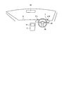
ここで、図2を用いて、運転支援制御システム1が搭載される車両の概略について説明する。図2は、運転支援制御システム1が搭載される車両の内部を示す概略図である。 Here, an outline of a vehicle in which the driving support control system 1 is mounted will be described with reference to FIG. FIG. 2 is a schematic diagram showing the inside of a vehicle in which the driving support control system 1 is mounted.
図2に示すように、ダッシュボードDには、インストルメントパネルIが設けられている。インストルメントパネルIには、左インジケータ31Lと、右インジケータ31Rが設けられている。ウィンカ操作部40は、ステアリングホイール50の右部に設けられている。この場合、運転者は、ウィンカ操作部40で左方向を指示すると左インジケータ31Lが点滅するとともに、図示しないウィンカ音出力部32から音が出力され、左方向のウィンカ発光部が点滅する。運転者は、ウィンカ操作部40で右方向を指示すると右インジケータ31Rが点滅するとともに、図示しないウィンカ音出力部32から音が出力され、右方向のウィンカ発光部が点滅する。また、車両には、インフォテインメントモニタ61を備えたセンターコンソールCと、リヤビューモニタ62などが設けられている。
As shown in FIG. 2, the dashboard D is provided with an instrument panel I. The instrument panel I is provided with a
再び図1を参照する。運転支援制御装置100は、経路案内部121と、位置情報取得部122と、判断部123と、ウィンカ動作制御部124と、ウィンカ操作受付部125とを備える。経路案内部121と、位置情報取得部122と、判断部123と、ウィンカ動作制御部124と、ウィンカ操作受付部125とは、バス110を介して互いに接続されている。このような運転支援制御装置100は、例えば、CPU(Central Processing Unit)を含む電子的な回路で実現することができる。
Referring back to FIG. The driving
経路案内部121は、例えば、ユーザに対して経路案内を実行する。経路案内部121は、例えば、ユーザから指示された目的地までの経路案内を、記憶部10に記憶されている地図データ11に基づいて実行する。例えば、経路案内部121は、車両の進行方向における交差点が右折を要する交差点である場合、インフォテインメントモニタ61に表示している地図に右折を案内する表示を行うとともに、「次の交差点を右方向です」といった音声案内を図示しないスピーカなどから出力することで、経路案内を実行する。この場合、経路案内部121は、現在位置に関する情報を位置情報取得部122から取得する。これにより、経路案内部121は、現在位置から目的地までの経路案内を地図データ11に基づいて実行する。
The route guidance unit 121 executes route guidance to the user, for example. The route guidance unit 121 executes, for example, route guidance to a destination designated by the user based on the
位置情報取得部122は、現在位置情報を取得する。位置情報取得部122は、例えば、GPS受信部20からGPS信号を取得し、取得したGPS信号に基づいて、現在位置情報を取得する。位置情報取得部122は、取得した現在位置情報を判断部123に出力する。位置情報取得部122は、取得した現在位置情報をウィンカ動作制御部124に出力してもよい。
The position
判断部123は、車両の現在位置がウィンカ操作の必要な位置であるか否かを判断する。判断部123は、例えば、経路案内部121による経路案内情報と、位置情報取得部122から受けた現在位置情報に基づいて、現在位置がウィンカ操作の必要な位置であるか否かを判定する。判断部123は、現在位置がウィンカ操作の必要な位置であった場合、第二操作信号をウィンカ動作制御部124に出力する。
The determination unit 123 determines whether or not the current position of the vehicle is a position where the blinker operation is required. The determination unit 123 determines, for example, based on the route guidance information by the route guidance unit 121 and the current position information received from the position
具体的には、判断部123は、例えば、現在位置と右左折地点との距離が、例えば30mなど、予め定めた所定の距離となった場合に、現在位置がウィンカ操作の必要な位置であると判断する。判断部123は、例えば、現在の走行速度に基づいて、現在位置から右左折地点まで予め定めた所定時間で到達する位置となった場合に、現在位置がウィンカ操作の必要な位置であると判断してもよい。判断部123は、例えば、地図データ11には右左折地点ごとに予め定められたウィンカ操作地点が登録されており、現在位置がウィンカ操作地点に到達した場合に、現在位置がウィンカ操作の必要な位置であると判断してもよい。判断部123は、例えば、経路案内部121が「次の交差点を右方向です」などの所定の音声案内を実行したときの位置をウィンカ操作の必要な位置であると判断してもよい。判断部123は、例えば、ナビゲーション装置の表示部に右左折する交差点の拡大画像などの所定の画像が表示される位置をウィンカ操作の必要な位置であると判断してもよい。
Specifically, for example, when the distance between the current position and the left or right turn point becomes a predetermined distance such as 30 m, the determination unit 123 determines that the current position is the position where the blinker operation is required. To judge. The determination unit 123 determines that the current position is a position that requires blinker operation, for example, when the position reaches the right/left turn point from the current position in a predetermined time based on the current traveling speed. You may. The determination unit 123 has, for example, a predetermined blinker operation point registered for each right/left turn point in the
ウィンカ動作制御部124は、ウィンカシステム30の動作を制御することによって、運転者に対して、ウィンカ操作部40を操作することを促す。ウィンカ動作制御部124は、ウィンカ操作受付部125から第一操作信号を受けた場合、ウィンカシステム30に対して第一制御信号を出力することで、ウィンカシステム30を第一状態で動作させる。ウィンカ動作制御部124は、判断部123から第二操作信号を受けた場合、ウィンカシステム30に対して第二制御信号を出力し、ウィンカシステム30を第一状態とは異なる第二状態で動作させて、運転者に対してウィンカ操作部40を操作することを促す。ウィンカ動作制御部124は、ウィンカシステム30が第二状態で動作している時に、第二状態で動作しているウィンカシステム30と同一方向に対応するウィンカ操作が行われた場合、ウィンカシステム30の動作を第一状態に推移させる。ウィンカ動作制御部124は、ウィンカ操作部40から解除信号を受け付けた場合、ウィンカシステム30の動作を終了する。ウィンカ動作制御部124は、インジケータ制御部1241と、ウィンカ音制御部1242と、ウィンカ発光制御部1243とを備える。
The turn signal
インジケータ制御部1241は、インジケータ31の動作を制御する。インジケータ制御部1241は、ウィンカ操作受付部125から第一操作信号を受けた場合には第一発光パターンでインジケータ31を発光させる。インジケータ制御部1241は、判断部123から第二操作信号を受けた場合には第一発光パターンとは異なる第二発光パターンでインジケータ31を発光させる。図2を例に説明すると、インジケータ制御部1241は、例えば、運転者に左折をさせたい場合、つまり左折を要する交差点の手前所定距離になった場合には左インジケータ31Lを第二発光パターンで発行させ、右折させたい場合、つまり右折を要する交差点の手前所定距離になった場合には右インジケータ31Rを第二発光パターンで発光させる。インジケータ制御部1241は、第二発光パターンとして、例えば、第一発光パターンとはインジケータ31の点滅の間隔を変えたり、インジケータ31を第一発光パターンとは異なる発光色で発光させるなど、運転者が第一発光パターンとは異なることが認識できる表示を行うことで、運転者に対してウィンカ操作部40を操作することを促す。インジケータ制御部1241は、第一発光パターンであるインジケータ31の点滅に対して、第二発光パターンの一例としては、インジケータ31を点滅させずに点灯状態とする。
The indicator control unit 1241 controls the operation of the indicator 31. When the indicator control unit 1241 receives the first operation signal from the winker operation reception unit 125, the indicator control unit 1241 causes the indicator 31 to emit light in the first light emission pattern. When the indicator control unit 1241 receives the second operation signal from the determination unit 123, the indicator control unit 1241 causes the indicator 31 to emit light in a second light emission pattern different from the first light emission pattern. Referring to FIG. 2 as an example, the indicator control unit 1241 issues the
インジケータ制御部1241は、例えば、インジケータ31を第二発光パターンで発光させている時に、インジケータ31と同一方向に対応するウィンカ操作が行われた場合、インジケータ31を第一発光パターンの動作に推移させる。インジケータ制御部1241は、例えば、インジケータ31を第二発光パターンで発光させたにも関わらず、運転者がウィンカ操作部40を操作しない場合には、インジケータ31の発光パターンをさらに変化させてもよい。図2を例に説明すると、運転者が、左方向のウィンカ操作をしない場合には左インジケータ31Lの発光パターンをさらに変化させ、右方向のウィンカ操作をしない場合には右インジケータ31Rの発光パターンをさらに変化させてもよい。この場合、インジケータ制御部1241は、例えば、現在位置と車両が進路変更する地点との距離に応じてインジケータ31の発光パターンを変化させればよい。具体的には、インジケータ制御部1241は、現在位置と進路変更する地点との距離が短くなるに連れて、インジケータ31の点滅の間隔を短くしたり、色を緑から赤に変更したりすればよい。この場合、インジケータ制御部1241は、現在位置と進路変更する地点との距離が短くなるに連れて、発光パターンを徐々に変化させてもよいし、段階的に変化させてもよい。インジケータ制御部1241は、現在位置の情報を、例えば、位置情報取得部122から取得するようにすればよい。
The indicator control unit 1241 shifts the indicator 31 to the operation of the first light emission pattern, for example, when the blinker operation corresponding to the same direction as the indicator 31 is performed while the indicator 31 is emitting light in the second light emission pattern. .. The indicator control unit 1241 may further change the light emission pattern of the indicator 31 when the driver does not operate the
ウィンカ音制御部1242は、ウィンカ音出力部32の動作を制御する。ウィンカ音制御部1242は、ウィンカ操作受付部125から第一操作信号を受けた場合にはウィンカ音出力部32から第一出力パターンでウィンカ音を出力する。ウィンカ音制御部1242は、判断部123から第二操作信号を受けた場合にはウィンカ音出力部32から第一出力パターンとは異なる第二出力パターンでウィンカ音を出力する。ウィンカ音制御部1242は、例えば、第二出力パターンとして、第一出力パターンとはウィンカ音の音と音との間隔を短くしたり、音の大きさを変化したり、音の種類を変化したりして、運転者に対してウィンカ操作部40を操作することを促す。また、ウィンカ音制御部1242は、第一操作信号を受けた場合にはウィンカ音出力部32からウィンカ音を出力させ、第二操作信号を受けた場合にはウィンカ音出力部32からウィンカ音を出力しないようにしてもよい。
The winker sound control unit 1242 controls the operation of the winker
ウィンカ音制御部1242は、例えば、第二出力パターンでウィンカ音を出力させている時に、第二発光パターンで動作しているインジケータ31と同一方向に対応するウィンカ操作が行われた場合、第一出力パターンの動作に推移させる。ウィンカ音制御部1242は、例えば、ウィンカ音出力部32から第二出力パターンでウィンカ音を出力したにも関わらず、運転者がウィンカ操作部40を操作しない場合には、ウィンカ音の出力パターンをさらに変化させてもよい。この場合、ウィンカ音制御部1242は、例えば、現在位置と車両が進路変更する地点との距離に応じてウィンカ音の出力パターンを変化させればよい。具体的には、ウィンカ音制御部1242は、現在位置と進路変更する地点との距離が短くなるにつれて、ウィンカ音の音と音との間隔を短くしたり、音を大きくしたりすればよい。ウィンカ音制御部1242は、現在位置の情報を、例えば、位置情報取得部122から取得すればよい。
For example, when the blinker sound control unit 1242 outputs the blinker sound in the second output pattern, when the blinker operation corresponding to the same direction as the indicator 31 operating in the second light emission pattern is performed, Change to output pattern operation. The winker sound control unit 1242 outputs the winker sound output pattern when the driver does not operate the
また、現在位置と、進路変更する地点までの間に、進路変更する方向と同一方向の曲がり角などが複数ある場合には、進路変更する地点の直前の曲がり角を過ぎてからウィンカシステム30を動作するようにすればよい。 In addition, when there are a plurality of bends in the same direction as the direction of course change between the current position and the point of course change, the winker system 30 is operated after passing the bend immediately before the point of course change. You can do it like this.
図3を用いて、進路変更する方向と同一方向の曲がり角などが複数ある場合の運転支援制御装置の動作について説明する。図3は、進路変更する方向と同一方向の曲がり角などが複数ある場合の運転支援制御装置の動作について説明するための模式図である。 The operation of the driving support control device in the case where there are a plurality of turning angles and the like in the same direction as the direction for changing the course will be described with reference to FIG. FIG. 3 is a schematic diagram for explaining the operation of the driving support control device in the case where there are a plurality of turning angles in the same direction as the direction of course change.
図3において、車両V1は、道路R1を走行しており、道路R2に対して左折するものとする。そして、車両V1の進行方向には、左折可能な道路R3と、道路R4とがあるものとする。道路R2と、道路R3と、道路R4との距離が比較的近い場合には、車両V1のウィンカの操作によっては、後続する他車両V2に誤解を与えてしまうおそれがある。 In FIG. 3, the vehicle V1 is traveling on the road R1 and turns left with respect to the road R2. Then, in the traveling direction of the vehicle V1, there are a road R3 and a road R4 that can turn left. When the roads R2, R3, and R4 are relatively close to each other, the operation of the winker of the vehicle V1 may give a misunderstanding to the following other vehicle V2.
インジケータ制御部1241と、ウィンカ音制御部1242とは、例えば、道路R2の直前の道路R3を過ぎて、区間S1に差し掛かってから、それぞれ、インジケータ31と、ウィンカ音出力部32とを、第二状態で動作させるようにすればよい。インジケータ制御部1241と、ウィンカ音制御部1242とは、車両V1が区間S1に差し掛かったか否かについては、位置情報取得部122から取得した車両V1の現在位置に関する情報に基づいて判断するようにすればよい。
For example, the indicator control unit 1241 and the blinker sound control unit 1242 pass the road R3 immediately before the road R2 and approach the section S1, and then, respectively, the indicator 31 and the blinker
再び図1を参照する。ウィンカ発光制御部1243は、ウィンカ発光部33の動作を制御する。ウィンカ発光制御部1243は、ウィンカ操作受付部125から第一操作信号を受けた場合にウィンカ発光部33の動作を制御する。具体的には、ウィンカ発光制御部1243は、第一操作信号に従った方向のウィンカ発光部33を発光させる。
Referring back to FIG. The blinker light
ウィンカ操作受付部125は、例えば、ウィンカ操作部40から第一操作信号を受け付ける。ウィンカ操作受付部125は、例えば、ウィンカ操作部40の操作が解除された場合にウィンカ操作部40から解除信号を受け付ける。ウィンカ操作受付部125は、ウィンカ操作部40から受け付けた第一操作信号および解除信号をウィンカ動作制御部124に出力する。
The winker operation receiving unit 125 receives the first operation signal from the
なお、ウィンカ動作制御部124が第二状態でインジケータ31を動作させたにも関わらず、運転者がウィンカ操作部40を操作しなかった場合には、現在位置から目的地までの経路を再検索してもよい。また、第二状態でインジケータ31を動作させた第一方向とは異なる第二方向にウィンカ操作がされた場合にも、現在位置から目的地までの経路を再検索してもよい。具体的には、経路案内部121は、車両が進行する道なり方向に基づいて、現在位置から目的地までの経路を再検索する。
If the driver does not operate the
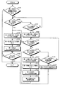
次に、図4を用いて、実施形態に係る運転支援制御装置の処理について説明する。図4は、運転支援制御装置の処理の流れの一例を示すフローチャートである。 Next, processing of the driving support control device according to the embodiment will be described with reference to FIG. FIG. 4 is a flowchart showing an example of the processing flow of the driving support control device.
まず、運転支援制御装置100は、ステップS101において、第一方向に進路変更する予定があるか否かを判定する。具体的には、運転支援制御装置100は、経路案内部121によって、進路変更を要する交差点等が存在するか否かを判定する。
First, the driving
第一方向に進路変更する予定がない場合(ステップS101の「No」)、運転支援制御装置100は、図4の処理を終了する。一方、第一方向に進路変更する予定がある場合(ステップS101の「Yes」)、運転支援制御装置100は、ステップS102に進む。
When there is no plan to change the course in the first direction (“No” in step S101), the driving
次に、運転支援制御装置100は、ステップS102において、第一方向のウィンカ操作が有ったか否かを判定する。具体的には、運転支援制御装置100は、ウィンカ操作受付部125によって、ウィンカ操作が有ったか否かを判定する。
Next, the driving
第一方向のウィンカ操作が有った場合(ステップS102の「Yes」)、運転支援制御装置100は、ステップS103に進む。
When there is the blinker operation in the first direction (“Yes” in step S102), the driving
次に、運転支援制御装置100は、第一状態で第一方向のインジケータ31を点滅させ(ステップS103)、第一状態でウィンカ音を出力させ(ステップS104)。
、第一方向のウィンカ発光部33を点滅させる(ステップS105)。ステップS103からステップS105の処理は、同時またはほぼ同時に行われる。
Next, the driving
, Blinks the blinker
次に、運転支援制御装置100は、ステップS106において、ウィンカ動作が終了したか否かを判定する。具体的には、運転支援制御装置100は、ウィンカ操作受付部125によって、ウィンカ動作が終了したか否かを判定する。
Next, the driving
ウィンカ動作が終了した場合(ステップS106の「Yes」)、運転支援制御装置100は、図4の処理を終了する。一方、ウィンカ動作が終了していない場合には(ステップS106の「No」)、運転支援制御装置100は、ステップS106の処理を繰り返し実行する。
When the winker operation is completed (“Yes” in step S106), the driving
そして、ステップS102において、第一方向のウィンカ操作がなかった場合(ステップS102の「No」)、運転支援制御装置100は、ステップS107に進む。
Then, in step S102, when there is no blinker operation in the first direction (“No” in step S102), the driving
次に、運転支援制御装置100は、ステップS107において、現在位置がウィンカ操作の必要区間であるか否かを判定する。具体的には、運転支援制御装置100は、経路案内部121によって、現在位置がウィンカ操作の必要区間であるか否かを判定する。
Next, the driving
現在位置がウィンカ操作の必要区間でなかった場合(ステップS107の「No」)、運転支援制御装置100は、ステップS102に戻る。一方、現在位置がウィンカ操作の必要区間である場合(ステップS107の「Yes」)、運転支援制御装置100は、ステップS108に進む。
When the current position is not the required section for blinker operation (“No” in step S107), the driving
次に、運転支援制御装置100は、第二状態で第一方向のインジケータ31を点滅させる(ステップS108)。具体的には、運転支援制御装置100は、インジケータ制御部1241によってインジケータ31を点滅させずに点灯させる。なお、ステップS108において、運転支援制御装置100は、第二状態でウィンカ音を出力させてもよく、第二状態としてウィンカ音を出力させなくてもよい。そして、運転支援制御装置100は、ステップS109に進む。
Next, the driving
次に、運転支援制御装置100は、ステップS109において、第一方向のウィンカ操作があったか否かを判定する。具体的には、運転支援制御装置100は、ウィンカ操作受付部125によって、ウィンカ操作があったか否かを判定する。
Next, the driving
第一方向のウィンカ操作があった場合(ステップS109の「Yes」)、運転支援制御装置100は、ステップS103に進み、上述した処理を実行する。すなわち、運転支援制御装置100は、インジケータ31の動作を第二状態から第一状態に推移させる。一方、第一方向のウィンカ操作がなかった場合(ステップS109の「No」)、運転支援制御装置100は、ステップS110に進む。
When there is the blinker operation in the first direction (“Yes” in step S109), the driving
次に、運転支援制御装置100は、ステップS110において、第一方向とは異なる第二方向のウィンカ操作があったか否かを判定する。具体的には、運転支援制御装置100は、ウィンカ操作受付部125によって、ウィンカ操作があったか否かを判定する。
Next, in step S110, the driving
第二方向のウィンカ操作があった場合(ステップS110の「Yes」)、運転支援制御装置100は、ステップS111に進む。
When there is a winker operation in the second direction (“Yes” in step S110), the driving
次に、運転支援制御装置100は、第一状態で第二方向のインジケータ31を点滅させ(ステップS111)、第一状態でウィンカ音を出力させ(ステップS112)、第一方向のウィンカ発光部33を点滅させる(ステップS113)。ステップS111からステップS112の処理は、同時またはほぼ同時に行われる。
Next, the driving
次に、運転支援制御装置100は、第二方向から目的地までの経路を再設定する(ステップS114)。具体的には、運転支援制御装置100は、経路案内部121によって、目的地までの経路を再設定する。そして、運転支援制御装置100は、ステップS106に進み、上述した処理を実行する。
Next, the driving
そして、ステップS110において、第一方向のウィンカ操作がなかった場合(ステップS110の「No」)、運転支援制御装置100は、ステップS115に進む。
Then, in step S110, when there is no blinker operation in the first direction (“No” in step S110), the driving
次に、運転支援制御装置100は、ステップS115において、現在位置がウィンカ操作の必要区間が終了したか否かを判定する。具体的には、運転支援制御装置100は、経路案内部121によって、ウィンカ操作の必要区間が終了したか否かを判定する。
Next, in step S115, the driving
ウィンカ操作の必要区間が終了していない場合(ステップS115の「No」)、運転支援制御装置100は、ステップS109に進み、上述の処理を実行する。一方、ウィンカ操作の必要区間が終了している場合(ステップS115の「Yes」)、運転支援制御装置100は、ステップS116に進む。
When the required section for blinker operation has not ended (“No” in step S115), the driving
次に、運転支援制御装置100は、道なり方向での目的地までの経路を再設定する(ステップS116)。具体的には、運転支援制御装置100は、経路案内部121によって、目的地までの経路を再設定する。そして、運転支援制御装置100は、図4の処理を終了する。
Next, the driving
上述のとおり、本実施形態は、ウィンカ操作の必要区間においてウィンカの操作が実行されていない場合、ウィンカ操作が行われた際の第一状態の動作とは異なる第二状態でインジケータ31を動作させることができる。また、インジケータ31は、運転者が車両を運転している際の視線の方向に設けられているので、例えば、ナビゲーション装置などの表示部でウィンカ操作を促す場合と比較して、運転者はウィンカ操作をすべきことを容易に把握することができる。その結果、本実施形態は、ウィンカの操作をすべき地点において、運転者に対してウィンカの操作を適切に促すことができる。 As described above, in the present embodiment, when the blinker operation is not executed in the required section of the blinker operation, the indicator 31 is operated in the second state different from the operation in the first state when the blinker operation is performed. be able to. Further, since the indicator 31 is provided in the direction of the line of sight of the driver when the driver is driving the vehicle, the driver can turn on the winker in comparison with a case where the winker operation is prompted on the display unit such as a navigation device. It is possible to easily understand what to do. As a result, the present embodiment can appropriately prompt the driver to operate the winker at the point where the winker should be operated.
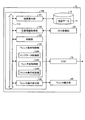
[変形例]
図5を用いて、本実施形態の変形例に係る運転支援制御システムについて説明する。図5は、本実施形態の変形例に係る運転支援制御システムの構成の一例を示すブロック図である。
[Modification]
A driving support control system according to a modified example of the present embodiment will be described with reference to FIG. FIG. 5: is a block diagram which shows an example of a structure of the driving assistance control system which concerns on the modification of this embodiment.
図5に示すように、運転支援制御システム1Aは、記憶部10と、GPS受信部20と、ウィンカ操作部40と、ECU(Engine Control Unit)70と、運転支援制御装置100とを備えている。運転支援制御システム1Aは、ECU70を備えている点で、運転支援制御システム1とは異なっている。
As shown in FIG. 5, the driving assistance control system 1A includes a
運転支援制御システム1Aにおいては、ウィンカ動作制御部124は、ウィンカシステム30を動作させるための情報を含む制御信号をECU70に出力する。すなわち、ウィンカ動作制御部124は、ECU70を介して、ウィンカシステム30を間接的に制御する。
In the driving assistance control system 1A, the winker
上述のとおり、本実施形態の変形例によれば、ウィンカ動作制御部124は、ウィンカシステム30を直接的に制御するだけでなく、ECU70を介して、間接的にウィンカシステム30を制御することができる。これにより、本実施形態の変形例は、運転者に対して、ウィンカ操作を適切に促すことができる。
As described above, according to the modified example of the present embodiment, the
なお、実施形態および実施形態の変形例では、インストルメントパネルIにインジケータ31(31L、31R)が配置されているものとして説明したが、これは例示であり、本発明を限定するものではない。例えば、図示しないナビゲーション装置の表示部に、運転者に対してウィンカ操作を促すためのインジケータ表示を表示させてもよい。 In the embodiment and the modification of the embodiment, the indicator 31 (31L, 31R) is arranged on the instrument panel I, but this is an example and does not limit the present invention. For example, an indicator display for prompting the driver to operate the blinker may be displayed on the display unit of the navigation device (not shown).
以上、本発明の実施形態を説明したが、これら実施形態の内容により実施形態が限定されるものではない。また、上述した構成要素には、当業者が容易に想定できるもの、実質的に同一のもの、いわゆる均等の範囲のものが含まれる。さらに、上述した構成要素は適宜組み合わせることが可能である。さらに、上述した実施形態の要旨を逸脱しない範囲で構成要素の種々の省略、置換または変更を行うことができる。 Although the embodiments of the present invention have been described above, the embodiments are not limited by the contents of these embodiments. Further, the above-described constituent elements include those that can be easily assumed by those skilled in the art, substantially the same elements, and so-called equivalent ranges. Furthermore, the components described above can be combined appropriately. Furthermore, various omissions, replacements, or changes of the constituent elements can be made without departing from the scope of the above-described embodiment.
1,1A 運転支援制御システム
10 記憶部
11 地図データ
20 GPS受信部
30 ウィンカシステム
31 インジケータ
32 ウィンカ音出力部
33 ウィンカ発光部
40 ウィンカ操作部
100 運転支援制御装置
110 バス
121 経路案内部
122 位置情報取得部
123 判断部
124 ウィンカ動作制御部
1241 インジケータ制御部
1242 ウィンカ音制御部
1243 ウィンカ発光制御部
125 ウィンカ操作受付部
1, 1A Driving
Claims (10)
前記車両の現在位置情報を取得する位置情報取得部と、
前記車両の現在位置が、前記経路案内部の案内においてウィンカ操作が必要となる位置であるか判断する判断部と、
前記ウィンカ操作が必要となる位置であると判断されたときに、ウィンカを操作するウィンカ操作部が操作されていない場合、前記車両の運転者がウィンカ動作を確認するインジケータを、前記ウィンカ操作による第一状態の動作とは異なる第二状態で動作させるインジケータ制御部と、
を備える、運転支援制御装置。 A route guidance section that provides route guidance for vehicles,
A position information acquisition unit that acquires the current position information of the vehicle,
A determination unit that determines whether or not the current position of the vehicle is a position where blinker operation is required in the guidance of the route guidance unit;
When it is determined that the position where the winker operation is required, if the winker operation unit that operates the winker is not operated, an indicator for the driver of the vehicle to confirm the winker operation is displayed by the operation of the winker. An indicator control unit that operates in a second state different from the one-state operation,
And a driving support control device.
請求項1に記載の運転支援制御装置。 The indicator control unit, when the blinker operation corresponding to the same direction as the indicator operating in the second state is performed while operating the indicator in the second state, the first state Transition to the operation of
The driving assistance control device according to claim 1.
請求項1または2に記載の運転支援制御装置。 The indicator control unit, in the first state and the second state, lights the indicator in a different pattern,
The driving assistance control device according to claim 1.
請求項1から3のいずれか1項に記載の運転支援制御装置。 A winker sound control unit that outputs a winker sound in the first state and does not output a winker sound in the second state is further provided.
The driving assistance control device according to any one of claims 1 to 3.
請求項1から4のいずれか1項に記載の運転支援制御装置。 The indicator control unit has a route that can travel in the same direction as the direction instructed by the blinker operation between the current position and the right/left turn point where the vehicle actually turns right or left in the direction according to the blinker operation. If there are two or more, the indicator is operated after passing the travelable route immediately before the turning point.
The driving assistance control device according to any one of claims 1 to 4.
請求項5に記載の運転支援制御装置。 The indicator control unit changes the operation of the indicator in the second state according to the distance from the current position to the right/left turn point,
The driving assistance control device according to claim 5.
請求項1から6のいずれか1項に記載の運転支援制御装置。 The route guidance unit, in the operation period of the second state, when the blinker operation corresponding to the same direction as the indicator operating in the second state is not performed, the destination in the traveling direction of the vehicle. Reset the route to,
The driving assistance control device according to any one of claims 1 to 6.
前記運転者が前記ウィンカ動作を確認するインジケータと、
前記ウィンカ操作を実行するウィンカ操作部と、
を備える、運転支援制御システム。 A driving assistance control device according to any one of claims 1 to 7,
An indicator for the driver to confirm the operation of the blinker,
A winker operation unit for executing the winker operation,
And a driving support control system.
前記車両の現在位置情報を取得する位置情報取得ステップと、
前記車両の現在位置が、前記経路案内ステップによる案内においてウィンカ操作が必要となる位置であるか判断する判断ステップと、
前記ウィンカ操作が必要となる位置であると判断されたときに、ウィンカを操作するウィンカ操作部が操作されていない場合、前記車両の運転者がウィンカ動作を確認するインジケータを、前記ウィンカ操作による第一状態の動作とは異なる第二状態で動作させるインジケータ制御ステップと、
を含む、運転支援制御方法。 A route guidance step of providing route guidance to the vehicle,
A position information acquisition step of acquiring the current position information of the vehicle,
A determination step of determining whether or not the current position of the vehicle is a position where a blinker operation is required in the guidance in the route guidance step;
When it is determined that the position where the winker operation is required, if the winker operation unit that operates the winker is not operated, an indicator for the driver of the vehicle to confirm the winker operation is displayed by the operation of the winker. An indicator control step of operating in a second state different from the one-state operation,
And a driving support control method.
前記車両の現在位置情報を取得する位置情報取得ステップと、
前記車両の現在位置が、前記経路案内ステップによる案内においてウィンカ操作が必要となる位置であるか判断する判断ステップと、
前記ウィンカ操作が必要となる位置であると判断されたときに、ウィンカを操作するウィンカ操作部が操作されていない場合、前記車両の運転者がウィンカ動作を確認するインジケータを、前記ウィンカ操作による第一状態の動作とは異なる第二状態で動作させるインジケータ制御ステップと、
をコンピュータに実行させるための運転支援制御プログラム。 A route guidance step of providing route guidance to the vehicle,
A position information acquisition step of acquiring the current position information of the vehicle,
A determination step of determining whether or not the current position of the vehicle is a position where a blinker operation is required in the guidance in the route guidance step;
When it is determined that the position where the winker operation is required, if the winker operation unit that operates the winker is not operated, an indicator for the driver of the vehicle to confirm the winker operation is displayed by the operation of the winker. Indicator control step to operate in a second state different from the one-state operation,
Driving support control program for causing a computer to execute.
Priority Applications (1)
| Application Number | Priority Date | Filing Date | Title |
|---|---|---|---|
| JP2018213757A JP2020080098A (en) | 2018-11-14 | 2018-11-14 | Driving support control device, driving support control system, driving support control method, and driving support control program |
Applications Claiming Priority (1)
| Application Number | Priority Date | Filing Date | Title |
|---|---|---|---|
| JP2018213757A JP2020080098A (en) | 2018-11-14 | 2018-11-14 | Driving support control device, driving support control system, driving support control method, and driving support control program |
Publications (1)
| Publication Number | Publication Date |
|---|---|
| JP2020080098A true JP2020080098A (en) | 2020-05-28 |
Family
ID=70801845
Family Applications (1)
| Application Number | Title | Priority Date | Filing Date |
|---|---|---|---|
| JP2018213757A Pending JP2020080098A (en) | 2018-11-14 | 2018-11-14 | Driving support control device, driving support control system, driving support control method, and driving support control program |
Country Status (1)
| Country | Link |
|---|---|
| JP (1) | JP2020080098A (en) |
Cited By (1)
| Publication number | Priority date | Publication date | Assignee | Title |
|---|---|---|---|---|
| JP2024144474A (en) * | 2021-07-07 | 2024-10-11 | トヨタ自動車株式会社 | Vehicle display control device, display method and program |
Citations (3)
| Publication number | Priority date | Publication date | Assignee | Title |
|---|---|---|---|---|
| JPH0719891A (en) * | 1993-07-01 | 1995-01-20 | Aqueous Res:Kk | Navigation device |
| JP2006242905A (en) * | 2005-03-07 | 2006-09-14 | Aisin Aw Co Ltd | Driving support device, and driving support method |
| JP2009210292A (en) * | 2008-02-29 | 2009-09-17 | Pioneer Electronic Corp | Route searching device, navigation system, route searching method, navigation method, route searching program, navigation program and recording medium |
-
2018
- 2018-11-14 JP JP2018213757A patent/JP2020080098A/en active Pending
Patent Citations (3)
| Publication number | Priority date | Publication date | Assignee | Title |
|---|---|---|---|---|
| JPH0719891A (en) * | 1993-07-01 | 1995-01-20 | Aqueous Res:Kk | Navigation device |
| JP2006242905A (en) * | 2005-03-07 | 2006-09-14 | Aisin Aw Co Ltd | Driving support device, and driving support method |
| JP2009210292A (en) * | 2008-02-29 | 2009-09-17 | Pioneer Electronic Corp | Route searching device, navigation system, route searching method, navigation method, route searching program, navigation program and recording medium |
Cited By (4)
| Publication number | Priority date | Publication date | Assignee | Title |
|---|---|---|---|---|
| JP2024144474A (en) * | 2021-07-07 | 2024-10-11 | トヨタ自動車株式会社 | Vehicle display control device, display method and program |
| JP7687498B2 (en) | 2021-07-07 | 2025-06-03 | トヨタ自動車株式会社 | Vehicle display control device, display method and program |
| JP2025105888A (en) * | 2021-07-07 | 2025-07-10 | トヨタ自動車株式会社 | Vehicle display control device, display method and program |
| JP7794352B2 (en) | 2021-07-07 | 2026-01-06 | トヨタ自動車株式会社 | Vehicle display control device, display method and program |
Similar Documents
| Publication | Publication Date | Title |
|---|---|---|
| JP7206010B2 (en) | Control device | |
| JP7120963B2 (en) | display unit | |
| WO2020261781A1 (en) | Display control device, display control program, and persistent tangible computer-readable medium | |
| JP2004505258A (en) | Car navigation method | |
| JP4590679B2 (en) | Navigation device | |
| WO2021002081A1 (en) | Display control device and display control program | |
| JP6631572B2 (en) | Display control device for vehicle and display unit for vehicle | |
| WO2019097762A1 (en) | Superimposed-image display device and computer program | |
| JP6318757B2 (en) | Navigation device and vehicle control system | |
| JP2023009653A (en) | Vehicle display control device, display method and program | |
| JP2010120501A (en) | Visual guide supporting device and vehicular display system | |
| JP4497316B2 (en) | Vehicle information display device | |
| JP4650247B2 (en) | Car navigation system | |
| JP5169740B2 (en) | Road information guidance device, road information guidance method, and road information guidance program | |
| JPH09184737A (en) | Navigation system | |
| US20200031227A1 (en) | Display control apparatus and method for controlling display | |
| JP2020080098A (en) | Driving support control device, driving support control system, driving support control method, and driving support control program | |
| JP4775131B2 (en) | Vehicle driving assistance device | |
| JP2006242905A (en) | Driving support device, and driving support method | |
| JP2019174214A (en) | Navigation system and navigation program | |
| JP7252253B2 (en) | Routing device, routing method, and program | |
| JP2022061902A (en) | Vehicle display device | |
| JP2016038613A (en) | Danger point warning device and danger point warning program | |
| JP2008181315A (en) | Driving-support method and driving-support device | |
| JP2007127504A (en) | Vehicle navigation device |
Legal Events
| Date | Code | Title | Description |
|---|---|---|---|
| A621 | Written request for application examination |
Free format text: JAPANESE INTERMEDIATE CODE: A621 Effective date: 20210226 |
|
| A131 | Notification of reasons for refusal |
Free format text: JAPANESE INTERMEDIATE CODE: A131 Effective date: 20220208 |
|
| A02 | Decision of refusal |
Free format text: JAPANESE INTERMEDIATE CODE: A02 Effective date: 20220802 |