JP2020075813A - Automation multicore power cable facility for punching unit - Google Patents
Automation multicore power cable facility for punching unit Download PDFInfo
- Publication number
- JP2020075813A JP2020075813A JP2019003932A JP2019003932A JP2020075813A JP 2020075813 A JP2020075813 A JP 2020075813A JP 2019003932 A JP2019003932 A JP 2019003932A JP 2019003932 A JP2019003932 A JP 2019003932A JP 2020075813 A JP2020075813 A JP 2020075813A
- Authority
- JP
- Japan
- Prior art keywords
- space
- end wall
- fixedly connected
- slot
- lift
- Prior art date
- Legal status (The legal status is an assumption and is not a legal conclusion. Google has not performed a legal analysis and makes no representation as to the accuracy of the status listed.)
- Ceased
Links
Images

Landscapes
- Transmission Devices (AREA)
Abstract
Description
本発明はケーブル製造分野に関し、具体的には穴あけユニット用の自動化多芯動力ケーブル設備のである。 The present invention relates to the field of cable manufacturing, and in particular to an automated multi-core power cable installation for drilling units.
科学技術の発展や社会の進歩に伴って、ケーブルの使用量がますます高まっています。現段階における穴あけユニット用の多芯動力ケーブルは複数のケーブルから組み合わせられ、ケーブルの製造中では特に最後のケーブルを巻く工程で、ケーブルから受ける付勢力が軸の使用寿命に大きな影響を及ぼし、且つ現在のこういうタイプのローラーを交換する工程は一般に大型機械を通じて操作し、作業量をひどく増加し、作業効率を下げる。 With the development of science and technology and the progress of society, the amount of cables used is increasing more and more. The multi-core power cable for the drilling unit at this stage is composed of a plurality of cables, and the urging force received from the cable has a great influence on the service life of the shaft, especially in the final step of winding the cable during the manufacture of the cable, and The current process of replacing these types of rollers is generally operated through large machines, which greatly increases the amount of work and reduces work efficiency.
本発明が解決する技術問題は穴あけユニット用の自動化多芯動力ケーブル設備を提供し、上記した技術的問題を解決する。 The technical problem to be solved by the present invention is to provide an automated multi-core power cable installation for a drilling unit and solve the above technical problem.
本発明は下記の技術プランを通じて実現される:本発明の穴あけユニット用の自動化多芯動力ケーブル設備は、整経台を含み、前記整経台の中にはリフトスペースが内設され、前記リフトスペースの中にはリフト機構が内設され、前記リフトスペースの下端壁の中には交換機構が内設され、前記リフトスペースの上端壁には上端壁が外界空間と連通する移動スペースが内設され、前記移動スペースの右端壁には移動モータが固定接続され、前記移動モータの左端面には移動軸が動力が伝達できるように接続され、前記移動軸の左端には上端が前記移動スペースの上端壁を貫通し且つ外界空間に位置する移動柱が螺合接続され、前記移動スペースの中に位置する前記移動柱の左端面には前記移動ボードが固定接続され、前記移動ボードの上端面の中には上端壁が外界空間と連通するリミットスロットが内設され、前記移動ボードの中には上端壁が前記リミットスロットと連通し且つ下端壁が前記移動スペースの下端壁と前記移動ボードの下端面とを貫通して前記リフトスペースと連通するリフトスロットが内設され、前記整経台の上端面には支持柱が固定接続され、前記支持柱の中には駆動スペースが内設され、前記駆動スペースの中には駆動ボードがスライドできるように接続され、前記駆動ボードの上端面には駆動モータが固定接続され、前記駆動モータの右端面には右端が前記駆動スペースの右端壁を貫通し且つ外界空間に位置する駆動軸が動力が伝達できるように接続され、前記駆動軸の右端にはプッシュボードが上下対称で固定接続され、前記駆動ボードの下端面には下端が前記駆動スペースの下端壁と前記リフトスペースの上端壁とを貫通し且つ前記リフトスペースの中に位置する駆動レバーが固定接続され、前記移動柱の中には移動スロットが内設され、前記移動スロットの中には移動ブロックがスライドできるように接続され、前記移動ブロックの左端には左端が前記移動スロットの左端壁を貫通し且つ外界空間に位置するプッシュ軸が軸受を介して接続され、前記プッシュ軸の左端の中には接続機構が内設され、前記移動ブロックの下端面には下端が前記移動スロットの下端壁と前記リフトスペースの上端壁を貫通し且つ前記リフトスペースの中に位置する移動レバーが固定接続され、前記支持柱の右側には巻軸が設置され、前記巻軸の左右両端にはリールが固定接続され、前記巻軸の左側の前記リールの中には伝達機構が内設され、前記巻軸の右側の前記リールの中には右端壁が外界空間と連通する接続スロットが内設され、前記プッシュ軸の左端が前記接続スロットの右端壁を貫通し且つ前記接続スロットの中に位置し、前記接続スロットの上下端壁には前記プッシュ軸に近接する端壁が前記接続スロットに連通する収容スロットが対称で設置され、前記整経台の右端面には警告機構が設置される。 The present invention is realized through the following technical plan: The automated multi-core power cable equipment for a drilling unit of the present invention includes a warping table, and a lift space is provided in the warping table, and the lift is provided. A lift mechanism is internally provided in the space, an exchange mechanism is internally provided in a lower end wall of the lift space, and a moving space having an upper end wall communicating with an external space is provided in an upper end wall of the lift space. A moving motor is fixedly connected to a right end wall of the moving space, a moving shaft is connected to a left end surface of the moving motor so that power can be transmitted, and an upper end of the moving shaft has an upper end of the moving space. A moving pillar that penetrates the upper end wall and is located in the external space is screwed and connected, and the moving board is fixedly connected to the left end surface of the moving pillar that is located in the moving space. A limit slot having an upper end wall communicating with an external space is provided therein, and an upper end wall communicates with the limit slot and a lower end wall has a lower end wall of the moving space and a lower part of the moving board. A lift slot penetrating the end face and communicating with the lift space is internally provided, a support column is fixedly connected to the upper end face of the warping table, and a drive space is internally provided in the support column. A drive board is slidably connected in the drive space, a drive motor is fixedly connected to an upper end surface of the drive board, and a right end of the drive motor penetrates a right end wall of the drive space. A drive shaft located in the external space is connected so that power can be transmitted, a push board is vertically and fixedly connected to the right end of the drive shaft, and a lower end of the drive board has a lower end at the lower end of the drive space. A drive lever penetrating the wall and the upper end wall of the lift space and located in the lift space is fixedly connected, a moving slot is internally provided in the moving column, and a moving slot is moved in the moving slot. The block is slidably connected to the left end of the moving block, and the left end of the moving block is connected to a push shaft penetrating the left end wall of the moving slot and located in the external space through a bearing. A connecting mechanism is internally provided in the moving block, and a lower end surface of the moving block has a lower end fixedly connected to a moving lever which penetrates a lower end wall of the moving slot and an upper end wall of the lift space and is located in the lift space. A winding shaft is installed on the right side of the support column, and reels are fixedly connected to the left and right ends of the winding shaft. A transmission mechanism is installed therein, a right end wall is internally provided with a connection slot in the reel on the right side of the winding shaft, and a left end of the push shaft is a right end wall of the connection slot. A receiving slot that penetrates and is located in the connection slot, and end walls near the push shaft that communicate with the connection slot is installed symmetrically on the upper and lower end walls of the connection slot, and the right end of the warping table A warning mechanism is installed on the surface.
優先的には、前記リフト機構はリフトボードを含み、前記リフトスペースの中には前記リフトボードがスライドできるように接続され、前記リフトボードの下端面には従動電磁石が固定接続され、前記リフトスペースの下端壁には主動電磁石が固定接続され、前記リフトボードの下端面には前記従動電磁石を中心として左右対称してリフトばねが固定接続され、前記リフトばねの下端が前記リフトスペースの下端壁と固定接続され、前記リフトボードの上端面には左右対称してリフトボードが固定接続され、前記リフトブロックの上端面には左右対称してリフト柱が固定接続され、且つ二つの前記リフト柱の間にはリフト軸が固定接続され、前記リフト軸の軸体には支持輪が軸受によって接続され、前記リフトブロックのうち前記リフトスペースの中心から遠離する一側には前記リフトボードの上端面と固定接続される固定ブロックが設置され、前記固定ブロックの中には上端壁が前記リフトスペースと連通するばねスロットが設置され、前記ばねスロットの下端壁には接続ばねが固定接続され、前記駆動レバーの下端が前記リフトボードの上端面の左側の前記ばねスロットの上端壁を貫通し且つ前記接続ばねと固定接続され、前記移動レバーの下端が前記リフトボードの上端面右側の前記ばねスロットの上端壁を貫通し且つ前記接続ばねと固定接続される。 Preferentially, the lift mechanism includes a lift board, the lift board is slidably connected to the lift space, and a driven electromagnet is fixedly connected to a lower end surface of the lift board. A main electromagnet is fixedly connected to a lower end wall of the lift board, and a lift spring is fixedly connected to the lower end surface of the lift board symmetrically about the driven electromagnet, and a lower end of the lift spring is a lower end wall of the lift space. The lift board is fixedly connected to the upper end surface of the lift board symmetrically, and the lift column is fixedly connected to the upper end surface of the lift block symmetrically to the upper end surface, and between the two lift pillars. A lift shaft is fixedly connected to the lift shaft, and a support wheel is connected to a shaft body of the lift shaft by a bearing. One side of the lift block that is far from the center of the lift space is fixed to the upper end surface of the lift board. A fixed block to be connected is installed, a spring slot having an upper end wall communicating with the lift space is installed in the fixed block, and a connection spring is fixedly connected to a lower end wall of the spring slot, The lower end penetrates the upper end wall of the spring slot on the left side of the upper end surface of the lift board and is fixedly connected to the connecting spring, and the lower end of the moving lever connects the upper end wall of the spring slot on the right side of the upper end surface of the lift board. It penetrates and is fixedly connected to the connection spring.
優先的には、前記交換機構はラックスペースを含み、前記リフトスペースの下端壁の中にはラックスペースが内設され、前記ラックスペースの左右端壁の間にはラック軸が回転できるように接続され、前記ラック軸の軸体にはラックギアが固定接続され、前記ラックギアの上端には従動ラックが噛合接続され、前記ラックギアの下側には前記ラックスペースとスライドできるように接続される主動ラックが噛合接続され、前記従動ラックの後端には下端が前記ラックスペースとスライドできるように接続される支持ブロックが固定接続され、前記支持ブロックの後端と前記ラックスペースの後端壁との間には伸縮ばねが固定接続され、前記リフトスペースの後端壁の中には上端壁が外界空間と連通する昇降スペースが内設され、前記昇降スペースの下端壁には昇降ばねが固定接続され、前記昇降ばねの上端には上端が前記昇降スペースの上端壁を貫通し且つ外界空間に位置する遮断ブロックが固定接続され、前記遮断ブロックの中には前端壁が外界空間と連通する回転スロットが設置され、前記回転スロットの左右端壁の間には回転軸が固定接続され、前記回転軸の軸体にはトーションスプリング(付図には示していない)によって回転ボードが接続され、前記回転ボードの上端には下端が前記回転スロットの下端壁と前記リフトスペースの後端壁とを貫通し且つ前記リフトボードの下端面と固定接続される紐が固定接続され、前記従動ラックの後端には後端が前記ラックスペースの後端壁と前記昇降スペースの下端壁とを貫通し且つ前記遮断ブロックと固定接続されるロープが固定接続され、前記昇降スペースの後端壁の中には上端壁が外界空間と連通する回転スペースが設置され、前記回転スペースの左右端壁の間には従動軸が回転できるように接続され、前記従動軸の軸体にはトーションスプリング(付図には示していない)によって従動ボードが接続され、前記移動スペースの前端壁の中には上端壁が外界空間と連通する昇降スロットが設置され、前記昇降スロットの中には昇降ボードがスライドできるように接続され、前記昇降ボードの下端面には下端が前記昇降スロットの下端壁と前記回転スペースの下端壁とを貫通し且つ前記従動ボードの後端と固定接続されるチェーンが固定接続され、前記昇降ボードの下端面には下端が前記昇降スロットの下端壁と固定接続される圧縮ばねが前記チェーンを中心として前後対称して固定接続され、前記チェーンの後側には上端が前記昇降ボードと固定接続され且つ下端が前記昇降スロットの下端壁と前記ラックスペースの前端壁とを貫通し且つ前記主動ラックの前端と固定接続される麻縄が設置される。 Preferentially, the exchange mechanism includes a rack space, a rack space is internally provided in a lower end wall of the lift space, and a rack shaft is rotatably connected between left and right end walls of the rack space. A rack gear is fixedly connected to the shaft body of the rack shaft, a driven rack is meshedly connected to an upper end of the rack gear, and a drive rack slidably connected to the rack space is provided below the rack gear. A support block, which is meshedly connected and has a lower end slidably connected to the rack space, is fixedly connected to the rear end of the driven rack, and a support block is provided between the rear end of the support block and the rear end wall of the rack space. A telescopic spring is fixedly connected, a lift space in which an upper end wall communicates with an external space is provided inside a rear end wall of the lift space, and a lift spring is fixedly connected to a lower end wall of the lift space. A blocking block, the upper end of which passes through the upper wall of the lifting space and is located in the external space, is fixedly connected to the upper end of the lifting spring, and a rotation slot is installed in the blocking block, the front end wall of which is in communication with the external space. A rotary shaft is fixedly connected between the left and right end walls of the rotary slot, and a rotary board is connected to a shaft body of the rotary shaft by a torsion spring (not shown in the accompanying drawings). Has a lower end penetrating the lower end wall of the rotary slot and the rear end wall of the lift space and fixedly connected to a string that is fixedly connected to the lower end surface of the lift board. A rope that penetrates the rear end wall of the rack space and the lower end wall of the elevating space and is fixedly connected to the blocking block is fixedly connected, and the upper end wall is an external space in the rear end wall of the elevating space. A rotating space communicating with the rotating space is installed, a driven shaft is rotatably connected between left and right end walls of the rotating space, and a driven board is attached to a shaft body of the driven shaft by a torsion spring (not shown in the accompanying drawings). And an upper and lower wall is installed in the front end wall of the moving space so that the upper end wall communicates with the external space, and an elevating board is slidably connected to the lower elevating slot. A chain having a lower end penetrating the lower end wall of the lifting slot and the lower end wall of the rotating space and fixedly connected to the rear end of the driven board is fixedly connected to the end face, and the lower end is attached to the lower end face of the lifting board. A compression spring fixedly connected to the lower end wall of the elevating slot moves forward around the chain. The chain is fixedly connected in a rearward symmetrical manner, the upper end is fixedly connected to the lifting board on the rear side of the chain, and the lower end penetrates the lower end wall of the lifting slot and the front end wall of the rack space and the front end of the driving rack. A hemp rope fixedly connected with is installed.
優先的には、前記接続機構が接続スペースを含み、前記プッシュ軸の左端の中には接続スペースが設置され、前記接続スペースの左端壁の中には前記接続スロットと前記接続スペースとを連通する貫通穴が設置され、前記貫通穴の上端壁には下端壁が前記貫通穴を連通するばねスペースを含み、前記接続スペースの中には左端が前記貫通穴の左右端壁を貫通し且つ前記接続スロットの中に位置する押圧レバーが設置され、前記押圧レバーの右端には主動テーパーブロックが固定接続され、前記接続スペースの右端壁の中にはプッシュスペースが設置され、前記プッシュスペースの中には左端が前記プッシュスペースの左端壁を貫通し且つ前記接続スペースの中に位置するプッシュレバーが固定接続され、前記プッシュレバーの左端には従動テーパーブロックが固定接続され、前記接続スペースの後端壁の中にはプッシュスロットが設置され、前記プッシュスロットの前端面の左側が前記貫通穴と連通し、前記プッシュスロットの前端壁の右側が前記プッシュスペースと連通し、前記プッシュスペースの上下端壁の間には旋転軸が固定接続され、前記旋転軸の軸体には前端が前記プッシュレバーと噛合接続されるプッシュギアが固定接続され、前記プッシュギアの後端にはプッシュ柱が噛合接続され、前記プッシュ柱の右端には後端が前記プッシュスペースの後端壁を貫通し且つ前記プッシュスロットの中に位置する接続レバーが固定接続され、前記プッシュスロットの中に位置する前記接続レバーの後端には接続柱が固定接続され、前記接続柱の左端には前端が前記プッシュスロットの前端壁の左側を貫通し且つ前記押圧レバーと固定接続されるタンデムバーが固定接続され、前記接続スペースの上下端壁の中にはパンスペースが対称で設置され、前記パンスペースの中には前記接続スペースから遠離する一端が前記パンスペースのうち前記接続スペースから遠離する端壁を貫通し且つ前記接続スロットの中に位置する収納レバーが設置され、前記収納レバーのうち前記接続スペースに近接する一端が前記パンスペースのうち前記接続スペースに近接する端壁を貫通し且つ前記接続スペースの中に位置し、前記収納レバーのうち前記接続スペースに近接する一端には前記主動テーパーブロックと前記従動テーパーブロックと接触し接続されるプッシュブロックが固定接続され、前記パンスペースの中に位置する前記収納レバーには前記パンスペースとスライドできるように接続される押圧ボードが左右対称して固定接続され、前記押圧ボードのうち前記接続スペースから遠離する端面には前記パンスペースの端壁と固定接続される突出しばねが固定接続され、前記収納レバーのうち前記接続スペースから遠離する一端の中には前記接続スペースから遠離する端壁が前記接続スロットと連通する突出しスロットが設置され、前記突出しスロットのうち前記接続スペースに近接する端壁には固定ばねが固定接続され、前記固定ばねのうち前記接続スペースから遠離する一端には前記突出しスロットのうち前記接続スペースから遠離する端壁を貫通し且つ前記接続スロットの中に位置する突出しブロックが固定接続される。 Preferentially, the connection mechanism includes a connection space, a connection space is installed in the left end of the push shaft, and the connection slot communicates with the connection space in the left end wall of the connection space. A through hole is installed, a lower end wall of the upper end wall of the through hole includes a spring space communicating with the through hole, and a left end of the connecting space penetrates the left and right end walls of the through hole and the connection A push lever located in the slot is installed, a driving taper block is fixedly connected to the right end of the push lever, a push space is installed in the right end wall of the connection space, and a push space is provided in the push space. A push lever having a left end penetrating the left end wall of the push space and located in the connection space is fixedly connected, and a driven taper block is fixedly connected to the left end of the push lever, and a rear end wall of the connection space is A push slot is installed therein, the left side of the front end face of the push slot communicates with the through hole, the right side of the front end wall of the push slot communicates with the push space, and between the upper and lower end walls of the push space. A rotary shaft is fixedly connected to the rotary shaft, a push gear whose front end is meshed with the push lever is fixedly connected to the shaft body of the rotary shaft, and a push column is meshed with the rear end of the push gear. At the right end of the push column, a rear end penetrates the rear end wall of the push space and a connection lever located in the push slot is fixedly connected to the rear end of the connection lever located in the push slot. Is fixedly connected to the connection pillar, and a tandem bar having a front end penetrating the left side of the front end wall of the push slot and fixedly connected to the pressing lever is fixedly connected to the left end of the connection pillar, and upper and lower ends of the connection space are connected. Pan spaces are symmetrically installed in the wall, and one end of the pan space far from the connection space penetrates an end wall of the pan space far from the connection space and is located in the connection slot. A storage lever located in the storage lever is installed, one end of the storage lever proximate to the connection space penetrates an end wall of the pan space proximate to the connection space, and is located in the connection space; A push block, which is in contact with and connected to the driven taper block and the driven taper block, is fixedly connected to one end of the lever that is close to the connection space, and the push lever block that is located in the pan space is connected to the push block. A pressing board slidably connected to the pan space is symmetrically fixedly connected to the pan, and an end face of the pressing board remote from the connection space is fixedly connected to an end wall of the pan space. A projecting spring is fixedly connected, and a projecting slot having an end wall distant from the connecting space communicating with the connecting slot is installed in one end of the housing lever away from the connecting space. A fixed spring is fixedly connected to an end wall adjacent to the connection space, and one end of the fixed spring remote from the connection space passes through an end wall of the protruding slot remote from the connection space and the connection slot. The protruding block located inside is fixedly connected.
優先的には、前記伝達機構は伝達スペースを含み、前記巻軸の左側の前記リールの中には左端壁が外界空間と連通する伝達スペースが設置され、前記伝達スペースの上端壁の中には下端壁が前記伝達スペースと連通するターンスペースが設置され、前記ターンスペースの左端壁の中には下端壁が前記伝達スペースと連通する伝達スロットが設置され、前記伝達スペースの中には上端が前記ターンスペースの下端壁を貫通し且つターンスペースの中に位置する伝達ボードがスライドできるように接続され、前記駆動軸の右端が前記伝達スペースの左端壁を貫通し且つ前記伝達ボードと固定接続され、前記ターンスペースの前後端壁の間にはターン軸が回転できるように接続され、前記ターン軸の軸体にはターンギアが固定接続され、前記ターンギアの下端が前記伝達ボードの上端と噛合接続され、前記ターンギアの上端には左端が前記ターンスペースの左端壁を貫通し且つ前記伝達スロットの中に位置するターンレバーが噛合接続され、前記伝達スロットの中には下端が前記伝達スロットの下端壁を貫通し且つ前記伝達スペースの中に位置する伝達ブロックがスライドできるように接続され、前記伝達ブロックの上端の中には左右端壁と下端壁とがいずれも前記伝達スロットと連通するパンスロットが設置され、前記パンスロットの中には左右両端がそれぞれ前記パンスロットの左右端壁を貫通し且つ前記伝達スロットとスライドできるように接続されるパンボードがスライドできるように接続され、前記パンボードの上端面には上端が前記パンスロットの上端壁を貫通し且つ前記伝達スロットの中に位置するパンブロックが固定接続され、前記パンブロックの上端面には回型ブロックが固定接続され、前記回型ブロックの上端面には上端が前記伝達スロットの上端壁と固定接続される旋転ばねが固定接続され、前記回型ブロックの中には左右端壁が前記伝達スロットと連通する貫通スペースが設置され、前記ターンレバーの左端が前記貫通スペースの左右端壁を貫通し且つ前記伝達スロットの中に位置し、前記ターンレバーの左端には右端が前記貫通スペースの左端壁を貫通し且つ前記貫通スペースの中に位置する三角ブロックが固定接続され、前記伝達スペースの右端壁と前記伝達ボードとの間には前記従動ばねが固定接続され、前記旋転ばねがずっと圧縮状態にある。 Preferentially, the transmission mechanism includes a transmission space, a transmission space having a left end wall communicating with an external space is installed in the reel on the left side of the winding shaft, and a transmission space is provided in an upper end wall of the transmission space. A lower end wall has a turn space communicating with the transmission space, a left end wall of the turn space has a transmission slot having a lower end wall communicating with the transmission space, and an upper end of the transmission space has an upper end. A transmission board penetrating the lower end wall of the turn space and located in the turn space is slidably connected, a right end of the drive shaft penetrates a left end wall of the transmission space and is fixedly connected to the transmission board; A turn shaft is rotatably connected between the front and rear end walls of the turn space, a turn gear is fixedly connected to the shaft of the turn shaft, and a lower end of the turn gear is meshed with an upper end of the transmission board. A left end of the turn gear penetrates a left end wall of the turn space and a turn lever located in the transmission slot is meshingly connected to the upper end of the turn gear, and a lower end of the turn slot penetrates a lower end wall of the transmission slot. And a transmission block located in the transmission space is slidably connected, and a pan slot is installed in the upper end of the transmission block, the left and right end walls and the lower end wall of the transmission block communicate with the transmission slot. An upper end surface of the breadboard, a left and right ends of the breadboard penetrating through the left and right end walls of the breadslot and slidably connected to the transmission slot. A pan block whose upper end penetrates the upper wall of the pan slot and is located in the transmission slot is fixedly connected to the pan block, and a rotary block is fixedly connected to the upper end surface of the pan block. A rotary spring whose upper end is fixedly connected to the upper end wall of the transmission slot is fixedly connected to the upper end surface, and a through space in which left and right end walls communicate with the transmission slot is installed in the revolving block. The left end of the lever penetrates the right and left end walls of the through space and is located in the transmission slot, and the right end of the turn lever is at the right end thereof through the left end wall of the through space and is located in the through space. The triangular block is fixedly connected, the driven spring is fixedly connected between the right end wall of the transmission space and the transmission board, and the rotary spring is in a compressed state all the time.
有益的には、前記警告機構はブザーを含み、前記整経台の右端面の中には発音体が設置され、前記整経台の右端面には前記ブザーが固定接続され、前記ブザーと前記発音体との間はデータラインを介して接続され、その作用は巻軸を取り替えた後、ブザーが作動して装置の取り付けの完了を提示することである。 Beneficially, the warning mechanism includes a buzzer, a sounding body is installed in the right end surface of the warping table, and the buzzer is fixedly connected to the right end surface of the warping table. It is connected to the sounding body via a data line, and its function is to replace the winding shaft and then activate a buzzer to indicate completion of installation of the device.
現在の技術と比べ、本発明の有益効果は:本発明は作動する中、巻軸とリールがパンボードの上側に位置する時、移動モータが作動し、これにより移動軸を回転駆動させ、これにより移動柱が左へ運動し、これによりプッシュ軸が左へ運動し、プッシュ軸の左端が接続スロットの中に進入し、プッシュ軸の運動に連動させられて押圧レバーが右へ運動し、これにより主動テーパーブロックが右へ運動し、同時に押圧レバーの運動によってタンデムレバーと接続柱と接続レバーとプッシュ柱を連動させて右へ運動させ、これによりプッシュギアを回転駆動させ、これによりプッシュレバーを左へ運動させ、これにより従動テーパーブロックを連動させて左へ運動させ、これによりプッシュブロックを連動させて接続スペースの中心から遠離する方向へ運動させ、これにより収納レバーを連動させて接続スペースの中心から遠離する方向へ運動させ、これにより突出しブロックを連動させて収納スロットに進入させ、プッシュ軸が左へ運動してリールを動かす時、駆動軸の右端が伝達スペースの中に進入し、これにより伝達ボードを連動させて右へ運動させ、これによりターンギアを回転駆動させ、これによりターンレバーを連動させて左へ運動させ、これにより三角ブロックを連動させて次第に貫通スペースから遠離させ、これにより旋転ばねによって回型ブロックを連動させて下へ運動させ、これにより伝達ブロックを連動させて下へ運動させ、これにより伝達ブロックをプッシュボードと当接させ、上記二つのプロセスが完了した時、リミットスロットの左端壁と巻軸の左側のリールの左端面との間に一定の距離があり、同時に移動ボードの中に位置するリフトスロットがリフトスペースと連通し、この時主動電磁石と従動電磁石が作動を停止し、これによりリフトばねによってリフトボードを連動させて上昇させ、これにより固定ブロックとリフトブロックとを連動させて上昇させ、これにより駆動レバーと移動レバーとを連動させて上昇させ、これにより駆動ボードと、巻軸と、移動ブロックとを上昇させ、同時に支持輪をリフトスロットに通過させてリールの下端と接触させ、この時紐が引き締まり、この時駆動モータが作動し、駆動軸の伝動によってリールと巻軸とを連動させて回転させ、これによりケーブルを巻き始め、ケーブルが巻くほど巻き軸に対する付勢力が大きく、これによりリフトばねを連動させて圧縮させ、リールの下端面が移動ボードの上端面と接触する時、主動電磁石と従動電磁石とが作動し、これによりリフトボードを連動させて次第に下降させ、これにより支持輪を連動させてリフトスロットから離れさせ、駆動モータが作動を停止し、移動モータが逆方向で回転し、これにより移動軸を逆方向で回転させ、これにより移動柱と移動ボードとを連動させて右へ運動させ、これによりプッシュ軸を連動させて右へ運動させ、押圧レバーが比較的に左へ運動することにつれて、これにより前記主動テーパーブロックと前記従動テーパーブロックとが連動させられて接続スペースの中心から遠離する方向へ運動し、これにより突出しブロックを連動させて収納スロットから遠離させ、突出しブロックが収納スロットから離れる時、リミットスロットの左端壁と巻軸の左側のリールの左端面とが接触し、これにより伝達ボードを連動させて従動ばねの付勢力のもとで左へ運動させ、これにより三角ブロックを連動させて右へ運動して次第に貫通スペースに進入させ、これにより回型ブロックと伝達ブロックとを連動させて上へ運動して伝達スペースから離れさせ、これにより駆動軸が伝達スペースから離れた後、移動モータが作動を停止し、同時にリフトボードの下降によって紐を緩め、これにより回転ボードがトーションスプリング(付図には示していない)の作用のもとで回転し、これによりケーブルがいっぱい巻かれたリールを動かして前へ運動させ、これによりケーブルがいっぱい巻かれたリールが昇降ボードの上側まで運動させ、これにより昇降ボードを連動させて下降させ、これによりチェーンと麻縄とを緩め、これにより主動ラックを伸縮ばねの作用のもとで後へ運動させ、これによりラックギアを回転駆動させ、これにより従動ラックを連動させて前へ運動させ、これによりロープの伝動により遮断ブロックを連動させて昇降スペースの中に進入させ、回転ボードが圧されて回転スロットの中に戻り、チェーンが緩めになったため、従動ボードがトーションスプリング(付図には示していない)の作用のもとで空の巻軸とリールとを連動させて移動ボードの上側に移動させ、これにより上記プロセスを繰り返し、この装置は構造が簡単で、操作が便利で、リフト機構の作用によって回転している巻軸とリールとをサポートし、これにより装置の安定性を改善し、同時に巻軸にケーブルが巻かれて重量が次第に増加している時、リフト機構の作用によって巻軸から駆動軸とプッシュ軸とに対する剪断応力を弱め、これにより軸の使用寿命を増加し、機械的伝達によって巻軸を自動に交換でき、これにより加工効率を高め、労働力を節約する。 Compared with the current technology, the beneficial effects of the present invention are: While the present invention is working, when the winding shaft and reel are located on the upper side of the panboard, the moving motor is actuated, which drives the moving shaft to rotate. Causes the moving column to move to the left, which causes the push shaft to move to the left, the left end of the push shaft to enter the connecting slot, and the push lever moves to the right in conjunction with the movement of the push shaft, Causes the driving taper block to move to the right, and at the same time, the movement of the pressing lever causes the tandem lever, the connecting post, the connecting lever, and the push post to move in conjunction with each other to move to the right, thereby rotationally driving the push gear, which causes the push lever to move. It is moved to the left, which causes the driven taper block to move in conjunction with it to the left, which in turn causes the push block to move in a direction away from the center of the connection space, which in turn causes the storage lever to move in conjunction with the connection space. When the push shaft moves to the left to move the reel, the right end of the drive shaft moves into the transmission space. Causes the transmission board to move to the right in conjunction with it, which in turn drives the turn gear to rotate, which in turn causes the turn lever to move in conjunction to move it to the left, thereby interlocking the triangular block and gradually moving it away from the penetration space. When the rotary block is interlocked to move downward by the rotation spring, which interlocks the transfer block to move downward, thereby bringing the transfer block into contact with the push board, and when the above two processes are completed, the limit is reached. There is a certain distance between the left end wall of the slot and the left end surface of the reel on the left side of the winding shaft, and at the same time, the lift slot located in the moving board communicates with the lift space, at which time the main electromagnet and the follower electromagnet operate. Stop, and thereby the lift board interlocks and raises the lift board, which causes the fixed block and the lift block to interlock and raise, which causes the drive lever and the moving lever to interlock and thereby raise. The drive board, winding shaft, and moving block are raised, and at the same time, the support wheel is passed through the lift slot to make contact with the lower end of the reel, at which time the cord is tightened, the drive motor is operated at this time, and the drive shaft is transmitted. The reel and winding shaft are rotated in conjunction with each other to start winding the cable, and the more the cable is wound, the greater the urging force on the winding shaft. When it is compressed and the lower end surface of the reel comes into contact with the upper end surface of the moving board, the main electromagnet and the follower electromagnet are activated, which interlocks the lift board and gradually lowers it, thereby interlocking the support wheels and lifting slots. Away, the drive motor stops operating, the move motor rotates in the opposite direction, which causes the move axis to rotate in the opposite direction, which causes the move column and move board to move in conjunction with each other to the right, which By moving the push shaft in conjunction with each other and moving the push lever relatively to the left, whereby the driving taper block and the driven taper block are interlocked with each other to move away from the center of the connection space. When the projecting block moves away from the storage slot by interlocking with the projecting block and the projecting block separates from the storage slot, the left end wall of the limit slot and the left end surface of the reel on the left side of the winding shaft come into contact with each other. The board is interlocked to move to the left under the urging force of the driven spring, which interlocks the triangular block to the right to gradually move into the penetration space, which interlocks the revolving block and the transmission block. And move it up and away from the transmission space, which causes the drive shaft to move away from the transmission space, after which the moving motor stops working and at the same time the lowering of the lift board loosens the cord, which causes the rotating board to rotate the torsion spring. It rotates under the action of (not shown in the attached figure), which moves the reel full of cables and moves it forward, which moves the reel full of cables to the upper side of the lifting board. This lowers the lifting board in conjunction with it, which loosens the chain and hemp rope, which causes the main rack to move backwards under the action of a telescopic spring, which in turn drives the rack gear to rotate. Causes the driven rack to move forward by interlocking with it, which interlocks the blocking block with the transmission of the rope to enter the lifting space, presses the rotating board into the rotating slot, and loosens the chain. Therefore, the driven board moves the upper side of the moving board by interlocking the empty reel and reel under the action of the torsion spring (not shown in the attached figure), and the above process is repeated. Simple structure, convenient operation, support the rotating reel and reel by the action of the lift mechanism, which improves the stability of the device and at the same time the cable is wound around the reel to reduce the weight. When gradually increasing, the action of the lift mechanism weakens the shear stress from the winding shaft to the drive shaft and the push shaft, thereby increasing the service life of the shaft and automatically changing the winding shaft by mechanical transmission. To improve processing efficiency and save labor.
下記に本発明の実施例の中の附図を交え、本発明の実施例の技術方案を明確にはっきり説明し、説明した実施例がただ本発明の一部分の実施例で、全部の実施例ではないである。本発明の実施例に基づいて、本領域の普通技術者が創造的な労働を払わないことを前提に得る全部のその他の実施例は本発明の保護範囲に所属する。 Hereinafter, the technical solution of the embodiment of the present invention will be clearly described with reference to the accompanying drawings in the embodiments of the present invention, and the described embodiments are merely some embodiments of the present invention, not all embodiments. Is. Based on the embodiments of the present invention, all other embodiments obtained by a person of ordinary skill in the art who does not pay creative labor belong to the protection scope of the present invention.
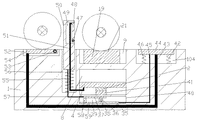
図1~5を参照し、本発明が提供する実施例は:穴あけユニット用の自動化多芯動力ケーブル設備は、整経台1を含み、前記整経台1の中にはリフトスペース8が内設され、前記リフトスペース8の中にはリフト機構28が内設され、前記リフトスペース8の下端壁の中には交換機構40が内設され、前記リフトスペース8の上端壁には上端壁が外界空間と連通する移動スペース9が内設され、前記移動スペース9の右端壁には移動モータ30が固定接続され、前記移動モータ30の左端面には移動軸29が動力が伝達できるように接続され、前記移動軸29の左端には上端が前記移動スペース9の上端壁を貫通し且つ外界空間に位置する移動柱23が螺合接続され、前記移動スペース9の中に位置する前記移動柱23の左端面には前記移動ボード19が固定接続され、前記移動ボード19の上端面の中には上端壁が外界空間と連通するリミットスロット21が内設され、前記移動ボード19の中には上端壁が前記リミットスロット21と連通し且つ下端壁が前記移動スペース9の下端壁と前記移動ボード19の下端面とを貫通して前記リフトスペース8と連通するリフトスロット18が内設され、前記整経台1の上端面には支持柱16が固定接続され、前記支持柱16の中には駆動スペース15が内設され、前記駆動スペース15の中には駆動ボード11がスライドできるように接続され、前記駆動ボード11の上端面には駆動モータ12が固定接続され、前記駆動モータ12の右端面には右端が前記駆動スペース15の右端壁を貫通し且つ外界空間に位置する駆動軸13が動力が伝達できるように接続され、前記駆動軸13の右端にはプッシュボード14が上下対称で固定接続され、前記駆動ボード11の下端面には下端が前記駆動スペース15の下端壁と前記リフトスペース8の上端壁とを貫通し且つ前記リフトスペース8の中に位置する駆動レバー10が固定接続され、前記移動柱23の中には移動スロット24が内設され、前記移動スロット24の中には移動ブロック26がスライドできるように接続され、前記移動ブロック26の左端には左端が前記移動スロット24の左端壁を貫通し且つ外界空間に位置するプッシュ軸25が軸受を介して接続され、前記プッシュ軸25の左端の中には接続機構22が内設され、前記移動ブロック26の下端面には下端が前記移動スロット24の下端壁と前記リフトスペース8の上端壁を貫通し且つ前記リフトスペース8の中に位置する移動レバー27が固定接続され、前記支持柱16の右側には巻軸20が設置され、前記巻軸20の左右両端にはリール17が固定接続され、前記巻軸20の左側の前記リール17の中には伝達機構63が内設され、前記巻軸20の右側の前記リール17の中には右端壁が外界空間と連通する接続スロット60が内設され、前記プッシュ軸25の左端が前記接続スロット60の右端壁を貫通し且つ前記接続スロット60の中に位置し、前記接続スロット60の上下端壁には前記プッシュ軸25に近接する端壁が前記接続スロット60に連通する収容スロット61が対称で設置され、前記整経台1の右端面には警告機構108が設置される。
1 to 5, an embodiment provided by the present invention is: An automated multi-core power cable installation for a drilling unit includes a warping table 1 in which a lift space 8 is provided. A lift mechanism 28 is installed in the lift space 8, a
有益的には、前記リフト機構28はリフトボード4を含み、前記リフトスペース8の中には前記リフトボード4がスライドできるように接続され、前記リフトボード4の下端面には従動電磁石2が固定接続され、前記リフトスペース8の下端壁には主動電磁石41が固定接続され、前記リフトボード4の下端面には前記従動電磁石3を中心として左右対称してリフトばね3が固定接続され、前記リフトばね3の下端が前記リフトスペース8の下端壁と固定接続され、前記リフトボード4の上端面には左右対称してリフトボード31が固定接続され、前記リフトブロック31の上端面には左右対称してリフト柱34が固定接続され、且つ二つの前記リフト柱34の間にはリフト軸33が固定接続され、前記リフト軸33の軸体には支持輪32が軸受によって接続され、前記リフトブロック31のうち前記リフトスペース8の中心から遠離する一側には前記リフトボード4の上端面と固定接続される固定ブロック7が設置され、前記固定ブロック7の中には上端壁が前記リフトスペース8と連通するばねスロット5が設置され、前記ばねスロット5の下端壁には接続ばね6が固定接続され、前記駆動レバー10の下端が前記リフトボード4の上端面の左側の前記ばねスロット5の上端壁を貫通し且つ前記接続ばね6と固定接続され、前記移動レバー27の下端が前記リフトボード4の上端面右側の前記ばねスロット5の上端壁を貫通し且つ前記接続ばね6と固定接続される。 Beneficially, the lift mechanism 28 includes a lift board 4, the lift board 4 is slidably connected to the lift space 8, and the driven electromagnet 2 is fixed to a lower end surface of the lift board 4. The main electromagnet 41 is fixedly connected to the lower end wall of the lift space 8, and the lift spring 3 is fixedly connected to the lower end surface of the lift board 4 symmetrically with the driven electromagnet 3 as a center. A lower end of the spring 3 is fixedly connected to a lower end wall of the lift space 8, a lift board 31 is fixedly connected to the upper end surface of the lift board 4 symmetrically, and a lift board 31 is symmetrically connected to an upper end surface of the lift block 31. A lift column 34 is fixedly connected, a lift shaft 33 is fixedly connected between the two lift columns 34, and a support wheel 32 is connected to a shaft body of the lift shaft 33 by a bearing. A fixed block 7 fixedly connected to the upper end surface of the lift board 4 is installed on one side farther from the center of the lift space 8, and the upper end wall of the fixed block 7 is the lift space 8 and the lift space 8. A communicating spring slot 5 is installed, a connection spring 6 is fixedly connected to the lower end wall of the spring slot 5, and the lower end of the drive lever 10 is the upper end wall of the spring slot 5 on the left side of the upper end surface of the lift board 4. And is fixedly connected to the connection spring 6, and the lower end of the moving lever 27 penetrates the upper end wall of the spring slot 5 on the right side of the upper end surface of the lift board 4 and is fixedly connected to the connection spring 6.
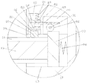
有益的には、前記交換機構40はラックスペース39を含み、前記リフトスペース8の下端壁の中にはラックスペース39が内設され、前記ラックスペース39の左右端壁の間にはラック軸38が回転できるように接続され、前記ラック軸38の軸体にはラックギア36が固定接続され、前記ラックギア36の上端には従動ラック37が噛合接続され、前記ラックギア36の下側には前記ラックスペース39とスライドできるように接続される主動ラック35が噛合接続され、前記従動ラック37の後端には下端が前記ラックスペース39とスライドできるように接続される支持ブロック58が固定接続され、前記支持ブロック58の後端と前記ラックスペース39の後端壁との間には伸縮ばね59が固定接続され、前記リフトスペース8の後端壁の中には上端壁が外界空間と連通する昇降スペース56が内設され、前記昇降スペース56の下端壁には昇降ばね55が固定接続され、前記昇降ばね55の上端には上端が前記昇降スペース56の上端壁を貫通し且つ外界空間に位置する遮断ブロック50が固定接続され、前記遮断ブロック50の中には前端壁が外界空間と連通する回転スロット49が設置され、前記回転スロット49の左右端壁の間には回転軸47が固定接続され、前記回転軸47の軸体にはトーションスプリング(付図には示していない)によって回転ボード48が接続され、前記回転ボード48の上端には下端が前記回転スロット49の下端壁と前記リフトスペース8の後端壁とを貫通し且つ前記リフトボード4の下端面と固定接続される紐51が固定接続され、前記従動ラック37の後端には後端が前記ラックスペース39の後端壁と前記昇降スペース56の下端壁とを貫通し且つ前記遮断ブロック50と固定接続されるロープ57が固定接続され、前記昇降スペース56の後端壁の中には上端壁が外界空間と連通する回転スペース52が設置され、前記回転スペース52の左右端壁の間には従動軸53が回転できるように接続され、前記従動軸53の軸体にはトーションスプリング(付図には示していない)によって従動ボード54が接続され、前記移動スペース9の前端壁の中には上端壁が外界空間と連通する昇降スロット104が設置され、前記昇降スロット104の中には昇降ボード44がスライドできるように接続され、前記昇降ボード44の下端面には下端が前記昇降スロット104の下端壁と前記回転スペース52の下端壁とを貫通し且つ前記従動ボード54の後端と固定接続されるチェーン43が固定接続され、前記昇降ボード44の下端面には下端が前記昇降スロット104の下端壁と固定接続される圧縮ばね46が前記チェーン43を中心として前後対称して固定接続され、前記チェーン43の後側には上端が前記昇降ボード44と固定接続され且つ下端が前記昇降スロット104の下端壁と前記ラックスペース39の前端壁とを貫通し且つ前記主動ラック35の前端と固定接続される麻縄45が設置される。
Beneficially, the
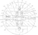
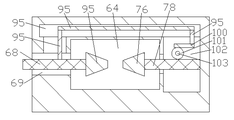
有益的には、前記接続機構22が接続スペース64を含み、前記プッシュ軸25の左端の中には接続スペース64が設置され、前記接続スペース64の左端壁の中には前記接続スロット60と前記接続スペース64とを連通する貫通穴69が設置され、前記貫通穴69の上端壁には下端壁が前記貫通穴69を連通するばねスペース66を含み、前記接続スペース64の中には左端が前記貫通穴69の左右端壁を貫通し且つ前記接続スロット60の中に位置する押圧レバー68が設置され、前記押圧レバー68の右端には主動テーパーブロック95が固定接続され、前記接続スペース64の右端壁の中にはプッシュスペース102が設置され、前記プッシュスペース102の中には左端が前記プッシュスペース102の左端壁を貫通し且つ前記接続スペース64の中に位置するプッシュレバー78が固定接続され、前記プッシュレバー78の左端には従動テーパーブロック76が固定接続され、前記接続スペース64の後端壁の中にはプッシュスロット96が設置され、前記プッシュスロット96の前端面の左側が前記貫通穴69と連通し、前記プッシュスロット96の前端壁の右側が前記プッシュスペース102と連通し、前記プッシュスペース102の上下端壁の間には旋転軸103が固定接続され、前記旋転軸103の軸体には前端が前記プッシュレバー78と噛合接続されるプッシュギア101が固定接続され、前記プッシュギア101の後端にはプッシュ柱100が噛合接続され、前記プッシュ柱100の右端には後端が前記プッシュスペース102の後端壁を貫通し且つ前記プッシュスロット96の中に位置する接続レバー99が固定接続され、前記プッシュスロット96の中に位置する前記接続レバー99の後端には接続柱97が固定接続され、前記接続柱97の左端には前端が前記プッシュスロット96の前端壁の左側を貫通し且つ前記押圧レバー68と固定接続されるタンデムバー98が固定接続され、前記接続スペース64の上下端壁の中にはパンスペース77が対称で設置され、前記パンスペース77の中には前記接続スペース64から遠離する一端が前記パンスペース77のうち前記接続スペース64から遠離する端壁を貫通し且つ前記接続スロット60の中に位置する収納レバー73が設置され、前記収納レバー73のうち前記接続スペース64に近接する一端が前記パンスペース77のうち前記接続スペース64に近接する端壁を貫通し且つ前記接続スペース64の中に位置し、前記収納レバー73のうち前記接続スペース64に近接する一端には前記主動テーパーブロック95と前記従動テーパーブロック76と接触し接続されるプッシュブロック62が固定接続され、前記パンスペース77の中に位置する前記収納レバー73には前記パンスペース77とスライドできるように接続される押圧ボード75が左右対称して固定接続され、前記押圧ボード75のうち前記接続スペース64から遠離する端面には前記パンスペース77の端壁と固定接続される突出しばね74が固定接続され、前記収納レバー73のうち前記接続スペース64から遠離する一端の中には前記接続スペース64から遠離する端壁が前記接続スロット60と連通する突出しスロット72が設置され、前記突出しスロット72のうち前記接続スペース64に近接する端壁には固定ばね71が固定接続され、前記固定ばね71のうち前記接続スペース64から遠離する一端には前記突出しスロット72のうち前記接続スペース64から遠離する端壁を貫通し且つ前記接続スロット60の中に位置する突出しブロック70が固定接続される。
Beneficially, the connection mechanism 22 includes a connection space 64, a connection space 64 is installed in a left end of the push shaft 25, and the connection slot 60 and the connection space 64 are provided in a left end wall of the connection space 64. A through
有益的には、前記伝達機構63は伝達スペース79を含み、前記巻軸20の左側の前記リール17の中には左端壁が外界空間と連通する伝達スペース79が設置され、前記伝達スペース90の上端壁の中には下端壁が前記伝達スペース79と連通するターンスペース90が設置され、前記ターンスペース90の左端壁の中には下端壁が前記伝達スペース79と連通する伝達スロット85が設置され、前記伝達スペース79の中には上端が前記ターンスペース90の下端壁を貫通し且つターンスペース90の中に位置する伝達ボード93がスライドできるように接続され、前記駆動軸13の右端が前記伝達スペース79の左端壁を貫通し且つ前記伝達ボード93と固定接続され、前記ターンスペース90の前後端壁の間にはターン軸91が回転できるように接続され、前記ターン軸91の軸体にはターンギア92が固定接続され、前記ターンギア92の下端が前記伝達ボード93の上端と噛合接続され、前記ターンギア92の上端には左端が前記ターンスペース90の左端壁を貫通し且つ前記伝達スロット85の中に位置するターンレバー89が噛合接続され、前記伝達スロット85の中には下端が前記伝達スロット85の下端壁を貫通し且つ前記伝達スペース79の中に位置する伝達ブロック80がスライドできるように接続され、前記伝達ブロック80の上端の中には左右端壁と下端壁とがいずれも前記伝達スロット85と連通するパンスロット81が設置され、前記パンスロット81の中には左右両端がそれぞれ前記パンスロット81の左右端壁を貫通し且つ前記伝達スロット85とスライドできるように接続されるパンボード82がスライドできるように接続され、前記パンボード82の上端面には上端が前記パンスロット81の上端壁を貫通し且つ前記伝達スロット85の中に位置するパンブロック83が固定接続され、前記パンブロック83の上端面には回型ブロック87が固定接続され、前記回型ブロック87の上端面には上端が前記伝達スロット85の上端壁と固定接続される旋転ばね86が固定接続され、前記回型ブロック87の中には左右端壁が前記伝達スロット85と連通する貫通スペース88が設置され、前記ターンレバー89の左端が前記貫通スペース88の左右端壁を貫通し且つ前記伝達スロット85の中に位置し、前記ターンレバー89の左端には右端が前記貫通スペース88の左端壁を貫通し且つ前記貫通スペース88の中に位置する三角ブロック8484が固定接続され、前記伝達スペース79の右端壁と前記伝達ボード93との間には前記従動ばね94が固定接続され、前記旋転ばね86がずっと圧縮状態にある。
Beneficially, the transmission mechanism 63 includes a transmission space 79, and a transmission space 79 having a left end wall communicating with an external space is installed in the reel 17 on the left side of the winding shaft 20. A turn space 90 whose lower end wall communicates with the transmission space 79 is installed in the upper end wall, and a transmission slot 85 whose lower end wall communicates with the transmission space 79 is installed in the left end wall of the turn space 90. The transmission space 79 has an upper end penetrating the lower end wall of the turn space 90, and a transmission board 93 located in the turn space 90 is slidably connected to the transmission space 79, and the right end of the drive shaft 13 is transmitted to the transmission space 79. It penetrates the left end wall of the space 79 and is fixedly connected to the transmission board 93, and a turn shaft 91 is rotatably connected between the front and rear end walls of the turn space 90. The turn gear 92 is fixedly connected, the lower end of the turn gear 92 is meshed with the upper end of the transmission board 93, and the left end of the upper end of the turn gear 92 penetrates the left end wall of the turn space 90 and is located in the transmission slot 85. A turn lever 89 located at a position is meshedly connected, and a lower end of the turn lever 89 penetrates a lower end wall of the transmission slot 85 and a transmission block 80 located in the transmission space 79 is slidably connected. A pan slot 81 is installed in the upper end of the transfer block 80, the left and right end walls and the lower end wall of which are in communication with the transfer slot 85. A
有益的には、前記警告機構108はブザー107を含み、前記整経台1の右端面の中には発音体105が設置され、前記整経台1の右端面には前記ブザー107が固定接続され、前記ブザー107と前記発音体105との間はデータライン106を介して接続され、その作用は巻軸20を取り替えた後、ブザー107が作動して装置の取り付けの完了を提示することである。 Beneficially, the warning mechanism 108 includes a buzzer 107, a sounding body 105 is installed in the right end surface of the warping table 1, and the buzzer 107 is fixedly connected to the right end surface of the warping table 1. The buzzer 107 and the sounding body 105 are connected to each other via the data line 106, and the operation is that the buzzer 107 is activated to indicate the completion of the installation of the device after the winding shaft 20 is replaced. is there.
具体的な使用方法:本発明は作動する中、巻軸20とリール17がパンボード19の上側に位置する時、移動モータ30が作動し、これにより移動軸29を回転駆動させ、これにより移動柱23が左へ運動し、これによりプッシュ軸25が左へ運動し、プッシュ軸25の左端が接続スロット60の中に進入し、プッシュ軸25の運動に連動させられて押圧レバー68が右へ運動し、これにより主動テーパーブロック95が右へ運動し、同時に押圧レバー68の運動によってタンデムレバー98と接続柱97と接続レバー99とプッシュ柱100を連動させて右へ運動させ、これによりプッシュギア101を回転駆動させ、これによりプッシュレバー78を左へ運動させ、これにより従動テーパーブロック76を連動させて左へ運動させ、これによりプッシュブロック62を連動させて接続スペース64の中心から遠離する方向へ運動させ、これにより収納レバー73を連動させて接続スペース64の中心から遠離する方向へ運動させ、これにより突出しブロック70を連動させて収納スロット61に進入させ、プッシュ軸25が左へ運動してリール17を動かす時、駆動軸13の右端が伝達スペース79の中に進入し、これにより伝達ボード93を連動させて右へ運動させ、これによりターンギア92を回転駆動させ、これによりターンレバー89を連動させて左へ運動させ、これにより三角ブロック84を連動させて次第に貫通スペース88から遠離させ、これにより旋転ばね86によって回型ブロック87を連動させて下へ運動させ、これにより伝達ブロック80を連動させて下へ運動させ、これにより伝達ブロック80をプッシュボード14と当接させ、上記二つのプロセスが完了した時、リミットスロット21の左端壁と巻軸20の左側のリール17の左端面との間に一定の距離があり、同時に移動ボード19の中に位置するリフトスロット18がリフトスペース8と連通し、この時主動電磁石41と従動電磁石2が作動を停止し、これによりリフトばね3によってリフトボード4を連動させて上昇させ、これにより固定ブロック7とリフトブロック31とを連動させて上昇させ、これにより駆動レバー10と移動レバー27とを連動させて上昇させ、これにより駆動ボード11と、巻軸20と、移動ブロック26とを上昇させ、同時に支持輪32をリフトスロット18に通過させてリール17の下端と接触させ、この時紐51が引き締まり、この時駆動モータ12が作動し、駆動軸13の伝動によってリール17と巻軸20とを連動させて回転させ、これによりケーブルを巻き始め、ケーブルが巻くほど巻き軸20に対する付勢力が大きく、これによりリフトばね3を連動させて圧縮させ、リール17の下端面が移動ボード19の上端面と接触する時、主動電磁石41と従動電磁石2とが作動し、これによりリフトボード4を連動させて次第に下降させ、これにより支持輪32を連動させてリフトスロット18から離れさせ、駆動モータ12が作動を停止し、移動モータ30が逆方向で回転し、これにより移動軸29を逆方向で回転させ、これにより移動柱23と移動ボード19とを連動させて右へ運動させ、これによりプッシュ軸25を連動させて右へ運動させ、押圧レバー68が比較的に左へ運動することにつれて、これにより前記主動テーパーブロック95と前記従動テーパーブロック76とが連動させられて接続スペース64の中心から遠離する方向へ運動し、これにより突出しブロック70を連動させて収納スロット61から遠離させ、突出しブロック70が収納スロット61から離れる時、リミットスロット21の左端壁と巻軸20の左側のリール17の左端面とが接触し、これにより伝達ボード93を連動させて従動ばね94の付勢力のもとで左へ運動させ、これにより三角ブロック8484を連動させて右へ運動して次第に貫通スペース88に進入させ、これにより回型ブロック87と伝達ブロック80とを連動させて上へ運動して伝達スペースから離れさせ、これにより駆動軸13が伝達スペース79から離れた後、移動モータ30が作動を停止し、同時にリフトボード4の下降によって紐51を緩め、これにより回転ボード48がトーションスプリング(付図には示していない)の作用のもとで回転し、これによりケーブルがいっぱい巻かれたリール17を動かして前へ運動させ、これによりケーブルがいっぱい巻かれたリール17が昇降ボード44の上側まで運動させ、これにより昇降ボード44を連動させて下降させ、これによりチェーン43と麻縄45とを緩め、これにより主動ラック35を伸縮ばね59の作用のもとで後へ運動させ、これによりラックギア36を回転駆動させ、これにより従動ラック37を連動させて前へ運動させ、これによりロープ57の伝動により遮断ブロック50を連動させて昇降スペース56の中に進入させ、回転ボード48が圧されて回転スロット49の中に戻り、チェーン43が緩めになったため、従動ボード54がトーションスプリング(付図には示していない)の作用のもとで空の巻軸20とリール17とを連動させて移動ボード19の上側に移動させ、これにより上記プロセスを繰り返し、この装置は構造が簡単で、操作が便利で、リフト機構28の作用によって回転している巻軸20とリール17とをサポートし、これにより装置の安定性を改善し、同時に巻軸20にケーブルが巻かれて重量が次第に増加している時、リフト機構28の作用によって巻軸20から駆動軸13とプッシュ軸25とに対する剪断応力を弱め、これにより軸の使用寿命を増加し、機械的伝達によって巻軸を自動に交換でき、これにより加工効率を高め、労働力を節約する。
Specific usage: The present invention operates, when the winding shaft 20 and the reel 17 are located above the panboard 19, the moving motor 30 is actuated, which drives the moving shaft 29 to rotate and move. The column 23 moves to the left, which causes the push shaft 25 to move to the left, and the left end of the push shaft 25 enters into the connection slot 60, which is interlocked with the movement of the push shaft 25 to move the
本分野の技術者にとって、本発明は上記の模範の実施例の細部に限らなく、本発明の意義また基本的な特徴から背離しない状況で、その他の具体的な形式で本発明を実現できる。だから、どこから見てもこの実施例を模範で制限性ではないことと見なして、本発明の範囲は添付の権利要求に限定され、権利要求の同等重要書類の意味と範囲に落ちる全部の変化を本発明に包括させる。権利要求の中の全ての附図マークを権利要求を制限することと見なしないである。 For those skilled in the art, the present invention is not limited to the details of the above-described exemplary embodiments, but can be implemented in other specific forms without departing from the meaning and basic characteristics of the present invention. Therefore, considering this example as an example and not limiting, the scope of the present invention is limited to the attached right claims, and all changes falling within the meaning and scope of the equivalent important document of the right claims It is included in the present invention. Do not consider all attachment marks in a claim to limit the claim to rights.
本発明はケーブル製造分野に関し、具体的には穴あけユニット用の自動化多芯動力ケーブル設備のである。 The present invention relates to the field of cable manufacturing, and in particular to an automated multi-core power cable installation for drilling units.
科学技術の発展や社会の進歩に伴って、ケーブルの使用量がますます高まっています。現段階における穴あけユニット用の多芯動力ケーブルは複数のケーブルから組み合わせられ、ケーブルの製造中では特に最後のケーブルを巻く工程で、ケーブルから受ける付勢力が軸の使用寿命に大きな影響を及ぼし、且つ現在のこういうタイプのローラーを交換する工程は一般に大型機械を通じて操作し、作業量をひどく増加し、作業効率を下げる。 With the development of science and technology and the progress of society, the amount of cables used is increasing more and more. The multi-core power cable for the drilling unit at this stage is composed of a plurality of cables, and the urging force received from the cable has a great influence on the service life of the shaft, especially in the final step of winding the cable during the manufacture of the cable, and The current process of replacing these types of rollers is generally operated through large machines, which greatly increases the amount of work and reduces work efficiency.
本発明が解決する技術問題は穴あけユニット用の自動化多芯動力ケーブル設備を提供し、上記した技術的問題を解決する。 The technical problem to be solved by the present invention is to provide an automated multi-core power cable installation for a drilling unit and solve the above technical problem.
本発明は下記の技術プランを通じて実現される:本発明の穴あけユニット用の自動化多芯動力ケーブル設備は、整経台を含み、前記整経台の中にはリフトスペースが内設され、前記リフトスペースの中にはリフト機構が内設され、前記リフトスペースの下端壁の中には交換機構が内設され、前記リフトスペースの上端壁には上端壁が外界空間と連通する移動スペースが内設され、前記移動スペースの右端壁には移動モータが固定接続され、前記移動モータの左端面には移動軸が動力が伝達できるように接続され、前記移動軸の左端には上端が前記移動スペースの上端壁を貫通し且つ外界空間に位置する移動柱が螺合接続され、前記移動スペースの中に位置する前記移動柱の左端面には移動ボードが固定接続され、前記移動ボードの上端面の中には上端壁が外界空間と連通するリミットスロットが内設され、前記移動ボードの中には上端壁が前記リミットスロットと連通し且つ下端壁が前記移動スペースの下端壁と前記移動ボードの下端面とを貫通して前記リフトスペースと連通するリフトスロットが内設され、前記整経台の上端面には支持柱が固定接続され、前記支持柱の中には駆動スペースが内設され、前記駆動スペースの中には駆動ボードがスライドできるように接続され、前記駆動ボードの上端面には駆動モータが固定接続され、前記駆動モータの右端面には右端が前記駆動スペースの右端壁を貫通し且つ外界空間に位置する駆動軸が動力が伝達できるように接続され、前記駆動軸の右端にはプッシュボードが上下対称で固定接続され、前記駆動ボードの下端面には下端が前記駆動スペースの下端壁と前記リフトスペースの上端壁とを貫通し且つ前記リフトスペースの中に位置する駆動レバーが固定接続され、前記移動柱の中には移動スロットが内設され、前記移動スロットの中には移動ブロックがスライドできるように接続され、前記移動ブロックの左端には左端が前記移動スロットの左端壁を貫通し且つ外界空間に位置するプッシュ軸が軸受を介して接続され、前記プッシュ軸の左端の中には接続機構が内設され、前記移動ブロックの下端面には下端が前記移動スロットの下端壁と前記リフトスペースの上端壁を貫通し且つ前記リフトスペースの中に位置する移動レバーが固定接続され、前記支持柱の右側には巻軸が設置され、前記巻軸の左右両端にはリールが固定接続され、前記巻軸の左側の前記リールの中には伝達機構が内設され、前記巻軸の右側の前記リールの中には右端壁が外界空間と連通する接続スロットが内設され、前記プッシュ軸の左端が前記接続スロットの右端壁を貫通し且つ前記接続スロットの中に位置し、前記接続スロットの上下端壁には前記プッシュ軸に近接する端壁が前記接続スロットに連通する収容スロットが対称で設置され、前記整経台の右端面には警告機構が設置される。 The present invention is realized through the following technical plan: The automated multi-core power cable equipment for a drilling unit of the present invention includes a warping table, and a lift space is provided in the warping table, and the lift is provided. A lift mechanism is internally provided in the space, an exchange mechanism is internally provided in a lower end wall of the lift space, and a moving space having an upper end wall communicating with an external space is provided in an upper end wall of the lift space. A moving motor is fixedly connected to a right end wall of the moving space, a moving shaft is connected to a left end surface of the moving motor so that power can be transmitted, and an upper end of the moving shaft has an upper end of the moving space. A moving pillar penetrating the upper end wall and located in the external space is screwed and connected, and a moving board is fixedly connected to the left end surface of the moving pillar located in the moving space, and is located in the upper end surface of the moving board. A limit slot having an upper end wall communicating with the external space is internally provided in the moving board. An upper end wall of the moving board communicates with the limit slot and a lower end wall of the moving board has a lower end wall of the moving space and a lower end surface of the moving board. A lift slot that penetrates through and communicates with the lift space is internally provided, a support column is fixedly connected to the upper end surface of the warping table, and a drive space is internally provided in the support column. A drive board is slidably connected to the space, a drive motor is fixedly connected to an upper end surface of the drive board, and a right end of the drive motor has a right end penetrating a right end wall of the drive space. A drive shaft located in the external space is connected to transmit power, a push board is vertically and fixedly connected to the right end of the drive shaft, and a lower end of the drive board has a lower end at a lower end wall of the drive space. And a driving lever penetrating the upper end wall of the lift space and located in the lift space are fixedly connected, a moving slot is internally provided in the moving column, and a moving block is provided in the moving slot. Is slidably connected to the left end of the moving block, the left end of which penetrates the left end wall of the moving slot and a push shaft located in the external space is connected through a bearing, and the push shaft is inserted into the left end of the push shaft. Is internally provided with a connecting mechanism, and a lower end surface of the moving block is fixedly connected to a lower end of the moving slot, a lower end of the moving slot and an upper end wall of the lift space, and a moving lever located in the lift space. A winding shaft is installed on the right side of the support column, and reels are fixedly connected to the left and right ends of the winding shaft. Is internally provided with a transmission mechanism, the reel on the right side of the winding shaft is internally provided with a connection slot whose right end wall communicates with the external space, and the left end of the push shaft penetrates the right end wall of the connection slot. In addition, in the upper and lower end walls of the connection slot, which are located in the connection slot, end walls close to the push shaft are symmetrically provided with accommodating slots that communicate with the connection slot, and on the right end surface of the warping table. Is equipped with a warning mechanism.
優先的には、前記リフト機構はリフトボードを含み、前記リフトスペースの中には前記リフトボードがスライドできるように接続され、前記リフトボードの下端面には従動電磁石が固定接続され、前記リフトスペースの下端壁には主動電磁石が固定接続され、前記リフトボードの下端面には前記従動電磁石を中心として左右対称してリフトばねが固定接続され、前記リフトばねの下端が前記リフトスペースの下端壁と固定接続され、リフトボードの上面の左右両側にはリフトブロックが対称になるように固定接続され、前記リフトブロックの上端面には左右対称してリフト柱が固定接続され、且つ二つの前記リフト柱の間にはリフト軸が固定接続され、前記リフト軸の軸体には支持輪が軸受によって接続され、前記リフトブロックのうち前記リフトスペースの中心から遠離する一側には前記リフトボードの上端面と固定接続される固定ブロックが設置され、前記固定ブロックの中には上端壁が前記リフトスペースと連通するばねスロットが設置され、前記ばねスロットの下端壁には接続ばねが固定接続され、前記駆動レバーの下端が前記リフトボードの上端面の左側の前記ばねスロットの上端壁を貫通し且つ前記接続ばねと固定接続され、前記移動レバーの下端が前記リフトボードの上端面右側の前記ばねスロットの上端壁を貫通し且つ前記接続ばねと固定接続される。 Preferentially, the lift mechanism includes a lift board, the lift board is slidably connected to the lift space, and a driven electromagnet is fixedly connected to a lower end surface of the lift board. A main electromagnet is fixedly connected to a lower end wall of the lift board, and a lift spring is fixedly connected to the lower end surface of the lift board symmetrically about the driven electromagnet, and a lower end of the lift spring is a lower end wall of the lift space. The lift blocks are fixedly connected to each other so that the lift blocks are symmetrically connected to the left and right sides of the upper surface of the lift board, and the lift columns are symmetrically fixedly connected to the upper end surface of the lift block. A lift shaft is fixedly connected between the lift shafts, and a support ring is connected to the shaft body of the lift shaft by a bearing, and one end of the lift block away from the center of the lift space has an upper end surface of the lift board. A fixed block fixedly connected to the lift block is installed, a spring slot having an upper end wall communicating with the lift space is installed in the fixed block, and a connection spring is fixedly connected to a lower end wall of the spring slot. The lower end of the lever penetrates the upper end wall of the spring slot on the left side of the upper end surface of the lift board and is fixedly connected to the connecting spring, and the lower end of the moving lever is the upper end of the spring slot on the right side of the upper end surface of the lift board. It penetrates the wall and is fixedly connected to the connection spring.
優先的には、前記交換機構はラックスペースを含み、前記リフトスペースの下端壁の中にはラックスペースが内設され、前記ラックスペースの左右端壁の間にはラック軸が回転できるように接続され、前記ラック軸の軸体にはラックギアが固定接続され、前記ラックギアの上端には従動ラックが噛合接続され、前記ラックギアの下側には前記ラックスペースとスライドできるように接続される主動ラックが噛合接続され、前記従動ラックの後端には下端が前記ラックスペースとスライドできるように接続される支持ブロックが固定接続され、前記支持ブロックの後端と前記ラックスペースの後端壁との間には伸縮ばねが固定接続され、前記リフトスペースの後端壁の中には上端壁が外界空間と連通する昇降スペースが内設され、前記昇降スペースの下端壁には昇降ばねが固定接続され、前記昇降ばねの上端には上端が前記昇降スペースの上端壁を貫通し且つ外界空間に位置する遮断ブロックが固定接続され、前記遮断ブロックの中には前端壁が外界空間と連通する回転スロットが設置され、前記回転スロットの左右端壁の間には回転軸が固定接続され、前記回転軸の軸体にはトーションスプリング(付図には示していない)によって回転ボードが接続され、前記回転ボードの上端には下端が前記回転スロットの下端壁と前記リフトスペースの後端壁とを貫通し且つ前記リフトボードの下端面と固定接続される紐が固定接続され、前記従動ラックの後端には後端が前記ラックスペースの後端壁と前記昇降スペースの下端壁とを貫通し且つ前記遮断ブロックと固定接続されるロープが固定接続され、前記昇降スペースの後端壁の中には上端壁が外界空間と連通する回転スペースが設置され、前記回転スペースの左右端壁の間には従動軸が回転できるように接続され、前記従動軸の軸体にはトーションスプリング(付図には示していない)によって従動ボードが接続され、前記移動スペースの前端壁の中には上端壁が外界空間と連通する昇降スロットが設置され、前記昇降スロットの中には昇降ボードがスライドできるように接続され、前記昇降ボードの下端面には下端が前記昇降スロットの下端壁と前記回転スペースの下端壁とを貫通し且つ前記従動ボードの後端と固定接続されるチェーンが固定接続され、前記昇降ボードの下端面には下端が前記昇降スロットの下端壁と固定接続される圧縮ばねが前記チェーンを中心として前後対称して固定接続され、前記チェーンの後側には上端が前記昇降ボードと固定接続され且つ下端が前記昇降スロットの下端壁と前記ラックスペースの前端壁とを貫通し且つ前記主動ラックの前端と固定接続される麻縄が設置される。 Preferentially, the exchange mechanism includes a rack space, a rack space is internally provided in a lower end wall of the lift space, and a rack shaft is rotatably connected between left and right end walls of the rack space. A rack gear is fixedly connected to the shaft body of the rack shaft, a driven rack is meshedly connected to an upper end of the rack gear, and a drive rack slidably connected to the rack space is provided below the rack gear. A support block, which is meshedly connected and has a lower end slidably connected to the rack space, is fixedly connected to the rear end of the driven rack, and a support block is provided between the rear end of the support block and the rear end wall of the rack space. A telescopic spring is fixedly connected, a lift space in which an upper end wall communicates with an external space is provided inside a rear end wall of the lift space, and a lift spring is fixedly connected to a lower end wall of the lift space. A blocking block, the upper end of which passes through the upper wall of the lifting space and is located in the external space, is fixedly connected to the upper end of the lifting spring, and a rotation slot is installed in the blocking block, the front end wall of which is in communication with the external space. A rotary shaft is fixedly connected between the left and right end walls of the rotary slot, and a rotary board is connected to a shaft body of the rotary shaft by a torsion spring (not shown in the accompanying drawings). Has a lower end penetrating the lower end wall of the rotary slot and the rear end wall of the lift space and fixedly connected to a string that is fixedly connected to the lower end surface of the lift board. A rope that penetrates the rear end wall of the rack space and the lower end wall of the elevating space and is fixedly connected to the blocking block is fixedly connected, and the upper end wall is an external space in the rear end wall of the elevating space. A rotating space communicating with the rotating space is installed, a driven shaft is rotatably connected between left and right end walls of the rotating space, and a driven board is attached to a shaft body of the driven shaft by a torsion spring (not shown in the accompanying drawings). And an upper and lower wall is installed in the front end wall of the moving space so that the upper end wall communicates with the external space, and an elevating board is slidably connected to the lower elevating slot. A chain having a lower end penetrating the lower end wall of the lifting slot and the lower end wall of the rotating space and fixedly connected to the rear end of the driven board is fixedly connected to the end face, and the lower end is attached to the lower end face of the lifting board. A compression spring fixedly connected to the lower end wall of the elevating slot moves forward around the chain. The chain is fixedly connected in a rearward symmetrical manner, the upper end is fixedly connected to the lifting board on the rear side of the chain, and the lower end penetrates the lower end wall of the lifting slot and the front end wall of the rack space and the front end of the driving rack. A hemp rope fixedly connected with is installed.
優先的には、前記接続機構が接続スペースを含み、前記プッシュ軸の左端の中には接続スペースが設置され、前記接続スペースの左端壁の中には前記接続スロットと前記接続スペースとを連通する貫通穴が設置され、前記貫通穴の上端壁には下端壁が前記貫通穴を連通するばねスペースを含み、前記接続スペースの中には左端が前記貫通穴の左右端壁を貫通し且つ前記接続スロットの中に位置する押圧レバーが設置され、前記押圧レバーの右端には主動テーパーブロックが固定接続され、前記接続スペースの右端壁の中にはプッシュスペースが設置され、前記プッシュスペースの中には左端が前記プッシュスペースの左端壁を貫通し且つ前記接続スペースの中に位置するプッシュレバーが固定接続され、前記プッシュレバーの左端には従動テーパーブロックが固定接続され、前記接続スペースの後端壁の中にはプッシュスロットが設置され、前記プッシュスロットの前端面の左側が前記貫通穴と連通し、前記プッシュスロットの前端壁の右側が前記プッシュスペースと連通し、前記プッシュスペースの上下端壁の間には旋転軸が固定接続され、前記旋転軸の軸体には前端が前記プッシュレバーと噛合接続されるプッシュギアが固定接続され、前記プッシュギアの後端にはプッシュ柱が噛合接続され、前記プッシュ柱の右端には後端が前記プッシュスペースの後端壁を貫通し且つ前記プッシュスロットの中に位置する接続レバーが固定接続され、前記プッシュスロットの中に位置する前記接続レバーの後端には接続柱が固定接続され、前記接続柱の左端には前端が前記プッシュスロットの前端壁の左側を貫通し且つ前記押圧レバーと固定接続されるタンデムバーが固定接続され、前記接続スペースの上下端壁の中にはパンスペースが対称で設置され、前記パンスペースの中には前記接続スペースから遠離する一端が前記パンスペースのうち前記接続スペースから遠離する端壁を貫通し且つ前記接続スロットの中に位置する収納レバーが設置され、前記収納レバーのうち前記接続スペースに近接する一端が前記パンスペースのうち前記接続スペースに近接する端壁を貫通し且つ前記接続スペースの中に位置し、前記収納レバーのうち前記接続スペースに近接する一端には前記主動テーパーブロックと前記従動テーパーブロックと接触し接続されるプッシュブロックが固定接続され、前記パンスペースの中に位置する前記収納レバーには前記パンスペースとスライドできるように接続される押圧ボードが左右対称して固定接続され、前記押圧ボードのうち前記接続スペースから遠離する端面には前記パンスペースの端壁と固定接続される突出しばねが固定接続され、前記収納レバーのうち前記接続スペースから遠離する一端の中には前記接続スペースから遠離する端壁が前記接続スロットと連通する突出しスロットが設置され、前記突出しスロットのうち前記接続スペースに近接する端壁には固定ばねが固定接続され、前記固定ばねのうち前記接続スペースから遠離する一端には前記突出しスロットのうち前記接続スペースから遠離する端壁を貫通し且つ前記接続スロットの中に位置する突出しブロックが固定接続される。 Preferentially, the connection mechanism includes a connection space, a connection space is installed in the left end of the push shaft, and the connection slot communicates with the connection space in the left end wall of the connection space. A through hole is installed, a lower end wall of the upper end wall of the through hole includes a spring space communicating with the through hole, and a left end of the connecting space penetrates the left and right end walls of the through hole and the connection A push lever located in the slot is installed, a driving taper block is fixedly connected to the right end of the push lever, a push space is installed in the right end wall of the connection space, and a push space is provided in the push space. A push lever having a left end penetrating the left end wall of the push space and located in the connection space is fixedly connected, and a driven taper block is fixedly connected to the left end of the push lever, and a rear end wall of the connection space is A push slot is installed therein, the left side of the front end face of the push slot communicates with the through hole, the right side of the front end wall of the push slot communicates with the push space, and between the upper and lower end walls of the push space. A rotary shaft is fixedly connected to the rotary shaft, a push gear whose front end is meshed with the push lever is fixedly connected to the shaft body of the rotary shaft, and a push column is meshed with the rear end of the push gear. At the right end of the push column, a rear end penetrates the rear end wall of the push space and a connection lever located in the push slot is fixedly connected to the rear end of the connection lever located in the push slot. Is fixedly connected to the connection pillar, and a tandem bar having a front end penetrating the left side of the front end wall of the push slot and fixedly connected to the pressing lever is fixedly connected to the left end of the connection pillar, and upper and lower ends of the connection space are connected. Pan spaces are symmetrically installed in the wall, and one end of the pan space far from the connection space penetrates an end wall of the pan space far from the connection space and is located in the connection slot. A storage lever located in the storage lever is installed, one end of the storage lever proximate to the connection space penetrates an end wall of the pan space proximate to the connection space, and is located in the connection space; A push block, which is in contact with and connected to the driven taper block and the driven taper block, is fixedly connected to one end of the lever that is close to the connection space, and the push lever block that is located in the pan space is connected to the push block. A pressing board slidably connected to the pan space is symmetrically fixedly connected to the pan, and an end face of the pressing board remote from the connection space is fixedly connected to an end wall of the pan space. A projecting spring is fixedly connected, and a projecting slot having an end wall distant from the connecting space communicating with the connecting slot is installed in one end of the housing lever away from the connecting space. A fixed spring is fixedly connected to an end wall adjacent to the connection space, and one end of the fixed spring remote from the connection space passes through an end wall of the protruding slot remote from the connection space and the connection slot. The protruding block located inside is fixedly connected.
優先的には、前記伝達機構は伝達スペースを含み、前記巻軸の左側の前記リールの中には左端壁が外界空間と連通する伝達スペースが設置され、前記伝達スペースの上端壁の中には下端壁が前記伝達スペースと連通するターンスペースが設置され、前記ターンスペースの左端壁の中には下端壁が前記伝達スペースと連通する伝達スロットが設置され、前記伝達スペースの中には上端が前記ターンスペースの下端壁を貫通し且つターンスペースの中に位置する伝達ボードがスライドできるように接続され、前記駆動軸の右端が前記伝達スペースの左端壁を貫通し且つ前記伝達ボードと固定接続され、前記ターンスペースの前後端壁の間にはターン軸が回転できるように接続され、前記ターン軸の軸体にはターンギアが固定接続され、前記ターンギアの下端が前記伝達ボードの上端と噛合接続され、前記ターンギアの上端には左端が前記ターンスペースの左端壁を貫通し且つ前記伝達スロットの中に位置するターンレバーが噛合接続され、前記伝達スロットの中には下端が前記伝達スロットの下端壁を貫通し且つ前記伝達スペースの中に位置する伝達ブロックがスライドできるように接続され、前記伝達ブロックの上端の中には左右端壁と下端壁とがいずれも前記伝達スロットと連通するパンスロットが設置され、前記パンスロットの中には左右両端がそれぞれ前記パンスロットの左右端壁を貫通し且つ前記伝達スロットとスライドできるように接続されるパンボードがスライドできるように接続され、前記パンボードの上端面には上端が前記パンスロットの上端壁を貫通し且つ前記伝達スロットの中に位置するパンブロックが固定接続され、前記パンブロックの上端面には回型ブロックが固定接続され、前記回型ブロックの上端面には上端が前記伝達スロットの上端壁と固定接続される旋転ばねが固定接続され、前記回型ブロックの中には左右端壁が前記伝達スロットと連通する貫通スペースが設置され、前記ターンレバーの左端が前記貫通スペースの左右端壁を貫通し且つ前記伝達スロットの中に位置し、前記ターンレバーの左端には右端が前記貫通スペースの左端壁を貫通し且つ前記貫通スペースの中に位置する三角ブロックが固定接続され、前記伝達スペースの右端壁と前記伝達ボードとは従動ばねによって連結され、前記旋転ばねがずっと圧縮状態にある。 Preferentially, the transmission mechanism includes a transmission space, a transmission space having a left end wall communicating with an external space is installed in the reel on the left side of the winding shaft, and a transmission space is provided in an upper end wall of the transmission space. A lower end wall has a turn space communicating with the transmission space, a left end wall of the turn space has a transmission slot having a lower end wall communicating with the transmission space, and an upper end of the transmission space has an upper end. A transmission board penetrating the lower end wall of the turn space and located in the turn space is slidably connected, a right end of the drive shaft penetrates a left end wall of the transmission space and is fixedly connected to the transmission board; A turn shaft is rotatably connected between the front and rear end walls of the turn space, a turn gear is fixedly connected to the shaft of the turn shaft, and a lower end of the turn gear is meshed with an upper end of the transmission board. A left end of the turn gear penetrates a left end wall of the turn space and a turn lever located in the transmission slot is meshingly connected to the upper end of the turn gear, and a lower end of the turn slot penetrates a lower end wall of the transmission slot. And a transmission block located in the transmission space is slidably connected, and a pan slot is installed in the upper end of the transmission block, the left and right end walls and the lower end wall of the transmission block communicate with the transmission slot. An upper end surface of the breadboard, a left and right ends of the breadboard penetrating through the left and right end walls of the breadslot and slidably connected to the transmission slot. A pan block whose upper end penetrates the upper wall of the pan slot and is located in the transmission slot is fixedly connected to the pan block, and a rotary block is fixedly connected to the upper end surface of the pan block. A rotary spring whose upper end is fixedly connected to the upper end wall of the transmission slot is fixedly connected to the upper end surface, and a through space in which left and right end walls communicate with the transmission slot is installed in the revolving block. The left end of the lever penetrates the right and left end walls of the through space and is located in the transmission slot, and the right end of the turn lever is at the right end thereof through the left end wall of the through space and is located in the through space. The triangular block is fixedly connected, the right end wall of the transmission space and the transmission board are connected by a driven spring, and the rotary spring is in a compressed state all the time.
有益的には、前記整経台の右壁の中に設けられた警告機構は、ブザーを含み、前記整経台の右端面の中には発音体が設置され、前記整経台の右端面には前記ブザーが固定接続され、前記ブザーと前記発音体との間はデータラインを介して接続され、前記警告機構の作用は巻軸を取り替えた後、ブザーが作動して装置の取り付けの完了を提示することである。 Beneficially, the warning mechanism provided in the right wall of the warping table includes a buzzer, a sounding body is installed in the right end surface of the warping table, and the right end surface of the warping table is provided. the buzzer is fixed connected to, between the sounding body and the buzzer is connected through the data lines, after the action of the warning mechanism, which replaced the winding shaft, completion of the mounting of the device buzzer is activated Is to present.
現在の技術と比べ、本発明の有益効果は:本発明は作動する中、巻軸とリールがパンボードの上側に位置する時、移動モータが作動し、これにより移動軸を回転駆動させ、これにより移動柱が左へ運動し、これによりプッシュ軸が左へ運動し、プッシュ軸の左端が接続スロットの中に進入し、プッシュ軸の運動に連動させられて押圧レバーが右へ運動し、これにより主動テーパーブロックが右へ運動し、同時に押圧レバーの運動によってタンデムレバーと接続柱と接続レバーとプッシュ柱を連動させて右へ運動させ、これによりプッシュギアを回転駆動させ、これによりプッシュレバーを左へ運動させ、これにより従動テーパーブロックを連動させて左へ運動させ、これによりプッシュブロックを連動させて接続スペースの中心から遠離する方向へ運動させ、これにより収納レバーを連動させて接続スペースの中心から遠離する方向へ運動させ、これにより突出しブロックを連動させて収納スロットに進入させ、プッシュ軸が左へ運動してリールを動かす時、駆動軸の右端が伝達スペースの中に進入し、これにより伝達ボードを連動させて右へ運動させ、これによりターンギアを回転駆動させ、これによりターンレバーを連動させて左へ運動させ、これにより三角ブロックを連動させて次第に貫通スペースから遠離させ、これにより旋転ばねによって回型ブロックを連動させて下へ運動させ、これにより伝達ブロックを連動させて下へ運動させ、これにより伝達ブロックをプッシュボードと当接させ、上記二つのプロセスが完了した時、リミットスロットの左端壁と巻軸の左側のリールの左端面との間に一定の距離があり、同時に移動ボードの中に位置するリフトスロットがリフトスペースと連通し、この時主動電磁石と従動電磁石が作動を停止し、これによりリフトばねによってリフトボードを連動させて上昇させ、これにより固定ブロックとリフトブロックとを連動させて上昇させ、これにより駆動レバーと移動レバーとを連動させて上昇させ、これにより駆動ボードと、巻軸と、移動ブロックとを上昇させ、同時に支持輪をリフトスロットに通過させてリールの下端と接触させ、この時紐が引き締まり、この時駆動モータが作動し、駆動軸の伝動によってリールと巻軸とを連動させて回転させ、これによりケーブルを巻き始め、ケーブルが巻くほど巻き軸に対する付勢力が大きく、これによりリフトばねを連動させて圧縮させ、リールの下端面が移動ボードの上端面と接触する時、主動電磁石と従動電磁石とが作動し、これによりリフトボードを連動させて次第に下降させ、これにより支持輪を連動させてリフトスロットから離れさせ、駆動モータが作動を停止し、移動モータが逆方向で回転し、これにより移動軸を逆方向で回転させ、これにより移動柱と移動ボードとを連動させて右へ運動させ、これによりプッシュ軸を連動させて右へ運動させ、押圧レバーが比較的に左へ運動することにつれて、これにより前記主動テーパーブロックと前記従動テーパーブロックとが連動させられて接続スペースの中心から遠離する方向へ運動し、これにより突出しブロックを連動させて収納スロットから遠離させ、突出しブロックが収納スロットから離れる時、リミットスロットの左端壁と巻軸の左側のリールの左端面とが接触し、これにより伝達ボードを連動させて従動ばねの付勢力のもとで左へ運動させ、これにより三角ブロックを連動させて右へ運動して次第に貫通スペースに進入させ、これにより回型ブロックと伝達ブロックとを連動させて上へ運動して伝達スペースから離れさせ、これにより駆動軸が伝達スペースから離れた後、移動モータが作動を停止し、同時にリフトボードの下降によって紐を緩め、これにより回転ボードがトーションスプリング(付図には示していない)の作用のもとで回転し、これによりケーブルがいっぱい巻かれたリールを動かして前へ運動させ、これによりケーブルがいっぱい巻かれたリールが昇降ボードの上側まで運動させ、これにより昇降ボードを連動させて下降させ、これによりチェーンと麻縄とを緩め、これにより主動ラックを伸縮ばねの作用のもとで後へ運動させ、これによりラックギアを回転駆動させ、これにより従動ラックを連動させて前へ運動させ、これによりロープの伝動により遮断ブロックを連動させて昇降スペースの中に進入させ、回転ボードが圧されて回転スロットの中に戻り、チェーンが緩めになったため、従動ボードがトーションスプリング(付図には示していない)の作用のもとで空の巻軸とリールとを連動させて移動ボードの上側に移動させ、これにより上記プロセスを繰り返し、この装置は構造が簡単で、操作が便利で、リフト機構の作用によって回転している巻軸とリールとをサポートし、これにより装置の安定性を改善し、同時に巻軸にケーブルが巻かれて重量が次第に増加している時、リフト機構の作用によって巻軸から駆動軸とプッシュ軸とに対する剪断応力を弱め、これにより軸の使用寿命を増加し、機械的伝達によって巻軸を自動に交換でき、これにより加工効率を高め、労働力を節約する。 Compared with the current technology, the beneficial effects of the present invention are: While the present invention is working, when the winding shaft and reel are located on the upper side of the panboard, the moving motor is actuated, which drives the moving shaft to rotate. Causes the moving column to move to the left, which causes the push shaft to move to the left, the left end of the push shaft to enter the connecting slot, and the push lever moves to the right in conjunction with the movement of the push shaft, Causes the driving taper block to move to the right, and at the same time, the movement of the pressing lever causes the tandem lever, the connecting post, the connecting lever, and the push post to move in conjunction with each other to move to the right, thereby rotationally driving the push gear, which causes the push lever to move. It is moved to the left, which causes the driven taper block to move in conjunction with it to the left, which in turn causes the push block to move in a direction away from the center of the connection space, which in turn causes the storage lever to move in conjunction with the connection space. When the push shaft moves to the left to move the reel, the right end of the drive shaft moves into the transmission space. Causes the transmission board to move to the right in conjunction with it, which in turn drives the turn gear to rotate, which in turn causes the turn lever to move in conjunction to move it to the left, thereby interlocking the triangular block and gradually moving it away from the penetration space. When the rotary block is interlocked to move downward by the rotation spring, which interlocks the transfer block to move downward, thereby bringing the transfer block into contact with the push board, and when the above two processes are completed, the limit is reached. There is a certain distance between the left end wall of the slot and the left end surface of the reel on the left side of the winding shaft, and at the same time, the lift slot located in the moving board communicates with the lift space, at which time the main electromagnet and the follower electromagnet operate. Stop, and thereby the lift board interlocks and raises the lift board, which causes the fixed block and the lift block to interlock and raise, which causes the drive lever and the moving lever to interlock and thereby raise. The drive board, winding shaft, and moving block are raised, and at the same time, the support wheel is passed through the lift slot to make contact with the lower end of the reel, at which time the cord is tightened, the drive motor is operated at this time, and the drive shaft is transmitted. The reel and winding shaft are rotated in conjunction with each other to start winding the cable, and the more the cable is wound, the greater the urging force on the winding shaft. When it is compressed and the lower end surface of the reel comes into contact with the upper end surface of the moving board, the main electromagnet and the follower electromagnet are activated, which interlocks the lift board and gradually lowers it, thereby interlocking the support wheels and lifting slots. Away, the drive motor stops operating, the move motor rotates in the opposite direction, which causes the move axis to rotate in the opposite direction, which causes the move column and move board to move in conjunction with each other to the right, which By moving the push shaft in conjunction with each other and moving the push lever relatively to the left, whereby the driving taper block and the driven taper block are interlocked with each other to move away from the center of the connection space. When the projecting block moves away from the storage slot by interlocking with the projecting block and the projecting block separates from the storage slot, the left end wall of the limit slot and the left end surface of the reel on the left side of the winding shaft come into contact with each other. The board is interlocked to move to the left under the urging force of the driven spring, which interlocks the triangular block to the right to gradually move into the penetration space, which interlocks the revolving block and the transmission block. And move it up and away from the transmission space, which causes the drive shaft to move away from the transmission space, after which the moving motor stops working and at the same time the lowering of the lift board loosens the cord, which causes the rotating board to rotate the torsion spring. It rotates under the action of (not shown in the attached figure), which moves the reel full of cables and moves it forward, which moves the reel full of cables to the upper side of the lifting board. This lowers the lifting board in conjunction with it, which loosens the chain and hemp rope, which causes the main rack to move backwards under the action of a telescopic spring, which in turn drives the rack gear to rotate. Causes the driven rack to move forward by interlocking with it, which interlocks the blocking block with the transmission of the rope to enter the lifting space, presses the rotating board into the rotating slot, and loosens the chain. Therefore, the driven board moves the upper side of the moving board by interlocking the empty reel and reel under the action of the torsion spring (not shown in the attached figure), and the above process is repeated. Simple structure, convenient operation, support the rotating reel and reel by the action of the lift mechanism, which improves the stability of the device and at the same time the cable is wound around the reel to reduce the weight. When gradually increasing, the action of the lift mechanism weakens the shear stress from the winding shaft to the drive shaft and the push shaft, thereby increasing the service life of the shaft and automatically changing the winding shaft by mechanical transmission. To improve processing efficiency and save labor.
下記に本発明の実施例の中の附図を交え、本発明の実施例の技術方案を明確にはっきり説明し、説明した実施例がただ本発明の一部分の実施例で、全部の実施例ではないである。本発明の実施例に基づいて、本領域の普通技術者が創造的な労働を払わないことを前提に得る全部のその他の実施例は本発明の保護範囲に所属する。 Hereinafter, the technical solution of the embodiment of the present invention will be clearly described with reference to the accompanying drawings in the embodiments of the present invention, and the described embodiments are merely some embodiments of the present invention, not all embodiments. Is. Based on the embodiments of the present invention, all other embodiments obtained by a person of ordinary skill in the art who does not pay creative labor belong to the protection scope of the present invention.
図1〜5を参照し、本発明が提供する実施例は:穴あけユニット用の自動化多芯動力ケーブル設備は、整経台1を含み、前記整経台1の中にはリフトスペース8が内設され、前記リフトスペース8の中にはリフト機構28が内設され、前記リフトスペース8の下端壁の中には交換機構40が内設され、前記リフトスペース8の上端壁には上端壁が外界空間と連通する移動スペース9が内設され、前記移動スペース9の右端壁には移動モータ30が固定接続され、前記移動モータ30の左端面には移動軸29が動力が伝達できるように接続され、前記移動軸29の左端には上端が前記移動スペース9の上端壁を貫通し且つ外界空間に位置する移動柱23が螺合接続され、前記移動スペース9の中に位置する前記移動柱23の左端面には移動ボード19が固定接続され、前記移動ボード19の上端面の中には上端壁が外界空間と連通するリミットスロット21が内設され、前記移動ボード19の中には上端壁が前記リミットスロット21と連通し且つ下端壁が前記移動スペース9の下端壁と前記移動ボード19の下端面とを貫通して前記リフトスペース8と連通するリフトスロット18が内設され、前記整経台1の上端面には支持柱16が固定接続され、前記支持柱16の中には駆動スペース15が内設され、前記駆動スペース15の中には駆動ボード11がスライドできるように接続され、前記駆動ボード11の上端面には駆動モータ12が固定接続され、前記駆動モータ12の右端面には右端が前記駆動スペース15の右端壁を貫通し且つ外界空間に位置する駆動軸13が動力が伝達できるように接続され、前記駆動軸13の右端にはプッシュボード14が上下対称で固定接続され、前記駆動ボード11の下端面には下端が前記駆動スペース15の下端壁と前記リフトスペース8の上端壁とを貫通し且つ前記リフトスペース8の中に位置する駆動レバー10が固定接続され、前記移動柱23の中には移動スロット24が内設され、前記移動スロット24の中には移動ブロック26がスライドできるように接続され、前記移動ブロック26の左端には左端が前記移動スロット24の左端壁を貫通し且つ外界空間に位置するプッシュ軸25が軸受を介して接続され、前記プッシュ軸25の左端の中には接続機構22が内設され、前記移動ブロック26の下端面には下端が前記移動スロット24の下端壁と前記リフトスペース8の上端壁を貫通し且つ前記リフトスペース8の中に位置する移動レバー27が固定接続され、前記支持柱16の右側には巻軸20が設置され、前記巻軸20の左右両端にはリール17が固定接続され、前記巻軸20の左側の前記リール17の中には伝達機構63が内設され、前記巻軸20の右側の前記リール17の中には右端壁が外界空間と連通する接続スロット60が内設され、前記プッシュ軸25の左端が前記接続スロット60の右端壁を貫通し且つ前記接続スロット60の中に位置し、前記接続スロット60の上下端壁には前記プッシュ軸25に近接する端壁が前記接続スロット60に連通する収容スロット61が対称で設置され、前記整経台1の右端面には警告機構108が設置される。
1 to 5, an embodiment provided by the present invention is: An automated multi-core power cable installation for a drilling unit includes a warping table 1 in which a lift space 8 is provided. A lift mechanism 28 is installed in the lift space 8, a
有益的には、前記リフト機構28はリフトボード4を含み、前記リフトスペース8の中には前記リフトボード4がスライドできるように接続され、前記リフトボード4の下端面には従動電磁石2が固定接続され、前記リフトスペース8の下端壁には主動電磁石41が固定接続され、前記リフトボード4の下端面には前記従動電磁石3を中心として左右対称してリフトばね3が固定接続され、前記リフトばね3の下端が前記リフトスペース8の下端壁と固定接続され、前記リフトボード4の上面の左右両側にはリフトブロック31が対称になるように固定接続され、前記リフトブロック31の上端面には左右対称してリフト柱34が固定接続され、且つ二つの前記リフト柱34の間にはリフト軸33が固定接続され、前記リフト軸33の軸体には支持輪32が軸受によって接続され、前記リフトブロック31のうち前記リフトスペース8の中心から遠離する一側には前記リフトボード4の上端面と固定接続される固定ブロック7が設置され、前記固定ブロック7の中には上端壁が前記リフトスペース8と連通するばねスロット5が設置され、前記ばねスロット5の下端壁には接続ばね6が固定接続され、前記駆動レバー10の下端が前記リフトボード4の上端面の左側の前記ばねスロット5の上端壁を貫通し且つ前記接続ばね6と固定接続され、前記移動レバー27の下端が前記リフトボード4の上端面右側の前記ばねスロット5の上端壁を貫通し且つ前記接続ばね6と固定接続される。 Beneficially, the lift mechanism 28 includes a lift board 4, the lift board 4 is slidably connected to the lift space 8, and the driven electromagnet 2 is fixed to a lower end surface of the lift board 4. The main electromagnet 41 is fixedly connected to the lower end wall of the lift space 8, and the lift spring 3 is fixedly connected to the lower end surface of the lift board 4 symmetrically about the driven electromagnet 3. A lower end of the spring 3 is fixedly connected to a lower end wall of the lift space 8, lift blocks 31 are fixedly connected to both left and right sides of an upper surface of the lift board 4 so as to be symmetrical, and an upper end surface of the lift block 31 is connected to the lift block 31. Lift columns 34 are fixedly connected symmetrically, a lift shaft 33 is fixedly connected between the two lift columns 34, and a support ring 32 is connected to a shaft of the lift shaft 33 by a bearing. A fixed block 7 fixedly connected to the upper end surface of the lift board 4 is installed on one side of the lift block 31 that is far from the center of the lift space 8. In the fixed block 7, the upper end wall is the lift. A spring slot 5 communicating with the space 8 is installed, a connecting spring 6 is fixedly connected to a lower end wall of the spring slot 5, and a lower end of the drive lever 10 is on the left side of an upper end surface of the lift board 4. Of the movable lever 27, and the lower end of the movable lever 27 penetrates the upper end wall of the spring slot 5 on the right side of the upper end surface of the lift board 4 and is fixedly connected to the connection spring 6. To be done.
有益的には、前記交換機構40はラックスペース39を含み、前記リフトスペース8の下端壁の中にはラックスペース39が内設され、前記ラックスペース39の左右端壁の間にはラック軸38が回転できるように接続され、前記ラック軸38の軸体にはラックギア36が固定接続され、前記ラックギア36の上端には従動ラック37が噛合接続され、前記ラックギア36の下側には前記ラックスペース39とスライドできるように接続される主動ラック35が噛合接続され、前記従動ラック37の後端には下端が前記ラックスペース39とスライドできるように接続される支持ブロック58が固定接続され、前記支持ブロック58の後端と前記ラックスペース39の後端壁との間には伸縮ばね59が固定接続され、前記リフトスペース8の後端壁の中には上端壁が外界空間と連通する昇降スペース56が内設され、前記昇降スペース56の下端壁には昇降ばね55が固定接続され、前記昇降ばね55の上端には上端が前記昇降スペース56の上端壁を貫通し且つ外界空間に位置する遮断ブロック50が固定接続され、前記遮断ブロック50の中には前端壁が外界空間と連通する回転スロット49が設置され、前記回転スロット49の左右端壁の間には回転軸47が固定接続され、前記回転軸47の軸体にはトーションスプリング(付図には示していない)によって回転ボード48が接続され、前記回転ボード48の上端には下端が前記回転スロット49の下端壁と前記リフトスペース8の後端壁とを貫通し且つ前記リフトボード4の下端面と固定接続される紐51が固定接続され、前記従動ラック37の後端には後端が前記ラックスペース39の後端壁と前記昇降スペース56の下端壁とを貫通し且つ前記遮断ブロック50と固定接続されるロープ57が固定接続され、前記昇降スペース56の後端壁の中には上端壁が外界空間と連通する回転スペース52が設置され、前記回転スペース52の左右端壁の間には従動軸53が回転できるように接続され、前記従動軸53の軸体にはトーションスプリング(付図には示していない)によって従動ボード54が接続され、前記移動スペース9の前端壁の中には上端壁が外界空間と連通する昇降スロット104が設置され、前記昇降スロット104の中には昇降ボード44がスライドできるように接続され、前記昇降ボード44の下端面には下端が前記昇降スロット104の下端壁と前記回転スペース52の下端壁とを貫通し且つ前記従動ボード54の後端と固定接続されるチェーン43が固定接続され、前記昇降ボード44の下端面には下端が前記昇降スロット104の下端壁と固定接続される圧縮ばね46が前記チェーン43を中心として前後対称して固定接続され、前記チェーン43の後側には上端が前記昇降ボード44と固定接続され且つ下端が前記昇降スロット104の下端壁と前記ラックスペース39の前端壁とを貫通し且つ前記主動ラック35の前端と固定接続される麻縄45が設置される。
Beneficially, the
有益的には、前記接続機構22が接続スペース64を含み、前記プッシュ軸25の左端の中には接続スペース64が設置され、前記接続スペース64の左端壁の中には前記接続スロット60と前記接続スペース64とを連通する貫通穴69が設置され、前記貫通穴69の上端壁には下端壁が前記貫通穴69を連通するばねスペース66を含み、前記接続スペース64の中には左端が前記貫通穴69の左右端壁を貫通し且つ前記接続スロット60の中に位置する押圧レバー68が設置され、前記押圧レバー68の右端には主動テーパーブロック95が固定接続され、前記接続スペース64の右端壁の中にはプッシュスペース102が設置され、前記プッシュスペース102の中には左端が前記プッシュスペース102の左端壁を貫通し且つ前記接続スペース64の中に位置するプッシュレバー78が固定接続され、前記プッシュレバー78の左端には従動テーパーブロック76が固定接続され、前記接続スペース64の後端壁の中にはプッシュスロット96が設置され、前記プッシュスロット96の前端面の左側が前記貫通穴69と連通し、前記プッシュスロット96の前端壁の右側が前記プッシュスペース102と連通し、前記プッシュスペース102の上下端壁の間には旋転軸103が固定接続され、前記旋転軸103の軸体には前端が前記プッシュレバー78と噛合接続されるプッシュギア101が固定接続され、前記プッシュギア101の後端にはプッシュ柱100が噛合接続され、前記プッシュ柱100の右端には後端が前記プッシュスペース102の後端壁を貫通し且つ前記プッシュスロット96の中に位置する接続レバー99が固定接続され、前記プッシュスロット96の中に位置する前記接続レバー99の後端には接続柱97が固定接続され、前記接続柱97の左端には前端が前記プッシュスロット96の前端壁の左側を貫通し且つ前記押圧レバー68と固定接続されるタンデムバー98が固定接続され、前記接続スペース64の上下端壁の中にはパンスペース77が対称で設置され、前記パンスペース77の中には前記接続スペース64から遠離する一端が前記パンスペース77のうち前記接続スペース64から遠離する端壁を貫通し且つ前記接続スロット60の中に位置する収納レバー73が設置され、前記収納レバー73のうち前記接続スペース64に近接する一端が前記パンスペース77のうち前記接続スペース64に近接する端壁を貫通し且つ前記接続スペース64の中に位置し、前記収納レバー73のうち前記接続スペース64に近接する一端には前記主動テーパーブロック95と前記従動テーパーブロック76と接触し接続されるプッシュブロック62が固定接続され、前記パンスペース77の中に位置する前記収納レバー73には前記パンスペース77とスライドできるように接続される押圧ボード75が左右対称して固定接続され、前記押圧ボード75のうち前記接続スペース64から遠離する端面には前記パンスペース77の端壁と固定接続される突出しばね74が固定接続され、前記収納レバー73のうち前記接続スペース64から遠離する一端の中には前記接続スペース64から遠離する端壁が前記接続スロット60と連通する突出しスロット72が設置され、前記突出しスロット72のうち前記接続スペース64に近接する端壁には固定ばね71が固定接続され、前記固定ばね71のうち前記接続スペース64から遠離する一端には前記突出しスロット72のうち前記接続スペース64から遠離する端壁を貫通し且つ前記接続スロット60の中に位置する突出しブロック70が固定接続される。
Advantageously, the connection mechanism 22 includes a connection space 64, the connection space 64 is installed in the left end of the push shaft 25, and the connection slot 60 and the connection space 64 are installed in the left end wall of the connection space 64. A through
有益的には、前記伝達機構63は伝達スペース79を含み、前記巻軸20の左側の前記リール17の中には左端壁が外界空間と連通する伝達スペース79が設置され、前記伝達スペース90の上端壁の中には下端壁が前記伝達スペース79と連通するターンスペース90が設置され、前記ターンスペース90の左端壁の中には下端壁が前記伝達スペース79と連通する伝達スロット85が設置され、前記伝達スペース79の中には上端が前記ターンスペース90の下端壁を貫通し且つターンスペース90の中に位置する伝達ボード93がスライドできるように接続され、前記駆動軸13の右端が前記伝達スペース79の左端壁を貫通し且つ前記伝達ボード93と固定接続され、前記ターンスペース90の前後端壁の間にはターン軸91が回転できるように接続され、前記ターン軸91の軸体にはターンギア92が固定接続され、前記ターンギア92の下端が前記伝達ボード93の上端と噛合接続され、前記ターンギア92の上端には左端が前記ターンスペース90の左端壁を貫通し且つ前記伝達スロット85の中に位置するターンレバー89が噛合接続され、前記伝達スロット85の中には下端が前記伝達スロット85の下端壁を貫通し且つ前記伝達スペース79の中に位置する伝達ブロック80がスライドできるように接続され、前記伝達ブロック80の上端の中には左右端壁と下端壁とがいずれも前記伝達スロット85と連通するパンスロット81が設置され、前記パンスロット81の中には左右両端がそれぞれ前記パンスロット81の左右端壁を貫通し且つ前記伝達スロット85とスライドできるように接続されるパンボード82がスライドできるように接続され、前記パンボード82の上端面には上端が前記パンスロット81の上端壁を貫通し且つ前記伝達スロット85の中に位置するパンブロック83が固定接続され、前記パンブロック83の上端面には回型ブロック87が固定接続され、前記回型ブロック87の上端面には上端が前記伝達スロット85の上端壁と固定接続される旋転ばね86が固定接続され、前記回型ブロック87の中には左右端壁が前記伝達スロット85と連通する貫通スペース88が設置され、前記ターンレバー89の左端が前記貫通スペース88の左右端壁を貫通し且つ前記伝達スロット85の中に位置し、前記ターンレバー89の左端には右端が前記貫通スペース88の左端壁を貫通し且つ前記貫通スペース88の中に位置する三角ブロック8484が固定接続され、前記伝達スペース79の右端壁と前記伝達ボード93とは従動ばね94によって連結され、前記旋転ばね86がずっと圧縮状態にある。
Beneficially, the transmission mechanism 63 includes a transmission space 79, and a transmission space 79 having a left end wall communicating with an external space is installed in the reel 17 on the left side of the winding shaft 20. A turn space 90 having a lower end communicating with the transmission space 79 is installed in the upper end wall, and a transmission slot 85 having a lower end communicating with the transfer space 79 is installed in a left end wall of the turn space 90. A transmission board 93 having an upper end penetrating a lower end wall of the turn space 90 and a slide board 93 located in the turn space 90 is slidably connected to the transmission space 79, and the right end of the drive shaft 13 is transmitted to the transmission space 79. The space 79 extends through the left end wall of the space 79 and is fixedly connected to the transmission board 93. A turn shaft 91 is rotatably connected between the front and rear end walls of the turn space 90. The turn gear 92 is fixedly connected, the lower end of the turn gear 92 is meshed with the upper end of the transmission board 93, and the left end of the upper end of the turn gear 92 penetrates the left end wall of the turn space 90 and the inside of the transmission slot 85. A turn lever 89 located at a position is meshedly connected, and a lower end of the turn lever 89 penetrates a lower end wall of the transmission slot 85 and a transmission block 80 located in the transmission space 79 is slidably connected. A pan slot 81 is installed in the upper end of the transmission block 80 so that the left and right end walls and the lower end wall communicate with the transmission slot 85. A
有益的には、前記整経台1の右壁の中に設けられた警告機構108は、ブザー107を含み、前記整経台1の右端面の中には発音体105が設置され、前記整経台1の右端面には前記ブザー107が固定接続され、前記ブザー107と前記発音体105との間はデータライン106を介して接続され、前記警告機構108の作用は巻軸20を取り替えた後、ブザー107が作動して装置の取り付けの完了を提示することである。 Beneficially, the warning mechanism 108 provided in the right wall of the warping table 1 includes a buzzer 107 , the sounding body 105 is installed in the right end surface of the warping table 1, and The buzzer 107 is fixedly connected to the right end surface of the pedestal 1, the buzzer 107 and the sounding body 105 are connected via a data line 106, and the warning mechanism 108 functions to replace the winding shaft 20. After that, the buzzer 107 is activated to indicate the completion of the installation of the device.
具体的な使用方法:本発明は作動する中、巻軸20とリール17がパンボード19の上側に位置する時、移動モータ30が作動し、これにより移動軸29を回転駆動させ、これにより移動柱23が左へ運動し、これによりプッシュ軸25が左へ運動し、プッシュ軸25の左端が接続スロット60の中に進入し、プッシュ軸25の運動に連動させられて押圧レバー68が右へ運動し、これにより主動テーパーブロック95が右へ運動し、同時に押圧レバー68の運動によってタンデムレバー98と接続柱97と接続レバー99とプッシュ柱100を連動させて右へ運動させ、これによりプッシュギア101を回転駆動させ、これによりプッシュレバー78を左へ運動させ、これにより従動テーパーブロック76を連動させて左へ運動させ、これによりプッシュブロック62を連動させて接続スペース64の中心から遠離する方向へ運動させ、これにより収納レバー73を連動させて接続スペース64の中心から遠離する方向へ運動させ、これにより突出しブロック70を連動させて収納スロット61に進入させ、プッシュ軸25が左へ運動してリール17を動かす時、駆動軸13の右端が伝達スペース79の中に進入し、これにより伝達ボード93を連動させて右へ運動させ、これによりターンギア92を回転駆動させ、これによりターンレバー89を連動させて左へ運動させ、これにより三角ブロック84を連動させて次第に貫通スペース88から遠離させ、これにより旋転ばね86によって回型ブロック87を連動させて下へ運動させ、これにより伝達ブロック80を連動させて下へ運動させ、これにより伝達ブロック80をプッシュボード14と当接させ、上記二つのプロセスが完了した時、リミットスロット21の左端壁と巻軸20の左側のリール17の左端面との間に一定の距離があり、同時に移動ボード19の中に位置するリフトスロット18がリフトスペース8と連通し、この時主動電磁石41と従動電磁石2が作動を停止し、これによりリフトばね3によってリフトボード4を連動させて上昇させ、これにより固定ブロック7とリフトブロック31とを連動させて上昇させ、これにより駆動レバー10と移動レバー27とを連動させて上昇させ、これにより駆動ボード11と、巻軸20と、移動ブロック26とを上昇させ、同時に支持輪32をリフトスロット18に通過させてリール17の下端と接触させ、この時紐51が引き締まり、この時駆動モータ12が作動し、駆動軸13の伝動によってリール17と巻軸20とを連動させて回転させ、これによりケーブルを巻き始め、ケーブルが巻くほど巻き軸20に対する付勢力が大きく、これによりリフトばね3を連動させて圧縮させ、リール17の下端面が移動ボード19の上端面と接触する時、主動電磁石41と従動電磁石2とが作動し、これによりリフトボード4を連動させて次第に下降させ、これにより支持輪32を連動させてリフトスロット18から離れさせ、駆動モータ12が作動を停止し、移動モータ30が逆方向で回転し、これにより移動軸29を逆方向で回転させ、これにより移動柱23と移動ボード19とを連動させて右へ運動させ、これによりプッシュ軸25を連動させて右へ運動させ、押圧レバー68が比較的に左へ運動することにつれて、これにより前記主動テーパーブロック95と前記従動テーパーブロック76とが連動させられて接続スペース64の中心から遠離する方向へ運動し、これにより突出しブロック70を連動させて収納スロット61から遠離させ、突出しブロック70が収納スロット61から離れる時、リミットスロット21の左端壁と巻軸20の左側のリール17の左端面とが接触し、これにより伝達ボード93を連動させて従動ばね94の付勢力のもとで左へ運動させ、これにより三角ブロック8484を連動させて右へ運動して次第に貫通スペース88に進入させ、これにより回型ブロック87と伝達ブロック80とを連動させて上へ運動して伝達スペースから離れさせ、これにより駆動軸13が伝達スペース79から離れた後、移動モータ30が作動を停止し、同時にリフトボード4の下降によって紐51を緩め、これにより回転ボード48がトーションスプリング(付図には示していない)の作用のもとで回転し、これによりケーブルがいっぱい巻かれたリール17を動かして前へ運動させ、これによりケーブルがいっぱい巻かれたリール17が昇降ボード44の上側まで運動させ、これにより昇降ボード44を連動させて下降させ、これによりチェーン43と麻縄45とを緩め、これにより主動ラック35を伸縮ばね59の作用のもとで後へ運動させ、これによりラックギア36を回転駆動させ、これにより従動ラック37を連動させて前へ運動させ、これによりロープ57の伝動により遮断ブロック50を連動させて昇降スペース56の中に進入させ、回転ボード48が圧されて回転スロット49の中に戻り、チェーン43が緩めになったため、従動ボード54がトーションスプリング(付図には示していない)の作用のもとで空の巻軸20とリール17とを連動させて移動ボード19の上側に移動させ、これにより上記プロセスを繰り返し、この装置は構造が簡単で、操作が便利で、リフト機構28の作用によって回転している巻軸20とリール17とをサポートし、これにより装置の安定性を改善し、同時に巻軸20にケーブルが巻かれて重量が次第に増加している時、リフト機構28の作用によって巻軸20から駆動軸13とプッシュ軸25とに対する剪断応力を弱め、これにより軸の使用寿命を増加し、機械的伝達によって巻軸を自動に交換でき、これにより加工効率を高め、労働力を節約する。
Specific usage: The present invention operates, when the winding shaft 20 and the reel 17 are located on the upper side of the panboard 19, the movement motor 30 is activated, and thereby the movement shaft 29 is rotationally driven, thereby moving. The column 23 moves to the left, whereby the push shaft 25 moves to the left, the left end of the push shaft 25 enters the connection slot 60, and the
本分野の技術者にとって、本発明は上記の模範の実施例の細部に限らなく、本発明の意義また基本的な特徴から背離しない状況で、その他の具体的な形式で本発明を実現できる。だから、どこから見てもこの実施例を模範で制限性ではないことと見なして、本発明の範囲は添付の権利要求に限定され、権利要求の同等重要書類の意味と範囲に落ちる全部の変化を本発明に包括させる。権利要求の中の全ての附図マークを権利要求を制限することと見なしないである。
For those skilled in the art, the present invention is not limited to the details of the above-described exemplary embodiments, but can be implemented in other specific forms without departing from the meaning and basic characteristics of the present invention. Therefore, considering this example as an example and not limiting, the scope of the present invention is limited to the attached right claims, and all changes falling within the meaning and scope of the equivalent important document of the right claims It is included in the present invention. Do not consider all attachment marks in a claim to limit the claim to rights.
Claims (6)
Applications Claiming Priority (2)
| Application Number | Priority Date | Filing Date | Title |
|---|---|---|---|
| CN201811319636 | 2018-11-07 | ||
| CN201811319636.7 | 2018-11-07 |
Publications (1)
| Publication Number | Publication Date |
|---|---|
| JP2020075813A true JP2020075813A (en) | 2020-05-21 |
Family
ID=70723496
Family Applications (1)
| Application Number | Title | Priority Date | Filing Date |
|---|---|---|---|
| JP2019003932A Ceased JP2020075813A (en) | 2018-11-07 | 2019-01-13 | Automation multicore power cable facility for punching unit |
Country Status (1)
| Country | Link |
|---|---|
| JP (1) | JP2020075813A (en) |
Cited By (4)
| Publication number | Priority date | Publication date | Assignee | Title |
|---|---|---|---|---|
| CN112589012A (en) * | 2020-10-26 | 2021-04-02 | 浙江江山福鑫工艺品有限公司 | Iron art curls up colored device |
| CN113092739A (en) * | 2021-04-09 | 2021-07-09 | 塔里木大学 | Online fiber component detecting instrument for textile processing |
| CN117444276A (en) * | 2023-11-09 | 2024-01-26 | 南通市天能电机有限公司 | Motor casing drilling equipment |
| CN119159419A (en) * | 2024-11-25 | 2024-12-20 | 山西灵石亨泰荣和金属压铸件有限公司 | A positioning device for hub flange drilling processing |
Citations (3)
| Publication number | Priority date | Publication date | Assignee | Title |
|---|---|---|---|---|
| JPS6133450A (en) * | 1984-07-20 | 1986-02-17 | Hitachi Metals Ltd | Chucking of paper roll |
| JPS6384052U (en) * | 1986-11-21 | 1988-06-02 | ||
| JPH03100244U (en) * | 1990-01-31 | 1991-10-21 |
-
2019
- 2019-01-13 JP JP2019003932A patent/JP2020075813A/en not_active Ceased
Patent Citations (3)
| Publication number | Priority date | Publication date | Assignee | Title |
|---|---|---|---|---|
| JPS6133450A (en) * | 1984-07-20 | 1986-02-17 | Hitachi Metals Ltd | Chucking of paper roll |
| JPS6384052U (en) * | 1986-11-21 | 1988-06-02 | ||
| JPH03100244U (en) * | 1990-01-31 | 1991-10-21 |
Cited By (5)
| Publication number | Priority date | Publication date | Assignee | Title |
|---|---|---|---|---|
| CN112589012A (en) * | 2020-10-26 | 2021-04-02 | 浙江江山福鑫工艺品有限公司 | Iron art curls up colored device |
| CN113092739A (en) * | 2021-04-09 | 2021-07-09 | 塔里木大学 | Online fiber component detecting instrument for textile processing |
| CN113092739B (en) * | 2021-04-09 | 2022-10-21 | 塔里木大学 | Online fiber component detecting instrument for textile processing |
| CN117444276A (en) * | 2023-11-09 | 2024-01-26 | 南通市天能电机有限公司 | Motor casing drilling equipment |
| CN119159419A (en) * | 2024-11-25 | 2024-12-20 | 山西灵石亨泰荣和金属压铸件有限公司 | A positioning device for hub flange drilling processing |
Similar Documents
| Publication | Publication Date | Title |
|---|---|---|
| JP6771720B2 (en) | How to use the cable winder and cable winder | |
| JP2020075813A (en) | Automation multicore power cable facility for punching unit | |
| KR100936547B1 (en) | Fixing bolt remover for reactor coolant pump casing | |
| CN203889517U (en) | Lateral spool feeding device of frame type wire stranding machine | |
| CN217380403U (en) | Investigation is auxiliary device for rig convenient to adjust fixedly | |
| CN109849122A (en) | A kind of plank slot-cutting machine | |
| CN113428793B (en) | Winch convenient to replace and maintain for crane | |
| CN203582933U (en) | Torque release machine for wire rope | |
| CN111455367A (en) | Processing production line | |
| CN220006939U (en) | Cutter switching device for numerical control machine tool | |
| CN217678995U (en) | Foundation pouring tamping device | |
| CN214141318U (en) | Hoisting accessory is used in electromechanical transportation in colliery | |
| CN114229305B (en) | Building templates gets puts device | |
| CN203986406U (en) | A kind of automatic drilling machine about sole | |
| CN210305772U (en) | Device for turning brake disc of elevator | |
| CN212503380U (en) | A traction device for cable processing | |
| CN218708510U (en) | Construction hoisting device | |
| CN210909194U (en) | Automatic induction alarm device for circular arc boring machine of cold rolling die | |
| CN108217302B (en) | Electric wire winding device for power transmission and distribution engineering construction | |
| CN210059695U (en) | Cutting device for bolt machining | |
| CN218261882U (en) | Spare return stroke hoisting device of central furnace outlet workpiece pushing equipment | |
| CN215048005U (en) | Disc circle hoisting tool for processing polished circular | |
| CN220930079U (en) | High-rotation-speed planetary gear box of petroleum equipment | |
| CN212330607U (en) | Grinding device for processing hydroelectric blades | |
| CN216922033U (en) | Propelling mechanism of mining emulsion drilling machine |
Legal Events
| Date | Code | Title | Description |
|---|---|---|---|
| A131 | Notification of reasons for refusal |
Free format text: JAPANESE INTERMEDIATE CODE: A131 Effective date: 20191129 |
|
| A521 | Request for written amendment filed |
Free format text: JAPANESE INTERMEDIATE CODE: A523 Effective date: 20200227 |
|
| A131 | Notification of reasons for refusal |
Free format text: JAPANESE INTERMEDIATE CODE: A131 Effective date: 20200811 |
|
| A521 | Request for written amendment filed |
Free format text: JAPANESE INTERMEDIATE CODE: A523 Effective date: 20200828 |
|
| A01 | Written decision to grant a patent or to grant a registration (utility model) |
Free format text: JAPANESE INTERMEDIATE CODE: A01 Effective date: 20210122 |
|
| A045 | Written measure of dismissal of application [lapsed due to lack of payment] |
Free format text: JAPANESE INTERMEDIATE CODE: A045 Effective date: 20210615 |