JP2020073014A - Game machine - Google Patents
Game machine Download PDFInfo
- Publication number
- JP2020073014A JP2020073014A JP2020013818A JP2020013818A JP2020073014A JP 2020073014 A JP2020073014 A JP 2020073014A JP 2020013818 A JP2020013818 A JP 2020013818A JP 2020013818 A JP2020013818 A JP 2020013818A JP 2020073014 A JP2020073014 A JP 2020073014A
- Authority
- JP
- Japan
- Prior art keywords
- state
- game
- slide
- ball
- determination
- Prior art date
- Legal status (The legal status is an assumption and is not a legal conclusion. Google has not performed a legal analysis and makes no representation as to the accuracy of the status listed.)
- Withdrawn
Links
Images


Abstract
Description
本発明は、パチンコ機などの遊技機に関するものである。 The present invention relates to a gaming machine such as a pachinko machine.
従来より、液晶表示装置等の表示手段に変動演出を始めとする種々の演出画像を表示して、遊技の興趣向上を図ったパチンコ機などの遊技機が知られている。変動演出は、始動口に遊技球等の遊技媒体が入賞(始動入賞)する等の始動条件が成立したことで行われる演出であり、例えば、有効表示領域に横又は縦に3個、或いは3×3のマス目に表示させた合計9個の図柄等を変動表示させ、その変動表示が停止した際に、所定の停止位置において停止表示される図柄等が予め定められた組み合わせとなっている場合に、当たり等の所定の遊技価値を遊技者に付与するものである。 2. Description of the Related Art A gaming machine such as a pachinko machine has been conventionally known in which various effect images including variation effects are displayed on a display unit such as a liquid crystal display device to improve the interest of the game. The variation effect is an effect that is performed when a start condition such as a game medium such as a game ball winning a prize (start prize) is established in the starting opening, and for example, three or three horizontally or vertically in the effective display area. A total of 9 symbols and the like displayed in the × 3 grid are variably displayed, and when the variability display is stopped, the symbols and the like that are stopped and displayed at a predetermined stop position are a predetermined combination. In this case, a predetermined game value such as a win is given to the player.
しかしながら、さらに遊技の興趣向上が求められていた。 However, there has been a demand for further improvement in the enjoyment of games.
本発明は、上記例示した問題点を解決するためになされたものであり、さらに遊技の興趣を向上できる遊技機を提供することを目的とする。 The present invention has been made to solve the above-mentioned problems, and an object of the present invention is to provide a gaming machine that can improve the enjoyment of the game.
この目的を達成するために請求項1記載の遊技機は、遊技球が入球可能な第1状態とその第1状態よりも入球困難となる第2状態とに可変可能な入球手段と、所定条件が成立するまでの特定期間、前記入球手段を前記第1状態に可変させ易くする入球制御手段と、前記入球手段に遊技球が入球したことに基づいて、情報を取得可能な取得手段と、その取得手段により取得された前記情報を所定数まで記憶可能な記憶手段と、始動条件の成立に基づいて、前記記憶手段に記憶されている前記情報に基づいて判定を実行する判定手段と、その判定手段による判定結果を示す識別情報が表示される表示手段と、その表示手段に特定の前記判定結果を示す識別情報が表示された場合に、通常の遊技状態よりも遊技者に有利となる特典が付与され易い特別遊技状態を終了条件が成立するまで付与する付与手段と、前記特定期間により前記第1状態に可変された前記入球手段に遊技球が入球したことに基づいて取得された情報に対して、前記判定手段により特定の判定結果と判定され易くする特別判定を設定する判定制御手段とを有するものである。
In order to achieve this object, the gaming machine according to
請求項2記載の遊技機は、請求項1記載の遊技機において、前記判定制御手段は、前記特定期間が終了するまでに前記記憶手段に記憶されている情報に対して前記特別判定を設定するものである。
The gaming machine according to
請求項3記載の遊技機は、請求項1または2記載の遊技機において、前記付与手段は、遊技球の入球が規制される規制状態と入球が許容される許容状態とに可変可能な入賞手段を前記許容状態にされ易く設定することを前記特典として付与するものであり、前記入賞手段に遊技球が入球することに基づいて、遊技者に所定数の遊技球を払い出す払出手段を有するものである。 A gaming machine according to a third aspect is the gaming machine according to the first or second aspect, wherein the imparting means is changeable between a restricted state in which the entry of the game ball is regulated and an allowable state in which the entry of the game ball is permitted. Setting the winning means to be easily set to the permissible state is given as the privilege, and a payout means for paying out a predetermined number of game balls to the player based on the game balls entering the prize winning means. Is to have.
請求項4記載の遊技機は、請求項1または2記載の遊技機において、前記入球手段とは異なる遊技球が入球可能な始動入球手段を有し、前記取得手段は、入球手段に遊技球が入球したことに基づいて、前記情報を取得するものであり、前記記憶手段は、前記入球手段と前記始動入球手段とに入球したことに基づいて取得された前記情報をそれぞれ識別可能に記憶されるものであり、前記判定手段は、前記始動入球手段に基づく前記情報について、前記入球手段に基づく前記情報に対する判定とは異なる判定を実行するものであり、前記判定手段による前記始動入球に基づく前記情報の判定が第1判定結果であることを示す前記識別情報が前記表示手段に表示された場合に、遊技者に有利となる特典遊技を実行する特典遊技実行手段と、前記特典遊技の実行後に、前記特定期間を設定する特定期間設定手段と、を有し前記特典遊技実行手段は、特定条件が成立することで前記判定手段の判定に関わらず前記特典遊技を実行するものであり、前記付与手段により付与される特典は、通常よりも前記特定条件が成立し易い遊技状態を設定するものである。
The gaming machine according to
請求項5記載の遊技機は、請求項4記載の遊技機において、遊技球が入球することで前記特定条件の成立となる特定領域を有し、前記付与手段は、前記特定条件が成立し易い遊技状態として、前記特定領域に遊技球を誘導し易くする誘導手段を有するものである。 A gaming machine according to a fifth aspect is the gaming machine according to the fourth aspect, wherein the gaming machine has a specific area in which the specific condition is satisfied when a game ball enters, and the granting means satisfies the specific condition. As an easy game state, it has a guide means for easily guiding the game ball to the specific area.
請求項1記載の遊技機によれば、遊技球が入球可能な第1状態とその第1状態よりも入球困難となる第2状態とに可変可能な入球手段と、所定条件が成立するまでの特定期間、前記入球手段を前記第1状態に可変させ易くする入球制御手段と、前記入球手段に遊技球が入球したことに基づいて、情報を取得可能な取得手段と、その取得手段により取得された前記情報を所定数まで記憶可能な記憶手段と、始動条件の成立に基づいて、前記記憶手段に記憶されている前記情報に基づいて判定を実行する判定手段と、その判定手段による判定結果を示す識別情報が表示される表示手段と、その表示手段に特定の前記判定結果を示す識別情報が表示された場合に、通常の遊技状態よりも遊技者に有利となる特典が付与され易い特別遊技状態を終了条件が成立するまで付与する付与手段と、前記特定期間により前記第1状態に可変された前記入球手段に遊技球が入球したことに基づいて取得された情報に対して、前記判定手段により特定の判定結果と判定され易くする特別判定を設定する判定制御手段とを有するものであるので、遊技の興趣を向上できるという効果がある。
According to the gaming machine of
請求項2記載の遊技機によれば、請求項1記載の遊技機の奏する効果に加え、前記判定制御手段は、前記特定期間が終了するまでに前記記憶手段に記憶されている情報に対して前記特別判定を設定するものであるので、特定期間に入球手段に遊技球を入球させるように遊技者に促すことができるという効果がある。
According to the gaming machine according to
請求項3記載の遊技機によれば、請求項1または2記載の遊技機の奏する効果に加え、前記付与手段は、遊技球の入球が規制される規制状態と入球が許容される許容状態とに可変可能な入賞手段を前記許容状態にされ易く設定することを前記特典として付与するものであり、前記入賞手段に遊技球が入球することに基づいて、遊技者に所定数の遊技球を払い出す払出手段を有するものであるので、より特典が付与されることで、遊技者の興趣をより向上できるという効果がある。
According to the gaming machine according to
請求項4記載の遊技機によれば、請求項1または2記載の遊技機の奏する効果に加え、前記入球手段とは異なる遊技球が入球可能な始動入球手段を有し、前記取得手段は、入球手段に遊技球が入球したことに基づいて、前記情報を取得するものであり、前記記憶手段は、前記入球手段と前記始動入球手段とに入球したことに基づいて取得された前記情報をそれぞれ識別可能に記憶されるものであり、前記判定手段は、前記始動入球手段に基づく前記情報について、前記入球手段に基づく前記情報に対する判定とは異なる判定を実行するものであり、前記判定手段による前記始動入球に基づく前記情報の判定が第1判定結果であることを示す前記識別情報が前記表示手段に表示された場合に、遊技者に有利となる特典遊技を実行する特典遊技実行手段と、前記特典遊技の実行後に、前記特定期間を設定する特定期間設定手段と、を有し前記特典遊技実行手段は、特定条件が成立することで前記判定手段の判定に関わらず前記特典遊技を実行するものであり、前記付与手段により付与される特典は、通常よりも前記特定条件が成立し易い遊技状態を設定するものであるので、特典遊技を短期間により多く実行されることが可能となり遊技者の興趣を向上できるという効果がある。
According to the gaming machine according to
請求項5記載の遊技機によれば、請求項4記載の遊技機の奏する効果に加え、遊技球が入球することで前記特定条件の成立となる特定領域を有し、前記付与手段は、前記特定条件が成立し易い遊技状態として、前記特定領域に遊技球を誘導し易くする誘導手段を有するものであるので、遊技者の興趣を向上できるという効果がある。
According to the gaming machine of
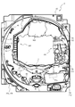
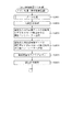
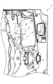
以下、本発明の実施形態について、添付図面を参照して説明する。まず、図1から図42を参照し、第1実施形態として、本発明をパチンコ遊技機(以下、単に「パチンコ機」という)10に適用した場合の一実施形態について説明する。図1は、第1実施形態におけるパチンコ機10の正面図であり、図2はパチンコ機10の遊技盤13の正面図であり、図3はパチンコ機10の後面図である。
Hereinafter, embodiments of the present invention will be described with reference to the accompanying drawings. First, with reference to FIGS. 1 to 42, as a first embodiment, an embodiment in which the present invention is applied to a pachinko gaming machine (hereinafter, simply referred to as a “pachinko machine”) 10 will be described. FIG. 1 is a front view of a
図1に示すように、パチンコ機10は、略矩形状に組み合わせた木枠により外殻が形成される外枠11と、その外枠11と略同一の外形形状に形成され外枠11に対して開閉可能に支持された内枠12とを備えている。外枠11には、内枠12を支持するために正面視(図1参照)左側の上下2カ所に金属製のヒンジ18が取り付けられ、そのヒンジ18が設けられた側を開閉の軸として内枠12が正面手前側へ開閉可能に支持されている。
As shown in FIG. 1, the
内枠12には、多数の釘や入賞口63,64等を有する遊技盤13(図2参照)が裏面側から着脱可能に装着される。この遊技盤13の正面を球(遊技球)が流下することにより弾球遊技が行われる。なお、内枠12には、球を遊技盤13の正面領域に発射する球発射ユニット112a(図4参照)やその球発射ユニット112aから発射された球を遊技盤13の正面領域まで誘導する発射レール(図示せず)等が取り付けられている。
A game board 13 (see FIG. 2) having a large number of nails, winning
内枠12の正面側には、その正面上側を覆う正面枠14と、その下側を覆う下皿ユニット15とが設けられている。正面枠14及び下皿ユニット15を支持するために正面視(図1参照)左側の上下2カ所に金属製のヒンジ19が取り付けられ、そのヒンジ19が設けられた側を開閉の軸として正面枠14及び下皿ユニット15が正面手前側へ開閉可能に支持されている。なお、内枠12の施錠と正面枠14の施錠とは、シリンダ錠20の鍵穴21に専用の鍵を差し込んで所定の操作を行うことでそれぞれ解除される。
On the front side of the
正面枠14は、装飾用の樹脂部品や電気部品等を組み付けたものであり、その略中央部には略楕円形状に開口形成された窓部14cが設けられている。正面枠14の裏面側には2枚の板ガラスを有するガラスユニット16が配設され、そのガラスユニット16を介して遊技盤13の正面がパチンコ機10の正面側に視認可能となっている。
The
正面枠14には、球を貯留する上皿17が正面側へ張り出して上面を開放した略箱状に形成されており、この上皿17に賞球や貸出球などが排出される。上皿17の底面は正面視(図1参照)右側に下降傾斜して形成され、その傾斜により上皿17に投入された球が球発射ユニット112a(図4参照)へと案内される。また、上皿17の上面には、枠ボタン22が設けられている。この枠ボタン22は、例えば、第3図柄表示装置81(図2参照)で表示される演出のステージを変更したり、スーパーリーチの演出内容を変更したりする場合などに、遊技者により操作される。
An
正面枠14には、その周囲(例えばコーナー部分)に各種ランプ等の発光手段が設けられている。これら発光手段は、大当たり時や所定のリーチ時等における遊技状態の変化に応じて、点灯又は点滅することにより発光態様が変更制御され、遊技中の演出効果を高める役割を果たす。窓部14cの周縁には、LED等の発光手段を内蔵した電飾部29〜33が設けられている。パチンコ機10においては、これら電飾部29〜33が大当たりランプ等の演出ランプとして機能し、大当たり時やリーチ演出時等には内蔵するLEDの点灯や点滅によって各電飾部29〜33が点灯または点滅して、大当たり中である旨、或いは大当たり一歩手前のリーチ中である旨が報知される。また、正面枠14の正面視(図1参照)左上部には、LED等の発光手段が内蔵され賞球の払い出し中とエラー発生時とを表示可能な表示ランプ34が設けられている。
The
また、右側の電飾部32下側には、正面枠14の裏面側を視認できるように裏面側より透明樹脂を取り付けて小窓35が形成され、遊技盤13正面の貼着スペースK1(図2参照)に貼付される証紙等がパチンコ機10の正面から視認可能とされている。また、パチンコ機10においては、より煌びやかさを醸し出すために、電飾部29〜33の周りの領域にクロムメッキを施したABS樹脂製のメッキ部材36が取り付けられている。
In addition, a
窓部14cの下方には、貸球操作部40が配設されている。貸球操作部40には、度数表示部41と、球貸しボタン42と、返却ボタン43とが設けられている。パチンコ機10の側方に配置されるカードユニット(球貸しユニット)(図示せず)に紙幣やカード等を投入した状態で貸球操作部40が操作されると、その操作に応じて球の貸出が行われる。具体的には、度数表示部41はカード等の残額情報が表示される領域であり、内蔵されたLEDが点灯して残額情報として残額が数字で表示される。球貸しボタン42は、カード等(記録媒体)に記録された情報に基づいて貸出球を得るために操作されるものであり、カード等に残額が存在する限りにおいて貸出球が上皿17に供給される。返却ボタン43は、カードユニットに挿入されたカード等の返却を求める際に操作される。なお、カードユニットを介さずに球貸し装置等から上皿17に球が直接貸し出されるパチンコ機、いわゆる現金機では貸球操作部40が不要となるが、この場合には、貸球操作部40の設置部分に飾りシール等を付加して部品構成は共通のものとしても良い。カードユニットを用いたパチンコ機と現金機との共通化を図ることができる。
A ball
上皿17の下側に位置する下皿ユニット15には、その中央部に上皿17に貯留しきれなかった球を貯留するための下皿50が上面を開放した略箱状に形成されている。下皿50の右側には、球を遊技盤13の正面へ打ち込むために遊技者によって操作される操作ハンドル51が配設される。
In the
操作ハンドル51の内部には、球発射ユニット112aの駆動を許可するためのタッチセンサ51aと、押下操作している期間中には球の発射を停止する発射停止スイッチ51bと、操作ハンドル51の回動操作量(回動位置)を電気抵抗の変化により検出する可変抵抗器(図示せず)などが内蔵されている。操作ハンドル51が遊技者によって右回りに回動操作されると、タッチセンサ51aがオンされると共に可変抵抗器の抵抗値が回動操作量に対応して変化し、その可変抵抗器の抵抗値に対応した強さ(発射強度)で球が発射され、これにより遊技者の操作に対応した飛び量で遊技盤13の正面へ球が打ち込まれる。また、操作ハンドル51が遊技者により操作されていない状態においては、タッチセンサ51aおよび発射停止スイッチ51bがオフとなっている。
Inside the
下皿50の正面下方部には、下皿50に貯留された球を下方へ排出する際に操作するための球抜きレバー52が設けられている。この球抜きレバー52は、常時、右方向に付勢されており、その付勢に抗して左方向へスライドさせることにより、下皿50の底面に形成された底面口が開口して、その底面口から球が自然落下して排出される。この球抜きレバー52の操作は、通常、下皿50の下方に下皿50から排出された球を受け取る箱(一般に「千両箱」と称される)を置いた状態で行われる。下皿50の右方には、上述したように操作ハンドル51が配設され、下皿50の左方には灰皿53が取り付けられている。
At the lower part of the front surface of the
図2に示すように、遊技盤13は、正面視略正方形状に切削加工したベース板60に、球案内用の多数の釘(図示せず)や風車(可動部材310を図示し、その他は図示せず)の他、レール61,62、一般入賞口63、第1入賞口64、第2入賞口640、第1可変入賞装置65、第2可変入賞装置(図示せず)、普通図柄始動口(スルーゲート)67、可変表示装置ユニット80等を組み付けて構成され、その周縁部が内枠12(図1参照)の裏面側に取り付けられる。ベース板60は光透過性の樹脂材料からなり、その正面側からベース板60の後面側に配設された各種構造体を遊技者に視認させることが可能に形成される。一般入賞口63、第1入賞口64、第2入賞口640、第1可変入賞装置65、第2可変入賞装置(図示せず)、可変表示装置ユニット80は、ルータ加工によってベース板60に形成された貫通穴に配設され、遊技盤13の正面側からタッピングネジ等により固定されている。
As shown in FIG. 2, the
遊技盤13の正面中央部分は、正面枠14の窓部14c(図1参照)を通じて内枠12の正面側から視認することができる。以下に、主に図2を参照して、遊技盤13の構成について説明する。
The front center portion of the
遊技盤13の正面には、帯状の金属板を略円弧状に屈曲加工して形成した外レール62が植立され、その外レール62の内側位置には外レール62と同様に帯状の金属板で形成した円弧状の内レール61が植立される。この内レール61と外レール62とにより遊技盤13の正面外周が囲まれ、遊技盤13とガラスユニット16(図1参照)とにより前後が囲まれることにより、遊技盤13の正面には、球の挙動により遊技が行われる遊技領域が形成される。遊技領域は、遊技盤13の正面であって2本のレール61,62とレール間を繋ぐ樹脂製の外縁部材73とにより区画して形成される領域(入賞口等が配設され、発射された球が流下する領域)である。
On the front of the
2本のレール61,62は、球発射ユニット112a(図4参照)から発射された球を遊技盤13上部へ案内するために設けられたものである。内レール61の先端部分(図2の左上部)には戻り球防止部材68が取り付けられ、一旦、遊技盤13の上部へ案内された球が再度球案内通路内に戻ってしまうといった事態が防止される。外レール62の先端部(図2の右上部)には、球の最大飛翔部分に対応する位置に返しゴム69が取り付けられ、所定以上の勢いで発射された球は、返しゴム69に当たって、勢いが減衰されつつ中央部側へ跳ね返される。
The two
遊技領域の正面視左側下部(図2の左側下部)には、発光手段である複数のLED及び7セグメント表示器を備える第1図柄表示装置37A,37Bが配設されている。第1図柄表示装置37A,37Bは、主制御装置110(図4参照)で行われる各制御に応じた表示がなされるものであり、主にパチンコ機10の遊技状態の表示が行われる。本実施形態では、第1図柄表示装置37A,37Bは、球が、第1入賞口64へ入賞したか、第2入賞口640へ入賞したかに応じて使い分けられるように構成されている。具体的には、球が、第1入賞口64へ入賞した場合には、第1図柄表示装置37Aが作動し、一方で、球が、第2入賞口640へ入賞した場合には、第1図柄表示装置37Bが作動するように構成されている。
The first
また、第1図柄表示装置37A,37Bは、LEDにより、パチンコ機10が確変中か時短中か通常中であるかを点灯状態により示したり、変動中であるか否かを点灯状態により示したり、停止図柄が確変大当たりに対応した図柄か普通大当たりに対応した図柄か外れ図柄であるかを点灯状態により示したり、保留球数を点灯状態により示すと共に、7セグメント表示装置により、大当たり中のラウンド数やエラー表示を行う。なお、複数のLEDは、それぞれのLEDの発光色(例えば、赤、緑、青)が異なるよう構成され、その発光色の組み合わせにより、少ないLEDでパチンコ機10の各種遊技状態を示唆することができる。
Further, the first
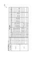
尚、本パチンコ機10では、第1入賞口64及び第2入賞口640へ入賞があったことを契機として抽選が行われる。パチンコ機10は、その抽選において、大当たりか否かの当否判定(大当たり抽選)を行うと共に、大当たりと判定した場合はその大当たり種別の判定も行う。ここで判定される大当たり種別としては、15R確変大当たり、4R確変大当たり、15R通常大当たりが用意されている。第1図柄表示装置37A,37Bには、変動終了後の停止図柄として抽選の結果が大当たりであるか否かが示されるだけでなく、大当たりである場合はその大当たり種別に応じた図柄が示される。
In the
ここで、「15R確変大当たり」とは、最大ラウンド数が15ラウンドの大当たりの後に高確率状態へ移行する確変大当たりのことであり、「4R確変大当たり」とは、最大ラウンド数が4ラウンドの大当たりの後に高確率状態へ移行する確変大当たりのことである。また、「15R通常大当たり」は、最大ラウンド数が15ラウンドの大当たりの後に、低確率状態へ移行すると共に、所定の変動回数の間(例えば、100変動回数)は時短状態となる大当たりのことである。 Here, the "15R probability variation jackpot" is a probability variation jackpot in which the maximum round number shifts to a high probability state after the 15 round jackpot, and the "4R probability variation jackpot" is a jackpot with a maximum round number of 4 rounds. It is a probability change jackpot that shifts to a high probability state after. In addition, "15R normal jackpot" is a jackpot that shifts to a low-probability state after the jackpot with the maximum round number of 15 rounds and becomes a shortened state for a predetermined number of fluctuations (for example, 100 fluctuations). is there.
また、「高確率状態」とは、大当たり終了後に付加価値としてその後の大当たり確率がアップした状態、いわゆる確率変動中(確変中)の時をいい、換言すれば、特別遊技状態へ移行し易い遊技の状態のことである。本実施形態における高確率状態(確変中)は、後述する第2図柄の当たり確率がアップして第2入賞口640へ球が入賞し易い遊技の状態を含む。「低確率状態」とは、確変中でない時をいい、大当たり確率が通常の状態、即ち、確変の時より大当たり確率が低い状態をいう。また、「低確率状態」のうちの時短状態(時短中)とは、大当たり確率が通常の状態であると共に、大当たり確率がそのままで第2図柄の当たり確率のみがアップして第2入賞口640へ球が入賞し易い遊技の状態のことをいう。一方、パチンコ機10が通常中とは、確変中でも時短中でもない遊技の状態(大当たり確率も第2図柄の当たり確率もアップしていない状態)である。
The "high probability state" means a state in which the subsequent jackpot probability increases as an added value after the jackpot ends, that is, when the probability is changing (probably changing), in other words, a game that easily transitions to a special game state. Is the state of. The high-probability state (probably changing) in the present embodiment includes a game state in which the probability of hitting a second symbol, which will be described later, increases and the ball easily wins the second winning
確変中や時短中は、第2図柄の当たり確率がアップするだけではなく、第2入賞口640に付随する電動役物640aが開放される時間も変更され、通常中と比して長い時間が設定される。電動役物640aが開放された状態(開放状態)にある場合は、その電動役物640aが閉鎖された状態(閉鎖状態)にある場合と比して、第2入賞口640へ球が入賞しやすい状態となる。よって、確変中や時短中は、第2入賞口640へ球が入賞し易い状態となり、大当たり抽選が行われる回数を増やすことができる。
During the probability change or shortening of time, not only the probability of hitting the second symbol is increased, but also the time for which the
なお、確変中や時短中において、第2入賞口640に付随する電動役物640aの開放時間を変更するのではなく、または、その開放時間を変更することに加えて、1回の当たりで電動役物640aが開放する回数を通常中よりも増やす変更を行うものとしてもよい。また、確変中や時短中において、第2図柄の当たり確率は変更せず、第2入賞口640に付随する電動役物640aが開放される時間および1回の当たりで電動役物640aが開放する回数の少なくとも一方を変更するものとしてもよい。また、確変中や時短中において、第2入賞口640に付随する電動役物640aが開放される時間や、1回の当たりで電動役物640aを開放する回数はせず、第2図柄の当たり確率だけを、通常中と比してアップするよう変更するものであってもよい。
It should be noted that, during the probable change or during the shortening of time, the opening time of the
遊技領域には、球が入賞することにより5個から15個の球が賞球として払い出される複数の一般入賞口63が配設されている。また、遊技領域の中央部分には、可変表示装置ユニット80が配設されている。可変表示装置ユニット80には、第1入賞口64及び第2入賞口640への入賞(始動入賞)をトリガとして、第1図柄表示装置37A,37Bにおける変動表示と同期させながら、第3図柄の変動表示を行う液晶ディスプレイ(以下単に「表示装置」と略す)で構成された第3図柄表示装置81と、普通図柄始動口(スルーゲート)67の球の通過をトリガとして第2図柄を変動表示するLEDで構成される第2図柄表示装置(図示せず)とが設けられている。また、可変表示装置ユニット80には、第3図柄表示装置81の外周を囲むようにして、センターフレーム86が配設されている。
In the game area, there are arranged a plurality of general winning
第3図柄表示装置81は9インチサイズの大型の液晶ディスプレイで構成されるものであり、表示制御装置114(図4参照)によって表示内容が制御されることにより、例えば上、中及び下の3つの図柄列が表示される。各図柄列は複数の図柄(第3図柄)によって構成され、これらの第3図柄が図柄列毎に横スクロールして第3図柄表示装置81の表示画面上にて第3図柄が可変表示されるようになっている。本実施形態の第3図柄表示装置81は、主制御装置110(図4参照)の制御に伴った遊技状態の表示が第1図柄表示装置37A,37Bで行われるのに対して、その第1図柄表示装置37A,37Bの表示に応じた装飾的な表示を行うものである。なお、表示装置に代えて、例えばリール等を用いて第3図柄表示装置81を構成するようにしても良い。
The third
第2図柄表示装置は、球が普通図柄始動口(スルーゲート)67を通過する毎に表示図柄(第2図柄(図示せず))としての「○」の図柄と「×」の図柄とを所定時間交互に点灯させる変動表示を行うものである。パチンコ機10では、球が普通図柄始動口(スルーゲート)67を通過したことが検出されると、当たり抽選が行われる。その当たり抽選の結果、当たりであれば、第2図柄表示装置において、第2図柄の変動表示後に「○」の図柄が停止表示される。また、当たり抽選の結果、外れであれば、第2図柄表示装置において、第3図柄の変動表示後に「×」の図柄が停止表示される。
The second symbol display device displays a symbol "○" and a symbol "x" as a display symbol (second symbol (not shown)) every time the ball passes through the normal symbol starting opening (through gate) 67. A variable display in which the lights are alternately turned on for a predetermined time is performed. In the
パチンコ機10は、第2図柄表示装置における変動表示が所定図柄(本実施形態においては「○」の図柄)で停止した場合に、第2入賞口640に付随された電動役物640aが所定時間だけ作動状態となる(開放される)よう構成されている。
In the
第2図柄の変動表示にかかる時間は、遊技状態が通常中の場合よりも、確変中または時短中の方が短くなるように設定される。これにより、確変中および時短中は、第2図柄の変動表示が短い時間で行われるので、当たり抽選を通常中よりも多く行うことができる。よって、当たり抽選において当たりとなる機会が増えるので、第2入賞口640の電動役物640aが開放状態となる機会を遊技者に多く与えることができる。よって、確変中および時短中は、第2入賞口640へ球が入賞しやすい状態とすることができる。
The time required for the variable display of the second symbol is set to be shorter during the probability change or during the time saving than when the game state is normal. As a result, during the probability change and the time reduction, the variable display of the second symbol is performed in a short time, so that the winning lottery can be performed more than usual. Therefore, the chances of winning in the winning lottery increase, so that the player can be given many opportunities to open the
なお、確変中または時短中において、当たり確率を高める、1回に当たりに対する電動役物640aの開放時間や開放回数を増やすなど、その他の方法によっても、確変中または時短中に第2入賞口640へ球が入賞しやすい状態としている場合は、第2図柄の変動表示にかかる時間を遊技状態にかかわらず一定としてもよい。一方、第2図柄の変動表示にかかる時間を、確変中または時短中において通常中よりも短く設定する場合は、当たり確率を遊技状態にかかわらず一定にしてもよいし、また、1回の当たりに対する電動役物640aの開放時間や開放回数を遊技状態にかかわらず一定にしてもよい。
In addition, during the probability change or time saving, the probability of winning is increased, and the opening time and the number of times of opening the
普通図柄始動口(スルーゲート)67は、可変表示装置ユニット80の下側の領域における右方において遊技盤に組み付けられ、遊技盤に発射された球のうち、遊技盤の右方を流下する球の一部が通過可能に構成されている。普通図柄始動口(スルーゲート)67を球が通過すると、第2図柄の当たり抽選が行われる。当たり抽選の後、第2図柄表示装置にて変動表示を行い、当たり抽選の結果が当たりであれば、変動表示の停止図柄として「○」の図柄を表示し、当たり抽選の結果が外れであれば、変動表示の停止図柄として「×」の図柄を表示する。
The normal symbol starting opening (through gate) 67 is assembled to the game board at the right side in the lower region of the variable
球の普通図柄始動口(スルーゲート)67の通過回数は、合計で最大4回まで保留され、その保留球数が上述した第1図柄表示装置37A,37Bにより表示されると共に第2図柄保留ランプ(図示せず)においても点灯表示される。第2図柄保留ランプは、最大保留数分の4つ設けられ、第3図柄表示装置81の下方に左右対称に配設されている。
The number of passages through the normal symbol starting opening (through gate) 67 of the ball is held up to a maximum of four times in total, and the number of holding balls is displayed by the above-mentioned first
なお、第2図柄の変動表示は、本実施形態のように、第2図柄表示装置において複数のランプの点灯と非点灯を切り換えることにより行うものの他、第1図柄表示装置37A,37B及び第3図柄表示装置81の一部を使用して行うようにしても良い。同様に、第2図柄保留ランプの点灯を第3図柄表示装置81の一部で行うようにしても良い。また、普通図柄始動口(スルーゲート)67の球の通過に対する最大保留球数は4回に限定されるものでなく、3回以下、又は、5回以上の回数(例えば、8回)に設定しても良い。また、普通図柄始動口(スルーゲート)67の組み付け数は1つに限定されるものではなく、複数(例えば、2つ)であっても良い。また、普通図柄始動口(スルーゲート)67の組み付け位置は可変表示装置ユニット80の右方に限定されるものではなく、例えば、可変表示装置ユニット80の左方でも良い。また、第1図柄表示装置37A,37Bにより保留球数が示されるので、第2図柄保留ランプにより点灯表示を行わないものとしてもよい。
The variable display of the second symbol is performed by switching lighting and non-lighting of a plurality of lamps in the second symbol display device as in the present embodiment, as well as the first
可変表示装置ユニット80の下方には、球が入賞し得る第1入賞口64が配設されている。この第1入賞口64へ球が入賞すると遊技盤13の裏面側に設けられる第1入賞口スイッチ(図示せず)がオンとなり、その第1入賞口スイッチのオンに起因して主制御装置110(図4参照)で大当たりの抽選がなされ、その抽選結果に応じた表示が第1図柄表示装置37Aで示される。
Below the variable
一方、第1入賞口64の正面視右方には、球が入賞し得る第2入賞口640が配設されている。この第2入賞口640へ球が入賞すると遊技盤13の裏面側に設けられる第2入賞口スイッチ(図示せず)がオンとなり、その第2入賞口スイッチのオンに起因して主制御装置110(図4参照)で大当たりの抽選がなされ、その抽選結果に応じた表示が第1図柄表示装置37Bで示される。
On the other hand, on the right side of the first winning
また、第1入賞口64および第2入賞口640は、それぞれ、球が入賞すると5個の球が賞球として払い出される入賞口の1つにもなっている。なお、本実施形態においては、第1入賞口64へ球が入賞した場合に払い出される賞球数と第2入賞口640へ球が入賞した場合に払い出される賞球数とを同じに構成したが、第1入賞口64へ球が入賞した場合に払い出される賞球数と第2入賞口640へ球が入賞した場合に払い出される賞球数とを異なる数、例えば、第1入賞口64へ球が入賞した場合に払い出される賞球数を3個とし、第2入賞口640へ球が入賞した場合に払い出される賞球数を5個として構成してもよい。
In addition, each of the first winning
第2入賞口640には電動役物640aが付随されている。この電動役物640aは開閉可能に構成されており、通常は電動役物640aが閉鎖状態(縮小状態)となって、球が第2入賞口640へ入賞しにくい状態となっている。一方、普通図柄始動口(スルーゲート)67への球の通過を契機として行われる第2図柄の変動表示の結果、「○」の図柄が第2図柄表示装置に表示された場合、電動役物640aが開放状態(拡大状態)となり、球が第2入賞口640へ入賞しやすい状態となる。
An
上述した通り、確変中および時短中は、通常中と比して第2図柄の当たり確率が高く、また、第2図柄の変動表示にかかる時間も短いので、第2図柄の変動表示において「○」の図柄が表示され易くなって、電動役物640aが開放状態(拡大状態)となる回数が増える。更に、確変中および時短中は、電動役物640aが開放される時間も、通常中より長くなる。よって、確変中および時短中は、通常時と比して、第2入賞口640へ球が入賞しやすい状態を作ることができる。
As described above, the probability of hitting the second symbol is higher than that in the normal state during the probability change and the shortening of the time period, and the time required for the variable display of the second symbol is short, so that in the variable display of the second symbol, “○” is displayed. Is easily displayed, and the number of times the
ここで、第1入賞口64に球が入賞した場合と第2入賞口640へ球が入賞した場合とで、大当たりとなる確率は、低確率状態であっても高確率状態でも同一である。しかしながら、大当たりとなった場合に選定される大当たりの種別として15R確変大当たりとなる確率は、第2入賞口640へ球が入賞した場合のほうが第1入賞口64へ球が入賞した場合よりも高く設定されている。一方、第1入賞口64は、第2入賞口640にあるような電動役物は有しておらず、球が常時入賞可能な状態となっている。
Here, the probability of being a big hit is the same in both the low-probability state and the high-probability state, when the ball wins the first winning
よって、通常中においては、第2入賞口640に付随する電動役物が閉鎖状態にある場合が多く、第2入賞口640に入賞しづらいので、電動役物のない第1入賞口64へ向けて、可変表示装置ユニット80の左方を球が通過するように球を発射し(所謂「左打ち」)、第1入賞口64への入賞によって大当たり抽選の機会を多く得て、大当たりとなることを狙った方が、遊技者にとって有利となる。
Therefore, during normal operation, the electric winning object associated with the second winning
一方、確変中や時短中は、普通図柄始動口(スルーゲート)67に球を通過させることで、第2入賞口640に付随する電動役物640aが開放状態となりやすく、第2入賞口640に入賞しやすい状態であるので、第2入賞口640へ向けて、可変表示装置80の右方を球が通過するように球を発射し(所謂「右打ち」)、普通図柄始動口(スルーゲート)67を通過させて電動役物を開放状態にすると共に、第2入賞口640への入賞によって15R確変大当たりとなることを狙った方が、遊技者にとって有利となる。
On the other hand, during probability change or shortening of time, by passing the ball through the normal symbol starting opening (through gate) 67, the
このように、本実施形態のパチンコ機10は、パチンコ機10の遊技状態(確変中であるか、時短中であるか、通常中であるか)に応じて、遊技者に対し、球の発射の仕方を「左打ち」と「右打ち」とに変えさせることができる。よって、遊技者に対して、球の打ち方に変化をもたらすことができるので、遊技を楽しませることができる。
In this way, the
第1入賞口64の下方右側には第1可変入賞装置65が配設されており、その略中央部分に横長矩形状の特定入賞口(大開放口)65aが設けられている。パチンコ機10においては、第1入賞口64又は第2入賞口640への入賞に起因して行われた大当たり抽選が大当たりとなると、所定時間(変動時間)が経過した後に、大当たりの停止図柄となるよう第1図柄表示装置37A又は第1図柄表示装置37Bを点灯させると共に、その大当たりに対応した停止図柄を第3図柄表示装置81に表示させて、大当たりの発生が示される。その後、球が入賞し易い特別遊技状態(大当たり)に遊技状態が遷移する。この特別遊技状態として、通常時には閉鎖されている特定入賞口65aが、所定時間(例えば、30秒経過するまで、或いは、球が10個入賞するまで)開放される。
A first variable winning
この特定入賞口65aは、所定時間が経過すると閉鎖され、その閉鎖後、再度、その特定入賞口65aが所定時間開放される。この特定入賞口65aの開閉動作は、最高で例えば15回(15ラウンド)繰り返し可能にされている。この開閉動作が行われている状態が、遊技者にとって有利な特別遊技状態の一形態であり、遊技者には、遊技上の価値(遊技価値)の付与として通常時より多量の賞球の払い出しが行われる。
The
第1可変入賞装置65は、具体的には、特定入賞口65aを覆う横長矩形状の開閉板と、その開閉板の下辺を軸として正面側に開閉駆動するための大開放口ソレノイド(図示せず)とを備えている。特定入賞口65aは、通常時は、球が入賞できないか又は入賞し難い閉状態になっている。大当たりの際には大開放口ソレノイドを駆動して開閉板を正面下側に傾倒し、球が特定入賞口65aに入賞しやすい開状態を一時的に形成し、その開状態と通常時の閉状態との状態を交互に繰り返すように作動する。
Specifically, the first variable winning
なお、上記した形態に特別遊技状態は限定されるものではない。特定入賞口65aとは別に開閉される大開放口を遊技領域に設け、第1図柄表示装置37A,37Bにおいて大当たりに対応したLEDが点灯した場合に、特定入賞口65aが所定時間開放され、その特定入賞口65aの開放中に、球が特定入賞口65a内へ入賞することを契機として特定入賞口65aとは別に設けられた大開放口が所定時間、所定回数開放される遊技状態を特別遊技状態として形成するようにしても良い。また、特定入賞口65aは1つに限るものではなく、1つ若しくは2以上の複数(例えば3つ)を配置しても良く、また配置位置も第1入賞口64の下方右側や、第1入賞口64の下方左側に限らず、例えば、可変表示装置ユニット80の左方でも良い。
The special game state is not limited to the above-mentioned form. A large opening that is opened and closed separately from the specific winning
遊技盤13の下側における右隅部には、証紙や識別ラベル等を貼着するための貼着スペースK1が設けられ、貼着スペースK1に貼られた証紙等は、正面枠14の小窓35(図1参照)を通じて視認することができる。
A sticking space K1 for sticking a stamp or an identification label is provided in the lower right corner of the
遊技盤13には、第1アウト口71が設けられている。遊技領域を流下する球であって、いずれの入賞口63,64,65a,640にも入賞しなかった球は、第1アウト口71を通って図示しない球排出路へと案内される。第1アウト口71は、第1入賞口64の下方に配設される。
The
遊技盤13には、球の落下方向を適宜分散、調整等するために多数の釘が植設されているとともに、風車等の各種部材(役物)とが配設されている。本実施形態においては、風車の内の一つ(可動部材310と称す)が遊技盤13の正面視左側上方に配設され、図2において図示されている。
On the
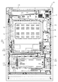
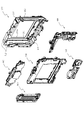
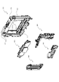
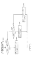
図3に示すように、パチンコ機10の後面側には、制御基板ユニット90,91と、裏パックユニット94とが主に備えられている。制御基板ユニット90は、主基板(主制御装置110)と音声ランプ制御基板(音声ランプ制御装置113)と表示制御基板(表示制御装置114)とが搭載されてユニット化されている。制御基板ユニット91は、払出制御基板(払出制御装置111)と発射制御基板(発射制御装置112)と電源基板(電源装置115)とカードユニット接続基板116とが搭載されてユニット化されている。
As shown in FIG. 3,
裏パックユニット94は、保護カバー部を形成する裏パック92と払出ユニット93とがユニット化されている。また、各制御基板には、各制御を司る1チップマイコンとしてのMPU、各種機器との連絡をとるポート、各種抽選の際に用いられる乱数発生器、時間計数や同期を図る場合などに使用されるクロックパルス発生回路等が、必要に応じて搭載されている。
The
なお、主制御装置110、音声ランプ制御装置113及び表示制御装置114、払出制御装置111及び発射制御装置112、電源装置115、カードユニット接続基板116は、それぞれ基板ボックス100〜104に収納されている。基板ボックス100〜104は、ボックスベースと該ボックスベースの開口部を覆うボックスカバーとを備えており、そのボックスベースとボックスカバーとが互いに連結されて、各制御装置や各基板が収納される。
The
また、基板ボックス100(主制御装置110)及び基板ボックス102(払出制御装置111及び発射制御装置112)は、ボックスベースとボックスカバーとを封印ユニット(図示せず)によって開封不能に連結(かしめ構造による連結)している。また、ボックスベースとボックスカバーとの連結部には、ボックスベースとボックスカバーとに亘って封印シール(図示せず)が貼着されている。この封印シールは、脆性な素材で構成されており、基板ボックス100,102を開封するために封印シールを剥がそうとしたり、基板ボックス100,102を無理に開封しようとすると、ボックスベース側とボックスカバー側とに切断される。よって、封印ユニット又は封印シールを確認することで、基板ボックス100,102が開封されたかどうかを知ることができる。
Further, in the board box 100 (main controller 110) and the board box 102 (
払出ユニット93は、裏パックユニット94の最上部に位置して上方に開口したタンク130と、タンク130の下方に連結され下流側に向けて緩やかに傾斜するタンクレール131と、タンクレール131の下流側に縦向きに連結されるケースレール132と、ケースレール132の最下流部に設けられ、払出モータ216(図4参照)の所定の電気的構成により球の払出を行う払出装置133とを備えている。タンク130には、遊技ホールの島設備から供給される球が逐次補給され、払出装置133により必要個数の球の払い出しが適宜行われる。タンクレール131には、当該タンクレール131に振動を付加するためのバイブレータ134が取り付けられている。
The
また、払出制御装置111には状態復帰スイッチ120が設けられ、発射制御装置112には可変抵抗器の操作つまみ121が設けられ、電源装置115にはRAM消去スイッチ122が設けられている。状態復帰スイッチ120は、例えば、払出モータ216(図4参照)部の球詰まり等、払出エラーの発生時に球詰まりを解消(正常状態への復帰)するために操作される。操作つまみ121は、発射ソレノイドの発射力を調整するために操作される。RAM消去スイッチ122は、パチンコ機10を初期状態に戻したい場合に電源投入時に操作される。
The
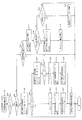
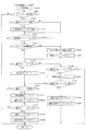
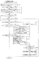
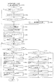
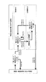
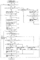
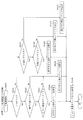
次に、図4を参照して、本パチンコ機10の電気的構成について説明する。図4は、パチンコ機10の電気的構成を示すブロック図である。
Next, the electrical configuration of the
主制御装置110には、演算装置である1チップマイコンとしてのMPU201が搭載されている。MPU201には、該MPU201により実行される各種の制御プログラムや固定値データを記憶したROM202と、そのROM202内に記憶される制御プログラムの実行に際して各種のデータ等を一時的に記憶するためのメモリであるRAM203と、そのほか、割込回路やタイマ回路、データ送受信回路などの各種回路が内蔵されている。主制御装置110では、MPU201によって、大当たり抽選や第1図柄表示装置37A,37B及び第3図柄表示装置81における表示の設定、第2図柄表示装置における表示結果の抽選といったパチンコ機10の主要な処理を実行する。
The
なお、払出制御装置111や音声ランプ制御装置113などのサブ制御装置に対して動作を指示するために、主制御装置110から該サブ制御装置へ各種のコマンドがデータ送受信回路によって送信されるが、かかるコマンドは、主制御装置110からサブ制御装置へ一方向にのみ送信される。
Note that various commands are transmitted from the
RAM203は、各種エリア、カウンタ、フラグのほか、MPU201の内部レジスタの内容やMPU201により実行される制御プログラムの戻り先番地などが記憶されるスタックエリアと、各種のフラグおよびカウンタ、I/O等の値が記憶される作業エリア(作業領域)とを有している。なお、RAM203は、パチンコ機10の電源の遮断後においても電源装置115からバックアップ電圧が供給されてデータを保持(バックアップ)できる構成となっており、RAM203に記憶されるデータは、すべてバックアップされる。
The
停電などの発生により電源が遮断されると、その電源遮断時(停電発生時を含む。以下同様)のスタックポインタや、各レジスタの値がRAM203に記憶される。一方、電源投入時(停電解消による電源投入を含む。以下同様)には、RAM203に記憶される情報に基づいて、パチンコ機10の状態が電源遮断前の状態に復帰される。RAM203への書き込みはメイン処理(図示せず)によって電源遮断時に実行され、RAM203に書き込まれた各値の復帰は電源投入時の立ち上げ処理(図示せず)において実行される。なお、MPU201のNMI端子(ノンマスカブル割込端子)には、停電等の発生による電源遮断時に、停電監視回路252からの停電信号SG1が入力されるように構成されており、その停電信号SG1がMPU201へ入力されると、停電時処理としてのNMI割込処理(図示せず)が即座に実行される。
When the power is cut off due to the occurrence of a power failure or the like, the
主制御装置110のMPU201には、アドレスバス及びデータバスで構成されるバスライン204を介して入出力ポート205が接続されている。入出力ポート205には、払出制御装置111、音声ランプ制御装置113、第1図柄表示装置37A,37B、第2図柄表示装置、第2図柄保留ランプ、特定入賞口65aの開閉板の下辺を軸として正面側に開閉駆動するための大開放口ソレノイドや電動役物を駆動するためのソレノイドなどからなるソレノイド209が接続され、MPU201は、入出力ポート205を介してこれらに対し各種コマンドや制御信号を送信する。
An input /
また、入出力ポート205には、図示しないスイッチ群およびスライド位置検出センサSや回転位置検出センサRを含むセンサ群などからなる各種スイッチ208、電源装置115に設けられた後述のRAM消去スイッチ回路253が接続され、MPU201は各種スイッチ208から出力される信号や、RAM消去スイッチ回路253より出力されるRAM消去信号SG2に基づいて各種処理を実行する。
Further, the input /
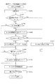
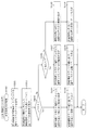
払出制御装置111は、払出モータ216を駆動させて賞球や貸出球の払出制御を行うものである。演算装置であるMPU211は、そのMPU211により実行される制御プログラムや固定値データ等を記憶したROM212と、ワークメモリ等として使用されるRAM213とを有している。
The
払出制御装置111のRAM213は、主制御装置110のRAM203と同様に、MPU211の内部レジスタの内容やMPU211により実行される制御プログラムの戻り先番地などが記憶されるスタックエリアと、各種のフラグおよびカウンタ、I/O等の値が記憶される作業エリア(作業領域)とを有している。RAM213は、パチンコ機10の電源の遮断後においても電源装置115からバックアップ電圧が供給されてデータを保持(バックアップ)できる構成となっており、RAM213に記憶されるデータは、すべてバックアップされる。なお、主制御装置110のMPU201と同様、MPU211のNMI端子にも、停電等の発生による電源遮断時に停電監視回路252から停電信号SG1が入力されるように構成されており、その停電信号SG1がMPU211へ入力されると、停電時処理としてのNMI割込処理(図示せず)が即座に実行される。
The
払出制御装置111のMPU211には、アドレスバス及びデータバスで構成されるバスライン214を介して入出力ポート215が接続されている。入出力ポート215には、主制御装置110や払出モータ216、発射制御装置112などがそれぞれ接続されている。また、図示はしないが、払出制御装置111には、払い出された賞球を検出するための賞球検出スイッチが接続されている。なお、該賞球検出スイッチは、払出制御装置111に接続されるが、主制御装置110には接続されていない。
An input /
発射制御装置112は、主制御装置110により球の発射の指示がなされた場合に、操作ハンドル51の回動操作量に応じた球の打ち出し強さとなるよう球発射ユニット112aを制御するものである。球発射ユニット112aは、図示しない発射ソレノイドおよび電磁石を備えており、その発射ソレノイドおよび電磁石は、所定条件が整っている場合に駆動が許可される。具体的には、遊技者が操作ハンドル51に触れていることをタッチセンサ51aにより検出し、球の発射を停止させるための発射停止スイッチ51bがオフ(操作されていないこと)を条件に、操作ハンドル51の回動操作量(回動位置)に対応して発射ソレノイドが励磁され、操作ハンドル51の操作量に応じた強さで球が発射される。
The
音声ランプ制御装置113は、音声出力装置(図示しないスピーカなど)226における音声の出力、ランプ表示装置(電飾部29〜33、表示ランプ34など)227における点灯および消灯の出力、変動演出(変動表示)や予告演出といった表示制御装置114で行われる第3図柄表示装置81の表示態様の設定などを制御するものである。演算装置であるMPU221は、そのMPU221により実行される制御プログラムや固定値データ等を記憶したROM222と、ワークメモリ等として使用されるRAM223とを有している。
The voice
音声ランプ制御装置113のMPU221には、アドレスバス及びデータバスで構成されるバスライン224を介して入出力ポート225が接続されている。入出力ポート225には、主制御装置110、表示制御装置114、音声出力装置226、ランプ表示装置227、その他装置228、枠ボタン22などがそれぞれ接続されている。その他装置228には、駆動装置340,464,560や駆動モータ441,771,772,773,774が含まれる。
An input /
音声ランプ制御装置113は、主制御装置110から受信した各種のコマンド(変動パターンコマンド、停止種別コマンド等)に基づいて、第3図柄表示装置81の表示態様を決定し、決定した表示態様をコマンド(表示用変動パターンコマンド、表示用停止種別コマンド等)によって表示制御装置114へ通知する。また、音声ランプ制御装置113は、枠ボタン22からの入力を監視し、遊技者によって枠ボタン22が操作された場合は、第3図柄表示装置81で表示されるステージを変更したり、スーパーリーチ時の演出内容を変更したりするように、表示制御装置114へ指示する。ステージが変更される場合は、変更後のステージに応じた後面画像を第3図柄表示装置81に表示させるべく、変更後のステージに関する情報を含めた後面画像変更コマンドを表示制御装置114へ送信する。ここで、後面画像とは、第3図柄表示装置81に表示させる主要な画像である第3図柄の後面側に表示される画像のことである。表示制御装置114は、この音声ランプ制御装置113から送信されるコマンドに従って、第3図柄表示装置81に各種の画像を表示する。
The voice
また、音声ランプ制御装置113は、表示制御装置114から第3図柄表示装置81の表示内容を表すコマンド(表示コマンド)を受信する。音声ランプ制御装置113では、表示制御装置114から受信した表示コマンドに基づき、第3図柄表示装置81の表示内容に合わせて、その表示内容に対応する音声を音声出力装置226から出力し、また、その表示内容に対応させてランプ表示装置227の点灯および消灯を制御する。
Further, the voice
表示制御装置114は、音声ランプ制御装置113及び第3図柄表示装置81が接続され、音声ランプ制御装置113より受信したコマンドに基づいて、第3図柄表示装置81における第3図柄の変動演出などの表示を制御するものである。また、表示制御装置114は、第3図柄表示装置81の表示内容を通知する表示コマンドを適宜音声ランプ制御装置113へ送信する。音声ランプ制御装置113は、この表示コマンドによって示される表示内容にあわせて音声出力装置226から音声を出力することで、第3図柄表示装置81の表示と音声出力装置226からの音声出力とをあわせることができる。
The
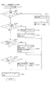
電源装置115は、パチンコ機10の各部に電源を供給するための電源部251と、停電等による電源遮断を監視する停電監視回路252と、RAM消去スイッチ122(図3参照)が設けられたRAM消去スイッチ回路253とを有している。電源部251は、図示しない電源経路を通じて、各制御装置110〜114等に対して各々に必要な動作電圧を供給する装置である。その概要としては、電源部251は、外部より供給される交流24ボルトの電圧を取り込み、各種スイッチ208などの各種スイッチや、ソレノイド209などのソレノイド、モータ等を駆動するための12ボルトの電圧、ロジック用の5ボルトの電圧、RAMバックアップ用のバックアップ電圧などを生成し、これら12ボルトの電圧、5ボルトの電圧及びバックアップ電圧を各制御装置110〜114等に対して必要な電圧を供給する。
The
停電監視回路252は、停電等の発生による電源遮断時に、主制御装置110のMPU201及び払出制御装置111のMPU211の各NMI端子へ停電信号SG1を出力するための回路である。停電監視回路252は、電源部251から出力される最大電圧である直流安定24ボルトの電圧を監視し、この電圧が22ボルト未満になった場合に停電(電源断、電源遮断)の発生と判断して、停電信号SG1を主制御装置110及び払出制御装置111へ出力する。停電信号SG1の出力によって、主制御装置110及び払出制御装置111は、停電の発生を認識し、NMI割込処理を実行する。なお、電源部251は、直流安定24ボルトの電圧が22ボルト未満になった後においても、NMI割込処理の実行に充分な時間の間、制御系の駆動電圧である5ボルトの電圧の出力を正常値に維持するように構成されている。よって、主制御装置110及び払出制御装置111は、NMI割込処理(図示せず)を正常に実行し完了することができる。
The power
RAM消去スイッチ回路253は、RAM消去スイッチ122(図3参照)が押下された場合に、主制御装置110へ、バックアップデータをクリアさせるためのRAM消去信号SG2を出力するための回路である。主制御装置110は、パチンコ機10の電源投入時に、RAM消去信号SG2を入力した場合に、バックアップデータをクリアすると共に、払出制御装置111においてバックアップデータをクリアさせるための払出初期化コマンドを払出制御装置111に対して送信する。
The RAM erase
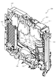
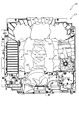
次いで、図5から図42を参照して、動作ユニット200について説明する。まず、図5から図7を参照して、背面ケース210への各ユニット300〜700の収容構造について説明する。
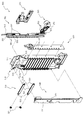
Next, the
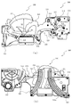
図5は、動作ユニット200の正面斜視図であり、図6及び図7は、分解した動作ユニット200を正面視した動作ユニット200の分解正面斜視図である。なお、図7では、第2スライド動作ユニット700が背面ケース210に装着された状態が図示される。
FIG. 5 is a front perspective view of the
図5から図7に示すように、動作ユニット200は、底壁部211と、その底壁部211の外縁から立設される外壁部212とから一面側(図6紙面手前側)が開放された箱状に形成される背面ケース210を備える。背面ケース210は、その底壁部211の中央に矩形状の開口211aが開口形成されることで、正面視矩形の枠状に形成される。開口211aは、第3図柄表示装置81(図2参照)の外形に対応した(即ち、第3図柄表示装置81を配設可能な)大きさに形成される。
As shown in FIGS. 5 to 7, in the
動作ユニット200は、背面ケース210の内部空間に、揺動動作ユニット300、第1スライド動作ユニット400、反転動作ユニット500、装飾動作ユニット600及び第2スライド動作ユニット700がそれぞれ収容され、これを1ユニットとして構成される。
In the
具体的には、第2スライド動作ユニット700は、背面ケース210の外壁部212の内側面が形成する形状よりも若干小さな外形で形成され、外壁部212の内側面に当接しながら、外壁部212に囲われる態様で底壁部211に配設される(図7参照)。第2スライド動作ユニット700は、組立状態(図5参照)において、正面視で背面ケース210の開口211aと一致する位置に矩形状の開口が形成される。
Specifically, the second
この図7に示す状態に対し、揺動動作ユニット300、第1スライド動作ユニット400、反転動作ユニット500及び装飾ユニット600は、第2スライド動作ユニット700の正面側に、それぞれ重ね合わされた積層状態で配設され、背面ケース210に収容される(図5参照)。
In contrast to the state shown in FIG. 7, the
このように、本実施形態では、所定の動作ユニット(例えば、第2スライド動作ユニット700)に対し、他の動作ユニット(例えば、第1スライド動作ユニット400)が正面側に重ね合わされた積層状態で配設されるので、正面視において、所定の動作ユニットを、他の動作ユニットによって遮蔽することができる。 As described above, in the present embodiment, a predetermined operation unit (for example, the second slide operation unit 700) and another operation unit (for example, the first slide operation unit 400) are stacked on the front side in a stacked state. Since it is provided, the predetermined operation unit can be shielded by another operation unit in the front view.
言い換えれば、遊技盤13(図2参照)が光透過性材料から形成され、その遊技盤13の背面側に配設される動作ユニットを遊技者が視認可能とされる場合に、所定の動作ユニットの必要な部分のみを遊技者に視認させ、他の部分を他の動作ユニットにより遊技者から遮蔽することができる。これにより、他の動作ユニットによって遮蔽される所定の演出部材については、その全体が遊技者から視認されることを前提として設計する必要がないので、その設計の自由度の向上を図ることができる。
In other words, when the game board 13 (see FIG. 2) is made of a light transmissive material and the operation unit arranged on the back side of the
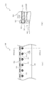
次いで、図8から図10を参照して、揺動動作ユニット300、第1スライド動作ユニット400及び第2スライド動作ユニット700の動作態様の概略について説明する。なお、図8から図10の説明においては、図5から図7を適宜参照する。
Next, with reference to FIGS. 8 to 10, an outline of operation modes of the
図8から図10は、動作ユニット200の正面図である。なお、図8では揺動動作ユニット300の起立部材330及びアーム部材320が張出位置に配置された状態が、図9では第1スライド動作ユニット400の傾倒部材460及び吊下部材430(図22参照)が張出位置に配置された状態が、図10では第2スライド動作ユニットの各スライド部材720,740が張出位置に配置された状態が、それぞれ図示される。
8 to 10 are front views of the
図8に示すように、揺動動作ユニット300は、基端側が揺動可能に軸支されるアーム部材320と、そのアーム部材320の基端側の反対側である揺動端側に揺動可能に軸支される起立部材330とを備えると共に、これらのアーム部材320及び起立部材330を、図5に示す退避位置と図8に示す張出位置との間で動作させる。図5に示す退避位置では、アーム部材320及び起立部材330は、背面ケース210の開口211aの下方に退避され、遊技者から視認不能とされる(図2参照)。一方、図8に示す張出位置では、アーム部材320が持ち上げられ、起立部材330が背面ケース210の開口211aの中央(即ち、第3図柄表示装置81の正面、図2参照)に配置される。
As shown in FIG. 8, the
図9に示すように、第1スライド動作ユニット400は、斜め下方にスライド移動される吊下部材430(図22参照)と、その吊下部材430の屈曲腕部433(図22参照)に揺動可能に軸支される傾倒部材460とを備えると共に、これらの吊下部材430及び傾倒部材460を、図5に示す退避位置と図9に示す張出位置との間で動作させる。図5に示す退避位置では、吊下部材430及び傾倒部材460は、背面ケース210の開口211aの右方に退避され、遊技者から視認不能とされる(図2参照)。一方、図9に示す張出位置では、吊下部材430がスライド方向(左方)終端に配置され、傾倒部材460が背面ケース210の開口211aの中央(即ち、第3図柄表示装置81の正面、図2参照)に配置される。
As shown in FIG. 9, the first
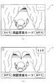
図10に示すように、第2スライド動作ユニット700は、スライド移動可能に形成されるそれぞれ一対の各スライド部材720,740を備えると共に、それらの各スライド部材720,740を、図5に示す退避位置と、図10に示す張出位置との間で動作させる。図5に示す退避位置では、一対の第1スライド部材720は、背面ケース210の開口211aの左右外方に退避されると共に、一対の第2スライド部材740は、背面ケース210の開口211aの上下外方に退避され、遊技者から視認不能とされる(図2参照)。一方、図10に示す張出位置では、各スライド部材720,740が背面ケース210の開口211aの中央(即ち、第3図柄表示装置81の正面、図2参照)に配置される。
As shown in FIG. 10, the second
なお、第2スライド動作ユニット700は、各スライド部材720,740が張り出した状態において、正面視で「ハート」の形状を視認可能に形成される。
The second
なお、後述するように、反転動作ユニット500は、矩形板状の反射部材520(図28参照)を備えると共に、その反射部材520が遊技者から視認される面を反転(裏返し)可能に形成される。反転動作ユニット500は、他の動作ユニット300,400,700に備えられるような、背面ケース210の開口211aの中央(即ち、第3図柄表示装置81の正面)に張り出す部材を持たない。そのため、反転動作ユニット500は、常に背面ケース210の開口211aの左方(図5参照)において動作される。
As will be described later, the reversing
これら各動作ユニット300〜700は、それぞれ独立して動作可能に形成されると共に、上述したように、重ね合わされた(積層された)状態で配設されるので、各動作ユニット300〜700のうちの層を違えて配設されるものについては、例え動作部材が背面ケース210の開口211aの内方に張り出す態様のものであっても同時に動作させることができる。即ち、図8から図10で例示したように、各動作ユニット300〜700をそれぞれ単体で動作させるだけでなく、これらの動作を組み合わせることができるので、その演出効果を高めることができる。なお、各動作ユニット300〜600が同じ層に配設され、それらの各動作ユニット300〜600と、第2スライド動作ユニット700とは層を違えて配設される(図7参照)。
Each of these
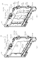
図11は、動作ユニット200の正面図である。なお、図11では、第1スライド動作ユニット400の傾倒部材460が張出位置に配置されると共に、第2スライド動作ユニット700の各スライド部材720,740が張出位置に配置される。
FIG. 11 is a front view of the
ここで、第1スライド動作ユニット400と第3図柄表示装置81(図2参照)との間には第2スライド動作ユニット700が配設されるため、第1スライド動作ユニット400と第3図柄表示装置81との間には第2スライド動作ユニット700分の隙間が生じる。そのため、第1スライド動作ユニット400の傾倒部材460のみが張出位置に配置される場合、正面視で第3図柄表示装置81の表示領域P(図2参照)の一部を視認できないように遮蔽することはできるが、遊技者が斜め方向(例えば正面視から左右方向に傾いた方向)から隙間を覗いて第3図柄表示装置81の表示領域Pを視認することを防止することは難しい。
Here, since the second
これに対し、図11に示すように、第1スライド動作ユニット400の傾倒部材460と第2スライド動作ユニット700の各スライド部材720,740とが共に張出位置に配置されることで、遊技者が斜め方向から覗く隙間を各スライド部材720,740で埋めることができる。これにより、第3図柄表示装置81の表示領域Pの一部を視認できないように確実に遮蔽することができ、動作ユニット200の演出効果を向上させることができる。
On the other hand, as shown in FIG. 11, the tilting
図12は、動作ユニット200の正面図である。なお、図12では、揺動動作ユニット300の起立部材330が張出位置に配置されると共に、第2スライド動作ユニット700の各スライド部材720,740が張出位置に配置される。
FIG. 12 is a front view of the
ここで、揺動動作ユニット300と第3図柄表示装置81(図2参照)との間には第2スライド動作ユニット700が配設されるため、揺動動作ユニット300と第3図柄表示装置81との間には第2スライド動作ユニット700分の隙間が生じる。そのため、揺動動作ユニット300の起立部材330のみが張出位置に配置される場合、正面視で第3図柄表示装置81の表示領域P(図2参照)の一部を視認できないように遮蔽することはできるが、遊技者が斜め方向(例えば正面視から左右方向に傾いた方向)から隙間を覗いて第3図柄表示装置81の表示領域Pを視認することを防止することは難しい。
Here, since the second
これに対し、図12に示すように、揺動動作ユニット300の起立部材330と第2スライド動作ユニット700の各スライド部材720,740とが共に張出位置に配置されることで、遊技者が斜め方向から覗く隙間を各スライド部材720,740で埋めることができる。これにより、第3図柄表示装置81の表示領域P(図2参照)の一部を視認できないように確実に遮蔽することができ、動作ユニット200の演出効果を向上させることができる。
On the other hand, as shown in FIG. 12, the standing
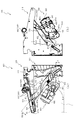
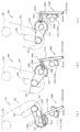
図13から図20を参照して、揺動動作ユニット300について説明する。図13(a)及び図13(b)は、揺動動作ユニット300の正面斜視図である。なお、図13(a)では、アーム部材320及び起立部材330が退避位置に配置され、図13(b)では、アーム部材320及び起立部材330が張出位置に配置される。
The
図13に示すように、揺動動作ユニット300のアーム部材320は、揺動軸312を中心に揺動され、その揺動の前後で起立部材330のアーム部材320に対する姿勢が変化される(張出位置に向かうほど起立する)。次に、揺動動作ユニット300の全体構成について説明する。
As shown in FIG. 13, the
図14は、揺動動作ユニット300の分解正面斜視図であり、図15は、揺動動作ユニット300の分解背面斜視図である。
14 is an exploded front perspective view of the
図14及び図15に示すように、揺動動作ユニット300は、板状に形成されるベース部材310と、そのベース部材310に基端側を軸支されるアーム部材320と、そのアーム部材320の基端側の反対側の端部である揺動端側に内嵌軸支される起立部材330と、ベース部材310の正面視(図14参照)右下部の背面に配設される駆動装置340と、その駆動装置340の駆動ギア341に歯合されると共にアーム部材320に連結される伝達装置350と、アーム部材320に付勢力を与えるねじりバネ360と、ベース部材310の正面視右下部の正面に取り付けられるカバー部材370と、を主に備えて構成される。
As shown in FIGS. 14 and 15, the
ベース部材310は、厚み方向と前後方向を一致させると共に揺動動作ユニット300の骨格となる部材であって、厚み方向に穿設される嵌合孔311と、その嵌合孔311に固着される円柱状の揺動軸312と、嵌合孔311の下方において厚み方向に突設される伝達軸313と、その伝達軸313と隣り合って穿設される駆動ギア挿通孔314と、嵌合孔311と同心円状に延設される一対の長孔である案内孔315と、その案内孔315の正面視(図14参照)左方に形成されると共に、案内孔315とは左右反対側に曲げられて延設される長孔である起立孔316と、嵌合孔311の正面視右方において正面側に鉤状に突設される鉤部317と、を備える。
The
アーム部材320は、揺動動作ユニット330を背面ケース210の開口211a(図5参照)の内方に張り出させるための部材であって、長尺板状に形成される本体部321と、その本体部321の基端側に配設される貫通した筒状の筒状部322と、本体部321の揺動端側に筒状部322と同じ方向に開口される摺動リング部323と、本体部321の正面側に嵩上げされて配設される板状の前当部324と、筒状部322から放射状に引かれる直線に沿って延設される長孔状の解除孔325と、本体部321の背面側に形成されベース部材310へ向けて突設される一対の摺動部326と、筒状部322の正面視(図14参照)左方において正面側へ向けて突設される突設部327と、を備える。
The
筒状部322は、ベース部材310の揺動軸312に外嵌軸支される部分である。即ち、アーム部材310は揺動軸312に軸支された筒状部322を支点に揺動される。
The
摺動リング部323は、起立部材330を内嵌軸支する部分である。大径に形成されており、起立部材330のぐらつきを抑制する。
The sliding
前当部324は、本体部321に基端側付近で締結固定され、揺動端側付近においては締結されない。そのため、前当部324と本体部321との間に隙間が形成され、アーム部材320が退避位置に配置された状態において、起立部材330の張出端側の部分が前当部324と本体部321との間の隙間に収容される(図16参照)。
The
解除孔325は、伝達装置350の規制摺動部351と連結される長孔であり、伝達装置350、筒状部322及び解除孔325の位置関係でアーム部材320の揺動を規制するという作用を生じる孔であるが、詳細は後述する。
The
一対の摺動部326は、ベース部材の一対の案内孔315にそれぞれ挿通されるので、アーム部材320の揺動中に、一対の摺動部326が一対の案内孔315に摺動されることでアーム部材320のがたつきを抑制すると共に、アーム部材320の揺動を安定させる。なお、摺動部326の先端にはリング状のカラー部材が回転可能に締結固定されるので、摺動部326が案内孔315から脱落することを防止すると共にアーム部材320の揺動動作を安定させることができる。
Since the pair of sliding
突設部327は、ねじりバネ360の移動端側腕部362が係止される部分であって、ねじりバネ360の付勢力が伝達される部分である。
The protruding
起立部材330は、アーム部材320の上昇方向への揺動により背面ケース210の開口211a(図5参照)の正面側に配置される部材であって、板状の本体部331と、その本体部331の背面側から大径リング状に張り出される張出リング部332と、基端側において背面側に突設される変化摺動部333と、張出リング部332の外径よりも大径の円板状に形成されると共に変化摺動部333に締結固定される抜止部334と、を備える。
The standing
本体部331は、長径方向D1(図16参照)と、短径方向D2(図16参照)とを備える楕円形板状に形成される。
The
張出リング部332は、アーム部材320の摺動リング部323の内径よりも若干小さな外径で形成される。そのため、起立部材330は、張出リング部332の外側面が摺動リング部323の内側面に広範囲(大面積)で当接され揺動可能に軸支される。そのため、大型の起立部材330を一カ所で軸支する場合であっても、アーム部材320の揺動に伴う起立部材330のぐらつきを抑制することができる。
The
変化摺動部333は、ベース部材310の起立孔316に挿通され、アーム部材320が揺動されるに伴って起立部材330の姿勢を変化させる役割を有する部分であるが、詳細は後述する。なお、変化摺動部333の先端にはリング状のカラー部材が回転可能に締結固定されるので、変化摺動部333が起立孔316から脱落することを防止すると共にアーム部材320の揺動動作を安定させることができる。
The changing sliding
抜止部334は、アーム部材320の摺動リング部323の内径よりも若干大きな外形で形成され、起立部材330の本体部331に締結固定されると共に、アーム部材320の摺動リング部323の背面側に当接される。よって、抜止部334によって、起立部材330をアーム部材320から引き抜き不能に形成することができる。
The retaining
駆動装置340は、ベース部材310の背面側に配設されると共にアーム部材320を駆動させるモータであり、回転駆動される駆動ギア341を備え、その駆動ギア341は、ベース部材310の駆動ギア挿通孔314を通してベース部材310の正面側に配設される(図20参照)。
The
伝達装置350は、駆動装置340の駆動力が最初に伝達される部材であって、基端側においてベース部材310の伝達軸313に軸支されると共に駆動装置340の駆動ギア341に歯合される。また、基端側の反対側の端部である揺動端に、正面側へ向けて突設される規制摺動部351を備える。
The
その規制摺動部351は、アーム部材320の解除孔325に挿通され、アーム部材320の揺動動作中において、規制摺動部351は、アーム部材320の解除孔325に摺動される。また、特にアーム部材320が張出位置から退避位置へ向けて揺動される場合には、伝達装置350を通して伝達される駆動装置340の駆動力によりアーム部材320が揺動される。
The
ねじりバネ360は、アーム部材320の揺動動作において、特にアーム部材320が退避位置から張出位置へ揺動される場合の動力源となる弾性バネであって、ベース部材310の鉤部317に支えられる(下方へ向けて押さえられる)基端側腕部361と、アーム部材320の突設部327に支えられる(下方へ向けて押さえられる)移動端側腕部362と、を備える。
The
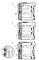
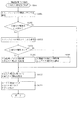
次いで、図16から図18を参照して、揺動動作ユニット300の揺動動作について説明する。図16(a)、図17(a)及び図18(a)は、アーム部材320の揺動動作および起立部材330の姿勢変化を時系列で図示した揺動動作ユニット300の正面図であり、図16(b)、図17(b)及び図18(b)は、アーム部材320の揺動動作および起立部材330の姿勢変化を時系列で図示した揺動動作ユニット300の背面図である。なお、図16では、アーム部材320が退避位置に配置された状態が、図17では、起立孔316の曲率が変化する点に起立部材330の変化摺動部333が配置された状態が、図18では、アーム部材320が張出位置に配置された状態が、それぞれ図示される。
Next, with reference to FIG. 16 to FIG. 18, the swing motion of the
図16に示すように、アーム部材320が退避位置に配置された状態において、起立部材330は長径方向D1(図16左右方向)を水平方向に倒した姿勢をとる。このとき、起立部材330の張出端側の部分は、アーム部材320の本体部321と前当部324との間に収納される。
As shown in FIG. 16, in a state where the
即ち、アーム部材320が退避位置に配置された状態において、アーム部材320を遊技者から遮蔽するために必要なスペースを利用して、起立部材330を遊技者から遮蔽することができる。よって、第3図柄表示装置81の表示領域P(図2参照)の外方において限られたスペースを有効に利用することができる。
That is, in a state where the
また、アーム部材320の一対の摺動部326が案内孔315の下端に配置されると共に、起立部材330の変化摺動部333が起立孔316の下端に配置される。これにより、一対の摺動部326と変化摺動部333とをアーム部材320が下方へ向けて揺動される際のストッパとして機能させることができる。
Further, the pair of sliding
図17に示すように、アーム部材320が張出位置へ向けて揺動されると、長径方向D1が鉛直方向へ向く姿勢(起立姿勢)に起立部材330が姿勢変化される。
As shown in FIG. 17, when the
ベース部材310の案内孔315の壁面(ベース部材310の厚み方向に形成される壁面)の厚み方向に沿った寸法(板厚)は、案内孔315の下端付近よりも上端付近の方が大きくされる。そして、案内孔315の上端付近において、案内孔315の壁面の寸法がアーム部材320の本体部321とカラー部材とで挟まれる摺動部326の長さより若干短い寸法で形成される。即ち、アーム部材320の本体部321及びカラー部材とベース部材310との間で形成される隙間は、案内孔315の上端付近よりも下端付近の方が大きくなる。なお、本実施形態では、形成される隙間が徐々に変化する態様で形成される。
The dimension (plate thickness) of the wall surface of the
アーム部材320の本体部321及びカラー部材とベース部材310との間で形成される隙間は、案内孔315の上端付近よりも下端付近の方が大きくなる。そのため、退避位置からの始動時にアーム部材320が案内孔315から受ける抵抗を抑制でき、アーム部材320の始動時の高速さを確保することができる。
The gap formed between the
また、案内孔315の上端付近では、ベース部材310の厚み方向における案内孔315の壁面の寸法(板厚)がアーム部材320の本体部321とカラー部材とで挟まれる摺動部326の長さより若干短い寸法で形成される(摺動部326の長さとベース部材310の板厚とが略同等で形成される)。そのため、案内孔315の上端付近に配置されたアーム部材320がベース部材310の厚み方向にぐらつくことを防止することができる。
In the vicinity of the upper end of the
本実施形態では、アーム部材320が張出位置に配置された状態(図18参照)において、起立部材330がアーム部材320の摺動部326の上方に配置される。そのため、アーム部材320が起立部材330の重みで前倒れする(図18(a)の紙面手前側に倒れる)際に、摺動部326が前倒れの支点となる。ここで、ベース部材310の厚み方向における案内孔315の壁面の寸法(板厚)がアーム部材320の本体部321とカラー部材とで挟まれる摺動部326の長さより若干短い寸法で形成されるので、アーム部材320をベース部材310に対して面で当接させて支えることができ、アーム部材320の前倒れに対する抵抗力を向上させることができる。
In the present embodiment, the standing
ここで、起立孔316は、下端付近に形成される姿勢変化部316aと、上端付近に形成される同心円部316bと、を備える。
Here, the standing
姿勢変化部316aは、長孔の延設方向が、アーム部材320の揺動軸である筒状部322(図14参照)へ向けられる部分である。姿勢変化部316aを起立部材330の変化摺動部333が摺動される場合、アーム部材320の揺動角の大きさに対する起立部材330の姿勢変化の度合いが最大となる。これは、姿勢変化部316aが、摺動リング部323の移動軌跡が形成する円と垂直な関係にあるためである。
The
これにより、始動から短期間で起立部材330の姿勢変化を完了させ、遊技者に起立部材330が視認される際に、起立部材330とアーム部材320との姿勢変化を小さくすることができる。よって、退避位置では起立部材330の上下方向の遮蔽スペースを抑制しつつ、張出位置では起立部材330とアーム部材320とを一体として視認させる効果を向上させることができる。
Thereby, the posture change of the standing
また、アーム部材320の退避位置からの始動時において、起立部材330に係る抵抗が抑制される。即ち、起立部材330が退避位置に配置される場合において、変化摺動部333が筒状部322を中心として回転される方向は、姿勢変化部316aと直交する。そのため、退避位置からのアーム部材320の始動時において、変化摺動部333に筒状部322を中心とした回転力がする仕事はゼロとなる(力×距離=0)。よって、退避位置からの始動時にアーム部材320に与えられる抵抗を抑制することができる。これにより、アーム部材320の始動時の高速さを確保することができる。
In addition, when the
同心円部316bは、長孔の延設方向がアーム部材320の筒状部322を中心とした円に沿った方向へ向けられる部分である。同心円部316bを起立部材330の変化摺動部333が摺動される場合、アーム部材320の摺動リング部323と起立部材330の変化摺動部333との相対的な位置関係が変化しないので、アーム部材320に対する起立部材330の姿勢が維持される。これにより、起立部材330とアーム部材320とを一体として視認させることができ、起立部材330とアーム部材320とを一体として行う演出を容易に実現することができる。
The
図18に示すように、アーム部材320が張出位置に配置されると、アーム部材320の一対の摺動部326が案内孔315の上端に配置されると共に、起立部材330の変化摺動部333が起立孔316の上端に配置される。これにより、アーム部材320が上方へ揺動される際に、一対の摺動部326をストッパとして機能させることができる。特に、後述するように、アーム部材320はねじりバネ360の付勢力で上昇方向へ揺動されるので、モータ等で駆動させる場合に比較して、終端でのストッパの必要性は大きい。また、摺動部326が一対で形成されるので、摺動部326がストッパとして機能した場合に生じる力を分散させることができる。これにより、摺動部326の耐久性を向上させることができる。
As shown in FIG. 18, when the
なお、起立部材330の変化摺動部333をストッパとして機能させることもできるが、起立部材330はアーム部材320に軸支される部材なので、強度的な問題が生じる。一方、一対の摺動部326はアーム部材320に一体に形成されているので、十分な強度を有するので。ストッパとして用いるのにより適している。
Although the changing sliding
図18に示すように、アーム部材320が張出位置に配置された場合において、起立部材330の張出端側(図18上側)は、アーム部材320の摺動リング部323よりも上方に張り出して形成される。よって、アーム部材320の揺動角度を小さくしても、起立部材330を第3図柄表示装置81(図2参照)の正面側へ張り出させる作用を確保することができ、アーム部材320の揺動角度の設計自由度を向上させることができる。
As shown in FIG. 18, when the
また、アーム部材320の揺動角度を小さくしたまま、起立部材330の張出端側の移動距離は大きく確保することができるので、起立部材330の移動速度を高速にする効果を向上させることができる。この効果は、アーム部材320の揺動に対する起立部材330の姿勢変化の度合いが激しい退避位置付近(図16参照)において顕著になるので、アーム部材320の始動時の速度を高速にする効果を顕著とすることができる。
Further, since the movement distance of the rising
次いで、図19を参照して、起立部材330がアーム部材320と前当部324との間に収納される直前の状態について説明する。図19(a)は、揺動動作ユニット300の正面図であり、図19(b)は、揺動動作ユニット300の背面図であり、図19(c)は、揺動動作ユニット300の底面図である。なお、図19(a)から図19(c)は、アーム部材320が張出位置と退避位置との間の中間位置に配置された状態が図示され、詳細には、アーム部材が張出位置から退避位置へ向けて揺動される場合に、起立部材330の張出端側がアーム部材320の本体部321と前当部324との間に収納され始める状態が図示される。
Next, with reference to FIG. 19, a state immediately before the standing
図19(c)に示すように、前当部324は起立部材330の正面側(図19(c)上方)に配設される。これにより、アーム部材320の揺動時に起立部材330が摺動リング部323を支点にぐらつく(図19(c)上下方向に振れる)場合にも、起立部材330が前当部324に当接され、起立部材330のぐらつきを抑制することができる。
As shown in FIG. 19C, the
ここで、起立部材330とアーム部材320の前当部324とが正面視において重なり始める位置Aが、第3図柄表示装置81の表示領域P(図2参照)の下側の縁Bよりも上方に形成される。そのため、アーム部材320が張出位置から退避位置へ揺動される場合に、起立部材330のぐらつきが大きくなる前段階(第3図柄表示装置81の表示領域Pの内方に配置される段階)で、起立部材330と前当部324との移動軌跡を前後方向に重ねることができると共に、アーム部材320の前当部324に起立部材330を当接させ起立部材330のぐらつきを抑制することができる。
Here, the position A where the standing
図20(a)から図20(d)は、揺動動作ユニット300のアーム部材320を退避位置から張出位置へ揺動動作させる過程を時系列で説明する図であり、アーム部材320の基端側における揺動動作ユニット300の部分正面拡大図である。なお、図20(b)は、アーム部材320が退避位置から張出位置へ向けて所定量だけ揺動動作された状態が図示され、図20(c)は、図20(b)の状態からアーム部材320が張出位置へ向けて所定量だけ揺動動作された状態が図示され、図20(a)から図20(d)は、カバー部材370の図示が省略される。
20A to 20D are time-series diagrams illustrating a process of swinging the
まず、アーム部材320が張出位置から退避位置へ揺動される場合(図20(d)から図20(a)への姿勢変化)について説明する。図20(d)に示すアーム部材320の張出位置から、駆動装置340(図14参照)の駆動ギア341が回転されることで駆動ギア341に歯合される伝達装置350が回転され、伝達装置350の規制摺動部351がアーム部材320の解除孔325を押すことによりアーム部材320が図20(c)及び図20(b)の状態を経由して移動されることで退避位置(図20(a)参照)へ配置される。即ち、アーム部材320が張出位置から退避位置へ揺動される場合には、駆動装置340の駆動力によりアーム部材320は揺動される。
First, a case where the
この場合、アーム部材320は下方向へ揺動されるので(図16から図18参照)、駆動装置340の必要容量を抑制することができる。例えば、電気モータであれば、モータ容量を抑制することができる。
In this case, since the
また、アーム部材320が張出位置に配置された状態において、案内孔315及び起立孔316は鉛直下方へ延設される(図18(b)参照)。これにより、張出位置からの揺動開始時に案内孔315及び起立孔316からアーム部材320及び起立部材330へ与えられる抵抗を抑制することができる。
Further, the
次いで、アーム部材320が退避位置から張出位置へ揺動される場合(図20(a)から図20(d)への姿勢変化)について説明する。アーム部材320には、ねじりバネ360の付勢力が作用される。アーム部材320が退避位置(図20(a)参照)に配置された状態において、ねじりバネ360の基端側腕部361はベース部材310の鉤部317に上側から押さえられ、移動端側端部362はアーム部材320の突設部327により右下方向へ押さえられる。
Next, a case where the
これにより、ねじりバネ360は、筒状部322を支点に基端側腕部361及び移動端側腕部362の距離が縮められており、アーム部材320を持ち上げる方向(左上方向)に向けた弾性力が最も蓄積された状態にある。その弾性力によるアーム部材320の揺動は、アーム部材320の解除孔325と伝達装置350との機械的な位置関係により規制される。以下、解除孔325と伝達装置350との機械的な位置関係について説明する。
As a result, the
図20(a)に示すように、アーム部材320が退避位置に配置された場合、アーム部材320の回転軸としての筒状部322と伝達装置350の規制摺動部351とを結ぶ方向Xが、伝達装置350を揺動可能に軸支するベース部材310の伝達軸313と伝達装置350の規制摺動部351とを結ぶ方向Yと直交される。
As shown in FIG. 20A, when the
この場合、規制摺動部351をアーム部材320と伝達装置350との関係において死点に位置させることができる。これにより、駆動装置340からの駆動力を不要としても、アーム部材320を退避位置に機械的に保持できるので、駆動装置340の消費エネルギーを抑制することができる。
In this case, the
なお、本実施形態においては、アーム部材320が張出位置に配置された状態においても、規制摺動部351がアーム部材320と伝達装置350との関係において死点に位置される。これにより、駆動装置340からの駆動力を不要としても、アーム部材320を張出位置に機械的に保持できるので、駆動装置340の消費エネルギーを抑制することができる。
In the present embodiment, the
アーム部材320が退避位置から張出位置へ揺動される場合の、駆動装置340の動作態様について説明する。まず、アーム部材320が退避位置(図20(a)参照)に配置された状態から、規制摺動部351をアーム部材320と伝達装置350との関係における死点から解除するために駆動装置340の駆動ギア341が正面視時計回りに所定量回転(ON状態)される。すると、駆動ギア341に歯合される伝達装置350も回転され、規制摺動部351がアーム部材320と伝達装置350との関係における死点から解除される(図20(b)参照)。
An operation mode of the
ここで、アーム部材320が退避位置に配置された状態において、ねじりバネ360は、筒状部322を支点に基端側腕部361及び移動端側腕部362の距離が縮められており、アーム部材320を持ち上げる方向(左上方向)に向けた弾性力が最も蓄積された状態にある。
Here, in the state where the
この状態から、規制摺動部351がアーム部材320と伝達装置350との関係における死点から解除されると、ねじりバネ360の弾性力によりアーム部材320が揺動される。これにより、アーム部材320を始動時から高速で揺動させることができる。
From this state, when the
例えば駆動モータのように徐々に駆動力を上げる態様では、はじめから大きな駆動力をアーム部材320に加えることは難しく、アーム部材320の始動時の速度がゆっくりになりやすい。一方、本実施形態では、始動時から大きな弾性力を加えることができるので、アーム部材320の始動時の加速度を大きく確保することができる。よって、アーム部材320を始動時から高速で揺動させることができる。
For example, in a mode in which the driving force is gradually increased like a drive motor, it is difficult to apply a large driving force to the
駆動ギア341を所定量回転させたら、駆動装置340は停止(OFF状態)され、駆動ギア341は空回り可能な状態にされる。アーム部材320はねじりバネ360に蓄積された弾性力で上昇方向へ揺動される(図20(c)参照)。
When the
アーム部材320が張出位置付近(図20(c)参照)に到達したら、駆動装置340の駆動ギア341が再度正面視時計回りに所定量回転(ON状態)され、規制摺動部351がアーム部材320と伝達装置350との関係における死点に配置される。
When the
即ち、アーム部材320が退避位置から張出位置へ向けて揺動される場合は、常時駆動装置340の駆動力がアーム部材320に生じるのではなく、アーム部材320が退避位置および張出位置付近に配置される場合においてのみ駆動装置340が駆動され(ON状態)、退避位置および張出位置の間においては駆動装置340が停止される(OFF状態)。これにより、常時駆動装置340の駆動力がアーム部材320に加えられる場合に比較して、駆動装置340を駆動させる期間を低減できるので、駆動装置340の寿命を向上させることができる。
That is, when the
図20(a)及び図20(d)に示すように、アーム部材320が退避位置または張出位置に配置された場合、規制摺動部351及び伝達装置350を軸支する伝達軸313を結ぶ直線に直交する方向と、解除孔325の延設方向とが一致して配設される。
As shown in FIGS. 20A and 20D, when the
これにより、退避位置または張出位置に配置された状態からアーム部材320を回転させる回転開始時点において、規制摺動部351の回転方向と解除孔325の延設方向とが一致するので、移動開始時に規制摺動部351が解除孔325から受ける抵抗を抑えることができる。よって、最も大きな力を必要とする動作開始時に必要な駆動力を低減することができる。
As a result, at the time of starting the rotation of rotating the
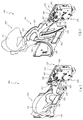
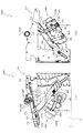
次いで、図21から図27を参照して、第1スライド動作ユニット400について説明する。図21(a)及び図21(b)は、第1スライド動作ユニット400の正面斜視図である。なお、図21(a)では、吊下部材430及び傾倒部材460が退避位置に配置された状態が図示され、図21(b)では、吊下部材430及び傾倒部材460が張出位置に配置された状態が図示される。
Next, the first
図21に示すように、第1スライド動作ユニット400の吊下部材430は、退避位置から斜め下方向(正面視右上から左下)へスライド移動され、そのスライド移動の過程で傾倒部材460の姿勢が変化する(張出位置に向かうほど傾倒する)。次に、第1スライド動作ユニット400の全体構成について説明する。
As shown in FIG. 21, the
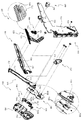
図22は、第1スライド動作ユニット400の分解正面斜視図であり、図23は、第1スライド動作ユニット400の分解背面斜視図である。
22 is an exploded front perspective view of the first
図22及び図23に示すように、第1スライド動作ユニット400は、正面視L字状に形成されるベース部材410と、そのベース部材410に正面側から取り付けられるカバー部材420と、そのカバー部材420とベース部材410との間に挟まれると共にベース部材410の正面側の側面に沿ってスライド移動される正面視略T字形状の吊下部材430と、その吊下部材430をスライド移動させる駆動力を発生する駆動装置440と、吊下部材430の基端側に一方の端部が軸支されると共に他方の端部がベース部材410に連結される長尺板状の補助部材450と、吊下部材430の基端側の反対側の端部である張出端側に軸支される傾倒部材460と、補助部材450と傾倒部材460とを連結する連結部材470と、を主に備えて構成される。
As shown in FIGS. 22 and 23, the first
ベース部材410は、正面視L字の板状に形成されると共に第1スライド動作ユニット400の骨格を成す部材であって、板状の本体横長部411と、その本体横長部411の右端部付近から鉛直下方へ延設される板状の本体縦長部412と、本体横長部411の正面側に左右方向に対して若干傾斜して延設されると共に直線リブ状に突設される案内リブ部413と、本体横長部の略中央部に穿設されると共に駆動装置441の駆動軸が挿通される挿通孔414と、本体縦長部412の下側部分に正面視右下方から左上方へ向けて延設される長孔状に穿設される案内孔415と、駆動装置440の各種ギアが軸支される一対の回転軸416と、を主に備える。
The
本体横長部411は、上側および左右の縁に正面側へ向けて壁状に突設される外枠411aを備える。外枠411aは、正面側にカバー部材420が当接される部分であって、吊下部材430のスライド本体部431の厚み方向(吊下部材430のスライド平面の垂直方向)の長さよりも若干長く形成される。
The main body laterally
なお、吊下部材430のスライド平面とは、ベース部材410の正面と平行な平面を意味する。
The sliding plane of the hanging
案内孔415は、ベース部材410の右下方から左上方へ向けて延設される。
The
カバー部材420は、ベース部材410の正面側から取り付けられると共にベース部材410との間に隙間を形成する部材であって、正面視で本体横長部411と略同一形状の板状に形成される本体部421と、ベース部材410の案内リブ部413の延設される方向に沿って長孔状に穿設される連通孔422と、を主に備える。
The
本体部421は、ベース部材410の本体横長部411と略同一形状に形成されるため、吊下部材430がスライド移動される場合に前後方向へ揺れたとしても、吊下部材430は前後の方向によらずベース部材410の本体横長部411及びカバー部材420の本体部421との当接面積を均等に確保することができる。
Since the
吊下部材430は、ベース部材410とカバー部材420とで形成される隙間に配設されると共にベース部材410の案内リブ部413に沿ってスライド移動される部材であって、上側面にラックギアが刻設される横長板状のスライド本体部431と、スライド本体部431の背面側に溝状に凹設されると共にベース部材410の案内リブ部413に当接される凹設溝432と、スライド本体部431の略中央部から垂下されると共に中間で張出位置側に屈曲される板状の屈曲腕部433と、スライド本体部431の屈曲腕部433が垂下され始める部分においてスライド本体部431から正面側へ向けて突設される揺動軸434と、屈曲腕部433の先端(張出端)において正面側へ向けて延設される筒状の吊下筒435と、を主に備える。
The
スライド本体部431は、ベース部材410とカバー部材420とが形成する隙間よりも若干薄く形成される。そのため、吊下部材430はベース部材410とカバー部材420との間をスライド可能となると共に厚さ方向(カバー部材420のベース部材410への締結方向)への移動を防止される。
The
凹設溝432は、案内リブ部413の幅よりも若干大きい幅で形成される凹溝であり、吊下部材430は案内リブ部413を凹設溝432が摺動することにより斜め下方へスライド移動される。
The recessed
屈曲腕部433は、吊下部材430が張出位置に配置された状態において、補助部材450の長手方向に沿って延設され、吊下部材430が退避位置に配置された状態においてベース部材410の本体横長部411の下方に形成される部分に、正面側に肉厚を増して形成される増厚部433aを備える。その増厚部433aよりもスライド本体部431側の屈曲腕部433の厚みは、スライド本体部431及び増厚部433aよりも薄厚で形成される。これにより、屈曲腕部433の厚さ方向への変形が増厚部433aよりもスライド本体部431側の屈曲腕部433で局所的に生じる態様で形成される。また、屈曲腕部433の厚み方向は、ラックギアが刻設される方向(スライド方向)と垂直に形成される。
The
揺動軸434は、カバー部材420の連通孔422を貫通しカバー部材420の正面側へ張り出して形成される軸であって、補助部材450の揺動孔452に挿通される。
The
吊下筒435は、補助部材450の厚みを越えて延設される。これにより、吊下部材430が退避位置(図21(a)、図25(a)参照)に配置された場合に、補助部材450が吊下部材430と傾倒部材460との間に収納可能となる。
The hanging
駆動装置440は、各部材がベース部材410を前後から挟み込む形で形成されると共に吊下部材430の移動に必要な駆動力を発生させる装置であり、ベース部材410の挿通孔414に背面側から貫通される駆動軸を備える駆動モータ441と、その駆動モータ441の駆動軸に軸支されると共にベース部材410の正面に配設される駆動ギア442と、その駆動ギア442に歯合されると共に一対の回転軸416にそれぞれ軸支される一対の伝達ギア443と、を主に備える。
The
一対の伝達ギア443の内の一方は、吊下部材430のスライド本体部431の上側面に刻設されるラックギアに歯合される(図25参照)。そのため、駆動モータ441の駆動力により駆動ギア442及び一対の伝達ギア443が回転されると、その伝達ギア443に歯合される吊下部材430がスライド移動される。
One of the pair of transmission gears 443 is meshed with a rack gear engraved on the upper surface of the
補助部材450は、カバー部材420の正面側に配設される部材であって一方の端部が吊下部材430に軸支されると共に他方の端部がベース部材410の案内孔415にスライド移動可能に連結され、長尺板状に形成される本体部451と、一方の端部に穿設される揺動孔452と、他方の端部で背面方向へ突設されるスライド軸453と、本体部451の中間位置から背面方向へ突設される吊下軸454と、を主に備える。
The
なお、補助部材450は吊下部材430に軸支されると共に他方の端部がベース部材410の案内孔415にスライド移動可能に連結されることで厚み方向(図25紙面垂直方向)に移動不能に形成される。また、吊下部材430が退避位置へスライド移動するほど補助部材450が屈曲腕部433の増厚部433aの先端に近づく(揺動される)態様で形成される。これにより、吊下部材430が厚み方向にぐらついても、吊下部材430が補助部材450に当接することで吊下部材430のぐらつきを抑制することができる。
The
揺動孔452は、吊下部材430の揺動軸434に外嵌軸支される。これにより、揺動軸434を軸に補助部材450が揺動可能に形成される。即ち、吊下部材430がスライド移動されるのに伴って、補助部材450は揺動軸434を軸に揺動(傾倒)される。
The
スライド軸453は、ベース部材410の案内孔415にスライド可能に連結される。これにより、補助部材450の他方の端部(正面視右下方の端部)は案内孔415の延設方向に沿ってスライド移動される。なお、吊下部材430が張出位置(図26参照)に配置された場合にスライド軸453は案内孔415の上端(左上端)に配置され、吊下部材430が退避位置(図25参照)に配置された場合にスライド軸453は案内孔415の下端(右下端)に配置される。
The
傾倒部材460は、吊下部材430の吊下筒435に軸支されると共に独立の駆動源(駆動装置464)を有する部材であって、吊下部材430に軸支されると共に長尺板状に形成されるベース部材461と、そのベース部材461の下部に正面側から締結されると共にベース部材461との間に隙間を形成する第1カバー部材462と、その第1カバー部材462とベース部材461との間に形成される隙間に配設される伝達装置463と、その伝達装置463に伝達される駆動力を発生する駆動装置464と、伝達装置463に連結されると共にベース部材461の長手方向にスライド可能に形成される移動ベース部材465と、その移動ベース部材465の正面側に配設されると共に移動ベース部材465に締結固定される第2カバー部材466と、を主に備える。
The tilting
ベース部材461は、長尺板状に形成される部材であって、背面側に円柱状に突設されると共に吊下部材430の吊下筒435に内嵌軸支される吊下軸461aと、その吊下軸461aと併設される連結軸461bと、その連結軸461bと隣接されると共に背面側へ開口が向けられる箱状に形成される収納部461cと、その収納部461cの上方において正面側に突設される一対の回転軸461dと、ベース部材461の長手方向に沿って複数併設される長孔状のスライド孔461eと、を主に備える。
The
収納部461cは、駆動装置464を収納するスペースを形成すると共に、底部に駆動装置464の駆動軸464aを貫通させる孔が穿設される。
The
伝達装置463は、駆動軸464aに軸支される駆動ギア463aと、その駆動ギア463aに歯合されると共に一対の回転軸461dに軸支される一対の伝達ギア463bと、その一対の伝達ギア463bの内、移動ベース部材465側に配設される伝達ギア463bから偏心した位置において突設されるクランクピン463cと、を主に備える。
The
クランクピン463cは、駆動ギア463aが回転され伝達ギア463bが回転されることで、回転軸461dを支点に回転される。
The
移動ベース部材465は、長尺板状に形成される部材であって、背面側から複数(本実施形態では3箇所)が突設されると共に複数のスライド孔461eに挿通される姿勢維持ピン465aと、長手方向と垂直な方向に延設され穿設される長孔状のスライド孔465bと、正面側に突設される一対の嵩上部465cと、を主に備える。
The
スライド孔465bは、伝達ギア463bのクランクピン463cが連結されるので、伝達ギア463bが回転されクランクピン463cの位置が変化されるにつれて、移動ベース部材465はスライド孔461eの延設方向に沿ってスライド移動される。
Since the
第2カバー部材466は、一対の嵩上部465cに締結固定される一対の締結部466aを備える。そのため第2カバー部材466が移動ベース部材465に締結される状態において、移動ベース部材465がスライド移動されるのに伴って、第2カバー部材466もスライド移動される。
The
連結部材470は、補助部材450と傾倒部材460とを連結すると共に樹脂材料から形成される部材であって、上端部に穿設されると共に補助部材450の吊下軸454に揺動可能に軸支される吊下孔471と、下端部に筒状に形成されると共に傾倒部材460の連結軸461bに揺動可能に外嵌軸支される筒状部472と、を備える。
The connecting
次いで、図24を参照して、傾倒部材460の駆動態様について説明する。図24は、吊下部材430が張出位置に配置された状態における第1スライド動作ユニット400の正面図である。なお、第1カバー部材466が斜め上方へスライド移動された状態が破線で図示され、カバー部材420の図示が部分的に省略される。
Next, with reference to FIG. 24, a drive mode of the tilting
第1スライド動作ユニット400の傾倒部材460は、駆動装置464(図23参照)が駆動されることで、第2カバー部材466がスライド移動され、傾倒部材460の正面視(図24参照)における外形が変化する演出を行うことができる。
The tilting
ここで、傾倒部材460は、吊下部材430の屈曲腕部433の先端側に軸支されるので、傾倒部材460の外形変化時に振動やぐらつきが生じやすい。本実施形態では、その振動やぐらつきを抑制する構成を複数有するため、それについて以下説明する。
Here, since the tilting
図25を参照して、吊下部材430が退避位置に配置された状態(図21(a)参照)における第1スライド動作ユニット400の構成について詳細に説明する。図25(a)は、第1スライド動作ユニット400の正面図であり、図25(b)は、第1スライド動作ユニット400の背面図である。なお、図25(a)及び図25(b)では、吊下部材430がスライド移動する移動経路の上端位置(退避位置)に配置された状態が図示され、カバー部材420の図示が部分的に省略される。
With reference to FIG. 25, the configuration of the first
図25(a)に示すように、吊下部材430が退避位置に配置されることで、吊下部材430に軸支される補助部材450及び傾倒部材460は、第3図柄表示装置81(図2参照)の表示領域Pの右外方に移動される。
As shown in FIG. 25 (a), the
このとき、補助部材450が、吊下部材430の正面側かつ傾倒部材460の背面側である位置に収納される。即ち、吊下部材430、補助部材450及び傾倒部材460が厚み方向(図25(a)紙面垂直方向)に積層配置されるので、吊下部材430、補助部材450及び傾倒部材460の厚み方向視における個々の部材の総面積に比較してコンパクトに配置することができる。よって、第3図柄表示装置81(図2参照)の表示領域Pの右外方のスペースを抑制でき、表示領域Pを大きく確保することができる。
At this time, the
また、図25に示すように、吊下部材430の屈曲腕部433は、大部分がベース部材410とカバー部材420との間に収納され、張出端側(先端側)の背面にはベース部材410の本体縦長部412が配設される。これにより、退避位置における吊下部材430の厚み方向のぐらつきを抑制することができる。
In addition, as shown in FIG. 25, most of the
また、本実施形態では、補助部材450は吊下部材430の屈曲腕部433が垂下される付近に形成される揺動軸434に軸支され、吊下部材430が張出位置に配置される場合には屈曲腕部433の延設方向に沿って補助部材450の長手方向が形成され、吊下部材430が退避位置から張出位置へスライド移動するほど補助部材450が屈曲腕部433の増厚部433aの先端に近づく(揺動される)態様で形成される。
In addition, in the present embodiment, the
そのため、吊下部材430が張出位置に配置された場合に比較して退避位置に配置された方が、補助部材450から屈曲腕部433の増厚部433a先端までの出代(張出長さ)が短くされる。これにより、傾倒部材460が駆動されることで吊下部材430がぐらつく場合でも、吊下部材430と補助部材450との当接位置から吊下部材430の先端までの長さが短く形成されるので、退避位置における吊下部材430の厚み方向のぐらつき(屈曲腕部433先端のぐらつき)を抑制することができる。
Therefore, when the
ここで、吊下部材430のスライド移動について説明する。吊下部材430は、背面側に形成される凹設溝432(図23参照)でベース部材410の案内リブ部413を挟み込むので、案内リブ部413の延設方向に沿ってスライド移動される。案内リブ部413は、上述した通り、斜め下方向(図25(a)右上から図25(a)左下)へ向けて一直線に延設される。
Here, the sliding movement of the
吊下部材430のスライド移動は駆動装置440の駆動力が伝達されることにより生じる。例えば、退避位置から張出位置まで吊下部材430がスライド移動される場合は、吊下部材430が退避位置に配置された状態(図25参照)から、駆動モータ441の駆動力により駆動ギア442が正面視時計回りに回転され、その回転により一対の伝達ギア443が回転され、その一対の伝達ギア443の一方(図25(a)の左側)に歯合されるラックギアが移動されることで、そのラックギアを上面側に備える吊下部材430が張出位置までスライド移動される。
The sliding movement of the
次いで、図26を参照して、吊下部材430が張出位置に配置された状態(図21(b)参照)における第1スライド動作ユニット400の構成について詳細に説明する。図26(a)は、第1スライド動作ユニット400の正面図であり、図26(b)は、第1スライド動作ユニット400の背面図である。なお、図26(a)及び図26(b)では、吊下部材430がスライド移動する移動経路の下端位置(張出位置)に配置された状態が図示され、カバー部材420の図示が部分的に省略される。
Next, with reference to FIG. 26, the configuration of the first
図26(a)に示すように、吊下部材430は張出位置に配置された状態において、スライド本体部431の移動方向の下端(図26(a)左下端)がベース部材410の外枠411aに当接される。また、上述した通り、吊下部材430は張出位置へ向かうほど下方へ移動するため、駆動装置440の駆動力の吊下部材430への伝達を解除しても、吊下部材430の位置を確実に張出位置に維持することができる。
As shown in FIG. 26A, the lower end (lower left end in FIG. 26A) of the
例えば、吊下部材430のスライド移動の方向が水平方向である場合、張出位置に吊下部材430が配置されてもスライド移動の方向に対して重力がかからないため、吊下部材430を張出位置に維持しておくための力を別で付加しておく必要がある。
For example, when the
一方、本実施形態の吊下部材430によれば、駆動装置440の駆動力の吊下部材430への伝達を解除しても、重力の分力がスライド移動の方向に作用されるため、吊下部材430を張出位置に維持することができる。よって、駆動装置440の消費電力を抑制することができる。
On the other hand, according to the
図26に示すように、吊下部材430が張出位置に配置された場合において、屈曲腕部433がベース部材410とカバー部材420との間に収納される部分は、吊下部材430が退避位置(図25(b)参照)に配置される場合に比較して小さくなる。よって、吊下部材430の厚み方向への屈曲腕部433のぐらつきをベース部材410とカバー部材420とにより抑制することは難しい。
As shown in FIG. 26, when the
一方で、屈曲腕部433の根本側は、吊下部材430が張出位置に配置された状態における補助部材450の延設方向(図26(b)左下方向)へ向けて延設される。これにより、吊下部材430が張出位置に配置された場合には、吊下部材430の厚み方向への補助部材450と屈曲腕部433との重なり面積が広く形成される。
On the other hand, the base side of the
補助部材450は、上述したように、吊下部材430の屈曲腕部433とはカバー部材420の厚み分のみ離間して形成されると共に屈曲腕部433が吊下部材430の厚み方向へぐらつく場合に当接可能に形成される。吊下部材430が張出位置に配置された状態において屈曲腕部433の薄厚部分(増厚部433aよりスライド本体部431側の部分)がベース部材410及びカバー部材420からはみ出して形成されるので、傾倒部材460が駆動されることによる吊下部材430の屈曲腕部433のぐらつきを厚み方向に生じやすくする(厚み方向のぐらつきが支配的にする)ことができる。これにより、吊下部材430のスライド方向へのぐらつきを抑制することができる。
As described above, the
また、屈曲腕部433の薄厚部分(増厚部433aよりスライド本体部431側の部分)は、ベース部材410及びカバー部材420に挟まれてスライド移動されるスライド本体部431の短手方向(スライド方向に垂直な方向)に隣接して形成される。これにより、傾倒部材460が駆動されることにより生じるぐらつきを屈曲腕部433の撓みで吸収することができ、スライド本体部431が厚み方向(図26紙面垂直方向)へぐらつくことを抑制することができる。これにより、スライド本体部431がベース部材410及びカバー部材420に押し当てられることを抑制し、スライド本体部431の厚さ方向の摩耗を抑制することができる。
Further, a thin portion of the bent arm portion 433 (a portion closer to the slide
例えば、スライド本体部431の短手方向へ向けてスライド本体部431と同等の厚みを有する腕部が延設され、その腕部の先端側が薄厚に形成されることも考えられる。しかし、この場合には、例えその薄厚部分が撓みを吸収するとしても、スライド本体部431と同等の厚みを有する腕部の先端がぐらつくことで、その腕部のぐらつきがスライド本体部431に伝達されスライド本体部431がぐらつくおそれがある。
For example, it is conceivable that an arm portion having the same thickness as that of the
一方、本実施形態では、スライド本体部431から延設される屈曲腕部433の根本から薄厚にされるので、屈曲腕部433の先端で生じたぐらつきは薄厚部分の撓みに使用され、スライド本体部431がぐらつくことを防止する効果を顕著にすることができる。
On the other hand, in the present embodiment, since the bending
図27は、図26(a)のXXVII−XXVII線における第1スライド動作ユニット400の断面図である。図27に示すように、屈曲腕部433は補助部材450側へ向けて増厚される増厚部433aを備えるため、屈曲腕部433が吊下部材430の厚み方向へぐらつく場合に、そのぐらつきの振幅が小さなときから屈曲腕部433を補助部材450に当接させやすくすることができる。
FIG. 27 is a sectional view of the first
図26に戻って説明する。補助部材450は、吊下部材430の揺動軸434とベース部材410の案内孔415とに連結されるので、厚み方向への移動を規制される。そのため、補助部材450は吊下部材430の屈曲腕部433が正面側へ移動しようとするのをせき止めるストッパの役割を果たす。これにより、吊下部材430が張出位置に配置された場合における吊下部材430の厚み方向へのぐらつきを抑制することができる。
It returns to FIG. 26 and demonstrates. Since the
図26(a)に示すように、吊下部材430が張出位置に配置された場合において、傾倒部材460の下端は第3図柄表示装置81(図2参照)の表示領域Pの下端よりも若干上方に配置される。ここで、傾倒部材460が吊下部材430に対して姿勢変化しない場合(固定される場合)には、吊下部材430は張出位置へ向かうほど下降傾斜してスライド移動される。そのため、吊下部材430が張出位置へ配置された状態において本実施形態の傾倒部材460の下端と同じ位置に傾倒部材460の下端を配置させるためには、吊下部材430が退避位置に配置された場合において下降傾斜分の距離L1だけ上方へオフセットした位置に傾倒部材460が配置される必要がある。
As shown in FIG. 26 (a), when the hanging
そのため、第3図柄表示装置81(図2参照)の表示領域Pの右外方のスペースが余分に必要となったり、傾倒部材460の大きさの設計自由度を低くする要因となったりする。
Therefore, an extra space on the outer right side of the display area P of the third symbol display device 81 (see FIG. 2) is required, and this may cause a reduction in the degree of freedom in designing the size of the tilting
しかし、本実施形態では、吊下部材430が張出位置へ向かうほど、補助部材450に連結される連結部材470に吊り上げられる態様で傾倒部材460が姿勢変化され、傾倒部材460の下端が吊下部材430に対して持ち上げられる。これにより、吊下部材430が退避位置に配置された場合(図25(a)参照)における傾倒部材460の下端位置と、吊下部材430が張出位置に配置された場合(図26(a)参照)における傾倒部材460の下端位置とが、ほぼ同じ高さ(図25及び図26上下方向)に位置する。
However, in the present embodiment, as the hanging
よって、吊下部材430が退避位置に配置された場合において下降傾斜分の距離L1だけ上方へオフセットした位置に傾倒部材460を配置する必要がなく、第3図柄表示装置81の表示領域Pの右外方のスペースを有効に使用することができると共に、傾倒部材460の大きさの設計自由度を向上させることができる。
Therefore, when the hanging
ここで、傾倒部材460の重心位置は、駆動装置464の配設される下端側に形成される。そのため、傾倒部材460の下端側が持ち上げられ傾斜されることにより、傾倒部材460の重心位置が上方へ移動される。そのため、吊下部材430のぐらつきの支点となる第3図柄表示装置81(図2参照)の表示領域Pの上縁から、傾倒部材460の重心までの距離が短縮化されるので、吊下部材430の厚み方向への屈曲腕部433のぐらつきを抑制することができる。
Here, the center of gravity of the tilting
また、傾倒部材460は、駆動装置464(図22参照)付近に重心位置が形成されるので、重力により吊下筒435を中心とした回転方向の力Rを下向きにかけられる。この力Rにより、補助部材450が連結部材470に引っ張られる。その際に、補助部材450のスライド軸453は、案内孔415の幅方向に沿った方向へ向けて力を受ける。そのため、スライド軸453と案内孔415との間の摩擦力を向上させ、補助部材450のスライド移動を防止することができるので、補助部材450と連結される他の部材のぐらつきを抑制することができる。
Further, since the center of gravity of the tilting
上述したように、傾倒部材460の下端側が補助部材450に軸支される連結部材470に連結される。これにより、傾倒部材460の駆動時に発生するぐらつきに対する抵抗力が吊下部材430と補助部材450とから生じるので、傾倒部材460のぐらつきを抑制することができる。即ち、傾倒部材460が吊下部材430だけに連結される場合、傾倒部材460で発生する振動やぐらつきは全て吊下部材430に伝達されるが、本実施形態では傾倒部材460の振動やぐらつきを吊下部材430と連結部材470とに分けて伝達させることができる。これにより、吊下部材430や連結部材470の剛性を過大に設定する必要がなくなり、吊下部材430や連結部材470の設計自由度を向上させることができる。
As described above, the lower end side of the tilting
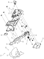
次いで、図28から図34を参照して、反転動作ユニット500について説明する。図28は、反転動作ユニット500の正面斜視図である。なお、図28では、反射部材520が回転方向に互いに当接された閉鎖状態が図示される。反転動作ユニット500は、反射部材520が回転されることで閉鎖状態(図28参照)と開放状態(図33(b)参照)とを形成可能に構成される。次に、反転動作ユニット500の全体構成について説明する。
Next, the reversing
図29は、反転動作ユニット500の分解正面斜視図であり、図30は、反転動作ユニット500の分解背面斜視図である。
29 is an exploded front perspective view of the reversing
図29及び図30に示すように、反転動作ユニット500は、骨格を成す枠状のベース部材510と、そのベース部材510の軸支溝512a,513aに軸支される反射部材520と、その反射部材520の回転軸522が内嵌される軸支孔531を備える第1蓋部材530と、反射部材520の駆動部側においてベース部材510の第2壁部513に取り付けられる第2蓋部材540と、反射部材520の回転ギア523に歯合される第1ラックギア553が刻設される伝達部材550と、その伝達部材550を移動させる駆動力を発生させる駆動装置560と、その駆動装置560の伝達ギア群562の背面側に配置されると共にベース部材510に締結固定されるカバー部材570と、を主に備える。
As shown in FIGS. 29 and 30, the reversing
ベース部材510は、中央に矩形状の開口を有すると共に平面枠状に形成される底面部511と、その底面部511の右端から底面部511の正面側および背面側へ向けて垂直に延設される第1壁部512と、底面部511の左端から底面部511の正面側へ向けて垂直に延設される第2壁部513と、を主に備える。なお、底面部511の開口はLED等の光源を有する基盤(図示せず)を配設するための開口であり、組立状態(図28参照)において光源から反射部材520へ向けて光が照射される。
The
底面部511は、背面視(図30参照)における底面部511の右側部分において上下方向に延設されると共に、伝達部材550を案内する長孔状のスライド孔511aを備える。
The
スライド孔511aは、延設方向が一直線上に一致する態様で底面部511の上下方向(図30上下方向)に複数(本実施形態では4箇所)並べられて形成され、そのうち上下両端に形成されるスライド孔511aには、その下端からスライド孔511aの延設方向に延設される長孔であって、スライド孔511aより細幅の長孔であると共に伝達部材550のリブ部555を案内するリブ部スライド孔511bが形成される。
The
また、底面部511は、開口の下方において背面側へ向けて複数が突設されると共に駆動装置560の伝達ギア群562が軸支される回転軸511cを備える。
Further, the
第1壁部512は、正面側から背面側へ向けてU字状に切りかかれる溝であって反射部材の回転軸部の外径より若干大きな幅の軸支溝512aが複数形成される。なお、軸支溝512aの配設間隔は等間隔であり反射部材520の幅寸法(回転軸方向視長手寸法)よりも短い間隔で形成される。
The
第2壁部513は、軸支溝512aと対向配置されると共に軸支溝512aと同一の態様で形成される複数の軸支溝513aと、その複数の軸支溝513aのうち隣接する軸支溝513aの間に形成されると共に第2壁部513の外壁面から正面側(図29手前側)へ向けて延設される延設部513bと、を備える。
The
延設部513bは、正面側へ向かうほど幅寸法(図29上下方向の寸法)が小さくなる階段状に形成され、組立状態(図28参照)において、第2蓋部材540の位置決め突設部543に嵌合される。
The extending
反射部材520は、光源から照射される光の進行方向を変化させる部材であって、不透明な樹脂材料から形成される長尺板状の本体部521と、その本体部521の左右両端から一直線上に突設される一対の回転軸522と、それら一対の回転軸522のうち伝達部材550が配設される側の回転軸522に軸どうしを一致させて締結固定される回転ギア523と、を備える。
The
本体部521は、幅方向の端面に面取り形成される面取部521a(図34参照)を備える。
The
回転軸522は、本体部521の幅方向(図29上下方向)中心位置に形成される。また、一対の回転軸522のうち伝達部材550が配設される側の回転軸522の方が長尺に延設されることで、回転ギア523と本体部521との間に第2壁部513が配設可能に形成される。
The
回転ギア523は、隣接して刻設される歯が連結されると共に回転中心からの径が他の歯よりも長く形成される膨張歯523aを備える。膨張歯523aにより、反射部材520の過回転を防止することができる。
The
第1蓋部材530は、第1壁部512の厚み方向(図29左右方向)から締結固定される長尺板状の部材であって、反射部材520の回転軸522が挿通される複数の軸支孔531と、第1蓋部材530の正面(図29手前側の面)に沿って第1壁部512へ向けて垂直に延設される部分であって複数の軸支孔531の正面側の縁に外接する端面を有する延設蓋部532(図31参照)と、を備える。
The
ここで、例えば、第1蓋部材530を第1壁部512の正面側から締結固定する場合、第1壁部512には締結ネジの頭の径以上の厚みが必要となる。この場合、本実施形態のように、反転動作ユニット500が第3図柄表示装置81の表示領域P(図2参照)の外縁に第1壁部512を挟んで隣接していると、第1壁部512の厚みが邪魔となり、反転動作ユニット500と第3図柄表示装置81の表示領域P(図2参照)の演出とを一体として視認させることが難しい。
Here, for example, when fastening and fixing the
一方、第1蓋部材530は、第1壁部512の厚み方向(図29左右方向)から締結固定されるため、反射部材520の右方の壁の厚みを締結ネジの頭の径によらず薄くすることができる。そのため、第1壁部512の厚みが邪魔とならず、反転動作ユニット500と第3図柄表示装置81の表示領域P(図2参照)での演出とを一体として視認させることが容易となり、演出効果を向上させることができる。
On the other hand, since the
なお、ベース部材510、反射部材520及び第1蓋部材530の組立方法に関して、少なくとも2通りの組立方法を行うことができる。例えば、第1に、ベース部材510の軸支溝512a,513aに反射部材520の回転軸522を嵌め込んだ状態で第1蓋部材530をベース部材510に締結固定する方法がある。この方法であれば、反射部材520を一度に第1蓋部材530の軸支孔531に挿通させることができる。
Regarding the method of assembling the
また、第2に、先にベース部材510に第1蓋部材530を締結固定した状態で、反射部材520の駆動部側とは反対側の回転軸522を第1蓋部材530の軸支孔531に斜め方向(正面側から斜め右奥へ向かう方向)で差し込んだ後に、駆動部側の回転軸522を第2壁部512の軸支溝513aに嵌め込む方法がある。
Secondly, with the
図31を参照して、第1壁部512の軸支溝512a、第1蓋部材530及び反射部材520の嵌合関係について説明する。図31(a)は、反転動作ユニット500の部分側面図であり、図31(b)は、図31(a)のXXXIb−XXXIb線における反転動作ユニット500の部分断面図である。なお、図31(a)は、第1蓋部材530が締結される側の側面が図示される。
With reference to FIG. 31, a fitting relationship between the
図31(a)に示すように、第1壁部512の軸支溝512aの深さは反射部材520の回転軸522の直径と略同一に形成される。そのため、例えば第1蓋部材530に軸支孔531が形成されていない場合であっても、反射部材520は第1壁部512の軸支溝512aと第1蓋部材530の延設蓋部532との間に位置決めされ、軸支される。
As shown in FIG. 31A, the depth of the
さらに本実施形態では、第1壁部512の軸支溝512aの深さと第1蓋部材530の軸支孔531の径とが同一に形成される。そのため、反射部材520の回転軸522は、上述したように第1壁部512の軸支溝512aと第1蓋部材530の延設蓋部532との間に軸支されると共に、第1蓋部材530の軸支孔531にも軸支される(図31(b)参照)。
Further, in this embodiment, the depth of the
よって、反射部材520の回転軸522を軸支する面積を大きく確保することができる。これは、第1蓋部材530を第1壁部512に右方から締結固定することで第1壁部512の厚みを抑制した本実施形態の構成において特に有効である。
Therefore, it is possible to secure a large area for pivotally supporting the
即ち、第1壁部512の厚みを抑制したために、そのままでは反射部材520を軸支する軸支溝512aの面積を十分確保することが困難になるおそれがある。そこで、第1蓋部材530に軸支孔531を穿設し、その軸支孔531でも反射部材520を軸支するようにしている。これにより、第1蓋部材530及び第1壁部512が反射部材520の軸方向に占めるスペースを有効利用し、反射部材520を軸支する面積を十分に確保することができる。
That is, since the thickness of the
図30に戻って説明する。第2蓋部材540は、反射部材520の駆動部側をベース部材510に軸支するための部材であって、最も正面側に配置される長尺板状のベース部材541と、そのベース部材541から背面側へ向けて突設されると共に上下方向(図30上下方向)に延設される延設軸支部542と、その延設軸支部542とベース部材541とを連結する態様で突設される位置決め突設部543と、を備える。
It returns to FIG. 30 and demonstrates. The
図32を参照して、第2蓋部材540とベース部材510との係合について説明する。図32(a)は、反転動作ユニット500の部分正面図であり、図32(b)は、図32(a)のXXXIIb―XXXIIb線における反転動作ユニット500の部分断面図であり、図32(c)は、図32(b)のXXXIIc―XXXIIc線における反転動作ユニット500の部分断面図であり、図32(d)は、図32(b)のXXXIId―XXXIId線における反転動作ユニット500の部分断面図である。
The engagement between the
図32(b)に示すように、第2蓋部材540の複数の位置決め突設部543は、ベース部材510の隣接する延設部513bの間にそれぞれ嵌合される。これにより、第2蓋部材540をベース部材510に対して上下方向(図32(b)上下方向)に精度よく位置合わせすることができる。
As shown in FIG. 32B, the plurality of positioning protruding
ここで、第2壁部513は長尺板状に形成されるため、厚み方向への剛性が低くなりがちであり、第2壁部513が厚み方向へ撓むことにより反射部材520に軸方向の力が加えられ、反射部材520の回転が阻害されるおそれがある。
Here, since the
一方、図32(c)に示すように、本実施形態ではベース部材510の延設部513bの厚み方向(図32(c)左右方向)から第2蓋部材540の延設軸支部542が当接される。これにより、第2壁部513の厚み方向の剛性を向上させることができる。
On the other hand, as shown in FIG. 32C, in the present embodiment, the extended
第2蓋部材540の延設軸支部542の延設方向の端部とベース部材510の軸支溝513aが形成される端部とは当接され、軸支溝513aの開放端を閉鎖する(図32(d)参照)。これにより、軸支溝513aと第2蓋部材540の延設軸支部542とが形成する孔により、反射部材520の回転軸522が軸支される(図32(b)参照)。
The end of the extending
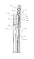
図29に戻って説明する。伝達部材550は、駆動装置560の駆動力を反射部材520に伝達するための部材であって、長尺板形状に形成されると共にベース部材510の底面部511の背面に当接される本体部551と、その本体部551の端面(図29左側端面)から正面側に延設される長尺板形状の延設壁部552と、その延設壁部552の正面側の端面に断続的に刻設されると共に反射部材520の回転ギア523に歯合される第1ラックギア553と、本体部551の正面側に複数(本実施形態では4箇所)が配設されると共にベース部材510のスライド孔511aに連結されるスライド軸554と、それらのスライド軸554のうち上下端のスライド軸554から下方に延設されると共にベース部材510のリブ部スライド孔511b(図30参照)の幅寸法よりも若干小さい幅寸法で突設されるリブ部555と、本体部551の側面に刻設されると共に駆動装置560の伝達ギア群に歯合される第2ラックギア556と、を備える。
It returns to FIG. 29 and demonstrates. The
第1ラックギア553は、四つの歯が連設される歯群が、一つの歯を省略する場合の間隔よりも若干短い間隔を空けて複数配設される。この間隔を空けられた空間により、反射部材520の回転ギア523の過回転を防止することができるが、詳細は後述する。
In the
駆動装置560は、駆動力を発生させる装置であって、駆動軸に軸支される駆動ギア561と、その駆動ギア561に歯合されるギアと伝達部材550の第2ラックギア556に歯合されるギアとを含む複数のギアであってそれぞれが複数の回転軸511cに歯合される伝達ギア群562と、を備える。
The
駆動装置560の駆動ギア561が回転されると、伝達ギア群562が回転され駆動装置560の駆動力が第2ラックギア556を介して伝達部材550に伝達される。伝達部材550は、駆動装置560の駆動力によりベース部材510のスライド孔511aの延設方向へスライド移動される。伝達部材550の第1ラックギア553は反射部材520の回転ギア523に歯合されるため、伝達部材550がスライド移動されることで反射部材520が回転軸522を支点に回転される。
When the
図33(a)、図33(b)及び図33(c)は、反射部材520の回転動作を時系列で図示した反転動作ユニット500の部分正面図であり、図33(d)、図33(e)及び図33(f)は、反射部材520の回転動作を時系列で図示した反転動作ユニット500の部分側面図であり、図34は、図33(d)の姿勢における反射部材520及び伝達部材550の部分側面図である。
33 (a), 33 (b), and 33 (c) are partial front views of the reversing
なお、図33では第2蓋部材540の図示は省略され、図33(a)及び図33(d)では、反射部材520の本体部521どうしが当接される状態(閉鎖状態)が図示され、図33(b)及び図33(e)では、図33(a)及び図33(d)の状態から反射部材520が所定量回転された状態(開放状態)が図示され、図33(c)及び図33(f)では、反射部材520が図33(a)及び図33(d)で正面側へ向けている面と反対側の面が正面側へ向けられると共に反射部材520の本体部521どうしが当接される状態(閉鎖状態)が図示される。
Note that the
図33(d)に示すように、閉鎖状態において、反射部材520の回転ギア523は、伝達部材550の第1ラックギア553に歯合され回転を規制される。
As shown in FIG. 33D, in the closed state, the
反射部材520の回転動作について説明する。図33(d)の状態から、伝達部材550の第1ラックギア553が駆動装置560(図29参照)により上方(図33(d)左方)へスライド移動されると反射部材520の回転ギア523が回転されることに伴い反射部材520の本体部521が回転される(図33(e)参照)。さらに第1ラックギア553が左方へスライド移動されることで反射部材520は互いの厚み方向の面が当接されるまで回転され、伝達部材550が停止される(図33(f)参照)。
The rotation operation of the
ここで、伝達部材550のスライド移動の終端位置では、反射部材520が端部で当接され姿勢が矯正される(図34参照)。そのため、反射部材520の回転ギア523と伝達部材550の第1ラックギア553とが精度よく歯合されていなくても、伝達部材550がスライド移動の終端位置に配置された状態における反射部材520の姿勢を安定化させることができる。
Here, at the end position of the sliding movement of the
反射部材520は、閉鎖状態において、本体部521の端部が厚み方向に当接される。このとき、ベース部材510の第1壁部512と第2壁部513との間の領域が反射部材520に閉鎖されるので、上述した光源から照射される光を反射部材520で遮断することができる。
In the closed state of the
ここで、光の漏れの抑制は、例えば板状のシャッター部材をスライド移動させて、そのシャッター部材を遊技者へ照射される光と遊技者との間に配置することでも達成できる。この場合、シャッター部材が開ききってしまえば遊技者へ照射される光の全体を遊技者は視認できる。しかし、遊技者へ照射される光と遊技者との間にシャッター部材が配置された状態からシャッター部材がスライド移動する途中では、シャッター部材と重なる光を視認することはできない。即ち、遊技者が光の全体を視認するまでの期間が長くなる。 Here, the suppression of light leakage can also be achieved by, for example, slidingly moving a plate-shaped shutter member and disposing the shutter member between the light emitted to the player and the player. In this case, if the shutter member is fully opened, the player can visually recognize the entire light emitted to the player. However, when the shutter member is slidingly moved from the state in which the shutter member is arranged between the light emitted to the player and the player, the light overlapping the shutter member cannot be visually recognized. That is, the period until the player visually recognizes the entire light becomes long.
一方、本実施形態によれば、反射部材520は、閉鎖状態では光の漏れを抑制しながら、閉鎖状態から反射部材520が回転することで遊技者へ照射される光を通過可能にする。ここで、複数の反射部材520には例示として上述した単一のシャッター部材と同じ役割を持たせることができる。即ち、シャッター部材に比較してそれぞれの反射部材520を小型に形成することができる。そのため、シャッター部材をスライド移動させる場合に比較して、反射部材520を回転させる場合の方が、遊技者が光の全体を視認するまでの時間を短くできる。
On the other hand, according to the present embodiment, the
また、本実施形態では、反射部材520が回転することにより、正面視(図32(a)参照)における反射部材520の占める領域が縮小されることで、反射部材の背面側に形成される光源の光を視認可能となる。そのため、反射動作ユニット500の配設スペースを省スペース化することができる。
Further, in the present embodiment, by rotating the
反射部材520は、閉鎖状態において面取部521aどうしが互いに当接される(図34参照)。これにより、厚み方向における反射部材520どうしの厚み方向の間隔を短くすることができ、複数の反射部材520で形成される面をより平坦面化することができる。
In the closed state of the
例えば、複数の反射部材520の厚み方向の面で一体として認識される模様が複数の反射部材520の厚み方向の面に形成される場合、隣接する反射部材520間の境界を目立たせなくし、模様のずれを抑制することができる。そのため、模様をより綺麗に認識させることができる。
For example, when a pattern that is integrally recognized on the surfaces of the plurality of reflecting
反射部材520の回転軸522から膨張歯523aの外端までの距離は、回転軸522から伝達部材550の本体部551までの距離よりも長く形成される。そのため、図33(a)の状態から、回転ギア523を図33(d)の反時計回りに回転させようとすると、膨張歯523aが本体部551にせき止められるため、回転させることができない。これにより、反射部材520の過回転を防止でき、反射部材520の当接面で圧力が過度に生じ、反射部材520が破損することを防止することができる。
The distance from the
また、上述したように、第1ラックギア553は四つの歯が連設される歯群が一つの歯を省略する場合の間隔よりも若干短い間隔を空けて配設されるため、図33(f)の状態から反射部材520の回転ギア523を図33(f)の時計回りに回転させようとすると、回転ギア523の歯が伝達部材550の第1ラックギア553の歯群間に形成される間隔にはまり込む。この場合、回転ギア523をそれ以上回転させることができない。よって反射部材520の過回転により、反射部材520が当接面である面取部521aで破損することを防止することができる。
Further, as described above, the
次いで、図35から図42を参照して、第2スライド動作ユニット700について説明する。図35(a)及び図35(b)は、第2スライド動作ユニット700の正面斜視図である。なお、図35(a)では、一対の第1スライド部材720及び一対の第2スライド部材740が退避位置に配置された状態が図示され、図35(b)では、一対の第1スライド部材720及び一対の第2スライド部材740が張出位置(第3図柄表示装置81の表示領域Pの正面側、図2参照)に配置された状態が図示される。
Next, the second
第2スライド動作ユニット700は、一対の第1スライド部材720及び一対の第2スライド部材740が第3図柄表示装置81の表示領域P(図2参照)の正面側に張り出すことで、表示領域Pを格子状に分割可能に形成される。次に、第2スライド動作ユニット700の全体構成について説明する。
In the second
図36及び図37は、第2スライド動作ユニット700の分解正面斜視図であり、図38及び図39は、第2スライド動作ユニット700の分解背面斜視図である。なお、図36及び図38では、ベース部材710及びベース部材710の正面側に配設される部材が分解された状態が図示され、図37及び図39では、ベース部材710及びベース部材710の背面側に配設される部材が分解された状態が図示される。
36 and 37 are exploded front perspective views of the second
図36から図39に示すように、第2スライド動作ユニット700は、中央に第3図柄表示装置81の表示領域P(図2参照)を形成する矩形状の開口を有する矩形板形状のベース部材710と、そのベース部材710の正面と所定間隔を空けてベース部材710に固定されると共に長手方向を水平方向と一致させる第1スライド軸棒S1と、その第1スライド軸棒S1に沿ってスライド移動される一対の第1スライド部材720と、それらの一対の第1スライド部材720の正面側からベース部材710に締結固定されると共に上下一対で形成される正面側カバー部材730と、を主に備える。
As shown in FIGS. 36 to 39, the second
また、第2スライド動作ユニット700は、ベース部材710の背面と所定間隔を空けてベース部材710に固定されると共に長手方向を鉛直方向と一致させる第2スライド軸棒S2と、その第2スライド軸棒S2に沿ってスライド移動される一対の第2スライド部材740と、それらの第2スライド部材740に歯合される複数のギアが配設される伝達装置750と、一対の第2スライド部材740及び伝達装置750の背面側からベース部材710に締結固定されると共に左右および上部に形成される背面側カバー部材760と、それらの背面側カバー部材760に配設されると共に第1スライド部材720及び第2スライド部材740をスライド移動させる駆動力を発生させる駆動装置770と、を主に備える。
The second
図36に示すように、第1スライド部材720は、形状の略同等な一対の部材により構成されるので、ここではその片方(図36左方)について説明し、他方の説明を省略する。
As shown in FIG. 36, since the
第1スライド部材720は、正面視L字の板形状に形成される本体部721と、その本体部721に締結固定される台車部722と、その台車部722の下端から下方へ延設される装飾部723と、を備える。
The
本体部721は、左右方向へ延設される長尺板形状に形成されると共に上面にラックギアが刻設されるラック部721aと、そのラック部721aの下方に連設されると共にラック部721aの正面視左寄りに配設される板形状の台車受け部721bと、を備える。
The
台車部722は、左端を台車受け部721bの左端と一致させて台車受け部721bの背面側に締結固定される。台車部722は、板状の底面の上下端から正面側にそれぞれ壁部が張り出すことで断面コ字状に形成される台車本体部722aと、その台車本体部722aの内方に配設されると共に底面と垂直な回転軸を有して形成される上下一対の回転体が左右一対で配設される回転体群722bと、を備える。
The
回転体群722bは、上下一対の回転体が左右に平行に配設されると共に、上下間隔の長さは第1スライド軸棒S1の直径より若干長く形成される。回転体群722bは、台車本体部722aの長手方向の側面(図36左右側面)から若干外方へ張り出して配置される。
In the
第1スライド軸棒S1は、両端にベース部材710に締結固定される一対の締結板部S1aを備えると共にステンレスなどの金属材料から形成される。
The first slide shaft S1 has a pair of fastening plate portions S1a fastened and fixed to the
第1スライド部材720のベース部材710への配設態様について説明する。まず、スライド軸棒S1を第1スライド部材720の回転体群722aの間に挿入し、その状態で締結板部S1aをベース部材710に締結固定する。これにより、台車部722aがベース部材710と第1スライド軸棒S1との間に配設される。また、これによりベース部材710が第1スライド軸棒S1の剛性により補強される。
An arrangement mode of the
次いで、本体部721の台車受け部721bと台車部722とを締結固定する。これにより、第1スライド軸棒S1により第1スライド部材720がスライド移動可能に軸支される。
Next, the
この状態で、第1スライド部材720のラック部721aが、駆動ギア711a,712aに歯合される伝達ギアに歯合される。そのため、駆動ギア711a,712a及び伝達ギアを介して駆動装置770(図35参照)の駆動力が第1スライド部材720に伝達されることで、第1スライド部材720が左右にスライド移動される。
In this state, the
第1スライド部材720のスライド移動時には、回転体群722bが第1スライド軸棒S1を挟み込むため、第1スライド部材720と第1スライド軸棒S1との接触面積を小さくでき摩擦が低減される。また、上下一対の回転体が左右に一対で配設され、それらが第1スライド軸棒S1に当接されるので、第1スライド部材720のぐらつきを複数点で抑制することができる。よって、第1スライド軸棒S1に対する第1スライド部材720の姿勢を安定させることができる。
When the
正面側カバー部材730は、第1スライド部材720がベース部材710に配設された後にベース部材710に締結固定される。下側のカバー部材730は、装飾部723の下端の正面側に配設される。これにより、第1スライド部材720が第1スライド軸棒S1を軸に前後方向(図36左手前方向)にぐらつく場合に、第1スライド部材720のぐらつきを抑制することができる。
The
図38に示すように、ベース部材710は、前後方向に貫通して配設されると共に軸回転可能に形成される伝達筒711,712と、背面視左方においてベース部材710の背面に締結固定され鉛直方向に沿って延設されると共に内方(図38右方)へ向く壁面にギアが刻設される固定ギア部713と、その固定ギア部713に歯合されると共にラックギア754(図39参照)の軸支部754a(図37参照)に軸支される転動ギア714と、背面視右方においてベース部材710の背面から突設されると共に鉛直方向に延設される案内壁部715と、を主に備える。
As shown in FIG. 38, the
伝達筒711,712は、ベース部材710の正面側に駆動ギア711a,712a(図36参照)をそれぞれ備える。伝達筒711,712は、駆動装置770の駆動モータ771,772の駆動軸が固着される部材であって、駆動装置770の駆動力を第1スライド部材720に伝達する部材である。
The
案内壁部715は、内方(図38左方)へ向く壁面に刻設される受けギア部715aを備える。
The
図37に示すように、第2スライド部材740は、形状の略同等な一対の部材により構成されるので、ここではその片方(図37上方)について説明し、他方の説明を省略する。
As shown in FIG. 37, since the
第2スライド部材740は、長尺板形状に形成される本体部741と、その本体部741に締結固定される台車部742と、その台車部742の正面視左端から左方へ延設される装飾部743と、を備える。
The
本体部741は、上下方向へ延設される長尺板形状に形成されると共に右面にラックギアが刻設される。
The
台車部742は、上端を本体部741の上端と一致させて本体部741の背面側に締結固定される。台車部742は、板状の底面の左右端から正面側にそれぞれ壁部が張り出すことで断面コ字状に形成される台車本体部742aと、その台車本体部742aの内方に底面と垂直な回転軸を有して形成される左右一対の回転体が上下一対で配設される回転体群742bと、を備える。
The
回転体群742bは、左右一対の回転体が上下に平行に配設されると共に、左右間隔の長さは第2スライド軸棒S2の直径より若干長く形成される。
In the
装飾部743は、正面視左方の端に、背面へ向けて突設される軸に軸支される上下一対の撓み抑制ギア743aを備える。
The
第2スライド軸棒S2は、両端にベース部材710に締結固定される一対の締結板部S2aを備える。
The second slide shaft S2 includes a pair of fastening plate portions S2a that are fastened and fixed to the
第2スライド部材740のベース部材710への配設態様について説明する。まず、スライド軸棒S2を第2スライド部材740の回転体群742aの間に挿入し、本体部741を台車部742の正面側に締結固定する。これにより、第2スライド軸棒S2により第2スライド部材740がスライド移動可能に軸支される。また、これによりベース部材710が第2スライド軸棒S2の剛性により補強される。
An arrangement mode of the
次いで、第2スライド軸棒S2の締結板部S2aをベース部材710の背面に締結固定する。これにより、本体部741がベース部材710と第2スライド軸棒S2との間に配設される。
Then, the fastening plate portion S2a of the second slide shaft S2 is fastened and fixed to the back surface of the
ここで、第2スライド部材740の本体部741から刻設されるラックギアは、ベース部材710の転動ギア714に歯合される。そのため、転動ギア714が回転されると、第2スライド部材740は上下にスライド移動される。
Here, the rack gear engraved from the
第2スライド部材740のスライド移動時には、回転体群742bが第2スライド軸棒S2を挟み込むため、第2スライド部材740と第2スライド軸棒S2との接触面積を小さくでき摩擦が低減される。また、左右一対の回転体が上下に一対で配設され、それらが第2スライド軸棒S2に当接されるので、第2スライド部材740のぐらつきを複数点で抑制することができる。よって、第2スライド軸棒S2に対する第2スライド部材740の姿勢を安定させることができる。
When the
ここで、転動ギア714(駆動部側)に歯合されるラックギアを有する本体部741と、第2スライド軸棒S2を挟み込む台車部742とが、第2スライド部材740の延設方向における同一端部に形成される。よって、第2スライド部材740の第2スライド軸棒S2を支点とする撓みが、ラックギアと転動ギア714との歯合状態に影響する度合いを低減することができる。よって、第2スライド部材740が歯合状態のずれにより受ける抵抗を抑制することができる。
Here, the
図39に示すように、伝達装置750は、駆動装置770の駆動力を第2スライド部材740へ伝達させる装置であって、長尺板形状の本体部751と、その本体部751の背面側に配設されると共に駆動装置770の駆動軸773a,774aが固着される駆動ギア752と、その駆動ギア752に歯合される伝達ギア753と、その伝達ギアに歯合される歯を有し上下方向に延設される長尺板形状の部材であると共に本体部751のスライド長孔751aに沿って上下にスライド移動されるラックギア754と、を主に備える。
As shown in FIG. 39, the
なお、伝達装置750の構成の説明において、上下一対の部分(図39参照)においてはその片方(上方)の説明のみを行い、もう一方の説明は省略する。
In the description of the configuration of the
本体部751は、鉛直方向(図39上下方向)に長手方向を向けた長孔状に穿設されるスライド長孔751aを備える。
The
ラックギア754は、正面から垂直に突設されると共に本体部751のスライド長孔751aを貫通する円柱状の軸支部754a(図37参照)を備える。その軸支部754aは、転動ギア714の軸支孔に挿通される。
The
ここで、第2スライド部材740への駆動力の伝達態様について説明する。まず、駆動装置773の駆動軸773aが回転されると、その駆動軸773aに固着される駆動ギア752が回転され、その駆動ギア752に歯合される伝達ギア753の回転を介してラックギア754がスライド長孔751aの長手方向に沿って上下にスライド移動される。
Here, the transmission mode of the driving force to the
ラックギア754の軸支部754a(図37参照)は、転動ギア714の軸支孔に挿通されるので、ラックギア754が上下にスライド移動されることで、転動ギア714も上下にスライド移動される。
Since the
このとき、転動ギア714は、ベース部材710の固定ギア部713の歯に歯合されると共に、固定ギア部713に対向配置される第2スライド部材740の本体部741とも歯合される。即ち、固定ギア部713、転動ギア714及び本体部741でダブルラックピニオン機構が形成され、第2スライド部材740はラックギア754に対して倍速で移動される。
At this time, the rolling
背面側カバー部材760は、第2スライド部材740の駆動部側に配設される背面駆動部カバー部材761と、上部に配設される背面上部カバー部材762と、背面駆動部カバー部材761と左右方向に対向配置される背面抜け止めカバー部材763と、を主に備える。
The
背面駆動部カバー部材761は、伝達装置750の背面側に締結固定されると共に、駆動装置770の駆動モータのうち第2スライド部材740を駆動させる駆動モータ773,774が背面に締結固定される。
The rear drive
背面上部カバー部材762は、ベース部材710の背面に締結固定されると共に、駆動装置770の駆動モータのうち第1スライド部材720を駆動させる駆動モータ771,772が背面に締結固定される。
The rear
背面抜け止めカバー部材763は、装飾部743の延設端側の背面に形成され、第2スライド部材740が第2スライド軸棒S2を支点に背面側に回転され抜け出してしまうことを防止する。
The back surface retaining
駆動装置770は、第1スライド部材720を駆動させる駆動モータ771,772と、第2スライド部材740を駆動させる駆動モータ773,774と、を主に備える。それらの駆動モータ771,772,773,774は駆動軸771a,772a,773a,774aをそれぞれ備える。
The
図40を参照して、一対の第1スライド部材720の移動態様の一例について説明する。図40は、第1スライド部材720の配置の変化の一例を時系列で図示した第2スライド動作ユニット700の正面図である。
An example of the movement mode of the pair of
なお、図40(a)では、一対の第1スライド部材720がそれぞれ退避位置に配置された状態が、図40(b)では、一対の第1スライド部材720の本体部721と台車部722とが張出位置で当接された状態が、図40(c)では、一対の第1スライド部材720が図40(b)の位置から正面視右方へ所定量移動された状態が、それぞれ図示され、図40(a)から図40(c)では、上下一対の正面側カバー部材730のうち上側の正面側カバー部材730の図示が省略される。
It should be noted that in FIG. 40 (a), the state in which the pair of
ここで、一対の第1スライド部材720のスライド移動時における駆動ギア711a,712aへの駆動力の伝達について説明する。図40(a)に示す退避位置から、駆動ギア711a,712aが(駆動ギア711aは正面視時計回り、駆動ギア712aは正面視反時計回りに)回転されると、一対の第1スライド部材720はそれぞれ張出位置へ向けてスライド移動され、張出位置において当接される(図40(b)参照)。
Here, the transmission of the driving force to the drive gears 711a and 712a during the sliding movement of the pair of
一対の第1スライド部材720のうち正面視右方に配設される第1スライド部材720をスライド移動させる駆動力を発生させる駆動モータ772(図35参照)は、図40(b)の状態に至る直前に駆動力の発生を止めるよう制御される。本実施形態では、一対の第1スライド部材720の当接が、台車受け部721bと台車部722の台車本体部722aとで生じるので、装飾部723のスライド方向への撓みを考慮することが不要であって、一対の第1スライド部材720の当接位置を正確に算出することができる。
Of the pair of
一対の第1スライド部材720は回転体群722bが台車本体部722aの長手方向の側面(図36左右側面)から若干外方へ張り出して配置されるため、一対の第1スライド部材720が当接される際には、回転体群722bのうち当接面側から外方へ張り出す回転体同士が初めに当接され、その後、台車受け部721bと台車部722の台車本体部722aとが押しつけられる。即ち、台車受け部721bと台車本体部722aとが当接される最中において、回転体群722bのうち当接面側から外方へ張り出す回転体同士には圧力がかけられる。これにより、一対のスライド部材720が当接された状態において回転体群722bの回転を制動させることができるので、一対の第1スライド部材720の当接時の衝撃を緩和することができる。
Since the pair of
一対の第1スライド部材720は、当接されたあと、一対の第1スライド部材720のうち正面視左方に配設される第1スライド部材720をスライド移動させる駆動力を発生させる駆動モータ771(図35参照)の駆動力により(正面視左方に配設される第1スライド部材720に正面視右方に配設される第1スライド部材720が押されることで)一対の第1スライド部材720が右方へスライド移動される(図40(c)参照)。
The pair of
即ち、一対の第1スライド部材720が互いに当接された後は、駆動モータ771,772を協調動作させることなく、一対の第1スライド部材720をスライド移動させることができる。これにより、駆動モータ771,772(図35参照)全体での電力消費量を抑制することができる。
That is, after the pair of
また、例えば、駆動モータ771(図35参照)のみで一対の第1スライド部材720を駆動させる場合、片方の第1スライド部材720のみを駆動させるよりもモータ負荷が増加する。しかし、第1スライド部材720が水平方向へ移動されるため、上下方向へ移動される場合のように重力負荷を考える必要は無く、モータ負荷の増加量は駆動モータ771,772(図35参照)それぞれで均等に生じる。
Further, for example, when the pair of
そのため、駆動モータ771,772(図35参照)のモータ寿命を調整しやすく、駆動モータ771,772の交換時期の調整を容易にすることができる。これにより、駆動モータ771,772のメンテナンス回数を減少させることができる。
Therefore, the motor life of the
図41を参照して、一対の第2スライド部材740の移動態様の一例について説明する。図41は、第2スライド部材720の配置の変化の一例を時系列で図示した第2スライド動作ユニット700の正面図である。
An example of the movement mode of the pair of
なお、図41(a)では、一対の第2スライド部材740がそれぞれ退避位置に配置された状態が、図41(b)では、一対の第2スライド部材740の本体部741どうしが張出位置で当接された状態が、図41(c)では、一対の第2スライド部材740が図41(b)の位置から正面視上方へ所定量移動された状態が、それぞれ図示される。
It should be noted that in FIG. 41 (a), the state in which the pair of
ここで、一対の第2スライド部材740のスライド移動時における駆動ギア752(図39参照)への駆動力の伝達について説明する。図41(a)に示す退避位置から、駆動モータ773,774(図35参照)により駆動ギア752が(駆動モータ773は正面視時計回り、駆動モータ774は正面視反時計回りに)回転されると、一対の第2スライド部材740はそれぞれ張出位置へ向けてスライド移動され、張出位置において当接される(図41(b)参照)。
Here, the transmission of the driving force to the drive gear 752 (see FIG. 39) during the sliding movement of the pair of
一対の第2スライド部材740のうち正面視上方に配設される第2スライド部材740をスライド移動させる駆動力を発生させる駆動モータ773(図35参照)は、図41(b)の状態に至る直前に駆動力の発生を止めるよう制御される。
Of the pair of
一対の第2スライド部材740は、当接されたあと、一対の第2スライド部材740のうち正面視下方に配設される第2スライド部材740をスライド移動させる駆動力を発生させる駆動モータ774(図35参照)の駆動力により(正面視下方に配設される第2スライド部材740に正面視上方に配設される第2スライド部材740が押されることで)一対の第2スライド部材740が上方へスライド移動される(図41(c)参照)。
The pair of
即ち、一対の第2スライド部材740が互いに当接された後は、駆動モータ773,774(図35参照)を協調動作させることなく、一対の第2スライド部材740をスライド移動させることができる。これにより、駆動モータ773,774全体で見た電力消費量を抑制することができる。
That is, after the pair of
ここで、下降移動する部材が上方へ移動方向を転換する場合、重力の影響により駆動モータへの負荷が上昇することでモータ寿命が低下するおそれがある。また、方向転換のための減速時間が長くかかるので、演出の自由度を低下させるおそれがある。 Here, when the member that moves downward changes its moving direction upward, the load on the drive motor increases due to the influence of gravity, which may shorten the life of the motor. In addition, since the deceleration time for changing the direction takes a long time, there is a possibility that the degree of freedom of the effect may be reduced.
しかし、本実施形態では、一対の第2スライド部材740のうちの上側の部材が下降移動から上方へ移動方向を転換する場合に、一対の第2スライド部材740のうちの下側の部材の上昇移動の勢いを利用することができる。これにより、重力の影響により第2スライド部材740の方向転換時に生じるモータ負荷を低減させることができ、モータ寿命を長期化することができる。また、第2スライド部材740の方向転換のための減速時間を短縮し、演出の自由度を向上させることができる。
However, in the present embodiment, when the upper member of the pair of
次いで、図42を参照して、第2スライド部材740の撓み抑制ギア743aの作用について説明する。図42は、第2スライド動作ユニット700の部分背面図である。なお、背面側カバー部材760の背面抜け止めカバー763(図39参照)の図示が省略される。
Next, with reference to FIG. 42, the operation of the
図42に示すように、第2スライド部材740は、第2スライド軸棒S2で支持される端部の反対側の端部が撓み抑制ギア743aを介してベース部材710の受けギア部715aに当接される。
As shown in FIG. 42, in the
ここで、第2スライド部材740の始動時には、撓み抑制ギア743aと受けギア部715aとの歯合関係は適正化され撓み抑制ギア743aはスムーズに回転されるため、第2スライド部材740と受けギア部715aとの間に生じる抵抗は抑制される。よって、第2スライド部材740の始動時に必要な駆動力を抑制することができる。
Here, at the time of starting the
一方、一対の第2スライド部材740が台車部742どうしで当接される場合には、当接時の衝撃が装飾部743に伝達され、装飾部743の撓み抑制ギア743aが配設される側の端部が案内壁部715に対して傾斜される。これにより、受けギア部715への撓み抑制ギア743aからの負荷が上昇する。詳述すると、例えば第2スライド部材740の装飾部743が台車部742を支点に下方(図42下方)へ傾斜されると、一対の撓み抑制ギア743aのうち上側の撓み抑制ギア743aが受けギア部715へ押しつけられる。
On the other hand, when the pair of
これにより、第2スライド部材740の傾斜を戻す方向の力が第2スライド部材740へ加えられるので、一対の第2スライド部材740が当接されることで生じる装飾部743の姿勢の傾斜を抑制することができる。
As a result, a force in the direction to return the inclination of the
また、第2スライド部材740と案内壁部715との当接がギアの歯合により構成されることで、当接面を増加させることができる。これにより、一対の第2スライド部材740の当接時に第2スライド部材740と案内壁部715との間で滑りが発生することを抑制することができるので、装飾部743の姿勢の傾斜を抑制する効果を向上させることができる。
Further, since the contact between the
<第1実施形態における第1可変入賞装置について>
図49〜図51を参照して、第1実施形態における第1可変入賞装置65の詳細について説明する。図49は、この第1可変入賞装置65の分解斜視図である。第1可変入賞装置65は、図49に示すように、遊技盤13の前面側に突出して配置される開口部形成部材65b、その開口部形成部材65bの背面側に組み合わされて、第1可変入賞装置65を遊技盤13にビス留めするためのベース部材65cと、そのベース部材65cの背面側に配置されてベース部材65cの背面側よりパチンコ機10の前面側に対してLEDを点灯させるためのLEDが複数配置されたLED基板65dと、そのLED基板65dをベース部材65cと狭持する裏カバー体65eと、開口部形成部材65dに形成されている特定入賞口65aを開閉するための開閉扉65f1を有した開閉ユニット65fと、裏カーバ体65eの背面側に組み合わされて流路を形成する流路カバー体65gと、裏カバー体65eと流路カバー体65gとで形成された流路に突出して遊技球の流路を切り替える切替部材65hと、その切替部材65hと係止されるリンク部材65iと、流路カバー体65gの背面側に配置される背面カバー体65jと、その背面カバー体65jの背面側に固定されて、リンク部材65iを作動させる流路ソレノイド65kと、その流路ソレノイド65kを背面側から覆って背面カバー体65jにビスにより固定するための固定用カバー体65mとで構成されている。
<Regarding the first variable winning device in the first embodiment>
The details of the first variable winning
図50は、第1可変入賞装置65の断面図である。図50(c)は第1可変入賞装置65の上面図であり、図50(b)は、第1可変入賞装置65のLb−Lb断面図である。図50(b)に示すように、第1可変入賞装置65には、遊技球が入球可能な開口部である特定入賞口65aが形成されている。特定入賞口65aは、パチンコ機10の上方を略長方形状の開口が形成されており、その開口を通過した遊技球が図50(b)の左方向に誘導されるように左下方に傾斜した底面が形成されている。底面の左端部には、遊技球の入賞を検知するための磁気センサー65c1で構成された検出口65a1が配置されている。この検出口65a1を通過した遊技球は、図51(b)で示す裏カバー体65eの背面側に形成された振り分け流路へと誘導される。
FIG. 50 is a cross-sectional view of the first variable winning
なお、図50(b)に示すように特定入賞口65aの開口は、遊技盤13側より出没可能なシャッター機構で構成された開閉扉65f1により遊技球が入球可能な開放状態と入球不可能(入球困難)な閉鎖状態とに可変される。閉鎖状態では、開口が完全に開閉扉65f1によって覆われ、開閉扉の上部を遊技球が転動可能に構成される。また、開放状態では、開閉扉65f1は、ベース部材65cの内側(遊技盤13の内部)に退避されることにより特定入賞口65a内から退避されるように構成されている。
As shown in FIG. 50 (b), the opening of the specific winning
このように構成することで、第1可変入賞装置65の開口が閉鎖されている場合には、遊技球が第1可変入賞装置65の上面を転動して、第2入賞口640側へと誘導されるように構成されている。よって、時短遊技中(確変遊技中含む)にも、右打ちした状態のまま、第2入賞口640へと遊技球を入球させることが可能となり、大当たり遊技後に直ちに左打ちへと遊技方法を変更させる手間を軽減できる。従って、より楽に遊技を行うことができる。
With this configuration, when the opening of the first variable winning
また、開放状態においては、遊技球が流下する方向と直交する面を第1可変入賞装置65の開口として構成できるので、より多くの遊技球が効率よく特定入賞口65a内に入賞できる。よって、大当たり遊技に要する時間を短くすることができ、遊技の効率化をはかることができる。
Further, in the open state, the surface orthogonal to the direction in which the game balls flow down can be configured as the opening of the first variable winning
図50(a)は、図50(b)に示すLa−La断面図である。図50(a)に示すように検出口65a1を有する磁気センサー65c1は、裏カバー体65eの振り分け流路側へと検出口65a1が傾くようにベース部材65cに固定されている。
FIG. 50 (a) is a La-La sectional view shown in FIG. 50 (b). As shown in FIG. 50A, a magnetic sensor 65c1 having a detection opening 65a1 is fixed to the
図51を参照して、裏カバー体65eの振り分け流路に誘導された遊技球が後述する通常排出流路65e1と特別排出流路65e2とに振り分けられる構成について説明する。
With reference to FIG. 51, a configuration in which the game balls guided to the distribution flow paths of the
図51(a)は、遊技球が特別排出口65e2に振り分けられるように切替部材65hが作動された状態を示す裏カバー体65eの背面図である。図51(a)に示すように、切替部材65hは、リンク部材65iの突部が挿入される係止穴65h1と遊技球を誘導する誘導片65h2とを有しており、流路カバー体65gに背面側より回動可能に軸支されている。ここで、流路カバー体65gには、この誘導片65h2を挿通することが可能な開口部が設けられており、流路カバー体65gの背面側より振り分け流路内に誘導片65hを回動可能に配置することが可能に構成されている。
FIG. 51A is a rear view of the
図51(a)に示すように、検出口65a1より振り分け流路内に誘導された遊技球は、左斜め下方に配置された誘導片65h2の上面に誘導されて特別排出口65e2に誘導される。特別排出口65e2を通過した遊技球は特別排出口65e2に設けられた遊技球の通過を検出可能な磁気センサーで構成された確変スイッチ65e3により検出されてアウト球としてパチンコ機10外へ排出される。
As shown in FIG. 51 (a), the game ball guided from the detection port 65a1 into the distribution channel is guided to the upper surface of the guide piece 65h2 arranged diagonally leftward and to the special discharge port 65e2. .. The game ball that has passed through the special discharge port 65e2 is detected by the probability change switch 65e3 that is formed of a magnetic sensor that can detect the passage of the game ball provided in the special discharge port 65e2, and is discharged to the outside of the
ここで、詳細については後述するが、本実施形態におけるパチンコ機10では、大当たり遊技中に上記した確変スイッチ65e3を遊技球が通過することにより、大当たり遊技後の遊技状態が高確率遊技状態(確変遊技状態)に設定される。即ち、確変スイッチ65e3は、確変遊技状態を付与するための入賞口として構成されている。また、切替部材65hは、大当たり後の遊技状態を低確率遊技状態(通常遊技状態)か確変遊技状態かに振り分けるための構成となる。
Here, as will be described in detail later, in the
このように、大当たり遊技中に第1可変入賞口65に入賞した遊技球の流下ルートにより大当たり遊技後に設定される遊技状態が可変されるので、大当たり遊技中にも遊技者の興趣を向上させることができる。なお、第1可変入賞装置65の開口から特別排出口65e2の入り口(切替部材65hの誘導片65h2により閉鎖さる開口面)を通過するのに必要な時間は、最短でも1秒で構成されている。切替部材65hの作動は、大当たり種別により作動タイミングと作動時間が設定されている。本実施形態では、大当たりAに当選した場合には、13ラウンド目の開始における第1可変入賞装置65の開放タイミングに合わせて切替部材65hが5秒間作動されるように構成されている。また、大当たりBに当選した場合には、13ラウンド目の開始における第1可変入賞装置65の開放タイミングに合わせて切替部材65hが0.5秒間作動されるように構成されている。
In this way, since the gaming state set after the jackpot game can be changed by the flow route of the game balls that have won the first
よって、大当たりAでは、第1可変入賞装置65に入賞した遊技球が確変スイッチ65e3を通過することが可能に構成されているが、大当たりBでは、確変スイッチ65e3を通過することが不可能に構成されている。よって、大当たり種別により確変付与割合を制御することができ、過剰に有利不利が発生してしまわないように構成できる。
Therefore, in the jackpot A, the game ball that has won the first variable winning
図51(b)を参照して、通常排出口65e2に遊技球が誘導される場合について説明する。図51(b)は、流路ソレノイド65kが非作動であり、特別排出口65e2の入り口の開口面を切替部材65hの誘導片65h2が塞いでいる状態を示す図である。
With reference to FIG. 51 (b), the case where the game ball is guided to the normal outlet 65e2 will be described. FIG. 51B is a diagram showing a state in which the
検出口65a1より振り分け流路に誘導された遊技球は、切替部材65hの誘導片65h2の上面に誘導されて通常排出口65e1に誘導される。この通常排出口65e1の端部には遊技球の通過を検出可能な磁気センサーで構成された排出確認スイッチ65e4が設けられている。これにより、第1可変入賞装置65内に入球した遊技球が全て排出されたかを排出確認スイッチ65e4と確変スイッチ65e3との合計により判別できる。
The game ball guided to the distribution flow path from the detection port 65a1 is guided to the upper surface of the guide piece 65h2 of the switching
よって、13ラウンド前に入賞した遊技球が排出されていない状態で13ラウンド目に入賞して、大当たりBであっても確変スイッチ65e3に入賞する不具合を抑制できる。 Therefore, it is possible to suppress a problem that the winning game ball won before the 13th round is won in the 13th round in a state where the gaming ball is not discharged, and the jackpot B is won in the probability variation switch 65e3.
このように、第1可変入賞装置65内に特定入賞口65aに入賞した遊技球が磁気センサー65c1により検出され、それに基づいて、遊技者に特典として賞球(本実施形態では1球入賞に対して15個の賞球)を払い出すことができる。また、その検出された後の遊技球を利用して、確変スイッチ65e3に通過するか否かを振り分け可能に構成することで、確変遊技状態を付与するか否かの抽選も実行することができる。よって、確変遊技状態を付与するための専用の入賞口を第1可変入賞装置65とは別に設ける必要がなく、遊技盤13のスペースを有効に利用することができる。
In this way, the game ball that has won the specific winning
次に、図110を参照して、第1可変入賞装置65と第2入賞口640との関係について説明する。第1可変入賞装置65の開閉扉65f1の右側には遊技球が1球通過可能な開口部が形成されており、その開口部を通過した遊技球が第1可変入賞装置65の下方に設けられている一般入賞口65b1まで誘導される誘導路が形成されている。一般入賞口65b1に遊技球が入球すると遊技者に対して10個の遊技球が賞球として上皿に払いだされる。ここで、遊技球が液晶表示ユニット80の右側を通過するように発射される遊技方法である右打ちで遊技された場合には、第1可変入賞装置65の開閉扉65f1上を転動せずに、第1可変入賞装置65の右側を転動する遊技球は全てこの開口部を通過して、一般入賞口65b1に入賞するように構成されている。第1可変入賞装置65の上部には、遊技球の転動方向を変えるための遊技釘が複数設けられている。
Next, with reference to FIG. 110, the relationship between the first variable winning
ここで、図110に示すように、開閉扉65f1が開放状態である場合に、特定入賞口65aに割合を調整するための手段として遊技釘K2、K3の角度を調整して、その間隔を狭くしたり、広くすることができるように構成されている。ここで、遊技店は、大当たり時に特定入賞口65aに入賞する遊技球を少なくすることで、1ラウンドで10球入球させるのに、発射する遊技球が多くなるようにして、利益を多くしようとすることが考えられる。しかしながら、本実施形態の構成では、遊技釘K2を左方向に傾けて、特定入賞口65aに入賞し難く調整すると調整釘K1とK2との間隔が広くなり、開閉扉65f1の右側の開口部に入球し易くなる。さらに、遊技釘K1とK2の間隔を狭くしようと、遊技釘K1を狭くすると、遊技釘K1の右側の流路が広くなり、その流路から開閉扉65f1の右側の開口部より遊技球が入球し易くなってしまう。よって、大当たり遊技中でない場合にも、一般入賞口65b1に入賞する割合が高くなってしまい、遊技店側の損害が大きくなってしまうので、特定入賞口65aに入賞する割合を低くするように遊技釘が調整されることを抑制できる。よって、遊技店側の調整により、遊技の趣向性が著しく低下してしまう不具合を抑制できる。
Here, as shown in FIG. 110, when the opening / closing door 65f1 is in the open state, the angle of the game nails K2 and K3 is adjusted as a means for adjusting the ratio to the specific winning
また、遊技釘K1を右側方向に傾けることで、遊技釘K2とK3との間隔を狭くして、特定入賞口65aへの入賞率を低くしようと調整すると、第2入賞口640側へ遊技球が流下し易くなる。これにより第2入賞口640への入賞率が高くなってしまい、時短遊技中や確変遊技状態中に第2入賞口640へ入賞する割合が高くなってしまい、遊技店側の損害が大きくなるので、特定入賞口65aの入賞率が低く設定されることを抑制できる。なお、第1可変入賞装置65と第2入賞口640との間には、遊技釘が複数配置されており、第1可変入賞装置65の開閉扉65f1の上面を左側方向に流下した遊技球が全て、第2入賞口640まで到達することが可能に構成されている。第1可変入賞装置65と第2入賞口640との間に配置去れた遊技釘は、調整しても、全ての遊技球が第2入賞口640まで案内されるように配置されている。
Also, by tilting the game nail K1 to the right, the gap between the game nails K2 and K3 is narrowed to adjust the winning rate to the specific winning
次いで、図43から図48を参照して、第2実施形態について説明する。まず、図43から図46を参照して、第2実施形態における揺動動作ユニット2300について説明する。
Next, a second embodiment will be described with reference to FIGS. 43 to 48. First, the
第1実施形態では、伝達装置350と駆動装置340の駆動ギア341とが常に歯合される場合を説明したが、第2実施形態における揺動動作ユニット2300は、伝達装置2350及び駆動装置2340の駆動ギア2341が歯合する状態(係合状態)と伝達装置2350及び駆動ギア2341の歯合が解除される状態(非係合状態)とを形成可能とされる。なお、上述した各実施形態と同一の部分には同一の符号を付して、その説明は省略する。
In the first embodiment, the case where the
図43及び図44は、第2実施形態における駆動ギア2341、伝達装置2350及びL字型レバー2380の揺動動作を時系列で図示した駆動ギア2341、伝達装置2350及びL字型レバー2380の正面図である。
43 and 44 are front views of the
なお、アーム部材320の本体部321及び解除孔325が想像線で図示され、図43(a)では、アーム部材320が張出位置に配置された状態が、図43(b)では、アーム部材320が張出位置から退避位置へ向けて所定量揺動された状態が、図43(c)では、アーム部材320が退避位置に配置された状態が、図44(a)では、図43(c)の状態から伝達装置2350がL字型レバー2380に引かれる直前の状態が、図44(b)では、アーム部材320が張出位置の手前まで張り出された状態が、図44(c)では、L字型レバー2380に伝達装置2350が引かれることでアーム部材320が張出位置に配置された状態が、それぞれ図示される。
The
図43(a)に示すように、駆動ギア2341と伝達装置2350とは歯合可能に形成される。
As shown in FIG. 43 (a), the
駆動ギア2341は、駆動軸に軸視されると共に正面視扇形状に形成される本体部2341aと、その本体部2341aの周面付近において正面側に突設される押し出しピン2341bと、を備える。
The
伝達装置2350は、規制摺動部351の正面視反対側の端部に正面側へ向けて突設される解除ピン2352を備える。
The
ベース部材2310は、駆動ギア2341の軸支位置の正面視右下方において正面側へ突設される揺動軸2318を備える。
The
L字型レバー2380は、長尺棒状に形成されると共に一端をベース部材2310の揺動軸2318に揺動可能に軸支される第1本体部2381と、その第1本体部2381の一端の反対側の他端に揺動可能に軸支されると共に長尺棒状に形成される第2本体部2382と、その第2本体部2382の延設方向に沿った長孔状に穿設されると共に解除ピン2352が連結される引きスライド孔2383と、を備える。なお、L字型レバー2380は、駆動ギア2341の正面側を揺動可能に形成されると共に駆動ギア2341が回転する際に押し出しピン2341bに当接可能に形成される。
The L-shaped
アーム部材320が張出位置から退避位置へ揺動される場合について説明する。アーム部材320は、解除孔325で連結される伝達装置2350が駆動ギア2341の回転により図43(c)の状態まで揺動されることで、アーム部材320が退避位置へ配置される。このとき、L字型レバー2380は、引きスライド孔2383を伝達装置2350の解除ピン2352に引かれ、伝達装置側へ傾斜される。
A case where the
図43(c)の状態から更に駆動ギア2341が正面視反時計回りに回転されると、伝達装置2350と駆動ギア2341との歯合が解除される(図44(a)参照)。次いで、アーム部材320が退避位置から張出位置へ向けて揺動される場合について説明する。
When the
アーム部材320が退避位置に配置された状態(図43(c)参照)では、伝達装置2350の規制摺動部351とアーム部材320の解除孔325とが死点を形成するので、伝達装置2350と駆動ギア2341との歯合が解除されてもアーム部材320は退避位置に維持される。
In the state where the
図44(a)に示す状態から、駆動ギア2341が更に回転され、L字型レバー2380を外方(図44右方)へ押すと、L字型レバー2380の引きスライド孔2383に伝達装置2350の解除ピン2352が引っ張られ、伝達装置2350がわずかに正面視反時計回りに回転される。
When the
伝達装置2350がわずかに回転されることで、伝達装置2350の規制摺動部351とアーム部材320の解除孔325とが形成する死点が解除され、アーム部材320はねじりバネ360(図20参照)の付勢力により張出位置へ向けて揺動される(図44(b)参照)。
When the
駆動ギア2341が更に回転され、押し出しピン2341bが回転軸の右方に配置されるとL字型レバー2380が再度伝達装置2350の解除ピンを引っ張る。これにより、伝達装置2350の規制摺動部351とアーム部材320の解除孔325とが死点を形成し、アーム部材320を張出位置に維持することができる(図44(c)参照)。
When the
即ち、アーム部材320が退避位置から張出位置へ向けて揺動される場合に、駆動ギア2341とアーム部材320に連結される伝達装置2350との歯合を解除することができ、アーム部材320にかけられる抵抗を減少させることができる。よって、ねじりバネ360(図20参照)の付勢力でアーム部材320を始動させることにより、始動時からアーム部材320を高速で揺動させるという作用を顕著にすることができる。
That is, when the
ここで、アーム部材320が張出位置から退避位置へ揺動される場合にのみ伝達装置2350と駆動ギア2341とが歯合される。そのため、伝達装置2350と駆動ギア2341との間で生じる抵抗の変化は、アーム部材320が張出位置から退避位置へ揺動される場合にのみアーム部材320の揺動に影響し、アーム部材320が退避位置から張出位置へ揺動される場合にはアーム部材320の揺動に影響しない。
Here, the
そのため、ねじりバネ360の弾性力を大きく設定することで、アーム部材320を張出位置から退避位置へ揺動させる時に大きな力が必要となることに伴い駆動装置2340の容量を大きく選定したとしても、アーム部材320が退避位置から張出位置へ揺動される際の始動時の高速さを確保する事ができる。
Therefore, by setting a large elastic force of the
図45(a)、図45(b)、図46(a)及び図46(b)は、アーム部材320が退避位置から張出位置へ揺動される動作を時系列で図示した第2実施形態における揺動動作ユニット2300の正面図である。なお、図45(a)では、アーム部材320が退避位置に配置された状態が図示され、図45(b)では、アーム部材320が退避位置から所定量揺動された状態が図示され、図46(a)では、図45(b)の状態からアーム部材320が所定量揺動された状態が図示され、図46(b)では、アーム部材320が張出位置に配置された状態が図示される。
45 (a), 45 (b), 46 (a) and 46 (b) is a second embodiment in which the operation of swinging the
第1実施形態では、起立部材330が緩やかに起立される場合を説明したが、第2実施形態における揺動動作ユニット2300は、起立部材330が急激に起立される。
In the first embodiment, the case where the
図46(b)に示すように、ベース部材2310の起立孔2316は、折れ曲がる点の上部に形成される姿勢変化部2316aと、下端付近に形成される同心円部2316bと、を備える。
As shown in FIG. 46 (b), the standing
姿勢変化部2316aは、長孔の延設方向が、アーム部材320の揺動軸である筒状部322へ向けられる部分である。姿勢変化部2316aを起立部材330の変化摺動部333が摺動される場合、アーム部材320の揺動角に対する起立部材330の姿勢変化の度合いが最大となる(図45(b)及び図46(a)参照)。これは、姿勢変化部2316aが、摺動リング部323(図17(b)参照)の移動軌跡が形成する円と垂直な関係にあるためである。
The
同心円部2316bは、長孔の延設方向がアーム部材320の筒状部322を中心とした円に沿った方向へ向けられる部分である。同心円部2316bを起立部材330の変化摺動部333が摺動される場合、アーム部材320の摺動リング部323と起立部材330の変化摺動部333との相対的な位置関係が変化しないので、アーム部材320に対する起立部材330の姿勢が維持される。
The concentric
本実施形態では、同心円部2316bが起立孔2316の下端に形成されるため、アーム部材320が退避位置から図45(b)に図示される位置に配置されるまでの間、アーム部材320に対する起立部材330の相対的な姿勢は維持される。
In this embodiment, since the
そして、姿勢変化部2316aは、起立孔2316の折れ曲がる点の上部(即ち同心円部2316bの上部付近)に形成されるので、図45(b)に図示される配置から図46(a)に図示される配置にアーム部材320が揺動されると、起立部材320が急激に起立される。
Since the
これにより、起立部材320が遊技者に視認された後における姿勢変化を急激なものにすることができる。よって、遊技者が感じる揺動動作ユニット2300の動作の高速さをより向上させることができる。
Thereby, the posture change after the standing
図47を参照して、第2実施形態における第1スライド動作ユニット2400について説明する。第1実施形態では、連結部材470が樹脂材料から形成される場合を説明したが、第2実施形態における第1スライド動作ユニット2400は、連結部材2470が弾性ゴム材料から形成される。なお、上述した各実施形態と同一の部分には同一の符号を付して、その説明は省略する。
The first
図47(a)は、第2実施形態における第1スライド動作ユニット2400の正面図であり、図47(b)は、第1スライド動作ユニット2400の背面図である。なお、図47では、吊下部材430が張出位置に配置された状態が図示され、カバー部材420の図示が部分的に省略される。
47A is a front view of the first
図47(a)に示すように、傾倒部材2460の第2カバー部材2466は、上側の端部に配設される質量部2466mを備える。
As shown in FIG. 47A, the
質量部2466mは、吊下部材430が張出位置に配置された状態において傾倒部材2460の重心が吊下軸461aの鉛直上方に形成されるのに必要な質量を有する部分である。よって、傾倒部材2460の重心Gは、吊下軸461aの鉛直上方に形成される。
The
傾倒部材2460の連結軸461bは、連結部材2470により補助部材450の吊下軸454と連結される。
The connecting
連結部材2470は、ゴム状弾性体から形成される長尺部材であり、傾倒部材2460の揺動により伸縮可能に形成される。
The connecting
ここで、吊下部材430が張出位置に配置された状態において、傾倒部材2460の重心Gは吊下軸461aの鉛直上方に形成されるので、傾倒部材2460は不安定に形成される。そのため、吊下部材430が張出位置に配置された状態において、駆動装置464(図23参照)が駆動され傾倒部材2460が伸縮動作を行うと、傾倒部材2460は吊下軸461aを中心に揺動される。
Here, since the center of gravity G of the tilting
この場合、傾倒部材2460の連結軸461bが連結部材2470を伸縮させるので、傾倒部材2460に対して弾性力を負荷する。これにより、傾倒部材2460の揺動方向とは逆向きの力が傾倒部材2460に負荷される。この場合、傾倒部材2460の揺れ戻りまでの時間が短縮され、傾倒部材2460の動作が高速化される。よって、駆動装置464(図23参照)が駆動された場合に生じる傾倒部材2460の揺動動作の速度を高速化することができ、傾倒部材2460の揺動(振動)による演出を効果的に行うことができる。
In this case, since the connecting
図48を参照して、第2実施形態における第2スライド動作ユニット2700について説明する。第1実施形態では、一対の第1スライド部材720の一方が停止され、他方の第1スライド部材720に当接される場合を説明したが、第2実施形態における第2スライド動作ユニット2700は、他方の第1スライド部材2720の位置と速度とを検出し、その検出結果に応じて一方の第1スライド部材2720が逆走するように制御される。なお、上述した各実施形態と同一の部分には同一の符号を付して、その説明は省略する。
The second
図48は、第1スライド部材2720が退避位置から張出位置へスライド移動される動作の一例を時系列で図示した第2実施形態における第2スライド動作ユニット2700の部分正面図である。なお、図48では、上側の正面側カバー部材730の図示が省略され、図48(a)では、一対の第1スライド部材2720が退避位置に配置された状態が図示され、図48(b)では、一対の第1スライド部材2720のうち右側の第1スライド部材2720が所定量スライド移動された状態が図示され、図48(c)では、図48(b)の状態から左側の第1スライド部材2720が所定量スライド移動された状態が図示される。
FIG. 48 is a partial front view of the second
図48(a)に示すように、第1スライド部材2720の本体部2721は、前後方向(図48紙面垂直方向)に穿設されると共に左右方向(図48左右方向)に延設される長孔状の検出孔2721cを備える。
As shown in FIG. 48 (a), the
ベース部材2710は、正面側に配設される透過型の光センサであって第1スライド部材2720がスライド移動されることにより透過光が検出孔2721cを貫通可能な位置に配設される検出装置2716を備える。なお、検出装置2716はベース部材2710の左右方向略中央に配設される(図48(a)参照)。
The
図48(b)に示すように、図48(a)の状態から、右側の第1スライド部材2720がスライド移動され、検出装置2716の透過光が検出孔2721cを貫通する位置に到達すると右側の第1スライド部材2720は停止するように制御される。
As shown in FIG. 48B, when the right
図48(c)に示すように、左側の第1スライド部材2720がスライド移動され、検出装置2716の透過光が検出孔2721cを貫通する位置に到達すると、右側のスライド部材2720は左側のスライド部材2720と等速で当接可能な速度で逆送(右方向へスライド移動)するように制御される。
As shown in FIG. 48C, when the left
即ち、左側の第1スライド部材2720がスライド移動する間は、その第1スライド部材2720のラック部721aに検出装置2716の透過光が遮光されるが、検出装置2716の透過光が検出孔2721cを貫通する位置に到達すると検出装置2716の透過光が検出され主制御装置に左側の第1スライド部材2720の位置情報が出力される。また、検出孔2721cは長孔状に形成されるので、検出装置2716の透過光が検出される長さを検出することで、主制御装置に左側の第1スライド部材2720の速度情報が出力される。
That is, while the
これらの左側の第1スライド部材2720の位置情報と速度情報とにより、右側の第1スライド部材2720が左側の第1スライド部材2720と等速で当接されるために必要な逆送の加速度を算出し、その加速度で右側の第1スライド部材2720がするように制御される。
Based on the position information and the speed information of the left
これにより、一対の第1スライド部材2720の当接時の衝撃を和らげることができ、第1スライド部材2720の耐久性を向上させることができる。
Thereby, the impact at the time of contact between the pair of
以上、上記実施形態に基づき本発明を説明したが、本発明は上記形態に何ら限定されるものではなく、本発明の趣旨を逸脱しない範囲内で種々の変形改良が可能であることは容易に推察できるものである。 Although the present invention has been described based on the above embodiment, the present invention is not limited to the above embodiment, and various modifications and improvements can be easily made without departing from the spirit of the present invention. It can be inferred.
上記各実施形態において、一の実施形態における構成の一部または全部を、他の実施形態における構成の一部または全部の構成と組み合わせて或いは置き換えて、別の実施形態としても良い。 In each of the above-described embodiments, part or all of the configuration of one embodiment may be combined or replaced with part or all of the configuration of another embodiment to form another embodiment.
上記各実施形態では、起立部材330の変化摺動部333が起立孔316,2316に摺動される場合を説明したが、必ずしもこれに限られるものではない。例えば、変化摺動部333に回転可能なローラが配設され、そのローラが起立孔316,2316を転動しても良い。これにより、起立部材330の姿勢変化時に発生する抵抗を抑制することができる。
In each of the above-described embodiments, the case where the changing sliding
上記各実施形態では、アーム部材320の本体部321及びカラー部材とベース部材310との間で形成される隙間の寸法が、案内孔315の下端付近から上端付近へむけて徐々に小さくなる態様で形成される場合を説明したが、必ずしもこれに限られるものではない。例えば、アーム部材320の本体部321及びカラー部材とベース部材310との間で形成される隙間の寸法を案内孔315の一部分で急激に変化させても良い。即ち、隙間の変化の程度を少なくとも2種類形成するようにしても良い。この場合、アーム部材320のスライド抵抗の変化の程度を変化させる(急激にしたり、緩くしたりする)ことができる。
In each of the above-described embodiments, the size of the gap formed between the
上記各実施形態では、アーム部材320の本体部321及びカラー部材とベース部材310との間で形成される隙間の寸法が、案内孔315の下端付近から上端付近へむけて徐々に小さくなる態様で形成される場合を説明したが、必ずしもこれに限られるものではない。例えば、起立部材330の本体部331及びカラー部材とベース部材310との間で形成される隙間の寸法が、起立孔316の下端付近から上端付近へむけて徐々に小さくなる態様で形成されてもよい。この場合、アーム部材320が退避位置から張出位置へ向けて始動する際に起立部材330にかけられる抵抗を抑制し、アーム部材320が張出位置に配置された状態において起立部材330のぐらつきを抑制することができる。
In each of the above-described embodiments, the size of the gap formed between the
上記各実施形態では、アーム部材320の本体部321及びカラー部材とベース部材310との間で形成される隙間の寸法が変化される場合を説明したが、必ずしもこれに限られるものではない。例えば、案内孔315の延設方向に直交する溝幅が、下端から上端へ向かうにつれて小さくされても良い。この場合に、案内孔315の延設方向に直交する径の縮小度合いを摺動部326の中心に対して左右違えて形成することもできる。
In each of the above-described embodiments, the case where the size of the gap formed between the
即ち、案内孔315の右側面(図18(a)右側)は、アーム部材320の摺動部326の上側に形成される箇所であって、アーム部材320が退避位置から張出位置へ揺動される際に、アーム部材320が揺動軸との遊びによりベース部材310の面方向(面厚方向と垂直な方向)にわずかに移動する際に積極的に当接される箇所であるので、溝幅の縮小度合いを退避位置に近い段階から大きく縮小させることで、アーム部材320の張出方向への揺動を滑らかにすることができる。
That is, the right side surface (right side in FIG. 18A) of the
一方で、案内孔315の左側面(図18(a)左側)は、アーム部材320が張出位置から退避位置へ揺動される際およびアーム部材320が前倒れする際に当接される箇所であるので、溝の縮小度合いを案内孔315の上端付近に至るまでは緩やかにし、上端付近において急激に形成することで、アーム部材320が退避位置へ向けて揺動される際に受ける抵抗を抑制することができる。即ち、アーム部材320が張出位置から退避位置へ揺動される場合や、アーム部材320が前倒れする場合に、摺動部326が案内孔315の左側面に当接することを防止でき、アーム部材320が張出位置から退避位置へ揺動する際に生じる抵抗を抑制することができる。これにより、駆動装置340に必要な駆動力を低減し、駆動装置340の小型化をすることができる。
On the other hand, the left side surface of the guide hole 315 (left side in FIG. 18A) is a portion that is brought into contact when the
なお、案内孔315の溝幅は変化させずに、揺動軸312から案内孔315までの径を案内孔315の部分によって変化させることでも同様の効果を得ることができる。例えば、案内孔315の下端付近において、上端付近に比較して揺動軸312からの径を大きくすることで、アーム部材320が退避位置から張出位置へ揺動される際の始動時から、摺動部326を案内孔315の上側面に当接させやすくすることができる。これにより、アーム部材320の揺動を滑らかにすることができる。
The same effect can be obtained by changing the diameter from the
また、案内孔315の上端付近において、下端付近に比較して揺動軸312からの径を大きくすることで、アーム部材320が張出位置に配置された状態において案内孔315の上側面からアーム部材320の摺動部326へ向けて下向きの力が作用する。これにより、アーム部材320が張出位置から退避位置へ揺動される始動時に必要な駆動力を低減することができる。
Further, by making the diameter from the
上記各実施形態では、反転動作ユニット500の全ての反射部材520が同時に回転される場合を説明したが、必ずしもこれに限られるものではない。例えば、反射部材520ごとに回転のタイミングをずらしたり、回転の速度をずらしたりしても良い。これにより、光源から照射され反射部材520に反射される光の反射方向を様々に設定でき、反転動作ユニットの正面側をきらびやかに演出することができる。
In each of the above embodiments, the case where all the reflecting
上記各実施形態では、反転動作ユニット500の反射部材520の回転ギア523が伝達部材550の第1ラックギア553と噛み合うことで反射部材520が回転される場合を説明したが、必ずしもこれに限られるものではない。例えば、伝達部材550が回転ベルトで形成され、回転ギア523がローラで形成されても良い。この場合は、反射部材520どうしが当接された状態で、回転ベルトが更に回転しても、回転ベルトとローラとの間で滑りが生じ反射部材520のそれ以上の回転が抑制される。よって、反射部材520の破損を防止することができる。
In each of the above embodiments, the case where the
上記各実施形態では、反転動作ユニット500の回転ギア523に膨張歯523aが形成され、伝達部材550の第1ラックギア553が間隔を空けて形成される場合を説明したが、必ずしもこれに限られるものではない。例えば、膨張歯523aが伝達部材550に形成されると共に歯の間隔が回転ギア523に形成されても良い。
In each of the above-described embodiments, a case has been described in which the
上記各実施形態では、反転動作ユニット500の反射部材520が不透明な樹脂材料から形成される場合を説明したが、必ずしもこれに限られるものではない。例えば、反射部材520が透明な樹脂材料から形成されても良い。この場合、反射部材520が閉鎖状態か開放状態かに関わらず、光源から照射される光を遊技者が視認可能となるので、光源から照射される光による演出を長期間遊技者に視認させることができる。
In each of the above embodiments, the case where the reflecting
上記各実施形態では第2スライド動作ユニット700の一対の第1スライド部材720のうち、一方のスライド部材720が他方のスライド部材720に押されてスライド移動する場合を説明したが、必ずしもこれに限られるものではない。例えば、一対の第1スライド部材720のそれぞれが、それぞれ独立した駆動モータで常に駆動されるように形成しても良い。
In each of the above embodiments, the case where one
上記各実施形態では、一対の第2スライド部材740が本体部741どうしを直接当接させる場合を説明したが、必ずしもこれに限られるものではない。例えば、本体部741の互いに当接される面にゴムやコイルスプリングなどの弾性部材を配設しても良い。この場合、本体部741どうしが直接当接される場合に比較して衝撃を和らげることができるので、第2スライド部材740の耐久性を向上させることができる。
In each of the above-described embodiments, a case has been described in which the pair of
上記各実施形態では、第2スライド動作ユニット700が、各スライド部材720,740が張り出した状態において、正面視で「ハート」の形状を視認可能に形成される場合を説明したが、必ずしもこれに限られるものではない。例えば、視認される形状は「ハート」に限られず、例えば「星」、「魚」や「車」などでもよい。また、各スライド部材720,740の張出の程度が違う場合に異なった形状を視認可能に形成しても良い。この場合には、第2スライド動作ユニット700の演出効果を向上させることができる。
In each of the above-described embodiments, the case where the second
上記各実施形態では、一対の第2スライド部材740の内、一方の第2スライド部材740が他方の第2スライド部材740を押しこみ移動させる場合を説明したが、必ずしもこれに限られるものではない。例えば、第2スライド部材740の当接箇所に磁石を取り付けることで、引っ張り方向に移動させることができる。この場合、一方の第2スライド部材740をスライド移動させる駆動モータ773により一対のスライド部材740を往復移動させることができる。よって、例えば一方の駆動モータ773が他方の駆動モータ774に比較して新しい場合に、駆動モータ773のみを用いて第2スライド部材740を駆動させるなど状況に合わせて駆動させるモータを切り替えることができるので、一対の駆動モータ773,774の寿命の調整を行うことができる。
In each of the above-described embodiments, the case where one
上記各実施形態では、一対の第1スライド部材720の当接時に、台車受け部721bと台車部722の台車本体部722aとが当接される場合を説明したが、必ずしもこれに限られるものではない。例えば、装飾部723の下端側、即ち装飾部723の長手方向両端のうち、駆動力が伝達される上端側の反対側である下端側で一対の第1スライド部材720が当接されても良い。この場合、一対の第1スライド部材720が当接される時の第1スライド部材720上端側における衝撃を和らげることができるので、駆動モータ771,772にかかる負担を低減することができる。
In each of the above-described embodiments, the case where the
上記各実施形態では、一対の第1スライド部材720の当接時に、台車受け部721bと台車部722の台車本体部722aとが当接される場合を説明したが、必ずしもこれに限られるものではない。例えば、装飾部723の上端側および下端側の両方で一対の第1スライド部材720が当接されても良い。この場合には、一対の第1スライド部材720の当接面積を増加させることができるので、一対の第1スライド部材720の当接時に単位面積あたりにかかる荷重を低減することができる。
In each of the above-described embodiments, the case where the
更に、一対の第1スライド部材720の内の一方の動きが確実に他方に伝達されるので、一対の第1スライド部材720を当接させた状態でスライド移動させる際に一対のスライド部材720を一体として視認させる効果を顕著にすることができる。このとき、両側の当接点を正面側カバー部材730で隠すと、互いに離間する一対のスライド部材720が協調動作する態様で視認されるので、一対のスライド部材720の演出効果を向上させることができる。
Furthermore, since the movement of one of the pair of
上記各実施形態では、台車部722の回転体群722bが同一径で形成される場合を説明したが、必ずしもこれに限られるものではない。例えば、回転体群722bの径を、一方の第1スライド部材720では大きく形成し、他方の第1スライド部材720では小さく形成しても良い。この場合、径の小さい回転体群722bを径の大きい回転体群722bと第1スライド軸棒S1との間に挟み込むことができる。これにより、回転体群722b同士が当接されることで回転体群722bを制動させる効果を向上させることができる。
In each of the above-described embodiments, the case where the
上記第2実施形態では、検出孔2721cが第1スライド部材2720に一箇所穿設される場合を説明したが、必ずしもこれに限られるものではない。例えば、検出孔2721cが複数箇所(例えば、第1スライド部材2720の本体部2721の一方の端部、中央部及び他方の端部)に穿設されることで、第1スライド部材2720の停止する位置を複数箇所形成することができる。このとき、検出孔2721cの長手方向の長さをそれぞれ違えることで、検出装置2716の検出期間により第1スライド部材2720の位置を複数箇所で検出することができる。
In the second embodiment described above, the case where the
上記第2実施形態では、検出孔2721cが長孔状に穿設される場合を説明したが、必ずしもこれに限られるものではない。例えば、検出孔2721cが円状に穿設されても良い。この場合には、検出孔2721cの加工コストを抑制することができる。なお、検出孔2721cが円状の場合でも、第1スライド部材2720のスライド方向に沿って検出孔2721cが複数個連続で穿設されることで、第1スライド部材2720の移動中に検出装置2716の透過光を遮る時間間隔により第1スライド部材2720の移動速度を判断することができる。また、第1スライド部材2720の長手方向の位置(例えば両端と中央部)ごとに円状の検出孔2721cの穿設個数を違えることで、第1スライド部材2720の移動中に検出装置2716の透過光を遮る回数により第1スライド部材2720の位置を検出することができる。
In the second embodiment, the case where the
上記第2実施形態では、一方のスライド部材2720が張出位置に停止された後、検出装置2716と検出孔2721cとの位置関係により他方の第1スライド部材2720の位置および速度を検出する場合を説明したが、必ずしもこれに限られるものではない。例えば、他方の第1スライド部材2720の位置または速度だけを検出する場合には、少なくとも一方の第1スライド部材2720を逆走させることで一対の第1スライド部材720の相対速度差を抑制することができ、当接時の衝撃を抑制することができる。
In the second embodiment, a case where the position and speed of the other
上記第2実施形態では、一の検出装置2716で一対の第2スライド部材740の位置と速度とを検出する場合を説明したが、必ずしもこれに限られるものではない。例えば、一対の検出装置2716が一対の第2スライド部材740にそれぞれ対応して配設されても良い。この場合には、一方の第2スライド部材740の配置によらず他方の第2スライド部材740の位置や速度を検出することができる。
In the second embodiment described above, a case has been described in which one
上記第2実施形態では、検出装置2716がベース部材2710に配設される場合を説明したが、必ずしもこれに限られるものではない。例えば、検出装置2716が一対の第2スライド部材740の内の少なくとも一方に配設されても良い。この場合には、一対の第2スライド部材740の相対速度を検出することができる。
In the second embodiment, the case where the
<第1制御処理例について>
次に、図52〜図96を参照して、本パチンコ機10の制御処理における第1制御処理例について説明する。
<Regarding First Control Processing Example>
Next, a first control processing example in the control processing of the
第3図柄表示装置81は、第1図柄表示装置37の表示に応じた装飾的な表示を行うものである。例えば、第1入賞口64または第2入賞口640へ球が入球(始動入賞)すると、それをトリガとして、第1図柄表示装置37において第1特別図柄または第2特別図柄(第1図柄)の変動表示が実行される。更に、第3図柄表示装置81では、その第1特別図柄または第2特別図柄の変動表示に同期して、その特別図柄の変動表示に対応する第3図柄の変動表示が行われる。なお、第3図柄は、第1特別図柄と第2特別図柄との変動表示に対して、共通して変動表示が行われる。また、第2特別図柄は、第1特別図柄よりも優先して、変動表示されるように構成されており、第1特別図柄と第2特別図柄とが同時に変動表示することがないように構成されている。
The third
なお、本実施形態では、第1特別図柄と第2特別図柄とは、同時に変動表示されない構成としたが、それに限らず、第1特別図柄と第2特別図柄とを同時に変動表示をさせることが可能な構成としてもよい。このように構成することで、同じ時間で、より多くの抽選遊技を実行させることができ、遊技の効率を向上させることができる。 In addition, in the present embodiment, the first special symbol and the second special symbol are configured not to be variably displayed at the same time, but the present invention is not limited thereto, and the first special symbol and the second special symbol can be variably displayed at the same time. It may be possible. With this configuration, more lottery games can be executed at the same time, and the efficiency of the game can be improved.
第3図柄表示装置81は、8インチサイズの液晶ディスプレイで構成されるものであり、後述する表示制御装置114によって表示内容が制御されることにより、例えば左、中及び右の3つの図柄列が表示される。各図柄列は複数の図柄によって構成され、これらの図柄が図柄列毎に縦スクロールして第3図柄表示装置81の表示画面上にて第3図柄が可変表示されるようになっている。本実施形態では、主制御装置110の制御に伴った遊技状態の表示が第1図柄表示装置37で行われるのに対して、第3図柄表示装置81はその第1図柄表示装置37の表示に応じた装飾的な表示が行われる。なお、表示装置に代えて、例えば、リール等を用いて第3図柄表示装置81を構成するようにしても良い。なお、第3図柄表示装置81の表示内容について説明する。第3図柄は、「0」から「9」の数字よりなる10種類の主図柄により構成されている。
The third
また、本実施形態のパチンコ機10においては、後述する主制御装置110により行われる特別図柄の抽選結果が大当たりであった場合に、同一の主図柄が揃う変動表示が行われ、その変動表示が終わった後に大当たりが発生するよう構成されている。一方、特別図柄の抽選結果が外れであった場合は、同一の主図柄が揃わない変動表示が行われる。
Further, in the
第3図柄表示装置81の表示領域には、主図柄が3つの図柄列が表示される。各図柄列には、上述した第3図柄が規定の順序で表示される。即ち、各図柄列には、数字の昇順または降順に主図柄が配列され、各図柄列毎に周期性をもって上から下へとスクロールして変動表示が行われる。図柄列は、表示領域の左側に表示される左図柄列、左図柄列の右隣に表示される中図柄列、中図柄列の右隣に表示される右図柄列で表示される。
In the display area of the third
また、各図柄列毎に上・中・下の3段に第3図柄が表示される。この第3図柄の中段部が有効ラインL1として設定されており、毎回の遊技に際して、左図柄列→右図柄列→中図柄列の順に、有効ラインL1上に第3図柄が停止表示される。その第3図柄の停止時に有効ラインL1上に大当たり図柄の組合せ(本実施形態では、同一の主図柄の組合せ)で揃えば大当たりとして大当たり動画が表示される。 Further, the third symbol is displayed in the upper, middle and lower three rows for each symbol row. The middle part of the third symbol is set as the activated line L1, and in each game, the third symbol is stopped and displayed on the activated line L1 in the order of the left symbol column → the right symbol column → the middle symbol column. If the combination of the jackpot symbols (combination of the same main symbols in the present embodiment) is arranged on the activated line L1 when the third symbol is stopped, the jackpot moving image is displayed as the jackpot.
一方、第3図柄表示装置81の表示領域の下方には、第1入賞口64に入球された球のうち変動が未実行である球(保留球)の数である保留球数が保留球1つに対して「黒丸」の識別図柄(保留図柄)が一つ表示されて遊技者に報知される。遊技者は、この保留図柄の個数により現在の保留球数を判別することができる。
On the other hand, in the lower part of the display area of the third
第3図柄表示装置81の表示領域には、第3図柄や保留図柄以外にも、第3図柄の変動表示(動的表示)中に表示される予告表示態様として、キャラクタ図柄や文字等が表示される。また、所定期間遊技が行われない場合には、パチンコ機10の機種名やリーチ表示態様のダイジェスト等の待ち受け表示画像が表示される。
In the display area of the third
第3図柄表示装置81(第1図柄表示装置37)にて変動表示が行われている間に球が第1入賞口64または第2入賞口640へ入球した場合、その入球回数はそれぞれ最大4回まで保留され、その保留球数は第1図柄表示装置37により示されると共に、第3図柄表示装置81にも保留図柄が表示される。
When the ball enters the first winning
なお、本実施形態においては、第1入賞口64と第2入賞口640とへの入球は、それぞれ最大4回まで保留されるように構成したが、最大保留球数は4回に限定されるものでなく、3回以下、又は、5回以上の回数(例えば、8回)に設定しても良い。また、小領域Ds1における保留球数図柄の表示に代えて、保留球数を第3図柄表示装置81の一部に数字で、或いは、4つに区画された領域を保留球数分だけ異なる態様(例えば、色や点灯パターン)にして表示するようにしても良い。また、第1図柄表示装置37により保留球数が示されるので、第3図柄表示装置81に保留球数を表示させないものとしてもよい。更に、可変表示装置ユニット80に、保留球数を示す保留ランプを最大保留数分の4つ設け、点灯状態の保留ランプの数に応じて、保留球数を表示するものとしてもよい。
In addition, in this embodiment, each of the first winning
<第1制御例におけるパチンコ機10の電気的構成について>
次に、図4を参照して、本パチンコ機10の電気的構成について説明する。図4は、パチンコ機10の電気的構成を示すブロック図である。
<Regarding the electrical configuration of the
Next, the electrical configuration of the
主制御装置110には、演算装置である1チップマイコンとしてのMPU201が搭載されている。MPU201には、該MPU201により実行される各種の制御プログラムや固定値データを記憶したROM202と、そのROM202内に記憶される制御プログラムの実行に際して各種のデータ等を一時的に記憶するためのメモリであるRAM203と、そのほか、割込回路やタイマ回路、データ送受信回路などの各種回路が内蔵されている。なお、払出制御装置111や音声ランプ制御装置113などのサブ制御装置に対して動作を指示するために、主制御装置110から該サブ制御装置へ各種のコマンドがデータ送受信回路によって送信されるが、かかるコマンドは、主制御装置110からサブ制御装置へ一方向にのみ送信される。
The
主制御装置110では、特別図柄の抽選、普通図柄の抽選、第1図柄表示装置37における表示の設定、第2図柄表示装置83における表示の設定、および、第3図柄表示装置81における表示の設定といったパチンコ機10の主要な処理を実行する。そして、RAM203には、これらの処理を制御するための各種カウンタが設けられている。ここで、図52を参照して、主制御装置110のRAM203内に設けられるカウンタ等について説明する。これらのカウンタ等は、特別図柄の抽選、普通図柄の抽選、第1図柄表示装置37における表示の設定、第2図柄表示装置83における表示の設定、および、第3図柄表示装置81における表示の設定などを行うために、主制御装置110のMPU201で使用される。
In the
特別図柄の抽選や、第1図柄表示装置37および第3図柄表示装置81の表示の設定には、特別図柄の抽選に使用する第1当たり乱数カウンタC1と、特別図柄の大当たり種別を選択するために使用する第1当たり種別カウンタC2と、特別図柄における外れの停止種別を選択するために使用する停止種別選択カウンタC3と、第1当たり乱数カウンタC1の初期値設定に使用する第1初期値乱数カウンタCINI1と、変動パターン選択に使用する変動種別カウンタCS1とが用いられる。また、普通図柄の抽選には、第2当たり乱数カウンタC4が用いられ、第2当たり乱数カウンタC4の初期値設定には第2初期値乱数カウンタCINI2が用いられる。これら各カウンタは、更新の都度、前回値に1が加算され、最大値に達した後0に戻るループカウンタとなっている。
In order to select the special symbol lottery and the display of the first symbol display device 37 and the third
各カウンタは、例えば、タイマ割込処理(図63参照)の実行間隔である2ミリ秒間隔で更新され、また、一部のカウンタは、メイン処理(図72参照)の中で不定期に更新されて、その更新値がRAM203の所定領域に設定されたカウンタ用バッファに適宜格納される。RAM203には、1つの実行エリアと4つの保留エリア(保留第1〜第4エリア)とからなる第1入賞口64への入賞に対応する特別図柄1保留球格納エリア203aと第2入賞口640への入賞に対応する特別図柄2保留球格納エリア203bとがそれぞれ設けられており、これらの各エリアには、第1入賞口64または第2入賞口640への入球タイミングに合わせて、第1当たり乱数カウンタC1、第1当たり種別カウンタC2及び停止種別選択カウンタC3の各値がそれぞれ格納される。また、RAM203には、1つの実行エリアと4つの保留エリア(保留第1〜第4エリア)とからなる普通図柄保留球格納エリア203cが設けられており、これらの各エリアには、球が左右何れかの普通始動口(スルーゲート)67を通過したタイミングに合わせて、第2当たり乱数カウンタC4の値が格納される。
Each counter is updated, for example, at an interval of 2 milliseconds, which is the execution interval of the timer interrupt process (see FIG. 63), and some counters are updated irregularly in the main process (see FIG. 72). Then, the updated value is appropriately stored in the counter buffer set in a predetermined area of the
図52を参照して、各カウンタについて詳しく説明する。第1当たり乱数カウンタC1は、所定の範囲(例えば、0〜299)内で順に1ずつ加算され、最大値(例えば、0〜299の値を取り得るカウンタの場合は299)に達した後0に戻る構成となっている。特に、第1当たり乱数カウンタC1が1周した場合、その時点の第1初期値乱数カウンタCINI1の値が当該第1当たり乱数カウンタC1の初期値として読み込まれる。 Each counter will be described in detail with reference to FIG. The first random number counter C1 is sequentially incremented by 1 within a predetermined range (for example, 0 to 299) and reaches 0 after reaching the maximum value (for example, 299 in the case of a counter that can take a value of 0 to 299). It is configured to return to. In particular, when the first random number counter C1 makes one round, the value of the first initial value random number counter CINI1 at that time is read as the initial value of the first random number counter C1.
また、第1初期値乱数カウンタCINI1は、第1当たり乱数カウンタC1と同一範囲で更新されるループカウンタとして構成される。即ち、例えば、第1当たり乱数カウンタC1が0〜299の値を取り得るループカウンタである場合には、第1初期値乱数カウンタCINI1もまた、0〜299の範囲のループカウンタである。この第1初期値乱数カウンタCINI1は、タイマ割込処理(図63参照)の実行毎に1回更新されると共に、メイン処理(図72参照)の残余時間内で繰り返し更新される。 Further, the first initial value random number counter CINI1 is configured as a loop counter that is updated within the same range as the first random number counter C1. That is, for example, when the first random number counter C1 is a loop counter that can take a value of 0 to 299, the first initial value random number counter CINI1 is also a loop counter in the range of 0 to 299. The first initial value random number counter CINI1 is updated once every time the timer interrupt process (see FIG. 63) is executed, and is repeatedly updated within the remaining time of the main process (see FIG. 72).
第1当たり乱数カウンタC1の値は、例えば定期的に(本実施形態ではタイマ割込処理毎に1回)更新され、球が第1入賞口64または第2入賞口640に入賞したタイミングでRAM203の特別図柄1保留球格納エリア203aまたは特別図柄2保留球格納エリア203bに格納される。そして、特別図柄の大当たりとなる乱数の値は、主制御装置110のROM202に格納される第1当たり乱数テーブル(図示せず)によって設定されており、第1当たり乱数カウンタC1の値が、第1当たり乱数テーブルによって設定された大当たりとなる乱数の値と一致する場合に、特別図柄の大当たりと判定する。また、この第1当たり乱数テーブルは、特別図柄の低確率時(特別図柄の低確率状態である期間)用と、その低確率時より特別図柄の大当たりとなる確率の高い高確率時(特別図柄の高確率状態である期間)用との2種類に分けられ、それぞれに含まれる大当たりとなる乱数の個数が異なって設定されている。このように、大当たりとなる乱数の個数を異ならせることにより、特別図柄の低確率時と特別図柄の高確率時とで、大当たりとなる確率が変更される。尚、特別図柄の高確率時用の第1当たり乱数テーブル(図示せず)と、特別図柄の低確率時用の第1当たり乱数テーブル(図示せず)とは、主制御装置110のROM202内に設けられている。
The value of the first random number counter C1 is updated, for example, regularly (once in each timer interrupt process in the present embodiment), and the
ここで、第1当たり乱数テーブル202aについて説明する。第1当たり乱数テーブル202aは、第1特別図柄または第2特別図柄の抽選において、各遊技状態で当たりと判定される乱数値(判定値)が設定されたテーブルである。具体的には、遊技状態が高確率遊技状態である場合には、第1特別図柄または第2特別図柄の抽選において、取得した第1当たり乱数カウンタC1の値が「0〜9」のいずれであるか判別されて、「0〜9」のいずれかであれば、大当たりであると判別される。また、遊技状態が通常遊技状態である場合には、取得した第1当たり乱数カウンタC1の値が「9」であるか判別されて、「9」であれば大当たりであると判別される。 Here, the first random number table 202a will be described. The first hit random number table 202a is a table in which a random number value (judgment value) determined to be a hit in each gaming state is set in the lottery of the first special symbol or the second special symbol. Specifically, when the game state is a high-probability game state, in the lottery of the first special symbol or the second special symbol, the value of the first random number counter C1 acquired is "0 to 9" It is determined whether or not there is any, and if any of "0 to 9", it is determined that it is a big hit. When the gaming state is the normal gaming state, it is determined whether the value of the first random number counter C1 acquired is "9". If "9", it is determined that the jackpot is a big hit.
第1当たり種別カウンタC2は、特別図柄の大当たりとなった場合に、第1図柄表示装置37の表示態様を決定するものであり、所定の範囲(例えば、0〜99)内で順に1ずつ加算され、最大値(例えば、0〜99の値を取り得るカウンタの場合は99)に達した後0に戻る構成となっている。第1当たり種別カウンタC2の値は、例えば、定期的に(本実施形態ではタイマ割込処理毎に1回)更新され、球が第1入賞口64に入賞したタイミングでRAM203の特別図柄1保留球格納エリア203aに格納される。
The first hit type counter C2 determines the display mode of the first symbol display device 37 when the special symbol is a big hit, and increments one by one within a predetermined range (for example, 0 to 99). After reaching the maximum value (for example, 99 in the case of a counter that can take a value of 0 to 99), it returns to 0. The value of the first hit type counter C2 is, for example, updated regularly (once in each timer interrupt process in the present embodiment), and the
ここで、特別図柄1保留球格納エリア203aまたは特別図柄2保留球格納エリア203bに格納された第1当たり乱数カウンタC1の値が、特別図柄の大当たりとなる乱数でなければ、即ち、特別図柄の外れとなる乱数であれば、第1図柄表示装置37に表示される停止図柄に対応した表示態様は、特別図柄の外れ時のものとなる。
Here, the value of the first random number counter C1 stored in the
一方で、特別図柄1保留球格納エリア203aまたは特別図柄2保留球格納エリア203bに格納された第1当たり乱数カウンタC1の値が、特別図柄の大当たりとなる乱数であれば、第1図柄表示装置37に表示される停止図柄に対応した表示態様は、特別図柄の大当たり時のものとなる。この場合、その大当たり時の具体的な表示態様は、同じ特別図柄1保留球格納エリア203aに格納されている第1当たり種別カウンタC2の値が示す表示態様となる。
On the other hand, if the value of the first random number counter C1 stored in the
本実施形態のパチンコ機10における第1当たり乱数カウンタC1は、0〜299の範囲の2バイトのループカウンタとして構成されている。この第1当たり乱数カウンタC1において、第1特別図柄、第2特別図柄の低確率時に、特別図柄の大当たりとなる乱数値は1個あり、その乱数値である「9」は、前述したように低確率時用の第1当たり乱数テーブル202aに格納されている。このように特別図柄の低確率時には、乱数値の総数が300ある中で、大当たりとなる乱数値の総数が1なので、特別図柄の大当たりとなる確率は、「1/300」となる。
The first random number counter C1 in the
一方で、特別図柄の高確率時に、第1特別図柄または第2特別図柄の大当たりとなる乱数値は10個あり、その値である「0〜9」は、高確率時用の第1当たり乱数テーブル202aに格納されている。このように特別図柄の高確率時には、乱数値の総数が300ある中で、大当たりとなる乱数値の総数が10なので、特別図柄の大当たりとなる確率は、「1/30」となる。 On the other hand, when the special symbol has a high probability, there are 10 random number values that are big hits for the first special symbol or the second special symbol, and the value "0-9" is the first random number for high probability. It is stored in the table 202a. In this way, when the special symbol has a high probability, the total number of random number values is 300, and the total number of random number values that are jackpots is 10. Therefore, the probability of being a jackpot of the special symbol is “1/30”.
また、本実施形態のパチンコ機10における第1当たり種別カウンタC2の値は、0〜99の範囲のループカウンタとして構成されている。そして、この第1当たり種別カウンタC2において、乱数値が「0〜49」のいずれかであった場合の大当たり種別は、「大当たりA」となる。また、乱数値が「50〜99」のいずれかであった場合の大当たり種別は、「大当たりB」となる。なお、本実施形態では、大当たりの種類は2種類としたが、それに限らず、1種類でもよいし、2種類以上設けるように構成してもよい。また、第1特別図柄と第2特別図柄とで、同じ第1当たり種別カウンタC2の値であっても、異なる大当たり種別が選択されるように構成してもよい。このように構成することで、例えば、第2特別図柄で大当たりした場合に、よりラウンド数が多く実行される大当たり種別を設定しておくことで、第2特別図柄での当たりをより遊技者に期待させることができる。よって、高確率遊技状態での当たりをより遊技者に有利にすることができ、高確率状態中における遊技の趣向性を向上させることができる。従って、高確率状態へ移行させたいと遊技者に強く思わせることができ、より長く遊技を行わせることができる。
The value of the first hit type counter C2 in the
変動種別カウンタCS1は、例えば0〜198の範囲内で順に1ずつ加算され、最大値(つまり198)に達した後0に戻る構成となっている。変動種別カウンタCS1によって、いわゆる短時間はずれ、長時間はずれ、ノーマルリーチ、スーパーリーチ等の大まかな表示態様が決定される。表示態様の決定は、具体的には、図柄変動の変動時間の決定である。変動種別カウンタCS1により決定された変動時間に基づいて、音声ランプ制御装置113や表示制御装置114により第3図柄表示装置81で表示される第3図柄のリーチ種別や細かな図柄変動態様が決定される。変動種別カウンタCS1の値は、後述するメイン処理(図72参照)が1回実行される毎に1回更新され、当該メイン処理内の残余時間内でも繰り返し更新される。尚、変動種別カウンタCS1の値(乱数値)から、図柄変動の変動時間を一つ決定する乱数値を格納した変動パターンテーブル(図55(a)参照)は、主制御装置110のROM202内に設けられている。
The variation type counter CS1 is configured to be incremented by 1 in order within the range of 0 to 198, for example, and then returns to 0 after reaching the maximum value (that is, 198). The variation type counter CS1 determines a rough display mode such as so-called short time out, long time out, normal reach, super reach, and the like. Specifically, the determination of the display mode is determination of the variation time of the symbol variation. Based on the variation time determined by the variation type counter CS1, the voice
変動パターン選択テーブル202bには、例えば、外れ用の変動パターンとして、「外れ(長時間用)」、「外れ(短時間用)」、「外れノーマルリーチ」各種、「外れスーパーリーチ」各種が規定され、大当たりAの変動パターンとして、「ノーマルリーチ」各種、「スーパーリーチ」各種が規定されている。そして、変動パターンテーブルに規定された各種変動パターンから、予測された抽選結果や、予測された停止種別(大当たりの場合には大当たり種別)に応じて変動パターンが選定される。なお、図示は省略したが、音声ランプ制御装置113にも変動パターン選択テーブル222aが設定されており、主制御装置110が出力する変動パターンコマンドが示す変動パターンの種別に対応して更に詳細な変動パターン内容が変動パターン選択テーブル222aより選択される。
In the variation pattern selection table 202b, for example, "disconnection (for long time)", "disconnection (for short time)", "disconnection normal reach", and "disconnection super reach" are defined as displacement patterns for disengagement. As the variation pattern of the jackpot A, various kinds of "normal reach" and various kinds of "super reach" are defined. Then, from the various fluctuation patterns defined in the fluctuation pattern table, a fluctuation pattern is selected according to the predicted lottery result and the predicted stop type (in the case of a big hit, the big hit type). Although not shown in the drawing, the fluctuation pattern selection table 222a is also set in the voice
第2当たり乱数カウンタC4は、例えば0〜239の範囲内で順に1ずつ加算され、最大値(つまり239)に達した後0に戻るループカウンタとして構成されている。また、第2当たり乱数カウンタC4が1周した場合、その時点の第2初期値乱数カウンタCINI2の値が当該第2当たり乱数カウンタC4の初期値として読み込まれる。第2当たり乱数カウンタC4の値は、本実施形態ではタイマ割込処理(図63参照)毎に、例えば定期的に更新され、球が左右何れかの普通始動口(スルーゲート)67を通過したことが検知された時に取得され、RAM203の普通図柄保留球格納エリア203cに格納される。
The second hit random number counter C4 is configured as a loop counter that is sequentially incremented by 1 in the range of 0 to 239, for example, and returns to 0 after reaching the maximum value (that is, 239). When the second per random number counter C4 makes one round, the value of the second initial value random number counter CINI2 at that time is read as the initial value of the second per random number counter C4. In the present embodiment, the value of the second random number counter C4 is updated, for example, periodically for each timer interrupt process (see FIG. 63), and the ball has passed through either the left or right normal starting opening (through gate) 67. It is acquired when it is detected, and is stored in the normal symbol holding
そして、普通図柄の当たりとなる乱数の値は、主制御装置のROM202に格納される第2当たり乱数テーブル202c(図53(a)参照)によって設定されており、第2当たり乱数カウンタC4の値が、第2当たり乱数テーブル202cによって設定された当たりとなる乱数の値と一致する場合に、普通図柄(第2図柄)の当たりと判定する。また、この第2当たり乱数テーブル202cは、普通図柄の低確率時(普通図柄の通常状態である期間)用と、その低確率時より普通図柄の当たりとなる確率の高い高確率時(普通図柄の時短状態である期間)用との2種類に分けられ、それぞれに含まれる大当たりとなる乱数の個数が異なって設定されている。このように、当たりとなる乱数の個数を異ならせることにより、普通図柄の低確率時と普通図柄の高確率時とで、当たりとなる確率が変更される。
Then, the value of the random number that is a normal symbol hit is set by a second random number table 202c (see FIG. 53 (a)) stored in the
図53(a)は、上述した第2当たり乱数テーブル202cの内容を模式的に示した模式図である。この第2当たり乱数テーブル202cでは、普通図柄の低確率時に、普通図柄の当たりとなる乱数値は24個あり、その範囲は「5〜28」となっている。これら乱数値は、低確率時用の第2当たり乱数テーブル202Cに格納されている。このように普通図柄の低確率時には、乱数値の総数が240ある中で、大当たりとなる乱数値の総数が24なので、特別図柄の大当たりとなる確率は、「1/10」となる。 FIG. 53A is a schematic diagram schematically showing the content of the second random number table 202c described above. In the second random number table 202c, at the time of low probability of the normal symbol, there are 24 random number values which are the symbols of the normal symbol, and the range is "5 to 28". These random number values are stored in the second random number table 202C for low probability. In this way, when the probability of a normal symbol is low, the total number of random number values is 240, and the total number of random number values that are jackpots is 24, so the probability of being a jackpot of a special symbol is "1/10".
パチンコ機10が普通図柄の低確率時である場合に、球が普通始動口67を通過すると、第2当たり乱数カウンタC4の値が取得されると共に、第2図柄表示装置83において普通図柄の変動表示が30秒間実行される。そして、取得された第2当たり乱数カウンタC4の値が「5〜28」の範囲であれば当選と判定されて、第2図柄表示装置83における変動表示が終了した後に、停止図柄(第2図柄)として「○」の図柄が点灯表示されると共に、第2入賞口640が「0.2秒間×1回」だけ開放される。尚、本実施形態では、パチンコ機10が普通図柄の低確率時である場合に、普通図柄の当たりとなったら第2入賞口640が「0.2秒間×1回」だけ開放されるが、開放時間や回数は任意に設定すれば良い。例えば、「0.5秒間×2回」開放しても良い。
When the
一方で、普通図柄の高確率時に、普通図柄の大当たりとなる乱数値は200個あり、その範囲は「5〜204」となっている。これらの乱数値は、高確率時用の第2当たり乱数テーブル202Cに格納されている。このように特別図柄の低確率時には、乱数値の総数が240ある中で、大当たりとなる乱数値の総数が200なので、特別図柄の大当たりとなる確率は、「1/1.2」となる。 On the other hand, at the time of high probability of the ordinary symbol, there are 200 random numbers that are the jackpots of the ordinary symbol, and the range is “5 to 204”. These random number values are stored in the second random number table 202C for high probability. In this way, when the probability of the special symbol is low, the total number of random number values is 240, and since the total number of random number values that are jackpots is 200, the probability of being a jackpot of the special symbol is "1 / 1.2".
パチンコ機10が普通図柄の高確率時である場合に、球が普通始動口67を通過すると、第2当たり乱数カウンタC4の値が取得されると共に、第2図柄表示装置83において普通図柄の変動表示が3秒間実行される。そして、取得された第2当たり乱数カウンタC4の値が「5〜204」の範囲であれば当選と判定されて、第2図柄表示装置83における変動表示が終了した後に、停止図柄(第2図柄)として「○」の図柄が点灯表示されると共に、第2入賞口640が「1秒間×2回」開放される。このように、普通図柄の高確率時には、普通図柄の低確率時と比較して、変動表示の時間が「30秒→3秒」と非常に短くなり、更に、第2入賞口640の解放期間が「0.2秒×1回→1秒間×2回」と非常に長くなるので、第1入賞口64へ球が入球し易い状態となる。尚、第2当たり乱数カウンタC4の値(乱数値)から、普通図柄の当たりか否かを判定する乱数値を格納したテーブル(図示せず)は、ROM202内に設けられている。尚、本実施形態では、パチンコ機10が普通図柄の高確率時である場合に、普通図柄の当たりとなったら第2入賞口640が「1秒間×2回」だけ開放されるが、開放時間や回数は任意に設定すれば良い。例えば、「3秒間×3回」開放しても良い。
When the
第2初期値乱数カウンタCINI2は、第2当たり乱数カウンタC4と同一範囲で更新されるループカウンタとして構成され(値=0〜239)、タイマ割込処理(図63参照)毎に1回更新されると共に、メイン処理(図72参照)の残余時間内で繰り返し更新される。 The second initial value random number counter CINI2 is configured as a loop counter that is updated in the same range as the second random number counter C4 (value = 0 to 239), and is updated once for each timer interrupt process (see FIG. 63). At the same time, it is repeatedly updated within the remaining time of the main process (see FIG. 72).
このように、RAM203には種々のカウンタ等が設けられており、主制御装置110では、このカウンタ等の値に応じて大当たり抽選や第1図柄表示装置37および第3図柄表示装置81における表示の設定、第2図柄表示装置83における表示結果の抽選といったパチンコ機10の主要な処理を実行することができる。
In this way, the
図52に戻り、説明を続ける。RAM203は、図52に図示した各種カウンタのほか、MPU201の内部レジスタの内容やMPU201により実行される制御プログラムの戻り先番地などが記憶されるスタックエリアと、各種のフラグおよびカウンタ、I/O等の値が記憶される作業エリア(作業領域)とを有している。
Returning to FIG. 52, the description will be continued. In addition to the various counters shown in FIG. 52, the
なお、RAM203は、パチンコ機10の電源の遮断後においても電源装置115からバックアップ電圧が供給されてデータを保持(バックアップ)できる構成となっており、RAM203に記憶されるデータは、すべてバックアップされる。
It should be noted that the
停電などの発生により電源が遮断されると、その電源遮断時(停電発生時を含む。以下同様)のスタックポインタや、各レジスタの値がRAM203に記憶される。一方、電源投入時(停電解消による電源投入を含む。以下同様)には、RAM203に記憶される情報に基づいて、パチンコ機10の状態が電源遮断前の状態に復帰される。RAM203への書き込みはメイン処理(図72参照)によって電源遮断時に実行され、RAM203に書き込まれた各値の復帰は電源投入時の立ち上げ処理(図71参照)において実行される。なお、MPU201のNMI端子(ノンマスカブル割込端子)には、停電等の発生による電源遮断時に、停電監視回路252からの停電信号SG1が入力されるように構成されており、その停電信号SG1がMPU201へ入力されると、停電時処理としてのNMI割込処理(図15参照)が即座に実行される。
When the power is cut off due to the occurrence of a power failure or the like, the
また、RAM203は、図53(c)に示すように、特別図柄1保留球格納エリア203a、特別図柄2保留球格納エリア203b、普通図柄保留球格納エリア203c、特別図柄1保留球数カウンタ203d、特別図柄2保留球数カウンタ203e、普通図柄保留球数カウンタ203f、確変フラグ203g、確変設定フラグ203h、確変通過カウンタ203i、入賞個数カウンタ203j、動作カウンタ203k、報知カウンタ203m、残球タイマフラグ203n、残球タイマ203o、確変有効フラグ203p、確変有効タイマ203r、排出個数カウンタ203s、時短中カウンタ203t、その他メモリエリア203zを有している。
Further, the
特別図柄1保留球格納エリア203aは、図52に示すように1つの実行エリアと、4つの保留エリア(保留第1エリア〜保留第4エリア)とを有しており、これらの各エリアには、第1入賞口64に入賞したことに基づいて取得された第1当たり乱数カウンタC1、第1当たり種別カウンタC2の各値がそれぞれ格納される。
As shown in FIG. 52, the
より具体的には、球が第1入賞口64へ入賞(始動入賞)したタイミングで、各カウンタC1〜C3の各値が取得され、その取得されたデータが、4つの保留エリア(保留第1エリア〜保留第4エリア)の空いているエリアの中で、エリア番号(第1〜第4)の小さいエリアから順番に記憶される。つまり、エリア番号の小さいエリアほど、時間的に古い入賞に対応するデータが記憶され、保留第1エリアには、時間的に最も古い入賞に対応するデータが記憶される。尚、4つの保留エリアの全てにデータが記憶されている場合には、新たに何も記憶されない。 More specifically, each value of the counters C1 to C3 is acquired at the timing when the ball wins the first winning opening 64 (start winning), and the acquired data is stored in four holding areas (holding first Among the vacant areas from the area to the reserved fourth area, the areas having the smallest area numbers (first to fourth) are stored in order. That is, the smaller the area number is, the data corresponding to the oldest prize in time is stored, and the reserved first area stores the data corresponding to the oldest prize in time. If data is stored in all four reserved areas, nothing is newly stored.
その後、主制御装置110において、特別図柄の抽選が行われる場合には、特別図柄1保留球格納エリア203aの保留第1エリアに記憶されている各カウンタC1〜C3の各値が、実行エリアへシフトされ(移動させられ)、その実行エリアに記憶された各カウンタC1〜C3の各値に基づいて、特別図柄の抽選などの判定が行われる。
After that, in the
尚、保留第1エリアから実行エリアへデータをシフトすると、保留第1エリアが空き状態となる。そこで、他の保留エリア(保留第2エリア〜保留第4エリア)に記憶されている入賞のデータを、エリア番号の1小さい保留エリア(保留第1エリア〜保留第3エリア)に詰めるシフト処理が行われる。本実施形態では、特別図柄1保留球格納エリア203aにおいて、入賞のデータが記憶されている保留エリア(第2保留エリア〜第4保留エリア)についてのみデータのシフトが行われる。
When the data is shifted from the holding first area to the execution area, the holding first area becomes empty. Therefore, a shift process of packing the winning data stored in the other holding areas (holding second area to holding fourth area) into the holding area having a smaller area number by one (holding first area to holding third area) Done. In the present embodiment, in the
特別図柄2保留球格納エリア203bは、特別図柄1保留球格納エリア203aに対して、第2入賞口640への入賞に対して取得されたカウンタ値がそれぞれ記憶される点で異なるのみで、その他の構成については、同一であるので、詳細な説明については省略する。
The
普通図柄保留球格納エリア203cは、特別図柄1保留球格納エリア203aまたは特別図柄2保留球格納エリア203bと同様に、1つの実行エリアと、4つの保留エリア(保留第1エリア〜保留第4エリア)とを有している。これらの各エリアには、第2当たり乱数カウンタC4が格納される。
Normally symbol reserve
より具体的には、球が左右何れかの普通始動口67を通過したタイミングで、カウンタC4の値が取得され、その取得されたデータが、4つの保留エリア(保留第1エリア〜保留第4エリア)の空いているエリアの中で、エリア番号(第1〜第4)の小さいエリアから順番に記憶される。つまり、特別図柄1保留球格納エリア203aと同様に、入賞した順序が保持されつつ、入賞に対応するデータが格納される。尚、4つの保留エリアの全てにデータが記憶されている場合には、新たに何も記憶されない。
More specifically, the value of the counter C4 is acquired at the timing when the ball passes through either of the left and right
その後、主制御装置110において、普通図柄の当たりの抽選が行われる場合には、普通図柄保留球格納エリア203cの保留第1エリアに記憶されているカウンタC4の値が、実行エリアへシフトされ(移動させられ)、その実行エリアに記憶されたカウンタC4の値に基づいて、普通図柄の当たりの抽選などの判定が行われる。
After that, in the
尚、保留第1エリアから実行エリアへデータをシフトすると、保留第1エリアが空き状態となるので、特別図柄1保留球格納エリア203aの場合と同様に、他の保留エリアに記憶されている入賞のデータを、エリア番号の1小さい保留エリアに詰めるシフト処理が行われる。また、データのシフトも、入賞のデータが記憶されている保留エリアについてのみ行われる。
Incidentally, when the data is shifted from the reserved first area to the execution area, the reserved first area becomes empty, so that the
特別図柄1保留球数カウンタ203dは、第1入賞口64への入球(始動入賞)に基づいて第1図柄表示装置37で行われる第1特別図柄(第1図柄)の変動表示(第3図柄表示装置81で行われる変動表示)の保留球数(待機回数)を最大4回まで計数するカウンタである。この特別図柄1保留球数カウンタ203dは、初期値がゼロに設定されており、第1入賞口64へ球が入球して変動表示の保留球数が増加する毎に、最大値4まで1加算される(図66のS404参照)。一方、特別図柄1保留球数カウンタ203dは、新たに特別図柄の変動表示が実行される毎に、1減算される(図64のS210参照)。
The
この特別図柄1保留球数カウンタ203dの値(特別図柄における変動表示の保留回数N)は、特別図柄1保留球数コマンドによって音声ランプ制御装置113に通知される(図64のS211、図66のS405参照)。特別図柄1保留球数コマンドは、特別図柄1保留球数カウンタ203dの値が変更される度に、主制御装置110から音声ランプ制御装置113に対して送信されるコマンドである。
The value of this
音声ランプ制御装置113は、特別図柄1保留球数カウンタ203dの値が変更される度に、主制御装置110より送信される特別図柄1保留球数コマンドによって、主制御装置110に保留された変動表示の保留球数そのものの値を取得することができる。これにより、音声ランプ制御装置113の特別図柄1保留球数カウンタ223bによって管理される変動表示の保留球数が、ノイズ等の影響によって、主制御装置110に保留された実際の変動表示の保留球数からずれてしまった場合であっても、次に受信する保留球数コマンドによって、そのずれを修正することができる。
The voice
なお、音声ランプ制御装置113は、保留球数コマンドに基づいて保留球数を管理し、保留球数が変化する度に表示制御装置114に対して、保留球数を通知するための表示用保留球数コマンドを送信する。表示制御装置114は、この表示用保留球数コマンドによって通知された保留球数を基に、第3図柄表示装置81の保留球数図柄(保留図柄)を表示する。
The voice
特別図柄2保留球数カウンタ203eは、特別図柄1保留球数カウンタ203dに対して、第2入賞口640に入賞して、保留された保留球の数が格納される点で相違する点で異なるので、その詳細な説明については省略する。なお、特別図柄2保留球数カウンタ203eの値が変更されると、特別図柄2保留球数コマンドによって音声ランプ制御装置113に対して通知される。
The
普通図柄保留球数カウンタ203fは、普通始動口67における球の通過に基づいて第2図柄表示装置83で行われる普通図柄(第2図柄)の変動表示の保留球数(待機回数)を最大4回まで計数するカウンタである。この普通図柄保留球数カウンタ203fは、初期値がゼロに設定されており、球が普通始動口67を通過して変動表示の保留球数が増加する毎に、最大値4まで1加算される(図69のS704参照)。一方、普通図柄保留球数カウンタ203fは、新たに普通図柄(第2図柄)の変動表示が実行される毎に、1減算される(図68のS605参照)。
The normal symbol holding
球が左右何れかの普通始動口67を通過した場合に、この普通図柄保留球数カウンタ203fの値(普通図柄における変動表示の保留回数M)が4未満であれば、第2当たり乱数カウンタC4の値が取得され、その取得されたデータが、普通図柄保留球格納エリア203cに記憶される(図69のS705)。一方、球が左右いずれかの普通始動口67を通過した場合に、この普通図柄保留球数カウンタ203fの値が4であれば、普通図柄保留球格納エリア203cには新たに何も記憶されない(図69のS703:No)。
When the ball passes through either the right or left
確変フラグ203gは、現在の遊技状態が確変遊技状態(確変遊技状態)であるか否かを示すフラグである。確変フラグ203gがオンに設定されていると、遊技状態が確変遊技状態であることを示し、オフであると低確率遊技状態(時短遊技状態含む)であることを示している。本実施形態では、大当たり遊技終了時に後述する確変設定フラグ203hがオンに設定されている場合に確変フラグ203gがオンに設定される(図75のS1213参照)。一方、大当たり遊技が開始される場合にオフに設定される。なお、初期化された状態では、オフに設定され、通常の電源断が発生した場合には、電源断直前の状態がバックアップされるように構成されている。
The
確変設定フラグ203hは、大当たり遊技後に遊技状態を確変遊技状態に移行させるか否かを示すフラグである。本パチンコ機10では、遊技状態が確変遊技状態に設定されるか否かは、大当たり遊技中に確変スイッチ65e3(図51(a)参照)に遊技球が通過したか否かにより決定される。ここで、この確変スイッチ65e3に遊技球が通過すると確変設定フラグ203hがオンに設定される(図77のS1242)。一方、この確変設定フラグ203hは、確変フラグ203gがオンに設定される(図75のS1213)のに基づいて、オフに設定される。なお、この確変設定フラグ203hは、電源断時にはバックアップされ、復帰時(電源投入時)には電源断直前の状態に設定される。また、初期化された状態ではオフに設定される。
The probability
なお、電源投入時に確変設定フラグ203hがオンに設定されている場合には、確変スイッチ65e3に電源断前に通過したかを判別して、通過していると判別できた場合に、確変設定フラグ203hを正式にオンに設定して復帰するように構成してもよい。この場合、電源断前に確変スイッチ65e3を通過しているかの判別は、後述する確変通過カウンタ203iが0より大きい値であるかにより判別できる。このように構成することで、電源断されている状態で、確変設定フラグ203hのみをオンに書き換えて電源を再投入されるような不正を判別して、遊技店側の被害を低減することができる。
If the probability
確変通過カウンタ203iは、大当たり遊技中の1つのラウンド(本実施形態では、大当たりAでの13ラウンド)で確変スイッチ65e3を通過した遊技球の数をカウントするためのカウンタである。なお、この確変通過カウンタ203iと後述する排出個数カウンタ203sとの合計により第1可変入賞装置65に入賞した遊技球が全て排出されたかを判別することができる。この確変通過カウンタ203iは、確変スイッチ65e3を通過した場合に1ずつ加算されて更新される(図77のS1241)。また、第1可変入賞装置65に入賞した遊技球の数と排出個数が一致するかの処理を実行した後に、初期値である「0」にリセットされる(図78のS1271)。なお、この確変通過カウンタ203iは、電源断時にはバックアップされる。また、初期化された状態では、0に設定される。
The probability
入賞個数カウンタ203jは、大当たり遊技における1つのラウンドで第1可変入賞装置65の特定入賞口65aに入賞した遊技球の数(即ち、第1可変入賞装置65に入球した遊技球の数)をカウントするためのカウンタである。具体的には、第1可変入賞装置65に設けられた検出口65a1(図49参照)を遊技球が通過したと検出されることに基づいて、1ずつ加算されて更新される(図77のS1233)。一方、1つのラウンドが終了した場合に、第1可変入賞装置65に入賞した個数(入賞個数カウンタ203jの値)と排出された個数(排出個数カウンタ203sと確変通過カウンタ203iとの合計値)とが一致しているか判別(図78のS1267)された後に、初期値である「0」にリセットされる。なお、この入賞個数カウンタ203jの値は、電源断時にはバックアップされる。また、初期化された状態では、0に設定される。
The winning
動作カウンタ203kは、流路ソレノイド(確変ソレノイド)65kがオン(励磁)に設定される時間を計時(カウント)するためのカウンタである。本パチンコ機10では、大当たりAでは、13ラウンドの開始に基づいて流路ソレノイド65kが5秒間オンに設定され、大当たりBでは13ラウンドの開始に基づいて流路ソレノイド65kが0.5秒間オンに設定される。動作カウンタ203kには、大当たりAでは、13ラウンドの開始データとして5秒に対応するカウンタ値が設定され、大当たりBでは0.5秒に対応するカウンタ値が設定される(図74のS1202)。一方、主制御装置110のMPU2011の実行する入賞処理(図77、S1112)のS1239の処理において1ずつ減算されて更新される。また、この動作カウンタ203kの値が0と判別されること(図77のS1243:Yes)に基づいて、流路ソレノイド65kがオフに設定される。なお、この動作カウンタ203kは、電源断時にはバックアップされ、初期化された状態では、初期値である0が設定される。このように、動作カウンタ203kを設定して流路ソレノイド65kを制御することで、確変スイッチ65e3への入賞を大当たり種別により制御できる。
The
報知カウンタ203mは、遊技者の注意を惹きつけるための報知演出(本実施形態では、「液晶を見て」という音声)を出力するタイミングを判別するためのカウンタである。本実施形態では12ラウンド目の終了タイミング(第1可変入賞装置65に10球入賞か30秒が経過)に1秒間に対応する報知カウンタ203mが設定される。この報知カウンタ203mは、主制御装置110の報知処理(図76、S1111)のS1224の処理により1ずつ減算されて更新される。報知カウンタ203mが0となることに基づいて、音声ランプ制御装置113に対して出力される報知コマンドが設定される。音声ランプ制御装置113では、このコマンドを受信すると上記した音声を出力する為の処理が実行される。
The
このように構成することで、流路ソレノイド65kが動作される13ラウンド目の開始前に「液晶を見て」という音声が出力されるので、遊技者は、液晶に相当する第3図柄表示装置81を注視する。ここで、詳細については後述するが、大当たり遊技の12ラウンド目は、第3図柄表示装置81では、図60(b)に示すように、女の子のキャラクタが表示されて、第3図柄表示装置81を遊技者に見るように促す報知である「注目」の文字が表示されている。13ラウンド目には、流路ソレノイド65kが作動するので、その作動を遊技者に注視されると、実行されている大当たり種別を流路ソレノイド65kの動作期間により判別されてしまう。遊技者には大当たり遊技の終了まで確変遊技状態が付与されることへの期待を持ち続けさせるために、切替部材65h(図51(a)参照)の動きを遊技者が見え難くするような報知演出が実行されている。しかしながら、12ラウンド目が終了した場合に、インターバル表示中に切替部材65hを遊技者が見てしまう虞があるので、そのインターバル期間中に、音声により第3図柄表示装置81を注視するように報知する報知演出が実行される。これにより、インターバル演出が実行された後に、表示される表示内容に遊技者の注意を惹きつけることができ、切替部材65hの動作から遊技者の注意をそらすことができる。
With this configuration, the voice "Look at the liquid crystal" is output before the 13th round when the
なお、本実施形態では、第3図柄表示装置81を見せるように報知することで、切替部材65hから遊技者の注意をそらすように構成したが、それに限らず、13ラウンド開始前に、第1可変入賞装置65に遊技者の手をかざすように報知することで、切替部材65hの動きを遊技者の手によって隠れるように報知してもよい。また、第3図柄表示装置81に限らず、装飾ランプ34等を遊技者に見るように報知することで、遊技者の注意をそらすように構成してもよい。さらに、12ラウンド中に、3次元コード等を表示させて、携帯電話で読み取るように促す報知をすることで、遊技者の注意をそらすように構成してもよい。本実施形態では、注意をそらす演出は、切替部材65hの動作が終了するまでの最長時間(13ラウンド開始から5秒間)が設定される。これにより、報知時間により大当たりAであるか大当たりBであるかが判別される不具合を抑制できる。
In addition, in the present embodiment, by notifying the third
残球タイマフラグ203nは、1のラウンドで第1可変入賞装置65の開閉扉65f1が閉鎖したことを示すフラグである。この残球タイマフラグ203nがオンに設定されていると、1のラウンドで第1可変入賞装置65の開閉扉65f1が開放状態から閉鎖状態に設定されたことを示している。この残球タイマフラグ203nがオンに設定されることで、後述する残球タイマ203oが1ずつ加算されて更新される(図78のS1264参照)。残球タイマ203oは、開閉扉65f1が閉鎖されてからの時間を判別するためのカウンタであり、第1可変入賞装置65内の遊技球が排出されるのに必要な時間が経過したかを判別するためのカウンタである。
The remaining
残球タイマ203oは、予め設定されている1のラウンドが終了して第1可変入賞装置65の開閉扉65f1が閉鎖した場合に、第1可変入賞装置65に入賞した遊技球が排出されるのに必要な時間が経過したかを判別するためのカウンタである。本実施形態では、第1可変入賞装置81に入賞した遊技球が排出されるまでに必要な時間は2秒であり、本実施形態では、予め3秒に対応するカウンタ値が残球タイマ203oの上限値として設定されている。この残球タイマ203oの上限値(本実施形態では、3秒)となったことに基づいて、第1可変入賞装置65への入賞個数とその排出個数とが一致しているかの判別が実行される(図78のS1267)。一致しない場合には、エラーコマンドが設定されて、その旨が報知される。よって、第1可変入賞装置65内に遊技球が球詰まりしていることを早期に知らせることができる。よって、不正に第1可変入賞装置65内に遊技球を残存させておき、13ラウンドの開始タイミングで衝撃等を与えて、実際よりも早く切替部材65hまで遊技球を到達させて、大当たりBであっても確変スイッチ65e3に遊技球を通過させる不正を抑制できる。
The remaining ball timer 203o discharges the game balls winning the first variable winning
なお、入賞個数と排出個数が一致しない場合には、専用のフラグをオンに設定しておき、そのフラグがオンである場合には確変スイッチ65e3を遊技球が通過しても確変設定フラグ203hをオンに設定しない構成にしてもよい。このように構成することで、不正に確変遊技状態が付与されることを抑制できる。
If the winning number and the discharging number do not match, a dedicated flag is set to ON, and if the flag is ON, the probability
確変有効フラグ203pは、流路ソレノイド65kがオフに設定された後に、遊技球が確変スイッチ65e3に通過した場合に、その通過を有効とするか否かを判別するためのフラグである。この確変有効フラグ203pがオンに設定されている場合には、流路ソレノイド65kがオンであることに基づいて、特別排出口65e2(図51(a)参照)に流入した遊技球が確変スイッチ65e3を通過するのに必要な時間以下であることを示している。即ち、確変有効フラグ203pがオンである期間は、確変スイッチ65e3に遊技球が通過することが正常な期間であることを示している。
The probability variation
確変有効タイマ203rは、上述した確変有効フラグ203pがオンに設定されてからの時間をカウントする為のカウンタである。この確変有効タイマ203rにより流路ソレノイド65kがオフとなった後に、確変スイッチ65e3を正常に通過するのに必要な期間を判別(計測)することができる。本実施形態では、特別排出口65e2に入球した遊技球が確変スイッチ65e3を通過するのに要する時間は1秒である。確変有効タイマ203rの上限値は1.2秒に対応するカウンタ値に設定されており、それ以後に確変スイッチ65e3を通過しても不正と判別して通過と判別しない。
The probability variation
これにより、切替部材65hが特別排出口65e2に誘導しない状態で、不正に特別排出口65e2に入球させて確変スイッチ65e3に遊技球を通過させたり、確変スイッチ65e3の下方よりピアノ線等で遊技球を押し上げて通過させたり、電波等により磁気センサーを通過と誤検出させたりする不正による被害を抑制できる。
As a result, in a state where the switching
排出個数カウンタ203sは、1のラウンドで排出確認スイッチ65e4(図51(a)参照)を通過した遊技球の数をカウントするためのカウンタである。この排出個数カウンタ203sは、第1可変入賞装置65に入賞した遊技球の数と排出個数とが判別された後に初期値である0にリセットされる(図78のS1271)。
The
時短中カウンタ203tは、時短遊技状態における残りの特別図柄の変動回数をカウントするためのカウンタである。この時短中カウンタ203tは、大当たり遊技終了時に確変設定フラグがオフである場合に、100が設定される。即ち、本実施形態では、大当たり遊技後に確変遊技状態に設定されない場合には、100回の時短遊技状態に移行する。
The
その他メモリエリア203zは、遊技に必要なその他のデータや、カウンタ、フラグ等が設定(記憶)される。
In the
図4に戻って説明を続ける。主制御装置110のMPU201には、アドレスバス及びデータバスで構成されるバスライン204を介して入出力ポート205が接続されている。入出力ポート205には、払出制御装置111、音声ランプ制御装置113、第1図柄表示装置37、第2図柄表示装置83、第2図柄保留ランプ84、特定入賞口65aの開閉板の下辺を軸として前方側に開閉駆動するための大開放口ソレノイドや電動役物を駆動するためのソレノイドなどからなるソレノイド209が接続され、MPU201は、入出力ポート205を介してこれらに対し各種コマンドや制御信号を送信する。
Returning to FIG. 4, the description will be continued. An input /
また、入出力ポート205には、図示しないスイッチ群やセンサ群などからなる各種スイッチ208や、電源装置115に設けられた後述のRAM消去スイッチ回路253が接続され、MPU201は各種スイッチ208から出力される信号や、RAM消去スイッチ回路253より出力されるRAM消去信号SG2に基づいて各種処理を実行する。
Further, the input /
払出制御装置111は、払出モータ216を駆動させて賞球や貸出球の払出制御を行うものである。演算装置であるMPU211は、そのMPU211により実行される制御プログラムや固定値データ等を記憶したROM212と、ワークメモリ等として使用されるRAM213とを有している。
The
払出制御装置111のRAM213は、主制御装置110のRAM203と同様に、MPU211の内部レジスタの内容やMPU211により実行される制御プログラムの戻り先番地などが記憶されるスタックエリアと、各種のフラグおよびカウンタ、I/O等の値が記憶される作業エリア(作業領域)とを有している。RAM213は、パチンコ機10の電源の遮断後においても電源装置115からバックアップ電圧が供給されてデータを保持(バックアップ)できる構成となっており、RAM213に記憶されるデータは、すべてバックアップされる。なお、主制御装置110のMPU201と同様、MPU211のNMI端子にも、停電等の発生による電源遮断時に停電監視回路252から停電信号SG1が入力されるように構成されており、その停電信号SG1がMPU211へ入力されると、停電時処理としてのNMI割込処理(図70参照)が即座に実行される。
The
払出制御装置111のMPU211には、アドレスバス及びデータバスで構成されるバスライン214を介して入出力ポート215が接続されている。入出力ポート215には、主制御装置110や払出モータ216、発射制御装置112などがそれぞれ接続されている。また、図示はしないが、払出制御装置111には、払い出された賞球を検出するための賞球検出スイッチが接続されている。なお、該賞球検出スイッチは、払出制御装置111に接続されるが、主制御装置110には接続されていない。
An input /
発射制御装置112は、主制御装置110により球の発射の指示がなされた場合に、操作ハンドル51の回転操作量に応じた球の打ち出し強さとなるよう球発射ユニット112aを制御するものである。球発射ユニット112aは、図示しない発射ソレノイドおよび電磁石を備えており、その発射ソレノイドおよび電磁石は、所定条件が整っている場合に駆動が許可される。具体的には、遊技者が操作ハンドル51に触れていることをタッチセンサ51aにより検出し、球の発射を停止させるための打ち止めスイッチ51bがオフ(操作されていないこと)を条件に、操作ハンドル51の回動量に対応して発射ソレノイドが励磁され、操作ハンドル51の操作量に応じた強さで球が発射される。
The
音声ランプ制御装置113は、音声出力装置(図示しないスピーカなど)226における音声の出力、ランプ表示装置(電飾部29〜33、表示ランプ34など)227における点灯および消灯の出力、変動演出(変動表示)や予告演出といった表示制御装置114で行われる第3図柄表示装置81の表示態様の設定などを制御するものである。演算装置であるMPU221は、そのMPU221により実行される制御プログラムや固定値データ等を記憶したROM222と、ワークメモリ等として使用されるRAM223とを有している。
The voice
音声ランプ制御装置113のMPU221には、アドレスバス及びデータバスで構成されるバスライン224を介して入出力ポート225が接続されている。入出力ポート225には、主制御装置110、表示制御装置114、音声出力装置226、ランプ表示装置227、枠ボタン22などがそれぞれ接続されている。
An input /
音声ランプ制御装置113は、枠ボタン22からの入力を監視し、遊技者によって枠ボタン22が操作された場合は、第3図柄表示装置81で表示されるステージを変更したり、スーパーリーチ時の演出内容を変更したりするように、音声出力装置226、ランプ表示装置227を制御し、また、表示制御装置114へ指示する。ステージが変更される場合は、変更後のステージに応じた背面画像を第3図柄表示装置81に表示させるべく、変更後のステージに関する情報を含めた背面画像変更コマンドを表示制御装置114へ送信する。ここで、背面画像とは、第3図柄表示装置81に表示させる主要な画像である第3図柄の背面側に表示される画像のことである。
The voice
音声ランプ制御装置113は、主制御装置110からのコマンドや、音声ランプ制御装置113に接続された各種装置等の状況に応じてエラーを判定し、そのエラーの種別を含めてエラーコマンドを表示制御装置114へ送信する。表示制御装置114では、受信したエラーコマンドによって示されるエラー種別(例えば、振動エラー)に応じたエラーメッセージ画像を第3図柄表示装置81に遅滞無く表示させる制御が行われる。
The voice
音声ランプ制御装置113のROM222には、図54(a)に示すように、変動パターン選択テーブル222a、長押し演出抽選テーブル222b、その他、遊技の制御に必要な各種データやプログラム等が記憶されている。
As shown in FIG. 54A, the
変動パターン選択テーブル222aは、図示しない変動パターン選択用のカウンタ値に各変動パターンの種別(ど外れ、リーチ外れ、リーチ各種等)の変動パターンがそれぞれ設定されている。音声ランプ制御装置113は、主制御装置110より受信した変動パターンコマンドが示す変動パターン種別、当否判定結果、取得した選択用のカウンタ値に基づいて、詳細な変動パターンを選択する。これにより、変動時間や変動パターンの種別等の大まかな情報は厳守しつつ、音声ランプ制御装置113が多種多様の変動態様を選択することができる。よって、同じ変動表示態様等が頻繁に表示されることが防止でき、遊技者が早期に飽きてしまう不具合を抑制できる。
In the variation pattern selection table 222a, variation patterns of each variation pattern type (out of reach, out of reach, various types of reach, etc.) are set in the counter value for selecting an unillustrated variation pattern. The voice
長押し演出抽選テーブル222bは、後述する変動パターンの一つとして、枠ボタン22を押下することにより表示態様が可変する表示態様が表示されるSW変動パターンが選択された場合に、その枠ボタン22の操作タイミング等を報知する報知態様を選択するための選択テーブルである。図55(b)は、この長押し演出抽選テーブル222bの内容を模式的に示した模式図である。この長押し演出抽選テーブル222bには、枠ボタン22を連続して一定期間以上押下させる長押し操作に関わる操作方法の報知態様種別が長押しナビ種別として設定されている。長押しナビ種別としては、長押しナビA、長押しナビB、長押しナビCの3種類が設定されている。
In the long press effect lottery table 222b, when the SW variation pattern in which the display mode in which the display mode is changed by pressing the
ここで、図61から図62を参照して、各長押しナビ種別について説明する。図61(a)から(b)は、長押しナビBの表示態様の一例を示した図である。SW変動パターンが選択されて、長押し演出Bが選択されると、図61(a)に示すように「長押しで大当たりをGETしろ!!」という文字が表示されて、遊技者に長押しを実行することで、大当たりが付与されることを期待させる報知態様が報知される。 Here, each long-press navigation type will be described with reference to FIGS. 61 to 62. 61 (a) and 61 (b) are diagrams showing an example of the display mode of the long press navigation B. FIG. When the SW variation pattern is selected and the long-press effect B is selected, the characters "Long press to get big hit GET !!" are displayed as shown in FIG. 61 (a), and the player long-presses. By executing, a notification mode that expects that the jackpot will be given is notified.
その後、図61(a)に示すように、第3図柄表示装置81に「期間メーター内で長押し開始タイミングを予測しろ!!」という文字が表示され、その下方に時間と共に色が左側より右側方向に順に可変するインジケータが表示される。遊技者は、この報知により、正しい長押し開始期間を予測してインジケータの色が全て可変するまでの任意のタイミングで枠ボタン22の押下を開始する。枠ボタン22の押下が開始されると、図61(b)に示すように、長押しを解除するタイミング(枠ボタン22の押下を解除するタイミング)が報知される。具体的には、図61(b)に示すように、「カウント0で離せ!!」という文字が表示されて、その下方に左側より右側に順に色が可変するインジケータが表示される。そのインジケータの右端上部には、「3・2・1・0・離せ!!」という文字が表示されて、「0」の文字の真下までインジケータの色が可変したタイミングで枠ボタン22の押下を解除することをナビゲーションしている。なお、ここでは、文字でカウントダウンが表示されて、「離せ!!」の文字が表示されたタイミングで枠ボタン22の解除をさせるように構成してもよい。
After that, as shown in FIG. 61 (a), the characters "Let's predict the long press start timing within the period meter !!" are displayed on the third
このように、長押しナビBの報知態様では、長押し開始のタイミングは遊技者に予測させるようにして、長押し解除のタイミングを明確に報知するようにすることで、中難度のナビゲーションで構成している。 As described above, in the notification mode of the long-press Navi B, the player can predict the timing of the long-press start and clearly inform the player of the release of the long-press. is doing.
長押し開始のタイミングが予めSW変動パターンで設定されている開始タイミングと一致した場合に、当否判定結果が大当たりであると遊技者に大当たりであることの報知が実行される。これにより、遊技者は早期に大当たりであることを知ることができる。 When the timing of the long press start coincides with the start timing set in advance in the SW variation pattern, the player is informed that the big hit is the big hit result. Thereby, the player can know that it is a big hit at an early stage.
図62(a)は、長押しナビAが選択された場合に、第3図柄表示装置81で表示される表示態様を示した図である。長押しナビAの報知態様では、第3図柄表示装置81に「長押しタイミングで大当たりをGETしろ!!」の文字が表示されて長押しのタイミングにより大当たりが付与されることを遊技者に期待させる報知態様が表示される。その後、図62(a)に示すように、インジケータが表示されて、そのインジケータの色が可変する間の任意の期間で長押しをした後に、遊技者の任意の期間、予め設定されている長押し期間を当てるように促す「長押し期間を当てろ!!」の文字が表示される。
FIG. 62A is a diagram showing a display mode displayed on the third
このように、長押しナビAでは、長押しの開始タイミングと長押しの解除タイミングとの両方を遊技者が予測せねばならない報知態様となっており、最も難易度の高いナビゲーション報知態様で構成されている。 As described above, the long press navigation A is a notification mode in which the player has to predict both the start timing of the long press and the release timing of the long press, and is configured in the navigation mode with the highest degree of difficulty. ing.
図62(b)は長押しナビCが選択された場合に、第3図柄表示装置81で表示される表示態様を示した図である。長押しナビCが選択されると、図62(b)に示すように、「指定の長押し期間で大当たりをGETしろ!!」という文字が表示され、長押しを指定通りのタイミングと期間で実行するように遊技者に促す報知が実行される。その後、図62(b)に示すように、インジケータが表示されて、そのインジケータの下側に「開始」「終了」の文字が表示されて、インジケータの色が開始まで可変したタイミングで長押しを開始して、「終了」のタイミングで長押しを解除することが報知される。
FIG. 62 (b) is a diagram showing a display mode displayed on the third
このように、長押しナビCは、長押しナビ種別の中で最も難易度の低いナビゲーション内容となっており、後述するが当否判定結果が大当たりである場合にのみ、選択される報知態様となっている。 In this way, the long press navigation C is the navigation content with the lowest difficulty level among the long press navigation types, and as will be described later, it is a notification mode that is selected only when the result of success / failure determination is a big hit. ing.
図55(b)に示すように、長押し演出抽選テーブル222bでは、当否判定結果別に、それぞれの長押しナビ種別に対して後述する演出カウンタ223fの値(0〜198の範囲)が設定されている。当否判定結果が当たりである場合には、外れである場合よりも難易度の低い長押しナビ種別が選択され易いように設定されている。これにより、表示される長押しナビ種別により大当たりへの期待感を変えるように構成できる。また、遊技者の操作方法によって大当たりが付与されるか否かが変化するように感じさせることができ、遊技者に新鮮味のある遊技を提供できる。
As shown in FIG. 55 (b), in the long press effect lottery table 222b, a value (a range of 0 to 198) of an
なお、長押しの操作が所定期間経過しても実行されない場合には、長押し演出を途中で終了して、予め定められた主図柄の変動演出に切り替えるように構成してもよい。このように構成することで、枠ボタン22を操作しない遊技者にも遊技を楽しませることができる。
In addition, when the long-press operation is not executed even after a predetermined period of time, the long-press effect may be terminated midway and switched to a variable effect of a predetermined main symbol. With such a configuration, it is possible to entertain the game even for a player who does not operate the
図54(b)を参照して、音声ランプ制御装置113のMPU221のRAM223について説明する。図54(b)に示すように、音声ランプ制御装置113のRAM223には、入賞情報格納エリア223a、特別図柄1保留球数カウンタ223bと、特別図柄2保留球数カウンタ223c、変動開始フラグ223d、停止種別選択フラグ223e、演出カウンタ223f、長押しフラグ223g、長押しカウンタ223h、SW有効時間記憶エリア223i、その他メモリエリア223zとが少なくとも設けられている。
The
入賞情報格納エリア223aは、1つの実行エリアと、4つのエリア(第1エリア〜第4エリア)とを有しており、これらの各エリアには、入賞情報がそれぞれ格納される。この入賞情報格納エリア223aに格納される情報により、保留球の抽選結果等が変動開始前に音声ランプ制御装置113により判別できる。
The prize
特別図柄1保留球数カウンタ223bは、主制御装置110の特別図柄1保留球数カウンタ203dと同様に、第1図柄表示装置37(および第3図柄表示装置81)で行われる変動演出(変動表示)であって、主制御装置110において保留されている変動演出の保留球数(待機回数)を最大4回まで計数するカウンタである。即ち、第1特別図柄に対応する保留球の数が、主制御装置110より出力される保留球数コマンドに基づいて設定される。
The
上述したように、音声ランプ制御装置113は、主制御装置110に直接アクセスして、主制御装置110のRAM203に格納されている特別図柄1保留球数カウンタ203dの値を取得することができない。よって、音声ランプ制御装置113では、主制御装置110から送信される保留球数コマンドに基づいて保留球数をカウントし、特別図柄1保留球数カウンタ223bにて、その第1特別図柄の保留球数を管理するようになっている。
As described above, the voice
具体的には、主制御装置110では、第1入賞口64への入球によって変動表示の保留球数が加算された場合、又は、主制御装置110において特別図柄における変動表示が実行されて保留球数が減算された場合に、加算後または減算後の特別図柄1保留球数カウンタ203dの値を示す保留球数コマンドを、音声ランプ制御装置113へ送信する。
Specifically, in the
音声ランプ制御装置113は、主制御装置110より送信される保留球数コマンドを受信すると、その保留球数コマンドから、主制御装置110の特別図柄1保留球数カウンタ203dの値を取得して、特別図柄1保留球数カウンタ223bに格納する(図25のS1408参照)。このように、音声ランプ制御装置113では、主制御装置110より送信される保留球数コマンドに従って、特別図柄1保留球数カウンタ223bの値を更新するので、主制御装置110の特別図柄1保留球数カウンタ203dと同期させながら、その値を更新することができる。
When the voice
特別図柄1保留球数カウンタ223bの値は、第3図柄表示装置81における保留球数図柄の表示に用いられる。即ち、音声ランプ制御装置113は、保留球数コマンドの受信に応じて、そのコマンドにより示される保留球数を特別図柄1保留球数カウンタ223bに格納すると共に、格納後の特別図柄1保留球数カウンタ223bの値を表示制御装置114に通知するべく、表示用保留球数コマンドを表示制御装置114に対して送信する。
The value of the
表示制御装置114では、この表示用保留球数コマンドを受信すると、そのコマンドにより示される保留球数の値、即ち、音声ランプ制御装置113の特別図柄1保留球数カウンタ223bの値分の保留球数図柄を第3図柄表示装置81の小領域Ds1に表示するように、画像の描画を制御する。上述したように、特別図柄1保留球数カウンタ223bは、主制御装置110の特別図柄保留球数カウンタ203aと同期しながら、その値が変更される。従って、第3図柄表示装置81に表示される保留球数図柄の数も、主制御装置110の特別図柄保留球数カウンタ203aの値に同期させながら、変化させることができる。よって、第3図柄表示装置81には、変動表示が保留されている保留球の数を正確に表示させることができる。
In the
特別図柄2保留球数カウンタ223cは、特別図柄1保留球数カウンタ223bに対して、第2特別図柄に対応する保留球の数が主制御装置110から出力される保留球数コマンドに基づいて記憶される点で異なるのみであるので、その詳細な説明については省略する。
The
変動開始フラグ223dは、主制御装置110から送信される変動パターンコマンドを受信した場合にオンされ(図81のS1602参照)、第3図柄表示装置81における変動表示の設定がなされるときにオフされる(図82のS1702参照)。変動開始フラグ223dがオンになると、受信した変動パターンコマンドから抽出された変動パターンに基づいて、表示用変動パターンコマンドが設定される。
The
ここで設定された表示用変動パターンコマンドは、RAM223に設けられたコマンド送信用のリングバッファに記憶され、MPU221により実行されるメイン処理(図80参照)のコマンド出力処理(S1502)の中で、表示制御装置114に向けて送信される。表示制御装置114では、この表示用変動パターンコマンドを受信することによって、この表示用変動パターンコマンドによって示される変動パターンで、第3図柄表示装置81において第3図柄の変動表示が行われるように、その変動演出の表示制御が開始される。
The display variation pattern command set here is stored in the command transmission ring buffer provided in the
停止種別選択フラグ223eは、主制御装置110から送信される停止種別コマンドを受信した場合にオンされ(図81のS1605参照)、第3図柄表示装置81における停止種別の設定がなされるときにオフされる(図82のS1706参照)。停止種別選択フラグ223eがオンになると、受信した停止種別コマンドから抽出された停止種別(大当たりの場合には大当たり種別)に基づいて、停止種別がそのまま設定される。
The stop
演出カウンタ223fは、予告演出や、各種抽選に使用されるカウンタである。0〜198の範囲で繰り返し更新される。図示は省略したが、音声ランプ制御装置113のMPU221が実行するメイン処理(図80参照)が実行される毎に1ずつ更新される。
The
長押しフラグ223gは、枠ボタン22が3秒以上押下されて長押しされていることを示すフラグである。枠ボタン22が連続して押下されている時間を後述する長押しカウンタ223hによりカウントして、そのカウント値が3秒を示すカウント値以上である場合にこの長押しフラグ223gがオンに設定される。
The
長押しカウンタ223hは、枠ボタン22が連続して押下されている時間をカウントするためのカウンタである。本実施形態では、枠ボタン22を連続して3秒以上押下し続けると長押しとして、通常の短時間で枠ボタン22を押下した状態とは異なる操作が実行されたと判別する(図83のS1810)ように構成されている。この長押しカウンタ223hにより長押しが実行されているか否かを判別することができる。
The
SW有効時間記憶エリア223iは、枠ボタン22が有効として判別される期間が記憶される記憶される記憶エリアである。本実施形態では、音声ランプ制御装置113のMPU221が選択した変動パターンが上述したSW変動パターンであった場合に、その変動パターンで設定されている枠ボタン22がオフであると判別された場合枠ボタン22の有効とされる(図83のS1807:No)にオフに設定されている期間(時間)がSW有効時間としてSW有効時間記憶エリア23iに設定される。SW有効時間記憶エリア223iにSW有効時間が設定されると、SW有効時間の経過に基づいて1ずつ減算されて更新される(図83のS1806参照)。
The SW effective time storage area 223i is a storage area in which the period during which the
RAM223は、その他、主制御装置110より受信したコマンドを、そのコマンドに対応した処理が行われるまで一時的に記憶するコマンド記憶領域(図示せず)などを有している。なお、コマンド記憶領域はリングバッファで構成され、FIFO(First In First Out)方式によってデータの読み書きが行われる。音声ランプ処理装置113のコマンド判定処理(図81参照)が実行されると、コマンド記憶領域に記憶された未処理のコマンドのうち、最初に格納されたコマンドが読み出され、コマンド判定処理によって、そのコマンドが解析されて、そのコマンドに応じた処理が行われる。
The
表示制御装置114は、音声ランプ制御装置113及び第3図柄表示装置81が接続され、音声ランプ制御装置113より受信したコマンドに基づいて、第3図柄表示装置81における第3図柄の変動表示(変動演出)や予告演出を制御するものである。この表示制御装置114の詳細については、詳細について後述する。
The
電源装置115は、パチンコ機10の各部に電源を供給するための電源部251と、停電等による電源遮断を監視する停電監視回路252と、RAM消去スイッチ122(図3参照)が設けられたRAM消去スイッチ回路253とを有している。電源部251は、図示しない電源経路を通じて、各制御装置110〜114等に対して各々に必要な動作電圧を供給する装置である。その概要としては、電源部251は、外部より供給される交流24ボルトの電圧を取り込み、各種スイッチ208などの各種スイッチや、ソレノイド209などのソレノイド、モータ等を駆動するための12ボルトの電圧、ロジック用の5ボルトの電圧、RAMバックアップ用のバックアップ電圧などを生成し、これら12ボルトの電圧、5ボルトの電圧及びバックアップ電圧を各制御装置110〜114等に対して必要な電圧を供給する。
The
停電監視回路252は、停電等の発生による電源遮断時に、主制御装置110のMPU201及び払出制御装置111のMPU211の各NMI端子へ停電信号SG1を出力するための回路である。停電監視回路252は、電源部251から出力される最大電圧である直流安定24ボルトの電圧を監視し、この電圧が22ボルト未満になった場合に停電(電源断、電源遮断)の発生と判断して、停電信号SG1を主制御装置110及び払出制御装置111へ出力する。停電信号SG1の出力によって、主制御装置110及び払出制御装置111は、停電の発生を認識し、NMI割込処理を実行する。なお、電源部251は、直流安定24ボルトの電圧が22ボルト未満になった後においても、NMI割込処理の実行に充分な時間の間、制御系の駆動電圧である5ボルトの電圧の出力を正常値に維持するように構成されている。よって、主制御装置110及び払出制御装置111は、NMI割込処理(図70参照)を正常に実行し完了することができる。
The power
RAM消去スイッチ回路253は、RAM消去スイッチ122(図3参照)が押下された場合に、主制御装置110へ、バックアップデータをクリアさせるためのRAM消去信号SG2を出力するための回路である。主制御装置110は、パチンコ機10の電源投入時に、RAM消去信号SG2を入力した場合に、バックアップデータをクリアすると共に、払出制御装置111においてバックアップデータをクリアさせるための払出初期化コマンドを払出制御装置111に対して送信する。
The RAM erase
<第1制御例における表示制御装置の電気的構成について>
次に、図56〜図59を参照して、本第1制御例における表示制御装置114の電気的構成について説明する。図56は、表示制御装置114の電気的構成を示すブロック図である。表示制御装置114は、MPU231と、ワークRAM233と、キャラクタROM234と、常駐用ビデオRAM235と、通常用ビデオRAM236と、画像コントローラ237と、入力ポート238と、出力ポート239と、バスライン240,241とを有している。
<Regarding the electrical configuration of the display control device in the first control example>
Next, the electrical configuration of the
入力ポート238の入力側には音声ランプ制御装置113の出力側が接続され、入力ポート238の出力側には、MPU231、ワークRAM233、キャラクタROM234、画像コントローラ237がバスライン240を介して接続されている。画像コントローラ237には、常駐用ビデオRAM235及び通常用ビデオRAM236が接続されると共に、バスライン241を介して出力ポート239が接続されている。また、出力ポート239の出力側には、第3図柄表示装置81が接続されている。
The input side of the
なお、パチンコ機10は、特別図柄の大当たりとなる抽選確率や、1回の特別図柄の大当たりで払い出される賞球数が異なる別機種であっても、第3図柄表示装置81で表示される図柄構成が全く同じ仕様の機種があるので、表示制御装置114は共通部品化されコスト低減が図られている。
In addition, the
以下では、先にMPU231、キャラクタROM234、画像コントローラ237、常駐用ビデオRAM235、通常用ビデオRAM236について説明し、次いで、ワークRAM233について説明する。
Hereinafter, the
まず、MPU231は、主制御装置110の変動パターンコマンドに基づく音声ランプ制御装置113から出力された表示用変動パターンコマンドに基づいて、第3図柄表示装置81の表示内容を制御するものである。MPU231は、命令ポインタ231aを内蔵しており、命令ポインタ231aで示されるアドレスに格納された命令コードを読み出してフェッチし、その命令コードに従って各種処理を実行する。MPU231には、電源投入(停電からの復電を含む。以下、同じ。)直後に、電源装置115からシステムリセットがかけられるようになっており、そのシステムリセットが解除されると、命令ポインタ231aは、MPU231のハードウェアによって自動的に「0000H」に設定される。そして、命令コードがフェッチされる度に、命令ポインタ231aは、その値が1ずつ加算される。また、MPU231が命令ポインタの設定命令を実行した場合は、その設定命令により指示されたポインタの値が命令ポインタ231aにセットされる。
First, the
なお、詳細については後述するが、本実施形態において、MPU231によって実行される制御プログラムや、その制御プログラムで使用される各種の固定値データは、従来の遊技機のように専用のプログラムROMを設けて記憶させるのではなく、第3図柄表示装置81に表示させる画像のデータを記憶させるために設けられたキャラクタROM234に記憶させている。
Although details will be described later, in the present embodiment, a control program executed by the
詳細については後述するが、キャラクタROM234は、小面積で大容量化を図ることが可能なNAND型フラッシュメモリ234aによって構成されている。これにより、画像データだけでなく制御プログラム等を十分に記憶させておくことができる。そして、キャラクタROM234に制御プログラム等を記憶させておけば、制御プログラム等を記憶する専用のプログラムROMを設ける必要がない。よって、表示制御装置114における部品点数を削減することができ、製造コストを削減できるほか、部品数増加による故障発生率の増加を抑制することができる。
Although the details will be described later, the
一方で、NAND型フラッシュメモリは、特にランダムアクセスを行う場合において読み出し速度が遅くなるという問題点がある。例えば、複数のページに連続して並んだデータの読み出しを行う場合において、2ページ目以降のデータは高速読み出しが可能であるが、最初の1ページ目のデータの読み出しには、アドレスが指定されてからデータが出力されるまでに大きな時間を要する。また、連続していないデータを読み出す場合は、そのデータを読み出す度に大きな時間を要する。このように、NAND型フラッシュメモリは、その読み出しに係る速度が遅いため、MPU231が直接キャラクタROM234から制御プログラムを読み出して各種処理を実行するように構成すると、制御プログラムを構成する命令の読み出しに時間がかかる場合が発生し、MPU231として高性能のプロセッサを用いても、表示制御装置114の処理性能を悪化させてしまうおそれがある。
On the other hand, the NAND flash memory has a problem that the read speed becomes slow particularly when random access is performed. For example, in the case of reading data arranged in series on a plurality of pages, the data on the second and subsequent pages can be read at high speed, but an address is specified for reading the data on the first page. It takes a long time to output the data. Further, when reading out data that is not continuous, it takes a long time each time the data is read out. As described above, since the NAND flash memory has a slow reading speed, if the
そこで、本実施形態では、MPU231のシステムリセットが解除されると、まず、キャラクタROM234のNAND型フラッシュメモリ234aに記憶されている制御プログラムを、各種データの一時記憶用に設けたワークRAM233に転送して格納する。そして、MPU231はワークRAM233に格納された制御プログラムに従って、各種処理を実行する。ワークRAM233は、後述するようにDRAM(Dynamic RAM)によって構成され、高速でデータの読み書きが行われるので、MPU231は遅滞なく制御プログラムを構成する命令の読み出しを行うことができる。よって、表示制御装置114において高い処理性能を保つことができ、第3図柄表示装置81を用いて、多様化、複雑化させた演出を容易に実行することができる。
Therefore, in the present embodiment, when the system reset of the
キャラクタROM234は、MPU231において実行される制御プログラムや、第3図柄表示装置81に表示される画像のデータを記憶したメモリであり、MPU231とバスライン240を介して接続されている。MPU231は、バスライン240を介してシステムリセット解除後にキャラクタROM234に直接アクセスし、そのキャラクタROM234の後述する第2プログラム記憶エリア234a1に記憶された制御プログラムを、ワークRAM233のプログラム格納エリア233aへ転送する。また、バスライン240には画像コントローラ237も接続されており、画像コントローラ237はキャラクタROM234の後述するキャラクタ記憶エリア234a2に格納された画像データを、画像コントローラ237に接続されている常駐用ビデオRAM235や通常用ビデオRAM236へ転送する。
The
このキャラクタROM234は、NAND型フラッシュメモリ234a、ROMコントローラ234b、バッファRAM234c、NOR型ROM234dをモジュール化して構成されている。
The
NAND型フラッシュメモリ234aは、キャラクタROM234におけるメインの記憶部として設けられる不揮発性のメモリであり、MPU231によって実行される制御プログラムの大部分や第3図柄表示装置81を駆動させるための固定値データを記憶する第2プログラム記憶エリア234a1と、第3図柄表示装置81に表示させる画像(キャラクタ等)のデータを格納するキャラクタ記憶エリア234a2とを少なくとも有している。
The NAND flash memory 234a is a non-volatile memory provided as a main storage unit in the
ここで、NAND型フラッシュメモリは、小さな面積で大きな記憶容量が得られる特徴を有しており、キャラクタROM234を容易に大容量化することができる。これにより、本パチンコ機において、例えば2ギガバイトの容量を持つNAND型フラッシュメモリ234aを用いることにより、第3図柄表示装置81に表示させる画像として、多くの画像をキャラクタ記憶エリア234a2に記憶させることができる。よって、遊技者の興趣をより高めるために、第3図柄表示装置81に表示される画像を多様化、複雑化することができる。
Here, the NAND flash memory has a feature that a large storage capacity can be obtained in a small area, and the
また、NAND型フラッシュメモリ234aは、多くの画像データをキャラクタ記憶エリア234a2に記憶させた状態で、更に、制御プログラムや固定値データも第2プログラム記憶エリア234a1に記憶させることができる。このように、制御プログラムや固定値データを、従来の遊技機のように専用のプログラムROMを設けて記憶させることなく、第3図柄表示装置81に表示させる画像のデータを記憶させるために設けられたキャラクタROM234に記憶させることができるので、表示制御装置114における部品点数を削減することができ、製造コストを削減できるほか、部品数増加による故障発生率の増加を抑制することができる。
Further, the NAND flash memory 234a can store a large amount of image data in the character storage area 234a2 and further store a control program and fixed value data in the second program storage area 234a1. In this way, the control program and the fixed value data are provided to store the data of the image to be displayed on the third
ROMコントローラ234bは、キャラクタROM234の動作を制御するためのコントローラであり、例えば、バスライン240を介してMPU231や画像コントローラ237から伝達されたアドレスに基づいて、NAND型フラッシュメモリ234a等から該当するデータを読み出し、バスライン240を介してMPU231又は画像コントローラ237へ出力する。
The
ここで、NAND型フラッシュメモリ234aは、その性質上、データの書き込み時にエラービット(誤ったデータが書き込まれたビット)が比較的多く発生したり、データを書き込むことができない不良データブロックが発生したりする。そこで、ROMコントローラ234bは、NAND型フラッシュメモリ234aから読み出したデータに対して公知の誤り訂正を施し、また、不良データブロックを避けてNAND型フラッシュメモリ234aへのデータの読み書きが行われるように公知のデータアドレスの変換を実行する。
Here, due to its nature, the NAND flash memory 234a has a relatively large number of error bits (bits in which erroneous data has been written) when writing data, or a defective data block in which data cannot be written. Or Therefore, the
このROMコントローラ234bにより、エラービットを含むNAND型フラッシュメモリ234aから読み出されたデータに対して誤り訂正が行われるので、キャラクタROM234としてNAND型フラッシュメモリ234aを用いたとしても、誤ったデータに基づいてMPU231が処理を行ったり、画像コントローラ237が各種画像を生成したりすることを抑制することができる。
Since the
また、ROMコントローラ234bによってNAND型フラッシュメモリ234aの不良データブロックが解析され、その不良データブロックへのアクセスが回避されるので、MPU231や画像コントローラ237は、個々のNAND型フラッシュメモリ234aで異なる不良データブロックのアドレス位置を考慮することなく、キャラクタROM234へのアクセスを容易に行うことができる。よって、キャラクタROM234にNAND型フラッシュメモリ234aを用いても、キャラクタROM234へのアクセス制御が複雑化することを抑制することができる。
Further, since the
バッファRAM234cは、NAND型フラッシュメモリ234aから読み出したデータを一時的に記憶するバッファとして用いられるメモリである。MPU231や画像コントローラ237からバスライン240を介してキャラクタROM234に割り振られたアドレスが指定されると、ROMコントローラ234bは、その指定されたアドレスに対応するデータを含む1ページ分(例えば、2キロバイト)のデータがバッファRAM234cにセットされているか否かを判断する。そして、セットされていなければ、その指定されたアドレスに対応するデータを含む1ページ分(例えば、2キロバイト)のデータをNAND型フラッシュメモリ234a(またはNOR型ROM234d)より読み出してバッファRAM234cに一旦セットする。そして、ROMコントローラ234bは、公知の誤り訂正処理を施した上で、指定されたアドレスに対応するデータを、バスライン240を介してMPU231や画像コントローラ237に出力する。
The
このバッファRAM234cは、2バンクで構成されており、1バンク当たりNAND型フラッシュメモリ234aの1ページ分のデータがセットできるようになっている。これにより、ROMコントローラ234bは、例えば、一方のバンクにデータをセットした状態のまま他方のバンクを使用して、NAND型フラッシュメモリ234aのデータを外部に出力したり、MPU231や画像コントローラ237より指定されたアドレスに対応するデータを含む1ページ分のデータをNAND型フラッシュメモリ234aから一方のバンクに転送してセットする処理と、MPU231や画像コントローラ237によって指定されたアドレスに対応するデータを他方のバンクから読み出してMPU231や画像コントローラ237に対して出力する処理とを、並列して処理したりすることができる。よって、キャラクタROM234の読み出しにおける応答性を向上させることができる。
The
NOR型ROM234dは、キャラクタROM234におけるサブの記憶部として設けられる不揮発性のメモリであり、NAND型フラッシュメモリ234aを補完することを目的にそのNAND型フラッシュメモリ234aよりも極めて小容量(例えば、2キロバイト)に構成されている。このNOR型ROM234dには、キャラクタROM234に記憶される制御プログラムのうち、NAND型フラッシュメモリ234aの第2プログラム記憶エリア234a1に記憶されていないプログラム、具体的には、MPU231においてシステムリセット解除後に最初に実行されるブートプログラムの一部を格納する第1プログラム記憶エリア234d1が少なくとも設けられている。
The NOR
ブートプログラムは、第3図柄表示装置81に対する各種制御が実行可能となるように表示制御装置114を起動するための制御プログラムであり、システムリセット解除後にMPU231が先ずこのブートプログラムを実行する。これにより、表示制御装置114において各種制御が実行可能に状態とすることができる。第1プログラム記憶エリア234d1は、このブートプログラムのうち、バッファRAM234cの1バンク分(即ち、NAND型フラッシュメモリ234aの1ページ分)の容量の範囲で、システムリセット解除後にMPU231によって最初に処理すべき命令から所定数の命令(例えば、1ページの容量が2キロバイトであれば、1024ワード(1ワード=2バイト)分の命令)を格納する。なお、第1プログラム記憶エリア234d1に格納されるブートプログラムの命令数は、バッファRAM234cの1バンク分の容量以下に収まっていればよく、表示制御装置114の仕様に合わせて適宜設定されるものであってもよい。
The boot program is a control program for activating the
MPU231は、システムリセットが解除されると、ハードウェアによって命令ポインタ231aの値を「0000H」に設定すると共に、バスライン240に対して命令ポインタ231aにて示されるアドレス「0000H」を指定するように構成されている。一方、キャラクタROM234のROMコントローラ234bは、バスライン240にアドレス「0000H」が指定されたことを検知すると、NOR型ROM234dの第1プログラム記憶エリア234d1に記憶されたブートプログラムをバッファRAM234cの一方のバンクにセットして、対応するデータ(命令コード)をMPU231へ出力する。
When the system reset is released, the
MPU231は、キャラクタROM234から受け取った命令コードをフェッチすると、そのフェッチした命令コードに従って各種処理を実行するとともに、命令ポインタ231aを1だけ加算し、命令ポインタ231aにて示されるアドレスをバスライン240に対して指定する。そして、キャラクタROM234のROMコントローラ234bは、バスライン240によって指定されたアドレスがNOR型ROM234dに記憶されたプログラムを指し示すアドレスである間、先にNOR型ROM234dからバッファRAM234cにセットされたプログラムの中から、対応するアドレスの命令コードをバッファRAM234cより読み出して、MPU231に対して出力する。
When the
ここで、本実施形態において、制御プログラムを全てNAND型フラッシュメモリ234aに格納するのではなく、ブートプログラムのうち、システムリセット解除後にMPU231によって最初に処理すべき命令から所定数の命令をNOR型ROM234dに格納するのは、次の理由による。即ち、NAND型フラッシュメモリ234aは、上述したように、最初の1ページ目のデータの読み出しにおいて、アドレスを指定してからデータが出力されるまでに大きな時間を要する、というNAND型フラッシュメモリ特有の問題がある。
Here, in the present embodiment, all the control programs are not stored in the NAND flash memory 234a, but a predetermined number of commands from the first command to be processed by the
このようなNAND型フラッシュメモリ234aに対して制御プログラムを全て格納すると、システムリセット解除後にMPU231が最初に実行すべき命令コードをフェッチするためにMPU231からバスライン240を介してアドレス「0000H」が指定された場合、キャラクタROM234はアドレス「0000H」に対応するデータ(命令コード)を含む1ページ分のデータをNAND型フラッシュメモリ234aから読み出してバッファRAM234cにセットしなければならい。そして、NAND型フラッシュメモリ234aの性質上、その読み出しからバッファRAM234cへのセットに多大な時間を要することになるので、MPU231は、アドレス「0000H」を指定してからアドレス「0000H」に対応する命令コードを受け取るまでに多くの待ち時間を消費する。よって、MPU231の起動にかかる時間が長くなるので、結果として、表示制御装置114における第3図柄表示装置81の制御が即座に開始されないおそれがあるという問題点が生じる。
When all the control programs are stored in such a NAND flash memory 234a, the address "0000H" is designated from the
これに対し、NOR型ROMは高速にデータを読み出すことが可能なメモリであるので、ブートプログラムのうち、システムリセット解除後にMPU231によって最初に処理すべき命令から所定数の命令をNOR型ROM234dに格納することによって、システムリセット解除後にMPU231からバスライン240を介してアドレス「0000H」が指定されると、キャラクタROM234は即座にNOR型ROM234dの第1プログラム記憶エリア234d1に記憶されたブートプログラムをバッファRAM234cにセットして、対応するデータ(命令コード)をMPU231へ出力することができる。よって、MPU231は、アドレス「0000H」を指定してから短い時間でアドレス「0000H」に対応する命令コードを受け取ることができ、MPU231の起動を短時間で行うことができる。従って、読み出し速度の遅いNAND型フラッシュメモリ234aで構成されたキャラクタROM234に制御プログラムを格納しても、表示制御装置114における第3図柄表示装置81の制御を即座に開始することができる。
On the other hand, since the NOR ROM is a memory that can read data at high speed, the NOR
さて、ブートプログラムは、NAND型フラッシュメモリ234aの第2プログラム記憶エリア234a1に記憶されている制御プログラム、即ち、NOR型ROM234dの第1プログラム記憶エリア234d1に記憶されているブートプログラムを除く制御プログラムや、その制御プログラムで用いられる固定値データ(例えば、後述する表示データテーブル、転送データテーブルなど)を、所定量(例えば、NAND型フラッシュメモリ234aの1ページ分の容量)ずつワークRAM233のプログラム格納エリア233aやデータテーブル格納エリア233bへ転送するようにプログラミングされている。そして、MPU231は、まず、システムリセット解除後に第1プログラム記憶エリア234d1から読み出したブートプログラムに従って、第2プログラム記憶エリア234a1に記憶されている制御プログラムを、第1プログラム記憶エリア234d1のブートプログラムがセットされているバッファRAM234cのバンクとは異なるバンクを使用しながら、所定量だけプログラム格納エリア233aに転送し、格納する。
By the way, the boot program is a control program stored in the second program storage area 234a1 of the NAND flash memory 234a, that is, a control program other than the boot program stored in the first program storage area 234d1 of the NOR
ここで、第1プログラム記憶エリア234d1に記憶されているブートプログラムは、上述したように、バッファRAM234cの1バンク分に相当する容量で構成されているので、内部バスのアドレスが「0000H」に指定されたことを受けて第1プログラム記憶エリア234d1のブートプログラムがバッファRAM234cにセットされる場合、そのブートプログラムはバッファRAM234cの一方のバンクにのみセットされる。よって、第1プログラム記憶エリア234d1のブートプログラムに従って、第2プログラム記憶エリア234a1に記憶されている制御プログラムをプログラム格納エリア233aに転送する場合は、バッファRAM234cの一方のバンクにセットされた第1プログラム記憶エリア234d1のブートプログラムを残したまま、他方のバンクを使用してその転送処理を実行することができる。従って、その転送処理後に、第1プログラム記憶エリア234d1のブートプログラムを再度バッファRAM234cにセットし直すといった処理が不要であるので、ブート処理に係る時間を短くすることができる。
Here, since the boot program stored in the first program storage area 234d1 has a capacity corresponding to one bank of the
第1プログラム記憶エリア234d1に記憶されているブートプログラムは、第2プログラム記憶エリア234a1に記憶されている制御プログラムを所定量だけプログラム格納エリア233aに転送すると、命令ポインタ231aをプログラム格納エリア233a内の第1の所定番地に設定するようにプログラミングされている。これにより、システムリセット解除後、MPU231によって第2プログラム記憶エリア234a1に記憶されている制御プログラムが所定量だけプログラム格納エリア233aに転送されると、命令ポインタ231aがプログラム格納エリア233aの第1の所定番地に設定される。
When the boot program stored in the first program storage area 234d1 transfers the control program stored in the second program storage area 234a1 to the
よって、第2プログラム記憶エリア234a1に記憶されている制御プログラムのうち所定量のプログラムがプログラム格納エリア233aに格納されると、MPU231は、そのプログラム格納エリア233aに格納された制御プログラムを読み出して、各種処理を実行することができる。即ち、MPU231は、第2プログラム記憶エリア234a1を有するNAND型フラッシュメモリ234aから制御プログラムを読み出して命令フェッチするのではなく、プログラム格納エリア233aを有するワークRAM233に転送された制御プログラムを読み出して命令フェッチし、各種処理を実行することになる。後述するように、ワークRAM233はDRAMによって構成されるため、高速に読み出し動作が行われる。よって、制御プログラムの殆どを読み出し速度の遅いNAND型フラッシュメモリ234aに記憶させた場合であっても、MPU231は高速に命令をフェッチし、その命令に対する処理を実行することができる。
Therefore, when a predetermined amount of programs among the control programs stored in the second program storage area 234a1 is stored in the
ここで、第2プログラム記憶エリア234a1に記憶されている制御プログラムには、第1プログラム記憶エリア234d1に記憶されていない残りのブートプログラムが含まれている。一方、第1プログラム記憶エリア234d1に記憶されているブートプログラムは、ワークRAM233のプログラム格納エリア233aに所定量だけ第2プログラム記憶エリア234a1から転送される制御プログラムの中に、その残りのブートプログラムが含まれるようにプログラミングされていると共に、プログラム格納エリア233aに格納されたその残りのブートプログラムの先頭アドレスを第1の所定番地として命令ポインタ231aを設定するようにプログラミングされている。
Here, the control programs stored in the second program storage area 234a1 include the remaining boot programs that are not stored in the first program storage area 234d1. On the other hand, the boot program stored in the first program storage area 234d1 is the control program transferred from the second program storage area 234a1 to the
これにより、MPU231は、第1プログラム記憶エリア234d1に記憶されているブートプログラムによって、第2プログラム記憶エリア234a1に記憶されている制御プログラムを所定量だけプログラム格納エリア233aに転送した後、その転送した制御プログラムに含まれる残りのブートプログラムを実行する。
As a result, the
この残りのブートプログラムでは、プログラム格納エリア233aに転送されていない残りの制御プログラムやその制御プログラムで用いられる固定値データ(例えば、後述する表示データテーブル、転送データテーブルなど)を全て第2プログラム記憶エリア234a1から所定量ずつプログラム格納エリア233a又はデータテーブル格納エリア233bに転送する処理を実行する。また、ブートプログラムの最後で、命令ポインタ231aをプログラム格納エリア233a内の第2の所定番地に設定する。具体的には、この第2の所定番地として、プログラム格納エリア233aに格納された、ブートプログラムによるブート処理(図84のS2001参照)の終了後に実行される初期化処理(図84のS2002参照)に対応するプログラムの先頭アドレスを設定する。
In this remaining boot program, all the remaining control programs that have not been transferred to the
MPU231は、この残りのブートプログラムを実行することによって、第2プログラム記憶エリア234a1に記憶されている制御プログラムや固定値データが全てプログラム格納エリア233a又はデータテーブル格納エリア233bに転送される。そして、ブートプログラムがMPU231により最後まで実行されると、命令ポインタ231aが第2の所定番地に設定され、以後、MPU231は、NAND型フラッシュメモリ234aを参照することなく、プログラム格納エリア233aに転送された制御プログラムを用いて各種処理を実行する。
By executing the remaining boot program, the
よって、制御プログラムの殆どを読み出し速度の遅いNAND型フラッシュメモリ234aによって構成されるキャラクタROM234に記憶させた場合であっても、システムリセット解除後にその制御プログラムをワークRAM233のプログラム格納エリア233aに転送することで、MPU231は、読み出し速度が高速なDRAMによって構成されるワークRAMから制御プログラムを読み出して各種制御を行うことができる。従って、表示制御装置114において高い処理性能を保つことができ、第3図柄表示装置81を用いて、多様化、複雑化させた演出を容易に実行することができる。
Therefore, even when most of the control programs are stored in the
また、上述したように、NOR型ROM234dにブートプログラムを全て格納せずに、システムリセット解除後にMPU231によって最初に処理すべき命令から所定数の命令を格納しておき、残りのブートプログラムについては、NAND型フラッシュメモリ234aの第2プログラム記憶エリア234a1に記憶させても、第2プログラム記憶エリア234a1に記憶されている制御プログラムを確実にプログラム格納エリア233aに転送することができる。よって、キャラクタROM234は、極めて小容量のNOR型ROM234dを追加するだけで、MPU231の起動を短時間で行うことができるようになるので、その短時間化に伴うキャラクタROM234のコスト増加を抑制することができる。
As described above, the NOR
画像コントローラ237は、画像を描画し、その描画した画像を所定のタイミングで第3図柄表示装置81に表示させるデジタル信号プロセッサ(DSP)である。画像コントローラ237は、MPU231から送信される後述の描画リスト(図59参照)に基づき1フレーム分の画像を描画して、後述する第1フレームバッファ236bおよび第2フレームバッファ236cのいずれか一方のフレームバッファに描画した画像を展開すると共に、他方のフレームバッファにおいて先に展開された1フレーム分の画像情報を第3図柄表示装置81へ出力することによって、第3図柄表示装置81に画像を表示させる。画像コントローラ237は、この1フレーム分の画像の描画処理と1フレーム分の画像の表示処理とを、第3図柄表示装置81における1フレーム分の画像表示時間(本実施形態では、20ミリ秒)の中で並列処理する。
The
画像コントローラ237は、1フレーム分の画像の描画処理が完了する20ミリ秒毎に、MPU231に対して垂直同期割込信号(以下、「V割込信号」と称す)を送信する。MPU231は、このV割込信号を検出する度に、V割込処理(図86(b)参照)を実行し、画像コントローラ237に対して、次の1フレーム分の画像の描画を指示する。この指示により、画像コントローラ237は、次の1フレーム分の画像の描画処理を実行すると共に、先に描画によって展開された画像を第3図柄表示装置81に表示させる処理を実行する。
The
このように、MPU231は、画像コントローラ237からのV割込信号に伴ってV割込処理を実行し、画像コントローラ237に対して描画指示を行うので、画像コントローラ237は、画像の描画処理および表示処理間隔(20ミリ秒)毎に、画像の描画指示をMPU231より受け取ることができる。よって、画像コントローラ237では、画像の描画処理や表示処理が終了していない段階で、次の画像の描画指示を受け取ることがないので、画像の描画途中で新たな画像の描画を開始したり、表示中の画像情報が格納されているフレームバッファに、新たな描画指示に伴って画像が展開されたりすることを防止することができる。
As described above, the
画像コントローラ237は、また、MPU231からの転送指示や、描画リストに含まれる転送データ情報に基づいて、画像データをキャラクタROM234から常駐用ビデオRAM235や通常用ビデオRAM236に転送する処理も実行する。
The
尚、画像の描画は、常駐用ビデオRAM235および通常用ビデオRAM236に格納された画像データを用いて行われる。即ち、描画の際に必要となる画像データは、その描画が行われる前に、MPU231からの指示に基づき、キャラクタROM234から常駐用ビデオRAM235または通常用ビデオRAM236へ転送される。
An image is drawn using the image data stored in the
ここで、NAND型フラッシュメモリは、ROMの大容量化を容易にする一方、読み出し速度がその他のROM(マスクROMやEEPROMなど)と比して遅い。これに対し、表示制御装置114では、MPU231が、キャラクタROM234に格納されている画像データのうち一部の画像データを電源投入後に常駐用ビデオRAM235に転送するように、画像コントローラ237に対して指示するよう構成されている。そして、後述するように、常駐用ビデオRAM235に格納された画像データは、上書きされることなく常駐されるように制御される。
Here, the NAND flash memory facilitates increasing the capacity of the ROM, but has a slower reading speed than other ROMs (mask ROM, EEPROM, etc.). On the other hand, in the
これにより、電源が投入されてから常駐用ビデオRAM235に常駐すべき画像データの転送が終了した後は、常駐用ビデオRAM235に常駐された画像データを使用しながら、画像コントローラ237にて画像の描画処理を行うことができる。よって、描画処理に使用する画像データが常駐用ビデオRAM235に常駐されていれば、画像描画時に読み出し速度の遅いNAND型フラッシュメモリ234aで構成されたキャラクタROM234から対応する画像データを読み出す必要がないため、その読み出しにかかる時間を省略でき、画像の描画を即座に行って第3図柄表示装置81に描画した画像を表示することができる。
Thus, after the transfer of the image data to be resident in the
特に、常駐用ビデオRAM235には、頻繁に表示される画像の画像データや、主制御装置110または表示制御装置114によって表示が決定された後、即座に表示すべき画像の画像データを常駐させるので、キャラクタROM234をNAND型フラッシュメモリ234aで構成しても、第3図柄表示装置81に何らかの画像を表示させるまでの応答性を高く保つことができる。
In particular, the
また、表示制御装置114は、常駐用ビデオRAM235に非常駐の画像データを用いて画像の描画を行う場合は、その描画が行われる前に、キャラクタROM234から通常用ビデオRAM236に対して描画に必要な画像データを転送するように、MPU231が画像コントローラ237に対して指示するよう構成されている。後述するように、通常用ビデオRAM236に転送された画像データは、画像の描画に用いられた後、上書きによって削除される可能性はあるものの、画像描画時には、読み出し速度の遅いNAND型フラッシュメモリ234aで構成されたキャラクタROM234から対応する画像データを読み出す必要がなく、その読み出しにかかる時間を省略できるので、画像の描画を即座に行って第3図柄表示装置81に描画した画像を表示することができる。
Further, when the
また、通常用ビデオRAM236にも画像データを格納することによって、全ての画像データを常駐用ビデオRAM235に常駐させておく必要がないため、大容量の常駐用ビデオRAM235を用意する必要がない。よって、常駐用ビデオRAM235を設けたことによるコスト増大を抑えることができる。
Further, by storing the image data in the
画像コントローラ237は、NAND型フラッシュメモリ234aの1ブロック分の容量である132キロバイトのSRAMによって構成されたバッファRAM237aを有している。
The
MPU231が、転送指示や描画リストの転送データ情報によって画像コントローラ237に対して行う画像データの転送指示には、転送すべき画像データが格納されているキャラクタROM234の先頭アドレス(格納元先頭アドレス)と最終アドレス(格納元最終アドレス)、転送先の情報(常駐用ビデオRAM235及び通常用ビデオRAM236のいずれに転送するかを示す情報)、及び転送先(常駐用ビデオRAM235又は通常用ビデオRAM236)の先頭アドレスが含まれる。なお、格納元最終アドレスに代えて、転送すべき画像データのデータサイズを含めてもよい。
The
画像コントローラ237は、この転送指示の各種情報に従って、キャラクタROM234の所定アドレスから1ブロック分のデータを読み出して一旦バッファRAM237aに格納し、常駐用ビデオRAM235または通常用ビデオRAM236の未使用時に、バッファRAM237aに格納された画像データを常駐RAM235または通常用ビデオRAM236に転送する。そして、転送指示により示された格納元先頭アドレスから格納元最終アドレスに格納された画像データが全て転送されるまで、その処理を繰り返し実行する。
The
これにより、キャラクタROM234から時間をかけて読み出された画像データを一旦そのバッファRAM237aに格納し、その後、その画像データをバッファRAM237aから常駐用ビデオRAM235又は通常用ビデオRAM236へ短時間で転送することができる。よって、キャラクタROM234から画像データが常駐用ビデオRAM235又は通常用ビデオRAM236へ転送される間に、常駐用ビデオRAM235又は通常用ビデオRAM236が、その画像データの転送で長時間占有されるのを防止することができる。従って、画像データの転送により常駐用ビデオRAM235や通常用ビデオRAM236が占有されることで、画像の描画処理にそれらのビデオRAM235,236が使用できず、結果として必要な時間までに画像の描画や、第3図柄表示装置81への表示が間に合わないことを防止することができる。
As a result, the image data read from the
また、バッファRAM234cから常駐用ビデオRAM235又は通常用ビデオRAM236への画像データへの転送は、画像コントローラ237によって行われるので、常駐用ビデオRAM235及び通常用ビデオRAM236が画像の描画処理や第3図柄表示装置81への表示処理に未使用である期間を容易に判定することができ、処理の単純化を図ることができる。
Further, since the image data is transferred from the
常駐用ビデオRAM235は、キャラクタROM234より転送された画像データが、電源投入中、上書きされることがなく保持され続けるように用いられ、電源投入時主画像エリア235a、背面画像エリア235c、キャラクタ図柄エリア235e、エラーメッセージ画像エリア235fが設けられているほか、電源投入時変動画像エリア235b、第3図柄エリア235dが少なくとも設けられている。
The
電源投入時主画像エリア235aは、電源が投入されてから常駐用ビデオRAM235に常駐すべき全ての画像データが格納されるまでの間に第3図柄表示装置81に表示する電源投入時主画像に対応するデータを格納する領域である。また、電源投入時変動画像エリア235bは、第3図柄表示装置81に電源投入時主画像が表示されている間に遊技者によって遊技が開始され、第1入賞口64への入球が検出された場合に、主制御装置110において行われた抽選結果を変動演出によって表示する電源投入時変動画像に対応する画像データを格納する領域である。
The power-on
MPU231は、電源部251から電源供給が開始されたときに、キャラクタROM234から電源投入時主画像および電源投入時変動画像に対応する画像データを電源投入時主画像エリア235aへ転送するように、画像コントローラ237へ転送指示を送信する(図84のS2003,S2004参照)。
When the power supply from the
電源投入時変動画像について説明する。表示制御装置114は、電源投入直後に、キャラクタROM234から電源投入時主画像および電源投入時変動画像に対応する画像データを、電源投入時主画像エリア235aおよび電源投入時変動画像エリア235bへ転送すると、続いて、常駐用ビデオRAM235に格納すべき残りの画像データを、キャラクタROM234から常駐用ビデオRAM235に対して転送する。この残りの画像データの転送が行われている間、表示制御装置114は、先に電源投入時主画像エリア235aに格納された画像データを用いて、電源投入時主画像を第3図柄表示装置81に表示させる(第3図柄表示装置81に「○」と「×」の表示)。
The power-on fluctuation image will be described. When the
このとき、変動開始の指示コマンドである主制御装置110からの変動パターンコマンドに基づき音声ランプ制御装置113から送信される表示用変動パターンコマンドを受信すると、表示制御装置114は、電源投入時主画像の表示画面上に、画面に向かって右下の位置に「○」図柄の電源投入時変動画像と、「○」図柄と同位置に「×」図柄の電源投入時変動画像とを、変動期間中、交互に繰り返して表示する。そして、主制御装置110からの変動パターンコマンドや停止種別コマンドに基づき音声ランプ制御装置113から送信される表示用変動パターンコマンドおよび表示用停止種別コマンドから、主制御装置110にて行われた抽選の結果を判断し、「特別図柄の大当たり」である場合は画像を変動演出の停止後に一定期間表示させ、「特別図柄の外れ」である場合は、画像を変動演出の停止後に一定期間表示させる。
At this time, when the display variation pattern command transmitted from the voice
MPU231は、常駐用ビデオRAM235に常駐すべき全ての画像データが常駐用ビデオRAM235に対して転送されるまで、画像コントローラ237に対し、電源投入時主画像エリア235aに格納された画像データを用いて電源投入時主画像の描画を行うよう指示する。これにより、残りの常駐すべき画像データが常駐用ビデオRAM235に転送されている間、遊技者やホール関係者は、第3図柄表示装置81に表示された電源投入時主画像を確認することができる。よって、表示制御装置114は、電源投入時主画像を第3図柄表示装置81に表示させている間に、時間をかけて残りの常駐すべき画像データをキャラクタROM234から常駐用ビデオRAM235に転送することができる。また、遊技者等は、電源投入時主画像が第3図柄表示装置81に表示されている間、何らかの処理が行われていることを認識できるので、残りの常駐用ビデオRAM235に常駐すべき画像データが、キャラクタROM234から常駐用ビデオRAM235に転送されるまでの間、動作が停止していないか、といった不安を持つことなく、常駐用ビデオRAM235への画像データの転送が完了するまで待機することができる。
The
また、製造時の工場等における動作チェックにおいても、電源投入時主画像がすぐに第3図柄表示装置81に表示されることによって、第3図柄表示装置81が電源投入によって問題なく動作が開始されていることをすぐに確認することができ、更に、キャラクタROM234に読み出し速度の遅いNAND型フラッシュメモリ234aを用いることにより動作チェックの効率が悪化することを抑制できる。
Also, in the operation check in the factory at the time of manufacturing, the main image at power-on is immediately displayed on the third
また、電源投入時主画像が第3図柄表示装置81に表示されている間に遊技者が遊技を開始し、第1入口球64に入球が検出された場合は、電源投入時変動画像エリア235bに常駐された電源投入時変動画像に対応する画像データを用いて電源投入時変動画像が描画され、画像が交互に第3図柄表示装置81に表示されるように、MPU231から画像コントローラ237に対して指示される。これにより、電源投入時変動画像を用いて簡単な変動演出を行うことができる。よって、遊技者は、電源投入時主画像が第3図柄表示装置81に表示されている間であっても、その簡単な変動演出によって確実に抽選が行われたことを確認することができる。
In addition, when the player starts the game while the power-on main image is displayed on the third
また、電源投入時主画像が第3図柄表示装置81に表示される段階で、すでに電源投入時変動演出画像に対応する画像データが電源投入時変動画像エリア235bに常駐されているので、電源投入時主画像が第3図柄表示装置81に表示されている間に第1入口球64に入球が検出された場合は、対応する変動演出を第3図柄表示装置81に即座に表示させることができる。
Further, when the power-on main image is displayed on the third
図56に戻って、説明を続ける。第3図柄エリア235dは、第3図柄表示装置81に表示される変動演出において使用される第3図柄を常駐するためのエリアである。即ち、第3図柄エリア235dには、第3図柄である「0」から「9」の数字を付した上述の10種類の主図柄に対応する画像データが常駐される。これにより、第3図柄表示装置81にて変動演出を行う場合、逐一キャラクタROM234から画像データを読み出す必要がないので、キャラクタROM234にNAND型フラッシュメモリ234aを用いても、第3図柄表示装置81において素早く変動演出を開始することができる。よって、第1入賞口64への入球が発生してから、第1図柄表示装置37では変動演出が開始されているにも関わらず、第3図柄表示装置81において変動演出が即座に開始されないような状態が発生するのを抑制することができる。
Returning to FIG. 56, the description will be continued. The
キャラクタ図柄エリア235eは、第3図柄表示装置81に表示される各種演出で使用されるキャラクタ図柄に対応する画像データを格納する領域である。本パチンコ機10では、「少年」をはじめとする様々なキャラクタが各種演出にあわせて表示されるようになっており、これらに対応するデータがキャラクタ図柄エリア235eに常駐されることにより、表示制御装置114は、音声ランプ制御装置113より受信したコマンドの内容に基づいてキャラクタ図柄を変更する場合、キャラクタROM234から対応の画像データを新たに読み出すのではなく、常駐用ビデオRAM235のキャラクタ図柄エリア235eに予め常駐されている画像データを読み出すことによって、画像コントローラ237にて所定の画像を描画できるようになっている。これにより、キャラクタROM234から対応の画像データを読み出す必要がないので、キャラクタROM234に読み出し速度の遅いNAND型フラッシュメモリ234aを用いても、キャラクタ図柄を即座に変更することができる。
The
エラーメッセージ画象エリア235fは、パチンコ機10内にエラーが発生した場合に表示されるエラーメッセージに対応する画像データを格納する領域である。本パチンコ機10では、例えば、遊技盤13の裏面に取り付けられた振動センサ(図示せず)の出力から、音声ランプ制御装置113によって振動を検出すると、音声ランプ制御装置113は振動エラーの発生をエラーコマンドによって表示制御装置114に通知する。また、音声ランプ制御装置113により、その他のエラーの発生が検出された場合にも、音声ランプ制御装置113は、エラーコマンドによって、そのエラーの発生をそのエラー種別と共に表示制御装置114へ通知する。表示制御装置114では、エラーコマンドを受信すると、その受信したエラーに対応するエラーメッセージを第3図柄表示装置81に表示させるように構成されている。
The error
ここで、エラーメッセージは、遊技者の不正防止やエラーに対する遊技者の保護の観点から、エラーの発生とほぼ同時に表示されることが求められる。本パチンコ機10では、エラーメッセージ画像エリア235fに、各種エラーメッセージに対応する画像データが予め常駐されているので、表示制御装置114は、受信したエラーコマンドに基づいて、常駐用ビデオRAM235のエラーメッセージ画象エリア235fに予め常駐されている画像データを読み出すことによって、画像コントローラ237にて各エラーメッセージ画像を即座に描画できるようになっている。これにより、キャラクタROM234から逐次エラーメッセージに対応する画像データを読み出す必要がないので、キャラクタROM234に読み出し速度の遅いNAND型フラッシュメモリ234aを用いても、エラーコマンドを受信してから対応するエラーメッセージを即座に表示させることができる。
Here, the error message is required to be displayed almost at the same time as the occurrence of the error from the viewpoints of preventing the player from cheating and protecting the player against the error. In the
通常用ビデオRAM236は、データが随時上書きされ更新されるように用いられるもので、画像格納エリア236a、第1フレームバッファ236b、第2フレームバッファ236cが少なくとも設けられている。
The
画像格納エリア236aは、第3図柄表示装置81に表示させる画像の描画に必要な画像データのうち、常駐用ビデオRAM235に常駐されていない画像データを格納するためのエリアである。画像格納エリア236aは、複数のサブエリアに分割されており、各サブエリア毎に、そのサブエリアに格納される画像データの種別が予め定められている。
The
MPU231は、常駐用ビデオRAM235に常駐されていない画像データのうち、その後の画像の描画で必要となる画像データを、キャラクタROM234から通常用ビデオRAM236の画像格納エリア236aに設けられたサブエリアのうち、その画像データの種別を格納すべき所定のサブエリアに転送するように、画像コントローラ237に対して指示をする。これにより画像コントローラ237は、MPU231により指示された画像データをキャラクタROM234から読み出し、バッファRAM237aを介して、画像格納エリア236aの指定された所定のサブエリアにその読み出した画像データを転送する。
Of the image data that is not resident in the
尚、画像データの転送指示は、MPU231が画像コントローラ237に対して画像の描画を指示する後述の描画リストの中に、転送データ情報を含めることによって行われる。これにより、MPU231は、画像の描画指示と、画像データの転送指示とを、描画リストを画像コントローラ237に送信するだけで行うことができるので、処理負荷を低減することができる。
The image data transfer instruction is performed by the
第1フレームバッファ236bおよび第2フレームバッファ236cは、第3図柄表示装置81に表示すべき画像を展開するためのバッファである。画像コントローラ237は、MPU231からの指示に従って描画した1フレーム分の画像を、第1フレームバッファ236bおよび第2フレームバッファ236cのいずれか一方のフレームバッファに書き込むことによって、そのフレームバッファに1フレーム分の画像を展開すると共に、その一方のフレームバッファに画像を展開している間、他方のフレームバッファから先に展開された1フレーム分の画像情報を読み出し、駆動信号と共に第3図柄表示装置81に対してその画像情報を送信することによって、第3図柄表示装置81に、その1フレーム分の画像を表示させる処理を実行する。
The
このように、フレームバッファとして、第1フレームバッファ236bおよび第2フレームバッファ236cの2つを設けることによって、画像コントローラ237は、一方のフレームバッファに描画した1フレーム分の画像を展開しながら、同時に、他方のフレームバッファから先に展開された1フレーム分の画像を読み出して、第3図柄表示装置81にその読み出した1フレーム分の画像を表示させることができる。
In this way, by providing the
そして、1フレーム分の画像を展開するフレームバッファと、第3図柄表示装置81に画像を表示させるために1フレーム分の画像情報が読み出されるフレームバッファとは、1フレーム分の画像の描画処理が完了する20ミリ秒毎に、MPU231によって、それぞれ第1フレームバッファ236bおよび第2フレームバッファ236cのいずれかが交互に入れ替えて指定される。
Then, the frame buffer for developing the image for one frame and the frame buffer for reading the image information for one frame to display the image on the third
即ち、あるタイミングで、1フレーム分の画像を展開するフレームバッファとして第1フレームバッファ236bが指定され、1フレーム分の画像情報が読み出されるフレームバッファとして第2フレームバッファ236cが指定されて、画像の描画処理および表示処理が実行されると、1フレーム分の画像の描画処理が完了する20ミリ秒後に、1フレーム分の画像を展開するフレームバッファとして第2フレームバッファ236cが指定され、1フレーム分の画像情報が読み出されるフレームバッファとして第1フレームバッファ236bが指定される。これにより、先に第1フレームバッファ236bに展開された画像の画像情報が読み出されて第3図柄表示装置81に表示させることができると同時に、第2フレームバッファ236cに新たな画像が展開される。
That is, at a certain timing, the
そして、更に次の20ミリ秒後には、1フレーム分の画像を展開するフレームバッファとして第1フレームバッファ236bが指定され、1フレーム分の画像情報が読み出されるフレームバッファとして第2フレームバッファ236cが指定される。これにより、先に第2フレームバッファ236cに展開された画像の画像情報が読み出されて第3図柄表示装置81に表示させることができると同時に、第1フレームバッファ236bに新たな画像が展開される。以後、1フレーム分の画像を展開するフレームバッファと、1フレーム分の画像情報が読み出されるフレームバッファとを、20ミリ秒毎に、それぞれ第1フレームバッファ236bおよび第2フレームバッファ236cのいずれかを交互に入れ替えて指定することによって、1フレーム分の画像の描画処理を行いながら、1フレーム分の画像の表示処理を20ミリ秒単位で連続的に行わせることができる。
Then, after the next 20 milliseconds, the
ワークRAM233は、キャラクタROM234に記憶された制御プログラムや固定値データを格納したり、MPU231による各種制御プログラムの実行時に使用されるワークデータやフラグを一時的に記憶するためのメモリであり、DRAMによって構成される。このワークRAM233は、プログラム格納エリア233a、データテーブル格納エリア233b、簡易画像表示フラグ233c、表示データテーブルバッファ233d、転送データテーブルバッファ233e、ポインタ233f、描画リストエリア233g、計時カウンタ233h、格納画像データ判別フラグ233j、描画対象バッファフラグ233kを少なくとも有している。
The
プログラム格納エリア233aは、MPU231によって実行される制御プログラムを格納するためのエリアである。MPU231は、システムリセットが解除されると、キャラクタROM234から制御プログラムを読み出してワークRAM233へ転送し、このプログラム格納エリア233aに格納する。そして、全ての制御プログラムをプログラム格納エリア233aに格納すると、以後、MPU231はプログラム格納エリア233aに格納された制御プログラムを用いて各種制御を実行する。上述したように、ワークRAM233はDRAMによって構成されるため、高速に読み出し動作が行われる。よって、制御プログラムを読み出し速度の遅いNAND型フラッシュメモリ234aによって構成されるキャラクタROM234に記憶させた場合であっても、表示制御装置114において高い処理性能を保つことができ、第3図柄表示装置81を用いて、多様化、複雑化させた演出を容易に実行することができる。
The
データテーブル格納エリア233bは、主制御装置110からのコマンドに基づき表示させる一の演出に対し、時間経過に伴い第3図柄表示装置81に表示すべき表示内容を記載した表示データテーブルと、表示データテーブルにより表示される一の演出において使用される画像データのうち常駐用ビデオRAM235に常駐されていない画像データの転送データ情報ならびに転送タイミングを規定した転送データテーブルとが格納される領域である。
The data
これらのデータテーブルは、通常、キャラクタROM234のNAND型フラッシュメモリ234aに設けられた第2プログラム記憶エリア434に固定値データの一種として記憶されており、システムリセット解除後にMPU231によって実行されるブートプログラムに従って、これらのデータテーブルがキャラクタROM234からワークRAM233へ転送され、このデータテーブル格納エリア233bに格納される。そして、全てのデータテーブルがデータテーブル格納エリア233bに格納されると、以後、MPU231は、データテーブル格納エリア233bに格納されたデータテーブルを用いて第3図柄表示装置81の表示を制御する。上述したように、ワークRAM233はDRAMによって構成されるため、高速に読み出し動作が行われる。よって、各種データテーブルを読み出し速度の遅いNAND型フラッシュメモリ234aによって構成されるキャラクタROM234に記憶させた場合であっても、表示制御装置114において高い処理性能を保つことができ、第3図柄表示装置81を用いて、多様化、複雑化させた演出を容易に実行することができる。
These data tables are normally stored as a kind of fixed value data in the second
ここで、各種データテーブルの詳細について説明する。まず、表示データテーブルは、主制御装置110からのコマンドに基づいて第3図柄表示装置81に表示される各演出の演出態様毎に1つずつ用意されるもので、例えば、変動演出、ラウンド演出、エンディング演出、デモ演出に対応する表示データテーブルが用意されている。
Here, details of various data tables will be described. First, the display data table is prepared one by one for each effect mode of each effect displayed on the third
変動演出は、音声ランプ制御装置113からの表示用変動パターンコマンドを受信した場合に、第3図柄表示装置81おいて開始される演出である。尚、表示用変動パターンコマンドが受信される場合には、変動演出の停止種別を示す表示用停止種別コマンドも受信される。例えば、変動演出が開始された場合に、その変動演出の停止種別が外れであれば、外れを示す停止図柄が最終的に停止表示される一方、その変動演出の停止種別が大当たりA、大当たりBのいずれかであれば、それぞれの大当たり示す停止図柄が最終的に停止表示される。遊技者は、この変動演出における停止図柄を視認することで大当たり種別を認識でき、大当たり種別に応じて付与される遊技価値を容易に判断することができる。
The variation effect is an effect that is started in the third
エンディング演出において普通図柄の時短期間を報知することによって、遊技者は、普通図柄の時短期間を容易に認識することができる。この普通図柄の時短期間が長ければ長い程、球が第2入球口67を通過する機会が多くなるので、普通図柄の抽選が行われる機会が多くなり、普通図柄の当たりになる機会も多くなる。よって、普通図柄の大当たりとなって電動役物が開放される機会も多くなるので、球が第2入賞口640へ入球し易くなり、特別図柄の抽選が行われ易くなる。従って、表示される普通図柄の時短期間が長いほど、特別図柄の大当たりになるという期待感を強く、遊技者に対して持たせることができるので、遊技者の遊技への参加意欲を高めることができる。故に、遊技者に遊技への参加意欲を継続して持たせることができる。
By notifying the time saving period of the ordinary symbol in the ending effect, the player can easily recognize the time saving period of the ordinary symbol. The longer the time saving period for this ordinary symbol, the more chances that the ball will pass through the
また、第1入賞口64は、球が入球すると5個の球が賞球として払い出される入賞口であるので、普通図柄の大当たりとなって電動役物が開放され、球が第2入賞口640へ入り易くなると賞球が多くなる。これにより、パチンコ機10は、遊技を行っても、持ち玉が減りにくい状態、又は、持ち玉が減らない状態になるので、遊技者は、持ち玉が減りにくい状態、又は、持ち玉が減らない状態で特別図柄の大当たりを得られるという期間感を得ることができる。従って、遊技者の遊技への参加意欲を高めることができるので、遊技者に遊技への参加意欲を継続して持たせることができる。
Further, the first winning
また、エンディング演出において、保留されている特別図柄の抽選のうち何れかの抽選結果が特別図柄の大当たりになることを報知することによって、遊技者は、保留されている特別図柄の抽選において特別図柄の大当たりになることを認識できるので、確実に特別図柄の大当たりになるという期待感を、遊技者に対して持たせることができる。よって、遊技者の遊技への参加意欲を高めることができるので、遊技者に遊技への参加意欲を継続して持たせることができる。 Also, in the ending production, by notifying that the lottery result of one of the special symbols that are being held will be a jackpot of the special symbol, the player is a special symbol in the lottery of the special symbol that is being held. Since it is possible to recognize that the jackpot will be a jackpot, it is possible to give the player a sense of expectation that the jackpot will be a jackpot of the special symbol. Therefore, since the player's motivation to participate in the game can be increased, the player can continue to have the motivation to participate in the game.
尚、デモ演出は、上述したように、一の変動演出が停止してから所定時間経過しても、始動入賞に伴う次の変動演出が開始されない場合に、第3図柄表示装置81に表示される演出であり、「0」から「9」の数字が付されていない主図柄からなる第3図柄が停止表示されると共に、背面画像のみが変化する。第3図柄表示装置81にデモ演出が表示されていれば、遊技者やホール関係者が、当該パチンコ機10において遊技が行われていないことを認識することができる。
As described above, the demonstration effect is displayed on the third
データテーブル格納エリア233bには、ラウンド演出、エンディング演出およびデモ演出に対応する表示データテーブルをそれぞれ1つずつ格納する。また、変動演出用の表示データテーブルである変動表示データテーブルは、設定される変動演出パターンが32パターンあれば、1変動演出パターンに1テーブル、合計で32テーブルが用意される。
In the data
ここで、図57を参照して、表示データテーブルの詳細について説明する。図57は、表示データテーブルのうち、変動表示データテーブルの一例を模式的に示した模式図である。表示データテーブルは、第3図柄表示装置81において1フレーム分の画像が表示される時間(本実施形態では、20ミリ秒)を1単位として表したアドレスに対応させて、その時間に表示すべき1フレーム分の画像の内容(描画内容)を詳細に規定したものである。
Here, details of the display data table will be described with reference to FIG. 57. FIG. 57 is a schematic diagram schematically showing an example of the variable display data table in the display data table. The display data table should be displayed at the time corresponding to an address representing a time (20 milliseconds in the present embodiment) in which an image for one frame is displayed on the third
描画内容には、1フレーム分の画像を構成する表示物であるスプライト毎に、そのスプライトの種別を規定すると共に、そのスプライトの種別に応じて、表示位置座標、拡大率、回転角度、半透明値、αブレンディング情報、色情報、フィルタ指定情報といった、スプライトを第3図柄表示装置81に描画させるための描画情報が規定されている。
For the drawing content, the type of the sprite is defined for each sprite that is a display object that constitutes an image for one frame, and the display position coordinates, the enlargement ratio, the rotation angle, and the semi-transparency are determined according to the type of the sprite. Drawing information for drawing the sprite on the third
スプライトの種別は、表示すべきスプライトを特定するための情報である。表示位置座標は、そのスプライトを表示すべき第3図柄表示装置81上の座標を特定するための情報である。拡大率は、そのスプライトに対して予め設定された標準的な表示サイズに対する拡大率を指定するための情報で、その拡大率に従って表示されるスプライトの大きさが特定される。尚、拡大率が100%より大きい場合は、そのスプライトが標準的な大きさよりも拡大されて表示され、拡大率が100%未満の場合は、そのスプライトが標準的な大きさもよりも縮小されて表示される。
The sprite type is information for specifying the sprite to be displayed. The display position coordinates are information for specifying the coordinates on the third
回転角度は、スプライトを回転させて表示させる場合の回転角度を特定するための情報である。半透明値は、スプライト全体の透明度を特定するためのものであり、半透明値が高いほど、スプライトの背面側に表示される画像が透けて見えるように画像が表示される。αブレンディング情報は、他のスプライトとの重ね合わせ処理を行う場合に用いられる既知のαブレンディング係数を特定するための情報である。色情報は、表示すべきスプライトの色調を指定するための情報である。そして、フィルタ指定情報は、指定されたスプライトを描画する場合に、そのスプライトに対して施すべき画像フィルタを指定するための情報である。 The rotation angle is information for specifying the rotation angle when the sprite is rotated and displayed. The translucent value is for specifying the transparency of the entire sprite, and the higher the translucent value, the more the image is displayed so that the image displayed on the back side of the sprite can be seen through. The α blending information is information for identifying a known α blending coefficient used when performing a superimposing process with another sprite. The color information is information for designating the color tone of the sprite to be displayed. The filter designation information is information for designating an image filter to be applied to the sprite when the designated sprite is drawn.
変動表示データテーブルでは、各アドレスに対応して規定される1フレーム分の描画内容として、1つの背面画像、9個の第3図柄(図柄1,図柄2,・・・)、その画像において光の差し込みなどを表現するエフェクト、少年画像や文字などの各種演出に用いられるキャラクタといった各スプライトに対する描画情報が、アドレス毎に規定されている。尚、エフェクトやキャラクタに関する情報は、そのフレームに表示すべき内容に合わせて、1つ又は複数規定される。
In the variable display data table, as one frame of drawing content defined corresponding to each address, one rear image, nine third symbols (
ここで、背面画像は、表示位置は第3図柄表示装置81の画面全体に固定され、拡大率、回転角度、半透明値、αブレンディング情報、色情報およびフィルタ指定情報は、時間経過に対して一定とされるので、変動表示データテーブルでは、背面画像の種別を特定するための情報である背面種別のみが規定されている。この背面種別は、遊技者によって選択されているステージ(「街中ステージ」、「空ステージ」、「島ステージ」のいずれか)に対応する背面A〜Cのいずれかを表示させるか、背面A〜Cとは異なる背面画像を表示させるかを特定する情報が記載されている。また、背面種別は、背面A〜Cとは異なる背面画像を表示させることを特定する場合、どの背面画像を表示させるかを特定する情報も合わせて記載されている。
Here, the display position of the rear image is fixed on the entire screen of the third
MPU231は、この背面種別によって、背面A〜Cのいずれかを表示させることが特定される場合は、背面A〜Cのうち遊技者によって指定されたステージに対応する背面画像を描画対象として特定し、また、そのフレームに対して表示すべき背面画像の範囲を時間経過に合わせて特定する。一方、背面A〜Cとは異なる背面画像を表示させることが特定される場合は、背面種別から表示させるべき背面画像を特定する。
When it is specified that one of the back surfaces A to C is to be displayed by this back surface type, the
尚、本実施形態では、表示データテーブルにおいて、背面画像の描画内容として背面種別のみを規定する場合について説明するが、これに代えて、背面種別と、その背面種別に対応する背面画像のどの範囲を表示すべきかを示す位置情報とを規定するようにしてもよい。この位置情報は、例えば、初期位置に対応する範囲の背面画像が表示されてからの経過時間を示す情報であってもよい。この場合、MPU231は、そのフレームに対して表示すべき背面画像の範囲を、位置情報により示される初期位置に対応する範囲の背面画像が表示されてからの経過時間に基づいて特定する。
In the present embodiment, a case will be described in which only the backside type is defined as the drawing content of the backside image in the display data table, but instead of this, the backside type and the range of the backside image corresponding to the backside type The position information indicating whether or not should be displayed may be defined. This position information may be, for example, information indicating the elapsed time from the display of the back image in the range corresponding to the initial position. In this case, the
また、位置情報は、この表示データテーブルに基づく画像の描画(もしくは、第3図柄表示装置81の表示)が開始されてからの経過時間を示す情報であってもよい。この場合、MPU231は、そのフレームに対して表示すべき背面画像の範囲を、表示用データベースに基づき画像の描画(もしくは、第3図柄表示装置81の表示)が開始された段階で表示されていた背面画像の位置と、位置情報により示される該画像の描画(もしくは、第3図柄表示装置81の表示)が開始されてからの経過時間とに基づいて特定する。
Further, the position information may be information indicating the elapsed time since the drawing of the image based on the display data table (or the display of the third symbol display device 81) is started. In this case, the
更に、位置情報は、背面種別に応じて、初期位置に対応する範囲の背面画像が表示されてからの経過時間を示す情報および表示データテーブルに基づく画像の描画(もしくは、第3図柄表示装置81の表示)が開始されてからの経過時間を示す情報のいずれかを示すものであってもよいし、背面種別および位置情報とともに、その位置情報の種別情報(例えば、初期位置に対応する範囲の背面画像が表示されてからの経過時間を示す情報であるか、表示用データベースに基づく画像の描画(もしくは、第3図柄表示装置81の表示)が開始されてからの経過時間を示す情報であるかを示す情報)を、背面画像の描画内容として規定してもよい。その他、位置情報は、経過時間を示す情報ではなく、表示すべき背面画像の範囲が格納されたアドレスを示す情報であってもよい。 Further, the position information is the drawing of the image based on the information and the display data table indicating the elapsed time since the display of the back surface image in the range corresponding to the initial position according to the back surface type (or the third symbol display device 81). Display) may be any of the information indicating the elapsed time from the start of the display, and the type information of the position information (for example, the range corresponding to the initial position) together with the back surface type and the position information. It is information indicating the elapsed time after the rear image is displayed, or information indicating the elapsed time after the drawing of the image based on the display database (or the display of the third symbol display device 81) is started. Information indicating that) may be defined as the drawing content of the back image. In addition, the position information may be information indicating an address in which the range of the rear image to be displayed is stored, instead of the information indicating the elapsed time.
第3図柄(図柄1,図柄2,・・・)は、表示すべき第3図柄を特定するための図柄種別情報として、図柄種別オフセット情報が記載されている。このオフセット情報は、各第3図柄に付された数字の差分を表す情報である。第3図柄の種別を直接特定するのではなく、オフセット情報を特定するのは、変動演出における第3図柄の表示は、1つ前に行われた変動演出の停止図柄および今回行われる変動演出の停止図柄に応じて変わるためであり、変動が開始されてから所定時間経過するまでの図柄オフセット情報では、1つ前に行われた変動演出の停止図柄からのオフセット情報を記載する。これにより、1つ前の変動演出における停止図柄から変動演出が開始される。
For the third symbol (
一方、変動が開始されてから所定時間経過後は、音声ランプ制御装置113を介して主制御装置110より受信した停止種別コマンド(表示用停止種別コマンド)に応じて設定される停止図柄からのオフセット情報を記載する。これにより、変動演出を、主制御装置110より指定された停止種別に応じた停止図柄で停止させることができる。
On the other hand, after a lapse of a predetermined time from the start of the fluctuation, the offset from the stop symbol set according to the stop type command (display stop type command) received from the
なお、各第3図柄には固有の数字が付されているので、1つ前の変動演出における変動図柄や、主制御装置110より指定された停止種別に応じた停止図柄を、その第3図柄に付された数字で管理し、また、オフセット情報を、各第3図柄に付された数字の差分で表すことにより、そのオフセット情報から容易に表示すべき第3図柄を特定することができる。
In addition, since each 3rd design is given a unique number, the variation design in the previous variation effect and the stop design according to the stop type designated by the
また、図柄オフセット情報において、1つ前に行われた変動演出の停止図柄のオフセット情報から今回行われている変動演出の停止図柄のオフセット情報に切り替えられる所定時間は、第3図柄が高速に変動表示されている時間となるように設定されている。第3図柄が高速に変動表示されている間は、その第3図柄が遊技者に視認不能な状態であるので、その間に、図柄オフセット情報を1つ前に行われた変動演出の停止図柄のオフセット情報から今回行われている変動演出の停止図柄のオフセット情報に切り替えることによって、第3図柄の数字の連続性が途切れても、その数字の連続性の途切れを遊技者に認識させないようにすることができる。 Further, in the symbol offset information, the predetermined symbol is changed from the offset information of the stop symbol of the variation effect that was performed immediately before to the offset information of the stop symbol of the variable effect that is currently performed, the third symbol fluctuates at high speed. The time is set to be displayed. While the third symbol is being displayed at high speed, the third symbol is invisible to the player, so during that time, the stop symbol of the variable effect performed one symbol offset information before is displayed. Even if the continuity of the numbers of the third symbol is interrupted by switching from the offset information to the offset information of the stop symbol of the variable effect that is being performed this time, the player is prevented from recognizing the interruption of the continuity of the numbers. be able to.
表示データテーブルの先頭アドレスである「0000H」には、データテーブルの開始を示す「Start」情報が記載され、表示データテーブルの最終アドレス(図57の例では、「02F0H」)には、データテーブルの終了を示す「End」情報が記載されている。そして、「Start」情報が記載されたアドレス「0000H」と「End」情報が記載されたアドレスとの間の各アドレスに対して、その表示データテーブルで規定すべき演出態様に対応させた描画内容が記載されている。 "Start" information indicating the start of the data table is described in "0000H" which is the start address of the display data table, and the last address of the display data table ("02F0H" in the example of FIG. 57) is the data table. The “End” information indicating the end of is described. Then, for each address between the address "0000H" in which the "Start" information is described and the address in which the "End" information is described, the drawing content corresponding to the rendering mode to be defined in the display data table. Is listed.
MPU231は、主制御装置110からのコマンド等に基づき音声ランプ制御装置113から送信されるコマンド(例えば、表示用変動パターンコマンド)等に応じて、使用する表示データテーブルを選定し、その選定した表示データテーブルをデータテーブル格納エリア233bから読み出して、表示データテーブルバッファ233dに格納すると共に、ポインタ233fを初期化する。そして、1フレーム分の描画処理が完了する度にポインタ233fを1加算し、表示データテーブルバッファ233dに格納された表示データテーブルにおいて、ポインタ233fが示すアドレスに規定された描画内容に基づき、次に描画すべき画像内容を特定して後述する描画リスト(図59参照)を作成する。この描画リストを画像コントローラ237に送信することで、その画像の描画指示を行う。これにより、ポインタ233fの更新に従って、表示データテーブルで規定された順に描画内容が特定されるので、その表示データテーブルで規定された通りの画像が第3図柄表示装置81に表示される。
The
このように、本パチンコ機10では、表示制御装置114において、主制御装置110からのコマンド等に基づき音声ランプ制御装置113から送信されるコマンド(例えば、表示用変動パターンコマンド)等に応じて、MPU231により実行すべきプログラムを変更するのではなく、表示データテーブルを表示データテーブルバッファ233dに適宜置き換えるという単純な操作だけで、第3図柄表示装置81に表示すべき演出画像を変更することができる。
As described above, in the
ここで、従来のパチンコ機のように、第3図柄表示装置81に表示させる演出画像を変更する度にMPU231で実行されるプログラムを起動するように構成した場合、演出画像の多種多様化に伴って複雑かつ膨大化するプログラムの起動や実行の処理に多大な負荷がかかるため、表示制御装置114における処理能力が制限となって、制御可能な演出画像の多様化に限界が生じてしまうおそれがあった。これに対し、本パチンコ機10では、表示データテーブルを表示データテーブルバッファ233dに適宜置き換えるという単純な操作だけで、第3図柄表示装置81に表示すべき演出画像を変更することができるので、表示制御装置114の処理能力に関係なく、多種態様な演出画像を第3図柄表示81に表示させることができる。
Here, as in the conventional pachinko machine, when the program executed by the
また、このように各演出態様に対応して表示データテーブルを用意し、表示すべき演出態様に応じた表示データテーブルバッファを設定して、その設定されたデータテーブルに従い、1フレームずつ描画リストを作成することができるのは、パチンコ機10では、始動入賞に基づいて行われる抽選の結果に基づいて、予め第3図柄表示装置81に表示させる演出が決定されるためである。これに対し、パチンコ機といった遊技機を除くゲーム機などでは、ユーザの操作に基づいてその場その場で表示内容が変わるため、表示内容を予測することができず、よって、上述したような各演出態様に対応する表示データテーブルを持たせることはできない。このように、各演出態様に対応して表示データテーブルを用意し、表示すべき演出態様に応じた表示データテーブルバッファを設定して、その設定されたデータテーブルに従い、1フレームずつ描画リストを作成する構成は、パチンコ機10が、始動入賞に基づいて行われる抽選の結果に基づき予め第3図柄表示装置81に表示させる演出態様を決定する構成であることに基づいて初めて実現できるものである。
Further, in this way, a display data table is prepared corresponding to each effect mode, a display data table buffer is set according to the effect mode to be displayed, and a drawing list is created for each frame according to the set data table. This can be created because, in the
次いで、図58を参照して、転送データテーブルの詳細について説明する。図58は、転送データテーブルの一例を模式的に示した模式図である。転送データテーブルは、各演出毎に用意された表示データテーブルに対応して用意されるもので、上述したように、表示データテーブルで規定されている演出において使用されるスプライトの画像データのうち、常駐用ビデオRAM235に常駐されていない画像データをキャラクタROM234から通常用ビデオRAM236の画像格納エリア236aに転送するための転送データ情報ならびにその転送タイミングが規定されている。
Next, details of the transfer data table will be described with reference to FIG. FIG. 58 is a schematic diagram schematically showing an example of the transfer data table. The transfer data table is prepared corresponding to the display data table prepared for each effect, and as described above, among the image data of the sprites used in the effect specified in the display data table, Transfer data information for transferring image data not resident in the
尚、表示データテーブルに規定された演出において使用されるスプライトの画像データが、全て常駐用ビデオRAM235に格納されていれば、その表示データテーブルに対応する転送データテーブルは用意されていない。これにより、データテーブル格納エリア233bの容量増大を抑制することができる。
If all the image data of sprites used in the effect specified in the display data table is stored in the
転送データテーブルは、表示データテーブルにおいて規定されるアドレスに対応させて、そのアドレスで示される時間に転送を開始すべきスプライトの画像データ(以下、「転送対象画像データ」と称す)の転送データ情報が記載されている(図58のアドレス「0001H」及び「0097H」が該当)。ここで、表示データテーブルに従って所定のスプライトの描画が開始されるまでに、その所定のスプライトに対応する画像データが画像格納エリア236aに格納されるように、その転送対象画像データの転送開始タイミングが設定されており、転送データテーブルでは、その転送開始タイミングに対応するアドレスに対応させて、転送対象画像データの転送データ情報が規定される。
The transfer data table corresponds to an address specified in the display data table, and transfer data information of sprite image data (hereinafter, referred to as “transfer target image data”) at which transfer is to be started at a time indicated by the address. Is described (corresponding to the addresses “0001H” and “0097H” in FIG. 58). Here, the transfer start timing of the transfer target image data is set so that the image data corresponding to the predetermined sprite is stored in the
一方、表示データテーブルにおいて規定されるアドレスで示される時間に、転送を開始すべき転送対象画像データが存在しない場合は、そのアドレスに対応して転送を開始すべき転送対象画像データが存在しないことを意味するNullデータが規定される(図15のアドレス「0002H」が該当)。 On the other hand, if there is no transfer target image data to start transfer at the time indicated by the address defined in the display data table, there is no transfer target image data to start transfer corresponding to the address. Null data that means is defined (corresponds to the address "0002H" in FIG. 15).
転送データ情報としては、その転送対象画像データが格納されているキャラクタROM234の先頭アドレス(格納元先頭アドレス)と最終アドレス(格納元最終アドレス)、及び、転送先(通常用ビデオRAM236)の先頭アドレスが含まれる。
As the transfer data information, the start address (storage source start address) and end address (storage source end address) of the
尚、転送データテーブルの先頭アドレスである「0000H」には、表示データテーブルと同様に、データテーブルの開始を示す「Start」情報が記載され、転送データテーブルの最終アドレス(図15の例では、「02F0H」)には、データテーブルの終了を示す「End」情報が記載されている。そして、「Start」情報が記載されたアドレス「0000H」と「End」情報が記載されたアドレスとの間の各アドレスに対して、その転送データテーブルで規定すべき転送対象画像データの転送データ情報が記載されている。 As in the display data table, "Start" information indicating the start of the data table is described in the start address "0000H" of the transfer data table, and the final address of the transfer data table (in the example of FIG. 15, "02F0H") describes "End" information indicating the end of the data table. Then, for each address between the address "0000H" in which the "Start" information is described and the address in which the "End" information is described, the transfer data information of the transfer target image data to be defined in the transfer data table. Is listed.
MPU231は、主制御装置110からのコマンド等に基づき音声ランプ制御装置113から送信されるコマンド(例えば、表示用変動パターンコマンド)等に応じて、使用する表示データテーブルを選定すると、その表示データテーブルに対応する転送データテーブルが存在する場合は、その転送データテーブルをデータテーブル格納エリア233bから読み出して、後述するワークRAM233の転送データテーブルバッファ233eに格納する。そして、ポインタ233fの更新毎に、表示データテーブルバッファ233dに格納された表示データテーブルから、ポインタ233fが示すアドレスに規定された描画内容を特定して、後述する描画リスト(図59参照)を作成すると共に、転送データテーブルバッファ233eに格納された転送データテーブルから、その時点において転送を開始すべき所定のスプライトの画像データの転送データ情報を取得して、その転送データ情報を作成した描画リストに追加する。
When the
例えば、図58の例では、ポインタ233fが「0001H」や「0097H」となった場合に、MPU231は、転送データテーブルの当該アドレスに規定された転送データ情報を、表示データテーブルに基づいて作成した描画リストに追加して、その追加後の描画リストを画像コントローラ237へ送信する。一方、ポインタ233fが「0002H」である場合、転送データテーブルのアドレス「0002H」には、Nullデータが規定されているので、転送を開始すべき転送対象画像データが存在しないと判断し、生成した描画リストに転送データ情報を追加せずに、描画リストを画像コントローラ237へ送信する。
For example, in the example of FIG. 58, when the pointer 233f becomes “0001H” or “0097H”, the
そして、画像コントローラ237は、MPU231より受信した描画リストに転送データ情報が記載されていた場合、その転送データ情報に従って、転送対象画像データを、キャラクタROM234から画像格納エリア236aの所定のサブエリアに転送する処理を実行する。
Then, when the transfer data information is described in the drawing list received from the
ここで、上述したように、表示データテーブルに従って所定のスプライトの描画が開始されるまでに、その所定のスプライトに対応する画像データが画像格納エリア236aに格納されるように、転送データテーブルでは、転送対象画像データの転送データ情報が所定のアドレスに対して規定されているので、この転送データテーブルに規定された転送データ情報に従って、画像データをキャラクタROM234から画像格納エリア236aに転送することにより、表示データテーブルに従って所定のスプライトを描画する場合に、そのスプライトの描画に必要な常駐用ビデオRAM235に常駐されていない画像データを、必ず画像格納エリア236aに格納させておくことができる。そして、その画像格納エリア236aに格納された画像データを用いて、表示データテーブルに基づき、所定のスプライトの描画を行うことができる。
Here, as described above, in the transfer data table, the image data corresponding to the predetermined sprite is stored in the
これにより、読み出し速度の遅いNAND型フラッシュメモリ234aによってキャラクタROM234を構成しても、遅滞なく表示に必要な画像を予めキャラクタROM234から読み出し、通常用ビデオRAM236へ転送しておくことができるので、表示データテーブルで指定された各スプライトの画像を描画しながら、対応する演出を第3図柄表示装置81に表示させることができる。また、転送データテーブルの記載によって、常駐用ビデオRAM235に非常駐の画像データだけを容易に且つ確実にキャラクタROM234から通常用ビデオRAM236へ転送することができる。
As a result, even if the
また、本パチンコ機10では、表示制御装置114において、主制御装置110からのコマンド等に基づき音声ランプ制御装置113から送信されるコマンド(例えば、表示用変動パターンコマンド)等に応じて、表示データテーブルを表示データテーブルバッファ233dに設定するのに合わせて、その表示データテーブルに対応する転送データテーブルが転送データテーブルバッファ233eに設定されるので、その表示データテーブルで用いられるスプライトの画像データを、所望のタイミングで確実にキャラクタROM234から通常用ビデオRAM236へ転送することができる。
In the
また、転送データテーブルでは、スプライトに対応する画像データ毎にキャラクタROM234から通常用ビデオRAM236へ画像データが転送されるように、その転送データ情報を規定する。これにより、その画像データの転送をスプライト毎に管理し、また、制御することができるので、その転送に係る処理を容易に行うことができる。そして、スプライト単位でキャラクタROM234から通常用ビデオRAM236への画像データの転送を制御することにより、その処理を容易にしつつ、詳細に画像データの転送を制御できる。よって、転送にかかる負荷の増大を効率よく抑制することができる。
In the transfer data table, the transfer data information is defined so that the image data is transferred from the
また、転送データテーブルは、表示データテーブルと同様のデータ構造を有し、表示データテーブルにおいて規定されるアドレスに対応させて、そのアドレスで示される時間に転送を開始すべき転送対象画像データの転送データ情報が規定されているので、表示データテーブルバッファ233dに設定された表示データテーブルに基づいて所定のスプライトの画像データが用いられる前に、確実にその画像データが通常用ビデオRAM236へ格納されるように、転送開始のタイミングを指示することができるので、読み出し速度の遅いNAND型フラッシュメモリ234aによってキャラクタROM234を構成しても、多種多様な演出画像を容易に第3図柄表示装置81に表示させることができる。
The transfer data table has the same data structure as the display data table, and corresponds to the address specified in the display data table, and the transfer target image data to be transferred at the time indicated by the address is transferred. Since the data information is specified, before the image data of a predetermined sprite is used based on the display data table set in the display
簡易画像表示フラグ233cは、第3図柄表示装置81に、電源投入時画像(電源投入時主画像および電源投入時変動画像)を表示するか否かを示すフラグである。この簡易画像表示フラグ233cは、電源投入時主画像および電源投入時変動画像に対応する画像データが常駐用ビデオRAMの電源投入時主画像エリア235a又は電源投入時変動画像エリア235bに転送された後に、MPU231により実行されるメイン処理(図84参照)の中でオンに設定される(図84のS2005参照)。そして、画像転送処理の常駐画像転送処理によって、全ての常駐対象画像データが常駐用ビデオRAM235に格納された段階で、第3図柄表示装置81に電源投入時画像以外の画像を表示させるために、オフに設定される(図86(b)のS2305参照)。
The simple
この簡易画像表示フラグ233cは、画像コントローラ237から送信されるV割込信号を検出する毎にMPU231によって実行されるV割込処理の中で参照され(図86(b)のS2301参照)、簡易画像表示フラグ233cがオンである場合は、電源投入時画像が第3図柄表示装置81に表示されるように、簡易コマンド判定処理(図86(b)のS2308参照)および簡易表示設定処理(図86(b)のS2309参照)が実行される。一方、簡易画像表示フラグ233cがオフである場合は、主制御装置110からのコマンド等に基づき音声ランプ制御装置113から送信されるコマンドに応じて、種々の画像が表示されるように、コマンド判定処理(図87〜図90参照)および表示設定処理(図91〜図93参照)が実行される。
The simple
また、簡易画像表示フラグ233cは、V割込処理の中でMPU231により実行される転送設定処理の中で参照され(図94(a)のS3301参照)、簡易画像表示フラグ233cがオンである場合は、常駐用ビデオRAM235に格納されていない常駐対象画像データが存在するため、常駐対象画像データをキャラクタROM234から常駐用ビデオRAM235へ転送する常駐画像転送設定処理(図94(b)参照)を実行し、簡易画像表示フラグ233cがオフである場合は、描画処理に必要な画像データをキャラクタROM234から通常用ビデオRAM236へ転送する通常画像転送設定処理(図95参照)を実行する。
When the simple
表示データテーブルバッファ233dは、主制御装置110からのコマンド等に基づき音声ランプ制御装置113から送信されるコマンド等に応じて第3図柄表示装置81に表示させる演出態様に対応する表示データテーブルを格納するためのバッファである。MPU231は、その音声ランプ制御装置113から送信されるコマンド等に基づいて、第3図柄表示装置81に表示させる演出態様を判断し、その演出態様に対応する表示データテーブルをデータテーブル格納エリア233bから選定して、その選定された表示データテーブルを表示データテーブルバッファ233dに格納する。そして、MPU231は、ポインタ233fを1ずつ加算しながら、表示データテーブルバッファ233dに格納された表示データテーブルにおいてそのポインタ233fで示されるアドレスに規定された描画内容に基づき、1フレーム毎に画像コントローラ237に対する画像描画の指示内容を記載した後述の描画リスト(図59参照)を生成する。これにより、第3図柄表示装置81には、表示データテーブルバッファ233dに格納された表示データテーブルに対応する演出が表示される。
The display
MPU231は、ポインタ233fを1ずつ加算しながら、表示データテーブルバッファ233dに格納された表示データテーブルにおいてそのポインタ233fで示されるアドレスに規定された描画内容に基づき、1フレーム毎に画像コントローラ237に対する画像描画の指示内容を記載した後述の描画リスト(図59参照)を生成する。これにより、第3図柄表示装置81には、表示データテーブルに対応する演出が表示される。
The
転送データテーブルバッファ233eは、主制御装置110からのコマンド等に基づき音声ランプ制御装置113から送信されるコマンド等に応じて、表示データテーブルバッファ233dに格納された表示データテーブルに対応する転送データテーブルを格納するためのバッファである。MPU231は、表示データテーブルバッファ233dに表示データテーブルを格納するのに合わせて、その表示データテーブルに対応する転送データテーブルをデータテーブル格納エリア233bから選定して、その選定された転送データテーブルを転送データテーブルバッファ233eに格納する。尚、表示データテーブルバッファ233dに格納される表示データテーブルにおいて用いられるスプライトの画像データが全て常駐用ビデオRAM235に格納されている場合は、その表示データテーブルに対応する転送データテーブルが用意されていないので、MPU231は、転送データテーブルバッファ233eに転送対象画像データが存在しないことを意味するNullデータを書き込むことで、その内容をクリアする。
The transfer
そして、MPU231は、ポインタ233fを1ずつ加算しながら、転送データテーブルバッファ233eに格納された転送データテーブルにおいてそのポインタ233fで示されるアドレスに規定された転送対象画像データの転送データ情報が規定されていれば(即ち、Nullデータが記載されていなければ)、1フレーム毎に生成される画像コントローラ237に対する画像描画の指示内容を記載した後述の描画リスト(図59参照)に、その転送データ情報を追加する。
Then, the
これにより、画像コントローラ237は、MPU231より受信した描画リストに転送データ情報が記載されていた場合、その転送データ情報に従って、転送対象画像データを、キャラクタROM234から画像格納エリア236aの所定のサブエリアに転送する処理を実行する。ここで、上述したように、表示データテーブルに従って所定のスプライトの描画が開始されるまでに、その所定のスプライトに対応する画像データが画像格納エリア236aに格納されるように、転送データテーブルでは、転送対象画像データの転送データ情報が所定のアドレスに対して規定されている。よって、この転送データテーブルに規定された転送データ情報に従って、画像データをキャラクタROM234から画像格納エリア236aに転送することにより、表示データテーブルに従って所定のスプライトを描画する場合に、そのスプライトの描画に必要な常駐用ビデオRAM235に常駐されていない画像データを、必ず画像格納エリア236aに格納させておくことができる。
Accordingly, when the transfer data information is described in the drawing list received from the
これにより、読み出し速度の遅いNAND型フラッシュメモリ234aによってキャラクタROM234を構成しても、遅滞なく表示に必要な画像を予めキャラクタROM234から読み出し、通常用ビデオRAM236へ転送しておくことができるので、表示データテーブルで指定された各スプライトの画像を描画しながら、対応する演出を第3図柄表示装置81に表示させることができる。また、転送データテーブルの記載によって、常駐用ビデオRAM235に非常駐の画像データだけを容易に且つ確実にキャラクタROM234から通常用ビデオRAM236へ転送することができる。
As a result, even if the
ポインタ233fは、表示データテーブルバッファ233dおよび転送データテーブルバッファ233eの各バッファにそれぞれ格納された表示データテーブルおよび転送データテーブルから、対応する描画内容もしくは転送対象画像データの転送データ情報を取得すべきアドレスを指定するためのものである。MPU231は、表示データテーブルバッファ233dに表示データテーブルが格納されるのに合わせて、ポインタ233fを一旦0に初期化する。そして、画像コントローラ237から1フレーム分の画像の描画処理が完了する20ミリ秒ごとに送信されるV割込信号に基づいてMPU231により実行されるV割込処理の表示設定処理(図86(b)のS2303参照)の中で、ポインタ更新処理(図93のS3005参照)が実行され、ポインタ233fの値が1ずつ加算される。
The pointer 233f is an address at which the corresponding drawing content or the transfer data information of the transfer target image data is to be acquired from the display data table and the transfer data table stored in each of the display
MPU231は、このようなポインタ233fの更新が行われる毎に、表示データテーブルバッファ233dに格納された表示データテーブルから、ポインタ233fが示すアドレスに規定された描画内容を特定して、後述する描画リスト(図59参照)を作成すると共に、転送データテーブルバッファ233eに格納された転送データテーブルから、その時点において転送を開始すべき所定のスプライトの画像データの転送データ情報を取得して、その転送データ情報を作成した描画リストに追加する。
Each time the pointer 233f is updated, the
これにより、表示データテーブルバッファ233dに格納された表示データテーブルに対応する演出が第3図柄表示装置81に表示される。よって、表示データテーブルバッファ233dに格納する表示データテーブルを変更するだけで、容易に第3図柄表示装置81に表示させる演出を変更することができる。従って、表示制御装置341の処理能力に関わらず、多種多様な演出を表示させることができる。
As a result, the effect corresponding to the display data table stored in the display
また、転送データテーブルバッファ233eに格納された転送データテーブルが格納されている場合は、その転送データテーブルに基づいて、対応する表示データテーブルによって所定のスプライトの描画が開始されるまでに、そのスプライトの描画で用いられる常駐用ビデオRAM235に常駐されていない画像データを、必ず画像格納エリア236aに格納させておくことができる。これにより、読み出し速度の遅いNAND型フラッシュメモリ234aによってキャラクタROM234を構成しても、遅滞なく表示に必要な画像を予めキャラクタROM234から読み出し、通常用ビデオRAM236へ転送しておくことができるので、表示データテーブルで指定された各スプライトの画像を描画しながら、対応する演出を第3図柄表示装置81に表示させることができる。また、転送データテーブルの記載によって、常駐用ビデオRAM235に非常駐の画像データだけを容易に且つ確実にキャラクタROM234から通常用ビデオRAM236へ転送することができる。
Further, when the transfer data table stored in the transfer
描画リストエリア233gは、表示データテーブルバッファ233dに格納された表示データテーブル、及び、転送データテーブルバッファ233eに格納された転送データテーブルに基づいて生成される、1フレーム分の画像の描画を画像コントローラ237に指示する描画リストを格納するためのエリアである。
The
ここで、図59を参照して、描画リストの詳細について説明する。図59は、描画リストの内容を模式的に示した模式図である。描画リストは、画像コントローラ237に対して、1フレーム分の画像の描画を指示する指示表であり、図59に示すように、1フレームの画像で使用する背面画像、第3図柄(図柄1,図柄2,・・・)、エフェクト(エフェクト1,エフェクト2,・・・)、キャラクタ(キャラクタ1,キャラクタ2,・・・,保留球数図柄1,保留球数図柄2,・・・,エラー図柄)といった各スプライト毎に、そのスプライトの詳細な描画情報(詳細情報)を記述したものである。また、描画リストには、画像コントローラ237に対して所定の画像データをキャラクタROM234から通常用ビデオRAM236へ転送させるための転送データ情報もあわせて記述される。
Here, the details of the drawing list will be described with reference to FIG. FIG. 59 is a schematic diagram schematically showing the contents of the drawing list. The drawing list is an instruction table for instructing the
各スプライトの詳細な描画情報(詳細情報)には、対応するスプライト(表示物)の画像データが格納されているRAM種別(常駐用ビデオRAM235か、通常用ビデオRAM236か)を示す情報と、そのアドレスとが記述されており、画像コントローラ237は、そのRAM種別およびアドレスによって指定されるメモリ領域から、当該スプライトの画像データを取得する。また、その詳細な描画情報(詳細情報)には、表示位置座標、拡大率、回転角度、半透明値、αブレンディング情報、色情報およびフィルタ指定情報が含まれており、画像コントローラ237は、各種ビデオRAMより読み出した当該スプライトの画像データにより生成される標準的な画像に対し、拡大率に応じて拡大縮小処理を施し、回転角度に応じて回転処理を施し、半透明値に応じて半透明化処理を施し、αブレンディング情報に応じて他のスプライトとの合成処理を施し、色情報に応じて色調補正処理を施し、フィルタ指定情報に応じてその情報により指定された方法でフィルタリング処理を施した上で、表示位置座標に示される表示位置に各種処理を施して得られた画像を描画する。そして、描画した画像は、画像コントローラ237によって、描画対象バッファフラグ233kで指定される第1フレームバッファ236b又は第2フレームバッファ236cのいずれかに展開される。
In the detailed drawing information (detailed information) of each sprite, information indicating a RAM type (
MPU231は、表示データテーブルバッファ233dに格納された表示データテーブルにおいて、ポインタ233fによって示されるアドレスに規定された描画内容と、その他の描画すべき画像の内容(例えば、保留球数図柄を表示する保留画像や、エラーの発生を通知する警告画像など)とに基づき、1フレーム分の画像の描画に用いられる全スプライトに対する詳細な描画情報(詳細情報)を生成すると共に、その詳細情報をスプライト毎に並び替えることによって描画リストを作成する。
In the display data table stored in the display
ここで、各スプライトの詳細情報のうち、スプライト(表示物)のデータの格納RAM種別とアドレスとは、表示データテーブルに規定されるスプライト種別や、その他の画像の内容から特定されるスプライト種別に応じて生成される。即ち、スプライト毎に、そのスプライトの画像データが格納される常駐用ビデオRAM235のエリア、又は、通常用ビデオRAM236の画像格納エリア236aのサブエリアが固定されているので、MPU231は、スプライト種別に応じて、そのスプライトの画像データが格納されている格納RAM種別とアドレスとを即座に特定し、それらの情報を描画リストの詳細情報に容易に含めることができる。
Here, among the detailed information of each sprite, the storage RAM type and address of the data of the sprite (display object) are the sprite type specified in the display data table or the sprite type specified from other image contents. Is generated accordingly. That is, the area of the
また、MPU231は、各スプライトの詳細情報のうち、その他の情報(表示位置座標、拡大率、回転角度、半透明値、αブレンディング情報、色情報およびフィルタ指定情報)について、表示データテーブルに規定されるそれらの情報をそのままコピーする。
Further, the
また、MPU231は、描画リストを生成するにあたり、1フレーム分の画像の中で、最も背面側に配置すべきスプライトから前面側に配置すべきスプライト順に並び替えて、それぞれのスプライトに対する詳細な描画情報(詳細情報)を記述する。即ち、描画リストでは、一番最初に背面画像に対応する詳細情報が記述され、次いで、第3図柄(図柄1,図柄2,・・・)、エフェクト(エフェクト1,エフェクト2,・・・)、キャラクタ(キャラクタ1,キャラクタ2,・・・,保留球数図柄1,保留球数図柄2,・・・,エラー図柄)の順に、それぞれのスプライトに対応する詳細情報が記述される。
Further, when generating the drawing list, the
画像コントローラ237では、描画リストに記述された順番に従って、各スプライトの描画処理を実行し、フレームバッファにその描画されたスプライトを上書きによって展開していく。従って、描画リストによって生成した1フレーム分の画像において、最初に描画したスプライトが最も背面側に配置させ、最後に描画したスプライトが最も前面側に配置させることができるのである。
The
また、MPU231は、転送データテーブルバッファ233eに格納された転送データテーブルにおいて、ポインタ233fによって示されるアドレスに転送データ情報が記載されている場合、その転送データ情報(転送対象画像データが格納されたキャラクタROM234における格納元先頭アドレスおよび格納元最終アドレスと、その転送対象画像データを格納すべき画像格納エリア236aに設けられたサブエリアの格納先先頭アドレス)を、描画リストの最後に追加する。画像コントローラ237は、描画リストにこの転送データ情報が含まれていれば、その転送データ情報に基づいて、キャラクタROM234の所定の領域(格納元先頭アドレスおよび格納元最終アドレスによって示される領域)から画像データを読み出して、通常用ビデオRAM236の画像格納エリア236aに設けられた所定のサブエリア(格納先アドレス)に、転送対象となる画像データを転送する。
When the transfer data table stored in the transfer
計時カウンタ233hは、表示データテーブルバッファ233dに格納された表示データテーブルにより第3図柄表示装置81にて表示される演出の演出時間をカウントするカウンタである。MPU231は、表示データテーブルバッファ233dに一の表示データテーブルを格納するのに合わせて、その表示データテーブルに基づいて表示される演出の演出時間を示す時間データを設定する。この時間データは、演出時間を第3図柄表示装置81における1フレーム分の画像表示時間(本実施形態では、20ミリ秒)で割った値である。
The
そして、1フレーム分の画像の描画処理および表示処理が完了する20ミリ秒毎に画像コントローラ237から送信されるV割込信号に基づいて、MPU231により実行されるV割込処理(図86(b)参照)の表示設定処理が実行される度に、計時カウンタ233hが1ずつ減算される(図91のS3007参照)。その結果、計時カウンタ233hの値が0以下となった場合、MPU231は、表示データテーブルバッファ233dに格納された表示データテーブルにより表示される演出が終了したことを判断し、演出終了に合わせて行うべき種々の処理を実行する。
Then, based on the V interrupt signal transmitted from the
格納画像データ判別フラグ233jは、対応する画像データが常駐用ビデオRAM235に常駐されない全てのスプライトに対して、それぞれ、そのスプライトに対応する画像データが通常用ビデオRAM236の画像格納エリア236aに格納されているか否かを表す格納状態を示すフラグである。
The stored image
この格納画像データ判別フラグ233jは、電源投入時にメイン処理の中でMPU231により実行される初期設定処理(図84のS2002参照)によって生成される。ここで生成される格納画像データ判別フラグ233jは、全てのスプライトに対する格納状態が、画像格納エリア236aに格納されていないことを示す「オフ」に設定される。
The stored image
そして、格納画像データ判別フラグ233jの更新は、MPU231により実行される通常画像転送設定処理(図95参照)の中で、一のスプライトに対応する転送対象画像データの転送指示を設定した場合に行われる。この更新では、転送指示が設定された一のスプライトに対応する格納状態を、対応する画像データが画像格納エリア236aに格納されていることを示す「オン」に設定する。また、その一のスプライトと同じ画像格納エリア236aのサブエリアに格納されることになっているその他のスプライトの画像データは、一のスプライトの画像データが格納されることによって必ず未格納状態となるので、その他のスプライトに対応する格納状態を「オフ」に設定する。
The stored image
また、MPU231は、常駐用ビデオRAM235に画像データが常駐されていないスプライトの画像データをキャラクタROM234から通常用ビデオRAM236へ転送する際に、格納画像データ判別フラグ233jを参照し、転送対象のスプライトの画像データが、既に通常用ビデオRAM235の画像格納エリア236aに格納されているか否かを判断する(図46のS3517参照)。そして、転送対象のスプライトに対応する格納状態が「オフ」であり、対応する画像データが画像格納エリア236aに格納されていなければ、その画像データの転送指示を設定し(図95のS3518参照)、画像コントローラ237に対して、その画像データをキャラクタROM234から画像格納エリア236aの所定サブエリアに転送させる。一方、転送対象のスプライトに対応する格納状態が「オン」であれば、既に対応する画像データが画像格納エリア236aに格納されているので、その画像データの転送処理を中止する。これにより、無駄にキャラクタROM234から通常用ビデオRAM236に対して転送されるのを抑制することができ、表示制御装置114の各部における処理負担の軽減や、バスライン240におけるトラフィックの軽減を図ることができる。
Further, the
描画対象バッファフラグ233kは、2つのフレームバッファ(第1フレームバッファ236bおよび第2フレームバッファ236c)の中から、画像コントローラ237によって描画された画像を展開するフレームバッファ(以下、「描画対象バッファ」と称す)を指定するためのフラグで、描画対象バッファフラグ233kが0である場合は描画対象バッファとして第1フレームバッファ236bを指定し、1である場合は第2フレームバッファ236cを指定する。そして、この指定された描画対象バッファの情報は、描画リストと共に画像コントローラ237に送信される(図96のS3602参照)。
The drawing
これにより、画像コントローラ237は、描画リストに基づいて描画した画像を、指定された描画対象バッファ上に展開する描画処理を実行する。また、画像コントローラ237は、描画処理と同時並列的に、描画対象バッファとは異なるフレームバッファから先に展開済みの描画画像情報を読み出し、駆動信号と共に第3図柄表示装置81に対して、その画像情報を転送することで、第3図柄表示装置81に画像を表示させる表示処理を実行する。
As a result, the
描画対象バッファフラグ233kは、描画対象バッファ情報が描画リストと共に画像コントローラ237に対して送信されるのに合わせて、更新される。この更新は、描画対象バッファフラグ233kの値を反転させることにより、即ち、その値が「0」であった場合は「1」に、「1」であった場合は「0」に設定することによって行われる。これにより、描画対象バッファは、描画リストが送信される度に、第1フレームバッファ236bと第2フレームバッファ236cとの間で交互に設定される。また、描画リストの送信は、1フレーム分の画像の描画処理および表示処理が完了する20ミリ秒毎に画像コントローラ237から送信されるV割込信号に基づいて、MPU231により実行されるV割込処理(図86(b)参照)の描画処理が実行される度に、行われる(図96のS3602参照)。
The drawing
即ち、あるタイミングで、1フレーム分の画像を展開するフレームバッファとして第1フレームバッファ236bが指定され、1フレーム分の画像情報が読み出されるフレームバッファとして第2フレームバッファ236cが指定されて、画像の描画処理および表示処理が実行されると、1フレーム分の画像の描画処理が完了する20ミリ秒後に、1フレーム分の画像を展開するフレームバッファとして第2フレームバッファ236cが指定され、1フレーム分の画像情報が読み出されるフレームバッファとして第1フレームバッファ236bが指定される。これにより、先に第1フレームバッファ236bに展開された画像の画像情報が読み出されて第3図柄表示装置81に表示させることができると同時に、第2フレームバッファ236cに新たな画像が展開される。
That is, at a certain timing, the
そして、更に次の20ミリ秒後には、1フレーム分の画像を展開するフレームバッファとして第1フレームバッファ236bが指定され、1フレーム分の画像情報が読み出されるフレームバッファとして第2フレームバッファ236cが指定される。これにより、先に第2フレームバッファ236cに展開された画像の画像情報が読み出されて第3図柄表示装置81に表示させることができると同時に、第1フレームバッファ236bに新たな画像が展開される。以後、1フレーム分の画像を展開するフレームバッファと、1フレーム分の画像情報が読み出されるフレームバッファとを、20ミリ秒毎に、それぞれ第1フレームバッファ236bおよび第2フレームバッファ236cのいずれかを交互に入れ替えて指定することによって、1フレーム分の画像の描画処理を行いながら、1フレーム分の画像の表示処理を20ミリ秒単位で連続的に行わせることができる。
Then, after the next 20 milliseconds, the
<第1制御例における主制御装置110により実行される制御処理について>
次に、図63から図78のフローチャートを参照して、主制御装置110内のMPU201により実行される各制御処理を説明する。かかるMPU201の処理としては大別して、電源投入に伴い起動される立ち上げ処理と、その立ち上げ処理後に実行されるメイン処理と、定期的に(本実施形態では2m秒間隔で)起動されるタイマ割込処理と、NMI端子への停電信号SG1の入力により起動されるNMI割込処理とがあり、説明の便宜上、はじめにタイマ割込処理とNMI割込処理とを説明し、その後、立ち上げ処理とメイン処理とを説明する。
<Regarding Control Process Executed by
Next, each control process executed by the
図63は、主制御装置110内のMPU201により実行されるタイマ割込処理を示すフローチャートである。タイマ割込処理は、例えば2ミリ秒毎に実行される定期処理である。タイマ割込処理では、まず各種入賞スイッチの読み込み処理を実行する(S101)。即ち、主制御装置110に接続されている各種スイッチの状態を読み込むと共に、当該スイッチの状態を判定して検出情報(入賞検知情報)を保存する。
FIG. 63 is a flowchart showing a timer interrupt process executed by
次に、第1初期値乱数カウンタCINI1と第2初期値乱数カウンタCINI2の更新を実行する(S102)。具体的には、第1初期値乱数カウンタCINI1を1加算すると共に、そのカウンタ値が最大値(本実施形態では299)に達した際、0にクリアする。そして、第1初期値乱数カウンタCINI1の更新値を、RAM203の該当するバッファ領域に格納する。同様に、第2初期値乱数カウンタCINI2を1加算すると共に、そのカウンタ値が最大値(本実施形態では239)に達した際、0にクリアし、その第2初期値乱数カウンタCINI2の更新値をRAM203の該当するバッファ領域に格納する。
Next, the first initial value random number counter CINI1 and the second initial value random number counter CINI2 are updated (S102). Specifically, the first initial value random number counter CINI1 is incremented by 1, and when the counter value reaches the maximum value (299 in this embodiment), it is cleared to 0. Then, the updated value of the first initial value random number counter CINI1 is stored in the corresponding buffer area of the
更に、第1当たり乱数カウンタC1、第1当たり種別カウンタC2、停止種別選択カウンタC3、第2当たり乱数カウンタC4の更新を実行する(S103)。具体的には、第1当たり乱数カウンタC1、第1当たり種別カウンタC2、停止種別選択カウンタC3及び第2当たり乱数カウンタC4をそれぞれ1加算すると共に、それらのカウンタ値が最大値(本実施形態ではそれぞれ、299,99、239)に達した際、それぞれ0にクリアする。そして、各カウンタC1〜C4の更新値を、RAM203の該当するバッファ領域に格納する。
Furthermore, the first random number counter C1, the first random type counter C2, the stop type selection counter C3, and the second random number counter C4 are updated (S103). Specifically, each of the first per random number counter C1, the first per type counter C2, the stop type selection counter C3, and the second per random number counter C4 is incremented by 1, and the counter values thereof are the maximum values (in the present embodiment, When each reaches 299, 99, 239), it is cleared to 0. Then, the updated values of the counters C1 to C4 are stored in the corresponding buffer areas of the
次に、第1図柄表示装置37A,37Bにおいて表示を行うための処理であると共に、第3図柄表示装置81による第3図柄の変動パターンなどを設定する特別図柄変動処理を実行する(S104)。その後、第1入賞口64または第2入賞口640への入賞(始動入賞)に伴う始動入賞処理を実行する(S105)。尚、特別図柄変動処理、始動入賞処理の詳細は、図64〜図66を参照して後述する。
Next, in addition to the processing for displaying on the first
始動入賞処理を実行した後は、第2図柄表示装置において表示を行うための処理である普通図柄変動処理を実行し(S106)、普通図柄始動口(スルーゲート)67における球の通過に伴うスルーゲート通過処理を実行する(S107)。尚、普通図柄変動処理、及び、スルーゲート通過処理の詳細は、図68および図69を参照して後述する。スルーゲート通過処理を実行した後は、発射制御処理を実行し(S108)、更に、定期的に実行すべきその他の処理を実行して(S109)、タイマ割込処理を終了する。なお、発射制御処理は、遊技者が操作ハンドル51に触れていることをタッチセンサ51aにより検出し、且つ、発射を停止させるための発射停止スイッチ51bが操作されていないことを条件に、球の発射のオン/オフを決定する処理である。主制御装置110は、球の発射がオンである場合に、発射制御装置112に対して球の発射指示をする。
After the start winning process is executed, the normal symbol variation process, which is a process for displaying on the second symbol display device, is executed (S106), and the normal symbol starting opening (through gate) 67 is accompanied by the passage of a ball. Gate passing processing is executed (S107). The details of the normal symbol variation process and the through gate passage process will be described later with reference to FIGS. 68 and 69. After the through-gate passage processing is executed, the firing control processing is executed (S108), and other processing that should be executed periodically is executed (S109), and the timer interrupt processing is ended. Note that the firing control process detects that the player is touching the operation handle 51 with the
次に、図64を参照して、主制御装置110内のMPU201により実行される特別図柄変動処理(S104)について説明する。図64は、この特別図柄変動処理(S104)を示すフローチャートである。この特別図柄変動処理(S104)は、タイマ割込処理(図63参照)の中で実行され、第1図柄表示装置37A,37Bにおいて行う特別図柄(第1図柄)の変動表示や、第3図柄表示装置81において行う第3図柄の変動表示などを制御するための処理である。
Next, with reference to FIG. 64, the special symbol variation process (S104) executed by the
この特別図柄変動処理では、まず、今現在が、特別図柄の大当たり中であるか否かを判定する(S201)。特別図柄の大当たり中としては、第1図柄表示装置37A,37B及び第3図柄表示装置81において特別図柄の大当たり(特別図柄の大当たり遊技中も含む)を示す表示がなされている最中と、特別図柄の大当たり遊技終了後の所定時間の最中とが含まれる。判定の結果、特別図柄の大当たり中であれば(S201:Yes)、そのまま本処理を終了する。
In this special symbol variation process, first, it is now determined whether or not the special symbol is a big hit (S201). As the big hit of the special symbol, the special symbol big hit in the first
特別図柄の大当たり中でなければ(S201:No)、第1図柄表示装置37A,37Bの表示態様が変動中であるか否かを判定し(S202)、第1図柄表示装置37A,37Bの表示態様が変動中でなければ(S202:No)、特別図柄2保留球数カウンタ203eの値(特別図柄における変動表示の保留回数N2)を取得する(S203)。次に、特別図柄2保留球数カウンタ203eの値(N2)が0よりも大きいか否かを判別する(S204)。
If the special symbol is not a big hit (S201: No), it is determined whether the display mode of the first
特別図柄2保留球数カウンタ203eの値(N2)が0でなければ(S204:Yes)、特別図柄2保留球数カウンタ203eの値(N2)を1減算し(S205)、演算により変更された特別図柄2保留球数カウンタ203eの値を示す保留球数コマンド(特図2保留球数コマンド)を設定する(S206)。ここで設定された保留球数コマンドは、RAM203に設けられたコマンド送信用のリングバッファに記憶され、MPU201により実行される後述のメイン処理(図72参照)の外部出力処理(S1001)の中で、音声ランプ制御装置113に向けて送信される。音声ランプ制御装置113は、保留球数コマンドを受信すると、その保留球数コマンドから特別図柄1保留球数カウンタ203d、特別図柄2保留球数カウンタ203eの値を抽出し、抽出した値をRAM223の特別図柄1保留球数カウンタ223b、特別図柄2保留球数カウンタ223cにそれぞれ格納する。
If the value (N2) of the
S206の処理により特図2保留球数コマンドを設定した後は、特別図柄2保留球格納エリア203bに格納されたデータをシフトする(S207)。S207の処理では、特別図柄2保留球格納エリア203bの保留第1エリア〜保留第4エリアに格納されているデータを、実行エリア側に順にシフトさせる処理を行う。より具体的には、保留第1エリア→実行エリア、保留第2エリア→保留第1エリア、保留第3エリア→保留第2エリア、保留第4エリア→保留第3エリアといった具合に各エリア内のデータをシフトする。データをシフトした後は、第1図柄表示装置37A,37Bにおいて変動表示を開始するための特別図柄変動開始処理を実行する(S213)。なお、特別図柄変動開始処理については、図65を参照して後述する。
After setting the special figure 2 reserved sphere number command by the process of S206, the data stored in the
一方、S204の処理において、特別図柄2保留球数カウンタ203eの値(N2)が0であると判別された場合には(S204:No)、特別図柄1保留球数カウンタ203dの値(N1)の値を取得する(S208)。特別図柄1保留球数カウンタ203dの値(N1)が0より大きいか判別する(S209)。特別図柄1保留球数カウンタ203dの値(N1)が0であると判別された場合には(S209:No)、この処理を終了する。
On the other hand, in the process of S204, if it is determined that the value of the
一方、特別図柄1保留球数カウンタ203dの値(N1)が0でなければ(S209:Yes)、特別図柄1保留球数カウンタ203dの値(N1)を減算し(S210)、演算により変更された特別図柄1保留球数カウンタ203dの値(N1)を示す保留球数コマンド(特図1保留球数コマンド)を設定する(S211)。S211の処理により特図1保留球数コマンドを設定した後は、特別図柄1保留球格納エリア203aに格納されたデータをシフトする(S212)。その後、S213の処理が実行される。
On the other hand, if the value (N1) of the
S202の処理において、第1図柄表示装置37A,37Bの表示態様が変動中であれば(S202:Yes)、第1図柄表示装置37A,37Bにおいて実行している変動表示の変動時間が経過したか否かを判別する(S214)。第1図柄表示装置37A,37Bにおいて実行される変動表示の変動時間は、変動種別カウンタCS1により選択された変動パターンに応じて決められており(変動パターンコマンドに応じて決められており)、この変動時間が経過していなければ(S214:No)、本処理を終了する。
In the process of S202, if the display mode of the first
一方、S214の処理において、実行している変動表示の変動時間が経過していれば(S214:Yes)、第1図柄表示装置37A,37Bの停止図柄に対応した表示態様を設定する(S215)。停止図柄の設定は、図65を参照して後述する特別図柄変動開始処理(S213)によって予め行われる。この特別図柄変動開始処理が実行されると、特別図柄1保留球格納エリア203aまたは特別図柄2保留球格納エリア203bの実行エリアに格納された各種カウンタの値に基づいて、特別図柄の抽選が行われる。より具体的には、第1当たり乱数カウンタC1の値に応じて特別図柄の大当たりか否かが決定されると共に、特別図柄の大当たりである場合には、第1当たり種別カウンタC2の値に応じて大当たりAとなるか、小当たりとなるか、外れとなるかが決定される。
On the other hand, in the processing of S214, if the variation time of the variation display being executed has elapsed (S214: Yes), the display mode corresponding to the stop symbol of the first
尚、本実施形態では、大当たりAになる場合には、第1図柄表示装置37A,37Bにおいて青色のLEDを点灯させる。また、小当たりである場合には、赤色のLEDを点灯させ、外れである場合には赤色のLEDと緑色のLEDとを点灯させる。なお、各LEDの表示は、次の変動表示が開始される場合に点灯が解除されるが、変動の停止後数秒間のみ点灯させるものとしても良い。
In the present embodiment, in the case of the big hit A, the blue LED is turned on in the first
S215の処理が終了した後は、第1図柄表示装置37A,37Bにおいて実行中の変動表示が開始されたときに、特別図柄変動開始処理によって行われた特別図柄の抽選結果(今回の抽選結果)が、特別図柄の大当たりであるかを判定する(S216)。今回の抽選結果が特別図柄の大当たりであれば(S216:Yes)、大当たり種別に基づいて、特定入賞口の開放シナリオを設定し(S217)、その後、大当たりAの開始の設定(16ラウンド等の大当たりの設定)を実行する(S218)。
After the processing of S215 is finished, when the variable display being executed in the first
一方、S216の処理において、今回の抽選結果が外れであれば(S216:No)、
時短中カウンタ203tの値が1以上であるか判別する(S220)。時短中カウンタ203tの値が0であると判別された場合には(S220:No)、この処理を終了する。一方、時短中カウンタ203tが1以上であると判別された場合には(S220:Yes)、時短中カウンタ203tの値を1減算する(S221)。
On the other hand, in the process of S216, if the result of this lottery is out (S216: No),
It is determined whether the value of the hour /
次に、図65を参照して、主制御装置110内のMPU201により実行される特別図柄変動開始処理(S213)について説明する。図65は、特別図柄変動開始処理(S213)を示したフローチャートである。この特別図柄変動開始処理(S213)は、タイマ割込処理(図63参照)の特別図柄変動処理(図64参照)の中で実行される処理であり、特別図柄1保留球格納エリア203aと特別図柄2保留球格納エリア203bとの共通の実行エリアに格納された各種カウンタの値に基づいて、「特別図柄の大当たり」又は「特別図柄の外れ」の抽選(当否判定)を行うと共に、第1図柄表示装置37A,37Bおよび第3図柄表示装置81で行われる変動演出の演出パターン(変動演出パターン)を決定するための処理である。
Next, with reference to FIG. 65, the special symbol variation start process (S213) executed by the
特別図柄変動開始処理では、まず、特別図柄1保留球格納エリア203aと特別図柄2保留球格納エリア203bとの共通の実行エリアに格納されている第1当たり乱数カウンタC1、第1当たり種別カウンタC2、停止種別選択カウンタC3、及び、停止種別カウンタCN1の各値を取得する(S301)。次に、RAM203の確変フラグ203gがオンであるかを判定する(S302)。
In the special symbol fluctuation start process, first, the first random number counter C1, the first per type counter C2 stored in the common execution area of the
確変フラグ203gがオンである場合は(S302:Yes)、S301の処理で取得した第1当たり乱数カウンタC1の値と、高確率時用の特別図柄大当たり乱数テーブルとに基づいて、特別図柄の大当たりか否かの抽選結果を第1当たり乱数テーブル202a(図53(b)参照)より取得する(S303)。具体的には、第1当たり乱数カウンタC1の値を、第1当たり乱数テーブル202a(図53(b)参照)に設定された10の乱数値と1つ1つ比較する。上述したように、特別図柄の大当たりとなる乱数値としては、「0〜9」の10個が設定されており、第1当たり乱数カウンタC1の値と、これらの当たりとなる乱数値とが一致する場合に、特別図柄の大当たりであると判定する。特別図柄の抽選結果を取得したら、S305の処理へ移行する。
If the
なお、本実施形態では、第1特別図柄と第2特別図柄とでは、大当たりと判定される判定値を同じとしたが、それに限らず、異なる乱数値としてもよい。このように構成することで、第1特別図柄では外れと判定される乱数値が第2特別図柄では、当たりと判定されるように構成され、大当たりの偏りを抑制できる。 In the present embodiment, the first special symbol and the second special symbol have the same determination value determined as a big hit, but the present invention is not limited to this, and different random number values may be used. By configuring in this way, the random number value determined to be out of the first special symbol is configured to be determined to be a hit in the second special symbol, and the big hit bias can be suppressed.
また、本実施形態では、第1特別図柄と第2特別図柄とで、大当たり乱数値の個数を同じに設定したが、それに限らず、第1特別図柄と第2特別図柄とで大当たりと判定される乱数値の数を異なるように設定してもよい。このように、構成することで、第1特別図柄と第2特別図柄とで大当たりの確率を異ならせることができ、大当たり確率の高い方の特別図柄で抽選が実行される場合には、遊技者により大当たりへの期待を持たせることができる。 Further, in the present embodiment, the first special symbol and the second special symbol, the number of the big hit random number value is set to the same, but not limited thereto, it is determined as a big hit in the first special symbol and the second special symbol The number of random number values may be set differently. In this way, by configuring, it is possible to make the jackpot probability different between the first special symbol and the second special symbol, and when the lottery is executed with the special symbol having the higher jackpot probability, the player Can make you expect big jackpots.
一方、S302の処理において、時短中カウンタ203gが0である場合は(S302:No)、パチンコ機10が特別図柄の通常状態(低確率遊技状態)であるので、S301の処理で取得した第1当たり乱数カウンタC1の値と、低確率時用の第1当たり乱数テーブル202a(図53(b)参照)とに基づいて、特別図柄の大当たりか否かの抽選結果を取得する(S304)。具体的には、第1当たり乱数カウンタC1の値を、低確率時用の第1当たり乱数テーブル202aに格納されている1の乱数値と比較する。特別図柄の大当たりとなる乱数値としては、「9」の1個が設定されており、第1当たり乱数カウンタC1の値と、この当たりとなる乱数値とが一致する場合に、特別図柄の大当たりであると判定する。特別図柄の抽選結果を取得したら、S305の処理へ移行する。
On the other hand, in the processing of S302, when the hour /
そして、S303またはS304の処理によって取得した特別図柄の抽選結果が、特別図柄の大当たりであるかを判定し(S305)、特別図柄の大当たりであると判定された場合には(S305:Yes)、大当たりAを示す大当たり時の表示態様を設定する(S306)。 And the lottery result of the special symbol acquired by the process of S303 or S304, it is determined whether it is a jackpot of the special symbol (S305), when it is determined that it is a jackpot of the special symbol (S305: Yes), The display mode at the time of the big hit showing the big hit A is set (S306).
このS306の処理では、判定された大当たり種別(大当たりA)に応じて、第1図柄表示装置37A、37Bの表示態様が設定される。また、大当たり種別に対応した停止図柄を、第3図柄表示装置81において停止表示させるべく、大当たり種別が停止種別として設定される。次に、大当たり時の変動パターンを変動種別カウンタCS1の値に基づいて、変動パターン選択テーブル202b(図55(a)参照)より変動パターンを決定する(S307)。
In the process of S306, the display mode of the first
一方、S305の処理において、特別図柄の外れであると判定された場合には(S305:No)、特別図柄に対応した外れ時の表示様態を設定する(S308)。このS308の処理では、判定された外れに応じて、第1図柄表示装置37A,37Bの表示態様が設定される。次に、外れ時の変動パターンを、現在の保留球数に基づいて決定する(S309)。その後、この処理を終了する。
On the other hand, in the process of S305, when it is determined that the special symbol is out (S305: No), the display state at the time of detachment corresponding to the special symbol is set (S308). In the process of S308, the display mode of the first
なお、図示は省略したが、決定した各変動パターンを音声ランプ制御装置113へ通知するための変動パターンコマンドが生成される。この処理が終わると、特別図柄変動処理へ戻る。
Although illustration is omitted, a variation pattern command for notifying the voice
次に、始動入賞情報処理(S105)を説明する。まず、図66のフローチャートを参照して、主制御装置110内のMPU201により実行される始動入賞処理(S105)を説明する。図66は、この始動入賞処理(S105)を示すフローチャートである。この始動入賞処理(S105)は、タイマ割込処理(図63参照)の中で実行され、第1入賞口64または第2入賞口640への入賞(始動入賞)の有無を判断し、始動入賞があった場合に、各種乱数カウンタを取得し、その値の保留処理を実行するための処理である。
Next, the start winning information processing (S105) will be described. First, with reference to the flowchart of FIG. 66, the starting winning processing (S105) executed by the
始動入賞処理(図66,S105)が実行されると、まず、球が第1入賞口64に入賞(始動入賞)したか否かを判定する(S401)。ここでは、第1入賞口64への入球を3回のタイマ割込処理にわたって検出する。そして、球が第1入賞口64に入賞したと判別されると(S401:Yes)、特別図柄1保留球数カウンタ203dの値(特別図柄における変動表示の保留回数N1)を取得する(S402)。そして、特別図柄1保留球数カウンタ203dの値(N1)が上限値(本実施形態では4)未満であるか否かを判定する(S403)。
When the starting winning process (FIG. 66, S105) is executed, it is first determined whether or not the ball has won the first winning opening 64 (starting winning) (S401). Here, the entry into the first winning
そして、第1入賞口64への入賞がないか(S401:No)、或いは、第1入賞口64への入賞があっても特別図柄1保留球数カウンタ203dの値(N1)が4未満でなければ(S403:No)、S407の処理へ移行する。一方、第1入賞口64への入賞があり(S401:Yes)、且つ、特別図柄1保留球数カウンタ203dの値(N1)が4未満であれば(S403:Yes)、特別図柄1保留球数カウンタ203dの値(N1)を1加算する(S404)。そして、演算により変更された特別図柄1保留球数カウンタ203dの値を示す保留球数コマンド(特図1保留球数コマンド)を設定する(S405)。
Then, whether or not there is a winning in the first winning opening 64 (S401: No), or even if there is a winning in the first winning
ここで設定された保留球数コマンドは、RAM203に設けられたコマンド送信用のリングバッファに記憶され、MPU201により実行される後述のメイン処理(図72参照)の外部出力処理(S1001)の中で、音声ランプ制御装置113に向けて送信される。音声ランプ制御装置113は、保留球数コマンドを受信すると、その保留球数コマンドから特別図柄1保留球数カウンタ203dの値を抽出し、抽出した値をRAM223の特別図柄1保留球数カウンタ223bに格納する。
The number of reserved balls command set here is stored in the command transmission ring buffer provided in the
S405の処理により保留球数コマンドを設定した後は、上述したタイマ割込処理のS103で更新した第1当たり乱数カウンタC1、第1当たり種別カウンタC2、停止種別選択カウンタC3の各値を、RAM203の特別図柄1保留球格納エリア203aの空き保留エリア(保留第1エリア〜保留第4エリア)のうち最初のエリアに格納する(S406)。尚、S406の処理では、特別図柄1保留球数カウンタ203dの値を参照し、その値が0であれば、保留第1エリアを最初のエリアとする。同様に、その値が1であれば保留第2エリアを、その値が2であれば保留第3エリアを、その値が3であれば保留第4エリアを、それぞれ最初のエリアとする。
After the number of reserved balls command is set by the processing of S405, the values of the first random number counter C1, the first hit type counter C2, and the stop type selection counter C3 updated in S103 of the timer interrupt process described above are set in the
次いで、S407〜S412までの処理では、S401〜S406までの処理に対して、同様の処理が第2入賞口640の入賞に対しても実行される。第2入賞口640の入賞に対して、第2特別図柄に対する保留処理が実行される点で異なるのみで、その他の処理については同一であるので、その詳細な説明は省略する。そして、S407の処理において球が第2入賞口へ入賞していないと判定された場合(S407:No)と、S412の処理の後、先読み処理を実行する(S413)。その後、この処理を終了する。
Next, in the processing of S407 to S412, the same processing as the processing of S401 to S406 is executed for the winning of the second winning
次に、図67を参照して、主制御装置110内のMPU201により実行される始動入賞処理(図66のS105参照)内の1処理である先読み処理(S413)について説明する。図67は、この先読み処理(S413)を示すフローチャートである。
Next, with reference to FIG. 67, the prefetching process (S413) which is one of the start winning process (see S105 in FIG. 66) executed by the
この先読み処理(図67,S413)では、まず、第1入賞口64または第2入賞口640に新たな入賞があるかどうかが判定される(S501)。判定の結果、第1入賞口64または第2入賞口640に新たな入賞がない場合(S501;No)、そのまま本処理を終了する。一方、第1入賞口64または第2入賞口640に新たな入賞があった場合(S501:Yes)、変動開始時の遊技状態が確変であるかどうか否かを判定し(S502)、遊技状態が確変であれば(S502:Yes)、高確率時用の第1当たり乱数テーブル202aに基づいて抽選結果を取得し(S503)、S505の処理に移る。S502の処理において、遊技状態が確変でなければ(S502:No)、低確率時用の第1当たり乱数テーブル202aに基づいて抽選結果を取得し(S504)、S505の処理に移る。S505の処理では、S503,S504の処理で実行した大当たり判定結果を含む入賞情報コマンドを設定し(S505)、この処理を終了する。
In this prefetching process (FIG. 67, S413), first, it is determined whether or not there is a new winning in the first winning
次に、図68を参照して、主制御装置110内のMPU201により実行される普通図柄変動処理(S106)について説明する。図68は、この普通図柄変動処理(S106)を示すフローチャートである。この普通図柄変動処理(S106)は、タイマ割込処理(図63参照)の中で実行され、第2図柄表示装置において行う第2図柄の変動表示や、第2入賞口640に付随する電動役物の開放時間などを制御するための処理である。
Next, with reference to FIG. 68, the normal symbol variation process (S106) executed by the
この普通図柄変動処理(図68,S106)では、まず、今現在が、普通図柄(第2図柄)の当たり中であるか否かを判定する(S601)。普通図柄(第2図柄)の当たり中としては、第2図柄表示装置において当たりを示す表示がなされている最中と、第1入賞口64に付随する電動役物640aの開閉制御がなされている最中とが含まれる。判定の結果、普通図柄(第2図柄)の当たり中であれば(S601:Yes)、そのまま本処理を終了する。
In this normal symbol variation process (FIG. 68, S106), first, now, it is determined whether or not the normal symbol (second symbol) is hitting (S601). As the normal symbol (second symbol) is being hit, the opening and closing control of the
一方、普通図柄(第2図柄)の当たり中でなければ(S601:No)、第2図柄表示装置の表示態様が変動中であるか否かを判定し(S602)、第2図柄表示装置の表示態様が変動中でなければ(S602:No)、普通図柄保留球数カウンタ203fの値(普通図柄における変動表示の保留回数M)を取得する(S603)。次に、普通図柄保留球数カウンタ203fの値(M)が0よりも大きいか否かを判別し(S604)、普通図柄保留球数カウンタ203fの値(M)が0であれば(S604:No)、そのまま本処理を終了する。一方、普通図柄保留球数カウンタ203fの値(M)が0でなければ(S604:Yes)、普通図柄保留球数カウンタ203fの値(M)を1減算する(S605)。
On the other hand, if the normal symbol (second symbol) is not hitting (S601: No), it is determined whether or not the display mode of the second symbol display device is changing (S602), and the second symbol display device If the display mode is not changing (S602: No), the value of the normal symbol holding
次に、普通図柄保留球格納エリア203cに格納されたデータをシフトする(S606)。S606の処理では、普通図柄保留球格納エリア203cの保留第1エリア〜保留第4エリアに格納されているデータを、実行エリア側に順にシフトさせる処理を行う。より具体的には、保留第1エリア→実行エリア、保留第2エリア→保留第1エリア、保留第3エリア→保留第2エリア、保留第4エリア→保留第3エリアといった具合に各エリア内のデータをシフトする。データをシフトした後は、普通図柄保留球格納エリア203cの実行エリアに格納されている第2当たり乱数カウンタC4の値を取得する(S607)。
Next, the data stored in the normal symbol holding
次に、パチンコ機10が普通図柄の時短状態であるか否かを判定する(S608)。
Next, it is determined whether the
パチンコ機10が普通図柄の時短状態である場合は(S608:Yes)、今現在が、特別図柄の大当たり中であるか否かを判定する(S609)。特別図柄の大当たり中としては、第1図柄表示装置37A,37B及び第3図柄表示装置81において特別図柄の大当たり(特別図柄の大当たり遊技中も含む)を示す表示がなされている最中と、特別図柄の大当たり遊技終了後の所定時間の最中とが含まれる。判定の結果、特別図柄の大当たり中であれば(S609:Yes)、S611の処理に移行する。
When the
S609の処理において、特別図柄の大当たり中でなければ(S609:No)、パチンコ機10が特別図柄の大当たり中でなくて、パチンコ機10が普通図柄の時短状態であるので、S607の処理で取得した第2当たり乱数カウンタC4の値と、高確率時用の第2図柄当たり乱数テーブル202cと基づいて、普通図柄の当たりか否かの抽選結果を取得する(S610)。具体的には、第2当たり乱数カウンタC4の値と、高確率時用の第2図柄当たり乱数テーブル202cに格納されている乱数値と比較する。上述したように、第2当たり種別カウンタC4の値が「5〜204」の範囲にあれば、普通図柄の当たりであると判定し、「0〜4,205〜239」の範囲にあれば、普通図柄の外れであると判定する(図53(a)参照)。
In the process of S609, if it is not during the special symbol big hit (S609: No), the
S608の処理において、パチンコ機10が普通図柄の時短状態である場合は(S608:No)、S611の処理へ移行する。S611の処理では、パチンコ機10が特別図柄の大当たり中であるか、又は、パチンコ機10が普通図柄の通常状態であるので、S607の処理で取得した第2当たり乱数カウンタC4の値と、低確率時用の第2当たり乱数テーブル202cとに基づいて、普通図柄の当たりか否かの抽選結果を取得する(S611)。具体的には、第2当たり乱数カウンタC4の値と、低確率時用の第2当たり乱数テーブル202cに格納されている乱数値と比較する。上述したように、第2当たり種別カウンタC4の値が「5〜28」の範囲にあれば、普通図柄の当たりであると判定し、「0〜4,29〜239」の範囲にあれば、普通図柄の外れであると判定する(図53(a)参照)。
In the process of S608, when the
次に、S610またはS611の処理によって取得した普通図柄の抽選結果が、普通図柄の当たりであるかを判定し(S612)、普通図柄の当たりであると判定された場合には(S612:Yes)、当たり時の表示態様を設定する(S613)。このS613の処理では、第2図柄表示装置における変動表示が終了した後に、停止図柄(第2図柄)として「○」の図柄が点灯表示されるように設定する。 Next, the lottery result of the normal symbol acquired by the processing of S610 or S611 determines whether or not it is a normal symbol hit (S612), and when it is determined that it is a normal symbol hit (S612: Yes) , The display mode at the time of winning is set (S613). In the processing of S613, after the variable display on the second symbol display device is finished, the symbol "○" is set to be lit up as the stop symbol (second symbol).
そして、パチンコ機10が普通図柄の時短状態であるかを判定し(S614)、パチンコ機10が普通図柄の時短状態であれば(S614:Yes)、今現在が、特別図柄の大当たり中であるか否かを判定する(S615)。判定の結果、特別図柄の大当たり中であれば(S615:Yes)、S617の処理に移行する。本実施形態では、特別図柄の大当たり中は、球が第1入賞口64に入ることをできるだけ抑制するために、普通図柄の当たりになった場合でも、普通図柄の外れとなった場合と同様に、電動役物640aの開放回数および開放時間が設定される。
Then, it is determined whether the
S615の処理において、特別図柄の大当たり中でなければ(S615:No)、パチンコ機10が特別図柄の大当たり中でなくて、パチンコ機10が普通図柄の時短状態であるので、第2入賞口640に付随する電動役物640aの開放期間を1秒間に設定すると共に、その開放回数を2回に設定し(S616)、S619の処理へ移行する。S614の処理において、パチンコ機10が普通図柄の時短状態でない場合は(S614:No)、S617の処理へ移行する。S617の処理では、パチンコ機10が特別図柄の大当たり中であるか、又は、パチンコ機10が普通図柄の通常状態であるので、第2入賞口640に付随する電動役物640aの開放期間を0.2秒間に設定すると共に、その開放回数を1回に設定し(S617)、S619の処理へ移行する。
In the process of S615, if the special symbol big hit is not in progress (S615: No), the
S612の処理において、普通図柄の外れであると判定された場合には(S612:No)、外れ時の表示態様を設定する(S618)。このS618の処理では、第2図柄表示装置における変動表示が終了した後に、停止図柄(第2図柄)として「×」の図柄が点灯表示されるように設定する。外れ時の表示態様の設定が終了したら、S619の処理へ移行する。 In the process of S612, when it is determined that the normal symbol is out (S612: No), the display mode at the time of detachment is set (S618). In the process of S618, after the variable display on the second symbol display device is finished, the symbol "x" is set to be displayed as a stopped symbol (second symbol) in a lit state. When the setting of the display mode at the time of disconnection is completed, the process proceeds to S619.
S619の処理では、パチンコ機10が普通図柄の時短状態であるかを判定し(S619)、パチンコ機10が普通図柄の時短状態であれば(S619:Yes)、第2図柄表示装置における変動表示の変動時間を3秒間に設定して(S620)、本処理を終了する。一方、パチンコ機10が普通図柄の時短状態でない場合は(S619:No)、第2図柄表示装置における変動表示の変動時間を30秒間に設定して(S621)、本処理を終了する。このように、特別図柄の大当たり中を除き、普通図柄の高確率時には、普通図柄の低確率時と比較して、変動表示の時間が「30秒→3秒」と非常に短くなり、更に、第2入賞口640の解放期間が「0.2秒×1回→1秒間×2回」と非常に長くなるので、第2入賞口640へ球が入球し易い状態となる。
In the process of S619, it is determined whether the
S602の処理において、第2図柄表示装置の表示態様が変動中であれば(S602:Yes)、第2図柄表示装置において実行している変動表示の変動時間が経過したか否かを判別する(S622)。尚、ここでの変動時間は、第2図柄表示装置において変動表示が開始される前に、S620の処理またはS621の処理によって予め設定された時間である。 In the processing of S602, if the display mode of the second symbol display device is changing (S602: Yes), it is determined whether or not the variation time of the variable display being executed on the second symbol display device has elapsed ( S622). The variable time here is a time preset by the process of S620 or the process of S621 before the variable display is started on the second symbol display device.
S622の処理において、変動時間が経過していなければ(S622:No)、本処理を終了する。一方、S622の処理において、実行している変動表示の変動時間が経過していれば(S622:Yes)、第2図柄表示装置の停止表示を設定する(S623)。S623の処理では、普通図柄の抽選が当たりとなって、S613の処理により表示態様が設定されていれば、第2図柄としての「○」図柄が、第2図柄表示装置において停止表示(点灯表示)されるように設定される。一方、普通図柄の抽選が外れとなって、S618の処理により表示態様が設定されていれば、第2図柄としての「×」図柄が、第2図柄表示装置において停止表示(点灯表示)されるように設定される。S623の処理により、停止表示が設定されると、次にメイン処理(図72参照)の第2図柄表示更新処理(S1007参照)が実行された場合に、第2図柄表示装置における変動表示が終了し、S613の処理またはS618の処理で設定された表示態様で、停止図柄(第2図柄)が第2図柄表示装置に停止表示(点灯表示)される。 In the processing of S622, if the variation time has not elapsed (S622: No), this processing ends. On the other hand, in the processing of S622, if the variation time of the variation display being executed has elapsed (S622: Yes), the stop display of the second symbol display device is set (S623). In the process of S623, the lottery of the normal symbol is a win, and if the display mode is set by the process of S613, the "○" symbol as the second symbol is a stop display (lighting display) on the second symbol display device. ) Is set to be. On the other hand, if the lottery for the normal symbols is missed and the display mode is set by the processing in S618, the "x" symbol as the second symbol is stopped and displayed (lighted) on the second symbol display device. Is set as follows. By the process of S623, when the stop display is set, when the second symbol display update process (see S1007) of the main process (see FIG. 72) is executed next, the variable display in the second symbol display device ends. Then, in the display mode set in the processing of S613 or the processing of S618, the stop symbol (second symbol) is stopped and displayed (lighted) on the second symbol display device.
次に、第2図柄表示装置において実行中の変動表示が開始されたときに、普通図柄変動処理(図68,S106)によって行われた普通図柄の抽選結果(今回の抽選結果)が、普通図柄の当たりであるかを判定する(S624)。今回の抽選結果が普通図柄の当たりであれば(S624:Yes)、第2入賞口640に付随する電動役物640aの開閉制御開始を設定し(S625)、本処理を終了する。S625の処理によって、電動役物640aの開閉制御開始が設定されると、次にメイン処理(図72参照)の電動役物開閉処理(S1005参照)が実行された場合に、電動役物の開閉制御が開始され、S616の処理またはS617の処理で設定された開放時間および開放回数が終了するまで電動役物の開閉制御が継続される。一方、S624の処理において、今回の抽選結果が普通図柄の外れであれば(S624:No)、S625の処理をスキップして、本処理を終了する。
Next, when the variable display being executed in the second symbol display device is started, the ordinary symbol lottery result (current lottery result) performed by the ordinary symbol variation process (FIG. 68, S106) is the ordinary symbol. It is determined whether it is a hit (S624). If the result of the lottery this time is a normal symbol (S624: Yes), the opening / closing control start of the
次に、図69のフローチャートを参照して、主制御装置110内のMPU201により実行されるスルーゲート通過処理(S107)を説明する。図69は、このスルーゲート通過処理(S107)を示すフローチャートである。このスルーゲート通過処理(S107)は、タイマ割込処理(図63参照)の中で実行され、普通図柄始動口(スルーゲート)67における球の通過の有無を判断し、球の通過があった場合に、第2当たり乱数カウンタC4が示す値を取得し保留するための処理である。
Next, the through gate passage processing (S107) executed by the
スルーゲート通過処理(図69,S107)では、まず、球が普通図柄始動口(スルーゲート)67を通過したか否かを判定する(S701)。ここでは、普通図柄始動口(スルーゲート)67における球の通過を3回のタイマ割込処理にわたって検出する。そして、球が普通図柄始動口(スルーゲート)67を通過したと判定されると(S701:Yes)、普通図柄保留球数カウンタ203fの値(普通図柄における変動表示の保留回数M)を取得する(S702)。そして、普通図柄保留球数カウンタ203fの値(M)が上限値(本実施形態では4)未満であるか否かを判定する(S703)。
In the through gate passage process (FIG. 69, S107), first, it is determined whether or not the ball has passed through the normal symbol starting opening (through gate) 67 (S701). Here, the passage of the ball in the normal symbol starting opening (through gate) 67 is detected over three timer interrupt processes. Then, when it is determined that the sphere has passed through the normal symbol starting opening (through gate) 67 (S701: Yes), the value of the normal symbol holding
球が普通図柄始動口(スルーゲート)67を通過していないか(S701:No)、或いは、球が普通図柄始動口(スルーゲート)67を通過していても普通図柄保留球数カウンタ203fの値(M)が4未満でなければ(S703:No)、本処理を終了する。一方、球が普通図柄始動口(スルーゲート)67を通過し(S701:Yes)、且つ、普通図柄保留球数カウンタ203fの値(M)が4未満であれば(S703:Yes)、普通図柄保留球数カウンタ203fの値(M)を1加算する(S704)。そして、上述したタイマ割込処理のS103で更新した第2当たり乱数カウンタC4の値を、RAM203の普通図柄保留球格納エリア203cの空き保留エリア(保留第1エリア〜保留第4エリア)のうち最初のエリアに格納して(S705)、本処理を終了する。尚、S705の処理では、普通図柄保留球カウンタ203dの値を参照し、その値が0であれば、保留第1エリアを最初のエリアとする。同様に、その値が1であれば保留第2エリアを、その値が2であれば保留第3エリアを、その値が3であれば保留第4エリアを、それぞれ最初のエリアとする。
Whether the ball does not pass through the normal symbol starting port (through gate) 67 (S701: No), or even if the ball passes through the normal symbol starting port (through gate) 67, the normal symbol holding
図70は、主制御装置110内のMPU201により実行されるNMI割込処理を示すフローチャートである。NMI割込処理は、停電の発生等によるパチンコ機10の電源遮断時に、主制御装置110のMPU201により実行される処理である。このNMI割込処理により、電源断の発生情報がRAM203に記憶される。即ち、停電の発生等によりパチンコ機10の電源が遮断されると、停電信号SG1が停電監視回路252から主制御装置110内のMPU201のNMI端子に出力される。すると、MPU201は、実行中の制御を中断してNMI割込処理を開始し、電源断の発生情報の設定として、電源断の発生情報をRAM203に記憶し(S801)、NMI割込処理を終了する。
FIG. 70 is a flowchart showing the NMI interrupt processing executed by the
なお、上記のNMI割込処理は、払出発射制御装置111でも同様に実行され、かかるNMI割込処理により、電源断の発生情報がRAM213に記憶される。即ち、停電の発生等によりパチンコ機10の電源が遮断されると、停電信号SG1が停電監視回路252から払出制御装置111内のMPU211のNMI端子に出力され、MPU211は実行中の制御を中断して、NMI割込処理を開始するのである。
Note that the NMI interrupt process described above is similarly executed in the payout
次に、図71を参照して、主制御装置110に電源が投入された場合に主制御装置110内のMPU201により実行される立ち上げ処理について説明する。図71は、この立ち上げ処理を示すフローチャートである。この立ち上げ処理は電源投入時のリセットにより起動される。立ち上げ処理では、まず、電源投入に伴う初期設定処理を実行する(S901)。例えば、スタックポインタに予め決められた所定値を設定する。次いで、サブ側の制御装置(音声ランプ制御装置113、払出制御装置111等の周辺制御装置)が動作可能な状態になるのを待つために、ウエイト処理(本実施形態では1秒)を実行する(S902)。そして、RAM203のアクセスを許可する(S903)。
Next, with reference to FIG. 71, a startup process executed by the
その後は、電源装置115に設けたRAM消去スイッチ122(図3参照)がオンされているか否かを判別し(S904)、オンされていれば(S904:Yes)、処理をS912へ移行する。一方、RAM消去スイッチ122がオンされていなければ(S904:No)、更にRAM203に電源断の発生情報が記憶されているか否かを判別し(S905)、記憶されていなければ(S905:No)、前回の電源遮断時の処理が正常に終了しなかった可能性があるので、この場合も、処理をS912へ移行する。
After that, it is determined whether or not the RAM erase switch 122 (see FIG. 3) provided in the
RAM203に電源断の発生情報が記憶されていれば(S905:Yes)、RAM判定値を算出し(S906)、算出したRAM判定値が正常でなければ(S907:No)、即ち、算出したRAM判定値が電源遮断時に保存したRAM判定値と一致しなければ、バックアップされたデータは破壊されているので、かかる場合にも処理をS912へ移行する。なお、図72のS1014の処理で後述する通り、RAM判定値は、例えばRAM203の作業領域アドレスにおけるチェックサム値である。このRAM判定値に代えて、RAM203の所定のエリアに書き込まれたキーワードが正しく保存されているか否かによりバックアップの有効性を判断するようにしても良い。
If the power-off occurrence information is stored in the RAM 203 (S905: Yes), the RAM determination value is calculated (S906), and the calculated RAM determination value is not normal (S907: No), that is, the calculated RAM. If the determination value does not match the RAM determination value saved when the power is shut off, the backed up data has been destroyed, and in such a case also, the process proceeds to S912. The RAM determination value is, for example, a checksum value at the work area address of the
S912の処理では、サブ側の制御装置(周辺制御装置)となる払出制御装置111を初期化するために払出初期化コマンドを送信する(S912)。払出制御装置111は、この払出初期化コマンドを受信すると、RAM213のスタックエリア以外のエリア(作業領域)をクリアし、初期値を設定して、遊技球の払い出し制御を開始可能な状態となる。主制御装置110は、払出初期化コマンドの送信後は、RAM203の初期化処理(S913,S914)を実行する。
In the process of S912, a payout initialization command is transmitted to initialize the
上述したように、本パチンコ機10では、例えばホールの営業開始時など、電源投入時にRAMデータを初期化する場合にはRAM消去スイッチ122を押しながら電源が投入される。従って、立ち上げ処理の実行時にRAM消去スイッチ122が押されていれば、RAMの初期化処理(S913,S914)を実行する。また、電源断の発生情報が設定されていない場合や、RAM判定値(チェックサム値等)によりバックアップの異常が確認された場合も同様に、RAM203の初期化処理(S913,S914)を実行する。RAMの初期化処理(S913,S914)では、RAM203の使用領域を0クリアし(S913)、その後、RAM203の初期値を設定する(S914)。RAM203の初期化処理の実行後は、S910の処理へ移行する。
As described above, in the
一方、RAM消去スイッチ122がオンされておらず(S904:No)、電源断の発生情報が記憶されており(S905:Yes)、更にRAM判定値(チェックサム値等)が正常であれば(S907:Yes)、RAM203にバックアップされたデータを保持したまま、電源断の発生情報をクリアする(S908)。次に、サブ側の制御装置(周辺制御装置)を駆動電源遮断時の遊技状態に復帰させるための復電時の払出復帰コマンドを送信し(S909)、S910の処理へ移行する。払出制御装置111は、この払出復帰コマンドを受信すると、RAM213に記憶されたデータを保持したまま、遊技球の払い出し制御を開始可能な状態となる。
On the other hand, if the RAM erase
S910の処理では、演出許可コマンドを音声ランプ制御装置113へ送信し、音声ランプ制御装置113および表示制御装置114に対して各種演出の実行を許可する。次いで、割込みを許可して(S911)、後述するメイン処理に移行する。
In the process of S910, the production permission command is transmitted to the voice
次に、図72を参照して、上記した立ち上げ処理後に主制御装置110内のMPU201により実行されるメイン処理について説明する。図72は、このメイン処理を示すフローチャートである。このメイン処理では遊技の主要な処理が実行される。その概要として、4m秒周期の定期処理としてS1001〜S1007の各処理が実行され、その残余時間でS1010,S1011のカウンタ更新処理が実行される構成となっている。
Next, with reference to FIG. 72, a main process executed by the
メイン処理(図72参照)においては、まず、タイマ割込処理(図63参照)の実行中に、RAM203に設けられたコマンド送信用のリングバッファに記憶されたコマンド等の出力データをサブ側の各制御装置(周辺制御装置)に送信する外部出力処理を実行する(S1001)。具体的には、タイマ割込処理(図63参照)におけるS101のスイッチ読み込み処理で検出した入賞検知情報の有無を判別し、入賞検知情報があれば払出制御装置111に対して獲得球数に対応する賞球コマンドを送信する。また、特別図柄変動処理(図64参照)や始動入賞処理(図66参照)で設定された保留球数コマンドを音声ランプ制御装置113に送信する。更に、この外部出力処理により、第3図柄表示装置81による第3図柄の変動表示に必要な変動パターンコマンド、停止種別コマンド等を音声ランプ制御装置113に送信する。また、大当たり制御処理(図73参照)で設定されたオープニングコマンド、ラウンド数コマンド、エンディングコマンドを音声ランプ制御装置113へ送信する。加えて、球の発射を行う場合には、発射制御装置112へ球発射信号を送信する。
In the main process (see FIG. 72), first, during execution of the timer interrupt process (see FIG. 63), output data such as a command stored in the command transmission ring buffer provided in the
次に、変動種別カウンタCS1の値を更新する(S1002)。具体的には、変動種別カウンタCS1を1加算すると共に、そのカウンタ値が最大値(本実施形態では198)に達した際、0にクリアする。そして、変動種別カウンタCS1の更新値を、RAM203の該当するバッファ領域に格納する。
Next, the value of the fluctuation type counter CS1 is updated (S1002). Specifically, the fluctuation type counter CS1 is incremented by 1, and when the counter value reaches the maximum value (198 in this embodiment), it is cleared to 0. Then, the update value of the fluctuation type counter CS1 is stored in the corresponding buffer area of the
変動種別カウンタCS1の更新が終わると、払出制御装置111より受信した賞球計数信号や払出異常信号を読み込み(S1003)、次いで、特別図柄の大当たり状態である場合に、大当たり演出の実行や、第1可変入賞装置65の特定入賞口(大開放口)65aを開放又は閉鎖するための大当たり制御処理を実行する(S1004)。大当たり制御処理では、大当たり状態のラウンド毎に特定入賞口65aを開放し、特定入賞口65aの最大開放時間が経過したか、又は特定入賞口65aに球が規定数入賞したかを判定する。そして、これら何れかの条件が成立すると特定入賞口65aを閉鎖する。この特定入賞口65aの開放と閉鎖とを所定ラウンド数繰り返し実行する。尚、本実施形態では、大当たり制御処理(S1004)をメイン処理(図72参照)において実行しているが、タイマ割込処理(図62参照)において実行しても良い。
When the variation type counter CS1 is updated, the prize ball counting signal and the payout abnormality signal received from the
次に、第2入賞口640に付随する電動役物640aの開閉制御を行う電動役物開閉処理を実行する(S1005)。電動役物開閉処理では、普通図柄変動処理(図68参照)のS625の処理によって電動役物の開閉制御開始が設定された場合に、電動役物の開閉制御を開始する。尚、この電動役物の開閉制御は、普通図柄変動処理におけるS616の処理またはS617の処理で設定された開放時間および開放回数が終了するまで継続される。
Next, the electric accessory opening / closing process for controlling the opening / closing of the
次に、第1図柄表示装置37A,37Bの表示を更新する第1図柄表示更新処理を実行する(S1006)。第1図柄表示更新処理では、特別図柄変動開始処理(図65参照)のS307の処理またはS309の処理によって変動パターンが設定された場合に、その変動パターンに応じた変動表示を、第1図柄表示装置37A,37Bにおいて開始する。本実施形態では、第1図柄表示装置37A,37BのLEDの内、変動が開始されてから変動時間が経過するまでは、例えば、現在点灯しているLEDが赤であれば、その赤のLEDを消灯すると共に緑のLEDを点灯させ、緑のLEDが点灯していれば、その緑のLEDを消灯すると共に青のLEDを点灯させ、青のLEDが点灯していれば、その青のLEDを消灯すると共に赤のLEDを点灯させる。
Next, the first symbol display update processing for updating the display of the first
なお、メイン処理は4ミリ秒毎に実行されるが、そのメイン処理の実行毎にLEDの点灯色を変更すると、LEDの点灯色の変化を遊技者が確認することができない。そこで、遊技者がLEDの点灯色の変化を確認することができるように、メイン処理が実行される毎にカウンタ(図示せず)を1カウントし、そのカウンタが100に達した場合に、LEDの点灯色の変更を行う。即ち、0.4s毎にLEDの点灯色の変更を行う。尚、カウンタの値は、LEDの点灯色が変更されたら、0にリセットされる。 The main process is executed every 4 milliseconds, but if the LED lighting color is changed every time the main process is executed, the player cannot confirm the change in the LED lighting color. Therefore, each time a main process is executed, a counter (not shown) is counted by 1 so that the player can confirm the change of the LED lighting color, and when the counter reaches 100, the LED Change the lighting color of. That is, the lighting color of the LED is changed every 0.4 seconds. The value of the counter is reset to 0 when the lighting color of the LED is changed.
また、第1図柄表示更新処理では、特別図柄変動開始処理(図65参照)のS307,S309の処理によって設定された変動パターンに対応する変動時間が終了した場合に、第1図柄表示装置37A,37Bにおいて実行されている変動表示を終了し、特別図柄変動開始処理(図65参照)のS306,S310の処理によって設定された表示態様で、停止図柄(第1図柄)を第1図柄表示装置37A,37Bに停止表示(点灯表示)する。
Further, in the first symbol display update process, when the variation time corresponding to the variation pattern set by the processes of S307 and S309 of the special symbol variation start process (see FIG. 65) ends, the first
次に、第2図柄表示装置の表示を更新する第2図柄表示更新処理を実行する(S1007)。第2図柄表示更新処理では、普通図柄変動開始処理(図68参照)のS620の処理またはS621の処理によって第2図柄の変動時間が設定された場合に、第2図柄表示装置において変動表示を開始する。これにより、第2図柄表示装置では、第2図柄としての「○」の図柄と「×」の図柄とを交互に点灯させる変動表示が行われる。また、第2図柄表示更新処理では、普通図柄変動処理(図68参照)のS623の処理によって第2図柄表示装置の停止表示が設定された場合に、第2図柄表示装置において実行されている変動表示を終了し、普通図柄変動開始処理(図68参照)のS613の処理またはS618の処理によって設定された表示態様で、停止図柄(第2図柄)を第2図柄表示装置に停止表示(点灯表示)する。 Next, a second symbol display update process for updating the display of the second symbol display device is executed (S1007). In the second symbol display update process, when the variation time of the second symbol is set by the process of S620 or the process of S621 of the normal symbol variation start process (see FIG. 68), the variation display is started on the second symbol display device. To do. As a result, in the second symbol display device, variable display is performed in which the symbol "O" and the symbol "X" as the second symbol are alternately turned on. Also, in the second symbol display update process, when the stop display of the second symbol display device is set by the process of S623 of the normal symbol variation process (see FIG. 68), the variation executed in the second symbol display device. End the display, in the display mode set by the process of S613 of the normal symbol variation start process (see FIG. 68) or the process of S618, the stop symbol (second symbol) is stopped and displayed on the second symbol display device (lighting display). ) Do.
その後は、RAM203に電源断の発生情報が記憶されているか否かを判別し(S1008)、RAM203に電源断の発生情報が記憶されていなければ(S1008:No)、停電監視回路252から停電信号SG1は出力されておらず、電源は遮断されていない。よって、かかる場合には、次のメイン処理の実行タイミングに至ったか否か、即ち今回のメイン処理の開始から所定時間(本実施形態では4m秒)が経過したか否かを判別し(S1009)、既に所定時間が経過していれば(S1009:Yes)、処理をS1001へ移行し、上述したS1001以降の各処理を繰り返し実行する。
After that, it is determined whether or not the power-off occurrence information is stored in the RAM 203 (S1008). If the power-off occurrence information is not stored in the RAM 203 (S1008: No), the power
一方、今回のメイン処理の開始から未だ所定時間が経過していなければ(S1009:No)、所定時間に至るまで間、即ち、次のメイン処理の実行タイミングに至るまでの残余時間内において、第1初期値乱数カウンタCINI1、第2初期値乱数カウンタCINI2及び変動種別カウンタCS1の更新を繰り返し実行する(S1010,S1011)。 On the other hand, if the predetermined time has not yet passed from the start of the main processing this time (S1009: No), the first time is reached during the predetermined time, that is, within the remaining time until the execution timing of the next main processing. The first initial value random number counter CINI1, the second initial value random number counter CINI2, and the variation type counter CS1 are repeatedly updated (S1010, S1011).
まず、第1初期値乱数カウンタCINI1と第2初期値乱数カウンタCINI2との更新を実行する(S1010)。具体的には、第1初期値乱数カウンタCINI1と第2初期値乱数カウンタCINI2を1加算すると共に、そのカウンタ値が最大値(本実施形態では299、239)に達した際、0にクリアする。そして、第1初期値乱数カウンタCINI1と第2初期値乱数カウンタCINI2の更新値を、RAM203の該当するバッファ領域にそれぞれ格納する。次に、変動種別カウンタCS1の更新を、S1002の処理と同一の方法によって実行する(S1011)。
First, the first initial value random number counter CINI1 and the second initial value random number counter CINI2 are updated (S1010). Specifically, the first initial value random number counter CINI1 and the second initial value random number counter CINI2 are incremented by 1, and when the counter value reaches the maximum value (299, 239 in this embodiment), it is cleared to 0. .. Then, the updated values of the first initial value random number counter CINI1 and the second initial value random number counter CINI2 are respectively stored in the corresponding buffer areas of the
ここで、S1001〜S1007の各処理の実行時間は遊技の状態に応じて変化するため、次のメイン処理の実行タイミングに至るまでの残余時間は一定でなく変動する。故に、かかる残余時間を使用して第1初期値乱数カウンタCINI1と第2初期値乱数カウンタCINI2の更新を繰り返し実行することにより、第1初期値乱数カウンタCINI1と第2初期値乱数カウンタCINI2(即ち、第1当たり乱数カウンタC1の初期値、第2当たり乱数カウンタC4の初期値)をランダムに更新することができ、同様に変動種別カウンタCS1についてもランダムに更新することができる。 Here, since the execution time of each processing of S1001 to S1007 changes according to the state of the game, the remaining time until the execution timing of the next main processing is not constant but fluctuates. Therefore, by repeatedly updating the first initial value random number counter CINI1 and the second initial value random number counter CINI2 using the remaining time, the first initial value random number counter CINI1 and the second initial value random number counter CINI2 (that is, , The initial value of the first random number counter C1 and the initial value of the second random number counter C4) can be randomly updated, and similarly, the fluctuation type counter CS1 can also be randomly updated.
また、S1008の処理において、RAM203に電源断の発生情報が記憶されていれば(S1008:Yes)、停電の発生または電源のオフにより電源が遮断され、停電監視回路252から停電信号SG1が出力された結果、図70のNMI割込処理が実行されたということなので、S1012以降の電源遮断時の処理が実行される。まず、各割込処理の発生を禁止し(S1012)、電源が遮断されたことを示す電源断コマンドを他の制御装置(払出制御装置111や音声ランプ制御装置113等の周辺制御装置)に対して送信する(S1013)。そして、RAM判定値を算出して、その値を保存し(S1014)、RAM203のアクセスを禁止して(S1015)、電源が完全に遮断して処理が実行できなくなるまで無限ループを継続する。ここで、RAM判定値は、例えば、RAM203のバックアップされるスタックエリア及び作業エリアにおけるチェックサム値である。
In addition, in the processing of S1008, if the power outage occurrence information is stored in the RAM 203 (S1008: Yes), the power is shut off due to the occurrence of a power failure or the power is turned off, and the power
なお、S1008の処理は、S1001〜S1007で行われる遊技の状態変化に対応した一連の処理の終了時、又は、残余時間内に行われるS1010とS1011の処理の1サイクルの終了時となるタイミングで実行されている。よって、主制御装置110のメイン処理において、各設定が終わったタイミングで電源断の発生情報を確認しているので、電源遮断の状態から復帰する場合には、立ち上げ処理の終了後、処理をS1001の処理から開始することができる。即ち、立ち上げ処理において初期化された場合と同様に、処理をS1001の処理から開始することができる。よって、電源遮断時の処理において、MPU201が使用している各レジスタの内容をスタックエリアへ退避したり、スタックポインタの値を保存しなくても、初期設定の処理(S901)において、スタックポインタが所定値(初期値)に設定されることで、S1001の処理から開始することができる。従って、主制御装置110の制御負担を軽減することができると共に、主制御装置110が誤動作したり暴走することなく正確な制御を行うことができる。
The processing of S1008 is performed at the timing when the series of processing corresponding to the game state change performed at S1001 to S1007 ends, or the end of one cycle of the processing of S1010 and S1011 performed within the remaining time. It is running. Therefore, in the main processing of the
次に、図73のフローチャートを参照して、主制御装置110内のMPU201により実行される大当たり制御処理(S1004)を説明する。図73は、この大当たり制御処理(S1004)を示すフローチャートである。この大当たり制御処理(S1004)は、メイン割込処理(図72参照)の中で実行され、パチンコ機10が特別図柄の大当たり状態である場合に、大当たりに応じた各種演出の実行や、特定入賞口(大開放口)65aを開放又は閉鎖するための処理である。
Next, the jackpot control process (S1004) executed by the
大当たり制御処理(図73,S1004)では、まず、特別図柄の大当たりが開始されるかを判定する(S1101)。具体的には、特別図柄変動処理(図64参照)のS218またはS220の処理が実行され、特別図柄の大当たりの開始が設定されていれば、特別図柄の大当たりが開始されると判定する。S1101の処理において、特別図柄の大当たりが開始される場合には(S1101:Yes)、オープニングコマンドを設定して(S1102)、本処理を終了する。 In the jackpot control process (FIG. 73, S1004), first, it is determined whether the jackpot of the special symbol is started (S1101). Specifically, the process of S218 or S220 of the special symbol variation process (see FIG. 64) is executed, and if the start of the special symbol jackpot is set, it is determined that the special symbol jackpot is started. In the process of S1101, if the big hit of the special symbol is started (S1101: Yes), the opening command is set (S1102), and the present process is ended.
一方、S1101の処理において、特別図柄の大当たりが開始されない場合には(S1101:No)、特別図柄の大当たり中であるかを判定する(S1103)。特別図柄の大当たり中としては、第1図柄表示装置37及び第3図柄表示装置81において特別図柄の大当たり(特別図柄の大当たり遊技中も含む)を示す表示がなされている最中と、特別図柄の大当たり遊技終了後の所定時間の最中とが含まれる。S1103の処理において、特別図柄の大当たり中でなければ(S1103:No)、そのまま本処理を終了する。
On the other hand, in the process of S1101, if the special symbol big hit is not started (S1101: No), it is determined whether or not the special symbol big hit is in progress (S1103). As during the big hit of the special symbol, the first symbol display device 37 and the third
一方、S1103の処理において、特別図柄の大当たり中であると判別した場合には(S1103:Yes)、S1104の処理を実行する。S1104の処理では、新たなラウンドの開始タイミングであるか判別する(S1104)。S1104の処理において、新たなラウンドの開始タイミングであると判別した場合には(S1104:Yes)、大当たり動作設定処理を実行する(S1105)。 On the other hand, in the process of S1103, when it is determined that the special symbol is in the big hit (S1103: Yes), the process of S1104 is executed. In the process of S1104, it is determined whether it is the start timing of a new round (S1104). In the processing of S1104, when it is determined that it is the start timing of a new round (S1104: Yes), the jackpot operation setting processing is executed (S1105).
ここで、図74を参照して、大当たり動作設定処理について説明する(S1105)。図74は、この大当たり動作設定処理(S1105)の内容を示したフローチャートである。大当たり動作設定処理(図74、S1105)では、まず、開始する大当たりのラウンド数に対応した開放動作を設定されている開放シナリオから読み込む(S1201)。流路ソレノイド(確変ソレノイド)65kの開放動作をS1201で読み込んだデータに基づいて設定する(S1202)。第1可変入賞装置65の開閉扉65f1の開放動作をS1201の処理で読み込んだデータにより設定する。その後、この処理を終了する。なお、S1202の処理では、1ラウンド毎の流路ソレノイド65kの動作、開閉扉65f1の動作が設定される。
Here, the jackpot operation setting process will be described with reference to FIG. 74 (S1105). FIG. 74 is a flowchart showing the contents of this jackpot operation setting process (S1105). In the jackpot operation setting process (FIG. 74, S1105), first, the opening operation corresponding to the number of rounds of the jackpot to be started is read from the set opening scenario (S1201). The opening operation of the flow path solenoid (probability change solenoid) 65k is set based on the data read in S1201 (S1202). The opening operation of the opening / closing door 65f1 of the first variable winning a
このように、各ラウンドの開始毎に、第1可変入賞装置65の各動作が設定されるので、予期せぬ電源断が大当たり遊技中に発生しても、大当たり遊技が途中で終了してしまうような不具合を抑制できる。
In this way, since each operation of the first variable winning
図73に戻って説明を続ける。S1104の処理において、新たなラウンドの開始タイミングでないと判別した場合には(S1104:No)、開閉扉65f1、流路ソレノイド(確変ソレノイド)65kの動作タイミングであるか判別する(S1106)。動作タイミングであると判別した場合には(S1106:Yes)、開放ソレノイド65f2をオンに設定する(S1107)。その後、流路ソレノイド(確変ソレノイド)65kをオンに設定する(S1108)。その後、この処理を終了する。 Returning to FIG. 73, the description will be continued. In the process of S1104, when it is determined that it is not the start timing of a new round (S1104: No), it is determined whether it is the operation timing of the opening / closing door 65f1 and the flow path solenoid (probability variation solenoid) 65k (S1106). When it is determined that it is the operation timing (S1106: Yes), the opening solenoid 65f2 is set to ON (S1107). After that, the flow path solenoid (probably variable solenoid) 65k is set to ON (S1108). Then, this process is completed.
一方、S1106の処理において、開放動作のタイミングでないと判別した場合には(S1106:No)、エンディング演出の開始タイミングであるか判別する(S1109)。エンディング演出の開始タイミングは、15ラウンドが終了して開閉扉65f1が閉状態にされ、球はけ時間である待機時間(本実施形態では、3秒)が経過した場合に、エンディング演出の開始タイミングとして判別する。エンディング演出の開始タイミングであると判別した場合には(S1109:Yes)、エンディング処理を実行する(S1110)。その後、この処理を終了する。 On the other hand, in the processing of S1106, when it is determined that it is not the opening operation timing (S1106: No), it is determined whether it is the ending effect start timing (S1109). The start timing of the ending effect is the start timing of the ending effect when the opening / closing door 65f1 is closed and the waiting time (3 seconds in the present embodiment), which is the ball throwing time, has elapsed after the 15th round has ended. Is determined as. When it is determined that it is the ending timing of the ending effect (S1109: Yes), the ending process is executed (S1110). Then, this process is completed.
ここで、図75を参照して、このエンディング処理(S1110)の詳細について説明する。図75は、このエンディング処理(図75、S1110)の内容を示したフローチャートである。エンディング処理(図75、S1110)では、まず、エンディングの開始を示すエンディングコマンドを音声ランプ制御装置113に対して設定する(S1211)。確変設定フラグ203hはオンであるか判別する(S1212)。確変フラグ203gをオンに設定する(S1213)。図示は省略したが、確変フラグ203gがオンに設定されるのに基づいて、確変設定フラグ203hはオフに設定されるように構成されている。その後、この処理を終了する。
Details of the ending process (S1110) will be described with reference to FIG. FIG. 75 is a flowchart showing the contents of this ending process (FIG. 75, S1110). In the ending process (FIG. 75, S1110), first, an ending command indicating the start of ending is set in the voice lamp control device 113 (S1211). It is determined whether the probability
このように、本実施形態では、大当たり遊技の終了時に、確変設定フラグ203hがオンであるか判別されて、オンであれば、確変フラグ203gがオンに設定される。よって、大当たり遊技の終了時に、確変スイッチ65e3を遊技球が通過しているかを判別して確変を設定できる。よって、大当たり遊技が終了するまで、確変遊技状態へ移行することを遊技者に期待させ続けることができる。さらには、確変スイッチ65e3に遊技球が大当たり遊技中に通過させることができれば、確変遊技状態が大当たり遊技後に付与されるので、大当たり遊技中にも確変スイッチ65e3に遊技球が通過するか否かに関心を持って遊技を行うことができる。
Thus, in the present embodiment, at the end of the jackpot game, it is determined whether the probability
図73に戻って説明を続ける。S1109の処理において、エンディング演出の開始タイミングでないと判別した場合には(S1109:No)、報知処理を実行する(S1111)。ここで、図76を参照して、報知処理(S1111)の詳細について説明する。図76は、この報知処理(S1111)の内容を示したフローチャートである。 Returning to FIG. 73, the description will be continued. In the process of S1109, when it is determined that it is not the ending timing of the ending effect (S1109: No), the notification process is executed (S1111). Here, the details of the notification process (S1111) will be described with reference to FIG. FIG. 76 is a flow chart showing the contents of this notification process (S1111).
報知処理(S1111)では、まず、報知カウンタ203mの値が0より大きい値であるか判別する(S1221)。報知カウンタ203mの値が0であると判別した場合には(S1221:No)、12ラウンド目の終了タイミングであるか判別する(S1222)。12ラウンド目の終了タイミングの判別は、12ラウンド目において、10球入賞したことを検知した場合または30秒が経過したと判別した場合によって判別を行う。12ラウンド目の終了タイミングであると判別した場合には(S1222:Yes)、報知カウンタ203mに2秒に対応するカウンタ値を設定する。その後、この処理を終了する。一方、S1222の処理において、12ラウンド目の終了タイミングでないと判別した場合には(S1222:No)、この処理を終了する。ここで、S1223で2秒のカウンタが設定されることで、12ラウンドが終了した後の球はけ時間であるインターバル時間の3秒間中に報知カウンタ203mが0となり、液晶を見てという音声が出力される。よって、13ラウンド目に流路ソレノイド65kが動作するが、遊技者は12ラウンド終了後のインターバル時間より液晶に注意が惹きつけられるので、第1可変入賞装置65の切替部材65hの動きを識別されて、大当たり種別を遊技者に識別されてしまうことを抑制できる。よって、遊技者は、大当たり遊技の終了まで、確変遊技状態が付与されることを期待して遊技を行うことができる。
In the notification process (S1111), first, it is determined whether the value of the
なお、本実施形態では、報知カウンタ203mを設けることにより、インターバル時間の終了1秒前より13ラウンド目に跨って液晶に注意を惹きつける演出を行うようにしたがそれに限らず、12ラウンド目より継続的に実行してもよい。
In addition, in the present embodiment, the
一方、S1221の処理において、報知カウンタ203mの値が0より大きい値であると判別した場合には(S1221:Yes)、報知カウンタ203mの値を−1して更新する(S1224)。更新後の報知カウンタ203mの値が0であるか判別する(S1225)。報知カウンタ203mの値が0であると判別した場合には(S1225:Yes)、報知コマンドを設定する(S1226)。その後、この処理を終了する。この報知コマンドにより音声ランプ制御装置113により、「液晶を見て」という音声の出力の設定が実行される。
On the other hand, in the process of S1221, when it is determined that the value of the
図73に戻って説明を続ける。報知処理(図76、S1111)が実行されると、入賞処理を実行する(S1112)。ここで、図77を参照して、この入賞処理(S1112)について詳細に説明する。図77は、この入賞処理(S1112)の内容を示したフローチャートである。 Returning to FIG. 73, the description will be continued. When the notification process (FIG. 76, S1111) is executed, the winning process is executed (S1112). Here, the winning process (S1112) will be described in detail with reference to FIG. FIG. 77 is a flow chart showing the contents of this winning process (S1112).
入賞処理(図77、S1112)では、まず、ラウンド有効期間であるか判別する(S1231)。ラウンド有効期間とは、ラウンド遊技が設定されている期間、即ち、開放扉65f1の開放状態からインターバル期間(3秒)が終了するまでの期間である。ラウンド有効期間外であると判別した場合には(S1231:No)、この処理を終了する。一方、ラウンド有効期間内であると判別した場合には(S1231:Yes)、特定入賞口65aの検出スイッチ65c1を通過したか判別される。特定入賞口65aの検出スイッチ65c1を通過したと判別した場合には(S1232:Yes)、入賞個数カウンタ203jを1加算して更新する(S1233)。その後、S1234の処理を実行する。一方、検出スイッチ65c1を通過していないと判別した場合には(S1232:No)、S1234の処理を実行する。
In the winning process (S1112 of FIG. 77), first, it is determined whether the round is in the valid period (S1231). The round valid period is a period during which the round game is set, that is, a period from the opened state of the opening door 65f1 to the end of the interval period (3 seconds). If it is determined that the round is out of the valid period (S1231: No), this process ends. On the other hand, when it is determined that it is within the round valid period (S1231: Yes), it is determined whether the detection switch 65c1 of the specific winning
S1234の処理では、入賞個数カウンタ203jの値が10以上であるか判別する(S1234)。入賞個数カウンタ203jの値が10以上であると判別した場合には(S1234:Yes)、特定入賞口65aの開閉扉65f1の閉鎖を設定する(S1236)。その後、残球タイマフラグ203nをオンに設定する(S1237)。その後、S1238の処理を実行する。この残球タイマフラグ203nがオンに設定されることで、開閉扉203nが閉鎖されてから球はけ時間中であることが判別できる。
In the process of S1234, it is determined whether or not the value of the winning
一方、S1234の処理において、入賞個数カウンタ203jの値が10未満であると判別した場合には、ラウンド時間(本実施形態では、30秒)が経過したか判別する(S1235)。ラウンド時間が経過したと判別した場合には(S1235:Yes)、S1236の処理を実行する。一方、ラウンド時間が経過していないと判別した場合には(S1235:No)、S1238の処理を実行する。
On the other hand, in the processing of S1234, when it is determined that the value of the winning
S1238の処理では、動作カウンタ203kの値が0より大きい値であるか判別する(S1238)。動作カウンタ203kの値が0より大きい値であると判別した場合には(S1238:Yes)、動作カウンタ203kの値を−1して更新する(S1239)。確変スイッチ65e3を遊技球が通過したか判別する(S1240)。確変通過スイッチ65e3を遊技球が通過したと判別した場合には(S1240:Yes)、確変通過カウンタ203iの値に1加算して更新する(S1241)。確変設定フラグ203hをオンに設定する(S1242)。その後、S1243の処理を実行する。一方、S1240の処理において、確変スイッチ65e3を遊技球が通過していないと判別した場合には(S1240:No)、S1243の処理を実行する。S1243の処理では、動作カウンタ203kが0であるか判別する(S1243)。動作カウンタ203kが0であると判別した場合には、流路ソレノイド65kをオフに設定する(S1244)。確変有効フラグ203pをオンに設定する(S1245)。その後、この処理を終了する。ここで、確変有効フラグ203pがオンに設定されることで、切替部材65hが切り替えられた後も、特別流路65e2に残存している遊技球が確変スイッチ65e3を通過した場合には、確変遊技が設定されるように制御できる。
In the process of S1238, it is determined whether the value of the
一方、S1238の処理において、動作カウンタ203kが0であると判別した場合には(S1238:No)、確変有効フラグ203pがオンであるか判別する(S1246)。確変有効フラグ203pがオフである場合には(S1246:No)、この処理を終了する。一方、確変有効フラグ203pがオンであると判別した場合には(S1246:Yes)、確変有効タイマ203rに1加算して更新する(S1247)。確変有効タイマの値が上限値(本実施形態では、1.2s)であるか判別する(S1248)。確変有効タイマ203rが上限値であると判別した場合には(S1248:Yes)、確変有効フラグ203pをオフに設定する(S1249)。確変有効タイマ203rを初期値である0にリセットする。その後、この処理を終了する。一方、S1248の処理において、確変有効タイマ203rが上限値でないと判別した場合には(S1248:No)、S1240の処理を実行する。
On the other hand, in the process of S1238, when it is determined that the
これにより、確変有効タイマ203rが上限値でないと、確変スイッチ65e3を遊技球が通過したか判別されるので、球はけの時間を考慮して確変遊技状態を設定できる。また、有効と判別される時間に上限があるので、不正に確変スイッチ65e3に遊技球を通過させて確変遊技状態が付与されることを抑制できる。
As a result, if the probability variation
図73に戻って説明を続ける。入賞処理(図77、S1112)が実行されると、異常処理を実行する(S1113)。その後、この処理を終了する。ここで、この異常処理(S1113)について、図78を参照して、詳細を説明する。図78は、この異常処理(S1113)の内容を示したフローチャートである。異常処理(S1113)では、不正に確変スイッチ65e3を通過させられていないかを監視する処理を実行する。 Returning to FIG. 73, the description will be continued. When the winning process (FIG. 77, S1112) is executed, the abnormal process is executed (S1113). Then, this process is completed. Here, the abnormality processing (S1113) will be described in detail with reference to FIG. FIG. 78 is a flowchart showing the contents of this abnormality processing (S1113). In the abnormality process (S1113), a process of monitoring whether the probability variation switch 65e3 is illegally passed is executed.
異常処理(図78、S1113)では、まず、ラウンド有効期間であるか判別する(S1261)。ラウンド有効期間外である場合には(S1261:No)、この処理を終了する。一方、ラウンド有効期間内であると判別した場合には(S1261:Yes)、球排出口スイッチ65e4を遊技球が通過したか判別する(S1262)。球排出口スイッチ65e4を遊技球が通過したと判別した場合には(S1262:Yes)、球排個数カウンタ203sの値を1加算して更新する(S1263)。その後、S1264の処理を実行する。一方、球排出口スイッチ65e4を遊技球が通過していないと判別した場合には(S1262:No)、S1264の処理を実行する。
In the abnormality processing (FIG. 78, S1113), first, it is determined whether or not it is the round valid period (S1261). When it is outside the valid period of the round (S1261: No), this processing is ended. On the other hand, when it is determined that it is within the round valid period (S1261: Yes), it is determined whether the game ball has passed the ball discharge port switch 65e4 (S1262). When it is determined that the game ball has passed the ball discharge switch 65e4 (S1262: Yes), the value of the ball
S1264の処理では、残球タイマフラグ203nがオンであるか判別する(S1264)。残球タイマフラグ203nがオフであると判別した場合には(S1264:No)、この処理を終了する。一方、残球タイマフラグ203nがオンであると判別した場合には(S1264:Yes)、球はけ時間の期間中であるので、残球タイマ203oを1加算して更新する(S1265)。残球タイマ203oは上限値(本実施形態では、3秒)が経過したか判別する(S1266)。上限値でないと判別した場合には(S1266:No)、この処理を終了する。一方、上限値であると判別した場合には(S1266:Yes)、排出個数(確変通過カウンタ203iと排出個数カウンタ203sとの合計値)と入賞個数(入賞個数カウンタ203jの値)とが一致するか判別する(S1267)。
In the process of S1264, it is determined whether the remaining
一致すると判別した場合には(S1267:Yes)、S1269の処理を実行する。一方、一致しないと判別した場合には(S1267:No)、エラーコマンドを設定する(S1268)。その後、S1269の処理を実行する。エラーコマンドを音声ランプ制御装置113が受信することにより、エラー表示(例えば、入賞個数不一致エラーの文字を表示)がされ、ホールコンピュータに対して、エラー信号の出力がされる。よって、第1可変入賞装置65内に不正に遊技球を残存させて、大当たりBであっても確変スイッチ65e3に遊技球を通過させる不正を抑制できる。
If it is determined that they match (S1267: Yes), the process of S1269 is executed. On the other hand, if it is determined that they do not match (S1267: No), an error command is set (S1268). Then, the process of S1269 is executed. When the voice
S1269の処理では、残球タイマフラグ203nをオフに設定し(S1269)、残球タイマ203oを初期値である0にリセットする(S1270)。その後、入賞個数カウンタ203j、排出個数カウンタ203s、確変通過カウンタ203iが初期値にそれぞれリセットされ(S1271)、その後、この処理を終了する。
In the process of S1269, the remaining
<第1実施形態における音声ランプ制御装置113により実行される制御処理>
次に、図79から図83を参照して、音声ランプ制御装置113内のMPU221により実行される各制御処理を説明する。かかるMPU221の処理としては大別して、電源投入に伴い起動される立ち上げ処理と、その立ち上げ処理後に実行されるメイン処理とがある。
<Control Processing Executed by Voice
Next, each control process executed by the
まず、図79を参照して、音声ランプ制御装置113内のMPU221により実行される立ち上げ処理を説明する。図79は、この立ち上げ処理を示したフローチャートである。この立ち上げ処理は電源投入時に起動される。
First, with reference to FIG. 79, a startup process executed by the
立ち上げ処理が実行されると、まず、電源投入に伴う初期設定処理を実行する(S1401)。具体的には、スタックポインタに予め決められた所定値を設定する。その後、電源断処理中フラグがオンしているか否かによって、今回の立ち上げ処理が瞬間的な電圧降下(瞬間的な停電、所謂「瞬停」)によって、S1514の電源断処理(図80参照)の実行途中に開始されたものであるか否かが判断される(S1402)。図80を参照して後述する通り、音声ランプ制御装置113は、主制御装置110から電源断コマンドを受信すると(図80のS1513参照)、S1514の電源断処理を実行する。かかる電源断処理の実行前に、電源断処理中フラグがオンされ、該電源断処理の終了後に、電源断処理中フラグはオフされる。よって、S1514の電源断処理が実行途中であるか否かは、電源断処理中フラグの状態によって判断できる。
When the start-up process is executed, first, an initial setting process accompanying power-on is executed (S1401). Specifically, the stack pointer is set to a predetermined value. After that, depending on whether or not the power-off processing in progress flag is turned on, the power-up processing of S1514 (see FIG. 80) occurs due to a momentary voltage drop (instantaneous power failure, so-called “instantaneous blackout”) in the startup processing of this time. It is determined whether or not the process is started during the execution of () (S1402). As will be described later with reference to FIG. 80, when the voice
電源断処理中フラグがオフであれば(S1402:No)、今回の立ち上げ処理は、電源が完全に遮断された後に開始されたか、瞬間的な停電が生じた後であってS1514の電源断処理の実行を完了した後に開始されたか、或いは、ノイズなどによって音声ランプ制御装置113のMPU221にのみリセットがかかって(主制御装置110からの電源断コマンドを受信することなく)開始されたものである。よって、これらの場合には、RAM223のデータが破壊されているか否かを確認する(S1403)。
If the power-off processing in progress flag is off (S1402: No), the startup processing this time is started after the power is completely cut off, or after a momentary power failure occurs and the power-off in S1514 is performed. It is started after completing the execution of the process, or is started (without receiving a power-off command from the main control unit 110) only on the
RAM223のデータ破壊の確認は、次のように行われる。即ち、RAM223の特定の領域には、S1406の処理によって「55AAh」のキーワードとしてのデータが書き込まれている。よって、その特定領域に記憶されるデータをチェックし、該データが「55AAh」であればRAM223のデータ破壊は無く、逆に「55AAh」でなければRAM223のデータ破壊を確認することができる。RAM223のデータ破壊が確認されれば(S1403:Yes)、S1404へ移行して、RAM223の初期化を開始する。一方、RAM223のデータ破壊が確認されなければ(S1403:No)、S1408へ移行する。
The confirmation of data destruction of the
なお、今回の立ち上げ処理が、電源が完全に遮断された後に開始された場合には、RAM223の特定領域に「55AAh」のキーワードは記憶されていないので(電源断によってRAM223の記憶は喪失するから)、RAM223のデータ破壊と判断され(S1403:Yes)、S1404へ移行する。一方、今回の立ち上げ処理が、瞬間的な停電が生じた後であってS1516の電源断処理の実行を完了した後に開始されたか、或いは、ノイズなどによって音声ランプ制御装置113のMPU221にのみリセットがかかって開始された場合には、RAM223の特定領域には「55AAh」のキーワードが記憶されているので、RAM223のデータは正常と判断されて(S1403:No)、S1408へ移行する。
If the power-on process is started after the power is completely cut off, the keyword “55AAh” is not stored in the specific area of the RAM 223 (the memory of the
電源断処理中フラグがオンであれば(S1402:Yes)、今回の立ち上げ処理は、瞬間的な停電が生じた後であって、S1516の電源断処理の実行途中に、音声ランプ制御装置113のMPU221にリセットがかかって開始されたものである。かかる場合は電源断処理の実行途中なので、RAM223の記憶状態は必ずしも正しくない。よって、かかる場合には制御を継続することはできないので、処理をS1404へ移行して、RAM223の初期化を開始する。
If the power-off processing in progress flag is on (S1402: Yes), the start-up processing of this time is after the momentary power failure has occurred, and during the execution of the power-off processing of S1516, the voice
S1404の処理では、RAM223の全範囲の記憶領域をチェックする(S1404)。チェック方法としては、まず、1バイト毎に「0FFh」を書き込み、それを1バイト毎に読み出して「0FFh」であるか否かを確認し、「0FFh」であれば正常と判別する。かかる1バイト毎の書き込み及び確認を、「0FFh」に次いで、「55h」、「0AAh」、「00h」の順に行う。このRAM223の読み書きチェックにより、RAM223のすべての記憶領域が0クリアされる。
In the process of S1404, the entire storage area of the
RAM223のすべての記憶領域について、読み書きチェックが正常と判別されれば(S1405:Yes)、RAM223の特定領域に「55AAh」のキーワードを書き込んで、RAM破壊チェックデータを設定する(S1406)。この特定領域に書き込まれた「55AAh」のキーワードを確認することにより、RAM223にデータ破壊があるか否かがチェックされる。一方、RAM223のいずれかの記憶領域で読み書きチェックの異常が検出されれば(S1405:No)、RAM223の異常を報知して(S1407)、電源が遮断されるまで無限ループする。RAM223の異常は、表示ランプ34により報知される。なお、音声出力装置226により音声を出力してRAM223の異常報知を行うようにしても良いし、表示制御装置114にエラーコマンドを送信して、第3図柄表示装置81にエラーメッセージを表示させるようにしてもよい。
If the read / write check is determined to be normal for all the storage areas of the RAM 223 (S1405: Yes), the keyword “55AAh” is written in the specific area of the
S1408の処理では、電源断フラグがオンされているか否かを判別する(S1408)。電源断フラグはS1516の電源断処理の実行時にオンされる(図80のS1515参照)。つまり、電源断フラグは、S1516の電源断処理が実行される前にオンされるので、電源断フラグがオンされた状態でS1408の処理に至るのは、今回の立ち上げ処理が、瞬間的な停電が生じた後であってS1516の電源断処理の実行を完了した状態で開始された場合である。従って、かかる場合には(S1408:Yes)、音声ランプ制御装置113の各処理を初期化するためにRAMの作業エリアをクリアし(S1409)、RAM223の初期値を設定した後(S1410)、割込み許可を設定して(S1411)、メイン処理へ移行する。なお、RAM223の作業エリアとしては、主制御装置110から受信したコマンド等を記憶する領域以外の領域をいう。
In the process of S1408, it is determined whether the power-off flag is turned on (S1408). The power-off flag is turned on when the power-off process of S1516 is executed (see S1515 of FIG. 80). That is, since the power-off flag is turned on before the power-off process of S1516 is executed, the process of S1408 with the power-off flag turned on is that the start-up process of this time is instantaneous. This is the case after the power failure occurs and the processing is started in the state where the execution of the power-off processing in S1516 is completed. Therefore, in such a case (S1408: Yes), the work area of the RAM is cleared to initialize each process of the voice lamp control device 113 (S1409), the initial value of the
一方、電源断フラグがオフされた状態でS1408の処理に至るのは、今回の立ち上げ処理が、例えば電源が完全に遮断された後に開始されたためにS1404からS1406の処理を経由してS1408の処理へ至ったか、或いは、ノイズなどによって音声ランプ制御装置113のMPU221にのみリセットがかかって(主制御装置110からの電源断コマンドを受信することなく)開始された場合である。よって、かかる場合には(S1408:No)、RAM223の作業領域のクリア処理であるS1409をスキップして、処理をS1410へ移行し、RAM223の初期値を設定した後(S1410)、割込み許可を設定して(S1411)、メイン処理へ移行する。
On the other hand, the reason why the process of S1408 is reached with the power-off flag turned off is that the present startup process is started after the power has been completely cut off, for example, and therefore, the process of S1404 to S1406 is performed and then the process of S1408 is performed. This is a case where processing has been reached or only the
なお、S1409のクリア処理をスキップするのは、S1404からS1406の処理を経由してS1408の処理へ至った場合には、S1404の処理によって、既にRAM223のすべての記憶領域はクリアされているし、ノイズなどによって音声ランプ制御装置113のMPU221にのみリセットがかかって、立ち上げ処理が開始された場合には、RAM223の作業領域のデータをクリアせず保存しておくことにより、音声ランプ制御装置113の制御を継続できるからである。
It should be noted that the clear processing of S1409 is skipped because all the storage areas of the
次に、図80を参照して、音声ランプ制御装置113の立ち上げ処理後に音声ランプ制御装置113内のMPU221により実行されるメイン処理について説明する。図80は、このメイン処理を示したフローチャートである。メイン処理が実行されると、まず、メイン処理が開始されてから、又は、今回のS1501の処理が実行されてから1m秒以上が経過したか否かが判別され(S1501)、1m秒以上経過していなければ(S1501:No)、S1502〜S1510の処理を行わずにS1512の処理へ移行する。S1501の処理で、1m秒経過したか否かを判別するのは、S1502〜S1510が主に表示(演出)に関する処理であり、短い周期(1m秒以内)で編集する必要がないのに対して、S1512の変動表示設定処理や、S1511のコマンド判定処理を短い周期で実行する方が好ましいからである。S1511の処理が短い周期で実行されることにより、主制御装置110から送信されるコマンドの受信洩れを防止でき、S1512の処理が短い周期で実行されることにより、コマンド判定処理によって受信されたコマンドに基づき、変動演出に関する設定を遅滞なく行うことができる。
Next, with reference to FIG. 80, a main process executed by the
S1501の処理で1m秒以上経過していれば(S1501:Yes)、まず、S1503〜S1512の処理によって設定された、表示制御装置114に対する各種コマンドを、表示制御装置114に対して送信する(S1502)。次いで、表示ランプ34の点灯態様の設定や後述するS1508の処理で編集されるランプの点灯態様となるよう各ランプの出力を設定し(S1503)、その後電源投入報知処理を実行する(S1504)。電源投入報知処理は、電源が投入された場合に所定の時間(例えば30秒)電源が投入されたことを知らせる報知を行うものであり、その報知は音声出力装置226やランプ表示装置227により行われる。また、第3図柄表示装置81の画面において電源が供給されたことを報知するようコマンドを表示制御装置114に送信するものとしても良い。なお、電源投入時でなければ、電源投入報知処理による報知は行わずにS1505の処理へ移行する。
If 1 millisecond or more has elapsed in the process of S1501 (S1501: Yes), first, the various commands for the
S1505の処理では客待ち演出処理が実行され、その後、保留個数表示更新処理が実行される(S1506)。客待ち演出処理では、パチンコ機10が遊技者により遊技されない時間が所定時間経過した場合に、第3図柄表示装置81の表示をタイトル画面に切り替える設定などが行われ、その設定がコマンドとして表示制御装置114に送信される。保留個数表示更新処理では、特別図柄1保留球数カウンタ223bの値に応じて保留ランプ(図示せず)を点灯させる処理が行われる。
In the process of S1505, the customer waiting effect process is executed, and then the reserved quantity display update process is executed (S1506). In the customer waiting effect process, when the
その後、枠ボタン入力監視・演出処理が実行される(S1507)。この枠ボタン入力監視・演出処理は、演出効果を高めるために遊技者に操作される枠ボタン22が押されたか否かの入力を監視し、枠ボタン22の入力が確認された場合に対応した演出を行うよう設定する処理である。この処理では、枠ボタン22の遊技者による操作が検出されると、表示制御装置114に対して枠ボタン22の操作に対応する表示用コマンドを設定する。尚、この枠ボタン入力監視・演出処理の詳細については、図83を参照して後述する。
Thereafter, frame button input monitoring / effect processing is executed (S1507). This frame button input monitoring / production process corresponds to the case where the input of the
枠ボタン入力監視・演出処理が終わると、ランプ編集処理を実行し(S1508)、その後音編集・出力処理を実行する(S1509)。ランプ編集処理では、第3図柄表示装置81で行われる表示に対応するよう電飾部29〜33の点灯パターンなどが設定される。音編集・出力処理では、第3図柄表示装置81で行われる表示に対応するよう音声出力装置226の出力パターンなどが設定され、その設定に応じて音声出力装置226から音が出力される。
When the frame button input monitoring / effect process is completed, the ramp edit process is executed (S1508), and then the sound edit / output process is executed (S1509). In the lamp editing process, the lighting patterns of the
S1509の処理後、液晶演出実行管理処理が実行される(S1510)。液晶演出実行管理処理では、主制御装置110から送信される変動パターンコマンドに基づいて第3図柄表示装置81で行われる変動表示に要する時間と同期した時間が設定される。この液晶演出実行監視処理で設定された時間に基づいてS1508のランプ編集処理が実行される。なお、S1509の音編集・出力処理も第3図柄表示装置81で行われる変動表示に要する時間と同期した時間で実行される。
After the processing of S1509, the liquid crystal effect execution management processing is executed (S1510). In the liquid crystal effect execution management process, the time synchronized with the time required for the variable display performed on the third
液晶演出実行管理処理の後に、主制御装置110より受信したコマンドに応じた処理を行うコマンド判定処理を行う(S1511)。このコマンド判定処理の詳細については、図81を参照して後述する。
After the liquid crystal effect execution management process, a command determination process for performing a process according to the command received from the
次に、S1512の処理へ移行する。S1512の処理では、変動表示設定処理が実行される(S1512)。変動表示設定処理では、第3図柄表示装置81において変動演出を実行させるために、主制御装置110より受信した変動パターンコマンドに基づいて表示用変動パターンコマンドが生成されて設定される。その結果、そのコマンドが表示制御装置114に送信される。尚、この変動表示設定処理の詳細については、図82を参照して後述する。
Next, the process proceeds to S1512. In the process of S1512, the variable display setting process is executed (S1512). In the variable display setting process, a display variation pattern command is generated and set based on the variation pattern command received from the
そして、変動表示設定処理が終わると、ワークRAM233に電源断の発生情報が記憶されているか否かを判別する(S1513)。電源断の発生情報は、主制御装置110から電源断コマンドを受信した場合に記憶される。S1513の処理で電源断の発生情報が記憶されていれば(S1513:Yes)、電源断フラグ及び電源断処理中フラグを共にオンして(S1515)、電源断処理を実行する(S1516)。電源断処理の実行後は、電源断処理中フラグをオフし(S1517)、その後、処理を、無限ループする。電源断処理では、割込処理の発生を禁止すると共に、各出力ポートをオフして、音声出力装置226およびランプ表示装置227からの出力をオフする。また、電源断の発生情報の記憶も消去する。
Then, when the variable display setting process is completed, it is determined whether or not the power-off occurrence information is stored in the work RAM 233 (S1513). The power-off occurrence information is stored when a power-off command is received from
一方、S1513の処理で電源断の発生情報が記憶されていなければ(S1513:No)、RAM223に記憶されるキーワードに基づき、RAM223が破壊されているか否かが判別され(S1514)、RAM223が破壊されていなければ(S1514:No)、S1501の処理へ戻り、繰り返しメイン処理が実行される。一方、RAM223が破壊されていれば(S1514:Yes)、以降の処理の実行を停止させるために、処理を無限ループする。ここで、RAM破壊と判別されて無限ループするとメイン処理が実行されないので、その後、第3図柄表示装置81による表示が変化しない。よって、遊技者は、異常が発生したことを知ることができるので、ホールの店員などを呼びパチンコ機10の修復などを頼むことができる。また、RAM223が破壊されていると確認された場合に、音声出力装置226やランプ表示装置227によりRAM破壊の報知を行うものとしても良い。
On the other hand, if the power-off occurrence information is not stored in the process of S1513 (S1513: No), it is determined whether the
次に、図81を参照して、音声ランプ制御装置113内のMPU221により実行されるコマンド判定処理(S1511)について説明する。図81は、このコマンド判定処理(S1511)を示したフローチャートである。このコマンド判定処理(S1511)は、音声ランプ制御装置113内のMPU221により実行されるメイン処理(図80参照)の中で実行され、上述したように、主制御装置110から受信したコマンドを判定する。また、この処理では、主制御装置110から保留球数コマンドを受信した場合に、第3図柄表示装置81による連続予告演出の開始の決定も行う。
Next, with reference to FIG. 81, the command determination processing (S1511) executed by the
コマンド判定処理(図81,S1511)では、まず、RAM223に設けられたコマンド記憶領域から、未処理のコマンドのうち主制御装置110より受信した最初のコマンドを読み出し、解析して、主制御装置110より変動パターンコマンドを受信したか否かを判定する(S1601)。変動パターンコマンドを受信した場合には(S1601:Yes)、RAM223に設けられた変動開始フラグ223dをオンし(S1602)、また、受信した変動パターンコマンドから変動パターン種別を抽出して(S1603)、メイン処理に戻る。ここで抽出された変動パターン種別は、RAM223に記憶され、後述の変動表示設定処理(図82参照)が実行される場合に参照される。そして、表示制御装置114に対して変動演出の開始とその変動パターン種別を通知する表示用変動パターンコマンドを設定するために用いられる。
In the command determination process (FIG. 81, S1511), first, of the unprocessed commands, the first command received from the
一方、変動パターンコマンドを受信していない場合には(S1601:No)、次いで、主制御装置110より停止種別コマンドを受信したか否かを判定する(S1604)。そして、停止種別コマンドを受信した場合には(S1604:Yes)、RAM223の停止種別選択フラグ223eをオンに設定し(S1605)、受信した停止種別コマンドから停止種別を抽出して(S1606)、メイン処理に戻る。ここで抽出された停止種別は、RAM223に記憶され、後述の変動表示設定処理(図82参照)が実行される場合に参照される。そして、表示制御装置114に対して変動演出の停止種別を通知する表示用停止種別コマンドを設定するために用いられる。
On the other hand, if the variation pattern command has not been received (S1601: No), then it is determined whether a stop type command has been received from the main control device 110 (S1604). When the stop type command is received (S1604: Yes), the stop
一方、停止種別コマンドを受信していない場合には(S1604:No)、次いで、主制御装置110より保留球数コマンドを受信したか否かを判定する(S1607)。そして、保留球数コマンドを受信した場合には(S1607:Yes)、受信した保留球数コマンドが特図1保留球数コマンドであるか、特図2保留球数コマンドであるかを判別して、そのコマンドに含まれている値、即ち、主制御装置110の特別図柄1保留球数カウンタ203dの値(特別図柄における変動表示の保留回数N1)を抽出し、主制御装置110の特別図柄2保留球数カウンタ203eの値(特別図柄における変動表示の保留回数N2)を抽出し、これを音声ランプ制御装置113の特別図柄2保留球数カウンタ223cに格納する(S1608)。また、S1608の処理では、更新された特別図柄1保留球数カウンタ223b、特別図柄2保留球数カウンタ223cの値をそれぞれ表示制御装置114へ通知するための表示用保留球数コマンドを設定する。S1608の処理の終了後は、メイン処理に戻る。
On the other hand, if the stop type command has not been received (S1604: No), then it is determined whether or not the number of reserved balls command has been received from the main control device 110 (S1607). When the reserved ball count command is received (S1607: Yes), it is determined whether the received reserved ball count command is the
ここで、特図1保留球数コマンド又は特図2保留球数コマンドは、球が第1入賞口64又は第2入賞口640に入賞(始動入賞)したとき、又は、特別図柄の抽選が行われたときに主制御装置110から送信されるので、始動入賞が検出される毎に、又は、特別図柄の抽選が行われる毎に、S1608の処理によって音声ランプ制御装置113の特別図柄1保留球数カウンタ223b、特別図柄2保留球数カウンタ223cの値を主制御装置110の特別図柄1保留球数カウンタ203d、特別図柄2保留球数カウンタ203eの値に合わせることができる。よって、ノイズなどの影響により、音声ランプ制御装置113の特別図柄1保留球数カウンタ223bまたは特別図柄2保留球数カウンタ223cの値が主制御装置110の特別図柄1保留球数カウンタ203dまたは特別図柄2保留球数カウンタ203eの値とずれても、始動入賞の検出時や特別図柄の抽選時に、音声ランプ制御装置113の特別図柄1保留球数カウンタ223bまたは特別図柄2保留球数カウンタ223cの値を修正し、主制御装置110の特別図柄1保留球数カウンタ203dまたは特別図柄2保留球数カウンタ203eの値に合わせることができる。尚、S1608の処理が実行されると、更新された特別図柄1保留球数カウンタ223b、特別図柄2保留球数カウンタ223cの値を表示制御装置114へ通知するための表示用保留球数コマンドが設定される。これにより、表示制御装置114では、保留球数に応じた保留球数図柄が第3図柄表示装置81に表示される。
Here, the special figure 1 reserved ball number command or the special figure 2 reserved ball number command, when the ball has won the first winning
S1607の処理において、保留球数コマンドを受信していない場合には(S1607:No)、次いで、主制御装置110より報知コマンドを受信したか判別する(S1609)。報知コマンドを受信したと判別した場合には(S1609:Yes)、受信したコマンドに対応した報知音声(本実施形態では、「液晶を見て」)を選択し、報知用の表示用コマンドを設定する(S1610)。 In the processing of S1607, when the number of reserved balls command has not been received (S1607: No), it is then determined whether the notification command has been received from the main control device 110 (S1609). When it is determined that the notification command has been received (S1609: Yes), the notification voice corresponding to the received command (in the present embodiment, "look at the liquid crystal") is selected, and the display command for notification is set. Yes (S1610).
次に、S1609の処理において、報知コマンドを受信していないと判別した場合には(S1609:No)、その他のコマンドを受信したか否かを判定し、その受信したコマンドに応じた処理を実行して(S1619)、メイン処理に戻る。その他のコマンドが、音声ランプ制御装置113で用いるコマンドであればそのコマンドに対応した処理を行い、処理結果をRAM223に記憶し、表示制御装置114で用いるコマンドであればそのコマンドを表示制御装置114に送信するように、コマンドの設定を行うものである。
Next, in the processing of S1609, when it is determined that the notification command has not been received (S1609: No), it is determined whether another command has been received, and the processing according to the received command is executed. Then (S1619), the process returns to the main process. If the other command is a command used by the voice
次に、図82を参照して、音声ランプ制御装置113内のMPU221により実行される変動表示設定処理(S1512)について説明する。図82は、この変動表示設定処理(S1512)を示したフローチャートである。この変動表示設定処理(S1512)は、音声ランプ制御装置113内のMPU221により実行されるメイン処理(図80参照)の中で実行され、第3図柄表示装置81において変動演出を実行させるために、主制御装置110より受信した変動パターンコマンドに基づいて表示用変動パターンコマンドを生成し設定する。
Next, the variable display setting process (S1512) executed by the
変動表示設定処理では、まず、RAM223に設けられた変動開始フラグ223dがオンか否かを判別する(S1701)。そして、変動開始フラグ223dがオンではない(即ち、オフである)と判別された場合(S1701:No)、主制御装置110より変動パターンコマンドを受信していない状態であるので、S1706の処理へ移行する。一方、変動開始フラグ223dがオンであると判別された場合(S1701:Yes)、変動開始フラグ223dをオフし(S1702)、次いで、コマンド判定処理(図81参照)のS1603の処理において、変動パターンコマンドから抽出した変動演出における変動パターン種別を、RAM223より取得する(S1703)。
In the fluctuation display setting process, first, it is determined whether or not the
そして、取得した変動パターン種別に基づいて、表示制御装置114へ通知するための表示用変動パターンコマンドを生成して、そのコマンドを表示制御装置114へ送信するために設定する(S1704)。表示制御装置114では、この表示用変動パターンコマンドを受信することによって、この表示用変動パターンコマンドによって示される変動パターンで、第3図柄表示装置81において第3図柄の変動表示が行われるように、その変動演出の表示制御が開始される。
Then, based on the acquired variation pattern type, a display variation pattern command for notifying the
S1705の処理では、RAM233に設けられた停止種別選択フラグ223eがオンか否かを判別する(S1705)。そして、停止種別選択フラグ223eがオンではない(即ち、オフである)と判別された場合(S1705:No)、主制御装置110より停止種別コマンドを受信していない状態であるので、この変動表示設定処理を終了し、メイン処理に戻る。一方、停止種別選択フラグ223eがオンであると判別された場合(S1705:Yes)、停止種別選択フラグ223eをオフし(S1706)、次いで、コマンド判定処理(図81参照)のS1606の処理において、停止種別コマンドから抽出された変動演出における停止種別を、RAM223より取得する(S1707)。主制御装置110からの停止種別コマンドによって指示された停止種別をそのまま、第3図柄表示装置81における変動演出の停止種別として設定し(S1708)、S1709の処理へ移行する。S1709の処理では、設定された停止種別に基づいて、表示制御装置114へ通知するための表示用停止種別コマンドを生成して、そのコマンドを表示制御装置114へ送信するために設定する(S1709)。表示制御装置114では、この表示用停止種別コマンドを受信することによって、この表示用停止種別コマンドによって示される停止種別に応じた停止図柄が、第3図柄表示装置81で停止表示されるように、変動演出の停止表示が制御される。
In the process of S1705, it is determined whether or not the stop
次に、図83を参照して、音声ランプ制御装置113内のMPU221により実行される枠ボタン入力監視・演出処理(S1507)について説明する。図83は、この枠ボタン入力監視・演出処理(S1507)を示したフローチャートである。この枠ボタン入力監視・演出処理(S1507)は、音声ランプ制御装置113内のMPU221により実行されるメイン処理(図80参照)の中で実行され、第3図柄表示装置81において演出効果を高めるために遊技者の操作に応じた演出を実行させるために、枠ボタン22の操作に基づいて表示用コマンドを生成し設定する。
Next, with reference to FIG. 83, the frame button input monitoring / effect process (S1507) executed by the
枠ボタン入力監視・演出処理(図83,S1507)では、まず、長押し演出の変動パターンが開始されているか否かを判別する(S1801)。そして、長押し演出の変動パターンが開始されていないと判別された場合(S1801:No)、S1805の処理へ移行する。一方、長押し演出の変動パターンが開始されていると判別された場合(S1801:Yes)、演出カウンタを取得し(S1802)、長押し演出抽選テーブル222b(図55(b)参照)より長押しナビパターンを選択する(S1803)。次いで、その選択された長押しパターンを示す表示用コマンドへ設定し(S1804)、S1805の処理へ移行する。 In the frame button input monitoring / effect process (FIG. 83, S1507), first, it is determined whether or not the variation pattern of the long press effect is started (S1801). When it is determined that the variation pattern of the long press effect has not started (S1801: No), the process proceeds to S1805. On the other hand, when it is determined that the variation pattern of the long press effect has started (S1801: Yes), the effect counter is acquired (S1802), and long press is performed from the long press effect lottery table 222b (see FIG. 55 (b)). A navigation pattern is selected (S1803). Next, the display command indicating the selected long press pattern is set (S1804), and the process proceeds to S1805.
S1805の処理では、SW有効時間記憶エリア223iのSW有効時間が0より大きいか否かを判別する(S1805)。SW有効時間が0であると判別された場合(S1805:No),枠ボタン入力監視・演出処理(図83,S1507)を終了し、メイン処理(図80参照)へ戻る。一方、SW有効時間が0より大きいと判別された場合(S1805:Yes)、SW有効時間を減算し(S1806)、枠ボタンがオンであるか否かを判別する(S1807)。ここで、SW有効時間の減算は、経過時間を減算するものである(本実施形態ではカウンタ値を1減算する)。 In the process of S1805, it is determined whether the SW valid time of the SW valid time storage area 223i is greater than 0 (S1805). When it is determined that the SW effective time is 0 (S1805: No), the frame button input monitoring / effect process (FIG. 83, S1507) is ended, and the process returns to the main process (see FIG. 80). On the other hand, when it is determined that the SW valid time is greater than 0 (S1805: Yes), the SW valid time is subtracted (S1806), and it is determined whether the frame button is on (S1807). Here, the SW effective time is subtracted by subtracting the elapsed time (in the present embodiment, the counter value is subtracted by 1).
枠ボタン22がオンである(枠ボタン22が押下された)と判別された場合は長押しカウンタ223hに1を加算し(S1808)、長押しフラグ223gがオンであるか否かを判別する(S1809)。長押しフラグ223gがオンであると判別された場合は(S1809:Yes)、枠ボタン入力監視・演出処理を終了し、メイン処理へ戻る。一方、長押しフラグ223gがオフであると判別された場合は(S1809:No)、長押しカウンタ223hが3秒以上となっているか否かを判別する(S1810)。
When it is determined that the
長押しカウンタ223hが3秒以上であると判別されなかった場合は(S1810:No)、そのまま本処理を終了し、メイン処理に戻る。一方、長押しカウンタ223hが3秒以上であると判別された場合は(S1810:Yes)、長押しフラグ223gをオンし(S1811)、長押し中を示す表示用コマンドを設定し(S1812)、メイン処理に戻る。
When it is not determined that the
一方、S1807の処理において枠ボタン22がオフである(枠ボタン22が押下されていない)と判別された場合(S1807:No)、長押しカウンタ223hが3秒以上となっているかを判別する(S1813)。長押しカウンタ223hの値が3秒以上であると判別された場合は(S1813:Yes)、長押しオフを示す表示用コマンドを設定し(S1814)、S1815の処理へ移行する。一方、長押しカウンタ223hが3秒以上であると判別されなかった場合は(S1813:No)、S1814の処理をスキップし、S1815の処理へ移行する。S1815の処理では、長押しカウンタ223hをリセットし(本実施形態ではカウンタ値を0に設定)(S1815)、次いで、長押しフラグ223gをオフに設定し(S1816)、メイン処理へ戻る。
On the other hand, when it is determined that the
<第1制御処理例における表示制御装置が実行する制御処理について>
次に、図84から図96を参照して、表示制御装置114のMPU231により実行される各制御について説明する。かかるMPU231の処理としては大別して、電源投入後から繰り返し実行されるメイン処理と、音声ランプ制御装置113よりコマンドを受信した場合に実行されるコマンド割込処理と、画像コントローラ237より1フレーム分の画像の描画処理が完了する20ミリ秒毎に送信されるV割込信号をMPU231が検出した場合に実行されるV割込処理とがある。MPU231は、通常、メイン処理を実行し、コマンドの受信やV割込信号の検出に合わせて、コマンド割込処理やV割込処理を実行する。尚、コマンドの受信とV割込信号の検出とが同時に行われた場合は、コマンド受信処理を優先的に実行する。これにより、音声ランプ制御装置113より受信したコマンドの内容を素早く反映して、V割込処理を実行させることができる。
<Regarding Control Process Performed by Display Control Device in First Control Process Example>
Next, each control executed by the
まず、図84を参照して、表示制御装置114内のMPU231により実行されるメイン処理について説明する。図84は、このメイン処理を示したフローチャートである。メイン処理は、電源投入時の初期化処理を実行するものである。
First, the main processing executed by the
このメイン処理の起動は、具体的には、以下の流れに従って行われる。電源回路115から表示制御装置114に対して電源が投入され、システムリセットが解除されると、MPU231は、そのハードウェア構成によって、MPU231内に設けられた命令ポインタ231aを「0000H」に設定すると共に、命令ポインタ231aにて示されるアドレス「0000H」をバスライン240に対して指定する。キャラクタROM234のROMコントローラ234bは、バスライン240に指定されたアドレスが「0000H」であることを検知すると、NOR型ROM234dの第1プログラム記憶エリア234d1に記憶されたブートプログラムをバッファRAM234cにセットして、対応するデータ(命令コード)をMPU231へ出力する。そして、MPU231は、キャラクタROM234から受け取った命令コードをフェッチし、そのフェッチした命令に応じた処理の実行を開始することで、メイン処理を起動する。
The activation of the main process is specifically performed according to the following flow. When the
ここで、仮にシステムリセット解除後にMPU231によって最初に処理されるブートプログラムを全てNAND型フラッシュメモリ234aに記憶させた場合、キャラクタROM234は、バスライン240に指定されたアドレスが「0000H」であることを検知すると、アドレス「0000H」に対応するデータ(命令コード)を含む1ページ分のデータをNAND型フラッシュメモリ234aから読み出してバッファRAM234cにセットしなければならない。そして、NAND型フラッシュメモリ234aの性質上、その読み出しからバッファRAM234cへのセットに多大な時間を要するので、MPU231は、アドレス「0000H」を指定してからアドレス「0000H」に対応する命令コードを受け取るまでに多くの待ち時間を消費することとなる。よって、MPU231の起動にかかる時間が長くなるので、結果として、表示制御装置114における第3図柄表示装置81の制御が即座に開始されないおそれがあるという問題点が生じる。
If all the boot programs first processed by the
これに対し、本実施形態のように、ブートプログラムのうち、システムリセット解除後にMPU231によって最初に処理すべき命令から所定数の命令がNOR型ROM234dに格納されることにより、NOR型ROMは高速にデータを読み出すことが可能なメモリであるため、システムリセット解除後にMPU231からバスライン240を介してアドレス「0000H」が指定されると、キャラクタROM234は即座にNOR型ROM234dの第1プログラム記憶エリア234d1に記憶されたブートプログラムをバッファRAM234cにセットして、対応するデータ(命令コード)をMPU231へ出力することができる。よって、MPU231は、アドレス「0000H」を指定してから短い時間でアドレス「0000H」に対応する命令コードを受け取ることができるので、MPU231においてメイン処理の起動を短時間で行うことができる。従って、読み出し速度の遅いNAND型フラッシュメモリ234aで構成されたキャラクタROM234に制御プログラムを格納しても、表示制御装置114における第3図柄表示装置81の制御を即座に開始することができる。
On the other hand, as in the present embodiment, the NOR
以上のようにしてメイン処理が実行されると、まず、ブートプログラムによって実行されるブート処理を実行し(S2001)、第3図柄表示装置81に対する各種制御が実行可能となるように表示制御装置114を起動する。
When the main process is executed as described above, first, the boot process executed by the boot program is executed (S2001), and the
ここで、図85を参照して、ブート処理(S2001)について説明する。図85は、表示制御装置114のMPU231において、メイン処理の中で実行されるブート処理(S2001)を示すフローチャートである。
Here, the boot process (S2001) will be described with reference to FIG. FIG. 85 is a flowchart showing the boot process (S2001) executed in the main process in the
上述したように、本実施形態では、MPU231によって実行される制御プログラムや固定値データは、従来の遊技機のように専用のプログラムROMを設けて記憶させるのではなく、第3図柄表示装置81に表示させる画像のデータを記憶させるために設けられたキャラクタROM234に記憶させている。そしてキャラクタROM234は、小面積で大容量化を図ることが可能なNAND型フラッシュメモリ234aによって構成されているため、画像データだけでなく制御プログラム等を十分に記憶させておくことができる一方、制御プログラム等を記憶する専用のプログラムROMを設ける必要がない。よって、表示制御装置114における部品点数を削減することができ、製造コストを削減できるほか、部品数増加による故障発生率の増加を抑制することができる。
As described above, in the present embodiment, the control program executed by the
一方、NAND型フラッシュメモリは、特にランダムアクセスを行う場合において読み出し速度が遅いため、MPU231がNAND型フラッシュメモリ234aに格納された制御プログラムや固定値データを直接読み出して処理していては、MPU231として高性能のプロセッサを用いても、表示制御装置114の処理性能を悪化させてしまうおそれがある。そこで、本ブート処理では、NAND型フラッシュメモリ234aの第2プログラム記憶エリア234a1に記憶されている制御プログラム及び固定値データを、DRAMによって構成されるワークRAM233に設けられたプログラム格納エリア233aやデータテーブル格納エリア233bへ転送し格納する処理を実行する。
On the other hand, the NAND flash memory has a low read speed particularly when performing random access. Therefore, if the
具体的には、まず、上述のMPU231及びキャラクタROM234のハードウェアによる動作に基づき、システムリセット解除後にNOR型ROM234dの第1プログラム記憶エリア234d1より読み出されバッファRAM234cにセットされたブートプログラムに従って、第2プログラム記憶エリア234a1に記憶されている制御プログラムのうち、所定量だけプログラム格納エリア233aへ転送する(S2301)。ここで転送される所定量の制御プログラムには、第1プログラム記憶エリア234d1に記憶されていない残りのブートプログラムが含まれる。
Specifically, first, based on the operation by the hardware of the
そして、命令ポインタ231aをプログラム格納エリア233aの第1の所定番地、即ち、プログラム格納エリア233aに格納されたその残りのブートプログラムの先頭アドレスを設定する(S2302)。これにより、MPU231は、S2101の処理によってプログラム格納エリア233aに転送され格納された制御プログラムに含まれる残りのブートプログラムの実行を開始する。
Then, the
また、S2102の処理により命令ポインタ231aをプログラム格納エリア233aの所定番地に設定することで、MPU231は、そのワークRAM233のプログラム格納エリア233aに格納された制御プログラムを読み出しながら、各種処理を実行することになる。即ち、MPU231は、第2プログラム記憶エリア234a1を有するNAND型フラッシュメモリ234aから制御プログラムを読み出して命令フェッチするのではなく、プログラム格納エリア233aを有するワークRAM233に転送された制御プログラムを読み出して命令フェッチし、各種処理を実行する。上述したように、ワークRAM233はDRAMによって構成されるため、高速に読み出し動作が行われる。よって、制御プログラムを読み出し速度の遅いNAND型フラッシュメモリ234aによって構成されるキャラクタROM234に記憶させた場合であっても、MPU231は高速に命令をフェッチし、その命令に対する処理を実行することができる。
Further, by setting the
S2302の処理により命令ポインタ231aが設定されると、続いて、その設定された命令ポインタ231aによって実行が開始される残りのブートプログラムに従って、NAND型フラッシュメモリ234aの第2プログラム記憶エリア234a1に記憶されている制御プログラムのうちプログラム格納エリア233aに未転送である残りの制御プログラムと固定値データとを、所定量ずつプログラム格納エリア233a又はデータテーブル格納エリア233bへ転送する(S2303)。具体的には、制御プログラムおよび一部の固定データを、ワークRAM233のプログラム格納エリア233aに格納し、また、固定値データのうち上述の各種データテーブル(表示データテーブル、転送データテーブル)をデータテーブル格納エリア233bに転送する。
When the
そして、ブート処理に必要なその他の処理を実行(S2304)した後、命令ポインタ231aをプログラム格納エリア233aの第2の所定番地、即ち、このブート処理(図84のS2001参照)の終了後に実行すべき初期化処理(図84のS2002参照)に対応するプログラムの先頭アドレスを設定することで(S2305)、ブートプログラムの実行を終え、本ブート処理を終了する。
Then, after executing other processing necessary for the boot processing (S2304), the
このように、ブート処理(S2001)が実行されることによって、NAND型フラッシュメモリ234aの第2プログラム記憶エリア234a1に記憶されている制御プログラム及び固定値データは、全てDRAMによって構成されたワークRAM233のプログラム格納エリア233a及びデータテーブル格納エリア233bに転送され、格納される。そして、ブート処理の終了時に、命令ポインタ231aが上述の第2の所定番地に設定され、以後、MPU231は、NAND型フラッシュメモリ234aを参照することなく、プログラム格納エリア233aに転送された制御プログラムを用いて各種処理を実行する。
As described above, by executing the boot process (S2001), the control program and the fixed value data stored in the second program storage area 234a1 of the NAND flash memory 234a are all stored in the
よって、制御プログラムを読み出し速度の遅いNAND型フラッシュメモリ234aによって構成されるキャラクタROM234に記憶させた場合であっても、システムリセット解除後にその制御プログラムや固定値データをワークRAM233のプログラム格納エリア233a及びデータテーブル格納エリア233bに転送することで、MPU231は、読み出し速度が高速なDRAMによって構成されるワークRAMから制御プログラムや固定値データを読み出して各種制御を行うことができるので、表示制御装置114において高い処理性能を保つことができ、補助演出部を用いて、多様化、複雑化させた演出を容易に実行することができる。
Therefore, even when the control program is stored in the
一方、NOR型ROM234dにブートプログラムを全て格納せずに、システムリセット解除後にMPU231によって最初に処理すべき命令から所定数の命令を格納しておき、残りのブートプログラムについては、NAND型フラッシュメモリ234aの第2プログラム記憶エリア234a1に記憶させても、第2プログラム記憶エリア234a1に記憶されている制御プログラムを確実にプログラム格納エリア233aに転送することができる。よって、キャラクタROM234は、極めて小容量のNOR型ROM234dを追加するだけで、MPU231の起動を短時間で行うことができるようになるので、その短時間化に伴うキャラクタROM234のコスト増加を抑制することができる。
On the other hand, the NOR
尚、図85に示すブート処理では、S2101の処理によってプログラム格納エリア233aに転送される所定量の制御プログラムに、第1プログラム記憶エリア234d1に記憶されていない残りのブートプログラムが全て含まれるように構成されているが、必ずしもこれに限られるものではなく、S2101の処理によってプログラム格納エリア233aに転送される所定量の制御プログラムは、S2102の処理に続いて処理すべきブート処理を実行するブートプログラムの一部としてもよい。ここで転送されるブートプログラムは、残りのブートプログラムを全て含む制御プログラムを所定量だけプログラム格納エリア233aに転送し、更に、これによりプログラム格納エリア233aに格納されたブートプログラムの先頭アドレスを命令ポインタ231aに設定する処理を実行するものであってもよい。そして、プログラム格納エリア233aに格納された残り全てのブートプログラムによって、S2103〜S2105の処理を実行するようにしてもよい。
In the boot process shown in FIG. 85, the predetermined amount of control program transferred to the
また、S2101の処理によって転送されるブートプログラムは、残りのブートプログラムの一部を更に所定量だけプログラム格納エリア233aに転送し、続いて、これによりプログラム格納エリア233aに格納されたブートプログラムの先頭アドレスを命令ポインタ231aに設定する処理を実行するものであってもよい。また、この処理によってプログラム格納エリア233aに格納された一部のブートプログラムは、更に残りのブートプログラムの一部を所定量だけプログラム格納エリア233aに転送し、続いて、これによりプログラム格納エリア233aに格納されたブートプログラムの先頭アドレスを命令ポインタ231aに設定する処理を実行するものであってもよい。そして、残りのブートプログラムの一部を所定量だけプログラム格納エリア233aに転送し、続いて、これによりプログラム格納エリア233aに格納されたブートプログラムの先頭アドレスを命令ポインタ231aに設定する処理を、S2101及びS2102の処理を含めて複数回繰り返した後、S2103〜S2105の処理を実行するようにしてもよい。
Further, the boot program transferred by the processing of S2101 further transfers a part of the remaining boot program to the
これにより、ブートプログラムのプログラムサイズが大きく、第1プログラム記憶エリア234d1に記憶されていない残りのブートプログラムが一度にプログラム格納エリア233aへ転送できなくても、MPU231はプログラム格納エリア233aに既に格納されたブートプログラムを使用して、所定量ずつプログラム格納エリア233aに転送することができる。
As a result, even if the boot program has a large program size and the remaining boot programs not stored in the first program storage area 234d1 cannot be transferred to the
また、本実施形態では、第1プログラム記憶エリア234d1に、ブートプログラムのうち、システムリセット解除時にまずMPU231によって実行されるブートプログラムの一部を記憶させる場合について説明したが、全てのブートプログラムを第1プログラム記憶エリア234d1に記憶させてもよい。この場合、MPU231は、ブート処理を開始すると、S2101及びS2102の処理を行わずに、S2103〜S2105の処理を実行してもよい。これにより、ブートプログラムをプログラム格納エリア233aへ転送する処理が不要となるので、キャラクタROM234かプログラム格納エリア233aへのプログラムの転送処理回数が減るため、ブート処理の処理時間を減らすことができる。よって、ブート処理後に可能となるMPU231における補助演出部の制御の開始をより早く行うことができる。
Further, in the present embodiment, a case has been described in which the first program storage area 234d1 stores a part of the boot program that is first executed by the
ここで、図84の説明に戻る。ブート処理を終了すると、次いで、ワークRAM233のプログラム格納エリア233aに転送され格納された制御プログラムに従って、初期設定処理を実行する(S2002)。具体的には、スタックポインタの値をMPU231内に設定すると共に、MPU231内のレジスタ群や、I/O装置等に対する各種の設定などを行う。また、ワークRAM233、常駐用ビデオRAM235、通常用ビデオRAM236の記憶をクリアする処理などが行われる。更に、ワークRAM233に各種フラグを設け、それぞれのフラグに初期値を設定する。尚、各フラグの初期値として、特に明示した場合を除き、「オフ」又は「0」が設定される。
Here, the description returns to FIG. 84. When the boot process is completed, next, the initial setting process is executed according to the control program transferred and stored in the
更に、初期設定処理では、画像コントローラ237の初期設定を行った後、第3図柄表示装置81に特定の色の画像が画面全体に表示されるように、画像コントローラ237に対して、画像の描画および表示処理の実行を指示する。これにより、電源投入直後において、第3図柄表示装置81には、まず、特定の色の画像が画面全体に表示される。ここで、電源投入直後に第3図柄表示装置81の画面全体に表示される画像の色が、パチンコ機の機種に応じて異なる色となるように設定されている。これにより、製造時の工場等における動作チェックにおいて、電源投入直後に、その機種に応じた色の画像が第3図柄表示装置81に表示されるか否かを検査することで、パチンコ機10が正常に起動開始できるか否かを簡易かつ即座に判断することができる。
Further, in the initial setting process, after the initial setting of the
次いで、電源投入時主画像に対応する画像データを常駐用ビデオRAM235の電源投入時主画像エリア235aへ転送するように、画像コントローラ237に対して転送指示を送信する(S2003)。この転送指示には、電源投入時主画像に対応する画像データが格納されているキャラクタROM234の先頭アドレスおよび最終アドレスと、転送先の情報(ここでは、常駐用ビデオRAM235)と、転送先である電源投入時主画像エリア235aの先頭アドレスとが含まれており、画像コントローラ237は、この転送指示に従って、電源投入時主画像に対応する画像データがキャラクタROM234から常駐用ビデオRAM235の電源投入時主画像エリア235aに転送される。
Next, a transfer instruction is transmitted to the
そして、転送指示により示された画像データの転送が全て完了すると、画像コントローラ237は、MPU231に対して転送終了を示す転送終了信号を送信する。MPU231はこの転送終了信号を受信することにより、転送指示で指定した画像データの転送が終了したことを把握することができる。なお、画像コントローラ237は、転送指示により示された画像データの転送を全て完了した場合、画像コントローラ237の内部に設けられたレジスタまたは内蔵メモリの一部領域に、転送終了を示す転送終了情報を書き込むようにしてもよい。そして、MPU231は随時このレジスタまたは内蔵メモリの一部領域の情報を読み出し、画像コントローラ237による転送終了情報の書き込みを検出することによって、転送指示で指定した画像データの転送が終了したことを把握するようにしてもよい。
When the transfer of the image data indicated by the transfer instruction is completed, the
電源投入時主画像エリア235aに転送された画像データは、電源が遮断されるまで上書きされないように保持される。S2003の処理により画像コントローラ237に対して送信された転送指示に基づき、電源投入時主画像に対応する画像データの電源投入時主画像エリア235aへの転送が終了すると、次いで、電源投入時変動画像に対応する画像データを常駐用ビデオRAM235の電源投入時変動画像エリア235bへ転送するように、画像コントローラに対して転送指示を送信する(S2004)。この転送指示には、電源投入時変動画像に対応する画像データが格納されているキャラクタROM234の先頭アドレスと、その画像データのデータサイズと、転送先の情報(ここでは、常駐用ビデオRAM235)と、転送先である電源投入時変動画像エリア235bの先頭アドレスとが含まれており、画像コントローラは、この転送指示に従って、電源投入時変動画像に対応する画像データがキャラクタROM234から常駐用ビデオRAM235の電源投入時変動画像エリア235bに転送される。そして、電源投入時変動画像エリア235bに転送された画像データは、電源が遮断されるまで上書きされないように保持される。
The image data transferred to the
S2004の処理により画像コントローラ237に対して送信された転送指示に基づき、電源投入時変動画像に対応する画像データの電源投入時変動画像エリア235bへの転送が終了すると、次いで、簡易画像表示フラグ233cをオンする(S2005)。これにより、簡易画像表示フラグ233cがオンの間は、後述する転送設定処理(図94(a)参照)において、常駐用ビデオRAM235に常駐すべき全ての画像データをキャラクタROM234から常駐用ビデオRAM235へ転送するように画像コントローラ237へ転送を指示する常駐画像転送設定処理が実行される(図94(a)のS3302参照)。
When the transfer of the image data corresponding to the power-on fluctuation image to the power-on
また、簡易画像表示フラグ233cは、この常駐画像転送設定処理による画像コントローラ237への転送指示に基づき、常駐用ビデオRAM235に常駐すべき全ての画像データのキャラクタROM234から常駐用ビデオRAM235への転送が終了するまでの間、オンに維持される。これにより、その間は、V割込処理(図86(b)参照)において、電源投入時画像である電源投入時主画像や電源投入時変動画像(図示せず)が描画されるように、簡易コマンド判定処理(図86(b)のS2308参照)および簡易表示設定処理(図86(b)のS2309参照)が実行される。
Further, the simple
上述したように、本パチンコ機10では、キャラクタROM234にNAND型フラッシュメモリ234aを用いているため、その読み出し速度が遅いことに起因して、常駐用ビデオRAM235に格納すべき全ての画像データが、キャラクタROM234から常駐用ビデオRAM235に転送されるまでに多くの時間を要する。そこで、本メイン処理のように、電源が投入された後、まず先に電源投入時主画像および電源投入時変動画像をキャラクタROM234から常駐用ビデオRAM235へ転送し、電源投入時主画像を第3図柄表示装置81に表示することで、残りの常駐すべき画像データが常駐用ビデオRAM235に転送されている間、遊技者やホール関係者は、第3図柄表示装置81に表示された電源投入時主画像を確認することができる。よって、表示制御装置114は、電源投入時主画像を第3図柄表示装置114に表示させている間に、時間をかけて残りの常駐すべき画像データをキャラクタROM234から常駐用ビデオRAM235に転送することができる。一方、遊技者等は、電源投入時主画像が第3図柄表示装置81に表示されている間、何らかの初期化処理が行われていることを認識できるので、残りの常駐用ビデオRAM235に常駐すべき画像データがキャラクタROM234から常駐用ビデオRAM235に転送されるまでの間、動作が停止していないか、といった不安を持つことなく、初期化が完了するまで待機することができる。
As described above, in the
また、製造時の工場等における動作チェックにおいても、電源投入時主画像がすぐに第3図柄表示装置81に表示されることによって、第3図柄表示装置81が電源投入によって問題なく動作が開始されていることをすぐに確認することができ、キャラクタROM234に読み出し速度の遅いNAND型フラッシュメモリ234aを用いることにより動作チェックの効率が悪化することを抑制できる。
Further, also in the operation check in the factory at the time of manufacturing, the main image at the time of power-on is immediately displayed on the third
また、パチンコ機10の表示制御装置114では、電源投入後に電源投入時主画像とあわせて電源投入時変動画像もキャラクタROM234から常駐用ビデオRAM235へ転送するので、電源投入時主画像が第3図柄表示装置81に表示されている間に遊技者が遊技を開始したことにより、第1入賞口64へ入球(始動入賞)があり、変動演出の開始指示が主制御装置110より音声ランプ制御装置113を介してあった場合、即ち、表示用変動パターンコマンドを受信した場合は、電源投入時変動画像(図示せず)をその変動演出期間中に即座に表示させ、簡単な変動演出を行うことができる。よって、遊技者は、電源投入時主画像が第3図柄表示装置81に表示されている間であっても、その簡単な変動演出によって確実に抽選が行われたことを確認することができる。
In the
また、上述したように、残りの常駐すべき画像データがキャラクタROM234から常駐用ビデオRAM235に転送されている間は、第3図柄表示装置81に電源投入時主画像が表示され続けるが、キャラクタROM234は読み出し速度の遅いNAND型フラッシュメモリ234aによって構成されているので、その転送に時間がかかるので、電源投入後、電源投入時主画像が表示され続ける時間も長くなる。しかしながら、本パチンコ機10では、電源投入後に常駐用ビデオRAM235に転送された電源投入時変動画像を用いて簡易的な変動演出を行うことができるので、電源が投入された直後、例えば、停電復帰直後などにおいて、電源投入時主画像が表示されている間であっても、遊技者に安心して遊技を行わせることができる。
Further, as described above, while the remaining image data to be resident is being transferred from the
S2005の処理の後、割込許可を設定し(S2006)、以後、メイン処理は電源が切断されるまで、無限ループ処理を実行する。これにより、S2006の処理によって割込許可が設定されて以降、コマンドの受信およびV割込信号の検出に従って、コマンド割込処理およびV割込処理を実行する。 After the process of S2005, the interrupt permission is set (S2006), and thereafter, the main process executes the infinite loop process until the power is turned off. As a result, after the interrupt permission is set by the process of S2006, the command interrupt process and the V interrupt process are executed according to the reception of the command and the detection of the V interrupt signal.
次いで、図86(a)を参照して、表示制御装置114のMPU231で実行されるコマンド割込処理について説明する。図86(a)は、そのコマンド割込処理を示すフローチャートである。上述したように、音声ランプ制御装置113からコマンドを受信すると、MPU231によってコマンド割込処理が実行される。
Next, with reference to FIG. 86 (a), the command interrupt processing executed by the
このコマンド割込処理では、受信したコマンドデータを抽出し、ワークRAM233に設けられたコマンドバッファ領域に、その抽出したコマンドデータを順次格納して(S2201)、終了する。このコマンド割込処理によってコマンドバッファ領域に格納された各種コマンドは、後述するV割込処理のコマンド判定処理または簡易コマンド判定処理によって読み出され、そのコマンドに応じた処理が行われる。 In this command interruption process, the received command data is extracted, the extracted command data is sequentially stored in the command buffer area provided in the work RAM 233 (S2201), and the process is ended. The various commands stored in the command buffer area by this command interrupt process are read by the command determination process or the simple command determination process of the V interrupt process described later, and the process according to the command is performed.
次いで、図86(b)を参照して、表示制御装置114のMPU231で実行されるV割込処理について説明する。図86(b)は、そのV割込処理を示すフローチャートである。このV割込処理では、コマンド割込処理によってコマンドバッファ領域に格納されたコマンドに対応する各種処理を実行すると共に、第3図柄表示装置81に表示させる画像を特定した上で、その画像の描画リスト(図59参照)を作成し、その描画リストを画像コントローラ237に送信することで、画像コントローラ237に対し、その画像の描画処理および表示処理の実行を指示するものである。
Next, with reference to FIG. 86 (b), the V interrupt process executed by the
上述したように、このV割込処理は、画像コントローラ237からのV割込信号が検出されることによって実行が開始される。このV割込信号は、画像コントローラ237において、1フレーム分の画像の描画処理が完了する20ミリ秒毎に生成され、MPU231に対して送信される信号である。よって、このV割込信号に同期させてV割込処理を実行することにより、画像コントローラ237に対して描画指示が、1フレーム分の画像の描画処理が完了する20ミリ秒毎に行われることになる。よって、画像コントローラ237では、画像の描画処理や表示処理が終了していない段階で、次の画像の描画指示を受け取ることがないので、画像の描画途中で新たな画像の描画を開始したり、表示中の画像情報が格納されているフレームバッファに、新たな描画指示に伴って画像が展開されたりすることを防止することができる。
As described above, the V interrupt processing is started when the V interrupt signal from the
ここでは、まず、V割込処理のフローの概略について説明し、次いで、各処理の詳細について他の図面を参照して説明する。このV割込処理では、図86(b)に示すように、まず、簡易画像表示フラグ233cがオンであるか否かを判別し(S2301)、簡易画像表示フラグ233cがオンではない、即ち、オフであれば(S2301:No)、常駐用ビデオRAM235に常駐すべき全ての画像データの転送が完了していることを意味するので、電源投入時画像(図示せず)ではなく、通常の演出画像を第3図柄表示装置81に表示させるべく、コマンド判定処理(S2302)を実行し、次いで、表示設定処理(S2303)を実行する。
Here, first, an outline of the flow of the V interrupt processing will be described, and then details of each processing will be described with reference to other drawings. In this V interrupt process, as shown in FIG. 86 (b), first, it is determined whether or not the simple
コマンド判定処理(S2302)では、コマンド割込処理によってコマンドバッファ領域に格納された音声ランプ制御装置113からのコマンドの内容を解析し、そのコマンドに応じた処理を実行すると共に、表示用デモコマンドや表示用変動パターンコマンドが格納されていた場合は、デモ用表示データテーブル又は変動パターン種別に応じた変動表示データテーブルを表示データテーブルバッファ233dに設定すると共に、設定された表示データテーブルに対応する転送データテーブルを転送データテーブルバッファ233eに設定する。
In the command determination processing (S2302), the content of the command from the voice
このコマンド判定処理では、その時点でコマンドバッファ領域に格納されている全てのコマンドを解析して、処理を実行する。これは、コマンド判定処理が、V割込処理の実行される20ミリ秒間隔で行われるため、その20ミリ秒の間に複数のコマンドがコマンドバッファ領域に格納されている可能性が高いためである。特に、主制御装置110において、変動演出の開始が決定された場合、表示用変動パターンコマンドや表示用停止種別コマンドなどが同時にコマンドバッファ領域に格納されている可能性が高い。従って、これらのコマンドを一度に解析して実行することによって、主制御装置110や音声ランプ制御装置113によって選定された変動演出の態様や停止種別を素早く把握し、その態様に応じた演出画像を第3図柄表示装置81に表示させるように、画像の描画を制御することができる。尚、このコマンド割込処理の詳細については、図87〜図90を参照して後述する。
In this command determination processing, all the commands stored in the command buffer area at that time are analyzed and the processing is executed. This is because the command determination process is performed at an interval of 20 milliseconds when the V interrupt processing is executed, and thus it is highly possible that a plurality of commands are stored in the command buffer area during the 20 milliseconds. is there. Particularly, in the
表示設定処理(S2303)では、コマンド判定処理(S2302)などによって表示データテーブルバッファ233dに設定された表示データテーブルの内容に基づき、第3図柄表示装置81において次に表示すべき1フレーム分の画像の内容を具体的に特定する。また、処理の状況などに応じて、第3図柄表示装置81に表示すべき演出態様を決定し、その決定した演出態様に対応する表示データテーブルを表示データテーブルバッファ233dに設定する。尚、この表示設定処理の詳細については、図91〜図93を参照して後述する。
In the display setting process (S2303), based on the contents of the display data table set in the display
表示設定処理が実行された後、次いで、タスク処理を実行する(S2304)。このタスク処理では、表示設定処理(S2303)もしくは簡易表示設定処理(S2309)によって特定された、第3図柄表示装置81に表示すべき次の1フレーム分の画像の内容に基づき、その画像を構成するスプライト(表示物)の種別を特定すると共に、スプライト毎に、表示座標位置や拡大率、回転角度といった描画に必要な各種パラメータを決定する。
After the display setting process is executed, next, a task process is executed (S2304). In this task process, the image is constructed based on the content of the image for the next one frame to be displayed on the third
次に、転送設定処理を実行する(S2305)。この転送設定処理では、簡易画像表示フラグ233cがオンである間は、画像コントローラ237に対して、常駐用ビデオRAM235に常駐すべき画像データをキャラクタROM234から常駐用ビデオRAM235の所定エリアへ転送させる転送指示を設定する。また、簡易画像表示フラグ233cがオフである間は、転送データテーブルバッファ233eに設定される転送データテーブルの転送データ情報に基づき、画像コントローラ237に対して、所定の画像データをキャラクタROM234から通常用ビデオRAM236の画像格納エリア236aの所定サブエリアへ転送させる転送指示を設定すると共に、音声ランプ制御装置113から連続予告コマンドや背面画像変更コマンドを受信した場合にも、画像コントローラ237に対して、連続予告演出で使用する連続予告画像の画像データや変更後の背面画像の画像データをキャラクタROM234から通常用ビデオRAM236の画像格納エリア236aの所定サブエリアへ転送させる転送指示を設定する。尚、転送設定処理の詳細については、図94および図95を参照して後述する。
Next, a transfer setting process is executed (S2305). In this transfer setting process, while the simple
次いで、描画処理を実行する(S2506)。この描画処理では、タスク処理(S2304)で決定された、1フレームを構成する各種スプライトの種別やそれぞれのスプライトの描画に必要なパラメータと、転送設定処理(S2305)により設定された転送指示とから、図59に示す描画リストを生成し、描画対象バッファ情報と共に、その描画リストを画像コントローラ237に対して送信する。これにより、画像コントローラ237では、描画リストに従って、画像の描画処理を実行する。尚、描画処理の詳細については、図96を参照して後述する。
Next, drawing processing is executed (S2506). In this drawing process, from the types of various sprites forming one frame and the parameters necessary for drawing each sprite determined in the task process (S2304), and the transfer instruction set by the transfer setting process (S2305). The drawing list shown in FIG. 59 is generated, and the drawing list is transmitted to the
次いで、表示制御装置114に設けられた各種カウンタの更新処理を実行する(S2307)。そして、V割込処理を終了する。S2307の処理によって更新されるカウンタとしては、例えば、停止図柄を決定するための停止図柄カウンタ(図示せず)がある。この停止図柄カウンタの値は、ワークRAM233に格納され、V割込処理が実行される度に、更新処理が行われる。そして、コマンド判定処理において、表示用停止種別コマンドの受信が検出されると、表示用停止種別コマンドにより示される停止種別(大当たりA、大当たりB、前後外れリーチ、前後外れ以外リーチ、完全外れ、チャンス目)に対応する停止種別テーブルと停止種別カウンタとが比較され、第3図柄表示装置81に表示される変動演出後の停止図柄が最終的に設定される。
Next, update processing of various counters provided in the
一方、S2301の処理において、簡易画像表示フラグ233cがオンであると判別されると(S2301:Yes)、常駐用ビデオRAM235に常駐すべき全ての画像データの転送が完了していないことを意味するので、電源投入時画像(図示せず)を第3図柄表示装置81に表示させるべく、簡易コマンド判定処理(S2308)を実行し、次いで、簡易表示設定処理(S2309)を実行して、S2304の処理へ移行する。
On the other hand, in the processing of S2301, if it is determined that the simple
次いで、図87〜図89を参照して、表示制御装置114のMPU231で実行されるV割込処理の一処理である上述のコマンド判定処理(S2302)の詳細について説明する。まず、図87は、このコマンド判定処理を示すフローチャートである。
Next, with reference to FIGS. 87 to 89, the details of the above-described command determination processing (S2302) which is one processing of the V interrupt processing executed by the
このコマンド判定処理では、図87に示すように、まず、コマンドバッファ領域に未処理の新規コマンドがあるか否かを判別し(S2401)、未処理の新規コマンドがなければ(S2401:No)、コマンド判定処理を終了してV割込処理に戻る。一方、未処理の新規コマンドがあれば(S2401:Yes)、オン状態で新規コマンドを処理したことを表示設定処理(S2303)に通知する新規コマンドフラグをオンに設定し(S2402)、次いで、コマンドバッファ領域に格納されている未処理のコマンドすべてについて、そのコマンドの種別を解析する(S2403)。 In this command determination processing, as shown in FIG. 87, it is first determined whether or not there is an unprocessed new command in the command buffer area (S2401), and if there is no unprocessed new command (S2401: No), The command determination process is terminated and the process returns to the V interrupt process. On the other hand, if there is an unprocessed new command (S2401: Yes), the new command flag for notifying the display setting process (S2303) that the new command has been processed in the ON state is set to ON (S2402), and then the command For all unprocessed commands stored in the buffer area, the command type is analyzed (S2403).
そして、未処理のコマンドの中に、まず、表示用変動パターンコマンドがあるか否かを判別し(S2404)、表示用変動パターンコマンドがあれば(S2404:Yes)、変動パターンコマンド処理を実行して(S2405)、S2401の処理へ戻る。 Then, it is first determined whether or not there is a display variation pattern command among the unprocessed commands (S2404), and if there is a display variation pattern command (S2404: Yes), the variation pattern command processing is executed. (S2405), the process returns to S2401.
ここで、図88(a)を参照して、変動パターンコマンド処理(S2405)の詳細について説明する。図88(a)は、変動パターンコマンド処理を示すフローチャートである。この変動パターンコマンド処理は、音声ランプ制御装置114より受信した表示用変動パターンコマンドに対応する処理を実行するものである。
Here, the details of the variation pattern command processing (S2405) will be described with reference to FIG. FIG. 88A is a flowchart showing the variation pattern command processing. This fluctuation pattern command processing is to execute processing corresponding to the display fluctuation pattern command received from the voice
変動パターンコマンド処理では、まず、表示用変動パターンコマンドによって示される変動演出パターンに対応した変動表示データテーブルを決定し、その決定した変動表示データテーブルをデータテーブル格納エリア233bから読み出して、表示データテーブルバッファ233dに設定する(S2501)。
In the variation pattern command processing, first, a variation display data table corresponding to the variation effect pattern indicated by the display variation pattern command is determined, the determined variation display data table is read from the data
ここで、主制御装置110において変動の開始の判断は、必ず数秒以上離れて行われるので、20ミリ秒以内に2以上の表示用変動パターンコマンドを受信することはなく、したがって、コマンド判定処理を実行する場合に、コマンドバッファ領域に2以上の表示用変動パターンコマンドが格納されている場合はあり得ないが、ノイズ等の影響によってコマンドの一部が変化し、別のコマンドが誤って表示用変動パターンコマンドとして解釈されるおそれもあり得る。S2501の処理では、このような場合に備え、2以上の表示用変動パターンコマンドがコマンドバッファ領域に格納されていると判断される場合は、変動時間が最も短い変動パターンに対応する変動表示データテーブルを表示データテーブルバッファ233dに設定する。
Here, since the determination of the start of fluctuation is always made in the
仮に、変動時間の長い変動パターンに対応する変動表示データテーブルを表示データテーブルバッファ233dに設定してしまうと、実際には、設定した表示データテーブルよりも短い変動時間を有する変動演出が主制御装置110によって指示されていた場合に、設定された変動表示データテーブルに従った変動演出を第3図柄表示装置81に表示させている最中に主制御装置110から次の表示用変動パターンコマンドを受信することとなり、別の変動表示が急に開始されてしまうので、遊技者に対して違和感を持たせるおそれがあった。
If a fluctuation display data table corresponding to a fluctuation pattern having a long fluctuation time is set in the display
これに対し、本実施形態のように、変動時間が最も短い変動パターンに対応する変動表示データテーブルを表示データテーブルバッファ233dに設定することで、実際には、設定した表示データテーブルよりも長い変動時間を有する変動演出が主制御装置110によって指示されていた場合であっても、後述するように、表示データテーブルバッファ233dに従った変動演出が終了したのち、主制御装置110から次の表示用パターンコマンドを受信するまでの間、デモ演出が表示されるように、表示設定処理によって、第3図柄表示装置81の表示が制御されるので、遊技者は違和感なく第3図柄表示装置81における第3図柄の変動を見続けることができる。
On the other hand, as in the present embodiment, by setting the fluctuation display data table corresponding to the fluctuation pattern having the shortest fluctuation time in the display
次いで、S2501で設定された表示データテーブルに対応する転送データテーブルを決定してデータテーブル格納エリア233bから読み出し、それを転送データテーブルバッファ233eに設定する(S2502)。そして、各変動パターンに対応する変動表示データテーブル毎に設けられたデータテーブル判別フラグのうち、S2501の処理によって設定された変動表示データテーブルに対応するデータテーブル判別フラグをオンすると共に、その他の変動表示データテーブルに対応するデータテーブル判別フラグをオフに設定する(S2503)。表示設定処理では、S2503の処理によって設定されるデータテーブル判別フラグを参照することによって、表示データテーブルバッファ233dに設定された変動表示データテーブルが、どの変動パターンに対応するものであるかを容易に判断することができる。
Next, the transfer data table corresponding to the display data table set in S2501 is determined, read from the data
次いで、S2501の処理によって表示データテーブルバッファ233dに設定された変動表示データテーブルに対応する変動パターンの変動時間を基に、その変動時間を表す時間データを計時カウンタ233hに設定し(S2504)、ポインタ233fを0に初期化する(S2505)。そして、デモ表示フラグおよび確定表示フラグをいずれもオフに設定して(S2506)、変動パターンコマンドを終了し、コマンド判定処理に戻る。
Next, based on the variation time of the variation pattern corresponding to the variation display data table set in the display
この変動パターンコマンド処理が実行されることにより、表示設定処理では、S2505の処理によって初期化されたポインタ233fを更新しながら、S2501の処理によって表示データテーブルバッファ233dに設定された変動表示データテーブルから、ポインタ233fに示されるアドレスに規定された描画内容を抽出し、第3図柄表示装置81において次に表示すべき1フレーム分の画像の内容を特定すると同時に、S2502の処理によって転送データテーブルバッファ233eに設定された転送データテーブルから、ポインタ233fに示されるアドレスに規定された転送データ情報を抽出し、設定された変動表示データテーブルにおいて必要なスプライトの画像データが、予めキャラクタROM234から通常用ビデオRAM236の画像格納エリア236aに転送されるように、画像コントローラ237を制御する。
By executing this fluctuation pattern command processing, in the display setting processing, the pointer 233f initialized by the processing of S2505 is updated, while the fluctuation display data table set in the display
また、表示設定処理では、S2504の処理によって時間データが設定された計時カウンタ233hを用いて、変動表示データテーブルで規定された変動演出の時間を計時し、変動表示データテーブルにおける変動演出が終了すると判断された場合、主制御装置110からの表示用停止種別コマンドに応じた停止図柄を第3図柄表示装置81に表示するように、その停止表示の設定を制御する。
Further, in the display setting process, the
ここで、図87の説明に戻る。S2404の処理において、表示用変動パターンコマンドがないと判別されると(S2404:No)、次いで、未処理のコマンドの中に、表示用停止種別コマンドがあるか否かを判別し(S2406)、表示用変動種別コマンドがあれば(S2406:Yes)、停止種別コマンド処理を実行して(S2407)、S2401の処理へ戻る。 Here, returning to the description of FIG. 87. In the processing of S2404, if it is determined that there is no display variation pattern command (S2404: No), then it is determined whether or not there is a display stop type command among the unprocessed commands (S2406), If there is a display variation type command (S2406: Yes), the stop type command process is executed (S2407), and the process returns to S2401.
ここで、図88(b)を参照して、停止種別コマンド処理(S2407)の詳細について説明する。図88(b)は、停止種別コマンド処理を示すフローチャートである。この停止種別コマンド処理は、音声ランプ制御装置114より受信した表示用変動種別コマンドに対応する処理を実行するものである。
Here, details of the stop type command processing (S2407) will be described with reference to FIG. 88 (b). FIG. 88 (b) is a flowchart showing the stop type command processing. The stop type command processing is to execute processing corresponding to the display variation type command received from the voice
停止種別コマンド処理では、まず、表示用停止種別コマンドによって示される停止種別情報(大当たりA、大当たりB、前後外れリーチ、前後外れ以外リーチ、完全外れ、チャンス目のいずれか)に対応する停止種別テーブルを決定し(S2601)、その停止種別テーブルと、V割込処理(図86(b)参照)が実行されるたびに更新される停止種別カウンタの値とを比較して、第3図柄表示装置81に表示される変動演出後の停止図柄を最終的に設定する(S2602)。 In the stop type command processing, first, a stop type table corresponding to the stop type information (big hit A, big hit B, out-of-front / rear reach, reach other than out-of-front / outside reach, complete omission, chance chance) indicated by the stop type command for display. Is determined (S2601), the stop type table is compared with the value of the stop type counter that is updated each time the V interrupt process (see FIG. 86 (b)) is executed, and the third symbol display device is displayed. The stop symbol after the variable effect displayed in 81 is finally set (S2602).
そして、停止図柄毎に設けられた停止図柄判別フラグのうち、S2602の処理によって設定された停止図柄に対応する停止図柄判別フラグをオンすると共に、その他の停止図柄に対応する停止図柄判別フラグをオフに設定し(S2603)、この停止種別コマンド処理を終了し、コマンド判定処理に戻る。 Then, among the stop symbol determination flags provided for each stop symbol, the stop symbol determination flag corresponding to the stop symbol set by the process of S2602 is turned on, and the stop symbol determination flags corresponding to other stop symbols are turned off. (S2603), the stop type command processing is ended, and the processing returns to the command determination processing.
ここで、上述したように、変動表示データテーブルでは、そのデータテーブルに基づく変動が開始されてから所定時間経過後において、第3図柄表示装置81に表示すべき第3図柄を特定する種別情報として、S2602の処理によって設定された停止図柄からのオフセット情報(図柄オフセット情報)が記載されている。上述のタスク処理(S2304)では、変動が開始されてから所定時間が経過した後、S2603によって設定された停止図柄判別フラグからS2602の処理によって設定された停止図柄を特定すると共に、その特定した停止図柄に対して表示設定処理により取得された図柄オフセット情報を加算することによって、実際に表示すべき第3図柄を特定する。そして、この特定された第3図柄に対応する画像データが格納されたアドレスを特定する。尚、第3図柄に対応する画像データは、上述したように、常駐用ビデオRAM235の第3図柄エリア235dに格納されている。
Here, as described above, in the variation display data table, as the type information for identifying the third symbol to be displayed on the third
上述したように、本実施形態では、キャラクタROM234を、読み出し速度の遅いNAND型フラッシュメモリ234aで構成しているが、第3図柄表示装置81において描画が行われる前に、キャラクタROM234から通常用ビデオRAM236に対して描画に必要な画像データを転送することができる。よって、キャラクタROM234をNAND型フラッシュメモリ234aで構成しても、第3図柄表示装置81における描画の応答性を高く保つことができる。
As described above, in the present embodiment, the
尚、主制御装置110において変動の開始の判断は、必ず数秒以上離れて行われるので、20ミリ秒以内に2以上の表示用停止種別コマンドを受信することはなく、したがって、コマンド判定処理を実行する場合に、コマンドバッファ領域に2以上の表示用停止種別コマンドが格納されている場合はあり得ないが、ノイズ等の影響によってコマンドの一部が変化し、別のコマンドが誤って表示用停止種別コマンドとして解釈されるおそれもあり得る。S2601の処理では、このような場合に備え、2以上の表示用停止種別コマンドがコマンドバッファ領域に格納されていると判断される場合は、停止種別が完全外れであると仮定して、停止種別テーブルを決定する。これにより、完全外れに対応する停止図柄がS2602の処理によって設定される。
It should be noted that the
仮に、「特別図柄の大当たり」に対応する停止図柄が設定されてしまうと、実際には、「特別図柄の外れ」であった場合であっても、第3図柄表示装置81には「特別図柄の大当たり」に対応する停止図柄が表示されることとなり、遊技者にパチンコ機10が「特別図柄の大当たり」となったと勘違いさせてしまい、パチンコ機10の信頼性を低下させるおそれがあった。これに対し、本実施形態のように、完全外れに対応する停止図柄が設定されることで、実際には、「特別図柄の大当たり」であれば、第3図柄表示装置81に完全外れの停止図柄が表示されても、パチンコ機10が「特別図柄の大当たり」になるので、遊技者を喜ばせることができる。
If the stop symbol corresponding to the "special symbol jackpot" is set, the "special symbol" is actually displayed on the third
ここで、図87の説明に戻る。S2406の処理において、表示用停止種別コマンドがないと判別されると(S2406:No)、次いで、未処理のコマンドの中に、背面画像変更コマンドがあるか否かを判別し(S2408)、背面画像変更コマンドがあれば(S2408:Yes)、背面画像変更コマンド処理を実行して(S2409)、S2401の処理へ戻る。 Here, returning to the description of FIG. 87. In the processing of S2406, if it is determined that there is no display stop type command (S2406: No), then it is determined whether or not there is a back image change command in the unprocessed commands (S2408), If there is an image change command (S2408: Yes), the back image change command process is executed (S2409) and the process returns to S2401.
ここで、図89(a)を参照して、背面画像変更コマンド処理(S2409)の詳細について説明する。図89(a)は、背面画像変更コマンド処理を示すフローチャートである。この背面画像変更コマンド処理は、音声ランプ制御装置114より受信した背面画像変更コマンドに対応する処理を実行するものである。
Details of the back image change command process (S2409) will be described with reference to FIG. 89 (a). FIG. 89 (a) is a flowchart showing the back image change command processing. The back image change command process is a process for executing a process corresponding to the back image change command received from the voice
背面画像変更コマンド処理では、まず、オン状態で背面画像変更コマンドを受信したことに伴う背面画像の変更を通常画像転送設定処理(S3303)に通知する背面画像変更フラグをオンに設定する(S2701)。そして、背面画像種別(背面A〜C)毎に設けられた背面画像判別フラグのうち、背面画像変更コマンドによって示された背面画像種別に対応する背面画像判別フラグをオンすると共に、その他の背面画像種別に対応する背面画像判別フラグをオフに設定して(S2702)、この背面画像変更コマンド処理を終了し、コマンド判定処理に戻る。 In the back image change command process, first, the back image change flag that notifies the normal image transfer setting process (S3303) of the change of the back image due to the reception of the back image change command in the ON state is set to ON (S2701). .. Then, among the back surface image discrimination flags provided for each back surface image type (back surface A to C), the back surface image discrimination flag corresponding to the back surface image type indicated by the back surface image change command is turned on, and other back surface images The back image discrimination flag corresponding to the type is set to OFF (S2702), the back image change command process is terminated, and the process returns to the command determination process.
通常画像転送設定処理では、S2701の処理により設定される背面画像変更フラグがオンされていることを検出すると、S2702の処理によって設定される背面画像判別フラグから、変更後の背面画像種別を特定する。そして、その特定された背面画像種別が背面B又は背面Cである場合は、上述したように、それらの背面画像に対応する画像データの一部が常駐用ビデオRAM235の背面画像エリア235cに常駐されていないので、所定の範囲の背面画像に対応する画像データをキャラクタROM234から通常用ビデオRAM236の画像格納エリア236aの所定のサブエリアに転送するよう、画像コントローラ237に対する転送指示の設定を行う。
In the normal image transfer setting process, when it is detected that the back image change flag set by the process of S2701 is turned on, the changed back image type is specified from the back image determination flag set by the process of S2702. .. When the specified back image type is the back image B or the back image C, as described above, a part of the image data corresponding to those back images is resident in the
また、タスク処理では、表示データテーブルに規定された背面画像の背面種別によって、背面A〜Cのいずれかを表示させることが規定されていた場合、S2702によって設定された背面画像判別フラグから、その時点において表示すべき背面画像種別を特定し、更に、表示すべき背面画像の範囲を時間経過に合わせて特定して、その背面画像の範囲に対応する画像データが格納されているRAM種別(常駐用ビデオRAM235か、通常用ビデオRAM236か)と、そのRAMのアドレスを特定する。
Further, in the task processing, when it is specified that one of the back surfaces A to C is to be displayed depending on the back surface type of the back surface image defined in the display data table, the rear surface image determination flag set in S2702 indicates that The type of the back image to be displayed at the time point is specified, the range of the back image to be displayed is specified according to the passage of time, and the RAM type storing the image data corresponding to the range of the back image (
尚、遊技者が枠ボタン22を20ミリ秒以下で連続して操作することはないので、20ミリ秒以内に2以上の背面画像変更コマンドを受信することはなく、したがって、コマンド判定処理を実行する場合に、コマンドバッファ領域に2以上の背面画像変更コマンドが格納されている場合はないはずであるが、ノイズ等の影響によってコマンドの一部が変化し、別のコマンドが誤って背面画像変更コマンドとして解釈されるおそれもあり得る。S2702の処理では、2以上の背面画像コマンドがコマンドバッファ領域に格納されていると判断される場合、先に受信した背面画像コマンドによって示される背面画像種別に対応する背面画像判別フラグをオンしてもよいし、後に受信した背面画像コマンドによって示される背面画像種別に対応する背面画像判別フラグをオンしてもよい。また、任意の1の背面画像変更コマンドを抽出し、そのコマンドによって示される背面画像種別に対応する背面画像判別フラグをオンしてもよい。この背面画像の変更は、パチンコ機10における遊技価値の直接影響を与えるものではないので、パチンコ機10の特性や操作性に応じて、適宜設定するのが好ましい。
Since the player does not continuously operate the
ここで、図87の説明に戻る。S2408の処理において、背面画像変更コマンドがないと判別されると(S2408:No)、次いで、未処理のコマンドの中に、エラーコマンドがあるか否かを判別し(S2410)、エラーコマンドがあれば(S2410:Yes)、エラーコマンド処理を実行して(S2411)、S2401の処理へ戻る。 Here, returning to the description of FIG. 87. In the processing of S2408, if it is determined that there is no back image change command (S2408: No), then it is determined whether or not there is an error command among unprocessed commands (S2410), and there is an error command. If (S2410: Yes), the error command process is executed (S2411), and the process returns to S2401.
ここで、図89(b)を参照して、エラーコマンド処理(S2411)の詳細について説明する。図89(b)は、エラーコマンド処理を示すフローチャートである。このエラーコマンド処理は、音声ランプ制御装置114より受信したエラーコマンドに対応する処理を実行するものである。
Details of the error command process (S2411) will be described with reference to FIG. 89 (b). FIG. 89 (b) is a flowchart showing the error command processing. This error command processing is to execute processing corresponding to the error command received from the voice
エラーコマンド処理では、まず、オン状態でエラーが発生していることを示すエラー発生フラグをオンに設定する(S2801)。そして、エラー種別毎に設けられたエラー判別フラグのうち、エラーコマンドによって示されるエラー種別に対応するエラー判別フラグをオンすると共に、その他のエラー判別フラグをオフに設定して(S2802)、エラーコマンド処理を終了し、コマンド判定処理に戻る。 In the error command processing, first, an error occurrence flag indicating that an error has occurred in the on state is set to on (S2801). Then, among the error determination flags provided for each error type, the error determination flag corresponding to the error type indicated by the error command is turned on, and the other error determination flags are turned off (S2802), and the error command The process is terminated, and the process returns to the command determination process.
表示設定処理では、S2801の処理によって設定されたエラー発生フラグに基づいて、エラーの発生を検出すると、S2802の処理によって設定されたエラー判別フラグから発生したエラー種別を判断し、そのエラー種別に対応する警告画像を第3図柄表示装置81に表示させるように処理を実行する。
In the display setting process, when an error occurrence is detected based on the error occurrence flag set by the process of S2801, the error type generated is judged from the error determination flag set by the process of S2802, and the error type is dealt with. The processing is executed so that the warning image to be displayed is displayed on the third
尚、2以上のエラーコマンドがコマンドバッファ領域に格納されていると判断される場合、S2802に処理では、それぞれのエラーコマンドによって示される全てのエラー種別に対応するエラー判別フラグをオンに設定する。これにより、全てのエラー種別に対応する警告画像が第3図柄表示装置81に表示されるので、遊技者やホール関係者が、エラーの発生状況を正しく把握することができる。
If it is determined that two or more error commands are stored in the command buffer area, the process in S2802 sets the error determination flags corresponding to all the error types indicated by the respective error commands to ON. As a result, the warning images corresponding to all the error types are displayed on the third
ここで、図87の説明に戻る。S2410の処理において、背面画像変更コマンドがないと判別されると(S2410:No)、次いで、未処理のコマンドの中に、長押しを示すコマンドがあるか否かを判別し(S2412)、長押しを示すコマンドがあれば(S2412:Yes)、長押し演出処理を実行して(S2413)、S2401の処理へ戻る。なお、ここで長押しを示すコマンドとは、S1804の処理で設定される長押しナビパターンを示す表示用コマンドと、S1812の処理で設定される長押し中を示す表示用コマンドと、S1814の処理で設定される長押しオフを示す表示用コマンドとが該当する。 Here, returning to the description of FIG. 87. In the processing of S2410, if it is determined that there is no back image change command (S2410: No), then it is determined whether or not there is a command indicating long press among unprocessed commands (S2412), and If there is a command indicating pressing (S2412: Yes), long press effect processing is executed (S2413), and the process returns to S2401. Here, the command indicating the long press is the display command indicating the long press navigation pattern set in the process of S1804, the display command indicating the long press in progress set in the process of S1812, and the process of S1814. Corresponds to the display command that indicates that the long press is off.
ここで、図90を参照して、長押し演出処理(S2413)の詳細について説明する。図90は、長押し演出処理を示すフローチャートである。この長押し演出処理は、音声ランプ制御装置114より受信した長押しを示すコマンドに対応する処理を実行するものである。
Details of the long press effect process (S2413) will be described with reference to FIG. 90. FIG. 90 is a flowchart showing a long press effect process. This long press effect process executes a process corresponding to a command indicating a long press received from the voice
長押し演出処理(図90,S2413)では、まず、長押しナビ演出のコマンド(図83のS1804参照)であるかを判定する(S2901)。S2901の処理において、長押しナビ演出と判定されると(S2901:Yes)、長押しナビに対応した表示データを設定し(S2902)、コマンド判定処理へ戻る。 In the long press effect process (FIG. 90, S2413), first, it is determined whether the command is a long press navigation effect command (see S1804 in FIG. 83) (S2901). In the process of S2901, if it is determined that the effect is a long press navigation effect (S2901: Yes), display data corresponding to the long press navigation is set (S2902), and the process returns to the command determination process.
一方、長押しナビ演出と判定されなかった場合は(S2901:No)、長押しコマンド(図83のS1812参照)であるかを判定する(S2903)。S2903の処理において、長押しコマンドと判定されると(S2903:Yes)、長押しの開始を示す表示データを設定し(S2904)、コマンド判定処理へ戻る。一方、長押しコマンドと判定されなかった場合は(S2903:No)、長押しオフに対応した表示データを設定し(S2905)コマンド判定処理へ戻る。 On the other hand, if it is not determined as the long press navigation effect (S2901: No), it is determined whether the long press command (see S1812 of FIG. 83) is received (S2903). In the process of S2903, when it is determined that the command is a long press command (S2903: Yes), display data indicating the start of long press is set (S2904), and the process returns to the command determination process. On the other hand, if the long press command is not determined (S2903: No), the display data corresponding to the long press off is set (S2905), and the process returns to the command determination process.
ここで、図87の説明に戻る。S2412の処理において、長押しを示すコマンドがないと判別されると(S2412:No)、次いで、その他の未処理のコマンドに対応する処理を実行し(S2419)、S2401の処理へ戻る。 Here, returning to the description of FIG. 87. In the process of S2412, if it is determined that there is no command indicating long press (S2412: No), then the process corresponding to the other unprocessed command is executed (S2419), and the process returns to S2401.
各コマンドの処理が実行された後に再び実行されるS2401の処理では、再度、コマンドバッファ領域に未処理の新規コマンドがあるか否かを判別し、未処理の新規コマンドがあれば(S2401:Yes)、再びS2402〜S2413,S2419の処理を実行する。そして、コマンドバッファ領域に未処理の新規コマンドがなくなるまで、S2401〜S2413,S2419の処理が繰り返し実行され、S2401の処理で、コマンドバッファ領域に未処理の新規コマンドがないと判別されると、このコマンド判定処理を終了する。 In the processing of S2401 which is executed again after the processing of each command is executed, it is again determined whether or not there is an unprocessed new command in the command buffer area, and if there is an unprocessed new command (S2401: Yes). ), And the processes of S2402 to S2413 and S2419 are executed again. Then, the processes of S2401 to S2413 and S2419 are repeatedly executed until there are no unprocessed new commands in the command buffer area, and when it is determined in the process of S2401 that there are no unprocessed new commands, The command determination process ends.
尚、V割込処理(図86(b)参照)において簡易画像表示フラグ233cがオンの場合に実行される簡易コマンド判定処理(S2309)も、コマンド判定処理と同様の処理が行われる。ただし、簡易コマンド判定処理では、コマンドバッファ領域に格納されている未処理のコマンドから、電源投入時画像(図示せず)を表示するのに必要なコマンド、即ち、表示用変動パターンコマンドおよび表示用停止種別コマンドだけを抽出して、それぞれのコマンドに対応する処理である、変動パターンコマンド処理(図88(a)参照)および停止種別コマンド処理(図88(b)参照)を実行すると共に、その他のコマンドについては、そのコマンドに対応する処理を実行せずに破棄する処理を行う。
The simple command determination process (S2309) executed when the simple
ここで、この場合に実行される、変動パターンコマンド処理(図88(a)参照)では、S2501の処理で、電源投入時変動画像の表示に対応した表示データテーブルバッファが表示データテーブルバッファ233dに設定され、また、その場合に必要となる電源投入時主画像および電源投入時変動画像の画像データは常駐用ビデオRAM235の電源投入時主動画像エリア235aおよび電源投入時変動動画像エリア235bに格納されているので、S2502の処理では、転送データテーブルバッファ233bにはNullデータを書き込み、その内容をクリアする処理が行われる。
Here, in the variation pattern command processing (see FIG. 88 (a)) executed in this case, the display data table buffer corresponding to the display of the variation image at power-on becomes the display
次いで、図91〜図93を参照して、表示制御装置114のMPU231で実行されるV割込処理の一処理である上述の表示設定処理(S2303)の詳細について説明する。図91は、この表示設定処理を示すフローチャートである。
Next, with reference to FIGS. 91 to 93, details of the above-described display setting process (S2303) which is one process of the V interrupt process executed by the
この表示設定処理では、図91に示すように、新規コマンドフラグがオンであるか否かを判別し(S3001)、新規コマンドフラグがオンではない、即ち、オフであれば(S3001:No)、先に実行されるコマンド判定処理おいて新規コマンドが処理されていないと判断して、S3002〜S3004の処理をスキップし、S3005の処理へ移行する。一方、新規フラグがオンであれば(S3001:Yes)、先に実行されるコマンド判定処理おいて新規コマンドが処理されたと判断し、新規コマンドフラグをオフに設定した後(S3002)、S3003〜S3004の処理によって、新規コマンドに対応する処理を実行する。 In this display setting process, as shown in FIG. 91, it is determined whether or not the new command flag is on (S3001), and if the new command flag is not on, that is, if it is off (S3001: No), In the command determination process executed first, it is determined that the new command has not been processed, the processes of S3002 to S3004 are skipped, and the process proceeds to S3005. On the other hand, if the new flag is on (S3001: Yes), it is determined that the new command has been processed in the command determination process executed first, and the new command flag is set to off (S3002), and then S3003 to S3004. The process corresponding to the new command is executed by the process of.
S3003の処理では、エラー発生フラグがオンであるか否かを判別する(S3003)。そして、エラー発生フラグがオンであれば(S3003:Yes)、警告画像設定処理を実行する(S3004)。 In the process of S3003, it is determined whether the error occurrence flag is on (S3003). If the error occurrence flag is on (S3003: Yes), the warning image setting process is executed (S3004).
ここで、図92を参照して、警告画像設定処理の詳細について説明する。図92は、警告画像設定処理を示すフローチャートである。この処理は、発生したエラーに対応する警告画像を第3図柄表示装置81に表示させる画像データを展開するための処理で、まず、エラー判別フラグを参照し、オンが設定された全てのエラー判別フラグに対応したエラーの警告画像を第3図柄表示装置81に表示させる警告画像データを展開する(S3101)。
Here, details of the warning image setting process will be described with reference to FIG. FIG. 92 is a flowchart showing the warning image setting process. This process is a process for expanding the image data for displaying the warning image corresponding to the error that has occurred on the third
タスク処理では、この展開された警告画像データを元に、その警告画像を構成するスプライト(表示物)の種別を特定すると共に、スプライト毎に、表示座標位置や拡大率、回転角度といった描画に必要な各種パラメータを決定する。 In the task processing, based on this expanded warning image data, the type of sprite (display object) that composes the warning image is specified, and it is necessary for each sprite to draw the display coordinate position, enlargement ratio, rotation angle, etc. Various parameters.
そして、警告画像設定処理では、S3101の処理の後、エラー発生フラグをオフに設定して(S3102)、表示設定処理に戻る。 Then, in the warning image setting process, after the process of S3101, the error occurrence flag is set to OFF (S3102), and the process returns to the display setting process.
ここで、図91の説明に戻る。警告画像設定処理(S3004)の後、又は、S3003の処理において、エラー発生フラグがオンではない、即ち、オフであると判別されると(S3003:No)、次いで、S3005の処理へ移行する。 Here, the description returns to FIG. 91. After the warning image setting process (S3004) or in the process of S3003, when it is determined that the error occurrence flag is not on, that is, it is off (S3003: No), the process proceeds to S3005.
S3005では、ポインタ更新処理を実行する(S3005)。ここで、図93を参照して、ポインタ更新処理の詳細について説明する。図93は、ポインタ更新処理を示すフローチャートである。このポインタ更新処理は、表示データテーブルバッファ233dおよび転送データテーブルバッファ233eの各バッファにそれぞれ格納された表示データテーブルおよび転送データテーブルから、対応する描画内容もしくは転送対象画像データの転送データ情報を取得すべきアドレスを指定するポインタ233fの更新を行う処理である。
In S3005, pointer update processing is executed (S3005). Here, the details of the pointer update processing will be described with reference to FIG. FIG. 93 is a flowchart showing the pointer update processing. In this pointer updating process, the transfer data information of the corresponding drawing content or transfer target image data is acquired from the display data table and the transfer data table stored in the display
このポインタ更新処理では、まず、ポインタ233fに1を加算する(S3201)。即ち、ポインタ233fは、原則、V割込処理が実行される度に1だけ加算されるように更新処理が行われる。また、上述したように、各種データテーブルは、アドレス「0000H」には、Start情報が記載されており、それぞれのデータの実体はアドレス「0001H」以降に規定されているところ、表示データテーブルが表示データテーブルバッファ233dに格納されるのに合わせてポインタ233fの値が0に初期化された場合は、このポインタ更新処理によってその値が1に更新されるので、アドレス「0001H」から順に、それぞれのデータテーブルから実体的なデータを読み出すことができる。
In this pointer update processing, first, 1 is added to the pointer 233f (S3201). That is, in principle, the updating process is performed so that the pointer 233f is incremented by 1 each time the V interrupt process is executed. Further, as described above, in the various data tables, the Start information is described at the address “0000H”, and the substance of each data is defined after the address “0001H”, the display data table is displayed. When the value of the pointer 233f is initialized to 0 while being stored in the
S3201の処理によって、ポインタ233fの値を更新した後、次いで、表示データテーブルバッファ233dに設定された表示データテーブルにおいて、その更新後のポインタ233fで示されるアドレスのデータがEnd情報であるか否かを判別する(S3202)。その結果、End情報であれば(S3202:Yes)、表示データテーブルバッファ233dに設定された表示データテーブルにおいて、その実体データが記載されたアドレスを過ぎてポインタ233fが更新されたことを意味する。
After the value of the pointer 233f is updated by the process of S3201, then, in the display data table set in the display
そこで、表示データテーブルバッファ233dに格納されている表示データテーブルがデモ用表示データテーブルであるか否かを判別して(S3203)、デモ用表示データテーブルであれば(S3203:Yes)、表示データテーブルバッファ233dに設定されているデモ用表示データテーブルの演出時間に対応する時間データを計時カウンタ233hに設定し(S3204)、ポインタ233fを1に設定して初期化し(S3205)、本処理を終了し、表示設定処理に戻る。これにより、表示設定処理では、デモ用表示データテーブルの先頭から順に描画内容を展開することができるので、第3図柄表示装置81には、デモ演出を繰り返し表示させることができる。
Therefore, it is determined whether the display data table stored in the display
一方、S3203の処理において、表示データテーブルバッファ233dに格納されている表示データテーブルがデモ用表示データテーブルでないと判別された場合は(S3203:No)、ポインタ233fの値を1だけ減算して(S3206)、本処理を終了し、表示設定処理に戻る。これにより、表示設定処理では、表示データテーブルバッファ233dにデモ用表示データテーブル以外の表示データテーブル、例えば、変動表示データテーブルが設定されている場合は、End情報が記載された1つ前のアドレスの描画内容が常に展開されるので、第3図柄表示装置81には、その表示データテーブルで規定される最後の画像を停止させた状態で表示させることができる。一方、S3202の処理において、更新後のポインタ233fで示されるアドレスのデータがEnd情報でなければ(S3202:No)、本処理を終了し、表示設定処理に戻る。
On the other hand, in the process of S3203, when it is determined that the display data table stored in the display
ここで、図91に戻り説明を続ける。ポインタ更新処理の後、表示データテーブルバッファ233dに設定されている表示データテーブルから、ポインタ更新処理によって更新されたポインタ233fで示されるアドレスの描画内容を展開する(S3006)。タスク処理では、先に展開された警告画像などと共に、S3006の処理で展開された描画内容を元に、画像を構成するスプライト(表示物)の種別を特定すると共に、スプライト毎に、表示座標位置や拡大率、回転角度といった描画に必要な各種パラメータを決定する。
Here, returning to FIG. 91, the description is continued. After the pointer update processing, the drawing content of the address indicated by the pointer 233f updated by the pointer update processing is expanded from the display data table set in the display
次いで、計時カウンタ233hの値を1だけ減算し(S3007)、減算後の計時カウンタ233hの値が0以下であるか否かを判別する(S3008)。そして、計時カウンタ233hの値が1以上である場合は(S3008:No)、そのまま表示設定処理を終了してV割込処理に戻る。一方、計時カウンタ233hの値が0以下である場合は(S3008:Yes)、表示データテーブルバッファ233dに設定されている表示データテーブルに対応する演出の演出時間が経過したことを意味する。このとき、表示データテーブルバッファ233dに変動表示データテーブルが設定されている場合は、その変動表示を終了すると共に停止表示を行うタイミングであるので、確定表示フラグがオンであるか否かを確認する(S3009)。
Next, the value of the
その結果、確定表示フラグがオフであれば(S3009:Yes)、まだ確定表示の演出を行っておらず、確定表示の演出を行うタイミングなので、まず、確定表示データテーブルを表示データテーブルバッファ233dに設定し(S3010)、次いで、転送データテーブルバッファ233eにNullデータを書き込むことで、その内容をクリアする(S3011)。そして、確定表示データテーブルの演出時間に対応する時間データを計時カウンタ233hに設定し(S3012)、更に、ポインタ233fの値を0に初期化する(S3013)。そして、オン状態で確定表示演出中であることを示す確定表示フラグをオンに設定した後(S3014)、停止図柄判別フラグの内容をそのままワークRAM233に設けられた前回停止図柄判別フラグにコピーして(S3015)、V割込処理に戻る。
As a result, if the confirmed display flag is off (S3009: Yes), the confirmed display data table is stored in the display
これにより、表示データテーブルバッファ233dに変動表示データテーブルが設定されている場合などにおいて、その演出の終了に合わせて、変動演出における停止図柄の確定表示演出が第3図柄表示装置81に表示されるように、その描画内容を設定することができる。また、表示データテーブルバッファ233bに設定される表示データテーブルを確定表示データテーブルに変更するだけで、容易に、第3図柄表示装置81に表示させる演出を確定表示演出に変更することができる。そして、従来のように、別のプログラムを起動させることによって表示内容を変更する場合と比較して、プログラムが複雑かつ肥大化することなく、よって、MPU231に多大な負荷がかかることがないので、表示制御装置114の処理能力に関係なく、多種態様な演出画像を第3図柄表示81に表示させることができる。
Thereby, in the case where the variable display data table is set in the display
尚、S3015の処理によって設定された前回停止図柄判別フラグは、次に行われる変動演出において第3図柄表示装置81に表示すべき第3図柄を特定するために用いられる。即ち、上述したように、変動演出における第3図柄の表示は、1つ前に行われた変動演出の停止図柄に応じて変わるためであり、変動表示データテーブルでは、そのデータテーブルに基づく変動が開始されてから所定時間経過するまでは、1つ前に行われた変動演出の停止図柄からの図柄オフセット情報が記載されている。タスク処理(S2304)では、変動が開始されてから所定時間が経過するまで、S3015によって設定された前回停止図柄判別フラグから、1つ前に行われた変動演出の停止図柄を特定すると共に、その特定した停止図柄に対して表示設定処理により取得された図柄オフセット情報を加算することによって、実際に表示すべき第3図柄を特定する。これにより、1つ前の変動演出における停止図柄から変動演出が開始される。
The last stop symbol determination flag set by the process of S3015 is used to specify the third symbol to be displayed on the third
一方、S3009の処理において、確定表示フラグがオンではなくオフであれば(S3009:No)、デモ表示フラグがオンであるか否かを判別する(S3016)。そして、デモ表示フラグがオフであれば(S3016:Yes)、確定表示演出の終了に伴って計時カウンタ233hの値が0以下になったことを意味するので、デモ用表示データテーブルを表示データテーブルバッファ233dに設定し(S3017)、次いで、転送データテーブルバッファ233eにNullデータを書き込むことで、その内容をクリアする(S3018)。そして、デモ表示データテーブルの演出時間に対応する時間データを計時カウンタ233hに設定する(S3019)。そして、ポインタ233fを0に初期化し(S3020)、オン状態でデモ演出中であることを示すデモ表示フラグをオンに設定して(S3021)、本処理を終了し、V割込処理に戻る。
On the other hand, in the process of S3009, if the confirmed display flag is OFF instead of ON (S3009: No), it is determined whether the demo display flag is ON (S3016). If the demo display flag is off (S3016: Yes), it means that the value of the
これにより、確定表示演出が終了した後に、次の変動演出開始を示す表示用変動パターンコマンドを受信しなかった場合には、自動的に、第3図柄表示装置81にデモ演出が表示されるように、その描画内容を設定することができる。
As a result, when the display variation pattern command indicating the start of the next variation effect is not received after the fixed display effect is finished, the demonstration effect is automatically displayed on the third
S3016の処理において、デモ表示フラグがオンであれば(S3016:Yes)、確定表示演出が終了した後にデモ演出が行われ、そのデモ演出が終了したことを意味するので、そのまま表示設定処理を終了し、V割込処理に戻る。そして、この場合、次回のV割込処理の中で実行されるポインタ更新処理によって、上述したように、再びデモ演出が開始されるように、各種設定が行われるので、音声ランプ制御装置113より新たな表示用変動パターンコマンドを受信するまでは、デモ演出を繰り返し第3図柄表示装置81に表示させることができる。
In the process of S3016, if the demo display flag is ON (S3016: Yes), it means that the demonstration effect is performed after the finalized display effect is finished, and the demonstration effect is finished, so the display setting process is ended as it is. Then, the procedure returns to the V interrupt processing. Then, in this case, various settings are made so that the demonstration effect is started again by the pointer updating process executed in the next V interrupt process. Until a new display variation pattern command is received, the demonstration effect can be repeatedly displayed on the third
尚、V割込処理(図86(b)参照)において簡易画像表示フラグ233cがオンの場合に実行される簡易表示設定処理(S2309)でも、表示設定処理と同様の処理が行われる。ただし、簡易表示設定処理では、電源投入時変動画像による変動演出の演出時間が終了した後、所定時間、表示用停止種別コマンドに基づいて設定された停止図柄に応じた電源投入時変動画像(図示せず)を停止表示させることを規定した表示データテーブルを、表示データテーブルバッファ233dに設定する処理が行われる。
The same processing as the display setting processing is performed in the simple display setting processing (S2309) executed when the simple
次いで、図94及び図95を参照して、表示制御装置114のMPU231で実行されるV割込処理の一処理である上述の転送設定処理(S2305)の詳細について説明する。まず、図94(a)は、この転送設定処理を示すフローチャートである。
Next, with reference to FIG. 94 and FIG. 95, details of the above-mentioned transfer setting process (S2305) which is one process of the V interrupt process executed by the
この転送設定処理では、まず、簡易画像表示フラグ233cがオンか否かを判別する(S3301)。そして、簡易画像表示フラグ233cがオンであれば、(S3301:Yes)、常駐用ビデオRAM235に常駐すべき全ての画像データがキャラクタROM234から常駐用ビデオRAM235に転送されていないので、常駐画像転送設定処理を実行して(S3302)、転送設定処理を終了し、V割込処理へ戻る。これにより、画像コントローラ237に対して、常駐用ビデオRAM235に常駐すべき画像データをキャラクタROM234から常駐用ビデオRAM235へ転送させるための転送指示が設定される。なお、常駐画像転送設定処理の詳細については、図94(b)を参照して後述する。
In this transfer setting process, first, it is determined whether or not the simple
一方、S3301の処理の結果、簡易画像表示フラグ233cがオンではない、即ち、オフであれば、(S3301:No)、常駐用ビデオRAM235に常駐すべき全ての画像データがキャラクタROM234から常駐用ビデオRAM235に転送されている。この場合は、通常画像転送設定処理を実行し(S3303)、転送設定処理を終了して、V割込処理へ戻る。これにより、以後のキャラクタROM234からの画像データの転送は、通常用ビデオRAM236に対して行われるように転送指示が設定される。なお、通常画像転送設定処理の詳細については、図95を参照して後述する。
On the other hand, as a result of the processing in S3301, if the simple
次いで、図94(b)を参照して、表示制御装置114のMPU231で実行される転送設定処理(S2305)の一処理である常駐画像転送設定処理(S3302)について説明する。図94(b)は、この常駐画像転送設定処理(S3302)を示すフローチャートである。
Next, the resident image transfer setting process (S3302) that is one process of the transfer setting process (S2305) executed by the
この常駐画像転送設定処理では、まず、画像コントローラ237に対して、未転送の画像データの転送指示をしているか否かを判別し(S3401)、転送指示を送信していれば(S3401:Yes)、更に、その転送指示に基づき画像コントローラ237により行われる画像データの転送処理が終了したか否かを判別する(S3402)。このS3402の処理では、画像コントローラ237に対して画像データの転送指示を行った後、画像コントローラ237から、転送処理の終了を示す転送終了信号を受信した場合に、転送処理が終了したと判断する。そして、S3402の処理により、転送処理が終了していないと判別される場合(S3402:No)、画像コントローラ237において画像の転送処理が継続して行われているので、この常駐画像転送設定処理を終了する。一方、転送処理が終了したと判別される場合(S3402:Yes)、S3403の処理へ移行する。また、S3401の処理の結果、画像コントローラ237に対して、未転送の画像データの転送指示を送信していない場合も(S3401:No)、S3403の処理へ移行する。
In this resident image transfer setting process, first, it is determined whether or not a transfer instruction of untransferred image data is issued to the image controller 237 (S3401), and if the transfer instruction is transmitted (S3401: Yes). ) Further, it is determined whether or not the image data transfer processing performed by the
S3403の処理では、常駐用ビデオRAM235に常駐すべき全ての常駐対象画像データを転送したか否かを判別し(S3403)、未転送の常駐対象画像データがあれば(S3403:No)、その未転送の常駐対象画像データをキャラクタROM234から常駐用ビデオRAM235へ転送するように、画像コントローラ237に対する転送指示を設定し(S3404)、常駐画像転送設定処理を終了する。
In the process of S3403, it is determined whether or not all the resident target image data to be resident in the
これにより、描画処理において画像コントローラ237に対して送信される描画リストに、未転送の常駐対象画像データに関する転送データ情報が含められることになり、画像コントローラ237は、その描画リストに記載された転送データ情報を基に、常駐対象画像データをキャラクタROM234から常駐用ビデオRAM236へ転送することができる。尚、転送データ情報には、常駐対象画像データが格納されているキャラクタROM234の先頭アドレスと最終アドレス、転送先の情報(この場合は、常駐用ビデオRAM235)、及び転送先(ここで転送される常駐対象画像データを格納すべき常駐用ビデオRAM235に設けられたエリア)の先頭アドレスが含められる。画像コントローラ237は、この転送データ情報に基づいて画像転送処理を実行し、転送処理で指定された画像データをキャラクタROM234から読み出して一旦バッファRAM237aに格納した後、常駐用ビデオRAM236の未使用期間中に、常駐用ビデオRAM236の指定されたアドレスに転送する。そして、転送が完了すると、MPU231に対して、転送終了信号を送信する。
As a result, the drawing list transmitted to the
S3403の処理の結果、全ての常駐対象画像データが転送されていれば(S3403:Yes)、簡易画像表示フラグ233cをオフに設定して(S3405)、常駐画像転送設定処理を終了する。これにより、V割込処理(図86(b)参照)において、簡易コマンド判定処理(図86(b)のS2308参照)および簡易表示設定処理(図86(b)のS2309参照)ではなく、コマンド判定処理(図87〜図89参照)および表示設定処理(図91〜図93参照)が実行されるので、通常時の画像の描画が設定されることになり、第3図柄表示装置81には通常時の画像が表示される。また、以後のキャラクタROM234からの画像データの転送は、通常画像転送設定処理(図95参照)により、通常用ビデオRAM236に対して行われる(図94(a)のS3301:No参照)。
As a result of the processing in S3403, if all the resident target image data have been transferred (S3403: Yes), the simple
MPU231は、この常駐画像転送設定処理を実行することにより、既にメイン処理の中で転送されている電源投入時主画像および電源投入時変動画像を除く、常駐用ビデオRAM235に常駐すべき全ての常駐対象画像データをキャラクタROM234から常駐用ビデオRAM235に対して転送することができる。そして、MPU231は、常駐用ビデオRAM235に転送された画像データを、電源投入中、上書きすることなく保持され続けるよう制御する。これにより、常駐画像転送設定処理によって常駐用ビデオRAM235に転送された画像データは、電源投入中、常駐用ビデオRAM235に常駐されることになる。
By executing the resident image transfer setting process, the
よって、常駐用ビデオRAM235に常駐すべき全ての画像データが常駐用ビデオRAM235に転送された後、表示制御装置114は、この常駐用ビデオRAM235に常駐された画像データを使用しながら、画像コントローラ237にて画像の描画処理を行うことができる。これにより、描画処理に使用する画像データが常駐用ビデオRAM235に常駐されていれば、画像描画時に読み出し速度の遅いNAND型フラッシュメモリ234aで構成されたキャラクタROM234から対応する画像データを読み出す必要がないため、その読み出しにかかる時間を省略でき、画像の描画を即座に行って第3図柄表示装置81に描画した画像を表示することができる。
Therefore, after all the image data to be resident in the
特に、常駐用ビデオRAM235には、背面画像や、第3図柄、キャラクタ図柄、エラーメッセージといった、頻繁に表示される画像の画像データや、主制御装置110、音声ランプ制御装置113や表示制御装置114などによって表示が決定された後、即座に表示すべき画像の画像データを常駐させるので、キャラクタROM234をNAND型フラッシュメモリ234aで構成しても、遊技者によって任意のタイミングで行われる種々の操作から、第3図柄表示装置81に何らかの画像を表示させるまでの応答性を高く保つことができる。
In particular, in the
次いで、図95を参照して、表示制御装置114のMPU231で実行される転送設定処理(S2305)の一処理である通常画像転送設定処理(S3303)について説明する。図95は、この通常画像転送設定処理(S3303)を示すフローチャートである。
Next, the normal image transfer setting process (S3303), which is one process of the transfer setting process (S2305) executed by the
この通常画像転送設定処理では、まず、転送データテーブルバッファ233eに設定されている転送データテーブルから、先に実行された表示設定処理(S2303)のポインタ更新処理(S3005)によって更新されたポインタ233fで示されるアドレスに記載された情報を取得する(S3501)。そして、取得した情報が転送データ情報であるか否かを判別し(S3502)、転送データ情報であれば(S3502:Yes)、その転送データ情報から、転送対象画像データが格納されているキャラクタROM234の先頭アドレス(格納元先頭アドレス)と最終アドレス(格納元最終アドレス)、及び、転送先(通常用ビデオRAM236)の先頭アドレスを抽出して、ワークRAM233に設けられた転送データバッファに格納し(S3503)、更に、ワークRAM233に設けられ、オン状態で転送開始すべき画像データが存在することを示す転送開始フラグをオンに設定して(S3504)、S3505の処理へ移行する。
In this normal image transfer setting process, first, the pointer 233f updated from the transfer data table set in the transfer
また、S3502の処理において、取得した情報が転送データ情報ではなく、Nullデータであれば(S3502:No)、S3503及びS3504の処理をスキップして、S3505の処理へ移行する。S3505の処理では、画像コントローラ237に対して、前回行われた画像データの転送が終了した後に、新たに画像データの転送指示を設定したか否かを判別し(S3505)、転送指示を設定していれば(S3505:Yes)、更に、その転送指示に基づき画像コントローラ237により行われる画像データの転送が終了したか否かを判別する(S3506)。
In the process of S3502, if the acquired information is not transfer data information but Null data (S3502: No), the processes of S3503 and S3504 are skipped and the process proceeds to S3505. In the process of S3505, it is determined whether or not a new image data transfer instruction has been set to the
このS3506の処理では、画像コントローラ237に対して画像データの転送指示を設定した後、画像コントローラ237から、転送処理の終了を示す転送終了信号を受信した場合に、転送処理が終了したと判断する。そして、S3506の処理により、転送処理が終了していないと判別される場合(S3506:No)、画像コントローラ237において画像の転送処理が継続して行われているので、この通常画像転送設定処理を終了する。一方、転送処理が終了したと判別される場合(S3506:Yes)、S3507の処理へ移行する。また、S3505の処理の結果、前回の転送処理の終了後に、画像コントローラ237に対して画像データの転送指示を設定していない場合も(S3505:No)、S3507の処理へ移行する。
In the process of S3506, after setting the image data transfer instruction to the
S3507の処理では、転送開始フラグがオンか否かを判別し(S3507)、転送開始フラグがオンであれば(S3507:Yes)、転送開始すべき画像データが存在しているので、転送開始フラグをオフにし(S3508)、S3503の処理によって転送データバッファに格納した各種情報によって示されるスプライトの画像データを転送対象画像データに設定した上で、S3517の処理へ移行する。一方、転送開始フラグがオンではなく、オフであれば(S3507:No)、次いで、背面画像変更フラグはオンか否かを判別する(S3513)。そして、背面画像変更フラグがオンではなく、オフであれば(S3513:No)、転送開始すべき画像データが存在していないので、そのまま通常画像転送設定処理を終了する。 In the process of S3507, it is determined whether or not the transfer start flag is on (S3507). If the transfer start flag is on (S3507: Yes), there is image data to be transferred, so the transfer start flag is present. Is turned off (S3508), the sprite image data indicated by the various information stored in the transfer data buffer by the process of S3503 is set as the transfer target image data, and the process proceeds to S3517. On the other hand, if the transfer start flag is not on but on (S3507: No), then it is determined whether the back image change flag is on (S3513). If the rear image change flag is not on but on (S3513: No), there is no image data to start transfer, and the normal image transfer setting process is terminated.
一方、背面画像変更フラグがオンであれば(S3513:Yes)、背面画像の変更を意味するので、背面画像変更フラグをオフに設定した後(S3514)、背面画像種別毎に設けられた背面画像判別フラグのうち、オン状態にある背面画像判別フラグに対応する背面画像の画像データを特定し、その画像データを転送対象画像データに設定する(S3515)。更に、オン状態にある背面画像判別フラグに対応する背面画像の画像データが格納されているキャラクタROM234の先頭アドレス(格納元先頭アドレス)と最終アドレス(格納元最終アドレス)、及び、転送先(通常用ビデオRAM236)の先頭アドレスを取得し(S3516)、S3517の処理へ移行する。
On the other hand, if the back image change flag is on (S3513: Yes), it means that the back image is changed. Therefore, after the back image change flag is turned off (S3514), the back image provided for each back image type is set. Of the discrimination flags, the image data of the rear image corresponding to the rear image discrimination flag in the ON state is specified, and the image data is set as the transfer target image data (S3515). Furthermore, the start address (storage source start address) and end address (storage source end address) of the
尚、オン状態にある背面画像判別フラグが背面Aのものである場合、対応する画像データは全て常駐用ビデオRAM235の背面画像エリア235cに常駐されているので、通常用ビデオRAM236に転送すべき画像データが存在しない。よって、S3515の処理では、オン状態にある背面画像判別フラグが背面Aのものであれば、そのまま通常画像転送処理を終了する。
When the back image discrimination flag in the on state is the back image A, all the corresponding image data is resident in the
S3517の処理では、転送対象画像データが通常用ビデオRAM236に既に格納されているか否かを判別する(S3517)。このS3517の処理における判別では、格納画像データ判別フラグ233jを参照することによって行われる。即ち、転送対象画像データとされたスプライトに対応する格納状態を格納画像データ判別フラグ233jより読み出して、その格納状態が「オン」であれば、転送対象となったスプライトの画像データが通常用ビデオRAM236に格納されていると判断し、格納状態が「オフ」であれば、転送対象となったスプライトの画像データが通常用ビデオRAM236に格納されていないと判断する。
In the process of S3517, it is determined whether or not the transfer target image data is already stored in the normal video RAM 236 (S3517). The determination in the process of S3517 is performed by referring to the stored image
そして、S3517の処理の結果、転送対象画像データが通常用ビデオRAM236に格納されていれば(S3517:Yes)、キャラクタROM234から通常用ビデオRAM236に対して、その画像データを転送する必要がないので、そのまま通常画像転送設定処理を終了する。これにより、無駄に画像データがキャラクタROM234から通常用ビデオRAM236に対して転送されるのを抑制することができ、表示制御装置114の各部における処理負担の軽減や、バスライン240におけるトラフィックの軽減を図ることができる。
If the transfer target image data is stored in the
一方、S3517の処理の結果、転送対象画像データが通常用ビデオRAM236に格納されていなければ(S3517:Yes)、その転送対象画像データの転送指示を設定する(S3518)。これにより、描画処理において画像コントローラ237に対して送信される描画リストに、転送対象画像データの転送データ情報が含められることになり、画像コントローラ237は、その描画リストに記載された転送データ情報を基に、転送対象画像の画像データをキャラクタROM234から通常用ビデオRAM236へ転送することができる。尚、転送データ情報には、転送対象画像の画像データが格納されているキャラクタROM234の先頭アドレスと最終アドレス、転送先の情報(この場合は、通常用ビデオRAM236)、及び転送先(ここで転送される転送対象画像の画像データを格納すべき通常用ビデオRAM236の画像格納エリア236aに設けられたサブエリア)の先頭アドレスが含められる。画像コントローラ237は、この転送データ情報に基づいて画像転送処理を実行し、転送処理で指定された画像データをキャラクタROM234から読み出して、指定されたビデオRAM(ここでは、通常用ビデオRAM236)の指定されたアドレスに転送する。そして、転送が完了すると、MPU231に対して、転送終了信号を送信する。
On the other hand, as a result of the processing in S3517, if the transfer target image data is not stored in the normal video RAM 236 (S3517: Yes), the transfer instruction of the transfer target image data is set (S3518). As a result, the drawing list transmitted to the
S3518の処理の後、格納画像データ判別フラグ233jを更新し(S3519)、この通常用転送設定処理を終了する。格納画像データ判別フラグ233jの更新は、上述したように、転送対象画像データとなったスプライトに対応する格納状態を「オン」に設定し、また、その一のスプライトと同じ画像格納エリア236aのサブエリアに格納されることになっているその他のスプライトに対応する格納状態を「オフ」に設定することによって行われる。
After the processing of S3518, the stored image
このように、この通常用画像転送処理を実行することによって、先に実行されたコマンド判定処理の中で背面画像変更コマンドの受信に基づいて背面画像の変更が行われた場合は、その背面画像で用いられる画像データのうち、常駐用ビデオRAM235の背面画像エリア235cに格納されていない画像データを、遅滞なく、キャラクタROM234から通常用ビデオRAM236に転送させることができる。
In this way, by executing this normal-use image transfer process, if the back image is changed based on the reception of the back image change command in the previously executed command determination process, the back image is changed. The image data not stored in the
また、本実施形態では、主制御装置110からのコマンド等に基づき音声ランプ制御装置113から送信されるコマンド(例えば、表示用変動パターンコマンド)等に応じて、表示データテーブルが表示データテーブルバッファ233dに設定されるのに合わせて、その表示データテーブルに対応する転送データテーブルが転送データテーブルバッファ233eに設定される。そして、MPU231は、通常画像転送設定処理を実行することにより、転送データテーブルバッファ233eに設定された転送データテーブルのポインタ233fで示されるエリアに記載されている転送データ情報に従って、画像コントローラ237に対し転送対象画像データの転送指示を設定するので、表示データテーブルバッファ233dに設定された表示データテーブルで用いられるスプライトの画像データを、所望のタイミングで確実にキャラクタROM234から通常用ビデオRAM236へ転送することができる。
Further, in the present embodiment, the display data table is the display
ここで、表示データテーブルに従って所定のスプライトの描画が開始されるまでに、その所定のスプライトに対応する画像データが画像格納エリア236aに格納されるように、転送データテーブルでは、転送対象画像データの転送データ情報が所定のアドレスに対して規定されているので、この転送データテーブルに規定された転送データ情報に従って、画像データをキャラクタROM234から画像格納エリア236aに転送することにより、表示データテーブルに従って所定のスプライトを描画する場合に、そのスプライトの描画に必要な常駐用ビデオRAM235に常駐されていない画像データを、必ず画像格納エリア236aに格納させておくことができる。
Here, in the transfer data table, so that image data corresponding to the predetermined sprite is stored in the
これにより、読み出し速度の遅いNAND型フラッシュメモリ234aによってキャラクタROM234を構成しても、遅滞なく表示に必要な画像を予めキャラクタROM234から読み出し、通常用ビデオRAM236へ転送しておくことができるので、表示データテーブルで指定された各スプライトの画像を描画しながら、対応する演出を第3図柄表示装置81に表示させることができる。また、転送データテーブルの記載によって、常駐用ビデオRAM235に非常駐の画像データだけを容易に且つ確実にキャラクタROM234から通常用ビデオRAM236へ転送することができる。
As a result, even if the
また、転送データテーブルでは、スプライトに対応する画像データ毎にキャラクタROM234から通常用ビデオRAM236へ画像データが転送されるように、その転送データ情報を規定する。これにより、その画像データの転送をスプライト毎に管理し、また、制御することができるので、その転送に係る処理を容易に行うことができる。そして、スプライト単位でキャラクタROM234から通常用ビデオRAM236への画像データの転送を制御することにより、その処理を容易にしつつ、詳細に画像データの転送を制御できる。よって、転送にかかる負荷の増大を効率よく抑制することができる。
In the transfer data table, the transfer data information is defined so that the image data is transferred from the
次いで、図96を参照して、表示制御装置114のMPU231で実行されるV割込処理の一処理である上述の描画処理(S2306)の詳細について説明する。図96は、この描画処理を示すフローチャートである。
Next, with reference to FIG. 96, details of the above-described drawing processing (S2306) which is one processing of the V interrupt processing executed by the
描画処理では、タスク処理(S2304)で決定された1フレームを構成する各種スプライトの種別ならびにそれぞれのスプライトの描画に必要なパラメータ(表示位置座標、拡大率、回転角度、半透明値、αブレンディング情報、色情報、フィルタ指定情報)、及び、転送設定処理(S2305)により設定された転送指示から、図59に示す描画リストを生成する(S3601)。即ち、S3601の処理では、タスク処理(S2304)で決定された1フレームを構成する各種スプライトの種別から、スプライト毎に、そのスプライトの画像データが格納されている格納RAM種別とアドレスとを特定し、その特定された格納RAM種別とアドレスとに対して、タスク処理で決定されたそのスプライトに必要なパラメータを対応付ける。そして、各スプライトを、1フレーム分の画像の中で最も背面側に配置すべきスプライトから前面側に配置すべきスプライト順に並び替えた上で、その並び替え後のスプライト順に、それぞれのスプライトに対する詳細な描画情報(詳細情報)として、スプライトの画像データが格納されている格納RAM種別ならびにアドレスおよびそのスプライトの描画に必要なパラメータを記述することで、描画リストを生成する。また、転送設定処理(S2305)により転送指示が設定された場合は、その描画リストの末尾に、転送データ情報として、転送対象画像データが格納されているキャラクタROM234の先頭アドレス(格納元先頭アドレス)と最終アドレス(格納元最終アドレス)、及び、転送先(通常用ビデオRAM236)の先頭アドレスを追記する。
In the drawing process, types of various sprites that form one frame determined in the task process (S2304) and parameters necessary for drawing each sprite (display position coordinates, enlargement ratio, rotation angle, translucent value, α blending information) , Color information, filter designation information) and the transfer instruction set by the transfer setting process (S2305), the drawing list shown in FIG. 59 is generated (S3601). That is, in the process of S3601, the storage RAM type and the address in which the image data of the sprite is stored are specified for each sprite from the types of the various sprites that form one frame determined in the task process (S2304). A parameter required for the sprite determined in the task processing is associated with the specified storage RAM type and address. Then, the sprites are rearranged in the order from the rearmost sprite in the one frame image to the frontmost sprite, and the sprite order after the rearrangement is detailed for each sprite. As the drawing information (detailed information), a drawing list is generated by describing the storage RAM type and the address where the image data of the sprite is stored and the parameters necessary for drawing the sprite. When a transfer instruction is set by the transfer setting process (S2305), the start address (storage source start address) of the
尚、上述したように、スプライト毎に、そのスプライトの画像データが格納される常駐用ビデオRAM235のエリア、又は、通常用ビデオRAM236の画像格納エリア236aのサブエリアが固定されているので、MPU231は、スプライト種別に応じて、そのスプライトの画像データが格納されている格納RAM種別とアドレスとを即座に特定し、それらの情報を描画リストの詳細情報に容易に含めることができる。
As described above, the area of the
描画リストを生成すると、その生成した描画リストと、描画対象バッファフラグ233kによって特定される描画対象バッファ情報とを画像コントローラへ送信する(S3602)。ここでは、描画対象バッファフラグ233kが0である場合は、描画対象バッファ情報として第1フレームバッファ236bに描画された画像を展開するよう指示する情報を含め、描画対象バッファフラグ233kが1である場合は、描画対象バッファ情報として第2フレームバッファ236cに描画された画像を展開するよう指示する情報を含める。
When the drawing list is generated, the generated drawing list and the drawing target buffer information specified by the drawing
画像コントローラ237は、MPU231より受信した描画リストに基づいて、その描画リストの先頭に記述されたスプライトから順に画像を描画し、それを描画対象バッファ情報によって指示されたフレームバッファに上書きによって展開する。これにより、描画リストによって生成された1フレーム分の画像において、最初に描画したスプライトが最も背面側に配置させ、最後に描画したスプライトが最も前面側に配置させることができる。
Based on the drawing list received from the
また、描画リストに転送データ情報が含まれている場合は、その転送データ情報から、転送対象画像データが格納されているキャラクタROM234の先頭アドレス(格納元先頭アドレス)と最終アドレス(格納元最終アドレス)、及び、転送先(通常用ビデオRAM236)の先頭アドレスを抽出し、その格納元先頭アドレスから格納元最終アドレスまでに格納された画像データを順にキャラクタROM234から読み出してバッファRAM237aに一時的に格納した後、通常用ビデオRAM236が未使用状態にあるときを見計らって、バッファRAM237aに格納した画像データを通常用ビデオRAM236の転送先先頭アドレスによって示されるエリアに順次転送する。そして、この通常用ビデオRAM236に格納された画像データは、その後にMPU231より送信される描画リストに基づいて使用され、描画リストに従った画像の描画が行われる。
If the drawing list includes transfer data information, the start address (storage source start address) and the final address (storage source end address) of the
尚、画像コントローラ237は、描画対象バッファ情報によって指示されたフレームバッファとは異なるフレームバッファから、先に展開された画像の画像情報を読み出して、駆動信号と共にその画像情報を第3図柄表示装置81に送信する。これにより、第3図柄表示装置81に対して、フレームバッファに展開した画像を表示させることができる。また、一方のフレームバッファに描画した画像を展開しながら、一方のフレームバッファから展開した画像を第3図柄表示81に表示させることができ、描画処理と表示処理とを同時並列的に処理することができる。
The
描画処理は、S3602の処理の後、描画対象バッファフラグ233kを更新する(S3603)。そして、描画処理を終了して、V割込処理に戻る。描画対象バッファフラグ233kの更新は、その値を反転させることにより、即ち、値が「0」であった場合は「1」に、「1」であった場合は「0」に設定することによって行われる。これにより、描画対象バッファは、描画リストが送信される度に、第1フレームバッファ236bと第2フレームバッファ236cとの間で交互に設定される。
In the drawing process, after the process of S3602, the drawing
ここで、描画リストの送信は、1フレーム分の画像の描画処理および表示処理が完了する20ミリ秒毎に画像コントローラ237から送信されるV割込信号に基づいて、MPU231により実行されるV割込処理(図86(b)参照)の描画処理が実行される度に、行われることになる。これにより、あるタイミングで、1フレーム分の画像を展開するフレームバッファとして第1フレームバッファ236bが指定され、1フレーム分の画像情報が読み出されるフレームバッファとして第2フレームバッファ236cが指定されて、画像の描画処理および表示処理が実行されると、1フレーム分の画像の描画処理が完了する20ミリ秒後に、1フレーム分の画像を展開するフレームバッファとして第2フレームバッファ236cが指定され、1フレーム分の画像情報が読み出されるフレームバッファとして第1フレームバッファ236bが指定される。よって、先に第1フレームバッファ236bに展開された画像の画像情報が読み出されて第3図柄表示装置81に表示させることができると同時に、第2フレームバッファ236cに新たな画像が展開される。
Here, the transmission of the drawing list is performed by the
そして、更に次の20ミリ秒後には、1フレーム分の画像を展開するフレームバッファとして第1フレームバッファ236bが指定され、1フレーム分の画像情報が読み出されるフレームバッファとして第2フレームバッファ236cが指定される。よって、先に第2フレームバッファ236cに展開された画像の画像情報が読み出されて第3図柄表示装置81に表示させることができると同時に、第1フレームバッファ236bに新たな画像が展開される。以後、1フレーム分の画像を展開するフレームバッファと、1フレーム分の画像情報が読み出されるフレームバッファとを、20ミリ秒毎に、それぞれ第1フレームバッファ236bおよび第2フレームバッファ236cのいずれかを交互に指定することによって、1フレーム分の画像の描画処理を行いながら、1フレーム分の画像の表示処理を20ミリ秒単位で連続的に行わせることができる。
Then, after the next 20 milliseconds, the
<第2制御例>
次に、図97〜図103を参照して本パチンコ機10の第2制御例について説明する。本第2制御例では、第1制御例に対して、SW変動パターンの内容が変更されている。上述した第1制御例では、枠ボタン22を長押しする演出がSW変動パターンでは実行されるように説明したが、本第2制御例では、枠ボタン22を押下するタイミングにより魚を捕獲する演出が実行される点で相違する。その他の構成については同一であるのでその他の構成については省略する。
<Second control example>
Next, a second control example of the
<第2制御例における電気的構成について>
本第2制御例では、第1制御例に対して、音声ランプ制御装置113のMPU221のROM222とRAM223の内容が変更されている点で相違する。その他の点については、第1制御例と同一であるので、その詳細な説明は省略する。
<Electrical configuration in the second control example>
The second control example is different from the first control example in that the contents of the
図97(a)は、第2制御例における音声ランプ制御装置113のMPU221におけるROM222の内容を模式的に示した模式図である。本第2制御例における音声ランプ制御装置113のMPU221のROM222は、第1制御例に対して、長押し演出抽選テーブル222bが削除され、捕獲演出抽選テーブル222cが追加されている。その他の構成については、第1制御例と同一であるので、その詳細な説明は省略する。
FIG. 97A is a schematic diagram schematically showing the contents of the
捕獲演出抽選テーブル222cは、第2制御例におけるSW変動パターンで表示される魚と網の移動方向等が設定されたデータテーブルである。ここで、図98を参照して、本第2制御例で表示されるSW変動パターンで表示される表示態様の一例について説明する。図98(a)〜(b)は、本第2制御例におけるSW変動パターンにおける第3図柄表示装置81で表示される表示態様の一例を示した図である。本第2制御例では、図98(a)に示すように、魚と網がそれぞれ表示され、さらに「魚にあわせてボタンを押せ!!」という文字が表示される。魚が網の網の中に入った位置で枠ボタン22を押下することで魚を遊技者が得られるような表示態様が表示される。さらに、表示領域の右側には、複数の目盛りで構成されたインジケータが表示され、高速で(例えば、0.5sに1マスの速度)上下に一マスずつ色が可変(例えば、青色から赤色に可変)して表示される。目盛りは6目盛りあり、下から3目盛り目と6目盛り目に「GET」という文字が表示されている。図98(b)に示すようにその目盛りの色が可変されている状態で枠ボタン22を押下すると、ちょうど魚が網の中に入っている表示タイミングとなるように構成されている。
The capture effect lottery table 222c is a data table in which the moving directions of the fish and net displayed in the SW variation pattern in the second control example are set. Here, with reference to FIG. 98, an example of a display mode displayed in the SW variation pattern displayed in the second control example will be described. FIGS. 98 (a) and 98 (b) are diagrams showing an example of a display mode displayed on the third
一方、魚と網とは、捕獲演出抽選テーブル222cで選択されたSW演出種別で設定されている移動方向に移動して表示されるように制御される。魚と網とは、不規則な位置に移動するが、インジケータの目盛り「GET」の位置が可変されるタイミングでは、魚が網の中に位置するように表示制御される。 On the other hand, the fish and the net are controlled to move and be displayed in the movement direction set in the SW effect type selected in the capture effect lottery table 222c. The fish and the net move to irregular positions, but the display is controlled so that the fish is located in the net at the timing when the position of the scale “GET” of the indicator is changed.
これにより、遊技者は、魚と網との位置関係だけでなく、インジケータが可変するタイミングも頼りにして、より容易に枠ボタン22を押下するタイミングが分かり易くなり、SW変動パターンの演出に参加して遊技をし易くできる。よって、遊技者は、魚が網の位置に表示されるタイミングをインジケータによって予測しながら遊技を行うことができる。なお、本実施形態では、常にインジケータが表示される構成としたが、それに限らず、大当たりの期待度が高い場合に、インジケータを表示し、低い場合には表示しないように構成してもよい。このように構成することで、インジケータが表示されることで、大当たりへの期待を高め、さらに、遊技者に魚を捕獲出来た状態で大当たりの演出を行うことができる。
This makes it easier for the player to understand not only the positional relationship between the fish and the net, but also the timing at which the indicator changes, making it easier to understand when to press the
図97(c)は、捕獲演出抽選テーブル222cの内容を模式的に示した模式図である。捕獲演出抽選テーブル222cでは、当否判定結果が当たりである場合に、捕獲演出A〜Cに対して、外れである場合に捕獲演出D〜Fに対して、それぞれ演出カウンタ223fの値が割り付けて設定されている。捕獲演出A〜Cは、魚が網の中に入っているタイミングで枠ボタン22を押下することが可能に構成されており、魚を捕獲することが可能な演出として設定されている。一方、捕獲演出D〜Fは、魚が網の中に入っているタイミング(期間)が枠ボタン22を押下して枠ボタン22が押下されていると検出されるのに必要な期間よりも短く設定されているの捕獲することが不可能に設定されている。
FIG. 97C is a schematic diagram schematically showing the contents of the capture effect lottery table 222c. In the capture effect lottery table 222c, the value of the
なお、本実施形態では、図示は省略したが、当否判定結果が外れの場合には、偶然、網と魚とが一致するタイミングで枠ボタン22を押下しても、その表示がずれて表示される、即ち、魚が捕獲出来た演出が表示されないように構成した。しかしながら、それに限らず、魚と網とが一致するタイミングでは、枠ボタン22の有効期間から瞬間的(例えば、0.2sの一致する表示期間)に除外して制御するように構成することで、ずらして表示する制御を行う負荷を軽減できる。
In the present embodiment, although illustration is omitted, if the result of the judgment is wrong, even if the
捕獲演出Aおよび捕獲演出Dは、魚と網とがそれぞれ横方向にランダムな位置に高速で移動して表示される表示態様が設定される。捕獲演出Bおよび捕獲演出Eは、魚と網とがそれぞれランダムな位置に移動して表示される表示態様である。捕獲演出CおよびFは、魚と網とが斜め方向にそれぞれランダムな位置に移動して表示される表示態様である。 For the capture effect A and the capture effect D, a display mode is set in which the fish and the net are moved laterally at random positions at high speed and displayed. The capture effect B and the capture effect E are display modes in which the fish and the net are moved and displayed at random positions. The capture effects C and F are display modes in which the fish and the net are diagonally moved to random positions and displayed.
図97(c)に示すように、当否判定結果が当たりである場合には、捕獲演出Aと捕獲演出Bとが外れである場合よりも選択され易く設定されている。よって、遊技者は、魚と網との移動方向(即ち、捕獲演出の種別)により当否判定結果を予測することができる。従って、遊技者にSW変動パターンの演出が実行されることを期待させることができる。 As shown in FIG. 97 (c), when the hit / miss determination result is a hit, it is set to be more easily selected than when the capture effect A and the capture effect B are out of alignment. Therefore, the player can predict the hit / miss determination result based on the moving direction of the fish and the net (that is, the type of capture effect). Therefore, it is possible to expect the player to execute the effect of the SW variation pattern.
なお、本実施形態では、SW変動パターンが選択されることに基づいて、捕獲演出の内容を抽選して決定するように構成したが、選択されるSW変動パターンに予め設定しておいてもよい。また、本制御例では、魚と網との移動方向を捕獲演出の種別によって設定するように構成したが、移動方向は予め設定せず、魚と網との表示位置を更新する毎に表示位置を抽選により決定して更新するようにしてもよい。この場合には、現在表示されている魚と網との表示位置から表示を更新する場合に、移動方向と移動距離を抽選により決定して表示するように構成してもよい。このように構成することで、より魚と網の位置をランダムにすることができ、遊技者に新鮮味のある演出を行うことができる。 In the present embodiment, the content of the capture effect is selected by lot based on the selection of the SW variation pattern, but the SW variation pattern to be selected may be set in advance. .. In this control example, the moving direction of the fish and the net is set according to the type of capture effect, but the moving direction is not set in advance and the display position is updated every time the display position of the fish and the net is updated. May be determined by lottery and updated. In this case, when the display is updated from the display positions of the fish and the net that are currently displayed, the moving direction and the moving distance may be determined and displayed by lottery. With this configuration, the positions of the fish and the net can be made more random, and the player can be provided with a fresh effect.
次に、図97(b)を参照して、第2制御例における音声ランプ制御装置113のMPU221のRAM223について説明する。図97(b)は、本第2制御例における音声ランプ制御装置113のMPU221のRAM223の内容を模式的に示した模式図である。本第2制御例では、第1制御例のRAM223(図54(b)参照)に対して、長押しフラグ223gと長押しカウンタ223hとがそれぞれ削除されている点で相違する。その他の構成については同一であるので詳細な説明は省略する。
Next, the
<第2制御例における制御処理について>
第2制御例における制御処理は、第1制御例に対して、音声ランプ制御装置113及び表示制御装置114における制御処理の内容が変更されている。その他の処理については、第1制御例と同一であるので、その詳細な説明は省略する。
<Regarding Control Process in Second Control Example>
In the control process in the second control example, the contents of the control process in the audio
次に、図99を参照して第2制御例におけるパチンコ機10の音声ランプ制御装置113のMPU221により実行される制御処理について説明する。本第2制御例では、第1制御例に対して、枠ボタン入力監視・演出処理(図83、S1507)が枠ボタン入力監視・演出処理(図99、S1520)に変更されている点で相違する。その他の構成については同一であるので、その詳細な説明は省略する。図99は、本第2制御例における枠ボタン入力監視・演出処理2(S1520)の内容を示したフローチャートである。
Next, the control processing executed by the
枠ボタン入力監視・演出処理2(図99、S1520)では、まず、SW変動パターンである捕獲演出の変動パターンが選択されているか判別する(S1821)。ここでは、主制御装置110より出力されている変動パターンコマンドに基づいて選択された変動パターンがSW変動パターン(捕獲演出の変動パターン)であるかが判別される。捕獲演出の変動パターンであると判別された場合には(S1821:Yes)、演出カウンタ223fの値を取得する(S1822)。捕獲演出抽選テーブル222c(図97(c)参照)より捕獲演出の内容を取得した演出カウンタ223f、選択されているSW変動パターンに対応する当否判定結果に基づいて、捕獲演出の種別を選択する(S1823)。選択された捕獲演出を示す表示用コマンドを設定する(S1824)。この表示用コマンドが表示制御装置113に対して出力されることにより、選択された捕獲演出に対応する表示態様が表示制御装置114により第3図柄表示装置81に表示される。SW変動パターンに設定されているSW有効時間をSW有効時間記憶エリア223iに設定する(S1825)。その後、S1826の処理を実行する。
In the frame button input monitoring / effect process 2 (FIG. 99, S1520), first, it is determined whether or not the variation pattern of the capture effect, which is the SW variation pattern, is selected (S1821). Here, it is determined whether the variation pattern selected based on the variation pattern command output from
一方、S1821の処理において、捕獲演出の変動パターンが選択されてないと判別した場合には(S1821:No)、S1826の処理を実行する。S1826の処理では、SW有効時間記憶エリア223iに記憶されているカウンタ値が0より大きい値であるか、即ち、SW有効時間が設定されているか判別する(S1826)。SW有効時間が設定されていると判別した場合には(S1826:Yes)、SW有効時間を減算して(S1827)、枠ボタン22はオン(押下されている)か判別する(S1828)。枠ボタン22が押下されていると判別した場合には(S1828:Yes)、SW押下を示す表示用コマンドを設定する(S1829)。SW有効時間を初期値である0にリセットする。これにより、SW有効時間が枠ボタン22の操作と共にリセットされるので、複数演出が可変されて遊技者が混乱してしまうのを抑制できる。一方、S1826の処理において、SW有効時間が0であると判別した場合(S1826:No)またはS1828の処理において、枠ボタン22がオフであると判別した場合には(S1828:No)、この処理を終了する。
On the other hand, in the process of S1821, when it is determined that the variation pattern of the capture effect is not selected (S1821: No), the process of S1826 is executed. In the process of S1826, it is determined whether the counter value stored in the SW valid time storage area 223i is greater than 0, that is, whether the SW valid time is set (S1826). When it is determined that the SW valid time is set (S1826: Yes), the SW valid time is subtracted (S1827), and it is determined whether the
なお、本制御例では、捕獲演出において、枠ボタン22を押下できる1度としたがそれに限らず、複数回設定してもよい。
In the control example, the
<第2制御例における表示制御装置114が実行する制御処理について>
次に、図100〜図103を参照して第2制御例における表示制御装置114のMPU231が実行する制御処理について説明する。本第2制御例では、第1制御例に対して、コマンド判定処理(図87、S2302)がコマンド判定処理2(図100、S2320)に、表示設定処理(図91、S2303)が表示設定処理2(図102、S2330)にそれぞれ変更されている点で相違する。その他の処理については、第1制御例と同一であるので、その詳細な説明を省略する。
<Regarding Control Process Performed by
Next, a control process executed by the
図100を参照して、本第2制御例における表示制御装置114のMPU231により実行されるコマンド判定処理2(図100、S2320)について説明する。図100は、このコマンド判定処理2(図100、S2320)の内容を示したフローチャートである。本第2制御例におけるコマンド判定処理2(図100、S2320)は、第1制御例におけるコマンド判定処理(図87、S2302)に対して、S2412〜S2413の処理が削除され、S2414〜S2415の処理がそれぞれ追加されている点で相違する。その他の処理については、第1制御例と同一であるので、その詳細な説明は省略する。
With reference to FIG. 100, the command determination processing 2 (FIG. 100, S2320) executed by the
S2410の処理において、エラーコマンドを受信していないと判別された場合には(S2410:No)、SW演出に関連することを示すコマンドを受信しているか判別する(S2414)。SW演出に関連するコマンドとは、選択された捕獲演出を示す表示用コマンド(図99のS1824参照)や、枠ボタン22を押下したことを示すSW押下を示す表示用コマンド等が該当する。
In the process of S2410, when it is determined that the error command is not received (S2410: No), it is determined whether or not the command indicating that it is related to the SW effect is received (S2414). The command related to the SW effect corresponds to a display command indicating the selected capture effect (see S1824 in FIG. 99), a display command indicating SW pressing indicating that the
S2414の処理においてSW演出に関連するコマンドを受信していると判別した場合には(S2414:Yes)、SW演出処理を実行する(S2415)。このSW演出処理(S2415)については、図101を参照して詳細について説明する。図101は、このSW演出処理(S2415)の内容を示したフローチャートである。SW演出処理では、音声ランプ制御装置113より受信したSW演出(捕獲演出)のコマンドや枠ボタン22を押下したことを示すコマンドに基づいて、対応する表示データの設定等を実行する処理が行われる。
When it is determined in the process of S2414 that the command related to the SW effect has been received (S2414: Yes), the SW effect process is executed (S2415). The SW effect process (S2415) will be described in detail with reference to FIG. FIG. 101 is a flowchart showing the contents of this SW effect process (S2415). In the SW effect process, a process of executing setting of corresponding display data or the like is performed based on a command of the SW effect (capture effect) received from the voice
SW演出処理(図101、S2415)では、まず、SW演出である捕獲演出A〜Fのいずれかを示すコマンドであるか判別する(S2911)。捕獲演出A〜Fのいずれかを示すコマンドであれば(S2911:Yes)、捕獲演出に対応した表示データが表示データテーブルに設定される。その後、この処理を終了する。 In the SW effect process (FIG. 101, S2415), first, it is determined whether the command is one of the capture effects A to F which is the SW effect (S2911). If the command indicates any of capture effects A to F (S2911: Yes), display data corresponding to the capture effect is set in the display data table. Then, this process is completed.
一方、S2911の処理において、捕獲演出A〜Fのいずれかを示すコマンドでないと判別した場合には(S2911:No)、枠ボタン22を押下したことを示すコマンドであるか判別する(S2913)。枠ボタン22を押下したことを示すコマンドであると判別した場合には(S2913:Yes)、表示されている捕獲演出の内容の停止を設定する(S2914)。その後、この処理を終了する。
On the other hand, when it is determined in the process of S2911 that the command does not indicate any of capture effects A to F (S2911: No), it is determined whether the command indicates that the
枠ボタン22が押下された場合には、捕獲演出の網と魚との位置が表示されている位置で固定されて一定期間(本制御例では、最初に設定されているSW有効時間が経過するまでの期間と同じ期間)が経過するまで表示され続ける。その後、魚が網の中に入っている位置で停止できていた場合には魚を捕獲できたことを示す表示態様(例えば「Get!!」の文字)が表示される。一方、魚が網の中に入っている位置以外の位置で停止した場合には、魚を捕獲できなかったことを示す表示態様(例えば、「捕獲失敗!!」の文字)が表示される。
When the
次に、図102を参照して、本第2制御例における表示制御装置114のMPU231が実行する表示設定処理2(S2330)について説明する。図102は、この表示設定処理2(S2330)の内容を模式的に示した模式図である。本第2制御例における表示設定処理2(図102、S2330)は、第1制御例における表示設定処理(図91、S2303)に対して、SW演出表示設定処理(図103、S3030)が追加されている点で相違する。その他の処理については、第1制御例と同一であるので、その詳細な説明は省略する。S3005の処理が実行された後には、SW演出表示設定処理を実行する(S3030)。このSW演出表示設定処理(S3030)については、図103を参照して詳細について説明する。
Next, the display setting process 2 (S2330) executed by the
図103は、このSW演出表示設定処理(S3030)の内容を示したフローチャートである。SW演出表示設定処理(S3030)では、まず、SW演出(捕獲演出)の表示中であるか判別する(S3031)。ここでは、捕獲演出の表示中であるかとは、インジケータが可変して表示される期間、即ち、SW有効時間中であり、枠ボタン22が押下される前のインジケータが高速で可変表示されている期間であるかを示している。
FIG. 103 is a flowchart showing the contents of this SW effect display setting process (S3030). In the SW effect display setting process (S3030), first, it is determined whether the SW effect (capture effect) is being displayed (S3031). Here, whether the capture effect is being displayed means that the indicator is variably displayed, that is, during the SW valid time, and the indicator before the
捕獲演出の表示中でないと判別された場合には(S3031:No)、この処理を終了する。一方、捕獲演出の表示中であると判別した場合には(S3031:Yes)、インジケータは「Get」対応した目盛りの色が可変して表示されているか判別する(S3032)。インジケータがGetの目盛りが可変して表示されている場合には(S3032:Yes)、魚データと網データとの表示位置を一致させた表示データを設定する(S3033)。その後、この処理を終了する。ここでは、網データの表示座標が魚データの表示されている表示座標に合わせて設定される。このように構成することで、インジケータがGetの目盛りが可変されているタイミングに合わせて魚と網との表示位置を一致させることができる。なお、本制御例では、捕獲演出A〜Cでは、インジケータがGetに表示されている期間は、枠ボタン22を押下するのに必要な期間よりも長い期間で設定されており、タイミング良く枠ボタン22を押下すれば、魚を捕獲することができるように設定されている。一方、捕獲演出D〜Fでは、インジケータがGetに表示されている期間は、枠ボタン22を押下するの必要な期間よりも短く設定されており、枠ボタン22をどのタイミングで押下しても捕獲できないように構成されている。
If it is determined that the capture effect is not being displayed (S3031: No), this process ends. On the other hand, when it is determined that the capture effect is being displayed (S3031: Yes), the indicator determines whether the color of the scale corresponding to “Get” is variably displayed (S3032). When the scale of Get is variably displayed on the indicator (S3032: Yes), the display data in which the display positions of the fish data and the net data are matched is set (S3033). Then, this process is completed. Here, the display coordinates of the mesh data are set according to the display coordinates of the fish data. With this configuration, the display positions of the fish and the net can be matched with each other at the timing when the scale of the Get indicator is changed. In this control example, in the capture effects A to C, the period in which the indicator is displayed on Get is set to be longer than the period required to press the
なお、本実施形態では、インジケータが可変される時間を可変することで、捕獲可能状態と捕獲不可能状態を設定したがそれに限らず、捕獲演出D〜Fでは、捕獲されるタイミングで枠ボタン22が押下された場合には、魚と網との位置を強制的にずらして表示して捕獲できないように構成してもよい。
In the present embodiment, the captureable state and the non-captureable state are set by changing the time when the indicator is changed, but the present invention is not limited to this, and in the capture effects D to F, the
また、本制御例では、捕獲成功を当否判定結果の大当たりを報知するように構成したがそれに限らず、捕獲成功することで、遊技者に遊技特典として、遊技内で使用するポイントを付与したり、携帯電話で使用する待ち受け画像をダウンロードできるURLや、3次元コードを表示したり、特殊な背景画像を設定するように構成してもよい。このように構成することで、当否判定結果が外れの場合にも捕獲を成功する演出を実行できる。よって、遊技者をよりSW演出で楽しませることができる。 In addition, in the present control example, the success of the capture is configured to be notified of the big hit of the success / failure determination result, but the present invention is not limited to this, and the point of being used in the game is given to the player as the game privilege by the success of the capture. Alternatively, a URL for downloading a standby image used by a mobile phone, a three-dimensional code may be displayed, or a special background image may be set. With such a configuration, it is possible to execute an effect in which the capture is successful even when the result of the hit / miss determination is out. Therefore, it is possible to entertain the player with the SW effect.
S3032の処理において、インジケータがGetに対応する位置以外の目盛りが可変して表示されている場合には(S3032:No)、インジケータが次の目盛りが可変して表示されるタイミングであるか判別する(S3034)。インジケータが次ぎの目盛りが可変して表示されるタイミングであると判別した場合には(S3034:Yes)、魚が表示される座標データと網が表示される座標データとをそれぞれ、選択されている捕獲演出で設定されている移動方向にそれぞれ移動させて設定する(S3035)。ここでは、所定のカウンタ(図示せず)を取得して抽選により、移動座標数を決定して設定される。魚と網との更新後の表示座標が一致するか判別する(S3036)。一致すると判別された場合には(S3036:Yes)、S3035と同一の処理が再度実行される(S3037)。これにより、インジケータがGetの目盛りでない場合に、魚と網との表示位置が一致して魚が網の中に表示される不具合を抑制できる。一方、S3034の処理において、インジケータの目盛りが可変するタイミングでない場合(S3034:No)、またはS3036の処理において位置データが一致しないと判別された場合には(S3036:No)、この処理を終了する。 In the process of S3032, when the scale other than the position corresponding to Get is variably displayed in the indicator (S3032: No), it is determined whether it is the timing at which the indicator variably displays the next graduation. (S3034). When it is determined that the indicator is the timing at which the next scale is variably displayed (S3034: Yes), the coordinate data for displaying the fish and the coordinate data for displaying the net are selected. The moving direction is set in the moving direction set in the capture effect (S3035). Here, a predetermined counter (not shown) is acquired and the number of moving coordinates is determined and set by lottery. It is determined whether the updated display coordinates of the fish and the net match (S3036). If it is determined that they match (S3036: Yes), the same process as S3035 is executed again (S3037). Thereby, when the indicator is not on the scale of Get, it is possible to suppress the problem that the display positions of the fish and the net match and the fish is displayed in the net. On the other hand, in the processing of S3034, if it is not the timing at which the scale of the indicator is changed (S3034: No), or if it is determined that the position data does not match in the processing of S3036 (S3036: No), this processing is ended. ..
このように、捕獲演出で設定された移動方向は定められているものの、魚と網との表示位置はランダムに抽選により設定されるので、魚と網との表示を不規則にすることができる。一方、インジケータの可変は、SW変動パターンに対応する表示データテーブルで予め設定されている。よって、インジケータの表示は規則的に可変して表示されるように構成できる。 In this way, although the moving direction set in the capture effect is set, the display positions of the fish and the net are randomly set by lottery, so that the display of the fish and the net can be irregular. .. On the other hand, the variable indicator is preset in the display data table corresponding to the SW variation pattern. Therefore, the display of the indicator can be configured to be regularly changed and displayed.
なお、本制御例では、魚と網との表示位置を表示位置の更新毎に抽選して決定するように構成したが、それに限らず、インジケータと同様に表示データテーブルに予め設定するように構成してもよい。 In the present control example, the display positions of the fish and the net are configured to be determined by lottery each time the display positions are updated, but the present invention is not limited to this, and is configured to be preset in the display data table similarly to the indicator. You may.
また、本制御例では、選択された捕獲演出の種別により魚の移動方向は規定されるように構成したがそれに限らず、魚と網との位置をランダムに抽選により設定するように構成してもよい。 Further, in the present control example, the moving direction of the fish is defined by the type of the selected capture effect, but the present invention is not limited to this, and the positions of the fish and the net may be randomly set by lottery. Good.
<第3制御例>
次に、図104〜図106を参照して、第3制御例におけるパチンコ機10について説明する。第1制御例では、遊技状態(確変遊技状態、時短遊技状態等)に関わらず、保留球が記憶されていない場合に特別図柄が変動開始されるタイミングは一定で構成されていた。しかしながら、本第2制御例では、遊技状態により変動開始のタイミングが異なるように処理が実行される点で相違する。その他の構成については、第1制御例と同一であるので、その詳細な説明については省略する。
<Third control example>
Next, the
<第3制御例における電気的構成について>
図104を参照して、第3制御例における電気的構成について説明する。本第3制御例では、第1制御例に対して、主制御装置113のMPU201のRAM203の内容が変更されている点で相違する。その他の構成については、第1制御例と同一であるので、その詳細な説明は省略する。
<Regarding Electrical Configuration in Third Control Example>
The electrical configuration in the third control example will be described with reference to FIG. 104. The third control example is different from the first control example in that the contents of the
図104は、第3制御例における主制御装置110のMPU201のRAM203の内容を模式的に示した模式図である。本第3制御例では、第1制御例におけるRAM203(図53(c)参照)に対して、ウエイトカウンタ203uが追加されている。その他の構成については、第1制御例と同一であるので、その詳細な説明は省略する。
FIG. 104 is a schematic diagram schematically showing the contents of
ウエイトカウンタ203uは、時短中である場合(確変遊技状態または時短遊技状態である場合)に保留球が0個であると、第2特別図柄の変動開始タイミングを遅延させる遅延時間をカウントするためのカウンタである。
このウエイトカウンタ203uは、時短中である場合に第2特別図柄の保留球が0個であると判別されると、ウエイトカウンタ203uに1秒に対応するカウンタ値が設定される(図106のS314参照)。また、ウエイトカウンタ203uにカウンタ値が設定されている場合には、時短中変動処理(図106、S231)が実行される毎に1ずつ減算されて更新される。
This
このように、時短中に第2特別図柄の保留球が0個であると判別されて、特別図柄の変動も実行されていない場合には、その後、第2入賞口640に遊技球が入球したとしてもその変動開始が1秒間遅延される。ここで、第2入賞口640は、電動役物640aが付随されており、その電動役物640aが開放状態となると、第2入賞口640に容易に遊技球が入賞可能となる。この場合には、1度の開放状態で2球以上の遊技球が入賞し易くなる。しかしながら、保留球が0個の状態で一度の開放で複数の遊技球が入球しても、1個目の遊技球が入球したタイミングで第2特別図柄の変動開始が直ぐに設定されると、第2特別図柄の保留球が0個として判別されてしまい、変動時間の比較的長い変動パターンが選択され易くなってしまう。これにより、時短中にも関わらず、遊技の効率が悪くなってしまい、遊技者を不快にさせてしまう。
In this way, it is determined that the number of reserved balls of the second special symbol is 0 during the time saving, and if the variation of the special symbol is not executed, then the game ball enters the second winning
しかしながら、本制御例の特徴的な構成では、ウエイトカウンタ203uにより変動開始のタイミングが1秒遅延されるので、その間に電動役物640aが開放状態となった場合には、複数の遊技球が連続して入球した場合には、第2特別図柄の保留球が0個として判別されて1つめの変動が開始される不具合を抑制できる。
However, in the characteristic configuration of the present control example, the timing of the start of fluctuation is delayed by 1 second by the
なお、本制御例では、時短中に変動停止している状態で、第2特別図柄の保留球が0個である場合に、1秒間の遅延時間を設定するように構成したがそれに限らず、時短中の普通図柄の変動時間である3秒よりも長い遅延時間(例えば、4秒)を設定するように構成してもよい。このように構成することで、より電動役物640aが開放するタイミングまで第2特別図柄の変動開始を遅延させることができ、遊技球が第2入賞口640に入賞するタイミングまで遅延させることができる。また、電動役物640aの開放が設定されるタイミングに合わせて、遅延時間を設定するように構成してもよい。この場合には短い遅延時間でも効果的に保留球が0個として判別されて比較的長い変動パターンが選択されることを抑制できる。また、時短中に限らず、第2入賞口640にも限らない。
In addition, in the present control example, when the number of holding balls of the second special symbol is 0 in a state where the stop is fluctuating during time saving, it is configured to set the delay time of 1 second, but is not limited thereto. It may be configured to set a delay time (for example, 4 seconds) longer than 3 seconds which is a variation time of the normal symbol during the time saving. With this configuration, it is possible to delay the start of variation of the second special symbol until the timing when the
なお、本制御例では、図55(a)に示すように、変動パターン選択テーブル202bでは、保留球が0個〜2個である場合に、比較的に長い変動パターンが選択され易く設定されている。よって、保留球が3個以上となる期間まで遅延させる遅延時間を設定することが好ましい。 In the present control example, as shown in FIG. 55 (a), in the variation pattern selection table 202b, a relatively long variation pattern is set to be easily selected when the number of holding balls is 0 to 2. There is. Therefore, it is preferable to set a delay time for delaying until a period in which there are three or more holding balls.
また、本制御例では、時短遊技状態において、第2特別図柄の変動開始を遅延させるように構成したが、それに限らず、確変遊技状態であってもよいし、抽選により遅延させるタイミングを決定してもよいし、保留球数が一定以下(例えば1個等)の場合に遅延させるように構成してもよい。さらに、第2特別図柄に限らず、第1特別図柄で遅延させるように構成してもよい。また、大当たり遊技の終了タイミングで、第2特別図柄の変動開始タイミングを遅延させることで、第2特別図柄の保留球数が無いと判別されて変動開始される不具合を抑制するように構成してもよい。 Further, in the present control example, in the time-saving game state, the variation start of the second special symbol is configured to be delayed, but the invention is not limited to this, it may be a probability variation game state, and the timing to be delayed is determined by lottery. Alternatively, the number may be delayed when the number of reserved balls is equal to or less than a certain number (for example, one). Further, not limited to the second special symbol, it may be configured to delay with the first special symbol. In addition, at the end timing of the jackpot game, by delaying the variation start timing of the second special symbol, it is configured to suppress the problem that it is determined that there is no reserve ball number of the second special symbol and the variation starts Good.
なお、本制御例では、変動開始のタイミングを遅延させるように構成したが、それに限らず、変動中の特別図柄の確定時間(変動時間が経過してから変動停止と判別されるまでの期間、即ち、図柄が確定停止されてから図64のS202の処理において変動停止中と判別されるまでの期間)を可変可能に設定して、第2特別図柄の保留球が記憶されていない場合には、その期間を長く設定するように構成してもよい。 In the present control example, it is configured to delay the timing of the fluctuation start, but not limited to this, the fixed time of the special symbol during the fluctuation (the period from when the fluctuation time elapses until the fluctuation is determined, That is, the period from the fixed stop of the symbol until it is determined that the variable is stopped in the process of S202 of FIG. 64) is set to be variable, and when the reserved ball of the second special symbol is not stored, The period may be set to be long.
また、本制御例では、時短中である場合に遅延させる構成としたが、第2特別図柄の変動開始時には、毎回変動開始を設定するまでの期間(保留球を判別して変動開始の設定をするまでの期間)を長く設定するように構成してもよい。また、遊技状態に関わらず、電動役物640aが開放状態となる場合には、第2特別図柄の変動開始を設定するタイミングを遅延させるように構成してもよい。
Further, in the present control example, it is configured to delay when the time is shortened, but at the start of fluctuation of the second special symbol, the period until setting the fluctuation start every time (holding ball is determined and fluctuation start is set It may be configured to set a longer period. Further, regardless of the game state, when the
<第3制御例における制御処理について>
次に、図105〜図106を参照して、本第3制御例における制御処理について説明する。本第3制御例では、第1制御例に対して、特別図柄変動処理(図64、S104)が特別図柄変動処理2(図105、S111)に変更されている点で相違する。その他の構成については、第1制御例と同一であるので、その詳細な説明については省略する。
<Regarding Control Processing in Third Control Example>
Next, the control process in the third control example will be described with reference to FIGS. The third control example is different from the first control example in that the special symbol variation process (FIG. 64, S104) is changed to the special symbol variation process 2 (FIG. 105, S111). The other configurations are the same as those in the first control example, and thus detailed description thereof will be omitted.
図105は、本第3制御例における主制御装置110のMPU201が実行する特別図柄変動処理2(S111)の内容を示したフローチャートである。第3制御例における特別図柄変動処理2(図105、S111)は、第1制御例における特別図柄変動処理(図64、S104)に対して、S231〜S233までの処理が追加されている。その他の処理については、第1制御例と同一の処理が実行されるので、その詳細な説明は省略する。
FIG. 105 is a flowchart showing the contents of special symbol variation processing 2 (S111) executed by
S202の処理において、第1特別図柄または第2特別図柄の変動中でないと判別された場合には(S202:No)、時短中であるか判別する(S231)。時短中であるとは、確変遊技状態または時短遊技状態であるかが判別される。時短中であると判別した場合には(S231:Yes)、時短中変動処理を実行する(S232)。 In the process of S202, when it is determined that the first special symbol or the second special symbol is not changing (S202: No), it is determined whether the time is shortening (S231). During the time saving, it is determined whether the probability variation game state or the time saving game state. If it is determined that the time is shortening (S231: Yes), the time-shortening change process is executed (S232).
ここで時短中変動処理(S232)について、図106を参照して、詳細について説明する。図106は、この時短中変動処理(S232)の内容を示したフローチャートである。時短中変動処理(図106,S232)では、まず、ウエイトカウンタ203uが0より大きい値であるか判別する(S311)。ウエイトカウンタ203uが0より大きい値である場合には、すでに第2特別図柄の変動開始に遅延時間が設定されている場合である。ウエイトカウンタ203uが0より大きい値であると判別した場合には(S311:Yes)、ウエイトカウンタ203uの値を−1減算して設定する(S312)。その後、この処理を終了する。
Here, details of the time saving medium variation processing (S232) will be described with reference to FIG. 106. FIG. 106 is a flowchart showing the contents of the time saving medium variation processing (S232). In the time saving process (FIG. 106, S232), first, it is determined whether the
一方、S311の処理において、ウエイトカウンタ203uが0であると判別した場合には(S311:No)、第2特別図柄の保留球数である特別図柄2保留球数カウンタ203eの値が0であるか判別する(S313)。第2特別図柄の保留球数が0個であると判別した場合には(S313:Yes)、ウエイトカウンタ203uに1秒に対応するカウンタ値を設定する(S314)。その後、この処理を終了する。一方、S313の処理において、第2特別図柄の保留球数が0でないと判別した場合には(S313:No)、この処理を終了する。
On the other hand, in the process of S311, when it is determined that the
ここで、図105に戻って説明を続ける。時短中変動処理(図106、S232)の処理を実行した後には、S233の処理を実行する。S233の処理では、ウエイトカウンタ203uが0より大きい値であるか判別する(S233)。ウエイトカウンタ203uにカウンタ値が設定されている場合には、この処理を終了する。一方、ウエイトカウンタ203uの値が0であると判別した場合には(S233:No)、S203の処理を実行する。
Here, returning to FIG. 105, the description is continued. After the processing of the time saving medium fluctuation processing (FIG. 106, S232) is executed, the processing of S233 is executed. In the process of S233, it is determined whether the
このように、ウエイトカウンタ203uが実行されるまでは、特別図柄の変動開始が設定されないので、時短中に第2特別図柄の変動が保留0個から2個と判別されて実行されるのを抑制できる。なお、本制御例では、ウエイトカウンタ203uに設定される値は、1秒としたが、それに限らず、時短中の普通図柄の変動時間(本制御例では3秒)よりも長い時間である5秒を設定するように構成してもよい。このように構成することで、より確実に第2特別図柄の保留球数を3個以上にしてから第2特別図柄の変動開始が設定されるように制御できる。よって、保留球が少ない状態(0個〜2個)として判別されて比較的長い変動パターンが選択されて時短中の遊技効率が悪化する不具合を抑制できる。
In this way, until the
<第4制御例>
次に、図107〜図109を参照して、本第4制御例におけるパチンコ機10について説明する。第4制御例では、第1制御例に対して、一の特別図柄の変動期間中に第3図柄を複数回仮停止(揺れ変動させて停止)して、複数回の特別図柄の変動であるかのように、擬似的に見せる演出が設定されている点で相違する。その他の構成についは、第1制御例と同一であるので、その詳細な説明は省略する。
<Fourth control example>
Next, the
図107を参照して、本第4制御例における第3図柄表示装置81で表示される疑似連続演出における表示態様の一例について説明する。疑似連続演出とは、1の特別図柄の変動において、1回以上第3図柄を仮停止させて、再び変動表示させる表示をすることで、1の変動を複数回の変動であるかのように遊技者に見せる演出である。
With reference to FIG. 107, an example of the display mode in the pseudo continuous effect displayed on the third
図107(a)は、疑似連続演出において、第3図柄表示装置81で表示される第3図柄が変動表示されている表示態様の一例を示した図である。疑似連続演出の変動パターンの変動表示が開始された場合には、変動開始から図柄の識別が可能な速度の変動(動的表示)である低速変動され、その後、図柄の種別を識別困難な変動速度の変動(動的表示)である高速変動となり、図107(b)に示すように突然、仮停止表示される。図107(b)は、疑似連続演出において仮停止表示された場合の表示態様の一例であり、第3図柄は、わずかに上下に揺れて変動されており、その前面側にキャラクタが表示された静止図柄が各第3図柄に重なってそれぞれ表示されている。この静止図柄は、各第3図柄の大きさよりも小さく設定されており、背面側の第3図柄の一部が視認可能に構成されている。また、静止図柄は、第3図柄が仮停止される前の高速変動している状態から仮停止される直前の変動表示のタイミングで付されて表示される。具体的には、高速表示されている場合には第3図柄は半透明で表示されて背景画像が透けて視認可能となる。そして、仮停止表示される直前、具体的には0.5秒前に半透明の表示が解除されて、不透明の状態で表示される。その表示タイミングで静止図柄が付されて表示される。なお、この静止図柄は、第3図柄のように揺れ変動して表示されず、静止表示されるので、遊技者は、仮停止しているのではなく第3図柄があたかも確定停止しているかのように感じることができる。
FIG. 107 (a) is a diagram showing an example of a display mode in which the third symbol displayed on the third
よって、疑似連続演出における仮停止を確定停止であるかのように遊技者に感じさせることができ、複数回の変動表示がされているように見せることができる。 Therefore, the temporary stop in the pseudo continuous effect can be made to be felt by the player as if it was a fixed stop, and it is possible to make it appear as if the variable display is performed a plurality of times.
なお、本制御例では、静止図柄は、各第3図柄に対して同一の図柄としたが、異なる図柄や形であってもよい。また、背面に表示される第3図柄の輝度を静止図柄の輝度よりも低く表示してもよい。このように表示することで、より静止図柄を目立たせることができ、遊技者に確定停止しているかのように思わせることができる。 In this control example, the static symbol is the same symbol for each of the third symbols, but may be a different symbol or shape. Further, the brightness of the third symbol displayed on the back surface may be displayed lower than the brightness of the static symbol. By displaying in this way, the static symbol can be made more conspicuous, and the player can be made to feel as if the player has definitely stopped.
なお、本制御例では、静止図柄はキャラクタが表示されているのみとしたが、それに限らず、背面側に表示される第3図柄の識別番号(例えば、7図柄であれば7)を付して表示するように構成してもよい。このように構成することで、静止図柄を第3図柄であるかのうように錯覚させることができ、より遊技者が確定停止しているかのように見せることができる。 In this control example, the static symbols are only displayed as characters, but the present invention is not limited to this, and the identification number of the third symbol displayed on the back side (for example, 7 for 7 symbols) is added. You may comprise so that it may be displayed. With such a configuration, it is possible to make the stationary symbol illusion as if it were the third symbol, and to make it appear as if the player is definitely stopped.
<第4制御例における制御処理について>
次に、図108〜図109を参照して、本第4制御例における制御処理について説明する。本第4制御例は、第1制御例に対して、表示制御装置114のMPU231が実行する表示設定処理(図91、S2303)が表示設定処理3(図108、S2340)に、変更されている点で相違する。その他の処理については、第1制御例と同一であるので、その説明は省略する。
<Regarding Control Process in Fourth Control Example>
Next, a control process in the fourth control example will be described with reference to FIGS. 108 to 109. In the fourth control example, the display setting process (FIG. 91, S2303) executed by the
図108は、本第4制御例における表示制御装置114のMPU231が実行する表示設定処理3(S2340)の内容を示したフローチャートである。本第4制御例における表示設定処理3(図108、S2340)は、第1制御例における表示設定処理(図91、S2303)に対して、図柄仮停止設定処理(図109、S3040)が追加されている点で相違する。その他の構成については、第1制御例と同一の処理が実行されるので、その詳細な説明は省略する。
FIG. 108 is a flowchart showing the contents of the display setting process 3 (S2340) executed by the
図109を参照して、表示設定処理3(図108、S2340)内の一処理である図柄仮停止設定処理(S3040)について説明する。図109は、この図柄仮停止設定処理(S3040)の内容を示したフローチャートである。図柄仮停止設定処理(S3040)では、疑似連続演出が設定されている場合に図柄を仮停止して表示する処理が実行される。なお、疑似連続演出では、図柄を仮停止するタイミングについては、予め変動パターンで設定されており、表示データテ−ブルを規定することで自動的に設定される。 With reference to FIG. 109, the symbol temporary stop setting process (S3040) which is one process in the display setting process 3 (FIG. 108, S2340) will be described. FIG. 109 is a flowchart showing the contents of the symbol temporary stop setting process (S3040). In the symbol temporary stop setting process (S3040), a process of temporarily stopping and displaying the symbol is executed when the pseudo continuous effect is set. In the pseudo continuous effect, the timing for temporarily stopping the design is set in advance in a variation pattern, and is automatically set by defining the display data table.
図柄仮停止設定処理(図109、S3040)では、まず、疑似連続演出の変動パターンの変動表示中であるか判別される。疑似連続演出の変動パターンであると判別した場合には(S3041:Yes)、第3図柄の仮停止のタイミングであるか判別する(S3042)。第3図柄の仮停止タイミングでないと判別した場合には(S3042:No)、この処理を終了する。一方、図柄仮停止のタイミングであると判別した場合には(S3043:Yes)、仮停止する図柄位置に静止画像データを設定する(S3043)。その後、この処理を終了する。 In the symbol temporary stop setting process (FIG. 109, S3040), first, it is determined whether or not the variation pattern of the pseudo continuous effect variation pattern is being displayed. When it is determined that the variation pattern of the pseudo continuous effect (S3041: Yes), it is determined whether it is the timing of the temporary stop of the third symbol (S3042). When it is determined that it is not the temporary stop timing of the third symbol (S3042: No), this process ends. On the other hand, when it is determined that it is the timing of temporary stop of the symbol (S3043: Yes), the still image data is set to the symbol position of the temporary stop (S3043). Then, this process is completed.
ここでは、表示データテーブルの図柄情報に静止画像データが重なるように設定される。このように、重ねて表示させる静止画像データを第3図柄の仮停止表示タイミングにより実行することで、静止画像データの種別等を遊技者の枠ボタン22の操作により可変させたり、その他抽選や、予告表示等に合わせて可変させて設定することができ、多種多様な静止画像にすることができる。
Here, the still image data is set so as to overlap the symbol information in the display data table. In this way, by executing the still image data to be displayed in an overlapping manner at the temporary stop display timing of the third symbol, the type of the still image data can be changed by the operation of the
本制御例では、疑似連続演出では、予めその変動パターンで設定されている回数で、第3図柄が仮停止表示され、その後、第3図柄が必ずリーチ表示態様となり、スーパーリーチの表示態様が表示される。仮停止される第3図柄には、静止図柄が仮停止表示され、仮停止がされた回数を遊技者が識別可能であるように、静止画像の色が1回目の仮停止では、緑色、2回目では、黄色、3回目では赤色、4回目では金色に設定されて表示される。実際には、静止画像が揺れ変動がされずに表示されると、遊技者には、仮停止ではなく実際に変動表示された回数として認識され易くなる。よって、遊技者は、複数の特別図柄の変動で、連続した回数を報知する静止図柄が表示されると、その後の特別図柄の変動表示でスーパーリーチとなる変動表示がされることを期待することができる。なお、本制御例では、仮停止される回数が多いほど、大当たりの期待度が高い(当否判定結果が大当たりの場合に選択され易く)ように設定されており、4回の仮停止が実行されるのは、当否判定結果が大当たりとなる疑似連続演出のみで構成されている。よって、3回目を示す赤色の静止図柄が表示されると、遊技者は、次の変動でも静止画像が表示されることを期待することができ、遊技の興趣を向上できる。 In this control example, in the pseudo continuous effect, the third symbol is temporarily stopped and displayed at the number of times set in advance in the variation pattern, and then the third symbol is always in the reach display mode, and the super reach display mode is displayed. To be done. In the third symbol that is temporarily stopped, the still symbol is temporarily stopped and displayed, and the color of the still image is green, 2 in the first temporary stop so that the player can identify the number of times the temporary stop is performed. At the first time, yellow is displayed, at the third time is set to red, and at the fourth time, gold is set and displayed. In fact, if the still image is displayed without shaking fluctuation, it becomes easier for the player to recognize as the number of times of actual fluctuation display instead of temporary stop. Therefore, the player expects that a variation display of the special symbols will be displayed as a super reach in the variation display of the special symbols when the static symbol indicating the number of consecutive times is displayed in the variation of the plurality of special symbols. You can In the present control example, the larger the number of temporary stops, the higher the expectation of a big hit (it is easy to select when the result of success / failure determination is a big hit), and four temporary stops are executed. It is composed of only the pseudo continuous effect in which the result of winning / judging is a big hit. Therefore, when the red still symbol indicating the third time is displayed, the player can expect that the still image will be displayed even in the next variation, and the enjoyment of the game can be improved.
なお、本制御例では、仮停止されてから、再度、第3図柄が動的表示されるタイミングで、静止画像は非表示に設定される。これにより、遊技者に第3図柄の変動を見やすく設定できる。 In this control example, the still image is set to non-display at the timing when the third symbol is dynamically displayed again after the temporary stop. As a result, it is possible for the player to easily set the variation of the third symbol.
なお、静止画像は、本制御例のキャラクタに限らず、文字でもよいし、背面の第3図柄の揺れ変動を隠すような大きさで表示してもよい。なお、実際には、仮停止であるので、背面の第3図柄が揺れ変動されているのがわずかに分かるように静止画像を透過して背面の第3図柄を視認可能に構成してもよい。 The still image is not limited to the character of this control example, and may be a character, or may be displayed in a size so as to hide the fluctuation fluctuation of the third pattern on the back surface. Actually, since it is a temporary stop, a still image may be transmitted so that the third symbol on the back side can be visually recognized so that the third symbol on the back side is slightly shaken and fluctuated. ..
<第5制御例>
図111から図151を参照して、本第5制御例におけるパチンコ機10について説明する。上述した各制御例では、大当たり遊技中に遊技球が入球可能な第1可変入賞装置65における、流路ソレノイド(確変ソレノイド)65kの動作により、確変遊技状態が付与されるか否かが決定されるように構成されていた。これに対し、第5制御例では、小当たり遊技中に遊技球が入球可能なV入賞装置900における、流路ソレノイド900kの動作により、大当たり遊技状態が付与されるか否かが決定されるように構成されている点で相違する。その他の構成については、第1制御例と同一であり、同一の部分には同一の符号を付して、その説明は省略する。
<Fifth control example>
The
図111を参照して、本制御例におけるパチンコ機10の遊技盤13の構成について説明する。本制御例では、上述した各制御例に対して、第2入賞口640に代えて第1可変入賞装置65が中央下部に設けられ、第1可変入賞装置65に代えてV入賞装置900が右下部に設けられ、第2入賞口640はV入賞装置900の上部に設けられ、第2入賞口640の右側に電動役物640aが設けられる点で相違する。その他の構成については、第1制御例と同一であるので、同一の部分には同一の符号を付して、その説明は省略する。
With reference to FIG. 111, the configuration of the
なお、詳細は後述するが、第1可変入賞装置65は、上述した各制御例における第2入賞口と同一の構造である。また、V入賞装置900は、上述した各制御例における第1可変入賞装置65に滞留部材900nを設けた点で相違し、その他の点は同一の構造である。
Although the details will be described later, the first variable winning
次に図112を参照して、本制御例における遊技盤13の相違点について説明する。図112は、遊技盤13の右下部の部分拡大図である。
Next, with reference to FIG. 112, differences between the
本制御例における遊技盤13の右下部には、普通図柄始動口(スルーゲート)67が設けられており、この普通図柄始動口(スルーゲート)67を通過した遊技球が、自然落下によって入球することがない位置(左下の位置)に第2入賞口640が設けられている。また、第2入賞口640の左部から右上部にかけて釘が設けられており、それらの釘は上述した普通図柄始動口(スルーゲート)67まで所定の間隔(遊技球が通過不可能な間隔)で設けられている。さらに、普通図柄始動口(スルーゲート)67(または、その右側)を通過した遊技球を第2入賞口640へ入球するように誘導できる位置に電動役物640aが設けられている。
In the lower right part of the
ここで、電動役物640aは図示しないソレノイド(その他ソレノイド209zの一つ)の作動により、遊技盤13の前後方向に動作する。この電動役物640aは、前方へと進出動作(開放動作)することで、遊技球を第2入賞口640へ入球するように誘導する働きをする。一方、後方へと退避動作(閉鎖動作)することで、遊技球を第2入賞口640へ誘導しない(入球しない)働きをする。
Here, the
即ち、第2入賞口640は、電動役物640aが開放動作しななければ遊技球が入球しないように構成されている。また、電動役物640aが開放動作したとしても、その開放動作の時間(開放時間)が短い場合、遊技球が誘導されている最中に開放動作が終了してしまうことにより、遊技球が第2入賞口640へ入球しないこととなる。
That is, the second winning
なお、本実施形態では、普通図柄始動口(スルーゲート)67から第2入賞口640にかけて釘を設けることで、普通図柄始動口(スルーゲート)67の左側を流下する遊技球が第2入賞口640へ入球しないように構成したが、これに限られず、ケース体で覆うなどすることで、同様の構成としてもよい。これにより、釘の間隔を遊技球が通過可能となるように変更するような不正行為を抑制することができる。また、そのケース体と普通図柄始動口(スルーゲート)67と第2入賞口640とを一体としたケース体としてもよいし、それらの一部のみを一体としたケース体としてもよい。
In this embodiment, by providing a nail from the normal symbol starting opening (through gate) 67 to the second winning
また、電動役物640aに連動する遮蔽部材を設け、電動役物640aが閉鎖状態(退避状態)のときに第2入賞口640を塞ぎ、電動役物640aが開放状態(進出状態)のときに第2入賞口を開放するようにしてもよい。これにより、電動役物640aが閉鎖状態であるにも関わらず、第2入賞口640へ遊技球が入球してしまうことをより確実に防止できる。
In addition, a shielding member that interlocks with the
さらに、普通図柄始動口(スルーゲート)67を通過した遊技球が、電動役物640aの動作に基づいて、第2入賞口640へ入球するか否かが変更されるように構成したが、これに限られず、所定の領域を通過した遊技球(例えば、通過口を通過した遊技球、単に発射された遊技球など)が、電動役物640aの動作に基づいて、第2入賞口640へ入球するか否かが変更されるように構成してもよい。
Furthermore, the game ball that has passed through the normal symbol starting opening (through gate) 67 is configured to be changed based on the operation of the
上述した第2入賞口640、電動役物640a等の下に、V入賞装置900が設けられている。このV入賞装置900には、V入賞口900aが設けられており、このV入賞口900aに遊技球が入球することで、遊技者に対して所定の遊技球(例えば、3球)が払い出される。また、V入賞口900aへ入球した遊技球が後述するV入賞スイッチ900e3を通過することにより、大当たり遊技が付与されることとなる。
The
V入賞口900aの上部には、上述した第1制御例と同様に遊技盤13側より出没可能なシャッター機構で構成された開閉扉900f1が設けられており、この開閉扉900f1が開放されることで遊技球がV入賞口900aへ入球可能となり、開閉扉900f1が閉鎖されることで遊技球がV入賞口900aへ入球不可能となる。このV入賞装置900の詳細については図113を参照して後述する。この開閉扉900f1は、図示しないV入口ソレノイド(その他ソレノイド209zの一つ)により開閉されるものである。
On the upper part of the
尚、開閉扉900f1の上面及び、V入賞装置900上部の遊技球転動面には転動する遊技球の勢いを抑制する構成が設けられている(図示せず)。具体的には、摩擦係数の高い素材(例:ゴム、凹凸のある素材)を用いて転動速度を落としたり、転動する遊技球が衝突する構造を用いて転動速度を落としたり、遊技盤奥行き方向に玉を誘導させ転動距離を長くしたりする構造がある。これは、開閉扉900f1が開放した際に多くの遊技球をまとめてV入賞装置へと入球させるための構成である。
The upper surface of the opening / closing door 900f1 and the game ball rolling surface on the upper portion of the
V入賞装置900の左側であって、遊技盤の中央下部には、第1入賞口64が設けられ、その第1入賞口64の下部に第1可変入賞装置65が設けられている。この第1可変入賞装置65は、大当たり遊技において所定回数(例えば、大当たりCの場合は16回)開閉されるものであり、この第1可変入賞装置65aに遊技球が入球することにより所定の遊技球(例えば、15球)が払い出される。なお、本制御例では、第1制御例において上述した第2入賞口640と同一の構造の装置を第1可変入賞装置65として取り扱うため、同一の部分については、符号を640から65へと変更した上で付して、その詳細な説明を省略する。
On the left side of the
次に、図113を参照して、V入賞装置900における裏カバー体900eの振り分け流路に誘導された遊技球が後述する通常排出流路900e1と特別排出流路900e2とに振り分けられる構成について説明する。本制御例におけるV入賞装置900は、第1制御例において上述した、第1可変入賞装置65の特別排出流路65e2上に滞留部材900nが設けられる点と、確変スイッチ65e3に代えてVスイッチ900e3が設けられる点で相違し、その他の点で同一である。なお、本制御例では、第1制御例において上述した第1可変入賞装置65と同様の構造である装置を、V入賞装置900として取り扱うため、同一の部分については、符号を65から900に変更した上で付して、その詳細な説明を省略する。
Next, with reference to FIG. 113, a configuration in which the game balls guided to the distribution flow paths of the
図113(a)は、遊技球が特別排出流路900e2に振り分けられるように切替部材900hが作動された状態を示す裏カバー体900eの背面図である。
FIG. 113A is a rear view of the
上述したように、切替部材900hが作動されていると、V入賞装置900の検出口900a1を通過した遊技球は、特別排出流路900e2へと振り分けられる。本制御例では、特別排出流路900e2に滞留部材900nが設けられる。この滞留部材900nにより、切替部材900hにより遊技球が特別排出流路900e2側に振り分けられる先の領域である振分先領域900h3に、遊技球を1球だけ滞留させることができる。これにより、振分先領域900h3に遊技球が1球滞留している場合は、V入賞装置900の検出口900a1を通過した遊技球は、特別排出流路900e2へと振り分けられずに、通常排出流路900e1へと流下することとなる。
As described above, when the switching
滞留部材900nは遊技盤13側より出没可能なシャッター機構で構成されている。この滞留部材900nは、図示しない滞留ソレノイド209aの作動により、遊技盤13の前後方向に動作する。この滞留部材900nは、前方へと進出動作(閉鎖動作)することで、振分先領域900h3に遊技球を1球滞留させることができる。一方、後方へと退避動作(開放動作)することで、振分先領域900h3に滞留する遊技球が特別排出流路900e2へと流下する。
The staying
ここで、V入賞装置900は、小当たり遊技中において開閉扉900f1が開放されることで、遊技球が入球可能となるものである。また、滞留部材900nは、小当たり遊技中(V入賞装置900への入球が可能な場合)に閉鎖動作となり、小当たり遊技が終了してから(V入賞装置900へ新たな入球が不可能となってから)から所定時間経過後(本制御例では3秒後)に開放動作するものである。即ち、本制御例では、V入賞装置900へ入球した遊技球は、切替部材900hが動作していたとしても、特別排出流路900e2へ流下する遊技球は1球に制限される。これにより、特別排出流路900e2へ流下する遊技球が過剰となることを抑制することができる。
Here, in the
特別排出流路900e2へと流下した遊技球は、Vスイッチ900e3を通過することとなる。第1制御例では確変スイッチ65e3の通過に基づいて確変遊技が付与されるよう構成したが、本制御例ではVスイッチ900e3の通過に基づいて、大当たり遊技が付与されるように構成している(後述する図138のS4603,S4607、図142のS4904参照)。 The game ball flowing down to the special discharge flow path 900e2 will pass through the V switch 900e3. In the first control example, the probability variation game is configured based on the passage of the probability variation switch 65e3, but in the present control example, the jackpot game is configured to be imparted based on the passage of the V switch 900e3 ( (See S4603 and S4607 in FIG. 138 and S4904 in FIG. 142, which will be described later)).
なお、本制御例では、特別排出流路900e2へと流下する遊技球を1球に制限するように構成したが、これに限られず、振分先領域900h3に遊技球が2球以上滞留可能としたり、滞留部材が小当たり遊技中において所定回数(例えば、2回)動作させるようにしたりすることで、制限する遊技球の個数を適宜変更してもよい。 In addition, in the present control example, the game ball flowing down to the special discharge flow path 900e2 is configured to be limited to one ball, but the present invention is not limited to this, and two or more game balls can be retained in the sorting destination area 900h3. Alternatively, the staying member may be operated a predetermined number of times (for example, twice) during the small hitting game, so that the number of restricted game balls may be appropriately changed.
図113(b)を参照して、通常排出流路900e2に遊技球が誘導される場合について説明する。図113(b)は、流路ソレノイド900kが非作動であり、特別排出流路900e2の入り口の開口面を切替部材900hの誘導片900h2が塞いでいる状態を示す図である。
Referring to FIG. 113 (b), the case where the game ball is guided to the normal discharge flow path 900e2 will be described. FIG. 113 (b) is a diagram showing a state in which the flow passage solenoid 900k is inactive and the guide piece 900h2 of the switching
本制御例では、流路ソレノイド900kが非作動である場合においても、特別排出流路900e2に設けられた滞留部材900nが動作するように構成している。これにより、流路ソレノイド900kの作動の有無に応じて処理を切り替える必要がないため、設計コストの低減やプログラム容量の削減を図ることができる。
In this control example, the
流路ソレノイド900kが非作動である場合は、V入賞装置900の検出口900a1を通過した遊技球は全て通常排出流路900e1へと流下する。一方、特別排出流路900e2へと流下する遊技球はないため、本制御例において新たに設けた滞留部材900nによる影響はなく、上述した第1制御例と同一の動作となるので、詳細な説明を省略する。
When the flow path solenoid 900k is inactive, all the game balls that have passed through the detection opening 900a1 of the
<第5制御例における電気的構成について>
次に、図114から図127を参照して、第5制御例における電気的構成について説明する。この第5制御例におけるパチンコ機10が第1制御例におけるパチンコ機10と電気的構成上において相違する点は、主制御装置110におけるROM202およびRAM203と、音声ランプ制御装置113におけるROM222およびRAM223の一部と、表示制御装置114におけるROM234(演出)の一部とが変更(追加)されている点と、主制御装置110に接続されるソレノイド209として滞留ソレノイド209aが追加されている点とで相違し、その他の点で同一である。同一の部分には同一の符号を付して、その詳細な説明を省略する。
<Regarding Electrical Configuration in Fifth Control Example>
Next, an electrical configuration in the fifth control example will be described with reference to FIGS. 114 to 127. The difference between the
まず、図114を参照して、第5制御例におけるパチンコ機10の電気的構成について説明する。図114は、第5制御例におけるパチンコ機10の電気的構成を示すブロック図である。
First, with reference to FIG. 114, an electrical configuration of the
本制御例では、上述した第1制御例に対し、ソレノイド209として滞留ソレノイド209aが設けられている点で相違する。この滞留ソレノイド209aは、上述した通り、V入賞装置900における滞留部材900nを動作させるために用いられるものである。また、上述した各制御例において説明したソレノイド(例えば、流路ソレノイド900kなど)はその他ソレノイド209zの一部として取り扱うこととする。
The present control example is different from the above-described first control example in that a
他の変更点としては、主制御装置110におけるROM202およびRAM203と、音声ランプ制御装置113におけるROM222およびRAM223の一部と、表示制御装置114におけるROM234(演出)の一部とが変更(追加)されている点であり、図115から図127を参照して後述する。その他の部分は同一であるので、同一の符号を付してその説明を省略する。
As other changes, the
次に、図115を参照して、本制御例における各カウンタについて詳しく説明する。本制御例では上述した第1制御例における各カウンタに加え、小当たり種別カウンタC5が追加されている点で相違する。 Next, with reference to FIG. 115, each counter in this control example will be described in detail. This control example is different in that a small hit type counter C5 is added in addition to the counters in the first control example described above.
この小当たり種別カウンタC5は、所定の範囲(本制御例では、0〜99)内で順に1ずつ加算され、最大値(99)に達した後0に戻る構成となっている。この小当たり種別カウンタC5は、例えば定期的に(本実施形態ではタイマ割込処理毎に1回)更新され、球が第1入賞口64または第2入賞口640に入賞したタイミングでRAM203の特別図柄1保留球格納エリア203aまたは特別図柄2保留球格納エリア203bに格納される。そして、この小当たり種別カウンタC5の値に基づいて、小当たり種別が選択されることとなる。詳細については、図119を参照して後述する。
The small hit type counter C5 is configured to be sequentially incremented by 1 within a predetermined range (0 to 99 in the present control example), and returns to 0 after reaching the maximum value (99). This small hit type counter C5 is updated, for example, regularly (once in each timer interrupt process in the present embodiment), and when the ball wins the first winning
その他のカウンタについては、上述した第1制御例と同一であるので、同一の符号を付して、その詳細な説明を省略する。 The other counters are the same as those in the above-described first control example, and therefore, the same reference numerals are given and detailed description thereof is omitted.
次に、図116を参照して、本制御例の主制御装置110におけるROM202とRAM203との内容について説明する。図116(a)は主制御装置110におけるROM202の内容を模式的に示した模式図であり、図116(b)は、主制御装置110におけるRAM203の内容を模式的に示した模式図である。
Next, the contents of the
本制御例におけるROM202は、第1制御例におけるROM202に加え、小当たり種別選択テーブル202eを少なくとも有している(図116(a)参照)。この小当たり種別選択テーブル202eは、第1入賞口64または第2入賞口640への遊技球の入球に基づいて小当たりとなった場合に、その小当たり種別を選択するために用いられるものである。詳細については、図119を参照して後述する。
The
また、本制御例におけるRAM203は、第1制御例におけるRAM203に加え、大当たり開始フラグ203v1、大当たり中フラグ203v2、小当たり開始フラグ203w1、小当たり中フラグ203w2、V通過時大当たり種別値203x1、Vフラグ203x2、普通図柄時短初回フラグ203yとを少なくとも有している。なお、本制御例においては、確変フラグ203eは不要であるため図示を省略した。
In addition to the
大当たり開始フラグ203v1は、大当たりの開始タイミングであるか否かを判別するために用いるフラグである。この大当たり開始フラグ203v1は、特別図柄変動処理において抽選結果が大当たりである場合にオンに設定され(図129のS241参照)、大当たり制御処理2において大当たりの開始タイミングであるかを判別するために参照され(図140のS4701参照)、その大当たり制御処理2において大当たり開始タイミングであると判別された場合にオフに設定されるものである(図140のS4702参照)。これにより、大当たり開始タイミングに応じた処理を実行することができる。上述した各制御例においても、図示は省略したが、同様にして大当たり開始タイミングを判別している。
The jackpot start flag 203v1 is a flag used to determine whether or not it is a jackpot start timing. The jackpot start flag 203v1 is set to ON when the lottery result is a jackpot in the special symbol variation process (see S241 in FIG. 129), and is referred to in the
大当たり中フラグ203v2は、大当たり中であるか否か、即ち、大当たり遊技が実行されているか否かを判別するために用いるフラグである。この大当たり中フラグ203v2は、上述した大当たり開始フラグ203hと同様に、特別図柄変動処理において抽選結果が大当たりである場合にオンに設定される(図129のS241参照)。そして、大当たり制御処理2において、大当たり中であるか否かを判別するために参照され(図140のS4704参照)、その大当たり制御処理2において、大当たり終了のタイミングであると判別された場合に、オフに設定される(図140のS4712参照)。
The big hit medium flag 203v2 is a flag used for determining whether or not a big hit is in progress, that is, whether or not a big hit game is being executed. This big hit medium flag 203v2 is set to ON when the lottery result is a big hit in the special symbol variation process, like the big
小当たり開始フラグ203w1は、小当たりの開始タイミングであるか否かを判別するために用いられるフラグである。この小当たり開始フラグ203w1は、特別図柄変動処理において抽選結果が小当たりであると判別された場合に実行される、小当たり開始設定処理においてオンに設定される(図133のS4308参照)。そして、小当たり制御処理において小当たりの開始タイミングであるか否かを判別するために参照され(図141のS4801参照)、その小当たり制御処理において小当たりの開始タイミングであると判別された場合にオフに設定される(図141のS4802参照)。 The small hit start flag 203w1 is a flag used for determining whether or not it is the start timing of the small hit. This small hit start flag 203w1 is set to ON in the small hit start setting process, which is executed when the lottery result is determined to be a small hit in the special symbol variation process (see S4308 in FIG. 133). Then, in the small hit control process, it is referred to for determining whether it is the small hit start timing (see S4801 in FIG. 141), and when it is determined in the small hit control process that it is the small hit start timing. Is set to off (see S4802 in FIG. 141).
小当たり中フラグ203w2は、小当たり中であるか否か、即ち、小当たり遊技が実行されているか否かを判別するために用いるフラグである。この小当たり中フラグ203w2は、上述した小当たり開始フラグ203w1と同様に、小当たり開始設定処理においてオンに設定される(図133のS4308参照)。そして、小当たり制御処理において小当たり中であるか否かを判別するために参照され(図141のS4807)、その小当たり制御処理において小当たりの終了タイミングであると判別された場合にオフに設定される(図141のS4812)。 The small hit medium flag 203w2 is a flag used to determine whether or not the small hit is in progress, that is, whether or not the small hit game is being executed. The small hitting medium flag 203w2 is set to ON in the small hitting start setting process similarly to the small hitting start flag 203w1 described above (see S4308 in FIG. 133). Then, the small hit control process is referred to for determining whether or not the small hit is in progress (S4807 in FIG. 141), and is turned off when it is determined that the small hit end timing is reached in the small hit control process. It is set (S4812 in FIG. 141).
V通過時大当たり種別値203x1は、V入賞装置900のV入賞スイッチ900e3を遊技球が通過した際に付与する大当たり種別を設定するために用いられる。このV通過時大当たり種別値203x1は、小当たり開始設定処理において小当たり種別に応じて設定されるものである(図133のS4305またはS4306)。そして、設定されたV通過時大当たり種別値203x1は、V通過処理において取得され(図138のS4601)、その取得した値に基づいてVフラグ203x2が設定される(図138のS4603、S4607)。このV通過時大当たり種別値203x1は、小当たり遊技の終了時に実行される小当たり終了処理においてクリアされる(図142のS4908)。
The V passing jackpot type value 203x1 is used to set a jackpot type to be given when a game ball passes through the V winning switch 900e3 of the
Vフラグ203x2は、V入賞装置900のV入賞スイッチ900e3を遊技球が通過したことを記憶するためのフラグであり、小当たり終了時にこのVフラグ203x2の値に基づいて大当たり種別を決定するものである。このVフラグ203x2は、V通過処理においてV通過時大当たり種別値203x1の値に基づいて設定され(図138のS4603、S4607)、小当たり終了処理において参照され(図142のS4902、S4904)、その参照された後にオフに設定される(図142のS4906)。
The V flag 203x2 is a flag for storing that the game ball has passed the V winning switch 900e3 of the
普通図柄時短初回フラグ203yは、時短遊技における普通図柄の変動が初回であるか否かを判別するためのフラグである。この普通図柄時短初回フラグ203yは、大当たり制御処理2において大当たり終了のタイミングに大当たり種別がCであった場合にオンに設定されるものであり(図140のS4715参照)、普通図柄変動処理において参照される(図136のS642参照)。詳細は後述するが、普通図柄変動処理において参照され、普通図柄時短初回フラグ203yがオンであると判別された場合は(図136のS641:Yes)、電動役物640aが長時間(5秒)開放されて第2入賞口640へ多くの遊技球が入球可能な状態となるよう設定され(図136のS642)、その後オフにされる(図136のS643)。一方、普通図柄時短初回フラグ203yがオフであると判別された場合は(図136のS641:No)、電動役物が短時間(0.5秒)開放された第2入賞口へ少しの遊技球が入球可能な状態となるよう設定される(図136のS644)。
The normal symbol time saving
次に、図117を参照して、第1当たり乱数テーブル202aと第2当たり乱数テーブル202cとの内容について説明する。図117の(a)〜(c)は、第1当たり乱数テーブル202aの内容を模式的に示した模式図であり、図117(d)は、第2当たり乱数テーブル202cの内容を模式的に示した模式図である。 Next, the contents of the first random number table 202a and the second random number table 202c will be described with reference to FIG. 117. 117 (a) to (c) are schematic diagrams schematically showing the contents of the first per random number table 202a, and FIG. 117 (d) is a schematic diagram of the contents of the second per random number table 202c. It is the schematic diagram shown.
第1当たり乱数テーブル202aは、図117(a)に示す通り、第1入賞口64へ遊技球が入球することにより取得される第1当たり乱数カウンタC1の値が、大当たりであるか否かを判別するための特別図柄1乱数テーブル202a1と、第2入賞口640へ遊技球が入球することにより取得される第1当たり乱数カウンタC1の値が、大当たりであるか否かを判別するための特別図柄2乱数テーブル202a2とが設けられている。
As shown in FIG. 117 (a), the first winning random number table 202a indicates whether or not the value of the first winning random number counter C1 acquired by the game ball entering the first winning
具体的には、特別図柄1乱数テーブル202a1は、図117(b)に示す通り、第1入賞口64への入球に基づく、第1特別図柄の抽選において、当たりと判定される乱数値(判定値)が設定されたテーブルである。第1特別図柄の抽選では、取得した第1当たり乱数カウンタC1の値が「0」であるかが判別されて、「0」であれば、大当たりであると判別される。また、取得した第1当たり乱数カウンタC1の値が「1〜3」であるか判別されて、「1〜3」であれば小当たりであると判別される。その他、「4〜399」の値であると判別された場合は、外れであると判別される。
Specifically, as shown in FIG. 117 (b), the
一方、特別図柄2乱数テーブル202a2は、図117(c)に示す通り、第2入賞口640への入球に基づく、第2特別図柄の抽選において、当たりと判定される乱数値(判定値)が設定されたテーブルである。第2特別図柄の抽選では、取得した第1当たり乱数カウンタC1の値が「0」であるかが判別されて、「0」であれば、大当たりであると判別される。また、取得した第1当たり乱数カウンタC1の値が「1〜398」であるか判別されて、「1〜398」であれば小当たりであると判別される。その他、「399」であると判別された場合は、外れであると判別される。
On the other hand, as shown in FIG. 117 (c), the
このように、本制御例のパチンコ機10における第1当たり乱数カウンタC1は、0〜399の範囲の、2バイトのループカウンタとして構成されている。この第1当たり乱数カウンタC1において、第1入賞口64への入球に基づく第1特別図柄の抽選時に、第1特別図柄の大当たりとなる乱数値は1個であり、乱数値の総数が400ある中で、大当たりとなる乱数値の総数が1なので、第1特別図柄の大当たりとなる確率は、「1/400」となる。また、小当たりとなる乱数値の総数は3であるので、第1特別図柄の小当たりとなる確率は「3/400」となる。
As described above, the first random number counter C1 in the
一方で、第2入賞口640への入球に基づく第2特別図柄の抽選時に、第2特別図柄の大当たりとなる乱数値は1個であり、乱数値の総数が400ある中で、大当たりとなる乱数値の総数が11なので、第2特別図柄の大当たりとなる確率は、「1/400」となる。また、小当たりとなる乱数値の総数は398であるので、第2特別図柄の小当たりとなる確率は「398/400」となる。
On the other hand, at the time of the lottery of the second special symbol based on the entry into the second winning
第2当たり乱数テーブル202c(図117(d)参照)は、普通図柄の当たり判定値が記憶されているデータテーブルである。図117(d)に示した通り、遊技機の状態に関わらず、第2当たり乱数カウンタバッファに格納された第2当たり乱数カウンタC4の値が5〜204の範囲の場合に普通図柄の当たりと判定される(図136のS640参照)。 The second hit random number table 202c (see FIG. 117 (d)) is a data table in which hit determination values of ordinary symbols are stored. As shown in FIG. 117 (d), regardless of the state of the gaming machine, when the value of the second per-random number counter C4 stored in the per-second random number counter buffer is in the range of 5 to 204, the normal symbol hits. It is determined (see S640 in FIG. 136).
なお、上述の各制御例と同じく、普通図柄の当たりと判定された場合は、第2図柄表示装置における変動表示が終了した後に、停止図柄(第2図柄)として「○」の図柄が点灯表示されると共に、電動役物640aが所定時間だけ開放される。
As in the above control examples, when it is determined that the normal symbol is hit, after the variable display on the second symbol display device is finished, a symbol "○" is displayed as a stopped symbol (second symbol) in a lit state. At the same time, the
ここで、本制御例における電動役物640aは、図112などで上述した通り、図示しないソレノイド(その他ソレノイド209zの一つ)の作動により、遊技盤13の前後方向に動作する。この電動役物640aは、前方へと進出動作(開放動作)することで、遊技球を第2入賞口640へ入球するように誘導する働きをする。一方、後方へと退避動作(閉鎖動作)することで、遊技球を第2入賞口640へ誘導しない(入球しない)働きをする。
Here, the
詳細は後述するが、本制御例における電動役物640aは、時短中の場合は5秒間又は0.5秒間開放されるが、時短中でない場合は0.2秒間しか開放されない。また、電動役物640aの開放時間0.2秒は、遊技球が第2入賞口640へと誘導されるのに必要な時間より短い時間である。よって、時短中でない場合に第2当たり乱数カウンタC4の値が当たりとなったとしても、第2入賞口へと遊技球を入賞させることができない。これにより、時短中でない(時短有りの大当たりを現出させていない)にも関わらず、第2入賞口へと入球させようとする遊技を抑制することができる。
As will be described later in detail, the
具体的には、電動役物640aは、開放動作中において電動役物640a上に自然落下した遊技球を受け止める遊技球落下領域a(図112のa)と、遊技球が自然落下してこない位置であって、遊技球落下領域aから転動してきた遊技球を第2入賞口640へと誘導する遊技球誘導領域bを有している。
Specifically, the
つまり、遊技球誘導領域bの長さ(遊技球の転動する距離)を、少なくとも電動役物640aの時短中ではない場合の開放時間(0.2秒)中に遊技球が転動する距離より長く且つ時短中の開放時間(0.5秒)中に遊技球が転動する距離より短く設計することで、時短中の開放動作では電動役物640a上に落下した遊技球を確実に第2入賞口640へと誘導し、時短中ではない場合の開放動作では電動役物640a上に落下した遊技球が第2入賞口に入賞することを防止することを可能としている。
In other words, the length of the game ball guiding area b (the distance that the game ball rolls) is at least the distance that the game ball rolls during the opening time (0.2 seconds) when the
次に、図118を参照して、第1当たり種別選択テーブル202bの内容について説明する。図118の(a)〜(c)は、第1当たり種別選択テーブル202bの内容を模式的に示した模式図である。 Next, the contents of the first hit type selection table 202b will be described with reference to FIG. 118. 118A to 118C are schematic diagrams schematically showing the contents of the first hit type selection table 202b.
第1当たり種別選択テーブル202bは、第1入賞口64に基づく大当たりの、大当たり種別を選択するための特別図柄1大当たり選択テーブル202b1と、第2入賞口640に基づく大当たりの、大当たり種別を選択するための特別図柄2大当たり選択テーブル202b2とを有している(図118(a)参照)。
The first winning type selection table 202b selects the special jackpot jackpot selection table 202b1 for selecting the jackpot type of the jackpot based on the first winning
図118(b)に示すように、第1入賞口64に基づく大当たり時には、第1当たり種別カウンタC2の値が、「0〜49」の場合は大当たりC(16R時短有大当たり)が選択され、「50〜99」の場合は大当たりD(16R時短無大当たり)が選択される。
As shown in FIG. 118 (b), during the big hit based on the first winning
一方、図118(c)に示すように、第2入賞口640に基づく大当たり時には、第1当たり種別カウンタC2の値に関わらず(値が「0〜99」の場合において)大当たりC(16R時短有大当たり)が選択される。
On the other hand, as shown in FIG. 118 (c), during the big hit based on the second winning
次に、図119を参照して、小当たり種別選択テーブル202eの内容について説明する。図119(a)〜(c)は、小当たり種別選択テーブル202eの内容を模式的に示した模式図である。 Next, the contents of the small hit type selection table 202e will be described with reference to FIG. 119 (a) to (c) are schematic diagrams schematically showing the contents of the small hit type selection table 202e.
小当たり種別選択テーブル202eは、第1入賞口64に基づく小当たりの、小当たり種別を選択するための特別図柄1小当たり選択テーブル202e1と、第2入賞口640に基づく小当たりの、小当たり種別を選択するための特別図柄2小当たり選択テーブル202e2とを有している(図119(a)参照)。
The small hit type selection table 202e is a small hit based on the first winning
図119(b)に示すように、第1入賞口64に基づく小当たり時には、小当たり種別カウンタC5の値が、「0〜1」の場合は小当たりC(V通過可能)が選択され、「2〜99」の場合は小当たりE(V通過不可能)が選択される。
As shown in FIG. 119 (b), in the case of a small hit based on the first winning
一方、図119(c)に示すように、第2入賞口640に基づく小当たり時には、第1当たり種別カウンタC5の値が、「0〜49」の場合は小当たりC(V通過可能)が選択され、「50〜99」の場合は小当たりD(V通過可能)が選択される。
On the other hand, as shown in FIG. 119 (c), at the time of a small hit based on the second winning
詳細は後述するが、本制御例では、小当たり種別に応じて、V入賞装置900の流路ソレノイド900kの動作が設定される。具体的には、小当たりCおよびDによる小当たり遊技では、V入賞装置900の流路ソレノイド900kが動作しており、特別排出流路900e2へと遊技球が入球可能となっている。一方、小当たりEによる小当たり遊技では、V入賞装置900の流路ソレノイド900kが動作していないため。特別排出流路900e2へと遊技球が入球不可能となっている。即ち、小当たりCおよびDは、その後V入賞スイッチ900e3を遊技球が通過することで大当たりが付与される小当たりであり、小当たりEは大当たりが付与されない小当たりである。
Although details will be described later, in this control example, the operation of the flow path solenoid 900k of the
また、本制御例では、小当たりの種別に応じて、その後付与される大当たりの種別が定められており、小当たりCの後に付与される大当たりは大当たりC(16R時短有大当たり)となり、小当たりDの後に付与される大当たりは大当たりD(16R時短無大当たり)となるように構成されている。 Further, in the present control example, the type of the jackpot to be given thereafter is determined according to the type of the small hit, and the jackpot to be given after the small hit C is the large jackpot C (16R hour short-lived big hit). The jackpot to be given after D is a jackpot D (16R hour short no jackpot).
尚、本制御例では、小当たりの種別に応じて、その後付与される大当たりの種別が定められているが、それ以外の仕様として、第2特別図柄の抽選結果が小当たりの場合であっても、大当たり選択テーブルによって大当たりの種別を決定(大当たりの権利のみ獲得)しておき、その後の小当たり遊技においてV入賞スイッチ900e3を遊技球が通過することで先ほど権利を獲得した大当たりを実行するようにしてもよい。このようにすることで、V入賞スイッチ900e3を通過させる小当たりを遊技者が選択可能となり、遊技の興趣を向上させることができる。 In addition, in the present control example, the type of the big hit to be given thereafter is determined according to the type of the small hit, but as a specification other than that, when the lottery result of the second special symbol is the small hit. Also, the type of jackpot is determined by the jackpot selection table (only the jackpot right is acquired), and in the subsequent jackpot game, the gaming ball passes through the V winning switch 900e3 so that the jackpot that has previously won the jackpot is executed. You can By doing so, the player can select a small hit to pass the V winning switch 900e3, and the interest of the game can be improved.
次に、図120を参照して変動パターンテーブル202dの内容について説明する。変動パターンテーブル202dは、変動パターンの表示態様を決定するために用いられるデータテーブルであり、変動種別カウンタCS1の値毎に表示態様が規定されている。この変動パターンテーブル202dには、特別図柄の抽選結果に対応した複数の異なるテーブルが規定されている。 Next, the contents of the fluctuation pattern table 202d will be described with reference to FIG. The fluctuation pattern table 202d is a data table used for determining the display mode of the fluctuation pattern, and the display mode is defined for each value of the fluctuation type counter CS1. In this variation pattern table 202d, a plurality of different tables corresponding to the special symbol lottery results are defined.
具体的には、図120(a)に示すように、大当たり用変動パターンテーブル202d1(図67(b)参照)と、外れ用(通常)変動パターンテーブル202d2(図67(c)参照)と、時短用変動パターンテーブル202d4とが少なくとも規定されている。なお、本制御例では確変状態を設けていないため、外れ用(確変)変動パターンテーブル202d3は省略している。また、大当たり用変動パターンテーブル202d1および外れ用(通常)変動パターンテーブル202d2の内容については、上述した第1制御例と同一であるので、その詳細な説明を省略する。 More specifically, as shown in FIG. 120 (a), a jackpot variation pattern table 202d1 (see FIG. 67 (b)), a deviation (normal) variation pattern table 202d2 (see FIG. 67 (c)), At least the time saving fluctuation pattern table 202d4 is defined. Note that, in this control example, the probability variation state is not provided, and thus the detachment (probability variation) variation pattern table 202d3 is omitted. Further, the contents of the jackpot variation pattern table 202d1 and the deviation (normal) variation pattern table 202d2 are the same as those in the above-described first control example, and thus detailed description thereof will be omitted.
時短用変動パターンテーブル202d4は、時短中における変動パターンが図120(d)に示す通り、規定されている。具体的には、時短中において、外れの場合は変動種別カウンタCS1の値に関わらず、短外れ(0.5秒)の変動パターンとなり、小当たりの場合は長小当たり(10秒)となり、大当たりの場合は長大当たり(20秒)となるように規定されている。尚、時短中における外れの場合の変動パターンを長外れ(10秒)とし、小当たりと同じ長さにしてもよい。 In the time saving variation pattern table 202d4, variation patterns during time saving are defined as shown in FIG. 120 (d). Specifically, during the time saving, if the deviation is out, regardless of the value of the fluctuation type counter CS1, the fluctuation pattern is a short deviation (0.5 seconds), and in the case of a small hit, it is a long or small hit (10 seconds). In the case of a big hit, it is stipulated to be a big hit (20 seconds). In addition, the variation pattern in the case of the deviation during the shortening of time may be set to the long deviation (10 seconds) to have the same length as the small hit.
次に、図121を参照して、音声ランプ制御装置113のROM222およびRAM223の内容について説明する。本制御例におけるRAM223は、第1制御例におけるRAM223に加え、V入口通過カウンタ223jと、ラウンド数累積カウンタ223kと、継続判定カウンタ223mと、を少なくとも有している(図124(b)参照)。なお、ROM222は、第1制御例におけるROM222と同一であるため、その詳細な説明を省略する。
Next, with reference to FIG. 121, the contents of the
V入口通過カウンタ223jは、V入賞装置900の検出口900a1を通過した遊技球をカウントするためのカウンタである。このV入口通過カウンタ203jは、検出口900a1を遊技球が通過した場合に送信されるV入口通過コマンドを受信した場合に1加算されるものである(図144のS5014)。このV入口通過カウンタ203jは、V通過処理において表示用の演出コマンドを設定する際に参照され(図145のS5103)、そのV通過処理において表示用の演出コマンドが設定された後に0に初期化される(図145のS5106)。
The V entrance passage counter 223j is a counter for counting the game balls that have passed through the detection opening 900a1 of the
ラウンド数累積カウンタ223kは、大当たりまたは小当たりが継続した場合において、大当たり遊技におけるラウンド数を累積してカウントするためのカウンタである。このラウンド数累積カウンタ223kは、新たなラウンドの開始を示すラウンド数コマンドを受信した場合に1加算されるものであり(図144のS5004)、大当たり終了コマンドを受信した場合に継続判定カウンタ223mが0であれば初期化される(図144のS5009)。音声ランプ制御装置113において、このラウンド数累積カウンタ203kに基づいて表示用ラウンド数コマンドが設定されることで(図144のS5005)、ラウンド数累積カウンタ203kの値に基づいた演出が第3図柄表示装置81に表示されることとなる。
The round number accumulation counter 223k is a counter for accumulating and counting the number of rounds in the big hit game when the big hit or the small hit continues. The round number accumulation counter 223k is incremented by 1 when a round number command indicating the start of a new round is received (S5004 in FIG. 144), and the continuation determination counter 223m is set when the jackpot end command is received. If it is 0, it is initialized (S5009 in FIG. 144). In the voice
継続判定カウンタ223mは、大当たりまたは小当たりが継続しているか否かを判別するために用いられるカウンタであり、上述したラウンド数累積カウンタ223kを初期化するかを判定するために用いられる。この継続判定カウンタ223mは、小当たりCの小当たり開始コマンドを受信した場合に2に設定され(図144のS5013参照)、小当たりDの小当たり開始コマンドを受信した場合に1減算されるものである(図144のS5015参照)。この継続判定カウンタ223mは、大当たり終了コマンドを受信した場合に参照され(図144のS5008参照)、継続判定カウンタが0であれば、即ち、小当たりDが2回連続した場合に、大当たりおよび小当たりの継続が終了したと判定し、ラウンド数累積カウンタ203kが0に初期化される(図144のS5009参照)。
The continuation determination counter 223m is a counter used to determine whether or not the big hit or the small hit continues, and is used to determine whether to initialize the round number accumulation counter 223k described above. This continuation determination counter 223m is set to 2 when a small hit start command of small hit C is received (see S5013 in FIG. 144), and is subtracted by 1 when a small hit start command of small hit D is received. (See S5015 in FIG. 144). The continuation determination counter 223m is referred to when the jackpot end command is received (see S5008 in FIG. 144), and when the continuation determination counter is 0, that is, when the jackpot D is consecutive twice, the jackpot and the jackpot are small. It is determined that the winning continuation has ended, and the round number
その他メモリエリア223zは、その他、主制御装置110より受信したコマンドを、そのコマンドに対応した処理が行われるまで一時的に記憶するコマンド記憶領域(図示せず)などを有している。なお、コマンド記憶領域はリングバッファで構成され、FIFO(First In First Out)方式によってデータの読み書きが行われる。音声ランプ制御装置113のコマンド判定処理2(図143参照)が実行されると、コマンド記憶領域に記憶された未処理のコマンドのうち、最初に格納されたコマンドが読み出され、コマンド判定処理によって、そのコマンドが解析されて、そのコマンドに応じた処理が行われる。
The
次に、図122を参照して本制御例における大当たりの流れを説明する。本制御例は遊技状態が特図1(以下、特1とも記述する)遊技状態(左打ち遊技)と、特図2(以下、特2とも記述する)遊技状態(右打ち遊技)とに分けられる。特図1遊技状態は第1入賞口64を狙って遊技球を発射する通常遊技状態である。第1入賞口64への遊技球の入球に基づいて第1特別図柄の抽選を行い、その抽選結果の大当たり種別が大当たりCの場合、その大当たりの終了後に第2入賞口640への入賞が容易となる時短遊技状態(図122では時短中と記載)が付与される。時短遊技状態に移行すると、遊技盤13の右側に配設されている第2入賞口640を狙うべく遊技球を遊技盤13右側へ発射する右打ちを行う右打遊技が行われる。一方、第1特別図柄の抽選結果の大当たり種別が大当たりDの場合は、その大当たりの終了後に時短遊技状態が付与されないため、再度特図1遊技状態を行うこととなる。又、本制御例では第1特別図柄の抽選結果が小当たりであって、その小当たり種別が小当たりCの場合に大当たり(V入賞)となるルートもある。この場合は、大当たり終了後に時短遊技状態へと移行する。
Next, the flow of the big hit in this control example will be described with reference to FIG. 122. In this control example, the game state is divided into a special figure 1 (hereinafter also referred to as special 1) game state (left-handed game) and a special figure 2 (hereinafter also referred to as special 2) game state (right-handed game) Be done. Special Figure 1 game state is a normal game state in which a game ball is shot aiming at the first winning
次に、第2入賞口640への遊技球の入賞に基づいて行われる第2特別図柄の抽選は、第1特別図柄の抽選よりも遊技者にとって有利な状態となる大当たりの確率が高く設定されている。本制御例では、第2特別図柄に基づく抽選を受ける権利を保留記憶する保留記憶機能を有しており、第2特別図柄の変動中(詳しくは、第2特別図柄の変動表示が開始されてから停止表示をした後、確定表示されるまでの間)に、第2入賞口640へと遊技球が入賞した場合、当該入賞に基づく抽選を行う権利を現在変動中である第2特別図柄が確定表示されるまで保留(保留上限=1)することができるようになっている。
Next, the lottery of the second special symbol performed based on the winning of the game ball into the second winning
次に、特図2遊技状態のうち、時短中遊技における大当たりの流れを説明する。この状態では、第2特別図柄の抽選が主として行われる。第2特別図柄の抽選内容は図117、図119に先述した通り、その殆どが小当たりに振り分けられている。これは、第2特別図柄の大当たり確率を高めるために、小当たり経由の大当たり(V入賞)の発生確率を高めるためである。ここで、第2特別図柄の抽選結果の小当たり種別が小当たりCの場合は、その大当たりの終了後に再度時短遊技状態が付与される。一方、小当たり種別が小当たりDの場合は、その大当たりの終了後に時短遊技状態が付与されないため、特図2遊技状態の時短遊技が付与されない非時短中に移行する。 Next, of the special figure 2 game state, the flow of the big hit in the time saving game is explained. In this state, the lottery for the second special symbol is mainly performed. As described above with reference to FIGS. 117 and 119, the lottery contents of the second special symbol are mostly distributed to the small hits. This is to increase the probability of occurrence of a big hit (V prize) via a small hit in order to increase the big hit probability of the second special symbol. Here, if the small hit type of the lottery result of the second special symbol is the small hit C, the time saving game state is again given after the end of the big hit. On the other hand, if the small hit type is a small hit D, the time saving game state is not given after the end of the big hit, so that the game shifts to the non-time saving period in which the time saving game of the special figure 2 game state is not given.
次に、特図2遊技状態のうち、非時短中遊技における大当たりの流れを説明する。この状態では、先述したように、第2特別図柄の保留記憶機能により保留記憶された第2特別図柄の抽選が実行される。その抽選の結果、小当たり種別が小当たりCの場合は、その大当たりの終了後に時短遊技が付与されるため、時短遊技状態へと移行する。一方、小当たり種別が小当たりDの場合は、その大当たりの終了後に時短遊技状態が付与されなく、且つ保留記憶も無いことから特図1遊技状態へと移行することになる。尚、本状態は非時短中であるため新たな保留記憶を獲得することができない。 Next, of the special figure 2 game state, the flow of the big hit in the non-time saving medium game will be described. In this state, as described above, the lottery of the second special symbol held and stored by the holding storage function of the second special symbol is executed. As a result of the lottery, if the small hit type is small hit C, the time saving game is given after the end of the big hit, and thus the time saving game state is entered. On the other hand, when the small hit type is the small hit D, the time saving game state is not given after the end of the big hit, and there is no reserved memory, so that the game state shifts to the special figure 1 game state. It should be noted that since this state is in the non-time saving state, new reserved storage cannot be acquired.
尚、本制御例では第2特別図柄の抽選において、大当たり種別が大当たりCの図柄当たりが選ばれることもある。 In this control example, in the lottery of the second special symbol, a symbol hit of the jackpot type C of the jackpot may be selected.
つまり、遊技者にとって有利な抽選である第2特別図柄に基づく抽選を上述した保留機能を用いて少なくとも2回の行えるように設計されており、特図2遊技状態に突入後、小当たり種別の小当たりDが2回連続で選択されない限り、特図2遊技状態をループすることが可能となっている。 That is, the lottery based on the second special symbol, which is a lottery advantageous to the player, is designed to be performed at least twice using the holding function described above. Unless the small hit D is selected twice in succession, it is possible to loop the special figure 2 game state.
図123は、本制御例における第2入賞口640への入賞から大当たり遊技の発生までの流れを説明したタイムチャートであり、(a)は第2入賞口640への入賞に基づく抽選結果が小当たりであって、特別排出経路900e2を通過することによる大当たり(V入賞)を、(b)は第2入賞口への入賞に基づく抽選結果が大当たり(図柄当たり)である場合を説明するものである。尚、各種装置の動作制御の詳細については後述する。
FIG. 123 is a time chart illustrating the flow from winning the second winning
まず、図123(a)を参照して説明をする。第2入賞口640への遊技球の入賞に基づき、主制御装置110にて第2特別図柄の変動制御が行われる。その際に表示制御装置114では第2特別図柄が変動中であることを示す第2特別図柄変動演出が実行される。尚、表示制御装置114によって実行される第2特別図柄変動演出の時間については後述する。そして、第2特別図柄の変動が停止し、主制御装置100が小当たり制御を開始すると、V入賞装置900に設けられたV入口ソレノイド,流路ソレノイド900k,滞留ソレノイド209aがオン状態となる(図113(a)の状態)。この状態では遊技者はV入賞装置900のV入賞口900aを狙い遊技球を発射しているため、V入賞装置900内に複数の遊技球が入球し、そのうちの1個が滞留部材900nによって滞留状態(図113の900h)となり、その他の遊技球は通常排出流路900e1を流下することとなる。尚、表示制御装置114によって実行される小当たり演出の時間については後述する。
First, a description will be given with reference to FIG. Based on the winning of the game ball into the second winning
次に、主制御装置110による小当たり制御の流れを説明する。ここでは小当たり制御全体の時間を10秒と設定している。まず小当たり制御が開始されてから設定時間t1(6.5秒)が経過すると、上述した複数ソレノイドのうち、V入口ソレノイドがオフ状態となり、開閉扉900f1が閉鎖する。開閉扉900f1が閉鎖することによりV入賞装置900内に新たな遊技球が入賞することが無くなる。次いで、設定時間t2(9秒)が経過し、滞留ソレノイド209aがオフ状態となり滞留部材900nが開状態(退避状態)となり、滞留部材900nによって滞留していた遊技球が特別排出経路900e2へと流下していく。設定時間t2は、設定時間t1経過時にV入賞装置900内に存在していた遊技球が通常排出流路900e1を流下するのに十分な時間が設定してあるため、設定時間t2経過時にV入賞装置900内には滞留部材900nによって滞留されていた遊技球のみが特別排出流路900e2を流下することとなる。次いで、設定時間t3(1秒)が経過し、流路ソレノイド900kがオフ状態となり特別排出流路900e2の入り口の開口面を切替部材900hの誘導片900h2が塞ぐ。設定時間t3は設定時間t2経過時に特別排出流路900e2を流下する遊技球を誘導片900h2の可動範囲より下流に流下させるのに十分な時間が設定されている。
Next, the flow of the small hit control by the
このように滞留ソレノイド209aと流路ソレノイド900kとを時間差を設けて駆動させることで、誘導片900h2の可動範囲内に滞留部材900nによって遊技球を滞留させたとしても、誘導片900h2と滞留部材900nによって滞留させた遊技球とが干渉することなく、確実に特別排出流路900e2へと流下させることができるため、装置のコンパクト化を図ることが出来る。
In this way, by driving the
最後に、特別排出流路900e2を流下した遊技球がV入賞スイッチ900e3を通過したことに基づいて、主制御装置110では小当たり遊技制御を終了し、大当たり遊技制御を行い、特定入賞口が開放される。
Finally, based on the game ball flowing down the special discharge flow path 900e2 passing the V winning switch 900e3, the
次に、図123(b)を参照して図123(a)と相違する点を説明する。図123(b)は、第2入賞口640への入賞に基づく第2特別図柄の抽選結果が大当たり(図柄当たり)であるため、V入賞装置900の作動は行われない。つまり、主制御装置110による第1特別図柄の変動制御が終了後、大当たり制御が開始される。その間表示制御装置114では第2特別図柄が変動中であることを示す第2特別図柄変動演出が実行される。
Next, differences from FIG. 123A will be described with reference to FIG. 123B. In FIG. 123 (b), the lottery result of the second special symbol based on the winning in the second winning
ここで、図123(a)にて表示制御装置114が実行する演出と図123(b)にて表示制御装置114が行う演出の時間の関係について説明する。図123(a)では第2特別図柄の変動時間(10秒)と小当たり演出時間(10秒)の合算が20秒で設定されており、図123(b)では第2特別図柄の変動時間が20秒で設定されている。これは、第2特別図柄の抽選結果に基づく大当たりが上述したV入賞当たり又は図柄当たりの何れかであっても大当たり遊技が開始されるタイミング、つまり、第1可変入賞装置65(特定入賞口65a)が開放するタイミングを合わせるためであり、このように構成することで、遊技者に対して第2特別図柄の抽選結果を把握させないようにし、表示制御装置が実行する演出を最後まで楽しませることができる。
Here, the relationship between the effect performed by the
次に、図124〜図127を参照して演出制御装置114によって実行される第3図柄表示装置81上の演出表示について説明する。図124(a)は本制御例における時短遊技開始時の演出画像である。第3図柄表示装置81の右上側には第2特別図柄の変動表示(動的表示)を示す変動表示領域が、第3図柄表示装置81の左上側には第2特別図柄の抽選保留数を示す保留表示領域が、第3図柄表示装置81の下側にはコメント表示および右打ち遊技を案内するコメント領域が、そして、中央部には遊技の進行に伴ってストーリー展開される演出領域が設けられている。図124(a)は、第2入賞口640への遊技球の入球が無い状態であるため、変動表示領域は変動していなことを示す表示が、保留表示領域では、保留が無いことを示す表示が、そして、コメント領域には現在のモード名と右打ち報知表示がされている。
Next, the effect display on the third
図124(b)は、第2特別図柄が変動中の演出画像である。図124(b)と異なる点は、変動表示領域が第2特別図柄が変動中であることを示す表示がされている点と、演出領域に分かれ道が表示されている点である。演出領域は第2特別図柄変動中において、キャラクターが洞窟の奥深くに進んで行く演出がなされており、第2入賞口640に遊技球が入賞する、つまり保留領域に保留ありの表示がされると、分かれ道の一方を進んでいく。このように、第3図柄表示装置81の演出領域にて表示されるストーリーの展開が第2入賞口640への入賞に基づいて行われるようにすることで、第2特別図柄変動中における遊技球の発射停止を防止し、確実に第2特別図柄の保留を確保できるようにしている。尚、本制御例では保留ありの表示に基づいて分かれ道の一方を選択し進んでいく制御を示したが、第2入賞口に遊技球が入賞する毎に分かれ道を進むようにしてもよいし、遊技者が所定の操作手段を操作することで進行すべき道を選択し、当該選択完了後に発生した第2入賞口640への遊技球の入賞を起因として選択された道に進むよう制御してもよい。更に、当該変動中の第2特別図柄の抽選結果や保留されている第2特別図柄の抽選結果に基づいて分かれ道の色調やデザインを変更してもよい。このようにすることで、演出領域で進行されるストーリーの展開に遊技者が参加できるとともに、第2特別図柄の抽選結果を示唆する演出を味わうことができることから、第2特別図柄変動中における遊技球の発射停止をより一層防止することができる。
FIG. 124 (b) is an effect image in which the second special symbol is changing. The point different from FIG. 124 (b) is that the variable display area is displayed to indicate that the second special symbol is changing, and that a branch road is displayed in the effect area. During the second special symbol change, the effect area is an effect in which the character goes deep inside the cave, and the game ball is won in the second winning
次に図125(a)は、第2特別図柄の抽選結果が小当たりの場合における変動停止後の演出画像である。演出領域では扉が、変動表示領域は小当たりを示す確定表示が、保留表示領域では、保留があることを示す表示が、そして、コメント領域には右打ち報知表示がされている。本演出画像が表示されているときは、遊技盤面右下側でV入賞装置900が開放されている状態であるため、右打をしてV入賞装置900を狙うようコメント表示がされ、V入賞装置900への遊技球の入賞に基づいて演出領域ではキャラクターが扉を破壊する演出が実行される。又、演出領域に表示される扉の色調やデザインは当該変動の第2特別図柄の抽選結果や保留されている第2特別図柄の抽選結果に基づいて変更されるものである。
Next, FIG. 125 (a) is an effect image after the fluctuation stop when the lottery result of the second special symbol is a small hit. A door is displayed in the effect area, a confirmation display indicating a small hit is displayed in the variable display area, a display indicating that there is a hold is displayed in the hold display area, and a right-handed notification display is displayed in the comment area. When the main effect image is displayed, since the
尚、第2特別図柄の抽選結果が大当たりの場合も、同じタイミングで同じ演出画像が表示される。ただし、図123の説明にて上述したように、第2特別図柄は未だ変動中であるため変動表示領域は変動中の表示がされることとなる。よって、表示表示領域を小さくしたり、第3図柄表示装置81以外に設けたりすることでより一層第2特別図柄の抽選結果が小当たりであるか大当たりであるかを遊技者に把握され難くすることができる。
In addition, even when the lottery result of the second special symbol is a big hit, the same effect image is displayed at the same timing. However, as described above with reference to FIG. 123, since the second special symbol is still changing, the changing display area is displayed as changing. Therefore, it is more difficult for the player to understand whether the lottery result of the second special symbol is a small hit or a big hit by making the display display area small or providing it other than the third
また、第2特別図柄の抽選結果が外れの場合の変動パターンを10秒(本制御例では0.5秒)とするならば、このタイミングで扉が出てこない演出画像を表示すればよい。 Moreover, if the variation pattern when the lottery result of the second special symbol is out is 10 seconds (0.5 seconds in this control example), it is sufficient to display the effect image in which the door does not come out at this timing.
次に図125(b)は、遊技球がV入賞装置900内の特別排出流路900e2に設けられたV入賞スイッチ900e4を通過したときの演出画像であって、演出領域では図125(a)の演出領域で表示した扉から怪獣が登場する。扉の中から登場するキャラクターの種類については図127にて後述する。怪獣が登場した場合は、図126に示す大当たり演出に移行する。図126(a)は大当たり中の演出画像である。大当たり中の演出画像は演出領域にて行われるバトル演出がメインとなるため、変動表示領域および保留表示領域は目立たない箇所又は第3図柄表示装置81外の適宜位置に移動される。代わりに大当たりのラウンド数表示や大当たり中の出玉表示(図示せず)が表示される。図126(b)では大当たり中のバトル演出において怪獣を討伐した際の演出画像である。バトル演出において怪獣を討伐したときは、少なくともあと一回大当たりがある状態(保留されている第2特別図柄の抽選結果が大当たり又は大当たり後に時短遊技が付与される状態)である。一方、図126(c)では大当たり中のバトル演出において怪獣に敗北した際の演出画像であり。バトル演出において怪獣に敗北したときは、通常遊技状態に移行する状態(第2特別図柄の保留が無く、大当たり後に時短遊技が付与されない状態)である。尚、一旦バトルに敗北する演出画像を表示させた後に、復活して怪獣を討伐するような所謂復活演出を設けてもよい。また、小当たり中にV入賞しなかった場合は、扉が開かない演出となる(図示せず)。
Next, FIG. 125 (b) is an effect image when the game ball passes through the V winning switch 900e4 provided in the special discharge flow path 900e2 in the
次に、図127を参照して、図125(a)にて表示した扉から登場するキャラクターについて説明する。図127(a)は第2特別図柄の抽選結果が大当たり(特別図柄2乱数テーブル202a2にて第1当たり乱数カウンタ値C1が「0」)の場合に表示される。
Next, with reference to FIG. 127, a character appearing from the door displayed in FIG. 125A will be described. 127 (a) is displayed when the lottery result of the second special symbol is a big hit (the first random number counter value C1 in the
図127(b)は第2特別図柄の抽選結果及び保留されている第2特別図柄の抽選結果がともに時短付小当たり(特別図柄2乱数テーブル202e2にて小当たり種別カウンタ値C5が「0〜49」)の場合に表示される。つまり、少なくともあと3回は大当たりが付与される状態となるプレミア演出となる。
127 (b) shows that the lottery result of the second special symbol and the lottery result of the second special symbol that are being held are both short-lived small hits (the small hit type counter value C5 in the
以上、演出制御装置114によって実行される第3図柄表示装置81上の演出表示について説明したが、図123にて示したように第2特別図柄の抽選に基づくどの大当たりも、大当たり状態の開始を同一タイミングに設定し、且つ、図125(b),図127に示すように第3図柄表示装置81にて大当たりの種別を表示するタイミングも同一タイミングとしたため、遊技者に第2特別図柄の抽選結果を把握し難くさせることができる。
The effect display on the third
又、図124(b),図125(a)の表示を行うことで、遊技者による遊技球発射の停止を抑制し、第2特別図柄の保留を確実に獲得させ且つV入賞装置への入賞を確実に行わせることができる。 Also, by performing the display of FIG. 124 (b), FIG. 125 (a), it is possible to suppress the stop of the game ball launch by the player, to reliably obtain the hold of the second special symbol, and to win the V winning device. Can be reliably performed.
<第5制御例における主制御装置が実行する制御処理について>
次に、図128〜図152を参照して、本第5制御例における主制御装置110のMPU201が実行する制御処理について説明する。本第5制御例では、上述した第1制御例に対し、タイマ割込み処理においてV入口通過処理とV通過処理とを実行する点と、タイマ割込み処理における特別図柄変動処理、始動入賞処理、普通図柄変動処理の一部処理が変更されている点と、メイン処理において大当たり制御処理2と小当たり制御処理とを実行する点とで相違する。その他の点は同一であるため、同一の部分には同一の符号を付して、その詳細な説明を省略する。
<Regarding control processing executed by main controller in fifth control example>
Next, with reference to FIGS. 128 to 152, a control process executed by the
まず、図128を参照して、主制御装置110内のMPU201により実行されるタイマ割込処理について説明する。図128は、本第5制御例におけるタイマ割込処理についてのフローチャートである。このタイマ割込処理のうち、S101〜S103、S107、S108〜S109の各処理では、それぞれ第1制御例におけるタイマ割込処理(図63参照)のS101〜S103、S107、S108〜S109の各処理と同一の処理が実行されるので、その詳細な説明は省略する。本第5制御例では、タイマ割込処理の中で実行されるS104の特別図柄変動処理(図129参照)、S105の始動入賞処理(図134参照)、S106の普通図柄変動処理(図136参照)の中の一部の処理と、後述するS140のV入口通過処理(図137参照)、S141のV通過処理(図138参照)が行われる点において、第1制御例と相違する。
First, with reference to FIG. 128, the timer interrupt processing executed by the
まず、図129を参照して、主制御装置110内のMPU201により実行される特別図柄変動処理(S104)の第1制御例との相違点を説明する。図129は、タイマ割込処理(図128参照)の中で実行される特別図柄変動処理(S104)を示すフローチャートであり、S240〜S244の処理が、第1制御例と相違する。その他の処理は、上述した第1制御例と同一であるので、その詳細な説明を省略する。
First, with reference to FIG. 129, differences from the first control example of the special symbol variation process (S104) executed by the
S240の特別図柄変動開始処理2は、第1制御例の特別図柄変動開始処理に代えて行われる(S213、図64参照)。特別図柄変動開始処理2(S240)の詳細は、図130〜図132を参照して後述する。
The special symbol
S241〜S242の処理は、第1制御例のS219の処理に代えて行われる。具体的には、変動時間経過後(S214:Yes)に今回の抽選結果が大当たりであると判別された場合は(S216:Yes)、大当たり種別に基づいて、特定入賞口の開放シナリオを設定し(S217)、大当たりの開始を設定する(S218)。次いで、大当たり開始フラグ203v1と大当たり中フラグ203v2とをオンに設定し(S241)、時短中カウンタ203fを0に設定して、本処理を終了する。
The processing of S241 to S242 is performed instead of the processing of S219 of the first control example. Specifically, when it is determined that the lottery result of this time is a big hit after the change time has passed (S214: Yes) (S216: Yes), a specific winning opening opening scenario is set based on the jackpot type. (S217), the big hit start is set (S218). Next, the big hit start flag 203v1 and the big hit medium flag 203v2 are set to on (S241), the time saving
S241の処理において大当たり開始フラグ203v1と大当たり中フラグ203v2とがオンに設定されることにより、後述する大当たり制御処理2(図140)において、大当たり開始タイミングであるか否か、大当たり遊技中であるか否かを判別することが可能となる。 In the processing of S241, the big hit start flag 203v1 and the big hit medium flag 203v2 are set to ON, so in the big hit control processing 2 (FIG. 140) described later, whether it is a big hit start timing, whether it is a big hit game or not. It is possible to determine whether or not.
また、S242の処理において時短中カウンタ203fを0に設定することにより、大当たり遊技が開始されると時短遊技が終了するように構成されている。
Further, by setting the time saving
一方、S216の処理において、今回の抽選結果が大当たりでないと判別された場合は(S216:No)、今回の抽選結果が小当たりであるか否かを判別する(S243)。 On the other hand, in the processing of S216, when it is determined that the current lottery result is not the big hit (S216: No), it is determined whether the current lottery result is the small hit (S243).
S243の処理において、今回の抽選結果が小当たりであると判別された場合は(S243:Yes)、小当たり開始設定処理を実行し(S244)、本処理を終了する。一方、S243の処理において、今回の抽選結果が小当たりでないと判別された場合は、上述した第1制御例と同様にS220〜S221の処理を実行し、本処理を終了する。 In the process of S243, when it is determined that the result of the lottery this time is the small hit (S243: Yes), the small hit start setting process is executed (S244), and the present process is ended. On the other hand, in the processing of S243, when it is determined that the current lottery result is not the small hit, the processing of S220 to S221 is executed as in the above-described first control example, and the present processing is ended.
本制御例では、上述したように、各特別図柄の抽選において小当たりとなるように構成したため、S243〜244の処理により抽選結果が小当たりであると判別された場合に、小当たり遊技を開始するように構成されている。S244の処理の詳細については、図133を参照して後述する。 In this control example, as described above, since it is configured to be a small hit in the lottery of each special symbol, when the lottery result is determined to be a small hit by the processing of S243 to 244, the small hit game is started. Is configured to. Details of the processing of S244 will be described later with reference to FIG. 133.
次いで、図130〜図132を参照して、特別図柄変動開始処理2について説明する。まず、図130は、第1制御例のS213の特別図柄変動開始処理に代えて実行される特別図柄変動開始処理2を示すフローチャートである。特別図柄変動開始処理2(S240)では、まず、時短中であるか否かを判定する(S4001)。時短中ではない場合(S4001:No)、通常変動開始処理(S4002)を実行し、本処理を終了する。一方、時短中である場合(S4001:Yes)、時短変動開始処理(S4003)を実行し、本処理を終了する。
Next, the special symbol
次いで、上述した特別図柄変動開始処理2(S240)の中で実行される、通常変動開始処理(S4002)及び時短変動開始処理(S4003)について説明する。 Next, the normal variation start processing (S4002) and the time saving variation start processing (S4003) executed in the special symbol variation start processing 2 (S240) described above will be described.
まず、図131を参照して通常変動開始処理(S4002)について説明する。図131は、特別図柄変動開始処理2(図130のS240参照)の中で実行される通常変動開始処理(S4002)を示すフローチャートである。 First, the normal fluctuation start process (S4002) will be described with reference to FIG. 131 is a flowchart showing a normal variation start process (S4002) executed in the special symbol variation start process 2 (see S240 in FIG. 130).
通常変動開始処理では、まず特別図柄保留球格納エリア203aにおける実行エリアのデータを取得する(S4101)。その後、取得した特別図柄の種別に対応した特別図柄大当たり乱数テーブルに基づいて、抽選結果を取得する(S4102)。具体的には、第1入賞口64への入球に基づく第1特別図柄の抽選であれば、特別図柄1乱数テーブル202a1(図117(b)参照)を参照して大当たりまたは小当たりの判別を行い、第2入賞口640への入球に基づく第2特別図柄の抽選であれば、特別図柄2乱数テーブル202a2(図117(c)参照)を参照して大当たりまたは小当たりの判別を行う。
In the normal fluctuation start process, first, the data of the execution area in the special symbol holding
次いで、抽選結果が大当たりであるか否かを判定する(S4103)。抽選結果が大当たりである場合(S4103:Yes)、特別図柄と大当たり種別とに対応した通常大当たり時の表示態様を設定する(S4104)。その後、変動種別カウンタの値に基づいて通常大当たり変動パターンを決定し(S4105)、本処理を終了する。 Next, it is determined whether or not the lottery result is a big hit (S4103). When the lottery result is a big hit (S4103: Yes), the display mode at the time of a normal big hit corresponding to the special symbol and the big hit type is set (S4104). After that, the normal jackpot fluctuation pattern is determined based on the value of the fluctuation type counter (S4105), and this processing ends.
一方、抽選結果が大当たりではない場合(S4103:No)、さらに、抽選結果が小当たりか否かを判定する(S4106)。抽選結果が小当たりである場合(S4106:Yes)、特別図柄と大当たり種別とに対応した通常小当たり時の表示態様を設定する(S4107)。その後、変動種別カウンタの値に基づいて通常小当たり変動パターンを決定し(S4108)、本処理を終了する。 On the other hand, when the lottery result is not a big hit (S4103: No), it is further determined whether the lottery result is a small hit (S4106). When the lottery result is a small hit (S4106: Yes), the display mode at the time of a normal small hit corresponding to the special symbol and the big hit type is set (S4107). After that, the normal small hitting variation pattern is determined based on the value of the variation type counter (S4108), and this processing ends.
抽選結果が小当たりではない場合(S4106:No)、特別図柄に対応した通常外れ時の表示態様を設定する(S4109)。その後、保留球数に基づいて通常外れ時の変動パターンを決定し(S4110)、本処理を終了する。 When the lottery result is not a small hit (S4106: No), the display mode at the time of the normal deviation corresponding to the special symbol is set (S4109). After that, the variation pattern at the time of the normal deviation is determined based on the number of reserved balls (S4110), and this processing is ended.
次に、図132を参照して、時短変動開始処理(S4003)について説明する。図132は、特別図柄変動開始処理2(S240、図130参照)の中で実行される時短変動開始処理(S4003)を示すフローチャートである。この時短変動開始処理(S4003)では、上述した通常変動開始処理(S4002)に対し、時短用の表示態様と変動パターンとを設定(決定)する点で相違し、その他の点は同一であるため、その詳細な説明を省略する。S4105、S4108、S4110において決定される時短用の変動パターンは、上述したように時短用変動パターンテーブル202d4(図120(d)参照)に基づいて決定されるものである。 Next, the time saving variation start processing (S4003) will be described with reference to FIG. FIG. 132 is a flowchart showing the time saving variation start processing (S4003) executed in the special symbol variation start processing 2 (S240, see FIG. 130). This time saving variation start processing (S4003) is different from the above-described normal variation starting processing (S4002) in that the display mode for time saving and the variation pattern are set (determined), and the other points are the same. , Its detailed description is omitted. The time saving variation patterns determined in S4105, S4108, and S4110 are determined based on the time saving variation pattern table 202d4 (see FIG. 120 (d)) as described above.
次に、図133を参照して、上述した第5制御例で加えられた処理である小当たり開始設定処理について説明する。図133は、特別図柄変動開始処理2(S240)の中で実行される、小当たり開始設定処理(S244)を示すフローチャートである。 Next, with reference to FIG. 133, a small hit start setting process, which is a process added in the fifth control example described above, will be described. FIG. 133 is a flowchart showing a small hitting start setting process (S244) executed in the special symbol variation start process 2 (S240).
小当たり開始設定処理(S244)では、まず、V入口ソレノイドの開放シナリオを設定する(S4301)。その後、小当たり種別C又はDであるか否か判定する(S4302)。小当たり種別C又はDではない場合(S4302:No)、S4303〜S4306の処理をスキップして、S4307の処理へ移行する。 In the small hit start setting process (S244), first, a scenario for opening the V inlet solenoid is set (S4301). Then, it is determined whether or not the small hit type is C or D (S4302). When it is not the small hit type C or D (S4302: No), the processes of S4303 to S4306 are skipped, and the process proceeds to S4307.
小当たり種別C又はDである場合は(S4302:Yes)、流路ソレノイド900kの開放シナリオを設定する(S4303)。次いで、小当たり種別がCであるか否かを判定する(S4304)。小当たり種別がCである場合(S4304:Yes)、V通過時大当たり種別値に大当たり種別Dを設定し、S4307の処理へ移行する。 When it is the small hit type C or D (S4302: Yes), the opening scenario of the flow path solenoid 900k is set (S4303). Next, it is determined whether or not the small hit type is C (S4304). When the small hit type is C (S4304: Yes), the big hit type D is set as the big hit type value at the time of V passage, and the process proceeds to S4307.
一方、小当たり種別がCではない場合(S4304:No)、V通過時大当たり種別値に大当たり種別Dを設定し、S4307の処理へ移行する。 On the other hand, when the small hit type is not C (S4304: No), the big hit type D is set to the V passing big hit type value, and the process proceeds to S4307.
S4302、S4305またはS4306の処理を終えると、小当たり種別に基づいて、小当たりの開始を設定する(S4307)。次いで、小当たり開始フラグ203w1、小当たり中フラグ203w2をオンに設定し(S4308)、本処理を終了する。 When the processing of S4302, S4305 or S4306 is completed, the start of the small hit is set based on the small hit type (S4307). Next, the small hitting start flag 203w1 and the small hitting medium flag 203w2 are set to ON (S4308), and this processing ends.
次に、図134を参照して、主制御装置110内のMPU201により実行される始動入賞処理(S105)について説明する。図134は、本第5制御例におけるタイマ割込処理(図128参照)の中で実行される始動入賞処理(S105)を示すフローチャートである。
Next, with reference to FIG. 134, the start winning process (S105) executed by the
この始動入賞処理(S105)では、上述した第1制御例と同様にS401〜405の処理を実行する。S405の処理を終えると、各種カウンタ値を取得して、特別図柄1保留球格納エリアにその取得した値を格納する(S406)。このS406では、本制御例において新たに設けた小当たり種別カウンタC5の値も取得し、格納するようにしている。
In this start winning process (S105), the processes of S401 to 405 are executed as in the first control example described above. When the process of S405 is completed, various counter values are acquired and the acquired values are stored in the
次いで、S407〜S408の処理を実行する。S408の処理を終えると、特別図柄2保留球数カウンタの値(N2)が1より小さいか否かを判別する(S409)。S409の処理では、本制御例において、第2特別図柄の抽選における保留数の上限を1とするため、このように構成している。
Next, the processes of S407 to S408 are executed. After finishing the process of S408, it is determined whether or not the value (N2) of the
S409の処理において、特別図柄2保留球数カウンタの値(N2)が1より小さいと判別された場合(S409:Yes)、第1制御例と同様に、S410〜S411の処理を実行する。S411の処理を終えると、各種カウンタ値を取得して、特別図柄2保留球格納エリアにその取得した値を格納する(S412)。このS412では、上述したS406の処理と同様に、本制御例において新たに設けた小当たり種別カウンタC5の値も取得し、格納するようにしている。
In the process of S409, when it is determined that the value (N2) of the
S407,S409またはS412の処理を終えると先読み処理2(S440)を実行し、本処理を終了する。 When the processing of S407, S409, or S412 is completed, the prefetch processing 2 (S440) is executed and this processing is completed.
次に、図135を参照して、先読み処理2(S440)について説明する。図135は、第1制御例の始動入賞処理(図66参照)において実行されるS413の先読み処理に代えて、始動入賞処理(図134参照)の中で実行される先読み処理2(S440)を示すフローチャートである。 Next, the prefetch processing 2 (S440) will be described with reference to FIG. 135. FIG. 135 shows pre-reading processing 2 (S440) executed in the starting winning processing (see FIG. 134) instead of the pre-reading processing in S413 executed in the starting winning processing (see FIG. 66) of the first control example. It is a flowchart shown.
先読み処理2では、まず新たな入賞があったか否かを判定する(S4401)。新たな入賞がない場合(S4401:No)、そのまま本処理を終了する。一方、新たな入賞があった場合(S4401:Yes)、次いで、その入賞が第1特別図柄の入賞であるか否かを判別する(S4402)。
In the
S4402の処理において、入賞が第1特別図柄の入賞であると判別された場合は(S4402:Yes)、特別図柄1乱数テーブル、特別図柄1大当たり選択テーブルおよび特別図柄1小当たり選択テーブルに基づいて抽選結果、大当たり種別および小当たり種別を取得し(S4403)、S4405の処理へ移行する。
In the process of S4402, if it is determined that the winning is the winning of the first special symbol (S4402: Yes), based on the
一方、S4402の処理において、入賞が第2特別図柄の入賞であると判別された場合は(S4402:No)、特別図柄2乱数テーブル、特別図柄2大当たり選択テーブルおよび特別図柄2小当たり選択テーブルに基づいて抽選結果、大当たり種別および小当たり種別を取得し(S4404)、S4405の処理へ移行する。
On the other hand, in the process of S4402, when it is determined that the winning is the winning of the second special symbol (S4402: No), the
次に、図136を参照して、主制御装置110内のMPU201により実行される普通図柄変動処理(S106)について説明する。図136は、タイマ割込み処理(図128参照)の中で実行される普通図柄変動処理(S106)を示すフローチャートである。この普通図柄変動処理(S106)は、上述した第1制御例に対し、普通図柄の抽選における抽選確率の変化を無くしたため、S608〜S611の処理に代えてS640の処理を実行するようにした点と、S616の処理に代えてS641〜S644の処理を実行するようにした点と、時短中か否かによる変動時間の変化を無くした(S619、S621の処理を削除)点とで相違する。その他の点は同一であるため、同一の部分には同一の符号を付してその詳細な説明を省略する。
Next, with reference to FIG. 136, the normal symbol variation process (S106) executed by the
本制御例における普通図柄変動処理(S106)では、第1制御例と同様に、S601〜S607の処理を実行する。S607の処理を終えると、第2当たり乱数テーブルに基づいて抽選結果を取得する(S640)。本制御例では、普通図柄の抽選における、高確率状態と低確率状態との区別がなく、普通図柄の当たりとなる確率は常に一定となっている。 In the normal symbol variation process (S106) in this control example, the processes of S601 to S607 are executed as in the first control example. When the process of S607 is completed, the lottery result is acquired based on the second random number table (S640). In this control example, there is no distinction between the high-probability state and the low-probability state in the ordinary symbol lottery, and the probability of winning the ordinary symbol is always constant.
S640の処理を終えると、第1制御例と同様に、S612〜S615の処理を実行する。S614の処理において、時短中であると判別され(S614:Yes)、S615の処理において、特別図柄の大当たり中でないと判別された場合は(S615:No)、普通図柄時短初回フラグ203yがオンであるか否かを判別する(S641)。
When the process of S640 is completed, the processes of S612 to S615 are executed as in the first control example. In the process of S614, it is determined that it is in time saving (S614: Yes), in the process of S615, when it is determined that the special symbol is not a big hit (S615: No), the normal symbol time saving
S641の処理において、普通図柄時短初回フラグ203yがオンであると判別された場合は(S641:Yes)、付与された時短遊技において、初回の普通図柄変動処理が実行される場合であるので、第2入賞口640へ遊技球を多く入賞させるために、電動役物640aの開放時間および回数を「5秒間×1回」に設定する(S642)。これにより、電動役物640が長時間(5秒)開放されることとなり、その間、普通図柄始動口(スルーゲート)67を通過する遊技球は第2入賞口640へ誘導されることとなる。よって、時短遊技における初回の普通図柄変動処理が実行されると、多くの遊技球が第2入賞口640へ入球し、第2入賞口640に基づく抽選(第2特別図柄の抽選)の保留球数を上限(本制御例では1)まで貯めさせることができる。
In the process of S641, when it is determined that the normal symbol time-shortening
S642の処理を終えると、普通図柄時短初回フラグ203yをオフに設定し(S643)、S620の処理へ移行する。
When the process of S642 is completed, the normal symbol time saving
一方、S641の処理において、普通図柄時短初回フラグ203yがオフであると判別された場合は(S641:No)、初回の普通図柄変動処理が実行された後であり、第2入賞口640に基づく抽選(第2特別図柄の抽選)の保留球数が上限(本制御例では1)となっている場合であるので、電動役物640aの開放時間および回数を「0.5秒×2回」に設定し(S644)、S620の処理へ移行する。これにより、電動役物が短期間(0.5秒)開放されることとなり、その間、普通図柄始動口(スルーゲート)67を通過する遊技球のうち一部の遊技球のみが第2入賞口640へ誘導されることとなる。よって、時短遊技における初回以降の普通図柄変動処理の実行時には、多くの遊技球が第2入賞口640へ入球せず、その下に配置されるV入賞装置900へと入球可能となる。よって、時短遊技中において、第2入賞口640ばかりに遊技球が入球し、V入賞装置900へ遊技球が入球しないという不具合を抑制できる。
On the other hand, in the process of S641, when it is determined that the normal symbol time saving
また、S644の処理で設定される電動役物640aの開放時間(0.5秒)は、普通図柄始動口(スルーゲート)67を通過した遊技球が第2入賞口640へ入球不可能な時間ではなく、普通図柄始動口(スルーゲート)67を通過した遊技球のうち一部が入球可能な時間となっている。これにより、初回の普通図柄変動処理の実行時において、遊技球が発射されなかった場合などでも、その後の普通図柄変動処理の実行中に、第2入賞口640に基づく抽選(第2特別図柄の抽選)の保留球数を上限(本制御例では1)まで貯めさせることができる。一方、S617の処理で設定される電動役物640aの開放時間(0.2秒)は、普通図柄始動口(スルーゲート)67を通過した遊技球が第2入賞口640へ入球することが不可能な時間となっている。これにより、時短遊技が付与されていない場合には、第2入賞口640へ遊技球を入球させないという遊技性を実現できる。
Further, the opening time (0.5 seconds) of the
S617,643またはS644の処理を終えると、普通図柄の変動時間を3秒に設定し(S620)、本処理を終了する。これにより、本制御例では、時短中であるか否かに関わらず、普通図柄の変動時間が3秒に固定されることとなる。 When the process of S617, 643 or S644 is finished, the variation time of the normal symbol is set to 3 seconds (S620), and this process is finished. Thereby, in the present control example, the variation time of the normal symbol is fixed to 3 seconds regardless of whether or not the time is shortened.
尚、普通図柄の変動時間についてはこれに限定されるものではなく、特別図柄の時短機能と連動して時短機能を持たせてもよい。例えば、時短中は変動時間を2秒にしてもよい。また、本制御例では電動役物640aの動作を終了する条件が時間経過のみであったが、それ以外にも所定個数(例えば、保留記憶数の上限数)の入球を条件に電動役物640aの動作を終了してもよい。このようにすることで、保留記憶が上限数に達すると電動役物640aが直ちに閉鎖動作し、初回の普通図柄時短動作が終了する。そして、2回目以降の普通図柄時短動作が開始されることとなる。よって、V入賞装置900のV入賞口900aが開放される小当たり遊技開始時には、電動役物640aが長期間開放状態になることを抑制することができ、小当たり遊技を円滑に行うことができる。
Incidentally, the variation time of the normal symbol is not limited to this, and a time saving function may be provided in conjunction with the time saving function of the special symbol. For example, the fluctuation time may be set to 2 seconds during the time saving. Further, in the present control example, the condition for ending the operation of the
次に、図137を参照して、主制御装置110内のMPU201により実行されるV入口通過処理(S140)について説明する。図137は、タイマ割込処理(図128参照)の中で実行されるV入口通過処理(S140)を示すフローチャートである。
Next, with reference to FIG. 137, the V entrance passage processing (S140) executed by the
V入口通過処理(S140)では、まず小当たり中であるか否かを判定する(S4501)。S4501の処理において、小当たり中であると判別された場合(S4501:Yes)、V入口通過コマンドを設定し(S4502)、本処理を終了する。小当たり中ではない場合は(S4502:No)、小当たり遊技でないにも関わらず、V入賞装置900へ遊技球が入球した場合であるので、エラーコマンドを設定し(S4503)、本処理を終了する。
In the V entrance passage processing (S140), it is first determined whether or not the small hit is in progress (S4501). In the process of S4501, when it is determined that the small hit is in progress (S4501: Yes), the V entrance passage command is set (S4502), and this process is ended. If the small hit is not in progress (S4502: No), it is the case where the game ball has entered the
S4502の処理において設定されたV入口通過コマンドは、RAM203に設けられたコマンド送信用のリングバッファに記憶され、MPU201により実行されるメイン処理(図139参照)の外部出力処理(S1001)の中で、音声ランプ制御装置113に向けて送信される。音声ランプ制御装置113では、V入口通過コマンドを受信すると、V入口を通過した遊技球をカウントすると共に、表示制御装置114へV入口通過に基づく演出を実行させるためのコマンドを送信する。これにより、V入賞装置900への入球に基づく小当たり遊技中の演出を実行することができる(図122参照)。
The V-entry passing command set in the process of S4502 is stored in the command transmitting ring buffer provided in the
次に、図138を参照して、主制御装置110内のMPU201により実行されるV通過処理(S141)について説明する。図137は、V通過処理(S141)を示すフローチャートである。このV通過処理(S141)は、タイマ割込処理(図28参照)の中で実行される処理である。
Next, the V passage processing (S141) executed by the
V通過処理では、まずV通過時大当たり種別値を取得する(S4601)。次いで、大当たりCに該当するか否かを判定する(S4602)。大当たりCに該当する場合(S4602:Yes)、大当たりCを示すVフラグ203x2をオンに設定し(S4603)、S4604の処理へ移行する。 In the V passage process, first, a jackpot type value at the time of V passage is acquired (S4601). Next, it is determined whether or not it corresponds to the big hit C (S4602). When it corresponds to the big hit C (S4602: Yes), the V flag 203x2 indicating the big hit C is set to ON (S4603), and the process proceeds to S4604.
一方、S4602の処理において、大当たりCに該当しない判別された場合(S4602:No)、次いで、大当たりDに該当するか否かを判別する(S4606)。S4606の処理において、大当たりDに該当すると判別された場合は(S4606:Yes)、次いで、大当たりDをを示すVフラグ203x2をオンに設定し(S4607)、S4604の処理へ移行する。S4603またはS4607の処理を終えると、V通過コマンドを設定し(S4604)、時短中カウンタ203fを0に設定して(S4605)、本処理を終了する。S4605の処理において、時短中カウンタ203fが0に設定されることにより、時短遊技が終了することとなる。
On the other hand, in the process of S4602, when it is determined that the jackpot C is not applicable (S4602: No), it is then determined whether or not the jackpot D is applicable (S4606). In the process of S4606, when it is determined that the big hit D is applicable (S4606: Yes), the V flag 203x2 indicating the big hit D is set to ON (S4607), and the process proceeds to S4604. When the processing of S4603 or S4607 is completed, the V passage command is set (S4604), the
S4606の処理において、大当たりDに該当しないと判別された場合は(S4606:No)、エラーコマンドを設定し(S4608)、本処理を終了する。本制御例では、V入賞装置900のV入賞スイッチ900e3を遊技球が通過可能となるのは、小当たりCまたは小当たりDとなり、V通過時大当たり種別値に大当たりCまたは大当たりDが設定されている場合のみである。よって、V通過時大当たり種別値が大当たりCまたは大当たりDでない場合に、遊技球がV入賞スイッチ900e3を通過することに基づいて実行されるV通過処理(S141)が実行される場合は、不正にV入賞スイッチ900e3へ遊技球が入賞された場合であると考えられる。この場合、S4608の処理においてエラーコマンドを設定されることにより、エラーの出力が実行され、不正行為を発見することができる。
In the process of S4606, when it is determined that the jackpot D does not apply (S4606: No), an error command is set (S4608), and the process ends. In this control example, the game ball can pass through the V winning switch 900e3 of the
次に、図139を参照して、主制御装置110内のMPU201により実行されるメイン処理について説明する。図139は、本第5制御例におけるメイン処理についてのフローチャートである。このメイン処理では、第1制御例における大当たり制御処理(S1004)に代えて大当たり制御処理2(S1040)が実行され、その大当たり制御処理2(S1040)の実行後に小当たり制御処理(S1041)が実行される点で相違する。
Next, with reference to FIG. 139, main processing executed by the
その他のS1001〜S1003、1005〜S1015の各処理は、それぞれ第1制御例におけるメイン処理(図72参照)のS1001〜S1003、1005〜S1015の各処理と同一の処理が実行されるので、その詳細な説明は省略する。 The other processes of S1001 to S1003 and 1005 to S1015 are the same as the processes of S1001 to S1003 and 1005 to S1015 of the main process (see FIG. 72) in the first control example. Detailed description is omitted.
図140を参照して、大当たり制御処理2(S1040)について説明する。図140は、メイン処理(図139参照)の中で実行される大当たり制御処理2(S1040)を示すフローチャートである。この大当たり制御処理2(S1040)は、メイン処理(図139参照)の中で実行され、パチンコ機10が特別図柄の大当たり状態である場合に、大当たりに応じた各種演出の実行や、第1可変入賞装置65の特定入賞口65aを開放又は閉鎖するための処理である。
The jackpot control process 2 (S1040) will be described with reference to FIG. 140. FIG. 140 is a flowchart showing the jackpot control process 2 (S1040) executed in the main process (see FIG. 139). This jackpot control processing 2 (S1040) is executed in the main processing (see FIG. 139), when the
大当たり制御処理2では、まず、特別図柄の大当たりが開始されるかを判定する(S4701)。具体的には、特別図柄変動処理(図129参照)のS241の処理により大当たり開始フラグ203v1がオンに設定されていれば、特別図柄の大当たりが開始されると判定する。S4701の処理において、特別図柄の大当たりが開始される場合には(S4701:Yes)、大当たり開始フラグ203v1をオフに設定し(S4702)、オープニングコマンドを設定して(S4703)、本処理を終了する。
In the
ここで設定された大当たり開始コマンドは、RAM203に設けられたコマンド送信用のリングバッファに記憶され、MPU201により実行されるメイン処理(図139参照)の外部出力処理(S1001)の中で、音声ランプ制御装置113に向けて送信される。音声ランプ制御装置113は、大当たり開始コマンドを受信すると、表示用大当たり開始コマンドを表示制御装置114へ送信する。表示制御装置114によって表示用大当たり開始コマンドが受信されると、第3図柄表示装置81において大当たりを開始する演出が表示される。
The jackpot start command set here is stored in a ring buffer for command transmission provided in the
一方、S4701の処理において、特別図柄の大当たりが開始されない場合には(S4701:No)、特別図柄の大当たり中であるかを判定する(S4704)。特別図柄の大当たり中としては、第1図柄表示装置37及び第3図柄表示装置81において特別図柄の大当たり(特別図柄の大当たり遊技中も含む)を示す表示がなされている最中と、特別図柄の大当たり遊技終了後の所定時間の最中とが含まれる。具体的には、大当たり中フラグ203v2がオンであるか否かにより判別する。S4704の処理において、特別図柄の大当たり中でなければ(S4704:No)、そのまま本処理を終了する。
On the other hand, in the process of S4701, if the special symbol jackpot is not started (S4701: No), it is determined whether or not the special symbol jackpot is in progress (S4704). As during the big hit of the special symbol, the first symbol display device 37 and the third
一方、S4704の処理において、特別図柄の大当たり中であれば(4704:Yes)、新たなラウンドの開始タイミングであるかを判定する(S4705)。新たなラウンドの開始タイミングであれば(S4705:Yes)、第1可変入賞装置65の特定入賞口65aを開放し(S4706)、新たに開始するラウンド数を示すラウンド数コマンドを設定する(S4707)。ラウンド数コマンドを設定した後は、本処理を終了する。ここで設定されたラウンド数コマンドは、RAM203に設けられたコマンド送信用のリングバッファに記憶され、MPU201により実行されるメイン処理(図139参照)の外部出力処理(S1001)の中で、音声ランプ制御装置113に向けて送信される。音声ランプ制御装置113は、ラウンド数コマンドを受信すると、ラウンド数に応じた表示用ラウンド数コマンドを表示制御装置114へ送信する。表示制御装置114によって表示用ラウンド数コマンドが受信されると、第3図柄表示装置81において新たなラウンド演出が開始される。
On the other hand, in the process of S4704, if the special symbol is a big hit (4704: Yes), it is determined whether it is the start timing of a new round (S4705). If it is the start timing of a new round (S4705: Yes), the specific winning
詳細は後述するが、本制御例では、音声ランプ制御装置113において、継続した大当たりが実行される場合には、ラウンド数の累積数に応じた表示用ラウンド数コマンドが送信されることとなる。よって、第3図柄表示装置81において継続した大当たりにおける累積されたラウンド数が表示されることとなる。これにより、大当たりが長く継続していることを遊技者に認識させることができるので、遊技者の興趣を向上させることができる。
Although details will be described later, in the present control example, when the continuous jackpot is executed in the audio
一方、S4705の処理において、新たなラウンドの開始タイミングでなければ(S4705:No)、第1可変入賞装置65の特定入賞口65aの閉鎖条件が成立したかを判定する(S4708)。具体的には、第1可変入賞装置65の特定入賞口65aを開放した後に所定時間(例えば、30秒)が経過した場合、または、第1可変入賞装置65に球が所定数(例えば、合計10個)入賞した場合に、閉鎖条件が成立したと判定する。
On the other hand, in the process of S4705, if it is not the start timing of a new round (S4705: No), it is determined whether or not the condition for closing the specific winning
S4708の処理において、第1可変入賞装置65の特定入賞口65aの閉鎖条件が成立した場合には(S4708:Yes)、第1可変入賞装置65の特定入賞口65aを閉鎖して、本処理を終了する。一方、第1可変入賞装置65の特定入賞口65aの閉鎖条件が成立していない場合には(S4708:No)、大当たり終了のタイミングであるか否かを判定する(S4710)。具体的には、通常時より多量の賞球の払い出しが行われる特別遊技状態(16ラウンド全て)が終了した場合に、大当たり終了のタイミングであると判定する。
In the process of S4708, if the condition for closing the specific winning
S4710の処理において、大当たり終了のタイミングである場合には(S4710:Yes)、大当たり終了コマンドを設定し(S4711)、大当たり中フラグをオフに設定する(S4712)。 In the process of S4710, when it is the timing of ending the big hit (S4710: Yes), the big hit end command is set (S4711), and the big hit medium flag is set to OFF (S4712).
次いで、実行されていた特別遊技が大当たりCであったか否かを判別する(S4713)。S4713の処理において、大当たりC(16R時短有大当たり)であったと判別された場合は(S4713:Yes)、時短中カウンタ203fを99に設定し(S4714)、普通図柄時短初回フラグ203yをオンに設定して(S4715)、本処理を終了する。一方、S4713の処理において、大当たりD(16R時短無大当たり)であったと判別された場合は(S4713:No)、S4714およびS4715の処理をスキップして、本処理を終了する。
Next, it is determined whether or not the special game being executed was the jackpot C (S4713). In the processing of S4713, if it is determined that it was a big hit C (16R time shortened big hit) (S4713: Yes), the time saving
ここで設定された大当たり終了コマンドは、RAM203に設けられたコマンド送信用のリングバッファに記憶され、MPU201により実行されるメイン処理(図139参照)の外部出力処理(S1001)の中で、音声ランプ制御装置113に向けて送信される。音声ランプ制御装置113は、大当たり終了コマンドを受信すると、RAM223の入賞情報格納エリア223aに格納されている入賞情報に基づいて、大当たり終了の演出の表示態様を選択する。そして、選択した大当たり終了のの表示態様に応じた表示用大当たり終了コマンドを表示制御装置114へ送信する。表示制御装置114によって表示用大当たり終了コマンドが受信されると、第3図柄表示装置81において大当たり終了の演出が開始される。一方、S4710の処理において、大当たり終了のタイミングでない場合には(S4710:No)、本処理を終了する。
The jackpot end command set here is stored in a ring buffer for command transmission provided in the
次いで、図141を参照して、小当たり制御処理(S1041)について説明する。図141は、メイン処理(図139参照)の中で実行される小当たり制御処理(S1041)を示すフローチャートである。この小当たり制御処理(S1041)は、メイン処理(図139参照)の中で実行され、パチンコ機10が特別図柄の小当たり状態である場合に、小当たりに応じた各種演出の実行や、V入賞装置900の開閉扉900f1を開放又は閉鎖するための処理である。
Next, the small hit control process (S1041) will be described with reference to FIG. 141. 141 is a flowchart showing the small hit control process (S1041) executed in the main process (see FIG. 139). This small hit control processing (S1041) is executed in the main processing (see FIG. 139), when the
小当たり制御処理では、まず、特別図柄の小当たりが開始されるかを判定する(S4801)。具体的には、小当たり開始設定処理(図133参照)のS4308の処理により小当たり開始フラグ203w1がオンに設定されていれば、特別図柄の小当たりが開始されると判定する。S4801の処理において、特別図柄の小当たりが開始される場合には(S4801:Yes)、小当たり開始フラグ203w1をオフに設定し(S4802)、小当たり開始コマンド設定する(S4803)。 In the small hit control process, first, it is determined whether the small hit of the special symbol is started (S4801). Specifically, if the small hit start flag 203w1 is set to ON by the process of S4308 of the small hit start setting process (see FIG. 133), it is determined that the small hit of the special symbol is started. In the process of S4801, when the small hit of the special symbol is started (S4801: Yes), the small hit start flag 203w1 is set to OFF (S4802), and the small hit start command is set (S4803).
ここで設定された小当たり開始コマンドは、RAM203に設けられたコマンド送信用のリングバッファに記憶され、MPU201により実行されるメイン処理(図139参照)の外部出力処理(S1001)の中で、音声ランプ制御装置113に向けて送信される。音声ランプ制御装置113は、小当たり開始コマンドを受信すると、表示用小当たり開始コマンドを表示制御装置114へ送信する。表示制御装置114によって表示用小当たり開始コマンドが受信されると、第3図柄表示装置81において小当たりを開始する演出が表示される。
The small hit start command set here is stored in a ring buffer for command transmission provided in the
S4803の処理を終えると、開放シナリオに基づいてV入口ソレノイドと流路ソレノイド900kをオンに設定し(S4804)、滞留部材の作動を開始して(S4805)、本処理を終了する。 When the process of S4803 is completed, the V inlet solenoid and the flow path solenoid 900k are set to ON based on the opening scenario (S4804), the operation of the staying member is started (S4805), and the present process is terminated.
このS4804の処理において参照する開放シナリオは、上述した小当たり開始設定処理(図133参照)において設定されるものであり、V入口ソレノイドの開放シナリオは小当たり種別に関わらず設定され、流路ソレノイド900kの開放シナリオは小当たり種別がCまたはDの場合にのみ設定される。よって、全ての小当たり遊技においてV入賞装置900の開閉扉900f1の開放が行われ、V入賞装置900へ遊技球を入球させることが可能となる。一方、流路ソレノイド900kがオンとなる小当たりCまたはDのみにおいて、V入賞装置900へ入球した遊技球が特別排出流路900e2へ流下可能となる。即ち、小当たりCまたはDは大当たりが付与される小当たり種別であり、小当たり種別Cは大当たりが付与されない小当たり種別である。
The opening scenario referred to in the process of S4804 is set in the small hit start setting process (see FIG. 133) described above, and the opening scenario of the V inlet solenoid is set regardless of the small hit type, and the flow path solenoid is set. The 900k opening scenario is set only when the small hit type is C or D. Therefore, the opening / closing door 900f1 of the
また、S4805の処理において滞留部材の作動が開始(滞留ソレノイド209aがオン)されることで、振分先領域900h3に遊技球が1球滞留させることが可能となる。
Further, the operation of the staying member is started (the staying
一方、S4801の処理において、特別図柄の小当たりが開始されるタイミングでない場合には(S4801:No)、特別図柄の小当たり中であるかを判定する(S4806)。特別図柄の小当たり中としては、第1図柄表示装置37及び第3図柄表示装置81において特別図柄の小当たり(特別図柄の小当たり遊技中も含む)を示す表示がなされている最中と、特別図柄の小当たり遊技終了後の所定時間の最中とが含まれる。具体的には、小当たり中フラグ203w2がオンであるか否かにより判別する。S4804の処理において、特別図柄の小当たり中でなければ(S4804:No)、そのまま本処理を終了する。
On the other hand, in the processing of S4801, if it is not the timing when the small hit of the special symbol is started (S4801: No), it is determined whether or not the small hit of the special symbol is in progress (S4806). During the small hit of the special symbol, the first symbol display device 37 and the third
S4806の処理において、特別図柄の小当たり中であると判別された場合は(S4806:Yes)、次いで、V入口の閉鎖条件が成立したか否かを判別する(S4807)。具体的には、V入賞装置900の開閉扉900f1を開放した後に所定時間(例えば、6.5秒)が経過した場合、または、V入賞装置900に球が所定数(例えば、合計10個)入賞した場合に、閉鎖条件が成立したと判定する。
In the process of S4806, when it is determined that the special symbol is in a small hit (S4806: Yes), it is then determined whether or not the V entrance closing condition is satisfied (S4807). Specifically, when a predetermined time (for example, 6.5 seconds) has passed after opening the opening / closing door 900f1 of the
尚、V入賞口900aに所定個数(例えば10個)の遊技球が入球したことを閉鎖条件としてもよい。
The closing condition may be that a predetermined number (for example, 10) of game balls have entered the
S4807の処理において、V入賞装置900の開閉扉900f1の閉鎖条件が成立した場合には(S4708:Yes)、V入賞装置900の開閉扉900f1を閉鎖するためにV入口ソレノイドをオフに設定し(S4808)、滞留部材の作動を終了させるために滞留ソレノイド209aをオフに設定し(S4809)、本処理を終了する。一方、V入賞装置900の開閉扉900f1の閉鎖条件が成立していない場合には(S4808:No)、小当たり終了のタイミングであるか否かを判定する(S4810)。具体的には、上述したV入口の閉鎖条件が成立してから所定時間経過後(本制御例では3秒)に、小当たり終了のタイミングであると判別する。これにより、滞留部材900nの作動が終了してから小当たり終了処理(流路ソレノイドのオフ)を実行することができるので、振分先領域900h3に滞留されている遊技球をV入賞スイッチ900e3へ確実に入球させることができる。
In the process of S4807, if the closing condition of the opening / closing door 900f1 of the
S4810の処理において、小当たり終了のタイミングである場合には(S4810:Yes)、小当たり中フラグ203w2をオフに設定し(S4811)、小当たり終了コマンドを設定し(S4811)、各ソレノイドの開放シナリオをクリアして(S4813)、本処理を終了する。 In the process of S4810, if it is the timing for ending the small hit (S4810: Yes), the small hit medium flag 203w2 is set to OFF (S4811), the small hit end command is set (S4811), and each solenoid is opened. The scenario is cleared (S4813), and this processing ends.
一方、S4810の処理において、小当たり終了のタイミングでない場合には(S4810:No)、そのまま本処理を終了する。 On the other hand, in the process of S4810, if it is not the timing for ending the small hit (S4810: No), the present process is directly terminated.
ここで、図142を参照して、小当たり終了処理(S4812)の詳細について説明する。図142は小当たり終了処理(S4812)を示すフローチャートである。この小当たり終了処理(S4812)は、小当たり制御処理において小当たり終了のタイミングであると判別された場合に実行される処理である。 Here, the details of the small hitting end process (S4812) will be described with reference to FIG. 142. FIG. 142 is a flowchart showing the small hit ending process (S4812). The small hitting end process (S4812) is a process executed when it is determined in the small hitting control process that it is the timing for ending the small hitting.
小当たり終了処理(S4812)では、まず、流路ソレノイド900kをオフに設定し(S4901)、Vフラグ203x2がオンであるか否かを判別する(S4902)。S4902の処理において、Vフラグ203x2がオンであると判別された場合は(S4902:Yes)、小当たり遊技中に遊技球がV入賞装置900のV入賞スイッチ900e3を通過した場合であるので、V入賞スイッチ900e3の通過に基づく大当たり遊技の実行を開始するための処理を行う。
In the small hit ending process (S4812), first, the flow path solenoid 900k is set to OFF (S4901), and it is determined whether or not the V flag 203x2 is ON (S4902). In the process of S4902, when it is determined that the V flag 203x2 is on (S4902: Yes), it means that the game ball has passed the V winning switch 900e3 of the
具体的には、Vフラグに対応する大当たり種別に基づいて特定入賞口65aの開放シナリオを設定し(S4903)、Vフラグに対応する大当たり種別に基づいて大当たりの開始を設定する(S4904)。次いで、大当たり開始フラグ203v1と大当たり中フラグ203v2とをオンに設定し(S4905)、Vフラグ203x2をオフに設定して(S4906)、S4908の処理へ移行する。
Specifically, the opening scenario of the specific winning
一方、S4902の処理において、Vフラグ203x2がオンでないと判別された場合は(S4902:No)、小当たり遊技球に遊技球がV入賞スイッチ900e3を通過しなかった場合であるので、大当たりを付与せず終了するために、小当たり終了コマンドを設定して(S4907)、S4909の処理へ移行する。 On the other hand, in the process of S4902, when it is determined that the V flag 203x2 is not turned on (S4902: No), it is a case where the game ball does not pass through the V winning switch 900e3 to the small hitting game ball, so a big hit is awarded. In order to end without doing so, a small hit end command is set (S4907), and the process proceeds to S4909.
ここで設定された小当たり終了コマンドは、RAM203に設けられたコマンド送信用のリングバッファに記憶され、MPU201により実行されるメイン処理(図139参照)の外部出力処理(S1001)の中で、音声ランプ制御装置113に向けて送信される。音声ランプ制御装置113は、大当たり終了コマンドを受信すると、RAM223の入賞情報格納エリア223aに格納されている入賞情報に基づいて、大当たり終了の演出の表示態様を選択する。そして、選択した大当たり終了のの表示態様に応じた表示用大当たり終了コマンドを表示制御装置114へ送信する。表示制御装置114によって表示用大当たり終了コマンドが受信されると、第3図柄表示装置81において大当たり終了の演出が開始される。
The small hit end command set here is stored in the command transmission ring buffer provided in the
S4906またはS4907の処理を終えると、V通過時大当たり種別値203x1の値をクリアして(S4908)、本処理を終了する。 When the processing of S4906 or S4907 is completed, the value of the V-passing jackpot type value 203x1 is cleared (S4908), and this processing is ended.
<第5制御例における音声ランプ制御装置が実行する制御処理について>
次に、図143から図145を参照して、本第5制御例における音声ランプ制御装置113のMPU221が実行する制御処理について説明する。本制御例では、上述した第1制御例に対し、コマンド判定処理2(S1530)において当たり関連のコマンドの受信に基づく処理を実行する点で相違する。その他の部分は同一であり、同一の部分には、同一の符号を付して、その詳細な説明を省略する。
<Regarding Control Process Performed by Voice Lamp Control Device in Fifth Control Example>
Next, the control processing executed by the
まず、図143を参照して、音声ランプ制御装置113内のMPU221により実行されるコマンド判定処理2(S1530)について説明する。図143は、このコマンド判定処理2(S1530)を示したフローチャートである。このコマンド判定処理(S1511)は、上述した第1制御例と同様に、主制御装置110より受信したコマンドに対応する処理を行う処理である。
First, with reference to FIG. 143, the command determination processing 2 (S1530) executed by the
コマンド判定処理2(S1530)では、第1制御例と同様に、S1601からS1610の処理を実行する。その後、S1609の処理において、報知コマンドを受信していないと判別された場合は(S1609)、その受信した入賞情報コマンドに基づいた入賞情報を入賞情報格納エリア223aに格納し(S1641)、S1619の処理へ移行する。一方、入賞情報コマンドを受信しなかった場合(S1640:No)、当たり関連のコマンドを受信したか否かを判定する(S1642)。当たり関連のコマンドを受信した場合(S1643:Yes)、当たり関連処理を実行し(S1643)、その後、S1619の処理へ移行する。一方、当たり関連のコマンドを受信していないと判別された場合は(S1642:No)、S1643の処理をスキップして、S1619の処理へ移行する。
In the command determination process 2 (S1530), the processes of S1601 to S1610 are executed as in the first control example. After that, in the processing of S1609, when it is determined that the notification command has not been received (S1609), the winning information based on the received winning information command is stored in the winning
S1619の処理では、第1制御例と同様に、その他コマンドに応じた処理を実行し(S1619)、その後、本処理を終了する。 In the process of S1619, similarly to the first control example, the process corresponding to the other command is executed (S1619), and then the present process is ended.
ここで、図144を参照して、音声ランプ制御装置113内のMPU221により実行される当たり関連処理(S1643)について説明する。図144は、当たり関連処理(S1643)を示すフローチャートである。この当たり関連処理(S1643)は、コマンド判定処理(図143参照)において当たり関連のコマンドを受信したと判別された場合に実行される処理である。
Here, the hit related processing (S1643) executed by the
当たり関連処理では、まず大当たり開始コマンドを受信したか否かを判定する(S5001)。大当たり開始コマンドを受信したと判別された場合(S5001:Yes)、表示用大当たり開始コマンドを設定し(S5002)、本処理を終了する。ここで設定される表示用大当たり開始コマンドは、RAM223に設けられたコマンド送信用のリングバッファに記憶され、MPU221により実行されるメイン処理(図80参照)のコマンド出力処理(S1502)の中で、表示制御装置114に向けて送信される。表示制御装置114は、表示用大当たり開始コマンドを受信すると、大当たりの開始を示唆する演出(例えば、図125(b)、図127)を第3図柄表示装置81に表示する。
In the hit-related processing, it is first determined whether or not a jackpot start command has been received (S5001). When it is determined that the jackpot start command has been received (S5001: Yes), the jackpot start command for display is set (S5002), and this processing ends. The display jackpot start command set here is stored in the command transmission ring buffer provided in the
一方、大当たり開始コマンドを受信していないと判別された場合は(S5001:No)、次いで、ラウンド数コマンドを受信したか否かを判別する(S5003)。S5003の処理において、ラウンド数コマンドを受信したと判別された場合(S5003:Yes)、ラウンド数累積カウンタ223kに1を加算する(S5004)。その後、ラウンド数累積カウンタ223kに基づいて表示用ラウンド数コマンドを設定し(S5005)、本処理を終了する。 On the other hand, if it is determined that the jackpot start command has not been received (S5001: No), then it is determined whether a round number command has been received (S5003). In the processing of S5003, when it is determined that the round number command is received (S5003: Yes), 1 is added to the round number cumulative counter 223k (S5004). After that, the display round number command is set based on the round number cumulative counter 223k (S5005), and this processing is ended.
S5003の処理において、ラウンド数コマンドを受信していないと判別された場合は(S5003:No)、大当たり終了コマンドを受信したか否かを判別する(S5006)。S5006の処理において、大当たり終了コマンドを受信したと判別された場合(S5006:Yes)、表示用大当たり終了コマンドを設定し(S5007)、次いで、継続判定カウンタ223mが0であるか否かを判別する(S5008)。 In the process of S5003, when it is determined that the round number command is not received (S5003: No), it is determined whether or not the jackpot end command is received (S5006). In the process of S5006, when it is determined that the jackpot end command is received (S5006: Yes), the display jackpot end command is set (S5007), and then it is determined whether the continuation determination counter 223m is 0 or not. (S5008).
S5008の処理において、継続判定カウンタ223mが0であると判別された場合は(S5008:Yes)、大当たりDが2回連続で実行された場合であり、大当たりの継続が終了するタイミングであるので、ラウンド累積カウンタ223kを0に設定し(S5009)、本処理を終了する。一方、S5008の処理において、継続判定カウンタが0ではないと判別された場合は(S5008:No)、そのまま本処理を終了する。 In the process of S5008, when it is determined that the continuation determination counter 223m is 0 (S5008: Yes), it means that the jackpot D is executed twice in succession, which is the timing when the jackpot continuation ends. The round accumulation counter 223k is set to 0 (S5009), and this processing ends. On the other hand, in the processing of S5008, when it is determined that the continuation determination counter is not 0 (S5008: No), the present processing is directly terminated.
S5006の処理において、大当たり終了コマンドを受信していないと判別された場合は(S5006:No)、小当たり開始コマンドを受信したか否かを判定する(S5010)。 In the process of S5006, when it is determined that the big hit end command has not been received (S5006: No), it is determined whether the small hit start command has been received (S5010).
S5010の処理において、小当たり開始コマンドを受信したと判別された場合は(S5006:Yes)、小当たり種別に基づいて表示用小当たり開始コマンドを設定し(S5011)、次いで、開始される小当たり遊技が小当たりCであるか否かを判別する(S5012)。S5012の処理において、開始される小当たり遊技が小当たりCであると判別された場合は(S5012:Yes)、その後、大当たりCに基づく大当たり遊技が付与されるので、大当たりDの連続実行回数をカウントするための継続判定カウンタ223mを初期化(2に設定)し(S5013)、本処理を終了する。 In the process of S5010, when it is determined that the small hit start command has been received (S5006: Yes), a small hit start command for display is set based on the small hit type (S5011), and then the small hit to be started. It is determined whether or not the game is a small hit C (S5012). In the process of S5012, if it is determined that the small hit game to be started is the small hit C (S5012: Yes), then the big hit game based on the big hit C is given, so the number of consecutive executions of the big hit D is set. The continuation determination counter 223m for counting is initialized (set to 2) (S5013), and this processing ends.
一方、S5012の処理において、小当たりCではないと判別された場合は(S5012:No)、次いで、小当たりDであるか否かを判別する(S5014)。S5014の処理において、小当たりDであると判別された場合は(S5014:Yes)、その後、大当たりDに基づく大当たり遊技が付与されるので、大当たりDの連続実行回数をカウントするための継続判定カウンタ223mを1減算して(S5015)、本処理を終了する。S5014の処理において、小当たりDでないと判別された場合は(S5014:No)そのまま本処理を終了する。 On the other hand, in the processing of S5012, if it is determined that the small hit C is not (S5012: No), then it is determined whether or not the small hit D is (S5014). In the process of S5014, if it is determined that the small hit D (S5014: Yes), since the big hit game based on the big hit D is given, a continuation determination counter for counting the number of consecutive executions of the big hit D 223m is decremented by 1 (S5015), and this processing ends. In the processing of S5014, when it is determined that the small hit D is not made (S5014: No), this processing is ended as it is.
S5010の処理において、小当たり開始コマンドを受信していないと判別された場合は(S5010:No)、小当たり終了コマンドを受信したか否かを判別する(S5016)。 In the process of S5010, when it is determined that the small hit start command has not been received (S5010: No), it is determined whether the small hit end command has been received (S5016).
S5016の処理において、小当たり終了コマンドを受信したと判別された場合は(S5016:Yes)、小当たり遊技の終了を示唆する演出を実行するため、表示用小当たり終了コマンドを設定し(S5017)、本処理を終了する。 In the processing of S5016, when it is determined that the small hitting end command is received (S5016: Yes), the small hitting end command for display is set in order to execute the effect suggesting the end of the small hitting game (S5017). , This process ends.
一方、S5016の処理において、小当たり終了コマンドを受信していないと判別された場合は(S5016:No)、V入口通過コマンドを受信したか否かを判別する(S5018)。 On the other hand, in the process of S5016, when it is determined that the small hit end command has not been received (S5016: No), it is determined whether the V entrance passage command has been received (S5018).
S5018の処理において、V入口通過コマンドを受信したと判別された場合は(S5018:Yes)、V入口通過カウンタ223jに1を加算する(S5019)。ここで加算されたV入口通過カウンタ223jは、後述するV通過処理において、小当たり遊技中におけるV入賞装置900への遊技球の入球数を判別するために参照される。
In the process of S5018, when it is determined that the V entrance passage command is received (S5018: Yes), 1 is added to the V entrance passage counter 223j (S5019). The V entrance passage counter 223j added here is referred to in the V passage process described later to determine the number of game balls entered into the
S5109の処理を終えると、小当たり遊技中におけるV入賞装置900への入球に基づく演出(例えば、図125(a)参照)を実行するために、表示用V入口通過コマンドを設定し(S5020)、本処理を終了する。
After the processing of S5109 is completed, a display V entrance passage command is set in order to execute an effect (for example, refer to FIG. 125 (a)) based on a ball entering the
一方、S5018の処理において、V入口通過コマンドを受信していないと判別された場合は(S5018:No)、V通過コマンドを受信したか否かを判定する(S5021)。 On the other hand, in the processing of S5018, when it is determined that the V-entry passing command is not received (S5018: No), it is determined whether or not the V-passing command is received (S5021).
S5021の処理において、V通過コマンドを受信したと判別された場合は(S5021:Yes)、V入賞装置900のV入賞スイッチ900e3への入球に基づく処理を実行するために、V通過処理を実行し(S5022)、本処理を終了する。一方、S5021の処理において、V通過コマンドを受信していないと判別された場合は(S5021:No)、そのまま本処理を終了する。
In the processing of S5021, when it is determined that the V passage command has been received (S5021: Yes), the V passage processing is executed in order to execute the processing based on the ball entering the V winning switch 900e3 of the
ここで、図145を参照して、音声ランプ制御装置113内のMPU221により実行されるV通過処理(S5022)について説明する。図145は、V通過処理(S5022)を示すフローチャートである。このV通過処理(S5022)は、当たり関連処理(図144参照)において、V通過コマンドを受信したと判別された場合に実行される処理である。
Here, the V passage processing (S5022) executed by the
V通過処理では、まず、実行されていた小当たり遊技が小当たりCであるか否かを判定する(S5101)。S5101の処理において、小当たりCであると判別された場合(S5101:Yes)、次いで、保留に当たりがあるか否かを判定する(S5102)。 In the V passage process, first, it is determined whether or not the small hit game being executed is the small hit C (S5101). In the processing of S5101, when it is determined that the small hit is C (S5101: Yes), it is then determined whether there is a hit for holding (S5102).
S5102の処理において、保留に当たりが無いと判別された場合は(S5102:No)、保留球に基づく大当たりまたは小当たりがないものの、V入賞スイッチ900e3の通過に基づいて大当たりCが付与される場合である。ここで、大当たりCは時短有り大当たりであり、その時短遊技において小当たりCまたはDとなる(即ち、その後大当たりCまたはDとなる)確率が「397/399」となっている。よって、その後に大当たり遊技が2連続で付与される確率が高いことを示唆する演出である2V演出を実行するために、表示用2V演出コマンドを設定し(S5105)、S5106の処理へ移行する。 In the process of S5102, if it is determined that there is no hit (S5102: No), there is no big hit or small hit based on the hold ball, but a big hit C is given based on the passage of the V winning switch 900e3. is there. Here, the big hit C is a big hit with a time saving, and the probability of becoming the small hit C or D (that is, subsequently becoming the big hit C or D) in the time saving game is "397/399". Therefore, in order to execute the 2V effect, which is an effect that suggests that the jackpot game is highly likely to be awarded for two consecutive times, the 2V effect command for display is set (S5105), and the process proceeds to S5106.
ここで設定される表示用2V演出コマンドは、RAM223に設けられたコマンド送信用のリングバッファに記憶され、MPU221により実行されるメイン処理(図80参照)のコマンド出力処理(S1502)の中で、表示制御装置114に向けて送信される。表示制御装置114は、表示用2Vコマンドを受信すると、大当たり遊技が2連続で付与される確率が高いことを示唆する演出を第3図柄表示装置81に表示する。
The display 2V effect command set here is stored in the command transmission ring buffer provided in the
一方、S5102の処理において、保留に当たりがあると判別された場合は(S5102:Yes)、V入賞スイッチ900e3の通過に基づいて大当たりCが付与され、かつ、保留球に基づく大当たりまたは小当たりが付与される場合である。即ち、2連続で大当たり遊技が実行される確率が高いと共に、保留における小当たりに基づいて大当たり遊技が実行されるため、大当たり遊技が3連続で付与される確率が高い場合となる。 On the other hand, in the process of S5102, when it is determined that there is a win on the hold (S5102: Yes), a big hit C is given based on the passage of the V winning switch 900e3, and a big hit or a small hit based on the hold ball is given. That is the case. That is, the probability that the jackpot game is executed in two consecutive times is high, and the jackpot game is executed based on the small hit in the hold, so that there is a high probability that the jackpot game is awarded in three consecutive times.
ここで、S5102の処理において、保留に小当たりがあると判別された場合は(S5102:Yes)V入口通過カウンタ223jが5より大きいか否かを判別する(S5103)。 Here, in the processing of S5102, when it is determined that there is a small hit to the hold (S5102: Yes), it is determined whether or not the V entrance passage counter 223j is larger than 5 (S5103).
S5103の処理において、V入口通過カウンタ223jが5より大きいと判別された場合は(S5103:Yes)、大当たり遊技が3連続で付与される確率が高いことを示唆する演出(例えば、図127(b)参照)を実行するために、表示用3V演出コマンドを設定し(S5104)、S5106の処理へ移行する。一方、V入口通過カウンタ223jが5より大きいと判別されなかった場合は(S5103:No)、小当たり遊技中において遊技球を十分に発射していないなど、V入賞装置900への遊技球の入球が十分でない場合である。この場合において、本制御例では、大当たり遊技が3連続で付与される確率が高いことを示唆する演出を表示しないようにするため、S5105の処理を実行して、S5106の処理へ移行する。これにより、V入賞装置900への入球に基づく賞球が少ない場合においても、V入賞装置900へ遊技球を入球させようとする遊技者の意欲を向上させることができる。
In the process of S5103, when it is determined that the V entrance passage counter 223j is larger than 5 (S5103: Yes), an effect that suggests that the jackpot game is highly likely to be awarded for three consecutive times (for example, FIG. 127 (b ) Reference), a display 3V effect command is set (S5104), and the process proceeds to S5106. On the other hand, when it is not determined that the V entrance passage counter 223j is larger than 5 (S5103: No), the game ball is not inserted into the
S5015の処理において設定される表示用3V演出コマンドは、RAM223に設けられたコマンド送信用のリングバッファに記憶され、MPU221により実行されるメイン処理(図80参照)のコマンド出力処理(S1502)の中で、表示制御装置114に向けて送信される。表示制御装置114は、表示用3Vコマンドを受信すると、大当たり遊技が3連続で付与される確率が高いことを示唆する演出(例えば、図127(b)参照)を第3図柄表示装置81に表示する。
The display 3V effect command set in the process of S5015 is stored in the command transmission ring buffer provided in the
S5101の処理において、実行されていた小当たり遊技が小当たりCでなかったと判別された場合は(S5101:No)、保留に当たりがあるか否かを判定する(S5107)。S5107の処理において保留に当たりがあると判別された場合(S5107:Yes)、次いで、小当たりCか否かを判定する(S5108)。 In the process of S5101, when it is determined that the small hit game being executed was not the small hit C (S5101: No), it is determined whether or not there is a hold (S5107). When it is determined in the process of S5107 that there is a win (S5107: Yes), it is then determined whether or not it is a small hit C (S5108).
S5108の処理において、保留に小当たりCがあると判別された場合は(S5108:Yes)、V通過に基づく大当たり遊技が実行され、保留球に基づいて小当たりCが付与される(即ち、2連続の大当たり遊技が付与される可能性が高い)場合である。よって、この場合、大当たり遊技が3連続で付与される確率が高いことを示唆する演出(例えば、図127(b)参照)を実行するために、表示用3V演出コマンドを設定し(S5109)、S5106の処理へ移行する。 In the processing of S5108, if it is determined that there is a small hit C in the hold (S5108: Yes), a big hit game based on V passage is executed, and a small hit C is given based on the hold ball (that is, 2). There is a high possibility that a continuous jackpot game will be awarded). Therefore, in this case, in order to execute an effect (for example, refer to FIG. 127 (b)) that suggests that the jackpot game is highly likely to be given in three consecutive times, the display 3V effect command is set (S5109), The processing moves to S5106.
一方、S5108の処理において、保留が小当たりCではないと判別された場合は(S5108:No)、V通過に基づく大当たり遊技が実行され、保留球に基づいて小当たりDが付与される(即ち、1の大当たり遊技が付与される)場合である。よって、この場合、大当たり遊技が2連続で付与されることを示唆する演出を実行するために、表示用2V演出コマンドを設定し(S5110)、S5106の処理へ移行する。 On the other hand, in the process of S5108, when it is determined that the hold is not the small hit C (S5108: No), the big hit game based on the passage of V is executed, and the small hit D is given based on the hold ball (that is, 1 jackpot game is given). Therefore, in this case, in order to execute the effect that suggests that the jackpot game is given in succession, the display 2V effect command is set (S5110), and the process proceeds to S5106.
S5107の処理において、保留に当たりがないと判別された場合は(S5107:No)、V通過に基づく大当たり遊技の実行後に、継続して大当たり遊技が実行される場合ではないので、V通過に基づく大当たりとなったことを示唆する演出を実行するために、表示用V演出コマンドを設定し(S5111)、S5106の処理へ移行する。 In the process of S5107, if it is determined that there is no hit (S5107: No), it is not the case where the jackpot game is continuously executed after the jackpot game based on the V passage, so the jackpot based on the V passage. In order to execute the effect that suggests that the display V effect command is set (S5111), the process proceeds to S5106.
S5111の処理において設定される表示用V演出コマンドは、RAM223に設けられたコマンド送信用のリングバッファに記憶され、MPU221により実行されるメイン処理(図80参照)のコマンド出力処理(S1502)の中で、表示制御装置114に向けて送信される。表示制御装置114は、表示用Vコマンドを受信すると、小当たり遊技においてV入賞スイッチ900e3を遊技球が通過したことに基づいて、大当たり遊技が付与されること示す演出を第3図柄表示装置81に表示する。
The display V effect command set in the process of S5111 is stored in the command transmitting ring buffer provided in the
S5104,S5105,S5109,S5110またはS5111の処理を終えると、V入口通過カウンタを0に設定し(S5106)、本処理を終了する。 When the processing of S5104, S5105, S5109, S5110 or S5111 is completed, the V entrance passage counter is set to 0 (S5106) and this processing is terminated.
<第5制御例における表示制御装置が実行する制御処理について>
次に、図146から図152を参照して、本第5制御例における表示制御装置114のMPU231が実行する制御処理について説明する。本第5制御例では、上述した第1制御例に対し、当たり関連のコマンドを受信した場合に当たり関連コマンド処理を実行する点で相違する。その他の部分については、同一であるため、同一の部分には同一の符号を付して、その詳細な説明を省略する。
<Regarding Control Process Performed by Display Control Device in Fifth Control Example>
Next, a control process executed by the
まず、図146を参照して、本制御例におけるコマンド判定処理(S2302)について説明する。図146はコマンド判定処理(S2302)を示すフローチャートである。このコマンド判定処理(S2302)では、音声ランプ制御装置113より受信したコマンドを判定し、その判定したコマンドに応じた処理を行うための処理である。
First, the command determination processing (S2302) in this control example will be described with reference to FIG. 146. FIG. 146 is a flowchart showing the command determination process (S2302). The command determination process (S2302) is a process for determining a command received from the voice
コマンド判定処理(S2302)では、上述した第1制御例と同様にS2401〜S2413の処理を実行する。次いで、S2412の処理において、長押しを示すコマンドが無いと判別された場合(S2412:No)、当たり関連コマンドがあるか否かを判別する(S2440)。 In the command determination process (S2302), the processes of S2401 to S2413 are executed similarly to the first control example described above. Next, in the processing of S2412, when it is determined that there is no command indicating long press (S2412: No), it is determined whether or not there is a hit related command (S2440).
S2440の処理において、当たり関連コマンドがあると判別された場合は(S2440:Yes)、当たり関連コマンド処理を実行し(S2441)、S2401の処理へ戻る。一方、S2440の処理において、当たり関連コマンドが無いと判別された場合は(S2440:No)、その他コマンド処理を実行し(S2419)、S2401の処理へ戻る。 When it is determined in the process of S2440 that there is a hit related command (S2440: Yes), the hit related command process is executed (S2441), and the process returns to S2401. On the other hand, in the processing of S2440, when it is determined that there is no hit related command (S2440: No), other command processing is executed (S2419), and the processing returns to S2401.
ここで、図147を参照して、当たり関連コマンド処理(S2441)の詳細について説明する。この当たり関連コマンド処理(S2441)は、コマンド判定処理(図146参照)において、当たり関連コマンドがあると判別された場合に実行される処理である。 Here, the details of the hit related command process (S2441) will be described with reference to FIG. 147. The hit related command process (S2441) is a process executed when it is determined in the command determination process (see FIG. 146) that there is a hit related command.
当たり関連コマンド処理(S2441)では、まず、表示用大当たり開始コマンドがあるか否かを判別する(S5201)。S5201の処理において表示用当たり開始コマンドがあると判別された場合は(S5201:Yes)、大当たり開始コマンド処理を実行し(S5202)、S5203の処理へ移行する。 In the hit related command processing (S2441), first, it is determined whether or not there is a display jackpot start command (S5201). When it is determined in the process of S5201 that there is a display hit start command (S5201: Yes), the jackpot start command process is executed (S5202), and the process proceeds to S5203.
ここで、図148(a)を参照して、大当たり開始コマンド処理(S5202)の詳細について説明する。図148(a)は、大当たり開始コマンド処理(S5202)を示すフローチャートである。この大当たり開始コマンド処理(S5202)は、当たり関連コマンド処理(図147)において、表示用大当たり開始コマンドがあると判別された場合に実行される処理であり、大当たりを開始を示唆する演出を第3図柄表示装置81に表示させるための処理である。
Here, the jackpot start command process (S5202) will be described in detail with reference to FIG. FIG. 148 (a) is a flowchart showing the jackpot start command process (S5202). This jackpot start command process (S5202) is a process that is executed when it is determined in the hit related command process (FIG. 147) that there is a display jackpot start command. This is processing for displaying on the
大当たり開始コマンド処理(S5202)では、まず、コマンドに対応した(例えば、大当たり種別に対応した)大当たり開始表示データテーブルを決定して、表示データテーブルバッファ233dに設定する(S5301)。次いで、大当たり開始表示データテーブルに対応する転送データテーブルを転送データテーブルバッファ233eに設定する(S5302)。その後、大当たり開始表示データテーブルを基に時間データを計時カウンタ233hに設定し(S5303)、ポインタ233fを初期化し(S5304)、デモ表示フラグと確定表示フラグとをオフに設定して(S5305)、本処理を終了する。
In the jackpot start command process (S5202), first, a jackpot start display data table corresponding to the command (for example, jackpot type) is determined and set in the display
図147に戻り、説明を続ける。S5201の処理において、表示用大当たり開始コマンドが無いと判別された場合は(S5201:No)、S5203の処理へ移行する。S5201またはS5202の処理を終えると、表示用ラウンド数コマンドがあるか否かを判別する(S5203)。S5203の処理において、表示用ラウンド数コマンドがあると判別された場合は、ラウンド数コマンド処理を実行し(S5204)、S5205の処理へ移行する。 Returning to FIG. 147, the description will be continued. In the process of S5201, when it is determined that there is no display jackpot start command (S5201: No), the process proceeds to S5203. When the processing of S5201 or S5202 is completed, it is determined whether or not there is a display round number command (S5203). In the process of S5203, if it is determined that there is a display round number command, the round number command process is executed (S5204), and the process proceeds to S5205.
ここで図148(b)を参照して、ラウンド数コマンド処理(S5204)の詳細について説明する。図148(b)は、ラウンド数コマンド処理(S5204)を示すフローチャートである。このラウンド数コマンド処理(S5204)は、当たり関連コマンド処理(図147)において、表示用ラウンド数コマンドを受信したと判別された場合に実行される処理であり、大当たり遊技中のラウンド数が更新される際の演出を第3図柄表示装置81に表示させるための処理である。
Here, the details of the round number command processing (S5204) will be described with reference to FIG. 148 (b). FIG. 148 (b) is a flowchart showing the round number command processing (S5204). This round number command processing (S5204) is processing executed when it is determined in the hit related command processing (FIG. 147) that the display round number command is received, and the number of rounds during the jackpot game is updated. It is a process for displaying the effect at the time of playing on the third
ラウンド数コマンド処理(S5204)では、まず、コマンドに対応したラウンド数表示データテーブルを決定して、表示データテーブルバッファ233dに設定する(S5401)。次いで、転送データテーブルバッファ233eをクリアし(S5402)、ラウンド数表示データテーブルを基に時間データを計時カウンタ233hに設定する(S5403)。その後、ポインタ233fを初期化し(S5404)、デモ表示フラグと確定表示フラグとをオフに設定して(S5405)、本処理を終了する。
In the round number command processing (S5204), first, the round number display data table corresponding to the command is determined and set in the display
図147に戻り、説明を続ける。S5203の処理において、表示用ラウンド数コマンドが無いと判別された場合は(S5203:No)、S5205の処理へ移行する。S5203またはS5204の処理を終えると、表示用大当たり終了コマンドを受信したか否かを判別する(S5205)。 Returning to FIG. 147, the description will be continued. In the process of S5203, when it is determined that there is no display round number command (S5203: No), the process proceeds to S5205. When the process of S5203 or S5204 is completed, it is determined whether or not the display jackpot end command has been received (S5205).
S5205の処理において、表示用大当たり終了コマンドがあると判別された場合は(S5205:Yes)、大当たり終了コマンド処理を実行し(S5206)、S5207の処理へ移行する。 When it is determined in the process of S5205 that there is a display jackpot end command (S5205: Yes), the jackpot end command process is executed (S5206), and the process proceeds to S5207.
ここで、図149(a)を参照して、大当たり終了コマンド処理(S5206)の詳細について説明する。図149(a)は、大当たり終了コマンド処理(S5206)を示すフローチャートである。この大当たり終了コマンド処理(S5206)は、コマンド判定処理(図147)において大当たり終了コマンドを受信したと判別された場合に実行される処理であり、大当たり遊技の終了を示唆する演出を第3図柄表示装置81に表示させるための処理である。
Here, the details of the jackpot end command process (S5206) will be described with reference to FIG. FIG. 149 (a) is a flowchart showing the jackpot end command processing (S5206). This jackpot end command processing (S5206) is processing that is executed when it is determined that the jackpot end command has been received in the command determination processing (FIG. 147), and an effect that suggests the end of the jackpot game is displayed as the third symbol. This is processing for displaying on the
大当たり終了コマンド処理(S5206)では、まず、コマンドに対応した大当たり終了表示データテーブルを決定して、表示データテーブルバッファ233dに設定する(S5501)。次いで、転送データテーブルバッファ233eをクリアして(S5502)、大当たり終了表示データテーブルを基に時間データを計時カウンタ233hに設定する(S5503)。その後、ポインタ233fを初期化し(S5504)、デモ表示フラグと確定表示フラグをオフに設定して(S5505)、本処理を終了する。
In the jackpot end command processing (S5206), first, the jackpot end display data table corresponding to the command is determined and set in the display
図147に戻り、説明を続ける。S5205の処理において、表示用大当たり終了コマンドが無いと判別された場合は、S5206の処理をスキップしてS5207の処理へ移行する。 Returning to FIG. 147, the description will be continued. In the process of S5205, when it is determined that there is no display jackpot end command, the process of S5206 is skipped and the process proceeds to S5207.
S5205またはS5206の処理を終えると、表示用小当たり開始コマンドがあるか否かを判別する(S5207)。S5207の処理いおいて、表示用小当たり開始コマンドがあると判別された場合は(S5207:Yes)、小当たり開始コマンド処理を実行し(S5208)、S5209の処理へ移行する。 When the processing of S5205 or S5206 is completed, it is determined whether or not there is a display small hitting start command (S5207). When it is determined in the process of S5207 that there is a small hit start command for display (S5207: Yes), the small hit start command process is executed (S5208), and the process proceeds to S5209.
ここで、図149(b)を参照して、小当たり開始コマンド処理(S5208)の詳細について説明する。図149(b)は、小当たり開始コマンド処理(S5208)を示すフローチャートである。この小当たり開始コマンド処理(S5208)は、コマンド判定処理(図147参照)において、小当たり開始コマンドを受信したと判別した場合に実行される処理であり、小当たり遊技の開始を示唆する演出を第3図柄表示装置81に表示するための処理である。
Here, the details of the small hit start command process (S5208) will be described with reference to FIG. 149 (b). FIG. 149 (b) is a flowchart showing the small hit start command processing (S5208). The small hitting start command process (S5208) is a process executed when it is determined that the small hitting start command is received in the command determination process (see FIG. 147), and an effect suggesting the start of the small hitting game is produced. It is a process for displaying on the third
小当たり開始コマンド処理(S5208)では、まず、受信したコマンドに対応した小当たり開始表示データテーブルを決定して、表示データテーブルバッファ233dに設定する(S5601)。次いで、小当たり開始表示データテーブルに対応する転送データテーブルバッファを転送データテーブルバッファ233eに設定する(S5602)。その後、小当たり開始表示データテーブルを基に時間データを計時カウンタ233hに設定し(S5603)、ポインタ233fを初期化し(S5604)、デモ表示フラグと確定表示フラグとをオフに設定して(S5605)、本処理を終了する。
In the small hit start command processing (S5208), first, a small hit start display data table corresponding to the received command is determined and set in the display
図147に戻り、説明を続ける。S5207の処理において、表示用小当たり開始コマンドが無いと判別された場合は(S5207:No)、S5208の処理をスキップしてS5209の処理へ移行する。 Returning to FIG. 147, the description will be continued. In the process of S5207, when it is determined that there is no display small hit start command (S5207: No), the process of S5208 is skipped and the process proceeds to S5209.
S5207またはS5208の処理を終えると、表示用小当たり終了コマンドがあるか否かを判別する(S5209)。S5209の処理において、小当たり終了コマンドがあると判別された場合は(S5209:Yes)、小当たり終了コマンド処理を実行し(S5210)、S5211の処理へ移行する。 When the processing of S5207 or S5208 is completed, it is determined whether or not there is a display small hit end command (S5209). In the process of S5209, when it is determined that there is a small hit end command (S5209: Yes), the small hit end command process is executed (S5210), and the process proceeds to S5211.
ここで、図150(a)を参照して、小当たり終了コマンド処理(S5210)の詳細について説明する。図150(a)は、小当たり終了コマンド処理(S5210)を示すフローチャートである。この小当たり終了コマンド処理(S5210)は、コマンド判定処理(図147参照)において、小当たり終了コマンドを受信したと判別された場合に実行される処理であり、小当たり遊技の終了を示唆する演出を第3図柄表示装置81に表示するための処理である。
Here, the details of the small hit end command processing (S5210) will be described with reference to FIG. FIG. 150 (a) is a flowchart showing the small hit end command processing (S5210). This small hit end command processing (S5210) is processing executed when it is determined in the command determination processing (see FIG. 147) that a small hit end command has been received, and an effect that suggests the end of the small hit game. Is a process for displaying on the third
小当たり終了コマンド処理(S5210)では、まず、受信したコマンドに対応した小当たり終了表示データテーブルを決定して、表示データテーブルバッファ233dに設定する(S5701)。次いで、転送データテーブルバッファ233eをクリアし(S5702)、小当たり終了表示データテーブルを基に時間データを計時カウンタ233hに設定する(S5703)。その後、ポインタ233fを初期化し(S5704)、デモ表示フラグと確定表示フラグとをオフに設定して(S5705)、本処理を終了する。
In the small hit end command processing (S5210), first, a small hit end display data table corresponding to the received command is determined and set in the display
図147に戻り、説明を続ける。S5209の処理において、表示用小当たり終了コマンドを受信していないと判別された場合は(S5209:No)、S5210の処理をスキップして、S5211の処理へ移行する。 Returning to FIG. 147, the description will be continued. In the process of S5209, when it is determined that the display small hit end command is not received (S5209: No), the process of S5210 is skipped and the process proceeds to S5211.
S5209またはS5210の処理を終えると、表示用V入口通過コマンドがあるか否かを判別する(S5211)。S5211の処理において、表示用V入口通過コマンドがあると判別された場合は(S5211:Yes)、V入口通過コマンド処理を実行し(S5212)、S5213の処理へ移行する。 When the processing of S5209 or S5210 is completed, it is determined whether or not there is a display V entrance passage command (S5211). In the processing of S5211, when it is determined that there is a display V entrance passage command (S5211: Yes), the V entrance passage command processing is executed (S5212), and the process proceeds to S5213.
ここで、図150(b)を参照して、V入口通過コマンド処理(S5212)の詳細について説明する。図150(b)は、V入口通過コマンド処理(S5212)を示すフローチャートである。このV入口通過コマンド処理(S5212)は、コマンド判定処理(図147)において、V入口通過コマンドを受信したと判別された場合に実行される処理であり、小当たり遊技中においてV入賞装置900への遊技球の入球に基づく演出を第3図柄表示装置81に表示するための処理である。
Here, the details of the V entrance passage command processing (S5212) will be described with reference to FIG. FIG. 150 (b) is a flowchart showing the V entrance passage command processing (S5212). This V entrance passage command processing (S5212) is processing executed when it is determined that the V entrance passage command has been received in the command determination processing (FIG. 147), and to the
」V入口通過コマンド処理(S5212)では、まず、受信したコマンドに対応したV入口通過表示データテーブルを決定して、表示データテーブルバッファ233dに設定する(S5801)。次いで、転送データテーブルバッファ233eをクリアし(S5802)、V入口通過表示データテーブルを基に時間データを計時カウンタ233hに設定する(S5803)。その後、ポインタ233fを初期化し(S5804)、デモ表示フラグと確定表示フラグとをオフに設定し(S5805)、本処理を終了する。
In the V-entry passage command processing (S5212), first, the V-entry passage display data table corresponding to the received command is determined and set in the display
図147に戻り、説明を続ける。S5211の処理において、表示用V入口通過コマンドが無いと判別された場合は(S5211:No)、S5212の処理をスキップしてS5213の処理へ移行する。 Returning to FIG. 147, the description will be continued. In the processing of S5211, when it is determined that there is no display V entrance passage command (S5211: No), the processing of S5212 is skipped and the processing proceeds to S5213.
S5211またはS5212の処理を終えると、表示用3V演出コマンドがあるか否かを判別する(S5213)。S5213の処理において、表示用3V演出コマンドがあると判別された場合は(S5213:Yes)、3V演出コマンド処理(S5214)を実行し、S5215の処理へ移行する。 When the processing of S5211 or S5212 is finished, it is determined whether or not there is a display 3V effect command (S5213). In the process of S5213, if it is determined that there is a display 3V effect command (S5213: Yes), the 3V effect command process (S5214) is executed, and the process proceeds to S5215.
ここで、図151(a)を参照して、3V演出コマンド処理(S5214)の詳細について説明する。図151(a)は、3V演出コマンド処理(S5214)を示すフローチャートである。この3V演出コマンド処理(S5214)は、コマンド判定処理(図147参照)において、表示用3V演出コマンドを受信したと判別された場合に実行される処理であり、小当たり遊技の終了時に3V(大当たりが3回継続)となることを示唆する演出を第3図柄表示装置81に表示させるための処理である。
Here, the details of the 3V effect command processing (S5214) will be described with reference to FIG. FIG. 151 (a) is a flowchart showing the 3V effect command processing (S5214). This 3V effect command process (S5214) is a process executed when it is determined in the command determination process (see FIG. 147) that the display 3V effect command is received, and 3V (big hit) at the end of the small hit game. Is a process for causing the third
具体的に、表示用3V演出コマンドは、上述したように、小当たり遊技中において、遊技球がV入賞装置900のV入賞スイッチ900e3を通過したことで大当たりが付与され、かつ、大当たりCとなる第2特別図柄の保留球が存在する場合に、音声ランプ制御装置113より受信するものである。
Specifically, as described above, the 3V display command for display is a big hit and a big hit C when the game ball passes through the V prize switch 900e3 of the
3V演出コマンド処理(S5214)では、まず、受信したコマンドに対応した3V演出表示データテーブルを決定して、表示データテーブルバッファ233dに設定する(S5901)。次いで、転送データテーブルバッファ233eをクリアし(S5902)、3V演出表示データテーブルを基に時間データを計時カウンタ233hに設定する(S5903)。その後、ポインタ233fを初期化し(S5904)、デモ表示フラグと確定表示フラグとをオフに設定し(S5905)、本処理を終了する。
In the 3V effect command processing (S5214), first, the 3V effect display data table corresponding to the received command is determined and set in the display
図147に戻り、説明を続ける。S5213の処理において、表示用3V演出コマンドがないと判別された場合は(S5213:No)、S5214の処理をスキップしてS5215の処理へ移行する。 Returning to FIG. 147, the description will be continued. In the process of S5213, when it is determined that there is no display 3V effect command (S5213: No), the process of S5214 is skipped and the process proceeds to S5215.
S5213またはS5214の処理を終えると、表示用2V演出コマンドがあるか否かを判別する(S5215)。S5215の処理において、表示用2V演出コマンドがあると判別された場合は(S5215:Yes)、2V演出コマンド処理を実行し(S5216)、S5217の処理へ移行する。 When the processing of S5213 or S5214 is finished, it is determined whether or not there is a display 2V effect command (S5215). In the process of S5215, if it is determined that there is a display 2V effect command (S5215: Yes), the 2V effect command process is executed (S5216), and the process proceeds to S5217.
ここで、図151(b)を参照して、2V演出コマンド処理(S5216)の詳細について説明する。図151(b)は、2V演出コマンド処理(S5216)を示すフローチャートである。この2V演出コマンド処理は、コマンド判定処理(図147参照)において、表示用2V演出コマンドを受信したと判別された場合に実行される処理であり、小当たり遊技の終了時に2V(大当たりが2回継続)となることを示唆する演出を第3図柄表示装置81に表示させるための処理である。
Here, the details of the 2V effect command processing (S5216) will be described with reference to FIG. 151 (b). FIG. 151 (b) is a flowchart showing the 2V effect command processing (S5216). This 2V effect command processing is processing that is executed when it is determined in the command determination processing (see FIG. 147) that a display 2V effect command has been received. At the end of the small hit game, 2V (big hit twice) This is processing for causing the third
具体的には、表示用2V演出コマンドは上述したように、小当たり遊技中において、遊技球がV入賞装置900のV入賞スイッチ900e3を通過したことで大当たりが付与され、かつ、大当たりDとなる第2特別図柄の保留球が存在する場合に、音声ランプ制御装置113より受信するものである。
Specifically, as described above, the 2V display command for display is a big hit and a big hit D as the game ball passes through the V prize switch 900e3 of the V
2V演出コマンド処理(S5216)では、まず、コマンドに対応した2V演出表示データテーブルを決定して、表示データテーブルバッファ233dに設定する(S6001)。次いで、転送データテーブルバッファをクリアし(S6002)、2V演出表示データテーブルを基に時間データを計時カウンタ233hに設定する(S6003)。その後、ポインタ233fを初期化し(S6004)、デモ表示フラグと確定表示フラグとをオフに設定し(S6005)、本処理を終了する。
In the 2V effect command processing (S5216), first, the 2V effect display data table corresponding to the command is determined and set in the display
図147に戻り、説明を続ける。S5215の処理において、表示用2V演出コマンドが無いと判別された場合は(S5215:No)、S5216の処理をスキップしてS5217の処理へ移行する。 Returning to FIG. 147, the description will be continued. In the process of S5215, when it is determined that there is no display 2V effect command (S5215: No), the process of S5216 is skipped and the process proceeds to S5217.
S5215またはS5216を終えると、表示用V演出コマンドがあるか否かを判別する(S5217)。S5217の処理において、表示用V演出コマンドがあると判別された場合は(S5217:Yes)、V演出コマンド処理を実行し(S5218)、本処理を終了する。一方、S5217の処理において、表示用V演出コマンドが無いと判別された場合は(S5217:No)、当たり関連のコマンドで実行すべきコマンドはないので、そのまま本処理を終了する。 When S5215 or S5216 is completed, it is determined whether or not there is a display V effect command (S5217). In the process of S5217, when it is determined that there is the display V effect command (S5217: Yes), the V effect command process is executed (S5218), and the present process ends. On the other hand, in the process of S5217, when it is determined that there is no display V effect command (S5217: No), there is no command to be executed as the hit related command, and thus the process is ended as it is.
ここで、図152を参照して、V演出コマンド処理(S5218)の詳細について説明する。図152は、V演出コマンド処理(S5218)を示すフローチャートである。このV演出コマンド処理(S5218)は、コマンド判定処理(図147参照)において、表示用V演出コマンドを受信したと判別された場合に実行される処理であり、小当たり遊技の終了時にV入賞したこと(V入賞スイッチ900e3を遊技球が通過したこと)を示唆する演出を第3図柄表示装置81に表示させるための処理である。
Here, the details of the V effect command processing (S5218) will be described with reference to FIG. 152. FIG. 152 is a flowchart showing the V effect command processing (S5218). This V effect command process (S5218) is a process executed when it is determined that the display V effect command is received in the command determination process (see FIG. 147), and V prize is won at the end of the small hit game. It is a process for displaying an effect suggesting that (the game ball has passed the V winning switch 900e3) on the third
V演出コマンド処理(S5218)では、まず、受信したコマンドに対応したV演出表示データテーブルを決定して、表示データテーブルバッファ233dに設定する(S6101)。次いで、転送データテーブルバッファ233eをクリアして(S6102)、V演出表示データテーブルを基に時間データを計時カウンタ233hに設定する(S6103)。その後、ポインタ233fを初期化し(S6104)、デモ表示フラグと確定表示フラグとをオフに設定して(S6105)、本処理を終了する。
In the V effect command processing (S5218), first, the V effect display data table corresponding to the received command is determined and set in the display
以上、説明したように、本第5制御例のパチンコ機10によれば、第1特別図柄の抽選結果に基づき第2特別図柄の抽選を受けやすい状態(時短遊技状態)へと移行させ、第2特別図柄の抽選結果に基づきV入賞装置900を開放させ、V入賞装置900内の特定領域(特別排出流路900e2)を通過(V入賞スイッチ900e4を通過)することで大当たりを提供する遊技性を備えている。
As described above, according to the
このような遊技性を備えるパチンコ機10では、適正な遊技順序以外での各種装置への遊技球の入球又は通過を防ぐための技術構成を複数具備している。
The
第1に、通常遊技状態(遊技盤13の左側を狙う遊技)において第2入賞口640が開かないように遊技盤13の左側に普通図柄始動口(スルーゲート)67を設けず、遊技盤13の右側にのみ設けた。第2に、通常遊技状態において普通図柄始動口(スルーゲート)67を遊技球が通過したことに基づき、第2入賞口に遊技球が入賞しやすい状態(電動役物640aが開)になったとしても、通常遊技状態における電動役物640aが開状態となる時間として遊技球が入球困難な時間(0.2秒)を設定する。第3に、電動役物640aに流下(自然落下)してきた遊技球を受け止める遊技球落下領域aと、遊技球落下領域aから転動していた遊技球を受け入れ第2入賞口640へと誘導可能で且つ遊技盤13上から自然落下した玉が緩衝することが無い遊技球誘導領域bを設け、遊技球が遊技球誘導領域bを転動して第2入賞口640に入賞するのに要する時間より、電動役物640aの開放時間を短くする。第4に、主制御装置110による第1特別図柄の抽選の結果、大当たりではないがV入賞装置900が開放する、所謂小当たりが選ばれた場合、V入賞スイッチ900e4が設けられた特別排出流路900e2への遊技球の流下を防ぐために、切替部材900hと滞留部材900nの2つを設ける。といった構成である。このような構成の全部又は一部を用いることで、適正な遊技順序以外での各種装置への遊技球の入球又は通過を防ぐことが可能となる。
First, in the normal game state (game aiming at the left side of the game board 13), the normal symbol starting opening (through gate) 67 is not provided on the left side of the
又、本第5制御例では、遊技球の流下経路上流側から普通図柄始動口(スルーゲート)67,第2入賞口640(電動役物640a),V入賞装置900,第1可変入賞装置65(特定入賞口65a)と配置したが、遊技盤13に設けられた各種装置の配置については適宜変更してもよく。右打ち状態の大当たり遊技中に第2入賞口640やV入賞装置900に遊技球が入球することにより、予期しない事態が発生してしまうことを防止するためには、普通図柄始動口(スルーゲート)67,第2入賞口640,V入賞装置900の全部または一部よりも遊技球流下経路上流側に第1可変入賞装置65を設ける構成にするとよい。このように構成することで、大当たり遊技中において、発射された遊技球は遊技球の流下経路上流側の第1可変入賞装置65へと入球するため、その下流に設けられた各種装置への入球を防止することができ、適正な遊技順序以外での各種装置への遊技球の入球又は通過を防ぐことができる。より確実に防止するためには、遊技球流下経路の上流側に設けられた第1可変入賞装置65の開閉板が開放することにより、下流側に設けられた各種装置の入球又は通過口を塞ぐようにするとよい。尚、万が一適正な遊技順序以外で各種装置への遊技球の入球又は通過が発生した際は、各種装置に設けられる遊技球を検出する各種スイッチからの検出信号と現在の遊技状態とに基づいて報知を行うとよい。その際の報知内容については、通常遊技状態において直接大当たり遊技に関わるV入賞装置900内で遊技球が検出された場合は異常報知、通常遊技状態において普通図柄始動口(スルーゲート)67の通過が検出された場合は状態報知と報知の緊急性を変えることで、遊技場店員が遊技場にとって不利益となり得る状況をいち早く察知することが可能となる。尚、異常報知としては、遊技音量よりも大きな音で報知をするとともに外部にも信号出力する報知で、状態報知としては、第3図柄表示装置の液晶上で正常な打ち方を指示する報知が考えられる。
Further, in the fifth control example, from the upstream side of the flow path of the game ball, the normal symbol starting port (through gate) 67, the second winning port 640 (electric accessory 640a), the
更に、本制御例では、遊技球の流下経路上流側から普通図柄始動口(スルーゲート)67,第2入賞口640(電動役物640a),V入賞装置900,第1可変入賞装置65(特定入賞口65a)と配置したが、小当たり遊技中のV入賞装置900への遊技球の入球を円滑に行うために、第2入賞口640(電動役物640a)より上方にV入賞装置900を設けてもよい。このように構成することで、小当たり遊技中に電動役物640aが可変動作して開状態になったとしてもV入賞装置900への遊技球の入球に影響を与えることが無い。また、普通図柄始動口(スルーゲート)67よりもV入賞装置を上方に設けてもよい。このような構成にすることで、小当たり遊技中に普通図柄始動口(スルーゲート)67を遊技球が通過することを抑制することができるため、小当たり遊技中に電動役物640aが可変動作することを抑制することができ、V入賞装置900への遊技球の入球に影響を与えることが無い。
Further, in the present control example, from the upstream side of the flow path of the game ball, the normal symbol starting opening (through gate) 67, the second winning opening 640 (electrical accessory 640a), the
また、本制御例ではV入賞装置900上部の遊技球転動面及び開閉扉900f1上面にて遊技球の流れを遅延させる構成を用いて、小当たり遊技時におけるV入賞装置900内への遊技球の入球をサポートしているが、それ以外に、例えば、V入賞装置内に遊技球が1個入るポケットを10個備えた回転体であって、そのうちの1つを遊技盤13に設けられた特別排出経路900e2と連通する開口が設けられるVポケットとし、小当たり遊技開始時に10球目に入球した遊技球がVポケットに格納されるような構成や、V入賞装置内に遊技球を貯めるスペースを設け、当該スペースに所定個数(10個)の遊技球が滞在することにより初めてV入賞スイッチ900e3を遊技球が通過する構成にしてもよい。また、電動役物640aの進退動作を利用して電動役物640a上を転動する遊技球をまとめてV入賞装置900へ入球させる制御及び構成を用いてもよい。
Further, in the present control example, a structure for delaying the flow of the game balls on the game ball rolling surface on the upper portion of the
尚、普通図柄の時短回数に制限を設けることにより、小当たり遊技中のV入賞装置900への遊技球の入球を円滑に行うようにしてもよい。具体的には、抽選結果が小当たりである第2特別図柄の変動時間(例えば22秒)よりも時短中の普通図柄変動時間(例えば3秒)と電動役物640a作動時間(例えば2秒)を合算した時間(例えば5秒)が少なくなる範囲を時短回数にすればよい(上記例示の場合なら時短回数は4回)。このように構成することで、小当たり遊技開始時には普通図柄の時短遊技が終了しているため、小当たり遊技中に電動役物640aが可変動作する時間を短くすることができる。また、小当たり遊技が開始されたことを契機に普通図柄の変動時間を延長したり電動役物640aの可変動作を禁止、短期間開放(0.2秒)に変更する制御を行ってもよいし、第2特別図柄の保留記憶が上限に達したことを契機に普通図柄の変動時間を延長したり電動役物640aの可変動作を禁止、短期間開放(0.2秒)に変更する制御を行ってもよい。なお、ここでいう普通図柄の時短とは、内部的に時短遊技を終了させて通常遊技に戻す制御以外にも、普通図柄の時短遊技のうち、初めの所定回数のみ変動時間を短くして、所定回数以降は変動時間を長く設定するものや、初めの所定回数のみ電動役物640aの可変動作時間を長く設定し、所定回数以降は可変動作時間を短く設定するといった制御の所定回数まで、つまり、第2入賞口640に遊技球が入球し易い状態の制御のすべてを含む概念である。
In addition, you may make it possible to smoothly enter the game ball into the
また、本制御例のパチンコ機10では第2特別図柄の抽選を保留記憶する保留記憶機能(特別図柄2保留球数カウンタ223c)を有している。この保留記憶は本制御例の遊技性を維持する上で重要な構成であるため、本制御例のパチンコ機10では、保留記憶を貯めさせるための技術構成を複数具備している。
Further, the
第1に、時短遊技状態における第3図柄表示装置81の演出領域にて表示されるストーリーの展開を第2入賞口640への入賞に基づいて行われるようにする。第2に、時短遊技中における抽選結果が小当たりとなる第2特別図柄の変動時間10秒(図120(d))を普通図柄の変動時間3秒(S620)よりも長くする。といった構成である。このような構成の全部又は一部を用いることで、保留記憶を貯めさせることが可能となる。尚、上述した第2の構成について、本制御例では普通図柄の変動時間を時短遊技中か否かに関わらず一定にしているが、時短遊技中の普通図柄の変動時間を時短遊技中以外(通常遊技中)より短く設定してもよい。ただし、その場合は、時短遊技中における抽選結果が小当たりとなる第2特別図柄の変動時間を通常遊技中の普通図柄変動時間より長く設定する必要がある。即ち、一般的にパチンコ機は、大当たり遊技中は時短機能が解除され通常遊技状態に基づく変動時間で普通図柄が変動する。よって、大当たり遊技終了後の時短遊技においては、最大で通常遊技中における普通図柄の変動時間が経過しなければ電動役物640aが作動せず、第2入賞口へ遊技球を入球させることが出来なくなる。その間に第2特別図柄の変動が確定し、小当たりを経由して大当たりが発生してしまうと、本制御例の特長である第2特別図柄の保留記憶を貯めることが出来なくなってしまうという問題が発生してしまう。そのような問題を解決するために第2特別図柄の変動時間と普通図柄の変動時間を上述した時間に設定しているのである。
First, the story displayed in the effect area of the third
尚、上述した内容では特別図柄の変動時間を普通図柄の変動時間より長く設定しているが、時短遊技中における抽選結果が小当たりとなる第2特別図柄の変動時間と小当たり遊技中(V入賞スイッチ900e4による遊技球の検出まで)の時間の合計が通常遊技中の普通図柄変動時間より長く設定されていてもよい。これは、小当たり遊技中は時短遊技状態であるこためである。ただしこの場合は本制御例のようにV入賞装置内で特別排出経路900e2へと流下する玉を滞留させる等の構成を用いて小当たり遊技を所定期間継続させる必要がある。尚、万が一、時短遊技中に第2特別図柄の保留記憶数が0になってしまう場合は、第1特別図柄の変動が開始してしまう恐れがあるため、第3図柄表示装置81にて右打を行うよう強調表示を行ったり、音声ランプ制御装置113を用いて音声案内を行ったりするとよい。
In addition, in the contents described above, the variation time of the special symbol is set to be longer than the variation time of the ordinary symbol, but the lottery result during the time saving game is a small hit and the variation time of the second special symbol and the small hit game (V The total of the time until the game ball is detected by the winning switch 900e4) may be set longer than the normal symbol variation time during the normal game. This is because during a small hit game, it is in a time saving game state. However, in this case, it is necessary to continue the small hitting game for a predetermined period by using a configuration such as retaining the balls flowing down to the special discharge path 900e2 in the V winning apparatus as in this control example. By the way, in the unlikely event that the number of reserved memories of the second special symbol becomes 0 during the time saving game, there is a risk that the variation of the first special symbol may start, so the right on the third
尚、本制御例では、図117(c)に示すように、第2特別図柄の抽選結果に若干の大当たりや外れが含まれているが、全てを小当たりに振り分けてもよい。そうすることで、特別図柄の保留記憶分は必ずV入賞装置を経由した大当たりとなり、遊技の速度を高めることができ遊技の興趣を向上させることができる。 In this control example, as shown in FIG. 117 (c), the lottery result of the second special symbol includes some big hits and misses, but all of them may be assigned to small hits. By doing so, the reserved storage portion of the special symbol is surely a big hit via the V winning device, so that the speed of the game can be increased and the enjoyment of the game can be improved.
尚、本制御例では、大当たり遊技を行う際に開放される第1可変入賞装置65(特定入賞口65a)と、V入賞装置900とを別構成で設けたが、その両方の機能をV入賞装置900に持たせてもよい。その場合、大当たり遊技中は、V入賞装置900に入球した遊技球を、切替部材900hを用いて図113(a)のように通常排出流路へと流下させる。こうすることで、装置の点数を減らすことができ、コストの削減とともに省スペース化を図ることが可能となる。また、V入賞装置900内の通常排出流路900e1と特別排出流路900e2とを用いて、大当たり遊技終了後に時短遊技を付与するか否かを決定する構成にしてもよい。この場合、特別排出流路900e2へと遊技球が流下したときに時短が付与されることとなる。尚、この場合の切替部材900hの切替制御は、第1特別図柄又は2の抽選に基づいて予め定められていてもよいし、一定の間隔で規則的に切替部材900hを可動させることで排出流路を切り替えるようにしてもよい。又、上記第1制御例〜第4制御例の技術構成と組み合わせ、確変を付与するか否かを決定する構成としてもよい。
In this control example, the first variable winning device 65 (specific winning
また、V入賞装置900内の排出流路は2つに限定されるものではなく、機能数に応じて3つ以上に構成してもよい。更に、各排出流路の切替を行う切替部材についても、本制御例の構成に限定されるものではなく、流路の切替が可能な構成であればよい。
Further, the number of discharge passages in the
尚、本制御例では、V入賞スイッチ900e4による遊技球の検出に基づく大当たりによって提供されるラウンド数を16ラウンドに固定しているが、大当たりのラウンド数は適宜変更してもよく、出玉が少なく(例えば2ラウンド)時短なしの大当たりを設定してもよい。そうすることで、出玉を大量に獲得することなく時短が終了してしまう遊技性(所謂、時短転落機能)を提供することができる。更に、本制御例では時短遊技中に開放状態となったV入賞装置900に遊技球を入球させると必ず大当たりとなる構成にしたが、小当たりE(図119(C)参照)への振り分けを設けてもよい。
In this control example, the number of rounds provided by the jackpot based on the detection of the game ball by the V winning switch 900e4 is fixed to 16 rounds, but the number of rounds of the jackpot may be changed as appropriate and You may set the big hit without a few (for example, two rounds) time saving. By doing so, it is possible to provide a gaming property (a so-called time saving fall function) in which the time saving ends without obtaining a large number of balls. Further, in this control example, when the game ball is thrown into the
上述した各構成を用いることにより、時短遊技中にV入賞装置900へ入球させた結果に、出玉が少なく時短が終了するパターンや大当たりにならないパターンを加えることができるため、大当たり遊技を獲得した際に遊技者が一喜一憂することができる。
By using each of the above-described configurations, it is possible to add a pattern in which there are few payouts and the time is not ended or a pattern which does not result in a jackpot, to the result of having entered the
また、大当たり終了後に時短遊技を付与するか否かの決定について、本制御例では、小当たり種別(尚書きでは大当たり種別)に基づいて決定するとしたが、例えば時短遊技中に大当たりした場合は、その大当たりの終了後には必ず時短が付与されず、非時短遊技中に大当たりした場合は、その大当たりの終了後には必ず時短が付与されるといった現在の遊技状態(時短中か否か)に応じて、大当たり終了後に時短が付与されるか否かを決定する制御を行ってもよい。このような制御であっても、第2特別図柄の抽選結果(小当たり又は外れ)に基づいて、大当たり後に時短遊技を付与するか否かを設定しているものである。 In addition, in this control example, it is decided to decide based on the small hit type (the big hit type in this note) about whether or not to give the time saving game after the big hit ends. However, for example, in the case of a big hit during the time saving game, Depending on the current gaming state (whether during the time saving or not), the time saving is not always awarded after the jackpot, and when the jackpot is hit during the non-time saving game, the hour saving is always awarded after the jackpot ends. Alternatively, control may be performed to determine whether or not to save time after the jackpot is over. Even in such control, based on the result of lottery of the second special symbol (small hit or miss), it is set whether or not to save the time saving game after the big hit.
尚、第2特別図柄の抽選を保留記憶可能な数については適宜設定すればよく、第2特別図柄の抽選保留記憶数と第2特別図柄の小当たり抽選確率を変更することで、様々な遊技性を持たせることが可能となる。 In addition, about the number that can be stored in the lottery of the second special symbol may be appropriately set, various games by changing the lottery reserve memory number of the second special symbol and the small hit lottery probability of the second special symbol. It becomes possible to have sex.
<第5制御例の変形例>
以下に、第5制御例の変形例を図153を参照して説明する。本変形例では、第2特別図柄の抽選を保留記憶可能な数を増やし(例えば4つ)、第2特別図柄の抽選に基づく特2当たりの確率を下げた(例えば1/6)パターン(図117(C)の小当たり判定値に該当する値C1を減らし、はずれを増やすパターン)であって、る。このようにすることで、特2当たりが2回発生する保障は無くなるが、第1特別図柄よりも大当たり期待度の高い第2特別図柄の抽選を多くうけることができるため、抽選結果次第で多くの連荘を獲得できる可能性を高めることができ、遊技の興趣向上を図ることが可能となる。また、保留記憶されている抽選の結果を先読みすることで、4連荘確定演出といった遊技者にとって至福の演出を提供することも可能となる。
<Modification of Fifth Control Example>
A modified example of the fifth control example will be described below with reference to FIG. 153. In this modified example, the number that can be stored in the lottery for the second special symbol is increased (for example, four), and the probability per special 2 based on the lottery for the second special symbol is reduced (for example, 1/6). The pattern C1 corresponding to the small hit determination value of 117 (C) is decreased and the deviance is increased). By doing this, the guarantee that the special 2 hits will occur twice will be lost, but you can receive more lots of the second special symbol with a higher jackpot expectation than the first special symbol, so depending on the lottery result It is possible to increase the possibility of acquiring a holiday cottage and improve the interest of the game. Further, by pre-reading the result of the lottery stored and stored, it is possible to provide a blissful production for the player, such as a four-seater finalized production.
<第6制御例>
次に、図154〜図156を参照して、第6制御例について説明する。本第6制御例では、第1可変入賞装置65の上部に迂回路部材660が配置され、遊技球を遊技領域の右側に発射する(右打ち)ように遊技すると、開閉扉65f1が閉状態である場合には、開閉扉65f1上に遊技球が約12球まで転動するように構成した点で相違する。さらに、第1可変入賞装置65の内部の構成を第1制御例に対して変更した点で第1制御例とは相違する。その他の構成については、第1制御例と同一であるので、その詳細な説明は省略する。
<Sixth control example>
Next, a sixth control example will be described with reference to FIGS. 154 to 156. In the sixth control example, the
図154は、遊技盤13の一部(迂回路部材660が配置された部分)を拡大した斜視拡大図である。迂回路部材660は、遊技盤13に形成された開口部に挿入され、遊技盤13の前面側に遊技球が流下可能な流路を突出した状態で、ネジにより遊技盤13に固定されている。迂回路部材660は、遊技盤13の前後方向で対向した流路壁部660aで構成されている。
FIG. 154 is an enlarged perspective view of a part of the game board 13 (a part where the
この流路壁部660aは、前面側流路壁部660a1と後面側流路壁部660a2とで構成されており、前面側流路壁部660a1と後面側流路壁部660a2とは、底面の一部で連結されており、一体に形成されている。前面側壁部660a1は、図154に示すように、後方側に突出した壁部を3つそれぞれ遊技球2球分以上の間隔(本制御例では、遊技球2.5個分)空けて配置されている。また、後面側壁部660a2は、前面側に3つ突出した壁部が形成されており、それぞれの壁部の間隔が前面側壁部と同様に構成されている。
The flow
前面側壁部660a1と後面側壁部660a2とは、前面側壁部660a1の突出壁部が後面側壁部660a2の突出した壁部間の中央に挿入され、さらに、前面側壁部660a1と後面側壁部660a2との間を遊技球が通過可能な位置に配置されている。迂回路部材660は、右から左方向に向かって若干下り傾斜で底面が構成されており、開閉扉65f1が閉状態となることで、底面が閉塞され、開閉扉65f1の上面を遊技球が迂回路部材660により遊技盤13の前後方向に蛇行しながら転動する。さらに、前面側壁部660a1と後面側壁部660a2とを底面でつなぐ連結部660kが迂回路部材660の入り口部と前面側壁部660a1の各突出壁から後面側壁部660a2に対してそれぞれの壁部をつなぐように形成されている。この連結部660kは、開閉扉65f1が閉状態でも開閉扉65f1の上面よりもわずかに突出して段差を形成するため、開閉扉65f1の上面を転動する遊技球を転動速度を減速させる。
The front side wall part 660a1 and the rear side wall part 660a2 are arranged such that the protruding wall part of the front side wall part 660a1 is inserted in the center between the protruding wall parts of the rear side wall part 660a2. It is arranged at a position where a game ball can pass through. The
連結部660kで遊技球の転動速度が減速され、さらに、遊技球は迂回路部材660により遊技盤13の前面側から後面側へと蛇行して転動するので、遊技球が開閉扉65f1上を転動できる個数を増加させることができる。本制御例における迂回路部材660では、前面側壁部660a1と後面側壁部660a2との間隔は遊技球2.5球分で構成されている。ここで、前面側壁部660a1より突出する壁部と後面側壁部660a2から突出する壁部とで囲まれて形成される第1迂回流路部660c2には、前後方向に遊技球が2球分入る流路で構成されている。同様な流路が5つ連通してそれぞれ形成されていることにより最大12球の遊技球が迂回路部材660内を転動することが可能に構成されている。
The rolling speed of the game ball is reduced at the connecting portion 660k, and the game ball is meanderingly rolled from the front side to the rear side of the
これにより、大当たり遊技が開始され、開閉扉65f1が開放された状態となると、開閉扉65f1上を流下していた遊技球が第1可変入賞装置65内に入球するように構成でき、より多くの遊技球を短時間に入球させるこができる。さらに、後述するが、本制御例における第1可変入賞装置65では、遊技球が通常排出流路65e1を1球通過する毎に、回動片650aを回動させることにより特別排出流路65e2を閉鎖する開放片650iが特別排出流路65e2を開放する方向(図155の左方向)へと少しずつ可動される。そして、遊技球が9球、通常排出流路65e4を通過すると、特別排出流路65e2へと遊技球が通過可能となる間隔となる位置まで開放片650iが可動される。よって、迂回路部材660に遊技球が9球以上転動している状態で開閉扉65f1が開放状態となると、特別排出路65e2に遊技球を流下させることが可能な状態にすることができる。従って、確変スイッチ65e3に遊技球を通過させることが可能となり、遊技者に確変遊技状態を付与することができる。その結果、遊技者は、大当たり遊技の開始となるタイミングで、迂回路部材660に遊技球がより多く転動している状態になるように、大当たりの開始前から多くの遊技球を迂回路部材660へ向けて発射させるように遊技を行わせることができる。よって、開閉扉65f1の開放時間を短時間に設定した大当たり遊技であっても、遊技者に多量の遊技球を消費させて遊技を行わせることができる。従って、遊技店側の利益を増大させるこができる。さらに、短時間の大当たり遊技であっても、興趣を増大させることができる。
As a result, when the jackpot game is started and the opening / closing door 65f1 is opened, the game ball flowing down on the opening / closing door 65f1 can be configured to enter the first variable winning
次に、図155を参照して、第1可変入賞装置65について説明する。本制御例では、第1制御例における第1可変入賞装置65に対して、切替部材65hとその切替部材65hを可動させる流路ソレノイド65kに代えて、流路開放装置650が設けられている点で相違する。
Next, the first variable winning
ここで、図156を参照して、この流路開放装置650の詳細について説明する。図156は、流路開放装置650の概略図を示した斜視図である。流路開放部材650は、特別排出流路65e2を開閉する開放片650iと、その開放片650iを可動させるためのバネワイヤ650hとそのバネワイヤ650hを回動して巻き上げる回動ドラム650b、その回転ドラム650bを一定方向に回動させるための回動片650aと、回動ドラム650bの回動を規制する規制片650dを前後方向に可動させる可動ソレノイド650cとで構成されている。
Here, the details of the flow
開放片650iは、図155に示すように、特別排出流路65e2の上流側開口を塞ぐように扉形状で構成されており、左右にスライド可能に第1可変入賞装置65に保持されている。また、開放片650iの一端側には、バネワイヤ650hの一端が取り付けられている。このバネワイヤ650hは、ステンレス製の極細ワイヤで構成されており、中間部にコイル状のバネで構成されている。このコイルバネ650hは、常には、開放片650iを特別排出流路65e2を閉鎖する方向に付勢するように取り付けされている。コイルバネ650hの他端側には、回転ドラム650bのワイヤ取り付け部650fに取り付けされており、回転ドラム650bがバネワイヤ650hを巻き上げる方向(図156の右回転方向)に回動することで、バネワイヤ650hが回転ドラム650bに巻き付き開放片650iがバネワイヤ650hにより引っ張られ、開放片650iが所定量可動される。
As shown in FIG. 155, the
回動片650aは、常に通常排出流路65e4に突出して配置されている。この回動片650aは、回動ドラム650bの軸部に係合されており、回動ドラム650bをバネワイヤ650hを巻き上げる方向にのみ回動させるワンウエイクラッチ構造を有している。回動片650aに遊技球が当接して、回動片650aを下方向(図155参照)に回動させると、回動ドラム650hを所定角度(本制御例では、90度)バネワイヤ650hを巻き上げる方向に回動させた後に、回動片650aに付されている付勢力により遊技球と当接する前の位置(図155に示した位置)に回動して戻るように構成されている。回動片650aが反転して戻る場合には、回転ドラム650bは回動させずに回動片650aのみが回動するように構成されている。ここで、回動ドラム650bには、図156に示すように、後方側(パチンコ機10の後方側)に突出したストッパ部材650e1〜e4が取り付けされている。このストッパ部材650e1〜e4はそれぞれ、回転ドラム650bの外周側に90度毎にそれぞれ取り付けされている。このストッパ部材650e1〜e4は、規制片650dと当接するように構成されており、規制片650dは、ストッパ部材65e1からe4のいずれかと当接すると、回転ドラム650bがバネワイヤ650hを巻き上げる方向と反対方向に回動することを規制する。一方、規制片650dは、回転ドラム650bがバネワイヤ650hを巻き上げる方向に回動すると、ストッパ部材650e1からe4と当接することにより回動方向に可変して、ストッパ部材65e1〜e4が規制部材650dの左側(図156参照)に位置することを許容した状態で、左側にストッパ部材e1からe4が位置した状態でワイヤを巻き上げる方向と反対方向の回動を規制する。
The
これにより、通常排出流路65e4を流下した遊技球が回動片650aを回動させ、その回動片650aにより回動ドラム650bが90度回動されると、ストッパ部材650e1〜e4が規制部材650dによりその回動位置で規制されることにより、回動ドラム650hは回動された位置で保持される。次の遊技球が通常排出流路65e4を流下することで、同様の動作が繰り返され、バネワイヤ650hがさらに回動ドラム650bにより巻き上げられる。本制御例では、開閉扉65f1が閉状態に可変されるタイミングで、可動ソレノイド650cも励磁されて、規制部材650dがパチンコ機10の背面側(ストッパ部材650e1〜e4と離間する方向)に可動されることにより、ストッパ部材65e1〜e4と規制部材650dとの係合が解除されて、回動ドラム650dがバネワイヤ650hの付勢力により巻き上げ方向と反対方向に回動され、開放片650iが閉鎖位置にスライドして可動される。
As a result, the game ball flowing down the normal discharge flow path 65e4 rotates the
よって、本制御例における第1可変入賞装置65では、第1可変入賞装置65に入球した遊技球の数により、確変を付与するか否かを決定することができる。よって、遊技者は大当たり遊技が開始されてからも、確変遊技が付与されるかに関心を持って遊技を行うことができる。また、第1可変入賞装置65の1ラウンドの開放時間により確変遊技の付与割合を可変させることができ、遊技の興趣をより向上させることができる。
Therefore, in the first variable winning a
なお、本実施形態では、回動片650aを通常排出流路65e4に配置したがそれに限らず、第1可変入賞装置65の特定入賞口65a1の位置に配置して、入球した遊技球が直ぐに、開放片650iを可動させるように構成してもよい。このように構成することで、10球目の遊技球が入球するタイミングでは、開放片650iが開放状態となり、特別排出流路65e2に流下させやすく構成することができる。よって、より10球入球することで確実に確変が付与されるように構成できる。
In the present embodiment, the
また、本実施形態では、開放片650iが9個の入賞により開放状態となるように構成したが、それに限らず、他の個数で構成してもよい。さらに、本制御例の構成に限らず、遊技球が第1可変入賞装置65に入賞することで、スプロケットを回動させ、10球目の遊技球では、スプロケットに設けられた入賞口が入賞可能な位置を向くように構成してもよい。
Further, in the present embodiment, the
<第7制御例について>
図157〜図170を参照して、第7制御例について説明する。本第7制御例では、上記した第1制御例にはない、後述する連続チャンス演出が実行される点で第1制御例とは異なる。その他の構成については、第1制御例と同一であるので、その詳細な説明と図示は省略する。
<Regarding the seventh control example>
The seventh control example will be described with reference to FIGS. 157 to 170. The seventh control example is different from the first control example in that a continuous chance effect, which will be described later, is executed, which is not included in the above-described first control example. The other configurations are the same as those in the first control example, and thus detailed description and illustration thereof are omitted.
まず、図157〜159を参照して、連続チャンス演出について説明する。本制御例では、第1制御例とは異なり、特別図柄の変動順序については、第1入賞口64、第2入賞口640に遊技球が入賞して、保留球が記憶された順序で変動されるように構成されている。図157(a)は、第1特別図柄と第2特別図柄との保留球を合わせた最大8個の保留球について示した図であり、それぞれの保留球に対して、選択される変動パターンの種別が記号にて示してある。なお、本第7制御例では、先読み処理2(図166、S450)において、選択される変動パターンの種別(短外れ、長外れ、リーチ、スーパーリーチ、スペシャルリーチのいずれか)まで判別可能に構成されている。
First, the continuous chance effect will be described with reference to FIGS. In the present control example, unlike the first control example, the variation order of the special symbols is changed in the order in which the game balls are won in the first winning
図157(a)に示した保留球が記憶されている一例では、保留球が第1特別図柄と第2特別図柄とを合わせて6個記憶されており、6個目の保留球が記憶された場合に、後述する音声ランプ制御装置113のMPU221により実行される入賞情報処理(図168、S1651)により連続チャンス演出の設定がされた状態を示している。詳細は、後述するが、主制御装置110より保留球が発生した場合に送信される入賞情報コマンドが、スーパーリーチまたはスペシャルリーチであった場合に、抽選により、連続チャンス演出を実行するか否かの判定が行われる。連続チャンスの演出を実行すると決定された場合には、既に記憶されている保留球の範囲内で、連続チャンス演出を実行する回数が決定される。この回数は、連続チャンスを実行すると決定された保留球(この一例では、6個目の保留球)を含んだ回数で決定される。例えば、保留球が図157(a)に示すように6個であれば、最大6回の回数で抽選により決定される。
In the example in which the holding balls shown in FIG. 157 (a) are stored, six holding balls including the first special symbol and the second special symbol are stored, and the sixth holding ball is stored. In this case, the continuous chance effect is set by the winning information processing (FIG. 168, S1651) executed by the
ここで、図158(a)〜図159(a)を参照して、連続チャンス演出において、第3図柄表示装置81で表示される表示態様の一例について説明する。図158(a)は、図157(a)に示す6個目の保留球に対する入賞情報コマンドにより連続チャンス演出の実行が決定され、1個目の保留球に対する特別図柄の変動表示から連続チャンス演出の実行が設定された場合におけるその1個目の特別図柄の変動表示の表示態様の一例を示した図である。
Here, with reference to FIGS. 158 (a) to 159 (a), an example of a display mode displayed on the third
連続チャン演出の実行が設定された演出では、特別図柄の変動開始時に、まだ特別図柄が前回の変動表示で停止した状態のままで、図柄が震える演出が実行される。その後、背景画像として、「連続チャンス!!」という文字が特別図柄の変動と同時に表示される。ここで、第3図柄表示装置81の左下に表示されている5個の「黒丸」で示した図柄haは、現在記憶されている保留球の数が示されている。ここで、保留図柄ha1は、図157(a)に示す保留球2個目の保留であり、保留図柄ha2は保留球3個目、保留図柄ha3は保留球4個目、保留図柄ha4は保留球5個目、保留図柄ha5は保留球6個目に対応している。
In the production in which execution of continuous Chang production is set, when the special symbol starts changing, the production in which the symbol trembles is executed while the special symbol remains stopped at the previous variation display. After that, as the background image, the character "continuous chance !!" is displayed at the same time as the change of the special symbol. Here, the symbols ha indicated by five “black circles” displayed at the lower left of the third
図158(b)は、図158(a)で示した特別図柄の変動(図157(a)で示す1個目の保留球に対応した変動)における変動時間が経過して、特別図柄が停止表示した場合の表示態様を示している。この連続チャンス演出は、次の保留球に対する変動も連続チャンス演出が設定されている場合には、前の連続チャンス演出では、チャンス目と呼ばれる特定の主図柄の組み合わせ(本制御例では、「341」)が表示されるように構成されている。なお、チャンス目は、大当たり(ぞろ目で表示)を示す図柄とは異なる図柄で設定され、外れであることを報知している。このチャンス目が表示されることで、遊技者は、抽選結果が外れであることを認識するだけでなく、次の変動についても連続チャンス演出が継続して実行されることを認識できる。そして、背景画像に表示されている「連続チャンス演出!!」の文字は、特別図柄の変動が停止した場合にも継続して表示され、次の特別図柄の変動開始に跨って表示される。 158 (b), the variation of the special symbol shown in FIG. 158 (a) variation (variation corresponding to the first holding ball shown in FIG. 157 (a)), the special symbol stops The display mode at the time of displaying is shown. This continuous chance effect is a combination of a specific main symbol called a chance eye in the preceding continuous chance effect when the variation with respect to the next reserved ball is also set to the continuous chance effect (in this control example, “341 )) Is displayed. It should be noted that the chance eye is set with a symbol different from the symbol showing the big hit (displayed in a uniform pattern) and notifies that it is out. By displaying the chance opportunity, the player can recognize not only that the lottery result is out of order but also that the continuous chance effect is continuously executed for the next change. Then, the characters "continuous chance production !!" displayed on the background image are continuously displayed even when the variation of the special symbol is stopped, and are displayed over the start of variation of the next special symbol.
図159(a)は、図157(a)で示す、保留2個目の変動である保留図柄ha1(図158(a)〜(b)参照)に対応する特別図柄の変動表示態様の一例について示した図である。図159(a)では、保留図柄ha2は、図157(a)に示すようにスーパーリーチの変動パターンが選択される保留球(図157(a)の2個目の保留球)であるので、変動開始から一定時間が経過した後に、リーチ状態となった場合の表示態様が示してある。ここで、この変動の当否判定結果は外れであるので、図159(b)に示した特別図柄の組み合わせのように、外れの組み合わせで停止表示される。 159 (a) is an example of the variation display mode of the special symbol corresponding to the retention symbol ha1 (see FIGS. 158 (a) and (b)), which is the variation of the second retention, shown in FIG. 157 (a). It is the figure shown. In FIG. 159 (a), the holding symbol ha2 is a holding ball (the second holding ball in FIG. 157 (a)) for which the variation pattern of super reach is selected as shown in FIG. 157 (a). A display mode in the case where the reach state is reached after a lapse of a fixed time from the start of fluctuation is shown. Here, since the determination result of this variation is out of alignment, like the combination of the special symbols shown in FIG. 159 (b), it is stopped and displayed in the out of combination.
ここで、図157(a)に戻って、連続チャンス演出における潜伏演出について説明する。既に上述したように、6個目の保留球に対応する入賞情報コマンドにより連続チャンス演出の実行が決定され、保留球1個目からの連続チャンス演出の実行が決定される。この場合に、入賞情報格納エリア223aに記憶されている保留球1個目から5個目までの入賞情報に基づいて、スーパーリーチまたはスペシャルリーチとなる保留球が記憶されているか判別される。スーパーリーチまたはスペシャルリーチとなる保留球が図157(a)に示す例(2個目の保留球がスーパーリーチ)のように記憶されている場合には、その保留球で連続チャンス演出が一度終了したように見せる演出を設定を実行して、その後の保留球(図157(a)の例では、3個目の保留球から5個目の保留球)のうち、1以上の連続する保留球に対して潜伏演出を実行する保留球について設定される。
Here, returning to FIG. 157 (a), the latent effect in the continuous chance effect will be described. As already described above, the execution of the continuous chance effect is determined by the winning information command corresponding to the sixth reserved ball, and the execution of the continuous chance effect from the first reserved ball is determined. In this case, based on the winning information for the first to fifth reserved balls stored in the winning
ここで、潜伏演出とは、図159(b)に示すように、特別図柄の変動開始時に、前回の特別図柄の停止状態の図柄を停止させた状態で、震えるように表示される演出である。連続チャンス演出の開始時にも同様に、停止図柄を震えさせて表示させた後に、変動と同時に連続チャンス演出であることを示す表示がされるが、この潜伏演出では、停止図柄を震えて表示させた後に、変動が開始されても連続チャンス演出であることを示す背景表示は表示されない。このように潜伏演出を構成することで、遊技者は、停止図柄が震えて表示されることで、連続チャンス演出が開始されるのでは、という期待を持つことが出来る。なお、この潜伏演出と同様の演出は、連続チャンス演出の実行が決定されていない場合にも、通常の特別図柄の変動時にも選択されて実行される場合があるように構成されている。よって、潜伏演出が表示されたからといって、その後の保留に対応する特別図柄の演出で必ず連続チャンス演出が実行されるわけではないことは遊技者も認識しており、潜伏演出により連続チャンス演出の実行を期待して遊技を行わせることができる。 Here, the latent effect is, as shown in FIG. 159 (b), when the special symbol starts changing, it is an effect that is displayed so as to quiver with the symbol in the last stopped state of the special symbol stopped. .. Similarly, at the start of the continuous chance production, after the stop symbol is quivered and displayed, a display indicating that it is a continuous chance production is displayed at the same time as the fluctuation, but in this latent production, the stop symbol is displayed quiveringly. Even if the fluctuation is started after that, the background display indicating the continuous chance performance is not displayed. By configuring the latent effect in this way, the player can expect that the continuous chance effect will be started by the shaking display of the stop symbol. Note that the same production as this latent production is configured so that it may be selected and executed even when the normal special symbol changes, even when execution of continuous chance production has not been decided. Therefore, even if the latent production is displayed, the player is aware that the continuous chance production is not always executed in the special design production corresponding to the subsequent hold, and the continuous production is performed by the latent production. The game can be performed in the expectation of execution of.
図157(a)では、3個目から5個目の保留球のうち、音声ランプ制御装置113のMPU221が実行する入賞情報処理(図168、S1651)のS1726の処理により5個目の保留球(3個目〜5個目の保留球)までは潜伏演出の実行が決定されている(決定されているとする)。これにより、3個目から5個目の保留球に対する特別図柄の変動では、図159(b)に示す潜伏演出が変動時間の開始時に実行される。よって、遊技者は、2個目の保留球で、連続チャンス演出での最終変動が外れてしまったが、再度連続チャンス演出が開始されるのではないか、または実は、連続チャンス演出は潜伏しているだけで継続しているのではないかという期待を持つことが出来る。そして、図157(a)の例では、6個目の保留球の特別図柄の変動において、連続チャンス演出が再度実行されることとなる。
In FIG. 157 (a), among the third to fifth holding balls, the fifth holding ball is obtained by the process of S1726 of the prize information processing (FIG. 168, S1651) executed by the
なお本制御例では、潜伏演出が何回連続して実行しようが、連続チャンス演出がその後実行される保証がない構成となっているが、それに限らず、例えば、3回以上潜伏演出が連続した場合には、その後に必ず連続チャンス演出が実行されるように構成してもよい。このように構成することで、遊技者に、潜伏演出が実行された場合に、その連続回数まで興味を持たせることができ、より興趣を向上できるという効果がある。 In this control example, no matter how many times the latent production is continuously executed, there is no guarantee that the continuous chance production will be executed thereafter, but the present invention is not limited to this, and for example, the latent production is repeated three times or more. In this case, the continuous chance presentation may be executed after that. With such a configuration, when the latent production is executed, the player can be interested in the number of consecutive times, and the interest can be further improved.
次に、図157(b)を参照して、連続チャンス演出の実行が決定される契機となった保留球の後に、成立する保留球の数を判断して、その保留球の数を最大として、潜伏演出の実行を設定する場合について説明する。図157(b)で示した例では、6個の保留球が成立しており、6個目の保留が成立した場合に出力された入賞情報コマンドにより3個目の保留球から連続チャンス演出の実行が決定された場合を示している。図157(c)は、図157(b)の状態より保留球の消化が進み、図157(b)で示した3個目の保留球が1個目の保留球までシフトされている場合を示した状態である。この状態で、1個目の保留球(図157(c)で示した1個目の保留球)が変動開始となるタイミングで、連続チャンス演出の実行が決定された保留球(図157(c)では、4個目の保留球)以降に成立している保留球数を最大として、潜伏演出の実行回数が決定される。ここでは、潜伏演出は、4個目の保留球に対する変動が終了して、その後に変動する保留球の変動に対して上述した潜伏演出が決定された連続回数で実行される。 Next, referring to FIG. 157 (b), the number of holding balls to be established is determined after the holding balls that have triggered the execution of the continuous chance effect, and the number of holding balls is set to the maximum. A case of setting the execution of the latent production will be described. In the example shown in FIG. 157 (b), six hold balls are established, and the winning information command output when the sixth hold is established creates a continuous chance from the third hold ball. The case where execution is decided is shown. FIG. 157 (c) shows a case in which the reservation balls are more digested than the state of FIG. 157 (b), and the third reservation ball shown in FIG. 157 (b) is shifted to the first reservation ball. This is the state shown. In this state, at the timing when the first holding ball (the first holding ball shown in FIG. 157 (c)) starts to change, the holding ball for which execution of the continuous chance effect is determined (FIG. 157 (c) In (), the number of executions of the latent production is determined with the maximum number of holding balls established after the fourth holding ball). Here, the latent production is executed for the continuous number of times in which the above-described latent production is determined with respect to the variation of the reserve ball that has changed after the variation of the fourth reserve ball ends.
これにより、遊技者は、連続チャンス演出における最終変動(本制御例では、4個目の保留球に対する特別図柄の変動)が終了した後でも、潜伏演出が実行されるのでさらに連続チャンス演出は継続しているのではないかと期待することができる。さらに、最初の連続チャンス演出の開始時に成立している保留球の範囲内で潜伏演出は実行されるように構成されているので、成立していた保留球に大当たりとなるスーパーリーチまたはスペシャルリーチの変動が記憶されていて、連続チャンス演出または潜伏演出が実行されているのではないかと期待することができる。 As a result, the player performs the latent production even after the final variation (variation of the special symbol for the fourth reserve ball in the present control example) in the continuous chance production is completed, so that the continuous chance production is continued. You can expect that you are doing. Furthermore, since the latent performance is configured to be executed within the range of the reserved balls established at the start of the first continuous chance production, a super-reach or a special reach of a jackpot to the established reserved balls is achieved. It is possible to expect that the continuous chance production or the latent production is being executed since the change is stored.
さらに、本制御例の構成に加えて、連続チャンス演出の開始変動時に成立している保留球(連続チャンス演出の最終変動の保留球よりも後に記憶されている保留球)にスーパーリーチまたはスペシャルリーチがある場合にはその変動の前までの保留球を潜伏演出を実行するように設定し、スーパーリーチまたはスペシャルリーチの変動で再度、連続チャンス演出を実行することで、より遊技者に潜伏演が表示された場合の連続チャンス演出の期待を増大させることができる。また、この場合では、スペシャルリーチまたはスーパーリーチとなる保留球よりも前に記憶されている保留球で連続チャンス演出を開始するように構成しても当然よい。 Furthermore, in addition to the configuration of this control example, the super-reach or special reach is performed on the holding ball established at the start change of the continuous chance performance (the holding ball stored after the holding ball of the final fluctuation of the continuous chance performance). If there is a change, set the holding balls until the change to execute the latent production, and by executing the continuous chance production again with the change of the super reach or the special reach, the latent performance will be more effective for the player. It is possible to increase the expectation of continuous chance performance when displayed. Further, in this case, it is of course possible to start the continuous chance effect with the reserved ball stored before the reserved ball that is the special reach or the super reach.
なお、連続チャンス演出については、本制御例では、背景で報知態様が表示されるように構成したが、それに限らず、特定のキャラクタが表示されてもよいし、背景の色が通常時とは異なる色に可変してもよいし、BGMの種類や特殊な効果音が出力されるように構成してもよい。さらに、連続チャンス演出で表示されるチャンス目については、本制御例の構成に限らず、他の組み合わせとしてもよいし、通常の図柄ではない例えば「継続」という文字の図柄に可変して表示されるように構成してもよいし、キャラクタ等の図柄に可変して表示するようにすれば良く、適宜、通常時の外れを示す図柄とは異なる特殊な外れの態様(大当たり(ぞろ目での表示等)とは異なる態様)で表示するように構成すればよい。 Regarding the continuous chance effect, in this control example, the notification mode is displayed in the background. However, the present invention is not limited to this, a specific character may be displayed, and the background color is different from the normal time. The color may be changed to a different color, or the BGM type and a special sound effect may be output. Further, the chance eyes displayed in the continuous chance effect are not limited to the configuration of this control example, other combinations may be used, and the symbols are displayed in a variable manner such as "continuation" which is not a normal symbol. It may be configured so that it can be variably displayed in the design of a character or the like, and a mode of special detachment different from the design showing detachment in the normal time (big hit (Display etc.)).
次に、図160〜図163を参照して、本第7制御例における電気的構成について説明する。なお、第1制御例に対して相違する点のみについて説明する。本第7制御例では、第1制御例の主制御装置110のMPU201のROM202に記憶されている変動パターン選択テーブル202aの内容が変更され、音声ランプ制御装置113のMPU221のROM222、RAM223の内容が変更されている点で相違する。その他の構成については、第1制御例と同一であるので、その詳細な説明は省略する。
Next, an electrical configuration in the seventh control example will be described with reference to FIGS. 160 to 163. Only the points different from the first control example will be described. In the seventh control example, the contents of the fluctuation pattern selection table 202a stored in the
本制御例における変動パターン選択テーブル202aの詳細については、図161(a)〜(c)を参照して後述し、先に、図160を参照して、本第7制御例における音声ランプ制御装置113のMPU221におけるROM222とRAM223との説明をする。図160(a)は、本第7制御例における音声ランプ制御装置113のMPU221におけるROM222の内容を模式的に示した模式図である。本第7制御例におけるROM222は、第1制御例におけるROM222に対して、連続チャンス回数テーブル222dと潜伏回数テーブル222eとが追加されている点で相違する。その他の構成については、第1実施形態と同一であるのでその詳細な説明は省略する。
Details of the variation pattern selection table 202a in the present control example will be described later with reference to FIGS. 161 (a) to 161 (c), and first with reference to FIG. 160, the audio lamp control device in the seventh control example. The
図162を参照して、本第7制御例における連続チャンス回数テーブル222dについて説明する。この連続チャンス回数テーブル222dは、受信した入賞情報コマンドが示す当否判定結果が当たりである場合に参照される当たり用の連続チャンス回数テーブル202d(図162(a)参照)と当否判定結果が外れである場合に参照される外れ用の連続チャンス回数テーブル222d(図162(b)参照)とで構成されている。連続チャンス回数テーブル222dは、連続チャンス演出の実行、非実行を決定し、実行する場合にはその回数を決定するためのデータデーブルである。 The consecutive chance number table 222d in the seventh control example will be described with reference to FIG. 162. This continuous chance number table 222d is out of alignment with the hit continuous chance number table 202d (see FIG. 162 (a)) that is referred to when the win / loss determination result indicated by the received prize information command is a win. It is composed of a continuous chance frequency table 222d (see FIG. 162 (b)) for deviation, which is referred to in a certain case. The continuous chance number table 222d is a data table for determining whether or not the continuous chance effect is to be executed and, when executing, to determine the number of times.
図162(a)は、当たり用の連続チャンス回数テーブル222dの内容を模式的に示した模式図である。この当たり用の連続チャンス回数テーブル222dでは、現在の保留球数別に連続チャンス演出の非実行、現在の保留球数を最大値として各実行回数に対して、後述する回数決定カウンタ223n(0〜198)に対する判定値がそれぞれ設定されている。保留球数が1個記憶されている状態である場合には、図162(a)に示すように、連続チャンス演出を非実行とする決定内容の判定値として「0〜160」の値が設定され、連続チャンス演出1回の判定値として「161〜198」の判定値が設定されている。ここで、取得した回数決定カウンタ223nの値に基づいて、連続チャンス回数テーブル222dの判定値と照合して、一致する判定値に設定されている決定内容が選択される。ここで、非実行が選択されれば、連続チャンス演出は実行されない。また、1回の連続チャンス演出回数が決定された場合には、1個目の保留球の実行に対して、連続チャンス演出が設定される。なお、この連続チャンス回数テーブル222dで設定されている実行回数は、連続チャンス演出を実行するか否かの契機となった保留球(図157(a)の例では、6個目の保留球)を含んでその前に連続して記憶されている保留球の数を示している。例えば、図157(a)に示す6個目の保留球に対して、連続チャンス演出の抽選を実行して、4回の実行回数が連続チャンス回数テーブル222dにより選択された場合には、3個目の保留球から連続チャンス演出が開始され、6個目の保留球まで継続して連続チャンス演出が実行される。
FIG. 162 (a) is a schematic diagram schematically showing the contents of the winning continuous chance number table 222 d. In the continuous chance number table 222d for this winning, the number-of-
同様にして、入賞情報コマンドを受信した際の保留球数によって、参照される判定値が連続チャンス回数テーブル222dよりそれぞれ設定される。なお、本制御例では、入賞コマンドを受信した際の保留球数の数が多いほど、連続チャンス演出が実行され易く設定している。また、図162(b)に示した外れ用の連続チャンス回数テーブル222dと比較した明らかなように、当否判定結果が当たりである場合の方が、全ての保留球数に対して、連続チャンス演出が実行される確率が高く設定されている。これにより、当否判定結果が当たりであるスーパーリーチまたはスペシャルリーチを示す入賞情報コマンドに対しては、連続チャンス演出の実行が設定され易く設定されている。さらに、保留球数が多いほど連続チャンス演出が決定され易く設定されているので、より多くの連続した保留球に対する変動に対して連続チャンス演出が実行され易くなり、外れ変動に対しても遊技者は大当たりへの期待度を高く持って遊技を行うことができる。 Similarly, the reference value is set from the consecutive chance count table 222d according to the number of reserved balls when the prize information command is received. In this control example, the larger the number of reserved balls when the winning command is received, the easier the continuous chance effect is set. Further, as is clear from comparison with the out-of-consecutive-opportunity number table 222d shown in FIG. 162 (b), in the case where the hit / absence determination result is a success, the continuous chance production is performed for all the reserved ball numbers. Is set to have a high probability of being executed. As a result, the execution of the continuous chance effect is easily set for the winning information command indicating the super reach or the special reach for which the hit / miss determination result is a win. Further, since the continuous chance effect is set to be determined more easily as the number of reserved balls is larger, the continuous chance effect is more likely to be executed with respect to a larger number of continuous reserved balls, and the player can also cope with deviations from the deviation. Can play games with high expectation for jackpots.
なお、外れ用の連続チャンス回数テーブル222dに示したように、保留球数が6個以上である場合にも、当否判定結果が外れである場合には最大6回の連続チャンス演出となるように判定値が設定されている。これにより、6回目の連続チャンス演出が開始された場合には、もう一回連続チャンス演出が継続することで、当否判定結果が大当たりであることを遊技者は早期に認識することができる。よって、連続チャンス演出の回数に対しても興味を持たせることができ、遊技の興趣を向上できる。 It should be noted that, as shown in the consecutive chance count table 222d for detachment, even when the number of reserved balls is 6 or more, if the result of the hit / miss determination is out, a maximum of 6 consecutive chance performances are produced. The judgment value is set. As a result, when the sixth consecutive chance effect is started, the player can early recognize that the win / loss determination result is a big hit by continuing the consecutive chance effect one more time. Therefore, it is possible to make the player interested in the number of times of continuous chance production, and the interest in the game can be improved.
次に、図163を参照して、本第7制御例における潜伏回数抽選テーブル222eについて説明する。図163は、この潜伏回数抽選テーブル222eの内容を模式的に示した模式図である。潜伏回数抽選テーブル222eは、上述した連続チャンス回数テーブル222dにより連続チャンス演出の実行が決定された場合に、その決定された連続チャンス演出の回数に対応した保留球のうち、連続チャンス演出の抽選契機となった保留球(スーパーリーチまたはスペシャルリーチとなる保留球)を除くその他の保留球に、スーパーリーチまたはスペシャルリーチとなる保留球が記憶されているか判別して、そのスーパーリーチまたはスペシャルリーチとなる保留球が記憶されている場合に、その保留球と連続チャンス演出の抽選契機となった保留球までの保留球で潜伏演出を実行する回数を決定するための抽選テーブルである。 Next, with reference to FIG. 163, the latency number lottery table 222e in the seventh control example will be described. FIG. 163 is a schematic diagram schematically showing the contents of the latent frequency lottery table 222e. When the execution of the continuous chance effect is determined by the continuous chance number table 222d described above, the latent number lottery table 222e is a lottery opportunity for the continuous chance effect of the reserved balls corresponding to the determined number of continuous chance effects. It becomes the super-reach or special reach by judging whether or not the reserved ball which becomes the super-reach or the special reach is stored in the other reserved balls except the reserved ball (the reserved ball which becomes the super-reach or the special reach) It is a lottery table for deciding the number of times that the latent production is executed with the holding balls up to the holding ball that has become the lottery opportunity for the continuous chance effect when the holding balls are stored.
図157(a)に示した例で説明すると、6個目の保留球が成立したことにより、実行回数6回の連続チャンス演出が決定され、1個目から6個目の保留球で連続チャンス演出が実行されることが決定される。そこで、1個目から5個目の保留球にスーパーリーチまたはスペシャルリーチとなる保留球があるか判別すると、図157(a)の例では、2個目の保留球がスーパーリーチまたはスペシャルリーチとなる保留球となっているので、3個目の保留球から5個目の保留球に対して、最大3回の潜伏演出を実行することが可能となる。ここで、潜伏回数抽選テーブル222eを参照して、6個目の保留球に対する当否判定結果に対して、それぞれ、選択されるテーブル内容が設定されており、各最大潜伏回数別にそれぞれ後述する潜伏回数決定カウンタ223oに対応する判定値が設定されている。図157(a)の例では、6個目の保留球の当否判定結果が当たりであるとすると、当たりのテーブル内容のうち、最大潜伏回数が3回の判定値が参照される。ここでは、取得した潜伏回数決定カウンタ223oの値が「0〜50」であれば潜伏回数1回、「51〜149」であれば潜伏回数2回、「150〜198」であれば潜伏回数3回が設定される。ここで、2回の潜伏回数が決定されると、図157(a)に示した例では、3個目と4個目の保留球が連続チャンス演出が非実行となり、上述した潜伏演出が実行される。5個目の保留球で再び連続チャンス演出が開始され、6個目の保留球まで継続して実行される。なお、図157(c)で示した連続チャンス演出後の潜伏演出の回数についても、同様に、潜伏回数抽選テーブル222eにより決定される。なお、連続チャンス演出が決定される契機となった保留球(図157(c)の例では、4個目の保留球に該当)以降の保留球(図157(c)の例では、5個目〜7個目の保留球に該当)にスーパーリーチまたはスペシャルリーチとなる保留球がない場合には、潜伏回数抽選テーブル222e(図163参照)の外れに対応したテーブル内容が参照される。 Explaining with the example shown in FIG. 157 (a), since the sixth hold ball is established, a continuous chance effect of 6 times of executions is determined, and the first to sixth hold balls produce continuous chances. It is determined that the effect will be executed. Therefore, if it is determined whether the first to fifth holding balls have a holding ball that is a super reach or a special reach, in the example of FIG. 157 (a), the second holding ball is a super reach or a special reach. Since it is a reserve ball, it is possible to perform the latent production up to three times from the third reserve ball to the fifth reserve ball. Here, with reference to the latency number lottery table 222e, the table contents to be selected are set for each of the hit determination results for the sixth holding ball, and the number of latencies described below is set for each maximum latency number. The determination value corresponding to the decision counter 223o is set. In the example of FIG. 157 (a), if the result of determination of whether or not the sixth reserved ball is a win is a win, the determination value of the maximum number of times of incubation of 3 times is referred to in the hit table contents. Here, if the value of the acquired latency number determination counter 223o is "0 to 50", the latency number is 1 time, if it is "51 to 149", the latency number is 2 times, and if "150 to 198", the latency number is 3 times. The number of times is set. Here, when the number of times of incubation is determined twice, in the example shown in FIG. 157 (a), the continuous chance effect is not executed for the third and fourth holding balls, and the above-described incubation effect is executed. To be done. The continuous chance production is started again with the fifth holding ball, and is continuously executed up to the sixth holding ball. It should be noted that the number of latent effects after the continuous chance effects shown in FIG. 157 (c) is similarly determined by the latent frequency lottery table 222e. It should be noted that the holding balls (corresponding to the fourth holding ball in the example of FIG. 157 (c)) and the subsequent holding balls (in the example of FIG. 157 (c), 5 balls that triggered the determination of the continuous chance presentation. If there are no reserved balls to be the super reach or the special reach (corresponding to the 7th to 7th reserved balls), the contents of the table corresponding to the deviation of the incubation number lottery table 222e (see FIG. 163) are referred to.
なお、潜伏回数抽選テーブル222eでは、図163に示すように、当否判定結果が外れである場合には、潜伏演出可能な保留球数の数に関わらず、最大3回の潜伏演出に制限されている。これにより、3回目の潜伏演出が実行されると、遊技者は、次の保留球で潜伏演出が実行されると、その後の連続チャンス演出で大当たりすることを認識できる。よって、遊技者は潜伏演出の連続回数についても、興味を持つことができ、遊技の興趣を向上できる。 In the latent number lottery table 222e, as shown in FIG. 163, when the hit / miss determination result is wrong, the latent production is limited to a maximum of three times regardless of the number of holding balls that can be hidden. There is. As a result, when the third latent effect is executed, the player can recognize that when the latent effect is executed with the next reserve ball, a big hit will occur in subsequent consecutive chance effects. Therefore, the player can be interested in the number of consecutive latent effects, and the interest in the game can be improved.
次に図160(b)を参照して、本第7制御例における音声ランプ制御装置113のMPU221のRAM223について説明する。図160(b)は、本第7制御例におけるRAM223の内容を模式的に示した模式図である。本第7制御例におけるRAM223は、第1制御例に対して、回数決定カウンタ223n、潜伏回数決定カウンタ223o、連続チャンス格納エリア223pがそれぞれ追加されている点で相違する。その他の構成については、第1制御例と同一であるのでその詳細な説明は省略する。
Next, with reference to FIG. 160 (b), the
回数決定カウンタ223nは、連続チャンス演出の実行、非実行および実行する場合のその回数を決定するためのカウンタである。この回数決定カウンタ223nは、0〜198の範囲で繰り返し更新されるカウンタである。なお図示は省略したが、音声ランプ制御装置113のMPU221により実行されるメイン処理(図80参照)により所定周期毎に1ずつ加算されて更新される。なお、演出カウンタ223f、後述する潜伏回数決定カウンタ223oとは更新周期がそれぞれ異なるように設定されており、同期しないよう構成される。この回数決定カウンタ223nは、電源投入時にはランダムな初期値より更新が開始されるようにプログラムされている。
The number-of-
潜伏回数決定カウンタ223oは、連続チャンス演出における潜伏演出を実行する回数を潜伏回数抽選テーブル222e(図163)より決定するためのカウンタである。この潜伏回数決定カウンタ223oは、0〜198の範囲で繰り返し1ずつ加算されて更新されるカウンタであり、音声ランプ制御装置113のMPU221により実行されるメイン処理(図80参照)により所定周期毎に1ずつ加算され更新される。この潜伏回数決定カウンタ223oは、電源投入時にはランダムな初期値より更新が開始されるようにプログラムされている。
The latency number determination counter 223o is a counter for determining the number of times the latency effect is executed in the continuous chance attraction from the latency number lottery table 222e (FIG. 163). The latency number determination counter 223o is a counter that is repeatedly incremented by 1 in the range of 0 to 198 and updated, and at a predetermined cycle by the main process (see FIG. 80) executed by the
連続チャンス格納エリア223pは、連続チャンス演出を実行する場合に、各保留球に対して実行する演出の内容を示すデータを記憶するための記憶エリアである。この連続チャンス格納エリア223pは、8個の保留球に対応した記憶エリアと1つの実行エリアにより構成されている。連続チャンス演出が決定されると対応する保留球のエリアに決定された演出内容を示すデータが格納され、保留球の消化に伴い一つまえの保留球に対応するエリアにシフトされる。変動開始する保留球は、実行エリアへとシフトされる。これにより連続チャンス演出を確実に実行することができる。
The continuous
なお、この連続チャンス格納エリア223pは、電断時にはバックアップされるように構成されており、電源が再投入された場合に、電断時の状態に復帰される。よって、電断が発生した場合にも、連続チャンス演出を継続して実行できる。
The continuous
次に、図161を参照して、本第7制御例における主制御装置110のMPU201のROM202に設定されている変動パターン選択テーブル202bについて説明する。変動パターンテーブル202dは、変動パターンの表示態様を決定するために用いられるデータテーブルであり、変動種別カウンタCS1の値毎に表示態様が規定されている。この変動パターンテーブル202dには、特別図柄の抽選結果に対応した複数の異なるテーブルが規定されている。具体的には、図161に示すように、大当たり用変動パターンテーブル202d1(図161(a)参照)と、外れ用(通常)変動パターンテーブル202d2(図161(b)参照)と、外れ用(確変)変動パターンテーブル202d3(図161(c)参照)とが少なくとも規定されている。なお、図示は省略したが、このほかにも、時短遊技状態における変動パターンテーブル等が設定されている。
Next, the variation pattern selection table 202b set in the
まず、大当たり用変動パターンテーブル202d1について説明する。図161(a)は、この大当たり用変動パターンテーブル202d1の内容を模式的に示した模式図である。大当たり用変動パターンテーブル202d1は、特別図柄の抽選結果が大当たりである場合に、選択される変動パターンの種別(変動時間)が設定されたデータテーブルである。大当たりの変動パターンとしては、ノーマルリーチ各種(30秒)、スーパーリーチ各種(60秒)、スペシャルリーチ(90秒)がそれぞれ設定されている。各変動パターンに対して、それぞれ変動種別カウンタCS1の値が判定値として設定されている。 First, the jackpot variation pattern table 202d1 will be described. FIG. 161 (a) is a schematic diagram schematically showing the contents of the jackpot variation pattern table 202d1. The jackpot variation pattern table 202d1 is a data table in which the type (variation time) of the variation pattern to be selected is set when the special symbol lottery result is a jackpot. Various normal reach types (30 seconds), super reach types (60 seconds), and special reach (90 seconds) are set as jackpot variation patterns. The value of the fluctuation type counter CS1 is set as a determination value for each fluctuation pattern.
具体的には、ノーマルリーチ各種(30秒)の変動パターンについては、「0〜50」が、スーパーリーチ各種(60秒)の変動パターンについては、「51〜179」が、スペシャルリーチ各種(90秒)の変動パターンについては、「180〜198」がそれぞれ変動種別カウンタCS1の判定値として設定される。主制御装置110のMPU201は、特別図柄の抽選結果が大当たりとなる場合の変動パターンを選択する時には、取得している変動種別カウンタCS1の値に対応する判定値が設定されている変動パターンを大当たり用変動パターンテーブル202d1より選択する。
Specifically, "0 to 50" for the variation patterns of normal reach (30 seconds), "51 to 179" for the variation patterns of super reach (60 seconds), and various special reach (90 seconds) ), The variation patterns “180 to 198” are set as the determination values of the variation type counter CS1. The
図161(b)は、外れ用(通常)変動パターンテーブル202d2の内容を模式的に示した模式図である。外れ用(通常)変動パターンテーブル202d2は、特別図柄の抽選結果が外れである場合に、選択される変動パターンの種別(変動時間)が設定されたデータテーブルである。特別図柄の抽選結果が外れである場合には、上述したように、図示しない停止種別選択テーブルより停止種別が完全外れ(非リーチ)であるか、リーチ外れ(リーチ共通)であるかが停止種別選択カウンタC3の値によって決定される。具体的には、停止種別選択カウンタC3の値が「0〜79」の範囲にあれば、完全外れを設定し、「80〜99」の範囲にあれば外れリーチを設定する。 FIG. 161 (b) is a schematic diagram schematically showing the contents of the deviation (normal) variation pattern table 202d2. The deviation (normal) variation pattern table 202d2 is a data table in which the type (variation time) of the variation pattern to be selected is set when the lottery result of the special symbol is out. If the lottery result of the special symbol is out, as described above, whether the stop type is completely out of reach (non-reach) or out of reach (common to reach) from the stop type selection table (not shown) It is determined by the value of the selection counter C3. Specifically, if the value of the stop type selection counter C3 is in the range of "0 to 79", complete disconnection is set, and if it is in the range of "80 to 99", disconnection reach is set.
ここで、変動パターン種別が、完全外れである場合には、変動時間の比較的に短い短外れ(7秒)と変動時間の長い長外れ(10秒)が設定されている。短外れ(7秒)に対しては、「0〜98」が、長外れ(10秒)に対しては、「99〜198」が変動種別カウンタCS1の判定値として設定されている。 Here, when the variation pattern type is complete deviation, short deviation (7 seconds) with a relatively short fluctuation time and long deviation (10 seconds) with a long fluctuation time are set. "0-98" is set for the short deviation (7 seconds), and "99-198" is set for the long deviation (10 seconds) as the determination value of the variation type counter CS1.
また、外れリーチに対しては、外れのノーマルリーチ各種(30秒)に対して「0〜149」が、外れのスーパーリーチ各種(60秒)に対して「150〜197」が、外れのスペシャルリーチ各種(90秒)に対して「198」が、変動種別カウンタCS1の判定値として設定されている。 For the out-of-range reach, "0-149" for various out-of-range normal reach (30 seconds), "150-197" for various out-of-range reach (60 seconds), and out-of-range special reach “198” is set as the determination value of the fluctuation type counter CS1 for various types (90 seconds).
このように、主制御装置110のMPU201は、通常遊技状態時に特別図柄の抽選結果が外れである場合には、停止種別が決定され、外れ用(通常)変動パターンテーブル202d2より取得している変動種別選択カウンタCS1の値に基づいて、外れ用(通常)変動パターンテーブル202d2より変動パターンを選択する。
In this way, the MPU 201 of the
図161(c)は、外れ用(確変)変動パターンテーブル202d3の内容を模式的に示した模式図である。この外れ用(確変)変動パターンテーブル202d3は、遊技状態が確変遊技状態である場合に、外れとなる特別図柄の変動パターンを選択するためのデータテーブルである。この外れ用(確変)変動パターンテーブル202d3では、設定されている変動種別選択カウンタCS1の値が、上述した外れ用(通常)変動パターンテーブル202d2とは異なる点で相違する。 FIG. 161 (c) is a schematic diagram schematically showing the contents of the deviation (probability change) variation pattern table 202d3. This deviation (probability change) fluctuation pattern table 202d3 is a data table for selecting a fluctuation pattern of a special symbol that is out when the gaming state is the probability variation gaming state. The deviation (probability change) fluctuation pattern table 202d3 is different in that the set value of the fluctuation type selection counter CS1 is different from the deviation (normal) fluctuation pattern table 202d2 described above.
なお、上述したように、遊技状態が確変遊技状態である場合には、図示しない停止種別選択テーブルにより停止種別選択カウンタC3の値が「0〜89」の範囲にあれば、完全外れが決定され、「90〜99」の範囲にあれば外れリーチが決定される。 As described above, when the gaming state is the probability variation gaming state, if the value of the stop type selection counter C3 is in the range of “0 to 89” by the stop type selection table (not shown), complete disconnection is determined. , "90-99", the out-reach is determined.
このように、通常遊技状態よりも確変遊技状態である場合には、外れである場合にリーチとなる確率が低く設定されている。よって、確変時に外れの変動時間が長くなってしまい、大当たりとなるまでの期間が長くなってしまうことを抑制できる。よって、大当たりし易い確変遊技状態時に遊技が間延びしてしまい、遊技者が退屈に感じる不具合を抑制できる。 In this way, when the probability variation gaming state is lower than the normal gaming state, the probability of reaching when the game is out of the normal gaming state is set low. Therefore, it is possible to prevent the fluctuation time of the deviation from increasing at the time of the probability change and the increase in the period until a big hit occurs. Therefore, it is possible to suppress a problem in which the game is lengthened during the probability variation game state where it is easy to hit the jackpot, and the player feels bored.
なお、本制御例では、上記したように変動パターン選択テーブル202dを構成して、第1入賞口64または第2入賞口640に遊技球が入賞したタイミング変動種別カウンタCS1を取得するように構成したので、入賞時に選択される変動種別まで変動開始前に判別することができる。また、本制御例の構成に限らず、第1制御例で示すように変動開始時の保留球数により選択される変動種別が異なるように構成する場合にも、スーパーリーチ等に割付けられる変動種別カウンタCS1の値を保留球数が可変した場合にも一定に割り付けることで、入賞時に変動種別を判別することができる。
In this control example, the variation pattern selection table 202d is configured as described above, and is configured to acquire the timing variation type counter CS1 in which the game ball wins the first winning
<第7制御例における主制御装置110の制御処理について>
次に、図164〜図166を参照して、本第7制御例における主制御装置110のMPU201により実行される制御処理について説明する。本第7制御例における主制御装置110のMPU201により実行される制御処理は、第1制御例に対して、特別図柄変動処理(図64、S104)が特別図柄変動処理(図164、S104)に、始動入処理処理(図66、S105)が始動入賞処理(図165、S105)にそれぞれ変更されている点で相違する。その他の処理については第1制御例と同一であるので、その詳細な説明については省略する。
<Regarding Control Process of
Next, with reference to FIGS. 164 to 166, a control process executed by the
図164を参照して、本第7制御例における主制御装置110のMPU201により実行される特別図柄変動処理(S104)について説明する。図164は、この特別図柄変動処理(S104)の内容を示したフローチャートである。本第7制御例における特別図柄変動処理(図164、S104)は、第1制御例における特別図柄変動処理(図64、S104)に対して、S203〜S204,S208〜S209の処理がS250〜S252の処理に変更されている点で相違する。その他の処理については、第1制御例と同一であるので、その詳細な説明については省略する。
With reference to FIG. 164, the special symbol variation process (S104) executed by the
S202の処理において、特別図柄の停止中であると判別した場合には(S202:No)、S250の処理を実行する。S250の処理では、特別図柄1保留球格納エリア203aと第2特別図柄保留球格納エリア203bとを参照して、保留順序が1の保留球が記憶されているか判別する(S251)。詳細については後述するが、本第7制御例では、第1入賞口64または第2入賞口640に入賞した場合に双方を合わせた入賞順序で特別図柄の変動が開始されるように構成されている。なお、第1特別図柄と第2特別図柄との最大保留数は第1制御例と変わらず4個である。保留球が発生すると対応する特別図柄1保留球格納エリア203aまたは特別図柄2保留球格納エリア203bにそれぞれ格納され、その場合に入賞順序を示す情報が記憶される。この入賞順序は、第1特別図柄と第2特別図柄との入賞数の合計に1加算した順序が記憶される。そして、保留球が1球消化(変動開始)されるのに基づいて、入賞順序も1減算されて更新される。
In the process of S202, when it is determined that the special symbol is stopped (S202: No), the process of S250 is executed. In the process of S250, it is determined whether or not the holding sphere having the holding order of 1 is stored by referring to the
S251の処理では、S250で判別した入賞順序が第2特別図柄(第2入賞口640)であるか判別する(S251)。ここでは、特別図柄2保留球格納エリア203aに記憶されている保留エリア1に記憶されている入賞順序が0であれば、第2特別図柄が次に変動開始される入賞順序であると判別される。S251の処理により次に変動開始する順序は第2特別図柄であると判別した場合には(S251:Yes)、S205の処理が実行される。なお、S205〜S207の処理については、第1制御例と同一であるので説明を省略する。
In the process of S251, it is determined whether the winning order determined in S250 is the second special symbol (the second winning opening 640) (S251). Here, if the winning order stored in the holding
S251の処理において、次に変動開始する順序が第2特別図柄でないと判別した場合うには(S251:No)、次に変動開始する順序が第1特別図柄であるか判別する(S252)。次に変動開始する入賞順序が第1特別図柄であると判別した場合には(S252:Yes)、S210の処理が実行される。S210〜S212の処理においては、第1制御例と同一であるので、その詳細な説明は省略する。一方、S252の処理において、入賞順序が第1特別図柄でない、即ち、保留球が記憶されていないと判別した場合には(S252:No)、この処理を終了する。その他の処理については、第1制御例については省略する。 In the process of S251, when it is determined that the order of next variation start is not the second special symbol (S251: No), it is determined whether or not the order of next variation start is the first special symbol (S252). Next, when it is determined that the winning order that starts changing is the first special symbol (S252: Yes), the process of S210 is executed. Since the processes of S210 to S212 are the same as those of the first control example, detailed description thereof will be omitted. On the other hand, in the processing of S252, when it is determined that the winning order is not the first special symbol, that is, the reserved ball is not stored (S252: No), this processing is ended. The other processes are omitted from the first control example.
次に、図165を参照して、本第7制御例における主制御装置110のMPU201により実行される始動入賞処理(S105)について説明する。図165は、この始動入賞処理(S105)の内容を示したフローチャートである。本第7制御例における始動入賞処理(図165、S105)は、第1制御例における始動入賞処理(図66、S105)に対して、S406の処理がS420に、S412の処理がS430の処理に、先読み処理(S413)が先読み処理2(S450)にそれぞれ変更されている点で相違する。その他の処理については、第1制御例と同一であるので、その詳細な説明は省略する。
Next, with reference to FIG. 165, the starting winning process (S105) executed by the
S420およびS430の処理では、第1制御例に対して、変動種別カウンタCS1の値を取得することが加えられ、第1特別図柄と第2特別図柄との保留球の合計に1加算した値が入賞順の情報として特別図柄1保留球格納エリア203aまたは特別図柄2保留球格納エリア203bに記憶される点で相違する。このように構成することで、本制御例では、入賞時に、変動種別カウンタCS1の値を取得することで、後述する先読み処理2(図166、S450)により選択される変動種別(短外れ、長外れ、ノーマルリーチ、スーパーリーチ、スペシャルリーチのいずれか)を判別して、入賞情報コマンドとして音声ランプ制御装置113に対して通知することが可能に構成されている。
In the processing of S420 and S430, the value of the variation type counter CS1 is added to the first control example, and the value obtained by adding 1 to the sum of the reserved balls of the first special symbol and the second special symbol is added. It is different in that it is stored in the
S407の処理でNoと判別した場合またはS430の処理が実行された後には、先読み処理2を実行する(S450)。先読み処理2(S450)を実行した後には、この処理を終了する。
When it is determined No in S407 or after the process of S430 is executed, the
この先読み処理2(S450)については、図166を参照して、詳細を説明する。図166は、この先読み処理2(S450)の内容を示したフローチャートである。本第7制御例における先読み処理2(図166、S450)は、第1制御例における先読み処理(図67、S413)に対して、S510の処理が加えられている点で相違する。その他の処理については、第1制御例と同一であるのでその詳細な説明は省略する。 The prefetch process 2 (S450) will be described in detail with reference to FIG. 166. FIG. 166 is a flowchart showing the contents of this prefetching process 2 (S450). The pre-reading process 2 (S450 in FIG. 166) in the seventh control example is different from the pre-reading process (S413 in FIG. 67) in the first control example in that the process of S510 is added. Other processes are the same as those in the first control example, and thus detailed description thereof will be omitted.
S503またはS504の処理が実行されると、S510の処理を実行する。S510の処理では、S503またはS504で実行した取得した入賞情報(各カウンタ値)に基づく抽選結果(当否判定)と取得した停止種別選択カウンタC3と変動種別カウンタCS1の値とに基づいて、変動パターン選択テーブル202dより選択する変動種別を判別する(S510)。その後、S510で判別した大当たり判定結果と変動種別とを示す入賞情報コマンドが設定される。 When the processing of S503 or S504 is executed, the processing of S510 is executed. In the process of S510, the variation pattern is determined based on the lottery result (winning / absence determination) based on the winning information (each counter value) obtained in S503 or S504 and the values of the stop type selection counter C3 and the variation type counter CS1 acquired. The variation type to be selected is determined from the selection table 202d (S510). After that, a prize information command indicating the jackpot determination result and the variation type determined in S510 is set.
このように、本制御例では、選択される変動種別についても入賞情報コマンドで音声ランプ制御装置113に対して通知することができる。よって、本制御例では、音声ランプ制御装置113により特定の変動パターンが実行される保留球が記憶されたことを契機に複数の変動に跨ぐ特殊な演出である連続チャンス演出を実行することができる。なお、本実施形態では、主制御装置110にて、変動種別を先読みして判別したがそれに限らず、取得した各カウンタ値の情報を示す入賞情報コマンドを設定して、音声ランプ制御装置113によって判別できる各データを設定しておいて、変動種別等を判別するように構成してもよい。
As described above, in the present control example, it is possible to notify the voice
<第7制御例における音声ランプ制御装置113による制御処理について>
図167〜図170を参照して、本第7制御例における音声ランプ制御装置113により実行される制御処理について説明する。本第7制御例では、第1制御例に対して、コマンド判定処理(図81、S1511)がコマンド判定処理3(図167、S1540)に、変動表示設定処理(図82、S1512)が変動表示設定処理2(図169、S1550)にそれぞれ変更されている点で相違する。その他の処理については、第1制御例と同一の処理が実行されるので、その詳細な説明は省略する。
<Regarding Control Processing by Audio
A control process executed by the voice
図167を参照して、本第7制御例における音声ランプ制御装置113のMPU221により実行されるコマンド判定処理3(S1540)について説明する。図167は、このコマンド判定処理3(S1540)の内容を示したフローチャートである。本第7制御例におけるコマンド判定処理3(図167、S1540)は、第1制御例におけるコマンド判定処理(図81、S1511)に対して、S1650〜S1651の処理が追加されている点で相違する。その他の処理については、第1制御例と同一の処理が実行されるので、その詳細な説明は省略する。
With reference to FIG. 167, the command determination processing 3 (S1540) executed by the
S1609の処理において、報知コマンドを受信していないと判別した場合には(S1609:No)、S1650の処理を実行する。S1650の処理では、主制御装置110より入賞情報コマンドを受信したか判別する(S1650)。入賞情報コマンドを受信した場合には(S1650:Yes)、入賞情報処理を実行する(S1651)。入賞情報処理を実行した後には、S1619の処理を実行する。 In the process of S1609, when it is determined that the notification command is not received (S1609: No), the process of S1650 is executed. In the process of S1650, it is determined whether or not the winning information command is received from the main control device 110 (S1650). When the winning information command is received (S1650: Yes), winning information processing is executed (S1651). After executing the winning information processing, the processing of S1619 is executed.
ここで、入賞情報処理(S1651)について、図168を参照して、詳細について説明する。図168は、この入賞情報処理(S1651)の内容を示したフローチャートである。この入賞情報処理(図168、S1651)では、まず、連続チャンス演出の設定中であるか判別する(S1721)。連続チャンス演出の設定中であるか否かは、連続チャンス格納エリア223pに連続チャンス演出に関する情報が記憶されているか判別する連続チャンス演出が設定されていると判別した場合には(S1721:Yes)、この処理を終了する。このように、連続チャンス演出が設定されている間には、新たな連続チャンス演出が設定されないように構成されているので、連続チャンス演出の実行途中で演出が上書きされる等の不具合を抑制できる。
Here, the winning information processing (S1651) will be described in detail with reference to FIG. 168. FIG. 168 is a flowchart showing the contents of this winning information processing (S1651). In this winning information processing (FIG. 168, S1651), first, it is determined whether or not a continuous chance effect is being set (S1721). If it is determined that the continuous chance effect is being set, it is determined whether or not the continuous chance effect is set, which determines whether information regarding the continuous chance effect is stored in the continuous
S1721の処理において、連続チャンス演出が設定されていないと判別した場合には(S1721:No)、受信した入賞情報コマンドは、スーパーリーチまたはスペシャルリーチを示す入賞情報コマンドであるか判別する(S1722)。受信した入賞情報コマンドがスーパーリーチまたはスペシャルリーチを示す入賞情報コマンドでない場合には(S1722:No)、この処理を終了する。一方、S1722の処理において、受信した入賞情報コマンドがスーパーリーチまたはスペシャルリーチを示す入賞情報コマンドであると判別した場合には(S1722:Yes)、回数決定カウンタ223nおよび潜伏回数決定カウンタ223oの値を取得する(S1724)。
In the process of S1721, when it is determined that the continuous chance effect is not set (S1721: No), it is determined whether the received winning information command is a winning information command indicating super reach or special reach (S1722). .. When the received prize information command is not the prize information command indicating the super reach or the special reach (S1722: No), this process is ended. On the other hand, in the processing of S1722, when it is determined that the received prize information command is the prize information command indicating the super reach or the special reach (S1722: Yes), the values of the number-of-
取得した回数決定カウンタ223nと受信した入賞情報コマンド、現在の保留球数(受信した入賞情報コマンドに対応する保留球数)に基づいて、連続チャンス回数テーブル222d(図162(a)〜(b)参照)より連続チャンス演出の実行に関する情報(実行回数または非実行)を取得(決定)する。S1724で取得した情報は、連続チャンス演出の実行回数、即ち、連続チャンス演出の実行であるか判別する(S1725)。連続チャンス演出の実行が決定されていない場合には(S1725:No)、この処理を終了する。一方、S1726の処理において、連続チャンス演出の実行が決定されていると判別した場合には(S1725:Yes)、決定された連続チャンス演出の回数に対応する保留球にスーパーリーチまたはスペシャルリーチとなる保留球(入賞情報コマンドを受信した保留球(連続チャンス演出の最終変動となる保留球)は除く)が記憶されているかを、入賞情報格納エリア223aより判別する(S1726)。なお、図示は省略したが、第1制御例と同様に、入賞情報コマンドを受信すると、その保留球に対応して入賞情報格納エリア223aに受信した入賞情報コマンドが示す情報に対応したデータが記憶される。なお、保留球の消化に伴って、データは対応する保留球のエリアにシフトされ、変動開始と共に次の保留球に対応する入賞情報のデータに上書きされる。
Based on the acquired number-of-
S1726の処理において、スーパーリーチまたはスペシャルリーチとなる保留球が記憶されていないと判別した場合には、S1728の処理を実行する。一方、S1726の処理において、スーパーリーチまたはスペシャルリーチとなる保留球があると判別した場合には(S1726:Yes)、潜伏回数抽選テーブル222eより受信した入賞情報コマンドが示す当否判定結果、S1726の処理で判別したスーパーリーチまたはスペシャルリーチとなる保留球から受信した入賞情報コマンドに対応する保留球の1つ前に記憶されている保留球までの保留球数である潜伏可能回数と、S1723の処理で取得した潜伏回数決定カウンタ223oの値より潜伏回数を決定する(S1727)。その後、決定された連続チャンス演出の内容に基づいて、連続チャンス格納エリア223pに各保琉球に対して実行する演出をそれぞれ保留球毎に記憶する。なお、連続チャンス格納エリア223pは、8個の保留球に対応してそれぞれ記憶領域が設定されており、各保留球に対して、連続チャンス演出の開始、連続チャンス演出の終了、潜伏演出、連続チャンス演出の再突入等を識別できるデータ記憶される(S1728)。なお、この連続チャンス格納エリア223pに記憶された各データは、保留球が消化される毎に対応する保留球に対応するエリアにシフトされる。連続チャンス演出が終了すると、記憶されていた全てのデータがクリアされることとなるので、連続チャンス格納エリア223pにデータが格納されているか否かにより連続チャンス演出が設定されているかを判別できる。S1728の処理が実行されると、この処理を終了する。
In the process of S1726, when it is determined that the reserved ball that is the super reach or the special reach is not stored, the process of S1728 is executed. On the other hand, in the processing of S1726, when it is determined that there is a reserved ball that becomes a super reach or a special reach (S1726: Yes), the winning / judgment determination result indicated by the winning information command received from the latent count lottery table 222e, the processing of S1726 In the process of S1723, the number of possible hiding is the number of holding balls up to the holding ball stored immediately before the holding ball corresponding to the winning information command received from the holding ball that is the super reach or the special reach determined in step S1723. The latent count is determined from the acquired value of the latent count determination counter 223o (S1727). Then, based on the content of the determined continuous chance effect, the effect to be executed for each Ryukyu ball is stored in the continuous
次に、図169を参照して、本第7制御例における音声ランプ制御装置113のMPU221により実行される変動表示設定処理2(図169、S1550)について説明する。図169は、この変動表示設定処理2(S1550)の内容を示したフローチャートである。本第7制御例における変動表示設定処理2(図169、S1550)は、第1制御例における変動表示設定処理(図82、S151)に対して、後潜伏設定処理(S1750)が追加されている点で相違する。その他の処理については、第1制御例と同一であるので、その詳細な説明は省略する。
Next, with reference to FIG. 169, the variable display setting process 2 (FIG. 169, S1550) executed by the
S1709の処理を実行すると、後潜伏設定処理を実行する(S1750)。なお、この後潜伏設定処理(S1750)については、図170を参照して詳細を説明する。図170は、この後潜伏設定処理(S1750)の内容を示したフローチャートである。 When the process of S1709 is executed, the rear latency setting process is executed (S1750). The post-latent setting process (S1750) will be described in detail with reference to FIG. 170. FIG. 170 is a flowchart showing the contents of the latent setting process (S1750) after this.
後潜伏設定処理(図170、S1750)では、まず、連続チャンス演出の最開始変動であるかを連続チャンス格納エリア223pに設定されているデータに基づいて判定する(S1751)。ここでは、変動開始する保留球に対応して連続チャンス格納エリア223pに設定されているデータが連続チャンス演出の開始を示すデータであるか判別する。
In the after-latent setting process (FIG. 170, S1750), first, it is determined whether or not it is the maximum start variation of the continuous chance effect based on the data set in the continuous
S1751の処理において、連続チャンス演出の開始変動でないと判別した場合には(S1751:No)、この処理を終了する。一方、連続チャンス演出の開始変動であると判別した場合には(S1751:Yes)、現在の保留球の情報を入賞情報格納エリア223aより取得する(S1752)。取得した保留球の情報について、連続チャンス演出の最終変動よりも後に記憶されている保留球に対して、スーパーリーチまたはスペシャルリーチとなる保留球が記憶されているか判別する(S1753)。スーパーリーチまたはスペシャルリーチとなる保留球が記憶されていると判別した場合には(S1753:Yes)、連続チャンス演出の最終変動に対応されている保留球の次に記憶されている保留球からスーパーリーチまたはスペシャルリーチとなる保留球よりも一つ前までに記憶されている保留球までの保留数を最大値(潜伏可能回数)として判定する(S1754)。潜伏回数決定カウンタ223oの値を取得してその値と、スーパーリーチまたはスペシャルリーチとなる保留球の当否判定結果と、S1754で判定した潜伏可能回数とに基づいて、潜伏回数抽選テーブル222eより潜伏回数を決定する(S1755)。S1755で決定した潜伏回数に基づいて、連続チャンス演出を決定する。ここでは、潜伏回数分の保留球の後に記憶されている保留球からスーパーリーチまたはスペシャルリーチとなる保留球までを連続チャンス演出を実行する保留球として設定する。S1756の処理の後には、S1758の処理を実行する。
In the process of S1751, when it is determined that the start variation of the continuous chance effect is not generated (S1751: No), this process ends. On the other hand, when it is determined that it is the start variation of the continuous chance effect (S1751: Yes), the information of the current reserved ball is acquired from the winning
S1753の処理において、スーパーリーチまたはスペシャルリーチとなる保留球がないと判定した場合には(S1753:No)、潜伏回数決定カウンタ223oの値を取得しその値と連続チャンス演出の最終変動後に記憶されている保留球数である潜伏可能回数とに基づいて、潜伏回数抽選テーブル222e(図163参照)より潜伏回数を決定する(S1757)。その後、S1758の処理を実行する。S1757の処理では、当否判定結果が外れのデータに基づいて潜伏回数が決定される。 In the processing of S1753, when it is determined that there is no reserved ball that becomes the super reach or the special reach (S1753: No), the value of the latency number determination counter 223o is acquired and stored after the final variation of the continuous chance performance. The number of times of incubation is determined from the number of times of incubation lottery table 222e (see FIG. 163) based on the number of possible hiding, which is the number of retained balls, (S1757). Then, the process of S1758 is executed. In the process of S1757, the number of latent times is determined based on the data indicating that the hit / miss judgment result is out of order.
S1758の処理では、S1755〜S1756,S1757の処理で決定した連続チャンス演出、潜伏演出の情報に基づいて、連続チャンス格納エリア223pに設定される(S1758)。その後、この処理を終了する。
In the process of S1758, the continuous
このように、連続チャンス演出の開始時にも、決定されてから開始するまでに成立している保留球に対して潜伏演出や新たな連続チャンス演出が設定されるので、遊技者により多様な連続チャンス演出を楽しませることができる。また、連続チャンス演出は、成立している保留球の判定結果を先読みして複数の連続する保留球の変動表示に対して行われる演出である。これにより、遊技者は、連続チャンス演出が開始されると、その時に成立している保留球の中にスーパーリーチまたはスペシャルリーチとなる保留球が成立しており、さらにその抽選結果が当たりではないかという期待を持つ。ここで、本制御例では、連続チャンス演出の開始タイミングで成立している保留球に対して連続チャンス演出や潜伏演出が設定されるので、遊技者により多くの保留球に対して期待を持たせることができる。よって、連続チャンス演出の終了後の保留球に対する潜伏演出についても、期待を持続して持たせることができる。 In this way, even at the start of the continuous chance effect, the latent effect and the new continuous opportunity effect are set for the holding balls that have been established from the time the determination is made until the time when the continuous opportunity effect is started. You can entertain the production. Further, the continuous chance effect is an effect that is performed on the variable display of a plurality of continuous reserved balls by pre-reading the determination result of the established reserved balls. As a result, when the continuous chance production is started, the player holds a reserved ball that is a super reach or a special reach among the reserved balls that are established at that time, and the lottery result is unsuccessful. I have an expectation. Here, in the present control example, the continuous chance effect and the latent effect are set for the holding balls established at the start timing of the continuous chance effects, so that the player can expect more holding balls. be able to. Therefore, it is possible to continue to hold expectations for the latent effect for the reserved ball after the completion of the continuous chance effect.
なお、本制御例では、潜伏演出は、図柄を震えさせる演出としたがそれに限らず、変動開始時等に効果音やキャラクタの表示等を実行するように構成してもよい。また、特別図柄の模様等を通常とは異なる模様に変えて表示してもよい。 In addition, in the present control example, the latent production is a production in which the design is shaken, but the present invention is not limited to this, and it may be configured to display a sound effect, a character, or the like at the start of fluctuation. Further, the pattern of the special symbol or the like may be changed to a pattern different from the normal one and displayed.
<第8制御例>
次に、図171から図177を参照して、第8制御例におけるパチンコ機10について説明する。本第8制御例では、上述した第1制御例に対し、大当たり種別に応じて外部出力端子板261へ出力する信号を変更する点で相違する。
<Eighth control example>
Next, the
具体的に、本制御例では、外部出力端子板261に役物連続作動装置の作動に基づいて出力がオンとなる役物連続作動端子と、大当たりの状態や種別を示すための大当たり1端子とが設けられている。
Specifically, in the present control example, the external
そして、大当たりF(16R確変抽選有・時短有大当たり)に基づく大当たりが実行される場合には、大当たり遊技が開始される時点では、外部出力端子板261の大当たり1端子はオフとなっており、確変スイッチ65e3を遊技球が通過した時点で、大当たり1端子がオンになるように制御される。これに対し、大当たりG(16R確変抽選無・時短有大当たり)に基づく大当たりが実行される場合には、大当たり遊技が開始される時点で、外部出力端子板261の大当たり1端子がオンになるように制御されるまた、大当たりH(16R確変抽選無・時短無大当たり)に基づく大当たりが実行される場合には、大当たり1端子はオフのままとなるように制御される。さらに、これら大当たり種別に関わらず、大当たり遊技が実行される場合には、各大当たり遊技の開始時に役物連続作動端子がオンとなるよう制御される(図174および図175参照)。
Then, when the jackpot based on the jackpot F (16R probability variation lottery / time saving yes jackpot) is executed, one jackpot of the external
よって、外部出力端子板261の信号を検出しているホールコンピュータ262では、役物連続作動端子の信号と、大当たり1端子の信号との、それぞれがオンとなったタイミングを比較することによって、大当たり種別を判別することができる。これにより、大当たり種別毎(大当たりF,G,H)に外部出力端子板261の端子を設けずとも、ホールコンピュータ262において、大当たり種別を判別することができ、遊技機の製造コストを低減することができる。
Therefore, in the hall computer 262 which detects the signal of the external
なお、本制御例は、第1制御例に上述した構成を付加する形としたが、これに限られず、上述した各制御例に付加するようにしても良い。以下の説明では、第1制御例と相違する点について説明する。第1制御例と同一の部分については、同一の符号を付して、その詳細な説明を省略する。 Although this control example has a configuration in which the above-described configuration is added to the first control example, the present invention is not limited to this, and may be added to each control example described above. In the following description, the points different from the first control example will be described. The same parts as those in the first control example are designated by the same reference numerals, and detailed description thereof will be omitted.
<第8制御例における遊技機の電気的構成について>
まず、図171を参照して、本第8制御例におけるパチンコ機10の電気的構成について説明する。図171は、パチンコ機10の電気的構成を模式的に示した模式図である。本第8制御例では、上述した第1制御例に対し、主制御装置110の入出力ポート205に外部出力端子板261が備えられていることを明示した点で相違する。その他の点は同一であるため、その同一部分についての詳細な説明は省略する。
<Regarding the electrical configuration of the gaming machine in the eighth control example>
First, with reference to FIG. 171, an electrical configuration of the
本制御例における、主制御装置110の入出力ポート205には、外部出力端子板261が接続されている。この外部出力端子板261には、役物連続作動端子、大当たり1端子および大当たり2端子が少なくとも設けられている。
In this control example, an external
役物連続作動端子は、連続役物作動装置が作動され、開閉扉65f1が開閉される期間、即ち、大当たり遊技が実行されている期間か否かを示す端子である。役物連続作動端子は、オンである場合は、開閉扉65f1が開閉される期間、即ち、大当たり遊技が実行される期間であることを示し、オフである場合は、それ以外の期間(大当たり遊技が実行されない期間)であることを示す。この役物連続作動端子は、主制御装置110のメイン処理で実行される外部出力処理において、大当たり遊技が開始されたと判別された場合にオンに設定され(図177のS7002参照)、当該処理において大当たり遊技が終了されたと判別された場合にオフに設定される(図177のS7007参照)。 The accessory continuous operation terminal is a terminal that indicates whether or not the continuous accessory operating device is operated and the opening / closing door 65f1 is opened, that is, whether or not the jackpot game is being executed. If the accessory continuous operation terminal is ON, it indicates that the opening / closing door 65f1 is opened / closed, that is, the jackpot game is executed, and if it is OFF, the other periods (the jackpot game). Is not executed). This accessory continuous operation terminal is set to ON when it is determined that the jackpot game is started in the external output process executed in the main process of the main controller 110 (see S7002 in FIG. 177), and in the process. When it is determined that the jackpot game is finished, it is set to off (see S7007 in FIG. 177).
大当たり1端子は、大当たり遊技中であるか否かを示す端子であり、オンである場合は、大当たり遊技中であることを示し、オフである場合は、大当たり遊技中でないことを示す。ただし、上述した役物連続作動端子と異なり、大当たり1端子は、大当たりF(16R確変抽選有・時短有大当たり)に基づく大当たり遊技の開始時には、オンに設定されず、確変スイッチ65e3への遊技球の通過時にオンに設定されるものである。
The
具体的に、大当たり1端子は、主制御装置110のメイン処理で実行される外部出力処理において、大当たり遊技中であると判別され(図177のS7001:Yes)、かつ、その大当たり遊技に係る大当たり種別が大当たりGであると判別された場合に(図177のS7003:Yes)、大当たり1端子がオンに設定される(図177のS7004参照)、また、当該処理において、大当たり遊技中であると判別され(図177のS7001:Yes)、かつ、その大当たり遊技に係る大当たり種別が大当たりFである場合は(図177のS7003:No)、更に、確変設定フラグ203hがオンであると判別された場合において(図177のS7005:Yes)、オンに設定される(図177のS7004参照)。そして、大当たり遊技が終了したと判別された場合に(図177のS7001:No)、オフに設定される(図177のS7007参照)。
Specifically, the
大当たり2端子は、遊技機の状態が遊技者にとって有利な状態である、大当たり遊技状態、確変遊技状態、時短遊技状態のいずれかの状態であるかを示す端子であり、大当たり2端子がオンである場合は、上述した遊技者にとって有利な状態であることを示し、オフである場合は、そうでないことを示す。ただし、上述した大当たり1端子と同様に、大当たりF(16R確変抽選有・時短有大当たり)に基づく大当たり遊技の開始時には、オンに設定されず、確変スイッチ65e3を遊技球が通過した時にオンに設定されるものである。
The
具体的に、大当たり2端子は、主制御装置110のメイン処理で実行される外部出力処理において、大当たり遊技中であると判別され(図177のS7001:Yes)、かつ、その大当たり遊技に係る大当たり種別が大当たりGであると判別された場合に(図177のS7003:Yes)、大当たり2端子がオンに設定される(図177のS7004)。また、当該処理において、大当たり遊技中であると判別され(図177のS7001:Yes)、かつ、その大当たり遊技に係る大当たり種別が大当たりFである場合は(図177のS7003:No)、更に、確変設定フラグ203hがオンであると判別された場合において(図177のS7005:Yes)、オンに設定される(図177のS7004参照)。そして、遊技者にとって有利な状態である確変状態または時短状態が終了したと判別された場合に(図177のS7008:No)、オフに設定される(図177のS7009参照)。
Specifically, the
外部出力端子板261には、その他の端子(例えば、賞球端子など)が備えられており、主制御装置110の入出力ポート205や払出制御装置111の入出力ポート215から出力される信号を受信可能となっている。その他の端子については、受信した信号をホールコンピュータ262によって検出可能に構成されており、既に公知の構成であるため、その詳細な説明を省略する。
The external
次に、図172を参照して、本制御例における主制御装置110のROM202の内容について説明する。図172は、主制御装置110のROM202の内容を模式的に示した模式図である。
Next, with reference to FIG. 172, the contents of the
図172(a)は、主制御装置110のROM202の内容を模式的に示した模式図であり、上述した第1制御例に対して、大当たり種別を選択するための第1当たり種別選択テーブル202fを新たに設けた点で相違する。その他の点は同一であるので、その同一部分についての詳細な説明は省略する。
FIG. 172 (a) is a schematic diagram schematically showing the contents of the
本制御例では、上述した第1制御例と異なり、大当たりの種別として大当たりF、大当たりG、大当たりHが設けられている。これらの大当たり種別は、大当たりFと大当たりG大当たりHとがそれぞれ選択可能となるように設定されている第1当たり種別選択テーブル202f(図172(b)参照)と、第1当たり種別カウンタ値C2とに基づいて選択される。 In the present control example, different from the above-described first control example, big hit F, big hit G, and big hit H are provided as types of big hits. Of these jackpot types, a first hit type selection table 202f (see FIG. 172 (b)) set so that a big hit F and a big hit G big hit H can be selected respectively, and a first hit type counter value C2. Selected based on and.
図172(b)を参照して、第1当たり種別選択テーブル202fの詳細について説明する。図172(b)は、第1当たり種別選択テーブル202fと第1当たり種別カウンタ値C2との関係を示した模式図である。この第1当たり種別選択テーブル202fは、大当たりFの判定値として第1当たり種別カウンタC2の値「0〜33」が、大当たりGの判定値として「34〜66」が、大当たりHの判定値として「67〜99」が設定されている。主制御装置110のタイマ割込処理で実行される特別図柄変動開始処理(図65参照)において、特別図柄の抽選結果を取得すると共に(図65のS303参照)、第1当たり種別選択テーブル202fと、第1当たり種別カウンタ値C2とに基づいて大当たり種別が選択されることとなる。ここで選択された大当たり種別に基づいて、大当たり遊技が実行される。
The details of the first hit type selection table 202f will be described with reference to FIG. 172 (b). FIG. 172 (b) is a schematic diagram showing the relationship between the first hit type selection table 202f and the first hit type counter value C2. In the first hit type selection table 202f, the value “0 to 33” of the first hit type counter C2 is used as the judgment value of the big hit F, “34 to 66” is set as the judgment value of the big hit G, and the judgment value of the big hit H is set. "67 to 99" is set. In the special symbol variation start process (see FIG. 65) executed in the timer interrupt process of the
大当たりF(16R確変抽選有・時短有大当たり)に基づく大当たり遊技では、大当たり遊技において流路ソレノイド65kが作動し、特定入賞口65aへ入球した遊技球が確変スイッチ65e3へ通過可能な大当たりとなっている。この確変スイッチ65e3へ遊技球が通過することに基づいて、当該大当たり遊技の終了後に確変遊技が付与されることとなる。また、大当たりG(16R確変抽選無・時短有大当たり)に基づく大当たり遊技では、大当たり遊技において流路ソレノイド65kは作動せず、特定入賞口65aへ入球した遊技球が確変スイッチ65e3へ入球することが無い大当たりとなっている。大当たりGに基づく大当たり遊技の終了後には、時短遊技が付与されることとなる。さらに、大当たりH(16R確変抽選無・時短無大当たり)に基づく大当たり遊技では、上述した大当たりGと同様に、特定入賞口65aへ入球した遊技球が確変スイッチ65e3へ入球することがない大当たりである。また、大当たりHに基づく大当たり遊技の終了後は、時短遊技は付与されず、通常遊技状態へと移行することとなる。
In the jackpot game based on the jackpot F (16R probability variation lottery / time saving jackpot), the
さらに、ここで選択された大当たり種別は、主制御装置110の特別図柄変動処理において、変動停止時に抽選結果が大当たりであると判別された場合(図176のS216:Yes)に参照され、大当たり種別に基づいて特定入賞口65aの開放シナリオが設定されたり(図176のS217参照)、大当たり種別格納エリア203αへ格納され(図176のS260)、後述する外部出力処理(図177参照)において参照されたりすることとなる。
Further, the jackpot type selected here is referred to when the lottery result is determined to be a jackpot when the fluctuation is stopped in the special symbol variation process of the main control device 110 (S216: Yes in FIG. 176), and the jackpot type. A scenario for opening the specific winning
次に、図173を参照して、本制御例における主制御装置110のRAM203の内容について説明する。図173は、主制御装置110のRAM203の内容を模式的に示した模式図である。本制御例における主制御装置110のRAM203は、上述した第1制御例のRAM203の内容に加え、大当たり種別格納エリア203αが設けられている点で相違する。その他の点は同一であるため、その同一部分についての詳細な説明は省略する。
Next, with reference to FIG. 173, the contents of the
大当たり種別格納エリア203αは、実行されている大当たり遊技に係る大当たり種別を判別するためのものであり、大当たり種別(大当たりF,G,H)に対応する値が格納される。この大当たり種別格納エリア203αは、主制御装置110のタイマ割込処理で実行される特別図柄変動処理(図176)において、抽選結果が大当たりであると判別された場合に設定されるものである(図176のS260参照)。 The jackpot type storage area 203α is for determining the jackpot type relating to the jackpot game being executed, and the value corresponding to the jackpot type (jackpot F, G, H) is stored. This jackpot type storage area 203α is set when the lottery result is determined to be a jackpot in the special symbol variation process (FIG. 176) executed in the timer interrupt process of the main control device 110 ( See S260 in FIG. 176).
そして、主制御装置110のメイン処理で実行される外部出力処理において参照され、大当たり種別が大当たりFであり、大当たりGでないと判別された場合は(図177のS7003:No)、確変設定フラグ203hがオンである場合に(図177のS7005:Yes)、外部出力端子板261のV入賞端子、大当たり1端子、大当たり2端子の出力がオンに設定される(図176のS7004参照)。一方、当該処理において、大当たり種別が大当たりGであると判別された場合は(図176のS7003:Yes)、そのまま大当たり1端子と大当たり2端子とへの出力がオンに設定される(図177のS7004参照)。また、大当たり種別が大当たりHである場合は、大当たり種別が大当たりFである場合と同様に、大当たり種別が大当たりGでないと判別される(図177のS7003:No)。しかし、大当たりHに基づく大当たり遊技では、遊技球が確変入賞スイッチ65e3を通過することがなく、確変設定フラグ203hがオンとなることはないため(図177のS7005:No)、大当たり1端子と大当たり2端子とがオンに設定されることはない。
Then, when the jackpot type is referred to in the external output process executed in the main process of the
よって、大当たり遊技が実行される場合に、外部出力端子板261に設けられた役物連続作動端子と、大当たり1端子との出力を比較することで、大当たり遊技の種別を判別することが可能となる。具体的には、大当たり遊技開始時に役物連続作動端子と大当たり1端子とのいずれもがオンとなる場合は、大当たりGであると判別でき、一方、大当たり開始時に役物連続作動端子がオンとなり、大当たり1端子がオフである場合は、大当たりFまたは大当たりHであると判別できる、そして、大当たり遊技中にV入賞(確変スイッチ65e3への遊技球の通過)に基づいて大当たり1端子がオンとなる場合は、大当たりFであると判別でき、一方、大当たり遊技中にV入賞(確変スイッチ65e3への遊技球の通過)がなく、大当たり1端子がオンとならない場合は、大当たりHであると判別できる。なお、役物連続作動端子と大当たり2端子とを比較して、大当たり遊技の大当たり種別を判別するように構成してもよい。
Therefore, when the jackpot game is executed, it is possible to determine the type of jackpot game by comparing the output of the accessory continuous operation terminal provided on the external
次に、図174を参照して、本制御例における、遊技機の遊技状態と外部出力端子板261の各端子の信号との関係について説明する。図174は、遊技機の遊技状態と確変スイッチ65e3の遊技球の通過状態、外部出力端子板261の各端子の信号との状態を示したタイミングチャートである。
Next, with reference to FIG. 174, the relationship between the gaming state of the gaming machine and the signal of each terminal of the external
図174(a)は、大当たりGに基づく大当たり遊技が実行される場合における、遊技機の遊技状態と、外部出力端子板261の役物連続作動端子の出力、確変スイッチ65e3の遊技球の通過状態、外部出力端子板261の大当たり1端子および大当たり2端子の出力を示したタイミングチャートである。
FIG. 174 (a) shows the gaming state of the gaming machine, the output of the accessory continuous operation terminal of the external
具体的には、遊技機の遊技状態が通常遊技状態である場合には、役物連続作動端子、大当たり1端子および大当たり2端子はオフの状態となっている。そして、遊技機の遊技状態が大当たりGに基づく大当たり遊技が開始されると、後述する外部出力処理(図177参照)において役物連続作動端子、大当たり1端子および大当たり2端子がオンに設定される。その後、大当たりGに基づく大当たり遊技が終了すると、遊技機の遊技状態が時短状態へと移行し、後述する外部出力処理において役物連続作動端子と、大当たり1端子との出力がオフに設定される(図177のS7007参照)。そして、時短遊技が終了すると、遊技機の遊技状態が通常遊技状態へと移行すると共に、大当たり2端子の出力がオフされる(図177のS7009参照)。
Specifically, when the gaming state of the gaming machine is the normal gaming state, the accessory continuous operation terminal, the
次いで、図174(b)を参照して、大当たりFに基づく大当たり遊技が実行される場合における、遊技機の遊技状態と、外部出力端子板261の役物連続作動端子の出力、確変スイッチ65e3の遊技球の通過状態、外部出力端子板261の大当たり1端子および大当たり2端子の出力を示したタイミングチャートである。大当たりFに基づく大当たり遊技が実行される場合には、上述した大当たりGに基づく大当たり遊技が実行される場合に比べて、大当たり遊技が開始される時点では大当たり1端子および大当たり2端子の出力がオンに設定されず、大当たり遊技中に確変スイッチ65e3を遊技球が通過した時点(V入賞した時点)で、大当たり1端子および大当たり2端子の信号がオンに設定される点で相違する。
Next, referring to FIG. 174 (b), when the jackpot game based on the jackpot F is executed, the gaming state of the gaming machine, the output of the accessory continuous operation terminal of the external
具体的には、遊技機の遊技状態が通常遊技状態である場合には、外部出力端子板261の役物連続作動端子、大当たり1端子および大当たり2端子はオフの状態となっている。そして、遊技機の遊技状態が大当たりFに基づく大当たり遊技状態となった場合に、後述する外部出力処理において役物連続作動端子への出力がオンに設定される(図177のS7002参照)。そして、大当たり遊技中に、確変スイッチ65e3を遊技球が通過することに基づいて、外部出力端子板261の大当たり1端子および大当たり2端子がオンに設定される(図177のS7004参照)。その後、上述した大当たりGに基づく大当たり遊技が実行される場合と同様に、大当たり遊技が終了すると共に、大当たり1端子がオフに設定され(図177のS7007参照)、大当たり遊技終了後に付与される確変遊技が終了すると、遊技機の遊技状態が通常遊技状態へと移行し、大当たり2端子がオフに設定される(図177のS7010参照)。
Specifically, when the gaming state of the gaming machine is the normal gaming state, the accessory continuous operation terminal, the
なお、大当たりHに基づく大当たり遊技が実行される場合には、遊技機の状態が大当たり遊技状態となると、役物連続作動端子の出力がオンになる一方、確変スイッチ65e3を遊技球が通過することもないため、大当たり1端子および大当たり2端子の出力はオフのままとなる。そして、大当たり遊技が終了すると遊技状態が通常遊技状態へと移行すると共に、役物連続作動端子の出力がオフとなる(図177のS7007参照)。大当たりHでは大当たり遊技の実行後に確変遊技または時短遊技の付与もされないため、大当たり1端子および大当たり2端子はオフのままに設定される(図175(b)参照)。
In addition, when the jackpot game based on the jackpot H is executed, when the state of the gaming machine becomes the jackpot game state, the output of the accessory continuous operation terminal is turned on, while the gaming ball passes through the probability variation switch 65e3. Therefore, the output of one jackpot and two jackpots remains off. Then, when the jackpot game ends, the game state shifts to the normal game state, and the output of the accessory continuous operation terminal is turned off (see S7007 in FIG. 177). In the jackpot H, since the probability variation game or the time saving game is not given after the jackpot game is executed, the
次に、図175を参照して、大当たり遊技が連続して実行される場合について説明する。図175は、大当たりGに基づく大当たり遊技が実行される場合における、遊技機の遊技状態と、外部出力端子板261の役物連続作動端子の出力、確変スイッチ65e3の遊技球の通過状態、外部出力端子板261の大当たり1端子および大当たり2端子の出力を示したタイミングチャートである。
Next, with reference to FIG. 175, a case where the jackpot game is continuously executed will be described. FIG. 175 is a gaming state of the gaming machine, the output of the accessory continuous operation terminal of the external
図175(a)は、大当たりGに基づく大当たり遊技が連続して実行される場合におけるタイミングチャートであり、図175(b)は、大当たりH、大当たりG、大当たりFの順に各大当たり種別に基づく大当たり遊技が連続して実行される場合におけるタイミングチャートである。 175 (a) is a timing chart when the jackpot game based on the jackpot G is continuously executed, and FIG. 175 (b) is a jackpot based on each jackpot type in the order of jackpot H, jackpot G, and jackpot F. It is a timing chart when a game is continuously executed.
まず、図175(a)を参照して、大当たりGに基づく大当たり遊技が連続して実行される場合について説明する。通常遊技状態では、外部出力端子板261の役物連続作動端子、大当たり1端子および大当たり2端子の出力は、全てオフに設定されている。その後、抽選結果が大当たりGの大当たりとなり、大当たりGに基づく大当たり遊技が開始される場合に、役物連続作動端子、大当たり1端子および大当たり2端子の出力が全てオンに設定される(図177のS7002,S7004参照)。その後、大当たりGに基づく大当たり遊技が終了すると、時短遊技が付与されると共に、役物連続作動端子と、大当たり1端子とがオフに設定され(図177のS7007参照)、一方、大当たり遊技の終了後には、時短遊技が付与され、遊技機の遊技状態が時短遊技状態となるため、大当たり2端子はオフに設定されず、継続してオンの信号が出力される。
First, with reference to FIG. 175 (a), a case will be described in which the jackpot game based on the jackpot G is continuously executed. In the normal gaming state, the outputs of the accessory continuous operation terminal, the
そして、時短遊技の実行中に、再度大当たりGの大当たりとなり、大当たりGに基づく大当たり遊技が実行されると、役物連続作動端子、大当たり1端子がオンに設定され、大当たり2端子も継続してオンに設定されることとなる(図177のS7002,S7004参照)。その後、再度実行される大当たり遊技が終了すると、時短遊技が付与されると共に、役物連続作動端子と、大当たり1端子とがオフに設定され(図177のS7007参照)、一方、大当たり2端子はオフに設定されず、継続してオンの信号が出力される。そして、時短遊技の実行中に大当たりとならず、時短遊技が終了すると、通常遊技状態へと移行すると共に、大当たり2端子の出力がオフに設定される(図177のS7009参照)。
And, during the execution of the time saving game, the jackpot of the jackpot G is again made, and when the jackpot game based on the jackpot G is executed, the accessory continuous operation terminal, the
次いで、図175(b)を参照して、大当たりH、大当たりG、大当たりFの順に各大当たり種別に基づく大当たり遊技が連続して実行される場合について説明する。通常遊技状態では、役物連続作動端子、大当たり1端子および大当たり2端子の出力は、全てオフに設定されている。その後、抽選結果が大当たりHの大当たりとなり、大当たりHに基づく大当たり遊技が実行される場合には(図177のS7001:Yes)、役物連続作動端子の出力がオンに設定され(図177のS7002参照)、一方、大当たり1端子および大当たり2端子の出力はオンに設定されず、オフのままとなる(図177のS7005:No)。そして、大当たり遊技が終了すると遊技状態が通常遊技状態へと移行すると共に、役物連続作動端子の出力がオフとなる(図177のS7007参照)。大当たりHでは大当たり遊技の実行後に確変遊技または時短遊技の付与もされないため、大当たり1端子および大当たり2端子はオフのままに設定される(図175(b)参照)。
Next, with reference to FIG. 175 (b), a case where the jackpot game based on each jackpot type is successively executed in the order of jackpot H, jackpot G, jackpot F will be described. In the normal gaming state, the outputs of the accessory continuous operation terminal, the
その後、抽選結果が大当たりGとなり、大当たりGに基づく大当たり遊技が実行されると(図177のS7001:Yes,S7003:Yes)、役物連続作動端子、大当たり1端子および大当たり2端子への出力がオンに設定される(図177のS7002,S7004参照)。そして、大当たりGに基づく大当たり遊技が終了すると、時短遊技が付与されると共に、役物連続作動端子と、大当たり1端子とへの出力がオフに設定される(図177のS7007参照)。一方、遊技機の遊技状態は時短遊技状態となるので、大当たり2端子への出力はオフに設定されず、出力がオンのままとなる。その後、時短遊技の実行中に、大当たりFの大当たりとなり、大当たりFに基づく大当たり遊技が実行されると、役物連続作動端子がオンに設定され(図177のS7002)、大当たり2端子は継続してオンに設定されることとなる。
After that, the lottery result becomes a jackpot G, and when the jackpot game based on the jackpot G is executed (S7001: Yes, S7003: Yes in FIG. 177), the output to the accessory continuous operation terminal, the
そして、大当たり遊技中に確変スイッチ65e3を遊技球が通過すると、大当たり1端子の出力がオンに設定され(図177のS7004参照)、大当たり遊技の終了後に確変遊技が付与されることとなる。大当たり遊技が終了すると、役物連続作動端子および大当たり1端子への出力はオフに設定され(図177のS7007)、一方、大当たり遊技の終了後には確変遊技が付与されるので、大当たり2端子への出力はオフされず、オンのままとなる。その後、確変遊技が終了すると、通常遊技へと移行すると共に、大当たり2端子への出力がオフに設定されることとなる。
Then, when the game ball passes the probability variation switch 65e3 during the jackpot game, the output of the
このように、本制御例では、外部出力端子板261に設けられた役物連続作動端子と、大当たり1端子との出力タイミングを、大当たり種別に応じて異なるように構成している。これにより、役物連続作動端子と、大当たり1端子との出力タイミングを比較することで、大当たり遊技の種別を判別することが可能となる。具体的には、大当たり遊技開始時に役物連続作動端子と大当たり1端子とのいずれもがオンとなる場合は、大当たりGであると判別でき、一方、大当たり開始時に役物連続作動端子がオンとなり、大当たり1端子がオフである場合は、大当たりFまたは大当たりHであると判別できる、そして、大当たり遊技中にV入賞(確変スイッチ65e3への遊技球の通過)に基づいて大当たり1端子がオンとなる場合は、大当たりFであると判別でき、一方、大当たり遊技中にV入賞(確変スイッチ65e3への遊技球の通過)がなく、大当たり1端子がオンとならない場合は、大当たりHであると判別できる。
As described above, in this control example, the output timings of the accessory continuous operation terminal provided on the external
また、外部出力板261に設けられている大当たり1端子と大当たり2端子とにより、発生した大当たりが継続した大当たりであるか否かを容易に判別することができる。具体的には、大当たり1端子では、大当たりの発生に基づく大当たり遊技が終了する毎に出力がオフとなるため、大当たりの発生は検出できるが、その大当たりが継続した大当たりであるか否かは判別できない。ここで、継続した大当たりとは、確変遊技中または時短遊技中における大当たりのことを指す。
Further, it is possible to easily determine whether or not the generated jackpot is a continuous jackpot, by the
本制御例における大当たり2端子は、確変遊技中または時短遊技中において大当たりとなった場合、出力がオフされずに継続して出力がオン(出力がオンの期間が継続)となる。よって、大当たり2端子の出力がオンの期間に発生した大当たり(大当たり1端子の出力がオンとなったもの)は一連の継続した大当たりであると判別することができる。
The
<第8制御例における主制御装置の制御処理について>
次に、図176および図177を参照して、本制御例における主制御装置110の制御処理について説明する。本第8制御例は、上述した第1制御例に対し、特別図柄変動処理と外部出力処理との一部処理を変更した点で相違し、その他の部分は同一である。同一の部分には、同一の符号を付して、その詳細な説明を省略する。
<Regarding control processing of main controller in eighth control example>
Next, with reference to FIGS. 176 and 177, the control processing of the
まず、図176を参照して、主制御装置110内のMPU201により実行される特別図柄変動処理(S104)の詳細について説明する。図176は、特別図柄変動処理(S104)を示すフローチャートである。本第8制御例では、上述した第1制御例に比べ、変動時間経過時に抽選結果が大当たりであると判別された場合(S216:Yes)、当該抽選結果に係る大当たり種別を大当たり種別格納エリア203αへ格納するように構成した点で相違し、その他の部分は同一であるため、その部分の詳細な説明は省略する。
First, with reference to FIG. 176, details of the special symbol variation process (S104) executed by the
特別図柄変動処理では、まず、第1制御例と同様にS201からS216の処理を実行する。次いで、今回の抽選結果が大当たりであると判別された場合(S216:Yes)、大当たり種別に基づいて、特定入賞口65aの開放シナリオを設定し(S217)、大当たりの開始を設定する(S218)。その後、抽選結果の大当たり種別に基づく値を大当たり種別格納エリア203αへ格納する(S260)。ここで格納された大当たり種別格納エリア203αの値は、後述する外部出力処理(図177参照)において参照され、大当たり種別に基づいて外部出力端子板261へ出力する信号のタイミングが制御されることとなる。
In the special symbol variation process, first, similarly to the first control example, the processes of S201 to S216 are executed. Next, when it is determined that the present lottery result is a big hit (S216: Yes), an opening scenario of the specific winning
S260の処理を終えると、そのまま本処理を終了する。また、S216の処理において、抽選結果が大当たりでないと判別された場合は(S216:No)、第1制御例と同様にS220とS221との処理を実行して、本処理を終了する。 When the process of S260 ends, this process ends. Further, in the process of S216, when it is determined that the lottery result is not a big hit (S216: No), the processes of S220 and S221 are executed similarly to the first control example, and the present process is ended.
次に、図177を参照して、主制御装置110内のMPU201により実行される外部出力処理(S1001)の詳細について説明する。図177は、外部出力処理(S1001)を示すフローチャートである。この外部出力処理(S1001)は、主制御装置110内のMPU201により実行されるメイン処理において4ミリ秒毎に実行され、主制御装置110のMPU201により実行される他の処理で設定されたコマンドを音声ランプ制御装置113などへ送信する処理や、RAM203の各領域の値などに応じて外部出力端子へ信号を出力する処理などを実行する処理である。
Next, with reference to FIG. 177, the details of the external output processing (S1001) executed by the
外部出力処理では、まず、遊技機の遊技状態が大当たり中であるか否かを判別する(S7001)。S7001の処理において、遊技機の遊技状態が大当たり中であると判別された場合は(S7001:Yes)、外部出力端子板261に設けられている役物連続作動端子の出力をオンにし(S7002)、S7003の処理へ移行する。S7002の処理において出力がオンにされる役物連続作動端子は、ホールコンピュータ262により検知される。これにより、ホールコンピュータ262は、当該遊技機が大当たり遊技状態へ移行したことを検知することができる。
In the external output process, first, it is determined whether or not the gaming state of the gaming machine is jackpot (S7001). In the processing of S7001, when it is determined that the gaming state of the gaming machine is a big hit (S7001: Yes), the output of the accessory continuous operation terminal provided on the external
次に、大当たり種別格納エリア203αの値が大当たりGを示す値であるか否かを判別する(S7003)。S7003の処理において、大当たり種別格納エリア203αの値が大当たりGを示す値であると判別された場合(S7003:Yes)、大当たり1端子への出力と、大当たり2端子への出力をオンにして(S7004)、S7010の処理へ移行する。S7004の処理により、大当たりGに基づく大当たり遊技の開始時に、大当たり1端子と大当たり2端子とへの出力がオンとなり、この大当たり1端子と大当たり2端子とは、ホールコンピュータ262により検知されている。これにより、ホールコンピュータ262は、S7002の処理において出力がオンにされる役物連続作動端子と、S7004の処理において出力がオンにされる大当たり1端子とが同じタイミングでオンとなったことを検知すると(図174(a)参照)、大当たりGによる大当たり遊技が実行されたことを判別し、それに応じた処理を行うことができる。
Next, it is determined whether or not the value of the jackpot type storage area 203α is a value indicating the jackpot G (S7003). In the process of S7003, when it is determined that the value of the jackpot type storage area 203α is a value indicating the jackpot G (S7003: Yes), the output to the
一方、大当たり種別格納エリア203αの値が大当たりFまたは大当たりHを示す値であり、大当たりGを示す値でないと判別された場合は(S7003:No)、S7005の処理へ移行する。S7005の処理では、確変設定フラグ203hがオンであるか否かを判別する。確変設定フラグ203hがオンであると判別された場合は(S7005:Yes)、確変スイッチ65e3へ遊技球が入球した場合であり、当該大当たり遊技の終了後に確変遊技が付与されることが確定する。この場合、S7004の処理へ移行し、大当たり1端子と大当たり2端子とへの出力をオンにし(S7004)、S7010の処理へ移行する。
On the other hand, if it is determined that the value of the big hit type storage area 203α is the value indicating the big hit F or the big hit H and not the big hit G (S7003: No), the process proceeds to S7005. In the process of S7005, it is determined whether or not the probability
ここで、大当たりFは確変抽選が有る大当たりであるので、大当たり遊技の実行中に流路ソレノイド65kが動作し、確変スイッチ65e3を遊技球が通過可能となる。一方、大当たりHは確変抽選が無い大当たりであるので、大当たり遊技の実行中に流路ソレノイド65kは動作せず、確変スイッチ65e3を遊技球が通過することがない。よって、ホールコンピュータ262は、大当たり遊技の開始時に出力がオンになる役物連続作動端子に遅れて、確変スイッチ65e3の通過時に大当たり1端子の出力がオンとなった場合は、大当たりFに基づく大当たり遊技が実行されたことを判別することができ、それに応じた処理を行うことができる。
Here, since the big hit F is a big hit with probability variation lottery, the
これに対し、大当たり遊技の開始時に役物連続作動端子がオンとなり、その後、大当たり1端子がオンとならなかった場合は、確変スイッチ65e3へ遊技球が通過しない大当たりHに基づく大当たり遊技が実行されていたとして判別することができる。
On the other hand, when the jackpot game is started, the accessory continuous operation terminal is turned on, and then the
一方、S7005の処理において、確変設定フラグ203hがオフであると判別された場合は(S7005:No)、S7010の処理へ移行する。
On the other hand, in the process of S7005, when it is determined that the probability
S7001の処理において、大当たり中でないと判別された場合は(S7001:No)、大当たり種別格納エリア203αの値をクリアして(S7006)、役物連続作動端子への出力と、大当たり1端子への出力をオフにし(S7007)、S7008の処理へ移行する。
In the processing of S7001, when it is determined that the jackpot is not in progress (S7001: No), the value of the jackpot type storage area 203α is cleared (S7006), and the output to the accessory continuous operation terminal and the
S7007の処理を終えると、次いで、遊技状態が確変遊技状態または時短遊技状態であるか否かを判別する(S7008)。具体的には、確変フラグ203gがオンである場合は確変遊技状態であると判別し、時短中カウンタが0より大きい場合は時短遊技状態であると判別する。S7008の処理において、確変遊技状態または時短遊技状態であると判別された場合は(S7008:Yes)、大当たり2端子への出力をオフにすることなく、S7010の処理へ移行する。一方、S7008の処理において、確変遊技状態または時短遊技状態でないと判別された場合は(S7008:No)、大当たり2端子への出力をオフして(S7009)、S7010の処理へ移行する。
After the processing of S7007 is finished, it is then determined whether the gaming state is the probability variation gaming state or the time saving gaming state (S7008). Specifically, when the
S7007の処理により、大当たり遊技の終了時に役物連続作動端子と大当たり1端子との出力をオフにすることができる。そして、大当たり遊技の終了時に確変遊技または時短遊技が付与され、遊技機の遊技状態が確変遊技状態または時短遊技状態となる場合は(S7008:Yes)、大当たり2端子の出力はオフにされず、継続して大当たり2端子の出力はオンとなる。一方、大当たり遊技の終了時に確変遊技または時短遊技が付与されず、遊技機の遊技状態が通常遊技状態となる場合には(S7008:No)、大当たり2端子の出力はオフとなる。
By the processing of S7007, the output of the accessory continuous operation terminal and the
S7010の処理では、その他の外部出力処理を実行し(S7010)、本処理を終了する。S7010の処理では、例えば、上述したRAM203に設けられたコマンド送信用のリングバッファに記憶された保留球数コマンドなどの各種コマンドを、音声ランプ制御装置113に向けて送信する処理などが実行される。これにより、音声ランプ制御装置113や、払出制御装置111に対して、主制御装置110からの情報を送信することができる。
In the processing of S7010, other external output processing is executed (S7010), and this processing ends. In the process of S7010, for example, a process of transmitting various commands such as the reserved ball number command stored in the command transmission ring buffer provided in the
以上、説明したように、本第8制御例では、抽選結果の大当たり種別に応じて、その大当たり種別に基づく大当たり遊技において、外部出力端子板261に設けられた端子に送信する信号のタイミングを異ならせるように構成している。具体的には、大当たりFの場合は、大当たり遊技が開始されると、役物連続作動端子がオンとなり、その後、確変スイッチ65e3を遊技球が通過すると、大当たり1端子がオンとなる。また、大当たりGの場合は、大当たり遊技が開始されると、役物連続作動端子がオンになると共に、大当たり1端子がオンとなる。さらに、大当たりHの場合は、大当たり遊技が開始されると、役物連続作動端子がオンとなり、その後、役物連続作動端子がオフとなるまで、大当たり1端子がオンとなることがない。
As described above, in the eighth control example, according to the jackpot type of the lottery result, in the jackpot game based on the jackpot type, if the timing of the signal transmitted to the terminal provided on the external
これにより、外部出力端子板261の端子の出力を検知しているホールコンピュータ262は、外部出力端子板261の役物連続作動端子と大当たり1端子との出力を検出することによって、3種類設けられている大当たり種別のうち、どの大当たり種別に基づく大当たり遊技が実行されているかを判別することができる。よって、各大当たり種別(3種類)に対応する端子をそれぞれ設けることなく、大当たり種別を判別することを可能とすることができる。
Thereby, the hall computer 262 detecting the output of the terminal of the external
また、外部出力板261に設けられている大当たり1端子と大当たり2端子とにより、発生した大当たりが継続した大当たりであるか否かを容易に判別することができる。具体的には、大当たり1端子では、大当たりの発生に基づく大当たり遊技が終了する毎に出力がオフとなるため、大当たりの発生は検出できるが、その大当たりが継続した大当たりであるか否かは判別できない。ここで、継続した大当たりとは、確変遊技中または時短遊技中における大当たりのことを指す。
Further, it is possible to easily determine whether or not the generated jackpot is a continuous jackpot, by the
本制御例における大当たり2端子は、確変遊技中または時短遊技中において大当たりとなった場合、出力がオフされずに継続して出力がオン(出力がオンの期間が継続)となる。よって、大当たり2端子の出力がオンの期間に発生した大当たり(大当たり1端子の出力がオンとなったもの)は一連の継続した大当たりであると判別することができる。
The
なお、本制御例では、役物連続作動端子と大当たり1端子とにより大当たり種別を判別するようにしたが、これに限られず、役物連続作動端子と大当たり2端子とにより大当たり種別を判別可能としてもよい。また、大当たり1端子と大当たり2端子とのいずれか一方を設けないようにしてもよいし、別途大当たりに関わる出力を行う端子を外部出力端子板261へ設けるようにしてもよい。
In this control example, the jackpot type is determined by the accessory continuous operation terminal and the
さらに、本制御例は、上述したものに限られず、その他の大当たり遊技に関わる情報を出力するための外部出力端子板261の端子を設けるようにしてもよい。例えば、確変スイッチ65e3の通過に基づいて、所定期間(例えば、100ms)のオン信号を出力するV入賞端子を外部出力端子板261に設けるようにしてもよい。これにより、確変抽選がない大当たりHの大当たり遊技の実行中にも関わらず、確変スイッチ65e3に遊技球を通過させるなどの不正行為を検出することが可能となる。具体的には、確変スイッチ65e3への遊技球の通過に基づいて、V入賞端子の出力がオンとなるが、大当たり種別Hの場合は、確変スイッチ65e3を遊技球が通過したとしても、大当たり1端子の出力はオンとならない。よって、ホールコンピュータ262は、V入賞端子の出力がオンとなったが、大当たり1端子の出力がオンとならない場合は不正行為によって確変スイッチ65e3へ遊技球が入球されたとして当該不正行為を検出し、報知することができる。
Further, the present control example is not limited to the above-mentioned one, and other terminals of the external
また、上述した第8制御例では、大当たり遊技の実行中であることを示す役物連続作動端子を設けるようにしたが、これに限られず、当該端子を設けないようにし、大当たり1端子のオン時間の差異によって、ホールコンピュータ262が大当たり種別を判別可能となるよう構成してもよい。
In addition, in the above-described eighth control example, the accessory continuous operation terminal indicating that the jackpot game is being executed is provided, but the present invention is not limited to this, the jack is not provided, and the
具体的には、大当たりGの大当たり遊技が実行される場合は、大当たり遊技開始時に大当たり1端子の出力をオンにし、大当たり遊技終了時に大当たり1端子の出力をオフにする。この場合、大当たり1端子の出力がオンとなる時間は大当たり遊技の時間(例えば、120秒)となる。また、大当たりFの大当たり遊技が実行される場合は、大当たり遊技開始時には大当たり1端子の出力をオンとせず、確変スイッチ65e3へ遊技球が通過した時点で大当たり1端子の出力をオンとし、大当たり遊技が終了時に大当たり1端子の出力をオフにする。この場合、大当たり1端子の出力がオンとなる時間は大当たり遊技の時間より短く、流路ソレノイド65kが動作している期間から大当たり遊技の終了までの時間(例えば、50秒から30秒)となる。さらに、大当たりHの大当たり遊技が実行される場合は、大当たり遊技の開始時には大当たり1端子の出力はオンとせず、大当たり遊技の終了時に所定時間(例えば、1秒)オンとする。この場合、大当たり1端子の出力がオンとなる時間は所定時間(例えば、1秒)となる。
Specifically, when the big hit G big hit game is executed, the output of the
このように構成することで、ホールコンピュータ262は、大当たり1端子の出力がオンとなっていた時間が120秒であったと判別した場合は、大当たりGによる大当たり遊技が実行されていたと判別することができる。また、大当たり1端子の出力がオンとなっていた時間が50秒から30秒の間であれば、大当たりFによる大当たり遊技が実行されていたと判別することができる。さらに、大当たり1端子の出力がオンとなっていた時間が1秒であったと判別した場合は、大当たりHによる大当たり遊技が実行されていたと判別することができる。よって、役物連続作動端子を設けることなく、ホールコンピュータ262で実行されていた大当たり遊技に係る大当たり種別を判別可能な遊技機とすることができ、遊技機の製造コストを低減することができる。なお、大当たり1端子の出力がオンである時間を大当たり種別毎に全て定めて、所定の契機(例えば、大当たり開始時)に規定されたオン時間だけ大当たり1端子の出力をオンにするようにしてもよい。
With such a configuration, the hall computer 262 can determine that the jackpot game by the jackpot G is being executed when it is determined that the output time of the
さらに、本第8制御例において、特定入賞口65aへの入球に基づいて出力がオンに設定される外部出力端子261の端子(入賞端子)を設けるようにしてもよい。これにより、大当たりFに基づく大当たり遊技が実行されているが、遊技球が発射されないなどにより、特定入賞口65aへ遊技球が入球されない場合は、確変スイッチ65e3を遊技球が通過することがなく、大当たり1端子および大当たり2端子との出力がオンにならないため、大当たりFであることを検出できない。そこで、特定入賞口65aへ遊技球が入球することに基づいて出力がオンとなる入賞端子を検出することで、特定入賞口65aへ遊技球が入球しているにも関わらず確変スイッチ65e3を遊技球が通過していない場合(大当たりHの場合)であるか否かを判別することができる。
Further, in the eighth control example, a terminal (winning terminal) of the
<第9制御例>
次に、図178から図180を参照して、第9制御例におけるパチンコ機10について説明する。本第9制御例では、上述した第8制御例に対し、特定入賞口65aへの入賞に応じて信号が出力される外部出力端子板261を備え、特定入賞口65aへ継続した入賞が行われていることを検出可能となるように構成した点で相違する。
<Ninth control example>
Next, the
具体的には、外部出力端子板261には入賞端子と、継続入賞端子とが設けられており、入賞端子は遊技機において入賞があった場合に所定時間(100ミリ秒)オンとなるよう制御される。継続入賞端子は、入賞が発生した後の継続入賞出力期間(2秒)に入賞があり、継続した入賞が行われている場合に出力がオンとなり続けるように制御される。
Specifically, the external
よって、外部出力端子板261の信号を検出しているホールコンピュータ262では、入賞端子と継続入賞端子との信号を取得することで、発生した入賞が継続して入賞されたものであるか否かを判別することができる。また、ホールコンピュータ262では、入賞端子の信号の取得結果を演算して継続した入賞が発生しているか否かを判別することなく、継続した入賞が発生している場合に実行する必要のある処理を、継続入賞端子の信号の取得結果に基づいて実行することで、処理負荷を軽減させることができる。
Therefore, in the hall computer 262 detecting the signal of the external
なお、本制御例は、第8制御例に上述した構成を付加する形としたが、これに限られず、上述した各制御例に付加するようにしても良い。例えば、第5制御例におけるV入賞装置への入球に応じて入賞端子、継続入賞端子の出力を制御するようにしてもよい。以下の説明では、第8制御例と相違する点について説明する。第8制御例と同一の部分については、同一の符号を付して、その詳細な説明を省略する。 It should be noted that although this control example has a configuration in which the above-described configuration is added to the eighth control example, the present invention is not limited to this, and may be added to each control example described above. For example, the outputs of the winning terminals and the continuous winning terminals may be controlled according to the ball entering the V winning device in the fifth control example. In the following description, differences from the eighth control example will be described. The same parts as those of the eighth control example are designated by the same reference numerals, and detailed description thereof will be omitted.
<第9制御例における遊技機の電気的構成について>
まず、図178を参照して、本第9制御例におけるパチンコ機10の電気的構成について説明する。図178は、主制御装置110のRAM203の内容を模式的に示した模式図である。本制御例における主制御装置110のRAM203は、上述した第8制御例のRAM203の内容に加え、入賞期間カウンタ203βおよび継続入賞期間カウンタ203γが設けられている点で相違する。その他の点は同一であるため、その同一部分についての詳細な説明は省略する。
<Regarding the electrical configuration of the gaming machine in the ninth control example>
First, the electrical configuration of the
入賞期間カウンタ203βは、入賞端子に信号を出力する期間(入賞出力期間)をカウントするためのカウンタである。この入賞期間カウンタ203βは、主制御装置110のメイン処理で実行される外部出力処理において、特定入賞口65aへの遊技球の入球(入賞)があったと判別された場合に(図180のS8001:Yes)、25(100ミリ秒に相当)に設定される(図180のS8003参照)。ここで、外部出力処理は、主制御装置110のメイン処理において4ミリ秒毎に実行される処理であり、当該外部出力処理が実行される毎に、入賞期間カウンタ203βが1以上の場合(図180のS8008:Yes)、1ずつ減算される(図180のS8009参照)。そして、入賞期間カウンタ203βが0となった場合に(図180のS8004:Yes)、外部出力端子板261の入賞端子への出力がオフに設定される(図180のS8005参照)。
The winning period counter 203β is a counter for counting a period (a winning output period) in which a signal is output to a winning terminal. The winning period counter 203β is determined in the external output process executed in the main process of the
これにより、特定入賞口65aへの入賞に基づいて、外部出力端子板261の入賞端子の出力を所定時間(100ミリ秒)オンにすることができる。
Thereby, based on the winning of the specific winning
継続入賞期間カウンタ203γは、継続入賞端子に信号を出力する期間をカウントするためのカウンタである。この継続入賞期間カウンタ203γは、主制御装置110のメイン処理で実行される外部出力処理において、特定入賞口65aへの遊技球の入球(入賞)があったと判別された場合に(図180のS8001:Yes)、500(2秒に相当)に設定される(図180のS8003参照)。ここで、外部出力処理は、主制御装置110のメイン処理において4ミリ秒毎に実行される処理であり、当該外部出力処理が実行される毎に、継続入賞期間カウンタ203γが1以上の場合に(図180のS8010:Yes)、1ずつ減算される(図180のS8011参照)。そして、継続入賞期間カウンタ203γが0となった場合に、外部出力端子板261の継続入賞端子への出力がオフに設定される。継続入賞期間カウンタ203γが0になる前に、特定入賞口65aへ遊技球が入球すると、再度継続入賞期間カウンタ203γが500(2秒に相当)に設定される(図18のS8003参照)。
The continuous winning period counter 203γ is a counter for counting the period during which a signal is output to the continuous winning terminal. This continuous winning period counter 203γ is, when it is determined in the external output process executed in the main process of the
これにより、継続入賞期間カウンタ203γが0になるまでの期間(本制御例では2秒間)において、特別入賞装置65aへ遊技球が入球している間は、外部出力端子板261の継続入賞端子への出力をオンとし続けることができる。継続入賞期間カウンタ203γを経過するまで遊技球が特定入賞口65aへ入球しなかった場合は、外部出力端子板261の継続入賞端子への出力がオフとなる(図180のS8007参照)。
Thereby, during the period until the continuous winning period counter 203γ becomes 0 (two seconds in this control example), the continuous winning terminal of the external
次に、図179を参照して、本制御例における、遊技機の遊技状態と外部出力端子板261の各端子の信号との関係について説明する。図179は、大当たり遊技が実行される場合における、遊技機の遊技状態と、外部出力端子板261の役物連続作動端子、入賞端子および継続入賞端子から出力される信号を示したタイミングチャートである。
Next, with reference to FIG. 179, the relationship between the gaming state of the gaming machine and the signal of each terminal of the external
図179(a)を参照して、大当たり遊技中に特定入賞口65aへ遊技球が入球する場合について説明する。図179(a)は、大当たり遊技中に特定入賞口65aへ遊技球が入球する場合における、遊技機の遊技状態と、外部出力端子板261の役物連続作動端子、入賞端子および継続入賞端子から出力される信号を示したタイミングチャートである。
With reference to FIG. 179 (a), a case where a game ball enters the specific winning
まず、遊技機の遊技状態が通常遊技状態である場合には、役物連続作動装置は作動しておらず、役物連続作動端子はオフとなっており、特定入賞口65aへ遊技球が入球することもないため、入賞端子、継続入賞端子は共にオフとなっている。
First, when the gaming state of the gaming machine is the normal gaming state, the accessory continuous operation device is not operating, the accessory continuous operation terminal is off, and the game ball enters the specific winning
次いで、第1入賞口64への入球に基づく抽選結果が大当たりとなり、大当たり遊技が開始され、役物連続作動装置が作動すると、役物連続作動端子がオンに設定される(図180のS8012参照)。役物連続作動装置が作動すると、第1可変入賞装置65の開閉扉65f1が開閉され、特定入賞口65aへ遊技球が入球可能な状態となる。役物連続作動装置の作動後に、遊技球が特定入賞口65aへ入球(入賞)したことを、検知スイッチ65c1が検出すると、入賞端子と継続入賞端子との出力が所定時間(本制御例では100ミリ秒と2秒)オンとなるように制御される(図180のS8002,S8003参照)。
Next, the lottery result based on the ball entering the first winning
そして、入賞端子の出力は、入賞出力期間(100ミリ秒)の経過後にオフとなる(図180のS8005参照)。一方、継続入賞装置の出力は継続入賞出力期間(2秒)の経過後までオンのままに制御され、継続入賞出力期間(2秒)経過後にオフとなる(図180のS8007)。その後、大当たり遊技が終了すると、役物連続作動装置が停止されると共に、役物連続作動端子の出力がオフに設定され、通常遊技(若しくは確変遊技または時短遊技)へ移行することとなる。 Then, the output of the winning terminal is turned off after the winning output period (100 milliseconds) has elapsed (see S8005 in FIG. 180). On the other hand, the output of the continuous winning device is controlled to remain on until after the continuous winning output period (2 seconds) has passed, and is turned off after the continuous winning output period (2 seconds) has passed (S8007 in FIG. 180). After that, when the jackpot game ends, the character continuous operation device is stopped, the output of the character continuous operation terminal is set to OFF, and the normal game (or the probability variation game or the time saving game) is performed.
次に、図179(b)を参照して、大当たり遊技中に特定入賞口65aへ遊技球が入球し、その入球に基づく継続入賞出力期間に新たな入球がある場合について説明する。図179(b)は、大当たり遊技中に特定入賞口65aへ遊技球が入球し、その入球に基づく継続入賞出力期間に新たな入球がある場合における、遊技機の遊技状態と、外部出力端子板261の役物連続作動端子、入賞端子および継続入賞端子から出力される信号を示したタイミングチャートである。
Next, with reference to FIG. 179 (b), a case will be described in which a game ball enters the specific winning
まず、遊技機の遊技状態が通常遊技状態である場合には、上述したように、役物連続作動端子、入賞端子、継続入賞端子は共にオフとなっている。次いで、第1入賞口64への入球に基づく抽選結果が大当たりとなり、大当たり遊技が開始されると、役物連続作動端子がオンに設定される(図180のS8012参照)。
First, when the gaming state of the gaming machine is the normal gaming state, as described above, the accessory continuous operation terminal, the winning terminal, and the continuous winning terminal are all off. Next, the lottery result based on the entry into the first winning
そして、遊技球が特定入賞口65aへ入球すると、検出スイッチ65c1により遊技球の入球が検出され、入賞端子と継続入賞端子との出力が所定時間(本制御例では100ミリ秒と2秒)オンとなるように制御される(図180のS8002,S8003参照)。その後、入賞端子の出力は、入賞出力期間(100ミリ秒)の経過後にオフとなり(図180のS8005参照)、継続入賞装置の出力は継続入賞出力期間(2秒)の経過後までオンのままとなる(図180のS8006:Yes)。
When the game ball enters the specific winning
継続入賞出力期間(2秒)の間に、新たに遊技球が特定入賞口65aへ入球したことを検出スイッチ65c1が検出すると、入賞端子の出力が入賞出力期間(100ミリ秒)オンとなるよう設定される(図180のS8002,S8003参照)。また、入賞継続端子の出力も、継続入賞出力期間(2秒)オンとなるように再設定(更新)され(図180のS8003参照)、継続して出力がオンとなる。
When the detection switch 65c1 detects that a game ball has newly entered the specific winning
そして、特定入賞口65aへの新たな入球に基づく入賞出力期間の経過後に入賞端子の出力がオフに設定され(図180のS8005参照)、さらにその後、更新された継続入賞期間の経過後に継続入賞端子の出力がオフに設定される(図180のS8007)。なお、更新(再設定)された継続入賞期間において、新たに特定入賞口65aへ遊技球が入球した場合には、再度継続入賞期間が更新(再設定)され、継続して継続入賞端子の出力がオンとなるよう設定されることとなる。
Then, the output of the winning terminal is set to OFF after the elapse of the winning output period based on a new ball to the specific winning
大当たり遊技が終了すると、役物連続作動装置が停止されると共に、役物連続作動端子の出力がオフに設定され、通常遊技(若しくは確変遊技または時短遊技)へ移行することとなる。 When the jackpot game is over, the accessory continuous operation device is stopped, the output of the accessory continuous operation terminal is set to OFF, and the normal game (or the probability variation game or the time saving game) is performed.
このように、本制御例では、外部端子出力板261に設けられた継続入賞端子によって、特定入賞口65aへ遊技球が継続して入球(入賞)していることを判別可能となっている。これにより、外部出力端子板261の信号を検出しているホールコンピュータ262では、外部出力端子板261に設けられた入賞端子によって、特定入賞口65aへ遊技球が入球(入賞)したことを検出することができ、その入賞が継続して入賞したものであるか否かを判別することができる。よって、ホールコンピュータ262では、入賞端子より検出した入賞が継続した入賞であるか否かを判別するために前回の入賞情報を元に演算せずとも、継続入賞端子の出力を参照するだけで判別することができ、ホールコンピュータ262の処理負荷を軽減させることができる。
As described above, in the present control example, it is possible to determine that the game ball is continuously entering (winning) the specific winning
<第9制御例における主制御装置の制御処理について>
次に、図180を参照して、本制御例における主制御装置の制御処理について説明する。本第9制御例は、上述した第8制御例に対し、外部出力処理との一部処理を変更した点で相違する。その他の部分は同一であるため、その同一部分についての詳細な説明は省略する。
<Regarding control processing of main controller in ninth control example>
Next, with reference to FIG. 180, a control process of the main controller in the present control example will be described. The ninth control example is different from the eighth control example described above in that a part of the external output process is changed. Since other parts are the same, detailed description of the same parts is omitted.
図180を参照して、主制御装置110内のMPU201により実行される外部出力処理(S1001)の詳細について説明する。図180は、本制御例における外部出力処理(S1001)を示すフローチャートである。この外部出力処理(S1001)は、主制御装置110内のMPU201により実行されるメイン処理において4ミリ秒毎に実行され、主制御装置110のMPU201により実行される他の処理で設定されたコマンドを音声ランプ制御装置113などへ送信する処理や、RAM203の各領域の値に応じて外部出力端子へ信号を出力する処理などを実行する処理である。
The details of the external output processing (S1001) executed by the
外部出力処理では、まず、特定入賞口65aへ遊技球が入球したか否かを判別する(S8001)。具体的には、特定入賞口65aへ入球した遊技球は、検出スイッチ65c1を通過することとなるので、主制御装置110のスイッチ読み込み処理において、検出スイッチ65c1のスイッチがオンであったか否かによって判別する。
In the external output process, first, it is determined whether or not a game ball has entered the specific winning
S8001の処理において、特定入賞口65aへ遊技球が入球したと判別された場合(S8001:Yes)、外部出力端子板261の入賞端子および継続入賞端子の出力をオンに設定し(S8002)、入賞期間カウンタ203βに25(100ミリ秒に相当)を設定すると共に、継続入賞期間カウンタ203γに500(2秒に相当)を設定し(S8003)、S8008の処理へ移行する。
In the processing of S8001, when it is determined that the game ball has entered the specific winning
一方、S8001の処理において、特定入賞口65aへ遊技球が入球していないと判別された場合(S8001:No)、次いで、入賞期間カウンタが0であるか否かを判別する(S8004)。S8004の処理において、入賞期間カウンタ203βが0であると判別された場合は(S8004:No)、特定入賞口65aへ遊技球が入球してから入賞出力期間(100ミリ秒)が経過した場合であるので、外部出力端子板261の入賞端子をオフに設定して、S8008の処理へ移行する。
On the other hand, in the process of S8001, if it is determined that the game ball has not entered the specific winning
S8004の処理において、入賞期間カウンタ203βが0でないと判別された場合は(S8004:No)、継続入賞期間カウンタ203γが0であるか否かを判別する(S8006)。S8006の処理において、継続入賞期間カウンタ203γが0であると判別された場合は(S8006:Yes)、特定入賞口65aへ遊技球が入球してから継続入賞期間(2秒)を経過し、継続入賞期間(2秒)において新たに特定入賞口65aへ遊技球が入球しなかった場合であるので、外部出力端子板261の継続入賞端子の出力をオフに設定し(S8007)、S8008の処理へ移行する。
In the process of S8004, when it is determined that the winning period counter 203β is not 0 (S8004: No), it is determined whether the continuous winning period counter 203γ is 0 (S8006). In the processing of S8006, when it is determined that the continuous winning period counter 203γ is 0 (S8006: Yes), the continuous winning period (2 seconds) has elapsed since the game ball entered the specific winning
S8006の処理において、継続入賞期間カウンタ203γが0でないと判別された場合は(S8006:No)、そのままS8008の処理へ移行する。 In the process of S8006, if it is determined that the continuous winning period counter 203γ is not 0 (S8006: No), the process directly proceeds to S8008.
ここで、遊技機の遊技状態が大当たり遊技状態以外の状態である場合など、特定入賞口65aへ入球しておらず、入賞期間カウンタ203βが既に0となっている場合にも、S8005の処理が実行される。この場合、既に外部出力端子板261の入賞端子の出力はオフとなっているので、そのまま継続して入賞端子の出力をオフとするよう設定する。なお、特定入賞口65aへ遊技球が入球するのは大当たり遊技中のみであることから、大当たり遊技中においてのみ、S8001からS8007の処理を実行するように構成してもよい。
Here, even when the gaming state of the gaming machine is a state other than the jackpot gaming state, even if the specific winning
これにより、大当たり遊技中以外の遊技状態において、S8001からS8007の処理を実行する必要がなくなり、処理負荷を軽減することができる。また、大当たり遊技中以外の状態において、特定入賞口65aへ遊技球が入球した場合は、不正行為や異常の発生が考えられるため、外部出力端子261に別途エラー用端子を設け、そのエラー用端子の出力をオンにすることで、不正行為や異常発生を検出できるように構成してもよい。なお、不正行為や異常発生の検知にはエラー用端子を用いなくてもよく、エラーを報知する報知音を出力したり、エラーの発生を示唆する表示を第3図柄表示装置81に表示させたりするようにしてもよい。
This eliminates the need to execute the processing of S8001 to S8007 in the gaming state other than during the big hit game, and the processing load can be reduced. In addition, when a game ball enters the specific winning
S8003,S8005,S8006またはS8007の処理を終えると、次いで、入賞期間カウンタ203βが0より大きいか否かを判別する(S8008)。S8008の処理において入賞期間カウンタ203βが0より大きいと判別された場合は(S8008:Yes)、特別入賞口65aへ遊技球が入球し、外部出力端子261の入賞端子の出力がオンとなっている入賞出力期間(100ミリ秒)であるので、入賞出力期間を計測するための入賞期間カウンタ203βを1減算して(S8009)、S8010の処理へ移行する。
After finishing the processing of S8003, S8005, S8006 or S8007, it is then determined whether or not the winning period counter 203β is larger than 0 (S8008). When it is determined in the process of S8008 that the winning period counter 203β is larger than 0 (S8008: Yes), the game ball enters the special winning
一方、S8008の処理において、入賞期間カウンタ203βが0であると判別された場合は(S8010:Yes)、入賞出力期間ではなく、入賞出力期間を計測する必要がないため、S8009の処理をスキップして、S8010の処理へ移行する。S8010の処理では、継続入賞期間カウンタ203γが0より大きいか否かを判別する(S8010)。S8010の処理において継続入賞期間カウンタ203γが0より大きいと判別された場合は(S8010:Yes)、特別入賞口65aへ遊技球が入球し、外部出力端子261の継続入賞端子の出力がオンとなっている継続入賞出力期間(2秒)であるので、継続入賞出力期間を計測するための継続入賞期間カウンタ203γを1減算して(S8011)、S8012の処理へ移行する。
On the other hand, in the process of S8008, if it is determined that the winning period counter 203β is 0 (S8010: Yes), it is not necessary to measure the winning output period, not the winning output period, and thus the process of S8009 is skipped. Then, the process proceeds to S8010. In the process of S8010, it is determined whether or not the continuous winning period counter 203γ is larger than 0 (S8010). When it is determined that the continuous winning period counter 203γ is larger than 0 in the process of S8010 (S8010: Yes), the game ball enters the special winning
S8010の処理において、継続入賞期間カウンタ203γが0であると判別された場合は(S8010:No)、継続入賞出力期間ではなく、継続入賞出力期間を計測する必要がないため、S8011の処理をスキップして、S8012の処理へ移行する。 In the processing of S8010, if it is determined that the continuous winning period counter 203γ is 0 (S8010: No), it is not necessary to measure the continuous winning output period, and it is not necessary to measure the continuous winning output period, so the processing of S8011 is skipped. Then, the process proceeds to S8012.
S8012の処理では、その他の外部出力処理を実行する(S8012)。その他の外部出力処理は、例えば、上述した第8制御例における外部出力処理と同様に、役物連続作動装置が作動する期間、即ち、大当たり遊技が実行される期間であることを示す外部出力端子板261の役物連続作動端子を所定の契機にオンにする処理などが実行される。S8012の処理を終えると、本処理を終了し、メイン処理へ戻る。
In the processing of S8012, other external output processing is executed (S8012). Other external output processing, for example, like the external output processing in the above-described eighth control example, an external output terminal indicating a period during which the accessory continuous operation device operates, that is, a period during which the jackpot game is executed. A process of turning on the accessory continuous operation terminal of the
以上、説明したように、本第9制御例では、外部端子出力板261に設けられた継続入賞端子によって、特定入賞口65aへ遊技球が継続して入球(入賞)していることを判別可能としている。具体的には、外部出力端子板261には入賞端子と、継続入賞端子とが設けられており、入賞端子は遊技機において入賞があった場合に所定時間(100ミリ秒)オンとなるよう制御される。一方、継続入賞端子は、入賞が発生した後の継続入賞出力期間(2秒)に入賞があり、継続した入賞が行われている場合に出力がオンになり続けるように制御される。
As described above, in the ninth control example, it is determined by the continuous winning terminal provided on the external
これにより、外部出力端子板261の信号を検出しているホールコンピュータ262では、外部出力端子板261に設けられた入賞端子によって、特定入賞口65aへ遊技球が入球(入賞)したことを検出することができ、その入賞が継続して入賞したものであるか否かを継続入賞端子の出力により判別することができる。よって、ホールコンピュータ262では、入賞端子より検出した入賞が継続した入賞であるか否かを判別するために前回の入賞情報を元に演算せずとも、継続入賞端子の出力を参照するだけで判別することができ、ホールコンピュータ262の処理負荷を軽減させることができる。
Thereby, in the hall computer 262 which detects the signal of the external
なお、本制御例は、上述したものに限られず、特定の大当たり種別の時にのみ継続入賞端子の出力が継続するように構成してもよい。これにより、ホールコンピュータ262など、外部出力端子板261の端子の出力を検出している装置が、入賞端子と継続入賞端子との出力を検出し比較することで、大当たりとなった大当たり種別を判別可能にすることができる。
Note that the present control example is not limited to the above-described one, and may be configured such that the output of the continuous winning terminal is continued only in the case of a specific jackpot type. As a result, a device that detects the output of the terminal of the external
また、特定入賞口65aへの遊技球の入球に基づいて、外部出力端子板261の入賞端子の出力がオンとなる期間(入賞出力期間)を、大当たり種別毎に異なるようにしてもよい。例えば、大当たり種別が、大当たりFの場合は入賞出力期間を50ミリ秒とし、大当たりGの場合は入賞出力期間を100ミリ秒とし、大当たりHの場合は入賞出力期間を150ミリ秒とする。これにより、ホールコンピュータ262は、外部出力端子板261の入賞端子の出力を検出し、入賞端子の出力がオンである期間(入賞出力期間)を計測することで、実行されている大当たり遊技の大当たり種別を判別することができる。よって、大当たり種別を判別することを目的として、外部出力端子板261に別途端子を設けることなく、大当たり種別を判別することが可能な遊技機とすることができ、遊技機の製造コストを低減することができる。
In addition, the period in which the output of the winning terminal of the external
さらに、本第9制御例では、特定入賞口65aへの遊技球の入球に基づき、外部出力端子板261の入賞端子の出力がオンとなる入賞出力期間は、特定入賞口65aへ遊技球が入球する間隔より短く設定する必要がある。入賞出力期間に新たに特定入賞口65aへ遊技球が入球すると、外部出力端子板261の入賞端子が継続してオンされることとなり、ホールコンピュータ262側で入賞数を正確に検出できなくなるからである。また、入賞出力期間が短くなると、ホールコンピュータ262による入賞端子の検出間隔もそれに対応して短くする必要がある。入賞出力期間内に入賞端子の出力を検出しなければ、入賞端子の出力がオフされてしまい、入賞数を正確に検出できなくなるからである。
Further, in the ninth control example, during the winning output period in which the output of the winning terminal of the external
よって、特定入賞口65aへ遊技球が入球する間隔が非常に短い場合(10ミリ秒など)、その非常に短い間隔でホールコンピュータ262が外部出力端子板261の入賞端子を検出する必要があり、ホールコンピュータ262の処理負荷が高くなってしまうとの問題がある。
Therefore, when the game ball enters the specific winning
そこで、入賞出力期間に新たに特定入賞口65aへ遊技球が入球した場合は、当該入賞出力期間が終了した後に外部出力端子板261の入賞端子の出力をオフにする期間(入賞出力停止期間)を設け、その入賞出力停止期間(例えば50ミリ秒)を経過してから、新たに特定入賞口65aへ入球した遊技球に基づいて、外部出力端子261の入賞端子の出力をオンするようにしてもよい。
Therefore, when a game ball newly enters the specific winning
これにより、外部出力端子261の入賞端子がオンに設定される入賞出力期間を、遊技球が入球する間隔よりも長い期間(例えば、100ミリ秒)としていても、入賞出力期間に新たに入球した遊技球に基づく出力を、入賞出力停止期間(例えば50ミリ秒)後に実行することができるので、ホールコンピュータ262が入賞を正確に検知可能(取りこぼさないよう)にできる。また、ホールコンピュータ262では、遊技球が入球する間隔よりも短い間隔(例えば、5ミリ秒)で外部出力端子板261の入賞端子の出力を検知する必要がなくなり、ホールコンピュータ262の処理負荷を軽減することができる。
As a result, even if the winning output period in which the winning terminal of the
ここで、外部出力端子板261の入賞端子の出力がオンとなるのは、大当たり遊技において特定入賞口65aへ遊技球が入球した場合である。大当たり遊技は第1可変入賞装置65の開閉扉65f1が開動作となり、特定入賞口65aへ遊技球が入球可能となる状態(ラウンド)が所定回数(例えば16ラウンド)実行されるよう構成されている。このラウンドは所定時間(30秒)の経過または特定入賞口65aへの所定球数(例えば、10球)の入球により終了し、その後ラウンド間インターバル(例えば、2秒)を経過することで、次のラウンドが開始されるものである。よって、特定入賞口65aへ遊技球が入球する間隔よりも、入賞出力期間を長く設定したとしても、ラウンド間インターバルの期間において、全ての入球(例えば、10球)に基づいて外部出力端子板261の入賞端子の出力をすることができる。
Here, the output of the winning terminal of the external
具体的には、特定入賞口65aへ遊技球が10球連続して非常に短い間隔(例えば、10ミリ秒)で入球した場合は、特定入賞口65aへの遊技球の入球(10球分)に基づいて外部出力端子板261の入賞端子が計10回、入賞出力期間(100ミリ秒)オンに設定する必要がある。ここで、入賞出力期間において新たに特定入賞口65aへ遊技球が入球した場合、当該入賞出力期間が終了し入賞端子の出力がオフされてから、入賞出力停止期間(50ミリ秒)後に、次の入賞出力期間を開始するように構成しているとする。この場合、全ての入球に基づく信号を外部出力端子板261の入賞端子に出力するのに必要な時間は、入賞端子の出力をオンにする回数(10回)と入賞出力期間(100ミリ秒)とを乗算したものと、入賞端子の出力後に必要な入賞出力期間の回数(9回)と入賞出力期間(50ミリ秒)とを乗算したものとを加算した、1450ミリ秒となる。この時間は、ラウンド間インターバル(2秒)より短いため、ラウンド間インターバルの期間において、全ての入球(例えば、10球)に基づいて外部出力端子板261の入賞端子の出力を実行し終えることが可能となる。
Specifically, when 10 game balls enter the specific winning
よって、外部出力端子261の入賞端子がオンに設定される入賞出力期間を、遊技球が入球する間隔よりも長い期間(例えば、100ミリ秒)にしても、入賞出力期間に新たに入球した遊技球に基づく出力を、その後のラウンド間インターバルの期間において全て実行することができるので、ホールコンピュータ262が入賞を検知可能(取りこぼさないよう)にできる。なお、ラウンド間インターバルの期間において、入賞出力期間に新たに入球した遊技球に基づく出力を全て実行できないとしても、大当たり遊技が実行されてから次の大当たり遊技が実行されるまでにも特定入賞口65aへ遊技球が入球しない期間(大当たり遊技のインターバル)があるため、その大当たり遊技のインターバルにおいて実行できるように構成してもよい。なお、上述した具体例は一例であり、入賞出力期間、入賞出力停止期間、ラウンド間インターバルなどの期間は適宜変更してもよい。
Therefore, even if the winning output period in which the winning terminal of the
また、本第9制御例において、例えば、確変スイッチ65e3への遊技球の通過に基づいて、所定期間(例えば、100ミリ秒)のオン信号を出力するV入賞端子を外部出力端子板261に設けるようにしてもよい。これにより、特定入賞口65aへの入球に基づいて出力がオンとなる入賞端子と、V入賞端子との出力タイミングを比較することで、不正なV入賞(確変スイッチ65e3への遊技球の入球)が行われたか否かをホールコンピュータ262で判別することが可能となる。
Further, in the present ninth control example, for example, a V winning terminal that outputs an ON signal for a predetermined period (for example, 100 milliseconds) is provided on the external
具体的には、入賞端子の出力がオンとなっていない、即ち、特定入賞口65aへ遊技球が入球していないにも関わらず、確変スイッチ65e3への遊技球の通過が検知され、V入賞端子の出力がオンとなった場合は不正にV入賞(確変スイッチ65e3へ遊技球が入球)された可能性が高い。よって、外部出力端子板261の入賞端子の出力がオフにも関わらずV入賞端子がオンである場合を、不正または異常であるとして検知することができる。
Specifically, even if the output of the winning terminal is not turned on, that is, the game ball has not entered the specific winning
さらに、特定入賞口65aへ遊技球が入球し、その遊技球が確変スイッチ65e3を通過するには所定の通過時間(例えば1秒)が必要となる。そこで、継続入賞端子がオンとなる期間(継続入賞出力期間)を通過に必要な時間(1秒)とすることで、継続入賞端子がオフの期間(継続入賞出力期間以外)にV入賞端子がオンとなる場合を、不正なV入賞であるとしてホールコンピュータ262が検出することができる。
Furthermore, a predetermined passing time (for example, 1 second) is required for the game ball to enter the specific winning
具体的には、特定入賞口65aへ入球した遊技球は、所定の通過時間(1秒)の経過後には、通常排出流路65e1と特別排出流路65e2のいずれかに振り分けられており、所定の通過時間(1秒)の経過後に確変スイッチ65e3を通過することはない。よって、特定入賞口65aへ遊技球が入球したことに基づきオンとなり、その後、所定の通過時間(1秒)の経過後にオフとなる継続入賞端子がオフとなっている場合には、確変スイッチ65e3を遊技球が通過することはない。従って、外部出力端子板261の継続入賞端子がオフの期間(継続入賞出力期間以外)に、V入賞端子がオンとなる場合は、不正なV入賞であるとして判別することができる。
Specifically, the game ball that has entered the specific winning
<その他の制御例について>
次に、その他の制御例(第5制御例の変形例)について説明する。上記した制御例で説明した特定入賞口65aへ入球可能となる小当たりを大当たり遊技後に時短遊技(例えば、時短回数1回)が必ず付与されるように設定しておき、第2入賞口(時短中の普通電動役物640a(図111参照)が作動している場合にのみに遊技球が入球可能)に遊技球が入球すると、100%の割合で小当たりに当選するように構成する。小当たりに当選すると、V入賞装置900に遊技球が入球可能となる。この場合に、確変入賞スイッチ655e3には、所定の確率(例えば、入球した遊技球の50%)で入球可能に構成しておき、確変入賞スイッチ65e3に遊技球が入球した場合には、確変が付与されるように構成してもよい。なお、この場合確変ではなく、大当たり遊技(例えば、16ラウンド大当たり、時短回数1回)が付与されるように構成してもよい。
<About other control examples>
Next, another control example (a modification of the fifth control example) will be described. The small winning that allows the player to enter the specific winning
さらに、大当たり遊技中に右打ち遊技(第3図柄表示装置81の右側に遊技球を流下させる遊技方法)を実行させて、可変入賞装置65に遊技球を入賞させるように構成する。大当たり遊技中に、普通電動役物640aを作動させ易く構成して、大当たり遊技中に第2入賞口に遊技球が入賞し易くしておき、大当たり遊技後に、第2入賞口に入賞したことにより、第2特別図柄の保留球に対して、小当たりを当選させやすく設定しておき、V入賞装置900にその保留で小当たりする毎に入賞させやすく構成してもよい。このように構成することで、確変スイッチ65e3に入賞したことで確変が付与されるように構成すれば、大当たり遊技後の、第2特別図柄の保留球分の遊技で、確変が付与されるかの期待を遊技者に持たせることができる。また、確変スイッチ65e3に入賞することで、大当たり(例えば、16ラウンド大当たり)を付与することで、大当たり遊技を連続で発生し易くすることができる。さらに、小当たりに種別を設けておき、確変スイッチ65e3に入賞し易い小当たりを設定することで、大当たりが連続で発生し易くすることができる。また、V入賞装置を確変等付与されるのではなく、入球した遊技球に対して、賞球(例えば15球)を払い出すのみに設定しておくことで、大当たり遊技後の第2特別図柄で実行される保留球分の変動で実行される小当たり遊技でさらに多くの遊技球を得ることができる。なお、大当たり遊技中にのみ第2入賞口に入球させやすくする構成としては、大当たり遊技以外の遊技状態では、普通図柄の高確率状態(例えば、1/1)として、変動時間を1時間等とする。このように構成することで、普通電動役物640aが作動する機会が少なくなり、第2入賞口に入賞させがたくできる。一方、大当たり遊技中には、普通図柄が通常(低)確率(例えば1/2)となり、変動時間が0.5sとなることで、普通電動役物の作動機会を増加させることができる。また、普通電動役物640aの作動時間も高確率では、0.5sとして、通常確率状態では、3s等とすることで、大当たり遊技中により多く第2入賞口に遊技球を入賞させることができる。また、時短中に第2入賞口に入球した遊技球に対しての保留のみに、小当たりが成立する確率を高く設定してもよい。また、時短終了後に入球した遊技球については、無効球として保留しない構成としてもよい。
Furthermore, during the jackpot game, a right-handed game (a game method in which a game ball flows down to the right side of the third symbol display device 81) is executed, and the variable winning
上記した各実施形態および各制御例の全部または一部をそれぞれ組み合わせても良い。 All or part of the above-described embodiments and control examples may be combined.
本発明を上記各実施形態とは異なるタイプのパチンコ機等に実施してもよい。例えば、一度大当たりすると、それを含めて複数回(例えば2回、3回)大当たり状態が発生するまで、大当たり期待値が高められるようなパチンコ機(通称、2回権利物、3回権利物と称される)として実施してもよい。また、大当たり図柄が表示された後に、所定の領域に球を入賞させることを必要条件として遊技者に所定の遊技価値を付与する特別遊技を発生させるパチンコ機として実施してもよい。また、Vゾーン等の特別領域を有する入賞装置を有し、その特別領域に球を入賞させることを必要条件として特別遊技状態となるパチンコ機に実施してもよい。更に、パチンコ機以外にも、アレパチ、雀球、スロットマシン、いわゆるパチンコ機とスロットマシンとが融合した遊技機などの各種遊技機として実施するようにしても良い。 The present invention may be applied to a pachinko machine or the like of a type different from those of the above embodiments. For example, a pachinko machine that raises the expectation value for a jackpot once it hits the jackpot several times (for example, twice or three times) including that (commonly known as a two-time title, a three-time title, and May be implemented as). Further, it may be implemented as a pachinko machine for generating a special game that gives a predetermined game value to a player on the condition that a ball is won in a predetermined area after the jackpot pattern is displayed. Further, it may be implemented in a pachinko machine which is in a special game state, having a winning device having a special area such as a V zone, and winning a ball in the special area is a necessary condition. Further, in addition to the pachinko machine, it may be implemented as various game machines such as arepaches, sparrow balls, slot machines, and game machines in which so-called pachinko machines and slot machines are integrated.
なお、スロットマシンは、例えばコインを投入して図柄有効ラインを決定させた状態で操作レバーを操作することにより図柄が変動され、ストップボタンを操作することにより図柄が停止されて確定される周知のものである。従って、スロットマシンの基本概念としては、「複数の識別情報からなる識別情報列を変動表示した後に識別情報を確定表示する表示装置を備え、始動用操作手段(例えば操作レバー)の操作に起因して識別情報の変動表示が開始され、停止用操作手段(例えばストップボタン)の操作に起因して、或いは、所定時間経過することにより、識別情報の変動表示が停止して確定表示され、その停止時の識別情報の組合せが特定のものであることを必要条件として、遊技者に所定の遊技価値を付与する特別遊技を発生させるスロットマシン」となり、この場合、遊技媒体はコイン、メダル等が代表例として挙げられる。 In the slot machine, for example, the symbol is changed by operating the operation lever in the state where the coin is inserted and the symbol effective line is determined, and the symbol is stopped and confirmed by operating the stop button. It is a thing. Therefore, the basic concept of the slot machine is that "a display device that variably displays an identification information sequence consisting of a plurality of identification information and then confirms the identification information is provided, The variation display of the identification information is started by the operation of the stop operation means (for example, the stop button) or when a predetermined time elapses, the variation display of the identification information is stopped and finally displayed, and then stopped. It becomes a slot machine that generates a special game that gives a predetermined game value to a player, provided that the combination of identification information at the time is specific ".In this case, the game medium is typically a coin, medal, etc. Take as an example.
また、パチンコ機とスロットマシンとが融合した遊技機の具体例としては、複数の図柄からなる図柄列を変動表示した後に図柄を確定表示する表示装置を備えており、球打出用のハンドルを備えていないものが挙げられる。この場合、所定の操作(ボタン操作)に基づく所定量の球の投入の後、例えば操作レバーの操作に起因して図柄の変動が開始され、例えばストップボタンの操作に起因して、或いは、所定時間経過することにより、図柄の変動が停止され、その停止時の確定図柄がいわゆる大当たり図柄であることを必要条件として遊技者に所定の遊技価値を付与する特別遊技が発生させられ、遊技者には、下部の受皿に多量の球が払い出されるものである。かかる遊技機をスロットマシンに代えて使用すれば、遊技ホールでは球のみを遊技価値として取り扱うことができるため、パチンコ機とスロットマシンとが混在している現在の遊技ホールにおいてみられる、遊技価値たるメダルと球との別個の取扱による設備上の負担や遊技機設置個所の制約といった問題を解消し得る。 Further, as a specific example of a gaming machine in which a pachinko machine and a slot machine are fused, a display device for confirming and displaying symbols after variably displaying a symbol row composed of a plurality of symbols is provided, and a handle for ball launching is provided. Some are not. In this case, after throwing in a predetermined amount of balls based on a predetermined operation (button operation), the fluctuation of the symbol is started due to the operation of the operation lever, for example, due to the operation of the stop button, or the predetermined By the passage of time, the fluctuation of the symbol is stopped, and a special game for giving a predetermined game value to the player is generated as a necessary condition that the definite symbol at the time of stop is a so-called jackpot symbol, and the player is caused to do so. Is a large amount of balls that are dispensed to the lower tray. If such a gaming machine is used in place of a slot machine, only balls can be treated as a gaming value in the gaming hall, which is the gaming value seen in the current gaming hall where pachinko machines and slot machines coexist. It is possible to solve problems such as a burden on equipment and a restriction on a place where a game machine is installed due to separate handling of a medal and a ball.
以下に、本発明の遊技機に加えて上述した実施形態に含まれる各種発明の概念を示す。 The concept of various inventions included in the above-described embodiment in addition to the gaming machine of the present invention will be shown below.
<付勢力のみで移動される移動部材の技術的思想の一例>
一方向への弾性的な付勢力を発生させる付勢装置と、その付勢装置の発生させる付勢力により液晶表示装置の表示領域の外方に位置する退避位置から前記液晶表示装置の前記表示領域の正面側に位置する所定位置へ移動可能に形成される移動部材と、前記退避位置において前記移動部材の移動を規制可能に形成される位置規制装置と、その位置規制装置による規制を解除する解除装置と、を備えることを特徴とする遊技機A1。
<Example of technical idea of moving member that is moved only by biasing force>
A biasing device that generates an elastic biasing force in one direction, and the display area of the liquid crystal display device from a retracted position located outside the display region of the liquid crystal display device by the biasing force generated by the biasing device. A movable member formed to be movable to a predetermined position located on the front side of the vehicle, a position regulating device formed to regulate the movement of the movable member at the retracted position, and a release for releasing the regulation by the position regulating device. A game machine A1 comprising: a device.
ここで、パチンコ機等の遊技機において、第1位置と第2位置との間で移動可能に形成される移動部材と、その移動部材を移動させるための駆動力を発生する駆動モータと、を備える遊技機がある(例えば特開2011−120640号公報を参照)。しかし、上述した従来の遊技機では、移動部材をモータ駆動により移動させる場合に、移動部材を徐々に加速させ高速にすることは容易であるが、始動時から移動部材を高速で移動させることは難しいという問題点があった。 Here, in a gaming machine such as a pachinko machine, a moving member that is formed to be movable between a first position and a second position, and a drive motor that generates a driving force for moving the moving member. There is a game machine provided (for example, see JP 2011-120640 A). However, in the above-mentioned conventional gaming machine, when moving the moving member by driving the motor, it is easy to gradually accelerate the moving member to increase the speed, but it is not possible to move the moving member at high speed from the start. There was a problem that it was difficult.
これに対し、遊技機A1によれば、一方向への付勢力により退避位置から所定位置へ移動可能に形成される移動部材は、退避位置において位置規制装置により移動を規制される(停止される)。そして、位置規制装置による規制が解除装置により解除されると、移動部材は退避位置に配置されることで蓄積された付勢力により移動を開始される。 On the other hand, according to the gaming machine A1, the movement member formed to be movable from the retracted position to the predetermined position by the urging force in one direction is restricted in movement (stopped) by the position restricting device in the retracted position. ). Then, when the restriction by the position restriction device is released by the release device, the moving member is moved to the retracted position and starts to move due to the accumulated biasing force.
そのため、退避位置から移動部材の移動を開始させる始動時から、移動部材にかかる力を目標値に形成することができ、移動部材を高速で始動させることができる。 Therefore, the force applied to the moving member can be formed to a target value from the time of starting the movement of the moving member from the retracted position, and the moving member can be started at high speed.
なお、付勢装置としては、磁石の反発力を利用した装置や、バネ弾性を利用した装置等が例示され、解除装置としては、位置規制装置を機械的に移動させる駆動力を与える駆動装置や、位置規制装置の電磁気的な吸着を解除する装置等が例示される。 Examples of the urging device include a device that uses the repulsive force of a magnet, a device that uses spring elasticity, and the like, and a release device that provides a driving force that mechanically moves the position regulating device, An example is a device that releases the electromagnetic attraction of the position control device.
遊技機A1において、少なくとも前記移動部材を前記所定位置から前記退避位置へ向けて移動させる駆動力を発生させる機能を有する駆動装置を備え、その駆動装置によって前記解除装置が構成されることを特徴とする遊技機A2。 In the gaming machine A1, at least a driving device having a function of generating a driving force for moving the moving member from the predetermined position to the retracted position is provided, and the releasing device is configured by the driving device. Gaming machine A2.
ここで、一方向への付勢力により移動部材が移動される場合、繰り返し演出を行うために、移動部材を付勢力に逆らって復帰させるための駆動力を発生させる装置が必要になる。そのため、駆動力を発生させる装置を配設するスペースが必要である。しかし、遊技機の内部に移動部材や駆動装置を配設するスペースは限られているので、駆動装置を追加することで移動部材の配設スペースが十分確保できなくなる恐れがある。 Here, when the moving member is moved by the urging force in one direction, a device that generates a driving force for returning the moving member against the urging force is necessary in order to repeatedly perform the effect. Therefore, a space for arranging the device for generating the driving force is required. However, since the space for arranging the moving member and the driving device inside the gaming machine is limited, there is a possibility that the installation space for the moving member cannot be sufficiently secured by adding the driving device.
これに対し、遊技機A2によれば、遊技機A1の奏する効果に加え、駆動装置によって解除装置が構成されるため、駆動装置を移動部材の規制の解除と、移動部材の所定位置から退避位置への復帰とに兼用することができる。よって、駆動装置を別で用意する場合に比較して、解除装置および駆動装置の配設スペースを抑制することができる。 On the other hand, according to the gaming machine A2, in addition to the effect of the gaming machine A1, the releasing device is constituted by the driving device, so that the driving device releases the regulation of the moving member and the retracted position from the predetermined position of the moving member. Can also be used to return to. Therefore, it is possible to reduce the installation space for the release device and the drive device as compared with the case where a separate drive device is prepared.
また、移動部材が退避位置から所定位置へ移動した後は、駆動装置による駆動力で移動部材を退避位置へ移動させることが可能なので、移動部材による演出を繰り返し行うことができる。 Further, after the moving member has moved from the retracted position to the predetermined position, the moving member can be moved to the retracted position by the driving force of the driving device, so that the effect by the moving member can be repeated.
なお、駆動装置としては、モータやエアシリンダー等が例示される。 A motor, an air cylinder, etc. are illustrated as a drive device.
遊技機A2において、前記移動部材は、基端側において回転可能に軸支され、前記位置規制装置は、第1軸を中心に回転される第1回転体と、その第1回転体から突出されると共に前記第1軸に偏心して位置するピン部材と、を備え、そのピン部材は、前記移動部材の前記基端側で前記移動部材と連結され、前記移動部材が前記退避位置に配設される場合に、前記第1軸および前記ピン部材を結ぶ方向が、前記移動部材の前記基端側に形成される回転軸および前記ピン部材を結ぶ方向と直交されることを特徴とする遊技機A3。 In the gaming machine A2, the moving member is rotatably supported on the base end side, and the position regulating device is protruded from the first rotating body which is rotated about the first axis and the first rotating body. And a pin member that is eccentrically located on the first axis, the pin member being connected to the moving member at the proximal end side of the moving member, and the moving member being disposed at the retracted position. In this case, the direction connecting the first shaft and the pin member is orthogonal to the direction connecting the rotation shaft formed on the proximal end side of the moving member and the pin member. ..
遊技機A3によれば、遊技機A2の奏する効果に加え、位置規制装置のピン部材が移動部材と連結され、移動部材が退避位置に配設される場合に、第1軸およびピン部材を結ぶ方向が、移動部材の基端側に形成される回転軸およびピン部材を結ぶ方向と直交される態様で形成される。 According to the gaming machine A3, in addition to the effect produced by the gaming machine A2, when the pin member of the position regulating device is connected to the moving member and the moving member is disposed at the retracted position, the first shaft and the pin member are tied together. The direction is formed so as to be orthogonal to the direction connecting the rotation shaft formed on the base end side of the moving member and the pin member.
そのため、移動部材が退避位置に移動されることで、自動的にピン部材を第1回転体と移動部材との関係において死点に位置させることができ、移動部材を退避位置に機械的に保持できる。これにより、例えば、移動部材が退避位置に配置されることを検出して位置規制装置を動作させて移動部材を規制するという構造は不要となる。 Therefore, when the moving member is moved to the retracted position, the pin member can be automatically positioned at the dead point in the relationship between the first rotating body and the moving member, and the moving member is mechanically held at the retracted position. it can. Thereby, for example, the structure of detecting that the moving member is arranged at the retracted position and operating the position restricting device to restrict the moving member is unnecessary.
また、移動部材が、第1軸、移動部材の基端側の回転軸およびピン部材の位置関係により機械的に保持されるため、駆動モータなどの駆動力がなくとも、移動部材を退避位置に規制する力を大きく確保することができる。そのため、付勢装置に蓄積される付勢力を大きく確保することができ、移動部材を高速で始動させる効果を顕著にすることができる。 In addition, since the moving member is mechanically held by the positional relationship between the first shaft, the rotary shaft on the proximal end side of the moving member, and the pin member, the moving member can be moved to the retracted position without the driving force of the driving motor or the like. A large amount of regulation power can be secured. Therefore, a large urging force accumulated in the urging device can be secured, and the effect of starting the moving member at high speed can be remarkable.
遊技機A3において、前記移動部材は、前記ピン部材を案内する案内部を備えると共に、前記退避位置または前記所定位置の少なくとも一方において、前記位置規制装置の前記ピン部材および前記第1軸を結ぶ直線に直交する方向と、前記案内部の延設方向とが一致して配設され、前記位置規制装置は、前記駆動装置に係合されると共に、前記駆動装置が発生させる駆動力が伝達されることにより回転されることで、前記ピン部材を案内部に沿って移動可能に形成されることを特徴とする遊技機A4。 In the gaming machine A3, the moving member includes a guide portion that guides the pin member, and a straight line that connects the pin member and the first shaft of the position regulating device at at least one of the retracted position and the predetermined position. And a direction in which the guide portion extends are aligned with each other, and the position regulating device is engaged with the drive device and the drive force generated by the drive device is transmitted. A gaming machine A4 characterized in that the pin member is formed so as to be movable along the guide portion by being rotated.
遊技機A4によれば、遊技機A3の奏する効果に加え、移動部材が退避位置または所定位置に配置された状態から移動部材を回転させ始める際に、ピン部材の移動方向と案内部の延設方向とが一致するので、第1回転体の回転開始時にピン部材が案内部から受ける抵抗を抑えることができる。 According to the gaming machine A4, in addition to the effect produced by the gaming machine A3, when the moving member starts to rotate from the state where the moving member is at the retracted position or the predetermined position, the moving direction of the pin member and the extension of the guide portion are provided. Since the directions coincide with each other, it is possible to suppress the resistance that the pin member receives from the guide portion when the rotation of the first rotating body is started.
そのため、移動部材に対する位置規制装置の規制を解除するために、第1軸、移動部材の基端側の回転軸およびピン部材の位置関係をずらす(位置規制装置を回転させる)際に、必要な駆動装置の駆動力を低減させることができる。 Therefore, in order to release the restriction of the position restricting device with respect to the moving member, it is necessary when the positional relationship between the first shaft, the rotation shaft on the proximal end side of the moving member, and the pin member is shifted (the position restricting device is rotated). The driving force of the driving device can be reduced.
遊技機A2からA4のいずれかにおいて、前記位置規制装置および前記駆動装置が互いに係合する係合状態と、前記位置規制装置および前記駆動装置の係合が解除される非係合状態とを形成可能であり、その非係合状態は、少なくとも前記移動部材が前記退避位置から始動する際に形成されることを特徴とする遊技機A5。 In any of the gaming machines A2 to A4, an engaged state in which the position regulation device and the drive device are engaged with each other and a non-engaged state in which the position regulation device and the drive device are disengaged from each other are formed. The gaming machine A5 is capable of being disengaged and is formed at least when the moving member is started from the retracted position.
遊技機A5によれば、遊技機A4の奏する効果に加え、移動部材が退避位置から始動する際に、位置規制装置および駆動装置が非係合状態を形成することで、位置規制装置にかけられる抵抗を抑制し、結果として移動部材の始動時の抵抗を削減することができる。この場合、駆動装置と位置規制装置とが係合状態を形成することで位置規制装置にかけられる抵抗は、移動部材が退避位置から始動する際には発生しない。よって、付勢装置の付勢力に対抗するために大型の駆動装置を選定しても、移動部材の始動時の高速さを確保できるので、付勢装置の設計自由度を向上することができる。即ち、より付勢力の大きい付勢装置を選定することが可能になる。 According to the gaming machine A5, in addition to the effect produced by the gaming machine A4, when the moving member is started from the retracted position, the position regulating device and the drive device form a disengaged state, so that the resistance exerted on the position regulating device is increased. Can be suppressed, and as a result, the resistance at the time of starting the moving member can be reduced. In this case, the resistance applied to the position regulating device by forming the engagement state between the drive device and the position regulating device does not occur when the moving member starts from the retracted position. Therefore, even if a large drive device is selected to counteract the biasing force of the biasing device, the high speed at the time of starting the moving member can be ensured, and the degree of freedom in designing the biasing device can be improved. That is, it is possible to select a biasing device having a larger biasing force.
なお、位置規制装置および駆動装置で非係合状態を形成する態様としては、例えば、位置規制装置の第1回転体の側面にギアが刻設され、そのギアに歯合されるギアが部分的に形成される第2回転体が駆動装置に配設され、それら第1回転体と第2回転体とのギアの歯合により駆動装置の駆動力が伝達される場合や、位置規制装置の第1回転体の側面に磁性体が形成され、その磁性体に吸着される磁性体が部分的に形成される第2回転体が駆動装置に配設され、それら第1回転体と第2回転体との吸着により駆動装置が伝達される場合などが例示される。 As a mode in which the position regulating device and the drive device form the non-engaged state, for example, a gear is engraved on the side surface of the first rotating body of the position regulating device and a gear meshed with the gear is partially formed. The second rotating body formed on the drive device is disposed in the drive device, and the driving force of the drive device is transmitted by the meshing of the gears of the first rotating body and the second rotating body, and A magnetic body is formed on a side surface of the one rotary body, and a second rotary body, in which the magnetic body attracted to the magnetic body is partially formed, is arranged in the drive device, and the first rotary body and the second rotary body are provided. An example is a case where the drive device is transmitted by adsorption with the.
詳述すると、第1回転態と第2回転体とがギアの歯合により駆動力を伝達する場合において、第1回転体または第2回転体の少なくとも一方のギアが、部分的に形成されることにより、ギアの歯合される領域においては位置規制装置と駆動装置とが係合状態を形成し、ギアの歯合が解除される領域(ギアが形成されない領域)においては位置規制装置と駆動装置とが非係合状態を形成する。 More specifically, when the first rotation state and the second rotation body transmit the driving force by the meshing of the gears, at least one gear of the first rotation body and the second rotation body is partially formed. As a result, the position regulating device and the drive device form an engaged state in the region where the gear meshes, and the position regulating device and the drive device drive in the region where the gear meshing is released (region where the gear is not formed). The device forms a disengaged condition.
遊技機A1からA5において、前記移動部材に揺動可能に軸支されると共に前記移動部材が少なくとも所定位置に配置されると前記液晶表示装置の正面側に配置される演出部材を備え、前記移動部材は、基端側から、その基端側の反対側の端部である揺動端側まで延設され、その延設方向を長手方向とする態様で形成され、前記基端側が、前記液晶表示装置の表示領域の外方において揺動可能に軸支され、前記演出部材は、第1の方向における長さが、その第1の方向に直交する第2の方向における長さよりも長い態様で形成され、前記退避位置においては、前記第1の方向を前記移動部材の長手方向に沿わせた姿勢をとり、前記所定位置においては、前記第1の方向を前記移動部材の回転軌跡の接線方向へ向けると共に前記第1の方向の一端が前記退避位置の反対側に張り出す姿勢をとることを特徴とする遊技機A6。 In the gaming machines A1 to A5, the moving member is provided with an effect member that is pivotally supported by the moving member and is arranged on the front side of the liquid crystal display device when the moving member is arranged at least at a predetermined position. The member is formed so as to extend from the base end side to the swing end side that is an end portion on the opposite side of the base end side, and the extending direction is the longitudinal direction, and the base end side is the liquid crystal. The effect member is pivotally supported outside the display area of the display device, and the effect member has a length in a first direction longer than a length in a second direction orthogonal to the first direction. In the retracted position, the posture is such that the first direction is along the longitudinal direction of the moving member, and at the predetermined position, the first direction is in the tangential direction of the rotation locus of the moving member. And one of the first direction Gaming machine A6 but characterized by taking the posture that projects on the opposite side of the retracted position.
遊技機A6によれば、遊技機A1からA5のいずれかの奏する効果に加え、演出部材が退避位置に配置される場合には、演出部材が、その第1の方向を移動部材の長手方向に沿わせた姿勢とされる。そのため、退避位置において、液晶表示装置の表示領域の外方に移動部材の長手方向に直角な方向の空間が十分形成しづらい場合においても、演出部材を液晶表示装置の表示領域の外方に配設しやすくすることができる。 According to the gaming machine A6, in addition to the effect produced by any of the gaming machines A1 to A5, when the effect member is arranged in the retracted position, the effect member moves its first direction to the longitudinal direction of the moving member. It is said to be in line with the posture. Therefore, in the retracted position, even when it is difficult to sufficiently form a space outside the display area of the liquid crystal display device in the direction perpendicular to the longitudinal direction of the moving member, the effect member is arranged outside the display area of the liquid crystal display device. It can be easy to set up.
また、演出部材が所定位置に配置される場合には、第1の方向を移動部材の回転方向の接線方向に向けるように姿勢が変化され、更に演出部材の第1方向の一端が演出端を挟んで退避位置の反対側に張り出されるので、液晶表示装置の表示領域を効果的に使用して演出を行うことができる。 Further, when the effect member is arranged at the predetermined position, the posture is changed so that the first direction is directed to the tangential direction of the rotation direction of the moving member, and further, one end of the effect member in the first direction becomes the effect end. Since it is sandwiched and juts out to the side opposite to the retracted position, it is possible to effectively use the display area of the liquid crystal display device to perform the effect.
なお、液晶表示装置の外方に移動部材の長手方向に直角な方向の空間が十分形成しづらい場合としては、例えば、液晶表示装置の表示領域の下側に退避位置が配置される場合が例示される。 In addition, as a case where it is difficult to sufficiently form a space in the direction perpendicular to the longitudinal direction of the moving member outside the liquid crystal display device, for example, a case where the retracted position is arranged below the display area of the liquid crystal display device is illustrated. To be done.
遊技機A6において、前記移動部材の前記基端側に形成される前記揺動軸に垂直な平面に形成される第1案内部を備え、前記演出部材は、前記第1案内部に案内される第1突出部を備え、前記演出部材の姿勢の変化は、前記第1突出部が前記第1案内部を案内されることで生じることを特徴とする遊技機A7。 The gaming machine A6 includes a first guide portion formed on a plane perpendicular to the swing shaft formed on the base end side of the moving member, and the effect member is guided by the first guide portion. A gaming machine A7 comprising a first projecting portion, wherein the change in the posture of the effect member is caused by the first projecting portion being guided by the first guide portion.
遊技機A7によれば、遊技機A6の奏する効果に加え、演出部材の姿勢の変化は、演出部材の突出部が第1案内部を案内されることにより生じるので、演出部材の姿勢変化の設計自由度を向上させることができる。 According to the gaming machine A7, in addition to the effect produced by the gaming machine A6, the change in the attitude of the effect member is caused by the projecting portion of the effect member being guided by the first guide portion. The degree of freedom can be improved.
即ち、例えば、演出部材の姿勢の変化が、移動部材が上昇移動されることで演出部材が傾倒される変化である場合において、移動部材が上昇移動される過程で徐々に演出部材を傾倒させるか、移動部材が上昇移動端に配置された時に突然演出部材が傾倒されるかを、第1案内部の設計次第で任意に選択することができる。 That is, for example, in the case where the change in the posture of the effect member is a change in which the effect member is tilted as the moving member is moved upward, whether the effect member is gradually tilted in the process of moving the moving member upward. Whether or not the effect member is suddenly tilted when the moving member is arranged at the ascending movement end can be arbitrarily selected depending on the design of the first guide portion.
なお、第1案内部としては、貫通して形成されると共に長尺方向を有する態様で形成される長穴や、長尺方向を有する窪みとして形成される溝等が例示され、また、案内される態様としては、第1突出部が第1案内部に摺動される態様や、第1突出部に回転体が配設され、その回転体が第1案内部に転動される態様等が例示される。 Examples of the first guide portion include a long hole that is formed so as to penetrate therethrough and that has a longitudinal direction, a groove that is formed as a recess having a longitudinal direction, and the like. As a mode, there are a mode in which the first protruding part slides on the first guide part, a mode in which the rotating body is arranged in the first protruding part, and the rotating body rolls in the first guide part. It is illustrated.
遊技機A7において、前記第1案内部は、前記移動部材の前記揺動軸から放射線状に延設される直線に沿って形成される姿勢変化部と、前記移動部材の前記揺動軸を中心とした円に沿って延設される同心円部と、を備え、その同心円部が、前記所定位置側に形成されると共に、前記姿勢変化部が前記退避位置側に形成されることを特徴とする遊技機A8。 In the gaming machine A7, the first guide portion is centered on the posture changing portion formed along a straight line radially extending from the swing shaft of the moving member and the swing shaft of the moving member. And a concentric circle portion extending along the circle, the concentric circle portion being formed on the predetermined position side and the posture changing portion being formed on the retracted position side. Gaming machine A8.
遊技機A8によれば、遊技機A7の奏する効果に加え、演出部材が移動部材に対して姿勢変化する期間を短くすることで、移動部材に対する姿勢変化はせずに移動部材と演出部材とが一体として移動される期間を長くすることができる。 According to the gaming machine A8, in addition to the effect produced by the gaming machine A7, by shortening the period during which the effect member changes its attitude with respect to the moving member, the moving member and the effect member do not change their attitude with respect to the moving member. It is possible to lengthen the period of being moved as a unit.
即ち、姿勢変化部が移動部材の回転軸から放射状に延設される直線に沿って形成されるので、演出部材の端部が姿勢変化部を案内されると、演出部材の端部と演出端軸部の移動軌跡が形成する円との距離が大きく変化され、移動部材の回転角度に対して演出部材の姿勢変化を大きくすることができる。 That is, since the attitude changing portion is formed along a straight line extending radially from the rotation axis of the moving member, when the end portion of the effect member is guided through the attitude changing portion, the end portion of the effect member and the effect end. The distance from the circle formed by the movement locus of the shaft portion is greatly changed, and the posture change of the effect member can be increased with respect to the rotation angle of the moving member.
一方、同心円部が移動部材の回転軸を中心とした円に沿って延設されるので、演出部材の第1突出部が同心円部を案内されると、演出部材の第1突出部と、演出部材および移動部材の軸支位置との相対的な位置関係が保持された状態で演出部材が移動される。よって、演出部材の移動部材に対する姿勢変化を抑制することができる。 On the other hand, since the concentric circle portion extends along the circle around the rotation axis of the moving member, when the first projecting portion of the effect member is guided through the concentric circle portion, the first projecting portion of the effect member and the effect The effect member is moved in a state in which the relative positional relationship between the member and the moving member and the pivotal support position is maintained. Therefore, it is possible to suppress the posture change of the effect member with respect to the moving member.
この場合に、同心円部が所定位置側に形成されるので、移動部材の回転移動中に長期間にわたって演出部材と移動部材とを一体として遊技者に視認させることができる。 In this case, since the concentric circle portion is formed on the predetermined position side, it is possible for the player to visually recognize the effect member and the moving member as one body for a long period of time during the rotational movement of the moving member.
遊技機A7において、前記第1案内部は、前記移動部材の前記揺動軸から放射線状に延設される直線に沿って形成される姿勢変化部と、前記移動部材の前記揺動軸を中心とした円に沿って延設される同心円部とを備え、前記姿勢変化部が、前記所定位置側に形成されることを特徴とする遊技機A9。 In the gaming machine A7, the first guide portion is centered on the posture changing portion formed along a straight line radially extending from the swing shaft of the moving member and the swing shaft of the moving member. And a concentric circle portion extending along the circle, wherein the posture changing portion is formed on the side of the predetermined position.
遊技機A9によれば、遊技機A7の奏する効果に加え、演出部材が移動部材に対して姿勢変化する期間を短くすることで、移動部材に対する姿勢変化はせずに移動部材と演出部材とが一体として移動される期間を長くすることができる。 According to the gaming machine A9, in addition to the effect produced by the gaming machine A7, by shortening the period during which the effect member changes its attitude with respect to the moving member, the moving member and the effect member do not change their attitude with respect to the moving member. It is possible to lengthen the period of being moved as a unit.
即ち、姿勢変化部が移動部材の回転軸から放射状に延設される直線に沿って形成されるので、演出部材の端部が姿勢変化部を案内されると、演出部材の端部と演出端軸部の移動軌跡が形成する円との距離が大きく変化され、移動部材の回転角度に対して演出部材の姿勢変化を大きくすることができる。 That is, since the attitude changing portion is formed along a straight line extending radially from the rotation axis of the moving member, when the end portion of the effect member is guided through the attitude changing portion, the end portion of the effect member and the effect end. The distance from the circle formed by the movement locus of the shaft portion is greatly changed, and the posture change of the effect member can be increased with respect to the rotation angle of the moving member.
一方、同心円部が移動部材の回転軸を中心とした円に沿って延設されるので、演出部材の第1突出部が第1案内部に案内されると、演出部材の第1突出部と、演出部材および移動部材の軸支位置との相対的な位置関係が保持された状態で演出部材が移動される。よって、演出部材の移動部材に対する姿勢変化を抑制することができる。 On the other hand, since the concentric circle portion extends along the circle around the rotation axis of the moving member, when the first projecting portion of the effect member is guided by the first guide portion, the first projecting portion of the effect member is The effect member is moved in a state in which the relative positional relationship between the effect member and the movable member and the pivotal support position is maintained. Therefore, it is possible to suppress the posture change of the effect member with respect to the moving member.
この場合に、姿勢変化部が、所定位置側に形成されるので、演出部材が遊技者に視認された状態で演出部材の姿勢を素早く変化させることができる。 In this case, since the posture changing unit is formed on the side of the predetermined position, the posture of the effect member can be quickly changed while the effect member is visually recognized by the player.
遊技機A6からA9のいずれかにおいて、前記移動部材の前記揺動軸に垂直な平面に形成されると共に、前記移動部材の回転軌跡に沿って延設される第2案内部を備え、前記移動部材は、前記第2案内部に案内される少なくとも1の第2突出部を備え、その第2突出部は、前記移動部材と一体的に形成され、前記移動部材が、前記所定位置に配置される場合に、前記第2突出部は、前記第2案内部の一方の端部に当接されることを特徴とする遊技機A10。 In any one of the gaming machines A6 to A9, the moving member is provided with a second guide portion that is formed on a plane perpendicular to the swing axis of the moving member and that extends along the rotation trajectory of the moving member. The member includes at least one second protrusion guided by the second guide, and the second protrusion is integrally formed with the moving member, and the moving member is arranged at the predetermined position. In this case, the second protrusion is brought into contact with one end of the second guide portion, and the gaming machine A10 is characterized in that.
移動部材は付勢装置の付勢力により移動されるため、モータ駆動を行う場合のようにモータを停止させて移動部材の勢いを減少させることはできず、移動部材の勢いを減少させるためにストッパ機構を形成する必要がある。 Since the moving member is moved by the urging force of the urging device, it is not possible to stop the motor to reduce the momentum of the moving member as in the case of driving the motor, and the stopper is used to reduce the momentum of the moving member. The mechanism needs to be formed.
これに対し、遊技機A10によれば、遊技機A6からA9のいずれかの奏する効果に加え、移動部材が所定位置に配置されると、第2突出部が第2案内部の端部に当接されることで、移動部材の移動を所定位置で確実に止めることができる。 On the other hand, according to the gaming machine A10, in addition to the effect of any one of the gaming machines A6 to A9, when the moving member is arranged at the predetermined position, the second protruding portion contacts the end portion of the second guide portion. By being in contact with each other, the movement of the moving member can be reliably stopped at a predetermined position.
また、第2突出部が移動部材の回転軌跡に沿って延設される第2案内部に案内されるので、第2案内部および第2突出部が移動部材の回転を適正化させると同時に、移動部材の揺動軸方向へのぐらつきを抑制することができる。 Further, since the second projecting portion is guided by the second guide portion that extends along the rotation trajectory of the moving member, the second guiding portion and the second projecting portion optimize the rotation of the moving member, and at the same time, It is possible to suppress wobbling of the moving member in the swing axis direction.
ここで、演出部材の第1突出部および第1案内部を当接させ、ストッパとしての役割を持たせることもできるが、演出部材は移動部材に回転可能に軸支されているので、軸支部分に強度的な問題が生じる。一方、第2突出部は移動部材から一体的に突設されるので、強度的な問題は小さく、ストッパとしての信頼性を高めることができる。 Here, the first projecting portion and the first guide portion of the effect member can be brought into contact with each other to serve as a stopper. However, since the effect member is rotatably supported by the moving member, the shaft support portion is supported. There is a problem in terms of strength. On the other hand, since the second protruding portion is integrally provided so as to project from the moving member, the problem of strength is small, and the reliability as a stopper can be improved.
なお、第2突出部および第2案内部の組を複数形成することで、移動部材が所定位置に到達したときに必要となる力を分散させることができる。これにより、第2突出部の耐久性を向上させることができる。また、第2案内部としては、貫通して形成されると共に長尺方向を有する態様で形成される長穴や、長尺方向を有する窪みとして形成される溝等が例示され、また、案内される態様としては、第2突出部が第2案内部に摺動される態様や、第2突出部に回転体が配設され、その回転体が第2案内部に転動される態様等が例示される。 By forming a plurality of sets of the second protrusion and the second guide, it is possible to disperse the force required when the moving member reaches the predetermined position. As a result, the durability of the second protrusion can be improved. Examples of the second guide portion include a long hole that is formed so as to penetrate therethrough and that has a longitudinal direction, a groove that is formed as a recess having a longitudinal direction, and the like. As a mode, there are a mode in which the second protruding part slides on the second guide part, a mode in which the rotating body is arranged in the second protruding part, and the rotating body rolls in the second guide part. It is illustrated.
遊技機A10において、前記第2案内部は、前記一方の端部の方が、その一方の端部の反対側の端部である他方の端部よりも、延設方向と垂直な方向の溝幅が縮小される態様で形成されることを特徴とする遊技機A11。 In the gaming machine A10, the second guide portion has a groove in a direction perpendicular to the extending direction of the one end portion rather than the other end portion which is an end portion on the opposite side of the one end portion. A gaming machine A11, characterized in that the width is reduced.
遊技機A11によれば、遊技機A10の奏する効果に加え、第2案内部は、一方の端部の方が他方の端部に比較して溝幅が縮小される態様で形成される。即ち、移動部材が退避位置に配置される場合の第2突出部と第2案内部とで形成される隙間が大きく確保されるので、移動部材の始動時の抵抗を抑制することができる。また、移動部材が所定位置に配置される場合の第2突出部と第2案内部とで形成される隙間を小さくすることができ、第2突出部のぐらつきを抑制することができる。 According to the gaming machine A11, in addition to the effect produced by the gaming machine A10, the second guide portion is formed in such a manner that one end portion has a smaller groove width than the other end portion. That is, since a large gap is formed between the second projecting portion and the second guide portion when the moving member is arranged at the retracted position, the resistance at the time of starting the moving member can be suppressed. Further, it is possible to reduce a gap formed between the second protrusion and the second guide when the moving member is arranged at the predetermined position, and it is possible to suppress wobbling of the second protrusion.
ここで、第2案内部の溝幅が縮小される態様としては、第2案内部の一方の端部から他方の端部へ向かうにつれて溝幅が徐々に縮小される場合や、第2案内部の一部分で急激に溝幅が縮小される(溝幅の縮小の度合いが少なくとも2種類で形成される)場合等が例示される。 Here, as a mode in which the groove width of the second guide portion is reduced, the groove width is gradually reduced from one end of the second guide portion toward the other end, or the second guide portion is reduced. An example is a case where the groove width is sharply reduced in a part of (the degree of reduction of the groove width is formed by at least two types).
なお、第2案内部を貫通孔で形成し、第2突出部が第2案内部に挿通されると共に第2突出部の先端に抜け止め部材を締結固定する場合において、第2案内部の穿設方向における厚みを、他方の端部に比較して、一方の端部の方が縮小される態様で形成しても、同様の作用効果を得ることができる。この場合には、更に、移動部材が張出位置に配置される場合において、特に第2案内部の穿設方向に移動部材がぐらつくことを抑制することができる。 In addition, when the second guide portion is formed by a through hole and the second protruding portion is inserted into the second guide portion and the retaining member is fastened and fixed to the tip of the second protruding portion, the second guide portion is drilled. Even when the thickness in the installation direction is formed so that one end is smaller than the other end, the same effect can be obtained. In this case, when the moving member is arranged at the projecting position, it is possible to further prevent the moving member from wobbling particularly in the direction in which the second guide portion is bored.
遊技機A11において、前記移動部材の前記退避位置から前記所定位置への揺動は上昇移動で形成され、前記第2案内部は、小径側の側面が、前記一方の端部から前記他方の端部付近までに亘って前記第2突出部との隙間が小さくされると共に、その隙間に比較して前記他方の端部では前記第2突出部との隙間が大きくされ、大径側の側面が、前記一方の端部において前記第2突出部との隙間が小さくされると共に、その隙間に比較して前記一方の端部付近から前記他方の端部付近までに亘って第2突出部との隙間が大きくされることを特徴とする遊技機A12。 In the gaming machine A11, the swing of the moving member from the retracted position to the predetermined position is formed by ascending movement, and the second guide portion has a side surface on the small diameter side from the one end to the other end. The gap with the second projecting portion is reduced to the vicinity of the portion, and the gap with the second projecting portion is increased at the other end as compared with the gap, and the side surface on the large diameter side is , A gap between the one end portion and the second projecting portion is reduced, and a gap between the one end portion and the second projecting portion is increased from near the one end portion to near the other end portion. A gaming machine A12 characterized by having a large gap.
遊技機A12によれば、退避位置から所定位置への移動部材の揺動が上昇移動で形成されるので、移動部材が退避位置から所定位置へ揺動される場合には、移動部材が揺動軸との遊びにより軸垂直方向にわずかに移動する場合に第2突出部は第2案内部の小径側に当接されやすい。ここで、第2案内部の小径側は移動部材が退避位置から所定位置へ揺動する過程の初期の段階で第2突設部との隙間が小さくされる。これにより、移動部材の退避位置から所定位置への揺動を滑らかにすることができる。 According to the gaming machine A12, since the swing of the moving member from the retracted position to the predetermined position is formed by the upward movement, when the movable member is swung from the retracted position to the predetermined position, the moving member swings. When slightly moving in the direction perpendicular to the axis due to play with the axis, the second protruding portion is likely to contact the small diameter side of the second guide portion. Here, on the small diameter side of the second guide portion, the gap between the movable member and the second protruding portion is made small in the initial stage of the process of swinging the moving member from the retracted position to the predetermined position. This makes it possible to smoothly swing the moving member from the retracted position to the predetermined position.
また、所定位置から退避位置へ揺動される場合には、第2突出部は第2案内部の大径側に当接されやすい。ここで、第2案内部の大径側は移動部材が所定位置に揺動されてようやく第2突設部との隙間が小さくされる。これにより、移動部材が所定位置から退避位置へ揺動する際に第2案内部から受ける摩擦抵抗を低減することができる。そのため、駆動装置の設計自由度を向上させることができる。 Further, when the second protruding portion is swung from the predetermined position to the retracted position, the second protruding portion is likely to contact the large diameter side of the second guide portion. Here, on the large diameter side of the second guide portion, the gap with the second projecting portion is reduced only when the moving member is swung to a predetermined position. Accordingly, it is possible to reduce the frictional resistance received from the second guide portion when the moving member swings from the predetermined position to the retracted position. Therefore, the degree of freedom in designing the drive device can be improved.
遊技機A6からA12のいずれかにおいて、前記移動部材は、前記基端側から前記揺動端側まで延設される本体部と、前記演出部材の厚さより若干大きい隙間を空けて前記本体部の正面側に離間して配設される装飾部を備え、前記演出部材が姿勢変化すると、前記第1の方向の一端もしくはその一端の反対側の他端のうち少なくとも一方が、前記本体部と前記装飾部との間に収納されることを特徴とする遊技機A13。 In any of the gaming machines A6 to A12, the moving member has a main body portion extending from the base end side to the swing end side and a main body portion with a gap slightly larger than the thickness of the effect member. At least one of the one end in the first direction or the other end opposite to the one end in the first direction is provided with the main body part and the decoration part. A gaming machine A13 characterized by being housed between a decoration part.
遊技機A13によれば、遊技機A6からA12のいずれかの奏する効果に加え、演出部材が姿勢を変化させると、演出部材の第1の方向の両端のうち少なくとも一方が、本体部と装飾部との間に若干の隙間を空けて収納される。そのため、演出部材が姿勢変化する時に、何らかの理由で、演出部材が本体部に対して、揺動軸方向に大きく移動可能となった場合に、本体部と装飾部とがその移動を妨げるガイドとなり、演出部材の揺動軸方向への大きな移動を制限することができる。 According to the gaming machine A13, in addition to the effect produced by any one of the gaming machines A6 to A12, when the effect member changes its posture, at least one of both ends of the effect member in the first direction has a main body portion and a decorative portion. It is stored with a slight gap between and. Therefore, when the direction of the effect member changes, the effect member can move largely in the swing axis direction relative to the main body for some reason. The large movement of the effect member in the swing axis direction can be restricted.
これによれば、演出部材と、他の役物が積層関係に配設される場合において、演出部材が他の役物に干渉することを防止することができる。 According to this, when the effect member and the other accessory are arranged in a stacked relationship, it is possible to prevent the effect member from interfering with the other effect.
遊技機A13において、前記演出部材のいずれかの部分の移動軌跡と、前記装飾部材のいずれかの部分の移動軌跡とが、前記液晶表示装置の表示領域の内方において、前記演出部材の前記揺動軸方向視で重なることを特徴とする遊技機A14。 In the gaming machine A13, a movement locus of any part of the effect member and a movement locus of any part of the decorative member are inside the display area of the liquid crystal display device, and the movement of the effect member is the same. A gaming machine A14, which is characterized by overlapping in the direction of the moving axis.
遊技機A14によれば、遊技機A13の奏する効果に加え、液晶表示装置の表示領域の内方において、演出部材を本体部と装飾部との間に確実に収納させることができる。これにより、固定板で前後方向のずれを防止する場合のように、液晶表示装置の表示領域の外方において初めて演出部材が本体部と装飾部との間に収納される場合に比較して、より早い段階から演出部材の揺動軸方向への動きを規制するガイド機能を発揮させることができる。 According to the gaming machine A14, in addition to the effect produced by the gaming machine A13, the effect member can be reliably housed between the main body portion and the decoration portion inside the display area of the liquid crystal display device. Thereby, as compared with the case where the effect member is housed between the main body portion and the decorative portion for the first time outside the display area of the liquid crystal display device, as in the case of preventing the displacement in the front-back direction with the fixing plate, A guide function for restricting the movement of the effect member in the swing axis direction can be exerted from an earlier stage.
これにより、複数の移動ユニットが積層配置される場合に、液晶表示装置の表示領域の外方における移動ユニットの移動部材間の干渉だけでなく、液晶表示装置の表示領域の内方における移動ユニットの移動部材間の干渉を防止することができる。 Accordingly, when a plurality of moving units are stacked and arranged, not only interference between moving members of the moving unit outside the display area of the liquid crystal display device but also movement of the moving unit inside the display area of the liquid crystal display device may occur. Interference between the moving members can be prevented.
<移動部材のぐらつきを抑制する技術的思想の一例>
退避位置と所定位置とをスライド移動可能に形成される移動部材と、その移動部材を駆動させる駆動力を発生させる第1駆動装置と、前記移動部材に配設される演出部材と、その演出部材を駆動させる駆動力を発生させる第2駆動装置と、を備える遊技機において、前記退避位置は、前記所定位置から前記遊技機の横方向へ所定距離だけ離間された位置であると共に前記所定位置から前記遊技機の縦方向上側へ所定距離だけ離間された位置であり、少なくとも前記所定位置は前記移動部材の移動終端とされ、少なくとも前記移動部材が前記所定位置に配置された状態において前記演出部材は駆動されることを特徴とする遊技機B1。
<Example of technical idea for suppressing wobbling of moving member>
A moving member that is slidably movable between a retracted position and a predetermined position, a first drive device that generates a driving force that drives the moving member, a performance member disposed on the moving member, and a performance member thereof. And a second drive device for generating a driving force for driving the game machine, wherein the retreat position is a position separated from the predetermined position in the lateral direction of the game machine by a predetermined distance and from the predetermined position. It is a position separated by a predetermined distance upward in the vertical direction of the gaming machine, at least the predetermined position is the movement end of the moving member, and at least the moving member is arranged at the predetermined position, the effect member is A gaming machine B1 characterized by being driven.
ここで、スライド移動可能に形成される移動部材と、その移動部材に配置されると共に、移動部材とは独立して駆動される演出部材と、を備え、移動部材が水平方向へスライド移動される遊技機がある(例えば特開2012−085811号公報を参照)。しかし、上述した従来の遊技機では、演出部材の駆動の反作用による力を移動部材が受け、移動部材がスライド方向へ移動されるため、移動部材を所定位置に維持しておくには、演出部材の駆動の反作用による力に抵抗する力を移動部材に加え続ける必要があるという問題点があった。 Here, a moving member that is formed so as to be slidable and a performance member that is arranged on the moving member and that is driven independently of the moving member are provided, and the moving member is slid in the horizontal direction. There is a game machine (for example, see JP 2012-085811A). However, in the conventional gaming machine described above, the moving member receives the force due to the reaction of the driving of the effect member, and the moving member is moved in the sliding direction. Therefore, in order to keep the moving member at the predetermined position, the effect member However, there is a problem in that it is necessary to continue to apply a force that resists the force due to the reaction of the drive to the moving member.
これに対し、遊技機B1によれば、移動部材の移動終端である所定位置は、退避位置の斜め下方向に形成される。そのため、所定位置で演出部材が第2駆動装置の駆動力により駆動され、その反作用による力を移動部材が受けても、移動部材の自重による力が所定位置へ向けて働き、移動部材を所定位置に維持できるため(押し戻すため)、第1駆動装置から移動部材に与えられる駆動力を不要としても、移動部材を所定位置に維持することができる。 On the other hand, according to the gaming machine B1, the predetermined position, which is the movement end of the moving member, is formed diagonally downward of the retracted position. Therefore, even if the effect member is driven by the driving force of the second drive device at the predetermined position and the moving member receives the force due to the reaction, the force due to the weight of the moving member works toward the predetermined position, and the moving member is moved to the predetermined position. Therefore, the moving member can be maintained at the predetermined position even if the driving force applied from the first driving device to the moving member is unnecessary.
なお、遊技機の縦方向とは、遊技機をホールに設置した際に鉛直方向に沿う方向を意味し、遊技機の横方向とは、遊技機の縦方向と略垂直に交差する方向を意味する。 Note that the vertical direction of the gaming machine means a direction along the vertical direction when the gaming machine is installed in the hall, and the lateral direction of the gaming machine means a direction that intersects the vertical direction of the gaming machine substantially vertically. To do.
なお、第1駆動装置の駆動力を移動部材に伝達させる方法としては、移動部材の基端側にラックギアを形成し、そのラックギアに歯合するピニオンギアを第1駆動装置の駆動力で回転させる方法や、移動部材の基端側にベルトを取り付け、そのベルトを巻き取る方法等が例示される。 As a method of transmitting the driving force of the first driving device to the moving member, a rack gear is formed on the base end side of the moving member, and a pinion gear meshing with the rack gear is rotated by the driving force of the first driving device. Examples thereof include a method and a method of attaching a belt to the base end side of the moving member and winding the belt.
遊技機B1において、前記移動部材のスライド移動する平面と垂直な方向に所定距離だけ離間して配置される補助部材を備え、前記移動部材は、少なくとも前記所定位置に配置された状態において、液晶表示装置の表示領域の内方に形成される張出部を備え、前記移動部材が、少なくとも前記所定位置に配置された状態において、前記張出部が前記移動部材のスライド移動する平面と垂直な方向に揺動する場合に、前記補助部材と当接されることを特徴とする遊技機B2。 The gaming machine B1 is provided with an auxiliary member that is arranged at a predetermined distance in a direction perpendicular to a plane on which the moving member slides, and the moving member is at least in the predetermined position. A direction perpendicular to a plane on which the moving member slides when the moving member is arranged at least at the predetermined position. A gaming machine B2, which is brought into contact with the auxiliary member when the gaming machine B2 swings.
ここで、移動部材の張出部は、移動部材が所定位置に配置される場合において、液晶表示装置の表示領域の内方に張り出して形成されるので、他の役物との干渉を防止するため、スライドする平面と垂直な方向への揺れを抑制することが求められる。 Here, since the projecting portion of the moving member is formed so as to project inward of the display area of the liquid crystal display device when the moving member is arranged at the predetermined position, it prevents interference with other accessory. Therefore, it is required to suppress shaking in a direction perpendicular to the sliding plane.
これに対し、遊技機B2によれば、遊技機B1の奏する効果に加え、補助部材が移動部材のスライドする平面と垂直な方向に所定距離離間して配置されると共に、移動部材が所定位置に配置された状態において、張出部が移動部材のスライド移動する平面と垂直な方向に揺動する場合に、補助部材と移動部材の張出部とが当接される。よって、張出部のぐらつきを抑制し、他の役物と張出部とが衝突することを防止することができる。 On the other hand, according to the gaming machine B2, in addition to the effect produced by the gaming machine B1, the auxiliary member is arranged at a predetermined distance in the direction perpendicular to the plane on which the moving member slides, and the moving member is at the predetermined position. In the arranged state, when the overhanging portion swings in a direction perpendicular to the plane in which the moving member slides, the auxiliary member and the overhanging portion of the moving member contact each other. Therefore, it is possible to suppress the wobbling of the projecting portion and prevent the other projecting object from colliding with the projecting portion.
遊技機B2において、前記張出部は、先端側に比較して根本側の剛性が弱められていることを特徴とする遊技機B3。 In the gaming machine B2, the overhanging portion is weakened in rigidity on the base side as compared with the tip side, the gaming machine B3.
遊技機B3によれば、遊技機B2の奏する効果に加え、張出部の先端側に比較して根本側の剛性が弱められているので、張出部の先端で生じるぐらつきが張出部の根本側に伝達される度合いを弱めることができる。 According to the gaming machine B3, in addition to the effect produced by the gaming machine B2, the rigidity of the root side is weakened as compared with the tip side of the overhanging portion, so that wobbling occurs at the tip of the overhanging portion of the overhanging portion. The degree of transmission to the root side can be weakened.
ここで、剛性を弱める方法としては、二色成型により部分的に剛性の異なる樹脂材料で張出部を構成する場合や、張出部の厚みが部分的に変化される場合などが例示される。 Here, examples of the method for weakening the rigidity include a case where the overhang is made of a resin material having a partially different rigidity by two-color molding, and a case where the thickness of the overhang is partially changed. ..
張出部が移動部材のスライド移動する平面と略垂直な方向に薄厚で形成される場合には、張出部の撓み変形により移動部材がスライド移動方向にぐらつくことを抑制することができる。 When the overhanging portion is formed thin in a direction substantially perpendicular to the sliding plane of the moving member, it is possible to prevent the moving member from wobbling in the sliding movement direction due to the bending deformation of the overhanging portion.
また、張出部の根本側が先端側に比較して薄厚に形成される場合には、張出部の先端側でのぐらつきが張出部の根本側を支点とする撓み変形に変換される。これにより、張出部の根本側において移動部材がスライド移動する平面と垂直な方向に水平移動されることを抑制することができる。 Further, when the root side of the overhanging portion is formed thinner than the tip end side, the wobbling on the tip end side of the overhanging portion is converted into flexural deformation with the root side of the overhanging portion as a fulcrum. Accordingly, it is possible to prevent the moving member from horizontally moving in the direction perpendicular to the plane on which the moving member slides on the base side of the overhang portion.
遊技機B2又はB3において、前記補助部材は、前記移動部材に一方の端部が軸支され、その一方の端部の反対側の端部である他方の端部が前記液晶表示装置の表示領域の外方で軸支され、前記移動部材が前記退避位置に配置される場合には、前記補助部材は前記液晶表示装置の表示領域の外方に配置されることを特徴とする遊技機B4。 In the gaming machine B2 or B3, one end of the auxiliary member is pivotally supported by the moving member, and the other end, which is the end opposite to the one end, is the display area of the liquid crystal display device. A gaming machine B4, wherein the auxiliary member is axially supported outside and the auxiliary member is arranged outside a display area of the liquid crystal display device when the moving member is arranged at the retracted position.
遊技機B4によれば、遊技機B2又はB3の奏する効果に加え、補助部材の一方の端部が移動部材に軸支され、補助部材の他方の端部が液晶表示装置の表示領域の外方で軸支されると共に、移動部材が退避位置に配置される場合には補助部材が液晶表示装置の表示領域の外方に配設される。よって、移動部材が退避位置に配置された場合において、液晶表示装置の表示領域の内方から補助部材を退避させることができる。 According to the gaming machine B4, in addition to the effect produced by the gaming machine B2 or B3, one end of the auxiliary member is pivotally supported by the moving member, and the other end of the auxiliary member is outside the display area of the liquid crystal display device. When the moving member is arranged at the retracted position, the auxiliary member is arranged outside the display area of the liquid crystal display device. Therefore, when the moving member is arranged at the retracted position, the auxiliary member can be retracted from the inside of the display area of the liquid crystal display device.
これにより、移動部材の配設される層と同じ層に他の移動部材を配設し、移動部材が退避位置に配置される場合に他の移動部材が液晶表示装置の内方に張り出すという演出を行うことが可能になり、限られたスペースで多様な演出を行うことができる。 Thereby, another moving member is arranged on the same layer as the layer on which the moving member is arranged, and when the moving member is arranged at the retracted position, the other moving member is projected inward of the liquid crystal display device. It becomes possible to perform a variety of effects in a limited space.
なお、補助部材がベース部材に軸支される態様としては、補助部材が回転軸により軸支される態様や、長孔に挿通される突出部を備えその突出部が長孔を案内される態様が例示される。 As a mode in which the auxiliary member is axially supported by the base member, a mode in which the auxiliary member is axially supported by the rotating shaft, or a mode in which the projecting part is provided through the slot and the projecting part is guided through the slot Is exemplified.
遊技機B4において、前記張出部は、前記所定位置に前記移動部材が配置された状態において、前記補助部材の前記一方の端部の軸支部から前記他方の端部へ向けた方向に沿って延設される当接部を備えることを特徴とする遊技機B5。 In the gaming machine B4, the overhang portion extends along the direction from the axial support portion of the one end portion of the auxiliary member to the other end portion in a state where the moving member is arranged at the predetermined position. A gaming machine B5, which is provided with an extended contact portion.
遊技機B5によれば、遊技機B4の奏する効果に加え、移動部材の張出部が当接部を備え、その当接部は、移動部材が所定位置に配置された状態において、補助部材の一方の端部の軸支部から他方の端部へ向けた方向に沿って延設される。そのため、移動部材が所定位置に配置された状態において、移動部材と補助部材とが当接される面積を、当接部で確保することができる。 According to the gaming machine B5, in addition to the effect produced by the gaming machine B4, the overhanging portion of the moving member includes an abutting portion, and the abutting portion serves as an auxiliary member when the moving member is arranged at a predetermined position. It extends along the direction from the shaft supporting portion at one end toward the other end. Therefore, in the state where the moving member is arranged at the predetermined position, it is possible to secure the area where the moving member and the auxiliary member come into contact with each other at the contact portion.
遊技機B5において、前記張出部は、前記当接部の延設先端から屈曲して延設される手先部を有し、その手先部の先端部に前記演出部材が配設され、前記移動部材が前記退避位置へスライド移動するにつれて、前記張出部と前記補助部材との重なり位置が前記手先部の先端側に移動することを特徴とする遊技機B6。 In the gaming machine B5, the projecting portion has a hand portion bent and extended from the extended tip of the contact portion, and the effect member is disposed at the tip portion of the hand portion, and the moving member is moved. A gaming machine B6, wherein the overlapping position of the projecting portion and the auxiliary member moves to the tip side of the hand portion as the member slides to the retracted position.
遊技機B6によれば、遊技機B5の奏する効果に加え、張出部の手先部に演出部材が配設されると共に、移動部材が退避位置へスライド移動するにつれて張出部と補助部材との重なり位置が手先部の先端側に移動される。そのため、移動部材が退避位置へスライド移動されるにつれて、補助部材を基準として演出部材まで延びる張出部の出代(張出距離)を短縮することができる。これにより、演出部材が駆動されることで張出部の先端側がぐらついたとしても、そのぐらつきが小さな段階から張出部を補助部材に当接させることができる。これにより、移動部材が退避位置に配置される場合に移動部材がスライド移動する平面と垂直な方向にぐらつくことを抑制する効果を顕著とすることができる。 According to the gaming machine B6, in addition to the effect produced by the gaming machine B5, the effect member is arranged at the hand portion of the overhanging portion, and as the moving member slides to the retracted position, the overhanging portion and the auxiliary member are formed. The overlapping position is moved to the tip side of the hand. Therefore, as the moving member is slid to the retracted position, the protrusion amount (extension distance) of the protrusion extending to the effect member with the auxiliary member as a reference can be shortened. Accordingly, even if the tip end side of the overhanging portion wobbles due to the driving of the effect member, the overhanging portion can be brought into contact with the auxiliary member from a stage where the wobbling is small. Accordingly, when the moving member is arranged at the retracted position, the effect of suppressing the wobbling in the direction perpendicular to the plane in which the moving member slides can be remarkable.
遊技機B4からB6において、前記演出部材は、前記移動部材の下方に配設されると共に、一方の端部が前記移動部材に揺動可能に軸支され、その一方の端部からその反対側の端部である他方の端部を結ぶ方向を長手方向として形成され、前記移動部材が前記退避位置に配置される場合に比較して、前記移動部材が前記所定位置に配置される場合の方が、前記演出部材の前記長手方向が水平方向に傾倒した姿勢をとることを特徴とする遊技機B7。 In the gaming machines B4 to B6, the effect member is disposed below the moving member, one end of which is pivotally supported by the moving member, and the other end of which is opposite to that of the moving member. A case where the moving member is arranged at the predetermined position as compared with the case where the moving member is arranged at the retreat position and is formed with the direction connecting the other end which is the end of the moving member as the longitudinal direction. However, the gaming machine B7 is characterized in that the longitudinal direction of the effect member is in a horizontal tilted position.
移動部材が所定位置に向かうほど斜め下方に移動されるため、移動部材が所定位置に配置された場合にも演出部材を液晶表示装置の表示領域の正面側に形成するためには、移動部材が退避位置に配置される場合において、移動部材が退避位置から所定位置へ向けて下方へ移動される距離だけ液晶表示装置の表示領域の下端から上昇した位置に演出部材の下端を配置する必要があった。そのため、移動部材が退避位置に配置された場合の演出部材の下方がデッドスペースとして無駄が生じていた。 Since the moving member is moved diagonally downward toward the predetermined position, even if the moving member is arranged at the predetermined position, in order to form the effect member on the front side of the display area of the liquid crystal display device, the moving member is When arranged in the retracted position, it is necessary to dispose the lower end of the effect member at a position elevated from the lower end of the display area of the liquid crystal display device by the distance that the moving member is moved downward from the retracted position toward the predetermined position. It was Therefore, when the moving member is arranged at the retracted position, the space below the effect member is dead space and wasted.
これに対して、遊技機B7によれば、遊技機B3又はB4の奏する効果に加え、演出部材が移動部材の下方に配設されると共に、移動部材が退避位置に配置される場合に比較して、移動部材が所定位置に配置される場合の方が、演出部材の長手方向と水平方向との成す角度が小さく形成されるので、移動部材が所定位置に配置される場合において、演出部材が水平方向に倒れた姿勢をとる。 On the other hand, according to the gaming machine B7, in addition to the effect produced by the gaming machine B3 or B4, compared to the case where the effect member is arranged below the moving member and the moving member is arranged at the retracted position. Thus, when the moving member is arranged at the predetermined position, the angle formed by the longitudinal direction and the horizontal direction of the effect member is formed to be smaller. Therefore, when the moving member is arranged at the predetermined position, the effect member is Take a horizontal position.
そのため、移動部材が退避位置に配置された場合において、演出部材を液晶表示装置の表示領域の下端に演出部材の下端を配置しても、移動部材が退避位置から所定位置へ向けて下方へ移動される距離を、演出部材の姿勢変化に吸収させることができる。よって、移動部材が退避位置に配置された場合の演出部材の下方がデッドスペースとして無駄となることを防止し、演出部材を長手方向により長い大きな部材として形成することができる。 Therefore, when the moving member is arranged at the retracted position, the moving member moves downward from the retracted position toward the predetermined position even if the effect member is arranged at the lower end of the display area of the liquid crystal display device. The distance thus set can be absorbed by the posture change of the effect member. Therefore, it is possible to prevent the lower part of the effect member from being wasted as a dead space when the moving member is disposed at the retracted position, and the effect member can be formed as a large member that is longer in the longitudinal direction.
遊技機B7において、前記演出部材の他方の端部と前記補助部材とを連結する連結部材を備え、前記補助部材は、前記移動部材が前記退避位置に配置される場合に比較して、前記移動部材が前記所定位置に配置される場合の方が水平方向に傾倒した姿勢をとることを特徴とする遊技機B8。 In the gaming machine B7, a connecting member that connects the other end of the effect member and the auxiliary member is provided, and the auxiliary member moves as compared with the case where the moving member is arranged at the retracted position. A gaming machine B8, characterized in that when the member is arranged at the predetermined position, the member takes a posture tilted in the horizontal direction.
遊技機B8によれば、遊技機B5の奏する効果に加え、補助部材は、移動部材が退避位置に配置される場合に比較して、移動部材が所定位置に配置される場合の方が水平方向に傾倒した姿勢をとると共に、演出部材の他方の端部が連結部材を介して補助部材に連結されるので、補助部材が水平方向に傾倒されるのに伴って、演出部材を水平方向に傾倒させることができる。 According to the gaming machine B8, in addition to the effect produced by the gaming machine B5, the auxiliary member is more horizontal when the moving member is arranged at the predetermined position than when the moving member is arranged at the retracted position. Since the other end of the effect member is connected to the auxiliary member via the connecting member, the effect member is inclined in the horizontal direction as the auxiliary member is inclined in the horizontal direction. Can be made
また、演出部材が移動部材だけでなく、その移動部材に軸支される補助部材を介して連結部材とも連結されることから、複数の部材により支持されるので、演出部材の駆動により生じる力を分散させ、演出部材および移動部材のぐらつきを抑制する効果を顕著にすることができる。 Further, since the effect member is connected not only to the moving member but also to the connecting member via the auxiliary member axially supported by the moving member, the effect member is supported by a plurality of members, so that the force generated by driving the effect member is The effect of suppressing the wobbling of the effect member and the moving member can be remarkably dispersed.
遊技機B8において、前記演出部材の重心位置が、前記演出部材の前記他方の端部側に形成されることを特徴とする遊技機B9。 In the gaming machine B8, the position of the center of gravity of the effect member is formed on the side of the other end of the effect member.
遊技機B9によれば、遊技機B8の奏する効果に加え、演出部材の重心位置が演出部材の他方の端部側に形成されるため、演出部材の重さを、連結部材に効果的に作用させることができる。よって、移動部材が所定位置に配置された場合において、補助部材に対して補助部材をより傾倒させる方向へ向けた力が効果的にかけられるので、補助部材のぐらつきを抑制することができる。結果として、補助部材と連結される移動部材および演出部材のぐらつきを抑制することができる。 According to the gaming machine B9, in addition to the effect produced by the gaming machine B8, the center of gravity of the effect member is formed on the other end side of the effect member, so that the weight of the effect member effectively acts on the connecting member. Can be made Therefore, when the moving member is arranged at the predetermined position, a force in the direction of further tilting the auxiliary member is effectively applied to the auxiliary member, so that wobbling of the auxiliary member can be suppressed. As a result, it is possible to suppress wobbling of the moving member and the effect member that are connected to the auxiliary member.
遊技機B8において、前記演出部材の重心位置が、前記演出部材が前記移動部材に軸支される位置の前記遊技機縦方向上側に形成されることを特徴とする遊技機B10。 In the gaming machine B8, the position of the center of gravity of the effect member is formed on the upper side in the longitudinal direction of the game machine with respect to the position at which the effect member is pivotally supported by the moving member.
遊技機B10によれば、遊技機B8の奏する効果に加え、演出部材の重心位置は、演出部材が移動部材に軸支される位置の遊技機縦方向上側に形成されるので、演出部材の重さを、移動部材と演出部材との軸支位置を境に水平方向に均等に割り振ることができる。 According to the gaming machine B10, in addition to the effect produced by the gaming machine B8, the center of gravity of the effect member is formed on the upper side in the longitudinal direction of the game machine at the position where the effect member is pivotally supported by the moving member. The height can be evenly distributed in the horizontal direction with the axis support positions of the moving member and the effect member as boundaries.
そのため、演出部材が第2駆動装置により駆動された場合の演出部材のぐらつきを、連結部材を通して補助部材に伝達しやすくすることができ、結果として、補助部材と連結される移動部材および演出部材のぐらつきを発生させることができる。これにより、演出部材が駆動されることにより、移動部材および演出部材をぐらつかせるという演出を行うことができる。 Therefore, the wobbling of the effect member when the effect member is driven by the second drive device can be easily transmitted to the auxiliary member through the connecting member, and as a result, the moving member and the effect member connected to the auxiliary member Wobble can be generated. With this, by driving the effect member, it is possible to perform an effect of wobbling the moving member and the effect member.
<組立工数を抑制する技術的思想の一例>
同方向に張り出して形成される一対の壁部を有するベース部材と、前記一対の壁部のうち少なくとも一方の壁部の張出端に当接される蓋部材と、前記一対の壁部に両端部が回転可能に軸支される複数の反射部材と、その複数の反射部材のうちの少なくとも一の反射部材へ向けて光を照射する光源と、を備え、前記一対の壁部のうち少なくとも一方の壁部は、張出端の端面に複数の軸支溝が形成され、前記反射部材は、本体部と、その本体部から突設されると共に前記軸支溝に嵌め込まれることで軸支される少なくとも一の回転軸部と、から構成され、前記軸支溝に嵌め込まれる回転軸部は、前記複数の軸支溝の開放端から嵌め込まれ、前記軸支溝の開放端が前記蓋部材に塞がれることで軸支されることを特徴とする遊技機C1。
<An example of a technical idea that suppresses the assembly man-hour>
A base member having a pair of wall portions formed to project in the same direction, a lid member that abuts the protruding end of at least one wall portion of the pair of wall portions, and both ends of the pair of wall portions. At least one of the pair of wall portions, the portion including a plurality of reflecting members rotatably supported, and a light source that emits light toward at least one reflecting member of the plurality of reflecting members. A plurality of shaft supporting grooves are formed on the end face of the overhanging end of the wall portion, and the reflecting member is supported by the main body portion and by protruding from the main body portion and being fitted into the shaft supporting groove. At least one rotating shaft part, and the rotating shaft part fitted into the shaft supporting groove is fitted from the open ends of the plurality of shaft supporting grooves, and the open end of the shaft supporting groove is attached to the lid member. A gaming machine C1 which is pivotally supported by being blocked.
ここで、両端を軸支され、LED光源から照射される光の進行方向を変更させるために姿勢変化可能に形成される可動体を備えた遊技機がある(例えば特開2008−272332号公報を参照)。しかし、上述した従来の遊技機では、LED光源が複数配設される場合には、可動体も複数必要であって、可動体を軸支するために可動体を孔に挿通する作業や、その後で可動体を孔から引き抜き不能に固定するための部品を取り付ける作業を、可動体の数だけ行う必要があり、組立工数が増大するという問題点があった。 Here, there is a gaming machine having a movable body whose both ends are pivotally supported and whose posture can be changed in order to change the traveling direction of the light emitted from the LED light source (for example, Japanese Patent Laid-Open No. 2008-272332). reference). However, in the above-mentioned conventional gaming machine, when a plurality of LED light sources are arranged, a plurality of movable bodies are also required, and the work of inserting the movable body into the hole to pivotally support the movable body, and thereafter Therefore, it is necessary to perform the work of attaching the components for fixing the movable body so that it cannot be pulled out from the hole, by the number of the movable bodies, which causes a problem that the number of assembling steps increases.
これに対し、遊技機C1によれば、ベース部材の壁部に複数の軸支溝が形成され、反射部材の回転軸部がその軸支溝に嵌め込まれ、軸支溝の開放端が蓋部材により塞がれることで、複数の反射部材を回転可能に軸支することができる。これらの反射部材を回転させることで、反射部材へ向けて光源から照射される光の向きを変化させることができる。 On the other hand, according to the gaming machine C1, a plurality of shaft supporting grooves are formed in the wall portion of the base member, the rotary shaft portion of the reflecting member is fitted into the shaft supporting groove, and the open end of the shaft supporting groove is the lid member. The plurality of reflecting members can be rotatably supported by being blocked by. By rotating these reflecting members, the direction of the light emitted from the light source toward the reflecting member can be changed.
そのため、軸支するために反射部材を孔に挿通する作業や、その後で反射部材を孔から引き抜き不能に固定するための部品(ねじや抜け止めストッパ等)を取り付ける作業を不要とでき、反射部材の数に比例して組み立て工数を増加させることを防止できる。 Therefore, it is possible to eliminate the work of inserting the reflecting member into the hole for axial support and the work of subsequently attaching parts (screws, stoppers, etc.) for fixing the reflecting member so that it cannot be pulled out from the hole. It is possible to prevent the number of assembling steps from increasing in proportion to the number.
なお、一対の壁部の一方のみに軸支溝を形成する場合としては、例えば、その一方の反対側の他方に孔が穿設され、その孔に反射部材の軸部が斜めに挿入されたのち、反射部材が倒されることで、その一方の反対側の他方に形成される軸部が軸支溝にはめ込まれる場合や、その一方の反対側の他方に軸ピンが突設され、その軸ピンに反射部材が外嵌されたのち、反射部材が倒されることで、その一方の反対側の他方に形成される軸部が軸支溝にはめ込まれる場合等が例示される。 In the case where the shaft support groove is formed only in one of the pair of wall portions, for example, a hole is bored in the other side opposite to the one side, and the shaft portion of the reflecting member is obliquely inserted into the hole. After that, when the reflecting member is tilted, the shaft portion formed on the other side of the one side is fitted into the shaft support groove, or the shaft pin is projected on the other side of the one side, and An example is a case in which the shaft is formed on the other side of the one side of the pin after the reflection member is fitted over the pin and then the reflection member is tilted.
遊技機C1において、前記蓋部材が、前記壁部の側面に締結されることを特徴とする遊技機C2。 In the gaming machine C1, the gaming machine C2, wherein the lid member is fastened to a side surface of the wall portion.
ここで、ベース部材の壁部が薄く形成されることが望まれる場合に、例えば、壁部の張出端面に蓋部材を締結固定すると、締結ネジの頭部の径が壁部の薄さの下限となり、設計自由度が低下する。 Here, when it is desired that the wall portion of the base member is thin, for example, when the lid member is fastened and fixed to the overhanging end face of the wall portion, the diameter of the head portion of the fastening screw is smaller than that of the thin wall portion. It becomes the lower limit, and the degree of freedom in design decreases.
これに対し、遊技機C2によれば、遊技機C1の奏する効果に加え、蓋部材が壁部の側面に締結されるので、締結ネジの頭部の径に限定されず、壁部を薄く形成することができる。 On the other hand, according to the gaming machine C2, in addition to the effect produced by the gaming machine C1, the lid member is fastened to the side surface of the wall portion, and therefore the diameter of the head of the fastening screw is not limited, and the wall portion is formed thin. can do.
この場合、例えば、壁部と液晶表示装置の表示領域が隣接する際には、壁部の存在を目立たなくすることができ、液晶表示装置の表示領域と、反射部材とで組み合わせて演出する場合の演出効果を向上させることができる。 In this case, for example, when the wall portion and the display area of the liquid crystal display device are adjacent to each other, the presence of the wall portion can be made inconspicuous, and when the display area of the liquid crystal display device and the reflecting member are combined and rendered. The effect of can be improved.
遊技機C2において、前記蓋部材は、前記反射部材の前記回転軸部を軸支する複数の軸支孔を備えることを特徴とする遊技機C3。 In the gaming machine C2, the lid member includes a plurality of shaft support holes that pivotally support the rotary shaft portion of the reflecting member.
遊技機C3によれば、遊技機C2の奏する効果に加え、蓋部材に形成される軸支孔に反射部材の回転軸部が挿通されるため、回転軸部を軸支する面積を、壁部が回転軸部を軸支する厚み分の面積と、軸支孔の形成長さ分の面積とで、十分に確保することができる。 According to the gaming machine C3, in addition to the effect produced by the gaming machine C2, since the rotary shaft portion of the reflecting member is inserted into the shaft supporting hole formed in the lid member, the area axially supporting the rotary shaft portion can be reduced to the wall portion. Can be sufficiently ensured by the area corresponding to the thickness that axially supports the rotating shaft portion and the area corresponding to the formation length of the shaft supporting hole.
遊技機C1からC3のいずれかにおいて、前記一対の壁部のうち、少なくとも一方の壁部は、隣接する軸支溝の間から延設される延設部を備え、前記蓋部材は、前記延設部に嵌合される嵌合部を備え、前記蓋部材を前記ベース部材に取り付けた状態において、前記嵌合部は前記延設部に、少なくとも前記軸支溝の隣接する方向と、前記回転軸部の軸方向とから当接されることを特徴とする遊技機C4。 In any of the gaming machines C1 to C3, at least one wall portion of the pair of wall portions includes an extension portion extended from between adjacent shaft support grooves, and the lid member is the extension member. A fitting portion that is fitted to the installation portion, and in a state in which the lid member is attached to the base member, the fitting portion is at least adjacent to the shaft support groove in the extending portion, A gaming machine C4, which is abutted from the axial direction of the shaft portion.
遊技機C4によれば、遊技機C1からC3のいずれかの奏する効果に加え、蓋部材の嵌合部と壁部の延設部とが軸支溝の隣接する方向で当接されるので、軸支溝の隣接する方向における壁部と、蓋部材との位置合わせを容易に行うことができる。 According to the gaming machine C4, in addition to the effect produced by any of the gaming machines C1 to C3, the fitting portion of the lid member and the extending portion of the wall portion are brought into contact with each other in the direction in which the shaft support groove is adjacent, It is possible to easily align the wall portion with the lid member in the direction in which the shaft support groove is adjacent.
また、蓋部材の嵌合部と壁部の延設部とが回転軸部の軸方向で当接されるため、壁部と蓋部材とを回転軸部の軸方向に位置合わせすると共に、壁部の剛性を蓋部材で補強することができる。 Further, since the fitting portion of the lid member and the extended portion of the wall portion are in contact with each other in the axial direction of the rotary shaft portion, the wall portion and the lid member are aligned with each other in the axial direction of the rotary shaft portion, and the wall The rigidity of the portion can be reinforced by the lid member.
遊技機C1からC4のいずれかにおいて、前記一対の壁部および隣接する前記一対の反射部材のそれぞれの軸心で形成される領域が、前記一対の反射部材の前記本体部により閉鎖される閉鎖状態を形成可能であり、その閉鎖状態において、前記一対の反射部材は、回転方向の面どうしが当接されることを特徴とする遊技機C5。 In any of the gaming machines C1 to C4, a closed state in which a region formed by the shaft center of each of the pair of wall portions and the pair of adjacent reflecting members is closed by the main body portion of the pair of reflecting members. The gaming machine C5 is characterized in that, in the closed state, the pair of reflecting members are in contact with each other in the rotational direction.
遊技機C5によれば、遊技機C1からC4のいずれかの奏する効果に加え、一対の壁部と、隣接する一対の反射部材のそれぞれの軸心とで形成される領域が、一対の反射部材の本体部により閉塞可能なので、光源から照射される光を複数の反射部材で遮蔽することができる。 According to the gaming machine C5, in addition to the effect produced by any of the gaming machines C1 to C4, a region formed by the pair of wall portions and the respective axial centers of the pair of adjacent reflecting members is a pair of reflecting members. Since it can be closed by the main body part, the light emitted from the light source can be shielded by the plurality of reflecting members.
また、閉鎖状態において、一対の反射部材の回転方向の面どうしが当接されるので、隣り合う反射部材の本体部の間に形成される隙間を塞ぐことができ、反射部材の間の隙間から光が漏れることを抑制することができる。 Further, in the closed state, the surfaces of the pair of reflecting members in the rotating direction are brought into contact with each other, so that the gap formed between the main bodies of the adjacent reflecting members can be closed, and the gap between the reflecting members can be reduced. It is possible to prevent light from leaking.
ここで、光の漏れの抑制は、例えば板状のシャッター部材をスライド移動させて、そのシャッター部材を遊技者へ照射される光と遊技者との間に配置することでも達成できる。この場合、シャッター部材が開放しきってしまえば遊技者は照射される光の全体を遊技者は視認できる。しかし、遊技者へ照射される光と遊技者との間にシャッター部材が配置された状態からシャッター部材がスライド移動する途中では、シャッター部材と重なる光を視認することはできない。即ち、遊技者が光の全体を視認するまでの期間が長くなる。 Here, the suppression of light leakage can also be achieved by, for example, slidingly moving a plate-shaped shutter member and disposing the shutter member between the light emitted to the player and the player. In this case, if the shutter member is fully opened, the player can visually recognize the entire emitted light. However, when the shutter member is slidingly moved from the state in which the shutter member is arranged between the light emitted to the player and the player, the light overlapping the shutter member cannot be visually recognized. That is, the period until the player visually recognizes the entire light becomes long.
一方、遊技機C5によれば、反射部材は、閉鎖状態では光の漏れを抑制しながら、閉鎖状態から反射部材が回転することで遊技者へ照射される光を通過可能にする。ここで、複数の反射部材には例示として上述した単一のシャッター部材と同じ役割を持たせることができる。即ち、シャッター部材に比較してそれぞれの反射部材を小型に形成することができる。そのため、シャッター部材をスライド移動させる場合に比較して、反射部材を回転させる場合の方が、遊技者が光の全体を視認するまでの時間を短くできる。 On the other hand, according to the gaming machine C5, the reflecting member allows the light emitted to the player to pass by rotating the reflecting member from the closed state while suppressing the leakage of light in the closed state. Here, the plurality of reflecting members can have the same role as the single shutter member described above as an example. That is, each reflecting member can be formed smaller than the shutter member. Therefore, as compared with the case of slidingly moving the shutter member, the time until the player visually recognizes the entire light can be shortened when the reflecting member is rotated.
また、隣り合う反射部材の反射面部の端部どうしが当接可能に形成されるので、反射部材の姿勢のずれを、他の反射部材により修正することができる。そのため、複数の反射部材の内、回転角度の精度が悪い反射部材があるとしても、他の反射部材に当接されることで、回転後の反射部材の姿勢が修正される。よって、反射部材の演出の品質を担保することができる。 Further, since the end portions of the reflecting surface portions of the adjacent reflecting members are formed so as to be in contact with each other, the deviation of the posture of the reflecting member can be corrected by another reflecting member. Therefore, even if there is a reflecting member having a poor rotation angle accuracy among the plurality of reflecting members, the posture of the reflecting member after rotation is corrected by being brought into contact with another reflecting member. Therefore, the quality of the performance of the reflecting member can be ensured.
遊技機C5において、前記反射部材は、前記互いに向かい合う面の当接部分が面取りされることを特徴とする遊技機C6。 In the gaming machine C5, the reflecting member has chamfered abutting portions of the surfaces facing each other.
遊技機C6によれば、遊技機C5の奏する効果に加え、反射部材の、互いに向かい合う面の当接部分が面取りされるので、反射部材を隣接する反射部材へ向けてより傾倒させることができる。よって、閉鎖状態において複数の反射部材で形成される面を、より平坦面化することができる。この場合、例えば、複数の反射部材の回転方向の側面を組み合わせて模様を形成する場合に、反射部材の境界での模様のずれを抑制することができる。 According to the gaming machine C6, in addition to the effect produced by the gaming machine C5, the abutting portions of the surfaces of the reflecting member that face each other are chamfered, so that the reflecting member can be tilted further toward the adjacent reflecting member. Therefore, the surface formed by the plurality of reflecting members in the closed state can be made more flat. In this case, for example, when a pattern is formed by combining the side surfaces of the plurality of reflecting members in the rotation direction, it is possible to suppress the deviation of the pattern at the boundary of the reflecting members.
なお、面取りの方法としては、曲面に削る方法(Rをつける)や、平坦面で削る方法等が例示される。 Examples of the chamfering method include a method of cutting on a curved surface (with R) and a method of cutting on a flat surface.
遊技機C1からC6のいずれかにおいて、前記複数の反射部材を回転動作させる駆動力を発生させる駆動装置と、その駆動装置によりスライド移動される伝達部材と、を備え、前記伝達部材は、前記回転軸部の軸方向に対して垂直方向にスライド移動可能に形成され、前記複数の反射部材は、前記一対の回転軸部のうち少なくとも一方に、前記伝達部材に当接される被伝達部をそれぞれ備え、前記伝達部材をスライド移動させることで、前記被伝達部および前記反射部材を回転可能に形成されることを特徴とする遊技機C7。 In any one of the gaming machines C1 to C6, a driving device that generates a driving force that rotationally operates the plurality of reflection members, and a transmission member that is slid by the driving device, the transmission member is the rotation. The plurality of reflecting members are formed so as to be slidable in a direction perpendicular to the axial direction of the shaft portion, and the plurality of reflecting members respectively include a transmitted portion abutting the transmitting member on at least one of the pair of rotating shaft portions. A gaming machine C7, characterized in that the transmission member and the reflection member are rotatably formed by slidingly moving the transmission member.
遊技機C7によれば、遊技機C1からC6のいずれかの奏する効果に加え、駆動装置により移動される伝達部材が、回転軸部の軸方向に対して垂直方向にスライド移動される態様で形成され、複数の反射部材の回転軸部にそれぞれ形成される被伝達部が伝達部材に当接される。ここで、伝達部材をスライド移動させることで、被伝達部が回転されると共に連動して反射部材が回転されるので、複数の反射部材を、一の伝達部材のスライド移動により回転させることができる。 According to the gaming machine C7, in addition to the effect of any one of the gaming machines C1 to C6, the transmission member moved by the drive device is formed to be slid in a direction perpendicular to the axial direction of the rotary shaft portion. Then, the transmitted parts formed respectively on the rotating shafts of the plurality of reflecting members are brought into contact with the transmitting member. Here, by slidingly moving the transmitting member, the transmitted portion is rotated and the reflecting member is rotated in conjunction therewith, so that a plurality of reflecting members can be rotated by the sliding movement of one transmitting member. ..
なお、伝達部材としてはベルトやラックギアが例示される。伝達部材がベルトの場合には、被伝達部として円柱状部分が例示され、伝達部材がラックギアの場合には、被伝達部として回転ギア形状の部分が例示される。 The transmission member may be a belt or a rack gear. When the transmission member is a belt, a cylindrical portion is illustrated as the transmitted portion, and when the transmission member is a rack gear, a rotary gear-shaped portion is illustrated as the transmitted portion.
遊技機C7において、前記伝達部材は、前記被伝達部と対向する側面に歯が刻設されるラックギア部を備え、前記被伝達部は、前記ラックギア部に歯合可能な歯が形成されることを特徴とする遊技機C8。 In the gaming machine C7, the transmission member includes a rack gear portion in which teeth are engraved on a side surface facing the transmitted portion, and the transmitted portion has teeth that can be meshed with the rack gear portion. A gaming machine C8 characterized by.
遊技機C8によれば、遊技機C7の奏する効果に加え、伝達部材がラックギア部を備え、伝達部材のラックギア部に歯合可能に形成される歯が被伝達部に形成される。これにより、伝達部材がスライド移動されると、ラックギア部に歯合される複数の反射部材の被伝達部が回転されるため、伝達部材と反射部材との間で滑りが生じることを防止することができる。よって、複数の反射部材を同期回転させることができる。 According to the gaming machine C8, in addition to the effect exhibited by the gaming machine C7, the transmission member includes the rack gear portion, and the teeth formed to be meshable with the rack gear portion of the transmission member are formed in the transmitted portion. As a result, when the transmission member is slid, the transmitted parts of the plurality of reflecting members that are meshed with the rack gear portion are rotated, so that slippage between the transmitting member and the reflecting member is prevented. You can Therefore, the plurality of reflecting members can be rotated synchronously.
遊技機C8において、前記伝達部材の前記ラックギア部または前記被伝達部に形成される歯の少なくとも一方に、向かい合う前記被伝達部または前記ラックギア部の隣接する歯の間隔よりも大きな幅で形成される膨張歯が形成されることを特徴とする遊技機C9。 In the gaming machine C8, at least one of the teeth formed on the rack gear portion or the transmitted portion of the transmission member is formed with a width larger than the interval between adjacent teeth of the transmitted portion or the rack gear portion facing each other. A gaming machine C9, characterized in that expansion teeth are formed.
遊技機C9によれば、遊技機C8の奏する効果に加え、伝達部材のラックギア部または被伝達部に形成される歯の少なくとも一方に、向かい合う被伝達部またはラックギア部の隣接する歯の間隔よりも大きな幅で形成される膨張歯が形成されるため、その膨張歯が歯合される場合にラックギア部から被伝達部への駆動力の伝達抵抗を一時的に上昇させることができる。 According to the gaming machine C9, in addition to the effect produced by the gaming machine C8, at least one of the teeth formed on the rack gear portion or the transmitted portion of the transmission member is more than the distance between adjacent teeth of the transmitted portion or rack gear portion facing each other. Since the expansion teeth having a large width are formed, the transmission resistance of the driving force from the rack gear portion to the transmitted portion can be temporarily increased when the expansion teeth are meshed with each other.
これにより、伝達部材のスライド移動を機械的に停止させることができる。よって、伝達部材の移動端のセンサが異常を起こした場合でも、伝達部材により回転される反射部材の過回転を防止することができる。 Thereby, the sliding movement of the transmission member can be mechanically stopped. Therefore, even if the sensor at the moving end of the transmission member has an abnormality, it is possible to prevent over-rotation of the reflection member rotated by the transmission member.
<相手部材を自らの駆動装置で移動させる技術的思想の一例>
液晶表示装置の正面側に配設され、その液晶表示装置の表示領域の外方と内方とを往復スライド移動可能に形成されると共に前記表示領域の内方において移動方向に形成される内側面が互いに当接可能な位置関係で形成される一対の移動部材と、それら一対の移動部材を駆動させる駆動装置と、を備え、前記一対の移動部材のうち、一方の移動部材の移動可能な範囲が、その一方の移動部材の反対側の移動部材である他方の移動部材の移動可能な範囲と干渉し、前記一方の移動部材を移動させることで前記他方の移動部材に当接させ、更に前記一方の移動部材を同一方向に移動させることで、前記他方の移動部材を押し進めて移動可能に形成されることを特徴とする遊技機D1。
<An example of a technical idea of moving a counterpart member by its own driving device>
An inner side surface that is disposed on the front side of the liquid crystal display device, is configured to be capable of reciprocating sliding movement between the outside and the inside of the display region of the liquid crystal display device, and is formed in the moving direction inside the display region. A pair of moving members formed in a positional relationship capable of abutting each other, and a drive device for driving the pair of moving members, and a movable range of one moving member of the pair of moving members. Is interfering with the movable range of the other moving member, which is the moving member on the opposite side of the one moving member, and is brought into contact with the other moving member by moving the one moving member, and further A gaming machine D1 characterized in that by moving one moving member in the same direction, the other moving member is pushed forward to be movable.
ここで、液晶表示装置の表示領域の外方から、液晶表示装置の表示領域の内方へ向けて一対の役物が移動され、互いに当接することで、液晶表示装置を視認不能にする遊技機が知られている(例えば特開2005−040413号公報を参照)。しかし、上述した従来の遊技機では、一対の役物の動作が単調であるという問題点があった。 Here, a game machine that makes the liquid crystal display device invisible by moving a pair of accessories from the outside of the display region of the liquid crystal display device toward the inside of the display region of the liquid crystal display device and contacting each other. Is known (for example, see Japanese Patent Laid-Open No. 2005-040413). However, the above-mentioned conventional game machine has a problem that the operation of the pair of winning objects is monotonous.
これに対し、遊技機D1によれば、一方の移動部材が他方の移動部材に当接し、更に一方の移動部材が移動することで、他方の移動部材を移動可能に形成されるので、他方の移動部材を駆動させる駆動装置のみでは形成することが難しい予想外の動きを形成することができる。 On the other hand, according to the gaming machine D1, one moving member comes into contact with the other moving member, and one moving member further moves, so that the other moving member is formed so as to be movable. It is possible to form an unexpected movement that is difficult to form only by the drive device that drives the moving member.
例えば、移動部材を単一の駆動装置で駆動させると、駆動方向の反転時に、減速時間に伴う遅れが生じ、移動部材の単調さの原因となる。そこで、一方の移動部材の駆動装置の駆動方向が方向転換されるのに合わせて、他方の移動部材を一方の移動部材に当接させ、更に他方の移動部材を同一方向に移動させる。これにより、他方の移動部材の駆動力を一方の移動部材を移動させる補助力として利用することができ、一方の移動部材の方向転換に必要な期間を短縮化することができる。よって、他方の移動部材を駆動させる駆動装置のみでは形成することが難しい、予想外の動きを形成することができる。 For example, when the moving member is driven by a single driving device, a delay due to the deceleration time occurs when reversing the driving direction, which causes monotonousness of the moving member. Therefore, as the driving direction of the driving device for one moving member is changed, the other moving member is brought into contact with one moving member, and the other moving member is further moved in the same direction. Accordingly, the driving force of the other moving member can be used as an auxiliary force for moving the one moving member, and the period required for changing the direction of the one moving member can be shortened. Therefore, it is possible to form an unexpected movement, which is difficult to form only by the driving device that drives the other moving member.
また、一対の移動部材を駆動させる駆動装置を同調動作しなくとも、一対の移動部材を移動させることができるので、駆動装置の消費電力を抑制すると共に駆動装置の制御負担を軽減することができる。 Further, since the pair of moving members can be moved without synchronizing the driving device for driving the pair of moving members, the power consumption of the driving device can be suppressed and the control load of the driving device can be reduced. ..
遊技機D1において、前記一対の移動部材の移動方向が、略鉛直方向であることを特徴とする遊技機D2。 In the gaming machine D1, a moving direction of the pair of moving members is a substantially vertical direction, the gaming machine D2.
ここで、一方の移動部材が退避位置から下方に移動する場合、重力の作用により一方の移動部材は下方向への力を受けている。そのため、一方の移動部材が方向転換をする場合に必要な駆動力は重力の分大きくなり、移動部材の方向転換時に移動部材の減速時間を短くすることは難しい。 Here, when one moving member moves downward from the retracted position, the one moving member receives a downward force due to the action of gravity. Therefore, the driving force required when one of the moving members changes direction becomes large due to gravity, and it is difficult to shorten the deceleration time of the moving member when changing the direction of the moving member.
これに対し、遊技機D2によれば、遊技機D1の奏する効果に加え、移動部材が略鉛直方向にスライド移動可能に形成されるので、退避位置から下方へ移動する過程で当接する一方の移動部材の方向転換時に、その一方の移動部材に退避位置から上方へ移動する他方の移動部材を当接させ、さらに、他方の移動部材を同一方向に移動させることで、一方の移動部材の方向転換に必要な期間を短くすることができる。なお、略鉛直方向とは、鉛直方向に限られず、若干の水平成分を許容する方向を意味する。 On the other hand, according to the gaming machine D2, in addition to the effect of the gaming machine D1, the moving member is formed so as to be slidable in a substantially vertical direction, so that one movement that abuts in the process of moving downward from the retracted position. When changing the direction of one member, the other moving member that moves upward from the retracted position is brought into contact with the one moving member, and the other moving member is moved in the same direction, so that the direction of one moving member is changed. The period required for can be shortened. Note that the substantially vertical direction is not limited to the vertical direction and means a direction that allows a slight horizontal component.
遊技機D1において、前記一対の移動部材の移動方向が、略水平方向であることを特徴とする遊技機D3。 In the gaming machine D1, a moving direction of the pair of moving members is a substantially horizontal direction, the gaming machine D3.
一方の移動部材が移動する過程で他方の移動部材に当接し、更に一方の移動部材が同方向に移動することで他方の移動部材を移動させる場合、一方の移動部材の駆動装置は、一対の移動部材を共に移動させているので、駆動装置に係る負担が大きくなる。 When one moving member is in contact with the other moving member in the process of moving and the other moving member is moved by further moving one moving member in the same direction, the drive device of one moving member is Since the moving member is moved together, the load on the drive device increases.
ここで、一対の移動部材が上下に配置される場合、下方に配置される移動部材を駆動させる駆動装置にかかる負担の方が、上方に配置される移動部材を駆動させる駆動装置にかかる負担に比較し大きくなり、駆動装置の寿命に差が生じる。そのため、一方の駆動装置の交換周期が他方の駆動装置に比較して短くなり、一対の駆動装置を同時に交換する場合に比較して、メンテナンスの予定がたてづらくなる。 Here, when the pair of moving members are arranged vertically, the burden on the driving device that drives the moving member arranged below is less than the burden on the driving device that drives the moving member arranged above. It becomes large in comparison, resulting in a difference in the life of the driving device. Therefore, the replacement cycle of one drive device becomes shorter than that of the other drive device, and it becomes more difficult to schedule maintenance as compared with the case of simultaneously replacing a pair of drive devices.
これに対し、遊技機D3によれば、遊技機D1の奏する効果に加え、一対の移動部材が略水平方向にスライド移動可能に形成されるので、一対の駆動装置にかかる負担の差を軽減することができる。 On the other hand, according to the gaming machine D3, in addition to the effect produced by the gaming machine D1, since the pair of moving members are formed so as to be slidable in the substantially horizontal direction, the difference in the load on the pair of drive devices is reduced. be able to.
即ち、移動部材が略水平方向に移動可能に形成される場合、移動部材は移動可能方向に重力による力を受けないため、駆動装置にかかる負担は移動の向きに寄らない。よって、駆動装置ごとの交換時期を合わせることができる。 That is, when the moving member is formed so as to be movable in a substantially horizontal direction, the moving member does not receive a force due to gravity in the moving direction, so that the load on the drive device does not depend on the moving direction. Therefore, the replacement time can be adjusted for each drive device.
なお、移動部材のスライド移動の方向は、水平方向と一致する必要はなく、移動部材が駆動装置との摩擦力により静止可能な程度の水平方向からの傾きは許容される。 The sliding direction of the moving member does not have to coincide with the horizontal direction, and a tilt from the horizontal direction that allows the moving member to stand still by the frictional force with the driving device is allowed.
遊技機D1からD3のいずれかにおいて、前記移動部材が配設されるベース部材を備え、そのベース部材には、前記移動部材をスライド移動可能に案内する軸棒が固定されることを特徴とする遊技機D4。 One of the gaming machines D1 to D3 is provided with a base member on which the moving member is arranged, and a shaft bar for slidably guiding the moving member is fixed to the base member. Gaming machine D4.
遊技機D4によれば、遊技機D1からD3のいずれかの奏する効果に加え、ベース部材に固定される軸棒により、ベース部材の剛性を向上させることができる。また、軸棒は、移動部材をスライド移動可能に案内する役割を有する。 According to the gaming machine D4, in addition to the effect of any one of the gaming machines D1 to D3, the rigidity of the base member can be improved by the shaft rod fixed to the base member. Further, the shaft rod has a role of guiding the moving member so that the moving member can slide.
これにより、軸棒を、移動部材をスライド移動可能に案内する部材と、ベース部材の剛性を向上させる部材とに兼用することができる。 Thus, the shaft rod can be used both as a member for guiding the moving member so as to be slidable and as a member for improving the rigidity of the base member.
遊技機D4において、前記軸棒を挟み込む態様で配置されると共に、前記軸棒に対して転動可能に形成される一対の車輪部を少なくとも両端に有する台車部を備え、その台車部は、前記移動部材の少なくとも一方の端部に固定されることを特徴とする遊技機D5。 In the gaming machine D4, the bogie portion is arranged so as to sandwich the shaft rod and has a pair of wheel portions formed at least at both ends thereof so as to be rollable with respect to the shaft rod. A gaming machine D5, which is fixed to at least one end of the moving member.
遊技機D5によれば、移動部材の少なくとも一方の端部に台車部が固定され、その台車部は軸棒に転動可能な車輪部を有するため、移動部材のスライド移動時に生じる摩擦抵抗を抑制することができる。 According to the gaming machine D5, the carriage portion is fixed to at least one end of the moving member, and the carriage portion has the wheel portion that can roll on the shaft rod, so that the frictional resistance generated when the moving member slides is suppressed. can do.
また、車輪部は、軸棒を挟み込む態様で一対が配置されると共に、それらが台車部の少なくとも両端に配設されるため、軸棒と台車部との姿勢を一定に維持することができる。 Further, since the pair of wheel portions are arranged so as to sandwich the shaft rod and they are arranged at least at both ends of the truck portion, the postures of the shaft rod and the truck portion can be kept constant.
遊技機D5において、前記一対の移動部材が当接される場合に、前記一対の移動部材にそれぞれ配設される車輪部が互いに当接されることを特徴とする遊技機D6。 In the gaming machine D5, when the pair of moving members come into contact with each other, the wheel portions provided in the pair of moving members come into contact with each other, respectively.
遊技機D6によれば、遊技機D5の奏する効果に加え、一対の移動部材の当接時に一対の移動部材にそれぞれ配設される車輪部が互いに当接される。これにより、一対の移動部材の当接時に車輪部にかかる抵抗を上昇させることができるので、一対の移動部材の当接時の衝撃を緩和することができる。 According to the gaming machine D6, in addition to the effect produced by the gaming machine D5, when the pair of moving members come into contact with each other, the wheel portions respectively arranged on the pair of moving members come into contact with each other. This can increase the resistance applied to the wheel portion when the pair of moving members come into contact with each other, so that the impact when the pair of moving members comes into contact can be mitigated.
なお、当接される一対の車輪部を互いに異径に形成してもよい。この場合には、大径の車輪部と軸棒との間に小径の車輪部を挟み込むことで、車輪部にかけられる抵抗をより上昇させることができる。 The pair of abutting wheel portions may have different diameters. In this case, by sandwiching the small-diameter wheel portion between the large-diameter wheel portion and the shaft rod, the resistance applied to the wheel portion can be further increased.
遊技機D6において、前記移動部材は、前記駆動装置の駆動力が伝達される伝達部を備えると共に前記軸棒の軸心方向と垂直方向に長尺に形成され、前記移動部材の長手方向の一方の端部に、前記伝達部および前記台車部が配設されることを特徴とする遊技機D7。 In the gaming machine D6, the moving member is provided with a transmitting portion to which the driving force of the driving device is transmitted, and is formed to be long in a direction perpendicular to the axial center direction of the shaft rod. A game machine D7, characterized in that the transmission part and the trolley part are provided at the end of the.
遊技機D7によれば、遊技機D6の奏する効果に加え、駆動装置の駆動力が伝達される伝達部が、台車部の配設される一方の端部に形成される。台車部は軸棒に案内されてスライド移動されるので、伝達部と駆動装置との係合関係を適正化することができる。 According to the gaming machine D7, in addition to the effect produced by the gaming machine D6, a transmission portion to which the driving force of the drive device is transmitted is formed at one end portion where the carriage portion is arranged. Since the carriage is slid while being guided by the shaft rod, the engagement relationship between the transmission unit and the drive device can be optimized.
即ち、移動部材は長尺に形成されるので撓みが生じやすく、その撓みは軸棒に案内される台車部が配設される一方の端部を支点として生じる。伝達部が、台車部の配設される一方の端部の反対側の端部である他方の端部に形成される場合、移動部材の撓みにより伝達部の位置が変化しやすく、また、移動部材の伝達部と駆動装置との係合関係にずれが生じやすい。移動部材の伝達部と駆動装置との係合関係にずれが生じると、移動部材のスライド移動時に伝達部と駆動装置との間で発生する抵抗が大きくなり問題である。 That is, since the moving member is formed in a long shape, it is likely to be bent, and the bending occurs with one end portion where the carriage portion guided by the shaft rod is disposed as a fulcrum. When the transmission part is formed at the other end, which is the end opposite to the one end where the carriage is disposed, the position of the transmission part is likely to change due to the bending of the moving member, and A shift is likely to occur in the engagement relationship between the transmission unit of the member and the drive device. If the engagement relationship between the transmission unit of the moving member and the drive device is deviated, the resistance generated between the transmission unit and the drive device when the moving member slides increases, which is a problem.
一方、伝達部が、台車部の配設される一方の端部に形成されていれば、駆動力の伝達位置と、移動部材の支持位置とが共に一方の端部に形成され、移動部材が撓んだとしても、それにより移動部材の伝達部の位置が変化されることはない。よって、移動部材の伝達部と駆動装置との係合関係を維持でき、移動部材のスライド移動時に伝達部と駆動装置との間で発生する抵抗を抑制することができる。 On the other hand, if the transmission portion is formed at one end portion where the carriage portion is disposed, the transmission position of the driving force and the support position of the moving member are both formed at the one end portion, and the moving member is Even if it bends, it does not change the position of the transmitting portion of the moving member. Therefore, the engagement relationship between the transmission unit of the moving member and the drive device can be maintained, and the resistance generated between the transmission unit and the drive device when the moving member slides can be suppressed.
なお、伝達部の態様としては、例えば、駆動装置側から回転ギアが形成されている場合に、一方の端部に形成されるラックギア部が例示される。 In addition, as a form of the transmission portion, for example, a rack gear portion formed at one end portion when the rotary gear is formed from the drive device side is exemplified.
遊技機D7において、前記一対の移動部材の当接が前記伝達部側で生じることを特徴とする遊技機D8。 In the gaming machine D7, the abutting of the pair of moving members occurs on the transmission unit side, the gaming machine D8.
遊技機D8によれば、遊技機D7の奏する効果に加え、一対の移動部材の当接位置の算出において移動部材の撓みによるずれを考慮する必要がないので、一対の移動部材の当接位置を正確に算出することができる。 According to the gaming machine D8, in addition to the effect produced by the gaming machine D7, it is not necessary to consider the deviation due to the bending of the moving member in the calculation of the abutting position of the pair of moving members. It can be calculated accurately.
遊技機D7において、前記一対の移動部材の当接が前記伝達部側の反対側の端部で生じることを特徴とする遊技機D9。 In the gaming machine D7, the abutting of the pair of moving members occurs at an end portion on the side opposite to the transmitting portion side, the gaming machine D9.
遊技機D9によれば、遊技機D7の奏する効果に加え、一対の移動部材の当接が伝達部側の反対側の端部で生じるので、一対の移動部材が当接される場合において伝達部側が受ける衝撃を緩和することができる。これにより、一対の移動部材が当接することで駆動装置が受ける負担を低減することができる。 According to the gaming machine D9, in addition to the effect produced by the gaming machine D7, the contact of the pair of moving members occurs at the end portion on the opposite side of the transmitting portion, so that the transmitting portion when the pair of moving members contact each other. The impact on the side can be reduced. As a result, it is possible to reduce the load on the drive device caused by the pair of moving members contacting each other.
遊技機D7からD9において、前記移動部材がスライド移動する方向と平行に延設されると共に、前記移動部材の前記一方の端部の反対側の端部である他方の端部に、前記軸棒の軸心方向と垂直な方向から当接される案内壁部を備え、前記移動部材は、前記他方の端部に回転可能に軸支されると共に、前記案内壁部に当接される一対の回転体を備え、それら一対の回転体は、前記移動部材のスライド方向に併設され、前記移動部材がスライド移動されるのに伴い回転されることを特徴とする遊技機D10。 In the gaming machines D7 to D9, the moving member is extended in parallel with the sliding direction, and the shaft bar is provided at the other end of the moving member opposite to the one end. A guide wall portion that is abutted from a direction perpendicular to the axial center direction of the moving member, and the moving member is rotatably supported by the other end portion and a pair of abutment portions that are abutted on the guide wall portion. A gaming machine D10 comprising a rotating body, wherein the pair of rotating bodies are arranged side by side in the sliding direction of the moving member and are rotated as the moving member is slid.
遊技機D10によれば、遊技機D7からD9の奏する効果に加え、案内壁部が、移動部材のスライドする方向と平行に延設されると共に、移動部材の他方の端部に軸支される一対の回転体が案内壁部に当接される。 According to the gaming machine D10, in addition to the effects produced by the gaming machines D7 to D9, the guide wall portion is extended in parallel with the sliding direction of the moving member, and is pivotally supported by the other end portion of the moving member. The pair of rotating bodies are brought into contact with the guide wall portion.
ここで、移動部材が急停止するなどして、移動部材が一方の端部を支点に大きく撓み振動する場合、移動部材の他方の端部に軸支される一対の回転体のうち、移動部材の撓みの方向と逆側の回転体が案内壁部に押しつけられる。そのため、移動部材の撓み振動の方向と逆方向に抵抗がかかるので、移動部材の他方の端部を自由端で形成する場合に比較して、移動部材の撓み振動を抑制しやすくすることができる。 Here, when the moving member suddenly stops, for example, when the moving member largely bends and vibrates with one end as a fulcrum, among the pair of rotating bodies pivotally supported by the other end of the moving member, the moving member The rotating body on the opposite side of the bending direction of the is pressed against the guide wall portion. Therefore, since resistance is applied in a direction opposite to the direction of flexural vibration of the moving member, it is possible to easily suppress the flexural vibration of the moving member as compared with the case where the other end of the moving member is formed as a free end. ..
また、移動部材の始動時には、回転体と案内壁部とが滑らかに当接されるため、移動部材の始動時に案内壁部と移動部材との間で生じる摩擦抵抗を抑制することができる。 Further, since the rotating body and the guide wall portion are smoothly brought into contact with each other at the time of starting the moving member, it is possible to suppress the frictional resistance generated between the guide wall portion and the moving member at the time of starting the moving member.
なお、案内壁部と回転体との当接の態様としては、案内壁部にラックギアが形成され、回転体の側面に案内壁部のラックギアに歯合されるギアが刻設される態様が例示される。 As an example of the contact between the guide wall portion and the rotating body, a rack gear is formed on the guide wall portion and a gear meshed with the rack gear of the guide wall portion is engraved on the side surface of the rotating body. To be done.
遊技機D10において、前記回転体は、側面に刻設されるギア状の歯部を備え、前記案内壁部は、前記歯部に歯合されるラックギア部を備えることを特徴とする遊技機D11。 In the gaming machine D10, the rotating body includes gear-shaped tooth portions engraved on a side surface thereof, and the guide wall portion includes a rack gear portion meshed with the tooth portions. ..
遊技機D11によれば、遊技機D10の奏する効果に加え、回転体の側面に歯部が形成され、その歯部に歯合されるラックギア部が案内壁部に形成される。よって、案内壁部と回転体との当接面積を増大させ、移動部材の撓み振動をより抑制することができる。 According to the gaming machine D11, in addition to the effect produced by the gaming machine D10, a tooth portion is formed on the side surface of the rotating body, and a rack gear portion meshing with the tooth portion is formed on the guide wall portion. Therefore, the contact area between the guide wall portion and the rotating body can be increased, and bending vibration of the moving member can be further suppressed.
遊技機D1からD11のいずれかにおいて、前記一対の移動部材の位置と速度とを検出可能な検出装置を備え、その検出装置の検出結果により、一対の移動部材の移動速度が決定される遊技機D12。 Any of the gaming machines D1 to D11 is provided with a detection device capable of detecting the position and speed of the pair of moving members, and the moving speed of the pair of moving members is determined by the detection result of the detection device. D12.
ここで、例えば、移動部材が電気モータで移動される場合、電気モータの電圧の不安定さにより移動部材の速度が不安定になることがある。これにより、一対の移動部材が予期せぬ速度で衝突するおそれがある。 Here, for example, when the moving member is moved by the electric motor, the speed of the moving member may become unstable due to the instability of the voltage of the electric motor. This may cause the pair of moving members to collide at an unexpected speed.
これに対し、遊技機D12によれば、遊技機D1からD11のいずれかの奏する効果に加え、一対の移動部材の位置と速度とを検出可能な検出装置を備え、その検出装置の検出結果により、一対の移動部材の移動速度が決定されるので、一対の移動部材が予期せぬ相対速度で衝突し、破損することを防止することができる。 On the other hand, according to the gaming machine D12, in addition to the effect of any one of the gaming machines D1 to D11, a detection device that can detect the position and speed of the pair of moving members is provided, and the detection result of the detection device is used. Since the moving speeds of the pair of moving members are determined, it is possible to prevent the pair of moving members from colliding at an unexpected relative speed and being damaged.
例えば、一対の移動部材が近接した状態で一方の移動部材の位置と速度とを検出可能な検出装置の検出結果により、他方の移動部材の速度を調節して、衝突時に一対の移動部材がほとんど等速な状態を形成することができる。これにより、一対の移動部材の衝突時の衝撃を和らげることができる。 For example, the speed of the other moving member is adjusted according to the detection result of the detection device capable of detecting the position and speed of the one moving member while the pair of moving members are close to each other, and the pair of moving members are almost A constant speed state can be formed. As a result, the impact at the time of collision between the pair of moving members can be softened.
<特徴E群>(V確作動時にV確アタッカーから注意をそらす)
抽選条件の成立に基づいて、抽選を実行する抽選手段と、その抽選手段による抽選結果を示す識別情報が表示される表示手段と、その表示手段に所定の抽選結果であることを示す前記識別情報が表示されたことに基づいて、遊技球が入球し難い閉鎖状態から入球し易い開放状態とに可変可能な可変入賞手段と、を有した遊技機において、前記可変入賞手段は、所定条件の成立に基づいて、前記可変入賞手段に入球した遊技球が入球可能な特定領域を開閉する開閉手段と、その特定領域に遊技球が入球したことを検出する入球検出手段と、を有し、前記入球検出手段により遊技球が検出されたことに基づいて、遊技者に有利となる特典状態を付与する特典状態付与手段と、少なくとも前記開閉手段が動作される場合に、所定の演出をする演出実行手段と、を有するものであることを特徴とする遊技機E1。
<Characteristic E group> (Distracts attention from V accuracy attacker during V accuracy operation)
Based on the establishment of the lottery conditions, a lottery means for performing a lottery, a display means for displaying identification information indicating a lottery result by the lottery means, and the identification information indicating that the display means has a predetermined lottery result In the gaming machine having a variable winning means that can be changed from a closed state where the game ball is difficult to enter to an open state where the game ball is easy to enter, the variable winning means is a predetermined condition. Based on the establishment of, the opening and closing means for opening and closing a specific area in which the game ball entered in the variable winning means can enter, and the entrance detecting means for detecting that the game ball enters the specified area, And a predetermined state when at least the opening / closing means and the privilege state giving means for giving a bonus state that is advantageous to the player based on the detection of the game ball by the entering ball detecting means. Directing the production of Gaming machine E1, characterized in that those having a means.
遊技機E1によれば、次の効果を奏する。即ち、抽選条件の成立に基づいて、抽選手段による抽選結果を示す識別情報が表示手段によって表示される。その表示手段に所定の抽選結果であることを示す識別情報が表示されたことに基づいて、可変入賞手段によって遊技球が入球し難い閉鎖状態から入球し易い開放状態とに可変される。可変入賞手段では、所定条件の成立に基づいて、可変入賞手段に入球した遊技球が入球可能な特定領域を開閉手段によって開閉される。そして、特定領域に遊技球が入球したことを入球検出手段によって検出されることに基づいて、特典状態付与手段によって遊技者に有利となる特典状態を付与される。また、少なくとも開閉手段が動作される場合に、演出実行手段によって所定の演出が行われる。これにより、開閉手段の動作が所定の演出により目立たなくすることができる。よって、遊技の違和感を抑制できるという効果がある。 The gaming machine E1 has the following effects. That is, based on the establishment of the lottery conditions, the display means displays the identification information indicating the result of the lottery by the lottery means. Based on the display of the identification information indicating the predetermined lottery result on the display means, the variable winning means changes the game ball from the closed state where it is difficult to enter to the open state where it is easy to enter. In the variable winning means, the opening / closing means opens and closes a specific area in which the game ball entered in the variable winning means can enter, based on the establishment of a predetermined condition. Then, based on the fact that the game ball has entered the specific area is detected by the ball detecting unit, the privilege state giving unit gives a privilege state that is advantageous to the player. In addition, when at least the opening / closing means is operated, the effect execution means performs a predetermined effect. Thereby, the operation of the opening / closing means can be made inconspicuous by a predetermined effect. Therefore, there is an effect that it is possible to suppress a feeling of strangeness in the game.
遊技機E1において、前記演出実行手段は、前記表示手段に特定の表示態様を表示させるものであることを特徴とする遊技機E2。 In the gaming machine E1, the gaming machine E2 is characterized in that the effect executing means causes the display means to display a specific display mode.
遊技機E2によれば、遊技機E1の奏する効果に加え、表示手段に特定の表示態様が演出実行手段によって表示されるので、開閉手段から遊技者の注意をそらすことができるという効果がある。 According to the gaming machine E2, in addition to the effect produced by the gaming machine E1, since a particular display mode is displayed on the display means by the effect executing means, there is an effect that the player can be distracted from the opening / closing means.
遊技機E1またはE2において、前記演出実行手段は、前記演出として前記可変入賞手段の前面側に手をかざすことを示す報知態様を報知するものであることを特徴とする遊技機E3。 In the gaming machine E1 or E2, the game effecting means notifies a notification mode indicating that a hand is held over the front side of the variable winning means as the effect.
遊技機E3によれば、遊技機E1または遊技機E2の奏する効果に加え、演出として可変入賞手段の前面側に手をかざすことを示す報知態様が演出実行手段によって報知されるので、開閉手段の動作が遊技者に判別でき難くすることができるという効果がある。 According to the gaming machine E3, in addition to the effect produced by the gaming machine E1 or the gaming machine E2, the effect mode is notified by the effect performing means as an effect indicating that the hand is placed on the front side of the variable winning means as an effect. This has the effect of making it difficult for the player to distinguish the motion.
遊技機E1からE3のいずれかにおいて、前記演出実行手段は、前記開閉手段が動作される所定期間前から動作される期間に跨って少なくとも実行されるものであることを特徴とする遊技機E4。 The gaming machine E4 according to any one of the gaming machines E1 to E3, characterized in that the effect execution means is at least executed over a period from a predetermined period before the opening / closing means is operated to an operating period.
遊技機E4によれば、遊技機E1からE3の何れかの奏する効果に加え、開閉手段が動作される所定期間前から動作される期間に跨って、少なくとも演出実行手段が実行されるので、より開閉手段の動作に遊技者が気づき難くすることができるという効果がある。 According to the gaming machine E4, in addition to the effect of any one of the gaming machines E1 to E3, at least the performance executing means is executed over the period from the predetermined period before the opening / closing means is operated. This has the effect of making it difficult for the player to notice the operation of the opening / closing means.
遊技機E1からE4のいずれかにおいて、前記可変入賞手段は、遊技球が入球可能な開口部と、その開口部を前記閉鎖状態で遊技球が入球困難な状態と前記開放状態で入球可能な状態とに可変する規制部材とを有し、前記開閉手段は、前記開口部から前記特定領域まで遊技球が流下するのに必要な時間よりも短い短開時間と、前記開口部から前記特定領域まで遊技球が流下するのに必要な時間以上の長開時間とのどちらか一方を所定条件に基づいて実行するものであることを特徴とする遊技機E5。 In any one of the gaming machines E1 to E4, the variable winning means enters an opening into which a game ball can enter, and a state in which the opening is in the closed state where the game ball is difficult to enter and the open state. The opening / closing means has a restricting member that is changed to a possible state, and the opening / closing means has a short opening time shorter than a time required for the game ball to flow down from the opening to the specific area, and the opening to A gaming machine E5, which executes one of a long open time longer than a time required for a game ball to flow down to a specific area based on a predetermined condition.
遊技機E5によれば、遊技機E1からE4の何れかの奏する効果に加え、次の効果を奏する。即ち、可変入賞手段では、遊技球が入球可能な開口部と、その開口部を遊技球が入球困難な閉鎖状態と入球可能な開放状態とに可変する規制部材とが備えられる。そして、開口部から特定領域まで遊技球が流下するのに必要な時間よりも短い短開時間と、開口部から特定領域まで遊技球が流下するのに必要な時間以上の長開時間とのどちらか一方を所定条件に基づいて、開閉手段が実行される。これにより、開口部に遊技球を入球させるか否かを容易な構成で制御できる。よって、遊技の制御を容易に構成できるという効果がある。 The gaming machine E5 has the following effect in addition to the effect of any one of the gaming machines E1 to E4. That is, the variable winning means is provided with an opening through which the game ball can enter and a restricting member that changes the opening between a closed state in which the game ball is difficult to enter and an open state in which the game ball can enter. And either a short open time shorter than the time required for the game ball to flow down from the opening to the specific area, or a long open time longer than the time required for the game ball to flow down from the opening to the specific area. The opening / closing means is executed based on one of the predetermined conditions. This makes it possible to control with a simple configuration whether or not to enter the game ball into the opening. Therefore, there is an effect that the control of the game can be easily configured.
遊技機E5において、前記抽選手段により前記特定の抽選結果であると抽選されたことに基づいて、前記可変入賞手段を前記開放状態に可変させる特別遊技を実行する特別遊技実行手段と、前記抽選手段により特定の抽選結果であると抽選された場合に、前記特別遊技の種別を決定する種別決定手段と、を有し、前記開閉手段は、前記種別決定手段により決定された特別遊技の種別に基づいて、前記短開時間と前記長開時間とのどちらか一方を決定するものであることを特徴とする遊技機E6。 In the gaming machine E5, a special game execution means for executing a special game for changing the variable winning means to the open state, based on being selected by the lottery means as the specific lottery result, and the lottery means. When the lottery is determined to be a specific lottery result by, there is a type determining means for determining the type of the special game, the opening and closing means, based on the type of the special game determined by the type determining means The gaming machine E6 is characterized in that one of the short opening time and the long opening time is determined.
遊技機E6によれば、遊技機E5の奏する効果に加え、次の効果を奏する。即ち、抽選手段により特定の抽選結果であると抽選されたことに基づいて、特別遊技実行手段によって可変入賞手段を開放状態に可変させる特別遊技が実行される場合に、種別決定手段によって特別遊技の種別が決定される。そして、開閉手段では、種別決定手段により決定された特別遊技の種別に基づいて、短開時間と長開時間とのどちらか一方が決定される。これにより、特典遊技の種別によって遊技者に与える特典を容易に可変できる。よって、遊技者に公平な遊技を提供できるという効果がある。 The gaming machine E6 has the following effect in addition to the effects of the gaming machine E5. That is, when the special game execution means executes the special game for changing the variable winning means to the open state based on the lottery means that the result is a specific lottery, the type determination means determines the special game The type is determined. Then, in the opening / closing means, one of the short opening time and the long opening time is determined based on the type of special game determined by the type determining means. Thereby, the privilege to be given to the player can be easily changed depending on the type of privilege game. Therefore, there is an effect that a fair game can be provided to the player.
<特徴F群>(アタッカー1個でV確ルートを形成)
抽選条件の成立に基づいて、抽選を実行する抽選手段と、その抽選手段による抽選結果を示す識別情報が表示される表示手段と、その表示手段に特定の抽選結果であることを示す前記識別情報が表示された場合に、遊技球が入球し難い閉鎖状態から入球し易い開放状態とに可変可能な可変入賞手段と、前記抽選手段が前記所定の抽選結果を抽選する確率を通常時の通常確率とその通常確率よりも高い確率である特別確率とのどちらか一方を設定する確率設定手段と、を有した遊技機において、前記可変入賞手段は、遊技球が前記開放状態となると入球可能とされる開口部と、その開口部に入球した遊技球が通過可能な第1特定領域とその第1特定領域とは異なる第2特定領域と、前記第1特定領域と前記第2特定領域とのどちらか一方に前記開口部に入球した遊技球を振り分ける振り分け手段と、を有し、前記確率設定手段は、前記第1特定領域に遊技球が通過したことを条件として、前記特別確率を設定するものであることを特徴とする遊技機F1。
<Feature F group> (V attack route is formed by one attacker)
Based on the establishment of the lottery conditions, a lottery means for performing a lottery, a display means for displaying identification information indicating a lottery result by the lottery means, and the identification information indicating that the display means is a specific lottery result When is displayed, the variable winning means that is variable from the closed state where the game ball is difficult to enter to the open state where it is easy to enter, and the probability that the lottery means will draw the predetermined lottery result In a gaming machine having a probability setting means for setting one of a normal probability and a special probability that is a higher probability than the normal probability, the variable winning means is a ball that enters when the game ball is in the open state. A possible opening portion, a first specific area through which a game ball entering the opening can pass, and a second specific area different from the first specific area, the first specific area and the second specific area Either in the area or above Distribution means for distributing the game balls entering the mouth, and the probability setting means sets the special probability on the condition that the game balls have passed the first specific area. A gaming machine F1 characterized by.
遊技機F1によれば、次の効果を奏する。即ち、抽選条件の成立に基づいて、抽選手段による抽選結果を示す識別情報が表示手段によって表示される。その表示手段に特定の抽選結果であることを示す識別情報が表示された場合に、可変入賞手段によって遊技球が入球し難い閉鎖状態から入球し易い開放状態とに可変される。そして、抽選手段による所定の抽選結果の抽選確率を通常時の通常確率とその通常確率よりも高い確率である特別確率とのどちらか一方が確率設定手段によって設定される。可変入賞手段では、開放状態となり開口部へ入球された遊技球が通過可能な第1特定領域とその第1特定領域とは異なる第2特定領域とのどちらか一方に、振り分け手段によって遊技球が振り分けられる。また、確率設定手段では、第1特定領域に遊技球が通過したことを条件として、特別確率が設定される。よって、可変入賞手段により特別確率が設定されるか否かを決定することができ、遊技の興趣を向上できるという効果がある。 The gaming machine F1 has the following effects. That is, based on the establishment of the lottery conditions, the display means displays the identification information indicating the result of the lottery by the lottery means. When the identification information indicating the specific lottery result is displayed on the display means, the variable winning means changes the game ball from the closed state in which it is difficult to enter to the open state in which it is easy to enter. Then, the probability setting means sets either one of the ordinary probability at the normal time and the special probability which is a higher probability than the ordinary probability as the lottery probability of the predetermined lottery result by the lottery means. In the variable winning means, the game balls are distributed by the allocating means to either one of the first specific area through which the game balls entered into the opening can be passed and the second specific area different from the first specific area. Are distributed. The probability setting means sets a special probability on condition that the game ball has passed through the first specific area. Therefore, it is possible to determine whether or not the special winning probability is set by the variable winning means, and it is possible to improve the interest of the game.
遊技機F1において、前記特定の抽選結果を示す前記識別情報が表示されたことに基づいて、所定の条件が成立するまでの間、前記可変入賞手段を前記開放状態に可変され易くする特別遊技を実行する特別遊技実行手段と、前記抽選手段により前記特定の抽選結果と抽選された場合に、前記特別遊技実行手段により実行される特別遊技の種別を決定する種別決定手段と、を有し、前記第1特定領域に遊技球を振り分け易い第1状態と前記第2特定領域に遊技球を振り分け易い第2状態とのどちらか一方に前記種別決定手段により決定された前記特別遊技の種別に基づいて前記1の特別遊技の期間内に設定される振り分け設定手段と、を有するものである特徴とする遊技機F2。 In the gaming machine F1, a special game that facilitates changing the variable winning means to the open state until a predetermined condition is satisfied based on the display of the identification information indicating the specific lottery result. A special game executing means for executing, and a type determining means for determining the type of the special game executed by the special game executing means when the specific lottery result is selected by the lottery means, and Based on the type of the special game determined by the type determining means, one of a first state where it is easy to distribute the game balls to the first specific area and a second state where it is easy to distribute the game balls to the second specific area. A gaming machine F2, comprising: a distribution setting means set within the period of the one special game.
遊技機F2によれば、遊技機F1の奏する効果に加え、次の効果を奏する。即ち、特定の抽選結果を示す識別情報が表示されたことに基づいて、所定の条件が成立するまでの間、可変入賞手段が開放状態に可変され易くする特別遊技が特別遊技実行手段によって実行される。そして、抽選手段により特定の抽選結果と抽選された場合に、特別遊技実行手段により実行される特別遊技の種別が種別決定手段によって決定される。また、第1特定領域に遊技球を振り分け易い第1状態と第2特定領域に遊技球を振り分け易い第2状態とのどちらか一方が、種別決定手段により決定された特別遊技の種別に基づいて1の特別遊技の期間内に振り分け設定手段によって設定される。これにより、種別決定手段により決定された特別遊技の種別により振り分け手段を制御できるので、制御を容易に構成できる。よって、より遊技の制御を単純に行うことができるという効果がある。 According to the gaming machine F2, in addition to the effects of the gaming machine F1, the following effects are achieved. That is, based on the display of the identification information indicating the specific lottery result, the special game execution means executes the special game for facilitating the variable winning means to be changed to the open state until the predetermined condition is satisfied. It Then, when the lottery means draws a specific lottery result, the type of the special game executed by the special game executing means is determined by the type determining means. In addition, one of a first state in which the game balls are easily distributed to the first specific area and a second state in which the game balls are easily distributed to the second specific area are based on the type of special game determined by the type determining means. It is set by the distribution setting means within the period of one special game. Thus, the distribution means can be controlled according to the type of special game determined by the type determination means, so that the control can be easily configured. Therefore, there is an effect that the game can be controlled more simply.
遊技機F1において、前記振り分け設定手段は、前記開口部から前記第1特定領域まで遊技球が到達するのに必要な時間よりも短い第1時間を前記第2状態として前記開放状態から設定し、前記開口部から前記第1特定領域まで遊技球が到達するのに必要な時間以上である第2時間を前記第1状態として前記開放状態から設定するものであることを特徴とする遊技機F3。 In the gaming machine F1, the distribution setting means sets a first time shorter than a time required for the game ball to reach the first specific area from the opening as the second state from the open state, A game machine F3, characterized in that a second time, which is a time required for a game ball to reach the first specific region from the opening, is set from the open state as the first state.
遊技機F3によれば、遊技機F1の奏する効果に加え、振り分け設定手段では、開口部から第1特定領域まで遊技球が到達するのに必要な時間よりも短い第1時間が、第2状態として開放状態から設定され、開口部から第1特定領域まで遊技球が到達するのに必要な時間以上である第2時間が、第1状態として開放状態から設定される。これにより、特別確率に設定するか否かを容易に制御することができる。よって、遊技の制御負荷を軽減できるという効果がある。 According to the gaming machine F3, in addition to the effect of the gaming machine F1, in the distribution setting means, the first time shorter than the time required for the gaming ball to reach the first specific region from the opening is in the second state. Is set from the open state as the first state, and the second time that is longer than the time required for the game ball to reach the first specific area from the opening is set as the first state. This makes it possible to easily control whether or not the special probability is set. Therefore, there is an effect that the control load of the game can be reduced.
遊技機F1からF3のいずれかにおいて、前記可変入賞手段は、前記特定の抽選結果を示す前記識別情報が表示された場合に、前記開放状態に複数回可変されるものであり、前記振り分け手段は、前記複数回の開放状態のうち、予め定められた開放状態で前記第2特定領域に遊技球を振り分ける状態に一定期間作動されるものであることを特徴とする遊技機F4。 In any of the gaming machines F1 to F3, the variable winning means is variable to the open state a plurality of times when the identification information indicating the specific lottery result is displayed, and the sorting means is The gaming machine F4, which is operated for a certain period of time to a state in which the game balls are distributed to the second specific area in a predetermined open state among the plurality of open states.
遊技機F4によれば、遊技機F1からF3の何れかの奏する効果に加え、次の効果を奏する。即ち、可変入賞手段では、特定の抽選結果を示す前記識別情報が表示された場合に、開放状態に複数回可変される。そして、振り分け手段では、複数回の開放状態のうち、予め定められた開放状態で第2特定領域に遊技球を振り分ける状態に一定期間作動される。これにより、遊技者に第2特定領域に遊技球が振り分けられることを期待させることができる。よって、遊技の興趣をより向上できるという効果がある。 According to the gaming machine F4, in addition to the effect of any one of the gaming machines F1 to F3, the following effect is achieved. That is, in the variable winning means, when the identification information indicating the specific lottery result is displayed, it is changed to the open state a plurality of times. Then, the distribution means operates for a certain period of time in a state in which the game balls are distributed to the second specific area in a predetermined open state among a plurality of open states. As a result, it is possible to expect the player to allocate the game balls to the second specific area. Therefore, there is an effect that the interest of the game can be further improved.
遊技機F1からF4のいずれかにおいて、前記第1特定領域または前記第2特定領域を遊技球が通過することに基づいて、遊技者に所定数の遊技球を払い出す払出手段を有するものであることを特徴とする遊技機F5。 Any one of the gaming machines F1 to F4 has a payout means for paying out a predetermined number of game balls to the player based on the fact that the game balls pass through the first specific region or the second specific region. A gaming machine F5 characterized by the following.
遊技機F5によれば、遊技機F1からF4の何れかの奏する効果に加え、第1特定領域または第2特定領域を遊技球が通過することに基づいて、遊技者に所定数の遊技球が払出手段によって払い出されるので、より遊技者に遊技に対する興味を増大できるという効果がある。 According to the gaming machine F5, in addition to the effect of any one of the gaming machines F1 to F4, a predetermined number of gaming balls are given to the player based on the fact that the gaming ball passes through the first specific area or the second specific area. Since it is paid out by the payout means, there is an effect that the player can be more interested in the game.
<特徴G群>(長押し演出)
抽選条件の成立に基づいて、抽選を実行する抽選手段と、その抽選手段による抽選結果に基づいて、演出を実行する演出実行手段と、遊技者が操作することが可能な操作手段と、その操作手段が操作されたことに基づいて、操作信号を出力する信号出力手段と、その信号出力手段により出力された操作信号を受信しているかを判別する判別手段と、その判別手段により前記操作信号を受信したと判別されてからその操作信号を受信していないと判別される解除タイミングに基づいて、前記演出実行手段により実行される演出を可変させる演出可変手段と、を有するものであることを特徴とする遊技機G1。
<Feature G group> (long press effect)
A lottery means for executing a lottery based on the establishment of a lottery condition, a performance executing means for performing a performance based on a lottery result by the lottery means, an operation means operable by a player, and an operation thereof. Based on the operation of the means, a signal output means for outputting an operation signal, a determination means for determining whether or not the operation signal output by the signal output means is received, and the operation signal by the determination means. And an effect varying unit that varies the effect executed by the effect executing unit based on the release timing when it is determined that the operation signal is received and when it is determined that the operation signal is not received. Gaming machine G1.
遊技機G1によれば、次の効果を奏する。即ち、抽選条件の成立に基づいて、実行される抽選手段の抽選結果に基づいて、演出実行手段によって演出が実行される。また、操作手段による遊技者の操作に基づいて、信号出力手段によって出力される操作信号が、判別手段により操作信号を受信したと判別されてから、その操作信号を受信していないと判別される解除タイミングに基づいて、演出実行手段により実行される演出が演出可変手段によって可変される。これにより、遊技者の操作により演出を多様に可変することができる。よって、遊技の興趣を向上できるという効果がある。 The gaming machine G1 has the following effects. That is, based on the establishment of the lottery conditions, the effect is executed by the effect executing means based on the lottery result of the executed lottery means. Further, based on the operation of the player by the operation means, the operation signal output by the signal output means is determined by the determination means to have received the operation signal, and then determined not to have received the operation signal. The effect executed by the effect executing means is changed by the effect changing means based on the release timing. Thereby, the effect can be variously changed by the player's operation. Therefore, there is an effect that the interest of the game can be improved.
遊技機G1において、前記演出可変手段は、前記解除タイミングが予め定められている許容期間内であるかを判別して、前記許容期間内である場合には、前記許容期間外である場合よりも遊技者に有利となる演出に可変させるものであることを特徴とする遊技機G2。 In the gaming machine G1, the effect varying means determines whether or not the release timing is within a predetermined allowable period, and when it is within the allowable period, it is more than when outside the allowable period. A gaming machine G2, which is capable of changing to an effect that is advantageous to the player.
遊技機G2によれば、遊技機G1の奏する効果に加え、演出可変手段では、解除タイミングが予め定められている許容期間内であると判別された場合には、許容期間外である場合よりも遊技者に有利となる演出に可変されるので、操作手段を操作することにより遊技者に興味を持たせることができるという効果がある。 According to the gaming machine G2, in addition to the effect produced by the gaming machine G1, when the effect changing means determines that the release timing is within the predetermined allowable period, it is more than outside the allowable period. Since the effect can be varied for the player, there is an effect that the player can be interested by operating the operation means.
遊技機G1またはG2において、前記判別手段により前記操作信号を受信していると判別されている場合に、前記許容期間のタイミングを報知する報知手段を有するものであることを特徴とする遊技機G3。 In the gaming machine G1 or G2, when the determination means determines that the operation signal is being received, the gaming machine G3 is provided with an informing means for informing the timing of the allowable period. ..
遊技機G3によれば、遊技機G1またはG2の奏する効果に加え、判別手段により操作信号を受信していると判別されている場合に、許容期間のタイミングが報知手段によって報知されるので、遊技者に分かり易く遊技を行わせることができるという効果がある。 According to the gaming machine G3, in addition to the effect produced by the gaming machine G1 or G2, the timing of the allowable period is notified by the notifying means when it is determined that the operation signal is received by the determining means. There is an effect that the player can easily play the game.
遊技機G3において、前記報知手段は、前記抽選手段による抽選結果が特定の抽選結果である場合に、前記許容期間が他の抽選結果よりも識別し易い特別報知態様で報知するものであることを特徴とする遊技機G4。 In the gaming machine G3, when the lottery result by the lottery means is a specific lottery result, the notification means notifies in a special notification mode that the allowable period is easier to identify than other lottery results. Characteristic gaming machine G4.
遊技機G4によれば、遊技機G3の奏する効果に加え、報知手段では、抽選手段による抽選結果が特定の抽選結果である場合に、許容期間が他の抽選結果よりも識別し易い特別報知態様で報知されるので、遊技者が報知態様により抽選結果を予測して遊技を行うことができるという効果がある。 According to the gaming machine G4, in addition to the effect produced by the gaming machine G3, in the notification means, when the lottery result by the lottery means is a specific lottery result, the notification period is easier to identify than the other lottery results. Therefore, there is an effect that the player can predict the lottery result in the notification mode and play the game.
遊技機G1からG4のいずれかにおいて、前記演出可変手段は、前記判別手段が前記操作信号を受信してから所定期間以上の間、継続して前記操作信号を受信した判別された後に、受信しなくなった場合に、前記演出を可変させるものであることを特徴とする遊技機G5。 In any of the gaming machines G1 to G4, the effect varying means receives the operation signal after it is determined that the operation signal is continuously received for a predetermined period or more after the determining means receives the operation signal. A game machine G5 characterized in that the effect is changed when the game is lost.
遊技機G5によれば、遊技機G1からG4の何れかの奏する効果に加え、演出可変手段では、判別手段が操作信号を受信してから所定期間以上の間、継続して操作信号を受信したと判別され、その後、操作信号を受信しなくなったと判別された場合に、演出が可変されるので、操作手段の操作をより楽しむこができるという効果がある。 According to the gaming machine G5, in addition to the effect of any one of the gaming machines G1 to G4, in the effect varying means, the operation signal is continuously received for a predetermined period or more after the determining means receives the operation signal. When it is determined that the operation signal is not received after that, the effect is changed, so that the operation of the operation means can be more enjoyed.
<特徴H群>(SW演出)
遊技の演出が表示される表示手段と、遊技者が操作可能な操作手段と、その操作手段が操作されたことを判別する操作判別手段と、その操作判別手段による判別結果に基づいて、前記演出を可変する演出可変手段と、前記操作手段を操作するタイミングにより前記演出可変手段により可変される演出内容を設定する演出設定手段と、前記操作手段が操作されたことに基づいて、遊技者に有利な演出内容が設定される第1期間と、その第1期間よりも遊技者に不利となる演出内容が設定される第2期間とを少なくとも設定する期間設定手段と、前記第1期間と前記第2期間とを判別可能に報知する第1報知態様とその第1報知態様とはことなる報知態様で前記第1期間と前記第2期間とを判別可能に報知する第2報知態様とを少なくとも同一期間に報知する報知手段と、有するものであることを特徴とする遊技機H1。
<Characteristic H group> (SW production)
Based on the display means for displaying the effect of the game, the operating means operable by the player, the operation determining means for determining that the operating means has been operated, and the determination result by the operation determining means, the effect It is advantageous to the player based on the effect changing means for changing the effect, the effect setting means for setting the effect contents changed by the effect changing means at the timing of operating the operation means, and the operation of the operation means. Period setting means for setting at least a first period in which the effect contents are set, and a second period in which the effect contents that are more disadvantageous to the player than the first period are set, the first period and the first period. At least the first notification mode that distinguishably notifies the two periods and the second notification mode that distinguishably notifies the first period and the second period in different notification modes. Term Gaming machine H1, characterized in that the informing means for informing, and has a.
遊技機H1によれば、次の効果を奏する。即ち、操作判別手段によって判別される操作手段による遊技者の操作の判別結果に基づいて、表示手段によって表示される遊技の演出が演出可変手段によって可変される。次に、遊技者が操作手段を操作するタイミングに基づいて、演出可変手段により可変される演出内容が演出設定手段によって設定される。そして、操作手段が操作されたことに基づいて、遊技者に有利な演出内容が設定される第1期間と、その第1期間よりも遊技者に不利となる演出内容が設定される第2期間とが、少なくとも期間設定手段によって設定される。その第1期間と第2期間とを判別可能に報知する第1報知態様とその第1報知態様とはことなる報知態様で第1期間と第2期間とを判別可能に報知する第2報知態様とが少なくとも同一期間に報知手段によって報知される。これにより、遊技者が報知手段の報知により分かり易く遊技ができる。よって、遊技者により分かり易い遊技を提供できるという効果がある。 The gaming machine H1 has the following effects. That is, the effect of the game displayed by the display means is varied by the effect varying means based on the result of the determination of the player's operation by the operating means determined by the operation determining means. Next, based on the timing at which the player operates the operation means, the effect setting means sets the effect contents changed by the effect changing means. Then, based on the operation of the operation means, a first period in which the effect contents that are advantageous to the player are set, and a second period in which the effect contents that are more disadvantageous to the player than the first period are set. And are set by at least the period setting means. A first notification mode in which the first period and the second period are notified in a distinguishable manner and a second notification mode in which the first period and the second period are notified in a distinguishable manner in a notification mode different from the first notification mode. And are notified by the notification means at least during the same period. As a result, the player can easily play the game by the notification of the notification means. Therefore, there is an effect that it is possible to provide a game that the player can understand more easily.
遊技機H1において、前記期間設定手段は、前記操作手段の操作が有効となる有効期間内に前記第1期間を複数設定するものであることを特徴とする遊技機H2。 In the gaming machine H1, the period setting means sets a plurality of the first periods within a valid period during which the operation of the operating means is valid, and the gaming machine H2.
遊技機H2によれば、遊技機H1の奏する効果に加え、期間設定手段では、操作手段の操作が有効となる有効期間内に第1期間が複数設定されるので、より第1期間で操作し易く構成できるという効果がある。 According to the gaming machine H2, in addition to the effect of the gaming machine H1, the period setting means sets a plurality of first periods within the valid period during which the operation of the operating means is valid, so that the operation is performed in the first period. The effect is that it can be easily configured.
遊技機H2において、前記第1報知態様は、予め定められた規則で期間の推移について図柄を可変させて表示させ、設定されている現在の期間を報知するものであることを特徴とする遊技機H3。 In the gaming machine H2, the first notification mode displays the current period that has been set by varying and displaying the symbols regarding the transition of the period according to a predetermined rule, and is informed of. H3.
遊技機H3によれば、遊技機H2の奏する効果に加え、第1報知態様では、予め定められた規則で期間の推移を図柄が可変されて表示され、設定されている現在の期間が報知されるので、遊技者が分かり易く遊技を行うことができるという効果がある。 According to the gaming machine H3, in addition to the effect exhibited by the gaming machine H2, in the first notification mode, the transition of the period is variably displayed in accordance with a predetermined rule, and the set current period is notified. Therefore, there is an effect that the player can easily play the game.
遊技機H1からH3のいずれかにおいて、前記第2報知態様は、ランダムに設定された規則に基づいて期間の推移について図柄を可変させて報知するものであることを特徴とする遊技機H4。 The gaming machine H4 according to any one of the gaming machines H1 to H3, characterized in that the second notification mode is to notify by changing a symbol about a transition of a period based on a randomly set rule.
遊技機H4によれば遊技機H1からH3の何れかの奏する効果に加え、第2報知態様では、ランダムに設定された規則に基づいて期間の推移を図柄が可変されて報知されるので、遊技者に多種多様な演出を提供できるという効果がある。 According to the gaming machine H4, in addition to the effect of any one of the gaming machines H1 to H3, in the second notification mode, the pattern of the period change is notified based on the rule set at random, so that the game is notified. There is an effect that a wide variety of performances can be provided to the person.
<特徴I群>(オーバーフロー制御)
遊技球が入球可能な入球口と、その入球口に遊技球が入球したことに基づいて、情報を取得する情報取得手段と、その情報取得手段により取得された前記情報に基づいて抽選条件の成立を契機に抽選する抽選手段と、その抽選手段による抽選結果を示す識別情報が表示される表示手段と、その表示手段に前記識別情報を動的表示する動的表示手段と、その動的表示手段により動的表示される前記識別情報の動的表示態様を決定する動的表示態様決定手段と、前記表示手段に特定の抽選結果を示す前記識別情報が表示された場合に遊技者に有利となる特典遊技を実行する特典遊技実行手段と、前記抽選条件が成立するまでの間、前記取得手段により取得された前記情報を所定数まで記憶可能な記憶手段と、前記入球口に遊技球が入球し易い第1状態とその第1状態よりも入球し難くなる第2状態とに可変する入球可変手段と、その入球可変手段が前記第1状態に通常時の通常状態よりも可変され易く設定される特別状態に所定条件の成立に基づいて設定する状態設定手段と、を有した遊技機において、前記動的表示態様決定手段は、前記記憶手段に記憶されている前記情報の数に基づいて、前記識別情報の動的表示期間が可変され易いように前記動的表示態様を決定するものであり、前記特別状態が設定されている場合に、少なくとも前記記憶手段に記憶された前記情報が所定数以下である場合には、前記抽選条件の成立が所定期間、遅延される遅延手段を有するものであることを特徴とする遊技機I1。
<Feature group I> (Overflow control)
Based on the information acquisition means for acquiring information based on the entrance into which the game ball can enter and the entry of the game ball into the entrance, and the information acquired by the information acquisition means A lottery means for performing a lottery upon establishment of a lottery condition, a display means for displaying identification information indicating a lottery result by the lottery means, and a dynamic display means for dynamically displaying the identification information on the display means, A dynamic display mode determining means for determining a dynamic display mode of the identification information dynamically displayed by the dynamic display means, and a player when the identification information indicating a specific lottery result is displayed on the display means. A privilege game executing means for executing a privilege game which is advantageous to, a storage means capable of storing a predetermined number of the information acquired by the acquisition means until the lottery condition is satisfied, and the entrance. 1st easy for game balls to enter State and a second state in which it is more difficult to enter the ball than in the first state, and the ball changing means is set in the first state so that it can be changed more easily than in the normal state at the normal time. In a gaming machine having a state setting means for setting a special state based on the establishment of a predetermined condition, the dynamic display mode determination means is based on the number of the information stored in the storage means. The dynamic display mode is determined so that the dynamic display period of the identification information is easily changed, and when the special state is set, at least the information stored in the storage unit is equal to or less than a predetermined number. In this case, the gaming machine I1 has a delay means for delaying the establishment of the lottery condition for a predetermined period.
遊技機I1によれば、次の効果を奏する。即ち、入球口に遊技球が入球したことに基づいて情報取得手段によって情報が取得される。その情報に基づいて、抽選条件の成立を契機に抽選手段による抽選結果を示す識別情報が表示される表示手段に、識別情報が動的表示手段によって動的表示される。その動的表示される動的表示態様が動的表示態様決定手段によって決定される。その表示手段に特定の抽選結果を示す識別情報が表示された場合に遊技者に有利となる特典遊技が特典遊技実行手段によって実行される。次に、抽選条件が成立するまでの間、取得手段により取得された情報は所定数まで記憶手段によって記憶される。また、入球口に遊技球が入球し易い第1状態とその第1状態よりも入球し難くなる第2状態とが入球可変手段によって可変される。そして、所定条件の成立に基づいて、通常時の通常状態よりも第1状態に可変され易い特別状態が、状態設定手段によって設定される。更に、動的表示態様決定手段では、記憶手段に記憶されている情報の数に基づいて、識別情報の動的表示期間が可変され易いように動的表示態様が決定されると共に、特別状態が設定されている場合に、少なくとも記憶手段に記憶された情報が所定数以下である場合には、抽選条件の成立が所定期間、遅延手段によって遅延される。これにより、遅延手段により遅延されるので、記憶手段により多くの情報が記憶された状態で、動的表示期間が決定されるように構成できる。よって、安定した遊技を遊技者に提供できるという効果がある。 The gaming machine I1 has the following effects. That is, the information is acquired by the information acquisition means based on the fact that the game ball has entered the entrance. Based on the information, the identification information is dynamically displayed by the dynamic display means on the display means on which the identification information indicating the lottery result by the lottery means is displayed when the lottery condition is satisfied. The dynamically displayed dynamic display mode is determined by the dynamic display mode determination means. The privilege game which is advantageous to the player when the identification information indicating the specific lottery result is displayed on the display means is executed by the privilege game executing means. Next, until the lottery condition is satisfied, the storage unit stores a predetermined number of pieces of information acquired by the acquisition unit. Further, the first state in which the game ball easily enters the ball entrance and the second state in which it is more difficult to enter the game ball than the first state are changed by the entering variable means. Then, based on the satisfaction of the predetermined condition, the special state that is more easily changed to the first state than the normal state at the normal time is set by the state setting means. Further, in the dynamic display mode determining means, the dynamic display mode is determined based on the number of pieces of information stored in the storage means so that the dynamic display period of the identification information is easily changed, and the special state is changed. When set, if at least the information stored in the storage means is equal to or less than the predetermined number, the delay means delays the establishment of the lottery condition for a predetermined period. As a result, since the delay means delays, the dynamic display period can be determined in a state where a lot of information is stored in the storage means. Therefore, there is an effect that a stable game can be provided to the player.
遊技機I1において、前記動的表示態様決定手段は、前記記憶手段に記憶された前記情報の数が設定数以下である場合には、動的表示期間の長い動的表示態様を前記設定数よりも多く記憶されている場合よりも決定し易いものであることを特徴とする遊技機I2。 In the gaming machine I1, the dynamic display mode determining means determines the dynamic display mode having a long dynamic display period from the set number when the number of the information stored in the storage means is equal to or less than the set number. The gaming machine I2 is characterized in that it is easier to determine than when a large amount is stored.
遊技機I2によれば、遊技機I1の奏する効果に加え、動的表示態様決定手段では、記憶手段に記憶された情報の数が設定数以下である場合には、設定数よりも多く記憶されている場合よりも動的表示期間の長い動的表示態様が決定され易いので、動的表示がされない期間を短く設定できるという効果がある。 According to the gaming machine I2, in addition to the effect produced by the gaming machine I1, the dynamic display mode determining means stores more information than the set number when the number of information stored in the storage means is less than or equal to the set number. Since it is easier to determine a dynamic display mode having a longer dynamic display period than that in the case where the dynamic display period is not set, there is an effect that the period during which dynamic display is not performed can be set shorter.
遊技機I1またはI2において、前記遅延手段は、前記入球可変手段が前記第2状態から前記第1状態に可変される期間よりも長い期間を遅延させるものであることを特徴とする遊技機I3。 In the gaming machine I1 or I2, the delay means delays a period longer than a period in which the ball entering variable means is varied from the second state to the first state. ..
遊技機I3によれば、遊技機I1またはI2の奏する効果に加え、遅延手段では、入球可変手段が第2状態から第1状態に可変される期間よりも長い期間が遅延されるので、より情報が多く記憶された状態で動的表示期間を決定することができるという効果がある。 According to the gaming machine I3, in addition to the effect produced by the gaming machine I1 or I2, the delay means delays a period longer than the period in which the ball entry varying means is varied from the second state to the first state, There is an effect that the dynamic display period can be determined in a state where much information is stored.
遊技機I1からI3のいずれかにおいて、前記入球可変手段は、前記第1状態に可変される場合に、前記記憶手段に前記情報が記憶される所定数以下の遊技球が入球可能な期間以下で前記第1状態に維持されるものであることを特徴とする遊技機I4。 In any of the gaming machines I1 to I3, when the entry variable means is variable to the first state, a period during which a predetermined number or less of game balls in which the information is stored in the storage means can enter The gaming machine I4, which is maintained in the first state below.
遊技機I4によれば、遊技機I1からI3の何れかの奏する効果に加え、入球可変手段では、第1状態に可変される場合に、記憶手段に情報が記憶される所定数以下の遊技球が入球可能な期間以下で第1状態に維持されるので、より効率的に遊技を行うことができるという効果がある。 According to the gaming machine I4, in addition to the effect produced by any one of the gaming machines I1 to I3, the entry variable means has a predetermined number or less of games in which information is stored in the storage means when it is changed to the first state. Since the ball is maintained in the first state within the period in which the ball can enter, there is an effect that the game can be played more efficiently.
<特徴J群>(揺れ変動隠し)
抽選を実行する抽選手段と、その抽選手段による抽選結果を示す識別情報が表示される表示手段と、その表示手段に前記識別情報を動的表示する動的表示手段と、その動的表示手段による動的表示される動的表示態様を決定する動的表示態様決定手段と、前記表示手段に特定の抽選結果を示す前記識別情報が表示された場合に、遊技者に有利となる特典遊技を実行する特典遊技実行手段と、を有する遊技機において、前記識別情報は、複数の識別図柄の組み合わせにより前記抽選手段による抽選結果を示すものであり、前記動的表示態様決定手段により決定される動的表示態様には、1の抽選結果の動的表示として、前記識別図柄を仮停止させた後、再び動的表示させる疑似連続動的表示態様が含まれるものであり、前記疑似連続動的表示態様で前記識別図柄が仮停止された場合に、その識別図柄の前面側に静止図柄を重ねて表示させる静止図柄表示手段を有するものであることを特徴とする遊技機J1。
<Feature J group> (Hidden fluctuation fluctuation)
The lottery means for executing the lottery, the display means for displaying the identification information indicating the lottery result by the lottery means, the dynamic display means for dynamically displaying the identification information on the display means, and the dynamic display means A dynamic display mode determination means for determining a dynamic display mode to be dynamically displayed, and a privilege game that is advantageous to a player when the identification information indicating a specific lottery result is displayed on the display means In the gaming machine having a privilege game executing means for performing, the identification information indicates a lottery result by the lottery means by a combination of a plurality of identification symbols, and is dynamically determined by the dynamic display mode determining means. The display mode includes, as a dynamic display of the lottery result of 1, a pseudo-continuous dynamic display mode in which the identification symbol is temporarily stopped and then dynamically displayed again. In when said identification symbols is temporarily stopped, the gaming machine is characterized in that with a stationary symbol display means for displaying overlapping the stationary pattern to the front side of the identification symbols J1.
遊技機J1によれば、次の効果を奏する。即ち、抽選手段による抽選結果を示す識別情報が表示される表示手段に、識別情報が動的表示手段によって動的表示される。その動的表示される動的表示態様が動的表示態様決定手段によって決定される。そして、表示手段に特定の抽選結果を示す識別情報が表示された場合に、遊技者に有利となる特典遊技が特典遊技実行手段によって実行される。その識別情報は、複数の識別図柄の組み合わせにより抽選手段による抽選結果が示されるものである。また、動的表示態様決定手段により決定される動的表示態様には、1の抽選結果の動的表示として、識別図柄が仮停止した後、再び動的表示される疑似連続動的表示態様が含まれ、疑似連続動的表示態様で識別図柄が仮停止された場合に、その識別図柄の前面側に静止図柄表示手段によって静止図柄が重ねて表示される。これにより、仮停止された識別図柄が静止図柄により確定停止されているかのうように見せることができる。よって、遊技者に多様な演出を提供することができるという効果がある。 The gaming machine J1 has the following effects. That is, the identification information is dynamically displayed by the dynamic display means on the display means on which the identification information indicating the lottery result by the lottery means is displayed. The dynamically displayed dynamic display mode is determined by the dynamic display mode determination means. Then, when the display unit displays the identification information indicating the specific lottery result, the privilege game which is advantageous to the player is executed by the privilege game execution unit. The identification information indicates a lottery result obtained by the lottery means by a combination of a plurality of identification symbols. Further, in the dynamic display mode determined by the dynamic display mode determining means, as a dynamic display of the lottery result of 1, there is a pseudo continuous dynamic display mode in which the identification symbol is temporarily stopped and then dynamically displayed again. It is included, and when the identification symbol is temporarily stopped in the pseudo continuous dynamic display mode, the static symbol is superimposed and displayed by the static symbol display means on the front side of the identification symbol. As a result, the temporarily stopped identification symbol can be made to appear as if it was fixedly stopped by the stationary symbol. Therefore, there is an effect that various effects can be provided to the player.
遊技機J1において、前記識別図柄は、仮停止される場合には、わずかに表示位置を定期的に変更して動的表示されるものであることを特徴とする遊技機J2。 In the gaming machine J1, the identification pattern is dynamically displayed by periodically changing the display position slightly when temporarily stopped.
遊技機J2によれば、遊技機J1の奏する効果に加え、識別図柄が仮停止される場合には、わずかに表示位置が定期的に変更され動的表示されるので、仮停止されていることを分かり易く報知できるという効果がある。 According to the gaming machine J2, in addition to the effect produced by the gaming machine J1, when the identification symbol is temporarily stopped, the display position is slightly changed periodically and dynamically displayed, so that it is temporarily stopped. Has an effect that it can be easily informed.
遊技機J1またはJ2において、前記静止図柄は、前記識別図柄が仮停止されるのに基づいて表示され、再び前記識別図柄が動的表示を開始するよりも前に非表示にされるものであることを特徴とする遊技機J3。 In the gaming machine J1 or J2, the stationary symbol is displayed based on the temporary stop of the identification symbol, and is hidden before the identification symbol is again displayed dynamically. A gaming machine J3 characterized by the above.
遊技機J3によれば、遊技機J1またはJ2の奏する効果に加え、静止図柄が識別図柄の仮停止に基づいて表示され、識別図柄の動的表示が開始されるよりも前に非表示にされるので遊技者に識別図柄を見やすく構成できるという効果がある。 According to the gaming machine J3, in addition to the effect produced by the gaming machine J1 or J2, the static symbol is displayed based on the temporary stop of the identification symbol, and is hidden before the dynamic display of the identification symbol is started. Therefore, there is an effect that the player can easily recognize the identification pattern.
遊技機J1からJ3のいずれかにおいて、前記識別図柄は、予め定められた順序で停止表示されるものであることを特徴とする遊技機J4。 In any one of the gaming machines J1 to J3, the identification symbols are displayed in a stopped order in a predetermined order.
遊技機J4によれば、遊技機J1からJ3の何れかの奏する効果に加え、識別図柄が予め定められた順序で停止表示されるので、遊技者に分かり易い遊技を提供できるという効果がある。 According to the gaming machine J4, in addition to the effect produced by any of the gaming machines J1 to J3, since the identification symbols are stopped and displayed in a predetermined order, there is an effect that a player can provide a game that is easy to understand.
遊技機J1からJ4のいずれかにおいて、前記動的表示態様決定手段は、前記抽選手段による抽選結果に基づいて1の前記動的表示態様を決定するものであり、前記疑似連続表示態様は、前記抽選手段による抽選結果が前記特定の抽選結果である場合に決定され易く設定されているものであることを特徴とする遊技機J5。 In any of the gaming machines J1 to J4, the dynamic display mode determination means determines one of the dynamic display modes based on a lottery result by the lottery means, and the pseudo continuous display mode is A gaming machine J5, wherein the lottery result by the lottery means is set to be easily determined when the specific lottery result is the specific lottery result.
遊技機J5によれば、遊技機J1からJ4の何れかの奏する効果に加え、次の効果を奏する。即ち、動的表示態様決定手段では、抽選手段による抽選結果に基づいて1の動的表示態様が決定される。そして、疑似連続表示態様では、抽選手段による抽選結果が特定の抽選結果である場合に決定され易く設定されているので、疑似連続表示態様により遊技者に特定の抽選結果を期待させることができるという効果がある。 The gaming machine J5 has the following effect in addition to the effect of any one of the gaming machines J1 to J4. That is, the dynamic display mode determination means determines one dynamic display mode based on the lottery result by the lottery means. In the pseudo continuous display mode, the lottery result is set to be easily determined when the lottery result is a specific lottery result. Therefore, the pseudo continuous display mode allows the player to expect a specific lottery result. effective.
<特徴K群>(普電チャッカーとアタッカーの入賞率を同じにして、アタッカーを絞ると普電入賞高くなる)
遊技が入球可能な入球口と、その入球口に遊技球が入球し易い第1状態とその第1状態よりも入球し難くなる第2状態とに可変可能な入球可変手段と、前記入球口に遊技球に遊技球が入球したことに基づいて情報を取得する取得手段と、その取得手段により取得された情報に基づいて抽選を実行する抽選手段と、その抽選手段により特定の抽選結果であると判別されたことに基づいて、遊技者に有利となる特典遊技を実行する特典遊技実行手段と、を有した遊技機において、前記遊技球が入球可能な開口部と、その開口部を遊技球が入球可能な開放状態と、困難な閉鎖状態とに可変させる開口可変手段と、を有し、前記特典遊技実行手段は、前記可変手段を前記開放状態に所定期間、可変させるものであり、前記開口部と前記入球口とは、前記開口部が前記閉鎖状態であり、前記入球口が前記第1状態である場合に、前記開口部に入球する遊技球が前記入球口に入球し易くなる位置にそれぞれ配置されるものであることを特徴とする遊技機K1。
<Characteristic K group> (If the attack rate is the same for the Poden chucker and attacker and the attackers are narrowed down, the Poden prize will be higher)
A ball entrance variable through which a game can enter, and a ball entrance variable means that can be changed between a first state in which a game ball can easily enter the ball entrance and a second state in which it is more difficult to enter a game ball than the first state. An acquisition means for acquiring information based on the fact that a game ball has entered the game ball into the entrance, a lottery means for executing a lottery based on the information acquired by the acquisition means, and a lottery means therefor. In a gaming machine having a privilege game executing means for executing a privilege game advantageous to the player based on the determination that the game result is a specific lottery result, an opening through which the game ball can enter And an opening changing means for changing the opening thereof into an open state in which a game ball can enter and a difficult closed state, and the privilege game executing means sets the changing means to the open state. The period is variable, and the opening and the entrance are When the opening is in the closed state and the ball entrance is in the first state, the game balls that enter the opening are arranged at positions where it easily enters the ball entrance. A gaming machine K1 characterized in that
遊技機K1によれば、入球口に遊技球が入球したことに基づいて取得された取得手段の情報に基づいて、抽選手段によって抽選が実行される。その抽選手段により特定の抽選結果であると判別されることに基づいて、遊技者に有利となる特典遊技が特典遊技実行手段によって実行される。入球口に遊技球が入球し易い第1状態とその第1状態よりも入球し難くなる第2状態とが入球可変手段によって可変される。開口部を遊技球が入球可能な開放状態と、困難な閉鎖状態とを可変させる開口可変手段によって可変され、特典遊技実行手段では、可変手段が開放状態に所定期間、可変される。更に、開口部と入球口とは、開口部が閉鎖状態であり、入球口が前記第1状態である場合に、開口部に入球する遊技球が入球口に入球し易くなる位置にそれぞれ配置される。これにより、効率良く遊技を行うことができる。よって、遊技の興趣をより向上することができるという効果がある。 According to the gaming machine K1, the lottery means performs the lottery based on the information of the obtaining means obtained based on the fact that the game ball has entered the ball entrance. Based on the fact that the lottery means determines that the result is a specific lottery result, the privilege game which is advantageous to the player is executed by the privilege game executing means. The first state in which the game ball easily enters the ball entrance and the second state in which it is more difficult to enter the game ball than the first state are changed by the ball changing means. The opening is changed by the opening changing means for changing the open state in which the game ball can enter and the difficult closed state. In the privilege game executing means, the changing means is changed to the open state for a predetermined period. Furthermore, the opening and the ball entrance, when the opening is in the closed state and the ball entrance is in the first state, it becomes easy for the game ball entering the opening to enter the ball entrance. It is arranged in each position. Thereby, the game can be played efficiently. Therefore, there is an effect that the interest of the game can be further improved.
遊技機K1において、前記開口可変手段は、前記開口部を開閉可能な壁部部材で構成され、前記閉鎖状態では前記遊技球を前記壁部部材の上面で受けて前記入球口側へと遊技球を誘導するように構成されているものであることを特徴とする遊技機K2。 In the gaming machine K1, the opening varying means is composed of a wall member capable of opening and closing the opening, and in the closed state, the game ball is received by the upper surface of the wall member and is played toward the ball entrance side. A gaming machine K2, which is configured to guide a sphere.
遊技機K2によれば、遊技機K1の奏する効果に加え、開口可変手段では、開口部を開閉可能な壁部部材で構成され、閉鎖状態では遊技球を壁部部材の上面で受けて入球口側へと遊技球が誘導されるので、遊技球が入球し易く構成でき、遊技の効率を向上できるという効果がある。 According to the gaming machine K2, in addition to the effect produced by the gaming machine K1, the opening varying means is composed of a wall member capable of opening and closing the opening, and in the closed state, the game ball is received on the upper surface of the wall member to enter the ball. Since the game ball is guided to the mouth side, it is possible to configure the game ball so that the game ball can easily enter, and there is an effect that the efficiency of the game can be improved.
遊技機K2において、記壁部部材から前記入球口へ遊技球を誘導する誘導手段が設けられていることを特徴とする遊技機K3。 In the gaming machine K2, a guiding means for guiding the gaming ball from the wall member to the ball entrance is provided.
遊技機K3によれば、遊技機K2の奏する効果に加え、より効率良く入球口へ遊技球を入球させることができるという効果がある。 According to the gaming machine K3, in addition to the effect produced by the gaming machine K2, there is an effect that the gaming ball can be more efficiently entered into the entrance.
遊技機K1からK3のいずれかにおいて、前記遊技球を遊技領域へ発射する発射手段と、
その発射手段により発射される遊技球の発射力を遊技者の操作に基づいて調整することが可能な発射力調整手段と、を有し、前記遊技領域には前記発射手段より発射された遊技球が流下することが可能な第1領域と、その第1領域とは異なる第2領域とが少なくとも形成されており、前記開口部は、前記第2領域を流下した遊技球が入球可能な位置に配置され、前記入球口は、前記第1領域と前記第2領域とのいずれかを流下した遊技球が共通して入球可能な位置に配置されているものであることを特徴とする遊技機K4。
In any of the gaming machines K1 to K3, a launching means for launching the game ball into a game area,
And a launching force adjusting unit capable of adjusting the launching force of the game ball launched by the launching unit based on the operation of the player, and the game ball launched from the launching unit in the game area. At least a first area capable of flowing down and a second area different from the first area are formed, and the opening is a position at which a game ball flowing down the second area can enter. The game ball, which has flowed down one of the first region and the second region, is commonly arranged at a position where the game ball can be commonly entered. Gaming machine K4.
遊技機K4によれば、遊技機K1からK3の奏する効果に加え、発射力調整手段により入球する状態を変えることができ、遊技の興趣を向上できるという効果がある。 According to the gaming machine K4, in addition to the effects produced by the gaming machines K1 to K3, the state of entering the ball can be changed by the firing force adjusting means, and the interest of the game can be improved.
遊技機K4において、前記第2領域を流下した遊技球が入球可能な特別入球口と、その特別入球口に遊技球が入球した場合に遊技者に有利な特典を付与する特典付与手段と、前記第2領域を流下した遊技球を前記開口部へ案内され易く、前記特別入球口へ案内され難い第1設定状態と、前記開口部へ案内され難く、前記特別入球口へ案内され易い第2設定状態とのどちらかに設定されることが可能な設定手段と、を有するものであることを特徴とする遊技機K5。 In the gaming machine K4, a special entrance for allowing a game ball that has flowed down the second area to enter, and a benefit for giving a beneficial advantage to the player when the game ball enters the special entrance A first setting state in which the means and the game ball flowing down the second area are easily guided to the opening and difficult to be guided to the special entrance, and it is difficult to be guided to the opening to the special entrance. A gaming machine K5, comprising: a setting means capable of being set to either the second setting state that is easily guided.
遊技機K5によれば、遊技機K4の奏する効果に加え、遊技の状態を可変させることができ、新鮮味のある遊技を遊技者に提供できるという効果がある。 According to the gaming machine K5, in addition to the effect produced by the gaming machine K4, there is an effect that the state of the game can be changed and a fresh game can be provided to the player.
遊技機K5において、前記設定手段は、遊技機外部より設定することが可能に構成されていることを特徴とする遊技機K6。 In the gaming machine K5, the setting means can be set from outside the gaming machine K6.
遊技機K6によれば、遊技機K5の奏する効果に加え、設定手段により設定を可変することができ、遊技の趣向を調整できるという効果がある。 According to the gaming machine K6, in addition to the effect of the gaming machine K5, the setting can be changed by the setting means, and the taste of the game can be adjusted.
遊技機K4からK5のいずれかにおいて、前記第2領域を流下した遊技球が前記開口部へ案内され易く、前記入球口側へ案内され難い第1調整状態と、前記開口部へ案内され難く、前記入球口側へ案内され易い第2調整状態とに調整されることが可能な調整手段を有するものであることを特徴とする遊技機K7。遊技機K7によれば、遊技機K4からK5のいずれかの奏する効果に加え、調整手段により調整することにより、遊技の射幸性を調整できるという効果がある。 In any one of the gaming machines K4 to K5, the game ball flowing down the second area is easily guided to the opening, and is difficult to be guided to the entrance side, and the game ball is difficult to be guided to the opening. A gaming machine K7 having an adjusting means capable of being adjusted to a second adjusting state in which the ball is easily guided to the entrance side. According to the gaming machine K7, in addition to the effect of any one of the gaming machines K4 to K5, there is an effect that the gambling property of the game can be adjusted by adjusting the adjusting means.
<特徴L群>(Vアタッカーで2回ループ)
遊技球が入球可能な第1入球手段と、遊技球が入球し難い第1状態から入球し易い第2状態へとに可変可能な第2入球手段と、その第1入球手段への遊技球の入球に基づいて判定を行う第1判定手段と、その第1判定手段の判定結果が第1判定結果であることに基づいて、前記第2入球手段が前記第2状態に可変され易い特別状態を設定する特別状態設定手段と、前記第2入球手段への遊技球の入球に基づいて判定を行う第2判定手段と、その第2判定手段の判定結果が第2判定結果である場合に、入球が可能となる第3入球手段と、その第3入球手段に入球した遊技球が通過可能な特定領域と、その特定領域を遊技球が通過したことに基づいて遊技者にとって有利な特典遊技を実行する特典遊技実行手段と、前記特別状態設定手段によって前記第2判定手段により判定が実行される権利を少なくとも2つ記憶可能な権利記憶手段と、前記第2判定手段の判定結果に基づいて、前記特別状態を前記特別状態設定手段により設定させるか否かを決定する決定手段と、を有するものであることを特徴とする遊技機L1。
<Feature L group> (V attacker loops twice)
First ball entering means capable of entering a game ball, second ball entering means capable of changing from a first state where the game ball is difficult to enter to a second state where it is easy to enter, and the first ball entering Based on the first determination means for making a determination based on the entry of the game ball into the means, and the determination result of the first determination means being the first determination result, the second entry means is the second Special state setting means for setting a special state that can be easily changed to a state, second determining means for making a determination based on the game ball entering the second ball entering means, and the result of the determination by the second determining means are If the second judgment result, the third ball entering means that can enter the ball, a specific area through which the game ball entered the third ball entering means can pass, and the game ball passes through the specific area. Based on the fact that the privilege game execution means for executing a privilege game advantageous to the player and the special state setting means Whether or not the special state is set by the special state setting means based on the right storage means capable of storing at least two rights for which the determination is performed by the second determination means, and the determination result of the second determination means. A gaming machine L1 having a determining means for determining whether or not.
従来より、液晶表示装置等の表示手段に変動演出を始めとする種々の演出画像を表示して、遊技の興趣向上を図ったパチンコ機などの遊技機が知られている。変動演出は、始動口に遊技球等の遊技媒体が入賞(始動入賞)する等の始動条件が成立したことで行われる演出であり、例えば、有効表示領域に横又は縦に3個、或いは3×3のマス目に表示させた合計9個の図柄等を変動表示させ、その変動表示が停止した際に、所定の停止位置において停止表示される図柄等が予め定められた組み合わせとなっている場合に、大当たり等の所定の遊技価値を遊技者に付与するものである。 2. Description of the Related Art A gaming machine such as a pachinko machine has been conventionally known in which various effect images including variation effects are displayed on a display unit such as a liquid crystal display device to improve the interest of the game. The variation effect is an effect that is performed when a start condition such as a game medium such as a game ball winning a prize (start prize) is established in the starting opening, and for example, three or three horizontally or vertically in the effective display area. A total of 9 symbols and the like displayed in the × 3 grid are variably displayed, and when the variability display is stopped, the symbols and the like that are stopped and displayed at a predetermined stop position are a predetermined combination. In this case, a predetermined game value such as a big hit is given to the player.
そのような遊技機においては、所定の条件を満たすことで大当たり等の所定の遊技価値が付与される確率が高くなる確率変動機能(確変)を備えるものも多く、中には、一度確変に突入すると、最低2回は大当たり等の所定の遊技価値を付与されるものもあり(例えば、特開平9−140880)、遊技の興趣向上を図っている。 Many of these gaming machines have a probability variation function (probability change) that increases the probability that a predetermined game value such as a jackpot will be given when a predetermined condition is satisfied. Then, some games are given a predetermined game value such as a big hit at least twice (for example, Japanese Patent Laid-Open No. 9-140880), and the interest of the game is improved.
しかしながら、上述した遊技機は一度確変に突入すると2回当たる点が斬新なだけであり、その他の遊技性については従来の遊技機と何ら変わらないもので、更なる遊技の興趣向上が求められていた。 However, the above-mentioned gaming machine is only novel in that it hits twice once if it suddenly changes, and the other gaming characteristics are the same as those of conventional gaming machines, and further interest in gaming is required. It was
これに対し、遊技機L1によれば、第1判定手段によって所定の第1判定結果が選ばれることで、第2判定手段による判定が受けやすくなる特別状態を提供し、更に、第2判定手段によって所定の第2判定結果が選ばれた後、特定領域に遊技球を通過させることで初めて大当たりが付与されるという興趣に富んだゲーム性を備えたうえで、第2判定手段による判定を実行する権利を記憶することで、一旦特別状態から通常状態へ移行したとしても、記憶されている第2判定手段による判定を実行できるようにしている。よって、遊技状態が大当たりから遠のいた(特別状態から通常状態へ移行した)場合に、少なくとも、もう一度大当たりのチャンスが付与されることにより、遊技者が最後まで大当たりを期待しながら楽しむことが出来、遊技の興趣を向上させるという効果がある。 On the other hand, according to the gaming machine L1, the predetermined first judgment result is selected by the first judgment means, thereby providing a special state in which the judgment by the second judgment means is easy, and the second judgment means is further provided. After the predetermined second determination result is selected by the player, the jackpot is provided for the first time by passing the game ball through the specific area, and the determination by the second determination means is executed. By storing the right to perform, even if the special state is once changed to the normal state, the stored determination by the second determination means can be executed. Therefore, when the gaming state is far from the jackpot (shifted from the special state to the normal state), the chance of winning the jackpot is given at least once again, so that the player can enjoy the jackpot until the end, and enjoy it. There is an effect of improving the interest of the game.
遊技機L1において、前記第2入球手段は、前記第3入球手段の上流側に配置され、前記第3入球手段に遊技球が入球可能となる期間の少なくとも一部での期間では、前記第1状態に可変されるものであることを特徴とする遊技機L2。 In the gaming machine L1, the second ball entering means is arranged on the upstream side of the third ball entering means, and at least part of a period during which the game ball can enter the third ball entering means. The gaming machine L2, which is variable to the first state.
上述した遊技機L1では、特別状態時において、第2判定手段による判定を確実に行わせるために、第2入球手段を入球し易い第2状態にする制御を行っていたが、第2状態となっている第2入球手段によって、第3入球手段への入球が阻害されるという問題が浮上した。 In the gaming machine L1 described above, in the special state, in order to surely make the determination by the second determining means, the second ball entering means is controlled to the second state where it is easy to enter the ball. The problem that the second ball entering means in the state impedes the ball entering the third ball entering means.
これに対し、遊技機L2によれば、遊技機L1が奏する効果に加え、第3入球手段が入球可能となる期間において、第2入球手段を閉鎖状態(退避状態)とさせることにより、第3入球手段への入球を阻害することなくスムーズに行わせることができるという効果を奏する。 On the other hand, according to the gaming machine L2, in addition to the effect of the gaming machine L1, the second ball entering means is closed (retracted) during the period when the third ball entering means can enter the ball. Thus, there is an effect that the ball can be smoothly entered without hindering the entry into the third ball entering means.
遊技機L2において、前記第2入球手段を前記第2状態に可変させるか否かを判定する第3判定手段と、その第3判定手段の判定結果を示す識別情報を動的表示可能な表示手段と、その表示手段に前記識別情報を動的表示する動的表示期間を決定する動的表示期間決定手段と、を有し、前記動的表示期間決定手段は、前記特別状態が設定されたことに基づいて、所定条件が成立するまで、通常よりも短い動的表示期間を決定し易く設定されるものであることを特徴とする遊技機L3。 In the gaming machine L2, a display capable of dynamically displaying third determination means for determining whether or not to change the second ball entering means to the second state, and identification information indicating the determination result of the third determination means. Means and a dynamic display period determining means for determining a dynamic display period for dynamically displaying the identification information on the display means, wherein the dynamic display period determining means is set to the special state. Based on this, the gaming machine L3 is characterized in that a dynamic display period shorter than usual is set so as to be easily determined until a predetermined condition is satisfied.
上述した遊技機L2は、第3入球手段への遊技球の入球をスムーズに行わせることが可能となったが、本技術的思想の遊技機ではそれに加え、特別状態中に第2特別図柄の保留記憶を確保するための構成も同時に達成しなければならなかった。 The gaming machine L2 described above can smoothly enter the game ball into the third ball entering means. However, in the gaming machine of the present technical idea, in addition to that, the second special during the special state. At the same time, it was necessary to achieve a structure for securing a reserved memory of symbols.
これに対し、遊技機L3では、第2入球手段を前記第2状態に可変させるための動的表示の期間を、特別状態では通常状態よりも短く設定させる制御を有している。 On the other hand, the gaming machine L3 has a control for setting the dynamic display period for changing the second ball entering means to the second state in the special state shorter than the normal state.
この制御により、遊技機L2の奏する効果に加え、所定条件(例えば、第3入球手段の開放、所定時間経過、第2入球手段への所定個数の入球、保留記憶が上限到達等)が成立するまでは、第2入球手段への遊技球の入球を優先させ、所定条件が成立した後は第3入球手段への遊技球の入球を優先させることができる。よって、円滑に遊技を行うことができるという効果を奏する。 By this control, in addition to the effect of the gaming machine L2, predetermined conditions (for example, opening of the third ball entering means, elapse of a predetermined time, entering a predetermined number of balls into the second ball entering means, reaching the upper limit of reserved memory, etc.) It is possible to prioritize the entry of the game ball into the second ball entering means until the above is established, and to give priority to the entry of the game ball into the third ball entering means after the predetermined condition is established. Therefore, there is an effect that a game can be played smoothly.
遊技機L2において、前記第2入球手段を前記第2状態に可変させるか否かを判定する第3判定手段と、その第3判定手段の判定結果を示す識別情報を動的表示可能な表示手段と、その表示手段に前記識別情報を動的表示する動的表示期間を決定する動的表示期間決定手段と、その動的表示期間決定手段により決定された動的表示期間が経過し、前記第2状態に可変させる判定結果を示す前記識別情報が表示された場合に、前記第2入球手段を前記第2状態に可変させる可変制御手段と、を有し、前記可変制御手段は、前記特別状態が設定されたことに基づいて、所定条件が成立するまで、前記第2入球手段を前記第2状態に通常よりも長い期間可変させるものであることを特徴とする遊技機L4。 In the gaming machine L2, a display capable of dynamically displaying third determination means for determining whether or not to change the second ball entering means to the second state, and identification information indicating the determination result of the third determination means. Means, a dynamic display period determining means for determining a dynamic display period for dynamically displaying the identification information on the display means, and a dynamic display period determined by the dynamic display period determining means has elapsed, and Variable control means for changing the second ball entering means to the second state when the identification information indicating the determination result of changing to the second state is displayed. A gaming machine L4, which is configured to change the second ball entering means to the second state for a longer period than usual until a predetermined condition is satisfied based on the setting of the special state.
遊技機L4では、遊技機L2の奏する効果に加え、第2入球手段を長い期間第2状態として可変させる制御を所定条件が成立するまで行う制御を有しており、この制御により、上記遊技機L3と同様の効果を奏することができる。 In addition to the effect of the gaming machine L2, the gaming machine L4 has a control for changing the second ball entering means to the second state for a long period until a predetermined condition is satisfied. The same effect as that of the machine L3 can be obtained.
遊技機L3またはL4において、前記所定条件は、前記第3入球手段が入球可能となるよりも前に成立するものであることを特徴とする遊技機L5。 In the gaming machine L3 or L4, the predetermined condition is satisfied before the third ball entering means can enter the ball.
遊技機L5によれば、遊技機L3またはL4の奏する効果に加え、第3入球手段が入球可能となる前に確実に所定条件を成立させることが可能となるため、より第3入球手段への入球を円滑に行うことができる。 According to the gaming machine L5, in addition to the effect of the gaming machine L3 or L4, it becomes possible to surely satisfy the predetermined condition before the third ball entering means can enter the ball. It is possible to smoothly enter the ball.
遊技機L3からL5のいずれかにおいて、前記第2判定手段の判定結果を示す第2識別情報を前記表示手段に動的表示する第2動的表示手段と、その第2動的表示手段により前記第2識別情報が動的表示される期間を決定する第2動的表示期間決定手段と、を有し、前記第2動的表示期間決定手段は、前記特別状態が設定されてから少なくとも1回目の動的表示について、前記動的表示期間決定手段により決定される動的表示期間よりも長い期間を設定するものであることを特徴とする遊技機L6。 In any one of the gaming machines L3 to L5, the second dynamic display means for dynamically displaying the second identification information indicating the determination result of the second determination means on the display means, and the second dynamic display means for the second dynamic display means. A second dynamic display period determining means for determining a period during which the second identification information is dynamically displayed, wherein the second dynamic display period determining means is at least a first time after the special state is set. Regarding the dynamic display of, the gaming machine L6 is characterized in that a period longer than the dynamic display period determined by the dynamic display period determining means is set.
上述した遊技機L5によって、第3入球手段への入球に対しては円滑な遊技が可能となった。しかし、本技術的思想の遊技機では、特別状態中の遊技において、第2判定手段による判定が実行される権利を少なくとも2つ記憶可能となっているが、特別状態中の各判定手段の判定タイミングによっては、第2判定手段による判定が実行される権利を少なくとも2つ記憶させることができないという新たな問題が浮上した。つまり、特別状態中において第3判定手段の判定結果として第2入球手段を第2状態とする前に、第2判定手段の判定結果に基づく大当たりが提供されてしまうと、その特別遊技が第2入球手段が第2状態になる前に終了してしまい、新たに第2判定手段による判定が実行される権利を記憶させることができないという問題が発生する。 With the gaming machine L5 described above, a smooth game can be performed with respect to the ball entering the third ball entering means. However, in the gaming machine of the present technical idea, it is possible to store at least two rights for executing the determination by the second determining means in the game in the special state, but the determination of each determining means in the special state is possible. Depending on the timing, there arises a new problem that it is not possible to store at least two rights to execute the determination by the second determination means. That is, if a jackpot based on the determination result of the second determining means is provided before the second entering means is brought into the second state as the determination result of the third determining means in the special state, the special game is There is a problem in that the second ball entering means ends before the second state and the right to newly perform the determination by the second determining means cannot be stored.
これに対し、遊技機L6によれば、遊技機L3からL5の何れかの遊技機の奏する効果に加え、特別遊技(時短遊技)が開始されてから少なくとも1回目の第2動的表示(第2特別図柄の変動表示)の期間を、動的表示(普通図柄の変動表示)時間より長く設定するため、1回目の第2動的表示が終了するまでに、動的表示が終了し、第2入球手段を第2状態へ可変することができる。よって、上述した新たな問題を解決し、本技術的思想の遊技機が有する特長的な遊技性を確保することができる。 On the other hand, according to the gaming machine L6, in addition to the effect of any gaming machine of the gaming machines L3 to L5, at least the second dynamic display (first time) after the special game (time saving game) is started. Because the period of 2 special symbols variable display) is set to be longer than the dynamic display (normal symbol variable display) time, the dynamic display ends by the end of the first second dynamic display, The 2 ball entering means can be changed to the second state. Therefore, it is possible to solve the new problems described above and secure the characteristic game playability of the gaming machine of the present technical idea.
遊技機L1からL6において、前記第3入球手段は、所定数以上の遊技球が入球した場合に、前記特定領域に遊技球が通過するものであることを特徴とする遊技機L7。 The gaming machine L7 in the gaming machines L1 to L6, wherein the third ball entering means allows the game ball to pass through the specific area when a predetermined number or more of game balls enter.
遊技機L7によれば、遊技機L1から遊技機L6の奏する効果に加え、遊技者は所定数以上の遊技球を入球させるまで第3入球手段を狙う遊技を行うことができる。即ち、第3入球手段が即座に終わってしまい遊技者が興醒めする事態を防ぎ、遊技の興趣を向上させることが可能となる。 According to the gaming machine L7, in addition to the effect of the gaming machine L1 to the gaming machine L6, the player can play a game aiming at the third ball entering means until a predetermined number or more of game balls are entered. In other words, it is possible to prevent the situation in which the player is awakened by the end of the third ball entering means immediately and to improve the interest of the game.
遊技機L7において、前記第3入球手段は、入球可能となった1の状態で、前記所定数以上の遊技球が入球した場合に、前記特定領域に遊技球が通過するものであることを特徴とする遊技機L8。 In the gaming machine L7, the third ball entering means allows the game ball to pass through the specific area when the predetermined number or more of the game balls have entered in the state where the ball can be entered. A gaming machine L8 characterized by the above.
遊技機L8によれば、遊技機L1から遊技機L6の奏する効果に加え、遊技者は所定数以上の遊技球を入球させるまで第3入球手段を狙う遊技を行うことができる。即ち、第3入球手段が即座に終わってしまい遊技者が興醒めする事態を防ぎ、遊技の興趣を向上させることが可能となる。 According to the gaming machine L8, in addition to the effect produced by the gaming machine L1 to the gaming machine L6, the player can play a game aiming at the third ball entering means until a predetermined number or more of game balls are entered. In other words, it is possible to prevent the situation in which the player is awakened by the end of the third ball entering means immediately and to improve the interest of the game.
遊技機L7またはL8において、前記第3入球手段は、前記特定領域へ遊技球が通過することを規制する規制手段と、前記所定数の遊技球が入球することで、前記規制手段を前記特定領域へ遊技球が通過可能となる解除状態に可変させる可変手段と、を有するものであることを特徴とする遊技機L9。 In the gaming machine L7 or L8, the third ball entering means restricts the restricting means by restricting the passing of the game balls into the specific area, and by entering the predetermined number of game balls. A gaming machine L9, comprising: a varying unit that varies the game ball to a released state in which the gaming ball can pass to a specific area.
遊技機L9によれば、遊技機L7またはL8の奏する効果に加え第3入球手段に入球した遊技球が所定数になるまで特定領域を通過することが無くなるため、第3入球手段が即座に終わってしまい遊技者が興醒めする事態を防ぎ、遊技の興趣を向上させることが可能となる。 According to the gaming machine L9, in addition to the effect produced by the gaming machine L7 or L8, the gaming ball that has entered the third ball entering means does not pass through the specific area until the number of game balls reaches a predetermined number. It is possible to prevent the situation in which the player is overdone and awaken, and to improve the interest of the game.
遊技機L1からL6のいずれかにおいて、前記特定領域に遊技球が入球可能となる開放状態と前記特定領域に遊技球が入球することを規制する規制状態とに可変可能な可変部材と、その可変部材を可変させる可変制御手段と、前記第1判定手段の判定結果が特定判定結果であることに基づいて、前記第3入球手段への入球が可能となり、前記第1判定手段により前記特定判定結果と判定された場合には、前記可変制御手段は、前記可変部材を前記第3入球手段に入球可能となる期間について前記規制状態に可変させるように制御するものであり、前記第2判定手段により前記第2判定結果と判定された場合には、前記可変制御手段は、前記可変部材を前記遊技球が特定領域に入球可能となる期間について前記開放状態に可変させるものであることを特徴とする遊技機L10。 In any one of the gaming machines L1 to L6, a variable member that is variable between an open state in which the game ball can enter the specific area and a restricted state in which the game ball enters the specific area is restricted. Based on the variable control means for changing the variable member and the determination result of the first determination means being the specific determination result, it becomes possible to enter the third ball entering means, and the first determining means allows When it is determined to be the specific determination result, the variable control means controls to vary the variable member to the restricted state for a period in which the variable member can enter the third ball entering means, When the second determination means determines the second determination result, the variable control means changes the variable member to the open state for a period in which the game ball can enter a specific area. Is Gaming machine L10 characterized and.
遊技機L10によれば、遊技機L1からL6のいずれかの遊技機が奏する効果に加え、第1判定手段により特定判定結果となった場合にも第3入球手段への入球を可能としているため、第1判定手段及び第2判定手段の何れの判定結果でも第3入球手段へ入球させる遊技を行うことが可能となり遊技の興趣を向上させることが可能となる。 According to the gaming machine L10, in addition to the effect exhibited by any one of the gaming machines L1 to L6, even when the specific determination result is obtained by the first determining means, it is possible to enter the third entering means. Therefore, it is possible to play the game of entering the third ball entering means with any of the judgment results of the first judging means and the second judging means, so that the interest of the game can be improved.
遊技機L1からL10のいずれかにおいて、前記決定手段は、前記第2判定結果であることに基づいて、前記特別状態を前記特別状態設定手段により設定させるか否かを決定するものであることを特徴とする遊技機L11。 In any of the gaming machines L1 to L10, the determining means determines whether or not the special state is set by the special state setting means based on the second determination result. Characteristic gaming machine L11.
遊技機L11によれば、遊技機L1からL10のいずれかの遊技機が奏する効果に加え、第2判定手段の判定結果が第2判定結果の場合に、特別状態を設定するか否かを決定するため、遊技者は第3入球手段が入球可能となったことで、特別状態になる可能性があると把握することで、先の遊技への期待感を持たせることができるため、遊技の興趣を向上することができる。 According to the gaming machine L11, in addition to the effect of any one of the gaming machines L1 to L10, when the determination result of the second determining means is the second determination result, it is determined whether to set the special state. Therefore, the player can have a sense of expectation for the previous game by knowing that there is a possibility of being in a special state because the third ball entering means can enter the ball. The interest of the game can be improved.
遊技機L1からL11のいずれかにおいて、前記第2判定手段は、すべての判定について前記第2判定結果または前記特典遊技実行手段により前記特典遊技が実行される判定結果のいずれかを判定するものであることを特徴とする遊技機L12。 In any of the gaming machines L1 to L11, the second determination means determines either the second determination result or the determination result in which the privilege game is executed by the privilege game execution means for all the determinations. A gaming machine L12 characterized by being present.
遊技機L12によれば、遊技機L1からL11のいずれかの遊技機が奏する効果に加え、第2判定手段による判定が行われる状態自体が遊技者にとって有利な状態となるため、興趣に富んだ遊技機を提供することができる。 According to the gaming machine L12, in addition to the effect of any one of the gaming machines L1 to L11, the state itself in which the determination by the second determination means is performed is advantageous for the player, and thus is entertaining. A game machine can be provided.
遊技機L1からL12のいずれかにおいて、前記特典遊技実行手段は、前記第1判定結果であることに基づいても、前記特典遊技を実行するものであることを特徴とする遊技機L13。 The gaming machine L13 according to any one of the gaming machines L1 to L12, wherein the privilege game executing means executes the privilege game based on the first determination result.
遊技機L13によれば、遊技機L1からL12のいずれかの遊技機が奏する効果に加え、第1判定結果でも、特典遊技が実行されるため興趣に富んだ遊技機を提供することができる。 According to the gaming machine L13, in addition to the effect exhibited by any of the gaming machines L1 to L12, the privilege game is executed even with the first determination result, so that it is possible to provide a gaming machine rich in interest.
遊技機L1からL13のいずれかにおいて、前記特典遊技実行手段は、前記特典遊技として、前記第3入球手段とは異なる第4入球手段に遊技球が入球可能にさせるものであることを特徴とする遊技機L14。 In any one of the gaming machines L1 to L13, the privilege game executing means allows the game ball to enter the fourth ball entering means different from the third ball entering means as the privilege game. Characteristic gaming machine L14.
遊技機L14によれば、遊技機L1からL13のいずれかの遊技機が奏する効果に加え、遊技機L1からL13のいずれかの遊技機が奏する効果に加え、4つの入球手段に向けて遊技球を発射する遊技を行うことになるため、興趣に富んだ遊技機を提供することができる。 According to the gaming machine L14, in addition to the effect of the gaming machine of any of the gaming machines L1 to L13, the effect of the gaming machine of any of the gaming machines L1 to L13, the game toward the four ball entrance means. Since a game of shooting a ball is to be performed, it is possible to provide a gaming machine rich in interest.
遊技機L1からL14のいずれかにおいて、前記第2入球手段は、前記遊技球が入球可能な入球部と、その入球部へ遊技球が入球するように誘導可能な誘導位置と遊技球が前記入球部へ入球することが困難な非誘導位置とに可変可能な誘導部材と、を有するものであることを特徴とする遊技機L15。 In any one of the gaming machines L1 to L14, the second ball entry means has a ball entry part into which the game ball can enter, and a guide position that can guide the game ball into the ball entry part. A gaming machine L15, comprising: a guiding member that is variable in a non-guiding position where it is difficult for a gaming ball to enter the ball-in portion.
本技術的思想の遊技機の遊技性を活かすためには、第2入球手段において、第1状態は入球し難く、第2状態は入球しやすい構成しなければならないという課題がある。 In order to make the best use of the playability of the gaming machine according to the present technical idea, there is a problem in that the second ball entry means must be configured so that it is difficult to enter the ball in the first state and easy to enter in the second state.
遊技機L15によれば、遊技機L1からL14のいずれかの遊技機が奏する効果に加え、第2入球手段に誘導部材を設け、その誘導部材を誘導位置と非誘導位置とに可変可能にすることで、第1状態は入球し難く、第2状態は入球しやすい構成となり、本遊技機の遊技性を活かすことが可能となるという効果がある。 According to the gaming machine L15, in addition to the effect exhibited by any one of the gaming machines L1 to L14, a guide member is provided in the second ball entering means, and the guide member can be changed between a guide position and a non-guide position. By doing so, it is difficult to enter the ball in the first state and easy to enter the ball in the second state, and it is possible to take advantage of the game playability of the gaming machine.
遊技機L15において、前記誘導部材は、落下してくる遊技球を受け止め可能な第1領域と、その第1領域から転動する遊技球が前記入球部へと転動可能な第2領域と、を有し、前記第2領域へと転動した遊技球が前記入球部へと入球可能に構成されているものであることを特徴とする遊技機L16。 In the gaming machine L15, the guide member has a first area in which the falling game ball can be received, and a second area in which the game ball rolling from the first area can roll to the ball-in portion. The gaming machine L16, which has, and is configured such that the gaming ball rolled into the second area can enter the ball-in portion.
遊技機L16によれば、遊技機L15の奏する効果に加え、誘導部材を第1領域と第2領域とで構成し、第2領域から入球部へと入球可能としているため、誘導部材が非誘導位置にある状態において遊技盤を落下してくる遊技球が入球し難い位置に入球部を設けたとしても、誘導部材が誘導位置にある状態においては入球部への入球を容易にすることができ、本遊技機の遊技性を活かすことができるという効果がある。 According to the gaming machine L16, in addition to the effect produced by the gaming machine L15, the guiding member is configured by the first region and the second region, and the ball can be entered from the second region into the ball entering portion. Even if the ball entry part is provided at a position where it is difficult for game balls that fall from the game board to enter when the guide member is in the guide position, it is possible to enter the ball into the ball entry part when the guide member is in the guide position. There is an effect that it can be facilitated and the playability of the gaming machine can be utilized.
遊技機L16において、前記特別状態では、前記誘導部材は、前記第1領域に受け止められた遊技球が前記入球部へと入球するのに要する転動期間よりも長い期間で前記第2状態に可変され、前記特別状態が設定されていない場合には、前記転動期間よりも短い期間で前記第2状態に可変されるものであることを特徴とする遊技機L17。 In the gaming machine L16, in the special state, the guide member is in the second state for a period longer than the rolling period required for the game ball received in the first region to enter the ball entering portion. And the special state is not set, the gaming machine L17 is changed to the second state in a period shorter than the rolling period.
遊技機L17によれば、遊技機L16の奏する効果に加え、誘導部材を非誘導位置から誘導位置へと可変させる期間を、特別状態が設定されている場合は誘導部材上の遊技球が入球部に入球しやすい期間と、特別状態が設定されていない場合は誘導部材上の遊技球が入球部に入球し難い期間と、それぞれ設定することが可能となるため、本遊技機の遊技性を活かすことが可能となるという効果がある。 According to the gaming machine L17, in addition to the effect produced by the gaming machine L16, the period during which the guide member is changed from the non-guide position to the guide position is set by the game ball on the guide member when the special state is set. Since it is possible to set the period during which it is easy to enter the ball and the period during which the game ball on the guide member is difficult to enter the ball entry part if no special condition is set, it is possible to set There is an effect that it is possible to make the most of the playability.
遊技機L1からL17のいずれかにおいて、前記第2判定手段の判定結果を示す第2識別情報を動的表示可能な第2動的表示手段と、その第2動的表示手段により前記第2識別情報が動的表示される期間を決定する第2動的表示期間決定手段と、前記第2判定手段の判定結果が前記第2判定結果となってから、前記特典遊技が実行されるまでの特典前遊技を実行する特典前遊技実行手段と、を備え、前記第2動的表示期間決定手段は、前記第2判定手段の判定結果が前記第2判定結果であるときの動的表示期間の長さと、前記特典前遊技の期間の長さとの合計が、前記第2判定手段の判定結果が前記第2判定結果以外の所定の判定結果であるときの動的表示期間の長さと等しくなるよう決定するものである。ことを特徴とする遊技機L18。 In any of the gaming machines L1 to L17, second dynamic display means capable of dynamically displaying second identification information indicating the determination result of the second determination means, and the second identification by the second dynamic display means. Second dynamic display period determining means for determining a period during which information is dynamically displayed, and a privilege from when the determination result of the second determining means becomes the second determination result until the privilege game is executed A privilege pre-game execution means for executing a pre-game, and the second dynamic display period determination means determines the length of the dynamic display period when the determination result of the second determination means is the second determination result. And the length of the pre-privilege game period are determined to be equal to the length of the dynamic display period when the determination result of the second determination means is a predetermined determination result other than the second determination result. To do. A gaming machine L18 characterized by the above.
本技術的思想の遊技機では、第2判定手段の判定結果が第2判定結果の場合、直ちに大当たり遊技が提供されるのではなく、その後、特定領域を通過させて初めて大当たり遊技が提供される。このような遊技機おいては、第2判定手段の判定結果を示す識別情報を動的表示する際に、可能な限り大当たり遊技が提供される寸前まで遊技者に期待を持たせたいという課題が浮上した。つまり、第2判定手段の判定結果をすべて同じタイミングで表示してしまうと、第2判定手段の判定結果が第2判定結果に基づく特典前遊技を実行する前に第2判定手段の判定結果を遊技者が認識してしまい、特典前遊技を実行している間の遊技性の興趣が乏しくなるという問題があった。 In the gaming machine of the present technical idea, when the determination result of the second determining means is the second determination result, the jackpot game is not provided immediately, but thereafter the jackpot game is provided only after passing through the specific area. .. In such a gaming machine, when dynamically displaying the identification information indicating the determination result of the second determining means, there is a problem that the player wants to expect as much as possible until the jackpot game is provided. Surfaced. That is, if all the determination results of the second determination means are displayed at the same timing, the determination result of the second determination means will be displayed before the bonus pre-game based on the second determination result is executed. There is a problem that the player recognizes it, and the interest in the game during the execution of the pre-privilege game becomes poor.
遊技機L18によれば、遊技機L1〜L17のいずれかの遊技機が奏する効果に加え、第2判定手段の判定結果が第2判定結果であるときの動的表示期間の長さと、特典前遊技の期間の長さの合計、つまり、第2判定結果に基づく動的表示が開始されてから大当たり遊技が提供されるまでの間の期間と、第2判定手段の判定結果が第2判定結果以外の所定の判定結果であるときの動的表示期間の長さ、つまり、第2判定手段の判定結果(第2判定結果以外)に基づく動的表示が開始されてから終了するまでの期間とを等しくすることで、特典前遊技が終了するタイミングになるまで、遊技者に対して第2判定手段の判定結果を認識し難くすることができ、遊技の興趣を向上できるという効果がある。 According to the gaming machine L18, in addition to the effect exhibited by any of the gaming machines L1 to L17, the length of the dynamic display period when the determination result of the second determining means is the second determination result, and the pre-privilege The total length of the game period, that is, the period from the start of the dynamic display based on the second determination result until the jackpot game is provided, and the determination result of the second determination means is the second determination result. The length of the dynamic display period when the predetermined determination result is other than, that is, the period from the start to the end of the dynamic display based on the determination result of the second determination means (other than the second determination result). By making them equal, it is possible to make it difficult for the player to recognize the determination result of the second determination means until the timing when the pre-privilege game ends, and it is possible to improve the interest of the game.
前記第1判定手段の判定結果が前記第1判定結果であることに基づいて遊技者にとって有利な第2特典遊技を実行する第2特典遊技実行手段を備え、前記所定の判定結果とは、前記第2判定手段の判定結果が、前記第2特典遊技が実行される判定結果であることを特徴とする遊技機L19。 The game player further comprises second privilege game executing means for executing a second privilege game advantageous to the player based on the judgment result of the first judging device being the first judgment result, and the predetermined judgment result is The gaming machine L19, wherein the determination result of the second determining means is a determination result of executing the second privilege game.
遊技機L19によれば、遊技機L18が奏する効果に加え、第2判定手段による判定に基づく大当たりの表示を同じタイミングとすることが可能となり、遊技者に最後まで動的表示を楽しませることができ、遊技の興趣を向上させることが可能となる。 According to the gaming machine L19, in addition to the effect produced by the gaming machine L18, the jackpot display based on the determination made by the second determining means can be performed at the same timing, and the player can enjoy the dynamic display to the end. Therefore, it becomes possible to improve the enjoyment of the game.
尚、第2判定結果に基づく大当たりと、所定の判定結果に基づく大当たりとで遊技者に付与される特典を異ならせることで、さらに遊技の興趣を向上させることが可能となる。 It is possible to further improve the enjoyment of the game by making the jackpot based on the second determination result and the jackpot based on the predetermined determination result different from each other.
前記遊技機L19において、前記第2動的表示手段の動的表示に対応した演出表示を実行する演出実行手段と、その演出実行手段によって実行される演出を表示する表示体と、を備え、前記演出実行手段は、前記第2判定結果に対応した第2判定結果演出と、前記特典前遊技に対応した特典前遊技演出とを前記表示体に表示するものであり、前記第2特典遊技が実行される判定結果に対応した演出を前記表示体に表示する場合は、少なくとも前記第2判定結果演出の一部を用いることを特徴とする遊技機L20。 In the gaming machine L19, a performance executing means for executing a performance display corresponding to the dynamic display of the second dynamic display means, and a display body for displaying a performance executed by the performance executing means, The effect execution means displays a second judgment result effect corresponding to the second judgment result and a pre-privilege game effect corresponding to the privilege pre-game on the display body, and the second privilege game is executed. The game machine L20, wherein at least a part of the second determination result effect is used when the effect corresponding to the determined result is displayed on the display body.
一般的に遊技機では、各種判定の結果を示す識別情報に基づく演出表示を表示体(例えば液晶装置)を用いて実行し、遊技者が把握できるようにされている。そして、遊技者は表示体に表示される演出表示の内容を把握しながら一喜一憂するものである。本技術的思想の遊技機においても、遊技性に適した演出表示が求められていた。 Generally, in a gaming machine, an effect display based on identification information indicating the results of various determinations is executed using a display body (for example, a liquid crystal device) so that the player can understand. Then, the player is overjoyed while grasping the contents of the effect display displayed on the display body. Even in the gaming machine of the present technical idea, there has been a demand for a performance display suitable for playability.
遊技機L20によれば、遊技機L19の奏する効果に加え、特典遊技が実行されることとなる判定結果に基づく演出表示の一部を第2特典遊技が実行されることとなる判定結果に基づく演出表示に用いることで、遊技者は表示体に表示される演出内容の一部だけではどちらの特典遊技が実行されることになるのかを把握できず、遊技者に対して表示される演出内容の全部に関心を持たせることができ、遊技の興趣を向上させることが可能となる効果がある。 According to the gaming machine L20, in addition to the effect produced by the gaming machine L19, part of the effect display based on the determination result that the privilege game is executed is based on the determination result that the second privilege game is executed. By using the effect display, the player cannot grasp which privilege game will be executed by only a part of the effect content displayed on the display body, and the effect content displayed to the player. There is an effect that it is possible to make all of the players interested and improve the interest of the game.
前記遊技機L20において、前記第2判定結果演出は、前記第2識別情報が動的表示されている間に対応する第2判定結果動的表示中演出と、前記第2識別情報が確定表示されたことに対応する第2判定結果動的表示確定演出とから構成され、前記演出実行手段により、前記第2特典遊技が実行される判定結果に対応した演出を実行する場合は、その一部に少なくとも前記第2判定結果動的表示中演出を用いることを特徴とする遊技機L21。 In the gaming machine L20, the second determination result effect is confirmed and displayed with the corresponding second determination result dynamically displaying effect while the second identification information is dynamically displayed. When the production corresponding to the determination result of the second privilege game is executed by the production execution means, the second determination result dynamic display confirmation production corresponding to that At least the above-described second determination result dynamic display effect is used for the gaming machine L21.
遊技機L21によれば、遊技機L20の奏する効果に加え、第2特典遊技が実行される判定結果に対応した演出を実行する場合において、その一部に第2判定結果動的表示中演出を用いることにより、第2判定手段の判定結果に基づく演出が開始されてからしばらくの間は共通の演出が行われることになり、遊技者は表示体に表示される演出内容の開始部分だけではどちらの特典遊技が実行されることになるのかを把握できず、遊技者に対して表示される演出内容の全部に関心を持たせることができ、遊技の興趣を向上させることが可能となる効果がある。また、共通の演出を用いることでプログラム容量の削減を図ることも可能とすることができるという効果がある。 According to the gaming machine L21, in addition to the effect produced by the gaming machine L20, when the effect corresponding to the determination result of the second privilege game is executed, the second determination result dynamic display effect is partially performed. By using, the common effect is performed for a while after the effect based on the determination result of the second determining means is started, and the player can use only the start portion of the effect content displayed on the display body. It is not possible to grasp whether or not the bonus game will be executed, and it is possible to make the player interested in all of the effect contents displayed, and it is possible to improve the interest of the game. is there. Further, there is an effect that it is possible to reduce the program capacity by using a common effect.
前記遊技機L20において前記特典前遊技演出は、前記特典前遊技が行われている間に対応する特典前遊技中演出と、前記特定領域を遊技球が通過したことに対応する特典遊技確定演出とから構成され、前記演出実行手段により、前記第2特典遊技が実行される判定結果に対応した演出を実行する場合は、その一部に少なくとも前記特典遊前遊技中演出を用いることを特徴とする遊技機L22。 In the gaming machine L20, the pre-privilege game effect is a pre-special privilege in-game effect corresponding to the pre-privilege game being performed, and a privilege game finalizing effect corresponding to a game ball passing through the specific area. When performing the effect corresponding to the determination result that the second privilege game is executed by the effect execution means, at least the privilege pre-play game effect is used as a part of the effect. Gaming machine L22.
遊技機L22によれば、遊技機L20からL21の奏する効果に加え、第2特典遊技が実行される判定結果に対応した演出を実行する場合において、その一部に特典前遊技中演出を用いることにより、第2判定手段の判定結果が表示される直前の最終段階において共通の演出が行われることになり、遊技者は表示体に表示される演出内容の最終段階部分だけではどちらの特典遊技が実行されることになるのかを把握できず、遊技者に対して表示される演出内容の全部に関心を持たせることができ、遊技の興趣を向上させることが可能となる効果がある。また、共通の演出を用いることでプログラム容量の削減を図ることも可能とすることができるという効果がある。 According to the gaming machine L22, in addition to the effects produced by the gaming machines L20 to L21, when executing an effect corresponding to the determination result of the second bonus game, a pre-special bonus game effect is used as a part of the effect. As a result, a common effect will be performed in the final stage immediately before the determination result of the second determination means is displayed, and the player can select which privilege game only in the final stage portion of the effect content displayed on the display body. There is an effect that it is not possible to grasp whether or not the game is to be executed, and it is possible to make the player interested in all of the effect contents displayed, which makes it possible to improve the interest of the game. Further, there is an effect that it is possible to reduce the program capacity by using a common effect.
遊技機L20からL22おいて、前記演出実行手段は、前記第2判定手段による判定結果が前記第2判定結果であることを報知する第1報知演出と、前記第2判定手段による判定結果が前記第2特典遊技が実行される判定結果であることを報知する第2報知演出を実行するものであり、前記演出実行手段が演出を実行してから、前記第1報知演出又は前記第2報知演出とを実行するタイミングを同一にしたことを特徴とする遊技機L23。 In the gaming machines L20 to L22, the effect execution means includes the first notification effect that notifies that the determination result of the second determination means is the second determination result and the determination result of the second determination means. A second notification effect for notifying that it is a determination result that the second privilege game is executed is executed, and the first execution effect or the second notification effect is executed after the effect execution means executes the effect. A gaming machine L23, characterized in that the timings of executing and are the same.
遊技機L23によれば、遊技機L20からL22の奏する効果に加え、第2判定手段の判定結果が報知される演出が表示されるタイミングを同一にしたため、遊技者が異なるタイミングで判定結果を把握してしまうことを防ぐことができ、遊技の興趣を向上させることができるという効果がある。 According to the gaming machine L23, in addition to the effects produced by the gaming machines L20 to L22, the timings at which the effects for notifying the determination result of the second determination means are displayed are the same, so the player grasps the determination result at different timings. There is an effect that it is possible to prevent it from happening and to improve the interest of the game.
尚、遊技機L21からL23までの構成の2つまたは全てを備えることにより、より有効な効果を奏することが可能となる。 By providing two or all of the configurations from the gaming machines L21 to L23, more effective effects can be achieved.
<特徴M群>(レッツマンボ中に潜伏演出を実行)
第1条件の成立に基づいて、情報を取得する取得手段と、その取得手段により取得された情報が記憶される情報記憶手段と、その情報記憶手段に記憶された情報に基づいて判定を実行する判定手段と、第2条件の成立に基づいて、前記判定手段による判定結果を示す識別情報を表示手段に動的表示する動的表示手段と、前記表示手段に特定の判定結果を示す前記識別情報が表示された場合に遊技者に有利となる特典を付与する特典付与手段と、前記第2条件が成立するよりも前に、前記情報記憶手段に記憶された情報を判定する事前判定手段と、その事前判定手段により判定された判定結果に基づいて、前記情報記憶手段に既に記憶されている情報に対する前記動的表示で特定の演出を実行するか否かを決定する特定演出決定手段と、その特定演出決定手段により前記特定の演出を実行すると決定された前記情報について、所定条件が成立しているか判別する判別手段と、その判別手段により前記所定条件が成立していると判別された情報よりも後に記憶され、前記特定演出の実行が決定される契機となった情報よりも前に記憶されている前記情報に対して、前記特定の演出の実行を規制する特定演出規制手段とを有するものであることを特徴とする遊技機M1。
<Characteristic M group> (Hidden effect is executed during Let's Mambo)
Based on the establishment of the first condition, an acquisition unit that acquires information, an information storage unit that stores the information acquired by the acquisition unit, and a determination is performed based on the information stored in the information storage unit. Determination means, dynamic display means for dynamically displaying on the display means identification information indicating the determination result by the determination means based on the establishment of the second condition, and the identification information indicating a specific determination result on the display means. And a pre-judgment means for judging the information stored in the information storage means before the second condition is satisfied, Based on the determination result determined by the pre-determination means, a specific effect determination means for determining whether to execute a specific effect in the dynamic display for the information already stored in the information storage means, and Special With respect to the information that is determined by the effect determination means to execute the specific effect, a determination unit that determines whether a predetermined condition is satisfied, and information that is determined by the determination unit that the predetermined condition is satisfied With respect to the information stored later and stored before the information that has triggered the execution of the specific effect, a specific effect control unit that restricts the execution of the specific effect. A gaming machine M1 characterized by being present.
従来より、液晶表示装置等の表示手段に変動演出を始めとする種々の演出画像を表示して、遊技の興趣向上を図ったパチンコ機などの遊技機が知られている。変動演出は、始動口に遊技球等の遊技媒体が入賞(始動入賞)する等の始動条件が成立したことで行われる演出であり、例えば、有効表示領域に横又は縦に3個、或いは3×3のマス目に表示させた合計9個の図柄等を変動表示させ、その変動表示が停止した際に、所定の停止位置において停止表示される図柄等が予め定められた組み合わせとなっている場合に、大当たり等の所定の遊技価値を遊技者に付与するものである。そのような遊技機においては、所定の条件を満たすことで大当たり等の所定の遊技価値が付与される確率が高くなる確率変動機能(確変)を備えるものも多く、中には、一度確変に突入すると、最低2回は大当たり等の所定の遊技価値を付与されるものもあり(例えば、特開平9−140880)、遊技の興趣向上を図っている。しかしながら、上述した遊技機は大当たりに対する興味を遊技者に持たせるのみであり、外れである変動表示に対しては遊技の興趣を低下させるという不具合があった。更なる遊技の興趣向上が求められていた。 2. Description of the Related Art A gaming machine such as a pachinko machine has been conventionally known in which various effect images including variation effects are displayed on a display unit such as a liquid crystal display device to improve the interest of the game. The variation effect is an effect that is performed when a start condition such as a game medium such as a game ball winning a prize (start prize) is established in the starting opening, and for example, three or three horizontally or vertically in the effective display area. A total of 9 symbols and the like displayed in the × 3 grid are variably displayed, and when the variability display is stopped, the symbols and the like that are stopped and displayed at a predetermined stop position are a predetermined combination. In this case, a predetermined game value such as a big hit is given to the player. Many of these gaming machines have a probability variation function (probability change) that increases the probability that a predetermined game value such as a jackpot will be given when a predetermined condition is satisfied. Then, some games are given a predetermined game value such as a big hit at least twice (for example, Japanese Patent Laid-Open No. 9-140880), and the interest of the game is improved. However, the above-mentioned gaming machine only causes the player to be interested in the big hit, and there is a problem that the interest of the game is deteriorated with respect to the variable display which is out of the way. There was a demand for further improvement in the entertainment of games.
これに対し、遊技機M1によれば、第1条件の成立に基づいて、情報が取得手段により取得される。その取得手段により取得された情報が情報記憶手段により記憶される。その情報記憶手段に記憶された情報に基づいて判定が判定手段により実行される。第2条件の成立に基づいて、判定手段による判定結果を示す識別情報が表示手段に動的表示手段により動的表示される。表示手段に特定の判定結果を示す前記識別情報が表示された場合に遊技者に有利となる特典が特典付与手段により付与される。第2条件が成立するよりも前に、情報記憶手段に記憶された情報が前判定手段により判定される。その事前判定手段により判定された判定結果に基づいて、情報記憶手段に既に記憶されている情報に対する動的表示で特定の演出を実行するか否かが特定演出決定手段により決定される。その特定演出決定手段により特定の演出を実行すると決定された情報について、所定条件が成立しているか判別手段により判別される。その判別手段により所定条件が成立していると判別された情報よりも後に記憶され、特定演出の実行が決定される契機となった情報よりも前に記憶されている情報に対して、特定の演出の実行が特定演出規制手段により規制される。 On the other hand, according to the gaming machine M1, the information is acquired by the acquisition means based on the establishment of the first condition. The information acquired by the acquisition unit is stored in the information storage unit. The determination is performed by the determination means based on the information stored in the information storage means. Based on the satisfaction of the second condition, the identification information indicating the determination result by the determination means is dynamically displayed on the display means by the dynamic display means. When the identification information indicating the specific determination result is displayed on the display means, the privilege that is advantageous to the player is given by the privilege giving means. Before the second condition is met, the information stored in the information storage means is determined by the pre-determination means. Based on the determination result determined by the pre-determination unit, the specific effect determination unit determines whether or not to execute a specific effect by dynamic display for the information already stored in the information storage unit. The determining unit determines whether or not a predetermined condition is satisfied for the information determined by the specific effect determining unit to execute the specific effect. The information stored after the information determined by the determination means that the predetermined condition is satisfied and stored before the information that triggers the execution of the specific effect is specified. Execution of the effect is restricted by the specific effect restricting means.
これにより、特定の演出が決定されている情報のうち、所定条件が成立している情報の後に記憶されている情報に対して特定の演出の実行が規制されるので、特定の演出が連続して実行される演出が終了したと思わせた後に、特定の演出を再び実行させることができる。よって、遊技者に意外性のある演出を提供でき、遊技の興趣を向上できるという効果がある。 As a result, among the information for which the specific effect is determined, the execution of the specific effect is restricted for the information stored after the information for which the predetermined condition is satisfied, so that the specific effect continues. It is possible to re-execute a specific effect after making it seem that the effect to be executed has ended. Therefore, it is possible to provide the player with an unexpected effect and improve the interest of the game.
遊技機M1において、前記動的表示手段により動的表示される動的表示態様として、1の動的表示態様を前記情報記憶手段に記憶されている前記情報に基づいて決定する動的表示態様決定手段を有し、前記判別手段は、前記動的表示態様決定手段により特定の動的表示態様が決定される前記情報であると判別した場合に前記所定条件が成立すると判別するものであることを特徴とする遊技機M2。 In the gaming machine M1, as a dynamic display mode dynamically displayed by the dynamic display unit, one dynamic display mode is determined based on the information stored in the information storage unit. Means for determining that the predetermined condition is satisfied when the determination means determines that the information determines a specific dynamic display mode by the dynamic display mode determination means. Characteristic gaming machine M2.
遊技機M2によれば、遊技機M1の奏する効果に加え、次の効果を奏する。即ち、動的表示手段により動的表示される動的表示態様として、1の動的表示態様を情報記憶手段に記憶されている情報に基づいて動的表示態様決定手段により決定される。動的表示態様決定手段により特定の動的表示態様が決定される情報であると判別した場合に所定条件が成立すると判別手段により判別される。これにより、特定の動的表示態様が表示されることで、遊技者に特定の演出が終了したように思わせることができるという効果がある。 According to the gaming machine M2, in addition to the effects produced by the gaming machine M1, the following effects are produced. That is, as the dynamic display mode dynamically displayed by the dynamic display means, one dynamic display mode is determined by the dynamic display mode determination means based on the information stored in the information storage means. When the dynamic display mode determining means determines that the information determines a specific dynamic display mode, the determining means determines that the predetermined condition is satisfied. As a result, by displaying the specific dynamic display mode, there is an effect that it is possible to make the player think that the specific effect has ended.
遊技機M2において、前記特定演出決定手段は、前記事前判定手段により前記特定の動的表示態様が決定される前記情報であると判定されたことに基づいて、前記特定の演出の実行を決定するものであることを特徴とする遊技機M3。 In the gaming machine M2, the specific effect determination means determines execution of the specific effect based on the determination by the pre-determination means that the information determines the specific dynamic display mode. A gaming machine M3 characterized in that
遊技機M3によれば、遊技機M2の奏する効果に加え、事前判定手段により特定の動的表示態様が決定される情報であると判定されたことに基づいて、特定の演出の実行が特定演出決定手段により決定されるので、特定の演出が実行されると連続する保留のいずれかの変動で特定の動的表示態様が実行されることを早期に遊技者に認識させ、遊技の興趣を向上できるという効果がある。 According to the gaming machine M3, in addition to the effect produced by the gaming machine M2, the execution of the specific effect is determined to be the specific effect based on the fact that the advance determination means determines that the specific dynamic display mode is the information to be determined. Since it is decided by the deciding means, the player is made to recognize early that the particular dynamic display mode is executed by any one of the continuous changes in the suspension when the particular effect is executed, and the interest of the game is improved. There is an effect that you can.
遊技機M1からM3のいずれかにおいて、前記特定演出決定手段により前記特定の演出を実行すると決定された場合に、既に記憶されている前記情報に対して、前記特定の演出の実行を開始する前記情報を所定の抽選により決定する開始情報決定手段を有するものであることを特徴とする遊技機M4。 In any of the gaming machines M1 to M3, when the specific effect determining unit determines to execute the specific effect, the execution of the specific effect is started with respect to the information already stored. A gaming machine M4 having a start information determining means for determining information by a predetermined lottery.
遊技機M4によれば、遊技機M1からM3のいずれかの遊技機の奏する効果に加え、特定演出決定手段により特定の演出を実行すると決定された場合に、既に記憶されている情報に対して、特定の演出の実行を開始する情報が所定の抽選により開始情報決定手段によって決定されるので、特定の演出が連続して実行される回数をランダムにして、遊技者に多様な演出を提供できるという効果がある。 According to the gaming machine M4, in addition to the effect produced by one of the gaming machines M1 to M3, when the specific rendering determination means determines to execute the specific rendering, the information already stored Since the information for starting the execution of the specific effect is determined by the start information determining means by a predetermined lottery, the number of times the specific effect is continuously executed can be randomized to provide the player with various effects. There is an effect.
遊技機M1からM4のいずれかにおいて、前記特定演出規制手段は、前記判別手段により前記所定条件が成立していると判別された情報よりも後に記憶され、前記特定の演出の実行が決定される契機となった情報よりも前に記憶されている前記情報のうち、前記所定条件が成立すると判別された前記情報の次に記憶されている前記情報から所定の回数連続して記憶される前記情報に対して、前記特定の演出を規制するものであることを特徴とする遊技機M5。 In any of the gaming machines M1 to M4, the specific effect regulation unit is stored after the information determined by the determining unit that the predetermined condition is satisfied, and execution of the specific effect is determined. Of the information stored before the information that triggered the trigger, the information stored consecutively a predetermined number of times from the information stored next to the information determined to satisfy the predetermined condition. On the other hand, a gaming machine M5, which regulates the specific effect.
遊技機M5によれば、遊技機M1からM4のいずれかの遊技機の奏する効果に加え、特定演出規制手段は、判別手段により所定条件が成立していると判別された情報よりも後に記憶され、特定の演出の実行が決定される契機となった情報よりも前に記憶されている情報のうち、所定条件が成立すると判別された情報の次に記憶されている情報から所定の回数連続して記憶される情報に対して、特定の演出が特定演出規制手段により規制されるので、連続した回数特定の演出が規制され、遊技者に特定の演出が再び実行される期待を高めることができるという効果がある。 According to the gaming machine M5, in addition to the effect produced by one of the gaming machines M1 to M4, the specific effect regulating means is stored after the information determined by the determining means to satisfy the predetermined condition. , Among the information stored prior to the information that triggered the execution of a specific effect, the information stored next to the information determined to satisfy the predetermined condition continues for a predetermined number of times. Since the specific effect is restricted by the specific effect restricting means with respect to the information stored as a result, the specific effect is restricted the number of times consecutively, and it is possible to increase the player's expectation that the specific effect is executed again. There is an effect.
遊技機M5において、前記特定演出規制手段は、前記所定の回数を抽選により決定するものであることを特徴とする遊技機M6。 In the gaming machine M5, the specific effect control means determines the predetermined number of times by lottery, the gaming machine M6.
遊技機M6によれば、遊技機M5の奏する効果に加え、所定の回数が抽選により特定規制手段により決定されるので、特定の演出が規制される回数をランダムにでき、遊技者の興趣を向上できるという効果がある。 According to the gaming machine M6, in addition to the effect produced by the gaming machine M5, the predetermined number of times is determined by the specific restriction means by lottery, so that the number of times the specific performance is restricted can be made random, and the interest of the player is improved. There is an effect that you can.
遊技機M1からM6のいずれかにおいて、前記特定演出規制手段により前記特定の演出が規制された前記情報に対する動的表示について、所定の示唆演出を実行する示唆演出実行手段を有することを特徴とする遊技機M7。 One of the gaming machines M1 to M6 has a suggestion effect executing means for executing a predetermined suggestion effect with respect to the dynamic display of the information for which the specific effect is restricted by the specific effect restricting means. Gaming machine M7.
遊技機M7によれば、遊技機M1からM6のいずれかの遊技機の奏する効果に加え、特定演出規制手段により特定の演出が規制された情報に対する動的表示について、所定の示唆演出が示唆演出実行手段により実行されるので、示唆演出により特定の演出が継続しているのではないかという期待を遊技者に持たせることができるという効果がある。 According to the gaming machine M7, in addition to the effect produced by any of the gaming machines M1 to M6, a predetermined suggestive suggestion is provided for the dynamic display of the information for which the specific production is restricted by the specific production restricting means. Since it is executed by the executing means, there is an effect that the player can have an expectation that the specific effect is continuing due to the suggestive effect.
<特徴N群>(レッツマンボ後の潜伏回数をレッツマンボ実行開始時の保留数によって決定)
第1条件の成立に基づいて、情報を取得する取得手段と、その取得手段により取得された情報が記憶される情報記憶手段と、その情報記憶手段に記憶された情報に基づいて判定を実行する判定手段と、第2条件の成立に基づいて、前記判定手段による判定結果を示す識別情報を表示手段に動的表示する動的表示手段と、前記表示手段に特定の判定結果を示す前記識別情報が表示された場合に遊技者に有利となる特典を付与する特典付与手段と、
前記第2条件が成立するよりも前に、前記情報記憶手段に記憶された情報を判定する事前判定手段と、その事前判定手段により判定された判定結果に基づいて、前記情報記憶手段に既に記憶されている情報に対して、前記識別情報の動的表示が実行される毎に特定の演出を実行する連続演出の実行を決定する演出決定手段と、その演出決定手段により前記連続演出を実行すると判別された前記情報の動的表示の終了までの所定の契機で、その判別された前記情報よりも後に記憶されている前記情報記憶手段に記憶されている前記情報の動的表示に対して示唆演出を実行するか否かを決定する示唆演出決定手段と、を有するものであることを特徴とする遊技機N1。
<Characteristic N group> (The number of latencies after the Let's Mambo is determined by the number of holdings at the start of the Let's Mombo)
Based on the establishment of the first condition, an acquisition unit that acquires information, an information storage unit that stores the information acquired by the acquisition unit, and a determination is performed based on the information stored in the information storage unit. Determination means, dynamic display means for dynamically displaying on the display means identification information indicating the determination result by the determination means based on the establishment of the second condition, and the identification information indicating a specific determination result on the display means. A privilege giving means for giving a privilege that is advantageous to the player when is displayed,
Before the second condition is satisfied, the information is already stored in the information storage unit based on the preliminary determination unit that determines the information stored in the information storage unit and the determination result determined by the preliminary determination unit. When the dynamic display of the identification information is performed for the information being displayed, an effect determining unit that determines execution of a continuous effect that executes a specific effect, and when the effect determining unit executes the continuous effect Suggestion for dynamic display of the information stored in the information storage means stored after the determined information at a predetermined trigger until the end of the dynamic display of the determined information A gaming machine N1 having: a suggested effect determining means for determining whether or not to execute an effect.
従来より、液晶表示装置等の表示手段に変動演出を始めとする種々の演出画像を表示して、遊技の興趣向上を図ったパチンコ機などの遊技機が知られている。変動演出は、始動口に遊技球等の遊技媒体が入賞(始動入賞)する等の始動条件が成立したことで行われる演出であり、例えば、有効表示領域に横又は縦に3個、或いは3×3のマス目に表示させた合計9個の図柄等を変動表示させ、その変動表示が停止した際に、所定の停止位置において停止表示される図柄等が予め定められた組み合わせとなっている場合に、大当たり等の所定の遊技価値を遊技者に付与するものである。そのような遊技機においては、所定の条件を満たすことで大当たり等の所定の遊技価値が付与される確率が高くなる確率変動機能(確変)を備えるものも多く、中には、一度確変に突入すると、最低2回は大当たり等の所定の遊技価値を付与されるものもあり(例えば、特開平9−140880)、遊技の興趣向上を図っている。しかしながら、上述した遊技機は大当たりに対する興味を遊技者に持たせるのみであり、外れである変動表示に対しては遊技の興趣を低下させるという不具合があった。更なる遊技の興趣向上が求められていた。 2. Description of the Related Art A gaming machine such as a pachinko machine has been conventionally known in which various effect images including variation effects are displayed on a display unit such as a liquid crystal display device to improve the interest of the game. The variation effect is an effect that is performed when a start condition such as a game medium such as a game ball winning a prize (start prize) is established in the starting opening, and for example, three or three horizontally or vertically in the effective display area. A total of 9 symbols and the like displayed in the × 3 grid are variably displayed, and when the variability display is stopped, the symbols and the like that are stopped and displayed at a predetermined stop position are a predetermined combination. In this case, a predetermined game value such as a big hit is given to the player. Many of these gaming machines have a probability variation function (probability change) that increases the probability that a predetermined game value such as a jackpot will be given when a predetermined condition is satisfied. Then, some games are given a predetermined game value such as a big hit at least twice (for example, Japanese Patent Laid-Open No. 9-140880), and the interest of the game is improved. However, the above-mentioned gaming machine only causes the player to be interested in the big hit, and there is a problem that the interest of the game is deteriorated with respect to the variable display which is out of the way. There was a demand for further improvement in the entertainment of games.
遊技機N1によれば、第1条件の成立に基づいて、情報が取得手段により取得される。その取得手段により取得された情報が情報記憶手段により記憶される。その情報記憶手段に記憶された情報に基づいて判定が判定手段により実行される。第2条件の成立に基づいて、判定手段による判定結果を示す識別情報が表示手段に動的表示手段により動的表示される。表示手段に特定の判定結果を示す識別情報が表示された場合に遊技者に有利となる特典が特典付与手段により付与される。第2条件が成立するよりも前に、情報記憶手段に記憶された情報が事前判定手段により判定される。その事前判定手段により判定された判定結果に基づいて、情報記憶手段に既に記憶されている情報に対して、識別情報の動的表示が実行される毎に特定の演出を実行する連続演出の実行が演出決定手段により決定される。その演出決定手段により連続演出を実行すると判別された情報の動的表示の終了までの所定の契機で、その判別された情報よりも後に記憶されている情報記憶手段に記憶されている情報の動的表示に対して示唆演出を実行するか否かが示唆演出決定手段により決定される。これにより、連続演出が終了した後にも示唆演出が実行されるので、連続演出が継続しているのではと遊技者に思わせることができる。よって、連続演出を実際の連続回数よりも多い回数であるかのように思わせることができ、遊技者の興趣を向上できるという効果がある。 According to the gaming machine N1, the information is acquired by the acquisition means based on the establishment of the first condition. The information acquired by the acquisition unit is stored in the information storage unit. The determination is performed by the determination means based on the information stored in the information storage means. Based on the satisfaction of the second condition, the identification information indicating the determination result by the determination means is dynamically displayed on the display means by the dynamic display means. The privilege granting unit grants a privilege that is advantageous to the player when the display unit displays the identification information indicating the specific determination result. Before the second condition is satisfied, the information stored in the information storage means is determined by the pre-determination means. Based on the determination result determined by the pre-determination means, for the information already stored in the information storage means, execution of a continuous performance for executing a specific performance each time a dynamic display of identification information is executed Is determined by the effect determination means. The movement of the information stored in the information storage means stored after the determined information is triggered at a predetermined timing until the end of the dynamic display of the information determined to execute the continuous production by the production determining means. The suggestive effect determination means determines whether or not to perform the suggestive effect on the dynamic display. As a result, since the suggestive effect is executed even after the continuous effect is completed, it is possible to make the player think that the continuous effect is continuing. Therefore, the continuous effect can be made to appear as if the number of times is larger than the actual number of continuous times, and there is an effect that the player's interest can be improved.
遊技機N1において、前記動的表示手段により動的表示される動的表示態様として、1の動的表示態様を前記情報記憶手段に記憶されている前記情報に基づいて、決定する動的表示態様決定手段を有し、前記演出決定手段は、前記事前判定手段により前記特定の動的表示態様が前記動的表示態様決定手段により決定される前記情報であると判定された場合に、前記連続演出を実行すると決定するものであることを特徴とする遊技機N2。 In the gaming machine N1, as a dynamic display mode dynamically displayed by the dynamic display means, one dynamic display mode is determined based on the information stored in the information storage means. The production determination means, the production determination means, if the predetermined dynamic display mode is determined by the advance determination means is the information determined by the dynamic display mode determination means, the continuous A gaming machine N2, characterized in that it is decided to execute an effect.
遊技機N2によれば、遊技機N1の奏する効果に加え、次の効果を奏する。即ち、動的表示手段により動的表示される動的表示態様として、1の動的表示態様を情報記憶手段に記憶されている情報に基づいて動的表示態様決定手段により決定される。事前判定手段により特定の動的表示態様が動的表示態様決定手段により決定される情報であると判定された場合に、連続演出が演出決定手段により実行されるので、連続演出では、特定の動的表示態様が行われることとなり、連続演出の開始により特定の動的表示態様が実行されることを早期に認識させることができるという効果がある。 The gaming machine N2 has the following effect in addition to the effect of the gaming machine N1. That is, as the dynamic display mode dynamically displayed by the dynamic display means, one dynamic display mode is determined by the dynamic display mode determination means based on the information stored in the information storage means. When the pre-determination means determines that the specific dynamic display mode is the information determined by the dynamic display mode determination means, the continuous production is executed by the production determination means. Since the dynamic display mode is performed, it is possible to quickly recognize that the specific dynamic display mode is executed by the start of the continuous effect.
遊技機N1またはN2において、前記示唆演出は、前記連続演出の演出開始まえの所定期間にも実行される演出であることを特徴とする遊技機N3。 In the gaming machine N1 or N2, the suggestive effect is an effect that is executed even during a predetermined period before the effect starts in the continuous effect.
遊技機N3によれば、遊技機N1またはN2の奏する効果に加え、連続演出の演出開始まえの所定期間にも示唆演出が実行されるので、示唆演出が実行されることで、連続演出の開始を遊技者に期待させることができるという効果がある。 According to the gaming machine N3, in addition to the effect produced by the gaming machine N1 or N2, the suggestive effect is executed during a predetermined period before the effect of the continuous effect is started. Therefore, the suggestive effect is executed to start the continuous effect. There is an effect that the player can expect.
遊技機N1からN3のいずれかにおいて、前記示唆演出を実行すると前記示唆演出決定手段により決定された場合に、連続回数を抽選により決定する回数決定手段を有するものであることを特徴とする遊技機N4。 In any one of the gaming machines N1 to N3, when the suggestive effect is determined to be executed when the suggestive effect is executed, the game machine is provided with a number-of-times determining unit that determines a continuous number by lottery. N4.
遊技機N4によれば、遊技機N1からN3のいずれかの遊技機の奏する効果に加え、示唆演出を実行すると示唆演出決定手段により決定された場合に、連続回数が抽選により回数決定手段により決定されるので、示唆演出が行われる回数をランダムにすることができ、遊技者の興趣を向上できるという効果がある。 According to the gaming machine N4, in addition to the effect exhibited by any of the gaming machines N1 to N3, when the suggestive effect determining means determines that the suggestive effect is executed, the number of consecutive times is determined by the number of times determining means by lottery. Therefore, the number of times the suggestive effect is performed can be randomized, which has the effect of improving the interest of the player.
<特徴O群>(V当たりと直当りの表示制御)
遊技球が入球可能な第1入球手段と、遊技球が入球し難い第1状態から入球し易い第2状態に可変可能な第2入球手段と、その第1入球手段への遊技球の入球に基づいて判定を行う第1判定手段と、その第1判定手段の判定結果が第1判定結果であることに基づいて、前記第2入球手段が前記第2状態に可変され易い特別状態を設定する特別状態設定手段と、前記第2入球手段への遊技球の入球に基づいて判定を行う第2判定手段と、その第2判定手段の判定結果が第2判定結果である場合に、入球が可能となる第3入球手段と、その第3入球手段に入球した遊技球が通過可能な特定領域と、その特定領域を遊技球が通過したことに基づいて遊技者にとって有利な特典遊技を実行する特典遊技実行手段と、前記第2判定手段の判定結果を示す第2識別情報を動的表示可能な第2動的表示手段と、その第2動的表示手段により前記第2識別情報が動的表示される期間を決定する第2動的表示期間決定手段と、前記第2判定手段の判定結果が前記第2判定結果となってから、前記特典遊技が実行されるまでの特典前遊技を実行する特典前遊技実行手段と、を備え、前記第2動的表示期間決定手段は、前記第2判定手段の判定結果が前記第2判定結果であるときの動的表示期間の長さと、前記特典前遊技の期間の長さとの合計が、前記第2判定手段の判定結果が前記第2判定結果以外の所定の判定結果であるときの動的表示期間の長さと等しくなるよう決定するものであることを特徴とする遊技機O1。
<Characteristic O group> (Display control for V contact and direct hit)
To a first ball entering means capable of entering a game ball, a second ball entering means capable of changing from a first state where the game ball is difficult to enter to a second state where the game ball is easy to enter, and the first ball entering means Based on the first determination means for making a determination based on the entry of the game ball, and the determination result of the first determination means being the first determination result, the second entry means is brought to the second state. The special state setting means for setting a special state that is easily changed, the second determining means for making a determination based on the entry of the game ball into the second entering means, and the determination result of the second determining means are the second. If the result of the determination is that the third ball entering means that allows the ball to enter, the specific area through which the game ball that entered the third ball entering means can pass, and that the game ball has passed through the specific area The privilege game executing means for executing the privilege game advantageous to the player based on the above, and the determination result of the second determining means are shown. Second dynamic display means capable of dynamically displaying the identification information, and second dynamic display period determining means for determining a period during which the second identification information is dynamically displayed by the second dynamic display means, A bonus pre-game execution means for executing a bonus pre-game until the bonus game is executed after the determination result of the second determination means becomes the second determination result, and the second dynamic display The period determining means determines that the total of the length of the dynamic display period when the determination result of the second determining means is the second determination result and the period of the privilege pre-game is the second determining means. The gaming machine O1 is characterized in that the determination result is determined to be equal to the length of the dynamic display period when the determination result is a predetermined determination result other than the second determination result.
従来より、液晶表示装置等の表示手段に変動演出を始めとする種々の演出画像を表示して、遊技の興趣向上を図ったパチンコ機などの遊技機が知られている。変動演出は、始動口に遊技球等の遊技媒体が入賞(始動入賞)する等の始動条件が成立したことで行われる演出であり、例えば、有効表示領域に横又は縦に3個、或いは3×3のマス目に表示させた合計9個の図柄等を変動表示させ、その変動表示が停止した際に、所定の停止位置において停止表示される図柄等が予め定められた組み合わせとなっている場合に、大当たり等の所定の遊技価値を遊技者に付与するものである。そのような遊技機においては、所定の条件を満たすことで大当たり等の所定の遊技価値が付与される確率が高くなる確率変動機能(確変)を備えるものも多く、中には、一度確変に突入すると、最低2回は大当たり等の所定の遊技価値を付与されるものもあり(例えば、特開平9−140880)、遊技の興趣向上を図っている。しかしながら、上述した遊技機は大当たりに対する興味を遊技者に持たせるのみであり、変動表示に対しては、更なる遊技の興趣向上が求められていた。 2. Description of the Related Art A gaming machine such as a pachinko machine has been conventionally known in which various effect images including variation effects are displayed on a display unit such as a liquid crystal display device to improve the interest of the game. The variation effect is an effect that is performed when a start condition such as a game medium such as a game ball winning a prize (start prize) is established in the starting opening, and for example, three or three horizontally or vertically in the effective display area. A total of 9 symbols and the like displayed in the × 3 grid are variably displayed, and when the variability display is stopped, the symbols and the like that are stopped and displayed at a predetermined stop position are a predetermined combination. In this case, a predetermined game value such as a big hit is given to the player. Many of these gaming machines have a probability variation function (probability change) that increases the probability that a predetermined game value such as a jackpot will be given when a predetermined condition is satisfied. Then, some games are given a predetermined game value such as a big hit at least twice (for example, Japanese Patent Laid-Open No. 9-140880), and the interest of the game is improved. However, the above-mentioned gaming machine only gives the player an interest in jackpots, and further improvement in the interest of the game is required for the variable display.
これに対し、遊技機O1によれば、第1判定手段によって所定の第1判定結果が選ばれることで、第2判定手段による判定が受けやすくなる特別状態を提供し、更に、第2判定手段によって所定の第2判定結果が選ばれた後、特定領域に遊技球を通過させることで初めて大当たりが付与されるという興趣に富んだゲーム性を備えたているため、遊技の興趣を向上させるという効果がある。 On the other hand, according to the gaming machine O1, the predetermined first judgment result is selected by the first judgment means, thereby providing a special state in which the judgment by the second judgment means is easy, and the second judgment means is further provided. After the predetermined second determination result is selected by the game, the game has an interesting game property that the jackpot is given only when the game ball is passed through the specific area. effective.
更に、第2判定手段の判定結果が第2判定結果であるときの動的表示期間の長さと、特典前遊技の期間の長さの合計、つまり、第2判定結果に基づく動的表示が開始されてから大当たり遊技が提供されるまでの間の期間と、第2判定手段の判定結果が第2判定結果以外の所定の判定結果であるときの動的表示期間の長さ、つまり、第2判定手段の判定結果(第2判定結果以外)に基づく動的表示が開始されてから終了するまでの期間とを等しくすることで、特典前遊技が終了するタイミングになるまで、遊技者に対して第2判定手段の判定結果を認識し難くすることができ、遊技の興趣を向上できるという効果がある。 Further, the total of the length of the dynamic display period when the determination result of the second determination means is the second determination result and the length of the pre-privilege game period, that is, the dynamic display based on the second determination result is started. The period from when the jackpot game is provided until the jackpot game is provided, and the length of the dynamic display period when the determination result of the second determination means is a predetermined determination result other than the second determination result, that is, the second By equalizing the period from the start to the end of the dynamic display based on the determination result of the determination means (other than the second determination result), until the timing before the bonus pre-game ends, the player is notified. There is an effect that it is possible to make it difficult to recognize the determination result of the second determination means and to improve the interest of the game.
遊技機O1において、前記第2判定手段の判定結果が前記第2判定結果以外の所定の判定結果であることに基づいて遊技者にとって有利な第2特典遊技を実行する第2特典遊技実行手段を備えたことを特徴とする遊技機O2。 In the gaming machine O1, the second privilege game executing means for executing the second privilege game advantageous to the player based on the determination result of the second determining means being a predetermined determination result other than the second determination result is provided. A gaming machine O2 characterized by being provided.
遊技機O2によれば、遊技機O1の奏する効果に加え、以下の効果を奏する。即ち、第2判定手段の判定結果が第2判定結果であることに基づく特典遊技の提供と、第2判定手段の判定結果が第2判定結果以外の所定の判定結果であることに基づく第2特典遊技の提供とを同じタイミングにすることが可能となる。よって、遊技者は動的表示される時間だけでは第2判定手段の判定結果を把握することができず、遊技者に最後まで動的表示を楽しませることができ、遊技の興趣を向上させることが可能となるという効果がある。 According to the gaming machine O2, in addition to the effects of the gaming machine O1, the following effects are achieved. That is, the bonus game is provided based on the determination result of the second determination means being the second determination result, and the bonus game based on the determination result of the second determination means being a predetermined determination result other than the second determination result. It becomes possible to provide the bonus game at the same timing. Therefore, the player cannot grasp the determination result of the second determination means only by the time during which the dynamic display is performed, and the player can entertain the dynamic display until the end, thereby improving the interest of the game. There is an effect that it becomes possible.
遊技機O2において、前記第2動的表示手段の動的表示に対応した演出表示を実行する演出実行手段と、その演出実行手段によって実行される演出を表示する表示体と、を備え、前記演出実行手段は、前記第2判定結果に対応した第2判定結果演出と、前記特典前遊技に対応した特典前遊技演出とを前記表示体に表示するものであり、前記第2特典遊技が実行される判定結果に対応した演出を前記表示体に表示する場合は、少なくとも前記第2判定結果演出の一部を用いることを特徴とする遊技機O3。 In the gaming machine O2, an effect display means for executing an effect display corresponding to the dynamic display of the second dynamic display means, and a display body for displaying the effect executed by the effect execution means are provided. The executing means displays a second determination result effect corresponding to the second determination result and a privilege pre-game effect corresponding to the privilege pre-game on the display body, and the second privilege game is executed. A game machine O3, wherein at least a part of the second determination result effect is used when an effect corresponding to the determination result is displayed on the display body.
遊技機O3によれば、遊技機O2の奏する効果に加え、以下の効果を奏する。即ち、特典遊技が実行されることとなる判定結果に基づく演出表示の一部を、第2特典遊技が実行されることとなる判定結果に基づく演出表示に用いることで、遊技者は表示体に表示される演出内容の一部だけではどちらの特典遊技が実行されることになるのかを把握すことができなくなる。よって、遊技者に対して表示される演出内容の全てに関心を持たせることができ、遊技の興趣を向上させることが可能となる効果がある。 According to the gaming machine O3, in addition to the effects of the gaming machine O2, the following effects are achieved. That is, by using a part of the effect display based on the determination result that the bonus game is executed, for the effect display based on the determination result that the second bonus game is executed, the player can display on the display body. It is not possible to understand which privilege game will be executed only by a part of the displayed effect contents. Therefore, it is possible to make the player interested in all the effect contents displayed, and it is possible to improve the interest of the game.
遊技機O3において、前記第2判定結果演出は、前記第2識別情報が動的表示されている間に対応する第2判定結果動的表示中演出と、前記第2識別情報が確定表示されたことに対応する第2判定結果動的表示確定演出とから構成され、前記演出実行手段により、前記第2特典遊技が実行される判定結果に対応した演出を実行する場合は、その一部に少なくとも前記第2判定結果動的表示中演出を用いることを特徴とする遊技機O4。 In the gaming machine O3, the second determination result effect is displayed while the second determination result dynamically displaying effect corresponding to the second identification information being dynamically displayed and the second identification information are confirmed and displayed. When a production corresponding to the determination result in which the second privilege game is executed is executed by the production execution means, at least a part of the second determination result dynamic display confirmation production is included. A game machine O4 characterized by using the second determination result dynamic display effect.
遊技機O4によれば、遊技機O3の奏する効果に加え、以下の効果を奏する。即ち、第2特典遊技が実行される判定結果に対応した演出を実行する場合において、その一部に第2判定結果動的表示中演出を用いることにより、第2判定手段の判定結果に基づく演出が開始されてからしばらくの間は共通の演出が行われることになる。よって、遊技者は表示体に表示される演出内容の開始部分だけではどちらの特典遊技が実行されることになるのかを把握できず、遊技者に対して表示される演出内容の全部に関心を持たせることができ、遊技の興趣を向上させることが可能となる効果がある。また、共通の演出を用いることでプログラム容量の削減を図ることも可能とすることができるという効果がある。 According to the gaming machine O4, in addition to the effects of the gaming machine O3, the following effects are achieved. That is, when the effect corresponding to the determination result of executing the second privilege game is executed, the effect based on the determination result of the second determination means is used by partially using the second determination result dynamic display effect. A common production will be performed for a while after the start. Therefore, the player cannot grasp which privilege game will be executed only by the start portion of the effect contents displayed on the display body, and is interested in all the effect contents displayed to the player. There is an effect that it can be held and the enjoyment of the game can be improved. Further, there is an effect that it is possible to reduce the program capacity by using a common effect.
遊技機O1からO4のいずれかにおいて、前記特別状態設定手段によって前記第2判定手段により判定が実行される権利を少なくとも2つ記憶可能な権利記憶手段と、前記第2判定手段の判定結果に基づいて、前記特別状態を前記特別状態設定手段による設定させるか否かを決定する決定手段とを有するものであることを特徴とする遊技機O5。 In any one of the gaming machines O1 to O4, based on the determination result of the second determination means, a right storage means capable of storing at least two rights for which the determination by the second determination means is performed by the special state setting means. And a determination means for determining whether or not the special state is set by the special state setting means.
遊技機O5によれば、遊技機O1からO4のいずれかの遊技機の奏する効果に加え、第2判定手段による判定を実行する権利を記憶することで、一旦特別状態から通常状態へ移行したとしても、記憶されている第2判定手段による判定を実行できるようにしている。よって、遊技状態が大当たりから遠のいた(特別状態から通常状態へ移行した)場合に、少なくとも、もう一度大当たりのチャンスが付与されることにより、遊技者が最後まで大当たりを期待しながら楽しむことが出来、遊技の興趣を向上させるという効果がある。 According to the gaming machine O5, by storing the right to execute the judgment by the second judging means in addition to the effect of the gaming machine O1 to O4, it is possible that the special state is once changed to the normal state. Also, the determination by the stored second determination means can be executed. Therefore, when the gaming state is far from the jackpot (shifted from the special state to the normal state), the chance of winning the jackpot is given at least once again, so that the player can enjoy the jackpot until the end, and enjoy it. There is an effect of improving the interest of the game.
<特徴P群>(1開放中に10個入賞でV入賞するアタッカー)
抽選条件の成立に基づいて、抽選を実行する抽選手段と、その抽選手段による抽選結果を示す識別情報が表示される表示手段と、その表示手段に特定の抽選結果であることを示す前記識別情報が表示された場合に、遊技球が入球し難い閉鎖状態から入球し易い開放状態とに可変可能な可変入賞手段と、を有した遊技機において、前記可変入賞手段は、前記開放状態により遊技球が入球可能とされる開口部と、その開口部に入球した遊技球が通過可能な第1特定領域と、その第1特定領域とは異なる第2特定領域と、前記開口部に所定数の遊技球が入球したことに基づいて、前記第2特定領域に遊技球を入球可能に可変する可変手段とを有し、前記第2特定領域に遊技球が入球したことに基づいて、遊技者に有利となる特典を付与する特典付与手段とを有するものであることを特徴とする遊技機P1。
<Characteristic P group> (Attacker who wins 10 Vs in 1 open)
Based on the establishment of the lottery conditions, a lottery means for performing a lottery, a display means for displaying identification information indicating a lottery result by the lottery means, and the identification information indicating that the display means is a specific lottery result When is displayed, in the gaming machine having a variable winning means that can be changed from a closed state where the game ball is difficult to enter to an open state where it is easy to enter, the variable winning means is An opening through which the game ball can enter, a first specific area through which the game ball entering the opening can pass, a second specific area different from the first specific area, and the opening. Based on the fact that a predetermined number of game balls have entered, it has variable means for changing the game balls into the second specific area so that the game balls can enter the second specific area. Based on the award, the award that gives the player an advantage Gaming machine P1, wherein those having a stage.
従来より、液晶表示装置等の表示手段に変動演出を始めとする種々の演出画像を表示して、遊技の興趣向上を図ったパチンコ機などの遊技機が知られている。変動演出は、始動口に遊技球等の遊技媒体が入賞(始動入賞)する等の始動条件が成立したことで行われる演出であり、例えば、有効表示領域に横又は縦に3個、或いは3×3のマス目に表示させた合計9個の図柄等を変動表示させ、その変動表示が停止した際に、所定の停止位置において停止表示される図柄等が予め定められた組み合わせとなっている場合に、当たり等の所定の遊技価値を遊技者に付与するものである。そのような遊技機においては、所定の条件を満たすことで当たり等の所定の遊技価値が付与される確率が高くなる確率変動機能(確変)が備えられているものがある。この確変が付与されるか否かについては、当たり遊技中に開放状態とされる入賞口の内部に設けられた特定の領域に遊技球が入球することで確変が付与される(例えば、特開平9−140880)。しかしながら、上記したような遊技機では、特定の領域に遊技球が入球するか否かについて遊技者が興味を持つのみであり、その過程については興味を持たせることができず、当たり中の遊技について、特定の領域に遊技球が入球するまでの期間も興趣を向上させることが求められていた。 2. Description of the Related Art A gaming machine such as a pachinko machine has been conventionally known in which various effect images including variation effects are displayed on a display unit such as a liquid crystal display device to improve the interest of the game. The variation effect is an effect that is performed when a start condition such as a game medium such as a game ball winning a prize (start prize) is established in the starting opening, and for example, three or three horizontally or vertically in the effective display area. A total of 9 symbols and the like displayed in the × 3 grid are variably displayed, and when the variability display is stopped, the symbols and the like that are stopped and displayed at a predetermined stop position are a predetermined combination. In this case, a predetermined game value such as a win is given to the player. Some of these gaming machines are equipped with a probability variation function (probability variation) that increases the probability that a predetermined game value such as a win is given when a predetermined condition is satisfied. Regarding whether or not this probability change is given, the probability change is given by the game ball entering a specific area provided inside the winning opening that is opened during the winning game (for example, Kaihei 9-140880). However, in the gaming machine as described above, the player is only interested in whether or not the game ball enters the specific area, and the player cannot be interested in the process. Regarding the game, it has been required to improve the interest even in the period until the game ball enters the specific area.
これに対して、遊技機P1によれば、開口部に遊技球が所定数入賞すると遊技者に有利な特典が付与される第2特定領域に遊技球が入球可能な状態に可変されるので、遊技者は、開口部が開放状態とされることで、入球した遊技球の数に興味を持たせることができる。よって、開口部が開放状態となり、第2特定領域に遊技球が入球するまでの期間についても遊技を楽しむことができ、遊技の興趣を向上できるという効果がある。 On the other hand, according to the game machine P1, when a predetermined number of game balls are won in the opening, the game balls can be changed into a state in which the game balls can be entered in the second specific region where a privilege advantageous to the player is given. The player can be interested in the number of game balls that have entered by opening the openings. Therefore, the opening is in the open state, and the player can enjoy the game even during the period until the game ball enters the second specific area, and the interest of the game can be improved.
遊技機P1において、前記可変手段は、前記第1特定領域に遊技球を振りわける第1状態と、前記第2特定領域に遊技球を振り分ける第2状態とに可変可能なものであることを特徴とする遊技機P2。 In the gaming machine P1, the changing means is changeable between a first state in which the game balls are distributed to the first specific area and a second state in which the game balls are distributed to the second specific area. A gaming machine P2.
遊技機P2によれば、遊技機P1の奏する効果に加え、可変手段により第2特定領域に入球しない遊技球を第1特定領域へと振りわけることができるので、開口部内での遊技球の転動をスムーズに行うことができるという効果がある。 According to the gaming machine P2, in addition to the effect achieved by the gaming machine P1, it is possible to distribute the gaming balls that do not enter the second specific area to the first specific area by the variable means, so that the gaming ball in the opening is There is an effect that rolling can be performed smoothly.
遊技機P2において、前記可変手段は、前記第2特定領域に遊技球が入球することを妨げることが可能な遮蔽壁と、前記遊技球が前記開口部に入球することに基づいて可動する可動片と、その可動片が可動することに従動して前記遮蔽壁を可動させる従動部と、を有し、前記所定数の遊技球により前記可動片が可動されることにより前記遮蔽壁が前記従動部により可動されることで、前記第2特定領域に遊技球が入球可能となる前記第2状態に可変されるものであることを特徴とする遊技機P3。 In the gaming machine P2, the variable means moves based on a shielding wall that can prevent a game ball from entering the second specific area, and that the game ball enters the opening. It has a movable piece and a driven portion that moves the shield wall by following movement of the movable piece, and the shield wall is moved by moving the movable piece by the predetermined number of game balls. A gaming machine P3, wherein the gaming machine P3 is variable in the second state in which the gaming ball can enter the second specific area by being moved by the driven portion.
遊技機P3によれば、遊技機P2の奏する効果に加え、入球した遊技球により、可変手段の可動片が可動されることで第2特定領域に遊技球が入球可能とされるので、簡易な制御で第2特定領域への入球制御を行うことができるという効果がある。 According to the gaming machine P3, in addition to the effect produced by the gaming machine P2, the movable ball of the variable means is moved by the entered gaming ball, so that the gaming ball can enter the second specific area. There is an effect that it is possible to perform a ball entry control into the second specific area with simple control.
遊技機P1からP3のいずれかにおいて、前記開口部は、遊技球が流下する方向と対向した開口面を有し、その開口面に対して直交方向にスライドする可動することで、前記閉鎖状態では前記開口部に遊技球が入球することを妨げ、前記開放状態では前記開口部に遊技球が入球可能にする可動部材と、その可動部材が前記閉鎖状態である場合に、前記開放状態に可動した場合に前記開口部に入球可能となる位置で遊技球を一定数まで転動させ易くする転動手段とを有することを特徴とする遊技機P4。 In any of the gaming machines P1 to P3, the opening has an opening surface facing the direction in which the game ball flows down, and is slidable in a direction orthogonal to the opening surface, so that in the closed state. A movable member that prevents the game ball from entering the opening and allows the game ball to enter the opening in the open state, and the movable member in the open state when the movable member is in the closed state. A gaming machine P4 having rolling means for facilitating rolling of a certain number of game balls at a position where the balls can enter the opening when moved.
遊技機P4によれば、遊技機P1からP3のいずれかの奏する効果に加え、転動手段により開口部に遊技球が一定数まで入球し易く転動されるので、開口部への入球数を制御することができ、第2特定領域の入球制御を行い易くできるという効果がある。 According to the gaming machine P4, in addition to the effect that any one of the gaming machines P1 to P3 has, the rolling means makes it easy for a certain number of gaming balls to roll into the opening, and thus rolls into the opening. It is possible to control the number, and it is possible to easily perform the ball entry control of the second specific area.
遊技機P4において、前記転動手段は、前記可動部材が前記閉鎖状態である場合に、遊技球が可動部材の上面を蛇行して転動させるものであることを特徴とする遊技機P5。 In the gaming machine P4, the rolling means is for rolling a game ball meandering over the upper surface of the movable member when the movable member is in the closed state.
遊技機P5によれば、遊技機P4の奏する効果に加え、可動部材の上面の遊技球を蛇行させることで、開放状態となった場合に、より多くの遊技球を開口部へと入球させることができるという効果がある。 According to the gaming machine P5, in addition to the effect produced by the gaming machine P4, by causing the gaming ball on the upper surface of the movable member to meander, when the game machine is in the open state, more gaming balls enter the opening. The effect is that you can.
遊技機P5において、遊技球が流下可能な遊技領域を前面に有した遊技面を有し、前記開口部の前記開口面は、遊技領域を流下する遊技球に対向して前記遊技面の前面側に配置されており、前記転動手段は、前記可動部材の上面から前記遊技面に設けられた開口を通して前記遊技面の内部側に遊技球を蛇行させるものであることを特徴とする遊技機P6。 In the gaming machine P5, a game surface having a game area in which a game ball can flow down is provided on the front surface, and the opening surface of the opening section faces the game ball flowing down the game area and is on the front surface side of the game surface. And the rolling means meanders the game ball from the upper surface of the movable member through the opening provided in the game surface to the inside of the game surface. ..
遊技機P6によれば、遊技機P5の奏する効果に加え、可動部材の上面の遊技球を蛇行させることで、開放状態となった場合に、より多くの遊技球を開口部へと入球させることができるという効果がある。 According to the gaming machine P6, in addition to the effect produced by the gaming machine P5, by causing the game ball on the upper surface of the movable member to meander, more game balls enter the opening when the game ball is opened. The effect is that you can.
遊技機P4からP6のいずれかにおいて、前記転動手段は、前記可動部材の上面を転動する遊技球の転動速度を減速する減速手段を有するものであることを特徴とする遊技機P7。 The gaming machine P7 according to any one of the gaming machines P4 to P6, wherein the rolling means has deceleration means for decelerating a rolling speed of a game ball rolling on the upper surface of the movable member.
遊技機P7によれば、遊技機P4からP6のいずれかの奏する効果に加え、減速手段により可動部材の上面を転動する遊技球の転動速度が減速されるので、可動部材の上面を転動する遊技球の数をより多くすることができ、開口部に遊技球が開放状態となった場合に短時間でより多く入球させることができるという効果がある。 According to the gaming machine P7, in addition to the effect of any one of the gaming machines P4 to P6, the rolling speed of the gaming ball rolling on the upper surface of the movable member is reduced by the speed reducing means, so that the upper surface of the movable member is rolled. There is an effect that the number of moving game balls can be increased and more balls can be entered in a short time when the game balls are opened in the opening.
遊技機P4において、前記転動手段は、遊技球を前記一定数まで滞留させることが可能な滞留部を有しているものであることを特徴とする遊技機P8。 In the gaming machine P4, the rolling means has a staying portion capable of staying the game balls up to the predetermined number.
遊技機P8によれば、遊技機P4の奏する効果に加え、転動手段により一定数まで遊技球が滞留されるので、開口部が開放状態となると滞留する遊技球を開口部へ短時間で入球させ易くでき、遊技の興趣を向上できるという効果がある。 According to the gaming machine P8, in addition to the effect of the gaming machine P4, the rolling means retains a certain number of game balls. Therefore, when the opening is in the open state, the retained game balls enter the opening in a short time. There is an effect that it is possible to make the ball easy to play and the enjoyment of the game can be improved.
遊技機P1またはP2において、前記可変手段は、前記開口部に入球した遊技球により回動する回動部材を有し、前記回動部材は、前記開口部に入球した遊技球を前記第1特定領域へと案内する第1案内部と、前記特定領域へと案内する第2案内部とが形成され、前記開口部に前記所定数まで遊技球が入球するまで前記第1案内部により入球した遊技球が案内される初期回動位置から、前記開口部に前記所定数の遊技球が入球することにより前記第2案内部により案内される案内回動位置まで回動されるものであることを特徴とする遊技機P9。 In the gaming machine P1 or P2, the variable means has a rotating member that is rotated by a game ball that has entered the opening, and the rotating member has the game ball that has entered the opening. A first guide portion that guides to one specific area and a second guide portion that guides to the specific area are formed, and by the first guide portion until the predetermined number of game balls enter the opening. One that is rotated from an initial rotation position where the entered game ball is guided to a guide rotation position that is guided by the second guide portion when the predetermined number of game balls enter the opening. A gaming machine P9 characterized by the following.
遊技機P9によれば、簡易な構成で所定数の遊技球が開口部に入球すると第2特定領域に遊技球を入球可能な状態にでき遊技の興趣を向上できるという効果がある。 According to the gaming machine P9, when a predetermined number of game balls enter the opening with a simple configuration, the game balls can be placed in the second specific area and the interest of the game can be improved.
遊技機P9において、前記回動部材は、前記閉鎖状態では、前記初期回動位置に設定される初期設定手段を有するものであることを特徴とする遊技機P11。 In the gaming machine P9, the rotating member has an initial setting unit that is set to the initial rotating position in the closed state.
遊技機P11によれば、遊技機P9の奏する効果に加え、閉鎖状態では、初期回動位置に設定されるので、不正に閉鎖状態で第2特定領域に入球させられる不具合を抑制できるという効果がある。 According to the gaming machine P11, in addition to the effect of the gaming machine P9, in the closed state, the initial rotation position is set, so that it is possible to suppress the problem of being illegally entered in the second specific region in the closed state. There is.
<特徴Q群>(入賞個数で開放する構造)
遊技球が入球可能な開口部と、その開口部を開閉する開閉手段と、前記開口部に入球した遊技球が入球可能な第1特定領域と、その第1特定領域とは異なる第2特定領域と、前記開口部に入球した遊技球を前記第1特定領域へと誘導する第1誘導路と、前記第2特定領域へと誘導する第2誘導路と、前記開口部に入球した遊技球が前記第2誘導路に流入することを規制する規制部と、その規制部を遊技球が前記第2誘導路に入球可能となる解除状態と、入球しない規制状態とに可動させる第1可動手段とを有し、前記第1可動手段は、前記第1誘導路に所定数の遊技球が流入した場合に、前記規制手段を前記解除状態に可動させるものであることを特徴とする遊技機Q1。
<Characteristic Q group> (Structure that opens according to winning number)
An opening into which the game ball can enter, an opening / closing means for opening and closing the opening, a first specific area into which the game ball entering the opening can enter, and a first specific area different from the first
従来より、液晶表示装置等の表示手段に変動演出を始めとする種々の演出画像を表示して、遊技の興趣向上を図ったパチンコ機などの遊技機が知られている。変動演出は、始動口に遊技球等の遊技媒体が入賞(始動入賞)する等の始動条件が成立したことで行われる演出であり、例えば、有効表示領域に横又は縦に3個、或いは3×3のマス目に表示させた合計9個の図柄等を変動表示させ、その変動表示が停止した際に、所定の停止位置において停止表示される図柄等が予め定められた組み合わせとなっている場合に、当たり等の所定の遊技価値を遊技者に付与するものである。そのような遊技機においては、所定の条件を満たすことで当たり等の所定の遊技価値が付与される確率が高くなる確率変動機能(確変)が備えられているものがある。この確変が付与されるか否かについては、当たり遊技中に開放状態とされる入賞口の内部に設けられた特定の領域に遊技球が入球することで確変が付与される(例えば、特開平9−140880)。しかしながら、上記したような遊技機では、特定の領域に遊技球が入球するか否かについて遊技者が興味を持つのみであり、その過程については興味を持たせることができず、当たり中の遊技について、特定の領域に遊技球が入球するまでの期間も興趣を向上させることが求められていた。 2. Description of the Related Art A gaming machine such as a pachinko machine has been conventionally known in which various effect images including variation effects are displayed on a display unit such as a liquid crystal display device to improve the interest of the game. The variation effect is an effect that is performed when a start condition such as a game medium such as a game ball winning a prize (start prize) is established in the starting opening, and for example, three or three horizontally or vertically in the effective display area. A total of 9 symbols and the like displayed in the × 3 grid are variably displayed, and when the variability display is stopped, the symbols and the like that are stopped and displayed at a predetermined stop position are a predetermined combination. In this case, a predetermined game value such as a win is given to the player. Some of these gaming machines are equipped with a probability variation function (probability variation) that increases the probability that a predetermined game value such as a win is given when a predetermined condition is satisfied. Regarding whether or not this probability change is given, the probability change is given by the game ball entering a specific area provided inside the winning opening that is opened during the winning game (for example, Kaihei 9-140880). However, in the gaming machine as described above, the player is only interested in whether or not the game ball enters the specific area, and the player cannot be interested in the process. Regarding the game, it has been required to improve the interest even in the period until the game ball enters the specific area.
これに対し、遊技機Q1によれば、第1誘導路に所定数の遊技球が入球した場合に、規制手段を解除状態に可動させることができるので、所定数の遊技球が入球することで第2特定領域に入球可能となり遊技の興趣を向上できるという効果がある。 On the other hand, according to the gaming machine Q1, when the predetermined number of game balls enter the first guide path, the restricting means can be moved to the released state, so that the predetermined number of game balls enter. As a result, it is possible to enter the second specific area and improve the enjoyment of the game.
遊技機Q1において、前記第1可動手段は、前記第1誘導路を流下した遊技球により所定量可動し、前記所定数の遊技球により可動された場合に、前記規制手段を前記解除状態とする第2可動手段を有するものであることを特徴とする遊技機Q2。 In the gaming machine Q1, the first movable means is moved by a predetermined amount by the game ball flowing down the first guide path, and when the game ball is moved by the predetermined number of game balls, the restricting means is in the release state. A game machine Q2 having a second movable means.
遊技機Q2によれば、遊技機Q1の奏する効果に加え、第2可動手段により規制手段が解除状態とされるので、遊技球が所定数入球した場合に確実に解除状態とすることができるという効果がある。 According to the gaming machine Q2, in addition to the effect produced by the gaming machine Q1, the restriction means is brought into the released state by the second movable means, so that the gaming machine can be reliably brought into the released state when a predetermined number of game balls are entered. There is an effect.
遊技機Q1またはQ2において、前記第2可動手段は、前記第1誘導路を流下した遊技球により回動される回動部と、その回動部の外周に遊技球と当接して回動力を受ける受動部と、前記回動部の回動力を前記規制手段へと伝達する伝達手段とを有するものであることを特徴とする遊技機Q3。 In the gaming machine Q1 or Q2, the second movable means is a turning portion that is turned by the game ball that has flowed down the first guide path, and a turning force is brought into contact with the game ball on the outer periphery of the turning portion. A gaming machine Q3 having a passive portion for receiving and a transmission means for transmitting the turning force of the rotating portion to the regulating means.
遊技機Q3によれば、遊技機Q1またはQ2の奏する効果に加え、回動部の回動力により規制手段を解除状態とすることができ、省スペースで第2可動手段を構成する事が出来るという効果がある。 According to the gaming machine Q3, in addition to the effect produced by the gaming machine Q1 or Q2, the regulating means can be brought into the released state by the turning force of the rotating portion, and the second movable means can be configured in a space-saving manner. effective.
遊技機Q1からQ3のいずれかにおいて、前記開口部が前記開閉手段により閉状態とされることに基づいて、前記規制手段を前記規制状態に可動する初期可動手段を有するものであることを特徴とする遊技機Q4。 Any one of the gaming machines Q1 to Q3 has an initial moving means for moving the restricting means to the restricted state based on the opening being closed by the opening / closing means. A gaming machine Q4.
遊技機Q4によれば、遊技機Q1からQ3の奏する効果に加え、規制手段は、開口部が閉状態となると初期可動手段により規制状態とされるので、閉状態に第2特定領域に遊技球を入球させられる不正を抑制することができるという効果がある。 According to the gaming machine Q4, in addition to the effect produced by the gaming machines Q1 to Q3, the regulating means is regulated by the initial movable means when the opening is closed, so that the gaming ball is closed in the second specific area. There is an effect that it is possible to suppress the fraud of being entered.
遊技機Q1からQ4のいずれかにおいて、前記開閉手段により前記開口部が閉状態とされる場合に、前記開口部が開状態とされた場合に前記開口部へと入球可能となる位置に遊技球を転動させ易くする転動手段を有するものであることを特徴とする遊技機Q5。 In any of the gaming machines Q1 to Q4, when the opening is closed by the opening / closing means, the game is placed at a position where the player can enter the opening when the opening is opened. A gaming machine Q5 having a rolling means for facilitating rolling of the ball.
遊技機Q5によれば、遊技機Q1からQ4の奏する効果に加え、転動手段により開口部が開状態とされた場合に短時間で多くの遊技球を開口部へ入球させることができるので、より興趣を向上できるという効果がある。 According to the gaming machine Q5, in addition to the effects produced by the gaming machines Q1 to Q4, many gaming balls can enter the opening portion in a short time when the opening portion is opened by the rolling means. There is an effect that the interest can be improved.
遊技機Q5において、前記転動手段は、前記開閉手段の上流側で遊技球を蛇行させて転動させるものであることを特徴とする遊技機Q6。 In the gaming machine Q5, the rolling means causes the gaming ball to meander and roll on the upstream side of the opening / closing means.
遊技機Q6によれば、遊技機Q5の奏する効果に加え、開閉手段の上流側で転動手段により遊技球が蛇行して転動されるので、開状態に開口部がされると短時間で多くの遊技球を開口部へ入球させることができるという効果がある。 According to the gaming machine Q6, in addition to the effect produced by the gaming machine Q5, the gaming ball is meanderingly rolled by the rolling means on the upstream side of the opening / closing means, so that the opening portion is opened in a short time. There is an effect that many game balls can be inserted into the opening.
遊技機Q5において、前記転動手段は、前記開閉手段の上面を転動する遊技球の転動速度を減速させる減速手段を有するものであることを特徴とする遊技機Q7。 In the gaming machine Q5, the rolling means has a decelerating means for decelerating a rolling speed of a game ball rolling on the upper surface of the opening / closing means.
遊技機Q7によれば、遊技機Q5の奏する効果に加え、減速手段により開閉手段の上面を転動する遊技球の転動速度が減速されるので、開閉手段の上面を転動する遊技球の数をより多くすることができ、開状態となった場合に開口部に遊技球を短時間でより多く入球させることができるという効果がある。 According to the gaming machine Q7, in addition to the effect produced by the gaming machine Q5, the rolling speed of the gaming ball rolling on the upper surface of the opening / closing means is reduced by the speed reducing means, so that the gaming ball rolling on the upper surface of the opening / closing means is reduced. There is an effect that the number can be increased and more game balls can be inserted into the opening portion in a short time when the opened state is achieved.
<特徴R群>(当たり信号でV確入賞を出力)
遊技球が入球し難い閉鎖状態から入球し易い開放状態とに可変可能な可変入賞手段と、抽選条件の成立に基づいて、抽選を実行する抽選手段と、その抽選手段による抽選結果を示す識別情報が表示される表示手段と、その表示手段に特定の抽選結果を示す前記識別情報が表示された場合に、前記可変入賞手段を前記開放状態に可変させる特典遊技を所定条件が成立するまで実行する特典遊技実行手段と、遊技機の外部に遊技の情報を示す信号を出力可能な出力手段と、を有した遊技機において、前記可変入賞手段は、遊技球が前記開放状態となると入球可能とされる開口部と、その開口部に入球した遊技球が通過可能な第1特定領域と、その第1特定領域とは異なる第2特定領域と、前記第1特定領域と前記第2特定領域とのどちらか一方に前記開口部に入球した遊技球を振り分ける振り分け手段と、を有し、前記第2特定領域に遊技球が入球したことに基づいて、前記抽選手段が前記特定の抽選結果を抽選する確率を通常時の通常確率よりも高い確率である高確率を設定する確率設定手段と、前記可変入賞手段が前記開放状態となる場合に、前記開口部に入球した遊技球が前記第2特定領域に前記振り分け手段により振り分けされ難い第1設定と、その第1設定よりも前記第2特定領域に前記振り分け手段により振り分けされ易い第2設定とのどちらか一方を選択する設定選択手段と、を有し、前記出力手段は、前記特典遊技が実行されていることを示す第1信号出力部と、前記特典遊技に関わる信号が出力される第2信号出力部と、その第2信号とは異なる前記特典遊技に関わる信号が出力される第3信号出力部と、を少なくとも有し、前記第2信号出力部と前記第3信号出力部とに出力される信号を前記設定選択手段により選択された設定種別と、前記第2特定領域に遊技球が入球したか否かに基づく情報とに基づいて可変させる信号可変制御手段を有することを特徴とする遊技機R1。
<Characteristic R group> (V confirmation winning a prize is output by a hit signal)
Shows the variable winning means that can be changed from the closed state where the game ball is difficult to enter to the open state where it is easy to enter, the lottery means that executes the lottery based on the establishment of the lottery conditions, and the lottery result by the lottery means When the display means for displaying the identification information and the identification information indicating the specific lottery result are displayed on the display means, until the predetermined condition is satisfied for the privilege game for changing the variable winning means to the open state. In a gaming machine having a privilege game executing means to be executed and an output means capable of outputting a signal indicating information on the game to the outside of the gaming machine, the variable winning means is a ball that enters when the game ball is in the open state A possible opening, a first specific area through which the game ball entering the opening can pass, a second specific area different from the first specific area, the first specific area, and the second To one of the specific areas And a distribution means for distributing the game balls that have entered the opening, and based on the game balls having entered the second specific area, the probability that the lottery means will draw the specific lottery result. Probability setting means for setting a high probability that is higher than the normal probability at the normal time, and when the variable winning means is in the open state, the game ball entering the opening is in the second specific area. And a setting selection unit that selects one of a first setting that is less likely to be distributed by the distribution unit and a second setting that is more likely to be distributed to the second specific area than the first setting by the distribution unit. The output means includes a first signal output unit that indicates that the privilege game is being executed, a second signal output unit that outputs a signal related to the privilege game, and the privilege that is different from the second signal. Play related A third signal output unit for outputting a signal, and a setting type selected by the setting selection unit for a signal output to the second signal output unit and the third signal output unit; A gaming machine R1 characterized by having signal variable control means for varying it based on information based on whether or not a game ball has entered the second specific area.
従来より、始動口に遊技球が入賞した場合に、所定の抽選を実行し、その抽選結果が当たりである場合には、可変入賞装置等の入賞装置へ遊技球が可能となる当たり遊技が実行される遊技機が提案されている。そのような遊技機では、一例として当たり遊技中に特定の入賞領域に遊技球が入球することで遊技者に有利となる特典として、当たりと抽選される確率を高く設定する確変遊技が当たり遊技が付与される。このような遊技機において、外部のホールコンピュータ等に遊技の情報(入賞情報や当たり情報等)を出力する為の、外部端子が設けられている遊技機が提案されている(例えば、特開2001−715)。しかしながら、上記したような遊技機では、多くの遊技情報を出力するためには、外部端子の端子数が多くなったり、ホールコンピュータ等の受け手側の処理負荷が大きくなり装置のコストが大きくなったり、信号を処理仕切れない等の不具合があった。これにより、容易な方法で外部に詳細な遊技の情報を出力することが求められていた。 Conventionally, when a game ball is won at the starting opening, a predetermined lottery is executed, and if the result of the lottery is a win, a winning game is executed in which a game ball can be given to a winning device such as a variable winning device. A gaming machine to be played is proposed. In such a gaming machine, as an example, a probability variation game in which the probability of winning and lottery is set as a privilege that is advantageous to a player by having a game ball enter a specific winning area during a winning game is a winning game. Is given. In such a gaming machine, there has been proposed a gaming machine provided with an external terminal for outputting game information (winning information, winning information, etc.) to an external hall computer or the like (for example, Japanese Patent Laid-Open No. 2001-2001). -715). However, in the above-mentioned gaming machine, in order to output a large amount of game information, the number of external terminals increases, and the processing load on the receiving side such as a hall computer increases and the cost of the apparatus increases. There was a problem that the signal processing could not be completed. Therefore, it has been required to output detailed game information to the outside by an easy method.
これに対し、遊技機R1によれば、第1信号出力部により特典遊技の開始状況を通知でき、第2信号出力部と第3信号出力部とを組み合わせることで、設定種別と第2特定領域への入球情報を外部に通知することができるので、容易に外部に詳細な遊技の情報を出力することができるという効果がある。さらに、第1信号出力部が可変されていない状態で、第2信号出力部と第3信号出力部とが可変されることで、不正の検知を可能にすることができるという効果がある。 On the other hand, according to the gaming machine R1, it is possible to notify the start situation of the privilege game by the first signal output unit, and by combining the second signal output unit and the third signal output unit, the setting type and the second specific region Since it is possible to notify the entry information to the outside, there is an effect that detailed game information can be easily output to the outside. Furthermore, by making the second signal output unit and the third signal output unit variable while the first signal output unit is not variable, it is possible to detect fraud.
遊技機R1において、前記信号可変制御手段は、前記設定選択手段により前記第1設定が選択されている場合には、前記特典遊技の開始に基づいて前記第2信号出力部に出力する信号を可変し、前記設定選択手段により前記第2設定が選択されている場合には、前記第2特定領域に遊技球が入球したことに基づいて前記第2信号出力部に出力する信号を可変するものであることを特徴とする遊技機R2。 In the gaming machine R1, the signal variable control means changes the signal to be output to the second signal output section based on the start of the privilege game when the first setting is selected by the setting selection means. However, when the second setting is selected by the setting selection means, the signal output to the second signal output unit is changed based on the fact that the game ball has entered the second specific area. A gaming machine R2 characterized by:
遊技機R2によれば、遊技機R1の奏する効果に加え、設定種別が第1設定であるか、第2設定であるかを第2信号出力部より出力される信号より判別でき、第2設定である場合には、第2特定領域に入球したタイミングを第2信号出力部より出力される信号が可変されるタイミングにより判別できるので、第2信号出力部により出力される信号により複数の情報を判別することができるという効果がある。さらに、第2特定領域に入球されていない場合に、高確率に設定されれば不正が行われていることを検知することができるという効果がある。 According to the gaming machine R2, in addition to the effect produced by the gaming machine R1, whether the setting type is the first setting or the second setting can be determined from the signal output from the second signal output unit, and the second setting In such a case, the timing of entering the second specific area can be determined by the timing at which the signal output from the second signal output unit is changed. Therefore, a plurality of information items are output from the signal output from the second signal output unit. There is an effect that can be determined. Furthermore, when the player has not entered the second specific area, it is possible to detect that fraud has occurred if the probability is set to high.
遊技機R1またはR2において、前記特典遊技実行手段により前記特典遊技が実行された後にも、通常の遊技状態よりも遊技者に有利となる特別遊技状態を付与するか否かを決定する特別遊技決定手段を有し、前記信号可変制御手段は、前記設定選択手段により前記第1設定が選択され、前記特別遊技決定手段により前記特別遊技状態の付与が決定されている場合には、前記第3信号出力部に出力される信号を前記特典遊技の開始する場合に可変するものであり、前記設定選択手段により前記第2設定が選択され、前記特別遊技決定手段により前記特別遊技状態の付与が決定されている場合には、前記第3信号出力部に出力される信号を前記第2特定領域への入球に基づいて可変するものであることを特徴とする遊技機R3。 In the gaming machine R1 or R2, a special game determination for deciding whether or not to give a special game state that is more advantageous to the player than the normal game state even after the privilege game execution means executes the privilege game The signal variable control means has means, and when the first setting is selected by the setting selection means and the special game determination means determines that the special game state is given, the third signal The signal output to the output unit is varied when the privilege game is started, the second setting is selected by the setting selection unit, and the special game state is determined by the special game determination unit. In this case, the gaming machine R3 is characterized in that the signal output to the third signal output unit is changed based on the ball entering the second specific area.
遊技機R3によれば、遊技機R1またはR2の奏する効果に加え、第3信号出力部より出力される信号により特典遊技の後に付与される遊技状態についても判別することができるので、より多くの情報を外部に通知することができるという効果がある。 According to the gaming machine R3, in addition to the effect produced by the gaming machine R1 or R2, it is possible to determine the gaming state given after the privilege game by the signal output from the third signal output unit, so that more There is an effect that information can be notified to the outside.
遊技機R3において、前記信号可変制御手段は、前記設定選択手段により前記第2設定が選択され、前記特別遊技決定手段により前記特別遊技状態の付与が決定されている前記特典遊技中に前記第2特定領域への入球がなかった場合には、前記特別遊技状態の開始に基づいて前記第3信号出力部に出力される信号を可変するものであることを特徴とする遊技機R4。 In the gaming machine R3, the signal variable control means is configured to select the second setting by the setting selection means, and the special game determination means determines that the special game state is to be provided. A game machine R4, wherein a signal output to the third signal output unit is changed based on the start of the special game state when there is no ball entering the specific area.
遊技機R4によれば、遊技機R3の奏する効果に加え、第2設定が設定されている場合でも第2特定領域に入球したか否かを第2信号出力部より出力される信号により判別することができるので、特典遊技の詳細な実行内容を通知することができるという効果がある。 According to the gaming machine R4, in addition to the effect produced by the gaming machine R3, whether or not the player has entered the second specific area even when the second setting is set is determined by the signal output from the second signal output unit. Therefore, there is an effect that the detailed execution content of the privilege game can be notified.
遊技機R3またはR4において、前記特別遊技状態は、前記通常の遊技状態よりも前記抽選条件が成立し易くなる遊技状態であることを特徴とする遊技機R5。 In the gaming machine R3 or R4, the special gaming state is a gaming state in which the lottery condition is more easily established than in the normal gaming state.
遊技機R5によれば、遊技機R3またはR4の奏する効果に加え、特別遊技状態では、抽選条件が成立し易くなるので、遊技の興趣を向上できるという効果がある。 According to the gaming machine R5, in addition to the effect played by the gaming machine R3 or R4, in the special gaming state, the lottery condition is easily established, so that the interest of the game can be improved.
<特徴S群>(大入賞口への入賞信号出力制御)
遊技球が入球し難い閉鎖状態から入球し易い開放状態とに可変可能な可変入賞手段と、抽選条件の成立に基づいて、抽選を実行する抽選手段と、その抽選手段による抽選結果を示す識別情報が表示される表示手段と、その表示手段に特定の抽選結果を示す前記識別情報が表示された場合に、前記可変入賞手段を前記開放状態に可変させる特典遊技を所定条件が成立するまで実行する特典遊技実行手段と、遊技機の外部に遊技の情報を示す信号を出力可能な出力手段と、を有した遊技機において、前記可変入賞手段は、遊技球が前記開放状態となると入球可能とされる開口部と、その開口部に遊技球が入球した遊技球を検出する検出手段と、を有し、前記出力手段は、前記特典遊技が実行されていることを示す第1信号出力部と、前記特典遊技に関わる信号が出力される第2信号出力部と、その第2信号とは異なる前記特典遊技に関わる信号が出力される第3信号出力部と、を少なくとも有し、前記第2信号出力部と前記第3信号出力部とにそれぞれ出力される信号を前記検出手段による検出結果に基づいて可変させる信号可変制御手段を有するものであることを特徴とする遊技機S1。
<Characteristic S group> (Winning signal output control to the big winning opening)
Shows the variable winning means that can be changed from the closed state where the game ball is difficult to enter to the open state where it is easy to enter, the lottery means that executes the lottery based on the establishment of the lottery conditions, and the lottery result by the lottery means When the display means for displaying the identification information and the identification information indicating the specific lottery result are displayed on the display means, until the predetermined condition is established for the privilege game for changing the variable winning means to the open state. In a gaming machine having a privilege game executing means to be executed and an output means capable of outputting a signal indicating information on a game to the outside of the gaming machine, the variable winning means is arranged when the game ball is in the open state. It has a possible opening and a detection means for detecting a game ball in which a game ball has entered the opening, and the output means has a first signal indicating that the privilege game is being executed. Output section and the bonus game At least a second signal output unit for outputting a signal related to the second signal, and a third signal output unit for outputting a signal related to the privilege game different from the second signal, and the second signal output unit and the A gaming machine S1 having a signal variable control means for varying a signal output to the third signal output portion based on the detection result of the detection means.
従来より、始動口に遊技球が入賞した場合に、所定の抽選を実行し、その抽選結果が当たりである場合には、可変入賞装置等の入賞装置へ遊技球が可能となる当たり遊技が実行される遊技機が提案されている。そのような遊技機では、一例として当たり遊技中に特定の入賞領域に遊技球が入球することで遊技者に有利となる特典として、当たりと抽選される確率を高く設定する確変遊技が当たり遊技が付与される。このような遊技機において、外部のホールコンピュータ等に遊技の情報(入賞情報や当たり情報等)を出力する為の、外部端子が設けられている遊技機が提案されている(例えば、特開2001−715)。しかしながら、上記したような遊技機では、多くの遊技情報を出力するためには、外部端子の端子数が多くなったり、ホールコンピュータ等の受け手側の処理負荷が大きくなり装置のコストが大きくなったり、信号を処理仕切れない等の不具合があった。これにより、容易な方法で外部に詳細な遊技の情報を出力することが求められていた。 Conventionally, when a game ball is won at the starting opening, a predetermined lottery is executed, and if the result of the lottery is a win, a winning game is executed in which a game ball can be given to a winning device such as a variable winning device. A gaming machine to be played is proposed. In such a gaming machine, as an example, a probability variation game in which the probability of winning and lottery is set as a privilege that is advantageous to a player by having a game ball enter a specific winning area during a winning game is a winning game. Is given. In such a gaming machine, there has been proposed a gaming machine provided with an external terminal for outputting game information (winning information, winning information, etc.) to an external hall computer or the like (for example, Japanese Patent Laid-Open No. 2001-2001). -715). However, in the above-mentioned gaming machine, in order to output a large amount of game information, the number of external terminals increases, and the processing load on the receiving side such as a hall computer increases and the cost of the apparatus increases. There was a problem that the signal processing could not be completed. Therefore, it has been required to output detailed game information to the outside by an easy method.
これに対して、遊技機S1によれば、特典遊技が行われているか否かを第1信号出力部より出力される信号により判別でき、第2信号出力部と第3信号出力部とからそれぞれ出力される信号により検出手段により検出された検出結果に基づいた情報を通知できるので特典遊技中の入球状態や、特典遊技以外の入球であることを遊技機外部より判別できるという効果がある。これにより、不正が行われているか否かや、遊技機の不具合(可変入賞手段の破損等)を早期に遊技機外部より判別することができるという効果がある。 On the other hand, according to the gaming machine S1, it is possible to determine whether or not the privilege game is being performed, by the signal output from the first signal output unit, and from the second signal output unit and the third signal output unit, respectively. Since the information based on the detection result detected by the detection means can be notified by the output signal, there is an effect that it is possible to determine from the outside of the gaming machine whether or not the state of the ball entered during the privilege game or the ball other than the privilege game. .. As a result, there is an effect that it is possible to discriminate whether or not a fraud has been made and a defect in the gaming machine (damage of the variable winning means, etc.) from the outside of the gaming machine at an early stage.
遊技機S1において、前記信号可変制御手段は、前記検出手段により遊技球が検出されたことに基づいて、前記第2信号出力部を第1期間可変し、前記第3信号出力部を前記第1期間よりも長い第2期間可変するものであることを特徴とする遊技機S2。 In the gaming machine S1, the signal variable control means changes the second signal output section for a first period based on the detection of the game ball by the detection means, and the third signal output section is changed to the first signal output section. A gaming machine S2 characterized by being variable for a second period which is longer than the period.
遊技機S2によれば、遊技機S1の奏する効果に加え、第2信号出力部により開口部への入球数を早期に遊技機外部より判別でき、第3信号出力部より出力される信号により開口部内に遊技球が入球している状態(開口部内を転動している状態)であることを遊技機外部に通知することができるという効果がある。ここでは、特典遊技が終了した場合にも開口部内に入球している遊技球がある期間を第3信号出力部により判別できる。 According to the gaming machine S2, in addition to the effect produced by the gaming machine S1, the number of balls entering the opening can be discriminated early from outside the gaming machine by the second signal output section, and by the signal output from the third signal output section. There is an effect that the outside of the gaming machine can be notified that the game ball is in the opening (rolling in the opening). Here, even when the bonus game is finished, the period during which the game ball is in the opening can be determined by the third signal output unit.
遊技機S2において、前記信号可変制御手段は、前記第2期間中に前記検出手段により遊技球が検出された場合には、新たに前記第2期間の間、前記第3信号出力部に出力される信号を可変するものであることを特徴とする遊技機S3。 In the gaming machine S2, the signal variable control means is newly output to the third signal output section during the second period when a game ball is detected by the detection means during the second period. A gaming machine S3 characterized by varying a signal.
遊技機S3によれば、遊技機S2の奏する効果に加え、連続して遊技球が検出手段により検出している場合にも新たに第2期間が設定されるので、最後に検出されてからの第2期間を正確に通知することができるという効果がある。 According to the gaming machine S3, in addition to the effect produced by the gaming machine S2, the second period is newly set when the gaming balls are continuously detected by the detecting means, so that the second period after the last detection is performed. There is an effect that the second period can be accurately notified.
遊技機S1からS3のいずれかにおいて、前記可変入賞手段は、前記開口部に入球した遊技球が通過可能な特定領域と、その特定領域に入球した遊技球を振り分けることが可能な第1状態とその第1状態よりも前記特定領域に遊技球を振りわけ難くする第2状態とに可変可能な振り分け手段と、を有し、前記特定領域に遊技球が入球したことに基づいて、遊技者に有利となる特典を付与する特典付与手段を有し、前記検出手段に遊技球が検出された遊技球が前記特定領域に入球されるまでの期間は、前記第2期間よりも短く設定されているものであることを特徴とする遊技機S4。 In any of the gaming machines S1 to S3, the variable winning means is capable of allocating a specific area through which the game ball entering the opening can pass and a game ball entering the specific area. A state and a second state that makes it more difficult to distribute the game ball to the specific area than the first state, and based on the fact that the game ball enters the specific area, A period is provided until the game ball in which the game ball is detected by the detection unit is entered in the specific area is shorter than the second period, which has a privilege giving unit that gives a benefit to the player. A gaming machine S4 characterized by being set.
遊技機S4によれば、遊技機S1からS3のいずれかの奏する効果に加え、第2期間により正常に特定領域に遊技球が入球している状態であるかを遊技機外部より判別することができ、不正や不具合の発生を早期に判別できるという効果がある。 According to the gaming machine S4, in addition to the effect of any one of the gaming machines S1 to S3, it is possible to determine from the outside of the gaming machine whether or not the gaming ball is normally entering the specific area in the second period. Therefore, there is an effect that it is possible to quickly determine the occurrence of fraud and defects.
遊技機S1からS4のいずれかにおいて、前記第1期間は、2球の遊技球が前記検出手段により検出される最短期間よりも短い期間で設定されているものであることを特徴とする遊技機S5。 In any one of the gaming machines S1 to S4, the first period is set to a period shorter than the shortest period in which the two game balls are detected by the detecting means. S5.
遊技機S5によれば、遊技機S1からS4のいずれかの奏する効果に加え、正確に遊技球の入球数を通知することができるという効果がある。 According to the gaming machine S5, in addition to the effect of any one of the gaming machines S1 to S4, there is an effect that the number of game balls entered can be accurately notified.
遊技機S4またはS5において、前記出力部は、前記特定領域に遊技球が入球したことに基づいて、前記信号可変制御手段により信号が可変される第4信号出力部を有するものであることを特徴とする遊技機S6。 In the gaming machine S4 or S5, the output unit has a fourth signal output unit in which a signal is changed by the signal change control means based on the fact that a game ball has entered the specific area. Characteristic gaming machine S6.
遊技機S6によれば、遊技機S4またはS5の奏する効果に加え、第4信号出力部と第3信号出力部とより出力される信号により正常に特定領域に入球したか否かを正確に判別できるという効果がある。 According to the gaming machine S6, in addition to the effect produced by the gaming machine S4 or S5, it is possible to accurately determine whether or not the player has normally entered the specific area by the signals output from the fourth signal output unit and the third signal output unit. There is an effect that it can be distinguished.
<特徴T群>(保留球が貯まり易い状態で小当たり確率UP)
遊技球が入球可能な第1状態とその第1状態よりも入球困難となる第2状態とに可変可能な入球手段と、所定条件が成立するまでの特定期間、前記入球手段を前記第1状態に可変させ易くする入球制御手段と、前記入球手段に遊技球が入球したことに基づいて、情報を取得可能な取得手段と、その取得手段により取得された前記情報を所定数まで記憶可能な記憶手段と、始動条件の成立に基づいて、前記記憶手段に記憶されている前記情報に基づいて判定を実行する判定手段と、その判定手段による判定結果を示す識別情報が表示される表示手段と、その表示手段に特定の前記判定結果を示す識別情報が表示された場合に、通常の遊技状態よりも遊技者に有利となる特典が付与され易い特別遊技状態を終了条件が成立するまで付与する付与手段と、前記特定期間により前記第1状態に可変された前記入球手段に遊技球が入球したことに基づいて取得された情報に対して、前記判定手段により特定の判定結果と判定され易くする特別判定を設定する判定制御手段とを有するものであることを特徴とする遊技機T1。
<Characteristic T group> (Small hit probability UP when reserve balls are easily accumulated)
The game ball can be changed into a first state in which the game ball can enter and a second state in which the game ball is more difficult to enter than the first state, and the ball entering means for a specific period until a predetermined condition is satisfied. The entering control means for facilitating the change to the first state, the acquiring means for acquiring information based on the game ball entering the entering means, and the information acquired by the acquiring means. A storage unit capable of storing up to a predetermined number, a determination unit that performs a determination based on the information stored in the storage unit based on the satisfaction of a start condition, and identification information indicating a determination result by the determination unit. When the display means to be displayed and the identification information indicating the specific determination result are displayed on the display means, the special game state in which the privilege that is advantageous to the player is more likely to be given than the normal game state is the ending condition. Granting hand that is granted until With the information obtained based on the fact that the game ball has entered the ball entering means that has been changed to the first state according to the specific period, it is easy for the determining means to determine a specific determination result. A gaming machine T1 having a determination control means for setting a special determination.
従来より、液晶表示装置等の表示手段に変動演出を始めとする種々の演出画像を表示して、遊技の興趣向上を図ったパチンコ機などの遊技機が知られている。変動演出は、始動口に遊技球等の遊技媒体が入賞(始動入賞)する等の始動条件が成立したことで行われる演出であり、例えば、有効表示領域に横又は縦に3個、或いは3×3のマス目に表示させた合計9個の図柄等を変動表示させ、その変動表示が停止した際に、所定の停止位置において停止表示される図柄等が予め定められた組み合わせとなっている場合に、大当たり等の所定の遊技価値を遊技者に付与するものである。そのような遊技機においては、所定の条件を満たすことで大当たり等の所定の遊技価値が付与される確率が高くなる確率変動機能(確変)を備えるものも多く、中には、一度確変に突入すると、最低2回は大当たり等の所定の遊技価値を付与されるものもあり(例えば、特開平9−140880)、遊技の興趣向上を図っている。しかしながら、上述した遊技機は確変遊技が実行されるまでは、遊技が単調となり遊技者が早期に遊技に飽きてしまうという不具合があった。このような問題点より、さらに遊技の興趣向上が求められていた。 2. Description of the Related Art A gaming machine such as a pachinko machine has been conventionally known in which various effect images including variation effects are displayed on a display unit such as a liquid crystal display device to improve the interest of the game. The variation effect is an effect that is performed when a start condition such as a game medium such as a game ball winning a prize (start prize) is established in the starting opening, and for example, three or three horizontally or vertically in the effective display area. A total of 9 symbols and the like displayed in the × 3 grid are variably displayed, and when the variability display is stopped, the symbols and the like that are stopped and displayed at a predetermined stop position are a predetermined combination. In this case, a predetermined game value such as a big hit is given to the player. Many of these gaming machines have a probability variation function (probability change) that increases the probability that a predetermined game value such as a jackpot will be given when a predetermined condition is satisfied. Then, some games are given a predetermined game value such as a big hit at least twice (for example, Japanese Patent Laid-Open No. 9-140880), and the interest of the game is improved. However, the above-described gaming machine has a problem that the game becomes monotonous and the player gets tired of the game early until the probability variation game is executed. Due to these problems, it has been demanded to further enhance the interest of the game.
遊技機T1によれば、特定期間に入球手段に入球すると、その入球に基づいて取得された情報に対して、特定の判定結果と判定され易くなるので、特定期間に移行した場合に、その期間内に遊技球を入球手段により多く入球させるように遊技を行わせることができ、遊技の興趣を向上できるという効果がある。 According to the gaming machine T1, when entering the ball entering means during the specific period, the information obtained based on the entering ball is likely to be determined as the specific determination result. There is an effect that the game can be played so that more game balls are entered by the entering means within the period, and the interest of the game can be improved.
遊技機T1において、前記判定制御手段は、前記特定期間が終了するまでに前記記憶手段に記憶されている情報に対して前記特別判定を設定するものであることを特徴とする遊技機T2。 In the gaming machine T1, the determination control means sets the special determination for the information stored in the storage means by the end of the specific period, the gaming machine T2.
遊技機T2によれば、遊技機T1の奏する効果に加え、より特定期間に遊技球を入球手段に入球させるように遊技を行わせることができ、特定期間の価値を高めることができるという効果がある。 According to the gaming machine T2, in addition to the effect exhibited by the gaming machine T1, it is possible to perform a game so that the game ball is allowed to enter the ball entering means during a more specific period, and the value of the specific period can be increased. effective.
遊技機T1またはT2において、前記付与手段は、遊技球の入球が規制される規制状態と入球が許容される許容状態とに可変可能な入賞手段を前記許容状態にされ易く設定することを前記特典として付与するものであり、前記入賞手段に遊技球が入球することに基づいて、遊技者に所定数の遊技球を払い出す払出手段を有するものであることを特徴とする遊技機T3。 In the gaming machine T1 or T2, the granting means is configured to easily set the winning means, which is changeable between a restricted state in which the game balls are restricted and a permissible state in which the game balls are allowed, into the allowable state. The gaming machine T3 is provided as the privilege, and has a payout means for paying out a predetermined number of game balls to the player based on the game balls entering the winning means. ..
遊技機T3によれば、遊技機T1またはT2の奏する効果に加え、遊技者により多くの遊技球を付与する事が出来るという効果がある。 According to the gaming machine T3, in addition to the effect produced by the gaming machine T1 or T2, there is an effect that more gaming balls can be given to the player.
遊技機T1またはT2において、前記入球手段とは異なる遊技球が入球可能な始動入球手段を有し、前記取得手段は、入球手段に遊技球が入球したことに基づいて、前記情報を取得するものであり、前記記憶手段は、前記入球手段と前記始動入球手段とに入球したことに基づいて取得された前記情報をそれぞれ識別可能に記憶されるものであり、前記判定手段は、前記始動入球手段に基づく前記情報について、前記入球手段に基づく前記情報に対する判定とは異なる判定を実行するものであり、前記判定手段による前記始動入球に基づく前記情報の判定が第1判定結果であることを示す前記識別情報が前記表示手段に表示された場合に、遊技者に有利となる特典遊技を実行する特典遊技実行手段と、前記特典遊技の実行後に、前記特定期間を設定する特定期間設定手段と、を有し前記特典遊技実行手段は、特定条件が成立することで前記判定手段の判定に関わらず前記特典遊技を実行するものであり、前記付与手段により付与される特典は、通常よりも前記特定条件が成立し易い遊技状態を設定するものであることを特徴とする遊技機T4。 In the gaming machine T1 or T2, there is a starting ball entering means capable of entering a game ball different from the ball entering means, and the acquiring means is based on the fact that the game ball has entered the ball entering means. In order to obtain the information, the storage means, each of the information acquired based on entering the ball entering means and the starting ball entering means is stored in a distinguishable manner, The determination means performs a determination different from the determination based on the starting ball entering means with respect to the information based on the ball entering means, and the determination means determines the information based on the starting ball entering. When the identification information indicating that is the first determination result is displayed on the display means, a privilege game executing means for executing a privilege game that is advantageous to the player, and the specification after the execution of the privilege game Period The privilege game execution means having a specific period setting means for setting is for executing the privilege game regardless of the determination of the determination means when a specific condition is satisfied, and is granted by the granting means. The game machine T4 is characterized in that the privilege sets a game state in which the specific condition is more easily established than usual.
遊技機T4によれば、遊技機T1またはT2の奏する効果に加え、次の効果を奏する即ち、特典遊技の終了後に設定される特定期間に遊技球を入球手段に入球させることで、特定条件が成立させ易くされる特典が付与されるので、特典遊技が短期間に連続して実行され易くできる。よって、特典遊技が実行されることによる価値を通常よりも高めることができ遊技者が早期に飽きる不具合を抑制できるという効果がある。 According to the gaming machine T4, in addition to the effect produced by the gaming machine T1 or T2, the following effect is produced, that is, by entering the game ball into the ball entering means during a specific period set after the end of the privilege game, Since the privilege for facilitating the establishment of the condition is given, the privilege game can be easily executed continuously in a short period of time. Therefore, there is an effect that the value resulting from the execution of the privilege game can be increased more than usual, and the problem that the player gets tired early can be suppressed.
遊技機T4において、遊技球が入球することで前記特定条件の成立となる特定領域を有し、前記付与手段は、前記特定条件が成立し易い遊技状態として、前記特定領域に遊技球を誘導し易くする誘導手段を有するものであることを特徴とする遊技機T5。 In the gaming machine T4, the game sphere has a specific area in which the specific condition is satisfied when the ball enters, and the giving means guides the game ball to the specific area as a game state in which the specific condition is easily satisfied. A gaming machine T5, characterized in that it has a guiding means for facilitating the operation.
遊技機T5によれば、遊技機T4の奏する効果に加え、特定領域に入球させることで、特定条件が成立するので、付与手段に付与される特典を遊技者が遊技球を利用して楽しむことができるという効果がある。 According to the gaming machine T5, in addition to the effect produced by the gaming machine T4, the specific condition is satisfied by allowing the player to enter the specific area, so that the player enjoys the privilege granted to the granting means by using the gaming ball. The effect is that you can.
<特徴U群>(保留分で小当たりさせて出玉増加)
遊技球が入球可能な入球手段と、前記入球手段に遊技球が入球したことに基づいて、情報を取得可能な取得手段と、その取得手段により取得された前記情報を所定数まで記憶可能な記憶手段と、始動条件の成立に基づいて、前記記憶手段に記憶されている前記情報に基づいて判定を実行する判定手段と、その判定手段による判定結果が第1判定結果であることに基づいて第1特典を付与し、前記第1判定結果と異なる第2判定結果であることに基づいて前記第1特典よりも遊技者に付与される特典の少ない第2特典を付与する特典付与手段と、特定条件の成立に基づいて、前記記憶手段に記憶されている前記情報に対して前記第2判定結果と判定され易く設定する判定制御手段とを有するものであることを特徴とする遊技機U1。
<Characteristic U group> (Slightly increase the number of coins by holding small hits)
Up to a predetermined number of acquisition means capable of acquiring information based on the game ball entering the game ball and the game ball entering the game ball, and the information acquired by the acquisition means Storable storage means, determination means for performing determination based on the information stored in the storage means based on satisfaction of a start condition, and the determination result by the determination means is the first determination result. Based on the second determination result different from the first determination result, the first benefit is given to the player, and the second benefit is given to the player less than the first benefit. Means and a judgment control means for setting the second judgment result with respect to the information stored in the storage means based on the establishment of a specific condition so as to be easily judged. Machine U1.
従来より、液晶表示装置等の表示手段に変動演出を始めとする種々の演出画像を表示して、遊技の興趣向上を図ったパチンコ機などの遊技機が知られている。変動演出は、始動口に遊技球等の遊技媒体が入賞(始動入賞)する等の始動条件が成立したことで行われる演出であり、例えば、有効表示領域に横又は縦に3個、或いは3×3のマス目に表示させた合計9個の図柄等を変動表示させ、その変動表示が停止した際に、所定の停止位置において停止表示される図柄等が予め定められた組み合わせとなっている場合に、大当たり等の所定の遊技価値を遊技者に付与するものである。そのような遊技機においては、所定の条件を満たすことで大当たり等の所定の遊技価値が付与される確率が高くなる確率変動機能(確変)を備えるものも多く、中には、一度確変に突入すると、最低2回は大当たり等の所定の遊技価値を付与されるものもあり(例えば、特開平9−140880)、遊技の興趣向上を図っている。しかしながら、上述した遊技機は確変遊技が実行されるまでは、遊技が単調となり遊技者が早期に遊技に飽きてしまうという不具合があった。このような問題点より、さらに遊技の興趣向上が求められていた。 2. Description of the Related Art A gaming machine such as a pachinko machine has been conventionally known in which various effect images including variation effects are displayed on a display unit such as a liquid crystal display device to improve the interest of the game. The variation effect is an effect that is performed when a start condition such as a game medium such as a game ball winning a prize (start prize) is established in the starting opening, and for example, three or three horizontally or vertically in the effective display area. A total of 9 symbols and the like displayed in the × 3 grid are variably displayed, and when the variability display is stopped, the symbols and the like that are stopped and displayed at a predetermined stop position are a predetermined combination. In this case, a predetermined game value such as a big hit is given to the player. Many of these gaming machines have a probability variation function (probability change) that increases the probability that a predetermined game value such as a jackpot will be given when a predetermined condition is satisfied. Then, some games are given a predetermined game value such as a big hit at least twice (for example, Japanese Patent Laid-Open No. 9-140880), and the interest of the game is improved. However, the above-described gaming machine has a problem that the game becomes monotonous and the player gets tired of the game early until the probability variation game is executed. Due to these problems, it has been demanded to further enhance the interest of the game.
これに対して、遊技機U1によれば、特定条件の成立に基づいて、記憶手段に記憶されている情報に対して、第2判定結果が成立し易く判定制御手段により設定されるので、特定条件の成立による興趣の変化を楽しませることができるという効果がある。 On the other hand, according to the gaming machine U1, the determination control means easily sets the second determination result for the information stored in the storage means based on the satisfaction of the specific condition. There is an effect that it is possible to entertain the change of interest depending on the establishment of the condition.
遊技機U1において、前記第1特典と前記第2特典として、遊技球が入球可能となる特典入球手段と、その特典入球手段に遊技球が入球した場合に、遊技球を遊技者に払い出す払出手段とを有し、前記第2特典は、前記第1特典よりも前記特典入球手段に遊技球が入球し難く設定されるものであることを特徴とする遊技機U2。 In the gaming machine U1, as the first benefit and the second benefit, a privilege ball entering means for allowing a game ball to enter and a game ball when the game ball enters the privilege ball entering means A gaming machine U2, characterized in that the second benefit is set such that a game ball is less likely to enter the privilege entry means than the first benefit.
遊技機U2によれば、遊技機U1の奏する効果に加え、第2特典で払い出される遊技球を過剰に多くなることを抑制でき、第2特典が連続しても射幸性が高くなりすぎる不具合を抑制できるという効果がある。 According to the gaming machine U2, in addition to the effect produced by the gaming machine U1, it is possible to suppress an excessive increase in the number of gaming balls paid out with the second privilege, and even if the second privilege continues, the gambling performance becomes too high. The effect is that it can be suppressed.
遊技機U1またはU2において、前記入球手段は、第1入球手段とその第1入球手段とは異なる第2入球手段とを有し、前記第2入球手段は、前記第1入球手段よりも入球し難い第1状態と、前記第1入球手段よりも入球し易くされる第2状態とに可変可能な可手段を有し、前記特定条件が成立したことに基づいて、前記第2入球手段が前記第2状態に可変され易くする可変制御手段と、前記判定制御手段は、前記第2入球手段に入球したことに基づいて取得された前記情報に対して前記第2判定結果と判定され易く設定するものであることを特徴とする遊技機U3。 In the gaming machine U1 or U2, the ball entering means has a first ball entering means and a second ball entering means different from the first ball entering means, and the second ball entering means is the first ball entering means. Based on that the specific condition is satisfied, it has variable means that can be changed between a first state in which it is more difficult to enter than the ball means and a second state in which it is easier to enter than the first ball means. The variable control means for facilitating the second ball entering means to be changed to the second state, and the determination control means for the information acquired based on entering the second ball entering means. A game machine U3, which is set so as to be easily determined to be the second determination result.
遊技機U3によれば、遊技機U1またはU2の奏する効果に加え、特定条件が成立したことに基づいて、第2入球手段が第1入球手段よりも入球し易くなるので、特定条件が成立することで、遊技者の遊技方法を変えさせることができ、遊技を多様にすることができるという効果がある。また、第2入球手段に入球させる遊技を特定条件が成立した場合に限定させることができ、第2特典が過度に付与される不具合を抑制できるという効果がある。 According to the gaming machine U3, in addition to the effect produced by the gaming machine U1 or U2, it is easier for the second ball entering means to enter the ball than the first ball entering means on the basis of the fact that the specific condition is satisfied. By the fact that is established, there is an effect that the game method of the player can be changed and the game can be diversified. Further, the game to be entered into the second entering means can be limited to the case where the specific condition is satisfied, and there is an effect that it is possible to suppress the problem that the second privilege is excessively given.
遊技機U3において、前記特典入球手段は、前記第1特典である場合に入球可能となる第1特典入球手段と、前記第2特典である場合に入球可能となる第2特典入球手段と、を有し、前記第2特典入球手段は、遊技球が入球可能な特定領域を有し、前記特定領域に遊技球が入球したことに基づいて前記第1特典を付与する特別付与手段を有するものであることを特徴とする遊技機U4。 In the gaming machine U3, the award entering means is a first award entering means that allows the player to enter a ball when the first benefit is included and a second award entering means that allows the player to enter a ball when the second benefit is included. Sphere means, the second privilege entering means has a specific area in which the game ball can enter, the first benefit is granted based on the game ball entering the specific area A gaming machine U4 characterized by having a special granting means.
遊技機U4によれば、遊技機U3の奏する効果に加え、第2特典が付与されることを契機として、第1特典が付与され易くすることができるので、より第2特典の価値を高めることができるという効果がある。また、第2特典で付与される特典(得られる遊技球)は、第1特典よりも少なく設定されているが、特定領域へ遊技球を入球させられるか否かの期待を付与することができ、第2特典の価値をより高めることができる。さらに、特定領域への入球を容易に設定しておけば、第2特典と第1特典との組み合わせで連続して遊技者に特典を付与することができるという効果がある。 According to the gaming machine U4, in addition to the effect produced by the gaming machine U3, the first privilege can be easily granted when the second privilege is granted, so that the value of the second privilege is further enhanced. There is an effect that can be. Further, the privilege (obtained game ball) given as the second privilege is set to be smaller than that of the first privilege, but it is possible to give the expectation as to whether or not the game ball can be entered in the specific area. Therefore, the value of the second privilege can be further increased. Furthermore, if the entrance to the specific area is easily set, there is an effect that the bonus can be continuously given to the player with the combination of the second bonus and the first bonus.
遊技機U3において、前記特典入球手段は、前記第1特典である場合に入球可能となる第1特典入球手段と、前記第2特典である場合に入球可能となる第2特典入球手段と、を有し、前記第2特典入球手段は、遊技球が入球可能な特定領域を有し、前記特定領域に遊技球が入球したことに基づいて、前記判定手段により所定条件が成立するまで前記第1判定結果が判定され易くする特定判定制御手段を有するものであることを特徴とする遊技機U5。 In the gaming machine U3, the award entering means is a first award entering means that allows the player to enter a ball when the first benefit is included and a second award entering means that allows the player to enter a ball when the second benefit is included. Sphere means, the second privilege entering means has a specific area in which the game ball can enter, the predetermined value by the determining means based on the game ball entering the specific area A gaming machine U5 having specific determination control means for facilitating determination of the first determination result until a condition is satisfied.
遊技機U5によれば、遊技機U3の奏する効果に加え、第2特典が付与され、特定領域に遊技球が入球することで、第1判定結果が判定され易く設定されるので、第2特典の価値をより高くすることができるという効果がある。 According to the gaming machine U5, in addition to the effect produced by the gaming machine U3, the second benefit is given, and the game ball enters the specific area, so that the first determination result is set to be easily determined. There is an effect that the value of the privilege can be increased.
遊技機A1からA14,B1からB10,C1からC9,D1からD12,E1からE6,F1からF5,G1からG5,H1からH4,I1からI4,J1からJ5,K1からK7,L1からL23,M1からM7,N1からN4,O1からO5,P1からP11,Q1からQ7,R1からR5,S1からS6,T1からT5,U1からU5のいずれかにおいて、前記遊技機はスロットマシンであることを特徴とする遊技機Z1。中でも、スロットマシンの基本構成としては、「複数の識別情報からなる識別情報列を動的表示した後に識別情報を確定表示する可変表示手段を備え、始動用操作手段(例えば操作レバー)の操作に起因して識別情報の動的表示が開始され、停止用操作手段(ストップボタン)の操作に起因して、或いは、所定時間経過することにより、識別情報の動的表示が停止され、その停止時の確定識別情報が特定識別情報であることを必要条件として、遊技者に有利な特別遊技状態を発生させる特別遊技状態発生手段とを備えた遊技機」となる。この場合、遊技媒体はコイン、メダル等が代表例として挙げられる。 Amusement machines A1 to A14, B1 to B10, C1 to C9, D1 to D12, E1 to E6, F1 to F5, G1 to G5, H1 to H4, I1 to I4, J1 to J5, K1 to K7, L1 to L23, In any one of M1 to M7, N1 to N4, O1 to O5, P1 to P11, Q1 to Q7, R1 to R5, S1 to S6, T1 to T5, U1 to U5, the gaming machine is a slot machine. Characteristic gaming machine Z1. Among them, the basic configuration of the slot machine is “provided with variable display means for confirming and displaying the identification information after dynamically displaying the identification information sequence including a plurality of identification information, and for operating the starting operation means (for example, operation lever). The dynamic display of the identification information is started due to the operation, and the dynamic display of the identification information is stopped due to the operation of the stop operation means (stop button) or after a predetermined time elapses. The game machine is provided with special game state generating means for generating a special game state advantageous to the player, provided that the confirmed identification information is the specific identification information. In this case, coins, medals, etc. are typical examples of the game medium.
遊技機A1からA14,B1からB10,C1からC9,D1からD12,E1からE6,F1からF5,G1からG5,H1からH4,I1からI4,J1からJ5,K1からK7,L1からL23,M1からM7,N1からN4,O1からO5,P1からP11,Q1からQ7,R1からR5,S1からS6,T1からT5,U1からU5のいずれかにおいて、前記遊技機はパチンコ遊技機であることを特徴とする遊技機Z2。中でも、パチンコ遊技機の基本構成としては操作ハンドルを備え、その操作ハンドルの操作に応じて球を所定の遊技領域へ発射し、球が遊技領域内の所定の位置に配設された作動口に入賞(又は作動口を通過)することを必要条件として、表示手段において動的表示されている識別情報が所定時間後に確定停止されるものが挙げられる。また、特別遊技状態の発生時には、遊技領域内の所定の位置に配設された可変入賞装置(特定入賞口)が所定の態様で開放されて球を入賞可能とし、その入賞個数に応じた有価価値(景品球のみならず、磁気カードへ書き込まれるデータ等も含む)が付与されるものが挙げられる。 Gaming machines A1 to A14, B1 to B10, C1 to C9, D1 to D12, E1 to E6, F1 to F5, G1 to G5, H1 to H4, I1 to I4, J1 to J5, K1 to K7, L1 to L23, In any one of M1 to M7, N1 to N4, O1 to O5, P1 to P11, Q1 to Q7, R1 to R5, S1 to S6, T1 to T5, U1 to U5, the gaming machine is a pachinko gaming machine. A gaming machine Z2 characterized by. Among them, the basic configuration of the pachinko gaming machine is provided with an operation handle, which shoots a ball to a predetermined game area in accordance with the operation of the operation handle, and the ball is actuated to a working opening arranged at a predetermined position in the game area. As a necessary condition for winning the prize (or passing through the operating port), there is a condition that the identification information dynamically displayed on the display means is fixedly stopped after a predetermined time. In addition, when a special game state occurs, a variable winning device (specific winning port) arranged at a predetermined position in the game area is opened in a predetermined manner to allow a ball to be won, and a value depending on the number of winning prizes. The value (including not only the gift ball but also the data written to the magnetic card, etc.) is given.
遊技機A1からA14,B1からB10,C1からC9,D1からD12,E1からE6,F1からF5,G1からG5,H1からH4,I1からI4,J1からJ5,K1からK7,L1からL23,M1からM7,N1からN4,O1からO5,P1からP11,Q1からQ7,R1からR5,S1からS6,T1からT5,U1からU5のいずれかにおいて、前記遊技機はパチンコ遊技機とスロットマシンとを融合させたものであることを特徴とする遊技機Z3。中でも、融合させた遊技機の基本構成としては、「複数の識別情報からなる識別情報列を動的表示した後に識別情報を確定表示する可変表示手段を備え、始動用操作手段(例えば操作レバー)の操作に起因して識別情報の変動が開始され、停止用操作手段(例えばストップボタン)の操作に起因して、或いは、所定時間経過することにより、識別情報の動的表示が停止され、その停止時の確定識別情報が特定識別情報であることを必要条件として、遊技者に有利な特別遊技状態を発生させる特別遊技状態発生手段とを備え、遊技媒体として球を使用すると共に、前記識別情報の動的表示の開始に際しては所定数の球を必要とし、特別遊技状態の発生に際しては多くの球が払い出されるように構成されている遊技機」となる。 Amusement machines A1 to A14, B1 to B10, C1 to C9, D1 to D12, E1 to E6, F1 to F5, G1 to G5, H1 to H4, I1 to I4, J1 to J5, K1 to K7, L1 to L23, In any one of M1 to M7, N1 to N4, O1 to O5, P1 to P11, Q1 to Q7, R1 to R5, S1 to S6, T1 to T5, U1 to U5, the gaming machine is a pachinko gaming machine and a slot machine. A gaming machine Z3 characterized by being a fusion of and. Among them, the basic configuration of the fused gaming machine is "provided with variable display means for confirming and displaying the identification information after dynamically displaying the identification information sequence consisting of a plurality of identification information, and starting operation means (for example, operation lever). The fluctuation of the identification information is started due to the operation of, and the dynamic display of the identification information is stopped due to the operation of the stop operation means (for example, the stop button) or after a predetermined time elapses. It is provided with a special game state generating means for generating a special game state advantageous to the player on condition that the fixed identification information at the time of stop is the specific identification information, and a ball is used as a game medium, and the identification information is provided. The game machine is configured such that a predetermined number of balls are required to start the dynamic display of, and a large number of balls are paid out when a special game state occurs.
10 パチンコ機(遊技機)
81 第3図柄表示装置(表示手段の一部)
203 RAM(記憶手段の一部)
640,640a 可変入球手段の一部
S105 取得手段の一部
S106 入球制御手段の一部
S305 抽選手段
10 Pachinko machines (gaming machines)
81 3rd symbol display device (a part of display means)
203 RAM (part of storage means)
640, 640a Part of variable entrance means S105 Part of acquisition means S106 Part of entrance control means S305 Lottery means
本発明は、パチンコ機などの遊技機に関するものである。 The present invention relates to a gaming machine such as a pachinko machine.
従来より、液晶表示装置等の表示手段に変動演出を始めとする種々の演出画像を表示して、遊技の興趣向上を図ったパチンコ機などの遊技機が知られている。変動演出は、始動口に遊技球等の遊技媒体が入賞(始動入賞)する等の始動条件が成立したことで行われる演出であり、例えば、有効表示領域に横又は縦に3個、或いは3×3のマス目に表示させた合計9個の図柄等を変動表示させ、その変動表示が停止した際に、所定の停止位置において停止表示される図柄等が予め定められた組み合わせとなっている場合に、当たり等の所定の遊技価値を遊技者に付与するものである。 2. Description of the Related Art A gaming machine such as a pachinko machine has been conventionally known in which various effect images including variation effects are displayed on a display unit such as a liquid crystal display device to improve the interest of the game. The variation effect is an effect that is performed when a start condition such as a game medium such as a game ball winning a prize (start prize) is established in the starting opening, and for example, three or three horizontally or vertically in the effective display area. A total of 9 symbols and the like displayed in the × 3 grid are variably displayed, and when the variability display is stopped, the symbols and the like that are stopped and displayed at a predetermined stop position are a predetermined combination. In this case, a predetermined game value such as a win is given to the player.
しかしながら、さらに遊技の興趣向上が求められていた。 However, there has been a demand for further improvement in the enjoyment of games.
本発明は、上記例示した問題点を解決するためになされたものであり、さらに遊技の興趣を向上できる遊技機を提供することを目的とする。 The present invention has been made to solve the above-mentioned problems, and an object of the present invention is to provide a gaming machine that can improve the enjoyment of the game.
この目的を達成するために請求項1記載の遊技機は、遊技球が入球可能な第1入球手段と、遊技球が入球可能な第1状態とその第1状態よりも入球困難となる第2状態とに可変されることが可能な第2入球手段と、特定期間が設定されている場合に、前記第2入球手段を前記第1状態に可変され易くする入球制御手段と、前記第1入球手段に遊技球が入球したことに基づいて、第1情報を取得可能な第1取得手段と、前記第2入球手段に遊技球が入球したことに基づいて、第2情報を取得可能な第2取得手段と、その第2取得手段により取得された前記第2情報を所定数まで記憶可能な記憶手段と、前記第1情報に基づいて第1判定を実行し、前記記憶手段に記憶されている前記第2情報に基づいて前記第1判定よりも優先して第2判定を実行する判定手段と、表示手段に前記第1判定における第1判定結果を示すための第1識別情報を動的表示可能な第1動的表示手段と、表示手段に特定の前記第1判定結果を示すための第1識別情報が停止表示された場合に、遊技者に有利となる第1特典遊技を実行することが可能な第1特典遊技実行手段と、前記第1特典遊技が実行された後に前記特定期間を設定することが可能な特定期間設定手段と、表示手段に前記第2判定における第2判定結果を示すための第2識別情報を動的表示可能な第2動的表示手段と、表示手段に特定の前記第2判定結果を示すための第2識別情報が表示された場合に、遊技者に有利となる第2特典遊技を実行することが可能な第2特典遊技実行手段と、前記第2特典遊技が実行された場合に、遊技球が入球可能となる特定領域を有した特定入球手段と、を有し、前記特定領域を遊技球が通過したことに基づいて、遊技者に有利な特典遊技が実行された後に前記特定期間が前記特定期間設定手段により設定されることが可能なものであり、前記特定期間は、該特定期間が開始されてから1回目の前記第2判定に対する第2判定結果を示すための前記第2識別情報の動的表示が実行され、その動的表示が前記第2判定結果を示すための前記第2識別情報で停止表示されたことに基づいて終了するものであり、前記判定手段は、前記特定の第2判定結果と判定される判定確率を他の第2判定結果と判定する確率よりも高く判定し、前記特定期間が終了した場合にも前記判定確率と同じ確率で前記特定の第2判定結果を判定するものであり、前記特定期間が設定されている場合には、前記第1識別情報が動的表示される動的表示期間よりも前記第2識別情報が動的表示される動的表示期間の方が長くなり易く構成されているものである。
In order to achieve this object, the gaming machine according to
請求項1記載の遊技機によれば、遊技球が入球可能な第1入球手段と、遊技球が入球可能な第1状態とその第1状態よりも入球困難となる第2状態とに可変されることが可能な第2入球手段と、特定期間が設定されている場合に、前記第2入球手段を前記第1状態に可変され易くする入球制御手段と、前記第1入球手段に遊技球が入球したことに基づいて、第1情報を取得可能な第1取得手段と、前記第2入球手段に遊技球が入球したことに基づいて、第2情報を取得可能な第2取得手段と、その第2取得手段により取得された前記第2情報を所定数まで記憶可能な記憶手段と、前記第1情報に基づいて第1判定を実行し、前記記憶手段に記憶されている前記第2情報に基づいて前記第1判定よりも優先して第2判定を実行する判定手段と、表示手段に前記第1判定における第1判定結果を示すための第1識別情報を動的表示可能な第1動的表示手段と、表示手段に特定の前記第1判定結果を示すための第1識別情報が停止表示された場合に、遊技者に有利となる第1特典遊技を実行することが可能な第1特典遊技実行手段と、前記第1特典遊技が実行された後に前記特定期間を設定することが可能な特定期間設定手段と、表示手段に前記第2判定における第2判定結果を示すための第2識別情報を動的表示可能な第2動的表示手段と、表示手段に特定の前記第2判定結果を示すための第2識別情報が表示された場合に、遊技者に有利となる第2特典遊技を実行することが可能な第2特典遊技実行手段と、前記第2特典遊技が実行された場合に、遊技球が入球可能となる特定領域を有した特定入球手段と、を有し、前記特定領域を遊技球が通過したことに基づいて、遊技者に有利な特典遊技が実行された後に前記特定期間が前記特定期間設定手段により設定されることが可能なものであり、前記特定期間は、該特定期間が開始されてから1回目の前記第2判定に対する第2判定結果を示すための前記第2識別情報の動的表示が実行され、その動的表示が前記第2判定結果を示すための前記第2識別情報で停止表示されたことに基づいて終了するものであり、前記判定手段は、前記特定の第2判定結果と判定される判定確率を他の第2判定結果と判定する確率よりも高く判定し、前記特定期間が終了した場合にも前記判定確率と同じ確率で前記特定の第2判定結果を判定するものであり、前記特定期間が設定されている場合には、前記第1識別情報が動的表示される動的表示期間よりも前記第2識別情報が動的表示される動的表示期間の方が長くなり易く構成されているものであるので、遊技の興趣を向上できるという効果がある。 According to the gaming machine of claim 1, the first ball entering means into which the game ball can enter, the first state into which the game ball can enter, and the second state in which it is more difficult to enter than the first state a ball entrance control means for the second ball entrance means that can be varied, when a specific time period is set, susceptible to varying the second ball entrance means to said first state in bets, the Based on the game ball entering the first ball entering means, the first acquiring means capable of acquiring the first information, and based on the game ball entering the second ball entering means, the second Second acquisition means capable of acquiring information, storage means capable of storing a predetermined number of the second information acquired by the second acquisition means, and a first determination based on the first information, a judging means for performing a second determination with priority over the first determination based on the second information in the storage means is stored, A first dynamic display unit capable of dynamic display first identification information for indicating the first determination result in the first determination shows means, first for indicating a specific first determination result to Viewing means When the 1 identification information is stopped and displayed, the first privilege game executing means capable of executing the first privilege game which is advantageous to the player, and the specific period after the first privilege game is executed. Specific period setting means that can be set, second dynamic display means that can dynamically display second identification information for indicating the second determination result in the second determination on the display means, and specify on the display means A second privilege game executing means capable of executing a second privilege game which is advantageous to the player when the second identification information indicating the second determination result is displayed, and the second privilege. When the game is executed, a specific area where the game ball can enter Based on the fact that the game ball has passed through the specific area, the specific period is set by the specific period setting unit after the privilege game advantageous to the player is executed. It is possible that, during the specific period, the dynamic display of the second identification information for indicating the second determination result for the first determination after the specific period is started, The dynamic display is terminated based on being stopped and displayed with the second identification information for indicating the second determination result, and the determination means is determined to be the specific second determination result. The determination probability is determined to be higher than the determination probabilities of other second determination results, and the specific second determination result is determined with the same probability as the determination probability even when the specific period ends, When a specific period is set Is configured such that the dynamic display period in which the second identification information is dynamically displayed is likely to be longer than the dynamic display period in which the first identification information is dynamically displayed. There is an effect that the interest of can be improved.
以下、本発明の実施形態について、添付図面を参照して説明する。まず、図1から図42を参照し、第1実施形態として、本発明をパチンコ遊技機(以下、単に「パチンコ機」という)10に適用した場合の一実施形態について説明する。図1は、第1実施形態におけるパチンコ機10の正面図であり、図2はパチンコ機10の遊技盤13の正面図であり、図3はパチンコ機10の後面図である。
Hereinafter, embodiments of the present invention will be described with reference to the accompanying drawings. First, with reference to FIGS. 1 to 42, as a first embodiment, an embodiment in which the present invention is applied to a pachinko gaming machine (hereinafter, simply referred to as a “pachinko machine”) 10 will be described. FIG. 1 is a front view of a
図1に示すように、パチンコ機10は、略矩形状に組み合わせた木枠により外殻が形成される外枠11と、その外枠11と略同一の外形形状に形成され外枠11に対して開閉可能に支持された内枠12とを備えている。外枠11には、内枠12を支持するために正面視(図1参照)左側の上下2カ所に金属製のヒンジ18が取り付けられ、そのヒンジ18が設けられた側を開閉の軸として内枠12が正面手前側へ開閉可能に支持されている。
As shown in FIG. 1, the
内枠12には、多数の釘や入賞口63,64等を有する遊技盤13(図2参照)が裏面側から着脱可能に装着される。この遊技盤13の正面を球(遊技球)が流下することにより弾球遊技が行われる。なお、内枠12には、球を遊技盤13の正面領域に発射する球発射ユニット112a(図4参照)やその球発射ユニット112aから発射された球を遊技盤13の正面領域まで誘導する発射レール(図示せず)等が取り付けられている。
A game board 13 (see FIG. 2) having a large number of nails, winning
内枠12の正面側には、その正面上側を覆う正面枠14と、その下側を覆う下皿ユニット15とが設けられている。正面枠14及び下皿ユニット15を支持するために正面視(図1参照)左側の上下2カ所に金属製のヒンジ19が取り付けられ、そのヒンジ19が設けられた側を開閉の軸として正面枠14及び下皿ユニット15が正面手前側へ開閉可能に支持されている。なお、内枠12の施錠と正面枠14の施錠とは、シリンダ錠20の鍵穴21に専用の鍵を差し込んで所定の操作を行うことでそれぞれ解除される。
On the front side of the
正面枠14は、装飾用の樹脂部品や電気部品等を組み付けたものであり、その略中央部には略楕円形状に開口形成された窓部14cが設けられている。正面枠14の裏面側には2枚の板ガラスを有するガラスユニット16が配設され、そのガラスユニット16を介して遊技盤13の正面がパチンコ機10の正面側に視認可能となっている。
The
正面枠14には、球を貯留する上皿17が正面側へ張り出して上面を開放した略箱状に形成されており、この上皿17に賞球や貸出球などが排出される。上皿17の底面は正面視(図1参照)右側に下降傾斜して形成され、その傾斜により上皿17に投入された球が球発射ユニット112a(図4参照)へと案内される。また、上皿17の上面には、枠ボタン22が設けられている。この枠ボタン22は、例えば、第3図柄表示装置81(図2参照)で表示される演出のステージを変更したり、スーパーリーチの演出内容を変更したりする場合などに、遊技者により操作される。
An
正面枠14には、その周囲(例えばコーナー部分)に各種ランプ等の発光手段が設けられている。これら発光手段は、大当たり時や所定のリーチ時等における遊技状態の変化に応じて、点灯又は点滅することにより発光態様が変更制御され、遊技中の演出効果を高める役割を果たす。窓部14cの周縁には、LED等の発光手段を内蔵した電飾部29〜33が設けられている。パチンコ機10においては、これら電飾部29〜33が大当たりランプ等の演出ランプとして機能し、大当たり時やリーチ演出時等には内蔵するLEDの点灯や点滅によって各電飾部29〜33が点灯または点滅して、大当たり中である旨、或いは大当たり一歩手前のリーチ中である旨が報知される。また、正面枠14の正面視(図1参照)左上部には、LED等の発光手段が内蔵され賞球の払い出し中とエラー発生時とを表示可能な表示ランプ34が設けられている。
The
また、右側の電飾部32下側には、正面枠14の裏面側を視認できるように裏面側より透明樹脂を取り付けて小窓35が形成され、遊技盤13正面の貼着スペースK1(図2参照)に貼付される証紙等がパチンコ機10の正面から視認可能とされている。また、パチンコ機10においては、より煌びやかさを醸し出すために、電飾部29〜33の周りの領域にクロムメッキを施したABS樹脂製のメッキ部材36が取り付けられている。
In addition, a
窓部14cの下方には、貸球操作部40が配設されている。貸球操作部40には、度数表示部41と、球貸しボタン42と、返却ボタン43とが設けられている。パチンコ機10の側方に配置されるカードユニット(球貸しユニット)(図示せず)に紙幣やカード等を投入した状態で貸球操作部40が操作されると、その操作に応じて球の貸出が行われる。具体的には、度数表示部41はカード等の残額情報が表示される領域であり、内蔵されたLEDが点灯して残額情報として残額が数字で表示される。球貸しボタン42は、カード等(記録媒体)に記録された情報に基づいて貸出球を得るために操作されるものであり、カード等に残額が存在する限りにおいて貸出球が上皿17に供給される。返却ボタン43は、カードユニットに挿入されたカード等の返却を求める際に操作される。なお、カードユニットを介さずに球貸し装置等から上皿17に球が直接貸し出されるパチンコ機、いわゆる現金機では貸球操作部40が不要となるが、この場合には、貸球操作部40の設置部分に飾りシール等を付加して部品構成は共通のものとしても良い。カードユニットを用いたパチンコ機と現金機との共通化を図ることができる。
A ball
上皿17の下側に位置する下皿ユニット15には、その中央部に上皿17に貯留しきれなかった球を貯留するための下皿50が上面を開放した略箱状に形成されている。下皿50の右側には、球を遊技盤13の正面へ打ち込むために遊技者によって操作される操作ハンドル51が配設される。
In the
操作ハンドル51の内部には、球発射ユニット112aの駆動を許可するためのタッチセンサ51aと、押下操作している期間中には球の発射を停止する発射停止スイッチ51bと、操作ハンドル51の回動操作量(回動位置)を電気抵抗の変化により検出する可変抵抗器(図示せず)などが内蔵されている。操作ハンドル51が遊技者によって右回りに回動操作されると、タッチセンサ51aがオンされると共に可変抵抗器の抵抗値が回動操作量に対応して変化し、その可変抵抗器の抵抗値に対応した強さ(発射強度)で球が発射され、これにより遊技者の操作に対応した飛び量で遊技盤13の正面へ球が打ち込まれる。また、操作ハンドル51が遊技者により操作されていない状態においては、タッチセンサ51aおよび発射停止スイッチ51bがオフとなっている。
Inside the
下皿50の正面下方部には、下皿50に貯留された球を下方へ排出する際に操作するための球抜きレバー52が設けられている。この球抜きレバー52は、常時、右方向に付勢されており、その付勢に抗して左方向へスライドさせることにより、下皿50の底面に形成された底面口が開口して、その底面口から球が自然落下して排出される。この球抜きレバー52の操作は、通常、下皿50の下方に下皿50から排出された球を受け取る箱(一般に「千両箱」と称される)を置いた状態で行われる。下皿50の右方には、上述したように操作ハンドル51が配設され、下皿50の左方には灰皿53が取り付けられている。
At the lower part of the front surface of the
図2に示すように、遊技盤13は、正面視略正方形状に切削加工したベース板60に、球案内用の多数の釘(図示せず)や風車(可動部材310を図示し、その他は図示せず)の他、レール61,62、一般入賞口63、第1入賞口64、第2入賞口640、第1可変入賞装置65、第2可変入賞装置(図示せず)、普通図柄始動口(スルーゲート)67、可変表示装置ユニット80等を組み付けて構成され、その周縁部が内枠12(図1参照)の裏面側に取り付けられる。ベース板60は光透過性の樹脂材料からなり、その正面側からベース板60の後面側に配設された各種構造体を遊技者に視認させることが可能に形成される。一般入賞口63、第1入賞口64、第2入賞口640、第1可変入賞装置65、第2可変入賞装置(図示せず)、可変表示装置ユニット80は、ルータ加工によってベース板60に形成された貫通穴に配設され、遊技盤13の正面側からタッピングネジ等により固定されている。
As shown in FIG. 2, the
遊技盤13の正面中央部分は、正面枠14の窓部14c(図1参照)を通じて内枠12の正面側から視認することができる。以下に、主に図2を参照して、遊技盤13の構成について説明する。
The front center portion of the
遊技盤13の正面には、帯状の金属板を略円弧状に屈曲加工して形成した外レール62が植立され、その外レール62の内側位置には外レール62と同様に帯状の金属板で形成した円弧状の内レール61が植立される。この内レール61と外レール62とにより遊技盤13の正面外周が囲まれ、遊技盤13とガラスユニット16(図1参照)とにより前後が囲まれることにより、遊技盤13の正面には、球の挙動により遊技が行われる遊技領域が形成される。遊技領域は、遊技盤13の正面であって2本のレール61,62とレール間を繋ぐ樹脂製の外縁部材73とにより区画して形成される領域(入賞口等が配設され、発射された球が流下する領域)である。
On the front of the
2本のレール61,62は、球発射ユニット112a(図4参照)から発射された球を遊技盤13上部へ案内するために設けられたものである。内レール61の先端部分(図2の左上部)には戻り球防止部材68が取り付けられ、一旦、遊技盤13の上部へ案内された球が再度球案内通路内に戻ってしまうといった事態が防止される。外レール62の先端部(図2の右上部)には、球の最大飛翔部分に対応する位置に返しゴム69が取り付けられ、所定以上の勢いで発射された球は、返しゴム69に当たって、勢いが減衰されつつ中央部側へ跳ね返される。
The two
遊技領域の正面視左側下部(図2の左側下部)には、発光手段である複数のLED及び7セグメント表示器を備える第1図柄表示装置37A,37Bが配設されている。第1図柄表示装置37A,37Bは、主制御装置110(図4参照)で行われる各制御に応じた表示がなされるものであり、主にパチンコ機10の遊技状態の表示が行われる。本実施形態では、第1図柄表示装置37A,37Bは、球が、第1入賞口64へ入賞したか、第2入賞口640へ入賞したかに応じて使い分けられるように構成されている。具体的には、球が、第1入賞口64へ入賞した場合には、第1図柄表示装置37Aが作動し、一方で、球が、第2入賞口640へ入賞した場合には、第1図柄表示装置37Bが作動するように構成されている。
The first
また、第1図柄表示装置37A,37Bは、LEDにより、パチンコ機10が確変中か時短中か通常中であるかを点灯状態により示したり、変動中であるか否かを点灯状態により示したり、停止図柄が確変大当たりに対応した図柄か普通大当たりに対応した図柄か外れ図柄であるかを点灯状態により示したり、保留球数を点灯状態により示すと共に、7セグメント表示装置により、大当たり中のラウンド数やエラー表示を行う。なお、複数のLEDは、それぞれのLEDの発光色(例えば、赤、緑、青)が異なるよう構成され、その発光色の組み合わせにより、少ないLEDでパチンコ機10の各種遊技状態を示唆することができる。
Further, the first
尚、本パチンコ機10では、第1入賞口64及び第2入賞口640へ入賞があったことを契機として抽選が行われる。パチンコ機10は、その抽選において、大当たりか否かの当否判定(大当たり抽選)を行うと共に、大当たりと判定した場合はその大当たり種別の判定も行う。ここで判定される大当たり種別としては、15R確変大当たり、4R確変大当たり、15R通常大当たりが用意されている。第1図柄表示装置37A,37Bには、変動終了後の停止図柄として抽選の結果が大当たりであるか否かが示されるだけでなく、大当たりである場合はその大当たり種別に応じた図柄が示される。
In the
ここで、「15R確変大当たり」とは、最大ラウンド数が15ラウンドの大当たりの後に高確率状態へ移行する確変大当たりのことであり、「4R確変大当たり」とは、最大ラウンド数が4ラウンドの大当たりの後に高確率状態へ移行する確変大当たりのことである。また、「15R通常大当たり」は、最大ラウンド数が15ラウンドの大当たりの後に、低確率状態へ移行すると共に、所定の変動回数の間(例えば、100変動回数)は時短状態となる大当たりのことである。 Here, the "15R probability variation jackpot" is a probability variation jackpot in which the maximum round number shifts to a high probability state after the 15 round jackpot, and the "4R probability variation jackpot" is a jackpot with a maximum round number of 4 rounds. It is a probability change jackpot that shifts to a high probability state after. In addition, "15R normal jackpot" is a jackpot that shifts to a low-probability state after the jackpot with the maximum round number of 15 rounds and becomes a shortened state for a predetermined number of fluctuations (for example, 100 fluctuations). is there.
また、「高確率状態」とは、大当たり終了後に付加価値としてその後の大当たり確率がアップした状態、いわゆる確率変動中(確変中)の時をいい、換言すれば、特別遊技状態へ移行し易い遊技の状態のことである。本実施形態における高確率状態(確変中)は、後述する第2図柄の当たり確率がアップして第2入賞口640へ球が入賞し易い遊技の状態を含む。「低確率状態」とは、確変中でない時をいい、大当たり確率が通常の状態、即ち、確変の時より大当たり確率が低い状態をいう。また、「低確率状態」のうちの時短状態(時短中)とは、大当たり確率が通常の状態であると共に、大当たり確率がそのままで第2図柄の当たり確率のみがアップして第2入賞口640へ球が入賞し易い遊技の状態のことをいう。一方、パチンコ機10が通常中とは、確変中でも時短中でもない遊技の状態(大当たり確率も第2図柄の当たり確率もアップしていない状態)である。
The "high probability state" means a state in which the subsequent jackpot probability increases as an added value after the jackpot ends, that is, when the probability is changing (probably changing), in other words, a game that easily transitions to a special game state. Is the state of. The high-probability state (probably changing) in the present embodiment includes a game state in which the probability of hitting a second symbol, which will be described later, increases and the ball easily wins the second winning
確変中や時短中は、第2図柄の当たり確率がアップするだけではなく、第2入賞口640に付随する電動役物640aが開放される時間も変更され、通常中と比して長い時間が設定される。電動役物640aが開放された状態(開放状態)にある場合は、その電動役物640aが閉鎖された状態(閉鎖状態)にある場合と比して、第2入賞口640へ球が入賞しやすい状態となる。よって、確変中や時短中は、第2入賞口640へ球が入賞し易い状態となり、大当たり抽選が行われる回数を増やすことができる。
During the probability change or shortening of time, not only the probability of hitting the second symbol is increased, but also the time for which the
なお、確変中や時短中において、第2入賞口640に付随する電動役物640aの開放時間を変更するのではなく、または、その開放時間を変更することに加えて、1回の当たりで電動役物640aが開放する回数を通常中よりも増やす変更を行うものとしてもよい。また、確変中や時短中において、第2図柄の当たり確率は変更せず、第2入賞口640に付随する電動役物640aが開放される時間および1回の当たりで電動役物640aが開放する回数の少なくとも一方を変更するものとしてもよい。また、確変中や時短中において、第2入賞口640に付随する電動役物640aが開放される時間や、1回の当たりで電動役物640aを開放する回数はせず、第2図柄の当たり確率だけを、通常中と比してアップするよう変更するものであってもよい。
It should be noted that, during the probable change or during the shortening of time, the opening time of the
遊技領域には、球が入賞することにより5個から15個の球が賞球として払い出される複数の一般入賞口63が配設されている。また、遊技領域の中央部分には、可変表示装置ユニット80が配設されている。可変表示装置ユニット80には、第1入賞口64及び第2入賞口640への入賞(始動入賞)をトリガとして、第1図柄表示装置37A,37Bにおける変動表示と同期させながら、第3図柄の変動表示を行う液晶ディスプレイ(以下単に「表示装置」と略す)で構成された第3図柄表示装置81と、普通図柄始動口(スルーゲート)67の球の通過をトリガとして第2図柄を変動表示するLEDで構成される第2図柄表示装置(図示せず)とが設けられている。また、可変表示装置ユニット80には、第3図柄表示装置81の外周を囲むようにして、センターフレーム86が配設されている。
In the game area, there are arranged a plurality of general winning
第3図柄表示装置81は9インチサイズの大型の液晶ディスプレイで構成されるものであり、表示制御装置114(図4参照)によって表示内容が制御されることにより、例えば上、中及び下の3つの図柄列が表示される。各図柄列は複数の図柄(第3図柄)によって構成され、これらの第3図柄が図柄列毎に横スクロールして第3図柄表示装置81の表示画面上にて第3図柄が可変表示されるようになっている。本実施形態の第3図柄表示装置81は、主制御装置110(図4参照)の制御に伴った遊技状態の表示が第1図柄表示装置37A,37Bで行われるのに対して、その第1図柄表示装置37A,37Bの表示に応じた装飾的な表示を行うものである。なお、表示装置に代えて、例えばリール等を用いて第3図柄表示装置81を構成するようにしても良い。
The third
第2図柄表示装置は、球が普通図柄始動口(スルーゲート)67を通過する毎に表示図柄(第2図柄(図示せず))としての「○」の図柄と「×」の図柄とを所定時間交互に点灯させる変動表示を行うものである。パチンコ機10では、球が普通図柄始動口(スルーゲート)67を通過したことが検出されると、当たり抽選が行われる。その当たり抽選の結果、当たりであれば、第2図柄表示装置において、第2図柄の変動表示後に「○」の図柄が停止表示される。また、当たり抽選の結果、外れであれば、第2図柄表示装置において、第3図柄の変動表示後に「×」の図柄が停止表示される。
The second symbol display device displays a symbol "○" and a symbol "x" as a display symbol (second symbol (not shown)) every time the ball passes through the normal symbol starting opening (through gate) 67. A variable display in which the lights are alternately turned on for a predetermined time is performed. In the
パチンコ機10は、第2図柄表示装置における変動表示が所定図柄(本実施形態においては「○」の図柄)で停止した場合に、第2入賞口640に付随された電動役物640aが所定時間だけ作動状態となる(開放される)よう構成されている。
In the
第2図柄の変動表示にかかる時間は、遊技状態が通常中の場合よりも、確変中または時短中の方が短くなるように設定される。これにより、確変中および時短中は、第2図柄の変動表示が短い時間で行われるので、当たり抽選を通常中よりも多く行うことができる。よって、当たり抽選において当たりとなる機会が増えるので、第2入賞口640の電動役物640aが開放状態となる機会を遊技者に多く与えることができる。よって、確変中および時短中は、第2入賞口640へ球が入賞しやすい状態とすることができる。
The time required for the variable display of the second symbol is set to be shorter during the probability change or during the time saving than when the game state is normal. As a result, during the probability change and the time reduction, the variable display of the second symbol is performed in a short time, so that the winning lottery can be performed more than usual. Therefore, the chances of winning in the winning lottery increase, so that the player can be given many opportunities to open the
なお、確変中または時短中において、当たり確率を高める、1回に当たりに対する電動役物640aの開放時間や開放回数を増やすなど、その他の方法によっても、確変中または時短中に第2入賞口640へ球が入賞しやすい状態としている場合は、第2図柄の変動表示にかかる時間を遊技状態にかかわらず一定としてもよい。一方、第2図柄の変動表示にかかる時間を、確変中または時短中において通常中よりも短く設定する場合は、当たり確率を遊技状態にかかわらず一定にしてもよいし、また、1回の当たりに対する電動役物640aの開放時間や開放回数を遊技状態にかかわらず一定にしてもよい。
In addition, during the probability change or time saving, the probability of winning is increased, and the opening time and the number of times of opening the
普通図柄始動口(スルーゲート)67は、可変表示装置ユニット80の下側の領域における右方において遊技盤に組み付けられ、遊技盤に発射された球のうち、遊技盤の右方を流下する球の一部が通過可能に構成されている。普通図柄始動口(スルーゲート)67を球が通過すると、第2図柄の当たり抽選が行われる。当たり抽選の後、第2図柄表示装置にて変動表示を行い、当たり抽選の結果が当たりであれば、変動表示の停止図柄として「○」の図柄を表示し、当たり抽選の結果が外れであれば、変動表示の停止図柄として「×」の図柄を表示する。
The normal symbol starting opening (through gate) 67 is assembled to the game board at the right side in the lower region of the variable
球の普通図柄始動口(スルーゲート)67の通過回数は、合計で最大4回まで保留され、その保留球数が上述した第1図柄表示装置37A,37Bにより表示されると共に第2図柄保留ランプ(図示せず)においても点灯表示される。第2図柄保留ランプは、最大保留数分の4つ設けられ、第3図柄表示装置81の下方に左右対称に配設されている。
The number of passages through the normal symbol starting opening (through gate) 67 of the ball is held up to a maximum of four times in total, and the number of holding balls is displayed by the above-mentioned first
なお、第2図柄の変動表示は、本実施形態のように、第2図柄表示装置において複数のランプの点灯と非点灯を切り換えることにより行うものの他、第1図柄表示装置37A,37B及び第3図柄表示装置81の一部を使用して行うようにしても良い。同様に、第2図柄保留ランプの点灯を第3図柄表示装置81の一部で行うようにしても良い。また、普通図柄始動口(スルーゲート)67の球の通過に対する最大保留球数は4回に限定されるものでなく、3回以下、又は、5回以上の回数(例えば、8回)に設定しても良い。また、普通図柄始動口(スルーゲート)67の組み付け数は1つに限定されるものではなく、複数(例えば、2つ)であっても良い。また、普通図柄始動口(スルーゲート)67の組み付け位置は可変表示装置ユニット80の右方に限定されるものではなく、例えば、可変表示装置ユニット80の左方でも良い。また、第1図柄表示装置37A,37Bにより保留球数が示されるので、第2図柄保留ランプにより点灯表示を行わないものとしてもよい。
The variable display of the second symbol is performed by switching lighting and non-lighting of a plurality of lamps in the second symbol display device as in the present embodiment, as well as the first
可変表示装置ユニット80の下方には、球が入賞し得る第1入賞口64が配設されている。この第1入賞口64へ球が入賞すると遊技盤13の裏面側に設けられる第1入賞口スイッチ(図示せず)がオンとなり、その第1入賞口スイッチのオンに起因して主制御装置110(図4参照)で大当たりの抽選がなされ、その抽選結果に応じた表示が第1図柄表示装置37Aで示される。
Below the variable
一方、第1入賞口64の正面視右方には、球が入賞し得る第2入賞口640が配設されている。この第2入賞口640へ球が入賞すると遊技盤13の裏面側に設けられる第2入賞口スイッチ(図示せず)がオンとなり、その第2入賞口スイッチのオンに起因して主制御装置110(図4参照)で大当たりの抽選がなされ、その抽選結果に応じた表示が第1図柄表示装置37Bで示される。
On the other hand, on the right side of the first winning
また、第1入賞口64および第2入賞口640は、それぞれ、球が入賞すると5個の球が賞球として払い出される入賞口の1つにもなっている。なお、本実施形態においては、第1入賞口64へ球が入賞した場合に払い出される賞球数と第2入賞口640へ球が入賞した場合に払い出される賞球数とを同じに構成したが、第1入賞口64へ球が入賞した場合に払い出される賞球数と第2入賞口640へ球が入賞した場合に払い出される賞球数とを異なる数、例えば、第1入賞口64へ球が入賞した場合に払い出される賞球数を3個とし、第2入賞口640へ球が入賞した場合に払い出される賞球数を5個として構成してもよい。
In addition, each of the first winning
第2入賞口640には電動役物640aが付随されている。この電動役物640aは開閉可能に構成されており、通常は電動役物640aが閉鎖状態(縮小状態)となって、球が第2入賞口640へ入賞しにくい状態となっている。一方、普通図柄始動口(スルーゲート)67への球の通過を契機として行われる第2図柄の変動表示の結果、「○」の図柄が第2図柄表示装置に表示された場合、電動役物640aが開放状態(拡大状態)となり、球が第2入賞口640へ入賞しやすい状態となる。
An
上述した通り、確変中および時短中は、通常中と比して第2図柄の当たり確率が高く、また、第2図柄の変動表示にかかる時間も短いので、第2図柄の変動表示において「○」の図柄が表示され易くなって、電動役物640aが開放状態(拡大状態)となる回数が増える。更に、確変中および時短中は、電動役物640aが開放される時間も、通常中より長くなる。よって、確変中および時短中は、通常時と比して、第2入賞口640へ球が入賞しやすい状態を作ることができる。
As described above, the probability of hitting the second symbol is higher than that in the normal state during the probability change and the shortening of the time period, and the time required for the variable display of the second symbol is short, so that in the variable display of the second symbol, “○” is displayed. Is easily displayed, and the number of times the
ここで、第1入賞口64に球が入賞した場合と第2入賞口640へ球が入賞した場合とで、大当たりとなる確率は、低確率状態であっても高確率状態でも同一である。しかしながら、大当たりとなった場合に選定される大当たりの種別として15R確変大当たりとなる確率は、第2入賞口640へ球が入賞した場合のほうが第1入賞口64へ球が入賞した場合よりも高く設定されている。一方、第1入賞口64は、第2入賞口640にあるような電動役物は有しておらず、球が常時入賞可能な状態となっている。
Here, the probability of being a big hit is the same in both the low-probability state and the high-probability state, when the ball wins the first winning
よって、通常中においては、第2入賞口640に付随する電動役物が閉鎖状態にある場合が多く、第2入賞口640に入賞しづらいので、電動役物のない第1入賞口64へ向けて、可変表示装置ユニット80の左方を球が通過するように球を発射し(所謂「左打ち」)、第1入賞口64への入賞によって大当たり抽選の機会を多く得て、大当たりとなることを狙った方が、遊技者にとって有利となる。
Therefore, during normal operation, the electric winning object associated with the second winning
一方、確変中や時短中は、普通図柄始動口(スルーゲート)67に球を通過させることで、第2入賞口640に付随する電動役物640aが開放状態となりやすく、第2入賞口640に入賞しやすい状態であるので、第2入賞口640へ向けて、可変表示装置80の右方を球が通過するように球を発射し(所謂「右打ち」)、普通図柄始動口(スルーゲート)67を通過させて電動役物を開放状態にすると共に、第2入賞口640への入賞によって15R確変大当たりとなることを狙った方が、遊技者にとって有利となる。
On the other hand, during probability change or shortening of time, by passing the ball through the normal symbol starting opening (through gate) 67, the
このように、本実施形態のパチンコ機10は、パチンコ機10の遊技状態(確変中であるか、時短中であるか、通常中であるか)に応じて、遊技者に対し、球の発射の仕方を「左打ち」と「右打ち」とに変えさせることができる。よって、遊技者に対して、球の打ち方に変化をもたらすことができるので、遊技を楽しませることができる。
In this way, the
第1入賞口64の下方右側には第1可変入賞装置65が配設されており、その略中央部分に横長矩形状の特定入賞口(大開放口)65aが設けられている。パチンコ機10においては、第1入賞口64又は第2入賞口640への入賞に起因して行われた大当たり抽選が大当たりとなると、所定時間(変動時間)が経過した後に、大当たりの停止図柄となるよう第1図柄表示装置37A又は第1図柄表示装置37Bを点灯させると共に、その大当たりに対応した停止図柄を第3図柄表示装置81に表示させて、大当たりの発生が示される。その後、球が入賞し易い特別遊技状態(大当たり)に遊技状態が遷移する。この特別遊技状態として、通常時には閉鎖されている特定入賞口65aが、所定時間(例えば、30秒経過するまで、或いは、球が10個入賞するまで)開放される。
A first variable winning
この特定入賞口65aは、所定時間が経過すると閉鎖され、その閉鎖後、再度、その特定入賞口65aが所定時間開放される。この特定入賞口65aの開閉動作は、最高で例えば15回(15ラウンド)繰り返し可能にされている。この開閉動作が行われている状態が、遊技者にとって有利な特別遊技状態の一形態であり、遊技者には、遊技上の価値(遊技価値)の付与として通常時より多量の賞球の払い出しが行われる。
The
第1可変入賞装置65は、具体的には、特定入賞口65aを覆う横長矩形状の開閉板と、その開閉板の下辺を軸として正面側に開閉駆動するための大開放口ソレノイド(図示せず)とを備えている。特定入賞口65aは、通常時は、球が入賞できないか又は入賞し難い閉状態になっている。大当たりの際には大開放口ソレノイドを駆動して開閉板を正面下側に傾倒し、球が特定入賞口65aに入賞しやすい開状態を一時的に形成し、その開状態と通常時の閉状態との状態を交互に繰り返すように作動する。
Specifically, the first variable winning
なお、上記した形態に特別遊技状態は限定されるものではない。特定入賞口65aとは別に開閉される大開放口を遊技領域に設け、第1図柄表示装置37A,37Bにおいて大当たりに対応したLEDが点灯した場合に、特定入賞口65aが所定時間開放され、その特定入賞口65aの開放中に、球が特定入賞口65a内へ入賞することを契機として特定入賞口65aとは別に設けられた大開放口が所定時間、所定回数開放される遊技状態を特別遊技状態として形成するようにしても良い。また、特定入賞口65aは1つに限るものではなく、1つ若しくは2以上の複数(例えば3つ)を配置しても良く、また配置位置も第1入賞口64の下方右側や、第1入賞口64の下方左側に限らず、例えば、可変表示装置ユニット80の左方でも良い。
The special game state is not limited to the above-mentioned form. A large opening that is opened and closed separately from the specific winning
遊技盤13の下側における右隅部には、証紙や識別ラベル等を貼着するための貼着スペースK1が設けられ、貼着スペースK1に貼られた証紙等は、正面枠14の小窓35(図1参照)を通じて視認することができる。
A sticking space K1 for sticking a stamp or an identification label is provided in the lower right corner of the
遊技盤13には、第1アウト口71が設けられている。遊技領域を流下する球であって、いずれの入賞口63,64,65a,640にも入賞しなかった球は、第1アウト口71を通って図示しない球排出路へと案内される。第1アウト口71は、第1入賞口64の下方に配設される。
The
遊技盤13には、球の落下方向を適宜分散、調整等するために多数の釘が植設されているとともに、風車等の各種部材(役物)とが配設されている。本実施形態においては、風車の内の一つ(可動部材310と称す)が遊技盤13の正面視左側上方に配設され、図2において図示されている。
On the
図3に示すように、パチンコ機10の後面側には、制御基板ユニット90,91と、裏パックユニット94とが主に備えられている。制御基板ユニット90は、主基板(主制御装置110)と音声ランプ制御基板(音声ランプ制御装置113)と表示制御基板(表示制御装置114)とが搭載されてユニット化されている。制御基板ユニット91は、払出制御基板(払出制御装置111)と発射制御基板(発射制御装置112)と電源基板(電源装置115)とカードユニット接続基板116とが搭載されてユニット化されている。
As shown in FIG. 3,
裏パックユニット94は、保護カバー部を形成する裏パック92と払出ユニット93とがユニット化されている。また、各制御基板には、各制御を司る1チップマイコンとしてのMPU、各種機器との連絡をとるポート、各種抽選の際に用いられる乱数発生器、時間計数や同期を図る場合などに使用されるクロックパルス発生回路等が、必要に応じて搭載されている。
The
なお、主制御装置110、音声ランプ制御装置113及び表示制御装置114、払出制御装置111及び発射制御装置112、電源装置115、カードユニット接続基板116は、それぞれ基板ボックス100〜104に収納されている。基板ボックス100〜104は、ボックスベースと該ボックスベースの開口部を覆うボックスカバーとを備えており、そのボックスベースとボックスカバーとが互いに連結されて、各制御装置や各基板が収納される。
The
また、基板ボックス100(主制御装置110)及び基板ボックス102(払出制御装置111及び発射制御装置112)は、ボックスベースとボックスカバーとを封印ユニット(図示せず)によって開封不能に連結(かしめ構造による連結)している。また、ボックスベースとボックスカバーとの連結部には、ボックスベースとボックスカバーとに亘って封印シール(図示せず)が貼着されている。この封印シールは、脆性な素材で構成されており、基板ボックス100,102を開封するために封印シールを剥がそうとしたり、基板ボックス100,102を無理に開封しようとすると、ボックスベース側とボックスカバー側とに切断される。よって、封印ユニット又は封印シールを確認することで、基板ボックス100,102が開封されたかどうかを知ることができる。
Further, in the board box 100 (main controller 110) and the board box 102 (
払出ユニット93は、裏パックユニット94の最上部に位置して上方に開口したタンク130と、タンク130の下方に連結され下流側に向けて緩やかに傾斜するタンクレール131と、タンクレール131の下流側に縦向きに連結されるケースレール132と、ケースレール132の最下流部に設けられ、払出モータ216(図4参照)の所定の電気的構成により球の払出を行う払出装置133とを備えている。タンク130には、遊技ホールの島設備から供給される球が逐次補給され、払出装置133により必要個数の球の払い出しが適宜行われる。タンクレール131には、当該タンクレール131に振動を付加するためのバイブレータ134が取り付けられている。
The
また、払出制御装置111には状態復帰スイッチ120が設けられ、発射制御装置112には可変抵抗器の操作つまみ121が設けられ、電源装置115にはRAM消去スイッチ122が設けられている。状態復帰スイッチ120は、例えば、払出モータ216(図4参照)部の球詰まり等、払出エラーの発生時に球詰まりを解消(正常状態への復帰)するために操作される。操作つまみ121は、発射ソレノイドの発射力を調整するために操作される。RAM消去スイッチ122は、パチンコ機10を初期状態に戻したい場合に電源投入時に操作される。
The
次に、図4を参照して、本パチンコ機10の電気的構成について説明する。図4は、パチンコ機10の電気的構成を示すブロック図である。
Next, the electrical configuration of the
主制御装置110には、演算装置である1チップマイコンとしてのMPU201が搭載されている。MPU201には、該MPU201により実行される各種の制御プログラムや固定値データを記憶したROM202と、そのROM202内に記憶される制御プログラムの実行に際して各種のデータ等を一時的に記憶するためのメモリであるRAM203と、そのほか、割込回路やタイマ回路、データ送受信回路などの各種回路が内蔵されている。主制御装置110では、MPU201によって、大当たり抽選や第1図柄表示装置37A,37B及び第3図柄表示装置81における表示の設定、第2図柄表示装置における表示結果の抽選といったパチンコ機10の主要な処理を実行する。
The
なお、払出制御装置111や音声ランプ制御装置113などのサブ制御装置に対して動作を指示するために、主制御装置110から該サブ制御装置へ各種のコマンドがデータ送受信回路によって送信されるが、かかるコマンドは、主制御装置110からサブ制御装置へ一方向にのみ送信される。
Note that various commands are transmitted from the
RAM203は、各種エリア、カウンタ、フラグのほか、MPU201の内部レジスタの内容やMPU201により実行される制御プログラムの戻り先番地などが記憶されるスタックエリアと、各種のフラグおよびカウンタ、I/O等の値が記憶される作業エリア(作業領域)とを有している。なお、RAM203は、パチンコ機10の電源の遮断後においても電源装置115からバックアップ電圧が供給されてデータを保持(バックアップ)できる構成となっており、RAM203に記憶されるデータは、すべてバックアップされる。
The
停電などの発生により電源が遮断されると、その電源遮断時(停電発生時を含む。以下同様)のスタックポインタや、各レジスタの値がRAM203に記憶される。一方、電源投入時(停電解消による電源投入を含む。以下同様)には、RAM203に記憶される情報に基づいて、パチンコ機10の状態が電源遮断前の状態に復帰される。RAM203への書き込みはメイン処理(図示せず)によって電源遮断時に実行され、RAM203に書き込まれた各値の復帰は電源投入時の立ち上げ処理(図示せず)において実行される。なお、MPU201のNMI端子(ノンマスカブル割込端子)には、停電等の発生による電源遮断時に、停電監視回路252からの停電信号SG1が入力されるように構成されており、その停電信号SG1がMPU201へ入力されると、停電時処理としてのNMI割込処理(図示せず)が即座に実行される。
When the power is cut off due to the occurrence of a power failure or the like, the
主制御装置110のMPU201には、アドレスバス及びデータバスで構成されるバスライン204を介して入出力ポート205が接続されている。入出力ポート205には、払出制御装置111、音声ランプ制御装置113、第1図柄表示装置37A,37B、第2図柄表示装置、第2図柄保留ランプ、特定入賞口65aの開閉板の下辺を軸として正面側に開閉駆動するための大開放口ソレノイドや電動役物を駆動するためのソレノイドなどからなるソレノイド209が接続され、MPU201は、入出力ポート205を介してこれらに対し各種コマンドや制御信号を送信する。
An input /
また、入出力ポート205には、図示しないスイッチ群およびスライド位置検出センサSや回転位置検出センサRを含むセンサ群などからなる各種スイッチ208、電源装置115に設けられた後述のRAM消去スイッチ回路253が接続され、MPU201は各種スイッチ208から出力される信号や、RAM消去スイッチ回路253より出力されるRAM消去信号SG2に基づいて各種処理を実行する。
Further, the input /
払出制御装置111は、払出モータ216を駆動させて賞球や貸出球の払出制御を行うものである。演算装置であるMPU211は、そのMPU211により実行される制御プログラムや固定値データ等を記憶したROM212と、ワークメモリ等として使用されるRAM213とを有している。
The
払出制御装置111のRAM213は、主制御装置110のRAM203と同様に、MPU211の内部レジスタの内容やMPU211により実行される制御プログラムの戻り先番地などが記憶されるスタックエリアと、各種のフラグおよびカウンタ、I/O等の値が記憶される作業エリア(作業領域)とを有している。RAM213は、パチンコ機10の電源の遮断後においても電源装置115からバックアップ電圧が供給されてデータを保持(バックアップ)できる構成となっており、RAM213に記憶されるデータは、すべてバックアップされる。なお、主制御装置110のMPU201と同様、MPU211のNMI端子にも、停電等の発生による電源遮断時に停電監視回路252から停電信号SG1が入力されるように構成されており、その停電信号SG1がMPU211へ入力されると、停電時処理としてのNMI割込処理(図示せず)が即座に実行される。
The
払出制御装置111のMPU211には、アドレスバス及びデータバスで構成されるバスライン214を介して入出力ポート215が接続されている。入出力ポート215には、主制御装置110や払出モータ216、発射制御装置112などがそれぞれ接続されている。また、図示はしないが、払出制御装置111には、払い出された賞球を検出するための賞球検出スイッチが接続されている。なお、該賞球検出スイッチは、払出制御装置111に接続されるが、主制御装置110には接続されていない。
An input /
発射制御装置112は、主制御装置110により球の発射の指示がなされた場合に、操作ハンドル51の回動操作量に応じた球の打ち出し強さとなるよう球発射ユニット112aを制御するものである。球発射ユニット112aは、図示しない発射ソレノイドおよび電磁石を備えており、その発射ソレノイドおよび電磁石は、所定条件が整っている場合に駆動が許可される。具体的には、遊技者が操作ハンドル51に触れていることをタッチセンサ51aにより検出し、球の発射を停止させるための発射停止スイッチ51bがオフ(操作されていないこと)を条件に、操作ハンドル51の回動操作量(回動位置)に対応して発射ソレノイドが励磁され、操作ハンドル51の操作量に応じた強さで球が発射される。
The
音声ランプ制御装置113は、音声出力装置(図示しないスピーカなど)226における音声の出力、ランプ表示装置(電飾部29〜33、表示ランプ34など)227における点灯および消灯の出力、変動演出(変動表示)や予告演出といった表示制御装置114で行われる第3図柄表示装置81の表示態様の設定などを制御するものである。演算装置であるMPU221は、そのMPU221により実行される制御プログラムや固定値データ等を記憶したROM222と、ワークメモリ等として使用されるRAM223とを有している。
The voice
音声ランプ制御装置113のMPU221には、アドレスバス及びデータバスで構成されるバスライン224を介して入出力ポート225が接続されている。入出力ポート225には、主制御装置110、表示制御装置114、音声出力装置226、ランプ表示装置227、その他装置228、枠ボタン22などがそれぞれ接続されている。その他装置228には、駆動装置340,464,560や駆動モータ441,771,772,773,774が含まれる。
An input /
音声ランプ制御装置113は、主制御装置110から受信した各種のコマンド(変動パターンコマンド、停止種別コマンド等)に基づいて、第3図柄表示装置81の表示態様を決定し、決定した表示態様をコマンド(表示用変動パターンコマンド、表示用停止種別コマンド等)によって表示制御装置114へ通知する。また、音声ランプ制御装置113は、枠ボタン22からの入力を監視し、遊技者によって枠ボタン22が操作された場合は、第3図柄表示装置81で表示されるステージを変更したり、スーパーリーチ時の演出内容を変更したりするように、表示制御装置114へ指示する。ステージが変更される場合は、変更後のステージに応じた後面画像を第3図柄表示装置81に表示させるべく、変更後のステージに関する情報を含めた後面画像変更コマンドを表示制御装置114へ送信する。ここで、後面画像とは、第3図柄表示装置81に表示させる主要な画像である第3図柄の後面側に表示される画像のことである。表示制御装置114は、この音声ランプ制御装置113から送信されるコマンドに従って、第3図柄表示装置81に各種の画像を表示する。
The voice
また、音声ランプ制御装置113は、表示制御装置114から第3図柄表示装置81の表示内容を表すコマンド(表示コマンド)を受信する。音声ランプ制御装置113では、表示制御装置114から受信した表示コマンドに基づき、第3図柄表示装置81の表示内容に合わせて、その表示内容に対応する音声を音声出力装置226から出力し、また、その表示内容に対応させてランプ表示装置227の点灯および消灯を制御する。
Further, the voice
表示制御装置114は、音声ランプ制御装置113及び第3図柄表示装置81が接続され、音声ランプ制御装置113より受信したコマンドに基づいて、第3図柄表示装置81における第3図柄の変動演出などの表示を制御するものである。また、表示制御装置114は、第3図柄表示装置81の表示内容を通知する表示コマンドを適宜音声ランプ制御装置113へ送信する。音声ランプ制御装置113は、この表示コマンドによって示される表示内容にあわせて音声出力装置226から音声を出力することで、第3図柄表示装置81の表示と音声出力装置226からの音声出力とをあわせることができる。
The
電源装置115は、パチンコ機10の各部に電源を供給するための電源部251と、停電等による電源遮断を監視する停電監視回路252と、RAM消去スイッチ122(図3参照)が設けられたRAM消去スイッチ回路253とを有している。電源部251は、図示しない電源経路を通じて、各制御装置110〜114等に対して各々に必要な動作電圧を供給する装置である。その概要としては、電源部251は、外部より供給される交流24ボルトの電圧を取り込み、各種スイッチ208などの各種スイッチや、ソレノイド209などのソレノイド、モータ等を駆動するための12ボルトの電圧、ロジック用の5ボルトの電圧、RAMバックアップ用のバックアップ電圧などを生成し、これら12ボルトの電圧、5ボルトの電圧及びバックアップ電圧を各制御装置110〜114等に対して必要な電圧を供給する。
The
停電監視回路252は、停電等の発生による電源遮断時に、主制御装置110のMPU201及び払出制御装置111のMPU211の各NMI端子へ停電信号SG1を出力するための回路である。停電監視回路252は、電源部251から出力される最大電圧である直流安定24ボルトの電圧を監視し、この電圧が22ボルト未満になった場合に停電(電源断、電源遮断)の発生と判断して、停電信号SG1を主制御装置110及び払出制御装置111へ出力する。停電信号SG1の出力によって、主制御装置110及び払出制御装置111は、停電の発生を認識し、NMI割込処理を実行する。なお、電源部251は、直流安定24ボルトの電圧が22ボルト未満になった後においても、NMI割込処理の実行に充分な時間の間、制御系の駆動電圧である5ボルトの電圧の出力を正常値に維持するように構成されている。よって、主制御装置110及び払出制御装置111は、NMI割込処理(図示せず)を正常に実行し完了することができる。
The power
RAM消去スイッチ回路253は、RAM消去スイッチ122(図3参照)が押下された場合に、主制御装置110へ、バックアップデータをクリアさせるためのRAM消去信号SG2を出力するための回路である。主制御装置110は、パチンコ機10の電源投入時に、RAM消去信号SG2を入力した場合に、バックアップデータをクリアすると共に、払出制御装置111においてバックアップデータをクリアさせるための払出初期化コマンドを払出制御装置111に対して送信する。
The RAM erase
次いで、図5から図42を参照して、動作ユニット200について説明する。まず、図5から図7を参照して、背面ケース210への各ユニット300〜700の収容構造について説明する。
Next, the
図5は、動作ユニット200の正面斜視図であり、図6及び図7は、分解した動作ユニット200を正面視した動作ユニット200の分解正面斜視図である。なお、図7では、第2スライド動作ユニット700が背面ケース210に装着された状態が図示される。
FIG. 5 is a front perspective view of the
図5から図7に示すように、動作ユニット200は、底壁部211と、その底壁部211の外縁から立設される外壁部212とから一面側(図6紙面手前側)が開放された箱状に形成される背面ケース210を備える。背面ケース210は、その底壁部211の中央に矩形状の開口211aが開口形成されることで、正面視矩形の枠状に形成される。開口211aは、第3図柄表示装置81(図2参照)の外形に対応した(即ち、第3図柄表示装置81を配設可能な)大きさに形成される。
As shown in FIGS. 5 to 7, in the
動作ユニット200は、背面ケース210の内部空間に、揺動動作ユニット300、第1スライド動作ユニット400、反転動作ユニット500、装飾動作ユニット600及び第2スライド動作ユニット700がそれぞれ収容され、これを1ユニットとして構成される。
In the
具体的には、第2スライド動作ユニット700は、背面ケース210の外壁部212の内側面が形成する形状よりも若干小さな外形で形成され、外壁部212の内側面に当接しながら、外壁部212に囲われる態様で底壁部211に配設される(図7参照)。第2スライド動作ユニット700は、組立状態(図5参照)において、正面視で背面ケース210の開口211aと一致する位置に矩形状の開口が形成される。
Specifically, the second
この図7に示す状態に対し、揺動動作ユニット300、第1スライド動作ユニット400、反転動作ユニット500及び装飾ユニット600は、第2スライド動作ユニット700の正面側に、それぞれ重ね合わされた積層状態で配設され、背面ケース210に収容される(図5参照)。
In contrast to the state shown in FIG. 7, the
このように、本実施形態では、所定の動作ユニット(例えば、第2スライド動作ユニット700)に対し、他の動作ユニット(例えば、第1スライド動作ユニット400)が正面側に重ね合わされた積層状態で配設されるので、正面視において、所定の動作ユニットを、他の動作ユニットによって遮蔽することができる。 As described above, in the present embodiment, a predetermined operation unit (for example, the second slide operation unit 700) and another operation unit (for example, the first slide operation unit 400) are stacked on the front side in a stacked state. Since it is provided, the predetermined operation unit can be shielded by another operation unit in the front view.
言い換えれば、遊技盤13(図2参照)が光透過性材料から形成され、その遊技盤13の背面側に配設される動作ユニットを遊技者が視認可能とされる場合に、所定の動作ユニットの必要な部分のみを遊技者に視認させ、他の部分を他の動作ユニットにより遊技者から遮蔽することができる。これにより、他の動作ユニットによって遮蔽される所定の演出部材については、その全体が遊技者から視認されることを前提として設計する必要がないので、その設計の自由度の向上を図ることができる。
In other words, when the game board 13 (see FIG. 2) is made of a light transmissive material and the operation unit arranged on the back side of the
次いで、図8から図10を参照して、揺動動作ユニット300、第1スライド動作ユニット400及び第2スライド動作ユニット700の動作態様の概略について説明する。なお、図8から図10の説明においては、図5から図7を適宜参照する。
Next, with reference to FIGS. 8 to 10, an outline of operation modes of the
図8から図10は、動作ユニット200の正面図である。なお、図8では揺動動作ユニット300の起立部材330及びアーム部材320が張出位置に配置された状態が、図9では第1スライド動作ユニット400の傾倒部材460及び吊下部材430(図22参照)が張出位置に配置された状態が、図10では第2スライド動作ユニットの各スライド部材720,740が張出位置に配置された状態が、それぞれ図示される。
8 to 10 are front views of the
図8に示すように、揺動動作ユニット300は、基端側が揺動可能に軸支されるアーム部材320と、そのアーム部材320の基端側の反対側である揺動端側に揺動可能に軸支される起立部材330とを備えると共に、これらのアーム部材320及び起立部材330を、図5に示す退避位置と図8に示す張出位置との間で動作させる。図5に示す退避位置では、アーム部材320及び起立部材330は、背面ケース210の開口211aの下方に退避され、遊技者から視認不能とされる(図2参照)。一方、図8に示す張出位置では、アーム部材320が持ち上げられ、起立部材330が背面ケース210の開口211aの中央(即ち、第3図柄表示装置81の正面、図2参照)に配置される。
As shown in FIG. 8, the
図9に示すように、第1スライド動作ユニット400は、斜め下方にスライド移動される吊下部材430(図22参照)と、その吊下部材430の屈曲腕部433(図22参照)に揺動可能に軸支される傾倒部材460とを備えると共に、これらの吊下部材430及び傾倒部材460を、図5に示す退避位置と図9に示す張出位置との間で動作させる。図5に示す退避位置では、吊下部材430及び傾倒部材460は、背面ケース210の開口211aの右方に退避され、遊技者から視認不能とされる(図2参照)。一方、図9に示す張出位置では、吊下部材430がスライド方向(左方)終端に配置され、傾倒部材460が背面ケース210の開口211aの中央(即ち、第3図柄表示装置81の正面、図2参照)に配置される。
As shown in FIG. 9, the first
図10に示すように、第2スライド動作ユニット700は、スライド移動可能に形成されるそれぞれ一対の各スライド部材720,740を備えると共に、それらの各スライド部材720,740を、図5に示す退避位置と、図10に示す張出位置との間で動作させる。図5に示す退避位置では、一対の第1スライド部材720は、背面ケース210の開口211aの左右外方に退避されると共に、一対の第2スライド部材740は、背面ケース210の開口211aの上下外方に退避され、遊技者から視認不能とされる(図2参照)。一方、図10に示す張出位置では、各スライド部材720,740が背面ケース210の開口211aの中央(即ち、第3図柄表示装置81の正面、図2参照)に配置される。
As shown in FIG. 10, the second
なお、第2スライド動作ユニット700は、各スライド部材720,740が張り出した状態において、正面視で「ハート」の形状を視認可能に形成される。
The second
なお、後述するように、反転動作ユニット500は、矩形板状の反射部材520(図28参照)を備えると共に、その反射部材520が遊技者から視認される面を反転(裏返し)可能に形成される。反転動作ユニット500は、他の動作ユニット300,400,700に備えられるような、背面ケース210の開口211aの中央(即ち、第3図柄表示装置81の正面)に張り出す部材を持たない。そのため、反転動作ユニット500は、常に背面ケース210の開口211aの左方(図5参照)において動作される。
As will be described later, the
これら各動作ユニット300〜700は、それぞれ独立して動作可能に形成されると共に、上述したように、重ね合わされた(積層された)状態で配設されるので、各動作ユニット300〜700のうちの層を違えて配設されるものについては、例え動作部材が背面ケース210の開口211aの内方に張り出す態様のものであっても同時に動作させることができる。即ち、図8から図10で例示したように、各動作ユニット300〜700をそれぞれ単体で動作させるだけでなく、これらの動作を組み合わせることができるので、その演出効果を高めることができる。なお、各動作ユニット300〜600が同じ層に配設され、それらの各動作ユニット300〜600と、第2スライド動作ユニット700とは層を違えて配設される(図7参照)。
Each of these
図11は、動作ユニット200の正面図である。なお、図11では、第1スライド動作ユニット400の傾倒部材460が張出位置に配置されると共に、第2スライド動作ユニット700の各スライド部材720,740が張出位置に配置される。
FIG. 11 is a front view of the
ここで、第1スライド動作ユニット400と第3図柄表示装置81(図2参照)との間には第2スライド動作ユニット700が配設されるため、第1スライド動作ユニット400と第3図柄表示装置81との間には第2スライド動作ユニット700分の隙間が生じる。そのため、第1スライド動作ユニット400の傾倒部材460のみが張出位置に配置される場合、正面視で第3図柄表示装置81の表示領域P(図2参照)の一部を視認できないように遮蔽することはできるが、遊技者が斜め方向(例えば正面視から左右方向に傾いた方向)から隙間を覗いて第3図柄表示装置81の表示領域Pを視認することを防止することは難しい。
Here, since the second
これに対し、図11に示すように、第1スライド動作ユニット400の傾倒部材460と第2スライド動作ユニット700の各スライド部材720,740とが共に張出位置に配置されることで、遊技者が斜め方向から覗く隙間を各スライド部材720,740で埋めることができる。これにより、第3図柄表示装置81の表示領域Pの一部を視認できないように確実に遮蔽することができ、動作ユニット200の演出効果を向上させることができる。
On the other hand, as shown in FIG. 11, the
図12は、動作ユニット200の正面図である。なお、図12では、揺動動作ユニット300の起立部材330が張出位置に配置されると共に、第2スライド動作ユニット700の各スライド部材720,740が張出位置に配置される。
FIG. 12 is a front view of the
ここで、揺動動作ユニット300と第3図柄表示装置81(図2参照)との間には第2スライド動作ユニット700が配設されるため、揺動動作ユニット300と第3図柄表示装置81との間には第2スライド動作ユニット700分の隙間が生じる。そのため、揺動動作ユニット300の起立部材330のみが張出位置に配置される場合、正面視で第3図柄表示装置81の表示領域P(図2参照)の一部を視認できないように遮蔽することはできるが、遊技者が斜め方向(例えば正面視から左右方向に傾いた方向)から隙間を覗いて第3図柄表示装置81の表示領域Pを視認することを防止することは難しい。
Here, since the second
これに対し、図12に示すように、揺動動作ユニット300の起立部材330と第2スライド動作ユニット700の各スライド部材720,740とが共に張出位置に配置されることで、遊技者が斜め方向から覗く隙間を各スライド部材720,740で埋めることができる。これにより、第3図柄表示装置81の表示領域P(図2参照)の一部を視認できないように確実に遮蔽することができ、動作ユニット200の演出効果を向上させることができる。
On the other hand, as shown in FIG. 12, the standing
図13から図20を参照して、揺動動作ユニット300について説明する。図13(a)及び図13(b)は、揺動動作ユニット300の正面斜視図である。なお、図13(a)では、アーム部材320及び起立部材330が退避位置に配置され、図13(b)では、アーム部材320及び起立部材330が張出位置に配置される。
The
図13に示すように、揺動動作ユニット300のアーム部材320は、揺動軸312を中心に揺動され、その揺動の前後で起立部材330のアーム部材320に対する姿勢が変化される(張出位置に向かうほど起立する)。次に、揺動動作ユニット300の全体構成について説明する。
As shown in FIG. 13, the
図14は、揺動動作ユニット300の分解正面斜視図であり、図15は、揺動動作ユニット300の分解背面斜視図である。
14 is an exploded front perspective view of the
図14及び図15に示すように、揺動動作ユニット300は、板状に形成されるベース部材310と、そのベース部材310に基端側を軸支されるアーム部材320と、そのアーム部材320の基端側の反対側の端部である揺動端側に内嵌軸支される起立部材330と、ベース部材310の正面視(図14参照)右下部の背面に配設される駆動装置340と、その駆動装置340の駆動ギア341に歯合されると共にアーム部材320に連結される伝達装置350と、アーム部材320に付勢力を与えるねじりバネ360と、ベース部材310の正面視右下部の正面に取り付けられるカバー部材370と、を主に備えて構成される。
As shown in FIGS. 14 and 15, the
ベース部材310は、厚み方向と前後方向を一致させると共に揺動動作ユニット300の骨格となる部材であって、厚み方向に穿設される嵌合孔311と、その嵌合孔311に固着される円柱状の揺動軸312と、嵌合孔311の下方において厚み方向に突設される伝達軸313と、その伝達軸313と隣り合って穿設される駆動ギア挿通孔314と、嵌合孔311と同心円状に延設される一対の長孔である案内孔315と、その案内孔315の正面視(図14参照)左方に形成されると共に、案内孔315とは左右反対側に曲げられて延設される長孔である起立孔316と、嵌合孔311の正面視右方において正面側に鉤状に突設される鉤部317と、を備える。
The
アーム部材320は、揺動動作ユニット330を背面ケース210の開口211a(図5参照)の内方に張り出させるための部材であって、長尺板状に形成される本体部321と、その本体部321の基端側に配設される貫通した筒状の筒状部322と、本体部321の揺動端側に筒状部322と同じ方向に開口される摺動リング部323と、本体部321の正面側に嵩上げされて配設される板状の前当部324と、筒状部322から放射状に引かれる直線に沿って延設される長孔状の解除孔325と、本体部321の背面側に形成されベース部材310へ向けて突設される一対の摺動部326と、筒状部322の正面視(図14参照)左方において正面側へ向けて突設される突設部327と、を備える。
The
筒状部322は、ベース部材310の揺動軸312に外嵌軸支される部分である。即ち、アーム部材310は揺動軸312に軸支された筒状部322を支点に揺動される。
The
摺動リング部323は、起立部材330を内嵌軸支する部分である。大径に形成されており、起立部材330のぐらつきを抑制する。
The sliding
前当部324は、本体部321に基端側付近で締結固定され、揺動端側付近においては締結されない。そのため、前当部324と本体部321との間に隙間が形成され、アーム部材320が退避位置に配置された状態において、起立部材330の張出端側の部分が前当部324と本体部321との間の隙間に収容される(図16参照)。
The
解除孔325は、伝達装置350の規制摺動部351と連結される長孔であり、伝達装置350、筒状部322及び解除孔325の位置関係でアーム部材320の揺動を規制するという作用を生じる孔であるが、詳細は後述する。
The
一対の摺動部326は、ベース部材の一対の案内孔315にそれぞれ挿通されるので、アーム部材320の揺動中に、一対の摺動部326が一対の案内孔315に摺動されることでアーム部材320のがたつきを抑制すると共に、アーム部材320の揺動を安定させる。なお、摺動部326の先端にはリング状のカラー部材が回転可能に締結固定されるので、摺動部326が案内孔315から脱落することを防止すると共にアーム部材320の揺動動作を安定させることができる。
Since the pair of sliding
突設部327は、ねじりバネ360の移動端側腕部362が係止される部分であって、ねじりバネ360の付勢力が伝達される部分である。
The protruding
起立部材330は、アーム部材320の上昇方向への揺動により背面ケース210の開口211a(図5参照)の正面側に配置される部材であって、板状の本体部331と、その本体部331の背面側から大径リング状に張り出される張出リング部332と、基端側において背面側に突設される変化摺動部333と、張出リング部332の外径よりも大径の円板状に形成されると共に変化摺動部333に締結固定される抜止部334と、を備える。
The standing
本体部331は、長径方向D1(図16参照)と、短径方向D2(図16参照)とを備える楕円形板状に形成される。
The
張出リング部332は、アーム部材320の摺動リング部323の内径よりも若干小さな外径で形成される。そのため、起立部材330は、張出リング部332の外側面が摺動リング部323の内側面に広範囲(大面積)で当接され揺動可能に軸支される。そのため、大型の起立部材330を一カ所で軸支する場合であっても、アーム部材320の揺動に伴う起立部材330のぐらつきを抑制することができる。
The
変化摺動部333は、ベース部材310の起立孔316に挿通され、アーム部材320が揺動されるに伴って起立部材330の姿勢を変化させる役割を有する部分であるが、詳細は後述する。なお、変化摺動部333の先端にはリング状のカラー部材が回転可能に締結固定されるので、変化摺動部333が起立孔316から脱落することを防止すると共にアーム部材320の揺動動作を安定させることができる。
The changing sliding
抜止部334は、アーム部材320の摺動リング部323の内径よりも若干大きな外形で形成され、起立部材330の本体部331に締結固定されると共に、アーム部材320の摺動リング部323の背面側に当接される。よって、抜止部334によって、起立部材330をアーム部材320から引き抜き不能に形成することができる。
The retaining
駆動装置340は、ベース部材310の背面側に配設されると共にアーム部材320を駆動させるモータであり、回転駆動される駆動ギア341を備え、その駆動ギア341は、ベース部材310の駆動ギア挿通孔314を通してベース部材310の正面側に配設される(図20参照)。
The
伝達装置350は、駆動装置340の駆動力が最初に伝達される部材であって、基端側においてベース部材310の伝達軸313に軸支されると共に駆動装置340の駆動ギア341に歯合される。また、基端側の反対側の端部である揺動端に、正面側へ向けて突設される規制摺動部351を備える。
The
その規制摺動部351は、アーム部材320の解除孔325に挿通され、アーム部材320の揺動動作中において、規制摺動部351は、アーム部材320の解除孔325に摺動される。また、特にアーム部材320が張出位置から退避位置へ向けて揺動される場合には、伝達装置350を通して伝達される駆動装置340の駆動力によりアーム部材320が揺動される。
The
ねじりバネ360は、アーム部材320の揺動動作において、特にアーム部材320が退避位置から張出位置へ揺動される場合の動力源となる弾性バネであって、ベース部材310の鉤部317に支えられる(下方へ向けて押さえられる)基端側腕部361と、アーム部材320の突設部327に支えられる(下方へ向けて押さえられる)移動端側腕部362と、を備える。
The
次いで、図16から図18を参照して、揺動動作ユニット300の揺動動作について説明する。図16(a)、図17(a)及び図18(a)は、アーム部材320の揺動動作および起立部材330の姿勢変化を時系列で図示した揺動動作ユニット300の正面図であり、図16(b)、図17(b)及び図18(b)は、アーム部材320の揺動動作および起立部材330の姿勢変化を時系列で図示した揺動動作ユニット300の背面図である。なお、図16では、アーム部材320が退避位置に配置された状態が、図17では、起立孔316の曲率が変化する点に起立部材330の変化摺動部333が配置された状態が、図18では、アーム部材320が張出位置に配置された状態が、それぞれ図示される。
Next, with reference to FIG. 16 to FIG. 18, the swing motion of the
図16に示すように、アーム部材320が退避位置に配置された状態において、起立部材330は長径方向D1(図16左右方向)を水平方向に倒した姿勢をとる。このとき、起立部材330の張出端側の部分は、アーム部材320の本体部321と前当部324との間に収納される。
As shown in FIG. 16, in a state where the
即ち、アーム部材320が退避位置に配置された状態において、アーム部材320を遊技者から遮蔽するために必要なスペースを利用して、起立部材330を遊技者から遮蔽することができる。よって、第3図柄表示装置81の表示領域P(図2参照)の外方において限られたスペースを有効に利用することができる。
That is, in a state where the
また、アーム部材320の一対の摺動部326が案内孔315の下端に配置されると共に、起立部材330の変化摺動部333が起立孔316の下端に配置される。これにより、一対の摺動部326と変化摺動部333とをアーム部材320が下方へ向けて揺動される際のストッパとして機能させることができる。
Further, the pair of sliding
図17に示すように、アーム部材320が張出位置へ向けて揺動されると、長径方向D1が鉛直方向へ向く姿勢(起立姿勢)に起立部材330が姿勢変化される。
As shown in FIG. 17, when the
ベース部材310の案内孔315の壁面(ベース部材310の厚み方向に形成される壁面)の厚み方向に沿った寸法(板厚)は、案内孔315の下端付近よりも上端付近の方が大きくされる。そして、案内孔315の上端付近において、案内孔315の壁面の寸法がアーム部材320の本体部321とカラー部材とで挟まれる摺動部326の長さより若干短い寸法で形成される。即ち、アーム部材320の本体部321及びカラー部材とベース部材310との間で形成される隙間は、案内孔315の上端付近よりも下端付近の方が大きくなる。なお、本実施形態では、形成される隙間が徐々に変化する態様で形成される。
The dimension (plate thickness) of the wall surface of the
アーム部材320の本体部321及びカラー部材とベース部材310との間で形成される隙間は、案内孔315の上端付近よりも下端付近の方が大きくなる。そのため、退避位置からの始動時にアーム部材320が案内孔315から受ける抵抗を抑制でき、アーム部材320の始動時の高速さを確保することができる。
The gap formed between the
また、案内孔315の上端付近では、ベース部材310の厚み方向における案内孔315の壁面の寸法(板厚)がアーム部材320の本体部321とカラー部材とで挟まれる摺動部326の長さより若干短い寸法で形成される(摺動部326の長さとベース部材310の板厚とが略同等で形成される)。そのため、案内孔315の上端付近に配置されたアーム部材320がベース部材310の厚み方向にぐらつくことを防止することができる。
In the vicinity of the upper end of the
本実施形態では、アーム部材320が張出位置に配置された状態(図18参照)において、起立部材330がアーム部材320の摺動部326の上方に配置される。そのため、アーム部材320が起立部材330の重みで前倒れする(図18(a)の紙面手前側に倒れる)際に、摺動部326が前倒れの支点となる。ここで、ベース部材310の厚み方向における案内孔315の壁面の寸法(板厚)がアーム部材320の本体部321とカラー部材とで挟まれる摺動部326の長さより若干短い寸法で形成されるので、アーム部材320をベース部材310に対して面で当接させて支えることができ、アーム部材320の前倒れに対する抵抗力を向上させることができる。
In the present embodiment, the standing
ここで、起立孔316は、下端付近に形成される姿勢変化部316aと、上端付近に形成される同心円部316bと、を備える。
Here, the standing
姿勢変化部316aは、長孔の延設方向が、アーム部材320の揺動軸である筒状部322(図14参照)へ向けられる部分である。姿勢変化部316aを起立部材330の変化摺動部333が摺動される場合、アーム部材320の揺動角の大きさに対する起立部材330の姿勢変化の度合いが最大となる。これは、姿勢変化部316aが、摺動リング部323の移動軌跡が形成する円と垂直な関係にあるためである。
The
これにより、始動から短期間で起立部材330の姿勢変化を完了させ、遊技者に起立部材330が視認される際に、起立部材330とアーム部材320との姿勢変化を小さくすることができる。よって、退避位置では起立部材330の上下方向の遮蔽スペースを抑制しつつ、張出位置では起立部材330とアーム部材320とを一体として視認させる効果を向上させることができる。
Thereby, the posture change of the standing
また、アーム部材320の退避位置からの始動時において、起立部材330に係る抵抗が抑制される。即ち、起立部材330が退避位置に配置される場合において、変化摺動部333が筒状部322を中心として回転される方向は、姿勢変化部316aと直交する。そのため、退避位置からのアーム部材320の始動時において、変化摺動部333に筒状部322を中心とした回転力がする仕事はゼロとなる(力×距離=0)。よって、退避位置からの始動時にアーム部材320に与えられる抵抗を抑制することができる。これにより、アーム部材320の始動時の高速さを確保することができる。
In addition, when the
同心円部316bは、長孔の延設方向がアーム部材320の筒状部322を中心とした円に沿った方向へ向けられる部分である。同心円部316bを起立部材330の変化摺動部333が摺動される場合、アーム部材320の摺動リング部323と起立部材330の変化摺動部333との相対的な位置関係が変化しないので、アーム部材320に対する起立部材330の姿勢が維持される。これにより、起立部材330とアーム部材320とを一体として視認させることができ、起立部材330とアーム部材320とを一体として行う演出を容易に実現することができる。
The
図18に示すように、アーム部材320が張出位置に配置されると、アーム部材320の一対の摺動部326が案内孔315の上端に配置されると共に、起立部材330の変化摺動部333が起立孔316の上端に配置される。これにより、アーム部材320が上方へ揺動される際に、一対の摺動部326をストッパとして機能させることができる。特に、後述するように、アーム部材320はねじりバネ360の付勢力で上昇方向へ揺動されるので、モータ等で駆動させる場合に比較して、終端でのストッパの必要性は大きい。また、摺動部326が一対で形成されるので、摺動部326がストッパとして機能した場合に生じる力を分散させることができる。これにより、摺動部326の耐久性を向上させることができる。
As shown in FIG. 18, when the
なお、起立部材330の変化摺動部333をストッパとして機能させることもできるが、起立部材330はアーム部材320に軸支される部材なので、強度的な問題が生じる。一方、一対の摺動部326はアーム部材320に一体に形成されているので、十分な強度を有するので。ストッパとして用いるのにより適している。
Although the changing sliding
図18に示すように、アーム部材320が張出位置に配置された場合において、起立部材330の張出端側(図18上側)は、アーム部材320の摺動リング部323よりも上方に張り出して形成される。よって、アーム部材320の揺動角度を小さくしても、起立部材330を第3図柄表示装置81(図2参照)の正面側へ張り出させる作用を確保することができ、アーム部材320の揺動角度の設計自由度を向上させることができる。
As shown in FIG. 18, when the
また、アーム部材320の揺動角度を小さくしたまま、起立部材330の張出端側の移動距離は大きく確保することができるので、起立部材330の移動速度を高速にする効果を向上させることができる。この効果は、アーム部材320の揺動に対する起立部材330の姿勢変化の度合いが激しい退避位置付近(図16参照)において顕著になるので、アーム部材320の始動時の速度を高速にする効果を顕著とすることができる。
Further, since the movement distance of the rising
次いで、図19を参照して、起立部材330がアーム部材320と前当部324との間に収納される直前の状態について説明する。図19(a)は、揺動動作ユニット300の正面図であり、図19(b)は、揺動動作ユニット300の背面図であり、図19(c)は、揺動動作ユニット300の底面図である。なお、図19(a)から図19(c)は、アーム部材320が張出位置と退避位置との間の中間位置に配置された状態が図示され、詳細には、アーム部材が張出位置から退避位置へ向けて揺動される場合に、起立部材330の張出端側がアーム部材320の本体部321と前当部324との間に収納され始める状態が図示される。
Next, with reference to FIG. 19, a state immediately before the standing
図19(c)に示すように、前当部324は起立部材330の正面側(図19(c)上方)に配設される。これにより、アーム部材320の揺動時に起立部材330が摺動リング部323を支点にぐらつく(図19(c)上下方向に振れる)場合にも、起立部材330が前当部324に当接され、起立部材330のぐらつきを抑制することができる。
As shown in FIG. 19C, the
ここで、起立部材330とアーム部材320の前当部324とが正面視において重なり始める位置Aが、第3図柄表示装置81の表示領域P(図2参照)の下側の縁Bよりも上方に形成される。そのため、アーム部材320が張出位置から退避位置へ揺動される場合に、起立部材330のぐらつきが大きくなる前段階(第3図柄表示装置81の表示領域Pの内方に配置される段階)で、起立部材330と前当部324との移動軌跡を前後方向に重ねることができると共に、アーム部材320の前当部324に起立部材330を当接させ起立部材330のぐらつきを抑制することができる。
Here, the position A where the standing
図20(a)から図20(d)は、揺動動作ユニット300のアーム部材320を退避位置から張出位置へ揺動動作させる過程を時系列で説明する図であり、アーム部材320の基端側における揺動動作ユニット300の部分正面拡大図である。なお、図20(b)は、アーム部材320が退避位置から張出位置へ向けて所定量だけ揺動動作された状態が図示され、図20(c)は、図20(b)の状態からアーム部材320が張出位置へ向けて所定量だけ揺動動作された状態が図示され、図20(a)から図20(d)は、カバー部材370の図示が省略される。
20A to 20D are time-series diagrams illustrating a process of swinging the
まず、アーム部材320が張出位置から退避位置へ揺動される場合(図20(d)から図20(a)への姿勢変化)について説明する。図20(d)に示すアーム部材320の張出位置から、駆動装置340(図14参照)の駆動ギア341が回転されることで駆動ギア341に歯合される伝達装置350が回転され、伝達装置350の規制摺動部351がアーム部材320の解除孔325を押すことによりアーム部材320が図20(c)及び図20(b)の状態を経由して移動されることで退避位置(図20(a)参照)へ配置される。即ち、アーム部材320が張出位置から退避位置へ揺動される場合には、駆動装置340の駆動力によりアーム部材320は揺動される。
First, a case where the
この場合、アーム部材320は下方向へ揺動されるので(図16から図18参照)、駆動装置340の必要容量を抑制することができる。例えば、電気モータであれば、モータ容量を抑制することができる。
In this case, since the
また、アーム部材320が張出位置に配置された状態において、案内孔315及び起立孔316は鉛直下方へ延設される(図18(b)参照)。これにより、張出位置からの揺動開始時に案内孔315及び起立孔316からアーム部材320及び起立部材330へ与えられる抵抗を抑制することができる。
Further, the
次いで、アーム部材320が退避位置から張出位置へ揺動される場合(図20(a)から図20(d)への姿勢変化)について説明する。アーム部材320には、ねじりバネ360の付勢力が作用される。アーム部材320が退避位置(図20(a)参照)に配置された状態において、ねじりバネ360の基端側腕部361はベース部材310の鉤部317に上側から押さえられ、移動端側端部362はアーム部材320の突設部327により右下方向へ押さえられる。
Next, a case where the
これにより、ねじりバネ360は、筒状部322を支点に基端側腕部361及び移動端側腕部362の距離が縮められており、アーム部材320を持ち上げる方向(左上方向)に向けた弾性力が最も蓄積された状態にある。その弾性力によるアーム部材320の揺動は、アーム部材320の解除孔325と伝達装置350との機械的な位置関係により規制される。以下、解除孔325と伝達装置350との機械的な位置関係について説明する。
As a result, the
図20(a)に示すように、アーム部材320が退避位置に配置された場合、アーム部材320の回転軸としての筒状部322と伝達装置350の規制摺動部351とを結ぶ方向Xが、伝達装置350を揺動可能に軸支するベース部材310の伝達軸313と伝達装置350の規制摺動部351とを結ぶ方向Yと直交される。
As shown in FIG. 20A, when the
この場合、規制摺動部351をアーム部材320と伝達装置350との関係において死点に位置させることができる。これにより、駆動装置340からの駆動力を不要としても、アーム部材320を退避位置に機械的に保持できるので、駆動装置340の消費エネルギーを抑制することができる。
In this case, the
なお、本実施形態においては、アーム部材320が張出位置に配置された状態においても、規制摺動部351がアーム部材320と伝達装置350との関係において死点に位置される。これにより、駆動装置340からの駆動力を不要としても、アーム部材320を張出位置に機械的に保持できるので、駆動装置340の消費エネルギーを抑制することができる。
In the present embodiment, the
アーム部材320が退避位置から張出位置へ揺動される場合の、駆動装置340の動作態様について説明する。まず、アーム部材320が退避位置(図20(a)参照)に配置された状態から、規制摺動部351をアーム部材320と伝達装置350との関係における死点から解除するために駆動装置340の駆動ギア341が正面視時計回りに所定量回転(ON状態)される。すると、駆動ギア341に歯合される伝達装置350も回転され、規制摺動部351がアーム部材320と伝達装置350との関係における死点から解除される(図20(b)参照)。
An operation mode of the
ここで、アーム部材320が退避位置に配置された状態において、ねじりバネ360は、筒状部322を支点に基端側腕部361及び移動端側腕部362の距離が縮められており、アーム部材320を持ち上げる方向(左上方向)に向けた弾性力が最も蓄積された状態にある。
Here, in the state where the
この状態から、規制摺動部351がアーム部材320と伝達装置350との関係における死点から解除されると、ねじりバネ360の弾性力によりアーム部材320が揺動される。これにより、アーム部材320を始動時から高速で揺動させることができる。
From this state, when the
例えば駆動モータのように徐々に駆動力を上げる態様では、はじめから大きな駆動力をアーム部材320に加えることは難しく、アーム部材320の始動時の速度がゆっくりになりやすい。一方、本実施形態では、始動時から大きな弾性力を加えることができるので、アーム部材320の始動時の加速度を大きく確保することができる。よって、アーム部材320を始動時から高速で揺動させることができる。
For example, in a mode in which the driving force is gradually increased like a drive motor, it is difficult to apply a large driving force to the
駆動ギア341を所定量回転させたら、駆動装置340は停止(OFF状態)され、駆動ギア341は空回り可能な状態にされる。アーム部材320はねじりバネ360に蓄積された弾性力で上昇方向へ揺動される(図20(c)参照)。
When the
アーム部材320が張出位置付近(図20(c)参照)に到達したら、駆動装置340の駆動ギア341が再度正面視時計回りに所定量回転(ON状態)され、規制摺動部351がアーム部材320と伝達装置350との関係における死点に配置される。
When the
即ち、アーム部材320が退避位置から張出位置へ向けて揺動される場合は、常時駆動装置340の駆動力がアーム部材320に生じるのではなく、アーム部材320が退避位置および張出位置付近に配置される場合においてのみ駆動装置340が駆動され(ON状態)、退避位置および張出位置の間においては駆動装置340が停止される(OFF状態)。これにより、常時駆動装置340の駆動力がアーム部材320に加えられる場合に比較して、駆動装置340を駆動させる期間を低減できるので、駆動装置340の寿命を向上させることができる。
That is, when the
図20(a)及び図20(d)に示すように、アーム部材320が退避位置または張出位置に配置された場合、規制摺動部351及び伝達装置350を軸支する伝達軸313を結ぶ直線に直交する方向と、解除孔325の延設方向とが一致して配設される。
As shown in FIGS. 20A and 20D, when the
これにより、退避位置または張出位置に配置された状態からアーム部材320を回転させる回転開始時点において、規制摺動部351の回転方向と解除孔325の延設方向とが一致するので、移動開始時に規制摺動部351が解除孔325から受ける抵抗を抑えることができる。よって、最も大きな力を必要とする動作開始時に必要な駆動力を低減することができる。
As a result, at the time of starting the rotation of rotating the
次いで、図21から図27を参照して、第1スライド動作ユニット400について説明する。図21(a)及び図21(b)は、第1スライド動作ユニット400の正面斜視図である。なお、図21(a)では、吊下部材430及び傾倒部材460が退避位置に配置された状態が図示され、図21(b)では、吊下部材430及び傾倒部材460が張出位置に配置された状態が図示される。
Next, the first
図21に示すように、第1スライド動作ユニット400の吊下部材430は、退避位置から斜め下方向(正面視右上から左下)へスライド移動され、そのスライド移動の過程で傾倒部材460の姿勢が変化する(張出位置に向かうほど傾倒する)。次に、第1スライド動作ユニット400の全体構成について説明する。
As shown in FIG. 21, the
図22は、第1スライド動作ユニット400の分解正面斜視図であり、図23は、第1スライド動作ユニット400の分解背面斜視図である。
22 is an exploded front perspective view of the first
図22及び図23に示すように、第1スライド動作ユニット400は、正面視L字状に形成されるベース部材410と、そのベース部材410に正面側から取り付けられるカバー部材420と、そのカバー部材420とベース部材410との間に挟まれると共にベース部材410の正面側の側面に沿ってスライド移動される正面視略T字形状の吊下部材430と、その吊下部材430をスライド移動させる駆動力を発生する駆動装置440と、吊下部材430の基端側に一方の端部が軸支されると共に他方の端部がベース部材410に連結される長尺板状の補助部材450と、吊下部材430の基端側の反対側の端部である張出端側に軸支される傾倒部材460と、補助部材450と傾倒部材460とを連結する連結部材470と、を主に備えて構成される。
As shown in FIGS. 22 and 23, the first
ベース部材410は、正面視L字の板状に形成されると共に第1スライド動作ユニット400の骨格を成す部材であって、板状の本体横長部411と、その本体横長部411の右端部付近から鉛直下方へ延設される板状の本体縦長部412と、本体横長部411の正面側に左右方向に対して若干傾斜して延設されると共に直線リブ状に突設される案内リブ部413と、本体横長部の略中央部に穿設されると共に駆動装置441の駆動軸が挿通される挿通孔414と、本体縦長部412の下側部分に正面視右下方から左上方へ向けて延設される長孔状に穿設される案内孔415と、駆動装置440の各種ギアが軸支される一対の回転軸416と、を主に備える。
The
本体横長部411は、上側および左右の縁に正面側へ向けて壁状に突設される外枠411aを備える。外枠411aは、正面側にカバー部材420が当接される部分であって、吊下部材430のスライド本体部431の厚み方向(吊下部材430のスライド平面の垂直方向)の長さよりも若干長く形成される。
The main body laterally
なお、吊下部材430のスライド平面とは、ベース部材410の正面と平行な平面を意味する。
The sliding plane of the hanging
案内孔415は、ベース部材410の右下方から左上方へ向けて延設される。
The
カバー部材420は、ベース部材410の正面側から取り付けられると共にベース部材410との間に隙間を形成する部材であって、正面視で本体横長部411と略同一形状の板状に形成される本体部421と、ベース部材410の案内リブ部413の延設される方向に沿って長孔状に穿設される連通孔422と、を主に備える。
The
本体部421は、ベース部材410の本体横長部411と略同一形状に形成されるため、吊下部材430がスライド移動される場合に前後方向へ揺れたとしても、吊下部材430は前後の方向によらずベース部材410の本体横長部411及びカバー部材420の本体部421との当接面積を均等に確保することができる。
Since the
吊下部材430は、ベース部材410とカバー部材420とで形成される隙間に配設されると共にベース部材410の案内リブ部413に沿ってスライド移動される部材であって、上側面にラックギアが刻設される横長板状のスライド本体部431と、スライド本体部431の背面側に溝状に凹設されると共にベース部材410の案内リブ部413に当接される凹設溝432と、スライド本体部431の略中央部から垂下されると共に中間で張出位置側に屈曲される板状の屈曲腕部433と、スライド本体部431の屈曲腕部433が垂下され始める部分においてスライド本体部431から正面側へ向けて突設される揺動軸434と、屈曲腕部433の先端(張出端)において正面側へ向けて延設される筒状の吊下筒435と、を主に備える。
The
スライド本体部431は、ベース部材410とカバー部材420とが形成する隙間よりも若干薄く形成される。そのため、吊下部材430はベース部材410とカバー部材420との間をスライド可能となると共に厚さ方向(カバー部材420のベース部材410への締結方向)への移動を防止される。
The
凹設溝432は、案内リブ部413の幅よりも若干大きい幅で形成される凹溝であり、吊下部材430は案内リブ部413を凹設溝432が摺動することにより斜め下方へスライド移動される。
The recessed
屈曲腕部433は、吊下部材430が張出位置に配置された状態において、補助部材450の長手方向に沿って延設され、吊下部材430が退避位置に配置された状態においてベース部材410の本体横長部411の下方に形成される部分に、正面側に肉厚を増して形成される増厚部433aを備える。その増厚部433aよりもスライド本体部431側の屈曲腕部433の厚みは、スライド本体部431及び増厚部433aよりも薄厚で形成される。これにより、屈曲腕部433の厚さ方向への変形が増厚部433aよりもスライド本体部431側の屈曲腕部433で局所的に生じる態様で形成される。また、屈曲腕部433の厚み方向は、ラックギアが刻設される方向(スライド方向)と垂直に形成される。
The
揺動軸434は、カバー部材420の連通孔422を貫通しカバー部材420の正面側へ張り出して形成される軸であって、補助部材450の揺動孔452に挿通される。
The
吊下筒435は、補助部材450の厚みを越えて延設される。これにより、吊下部材430が退避位置(図21(a)、図25(a)参照)に配置された場合に、補助部材450が吊下部材430と傾倒部材460との間に収納可能となる。
The hanging
駆動装置440は、各部材がベース部材410を前後から挟み込む形で形成されると共に吊下部材430の移動に必要な駆動力を発生させる装置であり、ベース部材410の挿通孔414に背面側から貫通される駆動軸を備える駆動モータ441と、その駆動モータ441の駆動軸に軸支されると共にベース部材410の正面に配設される駆動ギア442と、その駆動ギア442に歯合されると共に一対の回転軸416にそれぞれ軸支される一対の伝達ギア443と、を主に備える。
The
一対の伝達ギア443の内の一方は、吊下部材430のスライド本体部431の上側面に刻設されるラックギアに歯合される(図25参照)。そのため、駆動モータ441の駆動力により駆動ギア442及び一対の伝達ギア443が回転されると、その伝達ギア443に歯合される吊下部材430がスライド移動される。
One of the pair of transmission gears 443 is meshed with a rack gear engraved on the upper surface of the
補助部材450は、カバー部材420の正面側に配設される部材であって一方の端部が吊下部材430に軸支されると共に他方の端部がベース部材410の案内孔415にスライド移動可能に連結され、長尺板状に形成される本体部451と、一方の端部に穿設される揺動孔452と、他方の端部で背面方向へ突設されるスライド軸453と、本体部451の中間位置から背面方向へ突設される吊下軸454と、を主に備える。
The
なお、補助部材450は吊下部材430に軸支されると共に他方の端部がベース部材410の案内孔415にスライド移動可能に連結されることで厚み方向(図25紙面垂直方向)に移動不能に形成される。また、吊下部材430が退避位置へスライド移動するほど補助部材450が屈曲腕部433の増厚部433aの先端に近づく(揺動される)態様で形成される。これにより、吊下部材430が厚み方向にぐらついても、吊下部材430が補助部材450に当接することで吊下部材430のぐらつきを抑制することができる。
The
揺動孔452は、吊下部材430の揺動軸434に外嵌軸支される。これにより、揺動軸434を軸に補助部材450が揺動可能に形成される。即ち、吊下部材430がスライド移動されるのに伴って、補助部材450は揺動軸434を軸に揺動(傾倒)される。
The
スライド軸453は、ベース部材410の案内孔415にスライド可能に連結される。これにより、補助部材450の他方の端部(正面視右下方の端部)は案内孔415の延設方向に沿ってスライド移動される。なお、吊下部材430が張出位置(図26参照)に配置された場合にスライド軸453は案内孔415の上端(左上端)に配置され、吊下部材430が退避位置(図25参照)に配置された場合にスライド軸453は案内孔415の下端(右下端)に配置される。
The
傾倒部材460は、吊下部材430の吊下筒435に軸支されると共に独立の駆動源(駆動装置464)を有する部材であって、吊下部材430に軸支されると共に長尺板状に形成されるベース部材461と、そのベース部材461の下部に正面側から締結されると共にベース部材461との間に隙間を形成する第1カバー部材462と、その第1カバー部材462とベース部材461との間に形成される隙間に配設される伝達装置463と、その伝達装置463に伝達される駆動力を発生する駆動装置464と、伝達装置463に連結されると共にベース部材461の長手方向にスライド可能に形成される移動ベース部材465と、その移動ベース部材465の正面側に配設されると共に移動ベース部材465に締結固定される第2カバー部材466と、を主に備える。
The tilting
ベース部材461は、長尺板状に形成される部材であって、背面側に円柱状に突設されると共に吊下部材430の吊下筒435に内嵌軸支される吊下軸461aと、その吊下軸461aと併設される連結軸461bと、その連結軸461bと隣接されると共に背面側へ開口が向けられる箱状に形成される収納部461cと、その収納部461cの上方において正面側に突設される一対の回転軸461dと、ベース部材461の長手方向に沿って複数併設される長孔状のスライド孔461eと、を主に備える。
The
収納部461cは、駆動装置464を収納するスペースを形成すると共に、底部に駆動装置464の駆動軸464aを貫通させる孔が穿設される。
The
伝達装置463は、駆動軸464aに軸支される駆動ギア463aと、その駆動ギア463aに歯合されると共に一対の回転軸461dに軸支される一対の伝達ギア463bと、その一対の伝達ギア463bの内、移動ベース部材465側に配設される伝達ギア463bから偏心した位置において突設されるクランクピン463cと、を主に備える。
The
クランクピン463cは、駆動ギア463aが回転され伝達ギア463bが回転されることで、回転軸461dを支点に回転される。
The
移動ベース部材465は、長尺板状に形成される部材であって、背面側から複数(本実施形態では3箇所)が突設されると共に複数のスライド孔461eに挿通される姿勢維持ピン465aと、長手方向と垂直な方向に延設され穿設される長孔状のスライド孔465bと、正面側に突設される一対の嵩上部465cと、を主に備える。
The
スライド孔465bは、伝達ギア463bのクランクピン463cが連結されるので、伝達ギア463bが回転されクランクピン463cの位置が変化されるにつれて、移動ベース部材465はスライド孔461eの延設方向に沿ってスライド移動される。
Since the
第2カバー部材466は、一対の嵩上部465cに締結固定される一対の締結部466aを備える。そのため第2カバー部材466が移動ベース部材465に締結される状態において、移動ベース部材465がスライド移動されるのに伴って、第2カバー部材466もスライド移動される。
The
連結部材470は、補助部材450と傾倒部材460とを連結すると共に樹脂材料から形成される部材であって、上端部に穿設されると共に補助部材450の吊下軸454に揺動可能に軸支される吊下孔471と、下端部に筒状に形成されると共に傾倒部材460の連結軸461bに揺動可能に外嵌軸支される筒状部472と、を備える。
The connecting
次いで、図24を参照して、傾倒部材460の駆動態様について説明する。図24は、吊下部材430が張出位置に配置された状態における第1スライド動作ユニット400の正面図である。なお、第1カバー部材466が斜め上方へスライド移動された状態が破線で図示され、カバー部材420の図示が部分的に省略される。
Next, with reference to FIG. 24, a drive mode of the tilting
第1スライド動作ユニット400の傾倒部材460は、駆動装置464(図23参照)が駆動されることで、第2カバー部材466がスライド移動され、傾倒部材460の正面視(図24参照)における外形が変化する演出を行うことができる。
The tilting
ここで、傾倒部材460は、吊下部材430の屈曲腕部433の先端側に軸支されるので、傾倒部材460の外形変化時に振動やぐらつきが生じやすい。本実施形態では、その振動やぐらつきを抑制する構成を複数有するため、それについて以下説明する。
Here, since the tilting
図25を参照して、吊下部材430が退避位置に配置された状態(図21(a)参照)における第1スライド動作ユニット400の構成について詳細に説明する。図25(a)は、第1スライド動作ユニット400の正面図であり、図25(b)は、第1スライド動作ユニット400の背面図である。なお、図25(a)及び図25(b)では、吊下部材430がスライド移動する移動経路の上端位置(退避位置)に配置された状態が図示され、カバー部材420の図示が部分的に省略される。
With reference to FIG. 25, the configuration of the first
図25(a)に示すように、吊下部材430が退避位置に配置されることで、吊下部材430に軸支される補助部材450及び傾倒部材460は、第3図柄表示装置81(図2参照)の表示領域Pの右外方に移動される。
As shown in FIG. 25 (a), the
このとき、補助部材450が、吊下部材430の正面側かつ傾倒部材460の背面側である位置に収納される。即ち、吊下部材430、補助部材450及び傾倒部材460が厚み方向(図25(a)紙面垂直方向)に積層配置されるので、吊下部材430、補助部材450及び傾倒部材460の厚み方向視における個々の部材の総面積に比較してコンパクトに配置することができる。よって、第3図柄表示装置81(図2参照)の表示領域Pの右外方のスペースを抑制でき、表示領域Pを大きく確保することができる。
At this time, the
また、図25に示すように、吊下部材430の屈曲腕部433は、大部分がベース部材410とカバー部材420との間に収納され、張出端側(先端側)の背面にはベース部材410の本体縦長部412が配設される。これにより、退避位置における吊下部材430の厚み方向のぐらつきを抑制することができる。
In addition, as shown in FIG. 25, most of the
また、本実施形態では、補助部材450は吊下部材430の屈曲腕部433が垂下される付近に形成される揺動軸434に軸支され、吊下部材430が張出位置に配置される場合には屈曲腕部433の延設方向に沿って補助部材450の長手方向が形成され、吊下部材430が退避位置から張出位置へスライド移動するほど補助部材450が屈曲腕部433の増厚部433aの先端に近づく(揺動される)態様で形成される。
In addition, in the present embodiment, the
そのため、吊下部材430が張出位置に配置された場合に比較して退避位置に配置された方が、補助部材450から屈曲腕部433の増厚部433a先端までの出代(張出長さ)が短くされる。これにより、傾倒部材460が駆動されることで吊下部材430がぐらつく場合でも、吊下部材430と補助部材450との当接位置から吊下部材430の先端までの長さが短く形成されるので、退避位置における吊下部材430の厚み方向のぐらつき(屈曲腕部433先端のぐらつき)を抑制することができる。
Therefore, when the
ここで、吊下部材430のスライド移動について説明する。吊下部材430は、背面側に形成される凹設溝432(図23参照)でベース部材410の案内リブ部413を挟み込むので、案内リブ部413の延設方向に沿ってスライド移動される。案内リブ部413は、上述した通り、斜め下方向(図25(a)右上から図25(a)左下)へ向けて一直線に延設される。
Here, the sliding movement of the
吊下部材430のスライド移動は駆動装置440の駆動力が伝達されることにより生じる。例えば、退避位置から張出位置まで吊下部材430がスライド移動される場合は、吊下部材430が退避位置に配置された状態(図25参照)から、駆動モータ441の駆動力により駆動ギア442が正面視時計回りに回転され、その回転により一対の伝達ギア443が回転され、その一対の伝達ギア443の一方(図25(a)の左側)に歯合されるラックギアが移動されることで、そのラックギアを上面側に備える吊下部材430が張出位置までスライド移動される。
The sliding movement of the
次いで、図26を参照して、吊下部材430が張出位置に配置された状態(図21(b)参照)における第1スライド動作ユニット400の構成について詳細に説明する。図26(a)は、第1スライド動作ユニット400の正面図であり、図26(b)は、第1スライド動作ユニット400の背面図である。なお、図26(a)及び図26(b)では、吊下部材430がスライド移動する移動経路の下端位置(張出位置)に配置された状態が図示され、カバー部材420の図示が部分的に省略される。
Next, with reference to FIG. 26, the configuration of the first
図26(a)に示すように、吊下部材430は張出位置に配置された状態において、スライド本体部431の移動方向の下端(図26(a)左下端)がベース部材410の外枠411aに当接される。また、上述した通り、吊下部材430は張出位置へ向かうほど下方へ移動するため、駆動装置440の駆動力の吊下部材430への伝達を解除しても、吊下部材430の位置を確実に張出位置に維持することができる。
As shown in FIG. 26A, the lower end (lower left end in FIG. 26A) of the
例えば、吊下部材430のスライド移動の方向が水平方向である場合、張出位置に吊下部材430が配置されてもスライド移動の方向に対して重力がかからないため、吊下部材430を張出位置に維持しておくための力を別で付加しておく必要がある。
For example, when the
一方、本実施形態の吊下部材430によれば、駆動装置440の駆動力の吊下部材430への伝達を解除しても、重力の分力がスライド移動の方向に作用されるため、吊下部材430を張出位置に維持することができる。よって、駆動装置440の消費電力を抑制することができる。
On the other hand, according to the
図26に示すように、吊下部材430が張出位置に配置された場合において、屈曲腕部433がベース部材410とカバー部材420との間に収納される部分は、吊下部材430が退避位置(図25(b)参照)に配置される場合に比較して小さくなる。よって、吊下部材430の厚み方向への屈曲腕部433のぐらつきをベース部材410とカバー部材420とにより抑制することは難しい。
As shown in FIG. 26, when the
一方で、屈曲腕部433の根本側は、吊下部材430が張出位置に配置された状態における補助部材450の延設方向(図26(b)左下方向)へ向けて延設される。これにより、吊下部材430が張出位置に配置された場合には、吊下部材430の厚み方向への補助部材450と屈曲腕部433との重なり面積が広く形成される。
On the other hand, the base side of the
補助部材450は、上述したように、吊下部材430の屈曲腕部433とはカバー部材420の厚み分のみ離間して形成されると共に屈曲腕部433が吊下部材430の厚み方向へぐらつく場合に当接可能に形成される。吊下部材430が張出位置に配置された状態において屈曲腕部433の薄厚部分(増厚部433aよりスライド本体部431側の部分)がベース部材410及びカバー部材420からはみ出して形成されるので、傾倒部材460が駆動されることによる吊下部材430の屈曲腕部433のぐらつきを厚み方向に生じやすくする(厚み方向のぐらつきが支配的にする)ことができる。これにより、吊下部材430のスライド方向へのぐらつきを抑制することができる。
As described above, the
また、屈曲腕部433の薄厚部分(増厚部433aよりスライド本体部431側の部分)は、ベース部材410及びカバー部材420に挟まれてスライド移動されるスライド本体部431の短手方向(スライド方向に垂直な方向)に隣接して形成される。これにより、傾倒部材460が駆動されることにより生じるぐらつきを屈曲腕部433の撓みで吸収することができ、スライド本体部431が厚み方向(図26紙面垂直方向)へぐらつくことを抑制することができる。これにより、スライド本体部431がベース部材410及びカバー部材420に押し当てられることを抑制し、スライド本体部431の厚さ方向の摩耗を抑制することができる。
Further, a thin portion of the bent arm portion 433 (a portion closer to the slide
例えば、スライド本体部431の短手方向へ向けてスライド本体部431と同等の厚みを有する腕部が延設され、その腕部の先端側が薄厚に形成されることも考えられる。しかし、この場合には、例えその薄厚部分が撓みを吸収するとしても、スライド本体部431と同等の厚みを有する腕部の先端がぐらつくことで、その腕部のぐらつきがスライド本体部431に伝達されスライド本体部431がぐらつくおそれがある。
For example, it is conceivable that an arm portion having the same thickness as that of the
一方、本実施形態では、スライド本体部431から延設される屈曲腕部433の根本から薄厚にされるので、屈曲腕部433の先端で生じたぐらつきは薄厚部分の撓みに使用され、スライド本体部431がぐらつくことを防止する効果を顕著にすることができる。
On the other hand, in the present embodiment, since the bending
図27は、図26(a)のXXVII−XXVII線における第1スライド動作ユニット400の断面図である。図27に示すように、屈曲腕部433は補助部材450側へ向けて増厚される増厚部433aを備えるため、屈曲腕部433が吊下部材430の厚み方向へぐらつく場合に、そのぐらつきの振幅が小さなときから屈曲腕部433を補助部材450に当接させやすくすることができる。
FIG. 27 is a sectional view of the first
図26に戻って説明する。補助部材450は、吊下部材430の揺動軸434とベース部材410の案内孔415とに連結されるので、厚み方向への移動を規制される。そのため、補助部材450は吊下部材430の屈曲腕部433が正面側へ移動しようとするのをせき止めるストッパの役割を果たす。これにより、吊下部材430が張出位置に配置された場合における吊下部材430の厚み方向へのぐらつきを抑制することができる。
It returns to FIG. 26 and demonstrates. Since the
図26(a)に示すように、吊下部材430が張出位置に配置された場合において、傾倒部材460の下端は第3図柄表示装置81(図2参照)の表示領域Pの下端よりも若干上方に配置される。ここで、傾倒部材460が吊下部材430に対して姿勢変化しない場合(固定される場合)には、吊下部材430は張出位置へ向かうほど下降傾斜してスライド移動される。そのため、吊下部材430が張出位置へ配置された状態において本実施形態の傾倒部材460の下端と同じ位置に傾倒部材460の下端を配置させるためには、吊下部材430が退避位置に配置された場合において下降傾斜分の距離L1だけ上方へオフセットした位置に傾倒部材460が配置される必要がある。
As shown in FIG. 26 (a), when the hanging
そのため、第3図柄表示装置81(図2参照)の表示領域Pの右外方のスペースが余分に必要となったり、傾倒部材460の大きさの設計自由度を低くする要因となったりする。
Therefore, an extra space on the outer right side of the display area P of the third symbol display device 81 (see FIG. 2) is required, and this may cause a reduction in the degree of freedom in designing the size of the tilting
しかし、本実施形態では、吊下部材430が張出位置へ向かうほど、補助部材450に連結される連結部材470に吊り上げられる態様で傾倒部材460が姿勢変化され、傾倒部材460の下端が吊下部材430に対して持ち上げられる。これにより、吊下部材430が退避位置に配置された場合(図25(a)参照)における傾倒部材460の下端位置と、吊下部材430が張出位置に配置された場合(図26(a)参照)における傾倒部材460の下端位置とが、ほぼ同じ高さ(図25及び図26上下方向)に位置する。
However, in the present embodiment, as the hanging
よって、吊下部材430が退避位置に配置された場合において下降傾斜分の距離L1だけ上方へオフセットした位置に傾倒部材460を配置する必要がなく、第3図柄表示装置81の表示領域Pの右外方のスペースを有効に使用することができると共に、傾倒部材460の大きさの設計自由度を向上させることができる。
Therefore, when the hanging
ここで、傾倒部材460の重心位置は、駆動装置464の配設される下端側に形成される。そのため、傾倒部材460の下端側が持ち上げられ傾斜されることにより、傾倒部材460の重心位置が上方へ移動される。そのため、吊下部材430のぐらつきの支点となる第3図柄表示装置81(図2参照)の表示領域Pの上縁から、傾倒部材460の重心までの距離が短縮化されるので、吊下部材430の厚み方向への屈曲腕部433のぐらつきを抑制することができる。
Here, the center of gravity of the tilting
また、傾倒部材460は、駆動装置464(図22参照)付近に重心位置が形成されるので、重力により吊下筒435を中心とした回転方向の力Rを下向きにかけられる。この力Rにより、補助部材450が連結部材470に引っ張られる。その際に、補助部材450のスライド軸453は、案内孔415の幅方向に沿った方向へ向けて力を受ける。そのため、スライド軸453と案内孔415との間の摩擦力を向上させ、補助部材450のスライド移動を防止することができるので、補助部材450と連結される他の部材のぐらつきを抑制することができる。
Further, since the center of gravity of the tilting
上述したように、傾倒部材460の下端側が補助部材450に軸支される連結部材470に連結される。これにより、傾倒部材460の駆動時に発生するぐらつきに対する抵抗力が吊下部材430と補助部材450とから生じるので、傾倒部材460のぐらつきを抑制することができる。即ち、傾倒部材460が吊下部材430だけに連結される場合、傾倒部材460で発生する振動やぐらつきは全て吊下部材430に伝達されるが、本実施形態では傾倒部材460の振動やぐらつきを吊下部材430と連結部材470とに分けて伝達させることができる。これにより、吊下部材430や連結部材470の剛性を過大に設定する必要がなくなり、吊下部材430や連結部材470の設計自由度を向上させることができる。
As described above, the lower end side of the tilting
次いで、図28から図34を参照して、反転動作ユニット500について説明する。図28は、反転動作ユニット500の正面斜視図である。なお、図28では、反射部材520が回転方向に互いに当接された閉鎖状態が図示される。反転動作ユニット500は、反射部材520が回転されることで閉鎖状態(図28参照)と開放状態(図33(b)参照)とを形成可能に構成される。次に、反転動作ユニット500の全体構成について説明する。
Next, the reversing
図29は、反転動作ユニット500の分解正面斜視図であり、図30は、反転動作ユニット500の分解背面斜視図である。
29 is an exploded front perspective view of the reversing
図29及び図30に示すように、反転動作ユニット500は、骨格を成す枠状のベース部材510と、そのベース部材510の軸支溝512a,513aに軸支される反射部材520と、その反射部材520の回転軸522が内嵌される軸支孔531を備える第1蓋部材530と、反射部材520の駆動部側においてベース部材510の第2壁部513に取り付けられる第2蓋部材540と、反射部材520の回転ギア523に歯合される第1ラックギア553が刻設される伝達部材550と、その伝達部材550を移動させる駆動力を発生させる駆動装置560と、その駆動装置560の伝達ギア群562の背面側に配置されると共にベース部材510に締結固定されるカバー部材570と、を主に備える。
As shown in FIGS. 29 and 30, the reversing
ベース部材510は、中央に矩形状の開口を有すると共に平面枠状に形成される底面部511と、その底面部511の右端から底面部511の正面側および背面側へ向けて垂直に延設される第1壁部512と、底面部511の左端から底面部511の正面側へ向けて垂直に延設される第2壁部513と、を主に備える。なお、底面部511の開口はLED等の光源を有する基盤(図示せず)を配設するための開口であり、組立状態(図28参照)において光源から反射部材520へ向けて光が照射される。
The
底面部511は、背面視(図30参照)における底面部511の右側部分において上下方向に延設されると共に、伝達部材550を案内する長孔状のスライド孔511aを備える。
The
スライド孔511aは、延設方向が一直線上に一致する態様で底面部511の上下方向(図30上下方向)に複数(本実施形態では4箇所)並べられて形成され、そのうち上下両端に形成されるスライド孔511aには、その下端からスライド孔511aの延設方向に延設される長孔であって、スライド孔511aより細幅の長孔であると共に伝達部材550のリブ部555を案内するリブ部スライド孔511bが形成される。
The
また、底面部511は、開口の下方において背面側へ向けて複数が突設されると共に駆動装置560の伝達ギア群562が軸支される回転軸511cを備える。
Further, the
第1壁部512は、正面側から背面側へ向けてU字状に切りかかれる溝であって反射部材の回転軸部の外径より若干大きな幅の軸支溝512aが複数形成される。なお、軸支溝512aの配設間隔は等間隔であり反射部材520の幅寸法(回転軸方向視長手寸法)よりも短い間隔で形成される。
The
第2壁部513は、軸支溝512aと対向配置されると共に軸支溝512aと同一の態様で形成される複数の軸支溝513aと、その複数の軸支溝513aのうち隣接する軸支溝513aの間に形成されると共に第2壁部513の外壁面から正面側(図29手前側)へ向けて延設される延設部513bと、を備える。
The
延設部513bは、正面側へ向かうほど幅寸法(図29上下方向の寸法)が小さくなる階段状に形成され、組立状態(図28参照)において、第2蓋部材540の位置決め突設部543に嵌合される。
The extending
反射部材520は、光源から照射される光の進行方向を変化させる部材であって、不透明な樹脂材料から形成される長尺板状の本体部521と、その本体部521の左右両端から一直線上に突設される一対の回転軸522と、それら一対の回転軸522のうち伝達部材550が配設される側の回転軸522に軸どうしを一致させて締結固定される回転ギア523と、を備える。
The
本体部521は、幅方向の端面に面取り形成される面取部521a(図34参照)を備える。
The
回転軸522は、本体部521の幅方向(図29上下方向)中心位置に形成される。また、一対の回転軸522のうち伝達部材550が配設される側の回転軸522の方が長尺に延設されることで、回転ギア523と本体部521との間に第2壁部513が配設可能に形成される。
The
回転ギア523は、隣接して刻設される歯が連結されると共に回転中心からの径が他の歯よりも長く形成される膨張歯523aを備える。膨張歯523aにより、反射部材520の過回転を防止することができる。
The
第1蓋部材530は、第1壁部512の厚み方向(図29左右方向)から締結固定される長尺板状の部材であって、反射部材520の回転軸522が挿通される複数の軸支孔531と、第1蓋部材530の正面(図29手前側の面)に沿って第1壁部512へ向けて垂直に延設される部分であって複数の軸支孔531の正面側の縁に外接する端面を有する延設蓋部532(図31参照)と、を備える。
The
ここで、例えば、第1蓋部材530を第1壁部512の正面側から締結固定する場合、第1壁部512には締結ネジの頭の径以上の厚みが必要となる。この場合、本実施形態のように、反転動作ユニット500が第3図柄表示装置81の表示領域P(図2参照)の外縁に第1壁部512を挟んで隣接していると、第1壁部512の厚みが邪魔となり、反転動作ユニット500と第3図柄表示装置81の表示領域P(図2参照)の演出とを一体として視認させることが難しい。
Here, for example, when fastening and fixing the
一方、第1蓋部材530は、第1壁部512の厚み方向(図29左右方向)から締結固定されるため、反射部材520の右方の壁の厚みを締結ネジの頭の径によらず薄くすることができる。そのため、第1壁部512の厚みが邪魔とならず、反転動作ユニット500と第3図柄表示装置81の表示領域P(図2参照)での演出とを一体として視認させることが容易となり、演出効果を向上させることができる。
On the other hand, since the
なお、ベース部材510、反射部材520及び第1蓋部材530の組立方法に関して、少なくとも2通りの組立方法を行うことができる。例えば、第1に、ベース部材510の軸支溝512a,513aに反射部材520の回転軸522を嵌め込んだ状態で第1蓋部材530をベース部材510に締結固定する方法がある。この方法であれば、反射部材520を一度に第1蓋部材530の軸支孔531に挿通させることができる。
Regarding the method of assembling the
また、第2に、先にベース部材510に第1蓋部材530を締結固定した状態で、反射部材520の駆動部側とは反対側の回転軸522を第1蓋部材530の軸支孔531に斜め方向(正面側から斜め右奥へ向かう方向)で差し込んだ後に、駆動部側の回転軸522を第2壁部512の軸支溝513aに嵌め込む方法がある。
Secondly, with the
図31を参照して、第1壁部512の軸支溝512a、第1蓋部材530及び反射部材520の嵌合関係について説明する。図31(a)は、反転動作ユニット500の部分側面図であり、図31(b)は、図31(a)のXXXIb−XXXIb線における反転動作ユニット500の部分断面図である。なお、図31(a)は、第1蓋部材530が締結される側の側面が図示される。
With reference to FIG. 31, a fitting relationship between the
図31(a)に示すように、第1壁部512の軸支溝512aの深さは反射部材520の回転軸522の直径と略同一に形成される。そのため、例えば第1蓋部材530に軸支孔531が形成されていない場合であっても、反射部材520は第1壁部512の軸支溝512aと第1蓋部材530の延設蓋部532との間に位置決めされ、軸支される。
As shown in FIG. 31A, the depth of the
さらに本実施形態では、第1壁部512の軸支溝512aの深さと第1蓋部材530の軸支孔531の径とが同一に形成される。そのため、反射部材520の回転軸522は、上述したように第1壁部512の軸支溝512aと第1蓋部材530の延設蓋部532との間に軸支されると共に、第1蓋部材530の軸支孔531にも軸支される(図31(b)参照)。
Further, in this embodiment, the depth of the
よって、反射部材520の回転軸522を軸支する面積を大きく確保することができる。これは、第1蓋部材530を第1壁部512に右方から締結固定することで第1壁部512の厚みを抑制した本実施形態の構成において特に有効である。
Therefore, it is possible to secure a large area for pivotally supporting the
即ち、第1壁部512の厚みを抑制したために、そのままでは反射部材520を軸支する軸支溝512aの面積を十分確保することが困難になるおそれがある。そこで、第1蓋部材530に軸支孔531を穿設し、その軸支孔531でも反射部材520を軸支するようにしている。これにより、第1蓋部材530及び第1壁部512が反射部材520の軸方向に占めるスペースを有効利用し、反射部材520を軸支する面積を十分に確保することができる。
That is, since the thickness of the
図30に戻って説明する。第2蓋部材540は、反射部材520の駆動部側をベース部材510に軸支するための部材であって、最も正面側に配置される長尺板状のベース部材541と、そのベース部材541から背面側へ向けて突設されると共に上下方向(図30上下方向)に延設される延設軸支部542と、その延設軸支部542とベース部材541とを連結する態様で突設される位置決め突設部543と、を備える。
It returns to FIG. 30 and demonstrates. The
図32を参照して、第2蓋部材540とベース部材510との係合について説明する。図32(a)は、反転動作ユニット500の部分正面図であり、図32(b)は、図32(a)のXXXIIb―XXXIIb線における反転動作ユニット500の部分断面図であり、図32(c)は、図32(b)のXXXIIc―XXXIIc線における反転動作ユニット500の部分断面図であり、図32(d)は、図32(b)のXXXIId―XXXIId線における反転動作ユニット500の部分断面図である。
The engagement between the
図32(b)に示すように、第2蓋部材540の複数の位置決め突設部543は、ベース部材510の隣接する延設部513bの間にそれぞれ嵌合される。これにより、第2蓋部材540をベース部材510に対して上下方向(図32(b)上下方向)に精度よく位置合わせすることができる。
As shown in FIG. 32B, the plurality of positioning protruding
ここで、第2壁部513は長尺板状に形成されるため、厚み方向への剛性が低くなりがちであり、第2壁部513が厚み方向へ撓むことにより反射部材520に軸方向の力が加えられ、反射部材520の回転が阻害されるおそれがある。
Here, since the
一方、図32(c)に示すように、本実施形態ではベース部材510の延設部513bの厚み方向(図32(c)左右方向)から第2蓋部材540の延設軸支部542が当接される。これにより、第2壁部513の厚み方向の剛性を向上させることができる。
On the other hand, as shown in FIG. 32C, in the present embodiment, the extended
第2蓋部材540の延設軸支部542の延設方向の端部とベース部材510の軸支溝513aが形成される端部とは当接され、軸支溝513aの開放端を閉鎖する(図32(d)参照)。これにより、軸支溝513aと第2蓋部材540の延設軸支部542とが形成する孔により、反射部材520の回転軸522が軸支される(図32(b)参照)。
The end of the extending
図29に戻って説明する。伝達部材550は、駆動装置560の駆動力を反射部材520に伝達するための部材であって、長尺板形状に形成されると共にベース部材510の底面部511の背面に当接される本体部551と、その本体部551の端面(図29左側端面)から正面側に延設される長尺板形状の延設壁部552と、その延設壁部552の正面側の端面に断続的に刻設されると共に反射部材520の回転ギア523に歯合される第1ラックギア553と、本体部551の正面側に複数(本実施形態では4箇所)が配設されると共にベース部材510のスライド孔511aに連結されるスライド軸554と、それらのスライド軸554のうち上下端のスライド軸554から下方に延設されると共にベース部材510のリブ部スライド孔511b(図30参照)の幅寸法よりも若干小さい幅寸法で突設されるリブ部555と、本体部551の側面に刻設されると共に駆動装置560の伝達ギア群に歯合される第2ラックギア556と、を備える。
It returns to FIG. 29 and demonstrates. The
第1ラックギア553は、四つの歯が連設される歯群が、一つの歯を省略する場合の間隔よりも若干短い間隔を空けて複数配設される。この間隔を空けられた空間により、反射部材520の回転ギア523の過回転を防止することができるが、詳細は後述する。
In the
駆動装置560は、駆動力を発生させる装置であって、駆動軸に軸支される駆動ギア561と、その駆動ギア561に歯合されるギアと伝達部材550の第2ラックギア556に歯合されるギアとを含む複数のギアであってそれぞれが複数の回転軸511cに歯合される伝達ギア群562と、を備える。
The
駆動装置560の駆動ギア561が回転されると、伝達ギア群562が回転され駆動装置560の駆動力が第2ラックギア556を介して伝達部材550に伝達される。伝達部材550は、駆動装置560の駆動力によりベース部材510のスライド孔511aの延設方向へスライド移動される。伝達部材550の第1ラックギア553は反射部材520の回転ギア523に歯合されるため、伝達部材550がスライド移動されることで反射部材520が回転軸522を支点に回転される。
When the
図33(a)、図33(b)及び図33(c)は、反射部材520の回転動作を時系列で図示した反転動作ユニット500の部分正面図であり、図33(d)、図33(e)及び図33(f)は、反射部材520の回転動作を時系列で図示した反転動作ユニット500の部分側面図であり、図34は、図33(d)の姿勢における反射部材520及び伝達部材550の部分側面図である。
33 (a), 33 (b), and 33 (c) are partial front views of the reversing
なお、図33では第2蓋部材540の図示は省略され、図33(a)及び図33(d)では、反射部材520の本体部521どうしが当接される状態(閉鎖状態)が図示され、図33(b)及び図33(e)では、図33(a)及び図33(d)の状態から反射部材520が所定量回転された状態(開放状態)が図示され、図33(c)及び図33(f)では、反射部材520が図33(a)及び図33(d)で正面側へ向けている面と反対側の面が正面側へ向けられると共に反射部材520の本体部521どうしが当接される状態(閉鎖状態)が図示される。
Note that the
図33(d)に示すように、閉鎖状態において、反射部材520の回転ギア523は、伝達部材550の第1ラックギア553に歯合され回転を規制される。
As shown in FIG. 33D, in the closed state, the
反射部材520の回転動作について説明する。図33(d)の状態から、伝達部材550の第1ラックギア553が駆動装置560(図29参照)により上方(図33(d)左方)へスライド移動されると反射部材520の回転ギア523が回転されることに伴い反射部材520の本体部521が回転される(図33(e)参照)。さらに第1ラックギア553が左方へスライド移動されることで反射部材520は互いの厚み方向の面が当接されるまで回転され、伝達部材550が停止される(図33(f)参照)。
The rotation operation of the
ここで、伝達部材550のスライド移動の終端位置では、反射部材520が端部で当接され姿勢が矯正される(図34参照)。そのため、反射部材520の回転ギア523と伝達部材550の第1ラックギア553とが精度よく歯合されていなくても、伝達部材550がスライド移動の終端位置に配置された状態における反射部材520の姿勢を安定化させることができる。
Here, at the end position of the sliding movement of the
反射部材520は、閉鎖状態において、本体部521の端部が厚み方向に当接される。このとき、ベース部材510の第1壁部512と第2壁部513との間の領域が反射部材520に閉鎖されるので、上述した光源から照射される光を反射部材520で遮断することができる。
In the closed state of the
ここで、光の漏れの抑制は、例えば板状のシャッター部材をスライド移動させて、そのシャッター部材を遊技者へ照射される光と遊技者との間に配置することでも達成できる。この場合、シャッター部材が開ききってしまえば遊技者へ照射される光の全体を遊技者は視認できる。しかし、遊技者へ照射される光と遊技者との間にシャッター部材が配置された状態からシャッター部材がスライド移動する途中では、シャッター部材と重なる光を視認することはできない。即ち、遊技者が光の全体を視認するまでの期間が長くなる。 Here, the suppression of light leakage can also be achieved by, for example, slidingly moving a plate-shaped shutter member and disposing the shutter member between the light emitted to the player and the player. In this case, if the shutter member is fully opened, the player can visually recognize the entire light emitted to the player. However, when the shutter member is slidingly moved from the state in which the shutter member is arranged between the light emitted to the player and the player, the light overlapping the shutter member cannot be visually recognized. That is, the period until the player visually recognizes the entire light becomes long.
一方、本実施形態によれば、反射部材520は、閉鎖状態では光の漏れを抑制しながら、閉鎖状態から反射部材520が回転することで遊技者へ照射される光を通過可能にする。ここで、複数の反射部材520には例示として上述した単一のシャッター部材と同じ役割を持たせることができる。即ち、シャッター部材に比較してそれぞれの反射部材520を小型に形成することができる。そのため、シャッター部材をスライド移動させる場合に比較して、反射部材520を回転させる場合の方が、遊技者が光の全体を視認するまでの時間を短くできる。
On the other hand, according to the present embodiment, the
また、本実施形態では、反射部材520が回転することにより、正面視(図32(a)参照)における反射部材520の占める領域が縮小されることで、反射部材の背面側に形成される光源の光を視認可能となる。そのため、反射動作ユニット500の配設スペースを省スペース化することができる。
Further, in the present embodiment, by rotating the
反射部材520は、閉鎖状態において面取部521aどうしが互いに当接される(図34参照)。これにより、厚み方向における反射部材520どうしの厚み方向の間隔を短くすることができ、複数の反射部材520で形成される面をより平坦面化することができる。
In the closed state of the
例えば、複数の反射部材520の厚み方向の面で一体として認識される模様が複数の反射部材520の厚み方向の面に形成される場合、隣接する反射部材520間の境界を目立たせなくし、模様のずれを抑制することができる。そのため、模様をより綺麗に認識させることができる。
For example, when a pattern that is integrally recognized on the surfaces of the plurality of reflecting
反射部材520の回転軸522から膨張歯523aの外端までの距離は、回転軸522から伝達部材550の本体部551までの距離よりも長く形成される。そのため、図33(a)の状態から、回転ギア523を図33(d)の反時計回りに回転させようとすると、膨張歯523aが本体部551にせき止められるため、回転させることができない。これにより、反射部材520の過回転を防止でき、反射部材520の当接面で圧力が過度に生じ、反射部材520が破損することを防止することができる。
The distance from the
また、上述したように、第1ラックギア553は四つの歯が連設される歯群が一つの歯を省略する場合の間隔よりも若干短い間隔を空けて配設されるため、図33(f)の状態から反射部材520の回転ギア523を図33(f)の時計回りに回転させようとすると、回転ギア523の歯が伝達部材550の第1ラックギア553の歯群間に形成される間隔にはまり込む。この場合、回転ギア523をそれ以上回転させることができない。よって反射部材520の過回転により、反射部材520が当接面である面取部521aで破損することを防止することができる。
Further, as described above, the
次いで、図35から図42を参照して、第2スライド動作ユニット700について説明する。図35(a)及び図35(b)は、第2スライド動作ユニット700の正面斜視図である。なお、図35(a)では、一対の第1スライド部材720及び一対の第2スライド部材740が退避位置に配置された状態が図示され、図35(b)では、一対の第1スライド部材720及び一対の第2スライド部材740が張出位置(第3図柄表示装置81の表示領域Pの正面側、図2参照)に配置された状態が図示される。
Next, the second
第2スライド動作ユニット700は、一対の第1スライド部材720及び一対の第2スライド部材740が第3図柄表示装置81の表示領域P(図2参照)の正面側に張り出すことで、表示領域Pを格子状に分割可能に形成される。次に、第2スライド動作ユニット700の全体構成について説明する。
In the second
図36及び図37は、第2スライド動作ユニット700の分解正面斜視図であり、図38及び図39は、第2スライド動作ユニット700の分解背面斜視図である。なお、図36及び図38では、ベース部材710及びベース部材710の正面側に配設される部材が分解された状態が図示され、図37及び図39では、ベース部材710及びベース部材710の背面側に配設される部材が分解された状態が図示される。
36 and 37 are exploded front perspective views of the second
図36から図39に示すように、第2スライド動作ユニット700は、中央に第3図柄表示装置81の表示領域P(図2参照)を形成する矩形状の開口を有する矩形板形状のベース部材710と、そのベース部材710の正面と所定間隔を空けてベース部材710に固定されると共に長手方向を水平方向と一致させる第1スライド軸棒S1と、その第1スライド軸棒S1に沿ってスライド移動される一対の第1スライド部材720と、それらの一対の第1スライド部材720の正面側からベース部材710に締結固定されると共に上下一対で形成される正面側カバー部材730と、を主に備える。
As shown in FIGS. 36 to 39, the second
また、第2スライド動作ユニット700は、ベース部材710の背面と所定間隔を空けてベース部材710に固定されると共に長手方向を鉛直方向と一致させる第2スライド軸棒S2と、その第2スライド軸棒S2に沿ってスライド移動される一対の第2スライド部材740と、それらの第2スライド部材740に歯合される複数のギアが配設される伝達装置750と、一対の第2スライド部材740及び伝達装置750の背面側からベース部材710に締結固定されると共に左右および上部に形成される背面側カバー部材760と、それらの背面側カバー部材760に配設されると共に第1スライド部材720及び第2スライド部材740をスライド移動させる駆動力を発生させる駆動装置770と、を主に備える。
The second
図36に示すように、第1スライド部材720は、形状の略同等な一対の部材により構成されるので、ここではその片方(図36左方)について説明し、他方の説明を省略する。
As shown in FIG. 36, since the
第1スライド部材720は、正面視L字の板形状に形成される本体部721と、その本体部721に締結固定される台車部722と、その台車部722の下端から下方へ延設される装飾部723と、を備える。
The
本体部721は、左右方向へ延設される長尺板形状に形成されると共に上面にラックギアが刻設されるラック部721aと、そのラック部721aの下方に連設されると共にラック部721aの正面視左寄りに配設される板形状の台車受け部721bと、を備える。
The
台車部722は、左端を台車受け部721bの左端と一致させて台車受け部721bの背面側に締結固定される。台車部722は、板状の底面の上下端から正面側にそれぞれ壁部が張り出すことで断面コ字状に形成される台車本体部722aと、その台車本体部722aの内方に配設されると共に底面と垂直な回転軸を有して形成される上下一対の回転体が左右一対で配設される回転体群722bと、を備える。
The
回転体群722bは、上下一対の回転体が左右に平行に配設されると共に、上下間隔の長さは第1スライド軸棒S1の直径より若干長く形成される。回転体群722bは、台車本体部722aの長手方向の側面(図36左右側面)から若干外方へ張り出して配置される。
In the
第1スライド軸棒S1は、両端にベース部材710に締結固定される一対の締結板部S1aを備えると共にステンレスなどの金属材料から形成される。
The first slide shaft S1 has a pair of fastening plate portions S1a fastened and fixed to the
第1スライド部材720のベース部材710への配設態様について説明する。まず、スライド軸棒S1を第1スライド部材720の回転体群722aの間に挿入し、その状態で締結板部S1aをベース部材710に締結固定する。これにより、台車部722aがベース部材710と第1スライド軸棒S1との間に配設される。また、これによりベース部材710が第1スライド軸棒S1の剛性により補強される。
An arrangement mode of the
次いで、本体部721の台車受け部721bと台車部722とを締結固定する。これにより、第1スライド軸棒S1により第1スライド部材720がスライド移動可能に軸支される。
Next, the
この状態で、第1スライド部材720のラック部721aが、駆動ギア711a,712aに歯合される伝達ギアに歯合される。そのため、駆動ギア711a,712a及び伝達ギアを介して駆動装置770(図35参照)の駆動力が第1スライド部材720に伝達されることで、第1スライド部材720が左右にスライド移動される。
In this state, the
第1スライド部材720のスライド移動時には、回転体群722bが第1スライド軸棒S1を挟み込むため、第1スライド部材720と第1スライド軸棒S1との接触面積を小さくでき摩擦が低減される。また、上下一対の回転体が左右に一対で配設され、それらが第1スライド軸棒S1に当接されるので、第1スライド部材720のぐらつきを複数点で抑制することができる。よって、第1スライド軸棒S1に対する第1スライド部材720の姿勢を安定させることができる。
When the
正面側カバー部材730は、第1スライド部材720がベース部材710に配設された後にベース部材710に締結固定される。下側のカバー部材730は、装飾部723の下端の正面側に配設される。これにより、第1スライド部材720が第1スライド軸棒S1を軸に前後方向(図36左手前方向)にぐらつく場合に、第1スライド部材720のぐらつきを抑制することができる。
The
図38に示すように、ベース部材710は、前後方向に貫通して配設されると共に軸回転可能に形成される伝達筒711,712と、背面視左方においてベース部材710の背面に締結固定され鉛直方向に沿って延設されると共に内方(図38右方)へ向く壁面にギアが刻設される固定ギア部713と、その固定ギア部713に歯合されると共にラックギア754(図39参照)の軸支部754a(図37参照)に軸支される転動ギア714と、背面視右方においてベース部材710の背面から突設されると共に鉛直方向に延設される案内壁部715と、を主に備える。
As shown in FIG. 38, the
伝達筒711,712は、ベース部材710の正面側に駆動ギア711a,712a(図36参照)をそれぞれ備える。伝達筒711,712は、駆動装置770の駆動モータ771,772の駆動軸が固着される部材であって、駆動装置770の駆動力を第1スライド部材720に伝達する部材である。
The
案内壁部715は、内方(図38左方)へ向く壁面に刻設される受けギア部715aを備える。
The
図37に示すように、第2スライド部材740は、形状の略同等な一対の部材により構成されるので、ここではその片方(図37上方)について説明し、他方の説明を省略する。
As shown in FIG. 37, since the
第2スライド部材740は、長尺板形状に形成される本体部741と、その本体部741に締結固定される台車部742と、その台車部742の正面視左端から左方へ延設される装飾部743と、を備える。
The
本体部741は、上下方向へ延設される長尺板形状に形成されると共に右面にラックギアが刻設される。
The
台車部742は、上端を本体部741の上端と一致させて本体部741の背面側に締結固定される。台車部742は、板状の底面の左右端から正面側にそれぞれ壁部が張り出すことで断面コ字状に形成される台車本体部742aと、その台車本体部742aの内方に底面と垂直な回転軸を有して形成される左右一対の回転体が上下一対で配設される回転体群742bと、を備える。
The
回転体群742bは、左右一対の回転体が上下に平行に配設されると共に、左右間隔の長さは第2スライド軸棒S2の直径より若干長く形成される。
In the
装飾部743は、正面視左方の端に、背面へ向けて突設される軸に軸支される上下一対の撓み抑制ギア743aを備える。
The
第2スライド軸棒S2は、両端にベース部材710に締結固定される一対の締結板部S2aを備える。
The second slide shaft S2 includes a pair of fastening plate portions S2a that are fastened and fixed to the
第2スライド部材740のベース部材710への配設態様について説明する。まず、スライド軸棒S2を第2スライド部材740の回転体群742aの間に挿入し、本体部741を台車部742の正面側に締結固定する。これにより、第2スライド軸棒S2により第2スライド部材740がスライド移動可能に軸支される。また、これによりベース部材710が第2スライド軸棒S2の剛性により補強される。
An arrangement mode of the
次いで、第2スライド軸棒S2の締結板部S2aをベース部材710の背面に締結固定する。これにより、本体部741がベース部材710と第2スライド軸棒S2との間に配設される。
Then, the fastening plate portion S2a of the second slide shaft S2 is fastened and fixed to the back surface of the
ここで、第2スライド部材740の本体部741から刻設されるラックギアは、ベース部材710の転動ギア714に歯合される。そのため、転動ギア714が回転されると、第2スライド部材740は上下にスライド移動される。
Here, the rack gear engraved from the
第2スライド部材740のスライド移動時には、回転体群742bが第2スライド軸棒S2を挟み込むため、第2スライド部材740と第2スライド軸棒S2との接触面積を小さくでき摩擦が低減される。また、左右一対の回転体が上下に一対で配設され、それらが第2スライド軸棒S2に当接されるので、第2スライド部材740のぐらつきを複数点で抑制することができる。よって、第2スライド軸棒S2に対する第2スライド部材740の姿勢を安定させることができる。
When the
ここで、転動ギア714(駆動部側)に歯合されるラックギアを有する本体部741と、第2スライド軸棒S2を挟み込む台車部742とが、第2スライド部材740の延設方向における同一端部に形成される。よって、第2スライド部材740の第2スライド軸棒S2を支点とする撓みが、ラックギアと転動ギア714との歯合状態に影響する度合いを低減することができる。よって、第2スライド部材740が歯合状態のずれにより受ける抵抗を抑制することができる。
Here, the
図39に示すように、伝達装置750は、駆動装置770の駆動力を第2スライド部材740へ伝達させる装置であって、長尺板形状の本体部751と、その本体部751の背面側に配設されると共に駆動装置770の駆動軸773a,774aが固着される駆動ギア752と、その駆動ギア752に歯合される伝達ギア753と、その伝達ギアに歯合される歯を有し上下方向に延設される長尺板形状の部材であると共に本体部751のスライド長孔751aに沿って上下にスライド移動されるラックギア754と、を主に備える。
As shown in FIG. 39, the
なお、伝達装置750の構成の説明において、上下一対の部分(図39参照)においてはその片方(上方)の説明のみを行い、もう一方の説明は省略する。
In the description of the configuration of the
本体部751は、鉛直方向(図39上下方向)に長手方向を向けた長孔状に穿設されるスライド長孔751aを備える。
The
ラックギア754は、正面から垂直に突設されると共に本体部751のスライド長孔751aを貫通する円柱状の軸支部754a(図37参照)を備える。その軸支部754aは、転動ギア714の軸支孔に挿通される。
The
ここで、第2スライド部材740への駆動力の伝達態様について説明する。まず、駆動装置773の駆動軸773aが回転されると、その駆動軸773aに固着される駆動ギア752が回転され、その駆動ギア752に歯合される伝達ギア753の回転を介してラックギア754がスライド長孔751aの長手方向に沿って上下にスライド移動される。
Here, the transmission mode of the driving force to the
ラックギア754の軸支部754a(図37参照)は、転動ギア714の軸支孔に挿通されるので、ラックギア754が上下にスライド移動されることで、転動ギア714も上下にスライド移動される。
Since the
このとき、転動ギア714は、ベース部材710の固定ギア部713の歯に歯合されると共に、固定ギア部713に対向配置される第2スライド部材740の本体部741とも歯合される。即ち、固定ギア部713、転動ギア714及び本体部741でダブルラックピニオン機構が形成され、第2スライド部材740はラックギア754に対して倍速で移動される。
At this time, the rolling
背面側カバー部材760は、第2スライド部材740の駆動部側に配設される背面駆動部カバー部材761と、上部に配設される背面上部カバー部材762と、背面駆動部カバー部材761と左右方向に対向配置される背面抜け止めカバー部材763と、を主に備える。
The
背面駆動部カバー部材761は、伝達装置750の背面側に締結固定されると共に、駆動装置770の駆動モータのうち第2スライド部材740を駆動させる駆動モータ773,774が背面に締結固定される。
The rear drive
背面上部カバー部材762は、ベース部材710の背面に締結固定されると共に、駆動装置770の駆動モータのうち第1スライド部材720を駆動させる駆動モータ771,772が背面に締結固定される。
The rear
背面抜け止めカバー部材763は、装飾部743の延設端側の背面に形成され、第2スライド部材740が第2スライド軸棒S2を支点に背面側に回転され抜け出してしまうことを防止する。
The back surface retaining
駆動装置770は、第1スライド部材720を駆動させる駆動モータ771,772と、第2スライド部材740を駆動させる駆動モータ773,774と、を主に備える。それらの駆動モータ771,772,773,774は駆動軸771a,772a,773a,774aをそれぞれ備える。
The
図40を参照して、一対の第1スライド部材720の移動態様の一例について説明する。図40は、第1スライド部材720の配置の変化の一例を時系列で図示した第2スライド動作ユニット700の正面図である。
An example of the movement mode of the pair of
なお、図40(a)では、一対の第1スライド部材720がそれぞれ退避位置に配置された状態が、図40(b)では、一対の第1スライド部材720の本体部721と台車部722とが張出位置で当接された状態が、図40(c)では、一対の第1スライド部材720が図40(b)の位置から正面視右方へ所定量移動された状態が、それぞれ図示され、図40(a)から図40(c)では、上下一対の正面側カバー部材730のうち上側の正面側カバー部材730の図示が省略される。
It should be noted that in FIG. 40 (a), the state in which the pair of
ここで、一対の第1スライド部材720のスライド移動時における駆動ギア711a,712aへの駆動力の伝達について説明する。図40(a)に示す退避位置から、駆動ギア711a,712aが(駆動ギア711aは正面視時計回り、駆動ギア712aは正面視反時計回りに)回転されると、一対の第1スライド部材720はそれぞれ張出位置へ向けてスライド移動され、張出位置において当接される(図40(b)参照)。
Here, the transmission of the driving force to the drive gears 711a and 712a during the sliding movement of the pair of
一対の第1スライド部材720のうち正面視右方に配設される第1スライド部材720をスライド移動させる駆動力を発生させる駆動モータ772(図35参照)は、図40(b)の状態に至る直前に駆動力の発生を止めるよう制御される。本実施形態では、一対の第1スライド部材720の当接が、台車受け部721bと台車部722の台車本体部722aとで生じるので、装飾部723のスライド方向への撓みを考慮することが不要であって、一対の第1スライド部材720の当接位置を正確に算出することができる。
Of the pair of
一対の第1スライド部材720は回転体群722bが台車本体部722aの長手方向の側面(図36左右側面)から若干外方へ張り出して配置されるため、一対の第1スライド部材720が当接される際には、回転体群722bのうち当接面側から外方へ張り出す回転体同士が初めに当接され、その後、台車受け部721bと台車部722の台車本体部722aとが押しつけられる。即ち、台車受け部721bと台車本体部722aとが当接される最中において、回転体群722bのうち当接面側から外方へ張り出す回転体同士には圧力がかけられる。これにより、一対のスライド部材720が当接された状態において回転体群722bの回転を制動させることができるので、一対の第1スライド部材720の当接時の衝撃を緩和することができる。
Since the pair of
一対の第1スライド部材720は、当接されたあと、一対の第1スライド部材720のうち正面視左方に配設される第1スライド部材720をスライド移動させる駆動力を発生させる駆動モータ771(図35参照)の駆動力により(正面視左方に配設される第1スライド部材720に正面視右方に配設される第1スライド部材720が押されることで)一対の第1スライド部材720が右方へスライド移動される(図40(c)参照)。
The pair of
即ち、一対の第1スライド部材720が互いに当接された後は、駆動モータ771,772を協調動作させることなく、一対の第1スライド部材720をスライド移動させることができる。これにより、駆動モータ771,772(図35参照)全体での電力消費量を抑制することができる。
That is, after the pair of
また、例えば、駆動モータ771(図35参照)のみで一対の第1スライド部材720を駆動させる場合、片方の第1スライド部材720のみを駆動させるよりもモータ負荷が増加する。しかし、第1スライド部材720が水平方向へ移動されるため、上下方向へ移動される場合のように重力負荷を考える必要は無く、モータ負荷の増加量は駆動モータ771,772(図35参照)それぞれで均等に生じる。
Further, for example, when the pair of
そのため、駆動モータ771,772(図35参照)のモータ寿命を調整しやすく、駆動モータ771,772の交換時期の調整を容易にすることができる。これにより、駆動モータ771,772のメンテナンス回数を減少させることができる。
Therefore, the motor life of the
図41を参照して、一対の第2スライド部材740の移動態様の一例について説明する。図41は、第2スライド部材720の配置の変化の一例を時系列で図示した第2スライド動作ユニット700の正面図である。
An example of the movement mode of the pair of
なお、図41(a)では、一対の第2スライド部材740がそれぞれ退避位置に配置された状態が、図41(b)では、一対の第2スライド部材740の本体部741どうしが張出位置で当接された状態が、図41(c)では、一対の第2スライド部材740が図41(b)の位置から正面視上方へ所定量移動された状態が、それぞれ図示される。
It should be noted that in FIG. 41 (a), the state in which the pair of
ここで、一対の第2スライド部材740のスライド移動時における駆動ギア752(図39参照)への駆動力の伝達について説明する。図41(a)に示す退避位置から、駆動モータ773,774(図35参照)により駆動ギア752が(駆動モータ773は正面視時計回り、駆動モータ774は正面視反時計回りに)回転されると、一対の第2スライド部材740はそれぞれ張出位置へ向けてスライド移動され、張出位置において当接される(図41(b)参照)。
Here, the transmission of the driving force to the drive gear 752 (see FIG. 39) during the sliding movement of the pair of
一対の第2スライド部材740のうち正面視上方に配設される第2スライド部材740をスライド移動させる駆動力を発生させる駆動モータ773(図35参照)は、図41(b)の状態に至る直前に駆動力の発生を止めるよう制御される。
Of the pair of
一対の第2スライド部材740は、当接されたあと、一対の第2スライド部材740のうち正面視下方に配設される第2スライド部材740をスライド移動させる駆動力を発生させる駆動モータ774(図35参照)の駆動力により(正面視下方に配設される第2スライド部材740に正面視上方に配設される第2スライド部材740が押されることで)一対の第2スライド部材740が上方へスライド移動される(図41(c)参照)。
The pair of
即ち、一対の第2スライド部材740が互いに当接された後は、駆動モータ773,774(図35参照)を協調動作させることなく、一対の第2スライド部材740をスライド移動させることができる。これにより、駆動モータ773,774全体で見た電力消費量を抑制することができる。
That is, after the pair of
ここで、下降移動する部材が上方へ移動方向を転換する場合、重力の影響により駆動モータへの負荷が上昇することでモータ寿命が低下するおそれがある。また、方向転換のための減速時間が長くかかるので、演出の自由度を低下させるおそれがある。 Here, when the member that moves downward changes its moving direction upward, the load on the drive motor increases due to the influence of gravity, which may shorten the life of the motor. In addition, since the deceleration time for changing the direction takes a long time, there is a possibility that the degree of freedom of the effect may be reduced.
しかし、本実施形態では、一対の第2スライド部材740のうちの上側の部材が下降移動から上方へ移動方向を転換する場合に、一対の第2スライド部材740のうちの下側の部材の上昇移動の勢いを利用することができる。これにより、重力の影響により第2スライド部材740の方向転換時に生じるモータ負荷を低減させることができ、モータ寿命を長期化することができる。また、第2スライド部材740の方向転換のための減速時間を短縮し、演出の自由度を向上させることができる。
However, in the present embodiment, when the upper member of the pair of
次いで、図42を参照して、第2スライド部材740の撓み抑制ギア743aの作用について説明する。図42は、第2スライド動作ユニット700の部分背面図である。なお、背面側カバー部材760の背面抜け止めカバー763(図39参照)の図示が省略される。
Next, with reference to FIG. 42, the operation of the
図42に示すように、第2スライド部材740は、第2スライド軸棒S2で支持される端部の反対側の端部が撓み抑制ギア743aを介してベース部材710の受けギア部715aに当接される。
As shown in FIG. 42, in the
ここで、第2スライド部材740の始動時には、撓み抑制ギア743aと受けギア部715aとの歯合関係は適正化され撓み抑制ギア743aはスムーズに回転されるため、第2スライド部材740と受けギア部715aとの間に生じる抵抗は抑制される。よって、第2スライド部材740の始動時に必要な駆動力を抑制することができる。
Here, at the time of starting the
一方、一対の第2スライド部材740が台車部742どうしで当接される場合には、当接時の衝撃が装飾部743に伝達され、装飾部743の撓み抑制ギア743aが配設される側の端部が案内壁部715に対して傾斜される。これにより、受けギア部715への撓み抑制ギア743aからの負荷が上昇する。詳述すると、例えば第2スライド部材740の装飾部743が台車部742を支点に下方(図42下方)へ傾斜されると、一対の撓み抑制ギア743aのうち上側の撓み抑制ギア743aが受けギア部715へ押しつけられる。
On the other hand, when the pair of
これにより、第2スライド部材740の傾斜を戻す方向の力が第2スライド部材740へ加えられるので、一対の第2スライド部材740が当接されることで生じる装飾部743の姿勢の傾斜を抑制することができる。
As a result, a force in the direction to return the inclination of the
また、第2スライド部材740と案内壁部715との当接がギアの歯合により構成されることで、当接面を増加させることができる。これにより、一対の第2スライド部材740の当接時に第2スライド部材740と案内壁部715との間で滑りが発生することを抑制することができるので、装飾部743の姿勢の傾斜を抑制する効果を向上させることができる。
Further, since the contact between the
<第1実施形態における第1可変入賞装置について>
図49〜図51を参照して、第1実施形態における第1可変入賞装置65の詳細について説明する。図49は、この第1可変入賞装置65の分解斜視図である。第1可変入賞装置65は、図49に示すように、遊技盤13の前面側に突出して配置される開口部形成部材65b、その開口部形成部材65bの背面側に組み合わされて、第1可変入賞装置65を遊技盤13にビス留めするためのベース部材65cと、そのベース部材65cの背面側に配置されてベース部材65cの背面側よりパチンコ機10の前面側に対してLEDを点灯させるためのLEDが複数配置されたLED基板65dと、そのLED基板65dをベース部材65cと狭持する裏カバー体65eと、開口部形成部材65dに形成されている特定入賞口65aを開閉するための開閉扉65f1を有した開閉ユニット65fと、裏カーバ体65eの背面側に組み合わされて流路を形成する流路カバー体65gと、裏カバー体65eと流路カバー体65gとで形成された流路に突出して遊技球の流路を切り替える切替部材65hと、その切替部材65hと係止されるリンク部材65iと、流路カバー体65gの背面側に配置される背面カバー体65jと、その背面カバー体65jの背面側に固定されて、リンク部材65iを作動させる流路ソレノイド65kと、その流路ソレノイド65kを背面側から覆って背面カバー体65jにビスにより固定するための固定用カバー体65mとで構成されている。
<Regarding the first variable winning device in the first embodiment>
The details of the first variable winning
図50は、第1可変入賞装置65の断面図である。図50(c)は第1可変入賞装置65の上面図であり、図50(b)は、第1可変入賞装置65のLb−Lb断面図である。図50(b)に示すように、第1可変入賞装置65には、遊技球が入球可能な開口部である特定入賞口65aが形成されている。特定入賞口65aは、パチンコ機10の上方を略長方形状の開口が形成されており、その開口を通過した遊技球が図50(b)の左方向に誘導されるように左下方に傾斜した底面が形成されている。底面の左端部には、遊技球の入賞を検知するための磁気センサー65c1で構成された検出口65a1が配置されている。この検出口65a1を通過した遊技球は、図51(b)で示す裏カバー体65eの背面側に形成された振り分け流路へと誘導される。
FIG. 50 is a cross-sectional view of the first variable winning
なお、図50(b)に示すように特定入賞口65aの開口は、遊技盤13側より出没可能なシャッター機構で構成された開閉扉65f1により遊技球が入球可能な開放状態と入球不可能(入球困難)な閉鎖状態とに可変される。閉鎖状態では、開口が完全に開閉扉65f1によって覆われ、開閉扉の上部を遊技球が転動可能に構成される。また、開放状態では、開閉扉65f1は、ベース部材65cの内側(遊技盤13の内部)に退避されることにより特定入賞口65a内から退避されるように構成されている。
As shown in FIG. 50 (b), the opening of the specific winning
このように構成することで、第1可変入賞装置65の開口が閉鎖されている場合には、遊技球が第1可変入賞装置65の上面を転動して、第2入賞口640側へと誘導されるように構成されている。よって、時短遊技中(確変遊技中含む)にも、右打ちした状態のまま、第2入賞口640へと遊技球を入球させることが可能となり、大当たり遊技後に直ちに左打ちへと遊技方法を変更させる手間を軽減できる。従って、より楽に遊技を行うことができる。
With this configuration, when the opening of the first variable winning
また、開放状態においては、遊技球が流下する方向と直交する面を第1可変入賞装置65の開口として構成できるので、より多くの遊技球が効率よく特定入賞口65a内に入賞できる。よって、大当たり遊技に要する時間を短くすることができ、遊技の効率化をはかることができる。
Further, in the open state, the surface orthogonal to the direction in which the game balls flow down can be configured as the opening of the first variable winning
図50(a)は、図50(b)に示すLa−La断面図である。図50(a)に示すように検出口65a1を有する磁気センサー65c1は、裏カバー体65eの振り分け流路側へと検出口65a1が傾くようにベース部材65cに固定されている。
FIG. 50 (a) is a La-La sectional view shown in FIG. 50 (b). As shown in FIG. 50A, a magnetic sensor 65c1 having a detection opening 65a1 is fixed to the
図51を参照して、裏カバー体65eの振り分け流路に誘導された遊技球が後述する通常排出流路65e1と特別排出流路65e2とに振り分けられる構成について説明する。
With reference to FIG. 51, a configuration in which the game balls guided to the distribution flow paths of the
図51(a)は、遊技球が特別排出口65e2に振り分けられるように切替部材65hが作動された状態を示す裏カバー体65eの背面図である。図51(a)に示すように、切替部材65hは、リンク部材65iの突部が挿入される係止穴65h1と遊技球を誘導する誘導片65h2とを有しており、流路カバー体65gに背面側より回動可能に軸支されている。ここで、流路カバー体65gには、この誘導片65h2を挿通することが可能な開口部が設けられており、流路カバー体65gの背面側より振り分け流路内に誘導片65hを回動可能に配置することが可能に構成されている。
FIG. 51A is a rear view of the
図51(a)に示すように、検出口65a1より振り分け流路内に誘導された遊技球は、左斜め下方に配置された誘導片65h2の上面に誘導されて特別排出口65e2に誘導される。特別排出口65e2を通過した遊技球は特別排出口65e2に設けられた遊技球の通過を検出可能な磁気センサーで構成された確変スイッチ65e3により検出されてアウト球としてパチンコ機10外へ排出される。
As shown in FIG. 51 (a), the game ball guided from the detection port 65a1 into the distribution channel is guided to the upper surface of the guide piece 65h2 arranged diagonally leftward and to the special discharge port 65e2. .. The game ball that has passed through the special discharge port 65e2 is detected by the probability change switch 65e3 that is formed of a magnetic sensor that can detect the passage of the game ball provided in the special discharge port 65e2, and is discharged to the outside of the
ここで、詳細については後述するが、本実施形態におけるパチンコ機10では、大当たり遊技中に上記した確変スイッチ65e3を遊技球が通過することにより、大当たり遊技後の遊技状態が高確率遊技状態(確変遊技状態)に設定される。即ち、確変スイッチ65e3は、確変遊技状態を付与するための入賞口として構成されている。また、切替部材65hは、大当たり後の遊技状態を低確率遊技状態(通常遊技状態)か確変遊技状態かに振り分けるための構成となる。
Here, as will be described in detail later, in the
このように、大当たり遊技中に第1可変入賞口65に入賞した遊技球の流下ルートにより大当たり遊技後に設定される遊技状態が可変されるので、大当たり遊技中にも遊技者の興趣を向上させることができる。なお、第1可変入賞装置65の開口から特別排出口65e2の入り口(切替部材65hの誘導片65h2により閉鎖さる開口面)を通過するのに必要な時間は、最短でも1秒で構成されている。切替部材65hの作動は、大当たり種別により作動タイミングと作動時間が設定されている。本実施形態では、大当たりAに当選した場合には、13ラウンド目の開始における第1可変入賞装置65の開放タイミングに合わせて切替部材65hが5秒間作動されるように構成されている。また、大当たりBに当選した場合には、13ラウンド目の開始における第1可変入賞装置65の開放タイミングに合わせて切替部材65hが0.5秒間作動されるように構成されている。
In this way, since the gaming state set after the jackpot game can be changed by the flow route of the game balls that have won the first
よって、大当たりAでは、第1可変入賞装置65に入賞した遊技球が確変スイッチ65e3を通過することが可能に構成されているが、大当たりBでは、確変スイッチ65e3を通過することが不可能に構成されている。よって、大当たり種別により確変付与割合を制御することができ、過剰に有利不利が発生してしまわないように構成できる。
Therefore, in the jackpot A, the game ball that has won the first variable winning
図51(b)を参照して、通常排出口65e2に遊技球が誘導される場合について説明する。図51(b)は、流路ソレノイド65kが非作動であり、特別排出口65e2の入り口の開口面を切替部材65hの誘導片65h2が塞いでいる状態を示す図である。
With reference to FIG. 51 (b), the case where the game ball is guided to the normal outlet 65e2 will be described. FIG. 51B is a diagram showing a state in which the
検出口65a1より振り分け流路に誘導された遊技球は、切替部材65hの誘導片65h2の上面に誘導されて通常排出口65e1に誘導される。この通常排出口65e1の端部には遊技球の通過を検出可能な磁気センサーで構成された排出確認スイッチ65e4が設けられている。これにより、第1可変入賞装置65内に入球した遊技球が全て排出されたかを排出確認スイッチ65e4と確変スイッチ65e3との合計により判別できる。
The game ball guided to the distribution flow path from the detection port 65a1 is guided to the upper surface of the guide piece 65h2 of the switching
よって、13ラウンド前に入賞した遊技球が排出されていない状態で13ラウンド目に入賞して、大当たりBであっても確変スイッチ65e3に入賞する不具合を抑制できる。 Therefore, it is possible to suppress a problem that the winning game ball won before the 13th round is won in the 13th round in a state where the gaming ball is not discharged, and the jackpot B is won in the probability variation switch 65e3.
このように、第1可変入賞装置65内に特定入賞口65aに入賞した遊技球が磁気センサー65c1により検出され、それに基づいて、遊技者に特典として賞球(本実施形態では1球入賞に対して15個の賞球)を払い出すことができる。また、その検出された後の遊技球を利用して、確変スイッチ65e3に通過するか否かを振り分け可能に構成することで、確変遊技状態を付与するか否かの抽選も実行することができる。よって、確変遊技状態を付与するための専用の入賞口を第1可変入賞装置65とは別に設ける必要がなく、遊技盤13のスペースを有効に利用することができる。
In this way, the game ball that has won the specific winning
次に、図110を参照して、第1可変入賞装置65と第2入賞口640との関係について説明する。第1可変入賞装置65の開閉扉65f1の右側には遊技球が1球通過可能な開口部が形成されており、その開口部を通過した遊技球が第1可変入賞装置65の下方に設けられている一般入賞口65b1まで誘導される誘導路が形成されている。一般入賞口65b1に遊技球が入球すると遊技者に対して10個の遊技球が賞球として上皿に払いだされる。ここで、遊技球が液晶表示ユニット80の右側を通過するように発射される遊技方法である右打ちで遊技された場合には、第1可変入賞装置65の開閉扉65f1上を転動せずに、第1可変入賞装置65の右側を転動する遊技球は全てこの開口部を通過して、一般入賞口65b1に入賞するように構成されている。第1可変入賞装置65の上部には、遊技球の転動方向を変えるための遊技釘が複数設けられている。
Next, with reference to FIG. 110, the relationship between the first variable winning
ここで、図110に示すように、開閉扉65f1が開放状態である場合に、特定入賞口65aに割合を調整するための手段として遊技釘K2、K3の角度を調整して、その間隔を狭くしたり、広くすることができるように構成されている。ここで、遊技店は、大当たり時に特定入賞口65aに入賞する遊技球を少なくすることで、1ラウンドで10球入球させるのに、発射する遊技球が多くなるようにして、利益を多くしようとすることが考えられる。しかしながら、本実施形態の構成では、遊技釘K2を左方向に傾けて、特定入賞口65aに入賞し難く調整すると調整釘K1とK2との間隔が広くなり、開閉扉65f1の右側の開口部に入球し易くなる。さらに、遊技釘K1とK2の間隔を狭くしようと、遊技釘K1を狭くすると、遊技釘K1の右側の流路が広くなり、その流路から開閉扉65f1の右側の開口部より遊技球が入球し易くなってしまう。よって、大当たり遊技中でない場合にも、一般入賞口65b1に入賞する割合が高くなってしまい、遊技店側の損害が大きくなってしまうので、特定入賞口65aに入賞する割合を低くするように遊技釘が調整されることを抑制できる。よって、遊技店側の調整により、遊技の趣向性が著しく低下してしまう不具合を抑制できる。
Here, as shown in FIG. 110, when the opening / closing door 65f1 is in the open state, the angle of the game nails K2 and K3 is adjusted as a means for adjusting the ratio to the specific winning
また、遊技釘K1を右側方向に傾けることで、遊技釘K2とK3との間隔を狭くして、特定入賞口65aへの入賞率を低くしようと調整すると、第2入賞口640側へ遊技球が流下し易くなる。これにより第2入賞口640への入賞率が高くなってしまい、時短遊技中や確変遊技状態中に第2入賞口640へ入賞する割合が高くなってしまい、遊技店側の損害が大きくなるので、特定入賞口65aの入賞率が低く設定されることを抑制できる。なお、第1可変入賞装置65と第2入賞口640との間には、遊技釘が複数配置されており、第1可変入賞装置65の開閉扉65f1の上面を左側方向に流下した遊技球が全て、第2入賞口640まで到達することが可能に構成されている。第1可変入賞装置65と第2入賞口640との間に配置去れた遊技釘は、調整しても、全ての遊技球が第2入賞口640まで案内されるように配置されている。
Also, by tilting the game nail K1 to the right, the gap between the game nails K2 and K3 is narrowed to adjust the winning rate to the specific winning
次いで、図43から図48を参照して、第2実施形態について説明する。まず、図43から図46を参照して、第2実施形態における揺動動作ユニット2300について説明する。
Next, a second embodiment will be described with reference to FIGS. 43 to 48. First, the
第1実施形態では、伝達装置350と駆動装置340の駆動ギア341とが常に歯合される場合を説明したが、第2実施形態における揺動動作ユニット2300は、伝達装置2350及び駆動装置2340の駆動ギア2341が歯合する状態(係合状態)と伝達装置2350及び駆動ギア2341の歯合が解除される状態(非係合状態)とを形成可能とされる。なお、上述した各実施形態と同一の部分には同一の符号を付して、その説明は省略する。
In the first embodiment, the case where the
図43及び図44は、第2実施形態における駆動ギア2341、伝達装置2350及びL字型レバー2380の揺動動作を時系列で図示した駆動ギア2341、伝達装置2350及びL字型レバー2380の正面図である。
43 and 44 are front views of the
なお、アーム部材320の本体部321及び解除孔325が想像線で図示され、図43(a)では、アーム部材320が張出位置に配置された状態が、図43(b)では、アーム部材320が張出位置から退避位置へ向けて所定量揺動された状態が、図43(c)では、アーム部材320が退避位置に配置された状態が、図44(a)では、図43(c)の状態から伝達装置2350がL字型レバー2380に引かれる直前の状態が、図44(b)では、アーム部材320が張出位置の手前まで張り出された状態が、図44(c)では、L字型レバー2380に伝達装置2350が引かれることでアーム部材320が張出位置に配置された状態が、それぞれ図示される。
The
図43(a)に示すように、駆動ギア2341と伝達装置2350とは歯合可能に形成される。
As shown in FIG. 43 (a), the
駆動ギア2341は、駆動軸に軸視されると共に正面視扇形状に形成される本体部2341aと、その本体部2341aの周面付近において正面側に突設される押し出しピン2341bと、を備える。
The
伝達装置2350は、規制摺動部351の正面視反対側の端部に正面側へ向けて突設される解除ピン2352を備える。
The
ベース部材2310は、駆動ギア2341の軸支位置の正面視右下方において正面側へ突設される揺動軸2318を備える。
The
L字型レバー2380は、長尺棒状に形成されると共に一端をベース部材2310の揺動軸2318に揺動可能に軸支される第1本体部2381と、その第1本体部2381の一端の反対側の他端に揺動可能に軸支されると共に長尺棒状に形成される第2本体部2382と、その第2本体部2382の延設方向に沿った長孔状に穿設されると共に解除ピン2352が連結される引きスライド孔2383と、を備える。なお、L字型レバー2380は、駆動ギア2341の正面側を揺動可能に形成されると共に駆動ギア2341が回転する際に押し出しピン2341bに当接可能に形成される。
The L-shaped
アーム部材320が張出位置から退避位置へ揺動される場合について説明する。アーム部材320は、解除孔325で連結される伝達装置2350が駆動ギア2341の回転により図43(c)の状態まで揺動されることで、アーム部材320が退避位置へ配置される。このとき、L字型レバー2380は、引きスライド孔2383を伝達装置2350の解除ピン2352に引かれ、伝達装置側へ傾斜される。
A case where the
図43(c)の状態から更に駆動ギア2341が正面視反時計回りに回転されると、伝達装置2350と駆動ギア2341との歯合が解除される(図44(a)参照)。次いで、アーム部材320が退避位置から張出位置へ向けて揺動される場合について説明する。
When the
アーム部材320が退避位置に配置された状態(図43(c)参照)では、伝達装置2350の規制摺動部351とアーム部材320の解除孔325とが死点を形成するので、伝達装置2350と駆動ギア2341との歯合が解除されてもアーム部材320は退避位置に維持される。
In the state where the
図44(a)に示す状態から、駆動ギア2341が更に回転され、L字型レバー2380を外方(図44右方)へ押すと、L字型レバー2380の引きスライド孔2383に伝達装置2350の解除ピン2352が引っ張られ、伝達装置2350がわずかに正面視反時計回りに回転される。
When the
伝達装置2350がわずかに回転されることで、伝達装置2350の規制摺動部351とアーム部材320の解除孔325とが形成する死点が解除され、アーム部材320はねじりバネ360(図20参照)の付勢力により張出位置へ向けて揺動される(図44(b)参照)。
When the
駆動ギア2341が更に回転され、押し出しピン2341bが回転軸の右方に配置されるとL字型レバー2380が再度伝達装置2350の解除ピンを引っ張る。これにより、伝達装置2350の規制摺動部351とアーム部材320の解除孔325とが死点を形成し、アーム部材320を張出位置に維持することができる(図44(c)参照)。
When the
即ち、アーム部材320が退避位置から張出位置へ向けて揺動される場合に、駆動ギア2341とアーム部材320に連結される伝達装置2350との歯合を解除することができ、アーム部材320にかけられる抵抗を減少させることができる。よって、ねじりバネ360(図20参照)の付勢力でアーム部材320を始動させることにより、始動時からアーム部材320を高速で揺動させるという作用を顕著にすることができる。
That is, when the
ここで、アーム部材320が張出位置から退避位置へ揺動される場合にのみ伝達装置2350と駆動ギア2341とが歯合される。そのため、伝達装置2350と駆動ギア2341との間で生じる抵抗の変化は、アーム部材320が張出位置から退避位置へ揺動される場合にのみアーム部材320の揺動に影響し、アーム部材320が退避位置から張出位置へ揺動される場合にはアーム部材320の揺動に影響しない。
Here, the
そのため、ねじりバネ360の弾性力を大きく設定することで、アーム部材320を張出位置から退避位置へ揺動させる時に大きな力が必要となることに伴い駆動装置2340の容量を大きく選定したとしても、アーム部材320が退避位置から張出位置へ揺動される際の始動時の高速さを確保する事ができる。
Therefore, by setting a large elastic force of the
図45(a)、図45(b)、図46(a)及び図46(b)は、アーム部材320が退避位置から張出位置へ揺動される動作を時系列で図示した第2実施形態における揺動動作ユニット2300の正面図である。なお、図45(a)では、アーム部材320が退避位置に配置された状態が図示され、図45(b)では、アーム部材320が退避位置から所定量揺動された状態が図示され、図46(a)では、図45(b)の状態からアーム部材320が所定量揺動された状態が図示され、図46(b)では、アーム部材320が張出位置に配置された状態が図示される。
45 (a), 45 (b), 46 (a) and 46 (b) is a second embodiment in which the operation of swinging the
第1実施形態では、起立部材330が緩やかに起立される場合を説明したが、第2実施形態における揺動動作ユニット2300は、起立部材330が急激に起立される。
In the first embodiment, the case where the
図46(b)に示すように、ベース部材2310の起立孔2316は、折れ曲がる点の上部に形成される姿勢変化部2316aと、下端付近に形成される同心円部2316bと、を備える。
As shown in FIG. 46 (b), the standing
姿勢変化部2316aは、長孔の延設方向が、アーム部材320の揺動軸である筒状部322へ向けられる部分である。姿勢変化部2316aを起立部材330の変化摺動部333が摺動される場合、アーム部材320の揺動角に対する起立部材330の姿勢変化の度合いが最大となる(図45(b)及び図46(a)参照)。これは、姿勢変化部2316aが、摺動リング部323(図17(b)参照)の移動軌跡が形成する円と垂直な関係にあるためである。
The
同心円部2316bは、長孔の延設方向がアーム部材320の筒状部322を中心とした円に沿った方向へ向けられる部分である。同心円部2316bを起立部材330の変化摺動部333が摺動される場合、アーム部材320の摺動リング部323と起立部材330の変化摺動部333との相対的な位置関係が変化しないので、アーム部材320に対する起立部材330の姿勢が維持される。
The concentric
本実施形態では、同心円部2316bが起立孔2316の下端に形成されるため、アーム部材320が退避位置から図45(b)に図示される位置に配置されるまでの間、アーム部材320に対する起立部材330の相対的な姿勢は維持される。
In this embodiment, since the
そして、姿勢変化部2316aは、起立孔2316の折れ曲がる点の上部(即ち同心円部2316bの上部付近)に形成されるので、図45(b)に図示される配置から図46(a)に図示される配置にアーム部材320が揺動されると、起立部材320が急激に起立される。
Since the
これにより、起立部材320が遊技者に視認された後における姿勢変化を急激なものにすることができる。よって、遊技者が感じる揺動動作ユニット2300の動作の高速さをより向上させることができる。
Thereby, the posture change after the standing
図47を参照して、第2実施形態における第1スライド動作ユニット2400について説明する。第1実施形態では、連結部材470が樹脂材料から形成される場合を説明したが、第2実施形態における第1スライド動作ユニット2400は、連結部材2470が弾性ゴム材料から形成される。なお、上述した各実施形態と同一の部分には同一の符号を付して、その説明は省略する。
The first
図47(a)は、第2実施形態における第1スライド動作ユニット2400の正面図であり、図47(b)は、第1スライド動作ユニット2400の背面図である。なお、図47では、吊下部材430が張出位置に配置された状態が図示され、カバー部材420の図示が部分的に省略される。
47A is a front view of the first
図47(a)に示すように、傾倒部材2460の第2カバー部材2466は、上側の端部に配設される質量部2466mを備える。
As shown in FIG. 47A, the
質量部2466mは、吊下部材430が張出位置に配置された状態において傾倒部材2460の重心が吊下軸461aの鉛直上方に形成されるのに必要な質量を有する部分である。よって、傾倒部材2460の重心Gは、吊下軸461aの鉛直上方に形成される。
The
傾倒部材2460の連結軸461bは、連結部材2470により補助部材450の吊下軸454と連結される。
The connecting
連結部材2470は、ゴム状弾性体から形成される長尺部材であり、傾倒部材2460の揺動により伸縮可能に形成される。
The connecting
ここで、吊下部材430が張出位置に配置された状態において、傾倒部材2460の重心Gは吊下軸461aの鉛直上方に形成されるので、傾倒部材2460は不安定に形成される。そのため、吊下部材430が張出位置に配置された状態において、駆動装置464(図23参照)が駆動され傾倒部材2460が伸縮動作を行うと、傾倒部材2460は吊下軸461aを中心に揺動される。
Here, since the center of gravity G of the tilting
この場合、傾倒部材2460の連結軸461bが連結部材2470を伸縮させるので、傾倒部材2460に対して弾性力を負荷する。これにより、傾倒部材2460の揺動方向とは逆向きの力が傾倒部材2460に負荷される。この場合、傾倒部材2460の揺れ戻りまでの時間が短縮され、傾倒部材2460の動作が高速化される。よって、駆動装置464(図23参照)が駆動された場合に生じる傾倒部材2460の揺動動作の速度を高速化することができ、傾倒部材2460の揺動(振動)による演出を効果的に行うことができる。
In this case, since the connecting
図48を参照して、第2実施形態における第2スライド動作ユニット2700について説明する。第1実施形態では、一対の第1スライド部材720の一方が停止され、他方の第1スライド部材720に当接される場合を説明したが、第2実施形態における第2スライド動作ユニット2700は、他方の第1スライド部材2720の位置と速度とを検出し、その検出結果に応じて一方の第1スライド部材2720が逆走するように制御される。なお、上述した各実施形態と同一の部分には同一の符号を付して、その説明は省略する。
The second
図48は、第1スライド部材2720が退避位置から張出位置へスライド移動される動作の一例を時系列で図示した第2実施形態における第2スライド動作ユニット2700の部分正面図である。なお、図48では、上側の正面側カバー部材730の図示が省略され、図48(a)では、一対の第1スライド部材2720が退避位置に配置された状態が図示され、図48(b)では、一対の第1スライド部材2720のうち右側の第1スライド部材2720が所定量スライド移動された状態が図示され、図48(c)では、図48(b)の状態から左側の第1スライド部材2720が所定量スライド移動された状態が図示される。
FIG. 48 is a partial front view of the second
図48(a)に示すように、第1スライド部材2720の本体部2721は、前後方向(図48紙面垂直方向)に穿設されると共に左右方向(図48左右方向)に延設される長孔状の検出孔2721cを備える。
As shown in FIG. 48 (a), the
ベース部材2710は、正面側に配設される透過型の光センサであって第1スライド部材2720がスライド移動されることにより透過光が検出孔2721cを貫通可能な位置に配設される検出装置2716を備える。なお、検出装置2716はベース部材2710の左右方向略中央に配設される(図48(a)参照)。
The
図48(b)に示すように、図48(a)の状態から、右側の第1スライド部材2720がスライド移動され、検出装置2716の透過光が検出孔2721cを貫通する位置に到達すると右側の第1スライド部材2720は停止するように制御される。
As shown in FIG. 48B, when the right
図48(c)に示すように、左側の第1スライド部材2720がスライド移動され、検出装置2716の透過光が検出孔2721cを貫通する位置に到達すると、右側のスライド部材2720は左側のスライド部材2720と等速で当接可能な速度で逆送(右方向へスライド移動)するように制御される。
As shown in FIG. 48C, when the left
即ち、左側の第1スライド部材2720がスライド移動する間は、その第1スライド部材2720のラック部721aに検出装置2716の透過光が遮光されるが、検出装置2716の透過光が検出孔2721cを貫通する位置に到達すると検出装置2716の透過光が検出され主制御装置に左側の第1スライド部材2720の位置情報が出力される。また、検出孔2721cは長孔状に形成されるので、検出装置2716の透過光が検出される長さを検出することで、主制御装置に左側の第1スライド部材2720の速度情報が出力される。
That is, while the
これらの左側の第1スライド部材2720の位置情報と速度情報とにより、右側の第1スライド部材2720が左側の第1スライド部材2720と等速で当接されるために必要な逆送の加速度を算出し、その加速度で右側の第1スライド部材2720がするように制御される。
Based on the position information and the speed information of the left
これにより、一対の第1スライド部材2720の当接時の衝撃を和らげることができ、第1スライド部材2720の耐久性を向上させることができる。
Thereby, the impact at the time of contact between the pair of
以上、上記実施形態に基づき本発明を説明したが、本発明は上記形態に何ら限定されるものではなく、本発明の趣旨を逸脱しない範囲内で種々の変形改良が可能であることは容易に推察できるものである。 Although the present invention has been described based on the above embodiment, the present invention is not limited to the above embodiment, and various modifications and improvements can be easily made without departing from the spirit of the present invention. It can be inferred.
上記各実施形態において、一の実施形態における構成の一部または全部を、他の実施形態における構成の一部または全部の構成と組み合わせて或いは置き換えて、別の実施形態としても良い。 In each of the above-described embodiments, part or all of the configuration of one embodiment may be combined or replaced with part or all of the configuration of another embodiment to form another embodiment.
上記各実施形態では、起立部材330の変化摺動部333が起立孔316,2316に摺動される場合を説明したが、必ずしもこれに限られるものではない。例えば、変化摺動部333に回転可能なローラが配設され、そのローラが起立孔316,2316を転動しても良い。これにより、起立部材330の姿勢変化時に発生する抵抗を抑制することができる。
In each of the above-described embodiments, the case where the changing sliding
上記各実施形態では、アーム部材320の本体部321及びカラー部材とベース部材310との間で形成される隙間の寸法が、案内孔315の下端付近から上端付近へむけて徐々に小さくなる態様で形成される場合を説明したが、必ずしもこれに限られるものではない。例えば、アーム部材320の本体部321及びカラー部材とベース部材310との間で形成される隙間の寸法を案内孔315の一部分で急激に変化させても良い。即ち、隙間の変化の程度を少なくとも2種類形成するようにしても良い。この場合、アーム部材320のスライド抵抗の変化の程度を変化させる(急激にしたり、緩くしたりする)ことができる。
In each of the above-described embodiments, the size of the gap formed between the
上記各実施形態では、アーム部材320の本体部321及びカラー部材とベース部材310との間で形成される隙間の寸法が、案内孔315の下端付近から上端付近へむけて徐々に小さくなる態様で形成される場合を説明したが、必ずしもこれに限られるものではない。例えば、起立部材330の本体部331及びカラー部材とベース部材310との間で形成される隙間の寸法が、起立孔316の下端付近から上端付近へむけて徐々に小さくなる態様で形成されてもよい。この場合、アーム部材320が退避位置から張出位置へ向けて始動する際に起立部材330にかけられる抵抗を抑制し、アーム部材320が張出位置に配置された状態において起立部材330のぐらつきを抑制することができる。
In each of the above-described embodiments, the size of the gap formed between the
上記各実施形態では、アーム部材320の本体部321及びカラー部材とベース部材310との間で形成される隙間の寸法が変化される場合を説明したが、必ずしもこれに限られるものではない。例えば、案内孔315の延設方向に直交する溝幅が、下端から上端へ向かうにつれて小さくされても良い。この場合に、案内孔315の延設方向に直交する径の縮小度合いを摺動部326の中心に対して左右違えて形成することもできる。
In each of the above-described embodiments, the case where the size of the gap formed between the
即ち、案内孔315の右側面(図18(a)右側)は、アーム部材320の摺動部326の上側に形成される箇所であって、アーム部材320が退避位置から張出位置へ揺動される際に、アーム部材320が揺動軸との遊びによりベース部材310の面方向(面厚方向と垂直な方向)にわずかに移動する際に積極的に当接される箇所であるので、溝幅の縮小度合いを退避位置に近い段階から大きく縮小させることで、アーム部材320の張出方向への揺動を滑らかにすることができる。
That is, the right side surface (right side in FIG. 18A) of the
一方で、案内孔315の左側面(図18(a)左側)は、アーム部材320が張出位置から退避位置へ揺動される際およびアーム部材320が前倒れする際に当接される箇所であるので、溝の縮小度合いを案内孔315の上端付近に至るまでは緩やかにし、上端付近において急激に形成することで、アーム部材320が退避位置へ向けて揺動される際に受ける抵抗を抑制することができる。即ち、アーム部材320が張出位置から退避位置へ揺動される場合や、アーム部材320が前倒れする場合に、摺動部326が案内孔315の左側面に当接することを防止でき、アーム部材320が張出位置から退避位置へ揺動する際に生じる抵抗を抑制することができる。これにより、駆動装置340に必要な駆動力を低減し、駆動装置340の小型化をすることができる。
On the other hand, the left side surface of the guide hole 315 (left side in FIG. 18A) is a portion that is brought into contact when the
なお、案内孔315の溝幅は変化させずに、揺動軸312から案内孔315までの径を案内孔315の部分によって変化させることでも同様の効果を得ることができる。例えば、案内孔315の下端付近において、上端付近に比較して揺動軸312からの径を大きくすることで、アーム部材320が退避位置から張出位置へ揺動される際の始動時から、摺動部326を案内孔315の上側面に当接させやすくすることができる。これにより、アーム部材320の揺動を滑らかにすることができる。
The same effect can be obtained by changing the diameter from the
また、案内孔315の上端付近において、下端付近に比較して揺動軸312からの径を大きくすることで、アーム部材320が張出位置に配置された状態において案内孔315の上側面からアーム部材320の摺動部326へ向けて下向きの力が作用する。これにより、アーム部材320が張出位置から退避位置へ揺動される始動時に必要な駆動力を低減することができる。
Further, by making the diameter from the
上記各実施形態では、反転動作ユニット500の全ての反射部材520が同時に回転される場合を説明したが、必ずしもこれに限られるものではない。例えば、反射部材520ごとに回転のタイミングをずらしたり、回転の速度をずらしたりしても良い。これにより、光源から照射され反射部材520に反射される光の反射方向を様々に設定でき、反転動作ユニットの正面側をきらびやかに演出することができる。
In each of the above embodiments, the case where all the reflecting
上記各実施形態では、反転動作ユニット500の反射部材520の回転ギア523が伝達部材550の第1ラックギア553と噛み合うことで反射部材520が回転される場合を説明したが、必ずしもこれに限られるものではない。例えば、伝達部材550が回転ベルトで形成され、回転ギア523がローラで形成されても良い。この場合は、反射部材520どうしが当接された状態で、回転ベルトが更に回転しても、回転ベルトとローラとの間で滑りが生じ反射部材520のそれ以上の回転が抑制される。よって、反射部材520の破損を防止することができる。
In each of the above embodiments, the case where the
上記各実施形態では、反転動作ユニット500の回転ギア523に膨張歯523aが形成され、伝達部材550の第1ラックギア553が間隔を空けて形成される場合を説明したが、必ずしもこれに限られるものではない。例えば、膨張歯523aが伝達部材550に形成されると共に歯の間隔が回転ギア523に形成されても良い。
In each of the above-described embodiments, a case has been described in which the
上記各実施形態では、反転動作ユニット500の反射部材520が不透明な樹脂材料から形成される場合を説明したが、必ずしもこれに限られるものではない。例えば、反射部材520が透明な樹脂材料から形成されても良い。この場合、反射部材520が閉鎖状態か開放状態かに関わらず、光源から照射される光を遊技者が視認可能となるので、光源から照射される光による演出を長期間遊技者に視認させることができる。
In each of the above embodiments, the case where the reflecting
上記各実施形態では第2スライド動作ユニット700の一対の第1スライド部材720のうち、一方のスライド部材720が他方のスライド部材720に押されてスライド移動する場合を説明したが、必ずしもこれに限られるものではない。例えば、一対の第1スライド部材720のそれぞれが、それぞれ独立した駆動モータで常に駆動されるように形成しても良い。
In each of the above embodiments, the case where one
上記各実施形態では、一対の第2スライド部材740が本体部741どうしを直接当接させる場合を説明したが、必ずしもこれに限られるものではない。例えば、本体部741の互いに当接される面にゴムやコイルスプリングなどの弾性部材を配設しても良い。この場合、本体部741どうしが直接当接される場合に比較して衝撃を和らげることができるので、第2スライド部材740の耐久性を向上させることができる。
In each of the above-described embodiments, a case has been described in which the pair of
上記各実施形態では、第2スライド動作ユニット700が、各スライド部材720,740が張り出した状態において、正面視で「ハート」の形状を視認可能に形成される場合を説明したが、必ずしもこれに限られるものではない。例えば、視認される形状は「ハート」に限られず、例えば「星」、「魚」や「車」などでもよい。また、各スライド部材720,740の張出の程度が違う場合に異なった形状を視認可能に形成しても良い。この場合には、第2スライド動作ユニット700の演出効果を向上させることができる。
In each of the above-described embodiments, the case where the second
上記各実施形態では、一対の第2スライド部材740の内、一方の第2スライド部材740が他方の第2スライド部材740を押しこみ移動させる場合を説明したが、必ずしもこれに限られるものではない。例えば、第2スライド部材740の当接箇所に磁石を取り付けることで、引っ張り方向に移動させることができる。この場合、一方の第2スライド部材740をスライド移動させる駆動モータ773により一対のスライド部材740を往復移動させることができる。よって、例えば一方の駆動モータ773が他方の駆動モータ774に比較して新しい場合に、駆動モータ773のみを用いて第2スライド部材740を駆動させるなど状況に合わせて駆動させるモータを切り替えることができるので、一対の駆動モータ773,774の寿命の調整を行うことができる。
In each of the above-described embodiments, the case where one
上記各実施形態では、一対の第1スライド部材720の当接時に、台車受け部721bと台車部722の台車本体部722aとが当接される場合を説明したが、必ずしもこれに限られるものではない。例えば、装飾部723の下端側、即ち装飾部723の長手方向両端のうち、駆動力が伝達される上端側の反対側である下端側で一対の第1スライド部材720が当接されても良い。この場合、一対の第1スライド部材720が当接される時の第1スライド部材720上端側における衝撃を和らげることができるので、駆動モータ771,772にかかる負担を低減することができる。
In each of the above-described embodiments, the case where the
上記各実施形態では、一対の第1スライド部材720の当接時に、台車受け部721bと台車部722の台車本体部722aとが当接される場合を説明したが、必ずしもこれに限られるものではない。例えば、装飾部723の上端側および下端側の両方で一対の第1スライド部材720が当接されても良い。この場合には、一対の第1スライド部材720の当接面積を増加させることができるので、一対の第1スライド部材720の当接時に単位面積あたりにかかる荷重を低減することができる。
In each of the above-described embodiments, the case where the
更に、一対の第1スライド部材720の内の一方の動きが確実に他方に伝達されるので、一対の第1スライド部材720を当接させた状態でスライド移動させる際に一対のスライド部材720を一体として視認させる効果を顕著にすることができる。このとき、両側の当接点を正面側カバー部材730で隠すと、互いに離間する一対のスライド部材720が協調動作する態様で視認されるので、一対のスライド部材720の演出効果を向上させることができる。
Furthermore, since the movement of one of the pair of
上記各実施形態では、台車部722の回転体群722bが同一径で形成される場合を説明したが、必ずしもこれに限られるものではない。例えば、回転体群722bの径を、一方の第1スライド部材720では大きく形成し、他方の第1スライド部材720では小さく形成しても良い。この場合、径の小さい回転体群722bを径の大きい回転体群722bと第1スライド軸棒S1との間に挟み込むことができる。これにより、回転体群722b同士が当接されることで回転体群722bを制動させる効果を向上させることができる。
In each of the above-described embodiments, the case where the
上記第2実施形態では、検出孔2721cが第1スライド部材2720に一箇所穿設される場合を説明したが、必ずしもこれに限られるものではない。例えば、検出孔2721cが複数箇所(例えば、第1スライド部材2720の本体部2721の一方の端部、中央部及び他方の端部)に穿設されることで、第1スライド部材2720の停止する位置を複数箇所形成することができる。このとき、検出孔2721cの長手方向の長さをそれぞれ違えることで、検出装置2716の検出期間により第1スライド部材2720の位置を複数箇所で検出することができる。
In the second embodiment described above, the case where the
上記第2実施形態では、検出孔2721cが長孔状に穿設される場合を説明したが、必ずしもこれに限られるものではない。例えば、検出孔2721cが円状に穿設されても良い。この場合には、検出孔2721cの加工コストを抑制することができる。なお、検出孔2721cが円状の場合でも、第1スライド部材2720のスライド方向に沿って検出孔2721cが複数個連続で穿設されることで、第1スライド部材2720の移動中に検出装置2716の透過光を遮る時間間隔により第1スライド部材2720の移動速度を判断することができる。また、第1スライド部材2720の長手方向の位置(例えば両端と中央部)ごとに円状の検出孔2721cの穿設個数を違えることで、第1スライド部材2720の移動中に検出装置2716の透過光を遮る回数により第1スライド部材2720の位置を検出することができる。
In the second embodiment, the case where the
上記第2実施形態では、一方のスライド部材2720が張出位置に停止された後、検出装置2716と検出孔2721cとの位置関係により他方の第1スライド部材2720の位置および速度を検出する場合を説明したが、必ずしもこれに限られるものではない。例えば、他方の第1スライド部材2720の位置または速度だけを検出する場合には、少なくとも一方の第1スライド部材2720を逆走させることで一対の第1スライド部材720の相対速度差を抑制することができ、当接時の衝撃を抑制することができる。
In the second embodiment, a case where the position and speed of the other
上記第2実施形態では、一の検出装置2716で一対の第2スライド部材740の位置と速度とを検出する場合を説明したが、必ずしもこれに限られるものではない。例えば、一対の検出装置2716が一対の第2スライド部材740にそれぞれ対応して配設されても良い。この場合には、一方の第2スライド部材740の配置によらず他方の第2スライド部材740の位置や速度を検出することができる。
In the second embodiment described above, a case has been described in which one
上記第2実施形態では、検出装置2716がベース部材2710に配設される場合を説明したが、必ずしもこれに限られるものではない。例えば、検出装置2716が一対の第2スライド部材740の内の少なくとも一方に配設されても良い。この場合には、一対の第2スライド部材740の相対速度を検出することができる。
In the second embodiment, the case where the
<第1制御処理例について>
次に、図52〜図96を参照して、本パチンコ機10の制御処理における第1制御処理例について説明する。
<Regarding First Control Processing Example>
Next, a first control processing example in the control processing of the
第3図柄表示装置81は、第1図柄表示装置37の表示に応じた装飾的な表示を行うものである。例えば、第1入賞口64または第2入賞口640へ球が入球(始動入賞)すると、それをトリガとして、第1図柄表示装置37において第1特別図柄または第2特別図柄(第1図柄)の変動表示が実行される。更に、第3図柄表示装置81では、その第1特別図柄または第2特別図柄の変動表示に同期して、その特別図柄の変動表示に対応する第3図柄の変動表示が行われる。なお、第3図柄は、第1特別図柄と第2特別図柄との変動表示に対して、共通して変動表示が行われる。また、第2特別図柄は、第1特別図柄よりも優先して、変動表示されるように構成されており、第1特別図柄と第2特別図柄とが同時に変動表示することがないように構成されている。
The third
なお、本実施形態では、第1特別図柄と第2特別図柄とは、同時に変動表示されない構成としたが、それに限らず、第1特別図柄と第2特別図柄とを同時に変動表示をさせることが可能な構成としてもよい。このように構成することで、同じ時間で、より多くの抽選遊技を実行させることができ、遊技の効率を向上させることができる。 In addition, in the present embodiment, the first special symbol and the second special symbol are configured not to be variably displayed at the same time, but the present invention is not limited thereto, and the first special symbol and the second special symbol can be variably displayed at the same time. It may be possible. With this configuration, more lottery games can be executed at the same time, and the efficiency of the game can be improved.
第3図柄表示装置81は、8インチサイズの液晶ディスプレイで構成されるものであり、後述する表示制御装置114によって表示内容が制御されることにより、例えば左、中及び右の3つの図柄列が表示される。各図柄列は複数の図柄によって構成され、これらの図柄が図柄列毎に縦スクロールして第3図柄表示装置81の表示画面上にて第3図柄が可変表示されるようになっている。本実施形態では、主制御装置110の制御に伴った遊技状態の表示が第1図柄表示装置37で行われるのに対して、第3図柄表示装置81はその第1図柄表示装置37の表示に応じた装飾的な表示が行われる。なお、表示装置に代えて、例えば、リール等を用いて第3図柄表示装置81を構成するようにしても良い。なお、第3図柄表示装置81の表示内容について説明する。第3図柄は、「0」から「9」の数字よりなる10種類の主図柄により構成されている。
The third
また、本実施形態のパチンコ機10においては、後述する主制御装置110により行われる特別図柄の抽選結果が大当たりであった場合に、同一の主図柄が揃う変動表示が行われ、その変動表示が終わった後に大当たりが発生するよう構成されている。一方、特別図柄の抽選結果が外れであった場合は、同一の主図柄が揃わない変動表示が行われる。
Further, in the
第3図柄表示装置81の表示領域には、主図柄が3つの図柄列が表示される。各図柄列には、上述した第3図柄が規定の順序で表示される。即ち、各図柄列には、数字の昇順または降順に主図柄が配列され、各図柄列毎に周期性をもって上から下へとスクロールして変動表示が行われる。図柄列は、表示領域の左側に表示される左図柄列、左図柄列の右隣に表示される中図柄列、中図柄列の右隣に表示される右図柄列で表示される。
In the display area of the third
また、各図柄列毎に上・中・下の3段に第3図柄が表示される。この第3図柄の中段部が有効ラインL1として設定されており、毎回の遊技に際して、左図柄列→右図柄列→中図柄列の順に、有効ラインL1上に第3図柄が停止表示される。その第3図柄の停止時に有効ラインL1上に大当たり図柄の組合せ(本実施形態では、同一の主図柄の組合せ)で揃えば大当たりとして大当たり動画が表示される。 Further, the third symbol is displayed in the upper, middle and lower three rows for each symbol row. The middle part of the third symbol is set as the activated line L1, and in each game, the third symbol is stopped and displayed on the activated line L1 in the order of the left symbol column → the right symbol column → the middle symbol column. If the combination of the jackpot symbols (combination of the same main symbols in the present embodiment) is arranged on the activated line L1 when the third symbol is stopped, the jackpot moving image is displayed as the jackpot.
一方、第3図柄表示装置81の表示領域の下方には、第1入賞口64に入球された球のうち変動が未実行である球(保留球)の数である保留球数が保留球1つに対して「黒丸」の識別図柄(保留図柄)が一つ表示されて遊技者に報知される。遊技者は、この保留図柄の個数により現在の保留球数を判別することができる。
On the other hand, in the lower part of the display area of the third
第3図柄表示装置81の表示領域には、第3図柄や保留図柄以外にも、第3図柄の変動表示(動的表示)中に表示される予告表示態様として、キャラクタ図柄や文字等が表示される。また、所定期間遊技が行われない場合には、パチンコ機10の機種名やリーチ表示態様のダイジェスト等の待ち受け表示画像が表示される。
In the display area of the third
第3図柄表示装置81(第1図柄表示装置37)にて変動表示が行われている間に球が第1入賞口64または第2入賞口640へ入球した場合、その入球回数はそれぞれ最大4回まで保留され、その保留球数は第1図柄表示装置37により示されると共に、第3図柄表示装置81にも保留図柄が表示される。
When the ball enters the first winning
なお、本実施形態においては、第1入賞口64と第2入賞口640とへの入球は、それぞれ最大4回まで保留されるように構成したが、最大保留球数は4回に限定されるものでなく、3回以下、又は、5回以上の回数(例えば、8回)に設定しても良い。また、小領域Ds1における保留球数図柄の表示に代えて、保留球数を第3図柄表示装置81の一部に数字で、或いは、4つに区画された領域を保留球数分だけ異なる態様(例えば、色や点灯パターン)にして表示するようにしても良い。また、第1図柄表示装置37により保留球数が示されるので、第3図柄表示装置81に保留球数を表示させないものとしてもよい。更に、可変表示装置ユニット80に、保留球数を示す保留ランプを最大保留数分の4つ設け、点灯状態の保留ランプの数に応じて、保留球数を表示するものとしてもよい。
In addition, in this embodiment, each of the first winning
<第1制御例におけるパチンコ機10の電気的構成について>
次に、図4を参照して、本パチンコ機10の電気的構成について説明する。図4は、パチンコ機10の電気的構成を示すブロック図である。
<Regarding the electrical configuration of the
Next, the electrical configuration of the
主制御装置110には、演算装置である1チップマイコンとしてのMPU201が搭載されている。MPU201には、該MPU201により実行される各種の制御プログラムや固定値データを記憶したROM202と、そのROM202内に記憶される制御プログラムの実行に際して各種のデータ等を一時的に記憶するためのメモリであるRAM203と、そのほか、割込回路やタイマ回路、データ送受信回路などの各種回路が内蔵されている。なお、払出制御装置111や音声ランプ制御装置113などのサブ制御装置に対して動作を指示するために、主制御装置110から該サブ制御装置へ各種のコマンドがデータ送受信回路によって送信されるが、かかるコマンドは、主制御装置110からサブ制御装置へ一方向にのみ送信される。
The
主制御装置110では、特別図柄の抽選、普通図柄の抽選、第1図柄表示装置37における表示の設定、第2図柄表示装置83における表示の設定、および、第3図柄表示装置81における表示の設定といったパチンコ機10の主要な処理を実行する。そして、RAM203には、これらの処理を制御するための各種カウンタが設けられている。ここで、図52を参照して、主制御装置110のRAM203内に設けられるカウンタ等について説明する。これらのカウンタ等は、特別図柄の抽選、普通図柄の抽選、第1図柄表示装置37における表示の設定、第2図柄表示装置83における表示の設定、および、第3図柄表示装置81における表示の設定などを行うために、主制御装置110のMPU201で使用される。
In the
特別図柄の抽選や、第1図柄表示装置37および第3図柄表示装置81の表示の設定には、特別図柄の抽選に使用する第1当たり乱数カウンタC1と、特別図柄の大当たり種別を選択するために使用する第1当たり種別カウンタC2と、特別図柄における外れの停止種別を選択するために使用する停止種別選択カウンタC3と、第1当たり乱数カウンタC1の初期値設定に使用する第1初期値乱数カウンタCINI1と、変動パターン選択に使用する変動種別カウンタCS1とが用いられる。また、普通図柄の抽選には、第2当たり乱数カウンタC4が用いられ、第2当たり乱数カウンタC4の初期値設定には第2初期値乱数カウンタCINI2が用いられる。これら各カウンタは、更新の都度、前回値に1が加算され、最大値に達した後0に戻るループカウンタとなっている。
In order to select the special symbol lottery and the display of the first symbol display device 37 and the third
各カウンタは、例えば、タイマ割込処理(図63参照)の実行間隔である2ミリ秒間隔で更新され、また、一部のカウンタは、メイン処理(図72参照)の中で不定期に更新されて、その更新値がRAM203の所定領域に設定されたカウンタ用バッファに適宜格納される。RAM203には、1つの実行エリアと4つの保留エリア(保留第1〜第4エリア)とからなる第1入賞口64への入賞に対応する特別図柄1保留球格納エリア203aと第2入賞口640への入賞に対応する特別図柄2保留球格納エリア203bとがそれぞれ設けられており、これらの各エリアには、第1入賞口64または第2入賞口640への入球タイミングに合わせて、第1当たり乱数カウンタC1、第1当たり種別カウンタC2及び停止種別選択カウンタC3の各値がそれぞれ格納される。また、RAM203には、1つの実行エリアと4つの保留エリア(保留第1〜第4エリア)とからなる普通図柄保留球格納エリア203cが設けられており、これらの各エリアには、球が左右何れかの普通始動口(スルーゲート)67を通過したタイミングに合わせて、第2当たり乱数カウンタC4の値が格納される。
Each counter is updated, for example, at an interval of 2 milliseconds, which is the execution interval of the timer interrupt process (see FIG. 63), and some counters are updated irregularly in the main process (see FIG. 72). Then, the updated value is appropriately stored in the counter buffer set in a predetermined area of the
図52を参照して、各カウンタについて詳しく説明する。第1当たり乱数カウンタC1は、所定の範囲(例えば、0〜299)内で順に1ずつ加算され、最大値(例えば、0〜299の値を取り得るカウンタの場合は299)に達した後0に戻る構成となっている。特に、第1当たり乱数カウンタC1が1周した場合、その時点の第1初期値乱数カウンタCINI1の値が当該第1当たり乱数カウンタC1の初期値として読み込まれる。 Each counter will be described in detail with reference to FIG. The first random number counter C1 is sequentially incremented by 1 within a predetermined range (for example, 0 to 299) and reaches 0 after reaching the maximum value (for example, 299 in the case of a counter that can take a value of 0 to 299). It is configured to return to. In particular, when the first random number counter C1 makes one round, the value of the first initial value random number counter CINI1 at that time is read as the initial value of the first random number counter C1.
また、第1初期値乱数カウンタCINI1は、第1当たり乱数カウンタC1と同一範囲で更新されるループカウンタとして構成される。即ち、例えば、第1当たり乱数カウンタC1が0〜299の値を取り得るループカウンタである場合には、第1初期値乱数カウンタCINI1もまた、0〜299の範囲のループカウンタである。この第1初期値乱数カウンタCINI1は、タイマ割込処理(図63参照)の実行毎に1回更新されると共に、メイン処理(図72参照)の残余時間内で繰り返し更新される。 Further, the first initial value random number counter CINI1 is configured as a loop counter that is updated within the same range as the first random number counter C1. That is, for example, when the first random number counter C1 is a loop counter that can take a value of 0 to 299, the first initial value random number counter CINI1 is also a loop counter in the range of 0 to 299. The first initial value random number counter CINI1 is updated once every time the timer interrupt process (see FIG. 63) is executed, and is repeatedly updated within the remaining time of the main process (see FIG. 72).
第1当たり乱数カウンタC1の値は、例えば定期的に(本実施形態ではタイマ割込処理毎に1回)更新され、球が第1入賞口64または第2入賞口640に入賞したタイミングでRAM203の特別図柄1保留球格納エリア203aまたは特別図柄2保留球格納エリア203bに格納される。そして、特別図柄の大当たりとなる乱数の値は、主制御装置110のROM202に格納される第1当たり乱数テーブル(図示せず)によって設定されており、第1当たり乱数カウンタC1の値が、第1当たり乱数テーブルによって設定された大当たりとなる乱数の値と一致する場合に、特別図柄の大当たりと判定する。また、この第1当たり乱数テーブルは、特別図柄の低確率時(特別図柄の低確率状態である期間)用と、その低確率時より特別図柄の大当たりとなる確率の高い高確率時(特別図柄の高確率状態である期間)用との2種類に分けられ、それぞれに含まれる大当たりとなる乱数の個数が異なって設定されている。このように、大当たりとなる乱数の個数を異ならせることにより、特別図柄の低確率時と特別図柄の高確率時とで、大当たりとなる確率が変更される。尚、特別図柄の高確率時用の第1当たり乱数テーブル(図示せず)と、特別図柄の低確率時用の第1当たり乱数テーブル(図示せず)とは、主制御装置110のROM202内に設けられている。
The value of the first random number counter C1 is updated, for example, regularly (once in each timer interrupt process in the present embodiment), and the
ここで、第1当たり乱数テーブル202aについて説明する。第1当たり乱数テーブル202aは、第1特別図柄または第2特別図柄の抽選において、各遊技状態で当たりと判定される乱数値(判定値)が設定されたテーブルである。具体的には、遊技状態が高確率遊技状態である場合には、第1特別図柄または第2特別図柄の抽選において、取得した第1当たり乱数カウンタC1の値が「0〜9」のいずれであるか判別されて、「0〜9」のいずれかであれば、大当たりであると判別される。また、遊技状態が通常遊技状態である場合には、取得した第1当たり乱数カウンタC1の値が「9」であるか判別されて、「9」であれば大当たりであると判別される。 Here, the first random number table 202a will be described. The first hit random number table 202a is a table in which a random number value (judgment value) determined to be a hit in each gaming state is set in the lottery of the first special symbol or the second special symbol. Specifically, when the game state is a high-probability game state, in the lottery of the first special symbol or the second special symbol, the value of the first random number counter C1 acquired is "0 to 9" It is determined whether or not there is any, and if any of "0 to 9", it is determined that it is a big hit. When the gaming state is the normal gaming state, it is determined whether the value of the first random number counter C1 acquired is "9". If "9", it is determined that the jackpot is a big hit.
第1当たり種別カウンタC2は、特別図柄の大当たりとなった場合に、第1図柄表示装置37の表示態様を決定するものであり、所定の範囲(例えば、0〜99)内で順に1ずつ加算され、最大値(例えば、0〜99の値を取り得るカウンタの場合は99)に達した後0に戻る構成となっている。第1当たり種別カウンタC2の値は、例えば、定期的に(本実施形態ではタイマ割込処理毎に1回)更新され、球が第1入賞口64に入賞したタイミングでRAM203の特別図柄1保留球格納エリア203aに格納される。
The first hit type counter C2 determines the display mode of the first symbol display device 37 when the special symbol is a big hit, and increments one by one within a predetermined range (for example, 0 to 99). After reaching the maximum value (for example, 99 in the case of a counter that can take a value of 0 to 99), it returns to 0. The value of the first hit type counter C2 is, for example, updated regularly (once in each timer interrupt process in the present embodiment), and the
ここで、特別図柄1保留球格納エリア203aまたは特別図柄2保留球格納エリア203bに格納された第1当たり乱数カウンタC1の値が、特別図柄の大当たりとなる乱数でなければ、即ち、特別図柄の外れとなる乱数であれば、第1図柄表示装置37に表示される停止図柄に対応した表示態様は、特別図柄の外れ時のものとなる。
Here, the value of the first random number counter C1 stored in the
一方で、特別図柄1保留球格納エリア203aまたは特別図柄2保留球格納エリア203bに格納された第1当たり乱数カウンタC1の値が、特別図柄の大当たりとなる乱数であれば、第1図柄表示装置37に表示される停止図柄に対応した表示態様は、特別図柄の大当たり時のものとなる。この場合、その大当たり時の具体的な表示態様は、同じ特別図柄1保留球格納エリア203aに格納されている第1当たり種別カウンタC2の値が示す表示態様となる。
On the other hand, if the value of the first random number counter C1 stored in the
本実施形態のパチンコ機10における第1当たり乱数カウンタC1は、0〜299の範囲の2バイトのループカウンタとして構成されている。この第1当たり乱数カウンタC1において、第1特別図柄、第2特別図柄の低確率時に、特別図柄の大当たりとなる乱数値は1個あり、その乱数値である「9」は、前述したように低確率時用の第1当たり乱数テーブル202aに格納されている。このように特別図柄の低確率時には、乱数値の総数が300ある中で、大当たりとなる乱数値の総数が1なので、特別図柄の大当たりとなる確率は、「1/300」となる。
The first random number counter C1 in the
一方で、特別図柄の高確率時に、第1特別図柄または第2特別図柄の大当たりとなる乱数値は10個あり、その値である「0〜9」は、高確率時用の第1当たり乱数テーブル202aに格納されている。このように特別図柄の高確率時には、乱数値の総数が300ある中で、大当たりとなる乱数値の総数が10なので、特別図柄の大当たりとなる確率は、「1/30」となる。 On the other hand, when the special symbol has a high probability, there are 10 random number values that are big hits for the first special symbol or the second special symbol, and the value "0-9" is the first random number for high probability. It is stored in the table 202a. In this way, when the special symbol has a high probability, the total number of random number values is 300, and the total number of random number values that are jackpots is 10. Therefore, the probability of being a jackpot of the special symbol is “1/30”.
また、本実施形態のパチンコ機10における第1当たり種別カウンタC2の値は、0〜99の範囲のループカウンタとして構成されている。そして、この第1当たり種別カウンタC2において、乱数値が「0〜49」のいずれかであった場合の大当たり種別は、「大当たりA」となる。また、乱数値が「50〜99」のいずれかであった場合の大当たり種別は、「大当たりB」となる。なお、本実施形態では、大当たりの種類は2種類としたが、それに限らず、1種類でもよいし、2種類以上設けるように構成してもよい。また、第1特別図柄と第2特別図柄とで、同じ第1当たり種別カウンタC2の値であっても、異なる大当たり種別が選択されるように構成してもよい。このように構成することで、例えば、第2特別図柄で大当たりした場合に、よりラウンド数が多く実行される大当たり種別を設定しておくことで、第2特別図柄での当たりをより遊技者に期待させることができる。よって、高確率遊技状態での当たりをより遊技者に有利にすることができ、高確率状態中における遊技の趣向性を向上させることができる。従って、高確率状態へ移行させたいと遊技者に強く思わせることができ、より長く遊技を行わせることができる。
The value of the first hit type counter C2 in the
変動種別カウンタCS1は、例えば0〜198の範囲内で順に1ずつ加算され、最大値(つまり198)に達した後0に戻る構成となっている。変動種別カウンタCS1によって、いわゆる短時間はずれ、長時間はずれ、ノーマルリーチ、スーパーリーチ等の大まかな表示態様が決定される。表示態様の決定は、具体的には、図柄変動の変動時間の決定である。変動種別カウンタCS1により決定された変動時間に基づいて、音声ランプ制御装置113や表示制御装置114により第3図柄表示装置81で表示される第3図柄のリーチ種別や細かな図柄変動態様が決定される。変動種別カウンタCS1の値は、後述するメイン処理(図72参照)が1回実行される毎に1回更新され、当該メイン処理内の残余時間内でも繰り返し更新される。尚、変動種別カウンタCS1の値(乱数値)から、図柄変動の変動時間を一つ決定する乱数値を格納した変動パターンテーブル(図55(a)参照)は、主制御装置110のROM202内に設けられている。
The variation type counter CS1 is configured to be incremented by 1 in order within the range of 0 to 198, for example, and then returns to 0 after reaching the maximum value (that is, 198). The variation type counter CS1 determines a rough display mode such as so-called short time out, long time out, normal reach, super reach, and the like. Specifically, the determination of the display mode is determination of the variation time of the symbol variation. Based on the variation time determined by the variation type counter CS1, the voice
変動パターン選択テーブル202bには、例えば、外れ用の変動パターンとして、「外れ(長時間用)」、「外れ(短時間用)」、「外れノーマルリーチ」各種、「外れスーパーリーチ」各種が規定され、大当たりAの変動パターンとして、「ノーマルリーチ」各種、「スーパーリーチ」各種が規定されている。そして、変動パターンテーブルに規定された各種変動パターンから、予測された抽選結果や、予測された停止種別(大当たりの場合には大当たり種別)に応じて変動パターンが選定される。なお、図示は省略したが、音声ランプ制御装置113にも変動パターン選択テーブル222aが設定されており、主制御装置110が出力する変動パターンコマンドが示す変動パターンの種別に対応して更に詳細な変動パターン内容が変動パターン選択テーブル222aより選択される。
In the variation pattern selection table 202b, for example, "disconnection (for long time)", "disconnection (for short time)", "disconnection normal reach", and "disconnection super reach" are defined as displacement patterns for disengagement. As the variation pattern of the jackpot A, various kinds of "normal reach" and various kinds of "super reach" are defined. Then, from the various fluctuation patterns defined in the fluctuation pattern table, a fluctuation pattern is selected according to the predicted lottery result and the predicted stop type (in the case of a big hit, the big hit type). Although not shown in the drawing, the fluctuation pattern selection table 222a is also set in the voice
第2当たり乱数カウンタC4は、例えば0〜239の範囲内で順に1ずつ加算され、最大値(つまり239)に達した後0に戻るループカウンタとして構成されている。また、第2当たり乱数カウンタC4が1周した場合、その時点の第2初期値乱数カウンタCINI2の値が当該第2当たり乱数カウンタC4の初期値として読み込まれる。第2当たり乱数カウンタC4の値は、本実施形態ではタイマ割込処理(図63参照)毎に、例えば定期的に更新され、球が左右何れかの普通始動口(スルーゲート)67を通過したことが検知された時に取得され、RAM203の普通図柄保留球格納エリア203cに格納される。
The second hit random number counter C4 is configured as a loop counter that is sequentially incremented by 1 in the range of 0 to 239, for example, and returns to 0 after reaching the maximum value (that is, 239). When the second per random number counter C4 makes one round, the value of the second initial value random number counter CINI2 at that time is read as the initial value of the second per random number counter C4. In the present embodiment, the value of the second random number counter C4 is updated, for example, periodically for each timer interrupt process (see FIG. 63), and the ball has passed through either the left or right normal starting opening (through gate) 67. It is acquired when it is detected, and is stored in the normal symbol holding
そして、普通図柄の当たりとなる乱数の値は、主制御装置のROM202に格納される第2当たり乱数テーブル202c(図53(a)参照)によって設定されており、第2当たり乱数カウンタC4の値が、第2当たり乱数テーブル202cによって設定された当たりとなる乱数の値と一致する場合に、普通図柄(第2図柄)の当たりと判定する。また、この第2当たり乱数テーブル202cは、普通図柄の低確率時(普通図柄の通常状態である期間)用と、その低確率時より普通図柄の当たりとなる確率の高い高確率時(普通図柄の時短状態である期間)用との2種類に分けられ、それぞれに含まれる大当たりとなる乱数の個数が異なって設定されている。このように、当たりとなる乱数の個数を異ならせることにより、普通図柄の低確率時と普通図柄の高確率時とで、当たりとなる確率が変更される。
Then, the value of the random number that is a normal symbol hit is set by a second random number table 202c (see FIG. 53 (a)) stored in the
図53(a)は、上述した第2当たり乱数テーブル202cの内容を模式的に示した模式図である。この第2当たり乱数テーブル202cでは、普通図柄の低確率時に、普通図柄の当たりとなる乱数値は24個あり、その範囲は「5〜28」となっている。これら乱数値は、低確率時用の第2当たり乱数テーブル202Cに格納されている。このように普通図柄の低確率時には、乱数値の総数が240ある中で、大当たりとなる乱数値の総数が24なので、特別図柄の大当たりとなる確率は、「1/10」となる。 FIG. 53A is a schematic diagram schematically showing the content of the second random number table 202c described above. In the second random number table 202c, at the time of low probability of the normal symbol, there are 24 random number values which are the symbols of the normal symbol, and the range is "5 to 28". These random number values are stored in the second random number table 202C for low probability. In this way, when the probability of a normal symbol is low, the total number of random number values is 240, and the total number of random number values that are jackpots is 24, so the probability of being a jackpot of a special symbol is "1/10".
パチンコ機10が普通図柄の低確率時である場合に、球が普通始動口67を通過すると、第2当たり乱数カウンタC4の値が取得されると共に、第2図柄表示装置83において普通図柄の変動表示が30秒間実行される。そして、取得された第2当たり乱数カウンタC4の値が「5〜28」の範囲であれば当選と判定されて、第2図柄表示装置83における変動表示が終了した後に、停止図柄(第2図柄)として「○」の図柄が点灯表示されると共に、第2入賞口640が「0.2秒間×1回」だけ開放される。尚、本実施形態では、パチンコ機10が普通図柄の低確率時である場合に、普通図柄の当たりとなったら第2入賞口640が「0.2秒間×1回」だけ開放されるが、開放時間や回数は任意に設定すれば良い。例えば、「0.5秒間×2回」開放しても良い。
When the
一方で、普通図柄の高確率時に、普通図柄の大当たりとなる乱数値は200個あり、その範囲は「5〜204」となっている。これらの乱数値は、高確率時用の第2当たり乱数テーブル202Cに格納されている。このように特別図柄の低確率時には、乱数値の総数が240ある中で、大当たりとなる乱数値の総数が200なので、特別図柄の大当たりとなる確率は、「1/1.2」となる。 On the other hand, at the time of high probability of the ordinary symbol, there are 200 random numbers that are the jackpots of the ordinary symbol, and the range is “5 to 204”. These random number values are stored in the second random number table 202C for high probability. In this way, when the probability of the special symbol is low, the total number of random number values is 240, and since the total number of random number values that are jackpots is 200, the probability of being a jackpot of the special symbol is "1 / 1.2".
パチンコ機10が普通図柄の高確率時である場合に、球が普通始動口67を通過すると、第2当たり乱数カウンタC4の値が取得されると共に、第2図柄表示装置83において普通図柄の変動表示が3秒間実行される。そして、取得された第2当たり乱数カウンタC4の値が「5〜204」の範囲であれば当選と判定されて、第2図柄表示装置83における変動表示が終了した後に、停止図柄(第2図柄)として「○」の図柄が点灯表示されると共に、第2入賞口640が「1秒間×2回」開放される。このように、普通図柄の高確率時には、普通図柄の低確率時と比較して、変動表示の時間が「30秒→3秒」と非常に短くなり、更に、第2入賞口640の解放期間が「0.2秒×1回→1秒間×2回」と非常に長くなるので、第1入賞口64へ球が入球し易い状態となる。尚、第2当たり乱数カウンタC4の値(乱数値)から、普通図柄の当たりか否かを判定する乱数値を格納したテーブル(図示せず)は、ROM202内に設けられている。尚、本実施形態では、パチンコ機10が普通図柄の高確率時である場合に、普通図柄の当たりとなったら第2入賞口640が「1秒間×2回」だけ開放されるが、開放時間や回数は任意に設定すれば良い。例えば、「3秒間×3回」開放しても良い。
When the
第2初期値乱数カウンタCINI2は、第2当たり乱数カウンタC4と同一範囲で更新されるループカウンタとして構成され(値=0〜239)、タイマ割込処理(図63参照)毎に1回更新されると共に、メイン処理(図72参照)の残余時間内で繰り返し更新される。 The second initial value random number counter CINI2 is configured as a loop counter that is updated in the same range as the second random number counter C4 (value = 0 to 239), and is updated once for each timer interrupt process (see FIG. 63). At the same time, it is repeatedly updated within the remaining time of the main process (see FIG. 72).
このように、RAM203には種々のカウンタ等が設けられており、主制御装置110では、このカウンタ等の値に応じて大当たり抽選や第1図柄表示装置37および第3図柄表示装置81における表示の設定、第2図柄表示装置83における表示結果の抽選といったパチンコ機10の主要な処理を実行することができる。
In this way, the
図52に戻り、説明を続ける。RAM203は、図52に図示した各種カウンタのほか、MPU201の内部レジスタの内容やMPU201により実行される制御プログラムの戻り先番地などが記憶されるスタックエリアと、各種のフラグおよびカウンタ、I/O等の値が記憶される作業エリア(作業領域)とを有している。
Returning to FIG. 52, the description will be continued. In addition to the various counters shown in FIG. 52, the
なお、RAM203は、パチンコ機10の電源の遮断後においても電源装置115からバックアップ電圧が供給されてデータを保持(バックアップ)できる構成となっており、RAM203に記憶されるデータは、すべてバックアップされる。
It should be noted that the
停電などの発生により電源が遮断されると、その電源遮断時(停電発生時を含む。以下同様)のスタックポインタや、各レジスタの値がRAM203に記憶される。一方、電源投入時(停電解消による電源投入を含む。以下同様)には、RAM203に記憶される情報に基づいて、パチンコ機10の状態が電源遮断前の状態に復帰される。RAM203への書き込みはメイン処理(図72参照)によって電源遮断時に実行され、RAM203に書き込まれた各値の復帰は電源投入時の立ち上げ処理(図71参照)において実行される。なお、MPU201のNMI端子(ノンマスカブル割込端子)には、停電等の発生による電源遮断時に、停電監視回路252からの停電信号SG1が入力されるように構成されており、その停電信号SG1がMPU201へ入力されると、停電時処理としてのNMI割込処理(図15参照)が即座に実行される。
When the power is cut off due to the occurrence of a power failure or the like, the
また、RAM203は、図53(c)に示すように、特別図柄1保留球格納エリア203a、特別図柄2保留球格納エリア203b、普通図柄保留球格納エリア203c、特別図柄1保留球数カウンタ203d、特別図柄2保留球数カウンタ203e、普通図柄保留球数カウンタ203f、確変フラグ203g、確変設定フラグ203h、確変通過カウンタ203i、入賞個数カウンタ203j、動作カウンタ203k、報知カウンタ203m、残球タイマフラグ203n、残球タイマ203o、確変有効フラグ203p、確変有効タイマ203r、排出個数カウンタ203s、時短中カウンタ203t、その他メモリエリア203zを有している。
Further, the
特別図柄1保留球格納エリア203aは、図52に示すように1つの実行エリアと、4つの保留エリア(保留第1エリア〜保留第4エリア)とを有しており、これらの各エリアには、第1入賞口64に入賞したことに基づいて取得された第1当たり乱数カウンタC1、第1当たり種別カウンタC2の各値がそれぞれ格納される。
As shown in FIG. 52, the
より具体的には、球が第1入賞口64へ入賞(始動入賞)したタイミングで、各カウンタC1〜C3の各値が取得され、その取得されたデータが、4つの保留エリア(保留第1エリア〜保留第4エリア)の空いているエリアの中で、エリア番号(第1〜第4)の小さいエリアから順番に記憶される。つまり、エリア番号の小さいエリアほど、時間的に古い入賞に対応するデータが記憶され、保留第1エリアには、時間的に最も古い入賞に対応するデータが記憶される。尚、4つの保留エリアの全てにデータが記憶されている場合には、新たに何も記憶されない。 More specifically, each value of the counters C1 to C3 is acquired at the timing when the ball wins the first winning opening 64 (start winning), and the acquired data is stored in four holding areas (holding first Among the vacant areas from the area to the reserved fourth area, the areas having the smallest area numbers (first to fourth) are stored in order. That is, the smaller the area number is, the data corresponding to the oldest prize in time is stored, and the reserved first area stores the data corresponding to the oldest prize in time. If data is stored in all four reserved areas, nothing is newly stored.
その後、主制御装置110において、特別図柄の抽選が行われる場合には、特別図柄1保留球格納エリア203aの保留第1エリアに記憶されている各カウンタC1〜C3の各値が、実行エリアへシフトされ(移動させられ)、その実行エリアに記憶された各カウンタC1〜C3の各値に基づいて、特別図柄の抽選などの判定が行われる。
After that, in the
尚、保留第1エリアから実行エリアへデータをシフトすると、保留第1エリアが空き状態となる。そこで、他の保留エリア(保留第2エリア〜保留第4エリア)に記憶されている入賞のデータを、エリア番号の1小さい保留エリア(保留第1エリア〜保留第3エリア)に詰めるシフト処理が行われる。本実施形態では、特別図柄1保留球格納エリア203aにおいて、入賞のデータが記憶されている保留エリア(第2保留エリア〜第4保留エリア)についてのみデータのシフトが行われる。
When the data is shifted from the holding first area to the execution area, the holding first area becomes empty. Therefore, a shift process of packing the winning data stored in the other holding areas (holding second area to holding fourth area) into the holding area having a smaller area number by one (holding first area to holding third area) Done. In the present embodiment, in the
特別図柄2保留球格納エリア203bは、特別図柄1保留球格納エリア203aに対して、第2入賞口640への入賞に対して取得されたカウンタ値がそれぞれ記憶される点で異なるのみで、その他の構成については、同一であるので、詳細な説明については省略する。
The
普通図柄保留球格納エリア203cは、特別図柄1保留球格納エリア203aまたは特別図柄2保留球格納エリア203bと同様に、1つの実行エリアと、4つの保留エリア(保留第1エリア〜保留第4エリア)とを有している。これらの各エリアには、第2当たり乱数カウンタC4が格納される。
Normally symbol reserve
より具体的には、球が左右何れかの普通始動口67を通過したタイミングで、カウンタC4の値が取得され、その取得されたデータが、4つの保留エリア(保留第1エリア〜保留第4エリア)の空いているエリアの中で、エリア番号(第1〜第4)の小さいエリアから順番に記憶される。つまり、特別図柄1保留球格納エリア203aと同様に、入賞した順序が保持されつつ、入賞に対応するデータが格納される。尚、4つの保留エリアの全てにデータが記憶されている場合には、新たに何も記憶されない。
More specifically, the value of the counter C4 is acquired at the timing when the ball passes through either of the left and right
その後、主制御装置110において、普通図柄の当たりの抽選が行われる場合には、普通図柄保留球格納エリア203cの保留第1エリアに記憶されているカウンタC4の値が、実行エリアへシフトされ(移動させられ)、その実行エリアに記憶されたカウンタC4の値に基づいて、普通図柄の当たりの抽選などの判定が行われる。
After that, in the
尚、保留第1エリアから実行エリアへデータをシフトすると、保留第1エリアが空き状態となるので、特別図柄1保留球格納エリア203aの場合と同様に、他の保留エリアに記憶されている入賞のデータを、エリア番号の1小さい保留エリアに詰めるシフト処理が行われる。また、データのシフトも、入賞のデータが記憶されている保留エリアについてのみ行われる。
Incidentally, when the data is shifted from the reserved first area to the execution area, the reserved first area becomes empty, so that the
特別図柄1保留球数カウンタ203dは、第1入賞口64への入球(始動入賞)に基づいて第1図柄表示装置37で行われる第1特別図柄(第1図柄)の変動表示(第3図柄表示装置81で行われる変動表示)の保留球数(待機回数)を最大4回まで計数するカウンタである。この特別図柄1保留球数カウンタ203dは、初期値がゼロに設定されており、第1入賞口64へ球が入球して変動表示の保留球数が増加する毎に、最大値4まで1加算される(図66のS404参照)。一方、特別図柄1保留球数カウンタ203dは、新たに特別図柄の変動表示が実行される毎に、1減算される(図64のS210参照)。
The
この特別図柄1保留球数カウンタ203dの値(特別図柄における変動表示の保留回数N)は、特別図柄1保留球数コマンドによって音声ランプ制御装置113に通知される(図64のS211、図66のS405参照)。特別図柄1保留球数コマンドは、特別図柄1保留球数カウンタ203dの値が変更される度に、主制御装置110から音声ランプ制御装置113に対して送信されるコマンドである。
The value of this
音声ランプ制御装置113は、特別図柄1保留球数カウンタ203dの値が変更される度に、主制御装置110より送信される特別図柄1保留球数コマンドによって、主制御装置110に保留された変動表示の保留球数そのものの値を取得することができる。これにより、音声ランプ制御装置113の特別図柄1保留球数カウンタ223bによって管理される変動表示の保留球数が、ノイズ等の影響によって、主制御装置110に保留された実際の変動表示の保留球数からずれてしまった場合であっても、次に受信する保留球数コマンドによって、そのずれを修正することができる。
The voice
なお、音声ランプ制御装置113は、保留球数コマンドに基づいて保留球数を管理し、保留球数が変化する度に表示制御装置114に対して、保留球数を通知するための表示用保留球数コマンドを送信する。表示制御装置114は、この表示用保留球数コマンドによって通知された保留球数を基に、第3図柄表示装置81の保留球数図柄(保留図柄)を表示する。
The voice
特別図柄2保留球数カウンタ203eは、特別図柄1保留球数カウンタ203dに対して、第2入賞口640に入賞して、保留された保留球の数が格納される点で相違する点で異なるので、その詳細な説明については省略する。なお、特別図柄2保留球数カウンタ203eの値が変更されると、特別図柄2保留球数コマンドによって音声ランプ制御装置113に対して通知される。
The
普通図柄保留球数カウンタ203fは、普通始動口67における球の通過に基づいて第2図柄表示装置83で行われる普通図柄(第2図柄)の変動表示の保留球数(待機回数)を最大4回まで計数するカウンタである。この普通図柄保留球数カウンタ203fは、初期値がゼロに設定されており、球が普通始動口67を通過して変動表示の保留球数が増加する毎に、最大値4まで1加算される(図69のS704参照)。一方、普通図柄保留球数カウンタ203fは、新たに普通図柄(第2図柄)の変動表示が実行される毎に、1減算される(図68のS605参照)。
The normal symbol holding
球が左右何れかの普通始動口67を通過した場合に、この普通図柄保留球数カウンタ203fの値(普通図柄における変動表示の保留回数M)が4未満であれば、第2当たり乱数カウンタC4の値が取得され、その取得されたデータが、普通図柄保留球格納エリア203cに記憶される(図69のS705)。一方、球が左右いずれかの普通始動口67を通過した場合に、この普通図柄保留球数カウンタ203fの値が4であれば、普通図柄保留球格納エリア203cには新たに何も記憶されない(図69のS703:No)。
When the ball passes through either the right or left
確変フラグ203gは、現在の遊技状態が確変遊技状態(確変遊技状態)であるか否かを示すフラグである。確変フラグ203gがオンに設定されていると、遊技状態が確変遊技状態であることを示し、オフであると低確率遊技状態(時短遊技状態含む)であることを示している。本実施形態では、大当たり遊技終了時に後述する確変設定フラグ203hがオンに設定されている場合に確変フラグ203gがオンに設定される(図75のS1213参照)。一方、大当たり遊技が開始される場合にオフに設定される。なお、初期化された状態では、オフに設定され、通常の電源断が発生した場合には、電源断直前の状態がバックアップされるように構成されている。
The
確変設定フラグ203hは、大当たり遊技後に遊技状態を確変遊技状態に移行させるか否かを示すフラグである。本パチンコ機10では、遊技状態が確変遊技状態に設定されるか否かは、大当たり遊技中に確変スイッチ65e3(図51(a)参照)に遊技球が通過したか否かにより決定される。ここで、この確変スイッチ65e3に遊技球が通過すると確変設定フラグ203hがオンに設定される(図77のS1242)。一方、この確変設定フラグ203hは、確変フラグ203gがオンに設定される(図75のS1213)のに基づいて、オフに設定される。なお、この確変設定フラグ203hは、電源断時にはバックアップされ、復帰時(電源投入時)には電源断直前の状態に設定される。また、初期化された状態ではオフに設定される。
The probability
なお、電源投入時に確変設定フラグ203hがオンに設定されている場合には、確変スイッチ65e3に電源断前に通過したかを判別して、通過していると判別できた場合に、確変設定フラグ203hを正式にオンに設定して復帰するように構成してもよい。この場合、電源断前に確変スイッチ65e3を通過しているかの判別は、後述する確変通過カウンタ203iが0より大きい値であるかにより判別できる。このように構成することで、電源断されている状態で、確変設定フラグ203hのみをオンに書き換えて電源を再投入されるような不正を判別して、遊技店側の被害を低減することができる。
If the probability
確変通過カウンタ203iは、大当たり遊技中の1つのラウンド(本実施形態では、大当たりAでの13ラウンド)で確変スイッチ65e3を通過した遊技球の数をカウントするためのカウンタである。なお、この確変通過カウンタ203iと後述する排出個数カウンタ203sとの合計により第1可変入賞装置65に入賞した遊技球が全て排出されたかを判別することができる。この確変通過カウンタ203iは、確変スイッチ65e3を通過した場合に1ずつ加算されて更新される(図77のS1241)。また、第1可変入賞装置65に入賞した遊技球の数と排出個数が一致するかの処理を実行した後に、初期値である「0」にリセットされる(図78のS1271)。なお、この確変通過カウンタ203iは、電源断時にはバックアップされる。また、初期化された状態では、0に設定される。
The probability
入賞個数カウンタ203jは、大当たり遊技における1つのラウンドで第1可変入賞装置65の特定入賞口65aに入賞した遊技球の数(即ち、第1可変入賞装置65に入球した遊技球の数)をカウントするためのカウンタである。具体的には、第1可変入賞装置65に設けられた検出口65a1(図49参照)を遊技球が通過したと検出されることに基づいて、1ずつ加算されて更新される(図77のS1233)。一方、1つのラウンドが終了した場合に、第1可変入賞装置65に入賞した個数(入賞個数カウンタ203jの値)と排出された個数(排出個数カウンタ203sと確変通過カウンタ203iとの合計値)とが一致しているか判別(図78のS1267)された後に、初期値である「0」にリセットされる。なお、この入賞個数カウンタ203jの値は、電源断時にはバックアップされる。また、初期化された状態では、0に設定される。
The winning
動作カウンタ203kは、流路ソレノイド(確変ソレノイド)65kがオン(励磁)に設定される時間を計時(カウント)するためのカウンタである。本パチンコ機10では、大当たりAでは、13ラウンドの開始に基づいて流路ソレノイド65kが5秒間オンに設定され、大当たりBでは13ラウンドの開始に基づいて流路ソレノイド65kが0.5秒間オンに設定される。動作カウンタ203kには、大当たりAでは、13ラウンドの開始データとして5秒に対応するカウンタ値が設定され、大当たりBでは0.5秒に対応するカウンタ値が設定される(図74のS1202)。一方、主制御装置110のMPU2011の実行する入賞処理(図77、S1112)のS1239の処理において1ずつ減算されて更新される。また、この動作カウンタ203kの値が0と判別されること(図77のS1243:Yes)に基づいて、流路ソレノイド65kがオフに設定される。なお、この動作カウンタ203kは、電源断時にはバックアップされ、初期化された状態では、初期値である0が設定される。このように、動作カウンタ203kを設定して流路ソレノイド65kを制御することで、確変スイッチ65e3への入賞を大当たり種別により制御できる。
The
報知カウンタ203mは、遊技者の注意を惹きつけるための報知演出(本実施形態では、「液晶を見て」という音声)を出力するタイミングを判別するためのカウンタである。本実施形態では12ラウンド目の終了タイミング(第1可変入賞装置65に10球入賞か30秒が経過)に1秒間に対応する報知カウンタ203mが設定される。この報知カウンタ203mは、主制御装置110の報知処理(図76、S1111)のS1224の処理により1ずつ減算されて更新される。報知カウンタ203mが0となることに基づいて、音声ランプ制御装置113に対して出力される報知コマンドが設定される。音声ランプ制御装置113では、このコマンドを受信すると上記した音声を出力する為の処理が実行される。
The
このように構成することで、流路ソレノイド65kが動作される13ラウンド目の開始前に「液晶を見て」という音声が出力されるので、遊技者は、液晶に相当する第3図柄表示装置81を注視する。ここで、詳細については後述するが、大当たり遊技の12ラウンド目は、第3図柄表示装置81では、図60(b)に示すように、女の子のキャラクタが表示されて、第3図柄表示装置81を遊技者に見るように促す報知である「注目」の文字が表示されている。13ラウンド目には、流路ソレノイド65kが作動するので、その作動を遊技者に注視されると、実行されている大当たり種別を流路ソレノイド65kの動作期間により判別されてしまう。遊技者には大当たり遊技の終了まで確変遊技状態が付与されることへの期待を持ち続けさせるために、切替部材65h(図51(a)参照)の動きを遊技者が見え難くするような報知演出が実行されている。しかしながら、12ラウンド目が終了した場合に、インターバル表示中に切替部材65hを遊技者が見てしまう虞があるので、そのインターバル期間中に、音声により第3図柄表示装置81を注視するように報知する報知演出が実行される。これにより、インターバル演出が実行された後に、表示される表示内容に遊技者の注意を惹きつけることができ、切替部材65hの動作から遊技者の注意をそらすことができる。
With this configuration, the voice "Look at the liquid crystal" is output before the 13th round when the
なお、本実施形態では、第3図柄表示装置81を見せるように報知することで、切替部材65hから遊技者の注意をそらすように構成したが、それに限らず、13ラウンド開始前に、第1可変入賞装置65に遊技者の手をかざすように報知することで、切替部材65hの動きを遊技者の手によって隠れるように報知してもよい。また、第3図柄表示装置81に限らず、装飾ランプ34等を遊技者に見るように報知することで、遊技者の注意をそらすように構成してもよい。さらに、12ラウンド中に、3次元コード等を表示させて、携帯電話で読み取るように促す報知をすることで、遊技者の注意をそらすように構成してもよい。本実施形態では、注意をそらす演出は、切替部材65hの動作が終了するまでの最長時間(13ラウンド開始から5秒間)が設定される。これにより、報知時間により大当たりAであるか大当たりBであるかが判別される不具合を抑制できる。
In addition, in the present embodiment, by notifying the third
残球タイマフラグ203nは、1のラウンドで第1可変入賞装置65の開閉扉65f1が閉鎖したことを示すフラグである。この残球タイマフラグ203nがオンに設定されていると、1のラウンドで第1可変入賞装置65の開閉扉65f1が開放状態から閉鎖状態に設定されたことを示している。この残球タイマフラグ203nがオンに設定されることで、後述する残球タイマ203oが1ずつ加算されて更新される(図78のS1264参照)。残球タイマ203oは、開閉扉65f1が閉鎖されてからの時間を判別するためのカウンタであり、第1可変入賞装置65内の遊技球が排出されるのに必要な時間が経過したかを判別するためのカウンタである。
The remaining
残球タイマ203oは、予め設定されている1のラウンドが終了して第1可変入賞装置65の開閉扉65f1が閉鎖した場合に、第1可変入賞装置65に入賞した遊技球が排出されるのに必要な時間が経過したかを判別するためのカウンタである。本実施形態では、第1可変入賞装置81に入賞した遊技球が排出されるまでに必要な時間は2秒であり、本実施形態では、予め3秒に対応するカウンタ値が残球タイマ203oの上限値として設定されている。この残球タイマ203oの上限値(本実施形態では、3秒)となったことに基づいて、第1可変入賞装置65への入賞個数とその排出個数とが一致しているかの判別が実行される(図78のS1267)。一致しない場合には、エラーコマンドが設定されて、その旨が報知される。よって、第1可変入賞装置65内に遊技球が球詰まりしていることを早期に知らせることができる。よって、不正に第1可変入賞装置65内に遊技球を残存させておき、13ラウンドの開始タイミングで衝撃等を与えて、実際よりも早く切替部材65hまで遊技球を到達させて、大当たりBであっても確変スイッチ65e3に遊技球を通過させる不正を抑制できる。
The remaining ball timer 203o discharges the game balls winning the first variable winning
なお、入賞個数と排出個数が一致しない場合には、専用のフラグをオンに設定しておき、そのフラグがオンである場合には確変スイッチ65e3を遊技球が通過しても確変設定フラグ203hをオンに設定しない構成にしてもよい。このように構成することで、不正に確変遊技状態が付与されることを抑制できる。
If the winning number and the discharging number do not match, a dedicated flag is set to ON, and if the flag is ON, the probability
確変有効フラグ203pは、流路ソレノイド65kがオフに設定された後に、遊技球が確変スイッチ65e3に通過した場合に、その通過を有効とするか否かを判別するためのフラグである。この確変有効フラグ203pがオンに設定されている場合には、流路ソレノイド65kがオンであることに基づいて、特別排出口65e2(図51(a)参照)に流入した遊技球が確変スイッチ65e3を通過するのに必要な時間以下であることを示している。即ち、確変有効フラグ203pがオンである期間は、確変スイッチ65e3に遊技球が通過することが正常な期間であることを示している。
The probability variation
確変有効タイマ203rは、上述した確変有効フラグ203pがオンに設定されてからの時間をカウントする為のカウンタである。この確変有効タイマ203rにより流路ソレノイド65kがオフとなった後に、確変スイッチ65e3を正常に通過するのに必要な期間を判別(計測)することができる。本実施形態では、特別排出口65e2に入球した遊技球が確変スイッチ65e3を通過するのに要する時間は1秒である。確変有効タイマ203rの上限値は1.2秒に対応するカウンタ値に設定されており、それ以後に確変スイッチ65e3を通過しても不正と判別して通過と判別しない。
The probability variation
これにより、切替部材65hが特別排出口65e2に誘導しない状態で、不正に特別排出口65e2に入球させて確変スイッチ65e3に遊技球を通過させたり、確変スイッチ65e3の下方よりピアノ線等で遊技球を押し上げて通過させたり、電波等により磁気センサーを通過と誤検出させたりする不正による被害を抑制できる。
As a result, in a state where the switching
排出個数カウンタ203sは、1のラウンドで排出確認スイッチ65e4(図51(a)参照)を通過した遊技球の数をカウントするためのカウンタである。この排出個数カウンタ203sは、第1可変入賞装置65に入賞した遊技球の数と排出個数とが判別された後に初期値である0にリセットされる(図78のS1271)。
The
時短中カウンタ203tは、時短遊技状態における残りの特別図柄の変動回数をカウントするためのカウンタである。この時短中カウンタ203tは、大当たり遊技終了時に確変設定フラグがオフである場合に、100が設定される。即ち、本実施形態では、大当たり遊技後に確変遊技状態に設定されない場合には、100回の時短遊技状態に移行する。
The
その他メモリエリア203zは、遊技に必要なその他のデータや、カウンタ、フラグ等が設定(記憶)される。
In the
図4に戻って説明を続ける。主制御装置110のMPU201には、アドレスバス及びデータバスで構成されるバスライン204を介して入出力ポート205が接続されている。入出力ポート205には、払出制御装置111、音声ランプ制御装置113、第1図柄表示装置37、第2図柄表示装置83、第2図柄保留ランプ84、特定入賞口65aの開閉板の下辺を軸として前方側に開閉駆動するための大開放口ソレノイドや電動役物を駆動するためのソレノイドなどからなるソレノイド209が接続され、MPU201は、入出力ポート205を介してこれらに対し各種コマンドや制御信号を送信する。
Returning to FIG. 4, the description will be continued. An input /
また、入出力ポート205には、図示しないスイッチ群やセンサ群などからなる各種スイッチ208や、電源装置115に設けられた後述のRAM消去スイッチ回路253が接続され、MPU201は各種スイッチ208から出力される信号や、RAM消去スイッチ回路253より出力されるRAM消去信号SG2に基づいて各種処理を実行する。
Further, the input /
払出制御装置111は、払出モータ216を駆動させて賞球や貸出球の払出制御を行うものである。演算装置であるMPU211は、そのMPU211により実行される制御プログラムや固定値データ等を記憶したROM212と、ワークメモリ等として使用されるRAM213とを有している。
The
払出制御装置111のRAM213は、主制御装置110のRAM203と同様に、MPU211の内部レジスタの内容やMPU211により実行される制御プログラムの戻り先番地などが記憶されるスタックエリアと、各種のフラグおよびカウンタ、I/O等の値が記憶される作業エリア(作業領域)とを有している。RAM213は、パチンコ機10の電源の遮断後においても電源装置115からバックアップ電圧が供給されてデータを保持(バックアップ)できる構成となっており、RAM213に記憶されるデータは、すべてバックアップされる。なお、主制御装置110のMPU201と同様、MPU211のNMI端子にも、停電等の発生による電源遮断時に停電監視回路252から停電信号SG1が入力されるように構成されており、その停電信号SG1がMPU211へ入力されると、停電時処理としてのNMI割込処理(図70参照)が即座に実行される。
The
払出制御装置111のMPU211には、アドレスバス及びデータバスで構成されるバスライン214を介して入出力ポート215が接続されている。入出力ポート215には、主制御装置110や払出モータ216、発射制御装置112などがそれぞれ接続されている。また、図示はしないが、払出制御装置111には、払い出された賞球を検出するための賞球検出スイッチが接続されている。なお、該賞球検出スイッチは、払出制御装置111に接続されるが、主制御装置110には接続されていない。
An input /
発射制御装置112は、主制御装置110により球の発射の指示がなされた場合に、操作ハンドル51の回転操作量に応じた球の打ち出し強さとなるよう球発射ユニット112aを制御するものである。球発射ユニット112aは、図示しない発射ソレノイドおよび電磁石を備えており、その発射ソレノイドおよび電磁石は、所定条件が整っている場合に駆動が許可される。具体的には、遊技者が操作ハンドル51に触れていることをタッチセンサ51aにより検出し、球の発射を停止させるための打ち止めスイッチ51bがオフ(操作されていないこと)を条件に、操作ハンドル51の回動量に対応して発射ソレノイドが励磁され、操作ハンドル51の操作量に応じた強さで球が発射される。
The
音声ランプ制御装置113は、音声出力装置(図示しないスピーカなど)226における音声の出力、ランプ表示装置(電飾部29〜33、表示ランプ34など)227における点灯および消灯の出力、変動演出(変動表示)や予告演出といった表示制御装置114で行われる第3図柄表示装置81の表示態様の設定などを制御するものである。演算装置であるMPU221は、そのMPU221により実行される制御プログラムや固定値データ等を記憶したROM222と、ワークメモリ等として使用されるRAM223とを有している。
The voice
音声ランプ制御装置113のMPU221には、アドレスバス及びデータバスで構成されるバスライン224を介して入出力ポート225が接続されている。入出力ポート225には、主制御装置110、表示制御装置114、音声出力装置226、ランプ表示装置227、枠ボタン22などがそれぞれ接続されている。
An input /
音声ランプ制御装置113は、枠ボタン22からの入力を監視し、遊技者によって枠ボタン22が操作された場合は、第3図柄表示装置81で表示されるステージを変更したり、スーパーリーチ時の演出内容を変更したりするように、音声出力装置226、ランプ表示装置227を制御し、また、表示制御装置114へ指示する。ステージが変更される場合は、変更後のステージに応じた背面画像を第3図柄表示装置81に表示させるべく、変更後のステージに関する情報を含めた背面画像変更コマンドを表示制御装置114へ送信する。ここで、背面画像とは、第3図柄表示装置81に表示させる主要な画像である第3図柄の背面側に表示される画像のことである。
The voice
音声ランプ制御装置113は、主制御装置110からのコマンドや、音声ランプ制御装置113に接続された各種装置等の状況に応じてエラーを判定し、そのエラーの種別を含めてエラーコマンドを表示制御装置114へ送信する。表示制御装置114では、受信したエラーコマンドによって示されるエラー種別(例えば、振動エラー)に応じたエラーメッセージ画像を第3図柄表示装置81に遅滞無く表示させる制御が行われる。
The voice
音声ランプ制御装置113のROM222には、図54(a)に示すように、変動パターン選択テーブル222a、長押し演出抽選テーブル222b、その他、遊技の制御に必要な各種データやプログラム等が記憶されている。
As shown in FIG. 54A, the
変動パターン選択テーブル222aは、図示しない変動パターン選択用のカウンタ値に各変動パターンの種別(ど外れ、リーチ外れ、リーチ各種等)の変動パターンがそれぞれ設定されている。音声ランプ制御装置113は、主制御装置110より受信した変動パターンコマンドが示す変動パターン種別、当否判定結果、取得した選択用のカウンタ値に基づいて、詳細な変動パターンを選択する。これにより、変動時間や変動パターンの種別等の大まかな情報は厳守しつつ、音声ランプ制御装置113が多種多様の変動態様を選択することができる。よって、同じ変動表示態様等が頻繁に表示されることが防止でき、遊技者が早期に飽きてしまう不具合を抑制できる。
In the variation pattern selection table 222a, variation patterns of each variation pattern type (out of reach, out of reach, various types of reach, etc.) are set in the counter value for selecting an unillustrated variation pattern. The voice
長押し演出抽選テーブル222bは、後述する変動パターンの一つとして、枠ボタン22を押下することにより表示態様が可変する表示態様が表示されるSW変動パターンが選択された場合に、その枠ボタン22の操作タイミング等を報知する報知態様を選択するための選択テーブルである。図55(b)は、この長押し演出抽選テーブル222bの内容を模式的に示した模式図である。この長押し演出抽選テーブル222bには、枠ボタン22を連続して一定期間以上押下させる長押し操作に関わる操作方法の報知態様種別が長押しナビ種別として設定されている。長押しナビ種別としては、長押しナビA、長押しナビB、長押しナビCの3種類が設定されている。
In the long press effect lottery table 222b, when the SW variation pattern in which the display mode in which the display mode is changed by pressing the
ここで、図61から図62を参照して、各長押しナビ種別について説明する。図61(a)から(b)は、長押しナビBの表示態様の一例を示した図である。SW変動パターンが選択されて、長押し演出Bが選択されると、図61(a)に示すように「長押しで大当たりをGETしろ!!」という文字が表示されて、遊技者に長押しを実行することで、大当たりが付与されることを期待させる報知態様が報知される。 Here, each long-press navigation type will be described with reference to FIGS. 61 to 62. 61 (a) and 61 (b) are diagrams showing an example of the display mode of the long press navigation B. FIG. When the SW variation pattern is selected and the long-press effect B is selected, the characters "Long press to get big hit GET !!" are displayed as shown in FIG. 61 (a), and the player long-presses. By executing, a notification mode that expects that the jackpot will be given is notified.
その後、図61(a)に示すように、第3図柄表示装置81に「期間メーター内で長押し開始タイミングを予測しろ!!」という文字が表示され、その下方に時間と共に色が左側より右側方向に順に可変するインジケータが表示される。遊技者は、この報知により、正しい長押し開始期間を予測してインジケータの色が全て可変するまでの任意のタイミングで枠ボタン22の押下を開始する。枠ボタン22の押下が開始されると、図61(b)に示すように、長押しを解除するタイミング(枠ボタン22の押下を解除するタイミング)が報知される。具体的には、図61(b)に示すように、「カウント0で離せ!!」という文字が表示されて、その下方に左側より右側に順に色が可変するインジケータが表示される。そのインジケータの右端上部には、「3・2・1・0・離せ!!」という文字が表示されて、「0」の文字の真下までインジケータの色が可変したタイミングで枠ボタン22の押下を解除することをナビゲーションしている。なお、ここでは、文字でカウントダウンが表示されて、「離せ!!」の文字が表示されたタイミングで枠ボタン22の解除をさせるように構成してもよい。
After that, as shown in FIG. 61 (a), the characters "Let's predict the long press start timing within the period meter !!" are displayed on the third
このように、長押しナビBの報知態様では、長押し開始のタイミングは遊技者に予測させるようにして、長押し解除のタイミングを明確に報知するようにすることで、中難度のナビゲーションで構成している。 As described above, in the notification mode of the long-press Navi B, the player can predict the timing of the long-press start and clearly inform the player of the release of the long-press. is doing.
長押し開始のタイミングが予めSW変動パターンで設定されている開始タイミングと一致した場合に、当否判定結果が大当たりであると遊技者に大当たりであることの報知が実行される。これにより、遊技者は早期に大当たりであることを知ることができる。 When the timing of the long press start coincides with the start timing set in advance in the SW variation pattern, the player is informed that the big hit is the big hit result. Thereby, the player can know that it is a big hit at an early stage.
図62(a)は、長押しナビAが選択された場合に、第3図柄表示装置81で表示される表示態様を示した図である。長押しナビAの報知態様では、第3図柄表示装置81に「長押しタイミングで大当たりをGETしろ!!」の文字が表示されて長押しのタイミングにより大当たりが付与されることを遊技者に期待させる報知態様が表示される。その後、図62(a)に示すように、インジケータが表示されて、そのインジケータの色が可変する間の任意の期間で長押しをした後に、遊技者の任意の期間、予め設定されている長押し期間を当てるように促す「長押し期間を当てろ!!」の文字が表示される。
FIG. 62A is a diagram showing a display mode displayed on the third
このように、長押しナビAでは、長押しの開始タイミングと長押しの解除タイミングとの両方を遊技者が予測せねばならない報知態様となっており、最も難易度の高いナビゲーション報知態様で構成されている。 As described above, the long press navigation A is a notification mode in which the player has to predict both the start timing of the long press and the release timing of the long press, and is configured in the navigation mode with the highest degree of difficulty. ing.
図62(b)は長押しナビCが選択された場合に、第3図柄表示装置81で表示される表示態様を示した図である。長押しナビCが選択されると、図62(b)に示すように、「指定の長押し期間で大当たりをGETしろ!!」という文字が表示され、長押しを指定通りのタイミングと期間で実行するように遊技者に促す報知が実行される。その後、図62(b)に示すように、インジケータが表示されて、そのインジケータの下側に「開始」「終了」の文字が表示されて、インジケータの色が開始まで可変したタイミングで長押しを開始して、「終了」のタイミングで長押しを解除することが報知される。
FIG. 62 (b) is a diagram showing a display mode displayed on the third
このように、長押しナビCは、長押しナビ種別の中で最も難易度の低いナビゲーション内容となっており、後述するが当否判定結果が大当たりである場合にのみ、選択される報知態様となっている。 In this way, the long press navigation C is the navigation content with the lowest difficulty level among the long press navigation types, and as will be described later, it is a notification mode that is selected only when the result of success / failure determination is a big hit. ing.
図55(b)に示すように、長押し演出抽選テーブル222bでは、当否判定結果別に、それぞれの長押しナビ種別に対して後述する演出カウンタ223fの値(0〜198の範囲)が設定されている。当否判定結果が当たりである場合には、外れである場合よりも難易度の低い長押しナビ種別が選択され易いように設定されている。これにより、表示される長押しナビ種別により大当たりへの期待感を変えるように構成できる。また、遊技者の操作方法によって大当たりが付与されるか否かが変化するように感じさせることができ、遊技者に新鮮味のある遊技を提供できる。
As shown in FIG. 55 (b), in the long press effect lottery table 222b, a value (a range of 0 to 198) of an
なお、長押しの操作が所定期間経過しても実行されない場合には、長押し演出を途中で終了して、予め定められた主図柄の変動演出に切り替えるように構成してもよい。このように構成することで、枠ボタン22を操作しない遊技者にも遊技を楽しませることができる。
In addition, when the long-press operation is not executed even after a predetermined period of time, the long-press effect may be terminated midway and switched to a variable effect of a predetermined main symbol. With such a configuration, it is possible to entertain the game even for a player who does not operate the
図54(b)を参照して、音声ランプ制御装置113のMPU221のRAM223について説明する。図54(b)に示すように、音声ランプ制御装置113のRAM223には、入賞情報格納エリア223a、特別図柄1保留球数カウンタ223bと、特別図柄2保留球数カウンタ223c、変動開始フラグ223d、停止種別選択フラグ223e、演出カウンタ223f、長押しフラグ223g、長押しカウンタ223h、SW有効時間記憶エリア223i、その他メモリエリア223zとが少なくとも設けられている。
The
入賞情報格納エリア223aは、1つの実行エリアと、4つのエリア(第1エリア〜第4エリア)とを有しており、これらの各エリアには、入賞情報がそれぞれ格納される。この入賞情報格納エリア223aに格納される情報により、保留球の抽選結果等が変動開始前に音声ランプ制御装置113により判別できる。
The prize
特別図柄1保留球数カウンタ223bは、主制御装置110の特別図柄1保留球数カウンタ203dと同様に、第1図柄表示装置37(および第3図柄表示装置81)で行われる変動演出(変動表示)であって、主制御装置110において保留されている変動演出の保留球数(待機回数)を最大4回まで計数するカウンタである。即ち、第1特別図柄に対応する保留球の数が、主制御装置110より出力される保留球数コマンドに基づいて設定される。
The
上述したように、音声ランプ制御装置113は、主制御装置110に直接アクセスして、主制御装置110のRAM203に格納されている特別図柄1保留球数カウンタ203dの値を取得することができない。よって、音声ランプ制御装置113では、主制御装置110から送信される保留球数コマンドに基づいて保留球数をカウントし、特別図柄1保留球数カウンタ223bにて、その第1特別図柄の保留球数を管理するようになっている。
As described above, the voice
具体的には、主制御装置110では、第1入賞口64への入球によって変動表示の保留球数が加算された場合、又は、主制御装置110において特別図柄における変動表示が実行されて保留球数が減算された場合に、加算後または減算後の特別図柄1保留球数カウンタ203dの値を示す保留球数コマンドを、音声ランプ制御装置113へ送信する。
Specifically, in the
音声ランプ制御装置113は、主制御装置110より送信される保留球数コマンドを受信すると、その保留球数コマンドから、主制御装置110の特別図柄1保留球数カウンタ203dの値を取得して、特別図柄1保留球数カウンタ223bに格納する(図25のS1408参照)。このように、音声ランプ制御装置113では、主制御装置110より送信される保留球数コマンドに従って、特別図柄1保留球数カウンタ223bの値を更新するので、主制御装置110の特別図柄1保留球数カウンタ203dと同期させながら、その値を更新することができる。
When the voice
特別図柄1保留球数カウンタ223bの値は、第3図柄表示装置81における保留球数図柄の表示に用いられる。即ち、音声ランプ制御装置113は、保留球数コマンドの受信に応じて、そのコマンドにより示される保留球数を特別図柄1保留球数カウンタ223bに格納すると共に、格納後の特別図柄1保留球数カウンタ223bの値を表示制御装置114に通知するべく、表示用保留球数コマンドを表示制御装置114に対して送信する。
The value of the
表示制御装置114では、この表示用保留球数コマンドを受信すると、そのコマンドにより示される保留球数の値、即ち、音声ランプ制御装置113の特別図柄1保留球数カウンタ223bの値分の保留球数図柄を第3図柄表示装置81の小領域Ds1に表示するように、画像の描画を制御する。上述したように、特別図柄1保留球数カウンタ223bは、主制御装置110の特別図柄保留球数カウンタ203aと同期しながら、その値が変更される。従って、第3図柄表示装置81に表示される保留球数図柄の数も、主制御装置110の特別図柄保留球数カウンタ203aの値に同期させながら、変化させることができる。よって、第3図柄表示装置81には、変動表示が保留されている保留球の数を正確に表示させることができる。
In the
特別図柄2保留球数カウンタ223cは、特別図柄1保留球数カウンタ223bに対して、第2特別図柄に対応する保留球の数が主制御装置110から出力される保留球数コマンドに基づいて記憶される点で異なるのみであるので、その詳細な説明については省略する。
The
変動開始フラグ223dは、主制御装置110から送信される変動パターンコマンドを受信した場合にオンされ(図81のS1602参照)、第3図柄表示装置81における変動表示の設定がなされるときにオフされる(図82のS1702参照)。変動開始フラグ223dがオンになると、受信した変動パターンコマンドから抽出された変動パターンに基づいて、表示用変動パターンコマンドが設定される。
The
ここで設定された表示用変動パターンコマンドは、RAM223に設けられたコマンド送信用のリングバッファに記憶され、MPU221により実行されるメイン処理(図80参照)のコマンド出力処理(S1502)の中で、表示制御装置114に向けて送信される。表示制御装置114では、この表示用変動パターンコマンドを受信することによって、この表示用変動パターンコマンドによって示される変動パターンで、第3図柄表示装置81において第3図柄の変動表示が行われるように、その変動演出の表示制御が開始される。
The display variation pattern command set here is stored in the command transmission ring buffer provided in the
停止種別選択フラグ223eは、主制御装置110から送信される停止種別コマンドを受信した場合にオンされ(図81のS1605参照)、第3図柄表示装置81における停止種別の設定がなされるときにオフされる(図82のS1706参照)。停止種別選択フラグ223eがオンになると、受信した停止種別コマンドから抽出された停止種別(大当たりの場合には大当たり種別)に基づいて、停止種別がそのまま設定される。
The stop
演出カウンタ223fは、予告演出や、各種抽選に使用されるカウンタである。0〜198の範囲で繰り返し更新される。図示は省略したが、音声ランプ制御装置113のMPU221が実行するメイン処理(図80参照)が実行される毎に1ずつ更新される。
The
長押しフラグ223gは、枠ボタン22が3秒以上押下されて長押しされていることを示すフラグである。枠ボタン22が連続して押下されている時間を後述する長押しカウンタ223hによりカウントして、そのカウント値が3秒を示すカウント値以上である場合にこの長押しフラグ223gがオンに設定される。
The
長押しカウンタ223hは、枠ボタン22が連続して押下されている時間をカウントするためのカウンタである。本実施形態では、枠ボタン22を連続して3秒以上押下し続けると長押しとして、通常の短時間で枠ボタン22を押下した状態とは異なる操作が実行されたと判別する(図83のS1810)ように構成されている。この長押しカウンタ223hにより長押しが実行されているか否かを判別することができる。
The
SW有効時間記憶エリア223iは、枠ボタン22が有効として判別される期間が記憶される記憶される記憶エリアである。本実施形態では、音声ランプ制御装置113のMPU221が選択した変動パターンが上述したSW変動パターンであった場合に、その変動パターンで設定されている枠ボタン22がオフであると判別された場合枠ボタン22の有効とされる(図83のS1807:No)にオフに設定されている期間(時間)がSW有効時間としてSW有効時間記憶エリア23iに設定される。SW有効時間記憶エリア223iにSW有効時間が設定されると、SW有効時間の経過に基づいて1ずつ減算されて更新される(図83のS1806参照)。
The SW effective time storage area 223i is a storage area in which the period during which the
RAM223は、その他、主制御装置110より受信したコマンドを、そのコマンドに対応した処理が行われるまで一時的に記憶するコマンド記憶領域(図示せず)などを有している。なお、コマンド記憶領域はリングバッファで構成され、FIFO(First In First Out)方式によってデータの読み書きが行われる。音声ランプ処理装置113のコマンド判定処理(図81参照)が実行されると、コマンド記憶領域に記憶された未処理のコマンドのうち、最初に格納されたコマンドが読み出され、コマンド判定処理によって、そのコマンドが解析されて、そのコマンドに応じた処理が行われる。
The
表示制御装置114は、音声ランプ制御装置113及び第3図柄表示装置81が接続され、音声ランプ制御装置113より受信したコマンドに基づいて、第3図柄表示装置81における第3図柄の変動表示(変動演出)や予告演出を制御するものである。この表示制御装置114の詳細については、詳細について後述する。
The
電源装置115は、パチンコ機10の各部に電源を供給するための電源部251と、停電等による電源遮断を監視する停電監視回路252と、RAM消去スイッチ122(図3参照)が設けられたRAM消去スイッチ回路253とを有している。電源部251は、図示しない電源経路を通じて、各制御装置110〜114等に対して各々に必要な動作電圧を供給する装置である。その概要としては、電源部251は、外部より供給される交流24ボルトの電圧を取り込み、各種スイッチ208などの各種スイッチや、ソレノイド209などのソレノイド、モータ等を駆動するための12ボルトの電圧、ロジック用の5ボルトの電圧、RAMバックアップ用のバックアップ電圧などを生成し、これら12ボルトの電圧、5ボルトの電圧及びバックアップ電圧を各制御装置110〜114等に対して必要な電圧を供給する。
The
停電監視回路252は、停電等の発生による電源遮断時に、主制御装置110のMPU201及び払出制御装置111のMPU211の各NMI端子へ停電信号SG1を出力するための回路である。停電監視回路252は、電源部251から出力される最大電圧である直流安定24ボルトの電圧を監視し、この電圧が22ボルト未満になった場合に停電(電源断、電源遮断)の発生と判断して、停電信号SG1を主制御装置110及び払出制御装置111へ出力する。停電信号SG1の出力によって、主制御装置110及び払出制御装置111は、停電の発生を認識し、NMI割込処理を実行する。なお、電源部251は、直流安定24ボルトの電圧が22ボルト未満になった後においても、NMI割込処理の実行に充分な時間の間、制御系の駆動電圧である5ボルトの電圧の出力を正常値に維持するように構成されている。よって、主制御装置110及び払出制御装置111は、NMI割込処理(図70参照)を正常に実行し完了することができる。
The power
RAM消去スイッチ回路253は、RAM消去スイッチ122(図3参照)が押下された場合に、主制御装置110へ、バックアップデータをクリアさせるためのRAM消去信号SG2を出力するための回路である。主制御装置110は、パチンコ機10の電源投入時に、RAM消去信号SG2を入力した場合に、バックアップデータをクリアすると共に、払出制御装置111においてバックアップデータをクリアさせるための払出初期化コマンドを払出制御装置111に対して送信する。
The RAM erase
<第1制御例における表示制御装置の電気的構成について>
次に、図56〜図59を参照して、本第1制御例における表示制御装置114の電気的構成について説明する。図56は、表示制御装置114の電気的構成を示すブロック図である。表示制御装置114は、MPU231と、ワークRAM233と、キャラクタROM234と、常駐用ビデオRAM235と、通常用ビデオRAM236と、画像コントローラ237と、入力ポート238と、出力ポート239と、バスライン240,241とを有している。
<Regarding the electrical configuration of the display control device in the first control example>
Next, the electrical configuration of the
入力ポート238の入力側には音声ランプ制御装置113の出力側が接続され、入力ポート238の出力側には、MPU231、ワークRAM233、キャラクタROM234、画像コントローラ237がバスライン240を介して接続されている。画像コントローラ237には、常駐用ビデオRAM235及び通常用ビデオRAM236が接続されると共に、バスライン241を介して出力ポート239が接続されている。また、出力ポート239の出力側には、第3図柄表示装置81が接続されている。
The input side of the
なお、パチンコ機10は、特別図柄の大当たりとなる抽選確率や、1回の特別図柄の大当たりで払い出される賞球数が異なる別機種であっても、第3図柄表示装置81で表示される図柄構成が全く同じ仕様の機種があるので、表示制御装置114は共通部品化されコスト低減が図られている。
In addition, the
以下では、先にMPU231、キャラクタROM234、画像コントローラ237、常駐用ビデオRAM235、通常用ビデオRAM236について説明し、次いで、ワークRAM233について説明する。
Hereinafter, the
まず、MPU231は、主制御装置110の変動パターンコマンドに基づく音声ランプ制御装置113から出力された表示用変動パターンコマンドに基づいて、第3図柄表示装置81の表示内容を制御するものである。MPU231は、命令ポインタ231aを内蔵しており、命令ポインタ231aで示されるアドレスに格納された命令コードを読み出してフェッチし、その命令コードに従って各種処理を実行する。MPU231には、電源投入(停電からの復電を含む。以下、同じ。)直後に、電源装置115からシステムリセットがかけられるようになっており、そのシステムリセットが解除されると、命令ポインタ231aは、MPU231のハードウェアによって自動的に「0000H」に設定される。そして、命令コードがフェッチされる度に、命令ポインタ231aは、その値が1ずつ加算される。また、MPU231が命令ポインタの設定命令を実行した場合は、その設定命令により指示されたポインタの値が命令ポインタ231aにセットされる。
First, the
なお、詳細については後述するが、本実施形態において、MPU231によって実行される制御プログラムや、その制御プログラムで使用される各種の固定値データは、従来の遊技機のように専用のプログラムROMを設けて記憶させるのではなく、第3図柄表示装置81に表示させる画像のデータを記憶させるために設けられたキャラクタROM234に記憶させている。
Although details will be described later, in the present embodiment, a control program executed by the
詳細については後述するが、キャラクタROM234は、小面積で大容量化を図ることが可能なNAND型フラッシュメモリ234aによって構成されている。これにより、画像データだけでなく制御プログラム等を十分に記憶させておくことができる。そして、キャラクタROM234に制御プログラム等を記憶させておけば、制御プログラム等を記憶する専用のプログラムROMを設ける必要がない。よって、表示制御装置114における部品点数を削減することができ、製造コストを削減できるほか、部品数増加による故障発生率の増加を抑制することができる。
Although the details will be described later, the
一方で、NAND型フラッシュメモリは、特にランダムアクセスを行う場合において読み出し速度が遅くなるという問題点がある。例えば、複数のページに連続して並んだデータの読み出しを行う場合において、2ページ目以降のデータは高速読み出しが可能であるが、最初の1ページ目のデータの読み出しには、アドレスが指定されてからデータが出力されるまでに大きな時間を要する。また、連続していないデータを読み出す場合は、そのデータを読み出す度に大きな時間を要する。このように、NAND型フラッシュメモリは、その読み出しに係る速度が遅いため、MPU231が直接キャラクタROM234から制御プログラムを読み出して各種処理を実行するように構成すると、制御プログラムを構成する命令の読み出しに時間がかかる場合が発生し、MPU231として高性能のプロセッサを用いても、表示制御装置114の処理性能を悪化させてしまうおそれがある。
On the other hand, the NAND flash memory has a problem that the read speed becomes slow particularly when random access is performed. For example, in the case of reading data arranged in series on a plurality of pages, the data on the second and subsequent pages can be read at high speed, but an address is specified for reading the data on the first page. It takes a long time to output the data. Further, when reading out data that is not continuous, it takes a long time each time the data is read out. As described above, since the NAND flash memory has a slow reading speed, if the
そこで、本実施形態では、MPU231のシステムリセットが解除されると、まず、キャラクタROM234のNAND型フラッシュメモリ234aに記憶されている制御プログラムを、各種データの一時記憶用に設けたワークRAM233に転送して格納する。そして、MPU231はワークRAM233に格納された制御プログラムに従って、各種処理を実行する。ワークRAM233は、後述するようにDRAM(Dynamic RAM)によって構成され、高速でデータの読み書きが行われるので、MPU231は遅滞なく制御プログラムを構成する命令の読み出しを行うことができる。よって、表示制御装置114において高い処理性能を保つことができ、第3図柄表示装置81を用いて、多様化、複雑化させた演出を容易に実行することができる。
Therefore, in the present embodiment, when the system reset of the
キャラクタROM234は、MPU231において実行される制御プログラムや、第3図柄表示装置81に表示される画像のデータを記憶したメモリであり、MPU231とバスライン240を介して接続されている。MPU231は、バスライン240を介してシステムリセット解除後にキャラクタROM234に直接アクセスし、そのキャラクタROM234の後述する第2プログラム記憶エリア234a1に記憶された制御プログラムを、ワークRAM233のプログラム格納エリア233aへ転送する。また、バスライン240には画像コントローラ237も接続されており、画像コントローラ237はキャラクタROM234の後述するキャラクタ記憶エリア234a2に格納された画像データを、画像コントローラ237に接続されている常駐用ビデオRAM235や通常用ビデオRAM236へ転送する。
The
このキャラクタROM234は、NAND型フラッシュメモリ234a、ROMコントローラ234b、バッファRAM234c、NOR型ROM234dをモジュール化して構成されている。
The
NAND型フラッシュメモリ234aは、キャラクタROM234におけるメインの記憶部として設けられる不揮発性のメモリであり、MPU231によって実行される制御プログラムの大部分や第3図柄表示装置81を駆動させるための固定値データを記憶する第2プログラム記憶エリア234a1と、第3図柄表示装置81に表示させる画像(キャラクタ等)のデータを格納するキャラクタ記憶エリア234a2とを少なくとも有している。
The NAND flash memory 234a is a non-volatile memory provided as a main storage unit in the
ここで、NAND型フラッシュメモリは、小さな面積で大きな記憶容量が得られる特徴を有しており、キャラクタROM234を容易に大容量化することができる。これにより、本パチンコ機において、例えば2ギガバイトの容量を持つNAND型フラッシュメモリ234aを用いることにより、第3図柄表示装置81に表示させる画像として、多くの画像をキャラクタ記憶エリア234a2に記憶させることができる。よって、遊技者の興趣をより高めるために、第3図柄表示装置81に表示される画像を多様化、複雑化することができる。
Here, the NAND flash memory has a feature that a large storage capacity can be obtained in a small area, and the
また、NAND型フラッシュメモリ234aは、多くの画像データをキャラクタ記憶エリア234a2に記憶させた状態で、更に、制御プログラムや固定値データも第2プログラム記憶エリア234a1に記憶させることができる。このように、制御プログラムや固定値データを、従来の遊技機のように専用のプログラムROMを設けて記憶させることなく、第3図柄表示装置81に表示させる画像のデータを記憶させるために設けられたキャラクタROM234に記憶させることができるので、表示制御装置114における部品点数を削減することができ、製造コストを削減できるほか、部品数増加による故障発生率の増加を抑制することができる。
Further, the NAND flash memory 234a can store a large amount of image data in the character storage area 234a2 and further store a control program and fixed value data in the second program storage area 234a1. In this way, the control program and the fixed value data are provided to store the data of the image to be displayed on the third
ROMコントローラ234bは、キャラクタROM234の動作を制御するためのコントローラであり、例えば、バスライン240を介してMPU231や画像コントローラ237から伝達されたアドレスに基づいて、NAND型フラッシュメモリ234a等から該当するデータを読み出し、バスライン240を介してMPU231又は画像コントローラ237へ出力する。
The
ここで、NAND型フラッシュメモリ234aは、その性質上、データの書き込み時にエラービット(誤ったデータが書き込まれたビット)が比較的多く発生したり、データを書き込むことができない不良データブロックが発生したりする。そこで、ROMコントローラ234bは、NAND型フラッシュメモリ234aから読み出したデータに対して公知の誤り訂正を施し、また、不良データブロックを避けてNAND型フラッシュメモリ234aへのデータの読み書きが行われるように公知のデータアドレスの変換を実行する。
Here, due to its nature, the NAND flash memory 234a has a relatively large number of error bits (bits in which erroneous data has been written) when writing data, or a defective data block in which data cannot be written. Or Therefore, the
このROMコントローラ234bにより、エラービットを含むNAND型フラッシュメモリ234aから読み出されたデータに対して誤り訂正が行われるので、キャラクタROM234としてNAND型フラッシュメモリ234aを用いたとしても、誤ったデータに基づいてMPU231が処理を行ったり、画像コントローラ237が各種画像を生成したりすることを抑制することができる。
Since the
また、ROMコントローラ234bによってNAND型フラッシュメモリ234aの不良データブロックが解析され、その不良データブロックへのアクセスが回避されるので、MPU231や画像コントローラ237は、個々のNAND型フラッシュメモリ234aで異なる不良データブロックのアドレス位置を考慮することなく、キャラクタROM234へのアクセスを容易に行うことができる。よって、キャラクタROM234にNAND型フラッシュメモリ234aを用いても、キャラクタROM234へのアクセス制御が複雑化することを抑制することができる。
Further, since the
バッファRAM234cは、NAND型フラッシュメモリ234aから読み出したデータを一時的に記憶するバッファとして用いられるメモリである。MPU231や画像コントローラ237からバスライン240を介してキャラクタROM234に割り振られたアドレスが指定されると、ROMコントローラ234bは、その指定されたアドレスに対応するデータを含む1ページ分(例えば、2キロバイト)のデータがバッファRAM234cにセットされているか否かを判断する。そして、セットされていなければ、その指定されたアドレスに対応するデータを含む1ページ分(例えば、2キロバイト)のデータをNAND型フラッシュメモリ234a(またはNOR型ROM234d)より読み出してバッファRAM234cに一旦セットする。そして、ROMコントローラ234bは、公知の誤り訂正処理を施した上で、指定されたアドレスに対応するデータを、バスライン240を介してMPU231や画像コントローラ237に出力する。
The
このバッファRAM234cは、2バンクで構成されており、1バンク当たりNAND型フラッシュメモリ234aの1ページ分のデータがセットできるようになっている。これにより、ROMコントローラ234bは、例えば、一方のバンクにデータをセットした状態のまま他方のバンクを使用して、NAND型フラッシュメモリ234aのデータを外部に出力したり、MPU231や画像コントローラ237より指定されたアドレスに対応するデータを含む1ページ分のデータをNAND型フラッシュメモリ234aから一方のバンクに転送してセットする処理と、MPU231や画像コントローラ237によって指定されたアドレスに対応するデータを他方のバンクから読み出してMPU231や画像コントローラ237に対して出力する処理とを、並列して処理したりすることができる。よって、キャラクタROM234の読み出しにおける応答性を向上させることができる。
The
NOR型ROM234dは、キャラクタROM234におけるサブの記憶部として設けられる不揮発性のメモリであり、NAND型フラッシュメモリ234aを補完することを目的にそのNAND型フラッシュメモリ234aよりも極めて小容量(例えば、2キロバイト)に構成されている。このNOR型ROM234dには、キャラクタROM234に記憶される制御プログラムのうち、NAND型フラッシュメモリ234aの第2プログラム記憶エリア234a1に記憶されていないプログラム、具体的には、MPU231においてシステムリセット解除後に最初に実行されるブートプログラムの一部を格納する第1プログラム記憶エリア234d1が少なくとも設けられている。
The NOR
ブートプログラムは、第3図柄表示装置81に対する各種制御が実行可能となるように表示制御装置114を起動するための制御プログラムであり、システムリセット解除後にMPU231が先ずこのブートプログラムを実行する。これにより、表示制御装置114において各種制御が実行可能に状態とすることができる。第1プログラム記憶エリア234d1は、このブートプログラムのうち、バッファRAM234cの1バンク分(即ち、NAND型フラッシュメモリ234aの1ページ分)の容量の範囲で、システムリセット解除後にMPU231によって最初に処理すべき命令から所定数の命令(例えば、1ページの容量が2キロバイトであれば、1024ワード(1ワード=2バイト)分の命令)を格納する。なお、第1プログラム記憶エリア234d1に格納されるブートプログラムの命令数は、バッファRAM234cの1バンク分の容量以下に収まっていればよく、表示制御装置114の仕様に合わせて適宜設定されるものであってもよい。
The boot program is a control program for activating the
MPU231は、システムリセットが解除されると、ハードウェアによって命令ポインタ231aの値を「0000H」に設定すると共に、バスライン240に対して命令ポインタ231aにて示されるアドレス「0000H」を指定するように構成されている。一方、キャラクタROM234のROMコントローラ234bは、バスライン240にアドレス「0000H」が指定されたことを検知すると、NOR型ROM234dの第1プログラム記憶エリア234d1に記憶されたブートプログラムをバッファRAM234cの一方のバンクにセットして、対応するデータ(命令コード)をMPU231へ出力する。
When the system reset is released, the
MPU231は、キャラクタROM234から受け取った命令コードをフェッチすると、そのフェッチした命令コードに従って各種処理を実行するとともに、命令ポインタ231aを1だけ加算し、命令ポインタ231aにて示されるアドレスをバスライン240に対して指定する。そして、キャラクタROM234のROMコントローラ234bは、バスライン240によって指定されたアドレスがNOR型ROM234dに記憶されたプログラムを指し示すアドレスである間、先にNOR型ROM234dからバッファRAM234cにセットされたプログラムの中から、対応するアドレスの命令コードをバッファRAM234cより読み出して、MPU231に対して出力する。
When the
ここで、本実施形態において、制御プログラムを全てNAND型フラッシュメモリ234aに格納するのではなく、ブートプログラムのうち、システムリセット解除後にMPU231によって最初に処理すべき命令から所定数の命令をNOR型ROM234dに格納するのは、次の理由による。即ち、NAND型フラッシュメモリ234aは、上述したように、最初の1ページ目のデータの読み出しにおいて、アドレスを指定してからデータが出力されるまでに大きな時間を要する、というNAND型フラッシュメモリ特有の問題がある。
Here, in the present embodiment, all the control programs are not stored in the NAND flash memory 234a, but a predetermined number of commands from the first command to be processed by the
このようなNAND型フラッシュメモリ234aに対して制御プログラムを全て格納すると、システムリセット解除後にMPU231が最初に実行すべき命令コードをフェッチするためにMPU231からバスライン240を介してアドレス「0000H」が指定された場合、キャラクタROM234はアドレス「0000H」に対応するデータ(命令コード)を含む1ページ分のデータをNAND型フラッシュメモリ234aから読み出してバッファRAM234cにセットしなければならい。そして、NAND型フラッシュメモリ234aの性質上、その読み出しからバッファRAM234cへのセットに多大な時間を要することになるので、MPU231は、アドレス「0000H」を指定してからアドレス「0000H」に対応する命令コードを受け取るまでに多くの待ち時間を消費する。よって、MPU231の起動にかかる時間が長くなるので、結果として、表示制御装置114における第3図柄表示装置81の制御が即座に開始されないおそれがあるという問題点が生じる。
When all the control programs are stored in such a NAND flash memory 234a, the address "0000H" is designated from the
これに対し、NOR型ROMは高速にデータを読み出すことが可能なメモリであるので、ブートプログラムのうち、システムリセット解除後にMPU231によって最初に処理すべき命令から所定数の命令をNOR型ROM234dに格納することによって、システムリセット解除後にMPU231からバスライン240を介してアドレス「0000H」が指定されると、キャラクタROM234は即座にNOR型ROM234dの第1プログラム記憶エリア234d1に記憶されたブートプログラムをバッファRAM234cにセットして、対応するデータ(命令コード)をMPU231へ出力することができる。よって、MPU231は、アドレス「0000H」を指定してから短い時間でアドレス「0000H」に対応する命令コードを受け取ることができ、MPU231の起動を短時間で行うことができる。従って、読み出し速度の遅いNAND型フラッシュメモリ234aで構成されたキャラクタROM234に制御プログラムを格納しても、表示制御装置114における第3図柄表示装置81の制御を即座に開始することができる。
On the other hand, since the NOR ROM is a memory that can read data at high speed, the NOR
さて、ブートプログラムは、NAND型フラッシュメモリ234aの第2プログラム記憶エリア234a1に記憶されている制御プログラム、即ち、NOR型ROM234dの第1プログラム記憶エリア234d1に記憶されているブートプログラムを除く制御プログラムや、その制御プログラムで用いられる固定値データ(例えば、後述する表示データテーブル、転送データテーブルなど)を、所定量(例えば、NAND型フラッシュメモリ234aの1ページ分の容量)ずつワークRAM233のプログラム格納エリア233aやデータテーブル格納エリア233bへ転送するようにプログラミングされている。そして、MPU231は、まず、システムリセット解除後に第1プログラム記憶エリア234d1から読み出したブートプログラムに従って、第2プログラム記憶エリア234a1に記憶されている制御プログラムを、第1プログラム記憶エリア234d1のブートプログラムがセットされているバッファRAM234cのバンクとは異なるバンクを使用しながら、所定量だけプログラム格納エリア233aに転送し、格納する。
By the way, the boot program is a control program stored in the second program storage area 234a1 of the NAND flash memory 234a, that is, a control program other than the boot program stored in the first program storage area 234d1 of the NOR
ここで、第1プログラム記憶エリア234d1に記憶されているブートプログラムは、上述したように、バッファRAM234cの1バンク分に相当する容量で構成されているので、内部バスのアドレスが「0000H」に指定されたことを受けて第1プログラム記憶エリア234d1のブートプログラムがバッファRAM234cにセットされる場合、そのブートプログラムはバッファRAM234cの一方のバンクにのみセットされる。よって、第1プログラム記憶エリア234d1のブートプログラムに従って、第2プログラム記憶エリア234a1に記憶されている制御プログラムをプログラム格納エリア233aに転送する場合は、バッファRAM234cの一方のバンクにセットされた第1プログラム記憶エリア234d1のブートプログラムを残したまま、他方のバンクを使用してその転送処理を実行することができる。従って、その転送処理後に、第1プログラム記憶エリア234d1のブートプログラムを再度バッファRAM234cにセットし直すといった処理が不要であるので、ブート処理に係る時間を短くすることができる。
Here, since the boot program stored in the first program storage area 234d1 has a capacity corresponding to one bank of the
第1プログラム記憶エリア234d1に記憶されているブートプログラムは、第2プログラム記憶エリア234a1に記憶されている制御プログラムを所定量だけプログラム格納エリア233aに転送すると、命令ポインタ231aをプログラム格納エリア233a内の第1の所定番地に設定するようにプログラミングされている。これにより、システムリセット解除後、MPU231によって第2プログラム記憶エリア234a1に記憶されている制御プログラムが所定量だけプログラム格納エリア233aに転送されると、命令ポインタ231aがプログラム格納エリア233aの第1の所定番地に設定される。
When the boot program stored in the first program storage area 234d1 transfers the control program stored in the second program storage area 234a1 to the
よって、第2プログラム記憶エリア234a1に記憶されている制御プログラムのうち所定量のプログラムがプログラム格納エリア233aに格納されると、MPU231は、そのプログラム格納エリア233aに格納された制御プログラムを読み出して、各種処理を実行することができる。即ち、MPU231は、第2プログラム記憶エリア234a1を有するNAND型フラッシュメモリ234aから制御プログラムを読み出して命令フェッチするのではなく、プログラム格納エリア233aを有するワークRAM233に転送された制御プログラムを読み出して命令フェッチし、各種処理を実行することになる。後述するように、ワークRAM233はDRAMによって構成されるため、高速に読み出し動作が行われる。よって、制御プログラムの殆どを読み出し速度の遅いNAND型フラッシュメモリ234aに記憶させた場合であっても、MPU231は高速に命令をフェッチし、その命令に対する処理を実行することができる。
Therefore, when a predetermined amount of programs among the control programs stored in the second program storage area 234a1 is stored in the
ここで、第2プログラム記憶エリア234a1に記憶されている制御プログラムには、第1プログラム記憶エリア234d1に記憶されていない残りのブートプログラムが含まれている。一方、第1プログラム記憶エリア234d1に記憶されているブートプログラムは、ワークRAM233のプログラム格納エリア233aに所定量だけ第2プログラム記憶エリア234a1から転送される制御プログラムの中に、その残りのブートプログラムが含まれるようにプログラミングされていると共に、プログラム格納エリア233aに格納されたその残りのブートプログラムの先頭アドレスを第1の所定番地として命令ポインタ231aを設定するようにプログラミングされている。
Here, the control programs stored in the second program storage area 234a1 include the remaining boot programs that are not stored in the first program storage area 234d1. On the other hand, the boot program stored in the first program storage area 234d1 is the control program transferred from the second program storage area 234a1 to the
これにより、MPU231は、第1プログラム記憶エリア234d1に記憶されているブートプログラムによって、第2プログラム記憶エリア234a1に記憶されている制御プログラムを所定量だけプログラム格納エリア233aに転送した後、その転送した制御プログラムに含まれる残りのブートプログラムを実行する。
As a result, the
この残りのブートプログラムでは、プログラム格納エリア233aに転送されていない残りの制御プログラムやその制御プログラムで用いられる固定値データ(例えば、後述する表示データテーブル、転送データテーブルなど)を全て第2プログラム記憶エリア234a1から所定量ずつプログラム格納エリア233a又はデータテーブル格納エリア233bに転送する処理を実行する。また、ブートプログラムの最後で、命令ポインタ231aをプログラム格納エリア233a内の第2の所定番地に設定する。具体的には、この第2の所定番地として、プログラム格納エリア233aに格納された、ブートプログラムによるブート処理(図84のS2001参照)の終了後に実行される初期化処理(図84のS2002参照)に対応するプログラムの先頭アドレスを設定する。
In this remaining boot program, all the remaining control programs that have not been transferred to the
MPU231は、この残りのブートプログラムを実行することによって、第2プログラム記憶エリア234a1に記憶されている制御プログラムや固定値データが全てプログラム格納エリア233a又はデータテーブル格納エリア233bに転送される。そして、ブートプログラムがMPU231により最後まで実行されると、命令ポインタ231aが第2の所定番地に設定され、以後、MPU231は、NAND型フラッシュメモリ234aを参照することなく、プログラム格納エリア233aに転送された制御プログラムを用いて各種処理を実行する。
By executing the remaining boot program, the
よって、制御プログラムの殆どを読み出し速度の遅いNAND型フラッシュメモリ234aによって構成されるキャラクタROM234に記憶させた場合であっても、システムリセット解除後にその制御プログラムをワークRAM233のプログラム格納エリア233aに転送することで、MPU231は、読み出し速度が高速なDRAMによって構成されるワークRAMから制御プログラムを読み出して各種制御を行うことができる。従って、表示制御装置114において高い処理性能を保つことができ、第3図柄表示装置81を用いて、多様化、複雑化させた演出を容易に実行することができる。
Therefore, even when most of the control programs are stored in the
また、上述したように、NOR型ROM234dにブートプログラムを全て格納せずに、システムリセット解除後にMPU231によって最初に処理すべき命令から所定数の命令を格納しておき、残りのブートプログラムについては、NAND型フラッシュメモリ234aの第2プログラム記憶エリア234a1に記憶させても、第2プログラム記憶エリア234a1に記憶されている制御プログラムを確実にプログラム格納エリア233aに転送することができる。よって、キャラクタROM234は、極めて小容量のNOR型ROM234dを追加するだけで、MPU231の起動を短時間で行うことができるようになるので、その短時間化に伴うキャラクタROM234のコスト増加を抑制することができる。
As described above, the NOR
画像コントローラ237は、画像を描画し、その描画した画像を所定のタイミングで第3図柄表示装置81に表示させるデジタル信号プロセッサ(DSP)である。画像コントローラ237は、MPU231から送信される後述の描画リスト(図59参照)に基づき1フレーム分の画像を描画して、後述する第1フレームバッファ236bおよび第2フレームバッファ236cのいずれか一方のフレームバッファに描画した画像を展開すると共に、他方のフレームバッファにおいて先に展開された1フレーム分の画像情報を第3図柄表示装置81へ出力することによって、第3図柄表示装置81に画像を表示させる。画像コントローラ237は、この1フレーム分の画像の描画処理と1フレーム分の画像の表示処理とを、第3図柄表示装置81における1フレーム分の画像表示時間(本実施形態では、20ミリ秒)の中で並列処理する。
The
画像コントローラ237は、1フレーム分の画像の描画処理が完了する20ミリ秒毎に、MPU231に対して垂直同期割込信号(以下、「V割込信号」と称す)を送信する。MPU231は、このV割込信号を検出する度に、V割込処理(図86(b)参照)を実行し、画像コントローラ237に対して、次の1フレーム分の画像の描画を指示する。この指示により、画像コントローラ237は、次の1フレーム分の画像の描画処理を実行すると共に、先に描画によって展開された画像を第3図柄表示装置81に表示させる処理を実行する。
The
このように、MPU231は、画像コントローラ237からのV割込信号に伴ってV割込処理を実行し、画像コントローラ237に対して描画指示を行うので、画像コントローラ237は、画像の描画処理および表示処理間隔(20ミリ秒)毎に、画像の描画指示をMPU231より受け取ることができる。よって、画像コントローラ237では、画像の描画処理や表示処理が終了していない段階で、次の画像の描画指示を受け取ることがないので、画像の描画途中で新たな画像の描画を開始したり、表示中の画像情報が格納されているフレームバッファに、新たな描画指示に伴って画像が展開されたりすることを防止することができる。
As described above, the
画像コントローラ237は、また、MPU231からの転送指示や、描画リストに含まれる転送データ情報に基づいて、画像データをキャラクタROM234から常駐用ビデオRAM235や通常用ビデオRAM236に転送する処理も実行する。
The
尚、画像の描画は、常駐用ビデオRAM235および通常用ビデオRAM236に格納された画像データを用いて行われる。即ち、描画の際に必要となる画像データは、その描画が行われる前に、MPU231からの指示に基づき、キャラクタROM234から常駐用ビデオRAM235または通常用ビデオRAM236へ転送される。
An image is drawn using the image data stored in the
ここで、NAND型フラッシュメモリは、ROMの大容量化を容易にする一方、読み出し速度がその他のROM(マスクROMやEEPROMなど)と比して遅い。これに対し、表示制御装置114では、MPU231が、キャラクタROM234に格納されている画像データのうち一部の画像データを電源投入後に常駐用ビデオRAM235に転送するように、画像コントローラ237に対して指示するよう構成されている。そして、後述するように、常駐用ビデオRAM235に格納された画像データは、上書きされることなく常駐されるように制御される。
Here, the NAND flash memory facilitates increasing the capacity of the ROM, but has a slower reading speed than other ROMs (mask ROM, EEPROM, etc.). On the other hand, in the
これにより、電源が投入されてから常駐用ビデオRAM235に常駐すべき画像データの転送が終了した後は、常駐用ビデオRAM235に常駐された画像データを使用しながら、画像コントローラ237にて画像の描画処理を行うことができる。よって、描画処理に使用する画像データが常駐用ビデオRAM235に常駐されていれば、画像描画時に読み出し速度の遅いNAND型フラッシュメモリ234aで構成されたキャラクタROM234から対応する画像データを読み出す必要がないため、その読み出しにかかる時間を省略でき、画像の描画を即座に行って第3図柄表示装置81に描画した画像を表示することができる。
Thus, after the transfer of the image data to be resident in the
特に、常駐用ビデオRAM235には、頻繁に表示される画像の画像データや、主制御装置110または表示制御装置114によって表示が決定された後、即座に表示すべき画像の画像データを常駐させるので、キャラクタROM234をNAND型フラッシュメモリ234aで構成しても、第3図柄表示装置81に何らかの画像を表示させるまでの応答性を高く保つことができる。
In particular, the
また、表示制御装置114は、常駐用ビデオRAM235に非常駐の画像データを用いて画像の描画を行う場合は、その描画が行われる前に、キャラクタROM234から通常用ビデオRAM236に対して描画に必要な画像データを転送するように、MPU231が画像コントローラ237に対して指示するよう構成されている。後述するように、通常用ビデオRAM236に転送された画像データは、画像の描画に用いられた後、上書きによって削除される可能性はあるものの、画像描画時には、読み出し速度の遅いNAND型フラッシュメモリ234aで構成されたキャラクタROM234から対応する画像データを読み出す必要がなく、その読み出しにかかる時間を省略できるので、画像の描画を即座に行って第3図柄表示装置81に描画した画像を表示することができる。
Further, when the
また、通常用ビデオRAM236にも画像データを格納することによって、全ての画像データを常駐用ビデオRAM235に常駐させておく必要がないため、大容量の常駐用ビデオRAM235を用意する必要がない。よって、常駐用ビデオRAM235を設けたことによるコスト増大を抑えることができる。
Further, by storing the image data in the
画像コントローラ237は、NAND型フラッシュメモリ234aの1ブロック分の容量である132キロバイトのSRAMによって構成されたバッファRAM237aを有している。
The
MPU231が、転送指示や描画リストの転送データ情報によって画像コントローラ237に対して行う画像データの転送指示には、転送すべき画像データが格納されているキャラクタROM234の先頭アドレス(格納元先頭アドレス)と最終アドレス(格納元最終アドレス)、転送先の情報(常駐用ビデオRAM235及び通常用ビデオRAM236のいずれに転送するかを示す情報)、及び転送先(常駐用ビデオRAM235又は通常用ビデオRAM236)の先頭アドレスが含まれる。なお、格納元最終アドレスに代えて、転送すべき画像データのデータサイズを含めてもよい。
The
画像コントローラ237は、この転送指示の各種情報に従って、キャラクタROM234の所定アドレスから1ブロック分のデータを読み出して一旦バッファRAM237aに格納し、常駐用ビデオRAM235または通常用ビデオRAM236の未使用時に、バッファRAM237aに格納された画像データを常駐RAM235または通常用ビデオRAM236に転送する。そして、転送指示により示された格納元先頭アドレスから格納元最終アドレスに格納された画像データが全て転送されるまで、その処理を繰り返し実行する。
The
これにより、キャラクタROM234から時間をかけて読み出された画像データを一旦そのバッファRAM237aに格納し、その後、その画像データをバッファRAM237aから常駐用ビデオRAM235又は通常用ビデオRAM236へ短時間で転送することができる。よって、キャラクタROM234から画像データが常駐用ビデオRAM235又は通常用ビデオRAM236へ転送される間に、常駐用ビデオRAM235又は通常用ビデオRAM236が、その画像データの転送で長時間占有されるのを防止することができる。従って、画像データの転送により常駐用ビデオRAM235や通常用ビデオRAM236が占有されることで、画像の描画処理にそれらのビデオRAM235,236が使用できず、結果として必要な時間までに画像の描画や、第3図柄表示装置81への表示が間に合わないことを防止することができる。
As a result, the image data read from the
また、バッファRAM234cから常駐用ビデオRAM235又は通常用ビデオRAM236への画像データへの転送は、画像コントローラ237によって行われるので、常駐用ビデオRAM235及び通常用ビデオRAM236が画像の描画処理や第3図柄表示装置81への表示処理に未使用である期間を容易に判定することができ、処理の単純化を図ることができる。
Further, since the image data is transferred from the
常駐用ビデオRAM235は、キャラクタROM234より転送された画像データが、電源投入中、上書きされることがなく保持され続けるように用いられ、電源投入時主画像エリア235a、背面画像エリア235c、キャラクタ図柄エリア235e、エラーメッセージ画像エリア235fが設けられているほか、電源投入時変動画像エリア235b、第3図柄エリア235dが少なくとも設けられている。
The
電源投入時主画像エリア235aは、電源が投入されてから常駐用ビデオRAM235に常駐すべき全ての画像データが格納されるまでの間に第3図柄表示装置81に表示する電源投入時主画像に対応するデータを格納する領域である。また、電源投入時変動画像エリア235bは、第3図柄表示装置81に電源投入時主画像が表示されている間に遊技者によって遊技が開始され、第1入賞口64への入球が検出された場合に、主制御装置110において行われた抽選結果を変動演出によって表示する電源投入時変動画像に対応する画像データを格納する領域である。
The power-on
MPU231は、電源部251から電源供給が開始されたときに、キャラクタROM234から電源投入時主画像および電源投入時変動画像に対応する画像データを電源投入時主画像エリア235aへ転送するように、画像コントローラ237へ転送指示を送信する(図84のS2003,S2004参照)。
When the power supply from the
電源投入時変動画像について説明する。表示制御装置114は、電源投入直後に、キャラクタROM234から電源投入時主画像および電源投入時変動画像に対応する画像データを、電源投入時主画像エリア235aおよび電源投入時変動画像エリア235bへ転送すると、続いて、常駐用ビデオRAM235に格納すべき残りの画像データを、キャラクタROM234から常駐用ビデオRAM235に対して転送する。この残りの画像データの転送が行われている間、表示制御装置114は、先に電源投入時主画像エリア235aに格納された画像データを用いて、電源投入時主画像を第3図柄表示装置81に表示させる(第3図柄表示装置81に「○」と「×」の表示)。
The power-on fluctuation image will be described. When the
このとき、変動開始の指示コマンドである主制御装置110からの変動パターンコマンドに基づき音声ランプ制御装置113から送信される表示用変動パターンコマンドを受信すると、表示制御装置114は、電源投入時主画像の表示画面上に、画面に向かって右下の位置に「○」図柄の電源投入時変動画像と、「○」図柄と同位置に「×」図柄の電源投入時変動画像とを、変動期間中、交互に繰り返して表示する。そして、主制御装置110からの変動パターンコマンドや停止種別コマンドに基づき音声ランプ制御装置113から送信される表示用変動パターンコマンドおよび表示用停止種別コマンドから、主制御装置110にて行われた抽選の結果を判断し、「特別図柄の大当たり」である場合は画像を変動演出の停止後に一定期間表示させ、「特別図柄の外れ」である場合は、画像を変動演出の停止後に一定期間表示させる。
At this time, when the display variation pattern command transmitted from the voice
MPU231は、常駐用ビデオRAM235に常駐すべき全ての画像データが常駐用ビデオRAM235に対して転送されるまで、画像コントローラ237に対し、電源投入時主画像エリア235aに格納された画像データを用いて電源投入時主画像の描画を行うよう指示する。これにより、残りの常駐すべき画像データが常駐用ビデオRAM235に転送されている間、遊技者やホール関係者は、第3図柄表示装置81に表示された電源投入時主画像を確認することができる。よって、表示制御装置114は、電源投入時主画像を第3図柄表示装置81に表示させている間に、時間をかけて残りの常駐すべき画像データをキャラクタROM234から常駐用ビデオRAM235に転送することができる。また、遊技者等は、電源投入時主画像が第3図柄表示装置81に表示されている間、何らかの処理が行われていることを認識できるので、残りの常駐用ビデオRAM235に常駐すべき画像データが、キャラクタROM234から常駐用ビデオRAM235に転送されるまでの間、動作が停止していないか、といった不安を持つことなく、常駐用ビデオRAM235への画像データの転送が完了するまで待機することができる。
The
また、製造時の工場等における動作チェックにおいても、電源投入時主画像がすぐに第3図柄表示装置81に表示されることによって、第3図柄表示装置81が電源投入によって問題なく動作が開始されていることをすぐに確認することができ、更に、キャラクタROM234に読み出し速度の遅いNAND型フラッシュメモリ234aを用いることにより動作チェックの効率が悪化することを抑制できる。
Also, in the operation check in the factory at the time of manufacturing, the main image at power-on is immediately displayed on the third
また、電源投入時主画像が第3図柄表示装置81に表示されている間に遊技者が遊技を開始し、第1入口球64に入球が検出された場合は、電源投入時変動画像エリア235bに常駐された電源投入時変動画像に対応する画像データを用いて電源投入時変動画像が描画され、画像が交互に第3図柄表示装置81に表示されるように、MPU231から画像コントローラ237に対して指示される。これにより、電源投入時変動画像を用いて簡単な変動演出を行うことができる。よって、遊技者は、電源投入時主画像が第3図柄表示装置81に表示されている間であっても、その簡単な変動演出によって確実に抽選が行われたことを確認することができる。
In addition, when the player starts the game while the power-on main image is displayed on the third
また、電源投入時主画像が第3図柄表示装置81に表示される段階で、すでに電源投入時変動演出画像に対応する画像データが電源投入時変動画像エリア235bに常駐されているので、電源投入時主画像が第3図柄表示装置81に表示されている間に第1入口球64に入球が検出された場合は、対応する変動演出を第3図柄表示装置81に即座に表示させることができる。
Further, when the power-on main image is displayed on the third
図56に戻って、説明を続ける。第3図柄エリア235dは、第3図柄表示装置81に表示される変動演出において使用される第3図柄を常駐するためのエリアである。即ち、第3図柄エリア235dには、第3図柄である「0」から「9」の数字を付した上述の10種類の主図柄に対応する画像データが常駐される。これにより、第3図柄表示装置81にて変動演出を行う場合、逐一キャラクタROM234から画像データを読み出す必要がないので、キャラクタROM234にNAND型フラッシュメモリ234aを用いても、第3図柄表示装置81において素早く変動演出を開始することができる。よって、第1入賞口64への入球が発生してから、第1図柄表示装置37では変動演出が開始されているにも関わらず、第3図柄表示装置81において変動演出が即座に開始されないような状態が発生するのを抑制することができる。
Returning to FIG. 56, the description will be continued. The
キャラクタ図柄エリア235eは、第3図柄表示装置81に表示される各種演出で使用されるキャラクタ図柄に対応する画像データを格納する領域である。本パチンコ機10では、「少年」をはじめとする様々なキャラクタが各種演出にあわせて表示されるようになっており、これらに対応するデータがキャラクタ図柄エリア235eに常駐されることにより、表示制御装置114は、音声ランプ制御装置113より受信したコマンドの内容に基づいてキャラクタ図柄を変更する場合、キャラクタROM234から対応の画像データを新たに読み出すのではなく、常駐用ビデオRAM235のキャラクタ図柄エリア235eに予め常駐されている画像データを読み出すことによって、画像コントローラ237にて所定の画像を描画できるようになっている。これにより、キャラクタROM234から対応の画像データを読み出す必要がないので、キャラクタROM234に読み出し速度の遅いNAND型フラッシュメモリ234aを用いても、キャラクタ図柄を即座に変更することができる。
The
エラーメッセージ画象エリア235fは、パチンコ機10内にエラーが発生した場合に表示されるエラーメッセージに対応する画像データを格納する領域である。本パチンコ機10では、例えば、遊技盤13の裏面に取り付けられた振動センサ(図示せず)の出力から、音声ランプ制御装置113によって振動を検出すると、音声ランプ制御装置113は振動エラーの発生をエラーコマンドによって表示制御装置114に通知する。また、音声ランプ制御装置113により、その他のエラーの発生が検出された場合にも、音声ランプ制御装置113は、エラーコマンドによって、そのエラーの発生をそのエラー種別と共に表示制御装置114へ通知する。表示制御装置114では、エラーコマンドを受信すると、その受信したエラーに対応するエラーメッセージを第3図柄表示装置81に表示させるように構成されている。
The error
ここで、エラーメッセージは、遊技者の不正防止やエラーに対する遊技者の保護の観点から、エラーの発生とほぼ同時に表示されることが求められる。本パチンコ機10では、エラーメッセージ画像エリア235fに、各種エラーメッセージに対応する画像データが予め常駐されているので、表示制御装置114は、受信したエラーコマンドに基づいて、常駐用ビデオRAM235のエラーメッセージ画象エリア235fに予め常駐されている画像データを読み出すことによって、画像コントローラ237にて各エラーメッセージ画像を即座に描画できるようになっている。これにより、キャラクタROM234から逐次エラーメッセージに対応する画像データを読み出す必要がないので、キャラクタROM234に読み出し速度の遅いNAND型フラッシュメモリ234aを用いても、エラーコマンドを受信してから対応するエラーメッセージを即座に表示させることができる。
Here, the error message is required to be displayed almost at the same time as the occurrence of the error from the viewpoints of preventing the player from cheating and protecting the player against the error. In the
通常用ビデオRAM236は、データが随時上書きされ更新されるように用いられるもので、画像格納エリア236a、第1フレームバッファ236b、第2フレームバッファ236cが少なくとも設けられている。
The
画像格納エリア236aは、第3図柄表示装置81に表示させる画像の描画に必要な画像データのうち、常駐用ビデオRAM235に常駐されていない画像データを格納するためのエリアである。画像格納エリア236aは、複数のサブエリアに分割されており、各サブエリア毎に、そのサブエリアに格納される画像データの種別が予め定められている。
The
MPU231は、常駐用ビデオRAM235に常駐されていない画像データのうち、その後の画像の描画で必要となる画像データを、キャラクタROM234から通常用ビデオRAM236の画像格納エリア236aに設けられたサブエリアのうち、その画像データの種別を格納すべき所定のサブエリアに転送するように、画像コントローラ237に対して指示をする。これにより画像コントローラ237は、MPU231により指示された画像データをキャラクタROM234から読み出し、バッファRAM237aを介して、画像格納エリア236aの指定された所定のサブエリアにその読み出した画像データを転送する。
Of the image data that is not resident in the
尚、画像データの転送指示は、MPU231が画像コントローラ237に対して画像の描画を指示する後述の描画リストの中に、転送データ情報を含めることによって行われる。これにより、MPU231は、画像の描画指示と、画像データの転送指示とを、描画リストを画像コントローラ237に送信するだけで行うことができるので、処理負荷を低減することができる。
The image data transfer instruction is performed by the
第1フレームバッファ236bおよび第2フレームバッファ236cは、第3図柄表示装置81に表示すべき画像を展開するためのバッファである。画像コントローラ237は、MPU231からの指示に従って描画した1フレーム分の画像を、第1フレームバッファ236bおよび第2フレームバッファ236cのいずれか一方のフレームバッファに書き込むことによって、そのフレームバッファに1フレーム分の画像を展開すると共に、その一方のフレームバッファに画像を展開している間、他方のフレームバッファから先に展開された1フレーム分の画像情報を読み出し、駆動信号と共に第3図柄表示装置81に対してその画像情報を送信することによって、第3図柄表示装置81に、その1フレーム分の画像を表示させる処理を実行する。
The
このように、フレームバッファとして、第1フレームバッファ236bおよび第2フレームバッファ236cの2つを設けることによって、画像コントローラ237は、一方のフレームバッファに描画した1フレーム分の画像を展開しながら、同時に、他方のフレームバッファから先に展開された1フレーム分の画像を読み出して、第3図柄表示装置81にその読み出した1フレーム分の画像を表示させることができる。
In this way, by providing the
そして、1フレーム分の画像を展開するフレームバッファと、第3図柄表示装置81に画像を表示させるために1フレーム分の画像情報が読み出されるフレームバッファとは、1フレーム分の画像の描画処理が完了する20ミリ秒毎に、MPU231によって、それぞれ第1フレームバッファ236bおよび第2フレームバッファ236cのいずれかが交互に入れ替えて指定される。
Then, the frame buffer for developing the image for one frame and the frame buffer for reading the image information for one frame to display the image on the third
即ち、あるタイミングで、1フレーム分の画像を展開するフレームバッファとして第1フレームバッファ236bが指定され、1フレーム分の画像情報が読み出されるフレームバッファとして第2フレームバッファ236cが指定されて、画像の描画処理および表示処理が実行されると、1フレーム分の画像の描画処理が完了する20ミリ秒後に、1フレーム分の画像を展開するフレームバッファとして第2フレームバッファ236cが指定され、1フレーム分の画像情報が読み出されるフレームバッファとして第1フレームバッファ236bが指定される。これにより、先に第1フレームバッファ236bに展開された画像の画像情報が読み出されて第3図柄表示装置81に表示させることができると同時に、第2フレームバッファ236cに新たな画像が展開される。
That is, at a certain timing, the
そして、更に次の20ミリ秒後には、1フレーム分の画像を展開するフレームバッファとして第1フレームバッファ236bが指定され、1フレーム分の画像情報が読み出されるフレームバッファとして第2フレームバッファ236cが指定される。これにより、先に第2フレームバッファ236cに展開された画像の画像情報が読み出されて第3図柄表示装置81に表示させることができると同時に、第1フレームバッファ236bに新たな画像が展開される。以後、1フレーム分の画像を展開するフレームバッファと、1フレーム分の画像情報が読み出されるフレームバッファとを、20ミリ秒毎に、それぞれ第1フレームバッファ236bおよび第2フレームバッファ236cのいずれかを交互に入れ替えて指定することによって、1フレーム分の画像の描画処理を行いながら、1フレーム分の画像の表示処理を20ミリ秒単位で連続的に行わせることができる。
Then, after the next 20 milliseconds, the
ワークRAM233は、キャラクタROM234に記憶された制御プログラムや固定値データを格納したり、MPU231による各種制御プログラムの実行時に使用されるワークデータやフラグを一時的に記憶するためのメモリであり、DRAMによって構成される。このワークRAM233は、プログラム格納エリア233a、データテーブル格納エリア233b、簡易画像表示フラグ233c、表示データテーブルバッファ233d、転送データテーブルバッファ233e、ポインタ233f、描画リストエリア233g、計時カウンタ233h、格納画像データ判別フラグ233j、描画対象バッファフラグ233kを少なくとも有している。
The
プログラム格納エリア233aは、MPU231によって実行される制御プログラムを格納するためのエリアである。MPU231は、システムリセットが解除されると、キャラクタROM234から制御プログラムを読み出してワークRAM233へ転送し、このプログラム格納エリア233aに格納する。そして、全ての制御プログラムをプログラム格納エリア233aに格納すると、以後、MPU231はプログラム格納エリア233aに格納された制御プログラムを用いて各種制御を実行する。上述したように、ワークRAM233はDRAMによって構成されるため、高速に読み出し動作が行われる。よって、制御プログラムを読み出し速度の遅いNAND型フラッシュメモリ234aによって構成されるキャラクタROM234に記憶させた場合であっても、表示制御装置114において高い処理性能を保つことができ、第3図柄表示装置81を用いて、多様化、複雑化させた演出を容易に実行することができる。
The
データテーブル格納エリア233bは、主制御装置110からのコマンドに基づき表示させる一の演出に対し、時間経過に伴い第3図柄表示装置81に表示すべき表示内容を記載した表示データテーブルと、表示データテーブルにより表示される一の演出において使用される画像データのうち常駐用ビデオRAM235に常駐されていない画像データの転送データ情報ならびに転送タイミングを規定した転送データテーブルとが格納される領域である。
The data
これらのデータテーブルは、通常、キャラクタROM234のNAND型フラッシュメモリ234aに設けられた第2プログラム記憶エリア434に固定値データの一種として記憶されており、システムリセット解除後にMPU231によって実行されるブートプログラムに従って、これらのデータテーブルがキャラクタROM234からワークRAM233へ転送され、このデータテーブル格納エリア233bに格納される。そして、全てのデータテーブルがデータテーブル格納エリア233bに格納されると、以後、MPU231は、データテーブル格納エリア233bに格納されたデータテーブルを用いて第3図柄表示装置81の表示を制御する。上述したように、ワークRAM233はDRAMによって構成されるため、高速に読み出し動作が行われる。よって、各種データテーブルを読み出し速度の遅いNAND型フラッシュメモリ234aによって構成されるキャラクタROM234に記憶させた場合であっても、表示制御装置114において高い処理性能を保つことができ、第3図柄表示装置81を用いて、多様化、複雑化させた演出を容易に実行することができる。
These data tables are normally stored as a kind of fixed value data in the second
ここで、各種データテーブルの詳細について説明する。まず、表示データテーブルは、主制御装置110からのコマンドに基づいて第3図柄表示装置81に表示される各演出の演出態様毎に1つずつ用意されるもので、例えば、変動演出、ラウンド演出、エンディング演出、デモ演出に対応する表示データテーブルが用意されている。
Here, details of various data tables will be described. First, the display data table is prepared one by one for each effect mode of each effect displayed on the third
変動演出は、音声ランプ制御装置113からの表示用変動パターンコマンドを受信した場合に、第3図柄表示装置81おいて開始される演出である。尚、表示用変動パターンコマンドが受信される場合には、変動演出の停止種別を示す表示用停止種別コマンドも受信される。例えば、変動演出が開始された場合に、その変動演出の停止種別が外れであれば、外れを示す停止図柄が最終的に停止表示される一方、その変動演出の停止種別が大当たりA、大当たりBのいずれかであれば、それぞれの大当たり示す停止図柄が最終的に停止表示される。遊技者は、この変動演出における停止図柄を視認することで大当たり種別を認識でき、大当たり種別に応じて付与される遊技価値を容易に判断することができる。
The variation effect is an effect that is started in the third
エンディング演出において普通図柄の時短期間を報知することによって、遊技者は、普通図柄の時短期間を容易に認識することができる。この普通図柄の時短期間が長ければ長い程、球が第2入球口67を通過する機会が多くなるので、普通図柄の抽選が行われる機会が多くなり、普通図柄の当たりになる機会も多くなる。よって、普通図柄の大当たりとなって電動役物が開放される機会も多くなるので、球が第2入賞口640へ入球し易くなり、特別図柄の抽選が行われ易くなる。従って、表示される普通図柄の時短期間が長いほど、特別図柄の大当たりになるという期待感を強く、遊技者に対して持たせることができるので、遊技者の遊技への参加意欲を高めることができる。故に、遊技者に遊技への参加意欲を継続して持たせることができる。
By notifying the time saving period of the ordinary symbol in the ending effect, the player can easily recognize the time saving period of the ordinary symbol. The longer the time saving period for this ordinary symbol, the more chances that the ball will pass through the
また、第1入賞口64は、球が入球すると5個の球が賞球として払い出される入賞口であるので、普通図柄の大当たりとなって電動役物が開放され、球が第2入賞口640へ入り易くなると賞球が多くなる。これにより、パチンコ機10は、遊技を行っても、持ち玉が減りにくい状態、又は、持ち玉が減らない状態になるので、遊技者は、持ち玉が減りにくい状態、又は、持ち玉が減らない状態で特別図柄の大当たりを得られるという期間感を得ることができる。従って、遊技者の遊技への参加意欲を高めることができるので、遊技者に遊技への参加意欲を継続して持たせることができる。
Further, the first winning
また、エンディング演出において、保留されている特別図柄の抽選のうち何れかの抽選結果が特別図柄の大当たりになることを報知することによって、遊技者は、保留されている特別図柄の抽選において特別図柄の大当たりになることを認識できるので、確実に特別図柄の大当たりになるという期待感を、遊技者に対して持たせることができる。よって、遊技者の遊技への参加意欲を高めることができるので、遊技者に遊技への参加意欲を継続して持たせることができる。 Also, in the ending production, by notifying that the lottery result of one of the special symbols that are being held will be a jackpot of the special symbol, the player is a special symbol in the lottery of the special symbol that is being held. Since it is possible to recognize that the jackpot will be a jackpot, it is possible to give the player a sense of expectation that the jackpot will be a jackpot of the special symbol. Therefore, since the player's motivation to participate in the game can be increased, the player can continue to have the motivation to participate in the game.
尚、デモ演出は、上述したように、一の変動演出が停止してから所定時間経過しても、始動入賞に伴う次の変動演出が開始されない場合に、第3図柄表示装置81に表示される演出であり、「0」から「9」の数字が付されていない主図柄からなる第3図柄が停止表示されると共に、背面画像のみが変化する。第3図柄表示装置81にデモ演出が表示されていれば、遊技者やホール関係者が、当該パチンコ機10において遊技が行われていないことを認識することができる。
As described above, the demonstration effect is displayed on the third
データテーブル格納エリア233bには、ラウンド演出、エンディング演出およびデモ演出に対応する表示データテーブルをそれぞれ1つずつ格納する。また、変動演出用の表示データテーブルである変動表示データテーブルは、設定される変動演出パターンが32パターンあれば、1変動演出パターンに1テーブル、合計で32テーブルが用意される。
In the data
ここで、図57を参照して、表示データテーブルの詳細について説明する。図57は、表示データテーブルのうち、変動表示データテーブルの一例を模式的に示した模式図である。表示データテーブルは、第3図柄表示装置81において1フレーム分の画像が表示される時間(本実施形態では、20ミリ秒)を1単位として表したアドレスに対応させて、その時間に表示すべき1フレーム分の画像の内容(描画内容)を詳細に規定したものである。
Here, details of the display data table will be described with reference to FIG. 57. FIG. 57 is a schematic diagram schematically showing an example of the variable display data table in the display data table. The display data table should be displayed at the time corresponding to an address representing a time (20 milliseconds in the present embodiment) in which an image for one frame is displayed on the third
描画内容には、1フレーム分の画像を構成する表示物であるスプライト毎に、そのスプライトの種別を規定すると共に、そのスプライトの種別に応じて、表示位置座標、拡大率、回転角度、半透明値、αブレンディング情報、色情報、フィルタ指定情報といった、スプライトを第3図柄表示装置81に描画させるための描画情報が規定されている。
For the drawing content, the type of the sprite is defined for each sprite that is a display object that constitutes an image for one frame, and the display position coordinates, the enlargement ratio, the rotation angle, and the semi-transparency are determined according to the type of the sprite. Drawing information for drawing the sprite on the third
スプライトの種別は、表示すべきスプライトを特定するための情報である。表示位置座標は、そのスプライトを表示すべき第3図柄表示装置81上の座標を特定するための情報である。拡大率は、そのスプライトに対して予め設定された標準的な表示サイズに対する拡大率を指定するための情報で、その拡大率に従って表示されるスプライトの大きさが特定される。尚、拡大率が100%より大きい場合は、そのスプライトが標準的な大きさよりも拡大されて表示され、拡大率が100%未満の場合は、そのスプライトが標準的な大きさもよりも縮小されて表示される。
The sprite type is information for specifying the sprite to be displayed. The display position coordinates are information for specifying the coordinates on the third
回転角度は、スプライトを回転させて表示させる場合の回転角度を特定するための情報である。半透明値は、スプライト全体の透明度を特定するためのものであり、半透明値が高いほど、スプライトの背面側に表示される画像が透けて見えるように画像が表示される。αブレンディング情報は、他のスプライトとの重ね合わせ処理を行う場合に用いられる既知のαブレンディング係数を特定するための情報である。色情報は、表示すべきスプライトの色調を指定するための情報である。そして、フィルタ指定情報は、指定されたスプライトを描画する場合に、そのスプライトに対して施すべき画像フィルタを指定するための情報である。 The rotation angle is information for specifying the rotation angle when the sprite is rotated and displayed. The translucent value is for specifying the transparency of the entire sprite, and the higher the translucent value, the more the image is displayed so that the image displayed on the back side of the sprite can be seen through. The α blending information is information for identifying a known α blending coefficient used when performing a superimposing process with another sprite. The color information is information for designating the color tone of the sprite to be displayed. The filter designation information is information for designating an image filter to be applied to the sprite when the designated sprite is drawn.
変動表示データテーブルでは、各アドレスに対応して規定される1フレーム分の描画内容として、1つの背面画像、9個の第3図柄(図柄1,図柄2,・・・)、その画像において光の差し込みなどを表現するエフェクト、少年画像や文字などの各種演出に用いられるキャラクタといった各スプライトに対する描画情報が、アドレス毎に規定されている。尚、エフェクトやキャラクタに関する情報は、そのフレームに表示すべき内容に合わせて、1つ又は複数規定される。
In the variable display data table, as one frame of drawing content defined corresponding to each address, one rear image, nine third symbols (
ここで、背面画像は、表示位置は第3図柄表示装置81の画面全体に固定され、拡大率、回転角度、半透明値、αブレンディング情報、色情報およびフィルタ指定情報は、時間経過に対して一定とされるので、変動表示データテーブルでは、背面画像の種別を特定するための情報である背面種別のみが規定されている。この背面種別は、遊技者によって選択されているステージ(「街中ステージ」、「空ステージ」、「島ステージ」のいずれか)に対応する背面A〜Cのいずれかを表示させるか、背面A〜Cとは異なる背面画像を表示させるかを特定する情報が記載されている。また、背面種別は、背面A〜Cとは異なる背面画像を表示させることを特定する場合、どの背面画像を表示させるかを特定する情報も合わせて記載されている。
Here, the display position of the rear image is fixed on the entire screen of the third
MPU231は、この背面種別によって、背面A〜Cのいずれかを表示させることが特定される場合は、背面A〜Cのうち遊技者によって指定されたステージに対応する背面画像を描画対象として特定し、また、そのフレームに対して表示すべき背面画像の範囲を時間経過に合わせて特定する。一方、背面A〜Cとは異なる背面画像を表示させることが特定される場合は、背面種別から表示させるべき背面画像を特定する。
When it is specified that one of the back surfaces A to C is to be displayed by this back surface type, the
尚、本実施形態では、表示データテーブルにおいて、背面画像の描画内容として背面種別のみを規定する場合について説明するが、これに代えて、背面種別と、その背面種別に対応する背面画像のどの範囲を表示すべきかを示す位置情報とを規定するようにしてもよい。この位置情報は、例えば、初期位置に対応する範囲の背面画像が表示されてからの経過時間を示す情報であってもよい。この場合、MPU231は、そのフレームに対して表示すべき背面画像の範囲を、位置情報により示される初期位置に対応する範囲の背面画像が表示されてからの経過時間に基づいて特定する。
In the present embodiment, a case will be described in which only the backside type is defined as the drawing content of the backside image in the display data table, but instead of this, the backside type and the range of the backside image corresponding to the backside type The position information indicating whether or not should be displayed may be defined. This position information may be, for example, information indicating the elapsed time from the display of the back image in the range corresponding to the initial position. In this case, the
また、位置情報は、この表示データテーブルに基づく画像の描画(もしくは、第3図柄表示装置81の表示)が開始されてからの経過時間を示す情報であってもよい。この場合、MPU231は、そのフレームに対して表示すべき背面画像の範囲を、表示用データベースに基づき画像の描画(もしくは、第3図柄表示装置81の表示)が開始された段階で表示されていた背面画像の位置と、位置情報により示される該画像の描画(もしくは、第3図柄表示装置81の表示)が開始されてからの経過時間とに基づいて特定する。
Further, the position information may be information indicating the elapsed time since the drawing of the image based on the display data table (or the display of the third symbol display device 81) is started. In this case, the
更に、位置情報は、背面種別に応じて、初期位置に対応する範囲の背面画像が表示されてからの経過時間を示す情報および表示データテーブルに基づく画像の描画(もしくは、第3図柄表示装置81の表示)が開始されてからの経過時間を示す情報のいずれかを示すものであってもよいし、背面種別および位置情報とともに、その位置情報の種別情報(例えば、初期位置に対応する範囲の背面画像が表示されてからの経過時間を示す情報であるか、表示用データベースに基づく画像の描画(もしくは、第3図柄表示装置81の表示)が開始されてからの経過時間を示す情報であるかを示す情報)を、背面画像の描画内容として規定してもよい。その他、位置情報は、経過時間を示す情報ではなく、表示すべき背面画像の範囲が格納されたアドレスを示す情報であってもよい。 Further, the position information is the drawing of the image based on the information and the display data table indicating the elapsed time since the display of the back surface image in the range corresponding to the initial position according to the back surface type (or the third symbol display device 81). Display) may be any of the information indicating the elapsed time from the start of the display, and the type information of the position information (for example, the range corresponding to the initial position) together with the back surface type and the position information. It is information indicating the elapsed time after the rear image is displayed, or information indicating the elapsed time after the drawing of the image based on the display database (or the display of the third symbol display device 81) is started. Information indicating that) may be defined as the drawing content of the back image. In addition, the position information may be information indicating an address in which the range of the rear image to be displayed is stored, instead of the information indicating the elapsed time.
第3図柄(図柄1,図柄2,・・・)は、表示すべき第3図柄を特定するための図柄種別情報として、図柄種別オフセット情報が記載されている。このオフセット情報は、各第3図柄に付された数字の差分を表す情報である。第3図柄の種別を直接特定するのではなく、オフセット情報を特定するのは、変動演出における第3図柄の表示は、1つ前に行われた変動演出の停止図柄および今回行われる変動演出の停止図柄に応じて変わるためであり、変動が開始されてから所定時間経過するまでの図柄オフセット情報では、1つ前に行われた変動演出の停止図柄からのオフセット情報を記載する。これにより、1つ前の変動演出における停止図柄から変動演出が開始される。
For the third symbol (
一方、変動が開始されてから所定時間経過後は、音声ランプ制御装置113を介して主制御装置110より受信した停止種別コマンド(表示用停止種別コマンド)に応じて設定される停止図柄からのオフセット情報を記載する。これにより、変動演出を、主制御装置110より指定された停止種別に応じた停止図柄で停止させることができる。
On the other hand, after a lapse of a predetermined time from the start of the fluctuation, the offset from the stop symbol set according to the stop type command (display stop type command) received from the
なお、各第3図柄には固有の数字が付されているので、1つ前の変動演出における変動図柄や、主制御装置110より指定された停止種別に応じた停止図柄を、その第3図柄に付された数字で管理し、また、オフセット情報を、各第3図柄に付された数字の差分で表すことにより、そのオフセット情報から容易に表示すべき第3図柄を特定することができる。
In addition, since each 3rd design is given a unique number, the variation design in the previous variation effect and the stop design according to the stop type designated by the
また、図柄オフセット情報において、1つ前に行われた変動演出の停止図柄のオフセット情報から今回行われている変動演出の停止図柄のオフセット情報に切り替えられる所定時間は、第3図柄が高速に変動表示されている時間となるように設定されている。第3図柄が高速に変動表示されている間は、その第3図柄が遊技者に視認不能な状態であるので、その間に、図柄オフセット情報を1つ前に行われた変動演出の停止図柄のオフセット情報から今回行われている変動演出の停止図柄のオフセット情報に切り替えることによって、第3図柄の数字の連続性が途切れても、その数字の連続性の途切れを遊技者に認識させないようにすることができる。 Further, in the symbol offset information, the predetermined symbol is changed from the offset information of the stop symbol of the variation effect that was performed immediately before to the offset information of the stop symbol of the variable effect that is currently performed, the third symbol fluctuates at high speed. The time is set to be displayed. While the third symbol is being displayed at high speed, the third symbol is invisible to the player, so during that time, the stop symbol of the variable effect performed one symbol offset information before is displayed. Even if the continuity of the numbers of the third symbol is interrupted by switching from the offset information to the offset information of the stop symbol of the variable effect that is being performed this time, the player is prevented from recognizing the interruption of the continuity of the numbers. be able to.
表示データテーブルの先頭アドレスである「0000H」には、データテーブルの開始を示す「Start」情報が記載され、表示データテーブルの最終アドレス(図57の例では、「02F0H」)には、データテーブルの終了を示す「End」情報が記載されている。そして、「Start」情報が記載されたアドレス「0000H」と「End」情報が記載されたアドレスとの間の各アドレスに対して、その表示データテーブルで規定すべき演出態様に対応させた描画内容が記載されている。 "Start" information indicating the start of the data table is described in "0000H" which is the start address of the display data table, and the last address of the display data table ("02F0H" in the example of FIG. 57) is the data table. The “End” information indicating the end of is described. Then, for each address between the address "0000H" in which the "Start" information is described and the address in which the "End" information is described, the drawing content corresponding to the rendering mode to be defined in the display data table. Is listed.
MPU231は、主制御装置110からのコマンド等に基づき音声ランプ制御装置113から送信されるコマンド(例えば、表示用変動パターンコマンド)等に応じて、使用する表示データテーブルを選定し、その選定した表示データテーブルをデータテーブル格納エリア233bから読み出して、表示データテーブルバッファ233dに格納すると共に、ポインタ233fを初期化する。そして、1フレーム分の描画処理が完了する度にポインタ233fを1加算し、表示データテーブルバッファ233dに格納された表示データテーブルにおいて、ポインタ233fが示すアドレスに規定された描画内容に基づき、次に描画すべき画像内容を特定して後述する描画リスト(図59参照)を作成する。この描画リストを画像コントローラ237に送信することで、その画像の描画指示を行う。これにより、ポインタ233fの更新に従って、表示データテーブルで規定された順に描画内容が特定されるので、その表示データテーブルで規定された通りの画像が第3図柄表示装置81に表示される。
The
このように、本パチンコ機10では、表示制御装置114において、主制御装置110からのコマンド等に基づき音声ランプ制御装置113から送信されるコマンド(例えば、表示用変動パターンコマンド)等に応じて、MPU231により実行すべきプログラムを変更するのではなく、表示データテーブルを表示データテーブルバッファ233dに適宜置き換えるという単純な操作だけで、第3図柄表示装置81に表示すべき演出画像を変更することができる。
As described above, in the
ここで、従来のパチンコ機のように、第3図柄表示装置81に表示させる演出画像を変更する度にMPU231で実行されるプログラムを起動するように構成した場合、演出画像の多種多様化に伴って複雑かつ膨大化するプログラムの起動や実行の処理に多大な負荷がかかるため、表示制御装置114における処理能力が制限となって、制御可能な演出画像の多様化に限界が生じてしまうおそれがあった。これに対し、本パチンコ機10では、表示データテーブルを表示データテーブルバッファ233dに適宜置き換えるという単純な操作だけで、第3図柄表示装置81に表示すべき演出画像を変更することができるので、表示制御装置114の処理能力に関係なく、多種態様な演出画像を第3図柄表示81に表示させることができる。
Here, as in the conventional pachinko machine, when the program executed by the
また、このように各演出態様に対応して表示データテーブルを用意し、表示すべき演出態様に応じた表示データテーブルバッファを設定して、その設定されたデータテーブルに従い、1フレームずつ描画リストを作成することができるのは、パチンコ機10では、始動入賞に基づいて行われる抽選の結果に基づいて、予め第3図柄表示装置81に表示させる演出が決定されるためである。これに対し、パチンコ機といった遊技機を除くゲーム機などでは、ユーザの操作に基づいてその場その場で表示内容が変わるため、表示内容を予測することができず、よって、上述したような各演出態様に対応する表示データテーブルを持たせることはできない。このように、各演出態様に対応して表示データテーブルを用意し、表示すべき演出態様に応じた表示データテーブルバッファを設定して、その設定されたデータテーブルに従い、1フレームずつ描画リストを作成する構成は、パチンコ機10が、始動入賞に基づいて行われる抽選の結果に基づき予め第3図柄表示装置81に表示させる演出態様を決定する構成であることに基づいて初めて実現できるものである。
Further, in this way, a display data table is prepared corresponding to each effect mode, a display data table buffer is set according to the effect mode to be displayed, and a drawing list is created for each frame according to the set data table. This can be created because, in the
次いで、図58を参照して、転送データテーブルの詳細について説明する。図58は、転送データテーブルの一例を模式的に示した模式図である。転送データテーブルは、各演出毎に用意された表示データテーブルに対応して用意されるもので、上述したように、表示データテーブルで規定されている演出において使用されるスプライトの画像データのうち、常駐用ビデオRAM235に常駐されていない画像データをキャラクタROM234から通常用ビデオRAM236の画像格納エリア236aに転送するための転送データ情報ならびにその転送タイミングが規定されている。
Next, details of the transfer data table will be described with reference to FIG. FIG. 58 is a schematic diagram schematically showing an example of the transfer data table. The transfer data table is prepared corresponding to the display data table prepared for each effect, and as described above, among the image data of the sprites used in the effect specified in the display data table, Transfer data information for transferring image data not resident in the
尚、表示データテーブルに規定された演出において使用されるスプライトの画像データが、全て常駐用ビデオRAM235に格納されていれば、その表示データテーブルに対応する転送データテーブルは用意されていない。これにより、データテーブル格納エリア233bの容量増大を抑制することができる。
If all the image data of sprites used in the effect specified in the display data table is stored in the
転送データテーブルは、表示データテーブルにおいて規定されるアドレスに対応させて、そのアドレスで示される時間に転送を開始すべきスプライトの画像データ(以下、「転送対象画像データ」と称す)の転送データ情報が記載されている(図58のアドレス「0001H」及び「0097H」が該当)。ここで、表示データテーブルに従って所定のスプライトの描画が開始されるまでに、その所定のスプライトに対応する画像データが画像格納エリア236aに格納されるように、その転送対象画像データの転送開始タイミングが設定されており、転送データテーブルでは、その転送開始タイミングに対応するアドレスに対応させて、転送対象画像データの転送データ情報が規定される。
The transfer data table corresponds to an address specified in the display data table, and transfer data information of sprite image data (hereinafter, referred to as “transfer target image data”) at which transfer is to be started at a time indicated by the address. Is described (corresponding to the addresses “0001H” and “0097H” in FIG. 58). Here, the transfer start timing of the transfer target image data is set so that the image data corresponding to the predetermined sprite is stored in the
一方、表示データテーブルにおいて規定されるアドレスで示される時間に、転送を開始すべき転送対象画像データが存在しない場合は、そのアドレスに対応して転送を開始すべき転送対象画像データが存在しないことを意味するNullデータが規定される(図15のアドレス「0002H」が該当)。 On the other hand, if there is no transfer target image data to start transfer at the time indicated by the address defined in the display data table, there is no transfer target image data to start transfer corresponding to the address. Null data that means is defined (corresponds to the address "0002H" in FIG. 15).
転送データ情報としては、その転送対象画像データが格納されているキャラクタROM234の先頭アドレス(格納元先頭アドレス)と最終アドレス(格納元最終アドレス)、及び、転送先(通常用ビデオRAM236)の先頭アドレスが含まれる。
As the transfer data information, the start address (storage source start address) and end address (storage source end address) of the
尚、転送データテーブルの先頭アドレスである「0000H」には、表示データテーブルと同様に、データテーブルの開始を示す「Start」情報が記載され、転送データテーブルの最終アドレス(図15の例では、「02F0H」)には、データテーブルの終了を示す「End」情報が記載されている。そして、「Start」情報が記載されたアドレス「0000H」と「End」情報が記載されたアドレスとの間の各アドレスに対して、その転送データテーブルで規定すべき転送対象画像データの転送データ情報が記載されている。 As in the display data table, "Start" information indicating the start of the data table is described in the start address "0000H" of the transfer data table, and the final address of the transfer data table (in the example of FIG. 15, "02F0H") describes "End" information indicating the end of the data table. Then, for each address between the address "0000H" in which the "Start" information is described and the address in which the "End" information is described, the transfer data information of the transfer target image data to be defined in the transfer data table. Is listed.
MPU231は、主制御装置110からのコマンド等に基づき音声ランプ制御装置113から送信されるコマンド(例えば、表示用変動パターンコマンド)等に応じて、使用する表示データテーブルを選定すると、その表示データテーブルに対応する転送データテーブルが存在する場合は、その転送データテーブルをデータテーブル格納エリア233bから読み出して、後述するワークRAM233の転送データテーブルバッファ233eに格納する。そして、ポインタ233fの更新毎に、表示データテーブルバッファ233dに格納された表示データテーブルから、ポインタ233fが示すアドレスに規定された描画内容を特定して、後述する描画リスト(図59参照)を作成すると共に、転送データテーブルバッファ233eに格納された転送データテーブルから、その時点において転送を開始すべき所定のスプライトの画像データの転送データ情報を取得して、その転送データ情報を作成した描画リストに追加する。
When the
例えば、図58の例では、ポインタ233fが「0001H」や「0097H」となった場合に、MPU231は、転送データテーブルの当該アドレスに規定された転送データ情報を、表示データテーブルに基づいて作成した描画リストに追加して、その追加後の描画リストを画像コントローラ237へ送信する。一方、ポインタ233fが「0002H」である場合、転送データテーブルのアドレス「0002H」には、Nullデータが規定されているので、転送を開始すべき転送対象画像データが存在しないと判断し、生成した描画リストに転送データ情報を追加せずに、描画リストを画像コントローラ237へ送信する。
For example, in the example of FIG. 58, when the pointer 233f becomes “0001H” or “0097H”, the
そして、画像コントローラ237は、MPU231より受信した描画リストに転送データ情報が記載されていた場合、その転送データ情報に従って、転送対象画像データを、キャラクタROM234から画像格納エリア236aの所定のサブエリアに転送する処理を実行する。
Then, when the transfer data information is described in the drawing list received from the
ここで、上述したように、表示データテーブルに従って所定のスプライトの描画が開始されるまでに、その所定のスプライトに対応する画像データが画像格納エリア236aに格納されるように、転送データテーブルでは、転送対象画像データの転送データ情報が所定のアドレスに対して規定されているので、この転送データテーブルに規定された転送データ情報に従って、画像データをキャラクタROM234から画像格納エリア236aに転送することにより、表示データテーブルに従って所定のスプライトを描画する場合に、そのスプライトの描画に必要な常駐用ビデオRAM235に常駐されていない画像データを、必ず画像格納エリア236aに格納させておくことができる。そして、その画像格納エリア236aに格納された画像データを用いて、表示データテーブルに基づき、所定のスプライトの描画を行うことができる。
Here, as described above, in the transfer data table, the image data corresponding to the predetermined sprite is stored in the
これにより、読み出し速度の遅いNAND型フラッシュメモリ234aによってキャラクタROM234を構成しても、遅滞なく表示に必要な画像を予めキャラクタROM234から読み出し、通常用ビデオRAM236へ転送しておくことができるので、表示データテーブルで指定された各スプライトの画像を描画しながら、対応する演出を第3図柄表示装置81に表示させることができる。また、転送データテーブルの記載によって、常駐用ビデオRAM235に非常駐の画像データだけを容易に且つ確実にキャラクタROM234から通常用ビデオRAM236へ転送することができる。
As a result, even if the
また、本パチンコ機10では、表示制御装置114において、主制御装置110からのコマンド等に基づき音声ランプ制御装置113から送信されるコマンド(例えば、表示用変動パターンコマンド)等に応じて、表示データテーブルを表示データテーブルバッファ233dに設定するのに合わせて、その表示データテーブルに対応する転送データテーブルが転送データテーブルバッファ233eに設定されるので、その表示データテーブルで用いられるスプライトの画像データを、所望のタイミングで確実にキャラクタROM234から通常用ビデオRAM236へ転送することができる。
In the
また、転送データテーブルでは、スプライトに対応する画像データ毎にキャラクタROM234から通常用ビデオRAM236へ画像データが転送されるように、その転送データ情報を規定する。これにより、その画像データの転送をスプライト毎に管理し、また、制御することができるので、その転送に係る処理を容易に行うことができる。そして、スプライト単位でキャラクタROM234から通常用ビデオRAM236への画像データの転送を制御することにより、その処理を容易にしつつ、詳細に画像データの転送を制御できる。よって、転送にかかる負荷の増大を効率よく抑制することができる。
In the transfer data table, the transfer data information is defined so that the image data is transferred from the
また、転送データテーブルは、表示データテーブルと同様のデータ構造を有し、表示データテーブルにおいて規定されるアドレスに対応させて、そのアドレスで示される時間に転送を開始すべき転送対象画像データの転送データ情報が規定されているので、表示データテーブルバッファ233dに設定された表示データテーブルに基づいて所定のスプライトの画像データが用いられる前に、確実にその画像データが通常用ビデオRAM236へ格納されるように、転送開始のタイミングを指示することができるので、読み出し速度の遅いNAND型フラッシュメモリ234aによってキャラクタROM234を構成しても、多種多様な演出画像を容易に第3図柄表示装置81に表示させることができる。
The transfer data table has the same data structure as the display data table, and corresponds to the address specified in the display data table, and the transfer target image data to be transferred at the time indicated by the address is transferred. Since the data information is specified, before the image data of a predetermined sprite is used based on the display data table set in the display
簡易画像表示フラグ233cは、第3図柄表示装置81に、電源投入時画像(電源投入時主画像および電源投入時変動画像)を表示するか否かを示すフラグである。この簡易画像表示フラグ233cは、電源投入時主画像および電源投入時変動画像に対応する画像データが常駐用ビデオRAMの電源投入時主画像エリア235a又は電源投入時変動画像エリア235bに転送された後に、MPU231により実行されるメイン処理(図84参照)の中でオンに設定される(図84のS2005参照)。そして、画像転送処理の常駐画像転送処理によって、全ての常駐対象画像データが常駐用ビデオRAM235に格納された段階で、第3図柄表示装置81に電源投入時画像以外の画像を表示させるために、オフに設定される(図86(b)のS2305参照)。
The simple
この簡易画像表示フラグ233cは、画像コントローラ237から送信されるV割込信号を検出する毎にMPU231によって実行されるV割込処理の中で参照され(図86(b)のS2301参照)、簡易画像表示フラグ233cがオンである場合は、電源投入時画像が第3図柄表示装置81に表示されるように、簡易コマンド判定処理(図86(b)のS2308参照)および簡易表示設定処理(図86(b)のS2309参照)が実行される。一方、簡易画像表示フラグ233cがオフである場合は、主制御装置110からのコマンド等に基づき音声ランプ制御装置113から送信されるコマンドに応じて、種々の画像が表示されるように、コマンド判定処理(図87〜図90参照)および表示設定処理(図91〜図93参照)が実行される。
The simple
また、簡易画像表示フラグ233cは、V割込処理の中でMPU231により実行される転送設定処理の中で参照され(図94(a)のS3301参照)、簡易画像表示フラグ233cがオンである場合は、常駐用ビデオRAM235に格納されていない常駐対象画像データが存在するため、常駐対象画像データをキャラクタROM234から常駐用ビデオRAM235へ転送する常駐画像転送設定処理(図94(b)参照)を実行し、簡易画像表示フラグ233cがオフである場合は、描画処理に必要な画像データをキャラクタROM234から通常用ビデオRAM236へ転送する通常画像転送設定処理(図95参照)を実行する。
When the simple
表示データテーブルバッファ233dは、主制御装置110からのコマンド等に基づき音声ランプ制御装置113から送信されるコマンド等に応じて第3図柄表示装置81に表示させる演出態様に対応する表示データテーブルを格納するためのバッファである。MPU231は、その音声ランプ制御装置113から送信されるコマンド等に基づいて、第3図柄表示装置81に表示させる演出態様を判断し、その演出態様に対応する表示データテーブルをデータテーブル格納エリア233bから選定して、その選定された表示データテーブルを表示データテーブルバッファ233dに格納する。そして、MPU231は、ポインタ233fを1ずつ加算しながら、表示データテーブルバッファ233dに格納された表示データテーブルにおいてそのポインタ233fで示されるアドレスに規定された描画内容に基づき、1フレーム毎に画像コントローラ237に対する画像描画の指示内容を記載した後述の描画リスト(図59参照)を生成する。これにより、第3図柄表示装置81には、表示データテーブルバッファ233dに格納された表示データテーブルに対応する演出が表示される。
The display
MPU231は、ポインタ233fを1ずつ加算しながら、表示データテーブルバッファ233dに格納された表示データテーブルにおいてそのポインタ233fで示されるアドレスに規定された描画内容に基づき、1フレーム毎に画像コントローラ237に対する画像描画の指示内容を記載した後述の描画リスト(図59参照)を生成する。これにより、第3図柄表示装置81には、表示データテーブルに対応する演出が表示される。
The
転送データテーブルバッファ233eは、主制御装置110からのコマンド等に基づき音声ランプ制御装置113から送信されるコマンド等に応じて、表示データテーブルバッファ233dに格納された表示データテーブルに対応する転送データテーブルを格納するためのバッファである。MPU231は、表示データテーブルバッファ233dに表示データテーブルを格納するのに合わせて、その表示データテーブルに対応する転送データテーブルをデータテーブル格納エリア233bから選定して、その選定された転送データテーブルを転送データテーブルバッファ233eに格納する。尚、表示データテーブルバッファ233dに格納される表示データテーブルにおいて用いられるスプライトの画像データが全て常駐用ビデオRAM235に格納されている場合は、その表示データテーブルに対応する転送データテーブルが用意されていないので、MPU231は、転送データテーブルバッファ233eに転送対象画像データが存在しないことを意味するNullデータを書き込むことで、その内容をクリアする。
The transfer
そして、MPU231は、ポインタ233fを1ずつ加算しながら、転送データテーブルバッファ233eに格納された転送データテーブルにおいてそのポインタ233fで示されるアドレスに規定された転送対象画像データの転送データ情報が規定されていれば(即ち、Nullデータが記載されていなければ)、1フレーム毎に生成される画像コントローラ237に対する画像描画の指示内容を記載した後述の描画リスト(図59参照)に、その転送データ情報を追加する。
Then, the
これにより、画像コントローラ237は、MPU231より受信した描画リストに転送データ情報が記載されていた場合、その転送データ情報に従って、転送対象画像データを、キャラクタROM234から画像格納エリア236aの所定のサブエリアに転送する処理を実行する。ここで、上述したように、表示データテーブルに従って所定のスプライトの描画が開始されるまでに、その所定のスプライトに対応する画像データが画像格納エリア236aに格納されるように、転送データテーブルでは、転送対象画像データの転送データ情報が所定のアドレスに対して規定されている。よって、この転送データテーブルに規定された転送データ情報に従って、画像データをキャラクタROM234から画像格納エリア236aに転送することにより、表示データテーブルに従って所定のスプライトを描画する場合に、そのスプライトの描画に必要な常駐用ビデオRAM235に常駐されていない画像データを、必ず画像格納エリア236aに格納させておくことができる。
Accordingly, when the transfer data information is described in the drawing list received from the
これにより、読み出し速度の遅いNAND型フラッシュメモリ234aによってキャラクタROM234を構成しても、遅滞なく表示に必要な画像を予めキャラクタROM234から読み出し、通常用ビデオRAM236へ転送しておくことができるので、表示データテーブルで指定された各スプライトの画像を描画しながら、対応する演出を第3図柄表示装置81に表示させることができる。また、転送データテーブルの記載によって、常駐用ビデオRAM235に非常駐の画像データだけを容易に且つ確実にキャラクタROM234から通常用ビデオRAM236へ転送することができる。
As a result, even if the
ポインタ233fは、表示データテーブルバッファ233dおよび転送データテーブルバッファ233eの各バッファにそれぞれ格納された表示データテーブルおよび転送データテーブルから、対応する描画内容もしくは転送対象画像データの転送データ情報を取得すべきアドレスを指定するためのものである。MPU231は、表示データテーブルバッファ233dに表示データテーブルが格納されるのに合わせて、ポインタ233fを一旦0に初期化する。そして、画像コントローラ237から1フレーム分の画像の描画処理が完了する20ミリ秒ごとに送信されるV割込信号に基づいてMPU231により実行されるV割込処理の表示設定処理(図86(b)のS2303参照)の中で、ポインタ更新処理(図93のS3005参照)が実行され、ポインタ233fの値が1ずつ加算される。
The pointer 233f is an address at which the corresponding drawing content or the transfer data information of the transfer target image data is to be acquired from the display data table and the transfer data table stored in each of the display
MPU231は、このようなポインタ233fの更新が行われる毎に、表示データテーブルバッファ233dに格納された表示データテーブルから、ポインタ233fが示すアドレスに規定された描画内容を特定して、後述する描画リスト(図59参照)を作成すると共に、転送データテーブルバッファ233eに格納された転送データテーブルから、その時点において転送を開始すべき所定のスプライトの画像データの転送データ情報を取得して、その転送データ情報を作成した描画リストに追加する。
Each time the pointer 233f is updated, the
これにより、表示データテーブルバッファ233dに格納された表示データテーブルに対応する演出が第3図柄表示装置81に表示される。よって、表示データテーブルバッファ233dに格納する表示データテーブルを変更するだけで、容易に第3図柄表示装置81に表示させる演出を変更することができる。従って、表示制御装置341の処理能力に関わらず、多種多様な演出を表示させることができる。
As a result, the effect corresponding to the display data table stored in the display
また、転送データテーブルバッファ233eに格納された転送データテーブルが格納されている場合は、その転送データテーブルに基づいて、対応する表示データテーブルによって所定のスプライトの描画が開始されるまでに、そのスプライトの描画で用いられる常駐用ビデオRAM235に常駐されていない画像データを、必ず画像格納エリア236aに格納させておくことができる。これにより、読み出し速度の遅いNAND型フラッシュメモリ234aによってキャラクタROM234を構成しても、遅滞なく表示に必要な画像を予めキャラクタROM234から読み出し、通常用ビデオRAM236へ転送しておくことができるので、表示データテーブルで指定された各スプライトの画像を描画しながら、対応する演出を第3図柄表示装置81に表示させることができる。また、転送データテーブルの記載によって、常駐用ビデオRAM235に非常駐の画像データだけを容易に且つ確実にキャラクタROM234から通常用ビデオRAM236へ転送することができる。
Further, when the transfer data table stored in the transfer
描画リストエリア233gは、表示データテーブルバッファ233dに格納された表示データテーブル、及び、転送データテーブルバッファ233eに格納された転送データテーブルに基づいて生成される、1フレーム分の画像の描画を画像コントローラ237に指示する描画リストを格納するためのエリアである。
The
ここで、図59を参照して、描画リストの詳細について説明する。図59は、描画リストの内容を模式的に示した模式図である。描画リストは、画像コントローラ237に対して、1フレーム分の画像の描画を指示する指示表であり、図59に示すように、1フレームの画像で使用する背面画像、第3図柄(図柄1,図柄2,・・・)、エフェクト(エフェクト1,エフェクト2,・・・)、キャラクタ(キャラクタ1,キャラクタ2,・・・,保留球数図柄1,保留球数図柄2,・・・,エラー図柄)といった各スプライト毎に、そのスプライトの詳細な描画情報(詳細情報)を記述したものである。また、描画リストには、画像コントローラ237に対して所定の画像データをキャラクタROM234から通常用ビデオRAM236へ転送させるための転送データ情報もあわせて記述される。
Here, the details of the drawing list will be described with reference to FIG. FIG. 59 is a schematic diagram schematically showing the contents of the drawing list. The drawing list is an instruction table for instructing the
各スプライトの詳細な描画情報(詳細情報)には、対応するスプライト(表示物)の画像データが格納されているRAM種別(常駐用ビデオRAM235か、通常用ビデオRAM236か)を示す情報と、そのアドレスとが記述されており、画像コントローラ237は、そのRAM種別およびアドレスによって指定されるメモリ領域から、当該スプライトの画像データを取得する。また、その詳細な描画情報(詳細情報)には、表示位置座標、拡大率、回転角度、半透明値、αブレンディング情報、色情報およびフィルタ指定情報が含まれており、画像コントローラ237は、各種ビデオRAMより読み出した当該スプライトの画像データにより生成される標準的な画像に対し、拡大率に応じて拡大縮小処理を施し、回転角度に応じて回転処理を施し、半透明値に応じて半透明化処理を施し、αブレンディング情報に応じて他のスプライトとの合成処理を施し、色情報に応じて色調補正処理を施し、フィルタ指定情報に応じてその情報により指定された方法でフィルタリング処理を施した上で、表示位置座標に示される表示位置に各種処理を施して得られた画像を描画する。そして、描画した画像は、画像コントローラ237によって、描画対象バッファフラグ233kで指定される第1フレームバッファ236b又は第2フレームバッファ236cのいずれかに展開される。
In the detailed drawing information (detailed information) of each sprite, information indicating a RAM type (
MPU231は、表示データテーブルバッファ233dに格納された表示データテーブルにおいて、ポインタ233fによって示されるアドレスに規定された描画内容と、その他の描画すべき画像の内容(例えば、保留球数図柄を表示する保留画像や、エラーの発生を通知する警告画像など)とに基づき、1フレーム分の画像の描画に用いられる全スプライトに対する詳細な描画情報(詳細情報)を生成すると共に、その詳細情報をスプライト毎に並び替えることによって描画リストを作成する。
In the display data table stored in the display
ここで、各スプライトの詳細情報のうち、スプライト(表示物)のデータの格納RAM種別とアドレスとは、表示データテーブルに規定されるスプライト種別や、その他の画像の内容から特定されるスプライト種別に応じて生成される。即ち、スプライト毎に、そのスプライトの画像データが格納される常駐用ビデオRAM235のエリア、又は、通常用ビデオRAM236の画像格納エリア236aのサブエリアが固定されているので、MPU231は、スプライト種別に応じて、そのスプライトの画像データが格納されている格納RAM種別とアドレスとを即座に特定し、それらの情報を描画リストの詳細情報に容易に含めることができる。
Here, among the detailed information of each sprite, the storage RAM type and address of the data of the sprite (display object) are the sprite type specified in the display data table or the sprite type specified from other image contents. Is generated accordingly. That is, the area of the
また、MPU231は、各スプライトの詳細情報のうち、その他の情報(表示位置座標、拡大率、回転角度、半透明値、αブレンディング情報、色情報およびフィルタ指定情報)について、表示データテーブルに規定されるそれらの情報をそのままコピーする。
Further, the
また、MPU231は、描画リストを生成するにあたり、1フレーム分の画像の中で、最も背面側に配置すべきスプライトから前面側に配置すべきスプライト順に並び替えて、それぞれのスプライトに対する詳細な描画情報(詳細情報)を記述する。即ち、描画リストでは、一番最初に背面画像に対応する詳細情報が記述され、次いで、第3図柄(図柄1,図柄2,・・・)、エフェクト(エフェクト1,エフェクト2,・・・)、キャラクタ(キャラクタ1,キャラクタ2,・・・,保留球数図柄1,保留球数図柄2,・・・,エラー図柄)の順に、それぞれのスプライトに対応する詳細情報が記述される。
Further, when generating the drawing list, the
画像コントローラ237では、描画リストに記述された順番に従って、各スプライトの描画処理を実行し、フレームバッファにその描画されたスプライトを上書きによって展開していく。従って、描画リストによって生成した1フレーム分の画像において、最初に描画したスプライトが最も背面側に配置させ、最後に描画したスプライトが最も前面側に配置させることができるのである。
The
また、MPU231は、転送データテーブルバッファ233eに格納された転送データテーブルにおいて、ポインタ233fによって示されるアドレスに転送データ情報が記載されている場合、その転送データ情報(転送対象画像データが格納されたキャラクタROM234における格納元先頭アドレスおよび格納元最終アドレスと、その転送対象画像データを格納すべき画像格納エリア236aに設けられたサブエリアの格納先先頭アドレス)を、描画リストの最後に追加する。画像コントローラ237は、描画リストにこの転送データ情報が含まれていれば、その転送データ情報に基づいて、キャラクタROM234の所定の領域(格納元先頭アドレスおよび格納元最終アドレスによって示される領域)から画像データを読み出して、通常用ビデオRAM236の画像格納エリア236aに設けられた所定のサブエリア(格納先アドレス)に、転送対象となる画像データを転送する。
When the transfer data table stored in the transfer
計時カウンタ233hは、表示データテーブルバッファ233dに格納された表示データテーブルにより第3図柄表示装置81にて表示される演出の演出時間をカウントするカウンタである。MPU231は、表示データテーブルバッファ233dに一の表示データテーブルを格納するのに合わせて、その表示データテーブルに基づいて表示される演出の演出時間を示す時間データを設定する。この時間データは、演出時間を第3図柄表示装置81における1フレーム分の画像表示時間(本実施形態では、20ミリ秒)で割った値である。
The
そして、1フレーム分の画像の描画処理および表示処理が完了する20ミリ秒毎に画像コントローラ237から送信されるV割込信号に基づいて、MPU231により実行されるV割込処理(図86(b)参照)の表示設定処理が実行される度に、計時カウンタ233hが1ずつ減算される(図91のS3007参照)。その結果、計時カウンタ233hの値が0以下となった場合、MPU231は、表示データテーブルバッファ233dに格納された表示データテーブルにより表示される演出が終了したことを判断し、演出終了に合わせて行うべき種々の処理を実行する。
Then, based on the V interrupt signal transmitted from the
格納画像データ判別フラグ233jは、対応する画像データが常駐用ビデオRAM235に常駐されない全てのスプライトに対して、それぞれ、そのスプライトに対応する画像データが通常用ビデオRAM236の画像格納エリア236aに格納されているか否かを表す格納状態を示すフラグである。
The stored image
この格納画像データ判別フラグ233jは、電源投入時にメイン処理の中でMPU231により実行される初期設定処理(図84のS2002参照)によって生成される。ここで生成される格納画像データ判別フラグ233jは、全てのスプライトに対する格納状態が、画像格納エリア236aに格納されていないことを示す「オフ」に設定される。
The stored image
そして、格納画像データ判別フラグ233jの更新は、MPU231により実行される通常画像転送設定処理(図95参照)の中で、一のスプライトに対応する転送対象画像データの転送指示を設定した場合に行われる。この更新では、転送指示が設定された一のスプライトに対応する格納状態を、対応する画像データが画像格納エリア236aに格納されていることを示す「オン」に設定する。また、その一のスプライトと同じ画像格納エリア236aのサブエリアに格納されることになっているその他のスプライトの画像データは、一のスプライトの画像データが格納されることによって必ず未格納状態となるので、その他のスプライトに対応する格納状態を「オフ」に設定する。
The stored image
また、MPU231は、常駐用ビデオRAM235に画像データが常駐されていないスプライトの画像データをキャラクタROM234から通常用ビデオRAM236へ転送する際に、格納画像データ判別フラグ233jを参照し、転送対象のスプライトの画像データが、既に通常用ビデオRAM235の画像格納エリア236aに格納されているか否かを判断する(図46のS3517参照)。そして、転送対象のスプライトに対応する格納状態が「オフ」であり、対応する画像データが画像格納エリア236aに格納されていなければ、その画像データの転送指示を設定し(図95のS3518参照)、画像コントローラ237に対して、その画像データをキャラクタROM234から画像格納エリア236aの所定サブエリアに転送させる。一方、転送対象のスプライトに対応する格納状態が「オン」であれば、既に対応する画像データが画像格納エリア236aに格納されているので、その画像データの転送処理を中止する。これにより、無駄にキャラクタROM234から通常用ビデオRAM236に対して転送されるのを抑制することができ、表示制御装置114の各部における処理負担の軽減や、バスライン240におけるトラフィックの軽減を図ることができる。
Further, the
描画対象バッファフラグ233kは、2つのフレームバッファ(第1フレームバッファ236bおよび第2フレームバッファ236c)の中から、画像コントローラ237によって描画された画像を展開するフレームバッファ(以下、「描画対象バッファ」と称す)を指定するためのフラグで、描画対象バッファフラグ233kが0である場合は描画対象バッファとして第1フレームバッファ236bを指定し、1である場合は第2フレームバッファ236cを指定する。そして、この指定された描画対象バッファの情報は、描画リストと共に画像コントローラ237に送信される(図96のS3602参照)。
The drawing
これにより、画像コントローラ237は、描画リストに基づいて描画した画像を、指定された描画対象バッファ上に展開する描画処理を実行する。また、画像コントローラ237は、描画処理と同時並列的に、描画対象バッファとは異なるフレームバッファから先に展開済みの描画画像情報を読み出し、駆動信号と共に第3図柄表示装置81に対して、その画像情報を転送することで、第3図柄表示装置81に画像を表示させる表示処理を実行する。
As a result, the
描画対象バッファフラグ233kは、描画対象バッファ情報が描画リストと共に画像コントローラ237に対して送信されるのに合わせて、更新される。この更新は、描画対象バッファフラグ233kの値を反転させることにより、即ち、その値が「0」であった場合は「1」に、「1」であった場合は「0」に設定することによって行われる。これにより、描画対象バッファは、描画リストが送信される度に、第1フレームバッファ236bと第2フレームバッファ236cとの間で交互に設定される。また、描画リストの送信は、1フレーム分の画像の描画処理および表示処理が完了する20ミリ秒毎に画像コントローラ237から送信されるV割込信号に基づいて、MPU231により実行されるV割込処理(図86(b)参照)の描画処理が実行される度に、行われる(図96のS3602参照)。
The drawing
即ち、あるタイミングで、1フレーム分の画像を展開するフレームバッファとして第1フレームバッファ236bが指定され、1フレーム分の画像情報が読み出されるフレームバッファとして第2フレームバッファ236cが指定されて、画像の描画処理および表示処理が実行されると、1フレーム分の画像の描画処理が完了する20ミリ秒後に、1フレーム分の画像を展開するフレームバッファとして第2フレームバッファ236cが指定され、1フレーム分の画像情報が読み出されるフレームバッファとして第1フレームバッファ236bが指定される。これにより、先に第1フレームバッファ236bに展開された画像の画像情報が読み出されて第3図柄表示装置81に表示させることができると同時に、第2フレームバッファ236cに新たな画像が展開される。
That is, at a certain timing, the
そして、更に次の20ミリ秒後には、1フレーム分の画像を展開するフレームバッファとして第1フレームバッファ236bが指定され、1フレーム分の画像情報が読み出されるフレームバッファとして第2フレームバッファ236cが指定される。これにより、先に第2フレームバッファ236cに展開された画像の画像情報が読み出されて第3図柄表示装置81に表示させることができると同時に、第1フレームバッファ236bに新たな画像が展開される。以後、1フレーム分の画像を展開するフレームバッファと、1フレーム分の画像情報が読み出されるフレームバッファとを、20ミリ秒毎に、それぞれ第1フレームバッファ236bおよび第2フレームバッファ236cのいずれかを交互に入れ替えて指定することによって、1フレーム分の画像の描画処理を行いながら、1フレーム分の画像の表示処理を20ミリ秒単位で連続的に行わせることができる。
Then, after the next 20 milliseconds, the
<第1制御例における主制御装置110により実行される制御処理について>
次に、図63から図78のフローチャートを参照して、主制御装置110内のMPU201により実行される各制御処理を説明する。かかるMPU201の処理としては大別して、電源投入に伴い起動される立ち上げ処理と、その立ち上げ処理後に実行されるメイン処理と、定期的に(本実施形態では2m秒間隔で)起動されるタイマ割込処理と、NMI端子への停電信号SG1の入力により起動されるNMI割込処理とがあり、説明の便宜上、はじめにタイマ割込処理とNMI割込処理とを説明し、その後、立ち上げ処理とメイン処理とを説明する。
<Regarding Control Process Executed by
Next, each control process executed by the
図63は、主制御装置110内のMPU201により実行されるタイマ割込処理を示すフローチャートである。タイマ割込処理は、例えば2ミリ秒毎に実行される定期処理である。タイマ割込処理では、まず各種入賞スイッチの読み込み処理を実行する(S101)。即ち、主制御装置110に接続されている各種スイッチの状態を読み込むと共に、当該スイッチの状態を判定して検出情報(入賞検知情報)を保存する。
FIG. 63 is a flowchart showing a timer interrupt process executed by
次に、第1初期値乱数カウンタCINI1と第2初期値乱数カウンタCINI2の更新を実行する(S102)。具体的には、第1初期値乱数カウンタCINI1を1加算すると共に、そのカウンタ値が最大値(本実施形態では299)に達した際、0にクリアする。そして、第1初期値乱数カウンタCINI1の更新値を、RAM203の該当するバッファ領域に格納する。同様に、第2初期値乱数カウンタCINI2を1加算すると共に、そのカウンタ値が最大値(本実施形態では239)に達した際、0にクリアし、その第2初期値乱数カウンタCINI2の更新値をRAM203の該当するバッファ領域に格納する。
Next, the first initial value random number counter CINI1 and the second initial value random number counter CINI2 are updated (S102). Specifically, the first initial value random number counter CINI1 is incremented by 1, and when the counter value reaches the maximum value (299 in this embodiment), it is cleared to 0. Then, the updated value of the first initial value random number counter CINI1 is stored in the corresponding buffer area of the
更に、第1当たり乱数カウンタC1、第1当たり種別カウンタC2、停止種別選択カウンタC3、第2当たり乱数カウンタC4の更新を実行する(S103)。具体的には、第1当たり乱数カウンタC1、第1当たり種別カウンタC2、停止種別選択カウンタC3及び第2当たり乱数カウンタC4をそれぞれ1加算すると共に、それらのカウンタ値が最大値(本実施形態ではそれぞれ、299,99、239)に達した際、それぞれ0にクリアする。そして、各カウンタC1〜C4の更新値を、RAM203の該当するバッファ領域に格納する。
Furthermore, the first random number counter C1, the first random type counter C2, the stop type selection counter C3, and the second random number counter C4 are updated (S103). Specifically, each of the first per random number counter C1, the first per type counter C2, the stop type selection counter C3, and the second per random number counter C4 is incremented by 1, and the counter values thereof are the maximum values (in the present embodiment, When each reaches 299, 99, 239), it is cleared to 0. Then, the updated values of the counters C1 to C4 are stored in the corresponding buffer areas of the
次に、第1図柄表示装置37A,37Bにおいて表示を行うための処理であると共に、第3図柄表示装置81による第3図柄の変動パターンなどを設定する特別図柄変動処理を実行する(S104)。その後、第1入賞口64または第2入賞口640への入賞(始動入賞)に伴う始動入賞処理を実行する(S105)。尚、特別図柄変動処理、始動入賞処理の詳細は、図64〜図66を参照して後述する。
Next, in addition to the processing for displaying on the first
始動入賞処理を実行した後は、第2図柄表示装置において表示を行うための処理である普通図柄変動処理を実行し(S106)、普通図柄始動口(スルーゲート)67における球の通過に伴うスルーゲート通過処理を実行する(S107)。尚、普通図柄変動処理、及び、スルーゲート通過処理の詳細は、図68および図69を参照して後述する。スルーゲート通過処理を実行した後は、発射制御処理を実行し(S108)、更に、定期的に実行すべきその他の処理を実行して(S109)、タイマ割込処理を終了する。なお、発射制御処理は、遊技者が操作ハンドル51に触れていることをタッチセンサ51aにより検出し、且つ、発射を停止させるための発射停止スイッチ51bが操作されていないことを条件に、球の発射のオン/オフを決定する処理である。主制御装置110は、球の発射がオンである場合に、発射制御装置112に対して球の発射指示をする。
After the start winning process is executed, the normal symbol variation process, which is a process for displaying on the second symbol display device, is executed (S106), and the normal symbol starting opening (through gate) 67 is accompanied by the passage of a ball. Gate passing processing is executed (S107). The details of the normal symbol variation process and the through gate passage process will be described later with reference to FIGS. 68 and 69. After the through-gate passage processing is executed, the firing control processing is executed (S108), and other processing that should be executed periodically is executed (S109), and the timer interrupt processing is ended. Note that the firing control process detects that the player is touching the operation handle 51 with the
次に、図64を参照して、主制御装置110内のMPU201により実行される特別図柄変動処理(S104)について説明する。図64は、この特別図柄変動処理(S104)を示すフローチャートである。この特別図柄変動処理(S104)は、タイマ割込処理(図63参照)の中で実行され、第1図柄表示装置37A,37Bにおいて行う特別図柄(第1図柄)の変動表示や、第3図柄表示装置81において行う第3図柄の変動表示などを制御するための処理である。
Next, with reference to FIG. 64, the special symbol variation process (S104) executed by the
この特別図柄変動処理では、まず、今現在が、特別図柄の大当たり中であるか否かを判定する(S201)。特別図柄の大当たり中としては、第1図柄表示装置37A,37B及び第3図柄表示装置81において特別図柄の大当たり(特別図柄の大当たり遊技中も含む)を示す表示がなされている最中と、特別図柄の大当たり遊技終了後の所定時間の最中とが含まれる。判定の結果、特別図柄の大当たり中であれば(S201:Yes)、そのまま本処理を終了する。
In this special symbol variation process, first, it is now determined whether or not the special symbol is a big hit (S201). As the big hit of the special symbol, the special symbol big hit in the first
特別図柄の大当たり中でなければ(S201:No)、第1図柄表示装置37A,37Bの表示態様が変動中であるか否かを判定し(S202)、第1図柄表示装置37A,37Bの表示態様が変動中でなければ(S202:No)、特別図柄2保留球数カウンタ203eの値(特別図柄における変動表示の保留回数N2)を取得する(S203)。次に、特別図柄2保留球数カウンタ203eの値(N2)が0よりも大きいか否かを判別する(S204)。
If the special symbol is not a big hit (S201: No), it is determined whether the display mode of the first
特別図柄2保留球数カウンタ203eの値(N2)が0でなければ(S204:Yes)、特別図柄2保留球数カウンタ203eの値(N2)を1減算し(S205)、演算により変更された特別図柄2保留球数カウンタ203eの値を示す保留球数コマンド(特図2保留球数コマンド)を設定する(S206)。ここで設定された保留球数コマンドは、RAM203に設けられたコマンド送信用のリングバッファに記憶され、MPU201により実行される後述のメイン処理(図72参照)の外部出力処理(S1001)の中で、音声ランプ制御装置113に向けて送信される。音声ランプ制御装置113は、保留球数コマンドを受信すると、その保留球数コマンドから特別図柄1保留球数カウンタ203d、特別図柄2保留球数カウンタ203eの値を抽出し、抽出した値をRAM223の特別図柄1保留球数カウンタ223b、特別図柄2保留球数カウンタ223cにそれぞれ格納する。
If the value (N2) of the
S206の処理により特図2保留球数コマンドを設定した後は、特別図柄2保留球格納エリア203bに格納されたデータをシフトする(S207)。S207の処理では、特別図柄2保留球格納エリア203bの保留第1エリア〜保留第4エリアに格納されているデータを、実行エリア側に順にシフトさせる処理を行う。より具体的には、保留第1エリア→実行エリア、保留第2エリア→保留第1エリア、保留第3エリア→保留第2エリア、保留第4エリア→保留第3エリアといった具合に各エリア内のデータをシフトする。データをシフトした後は、第1図柄表示装置37A,37Bにおいて変動表示を開始するための特別図柄変動開始処理を実行する(S213)。なお、特別図柄変動開始処理については、図65を参照して後述する。
After setting the special figure 2 reserved sphere number command by the process of S206, the data stored in the
一方、S204の処理において、特別図柄2保留球数カウンタ203eの値(N2)が0であると判別された場合には(S204:No)、特別図柄1保留球数カウンタ203dの値(N1)の値を取得する(S208)。特別図柄1保留球数カウンタ203dの値(N1)が0より大きいか判別する(S209)。特別図柄1保留球数カウンタ203dの値(N1)が0であると判別された場合には(S209:No)、この処理を終了する。
On the other hand, in the process of S204, if it is determined that the value of the
一方、特別図柄1保留球数カウンタ203dの値(N1)が0でなければ(S209:Yes)、特別図柄1保留球数カウンタ203dの値(N1)を減算し(S210)、演算により変更された特別図柄1保留球数カウンタ203dの値(N1)を示す保留球数コマンド(特図1保留球数コマンド)を設定する(S211)。S211の処理により特図1保留球数コマンドを設定した後は、特別図柄1保留球格納エリア203aに格納されたデータをシフトする(S212)。その後、S213の処理が実行される。
On the other hand, if the value (N1) of the
S202の処理において、第1図柄表示装置37A,37Bの表示態様が変動中であれば(S202:Yes)、第1図柄表示装置37A,37Bにおいて実行している変動表示の変動時間が経過したか否かを判別する(S214)。第1図柄表示装置37A,37Bにおいて実行される変動表示の変動時間は、変動種別カウンタCS1により選択された変動パターンに応じて決められており(変動パターンコマンドに応じて決められており)、この変動時間が経過していなければ(S214:No)、本処理を終了する。
In the process of S202, if the display mode of the first
一方、S214の処理において、実行している変動表示の変動時間が経過していれば(S214:Yes)、第1図柄表示装置37A,37Bの停止図柄に対応した表示態様を設定する(S215)。停止図柄の設定は、図65を参照して後述する特別図柄変動開始処理(S213)によって予め行われる。この特別図柄変動開始処理が実行されると、特別図柄1保留球格納エリア203aまたは特別図柄2保留球格納エリア203bの実行エリアに格納された各種カウンタの値に基づいて、特別図柄の抽選が行われる。より具体的には、第1当たり乱数カウンタC1の値に応じて特別図柄の大当たりか否かが決定されると共に、特別図柄の大当たりである場合には、第1当たり種別カウンタC2の値に応じて大当たりAとなるか、小当たりとなるか、外れとなるかが決定される。
On the other hand, in the processing of S214, if the variation time of the variation display being executed has elapsed (S214: Yes), the display mode corresponding to the stop symbol of the first
尚、本実施形態では、大当たりAになる場合には、第1図柄表示装置37A,37Bにおいて青色のLEDを点灯させる。また、小当たりである場合には、赤色のLEDを点灯させ、外れである場合には赤色のLEDと緑色のLEDとを点灯させる。なお、各LEDの表示は、次の変動表示が開始される場合に点灯が解除されるが、変動の停止後数秒間のみ点灯させるものとしても良い。
In the present embodiment, in the case of the big hit A, the blue LED is turned on in the first
S215の処理が終了した後は、第1図柄表示装置37A,37Bにおいて実行中の変動表示が開始されたときに、特別図柄変動開始処理によって行われた特別図柄の抽選結果(今回の抽選結果)が、特別図柄の大当たりであるかを判定する(S216)。今回の抽選結果が特別図柄の大当たりであれば(S216:Yes)、大当たり種別に基づいて、特定入賞口の開放シナリオを設定し(S217)、その後、大当たりAの開始の設定(16ラウンド等の大当たりの設定)を実行する(S218)。
After the processing of S215 is finished, when the variable display being executed in the first
一方、S216の処理において、今回の抽選結果が外れであれば(S216:No)、
時短中カウンタ203tの値が1以上であるか判別する(S220)。時短中カウンタ203tの値が0であると判別された場合には(S220:No)、この処理を終了する。一方、時短中カウンタ203tが1以上であると判別された場合には(S220:Yes)、時短中カウンタ203tの値を1減算する(S221)。
On the other hand, in the process of S216, if the result of this lottery is out (S216: No),
It is determined whether the value of the hour /
次に、図65を参照して、主制御装置110内のMPU201により実行される特別図柄変動開始処理(S213)について説明する。図65は、特別図柄変動開始処理(S213)を示したフローチャートである。この特別図柄変動開始処理(S213)は、タイマ割込処理(図63参照)の特別図柄変動処理(図64参照)の中で実行される処理であり、特別図柄1保留球格納エリア203aと特別図柄2保留球格納エリア203bとの共通の実行エリアに格納された各種カウンタの値に基づいて、「特別図柄の大当たり」又は「特別図柄の外れ」の抽選(当否判定)を行うと共に、第1図柄表示装置37A,37Bおよび第3図柄表示装置81で行われる変動演出の演出パターン(変動演出パターン)を決定するための処理である。
Next, with reference to FIG. 65, the special symbol variation start process (S213) executed by the
特別図柄変動開始処理では、まず、特別図柄1保留球格納エリア203aと特別図柄2保留球格納エリア203bとの共通の実行エリアに格納されている第1当たり乱数カウンタC1、第1当たり種別カウンタC2、停止種別選択カウンタC3、及び、停止種別カウンタCN1の各値を取得する(S301)。次に、RAM203の確変フラグ203gがオンであるかを判定する(S302)。
In the special symbol fluctuation start process, first, the first random number counter C1, the first per type counter C2 stored in the common execution area of the
確変フラグ203gがオンである場合は(S302:Yes)、S301の処理で取得した第1当たり乱数カウンタC1の値と、高確率時用の特別図柄大当たり乱数テーブルとに基づいて、特別図柄の大当たりか否かの抽選結果を第1当たり乱数テーブル202a(図53(b)参照)より取得する(S303)。具体的には、第1当たり乱数カウンタC1の値を、第1当たり乱数テーブル202a(図53(b)参照)に設定された10の乱数値と1つ1つ比較する。上述したように、特別図柄の大当たりとなる乱数値としては、「0〜9」の10個が設定されており、第1当たり乱数カウンタC1の値と、これらの当たりとなる乱数値とが一致する場合に、特別図柄の大当たりであると判定する。特別図柄の抽選結果を取得したら、S305の処理へ移行する。
If the
なお、本実施形態では、第1特別図柄と第2特別図柄とでは、大当たりと判定される判定値を同じとしたが、それに限らず、異なる乱数値としてもよい。このように構成することで、第1特別図柄では外れと判定される乱数値が第2特別図柄では、当たりと判定されるように構成され、大当たりの偏りを抑制できる。 In the present embodiment, the first special symbol and the second special symbol have the same determination value determined as a big hit, but the present invention is not limited to this, and different random number values may be used. By configuring in this way, the random number value determined to be out of the first special symbol is configured to be determined to be a hit in the second special symbol, and the big hit bias can be suppressed.
また、本実施形態では、第1特別図柄と第2特別図柄とで、大当たり乱数値の個数を同じに設定したが、それに限らず、第1特別図柄と第2特別図柄とで大当たりと判定される乱数値の数を異なるように設定してもよい。このように、構成することで、第1特別図柄と第2特別図柄とで大当たりの確率を異ならせることができ、大当たり確率の高い方の特別図柄で抽選が実行される場合には、遊技者により大当たりへの期待を持たせることができる。 Further, in the present embodiment, the first special symbol and the second special symbol, the number of the big hit random number value is set to the same, but not limited thereto, it is determined as a big hit in the first special symbol and the second special symbol The number of random number values may be set differently. In this way, by configuring, it is possible to make the jackpot probability different between the first special symbol and the second special symbol, and when the lottery is executed with the special symbol having the higher jackpot probability, the player Can make you expect big jackpots.
一方、S302の処理において、時短中カウンタ203gが0である場合は(S302:No)、パチンコ機10が特別図柄の通常状態(低確率遊技状態)であるので、S301の処理で取得した第1当たり乱数カウンタC1の値と、低確率時用の第1当たり乱数テーブル202a(図53(b)参照)とに基づいて、特別図柄の大当たりか否かの抽選結果を取得する(S304)。具体的には、第1当たり乱数カウンタC1の値を、低確率時用の第1当たり乱数テーブル202aに格納されている1の乱数値と比較する。特別図柄の大当たりとなる乱数値としては、「9」の1個が設定されており、第1当たり乱数カウンタC1の値と、この当たりとなる乱数値とが一致する場合に、特別図柄の大当たりであると判定する。特別図柄の抽選結果を取得したら、S305の処理へ移行する。
On the other hand, in the processing of S302, when the hour /
そして、S303またはS304の処理によって取得した特別図柄の抽選結果が、特別図柄の大当たりであるかを判定し(S305)、特別図柄の大当たりであると判定された場合には(S305:Yes)、大当たりAを示す大当たり時の表示態様を設定する(S306)。 And the lottery result of the special symbol acquired by the process of S303 or S304, it is determined whether it is a jackpot of the special symbol (S305), when it is determined that it is a jackpot of the special symbol (S305: Yes), The display mode at the time of the big hit showing the big hit A is set (S306).
このS306の処理では、判定された大当たり種別(大当たりA)に応じて、第1図柄表示装置37A、37Bの表示態様が設定される。また、大当たり種別に対応した停止図柄を、第3図柄表示装置81において停止表示させるべく、大当たり種別が停止種別として設定される。次に、大当たり時の変動パターンを変動種別カウンタCS1の値に基づいて、変動パターン選択テーブル202b(図55(a)参照)より変動パターンを決定する(S307)。
In the process of S306, the display mode of the first
一方、S305の処理において、特別図柄の外れであると判定された場合には(S305:No)、特別図柄に対応した外れ時の表示様態を設定する(S308)。このS308の処理では、判定された外れに応じて、第1図柄表示装置37A,37Bの表示態様が設定される。次に、外れ時の変動パターンを、現在の保留球数に基づいて決定する(S309)。その後、この処理を終了する。
On the other hand, in the process of S305, when it is determined that the special symbol is out (S305: No), the display state at the time of detachment corresponding to the special symbol is set (S308). In the process of S308, the display mode of the first
なお、図示は省略したが、決定した各変動パターンを音声ランプ制御装置113へ通知するための変動パターンコマンドが生成される。この処理が終わると、特別図柄変動処理へ戻る。
Although illustration is omitted, a variation pattern command for notifying the voice
次に、始動入賞情報処理(S105)を説明する。まず、図66のフローチャートを参照して、主制御装置110内のMPU201により実行される始動入賞処理(S105)を説明する。図66は、この始動入賞処理(S105)を示すフローチャートである。この始動入賞処理(S105)は、タイマ割込処理(図63参照)の中で実行され、第1入賞口64または第2入賞口640への入賞(始動入賞)の有無を判断し、始動入賞があった場合に、各種乱数カウンタを取得し、その値の保留処理を実行するための処理である。
Next, the start winning information processing (S105) will be described. First, with reference to the flowchart of FIG. 66, the starting winning processing (S105) executed by the
始動入賞処理(図66,S105)が実行されると、まず、球が第1入賞口64に入賞(始動入賞)したか否かを判定する(S401)。ここでは、第1入賞口64への入球を3回のタイマ割込処理にわたって検出する。そして、球が第1入賞口64に入賞したと判別されると(S401:Yes)、特別図柄1保留球数カウンタ203dの値(特別図柄における変動表示の保留回数N1)を取得する(S402)。そして、特別図柄1保留球数カウンタ203dの値(N1)が上限値(本実施形態では4)未満であるか否かを判定する(S403)。
When the starting winning process (FIG. 66, S105) is executed, it is first determined whether or not the ball has won the first winning opening 64 (starting winning) (S401). Here, the entry into the first winning
そして、第1入賞口64への入賞がないか(S401:No)、或いは、第1入賞口64への入賞があっても特別図柄1保留球数カウンタ203dの値(N1)が4未満でなければ(S403:No)、S407の処理へ移行する。一方、第1入賞口64への入賞があり(S401:Yes)、且つ、特別図柄1保留球数カウンタ203dの値(N1)が4未満であれば(S403:Yes)、特別図柄1保留球数カウンタ203dの値(N1)を1加算する(S404)。そして、演算により変更された特別図柄1保留球数カウンタ203dの値を示す保留球数コマンド(特図1保留球数コマンド)を設定する(S405)。
Then, whether or not there is a winning in the first winning opening 64 (S401: No), or even if there is a winning in the first winning
ここで設定された保留球数コマンドは、RAM203に設けられたコマンド送信用のリングバッファに記憶され、MPU201により実行される後述のメイン処理(図72参照)の外部出力処理(S1001)の中で、音声ランプ制御装置113に向けて送信される。音声ランプ制御装置113は、保留球数コマンドを受信すると、その保留球数コマンドから特別図柄1保留球数カウンタ203dの値を抽出し、抽出した値をRAM223の特別図柄1保留球数カウンタ223bに格納する。
The number of reserved balls command set here is stored in the command transmission ring buffer provided in the
S405の処理により保留球数コマンドを設定した後は、上述したタイマ割込処理のS103で更新した第1当たり乱数カウンタC1、第1当たり種別カウンタC2、停止種別選択カウンタC3の各値を、RAM203の特別図柄1保留球格納エリア203aの空き保留エリア(保留第1エリア〜保留第4エリア)のうち最初のエリアに格納する(S406)。尚、S406の処理では、特別図柄1保留球数カウンタ203dの値を参照し、その値が0であれば、保留第1エリアを最初のエリアとする。同様に、その値が1であれば保留第2エリアを、その値が2であれば保留第3エリアを、その値が3であれば保留第4エリアを、それぞれ最初のエリアとする。
After the number of reserved balls command is set by the processing of S405, the values of the first random number counter C1, the first hit type counter C2, and the stop type selection counter C3 updated in S103 of the timer interrupt process described above are set in the
次いで、S407〜S412までの処理では、S401〜S406までの処理に対して、同様の処理が第2入賞口640の入賞に対しても実行される。第2入賞口640の入賞に対して、第2特別図柄に対する保留処理が実行される点で異なるのみで、その他の処理については同一であるので、その詳細な説明は省略する。そして、S407の処理において球が第2入賞口へ入賞していないと判定された場合(S407:No)と、S412の処理の後、先読み処理を実行する(S413)。その後、この処理を終了する。
Next, in the processing of S407 to S412, the same processing as the processing of S401 to S406 is executed for the winning of the second winning
次に、図67を参照して、主制御装置110内のMPU201により実行される始動入賞処理(図66のS105参照)内の1処理である先読み処理(S413)について説明する。図67は、この先読み処理(S413)を示すフローチャートである。
Next, with reference to FIG. 67, the prefetching process (S413) which is one of the start winning process (see S105 in FIG. 66) executed by the
この先読み処理(図67,S413)では、まず、第1入賞口64または第2入賞口640に新たな入賞があるかどうかが判定される(S501)。判定の結果、第1入賞口64または第2入賞口640に新たな入賞がない場合(S501;No)、そのまま本処理を終了する。一方、第1入賞口64または第2入賞口640に新たな入賞があった場合(S501:Yes)、変動開始時の遊技状態が確変であるかどうか否かを判定し(S502)、遊技状態が確変であれば(S502:Yes)、高確率時用の第1当たり乱数テーブル202aに基づいて抽選結果を取得し(S503)、S505の処理に移る。S502の処理において、遊技状態が確変でなければ(S502:No)、低確率時用の第1当たり乱数テーブル202aに基づいて抽選結果を取得し(S504)、S505の処理に移る。S505の処理では、S503,S504の処理で実行した大当たり判定結果を含む入賞情報コマンドを設定し(S505)、この処理を終了する。
In this prefetching process (FIG. 67, S413), first, it is determined whether or not there is a new winning in the first winning
次に、図68を参照して、主制御装置110内のMPU201により実行される普通図柄変動処理(S106)について説明する。図68は、この普通図柄変動処理(S106)を示すフローチャートである。この普通図柄変動処理(S106)は、タイマ割込処理(図63参照)の中で実行され、第2図柄表示装置において行う第2図柄の変動表示や、第2入賞口640に付随する電動役物の開放時間などを制御するための処理である。
Next, with reference to FIG. 68, the normal symbol variation process (S106) executed by the
この普通図柄変動処理(図68,S106)では、まず、今現在が、普通図柄(第2図柄)の当たり中であるか否かを判定する(S601)。普通図柄(第2図柄)の当たり中としては、第2図柄表示装置において当たりを示す表示がなされている最中と、第1入賞口64に付随する電動役物640aの開閉制御がなされている最中とが含まれる。判定の結果、普通図柄(第2図柄)の当たり中であれば(S601:Yes)、そのまま本処理を終了する。
In this normal symbol variation process (FIG. 68, S106), first, now, it is determined whether or not the normal symbol (second symbol) is hitting (S601). As the normal symbol (second symbol) is being hit, the opening and closing control of the
一方、普通図柄(第2図柄)の当たり中でなければ(S601:No)、第2図柄表示装置の表示態様が変動中であるか否かを判定し(S602)、第2図柄表示装置の表示態様が変動中でなければ(S602:No)、普通図柄保留球数カウンタ203fの値(普通図柄における変動表示の保留回数M)を取得する(S603)。次に、普通図柄保留球数カウンタ203fの値(M)が0よりも大きいか否かを判別し(S604)、普通図柄保留球数カウンタ203fの値(M)が0であれば(S604:No)、そのまま本処理を終了する。一方、普通図柄保留球数カウンタ203fの値(M)が0でなければ(S604:Yes)、普通図柄保留球数カウンタ203fの値(M)を1減算する(S605)。
On the other hand, if the normal symbol (second symbol) is not hitting (S601: No), it is determined whether or not the display mode of the second symbol display device is changing (S602), and the second symbol display device If the display mode is not changing (S602: No), the value of the normal symbol holding
次に、普通図柄保留球格納エリア203cに格納されたデータをシフトする(S606)。S606の処理では、普通図柄保留球格納エリア203cの保留第1エリア〜保留第4エリアに格納されているデータを、実行エリア側に順にシフトさせる処理を行う。より具体的には、保留第1エリア→実行エリア、保留第2エリア→保留第1エリア、保留第3エリア→保留第2エリア、保留第4エリア→保留第3エリアといった具合に各エリア内のデータをシフトする。データをシフトした後は、普通図柄保留球格納エリア203cの実行エリアに格納されている第2当たり乱数カウンタC4の値を取得する(S607)。
Next, the data stored in the normal symbol holding
次に、パチンコ機10が普通図柄の時短状態であるか否かを判定する(S608)。
Next, it is determined whether the
パチンコ機10が普通図柄の時短状態である場合は(S608:Yes)、今現在が、特別図柄の大当たり中であるか否かを判定する(S609)。特別図柄の大当たり中としては、第1図柄表示装置37A,37B及び第3図柄表示装置81において特別図柄の大当たり(特別図柄の大当たり遊技中も含む)を示す表示がなされている最中と、特別図柄の大当たり遊技終了後の所定時間の最中とが含まれる。判定の結果、特別図柄の大当たり中であれば(S609:Yes)、S611の処理に移行する。
When the
S609の処理において、特別図柄の大当たり中でなければ(S609:No)、パチンコ機10が特別図柄の大当たり中でなくて、パチンコ機10が普通図柄の時短状態であるので、S607の処理で取得した第2当たり乱数カウンタC4の値と、高確率時用の第2図柄当たり乱数テーブル202cと基づいて、普通図柄の当たりか否かの抽選結果を取得する(S610)。具体的には、第2当たり乱数カウンタC4の値と、高確率時用の第2図柄当たり乱数テーブル202cに格納されている乱数値と比較する。上述したように、第2当たり種別カウンタC4の値が「5〜204」の範囲にあれば、普通図柄の当たりであると判定し、「0〜4,205〜239」の範囲にあれば、普通図柄の外れであると判定する(図53(a)参照)。
In the process of S609, if it is not during the special symbol big hit (S609: No), the
S608の処理において、パチンコ機10が普通図柄の時短状態である場合は(S608:No)、S611の処理へ移行する。S611の処理では、パチンコ機10が特別図柄の大当たり中であるか、又は、パチンコ機10が普通図柄の通常状態であるので、S607の処理で取得した第2当たり乱数カウンタC4の値と、低確率時用の第2当たり乱数テーブル202cとに基づいて、普通図柄の当たりか否かの抽選結果を取得する(S611)。具体的には、第2当たり乱数カウンタC4の値と、低確率時用の第2当たり乱数テーブル202cに格納されている乱数値と比較する。上述したように、第2当たり種別カウンタC4の値が「5〜28」の範囲にあれば、普通図柄の当たりであると判定し、「0〜4,29〜239」の範囲にあれば、普通図柄の外れであると判定する(図53(a)参照)。
In the process of S608, when the
次に、S610またはS611の処理によって取得した普通図柄の抽選結果が、普通図柄の当たりであるかを判定し(S612)、普通図柄の当たりであると判定された場合には(S612:Yes)、当たり時の表示態様を設定する(S613)。このS613の処理では、第2図柄表示装置における変動表示が終了した後に、停止図柄(第2図柄)として「○」の図柄が点灯表示されるように設定する。 Next, the lottery result of the normal symbol acquired by the processing of S610 or S611 determines whether or not it is a normal symbol hit (S612), and when it is determined that it is a normal symbol hit (S612: Yes) , The display mode at the time of winning is set (S613). In the processing of S613, after the variable display on the second symbol display device is finished, the symbol "○" is set to be lit up as the stop symbol (second symbol).
そして、パチンコ機10が普通図柄の時短状態であるかを判定し(S614)、パチンコ機10が普通図柄の時短状態であれば(S614:Yes)、今現在が、特別図柄の大当たり中であるか否かを判定する(S615)。判定の結果、特別図柄の大当たり中であれば(S615:Yes)、S617の処理に移行する。本実施形態では、特別図柄の大当たり中は、球が第1入賞口64に入ることをできるだけ抑制するために、普通図柄の当たりになった場合でも、普通図柄の外れとなった場合と同様に、電動役物640aの開放回数および開放時間が設定される。
Then, it is determined whether the
S615の処理において、特別図柄の大当たり中でなければ(S615:No)、パチンコ機10が特別図柄の大当たり中でなくて、パチンコ機10が普通図柄の時短状態であるので、第2入賞口640に付随する電動役物640aの開放期間を1秒間に設定すると共に、その開放回数を2回に設定し(S616)、S619の処理へ移行する。S614の処理において、パチンコ機10が普通図柄の時短状態でない場合は(S614:No)、S617の処理へ移行する。S617の処理では、パチンコ機10が特別図柄の大当たり中であるか、又は、パチンコ機10が普通図柄の通常状態であるので、第2入賞口640に付随する電動役物640aの開放期間を0.2秒間に設定すると共に、その開放回数を1回に設定し(S617)、S619の処理へ移行する。
In the process of S615, if the special symbol big hit is not in progress (S615: No), the
S612の処理において、普通図柄の外れであると判定された場合には(S612:No)、外れ時の表示態様を設定する(S618)。このS618の処理では、第2図柄表示装置における変動表示が終了した後に、停止図柄(第2図柄)として「×」の図柄が点灯表示されるように設定する。外れ時の表示態様の設定が終了したら、S619の処理へ移行する。 In the process of S612, when it is determined that the normal symbol is out (S612: No), the display mode at the time of detachment is set (S618). In the process of S618, after the variable display on the second symbol display device is finished, the symbol "x" is set to be displayed as a stopped symbol (second symbol) in a lit state. When the setting of the display mode at the time of disconnection is completed, the process proceeds to S619.
S619の処理では、パチンコ機10が普通図柄の時短状態であるかを判定し(S619)、パチンコ機10が普通図柄の時短状態であれば(S619:Yes)、第2図柄表示装置における変動表示の変動時間を3秒間に設定して(S620)、本処理を終了する。一方、パチンコ機10が普通図柄の時短状態でない場合は(S619:No)、第2図柄表示装置における変動表示の変動時間を30秒間に設定して(S621)、本処理を終了する。このように、特別図柄の大当たり中を除き、普通図柄の高確率時には、普通図柄の低確率時と比較して、変動表示の時間が「30秒→3秒」と非常に短くなり、更に、第2入賞口640の解放期間が「0.2秒×1回→1秒間×2回」と非常に長くなるので、第2入賞口640へ球が入球し易い状態となる。
In the process of S619, it is determined whether the
S602の処理において、第2図柄表示装置の表示態様が変動中であれば(S602:Yes)、第2図柄表示装置において実行している変動表示の変動時間が経過したか否かを判別する(S622)。尚、ここでの変動時間は、第2図柄表示装置において変動表示が開始される前に、S620の処理またはS621の処理によって予め設定された時間である。 In the processing of S602, if the display mode of the second symbol display device is changing (S602: Yes), it is determined whether or not the variation time of the variable display being executed on the second symbol display device has elapsed ( S622). The variable time here is a time preset by the process of S620 or the process of S621 before the variable display is started on the second symbol display device.
S622の処理において、変動時間が経過していなければ(S622:No)、本処理を終了する。一方、S622の処理において、実行している変動表示の変動時間が経過していれば(S622:Yes)、第2図柄表示装置の停止表示を設定する(S623)。S623の処理では、普通図柄の抽選が当たりとなって、S613の処理により表示態様が設定されていれば、第2図柄としての「○」図柄が、第2図柄表示装置において停止表示(点灯表示)されるように設定される。一方、普通図柄の抽選が外れとなって、S618の処理により表示態様が設定されていれば、第2図柄としての「×」図柄が、第2図柄表示装置において停止表示(点灯表示)されるように設定される。S623の処理により、停止表示が設定されると、次にメイン処理(図72参照)の第2図柄表示更新処理(S1007参照)が実行された場合に、第2図柄表示装置における変動表示が終了し、S613の処理またはS618の処理で設定された表示態様で、停止図柄(第2図柄)が第2図柄表示装置に停止表示(点灯表示)される。 In the processing of S622, if the variation time has not elapsed (S622: No), this processing ends. On the other hand, in the processing of S622, if the variation time of the variation display being executed has elapsed (S622: Yes), the stop display of the second symbol display device is set (S623). In the process of S623, the lottery of the normal symbol is a win, and if the display mode is set by the process of S613, the "○" symbol as the second symbol is a stop display (lighting display) on the second symbol display device. ) Is set to be. On the other hand, if the lottery for the normal symbols is missed and the display mode is set by the processing in S618, the "x" symbol as the second symbol is stopped and displayed (lighted) on the second symbol display device. Is set as follows. By the process of S623, when the stop display is set, when the second symbol display update process (see S1007) of the main process (see FIG. 72) is executed next, the variable display in the second symbol display device ends. Then, in the display mode set in the processing of S613 or the processing of S618, the stop symbol (second symbol) is stopped and displayed (lighted) on the second symbol display device.
次に、第2図柄表示装置において実行中の変動表示が開始されたときに、普通図柄変動処理(図68,S106)によって行われた普通図柄の抽選結果(今回の抽選結果)が、普通図柄の当たりであるかを判定する(S624)。今回の抽選結果が普通図柄の当たりであれば(S624:Yes)、第2入賞口640に付随する電動役物640aの開閉制御開始を設定し(S625)、本処理を終了する。S625の処理によって、電動役物640aの開閉制御開始が設定されると、次にメイン処理(図72参照)の電動役物開閉処理(S1005参照)が実行された場合に、電動役物の開閉制御が開始され、S616の処理またはS617の処理で設定された開放時間および開放回数が終了するまで電動役物の開閉制御が継続される。一方、S624の処理において、今回の抽選結果が普通図柄の外れであれば(S624:No)、S625の処理をスキップして、本処理を終了する。
Next, when the variable display being executed in the second symbol display device is started, the ordinary symbol lottery result (current lottery result) performed by the ordinary symbol variation process (FIG. 68, S106) is the ordinary symbol. It is determined whether it is a hit (S624). If the result of the lottery this time is a normal symbol (S624: Yes), the opening / closing control start of the
次に、図69のフローチャートを参照して、主制御装置110内のMPU201により実行されるスルーゲート通過処理(S107)を説明する。図69は、このスルーゲート通過処理(S107)を示すフローチャートである。このスルーゲート通過処理(S107)は、タイマ割込処理(図63参照)の中で実行され、普通図柄始動口(スルーゲート)67における球の通過の有無を判断し、球の通過があった場合に、第2当たり乱数カウンタC4が示す値を取得し保留するための処理である。
Next, the through gate passage processing (S107) executed by the
スルーゲート通過処理(図69,S107)では、まず、球が普通図柄始動口(スルーゲート)67を通過したか否かを判定する(S701)。ここでは、普通図柄始動口(スルーゲート)67における球の通過を3回のタイマ割込処理にわたって検出する。そして、球が普通図柄始動口(スルーゲート)67を通過したと判定されると(S701:Yes)、普通図柄保留球数カウンタ203fの値(普通図柄における変動表示の保留回数M)を取得する(S702)。そして、普通図柄保留球数カウンタ203fの値(M)が上限値(本実施形態では4)未満であるか否かを判定する(S703)。
In the through gate passage process (FIG. 69, S107), first, it is determined whether or not the ball has passed through the normal symbol starting opening (through gate) 67 (S701). Here, the passage of the ball in the normal symbol starting opening (through gate) 67 is detected over three timer interrupt processes. Then, when it is determined that the sphere has passed through the normal symbol starting opening (through gate) 67 (S701: Yes), the value of the normal symbol holding
球が普通図柄始動口(スルーゲート)67を通過していないか(S701:No)、或いは、球が普通図柄始動口(スルーゲート)67を通過していても普通図柄保留球数カウンタ203fの値(M)が4未満でなければ(S703:No)、本処理を終了する。一方、球が普通図柄始動口(スルーゲート)67を通過し(S701:Yes)、且つ、普通図柄保留球数カウンタ203fの値(M)が4未満であれば(S703:Yes)、普通図柄保留球数カウンタ203fの値(M)を1加算する(S704)。そして、上述したタイマ割込処理のS103で更新した第2当たり乱数カウンタC4の値を、RAM203の普通図柄保留球格納エリア203cの空き保留エリア(保留第1エリア〜保留第4エリア)のうち最初のエリアに格納して(S705)、本処理を終了する。尚、S705の処理では、普通図柄保留球カウンタ203dの値を参照し、その値が0であれば、保留第1エリアを最初のエリアとする。同様に、その値が1であれば保留第2エリアを、その値が2であれば保留第3エリアを、その値が3であれば保留第4エリアを、それぞれ最初のエリアとする。
Whether the ball does not pass through the normal symbol starting port (through gate) 67 (S701: No), or even if the ball passes through the normal symbol starting port (through gate) 67, the normal symbol holding
図70は、主制御装置110内のMPU201により実行されるNMI割込処理を示すフローチャートである。NMI割込処理は、停電の発生等によるパチンコ機10の電源遮断時に、主制御装置110のMPU201により実行される処理である。このNMI割込処理により、電源断の発生情報がRAM203に記憶される。即ち、停電の発生等によりパチンコ機10の電源が遮断されると、停電信号SG1が停電監視回路252から主制御装置110内のMPU201のNMI端子に出力される。すると、MPU201は、実行中の制御を中断してNMI割込処理を開始し、電源断の発生情報の設定として、電源断の発生情報をRAM203に記憶し(S801)、NMI割込処理を終了する。
FIG. 70 is a flowchart showing the NMI interrupt processing executed by the
なお、上記のNMI割込処理は、払出発射制御装置111でも同様に実行され、かかるNMI割込処理により、電源断の発生情報がRAM213に記憶される。即ち、停電の発生等によりパチンコ機10の電源が遮断されると、停電信号SG1が停電監視回路252から払出制御装置111内のMPU211のNMI端子に出力され、MPU211は実行中の制御を中断して、NMI割込処理を開始するのである。
Note that the NMI interrupt process described above is similarly executed in the payout
次に、図71を参照して、主制御装置110に電源が投入された場合に主制御装置110内のMPU201により実行される立ち上げ処理について説明する。図71は、この立ち上げ処理を示すフローチャートである。この立ち上げ処理は電源投入時のリセットにより起動される。立ち上げ処理では、まず、電源投入に伴う初期設定処理を実行する(S901)。例えば、スタックポインタに予め決められた所定値を設定する。次いで、サブ側の制御装置(音声ランプ制御装置113、払出制御装置111等の周辺制御装置)が動作可能な状態になるのを待つために、ウエイト処理(本実施形態では1秒)を実行する(S902)。そして、RAM203のアクセスを許可する(S903)。
Next, with reference to FIG. 71, a startup process executed by the
その後は、電源装置115に設けたRAM消去スイッチ122(図3参照)がオンされているか否かを判別し(S904)、オンされていれば(S904:Yes)、処理をS912へ移行する。一方、RAM消去スイッチ122がオンされていなければ(S904:No)、更にRAM203に電源断の発生情報が記憶されているか否かを判別し(S905)、記憶されていなければ(S905:No)、前回の電源遮断時の処理が正常に終了しなかった可能性があるので、この場合も、処理をS912へ移行する。
After that, it is determined whether or not the RAM erase switch 122 (see FIG. 3) provided in the
RAM203に電源断の発生情報が記憶されていれば(S905:Yes)、RAM判定値を算出し(S906)、算出したRAM判定値が正常でなければ(S907:No)、即ち、算出したRAM判定値が電源遮断時に保存したRAM判定値と一致しなければ、バックアップされたデータは破壊されているので、かかる場合にも処理をS912へ移行する。なお、図72のS1014の処理で後述する通り、RAM判定値は、例えばRAM203の作業領域アドレスにおけるチェックサム値である。このRAM判定値に代えて、RAM203の所定のエリアに書き込まれたキーワードが正しく保存されているか否かによりバックアップの有効性を判断するようにしても良い。
If the power-off occurrence information is stored in the RAM 203 (S905: Yes), the RAM determination value is calculated (S906), and the calculated RAM determination value is not normal (S907: No), that is, the calculated RAM. If the determination value does not match the RAM determination value saved when the power is shut off, the backed up data has been destroyed, and in such a case also, the process proceeds to S912. The RAM determination value is, for example, a checksum value at the work area address of the
S912の処理では、サブ側の制御装置(周辺制御装置)となる払出制御装置111を初期化するために払出初期化コマンドを送信する(S912)。払出制御装置111は、この払出初期化コマンドを受信すると、RAM213のスタックエリア以外のエリア(作業領域)をクリアし、初期値を設定して、遊技球の払い出し制御を開始可能な状態となる。主制御装置110は、払出初期化コマンドの送信後は、RAM203の初期化処理(S913,S914)を実行する。
In the process of S912, a payout initialization command is transmitted to initialize the
上述したように、本パチンコ機10では、例えばホールの営業開始時など、電源投入時にRAMデータを初期化する場合にはRAM消去スイッチ122を押しながら電源が投入される。従って、立ち上げ処理の実行時にRAM消去スイッチ122が押されていれば、RAMの初期化処理(S913,S914)を実行する。また、電源断の発生情報が設定されていない場合や、RAM判定値(チェックサム値等)によりバックアップの異常が確認された場合も同様に、RAM203の初期化処理(S913,S914)を実行する。RAMの初期化処理(S913,S914)では、RAM203の使用領域を0クリアし(S913)、その後、RAM203の初期値を設定する(S914)。RAM203の初期化処理の実行後は、S910の処理へ移行する。
As described above, in the
一方、RAM消去スイッチ122がオンされておらず(S904:No)、電源断の発生情報が記憶されており(S905:Yes)、更にRAM判定値(チェックサム値等)が正常であれば(S907:Yes)、RAM203にバックアップされたデータを保持したまま、電源断の発生情報をクリアする(S908)。次に、サブ側の制御装置(周辺制御装置)を駆動電源遮断時の遊技状態に復帰させるための復電時の払出復帰コマンドを送信し(S909)、S910の処理へ移行する。払出制御装置111は、この払出復帰コマンドを受信すると、RAM213に記憶されたデータを保持したまま、遊技球の払い出し制御を開始可能な状態となる。
On the other hand, if the RAM erase
S910の処理では、演出許可コマンドを音声ランプ制御装置113へ送信し、音声ランプ制御装置113および表示制御装置114に対して各種演出の実行を許可する。次いで、割込みを許可して(S911)、後述するメイン処理に移行する。
In the process of S910, the production permission command is transmitted to the voice
次に、図72を参照して、上記した立ち上げ処理後に主制御装置110内のMPU201により実行されるメイン処理について説明する。図72は、このメイン処理を示すフローチャートである。このメイン処理では遊技の主要な処理が実行される。その概要として、4m秒周期の定期処理としてS1001〜S1007の各処理が実行され、その残余時間でS1010,S1011のカウンタ更新処理が実行される構成となっている。
Next, with reference to FIG. 72, a main process executed by the
メイン処理(図72参照)においては、まず、タイマ割込処理(図63参照)の実行中に、RAM203に設けられたコマンド送信用のリングバッファに記憶されたコマンド等の出力データをサブ側の各制御装置(周辺制御装置)に送信する外部出力処理を実行する(S1001)。具体的には、タイマ割込処理(図63参照)におけるS101のスイッチ読み込み処理で検出した入賞検知情報の有無を判別し、入賞検知情報があれば払出制御装置111に対して獲得球数に対応する賞球コマンドを送信する。また、特別図柄変動処理(図64参照)や始動入賞処理(図66参照)で設定された保留球数コマンドを音声ランプ制御装置113に送信する。更に、この外部出力処理により、第3図柄表示装置81による第3図柄の変動表示に必要な変動パターンコマンド、停止種別コマンド等を音声ランプ制御装置113に送信する。また、大当たり制御処理(図73参照)で設定されたオープニングコマンド、ラウンド数コマンド、エンディングコマンドを音声ランプ制御装置113へ送信する。加えて、球の発射を行う場合には、発射制御装置112へ球発射信号を送信する。
In the main process (see FIG. 72), first, during execution of the timer interrupt process (see FIG. 63), output data such as a command stored in the command transmission ring buffer provided in the
次に、変動種別カウンタCS1の値を更新する(S1002)。具体的には、変動種別カウンタCS1を1加算すると共に、そのカウンタ値が最大値(本実施形態では198)に達した際、0にクリアする。そして、変動種別カウンタCS1の更新値を、RAM203の該当するバッファ領域に格納する。
Next, the value of the fluctuation type counter CS1 is updated (S1002). Specifically, the fluctuation type counter CS1 is incremented by 1, and when the counter value reaches the maximum value (198 in this embodiment), it is cleared to 0. Then, the update value of the fluctuation type counter CS1 is stored in the corresponding buffer area of the
変動種別カウンタCS1の更新が終わると、払出制御装置111より受信した賞球計数信号や払出異常信号を読み込み(S1003)、次いで、特別図柄の大当たり状態である場合に、大当たり演出の実行や、第1可変入賞装置65の特定入賞口(大開放口)65aを開放又は閉鎖するための大当たり制御処理を実行する(S1004)。大当たり制御処理では、大当たり状態のラウンド毎に特定入賞口65aを開放し、特定入賞口65aの最大開放時間が経過したか、又は特定入賞口65aに球が規定数入賞したかを判定する。そして、これら何れかの条件が成立すると特定入賞口65aを閉鎖する。この特定入賞口65aの開放と閉鎖とを所定ラウンド数繰り返し実行する。尚、本実施形態では、大当たり制御処理(S1004)をメイン処理(図72参照)において実行しているが、タイマ割込処理(図62参照)において実行しても良い。
When the variation type counter CS1 is updated, the prize ball counting signal and the payout abnormality signal received from the
次に、第2入賞口640に付随する電動役物640aの開閉制御を行う電動役物開閉処理を実行する(S1005)。電動役物開閉処理では、普通図柄変動処理(図68参照)のS625の処理によって電動役物の開閉制御開始が設定された場合に、電動役物の開閉制御を開始する。尚、この電動役物の開閉制御は、普通図柄変動処理におけるS616の処理またはS617の処理で設定された開放時間および開放回数が終了するまで継続される。
Next, the electric accessory opening / closing process for controlling the opening / closing of the
次に、第1図柄表示装置37A,37Bの表示を更新する第1図柄表示更新処理を実行する(S1006)。第1図柄表示更新処理では、特別図柄変動開始処理(図65参照)のS307の処理またはS309の処理によって変動パターンが設定された場合に、その変動パターンに応じた変動表示を、第1図柄表示装置37A,37Bにおいて開始する。本実施形態では、第1図柄表示装置37A,37BのLEDの内、変動が開始されてから変動時間が経過するまでは、例えば、現在点灯しているLEDが赤であれば、その赤のLEDを消灯すると共に緑のLEDを点灯させ、緑のLEDが点灯していれば、その緑のLEDを消灯すると共に青のLEDを点灯させ、青のLEDが点灯していれば、その青のLEDを消灯すると共に赤のLEDを点灯させる。
Next, the first symbol display update processing for updating the display of the first
なお、メイン処理は4ミリ秒毎に実行されるが、そのメイン処理の実行毎にLEDの点灯色を変更すると、LEDの点灯色の変化を遊技者が確認することができない。そこで、遊技者がLEDの点灯色の変化を確認することができるように、メイン処理が実行される毎にカウンタ(図示せず)を1カウントし、そのカウンタが100に達した場合に、LEDの点灯色の変更を行う。即ち、0.4s毎にLEDの点灯色の変更を行う。尚、カウンタの値は、LEDの点灯色が変更されたら、0にリセットされる。 The main process is executed every 4 milliseconds, but if the LED lighting color is changed every time the main process is executed, the player cannot confirm the change in the LED lighting color. Therefore, each time a main process is executed, a counter (not shown) is counted by 1 so that the player can confirm the change of the LED lighting color, and when the counter reaches 100, the LED Change the lighting color of. That is, the lighting color of the LED is changed every 0.4 seconds. The value of the counter is reset to 0 when the lighting color of the LED is changed.
また、第1図柄表示更新処理では、特別図柄変動開始処理(図65参照)のS307,S309の処理によって設定された変動パターンに対応する変動時間が終了した場合に、第1図柄表示装置37A,37Bにおいて実行されている変動表示を終了し、特別図柄変動開始処理(図65参照)のS306,S310の処理によって設定された表示態様で、停止図柄(第1図柄)を第1図柄表示装置37A,37Bに停止表示(点灯表示)する。
Further, in the first symbol display update process, when the variation time corresponding to the variation pattern set by the processes of S307 and S309 of the special symbol variation start process (see FIG. 65) ends, the first
次に、第2図柄表示装置の表示を更新する第2図柄表示更新処理を実行する(S1007)。第2図柄表示更新処理では、普通図柄変動開始処理(図68参照)のS620の処理またはS621の処理によって第2図柄の変動時間が設定された場合に、第2図柄表示装置において変動表示を開始する。これにより、第2図柄表示装置では、第2図柄としての「○」の図柄と「×」の図柄とを交互に点灯させる変動表示が行われる。また、第2図柄表示更新処理では、普通図柄変動処理(図68参照)のS623の処理によって第2図柄表示装置の停止表示が設定された場合に、第2図柄表示装置において実行されている変動表示を終了し、普通図柄変動開始処理(図68参照)のS613の処理またはS618の処理によって設定された表示態様で、停止図柄(第2図柄)を第2図柄表示装置に停止表示(点灯表示)する。 Next, a second symbol display update process for updating the display of the second symbol display device is executed (S1007). In the second symbol display update process, when the variation time of the second symbol is set by the process of S620 or the process of S621 of the normal symbol variation start process (see FIG. 68), the variation display is started on the second symbol display device. To do. As a result, in the second symbol display device, variable display is performed in which the symbol "O" and the symbol "X" as the second symbol are alternately turned on. Also, in the second symbol display update process, when the stop display of the second symbol display device is set by the process of S623 of the normal symbol variation process (see FIG. 68), the variation executed in the second symbol display device. End the display, in the display mode set by the process of S613 of the normal symbol variation start process (see FIG. 68) or the process of S618, the stop symbol (second symbol) is stopped and displayed on the second symbol display device (lighting display). ) Do.
その後は、RAM203に電源断の発生情報が記憶されているか否かを判別し(S1008)、RAM203に電源断の発生情報が記憶されていなければ(S1008:No)、停電監視回路252から停電信号SG1は出力されておらず、電源は遮断されていない。よって、かかる場合には、次のメイン処理の実行タイミングに至ったか否か、即ち今回のメイン処理の開始から所定時間(本実施形態では4m秒)が経過したか否かを判別し(S1009)、既に所定時間が経過していれば(S1009:Yes)、処理をS1001へ移行し、上述したS1001以降の各処理を繰り返し実行する。
After that, it is determined whether or not the power-off occurrence information is stored in the RAM 203 (S1008). If the power-off occurrence information is not stored in the RAM 203 (S1008: No), the power
一方、今回のメイン処理の開始から未だ所定時間が経過していなければ(S1009:No)、所定時間に至るまで間、即ち、次のメイン処理の実行タイミングに至るまでの残余時間内において、第1初期値乱数カウンタCINI1、第2初期値乱数カウンタCINI2及び変動種別カウンタCS1の更新を繰り返し実行する(S1010,S1011)。 On the other hand, if the predetermined time has not yet passed from the start of the main processing this time (S1009: No), the first time is reached during the predetermined time, that is, within the remaining time until the execution timing of the next main processing. The first initial value random number counter CINI1, the second initial value random number counter CINI2, and the variation type counter CS1 are repeatedly updated (S1010, S1011).
まず、第1初期値乱数カウンタCINI1と第2初期値乱数カウンタCINI2との更新を実行する(S1010)。具体的には、第1初期値乱数カウンタCINI1と第2初期値乱数カウンタCINI2を1加算すると共に、そのカウンタ値が最大値(本実施形態では299、239)に達した際、0にクリアする。そして、第1初期値乱数カウンタCINI1と第2初期値乱数カウンタCINI2の更新値を、RAM203の該当するバッファ領域にそれぞれ格納する。次に、変動種別カウンタCS1の更新を、S1002の処理と同一の方法によって実行する(S1011)。
First, the first initial value random number counter CINI1 and the second initial value random number counter CINI2 are updated (S1010). Specifically, the first initial value random number counter CINI1 and the second initial value random number counter CINI2 are incremented by 1, and when the counter value reaches the maximum value (299, 239 in this embodiment), it is cleared to 0. .. Then, the updated values of the first initial value random number counter CINI1 and the second initial value random number counter CINI2 are respectively stored in the corresponding buffer areas of the
ここで、S1001〜S1007の各処理の実行時間は遊技の状態に応じて変化するため、次のメイン処理の実行タイミングに至るまでの残余時間は一定でなく変動する。故に、かかる残余時間を使用して第1初期値乱数カウンタCINI1と第2初期値乱数カウンタCINI2の更新を繰り返し実行することにより、第1初期値乱数カウンタCINI1と第2初期値乱数カウンタCINI2(即ち、第1当たり乱数カウンタC1の初期値、第2当たり乱数カウンタC4の初期値)をランダムに更新することができ、同様に変動種別カウンタCS1についてもランダムに更新することができる。 Here, since the execution time of each processing of S1001 to S1007 changes according to the state of the game, the remaining time until the execution timing of the next main processing is not constant but fluctuates. Therefore, by repeatedly updating the first initial value random number counter CINI1 and the second initial value random number counter CINI2 using the remaining time, the first initial value random number counter CINI1 and the second initial value random number counter CINI2 (that is, , The initial value of the first random number counter C1 and the initial value of the second random number counter C4) can be randomly updated, and similarly, the fluctuation type counter CS1 can also be randomly updated.
また、S1008の処理において、RAM203に電源断の発生情報が記憶されていれば(S1008:Yes)、停電の発生または電源のオフにより電源が遮断され、停電監視回路252から停電信号SG1が出力された結果、図70のNMI割込処理が実行されたということなので、S1012以降の電源遮断時の処理が実行される。まず、各割込処理の発生を禁止し(S1012)、電源が遮断されたことを示す電源断コマンドを他の制御装置(払出制御装置111や音声ランプ制御装置113等の周辺制御装置)に対して送信する(S1013)。そして、RAM判定値を算出して、その値を保存し(S1014)、RAM203のアクセスを禁止して(S1015)、電源が完全に遮断して処理が実行できなくなるまで無限ループを継続する。ここで、RAM判定値は、例えば、RAM203のバックアップされるスタックエリア及び作業エリアにおけるチェックサム値である。
In addition, in the processing of S1008, if the power outage occurrence information is stored in the RAM 203 (S1008: Yes), the power is shut off due to the occurrence of a power failure or the power is turned off, and the power
なお、S1008の処理は、S1001〜S1007で行われる遊技の状態変化に対応した一連の処理の終了時、又は、残余時間内に行われるS1010とS1011の処理の1サイクルの終了時となるタイミングで実行されている。よって、主制御装置110のメイン処理において、各設定が終わったタイミングで電源断の発生情報を確認しているので、電源遮断の状態から復帰する場合には、立ち上げ処理の終了後、処理をS1001の処理から開始することができる。即ち、立ち上げ処理において初期化された場合と同様に、処理をS1001の処理から開始することができる。よって、電源遮断時の処理において、MPU201が使用している各レジスタの内容をスタックエリアへ退避したり、スタックポインタの値を保存しなくても、初期設定の処理(S901)において、スタックポインタが所定値(初期値)に設定されることで、S1001の処理から開始することができる。従って、主制御装置110の制御負担を軽減することができると共に、主制御装置110が誤動作したり暴走することなく正確な制御を行うことができる。
The processing of S1008 is performed at the timing when the series of processing corresponding to the game state change performed at S1001 to S1007 ends, or the end of one cycle of the processing of S1010 and S1011 performed within the remaining time. It is running. Therefore, in the main processing of the
次に、図73のフローチャートを参照して、主制御装置110内のMPU201により実行される大当たり制御処理(S1004)を説明する。図73は、この大当たり制御処理(S1004)を示すフローチャートである。この大当たり制御処理(S1004)は、メイン割込処理(図72参照)の中で実行され、パチンコ機10が特別図柄の大当たり状態である場合に、大当たりに応じた各種演出の実行や、特定入賞口(大開放口)65aを開放又は閉鎖するための処理である。
Next, the jackpot control process (S1004) executed by the
大当たり制御処理(図73,S1004)では、まず、特別図柄の大当たりが開始されるかを判定する(S1101)。具体的には、特別図柄変動処理(図64参照)のS218またはS220の処理が実行され、特別図柄の大当たりの開始が設定されていれば、特別図柄の大当たりが開始されると判定する。S1101の処理において、特別図柄の大当たりが開始される場合には(S1101:Yes)、オープニングコマンドを設定して(S1102)、本処理を終了する。 In the jackpot control process (FIG. 73, S1004), first, it is determined whether the jackpot of the special symbol is started (S1101). Specifically, the process of S218 or S220 of the special symbol variation process (see FIG. 64) is executed, and if the start of the special symbol jackpot is set, it is determined that the special symbol jackpot is started. In the process of S1101, if the big hit of the special symbol is started (S1101: Yes), the opening command is set (S1102), and the present process is ended.
一方、S1101の処理において、特別図柄の大当たりが開始されない場合には(S1101:No)、特別図柄の大当たり中であるかを判定する(S1103)。特別図柄の大当たり中としては、第1図柄表示装置37及び第3図柄表示装置81において特別図柄の大当たり(特別図柄の大当たり遊技中も含む)を示す表示がなされている最中と、特別図柄の大当たり遊技終了後の所定時間の最中とが含まれる。S1103の処理において、特別図柄の大当たり中でなければ(S1103:No)、そのまま本処理を終了する。
On the other hand, in the process of S1101, if the special symbol big hit is not started (S1101: No), it is determined whether or not the special symbol big hit is in progress (S1103). As during the big hit of the special symbol, the first symbol display device 37 and the third
一方、S1103の処理において、特別図柄の大当たり中であると判別した場合には(S1103:Yes)、S1104の処理を実行する。S1104の処理では、新たなラウンドの開始タイミングであるか判別する(S1104)。S1104の処理において、新たなラウンドの開始タイミングであると判別した場合には(S1104:Yes)、大当たり動作設定処理を実行する(S1105)。 On the other hand, in the process of S1103, when it is determined that the special symbol is in the big hit (S1103: Yes), the process of S1104 is executed. In the process of S1104, it is determined whether it is the start timing of a new round (S1104). In the processing of S1104, when it is determined that it is the start timing of a new round (S1104: Yes), the jackpot operation setting processing is executed (S1105).
ここで、図74を参照して、大当たり動作設定処理について説明する(S1105)。図74は、この大当たり動作設定処理(S1105)の内容を示したフローチャートである。大当たり動作設定処理(図74、S1105)では、まず、開始する大当たりのラウンド数に対応した開放動作を設定されている開放シナリオから読み込む(S1201)。流路ソレノイド(確変ソレノイド)65kの開放動作をS1201で読み込んだデータに基づいて設定する(S1202)。第1可変入賞装置65の開閉扉65f1の開放動作をS1201の処理で読み込んだデータにより設定する。その後、この処理を終了する。なお、S1202の処理では、1ラウンド毎の流路ソレノイド65kの動作、開閉扉65f1の動作が設定される。
Here, the jackpot operation setting process will be described with reference to FIG. 74 (S1105). FIG. 74 is a flowchart showing the contents of this jackpot operation setting process (S1105). In the jackpot operation setting process (FIG. 74, S1105), first, the opening operation corresponding to the number of rounds of the jackpot to be started is read from the set opening scenario (S1201). The opening operation of the flow path solenoid (probability change solenoid) 65k is set based on the data read in S1201 (S1202). The opening operation of the opening / closing door 65f1 of the first variable winning a
このように、各ラウンドの開始毎に、第1可変入賞装置65の各動作が設定されるので、予期せぬ電源断が大当たり遊技中に発生しても、大当たり遊技が途中で終了してしまうような不具合を抑制できる。
In this way, since each operation of the first variable winning
図73に戻って説明を続ける。S1104の処理において、新たなラウンドの開始タイミングでないと判別した場合には(S1104:No)、開閉扉65f1、流路ソレノイド(確変ソレノイド)65kの動作タイミングであるか判別する(S1106)。動作タイミングであると判別した場合には(S1106:Yes)、開放ソレノイド65f2をオンに設定する(S1107)。その後、流路ソレノイド(確変ソレノイド)65kをオンに設定する(S1108)。その後、この処理を終了する。 Returning to FIG. 73, the description will be continued. In the process of S1104, when it is determined that it is not the start timing of a new round (S1104: No), it is determined whether it is the operation timing of the opening / closing door 65f1 and the flow path solenoid (probability variation solenoid) 65k (S1106). When it is determined that it is the operation timing (S1106: Yes), the opening solenoid 65f2 is set to ON (S1107). After that, the flow path solenoid (probably variable solenoid) 65k is set to ON (S1108). Then, this process is completed.
一方、S1106の処理において、開放動作のタイミングでないと判別した場合には(S1106:No)、エンディング演出の開始タイミングであるか判別する(S1109)。エンディング演出の開始タイミングは、15ラウンドが終了して開閉扉65f1が閉状態にされ、球はけ時間である待機時間(本実施形態では、3秒)が経過した場合に、エンディング演出の開始タイミングとして判別する。エンディング演出の開始タイミングであると判別した場合には(S1109:Yes)、エンディング処理を実行する(S1110)。その後、この処理を終了する。 On the other hand, in the processing of S1106, when it is determined that it is not the opening operation timing (S1106: No), it is determined whether it is the ending effect start timing (S1109). The start timing of the ending effect is the start timing of the ending effect when the opening / closing door 65f1 is closed and the waiting time (3 seconds in the present embodiment), which is the ball throwing time, has elapsed after the 15th round has ended. Is determined as. When it is determined that it is the ending timing of the ending effect (S1109: Yes), the ending process is executed (S1110). Then, this process is completed.
ここで、図75を参照して、このエンディング処理(S1110)の詳細について説明する。図75は、このエンディング処理(図75、S1110)の内容を示したフローチャートである。エンディング処理(図75、S1110)では、まず、エンディングの開始を示すエンディングコマンドを音声ランプ制御装置113に対して設定する(S1211)。確変設定フラグ203hはオンであるか判別する(S1212)。確変フラグ203gをオンに設定する(S1213)。図示は省略したが、確変フラグ203gがオンに設定されるのに基づいて、確変設定フラグ203hはオフに設定されるように構成されている。その後、この処理を終了する。
Details of the ending process (S1110) will be described with reference to FIG. FIG. 75 is a flowchart showing the contents of this ending process (FIG. 75, S1110). In the ending process (FIG. 75, S1110), first, an ending command indicating the start of ending is set in the voice lamp control device 113 (S1211). It is determined whether the probability
このように、本実施形態では、大当たり遊技の終了時に、確変設定フラグ203hがオンであるか判別されて、オンであれば、確変フラグ203gがオンに設定される。よって、大当たり遊技の終了時に、確変スイッチ65e3を遊技球が通過しているかを判別して確変を設定できる。よって、大当たり遊技が終了するまで、確変遊技状態へ移行することを遊技者に期待させ続けることができる。さらには、確変スイッチ65e3に遊技球が大当たり遊技中に通過させることができれば、確変遊技状態が大当たり遊技後に付与されるので、大当たり遊技中にも確変スイッチ65e3に遊技球が通過するか否かに関心を持って遊技を行うことができる。
Thus, in the present embodiment, at the end of the jackpot game, it is determined whether the probability
図73に戻って説明を続ける。S1109の処理において、エンディング演出の開始タイミングでないと判別した場合には(S1109:No)、報知処理を実行する(S1111)。ここで、図76を参照して、報知処理(S1111)の詳細について説明する。図76は、この報知処理(S1111)の内容を示したフローチャートである。 Returning to FIG. 73, the description will be continued. In the process of S1109, when it is determined that it is not the ending timing of the ending effect (S1109: No), the notification process is executed (S1111). Here, the details of the notification process (S1111) will be described with reference to FIG. FIG. 76 is a flow chart showing the contents of this notification process (S1111).
報知処理(S1111)では、まず、報知カウンタ203mの値が0より大きい値であるか判別する(S1221)。報知カウンタ203mの値が0であると判別した場合には(S1221:No)、12ラウンド目の終了タイミングであるか判別する(S1222)。12ラウンド目の終了タイミングの判別は、12ラウンド目において、10球入賞したことを検知した場合または30秒が経過したと判別した場合によって判別を行う。12ラウンド目の終了タイミングであると判別した場合には(S1222:Yes)、報知カウンタ203mに2秒に対応するカウンタ値を設定する。その後、この処理を終了する。一方、S1222の処理において、12ラウンド目の終了タイミングでないと判別した場合には(S1222:No)、この処理を終了する。ここで、S1223で2秒のカウンタが設定されることで、12ラウンドが終了した後の球はけ時間であるインターバル時間の3秒間中に報知カウンタ203mが0となり、液晶を見てという音声が出力される。よって、13ラウンド目に流路ソレノイド65kが動作するが、遊技者は12ラウンド終了後のインターバル時間より液晶に注意が惹きつけられるので、第1可変入賞装置65の切替部材65hの動きを識別されて、大当たり種別を遊技者に識別されてしまうことを抑制できる。よって、遊技者は、大当たり遊技の終了まで、確変遊技状態が付与されることを期待して遊技を行うことができる。
In the notification process (S1111), first, it is determined whether the value of the
なお、本実施形態では、報知カウンタ203mを設けることにより、インターバル時間の終了1秒前より13ラウンド目に跨って液晶に注意を惹きつける演出を行うようにしたがそれに限らず、12ラウンド目より継続的に実行してもよい。
In addition, in the present embodiment, the
一方、S1221の処理において、報知カウンタ203mの値が0より大きい値であると判別した場合には(S1221:Yes)、報知カウンタ203mの値を−1して更新する(S1224)。更新後の報知カウンタ203mの値が0であるか判別する(S1225)。報知カウンタ203mの値が0であると判別した場合には(S1225:Yes)、報知コマンドを設定する(S1226)。その後、この処理を終了する。この報知コマンドにより音声ランプ制御装置113により、「液晶を見て」という音声の出力の設定が実行される。
On the other hand, in the process of S1221, when it is determined that the value of the
図73に戻って説明を続ける。報知処理(図76、S1111)が実行されると、入賞処理を実行する(S1112)。ここで、図77を参照して、この入賞処理(S1112)について詳細に説明する。図77は、この入賞処理(S1112)の内容を示したフローチャートである。 Returning to FIG. 73, the description will be continued. When the notification process (FIG. 76, S1111) is executed, the winning process is executed (S1112). Here, the winning process (S1112) will be described in detail with reference to FIG. FIG. 77 is a flow chart showing the contents of this winning process (S1112).
入賞処理(図77、S1112)では、まず、ラウンド有効期間であるか判別する(S1231)。ラウンド有効期間とは、ラウンド遊技が設定されている期間、即ち、開放扉65f1の開放状態からインターバル期間(3秒)が終了するまでの期間である。ラウンド有効期間外であると判別した場合には(S1231:No)、この処理を終了する。一方、ラウンド有効期間内であると判別した場合には(S1231:Yes)、特定入賞口65aの検出スイッチ65c1を通過したか判別される。特定入賞口65aの検出スイッチ65c1を通過したと判別した場合には(S1232:Yes)、入賞個数カウンタ203jを1加算して更新する(S1233)。その後、S1234の処理を実行する。一方、検出スイッチ65c1を通過していないと判別した場合には(S1232:No)、S1234の処理を実行する。
In the winning process (S1112 of FIG. 77), first, it is determined whether the round is in the valid period (S1231). The round valid period is a period during which the round game is set, that is, a period from the opened state of the opening door 65f1 to the end of the interval period (3 seconds). If it is determined that the round is out of the valid period (S1231: No), this process ends. On the other hand, when it is determined that it is within the round valid period (S1231: Yes), it is determined whether the detection switch 65c1 of the specific winning
S1234の処理では、入賞個数カウンタ203jの値が10以上であるか判別する(S1234)。入賞個数カウンタ203jの値が10以上であると判別した場合には(S1234:Yes)、特定入賞口65aの開閉扉65f1の閉鎖を設定する(S1236)。その後、残球タイマフラグ203nをオンに設定する(S1237)。その後、S1238の処理を実行する。この残球タイマフラグ203nがオンに設定されることで、開閉扉203nが閉鎖されてから球はけ時間中であることが判別できる。
In the process of S1234, it is determined whether or not the value of the winning
一方、S1234の処理において、入賞個数カウンタ203jの値が10未満であると判別した場合には、ラウンド時間(本実施形態では、30秒)が経過したか判別する(S1235)。ラウンド時間が経過したと判別した場合には(S1235:Yes)、S1236の処理を実行する。一方、ラウンド時間が経過していないと判別した場合には(S1235:No)、S1238の処理を実行する。
On the other hand, in the processing of S1234, when it is determined that the value of the winning
S1238の処理では、動作カウンタ203kの値が0より大きい値であるか判別する(S1238)。動作カウンタ203kの値が0より大きい値であると判別した場合には(S1238:Yes)、動作カウンタ203kの値を−1して更新する(S1239)。確変スイッチ65e3を遊技球が通過したか判別する(S1240)。確変通過スイッチ65e3を遊技球が通過したと判別した場合には(S1240:Yes)、確変通過カウンタ203iの値に1加算して更新する(S1241)。確変設定フラグ203hをオンに設定する(S1242)。その後、S1243の処理を実行する。一方、S1240の処理において、確変スイッチ65e3を遊技球が通過していないと判別した場合には(S1240:No)、S1243の処理を実行する。S1243の処理では、動作カウンタ203kが0であるか判別する(S1243)。動作カウンタ203kが0であると判別した場合には、流路ソレノイド65kをオフに設定する(S1244)。確変有効フラグ203pをオンに設定する(S1245)。その後、この処理を終了する。ここで、確変有効フラグ203pがオンに設定されることで、切替部材65hが切り替えられた後も、特別流路65e2に残存している遊技球が確変スイッチ65e3を通過した場合には、確変遊技が設定されるように制御できる。
In the process of S1238, it is determined whether the value of the
一方、S1238の処理において、動作カウンタ203kが0であると判別した場合には(S1238:No)、確変有効フラグ203pがオンであるか判別する(S1246)。確変有効フラグ203pがオフである場合には(S1246:No)、この処理を終了する。一方、確変有効フラグ203pがオンであると判別した場合には(S1246:Yes)、確変有効タイマ203rに1加算して更新する(S1247)。確変有効タイマの値が上限値(本実施形態では、1.2s)であるか判別する(S1248)。確変有効タイマ203rが上限値であると判別した場合には(S1248:Yes)、確変有効フラグ203pをオフに設定する(S1249)。確変有効タイマ203rを初期値である0にリセットする。その後、この処理を終了する。一方、S1248の処理において、確変有効タイマ203rが上限値でないと判別した場合には(S1248:No)、S1240の処理を実行する。
On the other hand, in the process of S1238, when it is determined that the
これにより、確変有効タイマ203rが上限値でないと、確変スイッチ65e3を遊技球が通過したか判別されるので、球はけの時間を考慮して確変遊技状態を設定できる。また、有効と判別される時間に上限があるので、不正に確変スイッチ65e3に遊技球を通過させて確変遊技状態が付与されることを抑制できる。
As a result, if the probability variation
図73に戻って説明を続ける。入賞処理(図77、S1112)が実行されると、異常処理を実行する(S1113)。その後、この処理を終了する。ここで、この異常処理(S1113)について、図78を参照して、詳細を説明する。図78は、この異常処理(S1113)の内容を示したフローチャートである。異常処理(S1113)では、不正に確変スイッチ65e3を通過させられていないかを監視する処理を実行する。 Returning to FIG. 73, the description will be continued. When the winning process (FIG. 77, S1112) is executed, the abnormal process is executed (S1113). Then, this process is completed. Here, the abnormality processing (S1113) will be described in detail with reference to FIG. FIG. 78 is a flowchart showing the contents of this abnormality processing (S1113). In the abnormality process (S1113), a process of monitoring whether the probability variation switch 65e3 is illegally passed is executed.
異常処理(図78、S1113)では、まず、ラウンド有効期間であるか判別する(S1261)。ラウンド有効期間外である場合には(S1261:No)、この処理を終了する。一方、ラウンド有効期間内であると判別した場合には(S1261:Yes)、球排出口スイッチ65e4を遊技球が通過したか判別する(S1262)。球排出口スイッチ65e4を遊技球が通過したと判別した場合には(S1262:Yes)、球排個数カウンタ203sの値を1加算して更新する(S1263)。その後、S1264の処理を実行する。一方、球排出口スイッチ65e4を遊技球が通過していないと判別した場合には(S1262:No)、S1264の処理を実行する。
In the abnormality processing (FIG. 78, S1113), first, it is determined whether or not it is the round valid period (S1261). When it is outside the valid period of the round (S1261: No), this processing is ended. On the other hand, when it is determined that it is within the round valid period (S1261: Yes), it is determined whether the game ball has passed the ball discharge port switch 65e4 (S1262). When it is determined that the game ball has passed the ball discharge switch 65e4 (S1262: Yes), the value of the ball
S1264の処理では、残球タイマフラグ203nがオンであるか判別する(S1264)。残球タイマフラグ203nがオフであると判別した場合には(S1264:No)、この処理を終了する。一方、残球タイマフラグ203nがオンであると判別した場合には(S1264:Yes)、球はけ時間の期間中であるので、残球タイマ203oを1加算して更新する(S1265)。残球タイマ203oは上限値(本実施形態では、3秒)が経過したか判別する(S1266)。上限値でないと判別した場合には(S1266:No)、この処理を終了する。一方、上限値であると判別した場合には(S1266:Yes)、排出個数(確変通過カウンタ203iと排出個数カウンタ203sとの合計値)と入賞個数(入賞個数カウンタ203jの値)とが一致するか判別する(S1267)。
In the process of S1264, it is determined whether the remaining
一致すると判別した場合には(S1267:Yes)、S1269の処理を実行する。一方、一致しないと判別した場合には(S1267:No)、エラーコマンドを設定する(S1268)。その後、S1269の処理を実行する。エラーコマンドを音声ランプ制御装置113が受信することにより、エラー表示(例えば、入賞個数不一致エラーの文字を表示)がされ、ホールコンピュータに対して、エラー信号の出力がされる。よって、第1可変入賞装置65内に不正に遊技球を残存させて、大当たりBであっても確変スイッチ65e3に遊技球を通過させる不正を抑制できる。
If it is determined that they match (S1267: Yes), the process of S1269 is executed. On the other hand, if it is determined that they do not match (S1267: No), an error command is set (S1268). Then, the process of S1269 is executed. When the voice
S1269の処理では、残球タイマフラグ203nをオフに設定し(S1269)、残球タイマ203oを初期値である0にリセットする(S1270)。その後、入賞個数カウンタ203j、排出個数カウンタ203s、確変通過カウンタ203iが初期値にそれぞれリセットされ(S1271)、その後、この処理を終了する。
In the process of S1269, the remaining
<第1実施形態における音声ランプ制御装置113により実行される制御処理>
次に、図79から図83を参照して、音声ランプ制御装置113内のMPU221により実行される各制御処理を説明する。かかるMPU221の処理としては大別して、電源投入に伴い起動される立ち上げ処理と、その立ち上げ処理後に実行されるメイン処理とがある。
<Control Processing Executed by Voice
Next, each control process executed by the
まず、図79を参照して、音声ランプ制御装置113内のMPU221により実行される立ち上げ処理を説明する。図79は、この立ち上げ処理を示したフローチャートである。この立ち上げ処理は電源投入時に起動される。
First, with reference to FIG. 79, a startup process executed by the
立ち上げ処理が実行されると、まず、電源投入に伴う初期設定処理を実行する(S1401)。具体的には、スタックポインタに予め決められた所定値を設定する。その後、電源断処理中フラグがオンしているか否かによって、今回の立ち上げ処理が瞬間的な電圧降下(瞬間的な停電、所謂「瞬停」)によって、S1514の電源断処理(図80参照)の実行途中に開始されたものであるか否かが判断される(S1402)。図80を参照して後述する通り、音声ランプ制御装置113は、主制御装置110から電源断コマンドを受信すると(図80のS1513参照)、S1514の電源断処理を実行する。かかる電源断処理の実行前に、電源断処理中フラグがオンされ、該電源断処理の終了後に、電源断処理中フラグはオフされる。よって、S1514の電源断処理が実行途中であるか否かは、電源断処理中フラグの状態によって判断できる。
When the start-up process is executed, first, an initial setting process accompanying power-on is executed (S1401). Specifically, the stack pointer is set to a predetermined value. After that, depending on whether or not the power-off processing in progress flag is turned on, the power-up processing of S1514 (see FIG. 80) occurs due to a momentary voltage drop (instantaneous power failure, so-called “instantaneous blackout”) in the startup processing of this time. It is determined whether or not the process is started during the execution of () (S1402). As will be described later with reference to FIG. 80, when the voice
電源断処理中フラグがオフであれば(S1402:No)、今回の立ち上げ処理は、電源が完全に遮断された後に開始されたか、瞬間的な停電が生じた後であってS1514の電源断処理の実行を完了した後に開始されたか、或いは、ノイズなどによって音声ランプ制御装置113のMPU221にのみリセットがかかって(主制御装置110からの電源断コマンドを受信することなく)開始されたものである。よって、これらの場合には、RAM223のデータが破壊されているか否かを確認する(S1403)。
If the power-off processing in progress flag is off (S1402: No), the startup processing this time is started after the power is completely cut off, or after a momentary power failure occurs and the power-off in S1514 is performed. It is started after completing the execution of the process, or is started (without receiving a power-off command from the main control unit 110) only on the
RAM223のデータ破壊の確認は、次のように行われる。即ち、RAM223の特定の領域には、S1406の処理によって「55AAh」のキーワードとしてのデータが書き込まれている。よって、その特定領域に記憶されるデータをチェックし、該データが「55AAh」であればRAM223のデータ破壊は無く、逆に「55AAh」でなければRAM223のデータ破壊を確認することができる。RAM223のデータ破壊が確認されれば(S1403:Yes)、S1404へ移行して、RAM223の初期化を開始する。一方、RAM223のデータ破壊が確認されなければ(S1403:No)、S1408へ移行する。
The confirmation of data destruction of the
なお、今回の立ち上げ処理が、電源が完全に遮断された後に開始された場合には、RAM223の特定領域に「55AAh」のキーワードは記憶されていないので(電源断によってRAM223の記憶は喪失するから)、RAM223のデータ破壊と判断され(S1403:Yes)、S1404へ移行する。一方、今回の立ち上げ処理が、瞬間的な停電が生じた後であってS1516の電源断処理の実行を完了した後に開始されたか、或いは、ノイズなどによって音声ランプ制御装置113のMPU221にのみリセットがかかって開始された場合には、RAM223の特定領域には「55AAh」のキーワードが記憶されているので、RAM223のデータは正常と判断されて(S1403:No)、S1408へ移行する。
If the power-on process is started after the power is completely cut off, the keyword “55AAh” is not stored in the specific area of the RAM 223 (the memory of the
電源断処理中フラグがオンであれば(S1402:Yes)、今回の立ち上げ処理は、瞬間的な停電が生じた後であって、S1516の電源断処理の実行途中に、音声ランプ制御装置113のMPU221にリセットがかかって開始されたものである。かかる場合は電源断処理の実行途中なので、RAM223の記憶状態は必ずしも正しくない。よって、かかる場合には制御を継続することはできないので、処理をS1404へ移行して、RAM223の初期化を開始する。
If the power-off processing in progress flag is on (S1402: Yes), the start-up processing of this time is after the momentary power failure has occurred, and during the execution of the power-off processing of S1516, the voice
S1404の処理では、RAM223の全範囲の記憶領域をチェックする(S1404)。チェック方法としては、まず、1バイト毎に「0FFh」を書き込み、それを1バイト毎に読み出して「0FFh」であるか否かを確認し、「0FFh」であれば正常と判別する。かかる1バイト毎の書き込み及び確認を、「0FFh」に次いで、「55h」、「0AAh」、「00h」の順に行う。このRAM223の読み書きチェックにより、RAM223のすべての記憶領域が0クリアされる。
In the process of S1404, the entire storage area of the
RAM223のすべての記憶領域について、読み書きチェックが正常と判別されれば(S1405:Yes)、RAM223の特定領域に「55AAh」のキーワードを書き込んで、RAM破壊チェックデータを設定する(S1406)。この特定領域に書き込まれた「55AAh」のキーワードを確認することにより、RAM223にデータ破壊があるか否かがチェックされる。一方、RAM223のいずれかの記憶領域で読み書きチェックの異常が検出されれば(S1405:No)、RAM223の異常を報知して(S1407)、電源が遮断されるまで無限ループする。RAM223の異常は、表示ランプ34により報知される。なお、音声出力装置226により音声を出力してRAM223の異常報知を行うようにしても良いし、表示制御装置114にエラーコマンドを送信して、第3図柄表示装置81にエラーメッセージを表示させるようにしてもよい。
If the read / write check is determined to be normal for all the storage areas of the RAM 223 (S1405: Yes), the keyword “55AAh” is written in the specific area of the
S1408の処理では、電源断フラグがオンされているか否かを判別する(S1408)。電源断フラグはS1516の電源断処理の実行時にオンされる(図80のS1515参照)。つまり、電源断フラグは、S1516の電源断処理が実行される前にオンされるので、電源断フラグがオンされた状態でS1408の処理に至るのは、今回の立ち上げ処理が、瞬間的な停電が生じた後であってS1516の電源断処理の実行を完了した状態で開始された場合である。従って、かかる場合には(S1408:Yes)、音声ランプ制御装置113の各処理を初期化するためにRAMの作業エリアをクリアし(S1409)、RAM223の初期値を設定した後(S1410)、割込み許可を設定して(S1411)、メイン処理へ移行する。なお、RAM223の作業エリアとしては、主制御装置110から受信したコマンド等を記憶する領域以外の領域をいう。
In the process of S1408, it is determined whether the power-off flag is turned on (S1408). The power-off flag is turned on when the power-off process of S1516 is executed (see S1515 of FIG. 80). That is, since the power-off flag is turned on before the power-off process of S1516 is executed, the process of S1408 with the power-off flag turned on is that the start-up process of this time is instantaneous. This is the case after the power failure occurs and the processing is started in the state where the execution of the power-off processing in S1516 is completed. Therefore, in such a case (S1408: Yes), the work area of the RAM is cleared to initialize each process of the voice lamp control device 113 (S1409), the initial value of the
一方、電源断フラグがオフされた状態でS1408の処理に至るのは、今回の立ち上げ処理が、例えば電源が完全に遮断された後に開始されたためにS1404からS1406の処理を経由してS1408の処理へ至ったか、或いは、ノイズなどによって音声ランプ制御装置113のMPU221にのみリセットがかかって(主制御装置110からの電源断コマンドを受信することなく)開始された場合である。よって、かかる場合には(S1408:No)、RAM223の作業領域のクリア処理であるS1409をスキップして、処理をS1410へ移行し、RAM223の初期値を設定した後(S1410)、割込み許可を設定して(S1411)、メイン処理へ移行する。
On the other hand, the reason why the process of S1408 is reached with the power-off flag turned off is that the present startup process is started after the power has been completely cut off, for example, and therefore, the process of S1404 to S1406 is performed and then the process of S1408 is performed. This is a case where processing has been reached or only the
なお、S1409のクリア処理をスキップするのは、S1404からS1406の処理を経由してS1408の処理へ至った場合には、S1404の処理によって、既にRAM223のすべての記憶領域はクリアされているし、ノイズなどによって音声ランプ制御装置113のMPU221にのみリセットがかかって、立ち上げ処理が開始された場合には、RAM223の作業領域のデータをクリアせず保存しておくことにより、音声ランプ制御装置113の制御を継続できるからである。
It should be noted that the clear processing of S1409 is skipped because all the storage areas of the
次に、図80を参照して、音声ランプ制御装置113の立ち上げ処理後に音声ランプ制御装置113内のMPU221により実行されるメイン処理について説明する。図80は、このメイン処理を示したフローチャートである。メイン処理が実行されると、まず、メイン処理が開始されてから、又は、今回のS1501の処理が実行されてから1m秒以上が経過したか否かが判別され(S1501)、1m秒以上経過していなければ(S1501:No)、S1502〜S1510の処理を行わずにS1512の処理へ移行する。S1501の処理で、1m秒経過したか否かを判別するのは、S1502〜S1510が主に表示(演出)に関する処理であり、短い周期(1m秒以内)で編集する必要がないのに対して、S1512の変動表示設定処理や、S1511のコマンド判定処理を短い周期で実行する方が好ましいからである。S1511の処理が短い周期で実行されることにより、主制御装置110から送信されるコマンドの受信洩れを防止でき、S1512の処理が短い周期で実行されることにより、コマンド判定処理によって受信されたコマンドに基づき、変動演出に関する設定を遅滞なく行うことができる。
Next, with reference to FIG. 80, a main process executed by the
S1501の処理で1m秒以上経過していれば(S1501:Yes)、まず、S1503〜S1512の処理によって設定された、表示制御装置114に対する各種コマンドを、表示制御装置114に対して送信する(S1502)。次いで、表示ランプ34の点灯態様の設定や後述するS1508の処理で編集されるランプの点灯態様となるよう各ランプの出力を設定し(S1503)、その後電源投入報知処理を実行する(S1504)。電源投入報知処理は、電源が投入された場合に所定の時間(例えば30秒)電源が投入されたことを知らせる報知を行うものであり、その報知は音声出力装置226やランプ表示装置227により行われる。また、第3図柄表示装置81の画面において電源が供給されたことを報知するようコマンドを表示制御装置114に送信するものとしても良い。なお、電源投入時でなければ、電源投入報知処理による報知は行わずにS1505の処理へ移行する。
If 1 millisecond or more has elapsed in the process of S1501 (S1501: Yes), first, the various commands for the
S1505の処理では客待ち演出処理が実行され、その後、保留個数表示更新処理が実行される(S1506)。客待ち演出処理では、パチンコ機10が遊技者により遊技されない時間が所定時間経過した場合に、第3図柄表示装置81の表示をタイトル画面に切り替える設定などが行われ、その設定がコマンドとして表示制御装置114に送信される。保留個数表示更新処理では、特別図柄1保留球数カウンタ223bの値に応じて保留ランプ(図示せず)を点灯させる処理が行われる。
In the process of S1505, the customer waiting effect process is executed, and then the reserved quantity display update process is executed (S1506). In the customer waiting effect process, when the
その後、枠ボタン入力監視・演出処理が実行される(S1507)。この枠ボタン入力監視・演出処理は、演出効果を高めるために遊技者に操作される枠ボタン22が押されたか否かの入力を監視し、枠ボタン22の入力が確認された場合に対応した演出を行うよう設定する処理である。この処理では、枠ボタン22の遊技者による操作が検出されると、表示制御装置114に対して枠ボタン22の操作に対応する表示用コマンドを設定する。尚、この枠ボタン入力監視・演出処理の詳細については、図83を参照して後述する。
Thereafter, frame button input monitoring / effect processing is executed (S1507). This frame button input monitoring / production process corresponds to the case where the input of the
枠ボタン入力監視・演出処理が終わると、ランプ編集処理を実行し(S1508)、その後音編集・出力処理を実行する(S1509)。ランプ編集処理では、第3図柄表示装置81で行われる表示に対応するよう電飾部29〜33の点灯パターンなどが設定される。音編集・出力処理では、第3図柄表示装置81で行われる表示に対応するよう音声出力装置226の出力パターンなどが設定され、その設定に応じて音声出力装置226から音が出力される。
When the frame button input monitoring / effect process is completed, the ramp edit process is executed (S1508), and then the sound edit / output process is executed (S1509). In the lamp editing process, the lighting patterns of the
S1509の処理後、液晶演出実行管理処理が実行される(S1510)。液晶演出実行管理処理では、主制御装置110から送信される変動パターンコマンドに基づいて第3図柄表示装置81で行われる変動表示に要する時間と同期した時間が設定される。この液晶演出実行監視処理で設定された時間に基づいてS1508のランプ編集処理が実行される。なお、S1509の音編集・出力処理も第3図柄表示装置81で行われる変動表示に要する時間と同期した時間で実行される。
After the processing of S1509, the liquid crystal effect execution management processing is executed (S1510). In the liquid crystal effect execution management process, the time synchronized with the time required for the variable display performed on the third
液晶演出実行管理処理の後に、主制御装置110より受信したコマンドに応じた処理を行うコマンド判定処理を行う(S1511)。このコマンド判定処理の詳細については、図81を参照して後述する。
After the liquid crystal effect execution management process, a command determination process for performing a process according to the command received from the
次に、S1512の処理へ移行する。S1512の処理では、変動表示設定処理が実行される(S1512)。変動表示設定処理では、第3図柄表示装置81において変動演出を実行させるために、主制御装置110より受信した変動パターンコマンドに基づいて表示用変動パターンコマンドが生成されて設定される。その結果、そのコマンドが表示制御装置114に送信される。尚、この変動表示設定処理の詳細については、図82を参照して後述する。
Next, the process proceeds to S1512. In the process of S1512, the variable display setting process is executed (S1512). In the variable display setting process, a display variation pattern command is generated and set based on the variation pattern command received from the
そして、変動表示設定処理が終わると、ワークRAM233に電源断の発生情報が記憶されているか否かを判別する(S1513)。電源断の発生情報は、主制御装置110から電源断コマンドを受信した場合に記憶される。S1513の処理で電源断の発生情報が記憶されていれば(S1513:Yes)、電源断フラグ及び電源断処理中フラグを共にオンして(S1515)、電源断処理を実行する(S1516)。電源断処理の実行後は、電源断処理中フラグをオフし(S1517)、その後、処理を、無限ループする。電源断処理では、割込処理の発生を禁止すると共に、各出力ポートをオフして、音声出力装置226およびランプ表示装置227からの出力をオフする。また、電源断の発生情報の記憶も消去する。
Then, when the variable display setting process is completed, it is determined whether or not the power-off occurrence information is stored in the work RAM 233 (S1513). The power-off occurrence information is stored when a power-off command is received from
一方、S1513の処理で電源断の発生情報が記憶されていなければ(S1513:No)、RAM223に記憶されるキーワードに基づき、RAM223が破壊されているか否かが判別され(S1514)、RAM223が破壊されていなければ(S1514:No)、S1501の処理へ戻り、繰り返しメイン処理が実行される。一方、RAM223が破壊されていれば(S1514:Yes)、以降の処理の実行を停止させるために、処理を無限ループする。ここで、RAM破壊と判別されて無限ループするとメイン処理が実行されないので、その後、第3図柄表示装置81による表示が変化しない。よって、遊技者は、異常が発生したことを知ることができるので、ホールの店員などを呼びパチンコ機10の修復などを頼むことができる。また、RAM223が破壊されていると確認された場合に、音声出力装置226やランプ表示装置227によりRAM破壊の報知を行うものとしても良い。
On the other hand, if the power-off occurrence information is not stored in the process of S1513 (S1513: No), it is determined whether the
次に、図81を参照して、音声ランプ制御装置113内のMPU221により実行されるコマンド判定処理(S1511)について説明する。図81は、このコマンド判定処理(S1511)を示したフローチャートである。このコマンド判定処理(S1511)は、音声ランプ制御装置113内のMPU221により実行されるメイン処理(図80参照)の中で実行され、上述したように、主制御装置110から受信したコマンドを判定する。また、この処理では、主制御装置110から保留球数コマンドを受信した場合に、第3図柄表示装置81による連続予告演出の開始の決定も行う。
Next, with reference to FIG. 81, the command determination processing (S1511) executed by the
コマンド判定処理(図81,S1511)では、まず、RAM223に設けられたコマンド記憶領域から、未処理のコマンドのうち主制御装置110より受信した最初のコマンドを読み出し、解析して、主制御装置110より変動パターンコマンドを受信したか否かを判定する(S1601)。変動パターンコマンドを受信した場合には(S1601:Yes)、RAM223に設けられた変動開始フラグ223dをオンし(S1602)、また、受信した変動パターンコマンドから変動パターン種別を抽出して(S1603)、メイン処理に戻る。ここで抽出された変動パターン種別は、RAM223に記憶され、後述の変動表示設定処理(図82参照)が実行される場合に参照される。そして、表示制御装置114に対して変動演出の開始とその変動パターン種別を通知する表示用変動パターンコマンドを設定するために用いられる。
In the command determination process (FIG. 81, S1511), first, of the unprocessed commands, the first command received from the
一方、変動パターンコマンドを受信していない場合には(S1601:No)、次いで、主制御装置110より停止種別コマンドを受信したか否かを判定する(S1604)。そして、停止種別コマンドを受信した場合には(S1604:Yes)、RAM223の停止種別選択フラグ223eをオンに設定し(S1605)、受信した停止種別コマンドから停止種別を抽出して(S1606)、メイン処理に戻る。ここで抽出された停止種別は、RAM223に記憶され、後述の変動表示設定処理(図82参照)が実行される場合に参照される。そして、表示制御装置114に対して変動演出の停止種別を通知する表示用停止種別コマンドを設定するために用いられる。
On the other hand, if the variation pattern command has not been received (S1601: No), then it is determined whether a stop type command has been received from the main control device 110 (S1604). When the stop type command is received (S1604: Yes), the stop
一方、停止種別コマンドを受信していない場合には(S1604:No)、次いで、主制御装置110より保留球数コマンドを受信したか否かを判定する(S1607)。そして、保留球数コマンドを受信した場合には(S1607:Yes)、受信した保留球数コマンドが特図1保留球数コマンドであるか、特図2保留球数コマンドであるかを判別して、そのコマンドに含まれている値、即ち、主制御装置110の特別図柄1保留球数カウンタ203dの値(特別図柄における変動表示の保留回数N1)を抽出し、主制御装置110の特別図柄2保留球数カウンタ203eの値(特別図柄における変動表示の保留回数N2)を抽出し、これを音声ランプ制御装置113の特別図柄2保留球数カウンタ223cに格納する(S1608)。また、S1608の処理では、更新された特別図柄1保留球数カウンタ223b、特別図柄2保留球数カウンタ223cの値をそれぞれ表示制御装置114へ通知するための表示用保留球数コマンドを設定する。S1608の処理の終了後は、メイン処理に戻る。
On the other hand, if the stop type command has not been received (S1604: No), then it is determined whether or not the number of reserved balls command has been received from the main control device 110 (S1607). When the reserved ball count command is received (S1607: Yes), it is determined whether the received reserved ball count command is the
ここで、特図1保留球数コマンド又は特図2保留球数コマンドは、球が第1入賞口64又は第2入賞口640に入賞(始動入賞)したとき、又は、特別図柄の抽選が行われたときに主制御装置110から送信されるので、始動入賞が検出される毎に、又は、特別図柄の抽選が行われる毎に、S1608の処理によって音声ランプ制御装置113の特別図柄1保留球数カウンタ223b、特別図柄2保留球数カウンタ223cの値を主制御装置110の特別図柄1保留球数カウンタ203d、特別図柄2保留球数カウンタ203eの値に合わせることができる。よって、ノイズなどの影響により、音声ランプ制御装置113の特別図柄1保留球数カウンタ223bまたは特別図柄2保留球数カウンタ223cの値が主制御装置110の特別図柄1保留球数カウンタ203dまたは特別図柄2保留球数カウンタ203eの値とずれても、始動入賞の検出時や特別図柄の抽選時に、音声ランプ制御装置113の特別図柄1保留球数カウンタ223bまたは特別図柄2保留球数カウンタ223cの値を修正し、主制御装置110の特別図柄1保留球数カウンタ203dまたは特別図柄2保留球数カウンタ203eの値に合わせることができる。尚、S1608の処理が実行されると、更新された特別図柄1保留球数カウンタ223b、特別図柄2保留球数カウンタ223cの値を表示制御装置114へ通知するための表示用保留球数コマンドが設定される。これにより、表示制御装置114では、保留球数に応じた保留球数図柄が第3図柄表示装置81に表示される。
Here, the special figure 1 reserved ball number command or the special figure 2 reserved ball number command, when the ball has won the first winning
S1607の処理において、保留球数コマンドを受信していない場合には(S1607:No)、次いで、主制御装置110より報知コマンドを受信したか判別する(S1609)。報知コマンドを受信したと判別した場合には(S1609:Yes)、受信したコマンドに対応した報知音声(本実施形態では、「液晶を見て」)を選択し、報知用の表示用コマンドを設定する(S1610)。 In the processing of S1607, when the number of reserved balls command has not been received (S1607: No), it is then determined whether the notification command has been received from the main control device 110 (S1609). When it is determined that the notification command has been received (S1609: Yes), the notification voice corresponding to the received command (in the present embodiment, "look at the liquid crystal") is selected, and the display command for notification is set. Yes (S1610).
次に、S1609の処理において、報知コマンドを受信していないと判別した場合には(S1609:No)、その他のコマンドを受信したか否かを判定し、その受信したコマンドに応じた処理を実行して(S1619)、メイン処理に戻る。その他のコマンドが、音声ランプ制御装置113で用いるコマンドであればそのコマンドに対応した処理を行い、処理結果をRAM223に記憶し、表示制御装置114で用いるコマンドであればそのコマンドを表示制御装置114に送信するように、コマンドの設定を行うものである。
Next, in the processing of S1609, when it is determined that the notification command has not been received (S1609: No), it is determined whether another command has been received, and the processing according to the received command is executed. Then (S1619), the process returns to the main process. If the other command is a command used by the voice
次に、図82を参照して、音声ランプ制御装置113内のMPU221により実行される変動表示設定処理(S1512)について説明する。図82は、この変動表示設定処理(S1512)を示したフローチャートである。この変動表示設定処理(S1512)は、音声ランプ制御装置113内のMPU221により実行されるメイン処理(図80参照)の中で実行され、第3図柄表示装置81において変動演出を実行させるために、主制御装置110より受信した変動パターンコマンドに基づいて表示用変動パターンコマンドを生成し設定する。
Next, the variable display setting process (S1512) executed by the
変動表示設定処理では、まず、RAM223に設けられた変動開始フラグ223dがオンか否かを判別する(S1701)。そして、変動開始フラグ223dがオンではない(即ち、オフである)と判別された場合(S1701:No)、主制御装置110より変動パターンコマンドを受信していない状態であるので、S1706の処理へ移行する。一方、変動開始フラグ223dがオンであると判別された場合(S1701:Yes)、変動開始フラグ223dをオフし(S1702)、次いで、コマンド判定処理(図81参照)のS1603の処理において、変動パターンコマンドから抽出した変動演出における変動パターン種別を、RAM223より取得する(S1703)。
In the fluctuation display setting process, first, it is determined whether or not the
そして、取得した変動パターン種別に基づいて、表示制御装置114へ通知するための表示用変動パターンコマンドを生成して、そのコマンドを表示制御装置114へ送信するために設定する(S1704)。表示制御装置114では、この表示用変動パターンコマンドを受信することによって、この表示用変動パターンコマンドによって示される変動パターンで、第3図柄表示装置81において第3図柄の変動表示が行われるように、その変動演出の表示制御が開始される。
Then, based on the acquired variation pattern type, a display variation pattern command for notifying the
S1705の処理では、RAM233に設けられた停止種別選択フラグ223eがオンか否かを判別する(S1705)。そして、停止種別選択フラグ223eがオンではない(即ち、オフである)と判別された場合(S1705:No)、主制御装置110より停止種別コマンドを受信していない状態であるので、この変動表示設定処理を終了し、メイン処理に戻る。一方、停止種別選択フラグ223eがオンであると判別された場合(S1705:Yes)、停止種別選択フラグ223eをオフし(S1706)、次いで、コマンド判定処理(図81参照)のS1606の処理において、停止種別コマンドから抽出された変動演出における停止種別を、RAM223より取得する(S1707)。主制御装置110からの停止種別コマンドによって指示された停止種別をそのまま、第3図柄表示装置81における変動演出の停止種別として設定し(S1708)、S1709の処理へ移行する。S1709の処理では、設定された停止種別に基づいて、表示制御装置114へ通知するための表示用停止種別コマンドを生成して、そのコマンドを表示制御装置114へ送信するために設定する(S1709)。表示制御装置114では、この表示用停止種別コマンドを受信することによって、この表示用停止種別コマンドによって示される停止種別に応じた停止図柄が、第3図柄表示装置81で停止表示されるように、変動演出の停止表示が制御される。
In the process of S1705, it is determined whether or not the stop
次に、図83を参照して、音声ランプ制御装置113内のMPU221により実行される枠ボタン入力監視・演出処理(S1507)について説明する。図83は、この枠ボタン入力監視・演出処理(S1507)を示したフローチャートである。この枠ボタン入力監視・演出処理(S1507)は、音声ランプ制御装置113内のMPU221により実行されるメイン処理(図80参照)の中で実行され、第3図柄表示装置81において演出効果を高めるために遊技者の操作に応じた演出を実行させるために、枠ボタン22の操作に基づいて表示用コマンドを生成し設定する。
Next, with reference to FIG. 83, the frame button input monitoring / effect process (S1507) executed by the
枠ボタン入力監視・演出処理(図83,S1507)では、まず、長押し演出の変動パターンが開始されているか否かを判別する(S1801)。そして、長押し演出の変動パターンが開始されていないと判別された場合(S1801:No)、S1805の処理へ移行する。一方、長押し演出の変動パターンが開始されていると判別された場合(S1801:Yes)、演出カウンタを取得し(S1802)、長押し演出抽選テーブル222b(図55(b)参照)より長押しナビパターンを選択する(S1803)。次いで、その選択された長押しパターンを示す表示用コマンドへ設定し(S1804)、S1805の処理へ移行する。 In the frame button input monitoring / effect process (FIG. 83, S1507), first, it is determined whether or not the variation pattern of the long press effect is started (S1801). When it is determined that the variation pattern of the long press effect has not started (S1801: No), the process proceeds to S1805. On the other hand, when it is determined that the variation pattern of the long press effect has started (S1801: Yes), the effect counter is acquired (S1802), and long press is performed from the long press effect lottery table 222b (see FIG. 55 (b)). A navigation pattern is selected (S1803). Next, the display command indicating the selected long press pattern is set (S1804), and the process proceeds to S1805.
S1805の処理では、SW有効時間記憶エリア223iのSW有効時間が0より大きいか否かを判別する(S1805)。SW有効時間が0であると判別された場合(S1805:No),枠ボタン入力監視・演出処理(図83,S1507)を終了し、メイン処理(図80参照)へ戻る。一方、SW有効時間が0より大きいと判別された場合(S1805:Yes)、SW有効時間を減算し(S1806)、枠ボタンがオンであるか否かを判別する(S1807)。ここで、SW有効時間の減算は、経過時間を減算するものである(本実施形態ではカウンタ値を1減算する)。 In the process of S1805, it is determined whether the SW valid time of the SW valid time storage area 223i is greater than 0 (S1805). When it is determined that the SW effective time is 0 (S1805: No), the frame button input monitoring / effect process (FIG. 83, S1507) is ended, and the process returns to the main process (see FIG. 80). On the other hand, when it is determined that the SW valid time is greater than 0 (S1805: Yes), the SW valid time is subtracted (S1806), and it is determined whether the frame button is on (S1807). Here, the SW effective time is subtracted by subtracting the elapsed time (in the present embodiment, the counter value is subtracted by 1).
枠ボタン22がオンである(枠ボタン22が押下された)と判別された場合は長押しカウンタ223hに1を加算し(S1808)、長押しフラグ223gがオンであるか否かを判別する(S1809)。長押しフラグ223gがオンであると判別された場合は(S1809:Yes)、枠ボタン入力監視・演出処理を終了し、メイン処理へ戻る。一方、長押しフラグ223gがオフであると判別された場合は(S1809:No)、長押しカウンタ223hが3秒以上となっているか否かを判別する(S1810)。
When it is determined that the
長押しカウンタ223hが3秒以上であると判別されなかった場合は(S1810:No)、そのまま本処理を終了し、メイン処理に戻る。一方、長押しカウンタ223hが3秒以上であると判別された場合は(S1810:Yes)、長押しフラグ223gをオンし(S1811)、長押し中を示す表示用コマンドを設定し(S1812)、メイン処理に戻る。
When it is not determined that the
一方、S1807の処理において枠ボタン22がオフである(枠ボタン22が押下されていない)と判別された場合(S1807:No)、長押しカウンタ223hが3秒以上となっているかを判別する(S1813)。長押しカウンタ223hの値が3秒以上であると判別された場合は(S1813:Yes)、長押しオフを示す表示用コマンドを設定し(S1814)、S1815の処理へ移行する。一方、長押しカウンタ223hが3秒以上であると判別されなかった場合は(S1813:No)、S1814の処理をスキップし、S1815の処理へ移行する。S1815の処理では、長押しカウンタ223hをリセットし(本実施形態ではカウンタ値を0に設定)(S1815)、次いで、長押しフラグ223gをオフに設定し(S1816)、メイン処理へ戻る。
On the other hand, when it is determined that the
<第1制御処理例における表示制御装置が実行する制御処理について>
次に、図84から図96を参照して、表示制御装置114のMPU231により実行される各制御について説明する。かかるMPU231の処理としては大別して、電源投入後から繰り返し実行されるメイン処理と、音声ランプ制御装置113よりコマンドを受信した場合に実行されるコマンド割込処理と、画像コントローラ237より1フレーム分の画像の描画処理が完了する20ミリ秒毎に送信されるV割込信号をMPU231が検出した場合に実行されるV割込処理とがある。MPU231は、通常、メイン処理を実行し、コマンドの受信やV割込信号の検出に合わせて、コマンド割込処理やV割込処理を実行する。尚、コマンドの受信とV割込信号の検出とが同時に行われた場合は、コマンド受信処理を優先的に実行する。これにより、音声ランプ制御装置113より受信したコマンドの内容を素早く反映して、V割込処理を実行させることができる。
<Regarding Control Process Performed by Display Control Device in First Control Process Example>
Next, each control executed by the
まず、図84を参照して、表示制御装置114内のMPU231により実行されるメイン処理について説明する。図84は、このメイン処理を示したフローチャートである。メイン処理は、電源投入時の初期化処理を実行するものである。
First, the main processing executed by the
このメイン処理の起動は、具体的には、以下の流れに従って行われる。電源回路115から表示制御装置114に対して電源が投入され、システムリセットが解除されると、MPU231は、そのハードウェア構成によって、MPU231内に設けられた命令ポインタ231aを「0000H」に設定すると共に、命令ポインタ231aにて示されるアドレス「0000H」をバスライン240に対して指定する。キャラクタROM234のROMコントローラ234bは、バスライン240に指定されたアドレスが「0000H」であることを検知すると、NOR型ROM234dの第1プログラム記憶エリア234d1に記憶されたブートプログラムをバッファRAM234cにセットして、対応するデータ(命令コード)をMPU231へ出力する。そして、MPU231は、キャラクタROM234から受け取った命令コードをフェッチし、そのフェッチした命令に応じた処理の実行を開始することで、メイン処理を起動する。
The activation of the main process is specifically performed according to the following flow. When the
ここで、仮にシステムリセット解除後にMPU231によって最初に処理されるブートプログラムを全てNAND型フラッシュメモリ234aに記憶させた場合、キャラクタROM234は、バスライン240に指定されたアドレスが「0000H」であることを検知すると、アドレス「0000H」に対応するデータ(命令コード)を含む1ページ分のデータをNAND型フラッシュメモリ234aから読み出してバッファRAM234cにセットしなければならない。そして、NAND型フラッシュメモリ234aの性質上、その読み出しからバッファRAM234cへのセットに多大な時間を要するので、MPU231は、アドレス「0000H」を指定してからアドレス「0000H」に対応する命令コードを受け取るまでに多くの待ち時間を消費することとなる。よって、MPU231の起動にかかる時間が長くなるので、結果として、表示制御装置114における第3図柄表示装置81の制御が即座に開始されないおそれがあるという問題点が生じる。
If all the boot programs first processed by the
これに対し、本実施形態のように、ブートプログラムのうち、システムリセット解除後にMPU231によって最初に処理すべき命令から所定数の命令がNOR型ROM234dに格納されることにより、NOR型ROMは高速にデータを読み出すことが可能なメモリであるため、システムリセット解除後にMPU231からバスライン240を介してアドレス「0000H」が指定されると、キャラクタROM234は即座にNOR型ROM234dの第1プログラム記憶エリア234d1に記憶されたブートプログラムをバッファRAM234cにセットして、対応するデータ(命令コード)をMPU231へ出力することができる。よって、MPU231は、アドレス「0000H」を指定してから短い時間でアドレス「0000H」に対応する命令コードを受け取ることができるので、MPU231においてメイン処理の起動を短時間で行うことができる。従って、読み出し速度の遅いNAND型フラッシュメモリ234aで構成されたキャラクタROM234に制御プログラムを格納しても、表示制御装置114における第3図柄表示装置81の制御を即座に開始することができる。
On the other hand, as in the present embodiment, the NOR
以上のようにしてメイン処理が実行されると、まず、ブートプログラムによって実行されるブート処理を実行し(S2001)、第3図柄表示装置81に対する各種制御が実行可能となるように表示制御装置114を起動する。
When the main process is executed as described above, first, the boot process executed by the boot program is executed (S2001), and the
ここで、図85を参照して、ブート処理(S2001)について説明する。図85は、表示制御装置114のMPU231において、メイン処理の中で実行されるブート処理(S2001)を示すフローチャートである。
Here, the boot process (S2001) will be described with reference to FIG. FIG. 85 is a flowchart showing the boot process (S2001) executed in the main process in the
上述したように、本実施形態では、MPU231によって実行される制御プログラムや固定値データは、従来の遊技機のように専用のプログラムROMを設けて記憶させるのではなく、第3図柄表示装置81に表示させる画像のデータを記憶させるために設けられたキャラクタROM234に記憶させている。そしてキャラクタROM234は、小面積で大容量化を図ることが可能なNAND型フラッシュメモリ234aによって構成されているため、画像データだけでなく制御プログラム等を十分に記憶させておくことができる一方、制御プログラム等を記憶する専用のプログラムROMを設ける必要がない。よって、表示制御装置114における部品点数を削減することができ、製造コストを削減できるほか、部品数増加による故障発生率の増加を抑制することができる。
As described above, in the present embodiment, the control program executed by the
一方、NAND型フラッシュメモリは、特にランダムアクセスを行う場合において読み出し速度が遅いため、MPU231がNAND型フラッシュメモリ234aに格納された制御プログラムや固定値データを直接読み出して処理していては、MPU231として高性能のプロセッサを用いても、表示制御装置114の処理性能を悪化させてしまうおそれがある。そこで、本ブート処理では、NAND型フラッシュメモリ234aの第2プログラム記憶エリア234a1に記憶されている制御プログラム及び固定値データを、DRAMによって構成されるワークRAM233に設けられたプログラム格納エリア233aやデータテーブル格納エリア233bへ転送し格納する処理を実行する。
On the other hand, the NAND flash memory has a low read speed particularly when performing random access. Therefore, if the
具体的には、まず、上述のMPU231及びキャラクタROM234のハードウェアによる動作に基づき、システムリセット解除後にNOR型ROM234dの第1プログラム記憶エリア234d1より読み出されバッファRAM234cにセットされたブートプログラムに従って、第2プログラム記憶エリア234a1に記憶されている制御プログラムのうち、所定量だけプログラム格納エリア233aへ転送する(S2301)。ここで転送される所定量の制御プログラムには、第1プログラム記憶エリア234d1に記憶されていない残りのブートプログラムが含まれる。
Specifically, first, based on the operation by the hardware of the
そして、命令ポインタ231aをプログラム格納エリア233aの第1の所定番地、即ち、プログラム格納エリア233aに格納されたその残りのブートプログラムの先頭アドレスを設定する(S2302)。これにより、MPU231は、S2101の処理によってプログラム格納エリア233aに転送され格納された制御プログラムに含まれる残りのブートプログラムの実行を開始する。
Then, the
また、S2102の処理により命令ポインタ231aをプログラム格納エリア233aの所定番地に設定することで、MPU231は、そのワークRAM233のプログラム格納エリア233aに格納された制御プログラムを読み出しながら、各種処理を実行することになる。即ち、MPU231は、第2プログラム記憶エリア234a1を有するNAND型フラッシュメモリ234aから制御プログラムを読み出して命令フェッチするのではなく、プログラム格納エリア233aを有するワークRAM233に転送された制御プログラムを読み出して命令フェッチし、各種処理を実行する。上述したように、ワークRAM233はDRAMによって構成されるため、高速に読み出し動作が行われる。よって、制御プログラムを読み出し速度の遅いNAND型フラッシュメモリ234aによって構成されるキャラクタROM234に記憶させた場合であっても、MPU231は高速に命令をフェッチし、その命令に対する処理を実行することができる。
Further, by setting the
S2302の処理により命令ポインタ231aが設定されると、続いて、その設定された命令ポインタ231aによって実行が開始される残りのブートプログラムに従って、NAND型フラッシュメモリ234aの第2プログラム記憶エリア234a1に記憶されている制御プログラムのうちプログラム格納エリア233aに未転送である残りの制御プログラムと固定値データとを、所定量ずつプログラム格納エリア233a又はデータテーブル格納エリア233bへ転送する(S2303)。具体的には、制御プログラムおよび一部の固定データを、ワークRAM233のプログラム格納エリア233aに格納し、また、固定値データのうち上述の各種データテーブル(表示データテーブル、転送データテーブル)をデータテーブル格納エリア233bに転送する。
When the
そして、ブート処理に必要なその他の処理を実行(S2304)した後、命令ポインタ231aをプログラム格納エリア233aの第2の所定番地、即ち、このブート処理(図84のS2001参照)の終了後に実行すべき初期化処理(図84のS2002参照)に対応するプログラムの先頭アドレスを設定することで(S2305)、ブートプログラムの実行を終え、本ブート処理を終了する。
Then, after executing other processing necessary for the boot processing (S2304), the
このように、ブート処理(S2001)が実行されることによって、NAND型フラッシュメモリ234aの第2プログラム記憶エリア234a1に記憶されている制御プログラム及び固定値データは、全てDRAMによって構成されたワークRAM233のプログラム格納エリア233a及びデータテーブル格納エリア233bに転送され、格納される。そして、ブート処理の終了時に、命令ポインタ231aが上述の第2の所定番地に設定され、以後、MPU231は、NAND型フラッシュメモリ234aを参照することなく、プログラム格納エリア233aに転送された制御プログラムを用いて各種処理を実行する。
As described above, by executing the boot process (S2001), the control program and the fixed value data stored in the second program storage area 234a1 of the NAND flash memory 234a are all stored in the
よって、制御プログラムを読み出し速度の遅いNAND型フラッシュメモリ234aによって構成されるキャラクタROM234に記憶させた場合であっても、システムリセット解除後にその制御プログラムや固定値データをワークRAM233のプログラム格納エリア233a及びデータテーブル格納エリア233bに転送することで、MPU231は、読み出し速度が高速なDRAMによって構成されるワークRAMから制御プログラムや固定値データを読み出して各種制御を行うことができるので、表示制御装置114において高い処理性能を保つことができ、補助演出部を用いて、多様化、複雑化させた演出を容易に実行することができる。
Therefore, even when the control program is stored in the
一方、NOR型ROM234dにブートプログラムを全て格納せずに、システムリセット解除後にMPU231によって最初に処理すべき命令から所定数の命令を格納しておき、残りのブートプログラムについては、NAND型フラッシュメモリ234aの第2プログラム記憶エリア234a1に記憶させても、第2プログラム記憶エリア234a1に記憶されている制御プログラムを確実にプログラム格納エリア233aに転送することができる。よって、キャラクタROM234は、極めて小容量のNOR型ROM234dを追加するだけで、MPU231の起動を短時間で行うことができるようになるので、その短時間化に伴うキャラクタROM234のコスト増加を抑制することができる。
On the other hand, the NOR
尚、図85に示すブート処理では、S2101の処理によってプログラム格納エリア233aに転送される所定量の制御プログラムに、第1プログラム記憶エリア234d1に記憶されていない残りのブートプログラムが全て含まれるように構成されているが、必ずしもこれに限られるものではなく、S2101の処理によってプログラム格納エリア233aに転送される所定量の制御プログラムは、S2102の処理に続いて処理すべきブート処理を実行するブートプログラムの一部としてもよい。ここで転送されるブートプログラムは、残りのブートプログラムを全て含む制御プログラムを所定量だけプログラム格納エリア233aに転送し、更に、これによりプログラム格納エリア233aに格納されたブートプログラムの先頭アドレスを命令ポインタ231aに設定する処理を実行するものであってもよい。そして、プログラム格納エリア233aに格納された残り全てのブートプログラムによって、S2103〜S2105の処理を実行するようにしてもよい。
In the boot process shown in FIG. 85, the predetermined amount of control program transferred to the
また、S2101の処理によって転送されるブートプログラムは、残りのブートプログラムの一部を更に所定量だけプログラム格納エリア233aに転送し、続いて、これによりプログラム格納エリア233aに格納されたブートプログラムの先頭アドレスを命令ポインタ231aに設定する処理を実行するものであってもよい。また、この処理によってプログラム格納エリア233aに格納された一部のブートプログラムは、更に残りのブートプログラムの一部を所定量だけプログラム格納エリア233aに転送し、続いて、これによりプログラム格納エリア233aに格納されたブートプログラムの先頭アドレスを命令ポインタ231aに設定する処理を実行するものであってもよい。そして、残りのブートプログラムの一部を所定量だけプログラム格納エリア233aに転送し、続いて、これによりプログラム格納エリア233aに格納されたブートプログラムの先頭アドレスを命令ポインタ231aに設定する処理を、S2101及びS2102の処理を含めて複数回繰り返した後、S2103〜S2105の処理を実行するようにしてもよい。
Further, the boot program transferred by the processing of S2101 further transfers a part of the remaining boot program to the
これにより、ブートプログラムのプログラムサイズが大きく、第1プログラム記憶エリア234d1に記憶されていない残りのブートプログラムが一度にプログラム格納エリア233aへ転送できなくても、MPU231はプログラム格納エリア233aに既に格納されたブートプログラムを使用して、所定量ずつプログラム格納エリア233aに転送することができる。
As a result, even if the boot program has a large program size and the remaining boot programs not stored in the first program storage area 234d1 cannot be transferred to the
また、本実施形態では、第1プログラム記憶エリア234d1に、ブートプログラムのうち、システムリセット解除時にまずMPU231によって実行されるブートプログラムの一部を記憶させる場合について説明したが、全てのブートプログラムを第1プログラム記憶エリア234d1に記憶させてもよい。この場合、MPU231は、ブート処理を開始すると、S2101及びS2102の処理を行わずに、S2103〜S2105の処理を実行してもよい。これにより、ブートプログラムをプログラム格納エリア233aへ転送する処理が不要となるので、キャラクタROM234かプログラム格納エリア233aへのプログラムの転送処理回数が減るため、ブート処理の処理時間を減らすことができる。よって、ブート処理後に可能となるMPU231における補助演出部の制御の開始をより早く行うことができる。
Further, in the present embodiment, a case has been described in which the first program storage area 234d1 stores a part of the boot program that is first executed by the
ここで、図84の説明に戻る。ブート処理を終了すると、次いで、ワークRAM233のプログラム格納エリア233aに転送され格納された制御プログラムに従って、初期設定処理を実行する(S2002)。具体的には、スタックポインタの値をMPU231内に設定すると共に、MPU231内のレジスタ群や、I/O装置等に対する各種の設定などを行う。また、ワークRAM233、常駐用ビデオRAM235、通常用ビデオRAM236の記憶をクリアする処理などが行われる。更に、ワークRAM233に各種フラグを設け、それぞれのフラグに初期値を設定する。尚、各フラグの初期値として、特に明示した場合を除き、「オフ」又は「0」が設定される。
Here, the description returns to FIG. 84. When the boot process is completed, next, the initial setting process is executed according to the control program transferred and stored in the
更に、初期設定処理では、画像コントローラ237の初期設定を行った後、第3図柄表示装置81に特定の色の画像が画面全体に表示されるように、画像コントローラ237に対して、画像の描画および表示処理の実行を指示する。これにより、電源投入直後において、第3図柄表示装置81には、まず、特定の色の画像が画面全体に表示される。ここで、電源投入直後に第3図柄表示装置81の画面全体に表示される画像の色が、パチンコ機の機種に応じて異なる色となるように設定されている。これにより、製造時の工場等における動作チェックにおいて、電源投入直後に、その機種に応じた色の画像が第3図柄表示装置81に表示されるか否かを検査することで、パチンコ機10が正常に起動開始できるか否かを簡易かつ即座に判断することができる。
Further, in the initial setting process, after the initial setting of the
次いで、電源投入時主画像に対応する画像データを常駐用ビデオRAM235の電源投入時主画像エリア235aへ転送するように、画像コントローラ237に対して転送指示を送信する(S2003)。この転送指示には、電源投入時主画像に対応する画像データが格納されているキャラクタROM234の先頭アドレスおよび最終アドレスと、転送先の情報(ここでは、常駐用ビデオRAM235)と、転送先である電源投入時主画像エリア235aの先頭アドレスとが含まれており、画像コントローラ237は、この転送指示に従って、電源投入時主画像に対応する画像データがキャラクタROM234から常駐用ビデオRAM235の電源投入時主画像エリア235aに転送される。
Next, a transfer instruction is transmitted to the
そして、転送指示により示された画像データの転送が全て完了すると、画像コントローラ237は、MPU231に対して転送終了を示す転送終了信号を送信する。MPU231はこの転送終了信号を受信することにより、転送指示で指定した画像データの転送が終了したことを把握することができる。なお、画像コントローラ237は、転送指示により示された画像データの転送を全て完了した場合、画像コントローラ237の内部に設けられたレジスタまたは内蔵メモリの一部領域に、転送終了を示す転送終了情報を書き込むようにしてもよい。そして、MPU231は随時このレジスタまたは内蔵メモリの一部領域の情報を読み出し、画像コントローラ237による転送終了情報の書き込みを検出することによって、転送指示で指定した画像データの転送が終了したことを把握するようにしてもよい。
When the transfer of the image data indicated by the transfer instruction is completed, the
電源投入時主画像エリア235aに転送された画像データは、電源が遮断されるまで上書きされないように保持される。S2003の処理により画像コントローラ237に対して送信された転送指示に基づき、電源投入時主画像に対応する画像データの電源投入時主画像エリア235aへの転送が終了すると、次いで、電源投入時変動画像に対応する画像データを常駐用ビデオRAM235の電源投入時変動画像エリア235bへ転送するように、画像コントローラに対して転送指示を送信する(S2004)。この転送指示には、電源投入時変動画像に対応する画像データが格納されているキャラクタROM234の先頭アドレスと、その画像データのデータサイズと、転送先の情報(ここでは、常駐用ビデオRAM235)と、転送先である電源投入時変動画像エリア235bの先頭アドレスとが含まれており、画像コントローラは、この転送指示に従って、電源投入時変動画像に対応する画像データがキャラクタROM234から常駐用ビデオRAM235の電源投入時変動画像エリア235bに転送される。そして、電源投入時変動画像エリア235bに転送された画像データは、電源が遮断されるまで上書きされないように保持される。
The image data transferred to the
S2004の処理により画像コントローラ237に対して送信された転送指示に基づき、電源投入時変動画像に対応する画像データの電源投入時変動画像エリア235bへの転送が終了すると、次いで、簡易画像表示フラグ233cをオンする(S2005)。これにより、簡易画像表示フラグ233cがオンの間は、後述する転送設定処理(図94(a)参照)において、常駐用ビデオRAM235に常駐すべき全ての画像データをキャラクタROM234から常駐用ビデオRAM235へ転送するように画像コントローラ237へ転送を指示する常駐画像転送設定処理が実行される(図94(a)のS3302参照)。
When the transfer of the image data corresponding to the power-on fluctuation image to the power-on
また、簡易画像表示フラグ233cは、この常駐画像転送設定処理による画像コントローラ237への転送指示に基づき、常駐用ビデオRAM235に常駐すべき全ての画像データのキャラクタROM234から常駐用ビデオRAM235への転送が終了するまでの間、オンに維持される。これにより、その間は、V割込処理(図86(b)参照)において、電源投入時画像である電源投入時主画像や電源投入時変動画像(図示せず)が描画されるように、簡易コマンド判定処理(図86(b)のS2308参照)および簡易表示設定処理(図86(b)のS2309参照)が実行される。
Further, the simple
上述したように、本パチンコ機10では、キャラクタROM234にNAND型フラッシュメモリ234aを用いているため、その読み出し速度が遅いことに起因して、常駐用ビデオRAM235に格納すべき全ての画像データが、キャラクタROM234から常駐用ビデオRAM235に転送されるまでに多くの時間を要する。そこで、本メイン処理のように、電源が投入された後、まず先に電源投入時主画像および電源投入時変動画像をキャラクタROM234から常駐用ビデオRAM235へ転送し、電源投入時主画像を第3図柄表示装置81に表示することで、残りの常駐すべき画像データが常駐用ビデオRAM235に転送されている間、遊技者やホール関係者は、第3図柄表示装置81に表示された電源投入時主画像を確認することができる。よって、表示制御装置114は、電源投入時主画像を第3図柄表示装置114に表示させている間に、時間をかけて残りの常駐すべき画像データをキャラクタROM234から常駐用ビデオRAM235に転送することができる。一方、遊技者等は、電源投入時主画像が第3図柄表示装置81に表示されている間、何らかの初期化処理が行われていることを認識できるので、残りの常駐用ビデオRAM235に常駐すべき画像データがキャラクタROM234から常駐用ビデオRAM235に転送されるまでの間、動作が停止していないか、といった不安を持つことなく、初期化が完了するまで待機することができる。
As described above, in the
また、製造時の工場等における動作チェックにおいても、電源投入時主画像がすぐに第3図柄表示装置81に表示されることによって、第3図柄表示装置81が電源投入によって問題なく動作が開始されていることをすぐに確認することができ、キャラクタROM234に読み出し速度の遅いNAND型フラッシュメモリ234aを用いることにより動作チェックの効率が悪化することを抑制できる。
Further, also in the operation check in the factory at the time of manufacturing, the main image at the time of power-on is immediately displayed on the third
また、パチンコ機10の表示制御装置114では、電源投入後に電源投入時主画像とあわせて電源投入時変動画像もキャラクタROM234から常駐用ビデオRAM235へ転送するので、電源投入時主画像が第3図柄表示装置81に表示されている間に遊技者が遊技を開始したことにより、第1入賞口64へ入球(始動入賞)があり、変動演出の開始指示が主制御装置110より音声ランプ制御装置113を介してあった場合、即ち、表示用変動パターンコマンドを受信した場合は、電源投入時変動画像(図示せず)をその変動演出期間中に即座に表示させ、簡単な変動演出を行うことができる。よって、遊技者は、電源投入時主画像が第3図柄表示装置81に表示されている間であっても、その簡単な変動演出によって確実に抽選が行われたことを確認することができる。
In the
また、上述したように、残りの常駐すべき画像データがキャラクタROM234から常駐用ビデオRAM235に転送されている間は、第3図柄表示装置81に電源投入時主画像が表示され続けるが、キャラクタROM234は読み出し速度の遅いNAND型フラッシュメモリ234aによって構成されているので、その転送に時間がかかるので、電源投入後、電源投入時主画像が表示され続ける時間も長くなる。しかしながら、本パチンコ機10では、電源投入後に常駐用ビデオRAM235に転送された電源投入時変動画像を用いて簡易的な変動演出を行うことができるので、電源が投入された直後、例えば、停電復帰直後などにおいて、電源投入時主画像が表示されている間であっても、遊技者に安心して遊技を行わせることができる。
Further, as described above, while the remaining image data to be resident is being transferred from the
S2005の処理の後、割込許可を設定し(S2006)、以後、メイン処理は電源が切断されるまで、無限ループ処理を実行する。これにより、S2006の処理によって割込許可が設定されて以降、コマンドの受信およびV割込信号の検出に従って、コマンド割込処理およびV割込処理を実行する。 After the process of S2005, the interrupt permission is set (S2006), and thereafter, the main process executes the infinite loop process until the power is turned off. As a result, after the interrupt permission is set by the process of S2006, the command interrupt process and the V interrupt process are executed according to the reception of the command and the detection of the V interrupt signal.
次いで、図86(a)を参照して、表示制御装置114のMPU231で実行されるコマンド割込処理について説明する。図86(a)は、そのコマンド割込処理を示すフローチャートである。上述したように、音声ランプ制御装置113からコマンドを受信すると、MPU231によってコマンド割込処理が実行される。
Next, with reference to FIG. 86 (a), the command interrupt processing executed by the
このコマンド割込処理では、受信したコマンドデータを抽出し、ワークRAM233に設けられたコマンドバッファ領域に、その抽出したコマンドデータを順次格納して(S2201)、終了する。このコマンド割込処理によってコマンドバッファ領域に格納された各種コマンドは、後述するV割込処理のコマンド判定処理または簡易コマンド判定処理によって読み出され、そのコマンドに応じた処理が行われる。 In this command interruption process, the received command data is extracted, the extracted command data is sequentially stored in the command buffer area provided in the work RAM 233 (S2201), and the process is ended. The various commands stored in the command buffer area by this command interrupt process are read by the command determination process or the simple command determination process of the V interrupt process described later, and the process according to the command is performed.
次いで、図86(b)を参照して、表示制御装置114のMPU231で実行されるV割込処理について説明する。図86(b)は、そのV割込処理を示すフローチャートである。このV割込処理では、コマンド割込処理によってコマンドバッファ領域に格納されたコマンドに対応する各種処理を実行すると共に、第3図柄表示装置81に表示させる画像を特定した上で、その画像の描画リスト(図59参照)を作成し、その描画リストを画像コントローラ237に送信することで、画像コントローラ237に対し、その画像の描画処理および表示処理の実行を指示するものである。
Next, with reference to FIG. 86 (b), the V interrupt process executed by the
上述したように、このV割込処理は、画像コントローラ237からのV割込信号が検出されることによって実行が開始される。このV割込信号は、画像コントローラ237において、1フレーム分の画像の描画処理が完了する20ミリ秒毎に生成され、MPU231に対して送信される信号である。よって、このV割込信号に同期させてV割込処理を実行することにより、画像コントローラ237に対して描画指示が、1フレーム分の画像の描画処理が完了する20ミリ秒毎に行われることになる。よって、画像コントローラ237では、画像の描画処理や表示処理が終了していない段階で、次の画像の描画指示を受け取ることがないので、画像の描画途中で新たな画像の描画を開始したり、表示中の画像情報が格納されているフレームバッファに、新たな描画指示に伴って画像が展開されたりすることを防止することができる。
As described above, the V interrupt processing is started when the V interrupt signal from the
ここでは、まず、V割込処理のフローの概略について説明し、次いで、各処理の詳細について他の図面を参照して説明する。このV割込処理では、図86(b)に示すように、まず、簡易画像表示フラグ233cがオンであるか否かを判別し(S2301)、簡易画像表示フラグ233cがオンではない、即ち、オフであれば(S2301:No)、常駐用ビデオRAM235に常駐すべき全ての画像データの転送が完了していることを意味するので、電源投入時画像(図示せず)ではなく、通常の演出画像を第3図柄表示装置81に表示させるべく、コマンド判定処理(S2302)を実行し、次いで、表示設定処理(S2303)を実行する。
Here, first, an outline of the flow of the V interrupt processing will be described, and then details of each processing will be described with reference to other drawings. In this V interrupt process, as shown in FIG. 86 (b), first, it is determined whether or not the simple
コマンド判定処理(S2302)では、コマンド割込処理によってコマンドバッファ領域に格納された音声ランプ制御装置113からのコマンドの内容を解析し、そのコマンドに応じた処理を実行すると共に、表示用デモコマンドや表示用変動パターンコマンドが格納されていた場合は、デモ用表示データテーブル又は変動パターン種別に応じた変動表示データテーブルを表示データテーブルバッファ233dに設定すると共に、設定された表示データテーブルに対応する転送データテーブルを転送データテーブルバッファ233eに設定する。
In the command determination processing (S2302), the content of the command from the voice
このコマンド判定処理では、その時点でコマンドバッファ領域に格納されている全てのコマンドを解析して、処理を実行する。これは、コマンド判定処理が、V割込処理の実行される20ミリ秒間隔で行われるため、その20ミリ秒の間に複数のコマンドがコマンドバッファ領域に格納されている可能性が高いためである。特に、主制御装置110において、変動演出の開始が決定された場合、表示用変動パターンコマンドや表示用停止種別コマンドなどが同時にコマンドバッファ領域に格納されている可能性が高い。従って、これらのコマンドを一度に解析して実行することによって、主制御装置110や音声ランプ制御装置113によって選定された変動演出の態様や停止種別を素早く把握し、その態様に応じた演出画像を第3図柄表示装置81に表示させるように、画像の描画を制御することができる。尚、このコマンド割込処理の詳細については、図87〜図90を参照して後述する。
In this command determination processing, all the commands stored in the command buffer area at that time are analyzed and the processing is executed. This is because the command determination process is performed at an interval of 20 milliseconds when the V interrupt processing is executed, and thus it is highly possible that a plurality of commands are stored in the command buffer area during the 20 milliseconds. is there. Particularly, in the
表示設定処理(S2303)では、コマンド判定処理(S2302)などによって表示データテーブルバッファ233dに設定された表示データテーブルの内容に基づき、第3図柄表示装置81において次に表示すべき1フレーム分の画像の内容を具体的に特定する。また、処理の状況などに応じて、第3図柄表示装置81に表示すべき演出態様を決定し、その決定した演出態様に対応する表示データテーブルを表示データテーブルバッファ233dに設定する。尚、この表示設定処理の詳細については、図91〜図93を参照して後述する。
In the display setting process (S2303), based on the contents of the display data table set in the display
表示設定処理が実行された後、次いで、タスク処理を実行する(S2304)。このタスク処理では、表示設定処理(S2303)もしくは簡易表示設定処理(S2309)によって特定された、第3図柄表示装置81に表示すべき次の1フレーム分の画像の内容に基づき、その画像を構成するスプライト(表示物)の種別を特定すると共に、スプライト毎に、表示座標位置や拡大率、回転角度といった描画に必要な各種パラメータを決定する。
After the display setting process is executed, next, a task process is executed (S2304). In this task process, the image is constructed based on the content of the image for the next one frame to be displayed on the third
次に、転送設定処理を実行する(S2305)。この転送設定処理では、簡易画像表示フラグ233cがオンである間は、画像コントローラ237に対して、常駐用ビデオRAM235に常駐すべき画像データをキャラクタROM234から常駐用ビデオRAM235の所定エリアへ転送させる転送指示を設定する。また、簡易画像表示フラグ233cがオフである間は、転送データテーブルバッファ233eに設定される転送データテーブルの転送データ情報に基づき、画像コントローラ237に対して、所定の画像データをキャラクタROM234から通常用ビデオRAM236の画像格納エリア236aの所定サブエリアへ転送させる転送指示を設定すると共に、音声ランプ制御装置113から連続予告コマンドや背面画像変更コマンドを受信した場合にも、画像コントローラ237に対して、連続予告演出で使用する連続予告画像の画像データや変更後の背面画像の画像データをキャラクタROM234から通常用ビデオRAM236の画像格納エリア236aの所定サブエリアへ転送させる転送指示を設定する。尚、転送設定処理の詳細については、図94および図95を参照して後述する。
Next, a transfer setting process is executed (S2305). In this transfer setting process, while the simple
次いで、描画処理を実行する(S2506)。この描画処理では、タスク処理(S2304)で決定された、1フレームを構成する各種スプライトの種別やそれぞれのスプライトの描画に必要なパラメータと、転送設定処理(S2305)により設定された転送指示とから、図59に示す描画リストを生成し、描画対象バッファ情報と共に、その描画リストを画像コントローラ237に対して送信する。これにより、画像コントローラ237では、描画リストに従って、画像の描画処理を実行する。尚、描画処理の詳細については、図96を参照して後述する。
Next, drawing processing is executed (S2506). In this drawing process, from the types of various sprites forming one frame and the parameters necessary for drawing each sprite determined in the task process (S2304), and the transfer instruction set by the transfer setting process (S2305). The drawing list shown in FIG. 59 is generated, and the drawing list is transmitted to the
次いで、表示制御装置114に設けられた各種カウンタの更新処理を実行する(S2307)。そして、V割込処理を終了する。S2307の処理によって更新されるカウンタとしては、例えば、停止図柄を決定するための停止図柄カウンタ(図示せず)がある。この停止図柄カウンタの値は、ワークRAM233に格納され、V割込処理が実行される度に、更新処理が行われる。そして、コマンド判定処理において、表示用停止種別コマンドの受信が検出されると、表示用停止種別コマンドにより示される停止種別(大当たりA、大当たりB、前後外れリーチ、前後外れ以外リーチ、完全外れ、チャンス目)に対応する停止種別テーブルと停止種別カウンタとが比較され、第3図柄表示装置81に表示される変動演出後の停止図柄が最終的に設定される。
Next, update processing of various counters provided in the
一方、S2301の処理において、簡易画像表示フラグ233cがオンであると判別されると(S2301:Yes)、常駐用ビデオRAM235に常駐すべき全ての画像データの転送が完了していないことを意味するので、電源投入時画像(図示せず)を第3図柄表示装置81に表示させるべく、簡易コマンド判定処理(S2308)を実行し、次いで、簡易表示設定処理(S2309)を実行して、S2304の処理へ移行する。
On the other hand, in the processing of S2301, if it is determined that the simple
次いで、図87〜図89を参照して、表示制御装置114のMPU231で実行されるV割込処理の一処理である上述のコマンド判定処理(S2302)の詳細について説明する。まず、図87は、このコマンド判定処理を示すフローチャートである。
Next, with reference to FIGS. 87 to 89, the details of the above-described command determination processing (S2302) which is one processing of the V interrupt processing executed by the
このコマンド判定処理では、図87に示すように、まず、コマンドバッファ領域に未処理の新規コマンドがあるか否かを判別し(S2401)、未処理の新規コマンドがなければ(S2401:No)、コマンド判定処理を終了してV割込処理に戻る。一方、未処理の新規コマンドがあれば(S2401:Yes)、オン状態で新規コマンドを処理したことを表示設定処理(S2303)に通知する新規コマンドフラグをオンに設定し(S2402)、次いで、コマンドバッファ領域に格納されている未処理のコマンドすべてについて、そのコマンドの種別を解析する(S2403)。 In this command determination processing, as shown in FIG. 87, it is first determined whether or not there is an unprocessed new command in the command buffer area (S2401), and if there is no unprocessed new command (S2401: No), The command determination process is terminated and the process returns to the V interrupt process. On the other hand, if there is an unprocessed new command (S2401: Yes), the new command flag for notifying the display setting process (S2303) that the new command has been processed in the ON state is set to ON (S2402), and then the command For all unprocessed commands stored in the buffer area, the command type is analyzed (S2403).
そして、未処理のコマンドの中に、まず、表示用変動パターンコマンドがあるか否かを判別し(S2404)、表示用変動パターンコマンドがあれば(S2404:Yes)、変動パターンコマンド処理を実行して(S2405)、S2401の処理へ戻る。 Then, it is first determined whether or not there is a display variation pattern command among the unprocessed commands (S2404), and if there is a display variation pattern command (S2404: Yes), the variation pattern command processing is executed. (S2405), the process returns to S2401.
ここで、図88(a)を参照して、変動パターンコマンド処理(S2405)の詳細について説明する。図88(a)は、変動パターンコマンド処理を示すフローチャートである。この変動パターンコマンド処理は、音声ランプ制御装置114より受信した表示用変動パターンコマンドに対応する処理を実行するものである。
Here, the details of the variation pattern command processing (S2405) will be described with reference to FIG. FIG. 88A is a flowchart showing the variation pattern command processing. This fluctuation pattern command processing is to execute processing corresponding to the display fluctuation pattern command received from the voice
変動パターンコマンド処理では、まず、表示用変動パターンコマンドによって示される変動演出パターンに対応した変動表示データテーブルを決定し、その決定した変動表示データテーブルをデータテーブル格納エリア233bから読み出して、表示データテーブルバッファ233dに設定する(S2501)。
In the variation pattern command processing, first, a variation display data table corresponding to the variation effect pattern indicated by the display variation pattern command is determined, the determined variation display data table is read from the data
ここで、主制御装置110において変動の開始の判断は、必ず数秒以上離れて行われるので、20ミリ秒以内に2以上の表示用変動パターンコマンドを受信することはなく、したがって、コマンド判定処理を実行する場合に、コマンドバッファ領域に2以上の表示用変動パターンコマンドが格納されている場合はあり得ないが、ノイズ等の影響によってコマンドの一部が変化し、別のコマンドが誤って表示用変動パターンコマンドとして解釈されるおそれもあり得る。S2501の処理では、このような場合に備え、2以上の表示用変動パターンコマンドがコマンドバッファ領域に格納されていると判断される場合は、変動時間が最も短い変動パターンに対応する変動表示データテーブルを表示データテーブルバッファ233dに設定する。
Here, since the determination of the start of fluctuation is always made in the
仮に、変動時間の長い変動パターンに対応する変動表示データテーブルを表示データテーブルバッファ233dに設定してしまうと、実際には、設定した表示データテーブルよりも短い変動時間を有する変動演出が主制御装置110によって指示されていた場合に、設定された変動表示データテーブルに従った変動演出を第3図柄表示装置81に表示させている最中に主制御装置110から次の表示用変動パターンコマンドを受信することとなり、別の変動表示が急に開始されてしまうので、遊技者に対して違和感を持たせるおそれがあった。
If a fluctuation display data table corresponding to a fluctuation pattern having a long fluctuation time is set in the display
これに対し、本実施形態のように、変動時間が最も短い変動パターンに対応する変動表示データテーブルを表示データテーブルバッファ233dに設定することで、実際には、設定した表示データテーブルよりも長い変動時間を有する変動演出が主制御装置110によって指示されていた場合であっても、後述するように、表示データテーブルバッファ233dに従った変動演出が終了したのち、主制御装置110から次の表示用パターンコマンドを受信するまでの間、デモ演出が表示されるように、表示設定処理によって、第3図柄表示装置81の表示が制御されるので、遊技者は違和感なく第3図柄表示装置81における第3図柄の変動を見続けることができる。
On the other hand, as in the present embodiment, by setting the fluctuation display data table corresponding to the fluctuation pattern having the shortest fluctuation time in the display
次いで、S2501で設定された表示データテーブルに対応する転送データテーブルを決定してデータテーブル格納エリア233bから読み出し、それを転送データテーブルバッファ233eに設定する(S2502)。そして、各変動パターンに対応する変動表示データテーブル毎に設けられたデータテーブル判別フラグのうち、S2501の処理によって設定された変動表示データテーブルに対応するデータテーブル判別フラグをオンすると共に、その他の変動表示データテーブルに対応するデータテーブル判別フラグをオフに設定する(S2503)。表示設定処理では、S2503の処理によって設定されるデータテーブル判別フラグを参照することによって、表示データテーブルバッファ233dに設定された変動表示データテーブルが、どの変動パターンに対応するものであるかを容易に判断することができる。
Next, the transfer data table corresponding to the display data table set in S2501 is determined, read from the data
次いで、S2501の処理によって表示データテーブルバッファ233dに設定された変動表示データテーブルに対応する変動パターンの変動時間を基に、その変動時間を表す時間データを計時カウンタ233hに設定し(S2504)、ポインタ233fを0に初期化する(S2505)。そして、デモ表示フラグおよび確定表示フラグをいずれもオフに設定して(S2506)、変動パターンコマンドを終了し、コマンド判定処理に戻る。
Next, based on the variation time of the variation pattern corresponding to the variation display data table set in the display
この変動パターンコマンド処理が実行されることにより、表示設定処理では、S2505の処理によって初期化されたポインタ233fを更新しながら、S2501の処理によって表示データテーブルバッファ233dに設定された変動表示データテーブルから、ポインタ233fに示されるアドレスに規定された描画内容を抽出し、第3図柄表示装置81において次に表示すべき1フレーム分の画像の内容を特定すると同時に、S2502の処理によって転送データテーブルバッファ233eに設定された転送データテーブルから、ポインタ233fに示されるアドレスに規定された転送データ情報を抽出し、設定された変動表示データテーブルにおいて必要なスプライトの画像データが、予めキャラクタROM234から通常用ビデオRAM236の画像格納エリア236aに転送されるように、画像コントローラ237を制御する。
By executing this fluctuation pattern command processing, in the display setting processing, the pointer 233f initialized by the processing of S2505 is updated, while the fluctuation display data table set in the display
また、表示設定処理では、S2504の処理によって時間データが設定された計時カウンタ233hを用いて、変動表示データテーブルで規定された変動演出の時間を計時し、変動表示データテーブルにおける変動演出が終了すると判断された場合、主制御装置110からの表示用停止種別コマンドに応じた停止図柄を第3図柄表示装置81に表示するように、その停止表示の設定を制御する。
Further, in the display setting process, the
ここで、図87の説明に戻る。S2404の処理において、表示用変動パターンコマンドがないと判別されると(S2404:No)、次いで、未処理のコマンドの中に、表示用停止種別コマンドがあるか否かを判別し(S2406)、表示用変動種別コマンドがあれば(S2406:Yes)、停止種別コマンド処理を実行して(S2407)、S2401の処理へ戻る。 Here, returning to the description of FIG. 87. In the processing of S2404, if it is determined that there is no display variation pattern command (S2404: No), then it is determined whether or not there is a display stop type command among the unprocessed commands (S2406), If there is a display variation type command (S2406: Yes), the stop type command process is executed (S2407), and the process returns to S2401.
ここで、図88(b)を参照して、停止種別コマンド処理(S2407)の詳細について説明する。図88(b)は、停止種別コマンド処理を示すフローチャートである。この停止種別コマンド処理は、音声ランプ制御装置114より受信した表示用変動種別コマンドに対応する処理を実行するものである。
Here, details of the stop type command processing (S2407) will be described with reference to FIG. 88 (b). FIG. 88 (b) is a flowchart showing the stop type command processing. The stop type command processing is to execute processing corresponding to the display variation type command received from the voice
停止種別コマンド処理では、まず、表示用停止種別コマンドによって示される停止種別情報(大当たりA、大当たりB、前後外れリーチ、前後外れ以外リーチ、完全外れ、チャンス目のいずれか)に対応する停止種別テーブルを決定し(S2601)、その停止種別テーブルと、V割込処理(図86(b)参照)が実行されるたびに更新される停止種別カウンタの値とを比較して、第3図柄表示装置81に表示される変動演出後の停止図柄を最終的に設定する(S2602)。 In the stop type command processing, first, a stop type table corresponding to the stop type information (big hit A, big hit B, out-of-front / rear reach, reach other than out-of-front / outside reach, complete omission, chance chance) indicated by the stop type command for display. Is determined (S2601), the stop type table is compared with the value of the stop type counter that is updated each time the V interrupt process (see FIG. 86 (b)) is executed, and the third symbol display device is displayed. The stop symbol after the variable effect displayed in 81 is finally set (S2602).
そして、停止図柄毎に設けられた停止図柄判別フラグのうち、S2602の処理によって設定された停止図柄に対応する停止図柄判別フラグをオンすると共に、その他の停止図柄に対応する停止図柄判別フラグをオフに設定し(S2603)、この停止種別コマンド処理を終了し、コマンド判定処理に戻る。 Then, among the stop symbol determination flags provided for each stop symbol, the stop symbol determination flag corresponding to the stop symbol set by the process of S2602 is turned on, and the stop symbol determination flags corresponding to other stop symbols are turned off. (S2603), the stop type command processing is ended, and the processing returns to the command determination processing.
ここで、上述したように、変動表示データテーブルでは、そのデータテーブルに基づく変動が開始されてから所定時間経過後において、第3図柄表示装置81に表示すべき第3図柄を特定する種別情報として、S2602の処理によって設定された停止図柄からのオフセット情報(図柄オフセット情報)が記載されている。上述のタスク処理(S2304)では、変動が開始されてから所定時間が経過した後、S2603によって設定された停止図柄判別フラグからS2602の処理によって設定された停止図柄を特定すると共に、その特定した停止図柄に対して表示設定処理により取得された図柄オフセット情報を加算することによって、実際に表示すべき第3図柄を特定する。そして、この特定された第3図柄に対応する画像データが格納されたアドレスを特定する。尚、第3図柄に対応する画像データは、上述したように、常駐用ビデオRAM235の第3図柄エリア235dに格納されている。
Here, as described above, in the variation display data table, as the type information for identifying the third symbol to be displayed on the third
上述したように、本実施形態では、キャラクタROM234を、読み出し速度の遅いNAND型フラッシュメモリ234aで構成しているが、第3図柄表示装置81において描画が行われる前に、キャラクタROM234から通常用ビデオRAM236に対して描画に必要な画像データを転送することができる。よって、キャラクタROM234をNAND型フラッシュメモリ234aで構成しても、第3図柄表示装置81における描画の応答性を高く保つことができる。
As described above, in the present embodiment, the
尚、主制御装置110において変動の開始の判断は、必ず数秒以上離れて行われるので、20ミリ秒以内に2以上の表示用停止種別コマンドを受信することはなく、したがって、コマンド判定処理を実行する場合に、コマンドバッファ領域に2以上の表示用停止種別コマンドが格納されている場合はあり得ないが、ノイズ等の影響によってコマンドの一部が変化し、別のコマンドが誤って表示用停止種別コマンドとして解釈されるおそれもあり得る。S2601の処理では、このような場合に備え、2以上の表示用停止種別コマンドがコマンドバッファ領域に格納されていると判断される場合は、停止種別が完全外れであると仮定して、停止種別テーブルを決定する。これにより、完全外れに対応する停止図柄がS2602の処理によって設定される。
It should be noted that the
仮に、「特別図柄の大当たり」に対応する停止図柄が設定されてしまうと、実際には、「特別図柄の外れ」であった場合であっても、第3図柄表示装置81には「特別図柄の大当たり」に対応する停止図柄が表示されることとなり、遊技者にパチンコ機10が「特別図柄の大当たり」となったと勘違いさせてしまい、パチンコ機10の信頼性を低下させるおそれがあった。これに対し、本実施形態のように、完全外れに対応する停止図柄が設定されることで、実際には、「特別図柄の大当たり」であれば、第3図柄表示装置81に完全外れの停止図柄が表示されても、パチンコ機10が「特別図柄の大当たり」になるので、遊技者を喜ばせることができる。
If the stop symbol corresponding to the "special symbol jackpot" is set, the "special symbol" is actually displayed on the third
ここで、図87の説明に戻る。S2406の処理において、表示用停止種別コマンドがないと判別されると(S2406:No)、次いで、未処理のコマンドの中に、背面画像変更コマンドがあるか否かを判別し(S2408)、背面画像変更コマンドがあれば(S2408:Yes)、背面画像変更コマンド処理を実行して(S2409)、S2401の処理へ戻る。 Here, returning to the description of FIG. 87. In the processing of S2406, if it is determined that there is no display stop type command (S2406: No), then it is determined whether or not there is a back image change command in the unprocessed commands (S2408), If there is an image change command (S2408: Yes), the back image change command process is executed (S2409) and the process returns to S2401.
ここで、図89(a)を参照して、背面画像変更コマンド処理(S2409)の詳細について説明する。図89(a)は、背面画像変更コマンド処理を示すフローチャートである。この背面画像変更コマンド処理は、音声ランプ制御装置114より受信した背面画像変更コマンドに対応する処理を実行するものである。
Details of the back image change command process (S2409) will be described with reference to FIG. 89 (a). FIG. 89 (a) is a flowchart showing the back image change command processing. The back image change command process is a process for executing a process corresponding to the back image change command received from the voice
背面画像変更コマンド処理では、まず、オン状態で背面画像変更コマンドを受信したことに伴う背面画像の変更を通常画像転送設定処理(S3303)に通知する背面画像変更フラグをオンに設定する(S2701)。そして、背面画像種別(背面A〜C)毎に設けられた背面画像判別フラグのうち、背面画像変更コマンドによって示された背面画像種別に対応する背面画像判別フラグをオンすると共に、その他の背面画像種別に対応する背面画像判別フラグをオフに設定して(S2702)、この背面画像変更コマンド処理を終了し、コマンド判定処理に戻る。 In the back image change command process, first, the back image change flag that notifies the normal image transfer setting process (S3303) of the change of the back image due to the reception of the back image change command in the ON state is set to ON (S2701). .. Then, among the back surface image discrimination flags provided for each back surface image type (back surface A to C), the back surface image discrimination flag corresponding to the back surface image type indicated by the back surface image change command is turned on, and other back surface images The back image discrimination flag corresponding to the type is set to OFF (S2702), the back image change command process is terminated, and the process returns to the command determination process.
通常画像転送設定処理では、S2701の処理により設定される背面画像変更フラグがオンされていることを検出すると、S2702の処理によって設定される背面画像判別フラグから、変更後の背面画像種別を特定する。そして、その特定された背面画像種別が背面B又は背面Cである場合は、上述したように、それらの背面画像に対応する画像データの一部が常駐用ビデオRAM235の背面画像エリア235cに常駐されていないので、所定の範囲の背面画像に対応する画像データをキャラクタROM234から通常用ビデオRAM236の画像格納エリア236aの所定のサブエリアに転送するよう、画像コントローラ237に対する転送指示の設定を行う。
In the normal image transfer setting process, when it is detected that the back image change flag set by the process of S2701 is turned on, the changed back image type is specified from the back image determination flag set by the process of S2702. .. When the specified back image type is the back image B or the back image C, as described above, a part of the image data corresponding to those back images is resident in the
また、タスク処理では、表示データテーブルに規定された背面画像の背面種別によって、背面A〜Cのいずれかを表示させることが規定されていた場合、S2702によって設定された背面画像判別フラグから、その時点において表示すべき背面画像種別を特定し、更に、表示すべき背面画像の範囲を時間経過に合わせて特定して、その背面画像の範囲に対応する画像データが格納されているRAM種別(常駐用ビデオRAM235か、通常用ビデオRAM236か)と、そのRAMのアドレスを特定する。
Further, in the task processing, when it is specified that one of the back surfaces A to C is to be displayed depending on the back surface type of the back surface image defined in the display data table, the rear surface image determination flag set in S2702 indicates that The type of the back image to be displayed at the time point is specified, the range of the back image to be displayed is specified according to the passage of time, and the RAM type storing the image data corresponding to the range of the back image (
尚、遊技者が枠ボタン22を20ミリ秒以下で連続して操作することはないので、20ミリ秒以内に2以上の背面画像変更コマンドを受信することはなく、したがって、コマンド判定処理を実行する場合に、コマンドバッファ領域に2以上の背面画像変更コマンドが格納されている場合はないはずであるが、ノイズ等の影響によってコマンドの一部が変化し、別のコマンドが誤って背面画像変更コマンドとして解釈されるおそれもあり得る。S2702の処理では、2以上の背面画像コマンドがコマンドバッファ領域に格納されていると判断される場合、先に受信した背面画像コマンドによって示される背面画像種別に対応する背面画像判別フラグをオンしてもよいし、後に受信した背面画像コマンドによって示される背面画像種別に対応する背面画像判別フラグをオンしてもよい。また、任意の1の背面画像変更コマンドを抽出し、そのコマンドによって示される背面画像種別に対応する背面画像判別フラグをオンしてもよい。この背面画像の変更は、パチンコ機10における遊技価値の直接影響を与えるものではないので、パチンコ機10の特性や操作性に応じて、適宜設定するのが好ましい。
Since the player does not continuously operate the
ここで、図87の説明に戻る。S2408の処理において、背面画像変更コマンドがないと判別されると(S2408:No)、次いで、未処理のコマンドの中に、エラーコマンドがあるか否かを判別し(S2410)、エラーコマンドがあれば(S2410:Yes)、エラーコマンド処理を実行して(S2411)、S2401の処理へ戻る。 Here, returning to the description of FIG. 87. In the processing of S2408, if it is determined that there is no back image change command (S2408: No), then it is determined whether or not there is an error command among unprocessed commands (S2410), and there is an error command. If (S2410: Yes), the error command process is executed (S2411), and the process returns to S2401.
ここで、図89(b)を参照して、エラーコマンド処理(S2411)の詳細について説明する。図89(b)は、エラーコマンド処理を示すフローチャートである。このエラーコマンド処理は、音声ランプ制御装置114より受信したエラーコマンドに対応する処理を実行するものである。
Details of the error command process (S2411) will be described with reference to FIG. 89 (b). FIG. 89 (b) is a flowchart showing the error command processing. This error command processing is to execute processing corresponding to the error command received from the voice
エラーコマンド処理では、まず、オン状態でエラーが発生していることを示すエラー発生フラグをオンに設定する(S2801)。そして、エラー種別毎に設けられたエラー判別フラグのうち、エラーコマンドによって示されるエラー種別に対応するエラー判別フラグをオンすると共に、その他のエラー判別フラグをオフに設定して(S2802)、エラーコマンド処理を終了し、コマンド判定処理に戻る。 In the error command processing, first, an error occurrence flag indicating that an error has occurred in the on state is set to on (S2801). Then, among the error determination flags provided for each error type, the error determination flag corresponding to the error type indicated by the error command is turned on, and the other error determination flags are turned off (S2802), and the error command The process is terminated, and the process returns to the command determination process.
表示設定処理では、S2801の処理によって設定されたエラー発生フラグに基づいて、エラーの発生を検出すると、S2802の処理によって設定されたエラー判別フラグから発生したエラー種別を判断し、そのエラー種別に対応する警告画像を第3図柄表示装置81に表示させるように処理を実行する。
In the display setting process, when an error occurrence is detected based on the error occurrence flag set by the process of S2801, the error type generated is judged from the error determination flag set by the process of S2802, and the error type is dealt with. The processing is executed so that the warning image to be displayed is displayed on the third
尚、2以上のエラーコマンドがコマンドバッファ領域に格納されていると判断される場合、S2802に処理では、それぞれのエラーコマンドによって示される全てのエラー種別に対応するエラー判別フラグをオンに設定する。これにより、全てのエラー種別に対応する警告画像が第3図柄表示装置81に表示されるので、遊技者やホール関係者が、エラーの発生状況を正しく把握することができる。
If it is determined that two or more error commands are stored in the command buffer area, the process in S2802 sets the error determination flags corresponding to all the error types indicated by the respective error commands to ON. As a result, the warning images corresponding to all the error types are displayed on the third
ここで、図87の説明に戻る。S2410の処理において、背面画像変更コマンドがないと判別されると(S2410:No)、次いで、未処理のコマンドの中に、長押しを示すコマンドがあるか否かを判別し(S2412)、長押しを示すコマンドがあれば(S2412:Yes)、長押し演出処理を実行して(S2413)、S2401の処理へ戻る。なお、ここで長押しを示すコマンドとは、S1804の処理で設定される長押しナビパターンを示す表示用コマンドと、S1812の処理で設定される長押し中を示す表示用コマンドと、S1814の処理で設定される長押しオフを示す表示用コマンドとが該当する。 Here, returning to the description of FIG. 87. In the processing of S2410, if it is determined that there is no back image change command (S2410: No), then it is determined whether or not there is a command indicating long press among unprocessed commands (S2412), and If there is a command indicating pressing (S2412: Yes), long press effect processing is executed (S2413), and the process returns to S2401. Here, the command indicating the long press is the display command indicating the long press navigation pattern set in the process of S1804, the display command indicating the long press in progress set in the process of S1812, and the process of S1814. Corresponds to the display command that indicates that the long press is off.
ここで、図90を参照して、長押し演出処理(S2413)の詳細について説明する。図90は、長押し演出処理を示すフローチャートである。この長押し演出処理は、音声ランプ制御装置114より受信した長押しを示すコマンドに対応する処理を実行するものである。
Details of the long press effect process (S2413) will be described with reference to FIG. 90. FIG. 90 is a flowchart showing a long press effect process. This long press effect process executes a process corresponding to a command indicating a long press received from the voice
長押し演出処理(図90,S2413)では、まず、長押しナビ演出のコマンド(図83のS1804参照)であるかを判定する(S2901)。S2901の処理において、長押しナビ演出と判定されると(S2901:Yes)、長押しナビに対応した表示データを設定し(S2902)、コマンド判定処理へ戻る。 In the long press effect process (FIG. 90, S2413), first, it is determined whether the command is a long press navigation effect command (see S1804 in FIG. 83) (S2901). In the process of S2901, if it is determined that the effect is a long press navigation effect (S2901: Yes), display data corresponding to the long press navigation is set (S2902), and the process returns to the command determination process.
一方、長押しナビ演出と判定されなかった場合は(S2901:No)、長押しコマンド(図83のS1812参照)であるかを判定する(S2903)。S2903の処理において、長押しコマンドと判定されると(S2903:Yes)、長押しの開始を示す表示データを設定し(S2904)、コマンド判定処理へ戻る。一方、長押しコマンドと判定されなかった場合は(S2903:No)、長押しオフに対応した表示データを設定し(S2905)コマンド判定処理へ戻る。 On the other hand, if it is not determined as the long press navigation effect (S2901: No), it is determined whether the long press command (see S1812 of FIG. 83) is received (S2903). In the process of S2903, when it is determined that the command is a long press command (S2903: Yes), display data indicating the start of long press is set (S2904), and the process returns to the command determination process. On the other hand, if the long press command is not determined (S2903: No), the display data corresponding to the long press off is set (S2905), and the process returns to the command determination process.
ここで、図87の説明に戻る。S2412の処理において、長押しを示すコマンドがないと判別されると(S2412:No)、次いで、その他の未処理のコマンドに対応する処理を実行し(S2419)、S2401の処理へ戻る。 Here, returning to the description of FIG. 87. In the process of S2412, if it is determined that there is no command indicating long press (S2412: No), then the process corresponding to the other unprocessed command is executed (S2419), and the process returns to S2401.
各コマンドの処理が実行された後に再び実行されるS2401の処理では、再度、コマンドバッファ領域に未処理の新規コマンドがあるか否かを判別し、未処理の新規コマンドがあれば(S2401:Yes)、再びS2402〜S2413,S2419の処理を実行する。そして、コマンドバッファ領域に未処理の新規コマンドがなくなるまで、S2401〜S2413,S2419の処理が繰り返し実行され、S2401の処理で、コマンドバッファ領域に未処理の新規コマンドがないと判別されると、このコマンド判定処理を終了する。 In the processing of S2401 which is executed again after the processing of each command is executed, it is again determined whether or not there is an unprocessed new command in the command buffer area, and if there is an unprocessed new command (S2401: Yes). ), And the processes of S2402 to S2413 and S2419 are executed again. Then, the processes of S2401 to S2413 and S2419 are repeatedly executed until there are no unprocessed new commands in the command buffer area, and when it is determined in the process of S2401 that there are no unprocessed new commands, The command determination process ends.
尚、V割込処理(図86(b)参照)において簡易画像表示フラグ233cがオンの場合に実行される簡易コマンド判定処理(S2309)も、コマンド判定処理と同様の処理が行われる。ただし、簡易コマンド判定処理では、コマンドバッファ領域に格納されている未処理のコマンドから、電源投入時画像(図示せず)を表示するのに必要なコマンド、即ち、表示用変動パターンコマンドおよび表示用停止種別コマンドだけを抽出して、それぞれのコマンドに対応する処理である、変動パターンコマンド処理(図88(a)参照)および停止種別コマンド処理(図88(b)参照)を実行すると共に、その他のコマンドについては、そのコマンドに対応する処理を実行せずに破棄する処理を行う。
The simple command determination process (S2309) executed when the simple
ここで、この場合に実行される、変動パターンコマンド処理(図88(a)参照)では、S2501の処理で、電源投入時変動画像の表示に対応した表示データテーブルバッファが表示データテーブルバッファ233dに設定され、また、その場合に必要となる電源投入時主画像および電源投入時変動画像の画像データは常駐用ビデオRAM235の電源投入時主動画像エリア235aおよび電源投入時変動動画像エリア235bに格納されているので、S2502の処理では、転送データテーブルバッファ233bにはNullデータを書き込み、その内容をクリアする処理が行われる。
Here, in the variation pattern command processing (see FIG. 88 (a)) executed in this case, the display data table buffer corresponding to the display of the variation image at power-on becomes the display
次いで、図91〜図93を参照して、表示制御装置114のMPU231で実行されるV割込処理の一処理である上述の表示設定処理(S2303)の詳細について説明する。図91は、この表示設定処理を示すフローチャートである。
Next, with reference to FIGS. 91 to 93, details of the above-described display setting process (S2303) which is one process of the V interrupt process executed by the
この表示設定処理では、図91に示すように、新規コマンドフラグがオンであるか否かを判別し(S3001)、新規コマンドフラグがオンではない、即ち、オフであれば(S3001:No)、先に実行されるコマンド判定処理おいて新規コマンドが処理されていないと判断して、S3002〜S3004の処理をスキップし、S3005の処理へ移行する。一方、新規フラグがオンであれば(S3001:Yes)、先に実行されるコマンド判定処理おいて新規コマンドが処理されたと判断し、新規コマンドフラグをオフに設定した後(S3002)、S3003〜S3004の処理によって、新規コマンドに対応する処理を実行する。 In this display setting process, as shown in FIG. 91, it is determined whether or not the new command flag is on (S3001), and if the new command flag is not on, that is, if it is off (S3001: No), In the command determination process executed first, it is determined that the new command has not been processed, the processes of S3002 to S3004 are skipped, and the process proceeds to S3005. On the other hand, if the new flag is on (S3001: Yes), it is determined that the new command has been processed in the command determination process executed first, and the new command flag is set to off (S3002), and then S3003 to S3004. The process corresponding to the new command is executed by the process of.
S3003の処理では、エラー発生フラグがオンであるか否かを判別する(S3003)。そして、エラー発生フラグがオンであれば(S3003:Yes)、警告画像設定処理を実行する(S3004)。 In the process of S3003, it is determined whether the error occurrence flag is on (S3003). If the error occurrence flag is on (S3003: Yes), the warning image setting process is executed (S3004).
ここで、図92を参照して、警告画像設定処理の詳細について説明する。図92は、警告画像設定処理を示すフローチャートである。この処理は、発生したエラーに対応する警告画像を第3図柄表示装置81に表示させる画像データを展開するための処理で、まず、エラー判別フラグを参照し、オンが設定された全てのエラー判別フラグに対応したエラーの警告画像を第3図柄表示装置81に表示させる警告画像データを展開する(S3101)。
Here, details of the warning image setting process will be described with reference to FIG. FIG. 92 is a flowchart showing the warning image setting process. This process is a process for expanding the image data for displaying the warning image corresponding to the error that has occurred on the third
タスク処理では、この展開された警告画像データを元に、その警告画像を構成するスプライト(表示物)の種別を特定すると共に、スプライト毎に、表示座標位置や拡大率、回転角度といった描画に必要な各種パラメータを決定する。 In the task processing, based on this expanded warning image data, the type of sprite (display object) that composes the warning image is specified, and it is necessary for each sprite to draw the display coordinate position, enlargement ratio, rotation angle, etc. Various parameters.
そして、警告画像設定処理では、S3101の処理の後、エラー発生フラグをオフに設定して(S3102)、表示設定処理に戻る。 Then, in the warning image setting process, after the process of S3101, the error occurrence flag is set to OFF (S3102), and the process returns to the display setting process.
ここで、図91の説明に戻る。警告画像設定処理(S3004)の後、又は、S3003の処理において、エラー発生フラグがオンではない、即ち、オフであると判別されると(S3003:No)、次いで、S3005の処理へ移行する。 Here, the description returns to FIG. 91. After the warning image setting process (S3004) or in the process of S3003, when it is determined that the error occurrence flag is not on, that is, it is off (S3003: No), the process proceeds to S3005.
S3005では、ポインタ更新処理を実行する(S3005)。ここで、図93を参照して、ポインタ更新処理の詳細について説明する。図93は、ポインタ更新処理を示すフローチャートである。このポインタ更新処理は、表示データテーブルバッファ233dおよび転送データテーブルバッファ233eの各バッファにそれぞれ格納された表示データテーブルおよび転送データテーブルから、対応する描画内容もしくは転送対象画像データの転送データ情報を取得すべきアドレスを指定するポインタ233fの更新を行う処理である。
In S3005, pointer update processing is executed (S3005). Here, the details of the pointer update processing will be described with reference to FIG. FIG. 93 is a flowchart showing the pointer update processing. In this pointer updating process, the transfer data information of the corresponding drawing content or transfer target image data is acquired from the display data table and the transfer data table stored in the display
このポインタ更新処理では、まず、ポインタ233fに1を加算する(S3201)。即ち、ポインタ233fは、原則、V割込処理が実行される度に1だけ加算されるように更新処理が行われる。また、上述したように、各種データテーブルは、アドレス「0000H」には、Start情報が記載されており、それぞれのデータの実体はアドレス「0001H」以降に規定されているところ、表示データテーブルが表示データテーブルバッファ233dに格納されるのに合わせてポインタ233fの値が0に初期化された場合は、このポインタ更新処理によってその値が1に更新されるので、アドレス「0001H」から順に、それぞれのデータテーブルから実体的なデータを読み出すことができる。
In this pointer update processing, first, 1 is added to the pointer 233f (S3201). That is, in principle, the updating process is performed so that the pointer 233f is incremented by 1 each time the V interrupt process is executed. Further, as described above, in the various data tables, the Start information is described at the address “0000H”, and the substance of each data is defined after the address “0001H”, the display data table is displayed. When the value of the pointer 233f is initialized to 0 while being stored in the
S3201の処理によって、ポインタ233fの値を更新した後、次いで、表示データテーブルバッファ233dに設定された表示データテーブルにおいて、その更新後のポインタ233fで示されるアドレスのデータがEnd情報であるか否かを判別する(S3202)。その結果、End情報であれば(S3202:Yes)、表示データテーブルバッファ233dに設定された表示データテーブルにおいて、その実体データが記載されたアドレスを過ぎてポインタ233fが更新されたことを意味する。
After the value of the pointer 233f is updated by the process of S3201, then, in the display data table set in the display
そこで、表示データテーブルバッファ233dに格納されている表示データテーブルがデモ用表示データテーブルであるか否かを判別して(S3203)、デモ用表示データテーブルであれば(S3203:Yes)、表示データテーブルバッファ233dに設定されているデモ用表示データテーブルの演出時間に対応する時間データを計時カウンタ233hに設定し(S3204)、ポインタ233fを1に設定して初期化し(S3205)、本処理を終了し、表示設定処理に戻る。これにより、表示設定処理では、デモ用表示データテーブルの先頭から順に描画内容を展開することができるので、第3図柄表示装置81には、デモ演出を繰り返し表示させることができる。
Therefore, it is determined whether the display data table stored in the display
一方、S3203の処理において、表示データテーブルバッファ233dに格納されている表示データテーブルがデモ用表示データテーブルでないと判別された場合は(S3203:No)、ポインタ233fの値を1だけ減算して(S3206)、本処理を終了し、表示設定処理に戻る。これにより、表示設定処理では、表示データテーブルバッファ233dにデモ用表示データテーブル以外の表示データテーブル、例えば、変動表示データテーブルが設定されている場合は、End情報が記載された1つ前のアドレスの描画内容が常に展開されるので、第3図柄表示装置81には、その表示データテーブルで規定される最後の画像を停止させた状態で表示させることができる。一方、S3202の処理において、更新後のポインタ233fで示されるアドレスのデータがEnd情報でなければ(S3202:No)、本処理を終了し、表示設定処理に戻る。
On the other hand, in the process of S3203, when it is determined that the display data table stored in the display
ここで、図91に戻り説明を続ける。ポインタ更新処理の後、表示データテーブルバッファ233dに設定されている表示データテーブルから、ポインタ更新処理によって更新されたポインタ233fで示されるアドレスの描画内容を展開する(S3006)。タスク処理では、先に展開された警告画像などと共に、S3006の処理で展開された描画内容を元に、画像を構成するスプライト(表示物)の種別を特定すると共に、スプライト毎に、表示座標位置や拡大率、回転角度といった描画に必要な各種パラメータを決定する。
Here, returning to FIG. 91, the description is continued. After the pointer update processing, the drawing content of the address indicated by the pointer 233f updated by the pointer update processing is expanded from the display data table set in the display
次いで、計時カウンタ233hの値を1だけ減算し(S3007)、減算後の計時カウンタ233hの値が0以下であるか否かを判別する(S3008)。そして、計時カウンタ233hの値が1以上である場合は(S3008:No)、そのまま表示設定処理を終了してV割込処理に戻る。一方、計時カウンタ233hの値が0以下である場合は(S3008:Yes)、表示データテーブルバッファ233dに設定されている表示データテーブルに対応する演出の演出時間が経過したことを意味する。このとき、表示データテーブルバッファ233dに変動表示データテーブルが設定されている場合は、その変動表示を終了すると共に停止表示を行うタイミングであるので、確定表示フラグがオンであるか否かを確認する(S3009)。
Next, the value of the
その結果、確定表示フラグがオフであれば(S3009:Yes)、まだ確定表示の演出を行っておらず、確定表示の演出を行うタイミングなので、まず、確定表示データテーブルを表示データテーブルバッファ233dに設定し(S3010)、次いで、転送データテーブルバッファ233eにNullデータを書き込むことで、その内容をクリアする(S3011)。そして、確定表示データテーブルの演出時間に対応する時間データを計時カウンタ233hに設定し(S3012)、更に、ポインタ233fの値を0に初期化する(S3013)。そして、オン状態で確定表示演出中であることを示す確定表示フラグをオンに設定した後(S3014)、停止図柄判別フラグの内容をそのままワークRAM233に設けられた前回停止図柄判別フラグにコピーして(S3015)、V割込処理に戻る。
As a result, if the confirmed display flag is off (S3009: Yes), the confirmed display data table is stored in the display
これにより、表示データテーブルバッファ233dに変動表示データテーブルが設定されている場合などにおいて、その演出の終了に合わせて、変動演出における停止図柄の確定表示演出が第3図柄表示装置81に表示されるように、その描画内容を設定することができる。また、表示データテーブルバッファ233bに設定される表示データテーブルを確定表示データテーブルに変更するだけで、容易に、第3図柄表示装置81に表示させる演出を確定表示演出に変更することができる。そして、従来のように、別のプログラムを起動させることによって表示内容を変更する場合と比較して、プログラムが複雑かつ肥大化することなく、よって、MPU231に多大な負荷がかかることがないので、表示制御装置114の処理能力に関係なく、多種態様な演出画像を第3図柄表示81に表示させることができる。
Thereby, in the case where the variable display data table is set in the display
尚、S3015の処理によって設定された前回停止図柄判別フラグは、次に行われる変動演出において第3図柄表示装置81に表示すべき第3図柄を特定するために用いられる。即ち、上述したように、変動演出における第3図柄の表示は、1つ前に行われた変動演出の停止図柄に応じて変わるためであり、変動表示データテーブルでは、そのデータテーブルに基づく変動が開始されてから所定時間経過するまでは、1つ前に行われた変動演出の停止図柄からの図柄オフセット情報が記載されている。タスク処理(S2304)では、変動が開始されてから所定時間が経過するまで、S3015によって設定された前回停止図柄判別フラグから、1つ前に行われた変動演出の停止図柄を特定すると共に、その特定した停止図柄に対して表示設定処理により取得された図柄オフセット情報を加算することによって、実際に表示すべき第3図柄を特定する。これにより、1つ前の変動演出における停止図柄から変動演出が開始される。
The last stop symbol determination flag set by the process of S3015 is used to specify the third symbol to be displayed on the third
一方、S3009の処理において、確定表示フラグがオンではなくオフであれば(S3009:No)、デモ表示フラグがオンであるか否かを判別する(S3016)。そして、デモ表示フラグがオフであれば(S3016:Yes)、確定表示演出の終了に伴って計時カウンタ233hの値が0以下になったことを意味するので、デモ用表示データテーブルを表示データテーブルバッファ233dに設定し(S3017)、次いで、転送データテーブルバッファ233eにNullデータを書き込むことで、その内容をクリアする(S3018)。そして、デモ表示データテーブルの演出時間に対応する時間データを計時カウンタ233hに設定する(S3019)。そして、ポインタ233fを0に初期化し(S3020)、オン状態でデモ演出中であることを示すデモ表示フラグをオンに設定して(S3021)、本処理を終了し、V割込処理に戻る。
On the other hand, in the process of S3009, if the confirmed display flag is OFF instead of ON (S3009: No), it is determined whether the demo display flag is ON (S3016). If the demo display flag is off (S3016: Yes), it means that the value of the
これにより、確定表示演出が終了した後に、次の変動演出開始を示す表示用変動パターンコマンドを受信しなかった場合には、自動的に、第3図柄表示装置81にデモ演出が表示されるように、その描画内容を設定することができる。
As a result, when the display variation pattern command indicating the start of the next variation effect is not received after the fixed display effect is finished, the demonstration effect is automatically displayed on the third
S3016の処理において、デモ表示フラグがオンであれば(S3016:Yes)、確定表示演出が終了した後にデモ演出が行われ、そのデモ演出が終了したことを意味するので、そのまま表示設定処理を終了し、V割込処理に戻る。そして、この場合、次回のV割込処理の中で実行されるポインタ更新処理によって、上述したように、再びデモ演出が開始されるように、各種設定が行われるので、音声ランプ制御装置113より新たな表示用変動パターンコマンドを受信するまでは、デモ演出を繰り返し第3図柄表示装置81に表示させることができる。
In the process of S3016, if the demo display flag is ON (S3016: Yes), it means that the demonstration effect is performed after the finalized display effect is finished, and the demonstration effect is finished, so the display setting process is ended as it is. Then, the procedure returns to the V interrupt processing. Then, in this case, various settings are made so that the demonstration effect is started again by the pointer updating process executed in the next V interrupt process. Until a new display variation pattern command is received, the demonstration effect can be repeatedly displayed on the third
尚、V割込処理(図86(b)参照)において簡易画像表示フラグ233cがオンの場合に実行される簡易表示設定処理(S2309)でも、表示設定処理と同様の処理が行われる。ただし、簡易表示設定処理では、電源投入時変動画像による変動演出の演出時間が終了した後、所定時間、表示用停止種別コマンドに基づいて設定された停止図柄に応じた電源投入時変動画像(図示せず)を停止表示させることを規定した表示データテーブルを、表示データテーブルバッファ233dに設定する処理が行われる。
The same processing as the display setting processing is performed in the simple display setting processing (S2309) executed when the simple
次いで、図94及び図95を参照して、表示制御装置114のMPU231で実行されるV割込処理の一処理である上述の転送設定処理(S2305)の詳細について説明する。まず、図94(a)は、この転送設定処理を示すフローチャートである。
Next, with reference to FIG. 94 and FIG. 95, details of the above-mentioned transfer setting process (S2305) which is one process of the V interrupt process executed by the
この転送設定処理では、まず、簡易画像表示フラグ233cがオンか否かを判別する(S3301)。そして、簡易画像表示フラグ233cがオンであれば、(S3301:Yes)、常駐用ビデオRAM235に常駐すべき全ての画像データがキャラクタROM234から常駐用ビデオRAM235に転送されていないので、常駐画像転送設定処理を実行して(S3302)、転送設定処理を終了し、V割込処理へ戻る。これにより、画像コントローラ237に対して、常駐用ビデオRAM235に常駐すべき画像データをキャラクタROM234から常駐用ビデオRAM235へ転送させるための転送指示が設定される。なお、常駐画像転送設定処理の詳細については、図94(b)を参照して後述する。
In this transfer setting process, first, it is determined whether or not the simple
一方、S3301の処理の結果、簡易画像表示フラグ233cがオンではない、即ち、オフであれば、(S3301:No)、常駐用ビデオRAM235に常駐すべき全ての画像データがキャラクタROM234から常駐用ビデオRAM235に転送されている。この場合は、通常画像転送設定処理を実行し(S3303)、転送設定処理を終了して、V割込処理へ戻る。これにより、以後のキャラクタROM234からの画像データの転送は、通常用ビデオRAM236に対して行われるように転送指示が設定される。なお、通常画像転送設定処理の詳細については、図95を参照して後述する。
On the other hand, as a result of the processing in S3301, if the simple
次いで、図94(b)を参照して、表示制御装置114のMPU231で実行される転送設定処理(S2305)の一処理である常駐画像転送設定処理(S3302)について説明する。図94(b)は、この常駐画像転送設定処理(S3302)を示すフローチャートである。
Next, the resident image transfer setting process (S3302) that is one process of the transfer setting process (S2305) executed by the
この常駐画像転送設定処理では、まず、画像コントローラ237に対して、未転送の画像データの転送指示をしているか否かを判別し(S3401)、転送指示を送信していれば(S3401:Yes)、更に、その転送指示に基づき画像コントローラ237により行われる画像データの転送処理が終了したか否かを判別する(S3402)。このS3402の処理では、画像コントローラ237に対して画像データの転送指示を行った後、画像コントローラ237から、転送処理の終了を示す転送終了信号を受信した場合に、転送処理が終了したと判断する。そして、S3402の処理により、転送処理が終了していないと判別される場合(S3402:No)、画像コントローラ237において画像の転送処理が継続して行われているので、この常駐画像転送設定処理を終了する。一方、転送処理が終了したと判別される場合(S3402:Yes)、S3403の処理へ移行する。また、S3401の処理の結果、画像コントローラ237に対して、未転送の画像データの転送指示を送信していない場合も(S3401:No)、S3403の処理へ移行する。
In this resident image transfer setting process, first, it is determined whether or not a transfer instruction of untransferred image data is issued to the image controller 237 (S3401), and if the transfer instruction is transmitted (S3401: Yes). ) Further, it is determined whether or not the image data transfer processing performed by the
S3403の処理では、常駐用ビデオRAM235に常駐すべき全ての常駐対象画像データを転送したか否かを判別し(S3403)、未転送の常駐対象画像データがあれば(S3403:No)、その未転送の常駐対象画像データをキャラクタROM234から常駐用ビデオRAM235へ転送するように、画像コントローラ237に対する転送指示を設定し(S3404)、常駐画像転送設定処理を終了する。
In the process of S3403, it is determined whether or not all the resident target image data to be resident in the
これにより、描画処理において画像コントローラ237に対して送信される描画リストに、未転送の常駐対象画像データに関する転送データ情報が含められることになり、画像コントローラ237は、その描画リストに記載された転送データ情報を基に、常駐対象画像データをキャラクタROM234から常駐用ビデオRAM236へ転送することができる。尚、転送データ情報には、常駐対象画像データが格納されているキャラクタROM234の先頭アドレスと最終アドレス、転送先の情報(この場合は、常駐用ビデオRAM235)、及び転送先(ここで転送される常駐対象画像データを格納すべき常駐用ビデオRAM235に設けられたエリア)の先頭アドレスが含められる。画像コントローラ237は、この転送データ情報に基づいて画像転送処理を実行し、転送処理で指定された画像データをキャラクタROM234から読み出して一旦バッファRAM237aに格納した後、常駐用ビデオRAM236の未使用期間中に、常駐用ビデオRAM236の指定されたアドレスに転送する。そして、転送が完了すると、MPU231に対して、転送終了信号を送信する。
As a result, the drawing list transmitted to the
S3403の処理の結果、全ての常駐対象画像データが転送されていれば(S3403:Yes)、簡易画像表示フラグ233cをオフに設定して(S3405)、常駐画像転送設定処理を終了する。これにより、V割込処理(図86(b)参照)において、簡易コマンド判定処理(図86(b)のS2308参照)および簡易表示設定処理(図86(b)のS2309参照)ではなく、コマンド判定処理(図87〜図89参照)および表示設定処理(図91〜図93参照)が実行されるので、通常時の画像の描画が設定されることになり、第3図柄表示装置81には通常時の画像が表示される。また、以後のキャラクタROM234からの画像データの転送は、通常画像転送設定処理(図95参照)により、通常用ビデオRAM236に対して行われる(図94(a)のS3301:No参照)。
As a result of the processing in S3403, if all the resident target image data have been transferred (S3403: Yes), the simple
MPU231は、この常駐画像転送設定処理を実行することにより、既にメイン処理の中で転送されている電源投入時主画像および電源投入時変動画像を除く、常駐用ビデオRAM235に常駐すべき全ての常駐対象画像データをキャラクタROM234から常駐用ビデオRAM235に対して転送することができる。そして、MPU231は、常駐用ビデオRAM235に転送された画像データを、電源投入中、上書きすることなく保持され続けるよう制御する。これにより、常駐画像転送設定処理によって常駐用ビデオRAM235に転送された画像データは、電源投入中、常駐用ビデオRAM235に常駐されることになる。
By executing the resident image transfer setting process, the
よって、常駐用ビデオRAM235に常駐すべき全ての画像データが常駐用ビデオRAM235に転送された後、表示制御装置114は、この常駐用ビデオRAM235に常駐された画像データを使用しながら、画像コントローラ237にて画像の描画処理を行うことができる。これにより、描画処理に使用する画像データが常駐用ビデオRAM235に常駐されていれば、画像描画時に読み出し速度の遅いNAND型フラッシュメモリ234aで構成されたキャラクタROM234から対応する画像データを読み出す必要がないため、その読み出しにかかる時間を省略でき、画像の描画を即座に行って第3図柄表示装置81に描画した画像を表示することができる。
Therefore, after all the image data to be resident in the
特に、常駐用ビデオRAM235には、背面画像や、第3図柄、キャラクタ図柄、エラーメッセージといった、頻繁に表示される画像の画像データや、主制御装置110、音声ランプ制御装置113や表示制御装置114などによって表示が決定された後、即座に表示すべき画像の画像データを常駐させるので、キャラクタROM234をNAND型フラッシュメモリ234aで構成しても、遊技者によって任意のタイミングで行われる種々の操作から、第3図柄表示装置81に何らかの画像を表示させるまでの応答性を高く保つことができる。
In particular, in the
次いで、図95を参照して、表示制御装置114のMPU231で実行される転送設定処理(S2305)の一処理である通常画像転送設定処理(S3303)について説明する。図95は、この通常画像転送設定処理(S3303)を示すフローチャートである。
Next, the normal image transfer setting process (S3303), which is one process of the transfer setting process (S2305) executed by the
この通常画像転送設定処理では、まず、転送データテーブルバッファ233eに設定されている転送データテーブルから、先に実行された表示設定処理(S2303)のポインタ更新処理(S3005)によって更新されたポインタ233fで示されるアドレスに記載された情報を取得する(S3501)。そして、取得した情報が転送データ情報であるか否かを判別し(S3502)、転送データ情報であれば(S3502:Yes)、その転送データ情報から、転送対象画像データが格納されているキャラクタROM234の先頭アドレス(格納元先頭アドレス)と最終アドレス(格納元最終アドレス)、及び、転送先(通常用ビデオRAM236)の先頭アドレスを抽出して、ワークRAM233に設けられた転送データバッファに格納し(S3503)、更に、ワークRAM233に設けられ、オン状態で転送開始すべき画像データが存在することを示す転送開始フラグをオンに設定して(S3504)、S3505の処理へ移行する。
In this normal image transfer setting process, first, the pointer 233f updated from the transfer data table set in the transfer
また、S3502の処理において、取得した情報が転送データ情報ではなく、Nullデータであれば(S3502:No)、S3503及びS3504の処理をスキップして、S3505の処理へ移行する。S3505の処理では、画像コントローラ237に対して、前回行われた画像データの転送が終了した後に、新たに画像データの転送指示を設定したか否かを判別し(S3505)、転送指示を設定していれば(S3505:Yes)、更に、その転送指示に基づき画像コントローラ237により行われる画像データの転送が終了したか否かを判別する(S3506)。
In the process of S3502, if the acquired information is not transfer data information but Null data (S3502: No), the processes of S3503 and S3504 are skipped and the process proceeds to S3505. In the process of S3505, it is determined whether or not a new image data transfer instruction has been set to the
このS3506の処理では、画像コントローラ237に対して画像データの転送指示を設定した後、画像コントローラ237から、転送処理の終了を示す転送終了信号を受信した場合に、転送処理が終了したと判断する。そして、S3506の処理により、転送処理が終了していないと判別される場合(S3506:No)、画像コントローラ237において画像の転送処理が継続して行われているので、この通常画像転送設定処理を終了する。一方、転送処理が終了したと判別される場合(S3506:Yes)、S3507の処理へ移行する。また、S3505の処理の結果、前回の転送処理の終了後に、画像コントローラ237に対して画像データの転送指示を設定していない場合も(S3505:No)、S3507の処理へ移行する。
In the process of S3506, after setting the image data transfer instruction to the
S3507の処理では、転送開始フラグがオンか否かを判別し(S3507)、転送開始フラグがオンであれば(S3507:Yes)、転送開始すべき画像データが存在しているので、転送開始フラグをオフにし(S3508)、S3503の処理によって転送データバッファに格納した各種情報によって示されるスプライトの画像データを転送対象画像データに設定した上で、S3517の処理へ移行する。一方、転送開始フラグがオンではなく、オフであれば(S3507:No)、次いで、背面画像変更フラグはオンか否かを判別する(S3513)。そして、背面画像変更フラグがオンではなく、オフであれば(S3513:No)、転送開始すべき画像データが存在していないので、そのまま通常画像転送設定処理を終了する。 In the process of S3507, it is determined whether or not the transfer start flag is on (S3507). If the transfer start flag is on (S3507: Yes), there is image data to be transferred, so the transfer start flag is present. Is turned off (S3508), the sprite image data indicated by the various information stored in the transfer data buffer by the process of S3503 is set as the transfer target image data, and the process proceeds to S3517. On the other hand, if the transfer start flag is not on but on (S3507: No), then it is determined whether the back image change flag is on (S3513). If the rear image change flag is not on but on (S3513: No), there is no image data to start transfer, and the normal image transfer setting process is terminated.
一方、背面画像変更フラグがオンであれば(S3513:Yes)、背面画像の変更を意味するので、背面画像変更フラグをオフに設定した後(S3514)、背面画像種別毎に設けられた背面画像判別フラグのうち、オン状態にある背面画像判別フラグに対応する背面画像の画像データを特定し、その画像データを転送対象画像データに設定する(S3515)。更に、オン状態にある背面画像判別フラグに対応する背面画像の画像データが格納されているキャラクタROM234の先頭アドレス(格納元先頭アドレス)と最終アドレス(格納元最終アドレス)、及び、転送先(通常用ビデオRAM236)の先頭アドレスを取得し(S3516)、S3517の処理へ移行する。
On the other hand, if the back image change flag is on (S3513: Yes), it means that the back image is changed. Therefore, after the back image change flag is turned off (S3514), the back image provided for each back image type is set. Of the discrimination flags, the image data of the rear image corresponding to the rear image discrimination flag in the ON state is specified, and the image data is set as the transfer target image data (S3515). Furthermore, the start address (storage source start address) and end address (storage source end address) of the
尚、オン状態にある背面画像判別フラグが背面Aのものである場合、対応する画像データは全て常駐用ビデオRAM235の背面画像エリア235cに常駐されているので、通常用ビデオRAM236に転送すべき画像データが存在しない。よって、S3515の処理では、オン状態にある背面画像判別フラグが背面Aのものであれば、そのまま通常画像転送処理を終了する。
When the back image discrimination flag in the on state is the back image A, all the corresponding image data is resident in the
S3517の処理では、転送対象画像データが通常用ビデオRAM236に既に格納されているか否かを判別する(S3517)。このS3517の処理における判別では、格納画像データ判別フラグ233jを参照することによって行われる。即ち、転送対象画像データとされたスプライトに対応する格納状態を格納画像データ判別フラグ233jより読み出して、その格納状態が「オン」であれば、転送対象となったスプライトの画像データが通常用ビデオRAM236に格納されていると判断し、格納状態が「オフ」であれば、転送対象となったスプライトの画像データが通常用ビデオRAM236に格納されていないと判断する。
In the process of S3517, it is determined whether or not the transfer target image data is already stored in the normal video RAM 236 (S3517). The determination in the process of S3517 is performed by referring to the stored image
そして、S3517の処理の結果、転送対象画像データが通常用ビデオRAM236に格納されていれば(S3517:Yes)、キャラクタROM234から通常用ビデオRAM236に対して、その画像データを転送する必要がないので、そのまま通常画像転送設定処理を終了する。これにより、無駄に画像データがキャラクタROM234から通常用ビデオRAM236に対して転送されるのを抑制することができ、表示制御装置114の各部における処理負担の軽減や、バスライン240におけるトラフィックの軽減を図ることができる。
If the transfer target image data is stored in the
一方、S3517の処理の結果、転送対象画像データが通常用ビデオRAM236に格納されていなければ(S3517:Yes)、その転送対象画像データの転送指示を設定する(S3518)。これにより、描画処理において画像コントローラ237に対して送信される描画リストに、転送対象画像データの転送データ情報が含められることになり、画像コントローラ237は、その描画リストに記載された転送データ情報を基に、転送対象画像の画像データをキャラクタROM234から通常用ビデオRAM236へ転送することができる。尚、転送データ情報には、転送対象画像の画像データが格納されているキャラクタROM234の先頭アドレスと最終アドレス、転送先の情報(この場合は、通常用ビデオRAM236)、及び転送先(ここで転送される転送対象画像の画像データを格納すべき通常用ビデオRAM236の画像格納エリア236aに設けられたサブエリア)の先頭アドレスが含められる。画像コントローラ237は、この転送データ情報に基づいて画像転送処理を実行し、転送処理で指定された画像データをキャラクタROM234から読み出して、指定されたビデオRAM(ここでは、通常用ビデオRAM236)の指定されたアドレスに転送する。そして、転送が完了すると、MPU231に対して、転送終了信号を送信する。
On the other hand, as a result of the processing in S3517, if the transfer target image data is not stored in the normal video RAM 236 (S3517: Yes), the transfer instruction of the transfer target image data is set (S3518). As a result, the drawing list transmitted to the
S3518の処理の後、格納画像データ判別フラグ233jを更新し(S3519)、この通常用転送設定処理を終了する。格納画像データ判別フラグ233jの更新は、上述したように、転送対象画像データとなったスプライトに対応する格納状態を「オン」に設定し、また、その一のスプライトと同じ画像格納エリア236aのサブエリアに格納されることになっているその他のスプライトに対応する格納状態を「オフ」に設定することによって行われる。
After the processing of S3518, the stored image
このように、この通常用画像転送処理を実行することによって、先に実行されたコマンド判定処理の中で背面画像変更コマンドの受信に基づいて背面画像の変更が行われた場合は、その背面画像で用いられる画像データのうち、常駐用ビデオRAM235の背面画像エリア235cに格納されていない画像データを、遅滞なく、キャラクタROM234から通常用ビデオRAM236に転送させることができる。
In this way, by executing this normal-use image transfer process, if the back image is changed based on the reception of the back image change command in the previously executed command determination process, the back image is changed. The image data not stored in the
また、本実施形態では、主制御装置110からのコマンド等に基づき音声ランプ制御装置113から送信されるコマンド(例えば、表示用変動パターンコマンド)等に応じて、表示データテーブルが表示データテーブルバッファ233dに設定されるのに合わせて、その表示データテーブルに対応する転送データテーブルが転送データテーブルバッファ233eに設定される。そして、MPU231は、通常画像転送設定処理を実行することにより、転送データテーブルバッファ233eに設定された転送データテーブルのポインタ233fで示されるエリアに記載されている転送データ情報に従って、画像コントローラ237に対し転送対象画像データの転送指示を設定するので、表示データテーブルバッファ233dに設定された表示データテーブルで用いられるスプライトの画像データを、所望のタイミングで確実にキャラクタROM234から通常用ビデオRAM236へ転送することができる。
Further, in the present embodiment, the display data table is the display
ここで、表示データテーブルに従って所定のスプライトの描画が開始されるまでに、その所定のスプライトに対応する画像データが画像格納エリア236aに格納されるように、転送データテーブルでは、転送対象画像データの転送データ情報が所定のアドレスに対して規定されているので、この転送データテーブルに規定された転送データ情報に従って、画像データをキャラクタROM234から画像格納エリア236aに転送することにより、表示データテーブルに従って所定のスプライトを描画する場合に、そのスプライトの描画に必要な常駐用ビデオRAM235に常駐されていない画像データを、必ず画像格納エリア236aに格納させておくことができる。
Here, in the transfer data table, so that image data corresponding to the predetermined sprite is stored in the
これにより、読み出し速度の遅いNAND型フラッシュメモリ234aによってキャラクタROM234を構成しても、遅滞なく表示に必要な画像を予めキャラクタROM234から読み出し、通常用ビデオRAM236へ転送しておくことができるので、表示データテーブルで指定された各スプライトの画像を描画しながら、対応する演出を第3図柄表示装置81に表示させることができる。また、転送データテーブルの記載によって、常駐用ビデオRAM235に非常駐の画像データだけを容易に且つ確実にキャラクタROM234から通常用ビデオRAM236へ転送することができる。
As a result, even if the
また、転送データテーブルでは、スプライトに対応する画像データ毎にキャラクタROM234から通常用ビデオRAM236へ画像データが転送されるように、その転送データ情報を規定する。これにより、その画像データの転送をスプライト毎に管理し、また、制御することができるので、その転送に係る処理を容易に行うことができる。そして、スプライト単位でキャラクタROM234から通常用ビデオRAM236への画像データの転送を制御することにより、その処理を容易にしつつ、詳細に画像データの転送を制御できる。よって、転送にかかる負荷の増大を効率よく抑制することができる。
In the transfer data table, the transfer data information is defined so that the image data is transferred from the
次いで、図96を参照して、表示制御装置114のMPU231で実行されるV割込処理の一処理である上述の描画処理(S2306)の詳細について説明する。図96は、この描画処理を示すフローチャートである。
Next, with reference to FIG. 96, details of the above-described drawing processing (S2306) which is one processing of the V interrupt processing executed by the
描画処理では、タスク処理(S2304)で決定された1フレームを構成する各種スプライトの種別ならびにそれぞれのスプライトの描画に必要なパラメータ(表示位置座標、拡大率、回転角度、半透明値、αブレンディング情報、色情報、フィルタ指定情報)、及び、転送設定処理(S2305)により設定された転送指示から、図59に示す描画リストを生成する(S3601)。即ち、S3601の処理では、タスク処理(S2304)で決定された1フレームを構成する各種スプライトの種別から、スプライト毎に、そのスプライトの画像データが格納されている格納RAM種別とアドレスとを特定し、その特定された格納RAM種別とアドレスとに対して、タスク処理で決定されたそのスプライトに必要なパラメータを対応付ける。そして、各スプライトを、1フレーム分の画像の中で最も背面側に配置すべきスプライトから前面側に配置すべきスプライト順に並び替えた上で、その並び替え後のスプライト順に、それぞれのスプライトに対する詳細な描画情報(詳細情報)として、スプライトの画像データが格納されている格納RAM種別ならびにアドレスおよびそのスプライトの描画に必要なパラメータを記述することで、描画リストを生成する。また、転送設定処理(S2305)により転送指示が設定された場合は、その描画リストの末尾に、転送データ情報として、転送対象画像データが格納されているキャラクタROM234の先頭アドレス(格納元先頭アドレス)と最終アドレス(格納元最終アドレス)、及び、転送先(通常用ビデオRAM236)の先頭アドレスを追記する。
In the drawing process, types of various sprites that form one frame determined in the task process (S2304) and parameters necessary for drawing each sprite (display position coordinates, enlargement ratio, rotation angle, translucent value, α blending information) , Color information, filter designation information) and the transfer instruction set by the transfer setting process (S2305), the drawing list shown in FIG. 59 is generated (S3601). That is, in the process of S3601, the storage RAM type and the address in which the image data of the sprite is stored are specified for each sprite from the types of the various sprites that form one frame determined in the task process (S2304). A parameter required for the sprite determined in the task processing is associated with the specified storage RAM type and address. Then, the sprites are rearranged in the order from the rearmost sprite in the one frame image to the frontmost sprite, and the sprite order after the rearrangement is detailed for each sprite. As the drawing information (detailed information), a drawing list is generated by describing the storage RAM type and the address where the image data of the sprite is stored and the parameters necessary for drawing the sprite. When a transfer instruction is set by the transfer setting process (S2305), the start address (storage source start address) of the
尚、上述したように、スプライト毎に、そのスプライトの画像データが格納される常駐用ビデオRAM235のエリア、又は、通常用ビデオRAM236の画像格納エリア236aのサブエリアが固定されているので、MPU231は、スプライト種別に応じて、そのスプライトの画像データが格納されている格納RAM種別とアドレスとを即座に特定し、それらの情報を描画リストの詳細情報に容易に含めることができる。
As described above, the area of the
描画リストを生成すると、その生成した描画リストと、描画対象バッファフラグ233kによって特定される描画対象バッファ情報とを画像コントローラへ送信する(S3602)。ここでは、描画対象バッファフラグ233kが0である場合は、描画対象バッファ情報として第1フレームバッファ236bに描画された画像を展開するよう指示する情報を含め、描画対象バッファフラグ233kが1である場合は、描画対象バッファ情報として第2フレームバッファ236cに描画された画像を展開するよう指示する情報を含める。
When the drawing list is generated, the generated drawing list and the drawing target buffer information specified by the drawing
画像コントローラ237は、MPU231より受信した描画リストに基づいて、その描画リストの先頭に記述されたスプライトから順に画像を描画し、それを描画対象バッファ情報によって指示されたフレームバッファに上書きによって展開する。これにより、描画リストによって生成された1フレーム分の画像において、最初に描画したスプライトが最も背面側に配置させ、最後に描画したスプライトが最も前面側に配置させることができる。
Based on the drawing list received from the
また、描画リストに転送データ情報が含まれている場合は、その転送データ情報から、転送対象画像データが格納されているキャラクタROM234の先頭アドレス(格納元先頭アドレス)と最終アドレス(格納元最終アドレス)、及び、転送先(通常用ビデオRAM236)の先頭アドレスを抽出し、その格納元先頭アドレスから格納元最終アドレスまでに格納された画像データを順にキャラクタROM234から読み出してバッファRAM237aに一時的に格納した後、通常用ビデオRAM236が未使用状態にあるときを見計らって、バッファRAM237aに格納した画像データを通常用ビデオRAM236の転送先先頭アドレスによって示されるエリアに順次転送する。そして、この通常用ビデオRAM236に格納された画像データは、その後にMPU231より送信される描画リストに基づいて使用され、描画リストに従った画像の描画が行われる。
If the drawing list includes transfer data information, the start address (storage source start address) and the final address (storage source end address) of the
尚、画像コントローラ237は、描画対象バッファ情報によって指示されたフレームバッファとは異なるフレームバッファから、先に展開された画像の画像情報を読み出して、駆動信号と共にその画像情報を第3図柄表示装置81に送信する。これにより、第3図柄表示装置81に対して、フレームバッファに展開した画像を表示させることができる。また、一方のフレームバッファに描画した画像を展開しながら、一方のフレームバッファから展開した画像を第3図柄表示81に表示させることができ、描画処理と表示処理とを同時並列的に処理することができる。
The
描画処理は、S3602の処理の後、描画対象バッファフラグ233kを更新する(S3603)。そして、描画処理を終了して、V割込処理に戻る。描画対象バッファフラグ233kの更新は、その値を反転させることにより、即ち、値が「0」であった場合は「1」に、「1」であった場合は「0」に設定することによって行われる。これにより、描画対象バッファは、描画リストが送信される度に、第1フレームバッファ236bと第2フレームバッファ236cとの間で交互に設定される。
In the drawing process, after the process of S3602, the drawing
ここで、描画リストの送信は、1フレーム分の画像の描画処理および表示処理が完了する20ミリ秒毎に画像コントローラ237から送信されるV割込信号に基づいて、MPU231により実行されるV割込処理(図86(b)参照)の描画処理が実行される度に、行われることになる。これにより、あるタイミングで、1フレーム分の画像を展開するフレームバッファとして第1フレームバッファ236bが指定され、1フレーム分の画像情報が読み出されるフレームバッファとして第2フレームバッファ236cが指定されて、画像の描画処理および表示処理が実行されると、1フレーム分の画像の描画処理が完了する20ミリ秒後に、1フレーム分の画像を展開するフレームバッファとして第2フレームバッファ236cが指定され、1フレーム分の画像情報が読み出されるフレームバッファとして第1フレームバッファ236bが指定される。よって、先に第1フレームバッファ236bに展開された画像の画像情報が読み出されて第3図柄表示装置81に表示させることができると同時に、第2フレームバッファ236cに新たな画像が展開される。
Here, the transmission of the drawing list is performed by the
そして、更に次の20ミリ秒後には、1フレーム分の画像を展開するフレームバッファとして第1フレームバッファ236bが指定され、1フレーム分の画像情報が読み出されるフレームバッファとして第2フレームバッファ236cが指定される。よって、先に第2フレームバッファ236cに展開された画像の画像情報が読み出されて第3図柄表示装置81に表示させることができると同時に、第1フレームバッファ236bに新たな画像が展開される。以後、1フレーム分の画像を展開するフレームバッファと、1フレーム分の画像情報が読み出されるフレームバッファとを、20ミリ秒毎に、それぞれ第1フレームバッファ236bおよび第2フレームバッファ236cのいずれかを交互に指定することによって、1フレーム分の画像の描画処理を行いながら、1フレーム分の画像の表示処理を20ミリ秒単位で連続的に行わせることができる。
Then, after the next 20 milliseconds, the
<第2制御例>
次に、図97〜図103を参照して本パチンコ機10の第2制御例について説明する。本第2制御例では、第1制御例に対して、SW変動パターンの内容が変更されている。上述した第1制御例では、枠ボタン22を長押しする演出がSW変動パターンでは実行されるように説明したが、本第2制御例では、枠ボタン22を押下するタイミングにより魚を捕獲する演出が実行される点で相違する。その他の構成については同一であるのでその他の構成については省略する。
<Second control example>
Next, a second control example of the
<第2制御例における電気的構成について>
本第2制御例では、第1制御例に対して、音声ランプ制御装置113のMPU221のROM222とRAM223の内容が変更されている点で相違する。その他の点については、第1制御例と同一であるので、その詳細な説明は省略する。
<Electrical configuration in the second control example>
The second control example is different from the first control example in that the contents of the
図97(a)は、第2制御例における音声ランプ制御装置113のMPU221におけるROM222の内容を模式的に示した模式図である。本第2制御例における音声ランプ制御装置113のMPU221のROM222は、第1制御例に対して、長押し演出抽選テーブル222bが削除され、捕獲演出抽選テーブル222cが追加されている。その他の構成については、第1制御例と同一であるので、その詳細な説明は省略する。
FIG. 97A is a schematic diagram schematically showing the contents of the
捕獲演出抽選テーブル222cは、第2制御例におけるSW変動パターンで表示される魚と網の移動方向等が設定されたデータテーブルである。ここで、図98を参照して、本第2制御例で表示されるSW変動パターンで表示される表示態様の一例について説明する。図98(a)〜(b)は、本第2制御例におけるSW変動パターンにおける第3図柄表示装置81で表示される表示態様の一例を示した図である。本第2制御例では、図98(a)に示すように、魚と網がそれぞれ表示され、さらに「魚にあわせてボタンを押せ!!」という文字が表示される。魚が網の網の中に入った位置で枠ボタン22を押下することで魚を遊技者が得られるような表示態様が表示される。さらに、表示領域の右側には、複数の目盛りで構成されたインジケータが表示され、高速で(例えば、0.5sに1マスの速度)上下に一マスずつ色が可変(例えば、青色から赤色に可変)して表示される。目盛りは6目盛りあり、下から3目盛り目と6目盛り目に「GET」という文字が表示されている。図98(b)に示すようにその目盛りの色が可変されている状態で枠ボタン22を押下すると、ちょうど魚が網の中に入っている表示タイミングとなるように構成されている。
The capture effect lottery table 222c is a data table in which the moving directions of the fish and net displayed in the SW variation pattern in the second control example are set. Here, with reference to FIG. 98, an example of a display mode displayed in the SW variation pattern displayed in the second control example will be described. FIGS. 98 (a) and 98 (b) are diagrams showing an example of a display mode displayed on the third
一方、魚と網とは、捕獲演出抽選テーブル222cで選択されたSW演出種別で設定されている移動方向に移動して表示されるように制御される。魚と網とは、不規則な位置に移動するが、インジケータの目盛り「GET」の位置が可変されるタイミングでは、魚が網の中に位置するように表示制御される。 On the other hand, the fish and the net are controlled to move and be displayed in the movement direction set in the SW effect type selected in the capture effect lottery table 222c. The fish and the net move to irregular positions, but the display is controlled so that the fish is located in the net at the timing when the position of the scale “GET” of the indicator is changed.
これにより、遊技者は、魚と網との位置関係だけでなく、インジケータが可変するタイミングも頼りにして、より容易に枠ボタン22を押下するタイミングが分かり易くなり、SW変動パターンの演出に参加して遊技をし易くできる。よって、遊技者は、魚が網の位置に表示されるタイミングをインジケータによって予測しながら遊技を行うことができる。なお、本実施形態では、常にインジケータが表示される構成としたが、それに限らず、大当たりの期待度が高い場合に、インジケータを表示し、低い場合には表示しないように構成してもよい。このように構成することで、インジケータが表示されることで、大当たりへの期待を高め、さらに、遊技者に魚を捕獲出来た状態で大当たりの演出を行うことができる。
This makes it easier for the player to understand not only the positional relationship between the fish and the net, but also the timing at which the indicator changes, making it easier to understand when to press the
図97(c)は、捕獲演出抽選テーブル222cの内容を模式的に示した模式図である。捕獲演出抽選テーブル222cでは、当否判定結果が当たりである場合に、捕獲演出A〜Cに対して、外れである場合に捕獲演出D〜Fに対して、それぞれ演出カウンタ223fの値が割り付けて設定されている。捕獲演出A〜Cは、魚が網の中に入っているタイミングで枠ボタン22を押下することが可能に構成されており、魚を捕獲することが可能な演出として設定されている。一方、捕獲演出D〜Fは、魚が網の中に入っているタイミング(期間)が枠ボタン22を押下して枠ボタン22が押下されていると検出されるのに必要な期間よりも短く設定されているの捕獲することが不可能に設定されている。
FIG. 97C is a schematic diagram schematically showing the contents of the capture effect lottery table 222c. In the capture effect lottery table 222c, the value of the
なお、本実施形態では、図示は省略したが、当否判定結果が外れの場合には、偶然、網と魚とが一致するタイミングで枠ボタン22を押下しても、その表示がずれて表示される、即ち、魚が捕獲出来た演出が表示されないように構成した。しかしながら、それに限らず、魚と網とが一致するタイミングでは、枠ボタン22の有効期間から瞬間的(例えば、0.2sの一致する表示期間)に除外して制御するように構成することで、ずらして表示する制御を行う負荷を軽減できる。
In the present embodiment, although illustration is omitted, if the result of the judgment is wrong, even if the
捕獲演出Aおよび捕獲演出Dは、魚と網とがそれぞれ横方向にランダムな位置に高速で移動して表示される表示態様が設定される。捕獲演出Bおよび捕獲演出Eは、魚と網とがそれぞれランダムな位置に移動して表示される表示態様である。捕獲演出CおよびFは、魚と網とが斜め方向にそれぞれランダムな位置に移動して表示される表示態様である。 For the capture effect A and the capture effect D, a display mode is set in which the fish and the net are moved laterally at random positions at high speed and displayed. The capture effect B and the capture effect E are display modes in which the fish and the net are moved and displayed at random positions. The capture effects C and F are display modes in which the fish and the net are diagonally moved to random positions and displayed.
図97(c)に示すように、当否判定結果が当たりである場合には、捕獲演出Aと捕獲演出Bとが外れである場合よりも選択され易く設定されている。よって、遊技者は、魚と網との移動方向(即ち、捕獲演出の種別)により当否判定結果を予測することができる。従って、遊技者にSW変動パターンの演出が実行されることを期待させることができる。 As shown in FIG. 97 (c), when the hit / miss determination result is a hit, it is set to be more easily selected than when the capture effect A and the capture effect B are out of alignment. Therefore, the player can predict the hit / miss determination result based on the moving direction of the fish and the net (that is, the type of capture effect). Therefore, it is possible to expect the player to execute the effect of the SW variation pattern.
なお、本実施形態では、SW変動パターンが選択されることに基づいて、捕獲演出の内容を抽選して決定するように構成したが、選択されるSW変動パターンに予め設定しておいてもよい。また、本制御例では、魚と網との移動方向を捕獲演出の種別によって設定するように構成したが、移動方向は予め設定せず、魚と網との表示位置を更新する毎に表示位置を抽選により決定して更新するようにしてもよい。この場合には、現在表示されている魚と網との表示位置から表示を更新する場合に、移動方向と移動距離を抽選により決定して表示するように構成してもよい。このように構成することで、より魚と網の位置をランダムにすることができ、遊技者に新鮮味のある演出を行うことができる。 In the present embodiment, the content of the capture effect is selected by lot based on the selection of the SW variation pattern, but the SW variation pattern to be selected may be set in advance. .. In this control example, the moving direction of the fish and the net is set according to the type of capture effect, but the moving direction is not set in advance and the display position is updated every time the display position of the fish and the net is updated. May be determined by lottery and updated. In this case, when the display is updated from the display positions of the fish and the net that are currently displayed, the moving direction and the moving distance may be determined and displayed by lottery. With this configuration, the positions of the fish and the net can be made more random, and the player can be provided with a fresh effect.
次に、図97(b)を参照して、第2制御例における音声ランプ制御装置113のMPU221のRAM223について説明する。図97(b)は、本第2制御例における音声ランプ制御装置113のMPU221のRAM223の内容を模式的に示した模式図である。本第2制御例では、第1制御例のRAM223(図54(b)参照)に対して、長押しフラグ223gと長押しカウンタ223hとがそれぞれ削除されている点で相違する。その他の構成については同一であるので詳細な説明は省略する。
Next, the
<第2制御例における制御処理について>
第2制御例における制御処理は、第1制御例に対して、音声ランプ制御装置113及び表示制御装置114における制御処理の内容が変更されている。その他の処理については、第1制御例と同一であるので、その詳細な説明は省略する。
<Regarding Control Process in Second Control Example>
In the control process in the second control example, the contents of the control process in the audio
次に、図99を参照して第2制御例におけるパチンコ機10の音声ランプ制御装置113のMPU221により実行される制御処理について説明する。本第2制御例では、第1制御例に対して、枠ボタン入力監視・演出処理(図83、S1507)が枠ボタン入力監視・演出処理(図99、S1520)に変更されている点で相違する。その他の構成については同一であるので、その詳細な説明は省略する。図99は、本第2制御例における枠ボタン入力監視・演出処理2(S1520)の内容を示したフローチャートである。
Next, the control processing executed by the
枠ボタン入力監視・演出処理2(図99、S1520)では、まず、SW変動パターンである捕獲演出の変動パターンが選択されているか判別する(S1821)。ここでは、主制御装置110より出力されている変動パターンコマンドに基づいて選択された変動パターンがSW変動パターン(捕獲演出の変動パターン)であるかが判別される。捕獲演出の変動パターンであると判別された場合には(S1821:Yes)、演出カウンタ223fの値を取得する(S1822)。捕獲演出抽選テーブル222c(図97(c)参照)より捕獲演出の内容を取得した演出カウンタ223f、選択されているSW変動パターンに対応する当否判定結果に基づいて、捕獲演出の種別を選択する(S1823)。選択された捕獲演出を示す表示用コマンドを設定する(S1824)。この表示用コマンドが表示制御装置113に対して出力されることにより、選択された捕獲演出に対応する表示態様が表示制御装置114により第3図柄表示装置81に表示される。SW変動パターンに設定されているSW有効時間をSW有効時間記憶エリア223iに設定する(S1825)。その後、S1826の処理を実行する。
In the frame button input monitoring / effect process 2 (FIG. 99, S1520), first, it is determined whether or not the variation pattern of the capture effect, which is the SW variation pattern, is selected (S1821). Here, it is determined whether the variation pattern selected based on the variation pattern command output from
一方、S1821の処理において、捕獲演出の変動パターンが選択されてないと判別した場合には(S1821:No)、S1826の処理を実行する。S1826の処理では、SW有効時間記憶エリア223iに記憶されているカウンタ値が0より大きい値であるか、即ち、SW有効時間が設定されているか判別する(S1826)。SW有効時間が設定されていると判別した場合には(S1826:Yes)、SW有効時間を減算して(S1827)、枠ボタン22はオン(押下されている)か判別する(S1828)。枠ボタン22が押下されていると判別した場合には(S1828:Yes)、SW押下を示す表示用コマンドを設定する(S1829)。SW有効時間を初期値である0にリセットする。これにより、SW有効時間が枠ボタン22の操作と共にリセットされるので、複数演出が可変されて遊技者が混乱してしまうのを抑制できる。一方、S1826の処理において、SW有効時間が0であると判別した場合(S1826:No)またはS1828の処理において、枠ボタン22がオフであると判別した場合には(S1828:No)、この処理を終了する。
On the other hand, in the process of S1821, when it is determined that the variation pattern of the capture effect is not selected (S1821: No), the process of S1826 is executed. In the process of S1826, it is determined whether the counter value stored in the SW valid time storage area 223i is greater than 0, that is, whether the SW valid time is set (S1826). When it is determined that the SW valid time is set (S1826: Yes), the SW valid time is subtracted (S1827), and it is determined whether the
なお、本制御例では、捕獲演出において、枠ボタン22を押下できる1度としたがそれに限らず、複数回設定してもよい。
In the control example, the
<第2制御例における表示制御装置114が実行する制御処理について>
次に、図100〜図103を参照して第2制御例における表示制御装置114のMPU231が実行する制御処理について説明する。本第2制御例では、第1制御例に対して、コマンド判定処理(図87、S2302)がコマンド判定処理2(図100、S2320)に、表示設定処理(図91、S2303)が表示設定処理2(図102、S2330)にそれぞれ変更されている点で相違する。その他の処理については、第1制御例と同一であるので、その詳細な説明を省略する。
<Regarding Control Process Performed by
Next, a control process executed by the
図100を参照して、本第2制御例における表示制御装置114のMPU231により実行されるコマンド判定処理2(図100、S2320)について説明する。図100は、このコマンド判定処理2(図100、S2320)の内容を示したフローチャートである。本第2制御例におけるコマンド判定処理2(図100、S2320)は、第1制御例におけるコマンド判定処理(図87、S2302)に対して、S2412〜S2413の処理が削除され、S2414〜S2415の処理がそれぞれ追加されている点で相違する。その他の処理については、第1制御例と同一であるので、その詳細な説明は省略する。
With reference to FIG. 100, the command determination processing 2 (FIG. 100, S2320) executed by the
S2410の処理において、エラーコマンドを受信していないと判別された場合には(S2410:No)、SW演出に関連することを示すコマンドを受信しているか判別する(S2414)。SW演出に関連するコマンドとは、選択された捕獲演出を示す表示用コマンド(図99のS1824参照)や、枠ボタン22を押下したことを示すSW押下を示す表示用コマンド等が該当する。
In the process of S2410, when it is determined that the error command is not received (S2410: No), it is determined whether or not the command indicating that it is related to the SW effect is received (S2414). The command related to the SW effect corresponds to a display command indicating the selected capture effect (see S1824 in FIG. 99), a display command indicating SW pressing indicating that the
S2414の処理においてSW演出に関連するコマンドを受信していると判別した場合には(S2414:Yes)、SW演出処理を実行する(S2415)。このSW演出処理(S2415)については、図101を参照して詳細について説明する。図101は、このSW演出処理(S2415)の内容を示したフローチャートである。SW演出処理では、音声ランプ制御装置113より受信したSW演出(捕獲演出)のコマンドや枠ボタン22を押下したことを示すコマンドに基づいて、対応する表示データの設定等を実行する処理が行われる。
When it is determined in the process of S2414 that the command related to the SW effect has been received (S2414: Yes), the SW effect process is executed (S2415). The SW effect process (S2415) will be described in detail with reference to FIG. FIG. 101 is a flowchart showing the contents of this SW effect process (S2415). In the SW effect process, a process of executing setting of corresponding display data or the like is performed based on a command of the SW effect (capture effect) received from the voice
SW演出処理(図101、S2415)では、まず、SW演出である捕獲演出A〜Fのいずれかを示すコマンドであるか判別する(S2911)。捕獲演出A〜Fのいずれかを示すコマンドであれば(S2911:Yes)、捕獲演出に対応した表示データが表示データテーブルに設定される。その後、この処理を終了する。 In the SW effect process (FIG. 101, S2415), first, it is determined whether the command is one of the capture effects A to F which is the SW effect (S2911). If the command indicates any of capture effects A to F (S2911: Yes), display data corresponding to the capture effect is set in the display data table. Then, this process is completed.
一方、S2911の処理において、捕獲演出A〜Fのいずれかを示すコマンドでないと判別した場合には(S2911:No)、枠ボタン22を押下したことを示すコマンドであるか判別する(S2913)。枠ボタン22を押下したことを示すコマンドであると判別した場合には(S2913:Yes)、表示されている捕獲演出の内容の停止を設定する(S2914)。その後、この処理を終了する。
On the other hand, when it is determined in the process of S2911 that the command does not indicate any of capture effects A to F (S2911: No), it is determined whether the command indicates that the
枠ボタン22が押下された場合には、捕獲演出の網と魚との位置が表示されている位置で固定されて一定期間(本制御例では、最初に設定されているSW有効時間が経過するまでの期間と同じ期間)が経過するまで表示され続ける。その後、魚が網の中に入っている位置で停止できていた場合には魚を捕獲できたことを示す表示態様(例えば「Get!!」の文字)が表示される。一方、魚が網の中に入っている位置以外の位置で停止した場合には、魚を捕獲できなかったことを示す表示態様(例えば、「捕獲失敗!!」の文字)が表示される。
When the
次に、図102を参照して、本第2制御例における表示制御装置114のMPU231が実行する表示設定処理2(S2330)について説明する。図102は、この表示設定処理2(S2330)の内容を模式的に示した模式図である。本第2制御例における表示設定処理2(図102、S2330)は、第1制御例における表示設定処理(図91、S2303)に対して、SW演出表示設定処理(図103、S3030)が追加されている点で相違する。その他の処理については、第1制御例と同一であるので、その詳細な説明は省略する。S3005の処理が実行された後には、SW演出表示設定処理を実行する(S3030)。このSW演出表示設定処理(S3030)については、図103を参照して詳細について説明する。
Next, the display setting process 2 (S2330) executed by the
図103は、このSW演出表示設定処理(S3030)の内容を示したフローチャートである。SW演出表示設定処理(S3030)では、まず、SW演出(捕獲演出)の表示中であるか判別する(S3031)。ここでは、捕獲演出の表示中であるかとは、インジケータが可変して表示される期間、即ち、SW有効時間中であり、枠ボタン22が押下される前のインジケータが高速で可変表示されている期間であるかを示している。
FIG. 103 is a flowchart showing the contents of this SW effect display setting process (S3030). In the SW effect display setting process (S3030), first, it is determined whether the SW effect (capture effect) is being displayed (S3031). Here, whether the capture effect is being displayed means that the indicator is variably displayed, that is, during the SW valid time, and the indicator before the
捕獲演出の表示中でないと判別された場合には(S3031:No)、この処理を終了する。一方、捕獲演出の表示中であると判別した場合には(S3031:Yes)、インジケータは「Get」対応した目盛りの色が可変して表示されているか判別する(S3032)。インジケータがGetの目盛りが可変して表示されている場合には(S3032:Yes)、魚データと網データとの表示位置を一致させた表示データを設定する(S3033)。その後、この処理を終了する。ここでは、網データの表示座標が魚データの表示されている表示座標に合わせて設定される。このように構成することで、インジケータがGetの目盛りが可変されているタイミングに合わせて魚と網との表示位置を一致させることができる。なお、本制御例では、捕獲演出A〜Cでは、インジケータがGetに表示されている期間は、枠ボタン22を押下するのに必要な期間よりも長い期間で設定されており、タイミング良く枠ボタン22を押下すれば、魚を捕獲することができるように設定されている。一方、捕獲演出D〜Fでは、インジケータがGetに表示されている期間は、枠ボタン22を押下するの必要な期間よりも短く設定されており、枠ボタン22をどのタイミングで押下しても捕獲できないように構成されている。
If it is determined that the capture effect is not being displayed (S3031: No), this process ends. On the other hand, when it is determined that the capture effect is being displayed (S3031: Yes), the indicator determines whether the color of the scale corresponding to “Get” is variably displayed (S3032). When the scale of Get is variably displayed on the indicator (S3032: Yes), the display data in which the display positions of the fish data and the net data are matched is set (S3033). Then, this process is completed. Here, the display coordinates of the mesh data are set according to the display coordinates of the fish data. With this configuration, the display positions of the fish and the net can be matched with each other at the timing when the scale of the Get indicator is changed. In this control example, in the capture effects A to C, the period in which the indicator is displayed on Get is set to be longer than the period required to press the
なお、本実施形態では、インジケータが可変される時間を可変することで、捕獲可能状態と捕獲不可能状態を設定したがそれに限らず、捕獲演出D〜Fでは、捕獲されるタイミングで枠ボタン22が押下された場合には、魚と網との位置を強制的にずらして表示して捕獲できないように構成してもよい。
In the present embodiment, the captureable state and the non-captureable state are set by changing the time when the indicator is changed, but the present invention is not limited to this, and in the capture effects D to F, the
また、本制御例では、捕獲成功を当否判定結果の大当たりを報知するように構成したがそれに限らず、捕獲成功することで、遊技者に遊技特典として、遊技内で使用するポイントを付与したり、携帯電話で使用する待ち受け画像をダウンロードできるURLや、3次元コードを表示したり、特殊な背景画像を設定するように構成してもよい。このように構成することで、当否判定結果が外れの場合にも捕獲を成功する演出を実行できる。よって、遊技者をよりSW演出で楽しませることができる。 In addition, in the present control example, the success of the capture is configured to be notified of the big hit of the success / failure determination result, but the present invention is not limited to this, and the point of being used in the game is given to the player as the game privilege by the success of the capture. Alternatively, a URL for downloading a standby image used by a mobile phone, a three-dimensional code may be displayed, or a special background image may be set. With such a configuration, it is possible to execute an effect in which the capture is successful even when the result of the hit / miss determination is out. Therefore, it is possible to entertain the player with the SW effect.
S3032の処理において、インジケータがGetに対応する位置以外の目盛りが可変して表示されている場合には(S3032:No)、インジケータが次の目盛りが可変して表示されるタイミングであるか判別する(S3034)。インジケータが次ぎの目盛りが可変して表示されるタイミングであると判別した場合には(S3034:Yes)、魚が表示される座標データと網が表示される座標データとをそれぞれ、選択されている捕獲演出で設定されている移動方向にそれぞれ移動させて設定する(S3035)。ここでは、所定のカウンタ(図示せず)を取得して抽選により、移動座標数を決定して設定される。魚と網との更新後の表示座標が一致するか判別する(S3036)。一致すると判別された場合には(S3036:Yes)、S3035と同一の処理が再度実行される(S3037)。これにより、インジケータがGetの目盛りでない場合に、魚と網との表示位置が一致して魚が網の中に表示される不具合を抑制できる。一方、S3034の処理において、インジケータの目盛りが可変するタイミングでない場合(S3034:No)、またはS3036の処理において位置データが一致しないと判別された場合には(S3036:No)、この処理を終了する。 In the process of S3032, when the scale other than the position corresponding to Get is variably displayed in the indicator (S3032: No), it is determined whether it is the timing at which the indicator variably displays the next graduation. (S3034). When it is determined that the indicator is the timing at which the next scale is variably displayed (S3034: Yes), the coordinate data for displaying the fish and the coordinate data for displaying the net are selected. The moving direction is set in the moving direction set in the capture effect (S3035). Here, a predetermined counter (not shown) is acquired and the number of moving coordinates is determined and set by lottery. It is determined whether the updated display coordinates of the fish and the net match (S3036). If it is determined that they match (S3036: Yes), the same process as S3035 is executed again (S3037). Thereby, when the indicator is not on the scale of Get, it is possible to suppress the problem that the display positions of the fish and the net match and the fish is displayed in the net. On the other hand, in the processing of S3034, if it is not the timing at which the scale of the indicator is changed (S3034: No), or if it is determined that the position data does not match in the processing of S3036 (S3036: No), this processing is ended. ..
このように、捕獲演出で設定された移動方向は定められているものの、魚と網との表示位置はランダムに抽選により設定されるので、魚と網との表示を不規則にすることができる。一方、インジケータの可変は、SW変動パターンに対応する表示データテーブルで予め設定されている。よって、インジケータの表示は規則的に可変して表示されるように構成できる。 In this way, although the moving direction set in the capture effect is set, the display positions of the fish and the net are randomly set by lottery, so that the display of the fish and the net can be irregular. .. On the other hand, the variable indicator is preset in the display data table corresponding to the SW variation pattern. Therefore, the display of the indicator can be configured to be regularly changed and displayed.
なお、本制御例では、魚と網との表示位置を表示位置の更新毎に抽選して決定するように構成したが、それに限らず、インジケータと同様に表示データテーブルに予め設定するように構成してもよい。 In the present control example, the display positions of the fish and the net are configured to be determined by lottery each time the display positions are updated, but the present invention is not limited to this, and is configured to be preset in the display data table similarly to the indicator. You may.
また、本制御例では、選択された捕獲演出の種別により魚の移動方向は規定されるように構成したがそれに限らず、魚と網との位置をランダムに抽選により設定するように構成してもよい。 Further, in the present control example, the moving direction of the fish is defined by the type of the selected capture effect, but the present invention is not limited to this, and the positions of the fish and the net may be randomly set by lottery. Good.
<第3制御例>
次に、図104〜図106を参照して、第3制御例におけるパチンコ機10について説明する。第1制御例では、遊技状態(確変遊技状態、時短遊技状態等)に関わらず、保留球が記憶されていない場合に特別図柄が変動開始されるタイミングは一定で構成されていた。しかしながら、本第2制御例では、遊技状態により変動開始のタイミングが異なるように処理が実行される点で相違する。その他の構成については、第1制御例と同一であるので、その詳細な説明については省略する。
<Third control example>
Next, the
<第3制御例における電気的構成について>
図104を参照して、第3制御例における電気的構成について説明する。本第3制御例では、第1制御例に対して、主制御装置113のMPU201のRAM203の内容が変更されている点で相違する。その他の構成については、第1制御例と同一であるので、その詳細な説明は省略する。
<Regarding Electrical Configuration in Third Control Example>
The electrical configuration in the third control example will be described with reference to FIG. 104. The third control example is different from the first control example in that the contents of the
図104は、第3制御例における主制御装置110のMPU201のRAM203の内容を模式的に示した模式図である。本第3制御例では、第1制御例におけるRAM203(図53(c)参照)に対して、ウエイトカウンタ203uが追加されている。その他の構成については、第1制御例と同一であるので、その詳細な説明は省略する。
FIG. 104 is a schematic diagram schematically showing the contents of
ウエイトカウンタ203uは、時短中である場合(確変遊技状態または時短遊技状態である場合)に保留球が0個であると、第2特別図柄の変動開始タイミングを遅延させる遅延時間をカウントするためのカウンタである。
このウエイトカウンタ203uは、時短中である場合に第2特別図柄の保留球が0個であると判別されると、ウエイトカウンタ203uに1秒に対応するカウンタ値が設定される(図106のS314参照)。また、ウエイトカウンタ203uにカウンタ値が設定されている場合には、時短中変動処理(図106、S231)が実行される毎に1ずつ減算されて更新される。
This
このように、時短中に第2特別図柄の保留球が0個であると判別されて、特別図柄の変動も実行されていない場合には、その後、第2入賞口640に遊技球が入球したとしてもその変動開始が1秒間遅延される。ここで、第2入賞口640は、電動役物640aが付随されており、その電動役物640aが開放状態となると、第2入賞口640に容易に遊技球が入賞可能となる。この場合には、1度の開放状態で2球以上の遊技球が入賞し易くなる。しかしながら、保留球が0個の状態で一度の開放で複数の遊技球が入球しても、1個目の遊技球が入球したタイミングで第2特別図柄の変動開始が直ぐに設定されると、第2特別図柄の保留球が0個として判別されてしまい、変動時間の比較的長い変動パターンが選択され易くなってしまう。これにより、時短中にも関わらず、遊技の効率が悪くなってしまい、遊技者を不快にさせてしまう。
In this way, it is determined that the number of reserved balls of the second special symbol is 0 during the time saving, and if the variation of the special symbol is not executed, then the game ball enters the second winning
しかしながら、本制御例の特徴的な構成では、ウエイトカウンタ203uにより変動開始のタイミングが1秒遅延されるので、その間に電動役物640aが開放状態となった場合には、複数の遊技球が連続して入球した場合には、第2特別図柄の保留球が0個として判別されて1つめの変動が開始される不具合を抑制できる。
However, in the characteristic configuration of the present control example, the timing of the start of fluctuation is delayed by 1 second by the
なお、本制御例では、時短中に変動停止している状態で、第2特別図柄の保留球が0個である場合に、1秒間の遅延時間を設定するように構成したがそれに限らず、時短中の普通図柄の変動時間である3秒よりも長い遅延時間(例えば、4秒)を設定するように構成してもよい。このように構成することで、より電動役物640aが開放するタイミングまで第2特別図柄の変動開始を遅延させることができ、遊技球が第2入賞口640に入賞するタイミングまで遅延させることができる。また、電動役物640aの開放が設定されるタイミングに合わせて、遅延時間を設定するように構成してもよい。この場合には短い遅延時間でも効果的に保留球が0個として判別されて比較的長い変動パターンが選択されることを抑制できる。また、時短中に限らず、第2入賞口640にも限らない。
In addition, in the present control example, when the number of holding balls of the second special symbol is 0 in a state where the stop is fluctuating during time saving, it is configured to set the delay time of 1 second, but is not limited thereto. It may be configured to set a delay time (for example, 4 seconds) longer than 3 seconds which is a variation time of the normal symbol during the time saving. With this configuration, it is possible to delay the start of variation of the second special symbol until the timing when the
なお、本制御例では、図55(a)に示すように、変動パターン選択テーブル202bでは、保留球が0個〜2個である場合に、比較的に長い変動パターンが選択され易く設定されている。よって、保留球が3個以上となる期間まで遅延させる遅延時間を設定することが好ましい。 In the present control example, as shown in FIG. 55 (a), in the variation pattern selection table 202b, a relatively long variation pattern is set to be easily selected when the number of holding balls is 0 to 2. There is. Therefore, it is preferable to set a delay time for delaying until a period in which there are three or more holding balls.
また、本制御例では、時短遊技状態において、第2特別図柄の変動開始を遅延させるように構成したが、それに限らず、確変遊技状態であってもよいし、抽選により遅延させるタイミングを決定してもよいし、保留球数が一定以下(例えば1個等)の場合に遅延させるように構成してもよい。さらに、第2特別図柄に限らず、第1特別図柄で遅延させるように構成してもよい。また、大当たり遊技の終了タイミングで、第2特別図柄の変動開始タイミングを遅延させることで、第2特別図柄の保留球数が無いと判別されて変動開始される不具合を抑制するように構成してもよい。 Further, in the present control example, in the time-saving game state, the variation start of the second special symbol is configured to be delayed, but the invention is not limited to this, it may be a probability variation game state, and the timing to be delayed is determined by lottery. Alternatively, the number may be delayed when the number of reserved balls is equal to or less than a certain number (for example, one). Further, not limited to the second special symbol, it may be configured to delay with the first special symbol. In addition, at the end timing of the jackpot game, by delaying the variation start timing of the second special symbol, it is configured to suppress the problem that it is determined that there is no reserve ball number of the second special symbol and the variation starts Good.
なお、本制御例では、変動開始のタイミングを遅延させるように構成したが、それに限らず、変動中の特別図柄の確定時間(変動時間が経過してから変動停止と判別されるまでの期間、即ち、図柄が確定停止されてから図64のS202の処理において変動停止中と判別されるまでの期間)を可変可能に設定して、第2特別図柄の保留球が記憶されていない場合には、その期間を長く設定するように構成してもよい。 In the present control example, it is configured to delay the timing of the fluctuation start, but not limited to this, the fixed time of the special symbol during the fluctuation (the period from when the fluctuation time elapses until the fluctuation is determined, That is, the period from the fixed stop of the symbol until it is determined that the variable is stopped in the process of S202 of FIG. 64) is set to be variable, and when the reserved ball of the second special symbol is not stored, The period may be set to be long.
また、本制御例では、時短中である場合に遅延させる構成としたが、第2特別図柄の変動開始時には、毎回変動開始を設定するまでの期間(保留球を判別して変動開始の設定をするまでの期間)を長く設定するように構成してもよい。また、遊技状態に関わらず、電動役物640aが開放状態となる場合には、第2特別図柄の変動開始を設定するタイミングを遅延させるように構成してもよい。
Further, in the present control example, it is configured to delay when the time is shortened, but at the start of fluctuation of the second special symbol, the period until setting the fluctuation start every time (holding ball is determined and fluctuation start is set It may be configured to set a longer period. Further, regardless of the game state, when the
<第3制御例における制御処理について>
次に、図105〜図106を参照して、本第3制御例における制御処理について説明する。本第3制御例では、第1制御例に対して、特別図柄変動処理(図64、S104)が特別図柄変動処理2(図105、S111)に変更されている点で相違する。その他の構成については、第1制御例と同一であるので、その詳細な説明については省略する。
<Regarding Control Processing in Third Control Example>
Next, the control process in the third control example will be described with reference to FIGS. The third control example is different from the first control example in that the special symbol variation process (FIG. 64, S104) is changed to the special symbol variation process 2 (FIG. 105, S111). The other configurations are the same as those in the first control example, and thus detailed description thereof will be omitted.
図105は、本第3制御例における主制御装置110のMPU201が実行する特別図柄変動処理2(S111)の内容を示したフローチャートである。第3制御例における特別図柄変動処理2(図105、S111)は、第1制御例における特別図柄変動処理(図64、S104)に対して、S231〜S233までの処理が追加されている。その他の処理については、第1制御例と同一の処理が実行されるので、その詳細な説明は省略する。
FIG. 105 is a flowchart showing the contents of special symbol variation processing 2 (S111) executed by
S202の処理において、第1特別図柄または第2特別図柄の変動中でないと判別された場合には(S202:No)、時短中であるか判別する(S231)。時短中であるとは、確変遊技状態または時短遊技状態であるかが判別される。時短中であると判別した場合には(S231:Yes)、時短中変動処理を実行する(S232)。 In the process of S202, when it is determined that the first special symbol or the second special symbol is not changing (S202: No), it is determined whether the time is shortening (S231). During the time saving, it is determined whether the probability variation game state or the time saving game state. If it is determined that the time is shortening (S231: Yes), the time-shortening change process is executed (S232).
ここで時短中変動処理(S232)について、図106を参照して、詳細について説明する。図106は、この時短中変動処理(S232)の内容を示したフローチャートである。時短中変動処理(図106,S232)では、まず、ウエイトカウンタ203uが0より大きい値であるか判別する(S311)。ウエイトカウンタ203uが0より大きい値である場合には、すでに第2特別図柄の変動開始に遅延時間が設定されている場合である。ウエイトカウンタ203uが0より大きい値であると判別した場合には(S311:Yes)、ウエイトカウンタ203uの値を−1減算して設定する(S312)。その後、この処理を終了する。
Here, details of the time saving medium variation processing (S232) will be described with reference to FIG. 106. FIG. 106 is a flowchart showing the contents of the time saving medium variation processing (S232). In the time saving process (FIG. 106, S232), first, it is determined whether the
一方、S311の処理において、ウエイトカウンタ203uが0であると判別した場合には(S311:No)、第2特別図柄の保留球数である特別図柄2保留球数カウンタ203eの値が0であるか判別する(S313)。第2特別図柄の保留球数が0個であると判別した場合には(S313:Yes)、ウエイトカウンタ203uに1秒に対応するカウンタ値を設定する(S314)。その後、この処理を終了する。一方、S313の処理において、第2特別図柄の保留球数が0でないと判別した場合には(S313:No)、この処理を終了する。
On the other hand, in the process of S311, when it is determined that the
ここで、図105に戻って説明を続ける。時短中変動処理(図106、S232)の処理を実行した後には、S233の処理を実行する。S233の処理では、ウエイトカウンタ203uが0より大きい値であるか判別する(S233)。ウエイトカウンタ203uにカウンタ値が設定されている場合には、この処理を終了する。一方、ウエイトカウンタ203uの値が0であると判別した場合には(S233:No)、S203の処理を実行する。
Here, returning to FIG. 105, the description is continued. After the processing of the time saving medium fluctuation processing (FIG. 106, S232) is executed, the processing of S233 is executed. In the process of S233, it is determined whether the
このように、ウエイトカウンタ203uが実行されるまでは、特別図柄の変動開始が設定されないので、時短中に第2特別図柄の変動が保留0個から2個と判別されて実行されるのを抑制できる。なお、本制御例では、ウエイトカウンタ203uに設定される値は、1秒としたが、それに限らず、時短中の普通図柄の変動時間(本制御例では3秒)よりも長い時間である5秒を設定するように構成してもよい。このように構成することで、より確実に第2特別図柄の保留球数を3個以上にしてから第2特別図柄の変動開始が設定されるように制御できる。よって、保留球が少ない状態(0個〜2個)として判別されて比較的長い変動パターンが選択されて時短中の遊技効率が悪化する不具合を抑制できる。
In this way, until the
<第4制御例>
次に、図107〜図109を参照して、本第4制御例におけるパチンコ機10について説明する。第4制御例では、第1制御例に対して、一の特別図柄の変動期間中に第3図柄を複数回仮停止(揺れ変動させて停止)して、複数回の特別図柄の変動であるかのように、擬似的に見せる演出が設定されている点で相違する。その他の構成についは、第1制御例と同一であるので、その詳細な説明は省略する。
<Fourth control example>
Next, the
図107を参照して、本第4制御例における第3図柄表示装置81で表示される疑似連続演出における表示態様の一例について説明する。疑似連続演出とは、1の特別図柄の変動において、1回以上第3図柄を仮停止させて、再び変動表示させる表示をすることで、1の変動を複数回の変動であるかのように遊技者に見せる演出である。
With reference to FIG. 107, an example of the display mode in the pseudo continuous effect displayed on the third
図107(a)は、疑似連続演出において、第3図柄表示装置81で表示される第3図柄が変動表示されている表示態様の一例を示した図である。疑似連続演出の変動パターンの変動表示が開始された場合には、変動開始から図柄の識別が可能な速度の変動(動的表示)である低速変動され、その後、図柄の種別を識別困難な変動速度の変動(動的表示)である高速変動となり、図107(b)に示すように突然、仮停止表示される。図107(b)は、疑似連続演出において仮停止表示された場合の表示態様の一例であり、第3図柄は、わずかに上下に揺れて変動されており、その前面側にキャラクタが表示された静止図柄が各第3図柄に重なってそれぞれ表示されている。この静止図柄は、各第3図柄の大きさよりも小さく設定されており、背面側の第3図柄の一部が視認可能に構成されている。また、静止図柄は、第3図柄が仮停止される前の高速変動している状態から仮停止される直前の変動表示のタイミングで付されて表示される。具体的には、高速表示されている場合には第3図柄は半透明で表示されて背景画像が透けて視認可能となる。そして、仮停止表示される直前、具体的には0.5秒前に半透明の表示が解除されて、不透明の状態で表示される。その表示タイミングで静止図柄が付されて表示される。なお、この静止図柄は、第3図柄のように揺れ変動して表示されず、静止表示されるので、遊技者は、仮停止しているのではなく第3図柄があたかも確定停止しているかのように感じることができる。
FIG. 107 (a) is a diagram showing an example of a display mode in which the third symbol displayed on the third
よって、疑似連続演出における仮停止を確定停止であるかのように遊技者に感じさせることができ、複数回の変動表示がされているように見せることができる。 Therefore, the temporary stop in the pseudo continuous effect can be made to be felt by the player as if it was a fixed stop, and it is possible to make it appear as if the variable display is performed a plurality of times.
なお、本制御例では、静止図柄は、各第3図柄に対して同一の図柄としたが、異なる図柄や形であってもよい。また、背面に表示される第3図柄の輝度を静止図柄の輝度よりも低く表示してもよい。このように表示することで、より静止図柄を目立たせることができ、遊技者に確定停止しているかのように思わせることができる。 In this control example, the static symbol is the same symbol for each of the third symbols, but may be a different symbol or shape. Further, the brightness of the third symbol displayed on the back surface may be displayed lower than the brightness of the static symbol. By displaying in this way, the static symbol can be made more conspicuous, and the player can be made to feel as if the player has definitely stopped.
なお、本制御例では、静止図柄はキャラクタが表示されているのみとしたが、それに限らず、背面側に表示される第3図柄の識別番号(例えば、7図柄であれば7)を付して表示するように構成してもよい。このように構成することで、静止図柄を第3図柄であるかのうように錯覚させることができ、より遊技者が確定停止しているかのように見せることができる。 In this control example, the static symbols are only displayed as characters, but the present invention is not limited to this, and the identification number of the third symbol displayed on the back side (for example, 7 for 7 symbols) is added. You may comprise so that it may be displayed. With such a configuration, it is possible to make the stationary symbol illusion as if it were the third symbol, and to make it appear as if the player is definitely stopped.
<第4制御例における制御処理について>
次に、図108〜図109を参照して、本第4制御例における制御処理について説明する。本第4制御例は、第1制御例に対して、表示制御装置114のMPU231が実行する表示設定処理(図91、S2303)が表示設定処理3(図108、S2340)に、変更されている点で相違する。その他の処理については、第1制御例と同一であるので、その説明は省略する。
<Regarding Control Process in Fourth Control Example>
Next, a control process in the fourth control example will be described with reference to FIGS. 108 to 109. In the fourth control example, the display setting process (FIG. 91, S2303) executed by the
図108は、本第4制御例における表示制御装置114のMPU231が実行する表示設定処理3(S2340)の内容を示したフローチャートである。本第4制御例における表示設定処理3(図108、S2340)は、第1制御例における表示設定処理(図91、S2303)に対して、図柄仮停止設定処理(図109、S3040)が追加されている点で相違する。その他の構成については、第1制御例と同一の処理が実行されるので、その詳細な説明は省略する。
FIG. 108 is a flowchart showing the contents of the display setting process 3 (S2340) executed by the
図109を参照して、表示設定処理3(図108、S2340)内の一処理である図柄仮停止設定処理(S3040)について説明する。図109は、この図柄仮停止設定処理(S3040)の内容を示したフローチャートである。図柄仮停止設定処理(S3040)では、疑似連続演出が設定されている場合に図柄を仮停止して表示する処理が実行される。なお、疑似連続演出では、図柄を仮停止するタイミングについては、予め変動パターンで設定されており、表示データテ−ブルを規定することで自動的に設定される。 With reference to FIG. 109, the symbol temporary stop setting process (S3040) which is one process in the display setting process 3 (FIG. 108, S2340) will be described. FIG. 109 is a flowchart showing the contents of the symbol temporary stop setting process (S3040). In the symbol temporary stop setting process (S3040), a process of temporarily stopping and displaying the symbol is executed when the pseudo continuous effect is set. In the pseudo continuous effect, the timing for temporarily stopping the design is set in advance in a variation pattern, and is automatically set by defining the display data table.
図柄仮停止設定処理(図109、S3040)では、まず、疑似連続演出の変動パターンの変動表示中であるか判別される。疑似連続演出の変動パターンであると判別した場合には(S3041:Yes)、第3図柄の仮停止のタイミングであるか判別する(S3042)。第3図柄の仮停止タイミングでないと判別した場合には(S3042:No)、この処理を終了する。一方、図柄仮停止のタイミングであると判別した場合には(S3043:Yes)、仮停止する図柄位置に静止画像データを設定する(S3043)。その後、この処理を終了する。 In the symbol temporary stop setting process (FIG. 109, S3040), first, it is determined whether or not the variation pattern of the pseudo continuous effect variation pattern is being displayed. When it is determined that the variation pattern of the pseudo continuous effect (S3041: Yes), it is determined whether it is the timing of the temporary stop of the third symbol (S3042). When it is determined that it is not the temporary stop timing of the third symbol (S3042: No), this process ends. On the other hand, when it is determined that it is the timing of temporary stop of the symbol (S3043: Yes), the still image data is set to the symbol position of the temporary stop (S3043). Then, this process is completed.
ここでは、表示データテーブルの図柄情報に静止画像データが重なるように設定される。このように、重ねて表示させる静止画像データを第3図柄の仮停止表示タイミングにより実行することで、静止画像データの種別等を遊技者の枠ボタン22の操作により可変させたり、その他抽選や、予告表示等に合わせて可変させて設定することができ、多種多様な静止画像にすることができる。
Here, the still image data is set so as to overlap the symbol information in the display data table. In this way, by executing the still image data to be displayed in an overlapping manner at the temporary stop display timing of the third symbol, the type of the still image data can be changed by the operation of the
本制御例では、疑似連続演出では、予めその変動パターンで設定されている回数で、第3図柄が仮停止表示され、その後、第3図柄が必ずリーチ表示態様となり、スーパーリーチの表示態様が表示される。仮停止される第3図柄には、静止図柄が仮停止表示され、仮停止がされた回数を遊技者が識別可能であるように、静止画像の色が1回目の仮停止では、緑色、2回目では、黄色、3回目では赤色、4回目では金色に設定されて表示される。実際には、静止画像が揺れ変動がされずに表示されると、遊技者には、仮停止ではなく実際に変動表示された回数として認識され易くなる。よって、遊技者は、複数の特別図柄の変動で、連続した回数を報知する静止図柄が表示されると、その後の特別図柄の変動表示でスーパーリーチとなる変動表示がされることを期待することができる。なお、本制御例では、仮停止される回数が多いほど、大当たりの期待度が高い(当否判定結果が大当たりの場合に選択され易く)ように設定されており、4回の仮停止が実行されるのは、当否判定結果が大当たりとなる疑似連続演出のみで構成されている。よって、3回目を示す赤色の静止図柄が表示されると、遊技者は、次の変動でも静止画像が表示されることを期待することができ、遊技の興趣を向上できる。 In this control example, in the pseudo continuous effect, the third symbol is temporarily stopped and displayed at the number of times set in advance in the variation pattern, and then the third symbol is always in the reach display mode, and the super reach display mode is displayed. To be done. In the third symbol that is temporarily stopped, the still symbol is temporarily stopped and displayed, and the color of the still image is green, 2 in the first temporary stop so that the player can identify the number of times the temporary stop is performed. At the first time, yellow is displayed, at the third time is set to red, and at the fourth time, gold is set and displayed. In fact, if the still image is displayed without shaking fluctuation, it becomes easier for the player to recognize as the number of times of actual fluctuation display instead of temporary stop. Therefore, the player expects that a variation display of the special symbols will be displayed as a super reach in the variation display of the special symbols when the static symbol indicating the number of consecutive times is displayed in the variation of the plurality of special symbols. You can In the present control example, the larger the number of temporary stops, the higher the expectation of a big hit (it is easy to select when the result of success / failure determination is a big hit), and four temporary stops are executed. It is composed of only the pseudo continuous effect in which the result of winning / judging is a big hit. Therefore, when the red still symbol indicating the third time is displayed, the player can expect that the still image will be displayed even in the next variation, and the enjoyment of the game can be improved.
なお、本制御例では、仮停止されてから、再度、第3図柄が動的表示されるタイミングで、静止画像は非表示に設定される。これにより、遊技者に第3図柄の変動を見やすく設定できる。 In this control example, the still image is set to non-display at the timing when the third symbol is dynamically displayed again after the temporary stop. As a result, it is possible for the player to easily set the variation of the third symbol.
なお、静止画像は、本制御例のキャラクタに限らず、文字でもよいし、背面の第3図柄の揺れ変動を隠すような大きさで表示してもよい。なお、実際には、仮停止であるので、背面の第3図柄が揺れ変動されているのがわずかに分かるように静止画像を透過して背面の第3図柄を視認可能に構成してもよい。 The still image is not limited to the character of this control example, and may be a character, or may be displayed in a size so as to hide the fluctuation fluctuation of the third pattern on the back surface. Actually, since it is a temporary stop, a still image may be transmitted so that the third symbol on the back side can be visually recognized so that the third symbol on the back side is slightly shaken and fluctuated. ..
<第5制御例>
図111から図151を参照して、本第5制御例におけるパチンコ機10について説明する。上述した各制御例では、大当たり遊技中に遊技球が入球可能な第1可変入賞装置65における、流路ソレノイド(確変ソレノイド)65kの動作により、確変遊技状態が付与されるか否かが決定されるように構成されていた。これに対し、第5制御例では、小当たり遊技中に遊技球が入球可能なV入賞装置900における、流路ソレノイド900kの動作により、大当たり遊技状態が付与されるか否かが決定されるように構成されている点で相違する。その他の構成については、第1制御例と同一であり、同一の部分には同一の符号を付して、その説明は省略する。
<Fifth control example>
The
図111を参照して、本制御例におけるパチンコ機10の遊技盤13の構成について説明する。本制御例では、上述した各制御例に対して、第2入賞口640に代えて第1可変入賞装置65が中央下部に設けられ、第1可変入賞装置65に代えてV入賞装置900が右下部に設けられ、第2入賞口640はV入賞装置900の上部に設けられ、第2入賞口640の右側に電動役物640aが設けられる点で相違する。その他の構成については、第1制御例と同一であるので、同一の部分には同一の符号を付して、その説明は省略する。
With reference to FIG. 111, the configuration of the
なお、詳細は後述するが、第1可変入賞装置65は、上述した各制御例における第2入賞口と同一の構造である。また、V入賞装置900は、上述した各制御例における第1可変入賞装置65に滞留部材900nを設けた点で相違し、その他の点は同一の構造である。
Although the details will be described later, the first variable winning
次に図112を参照して、本制御例における遊技盤13の相違点について説明する。図112は、遊技盤13の右下部の部分拡大図である。
Next, with reference to FIG. 112, differences between the
本制御例における遊技盤13の右下部には、普通図柄始動口(スルーゲート)67が設けられており、この普通図柄始動口(スルーゲート)67を通過した遊技球が、自然落下によって入球することがない位置(左下の位置)に第2入賞口640が設けられている。また、第2入賞口640の左部から右上部にかけて釘が設けられており、それらの釘は上述した普通図柄始動口(スルーゲート)67まで所定の間隔(遊技球が通過不可能な間隔)で設けられている。さらに、普通図柄始動口(スルーゲート)67(または、その右側)を通過した遊技球を第2入賞口640へ入球するように誘導できる位置に電動役物640aが設けられている。
In the lower right part of the
ここで、電動役物640aは図示しないソレノイド(その他ソレノイド209zの一つ)の作動により、遊技盤13の前後方向に動作する。この電動役物640aは、前方へと進出動作(開放動作)することで、遊技球を第2入賞口640へ入球するように誘導する働きをする。一方、後方へと退避動作(閉鎖動作)することで、遊技球を第2入賞口640へ誘導しない(入球しない)働きをする。
Here, the
即ち、第2入賞口640は、電動役物640aが開放動作しななければ遊技球が入球しないように構成されている。また、電動役物640aが開放動作したとしても、その開放動作の時間(開放時間)が短い場合、遊技球が誘導されている最中に開放動作が終了してしまうことにより、遊技球が第2入賞口640へ入球しないこととなる。
That is, the second winning
なお、本実施形態では、普通図柄始動口(スルーゲート)67から第2入賞口640にかけて釘を設けることで、普通図柄始動口(スルーゲート)67の左側を流下する遊技球が第2入賞口640へ入球しないように構成したが、これに限られず、ケース体で覆うなどすることで、同様の構成としてもよい。これにより、釘の間隔を遊技球が通過可能となるように変更するような不正行為を抑制することができる。また、そのケース体と普通図柄始動口(スルーゲート)67と第2入賞口640とを一体としたケース体としてもよいし、それらの一部のみを一体としたケース体としてもよい。
In this embodiment, by providing a nail from the normal symbol starting opening (through gate) 67 to the second winning
また、電動役物640aに連動する遮蔽部材を設け、電動役物640aが閉鎖状態(退避状態)のときに第2入賞口640を塞ぎ、電動役物640aが開放状態(進出状態)のときに第2入賞口を開放するようにしてもよい。これにより、電動役物640aが閉鎖状態であるにも関わらず、第2入賞口640へ遊技球が入球してしまうことをより確実に防止できる。
In addition, a shielding member that interlocks with the
さらに、普通図柄始動口(スルーゲート)67を通過した遊技球が、電動役物640aの動作に基づいて、第2入賞口640へ入球するか否かが変更されるように構成したが、これに限られず、所定の領域を通過した遊技球(例えば、通過口を通過した遊技球、単に発射された遊技球など)が、電動役物640aの動作に基づいて、第2入賞口640へ入球するか否かが変更されるように構成してもよい。
Furthermore, the game ball that has passed through the normal symbol starting opening (through gate) 67 is configured to be changed based on the operation of the
上述した第2入賞口640、電動役物640a等の下に、V入賞装置900が設けられている。このV入賞装置900には、V入賞口900aが設けられており、このV入賞口900aに遊技球が入球することで、遊技者に対して所定の遊技球(例えば、3球)が払い出される。また、V入賞口900aへ入球した遊技球が後述するV入賞スイッチ900e3を通過することにより、大当たり遊技が付与されることとなる。
The
V入賞口900aの上部には、上述した第1制御例と同様に遊技盤13側より出没可能なシャッター機構で構成された開閉扉900f1が設けられており、この開閉扉900f1が開放されることで遊技球がV入賞口900aへ入球可能となり、開閉扉900f1が閉鎖されることで遊技球がV入賞口900aへ入球不可能となる。このV入賞装置900の詳細については図113を参照して後述する。この開閉扉900f1は、図示しないV入口ソレノイド(その他ソレノイド209zの一つ)により開閉されるものである。
On the upper part of the
尚、開閉扉900f1の上面及び、V入賞装置900上部の遊技球転動面には転動する遊技球の勢いを抑制する構成が設けられている(図示せず)。具体的には、摩擦係数の高い素材(例:ゴム、凹凸のある素材)を用いて転動速度を落としたり、転動する遊技球が衝突する構造を用いて転動速度を落としたり、遊技盤奥行き方向に玉を誘導させ転動距離を長くしたりする構造がある。これは、開閉扉900f1が開放した際に多くの遊技球をまとめてV入賞装置へと入球させるための構成である。
The upper surface of the opening / closing door 900f1 and the game ball rolling surface on the upper portion of the
V入賞装置900の左側であって、遊技盤の中央下部には、第1入賞口64が設けられ、その第1入賞口64の下部に第1可変入賞装置65が設けられている。この第1可変入賞装置65は、大当たり遊技において所定回数(例えば、大当たりCの場合は16回)開閉されるものであり、この第1可変入賞装置65aに遊技球が入球することにより所定の遊技球(例えば、15球)が払い出される。なお、本制御例では、第1制御例において上述した第2入賞口640と同一の構造の装置を第1可変入賞装置65として取り扱うため、同一の部分については、符号を640から65へと変更した上で付して、その詳細な説明を省略する。
On the left side of the
次に、図113を参照して、V入賞装置900における裏カバー体900eの振り分け流路に誘導された遊技球が後述する通常排出流路900e1と特別排出流路900e2とに振り分けられる構成について説明する。本制御例におけるV入賞装置900は、第1制御例において上述した、第1可変入賞装置65の特別排出流路65e2上に滞留部材900nが設けられる点と、確変スイッチ65e3に代えてVスイッチ900e3が設けられる点で相違し、その他の点で同一である。なお、本制御例では、第1制御例において上述した第1可変入賞装置65と同様の構造である装置を、V入賞装置900として取り扱うため、同一の部分については、符号を65から900に変更した上で付して、その詳細な説明を省略する。
Next, with reference to FIG. 113, a configuration in which the game balls guided to the distribution flow paths of the
図113(a)は、遊技球が特別排出流路900e2に振り分けられるように切替部材900hが作動された状態を示す裏カバー体900eの背面図である。
FIG. 113A is a rear view of the
上述したように、切替部材900hが作動されていると、V入賞装置900の検出口900a1を通過した遊技球は、特別排出流路900e2へと振り分けられる。本制御例では、特別排出流路900e2に滞留部材900nが設けられる。この滞留部材900nにより、切替部材900hにより遊技球が特別排出流路900e2側に振り分けられる先の領域である振分先領域900h3に、遊技球を1球だけ滞留させることができる。これにより、振分先領域900h3に遊技球が1球滞留している場合は、V入賞装置900の検出口900a1を通過した遊技球は、特別排出流路900e2へと振り分けられずに、通常排出流路900e1へと流下することとなる。
As described above, when the switching
滞留部材900nは遊技盤13側より出没可能なシャッター機構で構成されている。この滞留部材900nは、図示しない滞留ソレノイド209aの作動により、遊技盤13の前後方向に動作する。この滞留部材900nは、前方へと進出動作(閉鎖動作)することで、振分先領域900h3に遊技球を1球滞留させることができる。一方、後方へと退避動作(開放動作)することで、振分先領域900h3に滞留する遊技球が特別排出流路900e2へと流下する。
The staying
ここで、V入賞装置900は、小当たり遊技中において開閉扉900f1が開放されることで、遊技球が入球可能となるものである。また、滞留部材900nは、小当たり遊技中(V入賞装置900への入球が可能な場合)に閉鎖動作となり、小当たり遊技が終了してから(V入賞装置900へ新たな入球が不可能となってから)から所定時間経過後(本制御例では3秒後)に開放動作するものである。即ち、本制御例では、V入賞装置900へ入球した遊技球は、切替部材900hが動作していたとしても、特別排出流路900e2へ流下する遊技球は1球に制限される。これにより、特別排出流路900e2へ流下する遊技球が過剰となることを抑制することができる。
Here, in the
特別排出流路900e2へと流下した遊技球は、Vスイッチ900e3を通過することとなる。第1制御例では確変スイッチ65e3の通過に基づいて確変遊技が付与されるよう構成したが、本制御例ではVスイッチ900e3の通過に基づいて、大当たり遊技が付与されるように構成している(後述する図138のS4603,S4607、図142のS4904参照)。 The game ball flowing down to the special discharge flow path 900e2 will pass through the V switch 900e3. In the first control example, the probability variation game is configured based on the passage of the probability variation switch 65e3, but in the present control example, the jackpot game is configured to be imparted based on the passage of the V switch 900e3 ( (See S4603 and S4607 in FIG. 138 and S4904 in FIG. 142, which will be described later)).
なお、本制御例では、特別排出流路900e2へと流下する遊技球を1球に制限するように構成したが、これに限られず、振分先領域900h3に遊技球が2球以上滞留可能としたり、滞留部材が小当たり遊技中において所定回数(例えば、2回)動作させるようにしたりすることで、制限する遊技球の個数を適宜変更してもよい。 In addition, in the present control example, the game ball flowing down to the special discharge flow path 900e2 is configured to be limited to one ball, but the present invention is not limited to this, and two or more game balls can be retained in the sorting destination area 900h3. Alternatively, the staying member may be operated a predetermined number of times (for example, twice) during the small hitting game, so that the number of restricted game balls may be appropriately changed.
図113(b)を参照して、通常排出流路900e2に遊技球が誘導される場合について説明する。図113(b)は、流路ソレノイド900kが非作動であり、特別排出流路900e2の入り口の開口面を切替部材900hの誘導片900h2が塞いでいる状態を示す図である。
Referring to FIG. 113 (b), the case where the game ball is guided to the normal discharge flow path 900e2 will be described. FIG. 113 (b) is a diagram showing a state in which the flow passage solenoid 900k is inactive and the guide piece 900h2 of the switching
本制御例では、流路ソレノイド900kが非作動である場合においても、特別排出流路900e2に設けられた滞留部材900nが動作するように構成している。これにより、流路ソレノイド900kの作動の有無に応じて処理を切り替える必要がないため、設計コストの低減やプログラム容量の削減を図ることができる。
In this control example, the
流路ソレノイド900kが非作動である場合は、V入賞装置900の検出口900a1を通過した遊技球は全て通常排出流路900e1へと流下する。一方、特別排出流路900e2へと流下する遊技球はないため、本制御例において新たに設けた滞留部材900nによる影響はなく、上述した第1制御例と同一の動作となるので、詳細な説明を省略する。
When the flow path solenoid 900k is inactive, all the game balls that have passed through the detection opening 900a1 of the
<第5制御例における電気的構成について>
次に、図114から図127を参照して、第5制御例における電気的構成について説明する。この第5制御例におけるパチンコ機10が第1制御例におけるパチンコ機10と電気的構成上において相違する点は、主制御装置110におけるROM202およびRAM203と、音声ランプ制御装置113におけるROM222およびRAM223の一部と、表示制御装置114におけるROM234(演出)の一部とが変更(追加)されている点と、主制御装置110に接続されるソレノイド209として滞留ソレノイド209aが追加されている点とで相違し、その他の点で同一である。同一の部分には同一の符号を付して、その詳細な説明を省略する。
<Regarding Electrical Configuration in Fifth Control Example>
Next, an electrical configuration in the fifth control example will be described with reference to FIGS. 114 to 127. The difference between the
まず、図114を参照して、第5制御例におけるパチンコ機10の電気的構成について説明する。図114は、第5制御例におけるパチンコ機10の電気的構成を示すブロック図である。
First, with reference to FIG. 114, an electrical configuration of the
本制御例では、上述した第1制御例に対し、ソレノイド209として滞留ソレノイド209aが設けられている点で相違する。この滞留ソレノイド209aは、上述した通り、V入賞装置900における滞留部材900nを動作させるために用いられるものである。また、上述した各制御例において説明したソレノイド(例えば、流路ソレノイド900kなど)はその他ソレノイド209zの一部として取り扱うこととする。
The present control example is different from the above-described first control example in that a
他の変更点としては、主制御装置110におけるROM202およびRAM203と、音声ランプ制御装置113におけるROM222およびRAM223の一部と、表示制御装置114におけるROM234(演出)の一部とが変更(追加)されている点であり、図115から図127を参照して後述する。その他の部分は同一であるので、同一の符号を付してその説明を省略する。
As other changes, the
次に、図115を参照して、本制御例における各カウンタについて詳しく説明する。本制御例では上述した第1制御例における各カウンタに加え、小当たり種別カウンタC5が追加されている点で相違する。 Next, with reference to FIG. 115, each counter in this control example will be described in detail. This control example is different in that a small hit type counter C5 is added in addition to the counters in the first control example described above.
この小当たり種別カウンタC5は、所定の範囲(本制御例では、0〜99)内で順に1ずつ加算され、最大値(99)に達した後0に戻る構成となっている。この小当たり種別カウンタC5は、例えば定期的に(本実施形態ではタイマ割込処理毎に1回)更新され、球が第1入賞口64または第2入賞口640に入賞したタイミングでRAM203の特別図柄1保留球格納エリア203aまたは特別図柄2保留球格納エリア203bに格納される。そして、この小当たり種別カウンタC5の値に基づいて、小当たり種別が選択されることとなる。詳細については、図119を参照して後述する。
The small hit type counter C5 is configured to be sequentially incremented by 1 within a predetermined range (0 to 99 in the present control example), and returns to 0 after reaching the maximum value (99). This small hit type counter C5 is updated, for example, regularly (once in each timer interrupt process in the present embodiment), and when the ball wins the first winning
その他のカウンタについては、上述した第1制御例と同一であるので、同一の符号を付して、その詳細な説明を省略する。 The other counters are the same as those in the above-described first control example, and therefore, the same reference numerals are given and detailed description thereof is omitted.
次に、図116を参照して、本制御例の主制御装置110におけるROM202とRAM203との内容について説明する。図116(a)は主制御装置110におけるROM202の内容を模式的に示した模式図であり、図116(b)は、主制御装置110におけるRAM203の内容を模式的に示した模式図である。
Next, the contents of the
本制御例におけるROM202は、第1制御例におけるROM202に加え、小当たり種別選択テーブル202eを少なくとも有している(図116(a)参照)。この小当たり種別選択テーブル202eは、第1入賞口64または第2入賞口640への遊技球の入球に基づいて小当たりとなった場合に、その小当たり種別を選択するために用いられるものである。詳細については、図119を参照して後述する。
The
また、本制御例におけるRAM203は、第1制御例におけるRAM203に加え、大当たり開始フラグ203v1、大当たり中フラグ203v2、小当たり開始フラグ203w1、小当たり中フラグ203w2、V通過時大当たり種別値203x1、Vフラグ203x2、普通図柄時短初回フラグ203yとを少なくとも有している。なお、本制御例においては、確変フラグ203eは不要であるため図示を省略した。
In addition to the
大当たり開始フラグ203v1は、大当たりの開始タイミングであるか否かを判別するために用いるフラグである。この大当たり開始フラグ203v1は、特別図柄変動処理において抽選結果が大当たりである場合にオンに設定され(図129のS241参照)、大当たり制御処理2において大当たりの開始タイミングであるかを判別するために参照され(図140のS4701参照)、その大当たり制御処理2において大当たり開始タイミングであると判別された場合にオフに設定されるものである(図140のS4702参照)。これにより、大当たり開始タイミングに応じた処理を実行することができる。上述した各制御例においても、図示は省略したが、同様にして大当たり開始タイミングを判別している。
The jackpot start flag 203v1 is a flag used to determine whether or not it is a jackpot start timing. The jackpot start flag 203v1 is set to ON when the lottery result is a jackpot in the special symbol variation process (see S241 in FIG. 129), and is referred to in the
大当たり中フラグ203v2は、大当たり中であるか否か、即ち、大当たり遊技が実行されているか否かを判別するために用いるフラグである。この大当たり中フラグ203v2は、上述した大当たり開始フラグ203hと同様に、特別図柄変動処理において抽選結果が大当たりである場合にオンに設定される(図129のS241参照)。そして、大当たり制御処理2において、大当たり中であるか否かを判別するために参照され(図140のS4704参照)、その大当たり制御処理2において、大当たり終了のタイミングであると判別された場合に、オフに設定される(図140のS4712参照)。
The big hit medium flag 203v2 is a flag used for determining whether or not a big hit is in progress, that is, whether or not a big hit game is being executed. This big hit medium flag 203v2 is set to ON when the lottery result is a big hit in the special symbol variation process, like the big
小当たり開始フラグ203w1は、小当たりの開始タイミングであるか否かを判別するために用いられるフラグである。この小当たり開始フラグ203w1は、特別図柄変動処理において抽選結果が小当たりであると判別された場合に実行される、小当たり開始設定処理においてオンに設定される(図133のS4308参照)。そして、小当たり制御処理において小当たりの開始タイミングであるか否かを判別するために参照され(図141のS4801参照)、その小当たり制御処理において小当たりの開始タイミングであると判別された場合にオフに設定される(図141のS4802参照)。 The small hit start flag 203w1 is a flag used for determining whether or not it is the start timing of the small hit. This small hit start flag 203w1 is set to ON in the small hit start setting process, which is executed when the lottery result is determined to be a small hit in the special symbol variation process (see S4308 in FIG. 133). Then, in the small hit control process, it is referred to for determining whether it is the small hit start timing (see S4801 in FIG. 141), and when it is determined in the small hit control process that it is the small hit start timing. Is set to off (see S4802 in FIG. 141).
小当たり中フラグ203w2は、小当たり中であるか否か、即ち、小当たり遊技が実行されているか否かを判別するために用いるフラグである。この小当たり中フラグ203w2は、上述した小当たり開始フラグ203w1と同様に、小当たり開始設定処理においてオンに設定される(図133のS4308参照)。そして、小当たり制御処理において小当たり中であるか否かを判別するために参照され(図141のS4807)、その小当たり制御処理において小当たりの終了タイミングであると判別された場合にオフに設定される(図141のS4812)。 The small hit medium flag 203w2 is a flag used to determine whether or not the small hit is in progress, that is, whether or not the small hit game is being executed. The small hitting medium flag 203w2 is set to ON in the small hitting start setting process similarly to the small hitting start flag 203w1 described above (see S4308 in FIG. 133). Then, the small hit control process is referred to for determining whether or not the small hit is in progress (S4807 in FIG. 141), and is turned off when it is determined that the small hit end timing is reached in the small hit control process. It is set (S4812 in FIG. 141).
V通過時大当たり種別値203x1は、V入賞装置900のV入賞スイッチ900e3を遊技球が通過した際に付与する大当たり種別を設定するために用いられる。このV通過時大当たり種別値203x1は、小当たり開始設定処理において小当たり種別に応じて設定されるものである(図133のS4305またはS4306)。そして、設定されたV通過時大当たり種別値203x1は、V通過処理において取得され(図138のS4601)、その取得した値に基づいてVフラグ203x2が設定される(図138のS4603、S4607)。このV通過時大当たり種別値203x1は、小当たり遊技の終了時に実行される小当たり終了処理においてクリアされる(図142のS4908)。
The V passing jackpot type value 203x1 is used to set a jackpot type to be given when a game ball passes through the V winning switch 900e3 of the
Vフラグ203x2は、V入賞装置900のV入賞スイッチ900e3を遊技球が通過したことを記憶するためのフラグであり、小当たり終了時にこのVフラグ203x2の値に基づいて大当たり種別を決定するものである。このVフラグ203x2は、V通過処理においてV通過時大当たり種別値203x1の値に基づいて設定され(図138のS4603、S4607)、小当たり終了処理において参照され(図142のS4902、S4904)、その参照された後にオフに設定される(図142のS4906)。
The V flag 203x2 is a flag for storing that the game ball has passed the V winning switch 900e3 of the
普通図柄時短初回フラグ203yは、時短遊技における普通図柄の変動が初回であるか否かを判別するためのフラグである。この普通図柄時短初回フラグ203yは、大当たり制御処理2において大当たり終了のタイミングに大当たり種別がCであった場合にオンに設定されるものであり(図140のS4715参照)、普通図柄変動処理において参照される(図136のS642参照)。詳細は後述するが、普通図柄変動処理において参照され、普通図柄時短初回フラグ203yがオンであると判別された場合は(図136のS641:Yes)、電動役物640aが長時間(5秒)開放されて第2入賞口640へ多くの遊技球が入球可能な状態となるよう設定され(図136のS642)、その後オフにされる(図136のS643)。一方、普通図柄時短初回フラグ203yがオフであると判別された場合は(図136のS641:No)、電動役物が短時間(0.5秒)開放された第2入賞口へ少しの遊技球が入球可能な状態となるよう設定される(図136のS644)。
The normal symbol time saving
次に、図117を参照して、第1当たり乱数テーブル202aと第2当たり乱数テーブル202cとの内容について説明する。図117の(a)〜(c)は、第1当たり乱数テーブル202aの内容を模式的に示した模式図であり、図117(d)は、第2当たり乱数テーブル202cの内容を模式的に示した模式図である。 Next, the contents of the first random number table 202a and the second random number table 202c will be described with reference to FIG. 117. 117 (a) to (c) are schematic diagrams schematically showing the contents of the first per random number table 202a, and FIG. 117 (d) is a schematic diagram of the contents of the second per random number table 202c. It is the schematic diagram shown.
第1当たり乱数テーブル202aは、図117(a)に示す通り、第1入賞口64へ遊技球が入球することにより取得される第1当たり乱数カウンタC1の値が、大当たりであるか否かを判別するための特別図柄1乱数テーブル202a1と、第2入賞口640へ遊技球が入球することにより取得される第1当たり乱数カウンタC1の値が、大当たりであるか否かを判別するための特別図柄2乱数テーブル202a2とが設けられている。
As shown in FIG. 117 (a), the first winning random number table 202a indicates whether or not the value of the first winning random number counter C1 acquired by the game ball entering the first winning
具体的には、特別図柄1乱数テーブル202a1は、図117(b)に示す通り、第1入賞口64への入球に基づく、第1特別図柄の抽選において、当たりと判定される乱数値(判定値)が設定されたテーブルである。第1特別図柄の抽選では、取得した第1当たり乱数カウンタC1の値が「0」であるかが判別されて、「0」であれば、大当たりであると判別される。また、取得した第1当たり乱数カウンタC1の値が「1〜3」であるか判別されて、「1〜3」であれば小当たりであると判別される。その他、「4〜399」の値であると判別された場合は、外れであると判別される。
Specifically, as shown in FIG. 117 (b), the
一方、特別図柄2乱数テーブル202a2は、図117(c)に示す通り、第2入賞口640への入球に基づく、第2特別図柄の抽選において、当たりと判定される乱数値(判定値)が設定されたテーブルである。第2特別図柄の抽選では、取得した第1当たり乱数カウンタC1の値が「0」であるかが判別されて、「0」であれば、大当たりであると判別される。また、取得した第1当たり乱数カウンタC1の値が「1〜398」であるか判別されて、「1〜398」であれば小当たりであると判別される。その他、「399」であると判別された場合は、外れであると判別される。
On the other hand, as shown in FIG. 117 (c), the
このように、本制御例のパチンコ機10における第1当たり乱数カウンタC1は、0〜399の範囲の、2バイトのループカウンタとして構成されている。この第1当たり乱数カウンタC1において、第1入賞口64への入球に基づく第1特別図柄の抽選時に、第1特別図柄の大当たりとなる乱数値は1個であり、乱数値の総数が400ある中で、大当たりとなる乱数値の総数が1なので、第1特別図柄の大当たりとなる確率は、「1/400」となる。また、小当たりとなる乱数値の総数は3であるので、第1特別図柄の小当たりとなる確率は「3/400」となる。
As described above, the first random number counter C1 in the
一方で、第2入賞口640への入球に基づく第2特別図柄の抽選時に、第2特別図柄の大当たりとなる乱数値は1個であり、乱数値の総数が400ある中で、大当たりとなる乱数値の総数が11なので、第2特別図柄の大当たりとなる確率は、「1/400」となる。また、小当たりとなる乱数値の総数は398であるので、第2特別図柄の小当たりとなる確率は「398/400」となる。
On the other hand, at the time of the lottery of the second special symbol based on the entry into the second winning
第2当たり乱数テーブル202c(図117(d)参照)は、普通図柄の当たり判定値が記憶されているデータテーブルである。図117(d)に示した通り、遊技機の状態に関わらず、第2当たり乱数カウンタバッファに格納された第2当たり乱数カウンタC4の値が5〜204の範囲の場合に普通図柄の当たりと判定される(図136のS640参照)。 The second hit random number table 202c (see FIG. 117 (d)) is a data table in which hit determination values of ordinary symbols are stored. As shown in FIG. 117 (d), regardless of the state of the gaming machine, when the value of the second per-random number counter C4 stored in the per-second random number counter buffer is in the range of 5 to 204, the normal symbol hits. It is determined (see S640 in FIG. 136).
なお、上述の各制御例と同じく、普通図柄の当たりと判定された場合は、第2図柄表示装置における変動表示が終了した後に、停止図柄(第2図柄)として「○」の図柄が点灯表示されると共に、電動役物640aが所定時間だけ開放される。
As in the above control examples, when it is determined that the normal symbol is hit, after the variable display on the second symbol display device is finished, a symbol "○" is displayed as a stopped symbol (second symbol) in a lit state. At the same time, the
ここで、本制御例における電動役物640aは、図112などで上述した通り、図示しないソレノイド(その他ソレノイド209zの一つ)の作動により、遊技盤13の前後方向に動作する。この電動役物640aは、前方へと進出動作(開放動作)することで、遊技球を第2入賞口640へ入球するように誘導する働きをする。一方、後方へと退避動作(閉鎖動作)することで、遊技球を第2入賞口640へ誘導しない(入球しない)働きをする。
Here, the
詳細は後述するが、本制御例における電動役物640aは、時短中の場合は5秒間又は0.5秒間開放されるが、時短中でない場合は0.2秒間しか開放されない。また、電動役物640aの開放時間0.2秒は、遊技球が第2入賞口640へと誘導されるのに必要な時間より短い時間である。よって、時短中でない場合に第2当たり乱数カウンタC4の値が当たりとなったとしても、第2入賞口へと遊技球を入賞させることができない。これにより、時短中でない(時短有りの大当たりを現出させていない)にも関わらず、第2入賞口へと入球させようとする遊技を抑制することができる。
As will be described later in detail, the
具体的には、電動役物640aは、開放動作中において電動役物640a上に自然落下した遊技球を受け止める遊技球落下領域a(図112のa)と、遊技球が自然落下してこない位置であって、遊技球落下領域aから転動してきた遊技球を第2入賞口640へと誘導する遊技球誘導領域bを有している。
Specifically, the
つまり、遊技球誘導領域bの長さ(遊技球の転動する距離)を、少なくとも電動役物640aの時短中ではない場合の開放時間(0.2秒)中に遊技球が転動する距離より長く且つ時短中の開放時間(0.5秒)中に遊技球が転動する距離より短く設計することで、時短中の開放動作では電動役物640a上に落下した遊技球を確実に第2入賞口640へと誘導し、時短中ではない場合の開放動作では電動役物640a上に落下した遊技球が第2入賞口に入賞することを防止することを可能としている。
In other words, the length of the game ball guiding area b (the distance that the game ball rolls) is at least the distance that the game ball rolls during the opening time (0.2 seconds) when the
次に、図118を参照して、第1当たり種別選択テーブル202bの内容について説明する。図118の(a)〜(c)は、第1当たり種別選択テーブル202bの内容を模式的に示した模式図である。 Next, the contents of the first hit type selection table 202b will be described with reference to FIG. 118. 118A to 118C are schematic diagrams schematically showing the contents of the first hit type selection table 202b.
第1当たり種別選択テーブル202bは、第1入賞口64に基づく大当たりの、大当たり種別を選択するための特別図柄1大当たり選択テーブル202b1と、第2入賞口640に基づく大当たりの、大当たり種別を選択するための特別図柄2大当たり選択テーブル202b2とを有している(図118(a)参照)。
The first winning type selection table 202b selects the special jackpot jackpot selection table 202b1 for selecting the jackpot type of the jackpot based on the first winning
図118(b)に示すように、第1入賞口64に基づく大当たり時には、第1当たり種別カウンタC2の値が、「0〜49」の場合は大当たりC(16R時短有大当たり)が選択され、「50〜99」の場合は大当たりD(16R時短無大当たり)が選択される。
As shown in FIG. 118 (b), during the big hit based on the first winning
一方、図118(c)に示すように、第2入賞口640に基づく大当たり時には、第1当たり種別カウンタC2の値に関わらず(値が「0〜99」の場合において)大当たりC(16R時短有大当たり)が選択される。
On the other hand, as shown in FIG. 118 (c), during the big hit based on the second winning
次に、図119を参照して、小当たり種別選択テーブル202eの内容について説明する。図119(a)〜(c)は、小当たり種別選択テーブル202eの内容を模式的に示した模式図である。 Next, the contents of the small hit type selection table 202e will be described with reference to FIG. 119 (a) to (c) are schematic diagrams schematically showing the contents of the small hit type selection table 202e.
小当たり種別選択テーブル202eは、第1入賞口64に基づく小当たりの、小当たり種別を選択するための特別図柄1小当たり選択テーブル202e1と、第2入賞口640に基づく小当たりの、小当たり種別を選択するための特別図柄2小当たり選択テーブル202e2とを有している(図119(a)参照)。
The small hit type selection table 202e is a small hit based on the first winning
図119(b)に示すように、第1入賞口64に基づく小当たり時には、小当たり種別カウンタC5の値が、「0〜1」の場合は小当たりC(V通過可能)が選択され、「2〜99」の場合は小当たりE(V通過不可能)が選択される。
As shown in FIG. 119 (b), in the case of a small hit based on the first winning
一方、図119(c)に示すように、第2入賞口640に基づく小当たり時には、第1当たり種別カウンタC5の値が、「0〜49」の場合は小当たりC(V通過可能)が選択され、「50〜99」の場合は小当たりD(V通過可能)が選択される。
On the other hand, as shown in FIG. 119 (c), at the time of a small hit based on the second winning
詳細は後述するが、本制御例では、小当たり種別に応じて、V入賞装置900の流路ソレノイド900kの動作が設定される。具体的には、小当たりCおよびDによる小当たり遊技では、V入賞装置900の流路ソレノイド900kが動作しており、特別排出流路900e2へと遊技球が入球可能となっている。一方、小当たりEによる小当たり遊技では、V入賞装置900の流路ソレノイド900kが動作していないため。特別排出流路900e2へと遊技球が入球不可能となっている。即ち、小当たりCおよびDは、その後V入賞スイッチ900e3を遊技球が通過することで大当たりが付与される小当たりであり、小当たりEは大当たりが付与されない小当たりである。
Although details will be described later, in this control example, the operation of the flow path solenoid 900k of the
また、本制御例では、小当たりの種別に応じて、その後付与される大当たりの種別が定められており、小当たりCの後に付与される大当たりは大当たりC(16R時短有大当たり)となり、小当たりDの後に付与される大当たりは大当たりD(16R時短無大当たり)となるように構成されている。 Further, in the present control example, the type of the jackpot to be given thereafter is determined according to the type of the small hit, and the jackpot to be given after the small hit C is the large jackpot C (16R hour short-lived big hit). The jackpot to be given after D is a jackpot D (16R hour short no jackpot).
尚、本制御例では、小当たりの種別に応じて、その後付与される大当たりの種別が定められているが、それ以外の仕様として、第2特別図柄の抽選結果が小当たりの場合であっても、大当たり選択テーブルによって大当たりの種別を決定(大当たりの権利のみ獲得)しておき、その後の小当たり遊技においてV入賞スイッチ900e3を遊技球が通過することで先ほど権利を獲得した大当たりを実行するようにしてもよい。このようにすることで、V入賞スイッチ900e3を通過させる小当たりを遊技者が選択可能となり、遊技の興趣を向上させることができる。 In addition, in the present control example, the type of the big hit to be given thereafter is determined according to the type of the small hit, but as a specification other than that, when the lottery result of the second special symbol is the small hit. Also, the type of jackpot is determined by the jackpot selection table (only the jackpot right is acquired), and in the subsequent jackpot game, the gaming ball passes through the V winning switch 900e3 so that the jackpot that has previously won the jackpot is executed. You can By doing so, the player can select a small hit to pass the V winning switch 900e3, and the interest of the game can be improved.
次に、図120を参照して変動パターンテーブル202dの内容について説明する。変動パターンテーブル202dは、変動パターンの表示態様を決定するために用いられるデータテーブルであり、変動種別カウンタCS1の値毎に表示態様が規定されている。この変動パターンテーブル202dには、特別図柄の抽選結果に対応した複数の異なるテーブルが規定されている。 Next, the contents of the fluctuation pattern table 202d will be described with reference to FIG. The fluctuation pattern table 202d is a data table used for determining the display mode of the fluctuation pattern, and the display mode is defined for each value of the fluctuation type counter CS1. In this variation pattern table 202d, a plurality of different tables corresponding to the special symbol lottery results are defined.
具体的には、図120(a)に示すように、大当たり用変動パターンテーブル202d1(図67(b)参照)と、外れ用(通常)変動パターンテーブル202d2(図67(c)参照)と、時短用変動パターンテーブル202d4とが少なくとも規定されている。なお、本制御例では確変状態を設けていないため、外れ用(確変)変動パターンテーブル202d3は省略している。また、大当たり用変動パターンテーブル202d1および外れ用(通常)変動パターンテーブル202d2の内容については、上述した第1制御例と同一であるので、その詳細な説明を省略する。 More specifically, as shown in FIG. 120 (a), a jackpot variation pattern table 202d1 (see FIG. 67 (b)), a deviation (normal) variation pattern table 202d2 (see FIG. 67 (c)), At least the time saving fluctuation pattern table 202d4 is defined. Note that, in this control example, the probability variation state is not provided, and thus the detachment (probability variation) variation pattern table 202d3 is omitted. Further, the contents of the jackpot variation pattern table 202d1 and the deviation (normal) variation pattern table 202d2 are the same as those in the above-described first control example, and thus detailed description thereof will be omitted.
時短用変動パターンテーブル202d4は、時短中における変動パターンが図120(d)に示す通り、規定されている。具体的には、時短中において、外れの場合は変動種別カウンタCS1の値に関わらず、短外れ(0.5秒)の変動パターンとなり、小当たりの場合は長小当たり(10秒)となり、大当たりの場合は長大当たり(20秒)となるように規定されている。尚、時短中における外れの場合の変動パターンを長外れ(10秒)とし、小当たりと同じ長さにしてもよい。 In the time saving variation pattern table 202d4, variation patterns during time saving are defined as shown in FIG. 120 (d). Specifically, during the time saving, if the deviation is out, regardless of the value of the fluctuation type counter CS1, the fluctuation pattern is a short deviation (0.5 seconds), and in the case of a small hit, it is a long or small hit (10 seconds). In the case of a big hit, it is stipulated to be a big hit (20 seconds). In addition, the variation pattern in the case of the deviation during the shortening of time may be set to the long deviation (10 seconds) to have the same length as the small hit.
次に、図121を参照して、音声ランプ制御装置113のROM222およびRAM223の内容について説明する。本制御例におけるRAM223は、第1制御例におけるRAM223に加え、V入口通過カウンタ223jと、ラウンド数累積カウンタ223kと、継続判定カウンタ223mと、を少なくとも有している(図124(b)参照)。なお、ROM222は、第1制御例におけるROM222と同一であるため、その詳細な説明を省略する。
Next, with reference to FIG. 121, the contents of the
V入口通過カウンタ223jは、V入賞装置900の検出口900a1を通過した遊技球をカウントするためのカウンタである。このV入口通過カウンタ203jは、検出口900a1を遊技球が通過した場合に送信されるV入口通過コマンドを受信した場合に1加算されるものである(図144のS5014)。このV入口通過カウンタ203jは、V通過処理において表示用の演出コマンドを設定する際に参照され(図145のS5103)、そのV通過処理において表示用の演出コマンドが設定された後に0に初期化される(図145のS5106)。
The V entrance passage counter 223j is a counter for counting the game balls that have passed through the detection opening 900a1 of the
ラウンド数累積カウンタ223kは、大当たりまたは小当たりが継続した場合において、大当たり遊技におけるラウンド数を累積してカウントするためのカウンタである。このラウンド数累積カウンタ223kは、新たなラウンドの開始を示すラウンド数コマンドを受信した場合に1加算されるものであり(図144のS5004)、大当たり終了コマンドを受信した場合に継続判定カウンタ223mが0であれば初期化される(図144のS5009)。音声ランプ制御装置113において、このラウンド数累積カウンタ203kに基づいて表示用ラウンド数コマンドが設定されることで(図144のS5005)、ラウンド数累積カウンタ203kの値に基づいた演出が第3図柄表示装置81に表示されることとなる。
The round number accumulation counter 223k is a counter for accumulating and counting the number of rounds in the big hit game when the big hit or the small hit continues. The round number accumulation counter 223k is incremented by 1 when a round number command indicating the start of a new round is received (S5004 in FIG. 144), and the continuation determination counter 223m is set when the jackpot end command is received. If it is 0, it is initialized (S5009 in FIG. 144). In the voice
継続判定カウンタ223mは、大当たりまたは小当たりが継続しているか否かを判別するために用いられるカウンタであり、上述したラウンド数累積カウンタ223kを初期化するかを判定するために用いられる。この継続判定カウンタ223mは、小当たりCの小当たり開始コマンドを受信した場合に2に設定され(図144のS5013参照)、小当たりDの小当たり開始コマンドを受信した場合に1減算されるものである(図144のS5015参照)。この継続判定カウンタ223mは、大当たり終了コマンドを受信した場合に参照され(図144のS5008参照)、継続判定カウンタが0であれば、即ち、小当たりDが2回連続した場合に、大当たりおよび小当たりの継続が終了したと判定し、ラウンド数累積カウンタ203kが0に初期化される(図144のS5009参照)。
The continuation determination counter 223m is a counter used to determine whether or not the big hit or the small hit continues, and is used to determine whether to initialize the round number accumulation counter 223k described above. This continuation determination counter 223m is set to 2 when a small hit start command of small hit C is received (see S5013 in FIG. 144), and is subtracted by 1 when a small hit start command of small hit D is received. (See S5015 in FIG. 144). The continuation determination counter 223m is referred to when the jackpot end command is received (see S5008 in FIG. 144), and when the continuation determination counter is 0, that is, when the jackpot D is consecutive twice, the jackpot and the jackpot are small. It is determined that the winning continuation has ended, and the round number
その他メモリエリア223zは、その他、主制御装置110より受信したコマンドを、そのコマンドに対応した処理が行われるまで一時的に記憶するコマンド記憶領域(図示せず)などを有している。なお、コマンド記憶領域はリングバッファで構成され、FIFO(First In First Out)方式によってデータの読み書きが行われる。音声ランプ制御装置113のコマンド判定処理2(図143参照)が実行されると、コマンド記憶領域に記憶された未処理のコマンドのうち、最初に格納されたコマンドが読み出され、コマンド判定処理によって、そのコマンドが解析されて、そのコマンドに応じた処理が行われる。
The
次に、図122を参照して本制御例における大当たりの流れを説明する。本制御例は遊技状態が特図1(以下、特1とも記述する)遊技状態(左打ち遊技)と、特図2(以下、特2とも記述する)遊技状態(右打ち遊技)とに分けられる。特図1遊技状態は第1入賞口64を狙って遊技球を発射する通常遊技状態である。第1入賞口64への遊技球の入球に基づいて第1特別図柄の抽選を行い、その抽選結果の大当たり種別が大当たりCの場合、その大当たりの終了後に第2入賞口640への入賞が容易となる時短遊技状態(図122では時短中と記載)が付与される。時短遊技状態に移行すると、遊技盤13の右側に配設されている第2入賞口640を狙うべく遊技球を遊技盤13右側へ発射する右打ちを行う右打遊技が行われる。一方、第1特別図柄の抽選結果の大当たり種別が大当たりDの場合は、その大当たりの終了後に時短遊技状態が付与されないため、再度特図1遊技状態を行うこととなる。又、本制御例では第1特別図柄の抽選結果が小当たりであって、その小当たり種別が小当たりCの場合に大当たり(V入賞)となるルートもある。この場合は、大当たり終了後に時短遊技状態へと移行する。
Next, the flow of the big hit in this control example will be described with reference to FIG. 122. In this control example, the game state is divided into a special figure 1 (hereinafter also referred to as special 1) game state (left-handed game) and a special figure 2 (hereinafter also referred to as special 2) game state (right-handed game) Be done. Special Figure 1 game state is a normal game state in which a game ball is shot aiming at the first winning
次に、第2入賞口640への遊技球の入賞に基づいて行われる第2特別図柄の抽選は、第1特別図柄の抽選よりも遊技者にとって有利な状態となる大当たりの確率が高く設定されている。本制御例では、第2特別図柄に基づく抽選を受ける権利を保留記憶する保留記憶機能を有しており、第2特別図柄の変動中(詳しくは、第2特別図柄の変動表示が開始されてから停止表示をした後、確定表示されるまでの間)に、第2入賞口640へと遊技球が入賞した場合、当該入賞に基づく抽選を行う権利を現在変動中である第2特別図柄が確定表示されるまで保留(保留上限=1)することができるようになっている。
Next, the lottery of the second special symbol performed based on the winning of the game ball into the second winning
次に、特図2遊技状態のうち、時短中遊技における大当たりの流れを説明する。この状態では、第2特別図柄の抽選が主として行われる。第2特別図柄の抽選内容は図117、図119に先述した通り、その殆どが小当たりに振り分けられている。これは、第2特別図柄の大当たり確率を高めるために、小当たり経由の大当たり(V入賞)の発生確率を高めるためである。ここで、第2特別図柄の抽選結果の小当たり種別が小当たりCの場合は、その大当たりの終了後に再度時短遊技状態が付与される。一方、小当たり種別が小当たりDの場合は、その大当たりの終了後に時短遊技状態が付与されないため、特図2遊技状態の時短遊技が付与されない非時短中に移行する。 Next, of the special figure 2 game state, the flow of the big hit in the time saving game is explained. In this state, the lottery for the second special symbol is mainly performed. As described above with reference to FIGS. 117 and 119, the lottery contents of the second special symbol are mostly distributed to the small hits. This is to increase the probability of occurrence of a big hit (V prize) via a small hit in order to increase the big hit probability of the second special symbol. Here, if the small hit type of the lottery result of the second special symbol is the small hit C, the time saving game state is again given after the end of the big hit. On the other hand, if the small hit type is a small hit D, the time saving game state is not given after the end of the big hit, so that the game shifts to the non-time saving period in which the time saving game of the special figure 2 game state is not given.
次に、特図2遊技状態のうち、非時短中遊技における大当たりの流れを説明する。この状態では、先述したように、第2特別図柄の保留記憶機能により保留記憶された第2特別図柄の抽選が実行される。その抽選の結果、小当たり種別が小当たりCの場合は、その大当たりの終了後に時短遊技が付与されるため、時短遊技状態へと移行する。一方、小当たり種別が小当たりDの場合は、その大当たりの終了後に時短遊技状態が付与されなく、且つ保留記憶も無いことから特図1遊技状態へと移行することになる。尚、本状態は非時短中であるため新たな保留記憶を獲得することができない。 Next, of the special figure 2 game state, the flow of the big hit in the non-time saving medium game will be described. In this state, as described above, the lottery of the second special symbol held and stored by the holding storage function of the second special symbol is executed. As a result of the lottery, if the small hit type is small hit C, the time saving game is given after the end of the big hit, and thus the time saving game state is entered. On the other hand, when the small hit type is the small hit D, the time saving game state is not given after the end of the big hit, and there is no reserved memory, so that the game state shifts to the special figure 1 game state. It should be noted that since this state is in the non-time saving state, new reserved storage cannot be acquired.
尚、本制御例では第2特別図柄の抽選において、大当たり種別が大当たりCの図柄当たりが選ばれることもある。 In this control example, in the lottery of the second special symbol, a symbol hit of the jackpot type C of the jackpot may be selected.
つまり、遊技者にとって有利な抽選である第2特別図柄に基づく抽選を上述した保留機能を用いて少なくとも2回の行えるように設計されており、特図2遊技状態に突入後、小当たり種別の小当たりDが2回連続で選択されない限り、特図2遊技状態をループすることが可能となっている。 That is, the lottery based on the second special symbol, which is a lottery advantageous to the player, is designed to be performed at least twice using the holding function described above. Unless the small hit D is selected twice in succession, it is possible to loop the special figure 2 game state.
図123は、本制御例における第2入賞口640への入賞から大当たり遊技の発生までの流れを説明したタイムチャートであり、(a)は第2入賞口640への入賞に基づく抽選結果が小当たりであって、特別排出経路900e2を通過することによる大当たり(V入賞)を、(b)は第2入賞口への入賞に基づく抽選結果が大当たり(図柄当たり)である場合を説明するものである。尚、各種装置の動作制御の詳細については後述する。
FIG. 123 is a time chart illustrating the flow from winning the second winning
まず、図123(a)を参照して説明をする。第2入賞口640への遊技球の入賞に基づき、主制御装置110にて第2特別図柄の変動制御が行われる。その際に表示制御装置114では第2特別図柄が変動中であることを示す第2特別図柄変動演出が実行される。尚、表示制御装置114によって実行される第2特別図柄変動演出の時間については後述する。そして、第2特別図柄の変動が停止し、主制御装置100が小当たり制御を開始すると、V入賞装置900に設けられたV入口ソレノイド,流路ソレノイド900k,滞留ソレノイド209aがオン状態となる(図113(a)の状態)。この状態では遊技者はV入賞装置900のV入賞口900aを狙い遊技球を発射しているため、V入賞装置900内に複数の遊技球が入球し、そのうちの1個が滞留部材900nによって滞留状態(図113の900h)となり、その他の遊技球は通常排出流路900e1を流下することとなる。尚、表示制御装置114によって実行される小当たり演出の時間については後述する。
First, a description will be given with reference to FIG. Based on the winning of the game ball into the second winning
次に、主制御装置110による小当たり制御の流れを説明する。ここでは小当たり制御全体の時間を10秒と設定している。まず小当たり制御が開始されてから設定時間t1(6.5秒)が経過すると、上述した複数ソレノイドのうち、V入口ソレノイドがオフ状態となり、開閉扉900f1が閉鎖する。開閉扉900f1が閉鎖することによりV入賞装置900内に新たな遊技球が入賞することが無くなる。次いで、設定時間t2(9秒)が経過し、滞留ソレノイド209aがオフ状態となり滞留部材900nが開状態(退避状態)となり、滞留部材900nによって滞留していた遊技球が特別排出経路900e2へと流下していく。設定時間t2は、設定時間t1経過時にV入賞装置900内に存在していた遊技球が通常排出流路900e1を流下するのに十分な時間が設定してあるため、設定時間t2経過時にV入賞装置900内には滞留部材900nによって滞留されていた遊技球のみが特別排出流路900e2を流下することとなる。次いで、設定時間t3(1秒)が経過し、流路ソレノイド900kがオフ状態となり特別排出流路900e2の入り口の開口面を切替部材900hの誘導片900h2が塞ぐ。設定時間t3は設定時間t2経過時に特別排出流路900e2を流下する遊技球を誘導片900h2の可動範囲より下流に流下させるのに十分な時間が設定されている。
Next, the flow of the small hit control by the
このように滞留ソレノイド209aと流路ソレノイド900kとを時間差を設けて駆動させることで、誘導片900h2の可動範囲内に滞留部材900nによって遊技球を滞留させたとしても、誘導片900h2と滞留部材900nによって滞留させた遊技球とが干渉することなく、確実に特別排出流路900e2へと流下させることができるため、装置のコンパクト化を図ることが出来る。
In this way, by driving the
最後に、特別排出流路900e2を流下した遊技球がV入賞スイッチ900e3を通過したことに基づいて、主制御装置110では小当たり遊技制御を終了し、大当たり遊技制御を行い、特定入賞口が開放される。
Finally, based on the game ball flowing down the special discharge flow path 900e2 passing the V winning switch 900e3, the
次に、図123(b)を参照して図123(a)と相違する点を説明する。図123(b)は、第2入賞口640への入賞に基づく第2特別図柄の抽選結果が大当たり(図柄当たり)であるため、V入賞装置900の作動は行われない。つまり、主制御装置110による第1特別図柄の変動制御が終了後、大当たり制御が開始される。その間表示制御装置114では第2特別図柄が変動中であることを示す第2特別図柄変動演出が実行される。
Next, differences from FIG. 123A will be described with reference to FIG. 123B. In FIG. 123 (b), the lottery result of the second special symbol based on the winning in the second winning
ここで、図123(a)にて表示制御装置114が実行する演出と図123(b)にて表示制御装置114が行う演出の時間の関係について説明する。図123(a)では第2特別図柄の変動時間(10秒)と小当たり演出時間(10秒)の合算が20秒で設定されており、図123(b)では第2特別図柄の変動時間が20秒で設定されている。これは、第2特別図柄の抽選結果に基づく大当たりが上述したV入賞当たり又は図柄当たりの何れかであっても大当たり遊技が開始されるタイミング、つまり、第1可変入賞装置65(特定入賞口65a)が開放するタイミングを合わせるためであり、このように構成することで、遊技者に対して第2特別図柄の抽選結果を把握させないようにし、表示制御装置が実行する演出を最後まで楽しませることができる。
Here, the relationship between the effect performed by the
次に、図124〜図127を参照して演出制御装置114によって実行される第3図柄表示装置81上の演出表示について説明する。図124(a)は本制御例における時短遊技開始時の演出画像である。第3図柄表示装置81の右上側には第2特別図柄の変動表示(動的表示)を示す変動表示領域が、第3図柄表示装置81の左上側には第2特別図柄の抽選保留数を示す保留表示領域が、第3図柄表示装置81の下側にはコメント表示および右打ち遊技を案内するコメント領域が、そして、中央部には遊技の進行に伴ってストーリー展開される演出領域が設けられている。図124(a)は、第2入賞口640への遊技球の入球が無い状態であるため、変動表示領域は変動していなことを示す表示が、保留表示領域では、保留が無いことを示す表示が、そして、コメント領域には現在のモード名と右打ち報知表示がされている。
Next, the effect display on the third
図124(b)は、第2特別図柄が変動中の演出画像である。図124(b)と異なる点は、変動表示領域が第2特別図柄が変動中であることを示す表示がされている点と、演出領域に分かれ道が表示されている点である。演出領域は第2特別図柄変動中において、キャラクターが洞窟の奥深くに進んで行く演出がなされており、第2入賞口640に遊技球が入賞する、つまり保留領域に保留ありの表示がされると、分かれ道の一方を進んでいく。このように、第3図柄表示装置81の演出領域にて表示されるストーリーの展開が第2入賞口640への入賞に基づいて行われるようにすることで、第2特別図柄変動中における遊技球の発射停止を防止し、確実に第2特別図柄の保留を確保できるようにしている。尚、本制御例では保留ありの表示に基づいて分かれ道の一方を選択し進んでいく制御を示したが、第2入賞口に遊技球が入賞する毎に分かれ道を進むようにしてもよいし、遊技者が所定の操作手段を操作することで進行すべき道を選択し、当該選択完了後に発生した第2入賞口640への遊技球の入賞を起因として選択された道に進むよう制御してもよい。更に、当該変動中の第2特別図柄の抽選結果や保留されている第2特別図柄の抽選結果に基づいて分かれ道の色調やデザインを変更してもよい。このようにすることで、演出領域で進行されるストーリーの展開に遊技者が参加できるとともに、第2特別図柄の抽選結果を示唆する演出を味わうことができることから、第2特別図柄変動中における遊技球の発射停止をより一層防止することができる。
FIG. 124 (b) is an effect image in which the second special symbol is changing. The point different from FIG. 124 (b) is that the variable display area is displayed to indicate that the second special symbol is changing, and that a branch road is displayed in the effect area. During the second special symbol change, the effect area is an effect in which the character goes deep inside the cave, and the game ball is won in the second winning
次に図125(a)は、第2特別図柄の抽選結果が小当たりの場合における変動停止後の演出画像である。演出領域では扉が、変動表示領域は小当たりを示す確定表示が、保留表示領域では、保留があることを示す表示が、そして、コメント領域には右打ち報知表示がされている。本演出画像が表示されているときは、遊技盤面右下側でV入賞装置900が開放されている状態であるため、右打をしてV入賞装置900を狙うようコメント表示がされ、V入賞装置900への遊技球の入賞に基づいて演出領域ではキャラクターが扉を破壊する演出が実行される。又、演出領域に表示される扉の色調やデザインは当該変動の第2特別図柄の抽選結果や保留されている第2特別図柄の抽選結果に基づいて変更されるものである。
Next, FIG. 125 (a) is an effect image after the fluctuation stop when the lottery result of the second special symbol is a small hit. A door is displayed in the effect area, a confirmation display indicating a small hit is displayed in the variable display area, a display indicating that there is a hold is displayed in the hold display area, and a right-handed notification display is displayed in the comment area. When the main effect image is displayed, since the
尚、第2特別図柄の抽選結果が大当たりの場合も、同じタイミングで同じ演出画像が表示される。ただし、図123の説明にて上述したように、第2特別図柄は未だ変動中であるため変動表示領域は変動中の表示がされることとなる。よって、表示表示領域を小さくしたり、第3図柄表示装置81以外に設けたりすることでより一層第2特別図柄の抽選結果が小当たりであるか大当たりであるかを遊技者に把握され難くすることができる。
In addition, even when the lottery result of the second special symbol is a big hit, the same effect image is displayed at the same timing. However, as described above with reference to FIG. 123, since the second special symbol is still changing, the changing display area is displayed as changing. Therefore, it is more difficult for the player to understand whether the lottery result of the second special symbol is a small hit or a big hit by making the display display area small or providing it other than the third
また、第2特別図柄の抽選結果が外れの場合の変動パターンを10秒(本制御例では0.5秒)とするならば、このタイミングで扉が出てこない演出画像を表示すればよい。 Moreover, if the variation pattern when the lottery result of the second special symbol is out is 10 seconds (0.5 seconds in this control example), it is sufficient to display the effect image in which the door does not come out at this timing.
次に図125(b)は、遊技球がV入賞装置900内の特別排出流路900e2に設けられたV入賞スイッチ900e4を通過したときの演出画像であって、演出領域では図125(a)の演出領域で表示した扉から怪獣が登場する。扉の中から登場するキャラクターの種類については図127にて後述する。怪獣が登場した場合は、図126に示す大当たり演出に移行する。図126(a)は大当たり中の演出画像である。大当たり中の演出画像は演出領域にて行われるバトル演出がメインとなるため、変動表示領域および保留表示領域は目立たない箇所又は第3図柄表示装置81外の適宜位置に移動される。代わりに大当たりのラウンド数表示や大当たり中の出玉表示(図示せず)が表示される。図126(b)では大当たり中のバトル演出において怪獣を討伐した際の演出画像である。バトル演出において怪獣を討伐したときは、少なくともあと一回大当たりがある状態(保留されている第2特別図柄の抽選結果が大当たり又は大当たり後に時短遊技が付与される状態)である。一方、図126(c)では大当たり中のバトル演出において怪獣に敗北した際の演出画像であり。バトル演出において怪獣に敗北したときは、通常遊技状態に移行する状態(第2特別図柄の保留が無く、大当たり後に時短遊技が付与されない状態)である。尚、一旦バトルに敗北する演出画像を表示させた後に、復活して怪獣を討伐するような所謂復活演出を設けてもよい。また、小当たり中にV入賞しなかった場合は、扉が開かない演出となる(図示せず)。
Next, FIG. 125 (b) is an effect image when the game ball passes through the V winning switch 900e4 provided in the special discharge flow path 900e2 in the
次に、図127を参照して、図125(a)にて表示した扉から登場するキャラクターについて説明する。図127(a)は第2特別図柄の抽選結果が大当たり(特別図柄2乱数テーブル202a2にて第1当たり乱数カウンタ値C1が「0」)の場合に表示される。
Next, with reference to FIG. 127, a character appearing from the door displayed in FIG. 125A will be described. 127 (a) is displayed when the lottery result of the second special symbol is a big hit (the first random number counter value C1 in the
図127(b)は第2特別図柄の抽選結果及び保留されている第2特別図柄の抽選結果がともに時短付小当たり(特別図柄2乱数テーブル202e2にて小当たり種別カウンタ値C5が「0〜49」)の場合に表示される。つまり、少なくともあと3回は大当たりが付与される状態となるプレミア演出となる。
127 (b) shows that the lottery result of the second special symbol and the lottery result of the second special symbol that are being held are both short-lived small hits (the small hit type counter value C5 in the
以上、演出制御装置114によって実行される第3図柄表示装置81上の演出表示について説明したが、図123にて示したように第2特別図柄の抽選に基づくどの大当たりも、大当たり状態の開始を同一タイミングに設定し、且つ、図125(b),図127に示すように第3図柄表示装置81にて大当たりの種別を表示するタイミングも同一タイミングとしたため、遊技者に第2特別図柄の抽選結果を把握し難くさせることができる。
The effect display on the third
又、図124(b),図125(a)の表示を行うことで、遊技者による遊技球発射の停止を抑制し、第2特別図柄の保留を確実に獲得させ且つV入賞装置への入賞を確実に行わせることができる。 Also, by performing the display of FIG. 124 (b), FIG. 125 (a), it is possible to suppress the stop of the game ball launch by the player, to reliably obtain the hold of the second special symbol, and to win the V winning device. Can be reliably performed.
<第5制御例における主制御装置が実行する制御処理について>
次に、図128〜図152を参照して、本第5制御例における主制御装置110のMPU201が実行する制御処理について説明する。本第5制御例では、上述した第1制御例に対し、タイマ割込み処理においてV入口通過処理とV通過処理とを実行する点と、タイマ割込み処理における特別図柄変動処理、始動入賞処理、普通図柄変動処理の一部処理が変更されている点と、メイン処理において大当たり制御処理2と小当たり制御処理とを実行する点とで相違する。その他の点は同一であるため、同一の部分には同一の符号を付して、その詳細な説明を省略する。
<Regarding control processing executed by main controller in fifth control example>
Next, with reference to FIGS. 128 to 152, a control process executed by the
まず、図128を参照して、主制御装置110内のMPU201により実行されるタイマ割込処理について説明する。図128は、本第5制御例におけるタイマ割込処理についてのフローチャートである。このタイマ割込処理のうち、S101〜S103、S107、S108〜S109の各処理では、それぞれ第1制御例におけるタイマ割込処理(図63参照)のS101〜S103、S107、S108〜S109の各処理と同一の処理が実行されるので、その詳細な説明は省略する。本第5制御例では、タイマ割込処理の中で実行されるS104の特別図柄変動処理(図129参照)、S105の始動入賞処理(図134参照)、S106の普通図柄変動処理(図136参照)の中の一部の処理と、後述するS140のV入口通過処理(図137参照)、S141のV通過処理(図138参照)が行われる点において、第1制御例と相違する。
First, with reference to FIG. 128, the timer interrupt processing executed by the
まず、図129を参照して、主制御装置110内のMPU201により実行される特別図柄変動処理(S104)の第1制御例との相違点を説明する。図129は、タイマ割込処理(図128参照)の中で実行される特別図柄変動処理(S104)を示すフローチャートであり、S240〜S244の処理が、第1制御例と相違する。その他の処理は、上述した第1制御例と同一であるので、その詳細な説明を省略する。
First, with reference to FIG. 129, differences from the first control example of the special symbol variation process (S104) executed by the
S240の特別図柄変動開始処理2は、第1制御例の特別図柄変動開始処理に代えて行われる(S213、図64参照)。特別図柄変動開始処理2(S240)の詳細は、図130〜図132を参照して後述する。
The special symbol
S241〜S242の処理は、第1制御例のS219の処理に代えて行われる。具体的には、変動時間経過後(S214:Yes)に今回の抽選結果が大当たりであると判別された場合は(S216:Yes)、大当たり種別に基づいて、特定入賞口の開放シナリオを設定し(S217)、大当たりの開始を設定する(S218)。次いで、大当たり開始フラグ203v1と大当たり中フラグ203v2とをオンに設定し(S241)、時短中カウンタ203fを0に設定して、本処理を終了する。
The processing of S241 to S242 is performed instead of the processing of S219 of the first control example. Specifically, when it is determined that the lottery result of this time is a big hit after the change time has passed (S214: Yes) (S216: Yes), a specific winning opening opening scenario is set based on the jackpot type. (S217), the big hit start is set (S218). Next, the big hit start flag 203v1 and the big hit medium flag 203v2 are set to on (S241), the time saving
S241の処理において大当たり開始フラグ203v1と大当たり中フラグ203v2とがオンに設定されることにより、後述する大当たり制御処理2(図140)において、大当たり開始タイミングであるか否か、大当たり遊技中であるか否かを判別することが可能となる。 In the processing of S241, the big hit start flag 203v1 and the big hit medium flag 203v2 are set to ON, so in the big hit control processing 2 (FIG. 140) described later, whether it is a big hit start timing, whether it is a big hit game or not. It is possible to determine whether or not.
また、S242の処理において時短中カウンタ203fを0に設定することにより、大当たり遊技が開始されると時短遊技が終了するように構成されている。
Further, by setting the time saving
一方、S216の処理において、今回の抽選結果が大当たりでないと判別された場合は(S216:No)、今回の抽選結果が小当たりであるか否かを判別する(S243)。 On the other hand, in the processing of S216, when it is determined that the current lottery result is not the big hit (S216: No), it is determined whether the current lottery result is the small hit (S243).
S243の処理において、今回の抽選結果が小当たりであると判別された場合は(S243:Yes)、小当たり開始設定処理を実行し(S244)、本処理を終了する。一方、S243の処理において、今回の抽選結果が小当たりでないと判別された場合は、上述した第1制御例と同様にS220〜S221の処理を実行し、本処理を終了する。 In the process of S243, when it is determined that the result of the lottery this time is the small hit (S243: Yes), the small hit start setting process is executed (S244), and the present process is ended. On the other hand, in the processing of S243, when it is determined that the current lottery result is not the small hit, the processing of S220 to S221 is executed as in the above-described first control example, and the present processing is ended.
本制御例では、上述したように、各特別図柄の抽選において小当たりとなるように構成したため、S243〜244の処理により抽選結果が小当たりであると判別された場合に、小当たり遊技を開始するように構成されている。S244の処理の詳細については、図133を参照して後述する。 In this control example, as described above, since it is configured to be a small hit in the lottery of each special symbol, when the lottery result is determined to be a small hit by the processing of S243 to 244, the small hit game is started. Is configured to. Details of the processing of S244 will be described later with reference to FIG. 133.
次いで、図130〜図132を参照して、特別図柄変動開始処理2について説明する。まず、図130は、第1制御例のS213の特別図柄変動開始処理に代えて実行される特別図柄変動開始処理2を示すフローチャートである。特別図柄変動開始処理2(S240)では、まず、時短中であるか否かを判定する(S4001)。時短中ではない場合(S4001:No)、通常変動開始処理(S4002)を実行し、本処理を終了する。一方、時短中である場合(S4001:Yes)、時短変動開始処理(S4003)を実行し、本処理を終了する。
Next, the special symbol
次いで、上述した特別図柄変動開始処理2(S240)の中で実行される、通常変動開始処理(S4002)及び時短変動開始処理(S4003)について説明する。 Next, the normal variation start processing (S4002) and the time saving variation start processing (S4003) executed in the special symbol variation start processing 2 (S240) described above will be described.
まず、図131を参照して通常変動開始処理(S4002)について説明する。図131は、特別図柄変動開始処理2(図130のS240参照)の中で実行される通常変動開始処理(S4002)を示すフローチャートである。 First, the normal fluctuation start process (S4002) will be described with reference to FIG. 131 is a flowchart showing a normal variation start process (S4002) executed in the special symbol variation start process 2 (see S240 in FIG. 130).
通常変動開始処理では、まず特別図柄保留球格納エリア203aにおける実行エリアのデータを取得する(S4101)。その後、取得した特別図柄の種別に対応した特別図柄大当たり乱数テーブルに基づいて、抽選結果を取得する(S4102)。具体的には、第1入賞口64への入球に基づく第1特別図柄の抽選であれば、特別図柄1乱数テーブル202a1(図117(b)参照)を参照して大当たりまたは小当たりの判別を行い、第2入賞口640への入球に基づく第2特別図柄の抽選であれば、特別図柄2乱数テーブル202a2(図117(c)参照)を参照して大当たりまたは小当たりの判別を行う。
In the normal fluctuation start process, first, the data of the execution area in the special symbol holding
次いで、抽選結果が大当たりであるか否かを判定する(S4103)。抽選結果が大当たりである場合(S4103:Yes)、特別図柄と大当たり種別とに対応した通常大当たり時の表示態様を設定する(S4104)。その後、変動種別カウンタの値に基づいて通常大当たり変動パターンを決定し(S4105)、本処理を終了する。 Next, it is determined whether or not the lottery result is a big hit (S4103). When the lottery result is a big hit (S4103: Yes), the display mode at the time of a normal big hit corresponding to the special symbol and the big hit type is set (S4104). After that, the normal jackpot fluctuation pattern is determined based on the value of the fluctuation type counter (S4105), and this processing ends.
一方、抽選結果が大当たりではない場合(S4103:No)、さらに、抽選結果が小当たりか否かを判定する(S4106)。抽選結果が小当たりである場合(S4106:Yes)、特別図柄と大当たり種別とに対応した通常小当たり時の表示態様を設定する(S4107)。その後、変動種別カウンタの値に基づいて通常小当たり変動パターンを決定し(S4108)、本処理を終了する。 On the other hand, when the lottery result is not a big hit (S4103: No), it is further determined whether the lottery result is a small hit (S4106). When the lottery result is a small hit (S4106: Yes), the display mode at the time of a normal small hit corresponding to the special symbol and the big hit type is set (S4107). After that, the normal small hitting variation pattern is determined based on the value of the variation type counter (S4108), and this processing ends.
抽選結果が小当たりではない場合(S4106:No)、特別図柄に対応した通常外れ時の表示態様を設定する(S4109)。その後、保留球数に基づいて通常外れ時の変動パターンを決定し(S4110)、本処理を終了する。 When the lottery result is not a small hit (S4106: No), the display mode at the time of the normal deviation corresponding to the special symbol is set (S4109). After that, the variation pattern at the time of the normal deviation is determined based on the number of reserved balls (S4110), and this processing is ended.
次に、図132を参照して、時短変動開始処理(S4003)について説明する。図132は、特別図柄変動開始処理2(S240、図130参照)の中で実行される時短変動開始処理(S4003)を示すフローチャートである。この時短変動開始処理(S4003)では、上述した通常変動開始処理(S4002)に対し、時短用の表示態様と変動パターンとを設定(決定)する点で相違し、その他の点は同一であるため、その詳細な説明を省略する。S4105、S4108、S4110において決定される時短用の変動パターンは、上述したように時短用変動パターンテーブル202d4(図120(d)参照)に基づいて決定されるものである。 Next, the time saving variation start processing (S4003) will be described with reference to FIG. FIG. 132 is a flowchart showing the time saving variation start processing (S4003) executed in the special symbol variation start processing 2 (S240, see FIG. 130). This time saving variation start processing (S4003) is different from the above-described normal variation starting processing (S4002) in that the display mode for time saving and the variation pattern are set (determined), and the other points are the same. , Its detailed description is omitted. The time saving variation patterns determined in S4105, S4108, and S4110 are determined based on the time saving variation pattern table 202d4 (see FIG. 120 (d)) as described above.
次に、図133を参照して、上述した第5制御例で加えられた処理である小当たり開始設定処理について説明する。図133は、特別図柄変動開始処理2(S240)の中で実行される、小当たり開始設定処理(S244)を示すフローチャートである。 Next, with reference to FIG. 133, a small hit start setting process, which is a process added in the fifth control example described above, will be described. FIG. 133 is a flowchart showing a small hitting start setting process (S244) executed in the special symbol variation start process 2 (S240).
小当たり開始設定処理(S244)では、まず、V入口ソレノイドの開放シナリオを設定する(S4301)。その後、小当たり種別C又はDであるか否か判定する(S4302)。小当たり種別C又はDではない場合(S4302:No)、S4303〜S4306の処理をスキップして、S4307の処理へ移行する。 In the small hit start setting process (S244), first, a scenario for opening the V inlet solenoid is set (S4301). Then, it is determined whether or not the small hit type is C or D (S4302). When it is not the small hit type C or D (S4302: No), the processes of S4303 to S4306 are skipped, and the process proceeds to S4307.
小当たり種別C又はDである場合は(S4302:Yes)、流路ソレノイド900kの開放シナリオを設定する(S4303)。次いで、小当たり種別がCであるか否かを判定する(S4304)。小当たり種別がCである場合(S4304:Yes)、V通過時大当たり種別値に大当たり種別Dを設定し、S4307の処理へ移行する。 When it is the small hit type C or D (S4302: Yes), the opening scenario of the flow path solenoid 900k is set (S4303). Next, it is determined whether or not the small hit type is C (S4304). When the small hit type is C (S4304: Yes), the big hit type D is set as the big hit type value at the time of V passage, and the process proceeds to S4307.
一方、小当たり種別がCではない場合(S4304:No)、V通過時大当たり種別値に大当たり種別Dを設定し、S4307の処理へ移行する。 On the other hand, when the small hit type is not C (S4304: No), the big hit type D is set to the V passing big hit type value, and the process proceeds to S4307.
S4302、S4305またはS4306の処理を終えると、小当たり種別に基づいて、小当たりの開始を設定する(S4307)。次いで、小当たり開始フラグ203w1、小当たり中フラグ203w2をオンに設定し(S4308)、本処理を終了する。 When the processing of S4302, S4305 or S4306 is completed, the start of the small hit is set based on the small hit type (S4307). Next, the small hitting start flag 203w1 and the small hitting medium flag 203w2 are set to ON (S4308), and this processing ends.
次に、図134を参照して、主制御装置110内のMPU201により実行される始動入賞処理(S105)について説明する。図134は、本第5制御例におけるタイマ割込処理(図128参照)の中で実行される始動入賞処理(S105)を示すフローチャートである。
Next, with reference to FIG. 134, the start winning process (S105) executed by the
この始動入賞処理(S105)では、上述した第1制御例と同様にS401〜405の処理を実行する。S405の処理を終えると、各種カウンタ値を取得して、特別図柄1保留球格納エリアにその取得した値を格納する(S406)。このS406では、本制御例において新たに設けた小当たり種別カウンタC5の値も取得し、格納するようにしている。
In this start winning process (S105), the processes of S401 to 405 are executed as in the first control example described above. When the process of S405 is completed, various counter values are acquired and the acquired values are stored in the
次いで、S407〜S408の処理を実行する。S408の処理を終えると、特別図柄2保留球数カウンタの値(N2)が1より小さいか否かを判別する(S409)。S409の処理では、本制御例において、第2特別図柄の抽選における保留数の上限を1とするため、このように構成している。
Next, the processes of S407 to S408 are executed. After finishing the process of S408, it is determined whether or not the value (N2) of the
S409の処理において、特別図柄2保留球数カウンタの値(N2)が1より小さいと判別された場合(S409:Yes)、第1制御例と同様に、S410〜S411の処理を実行する。S411の処理を終えると、各種カウンタ値を取得して、特別図柄2保留球格納エリアにその取得した値を格納する(S412)。このS412では、上述したS406の処理と同様に、本制御例において新たに設けた小当たり種別カウンタC5の値も取得し、格納するようにしている。
In the process of S409, when it is determined that the value (N2) of the
S407,S409またはS412の処理を終えると先読み処理2(S440)を実行し、本処理を終了する。 When the processing of S407, S409, or S412 is completed, the prefetch processing 2 (S440) is executed and this processing is completed.
次に、図135を参照して、先読み処理2(S440)について説明する。図135は、第1制御例の始動入賞処理(図66参照)において実行されるS413の先読み処理に代えて、始動入賞処理(図134参照)の中で実行される先読み処理2(S440)を示すフローチャートである。 Next, the prefetch processing 2 (S440) will be described with reference to FIG. 135. FIG. 135 shows pre-reading processing 2 (S440) executed in the starting winning processing (see FIG. 134) instead of the pre-reading processing in S413 executed in the starting winning processing (see FIG. 66) of the first control example. It is a flowchart shown.
先読み処理2では、まず新たな入賞があったか否かを判定する(S4401)。新たな入賞がない場合(S4401:No)、そのまま本処理を終了する。一方、新たな入賞があった場合(S4401:Yes)、次いで、その入賞が第1特別図柄の入賞であるか否かを判別する(S4402)。
In the
S4402の処理において、入賞が第1特別図柄の入賞であると判別された場合は(S4402:Yes)、特別図柄1乱数テーブル、特別図柄1大当たり選択テーブルおよび特別図柄1小当たり選択テーブルに基づいて抽選結果、大当たり種別および小当たり種別を取得し(S4403)、S4405の処理へ移行する。
In the process of S4402, if it is determined that the winning is the winning of the first special symbol (S4402: Yes), based on the
一方、S4402の処理において、入賞が第2特別図柄の入賞であると判別された場合は(S4402:No)、特別図柄2乱数テーブル、特別図柄2大当たり選択テーブルおよび特別図柄2小当たり選択テーブルに基づいて抽選結果、大当たり種別および小当たり種別を取得し(S4404)、S4405の処理へ移行する。
On the other hand, in the process of S4402, when it is determined that the winning is the winning of the second special symbol (S4402: No), the
次に、図136を参照して、主制御装置110内のMPU201により実行される普通図柄変動処理(S106)について説明する。図136は、タイマ割込み処理(図128参照)の中で実行される普通図柄変動処理(S106)を示すフローチャートである。この普通図柄変動処理(S106)は、上述した第1制御例に対し、普通図柄の抽選における抽選確率の変化を無くしたため、S608〜S611の処理に代えてS640の処理を実行するようにした点と、S616の処理に代えてS641〜S644の処理を実行するようにした点と、時短中か否かによる変動時間の変化を無くした(S619、S621の処理を削除)点とで相違する。その他の点は同一であるため、同一の部分には同一の符号を付してその詳細な説明を省略する。
Next, with reference to FIG. 136, the normal symbol variation process (S106) executed by the
本制御例における普通図柄変動処理(S106)では、第1制御例と同様に、S601〜S607の処理を実行する。S607の処理を終えると、第2当たり乱数テーブルに基づいて抽選結果を取得する(S640)。本制御例では、普通図柄の抽選における、高確率状態と低確率状態との区別がなく、普通図柄の当たりとなる確率は常に一定となっている。 In the normal symbol variation process (S106) in this control example, the processes of S601 to S607 are executed as in the first control example. When the process of S607 is completed, the lottery result is acquired based on the second random number table (S640). In this control example, there is no distinction between the high-probability state and the low-probability state in the ordinary symbol lottery, and the probability of winning the ordinary symbol is always constant.
S640の処理を終えると、第1制御例と同様に、S612〜S615の処理を実行する。S614の処理において、時短中であると判別され(S614:Yes)、S615の処理において、特別図柄の大当たり中でないと判別された場合は(S615:No)、普通図柄時短初回フラグ203yがオンであるか否かを判別する(S641)。
When the process of S640 is completed, the processes of S612 to S615 are executed as in the first control example. In the process of S614, it is determined that it is in time saving (S614: Yes), in the process of S615, when it is determined that the special symbol is not a big hit (S615: No), the normal symbol time saving
S641の処理において、普通図柄時短初回フラグ203yがオンであると判別された場合は(S641:Yes)、付与された時短遊技において、初回の普通図柄変動処理が実行される場合であるので、第2入賞口640へ遊技球を多く入賞させるために、電動役物640aの開放時間および回数を「5秒間×1回」に設定する(S642)。これにより、電動役物640が長時間(5秒)開放されることとなり、その間、普通図柄始動口(スルーゲート)67を通過する遊技球は第2入賞口640へ誘導されることとなる。よって、時短遊技における初回の普通図柄変動処理が実行されると、多くの遊技球が第2入賞口640へ入球し、第2入賞口640に基づく抽選(第2特別図柄の抽選)の保留球数を上限(本制御例では1)まで貯めさせることができる。
In the process of S641, when it is determined that the normal symbol time-shortening
S642の処理を終えると、普通図柄時短初回フラグ203yをオフに設定し(S643)、S620の処理へ移行する。
When the process of S642 is completed, the normal symbol time saving
一方、S641の処理において、普通図柄時短初回フラグ203yがオフであると判別された場合は(S641:No)、初回の普通図柄変動処理が実行された後であり、第2入賞口640に基づく抽選(第2特別図柄の抽選)の保留球数が上限(本制御例では1)となっている場合であるので、電動役物640aの開放時間および回数を「0.5秒×2回」に設定し(S644)、S620の処理へ移行する。これにより、電動役物が短期間(0.5秒)開放されることとなり、その間、普通図柄始動口(スルーゲート)67を通過する遊技球のうち一部の遊技球のみが第2入賞口640へ誘導されることとなる。よって、時短遊技における初回以降の普通図柄変動処理の実行時には、多くの遊技球が第2入賞口640へ入球せず、その下に配置されるV入賞装置900へと入球可能となる。よって、時短遊技中において、第2入賞口640ばかりに遊技球が入球し、V入賞装置900へ遊技球が入球しないという不具合を抑制できる。
On the other hand, in the process of S641, when it is determined that the normal symbol time saving
また、S644の処理で設定される電動役物640aの開放時間(0.5秒)は、普通図柄始動口(スルーゲート)67を通過した遊技球が第2入賞口640へ入球不可能な時間ではなく、普通図柄始動口(スルーゲート)67を通過した遊技球のうち一部が入球可能な時間となっている。これにより、初回の普通図柄変動処理の実行時において、遊技球が発射されなかった場合などでも、その後の普通図柄変動処理の実行中に、第2入賞口640に基づく抽選(第2特別図柄の抽選)の保留球数を上限(本制御例では1)まで貯めさせることができる。一方、S617の処理で設定される電動役物640aの開放時間(0.2秒)は、普通図柄始動口(スルーゲート)67を通過した遊技球が第2入賞口640へ入球することが不可能な時間となっている。これにより、時短遊技が付与されていない場合には、第2入賞口640へ遊技球を入球させないという遊技性を実現できる。
Further, the opening time (0.5 seconds) of the
S617,643またはS644の処理を終えると、普通図柄の変動時間を3秒に設定し(S620)、本処理を終了する。これにより、本制御例では、時短中であるか否かに関わらず、普通図柄の変動時間が3秒に固定されることとなる。 When the process of S617, 643 or S644 is finished, the variation time of the normal symbol is set to 3 seconds (S620), and this process is finished. Thereby, in the present control example, the variation time of the normal symbol is fixed to 3 seconds regardless of whether or not the time is shortened.
尚、普通図柄の変動時間についてはこれに限定されるものではなく、特別図柄の時短機能と連動して時短機能を持たせてもよい。例えば、時短中は変動時間を2秒にしてもよい。また、本制御例では電動役物640aの動作を終了する条件が時間経過のみであったが、それ以外にも所定個数(例えば、保留記憶数の上限数)の入球を条件に電動役物640aの動作を終了してもよい。このようにすることで、保留記憶が上限数に達すると電動役物640aが直ちに閉鎖動作し、初回の普通図柄時短動作が終了する。そして、2回目以降の普通図柄時短動作が開始されることとなる。よって、V入賞装置900のV入賞口900aが開放される小当たり遊技開始時には、電動役物640aが長期間開放状態になることを抑制することができ、小当たり遊技を円滑に行うことができる。
Incidentally, the variation time of the normal symbol is not limited to this, and a time saving function may be provided in conjunction with the time saving function of the special symbol. For example, the fluctuation time may be set to 2 seconds during the time saving. Further, in the present control example, the condition for ending the operation of the
次に、図137を参照して、主制御装置110内のMPU201により実行されるV入口通過処理(S140)について説明する。図137は、タイマ割込処理(図128参照)の中で実行されるV入口通過処理(S140)を示すフローチャートである。
Next, with reference to FIG. 137, the V entrance passage processing (S140) executed by the
V入口通過処理(S140)では、まず小当たり中であるか否かを判定する(S4501)。S4501の処理において、小当たり中であると判別された場合(S4501:Yes)、V入口通過コマンドを設定し(S4502)、本処理を終了する。小当たり中ではない場合は(S4502:No)、小当たり遊技でないにも関わらず、V入賞装置900へ遊技球が入球した場合であるので、エラーコマンドを設定し(S4503)、本処理を終了する。
In the V entrance passage processing (S140), it is first determined whether or not the small hit is in progress (S4501). In the process of S4501, when it is determined that the small hit is in progress (S4501: Yes), the V entrance passage command is set (S4502), and this process is ended. If the small hit is not in progress (S4502: No), it is the case where the game ball has entered the
S4502の処理において設定されたV入口通過コマンドは、RAM203に設けられたコマンド送信用のリングバッファに記憶され、MPU201により実行されるメイン処理(図139参照)の外部出力処理(S1001)の中で、音声ランプ制御装置113に向けて送信される。音声ランプ制御装置113では、V入口通過コマンドを受信すると、V入口を通過した遊技球をカウントすると共に、表示制御装置114へV入口通過に基づく演出を実行させるためのコマンドを送信する。これにより、V入賞装置900への入球に基づく小当たり遊技中の演出を実行することができる(図122参照)。
The V-entry passing command set in the process of S4502 is stored in the command transmitting ring buffer provided in the
次に、図138を参照して、主制御装置110内のMPU201により実行されるV通過処理(S141)について説明する。図137は、V通過処理(S141)を示すフローチャートである。このV通過処理(S141)は、タイマ割込処理(図28参照)の中で実行される処理である。
Next, the V passage processing (S141) executed by the
V通過処理では、まずV通過時大当たり種別値を取得する(S4601)。次いで、大当たりCに該当するか否かを判定する(S4602)。大当たりCに該当する場合(S4602:Yes)、大当たりCを示すVフラグ203x2をオンに設定し(S4603)、S4604の処理へ移行する。 In the V passage process, first, a jackpot type value at the time of V passage is acquired (S4601). Next, it is determined whether or not it corresponds to the big hit C (S4602). When it corresponds to the big hit C (S4602: Yes), the V flag 203x2 indicating the big hit C is set to ON (S4603), and the process proceeds to S4604.
一方、S4602の処理において、大当たりCに該当しない判別された場合(S4602:No)、次いで、大当たりDに該当するか否かを判別する(S4606)。S4606の処理において、大当たりDに該当すると判別された場合は(S4606:Yes)、次いで、大当たりDをを示すVフラグ203x2をオンに設定し(S4607)、S4604の処理へ移行する。S4603またはS4607の処理を終えると、V通過コマンドを設定し(S4604)、時短中カウンタ203fを0に設定して(S4605)、本処理を終了する。S4605の処理において、時短中カウンタ203fが0に設定されることにより、時短遊技が終了することとなる。
On the other hand, in the process of S4602, when it is determined that the jackpot C is not applicable (S4602: No), it is then determined whether or not the jackpot D is applicable (S4606). In the process of S4606, when it is determined that the big hit D is applicable (S4606: Yes), the V flag 203x2 indicating the big hit D is set to ON (S4607), and the process proceeds to S4604. When the processing of S4603 or S4607 is completed, the V passage command is set (S4604), the
S4606の処理において、大当たりDに該当しないと判別された場合は(S4606:No)、エラーコマンドを設定し(S4608)、本処理を終了する。本制御例では、V入賞装置900のV入賞スイッチ900e3を遊技球が通過可能となるのは、小当たりCまたは小当たりDとなり、V通過時大当たり種別値に大当たりCまたは大当たりDが設定されている場合のみである。よって、V通過時大当たり種別値が大当たりCまたは大当たりDでない場合に、遊技球がV入賞スイッチ900e3を通過することに基づいて実行されるV通過処理(S141)が実行される場合は、不正にV入賞スイッチ900e3へ遊技球が入賞された場合であると考えられる。この場合、S4608の処理においてエラーコマンドを設定されることにより、エラーの出力が実行され、不正行為を発見することができる。
In the process of S4606, when it is determined that the jackpot D does not apply (S4606: No), an error command is set (S4608), and the process ends. In this control example, the game ball can pass through the V winning switch 900e3 of the
次に、図139を参照して、主制御装置110内のMPU201により実行されるメイン処理について説明する。図139は、本第5制御例におけるメイン処理についてのフローチャートである。このメイン処理では、第1制御例における大当たり制御処理(S1004)に代えて大当たり制御処理2(S1040)が実行され、その大当たり制御処理2(S1040)の実行後に小当たり制御処理(S1041)が実行される点で相違する。
Next, with reference to FIG. 139, main processing executed by the
その他のS1001〜S1003、1005〜S1015の各処理は、それぞれ第1制御例におけるメイン処理(図72参照)のS1001〜S1003、1005〜S1015の各処理と同一の処理が実行されるので、その詳細な説明は省略する。 The other processes of S1001 to S1003 and 1005 to S1015 are the same as the processes of S1001 to S1003 and 1005 to S1015 of the main process (see FIG. 72) in the first control example. Detailed description is omitted.
図140を参照して、大当たり制御処理2(S1040)について説明する。図140は、メイン処理(図139参照)の中で実行される大当たり制御処理2(S1040)を示すフローチャートである。この大当たり制御処理2(S1040)は、メイン処理(図139参照)の中で実行され、パチンコ機10が特別図柄の大当たり状態である場合に、大当たりに応じた各種演出の実行や、第1可変入賞装置65の特定入賞口65aを開放又は閉鎖するための処理である。
The jackpot control process 2 (S1040) will be described with reference to FIG. 140. FIG. 140 is a flowchart showing the jackpot control process 2 (S1040) executed in the main process (see FIG. 139). This jackpot control processing 2 (S1040) is executed in the main processing (see FIG. 139), when the
大当たり制御処理2では、まず、特別図柄の大当たりが開始されるかを判定する(S4701)。具体的には、特別図柄変動処理(図129参照)のS241の処理により大当たり開始フラグ203v1がオンに設定されていれば、特別図柄の大当たりが開始されると判定する。S4701の処理において、特別図柄の大当たりが開始される場合には(S4701:Yes)、大当たり開始フラグ203v1をオフに設定し(S4702)、オープニングコマンドを設定して(S4703)、本処理を終了する。
In the
ここで設定された大当たり開始コマンドは、RAM203に設けられたコマンド送信用のリングバッファに記憶され、MPU201により実行されるメイン処理(図139参照)の外部出力処理(S1001)の中で、音声ランプ制御装置113に向けて送信される。音声ランプ制御装置113は、大当たり開始コマンドを受信すると、表示用大当たり開始コマンドを表示制御装置114へ送信する。表示制御装置114によって表示用大当たり開始コマンドが受信されると、第3図柄表示装置81において大当たりを開始する演出が表示される。
The jackpot start command set here is stored in a ring buffer for command transmission provided in the
一方、S4701の処理において、特別図柄の大当たりが開始されない場合には(S4701:No)、特別図柄の大当たり中であるかを判定する(S4704)。特別図柄の大当たり中としては、第1図柄表示装置37及び第3図柄表示装置81において特別図柄の大当たり(特別図柄の大当たり遊技中も含む)を示す表示がなされている最中と、特別図柄の大当たり遊技終了後の所定時間の最中とが含まれる。具体的には、大当たり中フラグ203v2がオンであるか否かにより判別する。S4704の処理において、特別図柄の大当たり中でなければ(S4704:No)、そのまま本処理を終了する。
On the other hand, in the process of S4701, if the special symbol jackpot is not started (S4701: No), it is determined whether or not the special symbol jackpot is in progress (S4704). As during the big hit of the special symbol, the first symbol display device 37 and the third
一方、S4704の処理において、特別図柄の大当たり中であれば(4704:Yes)、新たなラウンドの開始タイミングであるかを判定する(S4705)。新たなラウンドの開始タイミングであれば(S4705:Yes)、第1可変入賞装置65の特定入賞口65aを開放し(S4706)、新たに開始するラウンド数を示すラウンド数コマンドを設定する(S4707)。ラウンド数コマンドを設定した後は、本処理を終了する。ここで設定されたラウンド数コマンドは、RAM203に設けられたコマンド送信用のリングバッファに記憶され、MPU201により実行されるメイン処理(図139参照)の外部出力処理(S1001)の中で、音声ランプ制御装置113に向けて送信される。音声ランプ制御装置113は、ラウンド数コマンドを受信すると、ラウンド数に応じた表示用ラウンド数コマンドを表示制御装置114へ送信する。表示制御装置114によって表示用ラウンド数コマンドが受信されると、第3図柄表示装置81において新たなラウンド演出が開始される。
On the other hand, in the process of S4704, if the special symbol is a big hit (4704: Yes), it is determined whether it is the start timing of a new round (S4705). If it is the start timing of a new round (S4705: Yes), the specific winning
詳細は後述するが、本制御例では、音声ランプ制御装置113において、継続した大当たりが実行される場合には、ラウンド数の累積数に応じた表示用ラウンド数コマンドが送信されることとなる。よって、第3図柄表示装置81において継続した大当たりにおける累積されたラウンド数が表示されることとなる。これにより、大当たりが長く継続していることを遊技者に認識させることができるので、遊技者の興趣を向上させることができる。
Although details will be described later, in the present control example, when the continuous jackpot is executed in the audio
一方、S4705の処理において、新たなラウンドの開始タイミングでなければ(S4705:No)、第1可変入賞装置65の特定入賞口65aの閉鎖条件が成立したかを判定する(S4708)。具体的には、第1可変入賞装置65の特定入賞口65aを開放した後に所定時間(例えば、30秒)が経過した場合、または、第1可変入賞装置65に球が所定数(例えば、合計10個)入賞した場合に、閉鎖条件が成立したと判定する。
On the other hand, in the process of S4705, if it is not the start timing of a new round (S4705: No), it is determined whether or not the condition for closing the specific winning
S4708の処理において、第1可変入賞装置65の特定入賞口65aの閉鎖条件が成立した場合には(S4708:Yes)、第1可変入賞装置65の特定入賞口65aを閉鎖して、本処理を終了する。一方、第1可変入賞装置65の特定入賞口65aの閉鎖条件が成立していない場合には(S4708:No)、大当たり終了のタイミングであるか否かを判定する(S4710)。具体的には、通常時より多量の賞球の払い出しが行われる特別遊技状態(16ラウンド全て)が終了した場合に、大当たり終了のタイミングであると判定する。
In the process of S4708, if the condition for closing the specific winning
S4710の処理において、大当たり終了のタイミングである場合には(S4710:Yes)、大当たり終了コマンドを設定し(S4711)、大当たり中フラグをオフに設定する(S4712)。 In the process of S4710, when it is the timing of ending the big hit (S4710: Yes), the big hit end command is set (S4711), and the big hit medium flag is set to OFF (S4712).
次いで、実行されていた特別遊技が大当たりCであったか否かを判別する(S4713)。S4713の処理において、大当たりC(16R時短有大当たり)であったと判別された場合は(S4713:Yes)、時短中カウンタ203fを99に設定し(S4714)、普通図柄時短初回フラグ203yをオンに設定して(S4715)、本処理を終了する。一方、S4713の処理において、大当たりD(16R時短無大当たり)であったと判別された場合は(S4713:No)、S4714およびS4715の処理をスキップして、本処理を終了する。
Next, it is determined whether or not the special game being executed was the jackpot C (S4713). In the processing of S4713, if it is determined that it was a big hit C (16R time shortened big hit) (S4713: Yes), the time saving
ここで設定された大当たり終了コマンドは、RAM203に設けられたコマンド送信用のリングバッファに記憶され、MPU201により実行されるメイン処理(図139参照)の外部出力処理(S1001)の中で、音声ランプ制御装置113に向けて送信される。音声ランプ制御装置113は、大当たり終了コマンドを受信すると、RAM223の入賞情報格納エリア223aに格納されている入賞情報に基づいて、大当たり終了の演出の表示態様を選択する。そして、選択した大当たり終了のの表示態様に応じた表示用大当たり終了コマンドを表示制御装置114へ送信する。表示制御装置114によって表示用大当たり終了コマンドが受信されると、第3図柄表示装置81において大当たり終了の演出が開始される。一方、S4710の処理において、大当たり終了のタイミングでない場合には(S4710:No)、本処理を終了する。
The jackpot end command set here is stored in a ring buffer for command transmission provided in the
次いで、図141を参照して、小当たり制御処理(S1041)について説明する。図141は、メイン処理(図139参照)の中で実行される小当たり制御処理(S1041)を示すフローチャートである。この小当たり制御処理(S1041)は、メイン処理(図139参照)の中で実行され、パチンコ機10が特別図柄の小当たり状態である場合に、小当たりに応じた各種演出の実行や、V入賞装置900の開閉扉900f1を開放又は閉鎖するための処理である。
Next, the small hit control process (S1041) will be described with reference to FIG. 141. 141 is a flowchart showing the small hit control process (S1041) executed in the main process (see FIG. 139). This small hit control processing (S1041) is executed in the main processing (see FIG. 139), when the
小当たり制御処理では、まず、特別図柄の小当たりが開始されるかを判定する(S4801)。具体的には、小当たり開始設定処理(図133参照)のS4308の処理により小当たり開始フラグ203w1がオンに設定されていれば、特別図柄の小当たりが開始されると判定する。S4801の処理において、特別図柄の小当たりが開始される場合には(S4801:Yes)、小当たり開始フラグ203w1をオフに設定し(S4802)、小当たり開始コマンド設定する(S4803)。 In the small hit control process, first, it is determined whether the small hit of the special symbol is started (S4801). Specifically, if the small hit start flag 203w1 is set to ON by the process of S4308 of the small hit start setting process (see FIG. 133), it is determined that the small hit of the special symbol is started. In the process of S4801, when the small hit of the special symbol is started (S4801: Yes), the small hit start flag 203w1 is set to OFF (S4802), and the small hit start command is set (S4803).
ここで設定された小当たり開始コマンドは、RAM203に設けられたコマンド送信用のリングバッファに記憶され、MPU201により実行されるメイン処理(図139参照)の外部出力処理(S1001)の中で、音声ランプ制御装置113に向けて送信される。音声ランプ制御装置113は、小当たり開始コマンドを受信すると、表示用小当たり開始コマンドを表示制御装置114へ送信する。表示制御装置114によって表示用小当たり開始コマンドが受信されると、第3図柄表示装置81において小当たりを開始する演出が表示される。
The small hit start command set here is stored in a ring buffer for command transmission provided in the
S4803の処理を終えると、開放シナリオに基づいてV入口ソレノイドと流路ソレノイド900kをオンに設定し(S4804)、滞留部材の作動を開始して(S4805)、本処理を終了する。 When the process of S4803 is completed, the V inlet solenoid and the flow path solenoid 900k are set to ON based on the opening scenario (S4804), the operation of the staying member is started (S4805), and the present process is terminated.
このS4804の処理において参照する開放シナリオは、上述した小当たり開始設定処理(図133参照)において設定されるものであり、V入口ソレノイドの開放シナリオは小当たり種別に関わらず設定され、流路ソレノイド900kの開放シナリオは小当たり種別がCまたはDの場合にのみ設定される。よって、全ての小当たり遊技においてV入賞装置900の開閉扉900f1の開放が行われ、V入賞装置900へ遊技球を入球させることが可能となる。一方、流路ソレノイド900kがオンとなる小当たりCまたはDのみにおいて、V入賞装置900へ入球した遊技球が特別排出流路900e2へ流下可能となる。即ち、小当たりCまたはDは大当たりが付与される小当たり種別であり、小当たり種別Cは大当たりが付与されない小当たり種別である。
The opening scenario referred to in the process of S4804 is set in the small hit start setting process (see FIG. 133) described above, and the opening scenario of the V inlet solenoid is set regardless of the small hit type, and the flow path solenoid is set. The 900k opening scenario is set only when the small hit type is C or D. Therefore, the opening / closing door 900f1 of the
また、S4805の処理において滞留部材の作動が開始(滞留ソレノイド209aがオン)されることで、振分先領域900h3に遊技球が1球滞留させることが可能となる。
Further, the operation of the staying member is started (the staying
一方、S4801の処理において、特別図柄の小当たりが開始されるタイミングでない場合には(S4801:No)、特別図柄の小当たり中であるかを判定する(S4806)。特別図柄の小当たり中としては、第1図柄表示装置37及び第3図柄表示装置81において特別図柄の小当たり(特別図柄の小当たり遊技中も含む)を示す表示がなされている最中と、特別図柄の小当たり遊技終了後の所定時間の最中とが含まれる。具体的には、小当たり中フラグ203w2がオンであるか否かにより判別する。S4804の処理において、特別図柄の小当たり中でなければ(S4804:No)、そのまま本処理を終了する。
On the other hand, in the processing of S4801, if it is not the timing when the small hit of the special symbol is started (S4801: No), it is determined whether or not the small hit of the special symbol is in progress (S4806). During the small hit of the special symbol, the first symbol display device 37 and the third
S4806の処理において、特別図柄の小当たり中であると判別された場合は(S4806:Yes)、次いで、V入口の閉鎖条件が成立したか否かを判別する(S4807)。具体的には、V入賞装置900の開閉扉900f1を開放した後に所定時間(例えば、6.5秒)が経過した場合、または、V入賞装置900に球が所定数(例えば、合計10個)入賞した場合に、閉鎖条件が成立したと判定する。
In the process of S4806, when it is determined that the special symbol is in a small hit (S4806: Yes), it is then determined whether or not the V entrance closing condition is satisfied (S4807). Specifically, when a predetermined time (for example, 6.5 seconds) has passed after opening the opening / closing door 900f1 of the
尚、V入賞口900aに所定個数(例えば10個)の遊技球が入球したことを閉鎖条件としてもよい。
The closing condition may be that a predetermined number (for example, 10) of game balls have entered the
S4807の処理において、V入賞装置900の開閉扉900f1の閉鎖条件が成立した場合には(S4708:Yes)、V入賞装置900の開閉扉900f1を閉鎖するためにV入口ソレノイドをオフに設定し(S4808)、滞留部材の作動を終了させるために滞留ソレノイド209aをオフに設定し(S4809)、本処理を終了する。一方、V入賞装置900の開閉扉900f1の閉鎖条件が成立していない場合には(S4808:No)、小当たり終了のタイミングであるか否かを判定する(S4810)。具体的には、上述したV入口の閉鎖条件が成立してから所定時間経過後(本制御例では3秒)に、小当たり終了のタイミングであると判別する。これにより、滞留部材900nの作動が終了してから小当たり終了処理(流路ソレノイドのオフ)を実行することができるので、振分先領域900h3に滞留されている遊技球をV入賞スイッチ900e3へ確実に入球させることができる。
In the process of S4807, if the closing condition of the opening / closing door 900f1 of the
S4810の処理において、小当たり終了のタイミングである場合には(S4810:Yes)、小当たり中フラグ203w2をオフに設定し(S4811)、小当たり終了コマンドを設定し(S4811)、各ソレノイドの開放シナリオをクリアして(S4813)、本処理を終了する。 In the process of S4810, if it is the timing for ending the small hit (S4810: Yes), the small hit medium flag 203w2 is set to OFF (S4811), the small hit end command is set (S4811), and each solenoid is opened. The scenario is cleared (S4813), and this processing ends.
一方、S4810の処理において、小当たり終了のタイミングでない場合には(S4810:No)、そのまま本処理を終了する。 On the other hand, in the process of S4810, if it is not the timing for ending the small hit (S4810: No), the present process is directly terminated.
ここで、図142を参照して、小当たり終了処理(S4812)の詳細について説明する。図142は小当たり終了処理(S4812)を示すフローチャートである。この小当たり終了処理(S4812)は、小当たり制御処理において小当たり終了のタイミングであると判別された場合に実行される処理である。 Here, the details of the small hitting end process (S4812) will be described with reference to FIG. 142. FIG. 142 is a flowchart showing the small hit ending process (S4812). The small hitting end process (S4812) is a process executed when it is determined in the small hitting control process that it is the timing for ending the small hitting.
小当たり終了処理(S4812)では、まず、流路ソレノイド900kをオフに設定し(S4901)、Vフラグ203x2がオンであるか否かを判別する(S4902)。S4902の処理において、Vフラグ203x2がオンであると判別された場合は(S4902:Yes)、小当たり遊技中に遊技球がV入賞装置900のV入賞スイッチ900e3を通過した場合であるので、V入賞スイッチ900e3の通過に基づく大当たり遊技の実行を開始するための処理を行う。
In the small hit ending process (S4812), first, the flow path solenoid 900k is set to OFF (S4901), and it is determined whether or not the V flag 203x2 is ON (S4902). In the process of S4902, when it is determined that the V flag 203x2 is on (S4902: Yes), it means that the game ball has passed the V winning switch 900e3 of the
具体的には、Vフラグに対応する大当たり種別に基づいて特定入賞口65aの開放シナリオを設定し(S4903)、Vフラグに対応する大当たり種別に基づいて大当たりの開始を設定する(S4904)。次いで、大当たり開始フラグ203v1と大当たり中フラグ203v2とをオンに設定し(S4905)、Vフラグ203x2をオフに設定して(S4906)、S4908の処理へ移行する。
Specifically, the opening scenario of the specific winning
一方、S4902の処理において、Vフラグ203x2がオンでないと判別された場合は(S4902:No)、小当たり遊技球に遊技球がV入賞スイッチ900e3を通過しなかった場合であるので、大当たりを付与せず終了するために、小当たり終了コマンドを設定して(S4907)、S4909の処理へ移行する。 On the other hand, in the process of S4902, when it is determined that the V flag 203x2 is not turned on (S4902: No), it is a case where the game ball does not pass through the V winning switch 900e3 to the small hitting game ball, so a big hit is awarded. In order to end without doing so, a small hit end command is set (S4907), and the process proceeds to S4909.
ここで設定された小当たり終了コマンドは、RAM203に設けられたコマンド送信用のリングバッファに記憶され、MPU201により実行されるメイン処理(図139参照)の外部出力処理(S1001)の中で、音声ランプ制御装置113に向けて送信される。音声ランプ制御装置113は、大当たり終了コマンドを受信すると、RAM223の入賞情報格納エリア223aに格納されている入賞情報に基づいて、大当たり終了の演出の表示態様を選択する。そして、選択した大当たり終了のの表示態様に応じた表示用大当たり終了コマンドを表示制御装置114へ送信する。表示制御装置114によって表示用大当たり終了コマンドが受信されると、第3図柄表示装置81において大当たり終了の演出が開始される。
The small hit end command set here is stored in the command transmission ring buffer provided in the
S4906またはS4907の処理を終えると、V通過時大当たり種別値203x1の値をクリアして(S4908)、本処理を終了する。 When the processing of S4906 or S4907 is completed, the value of the V-passing jackpot type value 203x1 is cleared (S4908), and this processing is ended.
<第5制御例における音声ランプ制御装置が実行する制御処理について>
次に、図143から図145を参照して、本第5制御例における音声ランプ制御装置113のMPU221が実行する制御処理について説明する。本制御例では、上述した第1制御例に対し、コマンド判定処理2(S1530)において当たり関連のコマンドの受信に基づく処理を実行する点で相違する。その他の部分は同一であり、同一の部分には、同一の符号を付して、その詳細な説明を省略する。
<Regarding Control Process Performed by Voice Lamp Control Device in Fifth Control Example>
Next, the control processing executed by the
まず、図143を参照して、音声ランプ制御装置113内のMPU221により実行されるコマンド判定処理2(S1530)について説明する。図143は、このコマンド判定処理2(S1530)を示したフローチャートである。このコマンド判定処理(S1511)は、上述した第1制御例と同様に、主制御装置110より受信したコマンドに対応する処理を行う処理である。
First, with reference to FIG. 143, the command determination processing 2 (S1530) executed by the
コマンド判定処理2(S1530)では、第1制御例と同様に、S1601からS1610の処理を実行する。その後、S1609の処理において、報知コマンドを受信していないと判別された場合は(S1609)、その受信した入賞情報コマンドに基づいた入賞情報を入賞情報格納エリア223aに格納し(S1641)、S1619の処理へ移行する。一方、入賞情報コマンドを受信しなかった場合(S1640:No)、当たり関連のコマンドを受信したか否かを判定する(S1642)。当たり関連のコマンドを受信した場合(S1643:Yes)、当たり関連処理を実行し(S1643)、その後、S1619の処理へ移行する。一方、当たり関連のコマンドを受信していないと判別された場合は(S1642:No)、S1643の処理をスキップして、S1619の処理へ移行する。
In the command determination process 2 (S1530), the processes of S1601 to S1610 are executed as in the first control example. After that, in the processing of S1609, when it is determined that the notification command has not been received (S1609), the winning information based on the received winning information command is stored in the winning
S1619の処理では、第1制御例と同様に、その他コマンドに応じた処理を実行し(S1619)、その後、本処理を終了する。 In the process of S1619, similarly to the first control example, the process corresponding to the other command is executed (S1619), and then the present process is ended.
ここで、図144を参照して、音声ランプ制御装置113内のMPU221により実行される当たり関連処理(S1643)について説明する。図144は、当たり関連処理(S1643)を示すフローチャートである。この当たり関連処理(S1643)は、コマンド判定処理(図143参照)において当たり関連のコマンドを受信したと判別された場合に実行される処理である。
Here, the hit related processing (S1643) executed by the
当たり関連処理では、まず大当たり開始コマンドを受信したか否かを判定する(S5001)。大当たり開始コマンドを受信したと判別された場合(S5001:Yes)、表示用大当たり開始コマンドを設定し(S5002)、本処理を終了する。ここで設定される表示用大当たり開始コマンドは、RAM223に設けられたコマンド送信用のリングバッファに記憶され、MPU221により実行されるメイン処理(図80参照)のコマンド出力処理(S1502)の中で、表示制御装置114に向けて送信される。表示制御装置114は、表示用大当たり開始コマンドを受信すると、大当たりの開始を示唆する演出(例えば、図125(b)、図127)を第3図柄表示装置81に表示する。
In the hit-related processing, it is first determined whether or not a jackpot start command has been received (S5001). When it is determined that the jackpot start command has been received (S5001: Yes), the jackpot start command for display is set (S5002), and this processing ends. The display jackpot start command set here is stored in the command transmission ring buffer provided in the
一方、大当たり開始コマンドを受信していないと判別された場合は(S5001:No)、次いで、ラウンド数コマンドを受信したか否かを判別する(S5003)。S5003の処理において、ラウンド数コマンドを受信したと判別された場合(S5003:Yes)、ラウンド数累積カウンタ223kに1を加算する(S5004)。その後、ラウンド数累積カウンタ223kに基づいて表示用ラウンド数コマンドを設定し(S5005)、本処理を終了する。 On the other hand, if it is determined that the jackpot start command has not been received (S5001: No), then it is determined whether a round number command has been received (S5003). In the processing of S5003, when it is determined that the round number command is received (S5003: Yes), 1 is added to the round number cumulative counter 223k (S5004). After that, the display round number command is set based on the round number cumulative counter 223k (S5005), and this processing is ended.
S5003の処理において、ラウンド数コマンドを受信していないと判別された場合は(S5003:No)、大当たり終了コマンドを受信したか否かを判別する(S5006)。S5006の処理において、大当たり終了コマンドを受信したと判別された場合(S5006:Yes)、表示用大当たり終了コマンドを設定し(S5007)、次いで、継続判定カウンタ223mが0であるか否かを判別する(S5008)。 In the process of S5003, when it is determined that the round number command is not received (S5003: No), it is determined whether or not the jackpot end command is received (S5006). In the process of S5006, when it is determined that the jackpot end command is received (S5006: Yes), the display jackpot end command is set (S5007), and then it is determined whether the continuation determination counter 223m is 0 or not. (S5008).
S5008の処理において、継続判定カウンタ223mが0であると判別された場合は(S5008:Yes)、大当たりDが2回連続で実行された場合であり、大当たりの継続が終了するタイミングであるので、ラウンド累積カウンタ223kを0に設定し(S5009)、本処理を終了する。一方、S5008の処理において、継続判定カウンタが0ではないと判別された場合は(S5008:No)、そのまま本処理を終了する。 In the process of S5008, when it is determined that the continuation determination counter 223m is 0 (S5008: Yes), it means that the jackpot D is executed twice in succession, which is the timing when the jackpot continuation ends. The round accumulation counter 223k is set to 0 (S5009), and this processing ends. On the other hand, in the processing of S5008, when it is determined that the continuation determination counter is not 0 (S5008: No), the present processing is directly terminated.
S5006の処理において、大当たり終了コマンドを受信していないと判別された場合は(S5006:No)、小当たり開始コマンドを受信したか否かを判定する(S5010)。 In the process of S5006, when it is determined that the big hit end command has not been received (S5006: No), it is determined whether the small hit start command has been received (S5010).
S5010の処理において、小当たり開始コマンドを受信したと判別された場合は(S5006:Yes)、小当たり種別に基づいて表示用小当たり開始コマンドを設定し(S5011)、次いで、開始される小当たり遊技が小当たりCであるか否かを判別する(S5012)。S5012の処理において、開始される小当たり遊技が小当たりCであると判別された場合は(S5012:Yes)、その後、大当たりCに基づく大当たり遊技が付与されるので、大当たりDの連続実行回数をカウントするための継続判定カウンタ223mを初期化(2に設定)し(S5013)、本処理を終了する。 In the process of S5010, when it is determined that the small hit start command has been received (S5006: Yes), a small hit start command for display is set based on the small hit type (S5011), and then the small hit to be started. It is determined whether or not the game is a small hit C (S5012). In the process of S5012, if it is determined that the small hit game to be started is the small hit C (S5012: Yes), then the big hit game based on the big hit C is given, so the number of consecutive executions of the big hit D is set. The continuation determination counter 223m for counting is initialized (set to 2) (S5013), and this processing ends.
一方、S5012の処理において、小当たりCではないと判別された場合は(S5012:No)、次いで、小当たりDであるか否かを判別する(S5014)。S5014の処理において、小当たりDであると判別された場合は(S5014:Yes)、その後、大当たりDに基づく大当たり遊技が付与されるので、大当たりDの連続実行回数をカウントするための継続判定カウンタ223mを1減算して(S5015)、本処理を終了する。S5014の処理において、小当たりDでないと判別された場合は(S5014:No)そのまま本処理を終了する。 On the other hand, in the processing of S5012, if it is determined that the small hit C is not (S5012: No), then it is determined whether or not the small hit D is (S5014). In the process of S5014, if it is determined that the small hit D (S5014: Yes), since the big hit game based on the big hit D is given, a continuation determination counter for counting the number of consecutive executions of the big hit D 223m is decremented by 1 (S5015), and this processing ends. In the processing of S5014, when it is determined that the small hit D is not made (S5014: No), this processing is ended as it is.
S5010の処理において、小当たり開始コマンドを受信していないと判別された場合は(S5010:No)、小当たり終了コマンドを受信したか否かを判別する(S5016)。 In the process of S5010, when it is determined that the small hit start command has not been received (S5010: No), it is determined whether the small hit end command has been received (S5016).
S5016の処理において、小当たり終了コマンドを受信したと判別された場合は(S5016:Yes)、小当たり遊技の終了を示唆する演出を実行するため、表示用小当たり終了コマンドを設定し(S5017)、本処理を終了する。 In the processing of S5016, when it is determined that the small hitting end command is received (S5016: Yes), the small hitting end command for display is set in order to execute the effect suggesting the end of the small hitting game (S5017). , This process ends.
一方、S5016の処理において、小当たり終了コマンドを受信していないと判別された場合は(S5016:No)、V入口通過コマンドを受信したか否かを判別する(S5018)。 On the other hand, in the process of S5016, when it is determined that the small hit end command has not been received (S5016: No), it is determined whether the V entrance passage command has been received (S5018).
S5018の処理において、V入口通過コマンドを受信したと判別された場合は(S5018:Yes)、V入口通過カウンタ223jに1を加算する(S5019)。ここで加算されたV入口通過カウンタ223jは、後述するV通過処理において、小当たり遊技中におけるV入賞装置900への遊技球の入球数を判別するために参照される。
In the process of S5018, when it is determined that the V entrance passage command is received (S5018: Yes), 1 is added to the V entrance passage counter 223j (S5019). The V entrance passage counter 223j added here is referred to in the V passage process described later to determine the number of game balls entered into the
S5109の処理を終えると、小当たり遊技中におけるV入賞装置900への入球に基づく演出(例えば、図125(a)参照)を実行するために、表示用V入口通過コマンドを設定し(S5020)、本処理を終了する。
After the processing of S5109 is completed, a display V entrance passage command is set in order to execute an effect (for example, refer to FIG. 125 (a)) based on a ball entering the
一方、S5018の処理において、V入口通過コマンドを受信していないと判別された場合は(S5018:No)、V通過コマンドを受信したか否かを判定する(S5021)。 On the other hand, in the processing of S5018, when it is determined that the V-entry passing command is not received (S5018: No), it is determined whether or not the V-passing command is received (S5021).
S5021の処理において、V通過コマンドを受信したと判別された場合は(S5021:Yes)、V入賞装置900のV入賞スイッチ900e3への入球に基づく処理を実行するために、V通過処理を実行し(S5022)、本処理を終了する。一方、S5021の処理において、V通過コマンドを受信していないと判別された場合は(S5021:No)、そのまま本処理を終了する。
In the processing of S5021, when it is determined that the V passage command has been received (S5021: Yes), the V passage processing is executed in order to execute the processing based on the ball entering the V winning switch 900e3 of the
ここで、図145を参照して、音声ランプ制御装置113内のMPU221により実行されるV通過処理(S5022)について説明する。図145は、V通過処理(S5022)を示すフローチャートである。このV通過処理(S5022)は、当たり関連処理(図144参照)において、V通過コマンドを受信したと判別された場合に実行される処理である。
Here, the V passage processing (S5022) executed by the
V通過処理では、まず、実行されていた小当たり遊技が小当たりCであるか否かを判定する(S5101)。S5101の処理において、小当たりCであると判別された場合(S5101:Yes)、次いで、保留に当たりがあるか否かを判定する(S5102)。 In the V passage process, first, it is determined whether or not the small hit game being executed is the small hit C (S5101). In the processing of S5101, when it is determined that the small hit is C (S5101: Yes), it is then determined whether there is a hit for holding (S5102).
S5102の処理において、保留に当たりが無いと判別された場合は(S5102:No)、保留球に基づく大当たりまたは小当たりがないものの、V入賞スイッチ900e3の通過に基づいて大当たりCが付与される場合である。ここで、大当たりCは時短有り大当たりであり、その時短遊技において小当たりCまたはDとなる(即ち、その後大当たりCまたはDとなる)確率が「397/399」となっている。よって、その後に大当たり遊技が2連続で付与される確率が高いことを示唆する演出である2V演出を実行するために、表示用2V演出コマンドを設定し(S5105)、S5106の処理へ移行する。 In the process of S5102, if it is determined that there is no hit (S5102: No), there is no big hit or small hit based on the hold ball, but a big hit C is given based on the passage of the V winning switch 900e3. is there. Here, the big hit C is a big hit with a time saving, and the probability of becoming the small hit C or D (that is, subsequently becoming the big hit C or D) in the time saving game is "397/399". Therefore, in order to execute the 2V effect, which is an effect that suggests that the jackpot game is highly likely to be awarded for two consecutive times, the 2V effect command for display is set (S5105), and the process proceeds to S5106.
ここで設定される表示用2V演出コマンドは、RAM223に設けられたコマンド送信用のリングバッファに記憶され、MPU221により実行されるメイン処理(図80参照)のコマンド出力処理(S1502)の中で、表示制御装置114に向けて送信される。表示制御装置114は、表示用2Vコマンドを受信すると、大当たり遊技が2連続で付与される確率が高いことを示唆する演出を第3図柄表示装置81に表示する。
The display 2V effect command set here is stored in the command transmission ring buffer provided in the
一方、S5102の処理において、保留に当たりがあると判別された場合は(S5102:Yes)、V入賞スイッチ900e3の通過に基づいて大当たりCが付与され、かつ、保留球に基づく大当たりまたは小当たりが付与される場合である。即ち、2連続で大当たり遊技が実行される確率が高いと共に、保留における小当たりに基づいて大当たり遊技が実行されるため、大当たり遊技が3連続で付与される確率が高い場合となる。 On the other hand, in the process of S5102, when it is determined that there is a win on the hold (S5102: Yes), a big hit C is given based on the passage of the V winning switch 900e3, and a big hit or a small hit based on the hold ball is given. That is the case. That is, the probability that the jackpot game is executed in two consecutive times is high, and the jackpot game is executed based on the small hit in the hold, so that there is a high probability that the jackpot game is awarded in three consecutive times.
ここで、S5102の処理において、保留に小当たりがあると判別された場合は(S5102:Yes)V入口通過カウンタ223jが5より大きいか否かを判別する(S5103)。 Here, in the processing of S5102, when it is determined that there is a small hit to the hold (S5102: Yes), it is determined whether or not the V entrance passage counter 223j is larger than 5 (S5103).
S5103の処理において、V入口通過カウンタ223jが5より大きいと判別された場合は(S5103:Yes)、大当たり遊技が3連続で付与される確率が高いことを示唆する演出(例えば、図127(b)参照)を実行するために、表示用3V演出コマンドを設定し(S5104)、S5106の処理へ移行する。一方、V入口通過カウンタ223jが5より大きいと判別されなかった場合は(S5103:No)、小当たり遊技中において遊技球を十分に発射していないなど、V入賞装置900への遊技球の入球が十分でない場合である。この場合において、本制御例では、大当たり遊技が3連続で付与される確率が高いことを示唆する演出を表示しないようにするため、S5105の処理を実行して、S5106の処理へ移行する。これにより、V入賞装置900への入球に基づく賞球が少ない場合においても、V入賞装置900へ遊技球を入球させようとする遊技者の意欲を向上させることができる。
In the process of S5103, when it is determined that the V entrance passage counter 223j is larger than 5 (S5103: Yes), an effect that suggests that the jackpot game is highly likely to be awarded for three consecutive times (for example, FIG. 127 (b ) Reference), a display 3V effect command is set (S5104), and the process proceeds to S5106. On the other hand, when it is not determined that the V entrance passage counter 223j is larger than 5 (S5103: No), the game ball is not inserted into the
S5015の処理において設定される表示用3V演出コマンドは、RAM223に設けられたコマンド送信用のリングバッファに記憶され、MPU221により実行されるメイン処理(図80参照)のコマンド出力処理(S1502)の中で、表示制御装置114に向けて送信される。表示制御装置114は、表示用3Vコマンドを受信すると、大当たり遊技が3連続で付与される確率が高いことを示唆する演出(例えば、図127(b)参照)を第3図柄表示装置81に表示する。
The display 3V effect command set in the process of S5015 is stored in the command transmission ring buffer provided in the
S5101の処理において、実行されていた小当たり遊技が小当たりCでなかったと判別された場合は(S5101:No)、保留に当たりがあるか否かを判定する(S5107)。S5107の処理において保留に当たりがあると判別された場合(S5107:Yes)、次いで、小当たりCか否かを判定する(S5108)。 In the process of S5101, when it is determined that the small hit game being executed was not the small hit C (S5101: No), it is determined whether or not there is a hold (S5107). When it is determined in the process of S5107 that there is a win (S5107: Yes), it is then determined whether or not it is a small hit C (S5108).
S5108の処理において、保留に小当たりCがあると判別された場合は(S5108:Yes)、V通過に基づく大当たり遊技が実行され、保留球に基づいて小当たりCが付与される(即ち、2連続の大当たり遊技が付与される可能性が高い)場合である。よって、この場合、大当たり遊技が3連続で付与される確率が高いことを示唆する演出(例えば、図127(b)参照)を実行するために、表示用3V演出コマンドを設定し(S5109)、S5106の処理へ移行する。 In the processing of S5108, if it is determined that there is a small hit C in the hold (S5108: Yes), a big hit game based on V passage is executed, and a small hit C is given based on the hold ball (that is, 2). There is a high possibility that a continuous jackpot game will be awarded). Therefore, in this case, in order to execute an effect (for example, refer to FIG. 127 (b)) that suggests that the jackpot game is highly likely to be given in three consecutive times, the display 3V effect command is set (S5109), The processing moves to S5106.
一方、S5108の処理において、保留が小当たりCではないと判別された場合は(S5108:No)、V通過に基づく大当たり遊技が実行され、保留球に基づいて小当たりDが付与される(即ち、1の大当たり遊技が付与される)場合である。よって、この場合、大当たり遊技が2連続で付与されることを示唆する演出を実行するために、表示用2V演出コマンドを設定し(S5110)、S5106の処理へ移行する。 On the other hand, in the process of S5108, when it is determined that the hold is not the small hit C (S5108: No), the big hit game based on the passage of V is executed, and the small hit D is given based on the hold ball (that is, 1 jackpot game is given). Therefore, in this case, in order to execute the effect that suggests that the jackpot game is given in succession, the display 2V effect command is set (S5110), and the process proceeds to S5106.
S5107の処理において、保留に当たりがないと判別された場合は(S5107:No)、V通過に基づく大当たり遊技の実行後に、継続して大当たり遊技が実行される場合ではないので、V通過に基づく大当たりとなったことを示唆する演出を実行するために、表示用V演出コマンドを設定し(S5111)、S5106の処理へ移行する。 In the process of S5107, if it is determined that there is no hit (S5107: No), it is not the case where the jackpot game is continuously executed after the jackpot game based on the V passage, so the jackpot based on the V passage. In order to execute the effect that suggests that the display V effect command is set (S5111), the process proceeds to S5106.
S5111の処理において設定される表示用V演出コマンドは、RAM223に設けられたコマンド送信用のリングバッファに記憶され、MPU221により実行されるメイン処理(図80参照)のコマンド出力処理(S1502)の中で、表示制御装置114に向けて送信される。表示制御装置114は、表示用Vコマンドを受信すると、小当たり遊技においてV入賞スイッチ900e3を遊技球が通過したことに基づいて、大当たり遊技が付与されること示す演出を第3図柄表示装置81に表示する。
The display V effect command set in the process of S5111 is stored in the command transmitting ring buffer provided in the
S5104,S5105,S5109,S5110またはS5111の処理を終えると、V入口通過カウンタを0に設定し(S5106)、本処理を終了する。 When the processing of S5104, S5105, S5109, S5110 or S5111 is completed, the V entrance passage counter is set to 0 (S5106) and this processing is terminated.
<第5制御例における表示制御装置が実行する制御処理について>
次に、図146から図152を参照して、本第5制御例における表示制御装置114のMPU231が実行する制御処理について説明する。本第5制御例では、上述した第1制御例に対し、当たり関連のコマンドを受信した場合に当たり関連コマンド処理を実行する点で相違する。その他の部分については、同一であるため、同一の部分には同一の符号を付して、その詳細な説明を省略する。
<Regarding Control Process Performed by Display Control Device in Fifth Control Example>
Next, a control process executed by the
まず、図146を参照して、本制御例におけるコマンド判定処理(S2302)について説明する。図146はコマンド判定処理(S2302)を示すフローチャートである。このコマンド判定処理(S2302)では、音声ランプ制御装置113より受信したコマンドを判定し、その判定したコマンドに応じた処理を行うための処理である。
First, the command determination processing (S2302) in this control example will be described with reference to FIG. 146. FIG. 146 is a flowchart showing the command determination process (S2302). The command determination process (S2302) is a process for determining a command received from the voice
コマンド判定処理(S2302)では、上述した第1制御例と同様にS2401〜S2413の処理を実行する。次いで、S2412の処理において、長押しを示すコマンドが無いと判別された場合(S2412:No)、当たり関連コマンドがあるか否かを判別する(S2440)。 In the command determination process (S2302), the processes of S2401 to S2413 are executed similarly to the first control example described above. Next, in the processing of S2412, when it is determined that there is no command indicating long press (S2412: No), it is determined whether or not there is a hit related command (S2440).
S2440の処理において、当たり関連コマンドがあると判別された場合は(S2440:Yes)、当たり関連コマンド処理を実行し(S2441)、S2401の処理へ戻る。一方、S2440の処理において、当たり関連コマンドが無いと判別された場合は(S2440:No)、その他コマンド処理を実行し(S2419)、S2401の処理へ戻る。 When it is determined in the process of S2440 that there is a hit related command (S2440: Yes), the hit related command process is executed (S2441), and the process returns to S2401. On the other hand, in the processing of S2440, when it is determined that there is no hit related command (S2440: No), other command processing is executed (S2419), and the processing returns to S2401.
ここで、図147を参照して、当たり関連コマンド処理(S2441)の詳細について説明する。この当たり関連コマンド処理(S2441)は、コマンド判定処理(図146参照)において、当たり関連コマンドがあると判別された場合に実行される処理である。 Here, the details of the hit related command process (S2441) will be described with reference to FIG. 147. The hit related command process (S2441) is a process executed when it is determined in the command determination process (see FIG. 146) that there is a hit related command.
当たり関連コマンド処理(S2441)では、まず、表示用大当たり開始コマンドがあるか否かを判別する(S5201)。S5201の処理において表示用当たり開始コマンドがあると判別された場合は(S5201:Yes)、大当たり開始コマンド処理を実行し(S5202)、S5203の処理へ移行する。 In the hit related command processing (S2441), first, it is determined whether or not there is a display jackpot start command (S5201). When it is determined in the process of S5201 that there is a display hit start command (S5201: Yes), the jackpot start command process is executed (S5202), and the process proceeds to S5203.
ここで、図148(a)を参照して、大当たり開始コマンド処理(S5202)の詳細について説明する。図148(a)は、大当たり開始コマンド処理(S5202)を示すフローチャートである。この大当たり開始コマンド処理(S5202)は、当たり関連コマンド処理(図147)において、表示用大当たり開始コマンドがあると判別された場合に実行される処理であり、大当たりを開始を示唆する演出を第3図柄表示装置81に表示させるための処理である。
Here, the jackpot start command process (S5202) will be described in detail with reference to FIG. FIG. 148 (a) is a flowchart showing the jackpot start command process (S5202). This jackpot start command process (S5202) is a process that is executed when it is determined in the hit related command process (FIG. 147) that there is a display jackpot start command. This is processing for displaying on the
大当たり開始コマンド処理(S5202)では、まず、コマンドに対応した(例えば、大当たり種別に対応した)大当たり開始表示データテーブルを決定して、表示データテーブルバッファ233dに設定する(S5301)。次いで、大当たり開始表示データテーブルに対応する転送データテーブルを転送データテーブルバッファ233eに設定する(S5302)。その後、大当たり開始表示データテーブルを基に時間データを計時カウンタ233hに設定し(S5303)、ポインタ233fを初期化し(S5304)、デモ表示フラグと確定表示フラグとをオフに設定して(S5305)、本処理を終了する。
In the jackpot start command process (S5202), first, a jackpot start display data table corresponding to the command (for example, jackpot type) is determined and set in the display
図147に戻り、説明を続ける。S5201の処理において、表示用大当たり開始コマンドが無いと判別された場合は(S5201:No)、S5203の処理へ移行する。S5201またはS5202の処理を終えると、表示用ラウンド数コマンドがあるか否かを判別する(S5203)。S5203の処理において、表示用ラウンド数コマンドがあると判別された場合は、ラウンド数コマンド処理を実行し(S5204)、S5205の処理へ移行する。 Returning to FIG. 147, the description will be continued. In the process of S5201, when it is determined that there is no display jackpot start command (S5201: No), the process proceeds to S5203. When the processing of S5201 or S5202 is completed, it is determined whether or not there is a display round number command (S5203). In the process of S5203, if it is determined that there is a display round number command, the round number command process is executed (S5204), and the process proceeds to S5205.
ここで図148(b)を参照して、ラウンド数コマンド処理(S5204)の詳細について説明する。図148(b)は、ラウンド数コマンド処理(S5204)を示すフローチャートである。このラウンド数コマンド処理(S5204)は、当たり関連コマンド処理(図147)において、表示用ラウンド数コマンドを受信したと判別された場合に実行される処理であり、大当たり遊技中のラウンド数が更新される際の演出を第3図柄表示装置81に表示させるための処理である。
Here, the details of the round number command processing (S5204) will be described with reference to FIG. 148 (b). FIG. 148 (b) is a flowchart showing the round number command processing (S5204). This round number command processing (S5204) is processing executed when it is determined in the hit related command processing (FIG. 147) that the display round number command is received, and the number of rounds during the jackpot game is updated. It is a process for displaying the effect at the time of playing on the third
ラウンド数コマンド処理(S5204)では、まず、コマンドに対応したラウンド数表示データテーブルを決定して、表示データテーブルバッファ233dに設定する(S5401)。次いで、転送データテーブルバッファ233eをクリアし(S5402)、ラウンド数表示データテーブルを基に時間データを計時カウンタ233hに設定する(S5403)。その後、ポインタ233fを初期化し(S5404)、デモ表示フラグと確定表示フラグとをオフに設定して(S5405)、本処理を終了する。
In the round number command processing (S5204), first, the round number display data table corresponding to the command is determined and set in the display
図147に戻り、説明を続ける。S5203の処理において、表示用ラウンド数コマンドが無いと判別された場合は(S5203:No)、S5205の処理へ移行する。S5203またはS5204の処理を終えると、表示用大当たり終了コマンドを受信したか否かを判別する(S5205)。 Returning to FIG. 147, the description will be continued. In the process of S5203, when it is determined that there is no display round number command (S5203: No), the process proceeds to S5205. When the process of S5203 or S5204 is completed, it is determined whether or not the display jackpot end command has been received (S5205).
S5205の処理において、表示用大当たり終了コマンドがあると判別された場合は(S5205:Yes)、大当たり終了コマンド処理を実行し(S5206)、S5207の処理へ移行する。 When it is determined in the process of S5205 that there is a display jackpot end command (S5205: Yes), the jackpot end command process is executed (S5206), and the process proceeds to S5207.
ここで、図149(a)を参照して、大当たり終了コマンド処理(S5206)の詳細について説明する。図149(a)は、大当たり終了コマンド処理(S5206)を示すフローチャートである。この大当たり終了コマンド処理(S5206)は、コマンド判定処理(図147)において大当たり終了コマンドを受信したと判別された場合に実行される処理であり、大当たり遊技の終了を示唆する演出を第3図柄表示装置81に表示させるための処理である。
Here, the details of the jackpot end command process (S5206) will be described with reference to FIG. FIG. 149 (a) is a flowchart showing the jackpot end command processing (S5206). This jackpot end command processing (S5206) is processing that is executed when it is determined that the jackpot end command has been received in the command determination processing (FIG. 147), and an effect that suggests the end of the jackpot game is displayed as the third symbol. This is processing for displaying on the
大当たり終了コマンド処理(S5206)では、まず、コマンドに対応した大当たり終了表示データテーブルを決定して、表示データテーブルバッファ233dに設定する(S5501)。次いで、転送データテーブルバッファ233eをクリアして(S5502)、大当たり終了表示データテーブルを基に時間データを計時カウンタ233hに設定する(S5503)。その後、ポインタ233fを初期化し(S5504)、デモ表示フラグと確定表示フラグをオフに設定して(S5505)、本処理を終了する。
In the jackpot end command processing (S5206), first, the jackpot end display data table corresponding to the command is determined and set in the display
図147に戻り、説明を続ける。S5205の処理において、表示用大当たり終了コマンドが無いと判別された場合は、S5206の処理をスキップしてS5207の処理へ移行する。 Returning to FIG. 147, the description will be continued. In the process of S5205, when it is determined that there is no display jackpot end command, the process of S5206 is skipped and the process proceeds to S5207.
S5205またはS5206の処理を終えると、表示用小当たり開始コマンドがあるか否かを判別する(S5207)。S5207の処理いおいて、表示用小当たり開始コマンドがあると判別された場合は(S5207:Yes)、小当たり開始コマンド処理を実行し(S5208)、S5209の処理へ移行する。 When the processing of S5205 or S5206 is completed, it is determined whether or not there is a display small hitting start command (S5207). When it is determined in the process of S5207 that there is a small hit start command for display (S5207: Yes), the small hit start command process is executed (S5208), and the process proceeds to S5209.
ここで、図149(b)を参照して、小当たり開始コマンド処理(S5208)の詳細について説明する。図149(b)は、小当たり開始コマンド処理(S5208)を示すフローチャートである。この小当たり開始コマンド処理(S5208)は、コマンド判定処理(図147参照)において、小当たり開始コマンドを受信したと判別した場合に実行される処理であり、小当たり遊技の開始を示唆する演出を第3図柄表示装置81に表示するための処理である。
Here, the details of the small hit start command process (S5208) will be described with reference to FIG. 149 (b). FIG. 149 (b) is a flowchart showing the small hit start command processing (S5208). The small hitting start command process (S5208) is a process executed when it is determined that the small hitting start command is received in the command determination process (see FIG. 147), and an effect suggesting the start of the small hitting game is produced. It is a process for displaying on the third
小当たり開始コマンド処理(S5208)では、まず、受信したコマンドに対応した小当たり開始表示データテーブルを決定して、表示データテーブルバッファ233dに設定する(S5601)。次いで、小当たり開始表示データテーブルに対応する転送データテーブルバッファを転送データテーブルバッファ233eに設定する(S5602)。その後、小当たり開始表示データテーブルを基に時間データを計時カウンタ233hに設定し(S5603)、ポインタ233fを初期化し(S5604)、デモ表示フラグと確定表示フラグとをオフに設定して(S5605)、本処理を終了する。
In the small hit start command processing (S5208), first, a small hit start display data table corresponding to the received command is determined and set in the display
図147に戻り、説明を続ける。S5207の処理において、表示用小当たり開始コマンドが無いと判別された場合は(S5207:No)、S5208の処理をスキップしてS5209の処理へ移行する。 Returning to FIG. 147, the description will be continued. In the process of S5207, when it is determined that there is no display small hit start command (S5207: No), the process of S5208 is skipped and the process proceeds to S5209.
S5207またはS5208の処理を終えると、表示用小当たり終了コマンドがあるか否かを判別する(S5209)。S5209の処理において、小当たり終了コマンドがあると判別された場合は(S5209:Yes)、小当たり終了コマンド処理を実行し(S5210)、S5211の処理へ移行する。 When the processing of S5207 or S5208 is completed, it is determined whether or not there is a display small hit end command (S5209). In the process of S5209, when it is determined that there is a small hit end command (S5209: Yes), the small hit end command process is executed (S5210), and the process proceeds to S5211.
ここで、図150(a)を参照して、小当たり終了コマンド処理(S5210)の詳細について説明する。図150(a)は、小当たり終了コマンド処理(S5210)を示すフローチャートである。この小当たり終了コマンド処理(S5210)は、コマンド判定処理(図147参照)において、小当たり終了コマンドを受信したと判別された場合に実行される処理であり、小当たり遊技の終了を示唆する演出を第3図柄表示装置81に表示するための処理である。
Here, the details of the small hit end command processing (S5210) will be described with reference to FIG. FIG. 150 (a) is a flowchart showing the small hit end command processing (S5210). This small hit end command processing (S5210) is processing executed when it is determined in the command determination processing (see FIG. 147) that a small hit end command has been received, and an effect that suggests the end of the small hit game. Is a process for displaying on the third
小当たり終了コマンド処理(S5210)では、まず、受信したコマンドに対応した小当たり終了表示データテーブルを決定して、表示データテーブルバッファ233dに設定する(S5701)。次いで、転送データテーブルバッファ233eをクリアし(S5702)、小当たり終了表示データテーブルを基に時間データを計時カウンタ233hに設定する(S5703)。その後、ポインタ233fを初期化し(S5704)、デモ表示フラグと確定表示フラグとをオフに設定して(S5705)、本処理を終了する。
In the small hit end command processing (S5210), first, a small hit end display data table corresponding to the received command is determined and set in the display
図147に戻り、説明を続ける。S5209の処理において、表示用小当たり終了コマンドを受信していないと判別された場合は(S5209:No)、S5210の処理をスキップして、S5211の処理へ移行する。 Returning to FIG. 147, the description will be continued. In the process of S5209, when it is determined that the display small hit end command is not received (S5209: No), the process of S5210 is skipped and the process proceeds to S5211.
S5209またはS5210の処理を終えると、表示用V入口通過コマンドがあるか否かを判別する(S5211)。S5211の処理において、表示用V入口通過コマンドがあると判別された場合は(S5211:Yes)、V入口通過コマンド処理を実行し(S5212)、S5213の処理へ移行する。 When the processing of S5209 or S5210 is completed, it is determined whether or not there is a display V entrance passage command (S5211). In the processing of S5211, when it is determined that there is a display V entrance passage command (S5211: Yes), the V entrance passage command processing is executed (S5212), and the process proceeds to S5213.
ここで、図150(b)を参照して、V入口通過コマンド処理(S5212)の詳細について説明する。図150(b)は、V入口通過コマンド処理(S5212)を示すフローチャートである。このV入口通過コマンド処理(S5212)は、コマンド判定処理(図147)において、V入口通過コマンドを受信したと判別された場合に実行される処理であり、小当たり遊技中においてV入賞装置900への遊技球の入球に基づく演出を第3図柄表示装置81に表示するための処理である。
Here, the details of the V entrance passage command processing (S5212) will be described with reference to FIG. FIG. 150 (b) is a flowchart showing the V entrance passage command processing (S5212). This V entrance passage command processing (S5212) is processing executed when it is determined that the V entrance passage command has been received in the command determination processing (FIG. 147), and to the
」V入口通過コマンド処理(S5212)では、まず、受信したコマンドに対応したV入口通過表示データテーブルを決定して、表示データテーブルバッファ233dに設定する(S5801)。次いで、転送データテーブルバッファ233eをクリアし(S5802)、V入口通過表示データテーブルを基に時間データを計時カウンタ233hに設定する(S5803)。その後、ポインタ233fを初期化し(S5804)、デモ表示フラグと確定表示フラグとをオフに設定し(S5805)、本処理を終了する。
In the V-entry passage command processing (S5212), first, the V-entry passage display data table corresponding to the received command is determined and set in the display
図147に戻り、説明を続ける。S5211の処理において、表示用V入口通過コマンドが無いと判別された場合は(S5211:No)、S5212の処理をスキップしてS5213の処理へ移行する。 Returning to FIG. 147, the description will be continued. In the processing of S5211, when it is determined that there is no display V entrance passage command (S5211: No), the processing of S5212 is skipped and the processing proceeds to S5213.
S5211またはS5212の処理を終えると、表示用3V演出コマンドがあるか否かを判別する(S5213)。S5213の処理において、表示用3V演出コマンドがあると判別された場合は(S5213:Yes)、3V演出コマンド処理(S5214)を実行し、S5215の処理へ移行する。 When the processing of S5211 or S5212 is finished, it is determined whether or not there is a display 3V effect command (S5213). In the process of S5213, if it is determined that there is a display 3V effect command (S5213: Yes), the 3V effect command process (S5214) is executed, and the process proceeds to S5215.
ここで、図151(a)を参照して、3V演出コマンド処理(S5214)の詳細について説明する。図151(a)は、3V演出コマンド処理(S5214)を示すフローチャートである。この3V演出コマンド処理(S5214)は、コマンド判定処理(図147参照)において、表示用3V演出コマンドを受信したと判別された場合に実行される処理であり、小当たり遊技の終了時に3V(大当たりが3回継続)となることを示唆する演出を第3図柄表示装置81に表示させるための処理である。
Here, the details of the 3V effect command processing (S5214) will be described with reference to FIG. FIG. 151 (a) is a flowchart showing the 3V effect command processing (S5214). This 3V effect command process (S5214) is a process executed when it is determined in the command determination process (see FIG. 147) that the display 3V effect command is received, and 3V (big hit) at the end of the small hit game. Is a process for causing the third
具体的に、表示用3V演出コマンドは、上述したように、小当たり遊技中において、遊技球がV入賞装置900のV入賞スイッチ900e3を通過したことで大当たりが付与され、かつ、大当たりCとなる第2特別図柄の保留球が存在する場合に、音声ランプ制御装置113より受信するものである。
Specifically, as described above, the 3V display command for display is a big hit and a big hit C when the game ball passes through the V prize switch 900e3 of the
3V演出コマンド処理(S5214)では、まず、受信したコマンドに対応した3V演出表示データテーブルを決定して、表示データテーブルバッファ233dに設定する(S5901)。次いで、転送データテーブルバッファ233eをクリアし(S5902)、3V演出表示データテーブルを基に時間データを計時カウンタ233hに設定する(S5903)。その後、ポインタ233fを初期化し(S5904)、デモ表示フラグと確定表示フラグとをオフに設定し(S5905)、本処理を終了する。
In the 3V effect command processing (S5214), first, the 3V effect display data table corresponding to the received command is determined and set in the display
図147に戻り、説明を続ける。S5213の処理において、表示用3V演出コマンドがないと判別された場合は(S5213:No)、S5214の処理をスキップしてS5215の処理へ移行する。 Returning to FIG. 147, the description will be continued. In the process of S5213, when it is determined that there is no display 3V effect command (S5213: No), the process of S5214 is skipped and the process proceeds to S5215.
S5213またはS5214の処理を終えると、表示用2V演出コマンドがあるか否かを判別する(S5215)。S5215の処理において、表示用2V演出コマンドがあると判別された場合は(S5215:Yes)、2V演出コマンド処理を実行し(S5216)、S5217の処理へ移行する。 When the processing of S5213 or S5214 is finished, it is determined whether or not there is a display 2V effect command (S5215). In the process of S5215, if it is determined that there is a display 2V effect command (S5215: Yes), the 2V effect command process is executed (S5216), and the process proceeds to S5217.
ここで、図151(b)を参照して、2V演出コマンド処理(S5216)の詳細について説明する。図151(b)は、2V演出コマンド処理(S5216)を示すフローチャートである。この2V演出コマンド処理は、コマンド判定処理(図147参照)において、表示用2V演出コマンドを受信したと判別された場合に実行される処理であり、小当たり遊技の終了時に2V(大当たりが2回継続)となることを示唆する演出を第3図柄表示装置81に表示させるための処理である。
Here, the details of the 2V effect command processing (S5216) will be described with reference to FIG. 151 (b). FIG. 151 (b) is a flowchart showing the 2V effect command processing (S5216). This 2V effect command processing is processing that is executed when it is determined in the command determination processing (see FIG. 147) that a display 2V effect command has been received. At the end of the small hit game, 2V (big hit twice) This is processing for causing the third
具体的には、表示用2V演出コマンドは上述したように、小当たり遊技中において、遊技球がV入賞装置900のV入賞スイッチ900e3を通過したことで大当たりが付与され、かつ、大当たりDとなる第2特別図柄の保留球が存在する場合に、音声ランプ制御装置113より受信するものである。
Specifically, as described above, the 2V display command for display is a big hit and a big hit D as the game ball passes through the V prize switch 900e3 of the V
2V演出コマンド処理(S5216)では、まず、コマンドに対応した2V演出表示データテーブルを決定して、表示データテーブルバッファ233dに設定する(S6001)。次いで、転送データテーブルバッファをクリアし(S6002)、2V演出表示データテーブルを基に時間データを計時カウンタ233hに設定する(S6003)。その後、ポインタ233fを初期化し(S6004)、デモ表示フラグと確定表示フラグとをオフに設定し(S6005)、本処理を終了する。
In the 2V effect command processing (S5216), first, the 2V effect display data table corresponding to the command is determined and set in the display
図147に戻り、説明を続ける。S5215の処理において、表示用2V演出コマンドが無いと判別された場合は(S5215:No)、S5216の処理をスキップしてS5217の処理へ移行する。 Returning to FIG. 147, the description will be continued. In the process of S5215, when it is determined that there is no display 2V effect command (S5215: No), the process of S5216 is skipped and the process proceeds to S5217.
S5215またはS5216を終えると、表示用V演出コマンドがあるか否かを判別する(S5217)。S5217の処理において、表示用V演出コマンドがあると判別された場合は(S5217:Yes)、V演出コマンド処理を実行し(S5218)、本処理を終了する。一方、S5217の処理において、表示用V演出コマンドが無いと判別された場合は(S5217:No)、当たり関連のコマンドで実行すべきコマンドはないので、そのまま本処理を終了する。 When S5215 or S5216 is completed, it is determined whether or not there is a display V effect command (S5217). In the process of S5217, when it is determined that there is the display V effect command (S5217: Yes), the V effect command process is executed (S5218), and the present process ends. On the other hand, in the process of S5217, when it is determined that there is no display V effect command (S5217: No), there is no command to be executed as the hit related command, and thus the process is ended as it is.
ここで、図152を参照して、V演出コマンド処理(S5218)の詳細について説明する。図152は、V演出コマンド処理(S5218)を示すフローチャートである。このV演出コマンド処理(S5218)は、コマンド判定処理(図147参照)において、表示用V演出コマンドを受信したと判別された場合に実行される処理であり、小当たり遊技の終了時にV入賞したこと(V入賞スイッチ900e3を遊技球が通過したこと)を示唆する演出を第3図柄表示装置81に表示させるための処理である。
Here, the details of the V effect command processing (S5218) will be described with reference to FIG. 152. FIG. 152 is a flowchart showing the V effect command processing (S5218). This V effect command process (S5218) is a process executed when it is determined that the display V effect command is received in the command determination process (see FIG. 147), and V prize is won at the end of the small hit game. It is a process for displaying an effect suggesting that (the game ball has passed the V winning switch 900e3) on the third
V演出コマンド処理(S5218)では、まず、受信したコマンドに対応したV演出表示データテーブルを決定して、表示データテーブルバッファ233dに設定する(S6101)。次いで、転送データテーブルバッファ233eをクリアして(S6102)、V演出表示データテーブルを基に時間データを計時カウンタ233hに設定する(S6103)。その後、ポインタ233fを初期化し(S6104)、デモ表示フラグと確定表示フラグとをオフに設定して(S6105)、本処理を終了する。
In the V effect command processing (S5218), first, the V effect display data table corresponding to the received command is determined and set in the display
以上、説明したように、本第5制御例のパチンコ機10によれば、第1特別図柄の抽選結果に基づき第2特別図柄の抽選を受けやすい状態(時短遊技状態)へと移行させ、第2特別図柄の抽選結果に基づきV入賞装置900を開放させ、V入賞装置900内の特定領域(特別排出流路900e2)を通過(V入賞スイッチ900e4を通過)することで大当たりを提供する遊技性を備えている。
As described above, according to the
このような遊技性を備えるパチンコ機10では、適正な遊技順序以外での各種装置への遊技球の入球又は通過を防ぐための技術構成を複数具備している。
The
第1に、通常遊技状態(遊技盤13の左側を狙う遊技)において第2入賞口640が開かないように遊技盤13の左側に普通図柄始動口(スルーゲート)67を設けず、遊技盤13の右側にのみ設けた。第2に、通常遊技状態において普通図柄始動口(スルーゲート)67を遊技球が通過したことに基づき、第2入賞口に遊技球が入賞しやすい状態(電動役物640aが開)になったとしても、通常遊技状態における電動役物640aが開状態となる時間として遊技球が入球困難な時間(0.2秒)を設定する。第3に、電動役物640aに流下(自然落下)してきた遊技球を受け止める遊技球落下領域aと、遊技球落下領域aから転動していた遊技球を受け入れ第2入賞口640へと誘導可能で且つ遊技盤13上から自然落下した玉が緩衝することが無い遊技球誘導領域bを設け、遊技球が遊技球誘導領域bを転動して第2入賞口640に入賞するのに要する時間より、電動役物640aの開放時間を短くする。第4に、主制御装置110による第1特別図柄の抽選の結果、大当たりではないがV入賞装置900が開放する、所謂小当たりが選ばれた場合、V入賞スイッチ900e4が設けられた特別排出流路900e2への遊技球の流下を防ぐために、切替部材900hと滞留部材900nの2つを設ける。といった構成である。このような構成の全部又は一部を用いることで、適正な遊技順序以外での各種装置への遊技球の入球又は通過を防ぐことが可能となる。
First, in the normal game state (game aiming at the left side of the game board 13), the normal symbol starting opening (through gate) 67 is not provided on the left side of the
又、本第5制御例では、遊技球の流下経路上流側から普通図柄始動口(スルーゲート)67,第2入賞口640(電動役物640a),V入賞装置900,第1可変入賞装置65(特定入賞口65a)と配置したが、遊技盤13に設けられた各種装置の配置については適宜変更してもよく。右打ち状態の大当たり遊技中に第2入賞口640やV入賞装置900に遊技球が入球することにより、予期しない事態が発生してしまうことを防止するためには、普通図柄始動口(スルーゲート)67,第2入賞口640,V入賞装置900の全部または一部よりも遊技球流下経路上流側に第1可変入賞装置65を設ける構成にするとよい。このように構成することで、大当たり遊技中において、発射された遊技球は遊技球の流下経路上流側の第1可変入賞装置65へと入球するため、その下流に設けられた各種装置への入球を防止することができ、適正な遊技順序以外での各種装置への遊技球の入球又は通過を防ぐことができる。より確実に防止するためには、遊技球流下経路の上流側に設けられた第1可変入賞装置65の開閉板が開放することにより、下流側に設けられた各種装置の入球又は通過口を塞ぐようにするとよい。尚、万が一適正な遊技順序以外で各種装置への遊技球の入球又は通過が発生した際は、各種装置に設けられる遊技球を検出する各種スイッチからの検出信号と現在の遊技状態とに基づいて報知を行うとよい。その際の報知内容については、通常遊技状態において直接大当たり遊技に関わるV入賞装置900内で遊技球が検出された場合は異常報知、通常遊技状態において普通図柄始動口(スルーゲート)67の通過が検出された場合は状態報知と報知の緊急性を変えることで、遊技場店員が遊技場にとって不利益となり得る状況をいち早く察知することが可能となる。尚、異常報知としては、遊技音量よりも大きな音で報知をするとともに外部にも信号出力する報知で、状態報知としては、第3図柄表示装置の液晶上で正常な打ち方を指示する報知が考えられる。
Further, in the fifth control example, from the upstream side of the flow path of the game ball, the normal symbol starting port (through gate) 67, the second winning port 640 (electric accessory 640a), the
更に、本制御例では、遊技球の流下経路上流側から普通図柄始動口(スルーゲート)67,第2入賞口640(電動役物640a),V入賞装置900,第1可変入賞装置65(特定入賞口65a)と配置したが、小当たり遊技中のV入賞装置900への遊技球の入球を円滑に行うために、第2入賞口640(電動役物640a)より上方にV入賞装置900を設けてもよい。このように構成することで、小当たり遊技中に電動役物640aが可変動作して開状態になったとしてもV入賞装置900への遊技球の入球に影響を与えることが無い。また、普通図柄始動口(スルーゲート)67よりもV入賞装置を上方に設けてもよい。このような構成にすることで、小当たり遊技中に普通図柄始動口(スルーゲート)67を遊技球が通過することを抑制することができるため、小当たり遊技中に電動役物640aが可変動作することを抑制することができ、V入賞装置900への遊技球の入球に影響を与えることが無い。
Further, in the present control example, from the upstream side of the flow path of the game ball, the normal symbol starting opening (through gate) 67, the second winning opening 640 (electrical accessory 640a), the
また、本制御例ではV入賞装置900上部の遊技球転動面及び開閉扉900f1上面にて遊技球の流れを遅延させる構成を用いて、小当たり遊技時におけるV入賞装置900内への遊技球の入球をサポートしているが、それ以外に、例えば、V入賞装置内に遊技球が1個入るポケットを10個備えた回転体であって、そのうちの1つを遊技盤13に設けられた特別排出経路900e2と連通する開口が設けられるVポケットとし、小当たり遊技開始時に10球目に入球した遊技球がVポケットに格納されるような構成や、V入賞装置内に遊技球を貯めるスペースを設け、当該スペースに所定個数(10個)の遊技球が滞在することにより初めてV入賞スイッチ900e3を遊技球が通過する構成にしてもよい。また、電動役物640aの進退動作を利用して電動役物640a上を転動する遊技球をまとめてV入賞装置900へ入球させる制御及び構成を用いてもよい。
Further, in the present control example, a structure for delaying the flow of the game balls on the game ball rolling surface on the upper portion of the
尚、普通図柄の時短回数に制限を設けることにより、小当たり遊技中のV入賞装置900への遊技球の入球を円滑に行うようにしてもよい。具体的には、抽選結果が小当たりである第2特別図柄の変動時間(例えば22秒)よりも時短中の普通図柄変動時間(例えば3秒)と電動役物640a作動時間(例えば2秒)を合算した時間(例えば5秒)が少なくなる範囲を時短回数にすればよい(上記例示の場合なら時短回数は4回)。このように構成することで、小当たり遊技開始時には普通図柄の時短遊技が終了しているため、小当たり遊技中に電動役物640aが可変動作する時間を短くすることができる。また、小当たり遊技が開始されたことを契機に普通図柄の変動時間を延長したり電動役物640aの可変動作を禁止、短期間開放(0.2秒)に変更する制御を行ってもよいし、第2特別図柄の保留記憶が上限に達したことを契機に普通図柄の変動時間を延長したり電動役物640aの可変動作を禁止、短期間開放(0.2秒)に変更する制御を行ってもよい。なお、ここでいう普通図柄の時短とは、内部的に時短遊技を終了させて通常遊技に戻す制御以外にも、普通図柄の時短遊技のうち、初めの所定回数のみ変動時間を短くして、所定回数以降は変動時間を長く設定するものや、初めの所定回数のみ電動役物640aの可変動作時間を長く設定し、所定回数以降は可変動作時間を短く設定するといった制御の所定回数まで、つまり、第2入賞口640に遊技球が入球し易い状態の制御のすべてを含む概念である。
In addition, you may make it possible to smoothly enter the game ball into the
また、本制御例のパチンコ機10では第2特別図柄の抽選を保留記憶する保留記憶機能(特別図柄2保留球数カウンタ223c)を有している。この保留記憶は本制御例の遊技性を維持する上で重要な構成であるため、本制御例のパチンコ機10では、保留記憶を貯めさせるための技術構成を複数具備している。
Further, the
第1に、時短遊技状態における第3図柄表示装置81の演出領域にて表示されるストーリーの展開を第2入賞口640への入賞に基づいて行われるようにする。第2に、時短遊技中における抽選結果が小当たりとなる第2特別図柄の変動時間10秒(図120(d))を普通図柄の変動時間3秒(S620)よりも長くする。といった構成である。このような構成の全部又は一部を用いることで、保留記憶を貯めさせることが可能となる。尚、上述した第2の構成について、本制御例では普通図柄の変動時間を時短遊技中か否かに関わらず一定にしているが、時短遊技中の普通図柄の変動時間を時短遊技中以外(通常遊技中)より短く設定してもよい。ただし、その場合は、時短遊技中における抽選結果が小当たりとなる第2特別図柄の変動時間を通常遊技中の普通図柄変動時間より長く設定する必要がある。即ち、一般的にパチンコ機は、大当たり遊技中は時短機能が解除され通常遊技状態に基づく変動時間で普通図柄が変動する。よって、大当たり遊技終了後の時短遊技においては、最大で通常遊技中における普通図柄の変動時間が経過しなければ電動役物640aが作動せず、第2入賞口へ遊技球を入球させることが出来なくなる。その間に第2特別図柄の変動が確定し、小当たりを経由して大当たりが発生してしまうと、本制御例の特長である第2特別図柄の保留記憶を貯めることが出来なくなってしまうという問題が発生してしまう。そのような問題を解決するために第2特別図柄の変動時間と普通図柄の変動時間を上述した時間に設定しているのである。
First, the story displayed in the effect area of the third
尚、上述した内容では特別図柄の変動時間を普通図柄の変動時間より長く設定しているが、時短遊技中における抽選結果が小当たりとなる第2特別図柄の変動時間と小当たり遊技中(V入賞スイッチ900e4による遊技球の検出まで)の時間の合計が通常遊技中の普通図柄変動時間より長く設定されていてもよい。これは、小当たり遊技中は時短遊技状態であるこためである。ただしこの場合は本制御例のようにV入賞装置内で特別排出経路900e2へと流下する玉を滞留させる等の構成を用いて小当たり遊技を所定期間継続させる必要がある。尚、万が一、時短遊技中に第2特別図柄の保留記憶数が0になってしまう場合は、第1特別図柄の変動が開始してしまう恐れがあるため、第3図柄表示装置81にて右打を行うよう強調表示を行ったり、音声ランプ制御装置113を用いて音声案内を行ったりするとよい。
In addition, in the contents described above, the variation time of the special symbol is set to be longer than the variation time of the ordinary symbol, but the lottery result during the time saving game is a small hit and the variation time of the second special symbol and the small hit game (V The total of the time until the game ball is detected by the winning switch 900e4) may be set longer than the normal symbol variation time during the normal game. This is because during a small hit game, it is in a time saving game state. However, in this case, it is necessary to continue the small hitting game for a predetermined period by using a configuration such as retaining the balls flowing down to the special discharge path 900e2 in the V winning apparatus as in this control example. By the way, in the unlikely event that the number of reserved memories of the second special symbol becomes 0 during the time saving game, there is a risk that the variation of the first special symbol may start, so the right on the third
尚、本制御例では、図117(c)に示すように、第2特別図柄の抽選結果に若干の大当たりや外れが含まれているが、全てを小当たりに振り分けてもよい。そうすることで、特別図柄の保留記憶分は必ずV入賞装置を経由した大当たりとなり、遊技の速度を高めることができ遊技の興趣を向上させることができる。 In this control example, as shown in FIG. 117 (c), the lottery result of the second special symbol includes some big hits and misses, but all of them may be assigned to small hits. By doing so, the reserved storage portion of the special symbol is surely a big hit via the V winning device, so that the speed of the game can be increased and the enjoyment of the game can be improved.
尚、本制御例では、大当たり遊技を行う際に開放される第1可変入賞装置65(特定入賞口65a)と、V入賞装置900とを別構成で設けたが、その両方の機能をV入賞装置900に持たせてもよい。その場合、大当たり遊技中は、V入賞装置900に入球した遊技球を、切替部材900hを用いて図113(a)のように通常排出流路へと流下させる。こうすることで、装置の点数を減らすことができ、コストの削減とともに省スペース化を図ることが可能となる。また、V入賞装置900内の通常排出流路900e1と特別排出流路900e2とを用いて、大当たり遊技終了後に時短遊技を付与するか否かを決定する構成にしてもよい。この場合、特別排出流路900e2へと遊技球が流下したときに時短が付与されることとなる。尚、この場合の切替部材900hの切替制御は、第1特別図柄又は2の抽選に基づいて予め定められていてもよいし、一定の間隔で規則的に切替部材900hを可動させることで排出流路を切り替えるようにしてもよい。又、上記第1制御例〜第4制御例の技術構成と組み合わせ、確変を付与するか否かを決定する構成としてもよい。
In this control example, the first variable winning device 65 (specific winning
また、V入賞装置900内の排出流路は2つに限定されるものではなく、機能数に応じて3つ以上に構成してもよい。更に、各排出流路の切替を行う切替部材についても、本制御例の構成に限定されるものではなく、流路の切替が可能な構成であればよい。
Further, the number of discharge passages in the
尚、本制御例では、V入賞スイッチ900e4による遊技球の検出に基づく大当たりによって提供されるラウンド数を16ラウンドに固定しているが、大当たりのラウンド数は適宜変更してもよく、出玉が少なく(例えば2ラウンド)時短なしの大当たりを設定してもよい。そうすることで、出玉を大量に獲得することなく時短が終了してしまう遊技性(所謂、時短転落機能)を提供することができる。更に、本制御例では時短遊技中に開放状態となったV入賞装置900に遊技球を入球させると必ず大当たりとなる構成にしたが、小当たりE(図119(C)参照)への振り分けを設けてもよい。
In this control example, the number of rounds provided by the jackpot based on the detection of the game ball by the V winning switch 900e4 is fixed to 16 rounds, but the number of rounds of the jackpot may be changed as appropriate and You may set the big hit without a few (for example, two rounds) time saving. By doing so, it is possible to provide a gaming property (a so-called time saving fall function) in which the time saving ends without obtaining a large number of balls. Further, in this control example, when the game ball is thrown into the
上述した各構成を用いることにより、時短遊技中にV入賞装置900へ入球させた結果に、出玉が少なく時短が終了するパターンや大当たりにならないパターンを加えることができるため、大当たり遊技を獲得した際に遊技者が一喜一憂することができる。
By using each of the above-described configurations, it is possible to add a pattern in which there are few payouts and the time is not ended or a pattern which does not result in a jackpot, to the result of having entered the
また、大当たり終了後に時短遊技を付与するか否かの決定について、本制御例では、小当たり種別(尚書きでは大当たり種別)に基づいて決定するとしたが、例えば時短遊技中に大当たりした場合は、その大当たりの終了後には必ず時短が付与されず、非時短遊技中に大当たりした場合は、その大当たりの終了後には必ず時短が付与されるといった現在の遊技状態(時短中か否か)に応じて、大当たり終了後に時短が付与されるか否かを決定する制御を行ってもよい。このような制御であっても、第2特別図柄の抽選結果(小当たり又は外れ)に基づいて、大当たり後に時短遊技を付与するか否かを設定しているものである。 In addition, in this control example, it is decided to decide based on the small hit type (the big hit type in this note) about whether or not to give the time saving game after the big hit ends. However, for example, in the case of a big hit during the time saving game, Depending on the current gaming state (whether during the time saving or not), the time saving is not always awarded after the jackpot, and when the jackpot is hit during the non-time saving game, the hour saving is always awarded after the jackpot ends. Alternatively, control may be performed to determine whether or not to save time after the jackpot is over. Even in such control, based on the result of lottery of the second special symbol (small hit or miss), it is set whether or not to save the time saving game after the big hit.
尚、第2特別図柄の抽選を保留記憶可能な数については適宜設定すればよく、第2特別図柄の抽選保留記憶数と第2特別図柄の小当たり抽選確率を変更することで、様々な遊技性を持たせることが可能となる。 In addition, about the number that can be stored in the lottery of the second special symbol may be appropriately set, various games by changing the lottery reserve memory number of the second special symbol and the small hit lottery probability of the second special symbol. It becomes possible to have sex.
<第5制御例の変形例>
以下に、第5制御例の変形例を図153を参照して説明する。本変形例では、第2特別図柄の抽選を保留記憶可能な数を増やし(例えば4つ)、第2特別図柄の抽選に基づく特2当たりの確率を下げた(例えば1/6)パターン(図117(C)の小当たり判定値に該当する値C1を減らし、はずれを増やすパターン)であって、る。このようにすることで、特2当たりが2回発生する保障は無くなるが、第1特別図柄よりも大当たり期待度の高い第2特別図柄の抽選を多くうけることができるため、抽選結果次第で多くの連荘を獲得できる可能性を高めることができ、遊技の興趣向上を図ることが可能となる。また、保留記憶されている抽選の結果を先読みすることで、4連荘確定演出といった遊技者にとって至福の演出を提供することも可能となる。
<Modification of Fifth Control Example>
A modified example of the fifth control example will be described below with reference to FIG. 153. In this modified example, the number that can be stored in the lottery for the second special symbol is increased (for example, four), and the probability per special 2 based on the lottery for the second special symbol is reduced (for example, 1/6). The pattern C1 corresponding to the small hit determination value of 117 (C) is decreased and the deviance is increased). By doing this, the guarantee that the special 2 hits will occur twice will be lost, but you can receive more lots of the second special symbol with a higher jackpot expectation than the first special symbol, so depending on the lottery result It is possible to increase the possibility of acquiring a holiday cottage and improve the interest of the game. Further, by pre-reading the result of the lottery stored and stored, it is possible to provide a blissful production for the player, such as a four-seater finalized production.
<第6制御例>
次に、図154〜図156を参照して、第6制御例について説明する。本第6制御例では、第1可変入賞装置65の上部に迂回路部材660が配置され、遊技球を遊技領域の右側に発射する(右打ち)ように遊技すると、開閉扉65f1が閉状態である場合には、開閉扉65f1上に遊技球が約12球まで転動するように構成した点で相違する。さらに、第1可変入賞装置65の内部の構成を第1制御例に対して変更した点で第1制御例とは相違する。その他の構成については、第1制御例と同一であるので、その詳細な説明は省略する。
<Sixth control example>
Next, a sixth control example will be described with reference to FIGS. 154 to 156. In the sixth control example, the
図154は、遊技盤13の一部(迂回路部材660が配置された部分)を拡大した斜視拡大図である。迂回路部材660は、遊技盤13に形成された開口部に挿入され、遊技盤13の前面側に遊技球が流下可能な流路を突出した状態で、ネジにより遊技盤13に固定されている。迂回路部材660は、遊技盤13の前後方向で対向した流路壁部660aで構成されている。
FIG. 154 is an enlarged perspective view of a part of the game board 13 (a part where the
この流路壁部660aは、前面側流路壁部660a1と後面側流路壁部660a2とで構成されており、前面側流路壁部660a1と後面側流路壁部660a2とは、底面の一部で連結されており、一体に形成されている。前面側壁部660a1は、図154に示すように、後方側に突出した壁部を3つそれぞれ遊技球2球分以上の間隔(本制御例では、遊技球2.5個分)空けて配置されている。また、後面側壁部660a2は、前面側に3つ突出した壁部が形成されており、それぞれの壁部の間隔が前面側壁部と同様に構成されている。
The flow
前面側壁部660a1と後面側壁部660a2とは、前面側壁部660a1の突出壁部が後面側壁部660a2の突出した壁部間の中央に挿入され、さらに、前面側壁部660a1と後面側壁部660a2との間を遊技球が通過可能な位置に配置されている。迂回路部材660は、右から左方向に向かって若干下り傾斜で底面が構成されており、開閉扉65f1が閉状態となることで、底面が閉塞され、開閉扉65f1の上面を遊技球が迂回路部材660により遊技盤13の前後方向に蛇行しながら転動する。さらに、前面側壁部660a1と後面側壁部660a2とを底面でつなぐ連結部660kが迂回路部材660の入り口部と前面側壁部660a1の各突出壁から後面側壁部660a2に対してそれぞれの壁部をつなぐように形成されている。この連結部660kは、開閉扉65f1が閉状態でも開閉扉65f1の上面よりもわずかに突出して段差を形成するため、開閉扉65f1の上面を転動する遊技球を転動速度を減速させる。
The front side wall part 660a1 and the rear side wall part 660a2 are arranged such that the protruding wall part of the front side wall part 660a1 is inserted in the center between the protruding wall parts of the rear side wall part 660a2. It is arranged at a position where a game ball can pass through. The
連結部660kで遊技球の転動速度が減速され、さらに、遊技球は迂回路部材660により遊技盤13の前面側から後面側へと蛇行して転動するので、遊技球が開閉扉65f1上を転動できる個数を増加させることができる。本制御例における迂回路部材660では、前面側壁部660a1と後面側壁部660a2との間隔は遊技球2.5球分で構成されている。ここで、前面側壁部660a1より突出する壁部と後面側壁部660a2から突出する壁部とで囲まれて形成される第1迂回流路部660c2には、前後方向に遊技球が2球分入る流路で構成されている。同様な流路が5つ連通してそれぞれ形成されていることにより最大12球の遊技球が迂回路部材660内を転動することが可能に構成されている。
The rolling speed of the game ball is reduced at the connecting portion 660k, and the game ball is meanderingly rolled from the front side to the rear side of the
これにより、大当たり遊技が開始され、開閉扉65f1が開放された状態となると、開閉扉65f1上を流下していた遊技球が第1可変入賞装置65内に入球するように構成でき、より多くの遊技球を短時間に入球させるこができる。さらに、後述するが、本制御例における第1可変入賞装置65では、遊技球が通常排出流路65e1を1球通過する毎に、回動片650aを回動させることにより特別排出流路65e2を閉鎖する開放片650iが特別排出流路65e2を開放する方向(図155の左方向)へと少しずつ可動される。そして、遊技球が9球、通常排出流路65e4を通過すると、特別排出流路65e2へと遊技球が通過可能となる間隔となる位置まで開放片650iが可動される。よって、迂回路部材660に遊技球が9球以上転動している状態で開閉扉65f1が開放状態となると、特別排出路65e2に遊技球を流下させることが可能な状態にすることができる。従って、確変スイッチ65e3に遊技球を通過させることが可能となり、遊技者に確変遊技状態を付与することができる。その結果、遊技者は、大当たり遊技の開始となるタイミングで、迂回路部材660に遊技球がより多く転動している状態になるように、大当たりの開始前から多くの遊技球を迂回路部材660へ向けて発射させるように遊技を行わせることができる。よって、開閉扉65f1の開放時間を短時間に設定した大当たり遊技であっても、遊技者に多量の遊技球を消費させて遊技を行わせることができる。従って、遊技店側の利益を増大させるこができる。さらに、短時間の大当たり遊技であっても、興趣を増大させることができる。
As a result, when the jackpot game is started and the opening / closing door 65f1 is opened, the game ball flowing down on the opening / closing door 65f1 can be configured to enter the first variable winning
次に、図155を参照して、第1可変入賞装置65について説明する。本制御例では、第1制御例における第1可変入賞装置65に対して、切替部材65hとその切替部材65hを可動させる流路ソレノイド65kに代えて、流路開放装置650が設けられている点で相違する。
Next, the first variable winning
ここで、図156を参照して、この流路開放装置650の詳細について説明する。図156は、流路開放装置650の概略図を示した斜視図である。流路開放部材650は、特別排出流路65e2を開閉する開放片650iと、その開放片650iを可動させるためのバネワイヤ650hとそのバネワイヤ650hを回動して巻き上げる回動ドラム650b、その回転ドラム650bを一定方向に回動させるための回動片650aと、回動ドラム650bの回動を規制する規制片650dを前後方向に可動させる可動ソレノイド650cとで構成されている。
Here, the details of the flow
開放片650iは、図155に示すように、特別排出流路65e2の上流側開口を塞ぐように扉形状で構成されており、左右にスライド可能に第1可変入賞装置65に保持されている。また、開放片650iの一端側には、バネワイヤ650hの一端が取り付けられている。このバネワイヤ650hは、ステンレス製の極細ワイヤで構成されており、中間部にコイル状のバネで構成されている。このコイルバネ650hは、常には、開放片650iを特別排出流路65e2を閉鎖する方向に付勢するように取り付けされている。コイルバネ650hの他端側には、回転ドラム650bのワイヤ取り付け部650fに取り付けされており、回転ドラム650bがバネワイヤ650hを巻き上げる方向(図156の右回転方向)に回動することで、バネワイヤ650hが回転ドラム650bに巻き付き開放片650iがバネワイヤ650hにより引っ張られ、開放片650iが所定量可動される。
As shown in FIG. 155, the
回動片650aは、常に通常排出流路65e4に突出して配置されている。この回動片650aは、回動ドラム650bの軸部に係合されており、回動ドラム650bをバネワイヤ650hを巻き上げる方向にのみ回動させるワンウエイクラッチ構造を有している。回動片650aに遊技球が当接して、回動片650aを下方向(図155参照)に回動させると、回動ドラム650hを所定角度(本制御例では、90度)バネワイヤ650hを巻き上げる方向に回動させた後に、回動片650aに付されている付勢力により遊技球と当接する前の位置(図155に示した位置)に回動して戻るように構成されている。回動片650aが反転して戻る場合には、回転ドラム650bは回動させずに回動片650aのみが回動するように構成されている。ここで、回動ドラム650bには、図156に示すように、後方側(パチンコ機10の後方側)に突出したストッパ部材650e1〜e4が取り付けされている。このストッパ部材650e1〜e4はそれぞれ、回転ドラム650bの外周側に90度毎にそれぞれ取り付けされている。このストッパ部材650e1〜e4は、規制片650dと当接するように構成されており、規制片650dは、ストッパ部材65e1からe4のいずれかと当接すると、回転ドラム650bがバネワイヤ650hを巻き上げる方向と反対方向に回動することを規制する。一方、規制片650dは、回転ドラム650bがバネワイヤ650hを巻き上げる方向に回動すると、ストッパ部材650e1からe4と当接することにより回動方向に可変して、ストッパ部材65e1〜e4が規制部材650dの左側(図156参照)に位置することを許容した状態で、左側にストッパ部材e1からe4が位置した状態でワイヤを巻き上げる方向と反対方向の回動を規制する。
The
これにより、通常排出流路65e4を流下した遊技球が回動片650aを回動させ、その回動片650aにより回動ドラム650bが90度回動されると、ストッパ部材650e1〜e4が規制部材650dによりその回動位置で規制されることにより、回動ドラム650hは回動された位置で保持される。次の遊技球が通常排出流路65e4を流下することで、同様の動作が繰り返され、バネワイヤ650hがさらに回動ドラム650bにより巻き上げられる。本制御例では、開閉扉65f1が閉状態に可変されるタイミングで、可動ソレノイド650cも励磁されて、規制部材650dがパチンコ機10の背面側(ストッパ部材650e1〜e4と離間する方向)に可動されることにより、ストッパ部材65e1〜e4と規制部材650dとの係合が解除されて、回動ドラム650dがバネワイヤ650hの付勢力により巻き上げ方向と反対方向に回動され、開放片650iが閉鎖位置にスライドして可動される。
As a result, the game ball flowing down the normal discharge flow path 65e4 rotates the
よって、本制御例における第1可変入賞装置65では、第1可変入賞装置65に入球した遊技球の数により、確変を付与するか否かを決定することができる。よって、遊技者は大当たり遊技が開始されてからも、確変遊技が付与されるかに関心を持って遊技を行うことができる。また、第1可変入賞装置65の1ラウンドの開放時間により確変遊技の付与割合を可変させることができ、遊技の興趣をより向上させることができる。
Therefore, in the first variable winning a
なお、本実施形態では、回動片650aを通常排出流路65e4に配置したがそれに限らず、第1可変入賞装置65の特定入賞口65a1の位置に配置して、入球した遊技球が直ぐに、開放片650iを可動させるように構成してもよい。このように構成することで、10球目の遊技球が入球するタイミングでは、開放片650iが開放状態となり、特別排出流路65e2に流下させやすく構成することができる。よって、より10球入球することで確実に確変が付与されるように構成できる。
In the present embodiment, the
また、本実施形態では、開放片650iが9個の入賞により開放状態となるように構成したが、それに限らず、他の個数で構成してもよい。さらに、本制御例の構成に限らず、遊技球が第1可変入賞装置65に入賞することで、スプロケットを回動させ、10球目の遊技球では、スプロケットに設けられた入賞口が入賞可能な位置を向くように構成してもよい。
Further, in the present embodiment, the
<第7制御例について>
図157〜図170を参照して、第7制御例について説明する。本第7制御例では、上記した第1制御例にはない、後述する連続チャンス演出が実行される点で第1制御例とは異なる。その他の構成については、第1制御例と同一であるので、その詳細な説明と図示は省略する。
<Regarding the seventh control example>
The seventh control example will be described with reference to FIGS. 157 to 170. The seventh control example is different from the first control example in that a continuous chance effect, which will be described later, is executed, which is not included in the above-described first control example. The other configurations are the same as those in the first control example, and thus detailed description and illustration thereof are omitted.
まず、図157〜159を参照して、連続チャンス演出について説明する。本制御例では、第1制御例とは異なり、特別図柄の変動順序については、第1入賞口64、第2入賞口640に遊技球が入賞して、保留球が記憶された順序で変動されるように構成されている。図157(a)は、第1特別図柄と第2特別図柄との保留球を合わせた最大8個の保留球について示した図であり、それぞれの保留球に対して、選択される変動パターンの種別が記号にて示してある。なお、本第7制御例では、先読み処理2(図166、S450)において、選択される変動パターンの種別(短外れ、長外れ、リーチ、スーパーリーチ、スペシャルリーチのいずれか)まで判別可能に構成されている。
First, the continuous chance effect will be described with reference to FIGS. In the present control example, unlike the first control example, the variation order of the special symbols is changed in the order in which the game balls are won in the first winning
図157(a)に示した保留球が記憶されている一例では、保留球が第1特別図柄と第2特別図柄とを合わせて6個記憶されており、6個目の保留球が記憶された場合に、後述する音声ランプ制御装置113のMPU221により実行される入賞情報処理(図168、S1651)により連続チャンス演出の設定がされた状態を示している。詳細は、後述するが、主制御装置110より保留球が発生した場合に送信される入賞情報コマンドが、スーパーリーチまたはスペシャルリーチであった場合に、抽選により、連続チャンス演出を実行するか否かの判定が行われる。連続チャンスの演出を実行すると決定された場合には、既に記憶されている保留球の範囲内で、連続チャンス演出を実行する回数が決定される。この回数は、連続チャンスを実行すると決定された保留球(この一例では、6個目の保留球)を含んだ回数で決定される。例えば、保留球が図157(a)に示すように6個であれば、最大6回の回数で抽選により決定される。
In the example in which the holding balls shown in FIG. 157 (a) are stored, six holding balls including the first special symbol and the second special symbol are stored, and the sixth holding ball is stored. In this case, the continuous chance effect is set by the winning information processing (FIG. 168, S1651) executed by the
ここで、図158(a)〜図159(a)を参照して、連続チャンス演出において、第3図柄表示装置81で表示される表示態様の一例について説明する。図158(a)は、図157(a)に示す6個目の保留球に対する入賞情報コマンドにより連続チャンス演出の実行が決定され、1個目の保留球に対する特別図柄の変動表示から連続チャンス演出の実行が設定された場合におけるその1個目の特別図柄の変動表示の表示態様の一例を示した図である。
Here, with reference to FIGS. 158 (a) to 159 (a), an example of a display mode displayed on the third
連続チャン演出の実行が設定された演出では、特別図柄の変動開始時に、まだ特別図柄が前回の変動表示で停止した状態のままで、図柄が震える演出が実行される。その後、背景画像として、「連続チャンス!!」という文字が特別図柄の変動と同時に表示される。ここで、第3図柄表示装置81の左下に表示されている5個の「黒丸」で示した図柄haは、現在記憶されている保留球の数が示されている。ここで、保留図柄ha1は、図157(a)に示す保留球2個目の保留であり、保留図柄ha2は保留球3個目、保留図柄ha3は保留球4個目、保留図柄ha4は保留球5個目、保留図柄ha5は保留球6個目に対応している。
In the production in which execution of continuous Chang production is set, when the special symbol starts changing, the production in which the symbol trembles is executed while the special symbol remains stopped at the previous variation display. After that, as the background image, the character "continuous chance !!" is displayed at the same time as the change of the special symbol. Here, the symbols ha indicated by five “black circles” displayed at the lower left of the third
図158(b)は、図158(a)で示した特別図柄の変動(図157(a)で示す1個目の保留球に対応した変動)における変動時間が経過して、特別図柄が停止表示した場合の表示態様を示している。この連続チャンス演出は、次の保留球に対する変動も連続チャンス演出が設定されている場合には、前の連続チャンス演出では、チャンス目と呼ばれる特定の主図柄の組み合わせ(本制御例では、「341」)が表示されるように構成されている。なお、チャンス目は、大当たり(ぞろ目で表示)を示す図柄とは異なる図柄で設定され、外れであることを報知している。このチャンス目が表示されることで、遊技者は、抽選結果が外れであることを認識するだけでなく、次の変動についても連続チャンス演出が継続して実行されることを認識できる。そして、背景画像に表示されている「連続チャンス演出!!」の文字は、特別図柄の変動が停止した場合にも継続して表示され、次の特別図柄の変動開始に跨って表示される。 158 (b), the variation of the special symbol shown in FIG. 158 (a) variation (variation corresponding to the first holding ball shown in FIG. 157 (a)), the special symbol stops The display mode at the time of displaying is shown. This continuous chance effect is a combination of a specific main symbol called a chance eye in the preceding continuous chance effect when the variation with respect to the next reserved ball is also set to the continuous chance effect (in this control example, “341 )) Is displayed. It should be noted that the chance eye is set with a symbol different from the symbol showing the big hit (displayed in a uniform pattern) and notifies that it is out. By displaying the chance opportunity, the player can recognize not only that the lottery result is out of order but also that the continuous chance effect is continuously executed for the next change. Then, the characters "continuous chance production !!" displayed on the background image are continuously displayed even when the variation of the special symbol is stopped, and are displayed over the start of variation of the next special symbol.
図159(a)は、図157(a)で示す、保留2個目の変動である保留図柄ha1(図158(a)〜(b)参照)に対応する特別図柄の変動表示態様の一例について示した図である。図159(a)では、保留図柄ha2は、図157(a)に示すようにスーパーリーチの変動パターンが選択される保留球(図157(a)の2個目の保留球)であるので、変動開始から一定時間が経過した後に、リーチ状態となった場合の表示態様が示してある。ここで、この変動の当否判定結果は外れであるので、図159(b)に示した特別図柄の組み合わせのように、外れの組み合わせで停止表示される。 159 (a) is an example of the variation display mode of the special symbol corresponding to the retention symbol ha1 (see FIGS. 158 (a) and (b)), which is the variation of the second retention, shown in FIG. 157 (a). It is the figure shown. In FIG. 159 (a), the holding symbol ha2 is a holding ball (the second holding ball in FIG. 157 (a)) for which the variation pattern of super reach is selected as shown in FIG. 157 (a). A display mode in the case where the reach state is reached after a lapse of a fixed time from the start of fluctuation is shown. Here, since the determination result of this variation is out of alignment, like the combination of the special symbols shown in FIG. 159 (b), it is stopped and displayed in the out of combination.
ここで、図157(a)に戻って、連続チャンス演出における潜伏演出について説明する。既に上述したように、6個目の保留球に対応する入賞情報コマンドにより連続チャンス演出の実行が決定され、保留球1個目からの連続チャンス演出の実行が決定される。この場合に、入賞情報格納エリア223aに記憶されている保留球1個目から5個目までの入賞情報に基づいて、スーパーリーチまたはスペシャルリーチとなる保留球が記憶されているか判別される。スーパーリーチまたはスペシャルリーチとなる保留球が図157(a)に示す例(2個目の保留球がスーパーリーチ)のように記憶されている場合には、その保留球で連続チャンス演出が一度終了したように見せる演出を設定を実行して、その後の保留球(図157(a)の例では、3個目の保留球から5個目の保留球)のうち、1以上の連続する保留球に対して潜伏演出を実行する保留球について設定される。
Here, returning to FIG. 157 (a), the latent effect in the continuous chance effect will be described. As already described above, the execution of the continuous chance effect is determined by the winning information command corresponding to the sixth reserved ball, and the execution of the continuous chance effect from the first reserved ball is determined. In this case, based on the winning information for the first to fifth reserved balls stored in the winning
ここで、潜伏演出とは、図159(b)に示すように、特別図柄の変動開始時に、前回の特別図柄の停止状態の図柄を停止させた状態で、震えるように表示される演出である。連続チャンス演出の開始時にも同様に、停止図柄を震えさせて表示させた後に、変動と同時に連続チャンス演出であることを示す表示がされるが、この潜伏演出では、停止図柄を震えて表示させた後に、変動が開始されても連続チャンス演出であることを示す背景表示は表示されない。このように潜伏演出を構成することで、遊技者は、停止図柄が震えて表示されることで、連続チャンス演出が開始されるのでは、という期待を持つことが出来る。なお、この潜伏演出と同様の演出は、連続チャンス演出の実行が決定されていない場合にも、通常の特別図柄の変動時にも選択されて実行される場合があるように構成されている。よって、潜伏演出が表示されたからといって、その後の保留に対応する特別図柄の演出で必ず連続チャンス演出が実行されるわけではないことは遊技者も認識しており、潜伏演出により連続チャンス演出の実行を期待して遊技を行わせることができる。 Here, the latent effect is, as shown in FIG. 159 (b), when the special symbol starts changing, it is an effect that is displayed so as to quiver with the symbol in the last stopped state of the special symbol stopped. .. Similarly, at the start of the continuous chance production, after the stop symbol is quivered and displayed, a display indicating that it is a continuous chance production is displayed at the same time as the fluctuation, but in this latent production, the stop symbol is displayed quiveringly. Even if the fluctuation is started after that, the background display indicating the continuous chance performance is not displayed. By configuring the latent effect in this way, the player can expect that the continuous chance effect will be started by the shaking display of the stop symbol. Note that the same production as this latent production is configured so that it may be selected and executed even when the normal special symbol changes, even when execution of continuous chance production has not been decided. Therefore, even if the latent production is displayed, the player is aware that the continuous chance production is not always executed in the special design production corresponding to the subsequent hold, and the continuous production is performed by the latent production. The game can be performed in the expectation of execution of.
図157(a)では、3個目から5個目の保留球のうち、音声ランプ制御装置113のMPU221が実行する入賞情報処理(図168、S1651)のS1726の処理により5個目の保留球(3個目〜5個目の保留球)までは潜伏演出の実行が決定されている(決定されているとする)。これにより、3個目から5個目の保留球に対する特別図柄の変動では、図159(b)に示す潜伏演出が変動時間の開始時に実行される。よって、遊技者は、2個目の保留球で、連続チャンス演出での最終変動が外れてしまったが、再度連続チャンス演出が開始されるのではないか、または実は、連続チャンス演出は潜伏しているだけで継続しているのではないかという期待を持つことが出来る。そして、図157(a)の例では、6個目の保留球の特別図柄の変動において、連続チャンス演出が再度実行されることとなる。
In FIG. 157 (a), among the third to fifth holding balls, the fifth holding ball is obtained by the process of S1726 of the prize information processing (FIG. 168, S1651) executed by the
なお本制御例では、潜伏演出が何回連続して実行しようが、連続チャンス演出がその後実行される保証がない構成となっているが、それに限らず、例えば、3回以上潜伏演出が連続した場合には、その後に必ず連続チャンス演出が実行されるように構成してもよい。このように構成することで、遊技者に、潜伏演出が実行された場合に、その連続回数まで興味を持たせることができ、より興趣を向上できるという効果がある。 In this control example, no matter how many times the latent production is continuously executed, there is no guarantee that the continuous chance production will be executed thereafter, but the present invention is not limited to this, and for example, the latent production is repeated three times or more. In this case, the continuous chance presentation may be executed after that. With such a configuration, when the latent production is executed, the player can be interested in the number of consecutive times, and the interest can be further improved.
次に、図157(b)を参照して、連続チャンス演出の実行が決定される契機となった保留球の後に、成立する保留球の数を判断して、その保留球の数を最大として、潜伏演出の実行を設定する場合について説明する。図157(b)で示した例では、6個の保留球が成立しており、6個目の保留が成立した場合に出力された入賞情報コマンドにより3個目の保留球から連続チャンス演出の実行が決定された場合を示している。図157(c)は、図157(b)の状態より保留球の消化が進み、図157(b)で示した3個目の保留球が1個目の保留球までシフトされている場合を示した状態である。この状態で、1個目の保留球(図157(c)で示した1個目の保留球)が変動開始となるタイミングで、連続チャンス演出の実行が決定された保留球(図157(c)では、4個目の保留球)以降に成立している保留球数を最大として、潜伏演出の実行回数が決定される。ここでは、潜伏演出は、4個目の保留球に対する変動が終了して、その後に変動する保留球の変動に対して上述した潜伏演出が決定された連続回数で実行される。 Next, referring to FIG. 157 (b), the number of holding balls to be established is determined after the holding balls that have triggered the execution of the continuous chance effect, and the number of holding balls is set to the maximum. A case of setting the execution of the latent production will be described. In the example shown in FIG. 157 (b), six hold balls are established, and the winning information command output when the sixth hold is established creates a continuous chance from the third hold ball. The case where execution is decided is shown. FIG. 157 (c) shows a case in which the reservation balls are more digested than the state of FIG. 157 (b), and the third reservation ball shown in FIG. 157 (b) is shifted to the first reservation ball. This is the state shown. In this state, at the timing when the first holding ball (the first holding ball shown in FIG. 157 (c)) starts to change, the holding ball for which execution of the continuous chance effect is determined (FIG. 157 (c) In (), the number of executions of the latent production is determined with the maximum number of holding balls established after the fourth holding ball). Here, the latent production is executed for the continuous number of times in which the above-described latent production is determined with respect to the variation of the reserve ball that has changed after the variation of the fourth reserve ball ends.
これにより、遊技者は、連続チャンス演出における最終変動(本制御例では、4個目の保留球に対する特別図柄の変動)が終了した後でも、潜伏演出が実行されるのでさらに連続チャンス演出は継続しているのではないかと期待することができる。さらに、最初の連続チャンス演出の開始時に成立している保留球の範囲内で潜伏演出は実行されるように構成されているので、成立していた保留球に大当たりとなるスーパーリーチまたはスペシャルリーチの変動が記憶されていて、連続チャンス演出または潜伏演出が実行されているのではないかと期待することができる。 As a result, the player performs the latent production even after the final variation (variation of the special symbol for the fourth reserve ball in the present control example) in the continuous chance production is completed, so that the continuous chance production is continued. You can expect that you are doing. Furthermore, since the latent performance is configured to be executed within the range of the reserved balls established at the start of the first continuous chance production, a super-reach or a special reach of a jackpot to the established reserved balls is achieved. It is possible to expect that the continuous chance production or the latent production is being executed since the change is stored.
さらに、本制御例の構成に加えて、連続チャンス演出の開始変動時に成立している保留球(連続チャンス演出の最終変動の保留球よりも後に記憶されている保留球)にスーパーリーチまたはスペシャルリーチがある場合にはその変動の前までの保留球を潜伏演出を実行するように設定し、スーパーリーチまたはスペシャルリーチの変動で再度、連続チャンス演出を実行することで、より遊技者に潜伏演が表示された場合の連続チャンス演出の期待を増大させることができる。また、この場合では、スペシャルリーチまたはスーパーリーチとなる保留球よりも前に記憶されている保留球で連続チャンス演出を開始するように構成しても当然よい。 Furthermore, in addition to the configuration of this control example, the super-reach or special reach is performed on the holding ball established at the start change of the continuous chance performance (the holding ball stored after the holding ball of the final fluctuation of the continuous chance performance). If there is a change, set the holding balls until the change to execute the latent production, and by executing the continuous chance production again with the change of the super reach or the special reach, the latent performance will be more effective for the player. It is possible to increase the expectation of continuous chance performance when displayed. Further, in this case, it is of course possible to start the continuous chance effect with the reserved ball stored before the reserved ball that is the special reach or the super reach.
なお、連続チャンス演出については、本制御例では、背景で報知態様が表示されるように構成したが、それに限らず、特定のキャラクタが表示されてもよいし、背景の色が通常時とは異なる色に可変してもよいし、BGMの種類や特殊な効果音が出力されるように構成してもよい。さらに、連続チャンス演出で表示されるチャンス目については、本制御例の構成に限らず、他の組み合わせとしてもよいし、通常の図柄ではない例えば「継続」という文字の図柄に可変して表示されるように構成してもよいし、キャラクタ等の図柄に可変して表示するようにすれば良く、適宜、通常時の外れを示す図柄とは異なる特殊な外れの態様(大当たり(ぞろ目での表示等)とは異なる態様)で表示するように構成すればよい。 Regarding the continuous chance effect, in this control example, the notification mode is displayed in the background. However, the present invention is not limited to this, a specific character may be displayed, and the background color is different from the normal time. The color may be changed to a different color, or the BGM type and a special sound effect may be output. Further, the chance eyes displayed in the continuous chance effect are not limited to the configuration of this control example, other combinations may be used, and the symbols are displayed in a variable manner such as "continuation" which is not a normal symbol. It may be configured so that it can be variably displayed in the design of a character or the like, and a mode of special detachment different from the design showing detachment in the normal time (big hit (Display etc.)).
次に、図160〜図163を参照して、本第7制御例における電気的構成について説明する。なお、第1制御例に対して相違する点のみについて説明する。本第7制御例では、第1制御例の主制御装置110のMPU201のROM202に記憶されている変動パターン選択テーブル202aの内容が変更され、音声ランプ制御装置113のMPU221のROM222、RAM223の内容が変更されている点で相違する。その他の構成については、第1制御例と同一であるので、その詳細な説明は省略する。
Next, an electrical configuration in the seventh control example will be described with reference to FIGS. 160 to 163. Only the points different from the first control example will be described. In the seventh control example, the contents of the fluctuation pattern selection table 202a stored in the
本制御例における変動パターン選択テーブル202aの詳細については、図161(a)〜(c)を参照して後述し、先に、図160を参照して、本第7制御例における音声ランプ制御装置113のMPU221におけるROM222とRAM223との説明をする。図160(a)は、本第7制御例における音声ランプ制御装置113のMPU221におけるROM222の内容を模式的に示した模式図である。本第7制御例におけるROM222は、第1制御例におけるROM222に対して、連続チャンス回数テーブル222dと潜伏回数テーブル222eとが追加されている点で相違する。その他の構成については、第1実施形態と同一であるのでその詳細な説明は省略する。
Details of the variation pattern selection table 202a in the present control example will be described later with reference to FIGS. 161 (a) to 161 (c), and first with reference to FIG. 160, the audio lamp control device in the seventh control example. The
図162を参照して、本第7制御例における連続チャンス回数テーブル222dについて説明する。この連続チャンス回数テーブル222dは、受信した入賞情報コマンドが示す当否判定結果が当たりである場合に参照される当たり用の連続チャンス回数テーブル202d(図162(a)参照)と当否判定結果が外れである場合に参照される外れ用の連続チャンス回数テーブル222d(図162(b)参照)とで構成されている。連続チャンス回数テーブル222dは、連続チャンス演出の実行、非実行を決定し、実行する場合にはその回数を決定するためのデータデーブルである。 The consecutive chance number table 222d in the seventh control example will be described with reference to FIG. 162. This continuous chance number table 222d is out of alignment with the hit continuous chance number table 202d (see FIG. 162 (a)) that is referred to when the win / loss determination result indicated by the received prize information command is a win. It is composed of a continuous chance frequency table 222d (see FIG. 162 (b)) for deviation, which is referred to in a certain case. The continuous chance number table 222d is a data table for determining whether or not the continuous chance effect is to be executed and, when executing, to determine the number of times.
図162(a)は、当たり用の連続チャンス回数テーブル222dの内容を模式的に示した模式図である。この当たり用の連続チャンス回数テーブル222dでは、現在の保留球数別に連続チャンス演出の非実行、現在の保留球数を最大値として各実行回数に対して、後述する回数決定カウンタ223n(0〜198)に対する判定値がそれぞれ設定されている。保留球数が1個記憶されている状態である場合には、図162(a)に示すように、連続チャンス演出を非実行とする決定内容の判定値として「0〜160」の値が設定され、連続チャンス演出1回の判定値として「161〜198」の判定値が設定されている。ここで、取得した回数決定カウンタ223nの値に基づいて、連続チャンス回数テーブル222dの判定値と照合して、一致する判定値に設定されている決定内容が選択される。ここで、非実行が選択されれば、連続チャンス演出は実行されない。また、1回の連続チャンス演出回数が決定された場合には、1個目の保留球の実行に対して、連続チャンス演出が設定される。なお、この連続チャンス回数テーブル222dで設定されている実行回数は、連続チャンス演出を実行するか否かの契機となった保留球(図157(a)の例では、6個目の保留球)を含んでその前に連続して記憶されている保留球の数を示している。例えば、図157(a)に示す6個目の保留球に対して、連続チャンス演出の抽選を実行して、4回の実行回数が連続チャンス回数テーブル222dにより選択された場合には、3個目の保留球から連続チャンス演出が開始され、6個目の保留球まで継続して連続チャンス演出が実行される。
FIG. 162 (a) is a schematic diagram schematically showing the contents of the winning continuous chance number table 222 d. In the continuous chance number table 222d for this winning, the number-of-
同様にして、入賞情報コマンドを受信した際の保留球数によって、参照される判定値が連続チャンス回数テーブル222dよりそれぞれ設定される。なお、本制御例では、入賞コマンドを受信した際の保留球数の数が多いほど、連続チャンス演出が実行され易く設定している。また、図162(b)に示した外れ用の連続チャンス回数テーブル222dと比較した明らかなように、当否判定結果が当たりである場合の方が、全ての保留球数に対して、連続チャンス演出が実行される確率が高く設定されている。これにより、当否判定結果が当たりであるスーパーリーチまたはスペシャルリーチを示す入賞情報コマンドに対しては、連続チャンス演出の実行が設定され易く設定されている。さらに、保留球数が多いほど連続チャンス演出が決定され易く設定されているので、より多くの連続した保留球に対する変動に対して連続チャンス演出が実行され易くなり、外れ変動に対しても遊技者は大当たりへの期待度を高く持って遊技を行うことができる。 Similarly, the reference value is set from the consecutive chance count table 222d according to the number of reserved balls when the prize information command is received. In this control example, the larger the number of reserved balls when the winning command is received, the easier the continuous chance effect is set. Further, as is clear from comparison with the out-of-consecutive-opportunity number table 222d shown in FIG. 162 (b), in the case where the hit / absence determination result is a success, the continuous chance production is performed for all the reserved ball numbers. Is set to have a high probability of being executed. As a result, the execution of the continuous chance effect is easily set for the winning information command indicating the super reach or the special reach for which the hit / miss determination result is a win. Further, since the continuous chance effect is set to be determined more easily as the number of reserved balls is larger, the continuous chance effect is more likely to be executed with respect to a larger number of continuous reserved balls, and the player can also cope with deviations from the deviation. Can play games with high expectation for jackpots.
なお、外れ用の連続チャンス回数テーブル222dに示したように、保留球数が6個以上である場合にも、当否判定結果が外れである場合には最大6回の連続チャンス演出となるように判定値が設定されている。これにより、6回目の連続チャンス演出が開始された場合には、もう一回連続チャンス演出が継続することで、当否判定結果が大当たりであることを遊技者は早期に認識することができる。よって、連続チャンス演出の回数に対しても興味を持たせることができ、遊技の興趣を向上できる。 It should be noted that, as shown in the consecutive chance count table 222d for detachment, even when the number of reserved balls is 6 or more, if the result of the hit / miss determination is out, a maximum of 6 consecutive chance performances are produced. The judgment value is set. As a result, when the sixth consecutive chance effect is started, the player can early recognize that the win / loss determination result is a big hit by continuing the consecutive chance effect one more time. Therefore, it is possible to make the player interested in the number of times of continuous chance production, and the interest in the game can be improved.
次に、図163を参照して、本第7制御例における潜伏回数抽選テーブル222eについて説明する。図163は、この潜伏回数抽選テーブル222eの内容を模式的に示した模式図である。潜伏回数抽選テーブル222eは、上述した連続チャンス回数テーブル222dにより連続チャンス演出の実行が決定された場合に、その決定された連続チャンス演出の回数に対応した保留球のうち、連続チャンス演出の抽選契機となった保留球(スーパーリーチまたはスペシャルリーチとなる保留球)を除くその他の保留球に、スーパーリーチまたはスペシャルリーチとなる保留球が記憶されているか判別して、そのスーパーリーチまたはスペシャルリーチとなる保留球が記憶されている場合に、その保留球と連続チャンス演出の抽選契機となった保留球までの保留球で潜伏演出を実行する回数を決定するための抽選テーブルである。 Next, with reference to FIG. 163, the latency number lottery table 222e in the seventh control example will be described. FIG. 163 is a schematic diagram schematically showing the contents of the latent frequency lottery table 222e. When the execution of the continuous chance effect is determined by the continuous chance number table 222d described above, the latent number lottery table 222e is a lottery opportunity for the continuous chance effect of the reserved balls corresponding to the determined number of continuous chance effects. It becomes the super-reach or special reach by judging whether or not the reserved ball which becomes the super-reach or the special reach is stored in the other reserved balls except the reserved ball (the reserved ball which becomes the super-reach or the special reach) It is a lottery table for deciding the number of times that the latent production is executed with the holding balls up to the holding ball that has become the lottery opportunity for the continuous chance effect when the holding balls are stored.
図157(a)に示した例で説明すると、6個目の保留球が成立したことにより、実行回数6回の連続チャンス演出が決定され、1個目から6個目の保留球で連続チャンス演出が実行されることが決定される。そこで、1個目から5個目の保留球にスーパーリーチまたはスペシャルリーチとなる保留球があるか判別すると、図157(a)の例では、2個目の保留球がスーパーリーチまたはスペシャルリーチとなる保留球となっているので、3個目の保留球から5個目の保留球に対して、最大3回の潜伏演出を実行することが可能となる。ここで、潜伏回数抽選テーブル222eを参照して、6個目の保留球に対する当否判定結果に対して、それぞれ、選択されるテーブル内容が設定されており、各最大潜伏回数別にそれぞれ後述する潜伏回数決定カウンタ223oに対応する判定値が設定されている。図157(a)の例では、6個目の保留球の当否判定結果が当たりであるとすると、当たりのテーブル内容のうち、最大潜伏回数が3回の判定値が参照される。ここでは、取得した潜伏回数決定カウンタ223oの値が「0〜50」であれば潜伏回数1回、「51〜149」であれば潜伏回数2回、「150〜198」であれば潜伏回数3回が設定される。ここで、2回の潜伏回数が決定されると、図157(a)に示した例では、3個目と4個目の保留球が連続チャンス演出が非実行となり、上述した潜伏演出が実行される。5個目の保留球で再び連続チャンス演出が開始され、6個目の保留球まで継続して実行される。なお、図157(c)で示した連続チャンス演出後の潜伏演出の回数についても、同様に、潜伏回数抽選テーブル222eにより決定される。なお、連続チャンス演出が決定される契機となった保留球(図157(c)の例では、4個目の保留球に該当)以降の保留球(図157(c)の例では、5個目〜7個目の保留球に該当)にスーパーリーチまたはスペシャルリーチとなる保留球がない場合には、潜伏回数抽選テーブル222e(図163参照)の外れに対応したテーブル内容が参照される。 Explaining with the example shown in FIG. 157 (a), since the sixth hold ball is established, a continuous chance effect of 6 times of executions is determined, and the first to sixth hold balls produce continuous chances. It is determined that the effect will be executed. Therefore, if it is determined whether the first to fifth holding balls have a holding ball that is a super reach or a special reach, in the example of FIG. 157 (a), the second holding ball is a super reach or a special reach. Since it is a reserve ball, it is possible to perform the latent production up to three times from the third reserve ball to the fifth reserve ball. Here, with reference to the latency number lottery table 222e, the table contents to be selected are set for each of the hit determination results for the sixth holding ball, and the number of latencies described below is set for each maximum latency number. The determination value corresponding to the decision counter 223o is set. In the example of FIG. 157 (a), if the result of determination of whether or not the sixth reserved ball is a win is a win, the determination value of the maximum number of times of incubation of 3 times is referred to in the hit table contents. Here, if the value of the acquired latency number determination counter 223o is "0 to 50", the latency number is 1 time, if it is "51 to 149", the latency number is 2 times, and if "150 to 198", the latency number is 3 times. The number of times is set. Here, when the number of times of incubation is determined twice, in the example shown in FIG. 157 (a), the continuous chance effect is not executed for the third and fourth holding balls, and the above-described incubation effect is executed. To be done. The continuous chance production is started again with the fifth holding ball, and is continuously executed up to the sixth holding ball. It should be noted that the number of latent effects after the continuous chance effects shown in FIG. 157 (c) is similarly determined by the latent frequency lottery table 222e. It should be noted that the holding balls (corresponding to the fourth holding ball in the example of FIG. 157 (c)) and the subsequent holding balls (in the example of FIG. 157 (c), 5 balls that triggered the determination of the continuous chance presentation. If there are no reserved balls to be the super reach or the special reach (corresponding to the 7th to 7th reserved balls), the contents of the table corresponding to the deviation of the incubation number lottery table 222e (see FIG. 163) are referred to.
なお、潜伏回数抽選テーブル222eでは、図163に示すように、当否判定結果が外れである場合には、潜伏演出可能な保留球数の数に関わらず、最大3回の潜伏演出に制限されている。これにより、3回目の潜伏演出が実行されると、遊技者は、次の保留球で潜伏演出が実行されると、その後の連続チャンス演出で大当たりすることを認識できる。よって、遊技者は潜伏演出の連続回数についても、興味を持つことができ、遊技の興趣を向上できる。 In the latent number lottery table 222e, as shown in FIG. 163, when the hit / miss determination result is wrong, the latent production is limited to a maximum of three times regardless of the number of holding balls that can be hidden. There is. As a result, when the third latent effect is executed, the player can recognize that when the latent effect is executed with the next reserve ball, a big hit will occur in subsequent consecutive chance effects. Therefore, the player can be interested in the number of consecutive latent effects, and the interest in the game can be improved.
次に図160(b)を参照して、本第7制御例における音声ランプ制御装置113のMPU221のRAM223について説明する。図160(b)は、本第7制御例におけるRAM223の内容を模式的に示した模式図である。本第7制御例におけるRAM223は、第1制御例に対して、回数決定カウンタ223n、潜伏回数決定カウンタ223o、連続チャンス格納エリア223pがそれぞれ追加されている点で相違する。その他の構成については、第1制御例と同一であるのでその詳細な説明は省略する。
Next, with reference to FIG. 160 (b), the
回数決定カウンタ223nは、連続チャンス演出の実行、非実行および実行する場合のその回数を決定するためのカウンタである。この回数決定カウンタ223nは、0〜198の範囲で繰り返し更新されるカウンタである。なお図示は省略したが、音声ランプ制御装置113のMPU221により実行されるメイン処理(図80参照)により所定周期毎に1ずつ加算されて更新される。なお、演出カウンタ223f、後述する潜伏回数決定カウンタ223oとは更新周期がそれぞれ異なるように設定されており、同期しないよう構成される。この回数決定カウンタ223nは、電源投入時にはランダムな初期値より更新が開始されるようにプログラムされている。
The number-of-
潜伏回数決定カウンタ223oは、連続チャンス演出における潜伏演出を実行する回数を潜伏回数抽選テーブル222e(図163)より決定するためのカウンタである。この潜伏回数決定カウンタ223oは、0〜198の範囲で繰り返し1ずつ加算されて更新されるカウンタであり、音声ランプ制御装置113のMPU221により実行されるメイン処理(図80参照)により所定周期毎に1ずつ加算され更新される。この潜伏回数決定カウンタ223oは、電源投入時にはランダムな初期値より更新が開始されるようにプログラムされている。
The latency number determination counter 223o is a counter for determining the number of times the latency effect is executed in the continuous chance attraction from the latency number lottery table 222e (FIG. 163). The latency number determination counter 223o is a counter that is repeatedly incremented by 1 in the range of 0 to 198 and updated, and at a predetermined cycle by the main process (see FIG. 80) executed by the
連続チャンス格納エリア223pは、連続チャンス演出を実行する場合に、各保留球に対して実行する演出の内容を示すデータを記憶するための記憶エリアである。この連続チャンス格納エリア223pは、8個の保留球に対応した記憶エリアと1つの実行エリアにより構成されている。連続チャンス演出が決定されると対応する保留球のエリアに決定された演出内容を示すデータが格納され、保留球の消化に伴い一つまえの保留球に対応するエリアにシフトされる。変動開始する保留球は、実行エリアへとシフトされる。これにより連続チャンス演出を確実に実行することができる。
The continuous
なお、この連続チャンス格納エリア223pは、電断時にはバックアップされるように構成されており、電源が再投入された場合に、電断時の状態に復帰される。よって、電断が発生した場合にも、連続チャンス演出を継続して実行できる。
The continuous
次に、図161を参照して、本第7制御例における主制御装置110のMPU201のROM202に設定されている変動パターン選択テーブル202bについて説明する。変動パターンテーブル202dは、変動パターンの表示態様を決定するために用いられるデータテーブルであり、変動種別カウンタCS1の値毎に表示態様が規定されている。この変動パターンテーブル202dには、特別図柄の抽選結果に対応した複数の異なるテーブルが規定されている。具体的には、図161に示すように、大当たり用変動パターンテーブル202d1(図161(a)参照)と、外れ用(通常)変動パターンテーブル202d2(図161(b)参照)と、外れ用(確変)変動パターンテーブル202d3(図161(c)参照)とが少なくとも規定されている。なお、図示は省略したが、このほかにも、時短遊技状態における変動パターンテーブル等が設定されている。
Next, the variation pattern selection table 202b set in the
まず、大当たり用変動パターンテーブル202d1について説明する。図161(a)は、この大当たり用変動パターンテーブル202d1の内容を模式的に示した模式図である。大当たり用変動パターンテーブル202d1は、特別図柄の抽選結果が大当たりである場合に、選択される変動パターンの種別(変動時間)が設定されたデータテーブルである。大当たりの変動パターンとしては、ノーマルリーチ各種(30秒)、スーパーリーチ各種(60秒)、スペシャルリーチ(90秒)がそれぞれ設定されている。各変動パターンに対して、それぞれ変動種別カウンタCS1の値が判定値として設定されている。 First, the jackpot variation pattern table 202d1 will be described. FIG. 161 (a) is a schematic diagram schematically showing the contents of the jackpot variation pattern table 202d1. The jackpot variation pattern table 202d1 is a data table in which the type (variation time) of the variation pattern to be selected is set when the special symbol lottery result is a jackpot. Various normal reach types (30 seconds), super reach types (60 seconds), and special reach (90 seconds) are set as jackpot variation patterns. The value of the fluctuation type counter CS1 is set as a determination value for each fluctuation pattern.
具体的には、ノーマルリーチ各種(30秒)の変動パターンについては、「0〜50」が、スーパーリーチ各種(60秒)の変動パターンについては、「51〜179」が、スペシャルリーチ各種(90秒)の変動パターンについては、「180〜198」がそれぞれ変動種別カウンタCS1の判定値として設定される。主制御装置110のMPU201は、特別図柄の抽選結果が大当たりとなる場合の変動パターンを選択する時には、取得している変動種別カウンタCS1の値に対応する判定値が設定されている変動パターンを大当たり用変動パターンテーブル202d1より選択する。
Specifically, "0 to 50" for the variation patterns of normal reach (30 seconds), "51 to 179" for the variation patterns of super reach (60 seconds), and various special reach (90 seconds) ), The variation patterns “180 to 198” are set as the determination values of the variation type counter CS1. The
図161(b)は、外れ用(通常)変動パターンテーブル202d2の内容を模式的に示した模式図である。外れ用(通常)変動パターンテーブル202d2は、特別図柄の抽選結果が外れである場合に、選択される変動パターンの種別(変動時間)が設定されたデータテーブルである。特別図柄の抽選結果が外れである場合には、上述したように、図示しない停止種別選択テーブルより停止種別が完全外れ(非リーチ)であるか、リーチ外れ(リーチ共通)であるかが停止種別選択カウンタC3の値によって決定される。具体的には、停止種別選択カウンタC3の値が「0〜79」の範囲にあれば、完全外れを設定し、「80〜99」の範囲にあれば外れリーチを設定する。 FIG. 161 (b) is a schematic diagram schematically showing the contents of the deviation (normal) variation pattern table 202d2. The deviation (normal) variation pattern table 202d2 is a data table in which the type (variation time) of the variation pattern to be selected is set when the lottery result of the special symbol is out. If the lottery result of the special symbol is out, as described above, whether the stop type is completely out of reach (non-reach) or out of reach (common to reach) from the stop type selection table (not shown) It is determined by the value of the selection counter C3. Specifically, if the value of the stop type selection counter C3 is in the range of "0 to 79", complete disconnection is set, and if it is in the range of "80 to 99", disconnection reach is set.
ここで、変動パターン種別が、完全外れである場合には、変動時間の比較的に短い短外れ(7秒)と変動時間の長い長外れ(10秒)が設定されている。短外れ(7秒)に対しては、「0〜98」が、長外れ(10秒)に対しては、「99〜198」が変動種別カウンタCS1の判定値として設定されている。 Here, when the variation pattern type is complete deviation, short deviation (7 seconds) with a relatively short fluctuation time and long deviation (10 seconds) with a long fluctuation time are set. "0-98" is set for the short deviation (7 seconds), and "99-198" is set for the long deviation (10 seconds) as the determination value of the variation type counter CS1.
また、外れリーチに対しては、外れのノーマルリーチ各種(30秒)に対して「0〜149」が、外れのスーパーリーチ各種(60秒)に対して「150〜197」が、外れのスペシャルリーチ各種(90秒)に対して「198」が、変動種別カウンタCS1の判定値として設定されている。 For the out-of-range reach, "0-149" for various out-of-range normal reach (30 seconds), "150-197" for various out-of-range reach (60 seconds), and out-of-range special reach “198” is set as the determination value of the fluctuation type counter CS1 for various types (90 seconds).
このように、主制御装置110のMPU201は、通常遊技状態時に特別図柄の抽選結果が外れである場合には、停止種別が決定され、外れ用(通常)変動パターンテーブル202d2より取得している変動種別選択カウンタCS1の値に基づいて、外れ用(通常)変動パターンテーブル202d2より変動パターンを選択する。
In this way, the
図161(c)は、外れ用(確変)変動パターンテーブル202d3の内容を模式的に示した模式図である。この外れ用(確変)変動パターンテーブル202d3は、遊技状態が確変遊技状態である場合に、外れとなる特別図柄の変動パターンを選択するためのデータテーブルである。この外れ用(確変)変動パターンテーブル202d3では、設定されている変動種別選択カウンタCS1の値が、上述した外れ用(通常)変動パターンテーブル202d2とは異なる点で相違する。 FIG. 161 (c) is a schematic diagram schematically showing the contents of the deviation (probability change) variation pattern table 202d3. This deviation (probability change) fluctuation pattern table 202d3 is a data table for selecting a fluctuation pattern of a special symbol that is out when the gaming state is the probability variation gaming state. The deviation (probability change) fluctuation pattern table 202d3 is different in that the set value of the fluctuation type selection counter CS1 is different from the deviation (normal) fluctuation pattern table 202d2 described above.
なお、上述したように、遊技状態が確変遊技状態である場合には、図示しない停止種別選択テーブルにより停止種別選択カウンタC3の値が「0〜89」の範囲にあれば、完全外れが決定され、「90〜99」の範囲にあれば外れリーチが決定される。 As described above, when the gaming state is the probability variation gaming state, if the value of the stop type selection counter C3 is in the range of “0 to 89” by the stop type selection table (not shown), complete disconnection is determined. , "90-99", the out-reach is determined.
このように、通常遊技状態よりも確変遊技状態である場合には、外れである場合にリーチとなる確率が低く設定されている。よって、確変時に外れの変動時間が長くなってしまい、大当たりとなるまでの期間が長くなってしまうことを抑制できる。よって、大当たりし易い確変遊技状態時に遊技が間延びしてしまい、遊技者が退屈に感じる不具合を抑制できる。 In this way, when the probability variation gaming state is lower than the normal gaming state, the probability of reaching when the game is out of the normal gaming state is set low. Therefore, it is possible to prevent the fluctuation time of the deviation from increasing at the time of the probability change and the increase in the period until a big hit occurs. Therefore, it is possible to suppress a problem in which the game is lengthened during the probability variation game state where it is easy to hit the jackpot, and the player feels bored.
なお、本制御例では、上記したように変動パターン選択テーブル202dを構成して、第1入賞口64または第2入賞口640に遊技球が入賞したタイミング変動種別カウンタCS1を取得するように構成したので、入賞時に選択される変動種別まで変動開始前に判別することができる。また、本制御例の構成に限らず、第1制御例で示すように変動開始時の保留球数により選択される変動種別が異なるように構成する場合にも、スーパーリーチ等に割付けられる変動種別カウンタCS1の値を保留球数が可変した場合にも一定に割り付けることで、入賞時に変動種別を判別することができる。
In this control example, the variation pattern selection table 202d is configured as described above, and is configured to acquire the timing variation type counter CS1 in which the game ball wins the first winning
<第7制御例における主制御装置110の制御処理について>
次に、図164〜図166を参照して、本第7制御例における主制御装置110のMPU201により実行される制御処理について説明する。本第7制御例における主制御装置110のMPU201により実行される制御処理は、第1制御例に対して、特別図柄変動処理(図64、S104)が特別図柄変動処理(図164、S104)に、始動入処理処理(図66、S105)が始動入賞処理(図165、S105)にそれぞれ変更されている点で相違する。その他の処理については第1制御例と同一であるので、その詳細な説明については省略する。
<Regarding Control Process of
Next, with reference to FIGS. 164 to 166, a control process executed by the
図164を参照して、本第7制御例における主制御装置110のMPU201により実行される特別図柄変動処理(S104)について説明する。図164は、この特別図柄変動処理(S104)の内容を示したフローチャートである。本第7制御例における特別図柄変動処理(図164、S104)は、第1制御例における特別図柄変動処理(図64、S104)に対して、S203〜S204,S208〜S209の処理がS250〜S252の処理に変更されている点で相違する。その他の処理については、第1制御例と同一であるので、その詳細な説明については省略する。
With reference to FIG. 164, the special symbol variation process (S104) executed by the
S202の処理において、特別図柄の停止中であると判別した場合には(S202:No)、S250の処理を実行する。S250の処理では、特別図柄1保留球格納エリア203aと第2特別図柄保留球格納エリア203bとを参照して、保留順序が1の保留球が記憶されているか判別する(S251)。詳細については後述するが、本第7制御例では、第1入賞口64または第2入賞口640に入賞した場合に双方を合わせた入賞順序で特別図柄の変動が開始されるように構成されている。なお、第1特別図柄と第2特別図柄との最大保留数は第1制御例と変わらず4個である。保留球が発生すると対応する特別図柄1保留球格納エリア203aまたは特別図柄2保留球格納エリア203bにそれぞれ格納され、その場合に入賞順序を示す情報が記憶される。この入賞順序は、第1特別図柄と第2特別図柄との入賞数の合計に1加算した順序が記憶される。そして、保留球が1球消化(変動開始)されるのに基づいて、入賞順序も1減算されて更新される。
In the process of S202, when it is determined that the special symbol is stopped (S202: No), the process of S250 is executed. In the process of S250, it is determined whether or not the holding sphere having the holding order of 1 is stored by referring to the
S251の処理では、S250で判別した入賞順序が第2特別図柄(第2入賞口640)であるか判別する(S251)。ここでは、特別図柄2保留球格納エリア203aに記憶されている保留エリア1に記憶されている入賞順序が0であれば、第2特別図柄が次に変動開始される入賞順序であると判別される。S251の処理により次に変動開始する順序は第2特別図柄であると判別した場合には(S251:Yes)、S205の処理が実行される。なお、S205〜S207の処理については、第1制御例と同一であるので説明を省略する。
In the process of S251, it is determined whether the winning order determined in S250 is the second special symbol (the second winning opening 640) (S251). Here, if the winning order stored in the holding
S251の処理において、次に変動開始する順序が第2特別図柄でないと判別した場合うには(S251:No)、次に変動開始する順序が第1特別図柄であるか判別する(S252)。次に変動開始する入賞順序が第1特別図柄であると判別した場合には(S252:Yes)、S210の処理が実行される。S210〜S212の処理においては、第1制御例と同一であるので、その詳細な説明は省略する。一方、S252の処理において、入賞順序が第1特別図柄でない、即ち、保留球が記憶されていないと判別した場合には(S252:No)、この処理を終了する。その他の処理については、第1制御例については省略する。 In the process of S251, when it is determined that the order of next variation start is not the second special symbol (S251: No), it is determined whether or not the order of next variation start is the first special symbol (S252). Next, when it is determined that the winning order that starts changing is the first special symbol (S252: Yes), the process of S210 is executed. Since the processes of S210 to S212 are the same as those of the first control example, detailed description thereof will be omitted. On the other hand, in the processing of S252, when it is determined that the winning order is not the first special symbol, that is, the reserved ball is not stored (S252: No), this processing is ended. The other processes are omitted from the first control example.
次に、図165を参照して、本第7制御例における主制御装置110のMPU201により実行される始動入賞処理(S105)について説明する。図165は、この始動入賞処理(S105)の内容を示したフローチャートである。本第7制御例における始動入賞処理(図165、S105)は、第1制御例における始動入賞処理(図66、S105)に対して、S406の処理がS420に、S412の処理がS430の処理に、先読み処理(S413)が先読み処理2(S450)にそれぞれ変更されている点で相違する。その他の処理については、第1制御例と同一であるので、その詳細な説明は省略する。
Next, with reference to FIG. 165, the starting winning process (S105) executed by the
S420およびS430の処理では、第1制御例に対して、変動種別カウンタCS1の値を取得することが加えられ、第1特別図柄と第2特別図柄との保留球の合計に1加算した値が入賞順の情報として特別図柄1保留球格納エリア203aまたは特別図柄2保留球格納エリア203bに記憶される点で相違する。このように構成することで、本制御例では、入賞時に、変動種別カウンタCS1の値を取得することで、後述する先読み処理2(図166、S450)により選択される変動種別(短外れ、長外れ、ノーマルリーチ、スーパーリーチ、スペシャルリーチのいずれか)を判別して、入賞情報コマンドとして音声ランプ制御装置113に対して通知することが可能に構成されている。
In the processing of S420 and S430, the value of the variation type counter CS1 is added to the first control example, and the value obtained by adding 1 to the sum of the reserved balls of the first special symbol and the second special symbol is added. It is different in that it is stored in the
S407の処理でNoと判別した場合またはS430の処理が実行された後には、先読み処理2を実行する(S450)。先読み処理2(S450)を実行した後には、この処理を終了する。
When it is determined No in S407 or after the process of S430 is executed, the
この先読み処理2(S450)については、図166を参照して、詳細を説明する。図166は、この先読み処理2(S450)の内容を示したフローチャートである。本第7制御例における先読み処理2(図166、S450)は、第1制御例における先読み処理(図67、S413)に対して、S510の処理が加えられている点で相違する。その他の処理については、第1制御例と同一であるのでその詳細な説明は省略する。 The prefetch process 2 (S450) will be described in detail with reference to FIG. 166. FIG. 166 is a flowchart showing the contents of this prefetching process 2 (S450). The pre-reading process 2 (S450 in FIG. 166) in the seventh control example is different from the pre-reading process (S413 in FIG. 67) in the first control example in that the process of S510 is added. Other processes are the same as those in the first control example, and thus detailed description thereof will be omitted.
S503またはS504の処理が実行されると、S510の処理を実行する。S510の処理では、S503またはS504で実行した取得した入賞情報(各カウンタ値)に基づく抽選結果(当否判定)と取得した停止種別選択カウンタC3と変動種別カウンタCS1の値とに基づいて、変動パターン選択テーブル202dより選択する変動種別を判別する(S510)。その後、S510で判別した大当たり判定結果と変動種別とを示す入賞情報コマンドが設定される。 When the processing of S503 or S504 is executed, the processing of S510 is executed. In the process of S510, the variation pattern is determined based on the lottery result (winning / absence determination) based on the winning information (each counter value) obtained in S503 or S504 and the values of the stop type selection counter C3 and the variation type counter CS1 acquired. The variation type to be selected is determined from the selection table 202d (S510). After that, a prize information command indicating the jackpot determination result and the variation type determined in S510 is set.
このように、本制御例では、選択される変動種別についても入賞情報コマンドで音声ランプ制御装置113に対して通知することができる。よって、本制御例では、音声ランプ制御装置113により特定の変動パターンが実行される保留球が記憶されたことを契機に複数の変動に跨ぐ特殊な演出である連続チャンス演出を実行することができる。なお、本実施形態では、主制御装置110にて、変動種別を先読みして判別したがそれに限らず、取得した各カウンタ値の情報を示す入賞情報コマンドを設定して、音声ランプ制御装置113によって判別できる各データを設定しておいて、変動種別等を判別するように構成してもよい。
As described above, in the present control example, it is possible to notify the voice
<第7制御例における音声ランプ制御装置113による制御処理について>
図167〜図170を参照して、本第7制御例における音声ランプ制御装置113により実行される制御処理について説明する。本第7制御例では、第1制御例に対して、コマンド判定処理(図81、S1511)がコマンド判定処理3(図167、S1540)に、変動表示設定処理(図82、S1512)が変動表示設定処理2(図169、S1550)にそれぞれ変更されている点で相違する。その他の処理については、第1制御例と同一の処理が実行されるので、その詳細な説明は省略する。
<Regarding Control Processing by Audio
A control process executed by the voice
図167を参照して、本第7制御例における音声ランプ制御装置113のMPU221により実行されるコマンド判定処理3(S1540)について説明する。図167は、このコマンド判定処理3(S1540)の内容を示したフローチャートである。本第7制御例におけるコマンド判定処理3(図167、S1540)は、第1制御例におけるコマンド判定処理(図81、S1511)に対して、S1650〜S1651の処理が追加されている点で相違する。その他の処理については、第1制御例と同一の処理が実行されるので、その詳細な説明は省略する。
With reference to FIG. 167, the command determination processing 3 (S1540) executed by the
S1609の処理において、報知コマンドを受信していないと判別した場合には(S1609:No)、S1650の処理を実行する。S1650の処理では、主制御装置110より入賞情報コマンドを受信したか判別する(S1650)。入賞情報コマンドを受信した場合には(S1650:Yes)、入賞情報処理を実行する(S1651)。入賞情報処理を実行した後には、S1619の処理を実行する。 In the process of S1609, when it is determined that the notification command is not received (S1609: No), the process of S1650 is executed. In the process of S1650, it is determined whether or not the winning information command is received from the main control device 110 (S1650). When the winning information command is received (S1650: Yes), winning information processing is executed (S1651). After executing the winning information processing, the processing of S1619 is executed.
ここで、入賞情報処理(S1651)について、図168を参照して、詳細について説明する。図168は、この入賞情報処理(S1651)の内容を示したフローチャートである。この入賞情報処理(図168、S1651)では、まず、連続チャンス演出の設定中であるか判別する(S1721)。連続チャンス演出の設定中であるか否かは、連続チャンス格納エリア223pに連続チャンス演出に関する情報が記憶されているか判別する連続チャンス演出が設定されていると判別した場合には(S1721:Yes)、この処理を終了する。このように、連続チャンス演出が設定されている間には、新たな連続チャンス演出が設定されないように構成されているので、連続チャンス演出の実行途中で演出が上書きされる等の不具合を抑制できる。
Here, the winning information processing (S1651) will be described in detail with reference to FIG. 168. FIG. 168 is a flowchart showing the contents of this winning information processing (S1651). In this winning information processing (FIG. 168, S1651), first, it is determined whether or not a continuous chance effect is being set (S1721). If it is determined that the continuous chance effect is being set, it is determined whether or not the continuous chance effect is set, which determines whether information regarding the continuous chance effect is stored in the continuous
S1721の処理において、連続チャンス演出が設定されていないと判別した場合には(S1721:No)、受信した入賞情報コマンドは、スーパーリーチまたはスペシャルリーチを示す入賞情報コマンドであるか判別する(S1722)。受信した入賞情報コマンドがスーパーリーチまたはスペシャルリーチを示す入賞情報コマンドでない場合には(S1722:No)、この処理を終了する。一方、S1722の処理において、受信した入賞情報コマンドがスーパーリーチまたはスペシャルリーチを示す入賞情報コマンドであると判別した場合には(S1722:Yes)、回数決定カウンタ223nおよび潜伏回数決定カウンタ223oの値を取得する(S1724)。
In the process of S1721, when it is determined that the continuous chance effect is not set (S1721: No), it is determined whether the received winning information command is a winning information command indicating super reach or special reach (S1722). .. When the received prize information command is not the prize information command indicating the super reach or the special reach (S1722: No), this process is ended. On the other hand, in the processing of S1722, when it is determined that the received prize information command is the prize information command indicating the super reach or the special reach (S1722: Yes), the values of the number-of-
取得した回数決定カウンタ223nと受信した入賞情報コマンド、現在の保留球数(受信した入賞情報コマンドに対応する保留球数)に基づいて、連続チャンス回数テーブル222d(図162(a)〜(b)参照)より連続チャンス演出の実行に関する情報(実行回数または非実行)を取得(決定)する。S1724で取得した情報は、連続チャンス演出の実行回数、即ち、連続チャンス演出の実行であるか判別する(S1725)。連続チャンス演出の実行が決定されていない場合には(S1725:No)、この処理を終了する。一方、S1726の処理において、連続チャンス演出の実行が決定されていると判別した場合には(S1725:Yes)、決定された連続チャンス演出の回数に対応する保留球にスーパーリーチまたはスペシャルリーチとなる保留球(入賞情報コマンドを受信した保留球(連続チャンス演出の最終変動となる保留球)は除く)が記憶されているかを、入賞情報格納エリア223aより判別する(S1726)。なお、図示は省略したが、第1制御例と同様に、入賞情報コマンドを受信すると、その保留球に対応して入賞情報格納エリア223aに受信した入賞情報コマンドが示す情報に対応したデータが記憶される。なお、保留球の消化に伴って、データは対応する保留球のエリアにシフトされ、変動開始と共に次の保留球に対応する入賞情報のデータに上書きされる。
Based on the acquired number-of-
S1726の処理において、スーパーリーチまたはスペシャルリーチとなる保留球が記憶されていないと判別した場合には、S1728の処理を実行する。一方、S1726の処理において、スーパーリーチまたはスペシャルリーチとなる保留球があると判別した場合には(S1726:Yes)、潜伏回数抽選テーブル222eより受信した入賞情報コマンドが示す当否判定結果、S1726の処理で判別したスーパーリーチまたはスペシャルリーチとなる保留球から受信した入賞情報コマンドに対応する保留球の1つ前に記憶されている保留球までの保留球数である潜伏可能回数と、S1723の処理で取得した潜伏回数決定カウンタ223oの値より潜伏回数を決定する(S1727)。その後、決定された連続チャンス演出の内容に基づいて、連続チャンス格納エリア223pに各保琉球に対して実行する演出をそれぞれ保留球毎に記憶する。なお、連続チャンス格納エリア223pは、8個の保留球に対応してそれぞれ記憶領域が設定されており、各保留球に対して、連続チャンス演出の開始、連続チャンス演出の終了、潜伏演出、連続チャンス演出の再突入等を識別できるデータ記憶される(S1728)。なお、この連続チャンス格納エリア223pに記憶された各データは、保留球が消化される毎に対応する保留球に対応するエリアにシフトされる。連続チャンス演出が終了すると、記憶されていた全てのデータがクリアされることとなるので、連続チャンス格納エリア223pにデータが格納されているか否かにより連続チャンス演出が設定されているかを判別できる。S1728の処理が実行されると、この処理を終了する。
In the process of S1726, when it is determined that the reserved ball that is the super reach or the special reach is not stored, the process of S1728 is executed. On the other hand, in the processing of S1726, when it is determined that there is a reserved ball that becomes a super reach or a special reach (S1726: Yes), the winning / judgment determination result indicated by the winning information command received from the latent count lottery table 222e, the processing of S1726 In the process of S1723, the number of possible hiding is the number of holding balls up to the holding ball stored immediately before the holding ball corresponding to the winning information command received from the holding ball that is the super reach or the special reach determined in step S1723. The latent count is determined from the acquired value of the latent count determination counter 223o (S1727). Then, based on the content of the determined continuous chance effect, the effect to be executed for each Ryukyu ball is stored in the continuous
次に、図169を参照して、本第7制御例における音声ランプ制御装置113のMPU221により実行される変動表示設定処理2(図169、S1550)について説明する。図169は、この変動表示設定処理2(S1550)の内容を示したフローチャートである。本第7制御例における変動表示設定処理2(図169、S1550)は、第1制御例における変動表示設定処理(図82、S151)に対して、後潜伏設定処理(S1750)が追加されている点で相違する。その他の処理については、第1制御例と同一であるので、その詳細な説明は省略する。
Next, with reference to FIG. 169, the variable display setting process 2 (FIG. 169, S1550) executed by the
S1709の処理を実行すると、後潜伏設定処理を実行する(S1750)。なお、この後潜伏設定処理(S1750)については、図170を参照して詳細を説明する。図170は、この後潜伏設定処理(S1750)の内容を示したフローチャートである。 When the process of S1709 is executed, the rear latency setting process is executed (S1750). The post-latent setting process (S1750) will be described in detail with reference to FIG. 170. FIG. 170 is a flowchart showing the contents of the latent setting process (S1750) after this.
後潜伏設定処理(図170、S1750)では、まず、連続チャンス演出の最開始変動であるかを連続チャンス格納エリア223pに設定されているデータに基づいて判定する(S1751)。ここでは、変動開始する保留球に対応して連続チャンス格納エリア223pに設定されているデータが連続チャンス演出の開始を示すデータであるか判別する。
In the after-latent setting process (FIG. 170, S1750), first, it is determined whether or not it is the maximum start variation of the continuous chance effect based on the data set in the continuous
S1751の処理において、連続チャンス演出の開始変動でないと判別した場合には(S1751:No)、この処理を終了する。一方、連続チャンス演出の開始変動であると判別した場合には(S1751:Yes)、現在の保留球の情報を入賞情報格納エリア223aより取得する(S1752)。取得した保留球の情報について、連続チャンス演出の最終変動よりも後に記憶されている保留球に対して、スーパーリーチまたはスペシャルリーチとなる保留球が記憶されているか判別する(S1753)。スーパーリーチまたはスペシャルリーチとなる保留球が記憶されていると判別した場合には(S1753:Yes)、連続チャンス演出の最終変動に対応されている保留球の次に記憶されている保留球からスーパーリーチまたはスペシャルリーチとなる保留球よりも一つ前までに記憶されている保留球までの保留数を最大値(潜伏可能回数)として判定する(S1754)。潜伏回数決定カウンタ223oの値を取得してその値と、スーパーリーチまたはスペシャルリーチとなる保留球の当否判定結果と、S1754で判定した潜伏可能回数とに基づいて、潜伏回数抽選テーブル222eより潜伏回数を決定する(S1755)。S1755で決定した潜伏回数に基づいて、連続チャンス演出を決定する。ここでは、潜伏回数分の保留球の後に記憶されている保留球からスーパーリーチまたはスペシャルリーチとなる保留球までを連続チャンス演出を実行する保留球として設定する。S1756の処理の後には、S1758の処理を実行する。
In the process of S1751, when it is determined that the start variation of the continuous chance effect is not generated (S1751: No), this process ends. On the other hand, when it is determined that it is the start variation of the continuous chance effect (S1751: Yes), the information of the current reserved ball is acquired from the winning
S1753の処理において、スーパーリーチまたはスペシャルリーチとなる保留球がないと判定した場合には(S1753:No)、潜伏回数決定カウンタ223oの値を取得しその値と連続チャンス演出の最終変動後に記憶されている保留球数である潜伏可能回数とに基づいて、潜伏回数抽選テーブル222e(図163参照)より潜伏回数を決定する(S1757)。その後、S1758の処理を実行する。S1757の処理では、当否判定結果が外れのデータに基づいて潜伏回数が決定される。 In the processing of S1753, when it is determined that there is no reserved ball that becomes the super reach or the special reach (S1753: No), the value of the latency number determination counter 223o is acquired and stored after the final variation of the continuous chance performance. The number of times of incubation is determined from the number of times of incubation lottery table 222e (see FIG. 163) based on the number of possible hiding, which is the number of retained balls, (S1757). Then, the process of S1758 is executed. In the process of S1757, the number of latent times is determined based on the data indicating that the hit / miss judgment result is out of order.
S1758の処理では、S1755〜S1756,S1757の処理で決定した連続チャンス演出、潜伏演出の情報に基づいて、連続チャンス格納エリア223pに設定される(S1758)。その後、この処理を終了する。
In the process of S1758, the continuous
このように、連続チャンス演出の開始時にも、決定されてから開始するまでに成立している保留球に対して潜伏演出や新たな連続チャンス演出が設定されるので、遊技者により多様な連続チャンス演出を楽しませることができる。また、連続チャンス演出は、成立している保留球の判定結果を先読みして複数の連続する保留球の変動表示に対して行われる演出である。これにより、遊技者は、連続チャンス演出が開始されると、その時に成立している保留球の中にスーパーリーチまたはスペシャルリーチとなる保留球が成立しており、さらにその抽選結果が当たりではないかという期待を持つ。ここで、本制御例では、連続チャンス演出の開始タイミングで成立している保留球に対して連続チャンス演出や潜伏演出が設定されるので、遊技者により多くの保留球に対して期待を持たせることができる。よって、連続チャンス演出の終了後の保留球に対する潜伏演出についても、期待を持続して持たせることができる。 In this way, even at the start of the continuous chance effect, the latent effect and the new continuous opportunity effect are set for the holding balls that have been established from the time the determination is made until the time when the continuous opportunity effect is started. You can entertain the production. Further, the continuous chance effect is an effect that is performed on the variable display of a plurality of continuous reserved balls by pre-reading the determination result of the established reserved balls. As a result, when the continuous chance production is started, the player holds a reserved ball that is a super reach or a special reach among the reserved balls that are established at that time, and the lottery result is unsuccessful. I have an expectation. Here, in the present control example, the continuous chance effect and the latent effect are set for the holding balls established at the start timing of the continuous chance effects, so that the player can expect more holding balls. be able to. Therefore, it is possible to continue to hold expectations for the latent effect for the reserved ball after the completion of the continuous chance effect.
なお、本制御例では、潜伏演出は、図柄を震えさせる演出としたがそれに限らず、変動開始時等に効果音やキャラクタの表示等を実行するように構成してもよい。また、特別図柄の模様等を通常とは異なる模様に変えて表示してもよい。 In addition, in the present control example, the latent production is a production in which the design is shaken, but the present invention is not limited to this, and it may be configured to display a sound effect, a character, or the like at the start of fluctuation. Further, the pattern of the special symbol or the like may be changed to a pattern different from the normal one and displayed.
<第8制御例>
次に、図171から図177を参照して、第8制御例におけるパチンコ機10について説明する。本第8制御例では、上述した第1制御例に対し、大当たり種別に応じて外部出力端子板261へ出力する信号を変更する点で相違する。
<Eighth control example>
Next, the
具体的に、本制御例では、外部出力端子板261に役物連続作動装置の作動に基づいて出力がオンとなる役物連続作動端子と、大当たりの状態や種別を示すための大当たり1端子とが設けられている。
Specifically, in the present control example, the external
そして、大当たりF(16R確変抽選有・時短有大当たり)に基づく大当たりが実行される場合には、大当たり遊技が開始される時点では、外部出力端子板261の大当たり1端子はオフとなっており、確変スイッチ65e3を遊技球が通過した時点で、大当たり1端子がオンになるように制御される。これに対し、大当たりG(16R確変抽選無・時短有大当たり)に基づく大当たりが実行される場合には、大当たり遊技が開始される時点で、外部出力端子板261の大当たり1端子がオンになるように制御されるまた、大当たりH(16R確変抽選無・時短無大当たり)に基づく大当たりが実行される場合には、大当たり1端子はオフのままとなるように制御される。さらに、これら大当たり種別に関わらず、大当たり遊技が実行される場合には、各大当たり遊技の開始時に役物連続作動端子がオンとなるよう制御される(図174および図175参照)。
Then, when the jackpot based on the jackpot F (16R probability variation lottery / time saving yes jackpot) is executed, one jackpot of the external
よって、外部出力端子板261の信号を検出しているホールコンピュータ262では、役物連続作動端子の信号と、大当たり1端子の信号との、それぞれがオンとなったタイミングを比較することによって、大当たり種別を判別することができる。これにより、大当たり種別毎(大当たりF,G,H)に外部出力端子板261の端子を設けずとも、ホールコンピュータ262において、大当たり種別を判別することができ、遊技機の製造コストを低減することができる。
Therefore, in the hall computer 262 which detects the signal of the external
なお、本制御例は、第1制御例に上述した構成を付加する形としたが、これに限られず、上述した各制御例に付加するようにしても良い。以下の説明では、第1制御例と相違する点について説明する。第1制御例と同一の部分については、同一の符号を付して、その詳細な説明を省略する。 Although this control example has a configuration in which the above-described configuration is added to the first control example, the present invention is not limited to this, and may be added to each control example described above. In the following description, the points different from the first control example will be described. The same parts as those in the first control example are designated by the same reference numerals, and detailed description thereof will be omitted.
<第8制御例における遊技機の電気的構成について>
まず、図171を参照して、本第8制御例におけるパチンコ機10の電気的構成について説明する。図171は、パチンコ機10の電気的構成を模式的に示した模式図である。本第8制御例では、上述した第1制御例に対し、主制御装置110の入出力ポート205に外部出力端子板261が備えられていることを明示した点で相違する。その他の点は同一であるため、その同一部分についての詳細な説明は省略する。
<Regarding the electrical configuration of the gaming machine in the eighth control example>
First, with reference to FIG. 171, an electrical configuration of the
本制御例における、主制御装置110の入出力ポート205には、外部出力端子板261が接続されている。この外部出力端子板261には、役物連続作動端子、大当たり1端子および大当たり2端子が少なくとも設けられている。
In this control example, an external
役物連続作動端子は、連続役物作動装置が作動され、開閉扉65f1が開閉される期間、即ち、大当たり遊技が実行されている期間か否かを示す端子である。役物連続作動端子は、オンである場合は、開閉扉65f1が開閉される期間、即ち、大当たり遊技が実行される期間であることを示し、オフである場合は、それ以外の期間(大当たり遊技が実行されない期間)であることを示す。この役物連続作動端子は、主制御装置110のメイン処理で実行される外部出力処理において、大当たり遊技が開始されたと判別された場合にオンに設定され(図177のS7002参照)、当該処理において大当たり遊技が終了されたと判別された場合にオフに設定される(図177のS7007参照)。 The accessory continuous operation terminal is a terminal that indicates whether or not the continuous accessory operating device is operated and the opening / closing door 65f1 is opened, that is, whether or not the jackpot game is being executed. If the accessory continuous operation terminal is ON, it indicates that the opening / closing door 65f1 is opened / closed, that is, the jackpot game is executed, and if it is OFF, the other periods (the jackpot game). Is not executed). This accessory continuous operation terminal is set to ON when it is determined that the jackpot game is started in the external output process executed in the main process of the main controller 110 (see S7002 in FIG. 177), and in the process. When it is determined that the jackpot game is finished, it is set to off (see S7007 in FIG. 177).
大当たり1端子は、大当たり遊技中であるか否かを示す端子であり、オンである場合は、大当たり遊技中であることを示し、オフである場合は、大当たり遊技中でないことを示す。ただし、上述した役物連続作動端子と異なり、大当たり1端子は、大当たりF(16R確変抽選有・時短有大当たり)に基づく大当たり遊技の開始時には、オンに設定されず、確変スイッチ65e3への遊技球の通過時にオンに設定されるものである。
The
具体的に、大当たり1端子は、主制御装置110のメイン処理で実行される外部出力処理において、大当たり遊技中であると判別され(図177のS7001:Yes)、かつ、その大当たり遊技に係る大当たり種別が大当たりGであると判別された場合に(図177のS7003:Yes)、大当たり1端子がオンに設定される(図177のS7004参照)、また、当該処理において、大当たり遊技中であると判別され(図177のS7001:Yes)、かつ、その大当たり遊技に係る大当たり種別が大当たりFである場合は(図177のS7003:No)、更に、確変設定フラグ203hがオンであると判別された場合において(図177のS7005:Yes)、オンに設定される(図177のS7004参照)。そして、大当たり遊技が終了したと判別された場合に(図177のS7001:No)、オフに設定される(図177のS7007参照)。
Specifically, the
大当たり2端子は、遊技機の状態が遊技者にとって有利な状態である、大当たり遊技状態、確変遊技状態、時短遊技状態のいずれかの状態であるかを示す端子であり、大当たり2端子がオンである場合は、上述した遊技者にとって有利な状態であることを示し、オフである場合は、そうでないことを示す。ただし、上述した大当たり1端子と同様に、大当たりF(16R確変抽選有・時短有大当たり)に基づく大当たり遊技の開始時には、オンに設定されず、確変スイッチ65e3を遊技球が通過した時にオンに設定されるものである。
The
具体的に、大当たり2端子は、主制御装置110のメイン処理で実行される外部出力処理において、大当たり遊技中であると判別され(図177のS7001:Yes)、かつ、その大当たり遊技に係る大当たり種別が大当たりGであると判別された場合に(図177のS7003:Yes)、大当たり2端子がオンに設定される(図177のS7004)。また、当該処理において、大当たり遊技中であると判別され(図177のS7001:Yes)、かつ、その大当たり遊技に係る大当たり種別が大当たりFである場合は(図177のS7003:No)、更に、確変設定フラグ203hがオンであると判別された場合において(図177のS7005:Yes)、オンに設定される(図177のS7004参照)。そして、遊技者にとって有利な状態である確変状態または時短状態が終了したと判別された場合に(図177のS7008:No)、オフに設定される(図177のS7009参照)。
Specifically, the
外部出力端子板261には、その他の端子(例えば、賞球端子など)が備えられており、主制御装置110の入出力ポート205や払出制御装置111の入出力ポート215から出力される信号を受信可能となっている。その他の端子については、受信した信号をホールコンピュータ262によって検出可能に構成されており、既に公知の構成であるため、その詳細な説明を省略する。
The external
次に、図172を参照して、本制御例における主制御装置110のROM202の内容について説明する。図172は、主制御装置110のROM202の内容を模式的に示した模式図である。
Next, with reference to FIG. 172, the contents of the
図172(a)は、主制御装置110のROM202の内容を模式的に示した模式図であり、上述した第1制御例に対して、大当たり種別を選択するための第1当たり種別選択テーブル202fを新たに設けた点で相違する。その他の点は同一であるので、その同一部分についての詳細な説明は省略する。
FIG. 172 (a) is a schematic diagram schematically showing the contents of the
本制御例では、上述した第1制御例と異なり、大当たりの種別として大当たりF、大当たりG、大当たりHが設けられている。これらの大当たり種別は、大当たりFと大当たりG大当たりHとがそれぞれ選択可能となるように設定されている第1当たり種別選択テーブル202f(図172(b)参照)と、第1当たり種別カウンタ値C2とに基づいて選択される。 In the present control example, different from the above-described first control example, big hit F, big hit G, and big hit H are provided as types of big hits. Of these jackpot types, a first hit type selection table 202f (see FIG. 172 (b)) set so that a big hit F and a big hit G big hit H can be selected respectively, and a first hit type counter value C2. Selected based on and.
図172(b)を参照して、第1当たり種別選択テーブル202fの詳細について説明する。図172(b)は、第1当たり種別選択テーブル202fと第1当たり種別カウンタ値C2との関係を示した模式図である。この第1当たり種別選択テーブル202fは、大当たりFの判定値として第1当たり種別カウンタC2の値「0〜33」が、大当たりGの判定値として「34〜66」が、大当たりHの判定値として「67〜99」が設定されている。主制御装置110のタイマ割込処理で実行される特別図柄変動開始処理(図65参照)において、特別図柄の抽選結果を取得すると共に(図65のS303参照)、第1当たり種別選択テーブル202fと、第1当たり種別カウンタ値C2とに基づいて大当たり種別が選択されることとなる。ここで選択された大当たり種別に基づいて、大当たり遊技が実行される。
The details of the first hit type selection table 202f will be described with reference to FIG. 172 (b). FIG. 172 (b) is a schematic diagram showing the relationship between the first hit type selection table 202f and the first hit type counter value C2. In the first hit type selection table 202f, the value “0 to 33” of the first hit type counter C2 is used as the judgment value of the big hit F, “34 to 66” is set as the judgment value of the big hit G, and the judgment value of the big hit H is set. "67 to 99" is set. In the special symbol variation start process (see FIG. 65) executed in the timer interrupt process of the
大当たりF(16R確変抽選有・時短有大当たり)に基づく大当たり遊技では、大当たり遊技において流路ソレノイド65kが作動し、特定入賞口65aへ入球した遊技球が確変スイッチ65e3へ通過可能な大当たりとなっている。この確変スイッチ65e3へ遊技球が通過することに基づいて、当該大当たり遊技の終了後に確変遊技が付与されることとなる。また、大当たりG(16R確変抽選無・時短有大当たり)に基づく大当たり遊技では、大当たり遊技において流路ソレノイド65kは作動せず、特定入賞口65aへ入球した遊技球が確変スイッチ65e3へ入球することが無い大当たりとなっている。大当たりGに基づく大当たり遊技の終了後には、時短遊技が付与されることとなる。さらに、大当たりH(16R確変抽選無・時短無大当たり)に基づく大当たり遊技では、上述した大当たりGと同様に、特定入賞口65aへ入球した遊技球が確変スイッチ65e3へ入球することがない大当たりである。また、大当たりHに基づく大当たり遊技の終了後は、時短遊技は付与されず、通常遊技状態へと移行することとなる。
In the jackpot game based on the jackpot F (16R probability variation lottery / time saving jackpot), the
さらに、ここで選択された大当たり種別は、主制御装置110の特別図柄変動処理において、変動停止時に抽選結果が大当たりであると判別された場合(図176のS216:Yes)に参照され、大当たり種別に基づいて特定入賞口65aの開放シナリオが設定されたり(図176のS217参照)、大当たり種別格納エリア203αへ格納され(図176のS260)、後述する外部出力処理(図177参照)において参照されたりすることとなる。
Further, the jackpot type selected here is referred to when the lottery result is determined to be a jackpot when the fluctuation is stopped in the special symbol variation process of the main control device 110 (S216: Yes in FIG. 176), and the jackpot type. A scenario for opening the specific winning
次に、図173を参照して、本制御例における主制御装置110のRAM203の内容について説明する。図173は、主制御装置110のRAM203の内容を模式的に示した模式図である。本制御例における主制御装置110のRAM203は、上述した第1制御例のRAM203の内容に加え、大当たり種別格納エリア203αが設けられている点で相違する。その他の点は同一であるため、その同一部分についての詳細な説明は省略する。
Next, with reference to FIG. 173, the contents of the
大当たり種別格納エリア203αは、実行されている大当たり遊技に係る大当たり種別を判別するためのものであり、大当たり種別(大当たりF,G,H)に対応する値が格納される。この大当たり種別格納エリア203αは、主制御装置110のタイマ割込処理で実行される特別図柄変動処理(図176)において、抽選結果が大当たりであると判別された場合に設定されるものである(図176のS260参照)。 The jackpot type storage area 203α is for determining the jackpot type relating to the jackpot game being executed, and the value corresponding to the jackpot type (jackpot F, G, H) is stored. This jackpot type storage area 203α is set when the lottery result is determined to be a jackpot in the special symbol variation process (FIG. 176) executed in the timer interrupt process of the main control device 110 ( See S260 in FIG. 176).
そして、主制御装置110のメイン処理で実行される外部出力処理において参照され、大当たり種別が大当たりFであり、大当たりGでないと判別された場合は(図177のS7003:No)、確変設定フラグ203hがオンである場合に(図177のS7005:Yes)、外部出力端子板261のV入賞端子、大当たり1端子、大当たり2端子の出力がオンに設定される(図176のS7004参照)。一方、当該処理において、大当たり種別が大当たりGであると判別された場合は(図176のS7003:Yes)、そのまま大当たり1端子と大当たり2端子とへの出力がオンに設定される(図177のS7004参照)。また、大当たり種別が大当たりHである場合は、大当たり種別が大当たりFである場合と同様に、大当たり種別が大当たりGでないと判別される(図177のS7003:No)。しかし、大当たりHに基づく大当たり遊技では、遊技球が確変入賞スイッチ65e3を通過することがなく、確変設定フラグ203hがオンとなることはないため(図177のS7005:No)、大当たり1端子と大当たり2端子とがオンに設定されることはない。
Then, when the jackpot type is referred to in the external output process executed in the main process of the
よって、大当たり遊技が実行される場合に、外部出力端子板261に設けられた役物連続作動端子と、大当たり1端子との出力を比較することで、大当たり遊技の種別を判別することが可能となる。具体的には、大当たり遊技開始時に役物連続作動端子と大当たり1端子とのいずれもがオンとなる場合は、大当たりGであると判別でき、一方、大当たり開始時に役物連続作動端子がオンとなり、大当たり1端子がオフである場合は、大当たりFまたは大当たりHであると判別できる、そして、大当たり遊技中にV入賞(確変スイッチ65e3への遊技球の通過)に基づいて大当たり1端子がオンとなる場合は、大当たりFであると判別でき、一方、大当たり遊技中にV入賞(確変スイッチ65e3への遊技球の通過)がなく、大当たり1端子がオンとならない場合は、大当たりHであると判別できる。なお、役物連続作動端子と大当たり2端子とを比較して、大当たり遊技の大当たり種別を判別するように構成してもよい。
Therefore, when the jackpot game is executed, it is possible to determine the type of jackpot game by comparing the output of the accessory continuous operation terminal provided on the external
次に、図174を参照して、本制御例における、遊技機の遊技状態と外部出力端子板261の各端子の信号との関係について説明する。図174は、遊技機の遊技状態と確変スイッチ65e3の遊技球の通過状態、外部出力端子板261の各端子の信号との状態を示したタイミングチャートである。
Next, with reference to FIG. 174, the relationship between the gaming state of the gaming machine and the signal of each terminal of the external
図174(a)は、大当たりGに基づく大当たり遊技が実行される場合における、遊技機の遊技状態と、外部出力端子板261の役物連続作動端子の出力、確変スイッチ65e3の遊技球の通過状態、外部出力端子板261の大当たり1端子および大当たり2端子の出力を示したタイミングチャートである。
FIG. 174 (a) shows the gaming state of the gaming machine, the output of the accessory continuous operation terminal of the external
具体的には、遊技機の遊技状態が通常遊技状態である場合には、役物連続作動端子、大当たり1端子および大当たり2端子はオフの状態となっている。そして、遊技機の遊技状態が大当たりGに基づく大当たり遊技が開始されると、後述する外部出力処理(図177参照)において役物連続作動端子、大当たり1端子および大当たり2端子がオンに設定される。その後、大当たりGに基づく大当たり遊技が終了すると、遊技機の遊技状態が時短状態へと移行し、後述する外部出力処理において役物連続作動端子と、大当たり1端子との出力がオフに設定される(図177のS7007参照)。そして、時短遊技が終了すると、遊技機の遊技状態が通常遊技状態へと移行すると共に、大当たり2端子の出力がオフされる(図177のS7009参照)。
Specifically, when the gaming state of the gaming machine is the normal gaming state, the accessory continuous operation terminal, the
次いで、図174(b)を参照して、大当たりFに基づく大当たり遊技が実行される場合における、遊技機の遊技状態と、外部出力端子板261の役物連続作動端子の出力、確変スイッチ65e3の遊技球の通過状態、外部出力端子板261の大当たり1端子および大当たり2端子の出力を示したタイミングチャートである。大当たりFに基づく大当たり遊技が実行される場合には、上述した大当たりGに基づく大当たり遊技が実行される場合に比べて、大当たり遊技が開始される時点では大当たり1端子および大当たり2端子の出力がオンに設定されず、大当たり遊技中に確変スイッチ65e3を遊技球が通過した時点(V入賞した時点)で、大当たり1端子および大当たり2端子の信号がオンに設定される点で相違する。
Next, referring to FIG. 174 (b), when the jackpot game based on the jackpot F is executed, the gaming state of the gaming machine, the output of the accessory continuous operation terminal of the external
具体的には、遊技機の遊技状態が通常遊技状態である場合には、外部出力端子板261の役物連続作動端子、大当たり1端子および大当たり2端子はオフの状態となっている。そして、遊技機の遊技状態が大当たりFに基づく大当たり遊技状態となった場合に、後述する外部出力処理において役物連続作動端子への出力がオンに設定される(図177のS7002参照)。そして、大当たり遊技中に、確変スイッチ65e3を遊技球が通過することに基づいて、外部出力端子板261の大当たり1端子および大当たり2端子がオンに設定される(図177のS7004参照)。その後、上述した大当たりGに基づく大当たり遊技が実行される場合と同様に、大当たり遊技が終了すると共に、大当たり1端子がオフに設定され(図177のS7007参照)、大当たり遊技終了後に付与される確変遊技が終了すると、遊技機の遊技状態が通常遊技状態へと移行し、大当たり2端子がオフに設定される(図177のS7010参照)。
Specifically, when the gaming state of the gaming machine is the normal gaming state, the accessory continuous operation terminal, the
なお、大当たりHに基づく大当たり遊技が実行される場合には、遊技機の状態が大当たり遊技状態となると、役物連続作動端子の出力がオンになる一方、確変スイッチ65e3を遊技球が通過することもないため、大当たり1端子および大当たり2端子の出力はオフのままとなる。そして、大当たり遊技が終了すると遊技状態が通常遊技状態へと移行すると共に、役物連続作動端子の出力がオフとなる(図177のS7007参照)。大当たりHでは大当たり遊技の実行後に確変遊技または時短遊技の付与もされないため、大当たり1端子および大当たり2端子はオフのままに設定される(図175(b)参照)。
In addition, when the jackpot game based on the jackpot H is executed, when the state of the gaming machine becomes the jackpot game state, the output of the accessory continuous operation terminal is turned on, while the gaming ball passes through the probability variation switch 65e3. Therefore, the output of one jackpot and two jackpots remains off. Then, when the jackpot game ends, the game state shifts to the normal game state, and the output of the accessory continuous operation terminal is turned off (see S7007 in FIG. 177). In the jackpot H, since the probability variation game or the time saving game is not given after the jackpot game is executed, the
次に、図175を参照して、大当たり遊技が連続して実行される場合について説明する。図175は、大当たりGに基づく大当たり遊技が実行される場合における、遊技機の遊技状態と、外部出力端子板261の役物連続作動端子の出力、確変スイッチ65e3の遊技球の通過状態、外部出力端子板261の大当たり1端子および大当たり2端子の出力を示したタイミングチャートである。
Next, with reference to FIG. 175, a case where the jackpot game is continuously executed will be described. FIG. 175 is a gaming state of the gaming machine, the output of the accessory continuous operation terminal of the external
図175(a)は、大当たりGに基づく大当たり遊技が連続して実行される場合におけるタイミングチャートであり、図175(b)は、大当たりH、大当たりG、大当たりFの順に各大当たり種別に基づく大当たり遊技が連続して実行される場合におけるタイミングチャートである。 175 (a) is a timing chart when the jackpot game based on the jackpot G is continuously executed, and FIG. 175 (b) is a jackpot based on each jackpot type in the order of jackpot H, jackpot G, and jackpot F. It is a timing chart when a game is continuously executed.
まず、図175(a)を参照して、大当たりGに基づく大当たり遊技が連続して実行される場合について説明する。通常遊技状態では、外部出力端子板261の役物連続作動端子、大当たり1端子および大当たり2端子の出力は、全てオフに設定されている。その後、抽選結果が大当たりGの大当たりとなり、大当たりGに基づく大当たり遊技が開始される場合に、役物連続作動端子、大当たり1端子および大当たり2端子の出力が全てオンに設定される(図177のS7002,S7004参照)。その後、大当たりGに基づく大当たり遊技が終了すると、時短遊技が付与されると共に、役物連続作動端子と、大当たり1端子とがオフに設定され(図177のS7007参照)、一方、大当たり遊技の終了後には、時短遊技が付与され、遊技機の遊技状態が時短遊技状態となるため、大当たり2端子はオフに設定されず、継続してオンの信号が出力される。
First, with reference to FIG. 175 (a), a case will be described in which the jackpot game based on the jackpot G is continuously executed. In the normal gaming state, the outputs of the accessory continuous operation terminal, the
そして、時短遊技の実行中に、再度大当たりGの大当たりとなり、大当たりGに基づく大当たり遊技が実行されると、役物連続作動端子、大当たり1端子がオンに設定され、大当たり2端子も継続してオンに設定されることとなる(図177のS7002,S7004参照)。その後、再度実行される大当たり遊技が終了すると、時短遊技が付与されると共に、役物連続作動端子と、大当たり1端子とがオフに設定され(図177のS7007参照)、一方、大当たり2端子はオフに設定されず、継続してオンの信号が出力される。そして、時短遊技の実行中に大当たりとならず、時短遊技が終了すると、通常遊技状態へと移行すると共に、大当たり2端子の出力がオフに設定される(図177のS7009参照)。
And, during the execution of the time saving game, the jackpot of the jackpot G is again made, and when the jackpot game based on the jackpot G is executed, the accessory continuous operation terminal, the
次いで、図175(b)を参照して、大当たりH、大当たりG、大当たりFの順に各大当たり種別に基づく大当たり遊技が連続して実行される場合について説明する。通常遊技状態では、役物連続作動端子、大当たり1端子および大当たり2端子の出力は、全てオフに設定されている。その後、抽選結果が大当たりHの大当たりとなり、大当たりHに基づく大当たり遊技が実行される場合には(図177のS7001:Yes)、役物連続作動端子の出力がオンに設定され(図177のS7002参照)、一方、大当たり1端子および大当たり2端子の出力はオンに設定されず、オフのままとなる(図177のS7005:No)。そして、大当たり遊技が終了すると遊技状態が通常遊技状態へと移行すると共に、役物連続作動端子の出力がオフとなる(図177のS7007参照)。大当たりHでは大当たり遊技の実行後に確変遊技または時短遊技の付与もされないため、大当たり1端子および大当たり2端子はオフのままに設定される(図175(b)参照)。
Next, with reference to FIG. 175 (b), a case where the jackpot game based on each jackpot type is successively executed in the order of jackpot H, jackpot G, jackpot F will be described. In the normal gaming state, the outputs of the accessory continuous operation terminal, the
その後、抽選結果が大当たりGとなり、大当たりGに基づく大当たり遊技が実行されると(図177のS7001:Yes,S7003:Yes)、役物連続作動端子、大当たり1端子および大当たり2端子への出力がオンに設定される(図177のS7002,S7004参照)。そして、大当たりGに基づく大当たり遊技が終了すると、時短遊技が付与されると共に、役物連続作動端子と、大当たり1端子とへの出力がオフに設定される(図177のS7007参照)。一方、遊技機の遊技状態は時短遊技状態となるので、大当たり2端子への出力はオフに設定されず、出力がオンのままとなる。その後、時短遊技の実行中に、大当たりFの大当たりとなり、大当たりFに基づく大当たり遊技が実行されると、役物連続作動端子がオンに設定され(図177のS7002)、大当たり2端子は継続してオンに設定されることとなる。
After that, the lottery result becomes a jackpot G, and when the jackpot game based on the jackpot G is executed (S7001: Yes, S7003: Yes in FIG. 177), the output to the accessory continuous operation terminal, the
そして、大当たり遊技中に確変スイッチ65e3を遊技球が通過すると、大当たり1端子の出力がオンに設定され(図177のS7004参照)、大当たり遊技の終了後に確変遊技が付与されることとなる。大当たり遊技が終了すると、役物連続作動端子および大当たり1端子への出力はオフに設定され(図177のS7007)、一方、大当たり遊技の終了後には確変遊技が付与されるので、大当たり2端子への出力はオフされず、オンのままとなる。その後、確変遊技が終了すると、通常遊技へと移行すると共に、大当たり2端子への出力がオフに設定されることとなる。
Then, when the game ball passes the probability variation switch 65e3 during the jackpot game, the output of the
このように、本制御例では、外部出力端子板261に設けられた役物連続作動端子と、大当たり1端子との出力タイミングを、大当たり種別に応じて異なるように構成している。これにより、役物連続作動端子と、大当たり1端子との出力タイミングを比較することで、大当たり遊技の種別を判別することが可能となる。具体的には、大当たり遊技開始時に役物連続作動端子と大当たり1端子とのいずれもがオンとなる場合は、大当たりGであると判別でき、一方、大当たり開始時に役物連続作動端子がオンとなり、大当たり1端子がオフである場合は、大当たりFまたは大当たりHであると判別できる、そして、大当たり遊技中にV入賞(確変スイッチ65e3への遊技球の通過)に基づいて大当たり1端子がオンとなる場合は、大当たりFであると判別でき、一方、大当たり遊技中にV入賞(確変スイッチ65e3への遊技球の通過)がなく、大当たり1端子がオンとならない場合は、大当たりHであると判別できる。
As described above, in this control example, the output timings of the accessory continuous operation terminal provided on the external
また、外部出力板261に設けられている大当たり1端子と大当たり2端子とにより、発生した大当たりが継続した大当たりであるか否かを容易に判別することができる。具体的には、大当たり1端子では、大当たりの発生に基づく大当たり遊技が終了する毎に出力がオフとなるため、大当たりの発生は検出できるが、その大当たりが継続した大当たりであるか否かは判別できない。ここで、継続した大当たりとは、確変遊技中または時短遊技中における大当たりのことを指す。
Further, it is possible to easily determine whether or not the generated jackpot is a continuous jackpot, by the
本制御例における大当たり2端子は、確変遊技中または時短遊技中において大当たりとなった場合、出力がオフされずに継続して出力がオン(出力がオンの期間が継続)となる。よって、大当たり2端子の出力がオンの期間に発生した大当たり(大当たり1端子の出力がオンとなったもの)は一連の継続した大当たりであると判別することができる。
The
<第8制御例における主制御装置の制御処理について>
次に、図176および図177を参照して、本制御例における主制御装置110の制御処理について説明する。本第8制御例は、上述した第1制御例に対し、特別図柄変動処理と外部出力処理との一部処理を変更した点で相違し、その他の部分は同一である。同一の部分には、同一の符号を付して、その詳細な説明を省略する。
<Regarding control processing of main controller in eighth control example>
Next, with reference to FIGS. 176 and 177, the control processing of the
まず、図176を参照して、主制御装置110内のMPU201により実行される特別図柄変動処理(S104)の詳細について説明する。図176は、特別図柄変動処理(S104)を示すフローチャートである。本第8制御例では、上述した第1制御例に比べ、変動時間経過時に抽選結果が大当たりであると判別された場合(S216:Yes)、当該抽選結果に係る大当たり種別を大当たり種別格納エリア203αへ格納するように構成した点で相違し、その他の部分は同一であるため、その部分の詳細な説明は省略する。
First, with reference to FIG. 176, details of the special symbol variation process (S104) executed by the
特別図柄変動処理では、まず、第1制御例と同様にS201からS216の処理を実行する。次いで、今回の抽選結果が大当たりであると判別された場合(S216:Yes)、大当たり種別に基づいて、特定入賞口65aの開放シナリオを設定し(S217)、大当たりの開始を設定する(S218)。その後、抽選結果の大当たり種別に基づく値を大当たり種別格納エリア203αへ格納する(S260)。ここで格納された大当たり種別格納エリア203αの値は、後述する外部出力処理(図177参照)において参照され、大当たり種別に基づいて外部出力端子板261へ出力する信号のタイミングが制御されることとなる。
In the special symbol variation process, first, similarly to the first control example, the processes of S201 to S216 are executed. Next, when it is determined that the present lottery result is a big hit (S216: Yes), an opening scenario of the specific winning
S260の処理を終えると、そのまま本処理を終了する。また、S216の処理において、抽選結果が大当たりでないと判別された場合は(S216:No)、第1制御例と同様にS220とS221との処理を実行して、本処理を終了する。 When the process of S260 ends, this process ends. Further, in the process of S216, when it is determined that the lottery result is not a big hit (S216: No), the processes of S220 and S221 are executed similarly to the first control example, and the present process is ended.
次に、図177を参照して、主制御装置110内のMPU201により実行される外部出力処理(S1001)の詳細について説明する。図177は、外部出力処理(S1001)を示すフローチャートである。この外部出力処理(S1001)は、主制御装置110内のMPU201により実行されるメイン処理において4ミリ秒毎に実行され、主制御装置110のMPU201により実行される他の処理で設定されたコマンドを音声ランプ制御装置113などへ送信する処理や、RAM203の各領域の値などに応じて外部出力端子へ信号を出力する処理などを実行する処理である。
Next, with reference to FIG. 177, the details of the external output processing (S1001) executed by the
外部出力処理では、まず、遊技機の遊技状態が大当たり中であるか否かを判別する(S7001)。S7001の処理において、遊技機の遊技状態が大当たり中であると判別された場合は(S7001:Yes)、外部出力端子板261に設けられている役物連続作動端子の出力をオンにし(S7002)、S7003の処理へ移行する。S7002の処理において出力がオンにされる役物連続作動端子は、ホールコンピュータ262により検知される。これにより、ホールコンピュータ262は、当該遊技機が大当たり遊技状態へ移行したことを検知することができる。
In the external output process, first, it is determined whether or not the gaming state of the gaming machine is jackpot (S7001). In the processing of S7001, when it is determined that the gaming state of the gaming machine is a big hit (S7001: Yes), the output of the accessory continuous operation terminal provided on the external
次に、大当たり種別格納エリア203αの値が大当たりGを示す値であるか否かを判別する(S7003)。S7003の処理において、大当たり種別格納エリア203αの値が大当たりGを示す値であると判別された場合(S7003:Yes)、大当たり1端子への出力と、大当たり2端子への出力をオンにして(S7004)、S7010の処理へ移行する。S7004の処理により、大当たりGに基づく大当たり遊技の開始時に、大当たり1端子と大当たり2端子とへの出力がオンとなり、この大当たり1端子と大当たり2端子とは、ホールコンピュータ262により検知されている。これにより、ホールコンピュータ262は、S7002の処理において出力がオンにされる役物連続作動端子と、S7004の処理において出力がオンにされる大当たり1端子とが同じタイミングでオンとなったことを検知すると(図174(a)参照)、大当たりGによる大当たり遊技が実行されたことを判別し、それに応じた処理を行うことができる。
Next, it is determined whether or not the value of the jackpot type storage area 203α is a value indicating the jackpot G (S7003). In the process of S7003, when it is determined that the value of the jackpot type storage area 203α is a value indicating the jackpot G (S7003: Yes), the output to the
一方、大当たり種別格納エリア203αの値が大当たりFまたは大当たりHを示す値であり、大当たりGを示す値でないと判別された場合は(S7003:No)、S7005の処理へ移行する。S7005の処理では、確変設定フラグ203hがオンであるか否かを判別する。確変設定フラグ203hがオンであると判別された場合は(S7005:Yes)、確変スイッチ65e3へ遊技球が入球した場合であり、当該大当たり遊技の終了後に確変遊技が付与されることが確定する。この場合、S7004の処理へ移行し、大当たり1端子と大当たり2端子とへの出力をオンにし(S7004)、S7010の処理へ移行する。
On the other hand, if it is determined that the value of the big hit type storage area 203α is the value indicating the big hit F or the big hit H and not the big hit G (S7003: No), the process proceeds to S7005. In the process of S7005, it is determined whether or not the probability
ここで、大当たりFは確変抽選が有る大当たりであるので、大当たり遊技の実行中に流路ソレノイド65kが動作し、確変スイッチ65e3を遊技球が通過可能となる。一方、大当たりHは確変抽選が無い大当たりであるので、大当たり遊技の実行中に流路ソレノイド65kは動作せず、確変スイッチ65e3を遊技球が通過することがない。よって、ホールコンピュータ262は、大当たり遊技の開始時に出力がオンになる役物連続作動端子に遅れて、確変スイッチ65e3の通過時に大当たり1端子の出力がオンとなった場合は、大当たりFに基づく大当たり遊技が実行されたことを判別することができ、それに応じた処理を行うことができる。
Here, since the big hit F is a big hit with probability variation lottery, the
これに対し、大当たり遊技の開始時に役物連続作動端子がオンとなり、その後、大当たり1端子がオンとならなかった場合は、確変スイッチ65e3へ遊技球が通過しない大当たりHに基づく大当たり遊技が実行されていたとして判別することができる。
On the other hand, when the jackpot game is started, the accessory continuous operation terminal is turned on, and then the
一方、S7005の処理において、確変設定フラグ203hがオフであると判別された場合は(S7005:No)、S7010の処理へ移行する。
On the other hand, in the process of S7005, when it is determined that the probability
S7001の処理において、大当たり中でないと判別された場合は(S7001:No)、大当たり種別格納エリア203αの値をクリアして(S7006)、役物連続作動端子への出力と、大当たり1端子への出力をオフにし(S7007)、S7008の処理へ移行する。
In the processing of S7001, when it is determined that the jackpot is not in progress (S7001: No), the value of the jackpot type storage area 203α is cleared (S7006), and the output to the accessory continuous operation terminal and the
S7007の処理を終えると、次いで、遊技状態が確変遊技状態または時短遊技状態であるか否かを判別する(S7008)。具体的には、確変フラグ203gがオンである場合は確変遊技状態であると判別し、時短中カウンタが0より大きい場合は時短遊技状態であると判別する。S7008の処理において、確変遊技状態または時短遊技状態であると判別された場合は(S7008:Yes)、大当たり2端子への出力をオフにすることなく、S7010の処理へ移行する。一方、S7008の処理において、確変遊技状態または時短遊技状態でないと判別された場合は(S7008:No)、大当たり2端子への出力をオフして(S7009)、S7010の処理へ移行する。
After the processing of S7007 is finished, it is then determined whether the gaming state is the probability variation gaming state or the time saving gaming state (S7008). Specifically, when the
S7007の処理により、大当たり遊技の終了時に役物連続作動端子と大当たり1端子との出力をオフにすることができる。そして、大当たり遊技の終了時に確変遊技または時短遊技が付与され、遊技機の遊技状態が確変遊技状態または時短遊技状態となる場合は(S7008:Yes)、大当たり2端子の出力はオフにされず、継続して大当たり2端子の出力はオンとなる。一方、大当たり遊技の終了時に確変遊技または時短遊技が付与されず、遊技機の遊技状態が通常遊技状態となる場合には(S7008:No)、大当たり2端子の出力はオフとなる。
By the processing of S7007, the output of the accessory continuous operation terminal and the
S7010の処理では、その他の外部出力処理を実行し(S7010)、本処理を終了する。S7010の処理では、例えば、上述したRAM203に設けられたコマンド送信用のリングバッファに記憶された保留球数コマンドなどの各種コマンドを、音声ランプ制御装置113に向けて送信する処理などが実行される。これにより、音声ランプ制御装置113や、払出制御装置111に対して、主制御装置110からの情報を送信することができる。
In the processing of S7010, other external output processing is executed (S7010), and this processing ends. In the process of S7010, for example, a process of transmitting various commands such as the reserved ball number command stored in the command transmission ring buffer provided in the
以上、説明したように、本第8制御例では、抽選結果の大当たり種別に応じて、その大当たり種別に基づく大当たり遊技において、外部出力端子板261に設けられた端子に送信する信号のタイミングを異ならせるように構成している。具体的には、大当たりFの場合は、大当たり遊技が開始されると、役物連続作動端子がオンとなり、その後、確変スイッチ65e3を遊技球が通過すると、大当たり1端子がオンとなる。また、大当たりGの場合は、大当たり遊技が開始されると、役物連続作動端子がオンになると共に、大当たり1端子がオンとなる。さらに、大当たりHの場合は、大当たり遊技が開始されると、役物連続作動端子がオンとなり、その後、役物連続作動端子がオフとなるまで、大当たり1端子がオンとなることがない。
As described above, in the eighth control example, according to the jackpot type of the lottery result, in the jackpot game based on the jackpot type, if the timing of the signal transmitted to the terminal provided on the external
これにより、外部出力端子板261の端子の出力を検知しているホールコンピュータ262は、外部出力端子板261の役物連続作動端子と大当たり1端子との出力を検出することによって、3種類設けられている大当たり種別のうち、どの大当たり種別に基づく大当たり遊技が実行されているかを判別することができる。よって、各大当たり種別(3種類)に対応する端子をそれぞれ設けることなく、大当たり種別を判別することを可能とすることができる。
Thereby, the hall computer 262 detecting the output of the terminal of the external
また、外部出力板261に設けられている大当たり1端子と大当たり2端子とにより、発生した大当たりが継続した大当たりであるか否かを容易に判別することができる。具体的には、大当たり1端子では、大当たりの発生に基づく大当たり遊技が終了する毎に出力がオフとなるため、大当たりの発生は検出できるが、その大当たりが継続した大当たりであるか否かは判別できない。ここで、継続した大当たりとは、確変遊技中または時短遊技中における大当たりのことを指す。
Further, it is possible to easily determine whether or not the generated jackpot is a continuous jackpot, by the
本制御例における大当たり2端子は、確変遊技中または時短遊技中において大当たりとなった場合、出力がオフされずに継続して出力がオン(出力がオンの期間が継続)となる。よって、大当たり2端子の出力がオンの期間に発生した大当たり(大当たり1端子の出力がオンとなったもの)は一連の継続した大当たりであると判別することができる。
The
なお、本制御例では、役物連続作動端子と大当たり1端子とにより大当たり種別を判別するようにしたが、これに限られず、役物連続作動端子と大当たり2端子とにより大当たり種別を判別可能としてもよい。また、大当たり1端子と大当たり2端子とのいずれか一方を設けないようにしてもよいし、別途大当たりに関わる出力を行う端子を外部出力端子板261へ設けるようにしてもよい。
In this control example, the jackpot type is determined by the accessory continuous operation terminal and the
さらに、本制御例は、上述したものに限られず、その他の大当たり遊技に関わる情報を出力するための外部出力端子板261の端子を設けるようにしてもよい。例えば、確変スイッチ65e3の通過に基づいて、所定期間(例えば、100ms)のオン信号を出力するV入賞端子を外部出力端子板261に設けるようにしてもよい。これにより、確変抽選がない大当たりHの大当たり遊技の実行中にも関わらず、確変スイッチ65e3に遊技球を通過させるなどの不正行為を検出することが可能となる。具体的には、確変スイッチ65e3への遊技球の通過に基づいて、V入賞端子の出力がオンとなるが、大当たり種別Hの場合は、確変スイッチ65e3を遊技球が通過したとしても、大当たり1端子の出力はオンとならない。よって、ホールコンピュータ262は、V入賞端子の出力がオンとなったが、大当たり1端子の出力がオンとならない場合は不正行為によって確変スイッチ65e3へ遊技球が入球されたとして当該不正行為を検出し、報知することができる。
Further, the present control example is not limited to the above-mentioned one, and other terminals of the external
また、上述した第8制御例では、大当たり遊技の実行中であることを示す役物連続作動端子を設けるようにしたが、これに限られず、当該端子を設けないようにし、大当たり1端子のオン時間の差異によって、ホールコンピュータ262が大当たり種別を判別可能となるよう構成してもよい。
In addition, in the above-described eighth control example, the accessory continuous operation terminal indicating that the jackpot game is being executed is provided, but the present invention is not limited to this, the jack is not provided, and the
具体的には、大当たりGの大当たり遊技が実行される場合は、大当たり遊技開始時に大当たり1端子の出力をオンにし、大当たり遊技終了時に大当たり1端子の出力をオフにする。この場合、大当たり1端子の出力がオンとなる時間は大当たり遊技の時間(例えば、120秒)となる。また、大当たりFの大当たり遊技が実行される場合は、大当たり遊技開始時には大当たり1端子の出力をオンとせず、確変スイッチ65e3へ遊技球が通過した時点で大当たり1端子の出力をオンとし、大当たり遊技が終了時に大当たり1端子の出力をオフにする。この場合、大当たり1端子の出力がオンとなる時間は大当たり遊技の時間より短く、流路ソレノイド65kが動作している期間から大当たり遊技の終了までの時間(例えば、50秒から30秒)となる。さらに、大当たりHの大当たり遊技が実行される場合は、大当たり遊技の開始時には大当たり1端子の出力はオンとせず、大当たり遊技の終了時に所定時間(例えば、1秒)オンとする。この場合、大当たり1端子の出力がオンとなる時間は所定時間(例えば、1秒)となる。
Specifically, when the big hit G big hit game is executed, the output of the
このように構成することで、ホールコンピュータ262は、大当たり1端子の出力がオンとなっていた時間が120秒であったと判別した場合は、大当たりGによる大当たり遊技が実行されていたと判別することができる。また、大当たり1端子の出力がオンとなっていた時間が50秒から30秒の間であれば、大当たりFによる大当たり遊技が実行されていたと判別することができる。さらに、大当たり1端子の出力がオンとなっていた時間が1秒であったと判別した場合は、大当たりHによる大当たり遊技が実行されていたと判別することができる。よって、役物連続作動端子を設けることなく、ホールコンピュータ262で実行されていた大当たり遊技に係る大当たり種別を判別可能な遊技機とすることができ、遊技機の製造コストを低減することができる。なお、大当たり1端子の出力がオンである時間を大当たり種別毎に全て定めて、所定の契機(例えば、大当たり開始時)に規定されたオン時間だけ大当たり1端子の出力をオンにするようにしてもよい。
With such a configuration, the hall computer 262 can determine that the jackpot game by the jackpot G is being executed when it is determined that the output time of the
さらに、本第8制御例において、特定入賞口65aへの入球に基づいて出力がオンに設定される外部出力端子261の端子(入賞端子)を設けるようにしてもよい。これにより、大当たりFに基づく大当たり遊技が実行されているが、遊技球が発射されないなどにより、特定入賞口65aへ遊技球が入球されない場合は、確変スイッチ65e3を遊技球が通過することがなく、大当たり1端子および大当たり2端子との出力がオンにならないため、大当たりFであることを検出できない。そこで、特定入賞口65aへ遊技球が入球することに基づいて出力がオンとなる入賞端子を検出することで、特定入賞口65aへ遊技球が入球しているにも関わらず確変スイッチ65e3を遊技球が通過していない場合(大当たりHの場合)であるか否かを判別することができる。
Further, in the eighth control example, a terminal (winning terminal) of the
<第9制御例>
次に、図178から図180を参照して、第9制御例におけるパチンコ機10について説明する。本第9制御例では、上述した第8制御例に対し、特定入賞口65aへの入賞に応じて信号が出力される外部出力端子板261を備え、特定入賞口65aへ継続した入賞が行われていることを検出可能となるように構成した点で相違する。
<Ninth control example>
Next, the
具体的には、外部出力端子板261には入賞端子と、継続入賞端子とが設けられており、入賞端子は遊技機において入賞があった場合に所定時間(100ミリ秒)オンとなるよう制御される。継続入賞端子は、入賞が発生した後の継続入賞出力期間(2秒)に入賞があり、継続した入賞が行われている場合に出力がオンとなり続けるように制御される。
Specifically, the external
よって、外部出力端子板261の信号を検出しているホールコンピュータ262では、入賞端子と継続入賞端子との信号を取得することで、発生した入賞が継続して入賞されたものであるか否かを判別することができる。また、ホールコンピュータ262では、入賞端子の信号の取得結果を演算して継続した入賞が発生しているか否かを判別することなく、継続した入賞が発生している場合に実行する必要のある処理を、継続入賞端子の信号の取得結果に基づいて実行することで、処理負荷を軽減させることができる。
Therefore, in the hall computer 262 detecting the signal of the external
なお、本制御例は、第8制御例に上述した構成を付加する形としたが、これに限られず、上述した各制御例に付加するようにしても良い。例えば、第5制御例におけるV入賞装置への入球に応じて入賞端子、継続入賞端子の出力を制御するようにしてもよい。以下の説明では、第8制御例と相違する点について説明する。第8制御例と同一の部分については、同一の符号を付して、その詳細な説明を省略する。 It should be noted that although this control example has a configuration in which the above-described configuration is added to the eighth control example, the present invention is not limited to this, and may be added to each control example described above. For example, the outputs of the winning terminals and the continuous winning terminals may be controlled according to the ball entering the V winning device in the fifth control example. In the following description, differences from the eighth control example will be described. The same parts as those of the eighth control example are designated by the same reference numerals, and detailed description thereof will be omitted.
<第9制御例における遊技機の電気的構成について>
まず、図178を参照して、本第9制御例におけるパチンコ機10の電気的構成について説明する。図178は、主制御装置110のRAM203の内容を模式的に示した模式図である。本制御例における主制御装置110のRAM203は、上述した第8制御例のRAM203の内容に加え、入賞期間カウンタ203βおよび継続入賞期間カウンタ203γが設けられている点で相違する。その他の点は同一であるため、その同一部分についての詳細な説明は省略する。
<Regarding the electrical configuration of the gaming machine in the ninth control example>
First, the electrical configuration of the
入賞期間カウンタ203βは、入賞端子に信号を出力する期間(入賞出力期間)をカウントするためのカウンタである。この入賞期間カウンタ203βは、主制御装置110のメイン処理で実行される外部出力処理において、特定入賞口65aへの遊技球の入球(入賞)があったと判別された場合に(図180のS8001:Yes)、25(100ミリ秒に相当)に設定される(図180のS8003参照)。ここで、外部出力処理は、主制御装置110のメイン処理において4ミリ秒毎に実行される処理であり、当該外部出力処理が実行される毎に、入賞期間カウンタ203βが1以上の場合(図180のS8008:Yes)、1ずつ減算される(図180のS8009参照)。そして、入賞期間カウンタ203βが0となった場合に(図180のS8004:Yes)、外部出力端子板261の入賞端子への出力がオフに設定される(図180のS8005参照)。
The winning period counter 203β is a counter for counting a period (a winning output period) in which a signal is output to a winning terminal. The winning period counter 203β is determined in the external output process executed in the main process of the
これにより、特定入賞口65aへの入賞に基づいて、外部出力端子板261の入賞端子の出力を所定時間(100ミリ秒)オンにすることができる。
Thereby, based on the winning of the specific winning
継続入賞期間カウンタ203γは、継続入賞端子に信号を出力する期間をカウントするためのカウンタである。この継続入賞期間カウンタ203γは、主制御装置110のメイン処理で実行される外部出力処理において、特定入賞口65aへの遊技球の入球(入賞)があったと判別された場合に(図180のS8001:Yes)、500(2秒に相当)に設定される(図180のS8003参照)。ここで、外部出力処理は、主制御装置110のメイン処理において4ミリ秒毎に実行される処理であり、当該外部出力処理が実行される毎に、継続入賞期間カウンタ203γが1以上の場合に(図180のS8010:Yes)、1ずつ減算される(図180のS8011参照)。そして、継続入賞期間カウンタ203γが0となった場合に、外部出力端子板261の継続入賞端子への出力がオフに設定される。継続入賞期間カウンタ203γが0になる前に、特定入賞口65aへ遊技球が入球すると、再度継続入賞期間カウンタ203γが500(2秒に相当)に設定される(図18のS8003参照)。
The continuous winning period counter 203γ is a counter for counting the period during which a signal is output to the continuous winning terminal. This continuous winning period counter 203γ is, when it is determined in the external output process executed in the main process of the
これにより、継続入賞期間カウンタ203γが0になるまでの期間(本制御例では2秒間)において、特別入賞装置65aへ遊技球が入球している間は、外部出力端子板261の継続入賞端子への出力をオンとし続けることができる。継続入賞期間カウンタ203γを経過するまで遊技球が特定入賞口65aへ入球しなかった場合は、外部出力端子板261の継続入賞端子への出力がオフとなる(図180のS8007参照)。
Thereby, during the period until the continuous winning period counter 203γ becomes 0 (two seconds in this control example), the continuous winning terminal of the external
次に、図179を参照して、本制御例における、遊技機の遊技状態と外部出力端子板261の各端子の信号との関係について説明する。図179は、大当たり遊技が実行される場合における、遊技機の遊技状態と、外部出力端子板261の役物連続作動端子、入賞端子および継続入賞端子から出力される信号を示したタイミングチャートである。
Next, with reference to FIG. 179, the relationship between the gaming state of the gaming machine and the signal of each terminal of the external
図179(a)を参照して、大当たり遊技中に特定入賞口65aへ遊技球が入球する場合について説明する。図179(a)は、大当たり遊技中に特定入賞口65aへ遊技球が入球する場合における、遊技機の遊技状態と、外部出力端子板261の役物連続作動端子、入賞端子および継続入賞端子から出力される信号を示したタイミングチャートである。
With reference to FIG. 179 (a), a case where a game ball enters the specific winning
まず、遊技機の遊技状態が通常遊技状態である場合には、役物連続作動装置は作動しておらず、役物連続作動端子はオフとなっており、特定入賞口65aへ遊技球が入球することもないため、入賞端子、継続入賞端子は共にオフとなっている。
First, when the gaming state of the gaming machine is the normal gaming state, the accessory continuous operation device is not operating, the accessory continuous operation terminal is off, and the game ball enters the specific winning
次いで、第1入賞口64への入球に基づく抽選結果が大当たりとなり、大当たり遊技が開始され、役物連続作動装置が作動すると、役物連続作動端子がオンに設定される(図180のS8012参照)。役物連続作動装置が作動すると、第1可変入賞装置65の開閉扉65f1が開閉され、特定入賞口65aへ遊技球が入球可能な状態となる。役物連続作動装置の作動後に、遊技球が特定入賞口65aへ入球(入賞)したことを、検知スイッチ65c1が検出すると、入賞端子と継続入賞端子との出力が所定時間(本制御例では100ミリ秒と2秒)オンとなるように制御される(図180のS8002,S8003参照)。
Next, the lottery result based on the ball entering the first winning
そして、入賞端子の出力は、入賞出力期間(100ミリ秒)の経過後にオフとなる(図180のS8005参照)。一方、継続入賞装置の出力は継続入賞出力期間(2秒)の経過後までオンのままに制御され、継続入賞出力期間(2秒)経過後にオフとなる(図180のS8007)。その後、大当たり遊技が終了すると、役物連続作動装置が停止されると共に、役物連続作動端子の出力がオフに設定され、通常遊技(若しくは確変遊技または時短遊技)へ移行することとなる。 Then, the output of the winning terminal is turned off after the winning output period (100 milliseconds) has elapsed (see S8005 in FIG. 180). On the other hand, the output of the continuous winning device is controlled to remain on until after the continuous winning output period (2 seconds) has passed, and is turned off after the continuous winning output period (2 seconds) has passed (S8007 in FIG. 180). After that, when the jackpot game ends, the character continuous operation device is stopped, the output of the character continuous operation terminal is set to OFF, and the normal game (or the probability variation game or the time saving game) is performed.
次に、図179(b)を参照して、大当たり遊技中に特定入賞口65aへ遊技球が入球し、その入球に基づく継続入賞出力期間に新たな入球がある場合について説明する。図179(b)は、大当たり遊技中に特定入賞口65aへ遊技球が入球し、その入球に基づく継続入賞出力期間に新たな入球がある場合における、遊技機の遊技状態と、外部出力端子板261の役物連続作動端子、入賞端子および継続入賞端子から出力される信号を示したタイミングチャートである。
Next, with reference to FIG. 179 (b), a case will be described in which a game ball enters the specific winning
まず、遊技機の遊技状態が通常遊技状態である場合には、上述したように、役物連続作動端子、入賞端子、継続入賞端子は共にオフとなっている。次いで、第1入賞口64への入球に基づく抽選結果が大当たりとなり、大当たり遊技が開始されると、役物連続作動端子がオンに設定される(図180のS8012参照)。
First, when the gaming state of the gaming machine is the normal gaming state, as described above, the accessory continuous operation terminal, the winning terminal, and the continuous winning terminal are all off. Next, the lottery result based on the entry into the first winning
そして、遊技球が特定入賞口65aへ入球すると、検出スイッチ65c1により遊技球の入球が検出され、入賞端子と継続入賞端子との出力が所定時間(本制御例では100ミリ秒と2秒)オンとなるように制御される(図180のS8002,S8003参照)。その後、入賞端子の出力は、入賞出力期間(100ミリ秒)の経過後にオフとなり(図180のS8005参照)、継続入賞装置の出力は継続入賞出力期間(2秒)の経過後までオンのままとなる(図180のS8006:Yes)。
When the game ball enters the specific winning
継続入賞出力期間(2秒)の間に、新たに遊技球が特定入賞口65aへ入球したことを検出スイッチ65c1が検出すると、入賞端子の出力が入賞出力期間(100ミリ秒)オンとなるよう設定される(図180のS8002,S8003参照)。また、入賞継続端子の出力も、継続入賞出力期間(2秒)オンとなるように再設定(更新)され(図180のS8003参照)、継続して出力がオンとなる。
When the detection switch 65c1 detects that a game ball has newly entered the specific winning
そして、特定入賞口65aへの新たな入球に基づく入賞出力期間の経過後に入賞端子の出力がオフに設定され(図180のS8005参照)、さらにその後、更新された継続入賞期間の経過後に継続入賞端子の出力がオフに設定される(図180のS8007)。なお、更新(再設定)された継続入賞期間において、新たに特定入賞口65aへ遊技球が入球した場合には、再度継続入賞期間が更新(再設定)され、継続して継続入賞端子の出力がオンとなるよう設定されることとなる。
Then, the output of the winning terminal is set to OFF after the elapse of the winning output period based on a new ball to the specific winning
大当たり遊技が終了すると、役物連続作動装置が停止されると共に、役物連続作動端子の出力がオフに設定され、通常遊技(若しくは確変遊技または時短遊技)へ移行することとなる。 When the jackpot game is over, the accessory continuous operation device is stopped, the output of the accessory continuous operation terminal is set to OFF, and the normal game (or the probability variation game or the time saving game) is performed.
このように、本制御例では、外部端子出力板261に設けられた継続入賞端子によって、特定入賞口65aへ遊技球が継続して入球(入賞)していることを判別可能となっている。これにより、外部出力端子板261の信号を検出しているホールコンピュータ262では、外部出力端子板261に設けられた入賞端子によって、特定入賞口65aへ遊技球が入球(入賞)したことを検出することができ、その入賞が継続して入賞したものであるか否かを判別することができる。よって、ホールコンピュータ262では、入賞端子より検出した入賞が継続した入賞であるか否かを判別するために前回の入賞情報を元に演算せずとも、継続入賞端子の出力を参照するだけで判別することができ、ホールコンピュータ262の処理負荷を軽減させることができる。
As described above, in the present control example, it is possible to determine that the game ball is continuously entering (winning) the specific winning
<第9制御例における主制御装置の制御処理について>
次に、図180を参照して、本制御例における主制御装置の制御処理について説明する。本第9制御例は、上述した第8制御例に対し、外部出力処理との一部処理を変更した点で相違する。その他の部分は同一であるため、その同一部分についての詳細な説明は省略する。
<Regarding control processing of main controller in ninth control example>
Next, with reference to FIG. 180, a control process of the main controller in the present control example will be described. The ninth control example is different from the eighth control example described above in that a part of the external output process is changed. Since other parts are the same, detailed description of the same parts is omitted.
図180を参照して、主制御装置110内のMPU201により実行される外部出力処理(S1001)の詳細について説明する。図180は、本制御例における外部出力処理(S1001)を示すフローチャートである。この外部出力処理(S1001)は、主制御装置110内のMPU201により実行されるメイン処理において4ミリ秒毎に実行され、主制御装置110のMPU201により実行される他の処理で設定されたコマンドを音声ランプ制御装置113などへ送信する処理や、RAM203の各領域の値に応じて外部出力端子へ信号を出力する処理などを実行する処理である。
The details of the external output processing (S1001) executed by the
外部出力処理では、まず、特定入賞口65aへ遊技球が入球したか否かを判別する(S8001)。具体的には、特定入賞口65aへ入球した遊技球は、検出スイッチ65c1を通過することとなるので、主制御装置110のスイッチ読み込み処理において、検出スイッチ65c1のスイッチがオンであったか否かによって判別する。
In the external output process, first, it is determined whether or not a game ball has entered the specific winning
S8001の処理において、特定入賞口65aへ遊技球が入球したと判別された場合(S8001:Yes)、外部出力端子板261の入賞端子および継続入賞端子の出力をオンに設定し(S8002)、入賞期間カウンタ203βに25(100ミリ秒に相当)を設定すると共に、継続入賞期間カウンタ203γに500(2秒に相当)を設定し(S8003)、S8008の処理へ移行する。
In the processing of S8001, when it is determined that the game ball has entered the specific winning
一方、S8001の処理において、特定入賞口65aへ遊技球が入球していないと判別された場合(S8001:No)、次いで、入賞期間カウンタが0であるか否かを判別する(S8004)。S8004の処理において、入賞期間カウンタ203βが0であると判別された場合は(S8004:No)、特定入賞口65aへ遊技球が入球してから入賞出力期間(100ミリ秒)が経過した場合であるので、外部出力端子板261の入賞端子をオフに設定して、S8008の処理へ移行する。
On the other hand, in the process of S8001, if it is determined that the game ball has not entered the specific winning
S8004の処理において、入賞期間カウンタ203βが0でないと判別された場合は(S8004:No)、継続入賞期間カウンタ203γが0であるか否かを判別する(S8006)。S8006の処理において、継続入賞期間カウンタ203γが0であると判別された場合は(S8006:Yes)、特定入賞口65aへ遊技球が入球してから継続入賞期間(2秒)を経過し、継続入賞期間(2秒)において新たに特定入賞口65aへ遊技球が入球しなかった場合であるので、外部出力端子板261の継続入賞端子の出力をオフに設定し(S8007)、S8008の処理へ移行する。
In the process of S8004, when it is determined that the winning period counter 203β is not 0 (S8004: No), it is determined whether the continuous winning period counter 203γ is 0 (S8006). In the processing of S8006, when it is determined that the continuous winning period counter 203γ is 0 (S8006: Yes), the continuous winning period (2 seconds) has elapsed since the game ball entered the specific winning
S8006の処理において、継続入賞期間カウンタ203γが0でないと判別された場合は(S8006:No)、そのままS8008の処理へ移行する。 In the process of S8006, if it is determined that the continuous winning period counter 203γ is not 0 (S8006: No), the process directly proceeds to S8008.
ここで、遊技機の遊技状態が大当たり遊技状態以外の状態である場合など、特定入賞口65aへ入球しておらず、入賞期間カウンタ203βが既に0となっている場合にも、S8005の処理が実行される。この場合、既に外部出力端子板261の入賞端子の出力はオフとなっているので、そのまま継続して入賞端子の出力をオフとするよう設定する。なお、特定入賞口65aへ遊技球が入球するのは大当たり遊技中のみであることから、大当たり遊技中においてのみ、S8001からS8007の処理を実行するように構成してもよい。
Here, even when the gaming state of the gaming machine is a state other than the jackpot gaming state, even if the specific winning
これにより、大当たり遊技中以外の遊技状態において、S8001からS8007の処理を実行する必要がなくなり、処理負荷を軽減することができる。また、大当たり遊技中以外の状態において、特定入賞口65aへ遊技球が入球した場合は、不正行為や異常の発生が考えられるため、外部出力端子261に別途エラー用端子を設け、そのエラー用端子の出力をオンにすることで、不正行為や異常発生を検出できるように構成してもよい。なお、不正行為や異常発生の検知にはエラー用端子を用いなくてもよく、エラーを報知する報知音を出力したり、エラーの発生を示唆する表示を第3図柄表示装置81に表示させたりするようにしてもよい。
This eliminates the need to execute the processing of S8001 to S8007 in the gaming state other than during the big hit game, and the processing load can be reduced. In addition, when a game ball enters the specific winning
S8003,S8005,S8006またはS8007の処理を終えると、次いで、入賞期間カウンタ203βが0より大きいか否かを判別する(S8008)。S8008の処理において入賞期間カウンタ203βが0より大きいと判別された場合は(S8008:Yes)、特別入賞口65aへ遊技球が入球し、外部出力端子261の入賞端子の出力がオンとなっている入賞出力期間(100ミリ秒)であるので、入賞出力期間を計測するための入賞期間カウンタ203βを1減算して(S8009)、S8010の処理へ移行する。
After finishing the processing of S8003, S8005, S8006 or S8007, it is then determined whether or not the winning period counter 203β is larger than 0 (S8008). When it is determined in the process of S8008 that the winning period counter 203β is larger than 0 (S8008: Yes), the game ball enters the special winning
一方、S8008の処理において、入賞期間カウンタ203βが0であると判別された場合は(S8010:Yes)、入賞出力期間ではなく、入賞出力期間を計測する必要がないため、S8009の処理をスキップして、S8010の処理へ移行する。S8010の処理では、継続入賞期間カウンタ203γが0より大きいか否かを判別する(S8010)。S8010の処理において継続入賞期間カウンタ203γが0より大きいと判別された場合は(S8010:Yes)、特別入賞口65aへ遊技球が入球し、外部出力端子261の継続入賞端子の出力がオンとなっている継続入賞出力期間(2秒)であるので、継続入賞出力期間を計測するための継続入賞期間カウンタ203γを1減算して(S8011)、S8012の処理へ移行する。
On the other hand, in the process of S8008, if it is determined that the winning period counter 203β is 0 (S8010: Yes), it is not necessary to measure the winning output period, not the winning output period, and thus the process of S8009 is skipped. Then, the process proceeds to S8010. In the process of S8010, it is determined whether or not the continuous winning period counter 203γ is larger than 0 (S8010). When it is determined that the continuous winning period counter 203γ is larger than 0 in the process of S8010 (S8010: Yes), the game ball enters the special winning
S8010の処理において、継続入賞期間カウンタ203γが0であると判別された場合は(S8010:No)、継続入賞出力期間ではなく、継続入賞出力期間を計測する必要がないため、S8011の処理をスキップして、S8012の処理へ移行する。 In the processing of S8010, if it is determined that the continuous winning period counter 203γ is 0 (S8010: No), it is not necessary to measure the continuous winning output period, and it is not necessary to measure the continuous winning output period, so the processing of S8011 is skipped. Then, the process proceeds to S8012.
S8012の処理では、その他の外部出力処理を実行する(S8012)。その他の外部出力処理は、例えば、上述した第8制御例における外部出力処理と同様に、役物連続作動装置が作動する期間、即ち、大当たり遊技が実行される期間であることを示す外部出力端子板261の役物連続作動端子を所定の契機にオンにする処理などが実行される。S8012の処理を終えると、本処理を終了し、メイン処理へ戻る。
In the processing of S8012, other external output processing is executed (S8012). Other external output processing, for example, like the external output processing in the above-described eighth control example, an external output terminal indicating a period during which the accessory continuous operation device operates, that is, a period during which the jackpot game is executed. A process of turning on the accessory continuous operation terminal of the
以上、説明したように、本第9制御例では、外部端子出力板261に設けられた継続入賞端子によって、特定入賞口65aへ遊技球が継続して入球(入賞)していることを判別可能としている。具体的には、外部出力端子板261には入賞端子と、継続入賞端子とが設けられており、入賞端子は遊技機において入賞があった場合に所定時間(100ミリ秒)オンとなるよう制御される。一方、継続入賞端子は、入賞が発生した後の継続入賞出力期間(2秒)に入賞があり、継続した入賞が行われている場合に出力がオンになり続けるように制御される。
As described above, in the ninth control example, it is determined by the continuous winning terminal provided on the external
これにより、外部出力端子板261の信号を検出しているホールコンピュータ262では、外部出力端子板261に設けられた入賞端子によって、特定入賞口65aへ遊技球が入球(入賞)したことを検出することができ、その入賞が継続して入賞したものであるか否かを継続入賞端子の出力により判別することができる。よって、ホールコンピュータ262では、入賞端子より検出した入賞が継続した入賞であるか否かを判別するために前回の入賞情報を元に演算せずとも、継続入賞端子の出力を参照するだけで判別することができ、ホールコンピュータ262の処理負荷を軽減させることができる。
Thereby, in the hall computer 262 which detects the signal of the external
なお、本制御例は、上述したものに限られず、特定の大当たり種別の時にのみ継続入賞端子の出力が継続するように構成してもよい。これにより、ホールコンピュータ262など、外部出力端子板261の端子の出力を検出している装置が、入賞端子と継続入賞端子との出力を検出し比較することで、大当たりとなった大当たり種別を判別可能にすることができる。
Note that the present control example is not limited to the above-described one, and may be configured such that the output of the continuous winning terminal is continued only in the case of a specific jackpot type. As a result, a device that detects the output of the terminal of the external
また、特定入賞口65aへの遊技球の入球に基づいて、外部出力端子板261の入賞端子の出力がオンとなる期間(入賞出力期間)を、大当たり種別毎に異なるようにしてもよい。例えば、大当たり種別が、大当たりFの場合は入賞出力期間を50ミリ秒とし、大当たりGの場合は入賞出力期間を100ミリ秒とし、大当たりHの場合は入賞出力期間を150ミリ秒とする。これにより、ホールコンピュータ262は、外部出力端子板261の入賞端子の出力を検出し、入賞端子の出力がオンである期間(入賞出力期間)を計測することで、実行されている大当たり遊技の大当たり種別を判別することができる。よって、大当たり種別を判別することを目的として、外部出力端子板261に別途端子を設けることなく、大当たり種別を判別することが可能な遊技機とすることができ、遊技機の製造コストを低減することができる。
In addition, the period in which the output of the winning terminal of the external
さらに、本第9制御例では、特定入賞口65aへの遊技球の入球に基づき、外部出力端子板261の入賞端子の出力がオンとなる入賞出力期間は、特定入賞口65aへ遊技球が入球する間隔より短く設定する必要がある。入賞出力期間に新たに特定入賞口65aへ遊技球が入球すると、外部出力端子板261の入賞端子が継続してオンされることとなり、ホールコンピュータ262側で入賞数を正確に検出できなくなるからである。また、入賞出力期間が短くなると、ホールコンピュータ262による入賞端子の検出間隔もそれに対応して短くする必要がある。入賞出力期間内に入賞端子の出力を検出しなければ、入賞端子の出力がオフされてしまい、入賞数を正確に検出できなくなるからである。
Further, in the ninth control example, during the winning output period in which the output of the winning terminal of the external
よって、特定入賞口65aへ遊技球が入球する間隔が非常に短い場合(10ミリ秒など)、その非常に短い間隔でホールコンピュータ262が外部出力端子板261の入賞端子を検出する必要があり、ホールコンピュータ262の処理負荷が高くなってしまうとの問題がある。
Therefore, when the game ball enters the specific winning
そこで、入賞出力期間に新たに特定入賞口65aへ遊技球が入球した場合は、当該入賞出力期間が終了した後に外部出力端子板261の入賞端子の出力をオフにする期間(入賞出力停止期間)を設け、その入賞出力停止期間(例えば50ミリ秒)を経過してから、新たに特定入賞口65aへ入球した遊技球に基づいて、外部出力端子261の入賞端子の出力をオンするようにしてもよい。
Therefore, when a game ball newly enters the specific winning
これにより、外部出力端子261の入賞端子がオンに設定される入賞出力期間を、遊技球が入球する間隔よりも長い期間(例えば、100ミリ秒)としていても、入賞出力期間に新たに入球した遊技球に基づく出力を、入賞出力停止期間(例えば50ミリ秒)後に実行することができるので、ホールコンピュータ262が入賞を正確に検知可能(取りこぼさないよう)にできる。また、ホールコンピュータ262では、遊技球が入球する間隔よりも短い間隔(例えば、5ミリ秒)で外部出力端子板261の入賞端子の出力を検知する必要がなくなり、ホールコンピュータ262の処理負荷を軽減することができる。
As a result, even if the winning output period in which the winning terminal of the
ここで、外部出力端子板261の入賞端子の出力がオンとなるのは、大当たり遊技において特定入賞口65aへ遊技球が入球した場合である。大当たり遊技は第1可変入賞装置65の開閉扉65f1が開動作となり、特定入賞口65aへ遊技球が入球可能となる状態(ラウンド)が所定回数(例えば16ラウンド)実行されるよう構成されている。このラウンドは所定時間(30秒)の経過または特定入賞口65aへの所定球数(例えば、10球)の入球により終了し、その後ラウンド間インターバル(例えば、2秒)を経過することで、次のラウンドが開始されるものである。よって、特定入賞口65aへ遊技球が入球する間隔よりも、入賞出力期間を長く設定したとしても、ラウンド間インターバルの期間において、全ての入球(例えば、10球)に基づいて外部出力端子板261の入賞端子の出力をすることができる。
Here, the output of the winning terminal of the external
具体的には、特定入賞口65aへ遊技球が10球連続して非常に短い間隔(例えば、10ミリ秒)で入球した場合は、特定入賞口65aへの遊技球の入球(10球分)に基づいて外部出力端子板261の入賞端子が計10回、入賞出力期間(100ミリ秒)オンに設定する必要がある。ここで、入賞出力期間において新たに特定入賞口65aへ遊技球が入球した場合、当該入賞出力期間が終了し入賞端子の出力がオフされてから、入賞出力停止期間(50ミリ秒)後に、次の入賞出力期間を開始するように構成しているとする。この場合、全ての入球に基づく信号を外部出力端子板261の入賞端子に出力するのに必要な時間は、入賞端子の出力をオンにする回数(10回)と入賞出力期間(100ミリ秒)とを乗算したものと、入賞端子の出力後に必要な入賞出力期間の回数(9回)と入賞出力期間(50ミリ秒)とを乗算したものとを加算した、1450ミリ秒となる。この時間は、ラウンド間インターバル(2秒)より短いため、ラウンド間インターバルの期間において、全ての入球(例えば、10球)に基づいて外部出力端子板261の入賞端子の出力を実行し終えることが可能となる。
Specifically, when 10 game balls enter the specific winning
よって、外部出力端子261の入賞端子がオンに設定される入賞出力期間を、遊技球が入球する間隔よりも長い期間(例えば、100ミリ秒)にしても、入賞出力期間に新たに入球した遊技球に基づく出力を、その後のラウンド間インターバルの期間において全て実行することができるので、ホールコンピュータ262が入賞を検知可能(取りこぼさないよう)にできる。なお、ラウンド間インターバルの期間において、入賞出力期間に新たに入球した遊技球に基づく出力を全て実行できないとしても、大当たり遊技が実行されてから次の大当たり遊技が実行されるまでにも特定入賞口65aへ遊技球が入球しない期間(大当たり遊技のインターバル)があるため、その大当たり遊技のインターバルにおいて実行できるように構成してもよい。なお、上述した具体例は一例であり、入賞出力期間、入賞出力停止期間、ラウンド間インターバルなどの期間は適宜変更してもよい。
Therefore, even if the winning output period in which the winning terminal of the
また、本第9制御例において、例えば、確変スイッチ65e3への遊技球の通過に基づいて、所定期間(例えば、100ミリ秒)のオン信号を出力するV入賞端子を外部出力端子板261に設けるようにしてもよい。これにより、特定入賞口65aへの入球に基づいて出力がオンとなる入賞端子と、V入賞端子との出力タイミングを比較することで、不正なV入賞(確変スイッチ65e3への遊技球の入球)が行われたか否かをホールコンピュータ262で判別することが可能となる。
Further, in the present ninth control example, for example, a V winning terminal that outputs an ON signal for a predetermined period (for example, 100 milliseconds) is provided on the external
具体的には、入賞端子の出力がオンとなっていない、即ち、特定入賞口65aへ遊技球が入球していないにも関わらず、確変スイッチ65e3への遊技球の通過が検知され、V入賞端子の出力がオンとなった場合は不正にV入賞(確変スイッチ65e3へ遊技球が入球)された可能性が高い。よって、外部出力端子板261の入賞端子の出力がオフにも関わらずV入賞端子がオンである場合を、不正または異常であるとして検知することができる。
Specifically, even if the output of the winning terminal is not turned on, that is, the game ball has not entered the specific winning
さらに、特定入賞口65aへ遊技球が入球し、その遊技球が確変スイッチ65e3を通過するには所定の通過時間(例えば1秒)が必要となる。そこで、継続入賞端子がオンとなる期間(継続入賞出力期間)を通過に必要な時間(1秒)とすることで、継続入賞端子がオフの期間(継続入賞出力期間以外)にV入賞端子がオンとなる場合を、不正なV入賞であるとしてホールコンピュータ262が検出することができる。
Furthermore, a predetermined passing time (for example, 1 second) is required for the game ball to enter the specific winning
具体的には、特定入賞口65aへ入球した遊技球は、所定の通過時間(1秒)の経過後には、通常排出流路65e1と特別排出流路65e2のいずれかに振り分けられており、所定の通過時間(1秒)の経過後に確変スイッチ65e3を通過することはない。よって、特定入賞口65aへ遊技球が入球したことに基づきオンとなり、その後、所定の通過時間(1秒)の経過後にオフとなる継続入賞端子がオフとなっている場合には、確変スイッチ65e3を遊技球が通過することはない。従って、外部出力端子板261の継続入賞端子がオフの期間(継続入賞出力期間以外)に、V入賞端子がオンとなる場合は、不正なV入賞であるとして判別することができる。
Specifically, the game ball that has entered the specific winning
<その他の制御例について>
次に、その他の制御例(第5制御例の変形例)について説明する。上記した制御例で説明した特定入賞口65aへ入球可能となる小当たりを大当たり遊技後に時短遊技(例えば、時短回数1回)が必ず付与されるように設定しておき、第2入賞口(時短中の普通電動役物640a(図111参照)が作動している場合にのみに遊技球が入球可能)に遊技球が入球すると、100%の割合で小当たりに当選するように構成する。小当たりに当選すると、V入賞装置900に遊技球が入球可能となる。この場合に、確変入賞スイッチ655e3には、所定の確率(例えば、入球した遊技球の50%)で入球可能に構成しておき、確変入賞スイッチ65e3に遊技球が入球した場合には、確変が付与されるように構成してもよい。なお、この場合確変ではなく、大当たり遊技(例えば、16ラウンド大当たり、時短回数1回)が付与されるように構成してもよい。
<About other control examples>
Next, another control example (a modification of the fifth control example) will be described. The small winning that allows the player to enter the specific winning
さらに、大当たり遊技中に右打ち遊技(第3図柄表示装置81の右側に遊技球を流下させる遊技方法)を実行させて、可変入賞装置65に遊技球を入賞させるように構成する。大当たり遊技中に、普通電動役物640aを作動させ易く構成して、大当たり遊技中に第2入賞口に遊技球が入賞し易くしておき、大当たり遊技後に、第2入賞口に入賞したことにより、第2特別図柄の保留球に対して、小当たりを当選させやすく設定しておき、V入賞装置900にその保留で小当たりする毎に入賞させやすく構成してもよい。このように構成することで、確変スイッチ65e3に入賞したことで確変が付与されるように構成すれば、大当たり遊技後の、第2特別図柄の保留球分の遊技で、確変が付与されるかの期待を遊技者に持たせることができる。また、確変スイッチ65e3に入賞することで、大当たり(例えば、16ラウンド大当たり)を付与することで、大当たり遊技を連続で発生し易くすることができる。さらに、小当たりに種別を設けておき、確変スイッチ65e3に入賞し易い小当たりを設定することで、大当たりが連続で発生し易くすることができる。また、V入賞装置を確変等付与されるのではなく、入球した遊技球に対して、賞球(例えば15球)を払い出すのみに設定しておくことで、大当たり遊技後の第2特別図柄で実行される保留球分の変動で実行される小当たり遊技でさらに多くの遊技球を得ることができる。なお、大当たり遊技中にのみ第2入賞口に入球させやすくする構成としては、大当たり遊技以外の遊技状態では、普通図柄の高確率状態(例えば、1/1)として、変動時間を1時間等とする。このように構成することで、普通電動役物640aが作動する機会が少なくなり、第2入賞口に入賞させがたくできる。一方、大当たり遊技中には、普通図柄が通常(低)確率(例えば1/2)となり、変動時間が0.5sとなることで、普通電動役物の作動機会を増加させることができる。また、普通電動役物640aの作動時間も高確率では、0.5sとして、通常確率状態では、3s等とすることで、大当たり遊技中により多く第2入賞口に遊技球を入賞させることができる。また、時短中に第2入賞口に入球した遊技球に対しての保留のみに、小当たりが成立する確率を高く設定してもよい。また、時短終了後に入球した遊技球については、無効球として保留しない構成としてもよい。
Furthermore, during the jackpot game, a right-handed game (a game method in which a game ball flows down to the right side of the third symbol display device 81) is executed, and the variable winning
上記した各実施形態および各制御例の全部または一部をそれぞれ組み合わせても良い。 All or part of the above-described embodiments and control examples may be combined.
本発明を上記各実施形態とは異なるタイプのパチンコ機等に実施してもよい。例えば、一度大当たりすると、それを含めて複数回(例えば2回、3回)大当たり状態が発生するまで、大当たり期待値が高められるようなパチンコ機(通称、2回権利物、3回権利物と称される)として実施してもよい。また、大当たり図柄が表示された後に、所定の領域に球を入賞させることを必要条件として遊技者に所定の遊技価値を付与する特別遊技を発生させるパチンコ機として実施してもよい。また、Vゾーン等の特別領域を有する入賞装置を有し、その特別領域に球を入賞させることを必要条件として特別遊技状態となるパチンコ機に実施してもよい。更に、パチンコ機以外にも、アレパチ、雀球、スロットマシン、いわゆるパチンコ機とスロットマシンとが融合した遊技機などの各種遊技機として実施するようにしても良い。 The present invention may be applied to a pachinko machine or the like of a type different from those of the above embodiments. For example, a pachinko machine that raises the expectation value for a jackpot once it hits the jackpot several times (for example, twice or three times) including that (commonly known as a two-time title, a three-time title, and May be implemented as). Further, it may be implemented as a pachinko machine for generating a special game that gives a predetermined game value to a player on the condition that a ball is won in a predetermined area after the jackpot pattern is displayed. Further, it may be implemented in a pachinko machine which is in a special game state, having a winning device having a special area such as a V zone, and winning a ball in the special area is a necessary condition. Further, in addition to the pachinko machine, it may be implemented as various game machines such as arepaches, sparrow balls, slot machines, and game machines in which so-called pachinko machines and slot machines are integrated.
なお、スロットマシンは、例えばコインを投入して図柄有効ラインを決定させた状態で操作レバーを操作することにより図柄が変動され、ストップボタンを操作することにより図柄が停止されて確定される周知のものである。従って、スロットマシンの基本概念としては、「複数の識別情報からなる識別情報列を変動表示した後に識別情報を確定表示する表示装置を備え、始動用操作手段(例えば操作レバー)の操作に起因して識別情報の変動表示が開始され、停止用操作手段(例えばストップボタン)の操作に起因して、或いは、所定時間経過することにより、識別情報の変動表示が停止して確定表示され、その停止時の識別情報の組合せが特定のものであることを必要条件として、遊技者に所定の遊技価値を付与する特別遊技を発生させるスロットマシン」となり、この場合、遊技媒体はコイン、メダル等が代表例として挙げられる。 In the slot machine, for example, the symbol is changed by operating the operation lever in the state where the coin is inserted and the symbol effective line is determined, and the symbol is stopped and confirmed by operating the stop button. It is a thing. Therefore, the basic concept of the slot machine is that "a display device that variably displays an identification information sequence consisting of a plurality of identification information and then confirms the identification information is provided, The variation display of the identification information is started by the operation of the stop operation means (for example, the stop button) or when a predetermined time elapses, the variation display of the identification information is stopped and finally displayed, and then stopped. It becomes a slot machine that generates a special game that gives a predetermined game value to a player, provided that the combination of identification information at the time is specific ".In this case, the game medium is typically a coin, medal, etc. Take as an example.
また、パチンコ機とスロットマシンとが融合した遊技機の具体例としては、複数の図柄からなる図柄列を変動表示した後に図柄を確定表示する表示装置を備えており、球打出用のハンドルを備えていないものが挙げられる。この場合、所定の操作(ボタン操作)に基づく所定量の球の投入の後、例えば操作レバーの操作に起因して図柄の変動が開始され、例えばストップボタンの操作に起因して、或いは、所定時間経過することにより、図柄の変動が停止され、その停止時の確定図柄がいわゆる大当たり図柄であることを必要条件として遊技者に所定の遊技価値を付与する特別遊技が発生させられ、遊技者には、下部の受皿に多量の球が払い出されるものである。かかる遊技機をスロットマシンに代えて使用すれば、遊技ホールでは球のみを遊技価値として取り扱うことができるため、パチンコ機とスロットマシンとが混在している現在の遊技ホールにおいてみられる、遊技価値たるメダルと球との別個の取扱による設備上の負担や遊技機設置個所の制約といった問題を解消し得る。 Further, as a specific example of a gaming machine in which a pachinko machine and a slot machine are fused, a display device for confirming and displaying symbols after variably displaying a symbol row composed of a plurality of symbols is provided, and a handle for ball launching is provided. Some are not. In this case, after throwing in a predetermined amount of balls based on a predetermined operation (button operation), the fluctuation of the symbol is started due to the operation of the operation lever, for example, due to the operation of the stop button, or the predetermined By the passage of time, the fluctuation of the symbol is stopped, and a special game for giving a predetermined game value to the player is generated as a necessary condition that the definite symbol at the time of stop is a so-called jackpot symbol, and the player is caused to do so. Is a large amount of balls that are dispensed to the lower tray. If such a gaming machine is used in place of a slot machine, only balls can be treated as a gaming value in the gaming hall, which is the gaming value seen in the current gaming hall where pachinko machines and slot machines coexist. It is possible to solve problems such as a burden on equipment and a restriction on a place where a game machine is installed due to separate handling of a medal and a ball.
以下に、本発明の遊技機に加えて上述した実施形態に含まれる各種発明の概念を示す。 The concept of various inventions included in the above-described embodiment in addition to the gaming machine of the present invention will be shown below.
<付勢力のみで移動される移動部材の技術的思想の一例>
一方向への弾性的な付勢力を発生させる付勢装置と、その付勢装置の発生させる付勢力により液晶表示装置の表示領域の外方に位置する退避位置から前記液晶表示装置の前記表示領域の正面側に位置する所定位置へ移動可能に形成される移動部材と、前記退避位置において前記移動部材の移動を規制可能に形成される位置規制装置と、その位置規制装置による規制を解除する解除装置と、を備えることを特徴とする遊技機A1。
<Example of technical idea of moving member that is moved only by biasing force>
A biasing device that generates an elastic biasing force in one direction, and the display area of the liquid crystal display device from a retracted position located outside the display region of the liquid crystal display device by the biasing force generated by the biasing device. A movable member formed to be movable to a predetermined position located on the front side of the vehicle, a position regulating device formed to regulate the movement of the movable member at the retracted position, and a release for releasing the regulation by the position regulating device. A game machine A1 comprising: a device.
ここで、パチンコ機等の遊技機において、第1位置と第2位置との間で移動可能に形成される移動部材と、その移動部材を移動させるための駆動力を発生する駆動モータと、を備える遊技機がある(例えば特開2011−120640号公報を参照)。しかし、上述した従来の遊技機では、移動部材をモータ駆動により移動させる場合に、移動部材を徐々に加速させ高速にすることは容易であるが、始動時から移動部材を高速で移動させることは難しいという問題点があった。 Here, in a gaming machine such as a pachinko machine, a moving member that is formed to be movable between a first position and a second position, and a drive motor that generates a driving force for moving the moving member. There is a game machine provided (for example, see JP 2011-120640 A). However, in the above-mentioned conventional gaming machine, when moving the moving member by driving the motor, it is easy to gradually accelerate the moving member to increase the speed, but it is not possible to move the moving member at high speed from the start. There was a problem that it was difficult.
これに対し、遊技機A1によれば、一方向への付勢力により退避位置から所定位置へ移動可能に形成される移動部材は、退避位置において位置規制装置により移動を規制される(停止される)。そして、位置規制装置による規制が解除装置により解除されると、移動部材は退避位置に配置されることで蓄積された付勢力により移動を開始される。 On the other hand, according to the gaming machine A1, the movement member formed to be movable from the retracted position to the predetermined position by the urging force in one direction is restricted in movement (stopped) by the position restricting device in the retracted position. ). Then, when the restriction by the position restriction device is released by the release device, the moving member is moved to the retracted position and starts to move due to the accumulated biasing force.
そのため、退避位置から移動部材の移動を開始させる始動時から、移動部材にかかる力を目標値に形成することができ、移動部材を高速で始動させることができる。 Therefore, the force applied to the moving member can be formed to a target value from the time of starting the movement of the moving member from the retracted position, and the moving member can be started at high speed.
なお、付勢装置としては、磁石の反発力を利用した装置や、バネ弾性を利用した装置等が例示され、解除装置としては、位置規制装置を機械的に移動させる駆動力を与える駆動装置や、位置規制装置の電磁気的な吸着を解除する装置等が例示される。 Examples of the urging device include a device that uses the repulsive force of a magnet, a device that uses spring elasticity, and the like, and a release device that provides a driving force that mechanically moves the position regulating device, An example is a device that releases the electromagnetic attraction of the position control device.
遊技機A1において、少なくとも前記移動部材を前記所定位置から前記退避位置へ向けて移動させる駆動力を発生させる機能を有する駆動装置を備え、その駆動装置によって前記解除装置が構成されることを特徴とする遊技機A2。 In the gaming machine A1, at least a driving device having a function of generating a driving force for moving the moving member from the predetermined position to the retracted position is provided, and the releasing device is configured by the driving device. Gaming machine A2.
ここで、一方向への付勢力により移動部材が移動される場合、繰り返し演出を行うために、移動部材を付勢力に逆らって復帰させるための駆動力を発生させる装置が必要になる。そのため、駆動力を発生させる装置を配設するスペースが必要である。しかし、遊技機の内部に移動部材や駆動装置を配設するスペースは限られているので、駆動装置を追加することで移動部材の配設スペースが十分確保できなくなる恐れがある。 Here, when the moving member is moved by the urging force in one direction, a device that generates a driving force for returning the moving member against the urging force is necessary in order to repeatedly perform the effect. Therefore, a space for arranging the device for generating the driving force is required. However, since the space for arranging the moving member and the driving device inside the gaming machine is limited, there is a possibility that the installation space for the moving member cannot be sufficiently secured by adding the driving device.
これに対し、遊技機A2によれば、遊技機A1の奏する効果に加え、駆動装置によって解除装置が構成されるため、駆動装置を移動部材の規制の解除と、移動部材の所定位置から退避位置への復帰とに兼用することができる。よって、駆動装置を別で用意する場合に比較して、解除装置および駆動装置の配設スペースを抑制することができる。 On the other hand, according to the gaming machine A2, in addition to the effect of the gaming machine A1, the releasing device is constituted by the driving device, so that the driving device releases the regulation of the moving member and the retracted position from the predetermined position of the moving member. Can also be used to return to. Therefore, it is possible to reduce the installation space for the release device and the drive device as compared with the case where a separate drive device is prepared.
また、移動部材が退避位置から所定位置へ移動した後は、駆動装置による駆動力で移動部材を退避位置へ移動させることが可能なので、移動部材による演出を繰り返し行うことができる。 Further, after the moving member has moved from the retracted position to the predetermined position, the moving member can be moved to the retracted position by the driving force of the driving device, so that the effect by the moving member can be repeated.
なお、駆動装置としては、モータやエアシリンダー等が例示される。 A motor, an air cylinder, etc. are illustrated as a drive device.
遊技機A2において、前記移動部材は、基端側において回転可能に軸支され、前記位置規制装置は、第1軸を中心に回転される第1回転体と、その第1回転体から突出されると共に前記第1軸に偏心して位置するピン部材と、を備え、そのピン部材は、前記移動部材の前記基端側で前記移動部材と連結され、前記移動部材が前記退避位置に配設される場合に、前記第1軸および前記ピン部材を結ぶ方向が、前記移動部材の前記基端側に形成される回転軸および前記ピン部材を結ぶ方向と直交されることを特徴とする遊技機A3。 In the gaming machine A2, the moving member is rotatably supported on the base end side, and the position regulating device is protruded from the first rotating body which is rotated about the first axis and the first rotating body. And a pin member that is eccentrically located on the first axis, the pin member being connected to the moving member at the proximal end side of the moving member, and the moving member being disposed at the retracted position. In this case, the direction connecting the first shaft and the pin member is orthogonal to the direction connecting the rotation shaft formed on the proximal end side of the moving member and the pin member. ..
遊技機A3によれば、遊技機A2の奏する効果に加え、位置規制装置のピン部材が移動部材と連結され、移動部材が退避位置に配設される場合に、第1軸およびピン部材を結ぶ方向が、移動部材の基端側に形成される回転軸およびピン部材を結ぶ方向と直交される態様で形成される。 According to the gaming machine A3, in addition to the effect produced by the gaming machine A2, when the pin member of the position regulating device is connected to the moving member and the moving member is disposed at the retracted position, the first shaft and the pin member are tied together. The direction is formed so as to be orthogonal to the direction connecting the rotation shaft formed on the base end side of the moving member and the pin member.
そのため、移動部材が退避位置に移動されることで、自動的にピン部材を第1回転体と移動部材との関係において死点に位置させることができ、移動部材を退避位置に機械的に保持できる。これにより、例えば、移動部材が退避位置に配置されることを検出して位置規制装置を動作させて移動部材を規制するという構造は不要となる。 Therefore, when the moving member is moved to the retracted position, the pin member can be automatically positioned at the dead point in the relationship between the first rotating body and the moving member, and the moving member is mechanically held at the retracted position. it can. Thereby, for example, the structure of detecting that the moving member is arranged at the retracted position and operating the position restricting device to restrict the moving member is unnecessary.
また、移動部材が、第1軸、移動部材の基端側の回転軸およびピン部材の位置関係により機械的に保持されるため、駆動モータなどの駆動力がなくとも、移動部材を退避位置に規制する力を大きく確保することができる。そのため、付勢装置に蓄積される付勢力を大きく確保することができ、移動部材を高速で始動させる効果を顕著にすることができる。 In addition, since the moving member is mechanically held by the positional relationship between the first shaft, the rotary shaft on the proximal end side of the moving member, and the pin member, the moving member can be moved to the retracted position without the driving force of the driving motor or the like. A large amount of regulation power can be secured. Therefore, a large urging force accumulated in the urging device can be secured, and the effect of starting the moving member at high speed can be remarkable.
遊技機A3において、前記移動部材は、前記ピン部材を案内する案内部を備えると共に、前記退避位置または前記所定位置の少なくとも一方において、前記位置規制装置の前記ピン部材および前記第1軸を結ぶ直線に直交する方向と、前記案内部の延設方向とが一致して配設され、前記位置規制装置は、前記駆動装置に係合されると共に、前記駆動装置が発生させる駆動力が伝達されることにより回転されることで、前記ピン部材を案内部に沿って移動可能に形成されることを特徴とする遊技機A4。 In the gaming machine A3, the moving member includes a guide portion that guides the pin member, and a straight line that connects the pin member and the first shaft of the position regulating device at at least one of the retracted position and the predetermined position. And a direction in which the guide portion extends are aligned with each other, and the position regulating device is engaged with the drive device and the drive force generated by the drive device is transmitted. A gaming machine A4 characterized in that the pin member is formed so as to be movable along the guide portion by being rotated.
遊技機A4によれば、遊技機A3の奏する効果に加え、移動部材が退避位置または所定位置に配置された状態から移動部材を回転させ始める際に、ピン部材の移動方向と案内部の延設方向とが一致するので、第1回転体の回転開始時にピン部材が案内部から受ける抵抗を抑えることができる。 According to the gaming machine A4, in addition to the effect produced by the gaming machine A3, when the moving member starts to rotate from the state where the moving member is at the retracted position or the predetermined position, the moving direction of the pin member and the extension of the guide portion are provided. Since the directions coincide with each other, it is possible to suppress the resistance that the pin member receives from the guide portion when the rotation of the first rotating body is started.
そのため、移動部材に対する位置規制装置の規制を解除するために、第1軸、移動部材の基端側の回転軸およびピン部材の位置関係をずらす(位置規制装置を回転させる)際に、必要な駆動装置の駆動力を低減させることができる。 Therefore, in order to release the restriction of the position restricting device with respect to the moving member, it is necessary when the positional relationship between the first shaft, the rotation shaft on the proximal end side of the moving member, and the pin member is shifted (the position restricting device is rotated). The driving force of the driving device can be reduced.
遊技機A2からA4のいずれかにおいて、前記位置規制装置および前記駆動装置が互いに係合する係合状態と、前記位置規制装置および前記駆動装置の係合が解除される非係合状態とを形成可能であり、その非係合状態は、少なくとも前記移動部材が前記退避位置から始動する際に形成されることを特徴とする遊技機A5。 In any of the gaming machines A2 to A4, an engaged state in which the position regulation device and the drive device are engaged with each other and a non-engaged state in which the position regulation device and the drive device are disengaged from each other are formed. The gaming machine A5 is capable of being disengaged and is formed at least when the moving member is started from the retracted position.
遊技機A5によれば、遊技機A4の奏する効果に加え、移動部材が退避位置から始動する際に、位置規制装置および駆動装置が非係合状態を形成することで、位置規制装置にかけられる抵抗を抑制し、結果として移動部材の始動時の抵抗を削減することができる。この場合、駆動装置と位置規制装置とが係合状態を形成することで位置規制装置にかけられる抵抗は、移動部材が退避位置から始動する際には発生しない。よって、付勢装置の付勢力に対抗するために大型の駆動装置を選定しても、移動部材の始動時の高速さを確保できるので、付勢装置の設計自由度を向上することができる。即ち、より付勢力の大きい付勢装置を選定することが可能になる。 According to the gaming machine A5, in addition to the effect produced by the gaming machine A4, when the moving member is started from the retracted position, the position regulating device and the drive device form a disengaged state, so that the resistance exerted on the position regulating device is increased. Can be suppressed, and as a result, the resistance at the time of starting the moving member can be reduced. In this case, the resistance applied to the position regulating device by forming the engagement state between the drive device and the position regulating device does not occur when the moving member starts from the retracted position. Therefore, even if a large drive device is selected to counteract the biasing force of the biasing device, the high speed at the time of starting the moving member can be ensured, and the degree of freedom in designing the biasing device can be improved. That is, it is possible to select a biasing device having a larger biasing force.
なお、位置規制装置および駆動装置で非係合状態を形成する態様としては、例えば、位置規制装置の第1回転体の側面にギアが刻設され、そのギアに歯合されるギアが部分的に形成される第2回転体が駆動装置に配設され、それら第1回転体と第2回転体とのギアの歯合により駆動装置の駆動力が伝達される場合や、位置規制装置の第1回転体の側面に磁性体が形成され、その磁性体に吸着される磁性体が部分的に形成される第2回転体が駆動装置に配設され、それら第1回転体と第2回転体との吸着により駆動装置が伝達される場合などが例示される。 As a mode in which the position regulating device and the drive device form the non-engaged state, for example, a gear is engraved on the side surface of the first rotating body of the position regulating device and a gear meshed with the gear is partially formed. The second rotating body formed on the drive device is disposed in the drive device, and the driving force of the drive device is transmitted by the meshing of the gears of the first rotating body and the second rotating body, and A magnetic body is formed on a side surface of the one rotary body, and a second rotary body, in which the magnetic body attracted to the magnetic body is partially formed, is arranged in the drive device, and the first rotary body and the second rotary body are provided. An example is a case where the drive device is transmitted by adsorption with the.
詳述すると、第1回転態と第2回転体とがギアの歯合により駆動力を伝達する場合において、第1回転体または第2回転体の少なくとも一方のギアが、部分的に形成されることにより、ギアの歯合される領域においては位置規制装置と駆動装置とが係合状態を形成し、ギアの歯合が解除される領域(ギアが形成されない領域)においては位置規制装置と駆動装置とが非係合状態を形成する。 More specifically, when the first rotation state and the second rotation body transmit the driving force by the meshing of the gears, at least one gear of the first rotation body and the second rotation body is partially formed. As a result, the position regulating device and the drive device form an engaged state in the region where the gear meshes, and the position regulating device and the drive device drive in the region where the gear meshing is released (region where the gear is not formed). The device forms a disengaged condition.
遊技機A1からA5において、前記移動部材に揺動可能に軸支されると共に前記移動部材が少なくとも所定位置に配置されると前記液晶表示装置の正面側に配置される演出部材を備え、前記移動部材は、基端側から、その基端側の反対側の端部である揺動端側まで延設され、その延設方向を長手方向とする態様で形成され、前記基端側が、前記液晶表示装置の表示領域の外方において揺動可能に軸支され、前記演出部材は、第1の方向における長さが、その第1の方向に直交する第2の方向における長さよりも長い態様で形成され、前記退避位置においては、前記第1の方向を前記移動部材の長手方向に沿わせた姿勢をとり、前記所定位置においては、前記第1の方向を前記移動部材の回転軌跡の接線方向へ向けると共に前記第1の方向の一端が前記退避位置の反対側に張り出す姿勢をとることを特徴とする遊技機A6。 In the gaming machines A1 to A5, the moving member is provided with an effect member that is pivotally supported by the moving member and is arranged on the front side of the liquid crystal display device when the moving member is arranged at least at a predetermined position. The member is formed so as to extend from the base end side to the swing end side that is an end portion on the opposite side of the base end side, and the extending direction is the longitudinal direction, and the base end side is the liquid crystal. The effect member is pivotally supported outside the display area of the display device, and the effect member has a length in a first direction longer than a length in a second direction orthogonal to the first direction. In the retracted position, the posture is such that the first direction is along the longitudinal direction of the moving member, and at the predetermined position, the first direction is in the tangential direction of the rotation locus of the moving member. And one of the first direction Gaming machine A6 but characterized by taking the posture that projects on the opposite side of the retracted position.
遊技機A6によれば、遊技機A1からA5のいずれかの奏する効果に加え、演出部材が退避位置に配置される場合には、演出部材が、その第1の方向を移動部材の長手方向に沿わせた姿勢とされる。そのため、退避位置において、液晶表示装置の表示領域の外方に移動部材の長手方向に直角な方向の空間が十分形成しづらい場合においても、演出部材を液晶表示装置の表示領域の外方に配設しやすくすることができる。 According to the gaming machine A6, in addition to the effect produced by any of the gaming machines A1 to A5, when the effect member is arranged in the retracted position, the effect member moves its first direction to the longitudinal direction of the moving member. It is said to be in line with the posture. Therefore, in the retracted position, even when it is difficult to sufficiently form a space outside the display area of the liquid crystal display device in the direction perpendicular to the longitudinal direction of the moving member, the effect member is arranged outside the display area of the liquid crystal display device. It can be easy to set up.
また、演出部材が所定位置に配置される場合には、第1の方向を移動部材の回転方向の接線方向に向けるように姿勢が変化され、更に演出部材の第1方向の一端が演出端を挟んで退避位置の反対側に張り出されるので、液晶表示装置の表示領域を効果的に使用して演出を行うことができる。 Further, when the effect member is arranged at the predetermined position, the posture is changed so that the first direction is directed to the tangential direction of the rotation direction of the moving member, and further, one end of the effect member in the first direction becomes the effect end. Since it is sandwiched and juts out to the side opposite to the retracted position, it is possible to effectively use the display area of the liquid crystal display device to perform the effect.
なお、液晶表示装置の外方に移動部材の長手方向に直角な方向の空間が十分形成しづらい場合としては、例えば、液晶表示装置の表示領域の下側に退避位置が配置される場合が例示される。 In addition, as a case where it is difficult to sufficiently form a space in the direction perpendicular to the longitudinal direction of the moving member outside the liquid crystal display device, for example, a case where the retracted position is arranged below the display area of the liquid crystal display device is illustrated. To be done.
遊技機A6において、前記移動部材の前記基端側に形成される前記揺動軸に垂直な平面に形成される第1案内部を備え、前記演出部材は、前記第1案内部に案内される第1突出部を備え、前記演出部材の姿勢の変化は、前記第1突出部が前記第1案内部を案内されることで生じることを特徴とする遊技機A7。 The gaming machine A6 includes a first guide portion formed on a plane perpendicular to the swing shaft formed on the base end side of the moving member, and the effect member is guided by the first guide portion. A gaming machine A7 comprising a first projecting portion, wherein the change in the posture of the effect member is caused by the first projecting portion being guided by the first guide portion.
遊技機A7によれば、遊技機A6の奏する効果に加え、演出部材の姿勢の変化は、演出部材の突出部が第1案内部を案内されることにより生じるので、演出部材の姿勢変化の設計自由度を向上させることができる。 According to the gaming machine A7, in addition to the effect produced by the gaming machine A6, the change in the attitude of the effect member is caused by the projecting portion of the effect member being guided by the first guide portion. The degree of freedom can be improved.
即ち、例えば、演出部材の姿勢の変化が、移動部材が上昇移動されることで演出部材が傾倒される変化である場合において、移動部材が上昇移動される過程で徐々に演出部材を傾倒させるか、移動部材が上昇移動端に配置された時に突然演出部材が傾倒されるかを、第1案内部の設計次第で任意に選択することができる。 That is, for example, in the case where the change in the posture of the effect member is a change in which the effect member is tilted as the moving member is moved upward, whether the effect member is gradually tilted in the process of moving the moving member upward. Whether or not the effect member is suddenly tilted when the moving member is arranged at the ascending movement end can be arbitrarily selected depending on the design of the first guide portion.
なお、第1案内部としては、貫通して形成されると共に長尺方向を有する態様で形成される長穴や、長尺方向を有する窪みとして形成される溝等が例示され、また、案内される態様としては、第1突出部が第1案内部に摺動される態様や、第1突出部に回転体が配設され、その回転体が第1案内部に転動される態様等が例示される。 Examples of the first guide portion include a long hole that is formed so as to penetrate therethrough and that has a longitudinal direction, a groove that is formed as a recess having a longitudinal direction, and the like. As a mode, there are a mode in which the first protruding part slides on the first guide part, a mode in which the rotating body is arranged in the first protruding part, and the rotating body rolls in the first guide part. It is illustrated.
遊技機A7において、前記第1案内部は、前記移動部材の前記揺動軸から放射線状に延設される直線に沿って形成される姿勢変化部と、前記移動部材の前記揺動軸を中心とした円に沿って延設される同心円部と、を備え、その同心円部が、前記所定位置側に形成されると共に、前記姿勢変化部が前記退避位置側に形成されることを特徴とする遊技機A8。 In the gaming machine A7, the first guide portion is centered on the posture changing portion formed along a straight line radially extending from the swing shaft of the moving member and the swing shaft of the moving member. And a concentric circle portion extending along the circle, the concentric circle portion being formed on the predetermined position side and the posture changing portion being formed on the retracted position side. Gaming machine A8.
遊技機A8によれば、遊技機A7の奏する効果に加え、演出部材が移動部材に対して姿勢変化する期間を短くすることで、移動部材に対する姿勢変化はせずに移動部材と演出部材とが一体として移動される期間を長くすることができる。 According to the gaming machine A8, in addition to the effect produced by the gaming machine A7, by shortening the period during which the effect member changes its attitude with respect to the moving member, the moving member and the effect member do not change their attitude with respect to the moving member. It is possible to lengthen the period of being moved as a unit.
即ち、姿勢変化部が移動部材の回転軸から放射状に延設される直線に沿って形成されるので、演出部材の端部が姿勢変化部を案内されると、演出部材の端部と演出端軸部の移動軌跡が形成する円との距離が大きく変化され、移動部材の回転角度に対して演出部材の姿勢変化を大きくすることができる。 That is, since the attitude changing portion is formed along a straight line extending radially from the rotation axis of the moving member, when the end portion of the effect member is guided through the attitude changing portion, the end portion of the effect member and the effect end. The distance from the circle formed by the movement locus of the shaft portion is greatly changed, and the posture change of the effect member can be increased with respect to the rotation angle of the moving member.
一方、同心円部が移動部材の回転軸を中心とした円に沿って延設されるので、演出部材の第1突出部が同心円部を案内されると、演出部材の第1突出部と、演出部材および移動部材の軸支位置との相対的な位置関係が保持された状態で演出部材が移動される。よって、演出部材の移動部材に対する姿勢変化を抑制することができる。 On the other hand, since the concentric circle portion extends along the circle around the rotation axis of the moving member, when the first projecting portion of the effect member is guided through the concentric circle portion, the first projecting portion of the effect member and the effect The effect member is moved in a state in which the relative positional relationship between the member and the moving member and the pivotal support position is maintained. Therefore, it is possible to suppress the posture change of the effect member with respect to the moving member.
この場合に、同心円部が所定位置側に形成されるので、移動部材の回転移動中に長期間にわたって演出部材と移動部材とを一体として遊技者に視認させることができる。 In this case, since the concentric circle portion is formed on the predetermined position side, it is possible for the player to visually recognize the effect member and the moving member as one body for a long period of time during the rotational movement of the moving member.
遊技機A7において、前記第1案内部は、前記移動部材の前記揺動軸から放射線状に延設される直線に沿って形成される姿勢変化部と、前記移動部材の前記揺動軸を中心とした円に沿って延設される同心円部とを備え、前記姿勢変化部が、前記所定位置側に形成されることを特徴とする遊技機A9。 In the gaming machine A7, the first guide portion is centered on the posture changing portion formed along a straight line radially extending from the swing shaft of the moving member and the swing shaft of the moving member. And a concentric circle portion extending along the circle, wherein the posture changing portion is formed on the side of the predetermined position.
遊技機A9によれば、遊技機A7の奏する効果に加え、演出部材が移動部材に対して姿勢変化する期間を短くすることで、移動部材に対する姿勢変化はせずに移動部材と演出部材とが一体として移動される期間を長くすることができる。 According to the gaming machine A9, in addition to the effect produced by the gaming machine A7, by shortening the period during which the effect member changes its attitude with respect to the moving member, the moving member and the effect member do not change their attitude with respect to the moving member. It is possible to lengthen the period of being moved as a unit.
即ち、姿勢変化部が移動部材の回転軸から放射状に延設される直線に沿って形成されるので、演出部材の端部が姿勢変化部を案内されると、演出部材の端部と演出端軸部の移動軌跡が形成する円との距離が大きく変化され、移動部材の回転角度に対して演出部材の姿勢変化を大きくすることができる。 That is, since the attitude changing portion is formed along a straight line extending radially from the rotation axis of the moving member, when the end portion of the effect member is guided through the attitude changing portion, the end portion of the effect member and the effect end. The distance from the circle formed by the movement locus of the shaft portion is greatly changed, and the posture change of the effect member can be increased with respect to the rotation angle of the moving member.
一方、同心円部が移動部材の回転軸を中心とした円に沿って延設されるので、演出部材の第1突出部が第1案内部に案内されると、演出部材の第1突出部と、演出部材および移動部材の軸支位置との相対的な位置関係が保持された状態で演出部材が移動される。よって、演出部材の移動部材に対する姿勢変化を抑制することができる。 On the other hand, since the concentric circle portion extends along the circle around the rotation axis of the moving member, when the first projecting portion of the effect member is guided by the first guide portion, the first projecting portion of the effect member is The effect member is moved in a state in which the relative positional relationship between the effect member and the movable member and the pivotal support position is maintained. Therefore, it is possible to suppress the posture change of the effect member with respect to the moving member.
この場合に、姿勢変化部が、所定位置側に形成されるので、演出部材が遊技者に視認された状態で演出部材の姿勢を素早く変化させることができる。 In this case, since the posture changing unit is formed on the side of the predetermined position, the posture of the effect member can be quickly changed while the effect member is visually recognized by the player.
遊技機A6からA9のいずれかにおいて、前記移動部材の前記揺動軸に垂直な平面に形成されると共に、前記移動部材の回転軌跡に沿って延設される第2案内部を備え、前記移動部材は、前記第2案内部に案内される少なくとも1の第2突出部を備え、その第2突出部は、前記移動部材と一体的に形成され、前記移動部材が、前記所定位置に配置される場合に、前記第2突出部は、前記第2案内部の一方の端部に当接されることを特徴とする遊技機A10。 In any one of the gaming machines A6 to A9, the moving member is provided with a second guide portion that is formed on a plane perpendicular to the swing axis of the moving member and that extends along the rotation trajectory of the moving member. The member includes at least one second protrusion guided by the second guide, and the second protrusion is integrally formed with the moving member, and the moving member is arranged at the predetermined position. In this case, the second protrusion is brought into contact with one end of the second guide portion, and the gaming machine A10 is characterized in that.
移動部材は付勢装置の付勢力により移動されるため、モータ駆動を行う場合のようにモータを停止させて移動部材の勢いを減少させることはできず、移動部材の勢いを減少させるためにストッパ機構を形成する必要がある。 Since the moving member is moved by the urging force of the urging device, it is not possible to stop the motor to reduce the momentum of the moving member as in the case of driving the motor, and the stopper is used to reduce the momentum of the moving member. The mechanism needs to be formed.
これに対し、遊技機A10によれば、遊技機A6からA9のいずれかの奏する効果に加え、移動部材が所定位置に配置されると、第2突出部が第2案内部の端部に当接されることで、移動部材の移動を所定位置で確実に止めることができる。 On the other hand, according to the gaming machine A10, in addition to the effect of any one of the gaming machines A6 to A9, when the moving member is arranged at the predetermined position, the second protruding portion contacts the end portion of the second guide portion. By being in contact with each other, the movement of the moving member can be reliably stopped at a predetermined position.
また、第2突出部が移動部材の回転軌跡に沿って延設される第2案内部に案内されるので、第2案内部および第2突出部が移動部材の回転を適正化させると同時に、移動部材の揺動軸方向へのぐらつきを抑制することができる。 Further, since the second projecting portion is guided by the second guide portion that extends along the rotation trajectory of the moving member, the second guiding portion and the second projecting portion optimize the rotation of the moving member, and at the same time, It is possible to suppress wobbling of the moving member in the swing axis direction.
ここで、演出部材の第1突出部および第1案内部を当接させ、ストッパとしての役割を持たせることもできるが、演出部材は移動部材に回転可能に軸支されているので、軸支部分に強度的な問題が生じる。一方、第2突出部は移動部材から一体的に突設されるので、強度的な問題は小さく、ストッパとしての信頼性を高めることができる。 Here, the first projecting portion and the first guide portion of the effect member can be brought into contact with each other to serve as a stopper. However, since the effect member is rotatably supported by the moving member, the shaft support portion is supported. There is a problem in terms of strength. On the other hand, since the second protruding portion is integrally provided so as to project from the moving member, the problem of strength is small, and the reliability as a stopper can be improved.
なお、第2突出部および第2案内部の組を複数形成することで、移動部材が所定位置に到達したときに必要となる力を分散させることができる。これにより、第2突出部の耐久性を向上させることができる。また、第2案内部としては、貫通して形成されると共に長尺方向を有する態様で形成される長穴や、長尺方向を有する窪みとして形成される溝等が例示され、また、案内される態様としては、第2突出部が第2案内部に摺動される態様や、第2突出部に回転体が配設され、その回転体が第2案内部に転動される態様等が例示される。 By forming a plurality of sets of the second protrusion and the second guide, it is possible to disperse the force required when the moving member reaches the predetermined position. As a result, the durability of the second protrusion can be improved. Examples of the second guide portion include a long hole that is formed so as to penetrate therethrough and that has a longitudinal direction, a groove that is formed as a recess having a longitudinal direction, and the like. As a mode, there are a mode in which the second protruding part slides on the second guide part, a mode in which the rotating body is arranged in the second protruding part, and the rotating body rolls in the second guide part. It is illustrated.
遊技機A10において、前記第2案内部は、前記一方の端部の方が、その一方の端部の反対側の端部である他方の端部よりも、延設方向と垂直な方向の溝幅が縮小される態様で形成されることを特徴とする遊技機A11。 In the gaming machine A10, the second guide portion has a groove in a direction perpendicular to the extending direction of the one end portion rather than the other end portion which is an end portion on the opposite side of the one end portion. A gaming machine A11, characterized in that the width is reduced.
遊技機A11によれば、遊技機A10の奏する効果に加え、第2案内部は、一方の端部の方が他方の端部に比較して溝幅が縮小される態様で形成される。即ち、移動部材が退避位置に配置される場合の第2突出部と第2案内部とで形成される隙間が大きく確保されるので、移動部材の始動時の抵抗を抑制することができる。また、移動部材が所定位置に配置される場合の第2突出部と第2案内部とで形成される隙間を小さくすることができ、第2突出部のぐらつきを抑制することができる。 According to the gaming machine A11, in addition to the effect produced by the gaming machine A10, the second guide portion is formed in such a manner that one end portion has a smaller groove width than the other end portion. That is, since a large gap is formed between the second projecting portion and the second guide portion when the moving member is arranged at the retracted position, the resistance at the time of starting the moving member can be suppressed. Further, it is possible to reduce a gap formed between the second protrusion and the second guide when the moving member is arranged at the predetermined position, and it is possible to suppress wobbling of the second protrusion.
ここで、第2案内部の溝幅が縮小される態様としては、第2案内部の一方の端部から他方の端部へ向かうにつれて溝幅が徐々に縮小される場合や、第2案内部の一部分で急激に溝幅が縮小される(溝幅の縮小の度合いが少なくとも2種類で形成される)場合等が例示される。 Here, as a mode in which the groove width of the second guide portion is reduced, the groove width is gradually reduced from one end of the second guide portion toward the other end, or the second guide portion is reduced. An example is a case where the groove width is sharply reduced in a part of (the degree of reduction of the groove width is formed by at least two types).
なお、第2案内部を貫通孔で形成し、第2突出部が第2案内部に挿通されると共に第2突出部の先端に抜け止め部材を締結固定する場合において、第2案内部の穿設方向における厚みを、他方の端部に比較して、一方の端部の方が縮小される態様で形成しても、同様の作用効果を得ることができる。この場合には、更に、移動部材が張出位置に配置される場合において、特に第2案内部の穿設方向に移動部材がぐらつくことを抑制することができる。 In addition, when the second guide portion is formed by a through hole and the second protruding portion is inserted into the second guide portion and the retaining member is fastened and fixed to the tip of the second protruding portion, the second guide portion is drilled. Even when the thickness in the installation direction is formed so that one end is smaller than the other end, the same effect can be obtained. In this case, when the moving member is arranged at the projecting position, it is possible to further prevent the moving member from wobbling particularly in the direction in which the second guide portion is bored.
遊技機A11において、前記移動部材の前記退避位置から前記所定位置への揺動は上昇移動で形成され、前記第2案内部は、小径側の側面が、前記一方の端部から前記他方の端部付近までに亘って前記第2突出部との隙間が小さくされると共に、その隙間に比較して前記他方の端部では前記第2突出部との隙間が大きくされ、大径側の側面が、前記一方の端部において前記第2突出部との隙間が小さくされると共に、その隙間に比較して前記一方の端部付近から前記他方の端部付近までに亘って第2突出部との隙間が大きくされることを特徴とする遊技機A12。 In the gaming machine A11, the swing of the moving member from the retracted position to the predetermined position is formed by ascending movement, and the second guide portion has a side surface on the small diameter side from the one end to the other end. The gap with the second projecting portion is reduced to the vicinity of the portion, and the gap with the second projecting portion is increased at the other end as compared with the gap, and the side surface on the large diameter side is , A gap between the one end portion and the second projecting portion is reduced, and a gap between the one end portion and the second projecting portion is increased from near the one end portion to near the other end portion. A gaming machine A12 characterized by having a large gap.
遊技機A12によれば、退避位置から所定位置への移動部材の揺動が上昇移動で形成されるので、移動部材が退避位置から所定位置へ揺動される場合には、移動部材が揺動軸との遊びにより軸垂直方向にわずかに移動する場合に第2突出部は第2案内部の小径側に当接されやすい。ここで、第2案内部の小径側は移動部材が退避位置から所定位置へ揺動する過程の初期の段階で第2突設部との隙間が小さくされる。これにより、移動部材の退避位置から所定位置への揺動を滑らかにすることができる。 According to the gaming machine A12, since the swing of the moving member from the retracted position to the predetermined position is formed by the upward movement, when the movable member is swung from the retracted position to the predetermined position, the moving member swings. When slightly moving in the direction perpendicular to the axis due to play with the axis, the second protruding portion is likely to contact the small diameter side of the second guide portion. Here, on the small diameter side of the second guide portion, the gap between the movable member and the second protruding portion is made small in the initial stage of the process of swinging the moving member from the retracted position to the predetermined position. This makes it possible to smoothly swing the moving member from the retracted position to the predetermined position.
また、所定位置から退避位置へ揺動される場合には、第2突出部は第2案内部の大径側に当接されやすい。ここで、第2案内部の大径側は移動部材が所定位置に揺動されてようやく第2突設部との隙間が小さくされる。これにより、移動部材が所定位置から退避位置へ揺動する際に第2案内部から受ける摩擦抵抗を低減することができる。そのため、駆動装置の設計自由度を向上させることができる。 Further, when the second protruding portion is swung from the predetermined position to the retracted position, the second protruding portion is likely to contact the large diameter side of the second guide portion. Here, on the large diameter side of the second guide portion, the gap with the second projecting portion is reduced only when the moving member is swung to a predetermined position. Accordingly, it is possible to reduce the frictional resistance received from the second guide portion when the moving member swings from the predetermined position to the retracted position. Therefore, the degree of freedom in designing the drive device can be improved.
遊技機A6からA12のいずれかにおいて、前記移動部材は、前記基端側から前記揺動端側まで延設される本体部と、前記演出部材の厚さより若干大きい隙間を空けて前記本体部の正面側に離間して配設される装飾部を備え、前記演出部材が姿勢変化すると、前記第1の方向の一端もしくはその一端の反対側の他端のうち少なくとも一方が、前記本体部と前記装飾部との間に収納されることを特徴とする遊技機A13。 In any of the gaming machines A6 to A12, the moving member has a main body portion extending from the base end side to the swing end side and a main body portion with a gap slightly larger than the thickness of the effect member. At least one of the one end in the first direction or the other end opposite to the one end in the first direction is provided with the main body part and the decoration part. A gaming machine A13 characterized by being housed between a decoration part.
遊技機A13によれば、遊技機A6からA12のいずれかの奏する効果に加え、演出部材が姿勢を変化させると、演出部材の第1の方向の両端のうち少なくとも一方が、本体部と装飾部との間に若干の隙間を空けて収納される。そのため、演出部材が姿勢変化する時に、何らかの理由で、演出部材が本体部に対して、揺動軸方向に大きく移動可能となった場合に、本体部と装飾部とがその移動を妨げるガイドとなり、演出部材の揺動軸方向への大きな移動を制限することができる。 According to the gaming machine A13, in addition to the effect produced by any one of the gaming machines A6 to A12, when the effect member changes its posture, at least one of both ends of the effect member in the first direction has a main body portion and a decorative portion. It is stored with a slight gap between and. Therefore, when the direction of the effect member changes, the effect member can move largely in the swing axis direction relative to the main body for some reason. The large movement of the effect member in the swing axis direction can be restricted.
これによれば、演出部材と、他の役物が積層関係に配設される場合において、演出部材が他の役物に干渉することを防止することができる。 According to this, when the effect member and the other accessory are arranged in a stacked relationship, it is possible to prevent the effect member from interfering with the other effect.
遊技機A13において、前記演出部材のいずれかの部分の移動軌跡と、前記装飾部材のいずれかの部分の移動軌跡とが、前記液晶表示装置の表示領域の内方において、前記演出部材の前記揺動軸方向視で重なることを特徴とする遊技機A14。 In the gaming machine A13, a movement locus of any part of the effect member and a movement locus of any part of the decorative member are inside the display area of the liquid crystal display device, and the movement of the effect member is the same. A gaming machine A14, which is characterized by overlapping in the direction of the moving axis.
遊技機A14によれば、遊技機A13の奏する効果に加え、液晶表示装置の表示領域の内方において、演出部材を本体部と装飾部との間に確実に収納させることができる。これにより、固定板で前後方向のずれを防止する場合のように、液晶表示装置の表示領域の外方において初めて演出部材が本体部と装飾部との間に収納される場合に比較して、より早い段階から演出部材の揺動軸方向への動きを規制するガイド機能を発揮させることができる。 According to the gaming machine A14, in addition to the effect produced by the gaming machine A13, the effect member can be reliably housed between the main body portion and the decoration portion inside the display area of the liquid crystal display device. Thereby, as compared with the case where the effect member is housed between the main body portion and the decorative portion for the first time outside the display area of the liquid crystal display device, as in the case of preventing the displacement in the front-back direction with the fixing plate, A guide function for restricting the movement of the effect member in the swing axis direction can be exerted from an earlier stage.
これにより、複数の移動ユニットが積層配置される場合に、液晶表示装置の表示領域の外方における移動ユニットの移動部材間の干渉だけでなく、液晶表示装置の表示領域の内方における移動ユニットの移動部材間の干渉を防止することができる。 Accordingly, when a plurality of moving units are stacked and arranged, not only interference between moving members of the moving unit outside the display area of the liquid crystal display device but also movement of the moving unit inside the display area of the liquid crystal display device may occur. Interference between the moving members can be prevented.
<移動部材のぐらつきを抑制する技術的思想の一例>
退避位置と所定位置とをスライド移動可能に形成される移動部材と、その移動部材を駆動させる駆動力を発生させる第1駆動装置と、前記移動部材に配設される演出部材と、その演出部材を駆動させる駆動力を発生させる第2駆動装置と、を備える遊技機において、前記退避位置は、前記所定位置から前記遊技機の横方向へ所定距離だけ離間された位置であると共に前記所定位置から前記遊技機の縦方向上側へ所定距離だけ離間された位置であり、少なくとも前記所定位置は前記移動部材の移動終端とされ、少なくとも前記移動部材が前記所定位置に配置された状態において前記演出部材は駆動されることを特徴とする遊技機B1。
<Example of technical idea for suppressing wobbling of moving member>
A moving member that is slidably movable between a retracted position and a predetermined position, a first drive device that generates a driving force that drives the moving member, a performance member disposed on the moving member, and a performance member thereof. And a second drive device for generating a driving force for driving the game machine, wherein the retreat position is a position separated from the predetermined position in the lateral direction of the game machine by a predetermined distance and from the predetermined position. It is a position separated by a predetermined distance upward in the vertical direction of the gaming machine, at least the predetermined position is the movement end of the moving member, and at least the moving member is arranged at the predetermined position, the effect member is A gaming machine B1 characterized by being driven.
ここで、スライド移動可能に形成される移動部材と、その移動部材に配置されると共に、移動部材とは独立して駆動される演出部材と、を備え、移動部材が水平方向へスライド移動される遊技機がある(例えば特開2012−085811号公報を参照)。しかし、上述した従来の遊技機では、演出部材の駆動の反作用による力を移動部材が受け、移動部材がスライド方向へ移動されるため、移動部材を所定位置に維持しておくには、演出部材の駆動の反作用による力に抵抗する力を移動部材に加え続ける必要があるという問題点があった。 Here, a moving member that is formed so as to be slidable and a performance member that is arranged on the moving member and that is driven independently of the moving member are provided, and the moving member is slid in the horizontal direction. There is a game machine (for example, see JP 2012-085811A). However, in the conventional gaming machine described above, the moving member receives the force due to the reaction of the driving of the effect member, and the moving member is moved in the sliding direction. Therefore, in order to keep the moving member at the predetermined position, the effect member However, there is a problem in that it is necessary to continue to apply a force that resists the force due to the reaction of the drive to the moving member.
これに対し、遊技機B1によれば、移動部材の移動終端である所定位置は、退避位置の斜め下方向に形成される。そのため、所定位置で演出部材が第2駆動装置の駆動力により駆動され、その反作用による力を移動部材が受けても、移動部材の自重による力が所定位置へ向けて働き、移動部材を所定位置に維持できるため(押し戻すため)、第1駆動装置から移動部材に与えられる駆動力を不要としても、移動部材を所定位置に維持することができる。 On the other hand, according to the gaming machine B1, the predetermined position, which is the movement end of the moving member, is formed diagonally downward of the retracted position. Therefore, even if the effect member is driven by the driving force of the second drive device at the predetermined position and the moving member receives the force due to the reaction, the force due to the weight of the moving member works toward the predetermined position, and the moving member is moved to the predetermined position. Therefore, the moving member can be maintained at the predetermined position even if the driving force applied from the first driving device to the moving member is unnecessary.
なお、遊技機の縦方向とは、遊技機をホールに設置した際に鉛直方向に沿う方向を意味し、遊技機の横方向とは、遊技機の縦方向と略垂直に交差する方向を意味する。 Note that the vertical direction of the gaming machine means a direction along the vertical direction when the gaming machine is installed in the hall, and the lateral direction of the gaming machine means a direction that intersects the vertical direction of the gaming machine substantially vertically. To do.
なお、第1駆動装置の駆動力を移動部材に伝達させる方法としては、移動部材の基端側にラックギアを形成し、そのラックギアに歯合するピニオンギアを第1駆動装置の駆動力で回転させる方法や、移動部材の基端側にベルトを取り付け、そのベルトを巻き取る方法等が例示される。 As a method of transmitting the driving force of the first driving device to the moving member, a rack gear is formed on the base end side of the moving member, and a pinion gear meshing with the rack gear is rotated by the driving force of the first driving device. Examples thereof include a method and a method of attaching a belt to the base end side of the moving member and winding the belt.
遊技機B1において、前記移動部材のスライド移動する平面と垂直な方向に所定距離だけ離間して配置される補助部材を備え、前記移動部材は、少なくとも前記所定位置に配置された状態において、液晶表示装置の表示領域の内方に形成される張出部を備え、前記移動部材が、少なくとも前記所定位置に配置された状態において、前記張出部が前記移動部材のスライド移動する平面と垂直な方向に揺動する場合に、前記補助部材と当接されることを特徴とする遊技機B2。 The gaming machine B1 is provided with an auxiliary member that is arranged at a predetermined distance in a direction perpendicular to a plane on which the moving member slides, and the moving member is at least in the predetermined position. A direction perpendicular to a plane on which the moving member slides when the moving member is arranged at least at the predetermined position. A gaming machine B2, which is brought into contact with the auxiliary member when the gaming machine B2 swings.
ここで、移動部材の張出部は、移動部材が所定位置に配置される場合において、液晶表示装置の表示領域の内方に張り出して形成されるので、他の役物との干渉を防止するため、スライドする平面と垂直な方向への揺れを抑制することが求められる。 Here, since the projecting portion of the moving member is formed so as to project inward of the display area of the liquid crystal display device when the moving member is arranged at the predetermined position, it prevents interference with other accessory. Therefore, it is required to suppress shaking in a direction perpendicular to the sliding plane.
これに対し、遊技機B2によれば、遊技機B1の奏する効果に加え、補助部材が移動部材のスライドする平面と垂直な方向に所定距離離間して配置されると共に、移動部材が所定位置に配置された状態において、張出部が移動部材のスライド移動する平面と垂直な方向に揺動する場合に、補助部材と移動部材の張出部とが当接される。よって、張出部のぐらつきを抑制し、他の役物と張出部とが衝突することを防止することができる。 On the other hand, according to the gaming machine B2, in addition to the effect produced by the gaming machine B1, the auxiliary member is arranged at a predetermined distance in the direction perpendicular to the plane on which the moving member slides, and the moving member is at the predetermined position. In the arranged state, when the overhanging portion swings in a direction perpendicular to the plane in which the moving member slides, the auxiliary member and the overhanging portion of the moving member contact each other. Therefore, it is possible to suppress the wobbling of the projecting portion and prevent the other projecting object from colliding with the projecting portion.
遊技機B2において、前記張出部は、先端側に比較して根本側の剛性が弱められていることを特徴とする遊技機B3。 In the gaming machine B2, the overhanging portion is weakened in rigidity on the base side as compared with the tip side, the gaming machine B3.
遊技機B3によれば、遊技機B2の奏する効果に加え、張出部の先端側に比較して根本側の剛性が弱められているので、張出部の先端で生じるぐらつきが張出部の根本側に伝達される度合いを弱めることができる。 According to the gaming machine B3, in addition to the effect produced by the gaming machine B2, the rigidity of the root side is weakened as compared with the tip side of the overhanging portion, so that wobbling occurs at the tip of the overhanging portion of the overhanging portion. The degree of transmission to the root side can be weakened.
ここで、剛性を弱める方法としては、二色成型により部分的に剛性の異なる樹脂材料で張出部を構成する場合や、張出部の厚みが部分的に変化される場合などが例示される。 Here, examples of the method for weakening the rigidity include a case where the overhang is made of a resin material having a partially different rigidity by two-color molding, and a case where the thickness of the overhang is partially changed. ..
張出部が移動部材のスライド移動する平面と略垂直な方向に薄厚で形成される場合には、張出部の撓み変形により移動部材がスライド移動方向にぐらつくことを抑制することができる。 When the overhanging portion is formed thin in a direction substantially perpendicular to the sliding plane of the moving member, it is possible to prevent the moving member from wobbling in the sliding movement direction due to the bending deformation of the overhanging portion.
また、張出部の根本側が先端側に比較して薄厚に形成される場合には、張出部の先端側でのぐらつきが張出部の根本側を支点とする撓み変形に変換される。これにより、張出部の根本側において移動部材がスライド移動する平面と垂直な方向に水平移動されることを抑制することができる。 Further, when the root side of the overhanging portion is formed thinner than the tip end side, the wobbling on the tip end side of the overhanging portion is converted into flexural deformation with the root side of the overhanging portion as a fulcrum. Accordingly, it is possible to prevent the moving member from horizontally moving in the direction perpendicular to the plane on which the moving member slides on the base side of the overhang portion.
遊技機B2又はB3において、前記補助部材は、前記移動部材に一方の端部が軸支され、その一方の端部の反対側の端部である他方の端部が前記液晶表示装置の表示領域の外方で軸支され、前記移動部材が前記退避位置に配置される場合には、前記補助部材は前記液晶表示装置の表示領域の外方に配置されることを特徴とする遊技機B4。 In the gaming machine B2 or B3, one end of the auxiliary member is pivotally supported by the moving member, and the other end, which is the end opposite to the one end, is the display area of the liquid crystal display device. A gaming machine B4, wherein the auxiliary member is axially supported outside and the auxiliary member is arranged outside a display area of the liquid crystal display device when the moving member is arranged at the retracted position.
遊技機B4によれば、遊技機B2又はB3の奏する効果に加え、補助部材の一方の端部が移動部材に軸支され、補助部材の他方の端部が液晶表示装置の表示領域の外方で軸支されると共に、移動部材が退避位置に配置される場合には補助部材が液晶表示装置の表示領域の外方に配設される。よって、移動部材が退避位置に配置された場合において、液晶表示装置の表示領域の内方から補助部材を退避させることができる。 According to the gaming machine B4, in addition to the effect produced by the gaming machine B2 or B3, one end of the auxiliary member is pivotally supported by the moving member, and the other end of the auxiliary member is outside the display area of the liquid crystal display device. When the moving member is arranged at the retracted position, the auxiliary member is arranged outside the display area of the liquid crystal display device. Therefore, when the moving member is arranged at the retracted position, the auxiliary member can be retracted from the inside of the display area of the liquid crystal display device.
これにより、移動部材の配設される層と同じ層に他の移動部材を配設し、移動部材が退避位置に配置される場合に他の移動部材が液晶表示装置の内方に張り出すという演出を行うことが可能になり、限られたスペースで多様な演出を行うことができる。 Thereby, another moving member is arranged on the same layer as the layer on which the moving member is arranged, and when the moving member is arranged at the retracted position, the other moving member is projected inward of the liquid crystal display device. It becomes possible to perform a variety of effects in a limited space.
なお、補助部材がベース部材に軸支される態様としては、補助部材が回転軸により軸支される態様や、長孔に挿通される突出部を備えその突出部が長孔を案内される態様が例示される。 As a mode in which the auxiliary member is axially supported by the base member, a mode in which the auxiliary member is axially supported by the rotating shaft, or a mode in which the projecting part is provided through the slot and the projecting part is guided through the slot Is exemplified.
遊技機B4において、前記張出部は、前記所定位置に前記移動部材が配置された状態において、前記補助部材の前記一方の端部の軸支部から前記他方の端部へ向けた方向に沿って延設される当接部を備えることを特徴とする遊技機B5。 In the gaming machine B4, the overhang portion extends along the direction from the axial support portion of the one end portion of the auxiliary member to the other end portion in a state where the moving member is arranged at the predetermined position. A gaming machine B5, which is provided with an extended contact portion.
遊技機B5によれば、遊技機B4の奏する効果に加え、移動部材の張出部が当接部を備え、その当接部は、移動部材が所定位置に配置された状態において、補助部材の一方の端部の軸支部から他方の端部へ向けた方向に沿って延設される。そのため、移動部材が所定位置に配置された状態において、移動部材と補助部材とが当接される面積を、当接部で確保することができる。 According to the gaming machine B5, in addition to the effect produced by the gaming machine B4, the overhanging portion of the moving member includes an abutting portion, and the abutting portion serves as an auxiliary member when the moving member is arranged at a predetermined position. It extends along the direction from the shaft supporting portion at one end toward the other end. Therefore, in the state where the moving member is arranged at the predetermined position, it is possible to secure the area where the moving member and the auxiliary member come into contact with each other at the contact portion.
遊技機B5において、前記張出部は、前記当接部の延設先端から屈曲して延設される手先部を有し、その手先部の先端部に前記演出部材が配設され、前記移動部材が前記退避位置へスライド移動するにつれて、前記張出部と前記補助部材との重なり位置が前記手先部の先端側に移動することを特徴とする遊技機B6。 In the gaming machine B5, the projecting portion has a hand portion bent and extended from the extended tip of the contact portion, and the effect member is disposed at the tip portion of the hand portion, and the moving member is moved. A gaming machine B6, wherein the overlapping position of the projecting portion and the auxiliary member moves to the tip side of the hand portion as the member slides to the retracted position.
遊技機B6によれば、遊技機B5の奏する効果に加え、張出部の手先部に演出部材が配設されると共に、移動部材が退避位置へスライド移動するにつれて張出部と補助部材との重なり位置が手先部の先端側に移動される。そのため、移動部材が退避位置へスライド移動されるにつれて、補助部材を基準として演出部材まで延びる張出部の出代(張出距離)を短縮することができる。これにより、演出部材が駆動されることで張出部の先端側がぐらついたとしても、そのぐらつきが小さな段階から張出部を補助部材に当接させることができる。これにより、移動部材が退避位置に配置される場合に移動部材がスライド移動する平面と垂直な方向にぐらつくことを抑制する効果を顕著とすることができる。 According to the gaming machine B6, in addition to the effect produced by the gaming machine B5, the effect member is arranged at the hand portion of the overhanging portion, and as the moving member slides to the retracted position, the overhanging portion and the auxiliary member are formed. The overlapping position is moved to the tip side of the hand. Therefore, as the moving member is slid to the retracted position, the protrusion amount (extension distance) of the protrusion extending to the effect member with the auxiliary member as a reference can be shortened. Accordingly, even if the tip end side of the overhanging portion wobbles due to the driving of the effect member, the overhanging portion can be brought into contact with the auxiliary member from a stage where the wobbling is small. Accordingly, when the moving member is arranged at the retracted position, the effect of suppressing the wobbling in the direction perpendicular to the plane in which the moving member slides can be remarkable.
遊技機B4からB6において、前記演出部材は、前記移動部材の下方に配設されると共に、一方の端部が前記移動部材に揺動可能に軸支され、その一方の端部からその反対側の端部である他方の端部を結ぶ方向を長手方向として形成され、前記移動部材が前記退避位置に配置される場合に比較して、前記移動部材が前記所定位置に配置される場合の方が、前記演出部材の前記長手方向が水平方向に傾倒した姿勢をとることを特徴とする遊技機B7。 In the gaming machines B4 to B6, the effect member is disposed below the moving member, one end of which is pivotally supported by the moving member, and the other end of which is opposite to that of the moving member. A case where the moving member is arranged at the predetermined position as compared with the case where the moving member is arranged at the retreat position and is formed with the direction connecting the other end which is the end of the moving member as the longitudinal direction. However, the gaming machine B7 is characterized in that the longitudinal direction of the effect member is in a horizontal tilted position.
移動部材が所定位置に向かうほど斜め下方に移動されるため、移動部材が所定位置に配置された場合にも演出部材を液晶表示装置の表示領域の正面側に形成するためには、移動部材が退避位置に配置される場合において、移動部材が退避位置から所定位置へ向けて下方へ移動される距離だけ液晶表示装置の表示領域の下端から上昇した位置に演出部材の下端を配置する必要があった。そのため、移動部材が退避位置に配置された場合の演出部材の下方がデッドスペースとして無駄が生じていた。 Since the moving member is moved diagonally downward toward the predetermined position, even if the moving member is arranged at the predetermined position, in order to form the effect member on the front side of the display area of the liquid crystal display device, the moving member is When arranged in the retracted position, it is necessary to dispose the lower end of the effect member at a position elevated from the lower end of the display area of the liquid crystal display device by the distance that the moving member is moved downward from the retracted position toward the predetermined position. It was Therefore, when the moving member is arranged at the retracted position, the space below the effect member is dead space and wasted.
これに対して、遊技機B7によれば、遊技機B3又はB4の奏する効果に加え、演出部材が移動部材の下方に配設されると共に、移動部材が退避位置に配置される場合に比較して、移動部材が所定位置に配置される場合の方が、演出部材の長手方向と水平方向との成す角度が小さく形成されるので、移動部材が所定位置に配置される場合において、演出部材が水平方向に倒れた姿勢をとる。 On the other hand, according to the gaming machine B7, in addition to the effect produced by the gaming machine B3 or B4, compared to the case where the effect member is arranged below the moving member and the moving member is arranged at the retracted position. Thus, when the moving member is arranged at the predetermined position, the angle formed by the longitudinal direction and the horizontal direction of the effect member is formed to be smaller. Therefore, when the moving member is arranged at the predetermined position, the effect member is Take a horizontal position.
そのため、移動部材が退避位置に配置された場合において、演出部材を液晶表示装置の表示領域の下端に演出部材の下端を配置しても、移動部材が退避位置から所定位置へ向けて下方へ移動される距離を、演出部材の姿勢変化に吸収させることができる。よって、移動部材が退避位置に配置された場合の演出部材の下方がデッドスペースとして無駄となることを防止し、演出部材を長手方向により長い大きな部材として形成することができる。 Therefore, when the moving member is arranged at the retracted position, the moving member moves downward from the retracted position toward the predetermined position even if the effect member is arranged at the lower end of the display area of the liquid crystal display device. The distance thus set can be absorbed by the posture change of the effect member. Therefore, it is possible to prevent the lower part of the effect member from being wasted as a dead space when the moving member is disposed at the retracted position, and the effect member can be formed as a large member that is longer in the longitudinal direction.
遊技機B7において、前記演出部材の他方の端部と前記補助部材とを連結する連結部材を備え、前記補助部材は、前記移動部材が前記退避位置に配置される場合に比較して、前記移動部材が前記所定位置に配置される場合の方が水平方向に傾倒した姿勢をとることを特徴とする遊技機B8。 In the gaming machine B7, a connecting member that connects the other end of the effect member and the auxiliary member is provided, and the auxiliary member moves as compared with the case where the moving member is arranged at the retracted position. A gaming machine B8, characterized in that when the member is arranged at the predetermined position, the member takes a posture tilted in the horizontal direction.
遊技機B8によれば、遊技機B5の奏する効果に加え、補助部材は、移動部材が退避位置に配置される場合に比較して、移動部材が所定位置に配置される場合の方が水平方向に傾倒した姿勢をとると共に、演出部材の他方の端部が連結部材を介して補助部材に連結されるので、補助部材が水平方向に傾倒されるのに伴って、演出部材を水平方向に傾倒させることができる。 According to the gaming machine B8, in addition to the effect produced by the gaming machine B5, the auxiliary member is more horizontal when the moving member is arranged at the predetermined position than when the moving member is arranged at the retracted position. Since the other end of the effect member is connected to the auxiliary member via the connecting member, the effect member is inclined in the horizontal direction as the auxiliary member is inclined in the horizontal direction. Can be made
また、演出部材が移動部材だけでなく、その移動部材に軸支される補助部材を介して連結部材とも連結されることから、複数の部材により支持されるので、演出部材の駆動により生じる力を分散させ、演出部材および移動部材のぐらつきを抑制する効果を顕著にすることができる。 Further, since the effect member is connected not only to the moving member but also to the connecting member via the auxiliary member axially supported by the moving member, the effect member is supported by a plurality of members, so that the force generated by driving the effect member is The effect of suppressing the wobbling of the effect member and the moving member can be remarkably dispersed.
遊技機B8において、前記演出部材の重心位置が、前記演出部材の前記他方の端部側に形成されることを特徴とする遊技機B9。 In the gaming machine B8, the position of the center of gravity of the effect member is formed on the side of the other end of the effect member.
遊技機B9によれば、遊技機B8の奏する効果に加え、演出部材の重心位置が演出部材の他方の端部側に形成されるため、演出部材の重さを、連結部材に効果的に作用させることができる。よって、移動部材が所定位置に配置された場合において、補助部材に対して補助部材をより傾倒させる方向へ向けた力が効果的にかけられるので、補助部材のぐらつきを抑制することができる。結果として、補助部材と連結される移動部材および演出部材のぐらつきを抑制することができる。 According to the gaming machine B9, in addition to the effect produced by the gaming machine B8, the center of gravity of the effect member is formed on the other end side of the effect member, so that the weight of the effect member effectively acts on the connecting member. Can be made Therefore, when the moving member is arranged at the predetermined position, a force in the direction of further tilting the auxiliary member is effectively applied to the auxiliary member, so that wobbling of the auxiliary member can be suppressed. As a result, it is possible to suppress wobbling of the moving member and the effect member that are connected to the auxiliary member.
遊技機B8において、前記演出部材の重心位置が、前記演出部材が前記移動部材に軸支される位置の前記遊技機縦方向上側に形成されることを特徴とする遊技機B10。 In the gaming machine B8, the position of the center of gravity of the effect member is formed on the upper side in the longitudinal direction of the game machine with respect to the position at which the effect member is pivotally supported by the moving member.
遊技機B10によれば、遊技機B8の奏する効果に加え、演出部材の重心位置は、演出部材が移動部材に軸支される位置の遊技機縦方向上側に形成されるので、演出部材の重さを、移動部材と演出部材との軸支位置を境に水平方向に均等に割り振ることができる。 According to the gaming machine B10, in addition to the effect produced by the gaming machine B8, the center of gravity of the effect member is formed on the upper side in the longitudinal direction of the game machine at the position where the effect member is pivotally supported by the moving member. The height can be evenly distributed in the horizontal direction with the axis support positions of the moving member and the effect member as boundaries.
そのため、演出部材が第2駆動装置により駆動された場合の演出部材のぐらつきを、連結部材を通して補助部材に伝達しやすくすることができ、結果として、補助部材と連結される移動部材および演出部材のぐらつきを発生させることができる。これにより、演出部材が駆動されることにより、移動部材および演出部材をぐらつかせるという演出を行うことができる。 Therefore, the wobbling of the effect member when the effect member is driven by the second drive device can be easily transmitted to the auxiliary member through the connecting member, and as a result, the moving member and the effect member connected to the auxiliary member Wobble can be generated. With this, by driving the effect member, it is possible to perform an effect of wobbling the moving member and the effect member.
<組立工数を抑制する技術的思想の一例>
同方向に張り出して形成される一対の壁部を有するベース部材と、前記一対の壁部のうち少なくとも一方の壁部の張出端に当接される蓋部材と、前記一対の壁部に両端部が回転可能に軸支される複数の反射部材と、その複数の反射部材のうちの少なくとも一の反射部材へ向けて光を照射する光源と、を備え、前記一対の壁部のうち少なくとも一方の壁部は、張出端の端面に複数の軸支溝が形成され、前記反射部材は、本体部と、その本体部から突設されると共に前記軸支溝に嵌め込まれることで軸支される少なくとも一の回転軸部と、から構成され、前記軸支溝に嵌め込まれる回転軸部は、前記複数の軸支溝の開放端から嵌め込まれ、前記軸支溝の開放端が前記蓋部材に塞がれることで軸支されることを特徴とする遊技機C1。
<An example of a technical idea that suppresses the assembly man-hour>
A base member having a pair of wall portions formed to project in the same direction, a lid member that abuts the protruding end of at least one wall portion of the pair of wall portions, and both ends of the pair of wall portions. At least one of the pair of wall portions, the portion including a plurality of reflecting members rotatably supported, and a light source that emits light toward at least one reflecting member of the plurality of reflecting members. A plurality of shaft supporting grooves are formed on the end face of the overhanging end of the wall portion, and the reflecting member is supported by the main body portion and by protruding from the main body portion and being fitted into the shaft supporting groove. At least one rotating shaft part, and the rotating shaft part fitted into the shaft supporting groove is fitted from the open ends of the plurality of shaft supporting grooves, and the open end of the shaft supporting groove is attached to the lid member. A gaming machine C1 which is pivotally supported by being blocked.
ここで、両端を軸支され、LED光源から照射される光の進行方向を変更させるために姿勢変化可能に形成される可動体を備えた遊技機がある(例えば特開2008−272332号公報を参照)。しかし、上述した従来の遊技機では、LED光源が複数配設される場合には、可動体も複数必要であって、可動体を軸支するために可動体を孔に挿通する作業や、その後で可動体を孔から引き抜き不能に固定するための部品を取り付ける作業を、可動体の数だけ行う必要があり、組立工数が増大するという問題点があった。 Here, there is a gaming machine having a movable body whose both ends are pivotally supported and whose posture can be changed in order to change the traveling direction of the light emitted from the LED light source (for example, Japanese Patent Laid-Open No. 2008-272332). reference). However, in the above-mentioned conventional gaming machine, when a plurality of LED light sources are arranged, a plurality of movable bodies are also required, and the work of inserting the movable body into the hole to pivotally support the movable body, and thereafter Therefore, it is necessary to perform the work of attaching the components for fixing the movable body so that it cannot be pulled out from the hole, by the number of the movable bodies, which causes a problem that the number of assembling steps increases.
これに対し、遊技機C1によれば、ベース部材の壁部に複数の軸支溝が形成され、反射部材の回転軸部がその軸支溝に嵌め込まれ、軸支溝の開放端が蓋部材により塞がれることで、複数の反射部材を回転可能に軸支することができる。これらの反射部材を回転させることで、反射部材へ向けて光源から照射される光の向きを変化させることができる。 On the other hand, according to the gaming machine C1, a plurality of shaft supporting grooves are formed in the wall portion of the base member, the rotary shaft portion of the reflecting member is fitted into the shaft supporting groove, and the open end of the shaft supporting groove is the lid member. The plurality of reflecting members can be rotatably supported by being blocked by. By rotating these reflecting members, the direction of the light emitted from the light source toward the reflecting member can be changed.
そのため、軸支するために反射部材を孔に挿通する作業や、その後で反射部材を孔から引き抜き不能に固定するための部品(ねじや抜け止めストッパ等)を取り付ける作業を不要とでき、反射部材の数に比例して組み立て工数を増加させることを防止できる。 Therefore, it is possible to eliminate the work of inserting the reflecting member into the hole for axial support and the work of subsequently attaching parts (screws, stoppers, etc.) for fixing the reflecting member so that it cannot be pulled out from the hole. It is possible to prevent the number of assembling steps from increasing in proportion to the number.
なお、一対の壁部の一方のみに軸支溝を形成する場合としては、例えば、その一方の反対側の他方に孔が穿設され、その孔に反射部材の軸部が斜めに挿入されたのち、反射部材が倒されることで、その一方の反対側の他方に形成される軸部が軸支溝にはめ込まれる場合や、その一方の反対側の他方に軸ピンが突設され、その軸ピンに反射部材が外嵌されたのち、反射部材が倒されることで、その一方の反対側の他方に形成される軸部が軸支溝にはめ込まれる場合等が例示される。 In the case where the shaft support groove is formed only in one of the pair of wall portions, for example, a hole is bored in the other side opposite to the one side, and the shaft portion of the reflecting member is obliquely inserted into the hole. After that, when the reflecting member is tilted, the shaft portion formed on the other side of the one side is fitted into the shaft support groove, or the shaft pin is projected on the other side of the one side, and An example is a case in which the shaft is formed on the other side of the one side of the pin after the reflection member is fitted over the pin and then the reflection member is tilted.
遊技機C1において、前記蓋部材が、前記壁部の側面に締結されることを特徴とする遊技機C2。 In the gaming machine C1, the gaming machine C2, wherein the lid member is fastened to a side surface of the wall portion.
ここで、ベース部材の壁部が薄く形成されることが望まれる場合に、例えば、壁部の張出端面に蓋部材を締結固定すると、締結ネジの頭部の径が壁部の薄さの下限となり、設計自由度が低下する。 Here, when it is desired that the wall portion of the base member is thin, for example, when the lid member is fastened and fixed to the overhanging end face of the wall portion, the diameter of the head portion of the fastening screw is smaller than that of the thin wall portion. It becomes the lower limit, and the degree of freedom in design decreases.
これに対し、遊技機C2によれば、遊技機C1の奏する効果に加え、蓋部材が壁部の側面に締結されるので、締結ネジの頭部の径に限定されず、壁部を薄く形成することができる。 On the other hand, according to the gaming machine C2, in addition to the effect produced by the gaming machine C1, the lid member is fastened to the side surface of the wall portion, and therefore the diameter of the head of the fastening screw is not limited, and the wall portion is formed thin. can do.
この場合、例えば、壁部と液晶表示装置の表示領域が隣接する際には、壁部の存在を目立たなくすることができ、液晶表示装置の表示領域と、反射部材とで組み合わせて演出する場合の演出効果を向上させることができる。 In this case, for example, when the wall portion and the display area of the liquid crystal display device are adjacent to each other, the presence of the wall portion can be made inconspicuous, and when the display area of the liquid crystal display device and the reflecting member are combined and rendered. The effect of can be improved.
遊技機C2において、前記蓋部材は、前記反射部材の前記回転軸部を軸支する複数の軸支孔を備えることを特徴とする遊技機C3。 In the gaming machine C2, the lid member includes a plurality of shaft support holes that pivotally support the rotary shaft portion of the reflecting member.
遊技機C3によれば、遊技機C2の奏する効果に加え、蓋部材に形成される軸支孔に反射部材の回転軸部が挿通されるため、回転軸部を軸支する面積を、壁部が回転軸部を軸支する厚み分の面積と、軸支孔の形成長さ分の面積とで、十分に確保することができる。 According to the gaming machine C3, in addition to the effect produced by the gaming machine C2, since the rotary shaft portion of the reflecting member is inserted into the shaft supporting hole formed in the lid member, the area axially supporting the rotary shaft portion can be reduced to the wall portion. Can be sufficiently ensured by the area corresponding to the thickness that axially supports the rotating shaft portion and the area corresponding to the formation length of the shaft supporting hole.
遊技機C1からC3のいずれかにおいて、前記一対の壁部のうち、少なくとも一方の壁部は、隣接する軸支溝の間から延設される延設部を備え、前記蓋部材は、前記延設部に嵌合される嵌合部を備え、前記蓋部材を前記ベース部材に取り付けた状態において、前記嵌合部は前記延設部に、少なくとも前記軸支溝の隣接する方向と、前記回転軸部の軸方向とから当接されることを特徴とする遊技機C4。 In any of the gaming machines C1 to C3, at least one wall portion of the pair of wall portions includes an extension portion extended from between adjacent shaft support grooves, and the lid member is the extension member. A fitting portion that is fitted to the installation portion, and in a state in which the lid member is attached to the base member, the fitting portion is at least adjacent to the shaft support groove in the extending portion, A gaming machine C4, which is abutted from the axial direction of the shaft portion.
遊技機C4によれば、遊技機C1からC3のいずれかの奏する効果に加え、蓋部材の嵌合部と壁部の延設部とが軸支溝の隣接する方向で当接されるので、軸支溝の隣接する方向における壁部と、蓋部材との位置合わせを容易に行うことができる。 According to the gaming machine C4, in addition to the effect produced by any of the gaming machines C1 to C3, the fitting portion of the lid member and the extending portion of the wall portion are brought into contact with each other in the direction in which the shaft support groove is adjacent, It is possible to easily align the wall portion with the lid member in the direction in which the shaft support groove is adjacent.
また、蓋部材の嵌合部と壁部の延設部とが回転軸部の軸方向で当接されるため、壁部と蓋部材とを回転軸部の軸方向に位置合わせすると共に、壁部の剛性を蓋部材で補強することができる。 Further, since the fitting portion of the lid member and the extended portion of the wall portion are in contact with each other in the axial direction of the rotary shaft portion, the wall portion and the lid member are aligned with each other in the axial direction of the rotary shaft portion, and the wall The rigidity of the portion can be reinforced by the lid member.
遊技機C1からC4のいずれかにおいて、前記一対の壁部および隣接する前記一対の反射部材のそれぞれの軸心で形成される領域が、前記一対の反射部材の前記本体部により閉鎖される閉鎖状態を形成可能であり、その閉鎖状態において、前記一対の反射部材は、回転方向の面どうしが当接されることを特徴とする遊技機C5。 In any of the gaming machines C1 to C4, a closed state in which a region formed by the shaft center of each of the pair of wall portions and the pair of adjacent reflecting members is closed by the main body portion of the pair of reflecting members. The gaming machine C5 is characterized in that, in the closed state, the pair of reflecting members are in contact with each other in the rotational direction.
遊技機C5によれば、遊技機C1からC4のいずれかの奏する効果に加え、一対の壁部と、隣接する一対の反射部材のそれぞれの軸心とで形成される領域が、一対の反射部材の本体部により閉塞可能なので、光源から照射される光を複数の反射部材で遮蔽することができる。 According to the gaming machine C5, in addition to the effect produced by any of the gaming machines C1 to C4, a region formed by the pair of wall portions and the respective axial centers of the pair of adjacent reflecting members is a pair of reflecting members. Since it can be closed by the main body part, the light emitted from the light source can be shielded by the plurality of reflecting members.
また、閉鎖状態において、一対の反射部材の回転方向の面どうしが当接されるので、隣り合う反射部材の本体部の間に形成される隙間を塞ぐことができ、反射部材の間の隙間から光が漏れることを抑制することができる。 Further, in the closed state, the surfaces of the pair of reflecting members in the rotating direction are brought into contact with each other, so that the gap formed between the main bodies of the adjacent reflecting members can be closed, and the gap between the reflecting members can be reduced. It is possible to prevent light from leaking.
ここで、光の漏れの抑制は、例えば板状のシャッター部材をスライド移動させて、そのシャッター部材を遊技者へ照射される光と遊技者との間に配置することでも達成できる。この場合、シャッター部材が開放しきってしまえば遊技者は照射される光の全体を遊技者は視認できる。しかし、遊技者へ照射される光と遊技者との間にシャッター部材が配置された状態からシャッター部材がスライド移動する途中では、シャッター部材と重なる光を視認することはできない。即ち、遊技者が光の全体を視認するまでの期間が長くなる。 Here, the suppression of light leakage can also be achieved by, for example, slidingly moving a plate-shaped shutter member and disposing the shutter member between the light emitted to the player and the player. In this case, if the shutter member is fully opened, the player can visually recognize the entire emitted light. However, when the shutter member is slidingly moved from the state in which the shutter member is arranged between the light emitted to the player and the player, the light overlapping the shutter member cannot be visually recognized. That is, the period until the player visually recognizes the entire light becomes long.
一方、遊技機C5によれば、反射部材は、閉鎖状態では光の漏れを抑制しながら、閉鎖状態から反射部材が回転することで遊技者へ照射される光を通過可能にする。ここで、複数の反射部材には例示として上述した単一のシャッター部材と同じ役割を持たせることができる。即ち、シャッター部材に比較してそれぞれの反射部材を小型に形成することができる。そのため、シャッター部材をスライド移動させる場合に比較して、反射部材を回転させる場合の方が、遊技者が光の全体を視認するまでの時間を短くできる。 On the other hand, according to the gaming machine C5, the reflecting member allows the light emitted to the player to pass by rotating the reflecting member from the closed state while suppressing the leakage of light in the closed state. Here, the plurality of reflecting members can have the same role as the single shutter member described above as an example. That is, each reflecting member can be formed smaller than the shutter member. Therefore, as compared with the case of slidingly moving the shutter member, the time until the player visually recognizes the entire light can be shortened when the reflecting member is rotated.
また、隣り合う反射部材の反射面部の端部どうしが当接可能に形成されるので、反射部材の姿勢のずれを、他の反射部材により修正することができる。そのため、複数の反射部材の内、回転角度の精度が悪い反射部材があるとしても、他の反射部材に当接されることで、回転後の反射部材の姿勢が修正される。よって、反射部材の演出の品質を担保することができる。 Further, since the end portions of the reflecting surface portions of the adjacent reflecting members are formed so as to be in contact with each other, the deviation of the posture of the reflecting member can be corrected by another reflecting member. Therefore, even if there is a reflecting member having a poor rotation angle accuracy among the plurality of reflecting members, the posture of the reflecting member after rotation is corrected by being brought into contact with another reflecting member. Therefore, the quality of the performance of the reflecting member can be ensured.
遊技機C5において、前記反射部材は、前記互いに向かい合う面の当接部分が面取りされることを特徴とする遊技機C6。 In the gaming machine C5, the reflecting member has chamfered abutting portions of the surfaces facing each other.
遊技機C6によれば、遊技機C5の奏する効果に加え、反射部材の、互いに向かい合う面の当接部分が面取りされるので、反射部材を隣接する反射部材へ向けてより傾倒させることができる。よって、閉鎖状態において複数の反射部材で形成される面を、より平坦面化することができる。この場合、例えば、複数の反射部材の回転方向の側面を組み合わせて模様を形成する場合に、反射部材の境界での模様のずれを抑制することができる。 According to the gaming machine C6, in addition to the effect produced by the gaming machine C5, the abutting portions of the surfaces of the reflecting member that face each other are chamfered, so that the reflecting member can be tilted further toward the adjacent reflecting member. Therefore, the surface formed by the plurality of reflecting members in the closed state can be made more flat. In this case, for example, when a pattern is formed by combining the side surfaces of the plurality of reflecting members in the rotation direction, it is possible to suppress the deviation of the pattern at the boundary of the reflecting members.
なお、面取りの方法としては、曲面に削る方法(Rをつける)や、平坦面で削る方法等が例示される。 Examples of the chamfering method include a method of cutting on a curved surface (with R) and a method of cutting on a flat surface.
遊技機C1からC6のいずれかにおいて、前記複数の反射部材を回転動作させる駆動力を発生させる駆動装置と、その駆動装置によりスライド移動される伝達部材と、を備え、前記伝達部材は、前記回転軸部の軸方向に対して垂直方向にスライド移動可能に形成され、前記複数の反射部材は、前記一対の回転軸部のうち少なくとも一方に、前記伝達部材に当接される被伝達部をそれぞれ備え、前記伝達部材をスライド移動させることで、前記被伝達部および前記反射部材を回転可能に形成されることを特徴とする遊技機C7。 In any one of the gaming machines C1 to C6, a driving device that generates a driving force that rotationally operates the plurality of reflection members, and a transmission member that is slid by the driving device, the transmission member is the rotation. The plurality of reflecting members are formed so as to be slidable in a direction perpendicular to the axial direction of the shaft portion, and the plurality of reflecting members respectively include a transmitted portion abutting the transmitting member on at least one of the pair of rotating shaft portions. A gaming machine C7, characterized in that the transmission member and the reflection member are rotatably formed by slidingly moving the transmission member.
遊技機C7によれば、遊技機C1からC6のいずれかの奏する効果に加え、駆動装置により移動される伝達部材が、回転軸部の軸方向に対して垂直方向にスライド移動される態様で形成され、複数の反射部材の回転軸部にそれぞれ形成される被伝達部が伝達部材に当接される。ここで、伝達部材をスライド移動させることで、被伝達部が回転されると共に連動して反射部材が回転されるので、複数の反射部材を、一の伝達部材のスライド移動により回転させることができる。 According to the gaming machine C7, in addition to the effect of any one of the gaming machines C1 to C6, the transmission member moved by the drive device is formed to be slid in a direction perpendicular to the axial direction of the rotary shaft portion. Then, the transmitted parts formed respectively on the rotating shafts of the plurality of reflecting members are brought into contact with the transmitting member. Here, by slidingly moving the transmitting member, the transmitted portion is rotated and the reflecting member is rotated in conjunction therewith, so that a plurality of reflecting members can be rotated by the sliding movement of one transmitting member. ..
なお、伝達部材としてはベルトやラックギアが例示される。伝達部材がベルトの場合には、被伝達部として円柱状部分が例示され、伝達部材がラックギアの場合には、被伝達部として回転ギア形状の部分が例示される。 The transmission member may be a belt or a rack gear. When the transmission member is a belt, a cylindrical portion is illustrated as the transmitted portion, and when the transmission member is a rack gear, a rotary gear-shaped portion is illustrated as the transmitted portion.
遊技機C7において、前記伝達部材は、前記被伝達部と対向する側面に歯が刻設されるラックギア部を備え、前記被伝達部は、前記ラックギア部に歯合可能な歯が形成されることを特徴とする遊技機C8。 In the gaming machine C7, the transmission member includes a rack gear portion in which teeth are engraved on a side surface facing the transmitted portion, and the transmitted portion has teeth that can be meshed with the rack gear portion. A gaming machine C8 characterized by.
遊技機C8によれば、遊技機C7の奏する効果に加え、伝達部材がラックギア部を備え、伝達部材のラックギア部に歯合可能に形成される歯が被伝達部に形成される。これにより、伝達部材がスライド移動されると、ラックギア部に歯合される複数の反射部材の被伝達部が回転されるため、伝達部材と反射部材との間で滑りが生じることを防止することができる。よって、複数の反射部材を同期回転させることができる。 According to the gaming machine C8, in addition to the effect exhibited by the gaming machine C7, the transmission member includes the rack gear portion, and the teeth formed to be meshable with the rack gear portion of the transmission member are formed in the transmitted portion. As a result, when the transmission member is slid, the transmitted parts of the plurality of reflecting members that are meshed with the rack gear portion are rotated, so that slippage between the transmitting member and the reflecting member is prevented. You can Therefore, the plurality of reflecting members can be rotated synchronously.
遊技機C8において、前記伝達部材の前記ラックギア部または前記被伝達部に形成される歯の少なくとも一方に、向かい合う前記被伝達部または前記ラックギア部の隣接する歯の間隔よりも大きな幅で形成される膨張歯が形成されることを特徴とする遊技機C9。 In the gaming machine C8, at least one of the teeth formed on the rack gear portion or the transmitted portion of the transmission member is formed with a width larger than the interval between adjacent teeth of the transmitted portion or the rack gear portion facing each other. A gaming machine C9, characterized in that expansion teeth are formed.
遊技機C9によれば、遊技機C8の奏する効果に加え、伝達部材のラックギア部または被伝達部に形成される歯の少なくとも一方に、向かい合う被伝達部またはラックギア部の隣接する歯の間隔よりも大きな幅で形成される膨張歯が形成されるため、その膨張歯が歯合される場合にラックギア部から被伝達部への駆動力の伝達抵抗を一時的に上昇させることができる。 According to the gaming machine C9, in addition to the effect produced by the gaming machine C8, at least one of the teeth formed on the rack gear portion or the transmitted portion of the transmission member is more than the distance between adjacent teeth of the transmitted portion or rack gear portion facing each other. Since the expansion teeth having a large width are formed, the transmission resistance of the driving force from the rack gear portion to the transmitted portion can be temporarily increased when the expansion teeth are meshed with each other.
これにより、伝達部材のスライド移動を機械的に停止させることができる。よって、伝達部材の移動端のセンサが異常を起こした場合でも、伝達部材により回転される反射部材の過回転を防止することができる。 Thereby, the sliding movement of the transmission member can be mechanically stopped. Therefore, even if the sensor at the moving end of the transmission member has an abnormality, it is possible to prevent over-rotation of the reflection member rotated by the transmission member.
<相手部材を自らの駆動装置で移動させる技術的思想の一例>
液晶表示装置の正面側に配設され、その液晶表示装置の表示領域の外方と内方とを往復スライド移動可能に形成されると共に前記表示領域の内方において移動方向に形成される内側面が互いに当接可能な位置関係で形成される一対の移動部材と、それら一対の移動部材を駆動させる駆動装置と、を備え、前記一対の移動部材のうち、一方の移動部材の移動可能な範囲が、その一方の移動部材の反対側の移動部材である他方の移動部材の移動可能な範囲と干渉し、前記一方の移動部材を移動させることで前記他方の移動部材に当接させ、更に前記一方の移動部材を同一方向に移動させることで、前記他方の移動部材を押し進めて移動可能に形成されることを特徴とする遊技機D1。
<An example of a technical idea of moving a counterpart member by its own driving device>
An inner side surface that is disposed on the front side of the liquid crystal display device, is configured to be capable of reciprocating sliding movement between the outside and the inside of the display region of the liquid crystal display device, and is formed in the moving direction inside the display region. A pair of moving members formed in a positional relationship capable of abutting each other, and a drive device for driving the pair of moving members, and a movable range of one moving member of the pair of moving members. Is interfering with the movable range of the other moving member, which is the moving member on the opposite side of the one moving member, and is brought into contact with the other moving member by moving the one moving member, and further A gaming machine D1 characterized in that by moving one moving member in the same direction, the other moving member is pushed forward to be movable.
ここで、液晶表示装置の表示領域の外方から、液晶表示装置の表示領域の内方へ向けて一対の役物が移動され、互いに当接することで、液晶表示装置を視認不能にする遊技機が知られている(例えば特開2005−040413号公報を参照)。しかし、上述した従来の遊技機では、一対の役物の動作が単調であるという問題点があった。 Here, a game machine that makes the liquid crystal display device invisible by moving a pair of accessories from the outside of the display region of the liquid crystal display device toward the inside of the display region of the liquid crystal display device and contacting each other. Is known (for example, see Japanese Patent Laid-Open No. 2005-040413). However, the above-mentioned conventional game machine has a problem that the operation of the pair of winning objects is monotonous.
これに対し、遊技機D1によれば、一方の移動部材が他方の移動部材に当接し、更に一方の移動部材が移動することで、他方の移動部材を移動可能に形成されるので、他方の移動部材を駆動させる駆動装置のみでは形成することが難しい予想外の動きを形成することができる。 On the other hand, according to the gaming machine D1, one moving member comes into contact with the other moving member, and one moving member further moves, so that the other moving member is formed so as to be movable. It is possible to form an unexpected movement that is difficult to form only by the drive device that drives the moving member.
例えば、移動部材を単一の駆動装置で駆動させると、駆動方向の反転時に、減速時間に伴う遅れが生じ、移動部材の単調さの原因となる。そこで、一方の移動部材の駆動装置の駆動方向が方向転換されるのに合わせて、他方の移動部材を一方の移動部材に当接させ、更に他方の移動部材を同一方向に移動させる。これにより、他方の移動部材の駆動力を一方の移動部材を移動させる補助力として利用することができ、一方の移動部材の方向転換に必要な期間を短縮化することができる。よって、他方の移動部材を駆動させる駆動装置のみでは形成することが難しい、予想外の動きを形成することができる。 For example, when the moving member is driven by a single driving device, a delay due to the deceleration time occurs when reversing the driving direction, which causes monotonousness of the moving member. Therefore, as the driving direction of the driving device for one moving member is changed, the other moving member is brought into contact with one moving member, and the other moving member is further moved in the same direction. Accordingly, the driving force of the other moving member can be used as an auxiliary force for moving the one moving member, and the period required for changing the direction of the one moving member can be shortened. Therefore, it is possible to form an unexpected movement, which is difficult to form only by the driving device that drives the other moving member.
また、一対の移動部材を駆動させる駆動装置を同調動作しなくとも、一対の移動部材を移動させることができるので、駆動装置の消費電力を抑制すると共に駆動装置の制御負担を軽減することができる。 Further, since the pair of moving members can be moved without synchronizing the driving device for driving the pair of moving members, the power consumption of the driving device can be suppressed and the control load of the driving device can be reduced. ..
遊技機D1において、前記一対の移動部材の移動方向が、略鉛直方向であることを特徴とする遊技機D2。 In the gaming machine D1, a moving direction of the pair of moving members is a substantially vertical direction, the gaming machine D2.
ここで、一方の移動部材が退避位置から下方に移動する場合、重力の作用により一方の移動部材は下方向への力を受けている。そのため、一方の移動部材が方向転換をする場合に必要な駆動力は重力の分大きくなり、移動部材の方向転換時に移動部材の減速時間を短くすることは難しい。 Here, when one moving member moves downward from the retracted position, the one moving member receives a downward force due to the action of gravity. Therefore, the driving force required when one of the moving members changes direction becomes large due to gravity, and it is difficult to shorten the deceleration time of the moving member when changing the direction of the moving member.
これに対し、遊技機D2によれば、遊技機D1の奏する効果に加え、移動部材が略鉛直方向にスライド移動可能に形成されるので、退避位置から下方へ移動する過程で当接する一方の移動部材の方向転換時に、その一方の移動部材に退避位置から上方へ移動する他方の移動部材を当接させ、さらに、他方の移動部材を同一方向に移動させることで、一方の移動部材の方向転換に必要な期間を短くすることができる。なお、略鉛直方向とは、鉛直方向に限られず、若干の水平成分を許容する方向を意味する。 On the other hand, according to the gaming machine D2, in addition to the effect of the gaming machine D1, the moving member is formed so as to be slidable in a substantially vertical direction, so that one movement that abuts in the process of moving downward from the retracted position. When changing the direction of one member, the other moving member that moves upward from the retracted position is brought into contact with the one moving member, and the other moving member is moved in the same direction, so that the direction of one moving member is changed. The period required for can be shortened. Note that the substantially vertical direction is not limited to the vertical direction and means a direction that allows a slight horizontal component.
遊技機D1において、前記一対の移動部材の移動方向が、略水平方向であることを特徴とする遊技機D3。 In the gaming machine D1, a moving direction of the pair of moving members is a substantially horizontal direction, the gaming machine D3.
一方の移動部材が移動する過程で他方の移動部材に当接し、更に一方の移動部材が同方向に移動することで他方の移動部材を移動させる場合、一方の移動部材の駆動装置は、一対の移動部材を共に移動させているので、駆動装置に係る負担が大きくなる。 When one moving member is in contact with the other moving member in the process of moving and the other moving member is moved by further moving one moving member in the same direction, the drive device of one moving member is Since the moving member is moved together, the load on the drive device increases.
ここで、一対の移動部材が上下に配置される場合、下方に配置される移動部材を駆動させる駆動装置にかかる負担の方が、上方に配置される移動部材を駆動させる駆動装置にかかる負担に比較し大きくなり、駆動装置の寿命に差が生じる。そのため、一方の駆動装置の交換周期が他方の駆動装置に比較して短くなり、一対の駆動装置を同時に交換する場合に比較して、メンテナンスの予定がたてづらくなる。 Here, when the pair of moving members are arranged vertically, the burden on the driving device that drives the moving member arranged below is less than the burden on the driving device that drives the moving member arranged above. It becomes large in comparison, resulting in a difference in the life of the driving device. Therefore, the replacement cycle of one drive device becomes shorter than that of the other drive device, and it becomes more difficult to schedule maintenance as compared with the case of simultaneously replacing a pair of drive devices.
これに対し、遊技機D3によれば、遊技機D1の奏する効果に加え、一対の移動部材が略水平方向にスライド移動可能に形成されるので、一対の駆動装置にかかる負担の差を軽減することができる。 On the other hand, according to the gaming machine D3, in addition to the effect produced by the gaming machine D1, since the pair of moving members are formed so as to be slidable in the substantially horizontal direction, the difference in the load on the pair of drive devices is reduced. be able to.
即ち、移動部材が略水平方向に移動可能に形成される場合、移動部材は移動可能方向に重力による力を受けないため、駆動装置にかかる負担は移動の向きに寄らない。よって、駆動装置ごとの交換時期を合わせることができる。 That is, when the moving member is formed so as to be movable in a substantially horizontal direction, the moving member does not receive a force due to gravity in the moving direction, so that the load on the drive device does not depend on the moving direction. Therefore, the replacement time can be adjusted for each drive device.
なお、移動部材のスライド移動の方向は、水平方向と一致する必要はなく、移動部材が駆動装置との摩擦力により静止可能な程度の水平方向からの傾きは許容される。 The sliding direction of the moving member does not have to coincide with the horizontal direction, and a tilt from the horizontal direction that allows the moving member to stand still by the frictional force with the driving device is allowed.
遊技機D1からD3のいずれかにおいて、前記移動部材が配設されるベース部材を備え、そのベース部材には、前記移動部材をスライド移動可能に案内する軸棒が固定されることを特徴とする遊技機D4。 One of the gaming machines D1 to D3 is provided with a base member on which the moving member is arranged, and a shaft bar for slidably guiding the moving member is fixed to the base member. Gaming machine D4.
遊技機D4によれば、遊技機D1からD3のいずれかの奏する効果に加え、ベース部材に固定される軸棒により、ベース部材の剛性を向上させることができる。また、軸棒は、移動部材をスライド移動可能に案内する役割を有する。 According to the gaming machine D4, in addition to the effect of any one of the gaming machines D1 to D3, the rigidity of the base member can be improved by the shaft rod fixed to the base member. Further, the shaft rod has a role of guiding the moving member so that the moving member can slide.
これにより、軸棒を、移動部材をスライド移動可能に案内する部材と、ベース部材の剛性を向上させる部材とに兼用することができる。 Thus, the shaft rod can be used both as a member for guiding the moving member so as to be slidable and as a member for improving the rigidity of the base member.
遊技機D4において、前記軸棒を挟み込む態様で配置されると共に、前記軸棒に対して転動可能に形成される一対の車輪部を少なくとも両端に有する台車部を備え、その台車部は、前記移動部材の少なくとも一方の端部に固定されることを特徴とする遊技機D5。 In the gaming machine D4, the bogie portion is arranged so as to sandwich the shaft rod and has a pair of wheel portions formed at least at both ends thereof so as to be rollable with respect to the shaft rod. A gaming machine D5, which is fixed to at least one end of the moving member.
遊技機D5によれば、移動部材の少なくとも一方の端部に台車部が固定され、その台車部は軸棒に転動可能な車輪部を有するため、移動部材のスライド移動時に生じる摩擦抵抗を抑制することができる。 According to the gaming machine D5, the carriage portion is fixed to at least one end of the moving member, and the carriage portion has the wheel portion that can roll on the shaft rod, so that the frictional resistance generated when the moving member slides is suppressed. can do.
また、車輪部は、軸棒を挟み込む態様で一対が配置されると共に、それらが台車部の少なくとも両端に配設されるため、軸棒と台車部との姿勢を一定に維持することができる。 Further, since the pair of wheel portions are arranged so as to sandwich the shaft rod and they are arranged at least at both ends of the truck portion, the postures of the shaft rod and the truck portion can be kept constant.
遊技機D5において、前記一対の移動部材が当接される場合に、前記一対の移動部材にそれぞれ配設される車輪部が互いに当接されることを特徴とする遊技機D6。 In the gaming machine D5, when the pair of moving members come into contact with each other, the wheel portions provided in the pair of moving members come into contact with each other, respectively.
遊技機D6によれば、遊技機D5の奏する効果に加え、一対の移動部材の当接時に一対の移動部材にそれぞれ配設される車輪部が互いに当接される。これにより、一対の移動部材の当接時に車輪部にかかる抵抗を上昇させることができるので、一対の移動部材の当接時の衝撃を緩和することができる。 According to the gaming machine D6, in addition to the effect produced by the gaming machine D5, when the pair of moving members come into contact with each other, the wheel portions respectively arranged on the pair of moving members come into contact with each other. This can increase the resistance applied to the wheel portion when the pair of moving members come into contact with each other, so that the impact when the pair of moving members comes into contact can be mitigated.
なお、当接される一対の車輪部を互いに異径に形成してもよい。この場合には、大径の車輪部と軸棒との間に小径の車輪部を挟み込むことで、車輪部にかけられる抵抗をより上昇させることができる。 The pair of abutting wheel portions may have different diameters. In this case, by sandwiching the small-diameter wheel portion between the large-diameter wheel portion and the shaft rod, the resistance applied to the wheel portion can be further increased.
遊技機D6において、前記移動部材は、前記駆動装置の駆動力が伝達される伝達部を備えると共に前記軸棒の軸心方向と垂直方向に長尺に形成され、前記移動部材の長手方向の一方の端部に、前記伝達部および前記台車部が配設されることを特徴とする遊技機D7。 In the gaming machine D6, the moving member is provided with a transmitting portion to which the driving force of the driving device is transmitted, and is formed to be long in a direction perpendicular to the axial center direction of the shaft rod. A game machine D7, characterized in that the transmission part and the trolley part are provided at the end of the.
遊技機D7によれば、遊技機D6の奏する効果に加え、駆動装置の駆動力が伝達される伝達部が、台車部の配設される一方の端部に形成される。台車部は軸棒に案内されてスライド移動されるので、伝達部と駆動装置との係合関係を適正化することができる。 According to the gaming machine D7, in addition to the effect produced by the gaming machine D6, a transmission portion to which the driving force of the drive device is transmitted is formed at one end portion where the carriage portion is arranged. Since the carriage is slid while being guided by the shaft rod, the engagement relationship between the transmission unit and the drive device can be optimized.
即ち、移動部材は長尺に形成されるので撓みが生じやすく、その撓みは軸棒に案内される台車部が配設される一方の端部を支点として生じる。伝達部が、台車部の配設される一方の端部の反対側の端部である他方の端部に形成される場合、移動部材の撓みにより伝達部の位置が変化しやすく、また、移動部材の伝達部と駆動装置との係合関係にずれが生じやすい。移動部材の伝達部と駆動装置との係合関係にずれが生じると、移動部材のスライド移動時に伝達部と駆動装置との間で発生する抵抗が大きくなり問題である。 That is, since the moving member is formed in a long shape, it is likely to be bent, and the bending occurs with one end portion where the carriage portion guided by the shaft rod is disposed as a fulcrum. When the transmission part is formed at the other end, which is the end opposite to the one end where the carriage is disposed, the position of the transmission part is likely to change due to the bending of the moving member, and A shift is likely to occur in the engagement relationship between the transmission unit of the member and the drive device. If the engagement relationship between the transmission unit of the moving member and the drive device is deviated, the resistance generated between the transmission unit and the drive device when the moving member slides increases, which is a problem.
一方、伝達部が、台車部の配設される一方の端部に形成されていれば、駆動力の伝達位置と、移動部材の支持位置とが共に一方の端部に形成され、移動部材が撓んだとしても、それにより移動部材の伝達部の位置が変化されることはない。よって、移動部材の伝達部と駆動装置との係合関係を維持でき、移動部材のスライド移動時に伝達部と駆動装置との間で発生する抵抗を抑制することができる。 On the other hand, if the transmission portion is formed at one end portion where the carriage portion is disposed, the transmission position of the driving force and the support position of the moving member are both formed at the one end portion, and the moving member is Even if it bends, it does not change the position of the transmitting portion of the moving member. Therefore, the engagement relationship between the transmission unit of the moving member and the drive device can be maintained, and the resistance generated between the transmission unit and the drive device when the moving member slides can be suppressed.
なお、伝達部の態様としては、例えば、駆動装置側から回転ギアが形成されている場合に、一方の端部に形成されるラックギア部が例示される。 In addition, as a form of the transmission portion, for example, a rack gear portion formed at one end portion when the rotary gear is formed from the drive device side is exemplified.
遊技機D7において、前記一対の移動部材の当接が前記伝達部側で生じることを特徴とする遊技機D8。 In the gaming machine D7, the abutting of the pair of moving members occurs on the transmission unit side, the gaming machine D8.
遊技機D8によれば、遊技機D7の奏する効果に加え、一対の移動部材の当接位置の算出において移動部材の撓みによるずれを考慮する必要がないので、一対の移動部材の当接位置を正確に算出することができる。 According to the gaming machine D8, in addition to the effect produced by the gaming machine D7, it is not necessary to consider the deviation due to the bending of the moving member in the calculation of the abutting position of the pair of moving members. It can be calculated accurately.
遊技機D7において、前記一対の移動部材の当接が前記伝達部側の反対側の端部で生じることを特徴とする遊技機D9。 In the gaming machine D7, the abutting of the pair of moving members occurs at an end portion on the side opposite to the transmitting portion side, the gaming machine D9.
遊技機D9によれば、遊技機D7の奏する効果に加え、一対の移動部材の当接が伝達部側の反対側の端部で生じるので、一対の移動部材が当接される場合において伝達部側が受ける衝撃を緩和することができる。これにより、一対の移動部材が当接することで駆動装置が受ける負担を低減することができる。 According to the gaming machine D9, in addition to the effect produced by the gaming machine D7, the contact of the pair of moving members occurs at the end portion on the opposite side of the transmitting portion, so that the transmitting portion when the pair of moving members contact each other. The impact on the side can be reduced. As a result, it is possible to reduce the load on the drive device caused by the pair of moving members contacting each other.
遊技機D7からD9において、前記移動部材がスライド移動する方向と平行に延設されると共に、前記移動部材の前記一方の端部の反対側の端部である他方の端部に、前記軸棒の軸心方向と垂直な方向から当接される案内壁部を備え、前記移動部材は、前記他方の端部に回転可能に軸支されると共に、前記案内壁部に当接される一対の回転体を備え、それら一対の回転体は、前記移動部材のスライド方向に併設され、前記移動部材がスライド移動されるのに伴い回転されることを特徴とする遊技機D10。 In the gaming machines D7 to D9, the moving member is extended in parallel with the sliding direction, and the shaft bar is provided at the other end of the moving member opposite to the one end. A guide wall portion that is abutted from a direction perpendicular to the axial center direction of the moving member, and the moving member is rotatably supported by the other end portion and a pair of abutment portions that are abutted on the guide wall portion. A gaming machine D10 comprising a rotating body, wherein the pair of rotating bodies are arranged side by side in the sliding direction of the moving member and are rotated as the moving member is slid.
遊技機D10によれば、遊技機D7からD9の奏する効果に加え、案内壁部が、移動部材のスライドする方向と平行に延設されると共に、移動部材の他方の端部に軸支される一対の回転体が案内壁部に当接される。 According to the gaming machine D10, in addition to the effects produced by the gaming machines D7 to D9, the guide wall portion is extended in parallel with the sliding direction of the moving member, and is pivotally supported by the other end portion of the moving member. The pair of rotating bodies are brought into contact with the guide wall portion.
ここで、移動部材が急停止するなどして、移動部材が一方の端部を支点に大きく撓み振動する場合、移動部材の他方の端部に軸支される一対の回転体のうち、移動部材の撓みの方向と逆側の回転体が案内壁部に押しつけられる。そのため、移動部材の撓み振動の方向と逆方向に抵抗がかかるので、移動部材の他方の端部を自由端で形成する場合に比較して、移動部材の撓み振動を抑制しやすくすることができる。 Here, when the moving member suddenly stops, for example, when the moving member largely bends and vibrates with one end as a fulcrum, among the pair of rotating bodies pivotally supported by the other end of the moving member, the moving member The rotating body on the opposite side of the bending direction of the is pressed against the guide wall portion. Therefore, since resistance is applied in a direction opposite to the direction of flexural vibration of the moving member, it is possible to easily suppress the flexural vibration of the moving member as compared with the case where the other end of the moving member is formed as a free end. ..
また、移動部材の始動時には、回転体と案内壁部とが滑らかに当接されるため、移動部材の始動時に案内壁部と移動部材との間で生じる摩擦抵抗を抑制することができる。 Further, since the rotating body and the guide wall portion are smoothly brought into contact with each other at the time of starting the moving member, it is possible to suppress the frictional resistance generated between the guide wall portion and the moving member at the time of starting the moving member.
なお、案内壁部と回転体との当接の態様としては、案内壁部にラックギアが形成され、回転体の側面に案内壁部のラックギアに歯合されるギアが刻設される態様が例示される。 As an example of the contact between the guide wall portion and the rotating body, a rack gear is formed on the guide wall portion and a gear meshed with the rack gear of the guide wall portion is engraved on the side surface of the rotating body. To be done.
遊技機D10において、前記回転体は、側面に刻設されるギア状の歯部を備え、前記案内壁部は、前記歯部に歯合されるラックギア部を備えることを特徴とする遊技機D11。 In the gaming machine D10, the rotating body includes gear-shaped tooth portions engraved on a side surface thereof, and the guide wall portion includes a rack gear portion meshed with the tooth portions. ..
遊技機D11によれば、遊技機D10の奏する効果に加え、回転体の側面に歯部が形成され、その歯部に歯合されるラックギア部が案内壁部に形成される。よって、案内壁部と回転体との当接面積を増大させ、移動部材の撓み振動をより抑制することができる。 According to the gaming machine D11, in addition to the effect produced by the gaming machine D10, a tooth portion is formed on the side surface of the rotating body, and a rack gear portion meshing with the tooth portion is formed on the guide wall portion. Therefore, the contact area between the guide wall portion and the rotating body can be increased, and bending vibration of the moving member can be further suppressed.
遊技機D1からD11のいずれかにおいて、前記一対の移動部材の位置と速度とを検出可能な検出装置を備え、その検出装置の検出結果により、一対の移動部材の移動速度が決定される遊技機D12。 Any of the gaming machines D1 to D11 is provided with a detection device capable of detecting the position and speed of the pair of moving members, and the moving speed of the pair of moving members is determined by the detection result of the detection device. D12.
ここで、例えば、移動部材が電気モータで移動される場合、電気モータの電圧の不安定さにより移動部材の速度が不安定になることがある。これにより、一対の移動部材が予期せぬ速度で衝突するおそれがある。 Here, for example, when the moving member is moved by the electric motor, the speed of the moving member may become unstable due to the instability of the voltage of the electric motor. This may cause the pair of moving members to collide at an unexpected speed.
これに対し、遊技機D12によれば、遊技機D1からD11のいずれかの奏する効果に加え、一対の移動部材の位置と速度とを検出可能な検出装置を備え、その検出装置の検出結果により、一対の移動部材の移動速度が決定されるので、一対の移動部材が予期せぬ相対速度で衝突し、破損することを防止することができる。 On the other hand, according to the gaming machine D12, in addition to the effect of any one of the gaming machines D1 to D11, a detection device that can detect the position and speed of the pair of moving members is provided, and the detection result of the detection device is used. Since the moving speeds of the pair of moving members are determined, it is possible to prevent the pair of moving members from colliding at an unexpected relative speed and being damaged.
例えば、一対の移動部材が近接した状態で一方の移動部材の位置と速度とを検出可能な検出装置の検出結果により、他方の移動部材の速度を調節して、衝突時に一対の移動部材がほとんど等速な状態を形成することができる。これにより、一対の移動部材の衝突時の衝撃を和らげることができる。 For example, the speed of the other moving member is adjusted according to the detection result of the detection device capable of detecting the position and speed of the one moving member while the pair of moving members are close to each other, and the pair of moving members are almost A constant speed state can be formed. As a result, the impact at the time of collision between the pair of moving members can be softened.
<特徴E群>(V確作動時にV確アタッカーから注意をそらす)
抽選条件の成立に基づいて、抽選を実行する抽選手段と、その抽選手段による抽選結果を示す識別情報が表示される表示手段と、その表示手段に所定の抽選結果であることを示す前記識別情報が表示されたことに基づいて、遊技球が入球し難い閉鎖状態から入球し易い開放状態とに可変可能な可変入賞手段と、を有した遊技機において、前記可変入賞手段は、所定条件の成立に基づいて、前記可変入賞手段に入球した遊技球が入球可能な特定領域を開閉する開閉手段と、その特定領域に遊技球が入球したことを検出する入球検出手段と、を有し、前記入球検出手段により遊技球が検出されたことに基づいて、遊技者に有利となる特典状態を付与する特典状態付与手段と、少なくとも前記開閉手段が動作される場合に、所定の演出をする演出実行手段と、を有するものであることを特徴とする遊技機E1。
<Characteristic E group> (Distracts attention from V accuracy attacker during V accuracy operation)
Based on the establishment of the lottery conditions, a lottery means for performing a lottery, a display means for displaying identification information indicating a lottery result by the lottery means, and the identification information indicating that the display means has a predetermined lottery result In the gaming machine having a variable winning means that can be changed from a closed state where the game ball is difficult to enter to an open state where the game ball is easy to enter, the variable winning means is a predetermined condition. Based on the establishment of, the opening and closing means for opening and closing a specific area in which the game ball entered in the variable winning means can enter, and the entrance detecting means for detecting that the game ball enters the specified area, And a predetermined state when at least the opening / closing means and the privilege state giving means for giving a bonus state that is advantageous to the player based on the detection of the game ball by the entering ball detecting means. Directing the production of Gaming machine E1, characterized in that those having a means.
遊技機E1によれば、次の効果を奏する。即ち、抽選条件の成立に基づいて、抽選手段による抽選結果を示す識別情報が表示手段によって表示される。その表示手段に所定の抽選結果であることを示す識別情報が表示されたことに基づいて、可変入賞手段によって遊技球が入球し難い閉鎖状態から入球し易い開放状態とに可変される。可変入賞手段では、所定条件の成立に基づいて、可変入賞手段に入球した遊技球が入球可能な特定領域を開閉手段によって開閉される。そして、特定領域に遊技球が入球したことを入球検出手段によって検出されることに基づいて、特典状態付与手段によって遊技者に有利となる特典状態を付与される。また、少なくとも開閉手段が動作される場合に、演出実行手段によって所定の演出が行われる。これにより、開閉手段の動作が所定の演出により目立たなくすることができる。よって、遊技の違和感を抑制できるという効果がある。 The gaming machine E1 has the following effects. That is, based on the establishment of the lottery conditions, the display means displays the identification information indicating the result of the lottery by the lottery means. Based on the display of the identification information indicating the predetermined lottery result on the display means, the variable winning means changes the game ball from the closed state where it is difficult to enter to the open state where it is easy to enter. In the variable winning means, the opening / closing means opens and closes a specific area in which the game ball entered in the variable winning means can enter, based on the establishment of a predetermined condition. Then, based on the fact that the game ball has entered the specific area is detected by the ball detecting unit, the privilege state giving unit gives a privilege state that is advantageous to the player. In addition, when at least the opening / closing means is operated, the effect execution means performs a predetermined effect. Thereby, the operation of the opening / closing means can be made inconspicuous by a predetermined effect. Therefore, there is an effect that it is possible to suppress a feeling of strangeness in the game.
遊技機E1において、前記演出実行手段は、前記表示手段に特定の表示態様を表示させるものであることを特徴とする遊技機E2。 In the gaming machine E1, the gaming machine E2 is characterized in that the effect executing means causes the display means to display a specific display mode.
遊技機E2によれば、遊技機E1の奏する効果に加え、表示手段に特定の表示態様が演出実行手段によって表示されるので、開閉手段から遊技者の注意をそらすことができるという効果がある。 According to the gaming machine E2, in addition to the effect produced by the gaming machine E1, since a particular display mode is displayed on the display means by the effect executing means, there is an effect that the player can be distracted from the opening / closing means.
遊技機E1またはE2において、前記演出実行手段は、前記演出として前記可変入賞手段の前面側に手をかざすことを示す報知態様を報知するものであることを特徴とする遊技機E3。 In the gaming machine E1 or E2, the game effecting means notifies a notification mode indicating that a hand is held over the front side of the variable winning means as the effect.
遊技機E3によれば、遊技機E1または遊技機E2の奏する効果に加え、演出として可変入賞手段の前面側に手をかざすことを示す報知態様が演出実行手段によって報知されるので、開閉手段の動作が遊技者に判別でき難くすることができるという効果がある。 According to the gaming machine E3, in addition to the effect produced by the gaming machine E1 or the gaming machine E2, the effect mode is notified by the effect performing means as an effect indicating that the hand is placed on the front side of the variable winning means as an effect. This has the effect of making it difficult for the player to distinguish the motion.
遊技機E1からE3のいずれかにおいて、前記演出実行手段は、前記開閉手段が動作される所定期間前から動作される期間に跨って少なくとも実行されるものであることを特徴とする遊技機E4。 The gaming machine E4 according to any one of the gaming machines E1 to E3, characterized in that the effect execution means is at least executed over a period from a predetermined period before the opening / closing means is operated to an operating period.
遊技機E4によれば、遊技機E1からE3の何れかの奏する効果に加え、開閉手段が動作される所定期間前から動作される期間に跨って、少なくとも演出実行手段が実行されるので、より開閉手段の動作に遊技者が気づき難くすることができるという効果がある。 According to the gaming machine E4, in addition to the effect of any one of the gaming machines E1 to E3, at least the performance executing means is executed over the period from the predetermined period before the opening / closing means is operated. This has the effect of making it difficult for the player to notice the operation of the opening / closing means.
遊技機E1からE4のいずれかにおいて、前記可変入賞手段は、遊技球が入球可能な開口部と、その開口部を前記閉鎖状態で遊技球が入球困難な状態と前記開放状態で入球可能な状態とに可変する規制部材とを有し、前記開閉手段は、前記開口部から前記特定領域まで遊技球が流下するのに必要な時間よりも短い短開時間と、前記開口部から前記特定領域まで遊技球が流下するのに必要な時間以上の長開時間とのどちらか一方を所定条件に基づいて実行するものであることを特徴とする遊技機E5。 In any one of the gaming machines E1 to E4, the variable winning means enters an opening into which a game ball can enter, and a state in which the opening is in the closed state where the game ball is difficult to enter and the open state. The opening / closing means has a restricting member that is changed to a possible state, and the opening / closing means has a short opening time shorter than a time required for the game ball to flow down from the opening to the specific area, and the opening to A gaming machine E5, which executes one of a long open time longer than a time required for a game ball to flow down to a specific area based on a predetermined condition.
遊技機E5によれば、遊技機E1からE4の何れかの奏する効果に加え、次の効果を奏する。即ち、可変入賞手段では、遊技球が入球可能な開口部と、その開口部を遊技球が入球困難な閉鎖状態と入球可能な開放状態とに可変する規制部材とが備えられる。そして、開口部から特定領域まで遊技球が流下するのに必要な時間よりも短い短開時間と、開口部から特定領域まで遊技球が流下するのに必要な時間以上の長開時間とのどちらか一方を所定条件に基づいて、開閉手段が実行される。これにより、開口部に遊技球を入球させるか否かを容易な構成で制御できる。よって、遊技の制御を容易に構成できるという効果がある。 The gaming machine E5 has the following effect in addition to the effect of any one of the gaming machines E1 to E4. That is, the variable winning means is provided with an opening through which the game ball can enter and a restricting member that changes the opening between a closed state in which the game ball is difficult to enter and an open state in which the game ball can enter. And either a short open time shorter than the time required for the game ball to flow down from the opening to the specific area, or a long open time longer than the time required for the game ball to flow down from the opening to the specific area. The opening / closing means is executed based on one of the predetermined conditions. This makes it possible to control with a simple configuration whether or not to enter the game ball into the opening. Therefore, there is an effect that the control of the game can be easily configured.
遊技機E5において、前記抽選手段により前記特定の抽選結果であると抽選されたことに基づいて、前記可変入賞手段を前記開放状態に可変させる特別遊技を実行する特別遊技実行手段と、前記抽選手段により特定の抽選結果であると抽選された場合に、前記特別遊技の種別を決定する種別決定手段と、を有し、前記開閉手段は、前記種別決定手段により決定された特別遊技の種別に基づいて、前記短開時間と前記長開時間とのどちらか一方を決定するものであることを特徴とする遊技機E6。 In the gaming machine E5, a special game execution means for executing a special game for changing the variable winning means to the open state, based on being selected by the lottery means as the specific lottery result, and the lottery means. When the lottery is determined to be a specific lottery result by, there is a type determining means for determining the type of the special game, the opening and closing means, based on the type of the special game determined by the type determining means The gaming machine E6 is characterized in that one of the short opening time and the long opening time is determined.
遊技機E6によれば、遊技機E5の奏する効果に加え、次の効果を奏する。即ち、抽選手段により特定の抽選結果であると抽選されたことに基づいて、特別遊技実行手段によって可変入賞手段を開放状態に可変させる特別遊技が実行される場合に、種別決定手段によって特別遊技の種別が決定される。そして、開閉手段では、種別決定手段により決定された特別遊技の種別に基づいて、短開時間と長開時間とのどちらか一方が決定される。これにより、特典遊技の種別によって遊技者に与える特典を容易に可変できる。よって、遊技者に公平な遊技を提供できるという効果がある。 The gaming machine E6 has the following effect in addition to the effects of the gaming machine E5. That is, when the special game execution means executes the special game for changing the variable winning means to the open state based on the lottery means that the result is a specific lottery, the type determination means determines the special game The type is determined. Then, in the opening / closing means, one of the short opening time and the long opening time is determined based on the type of special game determined by the type determining means. Thereby, the privilege to be given to the player can be easily changed depending on the type of privilege game. Therefore, there is an effect that a fair game can be provided to the player.
<特徴F群>(アタッカー1個でV確ルートを形成)
抽選条件の成立に基づいて、抽選を実行する抽選手段と、その抽選手段による抽選結果を示す識別情報が表示される表示手段と、その表示手段に特定の抽選結果であることを示す前記識別情報が表示された場合に、遊技球が入球し難い閉鎖状態から入球し易い開放状態とに可変可能な可変入賞手段と、前記抽選手段が前記所定の抽選結果を抽選する確率を通常時の通常確率とその通常確率よりも高い確率である特別確率とのどちらか一方を設定する確率設定手段と、を有した遊技機において、前記可変入賞手段は、遊技球が前記開放状態となると入球可能とされる開口部と、その開口部に入球した遊技球が通過可能な第1特定領域とその第1特定領域とは異なる第2特定領域と、前記第1特定領域と前記第2特定領域とのどちらか一方に前記開口部に入球した遊技球を振り分ける振り分け手段と、を有し、前記確率設定手段は、前記第1特定領域に遊技球が通過したことを条件として、前記特別確率を設定するものであることを特徴とする遊技機F1。
<Feature F group> (V attack route is formed by one attacker)
Based on the establishment of the lottery conditions, a lottery means for performing a lottery, a display means for displaying identification information indicating a lottery result by the lottery means, and the identification information indicating that the display means is a specific lottery result When is displayed, the variable winning means that is variable from the closed state where the game ball is difficult to enter to the open state where it is easy to enter, and the probability that the lottery means will draw the predetermined lottery result In a gaming machine having a probability setting means for setting one of a normal probability and a special probability that is a higher probability than the normal probability, the variable winning means is a ball that enters when the game ball is in the open state. A possible opening portion, a first specific area through which a game ball entering the opening can pass, and a second specific area different from the first specific area, the first specific area and the second specific area Either in the area or above Distribution means for distributing the game balls entering the mouth, and the probability setting means sets the special probability on the condition that the game balls have passed the first specific area. A gaming machine F1 characterized by.
遊技機F1によれば、次の効果を奏する。即ち、抽選条件の成立に基づいて、抽選手段による抽選結果を示す識別情報が表示手段によって表示される。その表示手段に特定の抽選結果であることを示す識別情報が表示された場合に、可変入賞手段によって遊技球が入球し難い閉鎖状態から入球し易い開放状態とに可変される。そして、抽選手段による所定の抽選結果の抽選確率を通常時の通常確率とその通常確率よりも高い確率である特別確率とのどちらか一方が確率設定手段によって設定される。可変入賞手段では、開放状態となり開口部へ入球された遊技球が通過可能な第1特定領域とその第1特定領域とは異なる第2特定領域とのどちらか一方に、振り分け手段によって遊技球が振り分けられる。また、確率設定手段では、第1特定領域に遊技球が通過したことを条件として、特別確率が設定される。よって、可変入賞手段により特別確率が設定されるか否かを決定することができ、遊技の興趣を向上できるという効果がある。 The gaming machine F1 has the following effects. That is, based on the establishment of the lottery conditions, the display means displays the identification information indicating the result of the lottery by the lottery means. When the identification information indicating the specific lottery result is displayed on the display means, the variable winning means changes the game ball from the closed state in which it is difficult to enter to the open state in which it is easy to enter. Then, the probability setting means sets either one of the ordinary probability at the normal time and the special probability which is a higher probability than the ordinary probability as the lottery probability of the predetermined lottery result by the lottery means. In the variable winning means, the game balls are distributed by the allocating means to either one of the first specific area through which the game balls entered into the opening can be passed and the second specific area different from the first specific area. Are distributed. The probability setting means sets a special probability on condition that the game ball has passed through the first specific area. Therefore, it is possible to determine whether or not the special winning probability is set by the variable winning means, and it is possible to improve the interest of the game.
遊技機F1において、前記特定の抽選結果を示す前記識別情報が表示されたことに基づいて、所定の条件が成立するまでの間、前記可変入賞手段を前記開放状態に可変され易くする特別遊技を実行する特別遊技実行手段と、前記抽選手段により前記特定の抽選結果と抽選された場合に、前記特別遊技実行手段により実行される特別遊技の種別を決定する種別決定手段と、を有し、前記第1特定領域に遊技球を振り分け易い第1状態と前記第2特定領域に遊技球を振り分け易い第2状態とのどちらか一方に前記種別決定手段により決定された前記特別遊技の種別に基づいて前記1の特別遊技の期間内に設定される振り分け設定手段と、を有するものである特徴とする遊技機F2。 In the gaming machine F1, a special game that facilitates changing the variable winning means to the open state until a predetermined condition is satisfied based on the display of the identification information indicating the specific lottery result. A special game executing means for executing, and a type determining means for determining the type of the special game executed by the special game executing means when the specific lottery result is selected by the lottery means, and Based on the type of the special game determined by the type determining means, one of a first state where it is easy to distribute the game balls to the first specific area and a second state where it is easy to distribute the game balls to the second specific area. A gaming machine F2, comprising: a distribution setting means set within the period of the one special game.
遊技機F2によれば、遊技機F1の奏する効果に加え、次の効果を奏する。即ち、特定の抽選結果を示す識別情報が表示されたことに基づいて、所定の条件が成立するまでの間、可変入賞手段が開放状態に可変され易くする特別遊技が特別遊技実行手段によって実行される。そして、抽選手段により特定の抽選結果と抽選された場合に、特別遊技実行手段により実行される特別遊技の種別が種別決定手段によって決定される。また、第1特定領域に遊技球を振り分け易い第1状態と第2特定領域に遊技球を振り分け易い第2状態とのどちらか一方が、種別決定手段により決定された特別遊技の種別に基づいて1の特別遊技の期間内に振り分け設定手段によって設定される。これにより、種別決定手段により決定された特別遊技の種別により振り分け手段を制御できるので、制御を容易に構成できる。よって、より遊技の制御を単純に行うことができるという効果がある。 According to the gaming machine F2, in addition to the effects of the gaming machine F1, the following effects are achieved. That is, based on the display of the identification information indicating the specific lottery result, the special game execution means executes the special game for facilitating the variable winning means to be changed to the open state until the predetermined condition is satisfied. It Then, when the lottery means draws a specific lottery result, the type of the special game executed by the special game executing means is determined by the type determining means. In addition, one of a first state in which the game balls are easily distributed to the first specific area and a second state in which the game balls are easily distributed to the second specific area are based on the type of special game determined by the type determining means. It is set by the distribution setting means within the period of one special game. Thus, the distribution means can be controlled according to the type of special game determined by the type determination means, so that the control can be easily configured. Therefore, there is an effect that the game can be controlled more simply.
遊技機F1において、前記振り分け設定手段は、前記開口部から前記第1特定領域まで遊技球が到達するのに必要な時間よりも短い第1時間を前記第2状態として前記開放状態から設定し、前記開口部から前記第1特定領域まで遊技球が到達するのに必要な時間以上である第2時間を前記第1状態として前記開放状態から設定するものであることを特徴とする遊技機F3。 In the gaming machine F1, the distribution setting means sets a first time shorter than a time required for the game ball to reach the first specific area from the opening as the second state from the open state, A game machine F3, characterized in that a second time, which is a time required for a game ball to reach the first specific region from the opening, is set from the open state as the first state.
遊技機F3によれば、遊技機F1の奏する効果に加え、振り分け設定手段では、開口部から第1特定領域まで遊技球が到達するのに必要な時間よりも短い第1時間が、第2状態として開放状態から設定され、開口部から第1特定領域まで遊技球が到達するのに必要な時間以上である第2時間が、第1状態として開放状態から設定される。これにより、特別確率に設定するか否かを容易に制御することができる。よって、遊技の制御負荷を軽減できるという効果がある。 According to the gaming machine F3, in addition to the effect of the gaming machine F1, in the distribution setting means, the first time shorter than the time required for the gaming ball to reach the first specific region from the opening is in the second state. Is set from the open state as the first state, and the second time that is longer than the time required for the game ball to reach the first specific area from the opening is set as the first state. This makes it possible to easily control whether or not the special probability is set. Therefore, there is an effect that the control load of the game can be reduced.
遊技機F1からF3のいずれかにおいて、前記可変入賞手段は、前記特定の抽選結果を示す前記識別情報が表示された場合に、前記開放状態に複数回可変されるものであり、前記振り分け手段は、前記複数回の開放状態のうち、予め定められた開放状態で前記第2特定領域に遊技球を振り分ける状態に一定期間作動されるものであることを特徴とする遊技機F4。 In any of the gaming machines F1 to F3, the variable winning means is variable to the open state a plurality of times when the identification information indicating the specific lottery result is displayed, and the sorting means is The gaming machine F4, which is operated for a certain period of time to a state in which the game balls are distributed to the second specific area in a predetermined open state among the plurality of open states.
遊技機F4によれば、遊技機F1からF3の何れかの奏する効果に加え、次の効果を奏する。即ち、可変入賞手段では、特定の抽選結果を示す前記識別情報が表示された場合に、開放状態に複数回可変される。そして、振り分け手段では、複数回の開放状態のうち、予め定められた開放状態で第2特定領域に遊技球を振り分ける状態に一定期間作動される。これにより、遊技者に第2特定領域に遊技球が振り分けられることを期待させることができる。よって、遊技の興趣をより向上できるという効果がある。 According to the gaming machine F4, in addition to the effect of any one of the gaming machines F1 to F3, the following effect is achieved. That is, in the variable winning means, when the identification information indicating the specific lottery result is displayed, it is changed to the open state a plurality of times. Then, the distribution means operates for a certain period of time in a state in which the game balls are distributed to the second specific area in a predetermined open state among a plurality of open states. As a result, it is possible to expect the player to allocate the game balls to the second specific area. Therefore, there is an effect that the interest of the game can be further improved.
遊技機F1からF4のいずれかにおいて、前記第1特定領域または前記第2特定領域を遊技球が通過することに基づいて、遊技者に所定数の遊技球を払い出す払出手段を有するものであることを特徴とする遊技機F5。 Any one of the gaming machines F1 to F4 has a payout means for paying out a predetermined number of game balls to the player based on the fact that the game balls pass through the first specific region or the second specific region. A gaming machine F5 characterized by the following.
遊技機F5によれば、遊技機F1からF4の何れかの奏する効果に加え、第1特定領域または第2特定領域を遊技球が通過することに基づいて、遊技者に所定数の遊技球が払出手段によって払い出されるので、より遊技者に遊技に対する興味を増大できるという効果がある。 According to the gaming machine F5, in addition to the effect of any one of the gaming machines F1 to F4, a predetermined number of gaming balls are given to the player based on the fact that the gaming ball passes through the first specific area or the second specific area. Since it is paid out by the payout means, there is an effect that the player can be more interested in the game.
<特徴G群>(長押し演出)
抽選条件の成立に基づいて、抽選を実行する抽選手段と、その抽選手段による抽選結果に基づいて、演出を実行する演出実行手段と、遊技者が操作することが可能な操作手段と、その操作手段が操作されたことに基づいて、操作信号を出力する信号出力手段と、その信号出力手段により出力された操作信号を受信しているかを判別する判別手段と、その判別手段により前記操作信号を受信したと判別されてからその操作信号を受信していないと判別される解除タイミングに基づいて、前記演出実行手段により実行される演出を可変させる演出可変手段と、を有するものであることを特徴とする遊技機G1。
<Feature G group> (long press effect)
A lottery means for executing a lottery based on the establishment of a lottery condition, a performance executing means for performing a performance based on a lottery result by the lottery means, an operation means operable by a player, and an operation thereof. Based on the operation of the means, a signal output means for outputting an operation signal, a determination means for determining whether or not the operation signal output by the signal output means is received, and the operation signal by the determination means. And an effect varying unit that varies the effect executed by the effect executing unit based on the release timing when it is determined that the operation signal is received and when it is determined that the operation signal is not received. Gaming machine G1.
遊技機G1によれば、次の効果を奏する。即ち、抽選条件の成立に基づいて、実行される抽選手段の抽選結果に基づいて、演出実行手段によって演出が実行される。また、操作手段による遊技者の操作に基づいて、信号出力手段によって出力される操作信号が、判別手段により操作信号を受信したと判別されてから、その操作信号を受信していないと判別される解除タイミングに基づいて、演出実行手段により実行される演出が演出可変手段によって可変される。これにより、遊技者の操作により演出を多様に可変することができる。よって、遊技の興趣を向上できるという効果がある。 The gaming machine G1 has the following effects. That is, based on the establishment of the lottery conditions, the effect is executed by the effect executing means based on the lottery result of the executed lottery means. Further, based on the operation of the player by the operation means, the operation signal output by the signal output means is determined by the determination means to have received the operation signal, and then determined not to have received the operation signal. The effect executed by the effect executing means is changed by the effect changing means based on the release timing. Thereby, the effect can be variously changed by the player's operation. Therefore, there is an effect that the interest of the game can be improved.
遊技機G1において、前記演出可変手段は、前記解除タイミングが予め定められている許容期間内であるかを判別して、前記許容期間内である場合には、前記許容期間外である場合よりも遊技者に有利となる演出に可変させるものであることを特徴とする遊技機G2。 In the gaming machine G1, the effect varying means determines whether or not the release timing is within a predetermined allowable period, and when it is within the allowable period, it is more than when outside the allowable period. A gaming machine G2, which is capable of changing to an effect that is advantageous to the player.
遊技機G2によれば、遊技機G1の奏する効果に加え、演出可変手段では、解除タイミングが予め定められている許容期間内であると判別された場合には、許容期間外である場合よりも遊技者に有利となる演出に可変されるので、操作手段を操作することにより遊技者に興味を持たせることができるという効果がある。 According to the gaming machine G2, in addition to the effect produced by the gaming machine G1, when the effect changing means determines that the release timing is within the predetermined allowable period, it is more than outside the allowable period. Since the effect can be varied for the player, there is an effect that the player can be interested by operating the operation means.
遊技機G1またはG2において、前記判別手段により前記操作信号を受信していると判別されている場合に、前記許容期間のタイミングを報知する報知手段を有するものであることを特徴とする遊技機G3。 In the gaming machine G1 or G2, when the determination means determines that the operation signal is being received, the gaming machine G3 is provided with an informing means for informing the timing of the allowable period. ..
遊技機G3によれば、遊技機G1またはG2の奏する効果に加え、判別手段により操作信号を受信していると判別されている場合に、許容期間のタイミングが報知手段によって報知されるので、遊技者に分かり易く遊技を行わせることができるという効果がある。 According to the gaming machine G3, in addition to the effect produced by the gaming machine G1 or G2, the timing of the allowable period is notified by the notifying means when it is determined that the operation signal is received by the determining means. There is an effect that the player can easily play the game.
遊技機G3において、前記報知手段は、前記抽選手段による抽選結果が特定の抽選結果である場合に、前記許容期間が他の抽選結果よりも識別し易い特別報知態様で報知するものであることを特徴とする遊技機G4。 In the gaming machine G3, when the lottery result by the lottery means is a specific lottery result, the notification means notifies in a special notification mode that the allowable period is easier to identify than other lottery results. Characteristic gaming machine G4.
遊技機G4によれば、遊技機G3の奏する効果に加え、報知手段では、抽選手段による抽選結果が特定の抽選結果である場合に、許容期間が他の抽選結果よりも識別し易い特別報知態様で報知されるので、遊技者が報知態様により抽選結果を予測して遊技を行うことができるという効果がある。 According to the gaming machine G4, in addition to the effect produced by the gaming machine G3, in the notification means, when the lottery result by the lottery means is a specific lottery result, the notification period is easier to identify than the other lottery results. Therefore, there is an effect that the player can predict the lottery result in the notification mode and play the game.
遊技機G1からG4のいずれかにおいて、前記演出可変手段は、前記判別手段が前記操作信号を受信してから所定期間以上の間、継続して前記操作信号を受信した判別された後に、受信しなくなった場合に、前記演出を可変させるものであることを特徴とする遊技機G5。 In any of the gaming machines G1 to G4, the effect varying means receives the operation signal after it is determined that the operation signal is continuously received for a predetermined period or more after the determining means receives the operation signal. A game machine G5 characterized in that the effect is changed when the game is lost.
遊技機G5によれば、遊技機G1からG4の何れかの奏する効果に加え、演出可変手段では、判別手段が操作信号を受信してから所定期間以上の間、継続して操作信号を受信したと判別され、その後、操作信号を受信しなくなったと判別された場合に、演出が可変されるので、操作手段の操作をより楽しむこができるという効果がある。 According to the gaming machine G5, in addition to the effect of any one of the gaming machines G1 to G4, in the effect varying means, the operation signal is continuously received for a predetermined period or more after the determining means receives the operation signal. When it is determined that the operation signal is not received after that, the effect is changed, so that the operation of the operation means can be more enjoyed.
<特徴H群>(SW演出)
遊技の演出が表示される表示手段と、遊技者が操作可能な操作手段と、その操作手段が操作されたことを判別する操作判別手段と、その操作判別手段による判別結果に基づいて、前記演出を可変する演出可変手段と、前記操作手段を操作するタイミングにより前記演出可変手段により可変される演出内容を設定する演出設定手段と、前記操作手段が操作されたことに基づいて、遊技者に有利な演出内容が設定される第1期間と、その第1期間よりも遊技者に不利となる演出内容が設定される第2期間とを少なくとも設定する期間設定手段と、前記第1期間と前記第2期間とを判別可能に報知する第1報知態様とその第1報知態様とはことなる報知態様で前記第1期間と前記第2期間とを判別可能に報知する第2報知態様とを少なくとも同一期間に報知する報知手段と、有するものであることを特徴とする遊技機H1。
<Characteristic H group> (SW production)
Based on the display means for displaying the effect of the game, the operating means operable by the player, the operation determining means for determining that the operating means has been operated, and the determination result by the operation determining means, the effect It is advantageous to the player based on the effect changing means for changing the effect, the effect setting means for setting the effect contents changed by the effect changing means at the timing of operating the operation means, and the operation of the operation means. Period setting means for setting at least a first period in which the effect contents are set, and a second period in which the effect contents that are more disadvantageous to the player than the first period are set, the first period and the first period. At least the first notification mode that distinguishably notifies the two periods and the second notification mode that distinguishably notifies the first period and the second period in different notification modes. Term Gaming machine H1, characterized in that the informing means for informing, and has a.
遊技機H1によれば、次の効果を奏する。即ち、操作判別手段によって判別される操作手段による遊技者の操作の判別結果に基づいて、表示手段によって表示される遊技の演出が演出可変手段によって可変される。次に、遊技者が操作手段を操作するタイミングに基づいて、演出可変手段により可変される演出内容が演出設定手段によって設定される。そして、操作手段が操作されたことに基づいて、遊技者に有利な演出内容が設定される第1期間と、その第1期間よりも遊技者に不利となる演出内容が設定される第2期間とが、少なくとも期間設定手段によって設定される。その第1期間と第2期間とを判別可能に報知する第1報知態様とその第1報知態様とはことなる報知態様で第1期間と第2期間とを判別可能に報知する第2報知態様とが少なくとも同一期間に報知手段によって報知される。これにより、遊技者が報知手段の報知により分かり易く遊技ができる。よって、遊技者により分かり易い遊技を提供できるという効果がある。 The gaming machine H1 has the following effects. That is, the effect of the game displayed by the display means is varied by the effect varying means based on the result of the determination of the player's operation by the operating means determined by the operation determining means. Next, based on the timing at which the player operates the operation means, the effect setting means sets the effect contents changed by the effect changing means. Then, based on the operation of the operation means, a first period in which the effect contents that are advantageous to the player are set, and a second period in which the effect contents that are more disadvantageous to the player than the first period are set. And are set by at least the period setting means. A first notification mode in which the first period and the second period are notified in a distinguishable manner and a second notification mode in which the first period and the second period are notified in a distinguishable manner in a notification mode different from the first notification mode. And are notified by the notification means at least during the same period. As a result, the player can easily play the game by the notification of the notification means. Therefore, there is an effect that it is possible to provide a game that the player can understand more easily.
遊技機H1において、前記期間設定手段は、前記操作手段の操作が有効となる有効期間内に前記第1期間を複数設定するものであることを特徴とする遊技機H2。 In the gaming machine H1, the period setting means sets a plurality of the first periods within a valid period during which the operation of the operating means is valid, and the gaming machine H2.
遊技機H2によれば、遊技機H1の奏する効果に加え、期間設定手段では、操作手段の操作が有効となる有効期間内に第1期間が複数設定されるので、より第1期間で操作し易く構成できるという効果がある。 According to the gaming machine H2, in addition to the effect of the gaming machine H1, the period setting means sets a plurality of first periods within the valid period during which the operation of the operating means is valid, so that the operation is performed in the first period. The effect is that it can be easily configured.
遊技機H2において、前記第1報知態様は、予め定められた規則で期間の推移について図柄を可変させて表示させ、設定されている現在の期間を報知するものであることを特徴とする遊技機H3。 In the gaming machine H2, the first notification mode displays the current period that has been set by varying and displaying the symbols regarding the transition of the period according to a predetermined rule, and is informed of. H3.
遊技機H3によれば、遊技機H2の奏する効果に加え、第1報知態様では、予め定められた規則で期間の推移を図柄が可変されて表示され、設定されている現在の期間が報知されるので、遊技者が分かり易く遊技を行うことができるという効果がある。 According to the gaming machine H3, in addition to the effect exhibited by the gaming machine H2, in the first notification mode, the transition of the period is variably displayed in accordance with a predetermined rule, and the set current period is notified. Therefore, there is an effect that the player can easily play the game.
遊技機H1からH3のいずれかにおいて、前記第2報知態様は、ランダムに設定された規則に基づいて期間の推移について図柄を可変させて報知するものであることを特徴とする遊技機H4。 The gaming machine H4 according to any one of the gaming machines H1 to H3, characterized in that the second notification mode is to notify by changing a symbol about a transition of a period based on a randomly set rule.
遊技機H4によれば遊技機H1からH3の何れかの奏する効果に加え、第2報知態様では、ランダムに設定された規則に基づいて期間の推移を図柄が可変されて報知されるので、遊技者に多種多様な演出を提供できるという効果がある。 According to the gaming machine H4, in addition to the effect of any one of the gaming machines H1 to H3, in the second notification mode, the pattern of the period change is notified based on the rule set at random, so that the game is notified. There is an effect that a wide variety of performances can be provided to the person.
<特徴I群>(オーバーフロー制御)
遊技球が入球可能な入球口と、その入球口に遊技球が入球したことに基づいて、情報を取得する情報取得手段と、その情報取得手段により取得された前記情報に基づいて抽選条件の成立を契機に抽選する抽選手段と、その抽選手段による抽選結果を示す識別情報が表示される表示手段と、その表示手段に前記識別情報を動的表示する動的表示手段と、その動的表示手段により動的表示される前記識別情報の動的表示態様を決定する動的表示態様決定手段と、前記表示手段に特定の抽選結果を示す前記識別情報が表示された場合に遊技者に有利となる特典遊技を実行する特典遊技実行手段と、前記抽選条件が成立するまでの間、前記取得手段により取得された前記情報を所定数まで記憶可能な記憶手段と、前記入球口に遊技球が入球し易い第1状態とその第1状態よりも入球し難くなる第2状態とに可変する入球可変手段と、その入球可変手段が前記第1状態に通常時の通常状態よりも可変され易く設定される特別状態に所定条件の成立に基づいて設定する状態設定手段と、を有した遊技機において、前記動的表示態様決定手段は、前記記憶手段に記憶されている前記情報の数に基づいて、前記識別情報の動的表示期間が可変され易いように前記動的表示態様を決定するものであり、前記特別状態が設定されている場合に、少なくとも前記記憶手段に記憶された前記情報が所定数以下である場合には、前記抽選条件の成立が所定期間、遅延される遅延手段を有するものであることを特徴とする遊技機I1。
<Feature group I> (Overflow control)
Based on the information acquisition means for acquiring information based on the entrance into which the game ball can enter and the entry of the game ball into the entrance, and the information acquired by the information acquisition means A lottery means for performing a lottery upon establishment of a lottery condition, a display means for displaying identification information indicating a lottery result by the lottery means, and a dynamic display means for dynamically displaying the identification information on the display means, A dynamic display mode determining means for determining a dynamic display mode of the identification information dynamically displayed by the dynamic display means, and a player when the identification information indicating a specific lottery result is displayed on the display means. A privilege game executing means for executing a privilege game which is advantageous to, a storage means capable of storing a predetermined number of the information acquired by the acquisition means until the lottery condition is satisfied, and the entrance. 1st easy for game balls to enter State and a second state in which it is more difficult to enter the ball than in the first state, and the ball changing means is set in the first state so that it can be changed more easily than in the normal state at the normal time. In a gaming machine having a state setting means for setting a special state based on the establishment of a predetermined condition, the dynamic display mode determination means is based on the number of the information stored in the storage means. The dynamic display mode is determined so that the dynamic display period of the identification information is easily changed, and when the special state is set, at least the information stored in the storage unit is equal to or less than a predetermined number. In this case, the gaming machine I1 has a delay means for delaying the establishment of the lottery condition for a predetermined period.
遊技機I1によれば、次の効果を奏する。即ち、入球口に遊技球が入球したことに基づいて情報取得手段によって情報が取得される。その情報に基づいて、抽選条件の成立を契機に抽選手段による抽選結果を示す識別情報が表示される表示手段に、識別情報が動的表示手段によって動的表示される。その動的表示される動的表示態様が動的表示態様決定手段によって決定される。その表示手段に特定の抽選結果を示す識別情報が表示された場合に遊技者に有利となる特典遊技が特典遊技実行手段によって実行される。次に、抽選条件が成立するまでの間、取得手段により取得された情報は所定数まで記憶手段によって記憶される。また、入球口に遊技球が入球し易い第1状態とその第1状態よりも入球し難くなる第2状態とが入球可変手段によって可変される。そして、所定条件の成立に基づいて、通常時の通常状態よりも第1状態に可変され易い特別状態が、状態設定手段によって設定される。更に、動的表示態様決定手段では、記憶手段に記憶されている情報の数に基づいて、識別情報の動的表示期間が可変され易いように動的表示態様が決定されると共に、特別状態が設定されている場合に、少なくとも記憶手段に記憶された情報が所定数以下である場合には、抽選条件の成立が所定期間、遅延手段によって遅延される。これにより、遅延手段により遅延されるので、記憶手段により多くの情報が記憶された状態で、動的表示期間が決定されるように構成できる。よって、安定した遊技を遊技者に提供できるという効果がある。 The gaming machine I1 has the following effects. That is, the information is acquired by the information acquisition means based on the fact that the game ball has entered the entrance. Based on the information, the identification information is dynamically displayed by the dynamic display means on the display means on which the identification information indicating the lottery result by the lottery means is displayed when the lottery condition is satisfied. The dynamically displayed dynamic display mode is determined by the dynamic display mode determination means. The privilege game which is advantageous to the player when the identification information indicating the specific lottery result is displayed on the display means is executed by the privilege game executing means. Next, until the lottery condition is satisfied, the storage unit stores a predetermined number of pieces of information acquired by the acquisition unit. Further, the first state in which the game ball easily enters the ball entrance and the second state in which it is more difficult to enter the game ball than the first state are changed by the entering variable means. Then, based on the satisfaction of the predetermined condition, the special state that is more easily changed to the first state than the normal state at the normal time is set by the state setting means. Further, in the dynamic display mode determining means, the dynamic display mode is determined based on the number of pieces of information stored in the storage means so that the dynamic display period of the identification information is easily changed, and the special state is changed. When set, if at least the information stored in the storage means is equal to or less than the predetermined number, the delay means delays the establishment of the lottery condition for a predetermined period. As a result, since the delay means delays, the dynamic display period can be determined in a state where a lot of information is stored in the storage means. Therefore, there is an effect that a stable game can be provided to the player.
遊技機I1において、前記動的表示態様決定手段は、前記記憶手段に記憶された前記情報の数が設定数以下である場合には、動的表示期間の長い動的表示態様を前記設定数よりも多く記憶されている場合よりも決定し易いものであることを特徴とする遊技機I2。 In the gaming machine I1, the dynamic display mode determining means determines the dynamic display mode having a long dynamic display period from the set number when the number of the information stored in the storage means is equal to or less than the set number. The gaming machine I2 is characterized in that it is easier to determine than when a large amount is stored.
遊技機I2によれば、遊技機I1の奏する効果に加え、動的表示態様決定手段では、記憶手段に記憶された情報の数が設定数以下である場合には、設定数よりも多く記憶されている場合よりも動的表示期間の長い動的表示態様が決定され易いので、動的表示がされない期間を短く設定できるという効果がある。 According to the gaming machine I2, in addition to the effect produced by the gaming machine I1, the dynamic display mode determining means stores more information than the set number when the number of information stored in the storage means is less than or equal to the set number. Since it is easier to determine a dynamic display mode having a longer dynamic display period than that in the case where the dynamic display period is not set, there is an effect that the period during which dynamic display is not performed can be set shorter.
遊技機I1またはI2において、前記遅延手段は、前記入球可変手段が前記第2状態から前記第1状態に可変される期間よりも長い期間を遅延させるものであることを特徴とする遊技機I3。 In the gaming machine I1 or I2, the delay means delays a period longer than a period in which the ball entering variable means is varied from the second state to the first state. ..
遊技機I3によれば、遊技機I1またはI2の奏する効果に加え、遅延手段では、入球可変手段が第2状態から第1状態に可変される期間よりも長い期間が遅延されるので、より情報が多く記憶された状態で動的表示期間を決定することができるという効果がある。 According to the gaming machine I3, in addition to the effect produced by the gaming machine I1 or I2, the delay means delays a period longer than the period in which the ball entry varying means is varied from the second state to the first state, There is an effect that the dynamic display period can be determined in a state where much information is stored.
遊技機I1からI3のいずれかにおいて、前記入球可変手段は、前記第1状態に可変される場合に、前記記憶手段に前記情報が記憶される所定数以下の遊技球が入球可能な期間以下で前記第1状態に維持されるものであることを特徴とする遊技機I4。 In any of the gaming machines I1 to I3, when the entry variable means is variable to the first state, a period during which a predetermined number or less of game balls in which the information is stored in the storage means can enter The gaming machine I4, which is maintained in the first state below.
遊技機I4によれば、遊技機I1からI3の何れかの奏する効果に加え、入球可変手段では、第1状態に可変される場合に、記憶手段に情報が記憶される所定数以下の遊技球が入球可能な期間以下で第1状態に維持されるので、より効率的に遊技を行うことができるという効果がある。 According to the gaming machine I4, in addition to the effect produced by any one of the gaming machines I1 to I3, the entry variable means has a predetermined number or less of games in which information is stored in the storage means when it is changed to the first state. Since the ball is maintained in the first state within the period in which the ball can enter, there is an effect that the game can be played more efficiently.
<特徴J群>(揺れ変動隠し)
抽選を実行する抽選手段と、その抽選手段による抽選結果を示す識別情報が表示される表示手段と、その表示手段に前記識別情報を動的表示する動的表示手段と、その動的表示手段による動的表示される動的表示態様を決定する動的表示態様決定手段と、前記表示手段に特定の抽選結果を示す前記識別情報が表示された場合に、遊技者に有利となる特典遊技を実行する特典遊技実行手段と、を有する遊技機において、前記識別情報は、複数の識別図柄の組み合わせにより前記抽選手段による抽選結果を示すものであり、前記動的表示態様決定手段により決定される動的表示態様には、1の抽選結果の動的表示として、前記識別図柄を仮停止させた後、再び動的表示させる疑似連続動的表示態様が含まれるものであり、前記疑似連続動的表示態様で前記識別図柄が仮停止された場合に、その識別図柄の前面側に静止図柄を重ねて表示させる静止図柄表示手段を有するものであることを特徴とする遊技機J1。
<Feature J group> (Hidden fluctuation fluctuation)
The lottery means for executing the lottery, the display means for displaying the identification information indicating the lottery result by the lottery means, the dynamic display means for dynamically displaying the identification information on the display means, and the dynamic display means A dynamic display mode determination means for determining a dynamic display mode to be dynamically displayed, and a privilege game that is advantageous to a player when the identification information indicating a specific lottery result is displayed on the display means In the gaming machine having a privilege game executing means for performing, the identification information indicates a lottery result by the lottery means by a combination of a plurality of identification symbols, and is dynamically determined by the dynamic display mode determining means. The display mode includes, as a dynamic display of the lottery result of 1, a pseudo-continuous dynamic display mode in which the identification symbol is temporarily stopped and then dynamically displayed again. In when said identification symbols is temporarily stopped, the gaming machine is characterized in that with a stationary symbol display means for displaying overlapping the stationary pattern to the front side of the identification symbols J1.
遊技機J1によれば、次の効果を奏する。即ち、抽選手段による抽選結果を示す識別情報が表示される表示手段に、識別情報が動的表示手段によって動的表示される。その動的表示される動的表示態様が動的表示態様決定手段によって決定される。そして、表示手段に特定の抽選結果を示す識別情報が表示された場合に、遊技者に有利となる特典遊技が特典遊技実行手段によって実行される。その識別情報は、複数の識別図柄の組み合わせにより抽選手段による抽選結果が示されるものである。また、動的表示態様決定手段により決定される動的表示態様には、1の抽選結果の動的表示として、識別図柄が仮停止した後、再び動的表示される疑似連続動的表示態様が含まれ、疑似連続動的表示態様で識別図柄が仮停止された場合に、その識別図柄の前面側に静止図柄表示手段によって静止図柄が重ねて表示される。これにより、仮停止された識別図柄が静止図柄により確定停止されているかのうように見せることができる。よって、遊技者に多様な演出を提供することができるという効果がある。 The gaming machine J1 has the following effects. That is, the identification information is dynamically displayed by the dynamic display means on the display means on which the identification information indicating the lottery result by the lottery means is displayed. The dynamically displayed dynamic display mode is determined by the dynamic display mode determination means. Then, when the display unit displays the identification information indicating the specific lottery result, the privilege game which is advantageous to the player is executed by the privilege game execution unit. The identification information indicates a lottery result obtained by the lottery means by a combination of a plurality of identification symbols. Further, in the dynamic display mode determined by the dynamic display mode determining means, as a dynamic display of the lottery result of 1, there is a pseudo continuous dynamic display mode in which the identification symbol is temporarily stopped and then dynamically displayed again. It is included, and when the identification symbol is temporarily stopped in the pseudo continuous dynamic display mode, the static symbol is superimposed and displayed by the static symbol display means on the front side of the identification symbol. As a result, the temporarily stopped identification symbol can be made to appear as if it was fixedly stopped by the stationary symbol. Therefore, there is an effect that various effects can be provided to the player.
遊技機J1において、前記識別図柄は、仮停止される場合には、わずかに表示位置を定期的に変更して動的表示されるものであることを特徴とする遊技機J2。 In the gaming machine J1, the identification pattern is dynamically displayed by periodically changing the display position slightly when temporarily stopped.
遊技機J2によれば、遊技機J1の奏する効果に加え、識別図柄が仮停止される場合には、わずかに表示位置が定期的に変更され動的表示されるので、仮停止されていることを分かり易く報知できるという効果がある。 According to the gaming machine J2, in addition to the effect produced by the gaming machine J1, when the identification symbol is temporarily stopped, the display position is slightly changed periodically and dynamically displayed, so that it is temporarily stopped. Has an effect that it can be easily informed.
遊技機J1またはJ2において、前記静止図柄は、前記識別図柄が仮停止されるのに基づいて表示され、再び前記識別図柄が動的表示を開始するよりも前に非表示にされるものであることを特徴とする遊技機J3。 In the gaming machine J1 or J2, the stationary symbol is displayed based on the temporary stop of the identification symbol, and is hidden before the identification symbol is again displayed dynamically. A gaming machine J3 characterized by the above.
遊技機J3によれば、遊技機J1またはJ2の奏する効果に加え、静止図柄が識別図柄の仮停止に基づいて表示され、識別図柄の動的表示が開始されるよりも前に非表示にされるので遊技者に識別図柄を見やすく構成できるという効果がある。 According to the gaming machine J3, in addition to the effect produced by the gaming machine J1 or J2, the static symbol is displayed based on the temporary stop of the identification symbol, and is hidden before the dynamic display of the identification symbol is started. Therefore, there is an effect that the player can easily recognize the identification pattern.
遊技機J1からJ3のいずれかにおいて、前記識別図柄は、予め定められた順序で停止表示されるものであることを特徴とする遊技機J4。 In any one of the gaming machines J1 to J3, the identification symbols are displayed in a stopped order in a predetermined order.
遊技機J4によれば、遊技機J1からJ3の何れかの奏する効果に加え、識別図柄が予め定められた順序で停止表示されるので、遊技者に分かり易い遊技を提供できるという効果がある。 According to the gaming machine J4, in addition to the effect produced by any of the gaming machines J1 to J3, since the identification symbols are stopped and displayed in a predetermined order, there is an effect that a player can provide a game that is easy to understand.
遊技機J1からJ4のいずれかにおいて、前記動的表示態様決定手段は、前記抽選手段による抽選結果に基づいて1の前記動的表示態様を決定するものであり、前記疑似連続表示態様は、前記抽選手段による抽選結果が前記特定の抽選結果である場合に決定され易く設定されているものであることを特徴とする遊技機J5。 In any of the gaming machines J1 to J4, the dynamic display mode determination means determines one of the dynamic display modes based on a lottery result by the lottery means, and the pseudo continuous display mode is A gaming machine J5, wherein the lottery result by the lottery means is set to be easily determined when the specific lottery result is the specific lottery result.
遊技機J5によれば、遊技機J1からJ4の何れかの奏する効果に加え、次の効果を奏する。即ち、動的表示態様決定手段では、抽選手段による抽選結果に基づいて1の動的表示態様が決定される。そして、疑似連続表示態様では、抽選手段による抽選結果が特定の抽選結果である場合に決定され易く設定されているので、疑似連続表示態様により遊技者に特定の抽選結果を期待させることができるという効果がある。 The gaming machine J5 has the following effect in addition to the effect of any one of the gaming machines J1 to J4. That is, the dynamic display mode determination means determines one dynamic display mode based on the lottery result by the lottery means. In the pseudo continuous display mode, the lottery result is set to be easily determined when the lottery result is a specific lottery result. Therefore, the pseudo continuous display mode allows the player to expect a specific lottery result. effective.
<特徴K群>(普電チャッカーとアタッカーの入賞率を同じにして、アタッカーを絞ると普電入賞高くなる)
遊技が入球可能な入球口と、その入球口に遊技球が入球し易い第1状態とその第1状態よりも入球し難くなる第2状態とに可変可能な入球可変手段と、前記入球口に遊技球に遊技球が入球したことに基づいて情報を取得する取得手段と、その取得手段により取得された情報に基づいて抽選を実行する抽選手段と、その抽選手段により特定の抽選結果であると判別されたことに基づいて、遊技者に有利となる特典遊技を実行する特典遊技実行手段と、を有した遊技機において、前記遊技球が入球可能な開口部と、その開口部を遊技球が入球可能な開放状態と、困難な閉鎖状態とに可変させる開口可変手段と、を有し、前記特典遊技実行手段は、前記可変手段を前記開放状態に所定期間、可変させるものであり、前記開口部と前記入球口とは、前記開口部が前記閉鎖状態であり、前記入球口が前記第1状態である場合に、前記開口部に入球する遊技球が前記入球口に入球し易くなる位置にそれぞれ配置されるものであることを特徴とする遊技機K1。
<Characteristic K group> (If the attack rate is the same for the Poden chucker and attacker and the attackers are narrowed down, the Poden prize will be higher)
A ball entrance variable through which a game can enter, and a ball entrance variable means that can be changed between a first state in which a game ball can easily enter the ball entrance and a second state in which it is more difficult to enter a game ball than the first state. An acquisition means for acquiring information based on the fact that a game ball has entered the game ball into the entrance, a lottery means for executing a lottery based on the information acquired by the acquisition means, and a lottery means therefor. In a gaming machine having a privilege game executing means for executing a privilege game advantageous to the player based on the determination that the game result is a specific lottery result, an opening through which the game ball can enter And an opening changing means for changing the opening thereof into an open state in which a game ball can enter and a difficult closed state, and the privilege game executing means sets the changing means to the open state. The period is variable, and the opening and the entrance are When the opening is in the closed state and the ball entrance is in the first state, the game balls that enter the opening are arranged at positions where it easily enters the ball entrance. A gaming machine K1 characterized in that
遊技機K1によれば、入球口に遊技球が入球したことに基づいて取得された取得手段の情報に基づいて、抽選手段によって抽選が実行される。その抽選手段により特定の抽選結果であると判別されることに基づいて、遊技者に有利となる特典遊技が特典遊技実行手段によって実行される。入球口に遊技球が入球し易い第1状態とその第1状態よりも入球し難くなる第2状態とが入球可変手段によって可変される。開口部を遊技球が入球可能な開放状態と、困難な閉鎖状態とを可変させる開口可変手段によって可変され、特典遊技実行手段では、可変手段が開放状態に所定期間、可変される。更に、開口部と入球口とは、開口部が閉鎖状態であり、入球口が前記第1状態である場合に、開口部に入球する遊技球が入球口に入球し易くなる位置にそれぞれ配置される。これにより、効率良く遊技を行うことができる。よって、遊技の興趣をより向上することができるという効果がある。 According to the gaming machine K1, the lottery means performs the lottery based on the information of the obtaining means obtained based on the fact that the game ball has entered the ball entrance. Based on the fact that the lottery means determines that the result is a specific lottery result, the privilege game which is advantageous to the player is executed by the privilege game executing means. The first state in which the game ball easily enters the ball entrance and the second state in which it is more difficult to enter the game ball than the first state are changed by the ball changing means. The opening is changed by the opening changing means for changing the open state in which the game ball can enter and the difficult closed state. In the privilege game executing means, the changing means is changed to the open state for a predetermined period. Furthermore, the opening and the ball entrance, when the opening is in the closed state and the ball entrance is in the first state, it becomes easy for the game ball entering the opening to enter the ball entrance. It is arranged in each position. Thereby, the game can be played efficiently. Therefore, there is an effect that the interest of the game can be further improved.
遊技機K1において、前記開口可変手段は、前記開口部を開閉可能な壁部部材で構成され、前記閉鎖状態では前記遊技球を前記壁部部材の上面で受けて前記入球口側へと遊技球を誘導するように構成されているものであることを特徴とする遊技機K2。 In the gaming machine K1, the opening varying means is composed of a wall member capable of opening and closing the opening, and in the closed state, the game ball is received by the upper surface of the wall member and is played toward the ball entrance side. A gaming machine K2, which is configured to guide a sphere.
遊技機K2によれば、遊技機K1の奏する効果に加え、開口可変手段では、開口部を開閉可能な壁部部材で構成され、閉鎖状態では遊技球を壁部部材の上面で受けて入球口側へと遊技球が誘導されるので、遊技球が入球し易く構成でき、遊技の効率を向上できるという効果がある。 According to the gaming machine K2, in addition to the effect produced by the gaming machine K1, the opening varying means is composed of a wall member capable of opening and closing the opening, and in the closed state, the game ball is received on the upper surface of the wall member to enter the ball. Since the game ball is guided to the mouth side, it is possible to configure the game ball so that the game ball can easily enter, and there is an effect that the efficiency of the game can be improved.
遊技機K2において、記壁部部材から前記入球口へ遊技球を誘導する誘導手段が設けられていることを特徴とする遊技機K3。 In the gaming machine K2, a guiding means for guiding the gaming ball from the wall member to the ball entrance is provided.
遊技機K3によれば、遊技機K2の奏する効果に加え、より効率良く入球口へ遊技球を入球させることができるという効果がある。 According to the gaming machine K3, in addition to the effect produced by the gaming machine K2, there is an effect that the gaming ball can be more efficiently entered into the entrance.
遊技機K1からK3のいずれかにおいて、前記遊技球を遊技領域へ発射する発射手段と、
その発射手段により発射される遊技球の発射力を遊技者の操作に基づいて調整することが可能な発射力調整手段と、を有し、前記遊技領域には前記発射手段より発射された遊技球が流下することが可能な第1領域と、その第1領域とは異なる第2領域とが少なくとも形成されており、前記開口部は、前記第2領域を流下した遊技球が入球可能な位置に配置され、前記入球口は、前記第1領域と前記第2領域とのいずれかを流下した遊技球が共通して入球可能な位置に配置されているものであることを特徴とする遊技機K4。
In any of the gaming machines K1 to K3, a launching means for launching the game ball into a game area,
And a launching force adjusting unit capable of adjusting the launching force of the game ball launched by the launching unit based on the operation of the player, and the game ball launched from the launching unit in the game area. At least a first area capable of flowing down and a second area different from the first area are formed, and the opening is a position at which a game ball flowing down the second area can enter. The game ball, which has flowed down one of the first region and the second region, is commonly arranged at a position where the game ball can be commonly entered. Gaming machine K4.
遊技機K4によれば、遊技機K1からK3の奏する効果に加え、発射力調整手段により入球する状態を変えることができ、遊技の興趣を向上できるという効果がある。 According to the gaming machine K4, in addition to the effects produced by the gaming machines K1 to K3, the state of entering the ball can be changed by the firing force adjusting means, and the interest of the game can be improved.
遊技機K4において、前記第2領域を流下した遊技球が入球可能な特別入球口と、その特別入球口に遊技球が入球した場合に遊技者に有利な特典を付与する特典付与手段と、前記第2領域を流下した遊技球を前記開口部へ案内され易く、前記特別入球口へ案内され難い第1設定状態と、前記開口部へ案内され難く、前記特別入球口へ案内され易い第2設定状態とのどちらかに設定されることが可能な設定手段と、を有するものであることを特徴とする遊技機K5。 In the gaming machine K4, a special entrance for allowing a game ball that has flowed down the second area to enter, and a benefit for giving a beneficial advantage to the player when the game ball enters the special entrance A first setting state in which the means and the game ball flowing down the second area are easily guided to the opening and difficult to be guided to the special entrance, and it is difficult to be guided to the opening to the special entrance. A gaming machine K5, comprising: a setting means capable of being set to either the second setting state that is easily guided.
遊技機K5によれば、遊技機K4の奏する効果に加え、遊技の状態を可変させることができ、新鮮味のある遊技を遊技者に提供できるという効果がある。 According to the gaming machine K5, in addition to the effect produced by the gaming machine K4, there is an effect that the state of the game can be changed and a fresh game can be provided to the player.
遊技機K5において、前記設定手段は、遊技機外部より設定することが可能に構成されていることを特徴とする遊技機K6。 In the gaming machine K5, the setting means can be set from outside the gaming machine K6.
遊技機K6によれば、遊技機K5の奏する効果に加え、設定手段により設定を可変することができ、遊技の趣向を調整できるという効果がある。 According to the gaming machine K6, in addition to the effect of the gaming machine K5, the setting can be changed by the setting means, and the taste of the game can be adjusted.
遊技機K4からK5のいずれかにおいて、前記第2領域を流下した遊技球が前記開口部へ案内され易く、前記入球口側へ案内され難い第1調整状態と、前記開口部へ案内され難く、前記入球口側へ案内され易い第2調整状態とに調整されることが可能な調整手段を有するものであることを特徴とする遊技機K7。遊技機K7によれば、遊技機K4からK5のいずれかの奏する効果に加え、調整手段により調整することにより、遊技の射幸性を調整できるという効果がある。 In any one of the gaming machines K4 to K5, the game ball flowing down the second area is easily guided to the opening, and is difficult to be guided to the entrance side, and the game ball is difficult to be guided to the opening. A gaming machine K7 having an adjusting means capable of being adjusted to a second adjusting state in which the ball is easily guided to the entrance side. According to the gaming machine K7, in addition to the effect of any one of the gaming machines K4 to K5, there is an effect that the gambling property of the game can be adjusted by adjusting the adjusting means.
<特徴L群>(Vアタッカーで2回ループ)
遊技球が入球可能な第1入球手段と、遊技球が入球し難い第1状態から入球し易い第2状態へとに可変可能な第2入球手段と、その第1入球手段への遊技球の入球に基づいて判定を行う第1判定手段と、その第1判定手段の判定結果が第1判定結果であることに基づいて、前記第2入球手段が前記第2状態に可変され易い特別状態を設定する特別状態設定手段と、前記第2入球手段への遊技球の入球に基づいて判定を行う第2判定手段と、その第2判定手段の判定結果が第2判定結果である場合に、入球が可能となる第3入球手段と、その第3入球手段に入球した遊技球が通過可能な特定領域と、その特定領域を遊技球が通過したことに基づいて遊技者にとって有利な特典遊技を実行する特典遊技実行手段と、前記特別状態設定手段によって前記第2判定手段により判定が実行される権利を少なくとも2つ記憶可能な権利記憶手段と、前記第2判定手段の判定結果に基づいて、前記特別状態を前記特別状態設定手段により設定させるか否かを決定する決定手段と、を有するものであることを特徴とする遊技機L1。
<Feature L group> (V attacker loops twice)
First ball entering means capable of entering a game ball, second ball entering means capable of changing from a first state where the game ball is difficult to enter to a second state where it is easy to enter, and the first ball entering Based on the first determination means for making a determination based on the entry of the game ball into the means, and the determination result of the first determination means being the first determination result, the second entry means is the second Special state setting means for setting a special state that can be easily changed to a state, second determining means for making a determination based on the game ball entering the second ball entering means, and the result of the determination by the second determining means are If the second judgment result, the third ball entering means that can enter the ball, a specific area through which the game ball entered the third ball entering means can pass, and the game ball passes through the specific area. Based on the fact that the privilege game execution means for executing a privilege game advantageous to the player and the special state setting means Whether or not the special state is set by the special state setting means based on the right storage means capable of storing at least two rights for which the determination is performed by the second determination means, and the determination result of the second determination means. A gaming machine L1 having a determining means for determining whether or not.
従来より、液晶表示装置等の表示手段に変動演出を始めとする種々の演出画像を表示して、遊技の興趣向上を図ったパチンコ機などの遊技機が知られている。変動演出は、始動口に遊技球等の遊技媒体が入賞(始動入賞)する等の始動条件が成立したことで行われる演出であり、例えば、有効表示領域に横又は縦に3個、或いは3×3のマス目に表示させた合計9個の図柄等を変動表示させ、その変動表示が停止した際に、所定の停止位置において停止表示される図柄等が予め定められた組み合わせとなっている場合に、大当たり等の所定の遊技価値を遊技者に付与するものである。 2. Description of the Related Art A gaming machine such as a pachinko machine has been conventionally known in which various effect images including variation effects are displayed on a display unit such as a liquid crystal display device to improve the interest of the game. The variation effect is an effect that is performed when a start condition such as a game medium such as a game ball winning a prize (start prize) is established in the starting opening, and for example, three or three horizontally or vertically in the effective display area. A total of 9 symbols and the like displayed in the × 3 grid are variably displayed, and when the variability display is stopped, the symbols and the like that are stopped and displayed at a predetermined stop position are a predetermined combination. In this case, a predetermined game value such as a big hit is given to the player.
そのような遊技機においては、所定の条件を満たすことで大当たり等の所定の遊技価値が付与される確率が高くなる確率変動機能(確変)を備えるものも多く、中には、一度確変に突入すると、最低2回は大当たり等の所定の遊技価値を付与されるものもあり(例えば、特開平9−140880)、遊技の興趣向上を図っている。 Many of these gaming machines have a probability variation function (probability change) that increases the probability that a predetermined game value such as a jackpot will be given when a predetermined condition is satisfied. Then, some games are given a predetermined game value such as a big hit at least twice (for example, Japanese Patent Laid-Open No. 9-140880), and the interest of the game is improved.
しかしながら、上述した遊技機は一度確変に突入すると2回当たる点が斬新なだけであり、その他の遊技性については従来の遊技機と何ら変わらないもので、更なる遊技の興趣向上が求められていた。 However, the above-mentioned gaming machine is only novel in that it hits twice once if it suddenly changes, and the other gaming characteristics are the same as those of conventional gaming machines, and further interest in gaming is required. It was
これに対し、遊技機L1によれば、第1判定手段によって所定の第1判定結果が選ばれることで、第2判定手段による判定が受けやすくなる特別状態を提供し、更に、第2判定手段によって所定の第2判定結果が選ばれた後、特定領域に遊技球を通過させることで初めて大当たりが付与されるという興趣に富んだゲーム性を備えたうえで、第2判定手段による判定を実行する権利を記憶することで、一旦特別状態から通常状態へ移行したとしても、記憶されている第2判定手段による判定を実行できるようにしている。よって、遊技状態が大当たりから遠のいた(特別状態から通常状態へ移行した)場合に、少なくとも、もう一度大当たりのチャンスが付与されることにより、遊技者が最後まで大当たりを期待しながら楽しむことが出来、遊技の興趣を向上させるという効果がある。 On the other hand, according to the gaming machine L1, the predetermined first judgment result is selected by the first judgment means, thereby providing a special state in which the judgment by the second judgment means is easy, and the second judgment means is further provided. After the predetermined second determination result is selected by the player, the jackpot is provided for the first time by passing the game ball through the specific area, and the determination by the second determination means is executed. By storing the right to perform, even if the special state is once changed to the normal state, the stored determination by the second determination means can be executed. Therefore, when the gaming state is far from the jackpot (shifted from the special state to the normal state), the chance of winning the jackpot is given at least once again, so that the player can enjoy the jackpot until the end, and enjoy it. There is an effect of improving the interest of the game.
遊技機L1において、前記第2入球手段は、前記第3入球手段の上流側に配置され、前記第3入球手段に遊技球が入球可能となる期間の少なくとも一部での期間では、前記第1状態に可変されるものであることを特徴とする遊技機L2。 In the gaming machine L1, the second ball entering means is arranged on the upstream side of the third ball entering means, and at least part of a period during which the game ball can enter the third ball entering means. The gaming machine L2, which is variable to the first state.
上述した遊技機L1では、特別状態時において、第2判定手段による判定を確実に行わせるために、第2入球手段を入球し易い第2状態にする制御を行っていたが、第2状態となっている第2入球手段によって、第3入球手段への入球が阻害されるという問題が浮上した。 In the gaming machine L1 described above, in the special state, in order to surely make the determination by the second determining means, the second ball entering means is controlled to the second state where it is easy to enter the ball. The problem that the second ball entering means in the state impedes the ball entering the third ball entering means.
これに対し、遊技機L2によれば、遊技機L1が奏する効果に加え、第3入球手段が入球可能となる期間において、第2入球手段を閉鎖状態(退避状態)とさせることにより、第3入球手段への入球を阻害することなくスムーズに行わせることができるという効果を奏する。 On the other hand, according to the gaming machine L2, in addition to the effect of the gaming machine L1, the second ball entering means is closed (retracted) during the period when the third ball entering means can enter the ball. Thus, there is an effect that the ball can be smoothly entered without hindering the entry into the third ball entering means.
遊技機L2において、前記第2入球手段を前記第2状態に可変させるか否かを判定する第3判定手段と、その第3判定手段の判定結果を示す識別情報を動的表示可能な表示手段と、その表示手段に前記識別情報を動的表示する動的表示期間を決定する動的表示期間決定手段と、を有し、前記動的表示期間決定手段は、前記特別状態が設定されたことに基づいて、所定条件が成立するまで、通常よりも短い動的表示期間を決定し易く設定されるものであることを特徴とする遊技機L3。 In the gaming machine L2, a display capable of dynamically displaying third determination means for determining whether or not to change the second ball entering means to the second state, and identification information indicating the determination result of the third determination means. Means and a dynamic display period determining means for determining a dynamic display period for dynamically displaying the identification information on the display means, wherein the dynamic display period determining means is set to the special state. Based on this, the gaming machine L3 is characterized in that a dynamic display period shorter than usual is set so as to be easily determined until a predetermined condition is satisfied.
上述した遊技機L2は、第3入球手段への遊技球の入球をスムーズに行わせることが可能となったが、本技術的思想の遊技機ではそれに加え、特別状態中に第2特別図柄の保留記憶を確保するための構成も同時に達成しなければならなかった。 The gaming machine L2 described above can smoothly enter the game ball into the third ball entering means. However, in the gaming machine of the present technical idea, in addition to that, the second special during the special state. At the same time, it was necessary to achieve a structure for securing a reserved memory of symbols.
これに対し、遊技機L3では、第2入球手段を前記第2状態に可変させるための動的表示の期間を、特別状態では通常状態よりも短く設定させる制御を有している。 On the other hand, the gaming machine L3 has a control for setting the dynamic display period for changing the second ball entering means to the second state in the special state shorter than the normal state.
この制御により、遊技機L2の奏する効果に加え、所定条件(例えば、第3入球手段の開放、所定時間経過、第2入球手段への所定個数の入球、保留記憶が上限到達等)が成立するまでは、第2入球手段への遊技球の入球を優先させ、所定条件が成立した後は第3入球手段への遊技球の入球を優先させることができる。よって、円滑に遊技を行うことができるという効果を奏する。 By this control, in addition to the effect of the gaming machine L2, predetermined conditions (for example, opening of the third ball entering means, elapse of a predetermined time, entering a predetermined number of balls into the second ball entering means, reaching the upper limit of reserved memory, etc.) It is possible to prioritize the entry of the game ball into the second ball entering means until the above is established, and to give priority to the entry of the game ball into the third ball entering means after the predetermined condition is established. Therefore, there is an effect that a game can be played smoothly.
遊技機L2において、前記第2入球手段を前記第2状態に可変させるか否かを判定する第3判定手段と、その第3判定手段の判定結果を示す識別情報を動的表示可能な表示手段と、その表示手段に前記識別情報を動的表示する動的表示期間を決定する動的表示期間決定手段と、その動的表示期間決定手段により決定された動的表示期間が経過し、前記第2状態に可変させる判定結果を示す前記識別情報が表示された場合に、前記第2入球手段を前記第2状態に可変させる可変制御手段と、を有し、前記可変制御手段は、前記特別状態が設定されたことに基づいて、所定条件が成立するまで、前記第2入球手段を前記第2状態に通常よりも長い期間可変させるものであることを特徴とする遊技機L4。 In the gaming machine L2, a display capable of dynamically displaying third determination means for determining whether or not to change the second ball entering means to the second state, and identification information indicating the determination result of the third determination means. Means, a dynamic display period determining means for determining a dynamic display period for dynamically displaying the identification information on the display means, and a dynamic display period determined by the dynamic display period determining means has elapsed, and Variable control means for changing the second ball entering means to the second state when the identification information indicating the determination result of changing to the second state is displayed. A gaming machine L4, which is configured to change the second ball entering means to the second state for a longer period than usual until a predetermined condition is satisfied based on the setting of the special state.
遊技機L4では、遊技機L2の奏する効果に加え、第2入球手段を長い期間第2状態として可変させる制御を所定条件が成立するまで行う制御を有しており、この制御により、上記遊技機L3と同様の効果を奏することができる。 In addition to the effect of the gaming machine L2, the gaming machine L4 has a control for changing the second ball entering means to the second state for a long period until a predetermined condition is satisfied. The same effect as that of the machine L3 can be obtained.
遊技機L3またはL4において、前記所定条件は、前記第3入球手段が入球可能となるよりも前に成立するものであることを特徴とする遊技機L5。 In the gaming machine L3 or L4, the predetermined condition is satisfied before the third ball entering means can enter the ball.
遊技機L5によれば、遊技機L3またはL4の奏する効果に加え、第3入球手段が入球可能となる前に確実に所定条件を成立させることが可能となるため、より第3入球手段への入球を円滑に行うことができる。 According to the gaming machine L5, in addition to the effect of the gaming machine L3 or L4, it becomes possible to surely satisfy the predetermined condition before the third ball entering means can enter the ball. It is possible to smoothly enter the ball.
遊技機L3からL5のいずれかにおいて、前記第2判定手段の判定結果を示す第2識別情報を前記表示手段に動的表示する第2動的表示手段と、その第2動的表示手段により前記第2識別情報が動的表示される期間を決定する第2動的表示期間決定手段と、を有し、前記第2動的表示期間決定手段は、前記特別状態が設定されてから少なくとも1回目の動的表示について、前記動的表示期間決定手段により決定される動的表示期間よりも長い期間を設定するものであることを特徴とする遊技機L6。 In any one of the gaming machines L3 to L5, the second dynamic display means for dynamically displaying the second identification information indicating the determination result of the second determination means on the display means, and the second dynamic display means for the second dynamic display means. A second dynamic display period determining means for determining a period during which the second identification information is dynamically displayed, wherein the second dynamic display period determining means is at least a first time after the special state is set. Regarding the dynamic display of, the gaming machine L6 is characterized in that a period longer than the dynamic display period determined by the dynamic display period determining means is set.
上述した遊技機L5によって、第3入球手段への入球に対しては円滑な遊技が可能となった。しかし、本技術的思想の遊技機では、特別状態中の遊技において、第2判定手段による判定が実行される権利を少なくとも2つ記憶可能となっているが、特別状態中の各判定手段の判定タイミングによっては、第2判定手段による判定が実行される権利を少なくとも2つ記憶させることができないという新たな問題が浮上した。つまり、特別状態中において第3判定手段の判定結果として第2入球手段を第2状態とする前に、第2判定手段の判定結果に基づく大当たりが提供されてしまうと、その特別遊技が第2入球手段が第2状態になる前に終了してしまい、新たに第2判定手段による判定が実行される権利を記憶させることができないという問題が発生する。 With the gaming machine L5 described above, a smooth game can be performed with respect to the ball entering the third ball entering means. However, in the gaming machine of the present technical idea, it is possible to store at least two rights for executing the determination by the second determining means in the game in the special state, but the determination of each determining means in the special state is possible. Depending on the timing, there arises a new problem that it is not possible to store at least two rights to execute the determination by the second determination means. That is, if a jackpot based on the determination result of the second determining means is provided before the second entering means is brought into the second state as the determination result of the third determining means in the special state, the special game is There is a problem in that the second ball entering means ends before the second state and the right to newly perform the determination by the second determining means cannot be stored.
これに対し、遊技機L6によれば、遊技機L3からL5の何れかの遊技機の奏する効果に加え、特別遊技(時短遊技)が開始されてから少なくとも1回目の第2動的表示(第2特別図柄の変動表示)の期間を、動的表示(普通図柄の変動表示)時間より長く設定するため、1回目の第2動的表示が終了するまでに、動的表示が終了し、第2入球手段を第2状態へ可変することができる。よって、上述した新たな問題を解決し、本技術的思想の遊技機が有する特長的な遊技性を確保することができる。 On the other hand, according to the gaming machine L6, in addition to the effect of any gaming machine of the gaming machines L3 to L5, at least the second dynamic display (first time) after the special game (time saving game) is started. Because the period of 2 special symbols variable display) is set to be longer than the dynamic display (normal symbol variable display) time, the dynamic display ends by the end of the first second dynamic display, The 2 ball entering means can be changed to the second state. Therefore, it is possible to solve the new problems described above and secure the characteristic game playability of the gaming machine of the present technical idea.
遊技機L1からL6において、前記第3入球手段は、所定数以上の遊技球が入球した場合に、前記特定領域に遊技球が通過するものであることを特徴とする遊技機L7。 The gaming machine L7 in the gaming machines L1 to L6, wherein the third ball entering means allows the game ball to pass through the specific area when a predetermined number or more of game balls enter.
遊技機L7によれば、遊技機L1から遊技機L6の奏する効果に加え、遊技者は所定数以上の遊技球を入球させるまで第3入球手段を狙う遊技を行うことができる。即ち、第3入球手段が即座に終わってしまい遊技者が興醒めする事態を防ぎ、遊技の興趣を向上させることが可能となる。 According to the gaming machine L7, in addition to the effect of the gaming machine L1 to the gaming machine L6, the player can play a game aiming at the third ball entering means until a predetermined number or more of game balls are entered. In other words, it is possible to prevent the situation in which the player is awakened by the end of the third ball entering means immediately and to improve the interest of the game.
遊技機L7において、前記第3入球手段は、入球可能となった1の状態で、前記所定数以上の遊技球が入球した場合に、前記特定領域に遊技球が通過するものであることを特徴とする遊技機L8。 In the gaming machine L7, the third ball entering means allows the game ball to pass through the specific area when the predetermined number or more of the game balls have entered in the state where the ball can be entered. A gaming machine L8 characterized by the above.
遊技機L8によれば、遊技機L1から遊技機L6の奏する効果に加え、遊技者は所定数以上の遊技球を入球させるまで第3入球手段を狙う遊技を行うことができる。即ち、第3入球手段が即座に終わってしまい遊技者が興醒めする事態を防ぎ、遊技の興趣を向上させることが可能となる。 According to the gaming machine L8, in addition to the effect produced by the gaming machine L1 to the gaming machine L6, the player can play a game aiming at the third ball entering means until a predetermined number or more of game balls are entered. In other words, it is possible to prevent the situation in which the player is awakened by the end of the third ball entering means immediately and to improve the interest of the game.
遊技機L7またはL8において、前記第3入球手段は、前記特定領域へ遊技球が通過することを規制する規制手段と、前記所定数の遊技球が入球することで、前記規制手段を前記特定領域へ遊技球が通過可能となる解除状態に可変させる可変手段と、を有するものであることを特徴とする遊技機L9。 In the gaming machine L7 or L8, the third ball entering means restricts the restricting means by restricting the passing of the game balls into the specific area, and by entering the predetermined number of game balls. A gaming machine L9, comprising: a varying unit that varies the game ball to a released state in which the gaming ball can pass to a specific area.
遊技機L9によれば、遊技機L7またはL8の奏する効果に加え第3入球手段に入球した遊技球が所定数になるまで特定領域を通過することが無くなるため、第3入球手段が即座に終わってしまい遊技者が興醒めする事態を防ぎ、遊技の興趣を向上させることが可能となる。 According to the gaming machine L9, in addition to the effect produced by the gaming machine L7 or L8, the gaming ball that has entered the third ball entering means does not pass through the specific area until the number of game balls reaches a predetermined number. It is possible to prevent the situation in which the player is overdone and awaken, and to improve the interest of the game.
遊技機L1からL6のいずれかにおいて、前記特定領域に遊技球が入球可能となる開放状態と前記特定領域に遊技球が入球することを規制する規制状態とに可変可能な可変部材と、その可変部材を可変させる可変制御手段と、前記第1判定手段の判定結果が特定判定結果であることに基づいて、前記第3入球手段への入球が可能となり、前記第1判定手段により前記特定判定結果と判定された場合には、前記可変制御手段は、前記可変部材を前記第3入球手段に入球可能となる期間について前記規制状態に可変させるように制御するものであり、前記第2判定手段により前記第2判定結果と判定された場合には、前記可変制御手段は、前記可変部材を前記遊技球が特定領域に入球可能となる期間について前記開放状態に可変させるものであることを特徴とする遊技機L10。 In any one of the gaming machines L1 to L6, a variable member that is variable between an open state in which the game ball can enter the specific area and a restricted state in which the game ball enters the specific area is restricted. Based on the variable control means for changing the variable member and the determination result of the first determination means being the specific determination result, it becomes possible to enter the third ball entering means, and the first determining means allows When it is determined to be the specific determination result, the variable control means controls to vary the variable member to the restricted state for a period in which the variable member can enter the third ball entering means, When the second determination means determines the second determination result, the variable control means changes the variable member to the open state for a period in which the game ball can enter a specific area. Is Gaming machine L10 characterized and.
遊技機L10によれば、遊技機L1からL6のいずれかの遊技機が奏する効果に加え、第1判定手段により特定判定結果となった場合にも第3入球手段への入球を可能としているため、第1判定手段及び第2判定手段の何れの判定結果でも第3入球手段へ入球させる遊技を行うことが可能となり遊技の興趣を向上させることが可能となる。 According to the gaming machine L10, in addition to the effect exhibited by any one of the gaming machines L1 to L6, even when the specific determination result is obtained by the first determining means, it is possible to enter the third entering means. Therefore, it is possible to play the game of entering the third ball entering means with any of the judgment results of the first judging means and the second judging means, so that the interest of the game can be improved.
遊技機L1からL10のいずれかにおいて、前記決定手段は、前記第2判定結果であることに基づいて、前記特別状態を前記特別状態設定手段により設定させるか否かを決定するものであることを特徴とする遊技機L11。 In any of the gaming machines L1 to L10, the determining means determines whether or not the special state is set by the special state setting means based on the second determination result. Characteristic gaming machine L11.
遊技機L11によれば、遊技機L1からL10のいずれかの遊技機が奏する効果に加え、第2判定手段の判定結果が第2判定結果の場合に、特別状態を設定するか否かを決定するため、遊技者は第3入球手段が入球可能となったことで、特別状態になる可能性があると把握することで、先の遊技への期待感を持たせることができるため、遊技の興趣を向上することができる。 According to the gaming machine L11, in addition to the effect of any one of the gaming machines L1 to L10, when the determination result of the second determining means is the second determination result, it is determined whether to set the special state. Therefore, the player can have a sense of expectation for the previous game by knowing that there is a possibility of being in a special state because the third ball entering means can enter the ball. The interest of the game can be improved.
遊技機L1からL11のいずれかにおいて、前記第2判定手段は、すべての判定について前記第2判定結果または前記特典遊技実行手段により前記特典遊技が実行される判定結果のいずれかを判定するものであることを特徴とする遊技機L12。 In any of the gaming machines L1 to L11, the second determination means determines either the second determination result or the determination result in which the privilege game is executed by the privilege game execution means for all the determinations. A gaming machine L12 characterized by being present.
遊技機L12によれば、遊技機L1からL11のいずれかの遊技機が奏する効果に加え、第2判定手段による判定が行われる状態自体が遊技者にとって有利な状態となるため、興趣に富んだ遊技機を提供することができる。 According to the gaming machine L12, in addition to the effect of any one of the gaming machines L1 to L11, the state itself in which the determination by the second determination means is performed is advantageous for the player, and thus is entertaining. A game machine can be provided.
遊技機L1からL12のいずれかにおいて、前記特典遊技実行手段は、前記第1判定結果であることに基づいても、前記特典遊技を実行するものであることを特徴とする遊技機L13。 The gaming machine L13 according to any one of the gaming machines L1 to L12, wherein the privilege game executing means executes the privilege game based on the first determination result.
遊技機L13によれば、遊技機L1からL12のいずれかの遊技機が奏する効果に加え、第1判定結果でも、特典遊技が実行されるため興趣に富んだ遊技機を提供することができる。 According to the gaming machine L13, in addition to the effect exhibited by any of the gaming machines L1 to L12, the privilege game is executed even with the first determination result, so that it is possible to provide a gaming machine rich in interest.
遊技機L1からL13のいずれかにおいて、前記特典遊技実行手段は、前記特典遊技として、前記第3入球手段とは異なる第4入球手段に遊技球が入球可能にさせるものであることを特徴とする遊技機L14。 In any one of the gaming machines L1 to L13, the privilege game executing means allows the game ball to enter the fourth ball entering means different from the third ball entering means as the privilege game. Characteristic gaming machine L14.
遊技機L14によれば、遊技機L1からL13のいずれかの遊技機が奏する効果に加え、遊技機L1からL13のいずれかの遊技機が奏する効果に加え、4つの入球手段に向けて遊技球を発射する遊技を行うことになるため、興趣に富んだ遊技機を提供することができる。 According to the gaming machine L14, in addition to the effect of the gaming machine of any of the gaming machines L1 to L13, the effect of the gaming machine of any of the gaming machines L1 to L13, the game toward the four ball entrance means. Since a game of shooting a ball is to be performed, it is possible to provide a gaming machine rich in interest.
遊技機L1からL14のいずれかにおいて、前記第2入球手段は、前記遊技球が入球可能な入球部と、その入球部へ遊技球が入球するように誘導可能な誘導位置と遊技球が前記入球部へ入球することが困難な非誘導位置とに可変可能な誘導部材と、を有するものであることを特徴とする遊技機L15。 In any one of the gaming machines L1 to L14, the second ball entry means has a ball entry part into which the game ball can enter, and a guide position that can guide the game ball into the ball entry part. A gaming machine L15, comprising: a guiding member that is variable in a non-guiding position where it is difficult for a gaming ball to enter the ball-in portion.
本技術的思想の遊技機の遊技性を活かすためには、第2入球手段において、第1状態は入球し難く、第2状態は入球しやすい構成しなければならないという課題がある。 In order to make the best use of the playability of the gaming machine according to the present technical idea, there is a problem in that the second ball entry means must be configured so that it is difficult to enter the ball in the first state and easy to enter in the second state.
遊技機L15によれば、遊技機L1からL14のいずれかの遊技機が奏する効果に加え、第2入球手段に誘導部材を設け、その誘導部材を誘導位置と非誘導位置とに可変可能にすることで、第1状態は入球し難く、第2状態は入球しやすい構成となり、本遊技機の遊技性を活かすことが可能となるという効果がある。 According to the gaming machine L15, in addition to the effect exhibited by any one of the gaming machines L1 to L14, a guide member is provided in the second ball entering means, and the guide member can be changed between a guide position and a non-guide position. By doing so, it is difficult to enter the ball in the first state and easy to enter the ball in the second state, and it is possible to take advantage of the game playability of the gaming machine.
遊技機L15において、前記誘導部材は、落下してくる遊技球を受け止め可能な第1領域と、その第1領域から転動する遊技球が前記入球部へと転動可能な第2領域と、を有し、前記第2領域へと転動した遊技球が前記入球部へと入球可能に構成されているものであることを特徴とする遊技機L16。 In the gaming machine L15, the guide member has a first area in which the falling game ball can be received, and a second area in which the game ball rolling from the first area can roll to the ball-in portion. The gaming machine L16, which has, and is configured such that the gaming ball rolled into the second area can enter the ball-in portion.
遊技機L16によれば、遊技機L15の奏する効果に加え、誘導部材を第1領域と第2領域とで構成し、第2領域から入球部へと入球可能としているため、誘導部材が非誘導位置にある状態において遊技盤を落下してくる遊技球が入球し難い位置に入球部を設けたとしても、誘導部材が誘導位置にある状態においては入球部への入球を容易にすることができ、本遊技機の遊技性を活かすことができるという効果がある。 According to the gaming machine L16, in addition to the effect produced by the gaming machine L15, the guiding member is configured by the first region and the second region, and the ball can be entered from the second region into the ball entering portion. Even if the ball entry part is provided at a position where it is difficult for game balls that fall from the game board to enter when the guide member is in the guide position, it is possible to enter the ball into the ball entry part when the guide member is in the guide position. There is an effect that it can be facilitated and the playability of the gaming machine can be utilized.
遊技機L16において、前記特別状態では、前記誘導部材は、前記第1領域に受け止められた遊技球が前記入球部へと入球するのに要する転動期間よりも長い期間で前記第2状態に可変され、前記特別状態が設定されていない場合には、前記転動期間よりも短い期間で前記第2状態に可変されるものであることを特徴とする遊技機L17。 In the gaming machine L16, in the special state, the guide member is in the second state for a period longer than the rolling period required for the game ball received in the first region to enter the ball entering portion. And the special state is not set, the gaming machine L17 is changed to the second state in a period shorter than the rolling period.
遊技機L17によれば、遊技機L16の奏する効果に加え、誘導部材を非誘導位置から誘導位置へと可変させる期間を、特別状態が設定されている場合は誘導部材上の遊技球が入球部に入球しやすい期間と、特別状態が設定されていない場合は誘導部材上の遊技球が入球部に入球し難い期間と、それぞれ設定することが可能となるため、本遊技機の遊技性を活かすことが可能となるという効果がある。 According to the gaming machine L17, in addition to the effect produced by the gaming machine L16, the period during which the guide member is changed from the non-guide position to the guide position is set by the game ball on the guide member when the special state is set. Since it is possible to set the period during which it is easy to enter the ball and the period during which the game ball on the guide member is difficult to enter the ball entry part if no special condition is set, it is possible to set There is an effect that it is possible to make the most of the playability.
遊技機L1からL17のいずれかにおいて、前記第2判定手段の判定結果を示す第2識別情報を動的表示可能な第2動的表示手段と、その第2動的表示手段により前記第2識別情報が動的表示される期間を決定する第2動的表示期間決定手段と、前記第2判定手段の判定結果が前記第2判定結果となってから、前記特典遊技が実行されるまでの特典前遊技を実行する特典前遊技実行手段と、を備え、前記第2動的表示期間決定手段は、前記第2判定手段の判定結果が前記第2判定結果であるときの動的表示期間の長さと、前記特典前遊技の期間の長さとの合計が、前記第2判定手段の判定結果が前記第2判定結果以外の所定の判定結果であるときの動的表示期間の長さと等しくなるよう決定するものである。ことを特徴とする遊技機L18。 In any of the gaming machines L1 to L17, second dynamic display means capable of dynamically displaying second identification information indicating the determination result of the second determination means, and the second identification by the second dynamic display means. Second dynamic display period determining means for determining a period during which information is dynamically displayed, and a privilege from when the determination result of the second determining means becomes the second determination result until the privilege game is executed A privilege pre-game execution means for executing a pre-game, and the second dynamic display period determination means determines the length of the dynamic display period when the determination result of the second determination means is the second determination result. And the length of the pre-privilege game period are determined to be equal to the length of the dynamic display period when the determination result of the second determination means is a predetermined determination result other than the second determination result. To do. A gaming machine L18 characterized by the above.
本技術的思想の遊技機では、第2判定手段の判定結果が第2判定結果の場合、直ちに大当たり遊技が提供されるのではなく、その後、特定領域を通過させて初めて大当たり遊技が提供される。このような遊技機おいては、第2判定手段の判定結果を示す識別情報を動的表示する際に、可能な限り大当たり遊技が提供される寸前まで遊技者に期待を持たせたいという課題が浮上した。つまり、第2判定手段の判定結果をすべて同じタイミングで表示してしまうと、第2判定手段の判定結果が第2判定結果に基づく特典前遊技を実行する前に第2判定手段の判定結果を遊技者が認識してしまい、特典前遊技を実行している間の遊技性の興趣が乏しくなるという問題があった。 In the gaming machine of the present technical idea, when the determination result of the second determining means is the second determination result, the jackpot game is not provided immediately, but thereafter the jackpot game is provided only after passing through the specific area. .. In such a gaming machine, when dynamically displaying the identification information indicating the determination result of the second determining means, there is a problem that the player wants to expect as much as possible until the jackpot game is provided. Surfaced. That is, if all the determination results of the second determination means are displayed at the same timing, the determination result of the second determination means will be displayed before the bonus pre-game based on the second determination result is executed. There is a problem that the player recognizes it, and the interest in the game during the execution of the pre-privilege game becomes poor.
遊技機L18によれば、遊技機L1〜L17のいずれかの遊技機が奏する効果に加え、第2判定手段の判定結果が第2判定結果であるときの動的表示期間の長さと、特典前遊技の期間の長さの合計、つまり、第2判定結果に基づく動的表示が開始されてから大当たり遊技が提供されるまでの間の期間と、第2判定手段の判定結果が第2判定結果以外の所定の判定結果であるときの動的表示期間の長さ、つまり、第2判定手段の判定結果(第2判定結果以外)に基づく動的表示が開始されてから終了するまでの期間とを等しくすることで、特典前遊技が終了するタイミングになるまで、遊技者に対して第2判定手段の判定結果を認識し難くすることができ、遊技の興趣を向上できるという効果がある。 According to the gaming machine L18, in addition to the effect exhibited by any of the gaming machines L1 to L17, the length of the dynamic display period when the determination result of the second determining means is the second determination result, and the pre-privilege The total length of the game period, that is, the period from the start of the dynamic display based on the second determination result until the jackpot game is provided, and the determination result of the second determination means is the second determination result. The length of the dynamic display period when the predetermined determination result is other than, that is, the period from the start to the end of the dynamic display based on the determination result of the second determination means (other than the second determination result). By making them equal, it is possible to make it difficult for the player to recognize the determination result of the second determination means until the timing when the pre-privilege game ends, and it is possible to improve the interest of the game.
前記第1判定手段の判定結果が前記第1判定結果であることに基づいて遊技者にとって有利な第2特典遊技を実行する第2特典遊技実行手段を備え、前記所定の判定結果とは、前記第2判定手段の判定結果が、前記第2特典遊技が実行される判定結果であることを特徴とする遊技機L19。 The game player further comprises second privilege game executing means for executing a second privilege game advantageous to the player based on the judgment result of the first judging device being the first judgment result, and the predetermined judgment result is The gaming machine L19, wherein the determination result of the second determining means is a determination result of executing the second privilege game.
遊技機L19によれば、遊技機L18が奏する効果に加え、第2判定手段による判定に基づく大当たりの表示を同じタイミングとすることが可能となり、遊技者に最後まで動的表示を楽しませることができ、遊技の興趣を向上させることが可能となる。 According to the gaming machine L19, in addition to the effect produced by the gaming machine L18, the jackpot display based on the determination made by the second determining means can be performed at the same timing, and the player can enjoy the dynamic display to the end. Therefore, it becomes possible to improve the enjoyment of the game.
尚、第2判定結果に基づく大当たりと、所定の判定結果に基づく大当たりとで遊技者に付与される特典を異ならせることで、さらに遊技の興趣を向上させることが可能となる。 It is possible to further improve the enjoyment of the game by making the jackpot based on the second determination result and the jackpot based on the predetermined determination result different from each other.
前記遊技機L19において、前記第2動的表示手段の動的表示に対応した演出表示を実行する演出実行手段と、その演出実行手段によって実行される演出を表示する表示体と、を備え、前記演出実行手段は、前記第2判定結果に対応した第2判定結果演出と、前記特典前遊技に対応した特典前遊技演出とを前記表示体に表示するものであり、前記第2特典遊技が実行される判定結果に対応した演出を前記表示体に表示する場合は、少なくとも前記第2判定結果演出の一部を用いることを特徴とする遊技機L20。 In the gaming machine L19, a performance executing means for executing a performance display corresponding to the dynamic display of the second dynamic display means, and a display body for displaying a performance executed by the performance executing means, The effect execution means displays a second judgment result effect corresponding to the second judgment result and a pre-privilege game effect corresponding to the privilege pre-game on the display body, and the second privilege game is executed. The game machine L20, wherein at least a part of the second determination result effect is used when the effect corresponding to the determined result is displayed on the display body.
一般的に遊技機では、各種判定の結果を示す識別情報に基づく演出表示を表示体(例えば液晶装置)を用いて実行し、遊技者が把握できるようにされている。そして、遊技者は表示体に表示される演出表示の内容を把握しながら一喜一憂するものである。本技術的思想の遊技機においても、遊技性に適した演出表示が求められていた。 Generally, in a gaming machine, an effect display based on identification information indicating the results of various determinations is executed using a display body (for example, a liquid crystal device) so that the player can understand. Then, the player is overjoyed while grasping the contents of the effect display displayed on the display body. Even in the gaming machine of the present technical idea, there has been a demand for a performance display suitable for playability.
遊技機L20によれば、遊技機L19の奏する効果に加え、特典遊技が実行されることとなる判定結果に基づく演出表示の一部を第2特典遊技が実行されることとなる判定結果に基づく演出表示に用いることで、遊技者は表示体に表示される演出内容の一部だけではどちらの特典遊技が実行されることになるのかを把握できず、遊技者に対して表示される演出内容の全部に関心を持たせることができ、遊技の興趣を向上させることが可能となる効果がある。 According to the gaming machine L20, in addition to the effect produced by the gaming machine L19, part of the effect display based on the determination result that the privilege game is executed is based on the determination result that the second privilege game is executed. By using the effect display, the player cannot grasp which privilege game will be executed by only a part of the effect content displayed on the display body, and the effect content displayed to the player. There is an effect that it is possible to make all of the players interested and improve the interest of the game.
前記遊技機L20において、前記第2判定結果演出は、前記第2識別情報が動的表示されている間に対応する第2判定結果動的表示中演出と、前記第2識別情報が確定表示されたことに対応する第2判定結果動的表示確定演出とから構成され、前記演出実行手段により、前記第2特典遊技が実行される判定結果に対応した演出を実行する場合は、その一部に少なくとも前記第2判定結果動的表示中演出を用いることを特徴とする遊技機L21。 In the gaming machine L20, the second determination result effect is confirmed and displayed with the corresponding second determination result dynamically displaying effect while the second identification information is dynamically displayed. When the production corresponding to the determination result of the second privilege game is executed by the production execution means, the second determination result dynamic display confirmation production corresponding to that At least the above-described second determination result dynamic display effect is used for the gaming machine L21.
遊技機L21によれば、遊技機L20の奏する効果に加え、第2特典遊技が実行される判定結果に対応した演出を実行する場合において、その一部に第2判定結果動的表示中演出を用いることにより、第2判定手段の判定結果に基づく演出が開始されてからしばらくの間は共通の演出が行われることになり、遊技者は表示体に表示される演出内容の開始部分だけではどちらの特典遊技が実行されることになるのかを把握できず、遊技者に対して表示される演出内容の全部に関心を持たせることができ、遊技の興趣を向上させることが可能となる効果がある。また、共通の演出を用いることでプログラム容量の削減を図ることも可能とすることができるという効果がある。 According to the gaming machine L21, in addition to the effect produced by the gaming machine L20, when the effect corresponding to the determination result of the second privilege game is executed, the second determination result dynamic display effect is partially performed. By using, the common effect is performed for a while after the effect based on the determination result of the second determining means is started, and the player can use only the start portion of the effect content displayed on the display body. It is not possible to grasp whether or not the bonus game will be executed, and it is possible to make the player interested in all of the effect contents displayed, and it is possible to improve the interest of the game. is there. Further, there is an effect that it is possible to reduce the program capacity by using a common effect.
前記遊技機L20において前記特典前遊技演出は、前記特典前遊技が行われている間に対応する特典前遊技中演出と、前記特定領域を遊技球が通過したことに対応する特典遊技確定演出とから構成され、前記演出実行手段により、前記第2特典遊技が実行される判定結果に対応した演出を実行する場合は、その一部に少なくとも前記特典遊前遊技中演出を用いることを特徴とする遊技機L22。 In the gaming machine L20, the pre-privilege game effect is a pre-special privilege in-game effect corresponding to the pre-privilege game being performed, and a privilege game finalizing effect corresponding to a game ball passing through the specific area. When performing the effect corresponding to the determination result that the second privilege game is executed by the effect execution means, at least the privilege pre-play game effect is used as a part of the effect. Gaming machine L22.
遊技機L22によれば、遊技機L20からL21の奏する効果に加え、第2特典遊技が実行される判定結果に対応した演出を実行する場合において、その一部に特典前遊技中演出を用いることにより、第2判定手段の判定結果が表示される直前の最終段階において共通の演出が行われることになり、遊技者は表示体に表示される演出内容の最終段階部分だけではどちらの特典遊技が実行されることになるのかを把握できず、遊技者に対して表示される演出内容の全部に関心を持たせることができ、遊技の興趣を向上させることが可能となる効果がある。また、共通の演出を用いることでプログラム容量の削減を図ることも可能とすることができるという効果がある。 According to the gaming machine L22, in addition to the effects produced by the gaming machines L20 to L21, when executing an effect corresponding to the determination result of the second bonus game, a pre-special bonus game effect is used as a part of the effect. As a result, a common effect will be performed in the final stage immediately before the determination result of the second determination means is displayed, and the player can select which privilege game only in the final stage portion of the effect content displayed on the display body. There is an effect that it is not possible to grasp whether or not the game is to be executed, and it is possible to make the player interested in all of the effect contents displayed, which makes it possible to improve the interest of the game. Further, there is an effect that it is possible to reduce the program capacity by using a common effect.
遊技機L20からL22おいて、前記演出実行手段は、前記第2判定手段による判定結果が前記第2判定結果であることを報知する第1報知演出と、前記第2判定手段による判定結果が前記第2特典遊技が実行される判定結果であることを報知する第2報知演出を実行するものであり、前記演出実行手段が演出を実行してから、前記第1報知演出又は前記第2報知演出とを実行するタイミングを同一にしたことを特徴とする遊技機L23。 In the gaming machines L20 to L22, the effect execution means includes the first notification effect that notifies that the determination result of the second determination means is the second determination result and the determination result of the second determination means. A second notification effect for notifying that it is a determination result that the second privilege game is executed is executed, and the first execution effect or the second notification effect is executed after the effect execution means executes the effect. A gaming machine L23, characterized in that the timings of executing and are the same.
遊技機L23によれば、遊技機L20からL22の奏する効果に加え、第2判定手段の判定結果が報知される演出が表示されるタイミングを同一にしたため、遊技者が異なるタイミングで判定結果を把握してしまうことを防ぐことができ、遊技の興趣を向上させることができるという効果がある。 According to the gaming machine L23, in addition to the effects produced by the gaming machines L20 to L22, the timings at which the effects for notifying the determination result of the second determination means are displayed are the same, so the player grasps the determination result at different timings. There is an effect that it is possible to prevent it from happening and to improve the interest of the game.
尚、遊技機L21からL23までの構成の2つまたは全てを備えることにより、より有効な効果を奏することが可能となる。 By providing two or all of the configurations from the gaming machines L21 to L23, more effective effects can be achieved.
<特徴M群>(レッツマンボ中に潜伏演出を実行)
第1条件の成立に基づいて、情報を取得する取得手段と、その取得手段により取得された情報が記憶される情報記憶手段と、その情報記憶手段に記憶された情報に基づいて判定を実行する判定手段と、第2条件の成立に基づいて、前記判定手段による判定結果を示す識別情報を表示手段に動的表示する動的表示手段と、前記表示手段に特定の判定結果を示す前記識別情報が表示された場合に遊技者に有利となる特典を付与する特典付与手段と、前記第2条件が成立するよりも前に、前記情報記憶手段に記憶された情報を判定する事前判定手段と、その事前判定手段により判定された判定結果に基づいて、前記情報記憶手段に既に記憶されている情報に対する前記動的表示で特定の演出を実行するか否かを決定する特定演出決定手段と、その特定演出決定手段により前記特定の演出を実行すると決定された前記情報について、所定条件が成立しているか判別する判別手段と、その判別手段により前記所定条件が成立していると判別された情報よりも後に記憶され、前記特定演出の実行が決定される契機となった情報よりも前に記憶されている前記情報に対して、前記特定の演出の実行を規制する特定演出規制手段とを有するものであることを特徴とする遊技機M1。
<Characteristic M group> (Hidden effect is executed during Let's Mambo)
Based on the establishment of the first condition, an acquisition unit that acquires information, an information storage unit that stores the information acquired by the acquisition unit, and a determination is performed based on the information stored in the information storage unit. Determination means, dynamic display means for dynamically displaying on the display means identification information indicating the determination result by the determination means based on the establishment of the second condition, and the identification information indicating a specific determination result on the display means. And a pre-judgment means for judging the information stored in the information storage means before the second condition is satisfied, Based on the determination result determined by the pre-determination means, a specific effect determination means for determining whether to execute a specific effect in the dynamic display for the information already stored in the information storage means, and Special With respect to the information that is determined by the effect determination means to execute the specific effect, a determination unit that determines whether a predetermined condition is satisfied, and information that is determined by the determination unit that the predetermined condition is satisfied With respect to the information stored later and stored before the information that has triggered the execution of the specific effect, a specific effect control unit that restricts the execution of the specific effect. A gaming machine M1 characterized by being present.
従来より、液晶表示装置等の表示手段に変動演出を始めとする種々の演出画像を表示して、遊技の興趣向上を図ったパチンコ機などの遊技機が知られている。変動演出は、始動口に遊技球等の遊技媒体が入賞(始動入賞)する等の始動条件が成立したことで行われる演出であり、例えば、有効表示領域に横又は縦に3個、或いは3×3のマス目に表示させた合計9個の図柄等を変動表示させ、その変動表示が停止した際に、所定の停止位置において停止表示される図柄等が予め定められた組み合わせとなっている場合に、大当たり等の所定の遊技価値を遊技者に付与するものである。そのような遊技機においては、所定の条件を満たすことで大当たり等の所定の遊技価値が付与される確率が高くなる確率変動機能(確変)を備えるものも多く、中には、一度確変に突入すると、最低2回は大当たり等の所定の遊技価値を付与されるものもあり(例えば、特開平9−140880)、遊技の興趣向上を図っている。しかしながら、上述した遊技機は大当たりに対する興味を遊技者に持たせるのみであり、外れである変動表示に対しては遊技の興趣を低下させるという不具合があった。更なる遊技の興趣向上が求められていた。 2. Description of the Related Art A gaming machine such as a pachinko machine has been conventionally known in which various effect images including variation effects are displayed on a display unit such as a liquid crystal display device to improve the interest of the game. The variation effect is an effect that is performed when a start condition such as a game medium such as a game ball winning a prize (start prize) is established in the starting opening, and for example, three or three horizontally or vertically in the effective display area. A total of 9 symbols and the like displayed in the × 3 grid are variably displayed, and when the variability display is stopped, the symbols and the like that are stopped and displayed at a predetermined stop position are a predetermined combination. In this case, a predetermined game value such as a big hit is given to the player. Many of these gaming machines have a probability variation function (probability change) that increases the probability that a predetermined game value such as a jackpot will be given when a predetermined condition is satisfied. Then, some games are given a predetermined game value such as a big hit at least twice (for example, Japanese Patent Laid-Open No. 9-140880), and the interest of the game is improved. However, the above-mentioned gaming machine only causes the player to be interested in the big hit, and there is a problem that the interest of the game is deteriorated with respect to the variable display which is out of the way. There was a demand for further improvement in the entertainment of games.
これに対し、遊技機M1によれば、第1条件の成立に基づいて、情報が取得手段により取得される。その取得手段により取得された情報が情報記憶手段により記憶される。その情報記憶手段に記憶された情報に基づいて判定が判定手段により実行される。第2条件の成立に基づいて、判定手段による判定結果を示す識別情報が表示手段に動的表示手段により動的表示される。表示手段に特定の判定結果を示す前記識別情報が表示された場合に遊技者に有利となる特典が特典付与手段により付与される。第2条件が成立するよりも前に、情報記憶手段に記憶された情報が前判定手段により判定される。その事前判定手段により判定された判定結果に基づいて、情報記憶手段に既に記憶されている情報に対する動的表示で特定の演出を実行するか否かが特定演出決定手段により決定される。その特定演出決定手段により特定の演出を実行すると決定された情報について、所定条件が成立しているか判別手段により判別される。その判別手段により所定条件が成立していると判別された情報よりも後に記憶され、特定演出の実行が決定される契機となった情報よりも前に記憶されている情報に対して、特定の演出の実行が特定演出規制手段により規制される。 On the other hand, according to the gaming machine M1, the information is acquired by the acquisition means based on the establishment of the first condition. The information acquired by the acquisition unit is stored in the information storage unit. The determination is performed by the determination means based on the information stored in the information storage means. Based on the satisfaction of the second condition, the identification information indicating the determination result by the determination means is dynamically displayed on the display means by the dynamic display means. When the identification information indicating the specific determination result is displayed on the display means, the privilege that is advantageous to the player is given by the privilege giving means. Before the second condition is met, the information stored in the information storage means is determined by the pre-determination means. Based on the determination result determined by the pre-determination unit, the specific effect determination unit determines whether or not to execute a specific effect by dynamic display for the information already stored in the information storage unit. The determining unit determines whether or not a predetermined condition is satisfied for the information determined by the specific effect determining unit to execute the specific effect. The information stored after the information determined by the determination means that the predetermined condition is satisfied and stored before the information that triggers the execution of the specific effect is specified. Execution of the effect is restricted by the specific effect restricting means.
これにより、特定の演出が決定されている情報のうち、所定条件が成立している情報の後に記憶されている情報に対して特定の演出の実行が規制されるので、特定の演出が連続して実行される演出が終了したと思わせた後に、特定の演出を再び実行させることができる。よって、遊技者に意外性のある演出を提供でき、遊技の興趣を向上できるという効果がある。 As a result, among the information for which the specific effect is determined, the execution of the specific effect is restricted for the information stored after the information for which the predetermined condition is satisfied, so that the specific effect continues. It is possible to re-execute a specific effect after making it seem that the effect to be executed has ended. Therefore, it is possible to provide the player with an unexpected effect and improve the interest of the game.
遊技機M1において、前記動的表示手段により動的表示される動的表示態様として、1の動的表示態様を前記情報記憶手段に記憶されている前記情報に基づいて決定する動的表示態様決定手段を有し、前記判別手段は、前記動的表示態様決定手段により特定の動的表示態様が決定される前記情報であると判別した場合に前記所定条件が成立すると判別するものであることを特徴とする遊技機M2。 In the gaming machine M1, as a dynamic display mode dynamically displayed by the dynamic display unit, one dynamic display mode is determined based on the information stored in the information storage unit. Means for determining that the predetermined condition is satisfied when the determination means determines that the information determines a specific dynamic display mode by the dynamic display mode determination means. Characteristic gaming machine M2.
遊技機M2によれば、遊技機M1の奏する効果に加え、次の効果を奏する。即ち、動的表示手段により動的表示される動的表示態様として、1の動的表示態様を情報記憶手段に記憶されている情報に基づいて動的表示態様決定手段により決定される。動的表示態様決定手段により特定の動的表示態様が決定される情報であると判別した場合に所定条件が成立すると判別手段により判別される。これにより、特定の動的表示態様が表示されることで、遊技者に特定の演出が終了したように思わせることができるという効果がある。 According to the gaming machine M2, in addition to the effects produced by the gaming machine M1, the following effects are produced. That is, as the dynamic display mode dynamically displayed by the dynamic display means, one dynamic display mode is determined by the dynamic display mode determination means based on the information stored in the information storage means. When the dynamic display mode determining means determines that the information determines a specific dynamic display mode, the determining means determines that the predetermined condition is satisfied. As a result, by displaying the specific dynamic display mode, there is an effect that it is possible to make the player think that the specific effect has ended.
遊技機M2において、前記特定演出決定手段は、前記事前判定手段により前記特定の動的表示態様が決定される前記情報であると判定されたことに基づいて、前記特定の演出の実行を決定するものであることを特徴とする遊技機M3。 In the gaming machine M2, the specific effect determination means determines execution of the specific effect based on the determination by the pre-determination means that the information determines the specific dynamic display mode. A gaming machine M3 characterized in that
遊技機M3によれば、遊技機M2の奏する効果に加え、事前判定手段により特定の動的表示態様が決定される情報であると判定されたことに基づいて、特定の演出の実行が特定演出決定手段により決定されるので、特定の演出が実行されると連続する保留のいずれかの変動で特定の動的表示態様が実行されることを早期に遊技者に認識させ、遊技の興趣を向上できるという効果がある。 According to the gaming machine M3, in addition to the effect produced by the gaming machine M2, the execution of the specific effect is determined to be the specific effect based on the fact that the advance determination means determines that the specific dynamic display mode is the information to be determined. Since it is decided by the deciding means, the player is made to recognize early that the particular dynamic display mode is executed by any one of the continuous changes in the suspension when the particular effect is executed, and the interest of the game is improved. There is an effect that you can.
遊技機M1からM3のいずれかにおいて、前記特定演出決定手段により前記特定の演出を実行すると決定された場合に、既に記憶されている前記情報に対して、前記特定の演出の実行を開始する前記情報を所定の抽選により決定する開始情報決定手段を有するものであることを特徴とする遊技機M4。 In any of the gaming machines M1 to M3, when the specific effect determining unit determines to execute the specific effect, the execution of the specific effect is started with respect to the information already stored. A gaming machine M4 having a start information determining means for determining information by a predetermined lottery.
遊技機M4によれば、遊技機M1からM3のいずれかの遊技機の奏する効果に加え、特定演出決定手段により特定の演出を実行すると決定された場合に、既に記憶されている情報に対して、特定の演出の実行を開始する情報が所定の抽選により開始情報決定手段によって決定されるので、特定の演出が連続して実行される回数をランダムにして、遊技者に多様な演出を提供できるという効果がある。 According to the gaming machine M4, in addition to the effect produced by one of the gaming machines M1 to M3, when the specific rendering determination means determines to execute the specific rendering, the information already stored Since the information for starting the execution of the specific effect is determined by the start information determining means by a predetermined lottery, the number of times the specific effect is continuously executed can be randomized to provide the player with various effects. There is an effect.
遊技機M1からM4のいずれかにおいて、前記特定演出規制手段は、前記判別手段により前記所定条件が成立していると判別された情報よりも後に記憶され、前記特定の演出の実行が決定される契機となった情報よりも前に記憶されている前記情報のうち、前記所定条件が成立すると判別された前記情報の次に記憶されている前記情報から所定の回数連続して記憶される前記情報に対して、前記特定の演出を規制するものであることを特徴とする遊技機M5。 In any of the gaming machines M1 to M4, the specific effect regulation unit is stored after the information determined by the determining unit that the predetermined condition is satisfied, and execution of the specific effect is determined. Of the information stored before the information that triggered the trigger, the information stored consecutively a predetermined number of times from the information stored next to the information determined to satisfy the predetermined condition. On the other hand, a gaming machine M5, which regulates the specific effect.
遊技機M5によれば、遊技機M1からM4のいずれかの遊技機の奏する効果に加え、特定演出規制手段は、判別手段により所定条件が成立していると判別された情報よりも後に記憶され、特定の演出の実行が決定される契機となった情報よりも前に記憶されている情報のうち、所定条件が成立すると判別された情報の次に記憶されている情報から所定の回数連続して記憶される情報に対して、特定の演出が特定演出規制手段により規制されるので、連続した回数特定の演出が規制され、遊技者に特定の演出が再び実行される期待を高めることができるという効果がある。 According to the gaming machine M5, in addition to the effect produced by one of the gaming machines M1 to M4, the specific effect regulating means is stored after the information determined by the determining means to satisfy the predetermined condition. , Among the information stored prior to the information that triggered the execution of a specific effect, the information stored next to the information determined to satisfy the predetermined condition continues for a predetermined number of times. Since the specific effect is restricted by the specific effect restricting means with respect to the information stored as a result, the specific effect is restricted the number of times consecutively, and it is possible to increase the player's expectation that the specific effect is executed again. There is an effect.
遊技機M5において、前記特定演出規制手段は、前記所定の回数を抽選により決定するものであることを特徴とする遊技機M6。 In the gaming machine M5, the specific effect control means determines the predetermined number of times by lottery, the gaming machine M6.
遊技機M6によれば、遊技機M5の奏する効果に加え、所定の回数が抽選により特定規制手段により決定されるので、特定の演出が規制される回数をランダムにでき、遊技者の興趣を向上できるという効果がある。 According to the gaming machine M6, in addition to the effect produced by the gaming machine M5, the predetermined number of times is determined by the specific restriction means by lottery, so that the number of times the specific performance is restricted can be made random, and the interest of the player is improved. There is an effect that you can.
遊技機M1からM6のいずれかにおいて、前記特定演出規制手段により前記特定の演出が規制された前記情報に対する動的表示について、所定の示唆演出を実行する示唆演出実行手段を有することを特徴とする遊技機M7。 One of the gaming machines M1 to M6 has a suggestion effect executing means for executing a predetermined suggestion effect with respect to the dynamic display of the information for which the specific effect is restricted by the specific effect restricting means. Gaming machine M7.
遊技機M7によれば、遊技機M1からM6のいずれかの遊技機の奏する効果に加え、特定演出規制手段により特定の演出が規制された情報に対する動的表示について、所定の示唆演出が示唆演出実行手段により実行されるので、示唆演出により特定の演出が継続しているのではないかという期待を遊技者に持たせることができるという効果がある。 According to the gaming machine M7, in addition to the effect produced by any of the gaming machines M1 to M6, a predetermined suggestive suggestion is provided for the dynamic display of the information for which the specific production is restricted by the specific production restricting means. Since it is executed by the executing means, there is an effect that the player can have an expectation that the specific effect is continuing due to the suggestive effect.
<特徴N群>(レッツマンボ後の潜伏回数をレッツマンボ実行開始時の保留数によって決定)
第1条件の成立に基づいて、情報を取得する取得手段と、その取得手段により取得された情報が記憶される情報記憶手段と、その情報記憶手段に記憶された情報に基づいて判定を実行する判定手段と、第2条件の成立に基づいて、前記判定手段による判定結果を示す識別情報を表示手段に動的表示する動的表示手段と、前記表示手段に特定の判定結果を示す前記識別情報が表示された場合に遊技者に有利となる特典を付与する特典付与手段と、
前記第2条件が成立するよりも前に、前記情報記憶手段に記憶された情報を判定する事前判定手段と、その事前判定手段により判定された判定結果に基づいて、前記情報記憶手段に既に記憶されている情報に対して、前記識別情報の動的表示が実行される毎に特定の演出を実行する連続演出の実行を決定する演出決定手段と、その演出決定手段により前記連続演出を実行すると判別された前記情報の動的表示の終了までの所定の契機で、その判別された前記情報よりも後に記憶されている前記情報記憶手段に記憶されている前記情報の動的表示に対して示唆演出を実行するか否かを決定する示唆演出決定手段と、を有するものであることを特徴とする遊技機N1。
<Characteristic N group> (The number of latencies after the Let's Mambo is determined by the number of holdings at the start of the Let's Mombo)
Based on the establishment of the first condition, an acquisition unit that acquires information, an information storage unit that stores the information acquired by the acquisition unit, and a determination is performed based on the information stored in the information storage unit. Determination means, dynamic display means for dynamically displaying on the display means identification information indicating the determination result by the determination means based on the establishment of the second condition, and the identification information indicating a specific determination result on the display means. A privilege giving means for giving a privilege that is advantageous to the player when is displayed,
Before the second condition is satisfied, the information is already stored in the information storage unit based on the preliminary determination unit that determines the information stored in the information storage unit and the determination result determined by the preliminary determination unit. When the dynamic display of the identification information is performed for the information being displayed, an effect determining unit that determines execution of a continuous effect that executes a specific effect, and when the effect determining unit executes the continuous effect Suggestion for dynamic display of the information stored in the information storage means stored after the determined information at a predetermined trigger until the end of the dynamic display of the determined information A gaming machine N1 having: a suggested effect determining means for determining whether or not to execute an effect.
従来より、液晶表示装置等の表示手段に変動演出を始めとする種々の演出画像を表示して、遊技の興趣向上を図ったパチンコ機などの遊技機が知られている。変動演出は、始動口に遊技球等の遊技媒体が入賞(始動入賞)する等の始動条件が成立したことで行われる演出であり、例えば、有効表示領域に横又は縦に3個、或いは3×3のマス目に表示させた合計9個の図柄等を変動表示させ、その変動表示が停止した際に、所定の停止位置において停止表示される図柄等が予め定められた組み合わせとなっている場合に、大当たり等の所定の遊技価値を遊技者に付与するものである。そのような遊技機においては、所定の条件を満たすことで大当たり等の所定の遊技価値が付与される確率が高くなる確率変動機能(確変)を備えるものも多く、中には、一度確変に突入すると、最低2回は大当たり等の所定の遊技価値を付与されるものもあり(例えば、特開平9−140880)、遊技の興趣向上を図っている。しかしながら、上述した遊技機は大当たりに対する興味を遊技者に持たせるのみであり、外れである変動表示に対しては遊技の興趣を低下させるという不具合があった。更なる遊技の興趣向上が求められていた。 2. Description of the Related Art A gaming machine such as a pachinko machine has been conventionally known in which various effect images including variation effects are displayed on a display unit such as a liquid crystal display device to improve the interest of the game. The variation effect is an effect that is performed when a start condition such as a game medium such as a game ball winning a prize (start prize) is established in the starting opening, and for example, three or three horizontally or vertically in the effective display area. A total of 9 symbols and the like displayed in the × 3 grid are variably displayed, and when the variability display is stopped, the symbols and the like that are stopped and displayed at a predetermined stop position are a predetermined combination. In this case, a predetermined game value such as a big hit is given to the player. Many of these gaming machines have a probability variation function (probability change) that increases the probability that a predetermined game value such as a jackpot will be given when a predetermined condition is satisfied. Then, some games are given a predetermined game value such as a big hit at least twice (for example, Japanese Patent Laid-Open No. 9-140880), and the interest of the game is improved. However, the above-mentioned gaming machine only causes the player to be interested in the big hit, and there is a problem that the interest of the game is deteriorated with respect to the variable display which is out of the way. There was a demand for further improvement in the entertainment of games.
遊技機N1によれば、第1条件の成立に基づいて、情報が取得手段により取得される。その取得手段により取得された情報が情報記憶手段により記憶される。その情報記憶手段に記憶された情報に基づいて判定が判定手段により実行される。第2条件の成立に基づいて、判定手段による判定結果を示す識別情報が表示手段に動的表示手段により動的表示される。表示手段に特定の判定結果を示す識別情報が表示された場合に遊技者に有利となる特典が特典付与手段により付与される。第2条件が成立するよりも前に、情報記憶手段に記憶された情報が事前判定手段により判定される。その事前判定手段により判定された判定結果に基づいて、情報記憶手段に既に記憶されている情報に対して、識別情報の動的表示が実行される毎に特定の演出を実行する連続演出の実行が演出決定手段により決定される。その演出決定手段により連続演出を実行すると判別された情報の動的表示の終了までの所定の契機で、その判別された情報よりも後に記憶されている情報記憶手段に記憶されている情報の動的表示に対して示唆演出を実行するか否かが示唆演出決定手段により決定される。これにより、連続演出が終了した後にも示唆演出が実行されるので、連続演出が継続しているのではと遊技者に思わせることができる。よって、連続演出を実際の連続回数よりも多い回数であるかのように思わせることができ、遊技者の興趣を向上できるという効果がある。 According to the gaming machine N1, the information is acquired by the acquisition means based on the establishment of the first condition. The information acquired by the acquisition unit is stored in the information storage unit. The determination is performed by the determination means based on the information stored in the information storage means. Based on the satisfaction of the second condition, the identification information indicating the determination result by the determination means is dynamically displayed on the display means by the dynamic display means. The privilege granting unit grants a privilege that is advantageous to the player when the display unit displays the identification information indicating the specific determination result. Before the second condition is satisfied, the information stored in the information storage means is determined by the pre-determination means. Based on the determination result determined by the pre-determination means, for the information already stored in the information storage means, execution of a continuous performance for executing a specific performance each time a dynamic display of identification information is executed Is determined by the effect determination means. The movement of the information stored in the information storage means stored after the determined information is triggered at a predetermined timing until the end of the dynamic display of the information determined to execute the continuous production by the production determining means. The suggestive effect determination means determines whether or not to perform the suggestive effect on the dynamic display. As a result, since the suggestive effect is executed even after the continuous effect is completed, it is possible to make the player think that the continuous effect is continuing. Therefore, the continuous effect can be made to appear as if the number of times is larger than the actual number of continuous times, and there is an effect that the player's interest can be improved.
遊技機N1において、前記動的表示手段により動的表示される動的表示態様として、1の動的表示態様を前記情報記憶手段に記憶されている前記情報に基づいて、決定する動的表示態様決定手段を有し、前記演出決定手段は、前記事前判定手段により前記特定の動的表示態様が前記動的表示態様決定手段により決定される前記情報であると判定された場合に、前記連続演出を実行すると決定するものであることを特徴とする遊技機N2。 In the gaming machine N1, as a dynamic display mode dynamically displayed by the dynamic display means, one dynamic display mode is determined based on the information stored in the information storage means. The production determination means, the production determination means, if the predetermined dynamic display mode is determined by the advance determination means is the information determined by the dynamic display mode determination means, the continuous A gaming machine N2, characterized in that it is decided to execute an effect.
遊技機N2によれば、遊技機N1の奏する効果に加え、次の効果を奏する。即ち、動的表示手段により動的表示される動的表示態様として、1の動的表示態様を情報記憶手段に記憶されている情報に基づいて動的表示態様決定手段により決定される。事前判定手段により特定の動的表示態様が動的表示態様決定手段により決定される情報であると判定された場合に、連続演出が演出決定手段により実行されるので、連続演出では、特定の動的表示態様が行われることとなり、連続演出の開始により特定の動的表示態様が実行されることを早期に認識させることができるという効果がある。 The gaming machine N2 has the following effect in addition to the effect of the gaming machine N1. That is, as the dynamic display mode dynamically displayed by the dynamic display means, one dynamic display mode is determined by the dynamic display mode determination means based on the information stored in the information storage means. When the pre-determination means determines that the specific dynamic display mode is the information determined by the dynamic display mode determination means, the continuous production is executed by the production determination means. Since the dynamic display mode is performed, it is possible to quickly recognize that the specific dynamic display mode is executed by the start of the continuous effect.
遊技機N1またはN2において、前記示唆演出は、前記連続演出の演出開始まえの所定期間にも実行される演出であることを特徴とする遊技機N3。 In the gaming machine N1 or N2, the suggestive effect is an effect that is executed even during a predetermined period before the effect starts in the continuous effect.
遊技機N3によれば、遊技機N1またはN2の奏する効果に加え、連続演出の演出開始まえの所定期間にも示唆演出が実行されるので、示唆演出が実行されることで、連続演出の開始を遊技者に期待させることができるという効果がある。 According to the gaming machine N3, in addition to the effect produced by the gaming machine N1 or N2, the suggestive effect is executed during a predetermined period before the effect of the continuous effect is started. Therefore, the suggestive effect is executed to start the continuous effect. There is an effect that the player can expect.
遊技機N1からN3のいずれかにおいて、前記示唆演出を実行すると前記示唆演出決定手段により決定された場合に、連続回数を抽選により決定する回数決定手段を有するものであることを特徴とする遊技機N4。 In any one of the gaming machines N1 to N3, when the suggestive effect is determined to be executed when the suggestive effect is executed, the game machine is provided with a number-of-times determining unit that determines a continuous number by lottery. N4.
遊技機N4によれば、遊技機N1からN3のいずれかの遊技機の奏する効果に加え、示唆演出を実行すると示唆演出決定手段により決定された場合に、連続回数が抽選により回数決定手段により決定されるので、示唆演出が行われる回数をランダムにすることができ、遊技者の興趣を向上できるという効果がある。 According to the gaming machine N4, in addition to the effect exhibited by any of the gaming machines N1 to N3, when the suggestive effect determining means determines that the suggestive effect is executed, the number of consecutive times is determined by the number of times determining means by lottery. Therefore, the number of times the suggestive effect is performed can be randomized, which has the effect of improving the interest of the player.
<特徴O群>(V当たりと直当りの表示制御)
遊技球が入球可能な第1入球手段と、遊技球が入球し難い第1状態から入球し易い第2状態に可変可能な第2入球手段と、その第1入球手段への遊技球の入球に基づいて判定を行う第1判定手段と、その第1判定手段の判定結果が第1判定結果であることに基づいて、前記第2入球手段が前記第2状態に可変され易い特別状態を設定する特別状態設定手段と、前記第2入球手段への遊技球の入球に基づいて判定を行う第2判定手段と、その第2判定手段の判定結果が第2判定結果である場合に、入球が可能となる第3入球手段と、その第3入球手段に入球した遊技球が通過可能な特定領域と、その特定領域を遊技球が通過したことに基づいて遊技者にとって有利な特典遊技を実行する特典遊技実行手段と、前記第2判定手段の判定結果を示す第2識別情報を動的表示可能な第2動的表示手段と、その第2動的表示手段により前記第2識別情報が動的表示される期間を決定する第2動的表示期間決定手段と、前記第2判定手段の判定結果が前記第2判定結果となってから、前記特典遊技が実行されるまでの特典前遊技を実行する特典前遊技実行手段と、を備え、前記第2動的表示期間決定手段は、前記第2判定手段の判定結果が前記第2判定結果であるときの動的表示期間の長さと、前記特典前遊技の期間の長さとの合計が、前記第2判定手段の判定結果が前記第2判定結果以外の所定の判定結果であるときの動的表示期間の長さと等しくなるよう決定するものであることを特徴とする遊技機O1。
<Characteristic O group> (Display control for V contact and direct hit)
To a first ball entering means capable of entering a game ball, a second ball entering means capable of changing from a first state where the game ball is difficult to enter to a second state where the game ball is easy to enter, and the first ball entering means Based on the first determination means for making a determination based on the entry of the game ball, and the determination result of the first determination means being the first determination result, the second entry means is brought to the second state. The special state setting means for setting a special state that is easily changed, the second determining means for making a determination based on the entry of the game ball into the second entering means, and the determination result of the second determining means are the second. If the result of the determination is that the third ball entering means that allows the ball to enter, the specific area through which the game ball that entered the third ball entering means can pass, and that the game ball has passed through the specific area The privilege game executing means for executing the privilege game advantageous to the player based on the above, and the determination result of the second determining means are shown. Second dynamic display means capable of dynamically displaying the identification information, and second dynamic display period determining means for determining a period during which the second identification information is dynamically displayed by the second dynamic display means, A bonus pre-game execution means for executing a bonus pre-game until the bonus game is executed after the determination result of the second determination means becomes the second determination result, and the second dynamic display The period determining means determines that the total of the length of the dynamic display period when the determination result of the second determining means is the second determination result and the period of the privilege pre-game is the second determining means. The gaming machine O1 is characterized in that the determination result is determined to be equal to the length of the dynamic display period when the determination result is a predetermined determination result other than the second determination result.
従来より、液晶表示装置等の表示手段に変動演出を始めとする種々の演出画像を表示して、遊技の興趣向上を図ったパチンコ機などの遊技機が知られている。変動演出は、始動口に遊技球等の遊技媒体が入賞(始動入賞)する等の始動条件が成立したことで行われる演出であり、例えば、有効表示領域に横又は縦に3個、或いは3×3のマス目に表示させた合計9個の図柄等を変動表示させ、その変動表示が停止した際に、所定の停止位置において停止表示される図柄等が予め定められた組み合わせとなっている場合に、大当たり等の所定の遊技価値を遊技者に付与するものである。そのような遊技機においては、所定の条件を満たすことで大当たり等の所定の遊技価値が付与される確率が高くなる確率変動機能(確変)を備えるものも多く、中には、一度確変に突入すると、最低2回は大当たり等の所定の遊技価値を付与されるものもあり(例えば、特開平9−140880)、遊技の興趣向上を図っている。しかしながら、上述した遊技機は大当たりに対する興味を遊技者に持たせるのみであり、変動表示に対しては、更なる遊技の興趣向上が求められていた。 2. Description of the Related Art A gaming machine such as a pachinko machine has been conventionally known in which various effect images including variation effects are displayed on a display unit such as a liquid crystal display device to improve the interest of the game. The variation effect is an effect that is performed when a start condition such as a game medium such as a game ball winning a prize (start prize) is established in the starting opening, and for example, three or three horizontally or vertically in the effective display area. A total of 9 symbols and the like displayed in the × 3 grid are variably displayed, and when the variability display is stopped, the symbols and the like that are stopped and displayed at a predetermined stop position are a predetermined combination. In this case, a predetermined game value such as a big hit is given to the player. Many of these gaming machines have a probability variation function (probability change) that increases the probability that a predetermined game value such as a jackpot will be given when a predetermined condition is satisfied. Then, some games are given a predetermined game value such as a big hit at least twice (for example, Japanese Patent Laid-Open No. 9-140880), and the interest of the game is improved. However, the above-mentioned gaming machine only gives the player an interest in jackpots, and further improvement in the interest of the game is required for the variable display.
これに対し、遊技機O1によれば、第1判定手段によって所定の第1判定結果が選ばれることで、第2判定手段による判定が受けやすくなる特別状態を提供し、更に、第2判定手段によって所定の第2判定結果が選ばれた後、特定領域に遊技球を通過させることで初めて大当たりが付与されるという興趣に富んだゲーム性を備えたているため、遊技の興趣を向上させるという効果がある。 On the other hand, according to the gaming machine O1, the predetermined first judgment result is selected by the first judgment means, thereby providing a special state in which the judgment by the second judgment means is easy, and the second judgment means is further provided. After the predetermined second determination result is selected by the game, the game has an interesting game property that the jackpot is given only when the game ball is passed through the specific area. effective.
更に、第2判定手段の判定結果が第2判定結果であるときの動的表示期間の長さと、特典前遊技の期間の長さの合計、つまり、第2判定結果に基づく動的表示が開始されてから大当たり遊技が提供されるまでの間の期間と、第2判定手段の判定結果が第2判定結果以外の所定の判定結果であるときの動的表示期間の長さ、つまり、第2判定手段の判定結果(第2判定結果以外)に基づく動的表示が開始されてから終了するまでの期間とを等しくすることで、特典前遊技が終了するタイミングになるまで、遊技者に対して第2判定手段の判定結果を認識し難くすることができ、遊技の興趣を向上できるという効果がある。 Further, the total of the length of the dynamic display period when the determination result of the second determination means is the second determination result and the length of the pre-privilege game period, that is, the dynamic display based on the second determination result is started. The period from when the jackpot game is provided until the jackpot game is provided, and the length of the dynamic display period when the determination result of the second determination means is a predetermined determination result other than the second determination result, that is, the second By equalizing the period from the start to the end of the dynamic display based on the determination result of the determination means (other than the second determination result), until the timing before the bonus pre-game ends, the player is notified. There is an effect that it is possible to make it difficult to recognize the determination result of the second determination means and to improve the interest of the game.
遊技機O1において、前記第2判定手段の判定結果が前記第2判定結果以外の所定の判定結果であることに基づいて遊技者にとって有利な第2特典遊技を実行する第2特典遊技実行手段を備えたことを特徴とする遊技機O2。 In the gaming machine O1, the second privilege game executing means for executing the second privilege game advantageous to the player based on the determination result of the second determining means being a predetermined determination result other than the second determination result is provided. A gaming machine O2 characterized by being provided.
遊技機O2によれば、遊技機O1の奏する効果に加え、以下の効果を奏する。即ち、第2判定手段の判定結果が第2判定結果であることに基づく特典遊技の提供と、第2判定手段の判定結果が第2判定結果以外の所定の判定結果であることに基づく第2特典遊技の提供とを同じタイミングにすることが可能となる。よって、遊技者は動的表示される時間だけでは第2判定手段の判定結果を把握することができず、遊技者に最後まで動的表示を楽しませることができ、遊技の興趣を向上させることが可能となるという効果がある。 According to the gaming machine O2, in addition to the effects of the gaming machine O1, the following effects are achieved. That is, the bonus game is provided based on the determination result of the second determination means being the second determination result, and the bonus game based on the determination result of the second determination means being a predetermined determination result other than the second determination result. It becomes possible to provide the bonus game at the same timing. Therefore, the player cannot grasp the determination result of the second determination means only by the time during which the dynamic display is performed, and the player can entertain the dynamic display until the end, thereby improving the interest of the game. There is an effect that it becomes possible.
遊技機O2において、前記第2動的表示手段の動的表示に対応した演出表示を実行する演出実行手段と、その演出実行手段によって実行される演出を表示する表示体と、を備え、前記演出実行手段は、前記第2判定結果に対応した第2判定結果演出と、前記特典前遊技に対応した特典前遊技演出とを前記表示体に表示するものであり、前記第2特典遊技が実行される判定結果に対応した演出を前記表示体に表示する場合は、少なくとも前記第2判定結果演出の一部を用いることを特徴とする遊技機O3。 In the gaming machine O2, an effect display means for executing an effect display corresponding to the dynamic display of the second dynamic display means, and a display body for displaying the effect executed by the effect execution means are provided. The executing means displays a second determination result effect corresponding to the second determination result and a privilege pre-game effect corresponding to the privilege pre-game on the display body, and the second privilege game is executed. A game machine O3, wherein at least a part of the second determination result effect is used when an effect corresponding to the determination result is displayed on the display body.
遊技機O3によれば、遊技機O2の奏する効果に加え、以下の効果を奏する。即ち、特典遊技が実行されることとなる判定結果に基づく演出表示の一部を、第2特典遊技が実行されることとなる判定結果に基づく演出表示に用いることで、遊技者は表示体に表示される演出内容の一部だけではどちらの特典遊技が実行されることになるのかを把握すことができなくなる。よって、遊技者に対して表示される演出内容の全てに関心を持たせることができ、遊技の興趣を向上させることが可能となる効果がある。 According to the gaming machine O3, in addition to the effects of the gaming machine O2, the following effects are achieved. That is, by using a part of the effect display based on the determination result that the bonus game is executed, for the effect display based on the determination result that the second bonus game is executed, the player can display on the display body. It is not possible to understand which privilege game will be executed only by a part of the displayed effect contents. Therefore, it is possible to make the player interested in all the effect contents displayed, and it is possible to improve the interest of the game.
遊技機O3において、前記第2判定結果演出は、前記第2識別情報が動的表示されている間に対応する第2判定結果動的表示中演出と、前記第2識別情報が確定表示されたことに対応する第2判定結果動的表示確定演出とから構成され、前記演出実行手段により、前記第2特典遊技が実行される判定結果に対応した演出を実行する場合は、その一部に少なくとも前記第2判定結果動的表示中演出を用いることを特徴とする遊技機O4。 In the gaming machine O3, the second determination result effect is displayed while the second determination result dynamically displaying effect corresponding to the second identification information being dynamically displayed and the second identification information are confirmed and displayed. When a production corresponding to the determination result in which the second privilege game is executed is executed by the production execution means, at least a part of the second determination result dynamic display confirmation production is included. A game machine O4 characterized by using the second determination result dynamic display effect.
遊技機O4によれば、遊技機O3の奏する効果に加え、以下の効果を奏する。即ち、第2特典遊技が実行される判定結果に対応した演出を実行する場合において、その一部に第2判定結果動的表示中演出を用いることにより、第2判定手段の判定結果に基づく演出が開始されてからしばらくの間は共通の演出が行われることになる。よって、遊技者は表示体に表示される演出内容の開始部分だけではどちらの特典遊技が実行されることになるのかを把握できず、遊技者に対して表示される演出内容の全部に関心を持たせることができ、遊技の興趣を向上させることが可能となる効果がある。また、共通の演出を用いることでプログラム容量の削減を図ることも可能とすることができるという効果がある。 According to the gaming machine O4, in addition to the effects of the gaming machine O3, the following effects are achieved. That is, when the effect corresponding to the determination result of executing the second privilege game is executed, the effect based on the determination result of the second determination means is used by partially using the second determination result dynamic display effect. A common production will be performed for a while after the start. Therefore, the player cannot grasp which privilege game will be executed only by the start portion of the effect contents displayed on the display body, and is interested in all the effect contents displayed to the player. There is an effect that it can be held and the enjoyment of the game can be improved. Further, there is an effect that it is possible to reduce the program capacity by using a common effect.
遊技機O1からO4のいずれかにおいて、前記特別状態設定手段によって前記第2判定手段により判定が実行される権利を少なくとも2つ記憶可能な権利記憶手段と、前記第2判定手段の判定結果に基づいて、前記特別状態を前記特別状態設定手段による設定させるか否かを決定する決定手段とを有するものであることを特徴とする遊技機O5。 In any one of the gaming machines O1 to O4, based on the determination result of the second determination means, a right storage means capable of storing at least two rights for which the determination by the second determination means is performed by the special state setting means. And a determination means for determining whether or not the special state is set by the special state setting means.
遊技機O5によれば、遊技機O1からO4のいずれかの遊技機の奏する効果に加え、第2判定手段による判定を実行する権利を記憶することで、一旦特別状態から通常状態へ移行したとしても、記憶されている第2判定手段による判定を実行できるようにしている。よって、遊技状態が大当たりから遠のいた(特別状態から通常状態へ移行した)場合に、少なくとも、もう一度大当たりのチャンスが付与されることにより、遊技者が最後まで大当たりを期待しながら楽しむことが出来、遊技の興趣を向上させるという効果がある。 According to the gaming machine O5, by storing the right to execute the judgment by the second judging means in addition to the effect of the gaming machine O1 to O4, it is possible that the special state is once changed to the normal state. Also, the determination by the stored second determination means can be executed. Therefore, when the gaming state is far from the jackpot (shifted from the special state to the normal state), the chance of winning the jackpot is given at least once again, so that the player can enjoy the jackpot until the end, and enjoy it. There is an effect of improving the interest of the game.
<特徴P群>(1開放中に10個入賞でV入賞するアタッカー)
抽選条件の成立に基づいて、抽選を実行する抽選手段と、その抽選手段による抽選結果を示す識別情報が表示される表示手段と、その表示手段に特定の抽選結果であることを示す前記識別情報が表示された場合に、遊技球が入球し難い閉鎖状態から入球し易い開放状態とに可変可能な可変入賞手段と、を有した遊技機において、前記可変入賞手段は、前記開放状態により遊技球が入球可能とされる開口部と、その開口部に入球した遊技球が通過可能な第1特定領域と、その第1特定領域とは異なる第2特定領域と、前記開口部に所定数の遊技球が入球したことに基づいて、前記第2特定領域に遊技球を入球可能に可変する可変手段とを有し、前記第2特定領域に遊技球が入球したことに基づいて、遊技者に有利となる特典を付与する特典付与手段とを有するものであることを特徴とする遊技機P1。
<Characteristic P group> (Attacker who wins 10 Vs in 1 open)
Based on the establishment of the lottery conditions, a lottery means for performing a lottery, a display means for displaying identification information indicating a lottery result by the lottery means, and the identification information indicating that the display means is a specific lottery result When is displayed, in the gaming machine having a variable winning means that can be changed from a closed state where the game ball is difficult to enter to an open state where it is easy to enter, the variable winning means is An opening through which the game ball can enter, a first specific area through which the game ball entering the opening can pass, a second specific area different from the first specific area, and the opening. Based on the fact that a predetermined number of game balls have entered, it has variable means for changing the game balls into the second specific area so that the game balls can enter the second specific area. Based on the award, the award that gives the player an advantage Gaming machine P1, wherein those having a stage.
従来より、液晶表示装置等の表示手段に変動演出を始めとする種々の演出画像を表示して、遊技の興趣向上を図ったパチンコ機などの遊技機が知られている。変動演出は、始動口に遊技球等の遊技媒体が入賞(始動入賞)する等の始動条件が成立したことで行われる演出であり、例えば、有効表示領域に横又は縦に3個、或いは3×3のマス目に表示させた合計9個の図柄等を変動表示させ、その変動表示が停止した際に、所定の停止位置において停止表示される図柄等が予め定められた組み合わせとなっている場合に、当たり等の所定の遊技価値を遊技者に付与するものである。そのような遊技機においては、所定の条件を満たすことで当たり等の所定の遊技価値が付与される確率が高くなる確率変動機能(確変)が備えられているものがある。この確変が付与されるか否かについては、当たり遊技中に開放状態とされる入賞口の内部に設けられた特定の領域に遊技球が入球することで確変が付与される(例えば、特開平9−140880)。しかしながら、上記したような遊技機では、特定の領域に遊技球が入球するか否かについて遊技者が興味を持つのみであり、その過程については興味を持たせることができず、当たり中の遊技について、特定の領域に遊技球が入球するまでの期間も興趣を向上させることが求められていた。 2. Description of the Related Art A gaming machine such as a pachinko machine has been conventionally known in which various effect images including variation effects are displayed on a display unit such as a liquid crystal display device to improve the interest of the game. The variation effect is an effect that is performed when a start condition such as a game medium such as a game ball winning a prize (start prize) is established in the starting opening, and for example, three or three horizontally or vertically in the effective display area. A total of 9 symbols and the like displayed in the × 3 grid are variably displayed, and when the variability display is stopped, the symbols and the like that are stopped and displayed at a predetermined stop position are a predetermined combination. In this case, a predetermined game value such as a win is given to the player. Some of these gaming machines are equipped with a probability variation function (probability variation) that increases the probability that a predetermined game value such as a win is given when a predetermined condition is satisfied. Regarding whether or not this probability change is given, the probability change is given by the game ball entering a specific area provided inside the winning opening that is opened during the winning game (for example, Kaihei 9-140880). However, in the gaming machine as described above, the player is only interested in whether or not the game ball enters the specific area, and the player cannot be interested in the process. Regarding the game, it has been required to improve the interest even in the period until the game ball enters the specific area.
これに対して、遊技機P1によれば、開口部に遊技球が所定数入賞すると遊技者に有利な特典が付与される第2特定領域に遊技球が入球可能な状態に可変されるので、遊技者は、開口部が開放状態とされることで、入球した遊技球の数に興味を持たせることができる。よって、開口部が開放状態となり、第2特定領域に遊技球が入球するまでの期間についても遊技を楽しむことができ、遊技の興趣を向上できるという効果がある。 On the other hand, according to the game machine P1, when a predetermined number of game balls are won in the opening, the game balls can be changed into a state in which the game balls can be entered in the second specific region where a privilege advantageous to the player is given. The player can be interested in the number of game balls that have entered by opening the openings. Therefore, the opening is in the open state, and the player can enjoy the game even during the period until the game ball enters the second specific area, and the interest of the game can be improved.
遊技機P1において、前記可変手段は、前記第1特定領域に遊技球を振りわける第1状態と、前記第2特定領域に遊技球を振り分ける第2状態とに可変可能なものであることを特徴とする遊技機P2。 In the gaming machine P1, the changing means is changeable between a first state in which the game balls are distributed to the first specific area and a second state in which the game balls are distributed to the second specific area. A gaming machine P2.
遊技機P2によれば、遊技機P1の奏する効果に加え、可変手段により第2特定領域に入球しない遊技球を第1特定領域へと振りわけることができるので、開口部内での遊技球の転動をスムーズに行うことができるという効果がある。 According to the gaming machine P2, in addition to the effect achieved by the gaming machine P1, it is possible to distribute the gaming balls that do not enter the second specific area to the first specific area by the variable means, so that the gaming ball in the opening is There is an effect that rolling can be performed smoothly.
遊技機P2において、前記可変手段は、前記第2特定領域に遊技球が入球することを妨げることが可能な遮蔽壁と、前記遊技球が前記開口部に入球することに基づいて可動する可動片と、その可動片が可動することに従動して前記遮蔽壁を可動させる従動部と、を有し、前記所定数の遊技球により前記可動片が可動されることにより前記遮蔽壁が前記従動部により可動されることで、前記第2特定領域に遊技球が入球可能となる前記第2状態に可変されるものであることを特徴とする遊技機P3。 In the gaming machine P2, the variable means moves based on a shielding wall that can prevent a game ball from entering the second specific area, and that the game ball enters the opening. It has a movable piece and a driven portion that moves the shield wall by following movement of the movable piece, and the shield wall is moved by moving the movable piece by the predetermined number of game balls. A gaming machine P3, wherein the gaming machine P3 is variable in the second state in which the gaming ball can enter the second specific area by being moved by the driven portion.
遊技機P3によれば、遊技機P2の奏する効果に加え、入球した遊技球により、可変手段の可動片が可動されることで第2特定領域に遊技球が入球可能とされるので、簡易な制御で第2特定領域への入球制御を行うことができるという効果がある。 According to the gaming machine P3, in addition to the effect produced by the gaming machine P2, the movable ball of the variable means is moved by the entered gaming ball, so that the gaming ball can enter the second specific area. There is an effect that it is possible to perform a ball entry control into the second specific area with simple control.
遊技機P1からP3のいずれかにおいて、前記開口部は、遊技球が流下する方向と対向した開口面を有し、その開口面に対して直交方向にスライドする可動することで、前記閉鎖状態では前記開口部に遊技球が入球することを妨げ、前記開放状態では前記開口部に遊技球が入球可能にする可動部材と、その可動部材が前記閉鎖状態である場合に、前記開放状態に可動した場合に前記開口部に入球可能となる位置で遊技球を一定数まで転動させ易くする転動手段とを有することを特徴とする遊技機P4。 In any of the gaming machines P1 to P3, the opening has an opening surface facing the direction in which the game ball flows down, and is slidable in a direction orthogonal to the opening surface, so that in the closed state. A movable member that prevents the game ball from entering the opening and allows the game ball to enter the opening in the open state, and the movable member in the open state when the movable member is in the closed state. A gaming machine P4 having rolling means for facilitating rolling of a certain number of game balls at a position where the balls can enter the opening when moved.
遊技機P4によれば、遊技機P1からP3のいずれかの奏する効果に加え、転動手段により開口部に遊技球が一定数まで入球し易く転動されるので、開口部への入球数を制御することができ、第2特定領域の入球制御を行い易くできるという効果がある。 According to the gaming machine P4, in addition to the effect that any one of the gaming machines P1 to P3 has, the rolling means makes it easy for a certain number of gaming balls to roll into the opening, and thus rolls into the opening. It is possible to control the number, and it is possible to easily perform the ball entry control of the second specific area.
遊技機P4において、前記転動手段は、前記可動部材が前記閉鎖状態である場合に、遊技球が可動部材の上面を蛇行して転動させるものであることを特徴とする遊技機P5。 In the gaming machine P4, the rolling means is for rolling a game ball meandering over the upper surface of the movable member when the movable member is in the closed state.
遊技機P5によれば、遊技機P4の奏する効果に加え、可動部材の上面の遊技球を蛇行させることで、開放状態となった場合に、より多くの遊技球を開口部へと入球させることができるという効果がある。 According to the gaming machine P5, in addition to the effect produced by the gaming machine P4, by causing the gaming ball on the upper surface of the movable member to meander, when the game machine is in the open state, more gaming balls enter the opening. The effect is that you can.
遊技機P5において、遊技球が流下可能な遊技領域を前面に有した遊技面を有し、前記開口部の前記開口面は、遊技領域を流下する遊技球に対向して前記遊技面の前面側に配置されており、前記転動手段は、前記可動部材の上面から前記遊技面に設けられた開口を通して前記遊技面の内部側に遊技球を蛇行させるものであることを特徴とする遊技機P6。 In the gaming machine P5, a game surface having a game area in which a game ball can flow down is provided on the front surface, and the opening surface of the opening section faces the game ball flowing down the game area and is on the front surface side of the game surface. And the rolling means meanders the game ball from the upper surface of the movable member through the opening provided in the game surface to the inside of the game surface. ..
遊技機P6によれば、遊技機P5の奏する効果に加え、可動部材の上面の遊技球を蛇行させることで、開放状態となった場合に、より多くの遊技球を開口部へと入球させることができるという効果がある。 According to the gaming machine P6, in addition to the effect produced by the gaming machine P5, by causing the game ball on the upper surface of the movable member to meander, more game balls enter the opening when the game ball is opened. The effect is that you can.
遊技機P4からP6のいずれかにおいて、前記転動手段は、前記可動部材の上面を転動する遊技球の転動速度を減速する減速手段を有するものであることを特徴とする遊技機P7。 The gaming machine P7 according to any one of the gaming machines P4 to P6, wherein the rolling means has deceleration means for decelerating a rolling speed of a game ball rolling on the upper surface of the movable member.
遊技機P7によれば、遊技機P4からP6のいずれかの奏する効果に加え、減速手段により可動部材の上面を転動する遊技球の転動速度が減速されるので、可動部材の上面を転動する遊技球の数をより多くすることができ、開口部に遊技球が開放状態となった場合に短時間でより多く入球させることができるという効果がある。 According to the gaming machine P7, in addition to the effect of any one of the gaming machines P4 to P6, the rolling speed of the gaming ball rolling on the upper surface of the movable member is reduced by the speed reducing means, so that the upper surface of the movable member is rolled. There is an effect that the number of moving game balls can be increased and more balls can be entered in a short time when the game balls are opened in the opening.
遊技機P4において、前記転動手段は、遊技球を前記一定数まで滞留させることが可能な滞留部を有しているものであることを特徴とする遊技機P8。 In the gaming machine P4, the rolling means has a staying portion capable of staying the game balls up to the predetermined number.
遊技機P8によれば、遊技機P4の奏する効果に加え、転動手段により一定数まで遊技球が滞留されるので、開口部が開放状態となると滞留する遊技球を開口部へ短時間で入球させ易くでき、遊技の興趣を向上できるという効果がある。 According to the gaming machine P8, in addition to the effect of the gaming machine P4, the rolling means retains a certain number of game balls. Therefore, when the opening is in the open state, the retained game balls enter the opening in a short time. There is an effect that it is possible to make the ball easy to play and the enjoyment of the game can be improved.
遊技機P1またはP2において、前記可変手段は、前記開口部に入球した遊技球により回動する回動部材を有し、前記回動部材は、前記開口部に入球した遊技球を前記第1特定領域へと案内する第1案内部と、前記特定領域へと案内する第2案内部とが形成され、前記開口部に前記所定数まで遊技球が入球するまで前記第1案内部により入球した遊技球が案内される初期回動位置から、前記開口部に前記所定数の遊技球が入球することにより前記第2案内部により案内される案内回動位置まで回動されるものであることを特徴とする遊技機P9。 In the gaming machine P1 or P2, the variable means has a rotating member that is rotated by a game ball that has entered the opening, and the rotating member has the game ball that has entered the opening. A first guide portion that guides to one specific area and a second guide portion that guides to the specific area are formed, and by the first guide portion until the predetermined number of game balls enter the opening. One that is rotated from an initial rotation position where the entered game ball is guided to a guide rotation position that is guided by the second guide portion when the predetermined number of game balls enter the opening. A gaming machine P9 characterized by the following.
遊技機P9によれば、簡易な構成で所定数の遊技球が開口部に入球すると第2特定領域に遊技球を入球可能な状態にでき遊技の興趣を向上できるという効果がある。 According to the gaming machine P9, when a predetermined number of game balls enter the opening with a simple configuration, the game balls can be placed in the second specific area and the interest of the game can be improved.
遊技機P9において、前記回動部材は、前記閉鎖状態では、前記初期回動位置に設定される初期設定手段を有するものであることを特徴とする遊技機P11。 In the gaming machine P9, the rotating member has an initial setting unit that is set to the initial rotating position in the closed state.
遊技機P11によれば、遊技機P9の奏する効果に加え、閉鎖状態では、初期回動位置に設定されるので、不正に閉鎖状態で第2特定領域に入球させられる不具合を抑制できるという効果がある。 According to the gaming machine P11, in addition to the effect of the gaming machine P9, in the closed state, the initial rotation position is set, so that it is possible to suppress the problem of being illegally entered in the second specific region in the closed state. There is.
<特徴Q群>(入賞個数で開放する構造)
遊技球が入球可能な開口部と、その開口部を開閉する開閉手段と、前記開口部に入球した遊技球が入球可能な第1特定領域と、その第1特定領域とは異なる第2特定領域と、前記開口部に入球した遊技球を前記第1特定領域へと誘導する第1誘導路と、前記第2特定領域へと誘導する第2誘導路と、前記開口部に入球した遊技球が前記第2誘導路に流入することを規制する規制部と、その規制部を遊技球が前記第2誘導路に入球可能となる解除状態と、入球しない規制状態とに可動させる第1可動手段とを有し、前記第1可動手段は、前記第1誘導路に所定数の遊技球が流入した場合に、前記規制手段を前記解除状態に可動させるものであることを特徴とする遊技機Q1。
<Characteristic Q group> (Structure that opens according to winning number)
An opening into which the game ball can enter, an opening / closing means for opening and closing the opening, a first specific area into which the game ball entering the opening can enter, and a first specific area different from the first
従来より、液晶表示装置等の表示手段に変動演出を始めとする種々の演出画像を表示して、遊技の興趣向上を図ったパチンコ機などの遊技機が知られている。変動演出は、始動口に遊技球等の遊技媒体が入賞(始動入賞)する等の始動条件が成立したことで行われる演出であり、例えば、有効表示領域に横又は縦に3個、或いは3×3のマス目に表示させた合計9個の図柄等を変動表示させ、その変動表示が停止した際に、所定の停止位置において停止表示される図柄等が予め定められた組み合わせとなっている場合に、当たり等の所定の遊技価値を遊技者に付与するものである。そのような遊技機においては、所定の条件を満たすことで当たり等の所定の遊技価値が付与される確率が高くなる確率変動機能(確変)が備えられているものがある。この確変が付与されるか否かについては、当たり遊技中に開放状態とされる入賞口の内部に設けられた特定の領域に遊技球が入球することで確変が付与される(例えば、特開平9−140880)。しかしながら、上記したような遊技機では、特定の領域に遊技球が入球するか否かについて遊技者が興味を持つのみであり、その過程については興味を持たせることができず、当たり中の遊技について、特定の領域に遊技球が入球するまでの期間も興趣を向上させることが求められていた。 2. Description of the Related Art A gaming machine such as a pachinko machine has been conventionally known in which various effect images including variation effects are displayed on a display unit such as a liquid crystal display device to improve the interest of the game. The variation effect is an effect that is performed when a start condition such as a game medium such as a game ball winning a prize (start prize) is established in the starting opening, and for example, three or three horizontally or vertically in the effective display area. A total of 9 symbols and the like displayed in the × 3 grid are variably displayed, and when the variability display is stopped, the symbols and the like that are stopped and displayed at a predetermined stop position are a predetermined combination. In this case, a predetermined game value such as a win is given to the player. Some of these gaming machines are equipped with a probability variation function (probability variation) that increases the probability that a predetermined game value such as a win is given when a predetermined condition is satisfied. Regarding whether or not this probability change is given, the probability change is given by the game ball entering a specific area provided inside the winning opening that is opened during the winning game (for example, Kaihei 9-140880). However, in the gaming machine as described above, the player is only interested in whether or not the game ball enters the specific area, and the player cannot be interested in the process. Regarding the game, it has been required to improve the interest even in the period until the game ball enters the specific area.
これに対し、遊技機Q1によれば、第1誘導路に所定数の遊技球が入球した場合に、規制手段を解除状態に可動させることができるので、所定数の遊技球が入球することで第2特定領域に入球可能となり遊技の興趣を向上できるという効果がある。 On the other hand, according to the gaming machine Q1, when the predetermined number of game balls enter the first guide path, the restricting means can be moved to the released state, so that the predetermined number of game balls enter. As a result, it is possible to enter the second specific area and improve the enjoyment of the game.
遊技機Q1において、前記第1可動手段は、前記第1誘導路を流下した遊技球により所定量可動し、前記所定数の遊技球により可動された場合に、前記規制手段を前記解除状態とする第2可動手段を有するものであることを特徴とする遊技機Q2。 In the gaming machine Q1, the first movable means is moved by a predetermined amount by the game ball flowing down the first guide path, and when the game ball is moved by the predetermined number of game balls, the restricting means is in the release state. A game machine Q2 having a second movable means.
遊技機Q2によれば、遊技機Q1の奏する効果に加え、第2可動手段により規制手段が解除状態とされるので、遊技球が所定数入球した場合に確実に解除状態とすることができるという効果がある。 According to the gaming machine Q2, in addition to the effect produced by the gaming machine Q1, the restriction means is brought into the released state by the second movable means, so that the gaming machine can be reliably brought into the released state when a predetermined number of game balls are entered. There is an effect.
遊技機Q1またはQ2において、前記第2可動手段は、前記第1誘導路を流下した遊技球により回動される回動部と、その回動部の外周に遊技球と当接して回動力を受ける受動部と、前記回動部の回動力を前記規制手段へと伝達する伝達手段とを有するものであることを特徴とする遊技機Q3。 In the gaming machine Q1 or Q2, the second movable means is a turning portion that is turned by the game ball that has flowed down the first guide path, and a turning force is brought into contact with the game ball on the outer periphery of the turning portion. A gaming machine Q3 having a passive portion for receiving and a transmission means for transmitting the turning force of the rotating portion to the regulating means.
遊技機Q3によれば、遊技機Q1またはQ2の奏する効果に加え、回動部の回動力により規制手段を解除状態とすることができ、省スペースで第2可動手段を構成する事が出来るという効果がある。 According to the gaming machine Q3, in addition to the effect produced by the gaming machine Q1 or Q2, the regulating means can be brought into the released state by the turning force of the rotating portion, and the second movable means can be configured in a space-saving manner. effective.
遊技機Q1からQ3のいずれかにおいて、前記開口部が前記開閉手段により閉状態とされることに基づいて、前記規制手段を前記規制状態に可動する初期可動手段を有するものであることを特徴とする遊技機Q4。 Any one of the gaming machines Q1 to Q3 has an initial moving means for moving the restricting means to the restricted state based on the opening being closed by the opening / closing means. A gaming machine Q4.
遊技機Q4によれば、遊技機Q1からQ3の奏する効果に加え、規制手段は、開口部が閉状態となると初期可動手段により規制状態とされるので、閉状態に第2特定領域に遊技球を入球させられる不正を抑制することができるという効果がある。 According to the gaming machine Q4, in addition to the effect produced by the gaming machines Q1 to Q3, the regulating means is regulated by the initial movable means when the opening is closed, so that the gaming ball is closed in the second specific area. There is an effect that it is possible to suppress the fraud of being entered.
遊技機Q1からQ4のいずれかにおいて、前記開閉手段により前記開口部が閉状態とされる場合に、前記開口部が開状態とされた場合に前記開口部へと入球可能となる位置に遊技球を転動させ易くする転動手段を有するものであることを特徴とする遊技機Q5。 In any of the gaming machines Q1 to Q4, when the opening is closed by the opening / closing means, the game is placed at a position where the player can enter the opening when the opening is opened. A gaming machine Q5 having a rolling means for facilitating rolling of the ball.
遊技機Q5によれば、遊技機Q1からQ4の奏する効果に加え、転動手段により開口部が開状態とされた場合に短時間で多くの遊技球を開口部へ入球させることができるので、より興趣を向上できるという効果がある。 According to the gaming machine Q5, in addition to the effects produced by the gaming machines Q1 to Q4, many gaming balls can enter the opening portion in a short time when the opening portion is opened by the rolling means. There is an effect that the interest can be improved.
遊技機Q5において、前記転動手段は、前記開閉手段の上流側で遊技球を蛇行させて転動させるものであることを特徴とする遊技機Q6。 In the gaming machine Q5, the rolling means causes the gaming ball to meander and roll on the upstream side of the opening / closing means.
遊技機Q6によれば、遊技機Q5の奏する効果に加え、開閉手段の上流側で転動手段により遊技球が蛇行して転動されるので、開状態に開口部がされると短時間で多くの遊技球を開口部へ入球させることができるという効果がある。 According to the gaming machine Q6, in addition to the effect produced by the gaming machine Q5, the gaming ball is meanderingly rolled by the rolling means on the upstream side of the opening / closing means, so that the opening portion is opened in a short time. There is an effect that many game balls can be inserted into the opening.
遊技機Q5において、前記転動手段は、前記開閉手段の上面を転動する遊技球の転動速度を減速させる減速手段を有するものであることを特徴とする遊技機Q7。 In the gaming machine Q5, the rolling means has a decelerating means for decelerating a rolling speed of a game ball rolling on the upper surface of the opening / closing means.
遊技機Q7によれば、遊技機Q5の奏する効果に加え、減速手段により開閉手段の上面を転動する遊技球の転動速度が減速されるので、開閉手段の上面を転動する遊技球の数をより多くすることができ、開状態となった場合に開口部に遊技球を短時間でより多く入球させることができるという効果がある。 According to the gaming machine Q7, in addition to the effect produced by the gaming machine Q5, the rolling speed of the gaming ball rolling on the upper surface of the opening / closing means is reduced by the speed reducing means, so that the gaming ball rolling on the upper surface of the opening / closing means is reduced. There is an effect that the number can be increased and more game balls can be inserted into the opening portion in a short time when the opened state is achieved.
<特徴R群>(当たり信号でV確入賞を出力)
遊技球が入球し難い閉鎖状態から入球し易い開放状態とに可変可能な可変入賞手段と、抽選条件の成立に基づいて、抽選を実行する抽選手段と、その抽選手段による抽選結果を示す識別情報が表示される表示手段と、その表示手段に特定の抽選結果を示す前記識別情報が表示された場合に、前記可変入賞手段を前記開放状態に可変させる特典遊技を所定条件が成立するまで実行する特典遊技実行手段と、遊技機の外部に遊技の情報を示す信号を出力可能な出力手段と、を有した遊技機において、前記可変入賞手段は、遊技球が前記開放状態となると入球可能とされる開口部と、その開口部に入球した遊技球が通過可能な第1特定領域と、その第1特定領域とは異なる第2特定領域と、前記第1特定領域と前記第2特定領域とのどちらか一方に前記開口部に入球した遊技球を振り分ける振り分け手段と、を有し、前記第2特定領域に遊技球が入球したことに基づいて、前記抽選手段が前記特定の抽選結果を抽選する確率を通常時の通常確率よりも高い確率である高確率を設定する確率設定手段と、前記可変入賞手段が前記開放状態となる場合に、前記開口部に入球した遊技球が前記第2特定領域に前記振り分け手段により振り分けされ難い第1設定と、その第1設定よりも前記第2特定領域に前記振り分け手段により振り分けされ易い第2設定とのどちらか一方を選択する設定選択手段と、を有し、前記出力手段は、前記特典遊技が実行されていることを示す第1信号出力部と、前記特典遊技に関わる信号が出力される第2信号出力部と、その第2信号とは異なる前記特典遊技に関わる信号が出力される第3信号出力部と、を少なくとも有し、前記第2信号出力部と前記第3信号出力部とに出力される信号を前記設定選択手段により選択された設定種別と、前記第2特定領域に遊技球が入球したか否かに基づく情報とに基づいて可変させる信号可変制御手段を有することを特徴とする遊技機R1。
<Characteristic R group> (V confirmation winning a prize is output by a hit signal)
Shows the variable winning means that can be changed from the closed state where the game ball is difficult to enter to the open state where it is easy to enter, the lottery means that executes the lottery based on the establishment of the lottery conditions, and the lottery result by the lottery means When the display means for displaying the identification information and the identification information indicating the specific lottery result are displayed on the display means, until the predetermined condition is satisfied for the privilege game for changing the variable winning means to the open state. In a gaming machine having a privilege game executing means to be executed and an output means capable of outputting a signal indicating information on the game to the outside of the gaming machine, the variable winning means is a ball that enters when the game ball is in the open state A possible opening, a first specific area through which the game ball entering the opening can pass, a second specific area different from the first specific area, the first specific area, and the second To one of the specific areas And a distribution means for distributing the game balls that have entered the opening, and based on the game balls having entered the second specific area, the probability that the lottery means will draw the specific lottery result. Probability setting means for setting a high probability that is higher than the normal probability at the normal time, and when the variable winning means is in the open state, the game ball entering the opening is in the second specific area. And a setting selection unit that selects one of a first setting that is less likely to be distributed by the distribution unit and a second setting that is more likely to be distributed to the second specific area than the first setting by the distribution unit. The output means includes a first signal output unit that indicates that the privilege game is being executed, a second signal output unit that outputs a signal related to the privilege game, and the privilege that is different from the second signal. Play related A third signal output unit for outputting a signal, and a setting type selected by the setting selection unit for a signal output to the second signal output unit and the third signal output unit; A gaming machine R1 characterized by having signal variable control means for varying it based on information based on whether or not a game ball has entered the second specific area.
従来より、始動口に遊技球が入賞した場合に、所定の抽選を実行し、その抽選結果が当たりである場合には、可変入賞装置等の入賞装置へ遊技球が可能となる当たり遊技が実行される遊技機が提案されている。そのような遊技機では、一例として当たり遊技中に特定の入賞領域に遊技球が入球することで遊技者に有利となる特典として、当たりと抽選される確率を高く設定する確変遊技が当たり遊技が付与される。このような遊技機において、外部のホールコンピュータ等に遊技の情報(入賞情報や当たり情報等)を出力する為の、外部端子が設けられている遊技機が提案されている(例えば、特開2001−715)。しかしながら、上記したような遊技機では、多くの遊技情報を出力するためには、外部端子の端子数が多くなったり、ホールコンピュータ等の受け手側の処理負荷が大きくなり装置のコストが大きくなったり、信号を処理仕切れない等の不具合があった。これにより、容易な方法で外部に詳細な遊技の情報を出力することが求められていた。 Conventionally, when a game ball is won at the starting opening, a predetermined lottery is executed, and if the result of the lottery is a win, a winning game is executed in which a game ball can be given to a winning device such as a variable winning device. A gaming machine to be played is proposed. In such a gaming machine, as an example, a probability variation game in which the probability of winning and lottery is set as a privilege that is advantageous to a player by having a game ball enter a specific winning area during a winning game is a winning game. Is given. In such a gaming machine, there has been proposed a gaming machine provided with an external terminal for outputting game information (winning information, winning information, etc.) to an external hall computer or the like (for example, Japanese Patent Laid-Open No. 2001-2001). -715). However, in the above-mentioned gaming machine, in order to output a large amount of game information, the number of external terminals increases, and the processing load on the receiving side such as a hall computer increases and the cost of the apparatus increases. There was a problem that the signal processing could not be completed. Therefore, it has been required to output detailed game information to the outside by an easy method.
これに対し、遊技機R1によれば、第1信号出力部により特典遊技の開始状況を通知でき、第2信号出力部と第3信号出力部とを組み合わせることで、設定種別と第2特定領域への入球情報を外部に通知することができるので、容易に外部に詳細な遊技の情報を出力することができるという効果がある。さらに、第1信号出力部が可変されていない状態で、第2信号出力部と第3信号出力部とが可変されることで、不正の検知を可能にすることができるという効果がある。 On the other hand, according to the gaming machine R1, it is possible to notify the start situation of the privilege game by the first signal output unit, and by combining the second signal output unit and the third signal output unit, the setting type and the second specific region Since it is possible to notify the entry information to the outside, there is an effect that detailed game information can be easily output to the outside. Furthermore, by making the second signal output unit and the third signal output unit variable while the first signal output unit is not variable, it is possible to detect fraud.
遊技機R1において、前記信号可変制御手段は、前記設定選択手段により前記第1設定が選択されている場合には、前記特典遊技の開始に基づいて前記第2信号出力部に出力する信号を可変し、前記設定選択手段により前記第2設定が選択されている場合には、前記第2特定領域に遊技球が入球したことに基づいて前記第2信号出力部に出力する信号を可変するものであることを特徴とする遊技機R2。 In the gaming machine R1, the signal variable control means changes the signal to be output to the second signal output section based on the start of the privilege game when the first setting is selected by the setting selection means. However, when the second setting is selected by the setting selection means, the signal output to the second signal output unit is changed based on the fact that the game ball has entered the second specific area. A gaming machine R2 characterized by:
遊技機R2によれば、遊技機R1の奏する効果に加え、設定種別が第1設定であるか、第2設定であるかを第2信号出力部より出力される信号より判別でき、第2設定である場合には、第2特定領域に入球したタイミングを第2信号出力部より出力される信号が可変されるタイミングにより判別できるので、第2信号出力部により出力される信号により複数の情報を判別することができるという効果がある。さらに、第2特定領域に入球されていない場合に、高確率に設定されれば不正が行われていることを検知することができるという効果がある。 According to the gaming machine R2, in addition to the effect produced by the gaming machine R1, whether the setting type is the first setting or the second setting can be determined from the signal output from the second signal output unit, and the second setting In such a case, the timing of entering the second specific area can be determined by the timing at which the signal output from the second signal output unit is changed. Therefore, a plurality of information items are output from the signal output from the second signal output unit. There is an effect that can be determined. Furthermore, when the player has not entered the second specific area, it is possible to detect that fraud has occurred if the probability is set to high.
遊技機R1またはR2において、前記特典遊技実行手段により前記特典遊技が実行された後にも、通常の遊技状態よりも遊技者に有利となる特別遊技状態を付与するか否かを決定する特別遊技決定手段を有し、前記信号可変制御手段は、前記設定選択手段により前記第1設定が選択され、前記特別遊技決定手段により前記特別遊技状態の付与が決定されている場合には、前記第3信号出力部に出力される信号を前記特典遊技の開始する場合に可変するものであり、前記設定選択手段により前記第2設定が選択され、前記特別遊技決定手段により前記特別遊技状態の付与が決定されている場合には、前記第3信号出力部に出力される信号を前記第2特定領域への入球に基づいて可変するものであることを特徴とする遊技機R3。 In the gaming machine R1 or R2, a special game determination for deciding whether or not to give a special game state that is more advantageous to the player than the normal game state even after the privilege game execution means executes the privilege game The signal variable control means has means, and when the first setting is selected by the setting selection means and the special game determination means determines that the special game state is given, the third signal The signal output to the output unit is varied when the privilege game is started, the second setting is selected by the setting selection unit, and the special game state is determined by the special game determination unit. In this case, the gaming machine R3 is characterized in that the signal output to the third signal output unit is changed based on the ball entering the second specific area.
遊技機R3によれば、遊技機R1またはR2の奏する効果に加え、第3信号出力部より出力される信号により特典遊技の後に付与される遊技状態についても判別することができるので、より多くの情報を外部に通知することができるという効果がある。 According to the gaming machine R3, in addition to the effect produced by the gaming machine R1 or R2, it is possible to determine the gaming state given after the privilege game by the signal output from the third signal output unit, so that more There is an effect that information can be notified to the outside.
遊技機R3において、前記信号可変制御手段は、前記設定選択手段により前記第2設定が選択され、前記特別遊技決定手段により前記特別遊技状態の付与が決定されている前記特典遊技中に前記第2特定領域への入球がなかった場合には、前記特別遊技状態の開始に基づいて前記第3信号出力部に出力される信号を可変するものであることを特徴とする遊技機R4。 In the gaming machine R3, the signal variable control means is configured to select the second setting by the setting selection means, and the special game determination means determines that the special game state is to be provided. A game machine R4, wherein a signal output to the third signal output unit is changed based on the start of the special game state when there is no ball entering the specific area.
遊技機R4によれば、遊技機R3の奏する効果に加え、第2設定が設定されている場合でも第2特定領域に入球したか否かを第2信号出力部より出力される信号により判別することができるので、特典遊技の詳細な実行内容を通知することができるという効果がある。 According to the gaming machine R4, in addition to the effect produced by the gaming machine R3, whether or not the player has entered the second specific area even when the second setting is set is determined by the signal output from the second signal output unit. Therefore, there is an effect that the detailed execution content of the privilege game can be notified.
遊技機R3またはR4において、前記特別遊技状態は、前記通常の遊技状態よりも前記抽選条件が成立し易くなる遊技状態であることを特徴とする遊技機R5。 In the gaming machine R3 or R4, the special gaming state is a gaming state in which the lottery condition is more easily established than in the normal gaming state.
遊技機R5によれば、遊技機R3またはR4の奏する効果に加え、特別遊技状態では、抽選条件が成立し易くなるので、遊技の興趣を向上できるという効果がある。 According to the gaming machine R5, in addition to the effect played by the gaming machine R3 or R4, in the special gaming state, the lottery condition is easily established, so that the interest of the game can be improved.
<特徴S群>(大入賞口への入賞信号出力制御)
遊技球が入球し難い閉鎖状態から入球し易い開放状態とに可変可能な可変入賞手段と、抽選条件の成立に基づいて、抽選を実行する抽選手段と、その抽選手段による抽選結果を示す識別情報が表示される表示手段と、その表示手段に特定の抽選結果を示す前記識別情報が表示された場合に、前記可変入賞手段を前記開放状態に可変させる特典遊技を所定条件が成立するまで実行する特典遊技実行手段と、遊技機の外部に遊技の情報を示す信号を出力可能な出力手段と、を有した遊技機において、前記可変入賞手段は、遊技球が前記開放状態となると入球可能とされる開口部と、その開口部に遊技球が入球した遊技球を検出する検出手段と、を有し、前記出力手段は、前記特典遊技が実行されていることを示す第1信号出力部と、前記特典遊技に関わる信号が出力される第2信号出力部と、その第2信号とは異なる前記特典遊技に関わる信号が出力される第3信号出力部と、を少なくとも有し、前記第2信号出力部と前記第3信号出力部とにそれぞれ出力される信号を前記検出手段による検出結果に基づいて可変させる信号可変制御手段を有するものであることを特徴とする遊技機S1。
<Characteristic S group> (Winning signal output control to the big winning opening)
Shows the variable winning means that can be changed from the closed state where the game ball is difficult to enter to the open state where it is easy to enter, the lottery means that executes the lottery based on the establishment of the lottery conditions, and the lottery result by the lottery means When the display means for displaying the identification information and the identification information indicating the specific lottery result are displayed on the display means, until the predetermined condition is established for the privilege game for changing the variable winning means to the open state. In a gaming machine having a privilege game executing means to be executed and an output means capable of outputting a signal indicating information on a game to the outside of the gaming machine, the variable winning means is arranged when the game ball is in the open state. It has a possible opening and a detection means for detecting a game ball in which a game ball has entered the opening, and the output means has a first signal indicating that the privilege game is being executed. Output section and the bonus game At least a second signal output unit for outputting a signal related to the second signal, and a third signal output unit for outputting a signal related to the privilege game different from the second signal, and the second signal output unit and the A gaming machine S1 having a signal variable control means for varying a signal output to the third signal output portion based on the detection result of the detection means.
従来より、始動口に遊技球が入賞した場合に、所定の抽選を実行し、その抽選結果が当たりである場合には、可変入賞装置等の入賞装置へ遊技球が可能となる当たり遊技が実行される遊技機が提案されている。そのような遊技機では、一例として当たり遊技中に特定の入賞領域に遊技球が入球することで遊技者に有利となる特典として、当たりと抽選される確率を高く設定する確変遊技が当たり遊技が付与される。このような遊技機において、外部のホールコンピュータ等に遊技の情報(入賞情報や当たり情報等)を出力する為の、外部端子が設けられている遊技機が提案されている(例えば、特開2001−715)。しかしながら、上記したような遊技機では、多くの遊技情報を出力するためには、外部端子の端子数が多くなったり、ホールコンピュータ等の受け手側の処理負荷が大きくなり装置のコストが大きくなったり、信号を処理仕切れない等の不具合があった。これにより、容易な方法で外部に詳細な遊技の情報を出力することが求められていた。 Conventionally, when a game ball is won at the starting opening, a predetermined lottery is executed, and if the result of the lottery is a win, a winning game is executed in which a game ball can be given to a winning device such as a variable winning device. A gaming machine to be played is proposed. In such a gaming machine, as an example, a probability variation game in which the probability of winning and lottery is set as a privilege that is advantageous to a player by having a game ball enter a specific winning area during a winning game is a winning game. Is given. In such a gaming machine, there has been proposed a gaming machine provided with an external terminal for outputting game information (winning information, winning information, etc.) to an external hall computer or the like (for example, Japanese Patent Laid-Open No. 2001-2001). -715). However, in the above-mentioned gaming machine, in order to output a large amount of game information, the number of external terminals increases, and the processing load on the receiving side such as a hall computer increases and the cost of the apparatus increases. There was a problem that the signal processing could not be completed. Therefore, it has been required to output detailed game information to the outside by an easy method.
これに対して、遊技機S1によれば、特典遊技が行われているか否かを第1信号出力部より出力される信号により判別でき、第2信号出力部と第3信号出力部とからそれぞれ出力される信号により検出手段により検出された検出結果に基づいた情報を通知できるので特典遊技中の入球状態や、特典遊技以外の入球であることを遊技機外部より判別できるという効果がある。これにより、不正が行われているか否かや、遊技機の不具合(可変入賞手段の破損等)を早期に遊技機外部より判別することができるという効果がある。 On the other hand, according to the gaming machine S1, it is possible to determine whether or not the privilege game is being performed, by the signal output from the first signal output unit, and from the second signal output unit and the third signal output unit, respectively. Since the information based on the detection result detected by the detection means can be notified by the output signal, there is an effect that it is possible to determine from the outside of the gaming machine whether or not the state of the ball entered during the privilege game or the ball other than the privilege game. .. As a result, there is an effect that it is possible to discriminate whether or not a fraud has been made and a defect in the gaming machine (damage of the variable winning means, etc.) from the outside of the gaming machine at an early stage.
遊技機S1において、前記信号可変制御手段は、前記検出手段により遊技球が検出されたことに基づいて、前記第2信号出力部を第1期間可変し、前記第3信号出力部を前記第1期間よりも長い第2期間可変するものであることを特徴とする遊技機S2。 In the gaming machine S1, the signal variable control means changes the second signal output section for a first period based on the detection of the game ball by the detection means, and the third signal output section is changed to the first signal output section. A gaming machine S2 characterized by being variable for a second period which is longer than the period.
遊技機S2によれば、遊技機S1の奏する効果に加え、第2信号出力部により開口部への入球数を早期に遊技機外部より判別でき、第3信号出力部より出力される信号により開口部内に遊技球が入球している状態(開口部内を転動している状態)であることを遊技機外部に通知することができるという効果がある。ここでは、特典遊技が終了した場合にも開口部内に入球している遊技球がある期間を第3信号出力部により判別できる。 According to the gaming machine S2, in addition to the effect produced by the gaming machine S1, the number of balls entering the opening can be discriminated early from outside the gaming machine by the second signal output section, and by the signal output from the third signal output section. There is an effect that the outside of the gaming machine can be notified that the game ball is in the opening (rolling in the opening). Here, even when the bonus game is finished, the period during which the game ball is in the opening can be determined by the third signal output unit.
遊技機S2において、前記信号可変制御手段は、前記第2期間中に前記検出手段により遊技球が検出された場合には、新たに前記第2期間の間、前記第3信号出力部に出力される信号を可変するものであることを特徴とする遊技機S3。 In the gaming machine S2, the signal variable control means is newly output to the third signal output section during the second period when a game ball is detected by the detection means during the second period. A gaming machine S3 characterized by varying a signal.
遊技機S3によれば、遊技機S2の奏する効果に加え、連続して遊技球が検出手段により検出している場合にも新たに第2期間が設定されるので、最後に検出されてからの第2期間を正確に通知することができるという効果がある。 According to the gaming machine S3, in addition to the effect produced by the gaming machine S2, the second period is newly set when the gaming balls are continuously detected by the detecting means, so that the second period after the last detection is performed. There is an effect that the second period can be accurately notified.
遊技機S1からS3のいずれかにおいて、前記可変入賞手段は、前記開口部に入球した遊技球が通過可能な特定領域と、その特定領域に入球した遊技球を振り分けることが可能な第1状態とその第1状態よりも前記特定領域に遊技球を振りわけ難くする第2状態とに可変可能な振り分け手段と、を有し、前記特定領域に遊技球が入球したことに基づいて、遊技者に有利となる特典を付与する特典付与手段を有し、前記検出手段に遊技球が検出された遊技球が前記特定領域に入球されるまでの期間は、前記第2期間よりも短く設定されているものであることを特徴とする遊技機S4。 In any of the gaming machines S1 to S3, the variable winning means is capable of allocating a specific area through which the game ball entering the opening can pass and a game ball entering the specific area. A state and a second state that makes it more difficult to distribute the game ball to the specific area than the first state, and based on the fact that the game ball enters the specific area, A period is provided until the game ball in which the game ball is detected by the detection unit is entered in the specific area is shorter than the second period, which has a privilege giving unit that gives a benefit to the player. A gaming machine S4 characterized by being set.
遊技機S4によれば、遊技機S1からS3のいずれかの奏する効果に加え、第2期間により正常に特定領域に遊技球が入球している状態であるかを遊技機外部より判別することができ、不正や不具合の発生を早期に判別できるという効果がある。 According to the gaming machine S4, in addition to the effect of any one of the gaming machines S1 to S3, it is possible to determine from the outside of the gaming machine whether or not the gaming ball is normally entering the specific area in the second period. Therefore, there is an effect that it is possible to quickly determine the occurrence of fraud and defects.
遊技機S1からS4のいずれかにおいて、前記第1期間は、2球の遊技球が前記検出手段により検出される最短期間よりも短い期間で設定されているものであることを特徴とする遊技機S5。 In any one of the gaming machines S1 to S4, the first period is set to a period shorter than the shortest period in which the two game balls are detected by the detecting means. S5.
遊技機S5によれば、遊技機S1からS4のいずれかの奏する効果に加え、正確に遊技球の入球数を通知することができるという効果がある。 According to the gaming machine S5, in addition to the effect of any one of the gaming machines S1 to S4, there is an effect that the number of game balls entered can be accurately notified.
遊技機S4またはS5において、前記出力部は、前記特定領域に遊技球が入球したことに基づいて、前記信号可変制御手段により信号が可変される第4信号出力部を有するものであることを特徴とする遊技機S6。 In the gaming machine S4 or S5, the output unit has a fourth signal output unit in which a signal is changed by the signal change control means based on the fact that a game ball has entered the specific area. Characteristic gaming machine S6.
遊技機S6によれば、遊技機S4またはS5の奏する効果に加え、第4信号出力部と第3信号出力部とより出力される信号により正常に特定領域に入球したか否かを正確に判別できるという効果がある。 According to the gaming machine S6, in addition to the effect produced by the gaming machine S4 or S5, it is possible to accurately determine whether or not the player has normally entered the specific area by the signals output from the fourth signal output unit and the third signal output unit. There is an effect that it can be distinguished.
<特徴T群>(保留球が貯まり易い状態で小当たり確率UP)
遊技球が入球可能な第1状態とその第1状態よりも入球困難となる第2状態とに可変可能な入球手段と、所定条件が成立するまでの特定期間、前記入球手段を前記第1状態に可変させ易くする入球制御手段と、前記入球手段に遊技球が入球したことに基づいて、情報を取得可能な取得手段と、その取得手段により取得された前記情報を所定数まで記憶可能な記憶手段と、始動条件の成立に基づいて、前記記憶手段に記憶されている前記情報に基づいて判定を実行する判定手段と、その判定手段による判定結果を示す識別情報が表示される表示手段と、その表示手段に特定の前記判定結果を示す識別情報が表示された場合に、通常の遊技状態よりも遊技者に有利となる特典が付与され易い特別遊技状態を終了条件が成立するまで付与する付与手段と、前記特定期間により前記第1状態に可変された前記入球手段に遊技球が入球したことに基づいて取得された情報に対して、前記判定手段により特定の判定結果と判定され易くする特別判定を設定する判定制御手段とを有するものであることを特徴とする遊技機T1。
<Characteristic T group> (Small hit probability UP when reserve balls are easily accumulated)
The game ball can be changed into a first state in which the game ball can enter and a second state in which the game ball is more difficult to enter than the first state, and the ball entering means for a specific period until a predetermined condition is satisfied. The entering control means for facilitating the change to the first state, the acquiring means for acquiring information based on the game ball entering the entering means, and the information acquired by the acquiring means. A storage unit capable of storing up to a predetermined number, a determination unit that performs a determination based on the information stored in the storage unit based on the satisfaction of a start condition, and identification information indicating a determination result by the determination unit. When the display means to be displayed and the identification information indicating the specific determination result are displayed on the display means, the special game state in which the privilege that is advantageous to the player is more likely to be given than the normal game state is the ending condition. Granting hand that is granted until With the information obtained based on the fact that the game ball has entered the ball entering means that has been changed to the first state according to the specific period, it is easy for the determining means to determine a specific determination result. A gaming machine T1 having a determination control means for setting a special determination.
従来より、液晶表示装置等の表示手段に変動演出を始めとする種々の演出画像を表示して、遊技の興趣向上を図ったパチンコ機などの遊技機が知られている。変動演出は、始動口に遊技球等の遊技媒体が入賞(始動入賞)する等の始動条件が成立したことで行われる演出であり、例えば、有効表示領域に横又は縦に3個、或いは3×3のマス目に表示させた合計9個の図柄等を変動表示させ、その変動表示が停止した際に、所定の停止位置において停止表示される図柄等が予め定められた組み合わせとなっている場合に、大当たり等の所定の遊技価値を遊技者に付与するものである。そのような遊技機においては、所定の条件を満たすことで大当たり等の所定の遊技価値が付与される確率が高くなる確率変動機能(確変)を備えるものも多く、中には、一度確変に突入すると、最低2回は大当たり等の所定の遊技価値を付与されるものもあり(例えば、特開平9−140880)、遊技の興趣向上を図っている。しかしながら、上述した遊技機は確変遊技が実行されるまでは、遊技が単調となり遊技者が早期に遊技に飽きてしまうという不具合があった。このような問題点より、さらに遊技の興趣向上が求められていた。 2. Description of the Related Art A gaming machine such as a pachinko machine has been conventionally known in which various effect images including variation effects are displayed on a display unit such as a liquid crystal display device to improve the interest of the game. The variation effect is an effect that is performed when a start condition such as a game medium such as a game ball winning a prize (start prize) is established in the starting opening, and for example, three or three horizontally or vertically in the effective display area. A total of 9 symbols and the like displayed in the × 3 grid are variably displayed, and when the variability display is stopped, the symbols and the like that are stopped and displayed at a predetermined stop position are a predetermined combination. In this case, a predetermined game value such as a big hit is given to the player. Many of these gaming machines have a probability variation function (probability change) that increases the probability that a predetermined game value such as a jackpot will be given when a predetermined condition is satisfied. Then, some games are given a predetermined game value such as a big hit at least twice (for example, Japanese Patent Laid-Open No. 9-140880), and the interest of the game is improved. However, the above-described gaming machine has a problem that the game becomes monotonous and the player gets tired of the game early until the probability variation game is executed. Due to these problems, it has been demanded to further enhance the interest of the game.
遊技機T1によれば、特定期間に入球手段に入球すると、その入球に基づいて取得された情報に対して、特定の判定結果と判定され易くなるので、特定期間に移行した場合に、その期間内に遊技球を入球手段により多く入球させるように遊技を行わせることができ、遊技の興趣を向上できるという効果がある。 According to the gaming machine T1, when entering the ball entering means during the specific period, the information obtained based on the entering ball is likely to be determined as the specific determination result. There is an effect that the game can be played so that more game balls are entered by the entering means within the period, and the interest of the game can be improved.
遊技機T1において、前記判定制御手段は、前記特定期間が終了するまでに前記記憶手段に記憶されている情報に対して前記特別判定を設定するものであることを特徴とする遊技機T2。 In the gaming machine T1, the determination control means sets the special determination for the information stored in the storage means by the end of the specific period, the gaming machine T2.
遊技機T2によれば、遊技機T1の奏する効果に加え、より特定期間に遊技球を入球手段に入球させるように遊技を行わせることができ、特定期間の価値を高めることができるという効果がある。 According to the gaming machine T2, in addition to the effect exhibited by the gaming machine T1, it is possible to perform a game so that the game ball is allowed to enter the ball entering means during a more specific period, and the value of the specific period can be increased. effective.
遊技機T1またはT2において、前記付与手段は、遊技球の入球が規制される規制状態と入球が許容される許容状態とに可変可能な入賞手段を前記許容状態にされ易く設定することを前記特典として付与するものであり、前記入賞手段に遊技球が入球することに基づいて、遊技者に所定数の遊技球を払い出す払出手段を有するものであることを特徴とする遊技機T3。 In the gaming machine T1 or T2, the granting means is configured to easily set the winning means, which is changeable between a restricted state in which the game balls are restricted and a permissible state in which the game balls are allowed, into the allowable state. The gaming machine T3 is provided as the privilege, and has a payout means for paying out a predetermined number of game balls to the player based on the game balls entering the winning means. ..
遊技機T3によれば、遊技機T1またはT2の奏する効果に加え、遊技者により多くの遊技球を付与する事が出来るという効果がある。 According to the gaming machine T3, in addition to the effect produced by the gaming machine T1 or T2, there is an effect that more gaming balls can be given to the player.
遊技機T1またはT2において、前記入球手段とは異なる遊技球が入球可能な始動入球手段を有し、前記取得手段は、入球手段に遊技球が入球したことに基づいて、前記情報を取得するものであり、前記記憶手段は、前記入球手段と前記始動入球手段とに入球したことに基づいて取得された前記情報をそれぞれ識別可能に記憶されるものであり、前記判定手段は、前記始動入球手段に基づく前記情報について、前記入球手段に基づく前記情報に対する判定とは異なる判定を実行するものであり、前記判定手段による前記始動入球に基づく前記情報の判定が第1判定結果であることを示す前記識別情報が前記表示手段に表示された場合に、遊技者に有利となる特典遊技を実行する特典遊技実行手段と、前記特典遊技の実行後に、前記特定期間を設定する特定期間設定手段と、を有し前記特典遊技実行手段は、特定条件が成立することで前記判定手段の判定に関わらず前記特典遊技を実行するものであり、前記付与手段により付与される特典は、通常よりも前記特定条件が成立し易い遊技状態を設定するものであることを特徴とする遊技機T4。 In the gaming machine T1 or T2, there is a starting ball entering means capable of entering a game ball different from the ball entering means, and the acquiring means is based on the fact that the game ball has entered the ball entering means. In order to obtain the information, the storage means, each of the information acquired based on entering the ball entering means and the starting ball entering means is stored in a distinguishable manner, The determination means performs a determination different from the determination based on the starting ball entering means with respect to the information based on the ball entering means, and the determination means determines the information based on the starting ball entering. When the identification information indicating that is the first determination result is displayed on the display means, a privilege game executing means for executing a privilege game that is advantageous to the player, and the specification after the execution of the privilege game Period The privilege game execution means having a specific period setting means for setting is for executing the privilege game regardless of the determination of the determination means when a specific condition is satisfied, and is granted by the granting means. The game machine T4 is characterized in that the privilege sets a game state in which the specific condition is more easily established than usual.
遊技機T4によれば、遊技機T1またはT2の奏する効果に加え、次の効果を奏する即ち、特典遊技の終了後に設定される特定期間に遊技球を入球手段に入球させることで、特定条件が成立させ易くされる特典が付与されるので、特典遊技が短期間に連続して実行され易くできる。よって、特典遊技が実行されることによる価値を通常よりも高めることができ遊技者が早期に飽きる不具合を抑制できるという効果がある。 According to the gaming machine T4, in addition to the effect produced by the gaming machine T1 or T2, the following effect is produced, that is, by entering the game ball into the ball entering means during a specific period set after the end of the privilege game, Since the privilege for facilitating the establishment of the condition is given, the privilege game can be easily executed continuously in a short period of time. Therefore, there is an effect that the value resulting from the execution of the privilege game can be increased more than usual, and the problem that the player gets tired early can be suppressed.
遊技機T4において、遊技球が入球することで前記特定条件の成立となる特定領域を有し、前記付与手段は、前記特定条件が成立し易い遊技状態として、前記特定領域に遊技球を誘導し易くする誘導手段を有するものであることを特徴とする遊技機T5。 In the gaming machine T4, the game sphere has a specific area in which the specific condition is satisfied when the ball enters, and the giving means guides the game ball to the specific area as a game state in which the specific condition is easily satisfied. A gaming machine T5, characterized in that it has a guiding means for facilitating the operation.
遊技機T5によれば、遊技機T4の奏する効果に加え、特定領域に入球させることで、特定条件が成立するので、付与手段に付与される特典を遊技者が遊技球を利用して楽しむことができるという効果がある。 According to the gaming machine T5, in addition to the effect produced by the gaming machine T4, the specific condition is satisfied by allowing the player to enter the specific area, so that the player enjoys the privilege granted to the granting means by using the gaming ball. The effect is that you can.
<特徴U群>(保留分で小当たりさせて出玉増加)
遊技球が入球可能な入球手段と、前記入球手段に遊技球が入球したことに基づいて、情報を取得可能な取得手段と、その取得手段により取得された前記情報を所定数まで記憶可能な記憶手段と、始動条件の成立に基づいて、前記記憶手段に記憶されている前記情報に基づいて判定を実行する判定手段と、その判定手段による判定結果が第1判定結果であることに基づいて第1特典を付与し、前記第1判定結果と異なる第2判定結果であることに基づいて前記第1特典よりも遊技者に付与される特典の少ない第2特典を付与する特典付与手段と、特定条件の成立に基づいて、前記記憶手段に記憶されている前記情報に対して前記第2判定結果と判定され易く設定する判定制御手段とを有するものであることを特徴とする遊技機U1。
<Characteristic U group> (Slightly increase the number of coins by holding small hits)
Up to a predetermined number of acquisition means capable of acquiring information based on the game ball entering the game ball and the game ball entering the game ball, and the information acquired by the acquisition means Storable storage means, determination means for performing determination based on the information stored in the storage means based on satisfaction of a start condition, and the determination result by the determination means is the first determination result. Based on the second determination result different from the first determination result, the first benefit is given to the player, and the second benefit is given to the player less than the first benefit. Means and a judgment control means for setting the second judgment result with respect to the information stored in the storage means based on the establishment of a specific condition so as to be easily judged. Machine U1.
従来より、液晶表示装置等の表示手段に変動演出を始めとする種々の演出画像を表示して、遊技の興趣向上を図ったパチンコ機などの遊技機が知られている。変動演出は、始動口に遊技球等の遊技媒体が入賞(始動入賞)する等の始動条件が成立したことで行われる演出であり、例えば、有効表示領域に横又は縦に3個、或いは3×3のマス目に表示させた合計9個の図柄等を変動表示させ、その変動表示が停止した際に、所定の停止位置において停止表示される図柄等が予め定められた組み合わせとなっている場合に、大当たり等の所定の遊技価値を遊技者に付与するものである。そのような遊技機においては、所定の条件を満たすことで大当たり等の所定の遊技価値が付与される確率が高くなる確率変動機能(確変)を備えるものも多く、中には、一度確変に突入すると、最低2回は大当たり等の所定の遊技価値を付与されるものもあり(例えば、特開平9−140880)、遊技の興趣向上を図っている。しかしながら、上述した遊技機は確変遊技が実行されるまでは、遊技が単調となり遊技者が早期に遊技に飽きてしまうという不具合があった。このような問題点より、さらに遊技の興趣向上が求められていた。 2. Description of the Related Art A gaming machine such as a pachinko machine has been conventionally known in which various effect images including variation effects are displayed on a display unit such as a liquid crystal display device to improve the interest of the game. The variation effect is an effect that is performed when a start condition such as a game medium such as a game ball winning a prize (start prize) is established in the starting opening, and for example, three or three horizontally or vertically in the effective display area. A total of 9 symbols and the like displayed in the × 3 grid are variably displayed, and when the variability display is stopped, the symbols and the like that are stopped and displayed at a predetermined stop position are a predetermined combination. In this case, a predetermined game value such as a big hit is given to the player. Many of these gaming machines have a probability variation function (probability change) that increases the probability that a predetermined game value such as a jackpot will be given when a predetermined condition is satisfied. Then, some games are given a predetermined game value such as a big hit at least twice (for example, Japanese Patent Laid-Open No. 9-140880), and the interest of the game is improved. However, the above-described gaming machine has a problem that the game becomes monotonous and the player gets tired of the game early until the probability variation game is executed. Due to these problems, it has been demanded to further enhance the interest of the game.
これに対して、遊技機U1によれば、特定条件の成立に基づいて、記憶手段に記憶されている情報に対して、第2判定結果が成立し易く判定制御手段により設定されるので、特定条件の成立による興趣の変化を楽しませることができるという効果がある。 On the other hand, according to the gaming machine U1, the determination control means easily sets the second determination result for the information stored in the storage means based on the satisfaction of the specific condition. There is an effect that it is possible to entertain the change of interest depending on the establishment of the condition.
遊技機U1において、前記第1特典と前記第2特典として、遊技球が入球可能となる特典入球手段と、その特典入球手段に遊技球が入球した場合に、遊技球を遊技者に払い出す払出手段とを有し、前記第2特典は、前記第1特典よりも前記特典入球手段に遊技球が入球し難く設定されるものであることを特徴とする遊技機U2。 In the gaming machine U1, as the first benefit and the second benefit, a privilege ball entering means for allowing a game ball to enter and a game ball when the game ball enters the privilege ball entering means A gaming machine U2, characterized in that the second benefit is set such that a game ball is less likely to enter the privilege entry means than the first benefit.
遊技機U2によれば、遊技機U1の奏する効果に加え、第2特典で払い出される遊技球を過剰に多くなることを抑制でき、第2特典が連続しても射幸性が高くなりすぎる不具合を抑制できるという効果がある。 According to the gaming machine U2, in addition to the effect produced by the gaming machine U1, it is possible to suppress an excessive increase in the number of gaming balls paid out with the second privilege, and even if the second privilege continues, the gambling performance becomes too high. The effect is that it can be suppressed.
遊技機U1またはU2において、前記入球手段は、第1入球手段とその第1入球手段とは異なる第2入球手段とを有し、前記第2入球手段は、前記第1入球手段よりも入球し難い第1状態と、前記第1入球手段よりも入球し易くされる第2状態とに可変可能な可手段を有し、前記特定条件が成立したことに基づいて、前記第2入球手段が前記第2状態に可変され易くする可変制御手段と、前記判定制御手段は、前記第2入球手段に入球したことに基づいて取得された前記情報に対して前記第2判定結果と判定され易く設定するものであることを特徴とする遊技機U3。 In the gaming machine U1 or U2, the ball entering means has a first ball entering means and a second ball entering means different from the first ball entering means, and the second ball entering means is the first ball entering means. Based on that the specific condition is satisfied, it has variable means that can be changed between a first state in which it is more difficult to enter than the ball means and a second state in which it is easier to enter than the first ball means. The variable control means for facilitating the second ball entering means to be changed to the second state, and the determination control means for the information acquired based on entering the second ball entering means. A game machine U3, which is set so as to be easily determined to be the second determination result.
遊技機U3によれば、遊技機U1またはU2の奏する効果に加え、特定条件が成立したことに基づいて、第2入球手段が第1入球手段よりも入球し易くなるので、特定条件が成立することで、遊技者の遊技方法を変えさせることができ、遊技を多様にすることができるという効果がある。また、第2入球手段に入球させる遊技を特定条件が成立した場合に限定させることができ、第2特典が過度に付与される不具合を抑制できるという効果がある。 According to the gaming machine U3, in addition to the effect produced by the gaming machine U1 or U2, it is easier for the second ball entering means to enter the ball than the first ball entering means on the basis of the fact that the specific condition is satisfied. By the fact that is established, there is an effect that the game method of the player can be changed and the game can be diversified. Further, the game to be entered into the second entering means can be limited to the case where the specific condition is satisfied, and there is an effect that it is possible to suppress the problem that the second privilege is excessively given.
遊技機U3において、前記特典入球手段は、前記第1特典である場合に入球可能となる第1特典入球手段と、前記第2特典である場合に入球可能となる第2特典入球手段と、を有し、前記第2特典入球手段は、遊技球が入球可能な特定領域を有し、前記特定領域に遊技球が入球したことに基づいて前記第1特典を付与する特別付与手段を有するものであることを特徴とする遊技機U4。 In the gaming machine U3, the award entering means is a first award entering means that allows the player to enter a ball when the first benefit is included and a second award entering means that allows the player to enter a ball when the second benefit is included. Sphere means, the second privilege entering means has a specific area in which the game ball can enter, the first benefit is granted based on the game ball entering the specific area A gaming machine U4 characterized by having a special granting means.
遊技機U4によれば、遊技機U3の奏する効果に加え、第2特典が付与されることを契機として、第1特典が付与され易くすることができるので、より第2特典の価値を高めることができるという効果がある。また、第2特典で付与される特典(得られる遊技球)は、第1特典よりも少なく設定されているが、特定領域へ遊技球を入球させられるか否かの期待を付与することができ、第2特典の価値をより高めることができる。さらに、特定領域への入球を容易に設定しておけば、第2特典と第1特典との組み合わせで連続して遊技者に特典を付与することができるという効果がある。 According to the gaming machine U4, in addition to the effect produced by the gaming machine U3, the first privilege can be easily granted when the second privilege is granted, so that the value of the second privilege is further enhanced. There is an effect that can be. Further, the privilege (obtained game ball) given as the second privilege is set to be smaller than that of the first privilege, but it is possible to give the expectation as to whether or not the game ball can be entered in the specific area. Therefore, the value of the second privilege can be further increased. Furthermore, if the entrance to the specific area is easily set, there is an effect that the bonus can be continuously given to the player with the combination of the second bonus and the first bonus.
遊技機U3において、前記特典入球手段は、前記第1特典である場合に入球可能となる第1特典入球手段と、前記第2特典である場合に入球可能となる第2特典入球手段と、を有し、前記第2特典入球手段は、遊技球が入球可能な特定領域を有し、前記特定領域に遊技球が入球したことに基づいて、前記判定手段により所定条件が成立するまで前記第1判定結果が判定され易くする特定判定制御手段を有するものであることを特徴とする遊技機U5。 In the gaming machine U3, the award entering means is a first award entering means that allows the player to enter a ball when the first benefit is included and a second award entering means that allows the player to enter a ball when the second benefit is included. Sphere means, the second privilege entering means has a specific area in which the game ball can enter, the predetermined value by the determining means based on the game ball entering the specific area A gaming machine U5 having specific determination control means for facilitating determination of the first determination result until a condition is satisfied.
遊技機U5によれば、遊技機U3の奏する効果に加え、第2特典が付与され、特定領域に遊技球が入球することで、第1判定結果が判定され易く設定されるので、第2特典の価値をより高くすることができるという効果がある。 According to the gaming machine U5, in addition to the effect produced by the gaming machine U3, the second benefit is given, and the game ball enters the specific area, so that the first determination result is set to be easily determined. There is an effect that the value of the privilege can be increased.
遊技機A1からA14,B1からB10,C1からC9,D1からD12,E1からE6,F1からF5,G1からG5,H1からH4,I1からI4,J1からJ5,K1からK7,L1からL23,M1からM7,N1からN4,O1からO5,P1からP11,Q1からQ7,R1からR5,S1からS6,T1からT5,U1からU5のいずれかにおいて、前記遊技機はスロットマシンであることを特徴とする遊技機Z1。中でも、スロットマシンの基本構成としては、「複数の識別情報からなる識別情報列を動的表示した後に識別情報を確定表示する可変表示手段を備え、始動用操作手段(例えば操作レバー)の操作に起因して識別情報の動的表示が開始され、停止用操作手段(ストップボタン)の操作に起因して、或いは、所定時間経過することにより、識別情報の動的表示が停止され、その停止時の確定識別情報が特定識別情報であることを必要条件として、遊技者に有利な特別遊技状態を発生させる特別遊技状態発生手段とを備えた遊技機」となる。この場合、遊技媒体はコイン、メダル等が代表例として挙げられる。 Amusement machines A1 to A14, B1 to B10, C1 to C9, D1 to D12, E1 to E6, F1 to F5, G1 to G5, H1 to H4, I1 to I4, J1 to J5, K1 to K7, L1 to L23, In any one of M1 to M7, N1 to N4, O1 to O5, P1 to P11, Q1 to Q7, R1 to R5, S1 to S6, T1 to T5, U1 to U5, the gaming machine is a slot machine. Characteristic gaming machine Z1. Among them, the basic configuration of the slot machine is “provided with variable display means for confirming and displaying the identification information after dynamically displaying the identification information sequence including a plurality of identification information, and for operating the starting operation means (for example, operation lever). The dynamic display of the identification information is started due to the operation, and the dynamic display of the identification information is stopped due to the operation of the stop operation means (stop button) or after a predetermined time elapses. The game machine is provided with special game state generating means for generating a special game state advantageous to the player, provided that the confirmed identification information is the specific identification information. In this case, coins, medals, etc. are typical examples of the game medium.
遊技機A1からA14,B1からB10,C1からC9,D1からD12,E1からE6,F1からF5,G1からG5,H1からH4,I1からI4,J1からJ5,K1からK7,L1からL23,M1からM7,N1からN4,O1からO5,P1からP11,Q1からQ7,R1からR5,S1からS6,T1からT5,U1からU5のいずれかにおいて、前記遊技機はパチンコ遊技機であることを特徴とする遊技機Z2。中でも、パチンコ遊技機の基本構成としては操作ハンドルを備え、その操作ハンドルの操作に応じて球を所定の遊技領域へ発射し、球が遊技領域内の所定の位置に配設された作動口に入賞(又は作動口を通過)することを必要条件として、表示手段において動的表示されている識別情報が所定時間後に確定停止されるものが挙げられる。また、特別遊技状態の発生時には、遊技領域内の所定の位置に配設された可変入賞装置(特定入賞口)が所定の態様で開放されて球を入賞可能とし、その入賞個数に応じた有価価値(景品球のみならず、磁気カードへ書き込まれるデータ等も含む)が付与されるものが挙げられる。 Gaming machines A1 to A14, B1 to B10, C1 to C9, D1 to D12, E1 to E6, F1 to F5, G1 to G5, H1 to H4, I1 to I4, J1 to J5, K1 to K7, L1 to L23, In any one of M1 to M7, N1 to N4, O1 to O5, P1 to P11, Q1 to Q7, R1 to R5, S1 to S6, T1 to T5, U1 to U5, the gaming machine is a pachinko gaming machine. A gaming machine Z2 characterized by. Among them, the basic configuration of the pachinko gaming machine is provided with an operation handle, which shoots a ball to a predetermined game area in accordance with the operation of the operation handle, and the ball is actuated to a working opening arranged at a predetermined position in the game area. As a necessary condition for winning the prize (or passing through the operating port), there is a condition that the identification information dynamically displayed on the display means is fixedly stopped after a predetermined time. In addition, when a special game state occurs, a variable winning device (specific winning port) arranged at a predetermined position in the game area is opened in a predetermined manner to allow a ball to be won, and a value depending on the number of winning prizes. The value (including not only the gift ball but also the data written to the magnetic card, etc.) is given.
遊技機A1からA14,B1からB10,C1からC9,D1からD12,E1からE6,F1からF5,G1からG5,H1からH4,I1からI4,J1からJ5,K1からK7,L1からL23,M1からM7,N1からN4,O1からO5,P1からP11,Q1からQ7,R1からR5,S1からS6,T1からT5,U1からU5のいずれかにおいて、前記遊技機はパチンコ遊技機とスロットマシンとを融合させたものであることを特徴とする遊技機Z3。中でも、融合させた遊技機の基本構成としては、「複数の識別情報からなる識別情報列を動的表示した後に識別情報を確定表示する可変表示手段を備え、始動用操作手段(例えば操作レバー)の操作に起因して識別情報の変動が開始され、停止用操作手段(例えばストップボタン)の操作に起因して、或いは、所定時間経過することにより、識別情報の動的表示が停止され、その停止時の確定識別情報が特定識別情報であることを必要条件として、遊技者に有利な特別遊技状態を発生させる特別遊技状態発生手段とを備え、遊技媒体として球を使用すると共に、前記識別情報の動的表示の開始に際しては所定数の球を必要とし、特別遊技状態の発生に際しては多くの球が払い出されるように構成されている遊技機」となる。
<その他>
従来より、液晶表示装置等の表示手段に変動演出を始めとする種々の演出画像を表示して、遊技の興趣向上を図ったパチンコ機などの遊技機が知られている。変動演出は、始動口に遊技球等の遊技媒体が入賞(始動入賞)する等の始動条件が成立したことで行われる演出であり、例えば、有効表示領域に横又は縦に3個、或いは3×3のマス目に表示させた合計9個の図柄等を変動表示させ、その変動表示が停止した際に、所定の停止位置において停止表示される図柄等が予め定められた組み合わせとなっている場合に、当たり等の所定の遊技価値を遊技者に付与するものである(例えば、特許文献1:特開平09−140880号公報)。
しかしながら、さらに遊技の興趣向上が求められていた。
本技術的思想は、上記例示した問題点を解決するためになされたものであり、さらに遊技の興趣を向上できる遊技機を提供することを目的とする。
<手段>
この目的を達成するために技術的思想1の遊技機は、遊技球が入球可能な第1状態とその第1状態よりも入球困難となる第2状態とに可変可能な入球手段と、所定条件が成立するまでの特定期間、前記入球手段を前記第1状態に可変させ易くする入球制御手段と、前記入球手段に遊技球が入球したことに基づいて、情報を取得可能な取得手段と、その取得手段により取得された前記情報を所定数まで記憶可能な記憶手段と、始動条件の成立に基づいて、前記記憶手段に記憶されている前記情報に基づいて判定を実行する判定手段と、その判定手段による判定結果を示す識別情報が表示される表示手段と、その表示手段に特定の前記判定結果を示す識別情報が表示された場合に、通常の遊技状態よりも遊技者に有利となる特典が付与され易い特別遊技状態を終了条件が成立するまで付与する付与手段と、前記特定期間により前記第1状態に可変された前記入球手段に遊技球が入球したことに基づいて取得された情報に対して、前記判定手段により特定の判定結果と判定され易くする特別判定を設定する判定制御手段とを有するものである。
技術的思想2の遊技機は、技術的思想1記載の遊技機において、前記判定制御手段は、前記特定期間が終了するまでに前記記憶手段に記憶されている情報に対して前記特別判定を設定するものである。
技術的思想3の遊技機は、技術的思想1または2記載の遊技機において、前記付与手段は、遊技球の入球が規制される規制状態と入球が許容される許容状態とに可変可能な入賞手段を前記許容状態にされ易く設定することを前記特典として付与するものであり、前記入賞手段に遊技球が入球することに基づいて、遊技者に所定数の遊技球を払い出す払出手段を有するものである。
技術的思想4の遊技機は、技術的思想1または2記載の遊技機において、前記入球手段とは異なる遊技球が入球可能な始動入球手段を有し、前記取得手段は、入球手段に遊技球が入球したことに基づいて、前記情報を取得するものであり、前記記憶手段は、前記入球手段と前記始動入球手段とに入球したことに基づいて取得された前記情報をそれぞれ識別可能に記憶されるものであり、前記判定手段は、前記始動入球手段に基づく前記情報について、前記入球手段に基づく前記情報に対する判定とは異なる判定を実行するものであり、前記判定手段による前記始動入球に基づく前記情報の判定が第1判定結果であることを示す前記識別情報が前記表示手段に表示された場合に、遊技者に有利となる特典遊技を実行する特典遊技実行手段と、前記特典遊技の実行後に、前記特定期間を設定する特定期間設定手段と、を有し前記特典遊技実行手段は、特定条件が成立することで前記判定手段の判定に関わらず前記特典遊技を実行するものであり、前記付与手段により付与される特典は、通常よりも前記特定条件が成立し易い遊技状態を設定するものである。
技術的思想5の遊技機は、技術的思想4記載の遊技機において、遊技球が入球することで前記特定条件の成立となる特定領域を有し、前記付与手段は、前記特定条件が成立し易い遊技状態として、前記特定領域に遊技球を誘導し易くする誘導手段を有するものである。
<効果>
技術的思想1記載の遊技機によれば、遊技球が入球可能な第1状態とその第1状態よりも入球困難となる第2状態とに可変可能な入球手段と、所定条件が成立するまでの特定期間、前記入球手段を前記第1状態に可変させ易くする入球制御手段と、前記入球手段に遊技球が入球したことに基づいて、情報を取得可能な取得手段と、その取得手段により取得された前記情報を所定数まで記憶可能な記憶手段と、始動条件の成立に基づいて、前記記憶手段に記憶されている前記情報に基づいて判定を実行する判定手段と、その判定手段による判定結果を示す識別情報が表示される表示手段と、その表示手段に特定の前記判定結果を示す識別情報が表示された場合に、通常の遊技状態よりも遊技者に有利となる特典が付与され易い特別遊技状態を終了条件が成立するまで付与する付与手段と、前記特定期間により前記第1状態に可変された前記入球手段に遊技球が入球したことに基づいて取得された情報に対して、前記判定手段により特定の判定結果と判定され易くする特別判定を設定する判定制御手段とを有するものであるので、遊技の興趣を向上できるという効果がある。
技術的思想2記載の遊技機によれば、技術的思想1記載の遊技機の奏する効果に加え、前記判定制御手段は、前記特定期間が終了するまでに前記記憶手段に記憶されている情報に対して前記特別判定を設定するものであるので、特定期間に入球手段に遊技球を入球させるように遊技者に促すことができるという効果がある。
技術的思想3記載の遊技機によれば、技術的思想1または2記載の遊技機の奏する効果に加え、前記付与手段は、遊技球の入球が規制される規制状態と入球が許容される許容状態とに可変可能な入賞手段を前記許容状態にされ易く設定することを前記特典として付与するものであり、前記入賞手段に遊技球が入球することに基づいて、遊技者に所定数の遊技球を払い出す払出手段を有するものであるので、より特典が付与されることで、遊技者の興趣をより向上できるという効果がある。
技術的思想4記載の遊技機によれば、技術的思想1または2記載の遊技機の奏する効果に加え、前記入球手段とは異なる遊技球が入球可能な始動入球手段を有し、前記取得手段は、入球手段に遊技球が入球したことに基づいて、前記情報を取得するものであり、前記記憶手段は、前記入球手段と前記始動入球手段とに入球したことに基づいて取得された前記情報をそれぞれ識別可能に記憶されるものであり、前記判定手段は、前記始動入球手段に基づく前記情報について、前記入球手段に基づく前記情報に対する判定とは異なる判定を実行するものであり、前記判定手段による前記始動入球に基づく前記情報の判定が第1判定結果であることを示す前記識別情報が前記表示手段に表示された場合に、遊技者に有利となる特典遊技を実行する特典遊技実行手段と、前記特典遊技の実行後に、前記特定期間を設定する特定期間設定手段と、を有し前記特典遊技実行手段は、特定条件が成立することで前記判定手段の判定に関わらず前記特典遊技を実行するものであり、前記付与手段により付与される特典は、通常よりも前記特定条件が成立し易い遊技状態を設定するものであるので、特典遊技を短期間により多く実行されることが可能となり遊技者の興趣を向上できるという効果がある。
技術的思想5記載の遊技機によれば、技術的思想4記載の遊技機の奏する効果に加え、遊技球が入球することで前記特定条件の成立となる特定領域を有し、前記付与手段は、前記特定条件が成立し易い遊技状態として、前記特定領域に遊技球を誘導し易くする誘導手段を有するものであるので、遊技者の興趣を向上できるという効果がある。
Gaming machines A1 to A14, B1 to B10, C1 to C9, D1 to D12, E1 to E6, F1 to F5, G1 to G5, H1 to H4, I1 to I4, J1 to J5, K1 to K7, L1 to L23, In any one of M1 to M7, N1 to N4, O1 to O5, P1 to P11, Q1 to Q7, R1 to R5, S1 to S6, T1 to T5, U1 to U5, the gaming machine is a pachinko gaming machine and a slot machine. A gaming machine Z3 characterized by being a fusion of and. Among them, the basic configuration of the fused gaming machine is "provided with variable display means for confirming and displaying identification information after dynamically displaying an identification information sequence consisting of a plurality of identification information, and starting operation means (for example, operating lever). The variation of the identification information is started due to the operation of, and the dynamic display of the identification information is stopped due to the operation of the stop operation means (for example, the stop button) or after a predetermined time elapses. It is provided with special game state generating means for generating a special game state advantageous to the player on condition that the fixed identification information at the time of stop is the specific identification information, and a ball is used as a game medium, and the identification information is also provided. The game machine is configured so that a predetermined number of balls are required to start the dynamic display of, and a large number of balls are paid out when the special game state occurs.
<Other>
2. Description of the Related Art A gaming machine such as a pachinko machine has been conventionally known in which various effect images including variation effects are displayed on a display unit such as a liquid crystal display device to improve the interest of the game. The variation effect is an effect that is performed when a start condition such as a game medium such as a game ball winning a prize (start prize) is established in the starting opening, and for example, three or three horizontally or vertically in the effective display area. A total of 9 symbols and the like displayed in the × 3 grid are variably displayed, and when the variability display is stopped, the symbols and the like that are stopped and displayed at a predetermined stop position are a predetermined combination. In this case, a predetermined game value such as a win is given to the player (for example, Patent Document 1: Japanese Patent Laid-Open No. 09-140880).
However, there has been a demand for further improvement in the enjoyment of games.
The present technical idea has been made in order to solve the above-mentioned problems, and an object thereof is to provide a gaming machine that can improve the interest of the game.
<Means>
In order to achieve this object, the gaming machine of the
The gaming machine according to the
The gaming machine of the
The game machine according to the
The gaming machine of the
<Effect>
According to the gaming machine described in the
According to the gaming machine described in the
According to the gaming machine described in the
According to the gaming machine described in the
According to the gaming machine described in the
10 パチンコ機(遊技機)
81 第3図柄表示装置(表示手段の一部)
203 RAM(記憶手段の一部)
640,640a 可変入球手段の一部
S105 取得手段の一部
S106 入球制御手段の一部
S305 抽選手段
10 Pachinko machines (gaming machines)
81 3rd symbol display device (a part of display means)
203 RAM (part of storage means)
640, 640a Part of variable entrance means S105 Part of acquisition means S106 Part of entrance control means S305 Lottery means
パチンコ機等の遊技機には、始動入賞口への遊技球の入賞に基づいて、抽選を実行して、その抽選結果を示す図柄が表示手段に動的表示される。1の抽選結果を示す動的表示において、図柄を仮停止して、再度動的表示を開始させる遊技機が提案されている。 On a gaming machine such as a pachinko machine, a lottery is executed based on the winning of a game ball to a starting winning opening, and a symbol showing the lottery result is dynamically displayed on a display means. In the dynamic display showing the lottery result of 1, a gaming machine is proposed in which the symbols are temporarily stopped and the dynamic display is started again .
しかしながら、かかる遊技機では、仮停止する場合に演出の興趣が低下してしまうという不具合があった。 However, in such a gaming machine, there is a problem that the attraction of the performance is lowered when the game is temporarily stopped .
本発明は、上記例示した問題点を解決するためになされたものであり、遊技の興趣が低下することを抑制できる遊技機を提供することを目的とする。 The present invention has been made to solve the above-mentioned problems, and an object of the present invention is to provide a gaming machine capable of suppressing a decrease in the interest of the game .
この目的を達成するために本発明の遊技機は、判定を実行する判定手段と、その判定手段による判定結果を示すための識別情報が表示される表示手段と、その表示手段に前記識別情報を動的表示することが可能な動的表示手段と、その動的表示手段により動的表示される動的表示態様を決定する動的表示態様決定手段と、前記表示手段に特定の判定結果を示すための前記識別情報が表示された場合に、遊技者に有利となる特典遊技を実行することが可能な特典遊技実行手段と、を有し、前記識別情報は、複数の識別図柄の組み合わせによる組み合わせ表示態様で前記判定手段による判定結果を示すものであり、前記動的表示態様決定手段により決定される動的表示態様には、1の前記判定結果の動的表示として、前記複数の識別図柄を揺動させた状態で仮停止させた後、再び動的表示させる疑似連続動的表示態様が含まれるものであり、前記遊技機は、前記疑似連続動的表示態様で前記複数の識別図柄が仮停止された場合に、仮停止された前記複数の識別図柄の前面側に重なるように前記識別情報を有さない所定の静止図柄を前記1の前記判定結果の動的表示内で前記疑似連続動的表示態様が実行された回数に対応する態様で表示する静止図柄表示手段と、前記静止図柄の種別として、複数の図柄種別の中から1の図柄種別を決定可能な種別決定手段と、を有し、前記静止図柄が表示されている状態で、前記静止図柄を示す表示態様よりも輝度を低下させた前記識別図柄の表示態様を表示可能であり、前記疑似連続動的表示態様が実行された回数に応じて、前記特定の判定結果を示すための前記識別情報が表示される期待度を異ならせることが可能であり、前記種別決定手段は、前記動的表示態様決定手段により決定された前記疑似連続動的表示態様の種別に対応させた前記図柄種別を決定可能である。 Gaming machine of the present invention in order to achieve this object, a judging means for performing determine constant, and display means identification information for indicating the determination result by the determination unit is displayed, the identification information on the display unit and a dynamic display unit capable of dynamic display, and the dynamic display mode determining means for determining a dynamic display mode which is dynamically displayed by its dynamic display means, said display specific determine a constant result means the identification information to indicate that when displayed includes a Privilege game execution means capable of implementing the Privilege game which is advantageous to the player, wherein the identification information includes a plurality of identification It shows the determination result by the determination means in a combination display mode by a combination of symbols, the dynamic display mode determined by the dynamic display mode determination means, as a dynamic display of 1 of the determination result, Swing multiple identification symbols It includes a pseudo continuous dynamic display mode in which the dynamic display is performed again after the temporary stop in the state, and the gaming machine is temporarily stopped in the pseudo continuous dynamic display mode. In this case, the pseudo continuous dynamic display mode within the dynamic display of the determination result of 1 in which a predetermined static symbol without the identification information is overlapped on the front side of the temporarily stopped identification symbols Has a static symbol display means for displaying in a mode corresponding to the number of times that has been executed, and a type determining means capable of determining one symbol type from a plurality of symbol types as the type of the static symbol, While the static symbol is displayed, it is possible to display the display mode of the identification symbol whose brightness is lower than the display mode showing the static symbol, and depending on the number of times the pseudo continuous dynamic display mode is executed. The specific judgment result It is possible to vary the degree of expectation that the identification information for displaying is different, and the type determining means corresponds to the type of the pseudo continuous dynamic display mode determined by the dynamic display mode determining means. The symbol type can be determined .
本発明の遊技機によれば、判定を実行する判定手段と、その判定手段による判定結果を示すための識別情報が表示される表示手段と、その表示手段に前記識別情報を動的表示することが可能な動的表示手段と、その動的表示手段により動的表示される動的表示態様を決定する動的表示態様決定手段と、前記表示手段に特定の判定結果を示すための前記識別情報が表示された場合に、遊技者に有利となる特典遊技を実行することが可能な特典遊技実行手段と、を有し、前記識別情報は、複数の識別図柄の組み合わせによる組み合わせ表示態様で前記判定手段による判定結果を示すものであり、前記動的表示態様決定手段により決定される動的表示態様には、1の前記判定結果の動的表示として、前記複数の識別図柄を揺動させた状態で仮停止させた後、再び動的表示させる疑似連続動的表示態様が含まれるものであり、前記遊技機は、前記疑似連続動的表示態様で前記複数の識別図柄が仮停止された場合に、仮停止された前記複数の識別図柄の前面側に重なるように前記識別情報を有さない所定の静止図柄を前記1の前記判定結果の動的表示内で前記疑似連続動的表示態様が実行された回数に対応する態様で表示する静止図柄表示手段と、前記静止図柄の種別として、複数の図柄種別の中から1の図柄種別を決定可能な種別決定手段と、を有し、前記静止図柄が表示されている状態で、前記静止図柄を示す表示態様よりも輝度を低下させた前記識別図柄の表示態様を表示可能であり、前記疑似連続動的表示態様が実行された回数に応じて、前記特定の判定結果を示すための前記識別情報が表示される期待度を異ならせることが可能であり、前記種別決定手段は、前記動的表示態様決定手段により決定された前記疑似連続動的表示態様の種別に対応させた前記図柄種別を決定可能であるので、遊技の興趣を向上できるという効果がある。 According to the gaming machine of the present invention, a determination means for performing determine constant, and display means identification information for indicating the determination result by the determination means is displayed dynamically displays the identification information on the display unit It said to indicate that the dynamic display means capable, dynamic display mode determining means for determining a dynamic display mode which is dynamically displayed by the dynamic display unit, a specific stamp constant results on the display means If the identification information is displayed, it has a Privilege game execution means capable of implementing the Privilege game which is advantageous to the player, wherein the identification information is a combination of a combination of a plurality of identification symbols In the display mode, the determination result by the determination means is shown, and in the dynamic display mode determined by the dynamic display mode determination means, the plurality of identification symbols are displayed as one dynamic display of the determination result. Temporarily stopped while swinging After that, the pseudo-continuous dynamic display mode for displaying again dynamically is included, and the gaming machine is temporarily stopped when the plurality of identification symbols are temporarily stopped in the pseudo-continuous dynamic display mode. The predetermined static symbol without the identification information is overlapped on the front side of the plurality of identification symbols to the number of times the pseudo continuous dynamic display mode is executed in the dynamic display of the determination result of 1 above. Still symbol display means for displaying in a corresponding manner, and, as the type of the static symbol, has a type determining means capable of determining one symbol type from a plurality of symbol types, and the static symbol is displayed. In the state, it is possible to display the display mode of the identification symbol whose brightness is lower than the display mode showing the still symbol, and according to the number of times the pseudo continuous dynamic display mode is executed, the specific determination The identification information for showing the result It is possible to vary the degree of expectation that is displayed, the type determining means determines the symbol type corresponding to the type of the pseudo-continuous dynamic display mode determined by the dynamic display mode determining means. Since this is possible , there is an effect that the interest of the game can be improved.
Claims (5)
所定条件が成立するまでの特定期間、前記入球手段を前記第1状態に可変させ易くする入球制御手段と、
前記入球手段に遊技球が入球したことに基づいて、情報を取得可能な取得手段と、
その取得手段により取得された前記情報を所定数まで記憶可能な記憶手段と、
始動条件の成立に基づいて、前記記憶手段に記憶されている前記情報に基づいて判定を実行する判定手段と、
その判定手段による判定結果を示す識別情報が表示される表示手段と、
その表示手段に特定の前記判定結果を示す識別情報が表示された場合に、通常の遊技状態よりも遊技者に有利となる特典が付与され易い特別遊技状態を終了条件が成立するまで付与する付与手段と、
前記特定期間により前記第1状態に可変された前記入球手段に遊技球が入球したことに基づいて取得された情報に対して、前記判定手段により特定の判定結果と判定され易くする特別判定を設定する判定制御手段とを有するものであることを特徴とする遊技機。 Ball entry means that can be changed between a first state in which a game ball can enter and a second state in which it is more difficult to enter than the first state,
Ball entry control means for facilitating the ball entry means to change to the first state for a specific period until a predetermined condition is satisfied,
Based on that a game ball has entered the ball entering means, an acquisition means capable of acquiring information,
Storage means capable of storing the information acquired by the acquisition means up to a predetermined number,
Determination means for performing determination based on the information stored in the storage means based on establishment of a start condition,
Display means for displaying identification information indicating the determination result by the determination means,
When the identification information indicating the specific determination result is displayed on the display means, a special game state in which a privilege that is more advantageous to the player than the normal game state is easily given is given until the end condition is satisfied. Means and
A special determination that makes it easier for the determination unit to determine a specific determination result for the information acquired based on the fact that the game ball has entered the ball input unit that has been changed to the first state according to the specific period. A gaming machine characterized by having a determination control means for setting.
前記入賞手段に遊技球が入球することに基づいて、遊技者に所定数の遊技球を払い出す払出手段を有するものであることを特徴とする請求項1または2記載の遊技機。 The awarding means is a means for awarding the prize state in which a winning means that can be varied between a restricted state in which the game balls are restricted and a permissible state in which the game balls are allowed is easily set in the allowable state. Yes,
3. The gaming machine according to claim 1, further comprising payout means for paying out a predetermined number of game balls to the player based on the fact that the game balls enter the winning means.
前記取得手段は、入球手段に遊技球が入球したことに基づいて、前記情報を取得するものであり、
前記記憶手段は、前記入球手段と前記始動入球手段とに入球したことに基づいて取得された前記情報をそれぞれ識別可能に記憶されるものであり、
前記判定手段は、前記始動入球手段に基づく前記情報について、前記入球手段に基づく前記情報に対する判定とは異なる判定を実行するものであり、
前記判定手段による前記始動入球に基づく前記情報の判定が第1判定結果であることを示す前記識別情報が前記表示手段に表示された場合に、遊技者に有利となる特典遊技を実行する特典遊技実行手段と、
前記特典遊技の実行後に、前記特定期間を設定する特定期間設定手段と、を有し、
前記特典遊技実行手段は、特定条件が成立することで前記判定手段の判定に関わらず前記特典遊技を実行するものであり、
前記付与手段により付与される特典は、通常よりも前記特定条件が成立し易い遊技状態を設定するものであることを特徴とする請求項1または2記載の遊技機。 Having a starting ball entering means capable of entering a game ball different from the ball entering means,
The acquisition means is for acquiring the information on the basis of the game ball entering the ball entering means,
The storage unit stores the information acquired based on the fact that the player has entered the ball entering unit and the starting ball entering unit, respectively, so as to be distinguishable from each other.
The determination means, for the information based on the starting ball entry means, to perform a determination different from the determination for the information based on the ball entry means,
A privilege to execute a privilege game that is advantageous to the player when the identification information indicating that the determination of the information based on the starting entrance ball by the determination unit is the first determination result is displayed on the display unit. Game execution means,
A specific period setting means for setting the specific period after executing the privilege game,
The privilege game executing means executes the privilege game regardless of the judgment of the judging means when a specific condition is satisfied,
The gaming machine according to claim 1 or 2, wherein the privilege given by the giving means sets a gaming state in which the specific condition is more easily established than usual.
前記付与手段は、前記特定条件が成立し易い遊技状態として、前記特定領域に遊技球を誘導し易くする誘導手段を有するものであることを特徴とする請求項4記載の遊技機。 Having a specific area where the specific condition is satisfied by entering a game ball,
5. The gaming machine according to claim 4, wherein the giving unit has a guiding unit that makes it easy to guide a game ball to the specific area as a game state in which the specific condition is easily satisfied.
Priority Applications (2)
| Application Number | Priority Date | Filing Date | Title |
|---|---|---|---|
| JP2020013818A JP2020073014A (en) | 2020-01-30 | 2020-01-30 | Game machine |
| JP2021149519A JP2021184953A (en) | 2020-01-30 | 2021-09-14 | Game machine |
Applications Claiming Priority (1)
| Application Number | Priority Date | Filing Date | Title |
|---|---|---|---|
| JP2020013818A JP2020073014A (en) | 2020-01-30 | 2020-01-30 | Game machine |
Related Parent Applications (1)
| Application Number | Title | Priority Date | Filing Date |
|---|---|---|---|
| JP2018113948A Division JP2018171467A (en) | 2018-06-14 | 2018-06-14 | Game machine |
Related Child Applications (1)
| Application Number | Title | Priority Date | Filing Date |
|---|---|---|---|
| JP2021149519A Division JP2021184953A (en) | 2020-01-30 | 2021-09-14 | Game machine |
Publications (2)
| Publication Number | Publication Date |
|---|---|
| JP2020073014A true JP2020073014A (en) | 2020-05-14 |
| JP2020073014A5 JP2020073014A5 (en) | 2020-09-10 |
Family
ID=70610439
Family Applications (2)
| Application Number | Title | Priority Date | Filing Date |
|---|---|---|---|
| JP2020013818A Withdrawn JP2020073014A (en) | 2020-01-30 | 2020-01-30 | Game machine |
| JP2021149519A Withdrawn JP2021184953A (en) | 2020-01-30 | 2021-09-14 | Game machine |
Family Applications After (1)
| Application Number | Title | Priority Date | Filing Date |
|---|---|---|---|
| JP2021149519A Withdrawn JP2021184953A (en) | 2020-01-30 | 2021-09-14 | Game machine |
Country Status (1)
| Country | Link |
|---|---|
| JP (2) | JP2020073014A (en) |
Cited By (1)
| Publication number | Priority date | Publication date | Assignee | Title |
|---|---|---|---|---|
| JP2020049321A (en) * | 2019-12-26 | 2020-04-02 | 株式会社三洋物産 | Game machine |
Families Citing this family (3)
| Publication number | Priority date | Publication date | Assignee | Title |
|---|---|---|---|---|
| JP2020022883A (en) * | 2019-11-21 | 2020-02-13 | 株式会社三洋物産 | Game machine |
| JP2020028745A (en) * | 2019-11-27 | 2020-02-27 | 株式会社三洋物産 | Game machine |
| JP2020062452A (en) * | 2019-12-28 | 2020-04-23 | 株式会社三洋物産 | Game machine |
Citations (10)
| Publication number | Priority date | Publication date | Assignee | Title |
|---|---|---|---|---|
| JP2001224780A (en) * | 2000-02-18 | 2001-08-21 | Sophia Co Ltd | Game machine |
| JP2005192826A (en) * | 2004-01-08 | 2005-07-21 | Ace Denken:Kk | Game machine |
| JP2011177232A (en) * | 2010-02-26 | 2011-09-15 | Kyoraku Sangyo Kk | Pachinko game machine |
| JP2013063180A (en) * | 2011-09-16 | 2013-04-11 | Kyoraku Sangyo Kk | Game machine |
| JP2013188470A (en) * | 2012-02-13 | 2013-09-26 | Sankyo Co Ltd | Game machine |
| JP2013223753A (en) * | 2013-06-20 | 2013-10-31 | Sankyo Co Ltd | Game machine |
| JP2013240495A (en) * | 2012-05-22 | 2013-12-05 | Sankyo Co Ltd | Game machine |
| JP2014064628A (en) * | 2012-09-25 | 2014-04-17 | Heiwa Corp | Game machine |
| JP2014090844A (en) * | 2012-11-02 | 2014-05-19 | Heiwa Corp | Game machine |
| JP2020049321A (en) * | 2019-12-26 | 2020-04-02 | 株式会社三洋物産 | Game machine |
Family Cites Families (7)
| Publication number | Priority date | Publication date | Assignee | Title |
|---|---|---|---|---|
| JP6638191B2 (en) * | 2014-05-31 | 2020-01-29 | 株式会社三洋物産 | Gaming machine |
| JP6822520B2 (en) * | 2019-06-12 | 2021-01-27 | 株式会社三洋物産 | Game machine |
| JP6822524B2 (en) * | 2019-06-25 | 2021-01-27 | 株式会社三洋物産 | Game machine |
| JP2020022883A (en) * | 2019-11-21 | 2020-02-13 | 株式会社三洋物産 | Game machine |
| JP2020028745A (en) * | 2019-11-27 | 2020-02-27 | 株式会社三洋物産 | Game machine |
| JP2020062452A (en) * | 2019-12-28 | 2020-04-23 | 株式会社三洋物産 | Game machine |
| JP7036239B2 (en) * | 2021-01-06 | 2022-03-15 | 株式会社三洋物産 | Pachinko machine |
-
2020
- 2020-01-30 JP JP2020013818A patent/JP2020073014A/en not_active Withdrawn
-
2021
- 2021-09-14 JP JP2021149519A patent/JP2021184953A/en not_active Withdrawn
Patent Citations (10)
| Publication number | Priority date | Publication date | Assignee | Title |
|---|---|---|---|---|
| JP2001224780A (en) * | 2000-02-18 | 2001-08-21 | Sophia Co Ltd | Game machine |
| JP2005192826A (en) * | 2004-01-08 | 2005-07-21 | Ace Denken:Kk | Game machine |
| JP2011177232A (en) * | 2010-02-26 | 2011-09-15 | Kyoraku Sangyo Kk | Pachinko game machine |
| JP2013063180A (en) * | 2011-09-16 | 2013-04-11 | Kyoraku Sangyo Kk | Game machine |
| JP2013188470A (en) * | 2012-02-13 | 2013-09-26 | Sankyo Co Ltd | Game machine |
| JP2013240495A (en) * | 2012-05-22 | 2013-12-05 | Sankyo Co Ltd | Game machine |
| JP2014064628A (en) * | 2012-09-25 | 2014-04-17 | Heiwa Corp | Game machine |
| JP2014090844A (en) * | 2012-11-02 | 2014-05-19 | Heiwa Corp | Game machine |
| JP2013223753A (en) * | 2013-06-20 | 2013-10-31 | Sankyo Co Ltd | Game machine |
| JP2020049321A (en) * | 2019-12-26 | 2020-04-02 | 株式会社三洋物産 | Game machine |
Non-Patent Citations (1)
| Title |
|---|
| "「CRスーパー海物語IN沖縄3」", パチンコ必勝ガイド, JPN6020049275, 15 September 2013 (2013-09-15), pages 27, ISSN: 0004413789 * |
Cited By (1)
| Publication number | Priority date | Publication date | Assignee | Title |
|---|---|---|---|---|
| JP2020049321A (en) * | 2019-12-26 | 2020-04-02 | 株式会社三洋物産 | Game machine |
Also Published As
| Publication number | Publication date |
|---|---|
| JP2021184953A (en) | 2021-12-09 |
Similar Documents
| Publication | Publication Date | Title |
|---|---|---|
| JP6717412B2 (en) | Amusement machine | |
| JP2016005530A5 (en) | ||
| JP2016005532A5 (en) | ||
| JP2020073014A (en) | Game machine | |
| JP2020062452A (en) | Game machine | |
| JP2020049321A (en) | Game machine | |
| JP2020022883A (en) | Game machine | |
| JP2020028745A (en) | Game machine | |
| JP6620403B2 (en) | Game machine | |
| JP2016140545A (en) | Game machine | |
| JP2020062483A (en) | Game machine | |
| JP2020179286A (en) | Game machine | |
| JP6183391B2 (en) | Game machine | |
| JP6743841B2 (en) | Amusement machine | |
| JP2017205559A (en) | Game machine | |
| JP6750190B2 (en) | Amusement machine | |
| JP2016154764A (en) | Game machine | |
| JP2016154760A (en) | Game machine | |
| JP2016140543A (en) | Game machine | |
| JP2020054909A (en) | Game machine | |
| JP2020028755A (en) | Game machine | |
| JP2020028756A (en) | Game machine | |
| JP2020062425A (en) | Game machine | |
| JP2016154763A (en) | Game machine | |
| JP2016140544A (en) | Game machine |
Legal Events
| Date | Code | Title | Description |
|---|---|---|---|
| A521 | Request for written amendment filed |
Free format text: JAPANESE INTERMEDIATE CODE: A523 Effective date: 20200131 |
|
| A521 | Request for written amendment filed |
Free format text: JAPANESE INTERMEDIATE CODE: A523 Effective date: 20200214 |
|
| A621 | Written request for application examination |
Free format text: JAPANESE INTERMEDIATE CODE: A621 Effective date: 20200214 |
|
| A521 | Request for written amendment filed |
Free format text: JAPANESE INTERMEDIATE CODE: A523 Effective date: 20200715 |
|
| A131 | Notification of reasons for refusal |
Free format text: JAPANESE INTERMEDIATE CODE: A131 Effective date: 20201222 |
|
| A02 | Decision of refusal |
Free format text: JAPANESE INTERMEDIATE CODE: A02 Effective date: 20210615 |
|
| A761 | Written withdrawal of application |
Free format text: JAPANESE INTERMEDIATE CODE: A761 Effective date: 20210915 |