JP2020065357A - motor - Google Patents

motor Download PDF

Info

Publication number
JP2020065357A
JP2020065357A JP2018195701A JP2018195701A JP2020065357A JP 2020065357 A JP2020065357 A JP 2020065357A JP 2018195701 A JP2018195701 A JP 2018195701A JP 2018195701 A JP2018195701 A JP 2018195701A JP 2020065357 A JP2020065357 A JP 2020065357A
Authority
JP
Japan
Prior art keywords
motor
flange member
attached
motor case
case
Prior art date
Legal status (The legal status is an assumption and is not a legal conclusion. Google has not performed a legal analysis and makes no representation as to the accuracy of the status listed.)
Pending
Application number
JP2018195701A
Other languages
Japanese (ja)
Other versions
JP2020065357A5 (en
Inventor
優佑 熊谷
Yusuke Kumagai
優佑 熊谷
Current Assignee (The listed assignees may be inaccurate. Google has not performed a legal analysis and makes no representation or warranty as to the accuracy of the list.)
Tamagawa Seiki Co Ltd
Original Assignee
Tamagawa Seiki Co Ltd
Priority date (The priority date is an assumption and is not a legal conclusion. Google has not performed a legal analysis and makes no representation as to the accuracy of the date listed.)
Filing date
Publication date
Application filed by Tamagawa Seiki Co Ltd filed Critical Tamagawa Seiki Co Ltd
Priority to JP2018195701A priority Critical patent/JP2020065357A/en
Publication of JP2020065357A publication Critical patent/JP2020065357A/en
Publication of JP2020065357A5 publication Critical patent/JP2020065357A5/ja
Pending legal-status Critical Current

Links

Images

Abstract

To provide a motor that allows free setting of a shape of a flange member in accordance with a shape of a motor attached part to which the motor is to be attached.SOLUTION: A motor 10 comprises: a motor case 11 which is formed in a bottomed cylinder integrally having a side wall part 25 and a bottom part 26, and includes an opening 27 on the side opposite to the bottom part 26; and a flange member 24 which is attached to an outer face 26b of the bottom part 26 of the motor case 11 and has a plurality of motor attachment holes.SELECTED DRAWING: Figure 1

Description

本発明は、モータケースとフランジ部材とを備えるモータに関する。   The present invention relates to a motor including a motor case and a flange member.

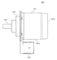
図8は、従来のモータを示す側面図である。
図8に示すように、モータ100は、モータケース101と、前蓋を兼ねるフランジ部材102と、コネクタ部103と、回転軸104と、を備えている。モータケース101は、側壁部101aと、底部101bとを一体に有する有底円筒形に形成されている。
FIG. 8 is a side view showing a conventional motor.
As shown in FIG. 8, the motor 100 includes a motor case 101, a flange member 102 that also serves as a front lid, a connector portion 103, and a rotating shaft 104. The motor case 101 is formed in a bottomed cylindrical shape that integrally has a side wall portion 101a and a bottom portion 101b.

上記構成のモータ100は、フランジ部材102を介して動力伝達機構(図示せず)に取り付けられる。モータ取付相手となる動力伝達機構にはモータ被取付部(図示せず)が設けられ、このモータ被取付部にフランジ部材102を突き当てた状態で、モータ100がボルト等によりモータ被取付部に固定される。このような構成のモータは、たとえば、特許文献1に記載されている。   The motor 100 having the above configuration is attached to a power transmission mechanism (not shown) via the flange member 102. A power receiving mechanism (not shown) is provided in the power transmission mechanism to which the motor is attached. When the flange member 102 is abutted against the motor receiving portion, the motor 100 is attached to the motor receiving portion with a bolt or the like. Fixed. A motor having such a configuration is described in Patent Document 1, for example.

特開2015−6070号公報JP, 2005-6070, A

ところで、モータ取付相手となるモータ被取付部にフランジ部材102を介してモータ100を取り付ける場合は、フランジ部材102の形状をモータ被取付部の形状に合わせる必要がある。   By the way, when the motor 100 is attached to the motor-attached portion that is a motor attachment partner through the flange member 102, the shape of the flange member 102 needs to be matched with the shape of the motor-attached portion.

しかしながら、従来のモータ100においては、たとえば、モータケース101とフランジ部材102との境界部からコネクタ部103を引き出すために、コネクタ部103の引き出し位置や引き出し構造などを考慮して、フランジ部材102の形状を決める必要がある。このため、モータ被取付部の形状に合わせてフランジ部材102の形状を自由に設定することができないという欠点がある。   However, in the conventional motor 100, for example, in order to pull out the connector portion 103 from the boundary portion between the motor case 101 and the flange member 102, the flange member 102 is taken into consideration in consideration of the pull-out position and the pull-out structure of the connector portion 103. It is necessary to decide the shape. Therefore, there is a drawback in that the shape of the flange member 102 cannot be freely set according to the shape of the motor mounting portion.

本発明は、上記課題を解決するためになされたもので、その目的は、モータ取付相手となるモータ被取付部の形状に合わせてフランジ部材の形状を自由に設定することができるモータを提供することにある。   The present invention has been made to solve the above problems, and an object thereof is to provide a motor in which the shape of a flange member can be freely set in accordance with the shape of a motor mounting portion that is a motor mounting partner. Especially.

本発明に係るモータは、側壁部および底部を一体に有する有底円筒形に形成され、前記底部と反対側に開口部を有するモータケースと、前記モータケースの底部の外面に取り付けられるとともに、複数のモータ取付用孔を有するフランジ部材と、を備える。   A motor according to the present invention is formed in a bottomed cylindrical shape integrally having a side wall portion and a bottom portion, has a motor case having an opening on the side opposite to the bottom portion, and is attached to an outer surface of the bottom portion of the motor case. And a flange member having a motor mounting hole.

本発明に係るモータは、前記モータケースの中心軸上に配置される回転軸と、前記モータケースの内部に配置されるモータ用ロータ部およびモータ用ステータ部と、前記モータ用ロータ部およびモータ用ステータ部よりも前記開口部側に位置して前記モータケースの内部に配置されるコネクタユニットと、前記回転軸の一端側に配置され、前記回転軸の回転角度を検知する角度センサと、をさらに備える。   A motor according to the present invention includes a rotating shaft arranged on a central axis of the motor case, a motor rotor part and a motor stator part arranged inside the motor case, a motor rotor part and a motor part. A connector unit disposed inside the motor case and located closer to the opening than the stator, and an angle sensor disposed on one end side of the rotation shaft and detecting a rotation angle of the rotation shaft. Prepare

本発明に係るモータにおいては、前記フランジ部材がアルミニウムによって構成されていてもよい。   In the motor according to the present invention, the flange member may be made of aluminum.

本発明によれば、モータケースの底部にフランジ部材を取り付けた構成を採用しているため、モータ取付相手となるモータ被取付部の形状に合わせてフランジ部材の形状を自由に設定することができる。   According to the present invention, since the configuration in which the flange member is attached to the bottom portion of the motor case is adopted, the shape of the flange member can be freely set in accordance with the shape of the motor-attached portion to which the motor is attached. .

本実施の形態に係るモータの断面図である。It is sectional drawing of the motor which concerns on this Embodiment. 図1に示すモータを背面側から見た斜視図である。It is the perspective view which looked at the motor shown in Drawing 1 from the back side. 図1に示すモータが備えるモータケースの正面図である。It is a front view of a motor case with which the motor shown in FIG. 1 is equipped. 図1に示すモータが備えるモータケースの断面図である。It is sectional drawing of the motor case with which the motor shown in FIG. 1 is equipped. 図1に示すモータが備えるフランジ部材を正面側から見たときの斜視図である。It is a perspective view when the flange member with which the motor shown in FIG. 1 is equipped is seen from the front side. 図1に示すモータが備えるフランジ部材を背面側から見たときの斜視図である。It is a perspective view when the flange member with which the motor shown in FIG. 1 is equipped is seen from the back side. モータケースにフランジ部材をかしめ固定した例を示す断面図である。It is sectional drawing which shows the example which crimped and fixed the flange member to the motor case. 従来のモータを示す側面図である。It is a side view which shows the conventional motor.

実施の形態1.
以下、本発明の実施の形態1について図面を参照して詳細に説明する。
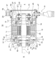
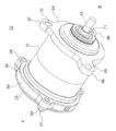
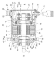
図1は、本実施の形態1に係るモータの断面図であり、図2は、図1に示すモータを背面側から見た斜視図である。なお、図1および図2においては、モータ中心軸方向の一方を正面側F、同他方を背面側Rとしている。
Embodiment 1.
Hereinafter, Embodiment 1 of the present invention will be described in detail with reference to the drawings.
FIG. 1 is a cross-sectional view of the motor according to the first embodiment, and FIG. 2 is a perspective view of the motor shown in FIG. 1 viewed from the back side. 1 and 2, one side in the motor central axis direction is the front side F and the other side is the rear side R.

<モータの構成>
図1および図2に示すように、モータ10は、モータケース11と、モータロータ12と、モータステータ13と、丸シャフトからなる回転軸14と、一対のベアリング15,16と、ベアリング15を保持するベアリングホルダ17と、バスバーユニット18と、モータ用ハーネス19と、レゾルバ20と、センサホルダ21と、キャップ部材23と、フランジ部材24と、を備えている。本実施の形態1においては、一例として、モータ10が3相のブラシレスモータによって構成されている。
<Motor configuration>
As shown in FIGS. 1 and 2, the motor 10 holds a motor case 11, a motor rotor 12, a motor stator 13, a rotating shaft 14 formed of a round shaft, a pair of bearings 15 and 16, and a bearing 15. The bearing holder 17, the bus bar unit 18, the motor harness 19, the resolver 20, the sensor holder 21, the cap member 23, and the flange member 24 are provided. In the first embodiment, as an example, the motor 10 is configured by a three-phase brushless motor.

モータロータ12は、回転軸14に同軸上に固定されている。モータロータ12は、回転軸14と一体に回転するものである。一方、モータステータ13は、全体的に輪状に形成されるとともに、回転軸14およびモータロータ12と同軸上に配置されている。   The motor rotor 12 is coaxially fixed to the rotating shaft 14. The motor rotor 12 rotates integrally with the rotating shaft 14. On the other hand, the motor stator 13 is formed in a ring shape as a whole, and is arranged coaxially with the rotating shaft 14 and the motor rotor 12.

回転軸14は、モータケース11の中心軸上に配置されている。回転軸14には、モータロータ12の両側に位置して一対のベアリング15,16が取り付けられている。一対のベアリング15,16は、モータ10の内部で回転軸14を回転自在に支持するものである。   The rotating shaft 14 is arranged on the central axis of the motor case 11. A pair of bearings 15 and 16 are attached to the rotary shaft 14 on both sides of the motor rotor 12. The pair of bearings 15 and 16 rotatably support the rotary shaft 14 inside the motor 10.

バスバーユニット18は、電気配線のためのコネクタユニットに相当するものであって、より具体的には、モータステータ13に巻線されているコイルにモータ駆動用の電力を供給するためのコネクタユニットに相当する。バスバーユニット18は、モータロータ12およびモータステータ13よりも開口部27側に位置してモータケース11の内部に配置されている。   The bus bar unit 18 corresponds to a connector unit for electrical wiring, and more specifically, a connector unit for supplying electric power for driving a motor to a coil wound around the motor stator 13. Equivalent to. The busbar unit 18 is located inside the motor case 11 and is located closer to the opening 27 than the motor rotor 12 and the motor stator 13.

モータ用ハーネス19は、リード線47を有している。リード線47は、バスバー端子45の端部に接続されている。レゾルバ20は、回転軸14の回転角度を検知する角度センサである。レゾルバ20は、レゾルバロータ51と、レゾルバステータ52と、を備えている。   The motor harness 19 has a lead wire 47. The lead wire 47 is connected to the end of the bus bar terminal 45. The resolver 20 is an angle sensor that detects the rotation angle of the rotary shaft 14. The resolver 20 includes a resolver rotor 51 and a resolver stator 52.

キャップ部材23は、モータケース11の一端部にハウジング50を介して取り付けられている。キャップ部材23は、モータケース11の開口部27を外部から覆い隠すようにモータ10の正面側Fに配置されている。回転軸14の正面側Fの端部は、キャップ部材23よりもモータ10の正面側Fに突出することなく、モータ10の内部に配置されている。キャップ部材23とハウジング50は、スタッドボルト57とナット58を用いてモータケース11に固定されている。スタッドボルト57の基端部は、モータケース11の貫通孔29(図3参照)に圧入構造で固定されている。また、ハウジング50には、上述したモータ用ハーネス19のリード線47をハウジング50の外側に引き出すための孔(図示せず)が設けられている。   The cap member 23 is attached to one end of the motor case 11 via the housing 50. The cap member 23 is arranged on the front side F of the motor 10 so as to cover the opening 27 of the motor case 11 from the outside. The end portion of the rotary shaft 14 on the front side F is arranged inside the motor 10 without projecting to the front side F of the motor 10 beyond the cap member 23. The cap member 23 and the housing 50 are fixed to the motor case 11 using stud bolts 57 and nuts 58. The base end of the stud bolt 57 is fixed to the through hole 29 (see FIG. 3) of the motor case 11 with a press-fit structure. Further, the housing 50 is provided with a hole (not shown) for drawing out the lead wire 47 of the motor harness 19 described above to the outside of the housing 50.

(モータケース)
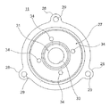
図3は、図1に示すモータが備えるモータケースの正面図であり、図4は、該モータケースの断面図である。
図3および図4に示すように、モータケース11は、円筒形の側壁部25と、側壁部25の一端部で径方向の内側に曲げられた底部26と、を一体に有する有底円筒形に形成されている。モータケース11は、プレス加工によって得られる金属製の一体成形品であり、より詳しくは、深絞り加工によって得られる深絞り加工品である。モータケース11は、底部26と反対側に開口部27を有している。開口部27は、モータ中心軸方向の一方(図4の右方向)を向いて開口している。
(Motor case)
FIG. 3 is a front view of a motor case included in the motor shown in FIG. 1, and FIG. 4 is a sectional view of the motor case.
As shown in FIGS. 3 and 4, the motor case 11 has a bottomed cylindrical shape integrally including a cylindrical side wall portion 25 and a bottom portion 26 that is bent inward in the radial direction at one end portion of the side wall portion 25. Is formed in. The motor case 11 is a metal integrally molded product obtained by press working, and more specifically, a deep drawing processed product obtained by deep drawing. The motor case 11 has an opening 27 on the side opposite to the bottom 26. The opening 27 is open toward one of the motor central axis directions (rightward in FIG. 4).

モータケース11の開口部27の縁には複数の第1鍔部28が形成されている。各々の第1鍔部28には貫通孔29が形成されている。一方、モータケース11の底部26には、ベアリング取付部31が形成されている。ベアリング取付部31は、ベアリング16が取り付けられる部分であって、略U字形に形成されている。また、モータケース11の底部26には、ベアリング取付部31を区画形成するように突出部32が形成されている。突出部32は、モータケース11の中心軸方向の外側に突出している。突出部32は、モータケース11の中心軸方向から見て円形に形成されている。また、突出部32は、モータケース11の中心軸を中心に、ベアリング取付部31と同心円状に形成されている。   A plurality of first flanges 28 are formed on the edge of the opening 27 of the motor case 11. A through hole 29 is formed in each of the first flange portions 28. On the other hand, a bearing mounting portion 31 is formed on the bottom portion 26 of the motor case 11. The bearing mounting portion 31 is a portion to which the bearing 16 is mounted, and is formed in a substantially U shape. Further, a protrusion 32 is formed on the bottom portion 26 of the motor case 11 so as to partition the bearing mounting portion 31. The projecting portion 32 projects outward in the central axis direction of the motor case 11. The protrusion 32 is formed in a circular shape when viewed from the central axis direction of the motor case 11. Further, the protruding portion 32 is formed concentrically with the bearing mounting portion 31 around the center axis of the motor case 11.

突出部32の中心には逃げ孔33が形成されている。逃げ孔33は、モータケース11と回転軸14との位置的な干渉を避けるための孔である。また、モータケース11の底部26において、ベアリング取付部31および突出部32の外側には複数の通し孔34が設けられている。本実施の形態1においては、一例として、モータケース11の底部26に4つの通し孔34が設けられている。4つの通し孔34は、モータケース11にフランジ部材24を取り付けるために形成された孔であって、モータケース11の円周方向に90°の角度間隔で配置されている。   An escape hole 33 is formed at the center of the protrusion 32. The escape hole 33 is a hole for avoiding positional interference between the motor case 11 and the rotary shaft 14. Further, in the bottom portion 26 of the motor case 11, a plurality of through holes 34 are provided outside the bearing mounting portion 31 and the protruding portion 32. In the first embodiment, as an example, four through holes 34 are provided in bottom portion 26 of motor case 11. The four through holes 34 are holes formed for attaching the flange member 24 to the motor case 11, and are arranged at angular intervals of 90 ° in the circumferential direction of the motor case 11.

(フランジ部材)
フランジ部材24は、キャップ部材23とは反対側となるモータ10の背面側Rに配置されている。フランジ部材24は、モータケース11の底部26に取り付けられている。モータケース11の底部26は、図4に示すように、正面側Fを向いて配置される内面26aと、背面側Rを向いて配置される外面26bとを有し、フランジ部材24は、底部26の外面26bに取り付けられている。フランジ部材24は、アルミニウムによって構成されている。回転軸14の端部14aは、フランジ部材24よりも外側(背面側R)に突出して配置されている。フランジ部材24は、モータ10全体を相手先の機械要素に連結するための部材となる。モータ10を取り付ける相手先の機械要素としては種々のものが考えられる。本実施の形態1においては、相手先の機械要素の一例として、歯車伝達機構などの動力伝達機構を想定する。フランジ部材24の構成(形状、寸法など)は、モータ10を取り付ける相手先の機械要素によって変わる。よって、以下に述べるフランジ部材24の構成は、あくまで一例にすぎない。
(Flange member)
The flange member 24 is arranged on the rear side R of the motor 10 on the side opposite to the cap member 23. The flange member 24 is attached to the bottom portion 26 of the motor case 11. As shown in FIG. 4, the bottom portion 26 of the motor case 11 has an inner surface 26a that faces the front side F and an outer surface 26b that faces the back side R, and the flange member 24 has a bottom portion. It is attached to the outer surface 26 b of 26. The flange member 24 is made of aluminum. The end portion 14 a of the rotating shaft 14 is arranged so as to project outward (back side R) from the flange member 24. The flange member 24 serves as a member for connecting the entire motor 10 to the mechanical element of the other party. Various types of machine elements to which the motor 10 is attached are conceivable. In the first embodiment, a power transmission mechanism such as a gear transmission mechanism is assumed as an example of a partner mechanical element. The configuration (shape, size, etc.) of the flange member 24 changes depending on the machine element to which the motor 10 is attached. Therefore, the configuration of the flange member 24 described below is merely an example.

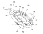
図5は、図1に示すモータが備えるフランジ部材を正面側から見たときの斜視図であり、図6は、該フランジ部材を背面側から見たときの斜視図である。
図5および図6に示すように、フランジ部材24の外周部には複数の鍔部66,67,68が設けられている。本実施の形態1においては、一例として、フランジ部材24に3つの鍔部66,67,68が設けられている。3つの鍔部66,67,68のうち、1つの鍔部66は、他の2つの鍔部67,68よりも径方向の外側に突出している。
FIG. 5 is a perspective view of the flange member included in the motor shown in FIG. 1 as viewed from the front side, and FIG. 6 is a perspective view of the flange member as viewed from the back side.
As shown in FIG. 5 and FIG. 6, a plurality of flange portions 66, 67, 68 are provided on the outer peripheral portion of the flange member 24. In the first embodiment, as an example, the flange member 24 is provided with three flange portions 66, 67, 68. Of the three flange portions 66, 67, 68, one flange portion 66 projects outward in the radial direction from the other two flange portions 67, 68.

鍔部66にはモータ取付用孔69が設けられている。また、鍔部67にはモータ取付用孔70が設けられ、鍔部68にはモータ取付用孔71が設けられている。モータ取付用孔69は、ネジ山が形成されていない貫通孔となっている。モータ取付用孔70および71は、いずれもネジ孔となっている。フランジ部材24を有するモータ10を図示しない動力伝達機構に取り付ける場合は、図示はしないが、3つのボルトを用いてモータ10を動力伝達機構に固定する。動力伝達機構には、モータ10が取り付けられるモータ被取付部(図示せず)が設けられる。また、動力伝達機構のモータ被取付部には、鍔部66のモータ取付用孔69に対応する位置にネジ孔が設けられ、鍔部67のモータ取付用孔70および鍔部68のモータ取付用孔71に対応する位置に、それぞれボルトを通すための貫通孔が設けられる。   The flange portion 66 is provided with a motor mounting hole 69. Further, the collar portion 67 is provided with a motor mounting hole 70, and the collar portion 68 is provided with a motor mounting hole 71. The motor mounting hole 69 is a through hole in which a screw thread is not formed. The motor mounting holes 70 and 71 are both screw holes. When the motor 10 having the flange member 24 is attached to a power transmission mechanism (not shown), although not shown, the motor 10 is fixed to the power transmission mechanism using three bolts. The power transmission mechanism is provided with a motor attachment portion (not shown) to which the motor 10 is attached. Further, a screw hole is provided at a position of the power transmission mechanism to which the motor is attached, at a position corresponding to the motor mounting hole 69 of the collar portion 66. Through holes for passing bolts are provided at positions corresponding to the holes 71.

ここで、モータケース11の底部26と対向するフランジ部材24の一面を第1面91とし、その反対側となるフランジ部材24の他面を第2面92とすると、フランジ部材24の第1面91には凹部75が形成されている。凹部75は、モータケース11にフランジ部材24を取り付ける場合に、モータケース11の突出部32(図4参照)を収容可能に形成されている。具体的には、凹部75の内径は、モータケース11の突出部32の外径よりも僅かに大きく設定されている。また、凹部75の深さ寸法は、突出部32の突出寸法よりも大きく設定されている。凹部75の底部には逃げ孔76が形成されている。逃げ孔76は、フランジ部材24を貫通するように、フランジ部材24の中心部に設けられている。逃げ孔76は、フランジ部材24と回転軸14との位置的な干渉を避けるための孔である。   Here, assuming that one surface of the flange member 24 facing the bottom portion 26 of the motor case 11 is a first surface 91 and the other surface of the flange member 24 on the opposite side is a second surface 92, the first surface of the flange member 24. A recess 75 is formed in 91. The recess 75 is formed so as to be able to accommodate the protrusion 32 (see FIG. 4) of the motor case 11 when the flange member 24 is attached to the motor case 11. Specifically, the inner diameter of the recess 75 is set to be slightly larger than the outer diameter of the protrusion 32 of the motor case 11. Further, the depth dimension of the recess 75 is set larger than the protrusion dimension of the protrusion 32. An escape hole 76 is formed at the bottom of the recess 75. The escape hole 76 is provided in the central portion of the flange member 24 so as to penetrate the flange member 24. The escape hole 76 is a hole for avoiding positional interference between the flange member 24 and the rotary shaft 14.

また、フランジ部材24の第1面91には、複数のネジ孔77と、第1周溝78と、嵌合部79とが形成されている。複数のネジ孔77は、モータケース11にフランジ部材24を取り付けるために形成された孔である。各々のネジ孔77は、凹部75よりもフランジ部材24の径方向の外側に配置されている。本実施の形態1においては、モータケース11のフランジ部材24に設けられた4つの通し孔34と1対1の関係で対応するように、4つのネジ孔77が円周方向に90°の角度間隔で設けられている。   A plurality of screw holes 77, a first circumferential groove 78, and a fitting portion 79 are formed on the first surface 91 of the flange member 24. The plurality of screw holes 77 are holes formed for attaching the flange member 24 to the motor case 11. Each of the screw holes 77 is arranged outside the recess 75 in the radial direction of the flange member 24. In the first embodiment, the four screw holes 77 have an angle of 90 ° in the circumferential direction so as to correspond to the four through holes 34 provided in the flange member 24 of the motor case 11 in a one-to-one relationship. It is provided at intervals.

第1周溝78は、凹部75および複数のネジ孔77の周囲を囲むように円環状に形成されている。第1周溝78には、図1に示すように、リング状のゴム状弾性体からなるシール部材80が取り付けられる。シール部材80は、モータ中心軸方向において、モータケース11とフランジ部材24との間に挟み込まれている。シール部材80は、モータ10の背面側Rにおいて、モータ10の内部への水分等の浸入を抑制するものである。   The first circumferential groove 78 is formed in an annular shape so as to surround the recess 75 and the plurality of screw holes 77. As shown in FIG. 1, a seal member 80 made of a ring-shaped rubber-like elastic body is attached to the first circumferential groove 78. The seal member 80 is sandwiched between the motor case 11 and the flange member 24 in the motor central axis direction. The seal member 80 suppresses the infiltration of water and the like into the inside of the motor 10 on the rear side R of the motor 10.

嵌合部79は、モータケース11にフランジ部材24を取り付けるときに、モータケース11の背面側Rの端部に嵌合される部分となる。嵌合部79は、第1周溝78の周囲を囲むように円環状に形成されている。また、嵌合部79は、フランジ部材24の中心軸を中心に、逃げ孔76および第1周溝78と同心円状に形成されている。   The fitting portion 79 is a portion that is fitted to the end portion on the rear surface side R of the motor case 11 when the flange member 24 is attached to the motor case 11. The fitting portion 79 is formed in an annular shape so as to surround the first circumferential groove 78. Further, the fitting portion 79 is formed concentrically with the escape hole 76 and the first circumferential groove 78 around the central axis of the flange member 24.

一方、フランジ部材24の第2面92には、筒状部81が形成されている。筒状部81の外周面には、第2周溝82が形成されている。第2周溝82には、図1に示すように、リング状のゴム状弾性体からなるシール部材83が取り付けられる。シール部材83は、モータ10の径方向において、フランジ部材24と図示しないモータ被取付部との間に挟み込まれることにより、モータ10の背面側Rで水分等の浸入を抑制するものである。筒状部81の内側には、図1に示すように、オイルシール部材84が取り付けられる。オイルシール部材84は、モータ10の背面側Rにおいて、モータ10の内部へのオイルの浸入を抑制するものである。オイルシール部材84の外周部は、筒状部81の内周面に圧接している。また、オイルシール部材84の内周部は、回転軸14の全周にわたって回転軸14の外周面に圧接している。   On the other hand, a tubular portion 81 is formed on the second surface 92 of the flange member 24. A second peripheral groove 82 is formed on the outer peripheral surface of the tubular portion 81. As shown in FIG. 1, a seal member 83 made of a ring-shaped rubber-like elastic body is attached to the second circumferential groove 82. The seal member 83 is sandwiched between the flange member 24 and a motor mounting portion (not shown) in the radial direction of the motor 10 so as to suppress the infiltration of moisture or the like on the rear side R of the motor 10. Inside the tubular portion 81, an oil seal member 84 is attached as shown in FIG. The oil seal member 84 prevents oil from entering the inside of the motor 10 on the rear surface side R of the motor 10. The outer peripheral portion of the oil seal member 84 is in pressure contact with the inner peripheral surface of the tubular portion 81. The inner peripheral portion of the oil seal member 84 is in pressure contact with the outer peripheral surface of the rotary shaft 14 over the entire circumference of the rotary shaft 14.

上記構成からなるフランジ部材24をモータケース11に取り付ける場合は、まず、モータケース11の底部26の外面26bにフランジ部材24の第1面91を対向させて押し付けることにより、モータケース11の突出部32をフランジ部材24の凹部75に収容する。このとき、モータケース11に設けられた4つの通し孔34(図3参照)とフランジ部材24に設けられた4つのネジ孔77(図5参照)を位置合わせする。次に、図1に示すように、モータケース11の通し孔34にネジ85を挿入し、そのネジ85をフランジ部材24のネジ孔77にねじ込んで締め付ける。ネジ85は、通し孔34およびネジ孔77と同じ個数、すなわち4つ使用し、これら4つのネジ85を適度に締め付ける。これにより、モータケース11にフランジ部材24を固定することができる。   When the flange member 24 having the above-described configuration is attached to the motor case 11, first, the first surface 91 of the flange member 24 is pressed against the outer surface 26b of the bottom portion 26 of the motor case 11 so that the protruding portion of the motor case 11 is pressed. 32 is housed in the recess 75 of the flange member 24. At this time, the four through holes 34 (see FIG. 3) provided in the motor case 11 and the four screw holes 77 (see FIG. 5) provided in the flange member 24 are aligned. Next, as shown in FIG. 1, a screw 85 is inserted into the through hole 34 of the motor case 11, and the screw 85 is screwed into the screw hole 77 of the flange member 24 and tightened. The same number of screws 85 as the through holes 34 and the screw holes 77, that is, four screws 85 are used, and these four screws 85 are appropriately tightened. Thereby, the flange member 24 can be fixed to the motor case 11.

また、図示しない動力伝達機構のモータ被取付部にモータ10を取り付ける場合は、鍔部68のモータ取付用孔69にボルトを通し、このボルトをモータ被取付部のネジ孔にねじ込んで締め付ける。また、鍔部68に対応してモータ被取付部に設けられた貫通孔にボルトを通し、このボルトをモータ取付用孔70にねじ込んで締め付ける。また、モータ取付用孔69に対応してモータ被取付部に設けられた貫通孔にボルトを通し、このボルトをモータ取付用孔71にねじ込んで締め付ける。これにより、動力伝達機構のモータ被取付部にモータ10を固定することができる。   When the motor 10 is attached to the motor-attached portion of the power transmission mechanism (not shown), a bolt is passed through the motor-attaching hole 69 of the collar portion 68, and the bolt is screwed into the screw hole of the motor-attached portion and tightened. Further, a bolt is passed through a through hole provided in the motor mounting portion corresponding to the flange portion 68, and the bolt is screwed into the motor mounting hole 70 and tightened. Further, a bolt is passed through a through hole provided in the motor mounting portion corresponding to the motor mounting hole 69, and the bolt is screwed into the motor mounting hole 71 and tightened. As a result, the motor 10 can be fixed to the motor mounting portion of the power transmission mechanism.

<実施の形態1の効果>
本実施の形態1においては、モータケース11の底部26の外面26bにフランジ部材24を取り付けた構成を採用している。これにより、モータケース11の開口部27側からモータ用ハーネス19などを引き出す場合に、その引き出し位置や引き出し構造などを考慮してフランジ部材24の形状を決める必要がなくなる。このため、図示しないモータ被取付部の形状に合わせてフランジ部材24の形状を自由に設定することができる。また、モータ被取付部の形状に変更が生じた場合にも、変更後のモータ被取付部の形状に合わせてフランジ部材24の形状を自由に変更することができる。その結果、モータ被取付部の様々な形状に柔軟に対応することができるモータ10を提供することが可能となる。
<Effect of Embodiment 1>
The first embodiment adopts a configuration in which the flange member 24 is attached to the outer surface 26b of the bottom portion 26 of the motor case 11. Accordingly, when the motor harness 19 and the like are pulled out from the opening 27 side of the motor case 11, it is not necessary to determine the shape of the flange member 24 in consideration of the pulling position, the pulling structure, and the like. Therefore, the shape of the flange member 24 can be freely set according to the shape of the motor-attached portion (not shown). Further, even if the shape of the motor mounted portion is changed, the shape of the flange member 24 can be freely changed according to the changed shape of the motor mounted portion. As a result, it becomes possible to provide the motor 10 capable of flexibly coping with various shapes of the motor attachment portion.

また、本実施の形態1においては、モータケース11の底部26にフランジ部材24をネジ止め固定しているため、モータケース11に取り付けるフランジ部材24を、必要に応じて交換することができる。また、モータケース11に取り付けるフランジ部材24を上記相手先の機械要素にあわせて、自由に選定することができる。   Further, in the first embodiment, since the flange member 24 is screwed and fixed to the bottom portion 26 of the motor case 11, the flange member 24 attached to the motor case 11 can be replaced as needed. Further, the flange member 24 attached to the motor case 11 can be freely selected according to the mechanical element of the other party.

また、従来のモータ100(図8参照)においては、モータケース101の内部にバスバーユニット(図示せず)を配置したり、モータ100内で回転軸104に角度センサ(図示せず)を配置したりすると、フランジ部材102の取付位置が、モータ用ロータ部やモータ用ステータ部から離れてしまう。このため、図示しないモータ被取付部にフランジ部材102を介してモータ100を取り付けた場合に、モータ用ロータ部やモータ用ステータ部の重量によってモータ被取付部に加わる負荷が大きくなる。よって、モータ100の動作が不安定になるおそれがある。
これに対して、本実施の形態1においては、モータケース11の内部にバスバーユニット18を配置し、かつ、回転軸14の一端側にレゾルバ20を配置した構成であるにもかかわらず、モータロータ12やモータステータ13の近くにフランジ部材24を配置することができる。このため、図示しないモータ被取付部にフランジ部材24を介してモータ10を取り付けた場合に、モータロータ12やモータステータ13の重量によってモータ被取付部に加わる負荷が小さくなる。よって、モータ10を安定して動作させることが可能となる。
Further, in the conventional motor 100 (see FIG. 8), a bus bar unit (not shown) is arranged inside the motor case 101, or an angle sensor (not shown) is arranged on the rotary shaft 104 in the motor 100. If so, the mounting position of the flange member 102 will be separated from the motor rotor portion and the motor stator portion. Therefore, when the motor 100 is attached to the motor attached portion (not shown) through the flange member 102, the load applied to the motor attached portion increases due to the weight of the motor rotor portion and the motor stator portion. Therefore, the operation of the motor 100 may become unstable.
On the other hand, in the first embodiment, although the bus bar unit 18 is arranged inside the motor case 11 and the resolver 20 is arranged at one end side of the rotating shaft 14, the motor rotor 12 is arranged. The flange member 24 can be arranged near the motor stator 13. For this reason, when the motor 10 is attached to the motor attached portion (not shown) via the flange member 24, the load applied to the motor attached portion due to the weight of the motor rotor 12 and the motor stator 13 is reduced. Therefore, the motor 10 can be stably operated.

また、本実施の形態1においては、フランジ部材24をアルミニウムによって構成している。これにより、フランジ部材24の製造方法にはダイカストなどの金型鋳造、あるいは鍛造などを適用することができる。また、フランジ部材24は、放熱性に優れるとともに、軽量でかつ低コスト化を図るうえでも有利になる。   Further, in the first embodiment, the flange member 24 is made of aluminum. Accordingly, die casting such as die casting or forging can be applied to the method of manufacturing the flange member 24. Further, the flange member 24 is excellent in heat dissipation, and is also advantageous in achieving light weight and cost reduction.

<変形例等>
本発明の技術的範囲は上述した実施の形態に限定されるものではなく、発明の構成要件やその組み合わせによって得られる特定の効果を導き出せる範囲において、種々の変更や改良を加えた形態も含む。
<Modifications, etc.>
The technical scope of the present invention is not limited to the above-described embodiments, and includes various modifications and improvements as long as a specific effect obtained by the constituent features of the invention or a combination thereof can be derived.

たとえば、上記実施の形態1においては、モータケース11の底部26にフランジ部材24をネジ止め固定した構成を例に挙げて説明したが、本発明はこれに限らず、たとえば図7に示すように、フランジ部材24にかしめ加工によってかしめ部95を形成し、このかしめ部95によってモータケース11の底部26にフランジ部材24をかしめ固定した構成を採用してもよい。フランジ部材24をかしめ固定した構成では、ネジなどが不要となるため、部品点数を削減することができる。   For example, in the above-described first embodiment, the configuration in which the flange member 24 is screwed and fixed to the bottom portion 26 of the motor case 11 has been described as an example, but the present invention is not limited to this, and as illustrated in FIG. 7, for example. It is also possible to adopt a configuration in which the flange member 24 is formed with a caulking portion 95 by caulking, and the flange member 24 is caulked and fixed to the bottom portion 26 of the motor case 11 by the caulking portion 95. In the configuration in which the flange member 24 is caulked and fixed, screws and the like are not required, so that the number of parts can be reduced.

10 モータ
11 モータケース
24 フランジ部材
25 側壁部
26 底部
26b 外面
27 開口部
DESCRIPTION OF SYMBOLS 10 motor 11 motor case 24 flange member 25 side wall part 26 bottom part 26b outer surface 27 opening part

Claims (4)

側壁部および底部を一体に有する有底円筒形に形成され、前記底部と反対側に開口部を有するモータケースと、
前記モータケースの底部の外面に取り付けられるとともに、複数のモータ取付用孔を有するフランジ部材と、
を備えるモータ。
A motor case that is formed in a bottomed cylindrical shape that integrally has a side wall portion and a bottom portion and that has an opening on the side opposite to the bottom portion;
A flange member that is attached to the outer surface of the bottom of the motor case and that has a plurality of motor attachment holes,
A motor.
前記フランジ部材がアルミニウムによって構成されている
請求項1に記載のモータ。
The motor according to claim 1, wherein the flange member is made of aluminum.
前記フランジ部材は、前記モータケースの底部にネジ止め固定されている
請求項1または2に記載のモータ。
The motor according to claim 1 or 2, wherein the flange member is fixed to the bottom of the motor case with a screw.
前記フランジ部材は、前記モータケースの底部にかしめ固定されている
請求項または2に記載のモータ。
The motor according to claim 2, wherein the flange member is caulked and fixed to a bottom portion of the motor case.
JP2018195701A 2018-10-17 2018-10-17 motor Pending JP2020065357A (en)

Priority Applications (1)

Application Number Priority Date Filing Date Title
JP2018195701A JP2020065357A (en) 2018-10-17 2018-10-17 motor

Applications Claiming Priority (1)

Application Number Priority Date Filing Date Title
JP2018195701A JP2020065357A (en) 2018-10-17 2018-10-17 motor

Publications (2)

Publication Number Publication Date
JP2020065357A true JP2020065357A (en) 2020-04-23
JP2020065357A5 JP2020065357A5 (en) 2021-09-30

Family

ID=70387672

Family Applications (1)

Application Number Title Priority Date Filing Date
JP2018195701A Pending JP2020065357A (en) 2018-10-17 2018-10-17 motor

Country Status (1)

Country Link
JP (1) JP2020065357A (en)

Citations (1)

* Cited by examiner, † Cited by third party
Publication number Priority date Publication date Assignee Title
JPS57159353U (en) * 1981-03-27 1982-10-06

Patent Citations (1)

* Cited by examiner, † Cited by third party
Publication number Priority date Publication date Assignee Title
JPS57159353U (en) * 1981-03-27 1982-10-06

Similar Documents

Publication Publication Date Title
US8400031B2 (en) Electrical connection for an electric motor
JP2005229721A (en) Motor for electric power steering device
TWI687028B (en) Motor structure
US11522407B2 (en) Electronic apparatus
US11565740B2 (en) Steering device
WO2019202916A1 (en) Rotor, motor, and brushless wiper motor
JP7139644B2 (en) electric wheel
JP2017208872A (en) Rotary electric machine
WO2018051989A1 (en) Motor
JP2020065357A (en) motor
JP4564982B2 (en) Rotating electric machine
JP2016077069A (en) On-vehicle rotary electric machine
JP5824019B2 (en) Rotating electric machine
JP2008228367A (en) Brushless motor
JP2018159335A5 (en)
KR20200042813A (en) Hollow Shaft Motor
JP2005117736A (en) Rotary electric machine
JP7275433B2 (en) Motorized gear system and automotive brake system
JP2010142053A (en) Brushless motor
JP2008148451A (en) Electric motor and method of assembling same
JP2017223319A (en) Seal member and motor
CN105932811B (en) motor structure assembly
CN211930385U (en) Motor and electric product
CN220857801U (en) Outer rotor motor
WO2018051773A1 (en) Motor

Legal Events

Date Code Title Description
A521 Request for written amendment filed

Free format text: JAPANESE INTERMEDIATE CODE: A523

Effective date: 20210819

A621 Written request for application examination

Free format text: JAPANESE INTERMEDIATE CODE: A621

Effective date: 20210819

A977 Report on retrieval

Free format text: JAPANESE INTERMEDIATE CODE: A971007

Effective date: 20220616

A131 Notification of reasons for refusal

Free format text: JAPANESE INTERMEDIATE CODE: A131

Effective date: 20220621

A02 Decision of refusal

Free format text: JAPANESE INTERMEDIATE CODE: A02

Effective date: 20221213