JP2020058762A - Chair - Google Patents
Chair Download PDFInfo
- Publication number
- JP2020058762A JP2020058762A JP2018210905A JP2018210905A JP2020058762A JP 2020058762 A JP2020058762 A JP 2020058762A JP 2018210905 A JP2018210905 A JP 2018210905A JP 2018210905 A JP2018210905 A JP 2018210905A JP 2020058762 A JP2020058762 A JP 2020058762A
- Authority
- JP
- Japan
- Prior art keywords
- backrest
- back frame
- support
- seat
- view
- Prior art date
- Legal status (The legal status is an assumption and is not a legal conclusion. Google has not performed a legal analysis and makes no representation as to the accuracy of the status listed.)
- Granted
Links
Images


Abstract
Description
本願発明は、椅子に関するものである。 The present invention relates to a chair.
椅子は様々な形態があり、オフィスで多用されている回転椅子は、キャスタを備えた脚装置、座、背もたれを主要要素としており、オプション品として肘掛け装置やヘッドレスト、ハンガーなどが取付けられている。 There are various types of chairs, and swivel chairs that are frequently used in offices have a leg device with casters, a seat, and a backrest as main elements, and an armrest device, a headrest, a hanger, etc. are attached as optional items.
椅子において、背もたれの支持構造は様々であり、背もたれを、その後ろに配置されたバックフレームに取り付けることも広く行われている。例えば、特許文献1には、バックフレームを背面視で逆V形に形成して、このバックフレームに、前向きのアーム部材を介して背もたれが取付けられている。
BACKGROUND ART In a chair, there are various support structures for a backrest, and it is also common to attach the backrest to a back frame arranged behind it. For example, in
また、特許文献1では、バックフレームは、左右中間部に位置した上下長さの背支柱と、背支柱の下部に設けた水平フレームとで構成されており、背支柱の上端に背もたれの上端部の左右中間部が取付けられて、水平フレームの左右両端部に、背もたれの左右側部が取付けられている。
Further, in
背もたれが、前後に開口した背フレームにメッシュ材を張った構造になっている場合、バックフレームを前後に開口した枠状に構成して、このバックフレームに背フレームを連結することも広く行われている。 If the backrest has a structure in which a mesh material is stretched over the back frame that is open to the front and back, it is also common to configure the back frame into a frame shape that opens to the front and back and connect the back frame to this back frame. ing.
また、椅子に肘掛け装置を設ける場合、座部の下面に取付けたり、背もたれが取り付く傾動フレームに取り付けたり、背もたれに取り付けたりしており、特許文献1では、脚支柱の状態に固定されたベース部に肘掛け装置を取付けている。すなわち、特許文献において、肘掛け装置は肘支柱と肘当てとを備えており、肘支柱をベース部に立設して、肘支柱の状態に肘当てを設けている。 Further, when an armrest device is provided on a chair, the armrest device is attached to the lower surface of the seat portion, is attached to a tilting frame to which the backrest is attached, or is attached to the backrest. The armrest device is attached to. That is, in the patent document, the armrest device includes an elbow support and an elbow support, and the elbow support is erected on the base portion and the elbow support is provided in the state of the elbow support.
さて、椅子は人が使用するものであり、その外観は、商品価値を決める重要な要素である。従って、椅子においては、外観は機能と不離一体の関係にある。端的には、椅子において、外観は機能が結実したものである。そして、特許文献1,2とも、それぞれ独自の設計思想に基づいてバックフレームや背もたれの外観がデザインされている。
Now, the chair is used by people, and its appearance is an important factor that determines the commercial value. Therefore, the appearance of a chair is inseparable from its function. In short, in a chair, the appearance is a fruitful function. In each of
そこで、特許文献1を取り上げてみると、特許文献1は、バックフレームは背支柱とロアフレームとで十字状又は逆T字状に形成されており、シンプルな外観であるが、シンプル過ぎて重厚性に欠けると云える。
Therefore, taking
本願発明は、このような現状に鑑み成されたものであり、特許文献1のように、左右中間部に背支柱が配置されたバックフレームを有する椅子において、機能面とデザイン面との両面から品質を向上させることを課題としている。
The invention of the present application has been made in view of such a current situation, and in a chair having a back frame in which a back strut is arranged in the left and right intermediate portions, as in
また、肘掛け装置について見ると、特許文献1のように肘支柱を有する構成では、肘支柱が空間に占める割合が大きいため、デザイン的に見て、椅子全体として纏まりに欠ける面がある。また、肘当てを水平動させる場合、肘支柱方式では、水平回動や前後動などが可能であるに過ぎないため、可動範囲が必ずしも広くないという問題もある。本願発明は、肘掛け装置の取付け構造の改良も課題としている。
Further, regarding the armrest device, in the configuration having an elbow brace as in
本願発明は様々な構成を備えており、典型的な構成を各請求項で特定している。このうち請求項1の発明は、
「座と背もたれ、及び、前記背もたれの後ろに配置されたバックフレームを備えており、前記背もたれは前記バックフレームに取り付けられている」
という基本構成において、
「前記バックフレームは、左右中間部に位置した背支柱と、前記背支柱の下端から左右両側に張り出して先端が自由端になっているロアサポートとを備えていて、前記ロアサポートの先端部に前記背もたれの下端部が連結されており、
かつ、前記ロアサポートの上下両面が、背面視において左右外側に向けて上にずれるように湾曲した曲面に形成されており、更に、前記バックフレームの下端面は背面視で下向きに膨れた湾曲面になっている」
という構成が付加されている。
The present invention has various configurations, and typical configurations are specified in each claim. Of these, the invention of
"Has a seat and a backrest, and a back frame disposed behind the backrest, and the backrest is attached to the back frame."
In the basic configuration
"The back frame is provided with a back strut located in the middle portion on the left and right and a lower support protruding from the lower end of the back strut to both left and right sides, and the tip is a free end. The lower end of the backrest is connected,
Moreover, the upper and lower surfaces of the lower support are formed into curved surfaces that are curved so as to shift upward toward the left and right outside in rear view, and the lower end surface of the back frame is a curved surface that bulges downward in rear view. It has become"
Is added.
請求項2の発明は、請求項1において、
「前記背もたれは、左右のサイドメンバーとアッパメンバー及びロアメンバーを有する前後開口の背フレームと、前記背フレームに張られたメッシュ材とを有しており、
前記背フレームにおけるロアメンバーの上面は、背面視で下方に膨れる湾曲面になっている一方、
前記左右のロアアームの上面は、前記背フレームにおけるロアメンバーの上面の湾曲面と略同じ形態の湾曲面になっている」
という構成になっている。
According to a second aspect of the present invention, in the first aspect,
"The backrest includes a front and rear opening back frame having left and right side members, an upper member and a lower member, and a mesh material stretched over the back frame,
The upper surface of the lower member in the back frame is a curved surface that bulges downward in rear view,
The upper surfaces of the left and right lower arms have substantially the same curved surface as the curved surfaces of the upper surfaces of the lower members of the back frame. "
It is configured as.
請求項3の発明は、請求項1又は2において、
「前記左右のロアサポートは、前記座の後部を左右両側から包むように平面視において湾曲した状態で手前に延びていて、側面視においては手前に向けて高くなるように傾斜しており、
かつ、前記左右のロアサポートは、平面視において厚さが前端に向けて小さくなるように形成されている」
という構成になっている。
The invention of
`` The left and right lower supports extend to the front in a curved state in a plan view so as to wrap the rear part of the seat from both the left and right sides, and incline so as to be higher toward the front in a side view,
Moreover, the left and right lower supports are formed so that the thickness becomes smaller toward the front end in a plan view.
It is configured as.
請求項4の発明は、請求項1〜3のうちのいずれかにおいて、
「前記座の後部でかつ左右両側部に上向きの突起を設けて、前記座の背面視形状を、前記左右ロアサポートの上面の背面視形状と略同じ形状に湾曲した形状に形成している」
という構成になっている。
The invention of
“Upward protrusions are provided on the rear part of the seat and on both left and right sides, and the rear view shape of the seat is formed into a curved shape substantially the same as the rear view shape of the upper surface of the left and right lower supports.”
It is configured as.
請求項5の発明は、請求項1〜4のうちのいずれかにおいて、
「前記バックフレームの上端は、前記背支柱の上端から左右両側に張り出したアッパサポートによって構成されていて、前記背もたれの上端の左右端部が前記アッパサポートの両端部に連結されており、従って、前記背もたれは、前記アッパサポートとロアサポートとによって4点支持の状態で前記バックフレームに連結されており、
前記背もたれとアッパサポートとの間、及び、前記背もたれとロアサポートとの間にそれぞれ空間が空いている」
という構成になっている。
The invention of
`` The upper end of the back frame is composed of upper supports protruding from the upper end of the back strut to the left and right sides, and the left and right end parts of the upper end of the backrest are connected to both end parts of the upper support. The backrest is connected to the back frame in a state of being supported at four points by the upper support and the lower support,
There is a space between the backrest and the upper support and between the backrest and the lower support, respectively. ''
It is configured as.
請求項6の発明は、請求項1と同じ基本構成において、
「前記バックフレームは、左右中間部に位置した背支柱と、前記背支柱の下端から左右両側に張り出して先端が自由端になっているロアサポートとを備えていて、前記ロアサポートの先端部に前記背もたれの下端部が連結されており、
かつ、前記ロアサポートの先端部が肘掛け装置の取付け部になっている」
という構成になっている。
The invention of
"The back frame is provided with a back strut located in the middle portion on the left and right and a lower support protruding from the lower end of the back strut to both left and right sides, and the tip is a free end. The lower end of the backrest is connected,
And the tip of the lower support is the mounting part of the armrest device. "
It is configured as.
更に、請求項7の発明は,請求項6において、
「前記ロアサポートにおける前端部の外側面に、当該外側面の外側にはみ出るように前記肘掛け装置のベース体が取付けられている」
という構成になっている。
Furthermore, the invention of
"A base body of the armrest device is attached to an outer surface of a front end portion of the lower support so as to protrude outside the outer surface."
It is configured as.
本願発明では、背もたれの下端は、バックフレームにおける左右のロアサポートに対して、両端支持の状態で取付けられている。従って、背もたれを伸び変形可能な構成とすることにより、着座者の押圧力が背もたれに掛かったときに、背もたれの下端が後ろ向きに伸び変形することが許容されている。従って、クッション性・フィット性を向上させることが可能になっている。 In the present invention, the lower end of the backrest is attached to the left and right lower supports of the back frame in a state of supporting both ends. Therefore, by making the backrest stretchable and deformable, it is allowed that the lower end of the backrest is stretched and deformed backward when the pressing force of the seated person is applied to the backrest. Therefore, it is possible to improve cushioning and fitting.
そして、バックフレームの下面は下向きに膨れた曲面になって、左右のロアサポートの上面で構成される面も下向きに膨れた曲面になっているため、バックフレームは、背面視で(正面視も同じ)錨の形態か、丸みを帯びた矢印の形態を成しており、シンプルでありながら安定感に優れた美観を呈するに至っている。すなわち、背もたれの下端を連結する機能は確保しつつ、高いデザイン性を獲得するに至っている。 Then, the lower surface of the back frame has a curved surface that bulges downward, and the surface formed by the upper surfaces of the left and right lower supports also has a curved surface that bulges downward. The same) either in the form of an anchor or in the form of a rounded arrow, leading to a simple yet stable aesthetic appearance. In other words, while maintaining the function of connecting the lower ends of the backrest, it has achieved high design.
請求項2の発明はメッシュタイプの背もたれに適用したものであるが、背フレームにおけるロアメンバーの上面の形状と、バックフレームにおける左右ロアサポートの上面の形状とが揃っているため、背フレームとバックフレームとのデザインが統一されて、まとまりのあるスッキリとした外観を呈している。従って、美観を更に向上できる。
The invention of
請求項3の発明では、ロアサポートは座の後部を包むように湾曲していることに加えて、ロアサポートは前端に向けて薄くなっているため、座とロアサポートとのデザイン的な統一性を保持させつつ、ロアサポートが目立ち過ぎることを防止して、シンプルな
外観になっている。従って、左右のロアサポートが座の後部を包むように配置されていながら、ロアサポートと座との一体感が形成されて、高い美的効果を発揮しているといえる。
In the invention of
また、背もたれの下端部とロアサポートとの間に空間を形成できるため、背もたれの下端部が着座者の押圧力によって後ろ向きに延び変形することが許容されて、フィット性とクッション性との向上に貢献できる。 Further, since a space can be formed between the lower end of the backrest and the lower support, the lower end of the backrest is allowed to extend rearward and deform due to the pressing force of the seated person, improving fit and cushioning. I can contribute.
更に、ロアサポートには肘掛け装置を取り付けることが可能であるが、ロアサポートは手前に延びているため、肘掛け装置の取付け位置をできるだけ前に寄せることができる。従って、肘掛け装置の前後長さをできるだけ小さくして、肘掛け装置の取付け部に対するモーメントを抑制できる。その結果、肘掛け装置の支持強度を向上できる。 Further, although an armrest device can be attached to the lower support, since the lower support extends toward the front, the mounting position of the armrest device can be moved as close as possible. Therefore, the front-rear length of the armrest device can be made as small as possible, and the moment to the mounting portion of the armrest device can be suppressed. As a result, the supporting strength of the armrest device can be improved.
請求項4の構成では、いわば、バックフレームのロアサポートが座の左右後部の後ろに隠れる状態になるため、ロアサポートと座との一体性が高まって、座とバックフレームとの外観の統一性がとられている。従って、スッキリとした外観を形成して高い美的効果を発揮しており、商品価値を向上できる。
In the structure of
また、請求項4の構成では、座の後部に設けた左右の突起によって着座者の臀部が左右から挟まれるような状態になるため、着座者の臀部が座によって包まれたような状態にななる。従って、着座者の身体の安定性を向上できる。
Further, in the configuration of
特に、実施形態のように背もたれが大きく捩じれ変形する構成の場合は、臀部が座によってホールドされるため、着座者は、臀部の安定性を確保した状態で上半身を大きく捩じることができる。従って、請求項4の構成は、座とロアサポートとのデザイン的な統一にによる美的効果のみでなく、着座者の動きを確保してフィット性を向上できるという機能的な利点も有している。
In particular, in the case of the configuration in which the backrest is largely twisted and deformed as in the embodiment, since the buttocks are held by the seat, the seated person can greatly twist the upper body while ensuring the stability of the buttocks. Therefore, the structure according to
請求項5の発明では、背もたれは4点支持の状態でバックフレームに連結されているため、背もたれを弾性変形する材料で構成することにより、着座者の押圧力によって後ろ側に凹むように背もたれ伸び変形させることができる。従って、フィット性とクッション性とを向上させて、使い心地を向上できる。
In the invention of
請求項6のように、肘掛け装置をロアサポートの先端部(自由端部)に取付ける構造を採用すると、肘掛け装置は座の上方のエリアに配置されるため、肘支柱を設けた場合に比べて座の左右側方はスッキリとする。従って、美観に優れたものとすることができる。また、実施形態のように水平旋回できる中間アームを取り付けることも容易であるため、肘当ての水平旋回エリアを広くすることも容易である。
When the structure in which the armrest device is attached to the tip portion (free end portion) of the lower support is adopted as in
肘掛け装置は、例えばロアサポートの先端部の上面に取り付けるといったことも可能であるが、この場合は、背もたれとの干渉を防止するために設計が厄介になる等の問題があり得る。これに対して、請求項7のようにロアサポートの外側面に取り付けると、取付けは容易である。また、肘掛け装置を座の左右外側に配置することも容易であるため、合理的である。
The armrest device can be attached to, for example, the upper surface of the tip portion of the lower support, but in this case, there may be a problem in that the design is troublesome in order to prevent interference with the backrest. On the other hand, when it is attached to the outer surface of the lower support as in
次に、本願発明の実施形態を図面に基づいて説明する。以下では、方向を特定するため前後・左右の文言を使用するが、これの方向は、普通に着座した人から見た状態として特定している。正面視方向は、着座者と対向した方向である。 Next, an embodiment of the present invention will be described with reference to the drawings. In the following, front and rear / left and right wording is used to specify the direction, but this direction is specified as the state viewed from a person who normally sits down. The front view direction is the direction facing the seated person.
(1).第1実施形態の概要
まず、第1実施形態の概要を説明する。本実施形態の椅子は、オフィス等で多用されている回転椅子に適用している。図1,2に示すように、椅子は、主要部材として、座1と背もたれ2、背もたれ2が取り付けられたバックフレーム3、及び脚装置4を備えている。また、背もたれ2の後ろにはランバーサポート装置5が配置されている。また、椅子は、オプション品として、肘掛け装置6とヘッドレスト(或いはショルダーレスト)7を備えている。
(1). Outline of First Embodiment First, an outline of the first embodiment will be described. The chair of this embodiment is applied to a swivel chair that is frequently used in offices and the like. As shown in FIGS. 1 and 2, the chair includes a
例えば図1に示すように、脚装置4は、キャスタを備えた枝足の群を有している。また、図5に示すように、中央部に配置した脚支柱(ガスシリンダ)8にベース体9を固定し、ベース体9に、バックフレーム3がジョイント部材10を介して後傾動自在に連結されている。正確に述べると、図4(A)(C)に示すように、バックフレーム3の下端には前向き部3aが一体に形成されており、前向き部3aがジョイント部材10に固定されて、ジョイント部材10が、図5(B)のとおり、ベース体9に後傾動自在に連結されている。いずれにしても、本実施形態の椅子は、背もたれ2が弾性手段に抗して後傾動するロッキングタイプである。
For example, as shown in FIG. 1, the
図5に大まかに示すように、ベース体9には、中間金具11を介して座アウターシェル12が後退動可能に取付けられており、座アウターシェル12の後部とジョイント部材10とが、相対回動可能に連結されている。従って、背もたれ2の後傾動に連動して座1が後退する。座1は、座アウターシェル12に取付けられている。なお、座アウターシェル12には、座1の前後長さを調節するためのスライド部12a(図5(A)参照)が取付けられている。
As roughly shown in FIG. 5, a seat
本実施形態の背もたれ2は、図1(C)から理解できるように、合成樹脂製の背板(背インナーシェル)2aの表裏にクッション材13を張って、表裏の全体を袋状の表皮材で覆った構造になっている。図1(A)(B)、図2(A)(B)などの多くの図では、クッション材13は省略して背板2aのみを表示している。
As can be understood from FIG. 1C, the
背板2aは、着座者がもたれ掛かることによる押圧力によって容易に撓み変形する強度になっている。そして、特に着座者の腰部の後ろの部位に、変形を容易化するために多数の横長スリットを形成している。従って、背もたれ2は、ランバーサポート装置5によって容易に変形する。また、背板2aは、後ろ向きに凹むようにも変形し得る。
The
(2).バックフレーム
例えば図6に示すように、バックフレーム3は、左右中間部に位置した上下長手の背支柱15と、その上端に水平旋回可能に取付けた左右長手のアッパサポート16と、背支柱15の下端に一体に設けた左右のロアサポート17とを有している。当然ながら、アッパサポート16の左右両端とロアサポート17の先端とは自由端になっている。背支柱15及びアッパサポート16は、合成樹脂製である(アルミダイキャスト品や板金加工品も採用できる。)。
(2). Back frame For example, as shown in FIG. 6, the
なお、本実施形態では、背支柱15とロアサポート17とは、背支柱15の下端から左右のロアサポート17が分岐している態様として捉えているが、1本のロアサポート17の左右中間部から背支柱15が立ち上がっている態様として捉えることも可能である。
In addition, in the present embodiment, the
例えば図6のとおり、アッパサポート16は、手前に向けて凹むように(後ろに向けて膨らむように)、平面視で弓なりに反った形態になっており、その左右両端部に、背もたれ2の左右両端部が連結されている。従って、アッパサポート16と背もたれ2との間には大きな空間が空いている。この空間の存在により、背もたれ2の上端部は、着座者の押圧力(体圧)によって後ろ向きに伸び変形する(凹み変形する)ことが許容されている。
For example, as shown in FIG. 6, the
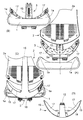
他方、例えば図7に明示するように、ロアサポート17は、背面視において上面と下面とが先端に向けて高くなるように湾曲しており、かつ、左右ロアサポート17の下面と背支柱15の下面とで形成される下面(すなわち,バックフレーム3の下面)も、下向きに膨れた湾曲面になっている。従って、バックフレーム3は、全体として錨に似た形態になっている。或いは、丸みを帯びた矢印に似た形態になっているということもできる。
On the other hand, as clearly shown in FIG. 7, for example, the
ロアサポート17の上部面の曲がり具合は、下面の曲がりの程度がやや大きくなっている。このため、ロアサポート17は、先端に行くに従って上下幅がやや小さくなっている。また、ロアサポート17は、例えば図1(B)(C)に示すように、平面視では、座の後部を抱くような状態で前向きに延びており、その先端部に肘掛け装置6が取付けられている。
Regarding the degree of bending of the upper surface of the
図7(D)に明示するように、ロアサポート17は、平面視において先端に向けて幅が小さくなっている。このため、座1の後部を後ろから抱持しつつも、ロアサポート17の外周面が座1の外周面に収束するかのような外観を呈している。
As clearly shown in FIG. 7D, the
例えば図7(A)(B)に明示するように、座1の後部には、正面視及び背面視において、ロアサポート17の上面の形状と相似形を成すように突部1aを設けている。このため、ロアサポート17の先端が上向きに反っていても、座1との一体感が形成されて、デザイン的に違和感のない状態になっている。座1の突部1aは、着座者の臀部に対するホールド効果も発揮しており、着座者の身体の安定性向上に貢献している。
For example, as clearly shown in FIGS. 7A and 7B, a
図7(D)から理解できるように、背もたれ2の下面は下向きに膨れた曲面になっているが、背もたれ2の下面の曲面は、バックフレーム3の下面の曲面と略同じ形状になっている。従って、デザイン的な統一がとれている。
As can be understood from FIG. 7 (D), the lower surface of the
例えば図7(C)に示すように、バックフレーム3の背面は、センターカバー18とサイドカバー19とで覆われている。すなわち、センターカバー18は、背支柱15の全体とロアサポート17の一部とを覆っており、サイドカバー19は、ロアサポート17の前半部の背面を覆っている。これらのカバー18,19は、バックフレーム3に手前から挿通したビスによって、バックフレーム3に固定されている。図9に、バックフレーム3に設けたビス挿通穴20と、センターカバー18に設けたタップ穴21とを表示している。
For example, as shown in FIG. 7C, the back surface of the
また、図5(C)に示すように、センターカバー18の左右側縁にリブ18aを前向きに突設する一方、背支柱15の背面には、リブ18aが嵌まる溝18bを形成している。従って、センターカバー18は左右ずれ不能に保持されている。
Further, as shown in FIG. 5 (C),
図12(B)に示すように、センターカバー18(及びサイドカバー19)の長手両側縁をテーパ状に形成することも可能である。この場合は、カバー18,19の厚さみが殆ど外観に現れないため、美観の面で有利である。
As shown in FIG. 12B, it is also possible to form the longitudinal both side edges of the center cover 18 (and the side cover 19) in a tapered shape. In this case, the thickness of the
(3).バックフレームと背もたれとの連結構造
図8(A)に示すように、背もたれ2を構成する背板2aの左右両端には下向き鉤状の係止爪22が形成されている一方、バックフレーム3におけるアッパサポート16の左右両端には、係止爪22が上から嵌まり込む係合枠部23が形成されている。
(3). Connection structure of back frame and backrest As shown in FIG. 8 (A), downward hook-shaped
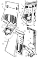
また、図8(B)に示すように、背もたれ2の下端の左右両端部に、四角錐の頭部分を切断した態様(四周各面が四角形の台錘形)のテーパ状角形突起24が後ろ向きに突設されている一方、ロアサポート17の先端部には、テーパ状角形突起24が入り込むテーパ状角形凹所25を形成し、ビス26によって、テーパ状角形突起24をテーパ状角形凹所25に引き込んでいる。
Further, as shown in FIG. 8 (B), tapered
ビス26は、ロアサポート17に後ろから挿通している一方、図8(D)に示すように、背もたれ2のテーパ状角形突起24に前向きの角形ポケット穴27が形成されており、ポケット穴27に回転不能に嵌め入れたナット28にビス26がねじ込まれている。
The
背もたれ2の上端はアッパサポート16の係合枠部23に嵌め込まれているため、左右2本のビスで背もたれ2のテーパ状角形凹所25を引き込むだけで、背もたれ2をバックフレーム3に離脱不能に取り付けることができる。そして、テーパ状角形突起24は、くさび作用によってテーパ状角形凹所25にしっかりと入り込むため、背もたれ2は、2本のビス26によってガタ付きのない状態に固定される。
Since the upper end of the
アッパサポート16は手前に向けて凹むように反っているため、アッパサポート16と背もたれ2との間には空間が空いている。ロアサポート17と背もたれ2との間にも、既述のように空間が空いている。また、背もたれ2は、4つのコーナー部がアッパサポート16とロアサポート17とに連結されていて、バックフレーム3に対して4点支持の状態に取付けられている。従って、背もたれ2の左右側部の後ろは開放されている。このため、背もたれ2は、着座者の押圧力によって後ろ向きに凹むように容易に弾性変形し得る。これにより、高いフィット性を確保することができる。
Since the
なお、背もたれ2を構成する背板2aは、単体の状態で、人が手で簡単に曲げることができる程度の弾性強度になっている。実施形態では、背板2aの前後両面をクッション材13で覆っているが、クッション材13を前面のみに配置することも可能である(但し、実施形態のように後面にも配置すると、背板2aの地肌やスリットなどが後ろから透けて見えない利点がある。)。また、背板2aをクロス等の表皮材のみで覆ったり、背板2aを剥き出しの状態で使用したりすることも可能である。
The
図8(A)に示すように、ヘッドレスト7の下端に後ろ向きの取付け片7aを設けている一方、アッパサポート16には、ヘッドレスト7の取付け片7aが嵌まる取付け穴7bを形成しており、取付け片7aが、図示しないビスでアッパサポート16に固定されている。取付け片7aは、ヘッドレスト7に内蔵した金具に形成している。
As shown in FIG. 8A, a rearward mounting
(4).アッパサポート
アッパサポート16は、背支柱15の上端部に水平旋回可能に連結されている。すなわち、例えば図1(B)や図2(B)に示すように、アッパサポート16の左右中間部に下向きロッド31を固定し、この下向きロッド31が、背支柱15に内蔵した軸受け部(図示せず)によって水平可能に保持されている。従って、アッパサポート16は、下向きロッド31を含む軸支手段によって、背支柱15に水平旋回可能に取付けられている。
(4). Upper support The
また、詳細は省略するが、下向きロッド31が背支柱15に対して相対的に回転する角度は、軸支手段に設けたストッパー部によって規制されており、かつ、軸支手段は、アッパサポート16を基準姿勢に戻すばね手段を備えている。背支柱15とアッパサポート16との間にある程度の間隔が空いている。このため、下向きロッド31は部分的に露出しているが、この露出部は、エラストマ等の軟質樹脂材からなる弾性カバー32によって覆われている。
Although not described in detail, the angle at which the
そして、背もたれ2の左側部又は右側部に着座者の押圧力が作用すると、図6(B)(C)に示すように、背もたれ2がアッパサポート16の水平旋回に追従して平面視で大きく捩じれ変形する。なお、図6(B)(C)に表示している平行斜線は、背もたれ2の外形を明示するための措置であり、断面の表示ではない。
Then, when the pressing force of the seated person acts on the left side portion or the right side portion of the
このようにアッパサポート16の水平旋回によって背もたれ2が大きく捩じれ変形するため、背もたれ2を撓み変形しやすい強度に設定しておくことにより、背もたれ2の強度に誤差があっても、また、使用者の体格が小さい人であって背もたれ2に対する押圧力が小さい場合であっても、背もたれ2を容易に変形させることができる。従って、身体の動きに対する背もたれ2の追従性を格段に向上できる。
Since the
更に、背もたれ2が全体的にねじれ変形するため、着座者の背中と背もたれ2との密着性を向上できる。その結果、高いフィット性を確保しつつ、身体の動きに対する背もたれ2の追従性を向上できる。これにより、椅子の品質を格段に向上できる。
Furthermore, since the
また、本実施形態では、背支柱15が着座者の押圧力によってねじれ変形する強度に設定されているため、背もたれ2は、まず、ばね47の弾性に抗して捩じれ変形し、次いで、背支柱15の弾性に抗して捩じれ変形しうる。このような2段階の捩じれ変形により、背もたれ2は、作用した押圧力の程度に応じて、着座者の身体の動きに的確に追従して変形することができる。従って、高い品質を確保できる。
Further, in the present embodiment, since the
このように、本実施形態では、背もたれ2が大きく捩じれ変形して着座者の快適性を向上できるが、このように背もたれ2の捩じれ変形が可能になっているのは、背もたれ2が4点支持の状態でバックフレーム3に連結されていることを基本として、背もたれ2の下端部はロアサポート17に対して水平旋回不能に連結されている一方、背もたれ2の上端部は水平旋回可能なアッパサポート16に連結されているからである。
As described above, in the present embodiment, the
また、背もたれ2が4点支持の状態でバックフレーム3に連結されていることは、捩じれ変形を捨象しても利点を有している。すなわち、背もたれ2がバックフレーム3に対して4点支持の状態で連結されていると、背もたれ2の上端部も下端部も左右側部も、着座者の押圧力によって後ろ向きに伸び変形し得るため、高いフィット性とクッション性とを得ることができる。
Further, the fact that the
例えば図1に示すように、肘掛け装置6は、ロアサポート17の外側面に取付けられたベース部50と、ベース部50に取付けられた中間リンク51と、中間リンク51の前端に水平旋回可能に取付けられた肘当て52とを有している。
For example, as shown in FIG. 1, the
詳細は省略するが、ベース部50は、ロアサポート17に固定されたケース部と、ケース部に水平回転自在に取り付けたロータ部とを有しており、ロータ部に、中間リンク51がその後端部を支点にして上下回動するように取付けられている。従って、中間リンク51の上下回動によって肘当て52の高さが調節されて、中間リンク51の水平旋回によって肘当て52の左右位置を変更できる。
Although not described in detail, the
ベース部50は、ロアサポートに向いて延びるアーム部50aを有しており、アーム部50aは図示しないボルトでロアサポート17の外側面に固定されている。また、アーム部50aに設けた係合突起が、ロアサポート17に形成した係合穴に嵌合している。
The
肘掛け装置6は、その全体が座1よりも上方に配置されているため、座の側方はスッキリとしており、美観に優れている。また、水平旋回自在な中間リンク51を取り付けることも問題ないため、肘当て52の可動エリアは非常に広い。従って、使い勝手がよい。
Since the
(5).第2実施形態
図10〜13では、メッシュタイプに適用した第2実施形態を示している。すなわち、背もたれ2は、前後に開口した背フレーム35にメッシュ材36を張った構造になっており、第1実施形態と同様に、ランバーサポート装置5と肘掛け装置6とヘッドレスト7とを備えている。
(5). Second Embodiment FIGS. 10 to 13 show a second embodiment applied to a mesh type. That is, the
背フレーム35は合成樹脂製であり、上下に長い左右のサイドメンバー37と、サイドメンバー37の上端に一体に繋がった水平状のアッパメンバー38と、サイドメンバー37の下端に一端に繋がった水平状のロアメンバー39とで構成されており、例えば、椅子に組み付けていない単体の状態で、人が容易に捩じり変形させ得る弾性強度になっている。
The
メッシュ材36は、図12に明示するテープ材40,41を介して背フレーム35に取付けられている。具体的には、左右の縦長テープ材40には、外向きに突出したボス42が多段に形成されており、このボス42が、サイドメンバー37の内周板に形成された係合溝43に嵌め込まれている。メッシュ材36の縦長縁部は縦長テープ材40の内面に重なっており、背フレーム35のサイドメンバー37は、メッシュ材36の左右端部に重なって後ろからぐるりと巻かれている。
The
他方、図12に明示するように、上下に配置された左右長手の横長テープ材41には、上下方向の外向きに突出した係止片44が左右方向に並べて形成されている一方、アッパメンバー38とロアメンバー39との対向面には、係止片44が嵌合する係合穴45が形成されている。そして、メッシュ材36の上下端部は、上下の横長テープ材41の内面に固定されており、メッシュ材36の上下端部により、アッパメンバー38及びロアメンバー39が外側からぐるりと巻かれている。
On the other hand, as clearly shown in FIG. 12, the laterally
このように、背フレーム35の全周はメッシュ材36でぐるりと包まれているため、背フレーム35の素材が露出することを極力抑制して、美観を向上できる。また、テープ材40,41の取付けも容易である。
In this way, since the entire circumference of the
メッシュ仕様の背もたれ2では、背フレーム35の内周が透けて見える。そして、図11から理解できるように、ロアメンバー39の上面(内面)の背面視形状(正面視形状も同じ)を、バックフレーム3における左右ロアサポート17の上面で形成される曲面とほぼ同じ形状の曲面と成している。このため、ロアメンバー39とロアサポート17とのデザイン的な統一性がとれて、すっきりとした外観を呈している。
In the
また、図11から理解できるように、ロアメンバー39の上面の凹面形状は、座1のうち左右の突部1aを有する後部の凹面形状ともほぼ一致している。従って、座1の後部の形状と、背フレーム35におけるロアメンバー39の形状と、バックフレーム3における左右ロアサポート17の形状とが、統一性をもって形成されている。
Further, as can be understood from FIG. 11, the concave shape of the upper surface of the
図13から理解できるように、バックフレーム3に対する背フレーム35の連結構造は、第1実施形態と同じである。すなわち、アッパサポート16に対する連結は、係止爪22と係合枠部23との組み合わせを使用し、ロアサポート17に対する連結は、テーパ状角形突起24とテーパ状角形凹所25の組み合わせを使用している。この実施形態でも、アッパサポート16は背支柱15に対して相対的に水平旋回し、また、背支柱15も、着座者の押圧力によって捩じれ変形し得る。
As can be understood from FIG. 13, the connection structure of the
以上、本願発明の実施形態を説明したが、本願発明は他にも様々に具体化できる。例えば、本願発明は、背もたれが後傾しないタイプの椅子にも適用できる。アッパサポートは、背支柱と相対回転しないように一体化することも可能である。或いは、アッパサポートを左右に分割して、それぞれが背支柱に対して相対回動する構成も採用できる。更に、背支柱がロアサポートに相対的に回転する構成も採用可能である。 Although the embodiments of the present invention have been described above, the present invention can be embodied in various other ways. For example, the present invention can be applied to a chair of a type in which the backrest does not tilt backward. The upper support may be integrated with the back support so as not to rotate relative to each other. Alternatively, it is also possible to adopt a configuration in which the upper support is divided into left and right parts, and each part rotates relative to the back support. Further, a configuration in which the back support column rotates relative to the lower support can also be adopted.
本願各発明は、椅子に具体化できる。従って、産業上利用できる。 Each invention of the present application can be embodied in a chair. Therefore, it can be used industrially.
1 座
1a 突部
2 背もたれ
2a 背板
3 バックフレーム
6 肘掛け装置
15 背支柱
16 アッパサポート
17 ロアサポート
35 背フレーム
36 メッシュ材
37 背フレームのサイドメンバー
38 背フレームのアッパメンバー
39 背フレームのロアメンバー
40,41 テープ材
1
Claims (7)
前記バックフレームは、左右中間部に位置した背支柱と、前記背支柱の下端から左右両側に張り出して先端が自由端になっているロアサポートとを備えていて、前記ロアサポートの先端部に前記背もたれの下端部が連結されており、
かつ、前記ロアサポートの上下両面が、背面視において左右外側に向けて上にずれるように湾曲した曲面に形成されており、更に、前記バックフレームの下端面は背面視で下向きに膨れた湾曲面になっている、
椅子。 A seat and a backrest, and a back frame arranged behind the backrest, the backrest being attached to the back frame,
The back frame includes a back strut located in the middle portion on the left and right, and a lower support projecting from the lower end of the back strut to both left and right sides, and the tip is a free end. The lower end of the backrest is connected,
Further, the upper and lower surfaces of the lower support are formed into curved surfaces which are curved so as to shift upward toward the left and right outside in rear view, and further, the lower end surface of the back frame is a curved surface which bulges downward in rear view. It has become,
Chair.
前記背フレームにおけるロアメンバーの上面は、背面視で下方に膨れる湾曲面になっている一方、
前記左右のロアアームの上面は、前記背フレームにおけるロアメンバーの上面の湾曲面と略同じ形態の湾曲面になっている、
請求項1に記載した椅子。 The backrest has a front and rear opening back frame having left and right side members, an upper member and a lower member, and a mesh material stretched over the back frame,
The upper surface of the lower member in the back frame is a curved surface that bulges downward in rear view,
The upper surfaces of the left and right lower arms are curved surfaces having substantially the same shape as the curved surfaces of the upper surfaces of the lower members in the back frame.
The chair according to claim 1.
かつ、前記左右のロアサポートは、平面視において厚さが前端に向けて小さくなるように形成されている、
請求項1又は2に記載した椅子。 The left and right lower supports extend toward the front in a curved state in a plan view so as to wrap the rear portion of the seat from both the left and right sides, and are inclined so as to be higher toward the front in a side view,
Also, the left and right lower supports are formed so that the thickness becomes smaller toward the front end in a plan view,
The chair according to claim 1 or 2.
請求項1〜3のうちのいずれかに記載した椅子。 Providing upward protrusions on the rear and left and right sides of the seat, the rear view shape of the seat is formed into a shape that is substantially the same as the rear view shape of the upper surface of the left and right lower supports,
The chair according to claim 1.
前記背もたれとアッパサポートとの間、及び、前記背もたれとロアサポートとの間にそれぞれ空間が空いている、
請求項1〜4のうちのいずれかに記載した椅子。 The upper end of the back frame is configured by an upper support protruding from the upper end of the back strut to the left and right sides, and the left and right end portions of the upper end of the backrest are connected to both end portions of the upper support. The backrest is connected to the back frame in a state of being supported at four points by the upper support and the lower support,
There is a space between the backrest and the upper support, and between the backrest and the lower support,
The chair according to any one of claims 1 to 4.
前記バックフレームは、左右中間部に位置した背支柱と、前記背支柱の下端から左右両側に張り出して先端が自由端になっているロアサポートとを備えていて、前記ロアサポートの先端部に前記背もたれの下端部が連結されており、
かつ、前記ロアサポートの先端部が肘掛け装置の取付け部になっている、
椅子。 A seat and a backrest, and a back frame arranged behind the backrest, the backrest being attached to the back frame,
The back frame includes a back strut located in the middle portion on the left and right, and a lower support projecting from the lower end of the back strut to both left and right sides, and the tip is a free end. The lower end of the backrest is connected,
And, the tip portion of the lower support is a mounting portion of the armrest device,
Chair.
請求項6に記載した椅子。 A base body of the armrest device is attached to an outer surface of a front end portion of the lower support so as to protrude outside the outer surface.
The chair according to claim 6.
Applications Claiming Priority (2)
| Application Number | Priority Date | Filing Date | Title |
|---|---|---|---|
| JP2018190577 | 2018-10-09 | ||
| JP2018190577 | 2018-10-09 |
Publications (2)
| Publication Number | Publication Date |
|---|---|
| JP2020058762A true JP2020058762A (en) | 2020-04-16 |
| JP7169166B2 JP7169166B2 (en) | 2022-11-10 |
Family
ID=70219814
Family Applications (10)
| Application Number | Title | Priority Date | Filing Date |
|---|---|---|---|
| JP2018210903A Active JP7198051B2 (en) | 2018-10-09 | 2018-11-08 | Chair |
| JP2018210901A Active JP7208766B2 (en) | 2018-10-09 | 2018-11-08 | Chair and its manufacturing method |
| JP2018210907A Active JP7295627B2 (en) | 2018-10-09 | 2018-11-08 | Chair |
| JP2018210905A Active JP7169166B2 (en) | 2018-10-09 | 2018-11-08 | Chair |
| JP2018210908A Pending JP2020058765A (en) | 2018-10-09 | 2018-11-08 | Armrest device for chair |
| JP2018210909A Active JP7295628B2 (en) | 2018-10-09 | 2018-11-08 | Chair and its armrest device |
| JP2018210904A Active JP7190334B2 (en) | 2018-10-09 | 2018-11-08 | Chair |
| JP2018210906A Active JP7252738B2 (en) | 2018-10-09 | 2018-11-08 | chair back |
| JP2018210902A Active JP7307537B2 (en) | 2018-10-09 | 2018-11-08 | Chair |
| JP2018220651A Active JP7414394B2 (en) | 2018-10-09 | 2018-11-26 | Chair |
Family Applications Before (3)
| Application Number | Title | Priority Date | Filing Date |
|---|---|---|---|
| JP2018210903A Active JP7198051B2 (en) | 2018-10-09 | 2018-11-08 | Chair |
| JP2018210901A Active JP7208766B2 (en) | 2018-10-09 | 2018-11-08 | Chair and its manufacturing method |
| JP2018210907A Active JP7295627B2 (en) | 2018-10-09 | 2018-11-08 | Chair |
Family Applications After (6)
| Application Number | Title | Priority Date | Filing Date |
|---|---|---|---|
| JP2018210908A Pending JP2020058765A (en) | 2018-10-09 | 2018-11-08 | Armrest device for chair |
| JP2018210909A Active JP7295628B2 (en) | 2018-10-09 | 2018-11-08 | Chair and its armrest device |
| JP2018210904A Active JP7190334B2 (en) | 2018-10-09 | 2018-11-08 | Chair |
| JP2018210906A Active JP7252738B2 (en) | 2018-10-09 | 2018-11-08 | chair back |
| JP2018210902A Active JP7307537B2 (en) | 2018-10-09 | 2018-11-08 | Chair |
| JP2018220651A Active JP7414394B2 (en) | 2018-10-09 | 2018-11-26 | Chair |
Country Status (1)
| Country | Link |
|---|---|
| JP (10) | JP7198051B2 (en) |
Families Citing this family (1)
| Publication number | Priority date | Publication date | Assignee | Title |
|---|---|---|---|---|
| KR102468455B1 (en) * | 2022-07-26 | 2022-11-18 | 신명수 | Lumbar Support Device for Chair with Height Adjustment |
Citations (5)
| Publication number | Priority date | Publication date | Assignee | Title |
|---|---|---|---|---|
| JPH08507935A (en) * | 1992-06-15 | 1996-08-27 | ハーマン、ミラー、インコーポレイテッド | Office chair |
| US20020190564A1 (en) * | 2001-06-15 | 2002-12-19 | Tim Coffield | Chair back construction |
| JP2003521956A (en) * | 1998-10-20 | 2003-07-22 | ヴィトラ・パテンテ・アクチェンゲゼルシャフト | Chair mechanism |
| JP2010505507A (en) * | 2006-10-04 | 2010-02-25 | フォームウェイ ファーニチャー リミテッド | Chair |
| JP2013103065A (en) * | 2011-11-16 | 2013-05-30 | Itoki Corp | Body receiving part for chair, back rest, and method for manufacturing body receiving part for chair |
Family Cites Families (34)
| Publication number | Priority date | Publication date | Assignee | Title |
|---|---|---|---|---|
| JPS60140454U (en) * | 1984-02-29 | 1985-09-17 | 池田物産株式会社 | vehicle seat |
| JPS6368115A (en) * | 1986-09-11 | 1988-03-28 | 東京シ−ト株式会社 | Armrest of seat for vehicle |
| JPH0475205U (en) * | 1990-11-13 | 1992-06-30 | ||
| JPH0767746A (en) * | 1993-08-31 | 1995-03-14 | Fuji Kiko Co Ltd | Car seat with arm rest |
| JPH0840120A (en) * | 1994-07-27 | 1996-02-13 | Ikeda Bussan Co Ltd | Rear seat for vehicle |
| JP3359862B2 (en) * | 1998-03-30 | 2002-12-24 | タカノ株式会社 | Locking device |
| JP3482842B2 (en) * | 1997-11-06 | 2004-01-06 | 株式会社イトーキクレビオ | Interlocking device between chair seat and backrest |
| JP3595953B2 (en) * | 1998-07-09 | 2004-12-02 | 株式会社イトーキクレビオ | Chair seat or backrest |
| JP4316748B2 (en) * | 1999-11-08 | 2009-08-19 | 株式会社岡村製作所 | Chair |
| JP2001204582A (en) * | 2000-01-31 | 2001-07-31 | Itoki Crebio Corp | Armrest device |
| KR200215809Y1 (en) | 2000-10-04 | 2001-03-15 | 이준구 | A chair for frame |
| GB0114581D0 (en) | 2001-06-14 | 2001-08-08 | White Adam | Twister seat |
| JP4189455B2 (en) * | 2002-01-31 | 2008-12-03 | 株式会社岡村製作所 | Chair tension structure |
| JP2003299548A (en) * | 2002-02-08 | 2003-10-21 | Koyo Giken Kk | Arm rest mechanism and furniture with arm rest containing the same |
| US20050062323A1 (en) | 2003-06-11 | 2005-03-24 | Dicks Gerald G. | Chair |
| JP4183084B2 (en) | 2003-11-21 | 2008-11-19 | 株式会社イトーキ | Chair and its back |
| JP5005167B2 (en) * | 2004-10-13 | 2012-08-22 | 株式会社岡村製作所 | Chair backrest structure |
| JP2006314437A (en) | 2005-05-11 | 2006-11-24 | T S Tec Kk | Vehicle seat |
| US7293832B2 (en) | 2005-08-19 | 2007-11-13 | Chien-Kai Huang | Chair adjustable device |
| US20080093908A1 (en) | 2006-10-19 | 2008-04-24 | Cooley Gordon D | Moveable Armrest |
| KR100982797B1 (en) * | 2008-02-26 | 2010-09-16 | 정해일 | Headrest for cars |
| TWM340761U (en) * | 2008-04-11 | 2008-09-21 | zheng-hong Lin | Mesh chair frame, and its assembly structure |
| JP4913185B2 (en) * | 2009-08-07 | 2012-04-11 | 株式会社岡村製作所 | Chair elbow frame mounting structure |
| CA2881887A1 (en) | 2012-09-20 | 2014-03-27 | Robert J. Battey | Chair arm assembly |
| WO2014061732A1 (en) | 2012-10-18 | 2014-04-24 | 株式会社岡村製作所 | Chair |
| JP6140419B2 (en) | 2012-10-18 | 2017-05-31 | 株式会社岡村製作所 | Lumber support and chair |
| WO2014196630A1 (en) | 2013-06-06 | 2014-12-11 | 株式会社イトーキ | Chair |
| JP6518073B2 (en) * | 2014-11-07 | 2019-05-22 | 株式会社イトーキ | Chair |
| JP6352785B2 (en) * | 2014-11-28 | 2018-07-04 | 株式会社タチエス | Seat device |
| JP6678417B2 (en) * | 2015-09-25 | 2020-04-08 | 株式会社オカムラ | Furniture sheets, furniture surface components and furniture |
| JP2017079943A (en) | 2015-10-26 | 2017-05-18 | タカノ株式会社 | Lock mechanism and chair |
| DE102016105751A1 (en) * | 2016-03-30 | 2017-10-05 | Bock 1 Gmbh & Co. Kg | Height-adjustable armrest |
| US10477973B2 (en) | 2016-11-01 | 2019-11-19 | Ergogenesis Workplace Solutions, Llc | Ergonomic chair |
| JP6876409B2 (en) | 2016-11-04 | 2021-05-26 | 株式会社イトーキ | Chair back |
-
2018
- 2018-11-08 JP JP2018210903A patent/JP7198051B2/en active Active
- 2018-11-08 JP JP2018210901A patent/JP7208766B2/en active Active
- 2018-11-08 JP JP2018210907A patent/JP7295627B2/en active Active
- 2018-11-08 JP JP2018210905A patent/JP7169166B2/en active Active
- 2018-11-08 JP JP2018210908A patent/JP2020058765A/en active Pending
- 2018-11-08 JP JP2018210909A patent/JP7295628B2/en active Active
- 2018-11-08 JP JP2018210904A patent/JP7190334B2/en active Active
- 2018-11-08 JP JP2018210906A patent/JP7252738B2/en active Active
- 2018-11-08 JP JP2018210902A patent/JP7307537B2/en active Active
- 2018-11-26 JP JP2018220651A patent/JP7414394B2/en active Active
Patent Citations (5)
| Publication number | Priority date | Publication date | Assignee | Title |
|---|---|---|---|---|
| JPH08507935A (en) * | 1992-06-15 | 1996-08-27 | ハーマン、ミラー、インコーポレイテッド | Office chair |
| JP2003521956A (en) * | 1998-10-20 | 2003-07-22 | ヴィトラ・パテンテ・アクチェンゲゼルシャフト | Chair mechanism |
| US20020190564A1 (en) * | 2001-06-15 | 2002-12-19 | Tim Coffield | Chair back construction |
| JP2010505507A (en) * | 2006-10-04 | 2010-02-25 | フォームウェイ ファーニチャー リミテッド | Chair |
| JP2013103065A (en) * | 2011-11-16 | 2013-05-30 | Itoki Corp | Body receiving part for chair, back rest, and method for manufacturing body receiving part for chair |
Also Published As
| Publication number | Publication date |
|---|---|
| JP2020058766A (en) | 2020-04-16 |
| JP2020058761A (en) | 2020-04-16 |
| JP7252738B2 (en) | 2023-04-05 |
| JP2020058763A (en) | 2020-04-16 |
| JP2020058760A (en) | 2020-04-16 |
| JP7198051B2 (en) | 2022-12-28 |
| JP2020058764A (en) | 2020-04-16 |
| JP7208766B2 (en) | 2023-01-19 |
| JP7169166B2 (en) | 2022-11-10 |
| JP7307537B2 (en) | 2023-07-12 |
| JP2020058765A (en) | 2020-04-16 |
| JP2020058769A (en) | 2020-04-16 |
| JP7295627B2 (en) | 2023-06-21 |
| JP2020058758A (en) | 2020-04-16 |
| JP7190334B2 (en) | 2022-12-15 |
| JP7414394B2 (en) | 2024-01-16 |
| JP2020058759A (en) | 2020-04-16 |
| JP7295628B2 (en) | 2023-06-21 |
Similar Documents
| Publication | Publication Date | Title |
|---|---|---|
| JP5646725B2 (en) | Rocking chair | |
| JP6262937B2 (en) | Nestable chair | |
| CN209950806U (en) | Waist is leaned on and seat | |
| KR200421443Y1 (en) | Chair with assistant back | |
| JP2020058762A (en) | Chair | |
| US20130175836A1 (en) | Adjustable hanging chair | |
| JP3080585B2 (en) | Chair | |
| JP6196438B2 (en) | Rocking chair | |
| JP7217110B2 (en) | Chair | |
| KR20130001400U (en) | Functional Chair | |
| KR200383047Y1 (en) | chair with headrest | |
| JP5935320B2 (en) | Chair | |
| KR200457483Y1 (en) | The connection support mounting structure for chest supporter of chair | |
| JP7173778B2 (en) | Chair | |
| JP7299004B2 (en) | Chair | |
| JP7436743B1 (en) | relaxing chair | |
| JP7078263B2 (en) | Chair | |
| JP3100353B2 (en) | Chair | |
| KR20110067613A (en) | Upper body health chair | |
| KR200411864Y1 (en) | Waist supporting unit of chair | |
| JP6670069B2 (en) | Chair | |
| KR200252699Y1 (en) | Chair | |
| JP2022073211A (en) | Foldable chair | |
| JPS595395Y2 (en) | Seat tilting device for chairs | |
| CA2671669A1 (en) | Foldable chair frame |
Legal Events
| Date | Code | Title | Description |
|---|---|---|---|
| A621 | Written request for application examination |
Free format text: JAPANESE INTERMEDIATE CODE: A621 Effective date: 20211026 |
|
| A977 | Report on retrieval |
Free format text: JAPANESE INTERMEDIATE CODE: A971007 Effective date: 20220831 |
|
| TRDD | Decision of grant or rejection written | ||
| A01 | Written decision to grant a patent or to grant a registration (utility model) |
Free format text: JAPANESE INTERMEDIATE CODE: A01 Effective date: 20220928 |
|
| A61 | First payment of annual fees (during grant procedure) |
Free format text: JAPANESE INTERMEDIATE CODE: A61 Effective date: 20221028 |
|
| R150 | Certificate of patent or registration of utility model |
Ref document number: 7169166 Country of ref document: JP Free format text: JAPANESE INTERMEDIATE CODE: R150 |