JP2020052964A - Disaster prevention system - Google Patents
Disaster prevention system Download PDFInfo
- Publication number
- JP2020052964A JP2020052964A JP2018184623A JP2018184623A JP2020052964A JP 2020052964 A JP2020052964 A JP 2020052964A JP 2018184623 A JP2018184623 A JP 2018184623A JP 2018184623 A JP2018184623 A JP 2018184623A JP 2020052964 A JP2020052964 A JP 2020052964A
- Authority
- JP
- Japan
- Prior art keywords
- signal line
- unit
- measurement result
- measurement
- current value
- Prior art date
- Legal status (The legal status is an assumption and is not a legal conclusion. Google has not performed a legal analysis and makes no representation as to the accuracy of the status listed.)
- Granted
Links
Images
Landscapes
- Testing Of Short-Circuits, Discontinuities, Leakage, Or Incorrect Line Connections (AREA)
- Alarm Systems (AREA)
- Fire Alarms (AREA)
Abstract
【課題】信号の測定手段の異常を検知できるようにする。【解決手段】制御部101は、選択部210を制御し、選択部210に接続されている信号線11a、信号線11c、信号線11dおよびダミー回路110に接続されている信号線を順次AD変換ポートへ接続する。制御部101は、接続された信号線毎に電圧を測定し、接続された信号線に流れる電流の電流値Iを、測定した電圧から算出し、算出した電流値を記録する。制御部101は、ダミー回路110を流れる電流の電流値の測定結果と、ダミー回路110に接続された信号線以外の信号線を流れる電流の電流値の測定結果に基づいて、信号線の電圧を測定するハードウェアの異常と信号線の異常を検知する。【選択図】図1PROBLEM TO BE SOLVED: To detect an abnormality of a signal measuring means. A control unit 101 controls a selection unit 210 and sequentially AD-converts a signal line 11a, a signal line 11c, a signal line 11d, and a signal line connected to a dummy circuit 110 connected to the selection unit 210. Connect to the port. The control unit 101 measures the voltage for each connected signal line, calculates the current value I of the current flowing through the connected signal line from the measured voltage, and records the calculated current value. The control unit 101 determines the voltage of the signal line based on the measurement result of the current value of the current flowing through the dummy circuit 110 and the measurement result of the current value of the current flowing through the signal line other than the signal line connected to the dummy circuit 110. Detects abnormalities in the hardware to be measured and abnormalities in the signal line. [Selection diagram] Fig. 1
Description
本発明は、防災システムに関する。 The present invention relates to a disaster prevention system.
防災受信盤と端末機器で構成されるトンネル防災システムにおいては、手動通報装置、消火栓起動装置、ダクト温度検知器等の端末機器は、防災受信盤に信号回線で接続される。この信号回線がどのような状態にあるかを調べる発明として、例えば特許文献1に開示されたトンネル防災システムがある。このトンネル防災システムは、複数の信号回線から一の信号回線を順次選択し、選択した信号回線を制御部のAD変換ポートに接続する。制御部は、接続された信号回線からAD変換ポートに入力される信号をサンプリングすることにより、信号回線に流れる電流を測定して記録する。測定結果は、例えば、特許文献2に開示されているトンネル防災システムのように、防災受信盤が備えるメインモニタ装置やサブモニタ装置で表示することにより、ユーザが信号回線の絶縁の劣化等、信号回線がどのような状態にあるのかを把握することができる。
In a tunnel disaster prevention system including a disaster prevention receiver and a terminal device, terminal devices such as a manual notification device, a fire hydrant activation device, and a duct temperature detector are connected to the disaster prevention receiver by a signal line. As an invention for examining the state of this signal line, for example, there is a tunnel disaster prevention system disclosed in
ところで、信号回線に接続するAD変換ポートや、AD変換ポートのADコンバータに不具合が発生した場合、測定値が異常な値となり、信号回線の劣化を判定できないこととなる。 By the way, when a failure occurs in the AD conversion port connected to the signal line or the AD converter of the AD conversion port, the measured value becomes an abnormal value, and it is impossible to determine the deterioration of the signal line.
本発明は、信号の測定手段の異常を検知できるようにすることを目的とする。 An object of the present invention is to make it possible to detect an abnormality of a signal measuring unit.
(1)発明に係る防災システムは、端末機器に接続する信号線およびダミー回路に接続する信号線において測定対象となる信号線を切り替える切替手段と、前記切替手段により測定対象となった信号線を流れる電流値または電圧値を少なくとも測定する測定手段と、前記端末機器に接続する信号線の前記測定手段による測定結果と、前記ダミー回路に接続する信号線の前記測定手段による測定結果を記録する記録手段とを備える。 (1) A disaster prevention system according to the present invention includes a switching unit for switching a signal line to be measured among a signal line connected to a terminal device and a signal line connected to a dummy circuit, and a signal line to be measured by the switching unit. Recording means for measuring at least a flowing current value or voltage value, a measurement result of the signal line connected to the terminal device by the measurement means, and a measurement result of the signal line connected to the dummy circuit by the measurement means. Means.
(2)本発明に係る防災システムは、(1)に記載の構成において、前記記録手段に記録された前記ダミー回路に接続する信号線を流れる電流値または電圧値の測定結果に基づいて、前記測定手段の異常を検知する第1検知手段を備えることを特徴とする。 (2) The disaster prevention system according to the present invention, in the configuration described in (1), based on a measurement result of a current value or a voltage value flowing through a signal line connected to the dummy circuit recorded in the recording unit. It is characterized by comprising a first detecting means for detecting an abnormality of the measuring means.
(3)また、本発明に係る防災システムは、(1)または(2)の構成において、前記記録手段に記録された前記端末機器に接続する信号線を流れる電流値または電圧値の測定結果と、前記記録手段に記録された前記ダミー回路に接続する信号線を流れる電流値または電圧値の測定結果に基づいて、前記端末機器に接続する信号線の異常を検知する第2検知手段を備えることを特徴とする。 (3) In the disaster prevention system according to the present invention, in the configuration of (1) or (2), a measurement result of a current value or a voltage value recorded on the recording unit and flowing through a signal line connected to the terminal device is provided. And a second detection unit for detecting an abnormality of a signal line connected to the terminal device based on a measurement result of a current value or a voltage value flowing through a signal line connected to the dummy circuit recorded in the recording unit. It is characterized by.
(4)また、本発明に係る防災システムは、(3)の構成において、前記第2検知手段は、前記ダミー回路に接続する信号線を流れる電流値または電圧値の測定結果が予め定められた閾値範囲内である場合に、前記測定手段に異常がないと判定し、前記測定手段に異常がないと判定した場合、前記記録手段に記録された前記端末機器に接続する信号線を流れる電流値または電圧値の測定結果が予め定められた閾値範囲外であると当該信号線の異常と判定し、前記記録手段に記録された前記端末機器に接続する信号線を流れる電流値または電圧値の測定結果と、前記記録手段に記録された前記ダミー回路に接続する信号線を流れる電流値または電圧値の測定結果に基づいて、前記閾値を設定する閾値設定手段を備えることを特徴とする。 (4) In the disaster prevention system according to the present invention, in the configuration according to (3), the second detection unit may determine a measurement result of a current value or a voltage value flowing through a signal line connected to the dummy circuit in advance. If it is within the threshold range, it is determined that there is no abnormality in the measuring means, and if it is determined that there is no abnormality in the measuring means, the current value flowing through the signal line connected to the terminal device recorded in the recording means Or, if the measurement result of the voltage value is out of the predetermined threshold range, it is determined that the signal line is abnormal, and the measurement of the current value or the voltage value flowing through the signal line connected to the terminal device recorded in the recording means And a threshold setting unit configured to set the threshold based on a result and a measurement result of a current value or a voltage value flowing through a signal line connected to the dummy circuit recorded in the recording unit.
(5)また、本発明に係る防災システムは、(1)乃至(4)のいずれか一の構成において、前記記録手段に記録された測定結果をグラフで表示する表示手段を備えることを特徴とする。 (5) Further, the disaster prevention system according to the present invention, in any one of the constitutions (1) to (4), further comprises a display unit for displaying a measurement result recorded in the recording unit in a graph. I do.
(6)また、本発明に係る防災システムは、(1)乃至(5)のいずれか一の構成において、前記測定手段は、前記切替手段により測定対象となった信号線を予め定められた周期でサンプリングして測定する手段であって、設定されたタイミングで前記サンプリングを開始し、前記タイミングを設定するタイミング設定手段を備えることを特徴とする。 (6) In the disaster prevention system according to the present invention, in any one of the constitutions (1) to (5), the measuring means sets the signal line to be measured by the switching means at a predetermined period. And means for sampling and measuring at a set timing, and comprising timing setting means for setting the timing.
上記の(1)の構成によれば、信号線の劣化および信号の測定手段の異常を検知することができる。
上記の(2)の構成によれば、信号の測定手段の異常を自動で検知することができる。
上記の(3)の構成によれば、信号線の異常を自動で検知することができる。
上記の(4)の構成によれば、閾値を変更しない構成と比較して、信号線の異常を早く検知することができる。
上記の(5)の構成によれば、測定結果をユーザが確認することができる。
上記の(6)の構成によれば、測定する信号線を切り替えた後で安定した信号の測定結果を記録することができる。
According to the above configuration (1), it is possible to detect the deterioration of the signal line and the abnormality of the signal measuring means.
According to the above configuration (2), it is possible to automatically detect an abnormality of the signal measuring means.
According to the configuration of the above (3), the abnormality of the signal line can be automatically detected.
According to the above configuration (4), an abnormality in the signal line can be detected earlier as compared with the configuration in which the threshold is not changed.
According to the above configuration (5), the user can confirm the measurement result.
According to the above configuration (6), a stable signal measurement result can be recorded after switching the signal line to be measured.
[実施形態]
(全体構成)
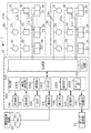
図1は、防災システム1の概要を示した図である。防災システム1は、トンネル内で発生する火災の拡大を防ぐためのシステムである。図1においては、自動車専用道路で上り線のトンネル2aと下り線のトンネル2bを有するトンネルに係る防災システム1の概要を示している。
[Embodiment]
(overall structure)
FIG. 1 is a diagram showing an outline of the
トンネル2aとトンネル2bの壁面には、トンネルの延伸方向に沿って予め定められた間隔で火災検知器32が設置されている。火災検知器32は、トンネルの上流側と下流側を監視して火災による炎を検知する。火災による炎が火災検知器32により検知されると、火災信号が流れる。
On the wall surfaces of the
トンネル2aとトンネル2bには、トンネルの延伸方向に沿って換気や排気のためのダクトが設けられており、ダクト内においては、予め定められた間隔で温度検知器31が設置されている。温度検知器31は、接点手段として機能するスイッチを備えており、火災によりダクト内の温度が上昇すると、このスイッチがオンとなり、温度検知信号が流れる。
Ducts for ventilation and exhaust are provided in the
また、トンネル2aとトンネル2bの監視員通路の壁面には、監視員通路の延伸方向に沿って、予め定められた間隔で消火栓装置33と手動通報装置34が設置されている。
Also, on the wall surfaces of the observer passages of the
消火栓装置33は、初期消火用の放水設備であり、ノズル付きホースが接続された消火栓と消火器を扉内に収納している。火災時には消火栓扉を開いてノズル付きホースを引き出し、消火栓弁開閉レバーを開操作すると、消火栓へ給水を行うための消火栓起動スイッチがオンとなり、起動信号が流れる。起動信号が流れると、消火栓に給水を行う消火ポンプが起動し、ホースのノズルから消火用水が放水される。
The
また、消火栓装置33には、消防隊が使用する給水栓と、給水栓へ給水を行う消火ポンプを起動する給水栓起動スイッチが設けられている。消防隊の操作により給水栓起動スイッチがオンとなると、起動信号が流れる。起動信号が流れると、消火ポンプが起動し、給水栓へ給水が行われる。なお、給水栓は必須の構成ではないため、消火栓装置33は、給水栓を備えていない構成であってもよい。
In addition, the
なお、消火栓起動スイッチと給水栓起動スイッチは、共に同じ消火ポンプ起動して起動信号を出力するスイッチであることから、以下、消火栓起動スイッチおよび給水栓起動スイッチを起動スイッチと称する場合がある。 Note that the fire hydrant start switch and the hydrant start switch are both switches that start the same fire pump and output a start signal, and hence the fire hydrant start switch and the hydrant start switch may be hereinafter referred to as start switches.
手動通報装置34は、火災を知らせるための装置であり、押しボタンが操作されてスイッチがオンとなると、火災通報信号が流れる。なお、押しボタン式である手動通報装置は、トンネル2aとトンネル2bの壁面に設けられた非常電話機にも設置されている。
The
手動通報装置34、消火栓装置33および温度検知器31は、本発明に係る端末機器の一例である。
The
防災受信盤10は、トンネル内の異常を検知する機能を有し、火災の発生を報知し、他の設備と連動してトンネル内の火災の拡大を防ぐ設備である。防災受信盤10は、トンネルの通信機械室に設置されている。防災受信盤10は、P型のシステムであり、温度検知器31に接続されている信号線11a、火災検知器32に接続されている信号線11b、手動通報装置34に接続されている信号線11d、および起動スイッチに接続されている信号線11cが接続されている。
The
温度検知器31に接続する信号線11aは、トンネル内を分割した複数の区画毎に設けられており、複数の信号線11aの各々は、対応する区画に設置されている温度検知器31に接続されている。火災検知器32に接続する信号線11bは、トンネル内を分割した複数の区画毎に設けられており、複数の信号線11bの各々は、対応する区画に設置されている火災検知器32に接続されている。手動通報装置34に接続する信号線11dは、トンネル内を分割した複数の区画毎に設けられており、複数の信号線11dの各々は、対応する区画に設置されている手動通報装置34に接続されている。起動スイッチに接続する信号線11cは、トンネル内を分割した複数の区画毎に設けられており、複数の信号線11cの各々は、対応する区画に設置されている起動スイッチに接続されている。
The
また、防災システム1は、消火ポンプの制御と、ダクトを冷却するダクト冷却ポンプの制御を行うポンプ制御盤21を備える。
Further, the
(防災受信盤10の構成)
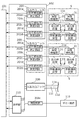
防災受信盤10は、制御部101、伝送部102、通信部103、GOT104、操作部105、警報部106、ポンプ制御部107、表示部108、記憶部109およびダミー回路110を備える。
(Configuration of disaster prevention receiver 10)
The
制御部101は、所謂PLC(Programmable Logic Controller)であり、CPUおよびメモリを有するCPUユニット、電源ユニット、AD変換機能を有する入力ポートを含む各種の入力ポートおよび出力ポートを備えた入出力ユニットを備える。
The
伝送部102は、信号線11a、信号線11b、信号線11cおよび信号線11dに接続されている。伝送部102は、温度検知信号、火災信号、起動信号、および火災通報信号を制御部101へ供給する。
The
GOT(Graphic Operation Terminal)104は、タッチパネルを備えた入出力装置である。GOT104は、制御部101と協働して各種のGUI画面を表示し、GUI画面に対して行われた操作を受け付ける。GOT104は、信号線11a、信号線11cおよび信号線11dを流れる電流の測定結果の表示や、電流の測定に係る設定画面の表示などを行う。また、GOT104は、USB端子を備えており、USB端子に接続されたUSBメモリに対して各種データを出力する。
A GOT (Graphic Operation Terminal) 104 is an input / output device provided with a touch panel. The
通信部103は、通信ネットワーク3を介して外部の上位設備である遠隔制御設備30と通信を行うための通信インターフェースとして機能する。操作部105は、防災受信盤10を操作するための各種スイッチやボタンを有する。警報部106は、スピーカ、主音響装置、警報表示灯を有し、火災発生時に警報を発する。ポンプ制御部107は、ポンプ制御盤21を制御し、消火ポンプやダクト冷却ポンプの制御を行う。表示部108は、液晶ディスプレイ装置を有し、火災の発生の警報表示や、信号線11a、信号線11cおよび信号線11dを流れる電流の異常表示などを行う。記憶部109は、例えば、メモリカードなどの不揮発性メモリであり、伝送部102に接続されている信号線に流れる電流や電圧などの測定結果を記憶する。ダミー回路110は、制御部101のAD変換ポートの故障を判定するための回路である。ダミー回路110は、伝送部102に接続されている。なお、制御部101は、PLCに限定されるものではなく、CPU、メモリ、入出力ユニットを備えたマイクロコンピュータまたはパーソナルコンピュータであってもよい。また、本実施形態においては、表示部108と操作部105とがメイン表示操作部を構成し、GOT104がサブ表示操作部を構成し、別々の構成となっているが、一体の構成であってもよい。
The
(伝送部102の構成)
図2は、伝送部102の構成を示したブロック図である。トンネル内を分割した複数の区画5の各々には、区画5に配置されている温度検知器31、消火栓装置33、手動通報装置34が含まれる。伝送部102は、トンネル内を分割した複数の区画5毎に入出力ユニット200を備えている。また、伝送部102は、測定回路202eを備える。測定回路202eは、ダミー回路110に流れる電流を測定するための回路であり、ダミー回路110に接続されている。
(Configuration of the transmission unit 102)
FIG. 2 is a block diagram showing a configuration of the
入出力ユニット200は、信号受信部201a、信号受信部201cおよび信号受信部201dを有する。信号受信部201aは、対応する区画5に含まれる温度検知器31に信号線11aで接続されている。信号受信部201cは、対応する区画5に含まれる消火栓装置33に信号線11cで接続されている。信号受信部201dは、対応する区画5に含まれる手動通報装置34に信号線11dで接続されている。
The input /
また、入出力ユニット200は、測定回路202a、測定回路202cおよび測定回路202dを有する。測定回路202aは、信号線11aに流れる電流を測定するための回路である。測定回路202cは、信号線11cに流れる電流を測定するための回路である。測定回路202dは、信号線11dに流れる電流を測定するための回路である。
Further, the input /
図3は、測定回路202a、測定回路202c、測定回路202dおよび測定回路202eの詳細を示した図である。信号線11a、信号線11cおよび信号線11dは、具体的には、信号ラインLとコモンラインCで構成されている。信号ラインLは抵抗R2を介して電源電圧Vcに接続されてプルアップされて直流信号が流れており、コモンラインCはグランドに接続されている。
FIG. 3 is a diagram illustrating details of the
ダミー回路110は、終端抵抗R1と信号ラインLを有する。ダミー回路110の信号ラインLは抵抗R2を介して電源電圧Vcに接続されてプルアップされて直流信号が流れており、終端抵抗R1は、グランドに接続されている。
The
信号ラインLとコモンラインCからなる信号線11aには、温度検知器31に設けられているスイッチSWaおよび終端抵抗R1が並列に接続されており、通常状態でスイッチSWaは図示したようにオフとなっている。
A switch SWa provided in the
信号ラインLとコモンラインCからなる信号線11cには、消火栓装置33に設けられている起動スイッチSWcおよび終端抵抗R1が並列に接続されており、通常状態で起動スイッチSWcは図示したようにオフとなっている。
A start switch SWc and a terminating resistor R1 provided in the
信号ラインLとコモンラインCからなる信号線11dには、手動通報装置34に設けられているスイッチSWdおよび終端抵抗R1が並列に接続されており、通常状態でスイッチSWdは図示したようにオフとなっている。
The switch SWd and the terminating resistor R1 provided in the
スイッチSWaがオフしている通常状態では、信号ラインLとコモンラインCの間の電圧は電源電圧Vcとなっており、この電圧が信号受信部201aに入力されている。スイッチSWaのいずれかが温度上昇によりオンとなると、信号ラインLとコモンラインCの間の電圧が低下する。信号受信部201aは、信号ラインLとコモンラインCの間の電圧が予め定められた電圧より低下した場合、温度検知信号を制御部101へ出力する。
In the normal state where the switch SWa is off, the voltage between the signal line L and the common line C is the power supply voltage Vc, and this voltage is input to the
また、起動スイッチがオフしている通常状態では、信号ラインLとコモンラインCの間の電圧は電源電圧Vcとなっており、この電圧が信号受信部201cに入力されている。起動スイッチSWcのいずれかがオンとなると、信号ラインLとコモンラインCの間の電圧が低下する。信号受信部201cは、信号ラインLとコモンラインCの間の電圧が予め定められた電圧より低下した場合、起動信号を制御部101へ出力する。
In the normal state where the start switch is off, the voltage between the signal line L and the common line C is the power supply voltage Vc, and this voltage is input to the
スイッチSWdがオフしている通常状態では、信号ラインLとコモンラインCの間の電圧は電源電圧Vcとなっており、この電圧が信号受信部201dに入力されている。押しボタンが操作されてスイッチSWdのいずれかがオンとなると、信号ラインLとコモンラインCの間の電圧が低下する。信号受信部201dは、信号ラインLとコモンラインCの間の電圧が予め定められた電圧より低下した場合、火災通報信号を制御部101へ出力する。
In a normal state where the switch SWd is off, the voltage between the signal line L and the common line C is the power supply voltage Vc, and this voltage is input to the
測定回路202a、測定回路202cおよび測定回路202dは、信号ラインLとコモンラインCとの間の電圧を検出するための回路であり、信号ラインLに接続する信号ラインLaを有する。測定回路202eは、ダミー回路110の信号ラインLとグランド間の電圧を検出するための回路であり、信号ラインLに接続する信号ラインLaを有する。なお、測定回路202a、測定回路202cおよび測定回路202dは、図示した回路に限定されるものではなく、信号ラインLにおいて信号ラインLaが接続されている点とコモンラインCとの間の電圧を信号ラインLに流れる電流の増減に応じて変化させる回路であればよい。また、測定回路202eについても図示した回路に限定されるものではなく、信号ラインLにおいて信号ラインLaが接続されている点とグランド間の電圧を信号ラインLに流れる電流の増減に応じて変化させる回路であればよい。
The
選択部210は、接続される複数の信号ラインLa毎にリレー回路を備えている。選択部210においては、制御部101からの制御信号によりリレー回路が動作し、複数の信号ラインLaのうちの一つがリレー回路により制御部101のAD変換ポートに接続される。選択部210は、本発明に係る切替手段の一例である。
The
(制御部101の構成)
制御部101においては、CPUがプログラムを実行することにより、本発明に係る電流測定部1001、検知部1002、設定部1003、監視部1004、GUI部1005を実現する。
(Configuration of the control unit 101)
In the
監視部1004は、伝送部102から供給される信号に応じて各部を制御する。監視部1004は、例えば、手動通報装置34の操作による火災通報信号を受信した場合、警報部106を制御して主音響装置を鳴動させ、表示部108を制御して火災表示と手動通報区画表示を行う。また、監視部1004は、火災通報信号を受信した場合、ポンプ制御部107でポンプ制御盤21を制御して消火ポンプを起動する。
The
また、監視部1004は、ダクト内温度が上昇したことにより温度検知信号を受信した場合、ポンプ制御部107でポンプ制御盤21を制御して冷却ポンプを起動し、ダクト内に設置されているヘッドから散水してダクト内を冷却する制御を行う。
When the temperature detection signal is received due to the rise in the temperature in the duct, the
電流測定部1001は、信号線11a、信号線11c、信号線11dおよびダミー回路110に流れる電流の電流値を測定し、測定結果を記憶部109に記録する。具体的には、電流測定部1001は、信号ラインLaとグランド間の電圧VaをAD変換ポートで測定することにより、信号ラインLに流れる電流の電流値Iを、例えば、I=(Vc−Va)/R2の式で算出する。電流測定部1001は、本発明に係る測定手段の一例である。
The
電流測定部1001は、一日の予め定められた時刻になると、選択部210を制御し、選択部210に接続されている信号ラインLaを順次AD変換ポートへ接続する。電流測定部1001は、接続された信号ラインLa毎に電圧を測定し、接続された信号ラインLaに流れる電流の電流値Iを、測定した電圧から算出し、算出した電流値を記憶部109に記録する。
At a predetermined time of the day, the
また、電流測定部1001は、全ての信号ラインLに流れる電流の測定を指示する操作がGOT104において行われた場合には、選択部210を制御して信号ラインLaを順次AD変換ポートへ接続する。電流測定部1001は、接続された信号ラインLa毎に電圧を測定し、接続された信号ラインLaに流れる電流の電流値を測定した電圧から算出し、算出した電流値を記憶部109に記録する。
In addition, when the operation of instructing the measurement of the current flowing through all the signal lines L is performed in the
また、電流測定部1001は、電流値を測定する信号ラインLがGOT104において選択され、選択された信号ラインLに流れる電流の測定を指示する操作がGOT104において行われた場合には、選択された信号ラインLに接続されている信号ラインLaをAD変換ポートに接続する。電流測定部1001は、接続された信号ラインLaの電圧を測定し、接続された信号ラインLaに流れる電流の電流値を測定した電圧から算出し、算出した電流値を記憶部109に記録する。
In addition, the
電流測定部1001は、電圧Vaの測定の際には、選択部210を制御した後、設定部1003で設定されたタイミングとなると、信号ラインLaとグランド間の電圧Vaのサンプリングを開始する。電流測定部1001は、電圧Vaのサンプリングを開始してから予め定められた時間が経過するとサンプリングを終了する。電流測定部1001は、サンプリング毎に得た電圧Va毎に電流値Iを算出し、算出した電流値Iの平均値を記憶部109に記録する。電流測定部1001は、本発明に係る記録手段の一例でもある。
When measuring the voltage Va, the
信号ラインLに流れる電流が増加すると、信号ラインLとコモンラインCとの間の電圧Vaが流れる電流の増加に比例して増加する。例えば、信号線11aの絶縁が劣化すると、絶縁抵抗が低下し、信号線11aを流れる電流が増加するため、信号ラインLとコモンラインCとの間の電圧Vaが増加する。電圧Vaが変化すると、前述の式で得られる電流値Iが変化するため、電流測定部1001が信号ラインLに流れる電流を測定し、記憶部109に記憶された電流値Iの変化を監視することにより、信号線の絶縁低下を判定することができる。
When the current flowing through the signal line L increases, the voltage Va between the signal line L and the common line C increases in proportion to the increase in the current flowing. For example, when the insulation of the
検知部1002は、信号ラインLaの電圧を測定するAD変換ポートの異常を検知する機能を有する(変形例として後記する)。また、検知部1002は、信号線11a、信号線11cおよび信号線11dの劣化を検知する機能を有する。検知部1002は、本発明に係る第1検知手段および第2検知手段の一例である。
The
ダミー回路110は、防災受信盤10内に設けられているため、ダミー回路110の信号ラインLの絶縁は、他の信号線11a、信号線11cおよび信号線11dと比較すると、経年変化による低下が極めて小さい。このため、ダミー回路110に流れる電流の測定結果は、信号ラインLaの電圧を測定するAD変換ポートに異常がない場合、変化が小さく予め定められた範囲内となり、予め定められた範囲外となった場合には、信号ラインLaの電圧を測定するAD変換ポートに異常が発生したと判定できる。
Since the
設定部1003は、選択部210を制御した後で電流測定部1001がサンプリングを開始するタイミングを、ユーザの操作に応じて設定する。設定部1003が設定したタイミングは、記憶部109に記憶される。また、設定部1003は、後述の各種の閾値(又はしきい値)をユーザの操作に応じて設定することもできる(変形例等として後記する)。設定部1003は、本発明に係る閾値設定手段とタイミング設定手段の一例である。なお、サンプリングを開始するタイミングを、測定する信号線を切り替えた後で信号が安定するタイミングに設定することにより、リレー回路を制御してチャタリングが発生しているときの信号を測定することがなく、安定した信号を測定して測定結果を記録することができる。
The
GUI部1005は、GOT104に対して行われた操作や操作部105で行われた操作に応じてGOT104で各種画面を表示する。例えば、GUI部1005は、測定した電流値の測定結果を表示する操作が行われた場合、記憶部109に記憶されている測定結果を、GOT104で表示する。また、GUI部1005は、電流測定部1001がサンプリングを開始するタイミングを設定する画面を表示する。
The
(実施形態の動作例)
次に、信号ラインLaの電圧を測定するAD変換ポートの異常を検知するときの動作例と、信号線11a、信号線11cおよび信号線11dの絶縁低下を検知するときの動作例について説明する。
(Operation Example of Embodiment)
Next, an operation example when detecting an abnormality of the AD conversion port for measuring the voltage of the signal line La, and an operation example when detecting a decrease in insulation of the
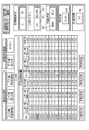
図4は、信号ラインLに流れる電流の測定を行うときにGOT104が表示するGUI画面(自動測定画面)の一例である。例えば、信号ラインを点検する利用者により図4に示したボタンB3を押す操作が行われると、電流測定部1001は、選択部210を制御して信号ラインLaを順次AD変換ポートへ接続する。電流測定部1001は、接続された信号ラインLa毎に電圧を測定し、接続された信号ラインLaに流れる電流の電流値を測定した電圧から算出し、算出した電流値を記憶部109に記録する。電流測定部1001は、電圧測定の際には、AD変換ポートに接続される信号ラインLaが替わった後、設定部1003で設定されたタイミングとなると、信号ラインLaとグランド間の電圧Vaのサンプリングを開始する。電流測定部1001は、電圧Vaのサンプリングを開始してから予め定められた時間が経過するとサンプリングを終了する。
FIG. 4 is an example of a GUI screen (automatic measurement screen) displayed by the
電流測定部1001は、一の信号ラインLaについて、流れる電流値の測定を終える毎にGUI画面を更新して測定値を表示する。例えば、電流測定部1001は、信号ラインLaの識別のために信号ラインLaの各々に付与されている回線番号が003の信号ラインLaについて測定が終了すると、算出した電流値を「No.」の列の「003」の行に表示する。なお、図4の画面例では、各回線番号に対応して、電流値を異常と判断するしきい値下限、電流値を異常と判断するしきい値上限、および電流値の測定値が表示されている。回線番号のいずれか一つは、ダミー回路110の信号ラインに対応している。そして、測定値がしきい値範囲外である場合は、電流値異常と判断されて、測定値の欄がハイライト表示される。
The
ユーザは、電流値の異常が検知された場合、GOT104を操作してダミー回路110を流れる電流の測定結果の経時的な変化を確認する。ユーザは、ダミー回路110を流れる電流の測定結果が、記録の開始時点から変化している場合、AD変換ポートに異常があると判定する。また、ユーザは、ダミー回路110を流れる電流の測定結果が、記録の開始時点から変化していない場合、AD変換ポートに異常がないと判定する。なお、ユーザは、ダミー回路110を流れる電流の測定結果が、しきい値範囲外(しきい値下限としきい値上限との範囲外)である場合に、AD変換ポートに異常があると判定し、しきい値範囲内である場合に、AD変換ポートに異常がないと判定してもよい。つぎに、ユーザは、AD変換ポートに異常がない場合、測定値の欄がハイライト表示された回線番号の信号線について、絶縁が低下していると判定し、測定値の欄がハイライト表示されていない回線番号の信号線については、絶縁が低下していないと判定する。
When an abnormality in the current value is detected, the user operates the
なお、ダミー回路110を流れる電流の測定結果はGOT104に必ずしも表示しなくてもよい。その場合、ユーザは、記憶部109等の記憶内容を外部出力等することにより、ダミー回路110を流れる電流の測定結果の経時的な変化等を確認して、AD変換ポートの異常と信号線11a,11c,11dの絶縁低下とを判別することができる。
Note that the measurement result of the current flowing through the
さらに、検知部1002が、信号ラインLa(信号線11a,11c,11d)に流れる電流の測定結果と、しきい値上限、しきい値下限とを比較して、信号線11a等の劣化を自動判別しているが、当該測定結果からユーザが判別してもよい。その場合、ユーザは、記憶部109等の記憶内容を外部出力等することにより、信号ラインLa(信号線11a,11c,11d)に流れる電流の測定結果、及びダミー回路110を流れる電流の測定結果の経時的な変化等を確認して、AD変換ポートの異常と信号線の絶縁低下とを判別することができる。
Further, the
本実施形態によれば、ダミー回路110を流れる電流の電流値の測定結果から、信号線11a、信号線11cおよび信号線11dの劣化の検知に使用するAD変換ポートの異常を検知することができる。
According to the present embodiment, an abnormality of the AD conversion port used for detecting the deterioration of the
[変形例]
以上、本発明の実施形態について説明したが、本発明は上述した実施形態に限定されることなく、他の様々な形態で実施可能である。例えば、上述の実施形態を以下のように変形して本発明を実施してもよい。なお、上述した実施形態および以下の変形例は、各々を組み合わせてもよい。
[Modification]
Although the embodiments of the present invention have been described above, the present invention is not limited to the above-described embodiments, and can be implemented in various other forms. For example, the present invention may be implemented by modifying the above-described embodiment as follows. The above-described embodiment and the following modified examples may be combined with each other.
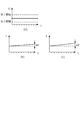
上述した実施形態においては、AD変換ポートの異常を、ダミー回路110を流れる電流の測定結果からユーザが判定しているが、制御部101が自動で判定する構成としてもよい。例えば、検知部1002は、全ての信号ラインLaについて、流れる電流の電流値の測定を終了すると、ダミー回路110を流れる電流の測定結果に基づいて、AD変換ポートに異常があるか否かを判定する。図5(a)は、ダミー回路110を流れる電流の電流値の経時的な測定結果の一例を示す図である。検知部1002は、ダミー回路110に流れる電流の測定結果を予め定められた第1閾値(しきい値上限)および第1閾値より小さい第2閾値(しきい値下限)と比較する。検知部1002は、ダミー回路110を流れる電流の測定結果が第1閾値を超えている場合、または第2閾値未満である場合、AD変換ポートに異常があると判定する。AD変換ポートに異常があることを検知部1002が検知すると、GUI部1005は、AD変換ポートに異常があることを知らせるための画面をGOT104に表示させるようにしてもよい。
In the above-described embodiment, the abnormality of the AD conversion port is determined by the user from the measurement result of the current flowing through the
このように、検知部1002は、ダミー回路110を流れる電流の測定結果が、予め定められた閾値範囲外である場合に、AD変換ポートに異常があると判定し、予め定められた閾値範囲内である場合に、AD変換ポートに異常がないと判定する。つぎに、検知部1002は、AD変換ポートに異常がない場合、上述した図4の動作例と同様に、端末機器に接続する信号線を流れる電流の測定結果が、予め定められた閾値範囲外である場合に、端末機器に接続する信号線の異常と判定し、予め定められた閾値範囲内である場合に、端末機器に接続する信号線の正常と判定する。
As described above, when the measurement result of the current flowing through the
また、本発明においては、検知部1002は、ダミー回路110を流れる電流の測定結果が上記の第1閾値以下且つ第2閾値以上である場合、信号線を流れる電流の経時的な変化量と、ダミー回路110を流れる電流の経時的な変化量から、AD変換ポートの異常を検知してもよい。図5(b)は、ダミー回路110を流れる電流の経時的な測定結果の一例を示す図である。図5(b)においては、ダミー回路110を流れる電流の記録開始時点からの変化量は、a1となっている。図5(c)は、信号線を流れる電流の記録開始時点からの経時的な測定結果の一例を示す図である。図5(c)においては、信号線を流れる電流の電流値の変化量は、a2となっている。検知部1002は、変化量a1と変化量a2が共に予め定められた閾値を超える場合、AD変換ポートに異常があると判定してもよい。また、検知部1002は、変化量a2が予め定められた閾値を超え、変化量a1が予め定められた閾値より低い場合、信号線の絶縁が低下していると判定してもよい。
Further, in the present invention, when the measurement result of the current flowing through the
本発明においては、検知部1002は、ダミー回路110を流れる電流の初回の測定結果と最新の測定結果との差が予め定められた閾値を超える場合、信号ラインLaの電圧を測定するAD変換ポートに異常があると判定してもよい。
In the present invention, when the difference between the first measurement result of the current flowing through the
本発明においては、設定部1003は、信号線11a、信号線11cおよび信号線11dに異常が発生していることを判定するためのしきい値上限としきい値下限を、電流測定部1001が行った測定の結果に応じて変更してもよい。例えば、設定部1003は、ダミー回路110を流れる電流の電流値の変化量a1と、予め定められた信号線を流れる電流の電流値の変化量a2が共に予め定められた閾値以下であり、変化量a1と変化量a2の差が予め定められた閾値以下である場合、初期設定よりしきい値上限を小さくし、初期設定よりしきい値下限を大きくしてもよい。また、設定部1003は、しきい値上限としきい値下限を変更する場合は、複数の信号線11a、信号線11cおよび信号線11d毎にしきい値上限およびしきい値下限を変更してもよい。
In the present invention, the
本発明においては、信号線11a、信号線11cおよび信号線11dを流れる電流の測定結果の経時的変化と、ダミー回路110を流れる電流の測定結果の経時的変化をGOT104においてグラフで表示してもよい。
In the present invention, the change over time of the measurement result of the current flowing through the
上述した実施形態においては、電圧Vaを測定し、電圧Vaから算出した電流値Iを記憶部109に記録しているが、本発明においては、AD変換ポートで測定した電圧Vaの平均値を記憶部109に記録する構成としてもよい。
In the above-described embodiment, the voltage Va is measured, and the current value I calculated from the voltage Va is stored in the
上述した実施形態においては、トンネル内に設置されている端末機器と防災受信盤10とを接続する信号線について、流れる電流を防災受信盤10で測定しているが、例えば、ビルなどの建築物に設置される火災受信機と熱や煙を感知する感知器や発信機とを接続する信号線に流れる電流について、火災受信機で測定してもよい。
In the above-described embodiment, the current flowing through the signal line connecting the terminal device installed in the tunnel and the
1…防災システム、2a、2b…トンネル、3…通信ネットワーク、5…区画、10…防災受信盤、11a、11b、11c、11d…信号線、21…ポンプ制御盤、30…遠隔制御設備、31…温度検知器、32…火災検知器、33…消火栓装置、34…手動通報装置、101…制御部、102…伝送部、103…通信部、104…GOT、105…操作部、106…警報部、107…ポンプ制御部、108…表示部、109…記憶部、110…ダミー回路、200…入出力ユニット、201a、201c、201d…信号受信部、202a、202c、202d、202e…測定回路、210…選択部、1001…電流測定部、1002…検知部、1003…設定部、1004…監視部、1005…GUI部。
DESCRIPTION OF
Claims (6)
前記切替手段により測定対象となった信号線を流れる電流値または電圧値を少なくとも測定する測定手段と、
前記端末機器に接続する信号線の前記測定手段による測定結果と、前記ダミー回路に接続する信号線の前記測定手段による測定結果を記録する記録手段と
を備える防災システム。 Switching means for switching a signal line to be measured in a signal line connected to a terminal device and a signal line connected to a dummy circuit,
A measuring unit that measures at least a current value or a voltage value flowing through the signal line that has been measured by the switching unit;
A disaster prevention system comprising: a measurement result of the signal line connected to the terminal device by the measurement unit; and a recording unit that records a measurement result of the signal line connected to the dummy circuit by the measurement unit.
を備える請求項1に記載の防災システム。 2. The disaster prevention device according to claim 1, further comprising: a first detection unit configured to detect an abnormality of the measurement unit based on a measurement result of a current value or a voltage value flowing through a signal line connected to the dummy circuit recorded on the recording unit. 3. system.
を備える請求項1または請求項2に記載の防災システム。 The measurement result of the current value or the voltage value flowing through the signal line connected to the terminal device recorded in the recording means, and the measurement result of the current value or the voltage value flowing through the signal line connected to the dummy circuit recorded in the recording means The disaster prevention system according to claim 1, further comprising: a second detection unit configured to detect an abnormality of a signal line connected to the terminal device based on a measurement result.
前記記録手段に記録された前記端末機器に接続する信号線を流れる電流値または電圧値の測定結果と、前記記録手段に記録された前記ダミー回路に接続する信号線を流れる電流値または電圧値の測定結果に基づいて、前記閾値を設定する閾値設定手段
を備える請求項3に記載の防災システム。 The second detection means determines that there is no abnormality in the measurement means when a measurement result of a current value or a voltage value flowing through a signal line connected to the dummy circuit is within a predetermined threshold range, When it is determined that there is no abnormality in the measuring unit, the signal line is connected to the signal line when the measurement result of the current value or the voltage value flowing through the signal line connected to the terminal device recorded in the recording unit is out of a predetermined threshold range. Is determined to be abnormal,
The measurement result of the current value or the voltage value flowing through the signal line connected to the terminal device recorded in the recording means, and the measurement result of the current value or the voltage value flowing through the signal line connected to the dummy circuit recorded in the recording means The disaster prevention system according to claim 3, further comprising: a threshold setting unit configured to set the threshold based on a measurement result.
を備える請求項1乃至4のいずれか1項に記載の防災システム。 The disaster prevention system according to any one of claims 1 to 4, further comprising a display unit configured to display a measurement result recorded in the recording unit in a graph.
前記タイミングを設定するタイミング設定手段を備える
請求項1乃至5のいずれか一項に記載の防災システム。 The measurement unit is a unit that samples and measures the signal line to be measured by the switching unit at a predetermined cycle, and starts the sampling at a set timing.
The disaster prevention system according to claim 1, further comprising a timing setting unit configured to set the timing.
Priority Applications (1)
| Application Number | Priority Date | Filing Date | Title |
|---|---|---|---|
| JP2018184623A JP7181039B2 (en) | 2018-09-28 | 2018-09-28 | disaster prevention system |
Applications Claiming Priority (1)
| Application Number | Priority Date | Filing Date | Title |
|---|---|---|---|
| JP2018184623A JP7181039B2 (en) | 2018-09-28 | 2018-09-28 | disaster prevention system |
Publications (2)
| Publication Number | Publication Date |
|---|---|
| JP2020052964A true JP2020052964A (en) | 2020-04-02 |
| JP7181039B2 JP7181039B2 (en) | 2022-11-30 |
Family
ID=69997426
Family Applications (1)
| Application Number | Title | Priority Date | Filing Date |
|---|---|---|---|
| JP2018184623A Active JP7181039B2 (en) | 2018-09-28 | 2018-09-28 | disaster prevention system |
Country Status (1)
| Country | Link |
|---|---|
| JP (1) | JP7181039B2 (en) |
Cited By (2)
| Publication number | Priority date | Publication date | Assignee | Title |
|---|---|---|---|---|
| US11695950B2 (en) | 2019-02-07 | 2023-07-04 | Vid Scale, Inc. | Systems, apparatus and methods for inter prediction refinement with optical flow |
| US12160582B2 (en) | 2019-06-21 | 2024-12-03 | Interdigital Vc Holdings, Inc. | Precision refinement for motion compensation with optical flow |
Citations (4)
| Publication number | Priority date | Publication date | Assignee | Title |
|---|---|---|---|---|
| JPH02173543A (en) * | 1988-11-30 | 1990-07-05 | Tatsuta Electric Wire & Cable Co Ltd | Leakage detection device |
| JPH0856160A (en) * | 1994-08-10 | 1996-02-27 | Nissin Electric Co Ltd | Abnormality detector for a/d converter |
| JP2018032114A (en) * | 2016-08-23 | 2018-03-01 | ホーチキ株式会社 | Tunnel disaster prevention system |
| JP2018049487A (en) * | 2016-09-23 | 2018-03-29 | ホーチキ株式会社 | Tunnel disaster prevention system |
-
2018
- 2018-09-28 JP JP2018184623A patent/JP7181039B2/en active Active
Patent Citations (4)
| Publication number | Priority date | Publication date | Assignee | Title |
|---|---|---|---|---|
| JPH02173543A (en) * | 1988-11-30 | 1990-07-05 | Tatsuta Electric Wire & Cable Co Ltd | Leakage detection device |
| JPH0856160A (en) * | 1994-08-10 | 1996-02-27 | Nissin Electric Co Ltd | Abnormality detector for a/d converter |
| JP2018032114A (en) * | 2016-08-23 | 2018-03-01 | ホーチキ株式会社 | Tunnel disaster prevention system |
| JP2018049487A (en) * | 2016-09-23 | 2018-03-29 | ホーチキ株式会社 | Tunnel disaster prevention system |
Cited By (3)
| Publication number | Priority date | Publication date | Assignee | Title |
|---|---|---|---|---|
| US11695950B2 (en) | 2019-02-07 | 2023-07-04 | Vid Scale, Inc. | Systems, apparatus and methods for inter prediction refinement with optical flow |
| US12143626B2 (en) | 2019-02-07 | 2024-11-12 | Interdigital Vc Holdings, Inc. | Systems, apparatus and methods for inter prediction refinement with optical flow |
| US12160582B2 (en) | 2019-06-21 | 2024-12-03 | Interdigital Vc Holdings, Inc. | Precision refinement for motion compensation with optical flow |
Also Published As
| Publication number | Publication date |
|---|---|
| JP7181039B2 (en) | 2022-11-30 |
Similar Documents
| Publication | Publication Date | Title |
|---|---|---|
| JP2018067032A (en) | Tunnel disaster prevention system | |
| JP2021122141A (en) | Disaster prevention system | |
| JP6804134B2 (en) | Tunnel disaster prevention system | |
| JP2020052964A (en) | Disaster prevention system | |
| JP7197321B2 (en) | disaster prevention system | |
| JP7181038B2 (en) | disaster prevention system | |
| JP7207925B2 (en) | disaster prevention system | |
| JP7082156B2 (en) | Disaster prevention system | |
| JP7207907B2 (en) | disaster prevention system | |
| KR100750513B1 (en) | P type and P type combined receiver for fire management | |
| JP7615192B2 (en) | Disaster Prevention System | |
| JP7441919B2 (en) | disaster prevention system | |
| JP3963416B2 (en) | Sprinkler fire extinguishing equipment | |
| JP2023089167A (en) | disaster prevention system | |
| JP6689711B2 (en) | Tunnel disaster prevention system | |
| JP6916926B2 (en) | Disaster prevention system | |
| JP7304325B2 (en) | disaster prevention system | |
| KR20210154386A (en) | Non-Fire Alarm Rate Reduction P-type Receiver | |
| JP7265608B2 (en) | disaster prevention system | |
| JP6990746B2 (en) | Disaster prevention system | |
| JP7592444B2 (en) | Fire Receiver | |
| JP7203152B2 (en) | disaster prevention system | |
| JP2015091284A (en) | Integrated fire extinguishing system | |
| KR200429451Y1 (en) | P type composite receiver for fire management | |
| JP2026013812A (en) | Disaster prevention system |
Legal Events
| Date | Code | Title | Description |
|---|---|---|---|
| A621 | Written request for application examination |
Free format text: JAPANESE INTERMEDIATE CODE: A621 Effective date: 20210611 |
|
| A977 | Report on retrieval |
Free format text: JAPANESE INTERMEDIATE CODE: A971007 Effective date: 20220520 |
|
| A131 | Notification of reasons for refusal |
Free format text: JAPANESE INTERMEDIATE CODE: A131 Effective date: 20220614 |
|
| A521 | Request for written amendment filed |
Free format text: JAPANESE INTERMEDIATE CODE: A523 Effective date: 20220728 |
|
| TRDD | Decision of grant or rejection written | ||
| A01 | Written decision to grant a patent or to grant a registration (utility model) |
Free format text: JAPANESE INTERMEDIATE CODE: A01 Effective date: 20221025 |
|
| A61 | First payment of annual fees (during grant procedure) |
Free format text: JAPANESE INTERMEDIATE CODE: A61 Effective date: 20221117 |
|
| R150 | Certificate of patent or registration of utility model |
Ref document number: 7181039 Country of ref document: JP Free format text: JAPANESE INTERMEDIATE CODE: R150 |