JP2020052958A - CONTROL DEVICE, ITS CONTROL METHOD, CONTROL PROGRAM, AND STRUCTURE - Google Patents
CONTROL DEVICE, ITS CONTROL METHOD, CONTROL PROGRAM, AND STRUCTURE Download PDFInfo
- Publication number
- JP2020052958A JP2020052958A JP2018184561A JP2018184561A JP2020052958A JP 2020052958 A JP2020052958 A JP 2020052958A JP 2018184561 A JP2018184561 A JP 2018184561A JP 2018184561 A JP2018184561 A JP 2018184561A JP 2020052958 A JP2020052958 A JP 2020052958A
- Authority
- JP
- Japan
- Prior art keywords
- control
- value
- linearization
- input
- target
- Prior art date
- Legal status (The legal status is an assumption and is not a legal conclusion. Google has not performed a legal analysis and makes no representation as to the accuracy of the status listed.)
- Granted
Links
Images


Landscapes
- Feedback Control In General (AREA)
Abstract
【課題】制御精度を向上させると共にエネルギー消費を抑制することできる制御装置、及びその制御方法並びに制御プログラム、構造体を提供することを目的とする。【解決手段】非線形要素を備える制御対象30を線形化システム28に線形化して制御する制御装置20であって、制御対象30の状態を示す制御量を量子化した値を検出するセンサ部25と、制御対象30の状態が目標状態に近づくように線形化システム28に入力される値と、線形化システム28の数理モデルとに基づいて制御量の推定値を連続量として算出し、制御量の推定値を量子化した値とセンサ部25の出力との偏差に基づいて制御量の推定値を再帰的に補正するフィルタ部26と、フィルタ部26から出力される制御量の推定値に基づいて、線形化システムに入力される値又はその変換値の補正を行う線形化フィードバック部24と、を備える。【選択図】図2PROBLEM TO BE SOLVED: To provide a control device capable of improving control accuracy and suppressing energy consumption, a control method thereof, a control program, and a structure. SOLUTION: This is a control device 20 for linearizing and controlling a control target 30 having a non-linear element in a linearization system 28, and a sensor unit 25 for detecting a value obtained by quantizing a control amount indicating a state of the control target 30. , The estimated value of the control amount is calculated as a continuous amount based on the value input to the linearization system 28 so that the state of the control target 30 approaches the target state and the mathematical model of the linearization system 28, and the control amount is calculated. Based on the filter unit 26 that recursively corrects the estimated value of the control amount based on the deviation between the quantized value of the estimated value and the output of the sensor unit 25, and the estimated value of the control amount output from the filter unit 26. , A linearization feedback unit 24 that corrects a value input to the linearization system or a converted value thereof. [Selection diagram] Fig. 2
Description
本発明は、制御装置、及びその制御方法並びに制御プログラム、構造体に関するものである。 The present invention relates to a control device, a control method thereof, a control program, and a structure.
水中航走体等の構造体では、深度やピッチ角等の各制御軸に対して制御が行われている。例えば特許文献1には、センサにおける量子化誤差を低減して制御を行うことが開示されている。
In a structure such as an underwater vehicle, control is performed on each control axis such as a depth and a pitch angle. For example,
また、水中航走体等の構造体の運動特性は一般的に非線形である。このため、制御精度を向上させるために非線形特性を線形化する必要がある。線形化手法としては、例えば複数の動作点まわりでそれぞれ線形近似を行い、それらを線形補完してつなぎ合わせるゲインスケジューリングが用いられる。しかしながら、ゲインスケジューリングでは、各動作点の近傍以外では線形化精度が劣化するため制御精度や安定性が十分ではない。 The motion characteristics of a structure such as an underwater vehicle are generally nonlinear. For this reason, it is necessary to linearize the nonlinear characteristic in order to improve the control accuracy. As a linearization method, for example, a gain scheduling that performs linear approximation around a plurality of operating points and linearly complements and connects them is used. However, in the gain scheduling, the control accuracy and the stability are not sufficient because the linearization accuracy is deteriorated in areas other than the vicinity of each operating point.
そこで、制御対象の非線形特性を近似することなく全領域で線形化する方法として厳密な線形化手法が提案されている(例えば、非特許文献1−4)。 Therefore, a strict linearization method has been proposed as a method of linearizing the entire region without approximating the non-linear characteristics of the control target (for example, Non-Patent Documents 1-4).
しかしながら、非線形特性を有する制御対象に対して厳密な線形化を適用した場合、制御精度が向上する一方で、厳密な線形化システムの入力の感度が高くなり、例えば、入力されるセンサ値の量子化誤差(量子化振動)に対して敏感に修正動作が働いてエネルギー消費が増加する可能性がある。すなわち、制御対象に対して線形化を適用した上で、量子化誤差の影響を抑制することが課題となっている。 However, when strict linearization is applied to a control target having a non-linear characteristic, while the control accuracy is improved, the sensitivity of the input of the strict linearization system is increased. There is a possibility that the correction operation works sensitively to the quantization error (quantization oscillation) and the energy consumption increases. In other words, it is an issue to apply the linearization to the control target and to suppress the influence of the quantization error.
本発明は、このような事情に鑑みてなされたものであって、制御精度を向上させると共にエネルギー消費を抑制することできる制御装置、及びその制御方法並びに制御プログラム、構造体を提供することを目的とする。 The present invention has been made in view of such circumstances, and has as its object to provide a control device capable of improving control accuracy and suppressing energy consumption, a control method thereof, a control program, and a structure. And
本発明の第1態様は、非線形要素を備える制御対象を線形化システムに線形化して制御する制御装置であって、前記制御対象の状態を示す制御量を量子化した値を検出するセンサ部と、前記制御対象の状態が目標状態に近づくように前記線形化システムに入力される値と、前記線形化システムの数理モデルとに基づいて前記制御量の推定値を連続量として算出し、前記制御量の推定値を量子化した値と前記センサ部の出力との偏差に基づいて前記制御量の推定値を再帰的に補正するフィルタ部と、前記フィルタ部から出力される前記制御量の推定値に基づいて、前記線形化システムに入力される値又はその変換値の補正を行う線形化フィードバック部と、を備える制御装置である。 A first aspect of the present invention is a control device that linearizes and controls a control target including a non-linear element into a linearization system, and a sensor unit that detects a value obtained by quantizing a control amount indicating a state of the control target. Calculating an estimated value of the control amount as a continuous amount based on a value input to the linearization system and a mathematical model of the linearization system so that the state of the control target approaches a target state; A filter section for recursively correcting the estimated value of the control amount based on a deviation between a value obtained by quantizing the estimated value of the amount and the output of the sensor section, and an estimated value of the control amount output from the filter section And a linearization feedback unit that corrects a value input to the linearization system or a conversion value thereof based on the linearization feedback control.
上記のような構成によれば、制御対象の非線形要素を線形化するため、制御精度を向上させることが可能となる。なお、線形化とは、例えば、厳密な線形化であり、厳密な線形化とは、制御対象の非線形特性を近似することなく全領域で線形化する手法である。 According to the above-described configuration, since the nonlinear element to be controlled is linearized, control accuracy can be improved. Note that the linearization is, for example, strict linearization, and the strict linearization is a method of linearizing over the entire region without approximating the non-linear characteristics of the control target.
また、制御対象を線形化した場合には、線形化システムにおける線形化フィードバック部の入力の感度が高くなり、例えば入力されるセンサ値の量子化誤差(量子化に伴う最小分解能の遷移。量子化振動)に対して敏感に修正動作が働いてエネルギー消費が増加する可能性がある。そこで、制御対象の制御量を検出するセンサ部と線形化を行う線形化フィードバック部との間に、フィルタ部を設けることとした。フィルタ部において、線形化システムの数理モデルを用いてセンサ部で量子化した制御量の推定連続値を出力することとしたため、線形化フィードバック部に入力される値を連続値とすることができ、量子化振動によるエネルギー消費の増加を抑制することが可能となる。 In addition, when the control target is linearized, the sensitivity of the input of the linearization feedback unit in the linearization system increases, and for example, the quantization error of the input sensor value (transition of the minimum resolution due to quantization. The corrective action may be sensitive to vibrations and increase energy consumption. Therefore, a filter unit is provided between the sensor unit that detects the control amount of the control target and the linearization feedback unit that performs linearization. In the filter unit, since the estimated continuous value of the control amount quantized by the sensor unit using the mathematical model of the linearization system is to be output, the value input to the linearization feedback unit can be a continuous value, It is possible to suppress an increase in energy consumption due to quantization oscillation.
すなわち、フィルタ部においてセンサ部の量子化された値を連続値に変換することによって量子化振動等に基づくエネルギー消費を抑制することが可能となる。 That is, by converting the quantized value of the sensor unit into a continuous value in the filter unit, it is possible to suppress energy consumption due to quantization vibration and the like.
上記制御装置において、前記フィルタ部の開ループ伝達関数は、前記フィルタ部の制御帯域付近において1次の積分特性とすることとしてもよい。 In the control device, the open-loop transfer function of the filter unit may have a first-order integral characteristic near a control band of the filter unit.
上記のような構成によれば、フィルタ部の開ループ特性が積分特性となるため、フィルタ部における振動発生を防止することができる。 According to the above configuration, the open-loop characteristic of the filter unit becomes an integral characteristic, so that the occurrence of vibration in the filter unit can be prevented.
上記制御装置において、前記フィルタ部は、開ループ上に前記数理モデルの積分要素の次数から1を引いた次数の微分要素を持つ伝達関数を有することとしてもよい。 In the control device, the filter unit may include a transfer function having a differential element of an order obtained by subtracting 1 from the order of an integral element of the mathematical model on an open loop.
上記のような構成によれば、数理モデルの積分要素の次数から1を引いた次数の微分要素を持つ伝達関数によってフィルタ部の開ループ特性が積分特性となるため、フィルタ部における振動発生を防止することができる。 According to the above configuration, the open loop characteristic of the filter unit becomes an integral characteristic by a transfer function having a differential element of the order obtained by subtracting 1 from the order of the integral element of the mathematical model, thereby preventing the occurrence of vibration in the filter unit. can do.
上記制御装置において、前記微分要素は、帯域制限付きの微分器であることとしてもよい。 In the control device, the differentiating element may be a differentiator with a band limit.
上記のような構成によれば、帯域制限付きの微分器を用いることで応答帯域を適切に設定することができる。 According to the above configuration, the response band can be appropriately set by using the differentiator with the band limitation.
上記制御装置において、前記フィルタ部は、前記偏差に対して所定の定数を乗算した値を用いて前記入力される値を補正することとしてもよい。 In the control device, the filter unit may correct the input value using a value obtained by multiplying the deviation by a predetermined constant.
上記のような構成によれば、センサ部の出力と数理モデルにおける制御量を量子化した値との偏差に対して所定の定数を乗算し、乗算した値を用いて数理モデルに入力される値を補正するため、定数によって応答性を調整することが可能となる。 According to the above configuration, the deviation between the output of the sensor unit and the value obtained by quantizing the control amount in the mathematical model is multiplied by a predetermined constant, and the value input to the mathematical model is calculated using the multiplied value. Is corrected, the response can be adjusted by a constant.
本発明の第2態様は、上記の制御装置を備えた構造体である。 A second aspect of the present invention is a structure provided with the above-described control device.
本発明の第3態様は、非線形要素を備える制御対象を線形化システムに線形化して制御する制御方法であって、前記制御対象の状態を示す制御量を量子化した値を検出する検出工程と、前記制御対象の状態が目標状態に近づくように前記線形化システムに入力される値と、前記線形化システムの数理モデルとに基づいて前記制御量の推定値を連続量として算出し、前記制御量の推定値を量子化した値と前記検出工程の出力との偏差に基づいて前記制御量の推定値を再帰的に補正するフィルタ工程と、前記フィルタ工程にて出力される前記制御量の推定値に基づいて、前記線形化システムに入力される値又はその変換値の補正を行う線形化フィードバック工程と、を有する制御方法である。 A third aspect of the present invention is a control method for linearizing and controlling a control target having a non-linear element to a linearization system, and detecting a value obtained by quantizing a control amount indicating a state of the control target, Calculating an estimated value of the control amount as a continuous amount based on a value input to the linearization system and a mathematical model of the linearization system so that the state of the control target approaches a target state; A filter step of recursively correcting the estimated value of the control amount based on a deviation between a value obtained by quantizing the estimated value of the amount and the output of the detection step, and estimating the control amount output in the filter step A linearization feedback step of correcting a value input to the linearization system or a conversion value thereof based on the value.
本発明の第4態様は、非線形要素を備える制御対象を線形化システムに線形化して制御する制御プログラムであって、前記制御対象の状態を示す制御量を量子化した値を検出する検出処理と、前記制御対象の状態が目標状態に近づくように前記線形化システムに入力される値と、前記線形化システムの数理モデルとに基づいて前記制御量の推定値を連続量として算出し、前記制御量の推定値を量子化した値と前記検出処理の出力との偏差に基づいて前記制御量の推定値を再帰的に補正するフィルタ処理と、前記フィルタ処理にて出力される前記制御量の推定値に基づいて、前記線形化システムに入力される値又はその変換値の補正を行う線形化フィードバック処理と、をコンピュータに実行させるための制御プログラムである。 A fourth aspect of the present invention is a control program for linearizing and controlling a control target having a non-linear element to a linearization system, and detecting a value obtained by quantizing a control amount indicating a state of the control target, Calculating an estimated value of the control amount as a continuous amount based on a value input to the linearization system and a mathematical model of the linearization system so that the state of the control target approaches a target state; A filter process for recursively correcting the control amount estimate based on a deviation between a value obtained by quantizing the amount estimate and an output of the detection process, and estimating the control amount output in the filter process A linearization feedback process for correcting a value input to the linearization system or a conversion value thereof based on the value is a control program for causing a computer to execute the process.
本発明によれば、制御精度を向上させると共にエネルギー消費を抑制することができるという効果を奏する。 ADVANTAGE OF THE INVENTION According to this invention, there exists an effect that control accuracy can be improved and energy consumption can be suppressed.
以下に、本発明に係る制御装置、及びその制御方法並びに制御プログラム、構造体の一実施形態について、図面を参照して説明する。制御装置は、非線形な運動特性を有する構造体であれば、幅広く適用できるものであって、以下に説明するような水中航走体のみに限定されるものではない。例えば、制御装置は、航空機やロケット、ドローン等の構造体に適用可能であり、有人及び無人に関わらず適用可能である。 Hereinafter, an embodiment of a control device, a control method, a control program, and a structure according to the present invention will be described with reference to the drawings. The control device can be widely applied as long as it has a structure having a non-linear motion characteristic, and is not limited to the underwater vehicle as described below. For example, the control device can be applied to a structure such as an aircraft, a rocket, and a drone, and can be applied regardless of whether it is manned or unmanned.
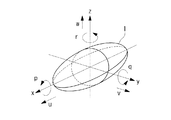
図1は、本発明の一実施形態に係る制御装置20を備えた水中航走体1を例示した図である。図1に示すように、水中航走体1は、船尾軸線(以下、「x軸」という。)、左右軸線(以下、「y軸」という。)、上下軸線(以下、「z軸」という。)からなる互いに直交する3つの直線軸と、これら各直線軸に対する3つの回転軸とからなる船体座標系の6軸(6自由度)が定義される。そして、x軸方向の速度をu、y軸方向の速度をv、z軸方向の速度をwとする。また、x軸周りの回転角速度pをロール角速度、y軸周りの回転角速度qをピッチ角速度、z軸周りの回転角速度rを方位角速度とする。更に、絶対座標系(地球座標系)におけるx軸周りの回転角度をロール角φ、y軸周りの回転角度をピッチ角θ、z軸周りの回転角度をヨー角ψと定義する。
FIG. 1 is a diagram illustrating an
制御装置20は、水中航走体1を制御対象30として水中航走体1の絶対座標系の各制御軸(深度、ピッチ角、方位角、ロール角)に対して制御を行う。具体的には、制御装置20は、水中航走体1に設けられた深度用アクチュエータ、ピッチ角用アクチュエータ、方位角用アクチュエータ、ロール角用アクチュエータに対して操作量(制御指令値)を与えることによって各軸方向の制御量を制御する。なお、各アクチュエータは船体に設けられた可動部(例えば、船尾の舵等)を駆動して各制御軸方向に水中航走体1を移動させる駆動装置である。
The
制御装置20は、例えば、図示しないCPU(中央演算装置)、RAM(Random Access Memory)等のメモリ、及びコンピュータ読み取り可能な記録媒体等から構成されている。後述の各種機能を実現するための一連の処理の過程は、プログラムの形式で記録媒体等に記録されており、このプログラムをCPUがRAM等に読み出して、情報の加工・演算処理を実行することにより、後述の各種機能が実現される。なお、プログラムは、ROMやその他の記憶媒体に予めインストールしておく形態や、コンピュータ読み取り可能な記憶媒体に記憶された状態で提供される形態、有線又は無線による通信手段を介して配信される形態等が適用されてもよい。コンピュータ読み取り可能な記憶媒体とは、磁気ディスク、光磁気ディスク、CD−ROM、DVD−ROM、半導体メモリ等である。
The
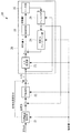
図2は、制御装置20が備える機能を示した機能ブロック図である。なお、図2に示す制御対象30は水中航走体1であり、制御装置20には含まれない(制御装置20による制御対象である)。図2に示されるように、制御装置20は、目標軌道生成部21と、フィードバック制御部22と、入力変換部23と、線形化フィードバック部24と、センサ部25と、フィルタ部26とを備えている。なお、図2において、厳密に線形化されたシステムを線形化システム28として示している。
FIG. 2 is a functional block diagram illustrating functions provided in the
目標軌道生成部21は、水中航走体1における上位制御装置等から出力される設定値に基づいて、目標値を算出する。設定値とは、各制御軸方向の目標指令(例えば、深度の目標指令)であり、例えば運転員等によって設定される。具体的には、目標軌道生成部21は、入力された設定値を用いて目標軌道を生成し出力する。目標軌道とは、現状の水中航走体1の状態から、入力された設定値まで状態を変化させるための軌道であり、現状の水中航走体1の状態から設定値まで所定の時間をかけて到達するように設定される。例えば、ピッチ角を例にとると、現状のピッチ角が所定の時間をかけて入力された設定値(ピッチ角)まで達するように目標値(軌道)が設定される。なお、設定値までの到達に要する時間については、例えば、アクチュエータの許容可能な可動速度等によって決定される。このように目標軌道を生成することによって、舵等の急な変化を抑制して、制御の安定性を確保することができる。
The target
目標軌道生成部21には、設定値と、水中航走体1の船尾軸方向の速度uの観測値とが入力される。そして、速度uに応じて必要な応答になるように時定数を決定した2次フィルタによって、目標軌道を算出する。また、目標軌道生成部21は、上記2次フィルタの内部変数として計算される加速度成分を目標加速度指令として出力し、フィードフォワード制御信号として利用することができる。
The set value and the observed value of the speed u of the
フィードバック制御部22は、目標駆動生成部から出力された目標値と、制御対象30から検出された制御量との差分に基づいて、後述する線形化システム28(厳密に線形化されたシステム)の入力νを演算する。具体的には、フィードバック制御部22には、目標値と、後述するフィルタ部26により出力された制御対象30の現在の制御量との差分が入力される。そして、フィードバック制御部22は、差分が低減されるような入力νを算出し、出力する。なお、速度uにより応答性が異なるため、フィードバック制御部22には、速度uの観測値が入力され、速度uに応じてゲインを可変制御するゲインスケジューリング制御が行われている。フィードバック制御部22から出力される入力νは、後述するように、制御対象30を厳密に線形化した線形システムに適合した入力である。なお、フィードバック制御部22には、例えばPID制御手法等を適宜適用可能である。
The
フィードバック制御部22の出力は、目標軌道生成部21から出力された目標加速度指令と直接加算され、線形化システム28へ入力される。目標加速度信号を利用することで、容易にフィードフォワード制御系を構成することができ、応答性を向上することができる。なお、フィードバック制御部22の出力は、目標加速度指令と加算されずに線形化システム28へ入力されることとしてもよい。
The output of the
なお、線形化システム28とは、非線形要素を備える制御対象30に厳密な線形化手法を適用して、後述する入力変換部23や線形化フィードバック部24等を付加して線形化したシステム(厳密に線形化されたシステム)である。すなわち、制御対象30自体は非線形特性を有していても、線形化システム28全体として見ると線形特性となる。
Note that the
入力変換部23は、制御対象30の入力側において、制御対象30の非線形特性を厳密に線形化するために、入力変換を行う。換言すると、入力変換部23は、厳密な線形化が適用された線形化システム28に入力される入力νと線形化システム28の制御対象30に入力される操作量との間の入力変換を行う。なお、入力変換部23の詳細については、後述する。
The
線形化フィードバック部24は、フィルタ部26から出力される制御量の推定値に基づいて、線形化システム28に入力される値又はその変換値の補正を行う。すなわち、線形化フィードバック部24は、制御対象30の非線形特性を厳密に線形化するために、検出された制御対象30の制御量に基づいて、制御対象30の入力側へフィードバックを行う。換言すると、線形化フィードバック部24は、制御対象30の制御量(フィルタ部26の出力)に基づいてフィードバックを行うことで、線形化システム28の制御対象30に入力される操作量を補正する。なお、線形化フィードバック部24の詳細については、後述する。
The
センサ部25は、制御対象30の状態を示す制御量を量子化した値を検出する。具体的には、センサ部25は、制御対象30の現在の状態を示す情報として、予め設定した制御対象30パラメータの現状値(制御量)を検出する。本実施形態では、水中航走体1を制御対象30としているため、制御対象30パラメータを水中航走体1の各制御軸(深度、ピッチ角、方位角、ロール角)とし、各制御パラメータの現在の状態を示す値を制御量として検出する。そして、センサ部25では、検出したアナログ値を、制御装置20においてデジタル処理可能なように、センサの最小分解能単位で離散的な値(デジタル値)に変換する。なお、以下の説明では、センサ部25から出力された値を制御量実測値(量子化された離散的な値)として説明する。
The
フィルタ部26は、制御対象の状態が目標状態に近づくように線形化システム28に入力される値と、線形化システム28の数理モデルとに基づいて制御量の推定値を連続量として算出し、制御量の推定値を量子化した値とセンサ部25の出力との偏差に基づいて制御量の推定値を再帰的に補正する。すなわち、フィルタ部26は、センサ部25の出力と、数理モデルにおける制御量をセンサと同等の分解能で量子化した値との偏差を算出し、偏差を用いて線形化システム28へ入力される値を補正し、補正した値を数理モデルに入力して制御量の推定連続値(制御量真値)を出力する。なお、数理モデルとは、入力変換部23と線形化フィードバック部24を用いて非線形要素を備える制御対象30を厳密に線形化した線形化システム28に対応したモデルである。すなわち、数理モデルには、線形化システム28の理論的特性(理想状態の伝達関数)が反映されている。センサ部25から出力された制御量実測値が所定の最小分解能単位で離散的に表されるため、フィルタ部26は、最小分解能間の誤差を補正して、離散的な値ではなく、連続的な制御量の値(以下、「制御量真値」という。)を算出する。すなわち、センサ部25からは制御量実測値が出力され、フィルタ部26からは制御量真値が出力され、制御量真値は、センサ部25によって量子化される前の、制御量の値(アナログ値)に近い値を示すものである。そして、フィルタ部26から出力された制御量真値は、線形化フィードバック部24とフィードバック制御部22に入力される。
The
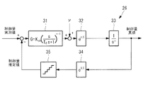
図3は、フィルタ部26の具体的な構成を示す図である。図3に示すように、フィルタ部26は、調整部31と、第1ディレイ32と、演算部33と、第2ディレイ34と、量子化部35とを備えている。なお、フィルタ部26の構成は一例であり、制御量の真値(連続値)が算出できれば、上記に限らず適用可能である。
FIG. 3 is a diagram showing a specific configuration of the
調整部31は、センサ部25から出力された制御量実測値と数理モデルにおける制御量を量子化した値(制御量真値を量子化した値)との偏差が入力され、該偏差を調整することによって応答性等を制御している。なお、以下の説明では、調整部31から出力された値を補正値として説明する。調整部31の伝達関数Gは、以下で示される。
The
(1)式において、Kobは、フィルタ部26の応答性を決定するゲインである。また、s/(Td・s+1)は帯域制限付きの微分フィルタである。なお、Tdは、高周波ノイズ成分を微分しないように適切な値に設定される。フィルタ部26の帯域は、制御装置20の制御帯域よりも高くなるように設定される。
In the equation (1), Kob is a gain that determines the response of the
調整部31の伝達関数である(1)式の1次微分フィルタは、フィルタ部26の開ループ伝達関数を制御帯域付近で1次の積分特性に整形するために設定されている。これは、開ループ伝達関数を1次の積分特性とすることでフィルタ部26の閉ループ応答特性をオーバーシュートのない理想的な応答に設計するためである。
The primary differential filter of the equation (1), which is the transfer function of the
微分フィルタの次数は、厳密に線形化された線形化システム28の伝達関数における積分要素の次数に基づいて決定される。すなわち、調整部31における微分器は、開ループ上に数理モデルの積分要素の次数(厳密に線形化された線形化システム28の伝達関数における積分要素の次数)から1を引いた次数の微分要素に設定される。本実施形態では、厳密に線形化された線形化システム28の伝達関数における積分要素の次数が2の場合を例としているため、微分フィルタの次数は1となる。
The order of the derivative filter is determined based on the order of the integral element in the transfer function of the strictly linearized
第1ディレイ32は、制御対象30へ入力される操作量の遅れを模擬して挿入されている。具体的には、制御対象30に入力される操作量Δは、コントローラからデジタル出力されて実際のアクチュエータを動作させるため、最悪ケースを想定するとデジタルサンプリングの1周期分遅れる可能性がある。このため、フィルタ部26においても、入力νを演算部33に入力する場合に、サンプリング遅れを模擬して第1ディレイ32を設けている。すなわち、第1ディレイ32は、同一の入力νの入力タイミングに対して、線形化システム28において制御対象30に操作量が入力されるタイミングと、フィルタ部26の演算部33に入力νが入力されるタイミングとが乖離しないように調整している。
The
第1ディレイ32には、調整部31の出力である補正値と線形化システム28に入力される入力νとが加算された値が入力され、サンプリング遅れを反映して出力する。
A value obtained by adding the correction value output from the
演算部33は、厳密に線形化された線形化システム28の数理モデルを用いて、連続的な制御量の値(制御量真値)を演算する。すなわち、演算部33は、数理モデルを用いて、センサ部25から出力された量子化された制御量実測値の真値を推定している。なお、真値とは、離散的な値ではなく連続的な値を示す。
The
第2ディレイ34は、センサの検出時のサンプリング遅れを模擬している。実際のセンサでは、制御量をセンシングしてコントローラに入力するまでには通信等のサンプリング遅れが存在する。従って、第2ディレイ34は、制御量がセンサ部25によって検出されるタイミング(制御量実測値のタイミング)と、演算部33において制御量を推定するタイミング(制御量推定値のタイミング)とが乖離しないように調整している。
The
量子化部35は、制御量真値を量子化している。具体的には、量子化部35は、センサ部25と同等の検出分解能を有しており、演算部33から出力された制御量真値(推定連続値)を量子化する。そして、量子化部35の出力は、制御量推定値としてフィードバックされる。
The
演算部33は、線形化システム28の数理モデルを有しているため、線形化システム28に入力される入力νを用いることで、数理モデルから理想的な制御量の状態を推定することが可能である。しかしながら、制御対象30を含む線形化システム28は外乱等の影響を受けるため、数理モデルの特性と誤差が生じる場合がある。このため、演算部33の前段では、センサ部25の出力(制御量実測値)と数理モデルの出力(制御量推定値)との偏差に基づいて入力νが補正され、補正された値が演算部33に入力される。
Since the
例えば、制御量推定値が、制御量実測値よりも小さい場合(制御量推定値<制御量実測値)には、制御量実測値に対して制御量推定値を減算した値が正となり、調整部31において定数倍され、正の補正値が算出される。そして、入力νと正の補正値とが加算されることによって、演算部33への入力値が入力νよりも大きい値となり、数理モデルで推定される制御量真値が増加する方向に修正される。制御量推定値が、制御量実測値よりも大きい場合(制御量推定値>制御量実測値)には、制御量実測値に対して制御量推定値を減算した値が負となり、調整部31において定数倍され、負の補正値が算出される。そして、入力νと負の補正値とが加算されることによって、演算部33への入力値が入力νよりも小さい値となり、数理モデルで推定される制御量真値が減少する方向に修正される。なお、制御量推定値が、制御量実測値と等しい場合(制御量推定値=制御量実測値)には、制御量実測値に対して制御量推定値を減算した値が零となり、補正値が零となる。すなわち、入力νがそのまま演算部33へ入力される。
For example, when the control amount estimated value is smaller than the control amount actual measured value (control amount estimated value <control amount actual measured value), the value obtained by subtracting the control amount estimated value from the control amount actual measured value is positive, and The
なお、本実施形態では、線形化システム28の理想的な伝達関数が、2次の積分要素を対角成分に持つ対角行列となるため、演算部33が有する数理モデルも2次の積分要素を対角成分に持つ対角行列として表現される。すなわち、数理モデルは、線形化システム28の理想的な伝達関数と等しい伝達関数を有する。
In this embodiment, since the ideal transfer function of the
次に、厳密な線形化手法について説明する。
厳密な線形化手法は、制御対象の非線形特性を示した非線形モデルを用いて、近似を行うことなく、特性の全領域において線形化する手法である。すなわち、非線形な制御対象をそれと同等の精度を有する非線形モデル(非線形性を表現した数式)を用いて入出力間が線形となるように数学的な変換を行うものである。なお、線形化システム28では、厳密な線形化手法に限定されず様々な線形化手法を適用することが可能である。
Next, a strict linearization method will be described.
The strict linearization method is a method of performing linearization over the entire region of the characteristic without performing approximation using a nonlinear model showing the nonlinear characteristic of the control target. That is, mathematical conversion is performed on a non-linear control target using a non-linear model (a mathematical expression expressing non-linearity) having the same accuracy as that of the non-linear control target so that the input and output become linear. Note that the
制御対象への操作量を入力Δ、制御対象の制御量を出力Yとすると、水中航走体1において、操作量及び制御量は、以下となる。
Assuming that the operation amount to the control target is input Δ and the control amount of the control target is output Y, the operation amount and the control amount in the
なお、(2)式において、δ1は深度用アクチュエータに対する操作量(操作指令)であり、δ2はピッチ角用アクチュエータに対する操作量(操作指令)であり、δ3は方位角用アクチュエータに対する操作量(操作指令)であり、δ4はロール角用アクチュエータに対する操作量(操作指令)である。また、(3)式において、zは深度の制御量、θはピッチ角の制御量、ψは方位角の制御量、φはロール角の制御量である。すなわち、制御対象に対して操作量を与えると、各アクチュエータが駆動され、各制御軸方向の現在の値が制御量としてセンサ等によって出力される。 In the equation (2), δ1 is an operation amount (operation command) for the depth actuator, δ2 is an operation amount (operation command) for the pitch angle actuator, and δ3 is an operation amount (operation command) for the azimuth actuator. Δ4 is an operation amount (operation instruction) for the roll angle actuator. In the equation (3), z is a depth control amount, θ is a pitch angle control amount, ψ is an azimuth angle control amount, and φ is a roll angle control amount. That is, when an operation amount is given to the control target, each actuator is driven, and the current value in each control axis direction is output as a control amount by a sensor or the like.
出力Yに関する制御対象の運動方程式に着目し、運動方程式の右辺に入力Δが現れるまで時間微分を行うと、水中航走体の場合は、2階微分時に入力Δが表れる。このときの非線形運動方程式は以下のようになる。 Focusing on the equation of motion of the control object related to the output Y and performing time differentiation until the input Δ appears on the right side of the equation of motion, the input Δ appears at the time of second-order differentiation in the case of an underwater vehicle. The nonlinear equation of motion at this time is as follows.
なお、(4)式において、u、v、wは、それぞれ船体座標系における船尾軸線方向の速度、左右軸線方向の速度、上下軸線方向の速度である。また、p、q、rは、それぞれ船体座標系における船尾軸線周りの角速度、左右軸線周りの角速度、上下軸線周りの角速度である。そして、fz、fθ、fψ、fφは、それぞれ深度軸に係る非線形関数、ピッチ軸に係る非線形関数、方位軸に係る非線形関数、ロール軸に係る非線形関数であり、入力Δに関係しない項である。また、gz1からgz4は深度軸に係る非線形関数、gθ1からgθ4はピッチ軸に係る非線形関数、gψ1からgψ4は方位軸に係る非線形関数、gφ1からgψ4はロール軸に係る非線形関数であり、入力Δに関する行列の各要素である。 In Equation (4), u, v, and w are the speed in the stern axis direction, the speed in the left-right axis direction, and the speed in the up-down axis direction, respectively, in the hull coordinate system. Further, p, q, and r are an angular velocity about the stern axis, an angular velocity about the left and right axes, and an angular velocity about the vertical axis in the hull coordinate system, respectively. Fz, fθ, fψ, and fφ are nonlinear functions related to the depth axis, nonlinear functions related to the pitch axis, nonlinear functions related to the azimuth axis, and nonlinear functions related to the roll axis, respectively, and are terms that are not related to the input Δ. . Further, gz1 to gz4 are nonlinear functions related to the depth axis, gθ1 to gθ4 are nonlinear functions related to the pitch axis, gψ1 to gψ4 are nonlinear functions related to the azimuth axis, and gφ1 to gψ4 are nonlinear functions related to the roll axis. Are the elements of the matrix for.
一般的に、非線形特性を持つ制御対象の出力は、1階または複数階微分することによって、(4)式に示されるように入力が表れる。(4)式では2階微分の例を示しているが、制御対象によって微分の階数は異なり、2階微分以外であっても同様に適用可能である。 In general, an output of a control target having a non-linear characteristic appears as shown in Expression (4) by differentiating one or more orders. Equation (4) shows an example of the second derivative, but the order of the derivative differs depending on the control target, and the present invention can be similarly applied to other than the second derivative.
ここで、(4)式の左辺である出力の2階微分を新しい入力νとし、入力Δにかからない非線形項をFとし、入力Δにかかる非線形項をGとすると、(4)式は以下のように整理される。 Here, assuming that the second derivative of the output, which is the left side of the equation (4), is a new input ν, the non-linear term not affecting the input Δ is F, and the non-linear term relating to the input Δ is G, the following equation (4) is obtained. Be organized as follows.
![]()
![]()
(5)式は、入力Δに対して変形することにより、以下の式となる。 The expression (5) is transformed into the following expression by transforming the input Δ.
![]()
![]()
なお、(6)式では、αをF/Gとし、βを1/Gとしている。(6)式の関係より、νを新たな入力とし、αをフィードバック変換とし、βを入力変換とすることによって、図4に示すような入出力関係に変換することができる。なお、αのフィードバック変換が図2における線形化フィードバック部24に対応し、βの入力変換が図2の入力変換部23に対応している。図4の厳密に線形化されたシステムに対する入力νと出力Yの関係は、以下となる。
In equation (6), α is F / G and β is 1 / G. According to the relationship of the expression (6), by using ν as a new input, α as a feedback conversion, and β as an input conversion, the input / output relationship as shown in FIG. 4 can be obtained. The feedback conversion of α corresponds to the
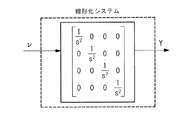
(7)式の関係を伝達関数で示すと図5のような入出力関係となる。すなわち、制御対象の非線形特性は、厳密な線形化手法を適用することによって、2次の積分要素を対角成分に持つ対角行列に変換することができる。なお、対角行列の積分要素の次数は、出力Yの微分の階数と対応して変化する。このように、フィードバック変換と入力変換を制御対象に付加して線形化システムを構成することによって、入出力間を厳密に線形化することができる。 When the relationship of equation (7) is represented by a transfer function, the input / output relationship is as shown in FIG. That is, the nonlinear characteristic of the control target can be converted into a diagonal matrix having a second-order integral element as a diagonal component by applying a strict linearization method. Note that the order of the integral element of the diagonal matrix changes in accordance with the order of differentiation of the output Y. As described above, by adding the feedback conversion and the input conversion to the control target to configure the linearization system, it is possible to strictly linearize the input and output.
このように、厳密な線形化とは、制御対象30の出力を1階または複数階微分したものが入力となると仮定した場合に、制御対象30を含む線形システムの入力から制御対象30に対する操作量を算出可能なように入力変換部23及び線形化フィードバック部24を付加することである。入力変換部23及び線形化フィードバック部24が付加された制御対象30は、線形化システム28全体として見た場合に、出力を1階または複数階微分したものが入力となる関係となっているため、線形化システム28全体として線形化されたこととなる。この場合、線形化フィードバック部24は、フィルタ部26から出力される制御量の推定値に基づいて、線形化システム28に入力される値の変換値(入力変換部23の出力値)の補正を行う。
As described above, the strict linearization means that, when it is assumed that the output of the controlled
なお、線形化フィードバック部24の構成、及び入力変換部23の構成は、上記に限らず適用できる。例えば、上記の例では、F/Gをフィードバック変換とし、1/Gを入力変換としたが、(6)式をΔ=(−F+ν)/Gと変形して、図6に示すように、Fをフィードバック変換とし、1/Gを入力変換とすることとしてもよい。この場合、線形化フィードバック部24は、フィルタ部26から出力される制御量の推定値に基づいて、線形化システム28に入力される値(ν)の補正を行う。また、上記の例では、入出力間の厳密な線形化について説明したが、入力―状態間の厳密な線形化についても同様に適用可能である。
Note that the configuration of the
次に、制御装置20の効果について図7−11を参照して説明する。なお、図7−11では、深度の目標値を一定として、時刻T0においてピッチ角の目標値を変更した場合の特性を例として説明する。なお、図7−11において、フィルタ部26を用いず、センサ部25から出力された制御量実測値が直接線形化フィードバック部24に入力される場合を参考例としている。
Next, effects of the
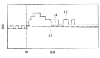
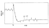
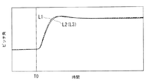
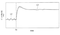
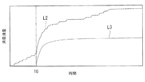
図7は、本実施形態と参考例とで深度の追従特性を比較した図である。図8は、本実施形態と参考例とで深度に係る舵の動作を比較した図である。図9は、本実施形態と参考例とでピッチ角の追従特性を比較した図である。図10は、本実施形態と参考例とでピッチ角に係る舵の動作を比較した図である。図11は、本実施形態と参考例とでアクチュエータの消費油量を比較した図である。図7−11において、目標値を一点鎖線L1で示しており、参考例の特性を点線L2で示しており、本実施形態の特性を線L3(連続線)で示している。 FIG. 7 is a diagram comparing the depth tracking characteristics of the present embodiment and the reference example. FIG. 8 is a diagram comparing the operation of the rudder according to the depth between the present embodiment and the reference example. FIG. 9 is a diagram comparing the tracking characteristics of the pitch angle between the present embodiment and the reference example. FIG. 10 is a diagram comparing the operation of the rudder according to the pitch angle between the present embodiment and the reference example. FIG. 11 is a diagram comparing the oil consumption of the actuator between the present embodiment and the reference example. 7-11, the target value is indicated by a dashed-dotted line L1, the characteristic of the reference example is indicated by a dotted line L2, and the characteristic of the present embodiment is indicated by a line L3 (continuous line).
なお、図7における追従特性では、本実施形態と参考例とでセンサ部25の出力値を比較しており、図8及び10では、本実施形態と参考例とで舵の角度を比較している。また、図11の消費油量は、各アクチュエータで消費された合計消費油量を示している。
In the following characteristic in FIG. 7, the output value of the
図9に示すように、時刻T0でピッチ角の目標値が変更されると、ピッチ角は目標値に追従して変化する。なお、図9では、変更されたピッチ角の設定値に基づいて目標軌道生成部21で生成した目標軌道が目標値として示されている。
As shown in FIG. 9, when the target value of the pitch angle is changed at time T0, the pitch angle changes following the target value. In FIG. 9, the target trajectory generated by the target
時刻T0においてピッチ角の目標値が変更されると、ピッチ角と深度は互いに干渉しているため、図7に示すようにピッチ角の制御に伴って深度が変化する。深度の目標値は一定としているため、図8に示すように深度に係る舵が制御され、深度が目標値を保持するように制御される。 If the target value of the pitch angle is changed at the time T0, the pitch angle and the depth interfere with each other, so that the depth changes with the control of the pitch angle as shown in FIG. Since the target value of the depth is constant, the steering related to the depth is controlled as shown in FIG. 8, and the depth is controlled so as to maintain the target value.
ここで、図7に示すように、参考例(点線L2)における深度は、特に目標値近傍において細かく変動している。これは、センサ部25における量子化誤差、すなわち量子化を行う際に最小分解能単位で出力値が変動する現象(量子化振動)であり、厳密に線形化された線形化システム28が量子化誤差に対して敏感に反応し、図8や図10に示すように操作量が変動することにより制御量(深度)が変動している。
Here, as shown in FIG. 7, the depth in the reference example (dotted line L2) fluctuates finely especially in the vicinity of the target value. This is a quantization error in the
これに対して、図7に示すように、フィルタ部26を用いた本願発明(線L3)における深度は、目標値近傍においても変動が抑制されている。すなわち、センサ部25の出力には量子化誤差が含まれているものの、フィルタ部26において制御量の真値を推定し、線形化フィードバック部24へ入力しているため、量子化誤差の影響を低減して、操作量の変動を抑制している。このため、図8に示すように、深度に係る舵の変動が抑制される。なお、なお、図10に示すように、ピッチ角に係る舵についても同様に変動が抑制される。
On the other hand, as shown in FIG. 7, the depth of the present invention (line L3) using the
このように、舵の頻繁な変動が抑制されることで、図11に示すように、参考例(点線L2)に対して、本実施形態(線L3)ではアクチュエータの消費油量を抑制することができる。すなわち、アクチュエータ等の消費エネルギーを抑制することができる。 In this manner, by suppressing the frequent fluctuation of the rudder, the present embodiment (line L3) can reduce the amount of oil consumed by the actuator as compared with the reference example (dotted line L2), as shown in FIG. Can be. That is, energy consumption of the actuator and the like can be suppressed.
以上説明したように、本実施形態に係る制御装置20、及びその制御方法並びに制御プログラム、構造体によれば、制御対象30の非線形要素を厳密な線形化手法を用いて線形化(厳密な線形化)を行うため、制御精度を向上させることが可能となる。また、厳密な線形化手法を適用した場合には、制御対象30を厳密に線形化した線形化システム28における入力変換部23や線形化フィードバック部24の入力の感度が高くなり、例えば入力されるセンサ値の量子化誤差(量子化に伴う最小分解能の遷移。量子化振動)に対して敏感に修正動作が働いてエネルギー消費が増加する可能性がある。そこで、制御対象30の制御量を量子化するセンサ部25と厳密な線形化を行う線形化フィードバック部24との間にフィルタ部26を設けることとした。フィルタ部26において、厳密な線形化システム28の数理モデルを用いてセンサ部25で量子化した制御量の推定連続値を出力することとしたため、線形化フィードバック部24に入力される値とフィードバック制御部22へ入力される値を連続値とすることができるため、量子化振動によるエネルギー消費の増加を抑制することが可能となる。
As described above, according to the
すなわち、厳密な線形化手法を適用することによって制御精度を向上させることができ、そして、フィルタ部26においてセンサ部25の量子化された値を連続値に変換することによって量子化振動等に基づくエネルギー消費を抑制することが可能となる。
That is, the control accuracy can be improved by applying a strict linearization method, and the
本発明は、実施形態のみに限定されるものではなく、発明の要旨を逸脱しない範囲において、種々変形実施が可能である。 The present invention is not limited to only the embodiments, and various modifications can be made without departing from the gist of the invention.
例えば、上記実施形態では、厳密な線形化が適用された線形化システム28の伝達関数が2次の積分特性である場合を例として説明した。すなわち、線形化システム28の伝達関数が2次の積分特性である場合には、フィルタ部26において開ループ伝達関数が1次の積分特性となるように、調整部31において1次の微分フィルタを付加した。
For example, in the above-described embodiment, the case where the transfer function of the
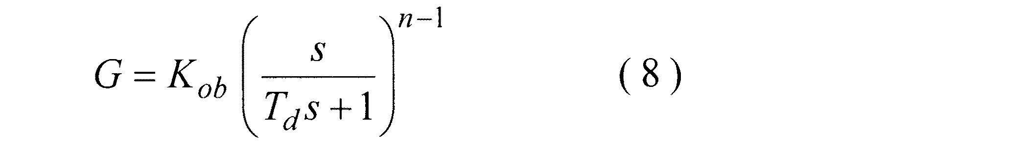
これを一般化すると、線形化システム28の伝達関数がn次の積分特性である場合(厳密な線形化後の対角行列の各対角成分がn次の積分特性である場合)には、フィルタ部26を図12のように構成することが可能である。すなわち、線形化システム28の伝達関数がn次の積分特性である場合には、数理モデルの伝達関数もn次の積分特性となるため、フィルタ部26において開ループ伝達関数が1次の積分特性となるように、調整部31の微分器をn−1次の微分要素とし、また、調整部31のローパスフィルタの特性についても、n−1次のローパス特性とする。すなわち、調整部31の伝達関数Gは、以下で示される。
When this is generalized, when the transfer function of the
(8)式に示すように、線形化システム28の伝達関数における積分要素の次数nに合わせて調整部31の伝達関数を設計することで、フィルタ部26を安定化させることができる。
As shown in the equation (8), the
1 :水中航走体
20 :制御装置
21 :目標軌道生成部
22 :フィードバック制御部
23 :入力変換部
24 :線形化フィードバック部
25 :センサ部
26 :フィルタ部
28 :線形化システム
30 :制御対象
31 :調整部
32 :第1ディレイ
33 :演算部
34 :第2ディレイ
35 :量子化部
1: Underwater vehicle 20: Control device 21: Target trajectory generation unit 22: Feedback control unit 23: Input conversion unit 24: Linearization feedback unit 25: Sensor unit 26: Filter unit 28: Linearization system 30: Control target 31 : Adjustment unit 32: First delay 33: Operation unit 34: Second delay 35: Quantization unit
Claims (8)
前記制御対象の状態を示す制御量を量子化した値を検出するセンサ部と、
前記制御対象の状態が目標状態に近づくように前記線形化システムに入力される値と、前記線形化システムの数理モデルとに基づいて前記制御量の推定値を連続量として算出し、前記制御量の推定値を量子化した値と前記センサ部の出力との偏差に基づいて前記制御量の推定値を再帰的に補正するフィルタ部と、
前記フィルタ部から出力される前記制御量の推定値に基づいて、前記線形化システムに入力される値又はその変換値の補正を行う線形化フィードバック部と、
を備える制御装置。 A control device that linearizes and controls a control target including a non-linear element into a linearization system,
A sensor unit that detects a value obtained by quantizing a control amount indicating the state of the control target,
Calculating an estimated value of the control amount as a continuous amount based on a value input to the linearization system and a mathematical model of the linearization system so that the state of the control target approaches the target state; A filter unit that recursively corrects the estimated value of the control amount based on a deviation between a value obtained by quantizing the estimated value of the output and the output of the sensor unit.
A linearization feedback unit that corrects a value input to the linearization system or a conversion value thereof based on the estimated value of the control amount output from the filter unit;
A control device comprising:
前記制御対象の状態を示す制御量を量子化した値を検出する検出工程と、
前記制御対象の状態が目標状態に近づくように前記線形化システムに入力される値と、前記線形化システムの数理モデルとに基づいて前記制御量の推定値を連続量として算出し、前記制御量の推定値を量子化した値と前記検出工程の出力との偏差に基づいて前記制御量の推定値を再帰的に補正するフィルタ工程と、
前記フィルタ工程にて出力される前記制御量の推定値に基づいて、前記線形化システムに入力される値又はその変換値の補正を行う線形化フィードバック工程と、
を有する制御方法。 A control method for linearizing and controlling a control target including a non-linear element into a linearization system,
A detection step of detecting a value obtained by quantizing a control amount indicating the state of the control target,
Calculating an estimated value of the control amount as a continuous amount based on a value input to the linearization system and a mathematical model of the linearization system so that the state of the control target approaches the target state; A filter step of recursively correcting the estimated value of the control amount based on a deviation between a value obtained by quantizing the estimated value of the output and the output of the detection step,
A linearization feedback step of correcting a value input to the linearization system or a conversion value thereof based on the estimated value of the control amount output in the filter step,
A control method having:
前記制御対象の状態を示す制御量を量子化した値を検出する検出処理と、
前記制御対象の状態が目標状態に近づくように前記線形化システムに入力される値と、前記線形化システムの数理モデルとに基づいて前記制御量の推定値を連続量として算出し、前記制御量の推定値を量子化した値と前記検出処理の出力との偏差に基づいて前記制御量の推定値を再帰的に補正するフィルタ処理と、
前記フィルタ処理にて出力される前記制御量の推定値に基づいて、前記線形化システムに入力される値又はその変換値の補正を行う線形化フィードバック処理と、
をコンピュータに実行させるための制御プログラム。
A control program for linearizing and controlling a control target having a non-linear element into a linearization system,
A detection process of detecting a value obtained by quantizing a control amount indicating the state of the control target;
Calculating an estimated value of the control amount as a continuous amount based on a value input to the linearization system and a mathematical model of the linearization system so that the state of the control target approaches the target state; Filter processing for recursively correcting the estimated value of the control amount based on a deviation between a value obtained by quantizing the estimated value of the detection value and an output of the detection processing,
A linearization feedback process for correcting a value input to the linearization system or a conversion value thereof based on the estimated value of the control amount output in the filter process;
Control program for causing a computer to execute the program.
Priority Applications (1)
| Application Number | Priority Date | Filing Date | Title |
|---|---|---|---|
| JP2018184561A JP7027291B2 (en) | 2018-09-28 | 2018-09-28 | Control device, its control method, control program, structure |
Applications Claiming Priority (1)
| Application Number | Priority Date | Filing Date | Title |
|---|---|---|---|
| JP2018184561A JP7027291B2 (en) | 2018-09-28 | 2018-09-28 | Control device, its control method, control program, structure |
Publications (2)
| Publication Number | Publication Date |
|---|---|
| JP2020052958A true JP2020052958A (en) | 2020-04-02 |
| JP7027291B2 JP7027291B2 (en) | 2022-03-01 |
Family
ID=69997400
Family Applications (1)
| Application Number | Title | Priority Date | Filing Date |
|---|---|---|---|
| JP2018184561A Active JP7027291B2 (en) | 2018-09-28 | 2018-09-28 | Control device, its control method, control program, structure |
Country Status (1)
| Country | Link |
|---|---|
| JP (1) | JP7027291B2 (en) |
Citations (5)
| Publication number | Priority date | Publication date | Assignee | Title |
|---|---|---|---|---|
| JPS6054007A (en) * | 1983-09-02 | 1985-03-28 | Toshiba Corp | Interpolating device of on-line control model |
| JPH01234901A (en) * | 1988-03-16 | 1989-09-20 | Toshiba Corp | Process control device |
| JPH0391801A (en) * | 1989-09-05 | 1991-04-17 | Toshiba Corp | Controller for subject having nonlinear dynamic characteristic |
| JP2015153232A (en) * | 2014-02-17 | 2015-08-24 | 三菱重工業株式会社 | Control device |
| JP2017208012A (en) * | 2016-05-20 | 2017-11-24 | 三菱重工業株式会社 | Control device, underwater vehicle, control method, and program |
-
2018
- 2018-09-28 JP JP2018184561A patent/JP7027291B2/en active Active
Patent Citations (5)
| Publication number | Priority date | Publication date | Assignee | Title |
|---|---|---|---|---|
| JPS6054007A (en) * | 1983-09-02 | 1985-03-28 | Toshiba Corp | Interpolating device of on-line control model |
| JPH01234901A (en) * | 1988-03-16 | 1989-09-20 | Toshiba Corp | Process control device |
| JPH0391801A (en) * | 1989-09-05 | 1991-04-17 | Toshiba Corp | Controller for subject having nonlinear dynamic characteristic |
| JP2015153232A (en) * | 2014-02-17 | 2015-08-24 | 三菱重工業株式会社 | Control device |
| JP2017208012A (en) * | 2016-05-20 | 2017-11-24 | 三菱重工業株式会社 | Control device, underwater vehicle, control method, and program |
Also Published As
| Publication number | Publication date |
|---|---|
| JP7027291B2 (en) | 2022-03-01 |
Similar Documents
| Publication | Publication Date | Title |
|---|---|---|
| CN110467111B (en) | Control of bridge cranes | |
| US10852748B2 (en) | Methods and apparatus to perform observer-based control of a vehicle | |
| JP4575508B1 (en) | Servo control device for dual position feedback control | |
| US8901871B2 (en) | Robust controller for electro-mechanical actuators employing sliding and second control modes | |
| US11669055B2 (en) | Vibration suppression device, method and computer-readable medium using estimated vibration torque | |
| KR102435901B1 (en) | Gyroscopic actuator friction prevention/compensation method and device using mpc and disturbance observaer | |
| JP2010033172A (en) | Digital servo control unit using feedforward signal | |
| CN111781938B (en) | Underactuated underwater vehicle and its stabilization method and device | |
| JP5319167B2 (en) | Control device | |
| KR19990063535A (en) | DEVICE AND METHOD FOR CONTROLLING MOVING OBJECT | |
| JP7027291B2 (en) | Control device, its control method, control program, structure | |
| Sawyer | Gain-scheduled control of a quadcopter UAV | |
| JP6189186B2 (en) | Underwater vehicle, its control device and control method | |
| CN120122446A (en) | AUV trajectory tracking method and system based on adaptive time-varying optimization control | |
| JP7114427B2 (en) | Control device, its control method, control program, structure | |
| JP4922954B2 (en) | Position control device | |
| JP6380951B2 (en) | Navigation body control device, navigation body, navigation body control method, program | |
| JP4078396B2 (en) | Positioning control device | |
| JPH0834396A (en) | Automatic steering gear for ship | |
| JP2017151590A (en) | Actuator drive control method and actuator drive control apparatus | |
| Mouchrif et al. | ADRC control of an unmanned Under-Actuated aerial vehicle | |
| Kodhanda et al. | Robust 3D Trajectory Tracking of an Under-Actuated Lighter-Than-Air | |
| WO2025057915A1 (en) | Automatic steering device for ship | |
| JP3600025B2 (en) | Shape measuring device | |
| CN121386858A (en) | A method and related equipment for attitude stabilization and adaptive heading control of unmanned equipment |
Legal Events
| Date | Code | Title | Description |
|---|---|---|---|
| A621 | Written request for application examination |
Free format text: JAPANESE INTERMEDIATE CODE: A621 Effective date: 20210212 |
|
| A131 | Notification of reasons for refusal |
Free format text: JAPANESE INTERMEDIATE CODE: A131 Effective date: 20211130 |
|
| A977 | Report on retrieval |
Free format text: JAPANESE INTERMEDIATE CODE: A971007 Effective date: 20211130 |
|
| A521 | Request for written amendment filed |
Free format text: JAPANESE INTERMEDIATE CODE: A523 Effective date: 20211227 |
|
| TRDD | Decision of grant or rejection written | ||
| A01 | Written decision to grant a patent or to grant a registration (utility model) |
Free format text: JAPANESE INTERMEDIATE CODE: A01 Effective date: 20220118 |
|
| A61 | First payment of annual fees (during grant procedure) |
Free format text: JAPANESE INTERMEDIATE CODE: A61 Effective date: 20220216 |
|
| R150 | Certificate of patent or registration of utility model |
Ref document number: 7027291 Country of ref document: JP Free format text: JAPANESE INTERMEDIATE CODE: R150 |