JP2020042762A - Parking lot management system - Google Patents
Parking lot management system Download PDFInfo
- Publication number
- JP2020042762A JP2020042762A JP2019043057A JP2019043057A JP2020042762A JP 2020042762 A JP2020042762 A JP 2020042762A JP 2019043057 A JP2019043057 A JP 2019043057A JP 2019043057 A JP2019043057 A JP 2019043057A JP 2020042762 A JP2020042762 A JP 2020042762A
- Authority
- JP
- Japan
- Prior art keywords
- vehicle
- transmitter
- user
- electromagnetic wave
- signal
- Prior art date
- Legal status (The legal status is an assumption and is not a legal conclusion. Google has not performed a legal analysis and makes no representation as to the accuracy of the status listed.)
- Withdrawn
Links
Images


Abstract
Description
本発明は、ユーザに貸し出される駐車場を管理する技術に関し、特に、駐車スペースに設置されたセンサを用いてその駐車スペースにおける車両の存否を検知する技術に関する。 The present invention relates to a technology for managing a parking lot lent to a user, and more particularly to a technology for detecting the presence or absence of a vehicle in a parking space using a sensor installed in the parking space.
ユーザに貸し出される駐車場を管理する技術が既に存在し、さらに、駐車スペース(駐車場、車室など)に設置されたセンサを用いてその駐車スペースにおける車両の存否を検知する技術が既に存在する。 A technology for managing a parking lot lent to a user already exists, and a technology for detecting the presence or absence of a vehicle in the parking space using a sensor installed in the parking space (a parking lot, a cabin, or the like) already exists. .
特許文献1は、そのような車両検知技術の一従来例として、駐車場の地中に埋設されたループコイル(磁界を感知するセンサの一種)によって車両の有無を検出するとともに、駐車場の地上に設置された2個のビーコン装置からの2つのビーコン信号を、前記車両に乗車しているユーザの携帯端末に受信させることによって駐車場を識別する技術を開示している。
特許文献1に開示されている技術によれば、ループコイルが車両を検出したタイミングと、2つのビーコン信号を携帯端末が受信したタイミングとの間の時間差が許容値以下であることを条件に、実際のユーザと実際の駐車場との間の紐付けが行われる。
According to the technology disclosed in
具体的には、この特許文献1に開示されている技術においては、ループコイルが車両を検出すると、車両がいずれかの駐車スペースに存在すると判定される。この際、車両を検出したループコイルの同一性から、車両が存在する駐車場が識別される。
Specifically, in the technology disclosed in
さらに、この特許文献1に開示されている技術においては、ユーザの携帯端末が2個のビーコン装置を同時に検出すると、それら2個のビーコン装置から同時に受信した2つの信号のそれぞれの強度から、ユーザの位置が、入庫を許可できるほどに適切であるか否かが判定される。
Further, in the technology disclosed in
さらに、この特許文献1に開示されている技術においては、ループコイルが車両を検出するタイミングと、携帯端末が2個のビーコン装置を検出するタイミングとは、互いに時間的に関連付けられ、それにより、ユーザが車両に乗車中であるか否かが判定される。
Further, in the technology disclosed in
特許文献2は、駐車場の地中に車室ごとに埋設されたループコイルであって車室IDが割り当てられているものにより、いずれかのユーザの車両が特定の車室に入庫したことを検出する技術と、車室内においてのみ受信可能である信号を発信するビーコンであってその信号には駐車場IDと車室IDとが割り当てられているものを車両に乗車しているユーザの携帯端末に受信させることにより、特定のユーザの車両が特定の駐車場内の特定の車室に入庫したことを検出する技術とを択一的に採用することを開示している。
さらに、この特許文献2は、駐車場にカメラを設置し、特定の車室に入庫した車両の車番(ナンバープレートの番号)を撮影することにより、不正駐車を行っている車両を摘発する技術も開示している。
Further,
特許文献3は、駐車場の地上に、赤外線または超音波である電磁波を出射する送波器を有するセンサを設置し、その送波器から出射した電磁波のうち、存在する車両によって反射された部分を前記センサのうちの受波器で受信することにより、車室内における車両の有無を検知する技術を開示している。 Patent Document 3 discloses that a sensor having a transmitter that emits electromagnetic waves that are infrared rays or ultrasonic waves is installed on the ground of a parking lot, and a portion of the electromagnetic waves emitted from the transmitter that is reflected by an existing vehicle. A technology for detecting the presence or absence of a vehicle in a vehicle cabin by receiving a signal from a receiver among the sensors is disclosed.
特許文献1および2に記載の技術では、いずれも、駐車場における車両の存否を検出するセンサとしてループコイルが使用される。
In each of the techniques described in
しかし、このループコイルは、駐車場の地中に埋設されるため、特許文献3に開示されているセンサであって、赤外線または超音波のような電磁波を出射するとともに駐車場の地上に設置されるものより、設備コストも設置コストも維持コストも高額化し易いという問題がある。 However, since this loop coil is buried in the ground of the parking lot, it is a sensor disclosed in Patent Document 3, which emits electromagnetic waves such as infrared rays or ultrasonic waves and is installed on the ground of the parking lot. However, there is a problem that the equipment cost, the installation cost, and the maintenance cost are easily increased.
一方、特許文献3に開示されている技術では、特定の駐車スペースに車両が存在するか否かを検出することはできるが、実際のユーザと実際の駐車場との間の紐付けを行うことができないという問題がある。 On the other hand, according to the technology disclosed in Patent Document 3, it is possible to detect whether or not a vehicle is present in a specific parking space, but to link a real user and a real parking lot. There is a problem that can not be.
以上の知見を背景にして、本発明は、駐車スペースに設置されたセンサを用いてその駐車スペースにおける車両の存否を検知する技術であって、ユーザが車両に乗車している状態でその車両が駐車スペース内に存在するか否かを判定することが可能であるものを提供することを課題としてなされたものである。 Against the background of the above knowledge, the present invention is a technology for detecting the presence or absence of a vehicle in a parking space using a sensor installed in the parking space, wherein the vehicle is in a state where the user is in the vehicle. It is an object of the present invention to provide a device capable of determining whether or not a vehicle is present in a parking space .
その課題を解決するために、本発明の一側面によれば、複数の駐車スペースを管理する駐車場管理システムであって、According to one embodiment of the present invention, there is provided a parking management system for managing a plurality of parking spaces,
各駐車スペースごとに設置され、電磁波を送波する送波器と、その送波された電磁波のうち被検出物の存否によって影響を受ける部分を受波する受波器とを備えた狭指向性のセンサを用いることにより、対応する駐車スペースに車両が存在するか否かを検出する車両存否検出装置と、 Narrow directivity provided with a transmitter installed in each parking space for transmitting electromagnetic waves and a receiver for receiving a portion of the transmitted electromagnetic waves that is affected by the presence or absence of an object to be detected. By using the sensor of the vehicle presence detection device that detects whether the vehicle is present in the corresponding parking space,
前記車両内に居るユーザの通信端末であって、前記電磁波の一部を受信することが可能であるものと、 A communication terminal of a user who is in the vehicle and capable of receiving a part of the electromagnetic wave,
その通信端末と通信可能な管理サーバと A management server that can communicate with the communication terminal
を含み、 Including
前記通信端末および/または前記管理サーバは、前記駐車スペース内に前記車両が存在することが前記車両存否検出装置によって検出されたタイミングで、前記通信端末が前記電磁波の一部を受信すると、前記ユーザが前記車両に乗車している状態でその車両が前記駐車スペース内に存在すると判定する判定部を含む駐車場管理システムが提供される。 The communication terminal and / or the management server, when the communication terminal receives a part of the electromagnetic wave at a timing when the vehicle presence detection device detects that the vehicle is present in the parking space, A parking lot management system that includes a determination unit that determines that the vehicle is present in the parking space while the vehicle is in the vehicle.
本発明によって下記の各態様が得られる。各態様は、項に区分し、各項には番号を付し、必要に応じて他の項の番号を引用する形式で記載する。これは、本発明が採用し得る技術的特徴の一部およびそれの組合せの理解を容易にするためであり、本発明が採用し得る技術的特徴およびそれの組合せが以下の態様に限定されると解釈すべきではない。すなわち、下記の態様には記載されていないが本明細書には記載されている技術的特徴を本発明の技術的特徴として適宜抽出して採用することは妨げられないと解釈すべきなのである。 The following aspects are obtained by the present invention. Each mode is divided into sections, each section is numbered, and if necessary, is described in a form in which the numbers of other sections are cited. This is to facilitate understanding of some of the technical features that can be adopted by the present invention and combinations thereof, and the technical features and the combinations thereof that can be adopted by the present invention are limited to the following aspects. Should not be interpreted as That is, it should be construed that it is not hampered that technical features not described in the following embodiments but described in the present specification are appropriately extracted and adopted as technical features of the present invention.
さらに、各項を他の項の番号を引用する形式で記載することが必ずしも、各項に記載の技術的特徴を他の項に記載の技術的特徴から分離させて独立させることを妨げることを意味するわけではなく、各項に記載の技術的特徴をその性質に応じて適宜独立させることが可能であると解釈すべきである。 Furthermore, listing each section in a form that quotes the number of the other section does not necessarily prevent the technical features described in each section from being separated from and independent of the technical features described in the other sections. It is to be construed that the technical features described in the respective sections can be appropriately made independent according to their properties.
(1) 複数の駐車スペースを管理する駐車場管理システムであって、
各駐車スペースごとに地上に設置され、電磁波を送波する送波器と、その送波された電磁波のうち被検出物の存否によって影響を受ける部分を受波する受波器とを備えた狭指向性のセンサを用いることにより、対応する駐車スペースに車両が存在するか否かを検出する車両存否検出装置と、
各駐車スペースごとに地上に設置され、対応する駐車スペースに固有の識別信号であって前記電磁波から弁別可能であるものを発信する広指向性の発信機と、
前記車両内に居るユーザの通信端末であって、前記電磁波の一部および前記識別信号の一部をそれぞれ互いに時間的に関連付けられるタイミングで受信する時間的関連受信状態が生起されると、前記受信した識別信号から抽出された発信機IDまたはその発信機IDから変換された駐車スペースIDである駐車スペース側IDと、当該通信端末の端末IDまたは前記ユーザのユーザIDであるユーザ側IDとを互いに関連付けるものと
を含む駐車場管理システム。
(1) A parking lot management system for managing a plurality of parking spaces,
A narrow transmitter including a transmitter installed on the ground for each parking space and transmitting an electromagnetic wave, and a receiver configured to receive a portion of the transmitted electromagnetic wave that is affected by the presence or absence of an object to be detected. By using a directional sensor, a vehicle presence detection device that detects whether a vehicle is present in the corresponding parking space,
A wide-directional transmitter that is installed on the ground for each parking space and transmits an identification signal unique to the corresponding parking space and can be discriminated from the electromagnetic wave,
A communication terminal of a user in the vehicle, wherein when a time-related reception state occurs in which a part of the electromagnetic wave and a part of the identification signal are received at timings respectively associated with each other, the reception is performed. The transmitter ID extracted from the identified identification signal or the parking space ID that is the parking space ID converted from the transmitter ID, and the terminal ID of the communication terminal or the user ID that is the user ID of the user are mutually associated with each other. Parking management system including associating.
このシステムにおいては、センサから出射する電磁波と、発信機から出射する識別信号とは、通信端末によって互いに識別可能な信号であり、例えば、使用する周波数帯、使用する変調方式、使用する通信プロトコルなどの通信属性が互いに異なる。 In this system, the electromagnetic wave emitted from the sensor and the identification signal emitted from the transmitter are signals that can be distinguished from each other by a communication terminal, such as a frequency band to be used, a modulation method to be used, and a communication protocol to be used. Have different communication attributes.
また、前記センサの指向性は、例えば、ある瞬間において送波器から放射状に出射する電磁波のカバーレッジ(扇状の到達可能範囲)の拡がり角によって表現される。そのカバーレッジは、例えば、車室1個分であるから、前記拡がり角は、例えば、15°,20°,30°(前記センサが車室の長さ方向の端に位置する場合には、例えば、30°より小さい角度)などである。 Further, the directivity of the sensor is expressed, for example, by a spread angle of a coverage (a fan-shaped reachable range) of an electromagnetic wave radially emitted from the transmitter at a certain moment. The coverage is, for example, for one cabin, and the divergence angle is, for example, 15 °, 20 °, 30 ° (when the sensor is located at the longitudinal end of the cabin, For example, an angle smaller than 30 °).
前記電磁波のカバーレッジは、また、その電磁波の到達可能距離によって表現される場合もある。その場合には、電磁波のカバーレッジが、概して車室1個分の長さであり、例えば、5m,6mである。 The coverage of the electromagnetic wave may also be represented by the reachable distance of the electromagnetic wave. In that case, the coverage of the electromagnetic wave is generally the length of one cabin, for example, 5 m or 6 m.
いずれにしても、前記センサは、電磁波のカバーレッジが、対応する車室に存在する車両はカバーするが、別の車室(例えば、隣の車室、通路を挟んで向かいの車室)に存在する車両はカバーしないように、設計されることが望ましい。 In any case, the sensor detects that the electromagnetic wave coverage covers a vehicle existing in the corresponding vehicle compartment, but in another vehicle compartment (for example, an adjacent vehicle compartment, a vehicle compartment opposite a passage). It is desirable that the existing vehicle be designed so as not to cover it.
これに対し、前記発信機の指向性は、概して全方位であって、当該発信機は、例えば、対応する車室22のうちの少なくとも一部を少なくともカバーするように設定される。
On the other hand, the directivity of the transmitter is generally omnidirectional, and the transmitter is set, for example, to cover at least a part of the
また、ユーザの通信端末は、センサからの電磁波と、発信機からの識別信号とを実質的に同時に受信可能であるようにするために、例えば、電磁波を受信する受信部と、識別信号を受信する受信部とを別々に有し、それら受信部が同時に作動するように設計してもよいし、1つの受信部しか有しないが、あるときには、電磁波のみを受信する通信モードに、別のときには、識別信号のみを受信する通信モードに時間的に交互に切り換わる駐車専用通信モードを実行するように設計してもよい。 Further, the communication terminal of the user, for example, a receiving unit that receives the electromagnetic wave, and a receiving unit that receives the identification signal so that the electromagnetic wave from the sensor and the identification signal from the transmitter can be received substantially simultaneously. May be designed so that they operate simultaneously, or they only have one receiver, but in some cases, in a communication mode that receives only electromagnetic waves, in others, Alternatively, it may be designed to execute a parking-only communication mode in which the communication mode is alternately temporally switched to a communication mode for receiving only the identification signal.
(2) さらに、前記車両存否検出装置および前記通信端末とそれぞれ通信可能な管理サーバであって、前記車両存否検出装置が、対応する車室に車両が存在していることを表す車両存在信号を当該管理サーバが受信し、かつ、前記通信端末から、前記駐車スペース側IDと前記ユーザ側IDとを互いに関連付けて当該管理サーバが受信することを条件に、当該管理サーバは、今回のユーザに今回の駐車スペースを利用する権限を付与するものを含む(1)項に記載の駐車場管理システム。 (2) Further, the management server is capable of communicating with the vehicle presence / absence detection device and the communication terminal, wherein the vehicle presence / absence detection device transmits a vehicle presence signal indicating that a vehicle is present in a corresponding vehicle compartment. On the condition that the management server receives the information and the management server receives the parking space side ID and the user side ID from the communication terminal in association with each other, the management server The parking lot management system according to the above mode (1), including a system which gives a right to use the parking space.
(3) 各駐車スペースごとの前記狭指向性のセンサから出射する電磁波の目標カバーレッジは、各駐車スペースに車両が存在する場合に、各駐車スペースのうちその車両によって占有される領域を除く空き領域に他のユーザが居ても、そのユーザの通信端末は、前記センサからの電磁波を受信することが不可能であるかまたは可能であってもその受信状態が正規の受信状態より低下するように設定されている(1)または(2)項に記載の駐車場管理システム。 (3) The target coverage of the electromagnetic wave emitted from the narrow directivity sensor for each parking space is, when there is a vehicle in each parking space, an empty space excluding the area occupied by the vehicle in each parking space. Even if there is another user in the area, the communication terminal of the user cannot receive the electromagnetic wave from the sensor, or even if it is possible, the reception state is lower than the normal reception state. The parking lot management system according to (1) or (2), wherein
(4) 前記通信端末は、前記電磁波を受信することなく前記識別信号を単独で受信すると、ユーザに対し、当該通信端末のうち前記電磁波を感知する部分を前記センサに向けることを催促するためのアラームを視覚的に、聴覚的におよび/または触覚的に出力するアラーム部を有する(1)ないし(3)項のいずれかに記載の駐車場管理システム。 (4) The communication terminal, when receiving the identification signal alone without receiving the electromagnetic wave, prompts a user to direct a part of the communication terminal that senses the electromagnetic wave to the sensor. The parking lot management system according to any one of (1) to (3), further including an alarm unit that outputs an alarm visually, audibly, and / or tactilely.
(11) 複数の車室を有する駐車場を管理する駐車場管理システムであって、
前記駐車場の地上に各車室ごとに設置され、電磁波を送波する送波器と、その送波された電磁波のうち被検出物の存否によって影響を受ける部分を受波する受波器とを備えた狭指向性のセンサを用いることにより、対応する車室に車両が存在するか否かを検出する車両存否検出装置と、
前記駐車場の地上に各車室ごとに設置され、対応する車室に固有の識別信号を発信する広指向性の発信機と、
管理サーバと、
前記車両内に居るユーザの通信端末であって、前記電磁波の一部および前記識別信号の一部をそれぞれ互いに時間的に関連付けられるタイミングで受信する時間的関連受信状態が生起されると、前記受信した識別信号から抽出された発信機IDまたはその発信機IDから変換された車室IDである車室側IDと、当該通信端末の端末IDまたは前記ユーザのユーザIDであるユーザ側IDとを互いに関連付けて前記管理サーバに送信するものと
を含む駐車場管理システム。
(11) A parking lot management system that manages a parking lot having a plurality of compartments,
A transmitter that is installed in each vehicle compartment on the ground of the parking lot and transmits an electromagnetic wave, and a receiver that receives a portion of the transmitted electromagnetic wave that is affected by the presence or absence of an object to be detected. By using a narrow directional sensor having
A wide-directional transmitter that is installed for each vehicle compartment on the ground of the parking lot and transmits a unique identification signal to the corresponding vehicle compartment,
An administration server,
A communication terminal of a user in the vehicle, wherein when a time-related reception state occurs in which a part of the electromagnetic wave and a part of the identification signal are received at timings respectively associated with each other, the reception is performed. The transmitter ID extracted from the identified identification signal or the passenger compartment ID which is the passenger compartment ID converted from the transmitter ID, and the terminal ID of the communication terminal or the user ID which is the user ID of the user are mutually associated with each other. And transmitting it to the management server in association with the parking lot management system.
(12) 前記管理サーバは、
前記通信端末から前記車室側IDおよび前記ユーザ側IDを受信すると、それらIDに基づき、今回のユーザが、今回の車室に駐車する駐車権限を有するか否かを判定する判定部と、
今回のユーザが前記駐車権限を有すると判定されると、前記ユーザが今回の車室に正当に入庫したことを表す正当入庫確認メッセージを前記ユーザの通信端末に返信する第1返信部と
を含む(11)項に記載の駐車場管理システム。
(12) The management server,
A determination unit configured to determine whether or not the current user has parking authority to park in the current vehicle compartment based on the IDs, when receiving the vehicle compartment ID and the user ID from the communication terminal;
A first reply unit that returns a valid entrance confirmation message indicating that the user has properly entered the current vehicle compartment to the communication terminal of the user when it is determined that the current user has the parking authority. (11) The parking lot management system according to the item.
(13) 前記管理サーバは、さらに、
今回のユーザが前記駐車権限を有しないと判定されると、前記ユーザが今回の車室に不当に入庫したことを表す不当入庫確認メッセージを前記ユーザの通信端末に返信する第2返信部を含む(12)項に記載の駐車場管理システム。
(13) The management server further includes:
When the current user is determined not to have the parking authority, a second reply unit is provided for returning to the communication terminal of the user an improper parking confirmation message indicating that the user has improperly parked in the current cabin. (12) The parking lot management system according to the item.
(14) 前記通信端末は、前記電磁波を受信することなく前記識別信号を単独で受信すると、ユーザに対し、当該通信端末のうち前記電磁波を感知する部分を前記センサに向けることを催促するための第1アラームを視覚的に、聴覚的におよび/または触覚的に出力する第1アラーム部を有する(11)ないし(13)項のいずれかに記載の駐車場管理システム。 (14) The communication terminal, when receiving the identification signal alone without receiving the electromagnetic wave, prompts a user to direct a part of the communication terminal that senses the electromagnetic wave to the sensor. The parking lot management system according to any one of (11) to (13), further including a first alarm unit that visually, audibly, and / or tactilely outputs the first alarm.
(15) 前記通信端末は、さらに、前記第1アラームを出力した後に、前記電磁波を受信できない場合には、ユーザに対し、今回の車室から車両を退出させることを催促するための第2アラームを視覚的に、聴覚的におよび/または触覚的に出力する第2アラーム部を有する(14)項に記載の駐車場管理システム。 (15) The communication terminal further outputs a second alarm for urging the user to leave the vehicle from the current compartment if the electromagnetic wave cannot be received after outputting the first alarm. The parking management system according to item (14), further comprising a second alarm unit that visually, audibly, and / or tactually outputs the information.
(16) 前記車両存否検出装置は、さらに、前記受波器からの出力信号に基づき、対応する車室に何らかの物体が存在するか否かの物体検知と、何らかの物体が前記車室内に存在すると判定した場合に、前記受波器からの出力信号に基づき、その何らかの物体が車両であるか否かの物体識別とのうち少なくとも前記物体検知を行う信号処理回路を含む(11)ないし(15)項のいずれかに記載の駐車場管理システム。 (16) The vehicle presence / absence detection device further detects, based on an output signal from the receiver, whether or not any object is present in a corresponding vehicle compartment, and determines that any object is present in the vehicle interior. A signal processing circuit for performing at least the object detection based on the output signal from the receiver when the determination is made, and object identification as to whether or not the object is a vehicle or not (11) to (15). A parking lot management system according to any one of the paragraphs.
(17) 前記車両存否検出装置は、さらに、前記管理サーバとの間で通信を行う通信装置を含み、その通信装置は、自発的にかまたは前記管理サーバからのリクエストに応じ、前記信号処理回路によって行われた少なくとも前記物体検知の結果を表す信号を前記管理サーバに送信し、それにより、その管理サーバが、前記通信端末に依存せずに、各車室に物体が存在するか否かを監視することを可能にするものを含む(16)項に記載の駐車場管理システム。 (17) The vehicle presence / absence detection device further includes a communication device that communicates with the management server, and the communication device voluntarily or in response to a request from the management server. Transmitting a signal representing the result of at least the object detection performed by the management server to the management server, whereby the management server determines whether an object exists in each vehicle compartment without depending on the communication terminal. A parking lot management system according to mode (16), including one that allows monitoring.
(18) (1)ないし(17)項のいずれかに記載の通信端末として機能させるためのプログラム。 (18) A program for functioning as the communication terminal according to any one of (1) to (17).
本項に係るプログラムは、例えば、それの機能を果たすためにコンピュータにより実行される指令の組合せを意味するように解釈したり、それら指令の組合せのみならず、各指令に従って処理されるファイルやデータをも含むように解釈することが可能であるが、それらに限定されない。 The program according to this section may be interpreted to mean, for example, a combination of instructions executed by a computer in order to fulfill its function, or not only the combination of these instructions, but also a file or data processed according to each instruction. Can be interpreted to include, but is not limited to.
また、このプログラムは、それ単独でコンピュータにより実行されることにより、所期の目的を達するものとしたり、他のプログラムと共にコンピュータにより実行されることにより、所期の目的を達するものとすることができるが、それらに限定されない。後者の場合、本項に係るプログラムは、データを主体とするものとすることができるが、それに限定されない。 In addition, this program may achieve its intended purpose by being executed by a computer by itself, or may achieve its intended purpose by being executed by a computer together with other programs. Can, but is not limited to. In the latter case, the program according to this section can be mainly composed of data, but is not limited thereto.
(19) (1)ないし(17)項のいずれかに記載の管理サーバとして機能させるためのプログラム。 (19) A program for functioning as the management server according to any one of (1) to (17).
(20) (18)または(19)項に記載のプログラムをコンピュータ読み取り可能に記録した記録媒体。 (20) A recording medium recording the program according to (18) or (19) in a computer-readable manner.
この記録媒体は種々な形式を採用可能であり、例えば、フレキシブル・ディスク等の磁気記録媒体、CD、CD−ROM等の光記録媒体、MO等の光磁気記録媒体、ROM等のアンリムーバブル・ストレージ等のいずれかを採用し得るが、それらに限定されない。 This recording medium can adopt various formats, for example, a magnetic recording medium such as a flexible disk, an optical recording medium such as a CD and a CD-ROM, a magneto-optical recording medium such as an MO, and an unremovable storage such as a ROM. Etc. can be adopted, but the present invention is not limited thereto.
以下、本発明のいくつかの例示的な実施形態のうちの一つを図面に基づいて詳細に説明する。 Hereinafter, one of several exemplary embodiments of the present invention will be described in detail with reference to the drawings.
<全体のハードウエア構成> <Overall hardware configuration>
まず、図1および図2を参照するに、本発明の例示的な一実施形態に従う駐車場管理システム(以下、単に「システム」という。)10は、各々、複数台の車両が駐車可能な複数の駐車場20(図1には、それら駐車場20のうちの代表的な駐車場20のみが図示されている)を管理するためのシステムである。
First, referring to FIGS. 1 and 2, a parking lot management system (hereinafter, simply referred to as “system”) 10 according to an exemplary embodiment of the present invention includes a plurality of parking lots each capable of parking a plurality of vehicles. Is a system for managing the
このシステム10においては、本発明の例示的な実施形態に従う駐車場管理方法であって、複数人のユーザの携帯端末(前記「通信端末」の一例)90との通信により、遠隔地にある管理サーバ50が複数の駐車場20を集中的に管理するものが実施される。
In the
一例においては、このシステム10が、ユーザが自身の携帯端末90を駐車券代わりに用い、かつ、予定された駐車時間の長さに見合う額の前払い駐車料金を支払うことを条件に、ユーザが駐車場20を利用することを許可する。別の例においては、このシステム10が、ユーザが自身の携帯端末90を駐車券代わりに用い、かつ、実際に駐車した時間の長さに見合う額の後払い駐車料金を支払うことを条件に、ユーザが駐車場20を利用することを許可する。
In one example, the
さらに別の例においては、このシステム10が、ユーザが会員であることと、駐車場20と車室22と利用時間帯とについて予約を行うこととを条件に、特定の車室22を無料でユーザに貸し出すサービスを提供する。
In still another example, the
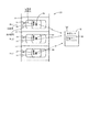
図1には、駐車場20が平面図で示されている。その駐車場20は、複数台の車両の同時駐車を可能にする複数の車室(前記「駐車スペース」の一例)22を有する。この駐車場20には、唯一の入出庫口24(入庫口でもあるし出庫口でもある)が存在する。図2には、複数の車室22のうちの一部が、各車室22に車両が停止している状態で示されている。
FIG. 1 shows the
この駐車場20は、無人式であり、さらに、この駐車場20には、駐車場20の入出庫口24からの不正車両の出庫を阻止するために適宜開閉するゲート装置も、車室22からの不正車両の出庫を阻止するために適宜出没する車止め装置も、運転者であるユーザに対し、駐車券をユーザに対して発行するための発券機およびユーザが駐車料金を精算するための精算機も設置されていない。
The
なお、「車両」なる用語の定義について付言するに、「車両」なる用語は、自動車のみならず、自転車、自動二輪車等、あらゆる種類の移動体を包含する用語として解釈すべきである。 It should be noted that the term "vehicle" should be interpreted as a term that encompasses not only automobiles but also all kinds of moving objects, such as bicycles and motorcycles.
図1に示すように、駐車場20の敷地には、2種類の駐車区画が存在する。それは、各車両のユーザに対し、1日単位で車室22を貸し出すための区画(一時預り区画または日貸し用区画)と、各車両のユーザに対し、事前の契約を前提に、1月単位で車室22を貸し出すための区画(月極用区画)とである。以下、単に「駐車場20」というときには、この駐車場20のうち、一時預り区画のみを意味する。
As shown in FIG. 1, two types of parking sections exist on the site of the
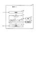
上述のように、システム10は、図4に示すように、複数の駐車場20を集中的に管理する管理センタ40に設置される管理サーバ50と、各駐車場20に居る各ユーザの携帯端末90とを備えている。管理サーバ50は、場外設備として、駐車場20の外部に設置される。
As described above, the
管理センタ40は、駐車場管理者(例えば、駐車場20として使用される土地の所有者であって自らその駐車場20を管理するもの、他人の土地の所有者からその土地を駐車場20として管理することを委託される駐車場管理会社)によって運営される。
The
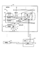
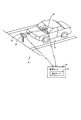
図2に示すように、システム10は、さらに、駐車場20の地上に各車室22ごとに設置される車両存否検出装置24および発信機30を、いずれも場内設備として有する。車両存否検出装置24は、対応する車室22における車両の有無の検出のため、電磁波を出射し、これに対し、発信機30は、対応する車室22を識別するために、識別信号であって前記電磁波から弁別可能であるものを出射する。
As shown in FIG. 2, the
<車両存否検出装置> <Vehicle presence detection device>
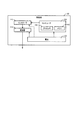
概略的には、図3に示すように、車両存否検出装置24は、狭指向性のセンサ26と、そのセンサ26からの出力信号を処理するための信号処理回路200と、管理サーバ50との間で通信(例えば、長距離無線通信)を行うための通信装置210とを有する。
Schematically, as shown in FIG. 3, the vehicle presence /
センサ26は、電磁波を送波する送波器27と、その送波された電磁波のうち被検出物の存否によって影響を受ける部分を受波する受波器28とを備えている。
The
図4に平面図で例示するように、センサ26は、平面視において、車両の前後中心線上の位置かまたはそれに近接する位置に配置される。また、センサ26は、狭指向性を有しており、送波器27が、電磁波を、拡がり角θが約20°(例えば、20°以下)で、かつ、到達距離が約5m(例えば、約10m以下)であるように設計されている。電磁波の種類としては、超音波、赤外線やミリ波などがある。
As illustrated in the plan view of FIG. 4, the
センサ26の電磁波の周波数は、赤外線であれば、例えば12−400THzであり、また、超音波であれば、例えば1−10MHzであり、また、ミリ波であれば、30GHz−300GHz(例えば、60GHz)である。超音波センサについては、周波数が高いほど、指向性が高くなる。ミリ波は、直線性が他の電波より高く、また、極めて狭い指向性を実現することが可能である。
The frequency of the electromagnetic wave of the
これに対し、発信機30の識別信号の周波数は、例えば2.427GHzである。その識別信号は、通常、無指向性を有し、センサ26の電磁波より広い指向性を有する。
On the other hand, the frequency of the identification signal of the
受波器28は、送波器27から出射した電磁波のうち自身に入射したものの強度に応じた信号を出力する。その出力信号は、対応する車室22における車両の有無を反映する信号である。車両が存在すれば、強い電磁波が受波器28に入射して、ハイレベルの出力信号を受波器28が出力するのに対し、車両が存在しなければ、前記電磁波のうちのいずれの部分も受波器28に入射せず、ローレベルの出力信号を受波器28が出力する。この出力信号の信号レベルから、受信した電磁波の強度が測定でき、ひいては、受波器28への電磁波の入射の有無、すなわち、対応する車室22における車両の存否を検出できる。
The
良く知られているように、センサ26に採用され得る形式としては、直接反射型と透過型とリフレクタ反射型とがある。
As is well known, types that can be adopted for the
直接反射型が採用されると、送波器27から出射した電磁波の一部が、車両が存在すればその車両によって反射して受波器28に入射するが、車両が存在しなければ前記反射が発生しないために前記電磁波のうちのいずれの部分も受波器28に入射しないように配置される。この形式は、例えば、後述のリフレクタ反射型より部品点数が少ない点と、送波器27と受波器28とを近接配置できる点とで有利である。
When the direct reflection type is adopted, a part of the electromagnetic wave emitted from the
これに対し、透過型が採用されると、送波器27から出射した電磁波の一部が、車両が存在しなければ受波器28に入射するが、車両が存在すればその車両によって遮断されて受波器28に入射しないように配置される。この形式は、後述のリフレクタ反射型より部品点数が少ない点と、電磁波が車両のうちのいずれの部位に照射されるかによって電磁波の進行方向が影響を受けずに済み、車両存否の検出精度が安定する点とで有利である。
On the other hand, when the transmission type is adopted, a part of the electromagnetic wave emitted from the
また、リフレクタ反射型が採用されると、電磁波の反射および光路の反転がリフレクタという別部品を用いて行われ、具体的には、送波器27から出射した電磁波の一部が、車両が存在しなければリフレクタ(図示しない)に入射してそこで反射して受波器28に入射するが、存在すれば、リフレクタに入射せず、受波器28にも入射入しないように配置される。この形式は、上述の直接反射型の利点すなわち送波器27および受波器28の近接配置が可能である点と、上述の透過型の利点すなわち電磁波が車両に照射される部分の性状(例えば、車両外面のうち、電磁波が入射する部分の向き、凹凸度)によって検出精度が低下しない点とで有利である。
When the reflector reflection type is adopted, the reflection of the electromagnetic wave and the reversal of the optical path are performed using a separate component called a reflector. Specifically, a part of the electromagnetic wave emitted from the
本実施形態においては、センサ26が、図2,図4および図17に例示するように、直接反射型を採用するが、他の形式に代えてもよい。
In the present embodiment, the
図17には、センサ26が直接反射型を採用するレイアウトの一例が斜視図で示されている。
FIG. 17 is a perspective view showing an example of a layout in which the
この例においては、車両存否検出装置24と発信機30とが1つのユニットに一体化され、そのユニットは、駐車場20の支持面(例えば、地面、舗装面など)から浮上した位置に設置されている。これにより、そのユニットが駐車場20の支持面上に設置される場合より、携帯端末90がセンサ26からの電磁波および発信機30からの識別信号を受信し易くなる。センサ26は、側面視において、車両のフロントガラスを通過する水平線上の位置かまたはそれに近接する位置に配置される。
In this example, the vehicle presence /
<車両存否検出装置のうちの信号処理回路> <Signal processing circuit in vehicle presence / absence detection device>
図5に示すように、信号処理回路200は、コンピュータとして機能するために、プロセッサ202とメモリ204とを有する。
As shown in FIG. 5, the signal processing circuit 200 includes a
信号処理回路200は、さらに、送波器27を駆動するためのドライバ206であってプロセッサ202によって制御されるものと、受波器28から出力されるアナログ信号をデジタル信号に変換するためのA/D変換器207であってプロセッサ202によって制御されるものとを有する。
The signal processing circuit 200 further includes a
信号処理回路200(または、同じ車両存否検出装置200のうちの他の部分)は、さらに、プロセッサ202、ドライバ206、A/D変換器207および通信装置210に電気エネルギーを供給するためのバッテリ208を有する。
The signal processing circuit 200 (or another part of the same vehicle presence detection device 200) further includes a
次に、図6を参照して信号処理回路200のソフトウエア構成を説明するに、信号処理回路200のプロセッサ202は、図6にフローチャートで概念的に表されている信号処理プログラムを反復的に実行する。この信号処理プログラムは、各車室22ごとに設置された車両存否検出装置200ごとに互いに独立して、かつ、反復的に実行される。
Next, the software configuration of the signal processing circuit 200 will be described with reference to FIG. 6. The
この信号処理プログラムの、ある車両存否検出装置200についての各回の実行時には、まず、ステップS61において、受波器28からの出力信号がA/D変換器207を経由し、デジタルデータに変換されてプロセッサ202に取り込まれる。次に、ステップS62において、そのデジタルデータから信号強度Iが測定される。
When this signal processing program is executed each time for a certain vehicle presence / absence detection device 200, first, in step S61, the output signal from the
続いて、ステップS63において、その測定された信号強度Iがしきい値I0より大きいか否か、すなわち、送波器27から出射した電磁波の一部を受波器28が受信したか否かが判定される。
Subsequently, in step S63, it is determined whether or not the measured signal strength I is larger than the threshold value I0, that is, whether or not the
その判定が肯定的であれば、ステップS64において、今回の車両存否検出装置200に対応する車室22に何らかの物体が存在すると判定される。この時点では、その物体が車両である可能性も車両ではなく例えば人間や動物である可能性も存在する。
If the determination is affirmative, in step S64, it is determined that there is any object in the
その後、ステップS65において、信号強度Iの測定値が時間的に安定しているか否か、すなわち、例えば、過去一定数個の測定値間のばらつき(例えば、標準偏差、移動平均値など)が許容値以下であるか否かが判定される。今回は、測定値ばらつきが前記許容値以下であると仮定すると、判定がYESとなり、ステップS66において、先のステップS64において存在すると判定された物体が車両として識別され、その結果、今回の車両存否検出装置200に対応する車室22に、いずれかのユーザが運転する車両が存在すると判定される。
Thereafter, in step S65, it is determined whether or not the measured value of the signal strength I is temporally stable, that is, for example, a variation (for example, a standard deviation, a moving average value, etc.) between a certain number of measured values in the past is allowed. It is determined whether the value is equal to or less than the value. In this case, assuming that the measured value variation is equal to or less than the allowable value, the determination is YES, and in step S66, the object determined to exist in step S64 is identified as a vehicle. It is determined that there is a vehicle driven by any user in
続いて、ステップS67において、今回の車両存否検出装置200に対応する車室22にいずれかの車両が存在することを表す車両存在信号が通信装置210から管理サーバ50に送信される。以上で、一回の実行サイクルが終了し、続いて、ステップS61に戻る。
Subsequently, in step S67, a vehicle presence signal indicating that any vehicle is present in the
これに対し、今回は、ステップS65の判定がNOであると、ステップS68において、今回の車両存否検出装置200に対応する車室22に存在すると判定された物体が車両以外の物体として識別される。その後、ステップS67がスキップされてステップS61に戻る。よって、この場合には、車両存在信号が通信装置210から管理サーバ50に転送されない
On the other hand, this time, if the determination in step S65 is NO, in step S68, the object determined to be present in the
<発信機のハードウエア構成> <Transmitter hardware configuration>
図2,図4および図17に示すように、発信機30は、駐車場20の地上に各車室22ごとに設置され、対応する車室22に固有の識別信号を発信する。
As shown in FIGS. 2, 4, and 17, the
ここで、発信機30につき、ハードウエア構成(図7参照)およびソフトウエア構成(図8参照)を説明する。
Here, the hardware configuration (see FIG. 7) and the software configuration (see FIG. 8) of the
まず、概念的に説明するに、発信機30は、固有の発信機IDを識別し得る識別信号を局地的に発信する非接触式または接触(近接)式の通信デバイスである。
First, conceptually, the
発信機30は、通常、対応する駐車場20に移動不能に固定的に設置されるが、随時移動可能であるように可動的に設置することも可能である。また、発信機30は、少なくとも送信機能を有すれば足りるが、必要に応じ、受信機能をも併有するように構成してもよい。
The
次に、作動方式を説明するに、発信機30は、固有の識別信号を外部からのトリガ信号を要することなく能動的に、局地的に、かつ、供給電力が不足しない限り永続的に発信する。
Next, the operation method will be described. The
発信機30は、一般に、識別信号としてのビーコン信号を発信するビーコン装置、無線標識などの名称でも知られている装置である。この発信機30は、一例においては、原信号を変調することにより、対応する発信機IDを表す識別信号を生成し、その生成された識別信号を、IR信号、Bluetooth(登録商標)信号、NFC(近距離無線通信)信号などとして局地的に発信する。
The
発信機30からの信号がBluetooth(登録商標)信号である場合には、携帯端末90においては、通信モードの設定が、手動で、Bluetooth(登録商標)信号での通信に適したものに変更されることが必要である。
When the signal from the
次に、図7を参照してハードウエア構成を説明するに、発信機30は、プロセッサ100およびそのプロセッサ100によって実行される複数のアプリケーションを記憶するメモリ102を有するコンピュータ104を主体として構成されている。
Next, a hardware configuration will be described with reference to FIG. 7. The
この発信機30は、さらに、電源としての交換可能な使い捨て電池106を有している。電池106に代えて、充電可能な電池を採用したり、外部電源としての商用電源または太陽電池を採用することが可能である。
The
外部電源として太陽電池を採用する場合、昼間に太陽電池を用いて発電された電気エネルギーのうち余剰のものをバッテリに蓄積し、夜間には、そのバッテリから電池エネルギーを取り出して発信機30を作動させてもよい。
When a solar cell is used as the external power source, surplus electric energy generated by using the solar cell in the daytime is stored in the battery, and at night, the battery energy is taken out from the battery and the
この発信機30は、さらに、識別信号を生成して発信する発信部108を有している。その発信部108は、電池106によって作動させられるとともに、コントローラ110によって制御される。そのコントローラ110は、コンピュータ100によって制御される。
The
<発信機のソフトウエア構成> <Software configuration of transmitter>
次に、図8を参照して発信機30のソフトウエア構成を説明するに、発信機30のプロセッサ100は、図8にフローチャートで概念的に表されている信号処理プログラムを反復的に実行する。
Next, the software configuration of the
この信号処理プログラムの各回の実行時には、まず、ステップS1において、メモリ102から発信機IDが読み込まれ、次に、ステップS2において、電池106の残量が推定される。
In each execution of this signal processing program, first, in step S1, the transmitter ID is read from the
続いて、ステップS3において、前記読み込まれた発信機IDと、前記推定された電池残量とが反映されるように、原信号(例えば、搬送信号)を変調するための信号がコントローラ110に対して出力される。そのコントローラ110は、発信部108を制御し、その結果、発信部108は、今回発信すべき識別信号を生成する。その後、ステップS4において、その生成された識別信号が発信部108から発信される。続いて、ステップS1に戻る。
Subsequently, in step S3, a signal for modulating an original signal (for example, a carrier signal) is sent to the
なお付言するに、発信機30において、発信機IDと電池残量とが反映されるように識別信号を生成するアルゴリズムまたは手順は、図8に示すアルゴリズムまたは手順とは異なるものを採用することが可能である。
Note that, in the
<携帯端末のハードウエア構成> <Hardware configuration of mobile terminal>
ユーザの携帯端末90は、ユーザによって携帯されるとともに無線通信機能を有するデバイス、例えば、携帯電話機、スマートフォン、ラップトップ型コンピュータ、タブレット型コンピュータ、PDAなどである。また、携帯端末90は、ユーザの通信端末の一例であり、その通信端末は、ユーザによって携帯されないもの、例えば、車載通信端末でもよい。
The user's
次に、図9を参照して携帯端末90のハードウエア構成を説明するに、携帯端末90は、プロセッサ130およびそのプロセッサ130によって実行される複数のプログラム(「アプリケーション」ともいう)を記憶するメモリ132を有するコンピュータ134を主体として構成されている。
Next, a hardware configuration of the
この携帯端末90は、さらに、情報を表示する表示部(例えば、液晶ディスプレイ)136と、発信機30および管理サーバ50からの信号を受信する受信部138と、信号を生成してその信号を管理サーバ50に送信する送信部140とを有する。ここに、受信部138は、センサ26の送波器27からの電磁波を感知する部分であるとともに、発信機30からの識別信号を感知する部分でもある。
The
この携帯端末90は、さらに、ユーザからデータやコマンドを入力するための入力部150を有する。その入力部150は、例えば、所望の情報(例えば、コマンド、データなど)を携帯端末90に入力するためにユーザによって操作可能な操作部を有する。その操作部としては、ユーザによって操作可能なアイコン(例えば、仮想的なボタン)を表示するタッチスクリーン、ユーザによって操作可能な物理的な操作部(例えば、キーボード、キーパッド、ボタンなど)、音声を感知するマイクなどがあるが、これらに限定されない。
The
この携帯端末90は、さらに、GPS(衛星測位システム)受信機152を有する。GPS受信機152は、よく知られているように、複数のGPS衛星から複数のGPS信号を受信し、それらGPS信号に基づき、GPS受信機152の地球上における位置(緯度、経度および高度)を三角測量によって測定する。
The
この携帯端末90は、さらに、自身の加速度を検出する加速度センサ154を内蔵している。その加速度センサ154は、携帯端末90に搭載されているため、携帯端末90と一体的に振動し、その結果、加速度センサ154自体に作用する加速度を、携帯端末90およびそれを携帯しているユーザに作用する加速度と等価なものとして検出する。
The
この加速度センサ154の型式は、例えば、半導体ピエゾ抵抗型、静電容量型、熱検知型などである。一例においては、この加速度センサ154が、X軸、Y軸およびZ軸という3軸方向の加速度Gx,Gy,Gzを個々に検出し、それら3つの検出値Gx,Gy,Gzの合成値Grとして1つの代表加速度を出力するように設計することが可能である。 The type of the acceleration sensor 154 is, for example, a semiconductor piezo resistance type, a capacitance type, a heat detection type, or the like. In one example, the acceleration sensor 154 individually detects accelerations Gx, Gy, and Gz in three axial directions, that is, an X axis, a Y axis, and a Z axis, and obtains a combined value Gr of the three detected values Gx, Gy, and Gz. It is possible to design to output one representative acceleration.
ここで、この発信機30に関連付けてユーザの携帯端末90の一機能を説明するに、その携帯端末90は、発信機30から識別信号を受信している状態で、その携帯端末90のコンピュータに予めインストールされているあるプログラム、すなわち、発信機処理のための専用アプリケーション(以下、「発信機用アプリケーション」という。)を起動させる(ログイン)と、前記受信した識別信号を復調し、それにより、前記発信機IDを解読する。携帯端末90は、さらに、その解読された発信機IDをユーザIDまたは端末ID(デバイスID)と共に管理サーバ50に送信する。
Here, one function of the user's
さらに、携帯端末90は、発信機30から識別信号を受信している状態で、前記発信機用アプリケーションを起動させると、前記受信した識別信号(例えば、その識別信号の強度)に基づき、その識別信号を発信したときの発信機30の位置と、その識別信号を受信したときの携帯端末90の位置との間の距離を測定することも行う。
Further, when the
すなわち、携帯端末90は、発信機30から受信した識別信号に基づき、その発信機30が実際に設置されている車室22に固有の発信機IDと、そのときの発信機30との距離との双方を獲得するようになっているのである。
That is, based on the identification signal received from the
<発信機の受信レンジ> <Receiver range of transmitter>
発信機30には、みかけ上、2種類の受信エリアが割り当てられる。それらは、受信可能エリアと有効受信エリア(以下、「受信レンジ」または「受信圏」ともいう。)である。
Apparently, two types of reception areas are assigned to the
それらエリアは、いずれも、発信機30の設置位置を中心とする1つの円で概して画定される。これが、発信機30から出射される識別信号が広指向性を有すると主張する理由である。
Each of these areas is generally defined by one circle centered on the installation position of the
発信機30の受信可能エリアは、最大受信半径(例えば、約50m)を有するのに対し、有効受信エリアは、有効受信半径(例えば、0mから約50mまでの範囲内の任意の値)を有する。最大受信半径は不変値であるのに対し、有効受信半径は、後述のように、携帯端末90によって随時設定可能な可変値である。
The receivable area of the
受信可能エリアは、発信機30の電力供給が正常である場合に、発信機30からの識別信号が到達可能なエリア、すなわち、そのエリア内に存在する限り、携帯端末90がその識別信号を受信可能なエリアを意味する。
The receivable area is an area where the identification signal from the
これに対し、有効受信エリアは、受信可能エリアの最大受信半径より小さい有効受信半径を有している。最大受信半径は、任意に設定することが不可能であるのに対し、有効受信半径は、携帯端末90においてソフト的に任意に設定することが可能である。
On the other hand, the effective reception area has an effective reception radius smaller than the maximum reception radius of the receivable area. While the maximum receiving radius cannot be set arbitrarily, the effective receiving radius can be set arbitrarily in the
すなわち、最大受信半径は、ハードウエアによって決まる受信限度を意味するのに対し、有効受信半径は、ソフトウエアによって決まる受信限度を意味するということが可能なのである。 In other words, the maximum reception radius means a reception limit determined by hardware, while the effective reception radius means a reception limit determined by software.
前述のように、携帯端末90は、それが受信した識別信号を発信したときの発信機30との距離を測定する。その距離測定値は、有効受信半径を超えることもあれば、超えないこともある。そして、その距離測定値が受信有効半径を超えないときは、携帯端末90が有効受信エリア内に存在するときであるのに対し、その距離測定値が受信有効半径を超えるときは、携帯端末90が受信可能エリア内には存在するが有効受信エリア内には存在しないときである。
As described above, the portable terminal 90 measures the distance from the
本実施形態においては、発信機30の受信レンジが、発信機30から出射する識別信号のカバーレッジ(到達可能範囲)が、対応する1つの車室22を少なくともカバーするように設定され、例えば、車室22のうちの後端部に発信機30が設置される場合には、受信レンジが例えば5mに設定される。
In the present embodiment, the reception range of the
識別信号のカバーレッジは、その識別信号が広指向性を有するため、対応する1つの車室22に専ら割り当てられるわけではない。そのため、携帯端末90が発信機30のみを頼りに、携帯端末90が存在する位置を特定しようとすると、携帯端末90は、理論上、複数の車室22に存在することは特定できるが、それを一つに絞り込むことは不可能である。
The coverage of the identification signal is not exclusively allocated to one corresponding
ところで、前述のように、本実施形態においては、センサ26からの電磁波が狭指向性を有し、1つの車室22しか電磁波によってカバーしないようにセンサ26が設計されている。したがって、発信機30が広指向性であるために、センサ26が担当する車室22とは別の車室22に居るユーザの携帯端末90が、予定された発信機30のみならず、別の車室22に設置された予定外の発信機30をも受信することがあっても、携帯端末90が電磁波と識別信号とを一緒に受信しない限り、その識別信号を参照して車室22を特定することはしないから、発信機30の広指向性が原因で誤った車室22を特定してしまうことはない。
By the way, as described above, in the present embodiment, the
一方、センサ26からの電磁波のみでは、携帯端末90は、いずれの車室22に存在するのかを特定できない。
On the other hand, the
そこで、本実施形態においては、一方の欠点を他方の利点で埋めるために狭指向性で電磁波を出射する車両存否センサ24と広指向性で識別信号を出射する発信機30とを組み合わせて用いることにより、いずれかの車室22に車両が存在するか否かの存否判定と、そのいずれかの車室22の識別とを一緒に達成することが可能となっている。車両存否検出装置24のみでは、いずれかの車室22に車両が存在するか否かは分かるが、その車室22を識別できないし、また、発信機30のみでは、ユーザが車両に乗車しているか否かが分からないから、ユーザと車両との間の紐付けができない。
Therefore, in the present embodiment, in order to fill one defect with the other advantage, the vehicle presence /
<システムが車両存否判定を行うために採用されている原理> <Principle used by the system to determine the presence or absence of a vehicle>
このシステム10によれば、車室22に入庫された車両は、電磁波を発信するセンサ26によって検知される。センサ26は、狭指向性であるから、対応する1つの車室22のみをカバーするように電磁波を出射するように設計することが可能である。その結果、センサ26による誤検出が防止される。
According to the
その電磁波の一部は、同時に、車両内のユーザの携帯端末90によっても受信される。車両が入庫したいずれかの車室22は、車両内のユーザの携帯端末90が発信機30から受信した識別信号を参照することによって識別される。いずれかの車室22に入庫している車両に乗車しているユーザが携帯している携帯端末90が電磁波と識別信号とを一緒に受信することが確認されると、センサ26によって検知された車両と、その車両のユーザおよび携帯端末90と、識別された車室22およびそれが属する駐車場20との間の紐付けが正確に行われる。
Some of the electromagnetic waves are also received by the user's mobile terminal 90 in the vehicle at the same time. One of the passenger compartments 22 in which the vehicle has entered is identified by referring to the identification signal received from the
さらに、各センサ26から出射する電磁波の目標カバーレッジは、対応する車室22に車両が存在する場合に、その車室22のうちその車両によって占有される領域を除く空き領域に他のユーザが居ても、そのユーザの携帯端末90は、センサ26からの電磁波を受信することが不可能であるかまたは可能であってもその受信状態が正規の受信状態より低下するように設定されている。
Furthermore, the target coverage of the electromagnetic wave emitted from each
したがって、本実施形態によれば、携帯端末90がセンサ26からの電磁波を良好に受信したというイベントが、ユーザが、対応する車室22内に存在する車両に乗車していると推定できる確度が向上する。また、図4に示すように、車両内のユーザから容易に視認できる位置に別のユーザが居れば、そのユーザが不適切な存在であることは本当のユーザでも容易に気付き、本当のユーザが、何らかの措置を事前に講じることが期待される。
Therefore, according to the present embodiment, there is a certainty that the event that the
<携帯端末による発信機の受信方法> <How to receive a transmitter using a mobile terminal>
携帯端末90は、前記発信機処理用アプリケーションを起動させることにより、前記距離測定値が有効受信半径の設定値以下であるか否かを判定し、その設定値以下であると判定すると、携帯端末90が現在、発信機30の有効受信エリア(受信レンジ)内に位置するから、携帯端末90は、「発信機30からの識別信号を有効に受信した(以下、単に「識別信号を受信した」ともいう。)」と判定する。
By activating the transmitter processing application, the
これに対し、携帯端末90は、前記距離測定値が前記設定値より大きいと判定すると、携帯端末90が現在、発信機30の有効受信エリア外に位置するから、携帯端末90は、「発信機30からの識別信号を有効に受信していない(以下、単に「識別信号を受信していない」ともいう。)」と判定する。
On the other hand, if the
すなわち、本実施形態においては、携帯端末90が有効受信エリア外に位置する場合には、実際には、携帯端末90が識別信号を受信しているにもかかわらず、みかけ上、携帯端末90は識別信号を受信していないこととしてソフトウエア上で取り扱われることになるのである。
That is, in the present embodiment, when the
<管理サーバのハードウエア構成> <Hardware configuration of management server>
次に、図10を参照して管理サーバ50のハードウエア構成を説明するに、管理サーバ50は、プロセッサ160およびそのプロセッサ160によって実行される複数のアプリケーションを記憶するメモリ162を有するコンピュータ164を主体として構成されている。
Next, the hardware configuration of the
この管理サーバ50は、さらに、情報を表示する表示部(例えば、液晶ディスプレイ)166と、携帯端末90からの信号を受信する受信部168と、信号を生成してその信号を携帯端末90に送信する送信部170と、時計172とを有する。この管理サーバ50は、発信機30からの受信を直接的には行わず、事実上、携帯端末90を介して行うことになる。
The
<車両存否検出装置からの情報に基づいて管理サーバが行う車両存否検出> <Vehicle presence detection performed by management server based on information from vehicle presence detection device>
管理サーバ50は、携帯端末90を経由することなく、直接的に車両存否検出装置24のうちの通信装置210と通信し、それにより、車両存否検出装置24を介して各駐車場20内の各車室22における車両の有無を遠隔的に監視する。
The
そのために管理サーバ50のプロセッサ160によって実行される車両存否判定プログラムの一例が図11にフローチャートで概念的に表されている。
For this purpose, an example of a vehicle presence / absence determination program executed by the
この車両存否判定プログラムの各回の実行時には、まず、ステップS1101において、管理サーバ50が通信装置210から、対応する車室22に車両が存在することを表す車両存在信号(車両の存否を表す車両存否信号のうちハイレベルの部分であり、ローレベルの部分は、車両不存在信号として機能する)を受信することが試行される。
In each execution of the vehicle presence / absence determination program, first, in step S1101, the
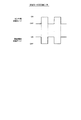
図12(a)にタイムチャートで例示するように、その車両存否信号は、車両が今回の車室22内に進入する進入時刻tsに立ち上がり(車両存否信号のレベルがハイレベルに上昇し)、やがて、車両が今回の車室22から退出する退出時刻teに立ち下がる(前記車両存否信号のレベルがローレベルに低下する)ように時間的に変化する2値信号である。
As illustrated in the time chart of FIG. 12A, the vehicle presence / absence signal rises at the entry time ts when the vehicle enters the
次に、ステップS1102において、管理サーバ50が通信装置210から車両存在信号(ハイレベル信号)を、対応する車室22の車室IDおよび駐車場IDに関連付けて受信したか否かが判定される。今回は、受信していないと仮定すると、判定がNOとなり、ステップS1103において、各車室22に関連付けてメモリ162に保存されている複数のフラグのうち今回の車室22に対応するフラグがON状態にあるか否かが判定される。今回は、前記フラグがOFF状態に初期化されたままであると仮定すると、判定がNOとなり、ステップS1101に戻る。
Next, in step S1102, it is determined whether or not the
やがて、管理サーバ50が通信装置210から車両存在信号(ハイレベル信号)を受信するに至ると、ステップS1102の判定がYESとなり、ステップS1104において、前記フラグがOFF状態にあるか否かが判定される。今回は、前記フラグがOFF状態に初期化されたままであると仮定すると、ステップS1104の判定がYESとなり、続いて、ステップS1105において、今回は、車両が、今回の車両存否検出装置24に対応する車室22に進入したと判定される。その後、ステップS1106において、現在時刻が時計172によって計測され、その現在時刻と同じ時刻として進入時刻tsが計測される。続いて、ステップS1107において、前記フラグがON状態にセットされる。
Eventually, when the
その後、ステップS1108において、図12(b)に例示する管理テーブルであってメモリ162に保存されているものにおいて、今回の駐車場20と今回の車室22とに関連付けて、前記進入時刻tsの測定値が記録され、それにより、その管理テーブルが更新される。続いて、ステップS1101に戻る。
Thereafter, in step S1108, in the management table illustrated in FIG. 12B and stored in the
その後も車両存在信号(ハイレベル信号)を管理サーバ50が受信する状態が継続したため、ステップS1102の判定がYESとなると、今回は、ステップS1104の判定がNOとなる。
Since the state in which the
続いて、ステップS1109において、現在時刻tcが時計172によって計測され、その後、ステップS1110において、その現在時刻tcから前記進入時刻tsを減算することにより、今回の車両が今回の車室22内に滞在し続けている滞在時間Δtが計算される。続いて、ステップS1108において、図12(b)に例示するように、その滞在時間Δtが今回の車室22に関連付けてメモリ162内の前記管理テーブルに保存される。
Subsequently, in step S1109, the current time tc is measured by the
やがて、車両存在信号が消滅する(車両存否信号のレベルがローレベルに低下する)と、ステップS1102の判定がNOとなる。今回は、前記フラグがON状態にあるため、ステップS1103の判定がYESとなる。続いて、ステップS1111において、前記フラグがOFF状態に初期化される。その後、ステップS1112において、車両が今回の車室22から退出したと判定される。
Eventually, when the vehicle presence signal disappears (the level of the vehicle presence / absence signal decreases to a low level), the determination in step S1102 becomes NO. This time, since the flag is ON, the determination in step S1103 is YES. Subsequently, in step S1111, the flag is initialized to an OFF state. Thereafter, in step S1112, it is determined that the vehicle has left the
続いて、ステップS1113において、現在時刻が時計172によって計測され、その現在時刻と同じ時刻として退出時刻teが計測される。その後、ステップS1114において、滞在時間Δtを0にリセットする。続いて、ステップS1108において、図12(b)に例示するように、その退出時刻teが今回の車室22に関連付けてメモリ162内の前記管理テーブルに保存される。
Subsequently, in step S1113, the current time is measured by the
図11に示すように、通信装置210が車両存在信号を管理サーバ50に送信している期間中(ハイレベル期間中)においては、同図において「ケース1」で示すように、ステップS1102の判定がYESとなる。これに対し、通信装置210が車両存在信号を管理サーバ50に送信していない期間中(ローレベル期間中)においては、同図において「ケース2」で示すように、ステップS1102の判定がNOとなる。
As shown in FIG. 11, during the period when the
<携帯端末および管理サーバが行う不当入庫検出> <Illegal warehousing detection performed by mobile terminal and management server>
図13は、システム10において、ユーザがある駐車場20において入庫処理を行うことを支援するために携帯端末90および管理サーバ50によってそれぞれ実行される入庫処理プログラムの一例を概念的に表すフローチャートである。
FIG. 13 is a flowchart conceptually illustrating an example of a storage processing program executed by the
携帯端末90にインストールされている入庫処理プログラムがユーザによるか、または自動的に起動すると、まず、携帯端末90が、ステップS1301において、自身の通信モードを駐車専用モードに自動的に切り換える。
When the storage processing program installed in the
携帯端末90は、図9に示すように、1つの受信部138しか有しないが、その受信部138が作動するための通信モードを、図16に例示するように、センサ26からの電磁波のみを受信するセンサ用通信モード(例えば、赤外線受信モード、超音波受信モードなど)と、発信機30からの識別信号のみを受信する発信機用通信モード(例えば、Bluetooth(登録商標)受信モード)とに所定の時間インターバルで交互に切り換える(交番シフト)。その時間インターバルのいくつかの例は、0.1s、0.5s、1s(例えば、1s以下)である。
The
図16に示す例においては、一連の複数回のオン期間のうちのある回のオン期間に携帯端末90が電磁波を感知し、次の回のオン期間に同じ携帯端末90が識別信号を感知する。
In the example illustrated in FIG. 16, the
この例においては、厳密には、それら電磁波および識別信号という2種類の信号が完全に同時に(または同期して)携帯端末90によって受信されるわけではない。すなわち、各瞬間ごとに、それら2種類の信号の受信タイミングを対比すると、携帯端末90における受信タイミングが互いに完全に一致するとは言えないのである。
In this example, strictly speaking, the two types of signals, the electromagnetic wave and the identification signal, are not received by the
しかし、今回の被検出対象は、実質的に停止状態にある車両およびその車両に乗車しているユーザが携帯している携帯端末90であるというように、それら被検出対象は実質的に静止物体であるとみなすことが妥当である。よって、それら被検出対象を観察してそれらの存否を議論する際に、1s(ないしは数秒)という時間スパンで観察しても、すなわち、それぞれの被検出対象の検出タイミング間に1s(ないしは数秒)という時間差が存在することを許容しても、それら被検出対象について検出誤差が発生することはないと推定される。
However, the detection targets this time are substantially stationary objects such as a vehicle in a stationary state and a
したがって、それら2種類の信号の受信タイミング間に存在する時間差が、例えば、1s以内である(1sより長くてもよい)である限り、それら2種類の信号は実質的に同時にまたは同期して携帯端末によって感知されていると言える。 Therefore, as long as the time difference existing between the reception timings of the two types of signals is, for example, within 1 s (may be longer than 1 s), the two types of signals may be carried substantially simultaneously or synchronously. It can be said that it is sensed by the terminal.
その結果、それら2種類の信号がそれぞれ互いに実質的に同時に受信される同時受信状態(または、同期受信状態、準同時受信状態、準同期受信状態)が成立する。この同時受信状態は、前述の「時間的関連受信状態」の一例を構成する。 As a result, a simultaneous reception state (or a synchronous reception state, a quasi-simultaneous reception state, or a quasi-synchronous reception state) in which the two types of signals are received substantially simultaneously with each other is established. This simultaneous reception state constitutes an example of the aforementioned “time-related reception state”.
また、同時受信状態が成立したか否かを議論する際に、このように隣接した2回のオン期間に着目することは不可欠ではなく、一定の時間窓、例えば、1s、2s、3s、5sの期間内に存在するある回のオン期間と、それに隣接しない別の回のオン期間とにおいてそれぞれ、電磁波および識別信号が感知される場合も、同時受信状態が成立すると考えることが可能である。 Further, when discussing whether or not the simultaneous reception state is established, it is not essential to pay attention to such two adjacent ON periods, and a certain time window, for example, 1s, 2s, 3s, 5s It is also possible to consider that the simultaneous reception state is established when the electromagnetic wave and the identification signal are sensed in a certain on-period existing within the period and another on-period not adjacent thereto.
ステップS1301において駐車専用モードが選択されると、ステップS1302において、携帯端末90がいずれかの発信機30から識別信号を受信することが試行される。続いて、ステップS1303において、携帯端末90がいずれかの発信機30から識別信号を有効に受信したか否かが判定される。有効に受信しなかった場合には、ステップS1301に戻るが、有効に受信した場合には、ステップS1304において、受信した識別信号から発信機IDが抽出される。
When the parking-only mode is selected in step S1301, the portable terminal 90 attempts to receive an identification signal from any of the
その後、ステップS1305において、携帯端末90は、発信機IDと駐車場ID(各発信機30が設置されているはずである駐車場20のID)との間に予め定められた関係モリ132に予め記憶されているものに従い、前記抽出された発信機IDを、今回の駐車場IDに変換し、さらに、発信機IDと車室ID(各発信機30が設置されているはずである車室22のIDとの間に予め定められた関係であってメモリ132に予め記憶されているものに従い、前記抽出された発信機IDを今回の車室IDに変換する。
Thereafter, in step S1305, the portable terminal 90 stores in advance a
続いて、ステップS1306において、携帯端末90がいずれかのセンサ26の送波器27から電磁波を受信することが試行され、その後、ステップS1307において、携帯端末90がいずれかのセンサ26から電磁波を受信したか否かが判定される。すなわち、携帯端末90が、識別信号と実質的に同時に(識別信号の受信タイミングに時間的に関連付けられるタイミングで)電磁波を受信したか否かが判定されるのである。
Subsequently, in step S1306, the portable terminal 90 attempts to receive an electromagnetic wave from the
携帯端末90が電磁波を受信しなかった場合には、ステップS1307の判定がNOとなり、ステップS1308において、ステップS1303において携帯端末90が最後にいずれかの発信機30を有効に受信したと判定された時刻からの経過時間Δsが、所定の制限時間S1内であるか否かが判定される。
If the
制限時間S1内であれば、ステップS1308の判定がYESとなり、ステップS1309において、携帯端末90が、ユーザに対し、当該携帯端末90のうち電磁波を感知する部分すなわち受信部138の向きを、センサ26に向かう向きに近づけることを催促するための第1アラームを視覚的に(特定の画像で)、聴覚的に(特定の音で)および/または触覚的に(特定パターンの振動で)出力する。
If the time is within the time limit S1, the determination in step S1308 is YES, and in step S1309, the
その後、ステップS1306に戻り、再度の受信試行が行われる。続いて、ステップS1306−S1309の実行が繰り返されるうちに、携帯端末90が電磁波を受信すると、ステップS1307の判定がYESとなり、ステップS1314に移行するが、携帯端末90が一度も電磁波を受信しないうちに制限時間S1が経過すると、ステップS1308の判定がNOとなる。
Thereafter, the process returns to step S1306, and another reception attempt is performed. Subsequently, if the
この場合には、携帯端末90がユーザに対して上記第1アラームを出力したにもかかわらず携帯端末90が電磁波を受信できないため、ステップS1310において、携帯端末90が、ユーザに対し、今回の車室22から車両を退出させることを催促するための第2アラームを視覚的に、聴覚的におよび/または触覚的に出力する。
In this case, since the
続いて、ステップS1311において、携帯端末90が、前述のように、発信機30から識別信号を受信したことから、ユーザ(車両ではない)が今回の車室22に存在していると推定されるが、ユーザが車両に乗車していない可能性があるから、不当入庫が発生している可能性があると判定する。
Subsequently, in step S1311, since the
その後、ステップS1312において、携帯端末90がその不当入庫の可能性を管理サーバ50に送信し、続いて、ステップS1313において、携帯端末90による一回の処理が終了する。
Thereafter, in step S1312, the
これに対し、管理サーバ50は、ステップS1354において、不当入庫の可能性を今回の車室22に関連付けてメモリ162に記録する。
On the other hand, the
これに対し、携帯端末90が電磁波を受信した場合には、ステップS1307の判定がYESとなり、ステップS1314において、携帯端末90が、電磁波の一部および識別信号の一部をそれぞれ互いに時間的に関連付けられるタイミングで携帯端末90が受信する時間的関連受信状態の一例としての前述の同時受信状態を表す同時受信完了信号を管理サーバ50に送信する。
On the other hand, when the
これに対し、管理サーバ50は、図11に示す車両存否検出プログラムの実行により、各車室22ごとに、前記進入判定が実行されたか否かを順次判定し、その結果、今回の車室22につき、滞在時間Δtが0より長くなると、ステップS1349の判定がYESとなり、ステップS1350において、管理サーバ50が、今回の車室22に車両が存在すると判定する。
On the other hand, the
続いて、ステップS1351において、管理サーバ50が携帯端末90から前記同時受信完了信号を受信することを試行し、実際に、その同時受信完了信号を受信すると、ステップS1352の判定がYESとなるが、同時受信完了信号を受信しないと、ステップS1352の判定がNOとなり、ステップS1353において、前記滞在時間Δtの最新値(時間の経過につれて更新される)が所定の制限時間S2内であるか否かが判定される。
Subsequently, in step S1351, the
制限時間S2内であれば、ステップS1353の判定がYESとなり、ステップS1351に戻り、再度の受信試行が行われる。前記滞在時間Δtの最新値が所定の制限時間S2より長くなると、ステップS1353の判定がNOとなり、その後、ステップS1354において、管理サーバ50が、いずれかの車室22に車両は存在しているがその車両にユーザが乗車していないという種類の不当入庫の可能性を今回の車室22に関連付けてメモリ162に記録する。
If the time is within the time limit S2, the determination in step S1353 becomes YES, and the process returns to step S1351 to perform another reception attempt. If the latest value of the stay time Δt is longer than the predetermined time limit S2, the determination in step S1353 is NO, and then in step S1354, the
携帯端末90は、ステップS1314の実行が終了すると、ステップS1315において、前述の駐車場ID、車室IDおよびユーザID(または携帯端末90のデバイスIDすなわち端末ID(例えば、電話番号、メールアドレスなど))(以下、それらIDをユーザ駐車関連情報」と総称する。)を互いに関連付けて管理サーバ50に送信する。
When the execution of step S1314 ends, the
これに対し、管理サーバ50は、ステップS1352の判定がYESとなると、ステップS1355において、携帯端末90から前記ユーザ駐車関連情報を受信する。続いて、ステップS1356において、管理サーバ50が、メモリ162の予約管理テーブルを参照することにより、前記受信したユーザ駐車関連情報の真正性を判定する。
On the other hand, if the determination in step S1352 is YES, the
その予約管理テーブルは、図示しないが、ユーザIDと、予約した駐車場20の駐車場ID(いずれかの駐車場20のみならず、その駐車場20におけるいずれかの車室22も予約することがユーザに要求される場合には、さらに、予約した車室22の車室ID)と、その駐車場20の予定利用時間帯(日付情報および時間情報(例えば、開始時刻および終了時刻)によって特定される)とを互いに関連付けて登録するためのテーブルである。
Although the reservation management table is not shown, the user ID and the parking lot ID of the reserved parking lot 20 (not only any one of the
管理サーバ50は、携帯端末90から前記ユーザ駐車関連情報を受信すると、そのユーザ駐車関連情報と、前記予約管理テーブルとの間の照合を行う。
When receiving the user parking-related information from the
その照合に成功すると、ステップS1357の判定がYESとなり、ステップS1360において、管理サーバ50が、今回の入庫が正当入庫(すなわち、予約あり入庫)であると判定し、続いて、ステップS1361において、管理サーバ50が、今回のユーザは、今回の車室22に駐車する権限を有していると判定し、ユーザによる入庫を許可する。
If the collation is successful, the determination in step S1357 is YES, and in step S1360, the
その後、管理サーバ50が、ステップS1362において、入庫許可を表す入庫許可信号を携帯端末90に送信すると、携帯端末90は、ステップS1318において、その入庫許可信号を受信する。続いて、ステップS1319において、携帯端末90が、その受信した入庫許可信号が表す情報を画面上に表示し、それにより、ユーザは、入庫が許可されたことを知らされる。
Thereafter, in step S1362, when the
これに対し、前記照合に失敗すると、ステップS1357の判定がNOとなり、ステップS1358において、管理サーバ50が、今回の入庫が予約なし入庫であると判定し、続いて、ステップS1359において、管理サーバ50が、今回のユーザは、今回の車室22に駐車する権限を有していないと判定し、ユーザによる入庫を禁止する。
On the other hand, if the collation fails, the determination in step S1357 is NO, and in step S1358, the
その後、管理サーバ50が、ステップS1359において、入庫禁止を表す入庫禁止信号を携帯端末90に送信すると、携帯端末90は、ステップS1316において、その入庫禁止信号を受信する。続いて、ステップS1317において、携帯端末90が、その受信した入庫禁止信号が表す情報を画面上に表示し、それにより、ユーザは、入庫が禁止されたことを知らされる。
After that, when the
ここで、以上説明した入庫処理プログラムのうちの要部の内容を、図14および図15にそれぞれタイムチャートで表されている複数のシナリオを通じて具体的に説明する。 Here, the contents of the main part of the storage processing program described above will be specifically described with reference to a plurality of scenarios represented by time charts in FIGS. 14 and 15, respectively.
前記入庫処理プログラムは、携帯端末90によって実行される携帯端末用サブプログラム(図13におけるステップS1301−S1319)と、管理サーバ50によって実行される管理サーバ用サブプログラム(図13におけるステップS1351−S1362)とに分解される。 The warehousing processing program includes a mobile terminal subprogram executed by the mobile terminal 90 (steps S1301 to S1319 in FIG. 13) and a management server subprogram executed by the management server 50 (steps S1351 to S1362 in FIG. 13). And is decomposed into
前記携帯端末用サブプログラムにおいては、特に、図13におけるステップS1306−S1313において、携帯端末90が、車両存否検出装置24からの情報(送波器27からの電磁波)と、発信機30からの情報(前記識別信号)とを参照して、不当入庫(携帯端末90が、発信機30からは識別信号を受信するが送波器27からは電磁波を受信しない状態、すなわち、ユーザのみが単独で車室22に存在する状態)を検出する。その判定のロジックを説明するのが、図14である。
In the portable terminal subprogram, in particular, in steps S1306 to S1313 in FIG. 13, the
これに対して、前記管理サーバ用サブプログラムにおいては、特に、図13におけるステップS1351−S1362において、管理サーバ50が、車両存否検出装置24からの情報(前記車両存否信号)と携帯端末90からの情報(前記同時受信完了信号)とを参照して、不当入庫(車両存否検出装置24が、対応する車室22内に車両が存在することを検出したが、携帯端末90が送波器27から電磁波を受信していない状態、車両のみが単独で車室22に存在する状態)の有無、正当入庫(前記同時受信状態が確立し、かつ、車両存否検出装置24が、対応する車室22内に車両が存在することを検出し、かつ、今回のユーザの予約が確認された状態)の有無、および予約なし入庫(前記同時受信状態が確立し、かつ、車両存否検出装置24が、対応する車室22内に車両が存在することを検出し、かつ、今回のユーザの予約が確認されなかった状態)の有無を判定する。その判定のロジックを説明するのが、図15である。
On the other hand, in the management server subprogram, particularly, in steps S1351 to S1362 in FIG. 13, the
図14(a)に示す第1のシナリオにおいては、前記携帯端末用サブプログラムの実行中、時刻t1において携帯端末90が広指向性の識別信号の受信を開始した。この時点では、せいぜい、ユーザが、車両に乗車している状態であるか否かを問わず、いずれかの車室22内に進入したと判定される。 In the first scenario shown in FIG. 14A, during execution of the mobile terminal subprogram, at time t1, the mobile terminal 90 starts receiving a wide directivity identification signal. At this point, at most, it is determined that the user has entered any one of the passenger compartments 22 irrespective of whether or not the user is in the vehicle.
その受信開始後またはそれとほぼ同時に携帯端末90が狭指向性の電磁波を受信したため、同時受信完了信号が携帯端末90から管理サーバ50に転送された。このシナリオにおいては、最終的に、ユーザが、車両に乗車している状態で、いずれかの車室22内に入庫したと判定される。
Since the
これに対し、図14(b)に示す第2のシナリオにおいては、前記携帯端末用サブプログラムの実行中、時刻t1において携帯端末90が識別信号の受信を開始したが、その後またはそれとほぼ同時に携帯端末90が電磁波を受信しなかったため、前記第1アラームが発生した。その後、制限時間S1の経過前に、携帯端末90が電磁波の受信を開始したため、同時受信完了信号が携帯端末90から管理サーバ50に転送された。
On the other hand, in the second scenario shown in FIG. 14B, the portable terminal 90 starts receiving the identification signal at time t1 during the execution of the portable terminal subprogram, but thereafter or almost at the same time. Since the terminal 90 did not receive the electromagnetic wave, the first alarm was generated. Thereafter, before the time limit S1 elapses, the portable terminal 90 starts receiving the electromagnetic wave, and thus the simultaneous reception completion signal is transferred from the
また、図14(c)に示す第3のシナリオにおいては、前記携帯端末用サブプログラムの実行中、時刻t1において携帯端末90が識別信号の受信を開始したが、その後またはそれとほぼ同時に携帯端末90が電磁波を受信しなかったため、前記第1アラームが発生した。しかし、制限時間S1の経過前に携帯端末90が電磁波を受信しなかったため、前記第2アラームが発生した。
In the third scenario shown in FIG. 14C, the portable terminal 90 starts receiving the identification signal at the time t1 during the execution of the portable terminal subprogram, but thereafter or almost simultaneously therewith. Did not receive the electromagnetic wave, the first alarm was generated. However, since the
このシナリオにおいては、不当入庫と判定され、また、同時受信完了信号は発生せず、やがて、ユーザは、時刻t2において車両を今回の車室22から退出させ、その結果、携帯端末90が識別信号を受信しない状態に遷移した。
In this scenario, it is determined that the vehicle is improperly received, and the simultaneous reception completion signal is not generated. At time t2, the user exits the vehicle from the
図15(a)に示す第1のシナリオにおいては、前記管理サーバ用サブプログラムの実行中、時刻t3において管理サーバ50が車両存否検出装置24から車両存在信号の受信を開始した。その開始時刻から制限時間S2が経過する前に、管理サーバ50は携帯端末90から同時受信完了信号の受信を開始した。このとき、ユーザが、車両に乗車している状態で、いずれかの車室22内に正当に入庫したと判定される。
In the first scenario shown in FIG. 15A, the
これに対し、図15(b)に示す第2のシナリオにおいては、前記管理サーバ用サブプログラムの実行中、時刻t3において管理サーバ50が車両存否検出装置24から車両存在信号の受信を開始した。その開始時刻から制限時間S2が経過する前に、管理サーバ50は携帯端末90から同時受信完了信号の受信を開始しなかった。このとき、車両はいずれかの車室22に存在するがユーザがその車両内にも車室22にも存在しないという不当入庫が発生したと判定される。
On the other hand, in the second scenario shown in FIG. 15B, during execution of the management server subprogram, the
また、図15(c)に示す第3のシナリオにおいては、前記管理サーバ用サブプログラムの実行中、いずれの時刻においても管理サーバ50が車両存否検出装置24から車両存在信号を受信しなかった。しかし、ある時刻において管理サーバ50は携帯端末90から同時受信完了信号を受信した。このとき、管理サーバ50は、プログラム上は、正当入庫の有無も不当入庫の有無も判定しない。
In the third scenario shown in FIG. 15C, the
これに対し、前記管理サーバ用サブプログラムを、管理サーバ50が、車両存否検出装置24からは車両存在信号を受信しないが、携帯端末90からは同時受信完了信号を受信した場合には、ユーザが単独でか(車両も他の物体も伴いことなく)、または車両以外の物体を伴う状態ではいずれかの車室22に存在する種類の不当入庫が発生していると判定し、携帯端末90に対し、入庫を許可しない旨の信号を返信するように設計変更してもよい。
On the other hand, when the
なお付言するに、上述のいくつかの実施形態は、本発明を、自動車を駐車対象とする駐車サービスに適用した場合のいくつかの具体例であるが、これに代えて、本発明は、例えば、自転車を駐車対象とする駐車サービスに適用したり、自動二輪車を駐車対象とする駐車サービスに適用することが可能である。 It should be noted that the above-mentioned embodiments are some specific examples in which the present invention is applied to a parking service for parking a car, but instead, the present invention is, for example, The present invention can be applied to a parking service for bicycles and a parking service for motorcycles.
さらに付言するに、本実施形態において、携帯端末90において実行されていた処理の全部または一部をその代わりに管理サーバ50において実行してもよいし、逆に、管理サーバ50において実行されていた処理の全部または一部をその代わりに携帯端末90において実行してもよい。実行されるべき処理がいずれのデバイスで実行されるのかは、そのときの事情、例えば、取り扱われるデータの量や種類、各デバイスの処理速度および記憶容量などによって決まるのが通常であるからである。
In addition, in the present embodiment, all or a part of the processing executed in the
以上、本発明のいくつかの実施形態を図面に基づいて詳細に説明したが、これらは例示であり、前記[発明の概要]の欄に記載の態様を始めとして、当業者の知識に基づいて種々の変形、改良を施した他の形態で本発明を実施することが可能である。 As described above, some embodiments of the present invention have been described in detail with reference to the drawings. However, these embodiments are merely examples, and based on the knowledge of those skilled in the art, including the aspects described in the section of [Summary of the Invention]. The present invention can be implemented in other forms with various modifications and improvements.
Claims (5)
各駐車スペースごとに設置され、電磁波を送波する送波器と、その送波された電磁波のうち被検出物の存否によって影響を受ける部分を受波する受波器とを備えた狭指向性のセンサを用いることにより、対応する駐車スペースに車両が存在するか否かを検出する車両存否検出装置と、
前記車両内に居るユーザの通信端末であって、前記電磁波の一部を受信することが可能であるものと、
その通信端末と通信可能な管理サーバと
を含み、
前記通信端末および/または前記管理サーバは、前記駐車スペース内に前記車両が存在することが前記車両存否検出装置によって検出されたタイミングで、前記通信端末が前記電磁波の一部を受信すると、前記ユーザが前記車両に乗車している状態でその車両が前記駐車スペース内に存在すると判定する判定部を含む駐車場管理システム。 A parking management system for managing a plurality of parking spaces,
Narrow directivity provided with a transmitter installed for each parking space and transmitting an electromagnetic wave, and a receiver for receiving a portion of the transmitted electromagnetic wave that is affected by the presence or absence of an object to be detected. By using the sensor of the vehicle presence detection device that detects whether the vehicle is present in the corresponding parking space,
A communication terminal of a user who is in the vehicle and capable of receiving a part of the electromagnetic wave,
Including a management server capable of communicating with the communication terminal,
The communication terminal and / or the management server, when the communication terminal receives a part of the electromagnetic wave at a timing when the presence or absence of the vehicle in the parking space is detected by the vehicle presence / absence detection device, Is a parking lot management system that includes a determination unit that determines that the vehicle is present in the parking space while the vehicle is in the vehicle.
前記通信端末は、前記電磁波を受信することなく前記信号を単独で受信すると、ユーザに対し、当該通信端末のうち前記電磁波を感知する部分を前記センサに向けることを催促するためのアラームを視覚的に、聴覚的におよび/または触覚的に出力するアラーム部を有する請求項1に記載の駐車場管理システム。 Furthermore, including a transmitter with a wide directivity that transmits a signal that can be distinguished from the electromagnetic wave,
The communication terminal, when receiving the signal alone without receiving the electromagnetic wave, visually alerts the user to direct the part of the communication terminal that senses the electromagnetic wave to the sensor. The parking lot management system according to claim 1, further comprising an alarm unit that outputs an auditory and / or tactile output.
Priority Applications (1)
| Application Number | Priority Date | Filing Date | Title |
|---|---|---|---|
| JP2019043057A JP2020042762A (en) | 2019-03-08 | 2019-03-08 | Parking lot management system |
Applications Claiming Priority (1)
| Application Number | Priority Date | Filing Date | Title |
|---|---|---|---|
| JP2019043057A JP2020042762A (en) | 2019-03-08 | 2019-03-08 | Parking lot management system |
Related Parent Applications (1)
| Application Number | Title | Priority Date | Filing Date |
|---|---|---|---|
| JP2018171025A Division JP6502607B1 (en) | 2018-09-12 | 2018-09-12 | Parking lot management system |
Publications (2)
| Publication Number | Publication Date |
|---|---|
| JP2020042762A true JP2020042762A (en) | 2020-03-19 |
| JP2020042762A5 JP2020042762A5 (en) | 2021-10-21 |
Family
ID=69798506
Family Applications (1)
| Application Number | Title | Priority Date | Filing Date |
|---|---|---|---|
| JP2019043057A Withdrawn JP2020042762A (en) | 2019-03-08 | 2019-03-08 | Parking lot management system |
Country Status (1)
| Country | Link |
|---|---|
| JP (1) | JP2020042762A (en) |
Citations (2)
| Publication number | Priority date | Publication date | Assignee | Title |
|---|---|---|---|---|
| JP2017204045A (en) * | 2016-05-09 | 2017-11-16 | 株式会社Nttドコモ | Parking lot reservation server |
| JP2017204044A (en) * | 2016-05-09 | 2017-11-16 | 株式会社Nttドコモ | Parking lot management server and parking lot management system |
-
2019
- 2019-03-08 JP JP2019043057A patent/JP2020042762A/en not_active Withdrawn
Patent Citations (2)
| Publication number | Priority date | Publication date | Assignee | Title |
|---|---|---|---|---|
| JP2017204045A (en) * | 2016-05-09 | 2017-11-16 | 株式会社Nttドコモ | Parking lot reservation server |
| JP2017204044A (en) * | 2016-05-09 | 2017-11-16 | 株式会社Nttドコモ | Parking lot management server and parking lot management system |
Similar Documents
| Publication | Publication Date | Title |
|---|---|---|
| JP5978414B1 (en) | Online rental system and online rental method | |
| US10464489B2 (en) | Integrated vehicle communication system and method | |
| US20190205847A1 (en) | Parking prevention apparatus, mobile terminal, and parking prevention system having same | |
| KR101831987B1 (en) | Subscription based parking space sharing method and system for the same | |
| JP2018092567A (en) | Parking lot management system | |
| CN103886227A (en) | Rotation laser | |
| CN110001575A (en) | Vehicle management system, method and non-transient computer readable medium recording program performing | |
| CN112150719A (en) | Vehicle management method, device, electronic equipment and storage medium | |
| JP6920708B2 (en) | Parking lot management method | |
| JP6140354B1 (en) | Object identification system and parking lot management system | |
| JP6502607B1 (en) | Parking lot management system | |
| JP2020042762A (en) | Parking lot management system | |
| JP6186487B1 (en) | Search system, parking lot management system, and search method | |
| JP6741374B2 (en) | Online rental system and online rental method | |
| KR20170034729A (en) | Portable apparatus of recognition car parking position on real time and operating method thereof | |
| JP6655272B2 (en) | Object management method | |
| JP6383844B2 (en) | Parking lot management system | |
| JP6887669B2 (en) | Object identification systems, programs and recording media | |
| JP7477228B2 (en) | Rental vehicle management system and program | |
| JP6482152B2 (en) | Object identification method and parking lot management method | |
| JP7296144B2 (en) | Object management system | |
| JP6383892B1 (en) | Parking lot management method | |
| JP6383845B2 (en) | Object identification system | |
| JP6305602B1 (en) | Object identification method and parking lot management method | |
| JP6445209B1 (en) | Parking lot management method |
Legal Events
| Date | Code | Title | Description |
|---|---|---|---|
| A521 | Request for written amendment filed |
Free format text: JAPANESE INTERMEDIATE CODE: A523 Effective date: 20210907 |
|
| A621 | Written request for application examination |
Free format text: JAPANESE INTERMEDIATE CODE: A621 Effective date: 20210907 |
|
| A871 | Explanation of circumstances concerning accelerated examination |
Free format text: JAPANESE INTERMEDIATE CODE: A871 Effective date: 20210907 |
|
| A521 | Request for written amendment filed |
Free format text: JAPANESE INTERMEDIATE CODE: A523 Effective date: 20210907 |
|
| A131 | Notification of reasons for refusal |
Free format text: JAPANESE INTERMEDIATE CODE: A131 Effective date: 20211013 |
|
| A521 | Request for written amendment filed |
Free format text: JAPANESE INTERMEDIATE CODE: A523 Effective date: 20211125 |
|
| A131 | Notification of reasons for refusal |
Free format text: JAPANESE INTERMEDIATE CODE: A131 Effective date: 20220107 |
|
| A601 | Written request for extension of time |
Free format text: JAPANESE INTERMEDIATE CODE: A601 Effective date: 20220202 |
|
| A521 | Request for written amendment filed |
Free format text: JAPANESE INTERMEDIATE CODE: A523 Effective date: 20220413 |
|
| A02 | Decision of refusal |
Free format text: JAPANESE INTERMEDIATE CODE: A02 Effective date: 20220615 |
|
| A761 | Written withdrawal of application |
Free format text: JAPANESE INTERMEDIATE CODE: A761 Effective date: 20220913 |