JP2020041475A - Air cleaner cap - Google Patents
Air cleaner cap Download PDFInfo
- Publication number
- JP2020041475A JP2020041475A JP2018169014A JP2018169014A JP2020041475A JP 2020041475 A JP2020041475 A JP 2020041475A JP 2018169014 A JP2018169014 A JP 2018169014A JP 2018169014 A JP2018169014 A JP 2018169014A JP 2020041475 A JP2020041475 A JP 2020041475A
- Authority
- JP
- Japan
- Prior art keywords
- air cleaner
- case
- cap
- protrusion
- discharge hole
- Prior art date
- Legal status (The legal status is an assumption and is not a legal conclusion. Google has not performed a legal analysis and makes no representation as to the accuracy of the status listed.)
- Pending
Links
Images


Classifications
-
- F—MECHANICAL ENGINEERING; LIGHTING; HEATING; WEAPONS; BLASTING
- F02—COMBUSTION ENGINES; HOT-GAS OR COMBUSTION-PRODUCT ENGINE PLANTS
- F02M—SUPPLYING COMBUSTION ENGINES IN GENERAL WITH COMBUSTIBLE MIXTURES OR CONSTITUENTS THEREOF
- F02M35/00—Combustion-air cleaners, air intakes, intake silencers, or induction systems specially adapted for, or arranged on, internal-combustion engines
- F02M35/02—Air cleaners
- F02M35/0201—Housings; Casings; Frame constructions; Lids; Manufacturing or assembling thereof
-
- F—MECHANICAL ENGINEERING; LIGHTING; HEATING; WEAPONS; BLASTING
- F02—COMBUSTION ENGINES; HOT-GAS OR COMBUSTION-PRODUCT ENGINE PLANTS
- F02M—SUPPLYING COMBUSTION ENGINES IN GENERAL WITH COMBUSTIBLE MIXTURES OR CONSTITUENTS THEREOF
- F02M35/00—Combustion-air cleaners, air intakes, intake silencers, or induction systems specially adapted for, or arranged on, internal-combustion engines
- F02M35/02—Air cleaners
- F02M35/024—Air cleaners using filters, e.g. moistened
- F02M35/02475—Air cleaners using filters, e.g. moistened characterised by the shape of the filter element
- F02M35/02483—Cylindrical, conical, oval, spherical or the like filter elements; wounded filter elements
-
- F—MECHANICAL ENGINEERING; LIGHTING; HEATING; WEAPONS; BLASTING
- F02—COMBUSTION ENGINES; HOT-GAS OR COMBUSTION-PRODUCT ENGINE PLANTS
- F02M—SUPPLYING COMBUSTION ENGINES IN GENERAL WITH COMBUSTIBLE MIXTURES OR CONSTITUENTS THEREOF
- F02M35/00—Combustion-air cleaners, air intakes, intake silencers, or induction systems specially adapted for, or arranged on, internal-combustion engines
- F02M35/02—Air cleaners
- F02M35/04—Air cleaners specially arranged with respect to engine, to intake system or specially adapted to vehicle; Mounting thereon ; Combinations with other devices
- F02M35/048—Arranging or mounting on or with respect to engines or vehicle bodies
-
- F—MECHANICAL ENGINEERING; LIGHTING; HEATING; WEAPONS; BLASTING
- F02—COMBUSTION ENGINES; HOT-GAS OR COMBUSTION-PRODUCT ENGINE PLANTS
- F02M—SUPPLYING COMBUSTION ENGINES IN GENERAL WITH COMBUSTIBLE MIXTURES OR CONSTITUENTS THEREOF
- F02M35/00—Combustion-air cleaners, air intakes, intake silencers, or induction systems specially adapted for, or arranged on, internal-combustion engines
- F02M35/02—Air cleaners
- F02M35/08—Air cleaners with means for removing dust, particles or liquids from cleaners; with means for indicating clogging; with by-pass means; Regeneration of cleaners
- F02M35/088—Water, snow or ice proofing; Separation or drainage of water, snow or ice
-
- F—MECHANICAL ENGINEERING; LIGHTING; HEATING; WEAPONS; BLASTING
- F02—COMBUSTION ENGINES; HOT-GAS OR COMBUSTION-PRODUCT ENGINE PLANTS
- F02M—SUPPLYING COMBUSTION ENGINES IN GENERAL WITH COMBUSTIBLE MIXTURES OR CONSTITUENTS THEREOF
- F02M35/00—Combustion-air cleaners, air intakes, intake silencers, or induction systems specially adapted for, or arranged on, internal-combustion engines
- F02M35/02—Air cleaners
- F02M35/024—Air cleaners using filters, e.g. moistened
Landscapes
- Engineering & Computer Science (AREA)
- Chemical & Material Sciences (AREA)
- Combustion & Propulsion (AREA)
- Mechanical Engineering (AREA)
- General Engineering & Computer Science (AREA)
- Manufacturing & Machinery (AREA)
- Filtering Of Dispersed Particles In Gases (AREA)
Abstract
Description
本開示は、内燃機関等に用いられるエアクリーナに設けられた穴を塞ぐキャップに関する。 The present disclosure relates to a cap for closing a hole provided in an air cleaner used for an internal combustion engine or the like.
内燃機関等の吸気を浄化するためのエアクリーナが普及している。エアクリーナの例としては、例えば入口から流入した空気がフィルタを通過する間に浄化され、浄化された空気が出口から流出するものがある。 2. Description of the Related Art Air cleaners for purifying intake air from internal combustion engines and the like have become widespread. As an example of an air cleaner, for example, there is an air cleaner in which air flowing in from an inlet is purified while passing through a filter, and the purified air flows out of an outlet.
このようなエアクリーナにおいて、水抜き等のためにケースの一部に開口部が設けられることがある。このような開口部を設けたエアクリーナにおいて、開口部から埃や水等が入って来ないようにするため、開口部にキャップを被せることが行われている。例えば特許文献1には、逆止弁を備えたキャップを水抜き用の開口に被せることで、水抜きと埃や水の浸入防止とを同時に行うことができる構成が開示されている。 In such an air cleaner, an opening may be provided in a part of the case for drainage or the like. In an air cleaner having such an opening, a cap is put on the opening in order to prevent dust, water, and the like from entering the opening. For example, Patent Document 1 discloses a configuration in which drainage and prevention of intrusion of dust and water can be performed at the same time by covering a cap provided with a check valve over a drainage opening.
エアクリーナは内燃機関に供給する空気を吸い込むものであるため、開口部に被せられたキャップに掛かる力は、エアクリーナの外側から内側へ向かう力が主となる。しかしながら、内燃機関の脈動等に起因して、エアクリーナの内側から外側へ向かう力がキャップに掛かる場合がある。このような場合、キャップが外れてしまうことがあるため、外れにくいキャップが要望されている。 Since the air cleaner sucks air supplied to the internal combustion engine, the force applied to the cap covering the opening is mainly the force from the outside to the inside of the air cleaner. However, a force from the inside to the outside of the air cleaner may be applied to the cap due to pulsation of the internal combustion engine or the like. In such a case, since the cap may come off, there is a demand for a cap that is difficult to come off.
本開示は、エアクリーナの開口部に被せられる、外れにくいエアクリーナ用キャップを提供することを目的とする。 An object of the present disclosure is to provide a cap for an air cleaner that is hard to come off and is covered with an opening of the air cleaner.
本開示の一態様に係るエアクリーナ用キャップは、エアクリーナの液体排出孔の周囲に突出するように設けられた筒状の突出部に被せられるエアクリーナ用キャップであって、蓋部と、前記蓋部から突出して、前記突出部の側面の内側に接触する第1の壁体と、前記蓋部から突出して、前記突出部の側面の外側に接触する第2の壁体と、を有する。 An air cleaner cap according to an aspect of the present disclosure is an air cleaner cap that is placed over a cylindrical protrusion provided to protrude around a liquid discharge hole of an air cleaner, and includes a lid, A first wall body protruding and contacting the inside of the side surface of the protrusion; and a second wall body protruding from the lid and contacting the outside of the side surface of the protrusion.
本開示によれば、エアクリーナの開口部に被せられるキャップを、掛かる力の向きが変化しても外れにくくすることができる。 According to the present disclosure, it is possible to make it difficult for the cap that covers the opening of the air cleaner to come off even if the direction of the applied force changes.
以下、本開示の各実施の形態について図面を参照して詳細に説明する。ただし、必要以上に詳細な説明、例えば、既によく知られた事項の詳細説明や実質的に同一の構成に対する重複説明等は省略する場合がある。 Hereinafter, each embodiment of the present disclosure will be described in detail with reference to the drawings. However, an unnecessary detailed description, for example, a detailed description of a well-known matter or a redundant description of substantially the same configuration may be omitted.
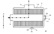
図1は、本開示の実施の形態に係るエアクリーナ10の外観について説明するための図である。図1に示すように、エアクリーナ10は、ほぼ円柱形状のケース11と、入口管12と、出口管13と、第1排出孔14と、第2排出孔15と、を有する。なお、図1から後出の図4には、本明細書における上下方向が示されている。
FIG. 1 is a diagram for describing an appearance of an
ケース11は、ほぼ円柱形状に形成されている。ケース11の円柱形状の側面の一部には、ケース11内に空気を流入させるための管である入口管12が接続されている。また、ケース11の円柱形状の底面の一方には、ケース11内の空気を流出させるための管である出口管13が接続されている。
The
エアクリーナ10は例えばトラック等の車両に搭載される。図示は省略するが、入口管12はラバーチューブ等を介して車両のエアインテーク等に接続されており、出口管13はエンジン等の内燃機関に接続されている。これにより、エアクリーナ10はエアインテークから取り入れた空気を浄化して内燃機関に供給することができる。
The
第1排出孔14および第2排出孔15は、それぞれケース11内に流入した水等の液体をケース11外に排出するための孔である。なお、第1排出孔14および第2排出孔15から排出されるのは水に限定されず、例えば油等、他の液体であってもよい。図1に示すように、第1排出孔14はケース11の側面の一部に設けられており、第2排出孔15はケース11の底面の一部に設けられている。
The
このように、エアクリーナ10は複数の排出孔を有する。これら複数の排出孔は、エアクリーナ10を複数の設置状態で設置する場合に対応するために設けられている。複数の設置状態とは、エアクリーナ10の設計時にあらかじめ想定された、異なる設置状態を含んでいる。
Thus, the
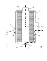
本実施の形態に係るエアクリーナ10は、図1に示すように、円柱形状のケース11の両底面が横を向いた状態である横置き状態で設置される他、図2に示すように、ケース11の両底面が縦(上下方向)を向いた状態となる縦置き状態でも設置されることがあらかじめ想定されている。図2は、エアクリーナ10を縦置き状態で設置した場合について例示した図である。
The
図1に示すエアクリーナ10の横置き状態では、入口管12がケース11の上側に、出口管13および第2排出孔15が横側に、第1排出孔14が下側に、それぞれ位置するようになる。
When the
一方、図2に示すエアクリーナ10の縦置き状態では、入口管12および第1排出孔14がケース11の横側に、出口管13が上側に、第2排出孔15が下側にそれぞれ位置するようになる。
On the other hand, in the vertically placed state of the
このような構成により、エアクリーナ10が横置き状態と縦置き状態のいずれの状態でも、第1排出孔14と第2排出孔15のいずれかが、ケース11の最下部に位置するようになる。従って、入口管12から空気とともに水がケース11の内部に流入した場合には、ケース11の最下部に位置する方の排出孔から水が排出される。このように、あらかじめ想定された複数の設置状態のうち、エアクリーナ10がいずれの状態で設置された場合でも、好適に水抜きを行うことができる。従って、エアクリーナ10を横置き状態と縦置き状態のどちらでも使用することができるようになる。
With such a configuration, either the
以下、エアクリーナ10に流入した空気および水の流れについて説明する。図3Aは、エアクリーナ10の横置き状態における、ケース11内に流入した空気の流れを例示した図である。図3Aにおける1点鎖線の矢印は、空気の流れを例示している。また、図3Bは、エアクリーナ10の横置き状態における、ケース11内に流入した水の流れを例示した図である。図3Bにおける点線の矢印は、水の流れを例示している。そして、図4は、エアクリーナ10の縦置き状態におけるケース11内に流入した空気および水の流れを例示した図である。
Hereinafter, the flow of air and water flowing into the
なお、図3Aは、ケース11の円柱形状の中心軸を含む平面であって、第1排出孔14を通る平面における、横置き状態のエアクリーナ10の断面図を示している。図3Bは、ケース11の円柱形状の中心軸に垂直な平面であって、第1排出孔14を通る平面における、横置き状態のエアクリーナ10の断面図を示している。また、図4は、ケース11の円柱形状の中心軸を含む平面であって、第2排出孔15を通る平面における、縦置き状態のエアクリーナ10の断面図を示している。
FIG. 3A is a cross-sectional view of the
図3A、図3Bおよび図4に示すように、ケース11の内部には、フィルタエレメント111と、第1空間112と、第2空間113と、が設けられている。
As shown in FIGS. 3A, 3B, and 4, inside the
フィルタエレメント111は、不織布や濾紙等のフィルタ素材をひだ状に折り曲げ、ひだ状のフィルタ素材をさらに円筒形状に湾曲させて形成された、一般に菊花型等と呼ばれるフィルタエレメントである。フィルタエレメント111は、空気(気体)は通すが水(液体)は通さないようになっている。エアクリーナ10のケース11内部は、フィルタエレメント111によって第1空間112と第2空間113とに分割されている。
The
第1空間112は、ケース11の内壁面とフィルタエレメント111とによって構成される空間である。また、第2空間113は、円柱形状をなすフィルタエレメント111の内部の空間である。
The
図3Aおよび図4に示すように、入口管12からケース11内部に流入した空気は、第1空間112を経て、フィルタエレメント111を通過し、濾過されて第2空間113へ到達する。そして、第2空間113内の浄化された空気は、出口管13を通って外部へ流出する。
As shown in FIGS. 3A and 4, the air that has flowed into the
一方、図3Bおよび図4に示すように、入口管12から流入した水は、フィルタエレメント111を通過せずに第1空間112内を流れ、エアクリーナ10の設置の向きに応じた、ケース11の最下部に位置する排出孔から外部へ排出される。ケース11の最下部に位置する排出孔とは、図3Bに示すエアクリーナ10の横置き状態では第1排出孔14であり、図4に示すエアクリーナ10の縦置き状態では第2排出孔15である。このように、エアクリーナ10は複数設けられた排出孔のうち、設置状態に応じていずれかから水が排出されるようになっている。
On the other hand, as shown in FIGS. 3B and 4, the water flowing from the
水が排出される方の排出孔には、排水弁が設けられることが望ましい。すなわち、図3Aに示すように、エアクリーナ10の横置き状態においては、第1排出孔14に第1排水弁141が設けられる。同様に、図4に示すように、エアクリーナ10の縦置き状態においては、第2排出孔15に第2排水弁151が設けられる。排水弁141および排水弁151の具体的な構成については、本開示では特に限定しない。例えばエアクリーナ10の外部から内部へ埃や水が入り込まないようにするための逆止弁、または、排出孔内に所定量以上の水が溜まった場合に水の重みで自動的に水を排出するような弁、または、車両の整備者等によって任意に開閉され、水を排出する開閉弁等、種々の弁が採用されうる。
It is desirable that a drain valve be provided in a discharge hole from which water is discharged. That is, as shown in FIG. 3A, when the
なお、エアクリーナ10の横置き状態において、ケース11の最下部に位置しない第2排出孔15から水が排出されることはない。このため、図1および図3Aに示すように、エアクリーナ10の横置き状態においては、埃や水等が入り込まないように、また空気が抜けないように、第2排出孔15は閉塞されることが望ましい。
When the
同様に、エアクリーナ10の縦置き状態において、ケース11の最下部に位置しない第1排出孔14から水が排出されることはない。このため、図2および図4に示すように、エアクリーナ10の縦置き状態においては、第1排出孔14は閉塞されることが望ましい。
Similarly, when the
以下では、第1排出孔14または第2排出孔15を閉塞するためのキャップ20について説明する。図3Aに示すように、第1排出孔14の周囲には、ケース11の外側へ向かって突出する円筒形状の第1突出部142が設けられている。同様に、図4に示すように、第2排出孔15の周囲には、ケース11の外側へ向かって突出する円筒形状の第2突出部152が設けられている。第1排出孔14または第2排出孔15を閉塞する場合、キャップ20は、第1突出部142または第2突出部152の先端部分に被せられる。キャップ20は、例えばラバーのような、弾力性を有する樹脂等で形成されている。このようなキャップ20により、水抜きに使用されない排出孔から埃や水等が入り込むのを防止することができるとともに、エアクリーナ10内の空気が抜けるのを防止することができる。
Hereinafter, the
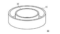
図5Aから図5Cは、キャップ20について説明するための図である。図5Aおよび図5Bに示すように、キャップ20は、蓋部21と、内側壁22と、外側壁23と、を有する。図5Aではキャップ20を蓋部21側から見ており、図5Bではキャップ20を内側壁22および外側壁23側から見ている。内側壁22は本開示の第1の壁体の一例であり、外側壁23は本開示の第2の壁体の一例である。
5A to 5C are diagrams for explaining the
なお、以下の説明においては、簡単のため、キャップ20が第1の排出孔14の周囲に設けられた第1突出部142に被せられた場合について説明し、第2の排出孔15の周囲に設けられた第2突出部152に被せられた場合については説明を省略する。
In the following description, for the sake of simplicity, the case where the
蓋部21は、キャップ20が第1突出部142に被せられたとき、第1排出孔14を塞ぐ蓋となる部位である。内側壁22および外側壁23は、キャップ20が第1突出部142に被せられたとき、第1突出部142の円筒形状の側面の外側または内側と接触することで、キャップ20を第1突出部142に対して固定するための部材である。すなわち、キャップ20は、内側壁22および外側壁23で第1突出部142の側面を挟むことにより、外れにくい構造を有する。なお、図5Bでは内側壁22と外側壁23との距離を強調して図示しているが、実際には内側壁22と外側壁23との距離は、第1突出部142の側面の厚みとほぼ同じに形成される。
The
図5Cは、キャップが第1排出孔14に被せられた状態での、キャップ20の中心軸を含む平面における断面図である。図5Cに示すように、内側壁22が第1突出部142の側面の内側と密着し、外側壁23が第1突出部142の側面の外側と密着する。このような構成により、内側壁を有しておらず、外側壁のみが突出部の側面の外側と密着している場合と比較して、キャップ20は、第1突出部142の側面との接触面積を多く取ることができる。このため、摩擦により、キャップ20を第1突出部142から外れにくくすることができる。
FIG. 5C is a cross-sectional view in a plane including the central axis of the
このような構成により、エアクリーナ10の外側から内側へ向かう力だけでなく、内側から外側へ向かう力がキャップ20に加わったとしても、キャップ20を外れにくくすることができる。また、キャップ20を第1突出部142に取り付ける際には、単に嵌め込むだけで取り付けが可能であるため、取り付けが容易である。このような構成により、キャップ20は、水抜きに使用されない方の排出孔を容易に塞ぐことができる。なお、上記説明ではキャップ20を第1突出部142に取り付ける場合について説明したが、キャップ20を第2突出部152に取り付ける場合も同様である。
With such a configuration, even when a force from the inside to the outside as well as a force from the outside to the inside of the
<作用・効果>
以上説明したように、本開示の実施の形態に係るキャップ20は、エアクリーナ10の第1排出孔14または第2排出孔15の周囲に突出するように設けられた筒状の第1突出部142または第2突出部152に被せられるエアクリーナ用のキャップ20であって、蓋部21と、蓋部21から突出して、第1突出部142または第2突出部152の側面の内側に接触する内側壁22と、蓋部21から突出して、第1突出部142または第2突出部152の側面の外側に接触する外側壁23と、を有する。
<Action and effect>
As described above, the
このような構成により、内側壁を有しておらず、外側壁のみが突出部の側面の外側と密着している場合と比較して、キャップ20は、第1突出部142または第2突出部152の側面との接触面積を多く取ることができる。このため、摩擦により、キャップ20を第1突出部142または第2突出部152から外れにくくすることができる。
With such a configuration, the
<変形例>
以上、図面を参照しながら本開示に係る実施の形態について説明したが、本開示はかかる例に限定されない。当業者であれば、特許請求の範囲に記載された範疇内において、各種の変更例または修正例に想到しうることは明らかであり、それらについても当然に本開示の技術的範囲に属するものと了解される。また、開示の趣旨を逸脱しない範囲において、上記実施の形態における各構成要素は任意に組み合わせてられてもよい。
<Modification>
The embodiments according to the present disclosure have been described with reference to the drawings, but the present disclosure is not limited to such examples. It will be apparent to those skilled in the art that various changes or modifications can be made within the scope of the claims, and these naturally belong to the technical scope of the present disclosure. I understand. Further, each component in the above embodiment may be arbitrarily combined without departing from the spirit of the disclosure.
上記した実施の形態では、エアクリーナ10は、トラック等の内燃機関を備えた車両に搭載されるとしたが、本開示はこれに限定されない。例えば、内燃機関を備えた農業機械や建設機械、ポンプ、発電機等にも適用が可能である。
In the above-described embodiment, the
上記した実施の形態では、エアクリーナ10は、円柱形状のケース11に入口管12および出口管13が設けられていたが、本開示はこれに限定されない。本開示のエアクリーナでは、入口管および出口管を含むケースの形状については特に限定せず、どのような形状であってもよい。ケースの具体的な形状の例には、直方体、立方体、円柱、円錐、円錐台、三角錐、またはこれらのいずれかの組み合わせにより構成される形状等が挙げられる。なお、本明細書において、各形状は厳密なものではなく、概形を指すものである。すなわち、上記した実施の形態におけるケース11の円柱形状には、例えば円柱の一部が削られた形状や、円柱に他の形状のものが加えられた形状等も含まれうる。他の形状に関しても同様である。
In the above-described embodiment, the
上記した実施の形態では、エアクリーナの例として、菊花型のフィルタエレメント111を用いて空気の浄化を行う形式のエアクリーナ10を示したが、本開示はこれに限定されない。本開示は例えば他の形状や形式のフィルタエレメントを用いるエアクリーナであってもよい。また、例えばサイクロン式等、他の方式のエアクリーナであってもよい。
In the above embodiment, as an example of the air cleaner, the
上記した実施の形態では、図3A、図3Bおよび図4等において、入口管12、出口管13、第1排出孔14および第2排出孔15が同一平面内に配置されている例について示したが、本開示はこれに限定されない。これらの構成は必ずしも同一平面内に配置されている必要はなく、適宜異なる平面内に配置されていてもよい。
In the above-described embodiment, an example in which the
上記した実施の形態では、エアクリーナ10の配置状態の例として、横置き状態および縦置き状態について説明したが、本開示はこれに限定されない。本開示において、エアクリーナは、設置される環境に応じて、3種類以上の配置状態で配置されることが想定されていてもよい。ここで、設置される環境とは、具体的にはエアクリーナの設置スペース、配管を取り回すスペース、内燃機関との位置関係、エアインテークとの位置関係等を意味する。そして、本開示のエアクリーナは、複数の向きで配置されることが想定されている場合に、それぞれの向きにおいてエアクリーナの最下部となる部位の近傍に、水抜き穴が1つずつ形成されていればよい。
In the above-described embodiment, the horizontal state and the vertical state are described as examples of the arrangement state of the
本開示は、内燃機関に供給する空気を浄化するエアクリーナに取り付けられるエアクリーナ用キャップに有用である。 The present disclosure is useful for an air cleaner cap attached to an air cleaner that purifies air supplied to an internal combustion engine.
20 キャップ
21 蓋部
22 内側壁
23 外側壁
10 エアクリーナ
11 ケース
111 フィルタエレメント
112 第1空間
113 第2空間
12 入口管
13 出口管
14 第1排出孔
141 第1排水弁
142 第1突出部
15 第2排出孔
151 第2排水弁
152 第2突出部
DESCRIPTION OF
Claims (4)
蓋部と、
前記蓋部から突出して、前記突出部の側面の内側に接触する第1の壁体と、
前記蓋部から突出して、前記突出部の側面の外側に接触する第2の壁体と、
を有する、エアクリーナ用キャップ。 An air cleaner cap that is placed over a cylindrical protrusion provided to protrude around a liquid discharge hole of the air cleaner,
A lid,
A first wall protruding from the lid and in contact with the inside of a side surface of the protrusion;
A second wall protruding from the lid and in contact with the outside of a side surface of the protruding portion;
A cap for an air cleaner having:
前記第2の壁体は、前記突出部の側面の外側に密着する、
請求項1に記載のエアクリーナ用キャップ。 The first wall is in close contact with the inside of the side surface of the protrusion,
The second wall body is in close contact with the outside of the side surface of the protrusion.
The air cleaner cap according to claim 1.
前記第1の設置状態で前記エアクリーナが設置された場合には、前記第2の突出部に被せられて前記第2の排出孔を塞ぎ、前記第2の設置状態で前記エアクリーナが設置された場合には、前記第1の突出部に被せられて前記第1の排出孔を塞ぐ、
請求項1または2に記載のエアクリーナ用キャップ。 The air cleaner has a first protrusion provided around a first liquid discharge hole for discharging liquid when the air cleaner is installed in the first installation state, and a first protrusion different from the first installation state. A second protruding portion provided around a second liquid discharge hole for discharging a liquid when the liquid is set in the setting state of No. 2;
When the air cleaner is installed in the first installation state, the air cleaner is installed in the second installation state when the air cleaner is covered by the second protrusion and closes the second discharge hole. To cover the first discharge hole by covering the first protrusion,
The air cleaner cap according to claim 1.
前記第1の設置状態は、前記ケースの両底面がそれぞれ横方向を向く横置き状態であり、前記第2の設置状態は、前記ケースの両底面がそれぞれ上下方向を向く縦置き状態であって、
前記エアクリーナが前記横置き状態で設置された場合には、前記ケースの円柱形状における側面の一部に設けられた第1の突出部に被せられ、
前記エアクリーナが前記縦置き状態で設置された場合には、前記ケースの円柱形状における底面の一部に設けられた第2の突出部に被せられる、
請求項3に記載のエアクリーナ用キャップ。
The case of the air cleaner has a cylindrical shape,
The first installation state is a horizontal installation state in which both bottom surfaces of the case are respectively oriented in the horizontal direction, and the second installation state is a vertical installation state in which both bottom surfaces of the case are each vertically oriented. ,
When the air cleaner is installed in the horizontal state, the air cleaner is put on a first protrusion provided on a part of a side surface of the case in a cylindrical shape,
When the air cleaner is installed in the vertical position, the air cleaner is put on a second protrusion provided on a part of a bottom surface of the case in a columnar shape.
The air cleaner cap according to claim 3.
Priority Applications (4)
| Application Number | Priority Date | Filing Date | Title |
|---|---|---|---|
| JP2018169014A JP2020041475A (en) | 2018-09-10 | 2018-09-10 | Air cleaner cap |
| PCT/JP2019/035400 WO2020054672A1 (en) | 2018-09-10 | 2019-09-09 | Cap for air cleaner |
| CN201980058755.8A CN112703310B (en) | 2018-09-10 | 2019-09-09 | End cover for air filter |
| DE112019004509.1T DE112019004509T5 (en) | 2018-09-10 | 2019-09-09 | CAP FOR AN AIR PURIFIER |
Applications Claiming Priority (1)
| Application Number | Priority Date | Filing Date | Title |
|---|---|---|---|
| JP2018169014A JP2020041475A (en) | 2018-09-10 | 2018-09-10 | Air cleaner cap |
Publications (1)
| Publication Number | Publication Date |
|---|---|
| JP2020041475A true JP2020041475A (en) | 2020-03-19 |
Family
ID=69778098
Family Applications (1)
| Application Number | Title | Priority Date | Filing Date |
|---|---|---|---|
| JP2018169014A Pending JP2020041475A (en) | 2018-09-10 | 2018-09-10 | Air cleaner cap |
Country Status (4)
| Country | Link |
|---|---|
| JP (1) | JP2020041475A (en) |
| CN (1) | CN112703310B (en) |
| DE (1) | DE112019004509T5 (en) |
| WO (1) | WO2020054672A1 (en) |
Family Cites Families (6)
| Publication number | Priority date | Publication date | Assignee | Title |
|---|---|---|---|---|
| JPH09137985A (en) * | 1995-11-14 | 1997-05-27 | Toshiba Corp | Ventilation fan for bathroom |
| US7186282B2 (en) * | 2004-06-08 | 2007-03-06 | Kwang Yang Motor Co., Ltd. | Motor-vehicle air cleaner |
| ES2314319T3 (en) * | 2004-07-19 | 2009-03-16 | Kwang Yang Motor Co., Ltd. | AIR FILTER FOR MOTOR VEHICLE. |
| CN203906133U (en) * | 2014-07-02 | 2014-10-29 | 安徽江淮汽车股份有限公司 | Air filter |
| CN203978573U (en) * | 2014-08-12 | 2014-12-03 | 广西玉柴机器股份有限公司 | A kind of catalytic muffler |
| CN108397318A (en) * | 2018-04-20 | 2018-08-14 | 上海邗越智能科技有限公司 | A kind of self-cleaning air filter |
-
2018
- 2018-09-10 JP JP2018169014A patent/JP2020041475A/en active Pending
-
2019
- 2019-09-09 DE DE112019004509.1T patent/DE112019004509T5/en active Pending
- 2019-09-09 WO PCT/JP2019/035400 patent/WO2020054672A1/en active Application Filing
- 2019-09-09 CN CN201980058755.8A patent/CN112703310B/en active Active
Also Published As
| Publication number | Publication date |
|---|---|
| WO2020054672A1 (en) | 2020-03-19 |
| CN112703310B (en) | 2022-08-16 |
| DE112019004509T5 (en) | 2021-06-10 |
| CN112703310A (en) | 2021-04-23 |
Similar Documents
| Publication | Publication Date | Title |
|---|---|---|
| CN106457108B (en) | Filter and filter cartridge | |
| JP6669018B2 (en) | Oil mist separator | |
| JP6094398B2 (en) | Manufacturing method of oil mist separator | |
| JP5447197B2 (en) | Oil separator | |
| WO2015159544A1 (en) | Oil strainer | |
| US9776118B2 (en) | Filter element and housing with cooperating filter media support structures | |
| JP5753214B2 (en) | Air cleaner case | |
| JP2019506291A (en) | Filter elements and filter systems | |
| CN109789366B (en) | Dust-proof and splash-proof filter | |
| WO2020054672A1 (en) | Cap for air cleaner | |
| KR101403212B1 (en) | Preventing apparatus to inflow water into canister | |
| WO2020054731A1 (en) | Air cleaner | |
| JP6493780B2 (en) | Vehicle oil catch tank | |
| JP5977115B2 (en) | air cleaner | |
| JP4786567B2 (en) | Dust filter | |
| CN103573487A (en) | Air filter for engine of operation machine | |
| JP7380427B2 (en) | internal combustion engine air cleaner | |
| KR101640547B1 (en) | Filler neck packing structure for prevent flooding | |
| JP4898779B2 (en) | In particular, ventilation devices for fluid storage containers such as tanks | |
| JP7461623B2 (en) | Float type steam trap | |
| JP7314788B2 (en) | air cleaner | |
| JP2018004203A (en) | Water supply unit and vaporization type humidifier | |
| JP2011214449A (en) | Intake device in internal combustion engine | |
| JPH0335875Y2 (en) | ||
| JP6507922B2 (en) | Air cleaner for internal combustion engine |
Legal Events
| Date | Code | Title | Description |
|---|---|---|---|
| RD02 | Notification of acceptance of power of attorney |
Free format text: JAPANESE INTERMEDIATE CODE: A7422 Effective date: 20190612 |
|
| RD04 | Notification of resignation of power of attorney |
Free format text: JAPANESE INTERMEDIATE CODE: A7424 Effective date: 20191028 |