JP2020032396A - Trigger type liquid sprayer - Google Patents

Trigger type liquid sprayer Download PDF

Info

Publication number
JP2020032396A
JP2020032396A JP2018163867A JP2018163867A JP2020032396A JP 2020032396 A JP2020032396 A JP 2020032396A JP 2018163867 A JP2018163867 A JP 2018163867A JP 2018163867 A JP2018163867 A JP 2018163867A JP 2020032396 A JP2020032396 A JP 2020032396A
Authority
JP
Japan
Prior art keywords
cylinder
ejection
trigger
nozzle member
hole
Prior art date
Legal status (The legal status is an assumption and is not a legal conclusion. Google has not performed a legal analysis and makes no representation as to the accuracy of the status listed.)
Granted
Application number
JP2018163867A
Other languages
Japanese (ja)
Other versions
JP6971208B2 (en
Inventor
中村 弘幸
Hiroyuki Nakamura
弘幸 中村
Current Assignee (The listed assignees may be inaccurate. Google has not performed a legal analysis and makes no representation or warranty as to the accuracy of the list.)
Yoshino Kogyosho Co Ltd
Original Assignee
Yoshino Kogyosho Co Ltd
Priority date (The priority date is an assumption and is not a legal conclusion. Google has not performed a legal analysis and makes no representation as to the accuracy of the date listed.)
Filing date
Publication date
Application filed by Yoshino Kogyosho Co Ltd filed Critical Yoshino Kogyosho Co Ltd
Priority to JP2018163867A priority Critical patent/JP6971208B2/en
Publication of JP2020032396A publication Critical patent/JP2020032396A/en
Application granted granted Critical
Publication of JP6971208B2 publication Critical patent/JP6971208B2/en
Active legal-status Critical Current
Anticipated expiration legal-status Critical

Links

Images

Landscapes

  • Closures For Containers (AREA)

Abstract

To suppress a liquid adhering to an inner surface or the like of a spray hole from solidifying.SOLUTION: A relay member 4 extends in a longitudinal direction, and includes a mounting cylinder part 92 on which a nozzle member 5 is mounted. The nozzle member is arranged so as to rotate between a spray position in which a liquid can be sprayed and a spray restricting position in which spraying of the liquid is restricted in a nozzle circumferential direction along an axial line O3 of the mounting cylinder part with respect to the relay member. A spray hole 6 is opened forward, and is eccentrically arranged with respect to the axial line of the mounting cylinder part. A lid body 23, which closes the spray hole from a front side of the spray hole when the nozzle member is positioned in the spray restricting position and opens the spray hole when the nozzle member is positioned in the spray position, is mounted in a fixed state to the relay member 4 or a sprayer main body 2.SELECTED DRAWING: Figure 2

Description

本発明は、トリガー式液体噴出器に関する。   The present invention relates to a trigger type liquid ejector.

従来から、下記特許文献1に記載のトリガー式液体噴出器が知られている。このトリガー式液体噴出器は、液体が収容された容器体に装着される噴出器本体と、噴出器本体から前方に突出した中継部材と、中継部材に対して前方から組み合わされ、液体を噴出する噴出孔が形成されたノズル部材と、を備える。
噴出器本体は、上下方向に延び、容器体内の液体を吸上げる縦供給筒部と、縦供給筒部の前方に配設され、縦供給筒部内の液体を噴出孔側に向けて流通させる射出筒部と、縦供給筒部の前方に前方付勢状態で後方に移動可能に配設されたトリガー部を有し、トリガー部の後方への移動によって、液体を縦供給筒部内から射出筒部内を通じて噴出孔側に向けて流通させるトリガー機構と、を備える。
BACKGROUND ART Conventionally, a trigger type liquid ejector described in Patent Document 1 below is known. This trigger-type liquid ejector is combined with an ejector body attached to a container body containing a liquid, a relay member protruding forward from the ejector body, and the relay member from the front to eject the liquid. And a nozzle member having an ejection hole.
The ejector body extends vertically and is disposed in front of the vertical supply cylinder to suck up the liquid in the container body, and the injection that circulates the liquid in the vertical supply cylinder toward the ejection hole side. A cylinder portion, and a trigger portion disposed in front of the vertical supply cylinder portion so as to be movable rearward in a forward biased state, and by moving the trigger portion rearward, the liquid is moved from inside the vertical supply cylinder portion to inside the injection cylinder portion. And a trigger mechanism that circulates the gas toward the ejection hole side.

特開2018−108553号公報JP 2018-108553 A

ところで、前記従来のトリガー式液体噴出器では、噴出孔の内面などに付着した液体が、乾燥して固化することで、噴出孔が塞がれるおそれがあった。   By the way, in the above-mentioned conventional trigger type liquid ejector, there is a possibility that the liquid adhering to the inner surface of the ejection hole or the like is dried and solidified, thereby closing the ejection hole.

本発明は、前述した事情に鑑みてなされたものであって、噴出孔の内面などに付着した液体が固化するのを抑制することができるトリガー式液体噴出器を提供することを目的とする。   The present invention has been made in view of the above-described circumstances, and has as its object to provide a trigger-type liquid ejector capable of suppressing solidification of a liquid attached to an inner surface of an ejection hole or the like.

前記課題を解決するために、本発明は以下の手段を提案している。
本発明に係るトリガー式液体噴出器は、液体が収容された容器体に装着される噴出器本体と、前記噴出器本体から前方に突出した中継部材と、前記中継部材に対して前方から組み合わされ、液体を噴出する噴出孔が形成されたノズル部材と、を備え、前記噴出器本体は、上下方向に延び、前記容器体内の液体を吸上げる縦供給筒部と、前記縦供給筒部の前方に配設され、前記縦供給筒部内の液体を前記噴出孔側に向けて流通させる射出筒部と、前記縦供給筒部の前方に前方付勢状態で後方に移動可能に配設されたトリガー部を有し、前記トリガー部の後方への移動によって、液体を前記縦供給筒部内から前記射出筒部内を通じて前記噴出孔側に向けて流通させるトリガー機構と、を備え、前記中継部材は、前後方向に延び、前記ノズル部材が装着される装着筒部を備え、前記ノズル部材は、液体の噴出が可能となる噴出可能位置と、液体の噴出が規制される噴出規制位置と、の間を、前記中継部材に対して前記装着筒部の軸線回りに沿うノズル周方向に回転可能に配設され、前記噴出孔は、前方に向けて開口するとともに、前記装着筒部の軸線に対して偏心して配置され、前記ノズル部材が噴出規制位置に位置したときに、前記噴出孔を前記噴出孔の前方から閉塞し、かつ前記ノズル部材が噴出可能位置に位置したときに、前記噴出孔を開放する蓋体が、前記中継部材若しくは前記噴出器本体に固定された状態で取付けられている。
In order to solve the above problems, the present invention proposes the following means.
A trigger-type liquid ejector according to the present invention includes an ejector main body mounted on a container body containing a liquid, a relay member protruding forward from the ejector main body, and a frontal combination with the relay member. A nozzle member formed with an ejection hole for ejecting a liquid, wherein the ejector main body extends in the up-down direction and sucks the liquid in the container body, and a front side of the vertical supply tube portion. An injection tube portion for circulating the liquid in the vertical supply tube portion toward the ejection hole side, and a trigger disposed in front of the vertical supply tube portion so as to be movable backward in a forward biased state. A trigger mechanism for causing the liquid to flow from the inside of the vertical supply cylinder toward the ejection hole side through the inside of the injection cylinder by moving the trigger backward. And the nozzle member extends The nozzle member is attached to the relay member between a spoutable position at which a liquid can be spouted and a spouting restricted position at which spouting of the liquid is regulated. The nozzle is rotatably disposed in the circumferential direction of the nozzle along the axis of the cylinder, and the ejection hole is opened forward and is eccentrically arranged with respect to the axis of the mounting cylinder. When located at the regulation position, the ejection hole is closed from the front of the ejection hole, and when the nozzle member is located at the ejection enabled position, the lid that opens the ejection hole is the relay member or the cover. It is attached to the ejector body in a fixed state.

本発明に係るトリガー式液体噴出器によれば、トリガー部をピストンとともに後方へ移動させると、シリンダ内の液体が縦供給筒部内に供給されることで、縦供給筒部および射出筒部それぞれの内圧が上昇し、液体が噴出孔から噴出される。
また、ノズル部材が噴出規制位置に位置したときに、噴出孔を噴出孔の前方から閉塞し、かつノズル部材が噴出可能位置に位置したときに、噴出孔を開放する蓋体を備えるので、液体を噴出孔から噴出したときに、液体が例えば、噴出孔内に残存したり、ノズル部材の前端部に付着したりしても、ノズル部材を噴出規制位置に位置させた状態で保管している間に、この液体が乾燥して固化し、噴出孔が塞がれるのを抑制することができる。
また、蓋体が、中継部材若しくは噴出器本体に固定された状態で取付けられているので、ノズル部材を噴出規制位置から噴出可能位置に移動させれば、蓋体をノズル部材から離脱する操作を行わなくても、噴出孔が開放されることとなり、操作性の悪化を防ぐことができる。
また、蓋体が、中継部材若しくは噴出器本体に固定された状態で取付けられていることから、ノズル部材を噴出可能位置から噴出規制位置に移動させれば、蓋体をノズル部材に装着する操作を行わなくても、噴出孔が蓋体により閉塞されることとなり、噴出孔を蓋体で閉塞し忘れるのを抑制することができる。
According to the trigger-type liquid ejector according to the present invention, when the trigger portion is moved rearward together with the piston, the liquid in the cylinder is supplied into the vertical supply cylinder portion, so that each of the vertical supply cylinder portion and the injection cylinder portion is provided. The internal pressure increases, and the liquid is ejected from the ejection holes.
In addition, when the nozzle member is located at the ejection regulation position, the ejection hole is closed from the front of the ejection hole, and when the nozzle member is located at the ejection-possible position, the lid is provided to open the ejection hole. When the liquid is ejected from the ejection hole, for example, even if the liquid remains in the ejection hole or adheres to the front end of the nozzle member, the liquid is stored in a state where the nozzle member is located at the ejection regulation position. In the meantime, it is possible to suppress that the liquid dries and solidifies, and the ejection holes are blocked.
In addition, since the lid is fixedly attached to the relay member or the ejector body, if the nozzle member is moved from the ejection restricting position to the ejectable position, the operation of detaching the lid from the nozzle member can be performed. Even if this is not performed, the ejection holes are opened, so that deterioration in operability can be prevented.
In addition, since the lid is fixedly attached to the relay member or the ejector main body, if the nozzle member is moved from the spoutable position to the ejection restricting position, the operation of attaching the lid to the nozzle member is performed. Even if not performed, the ejection hole is closed by the lid, and it is possible to suppress forgetting to close the ejection hole with the lid.

ここで、前記ノズル部材は、前記噴出孔の前方に配設されるとともに、前記噴出孔を囲い、かつ内側に外気を導入する外気導入孔が形成された造泡筒を備え、前記蓋体は、前記ノズル部材が噴出規制位置に位置したときに、前記造泡筒の前端開口および前記外気導入孔を閉塞し、かつ前記ノズル部材が噴出可能位置に位置したときに、前記造泡筒の前端開口および前記外気導入孔を開放してもよい。   Here, the nozzle member is provided in front of the ejection hole, surrounds the ejection hole, and includes a foaming cylinder in which an outside air introduction hole for introducing outside air is formed inside, and the lid is When the nozzle member is located at the ejection regulating position, the front end opening of the foaming cylinder and the outside air introduction hole are closed, and when the nozzle member is located at the ejectable position, the front end of the foaming cylinder is The opening and the outside air introduction hole may be opened.

この場合、ノズル部材が造泡筒を備えるので、噴出孔から噴出された液体が、造泡筒内に進入すると造泡筒内が負圧になり、造泡筒に形成された外気導入孔から造泡筒内に外気が導入される。これにより、液体が、造泡筒内で外気と混合されて発泡し、泡状となって造泡筒の前端開口から噴出される。
また、蓋体が、ノズル部材が噴出規制位置に位置したときに、造泡筒の前端開口および外気導入孔を閉塞し、かつノズル部材が噴出可能位置に位置したときに、造泡筒の前端開口および外気導入孔を開放するので、ノズル部材を噴出規制位置に位置させた状態で保管している間に、噴出孔、外気導入孔、および造泡筒の各内周面などに付着した液体が乾燥して固化するのを抑制することが可能になり、噴出孔が塞がれることだけでなく、外気導入孔が塞がれることも抑制することができる。したがって、噴出孔から造泡筒内に噴出される液体の量、および造泡筒内に導入される外気の量を安定させることが可能になり、噴出される泡体の泡質の悪化を防ぐことができる。
In this case, since the nozzle member includes the foaming cylinder, the liquid ejected from the ejection hole enters the inside of the foaming cylinder, so that the inside of the foaming cylinder becomes negative pressure, and the outside air introduction hole formed in the foaming cylinder becomes Outside air is introduced into the foaming cylinder. As a result, the liquid is mixed with the outside air in the foaming tube, foams, becomes foamy, and is ejected from the front end opening of the foaming tube.
Further, when the lid member is located at the ejection regulating position, the front end opening and the outside air introduction hole of the foaming cylinder are closed, and when the nozzle member is located at the ejectable position, the front end of the foaming cylinder is closed. Since the opening and the outside air introduction hole are opened, the liquid adhering to the ejection hole, the outside air introduction hole, and the inner peripheral surface of the foaming cylinder, etc., while storing the nozzle member in the ejection regulation position. Can be suppressed from drying and solidifying, so that not only the ejection holes are closed but also the outside air introduction holes can be suppressed. Therefore, it is possible to stabilize the amount of the liquid ejected from the ejection hole into the foaming cylinder and the amount of the outside air introduced into the foaming cylinder, and prevent the foam quality of the ejected foam from being deteriorated. be able to.

また、前記ノズル部材は、噴出規制位置に位置したときに、前記トリガー部に当接若しくは近接することで前記トリガー部の後方移動を規制し、かつ噴出可能位置に位置したときに、前記トリガー部から離れ、前記トリガー部の後方移動を許容する規制部を備えてもよい。   Further, when the nozzle member is located at the ejection restricting position, the nozzle member regulates rearward movement of the trigger portion by contacting or approaching the trigger portion, and when the nozzle member is located at the ejection enabled position, And a restricting portion that is separated from the trigger portion and allows the trigger portion to move backward.

この場合、ノズル部材が、噴出規制位置に位置したときに、トリガー部に当接若しくは近接することでトリガー部の後方移動を規制する規制部を備えるので、ノズル部材を噴出規制位置に位置させた状態で保管しているときに、トリガー部に不意に加えられた外力により、噴出器本体の内部に大きな圧力が生ずるのを抑制することができる。   In this case, when the nozzle member is located at the ejection regulating position, the regulating member regulates the rearward movement of the trigger portion by contacting or approaching the trigger portion. Therefore, the nozzle member is located at the ejection regulating position. When stored in a state, it is possible to suppress a large pressure from being generated inside the ejector body due to an external force applied to the trigger portion unexpectedly.

また、前記規制部は、前記ノズル部材が噴出規制位置に位置したときに、前記トリガー部に前記トリガー部の後方から当接若しくは近接し、かつ前記噴出器本体のうち、前記トリガー部と前後方向で対向する部分に、この部分の前方から当接若しくは近接してもよい。   Further, when the nozzle member is located at the ejection regulating position, the regulating portion abuts on or approaches the trigger portion from behind the trigger portion, and the ejector main body includes a front-rear direction with the trigger portion. May be abutted or approached from the front of this part.

この場合、規制部が、ノズル部材が噴出規制位置に位置したときに、トリガー部と、噴出器本体のうち、トリガー部と前後方向で対向する部分と、の前後方向の隙間部分に配設されるので、トリガー式液体噴出器の保管、若しくは陳列時等に、規制部がトリガー式液体噴出器から突出する等してかさ張るのを抑制することができる。
また、ノズル部材が噴出可能位置に位置したときに、規制部が、前記隙間部分から退避して、トリガー式液体噴出器から突出することとなり、液体の噴出後、保管する際に、ノズル部材を噴出可能位置から噴出規制位置に移動し忘れるのを抑制することができる。
In this case, when the nozzle member is located at the ejection restricting position, the restricting portion is disposed in the front-rear gap between the trigger portion and the portion of the ejector body that faces the trigger portion in the front-rear direction. Therefore, when the trigger-type liquid ejector is stored or displayed, it is possible to prevent the regulating portion from being bulky by protruding from the trigger-type liquid ejector.
In addition, when the nozzle member is located at the position where the nozzle can be ejected, the restricting portion retracts from the gap portion and projects from the trigger-type liquid ejector. It is possible to prevent the user from forgetting to move from the ejection enabled position to the ejection restricted position.

本発明によれば、噴出孔の内面などに付着した液体が固化するのを抑制することができる。   ADVANTAGE OF THE INVENTION According to this invention, solidification of the liquid adhered to the inner surface of the ejection hole or the like can be suppressed.

本発明に係る第1実施形態として示したトリガー式液体噴出器を前方から見た正面図であって、ノズル部材が噴出規制位置に位置した状態を示す図である。It is the front view which looked at the trigger type liquid ejector shown as a 1st embodiment concerning the present invention from the front, and is a figure showing the state where the nozzle member was located in the ejection regulation position. 図1に示すトリガー式液体噴出器のII−II線矢視断面図である。FIG. 2 is a cross-sectional view of the trigger type liquid ejector shown in FIG. 1 taken along line II-II. 本発明に係る第1実施形態として示したトリガー式液体噴出器を前方から見た正面図であって、ノズル部材が噴出可能位置に位置した状態を示す図である。It is the front view which looked at the trigger type liquid ejector shown as a 1st embodiment concerning the present invention from the front, and is a figure showing the state where the nozzle member was located in the position which can be ejected. 本発明に係る第2実施形態として示したトリガー式液体噴出器の一部外観を含む縦断面図であって、ノズル部材が噴出規制位置に位置した状態を示す図である。It is a longitudinal section including the partial appearance of the trigger type liquid ejector shown as a 2nd embodiment concerning the present invention, and is a figure showing the state where the nozzle member was located in the ejection regulation position. 図4に示すトリガー式液体噴出器を前方から見た正面図である。It is the front view which looked at the trigger type liquid ejector shown in FIG. 4 from the front.

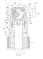
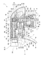
以下、図1から図3を参照し、この発明の実施の形態について説明する。本実施形態のトリガー式液体噴出器1は、容器体A内の液体を吸上げる縦供給筒部10を有し、かつ液体が収容された容器体Aに装着される噴出器本体2と、液体を噴出する噴出孔6が形成されたノズル部材5と、噴出器本体2とノズル部材5とを連結する中継部材4と、を備える。なお、トリガー式液体噴出器1の各構成部品は、特に記載がなければ合成樹脂を用いた成形品とされている。   Hereinafter, an embodiment of the present invention will be described with reference to FIGS. The trigger type liquid ejector 1 of the present embodiment has a vertical supply cylinder portion 10 for sucking up the liquid in the container A, and the ejector main body 2 mounted on the container A containing the liquid; And a relay member 4 for connecting the ejector main body 2 and the nozzle member 5 to each other. Each component of the trigger type liquid ejector 1 is a molded product using a synthetic resin unless otherwise specified.

以下、縦供給筒部10の中心軸線O1に沿う方向を上下方向といい、上下方向に沿って容器体A側を下側、その反対側を上側という。上下方向から見て、縦供給筒部10に対してノズル部材5が位置している側を前側、その逆側を後側という。上下方向から見て、前後方向に直交する方向を左右方向という。   Hereinafter, the direction along the central axis O1 of the vertical supply cylinder portion 10 is referred to as the up-down direction, the container body A side along the up-down direction is the lower side, and the opposite side is the upper side. When viewed from above and below, the side where the nozzle member 5 is located with respect to the vertical supply cylinder 10 is referred to as a front side, and the opposite side is referred to as a rear side. When viewed from above and below, a direction perpendicular to the front and rear direction is referred to as a left and right direction.

噴出器本体2は、上下方向に延びる縦供給筒部10と、縦供給筒部10の前方に配設され、縦供給筒部10内の液体を噴出孔6側に向けて流通させる射出筒部11と、縦供給筒部10の前方に前方付勢状態で後方に移動可能に配設されたトリガー部51を有するトリガー機構Tと、縦供給筒部10、射出筒部11および後述するシリンダ53を上方、後方および左右方向から一体に覆うカバー体55と、を備える。   The ejector main body 2 is provided with a vertical supply cylinder 10 extending in the up-down direction, and an injection cylinder that is disposed in front of the vertical supply cylinder 10 and allows the liquid in the vertical supply cylinder 10 to flow toward the ejection holes 6. 11, a trigger mechanism T having a trigger portion 51 disposed in front of the vertical supply cylinder portion 10 so as to be movable in a forward biased state, a vertical supply cylinder portion 10, an injection cylinder portion 11, and a cylinder 53 to be described later. And a cover body 55 that integrally covers the cover from above, from behind, and from the left and right.

縦供給筒部10は、有頂筒状の外筒12と、外筒12内に嵌合された内筒13と、を備える。
外筒12は、大径部12aと、大径部12aの上方に配置され、かつ大径部12aより内径および外径が小さい小径部12bと、大径部12aの上端部と小径部12bの下端部とを連結するフランジ部12cと、を備える。小径部12bの上端開口は、頂壁部12dに塞がれている。
内筒13は、大径部13aと、大径部13aの上方に配置され、かつ大径部13aより内径および外径が小さい小径部13bと、大径部13aの上端部と小径部13bの下端部とを連結するフランジ部13cと、を備える。
The vertical supply cylinder section 10 includes an outer cylinder 12 having a top cylindrical shape, and an inner cylinder 13 fitted in the outer cylinder 12.
The outer cylinder 12 includes a large-diameter portion 12a, a small-diameter portion 12b disposed above the large-diameter portion 12a, and having an inner diameter and an outer diameter smaller than the large-diameter portion 12a, and an upper end portion of the large-diameter portion 12a and a small-diameter portion 12b. And a flange portion 12c connecting the lower end portion. The upper end opening of the small diameter portion 12b is closed by the top wall portion 12d.
The inner cylinder 13 includes a large-diameter portion 13a, a small-diameter portion 13b disposed above the large-diameter portion 13a and having an inner diameter and an outer diameter smaller than the large-diameter portion 13a, and an upper end portion of the large-diameter portion 13a and a small-diameter portion 13b. And a flange portion 13c connecting the lower end portion.

内筒13の小径部13b内に、容器体A内に配置され、かつ容器体Aの図示しない底部に下端開口が位置するパイプ15の上部が嵌合されている。内筒13のフランジ部13cは、外筒12のフランジ部12cよりも下方に位置している。内筒13のフランジ部13cと、外筒12のフランジ部12cと、の間に隙間S1が設けられている。   The upper part of the pipe 15 which is disposed in the container A and whose lower end opening is located at the bottom (not shown) of the container A is fitted in the small diameter portion 13b of the inner cylinder 13. The flange 13c of the inner cylinder 13 is located lower than the flange 12c of the outer cylinder 12. A gap S1 is provided between the flange 13c of the inner cylinder 13 and the flange 12c of the outer cylinder 12.

内筒13の大径部13aにおいて、外筒12の大径部12aから下方に突出した部分に、その径方向の外側に向けて突出する環状の鍔部13dが形成されている。鍔部13dは、容器体Aの口部A1に装着(例えば螺着)される装着キャップ3の上端部内に配設され、装着キャップ3の上端部をその軸線回りに回転可能に係止する。鍔部13dは、装着キャップ3と容器体Aの口部A1における上端開口縁とにより上下方向に挟まれる。
外筒12および内筒13で構成される縦供給筒部10の中心軸線O1は、容器体Aの容器軸に対して後方に偏心している。
In the large-diameter portion 13a of the inner cylinder 13, a portion protruding downward from the large-diameter portion 12a of the outer cylinder 12 is formed with an annular flange portion 13d protruding radially outward. The flange 13d is provided in the upper end of the mounting cap 3 mounted (for example, screwed) on the mouth A1 of the container A, and locks the upper end of the mounting cap 3 rotatably around its axis. The flange 13d is vertically sandwiched between the mounting cap 3 and the upper edge of the opening at the mouth A1 of the container A.
The central axis O <b> 1 of the vertical supply cylinder portion 10 including the outer cylinder 12 and the inner cylinder 13 is eccentric to the rear with respect to the container axis of the container body A.

内筒13の上端部内に、上下方向に弾性変形可能に形成された吐出弁30が配設されている。
吐出弁30は、内筒13内に嵌合され、外筒12における頂壁部12dの下面に当接するベース部31と、ベース部31の下方に配置され、内筒13の内周面に段差状に形成された弁座32に対して上方から当接する弁体33と、ベース部31および弁体33を上下に連結する中空ばね部34と、を備える。
A discharge valve 30 is provided in the upper end of the inner cylinder 13 so as to be elastically deformable in the vertical direction.
The discharge valve 30 is fitted into the inner cylinder 13, and is disposed below the base 31, which is in contact with the lower surface of the top wall 12 d of the outer cylinder 12. A valve body 33 that comes into contact with the valve seat 32 formed in a shape from above, and a hollow spring portion 34 that connects the base portion 31 and the valve body 33 up and down are provided.

弁体33は、中空ばね部34によって上方から押圧されており、弁座32に対して密に当接している。弁体33は、内筒13内において、弁座32よりも上方に位置する空間と、弁座32よりも下方に位置する空間と、の連通を遮断する。弁体33は、中空ばね部34の付勢力に抗して上昇し、弁座32から離間することで、内筒13内において、弁座32よりも上方に位置する空間と、弁座32よりも下方に位置する空間と、を連通する。   The valve body 33 is pressed from above by the hollow spring portion 34 and is in close contact with the valve seat 32. The valve body 33 blocks communication between a space located above the valve seat 32 and a space located below the valve seat 32 in the inner cylinder 13. The valve body 33 rises against the urging force of the hollow spring portion 34 and separates from the valve seat 32, so that the space located above the valve seat 32 in the inner cylinder 13 and the valve seat 32 Also communicates with the space located below.

内筒13の内周面のうち、弁座32よりも下方に位置し、かつパイプ15の上端よりも上方に位置する部分に、内側に向けて突出する環状のテーパ筒部35が形成されている。テーパ筒部35は、下方に向かうに従って漸次、縮径している。テーパ筒部35の内側に、テーパ筒部35の内周面に離反可能に着座するボール弁36が配置されている。
ボール弁36は、内筒13内において、テーパ筒部35よりも上方に位置する空間と、テーパ筒部35よりも下方に位置する空間と、の連通を遮断する。ボール弁36は、上昇してテーパ筒部35の内周面から離間することで、内筒13内において、テーパ筒部35よりも上方に位置する空間と、テーパ筒部35よりも下方に位置する空間と、を連通する。
An annular tapered cylindrical portion 35 protruding inward is formed on a portion of the inner peripheral surface of the inner cylinder 13 that is located below the valve seat 32 and above the upper end of the pipe 15. I have. The diameter of the tapered tube portion 35 is gradually reduced toward the bottom. A ball valve 36 that is separably seated on the inner peripheral surface of the tapered tubular portion 35 is disposed inside the tapered tubular portion 35.
The ball valve 36 blocks communication between a space located above the tapered tube 35 and a space located below the tapered tube 35 in the inner tube 13. The ball valve 36 rises and separates from the inner peripheral surface of the tapered tube portion 35, so that the space located inside the inner tube 13 above the tapered tube portion 35 and the space located below the tapered tube portion 35. To communicate with the space.

射出筒部11は、前後方向に延び、後端部が縦供給筒部10における上端部の前側に接続されている。射出筒部11の内部は、外筒12に形成された外側吐出孔16、および内筒13に形成された内側吐出孔17を通じて縦供給筒部10の内部に連通している。内側吐出孔17は、内筒13内において、弁座32よりも上方に位置する空間に開口している。
外筒12において、射出筒部11よりも下方に位置する部分に、前方に向けて突出するシリンダ装着筒40が形成されている。シリンダ装着筒40は、前方に向けて開口している。シリンダ装着筒40の下端部は、外筒12におけるフランジ部12cと一体に形成されている。
The injection cylinder 11 extends in the front-rear direction, and has a rear end connected to a front side of an upper end of the vertical supply cylinder 10. The inside of the injection cylinder 11 communicates with the inside of the vertical supply cylinder 10 through an outer discharge hole 16 formed in the outer cylinder 12 and an inner discharge hole 17 formed in the inner cylinder 13. The inner discharge hole 17 is open in the inner cylinder 13 in a space located above the valve seat 32.
In the outer cylinder 12, a cylinder mounting cylinder 40 protruding forward is formed in a portion located below the injection cylinder portion 11. The cylinder mounting cylinder 40 is open forward. The lower end of the cylinder mounting cylinder 40 is formed integrally with the flange 12 c of the outer cylinder 12.

トリガー機構Tは、トリガー部51の後方への移動によって、液体を縦供給筒部10内から射出筒部11内を通じて噴出孔6側に向けて流通させる。トリガー機構Tは、縦供給筒部10の前方に前方付勢状態で後方に移動可能に配設されたトリガー部51と、トリガー部51に連動して前後方向に移動するピストン52と、ピストン52が挿入され、かつ内部が縦供給筒部10内に連通したシリンダ53と、を備える。   The trigger mechanism T causes the liquid to flow from the vertical supply cylinder 10 through the ejection cylinder 11 toward the ejection hole 6 by moving the trigger 51 backward. The trigger mechanism T includes a trigger portion 51 disposed in front of the vertical supply cylinder portion 10 so as to be movable rearward in a forward biased state, a piston 52 that moves in the front-rear direction in conjunction with the trigger portion 51, And a cylinder 53 whose inside communicates with the vertical supply cylinder 10.

シリンダ53は、シリンダ装着筒40内に嵌合され、かつ前方に向けて開口した外筒部60と、外筒部60の後端開口を塞ぐ後壁部61と、後壁部61の中央部から前方に向けて突出するとともに前端が閉塞された有頂筒状のピストンガイド62と、を備える。
外筒部60、ピストンガイド62、およびシリンダ装着筒40は、前後方向に延びるシリンダ軸O2と同軸に配置されている。
The cylinder 53 is fitted into the cylinder mounting cylinder 40 and has an outer cylinder part 60 opened forward, a rear wall part 61 closing a rear end opening of the outer cylinder part 60, and a central part of the rear wall part 61. And a front-end cylindrical piston guide 62 projecting forward from the front end and having a closed front end.
The outer cylinder part 60, the piston guide 62, and the cylinder mounting cylinder 40 are arranged coaxially with the cylinder axis O2 extending in the front-rear direction.

ピストンガイド62は内側が後方に開口しており、この開口内に、シリンダ装着筒40の後壁(外筒12の小径部12b)から前方に向けて突出した突部が嵌合されている。
外筒部60の外周面とシリンダ装着筒40の内周面とは、前後方向の両端部において密接している。外筒部60の外周面とシリンダ装着筒40の内周面との間のうち、前後方向の両端部同士の間に位置する中間部に、環状の隙間S2が設けられている。
The inner side of the piston guide 62 is opened rearward, and a projection projecting forward from the rear wall (small diameter portion 12b of the outer cylinder 12) is fitted into the opening.
The outer peripheral surface of the outer cylinder part 60 and the inner peripheral surface of the cylinder mounting cylinder 40 are in close contact at both ends in the front-rear direction. An annular gap S <b> 2 is provided at an intermediate portion located between both ends in the front-rear direction, between the outer peripheral surface of the outer cylinder portion 60 and the inner peripheral surface of the cylinder mounting cylinder 40.

外筒部60に、外筒部60の内側と前記隙間S2とを連通する第1通気孔63が形成されている。外筒12のフランジ部12cに、前記隙間S2と、外筒12のフランジ部12cと内筒13のフランジ部13cとの間の隙間S1と、を連通する第2通気孔64が形成されている。内筒13のフランジ部13cに、前記隙間S1と、内筒13の大径部13aおよび装着キャップ3の内側と、を連通する第3通気孔65が形成されている。   A first ventilation hole 63 that communicates the inside of the outer cylinder 60 with the gap S2 is formed in the outer cylinder 60. A second ventilation hole 64 is formed in the flange portion 12c of the outer cylinder 12 so as to communicate the gap S2 and the gap S1 between the flange portion 12c of the outer cylinder 12 and the flange portion 13c of the inner cylinder 13. . A third ventilation hole 65 is formed in the flange portion 13 c of the inner cylinder 13 to communicate the gap S <b> 1 with the large-diameter portion 13 a of the inner cylinder 13 and the inside of the mounting cap 3.

シリンダ53の後壁部61に、後方に向けて突出し、前後方向に開口する筒部66が形成されている。筒部66は、後壁部61において、ピストンガイド62より上方に位置する部分に形成されている。筒部66は、シリンダ装着筒40の後壁(外筒12の小径部12b)に形成された貫通孔に嵌合されている。
ここで、内筒13の小径部13bに、筒部66内に連通する第2貫通孔67が形成されている。第2貫通孔67は、内筒13内において、弁座32よりも下方に位置し、かつテーパ筒部35よりも上方に位置する空間に開口している。
A cylinder portion 66 is formed on the rear wall portion 61 of the cylinder 53 so as to project rearward and open in the front-rear direction. The cylindrical portion 66 is formed at a portion of the rear wall portion 61 located above the piston guide 62. The tubular portion 66 is fitted in a through hole formed in the rear wall of the cylinder mounting tube 40 (the small diameter portion 12b of the outer tube 12).
Here, a second through hole 67 communicating with the inside of the tubular portion 66 is formed in the small diameter portion 13b of the inner cylinder 13. The second through-hole 67 is located in the inner cylinder 13 in a space located below the valve seat 32 and above the tapered cylinder portion 35.

以上より、シリンダ53内と縦供給筒部10内とが、筒部66の内側、および第2貫通孔67を通して連通している。また、吐出弁30は、射出筒部11内とシリンダ53内との連通およびその遮断を切換え、ボール弁36は、容器体A内とシリンダ53内との連通およびその遮断を切換える。   As described above, the inside of the cylinder 53 and the inside of the vertical supply cylinder 10 communicate with each other through the inside of the cylinder 66 and the second through hole 67. Further, the discharge valve 30 switches between the communication between the inside of the injection cylinder 11 and the inside of the cylinder 53 and the shutoff thereof, and the ball valve 36 switches between the communication between the inside of the container A and the inside of the cylinder 53 and the shutoff thereof.

シリンダ53の上端部に、上方に向けて突出し、かつ後方に向けて延びる装着突部53aが配設されている。装着突部53aと外筒部60の外周面との間に隙間が設けられている。装着突部53aは、表裏面が上下方向を向く板状に形成されている。装着突部53aにおける左右方向の中央部に、後方に向けて開口し、かつ上下方向に貫き、前後方向に延びる細孔が形成されている。この細孔には、シリンダ装着筒40の上端部と、射出筒部11の後部における下端部と、を連結し、かつ表裏面が左右方向を向く差込板115が差し込まれている。   At the upper end of the cylinder 53, a mounting protrusion 53a that protrudes upward and extends rearward is provided. A gap is provided between the mounting projection 53a and the outer peripheral surface of the outer cylinder 60. The mounting projection 53a is formed in a plate-like shape with the front and back faces in the up-down direction. At the center of the mounting protrusion 53a in the left-right direction, a fine hole that opens rearward, penetrates vertically, and extends in the front-rear direction is formed. An insertion plate 115 that connects the upper end of the cylinder mounting cylinder 40 and the lower end of the rear part of the injection cylinder 11 and whose front and back faces in the left-right direction is inserted into the small hole.

ピストン52は、トリガー部51に連結された円柱状の連結部70と、連結部70より後方に位置し、連結部70よりも大径とされたピストン筒71と、を備え、全体として後方に開口した筒状に形成されている。ピストン52は、シリンダ軸O2と同軸に配置されている。   The piston 52 includes a cylindrical connecting portion 70 connected to the trigger portion 51, and a piston cylinder 71 located behind the connecting portion 70 and having a larger diameter than the connecting portion 70. It is formed in an open cylindrical shape. The piston 52 is arranged coaxially with the cylinder axis O2.

ピストン筒71は、後方に向けて開口し、かつ内部にピストンガイド62が挿入されるピストン本体部72と、ピストン本体部72の後端部からその径方向の外側に向けて突出し、かつ外筒部60の内周面に密に摺接する摺動筒部73と、を備える。
ピストン本体部72の内径は、ピストンガイド62の外径より大きい。ピストン本体部72の内周面とピストンガイド62の外周面との間に隙間が設けられている。
摺動筒部73は、前後方向の中央部から前方および後方に向かうに従って漸次、拡径しており、前後方向の両端部に位置するリップ部が外筒部60の内周面に対して摺動する。
The piston cylinder 71 is opened rearward and has a piston body 72 into which the piston guide 62 is inserted. The piston cylinder 71 projects radially outward from the rear end of the piston body 72 and A sliding cylinder portion 73 that comes into close sliding contact with the inner peripheral surface of the portion 60.
The inner diameter of the piston body 72 is larger than the outer diameter of the piston guide 62. A gap is provided between the inner peripheral surface of the piston main body 72 and the outer peripheral surface of the piston guide 62.
The diameter of the sliding cylinder 73 gradually increases from the center in the front-rear direction toward the front and the rear, and lip portions located at both ends in the front-rear direction slide on the inner peripheral surface of the outer cylinder 60. Move.

ピストン52の連結部70は、後述する連結軸86を介してトリガー部51に連結されている。これにより、ピストン52は、トリガー部51とともに後述する弾性板部54により前方に付勢され、かつトリガー部51の後方への移動に伴って後方に移動してシリンダ53内に押し込まれる。   The connecting portion 70 of the piston 52 is connected to the trigger portion 51 via a connecting shaft 86 described later. Thus, the piston 52 is urged forward by the elastic plate portion 54 described later together with the trigger portion 51, and moves backward as the trigger portion 51 moves backward and is pushed into the cylinder 53.

トリガー部51が最前方移動位置に位置しているときに、ピストン52の摺動筒部73は第1通気孔63を閉塞している。そして、トリガー部51の後方への移動によってピストン52が所定量だけ後方移動したときに、摺動筒部73が第1通気孔63を開放する。これにより、容器体Aの内部は、第3通気孔65、前記隙間S1、第2通気孔64、前記隙間S2および第1通気孔63を通じて外部に連通する。   When the trigger part 51 is located at the foremost movement position, the sliding cylinder part 73 of the piston 52 closes the first ventilation hole 63. Then, when the piston 52 moves rearward by a predetermined amount due to the rearward movement of the trigger portion 51, the sliding cylinder portion 73 opens the first ventilation hole 63. Thereby, the inside of the container body A communicates with the outside through the third ventilation hole 65, the gap S1, the second ventilation hole 64, the gap S2, and the first ventilation hole 63.

トリガー部51は、左右方向から見た側面視で後方に向けて凹状に湾曲する前面を有する主板部80と、主板部80の左右方向の両端部から後方に向けて突出する一対の側板部81と、を備える。   The trigger portion 51 includes a main plate portion 80 having a front surface curved concavely rearward in a side view as viewed from the left and right, and a pair of side plate portions 81 projecting rearward from both left and right ends of the main plate portion 80. And.

一対の側板部81の上端部には、上方に延び、射出筒部11を左右方向に挟み込む一対の連結板82が形成されている。一対の連結板82には、左右方向の外側に向けて突出する回転軸部83が各別に設けられている。回転軸部83は、射出筒部11の上方を覆う上板部材84に設けられた軸受け部に回動可能に支持されている。これにより、トリガー部51は、回転軸部83を中心に前後方向に揺動可能とされている。   A pair of connecting plates 82 extending upward and sandwiching the injection cylinder 11 in the left-right direction are formed at upper ends of the pair of side plates 81. Each of the pair of connecting plates 82 is separately provided with a rotating shaft 83 protruding outward in the left-right direction. The rotating shaft 83 is rotatably supported by a bearing provided on an upper plate member 84 that covers the upper part of the injection cylinder 11. Thus, the trigger portion 51 can swing in the front-rear direction about the rotation shaft portion 83.

主板部80の上端部に、後方に向けて延びる連結筒85が形成されている。連結筒85の内周面の後部に、連結筒85の内側に向けて左右方向に突出した一対の連結軸86が形成されている。連結軸86は、ピストン52の連結部70に形成された連結孔内に挿入されている。これにより、トリガー部51とピストン52とが、互いに連結されている。
ピストン52の連結部70は、連結軸86に対してその軸線回りに回動可能とされ、かつ上下方向に所定量だけ移動可能に連結されている。
A connecting cylinder 85 extending rearward is formed at the upper end of the main plate 80. A pair of connecting shafts 86 protruding in the left-right direction toward the inside of the connecting tube 85 are formed at the rear of the inner peripheral surface of the connecting tube 85. The connecting shaft 86 is inserted into a connecting hole formed in the connecting portion 70 of the piston 52. Thus, the trigger portion 51 and the piston 52 are connected to each other.
The connecting portion 70 of the piston 52 is rotatable around the axis thereof with respect to the connecting shaft 86 and is connected to be movable by a predetermined amount in the vertical direction.

射出筒部11の上面には、縦供給筒部10における外筒12の頂壁部12dに連結された水平板状の前記上板部材84が取付けられている。
上板部材84における左右方向の両端部に、左右方向から見た側面視で前方に突の円弧状を呈し、射出筒部11の下方まで延びる弾性板部54が形成されている。弾性板部54は、左右方向から見た側面視で同心の円弧状を呈し、前後に並ぶ一対の板ばねを備える。
The upper plate member 84 in the form of a horizontal plate connected to the top wall 12 d of the outer cylinder 12 in the vertical supply cylinder 10 is attached to the upper surface of the injection cylinder 11.
Elastic plate portions 54 are formed at both ends of the upper plate member 84 in the left-right direction, each having an arc shape projecting forward in a side view as viewed from the left-right direction, and extending to below the injection cylinder portion 11. The elastic plate portion 54 has a concentric arc shape in a side view as viewed from the left and right directions, and includes a pair of leaf springs arranged in front and rear.

一対の板ばねの各下端部は、左右方向から見た側面視で下方に向けて突の円弧状を呈する折返し部を介して接続されている。折返し部に、下方に向けて突出する係止片54dが形成されており、この係止片54dがトリガー部51の側板部81に形成されたポケット部81aに上方から差し込まれている。
これにより、弾性板部54は、係止片54dおよびポケット部81aを介してトリガー部51を前方に付勢している。
The lower ends of the pair of leaf springs are connected via a folded portion projecting downward in a side view as viewed from the left and right directions. A locking piece 54d projecting downward is formed in the folded portion, and the locking piece 54d is inserted from above into a pocket portion 81a formed in the side plate portion 81 of the trigger portion 51.
Thereby, the elastic plate portion 54 urges the trigger portion 51 forward through the locking piece 54d and the pocket portion 81a.

トリガー部51の主板部80の上端部は、弾性板部54による付勢によって後述する中継部材4における隔壁90の下端部に対して後方から当接している。これにより、トリガー部51は最前方移動位置に位置決めされている。
トリガー部51が後方に引かれて最前方移動位置から移動すると、係止片54dが後方に移動し、弾性板部54が弾性変形する。このとき、係止片54dは、ポケット部81aに対して上昇しつつも、ポケット部81aへの係合状態を維持する。
The upper end portion of the main plate portion 80 of the trigger portion 51 is in contact with the lower end portion of the partition wall 90 of the relay member 4 described later from behind by the bias of the elastic plate portion 54. Thereby, the trigger part 51 is positioned at the foremost movement position.
When the trigger portion 51 is pulled rearward and moves from the frontmost movement position, the locking piece 54d moves rearward, and the elastic plate portion 54 is elastically deformed. At this time, the locking piece 54d keeps being engaged with the pocket portion 81a while rising with respect to the pocket portion 81a.

中継部材4は、噴出器本体2に対して前方から組み合わされている。中継部材4は、射出筒部11に対して前方から組み合わされ、噴出器本体2から前方に突出している。中継部材4は、射出筒部11の前端開口を前方から覆う隔壁90と、隔壁90から後方に向けて延び、射出筒部11に外嵌された外嵌筒部91と、隔壁90から前方に向けて延び、ノズル部材5が装着された第1装着筒部92と、隔壁90のうち、第1装着筒部92の内側に位置する部分から前方に向けて延びるガイド軸部94と、を備える。   The relay member 4 is combined with the ejector main body 2 from the front. The relay member 4 is combined with the injection cylinder 11 from the front, and projects forward from the ejector main body 2. The relay member 4 includes a partition wall 90 that covers the front end opening of the injection tube portion 11 from the front, an outer fitting tube portion 91 that extends rearward from the partition wall 90, and is externally fitted to the injection tube portion 11, and a front portion from the partition wall 90. A first mounting cylinder portion 92 extending toward the nozzle member 5 to which the nozzle member 5 is mounted, and a guide shaft portion 94 extending forward from a portion of the partition wall 90 located inside the first mounting cylinder portion 92. .

隔壁90、およびカバー体55の前端縁それぞれの前後方向の位置は、互いに同等になっている。第1装着筒部92、およびガイド軸部94は、前後方向に延びる中心軸線O3と同軸に配設されている。中心軸線O3は、射出筒部11の中心軸線より下方に位置している。
以下、前後方向から見て、中心軸線O3に交差する方向をノズル径方向といい、中心軸線O3回りに周回する方向をノズル周方向という。
The positions in the front-rear direction of the front edge of the partition wall 90 and the front edge of the cover body 55 are equivalent to each other. The first mounting cylinder portion 92 and the guide shaft portion 94 are disposed coaxially with a center axis O3 extending in the front-rear direction. The central axis O3 is located below the central axis of the injection cylinder 11.
Hereinafter, when viewed from the front-back direction, a direction intersecting the center axis O3 is referred to as a nozzle radial direction, and a direction circling around the center axis O3 is referred to as a nozzle circumferential direction.

第1装着筒部92における前後方向の中間部に、ノズル径方向の外側に向けて突出し、全周にわたって延びる取付フランジ部106が形成されている。
ガイド軸部94は、前端部が閉塞され、かつ後方に開口した有頂筒状に形成されている。ガイド軸部94は第1装着筒部92よりも前方に突出することなく、第1装着筒部92の内側に収まるように形成されている。
なお、ガイド軸部94の形状はこの場合に限定されるものではなく、例えば中実の円柱状に形成しても構わない。
At an intermediate portion in the front-rear direction of the first mounting cylinder portion 92, a mounting flange portion 106 protruding outward in the nozzle radial direction and extending over the entire circumference is formed.
The guide shaft portion 94 is formed in a cylindrical shape with a closed top end and a rearward opening. The guide shaft portion 94 is formed so as to fit inside the first mounting cylinder 92 without protruding forward from the first mounting cylinder 92.
The shape of the guide shaft portion 94 is not limited to this case, and may be, for example, a solid columnar shape.

隔壁90のうち、ガイド軸部94の上方に位置し、かつ第1装着筒部92の内側に位置する部分に、射出筒部11内に連通する連通孔95が形成されている。これにより、ガイド軸部94と第1装着筒部92との間に画成された環状空間96は、連通孔95を通じて射出筒部11内に連通している。
ガイド軸部94における前端部側の外周面に、前後方向に延びるとともに前方に向けて開口する第1切換溝97が形成されている。第1切換溝97はノズル周方向に等間隔をあけて2つ形成されている。ただし、第1切換溝97の数は2つに限定されるものではなく、例えば1つ或いは3つ以上形成されていても良い。
A communication hole 95 that communicates with the inside of the injection cylinder 11 is formed in a portion of the partition 90 that is located above the guide shaft 94 and inside the first mounting cylinder 92. Thereby, the annular space 96 defined between the guide shaft portion 94 and the first mounting cylinder portion 92 communicates with the inside of the injection cylinder portion 11 through the communication hole 95.
A first switching groove 97 extending in the front-rear direction and opening forward is formed on the outer peripheral surface on the front end side of the guide shaft portion 94. Two first switching grooves 97 are formed at regular intervals in the nozzle circumferential direction. However, the number of the first switching grooves 97 is not limited to two, and for example, one or three or more may be formed.

ノズル部材5は、第1装着筒部92を介して中継部材4に装着されることで、中継部材4に対して前方から組み合わされている。ノズル部材5は、中継部材4に対して中心軸線O3回りに回転可能に装着されている。   The nozzle member 5 is assembled to the relay member 4 from the front by being mounted on the relay member 4 via the first mounting tubular portion 92. The nozzle member 5 is attached to the relay member 4 so as to be rotatable around the central axis O3.

ノズル部材5は、ガイド軸部94の前端面、および第1装着筒部92の前端開口を前方から覆うノズル壁部100と、ノズル壁部100から後方に向けて延び、第1装着筒部92に対して前方に抜け止めされた状態で回転可能に外嵌された第2装着筒部101と、ノズル壁部100のうち、第2装着筒部101の内側に位置する部分から後方に向けて延び、ガイド軸部94に回転可能に外嵌された第2嵌合筒部102と、ノズル壁部100から後方に向けて延び、第1装着筒部92の内側に中心軸線O3回りに回転可能に嵌合したサポート筒部105と、ノズル壁部100から前方に突出したノズルチップ107と、ノズル壁部100から前方に突出しノズルチップ107をノズル径方向の外側から囲うキャップ装着筒部108と、キャップ装着筒部108内に嵌合され、ノズルチップ107の前端面を前方から覆うノズルキャップ109と、を備える。   The nozzle member 5 includes a nozzle wall portion 100 that covers the front end face of the guide shaft portion 94 and the front end opening of the first mounting cylinder portion 92 from the front, and extends rearward from the nozzle wall portion 100 to form the first mounting cylinder portion 92. And a second mounting cylinder 101 rotatably fitted to the nozzle wall 100 in a state where the nozzle wall 100 is prevented from slipping forward, and a portion of the nozzle wall 100 located inside the second mounting cylinder 101 toward the rear. A second fitting cylinder portion 102 extending outward and rotatably fitted to the guide shaft portion 94; and extending rearward from the nozzle wall portion 100 and rotatable about the central axis O3 inside the first mounting cylinder portion 92. A support cylinder portion 105 fitted to the nozzle wall portion, a nozzle tip 107 protruding forward from the nozzle wall portion 100, a cap mounting cylinder portion 108 protruding forward from the nozzle wall portion 100 and surrounding the nozzle tip 107 from the outside in the nozzle radial direction, cap Fitted into the wear sleeve portion 108 includes a nozzle cap 109 for covering the front end face of the nozzle tip 107 from the front, the.

ノズル壁部100の後面と、ガイド軸部94の前端面と、の間に、第1切換溝97が開口する隙間110が設けられている。ノズル壁部100に、隙間110に開口する接続孔111が形成されている。
ノズルチップ107は、中実の柱状に形成され、中心軸線O3に対して上方に偏心して配設されている。ノズルチップ107の外周面に、前後方向の全長にわたって延び、接続孔111に連通するノズル連通溝112が形成されている。
ノズルキャップ109は、前方が閉塞された有頂筒状に形成され、その頂壁に前後方向に貫く噴出孔6が形成されている。噴出孔6は、中心軸線O3に対して上方に偏心して配設されている。噴出孔6は、ノズルチップ107のノズル連通溝112、ノズル壁部100の接続孔111、および隙間110を通して、ガイド軸部94の第1切換溝97に連通している。
A gap 110 in which the first switching groove 97 opens is provided between the rear surface of the nozzle wall portion 100 and the front end surface of the guide shaft portion 94. A connection hole 111 that opens into the gap 110 is formed in the nozzle wall 100.
The nozzle tip 107 is formed in a solid columnar shape, and is disposed eccentric upward with respect to the central axis O3. A nozzle communication groove 112 extending over the entire length in the front-rear direction and communicating with the connection hole 111 is formed on the outer peripheral surface of the nozzle tip 107.
The nozzle cap 109 is formed in the shape of a cylinder with a top closed at the front, and the ejection hole 6 penetrating in the front-rear direction is formed in the top wall. The ejection hole 6 is disposed eccentrically upward with respect to the central axis O3. The ejection hole 6 communicates with the first switching groove 97 of the guide shaft portion 94 through the nozzle communication groove 112 of the nozzle tip 107, the connection hole 111 of the nozzle wall 100, and the gap 110.

第2装着筒部101は、ノズル壁部100の外周縁部に配設されている。第2装着筒部101の後端開口縁は、第1装着筒部92の取付フランジ部106の前面に当接若しくは近接している。
第2嵌合筒部102は、ガイド軸部94の第1切換溝97を全域にわたってノズル径方向の外側から覆っている。第2嵌合筒部102の後端縁は、第1切換溝97より後方に位置している。第2嵌合筒部102の内周面に、前後方向に延びるとともに、後方に開口する第2切換溝103が形成されている。第2切換溝103は、環状空間96に開口している。第2切換溝103はノズル周方向に等間隔をあけて2つ形成されている。なお、第2切換溝103の数は2つに限定されるものではなく、例えば1つ或いは3つ以上形成されていても良く、第1切換溝97に対応して配置することが好ましい。
The second mounting cylinder part 101 is provided on the outer peripheral edge of the nozzle wall part 100. The rear end opening edge of the second mounting cylinder 101 is in contact with or close to the front surface of the mounting flange 106 of the first mounting cylinder 92.
The second fitting cylinder portion 102 covers the first switching groove 97 of the guide shaft portion 94 from the outside in the nozzle radial direction over the entire area. The rear end edge of the second fitting cylinder portion 102 is located behind the first switching groove 97. A second switching groove 103 extending in the front-rear direction and opening rearward is formed on the inner peripheral surface of the second fitting cylindrical portion 102. The second switching groove 103 is open to the annular space 96. Two second switching grooves 103 are formed at regular intervals in the nozzle circumferential direction. Note that the number of the second switching grooves 103 is not limited to two, and may be one or three or more, for example, and is preferably arranged corresponding to the first switching grooves 97.

ノズル部材5および中継部材4のノズル周方向の相対位置を変えることで、第1切換溝97と第2切換溝103との連通、およびその遮断が切替えられるようになっている。すなわち、ノズル部材5は、中継部材4に、液体の噴出が可能となる噴出可能位置と、液体の噴出が規制される噴出規制位置と、の間を、ノズル周方向に回転可能に配設されている。
なお、ノズル部材5が噴出規制位置に位置すると、第1切換溝97と第2切換溝103との連通が遮断され、ノズル部材5の第2嵌合筒部102と、中継部材4のガイド軸部94と、の間がシールされる。したがって、ノズル部材5を噴出規制位置に位置させた状態で保管しているときに、例えば環境温度の上昇、および容器体Aに加えられた押圧力などに起因して、噴出器本体2の内圧が上昇しても、噴出孔6から液体が漏出するのを防ぐことができる。
By changing the relative positions of the nozzle member 5 and the relay member 4 in the circumferential direction of the nozzle, the communication between the first switching groove 97 and the second switching groove 103 and the interruption thereof can be switched. That is, the nozzle member 5 is disposed on the relay member 4 so as to be rotatable in the nozzle circumferential direction between a spoutable position at which the liquid can be spouted and a spouting restricted position at which the spouting of the liquid is regulated. ing.
When the nozzle member 5 is located at the ejection restricting position, the communication between the first switching groove 97 and the second switching groove 103 is cut off, and the second fitting cylindrical portion 102 of the nozzle member 5 and the guide shaft of the relay member 4 are connected. The space between the portion 94 is sealed. Therefore, when the nozzle member 5 is stored in a state where the nozzle member 5 is located at the ejection regulating position, the internal pressure of the ejector main body 2 is increased due to, for example, an increase in the environmental temperature and the pressing force applied to the container body A. Even if the pressure rises, it is possible to prevent the liquid from leaking from the ejection holes 6.

さらにノズル部材5は、噴出孔6の前方に配設されるとともに、噴出孔6を囲い、かつ内側に外気を導入する外気導入孔26が形成された造泡筒27と、ノズル部材5が噴出規制位置に位置したときに、トリガー部51に当接若しくは近接することでトリガー部51の後方移動を規制し、かつノズル部材5が噴出可能位置に位置したときに、トリガー部51から離れ、トリガー部51の後方移動を許容する規制部28と、を備える。   Further, the nozzle member 5 is disposed in front of the ejection hole 6 and surrounds the ejection hole 6 and has an outside air introduction hole 26 formed therein for introducing outside air. When the nozzle member 5 is located at the regulating position, the rearward movement of the trigger portion 51 is restricted by contacting or approaching the trigger portion 51, and when the nozzle member 5 is located at the ejectable position, the trigger member 51 is separated from the trigger portion 51, and And a regulating portion 28 that allows the portion 51 to move backward.

造泡筒27は、キャップ装着筒部108に外嵌されている。前方から見て、造泡筒27およびノズル壁部100は円形状を呈し、造泡筒27は、ノズル壁部100に内接するように配設されている。
外気導入孔26は、前後方向に延び、造泡筒27の前面に開口し、かつ造泡筒27の内側において、ノズルキャップ109より前方に位置する通過孔27aに連通している。外気導入孔26は、噴出孔6回りに間隔をあけて複数配設されている。
The foaming cylinder 27 is externally fitted to the cap mounting cylinder 108. When viewed from the front, the foaming cylinder 27 and the nozzle wall 100 have a circular shape, and the foaming cylinder 27 is disposed so as to be inscribed in the nozzle wall 100.
The outside air introduction hole 26 extends in the front-rear direction, opens at the front surface of the foaming tube 27, and communicates with a passage hole 27 a located inside the foaming tube 27 in front of the nozzle cap 109. A plurality of outside air introduction holes 26 are provided around the ejection holes 6 at intervals.

規制部28は、ノズル部材5が噴出規制位置に位置したときに、シリンダ53にシリンダ53の前方から当接若しくは近接し、ノズル部材5が噴出可能位置に位置したときに、シリンダ53から離れる。規制部28は、トリガー部51の後部と、シリンダ53の前端開口縁の下端部と、の間に配設されている。規制部28は、表裏面が上下方向を向く板状に形成されている。規制部28は、上下方向から見て、一対の辺が前後方向に延び、かつ残り一対の辺が左右方向に延びる矩形状を呈する。規制部28の側面のうち、前方を向く前面がトリガー部51に当接若しくは近接し、後方を向く後面がシリンダ53の前端開口縁に当接若しくは近接している。前方から見て、規制部28の左右方向の中央部は、トリガー部51およびシリンダ53それぞれの左右方向の中央部に対して右側にずれている。なお、前方から見て、規制部28の左右方向の中央部を、トリガー部51およびシリンダ53それぞれの左右方向の中央部に対して左側にずらしてもよい。   The restricting portion abuts or approaches the cylinder 53 from the front of the cylinder 53 when the nozzle member 5 is located at the ejection regulating position, and separates from the cylinder 53 when the nozzle member 5 is located at the ejectable position. The restricting portion 28 is disposed between a rear portion of the trigger portion 51 and a lower end portion of a front opening edge of the cylinder 53. The restricting portion 28 is formed in a plate shape with the front and back faces in the vertical direction. The restricting portion 28 has a rectangular shape with a pair of sides extending in the front-rear direction and a pair of remaining sides extending in the left-right direction when viewed from the up-down direction. Among the side surfaces of the regulating portion 28, the front surface facing forward contacts or approaches the trigger portion 51, and the rear surface facing backward contacts or approaches the front end opening edge of the cylinder 53. When viewed from the front, the center in the left-right direction of the regulating portion 28 is shifted to the right with respect to the center in the left-right direction of each of the trigger portion 51 and the cylinder 53. When viewed from the front, the central portion in the left-right direction of the regulating portion 28 may be shifted to the left with respect to the central portion in the left-right direction of each of the trigger portion 51 and the cylinder 53.

規制部28は、第2装着筒部101に連結部29を介して連結されている。連結部29は、第2装着筒部101から下方に向けて延びる第1連結部29aと、規制部28から前方に向けて延びる第2連結部29bと、を備える。   The restricting portion 28 is connected to the second mounting cylinder portion 101 via a connecting portion 29. The connecting portion 29 includes a first connecting portion 29a extending downward from the second mounting cylinder portion 101, and a second connecting portion 29b extending forward from the restricting portion.

第1連結部29aは、第2装着筒部101の下端部から下方に向けて延びている。第1連結部29aは、トリガー部51より前方に配置されている。第1連結部29aの下部は、前方から見てトリガー部51より右側に位置している。
第2連結部29bは、第1連結部29aの下端部から後方に向けて延びている。第2連結部29bは、規制部28における右側の端部に連結されている。第2連結部29bは、トリガー部51より右側に位置している。第2連結部29bの前後方向の長さは、第1連結部29aの上下方向の長さと同等になっている。
The first connecting portion 29a extends downward from the lower end of the second mounting tubular portion 101. The first connecting portion 29a is arranged forward of the trigger portion 51. The lower portion of the first connecting portion 29a is located on the right side of the trigger portion 51 when viewed from the front.
The second connecting portion 29b extends rearward from the lower end of the first connecting portion 29a. The second connecting portion 29b is connected to the right end of the regulating portion 28. The second connecting portion 29b is located on the right side of the trigger portion 51. The length of the second connecting portion 29b in the front-rear direction is equal to the length of the first connecting portion 29a in the vertical direction.

さらにトリガー式液体噴出器1は、被覆筒部材20を備える。
被覆筒部材20は、内側に第2装着筒部101が中心軸線O3回りに回転可能に嵌合された本体筒21と、本体筒21の後端部から後方に向けて突出し、第1装着筒部92の取付フランジ部106をノズル径方向の外側から囲う固定部22と、本体筒21の前端部に配設された蓋体23と、を備える。
Further, the trigger type liquid ejector 1 includes a coating cylinder member 20.
The coating cylinder member 20 includes a main body cylinder 21 in which the second mounting cylinder portion 101 is rotatably fitted around the central axis O3 inside, and protrudes rearward from the rear end of the main body cylinder 21 to form the first mounting cylinder. A fixing portion 22 surrounding the mounting flange portion 106 of the portion 92 from the outside in the nozzle radial direction, and a lid 23 disposed at the front end of the main body cylinder 21 are provided.

本体筒21に、第1連結部29aが挿通された窓孔21aが形成されている。窓孔21aは、本体筒21における前後方向の全長にわたって形成されている。窓孔21aはノズル周方向に延びており、ノズル部材5が、噴出規制位置と噴出可能位置との間を移動するのに伴い、第1連結部29aが窓孔21aの内側を移動する。
本体筒21の内側に、造泡筒27が、前方から見て本体筒21に内接するように配設されている。本体筒21の後端開口縁は、取付フランジ部106の前面に当接若しくは近接している。
The main body cylinder 21 is formed with a window hole 21a through which the first connecting portion 29a is inserted. The window hole 21a is formed over the entire length of the main body cylinder 21 in the front-rear direction. The window 21a extends in the circumferential direction of the nozzle, and the first connecting portion 29a moves inside the window 21a as the nozzle member 5 moves between the ejection restricting position and the ejectable position.
Inside the main body cylinder 21, a foaming cylinder 27 is disposed so as to be inscribed in the main body cylinder 21 when viewed from the front. The rear end opening edge of the main body cylinder 21 is in contact with or close to the front surface of the mounting flange portion 106.

固定部22は、中心軸線Oと同軸に配設された矩形枠状に形成され、前方から見て本体筒21が内接するように配設されている。固定部22は、全周にわたって連続して延びている。固定部22の後端開口縁は、カバー体55の前端縁に前後方向で近接している。固定部22に、ノズル径方向の内側に向けて突出し、取付フランジ部106の後面に当接若しくは近接する係止突片24が形成されている。係止突片24と、本体筒21の後端開口縁と、により、取付フランジ部106が前後方向に挟まれることで、被覆筒部材20が、中継部材4に固定状態で取付けられている。係止突片24は、固定部22の角部に形成されている。
なお、被覆筒部材20は、噴出器本体2に固定状態で取付けられてもよい。
The fixing portion 22 is formed in a rectangular frame shape arranged coaxially with the central axis O, and is arranged so that the main body cylinder 21 is inscribed when viewed from the front. The fixing portion 22 extends continuously over the entire circumference. The rear opening edge of the fixing portion 22 is close to the front edge of the cover 55 in the front-rear direction. A locking protrusion 24 is formed on the fixing portion 22 and protrudes inward in the nozzle radial direction, and is in contact with or near the rear surface of the mounting flange portion 106. The covering flange member 106 is sandwiched in the front-rear direction by the locking projection 24 and the rear end opening edge of the main body cylinder 21, so that the covering cylinder member 20 is fixedly attached to the relay member 4. The locking projection 24 is formed at a corner of the fixed portion 22.
In addition, the covering cylinder member 20 may be fixedly attached to the ejector main body 2.

蓋体23は、本体筒21の上端部から下方に向けて突出している。蓋体23は、表裏面が前後方向を向く板状に形成されている。蓋体23は、ノズル部材5が噴出規制位置に位置したときに、噴出孔6を噴出孔6の前方から閉塞し、かつノズル部材5が噴出可能位置に位置したときに、噴出孔6を開放する。図示の例では、蓋体23は、ノズル部材5が噴出規制位置に位置したときに、造泡筒27の通過孔27aの前端開口および外気導入孔26を閉塞し、かつノズル部材5が噴出可能位置に位置したときに、通過孔27aの前端開口および外気導入孔26を開放する。蓋体23の後面に、ノズル部材5が噴出規制位置に位置したときに、通過孔27aの前端開口に着脱可能に嵌められる膨出部が形成されている。   The lid 23 protrudes downward from the upper end of the main body tube 21. The lid 23 is formed in a plate shape with the front and back faces in the front-rear direction. The lid 23 closes the ejection hole 6 from the front of the ejection hole 6 when the nozzle member 5 is located at the ejection regulation position, and opens the ejection hole 6 when the nozzle member 5 is located at the ejection enabled position. I do. In the illustrated example, when the nozzle member 5 is located at the ejection restricting position, the lid 23 closes the front end opening of the passage hole 27a of the foaming cylinder 27 and the outside air introduction hole 26, and the nozzle member 5 can eject. When it is located at the position, the front end opening of the passage hole 27a and the outside air introduction hole 26 are opened. A bulging portion is formed on the rear surface of the lid 23 so as to be detachably fitted to the front end opening of the passage hole 27a when the nozzle member 5 is located at the ejection regulating position.

次に、上述のように構成されたトリガー式液体噴出器1の作用について説明する。
なお、トリガー部51の複数回の操作によって、トリガー式液体噴出器1の各部内に液体が充填されているものとする。
Next, the operation of the trigger type liquid ejector 1 configured as described above will be described.
It is assumed that the liquid is filled in each part of the trigger type liquid ejector 1 by a plurality of operations of the trigger part 51.

まず、ノズル部材5を、中継部材4に対して中心軸線O3を中心に反時計回りに回転させ、図1および図2に示される噴出規制位置から、図3に示される噴出可能位置に移動させる。これにより、第1切換溝97と第2切換溝103とが連通する。
この際、造泡筒27が、蓋体23に対して中心軸線O3回りに回転することで、通過孔27aの前端開口および外気導入孔26が開放される。図示の例では、通過孔27aの前端開口および外気導入孔26は、前方から見て、蓋体23に対して左斜め下に移動して開放される。さらにこの際、規制部28が、トリガー部51の後部と、シリンダ53の前端開口縁の下端部と、の間から退避され、前方から見てカバー体55から右側に突出する。
First, the nozzle member 5 is rotated counterclockwise about the central axis O3 with respect to the relay member 4, and is moved from the ejection restricting position shown in FIGS. 1 and 2 to the ejectable position shown in FIG. . Thereby, the first switching groove 97 and the second switching groove 103 communicate with each other.
At this time, the front end opening of the passage hole 27a and the outside air introduction hole 26 are opened by the foaming cylinder 27 rotating around the central axis O3 with respect to the lid 23. In the illustrated example, the front end opening of the passage hole 27a and the outside air introduction hole 26 move obliquely downward to the left with respect to the lid 23 and are opened when viewed from the front. Further, at this time, the restricting portion 28 is retracted from between the rear portion of the trigger portion 51 and the lower end portion of the front opening edge of the cylinder 53, and projects rightward from the cover body 55 when viewed from the front.

そして、トリガー部51を弾性板部54の付勢力に抗して後方に引くと、トリガー部51の後方移動に伴ってピストン52が後退するので、シリンダ53内の液体が、筒部66の内側および第2貫通孔67を通じて縦供給筒部10の内筒13に導入される。すると、内筒13に導入された液体は、ボール弁36を押し下げて閉弁させるとともに、吐出弁30を押し上げて開弁させるので、液体が、加圧された状態で内側吐出孔17および外側吐出孔16を通じて射出筒部11内に供給される。   When the trigger portion 51 is pulled backward against the urging force of the elastic plate portion 54, the piston 52 retreats with the rearward movement of the trigger portion 51, so that the liquid in the cylinder 53 flows inside the cylinder portion 66. And it is introduced into the inner cylinder 13 of the vertical supply cylinder part 10 through the second through hole 67. Then, the liquid introduced into the inner cylinder 13 pushes down the ball valve 36 to close the valve and pushes up the discharge valve 30 to open the valve, so that the liquid is pressurized and the inside discharge hole 17 and the outside discharge It is supplied into the injection cylinder 11 through the hole 16.

すると、射出筒部11内に供給された液体は、連通孔95、環状空間96、第2切換溝103、第1切換溝97、隙間110、接続孔111、およびノズル連通溝112を通じて噴出孔6に到達し、噴出孔6から造泡筒27の通過孔27a内に噴出される。この際、通過孔27a内が負圧になり、造泡筒27内に外気導入孔26を通して外気(空気)が導入され、液体が、通過孔27a内で外気と混合されて発泡して泡状となり、通過孔27aの前端開口から噴出される。   Then, the liquid supplied into the injection cylinder portion 11 is discharged through the communication hole 95, the annular space 96, the second switching groove 103, the first switching groove 97, the gap 110, the connection hole 111, and the nozzle communication groove 112. And is ejected from the ejection hole 6 into the passage hole 27 a of the foaming cylinder 27. At this time, the inside of the passage hole 27a becomes a negative pressure, outside air (air) is introduced into the foaming cylinder 27 through the outside air introduction hole 26, and the liquid is mixed with the outside air in the passage hole 27a to foam and foam. And is ejected from the front end opening of the passage hole 27a.

液体の噴出後、トリガー部51を解放すると、弾性板部54の復元力によってトリガー部51が前方に付勢されて元の位置に復帰するので、これに伴ってピストン52が前方移動する。そのため、シリンダ53内に負圧が生じ、この負圧によって、吐出弁30が閉弁した状態で、ボール弁36が上昇して開弁し、容器体A内の液体が、パイプ15を通じて縦供給筒部10に吸い上げられ、第2貫通孔67および筒部66の内側を通してシリンダ53内に導入される。   When the trigger portion 51 is released after the ejection of the liquid, the trigger portion 51 is urged forward by the restoring force of the elastic plate portion 54 to return to the original position, and accordingly, the piston 52 moves forward. Therefore, a negative pressure is generated in the cylinder 53, and the negative pressure causes the ball valve 36 to rise and open with the discharge valve 30 closed, and the liquid in the container A is supplied vertically through the pipe 15. The liquid is sucked up by the cylinder portion 10 and introduced into the cylinder 53 through the second through hole 67 and the inside of the cylinder portion 66.

そして、ノズル部材5を、中継部材4に対して中心軸線O3を中心に時計回りに回転させ、図3に示される噴出可能位置から、図1および図2に示される噴出規制位置に移動させる。これにより、第1切換溝97と第2切換溝103との連通が遮断される。
この際、造泡筒27が、蓋体23に対して中心軸線O3回りに回転することで、通過孔27aの前端開口および外気導入孔26が、蓋体23により閉塞される。さらにこの際、規制部28が、トリガー部51の後部と、シリンダ53の前端開口縁の下端部と、の間に進入し、トリガー部51の後部、およびシリンダ53の前端開口縁に当接若しくは近接する。
Then, the nozzle member 5 is rotated clockwise around the central axis O3 with respect to the relay member 4 to move the nozzle member 5 from the ejectable position shown in FIG. 3 to the ejection regulating position shown in FIGS. Thus, communication between the first switching groove 97 and the second switching groove 103 is interrupted.
At this time, the front end opening of the passage hole 27a and the outside air introduction hole 26 are closed by the lid 23 by rotating the foaming cylinder 27 around the central axis O3 with respect to the lid 23. Further, at this time, the restricting portion 28 enters between the rear portion of the trigger portion 51 and the lower end portion of the front opening edge of the cylinder 53, and abuts on or contacts the rear portion of the trigger portion 51 and the front opening edge of the cylinder 53. Be close.

以上説明したように、本実施形態に係るトリガー式液体噴出器1によれば、ノズル部材5が噴出規制位置に位置したときに、噴出孔6を噴出孔6の前方から閉塞し、かつノズル部材5が噴出可能位置に位置したときに、噴出孔6を開放する蓋体23を備えるので、液体を噴出孔6から噴出したときに、液体が例えば、噴出孔6内に残存したり、ノズル部材5の前端部に付着したりしても、ノズル部材5を噴出規制位置に位置させた状態で保管している間に、この液体が乾燥して固化し、噴出孔6が塞がれるのを抑制することができる。   As described above, according to the trigger type liquid ejector 1 according to the present embodiment, when the nozzle member 5 is located at the ejection regulating position, the ejection hole 6 is closed from the front of the ejection hole 6 and the nozzle member 5 is closed. When the liquid is ejected from the ejection hole 6 when the liquid is ejected from the ejection hole 6, for example, the liquid remains in the ejection hole 6, or the nozzle member 5 is provided. Even if the liquid adheres to the front end of the nozzle 5, the liquid is dried and solidified while the nozzle member 5 is stored in the state where the nozzle member 5 is located at the ejection regulating position, and the ejection hole 6 is blocked. Can be suppressed.

また、蓋体23が、中継部材4に固定された状態で取付けられているので、ノズル部材5を噴出規制位置から噴出可能位置に移動させれば、蓋体23をノズル部材5から離脱する操作を行わなくても、噴出孔6が開放されることとなり、操作性の悪化を防ぐことができる。
また、蓋体23が、中継部材4に固定された状態で取付けられていることから、ノズル部材5を噴出可能位置から噴出規制位置に移動させれば、蓋体23をノズル部材5に装着する操作を行わなくても、噴出孔6が蓋体23により閉塞されることとなり、噴出孔6を蓋体23で閉塞し忘れるのを抑制することができる。
Further, since the lid 23 is fixedly attached to the relay member 4, the operation of detaching the lid 23 from the nozzle member 5 is possible by moving the nozzle member 5 from the ejection restricting position to the spoutable position. Even without performing the above, the ejection hole 6 is opened, so that deterioration in operability can be prevented.
In addition, since the lid 23 is fixedly attached to the relay member 4, the lid 23 is attached to the nozzle member 5 by moving the nozzle member 5 from the jettable position to the jetting restriction position. Even if the operation is not performed, the ejection hole 6 is closed by the lid 23, and it is possible to prevent the ejection hole 6 from being forgotten to be closed by the lid 23.

また、蓋体23が、ノズル部材5が噴出規制位置に位置したときに、造泡筒27の通過孔27aの前端開口、および外気導入孔26を閉塞し、かつノズル部材5が噴出可能位置に位置したときに、通過孔27aの前端開口、および外気導入孔26を開放するので、ノズル部材5を噴出規制位置に位置させた状態で保管している間に、噴出孔6、外気導入孔26、および通過孔27aの各内周面などに付着した液体が乾燥して固化するのを抑制することが可能になり、噴出孔6が塞がれることだけでなく、外気導入孔26が塞がれることも抑制することができる。したがって、噴出孔6から造泡筒27の通過孔27aに噴出される液体の量、および通過孔27aに導入される外気の量を安定させることが可能になり、噴出される泡体の泡質の悪化を防ぐことができる。   When the nozzle member 5 is located at the ejection restricting position, the lid 23 closes the front end opening of the passage hole 27a of the foaming cylinder 27 and the outside air introduction hole 26, and the nozzle member 5 is located at a position where the nozzle member 5 can eject. When the nozzle member 5 is stored, the front end opening of the passage hole 27a and the outside air introduction hole 26 are opened. , And the liquid adhering to the inner peripheral surfaces of the passage holes 27a can be prevented from drying and solidifying, so that not only the ejection holes 6 are closed but also the outside air introduction holes 26 are closed. Can be suppressed. Therefore, it is possible to stabilize the amount of the liquid ejected from the ejection hole 6 to the passage hole 27a of the foaming cylinder 27 and the amount of the outside air introduced into the passage hole 27a, and to improve the foam quality of the ejected foam. Can be prevented from deteriorating.

また、ノズル部材5が、噴出規制位置に位置したときに、トリガー部51に当接若しくは近接することでトリガー部51の後方移動を規制する規制部28を備えるので、ノズル部材5を噴出規制位置に位置させた状態で保管しているときに、トリガー部51に不意に加えられた外力により、噴出器本体2の内部に大きな圧力が生ずるのを抑制することができる。したがって、ノズル部材5を噴出規制位置に位置させた状態で保管しているときに、トリガー部51に不意に外力が加えられても、例えば、ノズル部材5が中継部材4から外れたり、ノズル部材5の第2嵌合筒部102と、中継部材4のガイド軸部94と、の間のシール性を確保できなくなったりするのを抑制することができる。   Further, when the nozzle member 5 is located at the ejection regulating position, the regulating member 28 is provided to regulate the rearward movement of the trigger portion 51 by contacting or approaching the trigger portion 51. Therefore, the nozzle member 5 is moved to the ejection regulating position. When stored in the state of being located at a position, a large pressure can be suppressed from being generated inside the ejector main body 2 due to an external force applied to the trigger portion 51 unexpectedly. Therefore, when the nozzle member 5 is stored in a state where the nozzle member 5 is located at the ejection restricting position, even if an external force is unexpectedly applied to the trigger portion 51, for example, the nozzle member 5 may come off from the relay member 4, 5 can be prevented from being unable to ensure the sealing performance between the second fitting cylindrical portion 102 and the guide shaft portion 94 of the relay member 4.

また、規制部28が、ノズル部材5が噴出規制位置に位置したときに、トリガー部51とシリンダ53との前後方向の隙間部分に配設されるので、トリガー式液体噴出器1の保管、若しくは陳列時等に、規制部28がトリガー式液体噴出器1から突出する等してかさ張るのを抑制することができる。
また、ノズル部材5が噴出可能位置に位置したときに、規制部28が、トリガー部51とシリンダ53との前後方向の隙間部分から退避して、トリガー式液体噴出器1から突出することとなり、液体の噴出後、保管する際に、ノズル部材5を噴出可能位置から噴出規制位置に移動し忘れるのを抑制することができる。
In addition, when the nozzle member 5 is located at the ejection regulating position, the regulating portion 28 is disposed in the gap between the trigger portion 51 and the cylinder 53 in the front-rear direction, so that the storage of the trigger type liquid ejector 1 or At the time of display or the like, it is possible to prevent the regulating portion 28 from protruding from the trigger-type liquid ejector 1 and bulking.
Further, when the nozzle member 5 is located at the position where the nozzle member 5 can be ejected, the restricting portion 28 retreats from the gap between the trigger portion 51 and the cylinder 53 in the front-rear direction and projects from the trigger-type liquid ejector 1. When the liquid is stored after being ejected, it is possible to prevent the nozzle member 5 from being forgotten to be moved from the ejectable position to the ejection restricted position.

次に、本発明に係る第2実施形態について説明するが、第1実施形態と基本的な構成は同様である。このため、同様の構成には同一の符号を付してその説明は省略し、異なる点についてのみ説明する。   Next, a second embodiment according to the present invention will be described, but the basic configuration is the same as that of the first embodiment. For this reason, the same components are denoted by the same reference numerals, and the description thereof will be omitted. Only different points will be described.

本実施形態のトリガー式液体噴出器7では、図4および図5に示されるように、本体筒21の後部に、前後方向の大きさが、第1連結部29aにおける第2装着筒部101との接続部分の前後方向の大きさと同等の窓孔21bが形成されている。固定部22において、窓孔21bに前後方向で連なる部分に、ノズル周方向の長さが窓孔21bと同じ間欠部22aが形成されている。
以上説明したように、本実施形態に係るトリガー式液体噴出器7によれば、固定部22に間欠部22aが形成されているので、被覆筒部材20を中継部材4に容易に取付けることができる。
In the trigger type liquid ejector 7 of the present embodiment, as shown in FIGS. 4 and 5, the size in the front-rear direction at the rear part of the main body cylinder 21 is the same as that of the second mounting cylinder part 101 in the first connection part 29a. A window hole 21b having a size equivalent to the size of the connecting portion in the front-rear direction is formed. In the fixed portion 22, an intermittent portion 22a having the same length as the window hole 21b in the nozzle circumferential direction is formed at a portion connected to the window hole 21b in the front-rear direction.
As described above, according to the trigger type liquid ejector 7 according to the present embodiment, since the intermittent portion 22a is formed in the fixing portion 22, the coating tubular member 20 can be easily attached to the relay member 4. .

なお、本発明の技術的範囲は前記実施形態に限定されるものではなく、本発明の趣旨を逸脱しない範囲において種々の変更を加えることが可能である。   Note that the technical scope of the present invention is not limited to the above embodiment, and various changes can be made without departing from the spirit of the present invention.

例えば、前記実施形態では、ノズル部材5を、噴出規制位置から噴出可能位置に移動したときに、通過孔27aの前端開口が、前方から見て、中心軸線O3の左側に位置した構成を示したが、ノズル部材5を、噴出規制位置から噴出可能位置に移動したときに、通過孔27aの前端開口が、前方から見て、ノズル壁部100における左右方向の中央部に位置するようにしてもよい。
また、前記実施形態では、ノズル部材5が、造泡筒27および規制部28を備える構成を示したが、これら27、28を有しないノズル部材を採用してもよい。
For example, in the above-described embodiment, the configuration in which the front end opening of the passage hole 27a is located on the left side of the center axis O3 when viewed from the front when the nozzle member 5 is moved from the ejection regulation position to the ejection enabled position is shown. However, when the nozzle member 5 is moved from the ejection regulating position to the ejection-possible position, the front end opening of the passage hole 27a may be located at the center in the left-right direction of the nozzle wall 100 when viewed from the front. Good.
Further, in the above-described embodiment, the configuration in which the nozzle member 5 includes the foaming cylinder 27 and the regulating portion 28 has been described, but a nozzle member having no such a member 27 or 28 may be employed.

また、前記実施形態では、ノズル部材5が噴出規制位置に位置したときに、規制部28が、シリンダ53にシリンダ53の前方から当接若しくは近接した構成を示したが、規制部28は、噴出器本体2のうち、トリガー部51と前後方向で対向する部分に、この部分の前方から当接若しくは近接してもよい。例えば、外筒12に、大径部12aから前方に向けて突出する突部を形成し、ノズル部材5が噴出規制位置に位置したときに、規制部28が、前記突部にこの突部の前方から当接若しくは近接するようにしてもよい。
また、ノズル部材5は、内部空間の圧力が所定値を超えたときに、開閉弁が開いて噴出孔6から液体が噴出される、蓄圧機構を備えてもよい。
Further, in the above-described embodiment, when the nozzle member 5 is located at the ejection restricting position, the restricting portion 28 abuts on or comes close to the cylinder 53 from the front of the cylinder 53. A portion of the container body 2 that faces the trigger portion 51 in the front-rear direction may be in contact with or approach from the front of this portion. For example, a projection is formed on the outer cylinder 12 so as to project forward from the large-diameter portion 12a, and when the nozzle member 5 is located at the ejection regulation position, the regulating portion 28 You may make it contact or approach from front.
Further, the nozzle member 5 may include a pressure accumulating mechanism that opens and closes the on-off valve to eject the liquid from the ejection hole 6 when the pressure in the internal space exceeds a predetermined value.

前記実施形態では、ノズル部材5が噴出規制位置に位置したときに、第1切換溝97と第2切換溝103との連通を遮断して、ノズル部材5の第2嵌合筒部102と、中継部材4のガイド軸部94と、の間をシールするだけでなく、規制部28が、トリガー部51に当接若しくは近接することでトリガー部51の後方移動を規制することによって、液体の噴出を規制したが、第2嵌合筒部102とガイド軸部94との間のシール、およびトリガー部51の後方移動の規制のうちのいずれか一方だけを行うことで、液体の噴出を規制してもよい。   In the embodiment, when the nozzle member 5 is located at the ejection restricting position, the communication between the first switching groove 97 and the second switching groove 103 is interrupted, and the second fitting cylinder portion 102 of the nozzle member 5 In addition to sealing between the guide shaft portion 94 of the relay member 4 and the guide shaft portion 94, the regulating portion 28 regulates the rearward movement of the trigger portion 51 by abutting or approaching the trigger portion 51, thereby ejecting the liquid. However, by restricting only one of the seal between the second fitting cylinder portion 102 and the guide shaft portion 94 and the restriction of the rearward movement of the trigger portion 51, the ejection of the liquid is restricted. You may.

その他、本発明の趣旨に逸脱しない範囲で、前記実施形態における構成要素を周知の構成要素に置き換えることは適宜可能であり、また、前記した変形例を適宜組み合わせてもよい。   In addition, without departing from the spirit of the present invention, it is possible to appropriately replace the components in the above-described embodiment with known components, and the above-described modifications may be appropriately combined.

1、7 トリガー式液体噴出器
2 噴出器本体
4 中継部材
5 ノズル部材
6 噴出孔
10 縦供給筒部
11 射出筒部
23 蓋体
26 外気導入孔
27 造泡筒
28 規制部
51 トリガー部
52 ピストン
53 シリンダ
92 装着筒部(第1装着筒部)
A 容器体
T トリガー機構
O3 軸線(中心軸線)
1, 7 trigger type liquid ejector 2 ejector main body 4 relay member 5 nozzle member 6 ejection hole 10 vertical supply cylinder portion 11 injection cylinder portion 23 lid 26 outside air introduction hole 27 foaming cylinder 28 regulating section 51 trigger section 52 piston 53 Cylinder 92 mounting cylinder (first mounting cylinder)
A Container body T Trigger mechanism O3 Axis (center axis)

Claims (4)

液体が収容された容器体に装着される噴出器本体と、
前記噴出器本体から前方に突出した中継部材と、
前記中継部材に対して前方から組み合わされ、液体を噴出する噴出孔が形成されたノズル部材と、を備え、
前記噴出器本体は、
上下方向に延び、前記容器体内の液体を吸上げる縦供給筒部と、
前記縦供給筒部の前方に配設され、前記縦供給筒部内の液体を前記噴出孔側に向けて流通させる射出筒部と、
前記縦供給筒部の前方に前方付勢状態で後方に移動可能に配設されたトリガー部を有し、前記トリガー部の後方への移動によって、液体を前記縦供給筒部内から前記射出筒部内を通じて前記噴出孔側に向けて流通させるトリガー機構と、を備え、
前記中継部材は、前後方向に延び、前記ノズル部材が装着される装着筒部を備え、
前記ノズル部材は、液体の噴出が可能となる噴出可能位置と、液体の噴出が規制される噴出規制位置と、の間を、前記中継部材に対して前記装着筒部の軸線回りに沿うノズル周方向に回転可能に配設され、
前記噴出孔は、前方に向けて開口するとともに、前記装着筒部の軸線に対して偏心して配置され、
前記ノズル部材が噴出規制位置に位置したときに、前記噴出孔を前記噴出孔の前方から閉塞し、かつ前記ノズル部材が噴出可能位置に位置したときに、前記噴出孔を開放する蓋体が、前記中継部材若しくは前記噴出器本体に固定された状態で取付けられている、トリガー式液体噴出器。
An ejector body attached to the container body containing the liquid,
A relay member protruding forward from the ejector body,
A nozzle member combined with the relay member from the front, and formed with an ejection hole for ejecting liquid,
The ejector body,
A vertical supply cylinder extending vertically and sucking up liquid in the container body;
An injection cylinder that is disposed in front of the vertical supply cylinder and allows the liquid in the vertical supply cylinder to flow toward the ejection hole side.
A trigger portion disposed in front of the vertical supply tube portion so as to be movable rearward in a forward biased state, and by moving the trigger portion rearward, liquid is transferred from the inside of the vertical supply tube portion to the inside of the injection tube portion. And a trigger mechanism that circulates toward the ejection hole side through
The relay member extends in the front-rear direction, and includes a mounting cylinder portion on which the nozzle member is mounted.
The nozzle member is disposed between an ejection position at which the liquid can be ejected and an ejection regulation position at which the ejection of the liquid is regulated. It is arranged rotatably in the direction,
The ejection hole is open toward the front, and is disposed eccentrically with respect to the axis of the mounting cylinder portion,
When the nozzle member is located at the ejection regulating position, the ejection hole is closed from the front of the ejection hole, and when the nozzle member is located at the ejection-possible position, a lid that opens the ejection hole, A trigger-type liquid ejector fixedly attached to the relay member or the ejector body.
前記ノズル部材は、前記噴出孔の前方に配設されるとともに、前記噴出孔を囲い、かつ内側に外気を導入する外気導入孔が形成された造泡筒を備え、
前記蓋体は、前記ノズル部材が噴出規制位置に位置したときに、前記造泡筒の前端開口および前記外気導入孔を閉塞し、かつ前記ノズル部材が噴出可能位置に位置したときに、前記造泡筒の前端開口および前記外気導入孔を開放する、請求項1に記載のトリガー式液体噴出器。
The nozzle member is disposed in front of the ejection hole, and includes a foaming cylinder surrounding the ejection hole, and having an outside air introduction hole for introducing outside air inside.
The lid closes the front end opening of the foaming cylinder and the outside air introduction hole when the nozzle member is located at the ejection regulating position, and when the nozzle member is located at a position where the nozzle member can be ejected, 2. The trigger type liquid ejector according to claim 1, wherein a front end opening of the foam tube and the outside air introduction hole are opened.
前記ノズル部材は、噴出規制位置に位置したときに、前記トリガー部に当接若しくは近接することで前記トリガー部の後方移動を規制し、かつ噴出可能位置に位置したときに、前記トリガー部から離れ、前記トリガー部の後方移動を許容する規制部を備える、請求項1または2に記載のトリガー式液体噴出器。   When the nozzle member is located at the ejection regulating position, the nozzle member regulates the rearward movement of the trigger portion by contacting or approaching the trigger portion, and separates from the trigger portion when located at the ejection enabled position. The trigger-type liquid ejector according to claim 1, further comprising a regulating portion that allows the trigger portion to move backward. 前記規制部は、前記ノズル部材が噴出規制位置に位置したときに、前記トリガー部に前記トリガー部の後方から当接若しくは近接し、かつ前記噴出器本体のうち、前記トリガー部と前後方向で対向する部分に、この部分の前方から当接若しくは近接する、請求項3に記載のトリガー式液体噴出器。   When the nozzle member is located at the ejection regulating position, the regulating portion abuts or approaches the trigger portion from behind the trigger portion, and faces the trigger portion of the ejector body in the front-rear direction. The trigger type liquid ejector according to claim 3, wherein the trigger-type liquid ejector is abutted or approached from a front portion of the portion.
JP2018163867A 2018-08-31 2018-08-31 Triggered liquid ejector Active JP6971208B2 (en)

Priority Applications (1)

Application Number Priority Date Filing Date Title
JP2018163867A JP6971208B2 (en) 2018-08-31 2018-08-31 Triggered liquid ejector

Applications Claiming Priority (1)

Application Number Priority Date Filing Date Title
JP2018163867A JP6971208B2 (en) 2018-08-31 2018-08-31 Triggered liquid ejector

Publications (2)

Publication Number Publication Date
JP2020032396A true JP2020032396A (en) 2020-03-05
JP6971208B2 JP6971208B2 (en) 2021-11-24

Family

ID=69666506

Family Applications (1)

Application Number Title Priority Date Filing Date
JP2018163867A Active JP6971208B2 (en) 2018-08-31 2018-08-31 Triggered liquid ejector

Country Status (1)

Country Link
JP (1) JP6971208B2 (en)

Cited By (2)

* Cited by examiner, † Cited by third party
Publication number Priority date Publication date Assignee Title
JP2023166710A (en) * 2022-05-10 2023-11-22 正弘 古沢 Liquid jetting device
JP7503971B2 (en) 2020-08-31 2024-06-21 株式会社吉野工業所 Trigger-type liquid ejector

Citations (3)

* Cited by examiner, † Cited by third party
Publication number Priority date Publication date Assignee Title
JP2008194642A (en) * 2007-02-14 2008-08-28 Kao Corp Trigger type liquid ejector
JP2017047350A (en) * 2015-08-31 2017-03-09 株式会社吉野工業所 Trigger type liquid ejector
JP2018089549A (en) * 2016-11-30 2018-06-14 株式会社吉野工業所 Trigger-type liquid sprayer

Patent Citations (3)

* Cited by examiner, † Cited by third party
Publication number Priority date Publication date Assignee Title
JP2008194642A (en) * 2007-02-14 2008-08-28 Kao Corp Trigger type liquid ejector
JP2017047350A (en) * 2015-08-31 2017-03-09 株式会社吉野工業所 Trigger type liquid ejector
JP2018089549A (en) * 2016-11-30 2018-06-14 株式会社吉野工業所 Trigger-type liquid sprayer

Cited By (2)

* Cited by examiner, † Cited by third party
Publication number Priority date Publication date Assignee Title
JP7503971B2 (en) 2020-08-31 2024-06-21 株式会社吉野工業所 Trigger-type liquid ejector
JP2023166710A (en) * 2022-05-10 2023-11-22 正弘 古沢 Liquid jetting device

Also Published As

Publication number Publication date
JP6971208B2 (en) 2021-11-24

Similar Documents

Publication Publication Date Title
CN108136424B (en) Ejector with nozzle
JP2020032396A (en) Trigger type liquid sprayer
JP6511385B2 (en) Trigger type liquid ejector
JP2018069186A (en) Trigger type liquid sprayer
JP6660811B2 (en) Trigger type liquid ejector
JP6543567B2 (en) Trigger type liquid ejector
JP6482387B2 (en) Trigger type liquid ejector
JP6609516B2 (en) Trigger type liquid ejector
JP2020069430A (en) Trigger type liquid sprayer
JP2020049475A (en) Trigger type liquid sprayer
JP2017100052A (en) Trigger type liquid ejector
JP6745204B2 (en) Trigger type liquid ejector
JP7055086B2 (en) Triggered liquid ejector
JP7370174B2 (en) trigger type liquid squirt
JP2018108547A (en) Trigger-type liquid injector
JP6460886B2 (en) Trigger type liquid ejector
JP2020082040A (en) Trigger type liquid sprayer
JP7304806B2 (en) trigger type liquid ejector
JP2018103105A (en) Liquid sprayer
JP7094201B2 (en) Triggered liquid ejector
JP7370172B2 (en) trigger type liquid squirt
JP7241624B2 (en) trigger type liquid ejector
JP2018108553A (en) Liquid ejector
JP2019131259A (en) Trigger type liquid dispenser
JP7507666B2 (en) Trigger-type liquid ejection container

Legal Events

Date Code Title Description
A621 Written request for application examination

Free format text: JAPANESE INTERMEDIATE CODE: A621

Effective date: 20210301

A977 Report on retrieval

Free format text: JAPANESE INTERMEDIATE CODE: A971007

Effective date: 20210921

TRDD Decision of grant or rejection written
A01 Written decision to grant a patent or to grant a registration (utility model)

Free format text: JAPANESE INTERMEDIATE CODE: A01

Effective date: 20211005

A61 First payment of annual fees (during grant procedure)

Free format text: JAPANESE INTERMEDIATE CODE: A61

Effective date: 20211101

R150 Certificate of patent or registration of utility model

Ref document number: 6971208

Country of ref document: JP

Free format text: JAPANESE INTERMEDIATE CODE: R150